scenario modelling with aspects
TRANSCRIPT
Scenario modelling with aspects
J. Whittle and J. Araujo
Abstract: There has been significant recent interest, within the aspect-oriented softwaredevelopment (AOSD) community, in representing crosscutting concerns at various stages of thesoftware lifecycle. However, most of these efforts have concentrated on the design andimplementation phases. The focus of this paper is on representing aspects during requirementsmodelling. In particular, the issue of how to model aspects as part of scenario-based modelling isaddressed. The use of scenarios is common in requirements development and analysis. The authorsdescribe how to represent and compose aspects at the scenario level. Aspectual scenarios aremodelled as interaction pattern specifications (IPSs) and are composed with nonaspectual scenariosusing instantiation and special composition operators. The composed collection of scenarios canthen be translated automatically into a set of state machines using an existing state machinesynthesis algorithm. The resulting set of state machines is an executable form of the scenarios andcan be used for simulation and analysis of the requirements.
1 Introduction
Requirements engineers must be prepared to deal with thevolatile and crosscutting nature of requirements. Havingvolatile requirements implies that any approach used toelicit and specify them must provide mechanisms to addressrequirements change and its impact on other requirements inan efficient way. Moreover, when requirements cut acrossother requirements we may end up with tangled represen-tations of those requirements throughout the requirementsdocument. Consequently, the reaction to change is moredifficult, as the impact of the change is more complicated tohandle. Hence, it is important to contemplate crosscuttingrequirements early in the software lifecycle.
The best way to deal with crosscutting requirements is toseparate them from other requirements and model themindependently. This modularisation avoids tangled rep-resentations in the requirements document, facilitatingrequirements evolution. On the other hand, if no attentionis paid to how the crosscutting requirements interact withother requirements, there is a danger that the nature ofthese interactions will only become clear during laterstages of software development. If problems with theseinteractions are only discovered at this point, they will, ingeneral, be costly to rectify. (It is well known that errorsdiscovered at the requirements phase are orders ofmagnitude less costly to fix [1]). Hence, it is necessary,at the requirements stage, to have both a means ofmodelling crosscutting concerns independently but also ameans of composing crosscutting concerns with otherrequirements in a way that will allow the entire set ofrequirements to be validated.
In this paper, we will focus on scenario-based require-ments. A scenario is a trace of an execution through anexisting system or system under development. Scenarioscan be used to validate existing requirements, as an initialstep towards developing a design, or as test cases for animplementation. Scenarios are usually written in isolation,however, possibly by different stakeholders. Hence, thereis a danger that they will include ambiguous, conflictingor inconsistent behaviours. To exploit the full power ofscenarios, it is necessary to have ways of composing themand identifying inconsistencies.
The main idea behind this paper is a way of composingscenario-based requirements and aspects, also representedas scenarios. Aspectual scenarios will be represented asinteraction pattern specifications (IPSs) (as introduced in[2]). An IPS is a generic way of representing patternsof interactions. Nonaspectual scenarios will be representedas UML sequence diagrams. We will present a technique forcomposing aspectual and nonaspectual scenarios using aninstantiation of the IPSs and the state machine synthesisalgorithm described in [3, 4]. The result will be a set of statemachines that represent the composed behaviour from theaspectual and nonaspectual scenarios. By executing thesestate machines, it will be possible to simulate, at a very earlystage of software development, the combined aspectual andnonaspectual behaviour.
To validate our approach, we apply it to an air trafficcontrol case study. CTAS (Center TRACON AutomationSystem) [5] is an air traffic control advisory tool underdevelopment at NASA Ames Research Center. We applyour techniques to model scenario-based aspects for a smallsubsystem of CTAS and show how it is possible to composeaspectual and nonaspectual scenarios into an executable setof state machines.
2 Process for modelling aspectual andnonaspectual scenarios
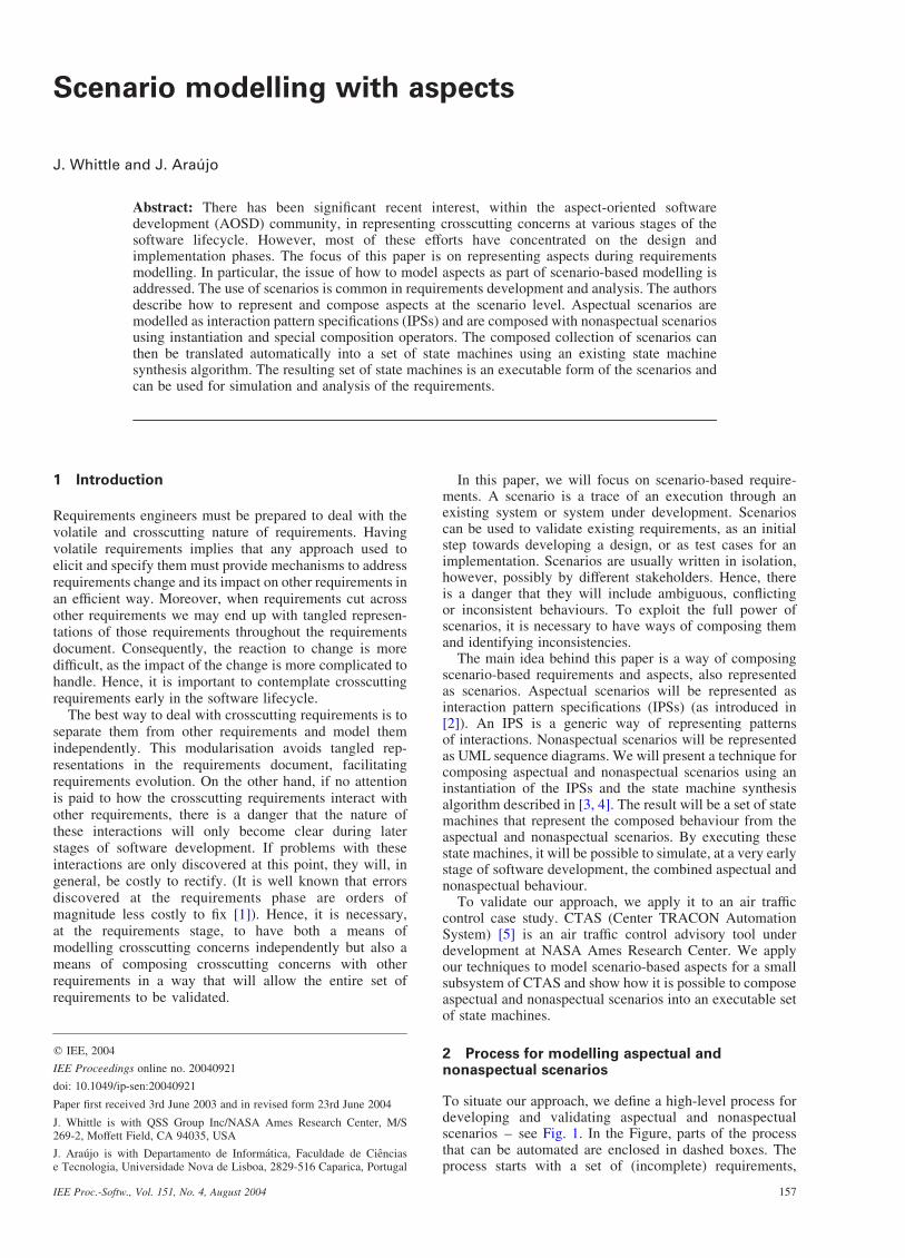
To situate our approach, we define a high-level process fordeveloping and validating aspectual and nonaspectualscenarios – see Fig. 1. In the Figure, parts of the processthat can be automated are enclosed in dashed boxes. Theprocess starts with a set of (incomplete) requirements,
q IEE, 2004
IEE Proceedings online no. 20040921
doi: 10.1049/ip-sen:20040921
J. Whittle is with QSS Group Inc/NASA Ames Research Center, M/S269-2, Moffett Field, CA 94035, USA
J. Araujo is with Departamento de Informatica, Faculdade de Cienciase Tecnologia, Universidade Nova de Lisboa, 2829-516 Caparica, Portugal
Paper first received 3rd June 2003 and in revised form 23rd June 2004
IEE Proc.-Softw., Vol. 151, No. 4, August 2004 157
acquired through interviews, questionnaires, manuals andother documents. Requirements elicitation involves carefulcapture and organisation of all relevant information.
From these requirements, we identify system functional-ities and nonfunctional concerns. Functionalities aredescribed by use cases. Nonfunctional concerns arespecified using templates (see Table 1), based on similartemplates in [6]. This table specifies the source of anonfunctional concern, the requirements that make it up, itspriority, its contribution to other nonfunctional concerns andwhich use cases are affected by the nonfunctional concern.
Based on an analysis of the relationship between thenonfunctional and functional concerns, candidate aspects[Note 1] are selected. Both functional and nonfunctionalconcerns are then refined to a set of scenarios. Aspectualscenarios are represented as interaction pattern specifica-tions (IPSs) and nonaspectual ones as UML sequencediagrams.
The box labelled ‘Composing scenarios’ in Fig. 1 isconcerned with composing the aspectual and nonaspectualscenarios. This is done by defining instantiations of the IPSswhich relate the IPSs to nonaspectual scenarios (see Section4 for more details). The result of ‘Composing scenarios’ is anew collection of scenarios in which aspectual scenarioshave been composed with nonaspectual ones.
identify and elicit
requirements
identify and specifynonfunctional
concerns
associate NF concerns and functional use cases
identify candidate aspects in
NF concerns and use cases
validate requirements and identify
conflicts
generate state machines from scenarios
compose state machines using
synthesis algorithm
identify and define actors and functional
use cases
describe scenarios for
use cases, NF concerns and candidate aspects
define composition of aspectual and nonaspectual
scenarios
composeaspectual and nonaspectual
scenarios
Composing scenarios
Composing state machines
refinefunctionaluse cases
Fig. 1 Process model
Table 1: Template for nonfunctional concern
Name the name of the nonfunctional concern
Description informal description of the concern
Source source of information
(e.g. stakeholders, documents)
Decomposition nonfunctional concerns can be
decomposed into simpler ones.
When all (sub) nonfunctional concerns
are needed to achieve the nonfunctional
concern, we have an AND relationship.
If not all the sub nonfunctional concerns
are necessary to achieve the nonfunctional
concern, we have an OR relationship
Priority expresses the importance of the
nonfunctional concern for the
stakeholders. A priority can be from
1 (very low) to 5 (very high)
Use cases list of the use cases influenced by
nonfunctional concern
Requirements requirements describing the
nonfunctional concern
Contribution represents how a nonfunctional concern
can be affected by the other nonfunctional
concern. This contribution can be positive
ðþÞ, negative ð�Þ or none
Note 1: The term ‘candidate aspect’ was coined in [7] to express the factthat not all the crosscutting concerns identified during requirementsmodelling will be implemented as an aspect. Some may be mapped into anarchitectural choice (e.g. availability).
IEE Proc.-Softw., Vol. 151, No. 4, August 2004158
In ‘Composing state machines’ in Fig. 1, each scenario istranslated into a set of state machines (one for eachcomponent in the interaction). The state machines fromdifferent scenarios are then merged using the synthesisalgorithm from [4]. The result is a complete and executablestate machine description of the requirements whereaspectual and nonaspectual behaviour has been merged.The point of generating state machines is so that the entirebehaviour (i.e. composed aspectual and nonaspectual) canbe validated. By including the aspectual cases in validation,we support a more realistic simulation of the behaviour.
3 Background
In this Section, we present the required technical back-ground for the rest of the paper. In particular, we introduceinteraction pattern specifications (IPSs) and state machinesynthesis from scenarios.
3.1 Interaction pattern specifications (IPSs)
Pattern specifications (PSs) are introduced in [2] as a way offormalising the structural and behavioural features of apattern. The notation for PSs is based on the unifiedmodelling language (UML). The abstract syntax of UML isdefined by a UML metamodel [8]. PSs specialise thismetamodel by describing what model elements mustparticipate in the pattern. Each element in the PS is arole–that is, a UML metaclass specialised by additionalproperties that any element fulfilling the role must possess.Hence, a role specifies a subset of the instances of the UMLmetaclass. A PS can be instantiated by assigning UMLmodel elements to the roles in the PS. A model conforms toa PS if its model elements that play the roles of the PSsatisfy the properties defined by the roles.
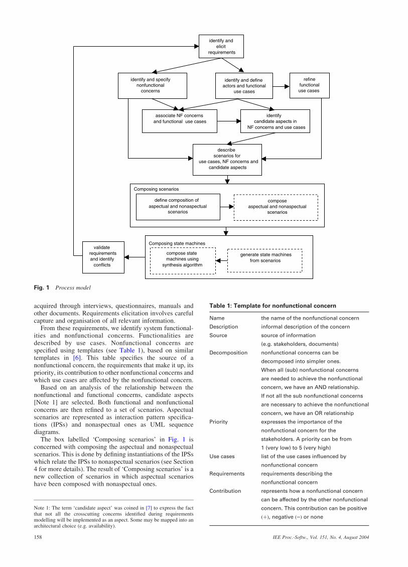
France et al. [2] define PSs for pattern structure (staticpattern specifications), interactions (interaction patternspecifications) and state-based behaviour (state machinepattern specifications). In this paper, we will be concernedonly with interaction pattern specifications (IPSs). An IPSdefines a pattern of interaction between its participants.It consists of a number of lifeline roles and message roleswhich are specialisations of the UML metaclasses Lifelineand Message, respectively. Each lifeline role is associatedwith a classifier role, a specialisation of a UML classifier.Figure 2 shows an example of an IPS and a conformingsequence diagram (taken from [2]).
The IPS formalises the Observer pattern. Role names arepreceded by a vertical bar to denote that they are roles.
A conforming sequence diagram (see Fig. 2b) mustinstantiate each of the roles with UML model elementssatisfying any multiplicity and other constraints (e.g. givenin the Object Constraint Language [9]). Note that anynumber of additional model elements may be present in aconforming sequence diagram as long as the role constraintsare maintained.
Figure 2b conforms to Fig. 2a if the following instantia-tions are made to Fig. 2a:
1. Bind jNotifyInteraction toKilnInteraction2. Bind js to s3. Bind jSubject toKiln4. Bind jo½i� to t½i�5. Bind jObserver to TempObs6. Bind jNotify toNotifyObs7. Bind jUpdate toUpdateTemp8. Bind jGetState toGetKilnTemp9. Bind jst to st10. Bind jNumOfObservers toNumOfObs
Note that additional modelling elements are allowed in theconforming sequence diagram, Fig. 2b – namely, m,Monitor and LogUpdateRecd. An IPS captures the factthat a sequence diagram is an instance of an IPS if therelative ordering of the messages in the IPS is preserved inthe sequence diagram and the participants in the interactionin the IPS are preserved as well. It allows for additionalcomponents and messages to be present in the conformingsequence diagram, however.
3.2 State machine synthesis
The following is a brief description of the algorithm used inthis paper to synthesise state machines from a collection ofscenarios (represented as UML sequence diagrams). Thealgorithm is a variant of the one described in [3].
Any algorithm that translates a set of scenarios into statemachines must transition from a global scenario-based view(in which interactions between all system components areconsidered) to local component-based views (in which astate machine is given for each component). In general, a setof state machines can be executed, whereas a set ofscenarios (e.g. UML sequence diagrams) cannot becauselocal models are needed for execution.
There are many algorithms for transforming scenarios intoexecutable state machines. The interested reader is referredto [10] for examples. We merely give the flavour of thetechnique here. Synthesis of state machines is performed in
s:Kiln
t[i]:TempObs
NotifyObs
UpdateTemp(s)
GetKilnTemp():st
KilnInteraction
m:Monitor
LogUpdateRecd(s)
loop ⟨NumOfObs⟩
|s:|Subject
|NotifyInteraction 1..*
|o[i]:|Observer
loop ⟨|NumOfObservers⟩
|Notify
|Update(|s)
a b
|GetState():|st
Fig. 2 IPS and a conforming sequence diagram
a IPS for observer patternb Conforming sequence diagram
IEE Proc.-Softw., Vol. 151, No. 4, August 2004 159
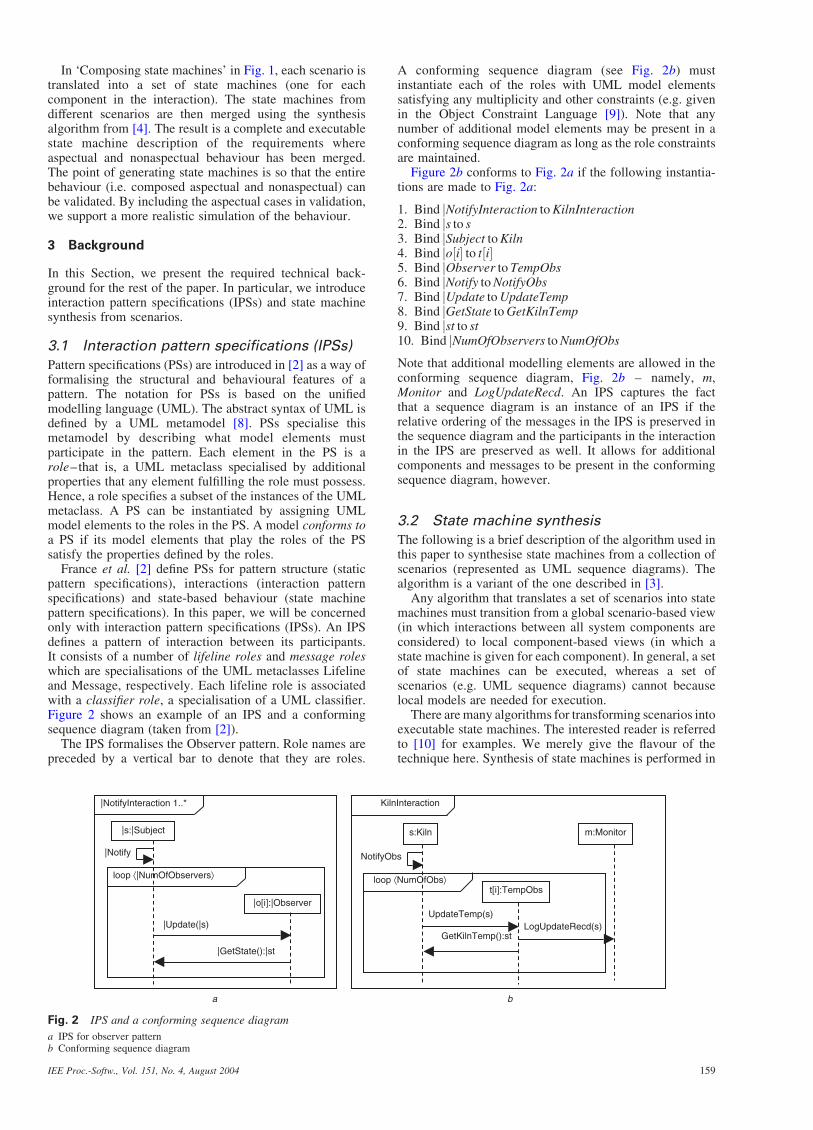
two steps. First, each sequence diagram is converted into a setof state machines – one for each object [Note 2] involved inthe interaction. Next, the individual state machines derivedfor each object (from different sequence diagrams) aremerged into a single state machine for that object.
In the first step, an individual sequence diagram istranslated into a collection of finite state machines (FSMs).Messages directed towards a particular object are con-sidered events in the FSM for that object. Messages directedaway from an object are considered actions. The synthesisalgorithm starts by generating an initial state for each FSM.It then traverses the sequence of messages. Messages have aunique sender object and a unique receiver object. For eachmessage, a transition is added to the FSM for the receiver ofthe message where the transition is labelled with an eventhaving the same name as the message. Similarly, a transitionis added to the FSM for the sender with an action defined,where the action is to send the message.
We allow state labels in sequence diagrams [Note 3] thatexplicitly label a state of an object in the interaction. Statelabels become named states in the generated FSM. Statelabels can lead to loops in the generated FSM if a state labeloccurs in multiple places.
Once finite state machines have been created for theindividual sequence diagrams, the finite state machinesgenerated from different sequence diagrams for a particularobject are merged together. Merging state machines derivedfrom different sequence diagrams is based on identifyingsimilar states in the FSMs. Our notion of similarity is basedon identifying common incoming and outgoing transitionsto states – see [4] for more details.
Figure 3 shows an example of synthesis from twosequence diagrams. The state machine shown was generatedfor B. a=b is the standard event=action notation for statemachines (i.e. if event a occurs, then the transition fireswhich results in action b being taken where, for the purposesof this paper, actions always involve sending messages).The black boxes are state labels.
4 Composing aspectual and nonaspectualscenarios
In the same way as [11, 12], we regard aspects as patterns.In particular, we represent aspectual scenarios as interaction
pattern specifications (IPSs). France et al. [2] do not addresshow to use IPSs to model aspects. They define what it meansfor a sequence diagram to conform to an IPS but their notionof conformance is too restrictive when using IPSs to modelaspects. In particular, in [2], an IPS consists solely of roleelements. We extend this definition to allow an IPS tocontain both role elements and nonrole (i.e. concretemodelling) elements. An example of this in Fig. 2a wouldbe if the jSubject role was replaced with the concretemodelling element, Kiln. Allowing nonrole elements in anIPS gives much greater flexibility in specifying aspects.For example, a security aspect might specify that any newuser to a system must have his=her password checked.The actions to check the password will be the same for anyuser and hence should be represented directly as concretemodelling elements rather than role elements that must beinstantiated.
Given that we have extended the definition of an IPS, wemust also extend the definition of conformance to an IPS.A conforming model (i.e. a sequence diagram) of anIPS consists of model elements that play all the roles of theIPS. As before, a conforming model may include its ownapplication-specific concrete model elements. Unlikebefore, however, it does not need to include the nonroleelements of the IPS. This last point deserves an explanation.Consider an IPS security aspect for an automated tellermachine (ATM) that incorporates checking of a passwordand a conforming sequence diagram representing a cashwithdrawal. The IPS would include role elements for theuser and the ATM and nonrole elements for checking apassword. The conforming sequence diagram would containconcrete elements for a particular user and a particular ATMthat conform to the roles in the IPS, but it would not containany elements corresponding to checking a password becausethose elements have been separated as an aspect. Weavingthe IPS and the sequence diagram would result in thepassword checking elements appearing in the sequencediagram, but at this stage, password checking is modelledindependently of any particular application.
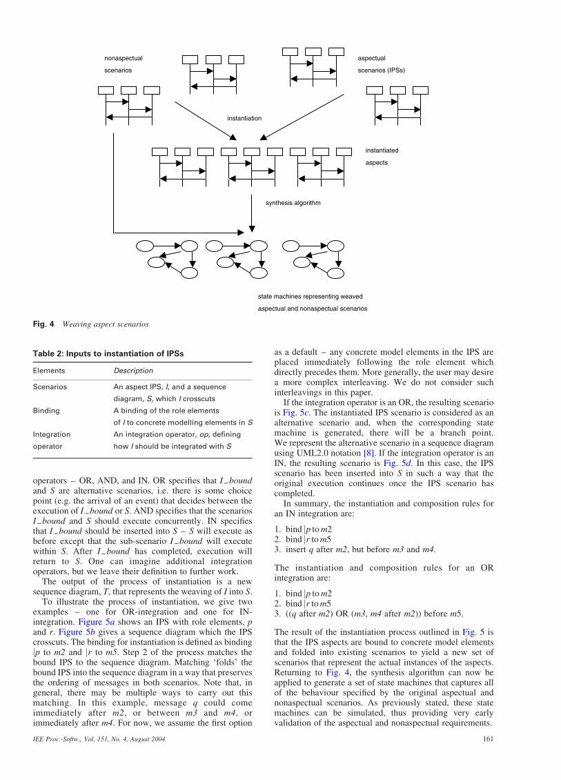
Figure 4 describes the composition of aspectual andnonaspectual scenarios using instantiation and the synthesisalgorithm. Aspectual scenarios are specified as IPSs. Foreach nonaspectual scenario that they crosscut, a bindingstatement is given. The aspectual scenarios are instantiatedusing these binding statements, which yields a new set ofscenarios (instantiated IPSs). The result is a set of scenariosthat each describes a particular functional or nonfunctionalbehaviour of the system. These scenarios are mergedtogether into a set of state machines (one for eachparticipating component) using the synthesis algorithm.These state machines can then be simulated which may leadto iterative refinements of the original scenarios.
The process of instantiation of the aspect IPSs has threeinputs (see Table 2) and proceeds as follows:
. Apply the binding to the role elements of I resulting in aconcrete sequence diagram, I bound:. Derive a new sequence diagram, S I; by matchingI bound to S. The elements in I bound are folded into Sto produce S I:. Modify S I into T by applying the integrationoperator, op.
The inputs to this process are the IPS, the sequence diagramwhich the IPS crosscuts, a binding for the elements in theIPS, and an integration operator. The integration operatordefines how the scenario represented by I bound and Sshould interact. Currently, we allow three integration
A B C
s1
s1
pq
r
s
t
s1p/q s/t
r /
A B C
s1
a
st
a/
s1
b
pq
b/
Fig. 3 Synthesis from multiple sequence diagrams
Note 2: When describing the synthesis algorithm, we will refer to objects inscenarios. More generally, however, scenarios may represent interactionsbetween components or subsystems, and hence all discussion referring toobjects equally applies to components and subsystems.
Note 3: State labels are similar to continuations in message sequence charts[13, 14] and UML2.0 sequence diagrams.
IEE Proc.-Softw., Vol. 151, No. 4, August 2004160
operators – OR, AND, and IN. OR specifies that I boundand S are alternative scenarios, i.e. there is some choicepoint (e.g. the arrival of an event) that decides between theexecution of I bound or S. AND specifies that the scenariosI bound and S should execute concurrently. IN specifiesthat I bound should be inserted into S – S will execute asbefore except that the sub-scenario I bound will executewithin S. After I bound has completed, execution willreturn to S. One can imagine additional integrationoperators, but we leave their definition to further work.
The output of the process of instantiation is a newsequence diagram, T, that represents the weaving of I into S.
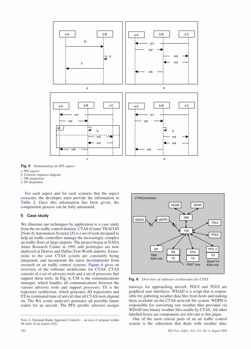
To illustrate the process of instantiation, we give twoexamples – one for OR-integration and one for IN-integration. Figure 5a shows an IPS with role elements, pand r. Figure 5b gives a sequence diagram which the IPScrosscuts. The binding for instantiation is defined as bindingjp to m2 and jr to m5. Step 2 of the process matches thebound IPS to the sequence diagram. Matching ‘folds’ thebound IPS into the sequence diagram in a way that preservesthe ordering of messages in both scenarios. Note that, ingeneral, there may be multiple ways to carry out thismatching. In this example, message q could comeimmediately after m2, or between m3 and m4, orimmediately after m4. For now, we assume the first option
as a default – any concrete model elements in the IPS areplaced immediately following the role element whichdirectly precedes them. More generally, the user may desirea more complex interleaving. We do not consider suchinterleavings in this paper.
If the integration operator is an OR, the resulting scenariois Fig. 5c. The instantiated IPS scenario is considered as analternative scenario and, when the corresponding statemachine is generated, there will be a branch point.We represent the alternative scenario in a sequence diagramusing UML2.0 notation [8]. If the integration operator is anIN, the resulting scenario is Fig. 5d. In this case, the IPSscenario has been inserted into S in such a way that theoriginal execution continues once the IPS scenario hascompleted.
In summary, the instantiation and composition rules foran IN integration are:
1. bind jp tom22. bind jr tom53. insert q after m2, but before m3 and m4.
The instantiation and composition rules for an ORintegration are:
1. bind jp tom22. bind jr tom53. ((q after m2) OR (m3, m4 after m2)) before m5.
The result of the instantiation process outlined in Fig. 5 isthat the IPS aspects are bound to concrete model elementsand folded into existing scenarios to yield a new set ofscenarios that represent the actual instances of the aspects.Returning to Fig. 4, the synthesis algorithm can now beapplied to generate a set of state machines that captures allof the behaviour specified by the original aspectual andnonaspectual scenarios. As previously stated, these statemachines can be simulated, thus providing very earlyvalidation of the aspectual and nonaspectual requirements.
nonaspectual
scenarios
aspectual
scenarios (IPSs)
instantiated
aspects
state machines representing weaved
aspectual and nonaspectual scenarios
instantiation
synthesis algorithm
Fig. 4 Weaving aspect scenarios
Table 2: Inputs to instantiation of IPSs
Elements Description
Scenarios An aspect IPS, I, and a sequence
diagram, S, which I crosscuts
Binding A binding of the role elements
of I to concrete modelling elements in S
Integration
operator
An integration operator, op, defining
how I should be integrated with S
IEE Proc.-Softw., Vol. 151, No. 4, August 2004 161
For each aspect and for each scenario that the aspectcrosscuts, the developer must provide the information inTable 2. Once this information has been given, thecomposition process can be fully automated.
5 Case study
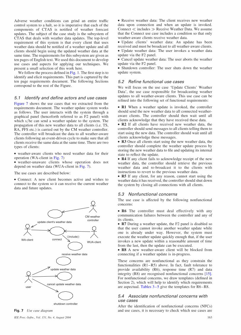
We illustrate our techniques by application to a case studyfrom the air traffic control domain. CTAS (Center TRACON[Note 4] Automation System) [5] is a set of tools designed tohelp air traffic controllers manage the increasingly complexair traffic flows at large airports. The project began at NASAAmes Research Center in 1991 and prototypes are nowdeployed at Denver and Dallas=Fort Worth airports. Exten-sions to the core CTAS system are constantly beingintegrated, and incorporate the latest developments fromresearch on air traffic control systems. Figure 6 gives anoverview of the software architecture for CTAS. CTASconsists of a set of advisory tools and a set of processes thatsupport these tools. In Fig. 6, CM is the communicationsmanager, which handles all communications between thevarious advisory tools and support processes. TS is thetrajectory synthesiser, which generates 4D trajectories andETAs (estimated time of arrival) that all CTAS tools dependon. The RA (route analyser) generates all possible futureroutes for an aircraft. The PFS (profile selector) assigns
runways for approaching aircraft. PGUI and TGUI aregraphical user interfaces. WDAD is a script that is respon-sible for gathering weather data files from hosts and makingthem available on the CTAS network file system. WDPD isresponsible for converting raw weather files provided viaWDAD into binary weather files usable by CTAS. All otherlabelled boxes are components not relevant to this paper.
One of the most crucial parts of an air traffic controlsystem is the subsystem that deals with weather data.
q
b:B
|p
|r
a:A b:B c:C
m1
m5
m4
m3
m2
a:A b:B c:C
m1
m5
m4
m3
m2
q
a:A
a b
c d
b:B c:C
m1
m5
m4
m3
m2
q alt
a:A
Fig. 5 Instantiating an IPS aspect
a IPS aspcectb Concrete sequence diagramc OR integrationd IN integration
HDAR ADAR
ISM
CM
WDPDWDAD
CTAS processes
TGUI
PGUI
PFS_C
TSTSTS
PFSRADP
TMA,EDA only
FAST onlyDirect-To/EDA only
Fig. 6 Overview of software architecture for CTAS
Note 4: Terminal Radar Approach Controls – an area of airspace within40 miles of an airport (US).
IEE Proc.-Softw., Vol. 151, No. 4, August 2004162
Adverse weather conditions can grind an entire trafficcontrol system to a halt, so it is imperative that each of thecomponents of CTAS is notified of weather forecastupdates. The subject of the case study is the subsystem ofCTAS that deals with weather data updates. The top-levelrequirement of this system is that every client that usesweather data should be notified of a weather update and allclients should begin using the updated weather data at thesame time. The requirements for this subsystem are given asten pages of English text. We used this document to developuse cases and aspects for applying our techniques. Wepresent a small selection of this work here.
We follow the process defined in Fig. 1. The first step is toidentify and elicit requirements. This part is captured by theten page requirements document. The following Sectionscorrespond to the rest of the Figure.
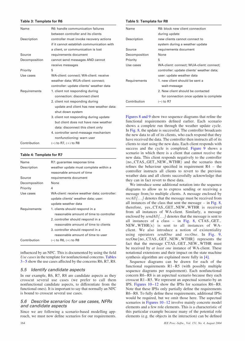
5.1 Identify and define actors and use cases
Figure 7 shows the use cases that we extracted from therequirements document. The weather update system worksas follows. The user interacts with the system through agraphical panel (henceforth referred to as F2 panel) withwhich s=he can send a weather update to the system. Thepropagation of this new weather data to all clients (i.e. TS,RA, PFS etc.) is carried out by the CM weather controller.The controller will broadcast the data to all weather-awareclients following an event-driven cycle to make sure that allclients receive the same data at the same time. There are twotypes of clients:
. weather-aware clients who need weather data for theiroperation (WA-client in Fig. 7). weather-unaware clients whose operation does notdepend on weather data (WUA-client in Fig. 7).
The use cases are described below:
. Connect: A new client becomes active and wishes toconnect to the system so it can receive the current weatherdata and future updates.
. Receive weather data: The client receives new weatherdata upon connection and when an update is invoked.Connect � includes � Receive Weather Data. We assumethat the Connect use case includes a condition so that onlyweather-aware clients receive weather data.. Update clients’ weather data: An update has beenreceived and must be broadcast to all weather-aware clients.. Update weather data: The user invokes a weather dataupdate via the F2 panel.. Cancel update weather data: The user aborts the weatherupdate via the F2 panel.. Shutdown controller: The user shuts down the weatherupdate system.
5.2 Refine functional use cases
We will focus on the use case ‘Update Clients’ WeatherData’, the use case responsible for broadcasting weatherupdates to all weather-aware clients. This use case can berefined into the following set of functional requirements:
. R1 When a weather update is invoked, the controllershould send the new weather data to all connected weather-aware clients. The controller should then wait until allclients acknowledge that they have received these data.. R2 If all clients have received new weather data, thecontroller should send messages to all clients telling them tostart using the new data. The controller should wait until allclients acknowledge these messages.. R3 Once all clients start using the new weather data, thecontroller should complete the weather update process bystoring the new weather data to file and updating its internalstate to reflect the update.. R4 If any client fails to acknowledge receipt of the newweather data, the controller should retrieve the previousweather data and re-broadcast it to the clients withinstructions to revert to the previous weather data.. R5 If any client, for any reason, cannot start using theweather data it has received, the controller should shut downthe system by closing all connections with all clients.
5.3 Nonfunctional concerns
The use case is affected by the following nonfunctionalconcerns:
. R6 The controller must deal effectively with anycommunication failures between the controller and any ofits clients.. R7 During a weather update, the F2 panel is disabled sothat the user cannot invoke another weather update whileone is already under way. However, the system mustexecute the weather update quickly enough that, if the userinvokes a new update within a reasonable amount of timefrom the last, then the update can be executed.. R8 A new weather-aware client will be blocked fromconnecting if a weather update is in-progress.
These concerns are nonfunctional as they constrain thefunctionalities (R1–R5) above. In fact, fault tolerance toprovide availability (R6), response time (R7) and dataintegrity (R8) are recognised nonfunctional concerns [15].For nonfunctional concerns, we draw templates (defined inSection 2), which will help to identify which requirementsare aspectual. Tables 3–5 give the templates for R6–R8.
5.4 Associate nonfunctional concerns withuse cases
After the identification of nonfunctional concerns (NFCs)and use cases, it is necessary to check which use cases are
user
receive weather data
connect⟨⟨include⟩⟩
CM weather controller
WUA-client
update client's weather data
WA-client
update weather data
cancel update weather data
shutdown controller
Fig. 7 Use case diagram
IEE Proc.-Softw., Vol. 151, No. 4, August 2004 163
influenced by an NFC. This is documented by using the fieldUse cases in the template for nonfunctional concerns. Tables3–5 show the use cases affected by the concerns R6, R7, R8.
5.5 Identify candidate aspects
In our example, R6, R7, R8 are candidate aspects as theycrosscut several use cases (we prefer to call themnonfunctional candidate aspects, to differentiate from thefunctional ones). It is important to say that normally an NFCis bound to crosscut several use cases.
5.6 Describe scenarios for use cases, NFRsand candidate aspects
Since we are following a scenario-based modelling app-roach, we must now define scenarios for our requirements.
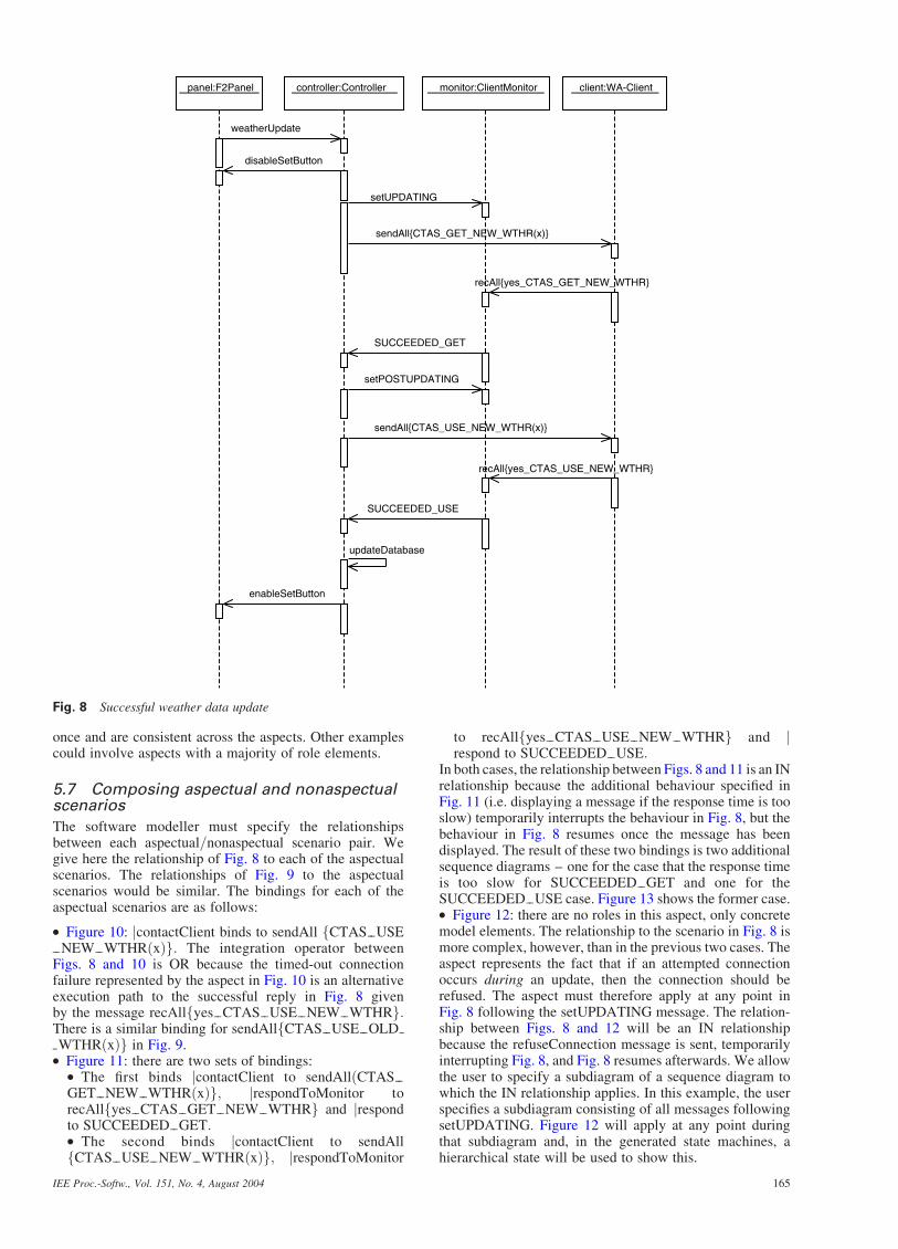
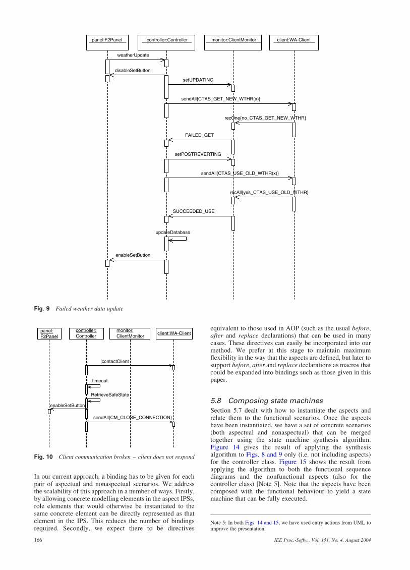
Figures 8 and 9 show two sequence diagrams that refine thefunctional requirements defined earlier. Each scenarioshows a complete run through the weather update cycle.In Fig. 8, the update is successful. The controller broadcaststhe new data to all of its clients, who each respond that theyhave received the data. The controller then instructs all of itsclients to start using the new data. Each client responds withsuccess and the cycle is completed. Figure 9 shows ascenario in which there is a client that cannot receive thenew data. This client responds negatively to the controllerðno CTAS GET NEW WTHRÞ and the scenario thenrefines the behaviour specified in requirement R4 – thecontroller instructs all clients to revert to the previousweather data and all clients successfully acknowledge thatthey can in fact revert to these data.
We introduce some additional notation into the sequencediagrams to allow us to express sending or receiving amessage from=to multiple clients. A message enclosed byrecAllf. . .g denotes that the message must be received fromall instances of the class that sent the message – in Fig. 8,therefore, yes CTAS GET NEW WTHR is receivedfrom all instances of WA-client. Similarly, a messageenclosed by sendAllf. . .g denotes that the message is sent toall instances of a class – in Fig. 8, CTAS GETNEW WTHRðxÞ is sent to all instances of WA-client. We also introduce a notion of existentialityusing operators sendOne and recOne. In Fig. 9,recOnefno CTAS GET NEW WTHRg represents thefact that the message CTAS GET NEW WTHR mustbe received by at least one instance of WA-client. Thesenotational extensions and their impact on the state machinesynthesis algorithm are explained more fully in [4].
Sequence diagrams can be drawn for each of thefunctional requirements R1–R5 (with possibly multiplesequence diagrams per requirement). Each nonfunctionalconcern R6–R8 is an aspectual scenario because they eachcrosscut R1–R5. We represent an aspectual scenario by anIPS. Figures 10–12 show the IPSs for scenarios R6–R8.Note that these IPSs only partially define the requirementsR6–R8. To fully define these requirements, additional IPSswould be required, but we omit those here. The aspectualscenarios in Figures 10–12 involve mainly concrete modelelements and a few role elements. This is a characteristic ofthis particular example because many of the potential roleelements (e.g. the objects in the interaction) can be defined
Table 3: Template for R6
Name R6: handle communication failures
between controller and its clients
Description controller must invoke recovery actions
if it cannot establish communication with
a client, or communication is lost
Source requirements document
Decomposition cannot send messages AND cannot
receive messages
Priority 5
Use cases WA-client: connect; WA-client: receive
weather data; WUA-client: connect;
controller: update clients’ weather data
Requirements 1. client not responding during
connection: disconnect client
2. client not responding during
update and client has new weather data:
shut down system
3. client not responding during update
but client does not have new weather
data: disconnect this client only
4. controller send-message mechanism
nonfunctioning: warn user
Contribution ð�Þ to R7, ðþÞ to R8
Table 4: Template for R7
Name R7: guarantee response time
Description weather update must complete within a
reasonable amount of time
Source requirements document
Decomposition None
Priority 4
Use cases WA-client: receive weather data; controller:
update clients’ weather data; user:
update weather data
Requirements 1. clients should respond in a
reasonable amount of time to controller
2. controller should respond in a
reasonable amount of time to clients
3. controller should respond in a
reasonable amount of time to user
Contribution ð�Þ to R6, ðþÞ to R8
Table 5: Template for R8
Name R8: block new client connection
during update
Description new clients cannot connect to
system during a weather update
Source requirements document
Decomposition None
Priority 5
Use cases WA-client: connect; WUA-client: connect;
controller: update clients’ weather data;
user: update weather data
Requirements 1. new client should be sent a
wait-message
2. New client should be contacted
for connection once update is complete
Contribution ð�Þ to R7
IEE Proc.-Softw., Vol. 151, No. 4, August 2004164
once and are consistent across the aspects. Other examplescould involve aspects with a majority of role elements.
5.7 Composing aspectual and nonaspectualscenarios
The software modeller must specify the relationshipsbetween each aspectual=nonaspectual scenario pair. Wegive here the relationship of Fig. 8 to each of the aspectualscenarios. The relationships of Fig. 9 to the aspectualscenarios would be similar. The bindings for each of theaspectual scenarios are as follows:
. Figure 10: jcontactClient binds to sendAll fCTAS USENEW WTHRðxÞg: The integration operator between
Figs. 8 and 10 is OR because the timed-out connectionfailure represented by the aspect in Fig. 10 is an alternativeexecution path to the successful reply in Fig. 8 givenby the message recAllfyes CTAS USE NEW WTHRg:There is a similar binding for sendAllfCTAS USE OLDWTHRðxÞg in Fig. 9.. Figure 11: there are two sets of bindings:
. The first binds jcontactClient to sendAllðCTASGET NEW WTHRðxÞg; jrespondToMonitor torecAllfyes CTAS GET NEW WTHRg and jrespondto SUCCEEDED GET:. The second binds jcontactClient to sendAllfCTAS USE NEW WTHRðxÞg; jrespondToMonitor
to recAllfyes CTAS USE NEW WTHRg and jrespond to SUCCEEDED USE:
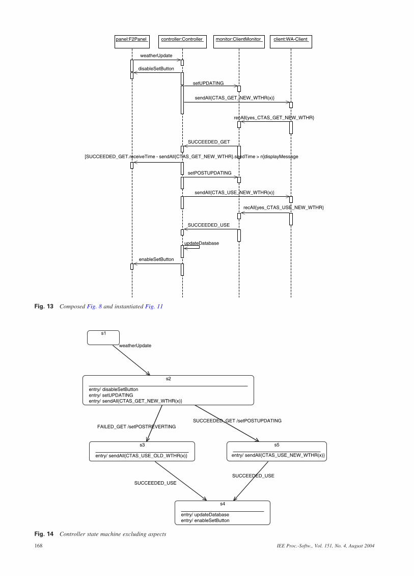
In both cases, the relationship between Figs. 8 and 11 is an INrelationship because the additional behaviour specified inFig. 11 (i.e. displaying a message if the response time is tooslow) temporarily interrupts the behaviour in Fig. 8, but thebehaviour in Fig. 8 resumes once the message has beendisplayed. The result of these two bindings is two additionalsequence diagrams – one for the case that the response timeis too slow for SUCCEEDED GET and one for theSUCCEEDED USE case. Figure 13 shows the former case.. Figure 12: there are no roles in this aspect, only concretemodel elements. The relationship to the scenario in Fig. 8 ismore complex, however, than in the previous two cases. Theaspect represents the fact that if an attempted connectionoccurs during an update, then the connection should berefused. The aspect must therefore apply at any point inFig. 8 following the setUPDATING message. The relation-ship between Figs. 8 and 12 will be an IN relationshipbecause the refuseConnection message is sent, temporarilyinterrupting Fig. 8, and Fig. 8 resumes afterwards. We allowthe user to specify a subdiagram of a sequence diagram towhich the IN relationship applies. In this example, the userspecifies a subdiagram consisting of all messages followingsetUPDATING. Figure 12 will apply at any point duringthat subdiagram and, in the generated state machines, ahierarchical state will be used to show this.
client:WA-Clientpanel:F2Panel controller:Controller monitor:ClientMonitor
recAll{yes_CTAS_GET_NEW_WTHR}
SUCCEEDED_GET
setPOSTUPDATING
sendAll{CTAS_USE_NEW_WTHR(x)}
recAll{yes_CTAS_USE_NEW_WTHR}
SUCCEEDED_USE
updateDatabase
enableSetButton
setUPDATING
sendAll{CTAS_GET_NEW_WTHR(x)}
weatherUpdate
disableSetButton
Fig. 8 Successful weather data update
IEE Proc.-Softw., Vol. 151, No. 4, August 2004 165
In our current approach, a binding has to be given for eachpair of aspectual and nonaspectual scenarios. We addressthe scalability of this approach in a number of ways. Firstly,by allowing concrete modelling elements in the aspect IPSs,role elements that would otherwise be instantiated to thesame concrete element can be directly represented as thatelement in the IPS. This reduces the number of bindingsrequired. Secondly, we expect there to be directives
equivalent to those used in AOP (such as the usual before,after and replace declarations) that can be used in manycases. These directives can easily be incorporated into ourmethod. We prefer at this stage to maintain maximumflexibility in the way that the aspects are defined, but later tosupport before, after and replace declarations as macros thatcould be expanded into bindings such as those given in thispaper.
5.8 Composing state machines
Section 5.7 dealt with how to instantiate the aspects andrelate them to the functional scenarios. Once the aspectshave been instantiated, we have a set of concrete scenarios(both aspectual and nonaspectual) that can be mergedtogether using the state machine synthesis algorithm.Figure 14 gives the result of applying the synthesisalgorithm to Figs. 8 and 9 only (i.e. not including aspects)for the controller class. Figure 15 shows the result fromapplying the algorithm to both the functional sequencediagrams and the nonfunctional aspects (also for thecontroller class) [Note 5]. Note that the aspects have beencomposed with the functional behaviour to yield a statemachine that can be fully executed.
panel:F2Panel controller:Controller monitor:ClientMonitor client:WA-Client
weatherUpdate
disableSetButton
setUPDATING
sendAll{CTAS_GET_NEW_WTHR(x)}
recOne{no_CTAS_GET_NEW_WTHR}
FAILED_GET
setPOSTREVERTING
sendAll{CTAS_USE_OLD_WTHR(x)}
recAll{yes_CTAS_USE_OLD_WTHR}
SUCCEEDED_USE
updateDatabase
enableSetButton
Fig. 9 Failed weather data update
panel:F2Panel
controller:Controller
monitor:ClientMonitor
client:WA-Client
|contactClient
timeout
RetrieveSafeState
enableSetButton
sendAll{CM_CLOSE_CONNECTION}
Fig. 10 Client communication broken – client does not respond
Note 5: In both Figs. 14 and 15, we have used entry actions from UML toimprove the presentation.
IEE Proc.-Softw., Vol. 151, No. 4, August 2004166

The state machine in Fig. 15 is a good deal morecomplicated than that in Fig. 14. It represents thecomposition of the aspectual and nonaspectual behaviourand hence can be used as a faithful simulation of thebehaviour described. We provide both Figs. 14 and 15 tothe user for validation purposes. The simpler Fig. 14 can beused as an easy means of communicating the essentialbehaviour of the example. On the other hand, if more detailis required about alternative execution paths etc., the usermay wish to look at Fig. 15. In addition, as already stated,Fig. 15 is the most useful for simulation as it contains all ofthe specified behaviours in an executable form.
There are a number of points to make about Fig. 15.As already stated, the synthesis algorithm has incorporatedthe alternative path representing a timed-out communi-cation between controller and client. It has also incorporateda slow response time from a client and an illegal attempt toconnect to the system by a client. The latter execution pathis implemented in the state machine using a hierarchicalstate (corresponding to the subchart identified earlier inSection 5.7) and a history marker attached to this state.History markers are part of the standard statechart notationand denote that when a hierarchical state is re-entered,execution resumes at the substate of the hierarchical statewhich was active before execution went outside thehierarchical state. In our context, the history state is a neatway to implement the IN integration operator when ahierarchical state is involved.
The state machine in Fig. 15 can be simulated usingexisting tools such as Rational Rose RealTime [16],Rhapsody [17] or Egyed’s simulator for Rational RoseEnterprise Edition [18]. In general, analysis techniquessuch as model checking [19] could also be applied. Theanalysis of the generated state machines is out of
the scope of this paper. We note here only that simulationhas been shown to be an effective tool in requirementsvalidation [20].
6 Related work
Requirements have an intrinsic crosscutting nature, i.e. arequirement may affect one or more requirements.Nevertheless, most approaches neither contemplate theseparation of these crosscutting requirements nor providemechanisms to compose such requirements in an effectivemanner without losing abstraction.
Some requirements approaches, such as viewpoints [21]and goals, [22] address separation of functional andnonfunctional concerns. PREView [23], for example, is aviewpoint-oriented requirements engineering method,which helps separate functional and nonfunctional proper-ties of a system. A viewpoint in PREView encapsulatespartial information about the system obtained from thestakeholders. PREView includes, among other components,focus, functional requirements and concerns. Theseconcerns are nonfunctional and specified with a set ofrequirements. Because of their granularity, they crosscut anumber of functional requirements. Moreover, PREViewhas an elaborate mechanism to deal with conflict resolution.However, the identification of crosscutting requirementsand their composition is not addressed explicitly.
Nonfunctional concerns are separated from functionalones in goal-oriented approaches [22]. Well known methodsthat adopt goals as the main concept=paradigm are KAOS[24] and i[25]. A goal is a purpose that the system issupposed to reach. A goal can be expressed informallyor formally (e.g. using temporal logic as in KAOS)and incorporate functional and nonfunctional concerns.A drawback of the approach is that composition of goals isnot separated from the goals involved in the composition.
There are some aspect-oriented requirements approacheswhich are related to ours [6, 7, 26–28]. In Grundy’sapproach [26], called aspect-oriented component require-ments engineering (AOCRE), there is a categorisation ofvarious aspects of a system (e.g. persistence, distribution)that each component makes available to other componentsor users. It is committed to component based softwaredevelopment, and does not present proof of its use in otherkinds of software development.
The approach in [27] shows the development of a systemfor runtime monitoring of system goals. KAOS is used tospecify the system. They define separated composition rulesusing Hyper=J, which consequently makes the approach
panel:F2Panel controller:Controller monitor:ClientMonitor client:WA-Client
|contactClient
|respondToMonitor
[|respond.receiveTime - |contactClient.sendTime > n] displayMessage
|respond
Fig. 11 Client responds but not within sufficient time: warning message displayed to user
controller:Controller
panel:F2Panel
monitor:ClientMonitor
client :WA-Client
connect
requestConnection
refuseConnection
Fig. 12 Client tries to connect during update
IEE Proc.-Softw., Vol. 151, No. 4, August 2004 167
monitor:ClientMonitorpanel:F2Panel controller:Controller client:WA-Client
updateDatabase
enableSetButton
weatherUpdate
disableSetButton
SUCCEEDED_GET
setPOSTUPDATING
SUCCEEDED_USE
setUPDATING
recAll{yes_CTAS_GET_NEW_WTHR}
sendAll{CTAS_USE_NEW_WTHR(x)}
recAll{yes_CTAS_USE_NEW_WTHR}
sendAll{CTAS_GET_NEW_WTHR(x)}
[SUCCEEDED_GET.receiveTime - sendAll{CTAS_GET_NEW_WTHR}.sendTime > n]displayMessage
Fig. 13 Composed Fig. 8 and instantiated Fig. 11
s1
s2
entry/ disableSetButtonentry/ setUPDATINGentry/ sendAll{CTAS_GET_NEW_WTHR(x)}
weatherUpdate
s3
entry/ sendAll{CTAS_USE_OLD_WTHR(x)}
s4
entry/ updateDatabaseentry/ enableSetButton
SUCCEEDED_USE
s5
entry/ sendAll{CTAS_USE_NEW_WTHR(x)}
SUCCEEDED_USE
SUCCEEDED_GET /setPOSTUPDATING FAILED_GET /setPOSTREVERTING
Fig. 14 Controller state machine excluding aspects
IEE Proc.-Softw., Vol. 151, No. 4, August 2004168

dependent on an implementation. Also, it is domain specific,limiting its applicability.
Cosmos is a schema for the modelling of multidimen-sional concern-spaces [28]. Cosmos defines any concern asa matter of interest. The schema includes concerns (logicaland physical), relationships (categorical, interpretive,mapping, physical) and predicates. Although the schemafavours detailed modelling and modularisation, littlesupport is given to composition of concerns.
In [6], separation of crosscutting concerns at the require-ments level is achieved by identifying and specifying qualityattributes (i.e. higher-level nonfunctional requirements) andfunctional requirements (using a use case driven approach).Quality attributes are described using special templates,identifying those that crosscut functional use cases. Finally,extensions to use cases and sequence diagrams are proposedto represent the composition of crosscutting qualityattributes with functional requirements. Nevertheless, com-position rules are presented very informally, and support formapping to design and conflict resolution is not considered.A similar approach is found in [29].
The aspect-oriented requirements engineering (AORE)approach [7] proposes a model that supports separation ofcrosscutting functional and nonfunctional properties at therequirements level. It also provides identification of theirmapping and influence on later development stages. Theapproach is refined in [30] with PREView and XML, wheredetailed composition rules for aspectual requirements aredefined and also separated. The XML composition rules usea list of constraint actions and operators, which are informal,
but with well defined semantics. They are used to specifyhow an aspectual requirement influences or constrains thebehaviour of a set of nonaspectual requirements. Also, anelaborated conflict resolution scheme is presented.Additionally, the approach is supported by a tool calledARCaDe. Although the composition rules are well definedand accessible by stakeholders, this list of constraint actionsand operators still has to be validated in different kinds ofapplication. Moreover, composition rules may grow toocomplex, making them hard to understand.
A related work close to our approach can be found in[11, 31]. They propose an aspect-oriented design approachthat defines an aspect through role models to be woven intoUML diagrams. The types of role models used were calledStatic Role Model (SRM), to be woven with class diagrams,and Interaction Role Model (IRM), to be woven withcollaboration diagrams. However, the rules for composing(weaving) aspects into these diagrams are presented in aninformal way and do not seem very flexible, as alternativeways to compose aspects with these models are notdiscussed.
There is some work on modelling aspects as statemachines. Aldawud et al. [32] provide a mechanism tosupport aspect-orientation in the context of state machines,where aspects are associated with methods and transitionsbut not with states. In [33], state machines can be defined asaspects and can be woven together. Our approach differsfrom that as we opted to model aspects at the scenario level,where the composition requires less work from therequirements engineer (as scenarios are more abstract than
t2
entry/ disableSetButtonentry/ setUPDATINGentry/ sendAll{CTAS_GET_NEW_WTHR(x)}
t1weatherUpdate
t6
entry/ RetrieveSaf eStateentry/ enableSetButtonentry/ sendAll{CM_CLOSE_CONNECTION}
t4
entry/ if SUCCEEDED_USE.receiveTime - sendAll{CTAS_USE_NEW_WTHR(x)}.sendTime > n then displayMessageentry/ updateDatabaseentry/ enableSetButton
H t5
entry/ if SUCCEEDED_GET.receiv yMessageentry/ setPOSTUPDATINGentry/ sendAll{CTAS_USE_NEW_WTHR(x)}
t3
entry/ if FAILED_GET.receiv yMessageentry/ setPOSTREVERTINGentry/ sendAll{CTAS_USE_OLD_WTHR(x)}
t6
entry/ RetrieveSafeStateentry/ enableSetButtonentry/ sendAll{CM_CLOSE_CONNECTION}
t4
entry/ if SUCCEEDED_USE.receiveTime - sendAll{CTAS_USE_NEW_WTHR(x)}.sendTime > n then displayMessageentry/ updateDatabaseentry/ enableSetButton
requestConnect / refuseConnection
H t5
entry/ if SUCCEEDED_GET.receiveTime - sendAll{CTAS_GET_NEW_WTHR(x)}.sendTime > n then displayMessageentry/ setPOSTUPDATINGentry/ sendAll{CTAS_USE_NEW_WTHR(x)}
t3
entry/ if FAILED_GET.receiveTime - sendAll{CTAS_GET_NEW_WTHR(x)}.sendTime > n then displayMessageentry/ setPOSTREVERTINGentry/ sendAll{CTAS_USE_OLD_WTHR(x)}
timeoutSUCCEEDED_USE
SUCCEEDED_GET
timeout
FAILED_GET
Fig. 15 Controller state machine including aspects
IEE Proc.-Softw., Vol. 151, No. 4, August 2004 169
state machines), and to derive state machines aftercomposing aspectual and nonaspectual scenarios. We havealso applied our techniques to aspect representation andcomposition at the state machine level [34].
There are also composition patterns [12, 35], which dealwith crosscutting concerns as patterns at the design level.Pattern binding is used, for example, to compose the patternwith concrete model elements. Sequence and class diagramsare used to illustrate compositions. The compositions,however, are rigid as they concentrate on pattern instantia-tions. Our approach is more flexible because we allowdifferent kinds of compositions. Also, they do not presentany guidelines to deal with requirements validation andconflict detection.
7 Conclusions
This paper presented an aspect-oriented scenario modellingapproach, to be used at the requirements level. Aspectualscenarios are modelled using interaction pattern specifica-tions and composed with nonaspectual requirements.The process model presented also included the generationof state machines from composed scenarios, to be used tocreate prototypes for stakeholders’ requirements validation.
To illustrate the approach, we applied it to part of an airtraffic control system. The aspectual scenarios presentedwere for nonfunctional concerns. However, the approachcan also be used to define functional aspectual scenariosrelated to aspectual use cases. An aspectual use case is a usecase that is included by or extends other use cases [29], i.e. itis a use case that crosscuts other use cases. Furthermore, theapproach is flexible enough to be used even for nonaspec-tual scenarios.
The advantages that we can draw attention to in the useof aspectual concepts in scenario-based modelling arecommon to aspect-oriented software development ingeneral: the achievement of a better modularisationand traceability of a system, resulting in a more effectivesystem evolution. Better modularisation is achieved havingcrosscutting behaviour separated since requirements. Trace-ability is guaranteed and facilitated, as the mergingalgorithm is defined in a flexible and simple way. Moreover,the approach facilitates the detection of erroneous require-ments, plus the identification of conflicts through prototyp-ing. Additionally, aspectual artefacts, such as aspectualscenarios, promote a homogeneous software developmentbased on aspects, starting in the early stages.
In our current approach, the developer must providebinding statements for each aspect and for each scenario thatthe aspect crosscuts. Clearly, this may lead to scalabilityproblems. However, we expect there to be many ways tomanage this scalability. For example, a language could bedefined to allow a role to be instantiated across multiplesequence diagrams simultaneously in a similar way thatpointcuts are used in Aspect=J [36]. Tool support will alsobe necessary. A Rational Rose plug-in has already beendeveloped by Dae-Kyoo Kim for creating and instantiatingpattern specifications. The synthesis algorithm has beenimplemented and extensively evaluated on real-worldexamples.
For future work we want to apply the approach to othercase studies contemplating functional aspectual scenarios.Also, we want to extend the approach, possibly consideringother models (e.g. class diagrams, activity diagrams).Additionally, we will address how to use the result ofthe simulation step to augment or correct the scenariomodels. Finally, a mapping to the design level will beinvestigated.
8 References
1 Boehm, B.W.: ‘Software engineering economics’ (Prentice Hall, UpperSaddle River, NJ, 1981)
2 France, R., Kim, D., Ghosh, S., and Song, E.: ‘A UML-based patternspecification technique’, IEEE Trans. Softw. Eng., 2004, 30, (3),pp. 193–206
3 Whittle, J., and Schumann, J.: ‘Generating statechart designs fromscenarios’. Proc. 22nd Int. Conf. on Software Engineering (ICSE),Limerick, Ireland, June 2000, pp. 314–323
4 Whittle, J., Kwan, R., and Saboo, J.: ‘From scenarios to code: an airtraffic control case study’. Proc. 25th Int. Conf. on SoftwareEngineering (ICSE), Portland, USA, May 2003, pp. 490–495
5 Denery, D., Erzberger, H., Davis, T., Green, S., and McNally, B.:‘Challenges of air traffic management research: analysis, simulationand field test’. Presented at AIAA Guidance, Navigation and ControlConf., New Orleans, LA, August 1997
6 Moreira, A., Araujo, J., and Brito, I.: ‘Crosscutting quality attributesfor requirements engineering’. Proc. 14th Int. Conf. on SoftwareEngineering and Knowledge Engineering (SEKE), Ischia, Italy,July 2002, pp. 167–174
7 Rashid, A., Sawyer, P., Moreira, A., and Araujo, J.: ‘Early aspects:a model for aspect-oriented requirements engineering’. Proc. IEEEJoint Int. Conf. on Requirements Engineering (RE), Essen, Germany,September 2002, pp. 199–202
8 Unified Modeling Language Specification, version 2.0. Available fromthe Object Management Group, January 2004, http://www.omg.org
9 Warmer, J., and Kleppe, A.: ‘The object constraint language:precise modeling with UML’ (Addison-Wesley, Reading, MA, 1999),Object Technology Series
10 Workshop on Scenarios and State Machines: Models, Algorithmsand Tools. Proc. 25th Int. Conf. on Software Engineering (ICSE),Portland, Oregon, USA, May 2003. http://www.doc.ic.ac.uk/,su2/SCESM
11 Georg, G., Ray, I., and France, R.: ‘Using aspects to design a securesystem’. Proc. 8th IEEE Int. Conf. on Engineering of ComplexComputer Systems (ICECCS), Greenbelt, Maryland, USA, December2002, p. 117
12 Clarke, S., and Walker, R.J.: ‘Composition patterns: an approach todesigning reusable aspects’. Proc. 23rd Int. Conf. on SoftwareEngineering (ICSE), Toronto, Canada, May 2001, pp. 5–14
13 Krueger, I., Grosu, R., Scholz, P., and Broy, M.: ‘From MSCs tostatecharts’, in Rammig, F.J. (Ed.): ‘Distributed and parallel embeddedsystems’ (Kluwer, Boston, MA, 1999)
14 Message sequence chart (MSC). Technical Report, ITU-TRecommendation Z.120 (previously CCITT Recommendation),Formal Description Techniques, 1996
15 Chung, L., Nixon, B., Yu, E., and Mylopoulos, J.: ‘Non-functionalrequirements in software engineering’ (Kluwer, Boston, MA, 2000)
16 Rational Rose RealTime. IBM Software Corporation17 Rhapsody. iLogix Corporation18 Egyed, A., and Wile, D.: ‘Statechart simulator for modeling architectural
dynamics’. Proc. 2nd IEEE/IFIP Conf. on Software Architecture(WICSA), Amsterdam, The Netherlands, August 2001, pp. 87–96
19 Clarke, E.M., Grumberg, O., and Peled, D.A.: ‘Model checking’(MIT Press, Cambridge, MA, 2000)
20 Schmid, R., Ryser, J., Berner, S., Glinz, M., Reutemann, R., andFahr, E.: ‘A Survey of simulation tools for requirements engineering’.Technical Report 2000.06, Institut fur Informatik, University of Zurich,Switzerland, 2000
21 Finkelstein, A., and Sommerville, I.: ‘The viewpoints FAQ’, Softw.Eng. J., 1996, 11, (1), pp. 2–4
22 Lamsweerde, A.: ‘Goal-oriented requirements engineering: a guidedtour’. Proc. 5th Int. Symp. on Requirements Engineering, Toronto,Canada, September 2001, pp. 249–261
23 Sommerville, I., and Sawyer, P.: ‘Requirements engineering - a goodpractice guide’ (Wiley, Chichester, 1997)
24 Dardenne, A., Lamsweerde, A., and Fickas, S.: ‘Goal-directed require-ments acquisition’, Sci. Comput. Program., 1993, 20, (1-2), pp. 3–50
25 Yu, E.: ‘Modelling strategic relationships for process reengineering’.PhD Thesis, University of Toronto, 1995
26 Grundy, J.: ‘Aspect-oriented requirements engineering for component-based software systems’. Proc. 4th IEEE Int. Symp. on RequirementsEngineering, Limerick, Ireland, June 1999, pp. 84–91
27 Dingwall-Smith, A., and Finkelstein, A.: ‘From requirements tomonitors by way of aspects’. Presented at Early Aspects 2002:Aspect-oriented requirements engineering and architecture design,Workshop of 1st Int. Conf. on Aspect-Oriented Software Development(AOSD), Enschede, The Netherlands, April 2002, http://trese.cs.utwente.nl/AOSD-EarlyAspectsWS/
28 Sutton, S.M., Jr., and Rouvellou, I.: ‘Modelling software concernsin cosmos’. Proc. 1st Int. Conf. on Aspect-Oriented SoftwareDevelopment (AOSD), Enschede, The Netherlands, April 2002,pp. 127–133
29 Araujo, J., and Coutinho, P.: ‘Identifying aspectual use casesusing a viewpoint-oriented requirements method’. Presented atEarly Aspects 2003: Aspect-Oriented Requirements Engineering andArchitecture Design, Workshop of 2nd Int. Conf. on Aspect-Oriented Software Development (AOSD), Boston, USA, March 2003,http://www.cs.bilkent.edu.tr/AOSD-EarlyAspects/
30 Rashid, A., Moreira, A., and Araujo, J.: ‘Modularisation andcomposition of aspectual requirements’. Proc. 2nd Int. Conf. on
IEE Proc.-Softw., Vol. 151, No. 4, August 2004170

Aspect-Oriented Software Development (AOSD), Boston, USA, March2003, pp. 11–20
31 Georg, G., and France, R.: ‘UML aspect specification using rolemodels’, Lect. Notes Comput. Sci., 2002, 2425, pp. 186–191
32 Aldawud, O., Bader, A., Constantinos, C., and Elrad, T.: ‘Modelingintra-object aspectual behavior’. Presented at AutomatingObject-Oriented Software Development Methods, Workshop of 15thEuropean Conf. on Object Oriented Programming (ECOOP), Budapest,Hungary, June 2001, http://trese.cs.utwente.nl/ecoop01-aoom/
33 Aldawud, O., Bader, A., and Elrad, T.: ‘Weaving with statecharts’.Presentedat Aspect-orientedModelingWorkshopof 1stAspect-Oriented
Software Development Conf. (AOSD), Enschede, The Netherlands,April 2002, http://lglwww.epfl.ch/workshops/aosd-uml/
34 Araujo, J., Whittle, J., and Kim, D.: ‘Modeling and composingscenario-based requirements with aspects’. To be presented at 12thIEEE Int. Requirements Engineering Conf. (RE), Kyoto, Japan,September 2004
35 Clarke, S., and Walker, R.J.: ‘Towards a standard design language forAOSD’. Proc. 1st Int. Conf. on Aspect Oriented Software Development(AOSD), April 2002, pp. 113–119
36 Laddad, R.: ‘AspectJ in action: practical aspect-oriented programming’(Manning, Greeenwich, CT, 2003)
IEE Proc.-Softw., Vol. 151, No. 4, August 2004 171