technical aspects
TRANSCRIPT


fm January 11, 2008 10:34 Char Count= 0
Electrodeposition from Ionic Liquids
Edited by
Frank Endres, Douglas MacFarlane,
and Andrew Abbott
i

fm January 11, 2008 10:34 Char Count= 0
Related Titles
Wasserscheid, P., Welton, T. (eds.)
Ionic Liquids in Synthesis
2007
ISBN 978-3-527-31239-9
Staikov, G. T. (ed.)
Electrocrystallization in Nanotechnology
2007
ISBN 978-3-527-31515-4
Paunovic, M., Schlesinger, M.
Fundamentals of Electrochemical Deposition
2006
ISBN 978-0-471-71221-3
Ohno, H.
Electrochemical Aspects of Ionic Liquids
2005
ISBN 978-0-471-64851-2
ii

fm January 11, 2008 10:34 Char Count= 0
Electrodeposition from Ionic Liquids
Edited byFrank Endres, Douglas MacFarlane,and Andrew Abbott
WILEY-VCH Verlag GmbH & Co. KGaA
iii

fm January 11, 2008 10:34 Char Count= 0
The Editors
Prof. Dr. Frank EndresFaculty of Natural and Material SciencesClausthal University of Technology38678 Clausthal-ZellerfeldGermany
Prof. Douglas MacFarlaneSchool of ChemistryMonash UniversityClayton, Victoria 3800Australia
Prof. Dr. Andrew AbbottChemistry DepartmentUniversity of LeicesterLeicester LE1 7RHUnited Kingdom
� All books published by Wiley-VCH arecarefully produced. Nevertheless, authors,editors, and publisher do not warrant theinformation contained in these books,including this book, to be free of errors.Readers are advised to keep in mind thatstatements, data, illustrations, proceduraldetails or other items may inadvertently beinaccurate.
Library of Congress Card No.: applied for
British Library Cataloguing-in-Publication DataA catalogue record for this book is availablefrom the British Library.
Bibliographic information published by theDeutsche NationalbibliothekDie Deutsche Nationalbibliothek lists thispublication in the Deutsche National-bibliografie; detailed bibliographic data areavailable in the Internet at http://dnb.d-nb.de
c© 2008 WILEY-VCH Verlag GmbH & Co.KGaA, Weinheim
All rights reserved (including those oftranslation into other languages). No part ofthis book may be reproduced in any form – byphotoprinting, microfilm, or any othermeans – nor transmitted or translated into amachine language without written permissionfrom the publishers. Registered names,trademarks, etc. used in this book, even whennot specifically marked as such, are not to beconsidered unprotected by law.
Composition Aptara, Inc., New Delhi, IndiaPrinting Strauss GmbH, MorlenbachBookbinding Litges & Dopf GmbH,HeppenheimCover Design Kessler, Karlsruhe
Printed in the Federal Republic of GermanyPrinted on acid-free paper
ISBN 978-3-527-31565-9
iv

fm January 11, 2008 10:34 Char Count= 0
v
Contents
Preface IX
Foreword XIII
List of Contributors XV
List of Abbreviations XIX
1 Why use Ionic Liquids for Electrodeposition? 1Andrew P. Abbott, Ian Dalrymple, Frank Endres, and Douglas R. MacFarlane
1.1 Non-aqueous Solutions 31.2 Ionic Fluids 31.3 What is an Ionic Liquid? 41.4 Technological Potential of Ionic Liquids 61.5 Concluding Remarks 12
References 12
2 Synthesis of Ionic Liquids 15Tom Beyersdorff, Thomas J. S. Schubert, Urs Welz-Biermann, Will Pitner,Andrew P. Abbott, Katy J. McKenzie, and Karl S. Ryder
2.1 Synthesis of Chloroaluminate Ionic Liquids 152.2 Air- and Water-stable Ionic Liquids 212.3 Eutectic-based Ionic Liquids 31
References 42
3 Physical Properties of Ionic Liquids for Electrochemical Applications 47Hiroyuki Ohno
3.1 Introduction 473.2 Thermal Properties 473.3 Viscosity 543.4 Density 553.5 Refractive Index 563.6 Polarity 583.7 Solubility of Metal Salts 64
Electrodeposition from Ionic Liquids. Edited by F. Endres, D. MacFarlane, A. AbbottCopyright C© 2008 WILEY-VCH Verlag GmbH & Co. KGaA, WeinheimISBN: 978-3-527-31565-9

fm January 11, 2008 10:34 Char Count= 0
vi Contents
3.8 Electrochemical Properties 663.9 Conclusion and Future Prospects 77
Acknowledgement 77References 78
4 Electrodeposition of Metals 83Thomas Schubert, Sherif Zein, El Abedin, Andrew P. Abbott,Katy J. McKenzie, Karl S. Ryder, and Frank Endres
4.1 Electrodeposition in AlCl3-based Ionic Liquids 844.2 Electrodeposition of Metals in Air- and Water-stable Ionic Liquids 924.3 Deposition of Metals from Non-chloroaluminate Eutectic
Mixtures 1034.4 Troublesome Aspects 114
References 120
5 Electrodeposition of Alloys 125I.-Wen Sun, and Po-Yu Chen
5.1 Introduction 1255.2 Electrodeposition of Al-containing Alloys from Chloroaluminate
Ionic Liquids 1265.3 Electrodeposition of Zn-containing Alloys from Chlorozincate
Ionic Liquids 1325.4 Fabrication of a Porous Metal Surface by Electrochemical Alloying
and De-alloying 1375.5 Nb–Sn 1395.6 Air- and Water-stable Ionic Liquids 1405.7 Summary 145
References 145
6 Electrodeposition of Semiconductors in Ionic Liquids 147Natalia Borisenko, Sherif Zein El Abedin, and Frank Endres
6.1 Introduction 1476.2 Gallium Arsenide 1496.3 Indium Antimonide 1496.4 Aluminum Antimonide 1506.5 Zinc Telluride 1506.6 Cadmium Telluride 1516.7 Germanium 1516.8 Silicon 1556.9 Grey Selenium 1606.10 Conclusions 164
References 164
7 Conducting Polymers 167Jennifer M. Pringle, Maria Forsyth, and Douglas R. MacFarlane
7.1 Introduction 1677.2 Electropolymerization – General Experimental Techniques 171

fm January 11, 2008 10:34 Char Count= 0
Contents vii
7.3 Synthesis of Conducting Polymers 1777.4 Characterization 1917.5 Future Directions 2037.6 Conclusions 207
References 208
8 Nanostructured Metals and Alloys Deposited from Ionic Liquids 213Rolf Hempelmann, and Harald Natter
8.1 Introduction 2138.2 Pulsed Electrodeposition from Aqueous Electrolytes 2158.3 Special Features of Ionic Liquids as Electrolytes 2208.4 Nanocrystalline Metals and Alloys from Chlorometallate-based
Ionic Liquids 2228.5 Nanocrystalline Metals from Air- and Water-stable Ionic Liquids 2278.6 Conclusion and Outlook 234
Acknowledgement 235References 235
9 Electrodeposition on the Nanometer Scale: In Situ ScanningTunneling Microscopy 239Frank Endres, and Sherif Zein El Abedin
9.1 Introduction 2399.2 In situ STM in [Py1,4] TFSA 2419.3 Electrodeposition of Aluminum 2459.4 Electrodeposition of Tantalum 2509.5 Electrodeposition of Poly(p-phenylene) 2529.6 Summary 256
References 256
10 Plasma Electrochemistry with Ionic Liquids 259Jurgen Janek, Marcus Rohnke, Manuel Polleth, and Sebastian A. Meiss
10.1 Introduction 25910.2 Concepts and Principles 26010.3 Early Studies 26510.4 The Stability of Ionic Liquids in Plasma Experiments 26910.5 Plasma Electrochemical Metal Deposition in Ionic Liquids 27410.6 Conclusions and Outlook 282
Acknowledgement 283References 283
11 Technical Aspects 287Debbie S. Silvester, Emma I. Rogers, Richard G. Compton, Katy J. McKenzie,Karl S. Ryder, Frank Endres, Douglas MacFarlane, and Andrew P. Abbott
11.1 Metal Dissolution Processes/Counter Electrode Reactions 28711.2 Reference Electrodes for Use in Room-temperature Ionic Liquids 29611.3 Process Scale Up 310

fm January 11, 2008 10:34 Char Count= 0
viii Contents
11.4 Towards Regeneration and Reuse of Ionic Liquids in Electroplating 31911.5 Impurities 334
Appendix: Protocol for the Deposition of Zinc from a Type IIIIonic Liquid 344References 345
12 Plating Protocols 353Frank Endres, Sherif Zein El Abedin, Q. Liu, Douglas R. MacFarlane,Karl S. Ryder, and Andrew P. Abbott
12.1 Electrodeposition of Al from 1-Ethyl-3-methylimidazoliumchloride/AlCl3 353
12.2 Electrodeposition of Al from 1-Butyl-3-methylimidazoliumchloride–AlCl3 – Toluene 356
12.3 Electrodeposition of Al from 1-Ethyl-3-methylimidazoliumbis(trifluoromethylsulfonyl)amide/AlCl3 358
12.4 Electrodeposition of Al from 1-Butyl-1-methylpyrrolidiniumbis(trifluoromethylsulfonyl)amide/AlCl3 360
12.5 Electrodeposition of Li from 1-Butyl-1-methylpyrrolidiniumbis(trifluoromethylsulfonyl)amide/Lithiumbis(trifluoromethylsulfonyl)amide 362
12.6 Electrodeposition of Ta from 1-Butyl-1-methylpyrrolidiniumbis(trifluoromethylsulfonyl)amide 364
12.7 Electrodeposition of Zinc Coatings from a Choline Chloride:Ethylene Glycol-based Deep Eutectic Solvent 365References 367
13 Future Directions and Challenges 369Frank Endres, Andrew P. Abbott, and Douglas MacFarlane
13.1 Impurities 36913.2 Counter Electrodes/Compartments 37013.3 Ionic Liquids for Reactive (Nano-)materials 37113.4 Nanomaterials/Nanoparticles 37213.5 Cation/Anion Effects 37313.6 Polymers for Batteries and Solar Cells 37313.7 Variable Temperature Studies 37413.8 Intrinsic Process Safety 37413.9 Economics (Price, Recycling) 37513.10 Which Liquid to Start With? 37513.11 Fundamental Knowledge Gaps 376
Subject Index 379

fm January 11, 2008 10:34 Char Count= 0
ix
Preface
Around ten years ago there were only about twenty papers per year dealing with“ionic liquids” or “room-temperature molten salts”. Hence the term “ionic liquid”was unknown to most of the scientific community at that time. Furthermore,there was practically no knowledge of it in industry, and just a handful of groupsworldwide were investigating ionic liquids. Ionic liquids were perceived as anacademic curiosity. When one of us (F.E.) started his independent research in1996 with the subject “room-temperature molten salts” many people cautionedhim about the eccentric topic. What was the reason for these opinions? From the1950s to about 1995 most of the people in the community performed studies withionic liquids based on AlCl3, often called “first generation” ionic liquids. Theseare hygroscopic liquids, liberating HCl and a variety of oxo-chloroaluminates uponexposure to moisture. Reproducible operation in these liquids requires either astrictly controlled inert gas atmosphere with extremely low water concentration orat least closed vessel conditions with limited contamination. Thus, these liquidswere considered to be difficult to work with and of little practical importance. On theother hand as “room-temperature molten salts” they had attractive electrochemicalwindows and allowed the electrodeposition of noble metals and of aluminum andits alloys in micrometer thick layers. Aluminum is quite an interesting metal asit is self-passivating, thus under air it forms spontaneously an oxide layer whichprotects the metal underneath from further corrosion.
It was John Wilkes who realized that “room-temperature molten salts” wouldonly experience a widespread interest and uptake if they were stable under environ-mental conditions. Wilkes’ group published details of the first such liquid in 1992using the BF–
4 and the PF–6 anions, the latter showing a miscibility gap with water.
Thus these liquids could, in principle, be made water free. (Today we know thationic liquids containing BF–
4 and PF–6 are subject to decomposition in the presence
of water.) Electrochemical studies showed that even these “early” ionic liquids hadwide electrochemical windows of about 4 V with cathodic limits of –2 to –2.5 V. vs.NHE. This cathodic limit should, from the thermodynamic point of view, be wideenough to electrodeposit many reactive elements.
Around 1995, Seddon realized that the expression “room-temperature moltensalts” was counter-productive. The expression “molten salt” was always associatedwith “high temperature”, as also the editors (and many authors) of this book had
Electrodeposition from Ionic Liquids. Edited by F. Endres, D. MacFarlane, A. AbbottCopyright C© 2008 WILEY-VCH Verlag GmbH & Co. KGaA, WeinheimISBN: 978-3-527-31565-9

fm January 11, 2008 10:34 Char Count= 0
x Preface
to experience. The introduction of the term “ionic liquids” for low melting moltensalts with melting temperatures below 100◦C (the definition was actually coined byWalden in 1914) created a clear distinction and the new term “ionic liquid” beganto appear in an unprecedented number of publications. In the late 1990s the firstpapers on the electrodeposition of silver and copper in ionic liquids based on BF–
4
and PF–6 appeared in the literature. From these early papers it was immediately
clear that electrodeposition from ionic liquids is not trivial and is actually morecomplicated than using ionic liquids based on AlCl3. In addition to viscosity andconductivity concerns, impurities such as water, halides and organic compoundsproved to be major difficulties.
Thus, nearly twenty years of accumulated knowledge on AlCl3-based ionic liquidscould only be transferred with difficulty to this new class of ionic liquids, becausetheir Lewis acidity/basicity was totally different. Thus, the electrochemistry of thesesecond generation ionic liquids had to be re-invented, more or less. Nevertheless,progress was not slowed and in 2002 alone there were already 600 papers dealingwith ionic liquids, about 10% concentrating on electrochemical aspects. In thefollowing years more stable ionic liquids with wider electrochemical windows weredeveloped and cathodic decomposition potentials as low as –3 V vs. NHE werereported, opening the door to the electrodeposition of many reactive elements suchas Si, Ge, Ta, Al.
Recently a novel class of deep eutectic solvents based on choline chloride havebeen developed. These can be handled easily under environmental conditions andcircumvent many problems that occur in aqueous solutions. They also offer thefirst economically viable liquids that can be used on an industrial scale. As theinterest of electrochemists and classical electroplaters in ionic liquids has risenstrongly in the last few years we decided, in 2006, to collect the key aspects of theelectrodeposition from ionic liquids in the present book. The book has been writtenby a panel of expert authors during late 2006 and the first half of 2007 and thusdescribes the state of the art as of that point in time.
In Chapter 1 we explain the motivation and basic concepts of electrodepositionfrom ionic liquids. In Chapter 2 an introduction to the principles of ionic liquidssynthesis is provided as background for those who may be using these materials forthe first time. While most of the ionic liquids discussed in this book are availablefrom commercial sources it is important that the reader is aware of the syntheticmethods so that impurity issues are clearly understood. Nonetheless, since a com-prehensive summary is beyond the scope of this book the reader is referred formore details to the second edition of Ionic Liquids in Synthesis, edited by PeterWasserscheid and Tom Welton. Chapter 3 summarizes the physical properties ofionic liquids, and in Chapter 4 selected electrodeposition results are presented.Chapter 4 also highlights some of the troublesome aspects of ionic liquid use. Onemight expect that with a decomposition potential down to –3 V vs. NHE all availableelements could be deposited; unfortunately, the situation is not as simple as thatand the deposition of tantalum is discussed as an example of the issues. In Chapters5 to 7 the electrodeposition of alloys is reviewed, together with the deposition ofsemiconductors and conducting polymers. The deposition of conducting polymers

fm January 11, 2008 10:34 Char Count= 0
Preface xi
is still a little neglected in the literature, although the wide anodic decompositionlimit allows even benzene to be easily polymerized to poly(p-phenylene) in ionicliquids.
Chapter 8 summarizes the principles of nanometal deposition as well as the fewexamples of nanometal deposition in ionic liquids. Chapter 9 shows how scanningprobe microscopy can be used to study the electrodeposition of metals on thesubmicro- and nano-scale. In situ STM is also used to probe impurities in theultralow concentration regime. Chapter 10 is devoted to a novel field in the scene,i.e. plasma electrochemistry. By applying a glow-discharge plasma to the surface ofan ionic liquid which contains metal ions, suspensions of nanoparticles can bemade that might be of interest, for example, as catalysts. Chapter 11 is devoted totechnical aspects such as counter electrode reactions, reference electrodes (a verycomplicated subject), upscaling, recycling and impurities. As industry increases thescale of production the focus on cost and purity will be of increasing importance.In Chapter 12 we provide some plating protocols, which will enable the reader tobegin electrodeposition experiments in ionic liquids. In Chapter 13 we have triedto summarize the future directions of the field as we see them and challengingaspects which, in our opinion, warrant further study. Of course, as the field is in apermanent state of development, such a chapter can hardly be comprehensive, butwe hope that our thoughts, which are based on many years of experience, will helpto stimulate further the field of “electrodeposition from ionic liquids”.
Frank Endres, Andrew Abbott and Douglas R. MacFarlaneYokohama, Japan, December 2007

fm January 11, 2008 10:34 Char Count= 0
xiii
Foreword
It is always an honour to be asked to write a foreword for what is clearly an impor-tant book, but it is also a curse! What can you say that is original and interesting? –Particularly when the editors themselves have written a Preface!! But this IS animportant book – electrodeposition is at the roots and heart of ionic liquid tech-nology. It was one of the earliest applications of ionic liquids, and currently is oneof the exciting areas which are developing at an amazing rate. It is a wonderfulexample of industrial processes developing hand-in-hand with academic research.So, I accepted this cursed honour, and am very glad that I did: the opportunity tosee the chapters of this book in advance has been a privilege.
So let’s start with the obvious. This book on electrodeposition from ionic liquidscomes on the tail of another excellent Wiley book, edited in 2005 by HiroyukiOhno, entitled “Electrochemical Aspects of Ionic Liquids”, an updated revision ofa 2003 Japanese volume with the title “Ionic Liquids: The Front and Future ofMaterial Development” (CMC Press, Tokyo). Is there any overlap? Well, in thethirty-two chapters of this earlier edited book, which covers the whole spectrum ofelectrochemistry in ionic liquids, there were only twenty pages devoted to the topicof electrodeposition (an article by Yasushi Katayama). So, there is no significantoverlap to worry about.
Then, there is the whole question of the philosophy of the edited book? Has itholistic value, or is it just a random collection of articles by disparate authors? Well,the editors here have taken the same approach as Wasserscheid and Welton (“IonicLiquids in Synthesis”, 2nd Edit., Wiley-VCH, 2007). There is a well developed planfor the book, and the chapters are integrated, and dovetail well. In addition, theauthors have been carefully selected – this is a book written by the leading lights ofthe field. The editors have done an excellent job of producing a volume which dealswith the literature, conceptual framework, and practical aspects of the subject. Itwas particularly pleasing to see chapters and sections dealing with the problemsassociated with the area, including impurities, recycling and scale-up, referenceelectrodes, and counter electrodes. Further, as one might expect with Andy Abbottas one of the editors, there is a clear distinction drawn between ionic liquids anddeep eutectic solvents.
So, is this book perfect? Well, no! One thing drove me to distraction, andit is a problem redolent of the wider literature – the choice of abbreviations
Electrodeposition from Ionic Liquids. Edited by F. Endres, D. MacFarlane, A. AbbottCopyright C© 2008 WILEY-VCH Verlag GmbH & Co. KGaA, WeinheimISBN: 978-3-527-31565-9

fm January 11, 2008 10:34 Char Count= 0
xiv Foreword
for the ionic liquids – or, more precisely, the lack of choice! Different chap-ters used different systems, and each cation and anion was represented in atleast four ways within the book (meaning up to, or more than, sixteen pos-sible abbreviations for some ionic liquids. For the simple, symmetrical andcommon ionic liquid cation, 1,3-dimethylimidazolium, there were five differentabbreviations used: [MMIM], [mmim], [C1mim], [C1MIM], and [DMIM]; for 1-butyl-1-methylpyrrolidinium, there were six different abbreviations used: [Py1,4],P1,4, [BMP], BuMePy, [c4mpyr], and [c4mpyrr]. And, even more bizarrely, forthe common anion bis(trifluoromethylsulfonyl)amide, six different abbreviationswere used: (CF3SO2)2N, NTF, Tf2N, NTf2, TFSI, and TFSA. Thus, in principle(I didn’t count!), 1-butyl-1-methylpyrrolidinium bis(trifluoromethylsulfonyl)amidecould have had thirty-six possible abbreviations!! This is way past ridiculous. Butthe problem doesn’t just lie with the editors; this is reflection of the problem inthe wider literature. The burgeoning of the ionic liquid literature during the pastdecade has meant that there has been no period of stability during which a consen-sus could be reached. The question of a uniform system, and the wider question ofthe fundamental definition of an ionic liquid, will have to be addressed elsewhere –the problem is manifest here, however. Another minor issue is that some of theEnglish has a distinctly Germanic ring to it – but never to the point of obscuringthe meaning.
To summarise then, this book is timely and edited by three of the four mainexperts in the field. It is planned with meticulous detail, and – of paramountimportance – it is authoritative. It is inconceivable that any researcher in the futurewill not need access to this book, and it will be extensively cited. I congratulateFrank, Doug and Andy on a wonderful volume. Editing books of this type is aservice to the community (no one does it for the royalties!), and we owe them a debtof gratitude for the huge investment of time they have made.
Kenneth R. SeddonThe QUILL Research Centre
The Queen’s University of BelfastBelfast, B9 5AG, U.K.

fm January 11, 2008 10:34 Char Count= 0
xv
List of Contributors
Andrew P. AbbottChemistry DepartmentUniversity of LeicesterLeicester LE1 7RHUK
Tom BeyersdorffIOLITEG GmbH & Co. KGFerdinand-Porsche-Straße 5/179211 DenzlingerGermany
Natalia BorisenkoFaculty of Natural and MaterialsSciencesClausthal University of Technology38678 Clausthal-ZellerfeldGermany
Po-Yu ChenFaculty of Medicinal and AppliedChemistryKaohsiung Medical University807 KaohsiungTaiwan
Richard G. ComptonOxford UniversityPhysical and Theoretical ChemistryLaboratorySouth Parks RoadOxford OX1 3QZUnited Kingdom
Jan DalrympleC-Tech Innovation Ltd.C-TechUnited Kingdom
Frank EndresFaculty of Natural and MaterialsSciencesClausthal University of Technology38678 Clausthal-ZellerfeldGermanyEmail: [email protected]
Maria ForsythAustralian Centre of Excellence forElectromaterials ScienceDepartment of Materials EngineeringMonash UniversityWellington RoadClaytonVIC 3800Australia
Rolf HempelmannPhysical Chemistry DepartmentSaarland University66123 SaarbruckenGermany
Jurgen JanekPhysikalisch-Chemisches InstitutJustus-Liebig-Universitaet GiessenHeinrich-Buff-Ring 5835392 GiessenGermany
Electrodeposition from Ionic Liquids. Edited by F. Endres, D. MacFarlane, A. AbbottCopyright C© 2008 WILEY-VCH Verlag GmbH & Co. KGaA, WeinheimISBN: 978-3-527-31565-9

fm January 11, 2008 10:34 Char Count= 0
xvi List of Contributors
Qunxian LiuFaculty of Natural and MaterialSciencesClausthal University of Technology38678 Clausthal-ZellerfeldGermany
Douglas MacFarlaneSchool of ChemistryMonash UniversityWellington RoadClaytonVIC 3800Australia
Katy J. McKenzieChemistry DepartmentUniversity of LeicesterLeicester LE1 7RHUK
Sebastian A. MeissPhysikalisch-Chemisches InstitutJustus-Liebig-Universitaet GiessenHeinrich-Buff-Ring 5835392 GiessenGermany
Harald NatterPhysical Chemistry DepartmentSaarland University66123 SaarbruckenGermanyEmail: [email protected]
Hiroyuki OhnoDepartment of BiotechnologyTokyo University of Agriculture andTechnology2-24-16 Nakacho, KoganeiTokyo 184-8588Japan
Will PitnerMerck KGaAPLS R&D LSS Ionic Liquids 1Frankfurter Str. 25064271 DarmstadtGermany
Manuel PollethPhysikalisch-Chemisches InstitutJustus-Liebig-Universitaet GiessenHeinrich-Buff-Ring 5835392 GiessenGermany
Jennifer M. PringleSchool of ChemistryMonash UniversityWellington RoadClaytonVIC 3800AustraliaEmail: [email protected]
Emma I. RogersOxford UniversityPhysical and Theoretical ChemistryLaboratorySouth Parks RoadOxford OX1 3QZUnited Kingdom
Marcus RohnkePhysikalisch-Chemisches InstitutJustus-Liebig-Universitaet GiessenHeinrich-Buff-Ring 5835392 GiessenGermany
Karl S. RyderChemistry DepartmentUniversity of LeicesterLeicester LE1 7RHUK

fm January 11, 2008 10:34 Char Count= 0
List of Contributors xvii
Thomas J. S. SchubertManaging DirectorIOLITEC GmbH & Co. KGFerdinand-Porsche-Straβe 5/179211 DenzlingenGermany
Debbie S. SilvesterOxford UniversityPhysical and Theoretical ChemistryLaboratorySouth Parks RoadOxford OX1 3QZUnited Kingdom
I.-Wen SunDepartment of ChemistryNational Cheng Kung UniversityTainan 70101Taiwan
Jorg ThomingUFTSection of Chemical Engineering –Regeneration and RecyclingUniversity of Bremen,Leobener Str.28359 BremenGermany
Daniel WaterkampUFTSection of Chemical Engineering –Regeneration and RecyclingUniversity of Bremen,Leobener Str.28359 BremenGermany
Urs Welz-BiermannNew Business- Chemicals/IonicLiquids (NB-C)Merck KGaANB-C, D1/311Frankfurter Str. 25064293 DarmstadtGermany
Sherif Zein El AbedinFaculty of Natural and MaterialsSciencesClausthal University of Technology38678 Clausthal-ZellerfeldGermanyPermanent address:Electrochemistry and CorrosionLaboratoryNational Research CentreDokkiCairoEgypt

fm January 11, 2008 10:34 Char Count= 0
xix
List of Abbreviations
Cations:
Pyrrolidinium cations:
1-Butyl-1-methylpyrrolidinium: [Py1,4], P1,4, [BMP], BuMePy, [c4mpyr],[c4mpyrr]
1-Propyl-1-methylpyrrolidinium: P1,3
Imidazolium Cations
1-Methyl-3-methylimidazolium: [MMIM], [mmim], [C1mim], [C1MIM],[DMIM]
1-Ethyl-3-methylimidazolium: [EMIM], [emim], [C2mim], [C2MIM]1-Propyl-3-methylimidazolium: [PMIM], [pmim], [C3mim], [C3MIM]1-Butyl-3-methylimidazolium: [BMIM], [bmim], [C4mim]1-Butyl-3-butylimidazolium: [BBIM], [bbim]1-Butyl-3H-imidazolium: [Hbim]1-Ethyl-3H-imidazolium: [Heim]1-Hexyl-3-methylimidazolium: [HMIM], [hmim], [C6mim], [HMPL]1-Octyl-3-methylimidazolium: [OMIM], [omim], [C8mim]1-Propyl-2,3-dimethylimidazolium: [p-DiMIM], [DMPIM]1-Butyl-2,3-dimethylimidazolium: [b-DiMIM], [C4-DMIM]1-Etyl-2,3-dimethylimidazolium: [e-DiMIM]1-Hexyl-2,3-dimethylimidazolium: [C6-DMIM]1-Decyl-3-methylimidazolium: [decyl-MIM], [C10MIM], [C10mim]1-Benzyl-3-methylimidazolium: [BZMIM]1-Hydroxyethyl-3-methylimidazolium: [HO(CH2)2MIM], [C2OHMIM]1,2-Di-ethyl-3,4-dimethylimidazolium: [DEDMIM]1-Alkyl-3-methylimidazolium: [CnMIM], [Cnmim]1-(2-hydroxyethyl)-3-methylimidazolium:
[C2OHmim]
1-(2-methoxyethyl)-3-methylimidazolium:
[C3Omim]
1-[2-(2-methoxyethoxy)ethyl]-3-methylimidazolium:
[C5O2mim]
Electrodeposition from Ionic Liquids. Edited by F. Endres, D. MacFarlane, A. AbbottCopyright C© 2008 WILEY-VCH Verlag GmbH & Co. KGaA, WeinheimISBN: 978-3-527-31565-9

fm January 11, 2008 10:34 Char Count= 0
xx List of Abbreviations
Pyridinium Cations:
N-Methylpyridinium [MP]N-Ethylpyridinium [EP], [C2py], [EtPy]N-Propylpyridinium [PP]N-Butylpyridinium: [BP], [bpyr], [bpyrr], [C4py]N-Hexylpyridinium: [HP], [HPYR], [C16py]
Piperidinium Cations:
N-Ethyl-N-methylpiperidinium: [C2mPip]N-Propyl-N-methylpiperidinium: [C3mPip], [PP13]N-Butyl-N-methylpiperidinium: [C4mPip], [PP14]
Phosphonium Cations:
Tri-hexyl-tetradecylphosphonium: [Ph3t], [P14,6,6,6], [P6,6,6,14]
Pyrazolium Cations:
N,N-Diethyl-3-methylpyrazolium [DEMPZ]
Ammonium-Cations:
Trimethylammonium: [TMHA]Tetramethylammonium: [N1111], [TMA]1,1,1-Trimethyl-1-methoxyethylammonium:
[N111,2O1]
Butyl-trimethylammonium: [N1114], [N4111], [BTMA]Benzyl-trimethylammonium: [BTMA]Propyl-trimethylammonium: [N1113], [N3111], [PTMA]1-Cyanomethyl-1,1,1-trimethylammonium:
[N111,1-CN]
1,1-Dimethyl-1-ethyl-1-methoxyethylammonium:
[N112,2O1]
1,1-Diethyl-1-methyl-1-methoxyethylammonium:
[N122,2O1]
Tributyl-methylammonium: [N4441], [TBMA]Trimethyl-n-hexylammonium: [N1116], [TMHA]Tetraethylammonium: [N2222], [TEA]Triethyl-hexylammonium: [N2226]Tetrabutylammonium: [N4444], [TBA], Bu4NTriethyl-hexylammonium: [N6222]Hydroxyethyl-trimethylammonium: [Me3NC2H4OH], Ch also called cholineButyl-diethyl-methylammonium: [N1224]

fm January 11, 2008 10:34 Char Count= 0
List of Abbreviations xxi
Sulfonium Cations:
Trimethylsulfonium: [S111]Triethylsulfonium: TES, [S222]Tributylsulfonium: TBS, [S444]
Anions:
Bis(trifluoromethylsulfonyl)amide:
(CF3SO2)2N, NTF, Tf2N, NTf2, TFSI, TFSASometimes this anion is also calledbis(trifluoromethylsulfonyl)imide or bistriflamide,bistriflimide
Trispentafluoroethyl-trifluorophosphate:
FAP
Trifluoroacetate: ATF, TFATrifluoromethylsulfonate: OTF, OTf, TFO, Tf Also called
trifluoromethanesulfonateDicyanoamide: DCATricyanomethide: TCMTetracyanoborate: TCBTetraphenylborate: [BPh4]Tris(trifluoromethylsulfonyl)methide:
[CTf3]
Thiocyanate: SCN
Other chemicals:
[CHES]: 2-(Cyclohexylamino)ethylsulfonateChCl: Choline chlorideDCM: DichloromethaneEDOT: EthylenedioxythiopheneEG: EthyleneglycoleFc: FerroceneFc+: FerrociniumGC: Glassy carbonITO: Indium-tin-oxidePC: PropylenecarbonatePEDOT: PolyethylenedioxythiopheneTMPD: TetramethylphenylenediamineTMS: Tetramethylsilane
Abbreviations:
AAS: Atomic Absorption SpectroscopyACD: Anomaleous CodepositionAFM: Atomic Force MicroscopyATR-FTIR: Attenuated Total Reflection Fourier Transform
Infrared Spectroscopy

fm January 11, 2008 10:34 Char Count= 0
xxii List of Abbreviations
BASIL: Biphasic Acid Scavenging Utilizing Ionic LiquidsCIS: Copper-indium-selenideCV: Cyclic VoltammetryCVD: Chemical Vapor DepositionDSSC: Dye Sensitized Solar CellECALE: Electrochemical Atomic Layer EpitaxyEC-STM: Electrochemical in situ scanning tunnelling microscopyEDX, EDS, EDAX: Energy Dispersive X-ray analysisEIS: Electrochemical Impedance SpectroscopyEMF: Electromotive ForceEQCM: Electrochemical Quarz Crystal MicrobalanceFAB MS: Fast atom bombardment mass spectroscopyFFG-NMR: Fixed Field Gradient Nuclear Magnetic Resonance
SpectroscopyFWHM: Full width at half maximumHBD: Hydrogen Bond DonorHOPG: Highly Oriented Pyrolytic GraphiteHO-ESY: Heteronuclear Overhauser Effect SpectroscopyH-REM, H-SEM: High Resolution Scanning Electron MicroscopyH-TEM: High Resolution Transmission Electron MicroscopyICP: Inductively Coupled Plasma (Spectroscopy)LCA: Life Cycle AnalysisLED: Light Emitting DiodeLSV: Linear Sweep VoltammetryMBE: Molecular Beam EpitaxyMNDO: Modified neglect of diatomic overlapNHE: Normal Hydrogen ElectrodeNMR: Nuclear Magnetic ResonanceOCP: Open Circuit PotentialOPD: Overpotential depositionPECD: Plasmaelectrochemical depositionPED: Pulsed ElectrodepositionPLED: Polymer Light Emitting DiodePPP: Poly-para-phenylenePVD: Physical Vapour DepositionRTIL: Room Temperature Ionic LiquidSAED: Selected Area Electron DiffractionSIGAL: Siemens Galvano-AluminiumSTM: Scanning Tunnelling MicroscopyTSIL: Task Specific Ionic LiquidUPD: Underpotential depositionUHV: Ultrahigh VacuumVFT, VTF: Vogel-Tammann-FulcherXPS: X-ray photoelectron spectroscopyXRD: X-ray diffraction

c01 (JWBG008-Endres) December 25, 2007 13:13 Char Count=
1
1Why use Ionic Liquids for Electrodeposition?Andrew P. Abbott, Ian Dalrymple, Frank Endres, and Douglas R. MacFarlane
With any great voyage of discovery the explorer should always be asked at theoutset “Why are you doing this?” To answer the question “Why use ionic liquidsfor electrodeposition?” it is first necessary to look at current best practice and findits limitations.
It is widely recognised that in 1805 Italian chemist, Luigi Brugnatelli madethe first experiments in what we now know as electroplating. Brugnatelli usedthe newly discovered Voltaic Pile to deposit gold “I have lately gilt in a completemanner two large silver medals, by bringing them into communication by meansof a steel wire, with a negative pole of a voltaic pile, and keeping them one after theother immersed in ammoniuret of gold newly made and well saturated” [1]. Theprocess was later improved by John Wright who found that potassium cyanide wasa beneficial electrolyte to add for silver and gold plating as it allowed thick adherentdeposits to be obtained. Until the middle of the 19th century the production ofjewellery and the gilding of decorative items were the main uses of electrode-position.
With an increased understanding of electrochemistry, the practice of metaldeposition spread to non-decorative metals such as nickel, brass, tin, and zincby the 1850s. Even though electroplated goods entered many aspects of manu-facturing industry very little changed about the physical processes involved inelectrodeposition for about 100 years. It was only with the advent of the elec-tronics industry in the middle of the 20th century that significant changes oc-curred in the hardware and chemistry of the plating solutions. The post-warperiod saw an increase in gold plating for electronic components and the useof less hazardous plating solutions. This trend has continued with increasedcontrol of hazardous materials to the environment. Improved solution compo-sition and power supply technology has allowed the development of fast andcontinuous plating of wire, metal strips, semiconductors and complex substrategeometries.
Many of the technological developments seen in the electronics industry dependupon sophisticated electroplating including the use of exotic metals and this isone of the drivers for new technology within the electroplating sector. The other
Electrodeposition from Ionic Liquids. Edited by F. Endres, D. MacFarlane, A. AbbottCopyright C© 2008 WILEY-VCH Verlag GmbH & Co. KGaA, WeinheimISBN: 978-3-527-31565-9

c01 (JWBG008-Endres) December 25, 2007 13:13 Char Count=
2 1 Why use Ionic Liquids for Electrodeposition?
main driver is the search for alternative technologies for metals such as chromium,nickel and cadmium. Anti-corrosion and wear-resistant coatings are predominantmarkets in the electroplating sector and environmental directives will evidentlylimit their usage in the future.
The main metals of that commercially deposited are Cr, Ni, Cu, Au, Ag, Znand Cd together with a number of copper and zinc-based alloys [1]. The wholeelectroplating sector is based on aqueous solutions. There are some niche marketsbased on organic solvents such as aluminum but these are very much exceptions.Metals outside this list are generally deposited using plasma or chemical vapordeposition techniques (PVD and CVD). These methods allow the coating of mostsubstrates (metal, plastic, glass, ceramic etc.) not only with metal but also with alloysor compounds (oxide, nitride, carbide, etc.), without damaging the environment.Although these techniques are technically interesting, it is regrettable that theyalways involve high capital investment and it is difficult to prepare thick coatings,thus they are only applied to high value niche markets.
Clearly the key advantages of using aqueous solutions are:
Ĺ CostĹ Non-flammableĹ High solubility of electrolytesĹ High conductivities resulting in low ohmic losses and good throwing powerĹ High solubility of metal saltsĹ High rates of mass transfer.
For these reasons water will remain the mainstay of the metal plating industry,however, there are also limitations of aqueous solutions including:
Ĺ Limited potential windowsĹ Gas evolution processes can be technically difficult to handle and result in hy-
drogen embrittlementĹ Passivation of metals can cause difficulties with both anodic and cathodic mate-
rialsĹ Necessity for complexing agents such as cyanideĹ All water must eventually be returned to the water course.
These prevent aqueous solutions being applied to the deposition of several techni-cally important materials.
The key technological goals include replacement of environmentally toxic metalcoatings, deposition of new alloys and semiconductors and new coating methodsfor reactive metals. The main driving force for non-aqueous electrolytes has beenthe desire to deposit refractory metals such as Ti, Al and W. These metals areabundant and excellent for corrosion resistance. It is, however, the stability of theiroxides that makes these metals difficult to extract from minerals and apply assurface coatings.

c01 (JWBG008-Endres) December 25, 2007 13:13 Char Count=
1.2 Ionic Fluids 3
1.1Non-aqueous Solutions
There is clearly a range of alternative non-aqueous solutions that could be used.Ideally, to obtain the properties required for an electrolyte solution, polar moleculeshave to be used and these should preferably be small to obtain the requisite highfluidity. Unfortunately, all polar molecules result from having electronegative ele-ments which by their nature makes them good electron donors. Accordingly, theywill strongly coordinate to metal ions making them difficult to reduce. While anumber of metals have been deposited from polar organic solvents these tend tobe the rather noble metals and the processes offer few advantages over aqueoussolutions. Some studies have been made using non-polar organic solvents, predom-inantly aromatic hydrocarbons but these suffer from the serious disadvantage thatthe dissolved electrolytes are highly associated and the solutions suffer from poorconductivity. The solutions do, however, have wide potential windows and it hasbeen demonstrated that metals such as aluminum and titanium (Ti at least in verythin layers) can be deposited from them. One of the most successful non-aqueousprocesses is the SIGAL process developed in the late 1980s for the deposition ofaluminum from toluene [2, 3]. The aluminum source is triethyl aluminum which ispyrophoric and, despite the high flammability of the electrolyte solution, the processhas been commercialized and is currently the only electrochemical method for thedeposition of aluminum. A review of electrochemistry in non-aqueous solutions isgiven by Izutsu [4].
1.2Ionic Fluids
Clearly an alternative to molecular solvents is the use of ionic fluids. Ionic mate-rials usually melt at high temperatures due to their large lattice energies. High-temperature molten salts have been extensively used for the electrowinning ofmetals such as Li, Na, Ti and Al at temperatures of up to 1000 ◦C [5–7]. They havewide potential windows, high conductivities and high solubilities for metal salts,in fact they have most of the advantages of aqueous solutions and overcome mostof the limitations of aqueous solutions, but clearly they suffer from the major limi-tation that the operational conditions are difficult to achieve and limit the range ofsubstrates that can be used for deposition.
The alternative to high-temperature molten salts is to use an ionic substance thatmelts at a low temperature. While this may sound like an oxymoron it is logicalto suppose that the melting point of an ionic substance is related to ionic size andif the ions are made large enough the material will eventually melt at ambientconditions. A significant amount of work was carried out in the middle of the20th century with the aim of developing lower temperature molten salts. One ofthe key aims was a lower temperature melt for aluminum deposition which led
c01 (JWBG008-Endres) December 25, 2007 13:13 Char Count=
4 1 Why use Ionic Liquids for Electrodeposition?
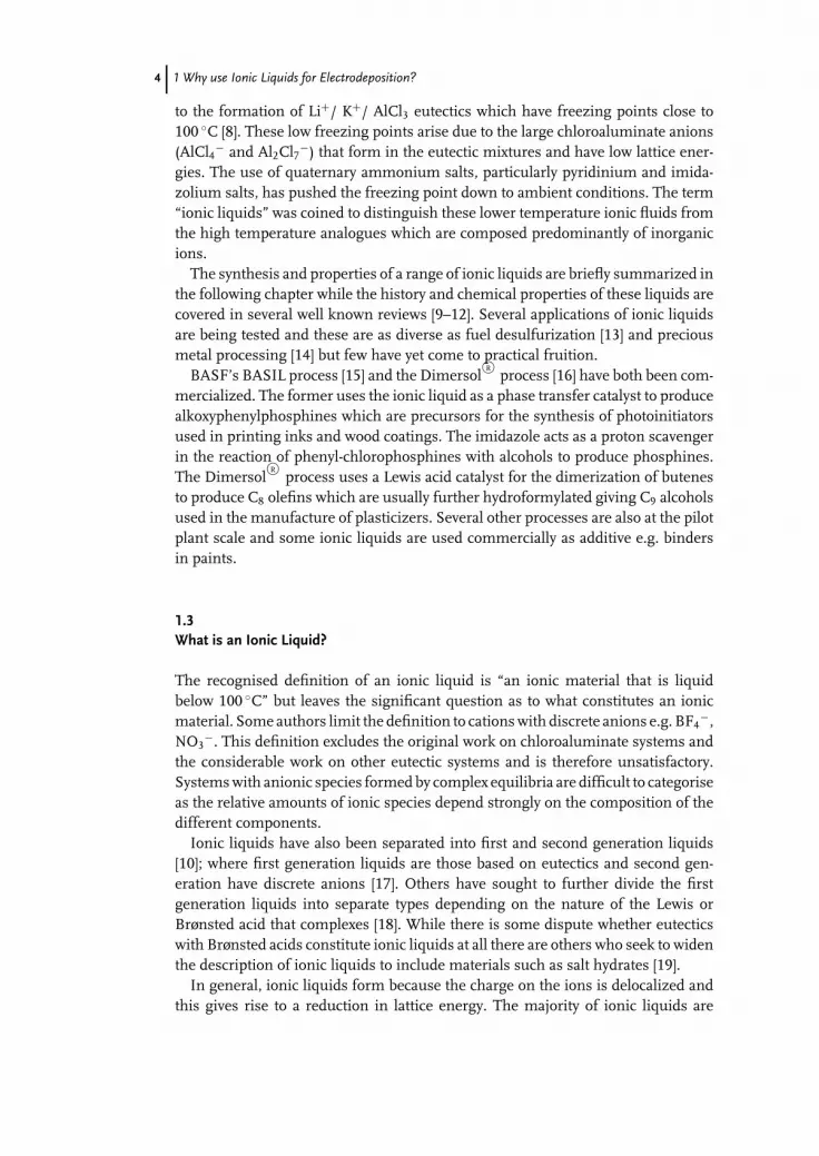
to the formation of Li+/ K+/ AlCl3 eutectics which have freezing points close to100 ◦C [8]. These low freezing points arise due to the large chloroaluminate anions(AlCl4− and Al2Cl7−) that form in the eutectic mixtures and have low lattice ener-gies. The use of quaternary ammonium salts, particularly pyridinium and imida-zolium salts, has pushed the freezing point down to ambient conditions. The term“ionic liquids” was coined to distinguish these lower temperature ionic fluids fromthe high temperature analogues which are composed predominantly of inorganicions.
The synthesis and properties of a range of ionic liquids are briefly summarized inthe following chapter while the history and chemical properties of these liquids arecovered in several well known reviews [9–12]. Several applications of ionic liquidsare being tested and these are as diverse as fuel desulfurization [13] and preciousmetal processing [14] but few have yet come to practical fruition.
BASF’s BASIL process [15] and the DimersolR©
process [16] have both been com-mercialized. The former uses the ionic liquid as a phase transfer catalyst to producealkoxyphenylphosphines which are precursors for the synthesis of photoinitiatorsused in printing inks and wood coatings. The imidazole acts as a proton scavengerin the reaction of phenyl-chlorophosphines with alcohols to produce phosphines.The Dimersol
R©process uses a Lewis acid catalyst for the dimerization of butenes
to produce C8 olefins which are usually further hydroformylated giving C9 alcoholsused in the manufacture of plasticizers. Several other processes are also at the pilotplant scale and some ionic liquids are used commercially as additive e.g. bindersin paints.
1.3What is an Ionic Liquid?
The recognised definition of an ionic liquid is “an ionic material that is liquidbelow 100 ◦C” but leaves the significant question as to what constitutes an ionicmaterial. Some authors limit the definition to cations with discrete anions e.g. BF4
−,NO3
−. This definition excludes the original work on chloroaluminate systems andthe considerable work on other eutectic systems and is therefore unsatisfactory.Systems with anionic species formed by complex equilibria are difficult to categoriseas the relative amounts of ionic species depend strongly on the composition of thedifferent components.
Ionic liquids have also been separated into first and second generation liquids[10]; where first generation liquids are those based on eutectics and second gen-eration have discrete anions [17]. Others have sought to further divide the firstgeneration liquids into separate types depending on the nature of the Lewis orBrønsted acid that complexes [18]. While there is some dispute whether eutecticswith Brønsted acids constitute ionic liquids at all there are others who seek to widenthe description of ionic liquids to include materials such as salt hydrates [19].
In general, ionic liquids form because the charge on the ions is delocalized andthis gives rise to a reduction in lattice energy. The majority of ionic liquids are

c01 (JWBG008-Endres) December 25, 2007 13:13 Char Count=
1.3 What is an Ionic Liquid? 5
described by the equilibrium:
cation + anion + complexing agent ↔ cation + complex anion (1.1)
Potentially, complex cations could also be formed using species such as cryptandsor crown ethers:
cation + anion + complexing agent ↔ complex cation + anion (1.2)
The confusion arises from the magnitude of the equilibrium constant. For dis-crete anions such as BF4
− and even ((CF3SO2)2N)− the equilibrium lies clearly tothe right of Eq. (1.1). For some eutectic-based liquids the equilibrium constant isalso to the right e.g.
Cat+ Cl− + AlCl3 ↔ Cat+ + AlCl−4 (1.3)
But the addition of more Lewis acid produces other anionic species.
Cat+ Cl− + 2AlCl3 ↔ Cat+ + Al2Cl−7 (1.4)
The use of less Lewis acidic metals e.g. ZnCl2 or SnCl2 will lead to a small amountof Cl−. The species formed between the anion and the complexing agent becomesweaker when a Brønsted acid e.g. urea is used [18].
Cat+ Cl− + urea ↔ Cat+ + Cl− · urea (1.5)
Others have claimed that, in the extreme, water can act as a good Brønsted acidand, in the extreme, hydrate salts can act as ionic liquids [19].
LiClO4 + 3.5 H2O ↔ Li+ · xH2O + ClO−4 · yH2O (1.6)
Ionic liquids with discrete anions have a fixed anion structure but in the eutectic-based liquids at some composition point the Lewis or Brønsted acid will be inconsiderable excess and the system becomes a solution of salt in the acid. A similarscenario also exists with the incorporation of diluents or impurities and hence weneed to define at what composition an ionic liquid is formed. Many ionic liquidswith discrete anions are hydrophilic and the absorption of water is found sometimesto have a significant effect upon the viscosity and conductivity of the liquid [20–22].Two recent approaches to overcome this difficulty have been to classify ionic liquidsin terms of their charge mobility characteristics [23] and the correlation between themolar conductivity and fluidity of the liquids [24]. This latter approach is thoughtby some to be due to the validity of the Walden rule
�η = constant (1.7)

c01 (JWBG008-Endres) December 25, 2007 13:13 Char Count=
6 1 Why use Ionic Liquids for Electrodeposition?
in ionic liquids, where � is the molar conductivity and η is the viscosity. This is,however a misrepresentation of Eq. (1.7) which was found empirically and is onlystrictly valid for a specific ion at infinite dilution and constant temperature. TheWalden rule is a useful tool for approximate classification of ionic liquids but itactually follows from the Nernst–Stokes–Einstein equation (See Chapters 2.3 and11.3) [23]. Most importantly, deviations from the Walden rule do not necessarilyshow that a salt is not an ionic liquid but more usually occur where ionic speciesdeviate from the model of centro-symmetric spherical ions with similar ionic radii.The Walden rule can, however, be used to give evidence of different charge transfermechanisms e.g. a Grotthus mechanism for protonic ionic liquids [24].
In this book a broad-church of ionic liquids will be assumed, encompassing allof the above types because, in the discipline of electrodeposition, it is the resultantdeposit that is important rather than the means. As will be seen later there is alsoa very fine line between a concentrated electrolyte solution and an ionic liquidcontaining diluents.
1.4Technological Potential of Ionic Liquids
A series of transition- and main group-metal-containing ionic liquids have beenformulated and the feasibility of achieving electrodeposition has been demonstratedfor the majority of these metals, Figure 1.1 shows the elements in the periodic tablethat have been deposited using ionic liquids. Details of these systems are givenin the subsequent chapters and concise summaries exists in recently publishedreviews [18,25,26].
It must be stressed that while the deposition of a wide range of metals has beendemonstrated from a number of ionic liquids the practical aspects of controllingdeposit morphology have not been significantly addressed due to the complexnature of the process parameters that still need to be understood. Despite the lackof reliable models to describe mass transport and material growth in ionic liquids,there are tantalizing advantages that ionic liquid solvents have over aqueous bathsthat make the understanding of their properties vitally important. Some of theseadvantages include:
Ĺ Electroplating of a range of metals impossible to deposit in water due to hydrolysise.g. Al, Ti, Ta, Nb, Mo, W. As an example, the deposition of Al by electrolysisin a low-temperature process has long been a highly desirable goal, with manypotential applications in aerospace for anti-friction properties, as well as replacingCr in decorative coatings. The deposition of Ti, Ta, Nb, Mo, W will open importantopportunities in various industries, because of their specific properties (heat,corrosion, abrasion resistance, low or high density etc.).
Ĺ Direct electroplating of metals on water-sensitive substrate materials such as Al,Mg and light alloys with good adherence should be possible using ionic liquids.
Ĺ There is potential for quality coatings to be obtained with ionic liquids ratherthan with water. Currently available metallic coatings suffer from hydrogen

c01 (JWBG008-Endres) December 25, 2007 13:13 Char Count=
1.4 Technological Potential of Ionic Liquids 7
Fig. 1.1 Summary of the elements deposited as single metals or alloys.
embrittlement; a major problem caused by gaseous hydrogen produced duringwater electrolysis. During electroplating with ionic liquids, negligible hydrogenis produced, and coatings will have the better mechanical properties.
Ĺ Metal ion electrodeposition potentials are much closer together in ionic liquidscompared with water, enabling easier preparation of alloys and the possibilityof a much wider range of possible electroplated alloys, which are difficult orimpossible in water.
Ĺ Ionic liquids complex metals and therefore offer the possibility to develop novelelectroless plating baths for coating polymers (e.g. in electronics) without theneed for the toxic and problematic organic complexants used in water.
Ĺ Although the cost of ionic liquids will be greater than aqueous electrolytes,high conductivity and better efficiency will provide significant energy savingscompared with water, and capital costs will be much lower than the alternativetechniques PVD and CVD.
Ĺ When used in electropolishing and electropickling processes, strongly acidicaqueous electrolytes create large quantities of metal-laden, corrosive effluentsolution, whereas in ionic liquid electrolytes the metals will precipitate and bereadily separated and recycled.

c01 (JWBG008-Endres) December 25, 2007 13:13 Char Count=
8 1 Why use Ionic Liquids for Electrodeposition?
Ĺ The replacement of many hazardous and toxic materials currently used in water,e.g. toxic form of chromium(VI), cyanide, highly corrosive and caustic elec-trolytes, would save about 10% of the current treatment costs.
Ĺ Nanocomposite coatings – nanoparticles giving improved properties compared tomicroparticles e.g. thermal and electrical conductivity, transparency, uniformity,low friction.
Ĺ An increased range of metal coatings on polymers is accessible by electrolessplating using ionic liquids containing reducing agents
In the longer term, specialist, ionic liquids will enable technically complex high-added-value products to be introduced, e.g. semiconductor coatings, special mag-netic alloys, nanoparticle composite coatings with special erosion/corrosion proper-ties, metal foams for energy storage activated surfaces for self-sterilization purposes(e.g. through photo-catalysis), etc.
Also, metals have significantly different reduction potentials in ionic liquid solu-tions compared to water. For example the difference in reduction potential betweenCr and Pt in ionic liquids may be as little as 100 mV whereas in aqueous solutionsit is in excess of 2 V. One consequence of this characteristic is that alloy coatingsmay be prepared more readily and that it should be possible to develop many novelalloy coatings.
A fundamental advantage of using ionic liquid electrolytes in electroplating isthat, since these are non-aqueous solutions, there is negligible hydrogen evolu-tion during electroplating and the coatings possess the much superior mechanicalproperties of the pure metal. Hence essentially crack-free, more corrosion-resistantdeposits are possible. This may allow thinner deposits to be used, thus reducingoverall material and power consumption still further.
The electrodeposition of metals from ionic liquids is a novel method for the pro-duction of nanocrystalline metals and alloys, because the grain size can be adjustedby varying the electrochemical parameters such as over-potential, current density,pulse parameters, bath composition and temperature and the liquids themselves.Recently, for the first time, nanocrystalline electrodeposition of Al, Fe and Al–Mnalloy has been demonstrated.
The properties of the new electrolyte media could also provide much higherhealth and safety standards for employees in the workplace, i.e. elimination ofhazardous vapors, elimination of highly corrosive acidic/alkaline solutions andsubstantially reduced use of toxic chemicals. These issues are dealt with later in thebook. Current aqueous processing systems have a strongly negative impact on theenvironment (risk of groundwater contamination, soil pollution), which obligesthe treatment of wastewater and the dumping of the ultimate waste in landfill.The metal finishing industry in general estimates that at least 15% of turnover isrelated to the cost of treatment for environmental protection. Legislation withinthe framework of sustainable development is increasingly stringent (e.g. EuropeanCommission directive 96/61/EC concerning “integrated pollution prevention andcontrol”). Thus, industries using metal finishing processes must search for newtechniques to achieve these environmental goals. In addition to the growing costs

c01 (JWBG008-Endres) December 25, 2007 13:13 Char Count=
1.4 Technological Potential of Ionic Liquids 9
and negative effects on competitiveness, it is a question of survival in the years tocome. The technology developed by this project is generic to most metal-platingsystems and, as such, should represent a significant advancement for the environ-mental sustainability of the metal finishing and electronics manufacturing sectors.
Ionic liquids are based on large non-centrosymmetric organic cations with com-plex anions, which are liquid at room temperature. The range of new ionic liquidshas insignificant vapor pressure (thus odorless), some are non-toxic (and evencompletely biodegradable) and most are highly conductive compared with organicelectrolyte solutions. This statement has to be tempered, naturally, because com-pared to the current state of the art, i.e. concentrated inorganic acids, the conduc-tivities are at best 10 to 100 times lower. An advantage might be that ionic liquidscan be operated at temperatures above 100 ◦C where ionic conductivities of up to0.2 �−1 cm−1 are achievable. The ongoing development of ionic liquids might leadto even better conducting liquids.
There are, however numerous risk elements in the development of ionic liquids:
Ĺ Coatings must achieve quality standards and a large amount of process develop-ment is required.
Ĺ A life cycle analysis (LCA) and an environmental impact study have not beencompleted for any of this technology.
Ĺ Issues of scale-up and integration design of generic prototype systems have notbeen addressed systematically.
Ĺ Some applications are at a fundamental research stage with associated higherrisk, i.e. electroless coating, semiconductors, anodising, nanocomposite coatings.
Ĺ Process economics are expected to be favorable for high-added-value products,but there are likely to be applications where economics are less favorable.
Ĺ For improved existing products, customer acceptance is likely to be a significantfactor, i.e. reluctance to change product specifications.
The potential impact is extremely broad and fundamental in nature, because theresearch will explore a totally innovative approach to metal finishing technology,which has never been exploited previously. The use of this completely differenttype of solvent/electrolyte system, entirely changes the normal behavior of metalfinishing processes seen in traditional aqueous electrolytes and an extensive rangeof entirely new processes and products can be expected.
The following chapters discuss the history, development and physical propertiesof low-temperature ionic substances but in this section it is useful to discuss thedifferences that arise in changing from a molecular to an ionic environment andthe implications that this will have for electrodeposition processes occurring at anelectrode surfaces.
There are several physical plating parameters that are different in an ionic liquidfrom those in an aqueous solution.
Temperature: Ionic liquids have wide liquid regions, typically in the range −50to 250 ◦C which allow more thermodynamic control than is possible in aqueoussolutions. This may have potential benefits for the development of new alloys.

c01 (JWBG008-Endres) December 25, 2007 13:13 Char Count=
10 1 Why use Ionic Liquids for Electrodeposition?
Diluents: Ionic liquids can be diluted with a range of organic and aqueous solventsand these significantly affect conductivity, viscosity and metal speciation. The effectshave not as yet been characterized and a significant amount of fundamental datastill needs to be obtained. A significant amount of work has been carried out on thechloroaluminate-based ionic liquids, although their use in other ionic liquids hasbeen generally ignored.
Cation: Cationic structure and size will affect the viscosity and conductivity of theliquid and hence will control mass transport of metal ions to the electrode surface.They will also be adsorbed at the electrode surface at the deposition potential andhence the structure of the double layer is dominated by cations. Some studieshave shown that changing the cationic component of the ionic liquid changes thestructure of deposits from microcrystalline to nanocrystalline [27]. While thesechanges are undeniable more studies need to be carried out to confirm that it isa double layer effect. If this is in fact the case then the potential exists to use thecationic component in the liquid as a built-in brightener.
Double Layer Structure: Surprisingly few studies have been carried out into thedouble layer structure of ionic liquids. This is partially due to experimental difficul-ties but also to interpretation of the resulting impedance spectra. What is clearlyevident, however, is that the double layer in an ionic liquid cannot be describedby applying the models used for aqueous solutions [28–30]. A study using imi-dazolium bistriflamide, (F3CSO2)2N− and BF4
− salts suggested that a model ofalternating anion and cation layers may be applicable to the data [29, 30]. Baldelli[31, 32] concluded that the double layer is one ion layer thick using sum frequencygeneration spectroscopy and electrochemistry to probe the electric field at the ionicliquid/electrode interface. The double layer capacitance in an ionic liquid is consid-erably smaller than in an aqueous solution and less than that predicted by havinga perfect Helmholtz layer at the interface, which could result from the presenceof ion pairs at the electrode surface at all potentials. Most likely the double layerstructure is also influenced by cation/anion interaction.
While the structure at the electrode/ionic liquid interface is uncertain it is clearthat in the absence of neutral molecules the concentration of anions and cationsat the interface will be potential dependent. The main difference between aque-ous solutions and ionic liquids is the size of the ions. The ionic radii of mostmetal ions are in the range 1–2 Å whereas for most ions of an ionic liquid theyare more typically 3–5 Å. This means that in an ionic liquid the electrode willbe coated with a layer of ions at least 6–7 Å thick. To dissolve in an ionic liq-uid most metal species are anionic and hence the concentration of metal ionsclose to the electrode surface will be potential dependent. The more negative theapplied potential the smaller the concentration of anions. This means that reac-tive metals such as Al, Ta, Ti and W will be difficult to deposit as the effectiveconcentration of metal might be too low to nucleate. It is proposed, as one ex-planation, that this is the reason that aluminum cannot be electrodeposited fromLewis basic chloroaluminate ionic liquids. More reactive metals such as lithium canhowever be deposited using ionic liquids because they are cationic and therefore

c01 (JWBG008-Endres) December 25, 2007 13:13 Char Count=
1.4 Technological Potential of Ionic Liquids 11
present at high concentrations close to the electrode surface at large negative over-potentials. The strategy to electrodeposit reactive metals must therefore be to ei-ther make cationic metal complexes or to work with metal salts at high concen-trations.
Anode material: In aqueous solutions the anodic processes are either breakdownof the electrolyte solution (with oxygen evolution at an inert anode being favored)or the use of soluble anodes. The use of soluble anodes is limited by the passivationof many metals in aqueous solutions. In ionic liquids, however, the first optionis not viable due to the cost and the nature of the anodic breakdown products.New strategies will therefore have to be developed to use soluble anodes wherepossible or add a sacrificial species that is oxidized to give a benign gaseous product.Preliminary data have shown that for some metals the anodic dissolution processis rate limiting and this affects the current distribution around the cathode and thecurrent density that can be applied.
Electrolytes: The above issue of double layer structure is important to the mech-anism of nucleation and growth in ionic liquids, it may therefore be possible tocontrol the structure at the electrode/solution interface by addition of an inertelectrolyte. In this respect most Group 1 metals are soluble in most ionic liquids,although it is only generally lithium salts that exhibit high solubility. In ionic liquidswith discrete anions the presence of Group 1 metal ions can be detrimental to thedeposition of reactive metals such as Al and Ta where they have been shown to beco-deposited despite their presence in trace concentrations.
Brighteners: Brighteners are added to most aqueous electroplating solutions andwork by either complexing the metal ions and decreasing the rate of nucleation orby acting as an interfacial adsorbate, blocking nucleation and hindering growth.Aqueous brighteners have not been studied in depth in ionic liquids and it isdoubtful that they will function in the same way as they do in water because ofthe difference in double layer structure and mass transport. In unpublished workwe have surveyed the use of aqueous brightener compounds and applied them tothe deposition of zinc and chromium from Type 2 or Type 3 eutectics (see alsoChapter 2). None of these were found to be effective in ionic liquids.
A small amount of work has been carried out into brighteners that complexthe metal ions in solution (see Chapter 11.3) but again no systematic studieshave been carried out. Brighteners which rely on electrostatic or hydrophobic in-teractions may function in ionic liquids but their efficacy is likely to be surfaceand cation/anion specific. To date all systems that have produced bright metal-lic finishes have been found to have a nanocrystalline structure which may bedue to a progressive nucleation mechanism. This is currently under investigationand if confirmed it will help significantly with the design of future brightenersystems.
As with other solutes in ionic liquids, the general rule of like dissolving likeis applicable i.e. ionic species will generally be soluble as will species capable ofinteracting with the anion. Aromatic species tend to exhibit poor solubility in ionicliquids consisting of aliphatic cations and vice versa.

c01 (JWBG008-Endres) December 25, 2007 13:13 Char Count=
12 1 Why use Ionic Liquids for Electrodeposition?
1.5Concluding Remarks
What is clear from this introduction is that the journey into the area of metaldeposition from ionic liquids has tantalizing benefits. It is also clear that we haveonly just begun to scratch the surface of this topic. Our models for the physicalproperties of these novel fluids are only in an early state of development andconsiderably more work is required to understand issues such as mass transport,speciation and double layer structure. Nucleation and growth mechanisms in ionicliquids will be considerably more complex than in their aqueous counterparts butthe potential to adjust mass transport, composition and speciation independentlyfor numerous metal ions opens the opportunity to deposit new metals, alloysand composite materials which have hitherto been outside the grasp of electro-platers.
References
1 (2000) Modern Electroplating, 4th edn (edsM. Schlesinger and M. Paunovic), JohnWiley & Sons, Inc., New York.
2 Peled, E. and Gileadi, E. (1976) J.Electrochem. Soc., 123, 15–19.
3 Simanavicius, L. (1990) Chemija, 3, 3–30.4 Izutsu, K. (2002) Electrochemistry in
Non-aqueous Solutions, Wiley-VCH,Verlag GmbH.
5 Kruesi, W.H. and Fray, D.J. (1993) Metall.Trans. B., 24, 605.
6 Fray, D.J. and Chen, G.Z. (2004) Mater.Sci. Technol., 20, 295.
7 Grjotheim, K., Krohn, C., Malinovsky, M.,Matiasovsky, K., and Thonstad, J. (1982)Aluminum Electrolysis, 2nd edn,Aluminium-Verlag, Dusseldorf.
8 Lantelme, F., Alexopoulos, H., Chemla,M., and Haas, O. (1988) Electrochim. Acta,33, 761.
9 Wasserscheid, P. and Welton, T. (2003)Ionic Liquids in Synthesis, Wiley-VCH,Verlag GmbH.
10 Welton, T. (1999) Chem. Rev., 99, 2071.11 Wasserscheid, P. and Keim, W. (2000)
Angew. Chem. Int. Ed., 39, 3772.12 Earle, M.J. and Seddon, K.R. (2000) Pure
Appl. Chem., 72, 1391.13 Zhang, S. and Conrad Zhang, Z. (2002)
Green Chemistry, 4, 376.14 Whitehead, J.A., Lawrence, G.A., and
McCluskey, A. (2004) Green Chem., 6, 313.
15 Maase, M. (2005) in Multiphase Homo-geneous Catalysis (eds B. Cornils et al.),Wiley-VCH, Weinheim, Germany,p. 560.
16 Chauvin, Y., Olivier, H., Wyrvalski, C.N.,Simon, L.C., de Souza, R., and Dupont, J.(1997) J. Catal., 165, 275.
17 Chiappe, C. and Pieraccini, D. (2005) J.Phys. Org. Chem., 18, 275–297.
18 Abbott, A.P. and McKenzie, K.J. (2006)Phys. Chem. Chem. Phys., 8, 4265–4279.
19 Xu, W. and Angell, C.A. (2003) Science,302, 422.
20 Billard, I., Mekki, S., Gaillard, C.,Hesemann, P., Moutiers, G., Mariet, C.,Labet, A., and Buenzli, J.G. (2004) Eur. J.Inorg. Chem., 6, 1190–1197.
21 Jarosik, A., Krajewski, S.R., Lewandowski,A., and Radzimski, P. (2006) J. Mol. Liq.,123, 43–50.
22 Widegren, J.A., Saurer, E.M., Marsh,K.N., and Magee, J.W. (2005) J. Chem.Thermodyn., 37, 569–575.
23 Abbott, A.P., Harris, R.C., and Ryder,K.S. (2007) J. Phys. Chem. B, 111,4910–4914.
24 Yoshizawa, M., Xu, W., and Angell, C.A.(2003) J. Am. Chem. Soc., 125, 15411.
25 Endres, F. and Zein El Abedin, S. (2006)Phys. Chem. Chem. Phys., 8, 2101.
26 Zein El-Abedin, S. and Endres, F. (2002)Phys. Chem. Chem. Phys., 4, 1640.

c01 (JWBG008-Endres) December 25, 2007 13:13 Char Count=
References 13
27 Moustafa, E.M., Zein El Abedin, S.,Shkurankov, A., Zschippang, E., Saad,A.Y., Bund, A., and Endres, F. (2007)J. Phys. Chem. B, 111, 4693.
28 Gale, R.J. and Osteryoung, R.A. (1980)Electrochim. Acta, 25, 1527.
29 Nanjundiah, C., McDevitt, S.F., and Koch,V.R. (1997) J. Electrochem. Soc., 144, 3392.
30 Nanjundiah, C., Goldman, J.L., McDevitt,S.F., and Koch, V.R. (1997) Proc.Electrochem. Soc., 96-25, 301.
31 Baldelli, S. (2005) J. Phys. Chem. B, 27,109.
32 Rivera-Rubero, S. and Baldelli, S. (2004)J. Phys. Chem. B, 108, 15133.

c02 (JWBG008-Endres) December 25, 2007 13:16 Char Count=
15
2Synthesis of Ionic LiquidsTom Beyersdorff, Thomas J. S. Schubert, Urs Welz-Biermann, Will Pitner,Andrew P. Abbott, Katy J. McKenzie, and Karl S. Ryder
As is well known in the Ionic Liquids Community 109 to 1018 ionic liquids, binaryand ternary mixtures have been predicted to be – theoretically – achievable. Ofcourse, this is an incredible number and it will hardly be possible to synthesizeall these liquids and investigate all of them in detail for electrochemical purposes.This chapter presents an introduction to some ionic liquids that are interesting forelectrochemistry. As the field is still ongoing this chapter can only give an intro-duction to the principles of ionic liquids synthesis. Section 2.1 briefly summarizesthe major aspects of first generation ionic liquids based on AlCl3, Section 2.2 givesa short introduction to the synthesis of air- and water-stable ionic liquids of thethird generation, and Section 2.3 introduces a class of deep eutectic solvents/ionicliquids based on comparatively well-priced educts such as choline chloride. For amore detailed introduction to the chemistry of ionic liquids we would like to referreaders to the 2nd edition of “Ionic Liquids in Synthesis”, ed. by Peter Wasserscheidand Tom Welton (ISBN: 978–3-527–31239-9).
2.1Synthesis of Chloroaluminate Ionic Liquids
2.1.1Introduction
Ionic liquids (IL) are a new class of salt-like materials that are entirely composedof ions and that are liquid at unusually low temperatures. For the most commonlyused definition of the term ionic liquid the boiling point of water was chosen as areference point, most likely for emotional reasons: “The term ionic liquids refers tocompounds consisting entirely of ions and existing in the liquid state below 100 ◦C.” Inmany cases the melting point is even below room temperature.
The history of ionic liquids began with the synthesis of ethylammonium nitratereported in 1914 by Walden [1]. This material is probably the first described in theliterature that fulfills the definition of ionic liquids used today. In this context it
Electrodeposition from Ionic Liquids. Edited by F. Endres, D. MacFarlane, A. AbbottCopyright C© 2008 WILEY-VCH Verlag GmbH & Co. KGaA, WeinheimISBN: 978-3-527-31565-9
c02 (JWBG008-Endres) December 25, 2007 13:16 Char Count=
16 2 Synthesis of Ionic Liquids
should be noted that at that time Walden had of course no idea of this definitionor the whole concept of ionic liquids. Consequently, it is not surprising that at thetime no attention was paid to the potential of this class of materials.
A major breakthrough was achieved in 1951 with the report of Hurley and Wier.They noticed that a mixture of N-ethylpyridinium bromide (EtPyBr) and AlCl3 witha eutectic composition of 1:2 {X(AlCl3) = 0.66}1) of EtPyBr to AlCl3 became liquidat unusually low temperatures [2]. They investigated these melts with regard totheir potential use in the electrodeposition of aluminum at ambient temperature[3]. Several studies were carried out on this system, however, its use was very limitedsince it is only liquid at a mole fraction of X(AlCl3) = 0.66 and the ease of oxidationof the bromide ion limits the electrochemical stability. In the following years themain interest in ionic liquids was focused on electrochemical applications [4–6].
In 1978 Osteryoung and coworkers replaced EtPyBr with N-butylpyridiniumchloride (BuPyCl) and found that the properties of the resulting ionic liquids im-proved significantly [7, 8]. The new chloroaluminate melts were found to be liquidat room temperature over a composition range from X(AlCl3) = 0.66 to 0.43. Inaddition the anodic limit had improved by changing from bromide to chloride. Themain disadvantage of these systems was the relative ease of both chemical andelectrochemical reduction of the buytlpyridinium cation [9]. Wilkes and coworkersperformed MNDO (modified neglect of diatomic overlap) calculations on a varietyof organic cations in 1982 and found that N,N′-dialkylimidazolium cations are morestable than the N-butylpyridinium cation due to the higher electron affinity of thesecations [10]. Many of the melts resulting from mixing N,N′-dialkylimidazoliumhalides with AlCl3 even displayed lower melting points than the N-butylpyridinium-based ionic liquids. In the case of the 1-ethyl-3-methyl-imidazolium chloride/AlCl3mixtures the liquid range at room temperature extends from X(AlCl3) = 0.66 to0.30 [11]. Further research on air- and water-stable anions and new cations hasbeen carried out during the past years resulting in more than 1500 materials beingdescribed in the literature today [12].
The first part of this chapter focuses on the synthesis and properties of the so-called “first generation of ionic liquids”, the haloaluminate-based ionic liquids andin particular on those of chloroaluminate melts.
2.1.2Synthesis of Room-temperature Chloroaluminate-based Ionic Liquids
2.1.2.1 IntroductionThe synthesis of haloaluminate-based ionic liquids from halide salts and aluminumLewis acids (most commonly AlX3; X=Cl, Br) can generally be split into two steps: (i)fomation of the desired cation by the reaction of a trialkylamine, trialkylphosphineor dialkylsulfide with a haloalkane, and (ii) formation of the haloaluminate anionby addition of an appropriate aluminum halide to this salt (Scheme 2.1).
1) The composition of haloaluminate ionic liq-uids is often described by the mole fractionof AlCl3 X(AlCl3) present in the mixture.

c02 (JWBG008-Endres) December 25, 2007 13:16 Char Count=
2.1 Synthesis of Chloroaluminate Ionic Liquids 17
Scheme 2.1 General synthesis route to haloaluminate-based ionic liquids.
Nowadays, as many halide salts are commercially available at reasonable prices,often only the second step is required.
The most commonly used groups of cations are presented in Figure 2.1.The following section focuses on the quaternization reaction of 1-alkylimidazoles
since these are the most commonly used starting materials for ionic liquids and havedominated ionic liquids research over the last twenty years. However, the generalmethod for the quaternization reaction is similar for pyridines [13], isoquinolines[14], 1-methylpyrrolidine [15], trialkylamines [16], phosphines [17] and sulfides [18].
2.1.2.2 The Quaternization ReactionFrom a practical point of view ionic liquids have no significant vapor pressure. As aconsequence, their purification using conventional methods is extremely difficult.Thus, it is recommended to remove as many impurities as possible from thestarting materials and to use synthetic procedures that produce as few side productsas possible, or allow their easy separation from the final product. In addition, allstarting materials should be dried prior to use considering the water-sensitivenature of many of the products.
All reagents used for the synthesis of cations should be purified according toliterature procedures before use [19]. Amines such as 1-alkylimidazoles or pyridinesare typically distilled from sodium hydroxide or calcium hydride if dry amines arerequired and stored under dry nitrogen or argon at 0 ◦C. Haloalkanes are washedwith sulfuric acid until no further color is extracted into the acid layer and thenneutralized with NaHCO3 and deionized water prior to distillation from CaCl2. Allsolvents used in the syntheses should be dried and distilled prior to use. In orderto obtain colorless halide salts it is recommended to perform all reactions under aprotective atmosphere of a dry inert gas in order to exclude moisture and oxygenfrom the reaction.
In order to obtain colorless chloroaluminate liquids it is recommended to sublimethe AlCl3 several times prior to use after the addition of sodium chloride andaluminum wire [8].
The synthesis of the cation is typically performed by alkylation of an amine,phosphine or sulfide, most commonly using an alkyl halide [ ]. In most cases thereaction is carried out with chloro-, bromo- and iodoalkanes as readily availablealkylating reagents, with the reaction conditions becoming more gentle changingfrom chloride to bromide to iodide, as can be expected for nucleophilic substitution
Fig. 2.1 Examples of cations commonly used for the synthesis of ionic liquids.

c02 (JWBG008-Endres) December 25, 2007 13:16 Char Count=
18 2 Synthesis of Ionic Liquids
Scheme 2.2 Quaternization reaction of 1-alkylimidazoles.
reactions. Onium fluorides cannot be synthesized in this manner due to the poorleaving-group qualities of fluoride anions (Scheme 2.2).
A typical lab scale alkylating reaction is performed in a round-bottomed flaskequipped with a reflux condenser and a dropping funnel with a nitrogen or argoninlet. The alkylating reagent is dissolved in the solvent and the amine is addeddropwise. After complete addition, the reaction mixture is heated until all of theamine has been consumed. The reaction conditions for the quaternization arestrongly dependent on the haloalkanes used, with the chloroalkanes being the leastreactive and the iodoalkanes the most. In general chloroalkanes have to be heatedto 80 ◦C for several days to ensure complete reaction, whereas reactions employingbromoalkanes are usually complete after 24 hours at lower temperatures, between50 and 60 ◦C. Alkylation reactions with iodoalkanes can often be performed atroom temperature with exclusion of light, since iodoalkanes and the resultingiodide salts are light-sensitive. Taking safety aspects into account, care has to betaken with large-scale reactions employing bromoalkanes, as such reactions arestrongly exothermic with increased reaction rates. Besides safety considerations,high thermal stress can also result in discoloration of the final product.
The reactivity of haloalkanes in alkylation reactions also decreases with increasingchain length. In general, syntheses of salts with short alkyl substituents are morecomplex due to the low boiling points of the haloalkanes. The most frequentlyused halide salt in this field, 1-ethyl-3-methylimidazolium chloride ([EMIM] Cl),is typically synthesized in an autoclave with the chloroethane cooled to below itsboiling point (12 ◦C) before addition.
In general, the use of solvents is not inevitably necessary as the reagents areliquid and mutually miscible, while the halide salts are usually immiscible withthe starting materials. Nevertheless, solvents are often used to keep the reactionhomogeneous and thus to ensure better heat transfer within the reaction mix-ture. Examples of solvents include the haloalkane itself [10], dichloromethane,acetonitrile, 1,1,1-trichloroethane [20], ethyl acetate [21] and toluene [22]. These sol-vents can be divided into two classes: those that are miscible with the product salt(dichloromethane, acetonitrile) and those that are immiscible with the halide saltproduct (1,1,1-trichloroethane, toluene, ethyl acetate). Reactions performed in theformer solvents result in homogenous reaction mixtures from which the productcan be precipitated, in many cases, by addition of an immiscible co-solvent. Forreactions in the latter solvents, removal of the solvent and unreacted starting ma-terials can be achieved by simple decantation and washing of the product with animmiscible solvent, as the product is generally denser than the solvents and startingmaterials. Purification of the halide salts is in all cases dependent on their stateof aggregation. In many cases the halide salts are solids at room temperature and

c02 (JWBG008-Endres) December 25, 2007 13:16 Char Count=
2.1 Synthesis of Chloroaluminate Ionic Liquids 19
can be recrystallized from mixtures of dry acetonitrile and ethyl acetate. However,if the product does not crystallize, it is advisable to wash the oily product with animmiscible solvent to remove excess starting materials. In all cases it is necessary toremove all excess starting materials, solvents and moisture by heating the productsalt under vacuum. Care has to be taken at this stage, as overheating can resultin the decomposition of the product via retro-alkylation. It is recommended not toheat the halide salt at temperatures higher than 80 ◦C.
An alternative approach to the reaction conditions described above employsmicrowave irradiation for the quaternization reaction of 1-methylimidazole withvarious haloalkanes and 1,ω-dihaloalkanes [23]. High yields and acceptable puritiescan be obtained in short reaction times (minutes instead of hours) and scaling upthis technology to an industrial scale can easily be achieved.
As a new class of materials, ionic liquids require special analytical methods.In the case of imidazolium halides and similar compounds the most commonimpurities are amines, alkyl halides and of course water. Seddon et al. describeda method for the detection of residual amines using the strong UV absorbance ofcopper tetramine complexes. These complexes are readily formed by the addition ofCu2+ ions [24]. The detection of both amines and alkyl halides is possible by NMRspectroscopy but with limited resolution [25]. By far the most powerful analyticalmethod is liquid chromatography combined with UV detection. This sensitivemethod allows the detection of traces of amines and halides [26]. Unreacted aminescan be also detected by ion chromatography combined with a suppressor module.In this case detection is achieved using a continuous flow conductivity cell sinceamines are protonated and thus detectable. For traces of other ionic impuritiesion chromatography is also the most powerful analytical tool [27]. Finally, residualwater can be quantified using Karl Fischer titration or coulometry [28].
2.1.2.3 Chloroaluminate SynthesisTreatment of a quaternary halide salt Q+X− with a Lewis acid MXn results inthe formation of a salt with the composition Q+MXn+1
−. In general, more thanjust one anion species is formed, depending on the relative proportions of MXn
and the halide salt Q+X−. A representative example is the reaction of 1-ethyl-3-methylimidazolium chloride [EMIM]Cl with AlCl3 (Scheme 2.3).
If the mole fraction X(AlCl3) is less than 0.5 in the final product, the ionic liquidsare basic, as chloride ions are present which are not bound to aluminum and whichact as Lewis bases. For mole fractions X(AlCl3) > 0.5 an excess of Lewis acid AlCl3is present and the melts are acidic. If the mole fraction X(AlCl3) = 0.5 the saltsare neutral as all of the chloride ions are bound to aluminum and the only speciespresent is the [AlCl4]− ion. However, as a consequence of the autosolvolysis of
Scheme 2.3 Reaction between [EMIM]Cl and AlCl3.

c02 (JWBG008-Endres) December 25, 2007 13:16 Char Count=
20 2 Synthesis of Ionic Liquids
Scheme 2.4 Autosolvolysis of AlCl4 melts.
AlCl4−, Cl− and [Al2Cl7]− species are always present in neutral liquids (Scheme2.4) [ ].
A detailed description of the analysis of the chloroaluminate species in theseionic liquids is given by Welton et al. [29].
It has to be mentioned that chloroaluminate melts are not the only Lewis acid-based ionic liquids produced in this manner. Other examples include for exampleAlEtCl2 [30], AlBr3 [31], BCl3 [32], CuCl [33], SnCl2 [34], FeCl3 [35], ZnCl2 [36]. Thepreparation of these salts is similar to that described for the [AlCl4]− salts. Eventhe treatment of halide salts with metal halides or metal oxides that are not typicalLewis acids has been used to synthesize ionic liquids. Examples of these salts are[EMIM]2[MCl4] (M=Co, Ni) [37], [EMIM]2[VOCl4] [38], [BMIM][CrO3Cl] [39].
The most common method for the synthesis of chloroaluminate-based ionicliquids is a solid-phase synthesis by mixing AlCl3 and a quaternary halide Q+X−
salt under vigorous stirring. This type of reaction should be carried out usingSchlenk techniques or, preferably, in a glove box. Since the ionic liquid is formeddirectly in an exothermic reaction on contact of the two starting materials, careshould be taken upon mixing the reagents. Although the starting materials as wellas the products are relatively thermally stable in general, local overheating can resultin decomposition and darkening of the ionic liquid. To prevent this, the reactionvessel should be cooled. An important point to avoid overheating is to add onestarting material to the other in small portions in order to allow the reaction heatto dissipate. In addition the resulting ionic liquids should be stored under argon ina Schlenk-type flask or in a glove box until use.
However, if a glove box is not available for the synthesis, the reaction can alsobe performed in a dry, inert solvent which covers the reaction mixture and protectsit from hydrolysis. An advantage of this procedure is that the solvent, which istypically an alkane, can also react as a heat carrier in the exothermic reaction. Aftercompletion of the reaction the ionic liquid forms a second layer below the solvent.The solvent can be removed by simple distillation before use of the ionic liquid.However, the ionic liquid will be contaminated with the organic solvent, which hasto be removed under vacuum.
Another method involves microwave irradiation. It has been described for thesynthesis of 1,3-dialkylimidazolium tetrachloroaluminates [40]. This method pre-cludes the use of volatile organic solvents and is faster, more efficient and alsoecofriendly, affording high yields of the desired products.
As mentioned above, purification of the resulting ionic liquids cannot be achievedby distillation of the products since these materials show no significant vapor pres-sure. In most cases AlCl3-based ionic liquids contain traces of oxo ion impuritiessuch as [AlOCl2]− as major impurities, especially if water and oxygen are not to-tally excluded during synthesis. As shown by 17O NMR experiments a complexset of equilibria is then present [41]. These impurities can easily be removed by

c02 (JWBG008-Endres) December 25, 2007 13:16 Char Count=
2.2 Air- and Water-stable Ionic Liquids 21
bubbling phosgene [42] or, considering the high toxicity of phosgene, triphosgene[43] through the ionic liquid. The by-product formed in this reaction is CO2, whichcan be easily removed under vacuum. Further purification of room temperaturehaloaluminate-based ionic liquids is not recommended, as these materials are ex-tremely sensitive towards moisture and must be handled either in vacuum or underan inert gas atmosphere. Although classic Schlenk techniques can be used to handlethese materials, working in a glove box is recommended.
Analysis of haloaluminate ionic liquids is much more limited than that of otherionic liquids. The most important analytical technique is surely NMR spectroscopy.The determination of residual water is difficult because of the instability of thesematerials. Hence it is crucial to work accurately to achieve the best results.
To summarize the most important points for the synthesis of pure and colorlessionic liquids it is recommended to:
Ĺ Purify all starting materials before useĹ Exclude oxygen and moisture from the reactions by working in a dry inert atmo-
sphere to prevent darkening of the ionic liquidsĹ Keep the reaction temperatures as low as possible, as overheating often results
in discoloration of the productsĹ Use Schlenk techniques or work in a glove box, as the chloride and bromide
salts are highly hygroscopic and the chloroaluminate melts are highly moisturesensitive.
The importance of these first generation ionic liquids for metal deposition issummarized in Chapter 4.1.
2.1.3Physical Data of Haloaluminate-based Ionic Liquids
A selection of physical data of selected haloaluminate-based ionic liquids is givenin Table 2.1.
2.2Air- and Water-stable Ionic Liquids
2.2.1Introduction
For forty years following the introduction of haloaluminate-based ionic liquids byHurley and Wier, [44, 45] the majority of research in this field was carried outon systems which were reactive with air and, more specifically, with water. Thedifficulty of working with these materials, using elaborate Schlenk-line airless tech-niques or expensive and difficult-to-maintain controlled-atmosphere glove boxes,had the effect of limiting the research to four American-based research groups,mostly funded by the US Air Force [46]. Well aware of this limitation, John Wilkesand coworkers made the decision to substitute the reactive haloaluminate anion

c02 (JWBG008-Endres) December 25, 2007 13:16 Char Count=
22 2 Synthesis of Ionic Liquids
Tabl
e2.
1Ph
ysic
alda
taof
sele
cted
ioni
cliq
uids
.
Com
posi
tion
ofth
eIL
Syst
emC
atio
nA
nion
Vis
cosi
tyC
ondu
ctiv
ityM
olar
Den
sity
Ref
.(m
Pas)
(mS
cm−1
)co
nduc
tivity
(gcm
−3)
34.0
/66.
0(m
ol%
)[M
MIM
]Cl/
AlC
l 3[M
MIM
]+[A
l 2C
l 7]−
1715
.04.
261.
404
[10]
34.0
/66.
0(m
ol%
)[E
MIM
]Cl/
AlC
l 3[E
MIM
]+[A
l 2C
l 7]−
1415
.04.
461.
389
[10]
50.0
/50.
0(m
ol%
)[E
MIM
]Cl/
AlC
l 3[E
MIM
]+[A
lCl 4
]−18
23.0
4.98
1.29
4[1
0]60
.0/4
0.0
(mol
%)
[EM
IM]C
l/A
lCl 3
[EM
IM]+
Cl−
,[A
lCl 4
]−47
6.5
1.22
1.25
6[1
0]
34.0
/66.
0(m
ol%
)[E
MIM
]Br/
AlB
r 3[E
MIM
]+[A
l 2B
r 7]−
325.
81.
892.
219
[31]
60.0
/40.
0(m
ol%
)[E
MIM
]Br/
AlB
r 3[E
MIM
]+B
r−,
[AlB
r 4]−
675.
71.
151.
828
[31]
40.0
/60.
0(m
ol%
)[P
MIM
]Cl/
AlC
l 3[P
MIM
]+[A
lCl 4
]−,
[Al 2
Cl 7
]−18
11.0
2.94
1.35
1[1
0]
50.0
/50.
0(m
ol%
)[P
MIM
]Cl/
AlC
l 3[P
MIM
]+[A
lCl 4
]−27
12.0
2.79
1.26
2[1
0]60
.0/4
0.0
(mol
%)
[PM
IM]C
l/A
lCl 3
[PM
IM]+
Cl−
,[A
lCl 4
]−3.
3[1
0]
34.0
/66.
0(m
ol%
)[B
MIM
]Cl/
AlC
l 3[B
MIM
]+[A
l 2C
l 7]−
199.
23.
041.
334
[10]
50.0
/50.
0(m
ol%
)[B
MIM
]Cl/
AlC
l 3[B
MIM
]+[A
lCl 4
]−27
10.0
2.49
1.23
8[1
0]34
.0/6
6.0
(mol
%)
[BB
IM]C
l/A
lCl 3
[BB
IM]+
[Al 2
Cl 7
]−24
6.0
2.32
1.25
2[1
0]50
.0/5
0.0
(mol
%)
[BB
IM]C
l/A
lCl 3
[BB
IM]+
[AlC
l 4]−
3854
.01.
501.
164
[10]
33.3
/66.
7(m
ol%
)[M
P]C
l/A
lCl 3
[MP
]+[A
l 2C
l 7]−
218.
12.
231.
441
[36]
33.3
/66.
7(m
ol%
)[E
P]C
l/A
lCl 3
[EP
]+[A
l 2C
l 7]−
1810
.02.
911.
408
[36]
33.3
/66.
7(m
ol%
)[P
P]C
l/A
lCl 3
[PP
]+[A
l 2C
l 7]−
188.
02.
471.
375
[36]
33.3
/66.
7(m
ol%
)[B
P]C
l/A
lCl 3
[BP
]+[A
l 2C
l 7]−
216.
72.
181.
346
[36]

c02 (JWBG008-Endres) December 25, 2007 13:16 Char Count=
2.2 Air- and Water-stable Ionic Liquids 23
systems with less reactive anions, under the belief that other anions could also pro-duce low-melting organic salts [47]. Perhaps they were aware of the singular workby Walden to generate low melting, high conductivity salts [48], work which is oftenused to mark him as the discoverer or inventor of ionic liquids. However, Waldenbased his “molten salts” upon protonated primary amines such as ethylamine, andsuch mixtures of organic bases with mineral and organic acids will always exist asmixtures of the acid, the base and salt formed through their neutralization. Suchequilibrium mixtures are well known to be thermally unstable, due to the vaporpressure of the two neutral components [49]. The ease with which the protonatedcation can be reduced to yield hydrogen gas also limits the usefulness of thesematerials in electrochemical applications. The non-chloroaluminate ionic liquidsintroduced by Wilkes have the advantages of high thermal and electrochemicalstability (with respect to Walden’s acid–base equilibrium mixtures) and ease ofhandling under ambient, humid conditions (as compared to Hurley and Wier’shaloaluminate ionic liquids).
The methathesis route employed by Wilkes in the production of these materialshas generally been followed for the majority of air- and moisture-stable ionic liquids.In brief (Scheme 2.5), an organic base (such as N-methylimidazole, pyridine or N-methylpyrrolidine) is alkylated using a haloalkane to generate an organic halidesalt. Anion exchange is carried out, generally in water, with the appropriate acidor metal salt. The ionic liquid is extracted from the aqueous salt into an organicphase, and the halide impurities removed through repeated washings with water.The more hydrophilic the ionic liquid, the more difficult it is to purify, as extractionof halides with water is complicated by loss of the ionic liquid to the aqueous phase.
Scheme 2.5 General synthetic route to producing air- and moisture-stable ionic liquids.

c02 (JWBG008-Endres) December 25, 2007 13:16 Char Count=
24 2 Synthesis of Ionic Liquids
Fig. 2.2 Structure, full name and abbreviations for the anions discussed in this section.
The discovery made by Wilkes in the early nineties was completely dependentupon a change in the anionic systems: the cation components of the haloaluminatesystems previously in use were not the cause of their reactivity with water and thepyridinium and imidazolium cations remain key components of air- and moisture-stable ionic liquids under investigation today. Therefore the focus of this section willbe air- and moisture-stable anionic systems (Figure 2.2), with the cation relegatedto the role of junior partner in an ionic couple. Due to their ease of handling,this report will also focus on those anion–cation combinations which yield room-temperature ionic liquids (RTILs), even though operation at room-temperature isnot a prerequisite for a commercially-viable electroplating bath.
2.2.2Tetrafluoroborate and Hexafluorophosphate-based Ionic Liquids
Wilkes launched the field of air- and moisture-stable ionic liquids by introducing fivenew materials, each containing the 1-ethyl-3-methylimidazolium cation [EMIM]+
with one of five anions: nitrate [NO3]−, nitrite [NO2]−, sulfate [SO4]2−, methylcarbonate [CH3CO2]− and tetrafluoroborate [BF4]− [47]. Only the last two materialshad melting points lower than room temperature, and the reactive nature of themethyl carbonate would make it unsuitable for many applications. This led tothe early adoption of [EMIM][BF4] as a favored ionic liquid, which has since beenthe subject of over 350 scientific publications. One of the first appeared in 1997 [50],reporting the investigation of [EMIM][BF4] as the electrolyte system for a number ofprocesses, including the electrodeposition of lithium (intended for use in lithiumion batteries).

c02 (JWBG008-Endres) December 25, 2007 13:16 Char Count=
2.2 Air- and Water-stable Ionic Liquids 25
The [BF4]− anion is frequently used in battery electrolyte formulations, and itwas not long before other anions from this branch were investigated for theircapacity to make ionic liquids. The combination of hexafluorophosphate [PF6]−
with [EMIM]+ produced a salt with a reported melting point of 58–60 ◦C [51].This was too high a melting point for most researchers to bother working with,but in 1995 Chauvin, Mussmann and Olivier reported the use of the analogous[BMIM][PF6], which is liquid at room temperature, as well as [BMIM][BF4] [52].These two RTILs would dominate ionic liquid publications for the next decade. Thepreference for [BMIM][BF4] over [EMIM][BF4] can probably be explained by the factthat the synthesis of [BMIM]Cl is an easier process than the synthesis of [EMIM]Cl,which requires a pressurised reaction vessel, and by the high water-solubility of[EMIM][BF4], which makes it much more difficult to purify than [BMIM][BF4].Another reason was the experimental symmetry afforded by switching from anionic liquid which is completely miscible with water ([BMIM][BF4]) to one whichformed biphasic aqueous mixtures ([BMIM][PF6]).
Other cation combinations with [BF4]− and [PF6]− have proved uninteresting inthe study of electrochemical systems. Although N-butylpyridinium tetrafluorobo-rate [bpyr][BF4]− is known to be a RTIL [53], the lower electrochemical stability ofpyridinium-based cations relative to imidazolium limits their electrochemical ap-plicability. On the other hand, pyrrolidinium-based cations are known to be moreelectrochemically stable than imidazolium salts, N-alkyl-N-methylpyrrolidiniumsalts of [BF4]− and [PF6]− are made less attractive to researchers by the fact thatthey are solids at room temperature [54, 55]. Therefore, most of the electrochem-ical investigations of ionic liquids containing [BF4]− and [PF6]− have focused on[BMIM][PF6], [BMIM][BF4] and, to a lesser extent, [EMIM][BF4].
Concerns about the stability of [BF4]− and [PF6]− and ionic liquids which containthese anions have led many researchers to turn their backs on these materials.Anecdotal evidence of glassware shattering during heating and vacuum drying iscommonplace, but more rigorous investigations confirm the rumours that [BF4]−
and [PF6]−-based ionic liquids hydrolyse to generate HF, a corrosive and toxicmaterial [56]. Experiments performed by Merck KGaA demonstrate this instabilitywith respect to ionic liquids based on other fluorinated anions (Figure 2.3). Despitesuch warnings, however, research continues on these materials for a number ofreasons: the large amount of baseline data on [BMIM][PF6], [BMIM][BF4] and[EMIM][BF4] which is available from prior experimentation and publications; theease with which these materials can be produced; and their low cost relative to othermore complex and stable anion systems. In addition, [BF4]− and [PF6]−-based ionicliquids can possess properties which, for a given application, provide a superiorperformance to other ionic liquids [57].
2.2.3Triflate- and Trifluoroacetate-based Ionic Liquids
Small, fluorinated organic anions, such as trifluoromethanesulfonate (or triflate)and trifluoroacetate, were quickly considered as alternatives to inorganic fluo-rinated phosphates and borates. Carlin and coworkers were the first to report

c02 (JWBG008-Endres) December 25, 2007 13:16 Char Count=
26 2 Synthesis of Ionic Liquids
Fig. 2.3 A comparison of the hydrolytic sta-bility of four 1-hexyl-3-methylimidazoliumionic liquids [HMIM]X ionic liquids. To25 g of each ionic liquid, 7.1 mol% waterwas added. These solutions were heated to
60 ◦C and the fluoride content measuredonce an hour for eight hours. All measure-ments performed at Merck KGaA, Darm-stadt, Germany.
an investigation using 1-ethyl-3-methylimidazolium triflate [EMIM][OTF], lookingat different RTILs for use in an ongoing battery project [58]. The 1-butyl-3-methylimidazolium triflate [BMIM][OTF] was suggested as an electrolyte compo-nent for dye-sensitised solar cells (DSSCs) [59], as was 1-ethyl-3-methylimidazoliumtrifluoroacetate [EMIM][ATF] [60]. These materials in general form ionic liquidswith relatively low viscosities, and are characterized by reasonably large electro-chemical windows (though not comparable with the inorganic fluorinated anions,see Table 2.2) [61]. The sulfate and carboxylate functional groups make themstrongly coordinating anions, although the electron-withdrawing trifluoromethane
Table 2.2 Dependence of selected physicochemical properties (at 20 ◦C)of ionic liquids [EMIM]X on the anion X−.
Ionic liquid Density/g cm−3 Dynamic Specific �ERed–Ox/Vviscosity/mPa s conductivity/mS cm−1
[EMIM][BF4] 1.30 60 11 5.2[EMIM][FAP] 1.72 75 4 6.5[EMIM][ATF] 1.30 41 5 3.4[EMIM][OTF] 1.39 52 7 4.1[EMIM][NTF] 1.52 40 8 6.3[EMIM][SCN] 1.15 44 14 3.2[EMIM][DCA] 1.08a,b 16a (17)b 28a (27)b 3.5a,b
[EMIM][TCM] 1.11b 18b 18b 3.5b
[EMIM][TCB] 1.04 20 13 4.5
aAt 25 ◦C [J. Phys. Chem. B, 111(18), 2007].bAt 22 ◦C [Inorganic Chemistry, 43(4), 2004].All other measurements performed at Merck KGaA, Darmstadt, Germany.

c02 (JWBG008-Endres) December 25, 2007 13:16 Char Count=
2.2 Air- and Water-stable Ionic Liquids 27
component makes them much less basic than their methanesulfonate and acetateanalogs. While the decreased electrochemical stability may be viewed as a negativewhen considering such ionic liquids as potential electroplating baths, their lowerviscosities are an attractive feature while their ability to coordinate may also workin their favor by increasing the solubility of metal salts.
2.2.4Bistriflamide-based Ionic Liquids
Lithium bis(trifluoromethylsulfonyl)amide Li[NTF] has been widely recognised asa possible component in battery electrolyte compositions since 1990 [62]. A readilyavailable material, Li[NTF] can be converted into [NTF]−-based ionic liquids througha very simple ion exchange step in an aqueous mixture because most [NTF]−-based ionic liquids form biphasic aqueous mixtures, as reported by Bonhote andcoworkers in 1996 [59, 60]. The ionic-liquid-rich phase is easily separated and can bepurified to a high level through simple washing with water. In the same year, Watan-abe and Mizumura reported ionic liquids based upon Li[NTF] in combination withlithium acetate and triethyl methyl ammonium benzoate. In addition to their easeof preparation, [NTF]−-based ionic liquids are generally characterised by higherelectrochemical and thermal stability, lower viscosity and higher conductivitythan ionic liquids based on [BF4]− and [PF6]− (Table 2.2). This collection of fa-vorable properties is one reason why there is currently great interest in thisclass of ionic liquids. While initial interest in [NTF]−-based ionic liquids fo-cused on imidazolium salts, it soon became clear that a broader range of cationscould be paired with [NTF]− to generate RTILs [63–65]. For electrochemists, thehigher electrochemical stability of tetraalkylphosphonium, tetraalkylammonium,N,N-dialkylpyrrolidinium and N,N-dialkylpiperidinium [NTF]−-based RTILs makethem attractive alternatives to 1,3-dialkylimidazolium and N-alkylpyridinium salts.This is especially true for applications involving the electrodeposition of active met-als, where reactions between the electrodeposited metal and the ionic liquid platingbath should be avoided.
More recently, concerns have arisen with respect to the assumed stability of[NTF]−-based ionic liquids. In an investigation of the electrochemical behavior oflithium in such ionic liquids, MacFarlane and coworkers reported the decomposi-tion of [NTF]−, due either to unwanted reactions between the active metal surfaceof the electrode or the electrochemical reduction of the anion at the negative po-tentials required for lithium reduction [66]. This potential instability of [NTF]− toreduction had been predicted by Makato and coworkers two years earlier, usingab initio molecular orbital calculations [67]. In addition, their possession of a neg-ligible vapor pressure, which was previously assumed to be a general property ofall ionic liquids, has been called into question with reports of the distillation of[NTF]−-based ionic liquids [68]. Moreover, while [NTF]− has been demonstrated tobe much more stable than [BF4]− and [PF6]− to hydrolysis (Figure 2.3), ab initiocalculations suggest that [NTF]−-based ionic liquids may be much more volatilethan those based on [BF4]− and [PF6]− [69]. In addition, [NTF]−-based ionic liq-uids, though often classified as “hydrophobic” due to their formation of biphasic

c02 (JWBG008-Endres) December 25, 2007 13:16 Char Count=
28 2 Synthesis of Ionic Liquids
Table 2.3 A comparison of the relative hydrophobicity of eight ionicliquids.
Ionic liquid Water content IL content ofof IL/wt% water/ppm
[HMIM][BF4] 18.1 7.27[HMIM][TCB] 5.39 0.44[HMIM][PF6] 1.84 —[Ph3t][NTF] 1.58 —[HPYR][NTF] 1.13 0.25[HMIM][NTF] 1.12 0.13[HMPL][NTF] 0.900 —[HMIM][FAP] 0.195 0.02[Ph3t][FAP] 0.180 —[HMPL][FAP] 0.114 —
aqueous mixtures, are demonstrably soluble in water (Table 2.3); even a a small lossof [NTF]− to the water-rich phase during synthesis could result in circumstanceswhere the economics of commercial applications are called into question by theloss of this high-cost component.
2.2.5Trispentafluoroethyltrifluorophosphate-based Ionic Liquids
The anion trispentafluoroethyltrifluorophosphate [FAP]− belongs to the broaderclass of perfluoroalkylphosphate-based anions first reported in the 1960s [70].Merck KGaA began investigating the use of Li[FAP] as a component in batteryelectrolytes in 2001, as a replacement for Li[PF6] [71]. The hydrolytic instabilityof the hexafluorophosphate anions is due to the facial protonation of the fluorineatom, followed by HF elimination and further reaction with water. This problemis addressed by replacement of some of the fluorine atoms by hydrophobicperfluoroalkyl groups, reducing the rate of hydrolysis through steric hindrance ofattacks on the phosphate center.
Recently, Merck KGaA developed a convenient method for the synthesis of[FAP]−-based ionic liquids as replacement for [PF6]−-based ionic liquids [72]. Liketheir [PF6]− analogs, [FAP]−-based ionic liquids form biphasic aqueous mixturesand can be separated and recovered easily from aqueous reaction mixtures. Theycan be easily obtained with very low water and chloride content by washing withwater followed by heating under reduced pressure. The hydrolytic stability (Figure2.3) and electrochemical stability (Table 2.2) of [FAP]− and its ionic liquids aresuperior to [PF6]− and [BF4]− and comparable with [NTF]−.
2.2.6Cyano-based Ionic Liquids
A family of ionic liquids has developed around anions containing a central elementcoordinated by one or more cyano groups. The stability of the carbon–nitrogen triple

c02 (JWBG008-Endres) December 25, 2007 13:16 Char Count=
2.2 Air- and Water-stable Ionic Liquids 29
bond of the cyano group, its high electronegativity and ability to increase chargedelocalization combine to give this family a unique set of chemical properties. Whilegenerally electrochemically stable, they are also capable of strong coordination andsolvation of polar hydrogen-bond donating materials such as cellulose and sugars[73, 74]. Cyano ligands are prone to polymerization during decomposition, andpreliminary investigations have indicated that the main concern with this type ofanion, the formation of HCN during their thermal decomposition, is negligible[75, 76]. They are generally much more hydrophilic than fluorinated anions.
The simplest example is the thiocyanate anion [SCN]−. Thiocyanate-based ionicliquids, such as [EMIM][SCN] [77] show good thermal stability, low melting pointsand electrochemical stability sufficient for a wide range of electrochemical applica-tions, most especially for dye-sensitised solar cells [78–80]. Their ability to dissolvemetal thiocyanates in high quantities is significant [81]. Nitrogen can coordinatetwo cyano ligands, to form the dicyanamide anion [DCA]−, which can form ionicliquids [82]. Certainly the popularity of [EMIM][DCA] is its extremely low viscosityof 17 cP (extremely low for an ionic liquid, that is). This anion can form RTILs witha broad range of electrochemically stable cations, including imidazoliums, ammo-niums and pyrrolidiniums [83]. Because of these properties, dicyanamide-basedionic liquids have been considered for a wide variety of electrochemical applica-tions [84], most especially for dye-sensitized solar cells (DSSC) [85, 86]. While thetricyanomethide anion [TCM]− can also be used to make RTILs [87] and has alsobeen investigated for photovoltaic applications [88], this anion system has beenmuch less investigated than thiocyanates and dicyanamides.
The synthesis of the tetracyanoborate anion [TCB]− was first described by Bessler[89, 90], but only the improvement of the sinter process of the key intermediatepotassium [TCB] [91] has made this material available in reasonable amounts andthus allowed the synthesis of [TCB]−-based ionic liquids [92]. The low viscosity(20 cP at 20 ◦C) and thermal and chemical robustness led to the use of [EMIM][TCB]as an electrolyte for DSSC [93].
2.2.7Effect of Anion on Ionic Liquid Physicochemical Properties
The choice of anion will have a known effect on the physicochemical properties ofthe ionic liquid. To demonstrate the anion effect, selected data on properties of gen-eral interest to electrochemists (density, viscosity, conductivity and electrochemicalwindow) have been gathered in Table 2.2. In each case, the anion is paired withthe same cation: 1-ethyl-3-methylimidazolium. Certain trends from this data canbe generalized, as well as in other collections of such data (for example, see Ref.[61] and references therein), that hold true regardless of the identity of the cation.For example, the effect of the anion on density follows the trend:
[TCB]− < [DCA]− < [TCM]− < [SCN]− � [BF4]− < [ATF]− < [OTF]−
� [PF6]− < [NTF]− <<< [FAP]−
Anions which are particularly large or which strongly coordinate tend to haveincreased densities.

c02 (JWBG008-Endres) December 25, 2007 13:16 Char Count=
30 2 Synthesis of Ionic Liquids
The trend for viscosity is:
[DCA]− ∼ [TCB]− < [TCM]− � [NTF]− < [ATF]− < [SCN]− < [OTF]−
< [BF4]− < [FAP]− < [PF6]−
and for specific conductivity:
[DCA]− > [TCM]− > [TCB]− ∼ [SCN]− � [BF4]− > [NTF]−
∼ [ATF]− ∼ [OTF]− > [FAP]− > [PF6]−
likewise appearing to be related to anion size and coordination strength, as well asthe amount of charge delocalization.
Ionic liquids which form biphasic aqueous mixtures are often classified as hy-drophobic, regardless of the fact that this phase behavior is temperature dependentand that ionic liquids are, in general, hygroscopic. The hydrophobicity of an ionicliquid used as an electroplating bath is an important factor if exclusion of water fromthe bath is important: the more hydrophobic the ionic liquids, the lower the watercontent will be upon saturation. The relative hydrophobicity of an ionic liquid is afactor of both the anion and cation, as has been demonstrated by research carried outby Merck KGaA (Table 2.3). To make this comparison, equal volumes of an ionic liq-uid and water were mixed for 2 h at room temperature, then allowed to separate intotwo phases. The water content of the ionic-liquid-rich phase was then determinedwith Karl–Fischer titration, and the ionic liquid content of the water-rich phase wasdetermined using high performance liquid chromatography (HPLC) (1-hexyl-3-methylimidazolium [HMIM]+ and N-hexylpyridinium [HPYR]+) or ion chromatog-raphy (IC) (1-hexyl-1-methylpyrrolidinium [HMPL]+). No satisfactory method wasfound for quantifying the trihexyl-tetradecylphosphonium bistriflamide [Ph3t][NTF]content of the water-rich phase. The clear trend of increasing hydrophobicity forthe four cations evaluated is
[Ph3t]+ < [HMIM]+ ∼ [HPYR]+ < [HMPL]+
while the trend for the five anions is
[BF4]− < [TCB]− < [PF6]− < [NTF]− < [FAP]−
In summary, there are many anion types which offer useful properties for thecreation of an electroplating medium. Choices must be made regarding electro-chemical stability, relative hydrophobicity, the ability to coordinate metal salts andthe mass transport properties of viscosity and conductivity.
2.2.8Concluding Remarks
In the years following Wilkes introduction of air- and moisture-stable ionic liquids,these materials have been transformed from laboratory curiosities which each

c02 (JWBG008-Endres) December 25, 2007 13:16 Char Count=
2.3 Eutectic-based Ionic Liquids 31
Table 2.4 Standard purity grades of ionic liquids available from MerckKGaA.
Merck purity grade
“for synthesis” “high purity” “ultra pure”
overall purity (%) > 98 > 99 > 99halide content (ppm) < 1000 < 100 < 10water content < 1 % < 100 ppm < 10 ppm
researcher had to prepare in-house, to commercially available materials. Over 200individual ionic liquids in a variety of purity grades can be ordered from a rangeof manufacturing companies including Merck KGaA (EMD Chemicals), BASFand Cytec and chemical supply companies such as Fluka, Simga-Aldrich, VWRand Kanto Chemical Co. Although the technical grades of ionic liquids which areavailable from most companies are unsuitable for electrochemical applications,a number of suppliers do offer higher purity grades. For example, Merck KGaAoffers its products in three purity grades (Table 2.4): “for synthesis” grade, whichis suitable for most non-electrochemical applications; “high purity” grade, whichis suitable for many catalytic and electrochemical applications; and “ultra pure”grade, which was specified with electrochemical applications in mind.
As ionic liquids are adopted for industrial applications, questions are arisingconcerning their toxicity, their impact on the environment and the registration ofthese new chemicals with regulatory bodies. Several academic groups have led theway in exploring the relationship between ionic liquids structures and their (eco)toxicological effects [94–96] and their biodegradability [96, 97]. Information fromthese studies will be useful in the design of more benign ionic liquids. Althoughthorough studies of ionic liquids are rare, the fact that 1-ethyl-3-methylimidazoliumethylsulfate has been classified as a non-toxic material gives a good indication thatother benign ionic liquids are highly likely. Although this ionic liquid is unlikely tofind use in electrochemical processes, due to the instability of the anion, there isso far no reason to doubt that one or more environmentally friendly ionic liquidsexist with the physicochemical properties suitable to make a key component in anelectroplating system.
2.3Eutectic-based Ionic Liquids
The melting point of two component mixtures is dependent upon the interactionbetween the components. For non-interacting components the freezing point canvary linearly with mole fraction whereas large negative deviations can occur whenthe components interact strongly with each other. This is shown schematicallyin Figure 2.4. The composition at which the minimum freezing point occurs is

c02 (JWBG008-Endres) December 25, 2007 13:16 Char Count=
32 2 Synthesis of Ionic Liquids
Fig. 2.4 Schematic representation of a eutectic point on a two-component phase diagram.
known as the eutectic point and this is also the temperature where the phasessimultaneously crystallise from molten solution. The word eutectic comes fromeutektos which is Greek for easily melted.
Eutectic mixtures have been used extensively for applications of molten salts toreduce the operating temperature and this is where the significant area of ionic liq-uids developed from i.e. the quest to find aluminum-based salt mixtures. While thedevelopment of aluminum-containing ionic liquids is technologically very impor-tant for the field of metal deposition it is clear that there are many other issues thatalso need to be addressed and hence methods need to be developed to incorporatea wide range of other metals into ionic liquid formulations.
While the first aluminum-based ionic liquids were reported in the 1950s [94],it was not until the late 1990s that other metal salts were used to form ionicliquids. Work by Abbott et al. [95, 96] and Sun et al. [97, 98] showed that eutecticmixtures of zinc halides and quaternary ammonium halides also have meltingpoints close to ambient conditions. This has been further extended to a wide rangeof other salts and organic compounds that form eutectic mixtures with quaternaryammonium salts. This area has received comparatively little attention comparedwith the chloroaluminate and discrete anions but the principle is simple in that thecomplexing agent just needs to be able to complex the simple anion to effectivelydelocalize the charge and decrease the interaction with the cation. This is shownschematically in Figure 2.5.
The systems so far described can be expressed in terms of the general formulaCat+X−· z Y, where Cat+ is in principle any ammonium, phosphonium or sulfo-nium cation, X is generally a halide anion (usually Cl−). They are based on equilibriaset up between X− and a Lewis or Brønsted acid Y, z refers to the number of Ymolecules which complex X−. The ionic liquids described can be subdivided intothree types depending on the nature of the complexing agent used.

c02 (JWBG008-Endres) December 25, 2007 13:16 Char Count=
2.3 Eutectic-based Ionic Liquids 33
Fig. 2.5 Schematic representation of the complexation occurring whena Lewis acid or a Brønsted acid interacts with a quaternary ammo-nium salt.
Eutectic Type 1 Y = MClx, M = Zn [95–98], Sn [96], Fe [96], Al [94], Ga [99], In [100]Eutectic Type 2 Y = MClx·yH2O, M = Cr [101], Co, Cu, Ni, FeEutectic Type 3 Y = RZ, Z = CONH2 [102], COOH [103], OH [104]
To date the only Cat+ species studied have been based on pyridinium, imidazoliumand quaternary ammonium moieties. In general, as with the chloroaluminate anddiscrete anion systems, the imidazolium-based liquids have the lowest freezingpoints and viscosities and higher conductivities. The depression of freezing pointis related to the strength of interaction between the anion and complexing agentalthough this has not really been quantified as yet due primarily to a lack of ther-modynamic data for the individual components.
One of the key advantages of these types of ionic liquids is the ease of manu-facture. The liquid formation is generally mildly endothermic and requires simplymixing the two components with gentle heating. Another key advantage is thatthey are water insensitive which is very important for practical electroplating sys-tems. As will be shown in Chapter 6.3, the electrochemistry of metals is relativelyunaffected by relatively large concentrations of water either naturally absorbed ordeliberately added to the ionic liquids. The final key advantage of eutectic-basedsystems is that because they are simple mixtures of known chemicals they do nothave to be registered as new entities as they revert to their constituent componentsupon excessive dilution in water.
2.3.1Type I Eutectics
An extensive range of metal salts [96] have been studied but the only ones whichproduce ionic liquids (i.e. liquid below 100 ◦C) with pyridinium, imidazolium andquaternary ammonium halides are FeCl3, ZnCl2, SnCl2, CuCl [105], InCl3 [100]and AuCl3 [106, 107].
It is thought that the ability of a metal salt to form a low melting point ionic liquidwill be related to its own melting point. The reason for this is apparent from Figure2.4. Hence aluminum chloride (mp 190 ◦C) has been shown to be useful with a widerange of quaternary ammonium salts. Table 2.5 shows that relatively low meltingpoints are also possessed by ZnCl2, SnCl2 and FeCl3. Metal salts that do not formionic liquids with ammonium salts tend to have high melting points resulting fromlarge lattice energies. It is generally true that the metals have linear or tetrahedral

c02 (JWBG008-Endres) December 25, 2007 13:16 Char Count=
34 2 Synthesis of Ionic Liquids
Table 2.5 Freezing temperature data for a variety of metal salts andamides when mixed with choline chloride in 2:1 ratio.
Tf/◦C Tf*/◦C �Tf/◦C
Type I ZnCl2 24 283 259SnCl2 37 246 209FeCl3 65 306 241
Type II CrCl3.6H2O 4 83 79MgCl2.6H2O 10 117a 107CoCl2.6H2O 16 86 70LaCl3.6H2O 6 91 85CuCl2.2H2O 48 100a 52
Type III Urea 12 134 1221, Methyl urea, 29 93 641,3 Dimethyl urea 70 102 321,1 Dimethyl urea 149 180 31Thiourea 69 175 106Acetamide 51 80 29Benzamide 92 129 37
aDenotes decomposition temperatures.
geometries and tend to form predominantly univalent anionic complexes. In thecases of FeCl3, ZnCl2 and SnCl2 a variety of complex anions are known to formwhereas for CuCl, InCl3, AuCl3 and TeCl4 only monometallate anions are knownto form i.e. CuCl2−, InCl4−, AuCl4− and TeCl62−.
For the zinc chloride: choline chloride mixtures the eutectic is observed at a 2:1composition, whereas for the tin chloride: choline chloride mixtures it is observedat 2.5:1. This is presumably because SnCl2 is less Lewis acidic than ZnCl2 andhence more SnCl2 is require to push the equilibrium for the reaction SnCl2 +SnCl3− � Sn2Cl5− to the optimum Sn2Cl5− composition.
The ZnCl2 system has probably been studied in the most detail. Fast atombombardment mass spectrometry (FAB MS) has been used to identify the speciespresent. It was found that ZnCl3−, Zn2Cl5− and Zn3Cl7− species are all presentin the liquids. The relative proportions of anionic species depend on the ionicliquid composition. Lecocq et al. [108] used electrospray ionization to look at thevarious species present and found that in Lewis basic liquids x(ZnCl2) < 0.5 ZnCl3−
whereas the di- and tri-metallate species were more prevalent in Lewis acidic liquids.Presumably, small changes in concentration of each of the complex anions
change the ion–ion interactions markedly and this in turn changes the freezingpoint. For example, ZnCl3− ions are smaller and have a higher charge density thanZn2Cl5− anions so are likely to have stronger electrostatic interactions with thecation thus increasing the freezing point. Hence, as the mole fraction of ZnCl2increases from 50% the amount of Zn2Cl5− relative to ZnCl3− should increaseand the freezing point decreases. Above a mole fraction of 66% ZnCl2 the freezingpoint increases again.

c02 (JWBG008-Endres) December 25, 2007 13:16 Char Count=
2.3 Eutectic-based Ionic Liquids 35
The composition of the various chlorozincate anions in the Lewis acid ionicliquids was determined using potentiometry in an analogous manner to that usedby Heerman and D’Olislager [109] who measured the potential of the cell
Al|BuPyCl, AlCl3(ref )||AlCl3(x), BuPyCl(1 − x)|Al
They found that the equilibrium constant for the process 2Al2Cl7− DAlCl4− +Al3Cl10
− was 2.93 × 10⁻³ at 60 ◦C i.e. Al2Cl7− is the most abundant species insolution.
The cell
Zn|ZnCl2(0.667) ChCl (0.333)||ZnCl2(x) ChCl (1 − x)|Zn
was used to determine an equilibrium constant of 2.0 × 10⁻⁵ for the reaction
2Zn2Cl5−→← ZnCl3
− + Zn3Cl7−
The value is lower than that for the analogous aluminum case, which would beexpected because of the difference in Lewis acidity. Hence the main species at theeutectic composition was found to be Zn2Cl5− [96].
Liu et al. [110] studied the crystal structures of chlorozincate–choline chloridecomplexes and identified that in an equimolar ratio the liquid is made up of twospecies. It was shown that two types of crystal could be grown from the super-cooledliquid, one rod-like and the other sheet-like, and these were thought to be due tothe Zn2Cl5− and ZnCl3− salts, respectively.
13C and 35Cl NMR spectra of [BMIM]Cl and [BMIM]ZnCl3 showed that at 25 ◦Cthere is a significant difference between the two systems whereas at 110 ◦C thesystems are similar; this showed that the zinc-containing liquid is highly associatedat lower temperatures. A more dissociated structure is favored at high temperatures.This is significant for metal deposition studies as the coordination geometry willaffect the way in which the metal is reduced.
The phase behavior of ionic liquids will depend upon the potential energy be-tween the ions but this is difficult to model for a eutectic-based ionic liquid becauseof the complex nature of the anion and the non-centrosymmetric charge distribu-tion on the cation. However, if the difference in freezing point between that of thequaternary ammonium salt and that of the complex with the metal salt is consideredthen the issue becomes significantly easier. The change in interionic potential en-ergy, Ep, and the resulting change in freezing temperature, T f will be related to theexpansion of the ionic lattice resulting from the formation of a complex anion. Since
Ep = q1q2
4πεor(2.1)
where q is the charge on the ions, εo is the vacuum permittivity and r is theseparation between the two charges. Therefore
�Ep ∝ rc − rs
rs(2.2)

c02 (JWBG008-Endres) December 25, 2007 13:16 Char Count=
36 2 Synthesis of Ionic Liquids
where rc and rs are the charge separation in the complex mixture and simplequaternary ammonium halide salt, respectively (assuming that at the eutecticcomposition the complex anion is predominantly of the form M2X5
−). Thedepression of freezing point, �T f, is taken as the difference between the measuredfreezing point at the eutectic composition, T f and the freezing temperature of thepure quaternary ammonium halide. It was shown [96] that by plotting the freezingpoint depression as a function of the normalized change in charge separation(Eq. (2.2)) produces a good correlation for ZnCl2-based ionic liquids. This is asignificant result as it allows phase behavior to be predicted from simple ionic sizeconsiderations and it shows that symmetry has a negligible effect on the depressionof freezing point, but it does change the absolute freezing point. Angell [111]recently used a similar approach to show that the glass transition temperature ofa range of ionic liquids is related to the molar volume of the ions.
The effect of the quaternary ammonium cations is quite complex because thesmaller cations depress the freezing point more because the halide salts of thesmaller cations also have a higher freezing point; the net result is that all of theeutectic mixtures will have reasonably similar freezing points. Hence the cation isobserved to have little effect on the absolute freezing point of the eutectic-basedionic liquids.
Lecocq et al. [108] studied ionic liquids formed between zinc chloride and1-butyl-2,3-dimethylimidazolium chloride [BMMIM]Cl with the amount of ZnCl2between 0 and 0.75 mol%. Analysis using NMR, and mass spectrometry showedCl− and [ZnCl3]− in Lewis basic liquids and [ZnCl3]− and [Zn3Cl7]− in Lewis acidicliquids. Infrared spectra with pyridine were used to quantify the Lewis acidity andhigh temperature (110 ◦C) NMR experiments showed that the structure varies withtime from [BMMIM][ZnCl3] to [BMMIM. . .Cl. . .ZnCl2].
The iron-based systems have two eutectic points in an analogous manner tothe chloroaluminate systems. The eutectic points occur at 33 and 67 mol% FeCl3[96]. We were only able to identify the species FeCl4− by FAB MS in the cholinechloride–FeCl3 system but this could be because other species are too weak tobe observed by this technique. Other groups have prepared iron-containing liq-uids with FeCl2 and FeCl3. Sitze et al. [112] found that [BMIM]Cl formed liquidswith FeCl2 in the molar ratio 0.3 FeCl2: 1 [BMIM]Cl whereas the ferric chlorideformed in the molar ratio 0.53 to 1.7. Raman scattering and ab initio calculationsshowed that FeCl42− was the prevalent anion present with ferrous chloride, whereasFeCl4− and Fe2Cl7− were present in the ferric chloride system. The relative con-centrations were dependent upon the Lewis acidity in an analogous manner to thezinc and aluminum systems. Zhang et al. [113] also studied FeCl3 and 1-methyl-3-butylimidazolium chloride ([BMIM]Cl) with a molar ratio of 1:1 and characterizedthe physical properties of the liquid. Hayashi et al. [114] also studied the [BMIM]FeCl4 system and found that the liquid is ferromagnetic.
The ability to vary the composition of Lewis or Brønsted acid adds an additionaldimension to the tuneability of the eutectic-based ionic liquids. It has been shownthat the Lewis acidity of the liquid affects not only the physical properties of theliquids but also the electrochemical behavior. Type I ionic liquids are also clearly

c02 (JWBG008-Endres) December 25, 2007 13:16 Char Count=
2.3 Eutectic-based Ionic Liquids 37
Scheme 2.6
useful for electroplating if the metal of interest falls in the category defined aboveas the metal ion concentration can be as high as 10 mol dm−3.
Eutectic mixtures of imidazolium chloride with GaCl3 and InCl3 have also beenreported [99, 100]. These metals will be of limited interest for electrodepositionalthough some studies have been made on the deposition of semiconductors [115,116]. Other metal halides that have been used include AuCl3, NiCl2 and CoCl2[106, 107]. These tend to have higher melting points than other metal salts for thereasons explained above. They have been used for synthetic applications and while,in principle, they could be used for electrodeposition there are better alternativesthat would be more suitable.
Seddon et al. [117] have produced ionic liquids of the type [EMIM]2[UCl6] fromthe reaction of UCl4 with [EMIM]Cl. The uranium was isolated using electrochem-ical reduction and it was proposed that this was a potential method for recyclingspent nuclear fuel. Hagiwara [118] produced ionic liquids containing niobium andtantalum from the reaction of [EMIM]F.2.3HF with TaF5 and NbF5 to produce[EMIM] TaF6 and [EMIM] NbF6.
While the majority of studies in this area have concentrated on halide salts someintriguing work has been carried out using metal oxides. Noguera et al. [119] showedthat CrO3 and Na2MoO4 could be incorporated into ionic liquids. Scheme 2.6 showsthe synthesis of two ionic liquids and although the electrodeposition of the metalwas not reported it could, in principle, be used for such applications. These liquidshave been shown to be good oxidants for organic reactions. A number of otherstrategies have been published for the production of metal-containing ionic liquidsand while most of these are very exotic and have been used for catalysis some of thegeneric methodologies may eventually find application in electrodeposition. Thisarea has recently been reviewed by Lin and Vasam [120].
The conductivities of Type I ionic liquids based on anhydrous zinc and ironsalts tend to be lower than those of the corresponding aluminum ionic liquids.This is due largely to the higher viscosity of the former, primarily because of thelarge size of the ions and the availability of suitably sized holes in the ionic liquidsfor the ions to move into. This has been quantified by the application of holetheory as is explained in Section 2.3.4. In general imidazolium-based liquids havelower viscosities and higher conductivities than the corresponding pyridinium orquaternary ammonium eutectics formed under the same conditions.

c02 (JWBG008-Endres) December 25, 2007 13:16 Char Count=
38 2 Synthesis of Ionic Liquids
2.3.2Type II Eutectics
These were developed in an endeavor to expand the range of metals that could beincorporated into an ionic liquid. The presence of waters of hydration decreasesthe melting point of metal salts because it decreases the lattice energy. Hence,as Figure 2.4 shows, hydrated salts should be more likely to form mixtures withquaternary ammonium salts that are liquid at ambient temperature than anhydroussalts. Table 2.5 shows a list of some of the metal salts that have been made intoionic liquids with choline chloride and the freezing point of a 1ChCl:2metal saltmixture.
Electrospray MS of the eutectic mixture showed two primary signals M+ 104[Choline]+ and M− 192/194*/196 [CrCl4]− (the waters of hydration are bound tooweakly to be observed and Cr(H2O)3Cl3 is neutral and therefore not detected) [101].The UV–vis spectrum of the eutectic mixture showed the presence of predominantlyCr(H2O)3Cl3 with some evidence of [CrCl4·2H2O]−. It was concluded that the maincharge carrying species were [Choline]+ and [Cl·3H2O]−. This would account forthe high conductivities of these liquids compared to the anhydrous salt mixtures.
The addition of LiCl to the ionic liquid was found to have only a small effect uponthe conductivity of the liquid, but it did affect the speciation [121], producing moreof the [CrCl4·2H2O]−. It was anticipated that the small Li+ ion would have a highmobility in the liquid but the conductivity is less than expected, suggesting that theion must be strongly solvated or highly associated with the anion.
Unlike the anhydrous metal salts, these mixtures are very sensitive to temperaturefluctuations. At ambient temperatures they are extremely hygroscopic and rapidlyabsorb up to 10 wt% water from the atmosphere. Above 70 ◦C the liquids lose waterand this is characterized by a change in color of the chromium-based liquid fromdark green to purple. At about 50 to 60 ◦C the water concentration in the liquidremains constant and can be used in an open atmosphere without significantalteration in the liquid composition. Thermogravimetry shows that the waters ofhydration are released in two steps; the first starts at about 85 ◦C, which equates toapproximately 3 waters, and the second at about 180 ◦C, corresponding to the other3 water molecules [101].
To date the only concerted study has been carried out using chromium chloride,but it has been reported that a number of other metals form this type of eutecticmixture and Table 2.5 lists just some of the metal salts that have been studied,together with their freezing points in eutectic mixtures with choline chloride. Po-tentially there are some very interesting systems but to date only Cr and Co havebeen deposited from these liquids. The deposition of metals such as Al and Ca isnot possible due to the limited potential window of these liquids.
2.3.3Type III Eutectics
It has recently been shown that the principle of creating an ionic fluid by complexinga halide salt can be applied to mixtures of quaternary ammonium salts with a

c02 (JWBG008-Endres) December 25, 2007 13:16 Char Count=
2.3 Eutectic-based Ionic Liquids 39
range of amides [102, 103]. The charge delocalization is achieved through hydrogenbonding between the halide anion with an amide, carboxylic acid or alcohol moiety.Table 2.5 lists the freezing points of a number of hydrogen bond donor (HBD)mixtures with choline chloride. These liquids have interesting solvent propertiesthat are similar to other eutectic ionic liquids and a wide variety of solutes werefound to exhibit high solubilities [102, 103]. The depression of freezing point (withrespect to an ideal mixture of the two components) for a number of these eutecticsystems is extremely large e.g. the oxalic acid–choline chloride system, is 212 ◦C andthe choline chloride–urea system is 178 ◦C [103]. The freezing point depressionsare not as large as the choline chloride–zinc chloride system (272 ◦C) [97] due tothe covalent bonds formed in the metal chloride case. To differentiate these liquidsfrom ionic liquids the term Deep Eutectic Solvents (DES) has been adopted. Unlikethe room-temperature ionic liquids, these eutectic mixtures are easy to prepare ina pure state. They are non-reactive with water, many are biodegradable and thetoxicological properties of the components are well characterized.
It is thought that the chloride complexes with 2 HBDs and this accounts for thevarying eutectic composition. For monofunctional HBDs e.g. urea, phenylpropi-onic acid, the eutectic point occurs at 67 mol% HBD, for difunctional HBDs, e.g.oxalic acid and malonic acid, the eutectic point occurs at 50 mol% HBD and forcitric acid the eutectic occurs at 33 mol% HBD. The tris-carboxylic acids exhibitthe rheology of gels and presumably have extensive bridging of the acids betweenneighboring chloride ions. The existence of hydrogen bonding in ChCl/urea eutec-tic mixtures can be observed using NMR spectroscopy [102]. Heteronuclear Over-hauser effect spectroscopy (HOESY) of HOCH2CH2N + (CH3)3F · 2(NH2)2COshows intense cross-correlation between the fluoride ion and the NH2 protons onthe urea molecule. Some anion complexes have been identified using FAB MSand it is evident that the HBD is sufficiently strongly coordinated to the chlorideanion to be detected by this technique. In a 1 choline chloride: 2 urea mixture thepresence of Cl− with two ureas (M− = 155) and Cl− with one urea (M− = 95) wasobserved.
As with the chlorometallate eutectics a model for the effect of HBD on the freezingpoint depression of the mixture would be beneficial for the design of new liquids.No correlations were observed between the freezing point of the mixtures and theenthalpy of formation or fusion of the pure acids but Table 2.5 shows qualitativelythat the larger depressions of freezing point occur with the lower molecular weightHBDs.
The freezing point of the HBD–salt mixtures will be dependent upon the latticeenergies of the salt and HBD and how these are counteracted by the anion–HBDinteraction and the entropy changes arising from forming a liquid. For a givenquaternary ammonium salt, the lattice energy of the HBD will be related to theanion–HBD interaction and hence, to a first approximation, the depression offreezing point will be a measure of the entropy change. It has been shown [103]that the depression of freezing point correlates well with the mass fraction of HBDin the mixture.
The lowest viscosities and highest conductivities are obtained with diol-basedHBDs. It is thought that the comparatively weak interactions between the alcohol

c02 (JWBG008-Endres) December 25, 2007 13:16 Char Count=
40 2 Synthesis of Ionic Liquids
Table 2.6 Viscosity and conductivity of a variety of ionic liquids at298 K.
Cation Anion j/mS cm−1 g/cP
EMIM BF4− 14 32
EMIM N(CF3SO2)2 8.4 28BMIM BF4
− 3.5 180BuMePy N(CF3SO2)2 2.2 85choline Zn2Cl5− 0.02 76 000choline CrCl4·6H2O 0.37 2346choline CoCl3·6H2O 1.7 392choline Cl·2urea 0.75 632choline Cl·2propanediol 2.2 89acetylcholine Cl·2propanediol 0.51 117choline Cl·malonic acid 0.36 3340choline Cl·2ethylene glycol 7.6 36
and the chloride mean that some ‘free’ glycol is able to move, decreasing theviscosity of the liquid. The glycol-based liquids tend also to have comparatively largepotential windows. Hence the Abbott group has carried out a number of studiesusing ethylene glycol with choline chloride. This mixture has been shown to beuseful for the deposition of zinc and zinc alloys [122] as well as the electropolishingof stainless steel [104] (see Chapter 11.1). The liquid is inexpensive, non-toxic,non-viscous and highly conducting compared to other ionic liquids.
2.3.4Modelling Viscosity and Conductivity
One of the main differences between ionic liquids and aqueous solutions is the com-paratively high viscosity of the former. Table 2.6 shows that viscosities are typicallyin the range 10–500 cP (0.01–0.50 Pa s) and this affects the diffusion coefficients ofspecies in solution.
Most new liquids have viscosity that varies as a function of temperature and themajority vary in an Arrhenius manner with temperature [123]:
ln η = ln η0 + Eη
RT(2.3)
where Eη is the activation energy viscous flow and η0 is a constant. Other researchershave found that the viscosity obeys a Vogel–Tamman–Fulcher relationship [124]. Acomprehensive study of viscosity is that of VanderNoot [124] and there are severalcollections of viscosity data in recent reviews [125–127].
We have fitted the viscosity of ionic liquids using hole theory [123]. The theorywas developed for molten salts but has been shown to be very useful for ionicliquids. It was shown that the value of Eη is related to the size of the ions andthe size of the voids present in the liquid [103]. The viscosity of ionic liquids is

c02 (JWBG008-Endres) December 25, 2007 13:16 Char Count=
2.3 Eutectic-based Ionic Liquids 41
several orders of magnitude higher than that of high-temperature molten salts duepartially to the difference in size of the ions, but also to the increased void volumein the latter. It has been shown [128] that hole theory can be applied to both ionicand molecular fluids to account for viscosity. The viscosity of a fluid, η, can bemodeled by assuming it behaves like an ideal gas, but its motion is restricted by theavailability of sites for the ions/molecules to move into. Hence it was shown that
η = mc/2.12σ
P (r > R)(2.4)
where m is the molecular mass (for ionic fluids this was taken as the geometricmean), c is the average speed of the molecule (=(8kT/πm)1/2) and σ is the collisiondiameter of the molecule (4πR2). The probability of finding a hole of radius, r,greater than the radius of the solvent molecule, R, in a given liquid, (P(r > R)) isgiven by integration of the following expression [123]:
Pdr = 16
15√
πa7/2r 6e−ar 2
dr (2.5)
where a = 4πγ /kT and γ is the surface tension. The good correlation obtainedbetween the calculated and measured viscosities shows that it is valid to think ofthe viscosity of fluids as being limited by the availability of holes. It is evidentfrom Eqs. (2.4) and (2.5) that decreased viscosity can be obtained by decreasing thesurface tension of the liquid, i.e. increasing the free volume, or by decreasing theionic radius.
Hence the ionic liquids with the lowest viscosity tend to have highly fluorinatedanions as these shield the charge density and result in low surface tensions. Thecation also affects the viscosity of ionic liquids. For imidazolium cations, the vis-cosity initially decreases as the length of the R group increases, as the ion–ioninteractions decrease and hence the surface tension decreases. However, as thealkyl group increases in size its mobility will decrease due to a lack of suitably sizedvoids for the cations to move into. This can be seen in the data presented by Tokudaet al. who showed a minimum in viscosity for ethyl methyl imidazolium salts [129].
The conductivity of ionic liquids can be modeled in the same manner as the vis-cosity, i.e. despite the high ionic strength of the liquid, ionic migration is limited bythe availability of suitably sized voids [130]. Since the fraction of suitably sized holesin ambient temperature ionic liquids is effectively at infinite dilution, migrationshould be described by a combination of the Stokes–Einstein and Nernst–Einsteinequations. This is explained in greater detail in Chapter 11.3 on process scale-upbut it is sufficient to say that an expression can be derived for the conductivity, κ
κ = z2 F e
6πη
(1
R++ 1
R
)ρ
Mw(2.6)
where ρ is the density and Mw is the molar mass of the ionic fluid. Hence the molarconductivity ( = κ/c) is, in effect, independent of the number of charge carriersand this is the reason why the empirical Walden rule [123, 126] (η = constant)

c02 (JWBG008-Endres) December 25, 2007 13:16 Char Count=
42 2 Synthesis of Ionic Liquids
is applicable to ionic liquids. The Walden rule is normally only valid for ions atinfinite dilution where ion–ion interactions can be ignored, which is clearly not thecase in ionic liquids.
It is apparent from the above discussion that ionic mobility is controlled by thefree volume of a liquid and the size of the ions. The size of the voids in the liquid andtheir effect on liquid density can be changed by decreasing the ion–ion interactions.This will manifest itself by a decrease in surface tension and, in general, the liquidswith lower surface tensions are more fluid and have higher conductivities. This isthe reason why ionic liquids with discrete, highly fluorinated anions such as PF6
and (F3CSO2)2N have become popular.It has recently been shown that the same principle can be applied to deep eutectic
solvents by using small quaternary ammonium cations such as ethylammoniumand fluorinated hydrogen bond donors such as trifluoroacetamide. However, thereis only a limited benefit that can be achieved using this approach as the physicalparameters cannot be varied totally independently of one another. For examplethere will be an optimum ion size; too small and the lattice energy will increase thesurface tension, too large and the ionic mobility will be impeded.
2.3.5Conclusions
This chapter shows that eutectic-based ionic liquids can be made in a variety ofways. The above description of liquids falling into three types is by no means exclu-sive and will certainly expand over the coming years. While there are disadvantagesin terms of viscosity and conductivity these are outweighed for many metal de-position processes by issues such as cost, ease of manufacture, decreased toxicityand insensitivity to moisture. The high viscosity of some of these liquids could beameliorated in many circumstances by the addition of inert diluents.
The physical principles underlying eutectic-based ionic liquids are now relativelywell understood, however, the liquids described above have tended to be less aca-demically fashionable and have received comparatively little attention. Concertedeffort with these types of liquids could lead to optimization of their properties suchthat they would be suitable for commercial deposition processes.
References
1 Walden, P. (1914) Bull. Acad. Imper. Sci.(St. Petersburg), 1800.
2 Hurley, F.H. and Wier, T.P. (1951) J.Electrochem. Soc., 98, 203.
3 Hurley, F.H. and Wier, T.P. (1951) J.Electrochem. Soc., 98, 207.
4 Wier, T.P. and Hurley, F.H., US Patent,2446349.
5 Wier, T.P., US Patent, 2446350.6 Hurley, F.H., US Patent, 2446331.
7 Gale, R.J., Gilbert, B., and Osteryoung,R.A. (1978) Inorg. Chem., 17, 2728.
8 Robinson, J. and Osteryoung, R.A.(1979) J. Am. Chem. Soc., 101,323.
9 Gale, R.J. and Osteryoung, R.A. (1979)Inorg. Chem., 17, 1603.
10 Wilkes, J.S., Levisky, J.A., Wilson, R.A.,and Hussey, C.L. (1982) Inorg. Chem.,21, 1263.

c02 (JWBG008-Endres) December 25, 2007 13:16 Char Count=
References 43
11 Fannin, A.A. Jr., Floreani, D.A., King,L.A., Landers, J.S., Piersma, B.J., Stech,D.J., Vaughn, R.L., Wilkes, J.S., andWilliams, J.L. (1984) J. Phys. Chem., 88,2614.
12 Wasserscheid, P. and Welton, T. (2003)Ionic Liquids in Synthesis, Wiley-VCH,Verlag GmbH.
13 Gordon, C.M., Holbrey, J.D., Kennedy,A.R., and Seddon, K.R. (1998) J. Mater.Chem., 8, 2627.
14 Visser, A.E., Holbrey, J.D., and Rogers,R.D. (2001) Chem. Comm., 2484.
15 MacFarlane, D.R., Meakin, P., Sun, J.,Amini, N., and Forsyth, M. (1999) J.Phys. Chem. B, 103, 4164.
16 Sun, J., Forsyth, M., and MacFarlane,D.R. (1998) J. Phys. Chem. B, 102, 8858.
17 (a) Johnson, W.A. (1993) Ylids and Iminesof Phosphorus, John Wiley and Sons, NewYork; (b) Hartley, F.R. (ed.) (1994) TheChemistry of OrganophosphorusCompounds Vol. 3: Phosphonium Salts,Ylids and Phosphoranes, John Wiley andSons, New York.
18 Paulsson, H., Hagfeldt, A., and Kloo, L.(2003) J. Phys. Chem. B, 107, 13665.
19 Armarego, W.L.F. and Perrin, D.D.(1996) Purification of LaboratoryChemicals, 4th edn,Butterworth-Heinemann.
20 Bonhote, P., Dias, A.P., Papageorgiou,N., Kalyanasundaram, K., and Gratzel,M. (1996) Inorg. Chem., 35, 1168.
21 Huddleston, J.G., Willauer, H.D.,Swatloski, R.P., Visser, A.E., and Rogers,R.D. (1998) Chem. Comm., 1765.
22 Lucas, P., El Mehdi, N., Ho, H.A.,Belanger, D., and Breau, L. (2000)Synthesis, 9, 1253.
23 Varma, R.S. and Namboodiri, V.V.(2001) Chem. Comm., 643.
24 Holbrey, J.D., Seddon, K.R., andWareing, R. (2001) Green Chem., 3,33–36.
25 Beyersdorff, T. and Schubert, T.J.S.,IOLITEC, unpublished results.
26 Beyersdorff, T. and Schubert, T.J.S.,IOLITEC; unpublished results.
27 Beyersdorff, T. and Schubert, T.J.S.,IOLITEC, unpublished results.
28 Beyersdorff, T. and Schubert, T.J.S.,IOLITEC, unpublished results.
29 Welton, T. (1999) Chem. Rev., 99, 2071.And references therein.
30 (a) Chauvin, Y., Eiloft, S., and Olivier, H.(1995) Ind. Eng. Chem. Res., 34, 1149;(b) Gilbert, B., Chauvin, Y., Olivier, H.,DiMarco-van Tiggelen, F. (1995) J.Chem. Soc., Dalton Trans., 3867.
31 Sanders, J.R., Ward, E.H., and Hussey,C.L. (1986) J. Electrochem. Soc., 133,325.
32 Williams, S.D., Schoebrechts, J.P.,Selkirk, J.C., and Mamantov, G. (1987) J.Am. Chem. Soc., 109, 2218.
33 Chauvin, Y. and Olivier-Bourbigou, H.(1995) CHEMTECH, 25, 26.
34 Parshall, G.W. (1972) J. Am. Chem. Soc.,94, 8716.
35 (a) Sitze, M.S., Schreiter, E.R., Patterson,E.V., and Freeman, R.G. (2001) Inorg.Chem., 40, 2298; (b) Hayashi, S. andHamaguchi, H. (2004) Chem. Lett., 33,1590.
36 Carpio, R.A., King, L.A., Lindstrom,R.E., Nardi, J.C., and Hussey, C.L. (1979)J. Electrochem. Soc., 126, 1644.
37 Hitchcock, P.B., Seddon, K.R., andWelton, T. (1993) J. Chem. Soc., DaltonTrans., 2639.
38 Hitchcock, P.B., Lewis, R.J., and Welton,T. (1993) Polyhedron, 12, 2039.
39 Noguera, G., Mostany, J., Agrifoglio, G.,and Dorta, R. (2005) Adv. Synth. Catal.,347, 231.
40 Namboodiri, V.V. and Varma, R.S.(2002) Chem. Comm., 342.
41 Zawodzinski, T.A. and Osteryoung, R.A.(1990) Inorg. Chem., 29, 2842.
42 (a) Abdul-Sada, A.K., Avent, A.G.,Parkington, M.J., Ryan, T.A., Seddon,K.R., and Welton, T. (1987) Chem.Commun., 1643; (b) Abdul-Sada, A.K.,Avent, A.G., Parkington, M.J., Ryan,T.A., Seddon, K.R., and Welton, T.(1993) J. Chem. Soc., Dalton Trans., 3283.
43 Dent, A.J., Lees, A., Lewis, R.J., andWelton, T. (1996) J. Chem. Soc., DaltonTrans., 2787.
44 Hurley, F.H. and Wier, T.P. (1951) J.Electrochem. Soc., 98, 203–206.
45 Hurley, F.H. and Wier, T.P. (1951) J.Electrochem. Soc., 98, 207–212.
46 Wilkes, J.S. (2002) Green Chem., 4,73–80.

c02 (JWBG008-Endres) December 25, 2007 13:16 Char Count=
44 2 Synthesis of Ionic Liquids
47 Wilkes, J.S. and Zaworotko, M.J. (1992)Chem. Commun., 965–967.
48 Walden, P. (1914) Bull. Acad. Imper. Sci.St. Petersburg, 405–427.
49 Hirao, M., Sugimoto, H., and Ohno, H.(2000) J. Electrochem. Soc., 147,4168–4172.
50 Fuller, J., Carlin, R.T., and Osteryoung,R.A. (1997) J. Electrochem. Soc., 144,3881–3886.
51 Fuller, J., Carlin, R.T., De Long, H.C.,and Haworth, D. (1994) J. Chem. Soc.,Chem. Commun., 299–300.
52 Chauvin, Y., Mussmann, L., and Olivier,H. (1995) Angew. Chem. Int. Ed. Engl.,34, 2698–2700.
53 Noda, A., Hayamizu, K., and Watanabe,M. (2001) J. Phys. Chem. B, 105,4603–4610.
54 Golding, J., Hamid, N., MacFarlane,D.R., Forsyth, M., Forsyth, C., Collins,C., and Huang, J. (2001) Chem. Mater.,13, 558–564.
55 Forsyth, S., Golding, J., MacFarlane,D.R., and Forsyth, M. (2001) Electrochim.Acta, 46, 1753–1757.
56 Villagran, C., Deetlefs, M., Pitner, W.R.,and Hardacre, C. (2004) Anal. Chem., 76,2118–2123.
57 Meindersma, G.W., Podt, A., and deHaan, A.B. (2006) J. Chem. Eng. Data,51, 1814–1819.
58 Carlin, R.T., De Long, H.C., Fuller, J.,and Trulove, P.C. (1994) J. Electrochem.Soc., 141, L73–L76.
59 Papageorgiou, N., Athanassov, Y.,Armand, M., Bonhote, P., Pettersson,H., Azam, A., and Gratzel, M. (1996) J.Electrochem. Soc., 143, 3099–3108.
60 Bonhote, P., Dias, A.-P., Papageorgiou,N., Kalyanasundaram, K., and Gratzel,M. (1996) Inorg. Chem., 35, 1168–1178.
61 Hagiwara, R. and Ito, Y. (2000) J.Fluorine Chem., 105, 221–227.
62 Dahn, J.R., Fong, R., and Spoon, M.J.(1990) Phys. Rev. B, 42, 6424–6432.
63 Sun, J., Forsyth, M., and MacFarlane,D.R. (1998) J. Phys. Chem. B, 102,8858–8864.
64 MacFarlane, D.R., Sun, J., Golding, J.,Meakin, P., and Forsyth, M. (2000)Electrochim. Acta, 45, 1271–1278.
65 Xu, W., Cooper, E.I., and Angell, C.A.(2003) J. Phys. Chem. B, 107, 6170–6178.
66 Howlett, P.C., MacFarlane, D.R., andHollenkamp, A.F. (2004) Electrochem.Solid–State Lett., 7, A97–A101.
67 Ue, M., Murakami, A., and Nakamura,S. (2002) J. Electrochem. Soc., 149,A1572–A1577.
68 Earle, M.J., Esperanca, J.M.S.S., Gilea,M.A., Lopes, J.N.C., Rebelo, L.P.N.,Magee, J.W., Seddon, K.R., andWidegren, J.A. (2006) Nature, 439,831–834.
69 Rebelo, L.P.N., Lopes, J.N.C., Esperanca,J.M.S.S., and Filipe, E. (2005) J. Phys.Chem. B, 109, 6040–6043.
70 Chan, S.S. and Willis, C.J. (1968) Can. J.Chem., 46, 1237–1248.
71 Schmidt, M., Heider, U., Kuehner, A.,Oesten, R., Jungnitz, M., Ignat’ev, N.,and Sartori, P. (2001) J. Power Sources,97–98, 557–560.
72 Ignat’ev, N.V., Welz–Biermann, U.,Kucheryna, A., Bissky, G., and Willner,H. (2005) J. Fluorine Chem., 126,1150–1159.
73 Liu, Q., Janssen, M.H.A., van Rantwijk,F., and Sheldon, R.A. (2005) GreenChem., 7, 39–42.
74 Swatloski, R.P., Spear, S.K., Holbrey,J.D., and Rogers, R.D. (2002) J. Am.Chem. Soc., 124, 4974–4975.
75 Vijayaraghavan, R. and MacFarlane,D.R. (2004) Aust. J. Chem., 57, 129–133.
76 Wooster, T.J., Johanson, K.M., Fraser,K.J., MacFarlane, D.R., and Scott, J.L.(2006) Green Chem., 8, 691–696.
77 Pringle, J.M., Golding, J., Forsyth, C.M.,Deacon, G.B., Forsyth, M., andMacFarlane, D.R. (2002) J. Mater. Chem.,12, 3475–3480.
78 Kumara, G.R.A., Konno, A., Shiratsuchi,K., Tsukahara, J., and Tennakone, K.(2002) Chem. Mater., 14, 954–955.
79 Meng, Q.-B., Takahashi, K., Zhang,X.-T., Sutanto, I., Rao, T.N., Sato, O.,Fujishima, A., Watanabe, H., Nakamori,T., and Uragami, M. (2003) Langmuir,19, 3572–3574.
80 Wang, P., Zakeeruddin, S.M.,Humphry-Baker, R., and Gratzel, M.(2004) Chem. Mater., 16, 2694–2696.

c02 (JWBG008-Endres) December 25, 2007 13:16 Char Count=
References 45
81 Nockemann, P., Thijs, B., Postelmans,N., Van Hecke, K., Van Meervelt, L., andBinnemans, K. (2006) J. Am. Chem. Soc.,128, 13658–13659.
82 MacFarlane, D.R., Golding, J., Forsyth,S., Forsyth, M., and Deacon, G.B. (2001)Chem. Commun., 1430–1431.
83 MacFarlane, D.R., Forsyth, S.A.,Golding, J., and Deacon, G.B. (2002)Green Chem., 4, 444–448.
84 Barisci, J.N., Wallace, G.G., MacFarlane,D.R., and Baughman, R.H. (2004)Electrochem. Commun., 6, 22–27.
85 Wang, P., Zakeeruddin, S.M., Moser,J.-E., and Gratzel, M. (2003) J. Phys.Chem. B, 107, 13280–13285.
86 Kawano, R., Matsui, H., Matsuyama, C.,Sato, A., Susan, Md.A.B.H., Tanabe, N.,and Watanabe, M. (2004) J. Photochem.Photobiol. A, 164, 87–92.
87 Yoshida, Y., Muroi, K., Otsuka, A., Saito,G., Takahashi, M., and Yoko, T. (2004)Inorg. Chem., 43, 1458–1462.
88 Wang, P., Wenger, B., Humphry-Baker,R., Moser, J.-E., Teuscher, J.,Kantlehner, W., Mezger, J., Stoyanov,E.V., Zakeeruddin, S.M., and Gratzel, M.(2005) J. Am. Chem. Soc., 127,6850–6856.
89 Bessler, E. and Goubeau, J. (1967) Z.Anorg. Allg. Chem., 352, 67–76.
90 Bessler, E. (1977) Z. Anorg. Allg. Chem.,430, 38–42.
91 Bernhardt, E., Finze, M., and Willner, H.(2003) Z. Anorg. Allg. Chem., 629,1229–1234.
92 Welz-Biermann, U., Ignat’ev, N.,Bernhardt, E., Finze, M., and Willner, H.(2004) German Pat. DE 10306617/A1.
93 Kuang, D., Wang, P., Ito, S.,Zakeeruddin, S.M., and Gratzel, M.(2006) J. Am. Chem. Soc., 128,7732–7733.
94 Hurley, F.H. and Weir, T.P. (1951) J.Electrochem. Soc., 98, 207.
95 Abbott, A.P., Capper, G., Davies, D.L.,Munro, H., Rasheed, R., andTambyrajah, V. (2001) Chem. Commun.,2010.
96 Abbott, A.P., Capper, G., Davies, D.L.,Munro, H., and Rasheed, R. (2004)Inorg. Chem., 43, 3447.
97 Hsiu, S.-I., Huang, J.-F., Sun, I.-W.,
Yuan, C.-H., and Shiea, J. (2002)Electrochim. Acta, 47, 4367–4372.
98 Lin, Y.-F. and Sun, I.-W. (1999)Electrochim. Acta, 44, 2771.
99 Xu, W.G., Lu, X.-M., Yang, J.Z., Gui,J.-S., and Yang, J.Z. (2006) Chinese J.Chem., 24, 331–335.
100 Yang, J.Z., Xu, W.G., Tian, P., and He,L.-L. (2003) Fluid Phase Equilib., 204,295–302.
101 Abbott, A.P., Capper, G., Davies, D.L.,and Rasheed, R. (2004) Chem. Eur. J., 10,3769.
102 Abbott, A.P., Capper, G., Davies, D.L.,Rasheed, R., and Tambyrajah, V. (2003)Chem. Commun, 70.
103 Abbott, A.P., Boothby, D., Capper, G.,Davies, D.L., and Rasheed, R. (2004) J.Am. Chem. Soc., 126, 9142.
104 Abbott, A.P., Capper, G., Swain, B.G.,and Wheeler, D.A. (2005) T. Inst. Met.Fin. 83, 51.
105 Bolkan, S.A. and Yoke, J.T. (1986) Inorg.Chem., 25, 3587.
106 Schreiter, E.R., Stevens, J.E., Ortwerth,M.F., and Freeman, R.G. (1999) Inorg.Chem., 38, 3935.
107 Hasan, M., Kozhevnikov, I.V., Siddiqui,M.R.H., Femoni, C., Steiner, A., andWinterton, N. (1999) Inorg. Chem., 38,5637.
108 Lecocq, V., Graille, A., Santini, C.C.,Baudouin, A., Chauvin, Y., Basset, J.M.,Arzel, L., Bouchu, D., and Fenet, B.(2005) New J. Chem., 29, 700–706.
109 Heerman, L. and D’Olislager, W. (1985)Inorg. Chem., 24, 4704.
110 Liu, Y., Wu, G., and Qi, M. (2005) J.Cryst. Growth, 281, 616.
111 Xu, W. and Angell, C.A. (2003) Science,203, 422.
112 Sitze, M.S., Schreiter, E.R., Patterson,E.V., and Freeman, R.G. (2001) Inorg.Chem., 40, 2298.
113 Zhang, Q.-G., Yang, J.Z., Lu, X.-M., Gui,J.-S., and Huang, M. (2004) Fluid PhaseEquil., 226, 207–211.
114 Hayashi, S. and Hamaguchi, H. (2004)Chem. Lett., 33, 1590–1591.
115 Verbrugge, M.W. and Carpenter, M.K.(1990) AIChE J., 36, 1097.
116 Carpenter, M.K. and Verbrugge, M.W.(1987) J. Electrochem. Soc., 87, 591.

c02 (JWBG008-Endres) December 25, 2007 13:16 Char Count=
46 2 Synthesis of Ionic Liquids
117 Hitchcock, P.B., Mohammed, T.J.,Seddon, K.R., and Zora, J.A. (1986)Inorg. Chim. Acta, 113, L25.
118 Matsumoto, K., Hagiwara, R., and Ito, Y.(2002) J. Fluorine Chem., 115, 133.
119 Noguera, G., Mostany, J., Agrifoglio, G.,and Dorta, R. (2005) Adv. Synth. Catal.,347, 231–234.
120 Lin, I.J.B. and Vasam, C.S. (2005) J.Organomet. Chem., 690, 3498–3512.
121 Abbott, A.P., Capper, G., Davies, D.L.,Rasheed, R.K., Archer, J., and John, C.(2004) Trans. Inst. Metal Finish, 82, 14.
122 Abbott, A.P., Capper, G., McKenzie, K.J.,and Ryder, K.S. (2007) J. Electroanal.Chem., 599, 288.
123 O’Bockris, J.M. and Reddy, A.K.N.(1970) Modern Electrochemistry, Vol. 1,Plenum Press, New York, Chapter 6.
124 Okoturo, O.O. and Van der Noot, T.J.(2004) J. Electroanal. Chem., 568, 167.
125 Wasserscheid, P. and Welton, T. (2003)Ionic Liquids in Synthesis, Wiley-VCHVerlag GmbH.
126 Galinski, M., Lewandowski, A., andStepniak, I. (2006) Electrochim Acta, 515567–5580.
127 Crosthwaite, J.M., Muldoon, M.J., Dixon,J.K., Anderson, J.L., and Brennecke, J.F.(2005) J. Chem. Thermodyn., 35, 559–568.
128 Abbott, A.P. (2004) Chem. Phys. Chem.,5, 1242.
129 Tokuda, H., Hayamizu, K., Ishii, K., AbuBin Hasan Susan, M., and Watanabe, M.(2005) J. Phys. Chem. B, 109, 6103.
130 Abbott, A.P. (2005) Chem. Phys. Chem.,6, 2404.

c03 (JWBG008-Endres) January 11, 2008 9:31 Char Count=
47
3Physical Properties of Ionic Liquids forElectrochemical ApplicationsHiroyuki Ohno
3.1Introduction
In spite of the explosion in studies on ionic liquids (ILs), there is only a smallnumber of studies of their basic characteristics. There are limitless possibilities forthe design of ILs by changing their component ion structures. However, the chanceof success is not very great without accurate information on the structure–propertiesrelationship. Physico-chemical property data for ILs are therefore very important forthe present and future of the field of ILs. In this chapter, some basic properties of air-stable ILs have been summarized. Some are not directly related to electrochemistrybut are very important and useful for a wide range of science and technology relatedto ILs.
3.2Thermal Properties
ILs are defined as organic salts having a melting point (Tm) below 100 ◦C [1–5].In order to use these ILs as non-volatile electrolyte solutions, it is necessary tomaintain the liquid phase over a wide temperature range. Consequently, Tm andthe thermal degradation temperature (Td) of ILs are important properties for ILsas electrochemical media. In this section, the thermal properties of ILs, especiallyof imidazolium salts, are summarized. The difference between ILs and generalelectrolyte solutions based on molecular solvents is clarified. Recent results on thecorrelation between the structure and properties of ILs will also be mentioned.
3.2.1Melting Point
ILs are differentiated from typical inorganic salts by their low Tm. Typical inorganicsalts have a high Tm, around 1000 ◦C reflecting high lattice energies, i.e., the highTm is attributable to a strong electrostatic attractive force between the ions. SinceILs are organic compounds, van der Waals interaction, hydrogen bonding, and π–π
Electrodeposition from Ionic Liquids. Edited by F. Endres, D. MacFarlane, A. AbbottCopyright C© 2008 WILEY-VCH Verlag GmbH & Co. KGaA, WeinheimISBN: 978-3-527-31565-9

c03 (JWBG008-Endres) January 11, 2008 9:31 Char Count=
48 3 Physical Properties of Ionic Liquids for Electrochemical Applications
Table 3.1 Melting point (◦C) of several salts
Cation Anion
Cl− (1.81 Å) Br− (1.96 Å) I− (2.20 Å) BF4− (2.29 Å) (CF3SO2)2N−
(3.25 Å)
Na+ (1.02 Å) 808 747 662 384K+ (1.38 Å) 772 734 685 530Cs+ (1.67 Å) 645 636 621[N1111]+ 420 230a 230[a]
[N2222]+ (3.35 Å) >300 285 300 72 104[emim]+ (3.04 Å) 87 77 78 11 −15
Ion radius is given in parentheses. a Decomposition temperature, [N1111]+, tetramethylammoniumcation; [N2222]+, tetraethylammonium cation; [EMIM]+, 1-ethyl-3-methylimidazolium cation.
interaction are additionally present among the component ions. These interactionsaffect the Tm of ILs. Accordingly, structural design of component ions to weakenthe electrostatic interaction and other interactions is directly effective in loweringthe Tm of the salts, as discussed in detail below. However, it is still difficult topredict the Tm of any given salt from its structure.
3.2.1.1 Effect of Ion RadiusWhen ions have equivalent charges, the electrostatic interaction decreases withincreasing ion radius because the surface charge density decreases with increasingion radius and the separation between the ions also increases. The electrostaticinteraction of larger ions is therefore weaker, and accordingly the salts show lowerTm. Table 3.1 shows the Tm of typical salts and their ion radii [6–9]. In general,organic salts have lower Tm than inorganic salts because of their larger ion size, asshown in Table 3.1. However, the tetraethylammonium cation ([N2222]+) is largerthan 1-ethyl-3-methylimidazolium cation ([EMIM]+), yet the [N2222]+ salts showhigher Tm than [EMIM]+ salts. This is a typical example that illustrates the casewhere Tm depends not only on the electrostatic interaction. Since the delocalizationof charge also contributes to lowering the electrostatic interaction, the existence ofπ electron orbitals is important in lowering the Tm.
3.2.1.2 Effect of Cation Structure on the Melting PointOnium Cations. Major families of ILs are composed of quaternary onium cationssuch as imidazolium, pyridinium, ammonium, phosphonium, sulfonium cationsand so on. As described above, the fact that most ILs are composed of organiccations is attributed to weaker electrostatic interaction among component ions.There have been several reports on the effect of cation structure on the Tm of ILs.The relationship between Tm and the basic structure of onium cations is importantin developing a protocol to prepare low melting ILs.
The cation structure and Tm of bis(trifluoromethanesulfonyl)imide type ILs areshown in Table 3.2. These cations, having similar length of alkyl chain, are chosen

c03 (JWBG008-Endres) January 11, 2008 9:31 Char Count=
3.2 Thermal Properties 49
Table 3.2 Melting point (Tm) of a series ofbis(trifluoromethanesulfonyl)imide type ionic liquids
Cation Tm/◦C Ref.
−15 7
−4 10
20 11
86 12
−18 12
44 13
29.2 14
28.7 14
104 15
90 15
for comparison to exclude the effect of the alkyl chain on their Tms. Among the saltsin Table 3.2, the imidazolium and pyridinium cations are aromatic and the othersare aliphatic. These aromatic salts show relatively low Tm because of delocalizedpositive charge, as mentioned previously.
Effect of Side Chain Length. The side chain bound to the cation also affects the Tm
due to flexibility and excluded volume effects. To discuss the relation between sidechain structure and Tm, the onium cation structure was fixed. The relation betweenthe side chain structure and the thermal properties of imidazolium salts has alreadybeen reported by Seddon et al. [16, 17]. The effect of alkyl chain length of 1-alkyl-3-methylimidazolium tetrafluoroborate on the phase transition temperatures is

c03 (JWBG008-Endres) January 11, 2008 9:31 Char Count=
50 3 Physical Properties of Ionic Liquids for Electrochemical Applications
Fig. 3.1 Phase diagram for 1-alkyl-3-methylimidazolium tetrafluorob-orate showing the melting (•), glass (◦) and clearing (�) transitionsmeasured by differential scanning calorimetry. Data from Ref. [16].
shown in Figure 3.1 [16]. With a carbon number from 2 to 9 on the imidazoliumring, the salts are liquid at room temperature. On the other hand, when the carbonnumber of the alkyl chain of the imidazolium ring was 0, 1, or larger than 9, thesalts showed a clear Tm. A liquid crystalline phase appeared for imidazolium saltswith a carbon chain longer than the dodecyl group. This liquid crystalline phasearises due to the orientational effect of the long alkyl chains. A similar tendencyhas also been observed in the case of PF6 imidazolium salts [17].
Symmetry is another factor to affect Tm. The salts with symmetric ions gen-erally show higher Tm than those with asymmetric ones. For example, 1,3-dimethylimidazolium tetrafluoroborate showed higher Tm than 1-methylimi-dazolium or 1-ethyl-3-methylimidazolium salts, as shown in Figure 3.1. In thecase of tetraalkylammonium salts, their Tm also increased with increasing sym-metry of the cation structure [18]. This tendency is understood to relate to thestructural effect on crystallinity [19], i.e., highly symmetric ions are more efficientlypacked into the crystalline structure than unsymmetric ones. Other kinds of chainstructures such as polyether [20], perfluorocarbon [21], etc. [22] are obviously alsoeffective in influencing thermal properties.
3.2.1.3 Anion SpeciesThere are many choices of anion species for IL synthesis. In particular, halogen-containing anions such as BF4
−, PF6−, and TFSI− are often used to prepare ILs.
Room-temperature ILs are obtained with ions having weaker electrostatic inter-action originating from negative charge delocalization and stabilization by theelectron-withdrawing effect of halogen atoms. Non-halogenated anion-containingILs with low Tm have also been prepared after suitable structural design tolower the anionic charge density [23]. Thermal properties of such 1-ethyl-3-methylimidazolium and 1-butyl-3-methylimidazolium salts are summarized in Ta-ble 3.3. Larger anions generally form ILs with lower Tm. Lowering the surface

c03 (JWBG008-Endres) January 11, 2008 9:31 Char Count=
3.2 Thermal Properties 51
Table 3.3 Thermal properties of imidazolium-type ionic liquids com-posed of various anions
Salt
Cation Anion Tm / ◦C Tg / ◦C Td / ◦C
[EMIM]+ [Cl]− 8915 –– 28515
[Br]− 7915 ––[I]− 7915 –– 30315
[BF4]− 1115, 1524 –8624 42034
[PF6]− 6215, 5825 –– ––[NO3]− 117, 3826 –– ––[CH3COO]− 4515 –– ––[CF3COO]− –146 15010
[CH3SO3]− 3927
[CF3SO3]− –96 –– 44010
[(CF3SO2)2N]− –157 –987 4557
[(C2F5SO2)2N]− –115 42315
[(CN)2N]− –2123a) –10423a) ––[(CF3SO2)3C]− 3915 45015
[(CN)3C]− –1128 –9528 ––
[BMIM]+ [Cl]− 6510 –– 25031
[Br]− –– –5031 27332
[I]− –– –– 26515
[BF4]− –8129 –9731 40331
[PF6]− –810,1027 –8031 34931
[NO3]−[CH3COO]− 22035
[CF3COO]− –– –7832 17632
[CH3SO3]−[CF3SO3]− 1610 –– 40932
[(CF3SO2)2N]− –410 –8733 43931
[(C2F5SO2)2N]− 40232
[(CN)2N]− –628 –9031 30031
[(CF3SO2)3C]− –– –6531 41331
[(CN)3C]−
[EMIM]+, 1-ethyl-3-methylimidazolium cation; [BMIM]+, 1-butyl-3-methylimiadzolium cation.Reference numbers are shown as superscripts to the data.
charge densities of the anion also lowers the Tm of the ILs. In spite of the fact thatmost anions used are symmetric, there are a few approaches where Tm has beenlowered by using asymmetric anions [36].
3.2.2Glass Transition Temperature
The glass transition temperature (Tg) is generally understood to be the temperaturewhere segmental motion begins on heating from the quenched amorphous solid.

c03 (JWBG008-Endres) January 11, 2008 9:31 Char Count=
52 3 Physical Properties of Ionic Liquids for Electrochemical Applications
Accordingly, the ionic conductivity and viscosity of many ILs are a function of Tg.The Tg is thus not so important for electrodeposition from ILs, but is importantfor ion conduction of and in the ILs (see ionic conductivity). In the case of ILs,there are many examples that show both Tg and Tm. Detailed phase studies havebeen reported elsewhere [16]. The relation between Tg and Tm has already beendiscussed by Angell et al. [37] who observed that Tg is almost equal to two-thirds ofTm in Kelvin.
3.2.3Thermal Decomposition Temperature
ILs are thermally stable but certainly decompose at high temperature. The decom-position temperature (Td) of general imidazolium type ILs is summarized in Table3.3. The Td of ILs depends on the component ion structure, similarly to other ther-mal properties [30]. ILs having excellent thermal stability up to 400 ◦C have beenreported [15,31,34]. However, this does not mean that these ILs can be used at anytemperature below Td, because most Td values are determined by using temper-ature sweeping thermogravimetric measurements. ILs gradually decompose evenbelow Td. It is therefore important to analyze the thermal behavior at constanttemperature.
Previously reported Td values of several imidazolium-type ILs are plotted againstside chain length (n) in Figure 3.2. Td is affected by water content, impurities, typeof flow gases, and vessel material for thermal gravimetric measurements [15]; henceit should be noted here that the Td shown in Figure 3.2 is not the absolute value foreach IL. As shown in Figure 3.2, the ILs composed of BF4
−, PF6− and TFSI− have Td
100 ◦C higher than ILs composed of halogen anions such as Cl− or I−. Chan et al.reported that an alkyl chain at the N-position of the imidazolium cation suffersnucleophilic attack by the halide anion in the manner shown in Scheme 3.1 [38].
While remarkable differences in Td are observed by changing the anion species,Td only depends slightly on the alkyl chain length on the imidazolium cation.
Fig. 3.2 Relation between thermal decomposition temperature (Td) of1-alkyl-3-methylimidazolium-type ILs with alkyl chain length (n). Anionspecies are Cl−: (�), I−: (•), BF4
−: (�), PF6−: (�) and TFSI−: (♦).

c03 (JWBG008-Endres) January 11, 2008 9:31 Char Count=
3.2 Thermal Properties 53
Scheme 3.1 Pyrolysis mechanism of ionic liquids containinig halide anions.
There is a report that the thermal stability of imidazolium salts is largely the same,despite a great difference in alkyl chain length between the butyl and octadecylgroups, suggesting simple extension of alkyl chain hardly affects Td [30].
3.2.4Liquid Crystallinity and Solid–Solid Transitions
Some compounds show meso-phases between the solid and liquid phases. Thesephases are classified into two kinds, namely liquid crystals in which the moleculeshave orientational order and disorganized position in one or more dimensions, andplastic crystal in which the molecules have organized positions and orientationaldisorder. Although the component ions in ILs are largely disordered, the appearanceof liquid crystalline or plastic crystal phases could be the function of ion structures,when component ions have a tendency towards orientational or positional orderingby alignment of the ions and/or interaction among ions. Onium salt-type plasticcrystals have been reported by MacFarlane [12,39].
A series of 1-alkyl-3-methylimidazolium salts show liquid crystalline phases byelongation of the alkyl side chain as shown in Figure 3.1. Seddon et al. reportedthe liquid crystalline phase for pyridinium salts with longer alkyl chains, as well asimidazolium salts [16, 17,40]. Introduction of a hydrophobic moiety into the anion isalso effective in yielding liquid crystalline properties in imidazolium salts. However,it should be noted here that not all hydrophobic anions show liquid crystal phases.The salts composed of an imidazolium cation having multiple methyl groups andlong chain alkylsulfonate anions showed liquid crystalline properties, depending onthe position and quantity of substituent groups on the imidazolium ring [41]. Thesematerials have been discussed as anisotropic ion conductors [42] and anomalousreaction media [43]. It might be interesting to examine electrodeoposition in thesematerials for super-fine surface designs such as parallel nanowires.
3.2.5Thermal Conductivity
The thermal conductivity of ILs is an important property when using ILs for elec-trochemical synthesis or thermal storage. The thermal conductivity of ILs wasreported, together with heat capacity, by Wilkes et al., as summarized in Table 3.4[44]. The heat capacities of ILs are 3 or 4 times larger than that of copper, but smallerthan that of water. The thermal conductivity of general ILs is lower than that of cop-per or water. Therminol
R©VP-1, diphenyl oxide/biphenyl type thermal conductor,
is commercially available as a heat transport fluid. The thermal conductivity andheat capacity of ILs are, in general, similar to those of VP-1.

c03 (JWBG008-Endres) January 11, 2008 9:31 Char Count=
54 3 Physical Properties of Ionic Liquids for Electrochemical Applications
Table 3.4 Heat capacity and thermal conductivity of ionic liquids
Heat capacity at 100 ◦C Thermal conductivity at 25 ◦CJ g−1 K−1 W m−1 K−1 Ref.
TherminolR©
VP-1 1.78 0.127 44[EMIM][BF4] 1.28 0.200±0.003 44[BMIM][BF4] 1.66±0.08 0.186±0.001 44[p-DMIM][(CF3SO2)2N] 1.20±0.05 0.131±0.001 44H2O at 30 ◦C 4.18 0.615 45H2O at 100 ◦C 4.22 0.679 45copper 0.385 398 46
[p-DIMIM][(CF3SO2)2N]: 1-propyl-2,3-dimethylimidazolium bis(trifluoromethanesulfonyl)imide.
3.2.6Vapor Pressure
The vapor pressure of ILs is substantially zero under ambient conditions. ThereforeILs have been recognized as non-volatile liquids at normal pressures. However, itis known experimentally that some ILs, synthesized by the neutralization of proticacid with organic base, easily evaporate on heating. Angell et al. pointed out thatthe acid–base equilibrium of those ILs becomes imbalanced on heating and thengenerates the volatile acid and base [47]. Based on this, MacFarlane et al. recentlyreported that the ILs prepared by neutralization, N-methylpyrrolidinium formate,could be distilled 100% at 70 ◦C under 0.9 mmHg [48]. Distillable ILs can, therefore,be prepared by neutralization of volatile bases with volatile acids. On the other hand,in general, ILs composed of quaternized onium cations and anions do not showsuch an equilibrium. These ILs are generally decomposed on heating withoutevaporation.
Recently, Seddon et al. reported that many known ILs including [EMIM][TFSI]can be evaporated at 300 ◦C under high vacuum (less than 0.1 mbar) [49]. Detailsof the evaporation mechanism are not yet clear; a cluster ion model is proposedbecause it is hardly conceivable that individual anions and cations are vaporized,even under high vacuum.
3.3Viscosity
Viscosity is an important property of ILs used as electrolyte solutions. There aresome basic studies on the viscosity of ILs in the literature [50, 51]. The reportedviscosities of imidazolium type ILs composed of commercially available anions arerelatively low, as summarized in Table 3.5. The reported viscosity values are notalways the same for any given IL owing to water content, impurities, syntheticroute, starting materials, and measurement method.

c03 (JWBG008-Endres) January 11, 2008 9:31 Char Count=
3.4 Density 55
Table 3.5 Viscosity of several liquids at room temperature (25 ◦C ± 1)
g / cP Ref. g / cP
[EMIM]+ [BF4]− 43 7 water 0.89[PF6]− 15 (80 ◦C) 7 methanol 0.54[(CF3SO2)2N]− 28 7 acetic acid 1.13[(CF3CF2SO2)2N]− 61 7 acetone 0.30[CF3CO2]− 35 6 acetonitrile 0.34[CF3SO3]− 45 (30 ◦C) 54 N,N-dimethylformamide 0.80
[BMIM]+ [BF4]− 219 30 ethylene glycol 16.1[PF6]− 450 30 propylene glycol 40.4[(CF3SO2)2N]− 69 30 glycerol 934[(CF3CF2SO2)2N]− 77 54[CF3CO2]− 70 35[CF3SO3]− 93 55
[HMIM]+ [BF4]− 314 (20 ◦C) 56[PF6]− 585 30[(CF3SO2)2N]− 68 35
[OMIM]+ [BF4]− 439 57[PF6]− 682 30[(CF3SO2)2N]− 93 58[(CF3CF2SO2)2N]− 492 59
[HMIM]+: 1-hexyl-3-methylimidazolium, [OMIM]+: 1-octyl-3-methylimidazolium.
The viscosity of ILs is typically 10 to 100 times higher than that of water or organicsolvents [50–52] as a result of the strong electrostatic and other interaction forces.The fluorohydrogenate type ILs reported by Hagiwara et al. have some of the lowestviscosities known [53]. Low viscosity ILs are obviously preferred in electrolyte orother reaction solvent applications, but it is quite difficult to design low viscosity ILs.
The imidazolium ILs tend to show decreasing viscosity in the following order ofanion species; PF6
−, BF4−, and TFSI−, depending on the alkyl side chain length.
In addition, CF3CO2− and CF3SO3
− anions tend to form relatively low viscosityILs. There are only a few studies of ILs containing Cl− or Br− anion [22], becausethese ILs are not in the liquid state at room temperature. Since viscosity is directlyaffected by electrostatic interaction, it is expected that ILs composed of larger ionsor charge delocalized ions should show lower viscosity. The degree of dissociationof salts is another important factor.
3.4Density
Table 3.6 summarizes the densities of various ILs. Since ILs are composed onlyof ions, almost all ILs are denser than water, from 1.0 to 1.6 g cm−3 dependingon their ion structure. The densities of some complex salts are even higher thanordinary ILs. Details will be given elsewhere.

c03 (JWBG008-Endres) January 11, 2008 9:31 Char Count=
56 3 Physical Properties of Ionic Liquids for Electrochemical Applications
Table 3.6 Density of several ionic liquids
Cation Anion q/g cm−3 Ref. Cation Anion q/g cm−3 Ref.
[EMIM]+ [NO3]− 1.28 60 [OMIM]+ [BF4]− 1.12 60[BF4]− 1.28 24a [PF6]− 1.23 60[PF6]− 1.56 24a [(CF3SO2)2N]− 1.31 60[CF3COO]− 1.29 6[C3F7COO]− 1.45 6 [b-diMIM]+ [BF4]− 1.20 60[CH3SO3]− 1.25 60 [PF6]− 1.35 60[CF3SO3]− 1.38 6 [bpyr]+ [BF4]− 1.22 24a[(CF3SO2)2N]− 1.46 6 [(CF3SO2)2N]− 1.45 24a[(C2F5SO2)2N]− 1.52 32 [N3111]+ [(CF3SO2)2N]− 1.44 61[(CN)2N]− 1.08 60 [N4111]+ [(CF3SO2)2N]− 1.39 62[(CN)3C]− 1.11 28 [N6222]+ [(CF3SO2)2N]− 1.27 18
[BMIM]+ [PF6]− 1.37 60 [N8222]+ [(CF3SO2)2N]− 1.25 18[BF4]− 1.21 60 [P14]+ [(CF3SO2)2N]− 1.41 12[CF3SO3]− 1.30 6 [P13]+ [(CF3SO2)2N]− 1.44 12[(CF3SO2)2N]− 1.43 6 [S111]+ [(CF3SO2)2N]− 1.58 63
[HMIM]+ [Cl]− 1.03 60 [S222]+ [(CF3SO2)2N]− 1.46 63[PF6]− 1.31 60 [S444]+ [(CF3SO2)2N]− 1.29 63[(CF3SO2)2N]− 1.37 60
[b-diMIM]+: 1-butyl-2,3-dimethylimidazolium, [bpyr]+: butylpyridinium.
The density has been found to decrease with increasing alkyl chain length on theimidazolium cation [33]. Similarly, in the ammonium and sulfonium salts, the den-sity decreases with increasing alkyl chain length. This clearly shows that the chargedion unit is heavier than the hydrocarbon chain. Accordingly, the density of ILs istunable to some extent. The density of aromatic onium salts is higher than that ofaliphatic ammonium salts. Generally, density decreases in the order of pyridiniumsalts > imidazolium salts > aliphatic ammonium salts and piperidinium salts.
The densities of ILs are also affected by the anion species. Similarly to thetrends for cations, the density of ILs decreases with increasing alkyl chain lengthof the anion. The density of ILs is increased on the introduction of a “heavy” chainsuch as fluoroalkyl chains. For example, 1-ethyl-3-methylimidazolium (EMIM) saltsbecame heavier with the following anion species; CH3SO3
− < BF4− and CF3COO−
< CF3SO3− < (CF3SO2)2N− < (C2F5SO2)2N−. It is easy to understand this order as
an effect of formula weight of the ions. However, these tendencies are still empirical,and a perfect correlation between ion structure and density is not yet available.
3.5Refractive Index
In the field of processing or engineering, there is a potential requirement formaterials with high refractive index. However, these materials are typically allsolid and those liquids that are known are poisonous. Accordingly liquids having

c03 (JWBG008-Endres) January 11, 2008 9:31 Char Count=
3.5 Refractive Index 57
Table 3.7 Refractive index of ionic liquids
Cation Anion n T/◦C Ref.
[EMIM]+ [CH3CO2]− 1.4405 20 6[CF3SO3]− 1.4332 20 6[(CF3SO2)2N]− 1.4231 20 6
[BMIM]+ [Br]− 1.54 25 30[I]− 1.572 25 64[CH3CO2]− 1.4887 20 6[BF4]− 1.42 25 64[CF3SO3]− 1.4380 20 6[(CF3SO2)2N]− 1.4271 20 6
[HMIM]+ [Cl]− 1.515 25 30[OMIM]+ [Cl]− 1.505 25 30
[BF4]− 1.4322 25 65[decyl-MIM]+ [BF4]− 1.4367 25 65
[EMIM]+ [IBr2]− 1.715 –– 67[BrI2]− 1.833 –– 67[I5]− 2.23 –– 67
[BMIM]+ [Br3]− 1.699 –– 67[IBr2]− 1.701 –– 67[BrI2]− 1.805 –– 67[I5]− 2.16 –– 67[I7]− 2.3 –– 67[I9]− 2.4 –– 67
[HMIM]+ [IBr2]− 1.685 –– 67[I3]− 1.88 –– 67
[decyl-MIM]+: 1-decyl-3-methylimidazolium cation.
high refractive index with low toxicity are highly desirable. The refractive index ofwater or methanol is ca. 1.33 at room temperature, whereas that of ILs is 1.4 ormore. Higher values (ca. 1.5) have been found in the ILs composed of halogenatedanions. Table 3.7 summarizes the refractive index for imidazolium salts composedof various anions.
From this table, it is clear that refractive index of ILs increases with increase inthe alkyl chain length of the imidazolium cation. Moreover, the refractive index isstrongly affected by the anion; the refractive index of ILs with larger anions, suchas [(CF3SO2)2N]− (TFSI anion) is lower than that of ILs having smaller anions suchas acetate or halide anions.
As mentioned before, the densities of ILs depend on the ion structure. Thereis also a tendency for ILs with lower density to show higher refractive in-dex. However, it was reported that the ILs containing complex metal anions([BMIM][Ln(NCS)x(H2O)y] show relatively high refractive index (ca. 1.57) [66]. Inthe case of these ILs, a clear correlation between refractive index and density isobserved; higher refractive index is found for the ILs with higher density (Figure3.3). This tendency is the opposite of what occurs with common ILs.

c03 (JWBG008-Endres) January 11, 2008 9:31 Char Count=
58 3 Physical Properties of Ionic Liquids for Electrochemical Applications
Fig. 3.3 Plot of refractive indices (n) vs. density (D) for a series of ionic liquids.
Furthermore, Seddon et al. reported that the poly-halide salts, such as[EMIM][IBr2] or [EMIM][I5], have a high refractive index of 1.6 or more, as shownin Table 3.7 [67]. The high refractive indices of the lanthanide salts and the heavyhalogens and their trihalide salts are well predictable from their polarizabilities,which in turn are well understood on the basis of periodic table trends: atoms/ionswith partly filled 4f, 5d etc. shells tend to be quite polarizable and hence have highrefractive indices.
3.6Polarity
Polarity is one of the most important parameters of ILs for its effect on electro-chemical reactions. It is important when we characterize ILs to measure not onlythermal properties such as melting point but also solvent properties such as polarity[68–70]. The most common method of polarity measurement is a dielectric con-stant measurement. Weingartner et al. and Hefter et al. have shown, by applyingappropriately high frequency methods, that the dielectric constants are uniformlyaround 10–15. Accordingly, the polarity of ILs should be estimated by other meth-ods. Solvatochromism is heavily applied for this purpose due to its simplicity.
3.6.1Solvatochromism
Solvatochromism is the shift of the maximum absorption wavelength of dyemolecules depending on the polarity of the solvents. The advantage of this method

c03 (JWBG008-Endres) January 11, 2008 9:31 Char Count=
3.6 Polarity 59
is the small amount of sample required for spectroscopic measurement. A reviewby Reichardt introduced over 80 probe molecules [71].
3.6.2Reichardt’s Betaine Dye
There are many kinds of probe molecules for estimation of polarity. Among them,the most widely used dye is Reichardt’s dye (2,4,6-triphenylpyridinium-N-4-(2,6-diphenylphenoxide) betaine) [72]. Both empirical scales for polarity; ET(30) andET
N are frequently used for polarity studies in ILs. The solvatochromism of theReichardt’s dye is based on the interaction of the solvent with the ground state of thedye. Kamlet and Taft proposed that about two-thirds of the shift of the maximumabsorption wavelength of Reichardt’s Dye could be assigned to the interactionsinvolving the phenoxide oxygen with the solvent [73]. ET(30) is estimated by Eq.(3.1). Reichardt and Harbusch-Gornert have defined an ET
N value according toEq. (3.2) as a dimensionless figure, using water and tetramethylsilane (TMS) asreferences of extreme polar and non-polar solvents, respectively. Hence, the ET
N
scale ranges from 0 to 1 [74].
ET(30) = 28591.5/λmax (3.1)
E NT = [ET(solvent) − 30.7]/32.4 (3.2)
The ET(30) (in kcal mol−1) and ETN scales of ILs are summarized in Table 3.8.
The ET(30) for 1-methyl-3-alkylimidazolium type ILs is about 51–53, similar tothat of methanol and ethanol. The alkyl chain length and the nature of the an-ion have no influence on the ET(30). For the ET(30) values of alkylimidazolium-type ILs, substitution of C-2 proton with a methyl group lowered the ET(30) to48–49, which is similar to that of octanol or isopropanol. On the other hand,[HO(CH2)2MIM][(CF3SO2)2N], which contains a hydroxy group, has a high ET(30)value (61.4). This suggests that the C-2 proton on the imidazolium ring showshigh acidity/hydrogen bond donor capability; furthermore the hydroxy group onthe side chain shows even higher acidity/ hydrogen bond donor capability thanthe C-2 proton. For the aliphatic cations, the ET(30) decreased in the followingorder: primary > tertiary > quaternary. Additionally, for quaternary ammoniumcations, the values decrease with increasing cation size. Generally, ET(30) valuesare dominated by the nature of the cations.
3.6.3Kamlet–Taft Parameter
Kamlet–Taft parameters are known to express three distinct measures of the sol-vent polarity such as dipolarity/polarizability (π*), hydrogen-bond acidity (α) andhydrogen-bond basicity (β). These parameters have been determined by absorptionmeasurements for individual or pairs of the following dye molecules; N,N-diethyl-4-nitroaniline, 4-netroaniline and Reichardt’s dye, as seen in Figure 3.4 [81–83].

c03 (JWBG008-Endres) January 11, 2008 9:31 Char Count=
60 3 Physical Properties of Ionic Liquids for Electrochemical Applications
Table 3.8 The value of ET(30) and ETN for some ionic liquids
Cation Anion ET(30) ETN Ref.
[EMIM]+ [BF4]− 53.7 0.71 75[(CF3SO2)2N]− 52.9 0.69 76
[PMIM]+ [BF4]− 53.1 0.69 75[(CF3SO2)2N]− 52.0 0.65 58
[BMIM]+ [BF4]− 52.5 0.67 77[PF6]− 52.3 0.67 77[TfO]− 51.2 0.66 77[(CF3SO2)2N]− 51.5 0.64 77[SbF6]− 52.4 0.67 77[CF3SO3]− 52.3 0.67 77
[HMIM]+ [(CF3SO2)2N]− 51.9 0.65 77[OMIM]+ [BF4]− 48.3 0.54 79
[PF6]− 51.2 0.63 77[(CF3SO2)2N]− 51.1 0.63 77
[DMIM]+ [(CF3SO2)2N]− 51 0.63 58[b-diMIM]+ [BF4]− 49.4 0.58 78
[(CF3SO2)2N]− 48.6 0.54 77[BZMIM]+ [(CF3SO2)2N]− 52.5 0.67 58[OH(CH2)2-MIM]+ [(CF3SO2)2N]− 61.4 0.95 58[P14]+ [(CF3SO2)2N]− 48.3 0.54 78n-butylammonium [SCN]− 61.4 0.95 79sec-butylammonium [SCN]− 61.6 0.95 79dipropylammonium [SCN]− 63.3 1.01 79ethylammonium [NO3]− 61.6 0.95 79n-propylammonium [NO3]− 60.6 0.92 58tributylammonium [NO3]− 56.7 0.8 79tetrabutylammonium [CHES]− 48 0.62 80tetrapropylammonium [CHES]− 51 0.53 80tetrapentylammonium [(CF3SO2)2N]− 44 0.41 69water 63.1 1.00methanol 55.5 0.77ethanol 51.9 0.65acetonitrile 46 0.47acetone 42.2 0.36dichloromethane 40.7 0.309toluene 33.9 0.1hexane (0.009dimethyl sulfoxide 45 0.44
[OMIM]+ : 1-octyl-3-methylimidazolium, [DMIM]+ : 1-decyl-3-methylimidazolium, [b-diMIM]+ :1-butyl-2,3-dimethylimidazolium, [BZMIM]+ : 1-benzyl-3-methylimidazolium, [OH-EMIM]+ :1-hydroxyethyl-3-methylimidazolium, [CHES]−: 2-(cyclohexylamino)ethanesulfate

c03 (JWBG008-Endres) January 11, 2008 9:31 Char Count=
3.6 Polarity 61
Fig. 3.4 Solvatochromic probe molecules.
N,N-Diethyl-4-nitroaniline, has an aromatic ring but no hydrogen bond donorsubstituent, shows a π–π* transition based on a non-specific interaction betweenions. Dipolarity/polarizability, π*, is estimated by the solvatochromic shift of N,N-diethyl-4-nitroaniline using Eq. (3.3), where λmax is the absorption maximum forN,N-diethyl-4-nitroaniline.
π∗ = 8.649 − 0.314ν1(ν1 = 1/(λmax × 10−4)) (3.3)
4-Nitroaniline can interact with solvent molecules with an amino group at the C-1position as a proton donor. The λmax shows a red shift when it interacts with a solventhaving a hydrogen bond acceptor group. The β value (hydrogen bond basicity) isestimated with Eq. (3.4).using spectral data of both N,N-diethyl-4-nitroaniline and4-nitroaniline.
B = (1.035ν2 − ν1 + 2.64)/2.80 (3.4)
Reichardt’s dye has thus been used to estimate hydrogen-bond acidity of solvents.The absorption maximum of Reichardt’s dye shows a blue shift when the solventmolecule interacts with the dye through a hydrogen bond. The α value (hydrogen-bond acidity) is estimated using ET(30) and π* with Eq. (3.5).
α = 0.0649ET(30) − 0.72π∗ − 2.03 (3.5)
Welton reported the effect of cations and anions on the Kamlet–Taft Parameters[78]. The Kamlet–Taft parameters for some ILs are summarized in Table 3.9. Asseen, π* values for these ILs are high, 0.9–1.3, in comparison with those for proticmolecular solvents as shown in the same table. Both cation and anion affect the π*
value. For anions, the π* value for ILs having TFSI anion is low due to weakenedcoulombic interaction caused by delocalized anionic charge.
The β values of ILs are mainly governed by the nature of the anions. They decreasein the order [Cl]− > [RSO3]− > [BF4]− > [PF6]−. On the other hand, α values of ILsare largely affected by the nature of the component cations, especially the presenceof hydrogen-bond donor groups. The nature of the anion seldom affects the α value[78].

c03 (JWBG008-Endres) January 11, 2008 9:31 Char Count=
62 3 Physical Properties of Ionic Liquids for Electrochemical Applications
Table 3.9 Kamlet–Taft parameters for typical ionic liquids
Cation Anion Kamlet-Taft parameters Ref.
p * α β
[EMIM]+ [(CF3SO2)2N]− 0.980 0.705 0.233 76[BMIM]+ [BF4]− 1.047 0.627 0.376 58
[Cl]− 1.17 0.41 0.95 68[PF6]− 1.032 0.634 0.207 77[CF3SO3]− 1.006 0.625 0.464 77[(CF3SO2)2N]− 0.984 0.617 0.243 77[SbF6]− 1.04 0.64 0.15 78
[HMIM]+ [(CF3SO2)2N]− 0.971 0.259 0.650 76[b-diMIM]+ [BF4]− 1.083 0.402 0.363 78
[(CF3SO2)2N]− 1.01 0.381 0.239 77[P14]+ [(CF3SO2)2N]− 0.954 0.427 0.252 77n-butylammonium [SCN]− 1.23 0.92 79sec-butylammonium [SCN]− 1.28 0.91 79dipropylammonium [SCN]− 1.16 0.97 0.39 79ethylammonium [NO3]− 1.24 0.85 0.46 79n-propylammonium [NO3]− 1.17 0.88 0.52 58tributylammonium [NO3]− 0.97 0.84 79
water 1.09 1.17 0.18methanol 0.6 0.93 0.62ethanol 0.54 0.83 0.77acetonitrile 0.75 0.19 0.31acetone 0.71 0.08 0.48dichloromethane 0.791 0.042 –0.014toluene 0.532 –0.213 0.077hexane (–0.12) (0.07) (0.04)dimethyl sulfoxide 1 0 0.76
3.6.4Acetylacetonatotetramethylethyldiaminecopper (II)
[Cu(acac)(tmen)]BPh4, is known to provide a good correlation between the donornumber (DN) of the solvent and the λmax corresponding to the lowest energy ofd–d transition [84]. In spite of the small number of experiments, there is a certainrelation between anion species and λmax, as shown in Table 3.10.
3.6.5Pyrene
Pyrene is one of the most widely studied neutral fluorescence probes, and ac-cordingly, this was sometimes used to determine the polarity of some ILs. Thepolarity scale of the IL analyzed with pyrene is defined as the emission intensity

c03 (JWBG008-Endres) January 11, 2008 9:31 Char Count=
3.6 Polarity 63
Table 3.10 Polarity of ionic liquids determined by Nile Red and[Cu(acac)(tmen)]+BPh4
−
Cation Anion [Cu(acac)(tmen)]Nile Red [BPh4]
kmax ENR Ref. kmax Ref.
[EMIM]+ [BF4]− 541 69[(CF3SO2)2N]− 547 69
[PMIM]+ [(CF3SO2)2N]− 550.3 52.3 88[BMIM]+ [BF4]− 550.8 51.9 88
[PF6]− 547.5 52.2 88 517 77[CF3SO3]− 516.5[(CF3SO2)2N]− 548.7 52.1 88 546 77[NO3]− 555.7 51.5 88 602
[HMIM]+ [BF4]− 551.9 51.8 88[PF6]− 551.7 51.8 88[NO3]− 552.9 51.7 88
[OMIM]+ [BF4]− 549.5 52 88[PF6]− 549.8 52 88 517 77[(CF3SO2)2N]− 549 77[NO3]− 550.1 217.4 88
[DMIM]+ [(CF3SO2)2N]− 560.5 52.2 88[BF4]− 545.7 52.4 88
[BZMIM]+ [(CF3SO2)2N]− 546 51.8 88[HMIM]+ [BF4]− 562.3 50.9 88[HEIM]+ [BF4]− 562.9 50.8 89[HBIM]+ [BF4]− 562.8 50.8 89water 584.5 48.2methanol 542.9 52ethanol 539.8 52.2acetonitrile 520.7 53.8 573acetone 569hexane 59DMSO 544.8 52
ratio “II/IIII”, where band I corresponds to an S1(ν = 0)→S0 (ν = 0) transition(at 373 nm), and band III is an S1(ν = 0)→S0 (ν = 1) transition (at 384 nm). The“II/IIII” emission intensity ratio is known to increase with increasing solvent polar-ity [85–87]. The II/IIII ratio for monoalkylammonium thiocyanates is 1.01–1.23. Inthe case of [EMIM][(CF3SO2)2N], it is 0.85, and [BMIM][PF6] shows a particularlyhigh ratio: 2.08 (cf. water = 1.87, acetonitrile = 1.79, methanol = 1.35) [68].
Additionally, estimation of the dielectric constant for some ILs has been carriedout from these measurements. Since [EMIM][(CF3SO2)2N] shows a λmax at 431 nm,the dielectric constant is estimated to be lower than 10 since λmax is shorter thanthat in hexanol (dielectric constant: 13.5) [69]. This correlates well with the directmeasurements of dielectric constant by Weingartner.

c03 (JWBG008-Endres) January 11, 2008 9:31 Char Count=
64 3 Physical Properties of Ionic Liquids for Electrochemical Applications
3.6.6Nile Red
Nile Red shows positive solvatochromism. The degree of λmax shift is known todepend on the dipolarity/polarizability of the medium. The λmax and the calculatedENR values of Nile Red are summarized in Table 3.10. For ILs of the [BMIM]+ cation,the ENR value decreased with anions in the following order: [NO3]− > [BF4]− >
[(CF3SO2)2N]− > [PF6]− [88, 89]. Additionally, Nile Red was applied to estimatethe polarity of protic ILs, while most other dyes were bleached in the presence ofprotons [89].
It should be noted here that comparison of ILs via only one polarity parameter isdangerous in discussion of the polarity of ILs.
3.7Solubility of Metal Salts
Solubility of metal salts in ILs is extremely important in electrodeposition. Inthis section, the solubility of metal salts in air stable ILs is summarized. Thesolubility of metal salts in halometalate type ILs has been summarized in previousreports [90, 91]. In addition, many IL systems have been reported as electrolytes forlithium-ion secondary batteries. Some metal salts were reported to be soluble above50 mol%. However, these systems were obtained by mixing ILs with metal salts inorganic solvent or water followed by removal of the solvent; this may producesupersaturated solutions. In this section, these systems are omitted due to spacelimitations.
In ILs, anions and/or cations have weakly coordinating properties, and this solva-tion energy is not large enough to break the electrostatic interactions between ionsor metal atoms in metal salts. Consequently, it is generally expected that commonILs have very low solubilizing ability for metals or metal salts. Rogers et al. reportedthe evaluation of distribution ratios of Cs+, Na+, Sr2+, Cl− in [CnMIM][PF6] (n = 4,6, 8)/water mixtures [40b]. The distribution ratio is defined as the concentration ra-tio of solute in the IL phase to that in the aqueous phase. As shown in Table 3.11, alldistribution ratios are very low, such as 10−3–10−2. Although the solubility of theseions in [CnMIM][PF6] is unknown, it is expected from these results to be very low.
Alfonso et al. evaluated the solubility of LiCl, HgCl2, and LaCl3 in [CnMIM][BF4](n = 4, 8, 10) and [CmMIM][PF6] (m = 4, 8) (Table 3.12 entries 1–5) [92]. The ILscontaining the BF4 anion solubilized these salts more than those containing thePF6 anion. However, the highest solubility was around 10−4 wt%, still very low. Inaddition, they prepared ILs from ions having ether or hydroxy groups, expectingfurther interaction with ions. In these ILs the solubility of HgCl2 and LaCl3 wascertainly improved (Table 3.12 entries 6–12).
MacFarlane et al. evaluated the solubility of CoCl2·6H2O and CuCl2·2H2O in[C2MIM] dicyanamide [93]. Compared to traditional ILs containing the Tf2N anion,the IL containing DCA anion dissolved CoCl2·6H2O and CuCl2·2H2O to a greater

c03 (JWBG008-Endres) January 11, 2008 9:31 Char Count=
3.7 Solubility of Metal Salts 65
Table 3.11 Distribution ratios between RTIL/aqueous phases. Datafrom Ref. [40d]
ion [C4MIM][PF6] [C6MIM][PF6] [C8MIM][PF6]
Na+ 0.023 0.011 0.011Cs+ 0.067 0.068 0.072Sr2+ 0.048 0.029 0.026Cl− 0.0017 0.0014 0.00041
Aqueous phase, pH 7
extent. In order to elevate the solubility, it is important to strengthen the interactionbetween the ILs and the metal ion. As an approach to enhancing the interaction,functional groups were incorporated in the cation or anion to prepare so-called task-specific ILs (TSIL). Davis et al. synthesized TSIL with thioether or thiourea groupsintroduced into a side chain of the imidazolium cation. These were effective inextracting Hg2+ or Cd2+ ions from an aqueous phase [94]. Table 3.13 shows thedistribution ratios of Hg2+ and Cd2+ in TSIL/water mixtures. Although the ionspecies are different, these distribution ratios were significantly improved. This isattributed to the interaction between the sulfur atom in TSIL and Hg2+ or Cd2+ ions.
As another approach to enhancing the interaction between ILs and metal salts,an extractant highly compatible with both ILs and the metal salt was added. Thereare many reports on the extraction of metal ions from the aqueous phase into anIL phase with such extractants. Typical examples include crown ethers [40b,95],
Table 3.12 Observed solubility constants (Ks) of inorganic salts in sev-eral ionic liquids. Data from Ref. [92]
Entry Ionic liquids Ks[a]
Cation Anion LiCl HgCl2 LaCl3
1 [C4MIM]+ [PF6]− 12.08 4.06 6.582 [C4MIM]+ [BF4]− 15.54 41.41 10.923 [C8MIM]+ [PF6]− 35.32 32.98 8.494 [C8MIM]+ [BF4]− 56.02 35.92 53.255 [C10MIM]+ [BF4]− 12.64 2.12 47.126 [C2OHMIM]+ [PF6]− 144.47 44.64 32.477 [C2OHMIM]+ [BF4]− 18.46 84.73 54.018 [C3OMIM]+ [PF6]− 12.44 50.13 37.619 [C3OMIM]+ [BF4]− 14.43 220.86 180.27
10 [C5O2MIM]+ [Cl]− 9.98 295.34 379.2311 [C5O2MIM]+ [PF6]− 35.52 147.48 97.2212 [C5O2MIM]+ [BF4]− 21.36 174.17 292.46
a Observed Ks (10−6 g of salt g−1 of ILs)

c03 (JWBG008-Endres) January 11, 2008 9:31 Char Count=
66 3 Physical Properties of Ionic Liquids for Electrochemical Applications
Table 3.13 Distribution ratio for Hg2+ and Cd2+ in the mixed systemsof water and TSIL 1 or TSIL 2. Data from Ref. [94]
TSIL Cation pH Distribution ratio
Hg2+ 1 198
Hg2+ 7 208Cd2+ 1 330Cd2+ 7 376Hg2+ 1 346Hg2+ 7 343Cd2+ 1 20Cd2+ 7 23
molecules containing phosphine oxide groups [96], and calixarenes [97]. The devel-opment of ILs having improved coordinating properties for metal salts will be animportant area of study in the future.
3.8Electrochemical Properties
3.8.1Potential Window
For electrochemical applications, the potential window of the electrolyte solutionis one of the important properties. The potential window is governed not only bythe chemical structure of the materials used but also by the electrode materials,sweep rate of the potential, temperature, atmosphere, solvent, impurity and soon. Since values of potential windows in the literature have been evaluated undervarious conditions, it is not easy to compare the values. Use of various referenceelectrodes (RE) for the determination of cathodic and anodic limits of ILs makesthe situation even more complicated. At least, the potential of REs should beconfirmed with common redox potentials for non-aqueous systems. For example,the ferrocene(Fc)/ferrocenium(Fc+) redox couple is helpful as a standard for manyILs. Although Ag/AgCl(aq), Ag/Ag+(organic solvents) and pseudo-metal electrodessuch as Ag wire and Pt wire are often used as REs, these are not stable enough dueto the generation of unstable membrane potentials, chemical reactions on the metalsurface, and so on. As a stable RE, Katayama et al. reported an Ag/Ag+ (IL) referenceconsisting of a silver wire inserted in a silver salt/IL solution as the inner solution[98]. The Ag/Ag+ (IL) reference is stable also in the measurement under specificconditions (under reduced pressure, high temperature, dry atmosphere, etc.). Thepotential windows are usually evaluated by cyclic voltammetry (CV) or linear sweepvoltammetry (LSV). In the CV method, it must be noted that the electrochemicallyoxidized (or reduced) products of the first sweep must affect the voltammogramsof the reverse sweeps. Such effects do not appear in the LSV method, since fresh

c03 (JWBG008-Endres) January 11, 2008 9:31 Char Count=
3.8 Electrochemical Properties 67
test solution and electrodes are employed for anodic sweep and cathodic sweep,respectively. Instead, reproducibility must be checked for LSV measurements. Inboth cases, the anodic and cathodic limits are defined as the voltage where thecurrent density reaches a certain value. The cut-off current density is generally1.0 mA cm−1 with a sweeping rate of 50 mV s−1. Generally, cathodic and anodiclimits of pure ILs are attributed to the oxidative decomposition of the anion andthe reductive decomposition of the cation, respectively. Impurities, especially waterand halide anions, must be removed carefully, otherwise these drastically narrowthe potential window.
Table 3.14 shows a series of potential windows and the conditions of measure-ment for a series of ILs. The potential windows of imidazolium salts are around4 V. Imidazolium salts having active protons on the 2-carbon sometimes decom-pose easily. In fact, the potential windows of imidazolium salts are wider when
Table 3.14 Electrochemical windows for a variety of ionic liquids
Cation Anion Working Reference Potential Ref.electrode electrode window[a]
[EMIM]+ [BF4]− Pt Al/Al3+ 4.4 105[BF4]− GC Al/Al3+ > 2.1[b] 105[BF4]− Pt I−/I3
− 4.4 106[BF4]− Pt Ag wire 4.4 107[(CN)2N]− Pt Ag wire 3.0 108[CF3CO2]− Pt I−/I3
− 3.2 6[CF3SO3]− Pt I−/I3
− 3.8 6[CF3BF3]− GC Fc/Fc+ 4.6 109[(CF3SO2)(CF3CO)N]− GC Fc/Fc+ 3.1 101[(CF3SO2)2N]− Pt I−/I3
− 4.2 6[(CF3SO2)2N]− GC Ag wire 4.1 7[(CF3CF2SO2)2N]− GC Ag wire 4.1 7
[e-diMIM]+ [(CF3SO2)2N]− Pt I−/I3− 4.4 6
[N1113]+ [(CF3SO2)2N]− GC I−/I3− 5.8 61
[N1114]+ [(CF3SO2)2N]− GC Fc/Fc+ 5.9 110[N1114]+ [(CF3SO2)2N]− GC Ag wire 5.6 57[N111,2O1]+ [(CF3SO2)2N]− GC I−/I3
− 5.4 61[N1224]+ [CF3BF3]− GC Fc/Fc+ 5.8 110[N122,2O1]+ [(CF3SO2)2N]− Pt Ag/AgCl aq 5.8 102[N2226]+ [(CF3SO2)2N]− GC Ag wire 5.6 57[P14]+ [(CF3SO2)2N]− GC Ag wire 5.5 57[P14]+ [C2F5BF3]− GC Fc/Fc+ 5.4 111[PP13]+ [(CF3SO2)2N]− GC I−/I3
− 5.8 103[C2-dabco]+ [(CF3SO2)2N]− Pt Fc/Fc+ 5.0 112[S222]+ [(CF3SO2)2N]− GC I−/I3
− 5.2 63[S444]+ [(CF3SO2)2N]− GC I−/I3
− 5.2 63
a Many of the potential windows were estimated from the voltammograms shown in the referencepapers; cut off current density ∼ 1 mA cm−2. b Anodic limit was not given. [e-diMIM]+ :1-ethyl-2,3-dimethylimidazolium, [PP13]+ : N-methyl-N-(n-propyl)piperidinium [C2-dabco]+ :N-ethyl-1,4-diazabicyclo[2.2.2]octane.

c03 (JWBG008-Endres) January 11, 2008 9:31 Char Count=
68 3 Physical Properties of Ionic Liquids for Electrochemical Applications
the 2-position is substituted by an alkyl chain. However, 2-substituted imidazoliumsalts generally have higher melting temperatures or higher viscosity than unsubsti-tuted ones. Aliphatic cations such as ammonium cations and piperidinium cationsare relatively strong against both oxidation and reduction. Therefore, their potentialwindows are usually around or wider than 5 V. Thus far, ionic liquids having a po-tential window over 7 V have also been reported [99]. Generally, TFSI anion-basedILs have relatively wide electrochemical windows on a wide variety of electrodes.Also, BF4
−-based ILs have good properties, but it must be noted here that this anionis not stable against carbon electrodes [100].
Since some ILs have excellent electrochemical stability, as shown in Table 3.14,they are favorable for application as electrolyte materials. Recently, ionic liquidshave been investigated as conductive and redox media for lithium ions. Stableelectrochemical deposition and dissolution of Li metal (Li/Li+) was observed for thelithium salt solution of [N1113][TFSI], [N122,2O1][TFSI], and [PP14][TFSI] [101–103].In order to observe the redox couple of lithium metal, Ni should be used as workingelectrode because it does not form alloys with lithium metal. In addition to this,the atmosphere must be pure Ar, because Li metal reacts rapidly with N2 to formconductive LiN.
The potential window is one of the most important physical properties for theselection of a solvent for electrolysis. However, it should also be noted that thesurface layer on the electrode, which is formed by chemical or electrochemicaldeposition, often stabilizes the system. For example, Katayama reported that alithium ion conductive passivated layer, which is formed on the tungsten electrodeas a result of reductive decomposition of the cation of the IL during the first sweeps,enables the reversible deposition and dissociation of Li metal [104]. Howlett et al.have also discussed this extensively [112a–c].
This surface film formation is being proposed to protect corrosion of somereactive metals [112d].
3.8.2Ionic Conductivity
The ionic conductivity (σ i) can be described by the following equation.
i =∑
ni eiµi (3.6)
where ni is the number of ith ions, e is the charge of an electron and µi is themobility of the ith ion. The net ionic conductivity is the sum of the product for eacheffective carrier ion species in the system. In order to compare the ionic conductivityof some ILs, one has to note that every IL has a different ion concentration (n).Therefore, the molar conductivity (�) is usually helpful to know the contributionof the ion mobility (µ) for the ionic conductivity.
� = σi/d (3.7)
where d is the salt concentration in mol L−1.

c03 (JWBG008-Endres) January 11, 2008 9:31 Char Count=
3.8 Electrochemical Properties 69
For classical dilute aqueous electrolyte solutions, where the salts are perfectlydissociated, the molar conductivity is governed by the viscosity of the system.
σ η = constant (3.8)
This equation is known as Walden’s rule. The constant is called the Waldenproduct. Although the salt contents of bulk ILs are very high (about 3–7 mol L−1),the Walden plots for a variety of ILs are similar to that of a conventional dilutedsystem [113]. This observation indicates that ILs are ionized effectively, even in thebulk. However, ILs also contain ion aggregates which do not contribute to the ionicconductivity. Recent research shows more specifically how much ILs are ionized[114].
The Arrhenius plot of the viscosity of the ILs is not a straight line but aVogel–Fulcher–Tamman (VFT) type curve. Since ionic conductivity is the inverseof the viscosity (Eq. (3.8)), it also obeys the VFT equation.
σi = σ0 exp( −B
T − T0
)(3.9)
where σ 0 and B are constants and T0 is the ideal Tg.Equation (3.9) clearly indicates that ionic conductivity could be improved by
lowering the Tg of the system. The difference in the temperature dependences ofionic conductivity (and viscosity) for ion-conductive glass-forming materials hasbeen discussed by Angell et al. using “fragility” parameters [115].
So far, the ionic conductivity of most ILs has been measured by the compleximpedance method [116]. In this method, charge transfer between carrier ions andelectrode is not necessary. Therefore platinum and stainless steel are frequentlyused as “blocking” electrodes. However, it is often difficult to distinguish the re-sistance and dielectric properties from Nyquist plots obtained by the impedancemeasurement. In order to clarify this, additional measurements using non-blockingelectrodes or DC polarization measurement are needed.
The ionic conductivities of ILs are lower than those of conventional aqueouselectrolytes, since the viscosity of ILs is generally high (> 30 cP, except for somesystems). However, comparing with salt solutions having similar viscosity such asoligo(ethylene oxide)/lithium salt solutions [117], ILs show even higher ionic con-ductivity because of the much larger number of carrier ions. The ionic conductivityand related properties of [EMIM] salts are summarized in Table 3.15. Among them,[EMIM][TFSI] and [EMIM][BF4] show both relatively high ionic conductivity andlow viscosity. Imidazolium salts are known to show higher ionic conductivity thanthose of ammonium ones having similar formula weight. The effect of the alkylchain length on the ions is also obvious. [EMIM][TFSI] shows the maximum ionicconductivity among the [TFSI]-based imidazolium salts, but further elongation ofthe alkyl chain causes a decrease in conductivity.
We have also investigated the ion conductive properties of a series of “neutralized”ILs, prepared by neutralization of amines with equimolar amounts of Brønsted

c03 (JWBG008-Endres) January 11, 2008 9:31 Char Count=
70 3 Physical Properties of Ionic Liquids for Electrochemical Applications
Table 3.15 Specific ionic conductivity and related properties of imida-zolium salts at 25 ◦C
Cation Anion Conductivity Molar conductivity Ref.r i/mS cm−1 �/ S cm2 mol−1
[EMIM]+ [BF]− 13.6 2.1 24a)[BF4]− 13.6 2.1 34[BF4]− 13 (26) 2.0 (26) 7[PF6]− 5.2 (26) 7
[CF3SO3]− 8.6 (20) 6[CF3CO2]− 9.6 (20) 6[C3F7CO2]− 2.7 (20) 6[CH3COO]− 2.8 (20) 6
[(CF3SO2)2N]− 8.8 (20) 6[(CF3SO2)2N]− 5.7 1.5 24a)[(CF3SO2)2N]− 8.4 (26) 2.1 (26) 7[(CF3SO2)2N]− 9.0 2.3 121
[(CF3CF2SO2)2N]− 3.4 (26) 1.1 (26) 7[C(CN)3]− 180 (20) 32.8 (20) 28[(CN)2N]− 270 (20) 44.3 (20) 28[NbF6]− 8.5 1.6 120[TaF6]− 7.1 1.3 120
[CH3BF3]− 9.0 1.5 34[C2H5BF3]− 6.3 1.2 34
[n-C3H7BF3]− 5.7 1.1 34[n-C4H9BF3]− 3.2 0.7 34[n-C5H11BF3]− 2.7 0.6 34[CH2CHBF3]− 10.5 1.9 34
[CF3BF3]− 14.8 2.7 109[C2F5BF3]− 12.0 2.5 109
[n-C3F7BF3]− 8.6 2.0 109[n-C4F9BF3]− 5.2 1.3 109
The number in parentheses is the measurement temperature.
acids [118]. Some conductivity values are shown in Table 3.16. Physical propertiesof the neutralized ILs showed similar trends to those of the quaternary ones. Sinceneutralized ILs are easy to prepare, these are useful models to find candidate ionsfor new ILs. They are also expected to be proton conductors.
Some ion conductive properties of lithium salt/ IL solutions are summarizedin Table 3.17. Generally, the ionic conductivity of ILs containing lithium salts arelower than those of pure ILs, even though the addition of lithium salt increasesthe net number of ions in the system, due to smaller formula weight of lithium.According to the literature, the major reason for these phenomena may be theincrease in viscosity and Tg (some specific values are shown in Table 3.17). Theaggregation of lithium ions in ILs, which causes the decrease in the effective carrierion number, might be another reason for the decrease in ionic conductivity.

c03 (JWBG008-Endres) January 11, 2008 9:31 Char Count=
3.8 Electrochemical Properties 71
Table 3.16 Ionic conductivity (25◦C) of amines neutralized by HBF4.Data from Ref. [118]
Amine Structure Conductivity r i/mS cm−1 Tg/ ◦C Tm /◦C
1-methylpyrazole 19 −109.3 −5.9
2-methyl-1-pyrroline 16 −94.3 17.1
1-methylpyrrolidine 16 –– −31.9
1-ethylcarbazole 2.2 −68.0 ––
2,3-lutidine 5.9 × 10⁻³ –– 59.4
2,6-lutidine < 10−4 −10.9 104.6
pyrrole < 10−5 0.1 ––
1-methylpyrrole < 10−5 −15.9 ––
Although the lithium ion transference numbers in lithium salt/ IL solutionsare important, especially for battery applications, few literature reports refer to thespecific values. Since the component ions of the ILs themselves have high mobility,the lithium ion transference number should be low for most cases. In order tosuppress the mobility of the component ions, we proposed zwitterion compoundshaving an imidazolium cation structure [119]. Normally, such zwitterions are solid

c03 (JWBG008-Endres) January 11, 2008 9:31 Char Count=
72 3 Physical Properties of Ionic Liquids for Electrochemical Applications
Table 3.17 Ionic conductivity of ionic liquids containing lithium salts at25 ◦C
Cation Anion Added salt, amount Conductivity Viscosity/ cP Ref.r i/mS cm−1
[EMIM]+ [(CF3SO2)2N]− –– 10.6 (30) 122LiTf2N, 0.32 mol kg−1 6.6 (30)
[DMPIM]+ [(CF3SO2)2N]− –– 3.41 (30) 122LiTf2N, 0.32 mol kg−1 2.1 (30)
[EMIM]+ [(CF3SO2)2N]− –– 10 30 123LiTf2N, 1m 2 ∼200
[EMIM]+ [BF4]− –– 15 36 123LiTf2N,1 m 7 ∼100
[N111,1-CN]+ [(CF3SO2)2N]− –– ∼10−4 124LiTf2N, 0.2 mol L−1 slight increase
[N1114]+ [(CF3SO2)2N]− –– ∼10−3 124LiTf2N, 0.2 mol L−1 slight decrease
[N112, 2O1]+ [(CF3SO2)2N]− –– 4.0 (30) ∼100 (20) 102LiTf2N, 0.9 mol L−1 0.37 (30) 300 (20)
[N112, 2O1]+ [BF4]− –– ∼10−2 (30) ∼1000 (20) 102LiTf2N, 0.9 mol L−1 0.34 (30) 3450 (20)
[DEDMIM]+ [(CF3SO2)2N]− –– 2.7 (20) 125LiTf2N, 0.4 mol L−1 1.4 (20)LiTf2N, 0.8 mol L−1 0.8 (20)
[C2dabco]+ [(CF3SO2)2N]− –– < 0.0001 112LiTf2N, 33 mol % > 0.001
[DEMPZ]+ [(CF3SO2)2N]− –– 2.6 (20) 126LiTf2N, 10 mol % 1.7 (20)
The numbers in parentheses are the temperature of measurement, [DMPIM]+ :1,2-dimethyl-3-(n-propyl)imidazolium, [DEDMIM]+ : 1,2-diethyl-3,4-dimethylimidazolium,[DEMPZ]+ : N,N-diethyl-3-methylpyrazolium.
at room temperature and obviously show almost no ionic conductivity. However,the zwitterions were readily changed to liquid by mixing with suitable lithium saltshaving soft anions. The ionic conductivity drastically increased after adding lithiumsalts, as shown in Table 3.18. The lithium ion transference number of such lithiumsalt/zwitterion mixtures was estimated to be higher than 0.5. The usefulness ofzwitterions will be mentioned in Section 3.8.4.2.
Recently, proton conductive ILs and iodide ion conductive ILs have also beeninvestigated separately. These ILs for specific ion transport are quite important forthe development of energy devices such as lithium batteries, fuel cells, and solarcells. This will be discussed further in the next section.

c03 (JWBG008-Endres) January 11, 2008 9:31 Char Count=
3.8 Electrochemical Properties 73
Table 3.18 Ionic conductivity of zwitterions containing equimolarlithium salts
r i/mS cm−1 at 100◦C Tm/ ◦C Tg/ ◦C
< 10 −5 175 18+ LiTFSI 0.89 –– −37+ LiBETI 6.1 × 10⁻² –– −5
+ LiCF3SO3 7.5 × 10⁻³ –– 19+ LiBF4 < 10−3 –– 4+ LiClO4 < 10−3 –– 24
3.8.3Diffusion Coefficients of Component Ions
In spite of the high ionic conductivity, there is no guarantee that the IL can transportthe desired ions such as metal ions or protons. It is therefore important to analyzethe ion transport properties in ILs. The ion conduction mechanism in ILs is differ-ent from that in molecular solvents. The ionic conductivity is generally coupled tocarrier ion migration and ionic conductivity (σ ) correlates to diffusion coefficient(D) according to the Nernst–Einstein equation (see Eq. (3.10)) where n and q implythe number of carrier ions and electric charge, respectively. R, T , and F stand forthe gas constant, the temperature in K, and the Faraday constant, respectively.
σ = Dnq 2 F 2
RT(3.10)
Compared with electrochemical measurements of ion mobility and diffusionin ion conductive materials [127], pulse-field-gradient NMR (PFG-NMR) is usefulto directly measure the diffusion coefficient of ions containing measurable nu-clei [128]. In general, diffusion coefficients of 1H, 13C, 19F, and 7Li are frequentlymeasured as target nuclei and the values obtained are used to calculate the dif-fusivity parameters of the corresponding component ions. Therefore, ions havingno measurable nuclei for NMR cannot be analyzed. Many low-viscosity ILs arecomposed of fluorinated anions such as BF4
− and TFSI−, and hence it is rathereasy to distinguish the diffusion behavior of anions from that of the onium cations.From previous studies [24a,129], diffusion coefficients of relatively low viscosityILs such as [EMIM][BF4] and [EMIM][TFSI] are reported as around 10−11 m2 s−1
at room temperature. The diffusivity of [EMIM][AlCl4] measured by electrochem-ical methods [127] is similar in value to that of [EMIM][BF4] and [EMIM][TFSI].Compared with water, in which diffusion coefficients are around 10−9 m2 s−1 atroom temperature [130], it is understandable that component ions in ILs find ithard to diffuse due to strong electrostatic interaction forces. It is readily seen thatthe difference in these diffusion coefficients arises from the higher viscosity of ILs

c03 (JWBG008-Endres) January 11, 2008 9:31 Char Count=
74 3 Physical Properties of Ionic Liquids for Electrochemical Applications
Table 3.19 Physical properties and diffusion coefficients of ionic liquidsat 30 ◦C. Data from Ref. [114]
Cation Anion g/cP r/mS cm−1 D/10−11 m2 s−1
Cation Anion t+
[BMIM]+ [BF4]− 75 4.5 1.8 1.8 0.50[PF6]− 182 1.9 0.89 0.71 0.56
[CF3CO2]− 58 3.8 2.2 1.9 0.54[CF3SO3]− 64 3.6 2.2 1.6 0.58
[(CF3SO2]2N]− 40 4.6 3.4 2.6 0.57[(C2F5SO2]2N]− 87 1.9 1.6 1.1 0.59
[MMIM]+ [(CF3SO2)2N]− 31 11 5.8 3.3 0.64[EMIM]+ 27 11 6.2 3.7 0.63[BMIM]+ 40 4.6 3.4 2.6 0.57[HMIM]+ 56 2.7 2.2 1.9 0.54[OMIM]+ 71 1.6 1.5 1.5 0.50[N4111]+ 77 2.6 1.7 1.4 0.55[bpy]+ 49 4 2.8 2.2 0.56[P14]+ 60 3.4 2.2 1.8 0.55
t+ = Dcation / (Dcation + Danion)
compared with that of water. Diffusion coefficients of ILs containing fluorinated(or fluorine-containing) anions are generally large due to weaker electrostatic forces[131]. Reported diffusion coefficients of relatively low viscosity ILs are summarizedin Table 3.19.
MacFarlane et al. [129] and Watanabe et al. [24a,114] discussed the differencein diffusivity of component ions. Reported diffusion coefficients of ILs are shownin Table 3.19 together with viscosity and ionic conductivity. From that table, it iseasy to see that lower viscosity ILs show larger diffusion coefficients and higherionic conductivity. Cations generally have larger diffusion coefficient values thando anions in ILs. This means that the cation diffuses more easily than the anion.However, the transference numbers of onium cation (t+) in ILs calculated from theresults of PFG-NMR is in the range 0.5 to 0.6 and their contribution to the ionic con-ductivity is mostly the same, irrespective of the ion species. In the case of [bpy][BF4],the BF4
− shows a larger diffusion coefficient than that of bpy+, and therefore t+
is below 0.5 [24a]. Thus, as well as thermal and electrochemical properties, thediffusion behavior of component ions is dependent on their structure.
Diffusion coefficients (Dimp) obtained from measurement are calculated via theNernst–Einstein equation. Furthermore, electrochemical diffusion coefficient mea-surements are possible which directly measure the diffusion coefficient. The degreeof dissociation of a component ion in the IL can be estimated from the relation(DNMR/Dimp) between Dimp and the diffusion coefficient measure by PFG-NMR(DNMR) [132]. This parameter is called the “Haven ratio” and should be unity

c03 (JWBG008-Endres) January 11, 2008 9:31 Char Count=
3.8 Electrochemical Properties 75
if all components completely dissociate into ions. In most cases, the diffusioncoefficient of ILs measured by PFG-NMR is larger than that calculated fromimpedance measurements [62,129]. These results imply that part of the compo-nent ions of ILs do not contribute to ion conduction. The gap between the diffusioncoefficient and ionic conductivity is attributed to the fact that PFG-NMR could notdistinguish the dissociation state of ions, i.e., either ion or ion pair. As a result,measured diffusion coefficients are an average value obtained from the summationof diffusion coefficients of ions and ion pairs. The difference between DNMR andDimp shows that a fraction of the component ions form ion pairs or an aggregatedstate. Therefore the carrier ion number is smaller than the calculated value basedon the molar concentration of the ILs.
Lithium cation transportation in ILs can be analyzed with PFG-NMR. The mix-tures [P13][TFSI]/LiTFSI and [EMIM][BF4]/LiBF4 have been analyzed [133]. Wheninorganic salts were added to ILs, their viscosity increased and accordingly ionicconductivity decreased. In both reported mixture systems, the diffusion coefficientof the component ions became smaller with increasing inorganic salt concentra-tion. The diffusion coefficient of the lithium cation is the smallest among the ionsin the mixture. The lithium cation, which has a smaller ion radius than any of theother component ions, has the strongest electrostatic interactions. This low lithiumcation transport number is one of the reasons why ILs are not currently applied assubstituents for electrolyte solutions in secondary batteries. Design of specific ILsfor target ion transport will be mentioned in the next section.
3.8.4Ionic Liquids for Specific Ion Conduction
Physicochemical properties of ILs can be changed by variation of the componentions. There are important studies to achieve ILs having excellent properties such aslow Tm, low viscosity, high ionic conductivity and wide electrochemical potentialwindows. It is generally understood that ILs are difficult to apply as electrolytesolution substituents because they contain a large number of ions which can-not work as carrier ions for electrochemical devices such as secondary batteries.Therefore, structural design of ions for particular applications is important forILs. Selective ion conduction is one of the attractive and challenging tasks for ILscience.
3.8.4.1 Ionic Liquids Containing Specific IonsSignificant differences between molecular solvents and ILs are based on the com-ponent species. This is not as a serious problem for the electrochemical devices thatrequire non-specific ions. The unique properties of ILs, especially their high ionicconductivity, thermal stability and non-volatility are great advantages for electrolytesolutions in electrochemical devices
These devices need long-range transportation of particular carrier cations suchas lithium cations or protons between electrodes. These small cations interact with

c03 (JWBG008-Endres) January 11, 2008 9:31 Char Count=
76 3 Physical Properties of Ionic Liquids for Electrochemical Applications
Fig. 3.5. Ionic liquids with a multivalent anion.
a counter anion with a strong electrostatic interaction and, accordingly, they aredifficult to migrate. Then, suitable carrier ions such as lithium cation and protonshould be added to ILs for these purposes.
It is easy to generate a target carrier ion for ILs if lithium salts or acids are addedto the ILs [134]. On the other hand, preparation of ILs composed of the requiredcation is a better way to provide a higher concentration of the required cations inILs [135]. A room-temperature molten lithium salt (lithium IL) has been designedby introducing the lithium salt structure into the tail of polar and flexible polymers,or by using anions having highly delocalized negative charge [69]. ILs inherentlycontaining target ions have been prepared by the combination of an onium cationand a multivalent anion. It is believed that the salts composed of multivalent ionshardly melt at room temperature owing to their strong electrostatic interaction.However, some multivalent anions give room temperature ILs by coupling withspecific onium cations like alkylimidazolium cations which have been known toform good ILs [131,136]. Multivalent anions can interact with multiple cationsand form ILs containing the target cation as shown in Fig. 3.5. For this strategy,sulfate, phosphate, phosphite, and pyrophosphate have been used to couple withboth imidazolium cation and protons [136b]. They showed excellent propertieswith moderate ionic conductivity of 10−5 to 3 × 10⁻³ S cm−1 at room temperature;with this strategy lithium ion-containing ILs can be prepared.
3.8.4.2 Selective Ion ConductionSince component ions of ILs are highly mobile, these ions potentially move to-gether with target small ions such as the lithium cation and proton. Componention migration should be inhibited in order to use the ILs for target ion transport.Zwitterionic salts have been proposed as IL derivatives to inhibit component ionmigration along the potential gradient [119,137]. Zwitterionic salts in which boththe onium cation and the counter anion are tethered covalently cannot migratealong with the potential gradient. Therefore, pure zwitterionic salts show no ionicconductivity. They become conductive when salts are added. The mixtures can beregarded as target ion transport materials. The cation and anion structures of zwit-terionic salts are shown in Figure 3.6. Most of the prepared zwitterionic salts aresolid at room temperature. However, the salt containing an equimolar mixture ofLiTFSI and zwitterionic salt (having imidazolium cation and sulfonic acid anion) isliquid at room temperature and shows ionic conductivity of 1.0 × 10⁻⁵ S cm−1
at 50 ◦C and a lithium ion transference number of 0.56. Liquidization was

c03 (JWBG008-Endres) January 11, 2008 9:31 Char Count=
3.9 Conclusion and Future Prospects 77
Fig. 3.6 Structure of a zwitterionic salt for selective ion conductive materials.
explained by the formation of an IL-like domain with low Tg between the cationicpart of the zwitterions and the anion of the added salt. Accordingly, the equimo-lar mixture of these can be regarded as an IL containing a negatively charged tail(and its counter cation). These zwitterions have much potential for electrochemicalapplications.
3.9Conclusion and Future Prospects
In this chapter, the basic characteristics of ILs have been summarized. These basicdata should be helpful for the use of known ILs for electrochemical purposes andfor the design of ILs with better properties.. With the aid of chemistry, there areincreasing numbers of ILs being discovered and studied; there may be some super-ILs that remain undiscovered or not yet synthesized. Through these studies we willbe able to achieve better ILs.
Some properties of ILs have been analyzed and collected to construct a databasefor future use as a guideline. A serious problem at present is the fluctuation of data.Even ILs having identical structure have different data reported. These differencesare attributed mainly to trace amounts of contaminants and to different analyticalmethods. Accordingly, the construction of an accurate database of highly pure ILsis the burning issue. Their movement on this issue and a set of accurate data forultra pure ILs will be supplied in the near future. After a few years, most physico-chemical properties of many ILs will be corrected and then we will be able toobtain new strategies to accurately predict the properties from their component ionstructures.
Acknowledgement
The following coworkers in our laboratory should be acknowledged for their coop-eration: Dr. Wataru Ogihara, Dr. Tomonobu Mizumo, Mr. Yukinobu Fukaya, MissJunko Kagimoto and Mr. Masahiro Tamada. Especially, the author would like tothank Dr. Wataru Ogihara for his considerable contribution to the preparation ofthis chapter.

c03 (JWBG008-Endres) January 11, 2008 9:31 Char Count=
78 3 Physical Properties of Ionic Liquids for Electrochemical Applications
References
1 Welton, T. (1999) Chem. Rev., 99,2071–2083.
2 Merrigan, T.L., Bates, E.D., Dorman,S.C., and Davis, J.H., Jr. (2000) Chem.Commun., 2051–2052.
3 Wilkes, J.S. (2002) Green Chem., 4,73–80.
4 Rogers, R.D. and Seddon, K.R. (2003)Science, 302, 792–793.
5 Seddon, K.R. (2003) Nat. Mater., 2,363–365.
6 Bonhote, P., Dias, A-P., Armand, M.,Papageorgiou, N., Kalyanasundaram, K.,and Gratzel, M. (1996) Inorg. Chem., 35,1168–1178.
7 McEwen, A.B., Ngo, H.L., LeCompte, K.,and Goldman, J.L. (1999) J. Electrochem.Soc., 146, 1687–1695.
8 (a) Janz, G.J. (1967) Molten SaltsHandbook, Academic Press, New Yorkand London; (b) Evans, H.T., Jr (1994)CRC Handbook of Chemistry and Physics,75th edn, D.R. Lide (Editor-in-chief),CRC Press, Boston, Section 3 andSection 4.
9 (a) Ui, K., Ueda, M., Hagiwara, R., andMizuhata, M. (2004) Yoyuen oyobi KoonKagaku, 47, 114–123; (b) Ue, M. (1994)J. Electrochem. Soc., 141, 3336–3342; (c)Ue, M. (1996) J. Electrochem. Soc., 143,L270–L272, (d) Evans, H.T., Jr (1994)CRC Handbook of Chemistry and Physics,75th, edn, D.R. Lide (Editor-in-chief),CRC Press, Boston, Section 12,p. 1.
10 Carda-Broch, S., Berthod, A., andArmstrong, A.W. (2003) Anal. Bioanal.Chem., 375, 191–199.
11 Baker, S.N., Baker, G.A., Kane, M.A.,and Bright, F.V. (2001) J. Phys. Chem. B,105, 9663–9668.
12 MacFarlane, D.R., Meakin, P., Sun, J.,Amini, N., and Forsyth, M. (1999)J. Phys. Chem. B, 103, 4164–4170.
13 Kim, J.W., Singh, R.P., and Shreeve,J.M. (2004) Inorg. Chem., 43, 2960–2966.
14 (a) Kim, K.S., Choi, S.,Demberelnyamba, D., Lee, H., Oh, J.,Lee, B.B., and Mun, S.J. (2004) Chem.Commun., 828–829; (b) Klapotke, T.M.,Mayer, P., Schulz, A., and Weigand, J.J.
(2005) J. Am. Chem. Soc., 127,2032–2033.
15 Ngo, H.L., LeCompte, K., Hargens, L.,and McEwen, A.B. (2000) Thermochim.Acta, 357–358, 97–102.
16 Holbrey, J.D. and Seddon, K.R. (1999)J. Chem. Soc., Dalton Trans., 2133–2140.
17 Gordon, C.M., Holbrey, J.D., Kennedy,A.R. and Seddon, K.R. (1998) J. Mater.Chem., 8, 2627–2636.
18 (a) Gordon, J.E. and SubbaRao, G.N.(1978) J. Am. Chem. Soc., 100,7445–7454; (b) Jones, S.D., andBlomgren, G.E. (1989) J. Electrochem.Soc., 136, 424–427; (c) Sun, J., Forsyth,M., and MacFarlane, D.R. (1998) J. Phys.Chem. B, 102, 8858–8864.
19 Dzyuba, S.V. and Bartsch, R.A. (2001)Chem. Commun., 16, 1466–1467.
20 (a) Pernak, J., Sobaszkiewicsz, K., andFoksowics-Flaczyk, J. (2004) Chem.-Eur.J., 10, 3479–3485; (b) Pernak, J.,Olszowka, A., and Olszewski, R. (2003)Pol. J. Chem., 77, 179–187.
21 Merrigan, T.L., Bates, E.D., Dorman,S.C., and Davis, J.H., Jr. (2000) Chem.Commun., 2051–2052.
22 Mizumo, T., Marwanta, E., Matsumi, N.,and Ohno, H. (2004) Chem. Lett., 33,1360–1361.
23 (a) MacFarlane, D.R., Golding, J.,Forsyth, S., Forsyth, M., and Deacon,G.B. (2001) Chem. Commun., 1430–1431;(b) Holbrey, J.D., Matthew, W.,Swatloski, R.P., Broker, G.A., Pinter,W.R., Seddon, K.R., and Rogers, R.D.(2002) Green Chem., 4, 407–413.
24 (a) Noda, A., Hayamizu, K., andWatanabe, M. (2001) J. Phys. Chem. B,105, 4603–4610; (b) Noda, A. andWatanabe, M. (2000) Electrochim. Acta,45, 1265–1270.
25 Fuller, J., Carlin, R.T., DeLomg, H.C.,and Haworth, D. (1994) J. Chem. Soc.,Chem. Commun., 299–300.
26 Wilkes, J.S. and Zaworotko, M. (1992)J. Chem. Soc., Chem. Commun., 965–967.
27 Cooper, E.I. and O’Sullivan, E.J.M.(1992) Proceedings of the 8th InternationalSymposium on Molten salts, The

c03 (JWBG008-Endres) January 11, 2008 9:31 Char Count=
References 79
Electrochemical Society, Pennington, NJ,Vol. 92–16, p. 386.
28 Yoshida, Y., Muroi, K., Otsuka, A., Saito,G., Takahashi, M., and Yoko, T. (2004)Inorg. Chem., 43, 1458–1462.
29 Susan, P.A.Z., Einloft, S., Dullius, J.E.L.,de Souza, R.F., and Dupont, J. (1998) J.Chim. Phys. Chim. Biol., 95, 1626–1639.
30 Huddleston, J.G., Visser, A.E., Reichert,W.M., Willauer, H.D., Broker, G.A., andRogers, R.D. (2001) Green Chem., 3,156–164.
31 Fredlake, C.P., Crosthwaite, J.M., Hert,D.G., Aki, S.N.V.K., and Brennecke, J.F.(2004) J. Chem. Eng. Data, 49, 954–964.
32 Tokuda, H., Hayamizu, K., Ishii, K.,Susan, M.A.B.H., and Watanabe, M.(2004) J. Phys. Chem. B, 108,16593–16600.
33 Dzyuba, S.V. and Bartsch, R.A. (2002)Chem. Phys. Chem., 3, 161–166.
34 Zhou, Z., Matsumoto, H., and Tastumi,K. (2005) Chem. Phys. Chem., 6, 1324–1332.
35 Crosthwaite, J.M., Muldoon, M.J., Dixon,J.K., Anderson, J.L., and Brennecke, J.F.(2005) J. Chem. Thermodyn., 37, 559–568.
36 (a) Matsumoto, H., Kageyama, H., andMiyazaki, Y. (2002) Proc. Electrochem.Soc. (Molten Salts XIII), 1057; (b)Matsumoto, H., Kageyama, H., andMiyazaki, Y. (2002) Chem. Commun.,1726–1727.
37 Alba-Simionesco, C., Fan, J., and Angell,C.A. (1999) J. Chem. Phys., 110,5262–5272.
38 Chan, B.K.M., Chang, N.-H., andGrimmett, M.R. (1977) Aust. J. Chem.,30, 2005–2003.
39 (a) Hill, A.J., Huang, J., Efthimiadis, J.,Meakin, P., Forsyth, M., andMacFarlane, D.R. (2002) Solid StateIonics, 154–155, 119–124; (b) Golding,J., Hamid, N., MacFarlane, D.R.,Forsyth, M., Forsyth, C., Collins, C., andHuang, J. (2001) Chem. Mater., 13,558–564; (c) Forsyth, S.A., Batten, S.R.,Dai, Q., and MacFarlane, D.R. (2004)Aust. J. Chem., 57, 121–124.
40 (a) Bowlas, C.J., Bruce, D.W., andSeddon, K.R. (1996) Chem. Commun.,1625–1626; (b) Visser, A.E., Swatolski,R.P., Reichert, W.M., Griffin, S.T., and
Rogers, R.D. (2000) Ind. Eng. Chem. Res.,39, 3596–3604.
41 Mukai, T., Yoshio, M., Kato, T., andOhno, H. (2004) Chem. Lett., 33,1630–1631.
42 (a) Yoshio, M., Mukai, T., Kanie, K.,Yoshizawa, M., Ohno, H., and Kato, T.(2002) Adv. Mater., 14, 351–354; (b)Yoshio, M., Mukai, T., Ohno, H., andKato, T. (2004) J. Am. Chem. Soc., 126,994–995.
43 Lee, C.K., Huang, H.W., and Lin, I.J.B.(2000) Chem. Commun., 1911–1912.
44 Valkenburg, M.E., Vaughn, R.L.,Williams, M., and Wilkes, J.S. (2005)Thermochim. Acta, 425, 181–188.
45 (1991) CRC Handbook of Chemistry andPhysics, 71st edn (ed. D.R. Lide) CRCPress, Boston, Section 6, p. 8.
46 (1991) CRC Handbook of Chemistry andPhysics, 71st edn (ed. D.R. Lide) CRCPress, Boston, Section 12, p. 107.
47 Yoshizawa, M., Xu, W., and Angell, C.A.(2003) J. Am. Chem. Soc., 125,15411–15419.
48 MacFarlane, D.R., Pringle, J.M.,Johnsson, K.M., and Forsyth, S.A. (2006)Chem. Commun., 1905–1917.
49 Earle, M.J., Esperanca, J.M.S.S., Gilea,M.A., Lopes, J.N.C., Rebelo, L.P.N.,Magee, J.W., Seddon, K.R., andWidegren, J.A. (2006) Nature, 439,831–834.
50 Trulove, P. and Mantz, R. (2003) in (edsP. Wasserscheid and T. Welton), IonicLiquids in Synthesis, Wiley-VCH, VerlagGmbH, pp. 112–116.
51 Seddon, K.R., Stark, A., and Torres, M.-J.(2002) Am. Chem. Soc., Symp. Ser., 819,34–49.
52 Evans, H.T., Jr (1994) CRC Handbook ofChemistry and Physics, 75th edn (ed. D.R.Lide), CRC Press, Boston, Section 6, p.243.
53 Ue, M., Takeda, M., Toriumi, A.,Kominato, A., Hagiwara, R., and Ito, Y.(2003) J. Electrochem. Soc., 150,A499–A502.
54 Morgan, D., Lee, F., and Scovazzo, P.(2005) Ind. Eng. Chem. Res., 44,4815–4823.
55 Kitaoka, S., Nobuoka, K., and Ishikawa,Y. (2005) Tetrahedron, 61, 7678–7685.

c03 (JWBG008-Endres) January 11, 2008 9:31 Char Count=
80 3 Physical Properties of Ionic Liquids for Electrochemical Applications
56 Seddon, K.R., Stark, A., and Torres, M.J.(2000) Pure. Appl. Chem., 72, 2275–2287.
57 MacFarlane, D.R., Sun, J., Golding, J.,Meakin, P., and Forsyth, M. (2000)Electrochim. Acta, 45, 1271–1278.
58 Dzyuba, S.V. and Bartsch, R.A. (2002)Tetrahedron Lett., 43, 4657–4659.
59 Hasan, M., Ivan, V., Kozhevnikov, M.,Siddiqui, R.H., Steiner, A., andWinterton, N. (1999) Inorg. Chem., 38,5637–5641.
60 Suga, T. (2006) in Ionic liquid II-Marvelous Developments and ColorfulNear Future (ed. H. Ohno), CMC, Tokyo,pp. 16–22.
61 Matsumoto, H., Ynagida, M., Tanimoto,K., Nomura, M., Kitagawa, Y., andMiyazaki, Y. (2000) Chem. Lett., 922–923.
62 Tokuda, H., Ishii, K., Susan, Md. AbuBin Hasan, Tsuzuki, S., Hayamizu, K.,and Watanabe, M. (2006) J. Phys. Chem.B, 110, 2833–2839.
63 Matsumoto, H., Matsuda, T., andMiyazaki, Y. (2000) Chem. Lett.,1430–1431.
64 Kim, K.S., Shin, B.K., Lee, H., andZiegler, F. (2004) Fluid Phase Equilib.,218, 215–220.
65 Przybysz, K., Drzewinska, E.,Stanislawska, A., Wysocka-Robak, A.,Cieniecka-Roslonkiewicz, A.,Foksowicz-Flaczyk, J., and Pernak,J. (2005) Ind. Eng. Chem. Res., 44,4599–4604.
66 Nockemann, P., Thijs, B., Postelmans,N., Hecke, K.V., Meervelt, L.V., andBinnemans, K. (2006) J. Am. Chem. Soc.,128, 13658–13659.
67 Deetlefs, M., Shara, M., and Seddon,K.R. (2005) Refractive Indexes of ILs, in(eds R.D. Rogers and K.R. Seddon), IonicLiquids IIIA: Fundamentals, Progress,Challenges, and Opportunities, , p. 219.
68 Wassercheid, P. and Welton, T. (2003)Ionic Liquids in Synthesis, Wiley-VCH,Verlag GmbH, pp. 94–103.
69 (a) H. Ohno (ed.) (2006) Ionic Liquid :TheFront and Future of Material Development,CMC, Tokyo; (b) H. Ohno (ed.) (2005)Electrochemical Aspects of Ionic Liquids,John Wiley and Sons, Inc., New York.
70 Poole, C.F. (2004) J. Chromatogr. A,1037, 49–82.
71 Reichardt, C. (1994) Chem. Rev., 94,2319–2358.
72 Reichardt, C. (2005) Green Chem., 7,339–351.
73 Taft, R.W. and Kamlet, M.J. (1976)J. Am. Chem. Soc., 98, 2886–2894.
74 Reichardt, C. and Harbusch-Gornert, E.(1983) Justus Liebigs Ann. Chem.,721–743.
75 Park, S. and Kazlauskas, R.J. (2001) J.Org. Chem., 66, 8395–8401.
76 Chiappe, C. and Pieraccini, D. (2006) J.Phys. Chem. A, 110, 4937–4941.
77 Muldoon, M.J., Gordon, C.M., andDunkin, I.R. (2001) J. Chem. Soc., PerkinTrans. 2, 3, 433–435.
78 Crowhurst, L., Mawdsley, P.R.,Perez-Arlandis, J.M., Salter, P.A., andWelton, T. (2003) Phys. Chem. Chem.Phys., 5, 2790–2794.
79 Abaraha, S.J. and Thomas, J. (1985)J. Anal. Appl. Pyrolysis, 9, 65–74.
80 Poole, S.K., Shetty, P.H., and Poole,C.F. (1989) Anal. Chim. Acta, 218,241–264.
81 Taft, R.W., Abboud, J.L.M., Kamlet, M.J.,and Abraham, M.H. (1985) J. SolutionChem., 14, 153–186.
82 Juan, A.D., Fonrodona, G., andCasassas, E. (1997) Trac-Trends Anal.Chem., 16, 52–62.
83 Kamlet, M.J., Abbound, J.L.M., and Taft,R.W. (1983) J. Org. Chem., 48, 2877–2887.
84 Soukup, R.W. and Sone, K. (1987) Bull.Chem. Soc. Jpn., 60, 2286–2288.
85 Waris, R., Acree, W.E. Jr., and Street,K.W., Jr. (1988) Analyst, 113, 1465–1467.
86 Dong, D.C. and Winnik, M.A. (1984)Can. J. Chem., 62, 2560–2565.
87 Karpovich, D.S. and Blanchard, G.J.(1995) J. Phys. Chem., 99, 3951–3958.
88 Carmichael, A.J. and Seddon, K. (2000)J. Phys. Org. Chem., 13, 591–595.
89 Ogihara, W., Aoyama, T., and Ohno, H.(2004) Chem. Lett., 33, 1414–1415.
90 Holbrey, J.D., Visser, A.E., and Rogers,R.D. (2003) in Ionic Liquids in Synthesis(eds P. Wasserscheid and T. Welton),Wiley-VCH: Weinheim, pp. 68–81.
91 Hussey, C.L. (1988) Pure Appl. Chem.,60, 1763–1772.

c03 (JWBG008-Endres) January 11, 2008 9:31 Char Count=
References 81
92 Branco, L.C., Rosa, J.N., Moura Ramos,J.J., and Alfonso, C.A.M. (2002) Chem.Eur. J., 8, 3671–3677.
93 MacFarlane, D.R., Forsyth, S.A.,Golding, J., and Deacon, G.B. (2002)Green Chem., 4, 444–448.
94 Visser, A.E., Swatloski, R.P., Reichert,W.M., Mayton, R., Sheff, S., Wierzbicki,A., Davis, J.H., Jr., and Rogers, R.D.(2002) Environ. Sci. Technol., 36, 2523–2529.
95 (a) Chun, S., Dzyuba, S.V., and Bartsch,R.A. (2001) Anal. Chem., 73, 3737–3741;(b) Luo, H.M., Dai, S., Bonnesen, P.V.,and Buchanan, A.C. (2004) Anal. Chem.,76, 2773–2779; (c) Dai, S., Ju, Y.H., andBarnes, C.E. (1999) J. Chem. Soc., DaltonTrans., 1201–1202; (d) Dietz, M.L. andDzielawa, J.A. (2001) Chem. Commun.,2124–2125.
96 (a) Visser, A.E., Jensen, M.P., Laszak, I.,Nash, K.L., Choppin, G.R., and Rogers,R.D. (2003) Inorg. Chem., 42, 2197–2199;(b) Visser, A.E. and Rogers, R.D. (2003)J. Solid State Chem., 171, 109–113.
97 (a) Shinjo, K. and Goto, M. (2004) Anal.Chem., 76, 5039–5044; (b) Luo, H.M.,Dai, S., Bonnesen, P.V., and Buchanan,A.C. (2004) Anal. Chem., 76, 3078–3083.
98 Katayama, Y. (2005) in ElectrochemicalAspects of Ionic Liquids (ed. H. Ohno), Ch.3, John Wiley and Sons, Inc., New York.
99 Ignat’et, N.V., Welz-Biermann, U.,Kucheryna, A., Bissky, G., and Willner,H. (2005) J. Fluorine Chem., 126,1150–1159.
100 Chandrasekaran, M., Noel, M., andKrishnan, V. (1990) Talanta, 37,695–699.
101 Matsumoto, H., Sakaebe, H., andTatsumi, K. (2005) J. Power Sources, 146,45–50.
102 Sato, T., Maruo, T., Marukane, S., andTakagi, K. (2004) J. Power Sources, 138,253–261.
103 (a) Sakaebe, H. and Matsumoto, H.(2003) Electrochem. Commun., 5,594–598; (b) Howlett, P.C. et al. (2004)Electrochem. Solid State Lett., 7 (5),A97–A101.
104 Katayama, Y., Morita, T., Yamagata, M.,and Miura, T. (2003) Electrochemistry, 71,1033–1035.
105 Fuller, J., Carlin, R.T., and Osteryoung,R.A. (1997) J. Electrochem. Soc., 144,3881–3886.
106 Katayama, Y., Dan, S., Miura, T., andKishi, T. (2001) J. Electrochem. Soc., 148,C102–C105.
107 Nakagawa, H., Izuchi, S., Kuwana, K.,Nukuda, T., and Aihara, Y. (2003) J.Electrochem. Soc., 150, A695–A700.
108 Barisci, J.N., Wallace, G.G., MacFarlane,D.R., and Baughman, R.H. (2004)Electrochem. Commun., 6, 22–27.
109 Zhou, Z-B., Matsumoto, H., andTatsumi, K. (2004) Chem. Eur. J., 10,6581–6591.
110 Zhou, Z-B., Matsumoto, H., andTatsumi, K. (2005) Chem. Eur. J., 11,752–766.
111 Zhou, Z-B., Matsumoto, H., andTatsumi, K. (2004) Chem. Lett., 33,1636–1637.
112 (a) Yoshizawa-Fujita, M., MacFarlane,D.R., Howlett, P.C., and Forsyth, M.(2006) Electrochem. Commun., 8,445–449; (b) Howlett, P.C., Brack, N.,Hollenkamp, A.F., Forsyth, M., andMacfarlane, D.R. (2006) J. Electrochem.Soc., 153 (3), A595–A606; (c) Howlett,P.C., Izgorodina, E.I., Forsyth, M., andMacFarlane, D.R. (2006) Z. Phys. Chem.,220 (10–11), 1483–1498; (d) Forsyth, M.,Howlett, P.C., Tan, S.K., MacFarlane,D.R., and Birbilis, N. (2006) Electrochem.Solid State Lett., 9 (11), B52–B55.
113 Xu, W., Cooper, E.I., and Angell, C.A.(2003) J. Phys. Chem. B, 107, 6170–6178.
114 Tokuda, H., Tsuzuki, S., Susan,M.A.B.H., Hayamizu, K., and Watanabe,M. (2006) J. Phys. Chem. B, 110, 19593–19600.
115 Angell, C.A., Imrie, C.T., and Ingram,M.D. (1998) Polym. Int., 47, 9–15.
116 Ohno, H., Yoshizawa, M., and Mizumo,T. (2005) Electrochemical Aspects of IonicLiquids (ed. H. Ohno), Ch. 6, John Wileyand Sons, Inc., New York.
117 Baril, D., Michot, C., and Armand, M.(1997) Solid State Ionics, 94, 35–47.
118 Hirao, M., Sugimoto, H., and Ohno, H.(2000) J. Electrochem. Soc., 147, 4168–4172.
119 Yoshizawa, M., Narita, A., and Ohno, H.(2004) Aust. J. Chem., 57, 139–144.

c03 (JWBG008-Endres) January 11, 2008 9:31 Char Count=
82 3 Physical Properties of Ionic Liquids for Electrochemical Applications
120 Matsumoto, K., Hagiwara, R., and Ito, Y.(2002) J. Fluorine Chem., 115, 133–135.
121 Tokuda, H., Hayamizu, K., Ishii, K.,Susan, M.A.B.H., and Watanabe, M.(2005) J. Phys. Chem. B, 109, 6103–6110.
122 Seki, S., Kobayashi, Y., Miyashiro, H.,Ohno, Y., Usami, A., Mita, Y., Kihira, N.,Watanabe, M., and Terada, N. (2006)J. Phys. Chem. B, 110, 10228–10230.
123 Garcia, B., Lavallee, S., Perron, G.,Michot, C., and Armand, M. (2004)Electrochim. Acta, 49, 4583–4588.
124 Egashira, M., Okada, S., Yamaki, J.-I.,Dri, D.A., Bonadies, F., and Scrosati, B.(2004) J. Power Sources, 138, 240–244.
125 Hayashi, K., Nemoto, Y., Akuto, K., andSakurai, Y. (2005) J. Power Sources, 146,689–692.
126 Abu-Lebdeh, Y., Abouimrane, A., Alarco,P-J., and Armand, M. (2006) J. PowerSources, 154, 255–261.
127 (a) Carlin, R.T. and Osteryoung, R.A.(1988) J. Electroanal. Chem., 252, 81;(b) Simonsen, L.R. and Donahue, F.M.(1990) Electrochim. Acta, 35, 89–92.
128 (a) Gorecki, W., Andreani, R., Berthier,C., Armand, M., Mali, M., Roos, J., andBrinkmann, D. (1986) Solid State Ionics,18–19, 295–299; (b) Bhattacharja, S.,Smoot, S.W., and Whitmore, D.H.(1986) Solid State Ionics, 18–19, 306–314.
129 (a) Every, H., Bishop, A.G., Forsyth, M.,and MacFarlane, D.R. (2000) Electrochim.Acta, 45, 1279–1284; (b) Every, H.A.,Bishop, Andrea G., MacFarlane, D.R.,Oradd, G., and Forsyth, M. (2004) Phys.Chem. Chem. Phys., 6, 1758–1765.
130 Mills, R. (1973) J. Phys. Chem., 77,685–688.
131 Ogihara, W., Sun, J., Forsyth, M.,MacFarlane, D.R., Yoshizawa, M., andOhno, H. (2004) Electrochim. Acta, 49,1797–1801.
132 Reiche, A., Cramer, T., Fleischer, G.,Sandner, R., Sandner, B., Kremer, F.,and Karger, J. (1998) J. Phys. Chem. B,102, 1861–1869.
133 (a) Hayamizu, K., Aihara, Y., Nakagawa,H., Nukuda, T., and Price, W.S. (2004) J.Phys. Chem. B, 108, 19527–19532; (b) Nicotera, I., Oliviero, C.,Henderson, W.A., Appetecchi, G.B., andPasserini, S. (2005) J. Phys. Chem. B,109, 22814–22819.
134 (a) Cooper, E.I. and Angell, C.A. (1983)Solid State Ionics, 9–10, 617–622; (b)Henderson, W.A. and Passerini, S.(2004) Chem. Mater., 16, 2881–2885.
135 (a) Xu, K. and Angell, C.A. (1995)Electrochim. Acta, 40, 2401–2403; (b)Ito, K. and Ohno, H. (1998) Electrochim.Acta, 43, 1247–1252; (c) Tokuda, H.,Muto, S., Hoshi, N., Minakata, T., Ikeda,M., Yamamoto, F., and Watanabe, M.(2002) Macromolecules, 35, 1403–1411;(d) Shobukawa, H., Tokuda, H., Susan,M.A.B.H., and Watanabe, M. (2005)Electrochim. Acta, 50, 3872–3877.
136 (a) Ogihara, W., Yoshizawa, M., andOhno, H. (2002) Chem. Lett., 880–881,(b) Ogihara, W., Kosukegawa, H., andOhno, H. (2006) Chem. Commun.,3637–3639.
137 (a) Yoshizawa, M., Hirao, M., I-Akita, K.,and Ohno, H. (2001) J. Mater. Chem., 11,1057–1062; (b) Narita, A., Shibayama,W., Sakamoto, K., Mizumo, T.,Matsumi, N., and Ohno, H. (2006)Chem. Comm., 1926–1928; (c) Narita,A., Shibayama, W., and Ohno, H. (2006)J. Mater. Chem., 16, 1475–1482.

c04 (JWBG008-Endres) December 25, 2007 13:28 Char Count=
83
4Electrodeposition of MetalsThomas Schubert, Sherif Zein El Abedin, Andrew P. Abbott, Katy J. McKenzie,Karl S. Ryder, and Frank Endres
Between 1980 and about 2000 most of the studies on the electrodeposition in ionicliquids were performed in the first generation of ionic liquids, formerly called“room-temperature molten salts” or “ambient temperature molten salts”. Theseliquids are comparatively easy to synthesize from AlCl3 and organic halides such as1-ethyl-3-methylimidazolium chloride. Aluminum can be quite easily be electrode-posited in these liquids as well as many relatively noble elements such as silver,copper, palladium and others. Furthermore, technically important alloys such asAl–Mg, Al–Cr and others can be made by electrochemical means. The major disad-vantage of these liquids is their extreme sensitivity to moisture which requires han-dling under a controlled inert gas atmosphere. Furthermore, Al is relatively nobleso that silicon, tantalum, lithium and other reactive elements cannot be depositedwithout Al codeposition. Section 4.1 gives an introduction to electrodeposition inthese first generation ionic liquids.
In the 1990s John Wilkes and coworkers introduced air- and water-stable ionicliquids (see Chapter 2.2) which have attractive electrochemical windows (up to ±3 V vs. NHE) and extremely low vapor pressures. Furthermore, they are free fromany aluminum species per se. Nevertheless, it took a while until the first electrode-position experiments were published. The main reason might have been that puritywas a concern in the beginning, making reproducible results a challenge. Waterand halide were prominent impurities interfering with the dissolved metal saltsand/or the deposits. Today about 300 different ionic liquids with different qualitiesare commercially available from several companies. Section 4.2 summarizes thestate-of-the-art of electrodeposition in air- and water-stable ionic liquids. These liq-uids are for example well suited to the electrodeposition of reactive elements suchas Ge, Si, Ta, Nb, Li and others.
Section 4.3 is devoted to electrodeposition in a special class of deep eutecticsolvents/ionic liquids which are based on well-priced educts such as e.g. cholinechloride. The impressive aspect of these liquids is their easy operation, even underair, as well as their large-scale commercial availability. One disadvantage has tobe mentioned: the choline chloride-based liquids especially are currently not yet
Electrodeposition from Ionic Liquids. Edited by F. Endres, D. MacFarlane, A. AbbottCopyright C© 2008 WILEY-VCH Verlag GmbH & Co. KGaA, WeinheimISBN: 978-3-527-31565-9

c04 (JWBG008-Endres) December 25, 2007 13:28 Char Count=
84 4 Electrodeposition of Metals
suited to the electrodeposition of reactive elements such as aluminum or elementalsemiconductors like silicon.
In Section 4.4, finally, troublesome aspects are shortly summarized. An im-portant aspect is that the electrochemical window alone is not sufficient and onecan be pretty surprised if the electroreduction of e.g. TaCl5 rather delivers non-stoichiometric halides instead of the desired tantalum metal. For an electroplatingbath the solution chemistry also plays an important role and a new concept ofadditives seems to be necessary.
4.1Electrodeposition in AlCl3-based Ionic Liquids
4.1.1Introduction
Historically, AlCl3-based ionic liquids were the first to be used for the electrodeposi-tion of metals. As described before, they are easy to synthesize by simple addition ofthe Lewis acidic AlCl3 to a 1,3-dialkyl-imidazolium, alkyl-pyridinium or quaternaryammonium compound under an inert atmosphere.
The main disadvantages of these materials are their corrosiveness and theirinstability against air and moisture. Nevertheless, they have a kind of universalcharacter to dissolve other metal salts.
The Lewis acidity of these materials can be varied by varying the relative amountof organic salt and AlCl3: with a molar excess of AlCl3 they are Lewis acidic; witha molar excess of the organic salt they are Lewis basic. To yield neutral liquidsit is necessary to buffer the 50:50 mol% mixture with NaCl, because minimumvariations from the equimolar composition would shift them towards basic oracidic compositions [1].
It is well known that the chemistry and electrochemistry of many elements areinfluenced significantly by the Lewis acidity of AlCl3-based ionic liquids.
By far the most studies on metal and alloy deposition have been performed inAlCl3-based ionic liquids. In the following subsections all metals are categorized ingroups of the periodic system of the elements.
4.1.2Group I Metals
Alkali metals have high oxidation–reduction potentials and low atomic masses.Thus they are attractive candidates for anodes in secondary batteries. In this con-text, it was shown in a couple of investigations that lithium and sodium can beelectrodeposited from tetrachloroaluminate-based ionic liquids.
4.1.2.1 Electrodeposition of LithiumLithium is of particular interest for use as an anode material for secondary batteriesbecause it has the highest electricity storage density of the active metals.

c04 (JWBG008-Endres) December 25, 2007 13:28 Char Count=
4.1 Electrodeposition in AlCl3-based Ionic Liquids 85
Fig. 4.1 Simplified electrochemical windows of 1-butyl-pyridiniumchloride and 1-ethyl-3-methyl-imidazolium chloride.
The first electrodeposition of lithium from an ionic liquid was reported in 1985by Lipsztajn and Osteryoung [2]. They were able to deposit lithium from a 1-ethyl-3-methyl-imidazolium chloride/aluminum trichloride ionic liquid. They noticedthat a “neutral” ionic liquid, a “neutral basic” ionic liquid (neutral + small excessof RCl) and a “neutral acidic” ionic liquid (neutral + small excess of AlCl3) eachhave unique features. Both the basic and the neutral acidic ionic liquids show anextension of 1.5 V of the electrochemical window, making them interesting forelectrochemical applications.
They found that lithium chloride was not soluble in the neutral but dissolvedin the neutral acidic ionic liquid. From the latter no reduction of lithium wasobserved prior to the cathodic limit of those ionic liquids. Thus they prepared firstthe neutral acidic ionic liquid with a certain excess of AlCl3 and then added anequivalent amount of lithium chloride to obtain a LiAlCl4 solution in a neutralionic liquid. From that they were able to reduce lithium ions on tungsten, glassycarbon, and aluminum electrodes.
Piersma et al. demonstrated that lithium can be electrodeposited from 1-ethyl-3-methyl-imidazolium tetrachloroaluminate ionic liquid, when lithium chloridewas dissolved in the melt [3]. Platinum, glassy carbon and tungsten were used asworking electrodes with molybdenum and platinum foils as counter electrodes.At −2.3 V a reduction peak of Li+ is observed and at about −1.6 V the strippingof lithium occurs. They noticed that the efficiency was much less than 100%. Inaddition, they were able to demonstrate that the addition of proton sources liketriethanolamine·HCl widens the electrochemical window and allows the platingand stripping of lithium (and also sodium).

c04 (JWBG008-Endres) December 25, 2007 13:28 Char Count=
86 4 Electrodeposition of Metals
Fig. 4.2 Cathodic scan cyclic voltammograms of near-Lewis neutraland LiCl-buffered [EMIM]Cl/AlCl3 ionic liquids at a W working elec-trode. Scan rate: 100 mV s−1. (a) Negative scan limit: −2.2 V; (b) neg-ative scan limit: −2.7 V.
4.1.2.2 Electrodeposition of SodiumThe first work in this field was reported by Winnick et al. in 1995 [4]. In orderto design a sodium/iron(II) chloride battery, they examined a 1-ethyl-3-methyl-imidazolium chloride/aluminum chloride-based system. As described by Lipsztajnand Osteryoung for lithium it was first necessary to synthesize the acidic ionicliquid by adding an excess of AlCl3 and then adding an equivalent amount ofsodium chloride as a buffer to obtain again the neutral species.

c04 (JWBG008-Endres) December 25, 2007 13:28 Char Count=
4.1 Electrodeposition in AlCl3-based Ionic Liquids 87
Fig. 4.3 Cyclic voltammogram of neutral buffered, unprotonated meltat tungsten (a) and 303 stainless steel (b).
For their experiments they used tungsten and 303 stainless steel as substrates.They used ionic liquids protonated with HCl in order to enhance the plating-stripping efficiency. Electrodeposition of sodium from AlCl3/[EMIM]Cl/NaCl ionicliquid was not observed because of limited cathodic stability.
The addition of gaseous HCl increased the cathodic stability so that a Na+/Naredox was observed: at a pressure of 6.1 Torr a reduction of Na+ at −2.3 V followedby a stripping wave at −2.1 V on the W electrode was observed.
Piersma et al. were able to enhance the deposition–stripping behavior by addingtriethanolamine hydrochloride instead of gaseous HCl. The addition widened theelectrochemical window and the resulting mixtures were reported to be stable fora month.

c04 (JWBG008-Endres) December 25, 2007 13:28 Char Count=
88 4 Electrodeposition of Metals
Fig. 4.4 Cyclic voltammogram at tungsten of a neutral buffered, ionicliquid protonated to a partial pressure of 6.1 Torr HCl.
Finally, Kohl et al. used quaternary ammonium chlorides, e.g. benzyltrimethy-lammonium chloride, together with AlCl3 and sodium chloride (working electrode:Pt, counter electrode : Pt wire, Al wire in melt). The addition of SOCl2 was requiredin order to reduce Na+. At −2.4 V the deposition of sodium started and at −1.8 Vthe reoxidation was observed [5].
4.1.3Group II Metals
From the elements of this group, magnesium is probably the most interestingto deposit on other metals because of its property of forming dense layers of thecorresponding oxides.
To date no method has been published that describes the electrodeposition ofmagnesium or any other Group II metal from tetrachloroaluminate-based ionicliquids.
4.1.4Group III Metals
4.1.4.1 Electrodeposition of Aluminum and Aluminum AlloysThe electrodeposition of aluminum has enormous potential in industrial applica-tions. The main reason for this is that aluminum reacts with oxygen to form denselayers of aluminum oxides, protecting metals from corrosion. By far most of thepublications concerning the electrodeposition of metals from tetrachloroaluminate-based ionic liquids focus on aluminum.
In this context, Osteryoung and Robinson were the first, in 1980, when theydescribed the electrodeposition of aluminum on platinum and glassy carbon from

c04 (JWBG008-Endres) December 25, 2007 13:28 Char Count=
4.1 Electrodeposition in AlCl3-based Ionic Liquids 89
an acidic composition of butylpyridinium chloride and AlCl3 where 50% benzenewas added [6]. The reduction was observed at −0.43 V. From basic reaction mixturesthey were not able to observe a deposition.
Osteryoung and Welch demonstrated by coulometry using a tungsten elec-trode that the deposition process of aluminum is reversible (in a butylpyridiniumchloride/AlCl3 ionic liquid) [7]. The deposition occurred at −0.43 V and the oxida-tion was observed at −0.22 V. In addition, they determined the rate of the corrosionprocess to be 1 × 10⁻¹¹ mol cm−2 s−1. In a bulk deposition they were able to depositaluminum on a brass substrate at a thickness up to 15 µm.
Lay and Skyllas-Kazacos were the first to describe a deposition from imidazolium-based tetrachloroaluminate ionic liquid [8]. On glassy carbon, aluminum was de-posited at −0.2 V (instead of −0.43 V for the pyridinium-based system of Ostery-oung and Welch). Furthermore, they were able to show that the deposition processhas complicated kinetics and is not simply controlled by diffusion. Using a tungstenelectrode they were able to demonstrate in chronopotentiometric measurementsthat initially a potential of −0.65 V is necessary due to the nucleation process, butafter reaching the barrier the potential drops below −0.2 V.
Hussey et al. carried out an aluminum bulk deposition on copper foil using aLewis acidic aluminum chloride 1-ethyl-3-methyl-imidazolium chloride-based ionicliquid [9]. The thickness of the observed deposits were in the range 24–30 µm. With-out additives the deposits were not shiny and only poorly adherent. The addition ofbenzene enhanced the quality of the deposit. XRD measurements confirmed thatthe composition of the deposits was 100% aluminum metal.
Very significant investigations concerning important parameters for the com-mercialization were performed by Abbott et al. They used benzyltrimethylam-monium chloride/AlCl3 instead of 1-ethyl-3-methyl-imidazolium chloride/AlCl3to deposit aluminum on a number of substrates [10]. The reason for using ben-zyltrimethylammonium chloride was that this material is less water sensitive, easierto purify, has greater thermal stability and is potentially more cost effective thanthe materials used before. Surprisingly, when using an iron electrode an underpo-tential deposition of aluminum at +0.20 V was observed, which was not the caseon aluminum (−0.20 V) and platinum (−0.25 V) substrates. In the correspondingcyclovoltammogram a nucleation loop was observed for Al and Pt, which suggests akinetic nucleation control of the deposition. A test in a hull cell was also performedon a nickel foil. It showed that the brightest and most uniform deposit was obtainedat 5.1 × 10⁻⁵ A cm−2.
Endres et al. were able to deposit nanocrystalline aluminum from an aluminumchloride/1-butyl-3-methyl-imidazolium chloride-based ionic liquid (molar ratio:55/45 mol%) and to characterize it by using XRD and TEM [11]. Figure 4.5 showsthe corresponding XRD pattern.
The size distribution is shown in Figure 4.6. The grain size was determined tobe 12 ± 1 nm.
Furthermore, Endres et al. were also able to deposit aluminum alloys suchas Al–Mn, which are widely used in the automotive and aviation industries forlightweight construction. The deposition was performed from a Lewis acidic ionic

c04 (JWBG008-Endres) December 25, 2007 13:28 Char Count=
90 4 Electrodeposition of Metals
Fig. 4.5 XRD pattern of nanocrystalline Al with a grain size of 12 ± 1 nm.
liquid (as described above), where MnCl2 was added. The average grain size of thedeposits was 26 ± 1 nm.
4.1.4.2 Electrodeposition of IndiumSun et al. reported the electrodeposition of indium on glassy carbon, tungstenand Nickel. In basic chloroaluminates, elemental indium is formed via one three-electron reduction step from the [InCl5]2− complex [12]. Furthermore, Carpenterreported the deposition of an indium(I) species [13].
Fig. 4.6 Size distribution of nanocrystalline Al TEM image.

c04 (JWBG008-Endres) December 25, 2007 13:28 Char Count=
4.1 Electrodeposition in AlCl3-based Ionic Liquids 91
4.1.4.3 Electrodeposition of GalliumThe electrodeposition of gallium is of interest for its extraction and purificationand for the production of III-V semiconductors. Sun et al. were the first to reportthe electrodeposition of gallium from Lewis acidic aluminum chloride–1-ethyl-3-methyl-imidazolium chloride melts (ratio 60:40 mol%) on tungsten and glassycarbon in 1999 [14] The Ga(I) species was introduced by anodization of the galliummetal.
Using a tungsten electrode the electroreduction was observed at +0.255 V. Ata deposition temperature of 30 ◦C the gallium deposits were liquid, covering thetungsten wire. If removed from the electrolyte they solidified in droplet-like form.The Ga(I)/Ga(III) electrode reaction exhibits slow charge transfer kinetics with ananodic transfer coefficient and a standard heterogeneous rate constant of 0.24 and3.16 × 10−4 cm s−1, respectively, at tungsten.
Using glassy carbon they observed a three-dimensional nucleation of gallium,with diffusion-controlled growth of the nuclei. The diffusion coefficients for theGa(III) and the Ga(I) species were 2.28 × 10⁻⁷ and 9.12 × 10⁻⁷ cm2 s−1, respectively.
4.1.5Group IV Metals
4.1.5.1 Electrodeposition of TinPitner and Hussey studied the electrochemistry of tin in acidic and basic AlCl3/1-ethyl-3-methyl-imidazolium chloride-based ionic liquids by using voltammetry andchronoamperometry at 40 ◦C [15]. They reported that the Sn(II) reduction processis uncomplicated at a platinum substrate, where in the acidic ionic liquid thereduction wave was observed at +0.46 V on the Pt electrode and the oxidationat +0.56 V. When they used a gold electrode instead of platinum, they observedan underpotential deposition of a tin monolayer and an additional underpotentialdeposition process that was attributed to the formation of tin–gold alloy at thesurface. The deposition of tin on glassy carbon was controlled by nucleation.
The formal potentials of the Sn(II)/Sn couple in the 66.7/33.3 and44.4/55.6 mol% ionic liquids were determined to be 0.55 ± 0.01 V and −0.85 ±0.03 V, respectively, vs. Al(III)/Al in the 66.7/33.3 mol% ionic liquid, and the diffu-sion coefficients of Sn(II) were determined to be (5.3 ± 0.7) × 10−7 and (5.1 ± 0.6)× 10−7 cm2 s−1, respectively.
4.1.6Group V Metals
4.1.6.1 Electrodeposition of AntimonyHabboush and Osteryoung were the first to describe the electrodeposition of aGroup V metal from AlCl3/1-butyl-pyridinium chloride-based ionic liquids. As an-timony sources they used SbCl3 or Sb-rods, dissolved by anodic dissolution [16]. Forthe composition AlCl3:BuPyCl (0.8:1) a deposition of Sb was observed at −0.885 V

c04 (JWBG008-Endres) December 25, 2007 13:28 Char Count=
92 4 Electrodeposition of Metals
and dissolution at −0.420 V and for the solution composed of AlCl3:BuPyCl (1.5:1)a deposition of Sb occurred at +0.53 V and anodic dissolution at +1.11 V.
They remarked that SbCl2+ was the dominant species in the acidic ionic liquids.The reduction of this species on glassy carbon exhibited irreversible behavior. In thebasic melts SbCl4− and SbCl6− were believed to be the dominant species. In basicmedia the reduction of Sb(III) to the metal on glassy carbon was also irreversiblewhile its oxidation to Sb(V) showed quasi-reversible behavior.
In another publication Lipsztain and Osteryoung used imidazolium-based ionicliquids to study the behavior of Sb(III) under conditions where the unbufferedproperties of a neutral ionic liquid played an important role [17].
4.1.7Group VI Metals
4.1.7.1 Electrodeposition of TelluriumSun et al. used basic melts of 1-ethyl-3-methyl-imidazolium chloride and aluminumchloride of different molar ratios to dissolve TeCl4 [18]. At −0.68 V reduction oftellurium was observed, which was clearly controlled by the nucleation/growth rate.The bulk deposition led only to poorly adherent powder which was confirmed to beTe◦ by XRD.
4.2Electrodeposition of Metals in Air- and Water-stable Ionic Liquids
4.2.1Introduction
Ionic liquids have attracted extensive attention since they have extraordinary phys-ical properties, superior to those of water or organic solvents. They are usuallynonvolatile, nonflammable, less toxic, good solvents for both organics and inorgan-ics and can be used over a wide temperature range (see Chapters 2 and 3). Moreover,ionic liquids have quite large electrochemical windows, up to 6 V, and hence theygive access to elements which cannot be electrodeposited from aqueous or organicsolutions. Another advantage of ionic liquids is that problems associated with hy-drogen ions in conventional protic solvents, for example hydrogen embrittlement,can be eliminated as most of them are aprotic.
Chloroaluminate ionic liquids are regarded as the first generation of ionic liq-uids. However, their hygroscopic nature has delayed progress in many applicationssince they must be prepared and handled under an inert gas atmosphere. Thus,the synthesis of air- and water-stable ionic liquids, which are considered as thesecond and third generations of ionic liquids, has attracted further interest in theuse of ionic liquids in various fields. Unlike the chloroaluminate ionic liquids,these ionic liquids can be prepared and safely stored outside an inert atmosphere.Generally, they are water insensitive. However, water-containing [BMIM]PF6 can

c04 (JWBG008-Endres) December 25, 2007 13:28 Char Count=
4.2 Electrodeposition of Metals in Air- and Water-stable Ionic Liquids 93
be pretty aggressive due to the formation of HF by decomposition of the ionic liquidin the presence of water. Therefore, ionic liquids based on more hydrophobic an-ions such as trifluoromethanesulfonate (CF3SO3
−), bis (trifluoromethanesulfonyl)amide [(CF3SO2)2N−] and tris (trifluoromethanesulfonyl) methide [(CF3SO2)3C−]have been developed [19–21]. These ionic liquids have received extensive attention,not only because of their low reactivity towards water but also because of theirlarge electrochemical windows. In general, the wide electrochemical windows ofthe ionic liquids have opened the door to the electrodeposition of reactive elements,such as Al, Ta, Si, Se and others, which cannot be obtained from aqueous solutionsat moderate temperatures. For more information on the use of ionic liquids assolvents for electrodeposition of metals and semiconductors, we refer to recentlypublished review articles [22–25]. We have reviewed the electrodeposition of metalsand semiconductors in the most popular air- and water-stable ionic liquids in ashort review [23]. In this section we present a review of the recent efforts for theelectrodeposition of less reactive metals (such as Zn, Cu, Cd, Cr, Pd, Ag, Pt andSb), highly reactive metals (such as Al, Mg and Li) and, finally, refractory metals(such as Ta and Ti) in air- and water-stable ionic liquids.
4.2.2Electrodeposition of Less Reactive Metals
Most of the metals that can be electrodeposited from aqueous solutions can alsobe electrodeposited from ionic liquids. As many ionic liquids are environmentallyfriendly, they are considered as suitable alternatives for poisonous plating baths.Furthermore, as ionic liquids have very low vapor pressures (often between 10−11
and 10−10 mbar at or near room temperature, at 100 ◦C the vapor pressure de-pends on the liquid, in the region of 10−6–10−4 mbar) they could principally beused in open galvanic baths at variable temperatures without releasing harmfulvapors which reduces the amount of volatile organic compounds released into theatmosphere. Another advantage of using ionic liquids instead of aqueous baths isthat their thermal stability makes it easier to electrodeposit metals through directelectrodeposition without subsequent annealing. Moreover, electrodeposition car-ried out in aqueous solutions is often complicated by problems involving hydrogenembrittlement and low current efficiency. As a result, ionic liquids wherein the co-evolution of hydrogen is excluded are good alternatives to aqueous plating baths.Examples of some important metals that can be electrodeposited from aqueouselectrolytes and ionic liquids will be presented below.
4.2.2.1 ZincZinc and its alloys are good materials for corrosion-resistant coatings and they arewidely used in the automobile industry. The electrodeposition of zinc or its alloys isnormally performed in aqueous electrolyte solutions. However, zinc and its alloyscan be obtained in improved quality from ionic liquids. It was shown that Lewisacidic ZnCl2–[EMIM]Cl (1-ethyl-3-methylimidazolium chloride) liquids in which

c04 (JWBG008-Endres) December 25, 2007 13:28 Char Count=
94 4 Electrodeposition of Metals
the concentration of ZnCl2 is higher than 33 mol%, are potentially useful for theelectrodeposition of zinc and zinc-containing alloys [26–28], see also Chapters 4.3and 5. The cathodic electrochemical window of these liquids is determined by thereduction of Zn(II) to Zn metal. As a result, the electrodeposition of Zn and itsalloys is possible from these melts. As these ionic liquids are aprotic solvents, hy-drogen embrittlement is excluded. Such systems and others under developmentmay allow deposition of zinc on safety-relevant steel supports, with high-strengthsteel qualities, which are not allowed to be zincated in aqueous solutions. More-over, in contrast to the AlCl3-based ionic liquids (see Chapters 2.1 and 4.1), theZnCl2–[EMIM]Cl liquid does not react vigorously with moisture and is thus easierto handle. Recently Abbott et al. [29] reported that Zn can be electrodeposited froma solution of ZnCl2 in urea and ethylene glycol/choline chloride-based ionic liquid(see Chapter 4.3).
4.2.2.2 CopperCopper is a widely used metal with extensive industrial applications, especially inthe semiconductor industry. Almost all connections on semiconductor chips aremade with copper due to its low electrical resistance, good mechanical propertiesand high corrosion resistance. Therefore, the electrochemical deposition of Cubecomes more attractive in the semiconductor manufacturing industry becauseof its low processing temperature, high selectivity and low cost. One problem insemiconductor technology is that the tantalum diffusion barrier, on which cop-per is deposited, reacts to tantalum oxide at the surface. The electrodepositionof copper has been intensively investigated in chloroaluminate ionic liquids (seefor example Ref. [30]). Sun et al. [31] demonstrated that Cu can be electrode-posited in a basic chloride containing 1-ethyl-3-methyl imidazolium tetrafluorobo-rate ([EMIM]BF4). Murase et al. [32] stated that Cu can be electrodeposited in theair- and water-stable ionic liquid trimethyl-n-hexylammonium bis (trifluoromethyl-sulfonyl) amide and the Cu deposition and dissolution involved one-electron redoxreactions.
Recently, we reported that nanocrystalline copper with an average crystallitesize of about 50 nm can be obtained without additives in the ionic liquid 1-butyl-1-methylpyrrolidinium bis (trifluoromethylsulfonyl) amide ([BMP]Tf2N) [33]. Be-cause of the limited solubility of many tested copper compounds in the ionic liquid[BMP]Tf2N, copper cations were introduced into the ionic liquid by anodic disso-lution of a copper electrode [33]. The SEM micrograph in Figure 4.7 shows thesurface morphology of such an electrodeposited copper layer on a gold substrateobtained at a constant potential of −0.250 V (vs. Pt) for 2 h in the ionic liquid[BMP]Tf2N containing 60 mmol L−1 of Cu(I) at 25 ◦C. As seen, the deposit is denseand contains fine crystallites with average sizes of about 50 nm. Interestingly, thedeposited copper is nanocrystalline without any additive. The electrodeposition ofnanocrystalline copper is quite interesting as a coating since nano-Cu has excellentmechanical and electronic properties, superior to those of microcrystalline copper,furthermore nano-Cu is an important catalyst [34].

c04 (JWBG008-Endres) December 25, 2007 13:28 Char Count=
4.2 Electrodeposition of Metals in Air- and Water-stable Ionic Liquids 95
Fig. 4.7 SEM micrograph of nanocrystalline copper obtained potentio-statically on Au in the ionic liquid [BMP]Tf2N containing 60 mmol L−1
Cu(I) at a potential of −0.25 V (vs. Pt) for 2 h at room temperature.
4.2.2.3 CadmiumDespite environmental and health issues, cadmium is still an important metalbecause of the wide variety of its applications, e.g. in solar cells [35] and rechargeablebatteries [36]. It was reported [37] that Cd can be electrodeposited from a basic1-ethyl-3-methyl imidazolium tetrafluoroborate [EMIM]BF4 ionic liquid containingCdCl2. The cadmium electrodeposits were found to be very pure and adhered wellto the tungsten substrate. Furthermore, Cd can also be deposited in the acidic zincchloride-1-ethyl-3-methyimidazolium chloride (ZnCl2–[EMIM]Cl) ionic liquid [38].At a more negative deposition potential, zinc can be codeposited with cadmium.The Cd content in the Cd–Zn electrodeposits can be increased by increasing theCd(II) concentration or by increasing the deposition temperature [38].
4.2.2.4 ChromiumThe electrodeposition of chromium in a mixture of choline chloride andchromium(III) chloride hexahydrate has been reported recently [39]. A dark green,viscous liquid is obtained by mixing choline chloride with chromium(III) chloridehexahydrate and the physical properties of this deep eutectic solvent are charac-teristic of an ionic liquid. The eutectic composition is found to be 1:2 cholinechloride/chromium chloride. From this ionic liquid chromium can be electrode-posited efficiently to yield a crack-free deposit [39]. Addition of LiCl to the cholinechloride–CrCl3·6H2O liquid was found to allow the deposition of nanocrystallineblack chromium films [40]. The use of this ionic liquid might offer an environ-mentally friendly process for electrodeposition of chromium instead of the currentchromic acid-based baths. However, some efforts are still necessary to get shining

c04 (JWBG008-Endres) December 25, 2007 13:28 Char Count=
96 4 Electrodeposition of Metals
chromium deposits which can compete with the conventional Cr(VI)- or Cr(III)-based aqueous galvanic processes.
4.2.2.5 PalladiumPalladium is employed in a number of industrial applications and fundamentalstudies because of its high catalytic activity for many chemical reactions, e.g. itsability to absorb hydrogen [41]. On the other hand, due to hydrogen absorption,only brittle Pd deposits can be obtained in aqueous solutions. The advantage ofperforming electrodeposition of Pd in ionic liquids is that hydrogen evolutiondoes not occur. Sun et al. demonstrated that Pd and some of its alloys, namelyPd–Ag [42], Pd–Au [43] and Pd–In [44], can be obtained from the basic 1-ethyl-3-methylimidazolium chloride/tetrafluoroborate ionic liquid. Compact alloy depositswere obtained and the Pd content in the deposits increased with the increase in Pdmole fraction in the plating bath.
4.2.2.6 SilverThe electrodeposition of silver from chloroaluminate ionic liquids has been studiedby several authors [45–47]. Katayama et al. [48] reported that the room-temperatureionic liquid 1-ethyl-3-methylimidazolium tetrafluoroborate ([EMIM]BF4) is appli-cable as an alternative electroplating bath for silver. The ionic liquid [EMIM]BF4 issuperior to the chloroaluminate systems since the electrodeposition of silver canbe performed without contamination of aluminum. Electrodeposition of silver inthe ionic liquids 1-butyl-3-methylimidazolium tetrafluoroborate ([BMIM]BF4) and1-butyl-3-methylimidazolium hexafluorophosphate was also reported [49]. Recentlywe showed that isolated silver nanoparticles can be deposited on the surface of theionic liquid 1-butyl-3-methylimidazolium trifluoromethylsulfonate ([BMIM]TfO)by electrochemical reduction with free electrons from low-temperature plasma [50](see Chapter 10). This unusual reaction represents a novel electrochemical process,leading to the reproducible growth of nanoscale materials. In our experience silveris quite easy to deposit in many air- and water-stable ionic liquids.
4.2.2.7 PlatinumFilms or nanoparticles of platinum are of particular interest since they are im-portant catalysts for many chemical reactions. The electrodeposition of platinumin the ionic liquids [BMIM]BF4 and [BMIM]PF6 has been reported [51]. The Ptdeposit was shiny, dense and contained nanocrystals with sizes less than 100 nm.Furthermore, the deposited Pt films obtained in the ionic liquids exhibited highercatalytic performance for the electroxidation of methanol compared with the Ptfilms obtained in HClO4 aqueous solution [51]. The electrodeposition of PtZn froma Lewis acidic 40–60% ZnCl2–[EMIM]Cl containing PtCl2 has also been reported[52]. Similar to the electrodeposition of palladium there is no hydrogen evolutionduring platinum deposition in ionic liquids which can alter the quality of platinumdeposited in aqueous solutions.

c04 (JWBG008-Endres) December 25, 2007 13:28 Char Count=
4.2 Electrodeposition of Metals in Air- and Water-stable Ionic Liquids 97
4.2.2.8 AntimonyAntimony is a brittle silvery-white metal. Although the unalloyed form of antimonyis not often used in industry, alloys of antimony have found wide commercial ap-plications. The integration of antimony gives certain desirable properties, such asincreased corrosion resistance and hardness. Moreover, antimony is also the com-ponent of some semiconductors such as InSb and InAs1–xSbx. Sb electrodepositswith good adherence were obtained in a water-stable 1-ethyl-3-methylimidazoliumchloride-tetrafluoroborate ([EMIM]Cl-BF4) room-temperature ionic liquid [53]. Fur-thermore, it was stated that a crystalline InSb compound can be obtained throughdirect electrodeposition in the ionic liquid [EMIM]Cl-BF4 containing In(III) andSb(III) at 120 ◦C [54]. It is just a question of time until antimony electrodepositionis reported in the third generation of ionic liquids.
4.2.3Electrodeposition of Reactive Metals
In this section we will show that air- and water-stable ionic liquids can be used forthe electrodeposition of highly reactive elements which cannot be obtained fromaqueous solutions, such as aluminum, magnesium and lithium, and also refractorymetals such as tantalum and titanium. Although these liquids are no longer air-and water-stable when AlCl3, TaF5, TiCl4 and others are dissolved, quite interestingresults can be obtained in these liquids.
4.2.3.1 Electrodeposition of AluminumAs is known, the commercial production of aluminum is carried out by electrolysisof molten cryolite (Na3AlF6) in which aluminum oxide is dissolved at an elevatedtemperature of about 1000 ◦C [55]. This method is still the main industrial methodfor primary aluminum production. However, it is not suitable for coating othermetals with a layer of aluminum since the electrolysis is performed at a tempera-ture where Al is liquid. Nowadays, there are various methods for aluminum coatingsuch as, hot dipping, thermal spraying, sputter deposition, vapor deposition andelectroplating in e.g. organic solvents. The electroplating process offers some ad-vantages: the deposits are usually adherent and do not affect the structural andmechanical properties of the substrate. Furthermore, the thickness and the qual-ity of the deposits can be adjusted by controlling the experimental parameters.Moreover, the electroplating process is rather cost-efficient, since it is performedat moderate temperature.
Because of its high reactivity (−1.67 V vs. NHE), the electrodeposition of alu-minum from aqueous solutions is not possible. Therefore, electrolytes for Al depo-sition must be aprotic, such as ionic liquids or organic solvents. The electrodepo-sition of aluminum in organic solutions is commercially available (SIGAL-process[56, 57]) but due to volatility and flammability there are some safety issues. There-fore, the development of room-temperature ionic liquids in recent years has resultedin another potential approach for aluminum electrodeposition. Many papers havebeen published on the electrodeposition of aluminum from chloroaluminate (first

c04 (JWBG008-Endres) December 25, 2007 13:28 Char Count=
98 4 Electrodeposition of Metals
generation) ionic liquids [58–68]. Although high quality Al deposits can be obtainedusing such liquids, a main disadvantage of them is that they are extremely hygro-scopic and thus must be strictly handled under inert gas conditions. Furthermore,the organic halides are very difficult to dry. Therefore, the electrodeposition ofaluminum in less reactive air- and water-stable ionic liquids is of great interest.
Quite recently we reported for the first time that nano- and microcrystallinealuminum can be electrodeposited in three different air- and water-stable ionicliquids, namely 1-butyl-1-methylpyrrolidinium bis(trifluoromethylsulfonyl) amide[BMP]Tf2N, 1-ethyl-3-methylimidazolium bis(trifluoromethylsulfonyl) amide[EMIM]Tf2N and trihexyl-tetradecyl phosphonium bis(trifluoromethylsulfonyl)amide (P14,6,6,6 Tf2N) [69, 70]. It was found that the ionic liquids [BMP] Tf2Nand [EMIM] Tf2N form biphasic mixtures in an AlCl3 concentration range1.6–2.5 mol L−1 and 2.5–5 mol L−1, respectively [70]. Moreover, the electrodepo-sition of aluminum at room temperature occurs only from the upper phase atAlCl3 concentrations ≥ 1.6 mol L−1 and ≥ 5 mol L−1 in the ionic liquids [BMP]Tf2Nand [EMIM] Tf2N, respectively. The biphasic behavior of such liquids was first re-ported by Wasserscheid [71], but a comprehensive understanding of the aluminumspecies in the phases is still missing. Interestingly, we have found that Al can onlybe electrodeposited from the upper phase of the biphasic mixture. This means thatthe reducible aluminum-containing species exists only in the upper phase of thebiphasic mixtures and hence the electrodeposition of Al occurs only from the upperphase.
In the case of the ionic liquid [BMP]Tf2N, shiny, dense and adherent depositswith very fine crystallites in the nanometer regime can be obtained without anyaddition of organic brighteners or use of pulse plating techniques (Figure 4.8(a)).In contrast, coarse cubic-shaped aluminum particles in the micrometer regime areobtained in the ionic liquid [EMIM]Tf2N (Figure 4.8(b)). As the temperature andelectrochemical parameters were varied it is unlikely that this observation is due toviscosity effects alone. Probably, the [BMP]+ cation acts as a grain refiner and playsits role by adsorption on the substrates and on growing nuclei, thus hindering thefurther growth of crystallites. Many more experiments are required to elucidate theeffect of the ionic liquid on the deposit quality.
4.2.3.2 Electrodeposition of MagnesiumMagnesium and its alloys offer a high potential for use as lightweight structuralmaterials in automotive and aircraft applications. As magnesium is a very reac-tive metal (E◦ = −2.37 V vs. NHE), it can be only obtained from aprotic elec-trolytes. It is worth noting that the electrodeposition of magnesium in organicelectrolytes or in ionic liquids is feasible but not straightforward. Recently, itwas claimed in several papers (with similar data) that magnesium can be elec-trodeposited from the ionic liquid 1-butyl-3-methylimidazolium tetrafluoroborate[BMIM]BF4 using magnesium trifluoromethylsulfonate [Mg(CF3SO3)2] as a sourceof magnesium [72–75]. Apart from the comparatively low reduction stability of im-idazolium ions with magnesium deposition, there is no hard evidence presentedfor the deposition of metallic magnesium. We ourselves could not electrodeposit

c04 (JWBG008-Endres) December 25, 2007 13:28 Char Count=
4.2 Electrodeposition of Metals in Air- and Water-stable Ionic Liquids 99
Fig. 4.8 (a) SEM micrograph of an elec-trodeposited Al film on gold formed in theupper phase of the mixture AlCl3/[BMP]Tf2N after potentiostatic polarization at−0.45 V (vs. Al) for 2 h at 100 ◦C. (b) SEM
micrograph of an electrodeposited Al filmon gold made in the upper phase of themixture AlCl3/[EMIm] Tf2N after potentio-static polarization at −0.05 V (vs. Al) for 2 hat 100 ◦C.
magnesium using the recipes described in the mentioned papers. In part wehad solubility problems with water-free ionic liquids, and a deposit forms whichseems to contain mainly decomposition products. On the other hand the reduc-tion stability of ionic liquids with tetra-alkylammonium or pyrrolidinium cations(∼ −3 V vs. NHE) should, thermodynamically, be sufficient to allow magnesiumdeposition. In a recent paper, we have tried to electrodeposit magnesium inthe ionic liquids 1-butyl-1-methyl-pyrrolidinium bis(trifluoromethylsulfonyl) amideand 1-butyl-1-methylpyrrolidinium trifluoromethylsulfonate ([BMP]TfO) using aGrignard reagent and magnesium perchlorate as sources of magnesium, respec-tively [76]. Pyrrolidinium ions are cathodically about 700 mV more stable than

c04 (JWBG008-Endres) December 25, 2007 13:28 Char Count=
100 4 Electrodeposition of Metals
imidazolium ions; furthermore, it is well known that magnesium can be electrode-posited from Grignard compounds in ether solvents [77, 78]. It was found that theelectroreduction of Grignard reagent in the ionic liquid [BMP]Tf2N might lead tothe formation of thin Mg films which, under air, are subject to oxidation to magne-sium oxide and hydroxide. Furthermore, the reduction of Mg(ClO4)2 in [BMP]TfOis followed by an anodic process showing typical stripping peak behavior; however,the current efficiency for magnesium deposition is not very high. The electrode-position of magnesium in ionic liquids should, thermodynamically, be possible.Nevertheless more effort is required to find a suitable ionic liquid and suitablemagnesium precursors for a technically relevant process.
4.2.3.3 Electrodeposition of LithiumLithium metal is of particular importance as an anode material for high energy bat-teries. Lithium batteries are used widely in portable electronic devices and electricvehicles. They show the highest energy density among the applicable chemical andelectrochemical energy storage systems (up to 180 Wh kg−1). Due to its high reactiv-ity (E◦ = −3.05 V vs. NHE), lithium cannot be electrodeposited from any aqueouselectrolytes. The electrodeposition of lithium in the ionic liquid [BMP]Tf2N con-taining Li(Tf2N) was reported by Katayama [79] and MacFarlane [80]. The lattergroup investigated the cycling properties (repetitive deposition and stripping) oflithium in the ionic liquid [BMP]Tf2N containing Li(Tf2N). It was shown that uni-form lithium deposit morphology over many cycles can be achieved at moderatecurrent densities. Cycling efficiencies exceeding 99% were obtained [80]. However,the Tf2N ion breaks down in the presence of lithium. On the one hand, the decom-position products stabilize the Li, on the other hand anion decomposition leads to alimited lifetime of such secondary batteries, therefore much more effort is requiredto make Li secondary batteries based on ionic liquids.
4.2.3.4 Electrodeposition of TantalumHigh-temperature molten salts were found to be efficient baths for the electrodepo-sition of tantalum [81–86]. Senderoff and Mellors reported the first results on theelectrodeposition of Ta using the ternary eutectic mixture LiF–NaF–KF as a solventand K2TaF7 as a source of Ta at temperatures between 650 and 850 ◦C [81, 82].Despite enormous importance, these baths have many technical and economicproblems, such as loss in the current efficiency of the electrolysis process due tothe dissolution of metal after its deposition [87] and the expected corrosion prob-lems at high temperatures. Furthermore, from a practical point of view, moltensalts are hardly suited for the coating of sensitive materials like NiTi shape memoryalloy with tantalum since the electrolysis process is performed at too high temper-atures. With ionic liquids a technical electroplating processes might be performedat moderate temperature.
Recently, we reported for the first time that tantalum can be electrodeposited asthin layers in the water and air stable ionic liquid 1-butyl-1-methyl pyrrolidiniumbis (trifluoromethylsulfonyl) amide at 200 ◦C using TaF5 as a source of tantalum[88]. The quality of the deposit was found to be improved on addition of LiF to the

c04 (JWBG008-Endres) December 25, 2007 13:28 Char Count=
4.2 Electrodeposition of Metals in Air- and Water-stable Ionic Liquids 101
Fig. 4.9 (a) SEM micrograph of the electrodeposit formed potentio-statically on Pt in ([BMP]Tf2N) containing 0.25 M TaF5 and 0.25 M LiFat a potential of −1.8 V for 1 h at 200 ◦C. (b) XRD patterns of the de-posited layer.
deposition bath. The SEM micrograph of the Ta electrodeposit, Figure 4.9(a), madepotentiostatically at −1.8 V in ([BMP]Tf2N) containing 0.25 M TaF5 and 0.25 M LiFon a Pt electrode at 200 ◦C for 1 h shows a smooth, coherent and dense layer. XRDpatterns of the electrodeposit clearly show the characteristic patterns of crystallinetantalum, Figure 4.9(b). We would like to point out clearly that tantalum depositionis not straightforward in ionic liquids, especially at low temperatures. Under thewrong conditions (high current density) mainly subvalent XRD-amorphous tan-talum species like [Ta6Cl12]2+ are obtained. There seems to be a limiting currentdensity above which one obtains only subhalides and below which thin crystallinetantalum layers (Figure 4.9(a)) are obtained. Currently we are able to deposit about1 µm thick tantalum layers. In our opinion thicker deposits are feasible, but the

c04 (JWBG008-Endres) December 25, 2007 13:28 Char Count=
102 4 Electrodeposition of Metals
development of a technical process will require some effort. Some problems in theelectrodeposition of refractory and rare earth elements will be presented in Section4.4.
Furthermore, we showed that adherent, dense and uniform layers of Ta can beelectrodeposited on NiTi alloy in the ionic liquid [BMP]Tf2N containing 0.25 M TaF5
and 0.25 M LiF at 200 ◦C [89]. NiTi alloys are widely used as orthodontic wires, self-expanding cardiovascular and urological stents, and bone fracture fixation platesand nails [90–92]. The biocompatibility of NiTi implants depends on their corrosionresistance. The major risk associated with NiTi implants is the breakdown of thepassive film which occurs owing to the aggressiveness of human body fluids,leading to a release of Ni ions that may cause allergic, toxic and carcinogeniceffects [93–95]. We found that the electrodeposition of only a 500 nm thick filmof Ta on NiTi alloy improves its corrosion resistance considerably, leading to adecreased release of Ni ions into solution which enhances its biocompatibility [89].Furthermore, we think that micrometer thick Ta layers, e.g. on stents to improvethe X-ray contrast, are possible.
4.2.3.5 Electrodeposition of TitaniumTitanium owes its great importance to its excellent mechanical and corrosionperformance. As for most refractory metals, high-temperature molten salts areconsidered as the most efficient baths for titanium electrodeposition. Recently,there was an attempt to electrodeposit titanium at room temperature in the air-and water-stable ionic liquid 1-butyl-3-methyl-imidazolium bis (trifluoromethylsul-fonyl) amide [BMIM] Tf2N containing TiCl4 as a source of titanium. Using in situSTM there were hints that titanium may be electrodeposited in ultrathin layers [96].Our own experience has shown that attempts to deposit micrometer thick titaniumdeposits with the recipe in Ref. [96] fail. Instead of elemental titanium soluble, poly-meric subvalent titanium halide species are obtained. In situ electrochemical quartzcrystal microbalance (EQCM) measurements show that there is a tremendous in-crease in viscosity during TiCl4 electroreduction, furthermore Tf2N breakdown (seeRefs. [97] and [98]) might alter titanium deposition. Thermodynamically, Ti depo-sition should be possible in thick layers in ionic liquids, but the right ionic liquidand especially the right titanium precursors still have to be found. An idea mightbe to make Ti(Tf2N)4 or similar compounds for titanium electrodeposition.
4.2.4Summary
In this chapter we have briefly discussed the high potential of air- and water-stable ionic liquids as electrolytes for metal deposition. Their extraordinary physicalproperties, superior to those of water or organic solvents, and their stability, openthe door to the electrodeposition of many metals. Some advantages of air- and water-stable ionic liquids in electrodeposition are that they are quite easy to purify andhandle and in most cases they do not decompose under environmental conditions.They can have pretty wide electrochemical windows of up to 6 V, and hence they

c04 (JWBG008-Endres) December 25, 2007 13:28 Char Count=
4.3 Deposition of Metals from Non-chloroaluminate Eutectic Mixtures 103
give access to reactive metals which cannot be electrodeposited from aqueous ororganic solutions. This branch of electrodeposition is quite novel and will requiremuch more effort to develop technical processes. However, there is also a price topay. In our experience only rarely can the know-how from aqueous electrochemistrybe transferred to ionic liquids. A quick success, especially with refractory and rareearth metals, is unlikely as cluster chemistry has to be considered.
4.3Deposition of Metals from Non-chloroaluminate Eutectic Mixtures
The preceding chapters have shown that the majority of metals can now be elec-trodeposited from ambient-temperature ionic liquids. However, this does not nec-essarily mean that the liquid with the widest potential window will negate the useof all other ionic liquids. Rather, it is most likely that ionic liquids will be task-specific with discrete anions being used for metals that cannot be electrodepositedfrom aqueous solutions such as Al, Li, Ti, V and W. Type I eutectics will prob-ably be the most suitable for Al, Ga and Ge. Type II eutectics are most suitablefor Cr and Type III are most suited to Zn, Cu, Ag and associated alloys. Type IIIwill also find application in metal winning, oxide recycling and electropolishing.To date most practically important metals have been electrodeposited from ionicliquids and a comprehensive review is given in articles by Abbott [99] and Endres[100–102].
In this chapter we will concentrate on the deposition of metals from eutectic-based ionic liquids. These have been developed since the end of the 1990s, primarilyby our group and that of Sun. Figure 4.10 shows just some of the metals that
Fig. 4.10 A range of metal and metal alloy coatings deposited elec-trolytically from type II (Cr) and type III (Ni, Cu Zn Sn, Ag) cholinechloride-based ionic liquids.

c04 (JWBG008-Endres) December 25, 2007 13:28 Char Count=
104 4 Electrodeposition of Metals
have been deposited from these types of eutectics. The principles underlying theeutectic-based liquids are all the same although clearly speciation is dominatedby the Lewis or Brønsted acidity of the components. The electrochemistry of theliquids is largely unaffected by the cation although this does have a significanteffect upon the physical properties, most noticeably the phase behavior, viscosityand conductivity.
A significant number of studies have characterized the physical properties ofeutectic-based ionic liquids but these have tended to focus on bulk properties suchas viscosity, conductivity, density and phase behavior. These are all covered inChapter 2.3. Some data are now emerging on speciation but little information isavailable on local properties such as double layer structure or adsorption. Depo-sition mechanisms are also relatively rare as are studies on diffusion. Hence thedifferences between metal deposition in aqueous and ionic liquids are difficult toanalyse because of our lack of understanding about processes occurring close tothe electrode/liquid interface.
One issue is that most metal complexes formed in ionic liquids are anionic andthese will have a significant effect on viscosity and mass transport. The effect ofmetal ion concentration on reduction current will therefore not be linear. RelativeLewis acidity will affect mass transport, ionic strength and speciation and accord-ingly the nucleation and growth mechanism of metals would be expected to beconcentration dependent.
The only models that exist for double layer structure in ionic liquids suggesta Helmholz layer at the electrode/solution interface [103, 104]. If the reductionpotential is below the point of zero charge (pzc) then this would result in a layerof cations approximately 5 Å thick across which most of the potential would bedropped, making it difficult to reduce an anionic metal complex. Hence, the doublelayer models must be incorrect.
Electrodeposition using eutectic-based ionic liquids has almost exclusively usedquaternary ammonium halides with metal halides primarily in the chloride form.Aqueous plating solutions rarely use chlorides as they tend to yield black powderydeposits and the inclusion of halides into metallic coatings is seen as undesirabledue to the possibility that it can lead to the breakdown of passivating layers andexacerbate corrosion. The morphology issue is thought to be due to the ease ofnucleation from halide salts which leads to large numbers of small nuclei formingat the electrode surface. Lewis basic anions cannot be circumvented for eutectic-based ionic liquids as they need to be good ligands to interact strongly with theLewis acid. The question that needs to be posed is whether chloride ions actuallycause a problem when their activity is negligible due to the presence of a strongLewis acid. The issue that needs to be addressed is that Type I and II eutectic-based ionic liquids necessarily have high concentrations of metal chlorides and willtend to promote nucleus formation. In many cases the working concentration is5 to 10 mol dm−3 which, although seemingly high, is not overly different to manyaqueous plating solutions. Further ionic liquid formulation needs to address hownucleation can be suppressed while growth is supported.

c04 (JWBG008-Endres) December 25, 2007 13:28 Char Count=
4.3 Deposition of Metals from Non-chloroaluminate Eutectic Mixtures 105
4.3.1Type I Eutectics
4.3.1.1 Chlorozincate Ionic LiquidsIn general the potential windows are not as wide as those for the haloaluminatesor the discrete anions and they tend to be limited by the deposition of metal at thecathodic limit and the evolution of chlorine at the anodic limit. Since ionic liquidsare aprotic solvents, hydrogen evolution and hydrogen embrittlement that oftenoccur in aqueous baths are circumvented in these liquids. Moreover, because oftheir thermal stability, these ionic liquids make it easier to electrodeposit crystallinemetals and semiconductors through direct electrodeposition without subsequentannealing.
From a practical perspective the chlorozincate liquids are easier to make andhandle than the corresponding chloroaluminates as they are less susceptible tohydrolysis. As with the aluminum-based liquids the electrochemistry is dominatedby the complex anions present in the liquid, which depend upon the compositionand the relative Lewis acidity. There is some evidence, however, that hydrolysisof zinc Lewis basic melts does occur as Hsiu et al. used fast atom bombard-ment mass spectroscopy (FAB MS) to show that some zinc species do containoxygen [105].
The same group studied the potential limits of [EMIM]Cl/ZnCl2 in the molar ra-tio range 3:1 to 1:3 [105]. It was found that in the Lewis acidic region (excess ZnCl2)the potential window was ca. 2 V; the negative potential limit is due to the depositionof metallic zinc and the positive potential limit is due to the oxidation of the chloroz-incate complexes to form chlorine. In the Lewis basic region the potential windowcould be as large as 3 V, corresponding to the cathodic reduction of [EMIM]+
and the anodic oxidation of Cl−, which is similar to the basic chloroaluminatemelts. The potential windows for the Lewis acidic ionic liquids are surprisinglyclose to the difference in the standard cell potentials for the corresponding half-cell reactions in aqueous solutions (E ◦
Zn2+/Zn− E ◦
Cl2/Cl− = 2.1 V). This suggests that
while the reduction potential for Zn2Cl5− will be shifted with respect to the Zn2+/Zncouple the oxidation of Cl− to Cl2 will be affected by the same amount.
In the Lewis acidic melts underpotential deposition (UPD) of zinc was observedon Pt and Ni electrodes. The potential window and UPD of zinc in Lewis acidiccholine chloride (ChCl):ZnCl2 was found to be exactly the same as the correspond-ing [EMIM]Cl system, suggesting that the cation has little or nothing to do with theelectrochemistry of the liquid.
An in depth study of the deposition mechanism was carried out by Sun et al. whostudied the 1:1 [EMIM]Cl/ZnCl2 system at various temperatures on glassy carbon(GC), nickel and platinum electrodes [106]. The GC electrode required the largestoverpotential for deposition. The stripping process showed a single peak on GC,whereas on Ni two oxidation processes were observed, separated by ca. 0.6 V. It wasproposed that the more positive oxidation process corresponded to the dissolutionof an intermetallic compound formed during electrodeposition.

c04 (JWBG008-Endres) December 25, 2007 13:28 Char Count=
106 4 Electrodeposition of Metals
Chronoamperometry on the GC and Ni electrodes at 50 ◦C showed that the elec-trodeposition of zinc proceeded by a three-dimensional instantaneous nucleationand growth process. The results also suggested that the growth process is undermixed diffusion and kinetic control. The zinc deposits formed by bulk electrolysisconsisted of hexagonal grains with a size of 4–5 µm. These crystals were coveredby numerous small needles which could be subsequently removed, however theunderlying grains showed good adherence to the substrate. Deposits formed atlarger overpotentials were poorly adherent flakes and increasing the temperatureto 80 ◦C also had little effect upon the morphology.
Sun also studied the effect of adding a diluent to a liquid to improve mass trans-port [106]. Propylene carbonate was added from 20 to 60% (v/v) and found to havelittle effect on the voltammetry. Chronoamperometry showed the same instanta-neous three-dimensional growth under mixed diffusion and kinetic control. Thepropylene carbonate did, however, lead to an improvement in deposit morphologycompared to the neat melt and no small needles were seen in any of the deposits.The grain size was affected by the deposition potential, indicating that nucleationdensity increases with increased overpotential. The grain size was also affected bydiluent concentration with larger grains forming with higher propylene carbonatecontent although this also increased the grain size distribution. Grain size couldalso be increased by increasing the temperature of the melt.
Iwagishi studied the deposition of zinc from Lewis basic [EMIM]Br/ZnBr2 eu-tectics at 120 ◦C and investigated the effect of adding ethylene glycol as a diluent[107, 108]. Analysis of the choronoamperometric current–time transients indicatedthat the overpotential was related to the progressive nucleation with diffusion-controlled growth of the nuclei. The nucleation loop observed using cyclic voltam-metry disappeared on adding more than 45 mol% ethylene glycol to the ionic liq-uid. The cathodic current increased with increasing ethylene glycol content andit was proposed that this promoted the dissociation of [EMIM]Br to [EMIM]+
cation and Br−, and accordingly the concentration of ZnBr42− in the liquid was
increased.The study was further extended to investigate the effect of a range of dihydric
alcohols (ethylene glycol, 1,3-propanediol, 1,2-butanediol and 1,3-butanediol). Theaddition of the dihydric alcohol improved the smoothness and color of the depositsand also increased the cathodic current efficiency at high current density. Of thefour dihydric alcohols, ethylene glycol gave the best results.
The same group studied the effect of water on zinc deposit morphologyin the same ionic liquid in the [EMIM]Br/ZnBr2 (70:30 mol%). Smooth layersof silver-colored Zn were obtained at cathodic current densities < 100 A m−2,whereas smooth grey Zn layers were electrodeposited at cathodic current densities>150 A m−2. The liquid with a water content of less than 10 ppm was superior tothe liquid with a water content of 400 ppm in cathodic current efficiency, smooth-ness, and metallic luster. The [EMIM]Br/ZnBr2–ethylene glycol ternary systemswere also studied with a water content of 30 ppm. The cathodic current efficiencieswere all 100%, even at a current density as high as 300 A m−2, in Lewis basic liquidswith an EG content of between 30 and 75 mol%.

c04 (JWBG008-Endres) December 25, 2007 13:28 Char Count=
4.3 Deposition of Metals from Non-chloroaluminate Eutectic Mixtures 107
Abbott et al. studied the deposition of zinc from a 1:2 choline chloride(ChCl):ZnCl2 ionic liquid [109] at 60 ◦C and found deposits with a similar mor-phology to that shown by Sun. The optimum current density was found to bebetween 2 and 5 A m−2 and higher current densities led to powdery, non-adherentdeposits. This is due primarily to the high viscosity and low conductivity of thecholine-based liquids. The current plating efficiency in this liquid was found tobe effectively 100% and the deposition process was shown to be almost totallyreversible, with only the UPD material remaining on the surface.
Chlorozincate liquids have also been studied for the deposition of numerouszinc-containing alloys including Pt–Zn, Zn–Fe, Sn–Zn and Cd–Zn alloys. Thesealloys will all be discussed in greater detail in Chapter 5.
One explanation for the change in deposit morphology with time observed by Sunand others [105–108] could be the structure of the double layer during deposition.As the chlorozincate anions are reduced at the electrode surface the liquid close tothe electrode surface will become more Lewis basic
i.e. Zn2Cl−5 + 4 e− → 2Zn + 5Cl−
and this will in turn affect the composition of the zinc-containing species
Zn2Cl−5 + Cl− → 2ZnCl−3
The effect of this will be exacerbated if the liquid is viscous. It can be seen from theabove studies that the nucleation and growth mechanisms are dependent upon theLewis acidity of the liquid and this may help to explain the growth of needle-shapedcrystals on top of the hexagonal crystallites. The addition of a diluent decreases theviscosity and could allow the chloride ions to diffuse away.
4.3.1.2 Other Type I EutecticsChlorostannate and chloroferrate [110] systems have been characterized but thesemetals are of little use for electrodeposition and hence no concerted studies havebeen made of their electrochemical properties. The electrochemical windows of theLewis acidic mixtures of FeCl3 and SnCl2 have been characterized with ChCl (bothin a 2:1 molar ratio) and it was found that the potential windows were similar to thosepredicted from the standard aqueous reduction potentials [110]. The ferric chloridesystem was studied by Katayama et al. for battery application [111]. The redoxreaction between divalent and trivalent iron species in binary and ternary moltensalt systems consisting of 1-ethyl-3-methylimidazolium chloride ([EMIM]Cl) withiron chlorides, FeCl2 and FeCl3, was investigated as possible half-cell reactions fornovel rechargeable redox batteries. A reversible one-electron redox reaction wasobserved on a platinum electrode at 130 ◦C.
Elemental gallium has been electrodeposited from chlorogallate ionic liquidsformed between [EMIM]Cl and GaCl3 [112]. The direct electrodeposition of GaAsfrom ionic liquids was studied mainly by two groups. Wicelinski et al. [113] usedan acidic chloroaluminate liquid to co-deposit Ga and As. However, it was reported

c04 (JWBG008-Endres) December 25, 2007 13:28 Char Count=
108 4 Electrodeposition of Metals
that Al underpotential deposition on Ga occurred. Carpenter and Verbrugge studiedthe deposition of GaAs using an ionic liquid based on GaCl3 to which AsCl3 wasadded [112, 114]. Unfortunately poor quality deposits were obtained and both pureAs and Ga were present in the deposits but they did show that semiconductordeposition was possible and thermal annealing could improve the quality of thedeposits.
The same principle has been used for the deposition of InSb alloys [115]. An ionicliquid based on InCl3 is made and SbCl3 is added. InSb alloy was electrodepositedbut there was also some elemental In and Sb in the deposits. The In:Sb ratio couldbe varied by altering the deposition potential.
4.3.2Type II Eutectics
Type I eutectics only form liquids at ambient temperatures with metal salts thatmelt below about 400 ◦C (e.g. ZnCl2/ChCl). This is related to the lattice energy ofthe salt and its ability to interact with the quaternary ammonium salt. There isa limited number of such salts and these preclude several of the technologicallyimportant metals being incorporated in eutectic-based ionic liquids. In general, itis metal salts with tetrahedral geometries that have lower lattice energies. One wayof decreasing the lattice energy, especially of octahedrally coordinated metal salts,is to use hydrate salts, as these have relatively low melting points.
A wide variety of hydrated salt mixtures with choline chloride have been foundto form these ionic liquids, including CrCl3·6H2O, CaCl2·6H2O, LaCl3·6H2OCoCl2·6H2O, LiNO3·4H2O and Zn(NO3)2·4H2O [116] and hence this technologycould be generic to the deposition of a range of metals and alloys. However,only chromium and cobalt have been deposited from these liquids. These liq-uids could be viewed as concentrated aqueous solutions, but because the ionicstrength is extremely high the water molecules are strongly coordinated to theions and hence they are difficult to reduce at the electrode surface. Accordinglythe deposition of metals such as chromium can be carried out with high currentefficiencies [117].
Figure 4.11 shows the voltammetry of a 1ChCl: 2 CrCl3·6H2O and the corre-sponding 1ChCl: 2 CoCl2·6H2O. It is immediately apparent that the two metalshave different electrochemical behavior. Chromium is reduced via a Cr(II) statewhich forms an insoluble intermediate at the electrode–solution interface andthe deposition process is irreversible. The cobalt analogue is quasi-reversible asthere is a ca. 500 mV difference between the deposition potential and the strip-ping potential. Metal can be deposited from both eutectic mixtures. In the case ofchromium a dull, metallic-looking coating is obtained from the bulk electrolysisof 1ChCl: 2 CrCl3·6H2O at − 4 V and 60 ◦C [116]. The corresponding experimentusing CoCl2·6H2O yields a bright adherent metallic film.
The addition of up to 10 wt.% LiCl, however, leads to a matt black chromiumlayer. The film has an amorphous morphology that is free of surface cracks, unlike

c04 (JWBG008-Endres) December 25, 2007 13:28 Char Count=
4.3 Deposition of Metals from Non-chloroaluminate Eutectic Mixtures 109
Fig. 4.11 Cyclic voltammetry of a 1ChCl: 2 CrCl3.6H2O and the corre-sponding 1ChCl: 2 CoCl2·6H2O ionic liquids on a Pt microelectrode ata sweep rate of 20 mV s−1. Cr data at 60 ◦C and Co data at 25 ◦C.
samples deposited using aqueous Cr(III) and Cr(VI) which are highly crystallineand have a highly cracked surface [116]. Cross-sectional analysis of the film pro-duced using an ionic liquid showed that it was homogeneous with no structuralcharacteristics, even under the highest magnification. Relatively fast depositionrates could be obtained (up to 60 µm h−1) although deposits thicker than about30 µm tended to become quite powdery and less adherent. Chromium films weredeposited onto 304 stainless steel but the substrate was found to corrode relativelyquickly (<6 h in a salt spray test), presumably because of the high chloride contentof the film. When the samples were electrolysed at + 2 V in a 0.1 M KNO3 solu-tion for 2 min they were found to have excellent corrosion resistance. The sampleswithstood > 1600 h in a salt spray test without any visible signs of corrosion. Theblack coloration of the film was due to the deposits being nanoparticulate and XRDanalysis shows that the 110 and 211 were the predominant crystal faces present.The deposit thickness, adherence and morphology could be further improved us-ing pulse-plating. A range of brighteners and additives used in aqueous platingbaths was tested, but none was found to cause an improvement in the depositmorphology.
The relatively high viscosity of these ionic liquids allows improved stability ofparticulate suspensions. Consequently, deposition of a range of Cr compositesusing Si3N4, BN, Al2O3 or particulate (0.3–1.0 µm) diamond is facile. The scanningelectron micrographs presented in Figure 4.12 show a Cr composite depositedfrom a type II Cr/ChCl liquid containing 5 wt.% diamond powder. The crystalsof C (diamond) are clearly visible, held within a Cr metal matrix. EDAX analysisconfirms large amounts of both Cr and C. Similar results were obtained with Si3N4
and Al2O3. The particles do not aggregate upon deposition in the film but ratherremain as discrete entities, suggesting that they are just dragged onto the surfaceas the metal deposits.

c04 (JWBG008-Endres) December 25, 2007 13:28 Char Count=
110 4 Electrodeposition of Metals
Fig. 4.12 (a) and (b) Scanning electron micrographs of a Cr compos-ite deposited from a type II Cr/ChCl liquid containing 5 wt.% diamondpowder.
4.3.3Type III Eutectics
Eutectics formed between quaternary ammonium salts and hydrogen bond donors(HBD) have potential windows that tend to be controlled by the stability of thecarboxylic acid, amide or alcohol. In general the potential windows depend uponthe pKa of the HBD. Figure 4.13 shows the potential windows of eutectics formedbetween ChCl with ethylene glycol, urea and malonic acid.
The potential windows are significantly smaller than some imidazolium-basedliquids with discrete anions, however, the windows are sufficiently wide for metalssuch as zinc and nickel to be electrodeposited with high current efficiencies. Thepotential windows are naturally wider on metals that are less catalytic than Pt. TypeIII eutectics have the advantages that they are relatively benign and inexpensiveand can thus be applied to large scale processes.

c04 (JWBG008-Endres) December 25, 2007 13:28 Char Count=
4.3 Deposition of Metals from Non-chloroaluminate Eutectic Mixtures 111
Fig. 4.13 Cyclic voltammograms of (a) urea/ChCl, (b) ethylene gly-col/ChCl and (c) malonic acid/ChCl ionic liquids. Voltammogramswere acquired at room temperature (20 ◦C), using a Pt disk (2 mmdiameter) working electrode, a Ag wire reference electrode and a po-tential scan rate of 50 mV s−1.
The deposition of zinc, tin and zinc–tin alloys has been studied in eutectics basedon choline chloride with ethylene glycol and urea [118]. SEM images of Zn–Sn alloysdeposited from choline chloride with ethylene glycol and urea liquids are shown inFigure 4.14. The morphologies are clearly very different. The electrochemistry ofthe different metals was affected by the different HBDs and this was assigned to thedifferent speciation of the metals in the liquids. In urea the only zinc-containingspecies is ZnCl3− whereas in ethylene glycol ZnCl3−, Zn2Cl5− and Zn3Cl7− weredetected. This is because urea acts as a far stronger ligand for ZnCl3− than ethyleneglycol [118]. The zinc deposits obtained from electrolysis of both the ethylene glycoland urea-based liquids were similar; dull grey metallic films with good adherence.The SEM images were similar to those reported by Sun et al. [106], which isunsurprising given that a type III eutectic with high ZnCl2 concentrations is verysimilar in composition to a chlorozincate melt to which ethylene glycol has beenadded as a diluent. What is clear however is that the diluent is affecting not only theviscosity but also the speciation, which will accordingly change the nucleation andgrowth processes.
The HBD also affects the way in which alloys form. Voltammetry and XRDshowed that when both Zn and Sn were present in the same melt a homogeneousZnSn alloy phase was formed when urea was used as the HBD whereas ethyleneglycol caused separate zinc and tin phases to form.
As with the type II metal-based liquids (e.g. Cr) particulate suspensions arestabilized by the relatively high viscocity. A dispersion of 3 wt.% Al2O3 was madein type III eutectics and mild agitation was sufficient to retain the alumina as

c04 (JWBG008-Endres) December 25, 2007 13:28 Char Count=
112 4 Electrodeposition of Metals
Fig. 4.14 Scanning electron micrographs obtained by the electrolysisof 0.5 M ZnCl2/0.05 M SnCl2 in (a) 1ChCl: 2urea and (b)1ChCl: 2EG,both at a current density of 10 mA cm−2 for 1 h.
a homogeneous dispersion. EDAX and SEM analysis showed the inclusion ofapproximately 1 wt.% Al2O3 in the film.
Recent work has focussed on converting these liquids into practical plating so-lutions by investigating ways of improving the morphology of the deposits. Inaqueous solutions a range of compounds is routinely added to act as brighteners.These are thought to work by either shifting the redox potential of the metal throughcomplexation or by hindering metal nucleation and growth at the electrode surface.It was shown that the anion of the metal salt has a significant effect on the reduc-tion potential for the Cu2+/Cu+ and Cu+/Cu couples in a ChCl: 2urea eutectic,even though it was only present in a small concentration (20 mM) compared to the

c04 (JWBG008-Endres) December 25, 2007 13:28 Char Count=
4.3 Deposition of Metals from Non-chloroaluminate Eutectic Mixtures 113
chloride ion (>1 M). The anion can also change the trend in Cu2+/Cu+ redox withrespect to that of the Cu+/Cu couple [99].
The addition of well known complexing agents such as ethylene diamine andEDTA can have a more significant effect on redox potentials where the position ofstripping potentials can be shifted by over 250 mV. The complexing agents makeit more difficult to reduce the metal and hinder nucleation, which leads to lessnuclei formation and allows the crystals to grow larger before they encounter aneighboring grain. Bulk deposition from an ionic liquid containing just CuCl2produces black, powdery deposits whereas the addition of a complexing agent canlead to lustrous copper deposits [99]. The addition of strong complexing agents toionic liquids may not be trivial, however, as it will also affect the charge on themetal center and the interaction between the metal center and the halide anionof the ammonium salt, influencing the phase behavior and viscosity. In Type IIIeutectics the possibility exists to choose a Brønsted acid that could act as a built-inbrightener.
Most deposition experiments in ionic liquids have been carried out primarilyusing halide salts, which is different to most aqueous processes. Oxides have beenfound to dissolve in high concentrations in Type III eutectics [119, 120] and thesehave been studied for the electrowinning of metals from ores or waste materials[121]. In principle, however. they could be used for metal plating as they producecoatings with morphologies similar to those obtained using chlorides. One issuethat arises is the speciation of the oxide following dissolution. FAB-MS data haveshown that some metals, particularly with acid-based hydrogen bond donors revertto the halometalate complexes, e.g. CuO gives CuCl3− [120]. Urea-based liquidsgive complexes where the oxygen is still attached to the metal center e.g. ZnO gives[ZnOCl·urea]− [119].
4.3.4Future Developments
From an academic standpoint there are numerous fundamental issues that stillneed to be addressed, including the effect of speciation on the mechanism of nu-cleation and growth. An understanding of the double layer structure and processesoccurring during deposition is essential for an informed choice of suitable metalsalts and the design of brighteners. Diluents to reduce the liquid viscosity andmake them easier to handle will also have to be identified. It is highly probable thatpractical plating solutions will be a complex mixture of salts, viscosity modifiers,brighteners and wetting agents, analogous to current aqueous plating solutions.
To develop practical plating systems information about the long term stability ofthe ionic liquids under high applied current densities needs to be determined. Theeffect of adsorbed moisture on deposit morphology also needs to be ascertained aspractical liquids will have to be as robust as possible.

c04 (JWBG008-Endres) December 25, 2007 13:28 Char Count=
114 4 Electrodeposition of Metals
4.4Troublesome Aspects
4.4.1Deposition of Reactive Elements
The deposition of anti-corrosion coatings is one of the main goals of electrochemicalresearch. The majority of useful metals for this application have extremely nega-tive reduction potentials. Metals such as vanadium, niobium, tantalum, titanium,magnesium and others are precluded from deposition in ambient temperaturesystems due to the narrow potential window of potential solvents. They should,however, be easily electrodeposited from ionic liquids. The cathodic limits of e.g.the 1,1-dialkylpyrrolidinium-based ionic liquids are below the electrodepositionpotential for lithium (around – 3 V vs. NHE), thus it should be trivial to depositvanadium (−1.17 V), titanium (−1.21 V) and magnesium (−2.34 V), to mention afew. However, thus far there has been no convincing report on the electrodeposi-tion of magnesium or titanium available in the literature, and we ourselves neededalmost two years to find a suitable way to electrodeposit crystalline tantalum inmicrometer thick layers. In the case of tantalum deposition we started initially with1-butyl-1-methylpyrrolidinium bis(trifluoromethylsulfonyl)amide, a liquid whichhas a cathodic limit of about −3 V vs. NHE on Au(111), in which we dissolvedTaCl5 (0.1–0.3 mol l−1). Indeed we got a relatively simple cyclic voltammogramwith two reduction processes and poorly defined oxidation reactions.
We were quite optimistic in the beginning as the second reduction processcorresponds to the formation of a black deposit which was potentially the firstelectrochemical route to make thick tantalum layers. After having washed off allionic liquid from the sample we were already a bit sceptical as the deposit wasquite brittle and did not look metallic. The SEM pictures and the EDX analysissupported our scepticism and the elemental analysis showed an elemental Ta/Clratio of about 1/2. Thus, overall we have deposited a low oxidation state tantalumchoride. Despite the initial disappointment we were still eager to obtain the metaland found some old literature from Cotton [122], in which he described subvalentclusters of molybdenum, tungsten and tantalum halides. In the case of tantalum thewell-defined Ta6Cl12
2+ complex was described with an average oxidation number of2.33 and thus with a Ta/Cl molar ratio very close to 1/2. Such clusters are depictedin Figure 4.15.
In these clusters tantalum atoms are bound to other tantalum atoms and arealso edge bridged via halide. As our deposit was completely amorphous withoutany XRD peak we concluded that it did not consist of crystalline tantalum butrather of such clusters. We varied the electrode potential for deposition and trieddeposition with very low constant current densities, but in no case was crystallinetantalum obtained. Thus, the electrochemical window of our liquid was surelywide enough, but for some reason the electrodeposition stopped before Ta(0) wasobtained. When we studied the literature dealing with metal clusters we found thatthe cluster chemistry with fluoride seems to be less comprehensive. Consequently

c04 (JWBG008-Endres) December 25, 2007 13:28 Char Count=
4.4 Troublesome Aspects 115
Fig. 4.15 Some metal/halide clusters described in 1969 by Cotton, Ref. [122].
we tried the deposition in the same liquid with TaF5 (0.25 mol l−1) as a source oftantalum. In Figure 4.16 the cyclic voltammogram of TaF5 in the above-mentionedliquid is shown at three different temperatures [123].
The cyclic voltammogram is quite similar to the voltammogram of TaCl5 andconsists mainly of two reduction processes. There is no visible surface process at
Fig. 4.16 Cyclic voltammogram of TaF5 in 1-butyl-1-methylpyrrolidinium bis(trifluoromethylsulfonyl)amide at variable tem-perature. The second cathodic process is correlated to the depositionof a black amorphous material.

c04 (JWBG008-Endres) December 25, 2007 13:28 Char Count=
116 4 Electrodeposition of Metals
Fig. 4.17 SEM picture of a “tantalum” deposit made from TaF5 in1-butyl-1-methylpyrrolidinium bis(trifluoromethylsulfonyl)amide. Thedeposit is obviously amorphous, with EDX a Ta/F ratio of 4/1 is ob-tained.
the first cathodic peak, at the second cathodic peak a black deposit again forms.Unfortunately the deposit is still XRD amorphous, and the SEM picture does notshow a crystalline material, Figure 4.17.
However, the EDX analysis made us more optimistic as we got an atomic Ta/Fratio of 4/1. Our assumption that with fluoride we would get a lower amount of sub-valent tantalum fluorides seemed to be right. Furthermore, underneath the blackbrittle deposit there was always a thin shining layer which looked metallic. An insitu STM study showed that triangularly shaped crystals grew on the nanoscalewith a typically metallic behavior in the tunnelling spectrum [123] which, takenboth together, is quite unusual for an amorphous deposit. Upon addition of LiFwe finally found (see Chapter 4.2) parameters with which we could deposit crys-talline tantalum layers with thicknesses of about 1 µm. The key parameter was alow current density for the electrodeposition. With high current densities in the10 mA cm−2 region we mainly got an amorphous deposit, whereas with currentdensities of about 10 µA cm−2 we got metallic tantalum, although the depositionrate was naturally slow. At least three aspects have to be considered:
1. It is known in inorganic chemistry that all refractory and rare earth elementstend to form subvalent halides from their iodides, bromides and chlorides.
2. In the case of tantalum deposition the addition of LiF was required. On the onehand the Li+ ion might destabilize the Ta–F bond and thus facilitate the deposi-tion of tantalum, on the other hand Li+ ions might influence the electrochemicaldouble layer and facilitate charge transfer. We are about to perform in situ STMstudies, the results will be reported in the peer reviewed literature.

c04 (JWBG008-Endres) December 25, 2007 13:28 Char Count=
4.4 Troublesome Aspects 117
3. Mass transport may influence material growth in ionic liquids. 1-Butyl-1-methylpyrrolidinium bis(trifluoromethylsulfonyl)amide, for example, is, at roomtemperature, about 60 times more viscous than water. At temperatures above150 ◦C its viscosity is similar to most molecular solvents at ambient conditions.Indeed, temperatures between 150 and 200 ◦C were best to deposit tantalumfrom TaF5 in the presence of LiF. One has to keep in mind that the deposi-tion of tantalum from TaF5 or an anionic complex delivers one Ta atom and5–7 fluorides. If the deposition is too fast F− may not diffuse rapidly enoughfrom the surface to the bulk of the solution and may be trapped in the deposit.This might explain why we only got crystalline tantalum layers at low currentdensities.
In our opinion non-stoichiometric metal halide compounds have to be expectedfor the electrodeposition of refractory and rare earth metals if the deposition is per-formed from halides as precursors. The electrodeposition of these metals requirestailor-made metal salts.
4.4.2Viscosity/Conductivity
The view of many electroplaters is that the viscosity of ionic liquids is too high andthe specific conductivity too low to be viable for the deposition of metals. At roomtemperature it is surely right that many liquids are viscous compared with aqueoussolutions. However, it is totally neglected that the situation changes completelywhen the liquids are heated. Even at a moderate temperature, i.e. 100 ◦C, manyliquids have viscosities of only a few mPa s, quite similar to water, thus reducingIR drops in electrochemical experiments considerably. From our point of view werecommend: “If it doesnt work at room temperature, just heat it up!”. As some ionicliquids have practical thermal windows as high as 200–300 ◦C they can be regardedas the missing link to high-temperature molten salts [124]. Methods for estimatingmaximum process operating times and temperatures have been developed [125].Thus, variation of temperature is rather a benefit and we ourselves were able to showthat at T > 100 ◦C the grey phase of selenium can be electrodeposited exclusively[126]. Furthermore one should take into account that there is constant progress inthe synthesis of ionic liquids, thus it can be expected that liquids with viscositiesaround 5 mPa s at room temperature (just 5 times more than water) will be availablein future.
4.4.3Impurities
It is commonly accepted in the ionic liquids community that the purification ofionic liquids can be relatively complex. Currently, they cannot be distilled at rea-sonable rates, crystallized or sublimed. Thus, the only reasonable solution is to syn-thesize them from high quality starting materials. Apart from organic impurities

c04 (JWBG008-Endres) December 25, 2007 13:28 Char Count=
118 4 Electrodeposition of Metals
(decomposition products of anions and/or cations, side products) halide, Li+ andK+ are common inorganic impurities. Li+ and K+ can be found in the 1000 ppmregime if the liquids are made by metathesis reaction from metal salts and or-ganic halides. Sometimes even low amounts of impurities washed off from silicaor alumina (often used to remove the yellowish color of ionic liquids) can be foundin the liquids. These impurities can only be removed by extensive washing withhighest quality water or by an electrochemical treatment with separated cathodicand anodic compartments. Water is introduced during the washing process, butusually it can easily be removed by putting the liquids under vacuum at elevatedtemperature. Water concentrations of 3 ppm and below are easily obtained for 1-butyl-1-methylpyrrolidinium bis(trifluoromethylsulfonyl)amide with this method.For a technical electrochemical process 10 ppm of Li+ or K+ might be negligi-ble, for fundamental electrochemical studies on the nanoscale with the in situSTM (Chapter 9) it is rather a nightmare if there is underpotential depositionof lithium in a potential regime where the deposition of e.g. silicon is expected.It took us four months to confirm results for silicon electrodeposition becauseof the contamination of one of our liquids with Li+ (see also Refs. [127, 128]).As will be shown in a later paper the decomposition of the organic cation of anionic liquid (e.g. by high galvanostatic pulses) can also strongly alter the morphol-ogy of materials. Whereas the electrodeposition in 1-ethyl-3-methylimidazoliumbis(trifluoromethylsulfonyl)amide usually delivers a microcrystalline aluminum, ananocrystalline deposit is obtained if the deposition is performed during cathodicbreakdown of the imidazolium cation. This is also a kind of in situ made impuritywhich can strongly alter electrodeposition.
Although almost all of the modern ionic liquids are per se air- and water-stable onehas to bear in mind that upon addition of SiCl4, TaF5, SeCl4, AlCl3 and other mois-ture sensitive compounds the resulting solutions are no longer water-stable. Thus,inert gas conditions are required to get reproducible results. From our experienceonly ultrapure ionic liquids should be employed for fundamental electrochemicalstudies unless the influence of impurities has been understood. Our own experi-ence and that of many other groups have shown that even a few ppm of impuritiescan strongly alter fundamental studies.
4.4.4Additives
There is a phalanx of different additives available in aqueous electroplating. Wehave often had the experience that aqueous electroplaters add personal additiverecipes to ionic liquids and are surprised, or even disappointed, that they do notwork. One has to bear in mind that all known additives were developed over severaldecades and their mode of action in aqueous solutions is still not fully understood.How can it be expected that one can just replace water by the ionic liquid and get thesame or even better results? In our opinion a deep understanding of cation/anion

c04 (JWBG008-Endres) December 25, 2007 13:28 Char Count=
4.4 Troublesome Aspects 119
interactions with dissolved substances is required to develop additives that aresuited for ionic liquids.
4.4.5Cation/Anion Effects
We were the first to find that there are cation/anion effects in the electrodeposi-tion of metals. In the case of aluminum we found that it is deposited as a nano-material in 1-butyl-1-methylpyrrolidinium bis(trifluoromethylsulfonyl)amide fromAlCl3, whereas it is deposited as a microcrystalline material under quite simi-lar conditions in 1-ethyl-3-methylimidazolium bis(trifluoromethylsulfonyl)amide[129]. The likely explanation is that the pyrrolidinium ion interferes with the elec-trode surface and the growing nuclei, thus hindering crystal growth [130]. Maybethese cation/anion effects explain why in first generation ionic liquids there areabout 100 papers on the electrodeposition of Al and its alloys from AlCl3 and1-ethyl-3-methylimidazolium chloride and only a few with tetraalkylammoniumchlorides/AlCl3. Our own experiments have shown that the deposition of Al from1-butyl-1-methylpyrrolidinium chloride/AlCl3 delivers a crystalline but rather flake-like black product. Thus it might be a bad choice to employ cheap liquids for elec-trodeposition. In our opinion a deep understanding of cation/anion interferencesis required and one should be aware of unexpected effects by just employing adifferent ionic liquid.
4.4.6Price
A main reproach is that the cost of ionic liquids is too high at the moment. Indeed,1 kg of ultrapure 1-butyl-1-methylpyrrolidinium bis(trifluoromethylsulfonyl)amidecosts up to 2000€ . One has to bear in mind that currently one pays more or lessthe salary of the technician in the laboratory who synthesizes the liquid from theeducts. If a large scale production line was available, operated automatically, thecosts would be reduced drastically. There is a dispute in the community about whatfuture prices will be. Currently it is believed that in a few years from now the priceswill start at about 10€ per liter for standard ionic liquids with prices up to 10 000€per kg for tailor-made “research liquids”. The first generation ionic liquids basedon AlCl3 and dialkylimidazolium chlorides are candidates for such comparativelycheap liquids and a price between 10 and 15€ per kg is conceivable. One shouldnot forget that ionic liquids have practically no vapor pressure and that they caneasily be recycled, as shown in Chapter 11.4. Thus the overall costs for a processwill decide whether an ionic liquids process will be established or not. In the caseof Al electrodeposition there would be an immediate advantage of ionic liquids: incontrast to the SIGAL process where Al is deposited from explosive alkyl-aluminumcompounds, thus strictly requiring inert gas, dry air would be sufficient in the case

c04 (JWBG008-Endres) December 25, 2007 13:28 Char Count=
120 4 Electrodeposition of Metals
of an ionic liquids process. It is likely that the overall costs would be at the samelevel or even lower.
4.4.7One Liquid for All Purposes?
The dream would be that there will be – like water – one ionic liquid that is suitedas a general liquid for all electrochemical reactions. It cannot be excluded thatsuch a liquid will be produced in the future, but at present the field is in rathera developmental state. We ourselves were pretty surprised when we realized thatthe cation of an ionic liquid can have a dramatic effect on the electrodepositionof metals. A deeper understanding of ionic liquids will be required before ionicliquids become standard electrolytes for electroplating.
The motivation of this chapter was to show that despite the enormous prospectsof ionic liquids in electrodeposition some troublesome aspects have to be expected.Apart from the purity and price of ionic liquids the optimum temperature for anyprocess has to be found. Furthermore, suitable additives for electrodeposition willhave to be developed and cation/anion effects that can strongly alter the morphologyof deposits have to be expected. Finally, the electrochemical window alone is notthe only factor that needs to be considered for the deposition of reactive metals.Suitable precursors will have to be tailor-made and it is our personal opinion thatthe electrodeposition of metals like Mg, Ti, Ta and Mo may not be possible frommetal halides but rather metal bis(trifluoromethylsulfonyl)amide salts and otherones may be more suitable.
References
1 Melton, T.J., Joyce, J., Maloy, J.T., Boon,J.A., and Wilkes, J.S. (1990) J.Electrochem. Soc., 137, 3865.
2 Lipsztajn, M. and Osteryoung, R.A.(1985) Inorg. Chem., 24, 716–719.
3 Piersma, B.J., Ryan, D.M., Schumacher,E.R., and Reichel, T.L. (1996) J.Electrochem. Soc., 143, 908–913.
4 Gray, G.E., Kohl, P.A., and Winnick, J.(1995) J. Electrochem. Soc., 142,3636–3642.
5 Kim, K., Lang, Ch., Moulton, R., andKohl, P.A. (2004) J. Electrochem. Soc.,151, A1168–A1172.
6 Robinson, J. and Osteryoung, R.A.(1980) J. Electrochem. Soc., 127,122–128.
7 Welch, B.J. and Osteryoung, R.A. (1981)J. Electroanal. Chem., 118, 456–466.
8 Lai, P.K. and Skyllas-Kazacos, M. (1988)J. Electroanal. Chem., 248, 431–440.
9 Liao, Q., Pitner, W.R., Stewart, G.,Hussey, Ch.L., and Stafford, G.R. (1997)J. Electrochem. Soc., 144, 936–943
10 Abbott, A.P., Eardley, Ch.A., Farley,N.R.S., Griffith, G.A., and Pratt, A.(2001) J. Appl. Electrochem., 31,1345–1350.
11 Endres, F., Bukowski, M.,Hempelmann, R., and Natter, H. (2003)Angew. Chem. Int. Ed., 42, 3428–3430.
12 Liu, J.S.-Y. and Sun, I.W. (1997) J.Electrochem. Soc., 144, 140.
13 Carpenter, M.K. (1994) J. Mater. Res., 9,2584.
14 Chen, P.Y., Lin, Y.F., and Sun, J.W.(1999) J. Electrochem. Soc., 146 (9),3290–3294.
15 Pitner, W.R. and Hussey, C.L. (1997) J.Electrochem. Soc., 144, 3095.
16 Habboush, D.A. and Osteryoung, R.A.(1984) Inorg. Chem., 23, 1726–1734.

c04 (JWBG008-Endres) December 25, 2007 13:28 Char Count=
References 121
17 Lipsztajn, M. and Osteryoung, R.A.(1985) Inorg. Chem., 24, 3492.
18 Jeng, E.G.-S. and Sun, I.-W. (1997) J.Electrochem. Soc., 144, 2369–2374.
19 Bonhote, P., Dias, A., Papageorgiou, N.,Kalyanasundaram, K., and Gratzel, M.(1996) Inorg. Chem., 35, 1168.
20 Fuller, J. and Carlin, R.T. (1998) inMolten Salts (eds P.C. Trulove, H.C. DeLong, G.R. Stafford, and S. Deki), PV98–11, p. 227, The ElectrochemicalSociety Proceedings Series,Pennington, NJ.
21 MacFarlane, D.R., Meakin, P., Sun, J.,Amini, N., and Forsyth, M. (1999) J.Phys Chem. B., 103, 4164.
22 Abbott, A.P. and McKenzie, K.J. (2006)Phys. Chem. Chem. Phys., 8, 4265.
23 Zein El Abedin, S. and Endres, F. (2006)Chem. Phys. Chem., 7, 58.
24 Buzzeo, M.C., Evans, R.G., andCompton, R. (2004) Chem. Phys. Chem.,5, 1106.
25 Galinski, M., Lewandowski, A., andStepniak, I. (2006) Electrochim. Acta, 51,5567.
26 Lin, Y.-F. and Sun, I-W. (1999)Electrochim. Acta, 44, 2771.
27 Chen, P.-Y., Lin, M.-C., and Sun, I-W.(2000) J. Electrochem. Soc., 147, 3350.
28 Chen, P.-Y. and Sun, I-W. (2001)Electrochim. Acta, 46, 1169.
29 Abbott, A.P., Capper, G., McKenzie,K.J., and Ryder, K.S. (2007) J.Electroanal. Chem., 599, 288.
30 Endres, F. and Schweizer, A. (2000)Phys. Chem. Chem. Phys., 2, 5455.
31 Chen, P.-Y. and Sun, I.-W. (1999)Electrochim. Acta, 45, 441.
32 Murase, K., Nitta, K., Hirato, T., andAwakura, Y. (2001) J. Appl. Electrochem.,31, 1089.
33 Zein El Abedin, S., Saad, A.Y., Farag,H.K., Boressinko, N., Liu, Q.X., andEndres, F. (2007) Electrochim. Acta, 52,2746.
34 Rostovshchikova, T.N., Smirnov, V.V.,Kozhevin, V.M., Yavsin, D.A., Zabelin,M.A., Yassievich, I.N., and Gurevic, S.A.(2005) Appl. Catal. A: General, 296,70.
35 Bube, R.H. and Mitchell, K.W. (1993) J.Electron. Mater., 22, 17.
36 Iwai, K. and Kojima, T. (1982) Prog.Batteries Sol. Cells, 4, 491.
37 Chen, P.-Y. and Sun, I.-W. (2000)Electrochim. Acta, 45, 3163.
38 Huang, J.-F. and Sun, I.-W. (2002) J.Electrochem. Soc., 149, E348.
39 Abbott, A.P., Capper, G., Davies, D.L.,and Rasheed, R.K. (2004) Chem. Eur. J.,10, 3769.
40 Abbott, A.P., Capper, G., Davies, D.L.,Rasheed, R.K., Archer, J., and John, C.(2004) Trans. Inst. Met. Finish., 82, 14.
41 Somorjai, G.A. (1994) Introduction toSurface Chemistry and Catalysis, JohnWiley & Sons, Inc., New York.
42 Tai, C.-C., Su, F.-Y., and Sun, I.-W.(2005) Electrochim. Acta, 50, 5504.
43 Su, F.-Y., Huang, J.-F., and Sun, I.-W.(2004) J. Electrochem. Soc., 151, C811.
44 Hsiu, S.-I., Tai, C.-C., and Sun, I.-W.(2006) Electrochim. Acta, 51, 2607.
45 Xu, X.-H. and Hussey, C.L. (1992) J.Electrochem. Soc., 139, 1295.
46 Endres, F. and Freyland, W. (1998) J.Phys. Chem. B, 102, 10229.
47 Zell, C.A., Endres, F., and Freyland, W.(1999) Phys. Chem. Chem. Phys., 1,697.
48 Katayama, Y., Dan, S., Miura, T., andKishi, T. (2001) J. Electrochem. Soc., 148,C102.
49 He, P., Liu, H.T., Li, Z.Y., Liu, Y., Xu,X.D., and Li, J.H. (2004) Langmuir, 20,10260.
50 Meiss, S.A., Rohnke, M., Kienle, L.,Zein El Abedin, S., Endres, F., andJanek, J. (2007) Chem. Phys. Chem., 8,50.
51 He, P., Liu, H., Li, Z., and Li, J. (2005) J.Electrochem. Soc., 152, E146.
52 Huang, J.-F. and Sun, I.-W. (2004)Electrochim. Acta, 49, 3251.
53 Yang, M.-H. and Sun, I.-W. (2003) J.Appl. Electrochem., 33, 1077.
54 Yang, M.-H., Yang, M.-C., and Sun,I.-W. (2003) J. Electrochem. Soc., 150,C544.
55 Brukin, A.R. (1987) Production ofAluminum and Alumina, CriticalReports in Applied Chemistry, Vol. 20,John Wiley & Sons, Ltd., Chichester.
56 Ziegler, K. and Lehmkuhl, H. (1956)Chemie, 283, 414.

c04 (JWBG008-Endres) December 25, 2007 13:28 Char Count=
122 4 Electrodeposition of Metals
57 Kautek, W. and Birkle, S. (1989)Electrochim. Acta, 34, 1213.
58 Zhao, Y. and VanderNoot, T.J. (1997)Electrochim. Acta, 42, 3.
59 Melton, T.J., Joyce, J., Maloy, J.T., Boon,J.A., and Wilkes, J.S. (1990) J.Electrochem. Soc., 137, 3865.
60 Carlin, R.T. and Osteryoung, R.A.(1989) J. Electrochem. Soc., 136, 1409.
61 Moffat, T.P. (1994) J. Electrochem. Soc.,141, L115.
62 Ali, M.R., Nishikata, A., and Tsuru, T.(1997) Electrochimica Acta, 42, 2347.
63 Stafford, G.R. (1994) J. Electrochem. Soc.,141, 945.
64 Tsuda, T., Hussey, C.L., and Stafford,G.R. (2004) J. Electrochem. Soc., 151,C379.
65 Stafford, G.R. (1989) J. Electrochem. Soc.,136, 635.
66 Endres, F., Bukowski, M.,Hempelmann, R., and Natter, H. (2003)Angew. Chem., 115, 3550; (2003)Angew. Chem. Int. Ed. Engl., 42, 3428.
67 Liu, Q.X., Zein El Abedin, S., andEndres, F. (2006) Surf. Coat. Technol.,201, 1352.
68 Jiang, T., Chollier, M.J., Dube, G., Lasia,A., and Brisard, G.M. (2006) Surf. Coat.Technol., 201, 1.
69 Zein El Abedin, S., Moustafa, E.,Hempelmann, R., Natter, H., andEndres, F. (2005) Electrochem. Commun.,7, 1111.
70 Zein El Abedin, S., Moustafa, E.,Hempelmann, R., Natter, H., andEndres, F. (2006) Chem. Phys. Chem., 7,1535.
71 Brausch, N., Metlen, A., andWasserscheid, P. (2004) Chem.Commun., 13, 1552.
72 NuLi, Y., Yang, J., and Wang, P. (2006)Appl. Surf. Sci., 252, 8086.
73 Wang, P., NuLi, Y., Yang, J., and Feng,Z. (2006) Surf. Coat. Technol., 201, 3783.
74 Feng, Z., NuLi, Y., Wang, J., and Yang,J. (2006) J. Electrochem. Soc., 135,C689.
75 NuLi, Y., Yang, J., and Wu, R. (2005)Electrochem. Commun., 7, 1105.
76 Cheek, G.T., O’Grady, W.E., Zein ElAbedin, S., Moustafa, E.M., and Endres,F., J. Electrochem. Soc., accepted.
77 Aurbach, D., Turgeman, R., Chusid, O.,and Gofer, Y. (2001) Electrochem.Commun., 3, 252.
78 Liebnow, C., Yang, Z., and Lobitz, P.(2000) Electrochem. Commun., 2, 641.
79 Katayama, Y., Morita, T., Yamagata, M.,and Miura, T. (2003) Electrochemistry,71, 1033.
80 Howlett, P.C., MacFarlane, D.R., andHollenkamp, A.F. (2004) Electrochem.Solid-State Lett., 7, A97.
81 Mellors, G.W. and Senderoff, S. (1965)J. Electrochem. Soc., 112, 840.
82 Senderoff, S. and Mellors, G.W. (1966)Science, 153, 1475.
83 Dutra, A.J.B., Vazquez, J.C., andEspinola, A. (1993) Miner. Eng., 6, 663.
84 Chamelot, P., Taxil, P., and Lafage, B.(1994) Electrochim. Acta, 39, 2571.
85 Chamelot, P., Palau, P., Massot, L.,Savall, A., and Taxil, P. (2002)Electrochim. Acta, 47, 3423.
86 Lantelme, F., Barhoun, A., Li, G., andBesse, J.P. (1992) J. Electrochem. Soc.,139, 1255.
87 Haarberg, G.M. and Thonstad, J. (1989)J. Appl. Electrochem., 119, 789.
88 Zein El Abedin, S., Farg, H.K.,Moustafa, E.M., Welz-Biermann, U.,and Endres, F. (2005) Phys. Chem.Chem. Phys., 7, 2333.
89 Zein El Abedin, S., Welz-Biermann, U.,and Endres, F. (2005) Electrochem.Commun., 7, 941.
90 El Medawar, L., Rocher, P., Hornez,J.-C., Traisnel, M., Breme, J., andHildebrand, H.F. (2002) Biomol. Eng.,19, 153.
91 Gil, F.X., Manero, J.M., and Planell, J.A.(1996) J. Mater. Sci.: Mater. Med., 7, 403.
92 Yachia, D. and Beyar, M. (1993) Eur.Urol., 24, 500.
93 Jia, W.Y., Beatty, M.W., Reinhardt, R.A.,Petro, T.M., Cohen, D.M., Maze, C.R.,Strom, E.A., and Hoffman, M. (1999) J.Biomed. Mater. Res., 48, 488.
94 Uo, M., Watari, F., Yokoyama, A.,Matsuno, H., and Kawasaki, T. (1999)Biomaterials, 20, 747.
95 Shih, C., Lin, S., Chen, Y., Su, Y., Lai,S., Wu, G.J., Kwok, C., and Chung, K.(2000) J. Biomed. Mater. Res., 52,395.

c04 (JWBG008-Endres) December 25, 2007 13:28 Char Count=
References 123
96 Mukhopadhyay, I., Aravinda, C.L.,Borissov, D., and Freyland, W. (2005)Electrochim. Acta, 50, 1275.
97 Howlett, P.C., Izgorodina, E., Forsyth,M., and MacFarlane, D.R. (2006) Z.Phys. Chem., 220, 1483.
98 Endres, F., Zein El Abedin, S., andBorissenko, N. (2006) Z. Phys. Chem.,220, 1377.
99 Abbott, A.P. and McKenzie, K.J. (2006)Phys. Chem. Chem. Phys., 8, 4265–4279.
100 Endres, F. (2002) Chem. Phys. Chem., 3,144.
101 Endres, F. and Zein El Abedin, S. (2006)Phys. Chem. Chem. Phys., 8, 2101.
102 Endres, F. (2004) Z. Phys. Chem., 218,255.
103 Gale, R.J. and Osteryoung, R.A. (1980)Electrochim. Acta, 25, 1527.
104 Nanjundiah, C., McDevitt, S.F., andKoch, V.R. (1997) J. Electrochem. Soc.,144, 3392; (b) Nanjundiah, C.,Goldman, J.L., McDevitt, S.F., andKoch, V.R. (1997) Proc. Electrochem.Soc., 96–25, 301.
105 Hsiu, S.-I., Huang, J.-F., Sun, I.-W.,Yuan, C.-H., and Shiea, J. (2002)Electrochim. Acta, 47, 4367–4372.
106 Lin, Y.-F. and Sun, I.-W. (1999)Electrochim. Acta, 44, 2771.
107 Koyama, K., Iwagishi, T., Yamamoto,H., Shirai, H., and Kobayashi, H. (2002)Electrochem., 70, 178–182.
108 Iwagishi, T., Yamamoto, H., Koyama,K., Shirai, H., and Kobayashi, H. (2002)Electrochem., 70, 671–674.
109 Abbott, A.P., Capper, G., Davies, D.L.,Munro, H., Rasheed, R., andTambyrajah, V. (2003) in (eds R.D.Rogers and K.R. Seddon), , Ionic Liquidsas Green Solvents: Progress and Prospects439.
110 Abbott, A.P., Capper, G., Davies, D.L.,Munro, H., and Rasheed, R. (2004)Inorg. Chem., 43, 3447.
111 Katayama, Y., Konishiike, I., Miura, T.,and Kishi, T. (2002) J. Power Sources,109, 327–332.
112 Verbrugge, M.W. and Carpenter, M.K.(1990) AIChE J., 36, 1097.
113 Wicelinski, S.P. and Gale, R.J. (1987)Proc. Electrochem. Soc., 134, 262.
114 Carpenter, M.K. and Verbrugge, M.W.(1987) J. Electrochem. Soc., 87, 591
115 Carpenter, M.K. and Verbrugge, M.W.(1994) J. Mater. Res., 9 (2), 584.
116 Abbott, A.P., Capper, G., Davies, D.L.,and Rasheed, R. (2004) Chem. Eur. J.,10, 3769.
117 Abbott, A.P., Capper, G., Davies, D.L.,Rasheed, R.K., Archer, J., and John, C.(2004) Trans. Inst. Metal Finish, 82, 14.
118 Abbott, A.P., Capper, G., McKenzie,K.J., and Ryder, K.S. (2007) J.Electroanal. Chem., 599, 288.
119 Abbott, A.P., Capper, G., Davies, D.L.,Rasheed, R., and Shikotra, P. (2005)Inorg Chem., 44, 6497.
120 Abbott, A.P., Capper, G., McKenzie,K.J., and Shikotra, P. (2006) J. Chem.Eng. Data, 51, 1280–1282.
121 Abbott, A.P., Capper, G., and Shikotra,P. (2006) Trans. Inst. Miner. Metall. C,115, 15.
122 Cotton, F.A. (1969) Acc. Chem. Res., 2,240.
123 Zein El Abedin, S., Farag, H.K.,Moustafa, E.M., Welz-Biermann, U.,and Endres, F. (2005) Phys. Chem.Chem. Phys., 7, 2333.
124 Endres, F. and Zein El Abedin, S., Acc.Chem. Res., ASAP Article,10.1021/ar700049w.
125 Baranyai, K.J., Deacon, G.B.,MacFarlane, D.R., Pringle, J.M., andScott, J.L. (2004) Aust. J. Chem., 57, 145.
126 Zein El Abedin, S., Saad, A.Y., Farag,H.K., Borissenko, N., Liu, Q., andEndres, F. (2007) Electrochim. Acta, 52,2746.
127 Endres, F., Zein El Abedin, S., andBorissenko, N. (2006) Z. Phys. Chem.,220, 1377.
128 Borisenko, N., Zein El Abedin, S., andEndres, F. (2006) J. Phys. Chem. B, 110(12), 6250–6256.
129 Zein El Abedin, S., Moustafa, E.M.,Hempelmann, R., Natter, H., andEndres, F. (2006) Chem. Phys. Chem., 7,1535–1543.
130 Moustafa, E.M., Zein El Abedin, S.,Shkurankov, A., Zschippang, E., Saad,A.Y., Bund, A., and Endres, F. (2007) J.Phys. Chem. B, 111 (18), 4693–4704.

c05 (JWBG008-Endres) December 25, 2007 14:10 Char Count=
125
5Electrodeposition of AlloysI.-Wen Sun, and Po-Yu Chen
5.1Introduction
Electrodeposition of alloys is an important subject as alloys often provide propertiessuperior to those of single-metal electrodeposits. The electrodeposited alloys canbe more corrosion resistant, more wear resistant, better in catalytic properties andbetter in magnetic properties. Similar to the deposition of pure metals, the prop-erties of the electrodeposited alloys can be varied by experimental factors such asplating bath composition, current density, overpotential and temperature. Further-more, applying pulsed electrodeposition allows one to influence the grain size ofthe deposits (see Chapter 9). The interest in the investigation of electrodepositionof alloys is increasing, quite simply because the number of alloy combinations isvast. While aqueous plating baths are widely employed for the electrodepositionof alloys, the limited electrochemical window and hydrogen evolution problemshave considerably restricted the number of alloys that can be electrodeposited fromaqueous plating baths.
Over the past two decades, ionic liquids (ILs) have attracted considerable interestas media for a wide range of applications. For electrochemical applications theyexhibit several advantages over the conventional molecular solvents and high tem-perature molten salts: they show good electrical conductivity, wide electrochemicalwindows of up to 6 V, low vapor pressure, non-flammability in most cases, andthermal windows of 300–400 ◦C (see Chapter 4). Moreover, ionic liquids are, inmost cases, aprotic so that the complications associated with hydrogen evolutionthat occur in aqueous baths are eliminated. Thus ILs are suitable for the electrode-position of metals and alloys, especially those that are difficult to prepare in anaqueous bath. Several reviews on the electrodeposition of metals and alloys in ILshave already been published [1–4]. A selection of published examples of the elec-trodeposition of alloys from ionic liquids is listed in Table 5.1 [5–40]. Ionic liquidscan be classified into water/air sensitive and water/air stable ones (see Chapter 3).Historically, the water-sensitive chloroaluminate first generation ILs are the mostintensively studied. However, in future the focus will rather be on air- and water-stable ionic liquids due to their variety and the less strict conditions under which
Electrodeposition from Ionic Liquids. Edited by F. Endres, D. MacFarlane, A. AbbottCopyright C© 2008 WILEY-VCH Verlag GmbH & Co. KGaA, WeinheimISBN: 978-3-527-31565-9

c05 (JWBG008-Endres) December 25, 2007 14:10 Char Count=
126 5 Electrodeposition of Alloys
Table 5.1 Metal alloys that have been electrodeposited from ionic liq-uids.
Alloy Ref. Ionic liquid
Al–Nb [5]Al–Ni [6] [EMIM]+Cl−/AlCl3Al–Co [7–10] [EMIM]+Cl−/AlCl3, [BP]+Cl−/AlCl3Al–Cr [11] [BP]+Cl−/AlCl3Al–Cu [12] [EMIM]+Cl−/AlCl3Al–Mn [13] [EMIM]+Cl−/AlCl3Al–La [14] [EMIM]+Cl−/AlCl3Al–Ag [15] [EMIM]+Cl−/AlCl3Al–Ti [16, 17] [EMIM]+Cl−/AlCl3, [BMIM]+Cl−/AlCl3Al–Mo [18] [EMIM]+Cl−/AlCl3Al–Zr [19] [EMIM]+Cl−/AlCl3Al–Pt [20] [BTMA]+Cl−/AlCl3Al–Mg [21] [EMIM]+Cl−/AlCl3Al–Mo–Mn [22] [EMIM]+Cl−/AlCl3Al–Cr–Ni [23] [EMIM]+Cl−/AlCl3Zn–Cu [24] [EMIM]+Cl−/ZnCl2Zn–Cd [25] [EMIM]+Cl−/ZnCl2Zn–Sn [26] [EMIM]+Cl−/ZnCl2Zn–Co [27, 28] [BP]+Cl−/ ZnCl2, [EMIM]+Cl−/ZnCl2Zn–Fe [29] [EMIM]+Cl−/ZnCl2Zn–Ni [30] [EMIM]+Cl−/ZnCl2/NiCl2Zn–Mg [31] [EMIM]+Br−/ZnBr2/MgBr2/EGZn–Pt [32] [EMIM]+Cl−/ZnCl2Pt–Zn [34] [EMIM]+Cl−/ZnCl2Au–Zn [35] [EMIM]+Cl−/ZnCl2Ag–Zn [36] [EMIM]+Cl−/ZnCl2Nb–Sn [37] [EMIM]+Cl−/SnCl2/NbCl5Pd–Au [38] [EMIM]+BF4
−Pd–Ag [39] [EMIM]+BF4
−Pd–In [40] [EMIM]+BF4
−In–Sn [41] [EMIM]+BF4
−Cu–Sn [42] [TMHA]+Tf2N−Zn–Mn [46] [TBMA]+Tf2N−
they can be handled. The principles of alloy electrodeposition are beyond the scopeof this book therefore for an overview on alloy electrodeposition the book by Brenner[44] is recommended.
5.2Electrodeposition of Al-containing Alloys from Chloroaluminate Ionic Liquids
The Lewis acidic chloroaluminate ILs are suitable for the electrodeposition ofaluminum-containing alloys. Many examples have been published but those thathave been reviewed in detail by Stafford and Hussey [1] will not be included in thissection.

c05 (JWBG008-Endres) December 25, 2007 14:10 Char Count=
5.2 Electrodeposition of Al-containing Alloys from Chloroaluminate Ionic Liquids 127
5.2.1Al–Ti
The electrodeposition of Al–Ti alloy has been investigated in the acidic aluminumchloride-1-ethyl-3-methylimidazolium chloride ([EMIM]+Cl−/AlCl3) ionic liquidcontaining Ti(II) up to 0.17 mol l−1 at 353 K [16]. Such alloys are technically in-teresting due to their high temperature resistance. Ti(II) can be introduced into theliquid by direct dissolution of TiCl2 or by the reduction of TiCl3 with Al metal in theliquid. It was proposed that TiCl2 dissolves in the liquid by forming [Ti(AlCl4)3]−
and its solubility increases with increasing IL acidity.
TiCl2(s) + 2Al2Cl7− → [Ti(AlCl4)3]− + AlCl4
− (5.1)
Lowering the liquid acidity from 66.7–33.3% to 60.0–40.0% mole fraction resultsin the disproportionation of [Ti(AlCl4)3]− producing TiCl3 and Ti precipitates.
3[Ti(AlCl4)3]− + 3AlCl4− ↔ 2TiCl3(s) + Ti + 6Al2Cl7− (5.2)
Ti(II) tends to form polymers or aggregates upon increasing the Ti(II) concentrationor the liquid acidity. Electrochemical, either galvanostatic or potentiostatic, oxida-tion of Ti metal produces either passive TiCl3 film or volatile TiCl4 which escapesfrom the liquid. The oxidation of metallic titanium to Ti(II) by direct anodizationof Ti metal in this liquid has not yet been described.
Cyclic voltammograms recorded on polycrystalline stationary and rotating Ptdisk electrodes in the acidic [EMIM]+Cl−/AlCl3 ionic liquids demonstrated thatthe reduction of Ti(II) to Ti(0) occurs at a potential where the deposition of Alalso occurs. As an Al–Ti alloy forms, both the deposition and stripping waves shiftto values more positive than the pure Al oxidation. The magnitude of the shiftsincreases with increasing Ti(II) concentration. Bulk deposits of Al–Ti alloys wereprepared by using DC galvanostatic electrolysis on a copper rotating disk electrode(Cu-RDE) at a current density of −10 mA cm−2 in a Ti(II)-saturated liquid. The Timetal content of bulk Al–Ti alloys prepared in this way decreased with increasingapplied current density, suggesting that the reduction potential of the Ti(II)/Ti cou-ple would be positive of that for the Al(III)/Al couple. Increasing the total appliedreduction current densities or making the applied potential more negative prob-ably leads to a mass-transport-limited value for Ti deposition, whereas the partialcurrent density for the deposition of Al still increases, resulting in alloy depositswith decreased Ti content. The Ti content in the Al–Ti electrodeposited from thisionic liquid is limited by the solubility of Ti(II) in the liquid and by the minimumpractical current density that can be applied. Scanning electron micrographs of theelectrodeposited Al–Ti alloys revealed that the deposits were compact dense nod-ules of single crystals. The nodule size decreases with decreasing current densityand increasing Ti content. X-ray powder diffraction (XRD) patterns of the electrode-posits containing 7.0 to 18.4 a/o Ti metal showed a disordered face-centered cubic(fcc) structure, very similar to that of pure Al. The aluminum lattice parameterdecreases as the smaller Ti atoms substitute for Al. Furthermore, X-ray reflections

c05 (JWBG008-Endres) December 25, 2007 14:10 Char Count=
128 5 Electrodeposition of Alloys
of the Al–Ti alloys broaden with increasing Ti content, suggesting a decrease inthe grain size of the deposit. Potentiodynamic anodic polarization curves recordedfor Al–Ti alloys electrodeposited on copper electrodes in deaerated aqueous NaClsolution revealed that, similar to what is found for Al–Ti alloys prepared by sputterdeposition, the electrodeposited Al–Ti alloys exhibit a significant increase in pittingpotential relative to pure Al.
The electrodeposition of Al–Ti alloys has also been examined at 298 K onAu(111) in an acidic aluminum chloride-1-butyl-3-methylimidazolium chloride([BMIM]+Cl−/AlCl3) containing 10 mM TiCl4 [17]. Cyclic voltammograms showedthat Ti(IV) can be electrochemically reduced to Ti(III) in the form of hardly solubleTiCl3, which can be further reduced to Ti(II) at a potential close to the underpo-tential deposition (UPD) of Al on Au(111), followed by the co-deposition of Al–Tiprior to the Al bulk deposition. The stripping of Al–Ti can be observed duringthe anodic scan. Comparing the electrochemical scanning tunneling microscopy(EC-STM) images of the deposits revealed that Al UPD clusters preferentially de-posit along the Au step edges in the absence of Ti whereas the UPD of Al–Ti beginswith the formation of monoatomically high clusters on the Au terraces without anysite preference. The formation of an Al–Ti phase in the electrodeposits was furtherconfirmed by X-ray photoelectron spectra (XPS) analysis.
5.2.2Al–Mo
The electrodeposition of Al–Mo high-temperature and corrosion resistant alloy wasinvestigated in a Lewis acidic [EMIM]+Cl−/AlCl3 ionic liquid using the octahe-dral hexanuclear Mo(II) cluster compound, (Mo6Cl8)Cl4 [18]. A previous study [42]showed that in basic [EMIM]+Cl−/AlCl3 liquid, (Mo6Cl8)Cl4 picks up two excesschloride ions from the liquid to form [(Mo6Cl8)Cl6]2− complex anion but the reduc-tion of this species does not produce Mo metal. The (Mo6Cl8)Cl4 is soluble in theacidic [EMIM]+Cl−/AlCl3 and preserves its {Mo6Cl8}4+ core structure. However,it cannot be oxidized within the anodic potential limit of this liquid and cannot bereduced prior to the electrodeposition of Al.
Cyclic voltammograms recorded at Pt stationary and rotating disk electrodesin 66.7 mol% [EMIM]+Cl−/AlCl3 liquid show that the addition of (Mo6Cl8)Cl4results in slightly negative shifts in the potential of the electrodeposition process.Furthermore, the stripping wave of pure Al deposits is replaced by a new strippingwave at a more positive potential. These results indicate that Al–Mo alloys areformed through the following reduction process.
x{Mo6Cl8}4+ + 8(3 − 2x) Al2Cl7− + 6(3 − x) e−
= 6Al1−xMox + 2(21 − 13x)AlCl4− (5.3)
Electrodeposits of Al–Mo alloys were prepared at Cu rotating disk electrode and ro-tating wire electrode substrates with galvanostatic electrolysis and examined with

c05 (JWBG008-Endres) December 25, 2007 14:10 Char Count=
5.2 Electrodeposition of Al-containing Alloys from Chloroaluminate Ionic Liquids 129
energy dispersive X-ray (EDX), SEM, and XRD for compositional and morpho-logical analysis. As the concentration of {Mo6Cl8}4+ in the plating bath is muchsmaller than that of Al2Cl7−, the partial current density for {Mo6Cl8}4+ reductionis fixed and small, and increasing the total applied deposition current density sim-ply leads to more Al deposition. As a result, the Mo content of the alloy decreaseswith increasing applied current density. Increasing the {Mo6Cl8}4+ concentrationincreases the partial current density for Mo deposition. Thus, at a fixed total appliedcurrent density, the Mo content increases with increasing {Mo6Cl8}4+ concentra-tion. The partial current for Mo deposition relative to that for Al deposition canalso be increased by increasing the deposition temperature, leading to higher Mocontent in the alloy. SEM images of the Al–Mo electrodeposits reveal a surfacemorphology consisting mainly of spherical nodules and a nearly specular surfacecould be obtained. EDX maps for Al and Mo in this electrodeposit indicate that bothelements are distributed more or less evenly over the surface of the deposit. XRDanalysis of the Al–Mo alloy deposits shows that those containing less than 5 atom%Mo are single phase, supersaturated solid solutions having an fcc structure verysimilar to that of pure Al. Broad reflection indicative of an amorphous phase ap-pears in deposits containing more than 6.5 atom% Mo. As the Mo content of thedeposits is increased, the amount of fcc phase in the alloy decreases whereas that ofthe amorphous phase increases. When the Mo content is more than 10 atom%, thedeposits are completely amorphous. As the Mo atom has a smaller lattice volumethan Al, the lattice parameter for the deposits decreases with increasing Mo con-tent. Potentiodynamic anodic polarization experiments in deaerated aqueous NaClrevealed that increasing the Mo content for the Al–Mo alloy increases the pittingpotential. It appears that the Al–Mo deposits show better corrosion resistance thanmost other aluminum–transition metal alloys prepared from chloroaluminate ionicliquids.
5.2.3Al–Zr
The electrodeposition of Al–Zr alloys was examined in the 66.7–33.3 mol%[EMIM]+Cl−/AlCl3 liquid [19]. The reduction of Zr(IV), which was introduced asZrCl4 in the liquid, produces a small ill-defined cathodic wave and a small negativeshift to the Al deposition wave. Voltammetric data show that the small ill-definedcathodic wave corresponds to the Zr(IV)/Zr(III) reaction. It is noted that a surfacepassivating film is formed on the electrode surface after this reaction, indicatingthat the Zr(III) is insoluble in the liquid.
Solutions of Zr(II) can be prepared by chemical reduction of Zr(IV) with Al or Zrmetals. The in situ formtion of Zr(II) is, however, more efficient with Al metal inmore acidic liquid. The maximum concentration of Zr(II) that could be producedby the Al reduction of Zr(IV) was about 0.02 mol l−1 in 66.7–33.3 mol% liquid. Themeasured diffusion coefficient for the Zr(II) species is much smaller than thatfor the Zr(IV) species and decreases as the Zr(II) concentration increases. Thisphenomenon suggests that polymerization of Zr(II) may possibly have occurred.

c05 (JWBG008-Endres) December 25, 2007 14:10 Char Count=
130 5 Electrodeposition of Alloys
The electrodeposition of Al–Zr alloys was investigated by using galvanostaticelectrolysis using Cu rotating wire electrodes at 353 K in the 66.7–33.3 mol% liquidcontaining either Zr(IV) or Zr(II). As a limiting current is more rapidly obtainedfor the reduction of Zr(II) than for the reduction of Al2Cl7−, the partial current forthe deposition of Zr reaches a constant value whereas that for the deposition of Alcontinuously increases with increasing current density. As a result, the Zr contentof the electrodeposited alloys decreases with increasing current density. It was alsonoted that because the diffusion coefficient of Zr(II) is much smaller than that ofZr(IV), solutions of Zr(II) lead, in Al–Zr alloys, to smaller amounts of Zr- relativeto Zr(IV)-containing solutions of equal concentration.
Results from SEM and XRD examinations revealed that the structure of theAl–Zr deposits varies with the alloy composition. Al–Zr deposits containing lessthan 5 atom% Zr consist of nodules of fcc crystals similar to pure Al. The nodulesdecrease in size with increasing Zr composition and decreasing current density,suggesting that a certain grain refining is driven by the incorporation of Zr intothe alloy rather than by the deposition overpotential. In addition to fcc Al, an amor-phous phase becomes apparent when the Zr content for the Al–Zr alloy is furtherincreased, and the alloy deposit containing 16.6 atom% Zr is completely amor-phous. The corrosion resistance of the electrodeposited Al–Zr alloy was examinedby pitting potential measurements. It was found that the addition of 8 atom% ormore Zr increases the pitting potential of the alloy by about +0.3 V vs. pure Al.
5.2.4Al–Pt
The electrodeposition of Al–Pt, which is an interesting material for catalysis, hasbeen studied in Lewis acidic ionic liquids formed from AlCl3 with benzyltrimethylammonium chloride ([BTMA]+Cl−/AlCl3) [20]. This ionic liquid is slightly lesswater sensitive than [EMIM]+Cl−/AlCl3. Cyclic voltammograms recorded at an Feelectrode in a 1:2 [BTMA]+Cl−/AlCl3 liquid containing BTMA2PtCl6 showed thatthe reduction of Pt(II) is slightly less negative than the reduction of Al(III). This issurprising at first glance but shows to what amount complexation can alter electrodepotentials. Constant potential electrolysis was employed to prepare Al–Pt deposits inliquids containing different platinum complex ions such as tetraaminoplatinum(II)and bis(acetylacetonato)platinum(IV). At a more negative potential (−1 V vs. an Alquasi-reference electrode immersed in the same liquid) where bulk deposition ofAl would occur, poorly adherent powders were obtained which contained primarilyAl and some trapped chloride. At a less negative applied potential (−0.6 V) wherethe deposition of Al may still be in the kinetic controlled region, bright, adherentAl–Pt alloy deposits with dense nodules could be obtained with negligible amountsof chloride. The Pt content for the Al–Pt deposits increased (from 5% to 13% byweight) with increasing Pt(II) (or Pt(IV)) concentration, which depended on thesolubility of the Pt complex used in the solution. EDX analysis suggested thatthe Al–Pt deposits were homogeneous. At even less positive deposition potential(−0.2 V) bright, adherent pure Pt could be obtained although the deposition rate wasvery slow. Information from XRD analysis was, however, not provided in this study.

c05 (JWBG008-Endres) December 25, 2007 14:10 Char Count=
5.2 Electrodeposition of Al-containing Alloys from Chloroaluminate Ionic Liquids 131
5.2.5Al–Mg
Al-Mg alloys are widely used for chemical-processing and food-handling equip-ment. While electrodeposition may be an effective and cost efficient option forthe preparation of thin alloy coatings, the fact that the standard potential of theMg(II)/Mg couple is much more negative than that of the Al(III)/Al makes theelectrodeposition of Al–Mg alloys, at first glance, implausible. Nevertheless, in-duced codeposition of Al–Mg alloys from Lewis acidic [EMIM]+Cl−/AlCl3 (moleratio 1:2) ionic liquid at 30 ◦C has been examined by Morimitsu et al. [21]. Mg(II)was introduced to the liquid by dissolution of 0.2 mol kg−1 MgCl2. Cyclic voltam-mograms were recorded at a tungsten working electrode vs. an Al(III)/Al referenceelectrode. They show that the deposition of pure Al at a W substrate requires alarge nucleation overpotential. Addition of MgCl2 reduces the overpotential andshifts the deposition process to less negative electrode potentials. Multiple strip-ping waves appear in the presence of MgCl2 and the relative magnitude of thesestripping waves depends on the reversing potential, indicating the codeposition ofMg with Al. The Mg atomic content of the deposits was found to increase withincreasing current density (or cathodic overpotential), supporting the fact that de-position of Mg starts at a potential more negative than that of pure Al. The alloydeposits obtained in this study were single phase Al–Mg solid solutions. As theMg atomic content was very low, 2.2 atom%, the XRD patterns of the alloy depositswere almost identical to that of pure Al. The codeposition of Mg with Al in thisstudy was classified as “induced codeposition” of which the alloy deposition occursat more positive potentials than the deposition of the more noble metal (Al in thiscase) of the alloy components [43].
5.2.6Al–Mo–Mn
Since both Al–Mo [18] and Al–Mn [13] alloys can be electrodeposited from Lewisacidic [EMIM]+Cl−/AlCl3 liquid, Tsuda et al. investigated the electrodeposition ofthe Al–Mo–Mn ternary alloys in the 33.3–66.7% mole ratio [EMIM]+Cl−/AlCl3liquid containing Mo(II) as (Mo6Cl8)Cl4 and Mn(II) as MnCl2 at 55 ◦C [22].Cyclic voltammograms recorded at a Pt disk electrode for the solutions revealedthat the Al–Mo–Mn electrodeposition process varies with the concentration ratioCMn(II)/CMo(II) and that the presence of Mn(II) in the solution inhibits the nucle-ation of Al. Controlled current techniques were employed to prepare Al–Mo–Mnalloy samples at a copper rotating wire electrode. The relationships between thetotal applied current density, jt, and the partial current densities of Mo, Mn, andAl were expressed as jMo, jMn, and jAl. Plots of −jMo, −jMn, and −jAl vs. −jt showthat −jAl varies linearly with jt. It appears that the deposition of Mo is inhibitedby Mn(II) so that −jMo reaches a limiting value and becomes a smaller fraction ofthe total current density as –jt is increased. Because of this, the Mo content of theAl–Mo–Mn alloy decreases with increasing −jt. On the other hand, −jMn increaseswith −jt so that the Mn content of the alloys increases with increasing −jt. Overall,

c05 (JWBG008-Endres) December 25, 2007 14:10 Char Count=
132 5 Electrodeposition of Alloys
Al–Mo–Mn alloys rich in Mo are obtained at small −jt, whereas alloys rich in Mnare obtained at large −jt, provided that CMn(II)/CMo(II) � 2. The inhibition of thedeposition of the more noble component, Mo, by the less noble component, Mn,makes the codeposition of Al, Mo, and Mn an anomalous process. SEM imagesof the Al–Mo–Mn alloy deposits reveal that the morphology varies from sphericalnodules to a shining surface, depending on the current density and the Mo andMn concentrations. XRD analysis revealed that the deposits containing less thanapproximately 10 atom% Mo + Mn exhibited a face-centered cubic Al and an amor-phous phase. When the concentration of Mo + Mn exceeded 10 atom%, only anamorphous phase was observed. Pitting potential measurements of the electrode-posited Al–Mo–Mn alloys revealed that the addition of relatively modest amountsof Mo and Mn to the alloy resulted in a significant increase in corrosion resistancecompared to pure Al and the comparable binary alloy containing only one of thetransition metal components.
5.2.7Al–Cr–Ni
Alloys with Al, Cr and Ni are of technical importance due to their excellent tem-perature and corrosion resistance. The electrodeposition of an Al–Cr–Ni layer wasattempted in 1:2 [EMIM]+Cl−/AlCl3 liquid containing 5 × 10⁻² mol l−1 NiCl2 and6 × 10−2 mol l−1 CrCl2 at 338 K [23]. Cyclic voltammetric experiments showedthat the reduction of Ni(II) occurs at a potential more positive than for Cr(II) andAl(III) whereas the reduction potential of Cr(II) almost overlapped with that ofAl(III). Al–Cr–Ni alloy samples were prepared by constant potential electrolysisat glassy carbon substrates and their compositions were analyzed by fluorescenceX-ray spectroscopy. The results showed that the atomic ratio of Al:Cr:Ni was 97:2:1at a potential where bulk deposition of Al occurred and 90:1:9 at a less negativepotential. The low atomic ratio of Cr and Ni in the deposits is partly due to thelow concentration of Ni(II) and Cr(II) in comparison to that of Al(III). To increasethe Ni and Cr content in the deposit, pulse potential electrolysis was adopted. Ina typical pulse electrolysis cycle, the potential was first stepped to a sufficientlynegative value for the codeposition of Al, Cr, and Ni, and then the potential wasapplied to a more positive value for the dissolution of Al. By changing pulse condi-tions, including negative and positive potentials and frequency, the concentrationof Ni and Cr in the deposits was enhanced to 20–27 and 15 atom%, respectively.
5.3Electrodeposition of Zn-containing Alloys from Chlorozincate Ionic Liquids
Ionic liquids can be obtained by the combination of zinc halide with certain organichalides (see Chapter 3.3). As the cathodic potential limit of Lewis acidic liquids(with more than 33 mol% zinc halide) is due to the deposition of metallic zinc, the

c05 (JWBG008-Endres) December 25, 2007 14:10 Char Count=
5.3 Electrodeposition of Zn-containing Alloys from Chlorozincate Ionic Liquids 133
electrodeposition of zinc and its alloys from these ionic liquids is feasible. Some ofthe studies are described below.
5.3.1Alloys of Zn with Cu, Cd and Sn
The electrodeposition of Zn–Cu, Zn–Sn, and Zn–Cd has been investigated in Lewisacidic [EMIM]+Cl−/ZnCl2 liquid containing Cu(II) [24], Cd(II) [25] and Sn(II) [26],respectively. Figure 5.1 illustrates the cyclic voltammograms of the 50.0–50.0 mol%[EMIM]+Cl−/ZnCl2 with and without Cu(I). A typical alloy formation was observed.The deposition of Cu, Sn, and Cd occurs at a potential of 0.5, 0.3 and 0.1 V,respectively, more positive than the deposition of Zn. In these studies samplesof the alloys were prepared on Ni substrates by constant potential electrolysisand examined with EDX, SEM, and XRD. It was found that the Zn content inthe electrodeposits increased as the deposition potential became more negativebut decreased with increasing concentrations of Cu(II), Sn(II), and Cd(II) in thesolution. Increasing the deposition temperature increases the mass-transport rates
Fig. 5.1 Staircase cyclic voltammograms for the 50.0–50.0 mol%[EMIM]+Cl−/ZnCl2 liquid on tungsten and nickel electrodes at80 ◦C, (a) and (b) with 200 mM Cu(I), (c) without Cu(I). Scan rate50 mV s−1. [Ref. 24].

c05 (JWBG008-Endres) December 25, 2007 14:10 Char Count=
134 5 Electrodeposition of Alloys
of the metal ions in the plating bath and decreases the overpotential required forthe deposition. As a result, increasing the temperature increases the content of themore noble metal (Cu, Cd, and Sn) in the deposit.
5.3.2Zn–Co
The electrodeposition of Zn–Co and Zn–Fe alloys in an aqueous bath is classifiedas an anomalous codeposition [44] because the less noble Zn is preferentially de-posited with respect to the more noble metal. This anomaly was attributed to theformation of Zn(OH)+ which adsorbs preferentially on the electrode surface andinhibits the effective deposition of the more noble metal. This anomaly was circum-vented by using zinc chloride-n-butylpyridinium chloride ([BP]+Cl−/ ZnCl2) [27] or[EMIM]+Cl−/ZnCl2 [28] ionic liquids containing Co(II). The Zn–Co deposits canbe varied from Co-rich to Zn-rich by decreasing the deposition potential or increas-ing the deposition current. XRD measurement reveals the presence of Co5Zn21
in the deposited Zn–Co alloys and that the Co-rich alloys are amorphous and thecrystalline nature of the electrodeposits increases as the Zn content of the alloysincreases. Addition of propylene carbonate cosolvent to the ionic liquid decreasesthe melting temperature of the solution and allows the electrodeposition to be per-formed at a lower temperature. The presence of CoZn alloy is evidenced by theXRD patterns shown in Figure 5.2.
Fig. 5.2 (A) XRD patterns of electrode-posits produced from a 60.0–40.0 mol%[EMIM]+Cl−/ZnCl2 liquid containing1.16 wt% of CoCl2 at 80 ◦C at depositionpotential of (b) 0.13, (c) −0.17, (d) −0.22,and (e) −0.26 V. For comparison, the XRDpattern of a pure zinc deposit is given in
(a). (B) XRD patterns of electrodepositsproduced from 6.0 g of 60.0–40.0 mol%[EMIM]+Cl−/ZnCl2 liquid containing1.16 wt% of CoCl2 and 6.0 g of propylenecarbonate at 40 ◦C at a deposition potentialof (a) 0.20 and (b) −0.27 V. [Ref. 28].

c05 (JWBG008-Endres) December 25, 2007 14:10 Char Count=
5.3 Electrodeposition of Zn-containing Alloys from Chlorozincate Ionic Liquids 135
5.3.3Zn–Fe
Similar to the electrodeposition of Zn–Co, the electrodeposition of corrosion re-sistant Zn–Fe alloy in an aqueous bath is an anomalous codeposition and theZn/Fe ratio in the deposit is higher than that in the electrolyte. However, non-anomalous deposition of Zn–Fe was achieved by conducting the deposition ina 60.0–40.0 mol% [EMIM]+Cl−/ZnCl2 ionic liquid containing Fe(II) [29]. Cyclicvoltammograms showed that the deposition of Fe occurs at a potential less nega-tive than that of Zn. Underpotential deposition of Zn on Fe occurred through aninstantaneous two-dimensional nucleation process observed prior to the depositionof bulk Zn. It is interesting to note that, as shown in Figure 5.3, the Zn adatomsfrom UPD were able to diffuse into the bulk iron to form Zn–Fe alloy. Zn–Fealloy could also be prepared at potentials where bulk deposition of Zn occurred.The Fe content in the deposit can be varied from 100 to 50 atom% by decreasingthe deposition potential or the Fe(II) concentration in the solution. SEM imagesof the deposits revealed that they were dense and compact, and the morphologyvaried from nodules to pyramidal and hexagonal as the iron content in the depositsdecreased.
Fig. 5.3 SEM analysis of Zn electrode-posits obtained at −0.12 V where only UPDof Zn on Fe substrate occurs from pure60.0–40.0 mol% [EMIM]+Cl−/ZnCl2 ionicliquid, on to a 0.25 cm2 iron foil: (a) sec-
ondary electron image of a polished cross-section; (b) EDS line scan of the polishedcross-section(scanned along the white linein the micrograph). [Ref. 29].

c05 (JWBG008-Endres) December 25, 2007 14:10 Char Count=
136 5 Electrodeposition of Alloys
5.3.4Zn–Ni
The electrodeposition of Zn–Ni alloy from the [EMIM]+Cl−/ZnCl2/NiCl2 ionic liq-uid was examined by Koura et al. [30]. The Ni content in the deposit decreasesfrom 98.6 to 12.3 mol% with increasing deposition current density. Due to the highviscosity of the [EMIM]+Cl−/ZnCl2/NiCl2 liquid, the current efficiency was low,even when the temperature was increased to 100 ◦C. XRD analysis of the depositsrevealed both amorphous and crystalline ZnNi, but the formation of the Zn21Ni5
compound was not observed. In order to reduce the viscosity and to enhance the cur-rent efficiency, ethanol (EtOH) was added to the [EMIM]+Cl−/ZnCl2/NiCl2 liquidat 40 ◦C. The current efficiency was improved to almost 100% in all the electrodepo-sitions performed in the [EMIM]+Cl−/ZnCl2/NiCl2/EtOH solution. The XRD pat-terns of the deposits obtained from the [EMIM]+Cl−/ZnCl2/NiCl2/EtOH showedboth crystalline Zn21Ni5 and amorphous ZnNi. Differential scanning calorime-try (DSC) of the deposit showed exothermic peaks that were attributed to theamorphous-to-crystalline transformation together with crystal growth.
5.3.5Zn–Mg
The electrodeposition of Zn–Mg alloy was examined in mixtures of 1-ethyl-3-methylimidazolium bromide ([EMIM]+Br−)/ZnBr2/MgBr2/ethylene glycol (EG)at 120 ◦C.[31] The total concentration of ZnBr and MgBr in the bath was kept at10 mol% while the ZnBr2/MgBr2 mole ratio was varied. Linear scan voltamme-try revealed a single reduction wave resulting from the deposition of Zn in the[EMIM]+Br−/ZnBr2/EG solution. The addition of MgBr2 shifted the reductionwave to more negative electrode potentials due to the codeposition of Mg. DenseZn–Mg alloys could be electrodeposited by potentiostatic electrolysis at a Cu sub-strate. The XRD diffraction analysis showed that the alloys contained Zn11Mg2 inaddition to Zn, and CuZn5. EDX analysis showed that the Zn and Mg were dis-tributed uniformly in the alloy. The composition of the alloy could be controlled bythe ionic liquid bath composition. A steel sample that was coated with Zn–Mg alloycontaining 2.5 mol% Mg showed significantly improved corrosion resistance.
5.3.6Pt–Zn
The electrodeposition of Pt–Zn from a 60.0–40.0 mol% [EMIM]+Cl−/ZnCl2 liquidcontaining Pt(II) was investigated at 90 ◦C [32]. Cyclic voltammograms showedthat the reduction of Pt(II) to Pt occurs at a potential slightly less negative thanthe reduction of Zn(II). Multiple anodic stripping waves were observed for thePt–Zn electrodeposits, indicative of a multiphasic structure of the deposits. TheZn component of the deposits was stripped at a less positive potential than the Ptcomponent of the deposits. Samples of Pt–Zn deposits containing 8 to 42 atom%

c05 (JWBG008-Endres) December 25, 2007 14:10 Char Count=
5.4 Fabrication of a Porous Metal Surface by Electrochemical Alloying and De-alloying 137
Fig. 5.4 The XRD pattern of the Pt–Zn coating (Pt a/o = 40.91%)that was electrodeposited on a tungsten foil at a deposition potentialof −0.2 V in the 60.0–40.0 mol% [EMIM]+Cl−/ZnCl2 ionic liquid con-taining 120 mM PtCl2 at 90 ◦C. [Ref. 32].
Pt were prepared on tungsten by constant potential electrolysis. EDX analysis ofthe deposits indicated that Pt and Zn were distributed uniformly in the deposits.The Pt content in the deposit decreases as the deposition potential approaches thevalue where bulk deposition of Zn occurs. Increasing the Pt(II) concentration inthe liquid increases the Pt content in the deposits. As shown in Figure 5.4, XRDresults indicated the presence of crystalline Zn and amorphous PtZn. If Zn iselectrodeposited on a Pt substrate, the deposited Zn atoms interact with the Pt toform Pt–Zn surface alloys.
5.4Fabrication of a Porous Metal Surface by Electrochemical Alloying and De-alloying
Porous metals are of interest due to their potential applications in catalysis, fuelcells, chemical sensors and so on. The fact that the electrodeposition of Zn on cer-tain metals, M, can lead to surface alloys MxZn1–x and that the Zn in the alloy canbe subsequently removed by anodic stripping makes it possible to prepare porousmetal surfaces by an electrochemical alloying/de-alloying process. Some examplesincluding Pt, Au, and Ag have been demonstrated [33–35]. The formation of aporous metal surface during electrochemical de-alloying can be accounted for withthe model described by Erlebacher [45]. For example, Figure 5.5 illustrates the de-alloying of a Ag–Zn surface alloy. The process starts with selective dissolution ofthe zinc atoms from the outermost Ag–Zn alloy surface, leaving behind the morenoble Ag atoms, which agglomerate to islands, leading to the formation of tinypits. The more pits formed, the more the original alloy is exposed to the electrolyte.The selective dissolution of zinc atoms from the newly exposed Ag–Zn releasesmore Ag atoms to the surface. These atoms diffuse to the Ag clusters left overfrom dissolution of previous layers, continuing to leave more Ag–Zn exposed to

c05 (JWBG008-Endres) December 25, 2007 14:10 Char Count=
138 5 Electrodeposition of Alloys
Fig. 5.5 Plan-view SEM images of silver wire samples that have beenelectrodeposited with 12.73 C cm−2 of zinc followed by de-alloying at0.6 V. The amounts of the zinc that was de-alloyed are: (a) 1.59, (b)4.77, (c) 9.55, and (d) 12.73 C cm−2. The temperature was 150 ◦C.[Ref. 35].
electrolyte and resulting in increased pore size. Such selective dissolution of zinc(roughening) and surface diffusion of Ag (agglomeration or smoothing) continuesas the de-alloying proceeds and an interconnected porous structure is formed. Thestructure and morphology of the porous metal surface are affected by electrochem-ical variation of the composition and the thickness of the M–Zn surface alloys(M = Pt, Au, or Ag). Higher deposition temperature favors the effective formationof the M–Zn alloy and increases the thickness of the alloy. Higher de-alloying tem-perature enhances the surface diffusion of the metals and results in larger pores.As both the deposition and de-alloying steps are performed in a single bath of[EMIM]+Cl−/ZnCl2 ionic liquid, the Zn(II) species consumed in the depositionstep returns to the ionic liquid during the de-alloying step, the composition of theionic liquid is essentially unchanged and thus can be re-used. The fabricated nanos-tructured platinum electrode was tested for the electro-oxidation of methanol. Amuch higher current density is observed on the nanostructured platinum electrodethan on the polished platinum electrode, indicating that the former has a muchhigher surface area.
The prospective application of the fabricated porous Ag electrode was testedfor the electrochemical reduction of chloroform. The advantageous catalytic effectof the Ag electrode over a glassy carbon electrode is illustrated in Figure 5.6 [35]which shows that while no significant current due to chloroform could be observed

c05 (JWBG008-Endres) December 25, 2007 14:10 Char Count=
5.5 Nb–Sn 139
Fig. 5.6 Typical cyclic voltammograms showing the electroreductionof 50 mM chloroform in acetonitrile containing 1 M H2O and 0.1 Mtetraethyl ammonium perchlorate (TEAP) as the supporting electrolyterecorded at (a) a bare glassy carbon, (b) a polished Ag, and (c) aporous Ag electrode. [Ref. 35].
at the glassy carbon electrode, appreciable current was observed at a polished Agelectrode at about −1.3 V. The current density was further enhanced at the porousAg electrode compared with that on the polished Ag electrode. It has been demon-strated that a nanoporous Au surface can be prepared by electrochemical alloying/dealloying from the [EMIM]+Cl−/ZnCl2 liquid. It should be mentioned here thataccording to IUPAC there are no nanoporous structures: <2 nm: microporous,2–50 nm: mesoporous, > 50 nm: macroporous. However, even in the peer-reviewedliterature the expression “nanoporous” is increasingly employed for materials withpores in the nanometer regime. Porous Au can for example be successfully func-tionalized with self-assembled monolayers of L-cysteine. Such functionalizationgreatly improves the utility of the nanoporous gold, as was demonstrated in thesensitive and selective determination of Cu(II) [34].
5.5Nb–Sn
Koura et al. investigated the electrodeposition of Nb–Sn alloy in the ionic liquidformed from a mixture of [EMIM]+Cl−/SnCl2/NbCl5 [36]. For the [EMIM]+Cl−/SnCl2 liquid, only one redox couple due to the cathodic deposition and anodic strip-ping of Sn was observed in the cyclic voltammogram. When NbCl5 was introducedinto the [EMIM]+Cl−/SnCl2 liquid, new waves appeared in the voltammogram,suggesting the codeposition of Nb–Sn alloy. The potential of these waves shiftednegatively on increasing the mole fraction of EMIC in the liquid, indicating that the

c05 (JWBG008-Endres) December 25, 2007 14:10 Char Count=
140 5 Electrodeposition of Alloys
Sn(II) and Nb(V) species changed their coordinations with the liquid composition.Nb–Sn alloy samples were prepared by the potentiostatic method and analyzed. Theresults showed that the Nb content in the alloy could be increased by increasing thebath temperature to 160 ◦C and increasing the NbCl5 content in the bath. However,increasing the NbCl5 mole fraction in the bath also increased the viscosity of thebath. Pulse electrolysis was found to be effective in increasing the Nb content inthe alloy. The maximum Nb content in the alloy was 60.8 wt% from constant po-tential electrolysis and 69.1 wt% from pulse electrolysis. XRD diffraction patternsshowed that the electrodeposits contained crystalline Sn and Nb3Sn which is asuperconductor material.
5.6Air- and Water-stable Ionic Liquids
For the electrodeposition of metals or alloys from air- and water-stable ionic liquids,it is necessary first to dissolve the corresponding metal ions in the ionic liquid. Sucha dissolution process is made possible by introducing excess amounts of halide ions(such as Cl−) to form soluble metal-halide complex anions. Alternatively, the metalis electrochemically oxidized in the ionic liquid to form the soluble salt such asSn(Tf2N) in the trimethyl-n-hexylammonium [bis(trifluoromethyl)sulfonyl]amide([TMHA]+Tf2N−) ionic liquid.
5.6.1Pd–Au, Pd–Ag, Pd–In
The electrodeposition of Pd–Au [37] and Pd–Ag [38] was investigated in the tem-perature range from 30 to 120 ◦C in the air- and water-stable ionic liquid 1-ethyl-3-methylimidazolium chloride-tetrafluoroborate ([EMIM]+BF4
−) containing Pd(II)and Au(I), or Pd(II) and Ag(I), as well as excess chloride ions. Cyclic voltammo-grams indicated that the reduction of Au(I) and Ag(I) occurs at potentials lessnegative than that of the Pd(II). Pd–Au and Pd–Ag alloys could be prepared bygalvanostatic or potentiostatic deposition on nickel substrates. EDX analysis of thedeposited alloys indicated that the Pd content of the alloy increased with increasingPd concentration in the bath and with lowering the deposition potential (or increas-ing the current density). XRD measurements indicated that the alloys were solidsolutions of Pd–Au and Pd–Ag. SEM images showed that increasing the depositiontemperature made the deposited alloys more compact.
The electrodeposition of Pd–In was investigated in the [EMIM]+BF4− ionic liquid
containing Pd(II) and In(III), and excess chloride ions [39]. The cyclic voltammo-grams shown in Figure 5.7 indicate that the reduction of Pd(II) occurs at a potentialless negative than that for the bulk deposition of In. However, UPD of In on Pdoccurs at the same potential as the deposition of Pd. Pd–In alloys can be preparedwithin the indium UPD regime or at more negative potentials where overpotentialdeposition of In occurs. As Figure 5.8 shows, in the UPD regime the In content

c05 (JWBG008-Endres) December 25, 2007 14:10 Char Count=
5.6 Air- and Water-stable Ionic Liquids 141
Fig. 5.7 Cyclic voltammograms of (a) 10 mM Pd(II), (b) 20 mM In(III)and (c) 10 mM Pd(II) + 20 mM In(III) in a [EMIM]+Cl−/BF4
− ionicliquid at a GC electrode at 120 ◦C. Scan rate = 100 mV s−1. [Ref. 39].
Fig. 5.8 Variation of the Pd–In electrodeposit composition with depo-sition potential. The deposits were prepared in a [EMIM]+Cl−/BF4
−ionic liquid at 120 ◦C containing: (�) 10 mM Pd(II) and 10 mM In(III);(�) 10 mM Pd(II) and 40 mM In(III); (�) 40 mM Pd(II) and 10 mMIn(III). [Ref. 39].

c05 (JWBG008-Endres) December 25, 2007 14:10 Char Count=
142 5 Electrodeposition of Alloys
of the alloys was less dependent on the In(III) concentration of the bath becausethe UPD of In on Pd is a slow process. In the mass-transport-limited potentialregime the alloy composition corresponds to the Pd(II)/In(III) composition in theplating bath. SEM images showed that the alloys prepared within the UPD regimeappeared to have more compact and smooth morphologies.
5.6.2In–Sn
The electrodeposition of In–Sn alloys from the Lewis basic [EMIM]+BF4− ionic
liquid containing 0.1 mol kg−1 InCl3 and 0.1 mol kg−1 SnCl2 was investigated byMorimitsu et al. using cyclic voltammetry and potentiostatic electrolysis [40]. Thecyclic voltammograms indicated that the reduction of Sn(II) occurred at a potentialless negative than the reduction of In(III). Furthermore, the deposition of Sn greatlyreduced the overpotential required for the deposition of In, making the codeposi-tion of InSn more feasible. The formation of at least two different phases duringthe deposition was indicated by the presence of multiple anodic stripping waves.Indium–tin alloy samples were prepared at a Pt flag electrode by constant potentialelectrolysis. The obtained samples were analyzed by inductively coupled plasma(ICP) atomic emission spectrometry and XRD measurements. The results showedthat the indium content increased to 29 atom% as the applied potential becamemore negative. The InSn alloys could not only be obtained by the bulk deposition ofboth In and Sn but could also be prepared by UPD of indium on the predepositedtin. XRD measurements showed that the electrodeposited alloys were mixtures ofSn and InSn4. The crystallinity of the InSn4 phase in the electrodeposits is signif-icantly affected by electrolysis temperature. Characteristic diffraction patterns ofInSn4 were not observed at room temperature but became evident when the alloysamples were electrodeposited at 80 ◦C. The fact that the maximum In content inthe deposits did not exceed 29 atom% indicates that the In–Sn alloy deposition isnot simply controlled by the mass-transport of individual Sn(II) and In(III) species.Otherwise, the In content would be close to 50 atom% considering that the In(III)and Sn(II) concentration ratio is 1:1 in the plating solution.
5.6.3Cu–Sn
The formation of Cu–Sn alloy by galvanic contact deposition in the trimethyl-n-hexylammonium [bis(trifluoromethyl)sulfonyl]amide ([TMHA]+Tf2N−) ionic liq-uid at a temperature above 100 ◦C has been demonstrated by Katase et al. [41]Sn(II) was introduced into the liquid by dissolution of the Sn(Tf2N) salt which hasa solubility of 0.2 mol dm−3. In the plating cell, a copper sheet was used as thecathodic substrate, a Sn sheet was used as the anode, and a Sn rod immersed inthe same solution was used as a quasi-reference electrode. On short-circuiting, theSn anode was oxidized to Sn(II) giving two electrons through external circuit to

c05 (JWBG008-Endres) December 25, 2007 14:10 Char Count=
5.6 Air- and Water-stable Ionic Liquids 143
the Cu cathode where Sn(II) was cathodically deposited. During deposition, thecurrent density decreased gradually to a steady-state current due to the depletion ofSn(II) concentration in the vicinity of the cathode. The cathode potential remainedpositive against Sn(II)/Sn, ensuring that the activity of the deposited Sn atoms islower than unity. After the conclusion of the deposition, silver-gray pinholes andcrack-free coatings were obtained. The XRD pattern of the Cu–Sn deposits ob-tained at 120, 130, and 140 ◦C showed that the deposits are composed of crystallineCu6Sn5, Cu3Sn, Cu10Sn3 intermetallic phases. The amounts of Cu-rich phases andthe alloy thickness increased with increasing temperature due to the enhanced dif-fusion of deposited Sn atoms into the Cu substrate. The temperature dependenceof the thickness (x) of the deposits obtained by deposition for 72 h was studied andArrhenius behavior was observed in the plot of log x vs. T−1. From the slope of thisplot, the apparent activation energy of the growth was estimated to be 58 kJ mol−1.
5.6.4Zn–Mn
The electrodeposition of Zn–Mn was investigated at 80 ◦C in the hydrophobic tri-1-butylmethylammonium bis((trifluoromethyl)sulfonyl)amide ([TBMA]+Tf2N−) [46]ionic liquid containing Zn(II) and Mn(II) species that were introduced into theionic liquid by anodic dissolution of the respective metal electrodes. Cyclic voltam-mograms indicated that the reduction of Zn(II) occurs at a potential less negativethan that of the Mn(II). Due to some kinetic limitations, which is a commonphenomenon in air- and water-stable ionic liquids, incomplete oxidation of Mnelectrodeposits was observed in this system. The current efficiency of Mn elec-trodeposition in this ionic liquid approaches 100%, which is a great improvementcompared to the results obtained in aqueous solution (20–70%). Electrodepositionof Zn–Mn alloy coatings has never been carried out in chloroaluminate ionic liquidbecause of the unavoidable codeposition of Mn and Al.
Coatings containing Zn, Mn or Zn–Mn were obtained by controlled-potentialelectrolysis and analyzed by SEM, EDX and XRD. It is very interesting that thereduction wave of Zn(II) disappeared when the ionic liquid contained both Zn(II)and Mn(II) species; this is illustrated by the CVs shown in Figure 5.9. The reasonis still not clear but compact and adherent Zn–Mn alloy deposits of various com-positions can be obtained and the Mn/Zn ratio of these alloys depended almostcompletely on the Mn(II)/Zn(II) concentration ratio in the ionic liquid. The SEMimages shown in Figure 5.10 demonstrate that the Zn–Mn alloy deposits were verysmooth and the grain size increased with increasing concentration of Mn. The XRDresults indicate that the Zn–Mn alloy deposits obtained from the [TBMA]+Tf2N−
were metallic glasses or amorphous. Potentiodynamic anodic polarization experi-ments in deaerated aqueous NaCl revealed that the addition of Mn up to 50 atom%improves the corrosion resistance of Zn. However, the addition of Mn beyond thisamount decreases the corrosion resistance of the Zn–Mn alloy.

c05 (JWBG008-Endres) December 25, 2007 14:10 Char Count=
144 5 Electrodeposition of Alloys
Fig. 5.9 Staircase cyclic voltammograms of (—) 0.3 M Zn(II), (. . .)0.2 M Mn(II) and (—) a mixture of 0.16 M Zn(II) + 0.1 M Mn(II)recorded at a W electrode in [TBMA]+Tf2N− ionic liquid. Temperature,80 ◦C. Scan rate, 50 mV s−1. [Ref. 46].
Fig. 5.10 SEM micrographs of pure Mn, pure Zn and various com-positions of Zn–Mn alloys. The composition of the alloy coatings areshown as atomic ratios on each plot. The magnification of each mi-crograph is 5000×. [Ref. 46].
c05 (JWBG008-Endres) December 25, 2007 14:10 Char Count=
References 145
5.7Summary
In this chapter some results on the electrodeposition of alloys from ionic liquids aresummarized. Many fundamental studies have been performed in chloroaluminatefirst generation ionic liquids but the number of studies employing air- and water-stable ionic liquids rather than the chloroaluminates is increasing. Currently, newionic liquids with better electrochemical properties are being developed. For exam-ple, Abbott et al. [47] have prepared a series of ionic liquids by mixing commerciallyavailable low-cost choline chloride and MCl2 (M = Zn, Sn) or urea and demon-strated that these ILs are good media for electrodeposition for pure metals (seeChapter 4.3). It can be expected that in the near future, the electrodeposition of al-loys from ILs may become available for industrial applications. Furthermore, due totheir variety, their wide electrochemical and thermal windows air- and water-stableionic liquids have unprecedented prospects for electrodeposition.
References
1 Stafford, G.R. and Hussey, C.L. (2002)Electrodeposition of transition metal–aluminum alloys from chloroaluminatemolten salts, in Advances inElectrochemical Science and Engineering,Vol. 7 (eds R.C. Alkire and D.M. Kolb),Wiley-VCH, Verlag GmbH.
2 Endres, F. (2002) Chem. Phys. Chem., 3,144.
3 Katayama, Y. (2005) Electrodeposition ofmetals in ionic liquids, in ElectrochemicalAspects of Ionic Liquids (ed. H. Ohno), Ch.9, Wiley & Sons, Inc., New York.
4 El Abedin, S.Z. and Endres, F. (2006)Chem. Phys. Chem., 7, 58.
5 Koura, N., Kato, T., and Yumoto, E. (1994)J. Surf. Finish. Soc. Jpn., 45, 805.
6 Pitner, W.R., Hussey, C.L., and Stafford,G.R. (1996) J. Electrochem. Soc., 143, 130.
7 Carlin, R.T., Trulove, P.C., and De Long,H.C. (1996) J. Electrochem. Soc., 143, 2747.
8 Mitchell, J.A., Pitner, W.R., Hussey, C.L.,and Stafford, G.R. (1996) J. Electrochem.Soc., 143, 3448.
9 Ali, M.R., Nishikata, A., and Tsurs, T.(1997) Electrochim. Acta, 42, 1819.
10 Carlin, R.T., De Long, H.C., Fuller, J., andTrulove, P.C. (1998) J. Electrochem. Soc.,145, 1598.
11 Ali, M.R., Nishikata, A., and Tsuru, T.(1997) Electrochim. Acta, 42, 2347.
12 Tierney, B.J., Pitner, W.R., Mitchell, J.A.,Hussey, C.L., and Stafford, G.R. (1998) J.Electrochem. Soc., 145, 3110.
13 De long, H.C., Mitchell, J.A., and Trulove,P.C. (1998) High Temp. Mater. Proc., 2,507.
14 Tsuda, T., Nohira, T., and Ito, Y. (2001)Electrochim. Acta, 46, 1891.
15 Zhu, Q., Hussey, C.L., and Stafford, G.R.(2001) J. Electrochem. Soc., 148, C88.
16 Tsuda, T., Hussey, C.L., Stafford, G.R.,and Bonevich, J.E. (2003) J. Electrochem.Soc., 150, C234.
17 Aravinda, C.L., Mukhopadhyay, I., andFreyland, W. (2004) Phys. Chem. Chem.Phys., 6, 5225.
18 Tsuda, T., Hussey, C.L., and Stafford,G.R. (2004) J. Electrochem. Soc., 151, C379.
19 Tsuda, T., Hussey, C.L., Stafford, G.R.,and Kongstein, O. (2004) J. Electrochem.Soc., 151, C447.
20 Abbott, A.P., Eardley, C.A., Farley, N.R.S.,Griffith, G.A., and Pratt, A. (2001) J. Appl.Electrochem., 31, 1345.
21 Morimitsu, M., Tanaka, N., andMatsunaga, M. (2000) Chem. Lett., 1028.
22 Tsuda, T., Hussey, C.L., and Stafford,G.R. (2005) J. Electrochem. Soc., 152,C620.
23 Ueda, M., Ebe, H., and Ohtsuka, T. (2005)Electrochemistry, 73, 739.

c05 (JWBG008-Endres) December 25, 2007 14:10 Char Count=
146 5 Electrodeposition of Alloys
24 Chen, P.-Y., Lin, M.-C., and Sun, I-W.(2000) J. Electrochem. Soc., 147, 3350.
25 Huang, J.-F. and Sun, I.-W. (2002) J.Electrochem. Soc., 149, E348.
26 Huang, J.-F. and Sun, I-W. (2003) J.Electrochem. Soc., 150, E299.
27 Koura, N., Endo, T., and Idemoto, Y.(1999) J. Non-Cryst. Solids, 205, 650.
28 Chen, P.-Y. and Sun, I-W. (2001)Electrochim. Acta, 46, 1169.
29 Huang, J.-F. and Sun, I-W. (2004) J.Electrochem. Soc., 151, C8.
30 Koura, N., Suzuki, Y., Idemoto, Y., Kato,T., and Matsumoto, F. (2003) Surf. Coat.Technol., 120, 169.
31 Iwagishi, T., Sawada, K., Yamamoto, H.,Koyama, K., and Shirai, H. (2003)Electrochemistry, 71, 318.
32 Huang, J.-F. and Sun, I-W. (2004)Electrochim. Acta, 49, 3251.
33 Huang, J.-F. and Sun, I-W. (2004) Chem.Mater., 16, 1829.
34 Huang, J.-F. and Sun, I.-W. (2005) Adv.Funct. Mater., 15, 989.
35 Yeh, F.-H., Tai, C.-C., Huang, J.-F., andSun, I.-W. (2006) J. Phys. Chem. B, 110,5215.
36 Koura, N., Umebayashi, T., Idemoto, Y.,
and Ling, G. (1999) Electrochemistry, 67,684.
37 Su, F.-Y., Huang, J.-F., and Sun, I.-W.(2004) J. Electrochem. Soc., 151, C811.
38 Tai, C.-C., Su, F.-Y., and Sun, I.-W. (2005)Electrochim. Acta, 50, 5504.
39 Hsiu, S.-I., Tai, C.-C., and Sun, I.-W.(2006) Electrochim. Acta, 51, 2607.
40 Morimitsu, M., Nakahara, Y., andMatsunaga, M. (2005) Electrochemistry, 73,754.
41 Katase, T., Kurosaki, R., Murase, K.,Hirato, T., and Awakura, Y. (2006)Electrochem. Solid-State Lett., 9, C69.
42 Barnard, P.A., Sun, I.-W., and Hussey,C.L. (1990) Inorg. Chem., 29, 3670.
43 Brenner, A. (ed.) (1963) Electrodeposition ofAlloys, Vol. 1, Academic Press, New York.
44 Brenner, A. (1963) Electrodeposition ofAlloys, Vol. 1, Academic Press, New York.
45 Erlebacher, J. (2005) J. Electrochem. Soc.,151, C614.
46 Chen, P.-Y. and Hussey, C.L. (2007)Electrochim. Acta, 52, 1857.
47 Abbott, A.P., Capper, G., Davies, D.L.,Munro, H.L., Rasheed, R.K., andTambyrajah, V. (2001) Chem. Commun.,7, 1010.

c06 (JWBG008-Endres) December 24, 2007 17:31 Char Count=
147
6Electrodeposition of Semiconductors in Ionic LiquidsNatalia Borisenko, Sherif Zein El Abedin, and Frank Endres
In this chapter we report on the electrodeposition of semiconductors in ionic liq-uids. It is shown that ionic liquids are, due to their extraordinary physicochemicalproperties, well suited as a solvent medium for the electrodeposition of elementalsemiconductors (like Si and Ge), their mixtures (SixGe1−x) and compound semi-conductors (GaAs, AlSb, InSb, ZnTe, CdTe, CuInSe2, etc.).
6.1Introduction
There is a wide variety of applications for elemental and compound semiconduc-tors. Compound semiconductor thin films, for example, are used in many opto-electronic devices like photon detectors, light emitting diodes (LED), photovoltaicsand lasers. Cadmium based II–VI semiconducting thin films, such as CdTe, CdSe,CdS, and CdHgTe, display a variety of band gaps and lattice constants, whichmake them interesting for optoelectronic applications [1, 2]. The family of III–Vcompound semiconductors, in particular antimony-based semiconductors (AlSb,GaSb, and InSb), are of great interest as barrier materials in high-speed electron-ics and long-wavelength optoelectronic devices [3, 4]. Au–Cd alloys are employedas ohmic contacts with semiconducting films and may provide additional dopingin these materials [5]. Ternary compound semiconductors, for example CuInSe2
(CIS), are promising materials for thin film photovoltaic applications due to theirstability, direct energy band gap and high absorption coefficient [6]. Elementalsemiconductors, such as Si and Ge, are widely used as wafer material for differentelectronic applications, and junctions of n- and p-doped Si are still interesting forphotovoltaic applications. Ge quantum dots made by molecular beam techniquesunder ultrahigh vacuum (UHV) conditions have interesting optical properties. Forexample, Ge quantum dots on Si(111) show a photoluminescence at about 1 eV[7]. Silicon nanocrystals embedded in a SiO2 matrix have been discussed for thedevelopment of nanoscale silicon-based lasers [8].
Electrochemical deposition is one of the main fields in electrochemistry, bothin industrial processes and in fundamental research. It has been applied to make
Electrodeposition from Ionic Liquids. Edited by F. Endres, D. MacFarlane, A. AbbottCopyright C© 2008 WILEY-VCH Verlag GmbH & Co. KGaA, WeinheimISBN: 978-3-527-31565-9

c06 (JWBG008-Endres) December 24, 2007 17:31 Char Count=
148 6 Electrodeposition of Semiconductors in Ionic Liquids
semiconductors by electrochemical means for over 30 years and a good generaloverview can be found in Ref. [9]. However, standard industrial procedures forsemiconductor electrodeposition are rare. Many studies on the deposition of semi-conductors and their characterization have been performed in different solutionssuch as aqueous media, organic solutions and molten salts. In fundamental re-search, most of the investigations have been performed by molecular beam epitaxy(MBE) under UHV conditions. In industrial processes, chemical or physical va-por deposition methods are preferred. The obtained layers are of a high quality,but such processes are cost-intensive thus making the deposits quite expensive.Therefore electrodeposition of semiconductors would be technically interesting aselectrodeposition is, in contrast to UHV techniques, a comparatively cheap process;only the imagination of the user limits the size of the objects onto which the semi-conductor can be deposited. Recently Stickney et al. demonstrated that compoundsemiconductors like CdTe, CdSe, CdS or HgSe can be electrodeposited in aque-ous media by the electrochemical atomic layer epitaxy (ECALE) method [10–15].The desired semiconductor is made by the subsequent layer-by-layer growth of therespective elements. The direct electrodeposition of compound semiconductors inone step is often difficult for kinetic reasons. At room temperature the elementsare codeposited in varying amounts together with the desired semiconductor andvariation in temperature can strongly affect the quality of the films [16]. The elec-trodeposition of III–V compound semiconductors, like InSb and InAs, has alsobeen investigated in aqueous solutions [17–21]. Unfortunately, elemental semicon-ductors like silicon, germanium and their mixtures (SixGe1−x) cannot be obtainedin aqueous solutions as the deposition is strongly disturbed by hydrogen evolution.Instead of Si deposition there would only be hydrogen evolution in aqueous me-dia. Macroscopically thick and amorphous germanium films can be obtained fromGeI4 dissolved in propylene glycol at elevated temperature under galvanostatic con-ditions [22]. Szekely et al. showed that a roughly 130 µm thick germanium layerwas electrodeposited from GeCl4 dissolved in propylene glycol at 59 ◦C and a con-stant current density of 0.4 mA cm−2. Unfortunately, the current efficiency in thesesystems is only about 1% [23]. Ge can also be electrodeposited in high-temperaturemolten salts [24]. There have been several attempts to electrodeposit silicon in or-ganic solvents [25–27], and smooth and uniform silicon deposits up to 0.25 µm thickwere described. However, Auger electron spectroscopy analysis of such depositsevidenced oxygen content and it was not clear whether the deposit was oxidizedduring the deposition process or if it was a consequence of an open porosity in thefilm. Of course, silicon can also be electrodeposited in high-temperature moltensalts [28]. Recently the electrodeposition of silicon from its halides in non-aqueoussolutions was investigated [29]. These authors also reported strong oxidation of theelectrochemically made silicon. The electrodeposition of semiconductors in ionicliquids is a comparably young research area. Ionic liquids are, due to their extraor-dinary physical properties, (see Chapter 3) very interesting as electrolytic media.They are good solvents for a variety of both organic and inorganic materials (de-pending on the liquid), they are immiscible with a variety of organic solvents and, inpart, immiscible with water, they are nonvolatile (in most cases) and, hence, can be

c06 (JWBG008-Endres) December 24, 2007 17:31 Char Count=
6.3 Indium Antimonide 149
used even in ultra-high-vacuum systems. Ionic liquids exhibit wide electrochemicalwindows of up to 6 V, and wide thermal windows of 300–400 ◦C. Depending onthe cation/anion combination, the temperature can be varied over several hundreddegrees, so that kinetic barriers in semiconductor compound formation could beovercome. The unique properties of ionic liquids open the opportunity to applythem as solvents for electrodeposition of semiconductors, which are hardly (oreven not at all) accessible from aqueous solutions, such as Si, Ge, GaAs, etc. Theelectrodeposition of GaSb, InP, InSb, InSe and ternary semiconductors in ionicliquids is also interesting, especially at elevated temperatures as kinetic barriersin compound formation might be more easily overcome at temperatures around200–300 ◦C. In this chapter we summarize recently published results on the elec-trodeposition of semiconductors in different ionic liquids.
6.2Gallium Arsenide
GaAs is a well-known III–V compound semiconductor with a direct band gapof 1.43 eV at room temperature. Due to the high mobility of the charge carriers,GaAs-based electronic devices can operate at higher frequencies than equivalent Sidevices, resulting in faster electronics, that makes these semiconductor interestingfor many optoelectronic applications including semiconductor lasers, LEDs andsolar cells. The direct electrodeposition of GaAs in ionic liquids has been studiedby two groups. In 1986 Wicelinski and Gale showed that GaAs can, in principle, beelectrodeposited from GaCl3 and AsCl3 at 40 ◦C in the Lewis acid chloroaluminateionic liquid composed of AlCl3 and 1-butylpyridinium chloride [30]. The authors re-port that Al codeposition occurs in the underpotential deposition regime on the Gasurface. In order to minimize Al contamination Carpenter and Verbrugge employeda chlorogallate ionic liquid [31, 32]. It was shown that GaAs film can be obtained atroom temperature in the Lewis basic GaCl3/1-methyl-3-ethylimidazolium chlorideionic liquid, to which AsCl3 was added. The quality of the deposit can be improved bythermal annealing, which makes this method promising, in principle, for the elec-trodeposition of GaAs-based compound semiconductors. However, GaCl3-basedionic liquids are extremely aggressive and AsCl3 is extremely poisonous so thatsuch liquids would involve enormous security issues.
6.3Indium Antimonide
InSb is an important compound semiconductor of the III–V family for optoelec-tronic purposes. At room temperature the semiconductor has a direct band gapof 0.17 eV and a high mobility of charge carriers. Similar to GaAs, it was reportedthat InSb can be directly electrodeposited at 45 ◦C in the Lewis basic chloroin-date ionic liquid InCl3/1-methyl-3-ethylimidazolium chloride, to which SbCl3 was

c06 (JWBG008-Endres) December 24, 2007 17:31 Char Count=
150 6 Electrodeposition of Semiconductors in Ionic Liquids
added before the deposition [33]. The In/Sb ratio in the deposit is strongly depen-dent on the applied electrode potential. Consequently elemental Sb and In canalso be found in the films. Recently Sun et al. employed the Lewis basic 1-ethyl-3-methylimidazolium chloride/tetrafluoroborate ionic liquid containing InCl3 andSbCl3 for InSb deposition [34]. The composition of the InSb films also dependsstrongly on the deposition potential. However, the crystallinity of the deposits isstrongly improved by increasing the deposition temperature, and polycrystallineInSb can be directly electrodeposited at 120 ◦C without additional annealing. Theband gap was determined by absorption spectroscopy to be 0.2 eV. Although thequality of the deposits depends on the absolute concentrations of In(III) and Sb(III)species and although individual indium and antimony crystals can be found in thefilms this result proves that the wide thermal windows of ionic liquids and the wideelectrochemical windows allow one to find parameters under which the compoundsemiconductors can be made directly.
6.4Aluminum Antimonide
The binary semiconductor AlSb is, like GaAs and InSb, one of the III–V semi-conductors. In particular, AlSb is a highly efficient solar cell material. It exhibitsa direct band gap of 2.5 eV and an indirect band gap of 1.2 eV at room tempera-ture. The electrodeposition of AlSb was investigated at room temperature in theLewis neutral ionic liquid AlCl3/1-butyl-3-methyl-imidazolium chloride [35, 36].A liquid containing Sb(III) was prepared by addition of SbCl3/1-butyl-3-methyl-imidazolium chloride to the chloroaluminate ionic liquid. The electrodeposition ofAlSb was investigated by in situ scanning tunneling microscopy (STM) and in situscanning tunneling spectroscopy (STS). A band gap of about 2.0 eV was obtained.As in the case of GaAs and InSb, codeposition of the elements occurs, furthermorestrong doping effects by the elements occur if the deposition is performed at elec-trode potentials away from the compound deposition potential. In future studiesit should be investigated whether deposition at elevated temperatures (∼ 200 ◦C)allows better control of AlSb-stoichiometry. Furthermore the use of air- and waterstable ionic liquids might lead to more reproducible results.
6.5Zinc Telluride
ZnTe is usually applied in switching devices and in solar cells. It is one of the II–VIcompound semiconductors with a direct band gap of 2.3 eV at room temperature.The electrodeposition of ZnTe was investigated by Sun et al. in the Lewis basicZnCl2/1-ethyl-3-methylimidazolium ionic liquid containing propylene carbonateas a cosolvent at 40 ◦C [37]. 8-Quinolinol was added to the solution to shift thereduction of Te(IV) to more negative potential, thus facilitating the codeposition.The composition of the ZnTe deposits is dependent on the deposition potential and

c06 (JWBG008-Endres) December 24, 2007 17:31 Char Count=
6.7 Germanium 151
on the concentration of Te(IV) in the solution. After thermal annealing the bandgap was determined by UV/vis absorption spectroscopy to be 2.3 eV, which is ingood agreement with ZnTe films made by others methods.
6.6Cadmium Telluride
CdTe, a II–VI compound semiconductor with a direct band gap of 1.44 eV at roomtemperature, is, from its physical properties, a promising photovoltaic material.The electrodeposition of CdTe in ionic liquid was published recently by Sun et al.[38]. They were able to show that the semiconductor can be electrodeposited at el-evated temperature (above 120 ◦C) in the Lewis basic 1-ethyl-3-methylimidazoliumchloride/tetrafluoroborate ionic liquid containing CdCl2 and TeCl4. CdTe filmswere obtained by the underpotential deposition (UPD) of Cd on the depositedTe. The deposit composition was independent of the deposition potential withinthe Cd UPD regime. The crystallinity of the deposits is improved by increasing thedeposition temperature, which again demonstrates the high potential of the widethermal windows of ionic liquids for compound electrodeposition.
6.7Germanium
Germanium is an elemental semiconductor with an indirect band gap of 0.67 eV atroom temperature in the microcrystalline phase. Its crystal structure is determinedby the tetrahedral symmetry of Ge in the crystalline phase. An interesting aspectis that Ge nanoparticles with diameters of only a few nanometers exhibit a size-dependent photoluminescence. Nanocrystalline Ge is a direct semiconductor andit is regarded today as a promising candidate for optical sensors. However, almostall studies on the production and characterization of Ge nanocrystals or quantumdots hitherto have been performed under UHV conditions, which require a highinstrumental effort for a possible nanotechnological process. An electrochemicalprocess would be quite interesting as there is, in principle, no limit on surface areaand geometry, furthermore electrochemical experiments are comparatively easy toperform.
The electrodeposition of germanium in ionic liquids was primarily investigatedin our group. The original aim was to find out if germanium can be made by elec-trochemical means at all. In situ STM and in situ STS techniques were employedfor this purpose. These techniques allow one to investigate the initial stages ofthe semiconductor electrodeposition and to understand the deposition process onthe nanometer scale. The electrodeposition of Ge was studied at room tempera-ture from GeX4 (where X = I, Br, Cl) on Au(111) in the ionic liquid 1-butyl-3-methylimidazolium hexafluorophospate ([BMIM]PF6) [39–42]. At the time of theexperiments this ionic liquid was one of a few which could easily be prepared

c06 (JWBG008-Endres) December 24, 2007 17:31 Char Count=
152 6 Electrodeposition of Semiconductors in Ionic Liquids
Fig. 6.1 CV of pure [BMIM]PF6 on Au(111). The scan rate is1 mV s−1. Mainly capacitive currents flow between the cathodic andthe anodic limits. The electrochemical window is a little more than4 V.
with water levels below 20 ppm and was, therefore, the best choice for such in-vestigations. All experiments have to be performed under inert gas conditions asthe germanium halides react rapidly with water. For comparison purposes thecyclic voltammograms were calibrated versus the overpotential deposition (OPD)of germanium.
The electrochemical window of dry [BMIM]PF6 on Au(111) is a little more than4 V, as can be seen in the cyclic voltammogram (CV) of Figure 6.1. In dry andhigh purity liquids only capacitive currents flow between the cathodic and anodiclimits. At the cathodic limit the organic cation is irreversibly reduced and STMpictures in this potential regime show that a less defined deposit is formed onthe electrode surface. This decomposition product is dissolved in the liquid whenthe potentiostat is switched off, turning the originally colorless liquid to purple.At the anodic limit gold oxidation occurs which, in the initial state, can also beprobed by in situ STM.
In the following the focus is on the electrodeposition of Ge from GeCl4. Theelectrodeposition is quite similar from all the halides but the oxidation of the goldsubstrate was least severe in the case of GeCl4.
If [BMIM]PF6 ionic liquid is saturated with GeCl4 (Figure 6.2), two main re-duction processes (P1 and P2) are observed in the cathodic regime [42]. The firstreduction peak, with a minimum at +500 mV vs. Ge (P1) is attributed to the reduc-tion of Ge(IV) to Ge(II). At potentials below 0 mV (P2) the bulk deposition of Gefrom Ge(II) sets in, as can be seen with the naked eye. The rising cathodic currentat about −1000 mV vs. Ge is attributed to the irreversible reduction of the organiccation. If only P1 is passed, an oxidation process is not observed. If Ge depositionis performed an oxidation peak at ∼1000 mV is observed, which means that thispeak must be correlated to Ge electrooxidation. A series of oxidation peaks above+1500 mV is also observed if the electrode potential is cycled between +1000 and

c06 (JWBG008-Endres) December 24, 2007 17:31 Char Count=
6.7 Germanium 153
Fig. 6.2 CV of GeCl4 saturated in dry[BMIM]PF6 on Au(111). The scan rate is1 mV s−1. Upon addition of GeCl4 twomainly irreversible reduction peaks (P1
and P2) are observed. The process P1 iscorrelated with the reduction of Ge(IV) toGe(II). At P2 the bulk deposition of Ge is
observed. The irreversible reduction of theimidazolium ion starts at −1000 mV (P3).A strong oxidation peak at +1000 mV isattributed to partial Ge dissolution. At elec-trode potentials above +1500 mV gold oxi-dation sets in.
+3000 mV vs. Ge, thus avoiding GeCl4 reduction. Therefore these processes aredue to the oxidation of the gold substrate which is difficult to probe with in situSTM.
At the open circuit potential, OCP, (+1200 mV vs. Ge) a typical Au(111) surfacewith step heights of 250 pm is probed (Figure 6.3(a)). When the electrode potentialis reduced to +1000 mV, the step edges become quite obviously decorated, and thisdecoration is not observed in the pure ionic liquid. First, small two-dimensionalislands with heights between 100 and 150 pm appear at about +950 mV (Figure6.3(b)). These islands can be reversibly stripped from the surface. When the elec-trode potential is further reduced to +750 mV, islands with an average height of250 pm form. If the potential is set back to +1200 mV the islands dissolve and tinyholes with a depth of about 100 pm appear. The holes completely heal in a fewminutes and a flat terrace-like gold structure is again obtained. Between +300 mVand 0 mV a rough but completely closed layer with a maximum thickness of 300 pmforms (Figure 6.3(c)). The in situ I/U tunnelling spectrum clearly reveals the metal-lic behavior of this layer but the tunnelling barrier is much higher than for a puregold substrate at OCP (Figure 6.3(d)), where even a linear increase in tunnelingcurrent can occur. It is therefore likely that, in the UPD regime, a surface alloyingbetween Au and Ge takes place so that the UPD germanium gets a more noblemetallic character. The deposit does not grow further if the electrode potential ofthe STM tip is set to sufficiently high values. However, if the tip potential is keptclose to the bulk deposition potential of Ge, cluster agglomerates composed ofsmall clusters of only some nanometers in diameter grow on the surface, probablydue to a jump from the tip to the sample (Figure. 6.4(a)). In situ I/U tunnelling

c06 (JWBG008-Endres) December 24, 2007 17:31 Char Count=
154 6 Electrodeposition of Semiconductors in Ionic Liquids
Fig. 6.3 The series of STM picturesshows the UPD of Ge on Au(111) inGeCl4/[BMIM]PF6. At +1200 mV vs. Ge(OCP) a typical Au(111) structure with stepheight 250 pm is observed (a). When theelectrode potential is reduced to +950 mVsmall two-dimensional islands with heightsbetween 100 and 150 pm appear (b). Be-
tween +300 and 0 mV a completely closedbut rough layer with an average height of300 pm forms (c). The layer shows metallicbehavior but the tunneling barrier is higherthan that for the pure Au substrate at OCP.Most likely an alloying between Ge and Auoccurs (d).
spectroscopy on different sites of these clusters shows a bias range of about 500 mVwith almost zero tunneling current (Figure 6.4(b)). At −50 mV vs. Ge (slightly in theOPD regime) islands/crystallites with diameters of 50 nm and heights of 5–10 nmare observed (Figure 6.5(a)). The band gap of these individual crystals is 0.7 ±0.1 eV, which is typical for intrinsic bulk germanium at room temperature. If theelectrode potential is further reduced to −200 mV vs. Ge about 100 nm thick de-posits with a band gap of 0.7 ± 0.1 eV form (Figure 6.5(b, c)). The film is composedof nanocrystals and tongue-like germanium islands. An XPS study of a micrometer

c06 (JWBG008-Endres) December 24, 2007 17:31 Char Count=
6.8 Silicon 155
Fig. 6.4 If the bias is only +200 mV smallcluster agglomerates grow on the surfaceat +100 mV vs. Ge (a). A higher resolutionimage (inset in (a)) shows that the clusteragglomerates are composed of small clus-
ters with diameters of only a few nm. Thein situ I/U tunneling spectrum reveals thatthese islands exhibit a bias range of about500 mV with almoust zero tunneling current(b).
thick Ge film made from GeX4 shows that indeed elemental Ge was obtained [43].The electrochemically made Ge is, however, subject to some attack by environmen-tal oxygen (Figure 6.6(a, b)). We would like to mention a further interesting effectwhich we observed when GeI4 microcrystals were directly reduced in the ionicliquid, instead of microcrystals Ge crystals with sizes around 100–200 nm wereobtained (Figure 6.7). Most likely the confined diffusion space between crystal andelectrode surface led to comparatively small crystals.
These results show that not only Ge layers but also Ge nanocrystals can be madeelectrochemically in ionic liquids by adjusting the experimental parameters.
6.8Silicon
Currently silicon is still one of the most important semiconductors as it is the basisof any computer chip. It exhibits an indirect band gap of 1.1 eV at room temperaturein the microcrystalline phase. Similar to Ge, silicon nanoparticles show a size-dependent photoluminescence. It was reported by Katayama et al. that a thin Silayer can be electrodeposited in 1-ethyl-3-methylimidazolium hexafluorosilicate at90 ◦C [44]. However, upon exposure to air the deposit reacted completely to SiO2,which makes it difficult to decide whether the deposit was semiconducting or not.Recently, we showed for the first time that silicon can be well electrodepositedfrom SiCl4 in the air and water stable ionic liquid 1-butyl-1-methylpyrrolidiniumbis(trifluoromethylsulfonyl)amide ([BMP]Tf2N) [45, 46]. This ionic liquid can be

c06 (JWBG008-Endres) December 24, 2007 17:31 Char Count=
156 6 Electrodeposition of Semiconductors in Ionic Liquids
Fig. 6.5 The STM images repre-sent the OPD of Ge on Au(111) inGeCl4/[BMIM]PF6. At −50 mV vs. Ge clus-ters with diameters of 50 nm and heights of5–10 nm are observed (a). When the elec-trode potential is set to −200 mV an about
100 nm thick Ge film, composed of smallnanoclusters and tongue-like islands, isprobed (b). The in situ tunneling spectrumalso shows semiconducting behavior with asymmetrical band gap of 0.7 ± 0.1 eV, typi-cal for elemental Ge (c).
dried to water contents below 1 ppm. Similar to Ge, the experiments were performedunder inert gas conditions. The reversible ferrocene/ferrocinium (Fc/Fc+) redoxcouple was employed as a reference electrode.
The liquid itself exhibits on Au(111) an electrochemical window slightly morethan 5 V (Figure 6.8). At the cathodic limit a series of peaks (C1–C3) is observedprior to the irreversible reduction of organic cation at −3200 mV vs. Fc/Fc+. At theanodic limit at +2000 mV vs. Fc/Fc+ gold oxidation sets in. The oxidation processesA3 and A4 are only observed if the reduction processes C3 and C4 have been passed.For the peaks C1 and C2 the respective oxidation processes are missing. It wasshown that the peaks C1 to C3 are correlated to the irreversible breakdown of theTf2N ion [47, 48].
If SiCl4 (0.1 mol l−1) is dissolved in [BMP]Tf2N two main reduction processespreceding the reduction of the organic cation at C3 are observed (Figure 6.9). As

c06 (JWBG008-Endres) December 24, 2007 17:31 Char Count=
6.8 Silicon 157
Fig. 6.6 XPS spectra of germanium de-posits made potentiostatically at −500 mVvs. Ge for 6 h from GeBr4 (a) and fromGeCl4 (b) on Au(111). For both depositsAuger peaks with binding energies of ∼105and ∼109 eV are found, which can be at-tributed to elemental Ge. A transition at114–115 eV is likely due to a chemical shiftas a higher oxidation state of Ge leads to
transitions at higer energies. For Ge fromGeBr4, the 3p transitions with binding ener-gies of ∼122 and ∼126 eV are found, as ex-pected for elemental Ge. For Ge from GeCl4besides the 3p transitions for elemental Ge,two more transitions shifted by 4–5 eV withrespect to 3p are obtained, indicating thepresence of Ge(IV) in the deposit.
C2 only appears when SiCl4 is in the solution, this peak must be correlated to thebulk deposition of silicon. It is interesting that the reduction of the organic cationon a silicon surface is strongly hindered. Furthermore, the decomposition of theionic liquid might passivate the Si surface as the deposition of Si can also start inthe anodic branch at C*. Since the peak C1 was not observed on HOPG [45] andas there is no deposition at this potential regime, the process might be correlatedwith ionic liquid breakdown and surface restructuring/reconstruction. A furtherexplanation might be the formation of low valent silicon species in the solution.

c06 (JWBG008-Endres) December 24, 2007 17:31 Char Count=
158 6 Electrodeposition of Semiconductors in Ionic Liquids
Fig. 6.7 SEM image of a germanium deposit, obtained upon elec-trodeposition under a GeI4 crystal at −1000 mV vs. Ge. The surfaceis completely covered by a thin germanium layer. A collection of nan-oclusters with a grain size of about 100 mn is obtained.
The broad oxidation processes at E > 0 mV are partly due to Si oxidation, goldoxidation and oxidation of cation reduction products.
STM images in Figure 6.10 show the growth of silicon in SiCl4(0.1 mol l−1)/[BMP]Tf2N on Au(111). Between −300 mV (OCP) and −600 mV vs.Fc/Fc+, instead of flat terraces, which would be typical for Au(111), the terracesshow a worm-like restructuring (Figure 6.10(a)), which is less clear if SiCl4 is in
Fig. 6.8 CV of dry ultrapure [BMP]Tf2Nionic liquid on Au(111) at a scan rate of10 mV s−1. The electrochemical window isabout 5 V, limited by the reduction of theorganic cation at C4 and by gold oxidation
at +2000 mV vs. Fc/Fc+. Within the elec-trochemical window a series of reductionpeaks C1–C3 is observed, due to an irre-versible breakdown of the Tf2N anion.
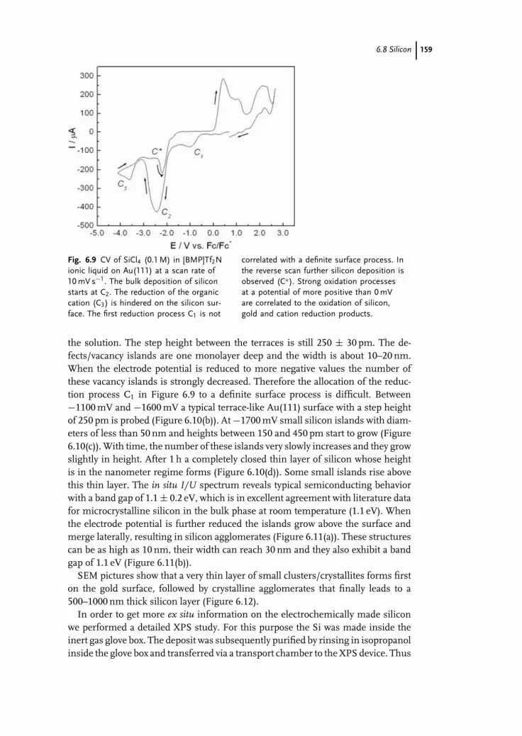
c06 (JWBG008-Endres) December 24, 2007 17:31 Char Count=
6.8 Silicon 159
Fig. 6.9 CV of SiCl4 (0.1 M) in [BMP]Tf2Nionic liquid on Au(111) at a scan rate of10 mV s−1. The bulk deposition of siliconstarts at C2. The reduction of the organiccation (C3) is hindered on the silicon sur-face. The first reduction process C1 is not
correlated with a definite surface process. Inthe reverse scan further silicon deposition isobserved (C*). Strong oxidation processesat a potential of more positive than 0 mVare correlated to the oxidation of silicon,gold and cation reduction products.
the solution. The step height between the terraces is still 250 ± 30 pm. The de-fects/vacancy islands are one monolayer deep and the width is about 10–20 nm.When the electrode potential is reduced to more negative values the number ofthese vacancy islands is strongly decreased. Therefore the allocation of the reduc-tion process C1 in Figure 6.9 to a definite surface process is difficult. Between−1100 mV and −1600 mV a typical terrace-like Au(111) surface with a step heightof 250 pm is probed (Figure 6.10(b)). At −1700 mV small silicon islands with diam-eters of less than 50 nm and heights between 150 and 450 pm start to grow (Figure6.10(c)). With time, the number of these islands very slowly increases and they growslightly in height. After 1 h a completely closed thin layer of silicon whose heightis in the nanometer regime forms (Figure 6.10(d)). Some small islands rise abovethis thin layer. The in situ I/U spectrum reveals typical semiconducting behaviorwith a band gap of 1.1 ± 0.2 eV, which is in excellent agreement with literature datafor microcrystalline silicon in the bulk phase at room temperature (1.1 eV). Whenthe electrode potential is further reduced the islands grow above the surface andmerge laterally, resulting in silicon agglomerates (Figure 6.11(a)). These structurescan be as high as 10 nm, their width can reach 30 nm and they also exhibit a bandgap of 1.1 eV (Figure 6.11(b)).
SEM pictures show that a very thin layer of small clusters/crystallites forms firston the gold surface, followed by crystalline agglomerates that finally leads to a500–1000 nm thick silicon layer (Figure 6.12).
In order to get more ex situ information on the electrochemically made siliconwe performed a detailed XPS study. For this purpose the Si was made inside theinert gas glove box. The deposit was subsequently purified by rinsing in isopropanolinside the glove box and transferred via a transport chamber to the XPS device. Thus

c06 (JWBG008-Endres) December 24, 2007 17:31 Char Count=
160 6 Electrodeposition of Semiconductors in Ionic Liquids
Fig. 6.10 The sequence of STM picturesshows the nanoscale growth of Si in theSiCl4 (0.1 M)/[BMP]Tf2N on Au(111) probedby in situ STM. Instead of a typical flatAu(111) surface, a worm-like structure isprobed at −300 mV vs. Fc/Fc+ (OCP) (a).When the electrode potential is reduced a
typical Au(111) terrace-like surface with astep height of 250 pm is observed (b). Ifthe electrode potential is set to −1700 mV,small silicon islands with a width of lessthan 60 nm and 150–450 pm in height startto grow (c). After 1 h an about 5 nm highclose silicon layer forms (d) close to theequilibrium potential.
the sample was never in air. As an example Figure 6.13 shows the XPS spectrum ofthe Si 2p peak. Besides the elemental peak at 101.3 eV there is strong evidence forSiOX at 104.4 eV. As discussed elsewhere [49] silicon is deposited electrochemically,but even in an inert gas glove box with an oxygen concentration as low as 1 ppm it isattacked by oxygen at the surface. The XPS study shows undoubtedly that elementalsilicon can be electrodeposited in ionic liquids.
6.9Grey Selenium
Grey selenium exhibits both photovoltaic and photoconductive properties, whichmake it useful in the production of photocells and solar cells. Moreover,

c06 (JWBG008-Endres) December 24, 2007 17:31 Char Count=
6.9 Grey Selenium 161
Fig. 6.11 When the electrode potential is reduced to −1800 mV vs.Fc/Fc+ silicon islands grow above the surface and merge laterallyleading to agglomerates (a). The in situ I/U tunneling spectrum showsthat both the layer and the islands exhibit a band gap of 1.1 ± 0.2 eV,typical for mycrocrystaline semiconducting Si (b).
Se-containing compound semiconductors, such as InSe, CdSe or CuInSe2 (CIS)have many optoelectronic applications, including advanced solar cells, IR detectorsand solid-state lasers. The CIS solar cells, especially, are very promising as a highlyefficient power supply. The electrodeposition of selenium has been intensively in-vestigated in aqueous solutions [50–53]. However, the exclusive electrodepositionof grey selenium in aqueous solutions is pretty difficult as at temperatures below100 ◦C red and black selenium, which are both insulators, grow in certain amountstogether with the desired grey phase. Consequently, in the technical process sele-nium is applied by gas phase condensation. Thermodynamically a phase transition
Fig. 6.12 SEM micrographs of electrode-posited Si, made potentiostatically at−2700 mV vs. Fc/Fc+. The surface is com-pletely covered by a thin silicon layer com-posed of individual clusters. Globular
50–150 nm wide crystallites consisting ofmany tiny crystals grow above this layer (a).A 500 nm thick silicon layer consists of co-herent spherical crystallites (b).

c06 (JWBG008-Endres) December 24, 2007 17:31 Char Count=
162 6 Electrodeposition of Semiconductors in Ionic Liquids
Fig. 6.13 High resolution XPS spectrum ofa nanoscale silicon deposit made potentio-statically at −2200 mV vs. Pt quasi-referencefor 2 h on a stainless steel substrate. (Dots:original data obtained from the measure-ment. Solid lines: fitted data. Dotted line:
sum of both fitted contributions.) A Si 2ppeak consists of two different contributionswith binding energies of 101.3 and 104.4 eV,which can be attributed to elemental Si andSiOX, respectivelly.
from amorphous red to crystalline grey selenium occurs at about 80 ◦C. But evenat 100 ◦C in aqueous solutions the deposit does not contain solely the grey phaseof Se. Obviously grey selenium can only be electrodeposited at elevated tempera-tures of more than 100 ◦C, which cannot be achieved in aqueous solutions. Thedirect electrodeposition of grey selenium can be performed in ionic liquids as thedeposition process can be realized at elevated temperatures due to the high thermalstability and low vapor pressure of most of the ionic liquids. In a recent paper wereported that grey selenium can be well electrodeposited from SeCl4 in [BMP]Tf2Nionic liquid [54]. All experiments were performed under an inert gas atmosphere.Unfortunately, we could not employ ferrocene as an internal reference, due tothe complexity of voltammograms and the need to exclude any interference withferrocene. Therefore, a Pt-wire had to be used as a quasi-reference electrode. Inour experience Pt has a sufficiently stable electrode potential for a while under theapplied conditions.
The cyclic voltammogram of [BMP]Tf2N containing 0.1 mol l−1 SeCl4 on a plat-inum substrate at 25 ◦C is presented in Figure 6.14(a). At a potential of −750 mVvs. Pt a dark red deposit forms on the electrode surface, obviously passivating it.It is likely that this peak is correlated to the reduction of Se(IV) to the red phaseof elemental Se. It cannot be excluded that the black phase is also formed. If the

c06 (JWBG008-Endres) December 24, 2007 17:31 Char Count=
6.9 Grey Selenium 163
Fig. 6.14 CVs of SeCl4 (0.1 M) in[BMP]Tf2N ionic liquid on Pt substrateat 25 ◦C (a) and 150 ◦C (b). Scan rate is10 mV s−1. At about −750 mV the deposi-tion of red amorphous Se occurs. The redcolour of the deposit turns to grey at C4.
The deposited Se is partly dissolved at A3.The shoulders C1 and C2 and their anodiccounterparts A1 and A2 might be related totwo different UPD processes. The pair C5
and A5 are likely to be due to the reductionof the deposited Se to Se2−.
temperature is increased to 150 ◦C (Figure 6.14(b)) five cathodic processes C1–C5
and their corresponding anodic counterparts A1–A5 are observed. C3 and C4 arecorrelated with the electrodeposition of selenium. Visually, first a red deposit formsat C3, which turns to a grey colour at C4. The peaks C1 and C2 are presumably corre-lated with different UPD processes. The peaks C5 and A5 are likely to be associatedwith the further reduction of the deposited selenium to Se2− as the selenium filmcan disappear completely at this electrode potential.
As one example the SEM picture in Figure 6.15 shows an electrodeposited Selayer made potentiostatically at −1100 mV vs. Pt at 150 ◦C. The XRD pattern of
Fig. 6.15 SEM image of Se layer, made potentiostatically at−1100 mV vs. Pt at 150 ◦C. The XRD pattern of this layer shows thatcrystalline grey Se is electrodeposited.

c06 (JWBG008-Endres) December 24, 2007 17:31 Char Count=
164 6 Electrodeposition of Semiconductors in Ionic Liquids
the electrodeposit reveals the characteristic peaks of the crystalline grey selenium.From XRD and SEM alone it cannot be excluded that some red or black Se alsoform, thermodynamically, however, it is unlikely at these temperatures.
In our opinion the electrodeposition of selenium is quite promising for a varietyof applications. For example, the possibility to deposit grey selenium, indium,and copper in one ionic liquid at variable temperatures might be regarded as thefirst step in making selenium-containing compound semiconductors like CIS byelectrochemical means.
6.10Conclusions
In this chapter we have summarized selected literature data on the electrodepositionof semiconductors in ionic liquids. It has been demonstrated that elemental silicon,germanium, and selenium can be elecrodeposited in ionic liquids. Furthermore,it is shown that compound semiconductors like InSb, AlSb, CdTe and others canbe made, especially at elevated temperatures where kinetic barriers are easier toovercome, even allowing the exclusive electrodeposition of grey selenium. In thiscontext ionic liquids are very promising for semiconductor electrodeposition. Bothwide electrochemical and thermal windows allow processes which are impossiblein aqueous or organic solvents.
References
1 Gore, R.B., Pandey, R.K., and Kulkarni,S.K. (1989) J. Appl. Phys., 65, 2693.
2 Loizos, Z., Mitsis, A., Spyrellis, N.,Froment, M., and Maurin, G. (1993) ThinSolid Films, 235, 51.
3 Razeghi, M. (2003) Eur. Phys. J.: Appl.Phys., 23, 149.
4 Baaziz, H., Charifi, Z., and Bouarissa, N.(2001) Mater. Chem. Phys., 68, 197.
5 Kelly, J.J., Rikken, J.M.G., Jacobs,J.W.M., and Valster, A. (1988) J. Vac. Sci.Technol. B, 6, 48.
6 Schock, H.W. (1996) Appl. Surf. Sci., 92,606.
7 Leifeld, O., Beyer, A., Muller, E.,Grutzmacher, D., and Kern, K. (2000)Thin Solid Films, 380, 176.
8 Jaiswal, S.L., Simpson, J.T., Withrow,S.P., White, C.W., and Norris, P.M.(2003) Appl. Phys., A77, 57.
9 Pandey, R.K., Sahu, S.N., and Chandra,S. (1996) Handbook of Semiconductor
Electrodeposition, Marcel Dekker, NewYork, NY.
10 Gregory, B.W. and Stickney, J.L. (1991) J.Electroanal. Chem., 300, 543.
11 Colletti, L.P., Flowers, B.H., andStickney, J.L. (1998) J. Electrochem. Soc.,145, 1442.
12 Flowers, B.H. Jr., Wade, T.L., Garvey,J.W., Lay, M., Happek, U., and Stickney,J.L. (2002) J. Electroanal. Chem., 524–525,273.
13 Mathe, M.K., Cox, S.M., Venkatasamy,V., Happek, U., and Stickney, J.L. (2005)J. Electrochem. Soc., 152, C751.
14 Venkatasamy, V., Mathe, M.K., Cox,S.M., Happek, U., and Stickney, J.L.(2005) Electrochim. Acta, 51,4347
15 Venkatasamy, V., Jayaraju, N., Cox, S.M.,Thambidurai, C., Happek, U., andStickney, J.L. (2006) J. Appl. Electrochem.,36, 1223.

c06 (JWBG008-Endres) December 24, 2007 17:31 Char Count=
References 165
16 Raza, A., Engelken, R., Kemp, B.,Siddiqui, A., and Mustafa, O. (1995) Proc.Arkansas Acad. Sci., 49, 143.
17 Mengoli, G., Musiani, M.M., Paolucci, F.,and Gazzano, M. (1991) J. Appl.Electrochem., 21, 863.
18 Kozlov, V.M., Agrigento, V., Bontempi,D., Canegallo, S., Moraitou, C.,Toussimi, A., Bicelli, L.P., and Serravalle,G. (1997) J. Alloys Compds., 259, 234.
19 Wade, T.L., Vaidyanathan, R., Happek,U., and Stickney, J.L. (2001) J.Electroanal. Chem., 500, 322.
20 Kozlov, V.M., Bozzini, B., and Bicelli,L.P. (2004) J. Alloys Compds., 366,152.
21 Fulop, T., Bekele, C., Landau, U., Angus,J., and Kash, K. (2004) Thin Solid Films,449, 1.
22 Fink, C.G. and Dokras, V.M. (1949) J.Electrochem. Soc., 95, 80.
23 Szekely, G. (1951) J. Electrochem. Soc., 98,318.
24 Monnier, R. and Tissot, P. (1964) Helv.Chim. Acta, 47, 2203.
25 Agrawal, A.K. and Austin, A.E. (1981) J.Electrochem. Soc., 128, 2292.
26 Gobet, J. and Tannenberger, H. (1986) J.Electrochem. Soc., 133, C322.
27 Gobet, J. and Tannenberger, H. (1988) J.Electrochem. Soc., 135, 109.
28 Matsuda, T., Nakamura, S., Ide, K.,Nyudo, K., Yae, S.J., and Nakato, Y.(1996) Chem. Lett., 7, 569.
29 Nicholson, J.P. (2005) J. Electrochem. Soc.,152, C795.
30 Wicelinski, S.P. and Gale, R.J. (1986) inFifth International Symposium on MoltenSalts, (PV 86-1), (eds M.-L. Saboungi,D.S. Newman, K. Johnson, and D.Inman), the Electrochemical SocietySoftbound Proceedings Series,Pennington, NJ, p. 144
31 Carpenter, M.K. and Verbrugge, M.W.(1990) J. Electrochem. Soc., 137, 123.
32 Verbrugge, M.W. and Carpenter, M.K.(1990) AIChE J., 36, 1097.
33 Carpenter, M.K. and Verbrugge, M.W.(1994) J. Mater. Res., 9, 2584.
34 Yang, M.H., Yang, M.C., and Sun, I.W.(2003) J. Electrochem. Soc., 150,C544.
35 Aravinda, C.L. and Freyland, W. (2006)Chem. Commun., 16, 1703.
36 Mann, O., Aravinda, C.L., and Freyland,W. (2006) J. Phys. Chem. B, 110, 21521.
37 Lin, M.C., Chen, P.Y., and Sun, I.W.(2001) J. Electrochem. Soc., 148, C653.
38 Hsiu, S.I. and Sun, I.W. (2004) J. Appl.Electrochem., 34, 1057.
39 Endres, F. and Schrodt, C. (2000) Phys.Chem. Chem. Phys., 2, 5517.
40 Endres, F. (2001) Phys. Chem. Chem.Phys., 3, 3165.
41 Endres, F. and Zein El Abedin, S. (2002)Phys. Chem. Chem. Phys., 4, 1640.
42 Endres, F. and Zein El Abedin, S. (2002)Phys. Chem. Chem. Phys., 4, 1649.
43 Endres, F. (2002) Electrochem. Solid-StateLett., 5, C38.
44 Katayama, Y., Yokomizo, M., Miura, T.,and Kishi, T. (2001) Electrochemistry, 69,834.
45 Zein El Abedin, S., Borissenko, N., andEndres, F. (2004) Electrochem. Commun.,6, 510.
46 Borisenko, N., Zein El Abedin, S., andEndres, F. (2006) J. Phys. Chem. B, 110,6250.
47 Howlett, P.C., Izgorodina, E.I., Forsyth,M., and MacFarlane, D.R. (2006) Z. Phys.Chem, 220, 1483.
48 Endres, F., Zein El Abedin, S., andBorissenko, N. (2006) Z. Phys. Chem.,220, 1377.
49 Bebensee, F., Borissenko, N., Frerichs,M., Hofft, O., Maus-Friedrichs, W., ZeinEl Abedin, S., and Endres, F. (2008) Z.Phys. Chem., accepted.
50 Huang, B.M., Lister, T.E., and Stickney,J.L. (1997) Surf. Sci., 392, 27.
51 Sorenson, T.A., Lister, T.E., Huang,B.M., and Stickney, J.L. (1999) J.Electrochem. Soc., 146, 1019.
52 Alanyalioglu, M., Demir, U., andShannon, C. (2004) J. Electroanal. Chem.,561, 21.
53 Zhang, X.Y., Cai, Y., Miao, J.Y., Ng, K.Y.,Chan, Y.F., Zhang, X.X., and Wang, N.(2005) J. Cryst. Growth., 276, 674.
54 Zein El Abedin, S., Saad, A.Y., Farag,H.K., Borisenko, N., Liu, Q.X., andEndres, F. (2007) Electrochim. Acta, 52,2746.

c07 (JWBG008-Endres) December 25, 2007 13:32 Char Count=
167
7Conducting PolymersJennifer M. Pringle, Maria Forsyth, and Douglas R. MacFarlane
7.1Introduction
The utilization of ionic liquids for the synthesis and use of conducting polymersbrings together two of the most exciting and promising areas of research fromrecent years.
Conducting polymers are organic materials that can display electronic, magneticand optical properties similar to metals, but that also have the mechanical proper-ties and low density of a polymer. They have the potential to allow the design andfabrication of a vast number of electrochemical devices including photovoltaics,batteries, chemical sensors, supercapacitors, conducting textiles, electrochromicsand electromechanical actuators [1–4]. In addition, these materials have the po-tential to impact in a major way on new biomedical processes such as controlledneural growth, which has significant application in spinal regeneration [5]. The useof electroactive polymers for the fabrication of electromechanical actuators, wherethe polymer can be made to bend and straighten on application of a small potential,has particular significance in the medical field, where they are being investigatedas artificial muscles for a range of prosthetic and therapeutic uses. The use ofconducting polymers in photovoltaic devices is another, extremely important areaof research and potential applications range from simple solar cells to sunlightharvesting paints and fabrics, for the production of electricity from sunlight.
Research into conducting polymers has been increasingly intense for the last25 years, since MacDiarmid, Heeger and Shirakawa published their seminal workon polyacetylene, which demonstrated that the conductivity of these materials canbe increased by several orders of magnitude by doping with anions [6, 7]. Theimportance of these materials and the progress made in this field is reflected in theaward of the Nobel Prize for Chemistry in 2000 to these founding researchers inthis area.
However, to allow the widespread use of conducting polymers, more research isneeded to improve their general performance, and one of their present limitationsis the rapid degradation of key properties such as conductivity and electrochem-ical cyclability. This limitation is primarily a result of the electrolyte used in the
Electrodeposition from Ionic Liquids. Edited by F. Endres, D. MacFarlane, A. AbbottCopyright C© 2008 WILEY-VCH Verlag GmbH & Co. KGaA, WeinheimISBN: 978-3-527-31565-9

c07 (JWBG008-Endres) December 25, 2007 13:32 Char Count=
168 7 Conducting Polymers
preparation and cycling of the electroactive polymer, which is required as a source ofdopants when the polymer is oxidized. These dopants have a significant influenceon all the properties of the polymer, including conductivity, mechanical proper-ties, electrochemical efficiency and stability, most likely through the control of thestructure and morphology of the material. Ionic liquids offer a unique combinationof chemical and physical properties that make them interesting as electrolyte andsolvent in one. Interestingly, but not entirely of surprise at the fundamental level,many of the anions that are effective in producing high conductivities in conduct-ing polymers are also the anions that commonly occur in ionic liquid compounds.Thus appropriate ionic liquids provide a superb source of the dopant anions.
Conducting polymers, such as poly(aniline), poly(pyrrole) or poly(thiophene)(Figure 7.1) have a conjugated system of delocalized π -orbitals, which allows con-duction to occur in the oxidized, or “doped” polymer.
The technological interest in these materials lies in their redox behavior. Whenthe films are oxidised in an appropriate electrolytic medium, positive charges aregenerated along the backbone and solvated counterions enter the polymer fromthe solution to effect charge balance. This results in an opening of the polymericstructure and an increase in volume. The opposite process occurs on reduction,when the incorporated anions are expelled back into solution and the film recoversits original volume. The size and nature of the dopant counterion incorporatedduring synthesis can have a dramatic effect on the ion movement occurring duringredox processes. There is a competitive reaction between anion expulsion and cationincorporation (from the electrolyte) during the reduction cycle. These two reactionscompete to achieve charge neutrality caused by the loss of charge on the polymerbackbone (Figure 7.2) [4]. For example, polyelectrolyte dopants, being relativelyimmobile, tend to remain in the polymer and with such films cation incorporationprocesses dominate.
The potential benefits of using ionic liquids as electrolytes in conducting polymerdevices have been investigated by a number of authors in recent years, for appli-cations such as actuators [8–17], supercapacitors [18–20], electrochromic devices[12, 21] and solar cells [22], with significant improvements in lifetimes and deviceperformance reported.
For example, in 2002, Lu et al. [12] reported significant improvements indevice performance when the ionic liquids 1-ethyl-3-methylimidazolium hex-afluorophosphate, [C2mim][PF6], and 1-ethyl-3-methylimidazolium tetrafluorob-orate, [C2mim][BF4], were used as supporting electrolytes for poly(pyrrole) andpoly(aniline) actuators and for polyethylenedioxythiophene (PEDOT) in elec-trochromic devices, respectively. For the PEDOT study, the ionic liquid wasalso used as the growth medium for the electropolymerization of PEDOT. No-tably, in both the poly(aniline) in the [C2mim][BF4] and the poly(pyrrole) in the[C2mim][PF6] actuator systems, cation incorporation and expulsion was the pre-dominant strain-generating mechanism during actuation, whereas in the propy-lene carbonate/tetrabutylammonium hexafluorophosphate (PC/[Bu4N]PF6) systemit was anion movement that was observed [12]. Thus, the linear displacement of thisactuator is in the opposite direction, illustrating the importance of the nature of ion

c07 (JWBG008-Endres) December 25, 2007 13:32 Char Count=
7.1 Introduction 169
Fig. 7.1 The chemical structure of common conducting polymers, intheir undoped, neutral form [4].

c07 (JWBG008-Endres) December 25, 2007 13:32 Char Count=
170 7 Conducting Polymers
Fig. 7.2 The redox cycling of poly(pyrrole) involving intercalation andexpulsion of (a) the anion or (b) the cation from the electrolyte toeffect charge balance.
incorporation in such ionic liquid systems. The poly(aniline) actuator maintainedelectromechanical actuation and electroactivity for >10 000 cycles, without anysignificant decrease in stress or strain (<1%), clearly demonstrating the potentialbenefits of the use of ionic liquids in such systems.
Thus, when an ionic liquid is used as the solvent/electrolyte for electrochemicalcycling of conducting polymers, both the cation and the anion of the ionic liquidmay be intricately involved in the redox processes and, therefore, the nature of eachmust be considered. The nature of the electrolyte is also critical in dictating thestability of conducting polymers at extreme potentials, which is often limited bydegradation of the solvent or electrolyte and, therefore, the use of an ionic liquidwith a wide electrochemical window of stability, particularly in the anodic region,will be of particular benefit in this respect.
In addition, the use of ionic liquids is often prompted by safety and environmentalconsiderations, where their negligible volatility and nonflammability makes themideal replacements for more toxic molecular solvents and, importantly, overcomesthe problem of solvent evaporation that exists with the long-term use of volatilesolvents in electrochemical applications. The wide liquid range and good thermalstability are also extremely advantageous for device applications.
Further to their role as supporting electrolytes, the conductivity and electrochem-ical stability of ionic liquids clearly also allows them to be used as solvents for theelectrochemical synthesis of conducting polymers, thereby impacting on the prop-erties and performance of the polymers from the outset. Parameters such as theionic liquid viscosity and conductivity, the high ionic concentration compared toconventional solvent/electrolyte systems, as well as the nature of the cation and

c07 (JWBG008-Endres) December 25, 2007 13:32 Char Count=
7.2 Electropolymerization – General Experimental Techniques 171
anion themselves, may all influence integral polymer properties such as structure,doping level, growth rate, growth mechanism, morphology, conductivity etc.
Exploration of these concepts began a number of years ago with the use ofchloroaluminate ionic liquids and has more recently focused on the use of air andmoisture stable species. These are discussed separately in Section 7.3. First wediscuss general experimental techniques in Section 7.2. Characterization methodsare then surveyed in Section 7.4.
7.2Electropolymerization – General Experimental Techniques
The generally accepted polymerization mechanism for heterocyclic polymers suchas poly(pyrrole) is shown in Figure 7.3 [23].
Fig. 7.3 The polymerization mechanism for heterocyclic polymers [23].

c07 (JWBG008-Endres) December 25, 2007 13:32 Char Count=
172 7 Conducting Polymers
However, this polymerization process is far from simple and there are still as-pects that are the subject of some debate, some of which may also be influencedby the use of ionic liquids as the polymerization medium. For example, the pointat which the polymer begins to deposit on the electrode must be considered; it isprobable that there is a certain degree of polymerization that occurs in solution,followed by the precipitation of oligomers onto the electrode surface, rather thanthe adsorption of the monomer onto the electrode followed by its polymerization.This oligomer deposition is influenced by the solubility of the intermediates andthe extent to which they diffuse away from the electrode rather than deposit ontoit; these factors may be influenced by the use of ionic liquids as a result of theirdifferent viscosities, conductivities, solubilising properties and even their potentialfor stabilizing radical or charged species. The color change that we have observedduring the use of ionic liquids for the polymerization of pyrrole suggests the pres-ence of significant quantities of oligomers dissolved in the ionic liquid. They way inwhich the polymer subsequently grows is also important; it may be via nucleationand growth processes, where the electropolymerization and precipitation contin-ues, or by chain growth of the polymer already on the electrode [23]. These differentmechanisms will influence the morphology of the final polymer film, as discussedin Section 7.4.2, and again may be influenced by the use of an ionic liquid.
There are also a number of other variables to consider when planning the elec-trochemical synthesis of conducting polymers in ionic liquids. While most of thesevariables also exist for the synthesis of the polymers in molecular/solvent systemsand have been investigated in detail, it is worth considering that the influence ofany of these factors may be different when utilizing ionic liquids as the growthmedium because of their distinctly different properties. These are discussed inmore detail below.
7.2.1Temperature
When ionic liquids are used, this will have a significant effect on the viscosity andhence the conductivity and rate of ion diffusion within the ionic liquids. Growth ofconducting polymers at reduced temperatures (as low as −28 ◦C) [4, 24] in molecularsolvent systems is generally accepted to result in smoother, more conductive films,but we have found that in ionic liquids the significant increase in the viscositycan be problematic. In addition, the temperature used for the conducting polymersynthesis may be limited by the melting point of the ionic liquid [25].
7.2.2Electrochemical Technique
Conducting polymer films are generally grown galvanostatically, potentiostaticallyor potentiodynamically, although pulsed current and pulsed potentials can also beused. All three of these techniques have been reported for the growth of variousconducting polymers in ionic liquids, but there has been no comprehensive com-parison of the relative benefits of each. In molecular solvents, constant potential

c07 (JWBG008-Endres) December 25, 2007 13:32 Char Count=
7.2 Electropolymerization – General Experimental Techniques 173
growth may result in less homogeneous films than those from constant currentgrowth due to inhomogeneities on the electrode surface, and this technique maybe more affected by iR drop effects [4], which may be considerably larger in themore viscous ionic liquid medium. During galvanostatic growth, the potential mustbe monitored closely to ensure that overoxidation of the polymer does not occur.Growth of the polymer film potentiodynamically (by cyclic voltammetry) is themost time-consuming technique and is not generally employed for the synthesisof significant quantities of film, but it is an advantageous technique for detailedelectrochemical analysis as the redox characteristics of the polymer can be moni-tored during film growth. It should be noted, however, that during potentiodynamicgrowth the auxiliary electrode can be exposed to extreme positive potentials. In amolecular solvent system this can result in oxidation of the solvent or any waterpresent, but this problem may be reduced in a more electrochemically stable ionicliquid medium.
7.2.3Growth Potential
The oxidation potential of various monomers may be different in ionic liquids com-pared to molecular solvent/electrolyte systems. An increase in monomer oxidationpotential in ionic liquids has been attributed to a decrease in the stability of themonomer cation (3-(4-fluorophenyl)thiophene) [26], and also to the viscosity of theionic liquid, which causes significant iR drop within the electrochemical cell [27].However, it should also be noted that determination of this potential is somewhatdependent on the nature of the reference electrode used and also any variation thatthis electrode might display on moving from molecular solvent systems to ionicliquids [28]. Thus, direct comparison of monomer electrode potentials, as reportedby different researchers, should be undertaken with considerable caution. Uponthe initial investigation of any new ionic liquid or monomer, or even when usingnew experimental conditions, it is prudent to record the cyclic voltammograms ofthe monomer in the ionic liquid, starting with a modest potential range and slowlyincreasing until monomer oxidation is observed, thereby determining the optimalconditions for polymer growth.
It is interesting to note at this point that, where previously the potential used togrow the electroactive polymers has been limited by the solvent window, one ofthe many benefits of using ionic liquids is their greater electrochemical stability,which allows access to much higher potentials for film growth. This should allowaccess to the oxidation potentials of monomers previously unreachable and thus in-crease the range of conducting polymers that can be synthesized by electrochemicalmethods.
7.2.4Electrodes
The choice of a suitable reference electrode for use in ionic liquids is a complexissue [28], which will be discussed in more detail elsewhere. There is also a range

c07 (JWBG008-Endres) December 25, 2007 13:32 Char Count=
174 7 Conducting Polymers
of different working electrodes available; existing studies of conducting polymersynthesis in ionic liquids almost entirely use platinum working electrodes, or in-dium titanium oxide (ITO) glass to allow spectroelectrochemical analysis of thepolymer. The synthesis of poly(pyrrole) onto iron has also been studied [29], anda glassy carbon electrode has been used for the deposition of PEDOT [25]. As forall electrochemical techniques, the condition and cleanliness of the electrodes isof great importance; it has been reported that the morphology of poly(pyrrole)films can be greatly altered by inadequate polishing of the working electrode [30].The working electrode can also be used as a template to allow the synthesis ofnanostructured polymers, although this technique has not been extensively uti-lized in ionic liquids [31]. The cell design and the arrangement and size of theelectrodes are also very important, influencing the hydrodynamics and potentialswithin the cell and thus the rate of ion transport and the quantity of unwantedside-reactions.
7.2.5Atmosphere and Water Content
The presence of oxygen in a molecular solvent/electrolyte system during the elec-trochemical synthesis of a conducting polymer can be problematic as it can reactwith radical intermediates and be reduced at the auxiliary electrode to form hydrox-ide [4]. The vast majority of reports detailing the synthesis of conducting polymersin ionic liquids perform this procedure under anaerobic conditions, using either anitrogen or an argon atmosphere. In our laboratory we have found that even a basicdry-nitrogen blanket can yield significant improvements in the conductivities ofsynthesized poly(pyrrole) films, probably by decreasing over-oxidation of the poly-mer. Similarly, the redox responses of poly(pyrrole) in ionic liquids can be muchmore defined after nitrogen purging [32].
The water content of the ionic liquid is another, perhaps more complex, factor forconsideration. The presence of small amounts (1–4%) of water may be beneficialto the properties of some polymers [33], but it should be noted that some ionicliquids utilizing fluorinated anions, particularly hexafluorophosphate, can slowlyhydrolyse in the presence of water to form HF and other species [34]. It is importantto note that even if an ionic liquid is immiscible with water, it may still contain asignificant quantity of water before drying, which can alter its physical properties,such as viscosity [34–36].
7.2.6Choice of Ionic Liquid
There is a plethora of different ionic liquids readily available, either commerciallyor through straightforward laboratory synthesis; investigations into their use forthe synthesis of conducting polymers has, so far, focused on a relatively smallnumber (Figure 7.4). Thus, the avenues for future investigation in this area are vast.

c07 (JWBG008-Endres) December 25, 2007 13:32 Char Count=
7.2 Electropolymerization – General Experimental Techniques 175
Fig. 7.4 The cations and anions utilized to date for the electrochemi-cal synthesis of conducting polymers in ionic liquids, and their abbre-viations.
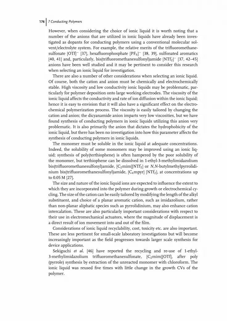
c07 (JWBG008-Endres) December 25, 2007 13:32 Char Count=
176 7 Conducting Polymers
However, when considering the choice of ionic liquid it is worth noting that anumber of the anions that are utilized in ionic liquids have already been inves-tigated as dopants for conducting polymers using a conventional molecular sol-vent/electrolyte system. For example, the relative merits of the trifluoromethane-sulfonate [OTf]− [37], hexafluorophosphate [PF6]− [38, 39], sulfonated aromatics[40, 41] and, particularly, bis(trifluoromethanesulfonyl)amide [NTf2]− [37, 42–45]anions have been well studied and it may be pertinent to consider this researchwhen selecting an ionic liquid for investigation.
There are also a number of other considerations when selecting an ionic liquid.Of course, both the cation and anion must be chemically and electrochemicallystable. High viscosity and low conductivity ionic liquids may be problematic, par-ticularly for polymer deposition onto large working electrodes. The viscosity of theionic liquid affects the conductivity and rate of ion diffusion within the ionic liquid;hence it is easy to envision that it will also have a significant effect on the electro-chemical polymerization process. The viscosity is easily tailored by changing thecation and anion; the dicyanamide anion imparts very low viscosities, but we havefound synthesis of conducting polymers in ionic liquids utilizing this anion veryproblematic. It is also primarily the anion that dictates the hydrophobicity of theionic liquid, but there has been no investigation into how this parameter affects thesynthesis of conducting polymers in ionic liquids.
The monomer must be soluble in the ionic liquid at adequate concentrations.Indeed, the solubility of some monomers may be improved using an ionic liq-uid; synthesis of poly(terthiophene) is often hampered by the poor solubility ofthe monomer, but terthiophene can be dissolved in 1-ethyl-3-methylimidazoliumbis(trifluoromethanesulfonyl)amide, [C2mim][NTf2] or N,N-butylmethylpyrrolidi-nium bis(trifluoromethanesulfonyl)amide, [C4mpyr] [NTf2], at concentrations upto 0.05 M [27].
The size and nature of the ionic liquid ions are expected to influence the extent towhich they are incorporated into the polymer during growth or electrochemical cy-cling. The size of the cation can be easily tailored by modifying the length of the alkylsubstituent, and choice of a planar aromatic cation, such as imidazolium, ratherthan non-planar aliphatic species such as pyrrolidinium, may also enhance cationintercalation. These are also particularly important considerations with respect totheir use in electromechanical actuators, where the magnitude of displacement isa direct result of ion movement into and out of the film.
Considerations of ionic liquid recyclability, cost, toxicity etc. are also important.These are less pertinent for small-scale laboratory investigations but will becomeincreasingly important as the field progresses towards larger scale synthesis fordevice applications.
Sekiguchi et al. [46] have reported the recycling and re-use of 1-ethyl-3-methylimidazolium trifluoromethanesulfonate, [C2mim][OTf], after poly(pyrrole) synthesis by extraction of the unreacted monomer with chloroform. Theionic liquid was reused five times with little change in the growth CVs of thepolymer.
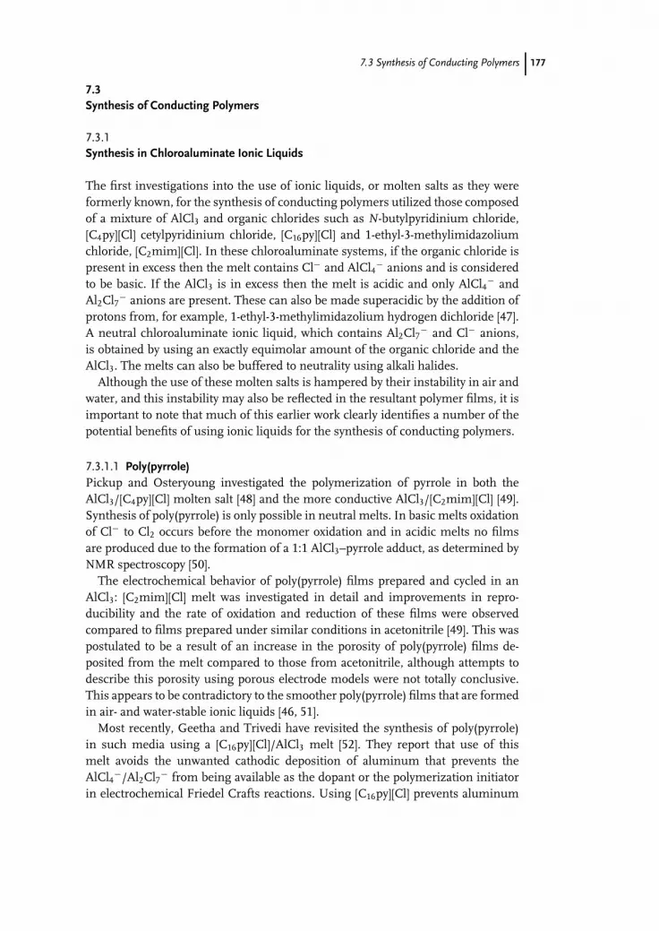
c07 (JWBG008-Endres) December 25, 2007 13:32 Char Count=
7.3 Synthesis of Conducting Polymers 177
7.3Synthesis of Conducting Polymers
7.3.1Synthesis in Chloroaluminate Ionic Liquids
The first investigations into the use of ionic liquids, or molten salts as they wereformerly known, for the synthesis of conducting polymers utilized those composedof a mixture of AlCl3 and organic chlorides such as N-butylpyridinium chloride,[C4py][Cl] cetylpyridinium chloride, [C16py][Cl] and 1-ethyl-3-methylimidazoliumchloride, [C2mim][Cl]. In these chloroaluminate systems, if the organic chloride ispresent in excess then the melt contains Cl− and AlCl4− anions and is consideredto be basic. If the AlCl3 is in excess then the melt is acidic and only AlCl4− andAl2Cl7− anions are present. These can also be made superacidic by the addition ofprotons from, for example, 1-ethyl-3-methylimidazolium hydrogen dichloride [47].A neutral chloroaluminate ionic liquid, which contains Al2Cl7− and Cl− anions,is obtained by using an exactly equimolar amount of the organic chloride and theAlCl3. The melts can also be buffered to neutrality using alkali halides.
Although the use of these molten salts is hampered by their instability in air andwater, and this instability may also be reflected in the resultant polymer films, it isimportant to note that much of this earlier work clearly identifies a number of thepotential benefits of using ionic liquids for the synthesis of conducting polymers.
7.3.1.1 Poly(pyrrole)Pickup and Osteryoung investigated the polymerization of pyrrole in both theAlCl3/[C4py][Cl] molten salt [48] and the more conductive AlCl3/[C2mim][Cl] [49].Synthesis of poly(pyrrole) is only possible in neutral melts. In basic melts oxidationof Cl− to Cl2 occurs before the monomer oxidation and in acidic melts no filmsare produced due to the formation of a 1:1 AlCl3–pyrrole adduct, as determined byNMR spectroscopy [50].
The electrochemical behavior of poly(pyrrole) films prepared and cycled in anAlCl3: [C2mim][Cl] melt was investigated in detail and improvements in repro-ducibility and the rate of oxidation and reduction of these films were observedcompared to films prepared under similar conditions in acetonitrile [49]. This waspostulated to be a result of an increase in the porosity of poly(pyrrole) films de-posited from the melt compared to those from acetonitrile, although attempts todescribe this porosity using porous electrode models were not totally conclusive.This appears to be contradictory to the smoother poly(pyrrole) films that are formedin air- and water-stable ionic liquids [46, 51].
Most recently, Geetha and Trivedi have revisited the synthesis of poly(pyrrole)in such media using a [C16py][Cl]/AlCl3 melt [52]. They report that use of thismelt avoids the unwanted cathodic deposition of aluminum that prevents theAlCl4−/Al2Cl7− from being available as the dopant or the polymerization initiatorin electrochemical Friedel Crafts reactions. Using [C16py][Cl] prevents aluminum

c07 (JWBG008-Endres) December 25, 2007 13:32 Char Count=
178 7 Conducting Polymers
deposition onto the electrode as the cetyl groups are preferentially deposited. Forsimilar reasons, the authors have also recently investigated this media for the elec-tropolymerization of benzene [53].
7.3.1.2 Poly(p-phenylene)The polymerization of benzene in chloroaluminate salts has attracted attentionfrom a number of authors. The electrosynthesis of this polymer is highly desirablebut challenging, with one of the primary considerations being the strict elimina-tion of water from the reaction medium, which is most commonly effected usingdifficult systems such as liquid sulfur dioxide, concentrated sulfuric acid or HF.The polymerization of benzene and biphenyl in organic solvents yields only lowconductivity films with low degrees of polymerization.
The earliest investigations into the use of chloroaluminate molten salts overcameproblems associated with the relatively high melting points of the then-knownchloroaluminates (containing [C2py][Br] or [C16py][Cl]) by mixing with equivalentvolumes of benzene. This also results in a decrease in viscosity and marked increasein conductivity [54, 55]. Later, Goldenberg and Osteryoung used the lower-meltingsystem of [C2mim][Cl]/AlCl3 and reported that the polymerization of benzene wasfacilitated in this melt, compared to solvents like acetonitrile or nitromethane,because it is drier and the nucleophilicity is low [56]. Unlike pyrrole, aniline orthiophene, benzene does not form adducts with AlCl3 and is polymerized using anacidic chloroaluminate melt. Further, the oxidation potential of the monomer doesnot appear to vary with melt composition. The resultant poly(p-phenylene) filmsdemonstrated good electrochemical stability when cycled in the melts; films werecycled in a 1.5:1 acidic melt in excess of 100 times with no significant change inactivity [56].
Kobryanskii and Arnautov reported a significant increase in the relative molec-ular mass of poly(p-phenylene) synthesised in [C4py][Cl]/AlCl3 compared to thehighest values previously reported using alternative media [57], and Goldenber etal. [58] reported the formation of highly conductive films from this melt, althoughthis conductivity decreased very rapidly with time, even in an inert atmosphere.Substitution of the chloroaluminate anions in the film with BF4
− anions reportedlyincreased the stability, but at the expense of the conductivity. The film instabilitywas attributed to the presence of the highly moisture sensitive chloroaluminateanions and possible destruction of the polymer by anion oxidation and polymerchlorination. There is also some question as to the quality (degree of polymer-ization and crosslinking, conjugation length and so on) of the poly(p-phenylene)films made from such melts [59]. Most recently, Geetha and Trivedi have used a[C16py][Cl]/AlCl3 system dissolved in benzene for the synthesis of poly(p-phenylene)[53], producing films with good conductivity, but again this decreased markedly onexposure to air.
7.3.1.3 Poly(thiophene)s and Poly(fluorene)Osteryoung and coworkers have also used chloroaluminate molten salts, uti-lizing the [C2mim] cation, for the electrosynthesis of poly(thiophene) and poly

c07 (JWBG008-Endres) December 25, 2007 13:32 Char Count=
7.3 Synthesis of Conducting Polymers 179
(bithiophene) [60] and poly(fluorine) [61]. The electrosynthesis of poly(fluorine)can be achieved in both neutral and acidic melts but in the basic compositionthe chloride ions are more easily oxidized. The resultant poly(fluorene) films arereportedly more stable than those synthesized in acetonitrile and the ability to ob-serve a ferrocene/ferrocenium couple through a thin deposit of poly(fluorine) onthe working electrode was concluded to indicate a porous film morphology [61].Similar observations of stability and porosity were made for poly(thiophene) andpoly(bithiophene) films prepared in this ionic liquid [60]. Poly(bithiophene) filmsprepared in the neutral melt were found to be unstable in acetonitrile, althoughfilms grown in acetonitrile and then electrochemically cycled in the melt exhibitedexcellent stability (>2000 cycles).
7.3.1.4 Poly(aniline)Osteryoung and coworkers have also investigated the use of chloroaluminate ionicliquids for the synthesis of polyaniline [62, 63]. Unlike pyrrole and thiophene,aniline was successfully polymerized in acidic, neutral and basic chloroaluminatemelts, although the best results were obtained using the neutral composition.
The oxidation potential of aniline is significantly affected by the composition ofthe melt, probably as a result of the formation of an adduct between aniline andAlCl3, similar to that observed for pyrrole. The oxidation potential of the anilinewas also found to be influenced by the nature of the electrode used (platinum orglassy carbon), and further shifted upon deposition of polymer onto the workingelectrode, in a direction that again depended on the composition of the moltensalt used [62]. Further, using molten salts of different acidity is reported to resultin changes to the backbone structure of the resultant poly(aniline). In comparisonto poly(aniline) films formed from aqueous and organic solvents, those preparedand cycled in basic chloroaluminate melts were reportedly very stable, retainingmore than 90% of their electrochemical activity after 30 000 cycles at 100 mV s−1
[63]. They also observed what was believed to be the influence of the viscosityof the molten salt medium on the electrochemical behavior of the conductingpolymer; when the poly(aniline) electrode, in its insulating state, was placed ina basic or neutral melt, it required around 30 potentiodynamic cycles before themaximum electroactivity was obtained. This kinetic limitation is most likely relatedto the ability of the anions to permeate the film (solvent swelling), which can beexpected to be significantly different in this, relatively viscous, molten salt mediacompared to molecular solvent systems. It is also dependent on the size of the anionpresent in the molten salt. This observation has subsequently been corroboratedby researchers using air and water stable ionic liquids [64].
7.3.2Synthesis in Air- and Water-stable Ionic Liquids
7.3.2.1 Poly(pyrrole)Poly(pyrrole) is one of the most popular conducting polymers as it can be highly con-ducting, quite environmentally stable and relatively easy to synthesize. Sekiguchi

c07 (JWBG008-Endres) December 25, 2007 13:32 Char Count=
180 7 Conducting Polymers
et al. [46] have studied synthesis of this polymer in ionic liquids utilizing the [C2mim]cation and the [BF4]−, [PF6]− and [OTf]− anions. Comparison of the growth CVs ofpoly(pyrrole) in these ionic liquids showed the highest polymer oxidation and reduc-tion currents were obtained during growth in [C2mim][OTf], and the lowest fromusing the [C2mim][PF6]. The authors thus suggest that the higher viscosity of theformer species results in a faster polymerization rate, because the polymerizationreaction products are accumulated near the electrode surface and thus can undergofurther radical coupling, oxidation and deposition onto the electrode rather thandiffusing away into the bulk. However, this is not always seen and therefore otherfactors also influence these processes. The authors concluded that the [OTf]− anionwas the superior choice for the electropolymerization of pyrrole. When comparingthe performance of this neat ionic liquid to that of solutions of the ionic liquidin water or acetonitrile it was noted that the undiluted ionic liquid gave greaterpolymer redox peak currents and smaller redox peak separation. The film grownin the neat ionic liquid was reportedly thinner than that from the dilute solutionsbut more electrochemically active and more highly doped. The films grown fromthe aqueous and acetonitrile solutions displayed a granular morphology (largerfrom the water solution) whereas the film from the ionic liquid appeared to bevery smooth. The origin of the cauliflower-like features observed in poly(pyrrole)from molecular solvent systems has been investigated by a number of researchers,who suggest that their appearance can be significantly altered depending on thenature of the anion used, the electrode material and polishing techniques used,the synthesis temperature and so on [4]. Sekiguchi et al. [65] also report the use ofpoly(pyrrole) films as a matrix for hosting palladium particles and show that theseare considerably more dispersed when deposited from the ionic liquid than fromaqueous solutions of the salt.
Significantly smoother film morphologies have also been observed forpoly(pyrrole) grown from the ionic liquids [C2mim][NTf2] and [C4mpyr] [NTf2] com-pared to those grown under the same experimental conditions from PC/Bu4NPF6
(Figure 7.5) [51]. However, lower polymer redox currents were observed in themore viscous, less conductive pyrrolidinium ionic liquid compared to the imida-zolium species (85 cP and 2.2 mS cm−1, respectively, at 25 ◦C for [C4mpyr] [NTf2][66] compared to 34 cP and 8.8 mS cm−1 at 20 ◦C for [C2mim][NTf2] [67]).
Fig. 7.5 Poly(pyrrole) films grown in [C4mpyr][NTf2] (a),[C2mim][NTf2] (b) and PC/Bu4NPF6 (c), constant potential onto Pt.

c07 (JWBG008-Endres) December 25, 2007 13:32 Char Count=
7.3 Synthesis of Conducting Polymers 181
The electrochemical synthesis of poly(pyrrole) from [C4mim][PF6] has also beenstudied in some detail [29, 32, 68]. Fenelon and Breslin used this ionic liquid todeposit poly(pyrrole) onto an iron electrode [29], an example of the electrochem-ical deposition of a conducting polymer from an ionic liquid onto a corrosion-susceptible electrode rather than the inert species used in the other studies. Thepolymer was deposited onto iron using a relatively high potential (1.3 V vs. a Agwire quasi-reference electrode) but was electroactive and conducting, indicatingnegligible polymer overoxidation problems compared to those associated with us-ing aqueous systems or even those observed using a platinum working electrodeat these potentials in this ionic liquid. The authors determined a critical growthconcentration of 0.2 mol dm−3, above which the rate of electropolymerization doesnot significantly increase, and reported that the poly(pyrrole) layers grown ontothis substrate were also smoother than those grown from aqueous systems. Thepoly(pyrrole)/iron electrode was stable for periods greater that 16 h in this ionicliquid, maintaining its low charge-transfer resistance and with no dissolution ofiron through the pores on the polymer coating detected, as has been observed usingaqueous systems. In this investigation the authors performed the polymerization ina dry nitrogen atmosphere, with an ionic liquid water content of ca. 10 ppm, belowwhich it is reported that the polymerization rate decreases. Mazurkiewicz et al. [32]have also reported an influence of water content on the polymerization of pyrrolein this ionic liquid. They demonstrated that the redox response of the polymergrowth CV was much more defined when the polymer was grown in [C4mim][PF6]that had been purged with dry nitrogen (Figure 7.6(a)) compared to the responseusing ionic liquid that had been equilibrated in air (Figure 7.6(b)), and also showedthe difference in growth CVs in [C4mim][PF6] compared to that in deoxygenated0.25 M Bu4NPF6 in PC (Figure 7.6(c)) [32].
Figure 7.6 demonstrates the typical appearance of growth CVs of conductingpolymers; the potential is repeatedly cycled in a positive and negative direction andat potentials above the oxidation potential of the monomer, polymer depositiononto the electrode occurs. The polymer oxidation and reduction peaks show anincrease in current with successive cycles (the arrows show the direction of peakprogression) indicating the deposition of increasing amounts of electroactive poly-mer. The peak position may also shift as the film becomes thicker, which may beattributed to factors such as heterogeneous electron-transfer kinetics or a decreasein conductivity, counter-ion mobility or conjugation length.
A significant improvement in cycle life was also demonstrated for thepoly(pyrrole) in the [C4mim][PF6] (>900 cycles) compared to cycling in 0.25 MPC/Bu4NPF6 (300 cycles) [32].
Finally, during the synthesis of poly(pyrrole) in [C2mim][NTf2] an unusual mech-anism of growth was observed, with the polymer growing along the surface of theionic liquid [69]. When the working electrode is a thin platinum wire, and thereaction is performed in air but using nitrogen-purged ionic liquid, the polymergrows along the surface of the ionic liquid after forming an initial thin layer on thesubmerged body of the electrode (Figure 7.7(a)). We believe that the presence ofsome water is necessary for this “solution-surface electropolymerization”, to react

c07 (JWBG008-Endres) December 25, 2007 13:32 Char Count=
182 7 Conducting Polymers
Fig.
7.6
Gro
wth
ofpo
ly(p
yrro
le)
in(a
)ai
r-eq
uilib
rate
d[C
4m
im][P
F 6],
(b)
[C4m
im][P
F 6]
afte
rN
2(g)
purg
ing
and
(c)
deox
ygen
ated
0.25
MB
u 4N
PF6
inPC
,10
0m
Vs−
1,
30cy
cles
[32]
.

c07 (JWBG008-Endres) December 25, 2007 13:32 Char Count=
7.3 Synthesis of Conducting Polymers 183
Fig. 7.7 Poly(pyrrole) grown along the surface of [C2mim][NTf2]: (a)constant potential, (b) with a circular auxiliary electrode, (c) usingvoltage pulses [69].
with the H+ produced in the reaction (water being a stronger base than the [NTf2]−
anion) and when a dry ionic liquid is used this is provided by absorption from theatmosphere. This phenomenon can be encouraged using an auxiliary electrode thatcircles the working electrode, to give directional growth (Figure 7.7(b)). Further,using a pulsed voltage the polymer forms first as a series of fibrils that can extendover a significant portion of the film. (Figure 7.7(c)). This fine structure imparts alarger surface area to the polymer than would be present in a solid, homogeneousfilm.
7.3.2.2 ThiophenesShi et al. [70] were the first to demonstrate the use of an air and moisture stableionic liquid, [C4mim][PF6], for the electrochemical synthesis of poly(thiophene),grown onto a platinum working electrode by potentiodynamic, constant potentialor constant current techniques. The use of growth potentials between 1.7 and1.9 V (vs. Ag/AgCl) reportedly gave smooth, blue–green electroactive films, whereaspotentials above 2 V resulted in film destruction by overoxidation.
Sekiguchi et al. [65] used [C2mim][OTf] for the polymerization of thiophene anddemonstrated larger polymer redox currents during potentiodynamic growth in thisionic liquid than were observed in a 0.1 M solution of the ionic liquid in acetonitrile.Thus, as for poly(pyrrole), the authors concluded that this ionic liquid gave a highergrowth rate, as well as smoother films and improved electrochemical capacity.
The growth of poly(thiophene), poly(bithiophene) and poly(terthiophene) in[C2mim][NTf2] and [C4mpyr][NTf2] has also been studied [27]. The oxidation po-tential of these monomers decreases with increasing chain length, consistent withtheir behavior in conventional electrolyte/solvent systems. This is the primary ad-vantage of using such materials – the high potential required to oxidise thiophenecan result in side-reactions and overoxidation of the poly(thiophene) polymer film;in other words poly(thiophene) is not stable at the potentials required for its synthe-sis [71]. The use of dimers or oligomers of thiophene is one way of overcoming this“polythiophene paradox” [72], and increasing the stereoregularity of the polymerby reducing the number of β,β or α,β mis-linkages. Ideally the conjugation length

c07 (JWBG008-Endres) December 25, 2007 13:32 Char Count=
184 7 Conducting Polymers
Fig. 7.8 Cyclic voltammograms of thiophene polymerization(0.2 M, 50 mV s−1) onto a Pt working electrode: (a) growth and (b)post-growth in [C2mim][NTf2], (c) growth and (d) post-growth in[C4mpyr][NTf2], vs. a Ag pseudo-reference electrode. Arrows indicatethe peak development with successive scans [27].
of the polymer would also be increased, although in reality the opposite may occur[73, 74].
The oxidation potential for all of the monomers appeared to be higher in thepyrrolidinium ionic liquid by approximately 0.1 V, which may be due to the higherviscosity and lower conductivity of this ionic liquid compared to the imidazoliumspecies. There are also significant differences in the growth CVs of the polymersin the two different ionic liquids (Figure 7.8).
For each monomer and ionic liquid, measurement of the total cathodic chargepassed during reduction of the polymers in the final post-polymerization CVs,compared to the peak polymer oxidation currents from the final growth cycles,allows comparison of the film electrochemical activities while taking into accountthe relative amounts of the polymer. The former value is often used as an indicationof the amount of polymer grown, but this assumes that the electrochemical activitiesof the films are identical.

c07 (JWBG008-Endres) December 25, 2007 13:32 Char Count=
7.3 Synthesis of Conducting Polymers 185
The peak oxidation current during the final growth cycle of poly(thiophene) isslightly higher in the imidazolium ionic liquid (Figure 7.8(a)), whereas the filmfrom the pyrrolidinium species exhibits a larger total reduction charge in the post-polymerization CV, suggesting better electrochemical activity, possibly as a resultof slower, more ordered film growth. Alternatively, this may indicate the superiorityof the pyrrolidinium ionic liquid as a cycling solvent, but this is probably less likelygiven its high viscosity; differences in the post-polymerization CVs of such polymerfilms in the ionic liquids probably reflect both an influence of the nature of the ionicliquids on the polymer growth and the effect of using the different ionic liquidsas the solvent for the post-polymerization cycling. Thus, for a direct assessment ofthe influence of the ionic liquid on polymer growth, post-polymerization cyclingmay be best performed in the same solvent, possibly a molecular solvent/electrolytesystem. However, the proven benefits of using ionic liquids as the supporting mediafor the electrochemical cycling of conducting polymers, such as improved stability,suggest that assessment of post-polymerization cycling of the polymers in the ionicliquids is of more interest to researchers considering utilization of these materialsin electrochemical devices.
For the electropolymerization of bithiophene [27], which is adequately solublein both ionic liquids, under the same conditions the growth CVs (Figure 7.9)suggest a stronger influence of the nature of the ionic liquid than was observed forthe thiophene monomer, with the polymerization of bithiophene appearing to befour times faster in the [C2mim][NTf2] than in the [C4mpyr][NTf2], and the redoxcurrents in the post-polymerization CVs also proportionally larger. Further, thereis only one distinct reduction peak evident during growth and cycling of the film inthe imidazolium ionic liquid but there are two distinct peaks evident during growthin the pyrrolidinium species, although in the post-polymerization cycles these areconsiderably broadened.
Terthiophene is less soluble than thiophene or bithiophene, and is insolublein most organic solvents, but concentrations of 0.05 M are attainable in both[C2mim][NTf2] and [C4mpyr][NTf2] with gentle (50 ◦C) heating. This is an ade-quate concentration for the electrosynthesis of coherent poly(terthiophene) filmsonto either small Pt working electrodes, for electrochemical analysis, or onto ITOglass of a few square centimeters for analysis by UV–Vis and any photovoltaic test-ing required [75]. In the growth CVs of poly(terthiophene) in these ionic liquids(Figure 7.10) the influence of the nature of the ionic liquid on the growth rate ofthe polymer films is again evident, with significantly faster growth in the imida-zolium species, and proportionally larger redox currents in the post-polymerizationCVs (Figure 7.10 (b,d)). The films display multiple redox peaks during post-polymerization cycling in the ionic liquids, more clearly defined in the imidazoliumionic liquid. The poly(terthiophene) films exhibit good reversibility and the redoxcurrents appear relatively stable over the 15 cycles recorded.
Murray et al. [76] have demonstrated that an ionic liquid can be used as boththe growth medium for poly(terthiophene) and also as a route to incorporation ofanionic dyes into the polymer, for use in photovoltaic devices. Again, the solubilityof terthiophene in [NTf2]-based ionic liquids is demonstrated; 1.6 × 10⁻² M in

c07 (JWBG008-Endres) December 25, 2007 13:32 Char Count=
186 7 Conducting Polymers
Fig. 7.9 Cyclic voltammograms of bithiophene polymerization (0.1 M,50 mV s−1): (a) growth and (b) post-growth in [C2mim][NTf2], (c)growth and (d) post-growth in [C4mpyr][NTf2], vs. a Ag pseudo-reference electrode. Arrows indicate the peak development with suc-cessive scans [27].
[C4mim][NTf2]. Electropolymerization of terthiophene, by potentiodynamic cyclingwith an ITO glass working electrode, from a solution of the ionic liquid containingterthiophene and the anionic dye Erioglaucine, resulted in the formation of a thick,mechanically strong polymer film with the dye incorporated as a dopant. The filmsproduced were more robust than those obtained using dimethylformamide as asolvent, and these could then be reduced in an acetonitrile solution of a cationicdye (brilliant green) to yield polymer films containing both anionic and cationicdopants, resulting in a significantly improved photovoltaic performance.
Naudin et al. [26] have studied the electrochemical synthesis of poly(3-(4-fluorophenyl)thiophene) in two alternative [NTf2]− ionic liquids, utilizingthe 1-ethyl-2,3-dimethylimidazolium and 1,3-diethyl-5-methylimidazolium cations.These ionic liquids have melting points of 20 and −22 ◦C, respectively, and viscosi-ties of 88 and 36 cP, respectively, at 20 ◦C [67]. The authors report that the oxidationpotential of the monomer is higher in these ionic liquids (1.16 and 1.22 V, re-spectively, for galvanostatic growth at 12.7 mA cm−2) compared to growth of thispolymer in propylene carbonate or acetonitrile (0.98 and 1.1 V, respectively), which

c07 (JWBG008-Endres) December 25, 2007 13:32 Char Count=
7.3 Synthesis of Conducting Polymers 187
Fig. 7.10 Cyclic voltammograms of terthiophene polymerization(0.01 M, 50 mV s−1): (a) growth and (b) post-growth in [C2mim][NTf2],(c) growth and (d) post-growth in [C4mpyr][NTf2], vs. a Ag pseudo-reference electrode [27].
they attribute to the lower stability of the monomer cation radical in the ionic liquids(a lower stability of the cation that is formed during the electrochemical polymer-ization would make its formation less energetically favorable and therefore requirehigher potentials). Electrochemical analysis of the films by cycling in the ionic liq-uids indicated slower redox processes than those observed for the films grown andcycled in 1 M acetonitrile/[Et4N]BF4, as evidenced by a larger separation between theanodic and cathodic peaks. This peak separation is only partly attributed to the lowerionic conductivity of the ionic liquids (3.2 and 6.6 mS cm−1, respectively) comparedto the acetonitrile solution (43 mS cm−1); it also reflects differences in the polymerfilms. The slower redox processes are also consistent with the smooth morphologyof the films. The doping levels, determined electrochemically, appeared to be littleinfluenced by the growth media and unfortunately the n-dedoping wave of this

c07 (JWBG008-Endres) December 25, 2007 13:32 Char Count=
188 7 Conducting Polymers
polymer overlaps with the negative limit of electrochemical stability of these ionicliquids (−2.1 V), which somewhat limits the redox switching. In general, the filmsexhibited poorer electrochemical activity in the ionic liquids, which was attributedto poorer swelling and slower ion transport kinetics, although the kinetics could beimproved by growth of a thinner film. The doping of the polymers was also studiedusing X-ray photoelectron spectroscopy (see Section 7.4.3), which also indicated thepresence of residual ionic liquid in the films that was hard to remove by washing.
The electrochemical activity of the films was assessed by scanning at 100 mV s−1
over the complete p-doping and n-doping range for the polymer and a rapid decreasein activity was observed (75% after 50 cycles). The authors suggest that this may bea result of gradual loss of ionic liquid from the polymer (deswelling) during cycling.An alternative explanation is that ions are trapped in the polymer, as evidenced bya significant charge imbalance between the n-doping and n-dedoping charges inthe CV. Interestingly, the authors note that a polymer film cycled in the n-dopingregion in the ionic liquid could be reactivated by cycling in the p-doping region inthe same ionic liquid, or by transferal to the acetonitrile solution to re-swell thepolymer.
7.3.2.3 Poly(3,4-ethylenedioxythiophene)Poly(3,4-ethylenedioxythiophene) (PEDOT) is a particularly popular conductingpolymer as it can have good conductivity and stability and has a low band gap,which is pertinent to its use in photovoltaic devices. A number of authors have nowstudied the electrochemical synthesis of this polymer in different ionic liquids. Luet al. [77] first demonstrated the use of [C4mim][BF4] to electrodeposit PEDOT ontoITO, and its application in an electrochromic numeric display.
Randriamahazaka et al. [64, 78, 79] have studied the synthesis and behaviorof PEDOT in [C2mim][NTf2] in detail. In their primary report, the authors elec-trodeposited a PEDOT film from an acetonitrile/LiClO4 solution and studied itselectrochemical behavior when cycled in the ionic liquid [79]. In their subsequentpaper [64], they reported the electrochemical response of PEDOT that was grownin the ionic liquid, and cycled in the ionic liquid that also contained lithiumbis(trifluoromethanesulfonyl)amide (LiNTf2), and contrasted this with the behaviorof a PEDOT film prepared in acetonitrile. PEDOT grown from acetonitrile and cy-cled in the ionic liquid displayed two oxidation and reduction peaks, the less anodicof which decreased in peak potential but increased in current upon increasing theconcentration of LiNTf2 in the ionic liquid. In contrast, PEDOT that was preparedin the ionic liquid itself displayed only one anodic and one cathodic peak (scan rate100–500 mV s−1), at the same position as the second oxidation and reduction peakthat was observed in the CV of PEDOT grown from acetonitrile, and the presenceof LiNTf2 in the ionic liquid had little effect on the electrochemical behavior ofthe film. In both cases it was concluded that the imidazolium cation of the ionicliquid was the primary intercalating/de-intercalating species. It is also interestingto note that when the PEDOT film from acetonitrile was cycled in the ionic liquid,the authors observed a continuous change in the shape of the CV and increasesin the redox current (up to 20 cycles), which was attributed to the uptake of the

c07 (JWBG008-Endres) December 25, 2007 13:32 Char Count=
7.3 Synthesis of Conducting Polymers 189
ionic liquid into the film. This effect has also been observed during the cycling ofPEDOT in the pyrrolidinium analogue [80].
Damlin et al. [81] have reported the synthesis and p-doping and n-doping ofPEDOT in [C4mim][BF4] and [C4mim][PF6] and characterized the resultant filmsby CV, in situ UV–Vis spectroelectrochemistry and ATR-FTIR (see also Section7.4). Here, two oxidation peaks were observed in the first few growth cycles in the[C4mim][BF4] (at 50 mV s−1), which merged into one as the film became thicker, andtwo reduction peaks were also seen. In the [C4mim][PF6] three oxidation peaks wereobserved at first, again merging into one with successive cycles, thus indicating aninfluence of the anion. In this ionic liquid, two reduction peaks are again evident.The authors report that the shapes of the CVs, and the oxidation potential of themonomer, are similar in the ionic liquids to those in organic solvents using Bu4NPF6 or Et4N BF4 electrolytes.
The synthesis of PEDOT in [C2mim][NTf2] and [C4mpyr][NTf2] has also beenstudied, and the multiple redox peaks observed were influenced by the choice ofionic liquid [80]. The current increase during potentiodynamic growth of the film inthe pyrrolidinium species was less than in the imidazolium analogue, suggestinga slower film growth due to the higher viscosity and lower conductivity of thismedium that limits ion/molecule transport kinetics. This is as observed for growthof poly(pyrrole) and poly(thiophene)s. Post-polymerization CVs of these films wererecorded in both acetonitrile/Bu4NClO4 and the ionic liquid, and compared tothose of PEDOT grown from an acetonitrile solution. For both films grown fromionic liquid there was an increase in the electrochemical activity upon cyclingin the acetonitrile solution, suggesting better swelling of the polymer and thusfaster transport of ionic species into and out of the polymer during cycling. Thus,the observed activity reflects the electrochemical accessibility of the polymer tothe electrolyte, which may suggest that the electrochemistry of the polymer isa surface-dominated phenomenon. On return to the [C4mpyr][NTf2] there was arapid return to the lower charge capacity regime, which was ascribed to structuralchanges. However, there was a progressive increase in current with cycling in the[C4mpyr][NTf2], as observed by Randriamahazaka et al. [64] and Wagner et al. [80]for the cycling of PEDOT in [C2mim][NTf2] after growth or cycling in acetonitrile,which is likely to be linked to the slow dissolution of entrained acetonitrile out ofthe film and/or the slow uptake of ionic liquid into the film. In agreement withother authors [79], no memory effect upon cycling the films in these differentsolvents was observed. The growth and post-polymerization CVs of PEDOT from[C2mim][NTf2] and from an acetonitrile solution are shown in Figure 7.11. Thereis a decrease in the electrochemical activity of the film grown in the acetonitrilesolution when cycled in the ionic liquid, whereas the activity of the film grown inthe ionic liquid was less affected by the nature of the cycling solvent.
Comparison of the chronoamperograms recorded during EDOT electropolymer-ization in the two different ionic liquids and two conventional acetonitrile-basedelectrolytes allows some conclusions to be drawn about the mechanism of poly-mer deposition of PEDOT from these different media (Figure 7.12) [80]. The cur-rent transients suggest that the process is initially much slower in the solution

c07 (JWBG008-Endres) December 25, 2007 13:32 Char Count=
190 7 Conducting Polymers
Fig. 7.11 Cyclic voltammograms of PEDOT (0.1 M, 20 cycles, everythird shown, 100 mV s−1): (a) Film I growth in acetonitrile/[Bu4NClO4],(b) post- growth of films I and II in acetonitrile/[Bu4NClO4], (c) FilmII growth in [C2mim][NTf2] and (d) post-growth of films I and II in[C2mim][NTf2], vs. a Ag pseudo-reference electrode [80].
containing Bu4NClO4 as the electrolyte than in the other cases. Moreover, thedifferent shape of the curve suggests a different mechanism of deposition; thecurrent transient in acetonitrile/Bu4NClO4 is indicative of progressive nucleation,with a slower growth rate and thus lower currents, whereas the current transientsin the ionic liquids and the acetonitrile/LiNTf2 solution (Figure 7.12(b–d)) suggest
Fig. 7.12 Current–time responses to potential step from 0 to 1.4 V forthe electropolymerization of 0.1 M EDOT onto ITO electrodes in differ-ent media: (a) 0.1 M Bu4NClO4 in acetonitrile, (b) [C4mpyr][NTf2], (c)0.1 M LiNTf2 in acetonitrile and (d) [C2mim][NTf2] [80].

c07 (JWBG008-Endres) December 25, 2007 13:32 Char Count=
7.4 Characterization 191
instantaneous nucleation, thus indicating a strong influence of the anion on poly-mer growth. The spectroelectrochemistry of the films from these solutions was alsostudied – see Section 7.4.3.
Danielsson et al. [25] have studied the synthesis of PEDOT in ionic liquidsthat utilize bulky organic anions, 1-butyl-3-methylimidazolium diethylene glycolmonomethyl ether sulfate and 1-butyl-3-methylimidazolium octyl sulfate, the latterof which is a solid at room temperature and thus requires the addition of eithermonomer or solvent (in this case water) to form a liquid at room temperature.Polymerization in a water-free ionic liquid was only possible in the octyl sulfatespecies, but the polymerization of EDOT was successful in aqueous solutions ofboth the ionic liquids (0.1 M). The ionic liquid anions appear to be mobile withinthe polymer, exchangeable with chloride ions at a polymer/KCl(aq) interface, butit is interesting that when the PEDOT is in aqueous solutions of the ionic liquid,at higher concentrations (0.01–0.1 M) the imidazolium cation can suppress thisanion response. The ion mobility in both the ionic liquid and in the polymer filmin contact with the solution is significantly increased by addition of water.
7.3.2.4 Poly(para-phenylene)Endres et al. [82] have demonstrated the suitability of an air- and water-stableionic liquid for the electropolymerization of benzene. This synthesis is normallyrestricted to media such as concentrated sulfuric acid, liquid SO2 or liquid HFas the solution must be completely anhydrous. The ionic liquid used, 1-hexyl-3-methylimidazolium tris(pentafluoroethyl)trifluorophosphate, can be dried to be-low 3 ppm water, and this ionic liquid is also exceptionally stable, particularly inthe anodic regime. Using this ionic liquid, poly(para-phenylene) was successfullydeposited onto platinum as a coherent, electroactive film. Electrochemical quartzcrystal microbalance techniques were also used to study the deposition and redoxbehavior of the polymer from this ionic liquid (Section 7.4.1) [83].
7.4Characterization
It is particularly important to fully characterize the nature of the materials producedwhen different growth media and methodologies are being investigated, and this isperhaps one area of conducting polymer research that has generally lacked sufficientattention. This is partly due to the insolubility of these materials, but there is stilla wide range of analytical techniques suitable, and a number of these have beenutilized for the analysis of conducting polymers synthesized in ionic liquids.
7.4.1Electrochemical Characterization
Cyclic voltammetry of the conducting polymers allows assessment of the electro-chemical activity of the films and the redox processes involved. The electrochemical

c07 (JWBG008-Endres) December 25, 2007 13:32 Char Count=
192 7 Conducting Polymers
response of the polymers can be strongly dependent on the solvent/electrolyte sys-tem used as the cycling medium. This is related to the extent to which the solventswells the polymer, which affects the size of response and capacitance measured.Thus, post-polymerization CVs of the polymers reflect not only the properties ofthe polymer film and any influence of the growth solvent used, but are also affectedby the nature of the solvent used for the post-polymerization cycling. It has beennoted that the post-polymerization CVs of polymers grown in ionic liquids canbe significantly different depending on whether they are cycled either in the ionicliquid or in a molecular solvent/electrolyte system, or that the films may take timeto equilibrate on transferal to a new medium [64, 80]. This effect has primarily beenattributed to the different degrees of polymer swelling in the different media.
Electrochemical analysis can provide valuable information relating to the struc-ture of the polymer. For example, Randriamahazaka et al. [64, 78, 79] have studiedthe behavior of PEDOT in [C2mim][NTf2], using a PEDOT film electrodepositedfrom an acetonitrile/LiClO4 solution and cycled in the ionic liquid [79]. Using po-tential step experiments, the authors showed that the redox switching dynamicsof the polymer consisted of two different processes, with different kinetics. Botha fast and a slow process were identified for the polymer oxidation and reduction,and the authors note that this is consistent with the proposal that the structure ofthe PEDOT films is composed of two coexisting zones, one rigid and compact zonecontaining polymer chains that are long and highly conjugated, and one zone witha more open polymer configuration with chains of a shorter conjugation length[84], as also proposed by other authors [85, 86]. The presence of these two zones isa suggested explanation for the presence of the two oxidation and reduction peaksthat are observed in the cyclic voltammogram of this polymer, with the lower po-tential peak arising from oxidation of the compact, highly conjugated polymer andthe more anodic peak ascribed to oxidation of the more open polymer with shorterconjugation.
There is extensive and somewhat inconclusive discussion in the literature re-garding the possible origin of the multiple redox peaks sometimes observed forpoly(thiophene) species. It has been proposed that these peaks are due to the tran-sitions between the neutral, polaron, bipolaron and metallic states of the polymer[87], which may also be influenced by the rate of counterion transport [88], the ef-fect of “charge-trapping” [84], conformational changes accompanying radical cationformation [89], consideration of the mechanical strain on the polymer that resultsfrom the forced intrusion of anions into the film [71], as well as the aforementionedreduction of different areas of the polymer film or of polymer chains of significantlydifferent lengths [86, 90, 91]. We have observed multiple redox peaks in a numberof conducting polymer films synthesized in ionic liquids and an additional possibleexplanation for this, when an ionic liquid is used as the supporting electrolyte, isthe presence of additional redox processes involving the intercalation and expulsionof the ionic liquid cation.
For further electrochemical characterization of the conducting polymer films,the charge passed during the electrochemical synthesis can also be used to es-timate the film thickness and level of doping, and thus the capacitance of the

c07 (JWBG008-Endres) December 25, 2007 13:32 Char Count=
7.4 Characterization 193
film if required. This may be more accurately achieved using an electrochemi-cal quartz crystal microbalance (EQCM), to study both polymer growth and theintercalation/expulsion of anions/cations from the film during cycling. In thistechnique, the polymer is deposited onto a metal-coated quartz crystal (as theworking electrode, typically gold- or platinum-coated) whose oscillating resonancefrequency changes according to the mass of the polymer. Thus, both growth ofthe polymer and its redox cycling (with the associated mass changes due to ionincorporation/expulsion) may be studied. Endres et al. [83] have demonstratedthe applicability of this technique for the analysis of a conducting polymer inionic liquids, through the synthesis and cycling of poly(p-phenylene) in 1-hexyl-3-methylimidazolium tris(pentafluoroethyl)trifluorophosphate. It should be notedthat when using this technique in combination with a viscous medium such as anionic liquid, the damping effect that the ionic liquid has on the frequency of the crys-tal must be considered [83]. However, if this damping does not change significantlyduring the growth and cycling of the polymer, whereas the resonance frequencydoes (by at least one order of magnitude more than the change in damping) thenunder these conditions it is valid to convert the frequency change to changes in themass of the polymer using the Sauerbrey equation. Using this technique, Schneideret al. [83] showed that, as a result of the large size of the anion used, cycling of thepolymer in the ionic liquid involved a significant amount of cation exchange, whichwas particularly prominent at higher scan rates. At low scan rates there is suffi-cient time for movement of the large anion and this dominates, especially in thecathodic peak region, whereas in faster scans anion removal or insertion into thepolymer film becomes more difficult. Outside the cathodic peak region, at low scanrates anion and cation movement are approximately equal but, as the scan rate isincreased, movement of the ionic liquid cation becomes the dominant process overthe whole potential range.
Cyclic voltammetry is also an ideal analytical tool for assessing the electrochem-ical stability of the polymer films. This is a fundamental requirement for anyconducting polymer to be considered for long-term use in electrochemical devices.The use of ionic liquids for the electrochemical cycling of poly(aniline) has beenreported to enhance lifetimes to over a million cycles [12], and significant improve-ments in the cycling stability of poly(pyrrole) have also been reported [32].
Electrochemical impedance spectroscopy is a powerful tool for elucidating thediffusion and conduction parameters of the film, particularly when used in com-bination with computer modeling. Danielsson et al. [25] utilized this technique tostudy parameters such as solution resistance, charge transfer resistance, doublelayer capacitance and bulk redox capacitance for PEDOT grown in ionic liquidscomposed of imidazolium cations and bulky anions, and assessed how thesewere influenced by dilution of the ionic liquid to different concentrations inwater. Naudin et al. [26] also used this technique for the analysis of poly(3-(4-fluorophenyl)thiophene) films grown in [1-ethyl-2,3-dimethylimidazolium][NTf2]and [1,3-diethyl-5-methylimidazolium][NTf2]. In both these studies, the polymersin the neat ionic liquids displayed slower ion transport compared to those inmolecular solvents or diluted ionic liquids. Fenelon and Breslin [29] also used

c07 (JWBG008-Endres) December 25, 2007 13:32 Char Count=
194 7 Conducting Polymers
electrochemical impedance measurements to demonstrate the conductivity andstability of poly(pyrrole) deposited onto iron from [C4mim][PF6].
The switching potential of the polymer – the potential at which there is a tran-sition between conducting and insulating states – can be significantly influencedby the nature of the solvent and electrolyte used for growth and cycling in molec-ular solvents [4], and thus this will also be influenced by the use of ionic liquids,and the nature of the cations and anions used. Boxall and Oseryoung [68] deter-mined the switching potentials of poly(pyrrole) and poly(N-methylpyrrole) from[C4mim][PF6], using rotating ring-disk voltammetry, to be 0.63 ± 0.04 and 1.07 ±0.03 V, respectively, vs. the cobaltocenium/cobaltocene couple. This technique wasalso used to study the potential-dependant conductivity of the polymers.
The DC conductivity of the polymer films is clearly an important property ofconducting polymer films and this can be accurately measured using a four-pointprobe conductivity apparatus, or may be extrapolated from EIS measurements.There are few reports in the literature documenting the conductivity of polymerssynthesized in ionic liquids. Sekiguchi et al. [65] measured the conductivities ofpoly(pyrrole) and poly(thiophene) synthesized in [C2mim][OTf], and compared thisto polymers synthesized in a dilute solution of this ionic liquid in acetonitrileor water. The conductivities were measured using a two-probe method, with thepolymers collected as powders by scraping off the electrode. This technique givesrelatively low values but nonetheless showed that the conductivities of the polymersfrom the neat ionic liquids were significantly higher than those from the acetoni-trile or water solutions. Consistent with this, the doping level of the poly(pyrrole)from the ionic liquid was significantly higher. In our preliminary investigationsinto the synthesis of poly(pyrrole) from [NTf2]-based ionic liquids, without any op-timization of the synthesis technique, we have measured conductivities up to ca.100 S cm−1.
7.4.2Morphological Characterization
Very striking differences between films grown in conventional solvents and thosegrown in ionic liquids have been observed using scanning electron microscopy(SEM) [51, 65, 80, 92, 93]. Generally, the films grown from ionic liquids appear tobe considerably smoother, which may also result in improved conductivities.
SEM analysis of poly(thiophene) grown from [C2mim][NTf2] and [C4mpyr][NTf2]reveals a slightly smoother morphology for the poly(thiophene) films from thepyrrolidinium ionic liquid [27]. The influence of the nature of the ionic liq-uid on the film morphology is consistent for poly(thiophene), poly(pyrrole), poly(bithiophene) and poly(terthiophene), although the difference is less marked in thelatter two.
The polythiophene film grown in the [C2mim][NTf2] (Figure 7.13) displays a‘packed grain’ structure commonly observed in polythiophene films, and is verysimilar to that reported by Sekiguchi et al. [65], who noted that the grain sizewas smaller than that obtained when acetonitrile was used as the solvent. This

c07 (JWBG008-Endres) December 25, 2007 13:32 Char Count=
7.4 Characterization 195
Fig. 7.13 SEMs of poly(thiophene) films grown from [C2mim][NTf2](a)–(c) and [C4mpyr][NTf2] (d)–(f), viewed from above (a), (b), (d)and (e) and edge-view (c) and (f) [27].
grain morphology is typical of 3D nucleation and growth [94]. The film grownfrom the [C4mpyr][NTf2] (Figure 7.13) was slightly smoother, suggesting a moreordered film, which is consistent with slightly slower film growth (Figure 7.8).The edge-on views of the poly(thiophene) films (Figure 7.13) also show a densefilm on the ITO electrode below the granular polymer, clearly suggesting that adifferent nucleation and growth mechanism operates at the onset of film growth,as has been proposed by Schrebler et al. [95]. Thus, initial film growth is consistentwith an instantaneous 2D mechanism, involving soluble oligomer growth at theITO electrode and subsequent deposition at some critical chain length, to form acompact film. This is then followed by progressive 3D nucleation and growth givingthe granular morphology, which is probably a result of the formation of a morebranched poly(thiophene). This is not unique to growth of polythiophene in ionicliquids – similar behavior is reported in other solvents and electrolytes [95–97] andfor poly(pyrrole) grown by solution-surface electropolymerization from this ionicliquid [69].
Poly(bithiophene) films from these two ionic liquids are morphologically similar(Figure 7.14), even though the redox behavior (Figure 7.9) is markedly different,suggesting that the dominant differences in the films produced are on an atomic orsub-micron rather than macroscopic level. The morphology of the poly(bithiophene)films appears to be similar to that described by Roncali et al. [74] who reported a thinfilm on the surface of the electrode, covered by a thick brittle powdery deposit, fromthe galvanostatic polymerization of bithiophene in acetonitrile. The nodular struc-tures are smaller in the poly(bithiophene) films than in the poly(thiophene), whichis consistent with the formation of shorter chain polymers [73], but this does not

c07 (JWBG008-Endres) December 25, 2007 13:32 Char Count=
196 7 Conducting Polymers
Fig. 7.14 SEM images of poly(bithiophene) ((a) and (b), 10:m,(c) and (d) 2:m edge-view) and poly(terthiophene) ((e) and (f),10:m) grown from [C2mim][NTf2] (a), (c), (e) and [C4mpyr][NTf2](b), (d), (f).
appear to result in inferior electrochemical activity (Figure 7.9). The edge-on views(Figure 7.14) again shed some light on the polymer growth mechanism. In contrastto the polythiophene films, the initial growth layer of both poly(bithiophene) filmsis granular, suggestive of a 3D nucleation and growth mechanism, and this appearsto be followed by a second granular 3D nucleation and growth phase [96], reflectingan influence of the starting monomer.
Poly(terthiophene) films from these ionic liquids are very smooth, with a spongymorphology at the micron level (Figure 7.14(e, f)) similar to that described by Sezai

c07 (JWBG008-Endres) December 25, 2007 13:32 Char Count=
7.4 Characterization 197
Fig. 7.15 SEM images of reduced PEDOT films on ITO, preparedby cyclic voltammetry (20 cycles, 100 mV s−1) from (a) 0.1 M LiNTf2in acetonitrile, (b) [C4mpyr][NTf2], (c) [C2mim][NTf2] and (d) 0.1 MBu4NClO4 in acetonitrile [80].
Sarac et al. [98] for poly(terthiophene) grown in acetonitrile, but without the largeamount of powdery deposit observed in the poly(bithiophene) films (Figure 7.14(a,b)). Again, the film from the pyrrolidinium ionic liquid appears to be slightly morecompact.
SEM analysis of PEDOT films grown from these ionic liquids compared to filmsgrown from acetonitrile/ Bu4NClO4 (Figure 7.15) [80] suggests that the effect ofchanging the dopant anion can be a more significant influence than the use of theionic liquids as the film from acetonitrile/ Bu4NClO4 is markedly different fromthose grown in either the ionic liquids or the acetonitrile/LiNTf2.
Reduction of a conducting polymer, with the simultaneous expulsion of anions,is generally expected to result in films becoming more compact, and this can bestudied by SEM. For these PEDOT films, the morphology of the polymer grown inacetonitrile/ Bu4NClO4 became more compact upon reduction, but this effect wasnot clearly observed in the other films [99].

c07 (JWBG008-Endres) December 25, 2007 13:32 Char Count=
198 7 Conducting Polymers
7.4.3Spectroscopic Characterization
Raman and FTIR Spectroscopy are important techniques for analysing the levelof doping of polymer films, both across the entire surface and by depth profilingusing a cross-section of film [100]. Raman spectroscopy measures the vibrationalenergies of molecules by irradiating the sample with monochromatic laser light andmeasuring the scattered radiation, which differs in frequency from the incident lightby an amount determined by the Stokes shift of the molecule. Raman spectra ofconducting polymers can provide information about the identity of the polymer (forexample Figure 7.16), the degree of oxidation of the polymer, and the identificationand quantification of any Raman-active dopants within the film.
Similar but complementary information can be obtained using infrared spec-troscopy. In situ Fourier transform infrared spectroscopy (FTIR) with attenuatedtotal reflection (ATR) allows changes in the structural and electronic propertiesof polymers in the near-IR region to be studied during electrochemical reactions.Damlin et al. [81] demonstrated the use of this technique to study the p-doping andn-doping of PEDOT synthesized and cycled in [C4mim][BF4] and [C4mim][PF6].Few conducting polymers can be both p-doped (by oxidation) and n-doped (by re-duction). The poor stability of the reduced form of PEDOT in organic electrolytesunder atmospheric conditions has not allowed the investigation of the n-dopingof this polymer in organic solvents. However, the PEDOT films were successfullyn-doped (−0.9 to −1.95 V) and p-doped (−0.9 to +0.8 V) in the ionic liquids, as ev-idenced by the doping-induced infrared active vibrations. In the tetrafluoroborateionic liquid the current response of the n-doping cycles appeared to stabilize afterabout five scans and remained stable for the next nine cycles. At a low degree ofdoping (< 0.1 V) the changes in the doping induced infrared active vibrations of thepolymers were the same, irrespective of growth solvent, whereas during p-dopingat more positive potentials the polymers from the ionic liquids showed further in-creases in the intensities of these bands that were not observed in the polymer from
Fig. 7.16 Examples of Raman spectra of (a) poly(pyrrole) and (b)poly(terthiophene), from [C2mim][NTf2].

c07 (JWBG008-Endres) December 25, 2007 13:32 Char Count=
7.4 Characterization 199
acetonitrile. The in situ FTIR-ATR spectra of the polymer from the ionic liquidswere similar to those from 0.1 M Bu4NClO4 in acetonitrile, with only slight shiftsin peak position. However, the relative intensities of the bands of the n-doped andp-doped polymer are higher in the polymer from the [C4mim][BF4], suggesting thatit is easier to create charge carriers in this film compared with those grown fromthe [C4mim][PF6] or the acetonitrile solution [81].
The p-doping and n-doping of conducting polymers, and the resultant incorpo-ration of cations/anion, can also be studied by X-ray photoelectron spectroscopy(XPS). This is a relatively surface-specific technique, where the photoelectrons fromthe solid (which have quite a short range) give rise to spectra with peaks of bindingenergies specific to the elements present. For each element, the binding energiesare influenced by chemical bonding or oxidation state (allowing, for example, thenitrogen of the poly(pyrrole) to be identified separately from the negative nitrogenof the [NTf2]− anion, as shown in Figure 7.17), thus deconvolution of the peaksallows structural analysis of the polymer, and the relative intensities of the peaksallows complete compositional analysis of the sample.
However, for analysis of conducting polymers grown in ionic liquids the spectramay be complicated by the presence of elements common to both polymer andgrowth medium. For example, poly(pyrrole) grown in an imidazolium NTf2 ionicliquid will give peaks in the N 1s core level spectra from the imidazolium cation
Fig. 7.17 Example of the deconvolution of peaks from XPS analysis ofpoly(pyrrole) containing the [NTf2] anion and the [C2mim] cation.

c07 (JWBG008-Endres) December 25, 2007 13:32 Char Count=
200 7 Conducting Polymers
and the anion as well as the polymer itself. Further, there may be residual ionicliquid on the polymer surface not removed by washing, as observed by Naudin etal. [26], in addition to ionic liquid cations and anions that are actually intercalatedinto the polymer film. However, some of this complication may be avoided byjudicious choice of ionic liquid, such as the use of the [BF4]− or [PF6]− anion or aphosphonium cation. Naudin et al. [26] demonstrated the use of XPS for analysisof poly(3-(4-fluorophenyl)thiophene) grown and cycled in ionic liquids and its usefor determining the nature and quantity of the dopant species in the p-doped andn-doped polymer.
UV–Vis spectroscopy is a cheap and readily available technique that is ideal forstudying conducting polymer films at each stage of growth and reduction/oxidation(when deposited onto ITO glass). As a result of electronic transitions between thefundamental levels and polaronic or bipolaronic levels, which involve photons withenergy in the visible region of the spectrum, the UV–Vis spectra of conductingpolymer films are significantly altered on oxidation (films change color). The wave-length maxima position changes as a function of the degree of oxidation/reduction,hence this is a valuable analytical technique for probing the electronic structure ofthe films.
Damlin et al. [81] utilized this technique to study the p-doping and n-doping ofPEDOT synthesized and cycled in [C4mim][BF4] and [C4mim][PF6]. They reportedthat the n-doping of PEDOT in the ionic liquids has little effect on the UV–Visspectrum, which can also be the case when organic solvents are used, whereas thep-doping results in significant changes, suggesting the existence of different typesof charge carriers in the different doping regimes (polarons vs. bipolarons). TheUV–Vis spectra also suggested little effect on the average conjugation length ofthe polymers from using the ionic liquid, which is indicated by the position of theπ–π* transition that occurs around 560 nm.
Fenelon and Breslin [29] demonstrated the use of spectroelectrochemistry tomonitor the growth of poly(pyrrole) from [C4mim][PF6] onto an iron working elec-trode by plotting the natural logarithm of the absorbance of the 450 nm transition(attributed to the electronic transition from the valence to the antipolaron band ofthe polymer) against time. The authors thereby demonstrated that the growth of thepoly(pyrrole) was a two-step process, starting with a faster nucleation and growthstep (for approximately 8 min) followed by a steady growth phase (approximately30 min), both of which obeyed first-order kinetics.
Using this technique a difficulty in fully reducing conducting polymer films inionic liquids has been observed [80], as indicated by the presence of a significantfree carrier electron band in the spectrum at high wavelengths, which may bedue to poor solvent swelling or a result of cation incorporation rather than anionexpulsion during reduction (Figure 7.18). Spectroelectrochemistry (Figure 7.18(c))of the PEDOT film electrodeposited from [C4mpyr][NTf2] also shows incompletereduction, and the reduced spectra do not change, even with reduction potentialsdown to −1.6 V. The appearance of the shoulder at around 900 nm, in both Figure7.18 (b) and (c), is consistent with an incompletely reduced material [101].
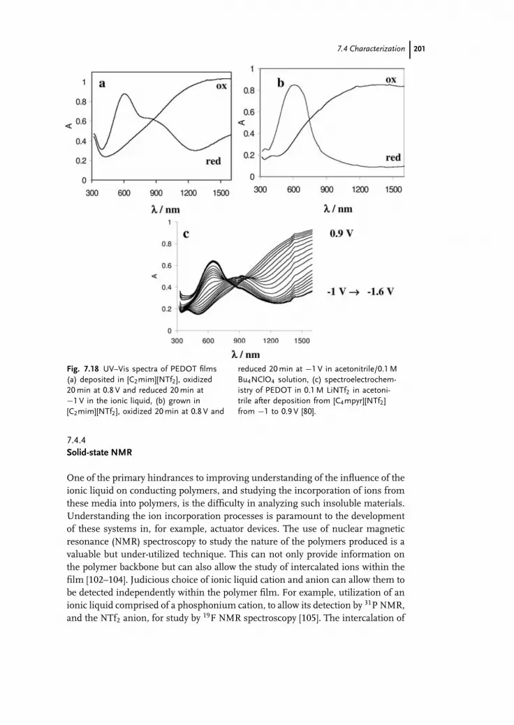
c07 (JWBG008-Endres) December 25, 2007 13:32 Char Count=
7.4 Characterization 201
Fig. 7.18 UV–Vis spectra of PEDOT films(a) deposited in [C2mim][NTf2], oxidized20 min at 0.8 V and reduced 20 min at−1 V in the ionic liquid, (b) grown in[C2mim][NTf2], oxidized 20 min at 0.8 V and
reduced 20 min at −1 V in acetonitrile/0.1 MBu4NClO4 solution, (c) spectroelectrochem-istry of PEDOT in 0.1 M LiNTf2 in acetoni-trile after deposition from [C4mpyr][NTf2]from −1 to 0.9 V [80].
7.4.4Solid-state NMR
One of the primary hindrances to improving understanding of the influence of theionic liquid on conducting polymers, and studying the incorporation of ions fromthese media into polymers, is the difficulty in analyzing such insoluble materials.Understanding the ion incorporation processes is paramount to the developmentof these systems in, for example, actuator devices. The use of nuclear magneticresonance (NMR) spectroscopy to study the nature of the polymers produced is avaluable but under-utilized technique. This can not only provide information onthe polymer backbone but can also allow the study of intercalated ions within thefilm [102–104]. Judicious choice of ionic liquid cation and anion can allow them tobe detected independently within the polymer film. For example, utilization of anionic liquid comprised of a phosphonium cation, to allow its detection by 31P NMR,and the NTf2 anion, for study by 19F NMR spectroscopy [105]. The intercalation of

c07 (JWBG008-Endres) December 25, 2007 13:32 Char Count=
202 7 Conducting Polymers
the bulky phosphonium cation is potentially of interest for use in actuator devices.In addition, the polymer backbone can be studied by 13C NMR [103, 104].
Poly(pyrrole) films grown by constant potential in the ionic liquid tri(hexyl)(tetradecyl) phosphonium bis(trifluoromethanesulfonyl)amide, [P6,6,6,14][NTf2], andsubsequently cycled 100 times and reduced in the monomer-free ionic liquid,showed the presence of both ionic liquid cations and anions within the film. In-terestingly, poly(pyrrole) films grown by constant potential in the ionic liquid butwith no subsequent electrochemical cycling also contained both ionic liquid cationand anion within the film (Figure 7.19).
The 31P NMR (Figure 7.19(a)) indicates incorporation of the phosphonium cationinto the film. The dominant signal appears at −12 ppm, with a minor peak at32 ppm. This latter peak is assigned to the phosphonium cation of residual ionicliquid on the surface of the film, which was not removed by washing but is notactually intercalated into the film. This shift is consistent with that reported byBradaric et al. [106] and with our own analysis of the neat ionic liquid. The largepeak at −12 ppm is assigned to phosphonium cations intercalated into the polypyr-role film, and this shift is consistent with a P–N interaction. The dramatic changein the chemical shift of the phosphorus compared to the neat ionic liquid indi-cates a significant change in environment on incorporation into the polymer film.
Fig. 7.19 (a) 31P (b) 19F and (c) 13C NMR spectra of polypyrrolegrown at constant potential in [P6,6,6,14][NTf2].

c07 (JWBG008-Endres) December 25, 2007 13:32 Char Count=
7.5 Future Directions 203
However, the DC conductivity of the pyrrole film was sufficiently high to indi-cate that the polymer chain was intact and this precludes the possibility of anychemical reaction between the cation and the polymer. The successful expulsionof cations from the film (see below) also eliminates this possibility. The 19F NMRspectrum (Figure 7.19(b)) shows the presence of intercalated anions within the film,as indicated by the peak at −82 ppm that is consistent with [NTf2]−. The 13C NMRspectrum of the film (Figure 7.19(c)) shows a broad resonance from the poly(pyrrole)centered at ca. 120 ppm, and also significant intensity between 0 and 30 ppm fromthe alkyl chains of phosphonium cations within the film [106].
NMR analysis of a poly(pyrrole) grown by constant potential from a 0.1 M so-lution of the [P6,6,6,14][NTf2] in acetonitrile also showed the presence of both theionic liquid cation and anion within the film. However, although the phosphoniumcations appear to be easily incorporated into the poly(pyrrole) during synthesis, ini-tial results suggest that they are not easily incorporated during cycling. Poly(pyrrole)films grown at constant potential from a 0.1 M solution of LiNTf2 in acetonitrileand then cycled 100 times in the neat [P6,6,6,14][NTf2] contained no detectable phos-phonium cations. This may be related to a lack of solvent swelling of the film in theionic liquid, which restricts ion movement.
This technique can also be used to investigate the ease of expulsion of anions fromthe polymer. It was initially thought that given the large size of the phosphoniumcations they would remain incorporated in the poly(pyrrole), as is observed for bulkyanions such as polyelectrolyte dopants, but films grown in the ionic liquid and thenoxidized overnight in the ionic liquid showed no detectable phosphonium cations.However, poly(pyrrole) oxidized for only 1 h still contained significant amounts ofphosphonium cations, thus it takes considerable time for the films to fully oxidizethrough incorporation of NTf2 anions and expulsion of the phosphonium cations(the current becomes negligible after about 5 h). However, poly(pyrrole) films grownin the ionic liquid then oxidized in a 0.1 M solution of LiNTf2 in acetonitrile for 4 hresulted in expulsion of all of the phosphonium cations from the film (the currentwas reduced to a background level in less than 1 h). This was attributed to the effectof solvent swelling of the polymer, which enables increased ion movement in andout of the film. This may also explain the observed lower electrochemical activity ofthe films in the ionic liquid compared with their activity when cycled in molecularsolvent systems. It is important to note, however, that the importance of solventswelling would be significantly reduced for thinner polymer films.
7.5Future Directions
7.5.1Chiral Ionic Liquids
There is significant interest in the formation of chiral conducting polymers, suchas chiral poly(aniline), as a result of their potential applications in chiral sensors,

c07 (JWBG008-Endres) December 25, 2007 13:32 Char Count=
204 7 Conducting Polymers
for chiral separations and so on. One route to these materials is by incorporatinga chiral dopant anion during the electrochemical polymerization [107]. Thus, ifthe polymer was synthesized in a chiral ionic liquid, of which there are a growingnumber [108], then formation of an optically active conducting polymer mightresult.
7.5.2Protic Ionic Liquids
One family of ionic liquids that has to date only been sparsely investigated foruse with conducting polymers is the protic ionic liquids, where the cation hasone or more mobile hydrogen atoms. A recent manuscript by Bicak detailed thesynthesis of 2-hydroxy ethylammonium formate [109], which melts at −82 ◦C andhas a room-temperature ionic conductivity of 3.3 mS cm−1, and reported the abilityof this protic ionic liquid to dissolve poly(aniline) (17 g mL−1) and poly(pyrrole) (noconcentration specified). The dissolution of conducting polymers into any solvent isof significant interest for a variety of reasons, such as improving their processabilityand ease of incorporation into different devices.
Li et al. [93] have used 1-ethylimidazolium trifluoroacetate, which is a Brønstedacidic ionic liquid, as a medium for the electropolymerization of aniline. Theyreport that in this ionic liquid the oxidation potential of aniline is lower (0.58 Vcompared to 0.83 V in 0.5 M H2SO4) and that the growth rate of the polymer is in-creased. Further, the resultant films are smooth, strongly adhered to the Pt workingelectrode and are very electrochemically stable. Similar results have been reportedby Liu et al. [92], who found that this was the best ionic liquid for the polymer-ization of aniline, compared to the unsatisfactory results observed in other proticionic liquids 1-butylimidazolium tetrafluoroborate, 1-butylimidazolium nitrate and1-butylimidazolium p-toluenesulfonate, as well as the 1-butyl-3-methylimidazoliumhydrogen sulfate and 1-butyl-3-methyimidazolium dihydrogen phosphate.
However, this family of ionic liquids holds an additional attraction, which is thepotential to create “distillable ionic liquids.” Earle et al. [110] have recently reportedthat a range of ionic liquids that are commonly perceived as nonvolatile, includingvarious imidazolium NTf2
− salts, can actually be distilled at low pressure and tem-peratures of 200–300 ◦C without significant decomposition. In such a process theionic liquids are transferred into the gas phase as ionic species. However, in thecase of protic ionic liquids, hydrogen transfer between the cation and anion canallow distillation of the neutral components and then subsequent recombinationto reform the ionic liquid as the distillate [111]. The primary amine reported byBicak [112], 2-hydroxy ethylammonium formate, decomposes on heating to give aformamide, but the combination of the formate anion with tertiary amine cationssuch as N-methylpyrrolidinium can give an ionic liquid that is distillable at modesttemperatures and pressures [111]. The use of distillable ionic liquids for the syn-thesis and use of conducting polymers may provide additional advantages in termsof easy removal of the ionic liquid and isolation of any oligomeric species fromthe growth solutions. Further, as this area of ionic liquid research is relatively new,

c07 (JWBG008-Endres) December 25, 2007 13:32 Char Count=
7.5 Future Directions 205
there is a considerable range of protic ionic liquids as yet undiscovered or still tobe investigated for their use for the growth and synthesis of different conductingpolymers, and the different acidities of these ionic liquids may be of particularlyinterest for the synthesis of poly(aniline).
7.5.3Nano-dimensional Polymers
The increasing interest in the use of conducting polymers [2] is fuelling a continuedneed for materials with improved physical and chemical properties. In particular,there is a recent drive towards nanostructured and reduced dimensionality mate-rials, such as thin films, nanotubes, wires, particles and so on, which can exhibitmarkedly different properties from those of the bulk materials [113, 114]. There isalready a small number of reports of the use of ionic liquids for the electrochem-ical synthesis of nanostructured conducting polymers and research in this area ispredicted to increase significantly in the coming years. Koo et al. [31] have reportedthe polymerization of pyrrole using a nanoporous aluminum oxide template in[C4mim][BF4], which yields poly(pyrrole) nanotubes and nanowires. Poly(aniline)nanotubules have been made by electrochemical polymerization onto an ITO glasselectrode from [C4mim][PF6] containing 1 M trifluoroacetic acid [115].
7.5.4Chemical Polymerization
The choice of synthetic route for the production of conducting polymers, eitherthrough electrochemical or chemical oxidation of the monomer or, in rare cases,photopolymerization or enzyme-catalysed polymerization, is primarily dictated bythe final application of the polymer. While electrochemical polymerization is widelyused for the controlled synthesis of polymer films, chemical polymerization resultsin the formation of powders or colloidal dispersions, is much more amenable toscale-up and can be used as a means to coat nonconducting substrates with conduct-ing polymers. Although outside the scope of this discussion, it is interesting to notethat despite the increased interest in the use of ionic liquids for the electrochemicalsynthesis of conducting polymers, there is a significant dearth of investigations intothe potential benefits of using ionic liquids for the synthesis of these materials viaalternative routes. The good electrochemical stability and solubilising properties ofionic liquids should allow access to a plethora of monomers and chemical oxidantsat significant concentrations, some of which are either insoluble in, or outsidethe electrochemical stability of, molecular solvents. Gao et al. [116] have reportedthe chemical synthesis of poly(aniline) at a water/ionic liquid interface, in which thepolymer grows into the water phase as nanoparticles, and Bicak et al. [109] havealso reported the use of their aforementioned protic ionic liquid, 2-hydroxyethylammonium formate, for the chemical synthesis of organo-soluble poly(aniline).An initial investigation into the use of [C2mim][NTf2] for the chemical synthesis ofpoly(pyrrole), poly(terthiophene) and nano-dimensional poly(thiophene) has also

c07 (JWBG008-Endres) December 25, 2007 13:32 Char Count=
206 7 Conducting Polymers
been reported [117]. However, the range of different monomers, oxidants and ionicliquids available, as well as different experimental techniques that may be em-ployed, for example with the ionic liquid as one phase or in a biphasic system incombination with a second solvent, suggests that this may be a particularly fruitfularea of future investigation for conducting polymer researchers.
7.5.5Remaining Challenges
The potential improvements that ionic liquids may impart to conducting polymershave been widely discussed – increased doping levels, smoother films, increasedconductivity, decreased over-oxidation and improved electrochemical stability andso on. However, the research to date in this area has only just begun to investigatethese hypotheses and demonstrate any material advantages in the use of ionicliquids; future directions in this area must focus on some of these issues in additionto simply demonstrating the use of new ionic liquids for conducting polymersynthesis.
The influence of the ionic liquid on the polymerization process itself is yet to beclarified. For example, does the ionic nature of these media stabilize the radicals/cations that are formed during the polymerization and, if so, how does this impacton the mechanism of polymer growth, the resultant chain length, conjugationlength and so on? The solubility of the oligomers that are formed during thepolymerization in the ionic liquid, and the extent to which they diffuse away fromthe electrode (which may be less in viscous ionic liquids) influences the length atwhich they precipitate onto the electrode. This will impact on polymer propertiessuch as conjugation length, morphology, conductivity and so on, and thereforewarrants some investigation. The solubility of the oligomers formed during thepolymerization is also of interest not just from a mechanistic point of view butbecause the solubilization of conducting polymers, even if they are relatively shortchained, is desirable for a number of applications.
It would also be interesting to measure the degree of solvent swelling of thepolymer films in ionic liquids compared to molecular solvents, as this will impactsignificantly on the ion mobility and thus the electrochemical activity of the poly-mer. It is expected that this will be lower in ionic liquids compared to molecularsolvents – although the extent of this difference may also depend on the thicknessof the film – but this is yet to be quantified.
The extent of the ionic liquid cation and anion intercalation into the film duringgrowth and cycling, and the structural features of the ions that influence this,requires more investigation. It has been postulated that the higher ion concentrationof ionic liquids compared to a traditional electrolyte/molecular solvent systemwill result in a higher polymer doping level, but this has not been extensivelydemonstrated. Anion and cation intercalation not only influences the properties ofthe polymer but is also important for understanding and developing conductingpolymer–ionic liquid actuator devices.
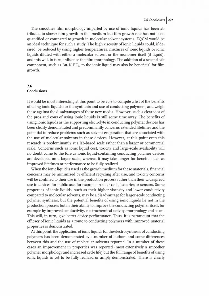
c07 (JWBG008-Endres) December 25, 2007 13:32 Char Count=
7.6 Conclusions 207
The smoother film morphology imparted by use of ionic liquids has been at-tributed to slower film growth in this medium but film growth rate has not beenquantified or compared to growth in molecular solvent systems. EQCM would bean ideal technique for such a study. The high viscosity of ionic liquids could, if de-sired, be reduced by using higher temperatures, mixtures of ionic liquids or ionicliquids diluted with either a molecular solvent or the monomer itself (if liquid),and this will, in turn, influence the film morphology. The addition of a second saltcomponent, such as Bu4N PF6, to the ionic liquid may also be beneficial for filmgrowth.
7.6Conclusions
It would be most interesting at this point to be able to compile a list of the benefitsof using ionic liquids for the synthesis and use of conducting polymers, and weighthese against the disadvantages of these new media. However, such a clear idea ofthe pros and cons of using ionic liquids is still some time away. The benefits ofusing ionic liquids as the supporting electrolyte in conducting polymer devices hasbeen clearly demonstrated and predominantly concerns extended lifetimes and thepotential to reduce problems such as solvent evaporation that are associated withthe use of molecular solvents in these devices. However, at this point even thisresearch is predominantly at a lab-based scale rather than a larger or commercialscale. Concerns such as ionic liquid cost, toxicity and large-scale availability willno doubt come to the fore as ionic liquid-containing conducting polymer devicesare developed on a larger scale, whereas it may take longer for benefits such asimproved lifetimes or performance to be fully realized.
When the ionic liquid is used as the growth medium for these materials, financialconcerns may be minimized by efficient recycling after use, and toxicity concernswill be confined to their use in the production process rather than their widespreaduse in devices for public use, for example in solar cells, batteries or sensors. Someproperties of ionic liquids, such as their higher viscosity and lower conductivitycompared to molecular solvents, may be a disadvantage for larger-scale conductingpolymer synthesis, but the potential benefits of using ionic liquids lie not in theproduction process but in their ability to improve the conducting polymer itself, forexample by improved conductivity, electrochemical activity, morphology and so on.This will, in turn, give better device performance. Thus, it is paramount that theefficacy of ionic liquids as a route to conducting polymers with improved materialproperties is demonstrated.
At this point, the application of ionic liquids for the electrosynthesis of conductingpolymers has been demonstrated by a number of authors and some differencesbetween this and the use of molecular solvents reported. In a number of thesecases an improvement in properties was reported (most extensively a smootherpolymer morphology and increased cycle life) but the full range of benefits of usingionic liquids is yet to be fully realized or amply demonstrated. There is clearly

c07 (JWBG008-Endres) December 25, 2007 13:32 Char Count=
208 7 Conducting Polymers
massive scope for future investigation, utilizing the vast range of ionic liquidspresently available either commercially or through reported synthetic routes. Thus,while the field of ionic liquids is immense, their potential use for the synthesis ofthe different types of conducting polymers is even more extensive. A number ofcommon ionic liquid anions have already been proven to be beneficial dopants forconducting polymers but there are also an extensive number that are still to be testedand maybe one of these new ionic liquids will prove to be the key to synthesizingconducting polymers with all of the physical and electrochemical properties thatwe desire.
References
1 Sandman, D.J. (1998) Handbook ofConducting Polymers, Mol. Cryst. Liq.Cryst. Sci. Technol, Section A: Mol. Cryst.Liq. Cryst., 325, 260.
2 Chandrasekhar, Prasanna (1999)Conducting Polymers, Fundamentals andApplications : a Practical Approach,Kluwer Academic, Boston, London.
3 Sonmez, G. (2005) Chem. Commun.,5251.
4 Wallace, G.G., Spinks, G.M.,Kane-Maguire, L.A.P., and Teasdale,P.R. (2003) Conductive ElectroactivePolymers: Intelligent Materials Systems,2nd edn, CRC Press, Boca Raton, FL.
5 Wallace, G.G. and Kane-Maguire, L.A.P.(2002) Adv. Mater., 14, 953.
6 Shirakawa, H., Louis, E.J., MacDiarmid,A.G., Chiang, C.K., and Heeger, A.J.(1977) J. Chem. Soc., Chem. Commun.,578.
7 Chiang, C.K., Druy, M.A., Gau, S.C.,Heeger, A.J., Louis, E.J., MacDiarmid,A.G., Park, Y.W., and Shirakawa, H.(1978) J. Am. Chem. Soc., 100, 1013.
8 Cho, M.S., Seo, H.J., Nam, J.D., Choi,H.R., Koo, J.C., and Lee, Y. (2006) Proc.SPIE-Int. Soc. Opt. Eng., 6168,61682E–61682E/7.
9 Ding, J., Zhou, D., Spinks, G., Wallace,G., Forsyth, S., Forsyth, M., andMacFarlane, D. (2003) Chem. Mater., 15,2392.
10 Lu, W., Norris, I.D., and Mattes, B.R.(2005) Aust. J. Chem., 58, 263.
11 Lu, W. and Mattes, B.R. (2005) Synth.Met., 152, 53.
12 Lu, W., Fadeev, A.G., Qi, B., Smela, E.,Mattes, B.R., Ding, J., Spinks, G.M.,
Mazurkiewicz, J., Zhou, D., Wallace,G.G., MacFarlane, D.R., Forsyth, S.A.,and Forsyth, M. (2002) Science, 297,983.
13 Zhou, D., Spinks, G.M., Wallace, G.G.,Tiyapiboonchaiya, C., MacFarlane, D.R.,Forsyth, M., and Sun, J. (2003)Electrochim. Acta, 48, 2355.
14 Vidal, F., Plesse, C., Randriamahazaka,H., Teyssie, D., and Chevrot, C. (2006)Mol. Cryst. Liq. Cryst., 448, 697.
15 Vidal, F., Plesse, C., Teyssie, D., andChevrot, C. (2004) Synth. Met., 142, 287.
16 Akle, B.J., Bennett, M.D., and Leo, D.J.(2006) Sens. Actuators, A, 126, 173.
17 Fukushima, T., Asaka, K., Kosaka, A.,and Aida, T. (2005) Angew. Chem., Int.Ed., 44, 2410.
18 Stenger-Smith, J.D., Webber, C.K.,Anderson, N., Chafin, A.P., Zong, K.,and Reynolds, J.R. (2002) J. Electrochem.Soc., 149, A973–A977.
19 Balducci, A., Soavi, F., andMastragostino, M. (2006) Appl. Phys. A,82, 627.
20 Balducci, A., Bardi, U., Caporali, S.,Mastragostino, M., and Soavi, F. (2004)Electrochem. Commun., 6, 566.
21 Lu, W., Fadeev, A.G., Qi, B., and Mattes,B.R. (2004) J. Electrochem. Soc., 151,H33–H39.
22 Yang, C., Sun, Q., Qiao, J., and Li, Y.(2003) J. Phys. Chem. B, 107, 12981.
23 John, R. and Wallace, G.G. (1991) J.Electroanal. Chem. InterfacialElectrochem., 306, 157.
24 Ogasawara, M., Funahashi, K., andIwata, K. (1985) Mol. Cryst. Liq. Cryst.,118, 159.

c07 (JWBG008-Endres) December 25, 2007 13:32 Char Count=
References 209
25 Danielsson, P., Bobacka, J., and Ivaska,A. (2004) J. Solid State Electrochem., 8,809.
26 Naudin, E., Ho, H.A., Branchaud, S.,Breau, L., and Belanger, D. (2002) J.Phys. Chem. B, 106, 10585.
27 Pringle, J.M., Forsyth, M., MacFarlane,D.R., Wagner, K., Hall, S.B., and Officer,D.L. (2005) Polymer, 46, 2047.
28 Snook, G.A., Best, A.S., Pandolfo, A.G.,and Hollenkamp, A.F. (2006)Electrochem. Commun., 8, 1405.
29 Fenelon, A.M. and Breslin, C.B. (2005) J.Electrochem. Soc., 152, D6–D11.
30 Yoon, C.O., Sung, H.K., Kim, J.H.,Barsoukov, E., Kim, J.H., and Lee, H.(1999) Synth. Met., 99, 201.
31 Koo, Y.K., Kim, B.H., Park, D.H., andJoo, J. (2004) Mol. Cryst. Liq. Cryst., 425,55.
32 Mazurkiewicz, J.H., Innis, P.C., Wallace,G.G., MacFarlane, D.R., and Forsyth, M.(2003) Synth. Met., 135–136, 31.
33 Mermilliod, N., and Tanguy, J. (1986) J.Electrochem. Soc., 133, 1073.
34 Huddleston, J.G., Visser, A.E., Reichert,W.M., Willauer, H.D., Broker, G.A.,and Rogers, R.D. (2001) Green Chem., 3,156.
35 Seddon, K.R., Stark, A., and Torres, M.-J.(2000) Pure Appl. Chem., 72, 2275.
36 Jacquemin, J., Husson, P., Padua,A.A.H., and Majer, V. (2006) GreenChem., 8, 172.
37 Favre, C., Abello, L., and Delabouglise,D. (1997) Adv. Mater., 9, 722.
38 Nogami, Y., Pouget, J.-P., and Ishiguro,T. (1994) Synth. Met., 62, 257.
39 Lee, K., Miller, E.K., Aleshin, A.L.,Menon, R., Heeger, A.J., Kim, J.H.,Yoon, C.O., and Lee, H. (1998) Adv.Mater., 10, 456.
40 Kiani, M.S. and Mitchell, G.R. (1992)Synth. Met., 48, 203.
41 Zhao, H., Price, W.E., and Wallace, G.G.(1994) J. Membrane Sci., 87, 47.
42 Garcia, B. and Belanger, D. (1998) Synth.Met., 98, 135.
43 Villareal, I., Morales, E., Otero, T.F.,and Acosta, J.L. (2000) Synth. Met., 108,57.
44 Ye, F., Noftle, R.E., and DesMarteau,D.D. (1993) Synth. Met., 60, 141.
45 Ciprelli, J.-L., Clarisse, C., andDelabouglise, D. (1995) Synth. Met., 74,217.
46 Sekiguchi, K., Atobe, M., andFuchigami, T. (2002) Electrochem.Commun., 4, 881.
47 Zawodzinski, T.A. Jr. and Osteryoung,R.A. (1988) Inorg. Chem., 27, 4383.
48 Pickup, P.G. and Osteryoung, R.A.(1984) J. Am. Chem. Soc., 106, 2294.
49 Pickup, P.G. and Osteryoung, R.A.(1985) J. Electroanal. Chem. InterfacialElectrochem., 195, 271.
50 Zawodzinski, T.A. Jr., Janiszewska, L.,and Osteryoung, R.A. (1988) J.Electroanal. Chem. InterfacialElectrochem., 255, 111.
51 Pringle, J.M., Efthimiadis, J., Howlett,P.C., Efthimiadis, J., MacFarlane, D.R.,Chaplin, A.B., Hall, S.B., Officer, D.L.,Wallace, G.G., and Forsyth, M. (2004)Polymer, 45, 1447.
52 Geetha, S. and Trivedi, D.C. (2004)Mater. Chem. Phys., 88, 388.
53 Geetha, S. and Trivedi, D.C. (2005)Synth. Met., 148, 187.
54 Trivedi, D.C. (1989) J. Chem. Soc., Chem.Commun., 544.
55 Koch, V.R., Miller, L.L., and Osteryoung,R.A. (1976) J. Am. Chem. Soc., 98, 5277.
56 Goldenberg, L.M. and Osteryoung, R.A.(1994) Synth. Met., 64, 63.
57 Kobryanskii, V.M. and Arnautov, S.A.(1992) Makromol. Chem., 193, 455.
58 Goldenberg, L.M., Pelekh, A.E.,Krinichnyi, V.I., Roshchupkina, O.S.,Zueva, A.F., Lyubovskaya, R.N., andEfimov, O.N. (1990) Synth. Met., 36, 217.
59 Lere-Porte, J.P., Radi, M., Chorro, C.,Petrissans, J., Sauvajol, J.L., Gonbeau,D., Pfister-Guillouzo, G., Louarn, G., andLefrant, S. (1993) Synth. Met., 59, 141.
60 Janiszewska, L. and Osteryoung, R.A.(1987) J. Electrochem. Soc., 134, 2787.
61 Janiszewska, L. and Osteryoung, R.A.(1988) J. Electrochem. Soc., 135, 116.
62 Tang, J. and Osteryoung, R.A. (1991)Synth. Met., 45, 1.
63 Tang, J. and Osteryoung, R.A. (1991)Synth. Met., 44, 307.
64 Randriamahazaka, H., Plesse, C.,Teyssie, D., and Chevrot, C. (2004)Electrochem. Commun., 6, 299.

c07 (JWBG008-Endres) December 25, 2007 13:32 Char Count=
210 7 Conducting Polymers
65 Sekiguchi, K., Atobe, M., andFuchigami, T. (2003) J. Electroanal.Chem., 557, 1.
66 MacFarlane, D.R., Meakin, P., Sun, J.,Amini, N., and Forsyth, M. (1999) J.Phys. Chem. B, 103, 4164.
67 Bonhote, P., Dias, A.-P., Papageorgiou,N., Kalyanasundaram, K., and Graetzel,M. (1996) Inorg. Chem., 35, 1168.
68 Boxall, D.L. and Osteryoung, R.A. (2004)J. Electrochem. Soc., 151, E41–E45.
69 Pringle, J.M., Forsyth, M., Wallace, G.G.,and MacFarlane, D.R. (2006)Macromolecules, 39, 7193.
70 Shi, W., Ge, D., Wang, J., Jiang, Z., Ren,L., and Zhang, Q. (2006) Macromol.Rapid Commun., 27, 926.
71 Marque, P. and Roncali, J. (1990) J. Phys.Chem., 94, 8614.
72 Krische, B. and Zagorska, M. (1989)Synth. Met., 28, C263–C268.
73 Roncali, J. (1992) Chem. Rev., 92, 711.74 Roncali, J., Garnier, F., Lemaire, M., and
Garreau, R. (1986) Synth. Met., 15, 323.75 Chen, J., Officer, D.L., Pringle, J.M.,
MacFarlane, D.R., Too, C.O., andWallace, G.G. (2005) Electrochem.Solid-State Lett., 8, A528–A530.
76 Murray, P.S., Ralph, S.F., Too, C.O., andWallace, G.G. (2006) Electrochim. Acta,51, 2471.
77 Lu, W., Fadeev, A.G., Qi, B., and Mattes,B.R. (2003) Synth. Met., 135–136, 139.
78 Randriamahazaka, H., Plesse, C.,Teyssie, D., and Chevrot, C. (2005)Electrochim. Acta, 50, 4222.
79 Randriamahazaka, H., Plesse, C.,Teyssie, D., and Chevrot, C. (2003)Electrochem. Commun., 5, 613.
80 Wagner, K., Pringle, J.M., Hall, S.B.,Forsyth, M., MacFarlane, D.R., andOfficer, D.L. (2005) Synth. Met., 153, 257.
81 Damlin, P., Kvarnstrom, C., and Ivaska,A. (2004) J. Electroanal. Chem., 570, 113.
82 Zein El Abedin, S., Borissenko, N., andEndres, F. (2004) Electrochem. Commun.,6, 422.
83 Schneider, O., Bund, A., Ispas, A.,Borissenko, N., El Abedin, S.Z., andEndres, F. (2005) J. Phys. Chem. B, 109,7159.
84 Zotti, G., Schiavon, G., and Zecchin, S.(1995) Synth. Met., 72, 275.
85 Wallace, G.G. and Innis, P.C. (2002) J.Nanosci. Nanotechnol., 2, 441.
86 Skompska, M. (1998) Electrochim. Acta,44, 357.
87 Chen, X. and Inganaes, O. (1996) J. Phys.Chem., 100, 15202.
88 Zotti, G. and Schiavon, G. (1989) Synth.Met., 31, 347.
89 Domagala, W., Lapkowski, M.,Guillerez, S., and Bidan, G. (2003)Electrochim. Acta, 48, 2379.
90 Sato, M., Tanaka, S., and Kaeriyama, K.(1987) Makromol. Chem., 188, 1763.
91 Hillman, A.R., Efimov, I., andSkompska, M. (2002) Faraday Discuss.,121, 423.
92 Liu, B.-Y., Xu, D.-Q., and Xu, Z.-Y.(2005) Chin. J. Chem., 23, 803.
93 Li, M.C., Ma, C.A., Liu, B.Y., and Jin,Z.M. (2005) Electrochem. Commun., 7,209.
94 Li, F.B. and Albery, W.J. (1992)Langmuir, 8, 1645.
95 Schrebler, R., Grez, P., Cury, P., Veas,C., Merino, M., Gomez, H., Cordova, R.,and del Valle, M.A. (1997) J. Electroanal.Chem., 430, 77.
96 del del Valle, M.A., Ugalde, L., Diaz,F.R., Bodini, M.E., Bernede, J.C., andChaillou, A. (2003) Polym. Bull., 51, 55.
97 Ugalde, L., Bernede, J.C., Del Valle,M.A., Diaz, F.R., and Leray, P. (2002) J.Appl. Polym. Sci., 84, 1799.
98 Sezai Sarac, A., Evans, U., Serantoni, M.,Clohessy, J., and Cunnane, V.J. (2004)Surf. Coatings Technol., 182, 7.
99 Wagner, K., Pringle, J.M., Hall, S.B.,Forsyth, M., MacFarlane, D.R., andOfficer, D.L. (2005) Synth. Met., 153,257.
100 Furukawa, Y. (1996) J. Phys. Chem., 100,15644.
101 Groenendaal, L.B., Zotti, G., Aubert,P.-H., Waybright, S.M., and Reynolds,J.R. (2003) Adv. Mater., 15, 855.
102 Meng, H., Perepichka, D.F., Bendikov,M., Wudl, F., Pan, G.Z., Yu, W., Dong,W., and Brown, S. (2003) J. Am. Chem.Soc., 125, 15151.
103 Forsyth, M., Truong, Van Tan, andSmith, M.E. (1994) Polymer, 35, 1593.
104 Forsyth, M. and Smith, M.E. (1993)Synth. Met., 55, 714.

c07 (JWBG008-Endres) December 25, 2007 13:32 Char Count=
References 211
105 Pringle, J.M., MacFarlane, D.R., andForsyth, M. (2005) Synth. Met., 155, 684.
106 Bradaric, C.J., Downard, A., Kennedy,C., Robertson, A.J., and Zhou, Y. (2003)Green Chem., 5, 143.
107 Pornputtkul, Y., Kane-Maguire, L.A.P.,and Wallace, G.G. (2006)Macromolecules, 39, 5604.
108 Baudequin, C., Bregeon, D., Levillain, J.,Guillen, F., Plaquevent, J.-C., andGaumont, A.-C. (2005) Tetrahedron:Asym., 16, 3921.
109 Bicak, N., Senkal, B.F., and Sezer, E.(2005) Synth. Met., 155, 105.
110 Earle, M.J., Esperanca, J.M.S.S., Gilea,M.A., Canongia Lopes, J.N., Rebelo,L.P.N., Magee, J.W., Seddon, K.R., andWidegren, J.A. (2006) Nature, 439, 831.
111 MacFarlane, D.R., Pringle, J.M.,Johansson, K.M., Forsyth, S.A., and
Forsyth, M. (2006) Chem. Commun.,1905.
112 Bicak, N. (2004) J. Mol. Liq., 116, 15.113 Leclere, Ph., Surin, M., Viville, P.,
Lazzaroni, R., Kilbinger, A.F.M., Henze,O., Feast, W.J., Cavallini, M., Biscarini,F., Schenning, A.P.H.J., and Meijer,E.W. (2004) Chem. Mater., 16, 4452.
114 Aleshin, A.N. (2006) Adv. Mater., 18,17.
115 Wei, D., Kvarnstroem, C., Lindfors, T.,and Ivaska, A. (2006) Electrochem.Commun., 8, 1563.
116 Gao, H., Jiang, T., Han, B., Wang, Y.,Du, J., Liu, Z., and Zhang, J. (2004)Polymer, 45, 3017.
117 Pringle, J.M., Ngamna, O., Chen, J.,Wallace, G.G., Forsyth, M., andMacFarlane, D.R. (2006) Synth. Met.,156, 979.

c08 (JWBG008-Endres) January 11, 2008 9:13 Char Count=
213
8Nanostructured Metals and Alloys Deposited fromIonic LiquidsRolf Hempelmann, and Harald Natter
8.1Introduction
Nanomaterials are composed of structural entities – isotropic grains or particles,rods, wires, platelets, layers – of size, at least in one dimension, between 1 and100 nm [1–3]. Larger particles are called submicron particles, smaller ones areknown as clusters. Some physical properties of nanomaterials [4–6] differ fromthose of coarse-grained materials of the same chemical composition due to twoessential features:
1. Large specific surface area and concomitantly large specific surface energy; hencesurface sensitive properties (like catalytic activity) are enhanced [7–10] and pro-cesses where the surface energy is the driving force (sintering, grain growth) arefacilitated [11–13].
2. Quantum size effects; famous examples are the color shift upon size reduc-tion of semiconductor nanoparticles like CdSe [14–16], and the surface plasmonresonance of metallic nanoparticles like gold [17, 18].
The term nanomaterial includes materials consisting of or containing individ-ual nanoparticles, nanorods, nanowires or nanoplatelets (for instance as compos-ites), materials in the form of thin layers or coatings, and compact polycrystallinematerials with grain sizes below 100 nm; the latter contain an appreciable vol-ume fraction of interphase or grain boundary regions (analogously to the surfaceregion of nanoparticles) and correspondingly a large specific interphase energy,such that these bulk nanomaterials are said to be dominated by their interphases[19]. Magnetic and mechanical properties are examples of properties which, evenfor coarse-grained materials, depend on grain boundaries and other lattice defects,in spite of their tiny volume fraction [20–22]. In bulk nanomaterials, with theirlarge volume fraction of grain boundaries and, particularly with respect to theabove-mentioned properties, pronounced nanoeffects occur which is the reasonfor the academic and industrial interest in bulk nanostructured materials.
Electrodeposition from Ionic Liquids. Edited by F. Endres, D. MacFarlane, A. AbbottCopyright C© 2008 WILEY-VCH Verlag GmbH & Co. KGaA, WeinheimISBN: 978-3-527-31565-9

c08 (JWBG008-Endres) January 11, 2008 9:13 Char Count=
214 8 Nanostructured Metals and Alloys Deposited from Ionic Liquids
Often the starting point of the route to bulk nanomaterials is a powder of nanopar-ticles which can be prepared either “top-down” by milling or “bottom-up” by con-trolled chemical synthesis [23]. This powder has to be compacted/densified in orderto get bulk nanomaterial. An example of such a route is the famous inert gas con-densation (IGC) introduced by Gleiter and Birringer [24]: a metal, for instancePd, is evaporated under He gas, in the gas atmosphere condensation starts withthe formation of clusters and small nanoparticles; these are deposited on a coldfinger (77 K), scraped off, collected, and uniaxially cold-pressed into the form of atablet. Isostatic hot-pressing of metal oxide nanoparticles is a route to nanoceramics[25–28]. In all these routes the densification step is crucial. Efficient densification(sintering) involves diffusion processes and requires elevated temperatures. How-ever, at elevated temperatures grain growth takes place and after a short time thesample is no longer nanocrystalline. At lower temperatures the sample remainsnanocrystalline but the densification is incomplete; the resulting porosity is themain disadvantage of all routes to bulk nanomaterials which start from powders.
This critical compaction step is avoided in the case of the electrochemical route ofpulsed electrodeposition (PED) [29] which transforms cations, i.e. atomic species,directly into nanomaterials without the detour via nanoparticles. In this way den-sities up to 99% of the theoretical value can be achieved, such that these materialsexhibit, for instance, intrinsic mechanical properties and not those dominated byvoids.
Furthermore, this technique allows variation of the grain size [30–33]; this isimportant because many chemical and physical properties of nanostructured ma-terials depend on the grain size. Only by variation of the crystallite size – this is anovel aspect in materials science and technology [34] – is it possible to tune andhopefully improve certain physical properties of one and the same material: for ex-ample, the enhanced hardness of nano-Au, the toughness of nano-Ni/P alloys [35],the soft magnetic properties of nano-Ni [36] and the resistance of nanostructuredmaterials [37, 38] promise industrial applications [39–41].
The production of such “tailor-made” nanomaterials by electrochemical proce-dures is advantageous because the two crucial steps in nanocrystal formation –nucleation and growth of nuclei – can be controlled by physical (current, voltage,time, temperature) and chemical (grain refiners, complex formers) parametersduring the deposition process [42, 43].
In Section 8.2 the basics of pulsed electrodeposition (PED) will be describedfor the case of aqueous electrolytes which allow the deposition of comparativelynoble metals like Cu, Ni, Pd, or Au; less noble metals like Fe or Zn can still beelectrodeposited from aqueous electrolytes because they exhibit a comparativelylarge overpotential for hydrogen evolution. However, the main limitation of aque-ous electrolytes, of course, is their narrow electrochemical window which adverselyaffects the electrodeposition of metals like Al or Ta. Therefore, recently, the PEDtechnique has been extended to ionic liquids as electrolytes. General electrochem-ical aspects of ionic liquids can be found in Ref. [44]; here, in Section 8.3, we willonly address the technical aspects with respect to PED. Examples of nanometals andnanoalloys electrodeposited from chloroaluminate-based ionic liquids are given in

c08 (JWBG008-Endres) January 11, 2008 9:13 Char Count=
8.2 Pulsed Electrodeposition from Aqueous Electrolytes 215
Section 8.4. The main disadvantage of these electrolytes is their extreme sensitivityto moisture [45]; so-called ionic liquids of the third generation are water stable[46], and examples of electrodeposition from these water-stable ionic liquids arepresented in Section 8.5. Finally, a short summary and outlook for possible futuredevelopments is given in Section 8.6.
8.2Pulsed Electrodeposition from Aqueous Electrolytes
The pulsed electrodeposition technique (PED) is a versatile method for the prepa-ration of nanostructured metals and alloys [47]. In the last two decades PED hasreceived much attention worldwide because it allows the preparation of large bulksamples with high purity, low porosity and enhanced thermal stability.
8.2.1Fundamental Aspects
The electrochemical deposition of nanostructured metals and alloys is a two-stepprocess:
1. The formation of a large number of nuclei2. The controlled growth of the deposited nuclei.
These two conditions can be realized by the proper choice of the chemical andphysical process parameters. The size and the number of nuclei can be controlledby the overvoltage (η):
r = 2 σ V
z e0 |η| (8.1)
In this electrochemical version of the Kelvin equation [48] r is the critical nucleationradius, σ the specific surface energy, V the atomic volume in the crystal and z thenumber of elementary charges e0. The message of Eq. (8.1) is: the higher theovervoltage the smaller the formed nuclei. A large overvoltage brings about a largecurrent density and thus a large rate of formation of nuclei. So PED is a depositionprocess at large overpotential, a rare type of study in electrocrystallization because,in most cases, underpotential deposition is studied [49–54]. This high overpotentialand the concomitant high deposition rate, however, can be maintained only for afew milliseconds (ton-time) because the metal ion concentration in the vicinity ofthe cathode decreases drastically and the process threatens to become diffusion-controlled. In order to avoid this and avoid losing control over the process via Eq.(8.1), the current has to be switched off, one has to wait for 20–100 ms (toff-time) inorder that the metal ions can diffuse from the bulk electrolyte to the cathode and

c08 (JWBG008-Endres) January 11, 2008 9:13 Char Count=
216 8 Nanostructured Metals and Alloys Deposited from Ionic Liquids
compensate the metal ion depletion there. Then the next current and voltage pulseis applied, and so on: this is the reason for the pulsing.
In the electroless break between two pulses exchange currents flow, an undesiredelectrochemical phenomenon because it induces the so-called Ostwald ripening[55]: the larger crystallites (with the lower surface energy) grow at the expense of thesmaller ones (with the higher surface energy), and the crystallite size distributionbroadens and shifts to larger size values, i.e., deteriorates. Another origin of Ostwaldripening could be surface diffusion of metal adatoms.
In view of this deposition mechanism several measures have to be taken tocontrol the crystallite size:
1. The voltage/current density in the peak has to be large; a reasonable value is1 A m−2 in the more common galvanostatic mode.
2. The ton-time has to be as short as is necessary to avoid the diffusion controlregime and as long as possible in order to reach sufficient deposition efficiency;a reasonable value is 3 ms.
3. The toff-time has to be as long as necessary for the material transport in theelectrolyte to take place, but not longer in order to minimize Ostwald ripeningand reach sufficient deposition efficiency.
4. The use of organic additives (grain refiners): they have to adsorb on the fresh nu-clei, with a Gibbs enthalpy of adsorption just sufficient to suppress the exchangecurrent in the toff-time but insufficient to impede the metal ion deposition in theton-time, i.e., in the next pulse. This enables one to control the crystallization pro-cess during the toff-time because these molecules are adsorbed reversibly on theelectrode surface and hinder the surface diffusion of the adatoms. For differentmetals different additives are most suited, but a typical and widespread exampleis thiourea. The use of additives is common practice in the galvanic industry, theselection of additive is a matter of experience, i.e., purely empirical [41].
5. Temperature influences all diffusion processes (cation diffusion in the elec-trolyte, surface diffusion of the adatoms). If small crystallite sizes are desired thedeposition should be performed at ambient temperatures or below in order toslow down the kinetics of recrystallisation of the nuclei.
The bath composition, the pH-value, the hydrodynamic conditions and also theuse of special current pulse shapes are further possibilities to influence the de-position process. It is advantageous to perform the pulsed electrodeposition inthe galvanostatic mode because the average deposition rate can be simply derivedfrom
Iav = Ipulseton
ton + toff(8.2)
In addition, there is better control of the current efficiency and the alloy composi-tion. The potentiostatic mode would be, on the basis of Eq. (8.1), more desirablebut is experimentally more difficult to realize because a three-electrode set-up is

c08 (JWBG008-Endres) January 11, 2008 9:13 Char Count=
8.2 Pulsed Electrodeposition from Aqueous Electrolytes 217
necessary and, upon the voltage jump, the current should start theoretically froman infinite value, which is not feasible due to electronic limitations. Also, in thepotentiostatic mode a short reverse pulse would be necessary to fix the initial po-tential, which is not generally desirable because passivation may occur during thisreverse potential pulse. Suitable substrates for the electrodeposition are stainlesssteel or titanium electrodes (20 × 20 mm, distance between the electrodes 25 mm);because of the poor adhesion the resulting deposits can be removed mechanicallyfrom the electrode.
Tuning the grain size must be accompanied by measuring the grain size. Themost convenient method is the line width or line shape analysis of X-ray diffrac-tion peaks according to Scherrer [56] (estimate of the grain size), or according tothe Williamson and Hall procedure [57] which allows one to separate grain sizeand microstrain effects on the line width. Fourier transform techniques like theWarren–Averbach technique [58–60] or certain full profile fit routines [61] evenallow determination of the crystallite size distribution. Details can be found inRef. [62].
8.2.2Nanometal Deposition with Nano-Gold as an Example
For n-gold, deposited from a commercial gold(I)sulfite bath, the influence of thedeposition parameters on the nanostructure has been demonstrated [63]. For abetter comparison of the different results the experiments were performed at anaverage current density (Iav) of 3 mA cm−2, see Eq. (8.2). If ton and toff are kept atconstant values (for details see Figure 8.1), the smallest crystallite size of 12 nmis found for Ipulse = 0.5 A cm−2 (see Figure 8.1); for higher current values powder
Fig. 8.1 The crystallite size dependence of the pulsed current densityfor gold deposits deposited from a commercial sulfite bath withoutany additives [29].

c08 (JWBG008-Endres) January 11, 2008 9:13 Char Count=
218 8 Nanostructured Metals and Alloys Deposited from Ionic Liquids
Fig. 8.2 The effect of the toff time on the nanostructure of gold de-posits. An average current density of 3 mA cm−2 was used for all ex-periments [29].
formation on the electrode surface is observed. The effect of the toff-time on thenanostructure of the deposits is shown in Figure 8.2. As expected the smallestcrystallites can be found for the shortest toff-times, in accordance with the depo-sition mechanism outlined above (recrystallization process of the nuclei duringthe toff time). To study the effects of organic additives on the nanostructure of thedeposit, butanediamine (a molecule with free amino groups), diammonium-EDTA(a chelating complex former) and saccharin (a molecule with a sulfur group) werecompared. The electrolytes free of additives yield crystallite sizes in the range of100 nm. With very small amounts of additives a strong reduction (by a factor ofabout 2) in the crystallite size is observed, see Figure 8.3. Increasing the concen-tration of the grain refiners does not cause a substantial further decrease in thecrystallite size. The three additives show the same effect, but the degree of grainrefining is substance-specific: as is well known, gold reacts strongly with sulfurgroups. Similar results were obtained for the system nano-copper/citric acid [64],nano-nickel/saccharin [61, 65] and nano-Pd/Na2EDTA [42]. A detailed descriptionof the influence of organic additives on the microstructure of metal deposits is givenby Fischer [66]. Further nanometals with crystallite sizes between 10 and 100 nmprepared by pulsed electrodeposition from aqueous electrolytes are: Pd [42, 67],Fe [61], Co [68], and Cr [69]. Detailed information on the preparation and physicalproperties are given in the cited references.
8.2.3Nanoalloy Deposition with FexNi1–x Alloys as an Example
The deposition of FexNi1−x alloys is of industrial interest because these materialsfind applications in electronic devices (e.g. computes hard disk). The most popular

c08 (JWBG008-Endres) January 11, 2008 9:13 Char Count=
8.2 Pulsed Electrodeposition from Aqueous Electrolytes 219
Fig. 8.3 The activity of different grain refiners (butanediamine, am-monium ethylenediamine tetra-acetic acid, benzosulfimide) on thenanostructure of gold deposits [29].
alloys are Permalloy (soft magnetic properties) and Invar (very low thermal expan-sion). The polycrystalline compounds can be prepared by melting processes or bydirect current plating [70]. The magnetic and mechanical properties of these alloyscan be designed by nanostructuring. In the case of alloy deposition the bath com-position is an additional process parameter which can influence the nanostructureof the deposit. An electrochemical DC current procedure was reported by Cheunget al. [71]. One condition for preparing homogeneous alloys by electrochemicalmethods is nearly equal electrode potentials of the components. Fe and Ni exhibitstandard reduction potentials of −0.44 and −0.22 V; in view of these similar valuesalloy formation can be expected. Ni exhibits a more positive standard reductionpotential than iron and therefore the Ni/Fe ratio in the deposited alloys should behigher than in the electrolyte. Actually, the literature reports opposite experimentalresults [70]. This anomalous codeposition (ACD) was also observed for CoFe, ZnNi,ZnFe and CuPb. Since the composition of the alloy depends strongly on the pHvalue [72] the electrolyte has to contain a buffer system. For different concentrationsof iron salts (Figure 8.4) alloys (crystallite size: 16–19 nm) with iron contents up to71 mol% have been obtained. Hessami et al. [73] explain the ACD by an increaseddissociation rate of the FeOH+ complex compared to that of the NiOH+ complex.For this reason the concentration of free iron ions in the electrolyte increases andtherefore the alloys exhibit an increased iron content. There is the risk (or chance)of preparing gradient materials in which the iron concentration increases withdeposition depth whereas laterally the deposited alloy is perfectly homogeneous.Varying the crystallite size by varying the pulse parameters or the temperature isimpossible because these factors also change the alloy composition (Figure 8.5).The best way to vary the crystallite size without changing the alloy composition isby the addition of different amounts of grain refiners.

c08 (JWBG008-Endres) January 11, 2008 9:13 Char Count=
220 8 Nanostructured Metals and Alloys Deposited from Ionic Liquids
Fig. 8.4 The influence of the Fe3+ concentration of the electrolyte onthe alloy composition [29].
8.3Special Features of Ionic Liquids as Electrolytes
The electrochemistry of ionic liquids is different in some essential features from theelectrochemistry of aqueous electrolytes. Particularly for electrodeposition, whichinvolves charge transfer from the electrolyte to the electrode, the double layer onthe electrode is of great importance. In general the cathode is negatively chargedfor the electrodeposition of metals and therefore coated with a (Helmholtz-) layer ofcations at least 0.5 nm thick; but the metal species in most ionic liquids is anionic(for instance AlCl4−). This makes the metal deposition process complicated, formore details we refer to Chapter 2.
Fig. 8.5 The influence of the temperature (left axis) and the pulsecurrent density (right axis) on the alloy composition of FeNialloys [29].

c08 (JWBG008-Endres) January 11, 2008 9:13 Char Count=
8.3 Special Features of Ionic Liquids as Electrolytes 221
In ionic liquids the coordination chemistry and concentration of metal complexesare also substantially different from those in aqueous electrolytes, with consequenteffects on both the thermodynamics, i.e., the redox potential, and the kinetics ofthe deposition process. For details we again refer to Chapter 2.
Since the viscosity of ionic liquids is large in some cases and concomitantly thediffusion is slow, ionic liquids generally exhibit a lower conductivity than aqueouselectrolytes. To improve the mass transport it has been suggested to add diluentslike benzene, toluene or acetonitrile. Water may also be a suitable diluent in somecases, acting as both a ligand and a viscosity improver.
Brighteners are common additives in the electroplating industry and are mostlybased on empirical recipes. A well-known inorganic example is arsenic acid. Hereonly the influence of organic compounds on the electrodeposition from ionic liquidsis discussed. The main effect of brighteners is adsorption on the electrode surfacethus impeding nucleation and influencing growth.
To determine the effectiveness of the brighteners Natter et al. [74] have examinedorganic molecules with different structures (see Table 8.1). The first group com-prises aromatic and aliphatic carboxylic acids with one or two carboxylic groups.The second group consists of aromatic carboxylic acids with chlorine substituentsin different positions (2-, 3- and 4-chlorobenzoic acid). The third group comprisescarboxylic acids with one or two hydroxy substituents and the last group are sub-stances with a sulfur-containing functional group (benzoic acid sulfimide, sodiumbutanesulfonate, sodium dodecyl sulfate). Aliphatic carboxylic acids and also theirhydroxy substituted derivatives (tartaric, malonic, malic and salicylic acids) showhardly any grain refining effect, maybe because these substances do not have freeelectron pairs which are important for adsorption at many metals. The aromaticsalicylic acid reduces the crystallite size down to 54 nm. For this reason the aromatic
Table 8.1 Effect of different additives on the crystallite size (electrolyte:63 mol% absolute dry AlCl3, 37 mol% [EMIM]Cl, DC: 5 mA cm−2, addi-tive concentration: 4 wt.%).
Additive D/nm
benzoic acid 193-chlorobenzoic acid 132-chlorobenzoic acid 184-chlorobenzoic acid 24benzoic acid sulfimide 12phthalic acid anhydride 16sodium dodecyl sulfate 21sodium butane sulfonate 132tartaric acid 99salicylic acid 54malonic acid 61malic acid 133

c08 (JWBG008-Endres) January 11, 2008 9:13 Char Count=
222 8 Nanostructured Metals and Alloys Deposited from Ionic Liquids
carboxylic acids seem to be the better grain refiners. The electronic interaction ofthe aromatic ring can be enhanced with halogen substituents. The use of benzoicacid chloroderivatives shows a strong crystallite refining effect which depends onthe position of the chlorine group. 3-Chlorobenzoic acid interacts strongly withthe metal surface and works as a good grain refiner. Saccharine (benzoic acid sul-fimide) has additional nitrogen and sulfur atoms which increase the surface activityand decrease the crystallite size. The same effect can be observed for long chainsulfonates and phthalic acid anhydride.
8.4Nanocrystalline Metals and Alloys from Chlorometallate-based Ionic Liquids
Chlorometallate-based ionic liquids are eutectic mixtures of an organic chloride,RCl, and a metal chloride MClx, mostly with M = Al or Zn; other possible butless commonly used metals are Sn, Ga, Fe, or Ge, i.e., chlorostannate, chloro-gallate, etc. Chloroborate (BCl4−) or bromoaluminate (AlBr4
−) systems are alsopossible. In chloroaluminate-based ionic liquids the AlIII exists in complexes likeAlCl4−, Al2Cl7− or Al3Cl10
−, in chlorozincate-based ionic liquids the ZnII exists incomplexes like ZnCl2−, Zn2Cl5− or Zn3 Cl7−, depending on the concentration.
The mole fraction of AlCl3 can be denoted as r = [AlCl3]/([AlCl3] + [RCl]).According to this ratio the chloroaluminate systems are categorized as follows:r > 0.5 called Lewis-acidic, r = 0.5 called Lewis-neutral and r < 0.5 called Lewis-basic melts. These systems have the serious drawback of being extremely sensitiveto humidity/water which causes hydrolysis and the formation of HCl: for thatreason extreme care has to be applied (controlled inert gas atmosphere with a watercontent below 1 ppm). However, under these demanding conditions, which mightbe too difficult in industrial applications, the chloroaluminate-based ionic liquidshave attractive electrochemical properties. They allow the electrodeposition not onlyof Al but also of a large number of other metals: salts or oxides of other metals canbe dissolved in chloroaluminate systems, and then the result is dependent on theratio r mentioned above (and of course on the potential): from Lewis-acidic systems,with r > 0.5, Al alloys are deposited, and from Lewis-basic systems, with r<0.5, theother metal can be deposited in a pure form. This flexibility of chlororaluminatesystems occurs because the potential determining electrochemical reaction changeswith the composition, therefore the molar ratio r is an important parameter for theexperimentalist.
Nanostructured aluminum [74–78], iron [74] and aluminum–manganese alloys[74] have been prepared from a Lewis acid AlCl3/[BMIM]Cl mixture (65 mol% AlCl3,35 mol% [BMIM]Cl) whereas palladium alloys have been deposited from a Lewisbasic system (45 mol% AlCl3, 55 mol% [BMIM]Cl). The electrochemical cell and allparts which are in contact with the electrolyte have to be built from inert materials.As cathode material glassy carbon can be used. A constant ion concentration inthe electrolyte can be realized by the use of a sacrificial anode consisting of the

c08 (JWBG008-Endres) January 11, 2008 9:13 Char Count=
8.4 Nanocrystalline Metals and Alloys from Chlorometallate-based Ionic Liquids 223
Table 8.2 The influence of different process parameters on the nano-structure of aluminum deposits. In the case of additive addition ben-zoic acid was used.
Sample Iaverage/mA cm−2 Ipeak/mA cm−2 ton/ms toff/ms additive/g L−1 D/nm
6.67 — ∞ 0 0 1212 10 — ∞ 0 0 983 54 — ∞ 0 0 844 11.9 310 2 50 0 1405 21.2 550 2 50 0 1296 60.1 1570 2 50 0 1227 4.2 — ∞ 0 2.5 208 60.1 1570 2 50 2.5 7
same material to be deposited on the cathode. In this way the electrolysis can runfor several days without a break. Grain refining additives like carboxylic acids havebeen used for crystallite size reduction because these organic substances exhibitvery good solubility in the ionic liquid. The temperature of the bath should be keptconstant at 40 ◦C to enhance the conductivity of the electrolyte. Temperatures above60 ◦C lead to crystallite growth during the deposition and have to be avoided.
The crystallite sizes of aluminum samples prepared with different process param-eters [74] are summarized in Table 8.2. The electrolyte consisted of 5.0 g [EMIM]Cland 8.8 g absolutely dry AlCl3. In the case of additive addition carboxylic acids, espe-cially benzoic acid or nicotinic acid, were used. According to Eq. (8.1) the crystallitesize should decrease with increasing overpotential. This behavior can be observedfor samples 1–3. The use of 54 mA cm−2 decreases the crystallite size to 84 nm.A further increase in the current causes decomposition of the electrolyte. For thisreason a pulsed current with high peak currents for a short time (ton) and properbreaks (toff) can be used. Samples 4–6 were prepared with different peak currents atconstant pulse times. It can be observed that with increasing peak current densitythe crystallite size decreases. This behavior can be explained by Ostwald ripening,which sets in during the toff-time, and can be impeded by the use of organic ad-ditives which interact with the active growth sites by adsorption [48, 79] and thusact as grain refiners. The freshly deposited adatoms are forced to form new nuclei,resulting in the formation of a nanostructure. Sample 7 confirms this behavior. Theaddition of just a small amount (2.5 g L−1) of benzoic acid reduces the crystallitesize to 20 nm. The additional use of pulsed current causes a further reduction inthe crystallite size.
From Table 8.2 it can be seen that sample 3 has a smaller crystallite size thansample 6 although sample 3 was prepared with a lower average current density.We consider the average current densities because sample 3 was prepared by DCplating whereas sample 6 was prepared by PED plating. The larger crystallites in thecase of PED plating can also be explained by Ostwald ripening during the toff-time

c08 (JWBG008-Endres) January 11, 2008 9:13 Char Count=
224 8 Nanostructured Metals and Alloys Deposited from Ionic Liquids
Fig. 8.6 The influence of the benzoic acid concentration on the crys-tallite size of aluminum deposits [74].
whereas in the case of DC deposition a continuous deposition and growth of nucleitakes place.
As mentioned above the organic additives block the active growth sites. In thiscase the crystallite size should be a function of the additive concentration [80,81]. Therefore the aluminum deposition from an AlCl3/[BMIM]Cl bath has beenrepeated with increasing benzoic acid amounts (see Figure 8.6). Only a smallconcentration of this additive reduces the crystallite size to 40 nm, and a furtheraddition does not lead to any substantial further reduction in the crystallite size.The limit is at about 1.5 wt.%. The addition of more benzoic acid shows no furthereffect because all active sites are blocked by the additive molecules. Even an extremesurplus of additive does not change the nanostructure [64].
Additive adsorption is evident from the results of cyclic voltammetry. Figure 8.7shows the cyclic voltammogram of a Lewis acid electrolyte consisting of[BMIM]Cl/AlCl3 electrolyte (66.7 mol% AlCl3) with and without additives. Theelectrochemical window is about 2.3 V limited by the cathodic bulk deposition ofaluminum (peak 3) and the decomposition of the electrolyte at 1.9 V (vs. Al/Al3+).Two additional peaks at −0.17 and +0.4 V (1 and 2) can be observed resultingfrom underpotential deposition [82, 83]. During the inverse run the formationof gold alloys (Al2Au5, AlAu2) [84] takes place at +0.33 and +0.37 V (Figure 8.7,inset).
With increasing amounts of benzoic acid (0 to 0.38 wt.%) we observe a decreasingpeak current for the aluminum deposition (see Figure 8.7), the aluminum oxidationpeak disappears and the underpotential deposition (UPD) of aluminum is alsostrongly diminished. These experiments lead to the conclusion that the additivemolecules block the active growth sites and therefore the peak current of aluminumdeposition increases with decreasing additive concentration. A further consequence

c08 (JWBG008-Endres) January 11, 2008 9:13 Char Count=
8.4 Nanocrystalline Metals and Alloys from Chlorometallate-based Ionic Liquids 225
Fig. 8.7 Cyclic voltammograms for aluminum deposition with increas-ing amounts of additive (benzoic acid) [74].
of this behavior is the irreversibility of the process (no aluminum oxidation) andthe strongly reduced UPD process.
The effect of temperature on the nanostructure of the deposits in the presenceof additives has been examined using an electrolyte with 3.5 wt.% benzoic acid.The experimental details of the deposition are given in Figure 8.8. The crystallitesize increases from 23 to 72 nm between 40 and 63◦C. This indicates a strong
Fig. 8.8 Temperature dependence of the crystallite size for Al samplesprepared from additive containing electrolyte [74].

c08 (JWBG008-Endres) January 11, 2008 9:13 Char Count=
226 8 Nanostructured Metals and Alloys Deposited from Ionic Liquids
Table 8.3 Saturation magnetization, relative remanence and coercivityfor different crystallite sizes of nanostructured iron.
D/nm Ms/kA m−1 Relative remanence MR/MS HC / kA m−1
40 1235 0.010 151.257 1372 0.121 135.362 1230 0.094 111.472 1235 0.089 103.579 1377 0.060 79.682 1179 0.074 87.5
114 1283 0.067 45.3159 1656 0.015 31.9
temperature dependence of the interaction between metal surface and additive;furthermore, Ostwald ripening is enhanced with increasing temperature since it isbased on surface diffusion of adatoms and additives which is strongly temperaturedependent.
Nanostructured iron was deposited from an electrolyte consisting of 5.0 g[BMIM]Cl, 8.8 g absolute dry AlCl3 and 0.5 g anhydrous FeCl3. Benzoic acid (40g L−1) was used as grain refiner. The crystallite size of the deposits (Table 8.3) canbe adjusted by the variation of the DC-current density (0.05–10 mA cm−2). Magne-tization measurements reveal a saturation magnetization essentially independentof D, an increase of the coercivity field Hc proportional to D−1, and a remanencewith a maximum where the grain size equals the magnetic exchange length.
Alloys like AlxMn1–x or AlxIn1–x are very difficult to prepare in nanostruc-tured form because the substantial difference in physical properties of both met-als (melting point, hardness) does not allow the use of ball milling methods,chemical processes or inert gas condensation procedures. The preparation ofthese alloys can, however, be realized with the electrodeposition technique, us-ing an AlCl3/[BMIM]Cl (53:47 wt.%) mixture with addition of the correspondingmetal salts (5.5 wt.% InCl3 or MnCl2). The alloys were deposited with Iaverage=10 mA cm−2 at 50 ◦C. In both cases nanostructured alloys with a crystallite size of25 nm were obtained (Figure 8.9). The alloy composition can be controlled by thecomposition of the bath [85–87]. A surplus of aluminum in the ionic liquid alsoincreases the aluminum content in the alloy. By the use of ionic liquids with AlCl3contents between 20 and 39 mol% different AlxMn1–x alloys can be prepared
In contrast to these electrodeposition experiments where nanocrystalline ma-terial in macroscopic quantities results there are a number of reports in the lit-erature where, in an electrochemical scanning tunneling microscope (EC-SCM)experiment, individual nanoclusters/nanocrystals were deposited and immediatelyimaged. Aravinda and Freyland [88] have studied the electrocrystallization of Sband AlSb on Au single crystals from a chloroaluminate-based ionic liquid; the ionicliquid was neither Lewis acidic nor Lewis basic but neutral. AlIII mainly exists asAlCl4− and is not reducible in the potential range of the Sb deposition; therefore, Sbnuclei can be electrodeposited and coalesce to form deposit domains and eventuallygrow according to the Stransky–Krastanov mode. On the other hand, at low potential

c08 (JWBG008-Endres) January 11, 2008 9:13 Char Count=
8.5 Nanocrystalline Metals from Air- and Water-stable Ionic Liquids 227
Fig. 8.9 X-ray diffraction pattern of an AlMn alloy prepared from aLewis acid AlCl3/[BMIM]Cl electrolyte [74].
three-dimensional clusters of AlxSby appear. With this EC-STM study the viabilityof electrochemical methods to deposit less noble compound semiconductors likeAlSb on the nanometer scale is claimed.
A detailed review and discussion of EC-STM studies can be found in Chapter 9.
8.5Nanocrystalline Metals from Air- and Water-stable Ionic Liquids
Nanocrystalline aluminum has also been electrodeposited, without any additives,from the ionic liquid 1-butyl-1-methyl-pyrrolidinium bis(trifluoromethylsulfonyl)imide saturated with AlCl3 [89]. This ionic liquid has, compared to chloroaluminateionic liquids, a number of advantages: it is water and air stable, easy to purify, andeasy to dry to water contents below 1 ppm. AlCl3 dissolves well and homogeneouslyin it up to a concentration of about 1.5 mol L−1 giving a clear solution, from which Alcannot be deposited. Upon further increase in the concentration of AlCl3 a biphasicmixture is obtained, similar to the behavior of several ionic liquid systems basedon the bis(trifluoromethylsulfonyl)imide
√(T f2 N), as described by Wasserscheid
[90]. The lower phase is colorless while the upper one is pale and more viscous,Figure 8.10(a). The biphasic mixture AlCl3/IL becomes monophasic by heating to atemperature of 80 ◦C, Figure 8.10(b). Obviously, reducible aluminium-containingspecies only exist in the upper phase of the AlCl3/IL mixture, and only from thatphase does electrodeposition of Al occur.
Figure 8.11 shows the cyclic voltammogram of the upper phase of the biphasicmixture of AlCl3/1-butyl-1-methylpyrrolidinium bis(trifluoromethylsulfonyl)imideon a gold substrate at room temperature. At a potential of −0.7 V (vs. Al), thecathodic current rises with two small cathodic steps at −0.9 and −1.3 V whichare correlated to two different redox processes before the bulk growth of Al sets

c08 (JWBG008-Endres) January 11, 2008 9:13 Char Count=
228 8 Nanostructured Metals and Alloys Deposited from Ionic Liquids
Fig. 8.10 (a) A biphasic mixture of the ionic liquid 1-butyl-1-methylpyrrolidinium bis(trifluoromethylsulfonyl)amide containing 1.6 M AlCl3at room temperature. (b) The biphasic mixture becomes monophasicat 80 ◦C [89].
in. A clear nucleation loop is observed in the forward scan which means thatthe bulk deposition of aluminum in this complicated system seems to require acertain activation energy/overpotential. The onset of bulk Al deposition occurs ata potential of about −1.5 V. In the reverse scan, the cathodic current continuesto flow, forming a current loop which is typical for nucleation processes. A small
Fig. 8.11 Cyclic voltammogram recorded at the Au(111)substrate in the ionic liquid 1-butyl-1-methyl pyrrolidiniumbis(trifluoromethylsulfonyl)amide containing 1.6 M AlCl3 (from theupper phase of the mixture) at room temperature. The scan rate was10 mV s−1 [89].

c08 (JWBG008-Endres) January 11, 2008 9:13 Char Count=
8.5 Nanocrystalline Metals from Air- and Water-stable Ionic Liquids 229
anodic peak is recorded on the reverse scan at a potential of about −0.17 V which isattributed to the incomplete stripping of the electrodeposited aluminum. Strippingseems to be kinetically hindered, which is a common phenomenon in ionic liquids.
The Al electrodeposits were investigated by means of a high resolution field-emission scanning electron microscope (SEM) and by energy dispersive X-rayanalysis (EDAX), to explore the morphology and composition, respectively. Visu-ally, the deposit appears thick and shiny. Figure 8.12(a) shows a high resolutionmicrograph of a 10 µm thick layer of Al on a gold substrate, electrodeposited atroom temperature at a constant potential of −1.7 V for 2 h. The layer containsvery fine crystallites about 20 nm in size. It is also seen in the micrograph thatthe deposited layer is a bit stressed. The quality of the deposit which is obtainedat a constant potential of −0.45 V for 2 h at 100 ◦C is significantly better and thecrystallites also become finer, Figure 8.12(b). The EDAX profile taken for the areashown in the micrograph of Figure 8.12(a) shows a strong Al peak and a weak Aupeak (originating from the gold substrate), Figure 8.12(c). This confirms that thedeposited Al layer is thick and dense.
Figure 8.13 shows the XRD patterns of a nanocrystalline Al film obtained ata constant potential of −1.7 V for 2 h at 100 ◦C in the ionic liquid [BMP]Tf2Ncontaining 1.6 M AlCl3 on a glassy carbon substrate. The X-ray diffractogram showsthe characteristic pattern of crystalline Al, with broad peaks indicating the smallcrystallite size of the electrodeposited Al. The inset of Figure 8.13 exhibits theevaluation of the full-width half maximum (FWHM) of the Al(111) Bragg reflection,as an example, of the electrodeposited Al film. The grain size of Al was determined,using Scherrer’s equation [56], to be 34 nm.
The organic cation in these ionic fluids has an amphiphilic character: 1-butyl-1-methyl pyrrolidinium, e.g., has a hydrophilic head (charged nitrogen atom) anda hydrophobic butyl tail. Thus it interacts with the nuclei in a similar way to theadditives discussed in Section 8.3, i.e., it affects the surface energy of the growingmetal nuclei, thus the relative energetics of the nucleation and growth processes,and thus the morphology of the deposit. Zein El Abedin et al. [91] actually found thatthe organic cations of Tf2N− salts strongly affect the morphology of the deposit.
The 1-butyl-1-methyl-pyrrolidinium cation and the trihexyl-tetradecyl-phosphonium cation have a pronounced amphiphilic character, and the aluminumfilms electrodeposited from both these Tf2N− salts exhibit very fine crystalliteswith average sizes of about 20 nm (Figure 8.14), whereas the 1-ethyl-3-methyl-imidazolium cation evidently is not suffiently amphiphilic and the correspondingAl deposits contain coarse cubic-shaped microcrystallites (Figure 8.15). Evidently,this behavior of the first mentioned cations is due to adsorption phenomena thatprevent Ostwald ripening and growth.
Nanocrystalline copper with an average crystallite size of about 50 nm canbe obtained without additives in the ionic liquid 1-butyl-1-methyl-pyrrolidiniumbis(trifluoromethylsulfonyl)imide ([BMP]Tf2N) [92]. Because of the limitedsolubility of the tested copper compounds in this ionic liquid, copper cationswere introduced into the ionic liquid by anodic dissolution of a sacrificial copperelectrode. The electrodeposition of copper was also investigated in the ionic liquid

c08 (JWBG008-Endres) January 11, 2008 9:13 Char Count=
230 8 Nanostructured Metals and Alloys Deposited from Ionic Liquids
Fig. 8.12 SEM micrographs of electrodeposited Al on gold formedafter potentiostatic polarization for 2 h in the upper phase of the mix-ture AlCl3/[BMP]Tf2N: (a) at room temperature, E = −1.7 V; (b) at100 ◦C, E = −0.45 V. (c) EDAX profile for the area shown in the SEMmicrograph (a) [89].

c08 (JWBG008-Endres) January 11, 2008 9:13 Char Count=
8.5 Nanocrystalline Metals from Air- and Water-stable Ionic Liquids 231
Fig. 8.13 XRD patterns of an electrodeposited Al layer obtainedpotentiostatically at −1.7 V for 2 h in the upper phase of the mix-ture AlCl3/ [BMP]Tf2N at 100 ◦C on a glassy carbon substrate. Inset:FWHM of Al(111) peak of XRD patterns [89].
1-butyl-1-methylpyrrolidinium trifluoromethanesulfonate [BMP]TFO, withCu(TFO)2 as a commercial source of copper [93]. The employed electrolyte wasprepared by adding appropriate amounts of Cu(TFO)2 to the ionic liquid [BMP]TFO until the saturation limit.
Figure 8.16 shows the cyclic voltammogram of the ionic liquid [BMP]TFO satu-rated with Cu(TFO)2 at a gold substrate. In the forward scan, two reduction steps arerecorded, c1 and c2. The first might be correlated to an underpotential depositionprocess, whereas the second one is clearly due to the bulk deposition of copper.The corresponding anodic peaks, a1 and a2, are recorded in the anodic branch ofthe cyclic voltammogram. It was concluded that the deposition of copper in theemployed electrolyte is a quasi-reversible diffusion-controlled process. The SEMmicrograph in Figure 8.17(a) shows the surface morphology of an electrodepositedcopper layer on gold obtained at a constant potential in the ionic liquid [BMP]TFOsaturated with Cu(TFO)2. As seen, the deposit is dense and contains fine crystalliteswith average sizes of about 40 nm. The deposit was analysed as metallic copper, asrevealed by the corresponding EDX profile, Figure 8.17(b).
Ge(111) bilayers can be obtained by electrodeposition in the dry ionic liquid[BMIM]PF6 containing GeI4 as a source of germanium [94]. This ionic liquid hasan electrochemical window of a little more than 4 V on Au(111). However, stable

c08 (JWBG008-Endres) January 11, 2008 9:13 Char Count=
232 8 Nanostructured Metals and Alloys Deposited from Ionic Liquids
Fig. 8.14 SEM micrographs of electrode-posited Al films on gold formed in the up-per phase of the mixture AlCl3/[BMP]Tf2Nafter potentiostatic polarization for 2 h at(a) room temperature (E = −1.7 V, corre-sponding I = −0.5 mA cm−2); (b) 50 ◦C (E
= −1.0 V, corresponding I = −1 mA cm−2);(c) 75 ◦C (E = −0.75 V, corresponding I= −1.7 mA cm−2) and (d) 100 ◦C (E =−0.45 V, corresponding I = −2 mA cm−2)[91].
nanoclusters/nanocrystals or thick layers could not be obtained from this system.Recently, thick layers of germanium have been electrodeposited from the ionic liq-uid [BMIM]PF6, saturated either with GeBr4 or GeCl4 [95, 96]. A thin germaniumlayer with a rather metallic behavior and a maximum thickness of 300 pm formsbefore bulk growth of germanium sets in. Bulk deposition starts with nanoclusters,and nanosized micrometer-thick layers can easily be obtained. Moreover, Endreset al. [97] have shown that germanium nanoclusters with a narrow height distribu-tion can be made in a dilute solution of GeCl4 in the ionic liquid [BMIM]PF6. Thelateral sizes of most of the clusters are in the range 20–30 nm, while their heightsvary from 1 to 10 nm, with most of them being between 1 and 5 nm.
Abbott et al. [98–103] reported the synthesis and characterization of new moisture-stable, Lewis acidic ionic liquids made from metal chlorides and commercially avail-able quaternary ammonium salts (see Chapter 2.3). They showed that mixtures ofcholine chloride (2-hydroxyethyltrimethylammonium chloride, [Me3NC2H4OH]Cland MCl2 (M=Zn, Sn) give conducting and viscous liquids at or around room tem-perature. These deep eutectic solvents/ionic liquids are easy to prepare, are water-and air-stable, and their low cost enables their use in large-scale applications. Fur-thermore, they reported [104] that a dark green, viscous liquid can be formed bymixing choline chloride with chromium(III) chloride hexahydrate and that the

c08 (JWBG008-Endres) January 11, 2008 9:13 Char Count=
8.5 Nanocrystalline Metals from Air- and Water-stable Ionic Liquids 233
Fig. 8.15 SEM micrographs of electrode-posited Al films on gold formed after po-tentiostatic polarization for 1 h in the upperphase of the mixture AlCl3/[EMIM]Tf2N at(a) 25 ◦C (E = −0.3 V, corresponding I =−1 mA cm−2); (b) 50 ◦C (E = −0.135 V,
corresponding I = −2.5 mA cm−2); (c)75 ◦C (E = −0.082 V, corresponding I= −3.5 mA cm−2) and (d) 100 ◦C (E =−0.055 V, corresponding I = −4 mA cm−2)[91].
Fig. 8.16 Cyclic voltammogram of the ionic liquid [BMP]TFO sat-urated with Cu(TFO)2 on gold at room temperature. Scan rate10 mV s−1 [93].

c08 (JWBG008-Endres) January 11, 2008 9:13 Char Count=
234 8 Nanostructured Metals and Alloys Deposited from Ionic Liquids
Fig. 8.17 (a) SEM micrograph of nanocrystalline copper obtainedpotentiostatically on Au in the ionic liquid [BMP]TFO saturated withCu(TFO)2 at a constant potential for 2 h at room temperature. (b)EDAX profile of the area shown in the SEM micrograph [93].
physical properties are characteristic of an ionic liquid. The eutectic compositionis 1:2 choline chloride/chromium chloride. Chromium can be electrodepositedefficiently from this ionic liquid to yield a crack-free deposit [104]. Adding smallions like Li+ to an ionic liquid decreases the Helmholtz layer thickness considerablyand should make ion reduction easier. This enhances nucleation, as has beenshown qualitatively in the chromium case, i.e., the deposition of chromium from aeutectic mixture of chromium chloride and choline chloride. Up to 10 mol% LiClled to a change in deposit morphology from microcrystalline to nanocrystalline anda change in visual appearance from metallic to black [105].
8.6Conclusion and Outlook
Nano is a word that is no longer reserved for science but has entered the publicconsciousness. The field of nanoscience with its promise of amazing nanotechnolo-gies is one of today’s most challenging, exciting, multidisciplinary and competitive

c08 (JWBG008-Endres) January 11, 2008 9:13 Char Count=
References 235
fields. A prerequisite for all achievements and promises is a synthetic access tonanomaterials. Electrodeposition of nanocrystalline metals and alloys has openedthe route to surface coatings with innovative functionalities and to bulk materialswith improved physical properties. The productive power and the possibilities ofelectrodeposition have been expanded significantly by the recent introduction ofionic liquids as electrolytes, and a variety of nanostructured metals, metal alloysand even semiconductors, deposited from ionic liquids, will contribute to the 21stcentury demand for new materials in the fields of nanotechnology, informationtechnology and even biomedicinal engineering. The transfer of the knowledge, ac-cumulated so far and to be accumulated, from academic research into industrialapplications is the great challenge for the near future.
Acknowledgment
We gratefully acknowledge financial support by the Deutsche Forschungsgemein-schaft in the framework of Sonderforschungsbereich 277. For stimulating discus-sions and mutually fruitful collaboration in the past years we thank Dr. Bukowskyand Professor Endres, and we are grateful for Professor Endres’ continuous en-couragement while writing this chapter.
References
1 Gleiter, H. (1982) Mater. Sci. Eng., 52,91–131.
2 Gleiter, H. (1995) Z. Metall., 86, 78–83.3 Gleiter, H. (2000) Acta Mater., 48, 1–29.4 Erb, U. (1995) Can. Metall. Quart., 34,
275–280.5 Erb, U., Palumbo, G., Zugic, R., and
Aust, K.T. (1996) Processing andProperties of Nanocrystalline Materials,TMS, Warrendale.
6 Fendler, J.H. (1998) Nanoparticles andNanostructured Films, Wiley-VCH,Verlag GmbH.
7 Daniel, M.C., and Astruc, D. (2004)Chem. Rev., 104, 293–346.
8 Lopez, N., and Norskov, J.K. (2003) Abs.Papers Am. Chem. Soc., 225, U688–U688.
9 Sommer, W.J., Crne, M., and Weck, M.(2003) Abs. Papers Am. Chem. Soc., 225,U130–U130.
10 Zhai, S., Zhang, Y., Shi, X., Wu, D., Sun,Y.H., Shan, Y., and He, M.Y. (2004)Catal. Lett., 93, 225–229.
11 Bowen, P. and Carry, C. (2002) PowderTechnol., 128, 248–255.
12 Goujon, C. and Goeuriot, P. (2001)Mater. Sci. Eng. A, 315, 180–188.
13 Nihara, K. (1991) Nippon SeramikkusuKyokai Gakujutsu Ronbunshi, J. Ceram.Soc. Jpn., 99, 974–982.
14 Adam, S., Talapin, D.V., Borchert, H.,Lobo, A., McGinley, C., de Castro,A.R.B., Haase, M., Weller, H., andMoller, T. (2005) J. Chem. Phys., 123,084706.
15 Gu, Y., Kuskovsky, O.L., Robinson, R.D.,Herman, I.P., Neumark, G.F., Zhou, X.,Guo, S.P., Munoz, M., and Tamargo,M.C. (2005) Solid State Commun., 134,677–681.
16 Mao, H.B., Chen, J., Wang, J.Q., Li, Z.F.,Dai, N., and Zhu, Z.Q. (2005) Physica E,27, 124–128.
17 Bigot, J.Y., Halte, V., Merle, J.C., andDaunois, A. (2000) Chem. Phys., 251,181–203.
18 Del Fatti, N., Vallee, F., Flytzanis, C.,Hamanaka, Y., and Nakamura, A. (2000)Chem. Phys., 251, 215–226.
19 Hempelmann, R. (2008) Progress inPhysical Chemistry, Materials Dominated

c08 (JWBG008-Endres) January 11, 2008 9:13 Char Count=
236 8 Nanostructured Metals and Alloys Deposited from Ionic Liquids
by their Interfaces, Oldenbourg,Munchen.
20 Szpunar, B., Aus, M., Cheung, C., Erb,U., Palumbo, G., and Szpunar, J.A.(1998) J. Magn. Magn. Mater., 187,325–336.
21 Wolf, H., Guan, Z., Lauer, S., Natter, H.,Schmelzer, M., Hempelmann, R., andWichert, T. (2000) Metastable,Mechanically Alloyed and NanocrystallineMaterials, 343–3, 847–852.
22 Zahi, S., Hashim, M., and Daud, A.R.(2007) J. Magn. Magn. Mater., 308,177–182.
23 Edelstein, A.S. and Cammaratu, R.C.(1996) Nanomaterials: Synthesis,Properties and Applications, Institute ofPhysics, Bristol.
24 Markmann, J., Bunzel, P., Rosner, H.,Liu, K.W., Padmanabhan, K.A.,Birringer, R., Gleiter, H., andWeissmuller, J. (2003) Scr. Mater., 49,637–644.
25 Hiratsuka, D., Tatami, J., Meguro, T.,Komeya, K., Hayashi, I., Yang, J.F., andOmori, M. (2006) Sci. Eng. Ceram. III,317–318, 633–636.
26 Kim, Y.W., Lee, Y.I., and Mitomo, M.(2006) J. Ceram. Soc. Jpn., 114, 681–685.
27 Lu, T.C., Chang, X.H., Qi, J.Q., Luo, X.J.,Wei, Q.M., Zhu, S., Sun, K., Lian, J.,Wang, L.M. (2006) Appl. Phys. Lett., 88,213120.
28 Strek, W., Bednarkiewcz, A., Hreniak,D., Mazur, P., and Lojkowski, W. (2007)J. Lumin., 122, 70–73.
29 Natter, H. and Hempelmann, R. (2003)Electrochim. Acta, 49, 51–61.
30 Elsherik, A.M. and Erb, U. (1995) PlatingSurf Finishing, 82, 85–89.
31 Elsherik, A.M. and Erb, U. (1995)J. Mater. Sci., 30, 5743–5749.
32 Popov, D. and Monev, M. (1995)Galvanotechnik, 86, 1417–1420.
33 Robertson, A., Erb, U., and Palumbo, G.(1999) Nanostruct. Mater., 12, 1035–1040.
34 Gleiter, H. (1989) Prog. Mater. Sci., 33,223–315.
35 Wang, N., Wang, Z.R., Aust, K.T., andErb, U. (1995) Acta Metall. Mater., 43,519–528.
36 Szpunar, B., Erb, U., Palumbo, G., Aust,
K.T., and Lewis, L.J. (1996) Phys. Rev. B,53, 5547–5556.
37 Lekka, M., Kouloumbi, N., Gajo, M., andBonora, P.L. (2005) Electrochim. Acta, 50,4551–4556.
38 Alfantazi, A.M. and Erb, U. (1996)Corrosion, 52, 880–888.
39 Erb, U. (1995) Nanostruct. Mater., 6,533–538.
40 Clark, D., Wood, D., and Erb, U. (1997)Nanostruct. Mater., 9, 755–758.
41 Palumbo, G., Gonzalez, F.,Tomantschger, K., Erb, U., and Aust,K.T. (2003) Plating Surf. Finishing, 90,36–45.
42 Natter, H., Krajewski, T., andHempelmann, R. (1996) Ber.Bunsen-Ges. Phys. Chem. Chem. Phys.,100, 55–64.
43 Alfantazi, A.M. and Erb, U. (1996)J. Mater. Sci. Lett., 15, 1361–1363.
44 Ohno, H. (2005) Electrochemical Aspectsof Ionic Liquids, John Wiley & Sons. Inc.,Hoboken, New Jersey.
45 Wasserscheid, P. and Welton, T. (2003)Ionic Liquids in Synthesis, Wiley-VCH,Verlag GmbH.
46 El Abedin, S.Z. and Endres, F. (2006)Chem. Phys. Chem., 7, 58–61.
47 Puippe, J.C. and Leamann, F. (1986)Theory and Practice of Pulse Plating,American Electroplaters Society, Florida.
48 Budevski, E., Staikov, G., and Lorenz,J.W. (1996) Electrochemical PhaseTransformation and Growth, Wiley-VCH,Verlag GmbH, p. 161.
49 Bertocci, U. and Bertocci, C. (1971)J. Electrochem. Soc., 118, C217.
50 Bockris, J.O. (1968) J. Electrochem. Soc.,115, C247.
51 Rangaraj S.K. (1965) Can. J. Chem., 43,1052.
52 Sluytersrehbach, M., Wijenberg,J.H.O.J., Bosco, E., and Sluyters, J.H.(1987) J. Electroanal. Chem., 236, 1–20.
53 Tajima, S. and Ogata, M. (1970) DenkiKagaku, 38, 939.
54 Walsh, F.C. and Herron, M.E. (1991)J. Phys. D-Appl. Phys., 24, 217–225.
55 Ostwald, W. (1927) Die Welt dervernachlassigten Dimensionen, VerlagTheodor Steinkopff, Dreden undLeipzig.

c08 (JWBG008-Endres) January 11, 2008 9:13 Char Count=
References 237
56 Scherrer, P. (1918) GottingerNachrichten, 2, 96–100.
57 Williamson, G.K. and Hall, W.H. (1953)Acta Metall., 1, 22–31.
58 Warren, B.E. and Averbach, B.L. (1952)J. Appl. Phys., 23, 497–497.
59 Warren, B.E. and Averbach, B.L. (1952)Phys. Rev., 86, 656–656.
60 Warren, B.E., Averbach, B.L., andWarekois, E. (1953) Phys. Rev., 91,233–233.
61 Natter, H., Schmelzer, M., Loeffler,M.S., Krill, C.E., Fitch, A., andHempelmann, R. (2000) J. Phys. Chem.B, 104, 2467–2476.
62 Krill, C.E. and Birringer, R. (1998)Philos. Mag. A, 77, 621–640.
63 Yevtushenko, O., Natter, H., andHempelmann, R. (2006) J. Solid StateElectrochem., 11, 138–143.
64 Natter, H. and Hempelmann, R. (1996)J. Phys. Chem., 100, 19525–19532.
65 Natter, H., Schmelzer, M., andHempelmann, R. (1998) J. Mater. Res.,13, 1186–1197.
66 Fischer, H. (1954) ElektrolytischeAbscheidung und Elektrokristallisation vonMetallen, Springer-Verlag,Berlin/Gottingen/Heidelberg.
67 Bryden, K.J. and Ying, J.Y. (1998)J. Electrochem. Soc., 145, 3339–3346.
68 Przenioslo, R., Winter, R., Natter, H.,Schmelzer, M., Hempelmann, R., andWagner, W. (2001) Phys. Rev. B,63, 054408.
69 Przenioslo, R., Wagner, J., Natter, H.,Hempelmann, R., and Wagner, W.(2001) J. Alloys Compd.,328, 259–263.
70 Brenner, A. (1963) Electrodeposition ofAlloys, Academic Press Inc., New York.
71 Cheung, C., Djuanda, F., Erb, U., andPalumbo, G. (1995) Nanostruct. Mater.,5, 513–523.
72 Harris, T.M. and Clair, J.S. (1996)J. Electrochem. Soc., 143, 245.
73 Hessami, S. and Tobias, C.W. (1989)J. Electrochem. Soc., 136, 3611–3616.
74 Natter, H., Bukowski, M.,Hempelmann, R., El Abedin, S.Z.,Moustafa, E.M., and Endres, F. (2006)Z. Phys. Chem., 220, 1275–1291.
75 Endres, F., Bukowski, M.,
Hempelmann, R., and Natter, H. (2003)Angew. Chem. Int. Ed., 42, 3428–3430.
76 Jiang, T., Brym, M.J.C., Dube, G., Lasia,A., and Brisard, G.M. (2006) Surf. Coat.Technol., 201, 1–9.
77 Jiang, T., Brym, M.J.C., Dube, G., Lasia,A., and Brisard, G.M. (2006) Surf. Coat.Technol., 201, 10–18.
78 Abbott, A.P., Eardley, C.A., Farley,N.R.S., Griffith, G.A., and Pratt, A.(2001) J. Appl. Electrochem., 31,1345–1350.
79 Roth, C.C. and Leidheiser, H. (1953)J. Electrochem. Soc., 100, 553–565.
80 Stern, D.A., Lagurendavidson, L., Frank,D.G., Gui, J.Y., Lin, C.H., Lu, F., Salaita,G.N., Walton, N., Zapien, D.C., andHubbard, A.T. (1989) J. Am. Chem. Soc.,111, 877–891.
81 Soriaga, M.P., Wilson, P.H., Hubbard,A.T., and Benton, C.S. (1982) J.Electroanal. Chem., 142, 317–336.
82 Herzfeld, K.F. (1913) Annal. Phys.(Berlin, Germany), 41, 27–52.
83 Hamann, C.H. and Vielstich, W. (2005)Elektrochemie, Wiley-VCH, VerlagGmbH.
84 Lee, J.J., Bae, I.T., Scherson, D.A.,Miller, B., and Wheeler, K.A. (2000)J. Electrochem. Soc., 147, 562–566.
85 Stafford, G.R. (1989) J. Electrochem. Soc.,136, 635–639.
86 Stafford, G.R., Grushko, B., andMcMichael, R.D. (1993) J. Alloys Compd.,200, 107–113.
87 Grushko, B. and Stafford, G.R. (1990)Metall. Trans. A, 21, 2869–2879.
88 Aravinda, C.L. and Freyland, W. (2006)Chem. Commun., 1703–1705.
89 El Abedin, S.Z., Moustafa, E.M.,Hempelmann, R., Natter, H., andEndres, F. (2005) Electrochem. Commun.,7, 1111–1116.
90 Brausch, N., Metlen, A., andWasserscheid, P., (2004) Chem.Commun., 1552–1553.
91 El Abedin, S.Z., Moustafa, E.M.,Hempelmann, R., Natter, H., andEndres, F. (2006) Chem. Phys. Chem., 7,1535–1543.
92 El Abedin, S.Z., Saad, A.Y., Farag, H.K.,Borisenko, N., Liu, Q.X., and Endres, F.(2007) Electrochim. Acta, 52, 2746–2754.

c08 (JWBG008-Endres) January 11, 2008 9:13 Char Count=
238 8 Nanostructured Metals and Alloys Deposited from Ionic Liquids
93 El Abedin, S.Z., Poelleth, M., Meiss,S.A., Janek, J., and Endres, F. (2007)Green Chem., 9, 549–553.
94 Endres, F. (2001) Phys. Chem. Chem.Phys., 3, 3165–3174.
95 Endres, F. and El Abedin, S.Z. (2002)Phys. Chem. Chem. Phys., 4, 1640–1648.
96 Endres, F. and El Abedin, S.Z. (2002)Phys. Chem. Chem. Phys., 4, 1649–1657.
97 Endres, F. and El Abedin, S.Z. (2006)Phys. Chem. Chem. Phys., 8, 2101–2116.
98 Abbott, A.P., Boothby, D., Capper, G.,Davies, D.L., and Rasheed, R.K. (2004)J. Am. Chem. Soc., 126, 9142–9147.
99 Abbott, A.P., Capper, G., Davies, D.L.,Munro, H., Rasheed, R.K., andTambyrajah, V. (2003) Ionic Liquids asGreen Solvents: Progress and Prospects,856, 439–452.
100 Abbott, A.P., Capper, G., Davies, D.L.,Rasheed, R.K., and Shikotra, P. (2005)Inorg. Chem., 44, 6497–6499.
101 Abbott, A.P., Capper, G., Davies, D.L.,Rasheed, R.K., and Tambyrajah, V.(2003) Chem. Commun., 70–71.
102 Abbott, A.P., Capper, G., McKenzie, K.J.,and Ryder, K.S. (2007) J. Electroanal.Chem., 599, 288–294.
103 Abbott, A.P., Capper, G., McKenzie, K.J.,and Ryder, K.S. (2007) J. Electroanal.Chem., 599, 288.
104 Abbott, A.P., Capper, G., Davies, D.L.,and Rasheed, R.K. (2004) Chem.-Eur. J.,10, 3769–3774.
105 Abbott, A.P., Capper, G., Davies, D.L.,Rasheed, R.K., Archer, J., and John, C.(2004) Trans. Inst. Met. Finishing, 82,14–17.

c09 (JWBG008-Endres) December 24, 2007 17:48 Char Count=
239
9Electrodeposition on the Nanometer Scale: In SituScanning Tunneling MicroscopyFrank Endres, and Sherif Zein El Abedin
9.1Introduction
Nanocrystalline materials have received extensive attention since they show uniquemechanical, electronic and chemical properties. As the particle size approachesthe nanoscale, the number of atoms in the grain boundaries increases, leadingto dramatic effects on the physical properties and on the catalytic activity of thebulk material. Nowadays, there is a wide variety of methods for the preparation ofnanocrystalline metals such as thermal spraying, sputter deposition, vapor deposi-tion and electrodeposition. The electrodeposition process is commercially attractivesince it can be performed at room temperature and the experimental set-up is lessdemanding. Furthermore, the particle size can be adjusted over a wide range bycontrolling the experimental parameters such as overvoltage, current density, com-position, and temperature (see Chapter 8).
Nowadays ionic liquids can be regarded as potential electrolytes for the elec-trodeposition of nanomaterials. Therefore, the electrochemical processes and thefactors that influence the deposition and the stability of the structures have to beinvestigated on the nanometer scale. Over the last decade, scanning tunneling mi-croscopy (STM) has been widely used as a powerful tool for probing surfaces onthe nanometer scale. A combination of classical electrochemical methods with insitu STM has facilitated the investigation of the electrodeposition process on thenanometer scale and even on the atomic scale. This gives valuable information onthe phase formation and growth at the electrode/electrolyte interface. At the endof the last decade, we started for the first time to carry out in situ STM studies onelectrochemical phase formation in ionic liquids. There was no knowledge of thelocal processes of phase formation in ionic liquids, however, due to wide electro-chemical windows, these systems give access to elements that cannot be obtainedin aqueous solutions, such as Al, Si, Ta and many more.
Apart from our in situ STM studies in ionic liquids, there are a few papers deal-ing with this subject, especially in chloroaluminate ionic liquids, although air- andwater-stable ionic liquids are now commercially available (see for example Refs.[1–3]). As chloroaluminate ionic liquids are extremely hygroscopic, in situ STM
Electrodeposition from Ionic Liquids. Edited by F. Endres, D. MacFarlane, A. AbbottCopyright C© 2008 WILEY-VCH Verlag GmbH & Co. KGaA, WeinheimISBN: 978-3-527-31565-9

c09 (JWBG008-Endres) December 24, 2007 17:48 Char Count=
240 9 Electrodeposition on the Nanometer Scale: In Si tu Scanning Tunneling Microscopy
Fig. 9.1 Photos of a home-built STM head for in situ studies in ionic liquids.
measurements have to be performed under inert gas conditions, otherwise theydecompose, liberating HCl and different oxo-chloro-aluminates in the liquid whichmakes reproducible fundamental experiments impossible. Evolution of HCl withits corrosive action can damage the STM heads and formation of the oxochloroalu-minates may lead to a contamination layer at the electrode/ionic liquid interface.Air- and water-stable ionic liquids enable one to perform high quality in situ STMstudies. Figure 9.1 shows two photos of one of our STM heads for in situ studies.The whole of the head is handled inside an inert gas glove box and put into avacuum-tight stainless steel vessel under inert gas with H2O and O2 contents ofless than 1 ppm. This allows experiments to run for up to one week without therisk of altering the ionic liquid quality. An important point is that we have a parallelapproach of the sample plate to the tip which allows complete remote control ofapproach and experiment. For details on STM theory and principles we would liketo refer the reader to Ref. [4].
In this chapter we present a few selected results on the nanoscale electrode-position of some important metals and semiconductors, namely, Al, Ta and Si,in air- and water-stable ionic liquids. Here we focus on the investigation of theelectrode/electrolyte interface during electrodeposition with the in situ scanningtunneling microscope and we would like to draw attention to the fascinating

c09 (JWBG008-Endres) December 24, 2007 17:48 Char Count=
9.2 In situ STM in [Py1,4] TFSA 241
electrode processes on the submicron/nanometer scale. The first step in investiga-tion of a new system is always to investigate the surface of Au(111) in the liquid ofinterest at variable electrode potentials. This is the only way to distinguish betweensurface processes which are due to the liquid alone (restructuring/reconstruction,impurities) and processes due to metal or semiconductor electrodeposition. Au(111)on mica is our standard substrate as it is easily commercially available and delivershigh quality experiments. The purity of ionic liquids is a challenge for fundamentalphysicochemical studies, especially with the in situ STM. It is tough to purify ionicliquids as, hitherto, they can neither be distilled without decomposition nor recrys-tallized nor sublimed. It will be briefly discussed how even apparently ultrapureionic liquids can contain low amounts of inorganic impurities leading to unex-pected behavior on the single crystalline surface of Au(111). Such impurities mightalso affect the deposition of metals, semiconductors and conducting polymers, inthe initial stages. Due to their importance we focus in this chapter solely on thethird generation of ionic liquids, i.e. air- and water-stable ones. The third genera-tion ionic liquids have received extensive attention, not only because of their lowreactivity with water but also because of their large electrochemical windows of upto 6 V. Usually these ionic liquids can be well dried to water contents below 1 ppmunder vacuum at temperatures between 100 and 150 ◦C. In the next section the elec-trochemical window of 1-butyl-1-methylpyrrolidinium bis(trifluoromethylsulfonyl)amide is discussed. The pyrrolidinium cation is one of the most stable againstcathodic breakdown and therefore it is interesting for electrochemistry. However,there is also an unexpected anion breakdown and an influence of the cation onthe size of the deposited crystals. The local probe electrodeposition of Al, Ta andpoly-p-phenylene is briefly summarized.
9.2In situ STM in [Py1,4] TFSA
Figure 9.2 shows a typical cyclic voltammogram of ultrapure 1-butyl-1-methylpyrrolidinium bis(trifluoromethylsulfonyl)amide ([Py1,4] TFSA) on Au(111)[5, 6]. Ultrapurity means that the supplier (here: Merck KGaA/EMD) guaranteesthat water and halide impurities are below the 10 ppm level. Routinely the liquidsare dried to water contents below 3 ppm prior to use in our laboratory.
As shown in Figure 9.2 the electrochemical window of this liquid on Au(111)can be determined by the extrapolation of the rising cathodic and the rising anodiccurrents to zero. This is not a thermodynamically exact value but gives a good valuefor the real thermodynamic window on the respective substrate. The cathodic limitis mainly due to the irreversible reduction of the [Py1,4] to N-methylpyrrolidine andbutyl radicals which undergo further decomposition to butene(s) and hydrogen (seealso Chapter 10). The oxidation wave A4 is directly correlated with the breakdown ofthe cation C4. The anodic limit is due to gold disintegration and partly to irreversibleanion oxidation. The potential regime in between is the maximum available elec-trochemical window and can be determined to be 5.6 V on Au(111). But what about

c09 (JWBG008-Endres) December 24, 2007 17:48 Char Count=
242 9 Electrodeposition on the Nanometer Scale: In Si tu Scanning Tunneling Microscopy
Fig. 9.2 CV of dry pure [Py1,4]TFSA on Au(111) at a scan rate of 10 mV s−1.
the peaks/waves C1–C3 and A3? Macroscopically there is no surface modificationvisible. In the potential regime between +2 V and −3 V vs. ferrocene/ferrocinium(Fc/Fc+) gold looks like gold should look, and thats all. The quartz crystal microbal-ance does not show any mass effect in this potential window. One could argueabout soluble organic or inorganic impurities, but the liquids are ultrapure withrespect to the inorganics and, furthermore, purified by chromatography to removeorganic impurities, thus this cannot be the reason. Figure 9.3 shows the surface ofAu(111) under [Py1,4] TFSA at the open circuit potential, i.e. at around −0.4 V vs.Fc/Fc+.
It is quite interesting that gold does not show here the typical surface knownin aqueous electrochemistry with flat terraces separated by steps, it is, in contrast,strongly structured with a wormlike pattern. Such patterns have also been describedby the Mao group in other ionic liquids [7]. Interactions of the gold surface withions of the ionic liquid lead to such restructuring phenomena. If the electrodepotential is reduced successively to −1.7 V the wormlike pattern disappears slowly.There is a potential regime where only vacancy islands are observed (from −0.4to −1.7 V), finally a flat terraced gold surface is obtained, as evidenced in Figure9.4(a). In this picture the transformation is not yet complete (some vacancy islandsare still present), but on a timescale of 20–30 min these vacancy islands disappearcompletely, i.e. in the potential regime of wave C1. Thus the peak C1 could becorrelated to the restructuring of the gold surface. However, the respective oxidationpeak is missing although MacFarlane et al. [8] have described that in this potentialregime the irreversible breakdown of the TFSA ion starts.

c09 (JWBG008-Endres) December 24, 2007 17:48 Char Count=
9.2 In situ STM in [Py1,4] TFSA 243
Fig. 9.3 STM image in pure [Py1,4]TFSA on an Au(111) surface. In-stead of a typical flat Au(111) surface, a rough surface with worm-likestructures is observed at −0.4 V (OCP) .
If we perform the same experiment with ultrapure 1-ethyl-3-methylimidazoliumbis(trifluoromethylsulfonyl)amide ([EMIM] TFSA), we do not see the same restruc-turing with the in situ STM, although MacFarlane describes that it is the anionwhich is subject to irreversible breakdown in this potential regime. As described byMacFarlane et al. [8] the reduction of TSFA weakens one of the N–S bonds leadingto its cleavage:
N(SO2CF3)−2 + e− = N(SO2CF3)2−2 = •NSO2CF−
3 + SO2CF−3 (9.1)
The reduction products of TFSA can undergo further reduction reactions asfollows:
•NSO2CF−3 + e− = NSO−
2 + CF3 (9.2)
SO2CF−3 + e− = SO−
2 + CF−3 (9.3)
This led us to the conclusion that adsorption of the [Py1,4] cation (maybe togetherwith TFSA + TFSA breakdown products) is responsible for the wormlike patternand the formation of a flat surface finally [9, 10]. Between −1.7 and −1.9 V vs. Fc/Fc+
a flat gold surface can be probed and around −2 V (i.e. in the potential regime ofwave C2) we observed routinely that the picture quality got worse, see Figure 9.4(b).In the first experiments we thought this would be due to a bad tip, a commonproblem the experimentalist has to struggle with, but it was surprising that the noiseshown in Figure 9.4(b) disappeared again when the electrode potential was set backto −1.7 V and reappeared at about −2 V. Such a reversible and reproducible behaviorexcludes a “bad tip”. If in the in situ STM experiment the electrode potential is set tovalues between −2.2 and −2.7 V it is evident that the picture quality is dramaticallyreduced, as shown in Figure 9.4(c). It should be mentioned clearly that this is

c09 (JWBG008-Endres) December 24, 2007 17:48 Char Count=
244 9 Electrodeposition on the Nanometer Scale: In Si tu Scanning Tunneling Microscopy
Fig. 9.4 (a) When the electrode potential isreduced to more negative values (−1.7 V)the typical Au(111) terrace-like surface isobserved.(b) At −2.0 V the surface appearsreproducibly “noise”, which disappearsagain when the electrode potential is setto less negative values and thus this effect
does not correlate to a “bad” tip.(c) Whenthe electrode potential is set between −2.2and −2.7 V, the intensity of the “noise” in-creases.(d) If the electrode potential is re-duced to −2.9 V, a thin film is formed onthe gold surface, which makes the identifica-tion of the gold terraces very difficult.
definitely not due to a bad tip, and there is still a tunnelling contact between tipand surface allowing one to probe the surface. At −2.9 V (in the potential regimeof wave C3), Figure 9.4(d), the surface is now obviously covered by a film whichmakes probing of the surface difficult. Nevertheless, the steps can still be identified.At lower electrode potentials, i.e. in the regime of the cathodic breakdown C4, thetunnelling contact is finally lost. Together with the results from the MacFarlanegroup it can be concluded that the TFSA is subject to a certain cathodic breakdownand with the in situ STM this breakdown can be probed.
It should be mentioned, furthermore, that MacFarlane et al. reported recently onthe breakdown of films of the TFSA on magnesium and magnesium alloy surfaces

c09 (JWBG008-Endres) December 24, 2007 17:48 Char Count=
9.3 Electrodeposition of Aluminum 245
[8]. It can be concluded from our in situ STM experiments presented here that theunderstanding of even apparently simple electrochemical windows of ionic liquidscan be a tough job, and we ourselves were not completely right with our first in-terpretation of the waves C1–C3 [6]. It is not sufficient just to have a look at thecyclic voltammograms, it may be required first to acquire fundamental local probeinformation of any ionic liquid which is to be employed for fundamental studies atthe interface electrode/ionic liquid. Furthermore, there are combined anion/cationeffects known in ionic liquids affecting chemical and electrochemical processes, soit might not be sufficient just to exchange the anion for a more stable one. The sur-face behavior might be different. Fundamental local probe electrochemistry mayfirst require a detailed characterization of the potential-dependent interface effects.It should be mentioned that inorganic impurities in ionic liquids (even in appar-ently ultrapure liquids) may lead to a complete misunderstanding of the surfaceprocesses. We have discussed in Ref. [5] that liquids, made by a metathesis reactionfrom [Py1,4]Cl and Li-TFSA, can contain low amounts of Li ions. Apparently perfecton glassy carbon there is clear evidence for the underpotential deposition of Li onAu(111). A further error in IL synthesis can originate from purification processes.In order to remove the often yellowish color of ionic liquids after synthesis they arecommonly purified over silica or alumina. One of the dominant impurities, even inhigh quality silica, is aluminum species, which can be washed off by the ionic liquidand finally reduced to Al in the cathodic regime. As a consequence, in our laborato-ries any newly delivered ionic liquid is first tested by cyclic voltammetry and in situSTM on Au(111) thoroughly before it is employed for fundamental studies. Thisapproach is somewhat time consuming, on the other hand it is currently the onlychance of avoiding misinterpretation of electrochemical experiments, especiallywith the in situ STM. This is one of the challenges in ionic liquids electrochemistryand makes in situ STM experiments extremely time consuming.
9.3Electrodeposition of Aluminum
Aluminum can be well electrodeposited in first generation ionic liquids and thereare many papers available in the peer-reviewed literature. A main shortcoming ofthese liquids is that the organic halides (e.g. [EMIM]Cl or [BMIM]Cl) are extremelydifficult to dry. Consequently these organic halides can easily contain more than1000 ppm of water. A typical “synthesis” quality from the catalogue might contain10 000 ppm of water. This water will consequently react with AlCl3 when the liquidis made from the educts. A major problem is the evolution of HCl, which canseverely damage the STM heads, apart from impurity effects at the interface withthe electrode due to the oxochloroaluminates which produce a slushy film on theelectrode surface. In in situ STM experiments such a contamination layer at theinterface electrode/ionic liquid makes high quality experiments impossible. Inorder to avoid such problems our aim was to investigate Al deposition from thirdgeneration ionic liquids, as these liquids can easily be dried to water contents below

c09 (JWBG008-Endres) December 24, 2007 17:48 Char Count=
246 9 Electrodeposition on the Nanometer Scale: In Si tu Scanning Tunneling Microscopy
Fig. 9.5 Biphasic behavior of the ionic liquid [Py1,4] TFSA/ 2 M AlCl3 at 25 and 80 ◦C.
3 ppm (the Karl–Fischer limit). Our original motivation was to try to deposit Al fromliquids that contain low amounts of Al(III) species. For this purpose we selectedagain [Py1,4] TFSA. On the one hand this liquid has a low decomposition potentialfor the cation, on the other hand the charge in the bulky TFSA ion is delocalized,thus maybe avoiding strong complexation with AlCl3. Unfortunately the latter wasnot the case: AlCl3 can indeed be dissolved easily in concentrations between 0.01and 1 mol l−1 giving a clear solution, but in no case can Al be deposited. ObviouslyAlCl3 and the TFSA form a not yet fully characterized complex which cannot bereduced to Al. Beginning with an AlCl3 concentration of 1.6 mol l−1 the solutionbecomes biphasic at room temperature. Above 2.5 mol l−1 the mixture solidifies. At80 ◦C the mixture becomes monophasic again and at 100 ◦C up to 5 mol l−1 AlCl3can be dissolved in [Py1,4]TFSA. From the lower phase of this biphasic ionic liquidAl cannot be deposited. Figure 9.5 shows the phase behavior of [Py1,4] TFSA with2 mol l−1 AlCl3 at 25 and 80 ◦C. Quite interestingly, electrodeposition in the upperphase delivers, at temperatures between 25 and 125 ◦C,clearly a nanocrystallinealuminum with grain sizes of about 20–30 nm [10]. Although the upper phase israther emulsion-like in nature around room temperature with high viscosity it ispossible, as shown below, to perform in situ STM experiments with an acceptableresolution in such a viscous liquid.
The cyclic voltammogram of this upper phase around room temperature onAu(111) is represented in Figure 9.6. There are several reduction peaks A–E and avery small oxidation peak E. The reduction peak E is correlated with the bulk elec-trodeposition of nanocrystalline aluminum, the peak E is due to some Al oxidation.However, under the mentioned conditions the deposition is practically irreversible.The gold surface is macroscopically not subject to any visible modification betweenthe peaks A and D. If the gold is polarized to −1.2 V for some time there is, visually,no modification at the surface. Even after removing the liquid, the gold surfacestill looks like gold. If the experiment is performed with [EMIM]TFSA and AlCl3 a

c09 (JWBG008-Endres) December 24, 2007 17:48 Char Count=
9.3 Electrodeposition of Aluminum 247
Fig. 9.6 Cyclic voltammogram for aluminum deposition on Au (111)in the upper phase of the biphasic mixture of AlCl3/[Py1,4] TFSA atroom temperature. Scan rate: 10 mV s−1.
biphasic mixture is also obtained and the cyclic voltammogram of that upper phasegives a fully reversible aluminum deposition with a clear underpotential depositionof Al, see Ref. [11]. With the in situ STM the Al deposition starts with the growthof islands in the underpotential deposition regime then, after deposition of nearly3 monolayers, the bulk growth sets in (for details see Ref.[11]). Figure 9.7 shows asequence of STM images recorded on Au(111) in the upper phase of the biphasicmixture of 5.5 M AlCl3/[EMIM] Tf2N. At a potential of 0.5 V, 2D Al islands areformed, as shown in Figure 9.7(a). If the potential is decreased further to 0.4 V thenumber of aluminum islands increase until – with the exception of a few vacancies –one aluminum monolayer is formed (Figure 9.7(b)). These vacancies are stillpresent even after further reducing the potential to 0.3 and 0.2 V, at which points asecond and a third aluminum layer, respectively, start to grow. When the electrodepotential is further reduced to 0.1 V, for several minutes, the number of depositedcrystallites increases rapidly and a 3D growth sets in, Figure 9.7(c). Reducing theelectrode potential to −0.1 V leads to a crystal growth and the initial aluminumdeposit exhibits a granular structure, as shown in Figure 9.7(d). This picture showsthat the crystallites are homogeneously spread with an average diameter of about15 nm. Nevertheless, when a bulk deposit is made in this liquid the obtained depositis clearly microcrystalline [10] showing that the results from in situ STM cannotnecessarily be transferred to bulk processes.
In the light of these results, it can be concluded that the Al deposition in[EMIM]TFSA behaves on the nanoscale more or less as in the first generationionic liquids published earlier [12, 13], but it is much easier to keep the quality ofthe STM experiments as the liquids are per se water free. With [Py1,4] TFSA thebehavior is more complicated. Figure 9.8 shows a set of STM images on Au(111) inthe upper phase of the [Py1,4]TFSA/AlCl3 mixture at room temperature at the open

c09 (JWBG008-Endres) December 24, 2007 17:48 Char Count=
248 9 Electrodeposition on the Nanometer Scale: In Si tu Scanning Tunneling Microscopy
Fig. 9.7 In situ STM images of Au (111) in the upper phase of thebiphasic mixture of AlCl3/[EMIM] TFSA at (a) E = 0.5 V, (b) E = 0.4 V,(c) E = 0.1 Vand (d) E = −0.1 V vs. Al/Al(III).
circuit potential (0.3 V). Quite similar to the pure liquid, the gold surface shows aworm-like pattern but the quality of the STM pictures under practically the sameconditions is not as good as in the pure liquid, Figure 9.8(a). This might be due tothe remarkably higher viscosity of this liquid with AlCl3 dissolved in it or due tothe influence of halide ions. If the electrode potential is decreased to values as lowas −0.9 V the worm-like pattern disappears completely and the more or less typicalgold surface is obtained (Figure 9.8 (b)).
At slightly lower electrode potentials (−1.1 V) tiny two-dimensional islands startgrowing (Figure 9.8(c)) and at −2 V the bulk phase of aluminum starts growinggiving, interestingly, crystals with sizes of 100–300 nm (see Ref. [11]), quite in con-trast to the nanocrystals obtained by potentiostatic deposition in the overpotentialdeposition regime. As already described above, this is a shortcoming of the STMexperiment which is performed at low overvoltages where there is a slow growth.

c09 (JWBG008-Endres) December 24, 2007 17:48 Char Count=
9.3 Electrodeposition of Aluminum 249
Fig. 9.8 In situ STM images of Au (111) in the upper phase of thebiphasic mixture of AlCl3/[Py1,4] TFSA at (a) E = 0.3 V, (b) E = −0.9 Vand (c) E = −1.1 V vs. Al/Al(III).

c09 (JWBG008-Endres) December 24, 2007 17:48 Char Count=
250 9 Electrodeposition on the Nanometer Scale: In Si tu Scanning Tunneling Microscopy
The bulk deposits are, in contrast, made at higher overvoltages where the initialnuclei are smaller than at lower overvoltages [14]. As there is no clear surfaceprocess the peaks A–D are likely to be correlated with solution species and somealuminum deposition. It is quite fascinating that the cation of an ionic liquid seemsto have such a dramatic influence on the electrodeposition of metals. In [EMIM]TFSA/AlCl3 the electrochemistry is reversible, with underpotential and overpoten-tial deposition giving a microcrystalline deposit. In [Py1,4] TFSA/AlCl3 there is noclear underpotential deposition, the electrochemistry is practically irreversible andthe final deposit is nanocrystalline with two orders of magnitude smaller crystalsizes. The reasons for this surprisingly different behavior are not yet understoodand will require, besides further in situ STM experiments with varying liquids,some solution chemistry and simulation studies.
9.4Electrodeposition of Tantalum
As was shown in Chapter 4, elemental tantalum can be electrodeposited in thewater- and air-stable ionic liquid [Py1,4] TFSA at 200 ◦C using TaF5 as a source oftantalum [15, 16]. The quality of the deposit was found to be improved upon additionof LiF to the deposition bath. At room temperature only ultrathin tantalum layerscan be deposited as the element. The electrodeposition of tantalum was investigatedby in situ STM to gain insight into the electrodeposition process.
Figure 9.9 shows the cyclic voltammogram of [Py1,4] TFSA containing 0.5 M TaF5
on Au(111) at room temperature. As shown, two reduction processes are recordedin the forward scan. The first starts at a potential of −0.5 V with a peak at −0.75 V,this might be correlated to the electrolytic reduction of Ta(V) to Ta(III). The second
Fig. 9.9 Cyclic voltammogram of 0.5 M TaF5 in [Py1,4]TFSA onAu(111) at 200 ◦C. Scan rate: 10 mV s−1.

c09 (JWBG008-Endres) December 24, 2007 17:48 Char Count=
9.4 Electrodeposition of Tantalum 251
Fig. 9.10 In situ STM images and I–U STS of an about 300 nm thicklayer of Ta deposited on Au(111) in [Py1,4]TFSA containing 0.5 M TaF5
at −1.25 V vs. Pt.

c09 (JWBG008-Endres) December 24, 2007 17:48 Char Count=
252 9 Electrodeposition on the Nanometer Scale: In Si tu Scanning Tunneling Microscopy
process starts at a potential of −1.5 V and is accompanied by the formation of a blackdeposit on the electrode surface. This can be attributed to the reduction of Ta(III)to Ta metal simultaneously with the formation of insoluble tantalum compoundson the electrode surface. The anodic peak recorded on the backward scan is due tothe partial dissolution of the electrodeposit which, however, does not seem to becomplete. Then the anodic current increases as a result of gold dissolution at E >
1.5 V. In situ STM measurements under potentiostatic conditions were performedon Au(111) in the ionic liquid [Py1,4] TFSA containing 0.5 M TaF5. The STM pictureof Figure 9.10(a) shows the surface morphology of a deposited tantalum layerobtained at a potential of −1.25 V (vs. Pt). As seen, the deposited layer is roughand some triangularly shaped islands with heights of several nanometers, Figure9.10(b), grow above the deposited layer. With time, these islands grow verticallyand laterally and finally merge together to a thick layer, Figure 9.10(c) and (d).The thickness of the deposited layer obtained from the change of z-position ofthe piezo, was found to be about 300 nm. In order to investigate whether the insitu deposit is metallic or not, current–voltage (I–U) tunneling spectroscopy wasconducted. A typical in situ tunneling spectrum of the 300 nm thick layer of theelectrodeposit at different positions is shown in Figure 9.10(e). As seen, the I–Uspectrum exhibits metallic behavior with an exponential-like rise in the current,indicating the formation of elemental Ta. There are approaches in the literature todetermine the apparent electron work function from such I–U spectra. As severalsimplifications are required and as the influence of the ionic liquid on the distance-dependent tunneling spectra are completely unknown we rather restrict ourselvesto a qualitative description.
In the light of the above results, it can be concluded that ionic liquids – due to theirwide electrochemical windows – not only give access to many elements like e.g. Aland Ta and many others, they also show unexpected cation/anion effects, both at theinterface electrode/ionic liquid and on the electrodeposition of metals. Due to theextremely high number of ionic liquids there is an enormous potential to performoriginal electrochemical studies on both the microscale and the nanoscale. But,there is a price to pay: as it is tough to purify ionic liquids – hitherto they can neitherbe recrystallized nor distilled nor sublimed without remarkable decomposition –only ultrapure liquids can be recommended for fundamental studies, and even theseliquids can contain very low amounts of inorganic impurities. The experimentalisthas to find first which impurities are present in a liquid of interest, then if they causeany problems at all and if there is a certain level of impurities which maybe can betolerated. Thus, there is no quick (and dirty) electrochemistry in ionic liquids, andthe comparatively slow progress, especially with the in situ STM, is maybe one ofthe greatest challenges for the experimentalist.
9.5Electrodeposition of Poly(p-phenylene)
Conducting polymers have been extensively investigated due to their potential ap-plications in supercapacitors, sensors, batteries, electrochromic devices and light

c09 (JWBG008-Endres) December 24, 2007 17:48 Char Count=
9.5 Electrodeposition of Poly(p-phenylene) 253
emitting diodes. Polypyrrole and polythiophene are the most studied conduct-ing polymers due to their high stability and simple preparation [17–19]. Amongall conducting polymers, poly(p-phenylene) (PPP) is very interesting because itis suitable for the fabrication of blue polymer light emitting diodes (PLED) [20–22]. However, the electrochemical polymerization of benzene to PPP is still achallenge as water in the solution has to be strictly avoided. Therefore, in thepast only solvents like concentrated sulfuric acid [23], liquid SO2 [24] or liquidHF were feasible for the electropolymerization of benzene. In 1993, ionic liquidsbased on AlCl3 were employed for the first time for the electropolymerization ofbenzene [25]. Because of side reactions due to chlorine co-evolution during theelectropolymerization the quality of the deposits was not satisfactory. Recently,we have reported for the first time that modern air- and water-stable ionic liq-uids are also well suited for the electropolymerization of benzene [26, 27]. Incontrast to the above-mentioned solvents, ionic liquids deliver much milder chem-ical conditions. The electropolymerization of benzene in the ionic liquid 1-hexyl-3-methylimidazolium tris(pentafluoroethyl)trifluorophosphate [HMIM]FAP is wellreproducible and gives as a result poly(p-phenylene) of spherulitic morphology withgrain sizes as small as 500 nm [26]. Figure 9.11(a) shows three successive cyclicvoltammograms for the oxidation of benzene in the ionic liquid [HMIM]FAP. Inthe anodic scan of the first cycle (curve 1) an anodic current starts at an electrodepotential of 1.8 V (vs. Pt-quasi reference). The current rises strongly, indicatingthe oxidation of benzene to form a polymer. It is worth mentioning that the riseof this current occurs at an electrode potential that is about 1 V below the anodicdecomposition limit of the liquid, see Ref. [26]. In the back scan a reduction processat a potential of 0.75 V is recorded. In the second anodic cycle (curve 2) an oxidationpeak at an electrode potential of 1.25 V is obtained, and in the second cathodic scanwith reference to the first cycle a more pronounced current flows. In the third cycle(curve 3) both anodic and cathodic currents increase. Such cyclic voltammetric be-havior is typical for the electrosynthesis of conducting polymers. Visual inspectionduring the deposition of the polymer reveals that a yellowish film has formed onthe platinum electrode after the second cycle. With subsequent cycles the colorchanges from yellowish to brownish, and finally a black polymer film is obtainedon the electrode surface. Quite a similar observation was reported by Kowalskiet al. during the electrosynthesis of poly(p-phenylene) by polymerization of ben-zene in a mixture of glacial acetic acid and concentrated sulfuric acid [28]. Here,a thick and well adhering polymer film was also obtained by applying, for a suf-ficiently long time, an electrode potential of 2.2 V vs. the quasi-reference to theplatinum working electrode. The surface morphology of an electrodeposited poly-mer film on the platinum electrode is shown in Figure 9.11(a). As seen, the filmconsists of small spherical and globular grains with an average diameter of about3 µm. The smallest grains that can be observed with the selected resolution of theSEM have sizes of around 500 nm. IR spectra of the deposited polymer film revealthe formation of poly(p-phenylene) as a result of the polymerization of benzene inthe employed ionic liquid [26].
In order to gain further insight into the growth and characterization ofthe deposited polymer film we acquired in situ STM and STS measurements.

c09 (JWBG008-Endres) December 24, 2007 17:48 Char Count=
254 9 Electrodeposition on the Nanometer Scale: In Si tu Scanning Tunneling Microscopy
Fig. 9.11 (a) Cyclic voltammogram of 0.2 M benzene in [HMIM]FAPon platinum. The numbers refer to the respective cycle. Scan rate:10 mV s−1. (b) SEM micrograph of the electropolymerized film on theplatinum electrode after synthesis in [HMIM]FAP.
Figure 9.12 shows a set of in situ STM images obtained on Au(111) in the ionicliquid [HMIM]FAP containing 0.2 M benzene, as well as an I–U spectrum of adeposited PPP layer. As shown in the STM image of Figure 9.12(a), obtained ata potential of 0.9 V, the gold surface is subject to slight oxidation at such anodicpotential and the gold terraces are still distinct. At 1.3 V, a number of randomly dis-tributed 2D-islands are formed on the gold surface, as manifested in the STM imageof Figure 9.12(b). This indicated the start of the formation of PPP. By setting thepotential at 1.9 V, a relatively thick polymer layer of PPP is obtained, Figure 9.12(c).In order to measure the band gap of the deposited polymer layer, current–voltagetunneling spectroscopy was performed. It has already been shown by us that I–U

c09 (JWBG008-Endres) December 24, 2007 17:48 Char Count=
9.5 Electrodeposition of Poly(p-phenylene) 255
Fig. 9.12 In situ STM images of Au(111) in the ionic liquid[HMIM]FAP containing 0.2 M benzene at (a) 0.9 V, (b) 1.3 V and (c)1.9 V vs. Pt-quasi ref.(d) In situ I–U spectrum of a PPP layer obtainedat a potential of 1.9 V (vs. Pt).
tunneling spectroscopy is a valuable technique for in situ characterization of elec-trodeposited semiconductors [29–31] and metals [15]. We could show with in situI–U tunneling spectroscopy that germanium with a layer thickness of 20 nm andmore is semiconducting with a symmetric band gap of 0.7 ± 0.1 eV. On the otherhand, we have found that very thin layers of germanium with thicknesses of severalmonolayers clearly exhibit metallic behavior [30, 31]. Figure 9.12(d) represents anin situ current–voltage tunneling spectrum of the deposited PPP layer shown inFigure 9.12(c). As seen in the spectrum, a band gap of 2.1 ± 0.2 eV is recorded.This value approaches the value reported in the literature for PPP, 2.7 eV, [32]. Adetailed in situ STM and STS study on the film formation stages during the elec-tropolymerization of benzene in the ionic liquid [HMIM]FAP is now in preparationand will be published elsewhere [33].

c09 (JWBG008-Endres) December 24, 2007 17:48 Char Count=
256 9 Electrodeposition on the Nanometer Scale: In Si tu Scanning Tunneling Microscopy
9.6Summary
Ionic liquids represent a promising class of solvents with unprecedented propertiesfor electrochemistry. They can have wide electrochemical windows of 6 V, theyhave – in most cases - practically no vapor pressure around room temperature,they have wide thermal windows of 300 ◦C and they show unusual cation/anioninteraction which can influence chemical and electrochemical reactions. Ultrapureionic liquids allow in situ STM experiments at deeply negative electrode potentialswith high quality and, consequently, give insight into the initial electrodepositionof reactive elements like Si, Al, Ta and presumably many others. Some ionic liquidslike those with the bis(trifluoromethylsulfonyl)amide anion are, however, subject toan unexpected anion breakdown which can alter the nanoscale processes. Varyingthe cation or the anion of an ionic liquid might have a dramatic influence on thesurface electrochemistry, as shown with the example of Al deposition. This opensthe door to many fundamental studies, not only with classical electrochemistry butalso with in situ STM. As shown in the example of benzene polymerization, thegrowth and in situ characterization of conducting polymers can be probed on thenanoscale with in situ STM.
References
1 Aravinda, C.L., Burger, B., and Freyland,W. (2007) Chem. Phys. Lett., 434, 271.
2 Mann, O., Aravinda, C.L., and Freyland,W. (2006) J. Phys. Chem. B, 110, 21521.
3 Aravinda, C.L., Mukhopadhyay, I., andFreyland, W. (2004) Phys. Chem. Chem.Phys., 6, 5225.
4 Bonnell, D. (ed.) (2001) Scanning ProbeMicroscopy and Spectroscopy, Wiley-VCH,Verlag GmbH.
5 Endres, F., Zein El Abedin, S., andBorissenko, N. (2006) Z. Phys. Chem.,220, 1377.
6 Boressinko, N., Zein El Abedin, S., andEndres, F. (2006) J. Phys. Chem. B., 110,6250.
7 Lin, L.G., Wang, Y., Yan, J.W., Yuan,Y.Z., Xiang, J., and Mao, B.W. (2003)Electrochem. Commun., 5, 995.
8 Howlett, P.C., Izgorodina, E., Forsyth,M., and MacFarlane, D.R. (2006) Z. Phys.Chem., 220, 1483.
9 Zein El Abedin, S., Saad, A.Y., Farag,H.K., Borisenko, N., Liu, Q.X., andEndres, F. (2007) Electrochim. Acta, 52,2746.
10 Zein El Abedin, S., Moustafa, E.M.,Hempelmann, R., Natter, H., andEndres, F. (2006) Chem. Phys. Chem., 7,1535.
11 Moustafa, E.M., Zein El Abedin, S.,Shkurankov, A., Zschippang, E., Saad,A.Y., Bund, A., and Endres, F. (in press)J. Phys. Chem. B.
12 Zell, C.A., Endres, F., and Freyland, W.(1999) Phys. Chem. Chem. Phys., 1, 697.
13 Endres, F. (2003) in Ionic Liquids inSynthesis, (eds P. Wasserscheid and T.Welton), Wiley-VCH, Verlag GmbH.
14 Staikov, G., Lorenz, W.J., and Budevski,E. (eds.) (1996) Electrochemical PhaseFormation and Growth, Wiley-VCH,Verlag GmbH.
15 Zein El Abedin, S., Farag, H.K.,Moustafa, E.M., Welz-Biermann, U., andEndres, F. (2005) Phys. Chem. Chem.Phys., 7, 2333.
16 Zein El Abedin, S., Welz-Biermann, U.,and Endres, F. (2005) Electrochem.Commun., 7, 941.
17 Skotheim, T.A., Elsenbaumer, R.L., andReynolds, J.R. (1998) Handbook of

c09 (JWBG008-Endres) December 24, 2007 17:48 Char Count=
References 257
Conducting Polymers, 2 edn, MarcelDekker, New York.
18 Kobayashi, T., Yoneyama, H., andTamura, H. (1984) J. Electroanal. Chem.,161, 419.
19 Inzelt, G., Pineri, M., Schultze, J.W., andVorotyntsev, M.A. (2000) Electrochim.Acta, 45, 2403.
20 Grem, G., Leditzky, G., Ullrich, B., andLeising, G. (1992) Adv. Mater., 4, 36.
21 Grem, G., Leditzky, G., Ullrich, B., andLeising, G. (1992) Synth. Met., 51, 383.
22 Leising, G. (1993) Phys. Blatter, 49,510.
23 Shepard, A.F. and Dannels, B.F. (1966) J.Polym. Sci., Polym. Chem., 4, 511.
24 Aeiyach, S., Soubiran, P., Lacaze, P.C.,Froyer, G., and Pelous, Y. (1995) Synth.Met., 68, 213.
25 Lere-Porte, J.P., Radi, M., Chorro, C.,Petrissans, J., Sauvajol, J.L., Gonbeau, D.,Pfister-Guillouzo, G., Louarn, G., andLefrant, S. (1993) Synth. Met., 59,141.
26 Zein El Abedin, S., Boressinko, N., andEndres, F. (2004) Electrochem. Commun.,6, 422.
27 Schneider, O., Bund, A., Ispas, A.,Boressinko, N., Zein El Abedin, S., andEndres, F. (2005) J. Phys. Chem. B., 109,7159.
28 Kowalski, J., Ploszynska, J., andSobkowiak, A. (2002) Synth. Met., 130,149.
29 Boressinko, N., Zein El Abedin, S., andEndres, F. (2006) J. Phys. Chem. B., 110,6250.
30 Endres, F. and Zein El Abedin, S. (2002)Phys. Chem. Chem. Phys., 4, 1640.
31 Endres, F. and Zein El Abedin, S. (2002)Phys. Chem. Chem. Phys., 4, 1649.
32 Leising, G., Pichler, K., and Stelzer, F.(1988) in Electronic Properties ofConjugated Polymers III (eds H.Kuzmany, M. Mehring, and S. Roth),Springer, Heidelberg, p. 100.
33 Carsten, T., Zein El Abedin, S., andEndres, F. (to be published).

c10 (JWBG008-Endres) January 11, 2008 9:34 Char Count=
259
10Plasma Electrochemistry with Ionic LiquidsJurgen Janek, Marcus Rohnke, Manuel Polleth, and Sebastian A. Meiss
10.1Introduction
Electrochemical reactions occur at the interface between two phases with suffi-ciently different conduction behavior, i.e. a predominantly ion-conducting elec-trolyte phase and an electrode phase with predominantly electronic conduction.Among all possible types of interfaces the most intensively applied are solidmetal|liquid electrolyte and solid metal|solid electrolyte. Electrode systems whichhave been much less studied are those formed by combining either a solid or liquidconducting phase with a low-temperature gas discharge (plasma).
This chapter aims to discuss and summarize theoretical and practical aspects ofsuch plasma interfaces, presenting the existing examples from our own recent workon plasma electrochemical reactions between typical ionic liquids and plasmas.First, we address the plasma state and essential properties with respect to itsapplication in electrochemistry. Today, low temperature plasmas – mostly in theform of radiofrequency or microwave plasmas – play an important role in thetreatment or modification of solid surfaces. However, as plasma chemistry is usuallynot an element of chemistry curricula, we include a very brief introduction but referthe reader to the literature for more detailed information.
Plasma electrochemical reactions have been studied by chemists for a surpris-ingly long time, with the first report on cathodic metal deposition at the free surfaceof a liquid electrolyte with free electrons from a plasma dating back to 1887 [1],long before the plasma state had been named by Langmuir in 1928 [2]. A shortsurvey of past work with more conventional liquid electrolytes is also included inthis chapter.
Typical low-temperature plasmas are usually only weakly ionized and quasi-neutral but are thermally in a non-equilibrium state, i.e. the different plasmaspecies (molecules, atoms, ions and electrons) possess different kinetic energydistributions. Because of their small mass electrons acquire much more kineticenergy than atomic or molecular species and thus show an energy distributionwhich corresponds to a much higher temperature than in the case of much heavierparticles. The stability of ionic liquids towards reduction by these “hot” electrons
Electrodeposition from Ionic Liquids. Edited by F. Endres, D. MacFarlane, A. AbbottCopyright C© 2008 WILEY-VCH Verlag GmbH & Co. KGaA, WeinheimISBN: 978-3-527-31565-9

c10 (JWBG008-Endres) January 11, 2008 9:34 Char Count=
260 10 Plasma Electrochemistry with Ionic Liquids
and also towards reactions with other reactive plasma species is considered inSection 10.4.
The central part of this chapter comprises a summary of our recent attempts todeposit metals from ionic liquids by plasma cathodic reduction. The concludingpart then analyzes the plasma electrochemical approach with respect to possibleapplications.
10.2Concepts and Principles
Like other salt melts ionic liquids are characterized by a specific combinationof physicochemical properties: high ionic conductivity, low viscosity, high thermalstability compared to conventional liquid solvents, wide electrochemical windows ofup to 7 V and – in most cases – extremely low vapor pressures. Due to their low vaporpressure ionic liquids are not only well suited for the application of UHV-basedanalytical techniques (e.g. photoelectron spectroscopy [3]), but also for use in plasmareactors with typical pressures of the order of 1 Pa up to 10 kPa. Moreover, due totheir high electrical conductivity, ionic liquids may even be used as “electrodes” forplasmas. To date there are just a few reports on the combination of low-temperatureplasmas and ionic liquids available in the literature [4–6]. Therefore, the essentialaspects of experiments with ionic liquids in typical plasma reactors are discussedin this section.
10.2.1Plasma Electrochemistry
As plasma chemistry deals with charged particles, there is no doubt that it can beconsidered as plasma electrochemistry a priori. However, a comparison of electro-chemistry and plasma chemistry [4–9] in more detail is instructive. Electrochemistrydeals with the interplay of electric fields (potential differences) and chemical reac-tions. Once electric fields get strong enough, e.g. at interfaces, electron transfer canbe enforced leading to reduction or oxidation of chemical compounds. Two routesexist within this interplay: (i) external electric potential differences can be used tocontrol chemical processes; (ii) chemical processes can be used to generate electricpotential differences. The first (synthetic/charging) route is the basis of electrochem-ical synthesis and galvanic technology. The second (analytical/discharging) route isthe basis for batteries, fuel cell and sensor technology.
Obviously, plasmas can be used very efficiently within the synthetic approach (i),and all examples given in this paper are assigned to the synthetic approach. It ismuch less obvious whether plasmas can be used also in the counter-direction.In order to measure a stable and reproducible electromotive force (EMF) thecorresponding electrochemical (galvanic) cell must be in (local) thermodynamicequilibrium. Low-temperature plasmas represent non-equilibrium states and arehighly inhomogeneous systems from a thermodynamic point of view, often not

c10 (JWBG008-Endres) January 11, 2008 9:34 Char Count=
10.2 Concepts and Principles 261
fulfilling the conditions of local equilibrium (at least at interfaces). Therefore EMFmeasurements in these plasmas will not provide easily accessible thermodynamicinformation. Flames can, in small volumes, be considered as equilibrium systemsunder certain conditions, and almost a century ago the first attempts to measureEMF signals in flame plasmas were reported [10–12]. The theoretical analysis of theEMF measurements in flames is complicated by complex electrode processes and,to date, no adequate treatment has been published. First steps towards a correct andcomprehensive description have been published by Caruana et al. [13, 14]. Severalother researchers have tried to measure EMF signals in flames but got no stablesignal (e.g. Lorenz et al. [15]).
10.2.2Low-temperature Plasmas: Electrodes or Electrolytes?
From the electrochemical point of view, the answer to this question appears, atfirst glance, to be simple: electrolytes are usually defined as electrically conductivemedia with a negligible electronic conductivity, for example as purely ionic conduc-tors. In contrast, electrode materials have to be predominantly electronic conductors(mostly metals). This definition originates from electrochemistry in the liquid state,where an electronic contribution to the bulk charge transport in electrolytes is arare phenomenon (except in some well-known cases, e.g. sodium/ammonia solu-tions). In solid state electrochemistry we deal mostly with mixed ionic/electronicconductors, as electronic charge carriers are a priori always present in solids, eitheras intrinsic defects (electron–hole pairs due to a sufficiently small band gap) or as aconsequence of non-stoichiometry (metal excess: n-type doping, non-metal excess:p-type doping). The mixed character of conduction in the solid state is the basisfor chemical diffusion of crystal components and, among other effects, is respon-sible for the occurrence of diffusion potentials. It becomes obvious in the Nernstequation for the EMF of solid state galvanic cells, which contains the electronictransference number as a factor.
A plasma is always a mixed ionic and electronic conductor, mostly with a smallionic transference number. The majority of charge carriers in plasmas of elec-tropositive gases (e.g. noble gases) are cations and electrons. The charge carriersin electronegative gases (e.g. halogens) are cations, anions and electrons. In ad-dition to their two orders of magnitude higher mean energy, the mobility of freeelectrons is two orders of magnitude higher than the mobility of free ions and,thus, the electronic partial conductivity is a priori much larger than the ionic partialconductivity.
Following these arguments, plasmas should rather be regarded as electrodesthan as electrolytes. However, this simple analysis completely neglects the inho-mogeneity of most plasmas, in particular in the boundary regions in front of walls.Low-temperature plasmas are non-equilibrium systems which only exist in station-ary states driven by a continuous conversion of electric energy into heat. Diffusionof the charged plasma species from the plasma bulk to the plasma boundariesestablishes extended space charges with large diffusion potentials and leads to

c10 (JWBG008-Endres) January 11, 2008 9:34 Char Count=
262 10 Plasma Electrochemistry with Ionic Liquids
a negative charging of the plasma walls. The resulting (electron-poor) positivespace charge region acts as a rectifying element and leads to strongly non-linearcurrent–voltage characteristics. As a consequence, the total resistance of a plasmais rather controlled by the mobility of ions in the plasma sheaths than by the mo-bility of electrons (see below). Depending on the applied potential to an electrodein a plasma, the carrier concentration in the plasma sheath changes considerably.Under negative polarization the plasma sheath is particularly poor in electrons andtherefore will act as an electrolyte rather than an electrode.
In the present context, we suggest considering low-temperature plasmas as fluidmixed conductors with a small ionic transference number in principle – in par-ticular for positive (anodic) polarization of the electrode in the ionic liquid andcorresponding negative (cathodic) polarization of the electrode in the plasma. Asexemplified below, plasmas are more often used as gaseous electrodes than aselectrolytes. One of the most important application of electrolytes, i.e. their use as“electron filters” in galvanic cells, is hampered by the large electronic contributionto the bulk conductivity and by the relatively large diffusion potential within theplasma sheaths. There is also a practical aspect that further complicates quantitativepotential measurements in plasmas: the local plasma density and the correspond-ing charge carrier density depend on the boundary conditions set by the reactorwalls and the electrode arrangement. Often the wall and electrode surfaces areslowly covered with thin sputtered films. Once these are electrically conducting thelocal plasma state may change considerably with time.
10.2.3The Plasma|Electrolyte Interface
One of the characteristic features of plasmas is their inhomogeneity at boundaries.The faster electrons charge any wall of a plasma reactor negative and leave a positivespace charge in front of the wall, the so-called “sheath” [16]. This space charge canformally be treated like a diffusion potential in conventional electrolytes. Dependingon the degree of ionization, the Debye length can take large values (up to severalmillimeters) for dilute plasmas with large potential drops within this region. Theexperimental study of these inhomogeneous plasma boundaries is hampered bythe fact that most methods interfere with the electric fields within the plasma.Therefore, only a few methods can be used for the investigation. However, for aqualitative discussion we can restrict ourselves to the general picture of plasma|solidboundaries with a positive space charge in the plasma in front of the solid, extendingto the order of the Debye length. The situation at the plasma|wall interface isdepicted schematically in Figure 10.1. The negatively charged wall does not affectneutral particles, while positive particles are accelerated towards it and negativeparticles are repelled from the wall so that only highly energetic negative particlescan reach it. In a stationary state the fluxes of highly energetic negative and positiveparticles towards the wall compensate each other.
The consequence of the plasma sheaths is two-fold: first, significant voltageshave to be applied to plasma electrochemical cells in order to draw sufficiently

c10 (JWBG008-Endres) January 11, 2008 9:34 Char Count=
10.2 Concepts and Principles 263
Fig. 10.1 Positive space charge layer at theinterface between a plasma and (a) a dielec-tric, (b) a metallic, (c) an electrolytic wallwith floating potential �W. Due to the neg-ative surface charge mainly neutral, positiveand only high energetic negative plasmaparticles reach the wall ( je− : flow of elec-trons, jK+ : flow of cations, jK: flow of neu-tralized particles, jA− : flow of anions). Thepotential difference between the zero poten-
tial �0 and the potential of the plasma �p
is denoted as plasma potential ��p. If thewall’s potential is not “free floating” (with-out an applied external potential) as shownabove, the characteristics of the potential inthe wall, the surface charge at the interfaceand hence the characteristics of the sheathand pre-sheath potential can be influencedby the applied external potential.

c10 (JWBG008-Endres) January 11, 2008 9:34 Char Count=
264 10 Plasma Electrochemistry with Ionic Liquids
large currents for electrochemical reactions, see below. Only by a careful designof the electrodes can we overcome the electric current limitations of the spacecharge regions. Secondly, the large electric fields within the plasma sheaths lead toa significant acceleration of ionic charge carriers and the resulting sputter effects.
10.2.4Types of Plasmas and Reactors
The properties of plasmas vary strongly with gas composition, pressure and themethod and parameters of the plasma generation process. The charge carrier con-centration depends on the pressure and the fractional ionization of the plasma, forinstance basically on the power density. The mobility of the electrons depends onthe electron temperature, which is typically several orders of magnitudes greaterthan the gas temperature or the temperature of the ionized species in non-thermallow temperature plasmas used for electrochemical purposes.
Both parameters, as well as the gas composition, can usually be changed relativelyeasy within the limits of the given experimental set-up. When employing the plasmamerely as a gaseous but chemically inert electrode, one will choose a noble gas,typically argon. For other purposes, reactive gases might be added to the noble gasor replace it. Depending on the reaction at the plasma|electrolyte interface, gaseousreaction products may emerge into the plasma, or components may disappearfrom it due to reactions with the electrolyte or substances dissolved in it, thereforechanging its composition. As the pressure of a typical non-thermal low-temperatureplasma is two to four orders of magnitude smaller than atmospheric pressure, evensmall absolute amounts of emerging or disappearing gas components can have arelatively high effect on the gas composition of the plasma. Therefore, it is desirableto design plasma electrochemical experiments in such a way that allows a high gasthroughput, especially near the interface, to retain a well defined gas composition.
The method of the plasma generation has a strong influence on the parametersof the plasma, including the distribution of the various ionized species of the gascomponents. Feasible plasma reactors are direct current (DC) discharge reactorsand inductively or capacitively coupled radio frequency (RF) discharge reactors, thelatter not being discussed here further. Microwave (µW) discharges are spatiallymuch more concentrated, due to the much smaller wavelength, and lead to aconsiderable increase in temperature. They are often applied in the form of “remoteplasma sources”, i.e. using a gas flux with particles excited during their passagethrough the plasma source rather than working in the center of the plasma source.
Figure 10.2(a) shows the set-up for a DC discharge, where the electrolyte (ionicliquid) is part of the serial electric circuit. This set-up has the advantage thatit is possible to gain information about the formation rate of a product at theplasma/electrolyte interface directly by measuring the electric current and havinginformation about the relevant transference numbers. However, it is not possibleto freely choose the applied voltage. It has a lower limit, given by the voltage of theorder of 100 –1000 V needed to sustain the discharge. Figure 10.2(b) shows a DCdischarge set-up where the electrolyte is not necessarily part of the electric circuit.

c10 (JWBG008-Endres) January 11, 2008 9:34 Char Count=
10.3 Early Studies 265
Fig. 10.2 Different types of plasma reac-tors employing the use of an IL: (a) DC dis-charge with the IL as an integral part of aserial set-up, (b) DC discharge with the ILas optional part of a parallel set-up, (c) in-
ductively coupled RF discharge with an elec-tric circuit for electrochemical experimentsindependent from the plasma generatingprocess.
It, rather, represents an ion-conducting wall of the plasma at a floating potentialand reactions are motivated by the plasma–wall interactions described earlier. It isfeasible to introduce a third electrode to the system, placing it in contact with theelectrolyte, but not with the plasma, and therefore gaining some control over thepotential difference between the electrolyte and the plasma. In the case of purelyion-conducting electrodes, the electric current offers information about the reactionrate at the plasma/electrolyte interfaces.
In an inductively coupled RF discharge (Figure 10.2(c)) the plasma is not incontact with the external RF coil (“electrode-free discharge”). Again the ionic liquidacts as a “wall” to the plasma, with the effects described earlier. Its floating potentialwill be negative, due to the collected electrons, and a positive space charge is foundabove the surface. Introducing an electrode to the electrolyte allows one to influenceits then no longer “floating” potential. A second electrode can be placed in the gasphase, but often metallic parts of the reactor itself are used as the second electrode.This set-up has been applied successfully in experiments with solid electrolytes andtypical I–U curves are reported by Vennekamp [17].
10.3Early Studies
The use of gas discharges for electrochemical processes has been investigated formore than 100 years, and a full account is beyond the scope of this chapter. Wewill focus on a few innovative and seminal studies which can be regarded as majoradvances. The first plasma electrochemical experiments were already reported in1887 by Gubkin [1], in the same year when Arrhenius published his most influ-ential paper on electrolytic dissociation of salts in water [18]. Gubkin investigated

c10 (JWBG008-Endres) January 11, 2008 9:34 Char Count=
266 10 Plasma Electrochemistry with Ionic Liquids
Fig. 10.3 Set-up of the reproduced Gubkin experiment: silver is dis-solved at the anode inside of the liquid electrolyte and reduced at theplasma|electrolyte interface; and photograph of the laboratory experi-ment.
the plasma-assisted cathodic deposition of silver, platinum and zinc oxide. For thispurpose an aqueous metal salt solution was put into a round flask fitted with twoplatinum electrodes. The anode was coated with a layer of the same metal that wasdissolved in the form of its salt in the electrolyte. It was immersed in the liquidelectrolyte and a vacuum was generated above the electrolyte by cooling the bulbwith the boiling electrolyte after sealing the bulb. A glow discharge over the surfaceof the liquid electrolyte was produced by applying a high voltage between both elec-trodes. Gubkin observed the deposition of clearly visible metal particles, formedby reduction of the metal cations with free electrons from the plasma at the inter-face between the plasma and the liquid. The plasma electrochemical cell can besummarised as:
metal Me (anode) | salt solution (Mez+) | plasma | inert metal Pt (cathode)
Figure 10.3 shows Gubkin’s original experiment, as it was reproduced in ourlaboratory. A sketch of the experimental set-up and a photograph of the experimentare depicted. It has to be mentioned that Gubkin was not the first person, whoreduced metal ions or metal compounds by using plasmas. Trasatti [19] reportson experiments performed by Father Beccaria as early as 1750, who seeminglyobserved the reduction of zinc oxide to zinc metal by an electric discharge.
In the 1920s the phenomenon of electrostenolysis was investigated by Sollner [20].When a voltage higher than required for electrostenolysis (U > 20 V) was appliedto the cell
anode | transition metal salt solution || membrane ||heavy metal salt solution | cathode
the deposition of metal was observed inside the membrane. In addition a lightemission was observed at higher voltages, which indicates the occurrence of mi-cro gas discharges. At still higher voltages spark discharges were observed. This

c10 (JWBG008-Endres) January 11, 2008 9:34 Char Count=
10.3 Early Studies 267
phenomenon is explained by the electrolytic formation of gas in pores and cracksof the glass membrane. Due to the high electric resistance of the gas bubbles, themain electrical potential decay is assumed at the gas bubbles inside the pores. Inconsequence, the electric fields at these pores are very high and micro-plasmas aregenerated inside the bubbles. At the gas|electrolyte interface metal deposition takesplace. Similar phenomena of plasma formation in gas bubbles were observed inelectrolytic commutators and capacitors [21].
The study of micro-, spark or arc discharges in liquid electrolytes (usually referredto as plasma electrolysis) has been continued by other groups [22], depositing eithermetals or metal oxides. Here the metal or metal oxide is deposited cathodically oranodically, respectively in the presence of a gas discharge in front of the electrode.Shen et al. reported that the resulting metal or metal oxide layers are comparativelydense and show better corrosion protection than conventionally deposited coatings[23]. They propose this plasma-assisted deposition as a method with high potentialfor industrial application in corrosion protection. The processes within micro arcdischarges in liquid electrolytes are complex and not yet fully understood. As theproperties of these discharges themselves cannot be controlled directly by welladjustable experimental parameters, we exclude them at this point from furtherconsideration. However, ionic liquids may provide new opportunities for the furtherdevelopment of spark electrolysis.
Gubkin’s simple plasma electrochemical experiment was reproduced and im-proved in the 1950s and 60s, mainly by Klemenc and Brenner [24–29]. A typicalexperimental set-up of Klemenc is depicted in Figure 10.4. The process was namedglow discharge electrolysis or electrode-less electrolysis (which is a misnomer a priori,as electrolysis always requires electrodes) and an attempt was made to explainthe phenomena occurring at the surfaces of the electrolytes. Surprisingly the ob-served yields of oxidation or reduction products were often higher than expected byFaraday’s law (positive deviation), e.g. as reported by Klemenc in the case of the ox-idation of hydrochloric acid [24]. This positive deviation from Faraday’s law caused
Fig. 10.4 Experimental set-ups for different plasma (electro)chemicalexperiments: (a) DC set-up of Klemenc, (b) set-up for the recoveryof metal from slags, (c) vapor-phase electrolytic deposition set-up ofOgumi et al.

c10 (JWBG008-Endres) January 11, 2008 9:34 Char Count=
268 10 Plasma Electrochemistry with Ionic Liquids
temporarily strong interest in glow discharge electrolysis. The effect was attributedto reactions driven by local high-temperature spots (hot spots) or by additional re-actions caused by UV emission from the plasma. Negative deviations are usuallycaused by a partial electronic conductivity in the electrolyte or by sputter loss of theproduct. Klemenc concluded that the interface between a liquid electrolyte and aplasma is comparable to the metal|plasma interface [24].
The electrolytic decomposition of organic compounds at plasma electrodes wasinvestigated both as an important side reaction and as a possible application itself.Compared to Gubkin’s original experimental arrangement the setups were im-proved, e.g. the electrode areas were separated spatially and the vacuum generationwas improved by using better vacuum pumps. In addition, by reversing the appliedpotential to the electrode immersed in the plasma, plasma-anodic experimentswere performed [28], but the mechanism of plasma-anodic processes remainedunclear. Brenner and other authors investigated the glow discharge electrolysis ofmetal salt melts [29, 30]. At the interface between the salt melt and the plasma theydeposited dendrites of zinc, cobalt, copper, silver and nickel. Their investigationscan be considered as the forerunner of our current studies of ionic liquids.
Glow discharge electrolysis reappeared in the 1990s as plasma electrolysis. Newtypes of plasma reactors and discharges were developed and introduced for the de-position of either metals or metal oxides. Ogumi focused on solid electrolytes anddeveloped a method for the plasma electrochemical deposition of ion-conductingmetal oxides without liquid electrolytes [31, 32]. For this purpose he injectedmetal-containing precursors (e.g. ZrCl4 and YCl3) into a capacitively coupled RF-discharge. The experimental set-up is shown in Figure 10.4. Yttria-stabilised zirco-nia was then formed on an oxygen-conducting substrate by electrolytic depositionapplying direct current between the substrate and a counter electrode within theplasma. Vennekamp et al. studied this approach more systematically and quantita-tively. They proved both the Faradaic character of plasma electrochemical processesand the specific surface morphologies of plasma electrochemically grown solid elec-trolyte films [33, 34]. Today, plasma electrolysis of liquid electrolytes is applied towaste water treatment [35]. In these applications ozone is formed in the dischargeregion, which then reacts with organic waste molecules in the liquid solution.
During the last few years another method for plasma electrolysis has been devel-oped. Thermal plasmas in the form of a plasma torch are used to melt metal oxidesand salts [36]. By applying an additional DC voltage via the thermal plasma electrode(anode), the pure metal or metal alloys are deposited at the cathode which is locatedin the melt (see Figure 10.4). The advantage of this process is that, due to the hightemperature of the plasma discharge, metal oxides can be used as electrolytes. Theprocess allows the direct recovery of pure metals from a slag of metal oxides [37].The electrochemical cell is:
anode | metal oxide slag | cathode
He et al. reported the production of noble metal nanoparticles (Ag, Au, Pd, Pt)by using plasmas [38], but no external voltage was applied, and the reduction was

c10 (JWBG008-Endres) January 11, 2008 9:34 Char Count=
10.4 The Stability of Ionic Liquids in Plasma Experiments 269
achieved with free electrons from the gas discharge under a floating potential. Theyincorporated noble metal cations into a titanium dioxide gel by ion exchange andreduced the cations by hydrogen low-temperature plasma treatment in a commer-cial plasma etcher. Inside the matrix nanoparticles of 2–10 nm in diameter wereproduced.
Directly applying Gubkin’s concept of a plasma cathode, Koo et al. producedisolated metal nanoparticles by reduction of a platinum salt at the free surface ofits aqueous solution [39]. The authors used an AC discharge as cathode over thesurface of an aqueous solution of H2PtCl6. Platinum particles with a diameter ofabout 2 nm were deposited at the plasma|liquid electrolyte interface by reductionwith free electrons from the discharge.
metal anode | aqueous H2PtCl6 solution | plasma | metal cathode
As indicated by Koo et al. in their paper and as shown in Figure 10.3, the gasdischarge over an aqueous solution is a localised corona discharge rather than anextended plasma. This leads to a spatially highly inhomogeneous reduction process.As demonstrated in Section 10.5 the use of ionic liquids leads to homogeneous andextended gas discharges, contacting the whole surface area of the electrolyte. Toour knowledge, this type of spatially extended and homogeneous plasma/electrolyteinterface has not been investigated before.
10.4The Stability of Ionic Liquids in Plasma Experiments
The voltages which are applied in order to ignite a DC discharge or which existacross plasma sheaths are far beyond the electrochemical window limits of anyionic liquid. But only a small part of the applied voltage (several hundreds ofvolts) actually drops across a pure ionic liquid or an ionic liquid containing anarbitrary metal salt situated beneath the burning plasma. Nevertheless, one mayexpect severe decomposition reactions and a number of questions can be raised:first, does the possible decomposition of ionic liquids lead to impurities of theobtained particles? And if so, to what extent? Secondly, does it affect the depositionnegatively in other ways, e.g. by inhibiting the desired reaction? Thirdly, does thedecomposition reduce the solubility of the metal salts and restrict the reusabilityof the ionic liquid? This section discusses some of these questions on the basis ofreports on ionic liquid decomposition reactions.
Our key reaction is the reduction of a metal salt dissolved in the ionic liquidwith free electrons from plasmas in order to obtain metal particles. Processes inlithium ion batteries which employ ionic liquids with dissolved lithium salts can beconsidered as close relatives. In both cases the dissolved metal salts crucially affectthe stability of the ionic liquid. Only if the anion of the dissolved metal salt is moreeasily oxidised and its cation is more easily reduced in comparison to the ions of theionic liquid, the decomposition of the ionic liquid would be negligible; of course

c10 (JWBG008-Endres) January 11, 2008 9:34 Char Count=
270 10 Plasma Electrochemistry with Ionic Liquids
this would be the ideal case. At present, the objective of numerous research groupsis to avoid the electrochemical decomposition of the ionic liquid or at least to reducethe extent of this side reaction. Hence, some decomposition reaction pathways ofionic liquid ions are already well investigated. Most examples stem from the fieldof lithium ion batteries, where the electrochemical stability of the electrolyte is acrucial point, e.g. with regard to the rechargeability of the devices. These exampleswill be briefly reviewed in this section, as ionic liquids with good stability towardslithium will probably be suitable candidates for plasma electrochemical reactions.The decomposition of the trifluoromethanesulfonate anion, CF3SO3
− (OTf), and itsderivatives, the imidazolium and pyrrolidium cations, are primarily considered. Atthe end of this section some proposals are given for reduction of the decompositionof the ionic liquid or perhaps even to avoid it completely.
In general the electrochemical stability of an electrolyte is experimentally evaluatedby means of cyclic voltammetry. However, the determination of the electrochem-ical windows exhibits several problems. First, the electrochemical degradation orbreakdown of an electrolyte is an irreversible reaction, thus there is no theoreticalredox potential [40, 41]. Passivation of the electrodes often makes it difficult toidentify the onset of the reaction due to inhibition of further reactions [40, 42].
Some of the already used electrolytes, and also future candidates for lithium ionbatteries, are based on organic solvents like propylene carbonate (PC), vinylenecarbonate (VC), 1,2-dimethoxyethane (DME), etc. containing a lithium salt insteadof an ionic liquid including a lithium salt. The organic solvent molecules of theelectrolyte decompose simultaneously beside the electrolyte ions [40, 43, 44]. Thusdifferent orders of anion stabilities were obtained for different electrolyte compo-sitions [40, 45, 46]. Of course, impurities can lead to a similar phenomenon. Theconnection between the disintegration reactions of electrolyte salt and electrolytesolvent as well as the influence of their composition ratio was demonstrated, forexample, by Rahner [47]. Koch et al. tried to circumvent the problem using pureionic liquids to investigate the stability of anions, in order to find the most suitablecounterion for the lithium ion, without distortion by a solvent [45]. However, oncesome ions of the ionic liquid were reduced or oxidised they could form neutralorganic molecules (as will be described below) acting as impurities and leading tosimilar problems as for PC, VC, DME, etc. lithium salt solutions.
Another point is that the reduction and oxidation potential limits (electrochem-ical window) are defined as the potentials at which the current density reaches apredefined value that is arbitrarily chosen [40, 48]. Ue et al. also mention that thesame problem arises in the choice of the sweep rate [40]. For example Egashiraand coworkers obtained a log I–U line shifted to a higher position at a faster po-tential scan in comparison to a slower scan because of non-Faradaic currents suchas the larger charging currents of the double-layer, and the decomposition of im-purities [41]. The last factor affecting the electrochemical window is the electrodeitself, its composition and its morphological surface structure, which defines theelectrocatalytic properties [40].
Johansson compared several theoretical measures in order to find a theoreticallycalculable substance property which correlates to the oxidation potential of anions

c10 (JWBG008-Endres) January 11, 2008 9:34 Char Count=
10.4 The Stability of Ionic Liquids in Plasma Experiments 271
and thus allows the prediction of the anodic stability limits of anions from differentanion families. First, he compared the highest occupied molecular orbital (HOMO)energy, which he converted as all the other energy changes to electrochemicalpotentials additionally corrected for the Li+/Li0 electrode, with the experimentalliterature oxidation potentials. Secondly, he used the vertical transition energy,which is the energy difference between the anion and the corresponding unrelaxedneutral radical following the Frank–Condon principle. The first two quantities aregas phase energies by definition. In order to mimic real battery electrolyte speciesbetter he carried out additional single point calculations for the anions and theirradicals using a self-consistent reaction field method to get the correspondingvertical free energy [49]. All of the considerations above are also valid for the caseof a metal salt dissolved in an ionic liquid.
Nakajima et al. considered the decomposition of the trifluoromethanesulfonateanion [OTf], in the context of aluminum corrosion in lithium ion batteries. Asa result of the electrochemical oxidation of [OTf], C–F active species like CF2
emerge, which either lead directly to corrosion of the aluminum or to a dispropor-tionation reaction that forms atomic carbon which also corrodes the aluminum.Additionally, S–O-containing species are created during the oxidation of [OTf].The authors were able to confirm their suggested decomposition products byenergy dispersive X-ray (EDX) spectra. These findings should also be valid forthe corresponding bis(trifluoromethanesulfonyl)amide, (CF3SO2)2N− [NTf2], andtris(trifluoromethanesulfonate)methide, (CF3SO2)3C− (CTf3), respectively, sincethey consist of comparable building substructures [50].
Witkamp and coworkers investigated the reductive decomposition of 1-butyl-1-methylpyrrolidinium bis(trifluoromethanesulfonyl)amide, [BMP][NTf2], and 1-butyl-3-methylimidazolium tetrafluoroborate, [BMIM][BF4], by a combination ofsimple and inexpensive semi-empirical calculations (Spartan ‘04 modelling pro-gram, PM3) and experiments, where a voltage (8 V) larger than the electrochemicalwindows of the considered room-temperature ionic liquids was applied at roomtemperature for 3 h [51]. Subsequently, the degradation product of [BMP][NTf2]was analysed via gas chromatography and mass spectroscopy (GC-MS) as well asnuclear magnetic resonance (NMR) spectroscopy, whereas for [BMIm][BF4] onlyNMR spectroscopy was used. In general the cations were reduced more easilythan the anions on the cathodic limit. One exception is the heptachloroaluminate(Al2Cl7−) anion of the acidic chloroaluminate ionic liquid family. After electrontransfer from the electrode to the cation the obtained radical can undergo severalpossible decomposition and rearrangement pathways. Witkamp et al. calculatedthe energies of all conceivable breakdown products. The main pathway was thenfound by comparison of the several product energies.
After formation of the analogue radical of 1-butyl-1-methyl-pyrrolidinium, itcan decompose into methylpyrrolidine and a butyl radical, whereupon the en-ergy of the products amounts to −61 kJ mol−1 in vacuum (see Figure 10.5, Eq.(2)). A second possible product represents the dibutylmethylamine radical (E =−43 kJ mol−1) resulting from a ring opening reaction (see Figure 10.5, Eq. (1)). Thethird and least likely product combination is butylpyrrolidine and a methyl radical

c10 (JWBG008-Endres) January 11, 2008 9:34 Char Count=
272 10 Plasma Electrochemistry with Ionic Liquids
Fig. 10.5 Decomposition pathways of 1,1-butylmethylpyrrolidinium according to Ref. [51].
(E = −21 kJ mol−1) (see Figure 10.5, Eq. (3)). For all decomposition pathwaysWitkamp et al. found experimental evidence.
In the case of the 1-butyl-3-methylimidazolium cation a stable radical is obtained[50], due to the stabilizing interaction of the singly occupied p orbital of the C2carbon atom with the p orbitals of the free electron pairs of the two adjacentnitrogen atoms. That is why the decomposition pathway would need 75 kJ mol−1
[51]. A dimerization needs only an energy of 33 kJ mol−1, whereupon two 1-butyl-3-methylimidazolium radicals are coupled to each other via their C2 atoms of the ringsystem (see Figure 10.6, Eq. (4)). Another reaction could be a disproportionation,i.e. a hydrogen abstraction from one radical to another, leading to 1-butyl-3-methyl-2,3-dihydro-1-H-imidazole and a zwitterionic structure (see Figure 10.6, Eq. (5)).Finally, they suggest that a radical addition of two imidazolium radicals to the C–Cdouble bond of the respective partner radical could take place, forming a cage-like,
Fig. 10.6 Decomposition pathways of 1-butyl-3-methylimidazolium according to Ref. [51].

c10 (JWBG008-Endres) January 11, 2008 9:34 Char Count=
10.4 The Stability of Ionic Liquids in Plasma Experiments 273
Fig. 10.7 Decomposition pathways of 1-butyl-3-methylimidazolium viaa biradical transition state.
neutral structure, where the former two independent imidazolium radicals areconnected to each other via two new bonds (see Figure 10.6, Eq. (6)). But the tworadicals cannot form a product like the suggested one where the two double bondsremain.
After a radical addition of one imidazolium to the C–C double bond of a secondone, a biradical results. This biradical could react with the remaining double bondto give a cage structure but with three bonds formed instead of only the twoproposed by Witkamp et al. and a concomitant vanishing of the two double bonds(see Figure 10.7, (7)). Compound (7) would be highly strained, hence, very unlikely.An internal rearrangement followed by a recombination of the two radical centersof the biradical could be another possible product (see Figure 10.7, (8)) but, as itis known, a transfer of a saturated alkyl group is also very unlikely to occur. Thus,they found evidence only for the first two reaction pathways in the NMR spectra ofthe decomposition of 1-butyl-3-methylimidazolium tetrafluoroborate [51].
In the case of metal deposition at the ionic liquid|plasma interface two possiblereduction processes can conceivably take place. First, the metal cations of thedissolved metal salt can be reduced. Secondly, the cations of the ionic liquid canbe reduced to neutral radicals, which can further react as described by Witkampand as summarized above. As a first guess of which process is preferred, the rateconstants of the reaction for example of silver ions (k ≥ 3.2 × 10¹⁰ L mol−1 s−1)and imidazolium ions (k ≤ 4.3 ×10⁹ L mol−1 s−1) with hydrated electrons, takenfrom the data collection of Buxton et al., can be considered [52]. Thus, as long assufficient silver ions are still in solution the reduction of the imidazolium cationsof the ionic liquid represent the minor reaction pathway and the ionic liquid shouldnot decompose significantly.
How can disintegration of the ionic liquids be avoided or reduced? The cationsof the ionic liquid have to be stabilized, e.g. via delocalisation of the positive charge,so that they are less eager for electron uptake in comparison to the dissolved metal

c10 (JWBG008-Endres) January 11, 2008 9:34 Char Count=
274 10 Plasma Electrochemistry with Ionic Liquids
salt cations. Once a reduction of the cation of the ionic liquid occurred, it wouldbe advantageous if the radical undergoes a quenching reaction with a metal ion,i.e. an electron transfer, instead of decomposing or forming a dimer. To preventoxidation of the anions a metal salt should be used with an anion that is mucheasier to oxidise than the anion of the ionic liquid.
A completely different approach might be the use of radio frequency plasmainstead of a DC plasma. The ignition and sustainment of the plasma is decoupledfrom the application of voltages to the electrodes that are now used only for electro-chemical reactions. Another method which has been proven to be quite successfulis the application of an U-shaped tube in order to avoid an IR-drop over the ionicliquid (see Figure 10.2). Unfortunately, this set-up led to a large size distributionof the obtained particles but it showed that RF plasma could further improve thestability of the ionic liquids during the metal deposition process.
10.5Plasma Electrochemical Metal Deposition in Ionic Liquids
Considering the different general reaction schemes for processes at plasma|ionicliquid interfaces, the plasma-cathodic reduction of compounds dissolved in an ionicliquid is the most obvious application. In fact, the plasma-cathodic reduction of dis-solved metal salts has recently emerged as a first example of plasma electrochemicalprocesses with ionic liquids [53–55]. Up to now deposition of the metals Ag [53, 54],Pt, Cu and Pd [55] from different ionic liquids has been tested. The experimentalapproach is based on previous work on processes at the interface between a solidionic conductor and a plasma [33, 56, 57] but it can, in principle, also be directlytraced back to original works on “glow discharge electrolysis” of aqueous solutionsby Gubkin [1], Klupfel [58] and Klemenc [59], as summarised in Section 10.3. Asshown schematically in Figure 10.8, the prototype experiment represents basicallya cathodic reduction of a precursor (starting material), dissolved in the ionic liquid,with free electrons from the plasma phase – driven by the external electric field.Electrons are generated in the cathode region of the plasma and are driven towardsthe surface of the ionic liquid, where they reduce the dissolved metal compounds.In essence, we use the free surface of the ionic liquid in contact with a plasma asthe electrode interface, leading to the deposition of solid products dispersed in theionic liquid at the surface.
The minimal experimental set-up (Figure 10.9) for a DC glow discharge experi-ment consists of a glass tube with two electrodes, of which the bottom electrode ismade of either an inert metal like Pt or of a consumable bulk metal or semicon-ductor, thus keeping the concentration of the electroactive cation in the ionic liquidconstant (side reactions at the anode are neglected). The pressure in the reactor iscontrolled by adjusting the mass flow of a gas (mostly argon in the case of metaland semiconductor deposition) and by a vacuum pump.
Deposition of silver metal: In order to exemplify the plasma electrochem-ical deposition (PECD) technique in ionic liquids we first deposited silver

c10 (JWBG008-Endres) January 11, 2008 9:34 Char Count=
10.5 Plasma Electrochemical Metal Deposition in Ionic Liquids 275
Fig. 10.8 Schematic experimental set-up for the deposition of metalnanoparticles by plasma electrochemical reduction of a metal salt dis-solved in an ionic liquid at room temperature.
nanoparticles from both a AgNO3 and a AgCF3SO3 solution in ultrapure 1-butyl-3-methylimidazolium trifluoromethanesulfonate ionic liquid ([BMIM][TfO]) by theuse of an argon plasma. Similar experiments with 1-ethyl-3-methylimidazoliumtrifluoromethanesulfonate ([EMIM][TfO]) and 1-butyl-1-methylpyrrolidinium tri-fluoromethanesulfonate ([BMP][TfO]) have also been successful. In the first
Fig. 10.9 DC discharge over [BMIM][TfO].

c10 (JWBG008-Endres) January 11, 2008 9:34 Char Count=
276 10 Plasma Electrochemistry with Ionic Liquids
experiments saturated solutions of silver nitrate in the ionic liquid were used,later we used silver trifluoromethanesulfonate (Aldrich, ≥99 %) due to its bettersolubility in the ionic liquids. The solutions typically contained 0.3 g of CF3SO3Agin 10 ml [BMIM][TfO], that corresponds to a concentration of about 0.15 mol l−1 ora molar fraction of 0.026.
A 1 × 1 cm2 platinum sheet was used as anode and a hollow platinum cylinderof about 1.5 cm height and 0.75 cm diameter was used as cathode, placed in thegas phase above the ionic liquid at a distance of typically 10 cm. The glass reactor(2.5 cm diameter) was filled with 10 ml of the silver salt solution, fully covering theanode with approximately 2 cm liquid phase. The reactor was then evacuated, andthe pressure was controlled to 100 Pa (argon atmosphere). Ascending bubbles wereusually observed for some minutes due to emerging gases originally dissolved inthe ionic liquid. After this outgassing the electric voltage was switched on. Drawinga current of 10 mA under galvanostatic conditions (corresponding to 2 mA cm−2),the voltage stabilised typically at about 470 V. The formation of a small number ofbubbles at the anode could be observed after some time during the electrochemicalexperiment. This effect was more distinct with [EMIM][TfO] as solvent.
The solution of the silver salts in the ionic liquids was almost transparent andcolorless before the deposition experiment was started (Figure 10.10 (a)). After theonset of the glow discharge process the following observations were made: (i) Ahomogeneous plasma burnt with a pale pink/blue optical emission between the
Fig. 10.10 Plasma electrochemical deposition of silver nanoparticlesat the free surface of [BMIM][TfO].

c10 (JWBG008-Endres) January 11, 2008 9:34 Char Count=
10.5 Plasma Electrochemical Metal Deposition in Ionic Liquids 277
upper electrode and the surface of the ionic liquid (Figure 10.10 (b)). During theinitial period of the reaction the optical emission of the plasma changed slightly,indicating a change in the plasma composition. (ii) Starting from the surface ofthe ionic liquid a dark cloud appeared reproducibly in the ionic liquid (see. Figure10.10 (b) and (c)). Upon longer reaction time this dark region widened until acompletely dark ionic liquid was obtained (see Figure 10.10 (d)). Thus, the productphase spreads completely across the ionic liquid. (iii) At the platinum anode weobserved the formation of gas bubbles. The amount of gas bubbles corresponds tothe electric current across the cell, and we assume at this point that either the NO3
−
or the CF3SO3− anion is oxidised, liberating oxygen and/or the products suggested
in Section 10.4. After 5 to 10 min of reaction time the plasma electrolysis wasstopped. After some minutes the homogeneous product region started to disperseand later to sediment at the bottom of the ionic liquid. Using an ultracentrifuge, thesedimentation process could be accelerated and the liquid phase of the dispersioncould be removed and replaced easily by distilled water. Using ultrasound, thesediment could be dispersed again. Several of these cleaning steps were used toremove fully any remnants of the ionic liquid, thus purifying the reaction product.
Images obtained by high resolution scanning electron microscopy (HRSEM)and high resolution transmission electron microscopy (HRTEM) (Figures 10.11and 10.12) show aggregates of particles with average sizes in the nanometer region.Energy dispersive X-ray (EDX) spectra were recorded in scanning and transmissionmode, both confirming that the aggregates mainly consist of silver with traces ofionic liquid. In transmission mode, we were able to focus on single nanocrystals,thus evidencing that they consist of pure silver; in particular no oxygen impuritiescould be detected. This finding was supported by selected area electron diffraction(SAED) and HRTEM. The diffraction patterns recorded on the aggregates showBragg reflections located on concentric rings. The d-values determined from thediameter of the rings are fully consistent with those of pure silver (Figure 10.12)the profile of the reflections underlines the high crystallinity of the silver particles.
Fig. 10.11 SEM image of the silver nanoparticles.

c10 (JWBG008-Endres) January 11, 2008 9:34 Char Count=
278 10 Plasma Electrochemistry with Ionic Liquids
Fig. 10.12 TEM image and size distribution of the silver nanoparticles.
The substance was found to consist exclusively of silver nanoparticles (for particlesize distribution see Figure 10.12). Silica nanoparticles were frequently found inthe product. We attribute this to sputter effects of the glass reactor walls. Thesesputter effects can easily be reduced by a more sophisticated design of the plasmareactor.
Deposition of copper metal: Since Cu(II) is the preferred oxidation state of copper,Cu2+ salts are more stable and more available, hence, in a technical application itwould be favorable to use them as starting material. We tried to reduce Cu(CF3SO3)2
dissolved in [EMIM][TfO], [BMP][TfO] and [BMIM][TfO] with an argon plasma (gaspressure 100 Pa) as well as with a nitrogen plasma (100 Pa), respectively. Additionalexperiments with Cu(CF3SO3)2 dissolved in [EMIM][TfO] and Ar/H2 plasmas werecarried out, with the distance between the hollow cathode in the gas phase and thesurface of the ionic liquid metal salt solution being 3, 45 and 100 mm. Moreover,for the 3 mm distance several experiments with different gas pressures from 50 to500 Pa were carried out.
Virtually all observed reactions proceeded in the same manner: A platinumelectrode was located in the middle of the ionic liquid, and a platinum hollowelectrode was placed in the gas phase above, as described for silver. After 5 minutesa light brown cloud appeared in the upper half of the ionic liquid – Cu(CF3SO3)2
solution. During the next 5 minutes the triple phase boundary between the glasswall, the ionic liquid and the blue–pink plasma grew darker and brown threadsstarting from this dark region spread down into the light brown area. Then blackparticles emerged at the triple phase boundary and some of them finally sank downto the bottom of the ionic liquid (see Figure 10.13). Later during the reaction, the
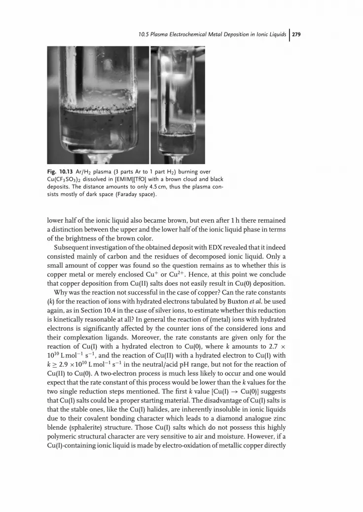
c10 (JWBG008-Endres) January 11, 2008 9:34 Char Count=
10.5 Plasma Electrochemical Metal Deposition in Ionic Liquids 279
Fig. 10.13 Ar/H2 plasma (3 parts Ar to 1 part H2) burning overCu(CF3SO3)2 dissolved in [EMIM][TfO] with a brown cloud and blackdeposits. The distance amounts to only 4.5 cm, thus the plasma con-sists mostly of dark space (Faraday space).
lower half of the ionic liquid also became brown, but even after 1 h there remaineda distinction between the upper and the lower half of the ionic liquid phase in termsof the brightness of the brown color.
Subsequent investigation of the obtained deposit with EDX revealed that it indeedconsisted mainly of carbon and the residues of decomposed ionic liquid. Only asmall amount of copper was found so the question remains as to whether this iscopper metal or merely enclosed Cu+ or Cu2+. Hence, at this point we concludethat copper deposition from Cu(II) salts does not easily result in Cu(0) deposition.
Why was the reaction not successful in the case of copper? Can the rate constants(k) for the reaction of ions with hydrated electrons tabulated by Buxton et al. be usedagain, as in Section 10.4 in the case of silver ions, to estimate whether this reductionis kinetically reasonable at all? In general the reaction of (metal) ions with hydratedelectrons is significantly affected by the counter ions of the considered ions andtheir complexation ligands. Moreover, the rate constants are given only for thereaction of Cu(I) with a hydrated electron to Cu(0), where k amounts to 2.7 ×10¹⁰ L mol−1 s−1, and the reaction of Cu(II) with a hydrated electron to Cu(I) withk ≥ 2.9 ×10¹⁰ L mol−1 s−1 in the neutral/acid pH range, but not for the reaction ofCu(II) to Cu(0). A two-electron process is much less likely to occur and one wouldexpect that the rate constant of this process would be lower than the k values for thetwo single reduction steps mentioned. The first k value [Cu(I) → Cu(0)] suggeststhat Cu(I) salts could be a proper starting material. The disadvantage of Cu(I) salts isthat the stable ones, like the Cu(I) halides, are inherently insoluble in ionic liquidsdue to their covalent bonding character which leads to a diamond analogue zincblende (sphalerite) structure. Those Cu(I) salts which do not possess this highlypolymeric structural character are very sensitive to air and moisture. However, if aCu(I)-containing ionic liquid is made by electro-oxidation of metallic copper directly

c10 (JWBG008-Endres) January 11, 2008 9:34 Char Count=
280 10 Plasma Electrochemistry with Ionic Liquids
in the ionic liquid the plasma electrochemical reduction to elemental copper shouldbe feasible.
Deposition of platinum metal: In the case of platinum no solid product was found.The ionic liquid darkened more and faster the smaller the distance between the sur-face of the ionic liquid [EMIM][TfO] containing tetrabutylammonium hexachloro-platinate ([n-Bu4N]2[PtCl6]) and the Ar/H2-plasma (3:1, overall pressure 100 Pa)was chosen. So far no other ionic liquid has been tested. The rate constant for thereduction of the tetrabutylammonium ion with a hydrated electron is only 1.4 ×10⁶ L mol−1 s−1, hence the main rival pathway for reduction of platinum(IV) is thereduction of the imidazolium ion of the ionic liquid. As in the case of copper, asuitable platinum salt – maybe made by electro-oxidation of metallic platinum in asuitable ionic liquid – has to be found.
Deposition of palladium metal: It was possible to deposit palladium nanoparti-cles by reduction of ammonium tetrachloropalladate ([NH4]2[PdCl4]) dissolved in[EMIM][TfO]. The product yield was only about 2.5% compared with the theoreticalvalue and was reached after 25 min. A longer application of the plasma did notlead to a significant increase in the amount of product. The lower yield and theslower reaction process might be a sign of the much more difficult two-electronreduction process compared to the one-electron process in the case of silver. Kooet al. stated that they did not obtain any platinum nanoparticles using a plasmawithout H2 gas [39]. In the case of palladium, nanoparticles formed when a Ar/H2
plasma (3:1, 100 Pa) was applied and when a pure Ar plasma was used. The HRSEM(Figure 10.14) picture reveals the high homogeneity of the particles which are allabout 5 nm in diameter (HRTEM, Figure 10.15), only a few are bigger but that canbe neglected. In Figure 10.15 is an additional SAED picture that exhibits the diffuserings which are typical for equally seized nanoparticles.
The successful deposition of silver and palladium nanoparticles proves the appli-cability of the PECD concept in ionic liquids. We expect that the cathodic depositionof other elements can be run in the same way under comparable conditions from
Fig. 10.14 HRSEM picture of the obtained palladium nanoparticles.

c10 (JWBG008-Endres) January 11, 2008 9:34 Char Count=
10.5 Plasma Electrochemical Metal Deposition in Ionic Liquids 281
Fig. 10.15 HRTEM/SAED picture of the palladium nanoparticles. Theletters in the SAED picture represent the lattice indices: a = 111, b =200, c = 220, d = 311.
suitable starting materials. In the case of highly reactive materials like titanium ahydrogen plasma may be used in order to avoid immediate re-oxidation by residualoxygen in the plasma phase. We believe that PECD in ionic liquids represents a ver-satile method with a potentially broad field of applications in the synthesis of metaland semiconductor micro- and nanoparticles. It can be expected that the physicalproperties of different ionic liquids, electric current density, the temperature, thechemistry of the plasma phase and also the convection in the liquid phase willinfluence the morphology of the reaction product and, thus, may be used profitablyas control parameters.
Comparing this approach with previous work – except the studies on solid elec-trolytes – ionic liquids have two distinct advantages over aqueous or organic sol-vents: (i) Due to their extremely low vapor pressure ionic liquids can be used withoutany problem in standard plasma vacuum chambers, and the pressure and composi-tion in the gas phase can be adjusted by mass flow controllers and vacuum pumps.As the typical DC or RF plasma requires gas pressures of the order of 1 to 100 Pa,this cannot be achieved with most of the conventional liquid solvents. If the solventhas a higher vapor pressure, the plasma will be a localised corona discharge ratherthan the desired extended plasma cloud. (ii) The wide electrochemical windowsof ionic liquids allow, in principle, the electrodeposition of elements that cannotbe obtained in aqueous solutions, such as Ge, Si, Se, Al and many others. Oftenthis electrodeposition leads to nanoscale products, as shown e.g. by Endres andcoworkers [60].
The development of methods for the reproducible and continuous production ofmetal and semiconductor particles with a typical size on the nanoscale is still anactive field of research [61–65]. The existing synthetic methods for isolated nanopar-ticles can be categorised into two major groups: (i) Gas or plasma phase-basedpreparation from gaseous or liquid precursors, (ii) preparation of nanoparticles in

c10 (JWBG008-Endres) January 11, 2008 9:34 Char Count=
282 10 Plasma Electrochemistry with Ionic Liquids
liquid solution by reduction or by precipitation, often with the help of templatemolecules or micelles [66]. Electrochemical methods are hardly used for the prepa-ration of isolated nanoparticles, mainly because the reaction products are usuallydeposited as compact materials at a solid electrode rather than as free particles.A particularly successful method is pulsed electrodeposition (PED), a well-knowntechnique in galvano plating [67], which was introduced into nanoscience by Erbet al. [68], mainly for n-Ni deposition. This concept was expanded by Natter andHempelmann to deposit n-Pd [69], n-Cu [70], n-Fe [71] and n-Cr [72]. They werealso able to deposit alloys like for example NixFe1–x or NixCu1–x [73]. Thus allmetals with E > 0 V (vs. NHE) can be electrodeposited in this way from aqueouselectrolytes [74, 75]. The electrodeposition of nanocrystalline metals and nanoscalesemiconductors in ionic liquids is summarized in Chapters 6 and 8 .
Koo et al. have recently published results from PECD of Pt nanoparticles in anaqueous solution of H2PtCl6 [39]. They also observe the formation of relativelysmall particles with a typical diameter of 2 nm. From the electrochemical point ofview, water is not a suitable solvent for plasma electrochemical processes, due toits relatively high vapor pressure, even at low temperatures.
10.6Conclusions and Outlook
The plasma|ionic liquid interface is interesting from both the fundamental and thepractical point of view. From the more fundamental point of view, this interfaceallows direct reactions between free electrons from the gas phase without side re-actions – once inert gases are used for the plasma generation. From the practicalpoint of view, ionic liquids are vacuum-stable electrolytes that can favorably be usedas solvents for compounds to be reduced or oxidised by plasmas. Plasma cathodicreduction may be used as a novel method for the generation of metal or semi-conductor particles, if degradation reactions of the ionic liquid can be suppressedsufficiently. Plasma anodic oxidation with ionic liquids has yet to be explored. Inthis case the ionic liquid is cathodically polarized causing an enhanced plasma ionbombardment, that leads to secondary electron emission and fast decompositionof the ionic liquid.
Currently only a few exploratory experimental studies have been reported, andmuch work has still to be done in order to explore fully the properties and charac-teristics of plasma|ionic liquid interfaces. Currently it is still too early to commentif technical applications will be found. From the economic point of view, both ionicliquids and plasmas are comparatively expensive media, therefore only applicationswhich show significant advantages compared to more conventional routes will besuccessful.
Introducing reactive gases to the plasma phase may even lead to the formation ofmetal or semiconductor compounds, extending the experimental possibilities evenfurther. From the physicochemical point of view, plasma electrochemical deposi-tion is a highly interesting interfacial phenomenon, linking plasma chemistry and

c10 (JWBG008-Endres) January 11, 2008 9:34 Char Count=
References 283
electrochemistry and utilizing nucleation under conditions far from equilibrium.A systematic investigation of this process is required in order to understand thenucleation and growth process in detail.
Acknowledgments
Parts of the experimental work have been performed in close collaboration withDr. Lorenz Kienle at MPI fur Festkorperforschung Stuttgart and Professor FrankEndres at TU Clausthal-Zellerfeld, Germany. The support of the DFG (Priorityprogram “Ionic Liquids”, projects Ja 648/13-1 and En 370/16-1) and the Funds ofthe Chemical Industry (FCI) is gratefully acknowledged.
References
1 Gubkin, J. (1887) Annal. Phys. N.F., 32,114–115.
2 Langmuir, I. (1928) Proc. Natl. Acad. Sci.U.S.A., 14, 627–637.
3 Hofft, O., Bahr, S., Himmerlich, M.,Krischok, S., Schaefer, J.A., and Kempter,V. (2006) Langmuir, 22, 7120–7123.
4 Peppler, K., Polleth, M., Meiss, S.,Rohnke, M., and Janek, J. (2006) Z. Phys.Chem., 220, 1507–1527.
5 Meiss, S.A., Rohnke, M., Kienle, L., ZeinEl Abedin, S., Endres, F., and Janek, J.(2007) Chem. Phys. Chem, 8, 50–53.
6 Torimoto, T., Okazaki, K., Kiyama, T.,Hirahara, K., Tanaka, N., and Kuwabata,S. (2006) Appl. Phys. Lett., 89, 243117.
7 Boenig, H.V. (1988) Fundamentals ofPlasma Chemistry and Technology,Technomic Publishing Co., Lancaster.
8 Lieberman, M.A. and Lichtenberg, A.J.(1994) Principles of Plasma Discharges andMaterials Processing, John Wiley & Sons,Inc., New York.
9 Drost, H. (1978) Plasmachemie,Akademie-Verlag, Berlin.
10 Moreau, M.G. (1913) Compt. Rend., 157,922–924.
11 Moreau, M.G. (1913) Compt. Rend., 157,1070–1072.
12 Moreau, M.G. and Bouty, M.E. (1914)Compt. Rend., 158, 260–262.
13 Hadzifejzovic, E., Sanchez Galiani, J.A.and Caruana, D.J. (2006) Phys. Chem.Chem. Phys., 8, 2797–2809.
14 Caruana, D.J. and McCormack, S.P.(2002) Electrochem. Commun., 4, 780–786.
15 Lorenz, H., Tittmann, K., Sitzki, L.,Trippler, S. and Rau, H. (1996) FreseniusJ. Anal. Chem., 356, 215–220.
16 Tonks, L. and Langmuir, I. (1929) Phys.Rev., 34, 876–922.
17 Vennekamp, M. and Janek, J. (2001) SolidState Ionics, 141–142, 71–80.
18 Arrhenius, S. (1887) Z. Phys. Chem., 1,631–648.
19 Trasatti, S. (1999) J. Electroanal. Chem.,476, 90–91.
20 Sollner, K. (1929) Z. Elektrochem., 35,789–799.
21 Gunterschulze, A. and Betz, H. (1937)Elektrolytkondensatoren: Ihre Entwicklung,wissenschaftliche Grundlagen, Herstellung,Messung und Verwendung, Krayn, Berlin.
22 Yerokhin, A.L., Nie, X., Leyland, A.,Matthews, A., and Dowey, S.J. (1999)Surf. Coat. Technol., 122, 73–93.
23 Shen, I. and Chu, P.K. (2004) TrendsCorrosion Res., 3, 41–57.
24 Klemenc, A. and Ofner, G. (1953) Z.Elektrochem., 57, 615–617.
25 Klemenc, A. and Kohl, W. (1953)Monatsh. Chem., 84, 498–511.
26 Couch, D. and Brenner, A. (1959) J.Electrochem. Soc., 106, 628–629.
27 Hickling, A. and Ingram, M. (1964)Trans. Faraday. Soc., 60, 783–793.
28 Klemenc, A. (1952) Chimia, 6, 177–200.29 Brenner, A. and Sligh, J. (1970) J.
Electrochem. Soc., 117, 602–608.30 Hamilton, L.W. and Ingram, M.D. (1972)
J. Chem. Soc., Faraday Trans. 1, 68,785–796.

c10 (JWBG008-Endres) January 11, 2008 9:34 Char Count=
284 10 Plasma Electrochemistry with Ionic Liquids
31 Ogumi, Z., Uchimoto, Y., Tsuji, Y., andTakehara, Z. (1992) Solid State Ionics, 58,345–350.
32 Ogumi, Z., Uchimoto, Y., and Takehara,Z. (1995) Adv. Mater., 7, 323–325.
33 Vennekamp, M. and Janek, J. (2005)Phys. Chem. Chem. Phys., 7, 666–677.
34 Vennekamp, M. and Janek, J. (2003) Z.Anor. Allg. Chem., 629, 1851–1862.
35 Locke, B.R., Sato, M., Sunka, P.,Hoffmann, M.R., and Chang, J.-S. (2006)Ind. Eng. Chem. Res., 45, 882–905.
36 Taylor, P.R. and Wang, W. (2002) PlasmaChem. Plasma Phys., 22, 387–400.
37 Taylor, P.R., Wang, W. and Vidal, E.E.(2003) in Metallurgical and MaterialsProcessing: Principles and Technologies, 1(eds F. Kongoli, K. Itagaki, C. Yamauchi,and H.Y. Sohn), Minerals, Metals &Materials Society, Warrendale, pp.977–990.
38 He, J., Ichinose, I., Kunitake, T., andNakao, A. (2002) Langmuir, 18,10005–10010.
39 Koo, I.G., Lee, M.S., Shim, J.H., Ahn,J.H., and Lee, W.M. (2005) J. Mater.Chem., 15, 4125–4128.
40 Ue, M., Murakami, A., and Nakamura, S.(2002) J. Electrochem. Soc., 149,A1572–A1577.
41 Egashira, M., Takahashi, H., Okada, S.,and Yamaki, J. (2001) J. Power Sources,92, 267–271.
42 Barthel, J., Buestrich, R., Gores, H.J.,Schmidt, M., and Wuhr, M. (1997) J.Electrochem. Soc., 144, 3866–3870.
43 Ue, M., Takeda, M., Takehara, M., andMori, S. (1997) J. Electrochem. Soc., 144,2684–2688.
44 Kanamura, K., Umegaki, T., Ohashi, M.,Toriyama, S., Shiraishi, S., and Takehara,Z. (2001) Electrochem. Acta, 47, 433–439.
45 Koch, V.R., Dominey, L.A., Nanjundiah,C., and Ondrechen, M.J. (1996) J.Electrochem. Soc., 143, 798–803.
46 Guyomard, D. and Tarascon, J.M. (1995)J. Power Sources, 54, 92–98.
47 Rahner, D. (1999) J. Power Sources, 81–82,358–361.
48 Xu, K., Ding, S.P., and Jow, T.R. (1999) J.Electrochem. Soc., 146, 4172–4178.
49 Johansson, P. (2006) J. Phys. Chem. Lett.A, 110, 12077–12080.
50 Nakajima, T., Mori, M., Gupta, V.,Ohzawa, Y., and Iwata, H. (2002) SolidState Sci., 4, 1385–1394.
51 Kroon, M.C., Buijs, W., Peters, C.J., andWitkamp, G.-J. (2006) Green Chem., 8,241–245.
52 Buxton, G.V., Greenstock, C.L., Helman,W.P., and Ross, A.B. (1988) J. Phys.Chem. Ref. Data, 17, 513–886.
53 Meiss, S.A., Rohnke, M., Kienle, L.,Abedin, S.Z.E., Endres, F., and Janek, J.(2007) Chem. Phys. Chem., 8, 50–53.
54 Zein El Abedin, S., Polleth, M., Janek, J.,and Endres, F., (2007) Green Chemistry, 9,549–553.
55 Polleth, M., unpublished results.56 Janek, J. and Rosenkranz, C. (1997) J.
Phys. Chem. B., 101, 5909–5912.57 Vennekamp, M. and Janek, J. (2003) J.
Electrochem. Soc., 150, C723–C729.58 Klupfel, K. (1905) Annal. Phys., 16,
574–583.59 Klemenc, A. and Hohn, H.F. (1931) Z.
Phys. Chem. A, 154, 385.60 Endres, F. (2004) Z. Phys. Chem., 218,
255–284.61 Fendler, J.H. (2002) Nanoparticles and
Nanostructured Films. Preparation,Characterisation and Applications,Wiley-VCH, Verlag GmbH.
62 Schmid, G. (2003) Nanoparticles. FromTheory to Application, Wiley-VCH, VerlagGmbH.
63 Trindade, T., O’Brien, P., and Picket,N.L. (2001) Chem. Mater., 13, 3843–3858.
64 Weller, H. (1996) Philos. Trans. R. Soc.London, Ser. A, 354, 757.
65 Gleiter, H. (1989) Progr. Mater. Sci., 33,223–315.
66 (1998) Nanoparticles and NanostructuredFilms (ed. J.H. Fendler), Wiley-VCH,Verlag GmbH.
67 Puippe, J.-C., Leaman, F. (1986) Theoryand Practice of Pulse Plating, AmericanElectroplaters and SurfacefinishersSociety, Orlando.
68 Erb, U. (1994) US patent, 5352266.69 Natter, H., Krajewski, T., and
Hempelmann, R. (1996) Ber. Bunsen-Ges.Phys. Chem., 100, 55–64.
70 Natter, H. and Hempelmann, R. (1996) J.Phys. Chem., 100, 19525–19532.

c10 (JWBG008-Endres) January 11, 2008 9:34 Char Count=
References 285
71 Natter, H., Schmelzer, M., Loffler, M.-S.,Krill, C.E., Fitch, A., and Hempelmann,R. (2000) J. Phys. Chem., 104, 2467–2476.
72 Przenioslo, R., Wagner, J., Natter, H.,Hempelmann, R., and Wagner, W.(2001) J. Alloys Compd., 328, 259–263.
73 Natter, H., Schmelzer, M., and
Hempelmann, R. (1998) J. Mater. Res.,13, 1186–1197.
74 Tench, D. and White, J. (1984) Metall.Trans. A, 15, 2039–2040.
75 Cheung, C., Djuanda, F., Erb, U., andPalumbo, G. (1995) Nanostr. Mater., 5,513–523.

c11 (JWBG008-Endres) January 11, 2008 9:55 Char Count=
287
11Technical AspectsDebbie S. Silvester, Emma I. Rogers, Richard G. Compton, Katy J. McKenzie,Karl S. Ryder, Frank Endres, Douglas MacFarlane, and Andrew P. Abbott
11.1Metal Dissolution Processes/Counter Electrode Reactions
While the subject of this chapter may seem counter to the title of the book, metaldissolution is vital in numerous aspects of metal deposition, counter electrodeprocesses, pre-treatment protocols and electropolishing. This chapter outlines thecurrent state of understanding of metal dissolution processes and discusses insome detail an electropolishing process that has now been commercialised using aType III ionic liquid.
11.1.1Counter Electrode Reactions
Little or no information is available in the open literature about counter electrodereactions occurring during deposition processes in ionic liquids. No data exist onanodic dissolution efficiencies and hence many practical issues associated withprocess scale-up are unknown at present. In ionic liquids the issues associated withpH can largely be ignored since the passivating layers either dissolve, e.g. in highchloride media, or trans-passive corrosion occurs at high enough over-potentials.This means that even metals such as Cr and Al have been used as soluble anodesas they can be readily oxidised in ionic liquids.
Most work to date has either used soluble anodes or has not considered theanodic reaction. A limited amount of information has been collated on the elec-trochemical windows of ionic liquids but this tends to be on either platinum orglassy carbon, which is not necessarily suitable for practical plating systems [1].The anodic limits of most liquids are governed by the stability of the anion, al-though pyridinium and EMIM salts are sometimes limited by the stability of thecation. The widest electrochemical windows are obtained with aliphatic quaternaryammonium salts with fluorous anions. A selection of potential windows is given inChapter 3.
Electrodeposition from Ionic Liquids. Edited by F. Endres, D. MacFarlane, A. AbbottCopyright C© 2008 WILEY-VCH Verlag GmbH & Co. KGaA, WeinheimISBN: 978-3-527-31565-9

c11 (JWBG008-Endres) January 11, 2008 9:55 Char Count=
288 11 Technical Aspects
The optimum process would ideally involve the use of soluble anodes, as theover-potential required to drive the deposition process will be small. This is espe-cially important with ionic liquids because the ohmic loss across the cell can besignificant. In aqueous solutions the use of soluble anodes is not often possibledue to passivation of the electrode surface at the operating pH.
While no systematic studies have been carried out, to date the only metal thatwe have been unable to electrochemically dissolve in eutectic-based ionic liquids isiridium. Although our research has not studied all metals we have found that evenPt, Au and Ti can be made to dissolve in eutectic-based liquids. Hence, in principle,soluble anodes could be used for the deposition of most pure metals from ionicliquids. This is, however, a considerable over-simplification and a number of factorsneed to be considered before employing a soluble metal anode. In ionic liquids withdiscrete anions attention needs to be given to the ligand present that will solvatethe dissolving metal. It is highly unlikely that an unsolvated anion could exist in anionic liquid and no evidence has been obtained to date to suggest otherwise. Metalsare known to be soluble in ionic liquids based upon Tf2N− and BF4
− anions butthe nature of the metal complexes is unknown [2]. It could be that dative bonds areformed with oxygen or fluorine moieties or it could be that trace water acts as aligand.
In eutectic-based ionic liquids, the chloride ions act as strong ligands for theoxidized metal ions, forming a range of chlorometallate anions. The free chlorideions are present in very low concentrations as they are complexed with the Lewisacidic metal ions and so the dissolution of metal ions must lead to a complex seriesof equilibria such as
4 ZnCl−3 + Zn2+ ↔ Zn2Cl−5 + Zn3Cl−7 (11.1)
Therefore it can be seen that metal dissolution is easier in Lewis basic melts. Thezinc and aluminum deposition processes, which are by far the most frequentlystudied, are almost totally reversible. Since these metals have no other stable oxida-tion states the deposition and dissolution processes are very efficient [3–6]. This hasthe distinct advantage that the composition of the ionic liquid remains constant andthe process becomes the removal of metal from one electrode and its deposition onthe other electrode.
Graphite has been used, but it fragments following electrolysis at high over-potentials leaving a black powdered residue at the base of the cell. Glassy carbonhas been used extensively in voltammetric studies, but its stability at high appliedcurrent densities has not yet been tested. While anodic dissolution of metals maybe advantageous for some metal deposition processes, for others it may proveproblematic e.g. for alloy deposition or for electrowinning applications. In somecases, e.g. chromium, it may be impossible to obtain electrodes because the metalsare not commercially available in a suitable form from which to make electrodes.
Another issue that needs to be considered is metals that exist in different oxida-tion states, e.g. Cr and Mn. The use of inert anodes could potentially lead to the buildup of metals in a higher oxidation state. However, unlike aqueous solutions, ionic

c11 (JWBG008-Endres) January 11, 2008 9:55 Char Count=
11.1 Metal Dissolution Processes/Counter Electrode Reactions 289
liquids tend to lack strong ligands such as oxygen which can stabilise higher oxi-dation states and this tends to negate the potential problem. Again no informationexists in the open literature but experiments carried out in our laboratory showedthat this was not an issue. The type II ionic liquid choline chloride: 2CrCl3·6H2Owas studied for the deposition of chromium using a soluble chromium anode [7, 8].Prolonged electrolysis was carried out over several months using the sample liquidand at the end of this period the liquid was analyzed. It was found that there wasno discernible breakdown of the choline cation and no chromium species otherthan Cr(III) was detected. The chromium content of the liquid was approximatelythe same as the initial sample and the only discernible change was that the watercontent of the liquid had decreased, presumably due to both anodic and cathodic de-composition. The chromium rod anodes were also severely etched over the processconfirming that they can act as soluble anodes.
The anodic processes occurring in the ionic liquids containing discrete anionshave not been well characterized. They will be extremely complex as the fluorinatedanions tend to be very stable and act as poor ligands. This means that both metaldissolution and solution oxidation will be difficult. If inert anodes, e.g. iridiumoxide coated titanium, are used then it is difficult to envisage what the anodicprocess will be and this is important to determine as the systems will have tooperate at relatively high current densities. Electrolysis of the ionic liquid itselfmust be avoided from the obvious economic viewpoint but also from the practicalperspective that most electrolytes will give off toxic fluorinated products. This isanalogous to the primary production of aluminum by the Hall–Heroult processwhere perfluorocarbons (PFCs) CF4 and C2F6 are produced at the anode. In theUnited States, aluminum smelting is the primary source of PFC emissions [9, 10].
Hence it can be concluded that little or nothing is known about the practical issuesassociated with suitable anode design. With such an array of ionic liquids, metalsand deposition conditions available it is impossible to make specific predictions ofhow all anodic materials will behave. Some general conclusions can, however, bedrawn, which should be good starting points from which to design specific pro-cesses. Where possible soluble anodes should be used as these improve processefficiency and bath longevity. Decomposition of the ionic liquid should be avoidedat all times as it is naturally costly to reprocess the liquid and shortens its use. Pro-cesses are in general more current efficient than corresponding aqueous systems.
11.1.2Pre-treatment Protocol
The surfaces of metal substrates require preparation and cleaning in order to en-sure adhesion and effectiveness of the finishing or coating treatment. Cleaning isalso employed for the removal of oil, grease or scale from metal surfaces. Abra-sive blasting, acid washes, multi-stage chemical cleaning and priming are someof the techniques used for surface preparation and cleaning [11]. Typical surfacepreparation and cleaning operations such as abrasive blasting are used for removalof paint, rust and scale prior to painting or refinishing. Organic solvents are used

c11 (JWBG008-Endres) January 11, 2008 9:55 Char Count=
290 11 Technical Aspects
for degreasing; aliphatic petroleum, aromatics, oxygenated hydrocarbons and halo-genated hydrocarbons are all applied to metal surfaces [11].
Electrocleaning techniques make use of a direct, reverse, or periodic reversedelectric current, in combination with an alkaline cleaning bath for the removal of soiland smut and the activation of the metallic surface. The workpiece may be set up ascathode or anode. Electrocleaning baths contain a solution with ingredients similarto those of alkaline cleaning and can be operated either at ambient temperaturesor in the range 40–80 ◦C [12]. To date no processes have demonstrated this inconjunction with an ionic liquid but there is no technical reason why this shouldnot be possible and in cases where the substrate etching is not reversible it may beadvantageous (vide infra).
In principle. there is no difference between the pretreatment that a metal shouldundergo before immersion in an ionic liquid or in an aqueous solution. The soledifference is that the workpiece must be dry before immersion in the ionic liquid.The sensitivity of the ionic liquid to water content is dependent upon the ionicliquid. Eutectic-based ionic liquids are less sensitive to water content than liquidswith discrete anions. This is thought to be due to the ability of the chloride anionsin the former interacting strongly with the water molecules, decreasing their abilityto be reduced. Especially with AlCl3-based ionic liquids water has to be strictlyavoided.
Most pre-treatment protocols studied so far follow the aqueous protocol quiteclosely. Good adhesion is obtained by degreasing in a chlorinated solvent, followedby an aqueous pickle in aqua regia, a water rinse and drying. A typical pre-treatmentprotocol is shown schematically in Figure 11.1.
Several groups have then used an anodic etch in the ionic liquid prior to depo-sition. Anodic etch potentials and times are dependent on the substrate and the
Fig. 11.1 Flow chart for the pretreatment of substrates before elec-trodeposition in ionic liquids

c11 (JWBG008-Endres) January 11, 2008 9:55 Char Count=
11.1 Metal Dissolution Processes/Counter Electrode Reactions 291
Fig. 11.2 AFM image of aluminum etched for 20 s at 10 V in a TypeIII eutectic of 1 choline chloride: 2 ethylene glycol (right side of imagemasked during experiment).
ionic liquid used but generally less than 1 min is required to achieve a suitablyetched substrate. The etch process has the dual purpose of removing any remain-ing oxide film and roughening the surface to act as a “key” for the coating layer.Metal oxide dissolution is easier in ionic liquids containing metal ions that are goodoxygen scavengers, e.g. Type I eutectics, because the oxygen scavengers ‘mop’ upany oxygen moieties which have been generated during the etch process.
Figure 11.2 shows an atomic force microscopy (AFM) image of an aluminumelectrode etched for 20 s at 10 V in a Type III eutectic of 1 choline chloride: 2ethylene glycol. The right side of the image was masked with a lacquer duringthe experiment which was then removed before the sample was imaged. It can beseen that the left side of the sample was significantly etched even during the shortduration of the anodic pulse. Dissolution rates of between 50 and 150 µm min−1
are observed under these conditions and result in a pitted surface. The sample inthe image is too well etched for practical purposes and hence shorter times or lowerover-potentials should be employed.
Figure 11.3 shows an analogous experiment for a copper electrode and it canbe seen that significantly less metal is removed in the same period. The surfacehas approximately the same roughness as the original sample but there are moremicro-pits on the sample, leading to a better key with the subsequently depositedfilm. Figure 11.4 shows that the etch rate for aluminum is almost three timesthat of copper under the same conditions. These figures show that in ionic liquidspassivating films on electrode surfaces play a smaller role in controlling metal dis-solution kinetics. The metals behave more characteristically, as would be predictedby their standard reduction potentials, i.e. metals with a more negative reductionpotential are easier to etch.
Many plating protocols advocate the use of a ‘flash’ step where a significantlyhigher overpotential is applied to ensure that the entire substrate is covered withmetal before the potential is reduced to the plating potential. This has been shownto be effective in ionic liquid and significantly improves the corrosion resistance ofthe coatings [7].

c11 (JWBG008-Endres) January 11, 2008 9:55 Char Count=
292 11 Technical Aspects
Fig. 11.3 AFM image of copper etched for 20 s at 10 V in a Type IIIeutectic of 1 choline chloride: 2 ethylene glycol (right side of imagemasked during experiment).
One issue that has to be addressed is the reversibility of the dissolution anddeposition of the substrate. If the dissolution of the substrate is reversible, i.e. allthe metal dissolved can be redeposited, then etching in situ in the plating liquidis possible. If the substrate cannot be redeposited then the metal will clearly buildup its concentration as the ionic liquid is used and this will significantly shorten
Fig. 11.4 Line traces taken through Figures 11.2 and 11.3; aluminum(dotted line) and copper (solid line).

c11 (JWBG008-Endres) January 11, 2008 9:55 Char Count=
11.1 Metal Dissolution Processes/Counter Electrode Reactions 293
the life of the bath. In this case a pre-etch in a different liquid should take placebefore the substrate is transferred to the ionic liquid. This is shown schematicallyin Figure 11.1.
No literature has been published in this area but, as a rule of thumb, metalswhich dissolve to give complexes that have linear or tetrahedral geometries, e.g.Cu, Ag, Zn, Sn, Pb, can be reversibly deposited and etched. Those with octahedralgeometries, e.g. Fe, Ni, Co and Cr, are less reversible. The exceptions to this are thevery electronegative metals, most notably Al which is difficult to electrodeposit fromsome ionic liquids. The reversibility is also dependent upon the type of ionic liquidand the metal being deposited. Endres has shown that the adhesion of aluminumto mild steel is greatly enhanced by an anodic pulse prior to deposition. It has beenshown that this alloy was formed between the steel substrate and the aluminumcoating [1].
11.1.3Electropolishing of Stainless Steels
Electropolishing is the controlled corrosion of a metal surface to bring about areduction in surface roughness and an increase in corrosion resistance of thecomponents. Electropolished pieces also decrease wear and increase lubricity inengines, thus reducing a major cause of failure, and offer several other functionalbenefits. The first systematic study of electropolishing was carried out by Jacquetand led to a patent in 1930 [13]. The majority of studies have been carried out onstainless steel although metals such as copper, nickel and titanium have also beenstudied [14–16]. The current stainless steel electropolishing process is performedworldwide on a commercial scale and is based on concentrated phosphoric acid andsulfuric acid mixtures. The polishing process is thought to involve the formation ofa viscous layer at the metal surface and many processes employ viscosity improverssuch as glycerol. The practical aspects of electropolishing have been reviewed byMohan et al. [17], whereas the more fundamental aspects are covered in a reviewby Landolt [18]. While electropolishing is an extremely successful process there aremajor issues associated with the technology, most notably that the solution used ishighly corrosive and extensive gassing occurs during the process, which results invery poor current efficiency.
As explained previously, electrodissolution in ionic liquids is a simple and ef-ficient process, particularly in chloride-based eutectics. Type III eutectics basedon hydrogen bond donors are particularly suitable for this purpose. However, ithas been noted that the polishing process only occurs in very specific liquids andeven structurally related compounds are often not effective. It has been shownthat 316 series stainless steels can be electropolished in choline chloride: ethyleneglycol eutectics [19] and extensive electrochemical studies have been carried out.The dissolution process in aqueous solutions has been described by two mainmodels; the duplex salt model, which describes a compact and porous layer at theiron surface [20], and an adsorbate–acceptor mechanism, which looks at the roleof adsorbed metallic species and the transport of the acceptor which solubilises

c11 (JWBG008-Endres) January 11, 2008 9:55 Char Count=
294 11 Technical Aspects
them [21]. Voltammetry and impedance spectroscopy have been used to confirmthat the dissolution mechanism in an ionic liquid is different from that in aqueousacidic solutions. Preliminary results suggest that a diffusion-limited process in theviscous ionic liquid appears to be responsible for electropolishing [22]. Impedancespectroscopy has also shown that one of the main differences between the elec-tropolishing mechanism in the ionic liquid and the aqueous solution is the rateat which the oxide is removed from the electrode surface. The electropolishingmechanism in the ethylene glycol eutectic is described in more detail in two recentpublications [21, 22].
Highly polished surfaces were obtained with current densities between ca. 70and 50 mA cm−2 with an applied voltage of 8 V. Below this current density a milkysurface was obtained and above this range some pitting was observed on an oth-erwise bright surface. It should be noted that the polishing region was narrowerthan that in aqueous phosphoric/ sulfuric acid mixtures, but the current densityrequirements were considerably lower using the ionic liquid. In acidic solutionstypical current densities are 100 mA cm−2 but much of this results in gas evolutionat the anode. With the ionic liquid no gas evolution was observed, suggesting thatthere are negligible side reactions occurring with the ionic liquid. The current ef-ficiency of the 1ChCl: 2EG electrolyte has been determined using coulometry andgravimetry and was found to be in excess of 90%, which is significantly higher thanthe aqueous-based electrolytes which are typically ∼30%. Given that the currentdensity used for the 1ChCl: 2EG electrolyte is considerably lower than that used inthe aqueous solution the slight difference in the conductivity of the two solutionsdoes not lead to a significant difference in the ohmic loss through the solution.In fact preventing a passivating layer at the electrode surface during polishing de-creases the overall ohmic resistance of the non-aqueous system. Hence the currentgoing to metal dissolution is probably similar for the two systems, explaining whythe polishing process takes approximately the same time.
Analysis of the polished surface and residue left in the polishing tank showedconclusively that no dealloying of the surface took place and AFM analysis of pre-and post-polished samples showed that the polishing process was effective at pre-venting corrosion because it removed the micro-cracks from the steel surface [22].
Various pre-treatment protocols have been developed including pickling andanodic/cathodic pulses to remove the oxide films. It was apparent that differenttypes of steel require different pre-treatments, i.e. cast pieces behave differently torolled pieces. Significant success was achieved in electropolishing cast pieces andthe finish obtained with the ionic liquid was superior to that with phosphoric acid,however, the converse was true for rolled pieces because the oxide film is thickerin the latter samples and hence slower to dissolve in the ionic liquid.
Similar electropolishing experiments were carried out using different grades ofstainless steel (410, 302, 304, 316 or 347) and it was found that the mechanism ofmetal dissolution and the oxidation potentials for the metals were very similar. Theslight exception was the 410 series steel (which has no Ni, unlike the 300 seriessteels which have 8–14%). The 410 steel required a more positive oxidation potentialto break down the oxide in the ionic liquid whereas once the oxide was removed the

c11 (JWBG008-Endres) January 11, 2008 9:55 Char Count=
11.1 Metal Dissolution Processes/Counter Electrode Reactions 295
Fig. 11.5 AFM image of a 316 stainless steel sample in which oneside has been electropolished while the other has been masked withlacquer.
metal was more easily oxidised than the other grades of steel. This shows why the410 steel was more likely to pit during the polishing process. The pitting could bereduced, however, by chemically pickling the steel with a proprietary phosphoricacid etch before electropolishing [23].
This technology was scaled-up to a 1.3 tonne plant by Anopol Ltd (Birmingham,UK). Results have shown that the technology can be applied in a similar manner tothe existing technology. The ionic liquid has been found to be compatible with mostof the materials used in current electropolishing equipment, i.e. polypropylene,nylon tank and fittings, stainless steel cathode sheets and a titanium anode jig.
Extended electropolishing using the same solution leads to a dark green–brownsolution arising from the dissolved iron, chromium and nickel. The solubility ofthe metals in the ionic liquid is relatively high and a dense sludge forms in the baseof the tank when the saturation concentration is exceeded. The metals are presentas glycolate and chloride complexes and numerous solvents have been tested todetermine their efficacy at precipitating the metal salts. (See SubChapter 11.3).
Water is completely miscible with the spent ionic liquid but the resulting mix-ture leads to a completely transparent liquid and almost all the metal complex isprecipitated to the base of the cell. The water can be distilled from the mixtureto leave a dry ionic liquid which has lost only ca. 15% ethylene glycol, mostly inthe form of the metal complex. The residual concentration of each metal in theionic liquids was less than 5 ppm. Hence, not only has it been demonstrated thatelectropolishing can be carried out in this non-corrosive liquid, but also that theliquid can be completely recycled and all of the metal can be recovered. Figure 11.6shows a variety of stainless steel pieces electropolished using the choline-basedionic liquid.

c11 (JWBG008-Endres) January 11, 2008 9:55 Char Count=
296 11 Technical Aspects
Fig. 11.6 A variety of pieces electropolished using a choline-based ionic liquid.
This subchapter has shown that metal dissolution processes are important tonumerous aspects of metal plating, however, very few concerted studies have beenmade in this area. An understanding of dissolution rates and processes, togetherwith information on the stability of oxide films in ionic liquids, is essential for thedevelopment of successful metal finishing processes.
11.2Reference Electrodes for Use in Room-temperature Ionic Liquids
Voltammetric, electrodeposition, electrosynthetic and electroanalytical studies arecarried out in room-temperature ionic liquids (RTILs) by a significant and increas-ing number of both industrial and academic laboratories [23–25]. Such studies,when carried out at anything other than a very empirical level, require the use of a‘reference electrode’. The purpose of this chapter is to address the special problemsthis poses and their solutions. First, however, we start by considering the essentialfeatures of a reference electrode in general.
11.2.1What is a Reference Electrode?
Consider a generalized electrode process: A ± ne → B, in which A is electrolyticallyconverted into B at a suitable electrode. The rate at which this happens is measuredby the current, I, flowing through the electrode, via. Faraday’s Law:
I = nF A� (11.2)

c11 (JWBG008-Endres) January 11, 2008 9:55 Char Count=
11.2 Reference Electrodes for Use in Room-temperature Ionic Liquids 297
where F is the Faraday constant (96 485 C mol−1), A is the electrode area, and � isthe flux of species A to the electrode (mol cm−2 s−1) averaged over its surface. Thisrate of reaction is controlled by the magnitude of the electrical potential applied tothe electrode of interest (often referred to as a “working” electrode). The applicationof this potential, self-evidently, requires the presence of at least a second electrodein the solution of interest, so that a defined potential can be applied between thetwo electrodes. This second electrode is known as a “reference” electrode. In orderthat a fixed and known driving potential is applied to the working electrode, it isa minimum requirement that the reference electrode maintains a fixed, constantpotential difference between itself (M) and the electrolytic solution (S) with whichit is in contact, (�M – �S)ref [26].
The potential difference (�M − �S)ref is established by means of a suitable elec-trochemical equilibrium being established at the surface of the reference electrode:Ox +e ↔ Red, so that the reference potential difference of interest is quantified bymeans of the Nernst equation [27]:
(�M − �S)ref = a constant − RT
Fln
ared
aox(11.3)
where R is the universal gas constant, T is the temperature in Kelvin, and ared andaox are the activities of the reduced and oxidized species, respectively.
Examples of reference electrode systems which operate successfully in aqueoussolutions include the following ‘potential determining equilibria’:
e− + H+ � 1
2H2 (11.4)
e− + 1
2Hg2Cl2 � Hg + Cl− (11.5)
e− + AgCl � Ag + Cl− (11.6)
In the first example, a platinized platinum electrode is immersed in a solution ofstrong acid. The purpose of the platinizing procedure is to ensure the kinetics of theelectrochemical processes are rapid enough to sustain the process at equilibrium.In the other two examples, a metal salt, highly insoluble in water (AgCl or Hg2Cl2)is in contact with a solution containing chloride ions and the corresponding metal(Ag or Hg). The corresponding appropriate forms of the Nernst equations are:
(�M − �S)ref = A − RT
Fln
pH1/22
aH+(11.7)
(�M − �S)ref = A′ − RT
Fln aCl− (11.8)
(�M − �S)ref = A′′ − RT
Fln aCl− (11.9)
In experimental practice, the reference electrode will most likely be used in con-junction with a three-electrode potentiostat with a third electrode, a counter (or

c11 (JWBG008-Endres) January 11, 2008 9:55 Char Count=
298 11 Technical Aspects
auxiliary) electrode, completing the circuit so that negligible currents pass throughthe reference electrode. The latter feature is of crucial importance otherwise elec-trolysis perturbs the concentrations (‘activities’) of the desired species establishingthe potential determining equilibrium and hence the quantity (�M – �S)ref which,under conditions of sustained current flow, is neither fixed nor constant [28]. Thatsaid, in the limit of microelectrodes, the currents passed can be sufficiently smallthat a two-electrode system becomes viable. In this arrangement, a single electrodecan act as a reference electrode and a counter electrode.
Classically, in relation to conventional solvent media, three classes of referenceelectrodes are recognised [29]:
1. Electrodes of the first kind: These are based on a potential determining equilib-rium such as Ag+ + e−�Ag or 1
2 Cl2 + e−�Cl− where, for “cationic electrodes”,equilibrium is established between atoms or molecules and their correspondingcations in solution or, for “anionic electrodes”, their corresponding anions.
2. Electrodes of the second kind: These consist of three phases. A metal is covered bya layer of its sparingly soluble salt, and immersed in a solution containing theanion of this salt. The Ag/AgCl/Cl− and Hg/Hg2Cl2/Cl− electrodes referred toabove are of this type.
3. Redox electrodes: In this case, an inert, non-reactive metal such as platinum or gold,is immersed in a solution containing both species contributing to a redox couple.For example in water: 1
2 BQ + e− + H+� 12 H2Q, where BQ is benzoquinone and
H2Q is hydroquinone or, in acetonitrile, Cp2Fe+ + e−�Cp2Fe, where Cp2Fe isferrocene and Cp2Fe+ the ferrocenium cation.
11.2.2Essential Characteristics of a Reference Electrode
In the context of classical solvent media, Butler [30] suggests:
“A satisfactory reference electrode must show one or more of the following properties: (1)have a potential stable with time, (2) return to the same potential after polarization,1)
(3) obey the Nernst equation with respect to some species in the electrolyte, and (4) if itis an electrode of the second kind, the solid phase must not be appreciably soluble in theelectrolyte.”
In the context of RTILs the criterion (3) raises considerable problems since the con-cept of activity and activity coefficients of ions is largely unexplored in such media.Accordingly, validation of the applicability of the Nernst equation in such media is anon-simple exercise, given that RTILs are likely to exhibit gross non-ideality. Rather,electrochemical measurements based on otherwise validated reference electrodes,may likely in the future provide a methodology for the study of RTIL non-ideality.
1) By ‘polarization’ is meant the application of avoltage perturbing the equilibrium potential ofthe electrode.

c11 (JWBG008-Endres) January 11, 2008 9:55 Char Count=
11.2 Reference Electrodes for Use in Room-temperature Ionic Liquids 299
Accordingly, for our present purposes, namely the identification of satisfactory ref-erence electrodes, the pragmatic criteria of (1), (2), and (4) are pertinent, and (1)in particular is paramount since, in essence, (2) and (4) merely indicate means bywhich (1) might fail. Underpinning the requirement for a stable electrode potentialis, of course, the need for relatively fast electrode kinetics to establish the potentialdetermining equilibrium. To quote Ives and Janz [31]:
“Exchange current densities for various kinds of metal–solution interfaces cover a range ofabout 10−2 to 10−18 A cm−2, but the useful range for reference electrodes is normally muchmore restricted than this; it will be in part dependant upon the sensitivity of the measuringinstrument to be used. One of the highest i0 values is for hydrogen ion discharge at platinum,which is one reason why the hydrogen electrode2) is one of the most satisfactory of all.”
11.2.3Pseudo-reference Electrodes and Internal Redox Reference Couples
Butler [30] says:
“If one is not too critical, many metal electrodes show relatively stable potentials in variouselectrolyte solutions.”
Accordingly, much voltammetry in non-aqueous solvents has been conducted usinga ‘pseudo’-reference electrode (alternatively labelled a ‘quasi’-reference electrode)constituting, quite simply, a metal wire, most often silver or platinum. It is thenexpected (hoped) that the potential of the wire remains constant throughout thevoltammetric experiment. This may be a realistic hope if, as Bard and Faulkner[32] point out, the composition of the bulk solution is essentially constant duringthe period of experimentation, as may be realized during voltammetric studies butcertainly not in electrosynthetic work.
When a pseudo-reference electrode is used, good practice [32] dictates that itsactual potential is calibrated by measuring, voltammetrically or otherwise, the for-mal potential of an electrochemically reversible couple. IUPAC recommend theuse of either the ferrocene/ferrocenium, Cp2Fe/Cp2Fe+ couple [33], alternatively,the cobaltocenium/cobaltocene Cp2Co+/Cp2Co (where Cp ≡ C5H5) has been sug-gested [34, 35]. In experimental practice, this simply involves measuring the voltam-mogram of either Cp2Fe or Cp2Co+ using the selected metal wire as the pseudo-reference electrode before (and after) recording that of the species of interest in thesame medium. Since the couples Cp2Fe+ + e−�Cp2Fe and Cp2Co+ + e−�Cp2Coare electrochemically reversible in most media and at most electrodes3), compari-son of the measurements allows redox data to be reported against either of the two
2) In aqueous solution.
3) Note that couples which show electrochem-ically reversible behavior at macro-electrodesmay display quasi-reversibility or irreversibilityat very small electrodes (ultramicro-electrodes,nano-electrodes)

c11 (JWBG008-Endres) January 11, 2008 9:55 Char Count=
300 11 Technical Aspects
couples. The possibility of using solid Cp2Fe+ + e−�Cp2Fe in the specific contextof RTIL voltammetry has been noted by Zhang and Bond [36, 37].
11.2.4Liquid Junction Potentials
Measurements of electrode potentials using reference electrodes are of two generaltypes: those that involve liquid junctions and those that do not. An example of acell which does not have a liquid junction is:
Pt | H2(g) | HCl(aq) | AgCl | Ag
where | denotes a phase boundary. In contrast the cell
Pt | Cp2Fe, Cp2Fe+(CH3CN) || AgNO3(CH3CN) | Ag
has a liquid junction (‖) since two liquid phases of different compositions arebrought into contact. The liquid phases may differ in terms of solvents and/orsolutes.
When liquid junctions exist, liquid junction potentials (LJPs) can arise due todiffering ion mobilities across the interface, leading to charge separation and thedevelopment of a potential difference across the liquid junction. These can amountto some tens of millivolts and add a corresponding uncertainty in any voltammetricmeasurement. It follows that systems that avoid LJPs are generally preferable;otherwise some consideration of their likely magnitude is desirable (see below).
11.2.5Reference electrodes in RTILs: What has been used?
Table 11.1 presents the results of a literature survey to establish which reference andpseudo-reference electrodes have been and are being used in RTILs. The structuresof the constituent anions and cations are shown in Figure 11.7. It is clear that themajority of researchers favor the use of pseudo-reference electrodes but that not alltake the trouble to calibrate using internal standards such as Cp2Co+ or Cp2Fe. Inthe latter case, the philosophy is nicely and honestly summarized by Welton andcolleagues [38]:
“The electrochemistry was performed on the neat ionic liquid. In such a set-up, withno recognised background electrolyte or redox standard, the potential vs. the platinumpseudo-reference is difficult to compare with standard potentials, however, in such unusualconditions it is the qualitative nature of the electrochemistry that is important.”
The most popular pseudo-reference electrodes are Pt or Ag wires. Other pseudo-reference electrodes have employed coating, for example Pt with polypyrrole [39]or Ag with AgCl [40] (but in the absence of deliberately added solution phase Cl−,

c11 (JWBG008-Endres) January 11, 2008 9:55 Char Count=
11.2 Reference Electrodes for Use in Room-temperature Ionic Liquids 301
Table 11.1 A cross-section of the different types of reference electrodesthat have been used by various researchers in a range of differentRTILs
RTIL solution Reference electrode material Referenced to . . . Ref.
[C4mim][PF6][C2mim][NTf2]
Ag wire Cc+/Cc[a]
Fc/Fc+[a][37]
[M(MePEG-bpy)2+][DNA][b] Ag wire Fc/Fc+[a] [52]Various [NTf2] Ag wire NR [23, 25][C4mim]Cl/AlCl3 Ag wire NR [53]DIMCARB Ag wire DMFc/DMFc+[a] [36][C4mPyrr][NTf2][N4,1,1,1][NTf2][N6,2,2,2][NTf2]
Ag wire NR [54]
[C4mim][BF4][C4mim][PF6][C4dmim][BF4]
Ag wire coated with AgCl Fc/Fc+[a]
(Eo = 0.3, 0.39 and0.49 V/ Ag/AgCl)
[40]
[C4mim][PF6][C4mPyrr][NTf2]
Pt wire Fc/Fc+ [24, 55]
[C4mim][BF4][C4mim][PF6]
Pt wire NR [45]
[C4mim][NTf2][C4mPyrr][NTf2]
Pt wire Fc/Fc+[a] [56]
[C4mim][Co(CO)4] Pt wire NR [38][C2mim][NTf2][C4mim][NTf2][C4mim][PF6][N8,8,8,1][NTf2]
Pt wire coated in polypyrrole Fc/Fc+[a]
(Eo = 0.405 V/ SCE)[39]
[C2mim][BF4] Al wire immersed in a 1.5:1.0acidic chloroaluminatemelt (frit)
n/a [57]
[C2mim]Cl/AlCl3 Al wire in an 0.6 M solutionof RTIL [C2mim]Cl/AlCl3(porous tip)
n/a [41]
[PP13][NTf2] Mg ribbon in Mg(CF3SO3)2 n/a [47][C6dmim][NTf2][C6dmim][CTf3][C6dmim][PF6][C6dmim][AsF6]
Li foil in Li+ salts n/a [48]
[C4mim][PF6] Saturated calomel (aq) n/a [43][C2mim][BF4][C3mim][BF4][C4mim][BF4]
Ag/AgCl KCl (sat., aq) n/a [44]
[C2mim][BF4][C4mim][BF4][C4dmim][BF4]
Ag/AgCl Na (sat., aq) n/a [42]
[C4mPyrr][NTf2] Ag wire in 0.1 M AgNO3 inRTIL [C4mim][NO3] (glassfrit)
n/a [58]
[C2mPip][F(HF)2][C4mPip][F(HF)2][C4mPyrr][F(HF)2][C2mim][F(HF)2]
Ag wire in 0.05 M AgBF4 inRTIL [C2mim][BF4]
n/a [50]

c11 (JWBG008-Endres) January 11, 2008 9:55 Char Count=
302 11 Technical Aspects
Table 11.1 (Continued)
RTIL solution Reference electrode material Referenced to . . . Ref.
[C4mim][NTf2][C4mim][BF4][C4dmim][PF6]
Ag wire in 0.1 M AgNO3 inRTIL and Ag/AgCl in0.1 M Bu4NCl in RTIL.
n/a [49]
[C4mPyrr][NTf2] Ag wire in 0.01 and 0.1 MAgTf in RTIL (frit)
n/a [51]
[N3,1,1,1][NTf2][TES][NTf2][TBS][NTf2]
Pt wire in 0.06 MN(n-C3H7)4I, 0.015 M I2 in[C2mim][NTf2]
n/a [46]
aCc+=Cp2Co+, Cc=Cp2Co, Fc=Cp2Fe, Fc+=Cp2Fe+, DMFc=(C5Me5)2Fe, DMFc+=(C5Me5)2Fe+.bM= Fe, Co and MePEG-bpy = 4,4’-(CH3(OCH2-CH)OCO)-2,2’-bipyridine).NR = no calibration vs. internal reference reported. All RTIL structures are given in Figure 11.7.
although some may arise locally from dissolution of AgCl). In both of these cases,the Cp2Fe/Cp2Fe+ couple was used as an internal reference for the purposes ofcalibration.
Another type of apparently “pseudo”-reference electrode involves the use of Alwires in contact with solutions containing AlCl4− ions [41]. A further group ofresearchers simply use conventional aqueous solution-based calomel or silver/silverchloride/aqueous chloride ion reference electrodes [42–44]. These are included inTable 11.1 for illustration and completeness. The use of such electrodes is highlylikely to lead to the introduction of water into the RTIL system in contact with thereference electrode, as well as to unknown problems in respect of LJPs. Propertiessuch as voltammetric windows, diffusion coefficients and RTIL viscosity are alllikely to be highly sensitive to trace amounts of water [45].
The following systems, in contrast to the above, are based on well-definedpotential-determining equilibria established within a RTIL.
1. The iodide/tri-iodide system: 12 I−
3 + e−� 32 I− has been used by Matsumoto et al.
[46]. The electrode was prepared by dissolving 60 mM N(n-C3H7)I and15 mM I2 in 1-ethyl-3-methylimidazolium bis(trifluoromethylsulfonyl)imide[C2mim][NTf2] and placing a platinum wire in the solution. It is highly likely,but not explicitly reported, that such a reference electrode was used to study thevoltammetry in various RTILs based on triallylsulfonium cations. If so, therewould be an unknown, but probably not too large and reasonably constant, liq-uid junction potential between the RTIL under study and the reference electrodecell.
2. The couple 12 Mg2+ + e−� 1
2 Mg, with the cation present as the salt Mg(CF3SO3)2
(1 M) has been used as a reference electrode in N-propyl-N-methylpiperidiniumbis(trifluoromethylsulfonyl)imide [C3mPip][NTf2] [47]. The authors also consid-ered the use of a magnesium ribbon as a pseudo-reference electrode. The RTIL

c11 (JWBG008-Endres) January 11, 2008 9:55 Char Count=
11.2 Reference Electrodes for Use in Room-temperature Ionic Liquids 303
Fig. 11.7 Structures of all RTILs listed in Table 11.1.

c11 (JWBG008-Endres) January 11, 2008 9:55 Char Count=
304 11 Technical Aspects
in the reference electrode and in the bulk solution used for voltammetry werethe same so that liquid junction potentials were relatively minimized.
3. The couple Li+ + e−�Li has been used for RTILs based on [1, 2-dimethyl-3-propylimidazolium] [X]− (where [X]−= [NTf2]−, [CTf3]−, [PF6]− and [AsF6]−)[48]. The electrode took the form of Li foil in the same ionic liquids to which wasadded 0.02 M LiAsF6, LiPF6, Li[NTf2] or Li[CTf3] according to the nature of theanion in the RTIL of interest. Again, this arrangement led to a minimization ofliquid junction potentials.
4. Josowicz et al. [49] have developed a reference electrode for use in RTILs basedon the equilibrium AgCl + e−�Cl− + Ag, in which a chlorinated silver wire isplaced in a solution of 0.1 M Bu4N+Cl− in the RTIL of interest. The latter solutionwas separated from the sample under study by a double junction arrangementin which a further compartment contained only the RTIL of interest.
5. Several researchers have used the following potential determining equilibrium:
Ag+ + e−�Ag
as the basis for well-defined reference electrodes. Josowicz et al. [49] dissolved0.1 M AgNO3 in the RTIL of interest and inserted a silver wire. This was used ina similar double junction arrangement as described above. Hagiwara et al. [50]used 0.05 M AgBF4 in the ionic liquid 1-ethyl-3-methylimidazolium tetrafluorob-orate [C2mim][BF4]. Finally, Snook and colleagues [51] devised and voltammet-rically characterized a Ag/Ag+ reference electrode which incorporated a knownconcentration (usually 10 mM) of silver trifluoromethanesulfonate (AgTf; Tf =CF3SO3
−) in 1-butyl-1-methylpyrroloidinium bis(trifluoromethylsulfonyl)imide[C4mPyrr][NTf2]. A stable and reproducible potential was reported. In a carefuland thorough study, the electrode Ag/Ag+ (10 mM AgTf, [C4mPyrr][NTf2]) wasfound to be stable to within a millivolt over a period of around three weeks, whenused in an argon atmosphere at room temperature. This is a highly importantand useful observation since the characterization of the RTIL-based referenceelectrode (see Section 11.2.2) was significantly more rigorous than in any otherstudy of which the present authors are aware. Specifically, for a high concentra-tion of Ag+, close to Nernstian behavior was seen and measurements showed theelectrode to be significantly more stable than a Ag pseudo-reference electrode,even when the latter was separated by a salt bridge. Above all, voltammetricdata recorded in a range of ionic liquids against the Ag/Ag+ (10 mM AgTf,[C4mPyrr][NTf2]) reference electrode showed apparent liquid junction potentialsof no more than a few tens of millivolts.
11.2.6Recommendations and Comments
It is evident from the previous section that a range of approaches have been, and canbe, adopted by experimentalists wishing to conduct voltammetric or other studies.The aim of this section is to answer some likely questions.

c11 (JWBG008-Endres) January 11, 2008 9:55 Char Count=
11.2 Reference Electrodes for Use in Room-temperature Ionic Liquids 305
11.2.6.1 When and How Can I Use a Pseudo-reference Electrode in Voltammetry?The use of a Pt or Ag wire as a pseudo-reference electrode is attractive becauseof its sheer simplicity and the fact that possible contamination of the test solutionis avoided. The issue as to whether this provides a stable reference potential is animportant consideration. To illustrate this, the electrochemistry of 5 mM Ferrocene(Cp2Fe) in the RTIL [C4mim][PF6] was studied on a platinum microdisk electrode(d = 10 µm). The pseudo-reference electrode used in this set-up was simply aplatinum wire inserted into a glass tube (standard non-aqueous reference electrodekit from BAS) in the same RTIL [C4mim][PF6], separated from the main solutionvia a Vycor plug. The reference electrode was, prior to recording the voltammetryof Cp2Fe, pre-oxidized for different times by holding the potential at ca. +1.75 V inblank [C4mim][PF6] vs. a silver wire pseudo-reference. It may be possible that thepre-oxidizing experiment deposits a layer of some species on the Pt wire, leading tosignificant shifts in potential. Figure 11.8 shows this effect: with no pre-oxidizing(a), the half-wave potential of Cp2Fe is +0.275 V, which systematically shifts tomore negative potentials with increased pre-oxidizing time (+0.255 V for 5 min (b),+0.225 V for 10 min (c), +0.185 V for 20 min (d), and +0.165 V for 40 min (e)).The Pt wire that had been pre-oxidized for 20 min was then left in air for a further1 h, after which the half-wave potential of Cp2Fe had shifted back to a potential(+0.245 V (f)) close to that observed with no pre-oxidizing. The same experimentswere repeated with a silver wire inside the reference compartment, and the resultsare shown in Figure 11.9. Here, although there was no systematic shift in peakpotentials with pre-oxidizing time: (+0.385 V for 0 min (a), +0.365 V for 5 min (b),+0.415 V for 10 min (c), and +0.385 V for 20 min), there was still a significantdifference in the half-wave potential of Cp2Fe under different conditions.
It is clear that Pt or Ag wires can show significant drift (which depends in parton their recent history as well as the solution in which they are immersed) and thatif such pseudo-reference electrodes are used, the regular internal calibration usingCp2Co+ or Cp2Fe, as advocated by IUPAC [33–35] and Zhang and Bond [37], isessential if anything other than the qualitative data is sought. Other redox coupleswith Nernstian characteristics may also be suitable. Examples might include:
(i) The benzoquinone/benzoquinone radical anion couple (BQ/BQ•−):
(ii) the N,N,N′,N′-tetramethylphenylenediamine radical cation / N,N,N′,N′-tetramethylphenylenediamine couple (TMPD•+/TMPD):

c11 (JWBG008-Endres) January 11, 2008 9:55 Char Count=
306 11 Technical Aspects
Fig. 11.8 Cyclic voltammograms for the ox-idation of 5 mM ferrocene in [C4mim][PF6]on a platinum microelectrode (diameter10 µm) at 100 mV s−1. Reference electrodewas a Pt wire inserted into [C4mim][PF6]
contained in a glass tube, separated by aVycor frit. Pre-oxidation of the referenceelectrode took place for (a) 0 min, (b)5 min, (c) 10 min, (d) 20 min, (e) 40 minand (f) 20 min with 1 h ‘rest’.
Figures 11.10 (a) and (b) show that the voltammetry of these couples in a rangeof RTILs is nearly electrochemically reversible. Note however that, unlike theferrocene- and cobaltocenium-based couples, the reduction potentials are likelyto vary significantly from one RTIL to another. In experimental practice it is alsoimportant to verify that the calibration molecules do not interfere chemically withthe voltammetric process under study. For example, we have investigated the oxi-dation of molecular hydrogen in the presence of TMPD and observed a reaction ofthe two species, as noted by the disappearance of the reverse-peak of the first redoxcouple (see Figure 11.11). This implies that the peak potentials of TMPD•+/TMPDare no longer obvious, and that this redox couple cannot be used as an internalreference in this type of experiment.

c11 (JWBG008-Endres) January 11, 2008 9:55 Char Count=
11.2 Reference Electrodes for Use in Room-temperature Ionic Liquids 307
Fig. 11.9 Cyclic voltammograms for the oxidation of 5 mM fer-rocene in [C4mim][PF6] on a platinum microelectrode (diameter10 µm) at 100 mV s−1. Reference electrode was a Ag wire inserted into[C4mim][PF6] contained in a glass tube, separated by a Vycor frit. Pre-oxidation took place for (a) 0 min, (b) 5 min, (c) 10 min, (d) 20 min.
11.2.6.2 How Do I Conduct an Electrosynthetic Experiment under Potential Control?In this case, since the aim of the experiment is the bulk concentration of thematerial being electrolyzed, then any attempts to maintain a fixed potential usinga pseudo-reference electrode will likely be hopeless. A properly defined and well-characterized electrode is essential and the present authors consider that describedby Snook et al. [51] to be very probably the best currently available. Note that
Fig. 11.10 Cyclic voltammograms for (a) the reduction of 12.5 mMbenzoquinone (BQ) in [C4mim][NTf2] on a platinum microelectrode(diameter 10 µm) at 100 mV s−1 and (b) the oxidation of 20 mMN,N,N′,N′-tetramethylphenylenediamine (TMPD) in [C4dmim][NTf2]on a platinum electrode (diameter 10 µm) at 4 V s−1.

c11 (JWBG008-Endres) January 11, 2008 9:55 Char Count=
308 11 Technical Aspects
Fig. 11.11 Cyclic voltammetry of 20 mM TMPD in [C4dmim][NTf2] ona platinum electrode (diameter 10 µm) at 100 mV s−1 in the presenceof 0% and 100% hydrogen.
the electrode can be constructed in the form of a separate probe as shown inFigure 11.12.
11.2.6.3 What Options Are Available for Rigorous, Quantitative Voltammetry?For most voltammetric purposes, the Ag/Ag+ (10 mM AgTf, [C4mPyrr][NTf2]) elec-trode discussed above can be recommended as a general, stable and well character-ized reference electrode although issues of the possible photo-instability of AgTfin daylight may need to be addressed in some applications. If an electrode of thistype is introduced into a RTIL other than [C4mPyrr][NTf2], the most likely sourceof error will occur from liquid junction potentials at the [C4mPyrr][NTf2]/RTILinterface. As Snook and co-workers [51] point out, these may amount to a few tensof millivolts, but probably no more.
It follows that for the more rigorous work, it is worth developing referenceelectrodes which minimize the liquid junction potentials. This is probably bestachieved by using the RTIL under study as the solvent in the reference system.Building on published experiments, the latter is probably most securely based onthe Ag/Ag+ system. Thus, for example, in an RTIL in which the anion is [BF4]−,
Fig. 11.12 Outline of components of Ag/Ag+ reference electrode, andthe reference electrode inserted into a salt bridge compartment.

c11 (JWBG008-Endres) January 11, 2008 9:55 Char Count=
11.2 Reference Electrodes for Use in Room-temperature Ionic Liquids 309
Fig. 11.13 (a) Cyclic voltammogramsfor the reduction of 84 mM AgTf in[C4mPyrr][NTf2] on a platinum micro-electrode (diameter 10 µm) at scan ratesof 200, 400, 700 mV s−1, 1, 2, 4, 7 and10 V s−1. The pseudo-reference electrode
used was a silver wire. (b) Cyclic voltam-metry for the reduction of 84 mM AgTf in[C4mPyrr][NTf2] on silver wire (diameter0.5 mm) at 10 mV s−1 with Ag/AgNO3 refer-ence electrode as in Ref. [58].
the Ag+ could most beneficially be introduced as AgBF4 (as in Ref. [50]). Similarly,in [NO3]−-based RTILs, AgNO3 might be a recommended source of Ag+. We notethat the following Ag salts (with anions corresponding to common RTIL anions)are commercially available from Aldrich: AgTf (silver trifluoromethanesulfonate),AgNTf2 (silver tri(fluoromethylsulfonyl)-imide), AgBF4 (silver tetrafluoroborate),AgPF6 (silver hexafluorophosphate), AgNO3 (silver nitrate), AgCl (silver chloride),AgMeSO4 (silver methanesulfonate), AgSCN (silver thiocyanate), AgHF2 (silverhydrogenfluoride), AgAc (silver acetate), AgTFA (silver trifluoroacetate).
In Cl−-based RTILs the Ag/AgCl/Cl− system can be used to generate a referenceelectrode relatively free of liquid junction potentials [49]. Finally, in generatingnew reference electrodes based on the Ag/Ag+ system, it is worthwhile pointingout that the electrode kinetics of this system are certainly unexplored in almostany RTIL medium. Prudence dictates that some brief study of the aspect precedesany application of newly developed reference systems. Usually, a voltammogram(recorded against a pseudo-reference electrode!) will suffice to show that the Ag/Ag+
couple does or does not possess sufficiently fast (“Nernstian”, “reversible”) electrodekinetics. Figure 11.13(a) illustrates the concept in respect of Ag metal depositedon a Pt microelectrode (d = 10 µm) from AgTf in [C4mPyrr][NTf2]. The relativecloseness of the peaks suggests quasi-reversible electrode kinetics and hence that alikely satisfactory reference electrode system can be based on Ag/AgTf in the RTILof interest. In essence, this approach is equivalent to the micro-polarization testadvocated by Ives and Janz in their classic text [31]. Figure 11.13(b) shows similardata to Figure 11.13(a), except performed using a Ag wire electrode; the near lack ofhysteresis confirms the near electrochemical reversibility of the system and hencethe validation of the system as the basis of a reference electrode, as advocated bySnook et al [51].

c11 (JWBG008-Endres) January 11, 2008 9:55 Char Count=
310 11 Technical Aspects
11.3Process Scale Up
11.3.1Introduction
Although the deposition of metals from ionic liquids has been possible for over50 years, to date no processes have been developed to a commercial scale. Thereare numerous technical and economic reasons for this, many of which will beapparent from the preceding chapters. Notwithstanding, the tantalizing prospectof wide potential windows, high solubility of metal salts, avoidance of water andmetal/water chemistry and high conductivity compared to non-aqueous solventsmeans that, for some metal deposition processes, ionic liquids must be a viableproposition.
To assess the issues that need to be addressed before commercialization canbe implemented it is probably easier to analyse the current and future marketsfor electroplating and compare the limitations of the current technology for var-ious metals. The main metals of interest are Cr, Ni, Cu, Au, Ag, Zn and Cd,together with a number of copper and zinc-based alloys. The electroplating indus-try, which dates back well over 100 years, is based, naturally, on aqueous solutionsdue to the high solubility of electrolytes and metal salts resulting in highly con-ducting solutions. Water does, however, suffer from the drawback that it has arelatively narrow potential window and hence the deposition of electronegativemetals such as Cr and Zn is hindered by poor current efficiencies and hydrogenembrittlement of the substrate. In addition there are specific difficulties with certainmetals.
The most obvious case is that of chromium plating. The major disadvantageof the current process of chrome plating is that it requires the use of chromicacid-based electrolytes comprising hexavalent chromium, Cr(VI). The toxicity andcarcinogeneity associated with Cr(VI) [59] has resulted in wide-ranging environ-mental legislation in the USA (OSHA, EPA) and Europe (IPPC) to reduce its use.For example, the EU End-of-Life Vehicles (ELV) Directive aims to ban the use ofCr(VI) in the manufacture of vehicles, although limits of 2 g per car are to be per-mitted for the foreseeable future. In addition, the Directive on Waste, Electrical andElectronic Equipment (WEEE) aims to ban the use of Cr(VI). In the US, compellinghealth data and legal suits are forcing OSHA regulators to lower the exposure limitto chromic acid and it is anticipated that future exposure limits could be establishedat levels between 20- and 200-fold below the current level. Past work carried outin the US and UK has generally examined the viability of reducing emissions ofchromic acid (air pollution control techniques and chemical fume suppressants)rather than applying fundamentally novel chemistries for chrome plating [60].However, environmental and social pressures of operating chromic acid-based pro-cesses are imposing demands upon the industry, which cannot be met througheffluent reductions alone. In answer to this, at least three types of aqueous trivalentchromium baths have been developed industrially [61–63]. However, finish quality,

c11 (JWBG008-Endres) January 11, 2008 9:55 Char Count=
11.3 Process Scale Up 311
cost and a perceived difficulty of operation has hindered the general acceptance ofthese commercially available baths. Ionic liquid-based processes could provide aroute to overcome these problems.
Other disadvantages of the existing aqueous technology are economic in nature,such as the low current efficiency of the reduction of Cr(VI) in acid media. In addi-tion, the difference in over-potential between chromium and hydrogen reductionresults in the evolution of hydrogen gas, which can lead to hydrogen embrittlementin the substrate.
A more general issue associated with aqueous solutions is that at some pointall water must return to the watercourse and hence the contamination with toxicmetal salts e.g. Cd (II) or Ni (II), complexing agents e.g. CN− or brighteners must beminimized. Hence, while the use of ionic liquids to replace aqueous technology maynot seem to have an urgent technological or economic driver there are numerouscircumstances where the use of ionic liquids has specific advantages, such as thedeposition on passivated substrates, e.g. Al, or the efficient deposition of specialistalloys that could not be carried out in aqueous solutions because of the chemistryof water.
It is most probable that practical plating liquids for Cr, Ni, Cu, Au, Ag and Znwill use eutectic-based ionic liquids. Numerous Zn-based Type I eutectics havebeen applied to small scale deposition studies but it is less likely that these willbe viable due to the comparatively low conductivities and high viscosities of theseliquids. Several companies are currently using Type III-based eutectic ionic liq-uids, primarily those with urea and ethylene glycol as the hydrogen bond donor,to electrodeposit zinc and zinc-based alloys [64]. This is at the 10–25 l scale usingsoluble zinc anodes. High current efficiencies can be obtained at low current den-sities but the morphology and current efficiency deteriorate as the current densityincreases. The main technological difficulty associated with the further scale upof these plating baths is the development of effective brighteners that function inionic liquids.
Outside of these seemingly niche markets the main driving force for using non-aqueous electrolytes has been the desire to deposit refractory metals such as Ti,Al and W. These metals have numerous applications, especially in the aerospaceindustry, and at present they are deposited primarily by PVD and CVD techniques.The difficulty with using these metals is the affinity of the metals to form oxides.All of the metal chlorides hydrolyze rapidly with traces of moisture to yield HClgas and hence any potential process will have to be carried out in strict anhydrousconditions. Therefore the factor most seriously limiting the commercialization ofaluminum deposition is the engineering of a practical plating cell.
Notwithstanding the perceived difficulties with commercializing such technol-ogy, a commercial aluminum electroplating process is already in existence andhas operated for over 10 years [65, 66]. It is based on triethylaluminum in organicsolvents such as toluene and although precise technical details are not given in theopen literature it is apparent that the process is successful. It is also highly probablythat a plating bath based upon a chloroaluminate ionic liquid is less water sensitivethan the organics solution.

c11 (JWBG008-Endres) January 11, 2008 9:55 Char Count=
312 11 Technical Aspects
11.3.2General Issues
There are several general issues where ionic liquids differ from aqueous solutions.Some of these are discussed in greater detail in the preceding chapters and allare discussed in more detail in a recent review [67]. The key issues are clearlyassociated with developing non-aqueous processing protocols and accounting forthe differences between the physical properties of a non-viscous polar fluid and aviscous ionic liquid.
11.3.2.1 Material CompatibilityIn general, ionic liquids tend to be non-corrosive towards most metallic and poly-meric materials that would normally be encountered in electroplating or electropol-ishing situations so there is no reason why they could not be simple “drop-in”replacements for aqueous systems. The majority of plating plants are constructedfrom polymers such as polyethylene, polypropylene, nylon and PVC, all of whichare stable in the majority of ionic liquids.
The only large scale tests that have been carried out using ionic liquids were incollaboration between Anopol Ltd and the University of Leicester for the electropol-ishing of stainless steel. Figure 11.14 shows a 1.3 m3 tank that was constructed frompolypropylene with polypropylene, nylon and polyethylene fittings and run as a pi-lot plant. It has a standard 3 kW heater to maintain the liquid at 50 to 60 ◦C. Tankagitation was achieved by recirculation of electrolyte via eight banks of inductornozzles [68].
As with aqueous solutions, “dip coatings” can be obtained when more electroneg-ative metals are placed in ionic liquids containing more electropositive metal ionse.g. silver ions will be deposited onto copper metal. Unlike aqueous solutions,
Fig. 11.14 Electropolishing bath (1300 L) operating at Anopol Ltd.(Birmingham, UK) based on an ethylene glycol:choline chlorideeutectic.

c11 (JWBG008-Endres) January 11, 2008 9:55 Char Count=
11.3 Process Scale Up 313
however, these dip coatings tend to be more adherent. It should also be noted thatthe redox potentials of some metals can be significantly shifted from the standardaqueous redox potentials due to the differences in metal ion speciation.
The main differences will occur with the design of baths suitable for aluminumand other water-sensitive metal salts. The evolution of HCl will require materialswhich are more corrosion resistant, and the main difficulty will be in the develop-ment of plants which will allow the transfer of pieces in and out of the liquid understrictly anhydrous conditions.
11.3.2.2 Pre-treatment ProtocolsThe aim of any pre-treatment protocol is clearly to remove non-metallic detritusfrom the surface and will naturally involve a wash with a solvent to remove organicresidues and an acidic or alkaline clean to dissolve inorganic residues. Chapter ?discusses the different approaches that can be used but, in principle, these are thesame that are currently employed with standard aqueous electroplating baths. Thekey issue is to introduce a dry substrate into the ionic liquid and this will involveeither a drying stage or a rinse in an ionic liquid prior to immersion in the platingliquid. Several methods have been studied but by far the best adhesion is obtainedby degreasing in a chlorinated solvent, followed by an aqueous pickle, rinse, dry andthen anodic etch in the ionic liquid prior to deposition. Anodic etch potentials andtimes are dependent on the substrate and the ionic liquid used. Metals such as Aland Mg will require a larger anodic pulse for a longer period than other metals suchas Cu or Ni. Metal oxide dissolution is easier in ionic liquids containing a metal thatis a good oxygen scavenger. Endres has shown that the adhesion of aluminum tomild steel is greatly enhanced by an anodic pulse prior to deposition. It was shownthat an alloy was formed between the substrate and the coating metal, improvingadhesion [69]. In situ anodic etching may not always be feasible if the substrateis difficult to re-deposit e.g. steel. In this situation a build-up of contaminatingmetal ions in the ionic liquid could change the physical properties of the liquid anddamage the quality of the coating. Anodic etching should take place in a compatibleionic liquid and the etched substrate is then transferred to the plating tank.
11.3.2.3 ConductivityThe conductivity, κ , of an ionic liquid is also strongly dependent upon temperatureand in an analogous manner to viscosity it is found to change in an Arrheniusmanner
ln κ = ln κ0 − E�
RT(11.10)
where E� is the activation energy for conduction and κ0 is a constant. It has beennoted that the empirical Walden rule (�η = constant) is applicable to ionic liquids,where � is the molar conductivity and η is the viscosity [70]. Deviations fromthe Walden rule have previously been used to explain ionic association in protontransfer ionic liquids [71, 72]. The Walden rule is normally only valid for ions at

c11 (JWBG008-Endres) January 11, 2008 9:55 Char Count=
314 11 Technical Aspects
infinite dilution where ion–ion interactions can be ignored but with ionic liquidsit is the availability of holes that allow ion migration that limits charge flow. Sincethe fraction of suitably sized holes in ambient temperature ionic liquids is very lowthe movement of holes can be defined by a combination of the Stokes–Einstein andNernst–Einstein equations [73, 74]:
λ+ = z2 F e/6πηR+ (11.11)
where z is the charge on the ion, F is the Faraday constant and e is the electroniccharge. This explains why so many studies of conductivity in ionic fluids have notedthat the empirical Walden rule is valid. Since the Stokes–Einstein equation is validfor both ions then the conductivity of the salt can be determined since
� = λ+ + λ− (11.12)
an expression can be written for the conductivity, κ
κ = z2 F e
6πη
(1
R++ 1
R−
)ρ
Mw
(11.13)
where ρ is the density and Mw is the molar mass of the ionic fluid. Hence allof the theories developed for limiting molar conductivities in molecular solventsare also applicable to ionic liquids where there is an infinite dilution of suitablysized holes [74]. Using this theory it is possible to estimate the limits of viscos-ity and conductivity that an ionic liquid can achieve. It is difficult to foresee anionic liquid that has a conductivity significantly in excess of EtNH3
+NO3− (ca.
150 mS cm−1 at 298 K) and this must be viewed as a probable upper ceiling withoutmodification [75].
11.3.2.4 Added electrolytesThe conductivities of most aqueous electroplating solutions are in the region of100 500 mS cm−1 because they are mostly high strength aqueous acids [76] andthis allows high current densities to be applied with only limited ohmic loss.Significantly lower conductivities are obtained with ionic liquids and one way toincrease the conductivity could be to add a small cation such as Li+ that couldhave better mobility compared to the large organic cation. This has been attemptedby a number of groups, particularly those developing lithium ion batteries, butthe effect on the conductivity has not been as significant as expected [77, 78]. Theviscosity and freezing point of the liquid are, however, affected as the small cationwill be strongly associated with the anions and little increase in the conductivityis generally achieved. Other salts such as Na+ and K+ have negligible solubilityin most ionic liquids. The addition of electrolytes is clearly an area that requiresconsiderable investigation in the future.
The structure of the double layer is also affected by the addition of lithium ions.Few studies have been carried out on the structure of the double layer in an ionic

c11 (JWBG008-Endres) January 11, 2008 9:55 Char Count=
11.3 Process Scale Up 315
liquid but those that have tend to suggest that the models used for aqueous solutionsare inappropriate in ionic liquids [79, 80]. If the metals are reduced at potentialsbelow the potential of zero charge then the electrode must be coated with a 6–7 Åthick layer of cations. Adding small ions such as Li+ to an ionic liquid will decreasethe Helmholtz layer thickness considerably and should make metal ion reductioneasier. This should simplify nucleation and it has been shown qualitatively to be thecase for the deposition of chromium from a eutectic mixture of chromium chlorideand choline chloride. The incorporation of up to 10 mol% LiCl led to a change indeposit morphology from microcrystalline to nanocrystalline and a change in visualappearance from metallic to black [81]. It has also been shown that the addition ofLiF to 1-butyl-1-methylpyrrolidinium bis(trifluoromethylsulfonyl)imide allows thedeposition of dense, thick, corrosion resistant coatings of tantalum [82].
11.3.2.5 BrightenersBrighteners are essential to most electroplating systems and act to decrease thesurface roughness and improve reflectivity. Brighteners are thought to functionby either forming metal complexes, which shift the reduction potential and hindermetal nucleation, or by adsorption on the electrode surface blocking nucleation andhindering growth. In aqueous solution most brighteners are complex mixtures ofcomponents, many of which are derived by serendipity, but most have the functionof viscosity modifiers or amphiphillic molecules that can specifically interact withthe metal surface. No systematic studies have been carried out in ionic liquid usingthe types of brighteners used in aqueous solutions and this is clearly an area thatneeds to be addressed to see if the brighteners function in the same way as they doin water. The Abbott group has carried out studies using commercial brightenersfor zinc plating from Type III eutectics but to date none of these have shown anyimproved surface finishes. To some extent this is not surprising given:
Ĺ The viscosity of the ionic liquids is much higher than aqueous solutions affectingmass transport,
Ĺ The double layer structure is totally different in the two liquids and hence thesurface potential will differ, meaning that specific adsorption of organics willdiffer,
Ĺ The metal speciation is different and hence the reduction potential will be shifted,Ĺ Electrode processes will be different due to the lack of proton or hydroxide ions
in ionic liquids.
It may seem to be an impossible task to find a brightener compatible with anionic liquid but comparison of practical aqueous plating solutions with currentionic liquids shows a fundamental difference in the metal speciation. In aqueoussolutions most plating is carried out with either strong bases e.g. KOH for zincplating, strong complexing agents e.g. CN− for silver plating or metals in the oxideform e.g. CrO3 for chromium plating. These will tend to shift the reduction potentialto more negative values, decreasing the rates of nucleation and growth.

c11 (JWBG008-Endres) January 11, 2008 9:55 Char Count=
316 11 Technical Aspects
Applying the same principle to ionic liquids a number of compounds containingnitrile, carboxylate and amine functionalities have been tested. Limited success hasbeen achieved with Ni, Ag, Cu and Zn baths. Brighteners that involve a complex-ation with a solution-based species will depend upon the comparative strength ofthe ionic liquid–metal interactions. It would therefore be logical to suppose thationic liquids with discrete anions would be likely to work directly with bright-eners used in aqueous solutions, as the interaction between the metal salt andthe anion will be considerably weaker than those between the metal salt and thebrightener. In eutectic-based ionic liquids the chloride anions act as strong Lewisbases and could decrease the relative interaction between the metal salt and thebrightener.
Brighteners which rely on electrostatic or hydrophobic interactions may functionin ionic liquids but their efficacy is likely to be surface and cation/anion specific.As with other solutes in ionic liquids, the general rule of like dissolving like isapplicable i.e. ionic species will generally be soluble as will species capable ofinteracting with the anion. Aromatic species tend to exhibit poor solubility in ionicliquids consisting of aliphatic cations and vice versa.
We have also studied the use of brighteners in Type III-based ionic liquids, aswell as the majority of brighteners that are used in aqueous zinc plating solutionsand none of them are active in ionic liquids. Some success has been achieved usingcomplexing agents such as ethylenediamine and acetonitrile but this has not beena significant improvement. Figure 11.15 shows an AFM image of silver depositedfrom a ChCl:2urea eutectic. It can be seen that in the absence of any brightenersa relatively rough surface is obtained whereas the addition of ethylenediamine actsas a brightener producing a much smoother surface finish. Endres studied the useof nicotinic acid for the deposition of Pd and Al/Mn alloys from an AlCl3-1-butyl-3-methylimidazolium chloride ionic liquid and showed that, in contrast to producinga brighter surface finish, it aided the formation of nanocrystalline deposits.
Fig. 11.15 Silver coating deposited from a urea:ChCl eutectic in theabsence (a) and presence (b) of ethylenediamine as a brightener.

c11 (JWBG008-Endres) January 11, 2008 9:55 Char Count=
11.3 Process Scale Up 317
11.3.2.6 Counter Electrode ReactionsAs outlined in previous chapters the counter electrode reactions occurring in ionicliquids will be significantly different from those in aqueous solutions. Given theincreased ohmic resistance that will be encountered compared to aqueous solutionsit will be preferable to use soluble anodes which will decrease the over-potential thatneeds to be applied between the electrodes. Soluble anodes will also minimize thebreakdown of the ionic liquid itself and retain the bath composition in its originalstate.
Anodic dissolution of most metals will occur in ionic liquids due to the absenceof passivating films on the electrode surface. Hence metals such as Al and Cr couldpotentially be used as anodic materials. While this is potentially useful it shouldalso be noted that caution should be exercised when choosing a suitable materialfor jigs or connectors that will be immersed in the ionic liquid.
No systematic study of inert electrode materials has taken place to date andnothing is known about the anodic processes taking place in ionic liquids. It isprobable that noble metal oxide coatings should be suitable but processes such aschlorine evolution will clearly have to be avoided for eutectic-based ionic liquids.The breakdown products of most cations are unknown but it is conceivable thatsome of them could be potentially hazardous.
11.3.2.7 Post-treatment Protocols and Waste TreatmentTreatment of the sample following electrodeposition has primarily been carried outusing a simple aqueous washing procedure. While this is an extremely effectivemethod it may not ultimately be applicable to large scale production due to toxi-cological issues with some of the anions or cations. Some ionic liquids have beendeveloped with biodegradable cations and anions but the liquids will still containlarge metal ion concentrations and some complexing agents which would be betterto keep separate from aqueous systems. The amount of “drag-out” and the extentof the issue will depend upon the viscosity of the liquid. To circumvent the need toprocess large volumes of rinse water it may be more practicable to rinse the piecewith a liquid that is immiscible with the ionic liquid, which will allow the separa-tion of the ionic liquid in a settling tank. The most appropriate washing liquid willdepend upon the nature of the ionic liquid and the phase behavior of most ionicliquids is well documented.
11.3.2.8 SupplyThe majority of aqueous plating solutions are supplied as finished products bymajor distribution suppliers. No such analogue exists for ionic liquids as no platingprocesses have been developed with a sufficiently good surface finish to replace theaqueous competitor. A number of companies make or distribute ionic liquids onthe > 100 kg scale. These include BASF, Merck, Scionix and Solvent Innovationalthough laboratory scale amounts can now be obtained from a wide range ofchemical supply houses.

c11 (JWBG008-Endres) January 11, 2008 9:55 Char Count=
318 11 Technical Aspects
Fig. 11.16 Recycling of ionic liquid (1 ChCl : 2 ethylene glycol) usedto electropolish stainless steel; (a) used liquid containing Fe Cr andNi salts, (b) as (a) with 1 equiv. v/v added water, (c) as (b), af-ter gravity filtration and subsequent removal of residual water bydistillation.
11.3.2.9 RecyclingGiven the cost and environmental compatibility of most ionic liquids, recyclingprotocols will be essential. Many of the issues will be associated with separating themetals from the ionic liquids. The same issues also exist in aqueous solutions andthey are usually addressed by the addition of concentrated base which precipitatesthe metals as an oxide or hydroxide. The solutions then need to be filtered and neu-tralized before disposal. Similar ideas will need to be developed for ionic liquidsi.e. ligands that can be added to precipitate the metals. An alternative approachis to add sufficient diluent to the ionic liquid, thus changing the solvent proper-ties such that the specific metal becomes insoluble. This idea has been applied tothe recycling of the commercial electropolishing solution. The electrodissolutionof stainless steel produces an ionic liquid that contains high iron, chromium andnickel concentrations. The metals are present as glycolate complexes and the addi-tion of water renders the complexes insoluble, Figure 11.16. This has the advantagethat it decreases the viscosity of the mixture and permits easier filtration. The watercan be distilled from the mixture with minimal loss of the ionic component. Whilethis process will only be applicable to a limited number of ionic liquids analogousprocesses should be possible using other solvents.
11.3.3Conclusions
Although no plating processes have been developed to date using ionic liquids,it is clear that the advantages afforded by this new technology will certainly havecommercial applications. There are some issues associated with process scale upbut these are only analogous to the aqueous solutions and are not insurmountable.The potential high current efficiency and longevity of the ionic liquids should makethe economics of the processes beneficial and with the current groundswell ofinterest in the area it is highly likely that the plating industry will see at least someprocesses entering the market within the next ten years.

c11 (JWBG008-Endres) January 11, 2008 9:55 Char Count=
11.4 Towards Regeneration and Reuse of Ionic Liquids in Electroplating 319
11.4Towards Regeneration and Reuse of Ionic Liquids in Electroplating
Daniel Watercamp, and Jorg Thoming
In electroplating, impurities can be assumed to interfere with the intended deposi-tion, deteriorating surface qualities or narrowing drastically the potential windowavailable. Due to their relatively high price and the anticipated cost for discharge ofspent liquors a breakthrough of ionic liquids in electroplating applications can beexpected to be linked to successful regeneration options. Because ionic liquids arenon-volatile and typically one to three orders of magnitude more viscous than water,their regeneration by separation from mixtures and purification is a challengingtask.
However, it can be assumed for most electrochemical applications of ionic liq-uids, especially for electroplating, that suitable regeneration procedures can befound. This is first, because transfer of several regeneration options that have beenestablished for aqueous solutions should be possible, allowing regeneration andreuse of ionic liquid based electrolytes. Secondly, for purification of fresh ionicliquids on the laboratory scale a number of methods, such as distillation, recrys-tallization, extraction, membrane filtration, batch adsorption and semi-continuousadsorption in a chromatography column, have already been tested. The recoveryof ionic liquids from rinse or washing water, e.g. by nanofiltration, can also be animportant issue.
11.4.1Introduction
For electroplating purposes ionic liquids show several attractive properties, such aslarge electrochemical windows, specific solvent characteristics and extremely lowvapor pressures compared to ordinary solvents. When used as base electrolytesin electroplating, ionic liquids can allow new processes that are impossible inconventional electroplating where the main solvent used is water.
Despite the great electrochemical potential offered, these new compounds haveto compete with water in terms of “greenness”, given that water is itself the mostenvironmentally benign solvent. Nonetheless, an advantage of ionic liquids is thatthey do not evaporate, even at elevated bath temperatures, avoiding heat and masslosses during processing. However, “greenness” should not be attributed to a com-pound due to a single characteristic, the whole system has to be considered andevery single chemical entity has to be assessed with respect to its entire life cycle.Based on the findings of a case specific analysis, a relative degree of greenness canbe attributed to comparative process and compound alternatives. In principle, thedegree of greenness can be determined through the following four main aspects:
Ĺ Greenness of the manufacturing process of the ionic liquidĹ Risk potential of the technical application of the ionic liquid (leakages, toxic and
eco-toxic effects, fate of the compounds in the environment)Ĺ Possibility of regeneration, recycling and reuse of the ionic liquidĹ Waste treatment options.

c11 (JWBG008-Endres) January 11, 2008 9:55 Char Count=
320 11 Technical Aspects
In general, recyclability is crucial for the design of sustainable chemical processes[83]. The aspect that should be elaborated here is the possibility of regeneration andreuse of the ionic liquid, depending on the type of impurity and the sensitivity ofthe specific application towards contamination.
Despite the huge number of publications dealing with the application of ionicliquids, there are only a couple that include reuse aspects. To the best of ourknowledge, there is none that deals with regeneration of spent ionic liquid basedelectrolytes. The intention of this contribution is to bridge this gap and suggestpotential concepts for ionic liquid regeneration.
In this chapter, an introduction to the principles of regeneration as they have beendeveloped in the field of water-based electroplating is given. With this background,a discussion of the purification options for ionic liquids is presented, followed by afirst case study.
11.4.2Recovery, Regeneration and Reuse of Electrolytes in Electroplating
11.4.2.1 The ConceptA general approach towards both more economical and more environmentallybenign applications of electrolytes in electroplating is the minimization of lossesand purge stream optimization. Losses are caused by drag-out, i.e. electrolyte thatclings to workpieces when they are removed from the plating bath. This makessubsequent rinsing of the workpieces necessary, through which the losses arediluted and discharged into the wastewater. Purge streams could be necessary asa measure for product quality assurance. This implies that, by replacing all theselosses with fresh electrolyte, the so called make-up, relevant contamination can bekept below critical levels.
To reduce the consumption of fresh electrolyte, diverse general approaches arepossible, such as the recovery and reuse of the losses from product and wastewaterstreams, the recycling of spent liquid back to the manufacturing of the electrolyteand the reuse of purge streams within the plating process. Fundamentally, all theseapproaches require regeneration of the electrolyte prior to reuse or recycling. Ideally,the regeneration makes use of the selective separation of the minor compound, theimpurity, from the electrolyte. Without such a regeneration step, impurities wouldaccumulate and eventually interfere with the intended functions of the electrolyte,thereby reducing product quality.
There are several possible sources of impurities in the electrolytes and reasonsfor their potential accumulation during use. Key amongst the sources, are theunavoidable side-reactions. Others include the widespread practice in electroplatingprocesses of using the more convenient open systems that allow easier handling ofworkpieces. Consequently the absorption of atmospheric gases and particles mightintroduce impurities.
The overall concept for recovery, regeneration and reuse in electroplating isshown in Figure 11.17. It includes the recovery stage, in which the workpieces arerinsed for further cleaning and the diluted electrolyte received. The diluted solution

c11 (JWBG008-Endres) January 11, 2008 9:55 Char Count=
11.4 Towards Regeneration and Reuse of Ionic Liquids in Electroplating 321
Fig. 11.17 Concept of sustainable use of process bath liquors in elec-troplating: recovery (rinsing and concentration), regeneration (concen-tration and purification) and reuse.
is then concentrated using membrane systems [84] producing wastewater. How-ever, there exists another strategy for avoidance of the production of wastewater andthe reuse of the diluted stream in rinsing, thereby achieving zero-water dischargesystems [85]. In this case, both, the concentration and the purification units can bepart of the regeneration, as shown in Figure 11.17.
More significantly, the design of the whole system should be subject to anoptimization process with respect to sustainability aspects such as cost and wastes[86]. As shown in industrial applications, there are surface finishing systems forwhich the recovery of electrolytes is feasible and economically attractive [87].
11.4.2.2 Regeneration Options for Water-based Process LiquorsChemical and electrochemical surface treatment processes such as electroplating,pickling, and etching often have a high consumption of chemicals and produce a lotof wastewater and heavy metal wastes. Consequently, cost saving and environmen-tal compatibility lead to the necessity of applying purification and concentrationunits. Purification units can be divided into two groups. The first group treat spentplating solutions, while the latter treat rinsing discharges.
Regenerators for Spent Process Liquors. Most effort in developing regenerationmethods for water-based process liquors in metal finishing has been spenton chromium plating baths. These solutions contain a significant amount ofchromium and a lesser amount of other heavy metals, which make them a sig-nificant environmental concern and obvious targets for regeneration and reuse.Typically a two-chamber electrolytic cell is applied and different electrode materialshave been tested [88]. The cell allows oxidation of Cr(III) to regenerate Cr(VI) inthe anode compartment. The removal of dissolved metal impurities such as Fe(II),Fe(III), Cu(II), and Ni(II) from contaminated chromic acid solutions can be per-formed through electrodialysis in the same two-chamber cell as the chromic acidrecovery, where the impurities that electromigrated into the cathode compartmentare deposited or precipitated.
To achieve chemically robust low-cost separators, ceramic membranes have beensuggested by Sanchez et al. [89]. A Nafion 117 membrane and a ceramic diaphragm

c11 (JWBG008-Endres) January 11, 2008 9:55 Char Count=
322 11 Technical Aspects
separator were compared by Huang et al. [90]. Their results indicated that a systemusing the Nafion separator and a small catholyte/anolyte volume ratio was bestsuited for removing impurities from concentrated plating solutions. Similarly,using a ceramic membrane for chamber separation, Jegadeesan et al. found up to69% impurity removal [91].
To reduce the energy demand in such a system Huang et al. [92] modified theset-up successfully and found that the average removal rate of each impurity wasapproximately proportional to the product of its initial concentration and the sep-arator area/anolyte volume ratio. More detailed investigations have been reportedin Huang et al. [93].
In the case of dissolved metal as major additive compounds, a combination ofprecipitation and redissolution can be applied for recovery from spent solutions.Gyliene et al. [94] found, for recovery of the main additive in nickel electrolessplating, that the Ni(II)-citrate complex could be precipitated with alkali followed byredissolution in citric acid for reuse in electroless nickel plating after separation ofthe precipitate. Additionally, for decontamination of spent electroless nickel platingsolutions Fe(III) can be used to precipitate the pollutant.
To simultaneously recover the metal and sulfuric acid from spent process liquorsof nickel electrolysis, Xu and Yang [95] tested diffusion dialysis successfully. Themembrane used was surface-cross-linked with aqueous ammonium to decreasewaste volume expansion caused by the water osmosis. They could control nickelleakage within 4% and recover about 70% of the acid.
Alternatively to diffusion dialysis, Pierard et al. [96] suggested electrodialysis as aregeneration process. In the case study involving acid pickling before electroplating,they demonstrated the selection of ion-exchange membrane couples as well as thedevelopment of tools to promote the use of electrodialysis in industrial applications.
For removing organic compounds, adsorption could be a good choice. Thisapplies to many decomposition products that might occur during electroplatingas well as for additives such as polyethylene glycol, a major organic additive incopper electroplating solution, used as a brightening and stabilization agent in thelow ppm concentration range. Chang et al. [97] reported a successful application ofactivated carbon, Calgon Filtrasorb 400, to remove polyethylene glycol from usedelectroplating solution in order to reuse it.
Other unit operations that can be used in this field of process liquor treatmentare evaporation and crystallization. Both were tested by Ozdemir et al. [98] forregenerating waste pickling liquors from hydrochloric acid pickling baths andare reported to be suitable for small to mid-scale plants, currently neutralizingand discarding waste pickling liquors. Even the relatively expensive crystallizationprocess, which can be used for removal of ferrous chloride to enable the recyclingof unused acid, was found to bring some improvement.
Purification Units for Rinsing Solutions. The second group of purification unitscomprises those for treating rinsing discharges. For example, dissolved metals canbe separated by applying a combination of electrodeposition and electrodialysis,as reported by Bolger and Szlag [99]. They recovered nickel from the rinse water

c11 (JWBG008-Endres) January 11, 2008 9:55 Char Count=
11.4 Towards Regeneration and Reuse of Ionic Liquids in Electroplating 323
cathodically in an electrolytic cell separated by an anion exchange membrane.Depending on the anions used in the electrolyte such a process generates anodicallya sulfuric/hydrochloric acid mixture. However, additives like boric acid that arecharacterized by high acid dissociation constants cannot be recovered by anionexchange.
A widespread technology for purifying diluted aqueous solutions and even elec-troplating waste solutions is ion exchange [100]. This is also true for rinsing solu-tions [101, 102]. In technical systems a set of ion exchange columns is applied [85].Usually liquid for regenerating the columns is discharged afterwards, but in somecases recovery of valuables is also possible [103].
For purification of aqueous solutions the use of adsorption processes for cationicimpurities is also common. As economical adsorbents, montmorillonite, tober-morite, magnetite and silica gel were found sufficient for the removal of Cd(II),Cr(VI) and Cu(II) in rinsing wastewater from a plating factory [104]. From thisinvestigation, it was found that the removal efficiency tended to increase with in-creasing pH and decrease with increasing metal concentration. This method allowsthe realization of a rapid, simple and cheap rinse water treatment system for theremoval of heavy metals.
A complete process scheme for regeneration and reuse of spent final rinse waterfrom an electroless plating operation has been developed by Wong et al. [105]. Itincludes (i) pre-treatment by microfiltration, UV irradiation, carbon adsorption; (ii)heavy metal removal by nanofiltration and (iii) polishing using an ion exchangemixed bed. The results of a pilot study showed that high quality product water withan overall water recovery of 90% could be produced with an estimated paybackperiod of less than 18 months.
Concentration Units. Typical concentrators for rinsing solutions are membranefiltration units, which split the feed into diluate and concentrate streams, meaningpurification and recovery, respectively [106]. Both nanofiltration and reverse osmo-sis might be applied, depending on the physico-chemical properties of the solutes.To produce highly concentrated solutions suitable for re-use in plating baths, highpressure reverse osmosis might be necessary [84].
A combination of electrodialysis with a concentrator media, ion-exchange resinsor activated carbon in the catholyte chamber has been suggested by Chaudharyet al. [107]. Besides anodic chromium regeneration about 90% of dissolved coppercould be recovered.
Another approach to achieve purification of rinses and recovery in one step,electrodialysis has been suggested for chromic acid recovery and removal of metallicimpurities [108]. As the authors point out there are two main process limitations:first, the poor stability of most anion-exchange membranes against the oxidativechromic acid solution and secondly the increase in membrane resistance due tothe formation of polychromates in the membrane.
Recovery of Minor Compounds. Extraction and separation of nickel(II) and itsrecovery from spent electroplating bath residue is reported by Singh et al. [109].

c11 (JWBG008-Endres) January 11, 2008 9:55 Char Count=
324 11 Technical Aspects
Along with Cr(III), Fe(III), Mn(II), Co(II), Cu(II) and Zn(II), Ni(II) was removedfrom sulfuric acid media, employing a Cyanex 301–toluene system. The successdepended on various parameters such as the concentration of the acid, metal ionand extractant and the nature of the diluent.
A more selective recovery of nickel from plating wastewater was described by Eomet al. [103].They used a column packed with strongly acidic cation resin throughwhich over 99% nickel ion was removed. In this process, sulfuric acid was employedwith a reagent in order to regenerate nickel ions from the resin adsorbed. Moreover,the nickel ions recovered by sulfuric acid were obtainable up to 120 g-Ni L−1 allowingreuse in the plating bath.
Investigations by Malinowska et al. [110] have shown that absorption can be usedto recover 90% of ammonia that is vaporized during chemical bath deposition ofcadmium sulfide thin layers from which concentrated solutions with more than10 mol L−1 of pure ammonia can be obtained. Additionally, a cake with mixedcadmium sulfide–cadmium cyanamide is produced, from which cadmium can berecovered hydrochemically as cadmium sulfate [111]. The global process recoversup to 99.999% of cadmium and generates only solid sulfur and a liquid effluentcontaining traces of cadmium.
Finally, impurities that accumulate during usage of electrolyte can also be recov-ered. For example, Ni–Cu–Zn ferrite powder can be prepared from steel pickledliquor and electroplating waste solutions by a hydrothermal process [112].
Transfer from Water-based to Ionic Liquid Based Liquors. In the case of water-basedelectrolytes, there are two economic incentives for the above mentioned approaches:the recovery of valuables and the avoidance of wastes and wastewaters. Despite theenvironmental attractiveness of such measures economic constraints may becomean obstacle in industrial application.
For ionic liquid based process liquors, the contrary can be assumed. Due totheir relatively high prices and anticipated costs for discharge of spent liquors abreakthrough of ionic liquids in plating applications can be expected to be linkedto successful regeneration options.
Even though regeneration units have not yet been reported for ionic liquid basedelectrolytes, it is most likely that some of those mentioned above could be trans-ferred to this new field. For example, the application of electrodialysis could pre-sumably allow removal of ionic impurities from ionic liquids. As in water-basedelectrolytes, it should be possible to separate small and relatively highly chargedmetal cations across cation exchange membranes and then to precipitate them outin an alkaline catholyte. But for such a method the complementary anodic processhas to be designed carefully. For example, there should be another species to beoxidised such as Cr(III) in spent chromic plating baths or the separated cationscould be replaced, for example, by anodic dissolution of the metal that is to beplated. However, electroneutrality has to be guaranteed as a crucial constraint inelectric field driven separation processes.
Other unit operations that have been established for aqueous solutions couldbe considered, to allow regeneration and reuse of ionic liquid based electrolytes.

c11 (JWBG008-Endres) January 11, 2008 9:55 Char Count=
11.4 Towards Regeneration and Reuse of Ionic Liquids in Electroplating 325
Actually, as can be seen in the following section, several of the separation methodsmentioned above have already been tested in the purification of at least freshionic liquids. However, there is still some development necessary to come up withsustainable regeneration units.
11.4.2.3 Regeneration Options for Ionic Liquids in ElectroplatingDespite the huge number of publications dealing with the application of ionic liq-uids, to the best of our knowledge, there is only one paper [113] that mentionsgeneral problems related to purification of ionic liquids for electrochemical appli-cations and it appears that there is none so far that deal with regeneration of spentionic liquid based electrolytes. This is amazing, considering that the influence ofimpurities often narrows drastically the potential window available, as illustratedby Zhang and Bond [113]. However, a number of purification procedures havealready been tested on the laboratory scale for fresh ionic liquids with respect totheir downstream processing but little is known about efficiency on a technicalscale.
The reason for this lack of experience in large scale purification is quite simple:downstream processing is avoided so as to minimize the production cost of ionicliquids. On a commercial scale separation processes needed for purification can beassumed to be more costly than improvements in the synthesis stage [114].
Regeneration Options for Ionic Liquids in Other Fields of Application. In fields ofapplication other than electroplating several examples of ionic liquid regenerationand reuse are described in the literature. For example, in the field of new reactionmedia [115, 116] or in the field of catalysis [117–121]. Even though they do notdeal with electrolytes, they are a useful guide to learning about possible conceptsand challenges. For example, Song et al. [122] described the reuse of an amino-functionalized ionic liquid applied as a nucleophilic scavenger in solution phasecombinatorial synthesis. Here regeneration was necessary to remove extractedelectrophiles, such as benzoyl chloride and phenyl isocyanate, by a combinationof extraction and phase separation steps, such as decanting and filtration. NeitherFTIR nor 1H NMR spectra showed any significant differences between the freshlyprepared and the regenerated ionic liquid. Here, the reusability of the regener-ated ionic liquid was demonstrated by reusing it three times as scavenger withcomparable activity in terms of product yield and purity.
Thermal Unit Operations. The easiest case for regenerating ionic liquid electrolytesis when the impurity is volatile. This is due to the negligible vapor pressure of theionic liquid and the resulting extreme vapor pressure difference. For such a task,simple distillation in a single step is sufficient. If more than one volatile soluteis present in the solution from which one is to be removed selectively, the taskbecomes more demanding. In this case, the other solutes would be lost throughthe simple distillation process. Alternatively, the volatile components could beseparated from each other by repeated vaporization–condensation cycles withina packed fractionating column. If the other solutes show lower boiling points

c11 (JWBG008-Endres) January 11, 2008 9:55 Char Count=
326 11 Technical Aspects
another method should be considered. Finally, the method is chosen on economicgrounds.
The same is true for the technical application of vacuum distillation that can beperformed by means of a rotary evaporator. For relatively high boiling temperaturecompounds such as water, that is a common impurity in ionic liquids from manyapplications, this technique is in general very useful, as it is for removing com-pounds with boiling points near or beyond the decomposition temperature of theionic liquid at atmospheric pressure. For high purity purposes, the target concen-trations of contaminants are extremely low and vacuum distillation might also bean option. For example, vacuum distillation at 120 ◦C resulted in ionic liquids withmoisture content below 10 ppm, as reported by Appetecchi et al. [123]. Scott et al.[115] found that successful reuse of an ionic liquid in a new synthetic route requiredregeneration by removing the methanol, which was used as a precipitating agent,under vacuum,.
As an alternative to simple distillation, pervaporation could be used [124]. Thistechnique makes use of non-porous membranes with a selective layer consistingof hydrophilic or hydrophobic polymer. Those compounds, which are volatile andsoluble in the membrane, are evaporated into the vacuum on the permeate side.By this means, selective separation, for example of volatile impurities from volatileauxiliary agents in the ionic liquid, should be possible.
To the best of our knowledge this possibility has not yet been shown to work. Thetwo major challenges are the relatively high Reynolds numbers necessary insidethe membrane module and the need to find selective membranes suitable for ionicliquids. Ceramic membranes show great potential for this application but so farthere are only a few choices available on the market.
Another thermal separation unit often used for the laboratory scale purificationof ionic liquids is recrystallization [125]. It is an attractive option for those ionicliquids that can form solids with a high degree of crystallinity. Crystals of ionicliquids are expected to be pure because each molecule or ion must fit perfectly intothe lattice as it leaves the solution. Impurities preferentially remain in solution asthey do not fit as well in the lattice. The level of purity of the crystal product finallydepends on the extent to which the impurities are incorporated into the lattice orhow much solvent is entrapped within the crystal formed.
In single-solvent recrystallization, the impure ionic liquid is dissolved in theminimum amount of a single solvent necessary to give a saturated solution; thesolution is then allowed to cool. As cooling progresses, the solubility of the com-pounds in solution drops, resulting in the desired recrystallization. To enhance theprocess, a seed crystal of the pure ionic liquid is preferably added to the saturatedsolution resulting in these crystals forming first and thus leaving a greater ratio ofimpurity in solution. In the case of unsatisfactory separation factors, multi-solventrecrystallization can be tested. Here a second solvent, in which the impurities aresoluble and the ionic liquid is not, is added carefully to the solution.
As mentioned above, a possible drawback of recrystallization is the potentialpresence of solvent traces in the ionic liquid. This might result in the formation ofyellowish compounds, as was reported by Appetecchi et al. [123].
c11 (JWBG008-Endres) January 11, 2008 9:55 Char Count=
11.4 Towards Regeneration and Reuse of Ionic Liquids in Electroplating 327
Extraction Processes. The extraction procedure usually applied for hydrophobicionic liquids containing hydrophilic impurities is “washing” with water. However,this method is a problem for certain types of ionic liquids that undergo hydrolytic de-composition, such as those containing hexaflurophosphate. At first glance, washingappears to be a simple and cheap method, but in large scale applications problemsrelated to the wastewater issues may arise. Even though hydrophobic ionic liq-uids have a low solubility in water, the concentrations are relatively high, typicallyranging from 0.1 to 10 g L−1 in the discharge. The fact that most cations and hy-drophobic anions do not show significant biodegradability, coupled with the loss ofcostly materials in the discharge, explains the problem in large scale applications.
A potential solution of this problem lies in the application of nanofiltration. Thesuccess of solvent extraction to remove polar or non-polar compounds from ionicliquids appears to depend strongly on the system for which it is used. While insome cases only “mixed success” is reported [126], in other applications solventextraction has been shown to lead to excellent results, for example extraction withhexane [127].
It has also been shown that in some cases consecutive removal of the extractantis necessary if it partly dissolves in the ionic liquid, as Zulfiqar and Kitazume [116]reported for the application of diethyl ether. They purified the ionic liquids afterextraction by distillation at 80 ◦C. Therefore, before planning for a process scale up,there are some questions that need to be answered such as: (i) How often could thesolvent be reused directly? (ii) By what means could the impurity be removed fromthe solvent? (iii) To what extent does the ionic liquid accumulate in the solvent?and (iv) How does this accumulation influence the performance of the intendedseparation?
The separation of the auxiliary agent can be easily handled on a technical scaleif it forms a pure phase. Otherwise more sophisticated separation methods areneeded. In the case of ionic liquids a process termed organic solvent nanofiltrationhas been tested successfully [120, 128].
Adsorption Processes. Since adsorption processes often show high distributioncoefficients, several adsorbents are favorite candidates for removing low concen-trations of impurities. An important group are chromophores. In the synthesis ofionic liquids the formation of color, generally ranging from yellowish to orange,has been attributed to side reactions, e.g. from excessive heating during synthesis[129]. It can be assumed that color occurs at elevated temperatures for instance dueto formation of a dimer of the amine and the ionic liquid or ionic liquid precursorin which the amine is dissolved. As an alternative to the avoidance of such side reac-tions during synthesis, several approaches for decolorization have been developed,ranging from recrystallization or adsorption to extraction. The prevalent method inthe literature is definitely adsorption. A number of attractive adsorbents have beentested already, among which are activated carbons and aluminas, synthetic zeolites,and silica gels.
Both batch contactors as well as chromatographic columns have been suggestedfor decolorization [130]. Nevertheless, to remove color with a single adsorbent was

c11 (JWBG008-Endres) January 11, 2008 9:55 Char Count=
328 11 Technical Aspects
not always sufficient, neither with powdered carbon in a batch contactor [131] norwith alumina or silica in a semi-continuous column [125]. However, with subse-quently applied powdered carbon and alumina [123] or in a combined chromato-graphic column with granular carbon and silica gel, as described by Earle et al.[132], the adsorption process provided even better results. However, losses of ionicliquid were significant in such adsorption procedures [123].
Redox Processes. Among the most serious impurity problems for electrochemicalapplications is the contamination of electrolytes with halides. Since they easilyreact anodically they can be expected to reduce the size of the electrochemicalwindow drastically but the readiness of their anodic decomposition can be usedfor a decontamination procedure. This was recently described by Li et al. [133] forchloride impurities. They found that, in combination with a subsequent removalof the gaseous product Cl2 by absorption, electrochemically pure ionic liquids canbe obtained. Ethylene was bubbled through the solution to absorb the chlorine gas.Without such an absorption step, the soluble complex Cl3− was formed which couldnot be removed by vacuum distillation. Both formation and subsequent removal ofthe complex Cl3− can be easily followed spectrometrically due to a strong band ofthis species at 302 nm.
The crucial parameter for the anodic decomposition of halides is the anodicpotential. This is simply due to the dilemma that a minimum potential for de-composition is needed but degradation of the ionic liquid cation is enhanced withincreasing potential. It was found for the [BMIM] cation that at a voltage about 20%above the decomposition value the appearance turned gradually from colorless tolight yellow.
Another option could be photochemical decomposition of impurities. Yang andDionysiou [134] described a combined approach for treating solids or liquids whichcontain environmentally important organic contaminants. They suggest usingroom-temperature ionic liquids as solvent media and a subsequent photolytic degra-dation of the contaminants. The second step, the photolytic degradation, could, inprinciple, also be used for regeneration. It can be assumed that photolytic degrada-tion is capable of degrading components in ionic electrolytes to below the requiredlimit concentrations. The constraint here is that metabolites may be produced,which accumulate instead of the primary compound, exceeding their own requiredlimits.
Mechanical Processes. For removing particulate matter from low viscous liquidsfiltration generally is the technique of choice. Gan et al. [135] studied microfiltrationcharacteristics of room temperature ionic liquids. They found that due to the rela-tively high viscosity it was impossible to get the tested liquids permeated throughthe microfiltration membranes with ease. They suggested mixing the ionic liquidwith 20 % volumetric proportion of diluting polar agents, preferably methanol orethanol, to drastically reduce viscosity. Alternatively, it can be assumed that at el-evated temperatures it should be possible to receive comparable results at hightemperatures without addition of another solvent.

c11 (JWBG008-Endres) January 11, 2008 9:55 Char Count=
11.4 Towards Regeneration and Reuse of Ionic Liquids in Electroplating 329
The separation of non-volatile products from ionic liquid solutions using nanofil-tration was suggested by Krockel and Kragl [136]. It was shown for both bromophe-nol blue and lactose, each in ionic liquid, that the product was rejected while theionic liquid permeated. It should be noted that in such cases the products arenot isolated. Instead, concentrated ionic liquid solutions are produced. However,depending on the solubility, phase separation might occur.
Another already mentioned application of membrane filtration is for the recov-ery of ionic liquids from wastewaters. Here the challenge is to find appropriatemembranes, since rejection values that have been reported to date [136] are too lowfor industrial application. However, for similar ionic liquids we found a membranethat shows rejection rates above 99% throughout at considerably high permeateflow rates above 50 L m−2 h−1 in cross-flow filtration. Such numbers make washingin combination with nanofiltration an interesting option.
11.4.3Case Study
Every single regeneration problem has to be analysed individually, however, thefollowing case study demonstrates how a selection of separation techniques, ex-traction and phase separation, can successfully be applied to regenerate a spentionic liquid based electrolyte satisfactorily. As a case study the electrolyte 1-butyl-1-methylpyrrolidinium bis(trifluoromethanesulfonyl)amide ([BMP]Tf2N) was cho-sen, which is used for electrodeposition of aluminum as described in the literature[137, 138].
The spent electrolyte was prepared by IoLiTec GmbH as follows: Dry AlCl3(26.2 wt%) was dissolved in [BMP]Tf2N, resulting in a solid at room temperature.At the process temperature (100 ◦C) the mixture formed two liquid phases. Thedeposition took place in the upper phase at a voltage of –2 V (anode: Al plate,cathode: gold plate). After 90 min of deposition (charge: 145 A s) a mixed black andsilver colored coating was received cathodically, and the electrolyte was collectedfor regeneration (Figure 11.18(a)).
Starting the regeneration procedure a 10 mL sample of the spent ionic liquid/AlCl3 mixture was heated to 75 ◦C and stirred under nitrogen flow (Figure 11.18(b)).Deionized water was added stepwise (in amounts of 1 mL) with a syringe to thestirred two-phase liquid.
During addition of water gas evolution could be observed in the vials. This couldeither be due to the strongly exothermic hydration (Hsolvation = –330 kJ mol−1) of theAlCl3 (Eq. (11.14)) leading to generation of water vapor or to the thermal decompo-sition of the hexaaquaaluminum trichloride resulting in the liberation of HCl gas(Eq. (11.15)).
AlCl3 + 6 H2O → AlCl3·6 H2O (11.14)
AlCl3·6 H2O → Al(OH)3 + 3 HCl + 3 H2O (11.15)
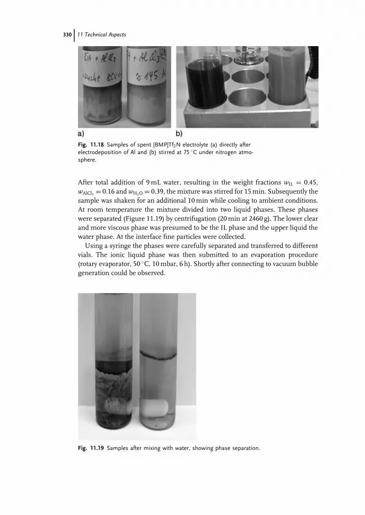
c11 (JWBG008-Endres) January 11, 2008 9:55 Char Count=
330 11 Technical Aspects
Fig. 11.18 Samples of spent [BMP]Tf2N electrolyte (a) directly afterelectrodeposition of Al and (b) stirred at 75 ◦C under nitrogen atmo-sphere.
After total addition of 9 mL water, resulting in the weight fractions wIL = 0.45,wAlCl3 = 0.16 and wH2O = 0.39, the mixture was stirred for 15 min. Subsequently thesample was shaken for an additional 10 min while cooling to ambient conditions.At room temperature the mixture divided into two liquid phases. These phaseswere separated (Figure 11.19) by centrifugation (20 min at 2460 g). The lower clearand more viscous phase was presumed to be the IL phase and the upper liquid thewater phase. At the interface fine particles were collected.
Using a syringe the phases were carefully separated and transferred to differentvials. The ionic liquid phase was then submitted to an evaporation procedure(rotary evaporator, 50 ◦C, 10 mbar, 6 h). Shortly after connecting to vacuum bubblegeneration could be observed.
Fig. 11.19 Samples after mixing with water, showing phase separation.

c11 (JWBG008-Endres) January 11, 2008 9:55 Char Count=
11.4 Towards Regeneration and Reuse of Ionic Liquids in Electroplating 331
Fig. 11.20 Recovered ionic liquid phase ([BMP]Tf2N) after regeneration.
After evaporation the ionic liquid phase contained a dispersed precipitate. Thesesolid particles were concentrated at the bottom of the flask by centrifugation (20 minat 2460 g) resulting in a very clear, slightly yellowish ionic liquid phase (Figure11.20).
It should be stated here that on a technical scale washing requires a concept forwater reuse and recovery of ionic liquid from the wastewater. As already discussed,nanofiltration is likely be a successful approach for the recovery task.
The regenerated ionic liquid phase was investigated electrochemically to deter-mine its quality. Cyclic voltammetry was performed using a rotating platinum diskelectrode (500 rpm), a platinum counter electrode and a platinum wire as (quasi-)reference electrode placed closed to the rotating disk.
In Figure 11.21 two ionic liquids are compared, a freshly synthesized [BMP]Tf2Nreceived from Iolitec GmbH and the regenerated ionic liquid. It can be clearly seenthat current densities after regeneration are lower than for the fresh electrolytethroughout the entire potential range. No additional signal can be recognized forthe regenerated ionic liquid. This indicates that none of the electrochemicallyactive additional ingredients, water and Al(III), remain. The regenerated ionicliquid appears to be at least as pure as the originally synthesized ionic liquid. Theregeneration was successful.
In the fresh electrolyte a first anodic step starts at 1500 mV. This could be a hintfor chloride impurity. Since this signal almost vanished for the regenerated ionicliquid, it can be assumed that the procedure presented is suitable also for purifyingfresh ionic liquids.

c11 (JWBG008-Endres) January 11, 2008 9:55 Char Count=
332 11 Technical Aspects
Fig. 11.21 Cyclic voltammograms of original and regenerated ionicliquid [BMP]Tf2N)). The potential was determined vs. Pt as quasi-reference electrode. Scan rate 5 mV s−1.
The pros and cons of this approach are summarized as follows:
Ĺ Ease of process.Ĺ Small amount of losses of ionic liquid, but aluminum salts are completely lost
after hydrolysis for the plating process.Ĺ Pure ionic liquid as product.Ĺ Only water as solvent necessary, which can be re-used in the regeneration process
to a certain extent.Ĺ Before discharge of the wastewater dissolved amounts of ionic liquid need to be
recovered for environmental and economical reasons, e.g. by nanofiltration.Ĺ In contrast to dead-end microfiltration, which could also be used to remove
solids from spent electrolytes producing (after addition of a solvent and at elevatedtemperatures) an ionic liquid as residue, the residue in the extractive regenerationis wet sludge only.
Despite the conspicuous advantages of the presented water-based regenerationapproach, it is still to be shown whether it can be transferred to other tasks andwhether the reuse of the regenerates in plating processes leads to surface qualitiessimilar to those received from fresh electrolytes.
11.4.4Conclusions
A general approach towards both more economical and more environmentallybenign applications of ionic liquids is maximization of their lifetime. The mea-sures to be applied in electroplating are recovery and regeneration, both to allow

c11 (JWBG008-Endres) January 11, 2008 9:55 Char Count=
11.4 Towards Regeneration and Reuse of Ionic Liquids in Electroplating 333
reuse. This study focuses mainly on regeneration, but also recovery of drag-outis considered, which should be possible in conventional counter-current rins-ing systems, albeit in combination with regeneration units such as membraneconcentrators.
This study focuses firstly on the transfer of regeneration principles as they havebeen developed in the field of water-based electroplating and of purification optionsfor ionic liquids as they are experienced in other fields of ionic liquid application. Anumber of purification procedures for fresh ionic liquids have already been testedon the laboratory scale with respect to their finishing in downstream processing.These include distillation, recrystallization, extraction, membrane filtration, batchadsorption and semi-continuous chromatography. But little is known yet aboutefficiency on the technical scale. Another important aspect discussed is the recoveryof ionic liquids from rinse or washing water.
However, the financial and environmental cost might be too high for a certainapproach. Hence the optimality of a solution is always subject to technical con-straints and the technical bottleneck of each option has to be identified. For anyoptimization approach it has to be considered that the demand for regenerationis finally related to large scale applications. The mass flow that has to be treatedduring regeneration will range typically from grams to kilograms per minute.
Since little is yet known about efficiency on the technical scale, future investiga-tion should focus on (i) efficiency with respect to separation yield, energy demandand amount of mass separation agents required, (ii) long-term re-use options ofauxiliary agents such as extractants or adsorbents and (iii) ease of scaling up. Fur-thermore, a crucial point for further development of regeneration will be to identifythe pollutants that disturb the main process as well as their critical concentrationlevels in the electrodeposition process.
In a case study, the extraction of a spent, turbid electrolyte with water at elevatedtemperature and subsequent phase separation is shown as an example. It couldbe demonstrated that purification of ionic liquids for re-use is not necessarily asdifficult as suspected in the literature [113]. The case study is going to be continuedto demonstrate whether the application of the regenerates will lead to comparablesurface qualities. Accordingly, it is of future interest to see whether the roughnessof cathodic deposits using regenerated electrolytes shows similar dependenceson current density and temperature as does the roughness of deposits from freshelectrolytes. Additionally, future investigations should consider gaseous impurities,which could be dragged in easily due to the high solubility and capacity of manyionic liquids for trace gases, especially sulfur compounds.
Acknowledgments
The authors wish to thank IoLiTec GmbH for providing ionic liquid and spentelectrolyte, and several partners of the BMBF project NEMESIS for fruitful dis-cussions. Financial support by VDI/VDE-IT (project No. 16SV1970) is gratefullyacknowledged.

c11 (JWBG008-Endres) January 11, 2008 9:55 Char Count=
334 11 Technical Aspects
11.5Impurities
Impurities are a concern in ionic liquids electrochemistry. Whereas even consider-able amounts of impurities, like different metal ions, water or organic impurities,might not disturb a technical process (e.g. extractive distillation, organic synthesis)the wide electrochemical windows of an ionic liquid (∼± 3 V vs. NHE) allow theelectrodeposition of even reactive metals like lithium and potassium, as well as theoxidation of halides to the respective gases. In the best case this codeposition onlyleads to a low level of impurities, in the worst case fundamental physicochemicalstudies are made impossible as the impurities are adsorbed onto the electrode sur-face and subsequently reduced. Furthermore, passivation or activation effects atthe counter electrode have to be expected.
In the last few years the different suppliers of ionic liquids have developed severalpurity grades. Merck has introduced “synthesis”, “high purity” and “ultrapurity”(see Chapter 1.2) and other suppliers also follow this purity scheme. In the pastmuch attention was focussed on impurity effects. However, as the different suppli-ers are about to establish large scale production lines where the costs for the eductshave to be quite low one has to be prepared that the problem of impurities mayreturn. As many groups (in part without any experience at all) have entered thefield of ionic liquids in recent years we would like to draw attention to the subject ofimpurities. Impurities can be a concern but do not necessarily have to be a concern.We could also imagine that for some processes impurities are beneficial but, as aminimum, one should know their role in the respective process.
11.5.1Origin of Impurities
11.5.1.1 Synthetic ImpuritiesThe synthesis process represents a very significant source of impurities in ionicliquids. Because of their typically low volatility, which makes distillation impractical,and the lack of any straightforward crystallization method of purification, ionicliquids are often delivered in a semi-impure state. Significant impurities includestarting materials, such as halides, and metal cations, such as lithium, sodium orsilver, and any impurities carried through from the synthesis of the organic cation,in particular amines. Where halides such as bromide and iodide are present, someoxidised species such as I3
− are often also present, generating color in the otherwisecolorless ionic liquid. Most of these can be quite difficult to remove; however, atthe 1% or below level, in many cases they can be tolerated as long as the impuritylevel is consistent from batch to batch. Seddon [139] has discussed the impact oflow levels of impurities on physical properties including viscosity. Chloride ionsare particularly notable for their effect in lowering viscosity.
If analytical information is not available from the supplier of the ionic liquid itis advisable to carry out analysis, using traditional AAS or ICP-MS methods forthe metals and halide-selective electrode analysis for the halides. Residual amine

c11 (JWBG008-Endres) January 11, 2008 9:55 Char Count=
11.5 Impurities 335
can be easily detected using a Cu(II) complex formation and UV/vis absorbancemeasurements.
In some ionic liquids, acid (proton) impurities are significant. This is commonin the phosphonium cation family of ionic liquids and can also be the case withnitrogen-based cations if the synthetic method involves a neutralization reaction. Itis relatively easy to deal with this situation. Acidity should be determined by a stan-dard titration method and then the acidity neutralized by addition of an appropriatebase. Carbonates are particularly useful in this regard since they produce CO2 asthe product.
11.5.1.2 WaterWater presents a rather different problem in that its presence can originate fromthe synthesis, or from handling and storage prior to (or even during) the electrode-position. Notably, even ionic liquids such as [EMIM]Ntf2] that we think of as beinghydrophobic are nonetheless reasonably hygroscopic up to their saturation point,so that storage and handling needs to involve an inert atmosphere. The presence ofthis water is particularly significant in the potential region below –0.5 V (vs Ag/Ag+)where it produces reduction products directly and also may cause degradation ofthe ionic liquid and/or a surface film to form on the deposited metal. Howlett et al.[140] have suggested that [Ntf2] ionic liquids produce breakdown products of theanion on metals such as lithium and magnesium in a reaction that is catalyzed byreduction products of water such as the hydroxyl radical. These reduction productsmay produce useful protective films in some cases, such as lithium, such that fur-ther reduction of the metal ion can take place via transport through the film, butthis is unlikely to be the situation in the case of more highly charged metal ionssuch as Ti(II).
Water analysis can be routinely carried out by a Karl–Fischer analysis in whichthe ionic liquid is diluted in methanol before analysis. A spiking approach can beused to produce a calibration curve that allows for background effects. At very lowlevels of water (<10 ppm) quite substantial sample sizes can be needed for thismethod to be meaningful.
Other significant impurities can arise from the breakdown of the ionic liquidduring storage. This is particularly important in the case of the PF6
− ionic liquids.It has been shown by a number of groups (sometimes with catastrophic results) thatsmall amounts of water in the ionic liquid (in some cases introduced by repeatedopening of a container of the IL in the laboratory atmosphere) can hydrolyze theanion during storage to produce a variety of oxyfluoride species:
PF−6 + H2O = H+ + F− + phosphorus oxyfluorides
The exact nature of the hydrolysis products is not well established, however, thegeneration of HF is clear. Such ionic liquids have been observed to etch their glasscontainers and, in one case, a small explosion occurred when there was a build up ofgas pressure in the bottle (presumably from the etch products). Notably, a numberof PF6
− ionic liquids are water immiscible; nonetheless they are able to dissolve

c11 (JWBG008-Endres) January 11, 2008 9:55 Char Count=
336 11 Technical Aspects
sufficient amounts of water for this process to be significant. For this reason the useof PF6
− ionic liquids in electrowinning processes is not recommended, especiallyfor a continuous use electroreduction process, or any situation where the IL isbeing recycled. While the build up of HF can be controlled and dealt with, theadditional analysis and process steps required mean that it is usually more effectiveto consider an alternate ionic liquid. Therefore, liquids with PF6
− and BF4− cannot
be recommended to the beginner!
11.5.1.3 Gaseous ImpuritiesDissolved gases, in particular oxygen and nitrogen, are no less problematic in ionicliquids than in other solvents. At very negative potentials, the presence of nitrogencan be problematic in an unfamiliar way in that metals such as Li easily formnitrides. There are also suggestions that the reduction products of oxygen may playa catalytic role in ionic liquid degradation in some cases [140]. The solutions inboth cases are the familiar degassing strategies adopted in electrochemical workwhenever dissolved gases are an issue. The only additional aspect that one needsto be aware of is that the higher viscosity of ionic liquids as compared to aqueousor aprotic solvents, means that degassing methods generally need more time andstirring. Increased temperatures during degassing facilitate the process and alsolower the gas solubility in a useful way.
11.5.1.4 Particulate ImpuritiesGiven the unusual solvency properties of ionic liquids, especially towards ionicmaterials, it is not surprising that there have been recent reports [141] concerningthe dissolved and nano-particulate impurities arising from absorbents used inthe synthetic process. Nano-particulate silica and alumina from this source can beidentified in many ionic liquids. Parts per million levels of Al and Si can be detectedby ICP-MS and there is evidence from one of our groups (F.E.) of this Al and Sibeing electrodeposited (see below). Such impurities may, or may not be an issue,depending on the metal being electrodeposited. They certainly may appear in theelectrodeposit as low level impurities, but they may also appear as surface and grainboundary layers on the deposit.
11.5.2Impurities in Deep Eutectic Solvents
Ionic liquids can be compared to any other liquid in that the reactivity of a specieswill depend upon its relative activity in solution. To this end it is important toconsider the relative Lewis and Brønsted acids that can interact with the solutes toaffect their activity. It is also important to remember that ionic liquids with discreteanions have wider potential windows and what we therefore hope to achieve withthem is more susceptible to the presence of reactive species. The influence ofimpurities on the electrochemical behavior of an ionic liquid will depend upon therelative Lewis acidity/basicity of the liquid and of the redox process in question.Eutectic-based ionic liquids behave very differently from ionic liquids with discrete

c11 (JWBG008-Endres) January 11, 2008 9:55 Char Count=
11.5 Impurities 337
anions. The presence of a high concentration of both Lewis acid and base in theeutectic mixtures makes them act like a buffer solution would in an aqueoussolution. Hence, the addition of a Lewis acid or base has minimal effect on theproperties of the liquid. An example of this is the addition of a simple halide salte.g. to a chloroaluminate ionic liquid. The presence of a large amount of AlCl3 inthe liquid means that the equilibrium:
a AlCl3 + b Cl− ↔ c AlCl−4 + d Al2Cl−7
will be perturbed but the concentration of free chloride will still be negligible. Theability of the ionic liquid to act as a buffer will depend upon the relative Lewis orBrønsted acidities of the components. This is true of ionic liquids with discreteanions, e.g. Tf2N− will be approximately Lewis neutral whereas Tf − will be moreLewis basic. These systems will be considerably more susceptible to the presenceof a Lewis Base such as Cl−.
The main contaminants in an ionic liquid will be introduced from the synthe-sis, absorbed from the atmosphere or produced as breakdown products throughelectrolysis (see above). The main contaminants for eutectic-based ionic liquidswill be from the components. These will be simple amines (often trimethylamineis present which gives the liquid a fishy smell) or alkyl halides. These do not in-terfere significantly with the electrochemical response of the liquids due to thebuffer behavior of the liquids. The contaminants can be effectively removed byrecrystallization of the components used to make the ionic liquids. For ionic liq-uids with discrete anions the major contaminants tend to be simple anions, suchas Li+, K+ and Cl−, present from the metathesis technique used. These can givesignificant difficulties for the deposition of reactive metals such as Al, W and Ti asis demonstrated below with the in situ scanning tunnelling microscope.
The absorption of species from the atmosphere is common to all electrolytesolutions and clearly the absorption of water is the biggest issue. This is not solelyconfined to ionic liquids, however, as all electroplaters who deal with aqueoussolutions of acids know, if the solution is not heated then the tank will overflowfrom absorption of atmospheric moisture after some time. In the aqueous acidthe inclusion of water is not a major issue as it does not significantly affect thecurrent efficiency or potential window of the solution. Water absorption is alsonot such a serious issue with eutectic-based ionic liquids and the strong Lewisacids and bases strongly coordinate the water molecules in solution. The presenceof up to 1 wt.% water can be tolerated by most eutectic-based systems. Far fromhaving a deleterious effect, water is often beneficial to eutectic-based liquids as itdecreases the viscosity, increases the conductivity and can improve the rate of theanodic reaction allowing better surface finishes. Water can even be tolerated in thechloroaluminate liquids to a certain extent [139] and it was recently shown that thepresence of trace HCl, that results from hydrolysis of the liquid, is beneficial forthe removal of oxide from the aluminum anode [140].
In ionic liquids with discrete anions the presence of water is often far from ideal.The lack of a Lewis or Brønsted acid to coordinate the water results in a high activity

c11 (JWBG008-Endres) January 11, 2008 9:55 Char Count=
338 11 Technical Aspects
of water molecules in the liquid. Accordingly the presence of only traces of watercan seriously limit the potential window of the ionic liquid.
No concerted studies on the breakdown products of ionic liquids have beencarried out. It is unlikely that these will interfere with the metal species formed,but tests need to be carried out at typical current densities that would be used forcommercial plating procedures.
11.5.3Impact of Impurities on Electrochemistry
Figure 11.22 shows a typical cyclic voltammogram of ultrapure 1-butyl-1-methylpyrrolidinium bis(trifluoromethylsulfonyl)amide ([Py1,4] TFSA) on Au(111)[143]. Ultrapurity means that the supplier (in the present case: Merck KGaA/EMD)guarantees that water and halide impurities are below the 10 ppm level. Routinelythe liquids are dried under vacuum and at elevated temperature to water contentsbelow 3 ppm (the detection limit of the Karl–Fischer method) prior to use in ourlaboratory.
As shown in Figure 11.22, the electrochemical window of this liquid on Au(111)can be determined by extrapolation of the rising cathodic and the rising anodiccurrents to zero. The cathodic limit is mainly due to the irreversible reductionof the [Py1,4] to N-methylpyrrolidine and butyl radicals which undergo further
Fig. 11.22 Cyclic voltammogram of ultrapure [Py1,4]TFSA on Au(111)with v = 10 mV s−1. The electrochemical window is 5.6 V. The reduc-tion peaks C1–C3 are correlated with TFSA breakdown which may beinduced by ultralow amounts of water or other impurities.

c11 (JWBG008-Endres) January 11, 2008 9:55 Char Count=
11.5 Impurities 339
Fig. 11.23 The in situ STM picture evidences that the Au(111) surfacenear the open circuit potential shows a wormlike surface pattern, likelydue to interference between the gold surface and the [Py1,4] cation.
decomposition to butene(s) and hydrogen. The oxidation wave A4 is directly cor-related with the breakdown of the cation C4. The anodic limit is due to golddisintegration and partly to irreversible anion oxidation. The potential regime inbetween is the maximum available electrochemical window and can be determinedto be 5.6 V. But what about the peaks/waves C1–C3 and A3 ? Macroscopically thereis no surface modification visible. In the potential regime between +2 and –3 V vs.ferrocene/ferrocinium (Fc/Fc+) gold looks – macroscopically – like gold should.The quartz crystal microbalance does not show any mass effect in this potentialregime. One could argue about soluble organic or inorganic impurities, but theliquids contain negligible inorganic ions and, furthermore, purified by chromatog-raphy to remove organic impurities, thus high impurity concentrations cannot bethe reason. Figure 11.23 shows the surface of Au(111) under [Py1,4] TFSA at theopen circuit potential, i.e. at around –0.5 V vs. Fc/Fc+.
It is quite interesting that gold does not show here the typical surface knownin aqueous electrochemistry with flat terraces separated by steps, it is, in contrast,strongly structured with a wormlike pattern. Interactions of the gold surface withions of the ionic liquid lead to such restructuring phenomena. If the electrodepotential is reduced successively to –1.7 V the wormlike pattern disappears slowly.There is a potential regime where only vacancy islands are observed, Figure 11.24(a).On this picture the transformation is not yet complete (still some vacancy islandsare present), but on a time-scale of 20–30 min these vacancy islands disappearcompletely, i.e. in the potential regime of wave C1. Thus the peak C1 could, atfirst glance, be correlated to the restructuring of the gold surface. But, on the onehand, the respective oxidation peak is missing, on the other hand MacFarlane et al.have described that in this potential regime the irreversible breakdown of the TFSAion starts [140]. New results from the Passerini group make it likely that quite lowamounts of water or other impurities, below the 10 ppm level, are involved in theTFSA decomposition reaction [144].

c11 (JWBG008-Endres) January 11, 2008 9:55 Char Count=
340 11 Technical Aspects
Fig. 11.24 The quality of the STM picture is reduced strongly in thepotential regime of the reduction peaks C1–C3 in [Py1,4]TFSA. TheSTM probes the breakdown of the TFSA, which may be induced bywater and/or other impurities in the ultralow concentration regime.
If we perform the same experiment with ultrapure 1-ethyl-3-methylimidazoliumbis(trifluoromethylsulfonyl)amide ([EMIM] TFSA), we do not see the same restruc-turing with the in situ STM, although it is described that it is the anion which issubject to irreversible breakdown in this potential regime. This led us to the con-clusion that adsorption of the [Py1,4] cation (maybe together with TFSA + TFSAbreakdown products) is responsible for the wormlike pattern and the formation ofa flat surface finally. As shown in Chapter 7 the impact of pyrrolidinium ions onthe grain size of electrochemically made metals is evident and pyrrolidinium ionsmight act as surface-active species which would open a novel concept of additives forionic liquids. Between –1.7 and –1.9 V vs. Fc/Fc+ a flat gold surface can be probedand around –2 V (i.e. in the potential regime of wave C2) we observed routinelythat the picture quality got worse, see Figure 11.24(b). In the first experiments wethought this would be due to a bad tip, a common problem the experimentalist hasto struggle with, but it was surprising that the noise shown in Figure 11.24(b) dis-appeared again when the electrode potential was set back to –1.7 V and reappearedat about –2 V. Such a reversible and reproducible behavior excludes a “bad tip”. If

c11 (JWBG008-Endres) January 11, 2008 9:55 Char Count=
11.5 Impurities 341
in the in situ STM experiment the electrode potential is set to values between –2.2and –2.7 V it is evident that the picture quality is dramatically reduced, as shownin Figure 11.24(c). It should be mentioned clearly that this is definitely not due toa bad tip, and there is still a tunnelling contact between tip and surface allowingone to probe the surface. At –2.9 V (in the potential regime of wave C3), Figure11.24(d), the surface is now obviously covered by a film which makes probing thesurface difficult. Nevertheless, the steps can still be identified. At lower electrodepotentials, i.e. in the regime of the cathodic breakdown C4, the tunnelling contactis finally lost. Together with the results from the MacFarlane group it can be con-cluded that the TFSA is subject to a certain cathodic breakdown, possibly inducedby ultralow amounts of impurities [144] although this cannot be confirmed at themoment. In any case, with the in situ STM this breakdown can be probed. It canbe concluded from these in situ STM experiments that the understanding of evenapparently simple electrochemical windows of ionic liquids can be a tough job. Inour experience it is not sufficient to have just a look at the cyclic voltammograms,it may first be necessary to acquire fundamental local probe information of anyionic liquid which is to be employed for fundamental studies at the electrode/ionicliquid interface. Furthermore there are known combined anion/cation effects inionic liquids that affect the chemical and electrochemical processes so that it maynot be sufficient just to exchange the anion for a more stable one. The surfacebehavior may be different. Fundamental local probe electrochemistry might firstrequire a detailed characterization of the potential-dependent interface effects. Itshould be mentioned that inorganic impurities in ionic liquids (even in appar-ently ultrapure liquids) may lead to a complete misunderstanding of the surfaceprocesses.
We have discussed in Ref. [143] that liquids, made by a metathesis reaction from[Py1,4]Cl and Li-TFSA, can contain low amounts of Li ions. The results will be brieflysummarized here. The ionic liquid is apparently perfect on glassy carbon but thereis clear evidence for deposition of Li on Au(111), Figure 11.25(a). From the cyclicvoltammogram the redox process C5 implies electrodeposition in the UPD regimewhereas the peak C6 would imply bulk deposition. Furthermore, the irreversibledecomposition peaks C1–C3, discussed above, are not observed here. The in situinvestigation of Au(111) in this liquid shows, for an electrode potential of –1.6 Vquite a nice gold surface, Figure 11.25(b), whereas at –2.4 V, Figure 11.25(c), adeposit is clearly observed. If we add LiTFSA to a [Py1,4]TFSA liquid made by themetathesis routine we get more or less the same result, furthermore Li can bedeposited reproducibly (see Chapter 12).
Our clear recommendation is to have a critical look at any ionic liquid delivered byany of the suppliers. Glassy carbon is a bad substrate to probe inorganic impuritiesin ionic liquids. In our experience noble metal electrodes like gold or platinumare better suited to detect low amounts of impurities. We have further examples inClausthal where we saw clearly, with the in situ STM, metal deposition in apparentlyultrapure liquids. In several liquids we found, with XPS and/or EDX, considerableamounts of potassium. Upon our insistence, the supplier finally told us that thesynthesis route had been changed. For technical experiments such low amounts of

c11 (JWBG008-Endres) January 11, 2008 9:55 Char Count=
342 11 Technical Aspects
Fig. 11.25 (a) Cyclic voltammogram of [Py1,4]TFSA (with low amountsof Li impurities) on Au(111): the processes C5 and C6 are typical fordeposition in the UPD and OPD regimes, respectively. (b) In situ STMof Au(111) before C5: flat gold surface. (c) In situ STM of Au(111)between C5 and C6: obviously Li deposition has occurred.
impurities maybe do not matter, but for fundamental studies such impurities canbe a nightmare, making progress a bit slow.
A further error in IL synthesis can originate from purification processes. Inorder to remove the often yellowish color of ionic liquids after synthesis they arecommonly purified over silica or alumina powder (see above). Once we obtaineda liquid where the supplier invested a lot of effort to deliver “Endres-quality”.[EMIM]TFSA was made with the best available educts in the acid–base routinefrom diluted aqueous [EMIM]OH and H-TFSA. This approach excludes metal andhalide impurities. The supplier removed the slight yellowish color by purificationover silica. For this purpose the supplier used quite a fresh silica, which hadnot been used in any purification process before. One has to bear in mind thatthe dominant impurities, even in hiqh quality silica, are aluminum species. Figure11.26 shows the 1st, the 7th and the 15th cycles of this liquid on Au(111). Apparently

c11 (JWBG008-Endres) January 11, 2008 9:55 Char Count=
11.5 Impurities 343
Fig. 11.26 Cyclic voltammograms (10 mV s−1) of [EMI]TFSA (purifiedover silica) on Au(111), (a) 1st, (b) 7th, (c) 15th cycle.
perfect in the beginning, deposition occurs in the 15th cycle, C1. In the in situ STMexperiment it was quite surprising that we got a bad surface, Figure 11.27(a). Theless experienced STM-experimentalist would conclude that he had a bad tip. Quiteinterestingly, the STM picture quality is improved tremendously by reducing theelectrode potential to –0.5 and subsequently to –1.8 V (Figure 11.27(b) and (c)). At–1.8 V there is a nice terraced surface. From unpublished XPS data and from theheight probed by in situ STM we have no other explanation but that a tiny, only afew nanometers high, aluminum layer was deposited, which would not be visiblewith a less sensitive analytical tool. The only explanation that we have is that, fromthe fresh silica, aluminum species were washed off into the ionic liquid, adsorbedloosely at the electrode and subsequently electrodeposited. This assumption wasrecently proved independently by one of us (D.R.M.). We have further resultsthat show that impurities can strongly alter chemical reactions. The hydrolysis ofTiCl4 by water in liquids with the TFSA anion only delivers nanocrystalline rutileif the liquids are ultrapure, i.e. with impurities below the 10 ppm level. Alreadyimpurity levels in the 100 ppm regime lead to a mixture of nano-anatase andnano-rutile [145].
As a consequence, in our laboratories in Clausthal, any newly delivered ionic liq-uid is first tested by cyclic voltammetry and in situ STM on Au(111) thoroughly be-fore it is used for fundamental studies. This approach is somewhat time-consumingand in part frustrating for the students, on the other hand it is currently the onlychance to avoid misinterpretation of electrochemical experiments, especially withthe in situ STM. This is one of the challenges in ionic liquids electrochemistry.

c11 (JWBG008-Endres) January 11, 2008 9:55 Char Count=
344 11 Technical Aspects
Fig. 11.27 In situ STM pictures of [EMIM]TFSA (purified over silica)on Au(111): obviously there is a surface film adsorbed initially whichcan be reduced to a nice terrace-like deposit.
This chapter draws attention to impurities in the ultralow concentration regime.We do not say that what we have described here will occur all the time in allliquids, but it can occur and, therefore, in our opinion, care has to be taken not tomisinterpret results. The suppliers should take more care in the characterizationof ionic liquids.
Appendix AProtocol for the Deposition of Zinc from a Type III Ionic Liquid
Preparation of Ionic Liquids
The eutectic mixture is formed by stirring the two components, 1 ChCl : 1.5 urea (forexample: 69.815 g ChCl and 45.045 g urea) at 75 ◦C until a homogeneous colorlessliquid is formed. Once the liquid has formed add 34.07 g ZnCl2 and stir until it isdissolved. The ratio of the three components is 1 ChCl : 1.5 urea : 0.5 ZnCl2.

c11 (JWBG008-Endres) January 11, 2008 9:55 Char Count=
References 345
Electroplating Experiment
MethodPour each of the ionic liquids into a 0.25 l beaker. Heat for 20 min with magneticstirring to 60 ◦C. To one of the beakers add 5 wt.% LiCl, and to a second add 10 wt.%ethanol.
Immerse copper workpiece in HCl for 2 min, then rinse with deionized waterand dry. Place in dichloromethane (to degrease the surface) for 2 min then removeusing tweezers and allow the dichloromethane to evaporate. Attach crocodile clipsto leads on the power supply. Position the two electrodes opposite each other in thesolution and clip them in place with crocodile clips. Attach the copper workpiece tothe positive terminal and use either glassy carbon or zinc attached to the negativeterminal. Perform an anodic etch at 1.0 V for 40 s. Then swap the leads on thepower supply to make the copper workpiece the cathode and the glassy carbon orzinc the anode. Next begin plating by setting the current density to 20 mA cm−2.Leave for 1 h. When the experiment is finished, rinse the copper workpiece withdeionised water and allow to dry.
Safety Precautions
Ĺ Choline chloride (HOCH2CH2N(CH3)3Cl) – Incompatible with strong oxidizingagents, moisture. Store under a dry atmosphere. May act as an irritant. Minimizecontact. Risk phrases: R36/37/38, irritating to eyes, respiratory system and skin.Safety phrases: S26-36. In case of contact with eyes, rinse immediately with waterand seek medical advice. In case of contact with skin, wash immediately withwater. Wear safety glasses and protective clothing/gloves.
Ĺ Urea (H2NC=ONH2) – Irritating to eyes, respiratory system and skin. In caseof contact with eyes, rinse immediately with plenty of water and seek medicaladvice. Wear suitable protective clothing. Risk phrases: R36 R37 R38 R40. Safetyphrases: S26 S36.
Ĺ Zinc Chloride (ZnCl2) – Incompatible with potassium. Corrosive. Causes burns.Harmful if swallowed or inhaled and in contact with skin. Irritant, risk of seriousdamage to eyes. In case of contact with eyes, rinse immediately with plenty ofwater and seek medical advice. Risk phrases: R34-50/53. Wear Safety glasses, usewith adequate ventilation and wear protective clothing. Safety phrases: S7/8-26-28-36-45-60-61.
References
1 Matsumoto, H. (2005) in ElectrochemicalAspects of Ionic Liquids (ed. H. Ohno),John Wiley & Sons, Inc., New York, pp.35–54; Liu, Q.X., El Abedin, S.Z., and
Endres, F. (2006) Surf. Coat. Technol.,201, 1352–1356.
2 Abbott, A.P., Capper, G., Davies, D.L.,Munro, H., Rasheed, R., and

c11 (JWBG008-Endres) January 11, 2008 9:55 Char Count=
346 11 Technical Aspects
Tambyrajah, V. (2003) Ionic Liquids asGreen Solvents: Progress and Prospects,ACS Symp. Ser., 439–452.
3 Jiang, T., Chollier Brym, M.J., Dube, G.,Lasia, A., and Brisard, G.M. (2006) Surf.Coat. Technol., 201, 1–9.
4 Lin, Y-F. and Sun, I.W. (1999)Electrochim. Acta, 44, 2771–2777.
5 Zhao, Y. and VanderNoot, T.J. (1997)Electrochim. Acta, 42, 1639–1643.
6 Abbott, A.P., Capper, G., Davies, D.L.,and Rasheed, R. (2004) Chem. Eur. J., 10,3769.
7 Abbott, A.P., Capper, G., Davies, D.L.,Rasheed, R.K., Archer, J., and John, C.(2004) Trans. Inst. Met. Finish., 82, 14.
8 Tabereaux, A.T. (1994) JOM, 42, 30–34.9 Leber, B.P., Tabereaux, A.T., Marks, J.,
Lamb, B., Howard, T., Kantamaneni, R.,Gibbs, M., Bakshi, V., and Dolin, E.J.(1998) in Light Metals, (ed. B.J. Welch),TMS, Warrendale PA, pp. 277–285.
10 (1989) The Canning Handbook, 23rd edn,E & F. N. Spoon Ltd., London.
11 M. Davis and T. Sandy (1992) inHandbook of Industrial Waste Treatment,(eds L.K. Wang and M.H.S. Wang),Marcel Dekker, New York, , pp. 127–171.
12 H. Figous and P.A. Jacquet (1930)French Patent No: 707526.
13 Berlouis, L.E.A. and Schiffrin, D.J.(1985) Trans. Inst. Met. Finish., 63, 52.
14 Alanis, I.L. and Schiffrin, D.J. (1979)Electrochim. Acta, 27, 837.
15 Pietrowski, O., Madore, C., and Landolt,D. (1998) J. Electrochem. Soc., 145, 2362.
16 Mohan, S., Kanagaraj, D., Sindhuja, R.,Vijayalakshmi, S., and Renganathan,N.G. (2001) Trans. Inst. Met. Finish., 79,140.
17 Landolt, D. (1987) Electrochim. Acta, 32,1.
18 Abbott, A.P., Capper, G., Swain, B.G.,and Wheeler, D.A. (2005) Trans. Inst.Met. Finish., 83, 51.
19 Grimm, R.D., West, A.C., and Landolt,D. (1992) J. Electrochem. Soc., 139, 1622.
20 Matlosz, M., Magaino, S., and Landolt,D. (1994) J. Electrochem. Soc., 141, 410.
21 Abbott, A.P., Capper, G., McKenzie, K.J.,and Ryder, K.S. (2006) Electrochim. Acta,51, 4420.
22 Abbott, A.P., Capper, G., McKenzie, K.J.,
and Ryder, K.S. (2006) Phys. Chem.Chem. Phys., 8, 4214.
23 Buzzeo, M.C., Evans, R.G., andCompton, R.G. (2004) Chem. Phys.Chem., 5, 1106–1120.
24 Endres, F. and Zein El Abedin, S. (2006)Phys. Chem. Chem. Phys., 8, 2101–2116.
25 Silvester, D.S. and Compton, R.G. (2006)Z. Phys. Chem., 220, 1247–1274.
26 Compton, R.G. and Sanders, G.H.W.(1996) Electrode Potentials, OxfordUniversity Press, Oxford, UK.
27 Nernst, W. (1888) Z. Phys. Chem., 2, 613.28 Albery, W.J. (1975) Electrode Kinetics,
Clarendon Press, Oxford.29 Kotyta, J., Dvorak, J., and Kavan, L.
(1993) Principles of Electrochemistry, 2ndedn, John Wiley & Sons, Inc., New York.
30 Butler, J.N. (1970) Reference Electrodes inAprotic Organic Solvents, John Wiley &Sons, Inc., New York.
31 Ives, D.J.G. and Janz, G.J. (1961)Reference Electrodes: Theory and Practice,Academic Press, New York.
32 Bard, A.J. and Faulkner, L.R. (2001)Electrochemical Methods: Fundamentalsand Applications, John Wiley & Sons,Inc., New York.
33 Gritzner, G. and Kuta, J. (1982) PureAppl. Chem., 54, 1527–1532.
34 Stojanovic, R.S. and Bond, A.M. (1993)Anal. Chem., 65, 56–64.
35 Hultgren, V.M., Mariotti, A.W.A., Bond,A.M., and Wedd, A.G. (2002) Anal.Chem., 74, 3151–3156.
36 Bhatt, A.I., Bond, A.M., MacFarlane,D.R., Zhang, J., Scott, J.L., Strauss, C.R.,Iotov, P.I., and Kalcheva, S.V. (2006)Green Chem., 8, 161–171.
37 Zhang, J. and Bond, A.M. (2005) Analyst,130, 1132–1147.
38 Brown, R.J.C., Dyson, P.J., Ellis, D.J.,and Welton, T. (2001) Chem. Commun.,1862–1863.
39 Lagrost, C., Carrie, D., Vaultier, M., andHapiot, P. (2003) J. Phys. Chem. A, 107,745–752.
40 Damlin, P., Kvarnstrom, C., and Ivaska,A. (2006) J. Electroanal. Chem., 590,190–197.
41 Ryan, D.M., Riechel, T.L., and Welton,T. (2002) J. Electrochem. Soc., 149,A371–A378.

c11 (JWBG008-Endres) January 11, 2008 9:55 Char Count=
References 347
42 Islam, M.M., Ferdousi, B.N., Okajima,T., and Ohsaka, T. (2005) Electrochem.Commun., 7, 789–795.
43 Sur, U.K., Marken, F., Coles, B.A.,Compton, R.G., and Dupont, J. (2004)Chem. Commun., 2816–2817.
44 Zhang, D., Okajima, T., Matsumoto, F.,and Ohsaka, T. (2004) J. Electrochem.Soc., 151, D31–D37.
45 Schroder, U., Wadhawan, J.D.,Compton, R.G., Marken, F., Suarez,P.A.Z., Consorti, C.S., De Souza, R.F.,and Dupont, J. (2000) New J. Chem., 24,1009–1015.
46 Matsumoto, H., Matsuda, T., andMiyazaki, Y. (2000) Chem. Lett., 29,1430–1431.
47 NuLi, Y., Yang, J., Wang, J.L., Xu, J.Q.,and Wang, P. (2005) Electrochem. SolidState, 8, C166–C169.
48 Koch, V.R., Dominey, L.A., Nanjundiah,C., and Ondrechen, M.J. (1996) J.Electrochem. Soc., 143, 798–803.
49 Saheb, A., Janata, J., and Josowicz, M.(2006) Electroanalysis, 18, 405–409.
50 Matsumoto, K., Hagiwara, R., and Ito, Y.(2004) Electrochem. Solid State Lett., 7,41–44.
51 Snook, G.A., Best, A.S., Pandolfo, A.G.,and Hollenkamp, A.F. (2006)Electrochem. Commun., 8, 1405–1411.
52 Leone, A.M., Weatherby, S.C., Williams,M.E., Thorp, H.H., and Murray, R.W.(2001) J. Am. Chem. Soc, 123, 218–222.
53 Endres, F. and Freyland, W. (1998) J.Phys. Chem. B, 102, 10229–10233.
54 MacFarlane, D.R., Sun, J., Golding, J.,Meakin, P., and Forsyth, M. (2000)Electrochim. Acta, 45, 1271–1278.
55 Borisenko, N., Zein El Abedin, S., andEndres, F. (2006) J. Phys. Chem. B, 110,6250–6256.
56 Brooks, C.A. and Doherty, A.P. (2005) J.Phys. Chem. B, 109, 6276–6279.
57 Fuller, J., Carlin, R.T., and Osteryoung,R.A. (1997) J. Electrochem. Soc., 144,3881–3886.
58 Silvester, D.S., Aldous, L., Lagunas,M.C., Hardacre, C., and Compton, R.G.(2006) J. Phys. Chem. B, 110,22035–22042.
59 Sorahan, T. and Harrington, J.M. (2000)Occup. Environ. Med., 57, 385–389.
60 Stevens, K. (1997) Trans. Inst. MetalFinish., 75 (2), B33–B34.
61 Rousseau, A. and Benaben, P. (2002)Metal Finish., 100, 92–97.
62 Pearson, T. and Long, E. (1998) Trans.Inst. Metal Finish., 76, B83–B87.
63 Ibrahim, S.K., Watson, A., and Gawne,D.T. (1997) Trans. Inst. Metal Finish., 75,181–188.
64 Abbott, A.P., Capper, G., McKenzie, K.J.,and Ryder, K.S. (2006) J. Electroanal.Chem., in press.
65 Simanavicius, L. (1990) Chemija, 3–30.66 Zhao, Y. and Vandernoot, T.J. (1997)
Electrochim. Acta, 42, 3.67 Abbott, A.P. and McKenzie, K.J. (2006)
Phys. Chem. Chem. Phys., 8, 4265–4279.68 Liu, Q.X., Zein El Abedin, S., and
Endres, F. (2006) Surf. Coat. Technol., inpress
69 Bockris, J. O’M. and Reddy, A.K.N.(1970) Modern Electrochemistry, Vol. 1,Plenum Press, New York, Chapter 6.
70 Xu, W., Cooper, E.I., and Angell, C.A.(2003) J. Phys. Chem. B, 107, 6170.
71 Cooper, E.I. and Angell, C.A. (1983)Solid State Ionics, 10, 617.
72 Abbott, A.P. (2004) Chem. Phys. Chem.,5, 1242.
73 Abbott, A.P. (2005) Chem. Phys. Chem.,6, 2404.
74 Cooper, E.I. and Angell, C.A. (1983)Solid State Ionics, 10, 617.
75 Xu, W. and Angell, C.A. (2003) Science,b, 422.
76 (1989) The Canning Handbook 23rd edn,E & F. N. Spoon Ltd., London.
77 (a) Hirao, M., Sugimoto, H., and Ohno,H. (2000) J. Electrochem. Soc., 147, 4168;(b) Yoshizawa, M., Xu, W., and Angell,C.A. (2003) J. Am. Chem. Soc., 125,15411.
78 (a) Sun, J., Jordan, L.R., Forsyth, M., andMacFarlane, D.R. (2001) ElectrochimActa, 46, 1703; (b) Yamada, M. andHonma, I. (2003) Electrochim. Acta, 48,2411.
79 Gale, R.J. and Osteryoung, R.A. (1980)Electrochim. Acta, 25, 1527.
80 (a) Nanjundiah, C., McDevitt, S.F., andKoch, V.R. (1997) J. Electrochem. Soc.,144, 3392; (b) Nanjundiah, C.,Goldman, J.L., McDevitt, S.F., and Koch,

c11 (JWBG008-Endres) January 11, 2008 9:55 Char Count=
348 11 Technical Aspects
V.R. (1997) Proc. Electrochem. Soc.,96–25, 301.
81 Abbott, A.P., Capper, G., Davies, D.L.,Rasheed, R.K., Archer, J., and John, C.(2004) Trans. Inst. Metal Finish., 82, 14.
82 Zein El Abedin, S., Farag, H.K.,Moustafa, E.M., Welz-Biermann, U., andEndres, F. (2005) Phys. Chem. Chem.Phys., 7, 2333.
83 Jastorff, B., Molter, K., Behrend, P.,Bottin-Weber, U., Filser, J., Heimers, A.,Ondruschka, B., Ranke, J., Schaefer, M.,Schroder, H., Slenzka, K., Stark, A.,Stepnowski, P., Stock, F., Stormann, R.,Stolte, S., Welz-Biermann, U., Ziegert,S., and Thoming, J. (2005) Strategy inevaluation of risk potential of ionicliquids – basis for an eco-design ofsustainable products. Green Chem., 7,362–372.
84 Chilyumova, E. and Thoming, J. (2006)Dynamic simulation of rinsing andregeneration networks based on highpressure RO. Desalination, 207, 45–58.
85 Thoming, J. (2002) Optimal design ofzero-water discharge rinsing systems.Environ. Sci. Technol., 36 (5), 1107–1112.
86 Erol, P. and Thoming, J. (2006)ECO-optimization of pre-treatmentprocesses in metal finishing. Comput.Chem. Eng., 30 (4), 587–598.
87 Fischwasser, K., Schwarz, R., and Suss,M. (2003) Material loss minimizedprocess technology - When areregeneration and concentration unitsefficient? Chem. Ing. Tech., 75 (6),781–786.
88 Vasudevan, S., Sozhan, G., Mohan, S.,Balaji, R., Malathy, P., andPushpavanam, S. (2007) Electrochemicalregeneration of chromium containingsolution from metal finishing industry.Ind. Eng. Chem. Res., 46 (9), 2898–2901.
89 Sanchez, E., Mestre, S., Perez-Herranz,V., and Garcia-Gabaldon, M. (2004)Ceramic membranes for continuousregeneration of spent chromium platingbaths. Key Eng. Mater., 264–268,2211–2214.
90 Huang, K.L., Holsen, T.M., Chou, T.C.,and Selman, J.R. (2003) Comparingnafion and ceramic separators used inelectrochemical purification of spent
chromium plating solutions: Cationicimpurity removal and transport. Environ.Sci. Technol., 37 (9), 1992–1998.
91 Jegadeesan, G., Mondal, K., and Lalvani,S.B. (2005) Iron removal andsimultaneous regeneration of hexavalentchromium in spent plating solutions. J.Electrochem. Soc., 152 (2), D26–D33.
92 Huang, K.L., Holsen, T.M., Chou, T.C.,and Yang, M.C. (2004) The use of air fuelcell cathodes to remove contaminantsfrom spent chromium plating solutions.Environ. Technol., 25 (1), 39–49.
93 Huang, K.L., Holsen, T.M., Selman, J.R.,and Chou, T.C. (2005) Theelectrochemical characteristics of air fuelcell electrodes used in an electrolyticsystem for spent chromium platingsolution regeneration. Journal of powersources, 142 (1–2), 243–252.
94 Gyliene, O., Aikaite, J., Tarozaite, R.,Dolgov, and I.A. (2004) Regenerationand decontamination of a nickel citratecomplex in spent electroless nickelplating solutions. Trans. Inst. Met.Finish., 82 (1–2), 33–37.
95 Xu, T.W. and Yang, W.H. (2004) Tuningthe diffusion dialysis performance bysurface cross-linking of PPO anionexchange membranes - simultaneousrecovery of sulfuric acid and nickel fromelectrolysis spent liquor of relatively lowacid concentration. J. Hazardous Mater.,109 (1–3), 157–164.
96 Pierard, J., Paquay, E., and Degrez, M.(2002) Recycling by electrodialysis: fromlab to industrial applications.Desalination, 149 (1–3), 393–398.
97 Chang, C.F., Chang, C.Y., Tsai, W.T.,and Wu, S.C. (2000) Adsorptionequilibrium of polyethylene glycol in thecopper electroplating solution onactivated carbon. J. Colloid Interface Sci.,232 (1), 207–209.
98 Ozdemir, T., Oztin, C., and Kincal, N.S.(2006) Treatment of waste picklingliquors: Process synthesis and economicanalysis. Chem. Eng. Commun., 193 (5),548–563.
99 Bolger P.T. and Szlag, D.C. (2002)Electrochemical treatment and reuse ofnickel plating rinse waters. Eviron. Prog.,21 (3), 203–208.

c11 (JWBG008-Endres) January 11, 2008 9:55 Char Count=
References 349
100 Juang, R.S., Kao, H.C., and Liu, F.Y.(2006) Ion exchange recovery of Ni(II)from simulated electroplating wastesolutions containing anionic ligands.Journal of Hazardous Materials, 128 (1),53–59.
101 Plokhov, S., Matasova, I., Utkin, V., andVodzinskii, V. (2002) Specific featuresof ion-exchange zinc(II) extractionfrom washing water of zinc plating.Russ. J. Appl. Chem., 75 (6), 950–953.
102 Agrawal, A., Kumar, V., and Pandey, B.(2006) Remediation options for thetreatment of electroplating and leathertanning effluent containing chromium -A review. Miner. Proc. Extractive Metall.Rev., 2, 99–130.
103 Eom, T.H., Lee, C.H., Kim, J.H., andLee, C.H. (2005) Development of an ionexchange system for plating wastewatertreatment. Desalination, 180 (1–3),163–172.
104 Katsumata, H., Kaneco, S., Inomata, K.,Itoh, K., Funasaka, K., Masuyama, K.,Suzuki, T., and Ohta, K. (2003) Removalof heavy metals in rinsing wastewaterfrom plating factory by adsorption witheconomical viable materials. J. Environ.Man., 69 (2), 187–191.
105 Wong, F.S., Qin, J.J., Wai, M.N., Lim,A.L., and Adiga, M (2002) A pilot studyon a membrane process for thetreatment and recycling of spent finalrinse water from electroless plating. Sep.Purif. Technol., 29 (1), 41–51.
106 Schmidt, B., Wolters, R., Kaplin, J.,Schneiker, T., Lobo-Recio, M.A., Lopez,F., Lopez-Delgado, A., and Alguacil, F.J.(2007) Rinse water regeneration instainless steel pickling. Desalination, 211(1–3), 64–71.
107 Chaudhary, A., Ganguli, B., and Grimes,S. (2006) The regeneration and recycle ofchromium etching solutions usingconcentrator cell membrane technology.Chemosphere, 62 (5), 841–846.
108 Frenzel, I., Holdik, H., Stamatialis, D.F.,Pourcelly, G., and Wessling, A. (2005)Chromic acid recovery byelectro-electrodialysis - I. Evaluation ofanion-exchange membrane. J. Membr.Sci., 261 (1–2), 49–57.
109 Singh, R., Khwaja, A., Gupta, B., andTandon, S. (1999) Extraction andseparation of nickel(II) usingbis(2,4,4-trimethylpentyl)dithiophosphinic acid (Cyanex 301) andits recovery from spent catalyst andelectroplating bath residue. Solv.Extraction Ion Exch., 17 (2), 367–390.
110 Malinowska, B., Rakib, M., and Durand,G. (2001) Ammonia recycling andcadmium confinement in chemical bathdeposition of CdS thin layers. Prog.Photovoltaics, 9 (5), 389–404.
111 Malinowska, B., Rakib, M., and Durand,G. (2002) Cadmium recovery andrecycling from chemical bath depositionof CdS thin layers. Progr. Photovoltaics,10 (3), 215–228.
112 Liu, C., Fu, Y., and Lin, C. (2007)Ni-Cu-Zn Ferrite Powder Prepared fromSteel Pickled Liquor and ElectroplatingWaste Solutions. Jpn. J. Appl. Phys., 46(3A), 1006.
113 Zhang, J. and Bond, A. (2005) Practicalconsiderations associated withvoltammetric studies in roomtemperature ionic liquids. Analyst, 130(8), 1132–1147.
114 Waterkamp, D., Heiland, M., Schluter,M., Sauvageau, J.C., Beyersdorff, T., andThoming, J. (2007) Synthesis of IonicLiquids in Micro-Reactors – A ProcessIntensification Study. Green Chem.,DOI:10.1039/B616882E.
115 Scott, J., MacFarlane, D.R., Raston, C.,and Teoh, C. (2000) Clean, efficientsyntheses of cyclotriveratrylene (CTV)and tris-(O-allyl)CTV in an ionic liquid.Green Chem., 2, 123–126.
116 Zulfiqar, F. and Kitazume, T. (2000)Lewis acid-catalysed sequential reactionin ionic liquids. Green Chem., 2, 296–297.
117 Kamal, A. and Chouhan, G. (2004)Investigations towards thechemoselective thioacetalization ofcarbonyl compounds by using ionicliquid [bmim]Br as a recyclable catalyticmedium. Adv. Synth. Catal., 346 (5),579–582.
118 Park, J., Sreekanth, P., and Kim, B.(2004) Recycling chiralimidazolidin-4-one catalyst forasymmetric Diels-Alder reactions:

c11 (JWBG008-Endres) January 11, 2008 9:55 Char Count=
350 11 Technical Aspects
Screening of various ionic liquids. Adv.Synth. Catal., 346 (1), 49–52.
119 Wasserscheid, P., Hilgers, C., and Keim,W. (2004) Ionic liquids -weakly-coordinating solvents for thebiphasic ethylene oligomerization toalpha-olefins using cationicNi-complexes. J. Mol. Catal. A – Chem.,214 (1), 83–90.
120 Wong, H., Pink, C., Ferreira, F., andLivingston, A. (2006) Recovery and reuseof ionic liquids and palladium catalystfor Suzuki reactions using organicsolvent nanofiltration. Green Chem., 8,373– 379.
121 Zhou, L. and Wang, L. (2006)Functionalized Ionic Liquid as anEfficient and Recyclable ReactionMedium for Phosphine-FreePalladium-Catalyzed Heck Reaction.Synthesis, 2653–2658, DOI:10.1055/s-2006-942466.
122 Song, G., Cai, Y., and Peng, Y. (2005)Amino-functionalized ionic liquid as anucleophilic scavenger in solution phasecombinatorial synthesis. J. Comb. Chem.,7, 561–566.
123 Appetecchi, G., Scaccia, S., Tizzani, C.,Alessandrini, F., and Passerini, S. (2006)Synthesis of Hydrophobic Ionic Liquidsfor Electrochemical Applications. J.Electrochem. Soc., 153 (9), A1685–A1691.
124 Schafer, T., Rodrigues, C.M., Afonso,C.A.M., and Crespo, J.G. (2001) Selectiverecovery of solutes from ionic liquids bypervaporation - a novel approach forpurification and green processing.Chem. Commun., 1622–1623.
125 Nockemann, P., Binnemanns, K., andDriesen, K. (2005) Purification ofimidazolium ionic liquids forspectroscopic applications. Chem. Phys.Lett., 415, 131–136.
126 McFarlane, J., Ridenour, W., Luo, H.,Hunt, R., DePaoli, D., and Ren, R.(2005) Room temperature ionic liquidsfor separating organics from producedwater. Sep. Sci. Technol., 40 (6),1245–1265.
127 Abbott, A., Capper, G., Davies, D.,Rasheed, R., and Tambyrajah, V. (2002)Quaternary ammonium zinc- or
tin-containing ionic liquids: waterinsensitive, recyclable catalysts forDiels–Alder reactions. Green Chem., 4,24–26.
128 Han, S., Wong, H., and Livingston, A.(2005) Application of organic solventnanofiltration to separation of ionicliquids and products from ionic liquidmediated reactions. Trans. Inst. Chem.Eng., 83 (A3), 309–316.
129 Gordon, C.M. (2003) Synthesis of ionicliquids in Ionic Liquids in Synthesis,Wiley-VCH, Verlag GmbH, p. 21.
130 Farmer V. and Welton, T. (2002) Theoxidation of alcohols in substitutedimidazolium ionic liquids usingruthenium catalysts. Green Chem., 4,97–102.
131 Burrell, A., Del Sesto, R., Baker, S.,McCleskey, T., and Baker, G. (2007) Thelarge scale synthesis of pureimidazolium and pyrrolidinium ionicliquids. Green Chem., 9, 449–454.
132 Earle, M., Gordon, C., Plechkova, M.,Seddon, K., and Welton, T. (2007)Decolorization of ionic liquids forspectroscopy. Anal. Chem., 79, 758–764.
133 Li, Z., Du, Z., Gu, Y., Zhu, L., Zhang, X.,and Deng, Y. (2006) Environmentallyfriendly and effective removal of Br- andCl- impurities in hydrophilic ionicliquids by electrolysis and reaction.Electrochem. Commun., 8, 1270–1274.
134 Yang, Q. and Dionysiou, D. (2005) Roomtemperature ionic liquids as solventmedia for the photolytic degradation ofenvironmentally important organiccontaminants. Ionic liquids IIB:Fundamentals, Progress, Challengesand Opportunities: Transformations andProcesses. ACS Symp. Ser., 902,182–198.
135 Gan, Q., Xue, M., and Rooney, D. (2006)A study of fluid properties andmicrofiltration characteristics of roomtemperature ionic liquids[C10-min][NTf2] and N8881[NTf2] andtheir polar solvent mixtures. Sep. Purif.Technol., 51 (2), 185–192.
136 Krockel, J. and Kragl, U. (2003)Nanofiltration for the separation ofnon-volatile products from solutions

c11 (JWBG008-Endres) January 11, 2008 9:55 Char Count=
References 351
containing ionic liquids. Chem. Eng.Technol., 26, 1166–1168.
137 Moustafa, E., Zein El Abedin, S.,Shkurankov, A., Zschippang, E., Saad,A., Bund, A., and Endres, F. (2007)Electrodeposition of Al in1-Butyl-1-methylpyrrolidiniumBis(trifluoromethylsulfonyl)amide and1-Ethyl-3-methylimidazoliumBis(trifluoromethylsulfonyl)amide IonicLiquids: In Situ STM and EQCMStudies. J. Phys. Chem. B, 111,4693–4704.
138 Zein El Abedin, S., Moustafa, E., Natter,H., Hempelmann, R., and Endres, F.(2005) Additive free electrodeposition ofnanocrystalline aluminium in a waterand air stable ionic liquid. Electrochem.Commun., 7, 1116.
139 Seddon, Kenneth R., Stark, Annegret,
and Torres, M-J. (2000) Pure Appl.Chem., 72 (12), 2275–2228.
140 Howlett, P.C., Izgorodina, E.I., Forsyth,M., and MacFarlane, R. (2006) Z. Phys.Chem., 220, 1483.
141 Abbott, A.P., Eardley, C.A., Farley, N.S.,and Pratt, A. (1999) Trans. Inst. MetalFinish., 77, 26.
142 Abbott, A.P., Qiu, F., and Ryder, K.S. (inpress).
143 Endres, F., Zein El Abedin, S., andBorissenko, N. (2006) Z. Phys. Chem.,220, 1377.
144 Passerini, S., lecture on the COIL-2presymposium, 4 August 2007Yokohama, Japan
145 Kaper, H., Endres, F., Djerdj, I.,Antonietti, M., Smarsly, B., Maier, J.,and Hu, Y.-S., Small, DOI:10.1002/smll.200700138

c12 (JWBG008-Endres) December 25, 2007 10:24 Char Count=
353
12Plating ProtocolsFrank Endres, Sherif Zein El Abedin, Q. Liu, Douglas R. MacFarlane,Karl S. Ryder, and Andrew P. Abbott
In this chapter we would like to present some plating protocols for the electrodepo-sition of aluminum, lithium, tantalum and zinc from different ionic liquids. These“recipes” have been elaborated in our laboratories and should allow the beginnerto perform his first electrodeposition experiments. For aluminum we give fourdifferent recipes in order to show that the ionic liquid itself can strongly influencethe deposition of metals. In the case of tantalum the deposition of the metallicphase is not straightforward as, in unstirred solutions, the more nonstoichiometrictantalum halides form the higher the current density for electrodeposition. Apartfrom the zinc deposition all experiments should be performed at least under dryair.
12.1Electrodeposition of Al from 1-Ethyl-3-methylimidazolium chloride/AlCl3
In this protocol we describe an electroplating procedure for mild steel with anadhesive aluminum layer in Lewis acidic ionic liquid 1-ethyl-3-methylimidazoliumchloride [EMIM]Cl containing AlCl3. We aim to electroplate mild steel with dense,adherent and uniform aluminum layers in the employed ionic liquids at roomtemperature.
12.1.1Experimental Set-up
In the designed electrochemical cell, Al sheets (Alfa, 99.999%) machined into acylinder configuration were used as reference and counter electrodes. Mild steelsheets were employed as working electrodes. Prior to use, the mild steel sheets weremechanically polished with emery paper, cleaned with acetone in an ultrasonic bath,treated with dilute hydrochloric acid and rinsed with distilled water. The mild steelsheets were always anodically polarized in the employed ionic liquid immediatelybefore the electrodeposition in order to remove as far as possible the inevitable
Electrodeposition from Ionic Liquids. Edited by F. Endres, D. MacFarlane, A. AbbottCopyright C© 2008 WILEY-VCH Verlag GmbH & Co. KGaA, WeinheimISBN: 978-3-527-31565-9

c12 (JWBG008-Endres) December 25, 2007 10:24 Char Count=
354 12 Plating Protocols
oxide layer. This pre-run anodic polarization, termed as in situ etching, has beenproved to be a vital prerequisite for the formation of adherent coatings. The cell wasthoroughly cleaned in boiling double-distilled water mixed with 10% (in volumeratio) H2O2. The deposition experiments were performed in an argon-filled glovebox using a Parstat 2263 Potentiostat/Galvanostat (Princeton Applied Research).
12.1.2Chemicals and Preparation
The commercial available 1-ethyl-3-methylimidazolium chloride [EMIM]Cl highpurity quality of was dried under high vacuum for 24 h at a temperature of 60 ◦Cthen transferred into an argon-filled glove box with water and oxygen below 1 ppm(OMNI-LAB from Vacuum-Atmospheres). Anhydrous AlCl3 (Fluka, 99%) was usedwithout further purification as a source of aluminum. It is recommended stronglythat AlCl3 grains are used, as powders (even in 99.999% quality) only containlow amounts of active AlCl3, according to our experience (due to their high surfacepowders rapidly absorb water, leading to a phalanx of different aluminumoxohalideswhich are difficult to reduce).
The mixing of AlCl3 with [EMIM]Cl is a violent exothermic reaction accompaniedby a sharp temperature increase. The addition of AlCl3 to [EMIM]Cl should becarried out carefully. The molar ratio of both chemicals is 2:3, with AlCl3 in excess.The obtained liquid [EMIM]Cl/AlCl3 is yellowish and of satisfactory fluidity at roomtemperature.
12.1.3Results
The SEM micrograph of Figure 12.1 shows the surface morphology of an electro-plated aluminum layer obtained at a current density of −20 mA cm−2 for 2 h inLewis acidic [EMIM]Cl/AlCl3 at room temperature on mild steel. As can be seen,the obtained Al deposit consists of coarse crystallites forming rather a compactlayer without observable cracks.
Figure 12.2 presents the optical view of the polished cross-section of Al layersmade at −20 mA cm−2 on a mild steel substrate without performing in situ etchingprior to the electroplating. An interstice between the substrate and the electroplatedlayer is seen due to a thin oxide layer which forms after the last pre-treatment step.
Figure 12.3 shows the optical view of the polished cross-section of Al layers madeat −20 mA cm−2 on a mild steel substrate. In contrast to the previous sample, ananodic polarization at 1.0 V was applied to the working electrode for around 2 minbefore electrodeposition. The layer adhesion is significantly improved.
The importance of an in situ etching process in making an adhesive Al layer inionic liquid on mild steel has been discussed in detail in one of our publications[1].

c12 (JWBG008-Endres) December 25, 2007 10:24 Char Count=
12.1 Electrodeposition of Al from 1-Ethyl-3-methylimidazolium chloride/AlCl3 355
Fig. 12.1 SEM micrograph of an Al layer electroplated on mild steelsubstrate at −20 mA cm−2.
Fig. 12.2 The optical view of the cross-section for an Al layer electro-plated on mild steel substrate at −20 mA cm−2.
Fig. 12.3 The optical view of the cross-section for an Al layer electro-plated on mild steel substrate at −20 mA cm−2 with significant adher-ence improvement by in situ electrochemical etching.

c12 (JWBG008-Endres) December 25, 2007 10:24 Char Count=
356 12 Plating Protocols
Fig. 12.4 An optical photo of deposits manufactured from the em-ployed ionic liquid with uneven surface and screw geometry.
The employed liquid can also be used to electroplate Al on an uneven surfaceor even a screw, as shown in Figure 12.4. The in situ etching leads to Al layers allshowing satisfactory adhesive qualities.
12.2Electrodeposition of Al from 1-Butyl-3-methylimidazoliumchloride–AlCl3 – Toluene
12.2.1Apparatus, Materials and Chemicals
Potentiostat, (typically, Echochemie, Autolab PGSTAT), Schlenk tube × 2, alu-minum sheet, mild steel rods, P400 sand paper, anhydrous AlCl3, 1-butyl-3-methylimidazolium chloride ([BMIM]Cl), toluene, acetone, dichloromethane, HCl, HNO3,H3PO4, acetic acid, isopropanol.
12.2.2Preparation of AlCl3–[BMIM]Cl–Toluene Ionic Liquid Mixture ([2:1]:3)
Aluminum chloride (Aldrich >99%) and 1-butyl-3-methyl imidazolium chloride([BMIM]Cl) (Aldrich >99%) were weighed at a 2:1 mole ratio into two separateSchlenk tubes and dried on a vacuum line for 2 h prior to use. The two compo-nents were mixed by adding AlCl3 to the [BMIM]Cl tube with stirring at roomtemperature, leading to a homogeneous, straw-brown liquid of “technical qual-ity”. Finally, 3 mole equivalents of toluene (corresponding to 39 wt.%) were thentransferred into the 2:1 neat ionic liquid using a stainless steel cannula. A ho-mogeneous mixture (dark green in color) was obtained by stirring the liquidfor 15 min. The liquid was maintained under a dry nitrogen atmosphere at alltimes.

c12 (JWBG008-Endres) December 25, 2007 10:24 Char Count=
12.2 Electrodeposition of Al from 1-Butyl-3-methylimidazolium chloride–AlCl3 – Toluene 357
12.2.3Pretreatments
To achieve a good adhesive coating and maintain the electrolyte stability, bothcathode and anode need to be treated properly before they are mantled for electro-plating.
12.2.3.1 Cathode (Mild Steel Rods)Ĺ Polished using P400 sand paper and cleaned using tissues.Ĺ Degreased in acetone under ultrasonic conditions for 15 min.Ĺ Activated chemically in 5 wt.% HCl for 2 min to remove possible oxide layer then
rinsed thoroughly using deionized water.Ĺ Degreased in dichloromethane for 10 min to remove any organic impurities and
form a chloride layer which is resistant to oxide formation.
12.2.3.2 Anode (Al)The anode was polished using P400 sand paper, and then activated by dipping in(1% HNO3, 65% H3PO4, 5% acetic acid and water) for 5 min, followed by rinsingthoroughly with deionized water and degreasing in acetone for 5 min.
12.2.4Electroplating and Morphology Analysis
Electroplating experiments were performed using a two-electrode set-up under N2
atmosphere in a Schlenk tube. The cathodes were mild steel rods with diameter0.6 cm, and the anode was a cylindrical bucket of Al sheet of diameter 1.6 cm placedaround the cathode. Anodic etching of mild steel rods was performed by applying+1 V for 30 s to remove any possible oxide layer prior to electroplating. All sampleswere prepared by applying constant potentials for 60 min. Samples were rinsedusing toluene followed by isopropanol and then deionized water after removalfrom the Schlenk tube. Surface analysis was carried out using scanning electronmicroscopy (Philips XL30 ESEM) and energy dispersive analysis by X-rays (EDX).
12.2.5Results
The surface morphologies of the deposits are highly dependent on the potentialapplied between the anode and cathode. For lower voltages (<0.5 V), the depositstend to grow to a bigger crystal, which gives a dull finish; for higher voltages(>0.5 V), a growth of nanocrystals dominates, leading to smooth bright and shiningsamples. Figure 12.5 shows photos of the samples and Figure 12.6 SEM images ofthe same samples.

c12 (JWBG008-Endres) December 25, 2007 10:24 Char Count=
358 12 Plating Protocols
Fig. 12.5 Photos showing (a) the dull finish at 0.5 V and (b) the bright finish at 1.0 V.
12.3Electrodeposition of Al from 1-Ethyl-3-methylimidazoliumbis(trifluoromethylsulfonyl)amide/AlCl3
In this protocol we describe the electroplating of mild steel with thick layers ofaluminum in the water and air stable ionic liquid 1-ethyl-3-methylimidazoliumbis(trifluoromethylsulfonyl) amide [EMIM]TFSA containing AlCl3. We aim to elec-troplate mild steel with dense, adherent aluminum layers in the employed ionicliquids.
12.3.1Experimental Set-up
A quartz round flask was used as an electrochemical cell with three electrodes.Al-wires (Alfa, 99.999%) were used as reference and counter electrodes. Mild steelsheets were employed as working electrodes. The working electrodes were me-chanically polished with emery paper, cleaned with acetone in an ultrasonic bath,treated with dilute hydrochloric acid and rinsed with distilled water. Prior to theelectrodeposition process the electrodes were anodically polarized in the employedionic liquid to remove as far as possible the native oxide layer. Removal of the
Fig. 12.6 SEM images of (a) the dull finish at 0.5 V and (b) the bright finish at 1.0 V.

c12 (JWBG008-Endres) December 25, 2007 10:24 Char Count=
12.3 Electrodeposition of Al from 1-Ethyl-3-methylimidazolium 359
surface air-formed oxide layer is a prerequisite for achieving adherent coatings.The cell was thoroughly cleaned in a mixture of 50/50 vol% H2SO4/H2O2 followedby refluxing in bi-distilled water. The deposition experiments were performed inan argon-filled glove box using a Parstat 2263 Potentiostat/Galvanostat (PrincetonApplied Research).
12.3.2Chemicals and Preparation
The ionic liquid [EMIM]TFSA was purchased from Merck KGaA(EMD) in thehighest available quality and was dried under vacuum for 12 h at a temperatureof 100 ◦C then stored in an argon-filled glove box with water and oxygen below1 ppm (OMNI-LAB from Vacuum-Atmospheres). Anhydrous AlCl3 (Fluka, 99%)was used without further purification as a source of aluminum. It is important thatAlCl3 grains are employed, as powders (even in 99.999% quality) only contain lowamounts of active AlCl3, according to our experience.
The ionic liquid [EMIM]TFSA shows, at room temperature, biphasic behavioron addition of AlCl3. AlCl3 dissolves well in [EMIM] TFSA up to a concentration ofabout 2.5 mol L−1, then a biphasic mixture is obtained on further addition of AlCl3.The upper phase of the mixture AlCl3/[EMIM] TFSA is clear and colorless while thelower one is pale and more viscous. On further addition of AlCl3 the viscosity of thelower phase increases. It is worth noting that Al can only be electrodeposited fromthe upper phase, the clear one, at AlCl3 concentrations ≥ 5 mol L−1. Furthermore,after a few days a precipitate which contains Al(TFSA)3 forms as a third phase.
12.3.3Results
The SEM micrograph of Figure 12.7(a) shows the surface morphology of a depositedaluminum layer obtained galvanostatically at a current density of −5 mA cm−2 for2 h in the upper phase of the biphasic mixture [EMIM] TFSA/6 M AlCl3 at roomtemperature. Prior to Al electrodeposition, the electrode was anodically polarizedat a potential of 1 V (vs. Al) for 2 min. As seen, the deposited Al layer is dense andcontains crystallites in the micrometer regime.
Figure 12.7(b) shows SEM micrographs of the cross-section of the depositedaluminum layer on a mild steel substrate. As shown in the SEM micrographthe deposited Al layer adheres well to the mild steel substrate and the layer ishomogeneous with a thickness of about 10 µm. Also, with higher magnification,the Al layer exhibits a good adhesion without any splits between it and the substrate,inset of Figure 12.7(b).
Figure 12.8 shows the photo of a deposited aluminum layer obtained potentio-statically on a mild steel substrate at −0.3 V (vs. Al) for 4 h in the upper phase ofthe mixture [EMIM] TFSA/6 M AlCl3. The substrate was electrochomically etchedat 1 V (vs. Al) for 2 min prior to electrodeposition. The aluminium layer adheres sowell that it can be mechanically polished to a mirror appearance.

c12 (JWBG008-Endres) December 25, 2007 10:24 Char Count=
360 12 Plating Protocols
Fig. 12.7 (a) SEM micrograph of an about 10:m aluminum layerelectrodeposited galvanostatically on a mild steel substrate at−5 mA cm−2. Inset: SEM micrograph of higher magnification show-ing the excellence of the coating adhesion. (b) SEM micrograph of thepolished cross-section of the deposited aluminium layer [2].
12.4Electrodeposition of Al from 1-Butyl-1-methylpyrrolidiniumbis(trifluoromethylsulfonyl)amide/AlCl3
In this protocol we describe the electrodeposition of nanocrystalline alu-minum without additives in the water- and air-stable ionic liquid 1-butyl-1-methylpyrrolidinium bis(trifluoromethylsulfonyl) amide [Py1,4]TFSA containingAlCl3.
12.4.1Experimental Set-up
The experimental set-up used was as described in Section 12.3.1. Gold substratesfrom Arrandee (gold films of 200–300 nm thickness deposited on chromium-covered borosilicate glass) and glassy carbon (Alfa) and mild steel sheets wereused as working electrodes, respectively. Directly before use, the gold substrateswere heated in a hydrogen flame to slightly red glow for several minutes. The glassycarbon substrate was degreased with acetone in an ultrasonic bath for 10 min. Themild steel substrates were mechanically polished with emery paper, cleaned with
Fig. 12.8 An optical photo of a deposited Al layer made potentio-statically at −0.3 V (vs. Al) in the upper phase of the mixture [EMIM]TFSA/6 M AlCl3 at room temperature.

c12 (JWBG008-Endres) December 25, 2007 10:24 Char Count=
12.4 Electrodeposition of Al from 1-Butyl-1-methylpyrrolidinium 361
acetone in an ultrasonic bath, treated with dilute hydrochloric acid and rinsed withdistilled water.
12.4.2Chemicals and Preparation
The ionic liquid 1-butyl-1-methylpyrrolidinium bis (trifluoromethylsulfonyl)amidewas purchased from Merck KGaA(EMD) in the highest available quality and wasdried under vacuum for 12 h at a temperature of 100 ◦C then stored in an argon-filled glove box with water and oxygen below 1 ppm (OMNI-LAB from Vacuum-Atmospheres). Anhydrous AlCl3 (Fluka, 99%) was used without further purificationas a source of aluminum.
Similar to the AlCl3/[EMIM]TFSA mixture, the mixture of AlCl3/[Py1,4] TFSAshows biphasic behavior with increase in the concentration of AlCl3 up to 1.6 M.In contrast to the AlCl3/[EMIM]TFSA mixture, the lower phase is colorless whilethe upper one is pale and more viscous. By adding more AlCl3 the volume ofthe lower phase decreases till a concentration of 2.7 mol L−1 is reached, then onlyone solid phase can be formed at room temperature. The biphasic mixture ofAlCl3/[Py1,4]TFSA becomes monophasic by heating to a temperature of about 80 ◦C.The electrodeposition of aluminum occurs only from the upper phase at AlCl3concentrations ≥ 1.6 mol L−1.
12.4.3Results
Nanocrystalline aluminum can be made in the employed ionic liquid withoutadditives, see Chapter 8. The SEM micrograph of Figure 12.9 shows the surfacemorphology of a deposited aluminum layer obtained potentiostatically on mild steelat −0.75 V (vs. Al) for 2 h in the upper phase of the biphasic mixture [Py1,4] Tf2N/2 MAlCl3 at 100 ◦C. Prior to Al electrodeposition, the electrode was anodically polarizedat a potential of 1 V (vs. Al) for 2 min. The deposited layer is dense, shining andadherent to the substrate with crystallites in the nanosize regime.
Figure 12.10 shows a high resolution SEM micrograph of an about 5 µm thicklayer of Al on gold substrate electrodeposited potentiostatically at 100 ◦C at −0.45 V(vs. Al) for 2 h in the upper phase of the mixture [Py1,4]TFSA/1.6 M AlCl3. Generally,the electrodeposited layer contains very fine crystallites in the nanometer regime.
Figure 12.11 shows the XRD patterns of a nanocrystalline Al film obtained ata constant potential of −1.7 V for 2 h at 100 ◦C in the ionic liquid [Py1,4] TFSAcontaining 1.6 M AlCl3 on a glassy carbon substrate. The XRD patterns show thecharacteristic diffraction patterns of crystalline Al, furthermore the peaks are ratherbroad, indicating the small crystallite size of the electrodeposited Al. The grain sizeof Al was determined using Scherrer’s equation to be 34 nm. For more informationon the electrodeposition of nanocrystalline aluminum in the employed ionic liquidwe refer to Refs. [3, 4].

c12 (JWBG008-Endres) December 25, 2007 10:24 Char Count=
362 12 Plating Protocols
Fig. 12.9 SEM micrograph of electrodeposited Al on mild steel madepotentiostatically at −0.75 V (vs. Al) for 2 h in the upper phase of themixture [Py1,4]TFSA/2 M AlCl3 at 100 ◦C.
12.5Electrodeposition of Li from 1-Butyl-1-methylpyrrolidiniumbis(trifluoromethylsulfonyl)amide/Lithium bis(trifluoromethylsulfonyl)amide
A solution of lithium bis(trifluoromethylsulfonyl)amide is made up at∼0.5 mol kg−1 in the ionic liquid 1-butyl-1-methylpyrrolidinium bis(trifluoro-methylsulfonyl)amide. Both the salt and the ionic liquid are dried prior to useat 100 ◦C or above, under vacuum for 12 h or more, which gives water values atleast below 10 ppm. These materials must be handled only in an argon-filled dry
Fig. 12.10 SEM micrograph of electrodeposited Al on gold formedpotentiostatically at −0.45 V (vs. Al) for 2 h in the upper phase of themixture [Py1,4]TFSA/1.6 M AlCl3) at 100 ◦C.

c12 (JWBG008-Endres) December 25, 2007 10:24 Char Count=
12.5 Electrodeposition of Li from 1-Butyl-1-methylpyrrolidinium 363
Fig. 12.11 XRD patterns of an electrodeposited Al layer obtained po-tentiostatically at −1.7 V for 2 h in the upper phase of the mixture[Py1,4]TFSA/1.6 M AlCl3 at 100 ◦C on a glassy carbon substrate.
box. Since lithium reacts rapidly with both oxygen and nitrogen this experimentmust be carried out under an argon, or other inert gas, atmosphere. To ensurethat the ionic liquid does not contain traces of nitrogen or oxygen the lithium saltsolution in the ionic liquid should be degassed by bubbling pure argon throughthe solution overnight; the solution is held at an elevated temperature (>50 ◦C)during this process to reduce the viscosity. If available, the water content should bedetermined at this stage by Karl–Fischer titration and should be < 30 ppm.
Plating of lithium can be performed galvanostatically with a current densityaround 1–2 mA cm−2 on a range of substrates including nickel, copper, plat-inum and glassy carbon. Nickel and glassy carbon tend to require a greater over-potential to achieve Li deposition. Platinum requires less over-potential, but tendsto form alloys easily with lithium and therefore it is not preferred for a sim-ple plating experiment. In all cases a passive film will form on the lithium de-posit as it plates. This surface film that forms in 1-butyl-1-methylpyrrolidiniumbis(trifluoromethylsulfonyl)amide is approximately a few hundred nanometersthick and is known to be highly conductive to lithium [5]. Lithium plating oc-curs through the film but at a rate which, to some extent, is limited by the film,particularly at lower temperatures. Despite the presence of this film, the depositwill remain bright and shiny.

c12 (JWBG008-Endres) December 25, 2007 10:24 Char Count=
364 12 Plating Protocols
The counter electrode is preferably lithium metal in order to provide a constantlithium concentration in the electrolyte. Lithium is also a very useful reference elec-trode in this ionic liquid in the form of a strip of foil. For preliminary experimentsplatinum is a suitable counter electrode.
The electrodeposition can be carried out at room temperature, but is more facile at50 ◦C or higher due to the resistance of the passive film. Typically about 50–100 mVof overpotential vs. Li/Li+ is sufficient to obtain a deposit. It is important to limitthis overpotential to <150 mV because of the reductive instability of the ionic liquidat more negative potentials. It is advisable therefore to plate under potentiostaticconditions. The achievable current density is very much dependent on the tempera-ture involved. At 50 ◦C a good deposit can be obtained at 1–1.5 mA cm−2. Initiationof a good uniform film is often achieved by depositing initially at lower currentdensities to allow the creation of the passive film before higher current densitiesare applied.
Additives such as certain zwitterionic compounds [6] can allow an increase inthe current density achieved.
12.6Electrodeposition of Ta from 1-Butyl-1-methylpyrrolidiniumbis(trifluoromethylsulfonyl)amide
Electrodeposition of tantalum thin layers in the water- and air-stable ionic liquid1-butyl-1-methyl pyrrolidinium bis (trifluoromethylsulfonyl) amide at 200 ◦C usingTaF5 as a source of tantalum is presented in this protocol. The electrodeposition ofTa is not a straightforward process as, under the wrong experimental conditions.Ta subhalides can be formed, see Chapter 4.4.
12.6.1Electrodes
Platinum sheets of thickness 0.5 mm (Alfa, 99.99%) were used as a working elec-trode. Directly before use, the Pt substrate was cleaned for 10 min in an ultrasonicbath in acetone then heated in a hydrogen flame to red glow for a few minutes.Pt-wires (Alfa, 99.99%) were used as reference and counter electrodes, respectively.A quartz round flask was used as an electrochemical cell. The electrodepositionexperiments were performed in an argon-filled glove box with water and oxygenbelow 1 ppm.
12.6.2Chemicals
The ionic liquid 1-butyl-1-methyl pyrrolidinium bis (trifluoromethylsulfonyl)amidewas purchased from Merck KGaA(EMD) in ultrapure quality. TaF5 (Alfa, 99.99%)and LiF (Alfa, 98.5%) were used without further purification.

c12 (JWBG008-Endres) December 25, 2007 10:24 Char Count=
12.7 Electrodeposition of Zinc Coatings from a Choline Chloride 365
Fig. 12.12 (a) SEM micrograph of the electrodeposit formed poten-tiostatically on Pt in [Py1,4]Tf2N containing 0.25 M TaF5 and 0.25 LiFat a potential of −1.8 V for 1 h at 200 ◦C. (b) XRD patterns of the de-posited Ta layer.
12.6.3Results
The electrodeposition of Ta was performed at 200 ◦C. It was found that the mechan-ical quality and the adherence of the electrodeposits improved as the temperatureincreased. Moreover, the quality and the adherence of the electrodeposit were foundto be improved upon addition of LiF to the electrolyte [7, 8].
During the electrodepsoition of Ta a non-stoichiometric layer of tantalum sub-halide(s) on top of tantalum is also formed. This layer can be removed efficientlyby washing with isopropanol followed by boiling in water. After such treatmentonly crystalline and elemental Ta can be detected at the electrode surface, about1 µm in thickness. The SEM micrograph of the Ta electrodeposit, Figure 12.12(a),made potentiostatically at −1.8 V in the ionic liquid [Py1,4]TFSA containing 0.25 MTaF5 and 0.25 M LiF on Pt at 200 ◦C for 1 h shows a coherent and dense layer. XRDpatterns of the electrodeposit clearly show the characteristic patterns of crystallinetantalum, Figure 12.12(b).
12.7Electrodeposition of Zinc Coatings from a Choline Chloride:Ethylene Glycol-based Deep Eutectic Solvent
12.7.1Experimental
Choline chloride (Aldrich >99%), ethylene glycol (Aldrich >99%), ZnCl2 (Aldrich>99%) and ethylene diamine (Aldrich >99%) were used as obtained. The eutecticmixture was formed by stirring a 1:2 molar ratio mixture of choline chloride and

c12 (JWBG008-Endres) December 25, 2007 10:24 Char Count=
366 12 Plating Protocols
ethylene glycol at 70 ◦C until a homogeneous colorless liquid was formed. ZnCl2was then dissolved in the liquid. As a further experiment two molar equivalents ofethylene diamine were added as a complexing agent.
12.7.2Pretreatment
To attain an adherent Zn Coating the pre-treatment protocol below was followed:The cathode (mild steel) must be:
Ĺ Polished using P400 sandpaper, rinsed in deionized water and dried.Ĺ Degreased in acetone for 5 min.Ĺ Chemically etched in 30% H2SO4 for 30 s, and rinsed with deionized water.Ĺ Degreased in dichloromethane for 5 min to remove organic impurities, rinsed in
deionized water and dried with N2.
Anode (IrOx-coated Ti mesh) must be:
Ĺ Degreased in acetone for 5 min, rinsed thoroughly in deionized water and driedwith N2.
Homogeneous coatings were obtained by driving a constant current density of5 mA cm−2 at 50 ◦C, without stirring for 60 min.
12.7.3Results
The deposition obtained from ZnCl2 dissolved in choline chloride: ethylene glycol(Figure 12.13(a)) contains small crystals of a homogeneous size. This deposit hasa matte dark gray appearance. The addition of ethylene diamine (Figure 12.13(b))leads to the growth of larger crystallites and a disperse silvery metallic finish.
Fig. 12.13 Scanning electron micrographsshowing the deposits gained from (a)choline chloride: ethylene glycol (1:2) +0.3 M ZnCl2 and (b) choline chloride: ethy-lene glycol (1:2) + 0.3 M ZnCl2 + 1 molar
equivalent ethylene diamine. Both experi-ments were carried out by applying a con-stant current density of 5 mA cm−2 at 50 ◦C,without stirring for 60 min.

c12 (JWBG008-Endres) December 25, 2007 10:24 Char Count=
References 367
References
1 Liu, Q.X., Zein El Abedin, S., and Endres,F. (2006) Surf. Coat. Technol., 201 (3–4),1352.
2 Zein El Abedin, S. (2006) Z. Phys. Chem.,220, 1293.
3 Zein El Abedin, S., Moustafa, E.M.,Hempelmann, R., Natter, H., and Endres,F. (2006) Chem. Phys. Chem., 7,1535.
4 Zein El Abedin, S., Moustafa, E.M.,Hempelmann, R., Natter, H., and Endres,F. (2005) Electrochem. Commun., 7,1116.
5 Howlett, P.C., Brack, N., Hollenkamp,A.F., Forsyth, M., and MacFarlane, D.R.(2006) J. Electrochem. Soc., 153, A595.
6 Tiyapiboonchaiya, C., Pringle, J. M., Sun,J.Z., Byrne, N., Howlett, P.C., Macfarlane,D.R., and Forsyth, M. (2004) NatureMater., 3, 29.
7 Zein El Abedin, S., Farag, H.K., Moustafa,E.M., Welz-Bierman, U., and Endres, F.(2005) Phys. Chem. Chem. Phys., 7, 2333.
8 Zein El Abedin, S., Welz-Bierman, U., andEndres, F. (2005) Electrochem. Commun., 7,941.

c13 (JWBG008-Endres) December 25, 2007 10:26 Char Count=
369
13Future Directions and ChallengesFrank Endres, Andrew P. Abbott, and Douglas MacFarlane
In this book the current state-of-the art of electrodeposition in ionic liquids has beensummarized. In Chapter 2 the key aspects of three types of ionic liquids, i.e. (i) firstgeneration ionic liquids based on AlCl3, (ii) air- and water -stable ionic liquids and(iii) systems based on choline chloride, were introduced. After an introduction tothe physical properties there are four chapters describing the more or less classicalelectrodeposition of metals, alloys, semiconductors and conducting polymers. Thesubsequent chapter describes rather novel aspects such as the electrodepositionof nanocrystalline metals and alloys which seems to be quite easy in some ionicliquids. The in situ scanning tunneling microscope gives direct insight into dynamicnanoscale processes during electrodeposition and plasma electrochemistry allowsthe preparation of suspensions of nanocrystalline metal particles quite simply bydischarging a plasma over the ionic liquid. In the following we discuss possiblefuture directions and some challenges.
13.1Impurities
As briefly discussed in Chapters 4.4 and 11.5 ionic liquids can contain variableamounts of organic and inorganic impurities. The organic impurities, which oftengive a yellowish color to some liquids, arise either from impurities in the startingmaterial or formed during the synthesis by partial decomposition/oligomerizationof the cation and/or the anion. In our experience low levels of such organic im-purities are not critical and even with the in situ STM, which is highly sensitivetowards impurities that adsorb at an electrode surface, there is quite good picturequality, even in yellowish ionic liquids. Thus a low level of organic impurities mightbe tolerable for an electrochemical application. Common inorganic impurities inionic liquids are water, metal ions and halide(s). Water is introduced during thesynthesis of most ionic liquids as they are typically made either by the acid–baseroute from e.g. bis(trifluoromethylsulfonyl)amide-acid and diluted solutions of 1-ethyl-3-methylimidazolium hydroxide in water, or via a metathesis reaction frome.g. lithium bis(trifluoromethyl-sulfonyl)amide and 1-ethyl-3-methylimidazolium
Electrodeposition from Ionic Liquids. Edited by F. Endres, D. MacFarlane, A. AbbottCopyright C© 2008 WILEY-VCH Verlag GmbH & Co. KGaA, WeinheimISBN: 978-3-527-31565-9

c13 (JWBG008-Endres) December 25, 2007 10:26 Char Count=
370 13 Future Directions and Challenges
chloride in aqueous solution. Water can be easily removed from such liquids sim-ply by stirring them at elevated temperature (about 100 ◦C) under vacuum. Waterlevels of 3 ppm and below are easily achieved.
Metal ion and halide impurities are an issue in ionic liquids with discrete anions.As we have demonstrated in Chapter 11.5 Li+ (and K+) are common cationic impu-rities, especially in the bis(trifluoromethylsulfonyl)amides which typically contain100 ppm of these ions from the metathesis reaction. Although Li and K are onlyelectrodeposited in the bulk phase at electrode potentials close to the decomposi-tion potential of the pyrrolidinium ions, there is evidence for the underpotentialdeposition of Li and K on gold and on other rather noble metals. For a technicalprocess to deposit nickel or cobalt from ionic liquids the codeposition of Li and/orK, even in the underpotential deposition regime, has to be expected.
Halide impurities can alter the complex chemistry in ionic liquids and can leadto unexpected oxidation reactions at the counter electrode. Furthermore even lowamounts of e.g. chlorine can be formed, leading to some side reactions.
When ILs were first commercially available, the quality of most samples wasquestionable as they contained numerous organic and inorganic impurities. Morerecently different quality levels have been introduced (for synthesis, high purity,ultrapurity). Ultrapure ionic liquids usually contain water, halide and metal ionimpurities below 10 ppm and they are currently the best choice for fundamentalphysicochemical studies.
There might be two distinct approaches to the purity issue in future: on theone hand ultrapure ionic liquids (i.e. impurity levels below 10 ppm) should beused for fundamental electrochemical studies to understand the electrochemicalreactions alone, which can be quite complicated in ionic liquids. On the otherhand a deep(er) understanding of the mentioned impurities might allow the use oflower quality ionic liquids for technical electrochemistry or electroplating. Waterimpurities might be less critical (if not beneficial) if an element like nickel orcobalt is deposited. Halide impurities might not be critical for semiconductorelectrodeposition which can be achieved easily from halides. An understanding ofthe influence of impurities on the electrochemical processes and information onthe levels that can be tolerated for a reaction would help in the design of technicalprocesses.
Impurities are a lot less problematic for eutectic-based ionic liquids. The strongacid–base nature of these systems leads to predominantly halometallate specieswhich tend to be unaffected by simple salts or other impurities such as water. Thestrong Lewis acids and bases coordinate well to water and even in the chloroa-luminate systems low amounts of water do not significantly affect voltammetricbehavior or have a deleterious effect on deposit morphology.
13.2Counter Electrodes/Compartments
In Chapter 11.1 some aspects of counter electrode reactions and metal disso-lution were discussed. An interesting aspect in ionic liquid electrochemistry isthat some reactive metals are quite noble. Aluminum, for example, is easily

c13 (JWBG008-Endres) December 25, 2007 10:26 Char Count=
13.3 Ionic Liquids for Reactive (Nano-)materials 371
oxidized electrochemically in first generation ionic liquids based on AlCl3, giv-ing a reversible counter electrode. In air- and water-stable ionic liquids with thebis(trifluoromethylsulfonyl)amide anion, aluminum behaves as a passive electrode.On the other hand gold is oxidized in both types of ionic liquids. This is nottoo surprising: ionic liquids can have wide anodic decomposition potentials (upto 3 V vs. NHE), wide enough to allow the oxidation of almost all elements. Incontrast to aluminum, gold can be present as “naked” Au+ ions which seemsto facilitate an electrochemical oxidation in the mentioned liquid. In some ionicliquids platinum (especially in the presence of halide) can be oxidized and de-posited on the working electrode if cathodic and anodic compartments are notseparated.
Counter electrode reactions have so far been more or less neglected in ionic liquidelectrochemistry. As there can be unusual reactions, more effort should be investedin studying these processes. There are suggestions that the counter electrode canalso influence the morphology of deposits at the cathode. In haloaluminate liquids,for example, although aluminum dissolves, the rate is limited by the diffusion ofAlCl4− to the electrode surface. The competition of generated Al3+ with AlCl3 for thehalide anion is controlled by the relative Lewis acidity of the ionic liquid componentsor, more accurately, of the components in the double layer close to the electrodesurface. Hence, in Lewis acidic ionic liquids the rate of aluminum dissolution isslower than the rate of deposition and under constant potential the rate is limitedby anodic dissolution. Preliminary results have shown that the increased rate ofdeposition and improved quality of the deposit brought about by the addition oftoluene is due primarily to the increase in the rate of the anodic process.
The limited reversibility of some electrode reactions might require considerationof consumable (cheap) ionic liquids in the anode compartment for technical appli-cations and commercial electroplating. For example, the electrochemical oxidationof oxalate delivers carbon dioxide, hydride could be oxidized to hydrogen, halidesto the halogen or trihalide salt in the case of iodide ionic liquids and so on . Sinceionic liquids can readily form biphasic systems an alternative may be to have theanodic reaction in an immiscible solvent. In that case a common ion would beneeded that can be transferred from one phase to the other.
13.3Ionic Liquids for Reactive (Nano-)materials
The electrodeposition of reactive elements like Al, Si, Ge, Ta and a few others ispossible. As discussed in Chapter 4.4 the successful electrodeposition of Ti, Mg,Mo and many others in relevant layer thicknesses has not yet been described,though attempts have been made in some cases. Apart from the availability ofsuitable precursors there is at least one other issue to consider: ionic liquids canbe reactive. It was found that magnesium and its alloys can form passivatingfilms in ionic liquids with the bis(trifluoromethylsulfonyl)amide (Tf2N) anion, es-pecially in the presence of water. It was found by two of our groups (Endres,MacFarlane) that, under certain circumstances, the Tf2N ion is subject to cathodic

c13 (JWBG008-Endres) December 25, 2007 10:26 Char Count=
372 13 Future Directions and Challenges
breakdown. It is likely that water in the liquid plays an important role in the break-down reaction. Attempts to deposit magnesium from Mg(Tf2N)2 have not yet beensuccessful since, in the presence of water, the Tf2N is subject to reduction, pro-ducing a variety of decomposition products. The IL designers and synthesizersshould cooperate more intensively with fundamental electrochemists and theoreti-cians to develop new ILs which do not exhibit such undesired electrochemical sidereactions.
A further important aspect is how to handle reactive elements? It was found inthe Clausthal group that nanocrystalline aluminum and nanoscale silicon made in1-butyl-1-methylpyrrolidinium bis(trifluoromethylsulfonyl)amide react even withthe comparably low level of oxygen (<1 ppm) in an inert gas glove box. Under airthe deposit can be oxidized on the time scale of a few days. Maybe in situ passivationmethods will have to be developed. One could think about deposition of a reactiveelement in an ionic liquid, washing off the ionic liquid, followed by passivation ina different liquid.
13.4Nanomaterials/Nanoparticles
Usually there is a lot of effort required to make nanomaterials by electrochemi-cal means. In aqueous solutions the electrodeposition of nanocrystalline metalsrequires pulsed electrodeposition and the addition of additives whose reactionmechanism hitherto has only been partly understood (see Chapter 8). A furthershortcoming is that usually a compact bulk material is obtained instead of isolatedparticles. The chemical synthesis of metal or metal oxide nanoparticles in aqueousor organic solutions by colloidal chemistry, for example, also requires additives andoften the desired product is only obtained under quite limited chemical conditions.Changing one parameter can lead to a different product.
In ionic liquids the situation seems to be totally different. It was surpris-ing to us that the electrodeposition of metals and semiconductors in 1-butyl-1-methylpyrrolidinium bis(trifluoromethylsulfonyl)amide delivers nanocrystallinedeposits with grain sizes varying from 10 to 200 nm for the different materials,like Si, Al, Cu, Ag and In, investigated to date. It was quite surprising in thecase of Al deposition that temperature did not play a tremendous role. Between25 and 125 ◦C we always got nanocrystalline Al with similar grain sizes. Similarresults were obtained if the deposition was performed in tri-hexyl- tetradecylphos-phonium bis(trifluoromethylsulfonyl)amide. Maybe liquids with saturated non-aromatic cations deliver preferentially nanomaterials; this is an aspect which, inour opinion, deserves further fundamental studies.
It was quite surprising (but also quite pleasant) to find that by plasma elec-trochemistry (see Chapter 10) isolated nanoparticles could be made in an ionicliquid. The physical mechanisms are not yet fully understood but it is likely thatthe particle size can be influenced by the ionic liquid itself, the metal salt con-centration and the temperature. As the particles coagulate on a long time scale, at

c13 (JWBG008-Endres) December 25, 2007 10:26 Char Count=
13.6 Polymers for Batteries and Solar Cells 373
the present state-of-the-art one might think about tailor-made ionic liquids whichform a surface layer on the particles, thus protecting them against agglomeration.Catalysis studies would be of interest to investigate the catalytic efficiency of suchnanoparticles.
13.5Cation/Anion Effects
As pointed out above there are unexpected cation effects on the electrodeposition ofmetals in ionic liquids leading, in one liquid, to nanocrystalline metals, in anotherliquid to microcrystalline metals. Viscosity effects alone are excluded. Furthermore,it is known that the addition of toluene or benzene to first generation ionic liquidsbased on AlCl3 can lead to strongly improved deposits, in part with shiny appear-ance. In our opinion it is worth investigating to what extent side chains in a cationor an anion can influence the quality, structure and grain size of electrochemicallymade deposits. For example, what happens if in 1,3-dialkyl-imidazolium cationsone side chain is modified, for example a short ethyl group is replaced by a com-paratively long tetradecyl group with a long hydrophobic chain? One could alsoconsider the introduction of aromatic groups in the cation (e.g. a benzyl group)given the effect of aromatic additives noted above; potentially the effect of tolueneand benzene on Al deposition could thus be realized by non-volatile, and thus en-vironmentally friendly, side groups. It might also be of interest to investigate theelectrodeposition of metals from mixed ionic liquids.
13.6Polymers for Batteries and Solar Cells
Electrodeposition of conducting polymer materials from ionic liquids (see Chapter7) clearly has important potential to generate a new and wider range of conduct-ing polymer materials and morphologies. The morphology aspect is particularlyimportant in applications such as batteries and photoelectrochemical solar cellswhere the internal, electrochemically accessible surface area of the material is acritical parameter. Thus there is scope for development of a range of novel con-ducting polymer films for these devices. On the nanometer length scale there isalso the scope to produce conducting polymer nanoparticles and nanofibres viaelectropolymerization in the ionic liquid or at the interface between an ionic liq-uid and another phase. Similarly the first steps are emerging that will allow thepreparation of metal nanoparticle composites in conducting polymer materials.Without doubt, as has been shown in the case of the thiophene oligomers and ben-zene, the greater potential window of the ionic liquids will allow the electropoly-merization of monomers/oligomers which cannot be polymerized by chemicalmeans.

c13 (JWBG008-Endres) December 25, 2007 10:26 Char Count=
374 13 Future Directions and Challenges
13.7Variable Temperature Studies
Hitherto almost all electrochemical studies in ionic liquids have been performed atmoderate temperature, often at room temperature. This motivation may be basedon aqueous electroplating processes that are mostly performed between 30 and70 ◦C but one should not neglect the wide thermal window of ionic liquids: 1-butyl-1-methylpyrrolidinium bis(trifluoromethylsulfonyl)amide as an example canbe heated to 200 ◦C without considerable decomposition. In comparison to anaqueous electroplating process this temperature is maybe high, however, in com-parison to a “real” molten salt process at temperatures of 500 ◦C and more, thisis quite a low temperature. Technical tantalum electrodeposition is carried outaround 600–700 ◦C in molten salts. In comparison to this, a low temperature pro-cess at 200–250 ◦C with comparable quality would be a milestone. The aqueouselectrodeposition of selenium is limited by the fact that, even at 100 ◦C consider-able amounts of insulating black and red selenium are formed, although the phasetransition temperature from black and red selenium to gray metallic selenium is at80 ◦C. If electrodeposition is not focussed on low temperatures, further benefits ofionic liquids arise: the electrodeposition of alloys and compound semiconductorsthat often require considerable activation energy might be facilitated at elevatedtemperature. Thus it is likely that ionic liquids are the missing link in terms oftemperature regimes between aqueous/organic electrochemistry and molten saltelectrochemistry. In our opinion, this somewhat neglected region of temperatureshould be considered more seriously.
13.8Intrinsic Process Safety
The toxicological properties of some ionic liquids are only now being quantified.Ionic liquids with alternative cations such as those derived from biodegradable im-idazoles, lactams, amino acids and choline have been prepared although it is onlythe last of these which has been used for metal deposition. Liquids that are lesstoxic tend to have narrow potential windows. It should, however, be appreciatedthat the most toxic component of any ionic liquid is still likely to be the metal salt,which is naturally the same for aqueous electroplating. Some efforts have beenmade to substitute high oxidation state metal salts with other less toxic alternativese.g. replacing CrO3 with CrCl3. Ionic liquids do not represent a safety hazard interms of their flammability as most will not burn, even upon contact with a nakedflame. The extremely low vapor pressure makes them easier to handle and generallycircumvents the necessity for air extraction. Many liquids are, however, sensitive tomoisture content and therefore may have to be handled under a controlled atmo-sphere. There is still a large amount of fundamental optimization that needs to becarried out before the overall green credentials of ionic liquids can be ascertained.The liquids will have to be recycled to make them economically viable and so it

c13 (JWBG008-Endres) December 25, 2007 10:26 Char Count=
13.10 Which Liquid to Start With? 375
should only be trace levels that will be emitted to the environment through mate-rial rinsing. Methodologies will have to be developed to minimize these, possiblythrough an initial rinse with non-aqueous solvents allowing the bulk of the drag-outto be separated and recycled.
13.9Economics (Price, Recycling)
There is naturally a significant difference between the current retail price for mostionic liquids and the current cost of aqueous electroplating solutions. It is difficultto imagine that many ionic liquids will ever approach the desirable $20 / kg level.This is due fundamentally to the synthetic complexity involved in producing ionicliquids. It is, however, essential to comprehend that the cost of the liquids need notnecessarily be an issue, as the key driver will be the running costs of the process, ofwhich the capital outlay for the liquid may only be a small component. The overallcost will be made up of:
1. pre-treatment costs2. equipment costs3. the cost of the liquid4. power consumption5. post-treatment costs6. disposal/recycling costs7. labour costs.
Points 1, 2, 5 and 7 will be effectively the same in both aqueous and ionic liquids.Point 3 will naturally be higher in an ionic liquid than an aqueous solution althoughsome liquids, particularly the eutectic-based systems, are approaching the costsof current aqueous solutions. The power consumption for ionic liquid processesshould be less than for water-based systems due to higher current efficiencies andhence the overall economic viability of ionic liquids will depend upon the balanceof the disposal and/or recycling costs. The key issue to address is the longevity ofthe ionic liquids which, in principle, should be long if soluble anodes are used, butdepends upon the breakdown products of the ionic liquid. No sustained studiesof this issue have been undertaken and it is particularly important that these arecarried out under high current density conditions.
13.10Which Liquid to Start With?
We have often been asked this question by beginners. To be honest, there is nocommon answer to the question. On the one hand there is an incredibly high num-ber of theoretically possible liquids (of which around 300–500 are commercially

c13 (JWBG008-Endres) December 25, 2007 10:26 Char Count=
376 13 Future Directions and Challenges
available in 2008), on the other hand one liquid does not make it all. In Chapter 12we have given some plating protocols that can be easily performed by beginners inthe field. Apart from these recipes, we generally recommend to employ chemicallystable ionic liquids. Liquids with PF6
− or BF4− anions cannot be recommended.
Maybe they are cheap, but under the wrong conditons they are subject to strongdegradation liberating highly toxic HF gas. In the best case just the electrochemistrygets fairly reproducible. From our point of view liquids with the CF3SO3
− anionare good candidates for the beginner, as this anion is both chemically and electro-chemically pretty stable. A suitable cation would be 1-ethyl-3-methylimidazolium.We would not like to recommend liquids with pyrrolidinium ions for the beginneras they tend to lead to nanostructured deposits. The beginner might misinterpretthe results and conclude that ionic liquids only deliver bad deposits. This liquidand others are available in different qualities, as mentioned briefly in Chapter 2.2.Despite the possibly somewhat higher price we would like to recommend pur-chasing these liquids in ultrapure quality, which means that the impurity level isbelow 10 ppm. This would in any case exclude tremendous impurity effects, al-lowing reproducible electrochemical experiments. This liquid is not sensitive towater, although it absorbs water under environmental conditions, and water can beremoved by evacuating the liquid under stirring and at an elevated temperature ofabout 100 ◦C. With such a high quality liquid, especially if the experiments can beperformed under controlled inert gas atmosphere, the beginner would get a feelingof how to handle these liquids, thus helping him to perform further experiments.
13.11Fundamental Knowledge Gaps
Apart from the above mentioned points, ionic liquids are fascinating liquids forfundamental physicochemical studies. Unfortunately, there are less than a handfulof groups investigating the local processes at the interface electrode/electrolyte inionic liquids with in situ scanning probe microscopy. One shortcoming is maybethat this requires ultrapure liquids with an extremely low level of impurities, thusinert gas conditions are strongly required. Nevertheless, there are unprecedentedeffects being observed that have not yet been described in aqueous solutions andthere are hints that the double layer is relatively thick, interfering with the electrodesurface, thus making atomic resolution, at the very least, difficult.
The nature of the double layer in ionic liquids is a fundamental issue thatis important to many applications but is little understood. The fact that doublelayer charging can produce only a limited range of concentration changes nearthe electrode means that the double layer is probably much thicker in an ionicliquid than it is in a solution-based electrolyte. This requires both theoretical andexperimental investigation.
Speciation of metal ions and complex ions in ionic liquid solution prior to elec-trodeposition is also clearly an important issue in understanding and developingelectrowinning processes. Little is known about the stoichiometry and structure of

c13 (JWBG008-Endres) December 25, 2007 10:26 Char Count=
13.11 Fundamental Knowledge Gaps 377
complex metal ion species, even in the most studied aluminium-based systems.When one considers the permutations of all the metal species of interest, the pos-sible metal salt precursors and the possible ionic liquid solvents, there is plainly anenormous body of work needing to be done in this field.
These issues impact on the most basic of knowledge gaps that one is confrontedwith in this field: transport and thermodynamic property (e.g. redox potential) data.Again, there is an enormous body of work needed in this area and we hope thatthis book will serve to stimulate a new generation of researchers to undertake thisimportant task.

ind December 25, 2007 16:6 Char Count= 0
379
Subject Index
aacetylacetonatotetramethylethyldiaminecopper
(II) 62additive 118– organic 216ff.adsorbent 323adsorption process 3271-alkyl-3-methylimidazolium
tetrafluoroborate 501-alkylimidazole 17f.alloy– deposition 7– electrochemical alloying 137– electrodeposition 125ff.– nanocrystalline 8, 222– nanostructured 213ff.aluminium– alloy 88, 128ff., 222, 316– anode 357– antimonide 150– 1-butyl-3-methylimidazolium chloride
356– 1-butyl-3-methylpyrrolidinium
bis(trifluoromethylsulfonyl)amide 360– chromium 132– electrodeposition 88ff., 128, 245ff., 329,
353ff.– 1-ethyl-3-methylimidazolium
bis(trifluoromethylsulfonyl)amide 358f.– 1-ethyl-3-methylimidazolium chloride
127f., 353f.– film 229– halide 16– Hall-Heroult process 289– magnesium 131– manganese 131, 222– microcrystalline 118– molybdenum 128ff.– nanocrystalline 372– nanostructured 222f.
– nickel 132– titanium 127– zirconium 129aluminium chloride 337aluminium chloride based ionic liquid– electrodeposition 84amine 71ammonium cation– quaternary 42, 110ammonium halide– quaternary 33anion– cation effect 119, 373anode material 11anodic dissolution 91anomalous codeposition (ACD) 219antimony– electrodeposition 91ff.attenuated total reflection (ATR) 198autosolvolysis 20
bBASIL process 4battery 373[BBIM]+ 22benzoic acid 223f.benzyltrimethyl ammonium [BTMA]+
chloride 1301-benzyl-3-methylimidazolium [BZMIM]+
60betaine dye 59bipolaron 200bis(trifluoromethylsulfonyl)amide [NTF]−,
[NTf2]−, [Tf2N]−, [TFSI]−, [TFSA]− 27,48, 54ff., 93, 98ff., 140, 180, 243
bithiophene 185brightener 11, 221, 315bromoalkane 18Brønsted acidity 104, 336
Electrodeposition from Ionic Liquids. Edited by F. Endres, D. MacFarlane, A. AbbottCopyright C© 2008 WILEY-VCH Verlag GmbH & Co. KGaA, WeinheimISBN: 978-3-527-31565-9
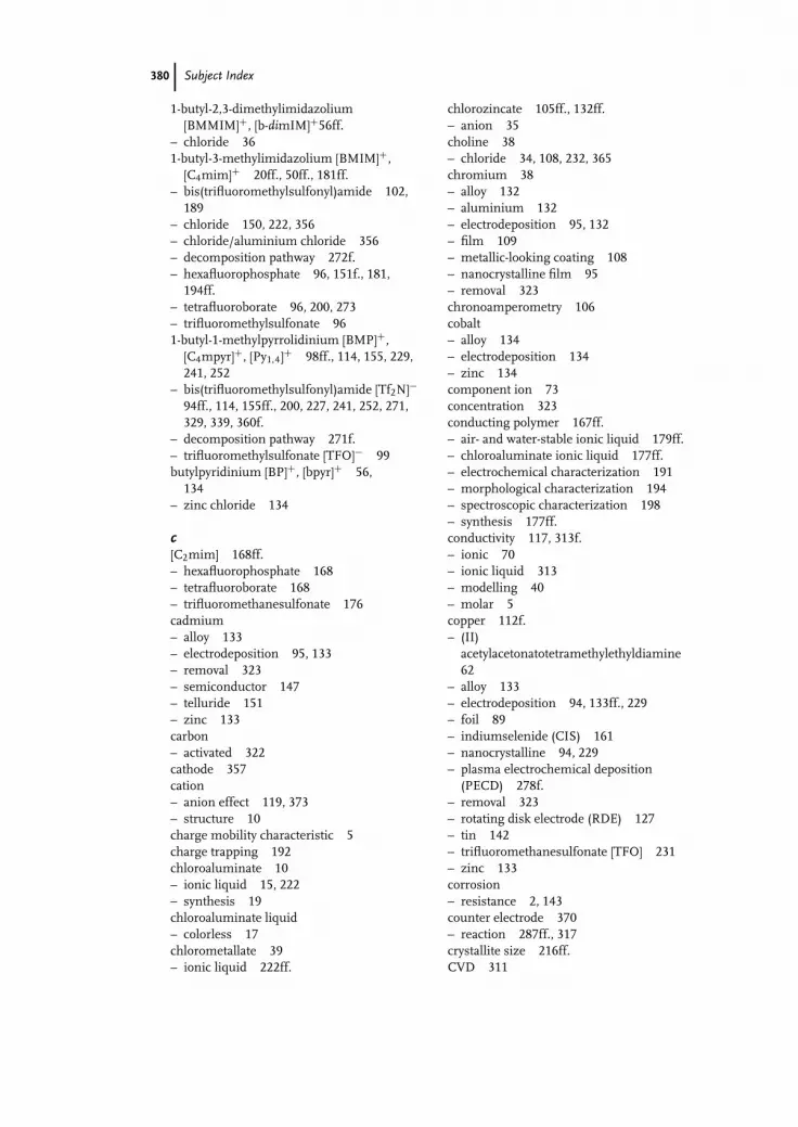
ind December 25, 2007 16:6 Char Count= 0
380 Subject Index
1-butyl-2,3-dimethylimidazolium[BMMIM]+, [b-dimIM]+56ff.
– chloride 361-butyl-3-methylimidazolium [BMIM]+,
[C4mim]+ 20ff., 50ff., 181ff.– bis(trifluoromethylsulfonyl)amide 102,
189– chloride 150, 222, 356– chloride/aluminium chloride 356– decomposition pathway 272f.– hexafluorophosphate 96, 151f., 181,
194ff.– tetrafluoroborate 96, 200, 273– trifluoromethylsulfonate 961-butyl-1-methylpyrrolidinium [BMP]+,
[C4mpyr]+, [Py1,4]+ 98ff., 114, 155, 229,241, 252
– bis(trifluoromethylsulfonyl)amide [Tf2N]−94ff., 114, 155ff., 200, 227, 241, 252, 271,329, 339, 360f.
– decomposition pathway 271f.– trifluoromethylsulfonate [TFO]− 99butylpyridinium [BP]+, [bpyr]+ 56,
134– zinc chloride 134
c[C2mim] 168ff.– hexafluorophosphate 168– tetrafluoroborate 168– trifluoromethanesulfonate 176cadmium– alloy 133– electrodeposition 95, 133– removal 323– semiconductor 147– telluride 151– zinc 133carbon– activated 322cathode 357cation– anion effect 119, 373– structure 10charge mobility characteristic 5charge trapping 192chloroaluminate 10– ionic liquid 15, 222– synthesis 19chloroaluminate liquid– colorless 17chlorometallate 39– ionic liquid 222ff.
chlorozincate 105ff., 132ff.– anion 35choline 38– chloride 34, 108, 232, 365chromium 38– alloy 132– aluminium 132– electrodeposition 95, 132– film 109– metallic-looking coating 108– nanocrystalline film 95– removal 323chronoamperometry 106cobalt– alloy 134– electrodeposition 134– zinc 134component ion 73concentration 323conducting polymer 167ff.– air- and water-stable ionic liquid 179ff.– chloroaluminate ionic liquid 177ff.– electrochemical characterization 191– morphological characterization 194– spectroscopic characterization 198– synthesis 177ff.conductivity 117, 313f.– ionic 70– ionic liquid 313– modelling 40– molar 5copper 112f.– (II)
acetylacetonatotetramethylethyldiamine62
– alloy 133– electrodeposition 94, 133ff., 229– foil 89– indiumselenide (CIS) 161– nanocrystalline 94, 229– plasma electrochemical deposition
(PECD) 278f.– removal 323– rotating disk electrode (RDE) 127– tin 142– trifluoromethanesulfonate [TFO] 231– zinc 133corrosion– resistance 2, 143counter electrode 370– reaction 287ff., 317crystallite size 216ff.CVD 311

ind December 25, 2007 16:6 Char Count= 0
Subject Index 381
cyano-based ionic liquid 282-(cyclohexylamino)ethanesulfate [CHES]−
60
dde-alloying 137– electrochemical 1371-decyl-3-methylimidazolium cation
[DMIM]+, [decyl-MIM]+ 57ff.deep eutectic solvent (DES) 39, 336, 365density 56f.deposition– mechanism 216– metal from non-chloroaluminate eutectic
mixture 103– nanometal 217– reactive element 1141,3-dialkylimidazolium tetrachloroaluminate
20N,N-dialkylpiperidinium 27N,N-dialkylpyrrolidinium 27– based ionic liquid 114dicyanamide anion [DCA]− 291,2-diethyl-3,4-dimethylimidazolium
[DEDMIM]+ 721,3-diethyl-5-methylimidazolium 186, 193N,N-diethyl-3-methylpyrazolium [DEMPZ]+
72N,N-diethyl-4-nitroaniline 59ff.diffusion coefficient 73f.diluent 10, 111Dimersol R© process 41,2-dimethyl-3-(n-propyl)imidazolium
[DMPIM]+ 72dimethylimidazolium [MMIM]+ 22dipolarity 59donor number (DN) 62dopant– chiral 204– Raman-active 198doping 187ff.double layer structure 10dye-sensitized solar cell (DSSC) 29
eED(A)X, see energyelectrochemical alloying 137electrochemical application 47ff.electrochemical atomic layer epitaxy
(ECALE) 148electrochemical cycling 193electrochemical method 172electrochemical property 66
electrochemical quartz crystal microbalance(EQCM) 102, 193
electrochemical synthesis– conducting polymer 175ff.electrochemical window 270electrochemistry– impurity 338electrode 173f., 261– blocking 69– first kind 298– redox 298– reference, see reference electrode– second kind 298electrode-free discharge 265electrodeposition– air- and water-stable ionic liquid 92– alloy 125ff.– aluminium 245ff., 353– aluminiumchloride-based ionic liquid
84, 353– antimony 91– chloroaluminate ionic liquid 126ff.– chromium 95– eutectic-based ionic liquid 104– gallium 91– indium 90– ionic liquid 1ff., 84ff., 147ff.– lithium 84– metal 83ff.– nanocrystalline 8– nanometer scale 239ff.– palladium 96– platinum 96– pulsed, see PED– semiconductor 147ff.– silver 96– sodium 86– tantalum 250– tellurium 92– tin 91– zinc 92electrodialysis 322electrolyte 261ff.electrolytic solution 297electromotive force 260f.electropickling 7electroplating 6, 319ff., 345electropolishing 7, 293ff.– stainless steel 293electropolymerization 171ff.– solution-surface 181electrostenolysis 266Endres-quality 342

ind December 25, 2007 16:6 Char Count= 0
382 Subject Index
energy– dispersive X-ray (EDX, EDAX) 109ff.,
1281-ethyl-2,3-dimethylimidazolium
[e-diMIM]+ 67, 1931-ethyl-3H-imidazolium– trifluoroacetate 2041-ethyl-3-methylimidazolium [EMIM]+,
[C2mim] 29ff., 48ff., 69, 118, 168ff.– bis(trifluoromethylsulfonyl)amide 98,
118, 176ff., 247, 340ff.– chloride 18f., 85ff., 107, 134ff., 353– chloride/aluminium trichloride ionic
liquid 85, 353– ethylsulfate 31– tetrafluoroborate 96– trifluoromethanesulfonate 176– zinc(II)chloride 95, 105ethylene glycol 111, 365eutectic– choline chloride based 111– eutectic-based ionic liquid 31ff., 104– impurity in deep eutectic solvent 336– mixture 103– point 32– solvent, see also deep eutectic solvent
336, 365– type I 33ff., 103ff.– type II 38, 103ff.– type III 38f., 103ff.extraction process 327
fFAB MS, see mass spectrometryferric chloride 36, 107ferrocene (Fc) 66, 305, 339ferrocenium (Fc+) 66, 339fluidity 5Fourier transform infrared spectroscopy
(FTIR) 198fragility parameter 69
ggallium– arsenide 107f., 149– electrodeposition 91germanium 151ff.– electrodeposition 151, 232– Ge(111) 231Gibbs enthalpy 216glass transition temperature 51gold– Au(111) 241ff., 338ff.– electrodeposition 140
– nano 217– porous 139grain refiner 216ff.grain size 217greenness 319
hhaloaluminate– anion 16– ionic liquid 21ff.HBD, see hydrogen bond donorHelmholtz layer 10heteronuclear Overhauser effect
spectroscopy (HOESY) 39hexafluorophosphate [PF6]−– ionic liquid 241-n-hexyl-3-methylimidazolium [HMIM]+
26ff., 253– tris(pentafluoroethyl)trifluorophosphate
[FAP] 253ff.1-hexyl-1-methylpyrrolidinium [HMPL]+
30N-hexylpyridinium [HPYR]+ 30high resolution scanning electron
microscopy (HRSEM) 277ff.high resolution transmission electron
microscopy (HRTEM) 277ff.highly oriented pyrolytic graphite (HOPG)
157hydrogen bond– acidity 59– basicity 59– donor (HBD) 39, 110hydrophobicity 28ff.2-hydroxylethyl ammonium formiate
2051-hydroxyethyl-3-methylimidazolium
[OH-EMIM]+ 60
iimidazolium 33, 51ff.– ionic liquid 51– salt 49impurity 117, 334, 369f.– gaseous 336– particulate 336– synthetic 334indium 90, 140– antimonide 108, 149– electrodeposition 90, 140– palladium 140– tin-oxide (ITO) 188ff.inert gas condensation (IGC) 214

ind December 25, 2007 16:6 Char Count= 0
Subject Index 383
ion conduction 75– selective 76ion conductor– anisotropic 53ion radius 48ionic conductivity 68ff.ionic fluid 3ionic liquid (IL)– air- and water stable 21ff., 140ff., 227– biodegradable 374– chiral 203f.– chlorometallate based 222ff.– chlorozincate 105ff., 222– definition 4– distillable 204– electrodeposition 92ff.– electrolyte 220f– eutectic-based 104– ferromagnetic 36– haloaluminate-based 17ff.– hexafluorophosphate 24– moisture-stable 23– nanocrystalline metal 227– nanomaterial 371– physical property 47ff.– physicochemical property 29– plasma electrochemical metal deposition
274– plasma electrochemistry 259ff.– protic 204– recycling 375– regeneration 319ff.– reuse 319– specific ion 75– stability 269– synthesis 15ff.– task-specific, see TSIL– technical potential 6– tetrafluoroborate 24– type III 344– water content 174– water-stable 21ff., 140ff., 227iron– (II) chloride 36, 107– (III) chloride 36, 107– alloy 135, 218f.– electrodeposition 135– nanostructured 226– zinc 135ITO (indium-tin-oxide), see indium
kKamlet-Taft parameter 59ff.
lLewis acid 16ff.– aluminium chloride 89– ionic liquid 35Lewis acidity 104ff., 222, 336Lewis base 10life cycle analysis (LCA) 9liquid– crystallinity 53– glycol-based 40– junction 300– junction potential (LJP) 300liquor– ionic liquid 324– water-based 321ff.lithium– bis(trifluoromethylsulfonyl)amide [NTF]−
27, 188, 341, 362– 1-butyl-1-methylpyrrolidinium [BMMIM]
bis(trifluoromethylsulfonyl)imide/lithium bis(trifluoromethylsulfonyl)imide 362
– electrodeposition 24, 85, 100– [FAP]− 28– salt 72ff.
mmacroporous structure 139magnesium– alloy 131ff.– aluminium 131– deposition 100, 114– electrodeposition 136– zinc 136manganese– alloy 131– aluminium 131– electrodeposition 143– zinc 143mass spectrometry (MS)– fast atom bombardment (FAB MS) 34,
105mass transport 104material compatibility 312mechanical process 328melting point 47ff.mesoporous structure 139metal– alloy 126– air- and water stable ionic liquid 227– deposit 218– dissolution process 287– group I 84

ind December 25, 2007 16:6 Char Count= 0
384 Subject Index
metal (continued)– group II 88– group III 88– group IV 91– group V 91f.– group VI 92– halide cluster 115– less reactive 93– nanocrystalline 8, 222ff.– nanostructured 213ff.– non-chloroaluminate eutectic mixture
103– oxide 37– porous surface 137– reactive metal 97– salt 64– water-stable ionic liquid 2271-methyl-3-methylimidazolium [MMIM]+
22N-methylpyrrolidinium formiate 54microporous structure 139[MMIM], see dimethylimidazoliummobility 41molybdenum– aluminium-alloy 128ff.– electrodeposition 128ff.– 1-ethyl-3-methylimidazolium chloride
128montmorillonite 323
nnanoalloy 218– deposition 218nanocomposite coating 8nanomaterial 213, 371f.– ionic liquid 371– tailor-made 214nanoparticle 8, 372nanoporous structure 139nanostructured metal– electrodeposition 215nanotube 205nanowire 205Nernst equation 297Nernst-Einstein equation 41, 73nickel– alloy 132, 218– aluminium 132– chromium 132– electroless plating 322– nano 214– recovery 323– titanium alloy 102nicotinic acid 316
nile red 64niobium– alloy 139– electrodeposition 139– ionic liquid 37– tin 1394-nitroaniline 59ff.non-chloroaluminate eutectic mixture 103nuclear magnetic resonance (NMR)– pulse-field-gradient (PFG NMR) 73ff.– solid-state 201
o1-octyl-3-methylimidazolium [OMIM]+
55ff.onium cation 48
ppalladium– deposition 316– electrodeposition 96, 140– gold 140– indium 140– plasma electrochemical deposition
(PECD) 280– silver 140PED (pulsed electrodeposition) 214f.– aqueous electrolyte 215PEDOT, see
poly(3,4-ethylenedioxythiophene)PFG NMR, see nuclear magnetic resonancephosphorus oxyfluoride 335plasma– electrochemical cell 266– electrochemical deposition (PECD)
274ff.– electrochemical metal deposition in ionic
liquid 274– electrolysis 267f.– electrolyte interface 262– experiment 269– low-temperature 261– reactor 264– type 264plasma electrochemistry 259ff.plating protocol 353ff.platinum– (II) tetraamino 130– (IV) bis(acetylacetonato) 130– alloy 130– aluminium 130– electrodeposition 96, 130ff.– plasma electrochemical deposition
(PECD) 280– zinc 136ff.

ind December 25, 2007 16:6 Char Count= 0
Subject Index 385
PMIM, see 1-n-propyl-3-methylimidazoliumpolarity 58ff.polarizability 59polarization 262polaron 200poly(aniline) 168, 179, 193ff.poly(bithiophene) 183poly(3,4-ethylenedioxythiophene) (PEDOT)
168, 188ff., 200poly(fluorene) 178poly(3-(4-fluorophenyl)thiophene) 186poly(N-methylpyrrole) 194poly(para-phenylene) (PPP) 178, 191,
252ff.– electrodeposition 252ff.poly(pyrrole) 168ff., 179, 200ff.poly(terthiophene) 176ff., 205poly(thiophene) 168ff., 183ff.– nano 205– paradox 183polyethylene glycol (PEG) 322polymer– coating 7– conducting, see conducting polymer– heterocyclic 171– nano-dimensional 205polymerization– chemical 205– electrochemical, see electropolymerizationpost-treatment protocol 317potential difference 297potential energy– interionic 35potential window 66pretreatment protocol 289f., 313probe molecule– solvatochromic 61process liquor– regeneration 321– water based 321process safety– intrinsic 3741-n-propyl-3-methylimidazolium [PMIM]+
22propylene carbonate/tetrabutylammonium– hexafluorophosphate 168PVD 311pyridine 17pyridinium 33
qquartz crystal– metal-coated 193quaternization reaction 17f.
rrecovery 320– electrolyte 320recycling 318, 375redox process 328reference electrode 296ff.– characteristics 298f.– pseudo/quasi 299ff.– room temperature ionic liquid 296refractive index 56regeneration– electrolyte 320– ionic liquid 319ff.Reichardt’s betaine dye 59ff.reuse– electrolyte 320– ionic liquid 319room temperature ionic liquid (RTIL) 24,
300ff.– structure 303rotating disk electrode (RDE) 127– copper 127
sscanning tunnelling microscope (STM)
239ff.– in situ 239ff.selenium 160f.– CIS 161– gray 160f.semiconductor 147ff.side chain effect 49SIGAL process 3, 97silicon 155ff.silver 308f.– de-alloying 137– deposition 309– electrode 138– electrodeposition 96, 140– palladium 140– plasma electrochemical deposition
(PECD) 274ff.– reference electrode 308– surface diffusion 138solar cell 373– copperindiumselenide (CIS) 161– dye-sensitized (DSSC) 29solubility 64solution– aqueous 2– non-aqueous 3solvatochromism 58solvent– polarity 59

ind December 25, 2007 16:6 Char Count= 0
386 Subject Index
stability– electrochemical 270– ionic liquid 269Stokes-Einstein equation 41surface energy 213
ttantalum 114– 1-butyl-1-methylpyrrolidinium
[BMP]bis(trifluoromethylsulfonyl)imide364
– deposition 116– electrodeposition 100, 250ff.– ionic liquid 37– XRD amorphous 101tellurium– electrodeposition 92temperature 9, 172– variable 374tetraalkylammonium 27tetraalkylphosphonium 27tetracyanoborate anion [TCB]− 29tetraethylammonium cation [N2222]+ 48tetrafluoroborate [BF4]− 69– ionic liquid 24tetramethylammonium cation [N1111]+ 48N,N,N′,N′-tetramethylphenylenediamine
radical cation/N,N,N′,N′-tetramethyl-phenylenediamine couple (TMPD·+/TMPD) 305f.
[TFSI]−, seebis(trifluoromethylsulfonyl)amide
thermal conductivity 53thermal decomposition temperature 52thermal degradation temperature 47thermal unit operation 325Therminol R© 53thiocyanate 29thiophene 183tin– alloy 133ff.– chloride 107– copper 142– deposition 111– electrodeposition 91, 133ff.– indium 142– niobium 139– zinc 133titanium 102– chloride 102– electrodeposition 102, 114– 1-ethyl-3-methylimidazolium chloride
127
toxicity 8transition– solid-solid 53tri-1-butylmethylammonium [TBMA]+
143– bis((trifluoromethyl)sulfonyl)amide 143tricyanomethide anion [TCM]− 29triflate [OTf]−, [TfO]−, [Tf]− 25, 93, 180– ionic liquid 25trifluoroacetate [ATF]−– ionic liquid 25trifluoromethylsulfonate, see triflatetrimethyl-n-hexylammonium [TMHA]+
140– bis (trifluoromethylsulfonyl)amide 94,
140trihexyl-tetradecyl phosphonium [P14,6,6,6]+,
[P6,6,6,14]+ 98, 229– bis(trifluoromethylsulfonyl)amide [Tf2N]
98, 202f.2,4,6-triphenylpyridinium-N-4-(2,6-
diphenylphenoxide)betaine59
tris(trifluoromethylsulfonyl)methide 93trispentafluoroethyltrifluorophosphate
[FAP]− 28TSIL (task specific ionic liquid) 65
uunderpotential deposition (UPD) 105, 128,
151, 224f.urea 111ff.
vvanadium– electrodeposition 114vapour pressure 54viscosity 40ff., 104ff.– modelling 40Vogel-Tamman-Fulcher (VFT) relationship
40, 69voltammetry 305f.– quantitative 308
wWalden product 69Walden rule 5f., 41f.Warren-Averbach technique 217waste treatment 317water 335– content 174Wilkes 23Wiliamson Hall procedure 217

ind December 25, 2007 16:6 Char Count= 0
Subject Index 387
xX-ray powder diffraction (XRD) 127– pattern 101X-ray photoelectron spectra (XPS) analysis
128, 199
zzinc– (II) chloride 36, 94– (II) chloride-1-ethyl-3-methylimidazolium
chloride 95, 105– cadmium 133– chlorozincate 105ff., 132ff.– coating 365– cobalt 134
– copper 133f.– deposition 111, 344– electrodeposition 93, 132ff., 365– iron 135– magnesium 136– manganese 143– nickel 136– platinum 136– tin 133zinc telluride– electrodeposition 150zirconium– aluminium alloy 129f.– electrodeposition 129f.zwitterionic salt 77