recovery of oil-pollutant from shipwrecks: difis project
TRANSCRIPT

International Journal of Structural IntegrityEmerald Article: Recovery of oil-pollutant from shipwrecks: DIFIS projectD.E. Mazarakos, F. Andritsos, V. Kostopoulos
Article information:
To cite this document: D.E. Mazarakos, F. Andritsos, V. Kostopoulos, (2012),"Recovery of oil-pollutant from shipwrecks: DIFIS project", International Journal of Structural Integrity, Vol. 3 Iss: 3 pp. 285 - 319
Permanent link to this document: http://dx.doi.org/10.1108/17579861211264398
Downloaded on: 11-09-2012
References: This document contains references to 28 other documents
To copy this document: [email protected]
Access to this document was granted through an Emerald subscription provided by UNIVERSITY OF PATRAS For Authors: If you would like to write for this, or any other Emerald publication, then please use our Emerald for Authors service. Information about how to choose which publication to write for and submission guidelines are available for all. Please visit www.emeraldinsight.com/authors for more information.
About Emerald www.emeraldinsight.comWith over forty years' experience, Emerald Group Publishing is a leading independent publisher of global research with impact in business, society, public policy and education. In total, Emerald publishes over 275 journals and more than 130 book series, as well as an extensive range of online products and services. Emerald is both COUNTER 3 and TRANSFER compliant. The organization is a partner of the Committee on Publication Ethics (COPE) and also works with Portico and the LOCKSS initiative for digital archive preservation.
*Related content and download information correct at time of download.

Recovery of oil-pollutant fromshipwrecks: DIFIS project
D.E. MazarakosMechanical Engineering and Aeronautics Department,
University of Patras, Patras, Greece
F. AndritsosInstitute for the Protection and Security of the Citizen,
Joint Research Centre (JRC), European Commission, Ispra, Italy, and
V. KostopoulosMechanical Engineering and Aeronautics Department, University of Patras,
Patras, Greece
Abstract
Purpose – The purpose of this paper is to describe a method for the prompt intervention andremediation of tanker wrecks, for recovering the fuel trapped in their tanks.
Design/methodology/approach – The environmental conditions, the functional specifications, theconceptual and preliminary design, the computational methods (fluid/structure interaction,computational fluid dynamics analysis and finite element analysis), the hydrodynamic scale modeltests and the dynamic response analysis are included in this research paper.
Findings – The paper provides analytical and numerical tools for the response of subsea structures.These tools were calibrated by hydrodynamic scale model tests and extrapolated for different depths(shallow, deep water and ultra deep water).
Research limitations/implications – The method is applicable as long as the trapped pollutantdoes not dissolve and is of lower density than the sea water.
Originality/value – This paper presents a new structure for the oil recovery from shipwrecks, whichis simple and quickly deployed.
Keywords Oil tankers, Oil pollution, Sea water, DIFIS Project, Computational fluid dynamics,Finite element method, Fluid/structure interaction, Vortex induced vibrations, Dynamic response
Paper type Research paper
1. IntroductionMaritime disasters leading to major environmental pollution such as ERIKA (1999)and PRESTIGE (2002) are a continuous threat (www.marcon.com/marcon2c.cfm?SectionListsID ¼ 85&PageID ¼ 234). While a number of systems have been developedand deployed for containing, treating or eliminating floating oil spills, in respect to thecontainment or the elimination of the pollution threat right at the sunken wreck no
The current issue and full text archive of this journal is available at
www.emeraldinsight.com/1757-9864.htm
The authors wish to acknowledge the role of Juan Catret and Daniel Grosset ( JRC) asco-inventors, with Dr F. Andritsos, of the DIFIS patent. They also wish to acknowledge the workof the MARIN, IFREMER, SENER, CEA, CYBERNETIX, ISI, SIREHNA and CONSULTRANSthat formed the DIFIS consortium. Special thanks to Ir. J.L. Cozijn, Senior Researcher of MARINand coordinator of DIFIS project, for his valuable contribution in the present work. The workreferring to the modeling of the scaled system and the comparisons between experimental andnumerical results has been performed by Dr Fabian Pecot of SIREHNA.
Recovery ofoil-pollutant
from shipwrecks
285
International Journal of StructuralIntegrity
Vol. 3 No. 3, 2012pp. 285-319
q Emerald Group Publishing Limited1757-9864
DOI 10.1108/17579861211264398

proposal has ever gone further than the conceptual state. The last two actualinterventions on ship wrecks applied only to the specific conditions and at least in thecase of PRESTIGE managed to collect a small fraction of the fuel load. The lessons learntfrom the PRESTIGE disaster lead to a concept for direct intervention on the ship wreck.The detailed study and laboratory simulations of that concept have been the objective ofEU funded project under the acronym of DIFIS.
2. The DIFIS conceptThe DIFIS system consists of a flexible, light structure deployed quickly around theshipwreck. It should contain all leakages and stay in place until all tanks of the wreck areemptied and pollution threat is eliminated. The fuel is collected through an invertedfunnel, consisting of a fabric dome anchored around and covering most of the wreck. Theleaking fuel is guided, along the sea water, through a long, flexible riser tube into a BufferBell. The riser tube is supported by mooring lines which run along its length positionedin the periphery of the tube in order to increase the stiffness and the stability of thesystem. The Buffer Bell is a kind of large temporary reservoir that can hold a quantity ofthe fuel until it is recovered by a shuttle tankers such as FPSO. It is placed of about 30 mbelow the sea surface so that it is not affected by the weather conditions (sea waves, windresistance) and it is designed to have large capacity and positive buoyancy. The DIFISstructure consists of seven basic components which are (Cozijn et al., 2008):
(1) The Buffer Bell (BB): a tank made of metal or composite for the temporarystorage of recovered oil (Figure 1).
Figure 1.The Buffer Belland riser tube
IJSI3,3
286

(2) The riser tube (RT): a vertical lightweight pipe for the connection of the BufferBell to the dome covering the shipwreck (Figure 2).
(3) The stiffening rings (SR): are metallic disks which connect each part of the risertube with the mooring lines (Figure 2).
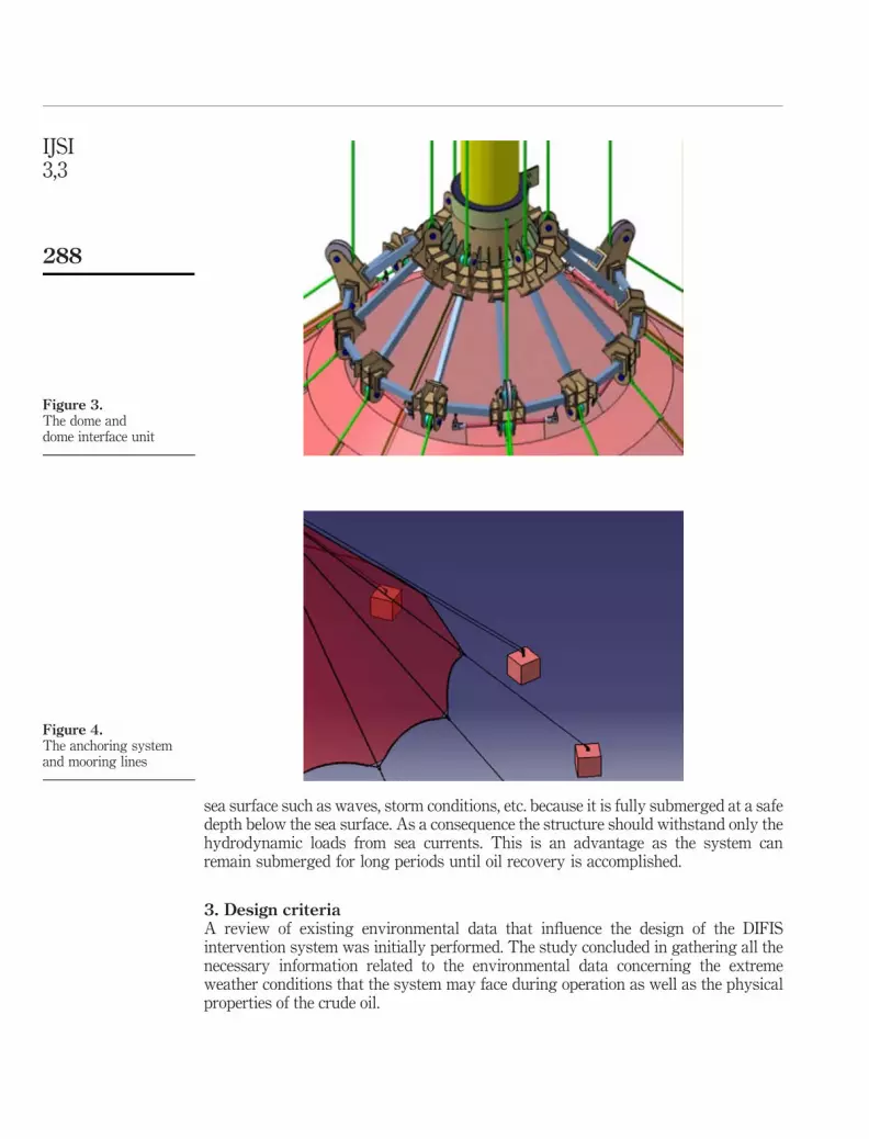
(4) The dome (DM): a conical shaped structure made of thin and flexible cloth,which covers the shipwreck and drives the collected outflow oil leakages to theBuffer Bell through the riser tube (Figure 3).
(5) The dome interface unit (DIU): a conical substructure serving asa connection interphase between the riser tube and the dome structure(Figure 3).
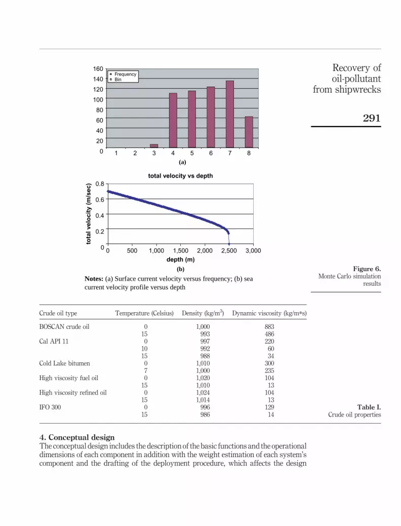
(6) The anchoring system (AS): it is composed by deadweight cement anchors,holding the overall structure to the seabed (Figure 4).
(7) The mooring lines (ML): are flexible cables, which support the riser tube and thedome, and are anchored to the seabed (Figures 2 and 4).
During the operation phase, the Buffer Bell is the substructure that produces theupwards force (buoyant force) keeping the whole structure under tension. The risertube is connected to the Buffer Bell by the mooring lines, which run along the wholelength of the tube through the stiffening rings, until they reach the dome interface unit.The upward force is not transmitted to the riser tube because the stiffening ringsallow the independent vertical displacement of the mooring lines. The DIU is securedbetween the dome and the riser tube. The mooring lines run in the periphery of thedome and attach to the deadweight anchors. In contrast to the typical offshorestructures, this new design for oil recovery is not affected by weather conditions at the
Figure 2.The riser tube and
stiffening rings
Recovery ofoil-pollutant
from shipwrecks
287
sea surface such as waves, storm conditions, etc. because it is fully submerged at a safedepth below the sea surface. As a consequence the structure should withstand only thehydrodynamic loads from sea currents. This is an advantage as the system canremain submerged for long periods until oil recovery is accomplished.
3. Design criteriaA review of existing environmental data that influence the design of the DIFISintervention system was initially performed. The study concluded in gathering all thenecessary information related to the environmental data concerning the extremeweather conditions that the system may face during operation as well as the physicalproperties of the crude oil.
Figure 3.The dome anddome interface unit
Figure 4.The anchoring systemand mooring lines
IJSI3,3
288

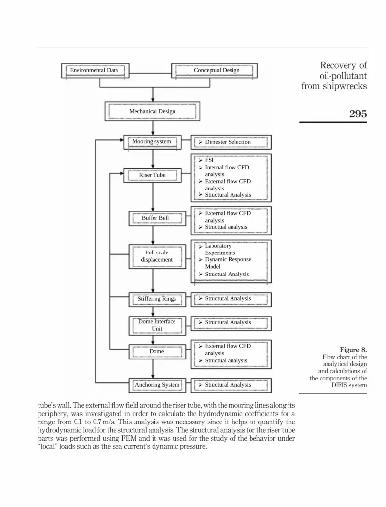
3.1 Environmental dataThe environmental data are the most important information for the design of theDIFIS system, since they provide the basic design loads of the system. Largeamounts of data, extended for long time period, were necessary for the prediction ofthe design limits. These data are mainly based on meteorological data for the weatherconditions in Europe, since the intension of the present work was the development ofa European system for the recovery of oil-pollutant from shipwrecks. The regionsfrom where these data are taken were the Mediterranean Sea, the Baltic Sea and theNorth Atlantic Coast. These environmental data were based on measurements ofwind velocity, sea waves’ height and period, sea currents velocity, bathymetry,sea water temperature, sea water salinity, density and viscosity and seabedcomposition (DIFIS Project FP6-516360, 2006c). A part of these data are shownin Figure 5(a)-(e).
Especially in the case of sea currents, the Monte Carlo Method was used for theprediction of the surface current velocity (Weinzierl, 2000). This method was selectedbecause there were only limited information about tidal currents and wind velocityclosed to the sea surface. The surface current velocity is modeled as the result of tidaland wind-driven currents. Both tidal and wind-driven currents follow a Weibulldistribution and the total surface current velocity is the sum of these values. Theprobability density function (PDF) is given by the relation:
f ðx; k; lÞ ¼k
l
� �*
x
a
� �l21
*e2ðx=lÞk ð1Þ
where x is a random variable and k, l are the Weibull distribution parameters.The Monte Carlo method generates random values between a minimum and
maximum values (sea current velocity) for each variable (the tidal and wind-drivenvelocity), which follow an almost Weibull distribution based on statistical data fromenvironmental conditions (tides and winds) (Mazarakos et al., 2008; Monahan, 2006).The sum of these two variables is a new Weibull distribution, which its peak is themaximum surface current velocity. Then, the sea current velocity is created for the allthe sea depth based on the formulas from OTRC (Wilson, 2003):
u ¼ 1 2z
h
� �1=7
*uwð0Þ þ 1 2z
h
� �*utð0Þ ð2Þ
where u represents the sea current velocity (m/s), z(m) the sea depth, uw(0) is thesurface wind-driven current velocity, ut(0) the surface tidal current both in (m/s)and h (m) is the overall depth of the selected location. The distribution of thesurface current velocity and the sea current profile versus the depth are shown inFigure 6.
The sea current profile was compared against the maximum sea current profile(DIFIS Project FP6-516360, 2006d) which was measured during the operational phaseof the PRESTIGE intervention. The real time measurement was selected as arequirement for the worst case scenario and the mathematical model as a designrequirement during the deployment and the operational phase. The prediction of seacurrent velocity was necessary for the calculation of the hydrodynamic load that eachcomponent faces.
Recovery ofoil-pollutant
from shipwrecks
289

3.2 Crude oil propertiesThe properties of crude oil are very important for the DIFIS system, since oil is the mostdangerous pollutant because it is insoluble in water, toxic and corrosive. The propertiesof oil are also critical for the operation and design of the DIFIS system. As the densityand the viscosity are temperature dependent, low temperatures can increase theviscosity to a point that it will make the flow inside the riser tube very difficult. For thesereasons data for various types of crude oil are taken into consideration and are presentedin Table I (DIFIS Project FP6-516360, 2006c). All these data were used as functionalspecifications of each component during the design of DIFIS system.
Figure 5.Environmental datain the region of interest
(a) (b)
(c) (d)
(e) (f)
Notes: (a) Mediterranean sea depth; (b) sea surface temperature; (c) sea surface salinityaround the world; (d) soil composition; (e) mean wind speed on European coasts; and (f)mean wave period on European coasts
IJSI3,3
290
4. Conceptual designThe conceptual design includes the description of the basic functions and the operationaldimensions of each component in addition with the weight estimation of each system’scomponent and the drafting of the deployment procedure, which affects the design
Crude oil type Temperature (Celsius) Density (kg/m3) Dynamic viscosity (kg/m*s)
BOSCAN crude oil 0 1,000 88315 993 486
Cal API 11 0 997 22010 992 6015 988 34
Cold Lake bitumen 0 1,010 3007 1,000 235
High viscosity fuel oil 0 1,020 10415 1,010 13
High viscosity refined oil 0 1,024 10415 1,014 13
IFO 300 0 996 12915 986 14
Table I.Crude oil properties
Figure 6.Monte Carlo simulation
results
0
20
40
60
80
100
120
140
160
1 2 3 4
(a)
(b)
5 6 7 8
FrequencyBin
total velocity vs depth
0
0.2
0.4
0.6
0.8
0 500 1,000 1,500 2,000 2,500 3,000
depth (m)
tota
l vel
oci
ty (
m/s
ec)
Notes: (a) Surface current velocity versus frequency; (b) seacurrent velocity profile versus depth
Recovery ofoil-pollutant
from shipwrecks
291

of the whole structure. The weight estimation is based on the preliminary selection ofmaterials used in already existed structures. The deployment procedures are based onmethods that are common to the offshore industry.
4.1 Weight estimationThe most important task of the preliminary design was the estimation of the weight ofeach component. A large number of candidate materials have been investigated in orderto minimize the weight of the system in water. For this reason the riser tube, the mooringsystem and the dome were proposed to be made of lightweight materials (density lowerthan 2,000 kg/m3) in order to have almost neural or even positive buoyancy by usingappropriate design configurations. The conceptual design included the definition of thebasic dimensions and the material selection for the main components and it was basedon experience coming from existing offshore and underwater structures (oil/gas offshoreplatforms, ship structures and sub-sea pipelines). Each component was modeled as asimple geometrical shape (cylinder, disk, etc.) and the weight in air and it is buoyancydue to water has been estimated. The difference between these two values is the weightin water. The positive sign means that the buoyancy is greater than the weight. TheBuffer’s Bell weight was calculated at the end of this process, since it is the componentthat must be designed to provide the needed buoyancy for the pre-tension of the DIFISsystem. Taking into consideration the weight in water of each component, it wascalculated that the overall structure should be tensioned with a 10,000 kN buoyancyforce at least. The total tension force is the sum of the weight of each component in waterand it is a critical parameter for the survivability of DIFIS system. In case there is a lossof tension force, the whole system would sink to the operational site.
The deployment procedure was also considered during this phase. The main datafrom the conceptual design phase are presented in Table II. All these preliminarycalculations were essential as they provided a starting point for the analytical designprocedure that would lead to the detailed configuration of each component.
4.2 Deployment procedure (deployment phase)The deployment procedure encompasses the sequence of activities that place the DIFISstructure is placed in operational depth. For the deployment of the system a small fleetof vessels (DIFIS Project FP6-516360, 2006b; Gerwick, 2000) (diving support vessels,heavy duty working boat, crane vessel, dock wise and a remotely operative vehicle),is required in order to accomplish the various operations. Typical configuration ofthese vessels is shown in Plate 1(a)-(d).
The successful installation of DIFIS system, with minimum risk for the vessels aswell as the oil recovery system requests calm weather conditions on the sea surface. Forthis reason a time scale between two and four months was estimated for the fulldeployment of the system. The actual erection time is much lower, compared to the timeneeded for the construction of a marine or offshore structure. The system’s design isaffected by the deployment procedure and the main steps of this procedure were takeninto consideration for the definition of the functional specifications of each component.Generally, the system is placed at the operational depth in an upward fashion, i.e. fromthe bottom up to the surface. Thus, the deployment starts with the installation of theanchoring system, then the lower components (dome/mooring lines, dome interface unit)
IJSI3,3
292

are placed followed by the higher components (riser tube parts/mooring lines, stiffeningrings, Buffer Bell). Features from different installation steps are shown in Figure 7(a)-(b).
The design of the deployment procedure made use of the results of the conceptualdesign and weight estimations as the total amount and capacity of the equipment (ships,dynamic positioning vessels, barges, cranes) was based on the size and weight of thecomponents. Several details of the deployment procedure (such as stiffening ringconnections) were completed during the analytical design, considering the design features.
5. Mechanical designThe mechanical design of such a complex system is not a trivial task and must follow amethodology that allows for a continuous feedback between the designs processes foreach component. For the design of the DIFIS system technologies commonly usedin marine structures had to be adopted and combined with innovative elements.
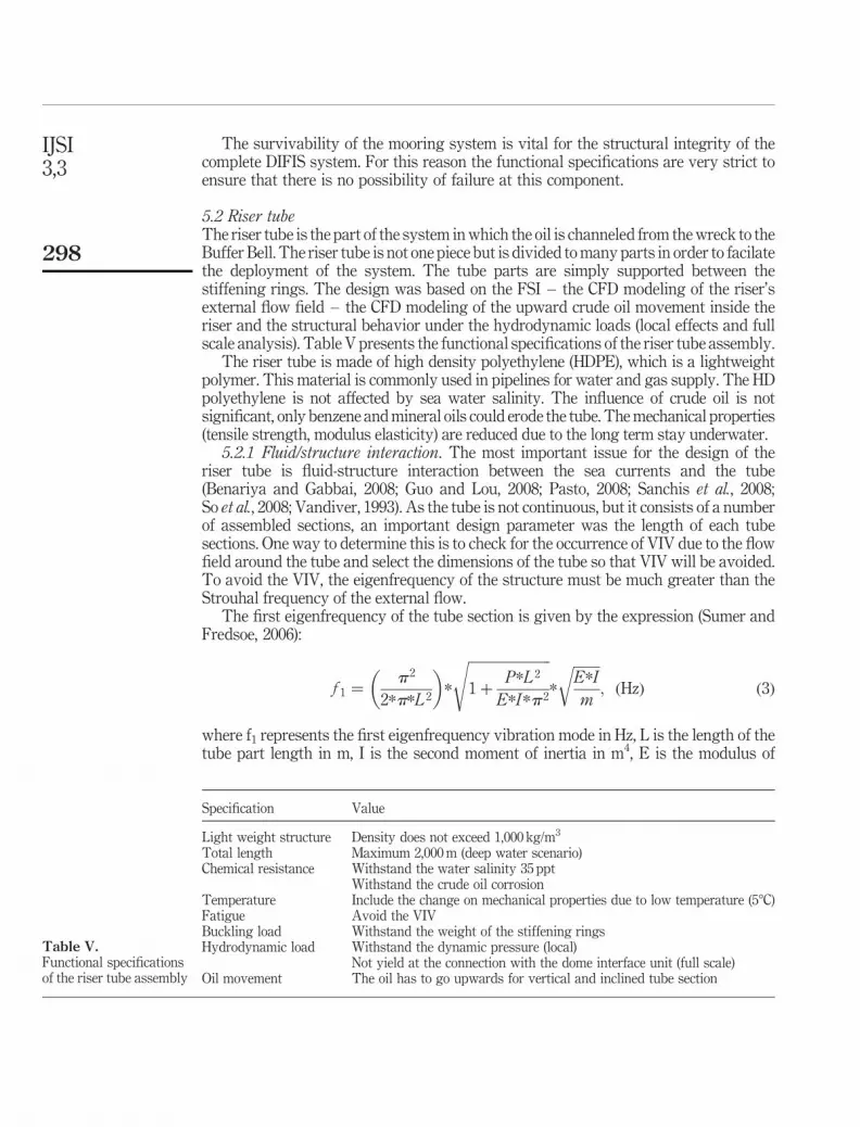
In order to maintain an overview of the design procedure, a flow chart is shown inFigure 8, which describes all the necessary computational analysis steps.
The mechanical design starts with the calculation of the diameter of the mooring linesfor a tension force of 10,000 kN. The fluid/structure interaction (FSI) is a design aspectfor the riser tube. Analytical equations were used to identify the dimensions of each risertube’s part in order to avoid vortex induced vibrations (VIV). As a second step, the oilupward movement into the riser tube was investigated. The buoyancy flow wasexamined using CFD analysis for both, vertical and inclined tube position to confirmthat the crude oil could overcome the frictional forces due to contact with the internal
ComponentGeometricalshape Material
Weight inair (tons)
Buoyancy(tons)
Weight in water(tons)
Riser tube Thin cylinder HDPE 634 680 46D ¼ 2 md ¼ 1.8 mL ¼ 2,200 m
Mooring system Cylinder Dyneema orVectran
547 437 2110D ¼ 92 mmL ¼ 2,500 mNumber: 6
Stiffening rings Disk Aluminum 163 60 2103D ¼ 3 mt ¼ 20 mm
Dome interfaceunit
Truncated cone Steel 80 68 212
D ¼ 50 md ¼ 5 m
Dome Truncated cone Fabric 1.3 9.8 8.3d ¼ 50 mD ¼ 150 m
Buffer Bell Cylinder Steel/aluminum 800 2,000 1,200D ¼ 36 mL ¼ 39 m
Anchoringsystem
Parallelepiped Cement – – –
Total tension force (tons) 1,029.3
Table II.Preliminary design
parameters of thecomponents of DIFIS
system
Recovery ofoil-pollutant
from shipwrecks
293

Figure 7.Installation procedureof the DIFIS system
SIDE DERRICK
(a) (b)
Notes: (a) Dome installation; (b) Buffer Bell installation
Plate 1.Fleet of vessels neededfor the deployment ofDIFIS system
(a) (b)
(c) (d)
Notes: (a) Dive support boat; b) heavy duty work boat; (c) crane vessel;(d) remote operative vehicle (ROV)
IJSI3,3
294
tube’s wall. The external flow field around the riser tube, with the mooring lines along itsperiphery, was investigated in order to calculate the hydrodynamic coefficients for arange from 0.1 to 0.7 m/s. This analysis was necessary since it helps to quantify thehydrodynamic load for the structural analysis. The structural analysis for the riser tubeparts was performed using FEM and it was used for the study of the behavior under“local” loads such as the sea current’s dynamic pressure.
Figure 8.Flow chart of theanalytical design
and calculations ofthe components of the
DIFIS system
Environmental Data Conceptual Design
Mechanical Design
Mooring system
Riser Tube
Buffer Bell
Full scaledisplacement
Stiffering Rings
Dome InterfaceUnit
Dome
Anchoring System
FSI
Dimester Selection
Internal flow CFDanalysisExternal flow CFDanalysis
External flow CFDanalysis
External flow CFDanalysis
LaboratoryExperimentsDynamic ResponseModel
Structural Analysis
Structual analysis
Structual Analysis
Structural Analysis
Structural Analysis
Structual analysis
Structural Analysis
Recovery ofoil-pollutant
from shipwrecks
295

The Buffer Bell’s analysis is based on the prediction of hydrodynamic coefficients(obtained from CFD analysis) and the use of a FE model for the structural analysis of theBuffer Bell hull subject to the hydrostatic pressure. The maximum displacement of thesystem due to the sea currents was also examined. A scale model test was performed in awater tunnel and a dynamic response model was created in order to predict the system’sbehavior under operational loads and during the deployment phase. Additional, a FEmodel was developed to predict the loads (forces and moments) acting on the stiffeningrings and the dome interface unit during the operational scenario. This FE model wascompared with the dynamic response model for the maximum displacement criterion. Themaximum loads (forces and moments) from the maximum displacement FE model wasused for the calculation of the dimensions of the stiffening ring and the dome interface unit.Finite element models were developed for these two components. A CFD analysis wasperformed to investigate the pressure distribution over the surface of the dome. Thispressure load and the reaction forces resulted from the analysis of the dome interface unitwere used to calculate the stresses faced by the dome and the total force applied on themooring system. For the dimensioning of the anchoring system, the highest forcecalculated for the mooring lines was chosen. The volume of cement for the anchoringsystem was calculated in order to withstand this force. Analytical equations were used tosecure the anchor’s stability on different types of seabed (cohesion or cohesion less). At theend, the maximum calculated force on the mooring line was compared against the forceresulted during the first step in order to confirm that fracture does not occur. The details ofthe basic analysis for each component are presented in the following section.
5.1 Mooring systemThe mooring system is the most crucial part of the DIFIS system. It supports all thestructure and transfers all the loads coming from Buffer Bell, riser tube and dome tothe anchors. The design of the mooring lines is based on the functional specificationsfor the sea environment. These specs are presented in Table III.
The best candidate material for the mooring system is Vectran. Chemically it isaromatic polyester produced by the polycondesation of 4-hydroxybenzoic acid and6-hydroxynaphthalene-2-carboxylic acid. The physical and mechanical properties ofVectran are appropriate for this application. It is a light weight material, with high thermaland chemical resistance (DIFIS Project FP6-516360, 2007a; Kuraray America, 2006),Fatigue and creep has low effect to the tensile strength. These characteristics are shown inFigure 9(a)-(d), while the mechanical properties of the Vectran rope are given in Table IV.
Specification Value
Light weight structure Density does not exceed 1,500 kg/m3
Chemical resistance Withstand the water salinity 35 pptWithstand the crude oil toxicity
Temperature No effect to mechanical properties for temperatures lower than 58CFatigue/creep effects No change to strength due to fatigue
No creep under long term tension loadTension load Withstand 15,000 kN without yieldDimensions Can be placed in the periphery of riser tube
Sufficient number of lines around the dome in order to support it
Table III.Functional specificationsof the mooring system
IJSI3,3
296

The dimensions of the mooring lines were selected according to the breaking strengthgiven by the rope manufacturers. The overall tension load is uniformly distributed to anumber of mooring lines placed in the periphery of the riser tube and running along itslength. In order to keep the installation procedure as simple as possible, a minimumnumber of mooring lines was chosen while maintaining a safety factor of two for theloading of the lines, which is typical for underwater structures.
Number of ropes 6 around the risertube12 around thedome
Tension load per rope 2,500 kNBreaking load of each rope 5,250 kNDiameter 92 mm
Weight 5,950 kg/km
Table IV.Mechanical properties of
the Vectran rope
Figure 9.Basic properties
of Vectran
(a) (b)
(c) (d)
Notes: (a) Tenacity retension versus temperature; (b) retension versus time of exposure;(c) creep versus time; and (d) strength versus fatigue cycles
Recovery ofoil-pollutant
from shipwrecks
297
The survivability of the mooring system is vital for the structural integrity of thecomplete DIFIS system. For this reason the functional specifications are very strict toensure that there is no possibility of failure at this component.
5.2 Riser tubeThe riser tube is the part of the system in which the oil is channeled from the wreck to theBuffer Bell. The riser tube is not one piece but is divided to many parts in order to facilatethe deployment of the system. The tube parts are simply supported between thestiffening rings. The design was based on the FSI – the CFD modeling of the riser’sexternal flow field – the CFD modeling of the upward crude oil movement inside theriser and the structural behavior under the hydrodynamic loads (local effects and fullscale analysis). Table V presents the functional specifications of the riser tube assembly.
The riser tube is made of high density polyethylene (HDPE), which is a lightweightpolymer. This material is commonly used in pipelines for water and gas supply. The HDpolyethylene is not affected by sea water salinity. The influence of crude oil is notsignificant, only benzene and mineral oils could erode the tube. The mechanical properties(tensile strength, modulus elasticity) are reduced due to the long term stay underwater.
5.2.1 Fluid/structure interaction. The most important issue for the design of theriser tube is fluid-structure interaction between the sea currents and the tube(Benariya and Gabbai, 2008; Guo and Lou, 2008; Pasto, 2008; Sanchis et al., 2008;So et al., 2008; Vandiver, 1993). As the tube is not continuous, but it consists of a numberof assembled sections, an important design parameter was the length of each tubesections. One way to determine this is to check for the occurrence of VIV due to the flowfield around the tube and select the dimensions of the tube so that VIV will be avoided.To avoid the VIV, the eigenfrequency of the structure must be much greater than theStrouhal frequency of the external flow.
The first eigenfrequency of the tube section is given by the expression (Sumer andFredsoe, 2006):
f 1 ¼p 2
2*p*L 2
� �*
ffiffiffiffiffiffiffiffiffiffiffiffiffiffiffiffiffiffiffiffiffiffiffiffi1 þ
P*L 2
E*I*p 2
s*
ffiffiffiffiffiffiffiffiE*I
m
r; ðHzÞ ð3Þ
where f1 represents the first eigenfrequency vibration mode in Hz, L is the length of thetube part length in m, I is the second moment of inertia in m4, E is the modulus of
Specification Value
Light weight structure Density does not exceed 1,000 kg/m3
Total length Maximum 2,000 m (deep water scenario)Chemical resistance Withstand the water salinity 35 ppt
Withstand the crude oil corrosionTemperature Include the change on mechanical properties due to low temperature (58C)Fatigue Avoid the VIVBuckling load Withstand the weight of the stiffening ringsHydrodynamic load Withstand the dynamic pressure (local)
Not yield at the connection with the dome interface unit (full scale)Oil movement The oil has to go upwards for vertical and inclined tube section
Table V.Functional specificationsof the riser tube assembly
IJSI3,3
298

elasticity in GPa, m is the tube’s total mass (the sum of tube’s mass and added mass)and P is positive for tension load in N.
A length of 15 m, a diameter of 2,000 mm and a thickness of 100 mm were calculatedfor the basic tube section. Avoiding vibrations due to the flow field around the tubeessentially means that fatigue is not an issue for the design of the tube. Thus, only staticloading may be considered. The main mechanical and physical properties for thesections of the riser tube are presented in Table VI.
These properties were used for the FEA modeling.5.2.2 Flow field around the riser tube. The external flow around the riser tube and
mooring lines is a complex phenomenon. Only using the appropriate numerical tools(FLUENT 6.1, 2003) the distribution of pressure and shear forces on the surface of thetube can be predicted. For this reason a CFD model for 3D unsteady flow was developedin order to determine the flow field around the riser tube and mooring lines. The cylinderand mooring lines were modeled as fixed structures. This assumption is a result of theFSI analysis, because the riser and mooring system are too stiff in order to withstand thevortex shedding. The hydrodynamic coefficients due to the presence of the mooring linesaround the tube were calculated for a flow velocity range 0.1-0.7 m/s. This analysis wasvery important for the full scale structural analysis of the system, which will predict thetotal displacement, the maximum stress on the riser tube and the reaction forces onstiffening rings and the dome interface unit. The hydrodynamic drag and cross flowforce were evaluated versus time for a time period of 100 s (Chen et al., 2006). The fastFourier transformation method (FFT) was used to investigate whether or not theinteraction between the mooring lines and the riser tube has changed the Strouhalfrequency of the flow. These results are shown in Figure 10(a)-(h).
5.2.3 Internal flow into the riser tube. The internal flow of the crude oil into the risertube was investigated for two different cases. For both cases an unsteady CFD analysiswas performed for a two phase flow inside the tube. The volume of fluid (VOF) modelwas used to simulate the oil/water movement inside the tube.
The first case considers a vertical orientation of the riser tube, which is very realisticfor the lower parts of the tube. The adhesion of the crude oil on the internal surface of theriser tube was examined and the buoyancy flow was confirmed for the heaviest crude oilbased on the existed environmental conditions. An axisymmetric model was developed.Typical results of the crude oil fraction at 2.73 s are shown in Figure 11, for the partof the riser tube just after the dome structure.
The second case considers an inclined configuration of the riser tube, which ispresented at the upper parts of the tube. The buoyant flow is confirmed for a maximuminclination of 78. A 3D model was developed for this simulation. This analysis was
Property Unit PE80 PE100
Density kg/m3 950 960Design stress 50 years MPa 6.4 8.0Design stress at time zero MPa 10.4 12.0Modulus of elasticity at time zero GPa 0.800 1.050Modulus of elasticity after 50 years GPa 0.150 0.200Poisson’s ratio – 0.4-0.5 0.4-0.5Average coefficient of thermal expansion 8C21 0.2*1023 0.2*1023
Table VI.Main mechanical and
physical properties for thesections of the riser tube
Recovery ofoil-pollutant
from shipwrecks
299
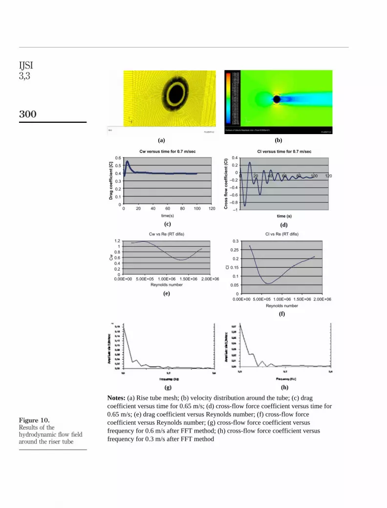
Figure 10.Results of thehydrodynamic flow fieldaround the riser tube
(a) (b)
(f)
(e)
(h)(g)
Cw vs Re (RT difis)
00.20.40.60.8
11.2
0.00E+00 5.00E+05 1.00E+06 1.50E+06 2.00E+06Reynolds number
Cw
Cl versus time for 0.7 m/sec
–1
–0.8
–0.6
–0.4
–0.2
0
0.2
0.4
0 20 40 60 80 100 120
time (s)
Cro
ss f
low
co
effi
cien
t (C
l)(d)
Cl vs Re (RT difis)
0
0.05
0.1
0.15
0.2
0.25
0.3
0.00E+00 5.00E+05 1.00E+06 1.50E+06 2.00E+06
Reynolds number
Cl
(c)
Cw versus time for 0.7 m/sec
0
0.1
0.2
0.3
0.4
0.5
0.6
0 20 40 60 80 100 120
time(s)
Dra
g c
oef
fici
ent
[C]
Notes: (a) Rise tube mesh; (b) velocity distribution around the tube; (c) dragcoefficient versus time for 0.65 m/s; (d) cross-flow force coefficient versus time for0.65 m/s; (e) drag coefficient versus Reynolds number; (f) cross-flow forcecoefficient versus Reynolds number; (g) cross-flow force coefficient versusfrequency for 0.6 m/s after FFT method; (h) cross-flow force coefficient versusfrequency for 0.3 m/s after FFT method
IJSI3,3
300

necessary in order to investigate the full scale displacement effect on the internal flow ofthe crude oil. Typical results of the oil fraction are shown in Figure 12 at 193 and 385 s(DIFIS Project FP6-516360, 2007c).
5.2.4 Structural analysis. The structural response of the complete tube is directlyrelated to the response of an individual tube section supported by the stiffening rings.
Figure 11.Results of the crude oil
fraction at 2.73 s, into theriser tube
Figure 12.Results of the oil fraction
at 193 and 385 s, for theinclined configuration of
the riser tubeTime = 193 9 9Time = 385
Recovery ofoil-pollutant
from shipwrecks
301

The main loads that have to be considered is the dynamic pressure of the sea currentson the tube section. A riser tube section was modeled using 2D shell elements andthe dynamic pressure was distributed uniformly on the surface of the tube walls. Themaximum displacement was determined in order to ensure that the sections are stiffenough to withstand the loads. The surface of the tube is not stretched and the amplitudeto diameter ratio (A/D) is low. The analysis showed that the lateral deformation of the risertube section does not affect the pressure distribution of the flow field (minimize FSIeffects). In addition the stress analysis has shown that the dynamic pressure does notoverstress the tube section. The finite element model, the stress analysis and thedisplacement results are shown in Figure 13.
The study of the riser tube confirms that the selected material and the maximumlength of the single riser tube section were correctly specified in order to avoid the vortexshedding. The maximum diameter of the riser tube was selected to increase the crude oilflow rate. The results of the hydrodynamic forces on the riser tube are introduced to thefull scale model for additional calculations.
5.3 Buffer BellThe Buffer Bell is the component that stores the crude oil and produces theupward-tension force. The design of the Buffer Bell was based on these two “functions”so it consists of two basic elements:
(1) the capacitor (CP), in where the oil is collected; and
(2) the floater (FLO), which produces the buoyancy that supplies the neededupward force and holds the system together.
The Buffer Bell is placed at an operational depth where is not affected by the sea surfacecondition (waves), For this reason the linear order (airy) theory and higher order stokestheory were used to estimate the minimum operational depth of Buffer Bell. Theoperational depth of DIFIS system, the significant wave height and the wave period fromthe environmental data were used for these calculations. The functional specificationsfor this component are presented in Table VII.
The design of the Buffer Bell starts with the estimation of the dimensions of thecapacitor (thin wall cylinder, height and diameter), in order to meet the specification forthe maximum oil capacity. Second, the dimensions of the floater (cylindrical model,diameter and height) are evaluated.
In order to facilitate the construction of such a complex structure, a design practicecommon to marine structures was employed. The floater was decided to be made byparallelepipeds and pyramid hulls. These hulls would create a continuous structure usingconnectors between them. The basic structural elements of the floater are shown inFigure 14.
The basic dimensions of the structural parts of the Buffer Bell are summarized inTable VIII.
5.3.1 Hydrodynamic analysis of the Buffer Bell. A CFD model was developed forthe flow field investigation around the Buffer Bell. A 3D steady flow model usingmaximum velocity (0.65 m/s) was used in order to estimate the hydrodynamiccoefficients (drag coefficient, cross-flow force coefficient, lift coefficient) (DIFISProject FP6-516360, 2006a). The k-omega turbulence model was selected for fullyturbulent flow. Hexahedron elements were used for the simulation. The turbulence
IJSI3,3
302

Figure 13.Results of the stress field(Pa) and the displacement
(m) of the riser tube
Recovery ofoil-pollutant
from shipwrecks
303

levels were set from bibliography for ocean turbulence (Newman, 1977) and from theenvironmental data.
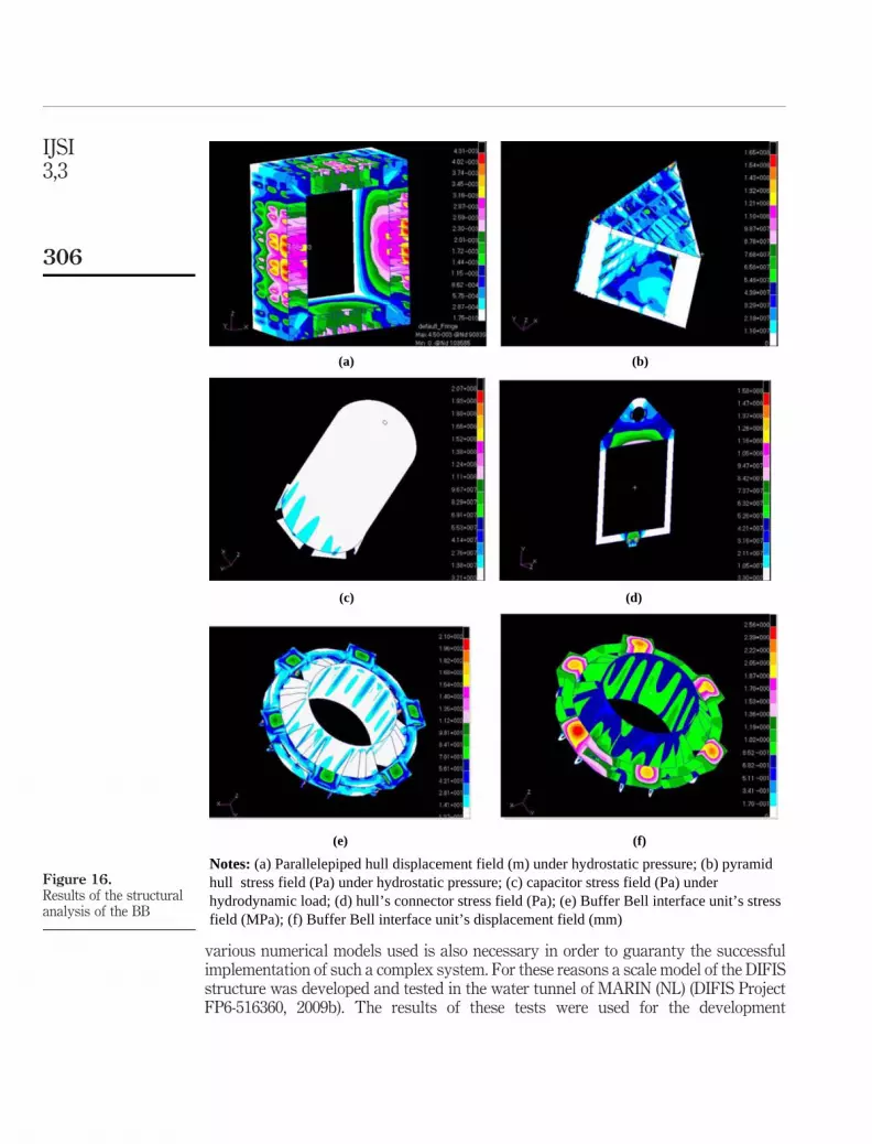
The results of the hydrodynamic analysis of the BB are shown in Figure 15(a)-(d).5.3.2 Structural analysis of the Buffer Bell. The structural analysis of the Buffer Bell
was performed using a finite element model of the system. The model included thevarious parts of the Buffer Bell, such as the hulls, the connectors, the capacitor, the hingesbetween CP and hulls and the Buffer Bell interface. Shell elements were used forthe modeling of the hulls, the connectors, the capacitor and the Buffer Bell Interface.The hinges were modeled as beams elements. Steel HY100 is the primary solution for theconstruction of the whole structure. In addition, to reduce the weight, aluminum 5,456was considered for an alternative design. The hulls have to withstand the maximumhydrostatic pressure due to operational depth for two cases:
(1) operational scenario (the pressure is applied on the external surface of the hull);and
(2) accident scenario (the hull is damaged).
The capacitor has to transfer the dynamic pressure, which is estimated from the BB’sCFD model. The connectors are stressed by the tension force (15,000 kN), thehydrodynamic drag and the cross flow force from the CFD analysis.
The Buffer Bell’s design is crucial for the performance of the DIFIS system. A detailedanalysis of this component was necessary in order to determine its structural limits.
Specification Value
Capacity 5,000 m3
Buoyancy force 20,000 kNWeight in air 800 kNChemical resistance Withstand sea water salinity up to 35 ppt
No effect due to crude oil corrosionOperational depth 25-30 m, Airy and Stokes wave theorySea temperature 208CHydrodynamic load Withstand the dynamic pressure due to a maximum sea current velocity
of 0.65 m/sHydrostatic pressure Withstand the maximum pressure 0.7 MPa
Table VII.Functional specificationsof the Buffer Bellstructure
Figure 14.The basic structuralelements of the floater
IJSI3,3
304

The hull damage could lead to tension loss, which could be destructive for all the system.In such a case the complete structure could sink the system to the maximum depth,devastating the riser tube and the other components. The results from Buffer Bell’shydrodynamic forces are introduced to the full scale model for additional calculations.The results of the structural analysis of the BB are shown in Figure 16(a)-(f).
5.4 Full scale displacement of the systemUp to this point the analysis of individual elements of the system was presented.However, the analysis of the assembled system is also needed in order to estimateamong others the maximum displacement of the system. In addition, validation of the
Buffer Bell’s part Dimension
Capacitor Diameter (mm) 16,000Cylinder height (mm) 25,000Sphere radius (mm) 8,000Overall length (mm) 33,000
Floater External diameter (mm) 26,000Internal diameter (mm) 16,000Height (mm) 6,000Length (mm) 5,000Net upward force (tons) 1,000
Table VIII.The basic dimensions of
the structural parts of theBuffer Bell
Figure 15.Results of the
hydrodynamicanalysis of the BB
(a) (b)
(c) (d)
Notes: (a) Buffer Bell mesh; (b) velocity distribution at the symmetry plane; (c) pressurecoefficient distribution around the Buffer Bell; (d) drag coefficient iteration history for 0.65 m/s
Recovery ofoil-pollutant
from shipwrecks
305
various numerical models used is also necessary in order to guaranty the successfulimplementation of such a complex system. For these reasons a scale model of the DIFISstructure was developed and tested in the water tunnel of MARIN (NL) (DIFIS ProjectFP6-516360, 2009b). The results of these tests were used for the development
Figure 16.Results of the structuralanalysis of the BB
(a) (b)
(c) (d)
(e) (f)
Notes: (a) Parallelepiped hull displacement field (m) under hydrostatic pressure; (b) pyramidhull stress field (Pa) under hydrostatic pressure; (c) capacitor stress field (Pa) underhydrodynamic load; (d) hull’s connector stress field (Pa); (e) Buffer Bell interface unit’s stressfield (MPa); (f) Buffer Bell interface unit’s displacement field (mm)
IJSI3,3
306

of a dynamic response model of the system that could extrapolate the results of thescale model and predict with confidence the performance of the actual system. Anadditional finite element model of the complete system was also developed to predictthe maximum stress on riser tube and the loads on the stiffening rings.
5.4.1 Hydrodynamic scale models. The hydrodynamic scale model was a structuremade of simple geometrical shapes. The Buffer Bell was constructed of a piece of PVCpipe of the appropriate diameter. Ballast weights were placed inside the BB model toachieve the correct total mass, center of gravity position and radii of inertia. At the centreof the BB bottom the riser tube was connected. For the riser tube and stiffening rings,a silicon hose (to model the correct diameter) with weighted steel wire inside (to achieve thecorrect underwater weight) was used. The dome interface unit was made of a circular pieceof PVC, closed at the top and open at the bottom. A force transducer was connected at thetop to measure the force exerted to the riser tube. At the bottom the dome the mooring lineswere connected. The weight was calibrated such that the DIU model has the weight tobuoyancy ratio determined by the preliminary calculations. The dome has a conical shapeand is made of a fabric material, similar to the one used in parachutes and kites, fabricatedby stitching together 12 triangular pieces of cloth. The dome model included provisions toguide mooring lines through the fabric and connect the dome to the dome interface. Themooring system was made of thin steel wire attached to a calibrated axial spring to ensurecorrect axial stiffness. Furthermore, ship models such as installation vessels, dynamicpositioning vessels shuttle tanker etc were used to simulate the deployment and offloadingphase. Plate 2(a)-(d) shows the various components of the scaled tested system as well asthe configuration of the complete system.
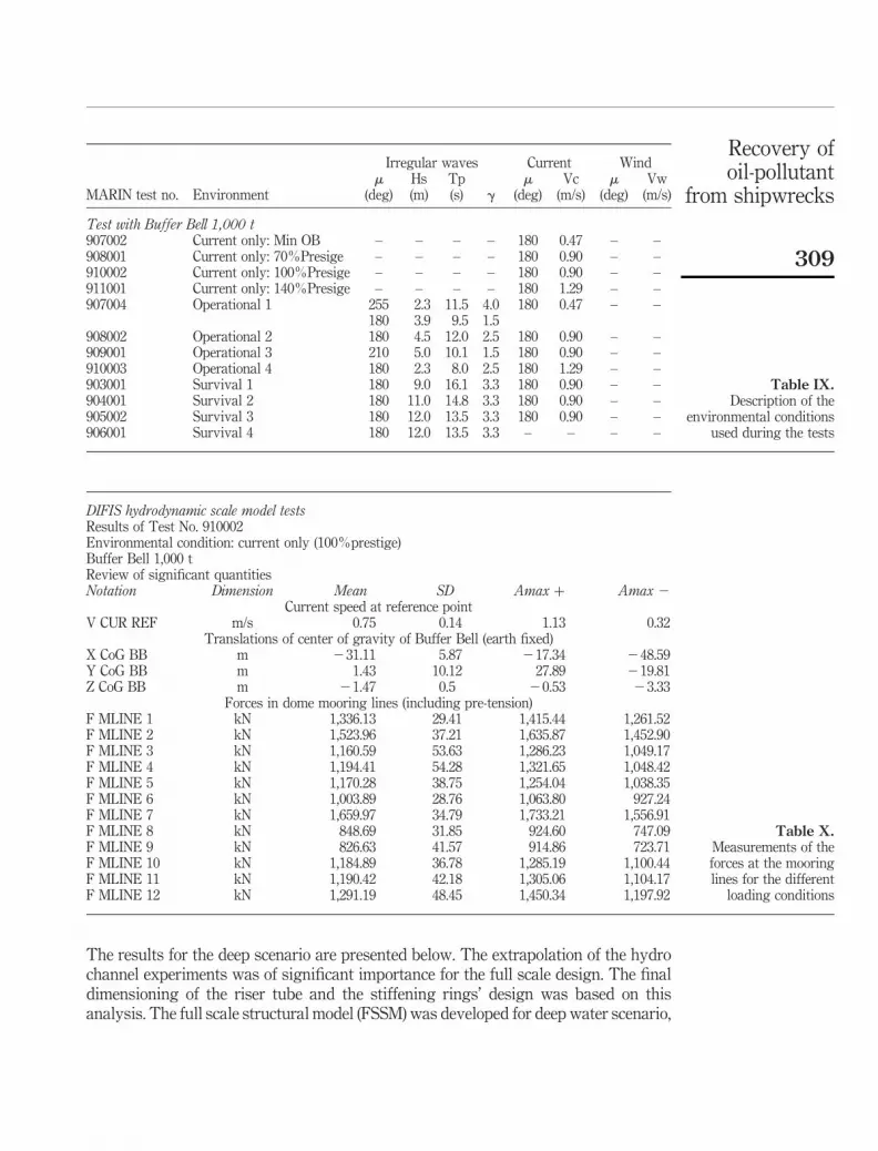
The model tests were carried out at a scale of 1:60, in a water depth of 10.2 m (equivalentto a full scale water depth of 612 m). The environmental conditions used in the tests aresummarized in Table IX. A large amount results were obtained by the hydrodynamicmodel tests for the operational, deployment and the offloading procedure. The mostimportant of them are the measurements of the forces at the mooring lines and themaximum displacement of Buffer Bell. These results are summarized in Table X. Thehydrodynamic scale model was used for the development of the dynamic response model.
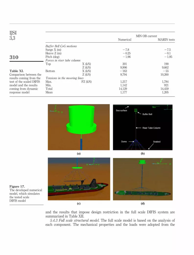
5.4.2 Dynamic response model. The dynamic response model was created inORCAFLEX by Sirehna. There are a number of assumptions, which were set for themodeling the dynamic behavior of DIFIS system. The Buffer Bell has been modeled byusing an element with 6 degrees of freedom, the mass and the inertias were chosen to besimilar as in the hydrodynamic tests and the drag and cross flow force coefficients werealso similar to the CFD analysis. The riser tube is modeled as an equivalent line. The ringsdo not contribute to the axial stiffness but they add mass. Thus, this feature is includedwith an overall increase in the line mass per unit. It is assumed that the axial tension iscarried by the six Vectran lines. The drag coefficient was the same from the CFD analysis.The dome has been modeled using 3D buoys and lines to connect them. The stiffness wasestimated to correspond to the dome properties from the preliminary design. Figure 17shows the developed numerical model, which simulates the tested scale DIFIS model.
The numerical model was set in the same environmental conditions as thehydrodynamic model tests (for a depth of 10.2 m). The three major features are the surge(the horizontal displacement of BB), the heave (the vertical displacement of BB)and the mooring lines forces. The numerical results were compared against theexperimental results. This comparison is presented in Table XI. The analysis was
Recovery ofoil-pollutant
from shipwrecks
307

extrapolated for the prediction of the maximum displacement and the mooring line forces ofthe actual real size DIFIS system for three different cases (DIFIS Project FP6-516360, 2009a):
(1) shallow water scenario (operational depth 400 m);
(2) deep water scenario (2,000 m); and
(3) ultra deep water scenario (4,000 m).
Plate 2.Presentation of thecomponents of thetested scale system
(a) (b)
(c) (d)
Notes: (a) Riser tube model section; (b) detail anchor point; (c) dome view during theunderwater set-up in the offshore basin; (d) DIFIS model view in the offshore basin
IJSI3,3
308
The results for the deep scenario are presented below. The extrapolation of the hydrochannel experiments was of significant importance for the full scale design. The finaldimensioning of the riser tube and the stiffening rings’ design was based on thisanalysis. The full scale structural model (FSSM) was developed for deep water scenario,
Irregular waves Current Wind
MARIN test no. Environmentm
(deg)Hs(m)
Tp(s) g
m(deg)
Vc(m/s)
m(deg)
Vw(m/s)
Test with Buffer Bell 1,000 t907002 Current only: Min OB – – – – 180 0.47 – –908001 Current only: 70%Presige – – – – 180 0.90 – –910002 Current only: 100%Presige – – – – 180 0.90 – –911001 Current only: 140%Presige – – – – 180 1.29 – –907004 Operational 1 255 2.3 11.5 4.0 180 0.47 – –
180 3.9 9.5 1.5908002 Operational 2 180 4.5 12.0 2.5 180 0.90 – –909001 Operational 3 210 5.0 10.1 1.5 180 0.90 – –910003 Operational 4 180 2.3 8.0 2.5 180 1.29 – –903001 Survival 1 180 9.0 16.1 3.3 180 0.90 – –904001 Survival 2 180 11.0 14.8 3.3 180 0.90 – –905002 Survival 3 180 12.0 13.5 3.3 180 0.90 – –906001 Survival 4 180 12.0 13.5 3.3 – – – –
Table IX.Description of the
environmental conditionsused during the tests
DIFIS hydrodynamic scale model testsResults of Test No. 910002Environmental condition: current only (100%prestige)Buffer Bell 1,000 tReview of significant quantitiesNotation Dimension Mean SD Amax þ Amax 2
Current speed at reference pointV CUR REF m/s 0.75 0.14 1.13 0.32
Translations of center of gravity of Buffer Bell (earth fixed)X CoG BB m 231.11 5.87 217.34 248.59Y CoG BB m 1.43 10.12 27.89 219.81Z CoG BB m 21.47 0.5 20.53 23.33
Forces in dome mooring lines (including pre-tension)F MLINE 1 kN 1,336.13 29.41 1,415.44 1,261.52F MLINE 2 kN 1,523.96 37.21 1,635.87 1,452.90F MLINE 3 kN 1,160.59 53.63 1,286.23 1,049.17F MLINE 4 kN 1,194.41 54.28 1,321.65 1,048.42F MLINE 5 kN 1,170.28 38.75 1,254.04 1,038.35F MLINE 6 kN 1,003.89 28.76 1,063.80 927.24F MLINE 7 kN 1,659.97 34.79 1,733.21 1,556.91F MLINE 8 kN 848.69 31.85 924.60 747.09F MLINE 9 kN 826.63 41.57 914.86 723.71F MLINE 10 kN 1,184.89 36.78 1,285.19 1,100.44F MLINE 11 kN 1,190.42 42.18 1,305.06 1,104.17F MLINE 12 kN 1,291.19 48.45 1,450.34 1,197.92
Table X.Measurements of theforces at the mooringlines for the different
loading conditions
Recovery ofoil-pollutant
from shipwrecks
309
and the results that impose design restriction in the full scale DIFIS system aresummarized in Table XII.
5.4.3 Full scale structural model. The full scale model is based on the analysis ofeach component. The mechanical properties and the loads were adopted from the
MIN OB currentNumerical MARIN tests
Buffer Bell CoG motionsSurge X (m) 27.8 27.5Heave Z (m) 20.25 20.1Pitch (deg) 21.96 21.95Forces in riser tube columnTop X (kN) 201 190
Z (kN) 9,906 9,662Bottom X (kN) 2163 255
Z (kN) 9,794 10,260Tensions in the mooring linesMax. FZ (kN) 1,217 1,784Min. 1,142 921Total 14,129 14,459Mean 1,177 1,205
Table XI.Comparison between theresults coming from thetest of the scaled DIFISmodel and the resultscoming from dynamicresponse model
Figure 17.The developed numericalmodel, which simulatesthe tested scaleDIFIS model
(a) (b)
(c) (d)
IJSI3,3
310

detail analysis. The FSSM was developed only for the deep water scenario due to thefunctional specifications imposed by the potential users. The main purpose of thismodel is the prediction of maximum BB displacement, the forces on mooring lines andthe maximum stresses and the bending moment that faces the riser tube (RT). It isconsisted of three different interactive models.
For the first model, it is assumed that the RT is clamped at the bottom and it issimply supported at the stiffening rings. The drag and cross-flow forces are applied onthe RT column. The reactions forces on the stiffening rings are calculated.
For the second model, it is assumed that the reactions forces are transferredtransversely to the mooring lines. The Buffer Bell hydrodynamic loads and the tensionforce are applied on the top and the maximum displacement is calculated.
For the third model, the RT is clamped at the bottom and the displacements ofprevious model are applied as loads. The maximum stresses at the clamped region of theRT are calculated. These models were developed in the environment of the commerciallyavailable FE code Patran/Nastran. 1D elements were used to model the RT and mooringlines in order to reduce the calculation time. The graphical output of the three models isshown in Figure 18(a)-(c).
The maximum bending moment was extracted from the third model as a reactionload. The resultant force on mooring lines is calculated by second model and finally thestiffening rings design load is concluded as a result of the first model. These loads are
Mean RMS Min. Max.
Buffer Bell CoG Surge (m) 2270.30 0.26 2271.15 2269.53Heave (m) 219.32 0.13 219.77 218.88Pitch (deg) 26.82 0.05 27.00 26.66
Riser tube column Top End X force (kN) 157 33 36 270End Z force (kN) 10,959 168 10,389 11,577Tension (kN) 10,959 168 10,389 11,577
Bottom End X force (kN) 21,841 41 21,991 21,707End Z force (kN) 11,052 245 10,248 11,951Tension (kN) 11,204 248 10,389 12,115
Dome mooring lines Max tension (kN) 1,791 50 1,627 1,973Min tension (kN) 1,106 31 1,003 1,220
Table XII.Extrapolate data for the
deep water scenario of thefull scale DIFIS system
Figure 18.The graphical output of
the three FSSMs
(a) (b) (c)
Notes: (a) RT column displacement (m) under drag forces; (b) mooring system maximumdisplacement (m) under RT column’s reaction forces; (c) RT column’s stress field (Pa) underthe maximum displacement load
Recovery ofoil-pollutant
from shipwrecks
311

necessary for the determination of the dimensions of the dome interface unit, thestiffening rings, the dome and the anchoring system.
5.5 Stiffening ringsThe stiffening rings are the interface elements between the riser tube parts. The mainpurpose of these components is to connect the tube sections, to keep them in place andallow for the riser tube sections to “slide” along the mooring lines and to transfer thehydrodynamic forces from the riser tube to the mooring lines. Furthermore, the weightof each ring has to remain within certain limits in order to retain the connection butalso to have a reduced contribution to the tension force. These contradictingcharacteristics make as the stiffening rings very challenging components as far as theirdesign is concerns. The functional specifications of the stiffening rings are presented inTable XIII.
The configuration of the stiffening rings is shown in Figure 19(a)-(c), together withthe way the mooring lines are guided within the body of the ring.
A structural finite element model was developed in FEA code for the stiffening ring.Aluminum 5,456 was selected as the construction material. 2D shell elements were usedto simulate the stiffening rings geometry. The design load was applied as a distributedforce on the nodes of the elements. An inertia load was used to model the weight in waterof the ring. The connectors are modeled as joints and the cylinder was simply supported
Specification Value
Chemical resistance Withstand the water salinity 35 pptWithstand the crude oil corrosion
Temperature Include the change on mechanical properties due to low temperature (58C)Loads Withstand the maximum resultant transverse force of 4 kNWeight in air 1.1 tons per ringDimensions External diameter 3 m
Internal diameter 2 mDesign The moorings lines must be placed at the external diameterConnection Allow the independent vertical movement of mooring line
Match the riser parts together with its own weight
Table XIII.The functionalspecifications of thestiffening rings
Figure 19.Schematic representationof the stiffening ring
(a) (b) (c)
Notes: (a) The body of the ring; stiffening ring; (b) stiffening ring’s union (closed position);(c) stiffening ring’s union (opened position)
IJSI3,3
312

at the internal surface, which contacts the riser tube part. The displacements concludedby the structural analysis are shown in Figure 20.
The structural analysis of this component is rather simple. The main difficulty was tothe estimate the weight in order to accomplish the functional specifications. The weight,also affects the riser tube integrity, since it compresses during the assembly and theoperation phase each riser tube part and secures the integrity of the system. For this reasonthere is a loop in flow chart in order to check the riser tube section under buckling condition.
5.6 Dome interface unitThe dome interface unit is a connecting component. Its duty is to serve as a connectorbetween the riser tube and the dome. This part was proposed during the preliminarydesign because direct connection between the riser tube and the dome was deemedunfeasible. The contribution of this component to the structural stability of wholestructure is the main feature. The loads from the riser tube and the mooring system aretransferred to the DIU, which has to withstand them without yield. The riser tube’sreaction loads (bending moment and transverse forces) and the mooring system’sresultant axial force are calculated by the FSSM and applied as mechanical loads on theDIU structure. The functional specifications of this component are presented inTable XIV.
This component was designed trying to keep its weight as low as possible. For thisreason beams and sheets were selected in order to create a continuous structure. Takinginto consideration that the loads, which are transferred to this part, are extremely high, ahigh tensile strength steel material was used. The steel HY100 contributes the maindemands of the functional specifications. It is a material which could be welded andcould be constructed in sheets. A structural model with finite elements was developed toestimate the stress field. 2D elements were used to model the structure. The momentsand the forces are applied as distributed loads on the nodes of the elements (at thetop section). The DIU was supported ( joints) on the lower section where it is connectedwith the 12 mooring lines.
The stresses and the displacement field developed at the DIU are shown in Figure 21.
Figure 20.Displacement field (mm)
developed on thestiffening rings
Recovery ofoil-pollutant
from shipwrecks
313

The reaction forces on the lower section are calculated by the FEA analysis. Theseforces are based on the static equilibrium of the DIU and could apply on dome andmooring lines as mechanical loads.
5.7 DomeThe dome is the lower component of the DIFIS system. It is placed near the shipwreck inorder to cover it. The main purpose of this part is to collect the leaked crude oil and lead itto the riser tube. It has a truncated cone shape and it is made of cloth in order to beflexible and easy to deploy. It is attached on 12 mooring lines with a fixed connection. It isstressed by the hydrodynamic load of the sea currents. The dome’s hydrodynamic loadis transferred to the 12 mooring lines via the supports. The DIU reaction forces areapplied on the mooring lines at the upper part. The functional specifications of the domeare presented on Table XV
5.7.1 Dome hydrodynamic analysis. A 3D CFD model (DIFIS Project FP6-516360,2007b) was developed in order to predict the pressure distribution over the surface
Figure 21.Stress and displacementfield developed on the DIU
(a) (b)
Notes: (a) DIU’s stress field (MPa) under mooring lines’ forces; (b) DIU’s displacement field(mm) under operational loads
Specification Value
Chemical resistance Withstand the water salinity 35 pptWithstand the crude oil corrosion
Temperature Include the change on mechanical properties due to low temperature (58C)Loads Withstand the riser tube’s maximum bending moment kNm
Withstand the riser tube’s transverse force kNWithstand each mooring line’s axial force kN
Weight in water 212 tons (based on preliminary design)Dimensions Small base diameter 5 m
Large base diameter 50 mHeight 10 m
Design Welded structure, use of sheets and beamsConnection Bolted (between riser tube and DIU)
Use finish (between mooring line and DIU)
Table XIV.The functionalspecifications of the DIU
IJSI3,3
314

of the dome. The velocity was placed at the 0.03 m/s and the pressure coefficient wasestimated. The dome was set 150 m above the seabed. The seabed was modeled as a rigidwall boundary condition. The pressure coefficient (Cp) contours are shown in Figure 22.
5.7.2 Dome structural analysis. A structural finite element model was developed toestimate the stresses and the displacements on nodes of the dome structure. 2D shellelements and 1D elements were used to model the dome and the mooring lines,respectively. multi-point constraints (MPC) (Kilroy, 1996) were used to transfer the loadsfrom the dome to mooring lines. The dynamic pressure load is distributed on the elements.The dome constructive material is PRECONTRAINT FERRARI 1002 fabric. The mooringlines were supported at the points where the anchors were placed. Figure 23 shows thereaction forces on anchors and the stresses developed on the dome material.
Figure 22.The pressure coefficient
(Cp) contours over thesurface of the dome
structure
1.00.3
–0.3–1.0–1.7–2.3–3.0–3.7–4.3–5.0
Cp
Current (0.0297 m.s–1)
Specification Value
Chemical resistance Withstand the water salinity 35 pptWithstand the crude oil corrosion
Temperature Include the change on mechanical properties due to low temperature (58C)Loads Withstand the dynamic pressure sea current’s velocity of 0.03 m/secWeight in air 1.2 tons (based on preliminary design)Dimensions To cover the half of ULCC
Large base diameter 150 mSmall base diameter 50 mHeight 100 m
Design Made of cloth, to reduce weightFlexible deployment
Connection Simple supported on mooring lines
Table XV.The functional
specifications of the dome
Recovery ofoil-pollutant
from shipwrecks
315
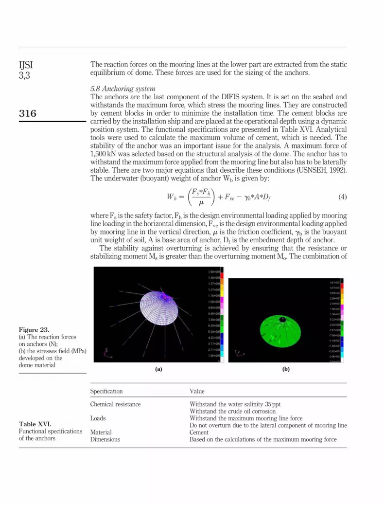
The reaction forces on the mooring lines at the lower part are extracted from the staticequilibrium of dome. These forces are used for the sizing of the anchors.
5.8 Anchoring systemThe anchors are the last component of the DIFIS system. It is set on the seabed andwithstands the maximum force, which stress the mooring lines. They are constructedby cement blocks in order to minimize the installation time. The cement blocks arecarried by the installation ship and are placed at the operational depth using a dynamicposition system. The functional specifications are presented in Table XVI. Analyticaltools were used to calculate the maximum volume of cement, which is needed. Thestability of the anchor was an important issue for the analysis. A maximum force of1,500 kN was selected based on the structural analysis of the dome. The anchor has towithstand the maximum force applied from the mooring line but also has to be laterallystable. There are two major equations that describe these conditions (USNSEH, 1992).The underwater (buoyant) weight of anchor Wb is given by:
Wb ¼Fs*Fh
m
� �þ Fve 2 gb*A*Df ð4Þ
where Fs is the safety factor, Fh is the design environmental loading applied by mooringline loading in the horizontal dimension, Fve is the design environmental loading appliedby mooring line in the vertical direction, m is the friction coefficient, gb is the buoyantunit weight of soil, A is base area of anchor, Df is the embedment depth of anchor.
The stability against overturning is achieved by ensuring that the resistance orstabilizing moment Ms is greater than the overturning moment Mo. The combination of
Specification Value
Chemical resistance Withstand the water salinity 35 pptWithstand the crude oil corrosion
Loads Withstand the maximum mooring line forceDo not overturn due to the lateral component of mooring line
Material CementDimensions Based on the calculations of the maximum mooring force
Table XVI.Functional specificationsof the anchors
Figure 23.(a) The reaction forceson anchors (N);(b) the stresses field (MPa)developed on thedome material
(a) (b)
IJSI3,3
316

these two equations leads to the sizing of the anchor. The minimum width B of theanchor is calculated by the relation:
B ¼6*Fh*ðH 1 þ zsÞ
Wb 2 Fveð5Þ
where H1 is the vertical distance from Fh to the base of the anchor and zs is theembedment depth of the anchor.
The calculations are based on the salvage engineer’s handbook and performed for thecohensionless seabed as the worst case. An anchor with dimensions 12 m £ 12 m £ 4 mis selected and a total cement volume of 600 m3 has to be used for the anchoring of eachmooring line.
6. ConclusionsThe development of an innovative system for the recovery of oil-pollutant fromshipwrecks (DIFIS system) is the subject of the present work. The design and thepreliminary analysis of DIFIS structure is discussed thoroughly. The DIFIS structureis formed by a large number of components, which are assembled together in order toserve the final goal. The preliminary analysis of the system has a large number of stepsand loops in order to specify all the parameters for an efficient design. Furthermore,the DIFIS system promises some significant advantages beyond the state of the artsuch as:
. It is a simple concept. Once installed does not require specializedequipment.
. It is a completely passive system. Does not require any external power other thanperiodic Buffer Bell offloading to the shuttle tanker.
. Its installation poses no risk for the structural stability of the wreck.
. Offloading operations are done near the surface through standard industrialequipment.
. The riser tube configuration can be implemented through a modular design,leading to operational flexibility and low cost.
. It is entirely passive: the flow of oil is gravity driven. There is no powerconsumption (pumping for example).
. Once in place does not require regular deep-sea operations or monitoring.
. The presence of a submerged and high capacity Buffer Bell makes the operationtolerant to the rough surface weather conditions.
. The system is highly configurable and can be placed in different sea depths suchas shallow, deep and ultra deep water.
. It has low manufacturing and installation costs compared to existing offshoreand/or underwater structures.
Finally, the DIFIS system is a structure, which can eliminate the pollutant threat atevery sea depth. This procedure can also be applied on existent shipwrecks around theworld.
Recovery ofoil-pollutant
from shipwrecks
317
References
Benariya, H. and Gabbai, R. (2008), “Modelling vortex-induced fluid structure interaction”, Philos.Trans. R. Soc., Vol. 366, pp. 1231-74.
Chen, H.-C., Chen, C.-R. and Mercier, S.R. (2006), “CFD simulation of riser VIV, mineralsmanagement service”, MMS Project Number 481.
Cozijn, J.L., Andritsos, F., Konstantinopoulos, A.P., Charatsis, J.K., Derdas, C., Mazarakos, D.E.,Kostopoulos, V., Hoornstra, D., Pena, A.A., Candini, L., Ametler, S., Fidani, A., Castex, A.,Delauze, M., Drogou, F.J., Leveque, P.J., Davies, P., Montandon, C., Geffard, F., Pecot, F. andEstrada, V. (2008), “Recovery of oil trapped in ship-wrecks: the DIFIS concept”, paperpresented at International Oil Spill Conference.
DIFIS Project FP6-516360 (2006a), Estimation of Pressure Drag Coefficients, DIFIS,Morristown, NJ.
DIFIS Project FP6-516360 (2006b), Report on Deployment. Recovery Procedure, DIFIS,Morristown, NJ.
DIFIS Project FP6-516360 (2006c), Report on Requirements Specification, DIFIS, Morristown, NJ.
DIFIS Project FP6-516360 (2006d), Report on State of the Art, DIFIS, Morristown, NJ.
DIFIS Project FP6-516360 (2007a), Dome Preliminary Design, DIFIS, Morristown, NJ.
DIFIS Project FP6-516360 (2007b), Pressure Distribution Due to Current Over theDome-Navier-Stokes Computation, DIFIS, Morristown, NJ.
DIFIS Project FP6-516360 (2007c), Report on DIFIS Internal Flow Analysis, DIFIS,Morristown, NJ.
DIFIS Project FP6-516360 (2009a), Dynamic Behavior DIFIS System, DIFIS, Morristown, NJ.
DIFIS Project FP6-516360 (2009b), Reported on Scaled Model Test Results, DIFIS, Morristown, NJ.
FLUENT 6.1 (2003), User Guide, FLUENT, Manhattan, NY.
Gerwick, B.C. Jr (2000), Construction of Marine and Offshores Structures, CRC Press LLC,Boca Raton, FL, pp. 50-150.
Guo, H.-Y. and Lou, M. (2008), “Effect of internal flow on vortex induced vibration of risers”,Journal of Fluid and Structures, Vol. 24, pp. 495-504.
Kilroy, K. (1996), Quick Reference Guide, Version 70, MSC/Nastran, Santa Ana, CA.
Kuraray America (2006), Physical and mechanical properties for Vectran, available at: www.vectranfiber.com/
Mazarakos, D., Derdas, C., Kostopoulos, V. and Andritsos, F. (2008), “Failure event analysis andoptimization of a submerged underwater critical structure against non deterministiccurrent loading conditions with the use of finite element method”, Proceedings of4th International ASRANet Colloquium.
Monahan, H.A. (2006), “The probability distribution of sea surface wind speeds. Part I: theoryand sea winds observations”, American Meteorological Society, Vol. 19.
Newman, N.J. (1977), Marine Hydrodynamics, MIT Press, Cambridge, MA, pp. 88-100.
Pasto, S. (2008), “Vortex-induced vibrations of a circular cylinder in laminar and turbulentflows”, Journal of Fluids and Structures, Vol. 24, pp. 977-93.
Sanchis, A., Saelevik, G. and Grue, J. (2008), “Two degrees of freedom vortex-induced vibrationsof a spring mounted rigid cylinder with low mass ratio”, Journal of Fluids and Structures,Vol. 24, pp. 907-19.
IJSI3,3
318

So, R.M.C., Wang, X.Q., Xie, W.-C. and Zhu, J. (2008), “Free stream turbulence effects onvortex-induced vibration and flow-induced force of an elastic cylinder”, Journal of Fluidsand Structures, Vol. 28, pp. 481-95.
Sumer, B.M. and Fredsoe, J. (2006), Hydrodynamics Around Cylindrical Structures,World Scientific, River Edge, NJ, pp. 120-200.
USNSEH (1992), US Navy Salvage Engineer’s Handbook, Vol. 1, Salvage Publications,Washington, DC, pp. 20-35.
Vandiver, J.K. (1993), “Dimensionless parameters important to the prediction of vortex-inducedvibration of long, flexible cylinders in ocean currents”, Journal of Fluids and Structures,Vol. 7, pp. 423-55.
Weinzierl, S. (2000), Introduction to Monte Carlo Methods, NIKHEF Theory Group, NIKHEF,Amsterdam.
Wilson, F.J. (2003), Dynamics of Offshore Structures, 2nd ed., Wiley, Hoboken, NJ, pp. 10-20.
Corresponding authorV. Kostopoulos can be contacted at: [email protected]
To purchase reprints of this article please e-mail: [email protected] visit our web site for further details: www.emeraldinsight.com/reprints
Recovery ofoil-pollutant
from shipwrecks
319