realization of true-time-delay using cascaded long-period fiber gratings: theory and applications to...
TRANSCRIPT
JOURNAL OF LIGHTWAVE TECHNOLOGY, VOL. 23, NO. 2, FEBRUARY 2005 597
Realization of True-Time-Delay UsingCascaded Long-Period Fiber Gratings:Theory and Applications to the Optical
Pulse Multiplication andTemporal Encoder/Decoder
Tae Joong Eom, Sun-Jong Kim, Tae-Young Kim, Chang-Soo Park, Member, OSA,Un-Chul Paek, Senior Member, IEEE, Fellow, OSA, and Byeong Ha Lee, Member, IEEE
Abstract—This paper proposes and demonstrates a techniquefor repetition-rate multiplication of an optical pulse train havingan arbitrary period or pattern and the optical temporal en-coding/decoding for the optical-code-division multiple-access(O-CDMA) system. The technique exploits the difference in thepropagation speeds between the core and copropagating claddingmodes of a fiber to obtain true-time-delay between the modes trav-eling in the core mode and the cladding mode, which can be usedto achieve pulse multiplication. For the coupling to the claddingmode, long-period fiber gratings (LPGs) were used. A series ofcascaded LPGs imprinted in a fiber with a specific separation hasbeen employed to obtain a specific rate of pulse multiplicationwith a single input pulse. Second, by controlling the separationsamong the gratings, the temporal encoder/decoder for O-CDMAcould be implemented. The principle and the applications of theproposed device are investigated in detail. The effect of the bire-fringence of fiber and fiber gratings on the system performance inthe time and spectral domains is presented. The sensitivity of thecladding modes in a conventional fiber to the perturbations at thecladding has been overcome by replacing the conventional fiberwith inner-cladding fiber. The properties and the benefits of usingthe inner-cladding mode are investigated.
Index Terms—Birefringence, cascaded gratings, disper-sion-compensating fiber (DCF), fiber gratings, long-period fibergratings (LPGs), optical-code-division multiple access (O-CDMA),optical fiber communications, optical fiber devices.
I. INTRODUCTION
THE DEMAND for an effective technique capable ofachieving a precise optical delay control, called a
true-time-delay (TTD), have been increasing in telecommuni-cation applications, such as optical-time-division multiplexing(OTDM), optical-code-division multiplexing (OCDM), andan optical packet switching [1]–[3]. A variety of technologieshave been proposed. Many researchers have approached using
Manuscript received June 2, 2004; revised December 7, 2004. This work wassupported in part by Korean Science and Engineering Foundation (KOSEF)under Grant R01-2004-000-10864-0 under the Basic Program, an EngineeringResearch Center (ERC) Program (Ultrafast Fiber-Optic Networks ResearchCenter), and MOE-BK21.
The authors are with the Department of Information and Communications,Kwangju Institute of Science and Technology (K-JIST), Gwangju 500-712,Korea (e-mail: [email protected]).
Digital Object Identifier 10.1109/JLT.2004.842299
optical fiber delay lines based on multimode fiber [4] or 3-dBfiber couplers [5]. In spite of its quite simple structure, it cannotassure the TTD as being fabricated, due to its bulky features.
More sophisticated methods have been proposed for multi-plying the repetition rate of pulses and generating specific codepatterns for an OCDM system. In the former applications, thepulse multiplication methods using a single-mode fiber (SMF)[6] and a non-zero-dispersion-shifted fiber (NZ-DSF) [7] havebeen reported. In addition, a planar-lightwave-circuit-basedtechnology has been used to generate the optical pulses witha 160-GHz repetition rate [8]. Recently, fiber Bragg gratings(FBGs) have been used for achieving high-speed pulse multi-plication [9], pulse reshaping [10], and generation/recognitionof OCDM code patterns [11]–[13]. These systems used a seriesof FBGs having the same resonant wavelengths at which theoptical pulses were reflected. They can be implemented withlow cost and compact size because they are based on fibergratings. Note that they are suitable to generate a time delay ofa few tens of picoseconds, but the fabrication accuracy cannotbe ensured for shorter time delays.
Therefore, an alternative method providing a more precisetime delay adequate for high-speed applications is considerednecessary. In response, a pulse duplication method using cas-caded long-period fiber gratings (CLPGs) has been proposed[14] by the present authors group, and its applications have beendemonstrated for optical pulse multiplication [15] and temporalencoder/decoder [16].
A long-period fiber grating (LPG) has been studied for manyapplications in optical communication systems, such as bandrejection filters [17] and gain flattening filters for erbium-dopedfiber amplifiers (EDFAs) [18]. The properties of an LPG are wellknown as the device that couples the fundamental core mode ofan SMF to several copropagating cladding modes, depending onthe periodicity of the grating fabricated along the fiber core.
When another grating is cascaded along the fiber, the trans-mission spectrum comes to have interference fringe patterns.The interference phenomenon in the LPG pair (LPGP) hasbeen well explained with a Mach–Zehnder interferometer[19]–[21]. The CLPGs can be used in applications such as anall-optical fiber bandpass filter [22] and optical signal gating
0733-8724/$20.00 © 2005 IEEE
598 JOURNAL OF LIGHTWAVE TECHNOLOGY, VOL. 23, NO. 2, FEBRUARY 2005
devices [23]. Furthermore, the interference phenomenon hasbeen used for measuring the coating effect on fiber modes [24],the thermooptic coefficient [25], the chromatic dispersion of afiber [26], and so on.
On the other hand, in the time domain, when a single pulsepropagates along the CLPGs, it is divided into several pulseswith different delays. The optical pulse in the cladding modepropagates faster than the one in the core mode, owing to itslower effective index. It should be noted that the time delay isdominantly determined by the differential effective group index(DEGI) between the core and the cladding modes that is in anorder of in a conventional SMF. It is manifest thatthe time delay through the CLPGs is very short, even for thelong separations between the LPGs. This enables the TTD op-eration, which can be used for optical pulse multiplication andtemporal encoder/decoder requiring ultrashort time delays. Theproposed method has great tolerance for fabrication errors dueto the ultrashort time delay between the modes. Note that sincethe SMF used in that application has a single cladding structure,it has packaging problems and high excess loss because the cou-pled cladding mode was affected by the optical quality of thecladding surface of the fiber. This problem can be overcome byusing the fiber having an inner-cladding structure, which is de-scribed in this paper.
This paper is organized as follows. Section II deals withthe basic theory regarding the LPG where the mode couplingbetween the core and the cladding modes occurs. In addition,a theoretical description for the CLPGs is given in the spec-tral/temporal domain. In Section III, several applications (i.e.,optical pulse multiplication and temporal encoding/decodingfor an optical-code-division multiple access (O-CDMA)) usingthe CLPGs fabricated with two types of optical fibers (i.e,, anSMF and a dispersion-compensating fiber, or DCF) are experi-mentally demonstrated. In addition, the section deals with thepolarization dependency of CLPGs and its effects to the entiredecoding performances in the O-CDMA system. Section IVprovides some useful discussions with a summary of this paper.
II. DIFFERENTIAL EFFECTIVE GROUP INDEX AND
TRUE-TIME-DELAY WITH AN LPGP
In an SMF, by definition, there exists only one core mode,called the fundamental core mode, but the cladding of the fibercan carry several modes, called cladding modes. If a monochro-matic beam propagating along the core meets an LPG, a part ofit can be coupled to one of the cladding modes when it fulfillsthe well-known phase-matching condition of
(1)
where the grating momentum is defined as
(2)
with the periodicity of the grating. and are the prop-agation constants of the core mode and the th-order claddingmode, respectively. From the relationship with the propagationconstant and the effective index, each mode [17] equation of (1)can be rewritten as
(3)
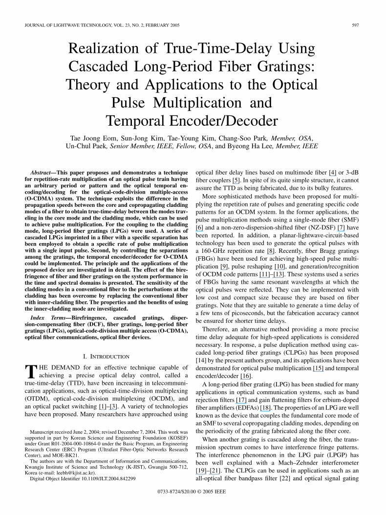
Fig. 1. Schematic diagram of the delayed optical pulse signal generation usingan LPGP. The inset figures are the measured near-field patterns of the core modeand the fourth cladding mode.
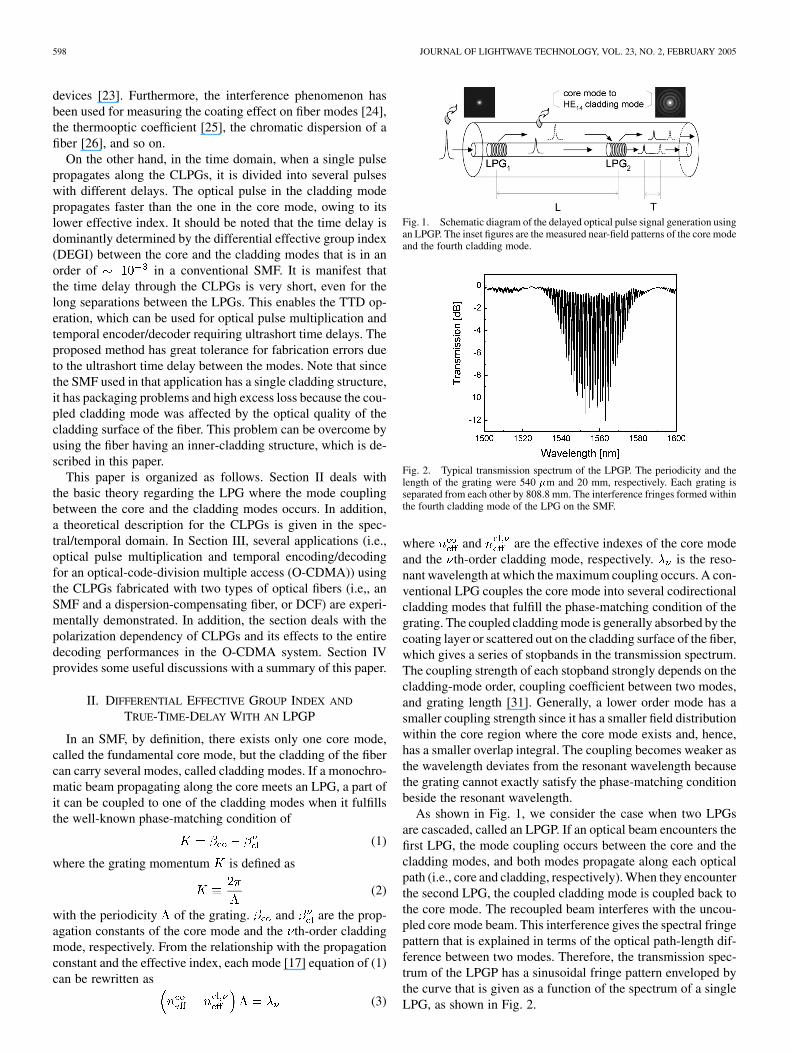
Fig. 2. Typical transmission spectrum of the LPGP. The periodicity and thelength of the grating were 540 �m and 20 mm, respectively. Each grating isseparated from each other by 808.8 mm. The interference fringes formed withinthe fourth cladding mode of the LPG on the SMF.
where and are the effective indexes of the core modeand the th-order cladding mode, respectively. is the reso-nant wavelength at which the maximum coupling occurs. A con-ventional LPG couples the core mode into several codirectionalcladding modes that fulfill the phase-matching condition of thegrating. The coupled cladding mode is generally absorbed by thecoating layer or scattered out on the cladding surface of the fiber,which gives a series of stopbands in the transmission spectrum.The coupling strength of each stopband strongly depends on thecladding-mode order, coupling coefficient between two modes,and grating length [31]. Generally, a lower order mode has asmaller coupling strength since it has a smaller field distributionwithin the core region where the core mode exists and, hence,has a smaller overlap integral. The coupling becomes weaker asthe wavelength deviates from the resonant wavelength becausethe grating cannot exactly satisfy the phase-matching conditionbeside the resonant wavelength.
As shown in Fig. 1, we consider the case when two LPGsare cascaded, called an LPGP. If an optical beam encounters thefirst LPG, the mode coupling occurs between the core and thecladding modes, and both modes propagate along each opticalpath (i.e., core and cladding, respectively). When they encounterthe second LPG, the coupled cladding mode is coupled back tothe core mode. The recoupled beam interferes with the uncou-pled core mode beam. This interference gives the spectral fringepattern that is explained in terms of the optical path-length dif-ference between two modes. Therefore, the transmission spec-trum of the LPGP has a sinusoidal fringe pattern enveloped bythe curve that is given as a function of the spectrum of a singleLPG, as shown in Fig. 2.
EOM et al.: REALIZATION OF TTD USING CASCADED LPGs 599
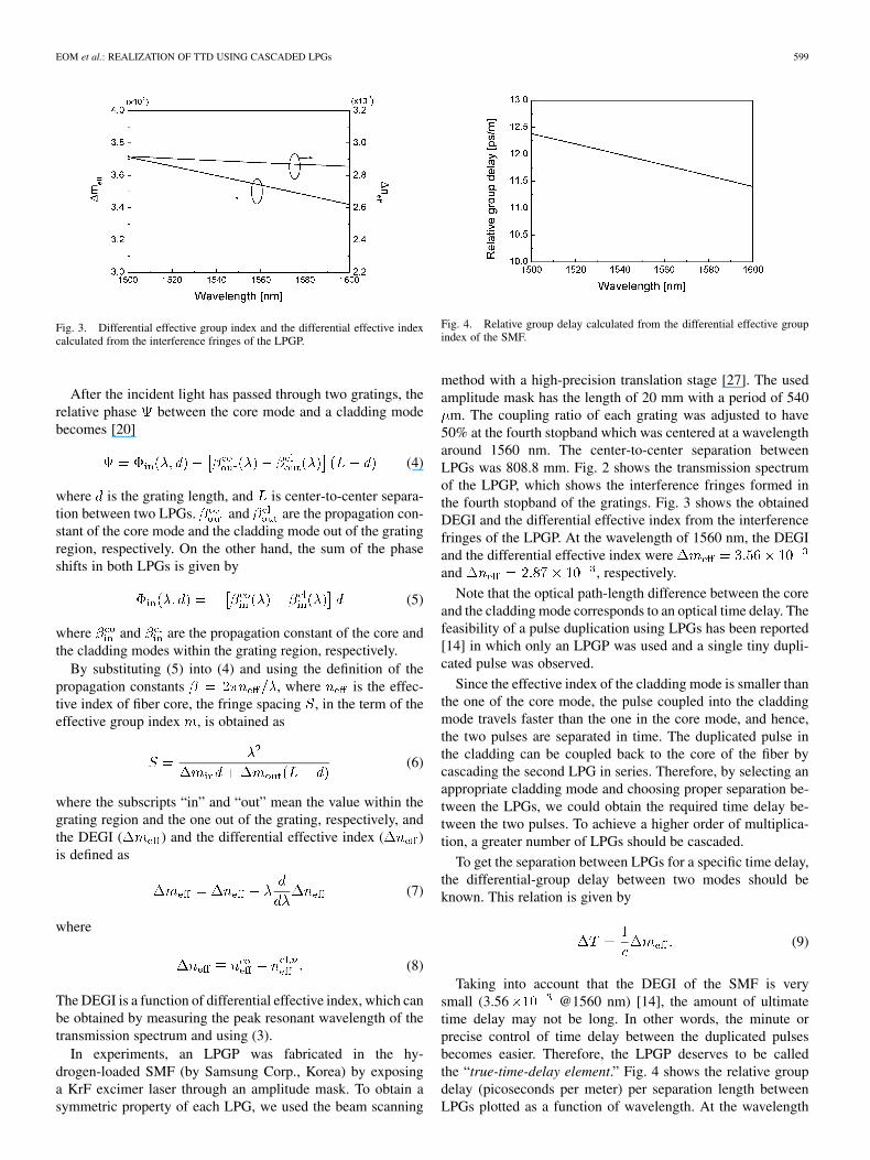
Fig. 3. Differential effective group index and the differential effective indexcalculated from the interference fringes of the LPGP.
After the incident light has passed through two gratings, therelative phase between the core mode and a cladding modebecomes [20]
(4)
where is the grating length, and is center-to-center separa-tion between two LPGs. and are the propagation con-stant of the core mode and the cladding mode out of the gratingregion, respectively. On the other hand, the sum of the phaseshifts in both LPGs is given by
(5)
where and are the propagation constant of the core andthe cladding modes within the grating region, respectively.
By substituting (5) into (4) and using the definition of thepropagation constants , where is the effec-tive index of fiber core, the fringe spacing , in the term of theeffective group index , is obtained as
(6)
where the subscripts “in” and “out” mean the value within thegrating region and the one out of the grating, respectively, andthe DEGI ( ) and the differential effective index ( )is defined as
(7)
where
(8)
The DEGI is a function of differential effective index, which canbe obtained by measuring the peak resonant wavelength of thetransmission spectrum and using (3).
In experiments, an LPGP was fabricated in the hy-drogen-loaded SMF (by Samsung Corp., Korea) by exposinga KrF excimer laser through an amplitude mask. To obtain asymmetric property of each LPG, we used the beam scanning
Fig. 4. Relative group delay calculated from the differential effective groupindex of the SMF.
method with a high-precision translation stage [27]. The usedamplitude mask has the length of 20 mm with a period of 540
m. The coupling ratio of each grating was adjusted to have50% at the fourth stopband which was centered at a wavelengtharound 1560 nm. The center-to-center separation betweenLPGs was 808.8 mm. Fig. 2 shows the transmission spectrumof the LPGP, which shows the interference fringes formed inthe fourth stopband of the gratings. Fig. 3 shows the obtainedDEGI and the differential effective index from the interferencefringes of the LPGP. At the wavelength of 1560 nm, the DEGIand the differential effective index wereand , respectively.
Note that the optical path-length difference between the coreand the cladding mode corresponds to an optical time delay. Thefeasibility of a pulse duplication using LPGs has been reported[14] in which only an LPGP was used and a single tiny dupli-cated pulse was observed.
Since the effective index of the cladding mode is smaller thanthe one of the core mode, the pulse coupled into the claddingmode travels faster than the one in the core mode, and hence,the two pulses are separated in time. The duplicated pulse inthe cladding can be coupled back to the core of the fiber bycascading the second LPG in series. Therefore, by selecting anappropriate cladding mode and choosing proper separation be-tween the LPGs, we could obtain the required time delay be-tween the two pulses. To achieve a higher order of multiplica-tion, a greater number of LPGs should be cascaded.
To get the separation between LPGs for a specific time delay,the differential-group delay between two modes should beknown. This relation is given by
(9)
Taking into account that the DEGI of the SMF is verysmall (3.56 @1560 nm) [14], the amount of ultimatetime delay may not be long. In other words, the minute orprecise control of time delay between the duplicated pulsesbecomes easier. Therefore, the LPGP deserves to be calledthe “true-time-delay element.” Fig. 4 shows the relative groupdelay (picoseconds per meter) per separation length betweenLPGs plotted as a function of wavelength. At the wavelength
600 JOURNAL OF LIGHTWAVE TECHNOLOGY, VOL. 23, NO. 2, FEBRUARY 2005
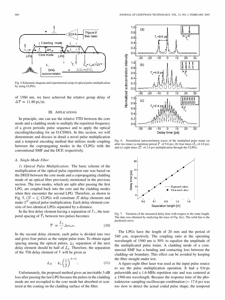
Fig. 5.Schematic diagram and experimental setup of optical pulse multiplicationby using CLPGs.
of 1560 nm, we have achieved the relative group delay of11.80 ps m.
III. APPLICATIONS
In principle, one can use the relative TTD between the coremode and a cladding mode to multiply the repetition frequencyof a given periodic pulse sequence and to apply the opticalencoding/decoding for an O-CDMA. In this section, we willdemonstrate and discuss in detail a novel pulse multiplicationand a temporal encoding method that utilizes mode couplingbetween the copropagating modes in the CLPGs with theconventional SMF and the DCF, respectively.
A. Single-Mode Fiber
1) Optical Pulse Multiplication: The basic scheme of themultiplication of the optical pulse repetition rate was based onthe DEGI between the core mode and a copropagating claddingmode of an optical fiber previously mentioned in the previoussection. The two modes, which are split after passing the firstLPG, are coupled back into the core and the cladding modeswhen they encounter the second LPG. Therefore, as shown inFig. 5, CLPGs will constitute delay elements andmake optical pulse-multiplication. Each delay element con-sists of two identical LPGs separated by a distance.
In the first delay element having a separation of , the tem-poral spacing of between two pulses becomes
(10)
In the second delay element, each pulse is divided into twoand gives four pulses as the output pulse train. To obtain equalspacing among the optical pulses, separation of the nextdelay element should be half of . Therefore, the separationof the th delay element of will be given as
(11)
Unfortunately, the proposed method gives an inevitable 3-dBloss after passing the last LPG because the pulses in the claddingmode are not recoupled to the core mode but absorbed or scat-tered at the coating on the cladding surface of the fiber.
Fig. 6. Normalized autocorrelation traces of the multiplied pulse trains (a)after two times (a repetition period T of 9.6 ps), (b) four times (T of 4.8 ps),and (c) eight times (T of 2.4 ps) multiplication through the CLPGs.
Fig. 7. Variation of the measured delay time with respect to the route length.The data was obtained by analyzing the trace of Fig. 6(c). The solid line is thepredicted curve.
The LPGs have the length of 20 mm and the period of540 m, respectively. The coupling ratio at the operatingwavelength of 1560 nm is 50% to equalize the amplitude ofthe multiplicated pulse trains. A cladding mode of a com-mercial SMF has a bending and contacting loss between thecladding–air boundary. This effect can be avoided by keepingthe fiber straight under test.
A figure-eight fiber laser was used as the input pulse sourceto see the pulse multiplication operation. It had a 0.6-pspulsewidth and a 1.6-MHz repetition rate and was centered ata 1560-nm wavelength. Because the response time of the pho-todetector–sampling oscilloscope combination ( 17.6 ps) wastoo slow to detect the actual coded pulse shape, the temporal
EOM et al.: REALIZATION OF TTD USING CASCADED LPGs 601
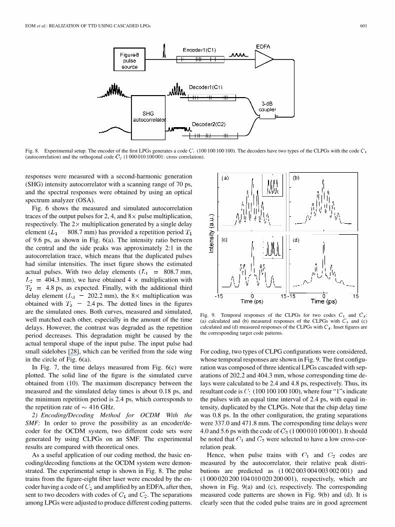
Fig. 8. Experimental setup. The encoder of the first LPGs generates a code C (100 100 100 100). The decoders have two types of the CLPGs with the code C(autocorrelation) and the orthogonal code C (1 000 010 100 001: cross correlation).
responses were measured with a second-harmonic generation(SHG) intensity autocorrelator with a scanning range of 70 ps,and the spectral responses were obtained by using an opticalspectrum analyzer (OSA).
Fig. 6 shows the measured and simulated autocorrelationtraces of the output pulses for 2, 4, and 8 pulse multiplication,respectively. The 2 multiplication generated by a single delayelement ( 808.7 mm) has provided a repetition periodof 9.6 ps, as shown in Fig. 6(a). The intensity ratio betweenthe central and the side peaks was approximately 2:1 in theautocorrelation trace, which means that the duplicated pulseshad similar intensities. The inset figure shows the estimatedactual pulses. With two delay elements ( 808.7 mm,
404.3 mm), we have obtained 4 multiplication with4.8 ps, as expected. Finally, with the additional third
delay element ( 202.2 mm), the 8 multiplication wasobtained with 2.4 ps. The dotted lines in the figuresare the simulated ones. Both curves, measured and simulated,well matched each other, especially in the amount of the timedelays. However, the contrast was degraded as the repetitionperiod decreases. This degradation might be caused by theactual temporal shape of the input pulse. The input pulse hadsmall sidelobes [28], which can be verified from the side wingin the circle of Fig. 6(a).
In Fig. 7, the time delays measured from Fig. 6(c) wereplotted. The solid line of the figure is the simulated curveobtained from (10). The maximum discrepancy between themeasured and the simulated delay times is about 0.18 ps, andthe minimum repetition period is 2.4 ps, which corresponds tothe repetition rate of 416 GHz.
2) Encoding/Decoding Method for OCDM With theSMF: In order to prove the possibility as an encoder/de-coder for the OCDM system, two different code sets weregenerated by using CLPGs on an SMF. The experimentalresults are compared with theoretical ones.
As a useful application of our coding method, the basic en-coding/decoding functions at the OCDM system were demon-strated. The experimental setup is shown in Fig. 8. The pulsetrains from the figure-eight fiber laser were encoded by the en-coder having a code of and amplified by an EDFA, after then,sent to two decoders with codes of and . The separationsamong LPGs were adjusted to produce different coding patterns.
Fig. 9. Temporal responses of the CLPGs for two codes C and C :(a) calculated and (b) measured responses of the CLPGs with C and (c)calculated and (d) measured responses of the CLPGs with C . Inset figures arethe corresponding target code patterns.
For coding, two types of CLPG configurations were considered,whose temporal responses are shown in Fig. 9. The first configu-ration was composed of three identical LPGs cascaded with sep-arations of 202.2 and 404.3 mm, whose corresponding time de-lays were calculated to be 2.4 and 4.8 ps, respectively. Thus, itsresultant code is (100 100 100 100), where four “1”s indicatethe pulses with an equal time interval of 2.4 ps, with equal in-tensity, duplicated by the CLPGs. Note that the chip delay timewas 0.8 ps. In the other configuration, the grating separationswere 337.0 and 471.8 mm. The corresponding time delays were4.0 and 5.6 ps with the code of (1 000 010 100 001). It shouldbe noted that and were selected to have a low cross-cor-relation peak.
Hence, when pulse trains with and codes aremeasured by the autocorrelator, their relative peak distri-butions are predicted as (1 002 003 004 003 002 001) and(1 000 020 200 104 010 020 200 001), respectively, which areshown in Fig. 9(a) and (c), respectively. The correspondingmeasured code patterns are shown in Fig. 9(b) and (d). It isclearly seen that the coded pulse trains are in good agreement
602 JOURNAL OF LIGHTWAVE TECHNOLOGY, VOL. 23, NO. 2, FEBRUARY 2005
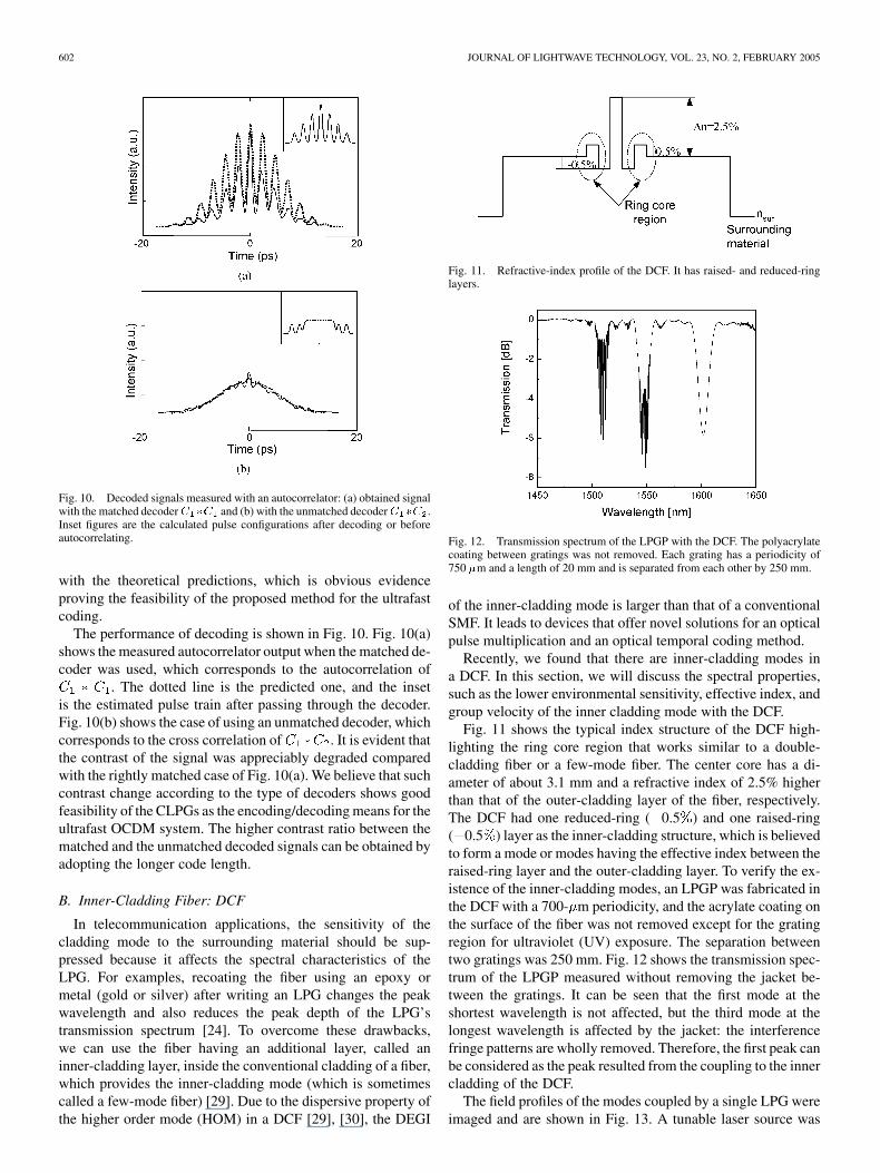
Fig. 10. Decoded signals measured with an autocorrelator: (a) obtained signalwith the matched decoderC �C and (b) with the unmatched decoderC �C .Inset figures are the calculated pulse configurations after decoding or beforeautocorrelating.
with the theoretical predictions, which is obvious evidenceproving the feasibility of the proposed method for the ultrafastcoding.
The performance of decoding is shown in Fig. 10. Fig. 10(a)shows the measured autocorrelator output when the matched de-coder was used, which corresponds to the autocorrelation of
. The dotted line is the predicted one, and the insetis the estimated pulse train after passing through the decoder.Fig. 10(b) shows the case of using an unmatched decoder, whichcorresponds to the cross correlation of . It is evident thatthe contrast of the signal was appreciably degraded comparedwith the rightly matched case of Fig. 10(a). We believe that suchcontrast change according to the type of decoders shows goodfeasibility of the CLPGs as the encoding/decoding means for theultrafast OCDM system. The higher contrast ratio between thematched and the unmatched decoded signals can be obtained byadopting the longer code length.
B. Inner-Cladding Fiber: DCF
In telecommunication applications, the sensitivity of thecladding mode to the surrounding material should be sup-pressed because it affects the spectral characteristics of theLPG. For examples, recoating the fiber using an epoxy ormetal (gold or silver) after writing an LPG changes the peakwavelength and also reduces the peak depth of the LPG’stransmission spectrum [24]. To overcome these drawbacks,we can use the fiber having an additional layer, called aninner-cladding layer, inside the conventional cladding of a fiber,which provides the inner-cladding mode (which is sometimescalled a few-mode fiber) [29]. Due to the dispersive property ofthe higher order mode (HOM) in a DCF [29], [30], the DEGI
Fig. 11. Refractive-index profile of the DCF. It has raised- and reduced-ringlayers.
Fig. 12. Transmission spectrum of the LPGP with the DCF. The polyacrylatecoating between gratings was not removed. Each grating has a periodicity of750 �m and a length of 20 mm and is separated from each other by 250 mm.
of the inner-cladding mode is larger than that of a conventionalSMF. It leads to devices that offer novel solutions for an opticalpulse multiplication and an optical temporal coding method.
Recently, we found that there are inner-cladding modes ina DCF. In this section, we will discuss the spectral properties,such as the lower environmental sensitivity, effective index, andgroup velocity of the inner cladding mode with the DCF.
Fig. 11 shows the typical index structure of the DCF high-lighting the ring core region that works similar to a double-cladding fiber or a few-mode fiber. The center core has a di-ameter of about 3.1 mm and a refractive index of 2.5% higherthan that of the outer-cladding layer of the fiber, respectively.The DCF had one reduced-ring ( 0.5 ) and one raised-ring( 0.5 ) layer as the inner-cladding structure, which is believedto form a mode or modes having the effective index between theraised-ring layer and the outer-cladding layer. To verify the ex-istence of the inner-cladding modes, an LPGP was fabricated inthe DCF with a 700- m periodicity, and the acrylate coating onthe surface of the fiber was not removed except for the gratingregion for ultraviolet (UV) exposure. The separation betweentwo gratings was 250 mm. Fig. 12 shows the transmission spec-trum of the LPGP measured without removing the jacket be-tween the gratings. It can be seen that the first mode at theshortest wavelength is not affected, but the third mode at thelongest wavelength is affected by the jacket: the interferencefringe patterns are wholly removed. Therefore, the first peak canbe considered as the peak resulted from the coupling to the innercladding of the DCF.
The field profiles of the modes coupled by a single LPG wereimaged and are shown in Fig. 13. A tunable laser source was
EOM et al.: REALIZATION OF TTD USING CASCADED LPGs 603
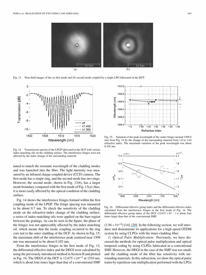
Fig. 13. Near-field images of the (a) first mode and (b) second mode coupled by a single LPG fabricated in the DCF.
Fig. 14. Transmission spectra of the LPGP fabricated in the DCF with variousindex-matching oils on the cladding surface. The interference fringes were notaffected by the index change of the surrounding material.
tuned to match the resonant wavelength of the cladding modesand was launched into the fiber. The light intensity was mea-sured by an infrared charge-coupled device (CCD) camera. Thefirst mode has a single ring, and the second mode has two rings.However, the second mode, shown in Fig. 13(b), has a largermode boundary compared with the first mode of Fig. 13(a); thus,it is more easily affected by the optical condition of the claddingsurface.
Fig. 14 shows the interference fringes formed within the firstcoupling mode of the LPGP. The fringe spacing was measuredto be about 0.7 nm. To check the sensitivity of the claddingmode on the refractive-index change of the cladding surface,a series of index-matching oils were applied on the bare regionbetween the gratings. As can be seen in the figure, the phase ofthe fringes was not appreciably affected by the index-matchingoil, which means that the mode coupling occurred to the ringcore not to the outer cladding of the DCF. As shown in Fig. 15,the maximum shift of the interference peak centered near 1509nm was measured to be about 0.102 nm.
From the interference fringes in the first mode of Fig. 13,the differential effective index and the DEGI were calculated byusing the previously introduced method in Section II and plottedin Fig. 16. The DEGI of the DCF is 12.675 at 1510 nm,which is about four times lager than that of a conventional SMF
Fig. 15. Variation of the peak wavelength of the center fringe (around 1509.6nm) from Fig. 14 by the change of the surrounding material from 1.0 to 1.64refractive index. The maximum variation of the peak wavelength was about0.102 nm.
Fig. 16. Differential effective group index and the differential effective indexcalculated from the interference fringes in the first mode of Fig. 14. Thedifferential effective group index of the DCF (12.637�10 ) is about fourtimes larger than that of the conventional SMF.
(3.56 ) [14], [20]. In the following section, we will intro-duce and demonstrate its applications for a high-speed OTDMsystem by using CLPGs with the inner-cladding fiber.
1) Optical Pulse Multiplication: Previously, we have dis-cussed the methods for optical pulse multiplication and opticaltemporal coding by using CLPGs fabricated in a conventionalSMF. However, the DEGI in the case of the SMF was too small,and the cladding mode of the fiber has sensitivity with sur-rounding materials. In this subsection, we show the optical pulsetrains by repetition-rate multiplication performed with the LPGs
604 JOURNAL OF LIGHTWAVE TECHNOLOGY, VOL. 23, NO. 2, FEBRUARY 2005
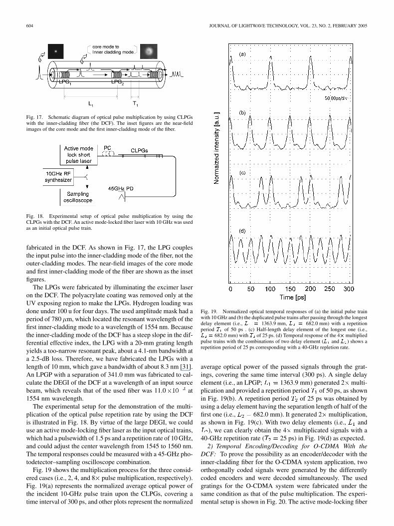
Fig. 17. Schematic diagram of optical pulse multiplication by using CLPGswith the inner-cladding fiber (the DCF). The inset figures are the near-fieldimages of the core mode and the first inner-cladding mode of the fiber.
Fig. 18. Experimental setup of optical pulse multiplication by using theCLPGs with the DCF. An active mode-locked fiber laser with 10 GHz was usedas an initial optical pulse train.
fabricated in the DCF. As shown in Fig. 17, the LPG couplesthe input pulse into the inner-cladding mode of the fiber, not theouter-cladding modes. The near-field images of the core modeand first inner-cladding mode of the fiber are shown as the insetfigures.
The LPGs were fabricated by illuminating the excimer laseron the DCF. The polyacrylate coating was removed only at theUV exposing region to make the LPGs. Hydrogen loading wasdone under 100 u for four days. The used amplitude mask had aperiod of 780 m, which located the resonant wavelength of thefirst inner-cladding mode to a wavelength of 1554 nm. Becausethe inner-cladding mode of the DCF has a steep slope in the dif-ferential effective index, the LPG with a 20-mm grating lengthyields a too-narrow resonant peak, about a 4.1-nm bandwidth ata 2.5-dB loss. Therefore, we have fabricated the LPGs with alength of 10 mm, which gave a bandwidth of about 8.3 nm [31].An LPGP with a separation of 341.0 mm was fabricated to cal-culate the DEGI of the DCF at a wavelength of an input sourcebeam, which reveals that of the used fiber was 11.0 at1554 nm wavelength.
The experimental setup for the demonstration of the multi-plication of the optical pulse repetition rate by using the DCFis illustrated in Fig. 18. By virtue of the large DEGI, we coulduse an active mode-locking fiber laser as the input optical trains,which had a pulsewidth of 1.5 ps and a repetition rate of 10 GHz,and could adjust the center wavelength from 1545 to 1560 nm.The temporal responses could be measured with a 45-GHz pho-todetector–sampling oscilloscope combination.
Fig. 19 shows the multiplication process for the three consid-ered cases (i.e., 2, 4, and 8 pulse multiplication, respectively).Fig. 19(a) represents the normalized average optical power ofthe incident 10-GHz pulse train upon the CLPGs, covering atime interval of 300 ps, and other plots represent the normalized
Fig. 19. Normalized optical temporal responses of (a) the initial pulse trainwith 10 GHz and (b) the duplicated pulse trains after passing through the longestdelay element (i.e., L = 1363.9 mm, L = 682.0 mm) with a repetitionperiod T of 50 ps . (c) Half-length delay element of the longest one (i.e.,L = 682.0 mm) with T of 25 ps. (d) Temporal response of the 4�multipliedpulse trains with the combinations of two delay element (L and L ) shows arepetition period of 25 ps corresponding with a 40-GHz repletion rate.
average optical power of the passed signals through the grat-ings, covering the same time interval (300 ps). A single delayelement (i.e., an LPGP; 1363.9 mm) generated 2 multi-plication and provided a repetition period of 50 ps, as shownin Fig. 19(b). A repetition period of 25 ps was obtained byusing a delay element having the separation length of half of thefirst one (i.e., 682.0 mm). It generated 2 multiplication,as shown in Fig. 19(c). With two delay elements (i.e., and
), we can clearly obtain the 4 multiplicated signals with a40-GHz repetition rate ( 25 ps) in Fig. 19(d) as expected.
2) Temporal Encoding/Decoding for O-CDMA With theDCF: To prove the possibility as an encoder/decoder with theinner-cladding fiber for the O-CDMA system application, twoorthogonally coded signals were generated by the differentlycoded encoders and were decoded simultaneously. The usedgratings for the O-CDMA system were fabricated under thesame condition as that of the pulse multiplication. The experi-mental setup is shown in Fig. 20. The active mode-locking fiber
EOM et al.: REALIZATION OF TTD USING CASCADED LPGs 605
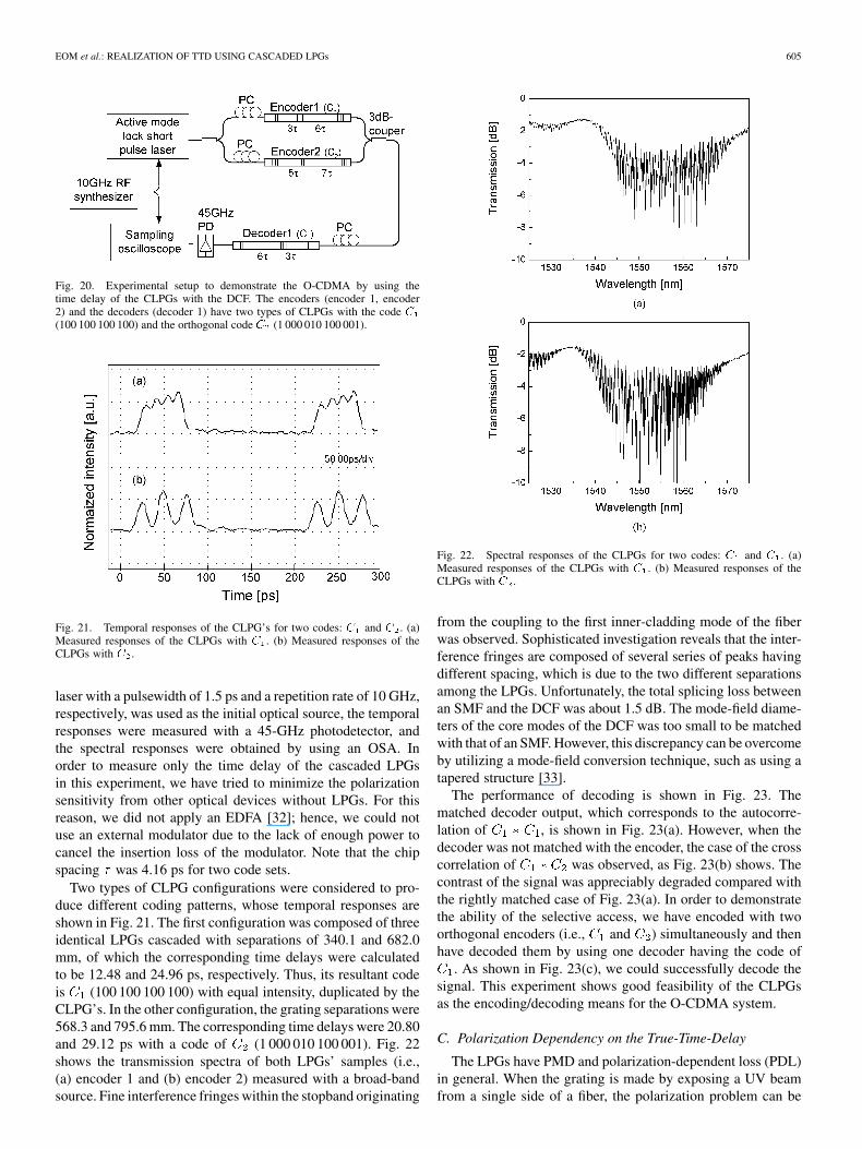
Fig. 20. Experimental setup to demonstrate the O-CDMA by using thetime delay of the CLPGs with the DCF. The encoders (encoder 1, encoder2) and the decoders (decoder 1) have two types of CLPGs with the code C(100 100 100 100) and the orthogonal code C (1 000 010 100 001).
Fig. 21. Temporal responses of the CLPG’s for two codes: C and C . (a)Measured responses of the CLPGs with C . (b) Measured responses of theCLPGs with C .
laser with a pulsewidth of 1.5 ps and a repetition rate of 10 GHz,respectively, was used as the initial optical source, the temporalresponses were measured with a 45-GHz photodetector, andthe spectral responses were obtained by using an OSA. Inorder to measure only the time delay of the cascaded LPGsin this experiment, we have tried to minimize the polarizationsensitivity from other optical devices without LPGs. For thisreason, we did not apply an EDFA [32]; hence, we could notuse an external modulator due to the lack of enough power tocancel the insertion loss of the modulator. Note that the chipspacing was 4.16 ps for two code sets.
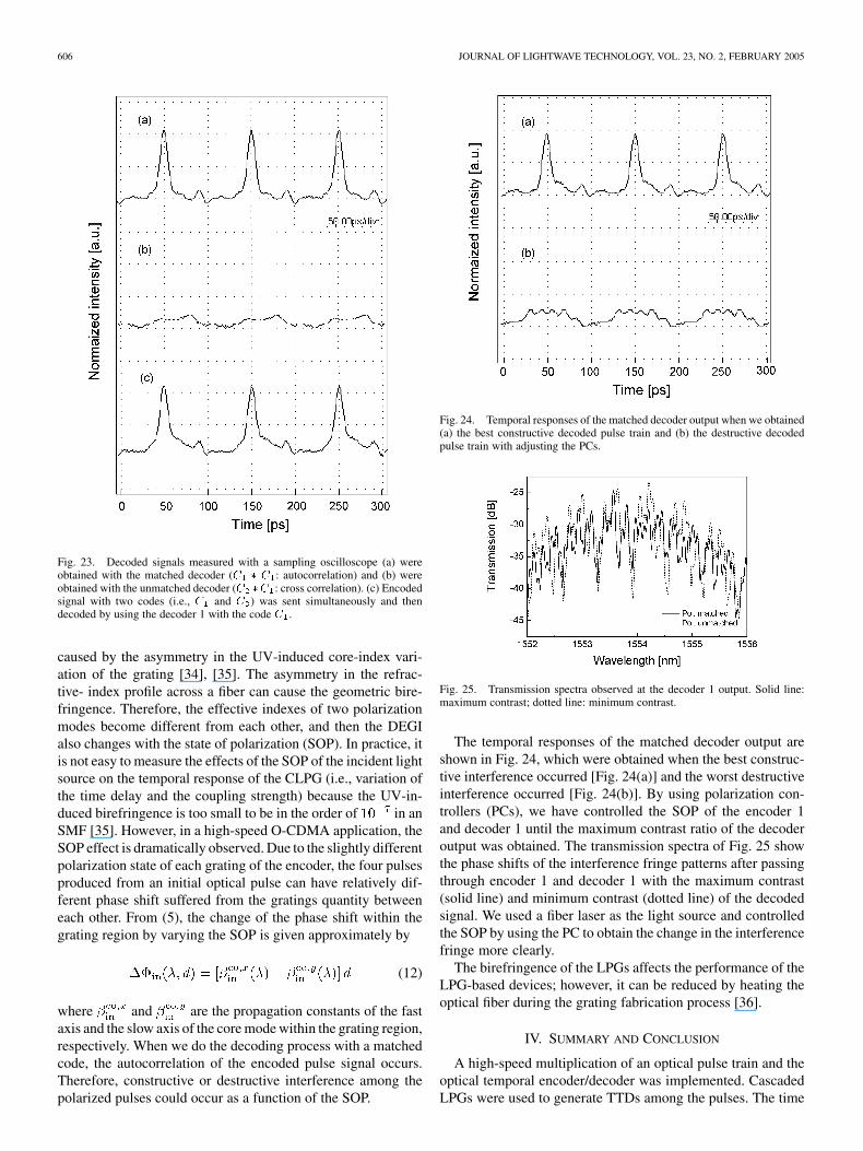
Two types of CLPG configurations were considered to pro-duce different coding patterns, whose temporal responses areshown in Fig. 21. The first configuration was composed of threeidentical LPGs cascaded with separations of 340.1 and 682.0mm, of which the corresponding time delays were calculatedto be 12.48 and 24.96 ps, respectively. Thus, its resultant codeis (100 100 100 100) with equal intensity, duplicated by theCLPG’s. In the other configuration, the grating separations were568.3 and 795.6 mm. The corresponding time delays were 20.80and 29.12 ps with a code of (1 000 010 100 001). Fig. 22shows the transmission spectra of both LPGs’ samples (i.e.,(a) encoder 1 and (b) encoder 2) measured with a broad-bandsource. Fine interference fringes within the stopband originating
Fig. 22. Spectral responses of the CLPGs for two codes: C and C . (a)Measured responses of the CLPGs with C . (b) Measured responses of theCLPGs with C .
from the coupling to the first inner-cladding mode of the fiberwas observed. Sophisticated investigation reveals that the inter-ference fringes are composed of several series of peaks havingdifferent spacing, which is due to the two different separationsamong the LPGs. Unfortunately, the total splicing loss betweenan SMF and the DCF was about 1.5 dB. The mode-field diame-ters of the core modes of the DCF was too small to be matchedwith that of an SMF. However, this discrepancy can be overcomeby utilizing a mode-field conversion technique, such as using atapered structure [33].
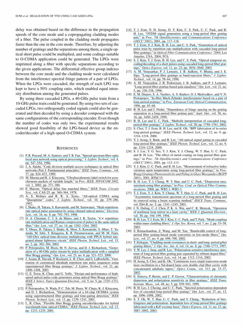
The performance of decoding is shown in Fig. 23. Thematched decoder output, which corresponds to the autocorre-lation of , is shown in Fig. 23(a). However, when thedecoder was not matched with the encoder, the case of the crosscorrelation of was observed, as Fig. 23(b) shows. Thecontrast of the signal was appreciably degraded compared withthe rightly matched case of Fig. 23(a). In order to demonstratethe ability of the selective access, we have encoded with twoorthogonal encoders (i.e., and ) simultaneously and thenhave decoded them by using one decoder having the code of
. As shown in Fig. 23(c), we could successfully decode thesignal. This experiment shows good feasibility of the CLPGsas the encoding/decoding means for the O-CDMA system.
C. Polarization Dependency on the True-Time-Delay
The LPGs have PMD and polarization-dependent loss (PDL)in general. When the grating is made by exposing a UV beamfrom a single side of a fiber, the polarization problem can be
606 JOURNAL OF LIGHTWAVE TECHNOLOGY, VOL. 23, NO. 2, FEBRUARY 2005
Fig. 23. Decoded signals measured with a sampling oscilloscope (a) wereobtained with the matched decoder (C � C : autocorrelation) and (b) wereobtained with the unmatched decoder (C �C : cross correlation). (c) Encodedsignal with two codes (i.e., C and C ) was sent simultaneously and thendecoded by using the decoder 1 with the code C .
caused by the asymmetry in the UV-induced core-index vari-ation of the grating [34], [35]. The asymmetry in the refrac-tive- index profile across a fiber can cause the geometric bire-fringence. Therefore, the effective indexes of two polarizationmodes become different from each other, and then the DEGIalso changes with the state of polarization (SOP). In practice, itis not easy to measure the effects of the SOP of the incident lightsource on the temporal response of the CLPG (i.e., variation ofthe time delay and the coupling strength) because the UV-in-duced birefringence is too small to be in the order of in anSMF [35]. However, in a high-speed O-CDMA application, theSOP effect is dramatically observed. Due to the slightly differentpolarization state of each grating of the encoder, the four pulsesproduced from an initial optical pulse can have relatively dif-ferent phase shift suffered from the gratings quantity betweeneach other. From (5), the change of the phase shift within thegrating region by varying the SOP is given approximately by
(12)
where and are the propagation constants of the fastaxis and the slow axis of the core mode within the grating region,respectively. When we do the decoding process with a matchedcode, the autocorrelation of the encoded pulse signal occurs.Therefore, constructive or destructive interference among thepolarized pulses could occur as a function of the SOP.
Fig. 24. Temporal responses of the matched decoder output when we obtained(a) the best constructive decoded pulse train and (b) the destructive decodedpulse train with adjusting the PCs.
Fig. 25. Transmission spectra observed at the decoder 1 output. Solid line:maximum contrast; dotted line: minimum contrast.
The temporal responses of the matched decoder output areshown in Fig. 24, which were obtained when the best construc-tive interference occurred [Fig. 24(a)] and the worst destructiveinterference occurred [Fig. 24(b)]. By using polarization con-trollers (PCs), we have controlled the SOP of the encoder 1and decoder 1 until the maximum contrast ratio of the decoderoutput was obtained. The transmission spectra of Fig. 25 showthe phase shifts of the interference fringe patterns after passingthrough encoder 1 and decoder 1 with the maximum contrast(solid line) and minimum contrast (dotted line) of the decodedsignal. We used a fiber laser as the light source and controlledthe SOP by using the PC to obtain the change in the interferencefringe more clearly.
The birefringence of the LPGs affects the performance of theLPG-based devices; however, it can be reduced by heating theoptical fiber during the grating fabrication process [36].
IV. SUMMARY AND CONCLUSION
A high-speed multiplication of an optical pulse train and theoptical temporal encoder/decoder was implemented. CascadedLPGs were used to generate TTDs among the pulses. The time
EOM et al.: REALIZATION OF TTD USING CASCADED LPGs 607
delay was obtained based on the difference in the propagationspeeds of the core mode and a copropagating cladding modesof a fiber. The pulse coupled in the cladding mode propagatesfaster than the one in the core mode. Therefore, by adjusting thenumber of gratings and the separations among them, a single op-tical short pulse could be multiplied, and some codings suitableto O-CDMA application could be generated. The LPGs wereimprinted along a fiber with specific separations according tothe given applications. The differential effective group indexesbetween the core mode and the cladding mode were calculatedfrom the interference spectral fringe pattern of a pair of LPGs.When the LPGs were cascaded, the strength of each LPG waskept to have a 50% coupling ratio, which enabled equal inten-sity distribution among the generated pulses.
By using three cascaded LPGs, a 40-GHz pulse train from a10-GHz pulse train could be generated. By using two sets of cas-caded LPGs, two orthogonally coded signals could also be gen-erated and then decoded by using a decoder composed with thesame configurations of the corresponding encoder. Even thoughthe number of codes was only two, the experimental resultsshowed good feasibility of the LPG-based device as the en-coder/decoder of a high-speed O-CDMA system.
REFERENCES
[1] P. R. Prucnal, M. A. Santoro, and T. R. Fan, “Spread spectrum fiber-opticlocal area network using optical processing,” J. Lightw. Technol., vol. 4,pp. 547–554, 1986.
[2] J. A. Salehi, “Code division multiple-access techniques in optical fibernetworks-Part I: Fundamental principles,” IEEE Trans. Commun., vol.37, pp. 824–833, 1989.
[3] M. Murata and K.-I. Kitayama, “Ultrafast photonic label switch for asyn-chronous packets of variable length,” in Proc. IEEE, INFOCOM 2002,vol. 1, 2002, pp. 371–380.
[4] E. Marom, “Optical delay line matched filters,” IEEE Trans. CircuitsSyst., vol. CAS-25, pp. 360–364, 1978.
[5] A. S. Holmes and R. R. A. Syms, “All-optical CDMA using“Quasiprime” codes,” J. Lightw. Technol., vol. 10, pp. 279–286,1992.
[6] I. Shake, H. Takara, S. Kawanishi, and M. Saruwatari, “High-repetition-rate optical pulse generation by using chirped optical pulses,” Electron.Lett., vol. 34, no. 8, pp. 792–793, 1998.
[7] D. A. Chestnut, C. J. S. de Matos, and J. R. Taylor, “4� repetition-rate multiplication and Raman compression of pulses in the same opticalfiber,” Opt. Lett., vol. 27, no. 14, pp. 1262–1264, 2002.
[8] T. Ohara, H. Takara, I. Shake, K. Mori, S. Kawanishi, S. Mino, T. Ya-mada, M. Ishii, T. Kitagawa, K. R. Parameswaran, and M. M. Fejer,“160-Gb/s optical-time-division multiplexing with PPLN hybrid inte-grated planar lightwave circuit,” IEEE Photon. Technol. Lett., vol. 15,no. 2, pp. 302–304, 2003.
[9] P. Petropoulos, M. Ibsen, M. N. Zervas, and D. J. Richardson, “Gener-ation of a 40-GHz pulse stream by pulse multiplication with a sampledfiber Bragg grating,” Opt. Lett., vol. 25, no. 8, pp. 521–523, 2000.
[10] J. Azana, R. Slavaik, P. Kockaert, L. R. Chen, and S. LaRochelle, “Gen-eration of customized ultrahigh repetition rate pulse sequences usingsuperimposed fiber Bragg gratings,” J. Lightw. Technol., vol. 21, pp.1490–1498, 2003.
[11] G. E. Town, K. Chan, and G. Yoffe, “Design and performance of high-speed optical pulse-code generators using optical fiber Bragg gratings,”IEEE J. Select. Topics Quantum Electron., vol. 5, no. 5, pp. 1325–1331,1999.
[12] P. Petropoulos, N. Wada, P. C. Teh, M. Ibsen, W. Chujo, K.-I. Kitayama,and D. J. Richardson, “Demonstration of a 64-chip OCDMA systemusing superstructured fiber gratings and time-gating detection,” IEEEPhoton. Technol. Lett., vol. 13, pp. 1239–1241, 2001.
[13] L. R. Chen, “Flexible fiber Bragg grating encoder/decoder for hybridwavelength-time optical CDMA,” IEEE Photon. Technol. Lett., vol. 13,pp. 1233–1235, 2001.
[14] T. J. Eom, N. H. Seong, D. Y. Kim, C. S. Park, U. C. Paek, and B.H. Lee, “OTDM signal generation using a long-period fiber gratingpair,” in Proc. 7th OptoElectronics and Communications Conference(OECC’2001), 2001, pp. 117–118.
[15] T. J. Eom, S. J. Kim, B. H. Lee, and C. S. Park, “Generation of opticalpulse train by repetition rate multiplication with cascaded long-periodfiber gratings,” in Optical Fiber Communication Conference ’2004, LosAngeles, USA, 2004, FC6.
[16] S. J. Kim, T. J. Eom, B. H. Lee, and C. S. Park, “Optical temporal en-coding/decoding of a short pulses using cascaded long-period fiber grat-ings,” Optics Express, vol. 11, no. 23, pp. 3034–3040, 2003.
[17] A. M. Vengsarkar, P. J. Lemaire, J. B. Judkins, V. Bhatia, and J. E.Sipe, “Long-period fiber gratings as band-rejection filters,” J. Lightw.Technol., vol. 14, pp. 58–64, 1996.
[18] A. M. Vengsarkar, J. R. Pedrazzani, J. B. Judkins, and P. J. Lemaire,“Long-period fiber-grating-based gain equalizer,” Opt. Lett., vol. 21, no.5, pp. 336–338, 1996.
[19] E. M. Dianov, S. A. Vasiliev, A. S. Kurkov, O. I. Medvedkov, and V. N.Protopopov, “In-fiber Mach-Zehnder interferometer based on a pair oflong-period gratings,” in Proc. European Conf. Optical Communication,1996, pp. 65–68.
[20] B. H. Lee and J. Nishii, “Dependence of fringe spacing on the gratingseparation in a long-period fiber grating pair,” Appl. Opt., vol. 38, no.16, pp. 3450–3459, 1999.
[21] B. H. Lee and U. C. Paek, “Multislit interpretetion of cascaded long-period fiber gratings,” J. Lightw. Technol., vol. 20, pp. 1750–1761, 2002.
[22] S. Choi, T. J. Eom, B. H. Lee, and K. Oh, “BPF fabrication of in-serieslong-period gratings,” IEEE Photon. Technol. Lett., vol. 12, no. 9, pp.1216–1218, 2000.
[23] Y. J. Jeong, S. Baek, and B. Lee, “All-optical signal gating in cascadedlong-period fiber gratings,” IEEE Photon. Technol. Lett., vol. 12, no. 9,pp. 1216–1218, 2000.
[24] S. J. Lee, Y. G. Seo, Y. J. Kim, Y. J. Chung, W. T. Han, U. C. Paek,and B. H. Lee, “The effect of metal coating on long-period fiber grat-ings,” in Proc. 7th OptoElectronics and Communications Conference(OECC’2001), 2001, pp. 112–113.
[25] Y. J. Kim, U. C. Paek, and B. H. Lee, “Measurement of refractive indexvariation upon temperature using long-period fiber gratings,” in Proc.Bragg Gratings Photosensitivity and Poling in Glass Waveguides (BGPP2001), 2001, BThC15.
[26] B. H. Lee, Y. J. Chung, W. T. Han, and U. C. Paek, “Dispersion mea-surement using fiber gratings,” in Proc. Conf. on Optical Fiber Commu-nications, 2000, pp. WB5-1–WB5-3.
[27] T. J. Eom, Y. J. Kim, Y. Chung, W. T. Han, U. C. Paek, and B. H. Lee,“Asymmetric transmission spectrum of a long-period fiber grating andits removal using a beam scanning method,” IEICE Trans. Commun.,vol. E84-B, no. 5, pp. 1241–1245, 2001.
[28] I. N. Duling, C.-J. Chen, P. K. A. Wai, and C. R. Menyuk, “Operationof nonlinear loop mirror in a laser cavity,” IEEE J. Quantum Electron.,vol. 30, pp. 194–199, 1994.
[29] B. H. Lee, T. J. Eom, M. J. Kim, U. C. Paek, and T. Park, “Mode couplingwithin inner cladding fibers,” J. Opt. Soc. Korea, vol. 7, no. 2, pp. 53–58,2003.
[30] S. Ramachandran, Z. Wang, and M. Yan, “Bandwidth control of long-period fiber grating-based mode converters in few-mode fibers,” Opt.Lett., vol. 27, no. 9, pp. 698–700, 2002.
[31] T. Erdogan, “Cladding-mode resonances in short- and long- period gibergrating filters,” J. Opt. Soc. Am. A, vol. 14, no. 8, pp. 1760–1773, 1997.
[32] Y. W. Lee, J. Jung, and B. Lee, “Polarization-sensitive interference spec-trum of long-period fiber grating pair separated by erbium-doped fiber,”IEEE Photon. Technol. Lett., vol. 14, pp. 1312–1314, 2002.
[33] H. Jeong, S. Choi, and K. Oh, “Continuous wave single transverse modelaser oscillation in a Nd-doped large core double clad fiber cavity withconcatenated adiabatic tapers,” Optics Comm., vol. 213, pp. 33–37,2002.
[34] E. Simova, P. Berini, and C. P. Grover, “Characterization of chromaticdispersion and polarization sensitivity in fiber gratings,” IEEE Trans.Instrum. Meas., vol. 48, no. 5, pp. 939–943, 1999.
[35] B. H. Lee, J. Cheong, and U. C. Paek, “Spectral polarization-dependentloss of cascaded long-period fiber grating,” Opt. Lett., vol. 27, no. 13,pp. 1096–1098, 2002.
[36] S. T. Oh, W. T. Han, U. C. Paek, and Y. Chung, “Reduction of bire-fringence and polarization- dependent loss of long-period fiber gratingsfabricated with a KrF excimer laser,” Optics Express, vol. 11, no. 23, pp.3087–3092, 2003.
608 JOURNAL OF LIGHTWAVE TECHNOLOGY, VOL. 23, NO. 2, FEBRUARY 2005
Tae Joong Eom was born in Busan, Korea. Hereceived the Diploma in electronics from PusanNational University, Busan, Korea, in 1998, and theM.S. degree in information and communicationsengineering from the Kwangju Institute of Scienceand Technology (K-JIST), Kwangju, Korea, in 2000.He is now a Ph.D. candidate in K-JIST.
His interests are in the field of fiber optics, fibergratings, especially fiber optic devices for WDMcommunications, optical code-division multipleaccess system, and smart sensor systems.
Mr. Eom is a Member of the Optical Society of America (OSA) and the Op-tical Society of Korea (OSK).
Sun-Jong Kim was born in Nam-won, Korea, in1974. He received the B.S. and M.S. degrees inelectronic engineering from the Kwang-woon Uni-versity, Seoul, Korea, in 1997 and 1999, respectively.He is currently working towards the Ph.D. degreeat the Kwangju Institute of Science and Technology(K-JIST), Kwangju, Korea.
His research interests include optical code-divisionmultiple access system, optical encryption/decryp-tion method, long-period fiber grating, opticalpulse generation, nonlinear optical switching, and
spectrum-sliced source.
Tae-Young Kim was born in Seoul, Korea, in 1978.He received the B.E. degree in avionics engineeringfrom the Hankuk Aviation University, Koyang,Kyung-gi, Korea, in 2001, and the M.S. degree ininformation and communications from KwangjuInstitute of Science and Technology (K-JIST),Kwangju, Korea, in 2003. He is currently pursuingthe Ph.D. degree in information and communicationsat K-JIST.
His research interests include optical code-divisionmultiple access system, optical encryption/decryp-
tion method, long-period fiber grating, optical pulse generation, nonlinearoptical switching, and spectrum-sliced source.
Chang-Soo Park received the B.S. degree from theHanyang University, Seoul, Korea, in 1979, the M.S.degree from the Seoul National University, Seoul,Korea, in 1981, and the Ph.D. degree from TexasA&M University, College Station, in 1990.
He was a Senior Member of Technical Staff inthe Electronics and Telecommunications ResearchInstitute (ETRI), Daejong, Korea, from 1982 to1987. From 1987 to 1990, he was Research Assis-tant, Engineering Center, Texas A&M University,College Station. From 1991 to 2000, he was Prin-
cipal member of Technical Staff in ETRI. In 2000, he joined the KwangjuInstitute of Science and Technology (K-JIST), Kwangju, Korea, as an AssociateProfessor in the Department of Information and Communications, where heis currently a Professor. He is also the Director of the Photonics ResearchCenter (PRC), which is sponsored by the Ministry of Commerce, Industry, andEnergy, Republic of Korea. His current research areas are in high-speed opticalcommunication, optical internet, and microwave photonics.
Prof. Park is a Member of the IEEE Lasers & Electro-Optics Society (LEOS)and the Optical Society of America (OSA).
Un-Chul Paek (M’90–SM’94) was born in Korea.He received the B.S. degree from the Korea MerchantMarine Academy, Pusan, Korea, in 1957 and the M.S.and Ph.D. degrees from the University of California,Berkeley, in 1965 and 1969, respectively.
He was with Bell Laboratories, Lucent Technolo-gies (then AT&T), Princeton, NJ, from 1969 to 1991,where he was a Member of the Technical Staff, aDistinguished Member of the Technical Staff, andthen a Bell Laboratories Fellow. In 1991, he returnedto Korea as the Executive Vice President of the
Korea Academy of Industrial Technology. In 1994, he joined the Faculty of theKwangju Institute of Science Technology (K-JIST), Kwangju, Korea, as a Pro-fessor of the Department of Information and Communication and became theDirector of the Research Center for Ultra-fast Fiber-Optics Networks, in 1997.In 2000, he was appointed Chaired Professor of the Department in the Institute.His current research interests include areas of optical communications, opticalfiber technology, and fabrication of optical devices and components.
Dr. Paek is a Fellow of the Optical Society of America (OSA), the AmericanCeramic Society, and the Institution of Electrical Engineers (IEE). He is also aMember of Sigma Xi, the Korea Academy of Science and Technology, and theU.S. National Academy of Engineering.
Byeong Ha Lee (M’00) received the B.S. and M.S.degrees from Department of Physics, Seoul NationalUniversity, Seoul, Korea, in 1984 and 1989, respec-tively, and the Ph.D. degree in physics from Univer-sity of Colorado, Boulder.
From 1997 to 1999, he worked at Osaka NationalResearch Institute of Japan, Osaka, Japan, as anSTA Fellow. He is currently an Assistant Professorat the Department of Information and Communica-tions, Kwangju Institute of Science and Technology(K-JIST), Kwangju, Korea. His interests are in the
field of fiber optics, fiber gratings, fiber property measurement using fibergratings, especially fiber optic devices for WDM communications and smartsensor systems.