com-1807soft reed-solomon code encoder/decoder ip core
TRANSCRIPT
COM-1807SOFTReed-Solomon codes encoder/decoderVHDL source code overview / IP core
OverviewThe COM-1807SOFT is a Reed-Solomon code error correction encoder/decoder written in generic VHDL.
The entire VHDL source code is deliverable.
Key features and performance:
Includes encoding, decoding, frame synchronization, interleaving and data randomization.
Runtime configuration selection:
o Intelsat (IESS-308) sync word 5A0FBC66: I interleaved code blocks,(225, 205, 10), (219, 201, 9), (194, 178, 8), (208, 192, 8), (126, 112, 7)
o CCSDS (131.0-B) sync word 1ACFFC1DI interleaved code blocks(255,223,16), (255,239,8)
o DVB (ETS 300 421): (204, 188, 8)
o Other commonly used (N,K,t) RS configurations:(80, 56, 12), (255, 233, 11), (66, 52, 7)
Corrects all Byte errors up to t, for a (N,K,t) code, as per theory.
Throughput range: 580 Mbits/s to 1.3 Gbits/s (coded bits), depending on the FPGA technology
Provided with IP core:
o VHDL source code
o Matlab .m file for simulating the encoding and decoding algorithms, for
generating stimulus files for VHDL simulation and for end-to-end BER/FER performance analysis at various signal-to-noise ratios
o VHDL testbench
Portable VHDL codeThe code is written in generic standard VHDL and is thus portable to a variety of FPGAs. The code was developed and tested on a Xilinx 7-series FPGA but is expected to work similarly on other targets. No manufacturer-specific primitive is used.
MSS • 845-N Quince Orchard Boulevard • Gaithersburg, Maryland 20878 • U.S.A.Telephone: (240) 631-1111 Facsimile: (240) 631-1676 www.ComBlock.com
© MSS 2020 Issued 10/16/2020

ConfigurationSynthesis-time configuration parameters
The following constants are user-defined in the codec top components generic sections prior to synthesis. These parameters generally define the size of the decoder embodiment.
Synthesis-time configuration parameters
Encoder & DecoderENCAPSULATED_RS_ENCODERENCAPSULATED_RS_DECODER
Standards instantiation
ENABLE_DVBENABLE_INTELSATENABLE_CCSDS8ENABLE_CCSDS16
Instantiate the resources necessary to implement various Reed-Solomon standards: Tailor FPGA device utilization by enabling just the GF needed for the selected application
‘1’ to instantiate’0' otherwose
DecoderENCAPSULATED_RS_DECODER
Maximum number of corrected BytesTMAX
Device utilization can be tailored to the code with the most error correction capability t.
Notations
RS_N = number of encoded Bytes in a block at the RS encoder output. Excludes sync marker
RS_K = number of uncoded Bytes in a block at the RS encoder input. Excludes sync marker.
RS_I = number of interleaved RS code blocks in a frame (i.e. between sync markers) = interleaving depth, in number of RS blocks.
RS_T = error correction capability, in Bytes, for the selected RS code
I/Os
GeneralCLK: inputThe synchronous clock. The user must provide a global clock (use BUFG). The CLK timing period must be constrained in the .xdc file associated with the project.
SYNC_RESET: inputSynchronous reset. The reset MUST be exercised at least once to initialize the internal variables. It must be exercised whenever a control parameter is changed.
Encoder
CLKSYNC_RESET
DATA_IN(7:0)DATA_IN_VALIDSOF_INDATA_IN_CTS
RS_CODE(3:0)REG1(1:0)RS_I(3:0)RS_SHORT(7:0)
INPUTBYTES
DATA_OUT(7:0)DATA_OUT_VALID
SOF_OUTEOF_OUT
DATA_OUT_CTS
ENCODEDBYTES
ENCAPSULATED_RS_ENCODER
200012
CONTROLS
RS_CODE(3:0) Standard selection, enacted at SYNC_RESET0 = Intelsat (225, 205, 10) sync word 5A0FBC661 = Intelsat (219, 201, 9)2 = Intelsat (194, 178, 8)3 = Intelsat (208, 192, 8)4 = Intelsat (126, 112, 7)5 = CCSDS (255,223,16) sync word 1ACFFC1D6 = CCSDS (255,239,8) sync word 1ACFFC1D8 = DVB (204, 188, 8) (no sync word)12 = code (80, 56, 12)13 = code (255, 233, 11)14 = code (66, 52, 7)
REG1(1:0)coding rate, enacted at SYNC_RESET.Bit 0: 0 = Tx sync word insertion off
1 = Tx sync word insertion onBit 1: 0 = Internal pattern generator off
1 = Internal pattern generator onBit 2: 0 = Randomization off
1 = Randomization on
2
RS_I(3:0) Number of interleaved code blocks. CCSDS valid values 1 (no interleaving),2,3,4,5,8Intelsat valid values: 1 (no interleaving), 4DVB case: must be set to 1 (DVB interleaver is always on)
RS_SHORT(7:0) Uncoded blocks can be shortened by RS_SHORT Bytes. RS_SHORT Bytes (zeroes) are inserted before the payload data prior to encoding.They are not sent over the transmission channel.In effect, the shortened payload size in a frame is RS_I*(RS_K - RS_SHORT)
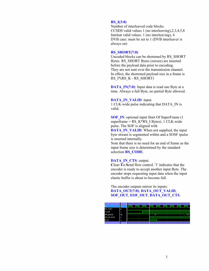
DATA_IN(7:0): Input data is read one Byte at a time. Always a full Byte, no partial Byte allowed.
DATA_IN_VALID: input.1 CLK-wide pulse indicating that DATA_IN is valid.
SOF_IN: optional input Start Of SuperFrame (1 superframe = RS_K*RS_I Bytes). 1 CLK-wide pulse. The SOF is aligned with DATA_IN_VALID. When not supplied, the input byte stream is segmented within and a SOSF ipulse is inserted internally.Note that there is no need for an end of frame as the input frame size is determined by the standard selection RS_CODE.
DATA_IN_CTS: output.Clear-To-Send flow control. '1' indicates that the encoder is ready to accept another input Byte. The encoder stops requesting input data when the input elastic buffer is about to become full.
The encoder outputs mirror its inputs:DATA_OUT(7:0), DATA_OUT_VALID, SOF_OUT, EOF_OUT, DATA_OUT_CTS.
3

Decoder
CLKSYNC_RESET
DATA_IN(7:0)DATA_IN_VALIDSOF_INDATA_IN_CTS
RS_CODE(3:0)REG1(1:0)RS_I(3:0)RS_SHORT(7:0)
INPUTSYMBOLS
DATA_OUT(7:0)DATA_OUT_VALID
SOF_OUTEOF_OUT
DATA_OUT_CTSVALID_FRAME_OUT
DECODEDBITS OUTPUT
ENCAPSULATED_RS_DECODER
200013
CONTROLS
DATA_IN(7:0): eight hard-quantized received input bits. Bytes are packed MSb first. If the received stream includes a sync marker, this component will recover the correct bit to Byte alignment. Otherwise, a SOF_IN is required at the first input Byte and the frame first bit must be in DATA_IN(7).
DATA_IN_VALID: input.1 CLK-wide pulse indicating that the DATA_IN Byte is valid.
SOF_IN: input Start Of Frame. 1 CLK-wide pulses.Aligned with DATA_IN_VALID.
DATA_IN_CTS: output Clear-To-Send flow control. '1' indicates that the decoder is ready to accept another input Byte.
The decoder outputs mirror its inputs:DATA_OUT(7:0), DATA_OUT_VALID, SOF_OUT, EOF_OUT, DATA_OUT_CTS.Output data DATA_OUT is sent one Byte at a time. Bits are packed MSb first.
The decoder controls RS_CODE, REG1, RS_I, RS_SHORT are identically defined as the encoder controls.
Reed-Solomon Codes
CCSDSSpecifications [1]Field Generator Polynomial: p(x) = x8+x7+x2+x+1 over GF(2).
Code Generator Polynomial: g(x) = (x - α11j) j = 128-t to 127+t where α is a root of p(x), and t is the maximum number of correctable errors in a block.
User selectable codeword length N and correction power t: (N, K, t) = (255, 239, 8).(N, K, t) = (255, 223, 16).
Intelsat IESS-308Field Generator Polynomial: p(x) = x8+x7+x2+x+1 over GF(2).
Code Generator Polynomial: g(x) = (x + α120). (x + α121). (x + α122)…. (x + α119+2t).
where α is a root of p(x), and t is the maximum number of correctable errors in a block. α = 02HEX.
User selectable codeword length N and correction power t: (N, K, t) = (225, 205, 10).(N, K, t) = (219, 201, 9).(N, K, t) = (194, 178, 8).(N, K, t) = (208, 192, 8).(N, K, t) = (126, 112, 7).
DVB ETS 300 421Field Generator Polynomial:p(x) = x8+x4+x3+x2+1. over GF(2).
Code Generator Polynomial: g(x) = (x + α0). (x + α1). (x + α2)…. (x + α15). where α = 02HEX.
Codeword length N and correction power t: (N, K, t) = (204, 188, 8).
REG1(0) must be set to zero (no sync word) lengthRS_I must be set to 1 (DVB interleaver is always on)
4

Other Common RS CodesField Generator Polynomial:p(x) = x8+x4+x3+x2+1. over GF(2).
Code Generator Polynomial: g(x) = (x + α0). (x + α1). (x + α2)…. (x + α2t-1). where α = 02HEX.
User selectable codeword length N and correction power t:(N,K,t) = (80, 56, 12)(N,K,t) = (255, 233, 11)(N,K,t) = (66, 52, 7)
Reed-Solomon decodingDecoding a RS block is done in three steps:
1. Compute the syndromes
2. Derive the error locator and error evaluator polynomials
3. Find the roots of the error locator polynomial, compute the error Bytes values and correct the Byte errors.
SyndromesComputing a syndrome consists in replacing x in the received code block polynomial with one of the 2t roots of the code generator polynomial g(x). If the received code block does not have any error, then all 2t syndromes are zero.
The 2t roots of the code generator polynomial g(x) are clearly identified by the g(x) definition. In the case of CCSDS (255, 223, 16) for example, g(x) = (x - α11j) j = 128-t to 127+t. Therefore, the roots are α112*11, α113*11, α114*11, …, α143*11 .All exponents are modulo 255 in the Galois field.
In the Matlab program rs_codec.m, the powers of are obtained by% generate entire field in both ntuple and exponent form[field_poly, field_exp] = gftuple([-1:254]',prim_poly,2);
Error Locator Polynomial Using Berlekamp algorithm as described in https://en.wikipedia.org/wiki/Berlekamp%E2%80%93Massey_algorithm
Error Evaluator Polynomial The error evaluator polynomial computation mirrors the computation for the error locator. These two computations are thus performed in parallel as illustrated by the block diagram below:
5

Performance
Encoder LatencyAbout 11 clock periods when no interleaving (RS_I = 1)About 2*RS_I code blocks when interleaving is enabled.
Decoder LatencyTypically 2*RS_I + 2 code blocks, less when no Byte errors.
Codec Throughput1 input frame per 533 clock periods. [case CCSDS (255,223,16)]580 Mbits/s to 1.3 Gbits/s (coded bits), depending on the FPGA technology
BER/ FER performance
This RS codec implementation behaves as per theory: given a (N,K,t) code, it corrects all Byte errors up to t.
6

Software LicensingThe COM-1807SOFT is supplied under the following key licensing terms:
1. A nonexclusive, nontransferable license to use the VHDL source code internally, and
2. An unlimited, royalty-free, nonexclusive transferable license to make and use products incorporating the licensed materials, solely in bit stream format, on a worldwide basis.
The complete VHDL/IP Software License Agreement can be downloaded from http://www.comblock.com/download/softwarelicense.pdf
Configuration ManagementThe current software revision is 1.
Directory Contents
/doc Specifications, user manual, implementation documents
/src .vhd source code,.pkg packages, .xdc constraint files (Xilinx)One component per file.
/sim VHDL test benches
/matlab Matlab .m file for simulating the encoding and decoding algorithms, for generating stimulus files for VHDL simulation and for end-to-end BER performance analysis at various signal to noise ratios
Project files:
Xilinx ISE 14 project file: COM-1807.xiseXilinx Vivado v2019.2 project file: project_1.xpr
VHDL development environmentThe VHDL software was developed using the following development environment:
(a) Xilinx Vivado 2019.2 for synthesis, place and route and VHDL simulation
(b) Xilinx ISE 14.7 for synthesis, place and route
The entire project fits easily within a Xilinx Artix7-100T. Therefore, the ISE project can be processed using the free Xilinx WebPack tools.
Reference documents
[1] CCSDS “Recommended Standard for TM Synchronization and Channel Coding”,
CCSDS 131.0-B-3, Blue Book, September 2017.
Applicable sections: Section 4: Reed-Solomon codingSection 9: Frame SynchronizationSection 10: Pseudo-Randomizer
[2] Intelsat IESS-308, Appendix H, Rev 11
Applicable sections: Reed Solomon codecUnique Word insertion/detection
[3] DVB standard EN 300 421
7

Device Utilization Summary
Encoder
All supported codes instantiated
% of Xilinx Artix7-100T
LUTs 3042 4.8%
Registers 1033 0.8%
Block RAM/FIFO 36Kb 4.5 3.3%
DSP48 0 0%
GCLKs 1 3.1%
Decoder
All supported codes instantiated
% of Xilinx Artix7-100T
LUTs 7557 11.9%
Registers 3690 2.9%
Block RAM/FIFO 36Kb 6 4.4%
DSP48 0 0%
GCLKs 1 3.1%
Clock and decoding speedThe entire design uses a single global clock CLK. Typical maximum clock frequencies for various FPGA families are listed below:
Device family Encoder Decoder
Xilinx Artix 7 -1 (slowest) speed grade
159 MHz 151 MHz
Xilinx Zynq ultrascale+ -1 speed grade
344 MHz 348 MHz
VHDL components overview
Encoder top level
ENCAPSULATED_RS_ENCODER.vhd includes all encoding functions on the transmit side: RS encoding, shortened frame, interleaving/de-interleaving, dual-basis conversion T and T-1, sync marker insertion and randomization. This component buffers the input Byte stream and computes the parity Bytes for each input frame. If a Start Of Frame marker is not supplied, the component will segment the input Byte stream into frames. Both inputs and outputs are 8-bit parallel.
The INPUT_CONDITIONING.vhd component performs the following tasks:1. Short (16 Byte) input elastic buffer2. Segment input Byte stream into frames. Insert SOF/EOF markers3. Insert all zeros Bytes prior to the payload when the frame is shortened ([1] Section 4.3.7).4. Report inconsistency between internal segmentation and external SOF_IN marker
The INTERLEAVER1.vhd component consists of a I-rows by K-columns interleaver prior to RS encoding, as per CCSDS specifications [1] Sections 4.3.5, 4.4.2. INTERLEAVER2.vhd performs the inverse de-interleaving.
8

Likewise, the INTERLEAVER_DVB1.vhd component is a Byte interleaver I=12, M=17, K columns used after RS encoding in the context of the DVB standard EN 300 421.
BRAM_DP2.vhd is a generic dual-port memory, used as input and output elastic buffers. Memory is inferred for code portability (no primitive is used).
DUAL_BASIS.vhd transforms Bytes between Berlekamp and Conventional representations. See [1] Annex F.
The heart of the encoder is RS_ENCODER.vhd. The encoder processes one block at a time. It supports multiple standards, encompassing two distinct Galois fields with primitive polynomials p(x) = x8+x7+x2+x+1 (391)p(x) = x8+x4+x3+x2+1 (285)
RS_ENC_SPECIFICATIONS.vhd describes the supported standards in terms of primitive polynomial to generate the Galois field, uncoded block size K, encoded block size N and code generator polynomials G(x).
GF_MULT_285.vhd multiplies two numbers over GF(2^8) that are in polynomial tuple representation. The component assumes that the polynomial representation is based on the primitive polynomial x8+x4+x3+x2+1.
GF_MULT_391.vhd multiplies two numbers over GF(2^8) that are in polynomial tuple representation. The component assumes that the polynomial representation is based on the primitive polynomial x8+x7+x2+x+1.
SHIFT_REGISTER.vhd implements the shift registers and multipliers part of the polynomial division and remainder computation.
CCSDS_RANDOMIZER.vhd is a pseudo-randomizer to increase the bit transition density prior to modulation. It also inserts a periodic sync marker. The implementation follows [1] Section 10.
Decoder top level
ENCAPSULATED_RS_DECODER.vhd includes all decoding functions on the receive side: RS decoding, shortened frame, interleaving/de-interleaving, dual-basis conversion T and T-1, sync marker detection, frame synchronization and derandomization. A Start-Of-Frame is required if the input Byte stream does not include a periodic sync marker. Both inputs and outputs are 8-bit parallel.
RS_ENC_SPECIFICATIONS.vhd describes the supported standards in terms of primitive polynomial to generate the Galois field, uncoded block size K, encoded block size N and code generator polynomials G(x).
The CCSDS_DERANDOMIZER.vhd component detects and removes the periodic sync markers, reconstructs the start of frame and end of frame
9

pulses and descrambles the received soft-quantized bit stream. It complies with sections 9 and 10 of the specifications [1].
The SOF_SYNC8P.vhd component detects, confirms and removes the periodic sync markers. It includes a fly-wheel mechanism to reconstruct the frame structure in the event of high bit errors. It also reports and corrects the input symbols bit to Byte packing alignment. Finally, it monitors the bit error rate within the received sync markers. I/Os are 8-symbols in parallel.
MATCHED_FILTER_NBYTESx8.vhd: a 64-bit matched filter operating on 8-parallel 1-bit hard-quantized input symbols. The matched filter detects a match 'on-the-fly' on all 8 possible bits/Byte alignments. It also report inverted sequences. Default detection threshold is 10 mismatches out of 64 (15.6% BER). The threshold can be adjusted through the DETECT_THRESHOLD generic parameter.
SOF_TRACK8.vhd: Confirmation circuit for the frame synchronization. It generates a reliable SOF_LOCK_DETECT status based on the detection of the periodic sync marker at the expected time.
The INTERLEAVER1.vhd component consists of a I-rows by N-columns interleaver prior to RS decoding, as per CCSDS specifications [1] Sections 4.3.5, 4.4.2. INTERLEAVER2.vhd performs the inverse de-interleaving.
DUAL_BASIS.vhd transforms Bytes between Berlekamp and Conventional representations. See [1] Annex F.
RS_DECODER.vhd is the RS decoder proper. It computes the syndromes in RS_SYNDROMES.vhd, then derives coefficients of the error locator polynominal ELP and the error evaluator polynomial EEP in RS_ERRORLOCATOR.vhd using the Berlekamp algorithm. The RS_EC.vhd component implements the Chien algorithm to find the error locations and the Forney algorithm to determine the error values. As a final step, the error correction is performed on the payload field of the frame stored in elastic frame just before output.
INFILE2SIM.vhd reads an input file. This component is used by the testbench to read a hard-quantized encoded bit stream generated by the rs_codec.m Matlab program for various codes, interleaving, randomization and Eb/No cases.
SIM2OUTFILE.vhd writes three 12-bit data variables to a tab delimited file which can be subsequently read by Matlab (load command) for plotting or analysis.
Xilinx Vivado: Synthesis settings(* denotes changes from the default settings)
10

VHDL simulationThe two main bit-accurate VHDL simulation avenues are:
- tb_rs_codec.vhd is a testbench for back to back encoder-decoder VHDL simulation. The testbench encompasses encoder, decoder, frame shortening, interleaving/deinterleaving, sync marker insertion, sync marker detection, PRBS-11 test sequence generation, but excludes CCSDS randomization. Errors can also be added either by specifying a Eb/No ratio or by adding errors at various points (search for the "add errors" string)
- tb_rs_dec.vhd is the decoder testbench. Its input consists of a received bit stream generated by the supplied Matlab program rs_codec.m.
Other minor testbenches:
- tb_rs_enc.vhd is a minimal testbench for the RS encoder proper. tbGalois_multiply_enc.vhd tests GF multipliers and compare the multiplication results with thos in Matlab gf_ops.m
Matlab simulationThe rs_codec.m program
Generates a stimulus file fecdecin.txt for use as input to the decoder VHDL simulation (testbench tb_rs_dec.vhd). The file includes a frame of pseudo-random (PRBS11) data bits, RS encoding, Additive White Gaussian Noise and hard-quantization. To enable the stimulus file generation, set outputFile = 1;
The Matlab encoder and decoder codes are representative of the actual VHDL implementation. Thus Matlab and VHDL variables are expected to match.
PRBS11 test sequenceEncoderAWGN
Matlab rs_codec.m
RSDecoder
VHDL tb_rs_dec.vhd
fecdecin.txtsample file
200014
BERTester
When moving the project folder location, be sure to change accordingly the FILENAME file paths in tb_rs_dec.vhd INFILE2SIM and SIM2OUTFILE components generic section.
The following .m programs were also used during the design:
The syndromes.m program computes the powers of (smallest root in the Galois field generated by the primitive polynomial prim_poly)
The GFexp2poly_rom1.m and GFpoly2exp_rom1.m programs generate the contents of the VHDL ROM tables used for swapping representation of GF elements between polynomial and exponential. The associated VHDL components are GFPOLY2EXP_ROM1.vhd and GFEXP2PLY_ROM1.vhd respectively.
The ee_alphapower_rom1.m program generates the entries of a VHDL ROM table used for looking up the following expression during error evaluation:mod((255-err_loc(i))*alphapowerstep*(1-alphapowerstart),255)
11

AcronymsAcronym DefinitionAWGN Additive White Gaussian Noise
BER Bit Error Rate
BRAM Dual-port Block RAM
CCSDS Consultative Committee For Space Data Systems
CTS Clear To Send, a flow-control signal allowing the data source to send data.
DVB Digital Video Broadcast standard
EOF End Of Frame (RS_K payload Bytes)
EOSF End Of SuperFrame (RS_K*RS_I payload Bytes)
GF Galois Field
LSb Least Significant bit
MSb Most Significant bit
PRBS-11 Pseudo-Random Binary Sequence, 2047-bit period
RS Reed-Solomon code
Rx Receive
SOF Start Of Frame (RS_K payload Bytes)
SOsF Start Of SuperFrame (RS_K*RS_I payload
Bytes)
Tx Transmit
ComBlock Ordering Information
COM-1807SOFT ENCODER Reed-Solomon code encoder. VHDL source code / IP core
COM-1807SOFT DECODER Reed-Solomon code decoder. VHDL source code / IP core
COM-1807SOFT CODEC Reed-Solomon code encoder and decoder. VHDL source code / IP core
ECCN: EAR99
Contact InformationMSS • 845-N Quince Orchard Boulevard • Gaithersburg, Maryland 20878-1676 • U.S.A.
Telephone: (240) 631-1111 Facsimile: (240) 631-1676 E-mail: [email protected]
12