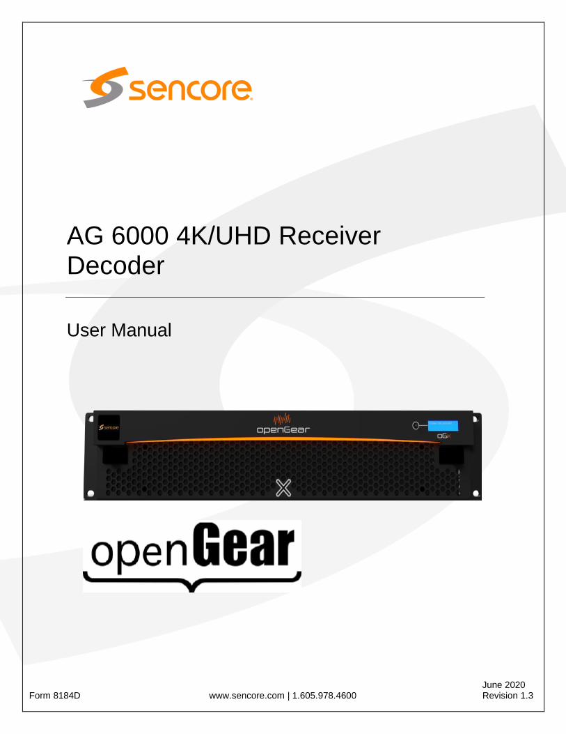
ag 6000 4k/uhd receiver decoder - sencore
TRANSCRIPT
June 2020 Form 8184D www.sencore.com | 1.605.978.4600 Revision 1.3
AG 6000 4K/UHD Receiver Decoder
User Manual
AG 6000 – User Manual
Page 2 (111)
Copyright © 2020 Sencore, Inc. All rights reserved. 3200 Sencore Drive, Sioux Falls, SD USA www.sencore.com This publication contains confidential, proprietary, and trade secret information. No part of this document may be copied, photocopied, reproduced, translated, or reduced to any machine-readable or electronic format without prior written permission from Sencore. Information in this document is subject to change without notice and Sencore Inc. assumes no responsibility or liability for any errors or inaccuracies. Sencore, Sencore Inc, and the Sencore logo are trademarks or registered trademarks in the United States and other countries. All other products or services mentioned in this document are identified by the trademarks, service marks, or product names as designated by the companies who market those products. Inquiries should be made directly to those companies. This document may also have links to third-party web pages that are beyond the control of Sencore. The presence of such links does not imply that Sencore endorses or recommends the content on those pages. Sencore acknowledges the use of third-party open source software and licenses in some Sencore products. This freely available source code can be obtained by contacting Sencore Inc.
About Sencore Sencore is an engineering leader in the development of high-quality signal transmission solutions for the broadcast, cable, satellite, IPTV, telecommunications, and professional audio/video markets. The company’s world-class portfolio includes video delivery products, system monitoring and analysis solutions, and test and measurement equipment, all designed to support system interoperability and backed by best-in-class customer support. Sencore meets the rapidly changing needs of modern media by ensuring the efficient delivery of high-quality video from the source to the home. For more information, visit www.sencore.com.

AG 6000 – User Manual
Page 3 (111)
Revision History
Date (MM/DD/YYYY) Version Description Author
1/14/2020 1.0 Initial Release BCR
1/27/2020 1.1 Appending to S2X Module Specs BCR
06/20/2020 1.2 4.2.2 Release BCR
06/24/2020 1.3 4.2.3 Release BCR
AG 6000 – User Manual
Page 4 (111)
Safety Instructions
Read and follow all instructions
Keep this manual
Heed all warnings
Do not use this apparatus near water
Do not install near any heat sources such as radiators, heat registers, stoves, or other apparatus (including amplifiers) that produce heat
Do not defeat the safety purpose of the polarized or grounding-type plug. A polarized plug has two blades with one wider than the other. A grounding type plug has two blades and a third grounding prong. The wide blade or the third prong is provided for your safety. If the provided plug does not fit into your outlet, consult an electrician for replacement of the obsolete outlet.
Protect the power cord from being walked on or pinched particularly at plugs, convenience receptacles, and the point where they exit from the apparatus.
Only use attachments/accessories specified by the manufacturer.
Unplug this apparatus during lightning storms or when unused for long periods of time.
Refer all servicing to qualified service personnel. Servicing is required when the apparatus has been damaged in any way, such as power-supply cord or plug is damaged, liquid has been spilled or objects have fallen into the apparatus, the apparatus has been exposed to rain or moisture, does not operate normally, or has been dropped.
Do not expose this apparatus to dripping or splashing and ensure that no objects filled with liquids, such as vases, are placed on the apparatus.
To completely disconnect this apparatus from the AC Mains, disconnect the power supply cord plug from the AC receptacle.
The mains plug of the power supply cord shall remain readily operable.
Damage Requiring Service: Unplug this product from the wall outlet and refer servicing to qualified service personnel under the following conditions:
o When the power-supply cord or plug is damaged. o If liquid has been spilled, or objects have fallen into the product. o If the product has been exposed to rain or water. o If the product does not operate normally by following the operating
instructions. Adjust only those controls that are covered by the operating instructions as an improper adjustment of the controls may result in damage and will often require extensive work by a qualified technician to restore the product to its normal operation.
o If the product has been dropped or damaged in any way. o The product exhibits a distinct change in performance.
Replacement Parts: When replacement parts are required, be sure the service technician uses replacement parts specified by Sencore, or parts having the same operating characteristics as the original parts. Unauthorized part substitutions made may result in fire, electric shock or other hazards.
AG 6000 – User Manual
Page 5 (111)
SAFETY PRECAUTIONS
There is always a danger present when using electronic equipment.
Unexpected high voltages can be present at unusual locations in defective equipment and signal distribution systems. Become familiar with the equipment that you are working with and observe the following safety precautions.
Every precaution has been taken in the design of your AG 6000 to ensure that it is as safe as possible. However, safe operation depends on you the operator.
Always be sure your equipment is in good working order. Ensure that all points of connection are secure to the chassis and that protective covers are in place and secured with fasteners.
Never work alone when working in hazardous conditions. Always have another person close by in case of an accident.
Always refer to the manual for safe operation. If you have a question about the application or operation call Sencore for assistance.
WARNING – To reduce the risk of fire or electrical shock never allow your equipment to be exposed to water, rain or high moisture environments. If exposed to a liquid, remove power safely (at the breaker) and send your equipment to be serviced by a qualified technician.
To reduce the risk of shock the AG 6000 must be securely connected backplane in a frame that is connected to a mains socket outlet with a protective earthing connection.
CAUTION – Danger of explosion if battery is incorrectly replaced. Replace only with the same or equivalent type.
STATIC DISCHARGE
Throughout this chapter, please heed the following cautionary note:
ESD Susceptibility: Static discharge can cause serious damage to sensitive
semiconductor devices. Avoid handling circuit boards in high static environments such as carpeted areas, and when wearing synthetic fiber clothing. Always exercise proper grounding precautions when working on circuit boards and related equipment.
AG 6000 – User Manual
Page 6 (111)
FCC Class A Information
The AG 6000 has been tested and found to comply with the limits for a Class A digital device, pursuant to Part 15 of the FCC Rules. These limits are designed to provide reasonable protection against harmful interference when the equipment is operated in a commercial environment. This equipment generates, uses, and can radiate radio frequency energy and, if not installed and used in accordance with the instructions, may cause harmful interference to radio communications. Operation of this equipment in a residential area is likely to cause harmful interference in which case the user will be required to correct the interference at his or her own expense.
Shielded cables must be used with this unit to ensure compliance with the Class A FCC limits.
Warning: Changes or modifications to this unit not expressly approved by the
party responsible for compliance could void the user’s authority to operate the equipment.
Dolby Digital Information
This product has been manufactured under license from Dolby Laboratories.
“Dolby Digital”, “AC-3”, and “Dolby Digital Plus” are licensed trademarks of Dolby Laboratories.
AG 6000 – User Manual
Page 7 (111)
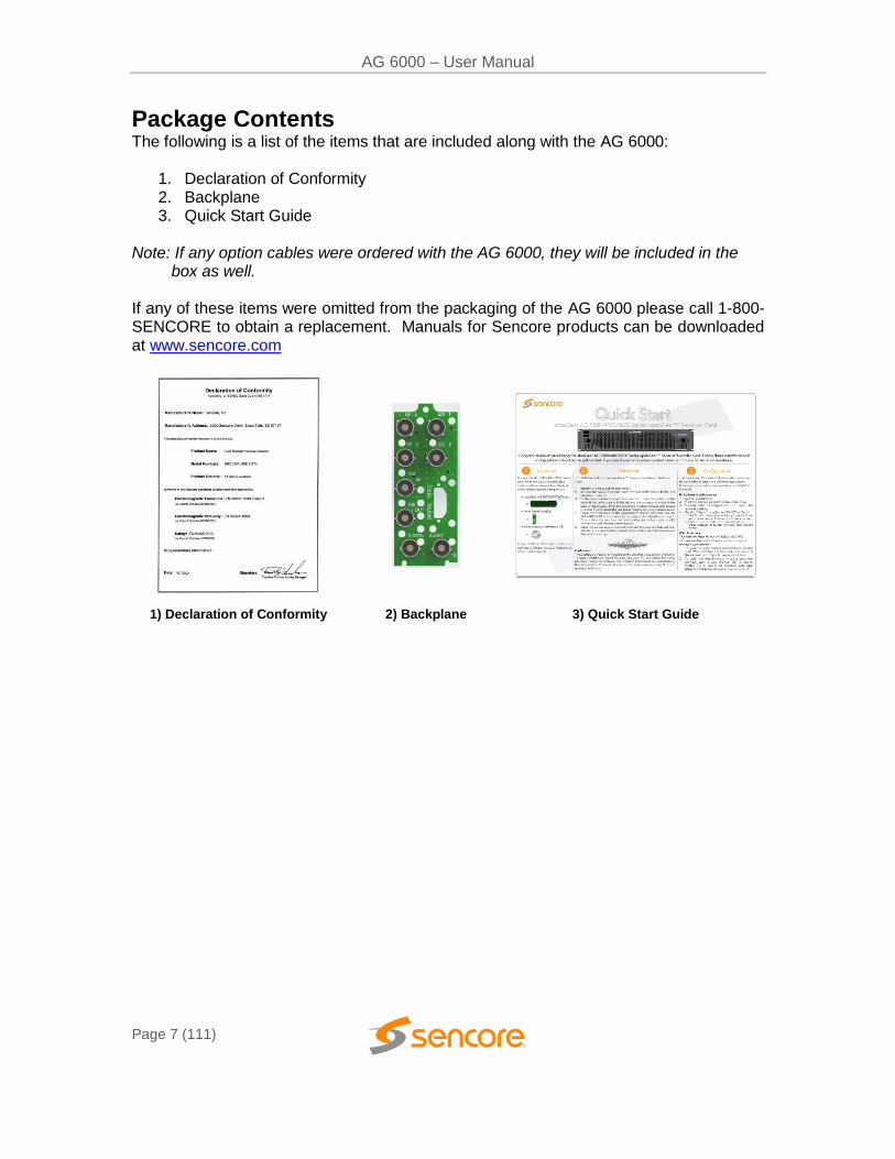
Package Contents The following is a list of the items that are included along with the AG 6000:
1. Declaration of Conformity 2. Backplane 3. Quick Start Guide
Note: If any option cables were ordered with the AG 6000, they will be included in the
box as well. If any of these items were omitted from the packaging of the AG 6000 please call 1-800-SENCORE to obtain a replacement. Manuals for Sencore products can be downloaded at www.sencore.com
1) Declaration of Conformity 2) Backplane 3) Quick Start Guide
AG 6000 – User Manual
Page 8 (111)
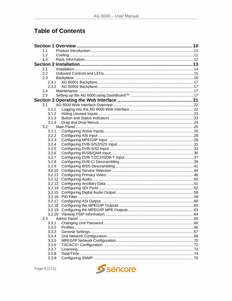
Table of Contents
Section 1 Overview ........................................................................................... 10 1.1 Product Introduction ................................................................................................... 11 1.2 Cooling ....................................................................................................................... 11 1.3 Rack Information ........................................................................................................ 12
Section 2 Installation ........................................................................................ 13 2.1 Installation .................................................................................................................. 14 2.2 Onboard Controls and LEDs...................................................................................... 15 2.3 Backplane .................................................................................................................. 16
2.3.1 AG 60001 Backplane ............................................................................................ 17 2.3.2 AG 60002 Backplane ............................................................................................ 17
2.4 Maintenance .............................................................................................................. 17 2.5 Setting up the AG 6000 using DashBoardTM ............................................................. 17
Section 3 Operating the Web Interface ........................................................... 21 3.1 AG 6000 Web Interface Overview ............................................................................. 22
3.1.1 Logging into the AG 6000 Web Interface ............................................................. 22 3.1.2 Hiding Unused Inputs ........................................................................................... 23 3.1.3 Button and Status Indicators ................................................................................ 23 3.1.4 Drag and Drop Menus .......................................................................................... 24
3.2 Main Panel ................................................................................................................. 25 3.2.1 Configuring Active Inputs...................................................................................... 26 3.2.2 Configuring ASI Input ........................................................................................... 28 3.2.3 Configuring MPEG/IP Input .................................................................................. 28 3.2.4 Configuring DVB-S/S2/S2X Input ......................................................................... 31 3.2.5 Configuring DVB-S/S2 Input ................................................................................. 33 3.2.6 Configuring 8VSB/QAM Input ............................................................................... 36 3.2.7 Configuring DVB-T2/C2/ISDB-T Input .................................................................. 37 3.2.8 Configuring DVB-CI Descrambling ....................................................................... 39 3.2.9 Configuring BISS Descrambling ........................................................................... 41 3.2.10 Configuring Service Selection .............................................................................. 44 3.2.11 Configuring Primary Video.................................................................................... 48 3.2.12 Configuring Audio ................................................................................................. 50 3.2.13 Configuring Ancillary Data .................................................................................... 51 3.2.14 Configuring SDI Ports ........................................................................................... 52 3.2.15 Configuring Digital Audio Output .......................................................................... 58 3.2.16 PID Filter ............................................................................................................... 58 3.2.17 Configuring ASI Output ......................................................................................... 60 3.2.18 Configuring the MPEG/IP Outputs ....................................................................... 60 3.2.19 Configuring the MPEG/IP MPE Outputs ............................................................... 63 3.2.20 Viewing PSIP Information ..................................................................................... 64
3.3 Admin Panel .............................................................................................................. 65 3.3.1 Changing Unit Password ...................................................................................... 66 3.3.2 Profiles .................................................................................................................. 66 3.3.3 General Settings ................................................................................................... 67 3.3.4 Unit Network Configuration................................................................................... 68 3.3.5 MPEG/IP Network Configuration .......................................................................... 70 3.3.6 TACACS+ Configuration ...................................................................................... 72 3.3.7 Licensing............................................................................................................... 73 3.3.8 Date/Time ............................................................................................................. 74 3.3.9 Configuring SNMP ................................................................................................ 75
AG 6000 – User Manual
Page 9 (111)
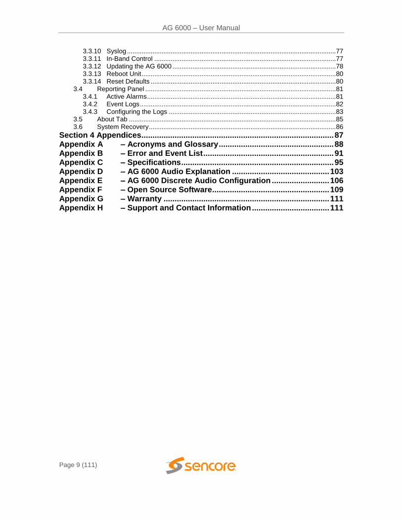
3.3.10 Syslog ................................................................................................................... 77 3.3.11 In-Band Control .................................................................................................... 77 3.3.12 Updating the AG 6000 .......................................................................................... 78 3.3.13 Reboot Unit ........................................................................................................... 80 3.3.14 Reset Defaults ...................................................................................................... 80
3.4 Reporting Panel ......................................................................................................... 81 3.4.1 Active Alarms ........................................................................................................ 81 3.4.2 Event Logs ............................................................................................................ 82 3.4.3 Configuring the Logs ............................................................................................ 83
3.5 About Tab .................................................................................................................. 85 3.6 System Recovery ....................................................................................................... 86
Section 4 Appendices ....................................................................................... 87
Appendix A – Acronyms and Glossary .................................................... 88 Appendix B – Error and Event List ........................................................... 91 Appendix C – Specifications ..................................................................... 95
Appendix D – AG 6000 Audio Explanation ............................................ 103 Appendix E – AG 6000 Discrete Audio Configuration .......................... 106 Appendix F – Open Source Software ..................................................... 109
Appendix G – Warranty ........................................................................... 111 Appendix H – Support and Contact Information ................................... 111
AG 6000 – User Manual
Page 10 (111)
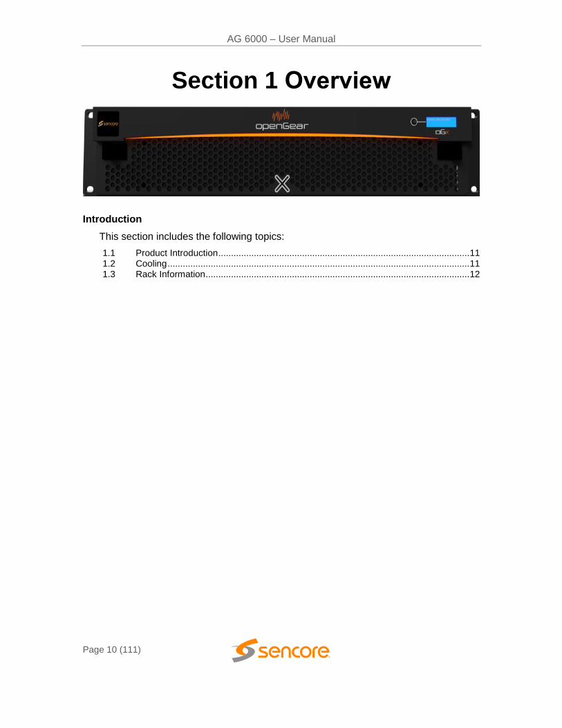
Section 1 Overview
Introduction
This section includes the following topics:
1.1 Product Introduction ................................................................................................... 11 1.2 Cooling ....................................................................................................................... 11 1.3 Rack Information ........................................................................................................ 12
AG 6000 – User Manual
Page 11 (111)
1.1 Product Introduction
The AG 6000 4K/UHD receiver decoder is built with the latest-generation 4K/UHD ASIC decoder technology. It delivers dense, cost-effective any-codec solutions for the purposes of monitoring, turn-around, signage, hospitality and enterprise of 4K/UHD video applications.
The product boasts a full complement of cutting-edge features, including HEVC decoding up to MP@HT and M10P@HT to L5.1 on streams to 40 Mbps for decoding professional 4K and consumer UHD formats with 4:2:0 chroma 8 and 10 bit. It outputs HDMI 2.0 or quad 3G-SDI of 4K/UHD to 4Kp60 and 2160p60 formats. It includes legacy format decoding of MPEG 2 and H.264 up to [email protected].
Every AG 6000 ships with a full complement of basic inputs and outputs, including ASI I/O and two AES output ports. Video output ports will be different depending on the AG 6000 model purchased (see section 2.3 for examples). The AG 60001 backplane will include two mirrored 3G-SDI ports and an HDMI port. The AG 60002 backplane will include quad 3G-SDI ports. The HDMI output makes monitoring as easy as finding the nearest standard consumer television or PC monitor. With the quad 3G-SDI ports, the AG 6000 decodes and outputs 4K/UHD video and includes core features required in professional video delivery networks.
The AG 6000 further features MPEG/IP I/O, or optional DVB-S/S2/S2X satellite inputs, QAM/VSB RF receiver, DVB-T/T2, C/C2, & ISDB-T inputs, BISS descrambling, and dual DVB-CI CAM slot options. Its configurable feature set makes the AG 6000 the ideal choice for contribution reception or demanding distribution applications which require a future-proof set of specifications.
The receiver maintains Sencore’s long tradition of ease of use, with a straight-forward web interface accessible via all major browsers and is backed by Sencore’s best-in-class staff of ProCare support engineers.
1.2 Cooling
The AG 6000 is cooled via forced induction through the front of the AG 4800X-XS frame and exhausted through the vents in the rear of the backplane. The AG 6000 is equipped with a temperature controlled status indicator. If the external temperature of the card exceeds 60° C, a temperature error will be triggered and the description of the error will appear in the “Error List.”

AG 6000 – User Manual
Page 12 (111)
1.3 Rack Information
The AG 6000 is intended to be mounted in an AG-4800X-XS openGearTM frame (or equivalent). The card takes up two slots in the 20 slot chassis (10 card maximum).
AG 6000 – User Manual
Page 13 (111)
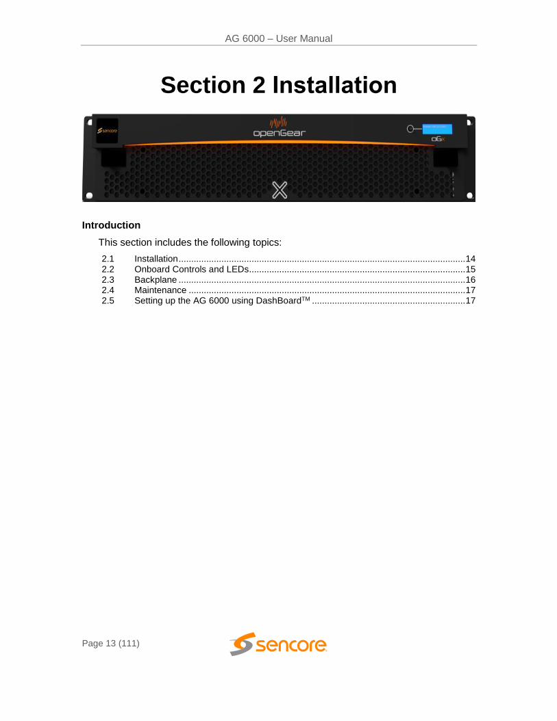
Section 2 Installation
Introduction
This section includes the following topics:
2.1 Installation .................................................................................................................. 14 2.2 Onboard Controls and LEDs...................................................................................... 15 2.3 Backplane .................................................................................................................. 16 2.4 Maintenance .............................................................................................................. 17 2.5 Setting up the AG 6000 using DashBoardTM ............................................................. 17
AG 6000 – User Manual
Page 14 (111)
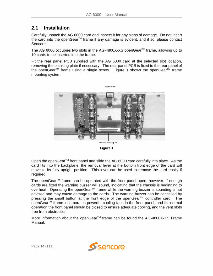
2.1 Installation
Carefully unpack the AG 6000 card and inspect it for any signs of damage. Do not insert the card into the openGearTM frame if any damage is evident, and if so, please contact Sencore.
The AG 6000 occupies two slots in the AG-4800X-XS openGearTM frame, allowing up to 10 cards to be inserted into the frame.
Fit the rear panel PCB supplied with the AG 6000 card at the selected slot location, removing the blanking plate if necessary. The rear panel PCB is fixed to the rear panel of the openGearTM frame using a single screw. Figure 1 shows the openGearTM frame mounting system.
Figure 1
Open the openGearTM front panel and slide the AG 6000 card carefully into place. As the card fits into the backplane, the removal lever at the bottom front edge of the card will move to its fully upright position. This lever can be used to remove the card easily if required.
The openGearTM frame can be operated with the front panel open; however, if enough cards are fitted the warning buzzer will sound, indicating that the chassis is beginning to overheat. Operating the openGearTM frame while the warning buzzer is sounding is not advised and may cause damage to the cards. The warning buzzer can be cancelled by pressing the small button at the front edge of the openGearTM controller card. The openGearTM frame incorporates powerful cooling fans in the front panel, and for normal operation the front panel should be closed to ensure adequate cooling, and the vent slots free from obstruction.
More information about the openGearTM frame can be found the AG-4800X-XS Frame Manual.
AG 6000 – User Manual
Page 15 (111)
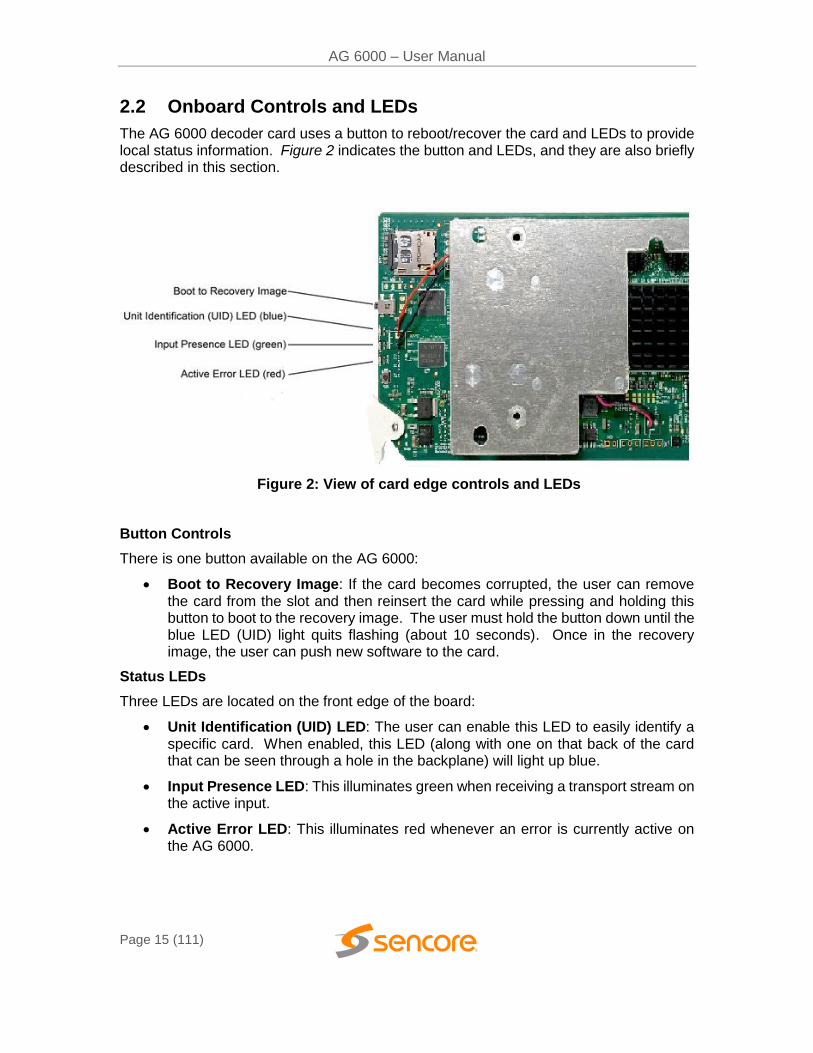
2.2 Onboard Controls and LEDs
The AG 6000 decoder card uses a button to reboot/recover the card and LEDs to provide local status information. Figure 2 indicates the button and LEDs, and they are also briefly described in this section.
Figure 2: View of card edge controls and LEDs
Button Controls
There is one button available on the AG 6000:
Boot to Recovery Image: If the card becomes corrupted, the user can remove the card from the slot and then reinsert the card while pressing and holding this button to boot to the recovery image. The user must hold the button down until the blue LED (UID) light quits flashing (about 10 seconds). Once in the recovery image, the user can push new software to the card.
Status LEDs
Three LEDs are located on the front edge of the board:
Unit Identification (UID) LED: The user can enable this LED to easily identify a specific card. When enabled, this LED (along with one on that back of the card that can be seen through a hole in the backplane) will light up blue.
Input Presence LED: This illuminates green when receiving a transport stream on the active input.
Active Error LED: This illuminates red whenever an error is currently active on the AG 6000.
AG 6000 – User Manual
Page 16 (111)
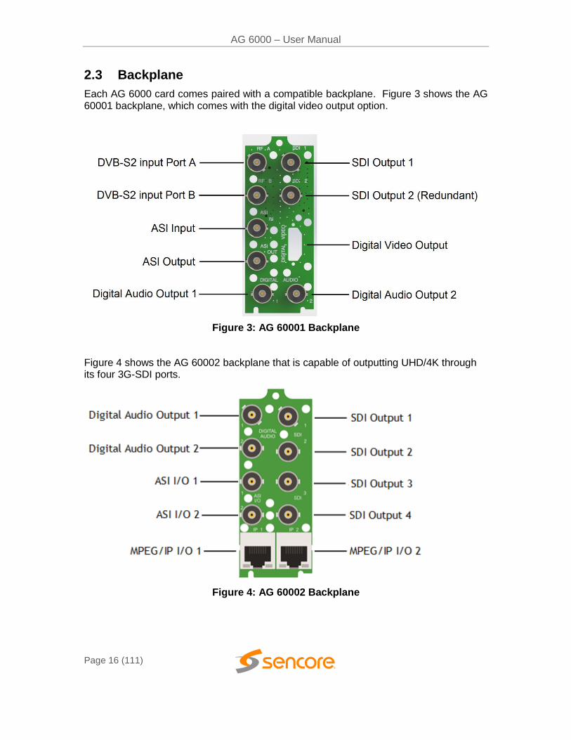
2.3 Backplane
Each AG 6000 card comes paired with a compatible backplane. Figure 3 shows the AG 60001 backplane, which comes with the digital video output option.
Figure 3: AG 60001 Backplane
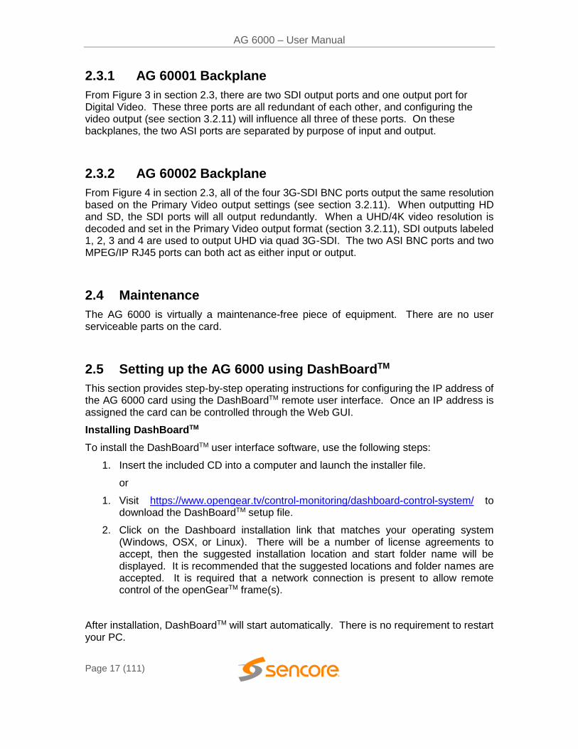
Figure 4 shows the AG 60002 backplane that is capable of outputting UHD/4K through its four 3G-SDI ports.
Figure 4: AG 60002 Backplane
AG 6000 – User Manual
Page 17 (111)
2.3.1 AG 60001 Backplane
From Figure 3 in section 2.3, there are two SDI output ports and one output port for Digital Video. These three ports are all redundant of each other, and configuring the video output (see section 3.2.11) will influence all three of these ports. On these backplanes, the two ASI ports are separated by purpose of input and output.
2.3.2 AG 60002 Backplane
From Figure 4 in section 2.3, all of the four 3G-SDI BNC ports output the same resolution based on the Primary Video output settings (see section 3.2.11). When outputting HD and SD, the SDI ports will all output redundantly. When a UHD/4K video resolution is decoded and set in the Primary Video output format (section 3.2.11), SDI outputs labeled 1, 2, 3 and 4 are used to output UHD via quad 3G-SDI. The two ASI BNC ports and two MPEG/IP RJ45 ports can both act as either input or output.
2.4 Maintenance
The AG 6000 is virtually a maintenance-free piece of equipment. There are no user serviceable parts on the card.
2.5 Setting up the AG 6000 using DashBoardTM
This section provides step-by-step operating instructions for configuring the IP address of the AG 6000 card using the DashBoardTM remote user interface. Once an IP address is assigned the card can be controlled through the Web GUI.
Installing DashBoardTM
To install the DashBoardTM user interface software, use the following steps:
1. Insert the included CD into a computer and launch the installer file.
or
1. Visit https://www.opengear.tv/control-monitoring/dashboard-control-system/ to download the DashBoardTM setup file.
2. Click on the Dashboard installation link that matches your operating system (Windows, OSX, or Linux). There will be a number of license agreements to accept, then the suggested installation location and start folder name will be displayed. It is recommended that the suggested locations and folder names are accepted. It is required that a network connection is present to allow remote control of the openGearTM frame(s).
After installation, DashBoardTM will start automatically. There is no requirement to restart your PC.
AG 6000 – User Manual
Page 18 (111)
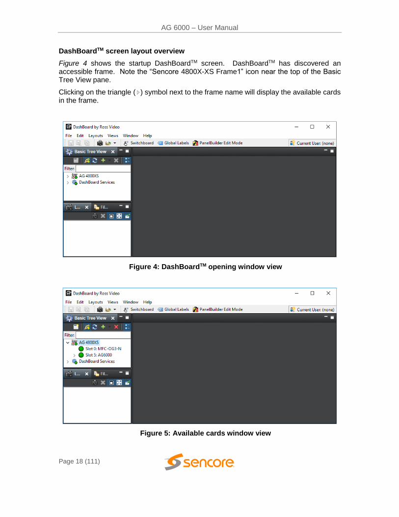
DashBoardTM screen layout overview
Figure 4 shows the startup DashBoardTM screen. DashBoardTM has discovered an accessible frame. Note the “Sencore 4800X-XS Frame1” icon near the top of the Basic Tree View pane.
Clicking on the triangle ( ) symbol next to the frame name will display the available cards in the frame.
Figure 4: DashBoardTM opening window view
Figure 5: Available cards window view
AG 6000 – User Manual
Page 19 (111)
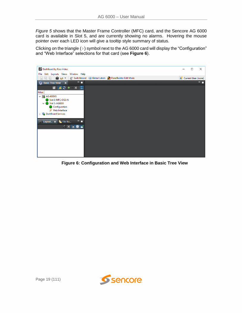
Figure 5 shows that the Master Frame Controller (MFC) card, and the Sencore AG 6000 card is available in Slot 5, and are currently showing no alarms. Hovering the mouse pointer over each LED icon will give a tooltip style summary of status.
Clicking on the triangle ( ) symbol next to the AG 6000 card will display the “Configuration” and “Web Interface” selections for that card (see Figure 6).
Figure 6: Configuration and Web Interface in Basic Tree View
AG 6000 – User Manual
Page 20 (111)
Network setup using DashBoardTM
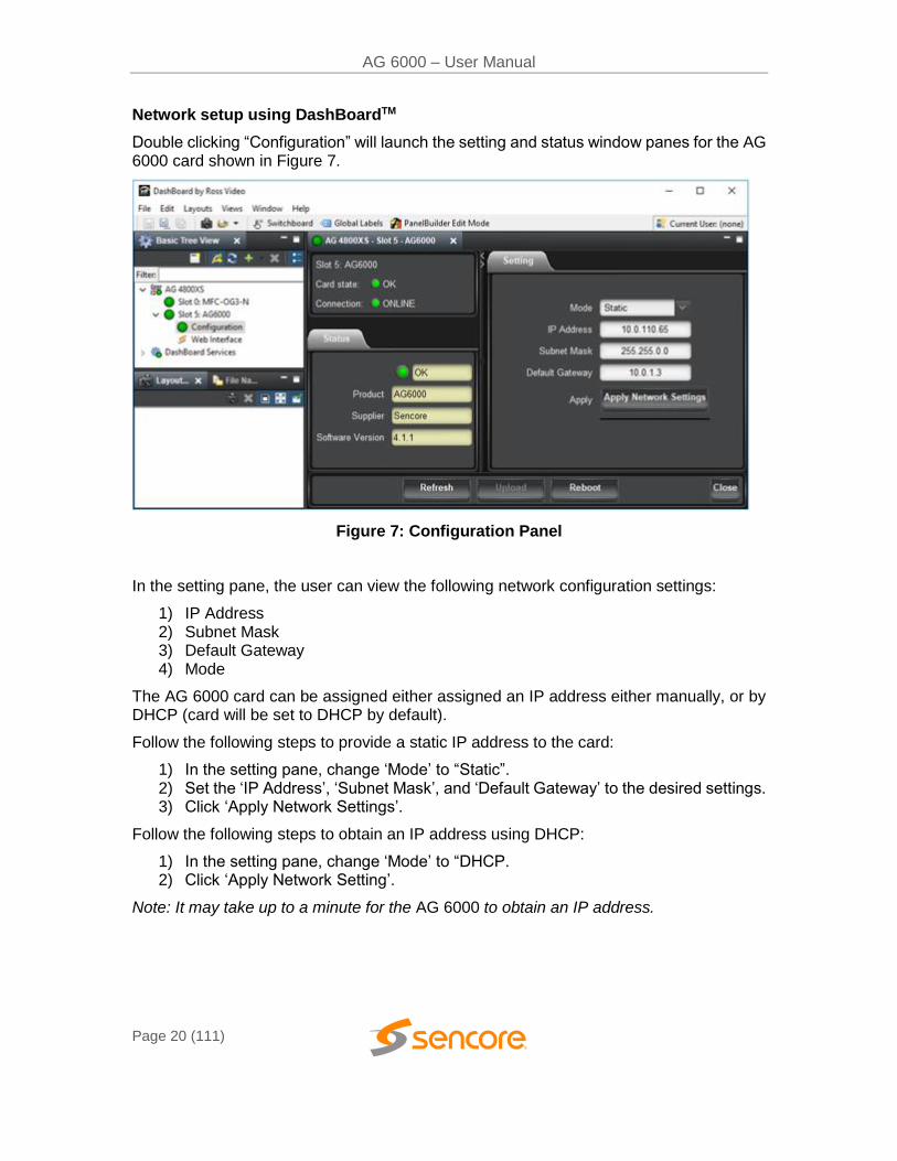
Double clicking “Configuration” will launch the setting and status window panes for the AG 6000 card shown in Figure 7.
Figure 7: Configuration Panel
In the setting pane, the user can view the following network configuration settings:
1) IP Address 2) Subnet Mask 3) Default Gateway 4) Mode
The AG 6000 card can be assigned either assigned an IP address either manually, or by DHCP (card will be set to DHCP by default).
Follow the following steps to provide a static IP address to the card:
1) In the setting pane, change ‘Mode’ to “Static”. 2) Set the ‘IP Address’, ‘Subnet Mask’, and ‘Default Gateway’ to the desired settings. 3) Click ‘Apply Network Settings’.
Follow the following steps to obtain an IP address using DHCP:
1) In the setting pane, change ‘Mode’ to “DHCP. 2) Click ‘Apply Network Setting’.
Note: It may take up to a minute for the AG 6000 to obtain an IP address.
AG 6000 – User Manual
Page 21 (111)
Section 3 Operating the Web Interface
Introduction
This section includes the following topics:
3.1 AG 6000 Web Interface Overview ............................................................................. 22 3.2 Main Panel ................................................................................................................. 25 3.3 Admin Panel .............................................................................................................. 65 3.4 Reporting Panel ......................................................................................................... 81 3.5 About Tab .................................................................................................................. 85 3.6 System Recovery ....................................................................................................... 86
AG 6000 – User Manual
Page 22 (111)
3.1 AG 6000 Web Interface Overview
3.1.1 Logging into the AG 6000 Web Interface
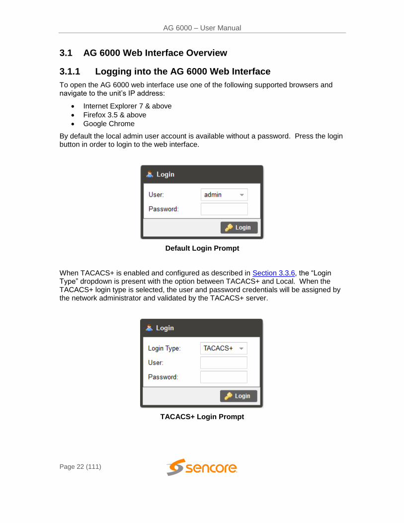
To open the AG 6000 web interface use one of the following supported browsers and navigate to the unit’s IP address:
Internet Explorer 7 & above
Firefox 3.5 & above
Google Chrome
By default the local admin user account is available without a password. Press the login button in order to login to the web interface.
Default Login Prompt
When TACACS+ is enabled and configured as described in Section 3.3.6, the “Login Type” dropdown is present with the option between TACACS+ and Local. When the TACACS+ login type is selected, the user and password credentials will be assigned by the network administrator and validated by the TACACS+ server.
TACACS+ Login Prompt
AG 6000 – User Manual
Page 23 (111)
3.1.2 Hiding Unused Inputs
The AG 6000 web interface lets the user hide inactive inputs with the
button or show all available inputs by click the button. Only the inputs configured as the Primary Input and Backup Input (see Section 3.2.1) will be displayed when unused inputs are hidden.
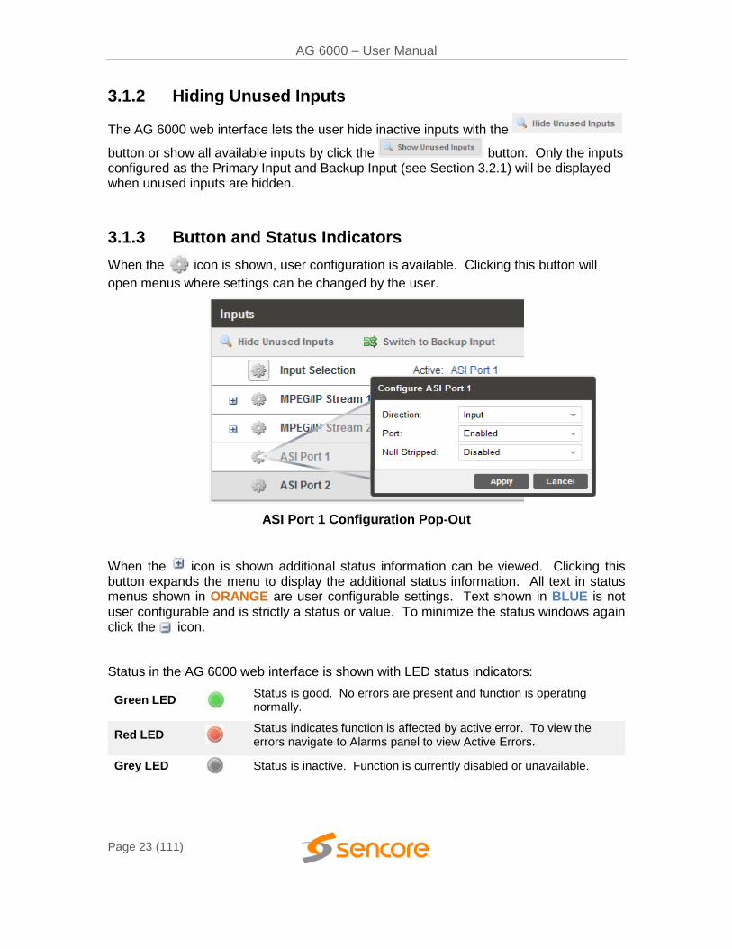
3.1.3 Button and Status Indicators
When the icon is shown, user configuration is available. Clicking this button will
open menus where settings can be changed by the user.
ASI Port 1 Configuration Pop-Out
When the icon is shown additional status information can be viewed. Clicking this button expands the menu to display the additional status information. All text in status menus shown in ORANGE are user configurable settings. Text shown in BLUE is not user configurable and is strictly a status or value. To minimize the status windows again click the icon.
Status in the AG 6000 web interface is shown with LED status indicators:
Green LED
Status is good. No errors are present and function is operating normally.
Red LED Status indicates function is affected by active error. To view the errors navigate to Alarms panel to view Active Errors.
Grey LED Status is inactive. Function is currently disabled or unavailable.
AG 6000 – User Manual
Page 24 (111)
3.1.4 Drag and Drop Menus
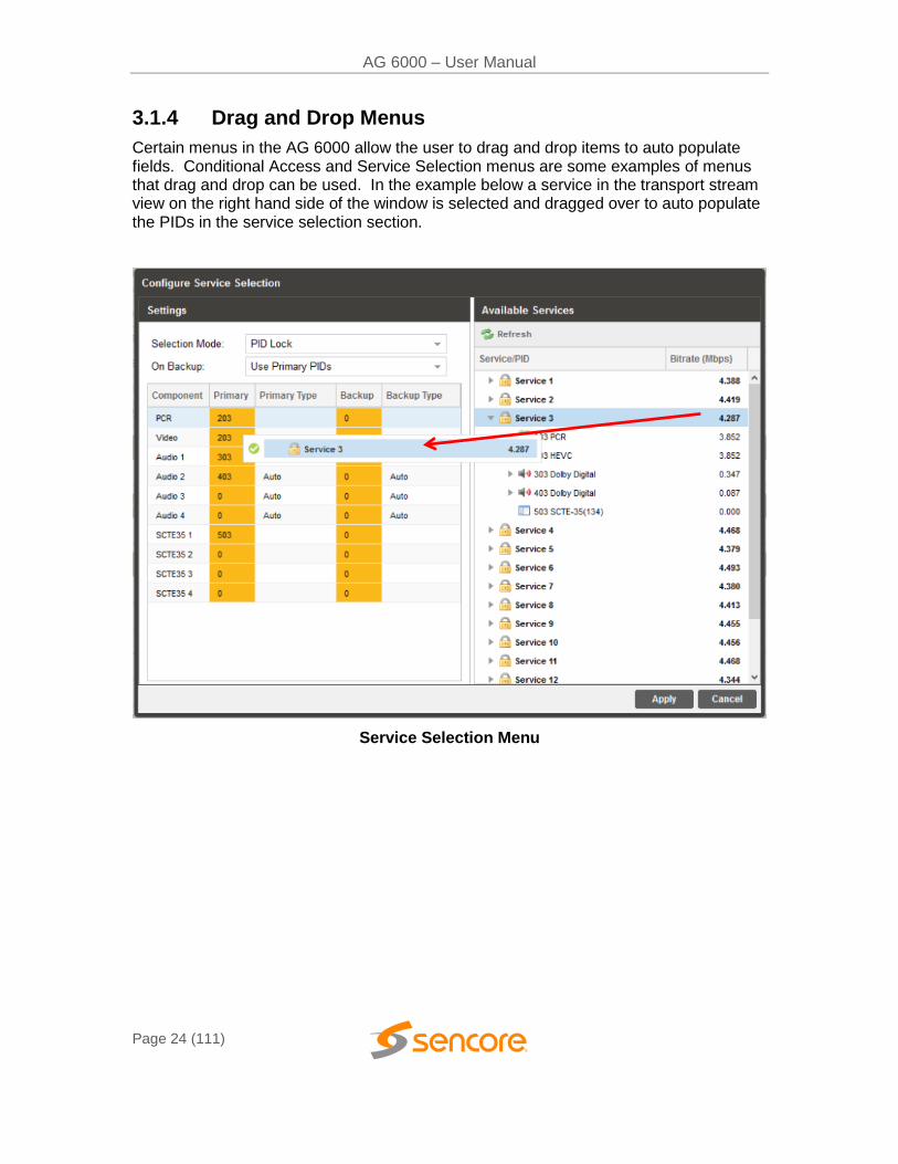
Certain menus in the AG 6000 allow the user to drag and drop items to auto populate fields. Conditional Access and Service Selection menus are some examples of menus that drag and drop can be used. In the example below a service in the transport stream view on the right hand side of the window is selected and dragged over to auto populate the PIDs in the service selection section.
Service Selection Menu
AG 6000 – User Manual
Page 25 (111)
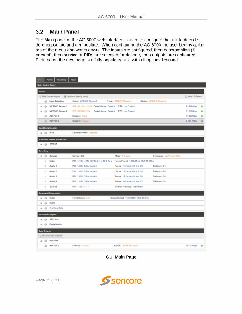
3.2 Main Panel
The Main panel of the AG 6000 web interface is used to configure the unit to decode, de-encapsulate and demodulate. When configuring the AG 6000 the user begins at the top of the menu and works down. The inputs are configured, then descrambling (if present), then service or PIDs are selected for decode, then outputs are configured. Pictured on the next page is a fully populated unit with all options licensed.
GUI Main Page
AG 6000 – User Manual
Page 26 (111)
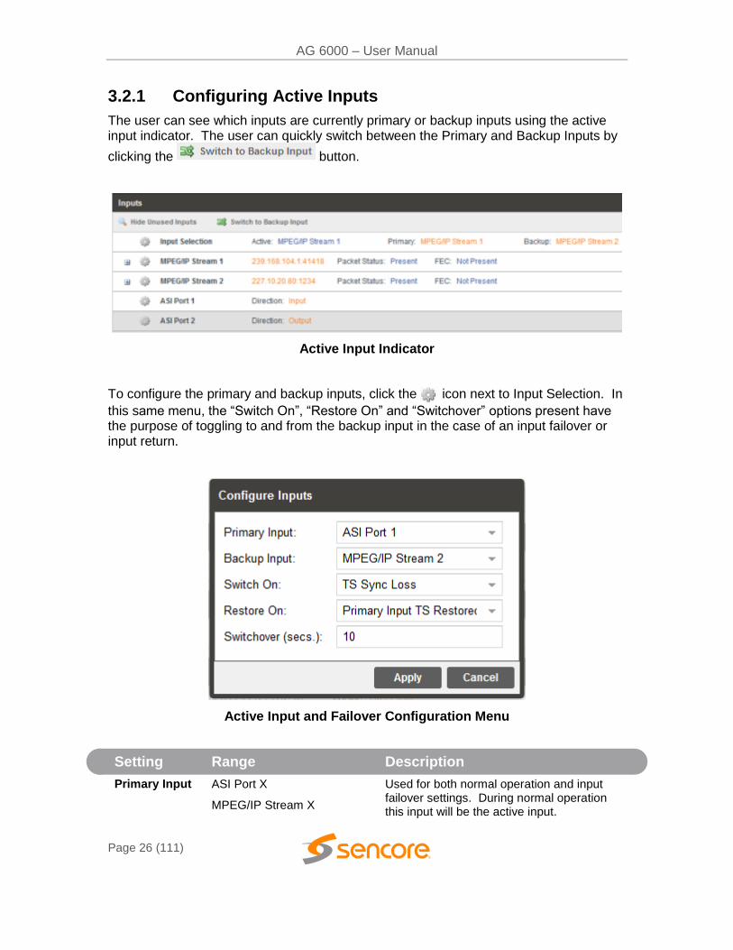
3.2.1 Configuring Active Inputs
The user can see which inputs are currently primary or backup inputs using the active input indicator. The user can quickly switch between the Primary and Backup Inputs by
clicking the button.
Active Input Indicator
To configure the primary and backup inputs, click the icon next to Input Selection. In
this same menu, the “Switch On”, “Restore On” and “Switchover” options present have the purpose of toggling to and from the backup input in the case of an input failover or input return.
Active Input and Failover Configuration Menu
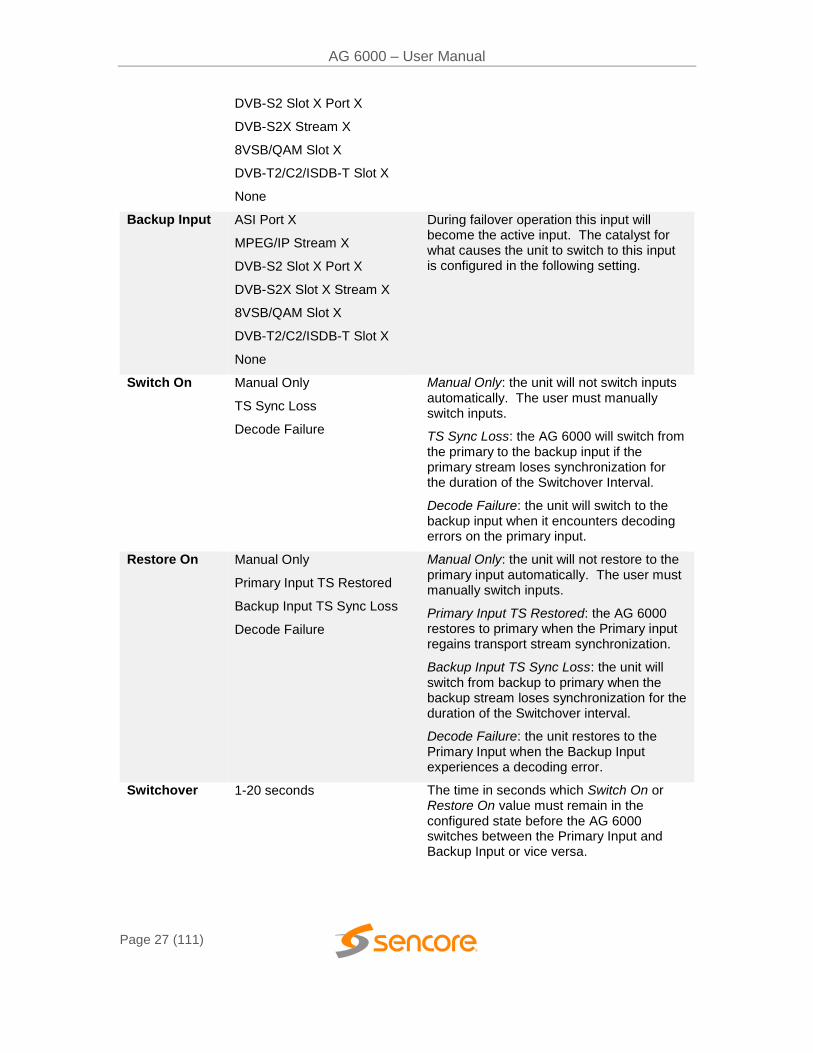
Setting Range Description
Primary Input ASI Port X
MPEG/IP Stream X
Used for both normal operation and input failover settings. During normal operation this input will be the active input.
AG 6000 – User Manual
Page 27 (111)
DVB-S2 Slot X Port X
DVB-S2X Stream X
8VSB/QAM Slot X
DVB-T2/C2/ISDB-T Slot X
None
Backup Input ASI Port X
MPEG/IP Stream X
DVB-S2 Slot X Port X
DVB-S2X Slot X Stream X
8VSB/QAM Slot X
DVB-T2/C2/ISDB-T Slot X
None
During failover operation this input will become the active input. The catalyst for what causes the unit to switch to this input is configured in the following setting.
Switch On Manual Only
TS Sync Loss
Decode Failure
Manual Only: the unit will not switch inputs automatically. The user must manually switch inputs.
TS Sync Loss: the AG 6000 will switch from the primary to the backup input if the primary stream loses synchronization for the duration of the Switchover Interval.
Decode Failure: the unit will switch to the backup input when it encounters decoding errors on the primary input.
Restore On Manual Only
Primary Input TS Restored
Backup Input TS Sync Loss
Decode Failure
Manual Only: the unit will not restore to the primary input automatically. The user must manually switch inputs.
Primary Input TS Restored: the AG 6000 restores to primary when the Primary input regains transport stream synchronization.
Backup Input TS Sync Loss: the unit will switch from backup to primary when the backup stream loses synchronization for the duration of the Switchover interval.
Decode Failure: the unit restores to the Primary Input when the Backup Input experiences a decoding error.
Switchover 1-20 seconds The time in seconds which Switch On or Restore On value must remain in the configured state before the AG 6000 switches between the Primary Input and Backup Input or vice versa.
AG 6000 – User Manual
Page 28 (111)
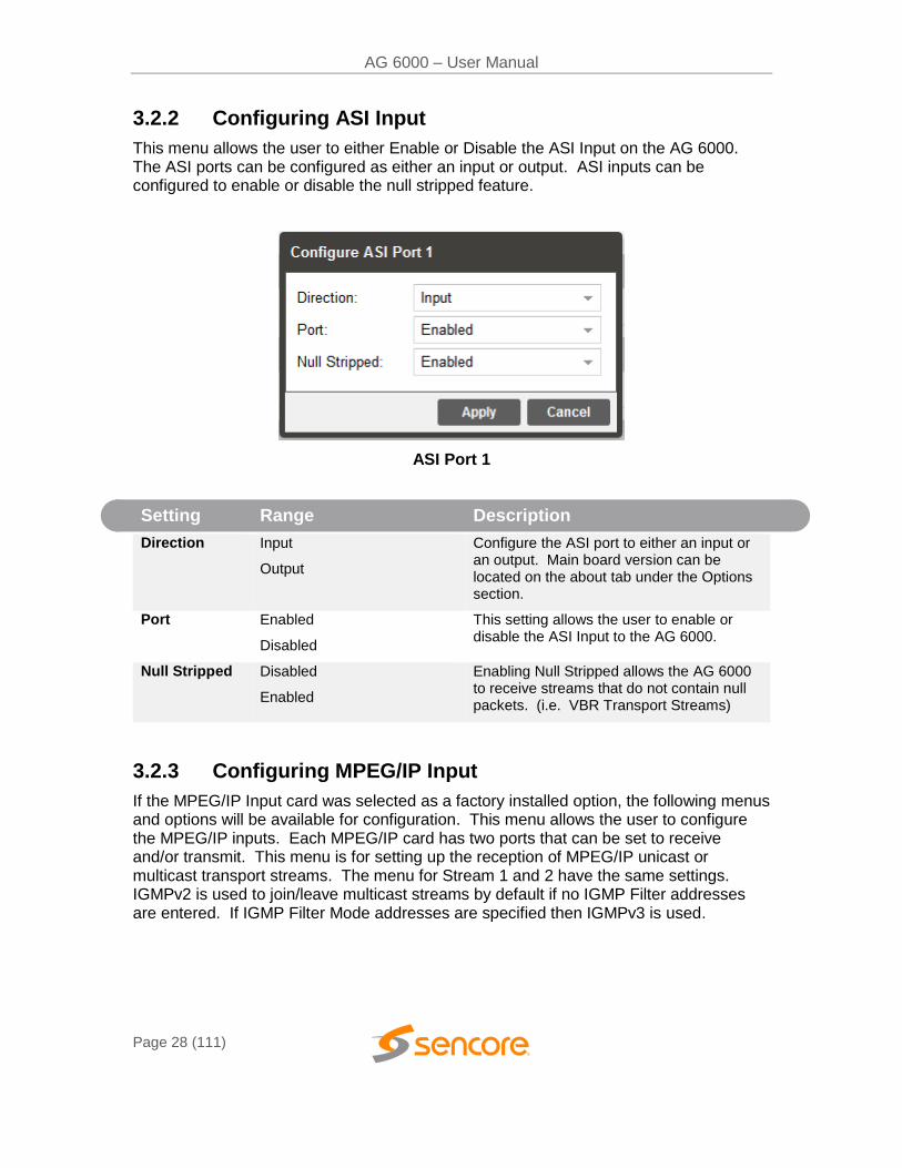
3.2.2 Configuring ASI Input
This menu allows the user to either Enable or Disable the ASI Input on the AG 6000. The ASI ports can be configured as either an input or output. ASI inputs can be configured to enable or disable the null stripped feature.
ASI Port 1
Setting Range Description
Direction Input
Output
Configure the ASI port to either an input or an output. Main board version can be located on the about tab under the Options section.
Port Enabled
Disabled
This setting allows the user to enable or disable the ASI Input to the AG 6000.
Null Stripped Disabled
Enabled
Enabling Null Stripped allows the AG 6000 to receive streams that do not contain null packets. (i.e. VBR Transport Streams)
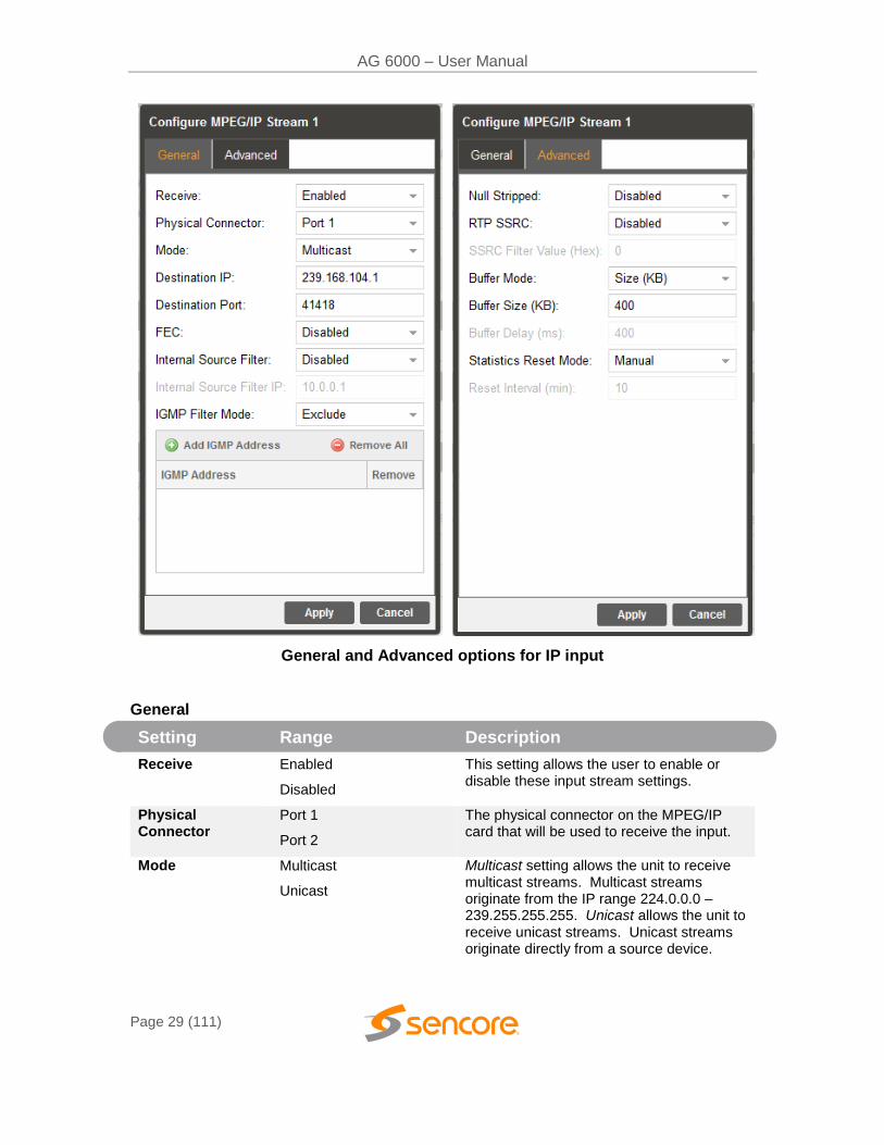
3.2.3 Configuring MPEG/IP Input
If the MPEG/IP Input card was selected as a factory installed option, the following menus and options will be available for configuration. This menu allows the user to configure the MPEG/IP inputs. Each MPEG/IP card has two ports that can be set to receive and/or transmit. This menu is for setting up the reception of MPEG/IP unicast or multicast transport streams. The menu for Stream 1 and 2 have the same settings. IGMPv2 is used to join/leave multicast streams by default if no IGMP Filter addresses are entered. If IGMP Filter Mode addresses are specified then IGMPv3 is used.
AG 6000 – User Manual
Page 29 (111)
General and Advanced options for IP input
General
Setting Range Description
Receive Enabled
Disabled
This setting allows the user to enable or disable these input stream settings.
Physical Connector
Port 1
Port 2
The physical connector on the MPEG/IP card that will be used to receive the input.
Mode Multicast
Unicast
Multicast setting allows the unit to receive multicast streams. Multicast streams originate from the IP range 224.0.0.0 – 239.255.255.255. Unicast allows the unit to receive unicast streams. Unicast streams originate directly from a source device.
AG 6000 – User Manual
Page 30 (111)
Destination IP 224.0.0.0 – 239.255.255.255
This setting is only available when receiving a multicast stream. This address is the IP address the source device is sending to.
Destination Port 0 - 65535 This is the UDP port the source device is sending to. This is the only setting required to receive a unicast stream.
FEC Enabled
Disabled
Enabling FEC (Forward Error Correction) tells the AG 6000 to look at Destination Port +2 and Destination Port +4 for a SMPTE 2022 FEC Matrix.
Internal Source Filter
Enabled
Disabled
Enabling Source filtering disables IGMP V3 filtering and allows a user to whitelist a single IP address for a given multicast and block all other source IP’s
Internal Source Filter IP
0.0.0.0 – 255.255.255.255 Source IP for whitelist. All other source IP addresses are blocked
IGMP Filter Mode Exclude
Include
Used on networks supporting IGMPv3. If this setting is set to Exclude any streams originating from the user defined IP addresses will be rejected. If this setting is set to Include any streams originating from the user defined IP addresses will be received.
Null Stripped Enabled
Disabled
Enabling Null Stripped allows the AG 6000 to receive streams that do not contain null packets. (i.e. VBR TS Streams)
RTP SSRC Enabled
Disabled
Enabling RTP SSRC allows the AG 6000 to filter the input by the user defined value. Only streams containing the user defined value will be received by the AG 6000.
SSRC Filter Value 0 - 4294967295 The Filter Value the AG 6000 checks for before receiving a stream with RTP SSRC.
Buffer Mode Size (KB)
Delay (ms)
Allows option to set buffer mode to Size in KB or Delay ms
Buffer Size (KB) 1 – 4000 KB This setting determines how much data is received before the AG 6000 starts decoding. Increasing this value will allow the AG 6000 is receive streams on networks with high network jitter. Increasing this value also increases the latency of the AG 6000.
Buffer Delay (ms) 1 – 4000 ms The buffer delay setting allows the buffer size to be set by delay time. The Buffer delay time will be determined by the input data rate.
AG 6000 – User Manual
Page 31 (111)
Statistics Reset Mode
Manual
Auto
Statistics can be viewed by hitting the ‘+’ symbol next to the MPEG/IP option card on the main window. Auto will reset the statistics on a chosen interval. When reset occurs, statistical information for that period will be logged. Selecting Manual will only clear the statistics by hitting the refresh button.
Reset Interval (min)
5-65535 Interval in which the Auto option will reset and log the statistics displayed on the main window
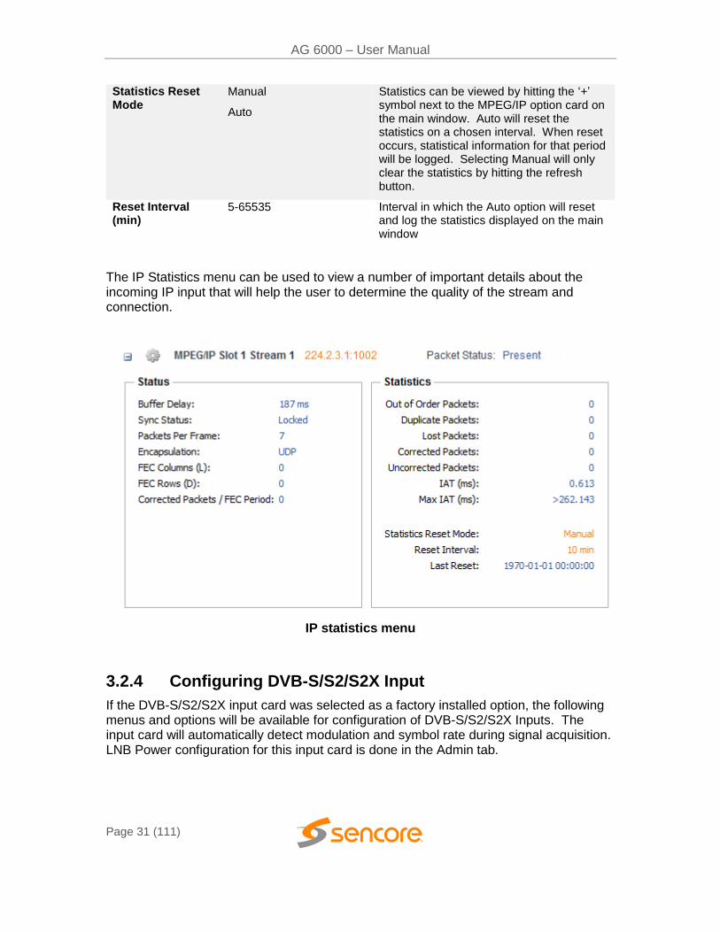
The IP Statistics menu can be used to view a number of important details about the incoming IP input that will help the user to determine the quality of the stream and connection.
IP statistics menu
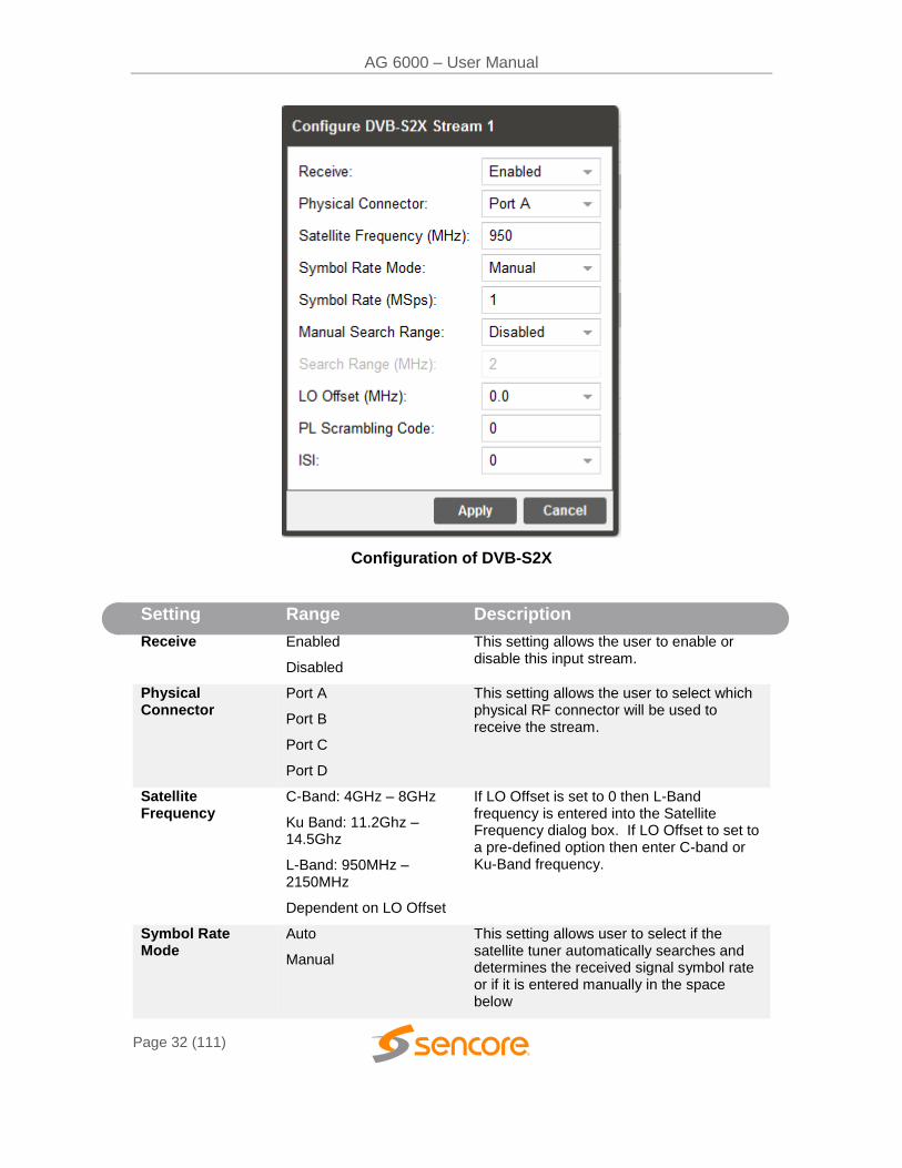
3.2.4 Configuring DVB-S/S2/S2X Input
If the DVB-S/S2/S2X input card was selected as a factory installed option, the following menus and options will be available for configuration of DVB-S/S2/S2X Inputs. The input card will automatically detect modulation and symbol rate during signal acquisition. LNB Power configuration for this input card is done in the Admin tab.
AG 6000 – User Manual
Page 32 (111)
Configuration of DVB-S2X
Setting Range Description
Receive Enabled
Disabled
This setting allows the user to enable or disable this input stream.
Physical Connector
Port A
Port B
Port C
Port D
This setting allows the user to select which physical RF connector will be used to receive the stream.
Satellite Frequency
C-Band: 4GHz – 8GHz
Ku Band: 11.2Ghz – 14.5Ghz
L-Band: 950MHz – 2150MHz
Dependent on LO Offset
If LO Offset is set to 0 then L-Band frequency is entered into the Satellite Frequency dialog box. If LO Offset to set to a pre-defined option then enter C-band or Ku-Band frequency.
Symbol Rate Mode
Auto
Manual
This setting allows user to select if the satellite tuner automatically searches and determines the received signal symbol rate or if it is entered manually in the space below
AG 6000 – User Manual
Page 33 (111)
Symbol Rate (Msps)
0.5 to 60 If Symbol Rate Mode is set to Manual then enter the satellite receive signal symbol rate
Manual Search Range
Enabled
Disabled
This setting determines the satellite receiver automatic fine tuning (AFT) search range. Disabled by default – permits the receiver to auto tune or AFT range (+/- 20 MHz). Enabled allows the user to enter a manual range limiting or expanding the AFT search range
Search Range (MHz)
.5 – 70 MHz If the Manual Search Range is set to Enabled then enter a MHz value for an AFT search range. The entered value includes a positive and negative search total range. For example: 10 MHz enables a +/- 5 MHz search range.
LO Offset 5150
9750
10600
10750
11250
The offset in MHz that the local oscillator is operating. Set to the LO frequency when you want to enter the Satellite transponder frequency in the Satellite Frequency field. Set to 0.0 when you want to enter the L-Band frequency in the Satellite Frequency field. Note that this setting and the Satellite Frequency setting determine the L-Band frequency input to the receiver.
PL Scrambling Code
0 – 262141 The AG has the ability to receive satellite signals scrambled using PL Scrambling. In order to receive the stream, enter the value of the incoming signals PL Scrambling code.
ISI Enter input stream identifier (ISI)
Enter unique ID of the stream you want to receive within the DVB-S2/S2X satellite multi-stream (Advanced AG 60916 licensed feature)
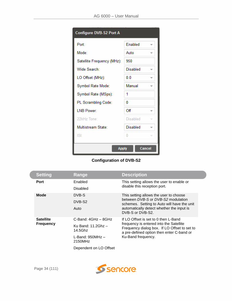
3.2.5 Configuring DVB-S/S2 Input
If the DVB-S/S2 Input card was selected as a factory installed option, the following menus and options will be available for configuration. This menu allows the user to configure the DVB-S/S2 inputs. Each DVB-S/S2 input card has four ports (labeled A, B, C and D) which only one port can be active at a time. This menu is for setting up the reception of DVB-S/S2 satellite signals. The menu for Port A, B, C and D have the same settings.
AG 6000 – User Manual
Page 34 (111)
Configuration of DVB-S2
Setting Range Description
Port Enabled
Disabled
This setting allows the user to enable or disable this reception port.
Mode DVB-S
DVB-S2
Auto
This setting allows the user to choose between DVB-S or DVB-S2 modulation schemes. Setting to Auto will have the unit automatically detect whether the input is DVB-S or DVB-S2.
Satellite Frequency
C-Band: 4GHz – 8GHz
Ku Band: 11.2Ghz – 14.5Ghz
L-Band: 950MHz – 2150MHz
Dependent on LO Offset
If LO Offset is set to 0 then L-Band frequency is entered into the Satellite Frequency dialog box. If LO Offset to set to a pre-defined option then enter C-band or Ku-Band frequency.
AG 6000 – User Manual
Page 35 (111)
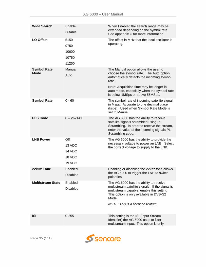
Wide Search Enable
Disable
When Enabled the search range may be extended depending on the symbol rate. See appendix C for more information.
LO Offset 5150
9750
10600
10750
11250
The offset in MHz that the local oscillator is operating.
Symbol Rate Mode
Manual
Auto
The Manual option allows the user to choose the symbol rate. The Auto option automatically detects the incoming symbol rate.
Note: Acquisition time may be longer in auto mode, especially when the symbol rate is below 1MSps or above 55MSps.
Symbol Rate 0 - 60 The symbol rate of incoming satellite signal in Msps. Accurate to one decimal place (ksps). Used when Symbol Rate Mode is set to Manual.
PLS Code 0 – 262141 The AG 6000 has the ability to receive satellite signals scrambled using PL Scrambling. In order to receive the stream, enter the value of the incoming signals PL Scrambling code.
LNB Power Off
13 VDC
14 VDC
18 VDC
19 VDC
The AG 6000 has the ability to provide the necessary voltage to power an LNB. Select the correct voltage to supply to the LNB.
22kHz Tone Enabled
Disabled
Enabling or disabling the 22khz tone allows the AG 6000 to trigger the LNB to switch polarities.
Multistream State Enabled
Disabled
The AG 6000 has the ability to receive multistream satellite signals. If the signal is multistream capable, enable this setting. This option is only available in DVB-S2 Mode.
NOTE: This is a licensed feature.
ISI 0-255 This setting is the ISI (Input Stream Identifier) the AG 6000 uses to filter multistream input. This option is only
AG 6000 – User Manual
Page 36 (111)
available if Multistream is licensed and enabled.
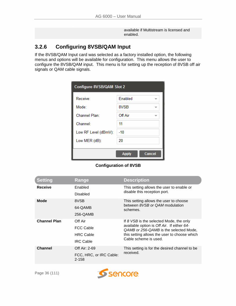
3.2.6 Configuring 8VSB/QAM Input
If the 8VSB/QAM Input card was selected as a factory installed option, the following menus and options will be available for configuration. This menu allows the user to configure the 8VSB/QAM input. This menu is for setting up the reception of 8VSB off air signals or QAM cable signals.
Configuration of 8VSB
Setting Range Description
Receive Enabled
Disabled
This setting allows the user to enable or disable this reception port.
Mode 8VSB
64-QAMB
256-QAMB
This setting allows the user to choose between 8VSB or QAM modulation schemes.
Channel Plan Off Air
FCC Cable
HRC Cable
IRC Cable
If 8 VSB is the selected Mode, the only available option is Off Air. If either 64-QAMB or 256-QAMB is the selected Mode, this setting allows the user to choose which Cable scheme is used.
Channel Off Air: 2-69
FCC, HRC, or IRC Cable: 2-158
This setting is for the desired channel to be received.
AG 6000 – User Manual
Page 37 (111)
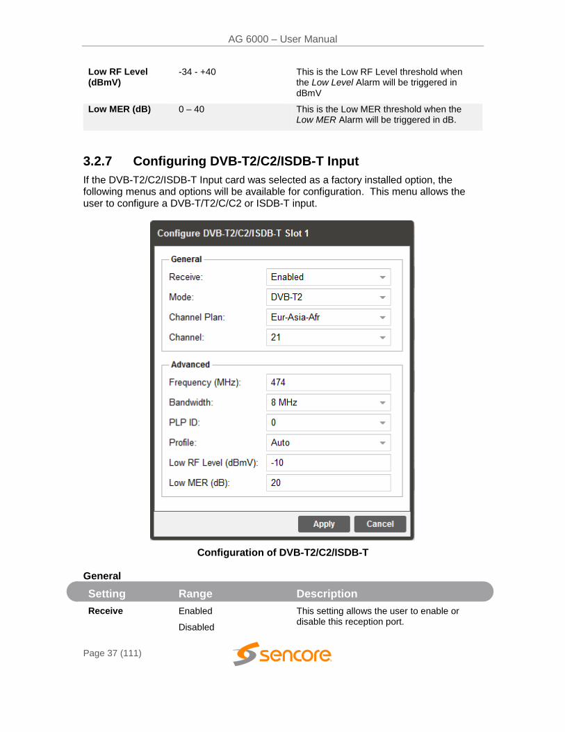
Low RF Level (dBmV)
-34 - +40
This is the Low RF Level threshold when the Low Level Alarm will be triggered in dBmV
Low MER (dB) 0 – 40 This is the Low MER threshold when the Low MER Alarm will be triggered in dB.
3.2.7 Configuring DVB-T2/C2/ISDB-T Input
If the DVB-T2/C2/ISDB-T Input card was selected as a factory installed option, the following menus and options will be available for configuration. This menu allows the user to configure a DVB-T/T2/C/C2 or ISDB-T input.
Configuration of DVB-T2/C2/ISDB-T
General
Setting Range Description
Receive Enabled
Disabled
This setting allows the user to enable or disable this reception port.
AG 6000 – User Manual
Page 38 (111)
Mode DVB-T
DVB-T2
DVB-C
DVB-C2
ISDB-T
This setting allows the user to choose between DVB-T/T2/C/C2 or ISDB-T modulation schemes.
Channel Plan Australia
Eur-Asia-Afr
Ireland
New Zealand
Taiwan
South Africa
South America
United Kingdom
European Cable
Japan
Philippines
This setting allows the user to select which channel plan they would like to use. Channel Plan options are tied to which modulation mode is selected.
Channel Select a channel from the channels available in the dropdown. The list of available channels will be based on which channel plan is selected
Advanced
Setting Range Description
Frequency (MHz) 42-1002 Selecting a channel from the channel dropdown will populate this field automatically based on the user selected channel. A user can manually select a frequency if desired
Bandwidth 1.7 MHz
5 MHz
6 MHz
7 MHz
8 MHz
Selecting a channel from the channel dropdown will populate this field automatically based on the user selected channel plan. A user can manually select channel bandwidth if desired.
AG 6000 – User Manual
Page 39 (111)
PLP ID Unique PLP ID used to select a particular stream within the DVB-T2 or DVB-C2 input signal
Profile Auto
Base
Lite
Select the DVB-T2 profile to use
Low RF Level (dBmV)
-34 - +40
This is the Low RF Level threshold when the Low Level Alarm will be triggered in dBmV
Low MER (dB) 0 - 40 This is the Low MER threshold when the Low MER Alarm will be triggered in dB.
3.2.8 Configuring DVB-CI Descrambling
This section will describe how to configure DVB-CI descrambling in the AG 6000. First, the user will need to configure the CAM slots and descrambling mode. Once this is complete the user can configure which services or PIDs to descramble.
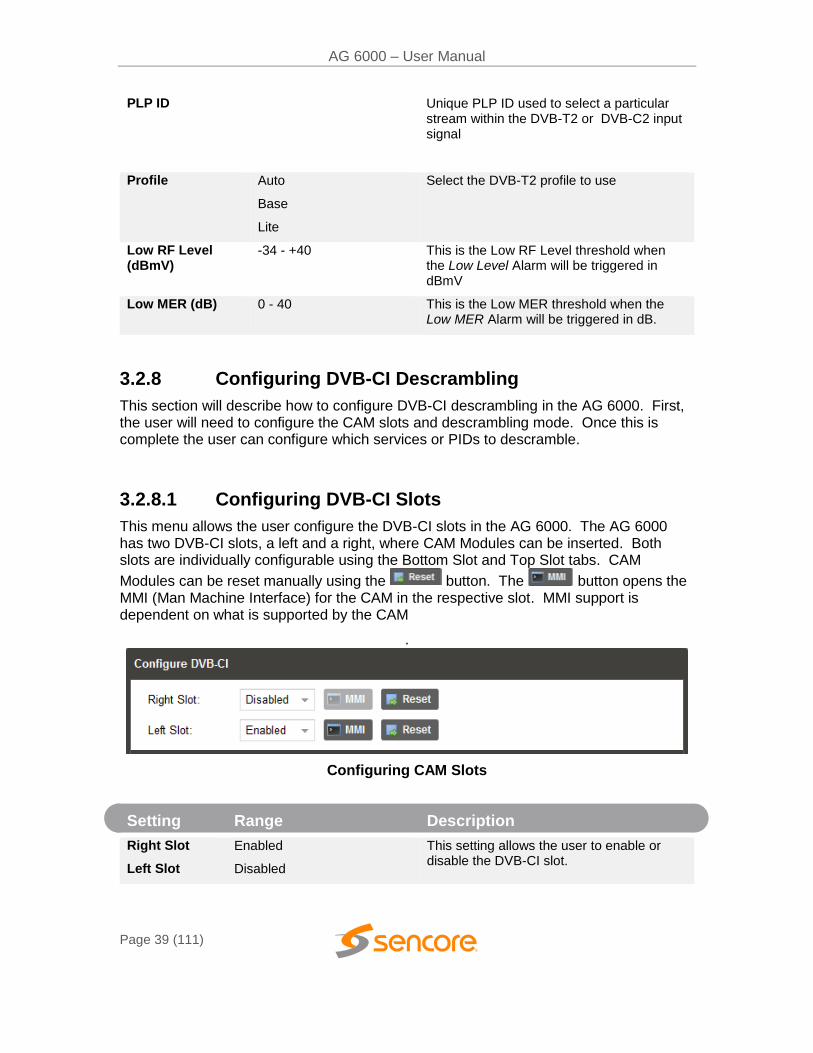
3.2.8.1 Configuring DVB-CI Slots
This menu allows the user configure the DVB-CI slots in the AG 6000. The AG 6000 has two DVB-CI slots, a left and a right, where CAM Modules can be inserted. Both slots are individually configurable using the Bottom Slot and Top Slot tabs. CAM
Modules can be reset manually using the button. The button opens the MMI (Man Machine Interface) for the CAM in the respective slot. MMI support is dependent on what is supported by the CAM
.
Configuring CAM Slots
Setting Range Description
Right Slot
Left Slot
Enabled
Disabled
This setting allows the user to enable or disable the DVB-CI slot.
AG 6000 – User Manual
Page 40 (111)
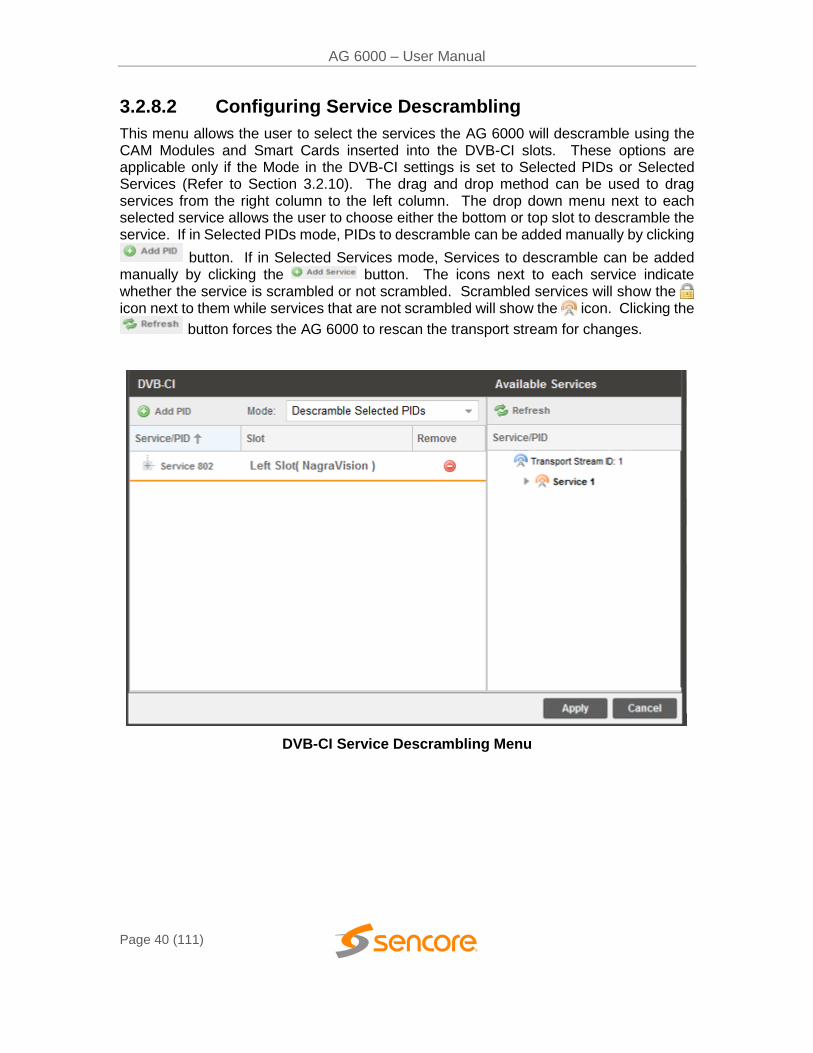
3.2.8.2 Configuring Service Descrambling
This menu allows the user to select the services the AG 6000 will descramble using the CAM Modules and Smart Cards inserted into the DVB-CI slots. These options are applicable only if the Mode in the DVB-CI settings is set to Selected PIDs or Selected Services (Refer to Section 3.2.10). The drag and drop method can be used to drag services from the right column to the left column. The drop down menu next to each selected service allows the user to choose either the bottom or top slot to descramble the service. If in Selected PIDs mode, PIDs to descramble can be added manually by clicking
button. If in Selected Services mode, Services to descramble can be added manually by clicking the button. The icons next to each service indicate whether the service is scrambled or not scrambled. Scrambled services will show the icon next to them while services that are not scrambled will show the icon. Clicking the
button forces the AG 6000 to rescan the transport stream for changes.
DVB-CI Service Descrambling Menu
AG 6000 – User Manual
Page 41 (111)
Setting Range Description
Mode Descramble Decoded PIDs
Descramble Selected PIDs
Descramble Selected Services
Decoded PIDs sets the AG 6000 to descramble only the PIDs of the service that is currently set to decode. If the PIDs change in the incoming stream the AG 6000 will adapt to these changes, provided that Service Selection is set to “Service Lock”
(Refer to Section 3.2.10). Selected PIDs
sets the AG 6000 to descramble PIDs set in the Descramble Services window (Refer to
Section 3.2.8.2). If the PIDs change in the
incoming stream the AG 6000 will not adapt to these changes and will not be able to descramble. Selected Services sets the AG 6000 to descramble Services set in the Descramble Services window Refer to Section 3.2.8.2). If the Services change in the incoming stream the AG 6000 will not be able to descramble.
3.2.9 Configuring BISS Descrambling
This section will describe how to configure BISS descrambling in the AG 6000. There are two types of BISS descrambling.
In “Descramble All PIDs” or “Descramble Decoded PIDs” mode, the user simply configures a BISS key set and selects it from the drop down.
For streams with multiple, per-service keys the user must first configure the key sets, and then assign them to services.
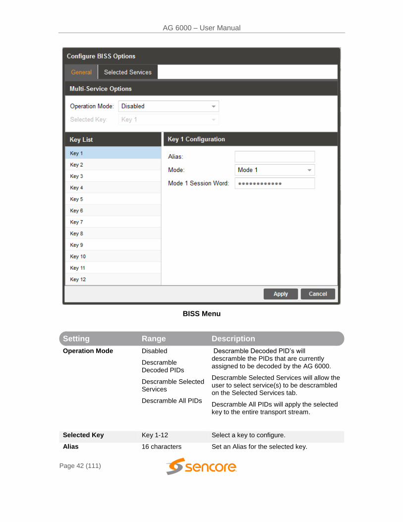
3.2.9.1 Configuring BISS Keys
This menu allows the user to configure BISS descrambling. 12 unique BISS keys can
be entered. If the BISS mode is set to Mode E a icon will appear next to Mode E
Injected ID. This icon allows the user to unlock and modify the Injected ID.
AG 6000 – User Manual
Page 42 (111)
BISS Menu
Setting Range Description
Operation Mode Disabled
Descramble Decoded PIDs
Descramble Selected Services
Descramble All PIDs
Descramble Decoded PID’s will descramble the PIDs that are currently assigned to be decoded by the AG 6000.
Descramble Selected Services will allow the user to select service(s) to be descrambled on the Selected Services tab.
Descramble All PIDs will apply the selected key to the entire transport stream.
Selected Key Key 1-12 Select a key to configure.
Alias 16 characters Set an Alias for the selected key.
AG 6000 – User Manual
Page 43 (111)
Mode Mode 1
Mode E
This setting sets the Mode of the BISS key that has scrambled the transport stream.
Mode 1 Session Word N/A If Mode 1 is selected the user enters the BISS session word here.
Mode E Session Word N/A If Mode E is selected the user enters the BISS session word here.
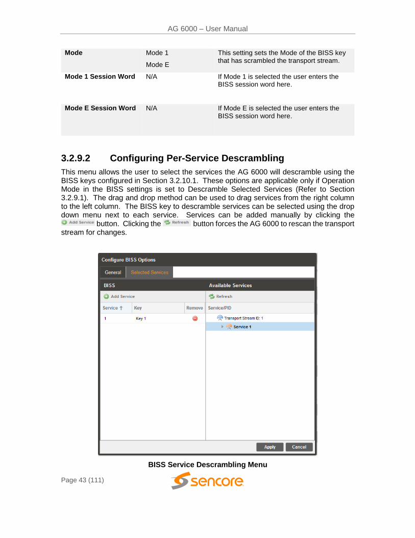
3.2.9.2 Configuring Per-Service Descrambling
This menu allows the user to select the services the AG 6000 will descramble using the BISS keys configured in Section 3.2.10.1. These options are applicable only if Operation Mode in the BISS settings is set to Descramble Selected Services (Refer to Section 3.2.9.1). The drag and drop method can be used to drag services from the right column to the left column. The BISS key to descramble services can be selected using the drop down menu next to each service. Services can be added manually by clicking the
button. Clicking the button forces the AG 6000 to rescan the transport stream for changes.
BISS Service Descrambling Menu
AG 6000 – User Manual
Page 44 (111)
3.2.10 Configuring Service Selection
This menu allows the user to configure the PIDs or Service the AG 6000 decodes. Depending on the Selection Mode that is selected, the menu changes to reflect the applicable settings.
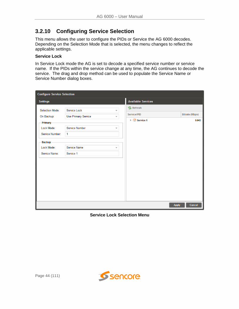
Service Lock
In Service Lock mode the AG is set to decode a specified service number or service name. If the PIDs within the service change at any time, the AG continues to decode the service. The drag and drop method can be used to populate the Service Name or Service Number dialog boxes.
Service Lock Selection Menu
AG 6000 – User Manual
Page 45 (111)
Setting Range Description
Selection Mode Service Lock
PID Lock
Auto Seek
Setting to Service Lock sets the unit to decode any PIDs associated with a service number or service name. Setting to PID Lock sets the unit to decode only the PIDs specified in the PID Lock Configuration matrix. Auto Seek mode will tune the unit to the first service listed in the PAT if a transport stream is present.
On Backup Use Primary Service
Use Backup Service
Sets the service the AG 6000 will tune to in case of an input failover. If Use Primary Service is selected the AG 6000 will tune to the service name specified in the Primary section. If Use Backup Service is selected the service name specified in the Backup section will be tuned. How the AG 6000
fails over inputs is configured in Section 3.2.1
Lock Mode Service Name
Service Number
If set to Service Name the AG will decode only services matching the name specified (SDT in DVB or TVCT in ATSC tables must be present in this mode). If set to Service Number the AG will decode only services matching the number specified.
AG 6000 – User Manual
Page 46 (111)
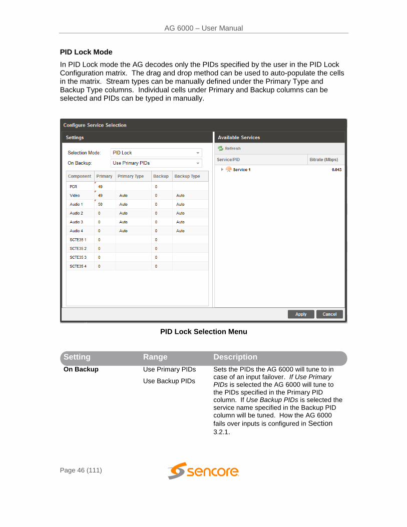
PID Lock Mode
In PID Lock mode the AG decodes only the PIDs specified by the user in the PID Lock Configuration matrix. The drag and drop method can be used to auto-populate the cells in the matrix. Stream types can be manually defined under the Primary Type and Backup Type columns. Individual cells under Primary and Backup columns can be selected and PIDs can be typed in manually.
PID Lock Selection Menu
Setting Range Description
On Backup Use Primary PIDs
Use Backup PIDs
Sets the PIDs the AG 6000 will tune to in case of an input failover. If Use Primary PIDs is selected the AG 6000 will tune to the PIDs specified in the Primary PID column. If Use Backup PIDs is selected the service name specified in the Backup PID column will be tuned. How the AG 6000
fails over inputs is configured in Section
3.2.1.
AG 6000 – User Manual
Page 47 (111)
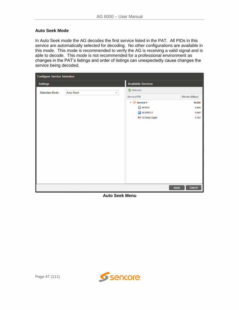
Auto Seek Mode In Auto Seek mode the AG decodes the first service listed in the PAT. All PIDs in this service are automatically selected for decoding. No other configurations are available in this mode. This mode is recommended to verify the AG is receiving a valid signal and is able to decode. This mode is not recommended for a professional environment as changes in the PAT’s listings and order of listings can unexpectedly cause changes the service being decoded.
Auto Seek Menu
AG 6000 – User Manual
Page 48 (111)
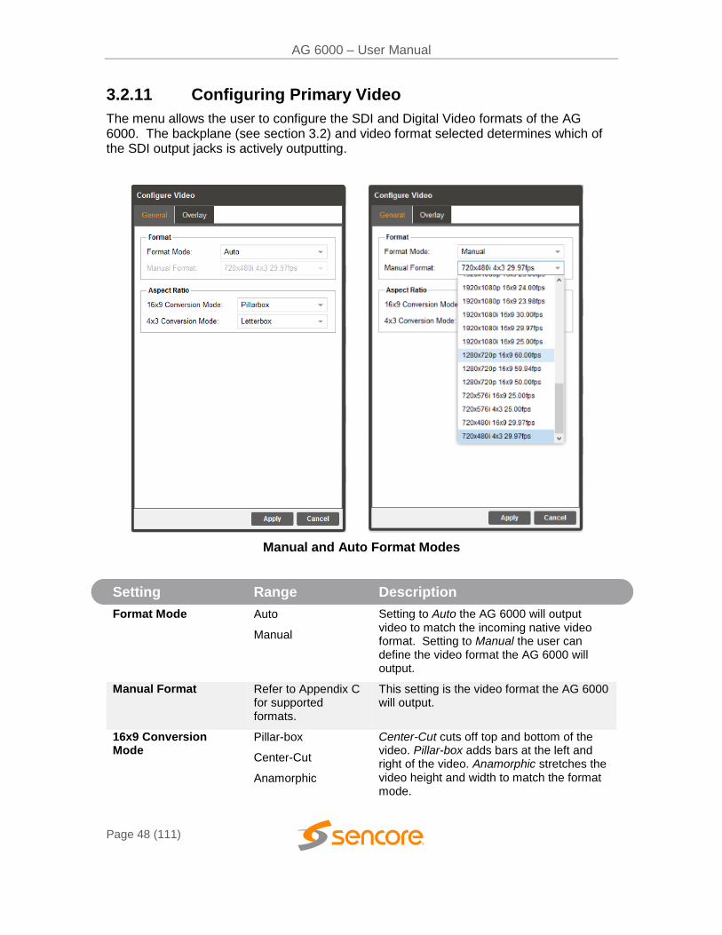
3.2.11 Configuring Primary Video
The menu allows the user to configure the SDI and Digital Video formats of the AG 6000. The backplane (see section 3.2) and video format selected determines which of the SDI output jacks is actively outputting.
Manual and Auto Format Modes
Setting Range Description
Format Mode Auto
Manual
Setting to Auto the AG 6000 will output video to match the incoming native video format. Setting to Manual the user can define the video format the AG 6000 will output.
Manual Format Refer to Appendix C for supported formats.
This setting is the video format the AG 6000 will output.
16x9 Conversion Mode
Pillar-box
Center-Cut
Anamorphic
Center-Cut cuts off top and bottom of the video. Pillar-box adds bars at the left and right of the video. Anamorphic stretches the video height and width to match the format mode.
AG 6000 – User Manual
Page 49 (111)
4x3 Conversion Mode Center-Cut
Letterbox
Anamorphic
Center-Cut cuts off top and bottom of the video. Letterbox adds bars at the top and bottom of the video. Anamorphic stretches the video height and width to match the format mode.
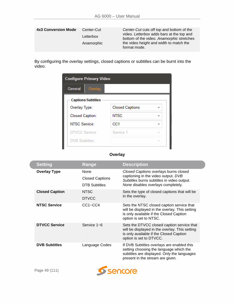
By configuring the overlay settings, closed captions or subtitles can be burnt into the video.
Overlay
Setting Range Description
Overlay Type None
Closed Captions
DTB Subtitles
Closed Captions overlays burns closed captioning in the video output. DVB Subtitles burns subtitles in video output. None disables overlays completely.
Closed Caption NTSC
DTVCC
Sets the type of closed captions that will be in the overlay.
NTSC Service CC1~CC4 Sets the NTSC closed caption service that will be displayed in the overlay. This setting is only available if the Closed Caption option is set to NTSC.
DTVCC Service Service 1~6 Sets the DTVCC closed caption service that will be displayed in the overlay. This setting is only available if the Closed Caption option is set to DTVCC.
DVB Subtitles Language Codes If DVB Subtitles overlays are enabled this setting choosing the language which the subtitles are displayed. Only the languages present in the stream are given.
AG 6000 – User Manual
Page 50 (111)
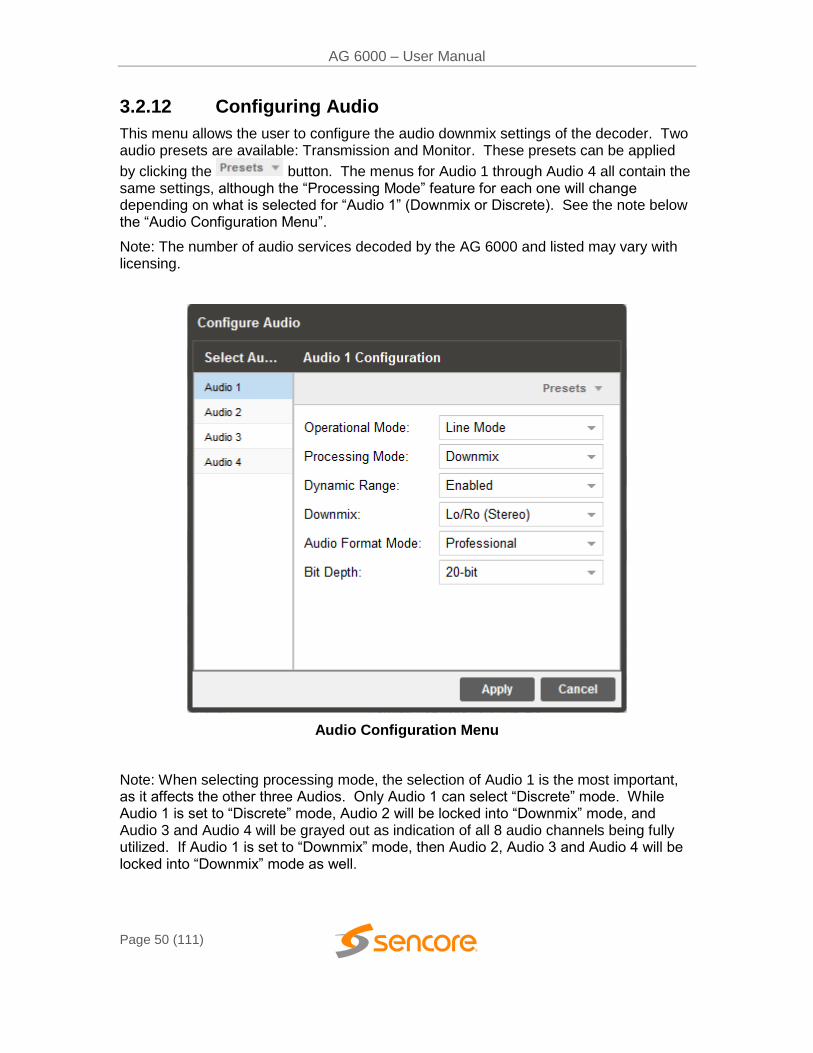
3.2.12 Configuring Audio
This menu allows the user to configure the audio downmix settings of the decoder. Two audio presets are available: Transmission and Monitor. These presets can be applied
by clicking the button. The menus for Audio 1 through Audio 4 all contain the same settings, although the “Processing Mode” feature for each one will change depending on what is selected for “Audio 1” (Downmix or Discrete). See the note below the “Audio Configuration Menu”.
Note: The number of audio services decoded by the AG 6000 and listed may vary with licensing.
Audio Configuration Menu
Note: When selecting processing mode, the selection of Audio 1 is the most important, as it affects the other three Audios. Only Audio 1 can select “Discrete” mode. While Audio 1 is set to “Discrete” mode, Audio 2 will be locked into “Downmix” mode, and Audio 3 and Audio 4 will be grayed out as indication of all 8 audio channels being fully utilized. If Audio 1 is set to “Downmix” mode, then Audio 2, Audio 3 and Audio 4 will be locked into “Downmix” mode as well.
AG 6000 – User Manual
Page 51 (111)
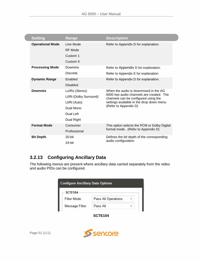
3.2.13 Configuring Ancillary Data
The following menus are present where ancillary data carried separately from the video and audio PIDs can be configured.
SCTE104
Setting Range Description
Operational Mode Line Mode
RF Mode
Custom 1
Custom 0
Refer to Appendix D for explanation.
Processing Mode Downmix
Discrete
Refer to Appendix D for explanation.
Refer to Appendix E for explanation
Dynamic Range Enabled
Disabled
Refer to Appendix D for explanation.
Downmix Lo/Ro (Stereo)
Lt/Rt (Dolby Surround)
Lt/Rt (Auto)
Dual Mono
Dual Left
Dual Right
When the audio is downmixed in the AG 6000 two audio channels are created. The channels can be configured using the settings available in the drop down menu. (Refer to Appendix D)
Format Mode Consumer
Professional
This option selects the PCM or Dolby Digital format mode. (Refer to Appendix D)
Bit Depth 20-bit
24-bit
Defines the bit depth of the corresponding audio configuration.
AG 6000 – User Manual
Page 52 (111)
SCTE104
Setting Ranges Description
Filter Mode Pass First Operation
Pass All Operations
Pass First Operation ensures that embedded SCTE104 messages will contain no more than one operating ID. Pass All Operations allows embedded SCTE104 messages to contain all operations on output.
Message Filter Pass Splice Insert Only
Pass All
Pass Splice Insert Only selection will filter out all SCTE104 message types except for Splice Inserts. Pass All selection will allow all SCTE104 message types to pass to the output.
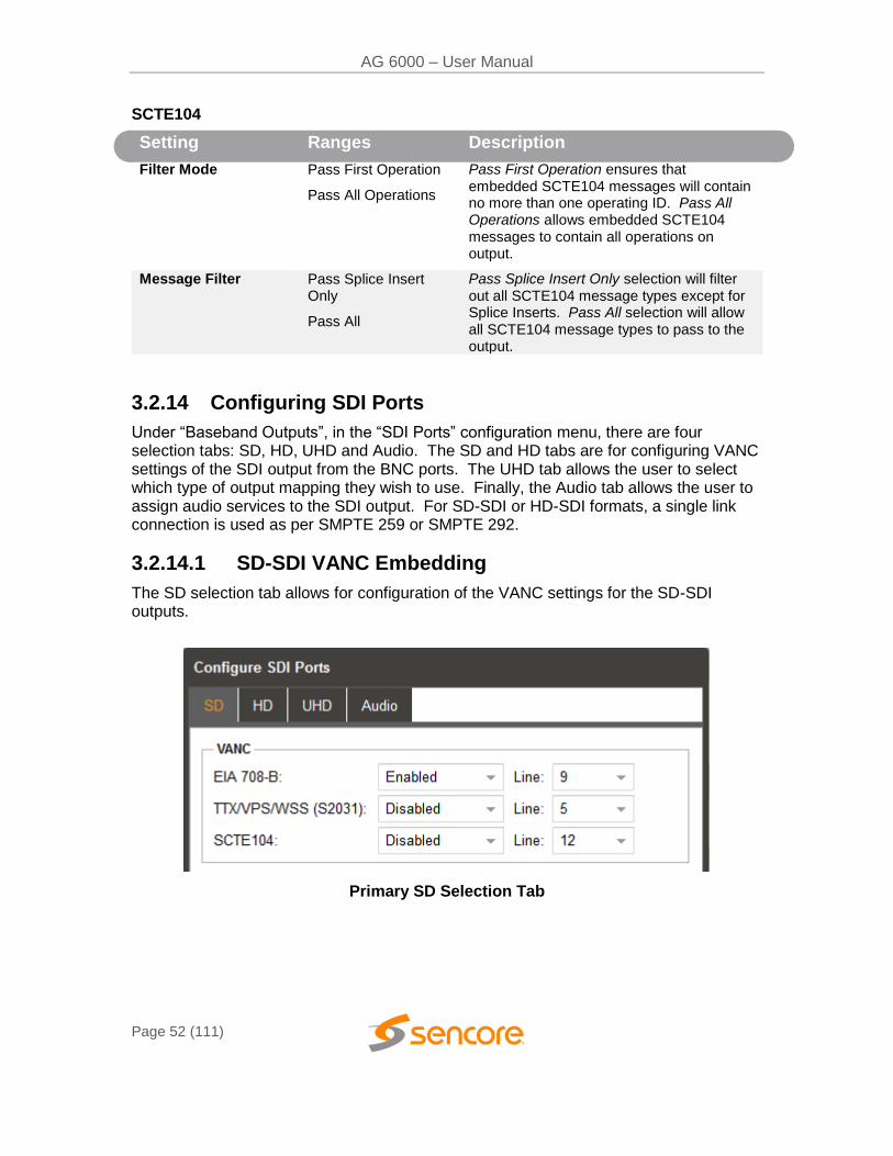
3.2.14 Configuring SDI Ports
Under “Baseband Outputs”, in the “SDI Ports” configuration menu, there are four selection tabs: SD, HD, UHD and Audio. The SD and HD tabs are for configuring VANC settings of the SDI output from the BNC ports. The UHD tab allows the user to select which type of output mapping they wish to use. Finally, the Audio tab allows the user to assign audio services to the SDI output. For SD-SDI or HD-SDI formats, a single link connection is used as per SMPTE 259 or SMPTE 292.
3.2.14.1 SD-SDI VANC Embedding
The SD selection tab allows for configuration of the VANC settings for the SD-SDI outputs.
Primary SD Selection Tab
AG 6000 – User Manual
Page 53 (111)
VANC
Setting Range Description
EIA 708-B Enable/Disable
Line: 4~19
Enables and disables EIA 708-B Captions
Allows user to specify which line the captions are assigned to.
TTX/VPS/WSS (S2031)
Enable/Disable
Line: 4~19
When enabled, SMPTE 2031 data will be embedded in the VANC.
Selecting line number determines which line the SMPTE 2031 data starts on.
SCTE 104 Enable/Disable
Line: 4~19
Enables and Disable SCTE35/104 Convert
Allows user to specify starting line
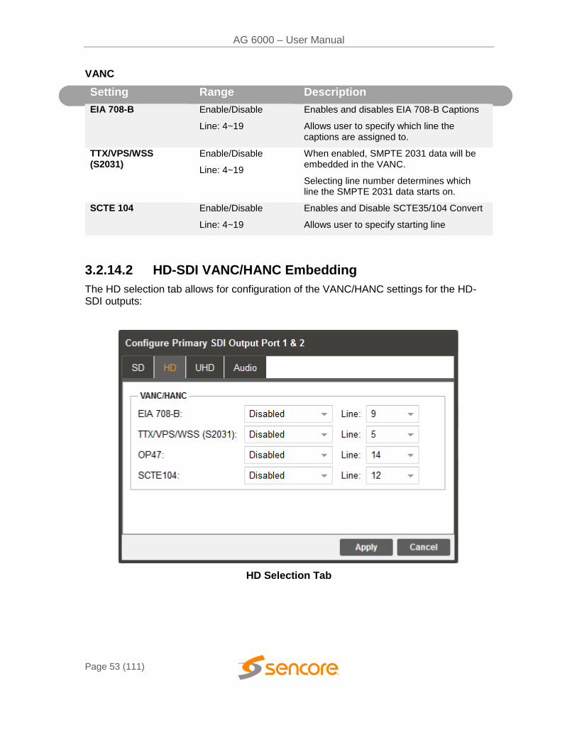
3.2.14.2 HD-SDI VANC/HANC Embedding
The HD selection tab allows for configuration of the VANC/HANC settings for the HD-SDI outputs:
HD Selection Tab
AG 6000 – User Manual
Page 54 (111)
VANC/HANC
Setting Ranges Description
EIA 708-B Disabled/Enabled
Line Number (4~21)
When enabled, EIA 708-B captions will be embedded in the VANC.
Selecting Line number determines which line the captions start on.
TTX/VPS/WSS (S2031)
Disabled/Enabled
Line Number (4~21)
When enabled, SMPTE 2031 data will be embedded in the VANC.
Selecting line number determines which line the SMPTE 2031 data starts on.
OP47 Disabled/Enabled
Line Number (4~19)
When enabled, OP47 subtitle data will be embedded in the VANC.
SCTE104 Disabled/Enabled
Line Number (4~21)
When enabled, SCTE35 to 104 Embedding occurs.
Selecting line number determines which line SCTE104 data starts on.
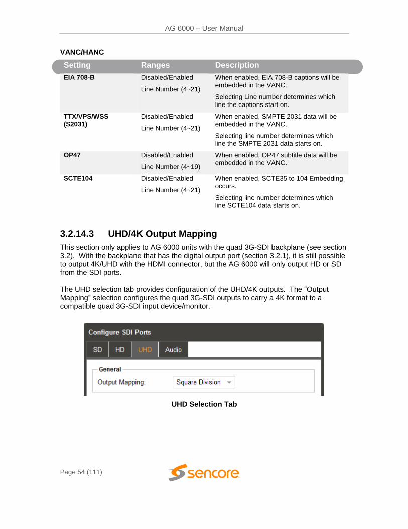
3.2.14.3 UHD/4K Output Mapping
This section only applies to AG 6000 units with the quad 3G-SDI backplane (see section 3.2). With the backplane that has the digital output port (section 3.2.1), it is still possible to output 4K/UHD with the HDMI connector, but the AG 6000 will only output HD or SD from the SDI ports. The UHD selection tab provides configuration of the UHD/4K outputs. The “Output Mapping” selection configures the quad 3G-SDI outputs to carry a 4K format to a compatible quad 3G-SDI input device/monitor.
UHD Selection Tab
AG 6000 – User Manual
Page 55 (111)
General
Setting Ranges Description
Output Mapping Square Division
Two Sample Interleave
Setting to Two Sample Interleave configures the SDI output for quad 3G-SDI format in which each of 4 stream outputs carries ¼ pixels and the picture resolution. Setting to Square Division configures a quad 3G-SDI output format in which each of 4 streams carries a quarter section of the picture in full resolution. Quad 3G-SDI Formats conform to SMPTE 425-3 and SMPTE 425-5.
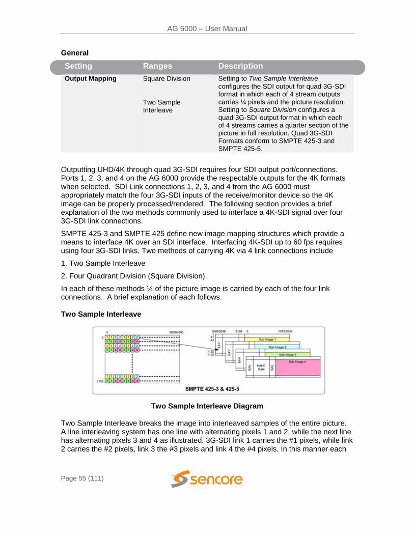
Outputting UHD/4K through quad 3G-SDI requires four SDI output port/connections. Ports 1, 2, 3, and 4 on the AG 6000 provide the respectable outputs for the 4K formats when selected. SDI Link connections 1, 2, 3, and 4 from the AG 6000 must appropriately match the four 3G-SDI inputs of the receive/monitor device so the 4K image can be properly processed/rendered. The following section provides a brief explanation of the two methods commonly used to interface a 4K-SDI signal over four 3G-SDI link connections.
SMPTE 425-3 and SMPTE 425 define new image mapping structures which provide a means to interface 4K over an SDI interface. Interfacing 4K-SDI up to 60 fps requires using four 3G-SDI links. Two methods of carrying 4K via 4 link connections include
1. Two Sample Interleave
2. Four Quadrant Division (Square Division).
In each of these methods ¼ of the picture image is carried by each of the four link connections. A brief explanation of each follows. Two Sample Interleave
Two Sample Interleave Diagram
Two Sample Interleave breaks the image into interleaved samples of the entire picture. A line interleaving system has one line with alternating pixels 1 and 2, while the next line has alternating pixels 3 and 4 as illustrated. 3G-SDI link 1 carries the #1 pixels, while link 2 carries the #2 pixels, link 3 the #3 pixels and link 4 the #4 pixels. In this manner each
AG 6000 – User Manual
Page 56 (111)
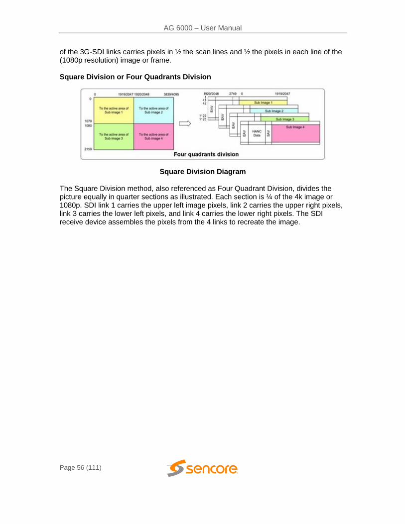
of the 3G-SDI links carries pixels in ½ the scan lines and ½ the pixels in each line of the (1080p resolution) image or frame. Square Division or Four Quadrants Division
Square Division Diagram
The Square Division method, also referenced as Four Quadrant Division, divides the picture equally in quarter sections as illustrated. Each section is ¼ of the 4k image or 1080p. SDI link 1 carries the upper left image pixels, link 2 carries the upper right pixels, link 3 carries the lower left pixels, and link 4 carries the lower right pixels. The SDI receive device assembles the pixels from the 4 links to recreate the image.
AG 6000 – User Manual
Page 57 (111)
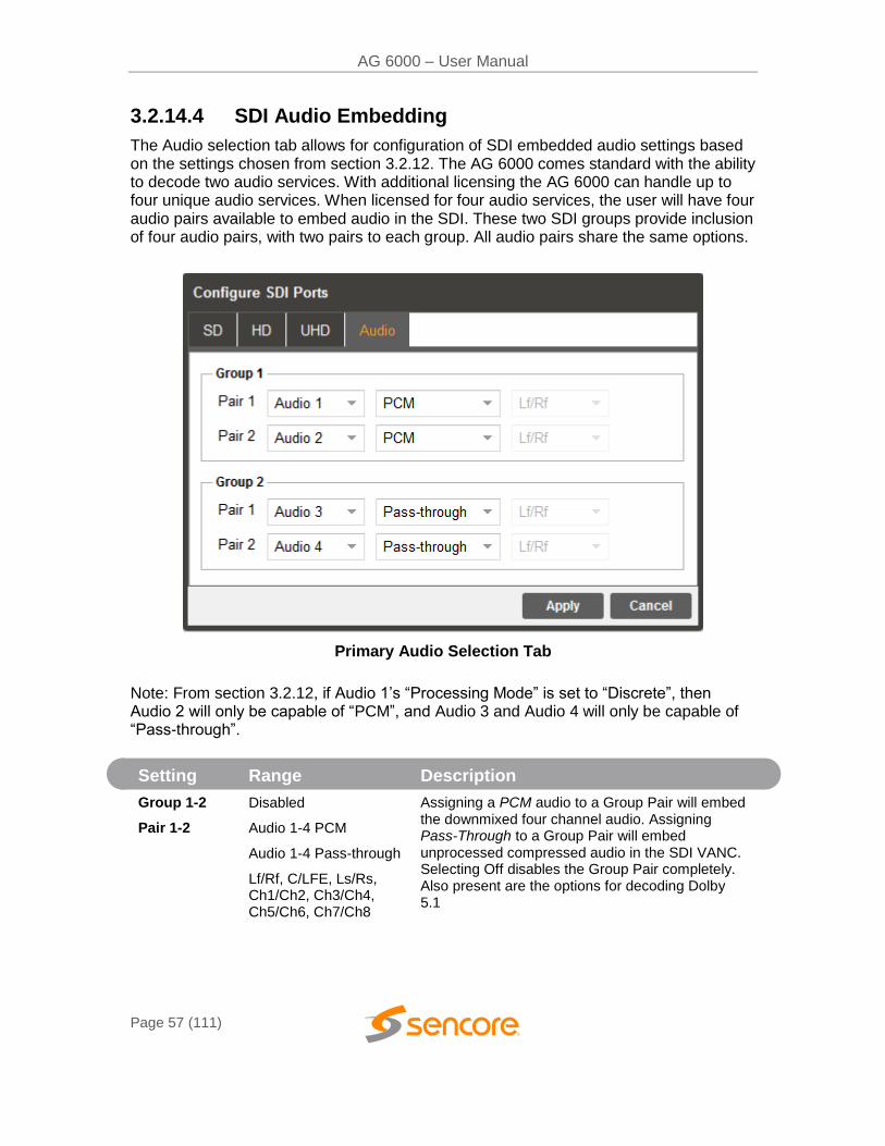
3.2.14.4 SDI Audio Embedding
The Audio selection tab allows for configuration of SDI embedded audio settings based on the settings chosen from section 3.2.12. The AG 6000 comes standard with the ability to decode two audio services. With additional licensing the AG 6000 can handle up to four unique audio services. When licensed for four audio services, the user will have four audio pairs available to embed audio in the SDI. These two SDI groups provide inclusion of four audio pairs, with two pairs to each group. All audio pairs share the same options.
Primary Audio Selection Tab
Note: From section 3.2.12, if Audio 1’s “Processing Mode” is set to “Discrete”, then Audio 2 will only be capable of “PCM”, and Audio 3 and Audio 4 will only be capable of “Pass-through”.
Setting Range Description
Group 1-2
Pair 1-2
Disabled
Audio 1-4 PCM
Audio 1-4 Pass-through
Lf/Rf, C/LFE, Ls/Rs, Ch1/Ch2, Ch3/Ch4, Ch5/Ch6, Ch7/Ch8
Assigning a PCM audio to a Group Pair will embed the downmixed four channel audio. Assigning Pass-Through to a Group Pair will embed unprocessed compressed audio in the SDI VANC. Selecting Off disables the Group Pair completely. Also present are the options for decoding Dolby 5.1
AG 6000 – User Manual
Page 58 (111)
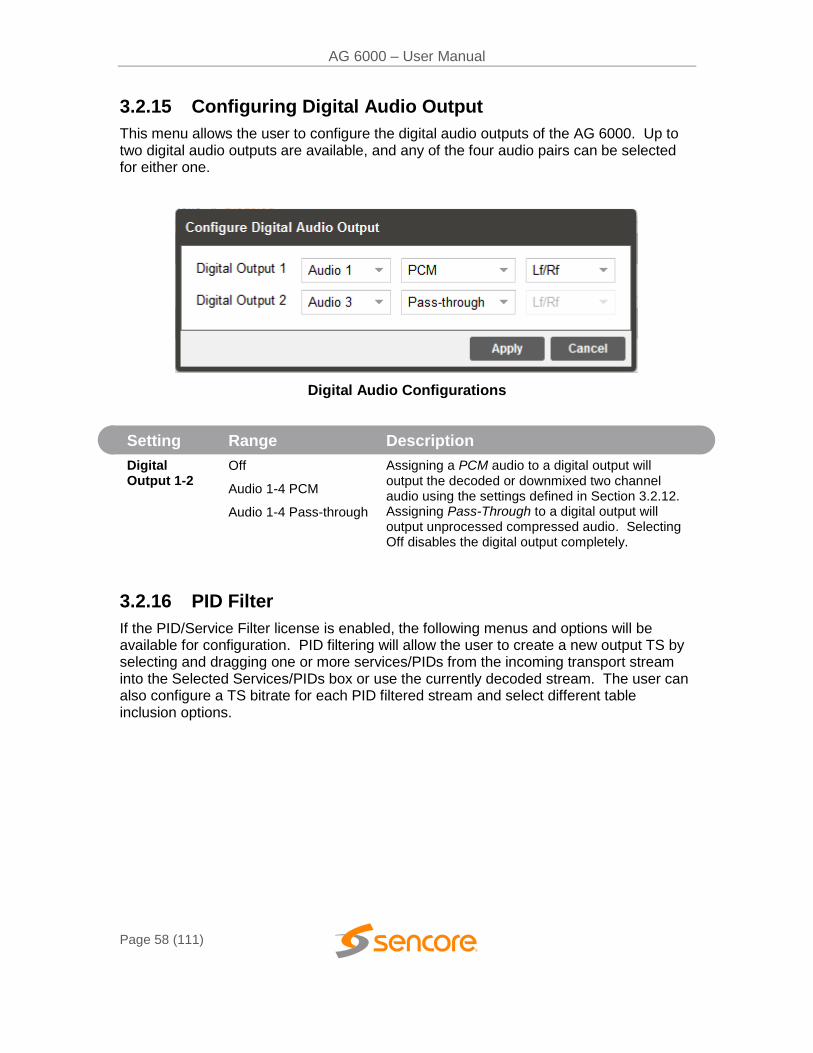
3.2.15 Configuring Digital Audio Output
This menu allows the user to configure the digital audio outputs of the AG 6000. Up to two digital audio outputs are available, and any of the four audio pairs can be selected for either one.
Digital Audio Configurations
Setting Range Description
Digital Output 1-2
Off
Audio 1-4 PCM
Audio 1-4 Pass-through
Assigning a PCM audio to a digital output will output the decoded or downmixed two channel audio using the settings defined in Section 3.2.12. Assigning Pass-Through to a digital output will output unprocessed compressed audio. Selecting Off disables the digital output completely.
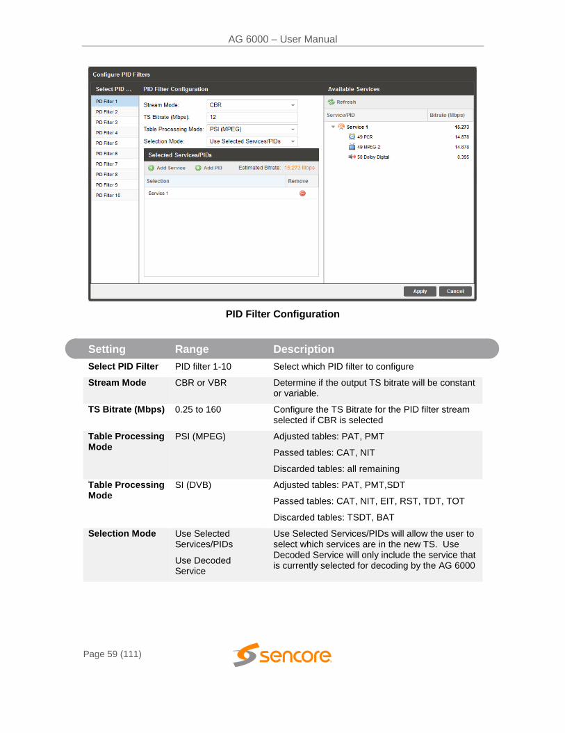
3.2.16 PID Filter
If the PID/Service Filter license is enabled, the following menus and options will be available for configuration. PID filtering will allow the user to create a new output TS by selecting and dragging one or more services/PIDs from the incoming transport stream into the Selected Services/PIDs box or use the currently decoded stream. The user can also configure a TS bitrate for each PID filtered stream and select different table inclusion options.
AG 6000 – User Manual
Page 59 (111)
PID Filter Configuration
Setting Range Description
Select PID Filter PID filter 1-10 Select which PID filter to configure
Stream Mode CBR or VBR Determine if the output TS bitrate will be constant or variable.
TS Bitrate (Mbps) 0.25 to 160 Configure the TS Bitrate for the PID filter stream selected if CBR is selected
Table Processing Mode
PSI (MPEG) Adjusted tables: PAT, PMT
Passed tables: CAT, NIT
Discarded tables: all remaining
Table Processing Mode
SI (DVB) Adjusted tables: PAT, PMT,SDT
Passed tables: CAT, NIT, EIT, RST, TDT, TOT
Discarded tables: TSDT, BAT
Selection Mode Use Selected Services/PIDs
Use Decoded Service
Use Selected Services/PIDs will allow the user to select which services are in the new TS. Use Decoded Service will only include the service that is currently selected for decoding by the AG 6000
AG 6000 – User Manual
Page 60 (111)
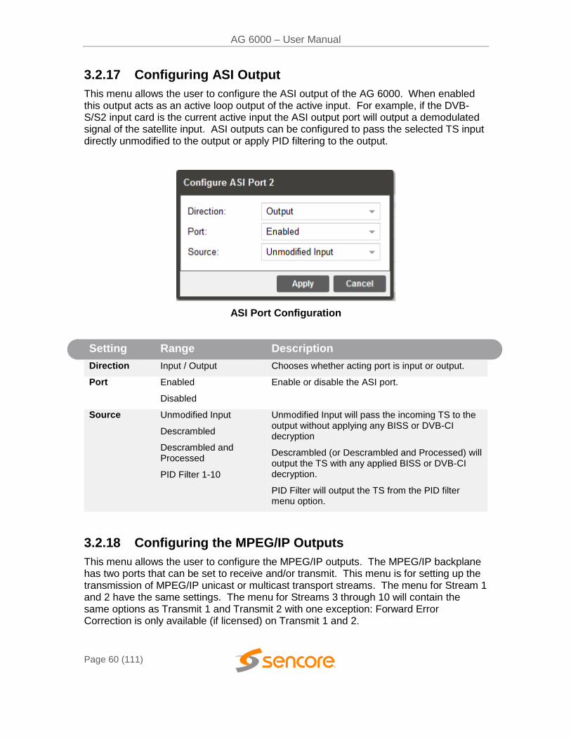
3.2.17 Configuring ASI Output
This menu allows the user to configure the ASI output of the AG 6000. When enabled this output acts as an active loop output of the active input. For example, if the DVB-S/S2 input card is the current active input the ASI output port will output a demodulated signal of the satellite input. ASI outputs can be configured to pass the selected TS input directly unmodified to the output or apply PID filtering to the output.
ASI Port Configuration
Setting Range Description
Direction Input / Output Chooses whether acting port is input or output.
Port Enabled
Disabled
Enable or disable the ASI port.
Source Unmodified Input
Descrambled
Descrambled and Processed
PID Filter 1-10
Unmodified Input will pass the incoming TS to the output without applying any BISS or DVB-CI decryption
Descrambled (or Descrambled and Processed) will output the TS with any applied BISS or DVB-CI decryption.
PID Filter will output the TS from the PID filter menu option.
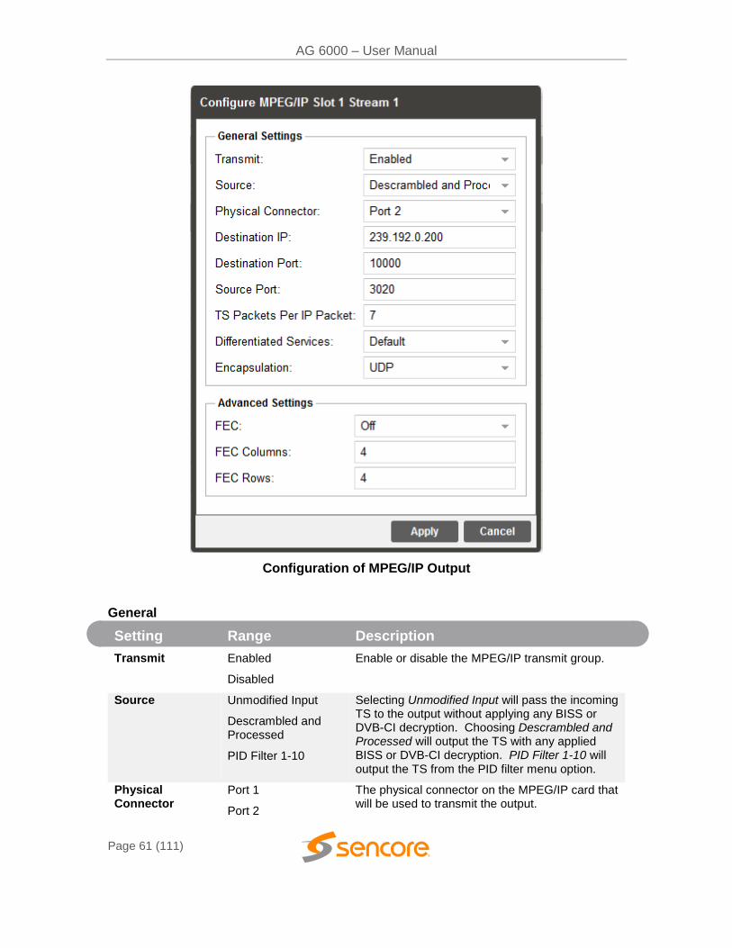
3.2.18 Configuring the MPEG/IP Outputs
This menu allows the user to configure the MPEG/IP outputs. The MPEG/IP backplane has two ports that can be set to receive and/or transmit. This menu is for setting up the transmission of MPEG/IP unicast or multicast transport streams. The menu for Stream 1 and 2 have the same settings. The menu for Streams 3 through 10 will contain the same options as Transmit 1 and Transmit 2 with one exception: Forward Error Correction is only available (if licensed) on Transmit 1 and 2.
AG 6000 – User Manual
Page 61 (111)
Configuration of MPEG/IP Output
General
Setting Range Description
Transmit Enabled
Disabled
Enable or disable the MPEG/IP transmit group.
Source Unmodified Input
Descrambled and Processed
PID Filter 1-10
Selecting Unmodified Input will pass the incoming TS to the output without applying any BISS or DVB-CI decryption. Choosing Descrambled and Processed will output the TS with any applied BISS or DVB-CI decryption. PID Filter 1-10 will output the TS from the PID filter menu option.
Physical Connector
Port 1
Port 2
The physical connector on the MPEG/IP card that will be used to transmit the output.
AG 6000 – User Manual
Page 62 (111)
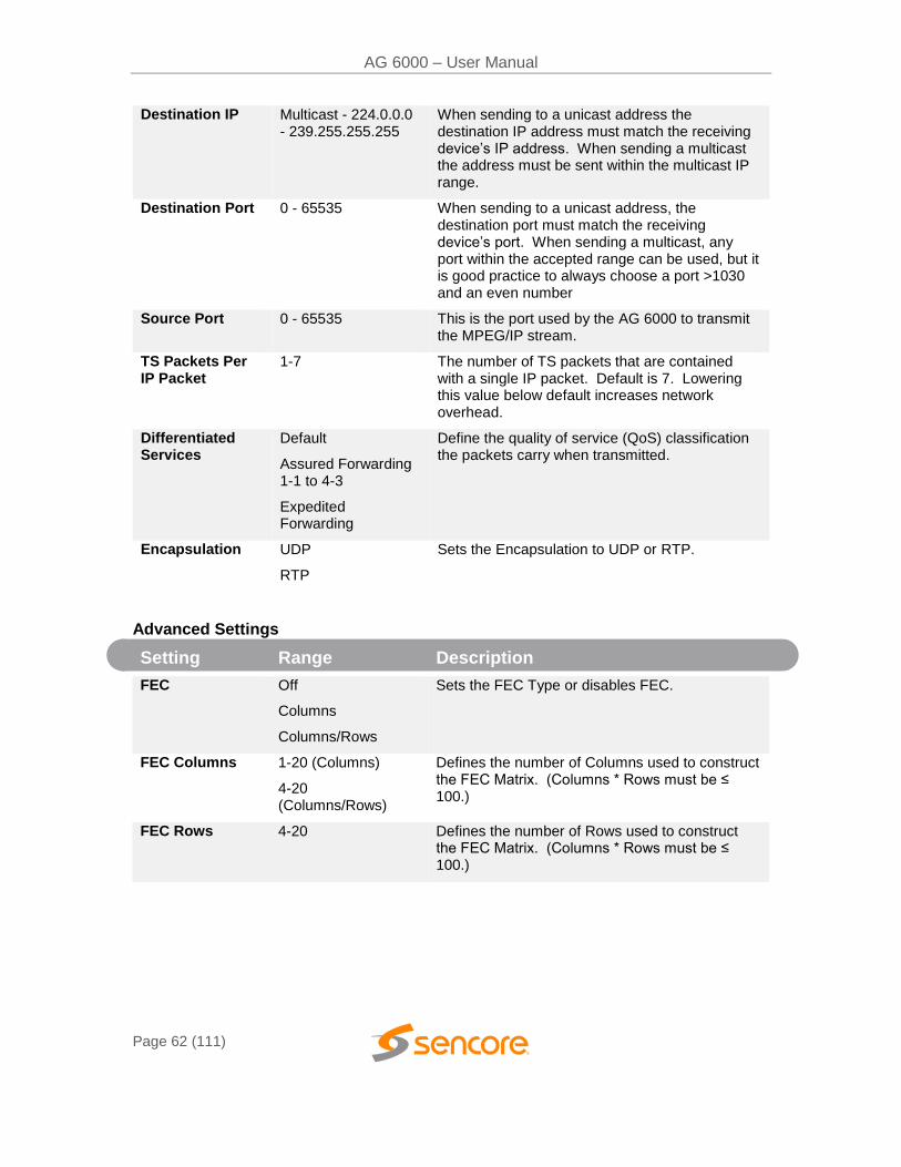
Destination IP Multicast - 224.0.0.0 - 239.255.255.255
When sending to a unicast address the destination IP address must match the receiving device’s IP address. When sending a multicast the address must be sent within the multicast IP range.
Destination Port 0 - 65535 When sending to a unicast address, the destination port must match the receiving device’s port. When sending a multicast, any port within the accepted range can be used, but it is good practice to always choose a port >1030 and an even number
Source Port 0 - 65535 This is the port used by the AG 6000 to transmit the MPEG/IP stream.
TS Packets Per IP Packet
1-7 The number of TS packets that are contained with a single IP packet. Default is 7. Lowering this value below default increases network overhead.
Differentiated Services
Default
Assured Forwarding 1-1 to 4-3
Expedited Forwarding
Define the quality of service (QoS) classification the packets carry when transmitted.
Encapsulation UDP
RTP
Sets the Encapsulation to UDP or RTP.
Advanced Settings
Setting Range Description
FEC Off
Columns
Columns/Rows
Sets the FEC Type or disables FEC.
FEC Columns 1-20 (Columns)
4-20 (Columns/Rows)
Defines the number of Columns used to construct the FEC Matrix. (Columns * Rows must be ≤ 100.)
FEC Rows 4-20 Defines the number of Rows used to construct the FEC Matrix. (Columns * Rows must be ≤ 100.)
AG 6000 – User Manual
Page 63 (111)
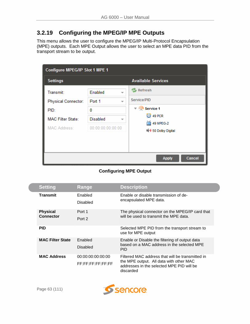
3.2.19 Configuring the MPEG/IP MPE Outputs
This menu allows the user to configure the MPEG/IP Multi-Protocol Encapsulation (MPE) outputs. Each MPE Output allows the user to select an MPE data PID from the transport stream to be output.
Configuring MPE Output
Setting Range Description
Transmit Enabled
Disabled
Enable or disable transmission of de-encapsulated MPE data.
Physical Connector
Port 1
Port 2
The physical connector on the MPEG/IP card that will be used to transmit the MPE data.
PID Selected MPE PID from the transport stream to use for MPE output
MAC Filter State Enabled
Disabled
Enable or Disable the filtering of output data based on a MAC address in the selected MPE PID
MAC Address 00:00:00:00:00:00
FF:FF:FF:FF:FF:FF
Filtered MAC address that will be transmitted in the MPE output. All data with other MAC addresses in the selected MPE PID will be discarded
AG 6000 – User Manual
Page 64 (111)
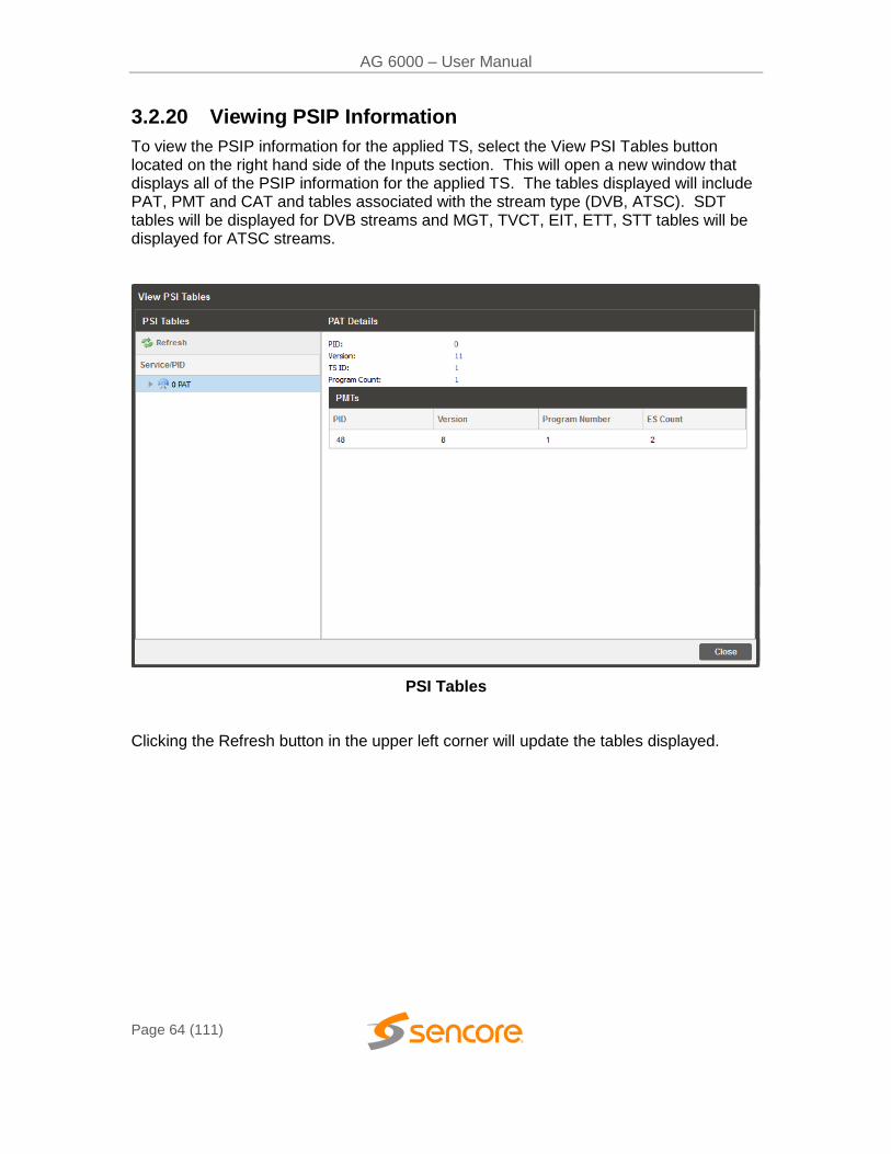
3.2.20 Viewing PSIP Information
To view the PSIP information for the applied TS, select the View PSI Tables button located on the right hand side of the Inputs section. This will open a new window that displays all of the PSIP information for the applied TS. The tables displayed will include PAT, PMT and CAT and tables associated with the stream type (DVB, ATSC). SDT tables will be displayed for DVB streams and MGT, TVCT, EIT, ETT, STT tables will be displayed for ATSC streams.
PSI Tables
Clicking the Refresh button in the upper left corner will update the tables displayed.
AG 6000 – User Manual
Page 65 (111)
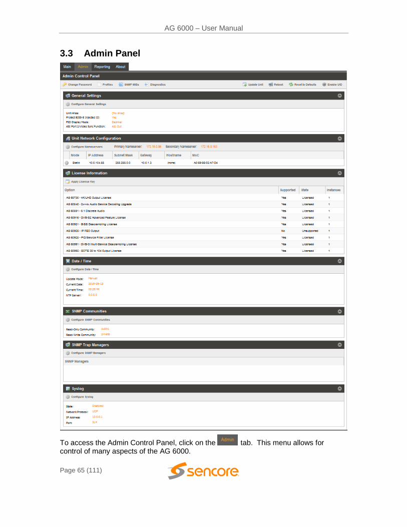
3.3 Admin Panel
To access the Admin Control Panel, click on the tab. This menu allows for control of many aspects of the AG 6000.
AG 6000 – User Manual
Page 66 (111)
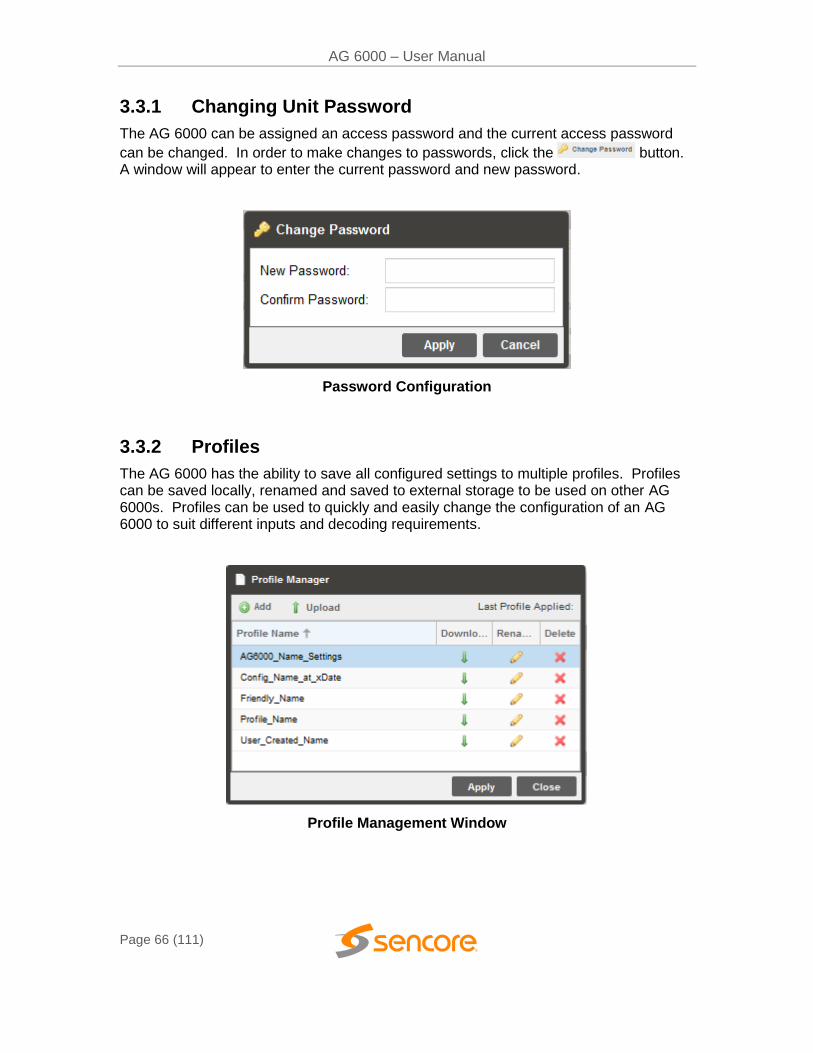
3.3.1 Changing Unit Password
The AG 6000 can be assigned an access password and the current access password
can be changed. In order to make changes to passwords, click the button. A window will appear to enter the current password and new password.
Password Configuration
3.3.2 Profiles
The AG 6000 has the ability to save all configured settings to multiple profiles. Profiles can be saved locally, renamed and saved to external storage to be used on other AG 6000s. Profiles can be used to quickly and easily change the configuration of an AG 6000 to suit different inputs and decoding requirements.
Profile Management Window
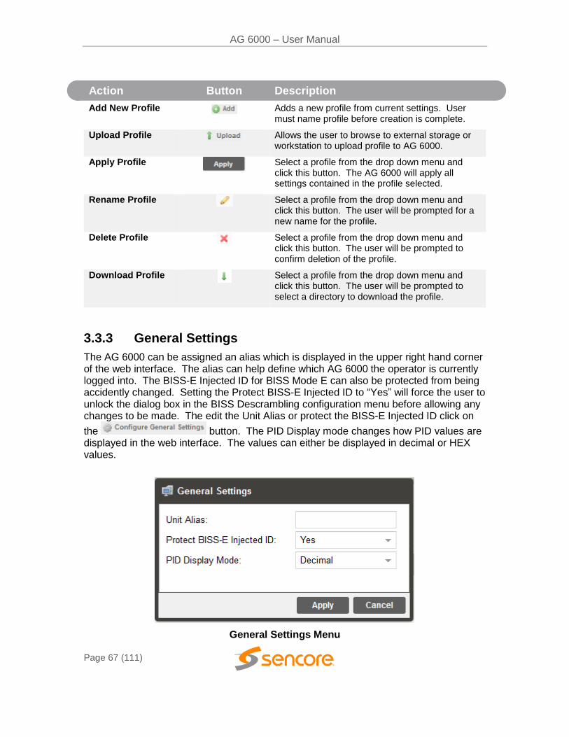
AG 6000 – User Manual
Page 67 (111)
Action Button Description
Add New Profile Adds a new profile from current settings. User must name profile before creation is complete.
Upload Profile Allows the user to browse to external storage or workstation to upload profile to AG 6000.
Apply Profile
Select a profile from the drop down menu and click this button. The AG 6000 will apply all settings contained in the profile selected.
Rename Profile
Select a profile from the drop down menu and click this button. The user will be prompted for a new name for the profile.
Delete Profile Select a profile from the drop down menu and click this button. The user will be prompted to confirm deletion of the profile.
Download Profile
Select a profile from the drop down menu and click this button. The user will be prompted to select a directory to download the profile.
3.3.3 General Settings
The AG 6000 can be assigned an alias which is displayed in the upper right hand corner of the web interface. The alias can help define which AG 6000 the operator is currently logged into. The BISS-E Injected ID for BISS Mode E can also be protected from being accidently changed. Setting the Protect BISS-E Injected ID to “Yes” will force the user to unlock the dialog box in the BISS Descrambling configuration menu before allowing any changes to be made. The edit the Unit Alias or protect the BISS-E Injected ID click on
the button. The PID Display mode changes how PID values are displayed in the web interface. The values can either be displayed in decimal or HEX values.
General Settings Menu
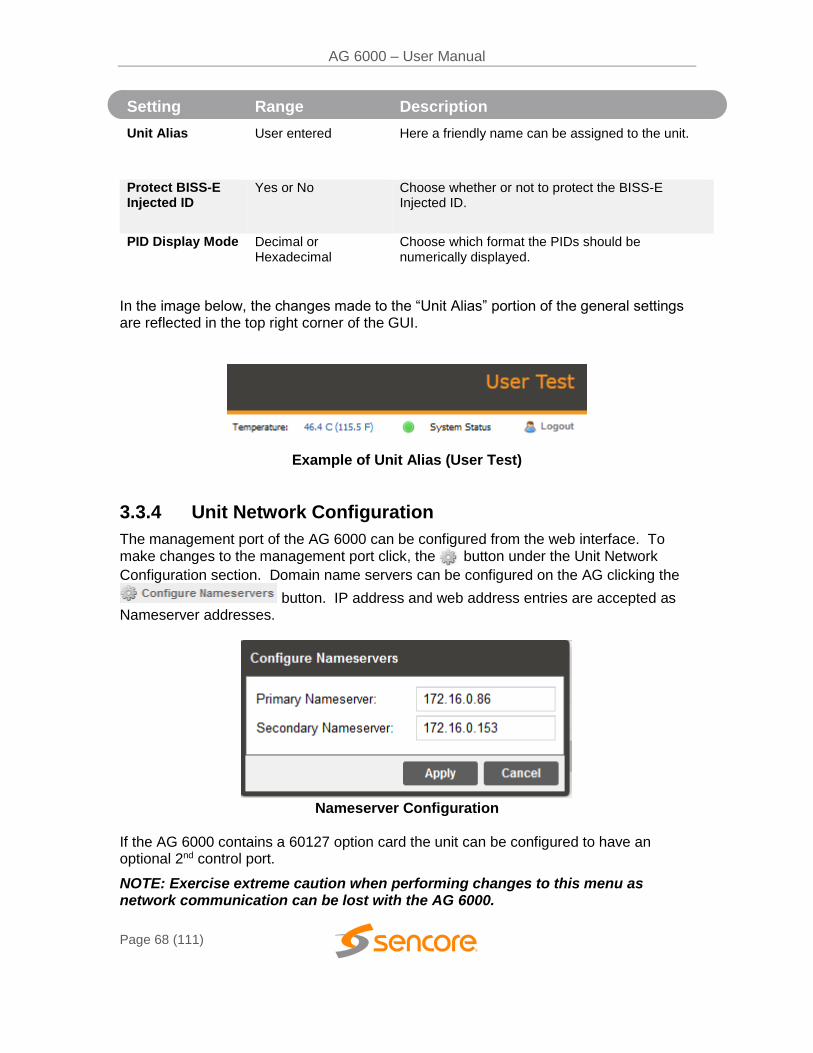
AG 6000 – User Manual
Page 68 (111)
Setting Range Description
Unit Alias User entered Here a friendly name can be assigned to the unit.
Protect BISS-E Injected ID
Yes or No Choose whether or not to protect the BISS-E Injected ID.
PID Display Mode Decimal or Hexadecimal
Choose which format the PIDs should be numerically displayed.
In the image below, the changes made to the “Unit Alias” portion of the general settings are reflected in the top right corner of the GUI.
Example of Unit Alias (User Test)
3.3.4 Unit Network Configuration
The management port of the AG 6000 can be configured from the web interface. To make changes to the management port click, the button under the Unit Network
Configuration section. Domain name servers can be configured on the AG clicking the
button. IP address and web address entries are accepted as Nameserver addresses.
Nameserver Configuration
If the AG 6000 contains a 60127 option card the unit can be configured to have an optional 2nd control port.
NOTE: Exercise extreme caution when performing changes to this menu as network communication can be lost with the AG 6000.
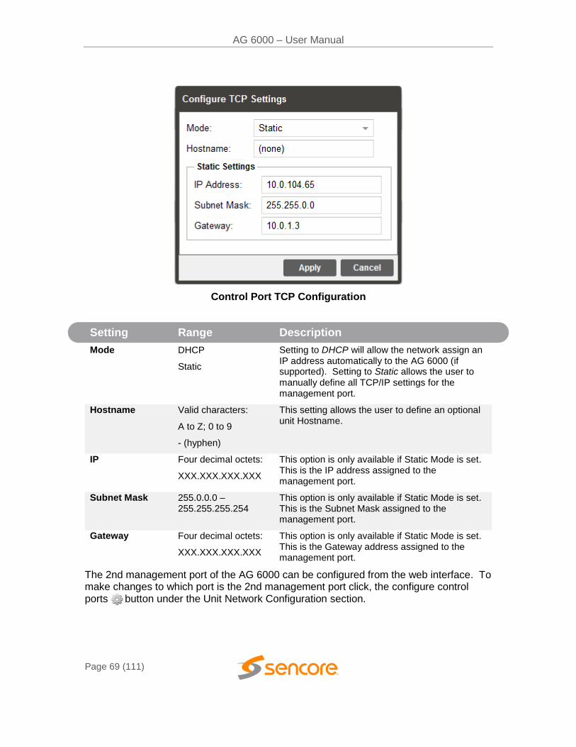
AG 6000 – User Manual
Page 69 (111)
Control Port TCP Configuration
Setting Range Description
Mode DHCP
Static
Setting to DHCP will allow the network assign an IP address automatically to the AG 6000 (if supported). Setting to Static allows the user to manually define all TCP/IP settings for the management port.
Hostname Valid characters:
A to Z; 0 to 9
- (hyphen)
This setting allows the user to define an optional unit Hostname.
IP Four decimal octets:
XXX.XXX.XXX.XXX
This option is only available if Static Mode is set. This is the IP address assigned to the management port.
Subnet Mask 255.0.0.0 – 255.255.255.254
This option is only available if Static Mode is set. This is the Subnet Mask assigned to the management port.
Gateway Four decimal octets:
XXX.XXX.XXX.XXX
This option is only available if Static Mode is set. This is the Gateway address assigned to the management port.
The 2nd management port of the AG 6000 can be configured from the web interface. To make changes to which port is the 2nd management port click, the configure control ports button under the Unit Network Configuration section.
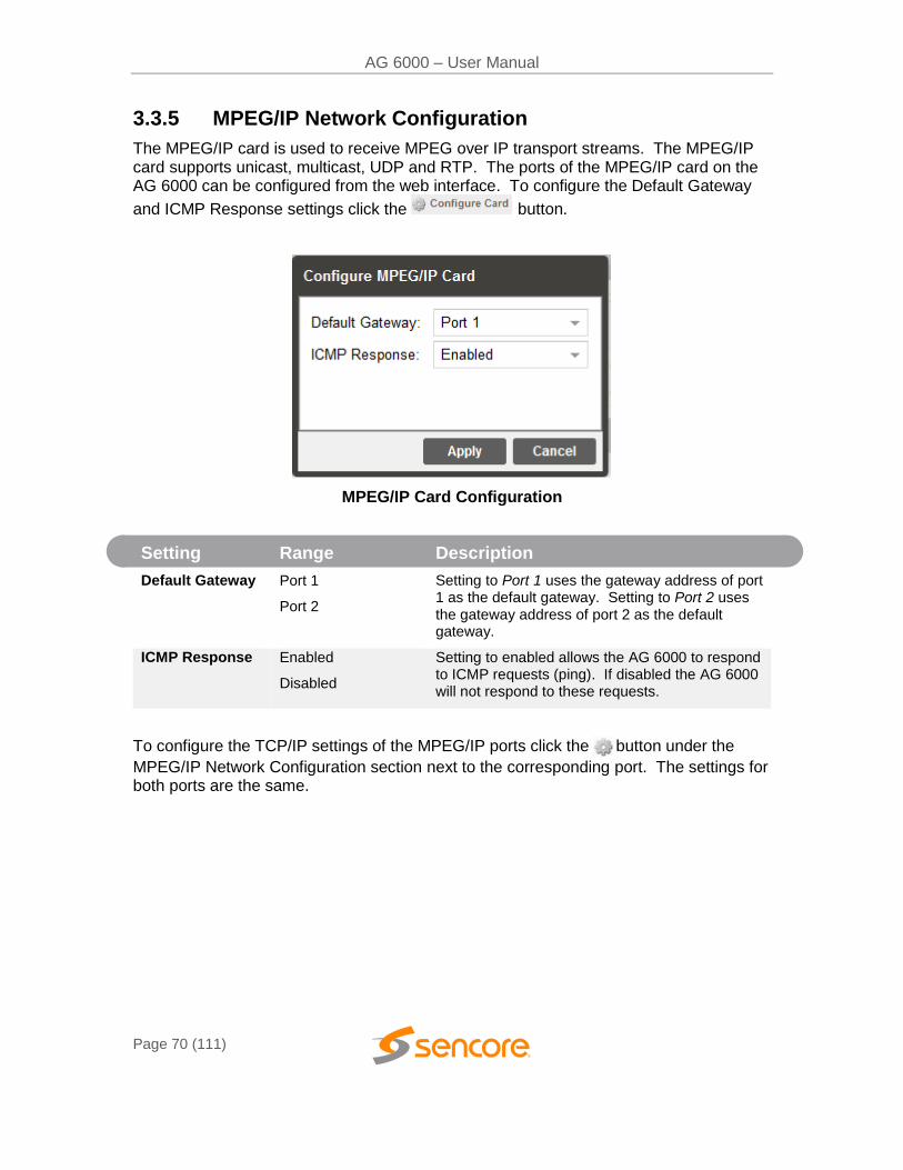
AG 6000 – User Manual
Page 70 (111)
3.3.5 MPEG/IP Network Configuration
The MPEG/IP card is used to receive MPEG over IP transport streams. The MPEG/IP card supports unicast, multicast, UDP and RTP. The ports of the MPEG/IP card on the AG 6000 can be configured from the web interface. To configure the Default Gateway
and ICMP Response settings click the button.
MPEG/IP Card Configuration
Setting Range Description
Default Gateway Port 1
Port 2
Setting to Port 1 uses the gateway address of port 1 as the default gateway. Setting to Port 2 uses the gateway address of port 2 as the default gateway.
ICMP Response Enabled
Disabled
Setting to enabled allows the AG 6000 to respond to ICMP requests (ping). If disabled the AG 6000 will not respond to these requests.
To configure the TCP/IP settings of the MPEG/IP ports click the button under the
MPEG/IP Network Configuration section next to the corresponding port. The settings for both ports are the same.
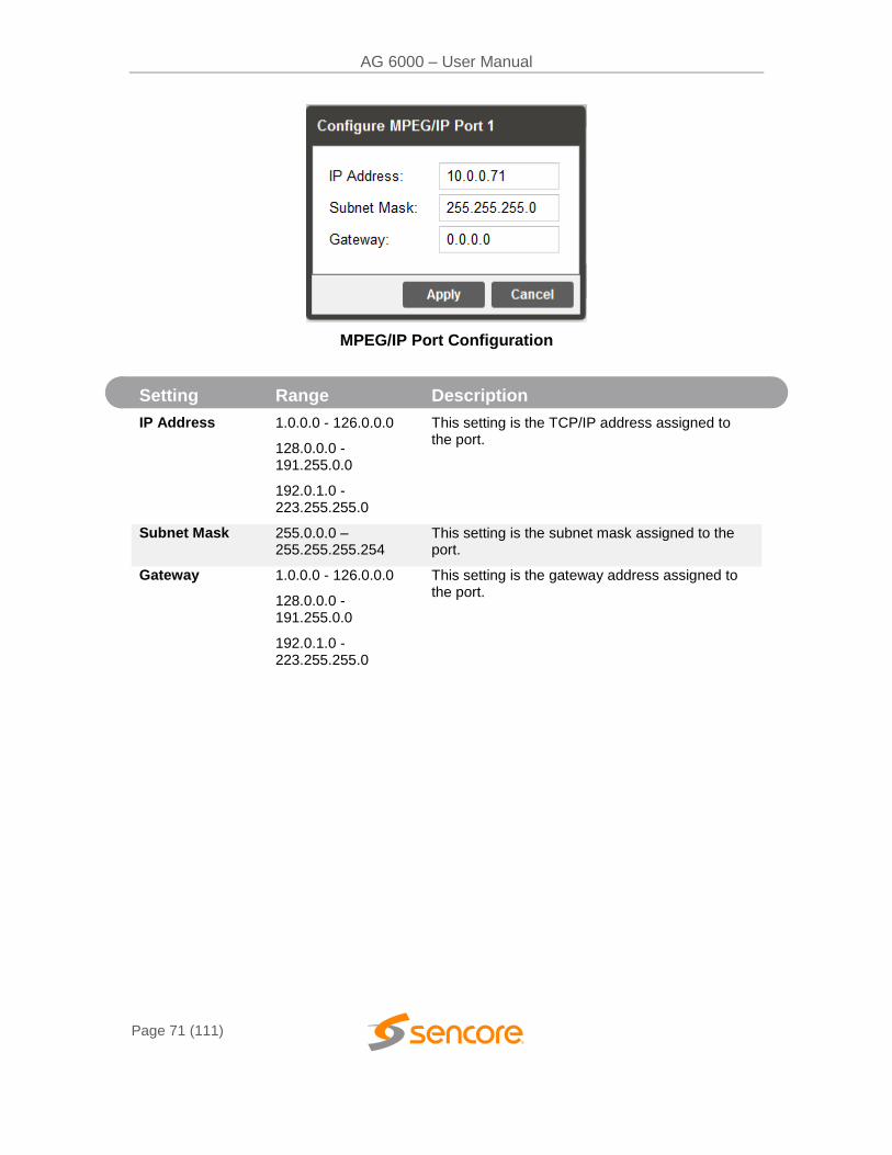
AG 6000 – User Manual
Page 71 (111)
MPEG/IP Port Configuration
Setting Range Description
IP Address 1.0.0.0 - 126.0.0.0
128.0.0.0 - 191.255.0.0
192.0.1.0 - 223.255.255.0
This setting is the TCP/IP address assigned to the port.
Subnet Mask 255.0.0.0 – 255.255.255.254
This setting is the subnet mask assigned to the port.
Gateway 1.0.0.0 - 126.0.0.0
128.0.0.0 - 191.255.0.0
192.0.1.0 - 223.255.255.0
This setting is the gateway address assigned to the port.
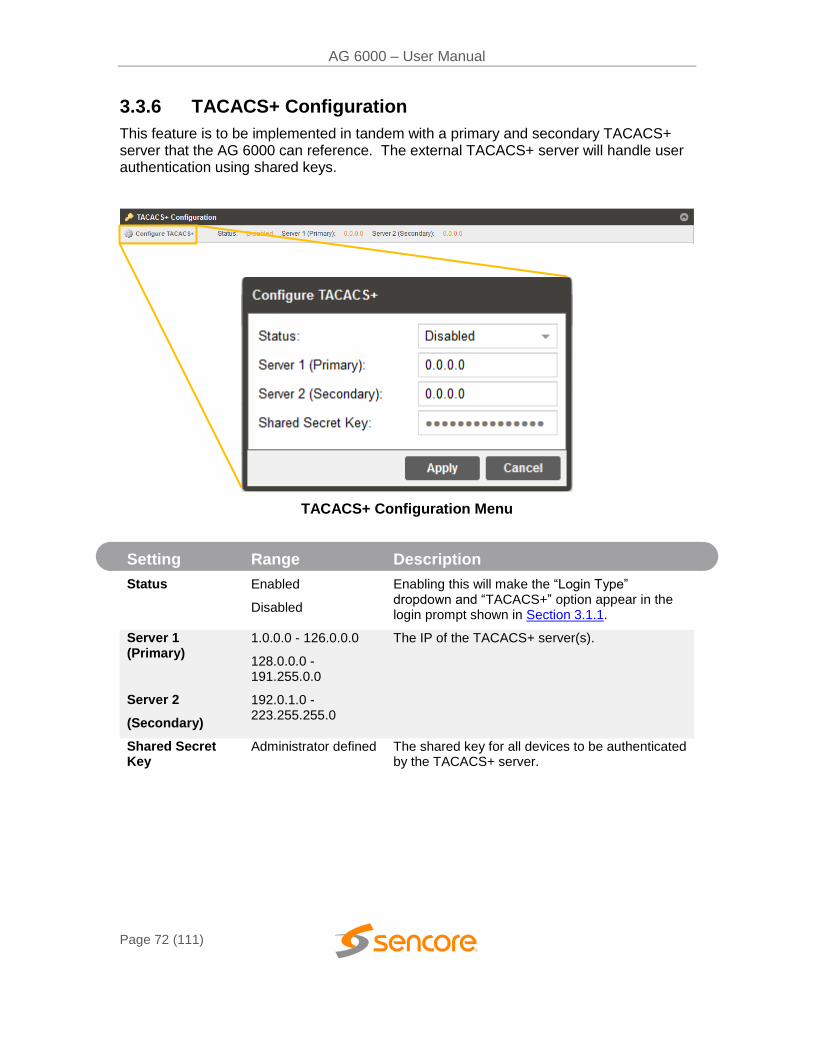
AG 6000 – User Manual
Page 72 (111)
3.3.6 TACACS+ Configuration
This feature is to be implemented in tandem with a primary and secondary TACACS+ server that the AG 6000 can reference. The external TACACS+ server will handle user authentication using shared keys.
TACACS+ Configuration Menu
Setting Range Description
Status Enabled
Disabled
Enabling this will make the “Login Type” dropdown and “TACACS+” option appear in the login prompt shown in Section 3.1.1.
Server 1 (Primary)
Server 2
(Secondary)
1.0.0.0 - 126.0.0.0
128.0.0.0 - 191.255.0.0
192.0.1.0 - 223.255.255.0
The IP of the TACACS+ server(s).
Shared Secret Key
Administrator defined The shared key for all devices to be authenticated by the TACACS+ server.
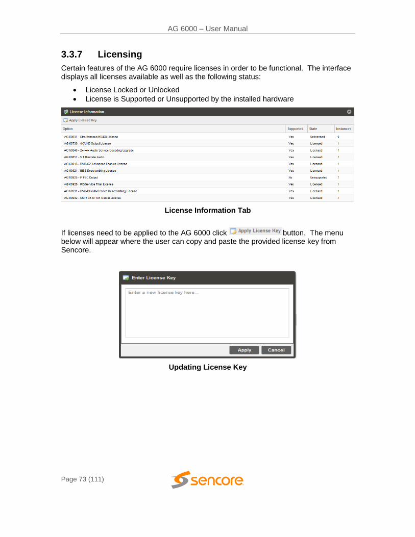
AG 6000 – User Manual
Page 73 (111)
3.3.7 Licensing
Certain features of the AG 6000 require licenses in order to be functional. The interface displays all licenses available as well as the following status:
License Locked or Unlocked
License is Supported or Unsupported by the installed hardware
License Information Tab
If licenses need to be applied to the AG 6000 click button. The menu below will appear where the user can copy and paste the provided license key from Sencore.
Updating License Key
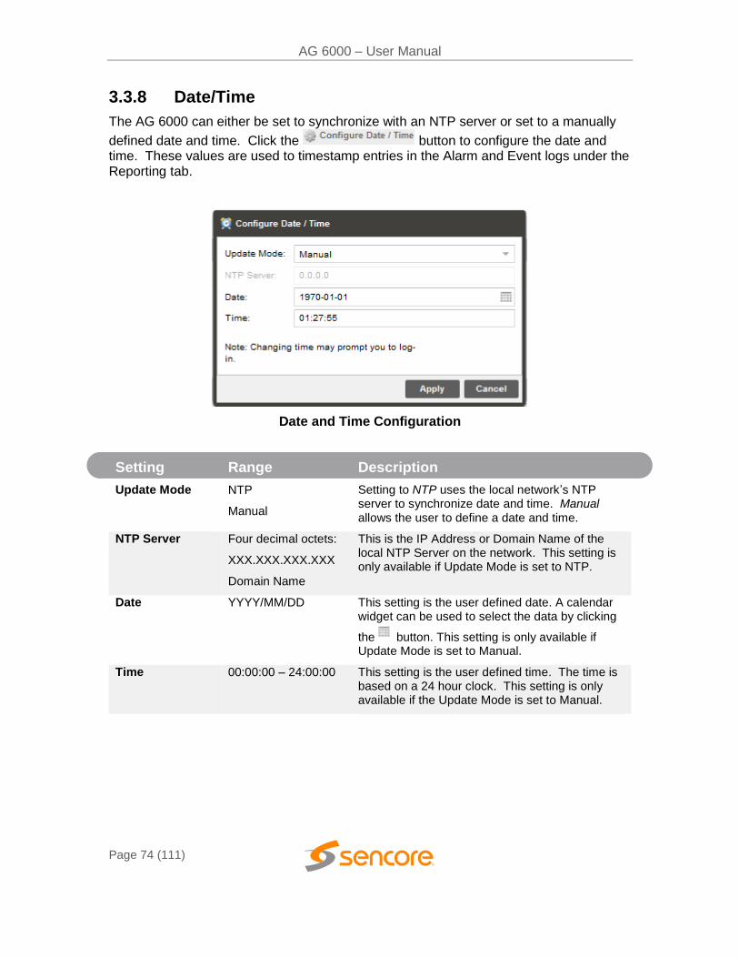
AG 6000 – User Manual
Page 74 (111)
3.3.8 Date/Time
The AG 6000 can either be set to synchronize with an NTP server or set to a manually
defined date and time. Click the button to configure the date and time. These values are used to timestamp entries in the Alarm and Event logs under the Reporting tab.
Date and Time Configuration
Setting Range Description
Update Mode NTP
Manual
Setting to NTP uses the local network’s NTP server to synchronize date and time. Manual allows the user to define a date and time.
NTP Server Four decimal octets:
XXX.XXX.XXX.XXX
Domain Name
This is the IP Address or Domain Name of the local NTP Server on the network. This setting is only available if Update Mode is set to NTP.
Date YYYY/MM/DD
This setting is the user defined date. A calendar widget can be used to select the data by clicking
the button. This setting is only available if Update Mode is set to Manual.
Time 00:00:00 – 24:00:00 This setting is the user defined time. The time is based on a 24 hour clock. This setting is only available if the Update Mode is set to Manual.
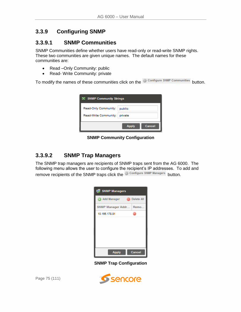
AG 6000 – User Manual
Page 75 (111)
3.3.9 Configuring SNMP
3.3.9.1 SNMP Communities
SNMP Communities define whether users have read-only or read-write SNMP rights. These two communities are given unique names. The default names for these communities are:
Read –Only Community: public
Read- Write Community: private
To modify the names of these communities click on the button.
SNMP Community Configuration
3.3.9.2 SNMP Trap Managers
The SNMP trap managers are recipients of SNMP traps sent from the AG 6000. The following menu allows the user to configure the recipient’s IP addresses. To add and
remove recipients of the SNMP traps click the button.
SNMP Trap Configuration
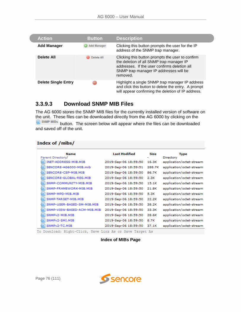
AG 6000 – User Manual
Page 76 (111)
Action Button Description
Add Manager Clicking this button prompts the user for the IP address of the SNMP trap manager.
Delete All Clicking this button prompts the user to confirm the deletion of all SNMP trap manager IP addresses. If the user confirms deletion all SNMP trap manager IP addresses will be removed.
Delete Single Entry
Highlight a single SNMP trap manager IP address and click this button to delete the entry. A prompt will appear confirming the deletion of IP address.
3.3.9.3 Download SNMP MIB Files
The AG 6000 stores the SNMP MIB files for the currently installed version of software on the unit. These files can be downloaded directly from the AG 6000 by clicking on the
button. The screen below will appear where the files can be downloaded and saved off of the unit.
Index of MIBs Page
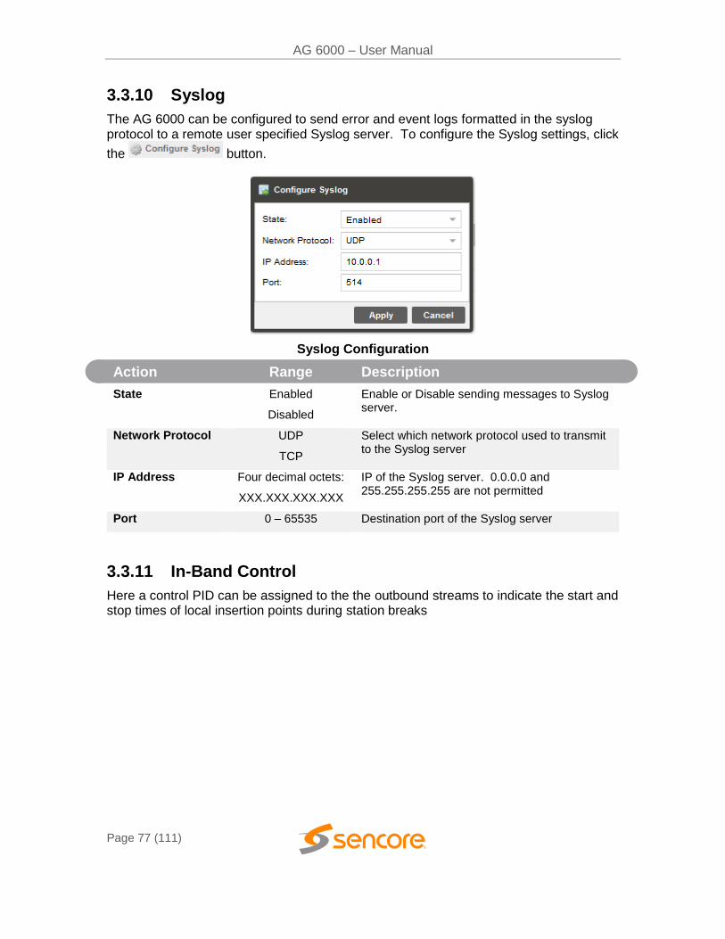
AG 6000 – User Manual
Page 77 (111)
3.3.10 Syslog
The AG 6000 can be configured to send error and event logs formatted in the syslog protocol to a remote user specified Syslog server. To configure the Syslog settings, click
the button.
Syslog Configuration
Action Range Description
State Enabled
Disabled
Enable or Disable sending messages to Syslog server.
Network Protocol UDP
TCP
Select which network protocol used to transmit to the Syslog server
IP Address Four decimal octets:
XXX.XXX.XXX.XXX
IP of the Syslog server. 0.0.0.0 and 255.255.255.255 are not permitted
Port 0 – 65535 Destination port of the Syslog server
3.3.11 In-Band Control
Here a control PID can be assigned to the the outbound streams to indicate the start and stop times of local insertion points during station breaks
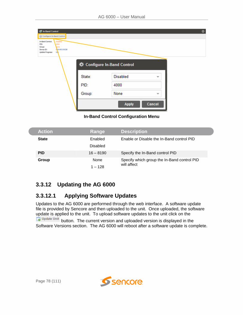
AG 6000 – User Manual
Page 78 (111)
In-Band Control Configuration Menu
Action Range Description
State Enabled
Disabled
Enable or Disable the In-Band control PID
PID 16 – 8190 Specify the In-Band control PID
Group None
1 – 128
Specify which group the In-Band control PID will affect
3.3.12 Updating the AG 6000
3.3.12.1 Applying Software Updates
Updates to the AG 6000 are performed through the web interface. A software update file is provided by Sencore and then uploaded to the unit. Once uploaded, the software update is applied to the unit. To upload software updates to the unit click on the
button. The current version and uploaded version is displayed in the Software Versions section. The AG 6000 will reboot after a software update is complete.
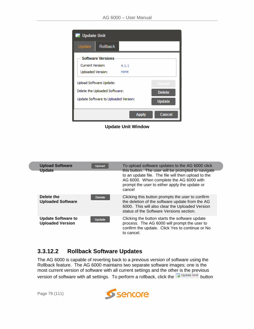
AG 6000 – User Manual
Page 79 (111)
Update Unit Window
Action Button Description
Upload Software Update
To upload software updates to the AG 6000 click this button. The user will be prompted to navigate to an update file. The file will then upload to the AG 6000. When complete the AG 6000 with prompt the user to either apply the update or cancel
Delete the Uploaded Software
Clicking this button prompts the user to confirm the deletion of the software update from the AG 6000. This will also clear the Uploaded Version status of the Software Versions section.
Update Software to Uploaded Version
Clicking the button starts the software update process. The AG 6000 will prompt the user to confirm the update. Click Yes to continue or No to cancel.
3.3.12.2 Rollback Software Updates
The AG 6000 is capable of reverting back to a previous version of software using the Rollback feature. The AG 6000 maintains two separate software images; one is the most current version of software with all current settings and the other is the previous
version of software with all settings. To perform a rollback, click the button
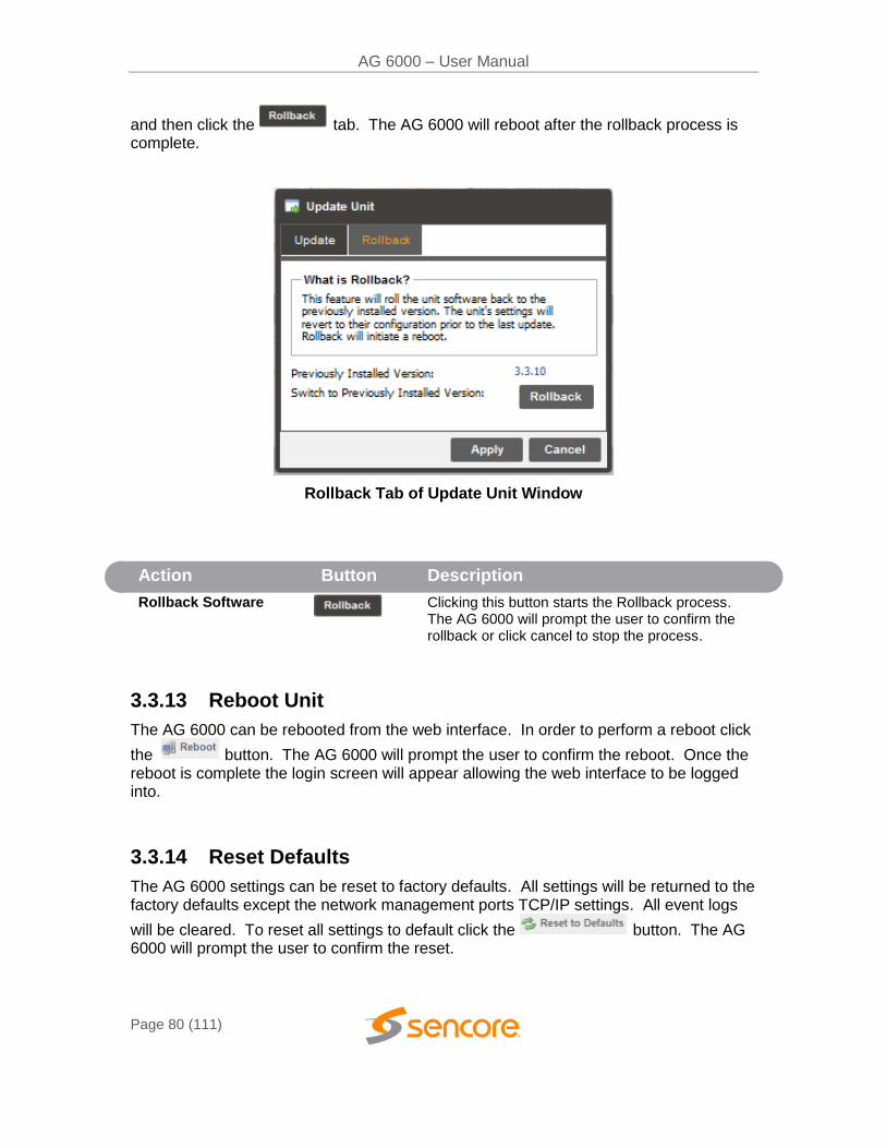
AG 6000 – User Manual
Page 80 (111)
and then click the tab. The AG 6000 will reboot after the rollback process is complete.
Rollback Tab of Update Unit Window
Action Button Description
Rollback Software
Clicking this button starts the Rollback process. The AG 6000 will prompt the user to confirm the rollback or click cancel to stop the process.
3.3.13 Reboot Unit
The AG 6000 can be rebooted from the web interface. In order to perform a reboot click
the button. The AG 6000 will prompt the user to confirm the reboot. Once the reboot is complete the login screen will appear allowing the web interface to be logged into.
3.3.14 Reset Defaults
The AG 6000 settings can be reset to factory defaults. All settings will be returned to the factory defaults except the network management ports TCP/IP settings. All event logs
will be cleared. To reset all settings to default click the button. The AG 6000 will prompt the user to confirm the reset.
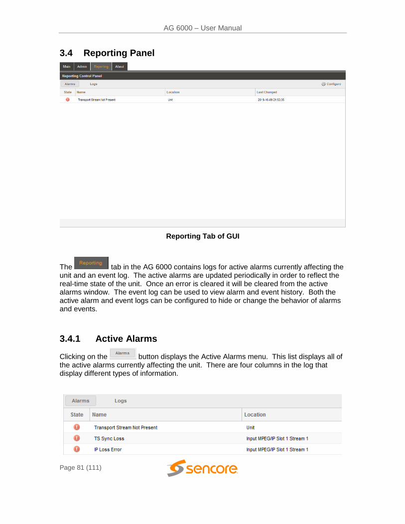
AG 6000 – User Manual
Page 81 (111)
3.4 Reporting Panel
Reporting Tab of GUI
The tab in the AG 6000 contains logs for active alarms currently affecting the unit and an event log. The active alarms are updated periodically in order to reflect the real-time state of the unit. Once an error is cleared it will be cleared from the active alarms window. The event log can be used to view alarm and event history. Both the active alarm and event logs can be configured to hide or change the behavior of alarms and events.
3.4.1 Active Alarms
Clicking on the button displays the Active Alarms menu. This list displays all of the active alarms currently affecting the unit. There are four columns in the log that display different types of information.
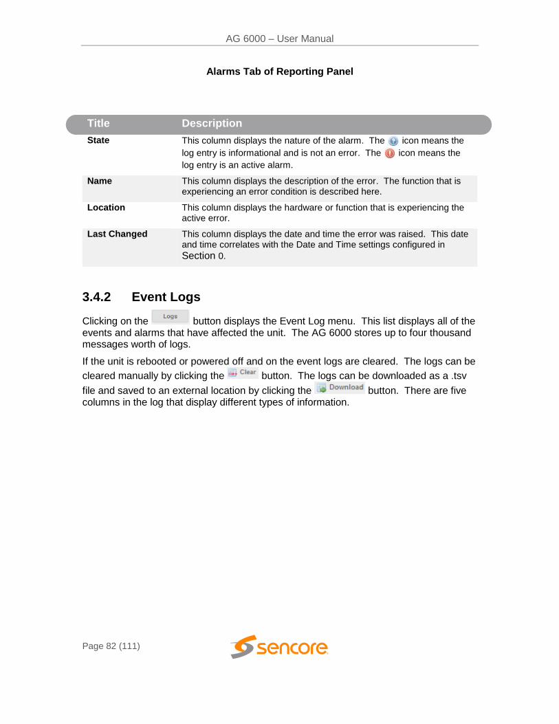
AG 6000 – User Manual
Page 82 (111)
Alarms Tab of Reporting Panel
Title Description
State This column displays the nature of the alarm. The icon means the
log entry is informational and is not an error. The icon means the
log entry is an active alarm.
Name This column displays the description of the error. The function that is experiencing an error condition is described here.
Location This column displays the hardware or function that is experiencing the active error.
Last Changed This column displays the date and time the error was raised. This date and time correlates with the Date and Time settings configured in
Section 0.
3.4.2 Event Logs
Clicking on the button displays the Event Log menu. This list displays all of the events and alarms that have affected the unit. The AG 6000 stores up to four thousand messages worth of logs.
If the unit is rebooted or powered off and on the event logs are cleared. The logs can be
cleared manually by clicking the button. The logs can be downloaded as a .tsv
file and saved to an external location by clicking the button. There are five columns in the log that display different types of information.
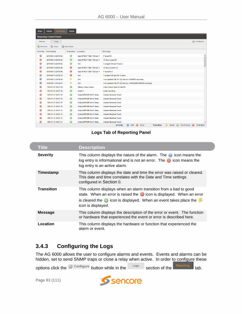
AG 6000 – User Manual
Page 83 (111)
Logs Tab of Reporting Panel
Title Description
Severity This column displays the nature of the alarm. The icon means the
log entry is informational and is not an error. The icon means the
log entry is an active alarm.
Timestamp This column displays the date and time the error was raised or cleared. This date and time correlates with the Date and Time settings
configured in Section 0.
Transition This column displays when an alarm transition from a bad to good
state. When an error is raised the icon is displayed. When an error
is cleared the icon is displayed. When an event takes place the
icon is displayed.
Message This column displays the description of the error or event. The function or hardware that experienced the event or error is described here.
Location This column displays the hardware or function that experienced the alarm or event.
3.4.3 Configuring the Logs
The AG 6000 allows the user to configure alarms and events. Events and alarms can be hidden, set to send SNMP traps or close a relay when active. In order to configure these
options click the button while in the section of the tab.
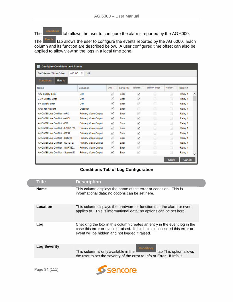
AG 6000 – User Manual
Page 84 (111)
The tab allows the user to configure the alarms reported by the AG 6000.
The tab allows the user to configure the events reported by the AG 6000. Each column and its function are described below. A user configured time offset can also be applied to allow viewing the logs in a local time zone.
Conditions Tab of Log Configuration
Title Description
Name This column displays the name of the error or condition. This is informational data: no options can be set here.
Location This column displays the hardware or function that the alarm or event applies to. This is informational data; no options can be set here.
Log Checking the box in this column creates an entry in the event log in the case this error or event is raised. If this box is unchecked this error or event will be hidden and not logged if raised.
Log Severity
This column is only available in the tab This option allows the user to set the severity of the error to Info or Error. If Info is
AG 6000 – User Manual
Page 85 (111)
3.5 About Tab
Under the tab, is useful information about the unit software, serial number and licensing. There are no user definable parameters in the “About” panel. The Panel includes information about the unit software version currently installed, the unit serial and/or ID number, which licenses are installed, and how to contact Sencore. Information regarding third party software is available by clicking on the dropdown menu box.
selected in the drop down box the icon will displayed in the event
log. If Error is selected the icon will be displayed in the event log.
Alarm
This column is only available in the tab This option allows the user to enable or disable this alarm in the Active Alarms log. If checked the alarm will be displayed in the Active Alarms log if raised. If this box is unchecked this error will be hidden.
SNMP Trap This column allows the user to send an SNMP Trap if this alarm is raised. If this box is checked an SNMP Trap is sent when this alarm is raised. If this box is unchecked an SNMP is not sent.
Relay This column allows the user to set a Relay closure if this alarm is raised. If this box is checked a Relay will be closed. If this box is unchecked a Relay will not be closed.
.
Relay # This column allows the user to select which of the three relays available on the AG 6000 will be closed when the alarm is raised.
Relay Duration This column is only available in the tab. This option allows the user to define the length of time in milliseconds the relay will be closed after the event is logged. This setting can be configured from 100-1000 milliseconds.
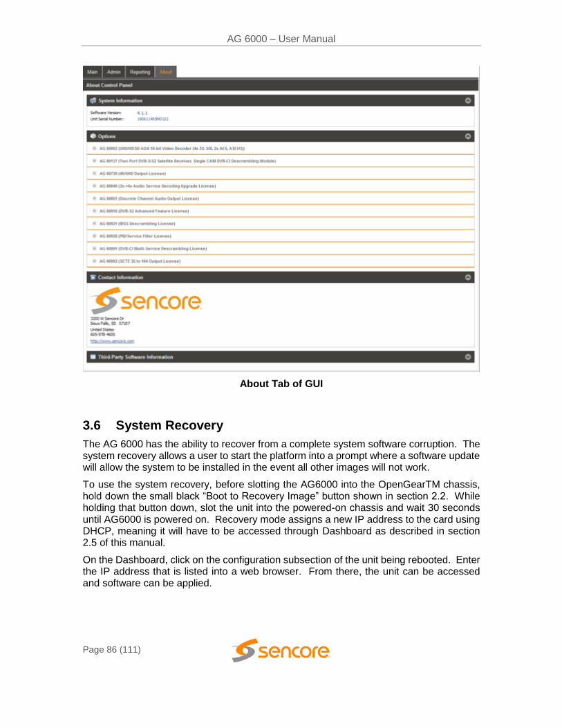
AG 6000 – User Manual
Page 86 (111)
About Tab of GUI
3.6 System Recovery
The AG 6000 has the ability to recover from a complete system software corruption. The system recovery allows a user to start the platform into a prompt where a software update will allow the system to be installed in the event all other images will not work.
To use the system recovery, before slotting the AG6000 into the OpenGearTM chassis, hold down the small black “Boot to Recovery Image” button shown in section 2.2. While holding that button down, slot the unit into the powered-on chassis and wait 30 seconds until AG6000 is powered on. Recovery mode assigns a new IP address to the card using DHCP, meaning it will have to be accessed through Dashboard as described in section 2.5 of this manual.
On the Dashboard, click on the configuration subsection of the unit being rebooted. Enter the IP address that is listed into a web browser. From there, the unit can be accessed and software can be applied.
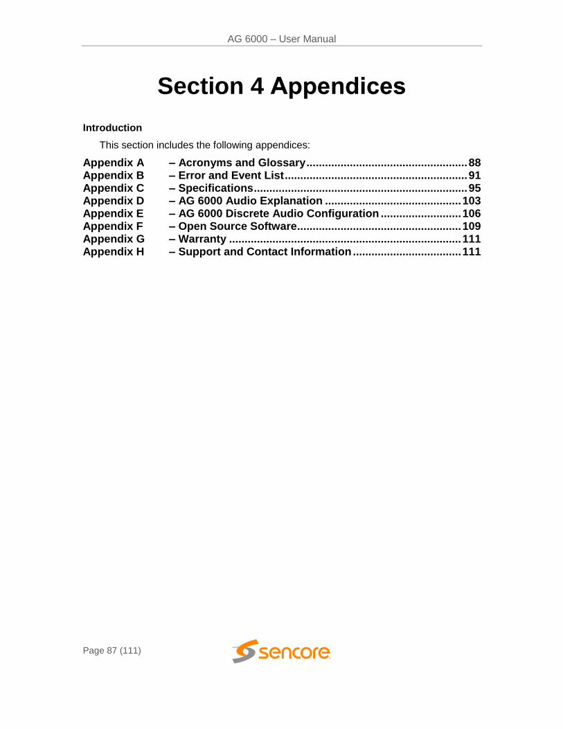
AG 6000 – User Manual
Page 87 (111)
Section 4 Appendices
Introduction
This section includes the following appendices:
Appendix A – Acronyms and Glossary .................................................... 88 Appendix B – Error and Event List ........................................................... 91
Appendix C – Specifications ..................................................................... 95 Appendix D – AG 6000 Audio Explanation ............................................ 103 Appendix E – AG 6000 Discrete Audio Configuration .......................... 106 Appendix F – Open Source Software ..................................................... 109
Appendix G – Warranty ........................................................................... 111 Appendix H – Support and Contact Information ................................... 111

AG 6000 – User Manual
Page 88 (111)
Appendix A – Acronyms and Glossary
8VSB: Vestigial sideband modulation with 8 discrete amplitude levels. 16VSB: Vestigial sideband modulation with 16 discrete amplitude levels. AAC: Advanced Audio Coding AC-3: Also known as Dolby Digital AES: Audio Engineering Society AG: Atlas Gear AFD: Active Format Descriptor ASI: Asynchronous Serial Interface ATSC: Advanced Television Systems Committee AV: Audio Video Bit Rate: The rate at which the compressed bit stream is delivered from the channel to
the input of a decoder. BNC: British Naval Connector BPS: Bits per second. CAM: Conditional Access Module CAT: Conditional Access Table CAT6: Category 6 – Cable standard for gigabit Ethernet CC: Closed Caption CI: Common Interface CoP: Code of Practice CRC: Cyclic Redundancy Check CVCT: Cable Virtual Channel Table dB: Decibel DDPlus: Dolby Digital Plus DHCP: Dynamic Host Configuration Protocol DPI: Digital Program Insertion DTVCC: Digital Television Closed Captioning DVB: Digital Video Broadcasting EBU: European Broadcasting Union EIA: Electronic Industries Alliance EIT: Event Information Table EPG: Electronic Program Guide ETM: Extended Text Message ETT: Extended Text Table Event: An event is defined as a collection of elementary streams with a common time
base, an associated start time, and an associated end time. FCC: Federal Communications Commission FEC: Forward Error Correction Field: For an interlaced video signal, a “field” is the assembly of alternate lines of a
frame. Therefore, an interlaced frame is composed of two fields, a top field and a bottom field.
Frame: A frame contains lines of spatial information of a video signal. For progressive video, these lines contain samples starting from one time instant and continuing through successive lines to the bottom of the frame. For interlaced video a frame consists of two fields, a top field and a bottom field. One of these fields will commence one field later than the other.
HANC: Horizontal Ancillary
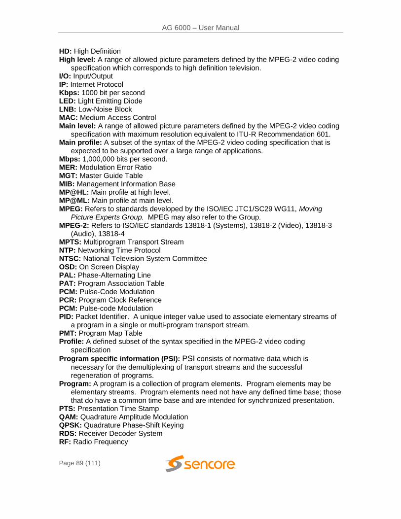
AG 6000 – User Manual
Page 89 (111)
HD: High Definition High level: A range of allowed picture parameters defined by the MPEG-2 video coding
specification which corresponds to high definition television. I/O: Input/Output IP: Internet Protocol Kbps: 1000 bit per second LED: Light Emitting Diode LNB: Low-Noise Block MAC: Medium Access Control Main level: A range of allowed picture parameters defined by the MPEG-2 video coding
specification with maximum resolution equivalent to ITU-R Recommendation 601. Main profile: A subset of the syntax of the MPEG-2 video coding specification that is
expected to be supported over a large range of applications. Mbps: 1,000,000 bits per second. MER: Modulation Error Ratio MGT: Master Guide Table MIB: Management Information Base MP@HL: Main profile at high level. MP@ML: Main profile at main level. MPEG: Refers to standards developed by the ISO/IEC JTC1/SC29 WG11, Moving
Picture Experts Group. MPEG may also refer to the Group. MPEG-2: Refers to ISO/IEC standards 13818-1 (Systems), 13818-2 (Video), 13818-3
(Audio), 13818-4 MPTS: Multiprogram Transport Stream NTP: Networking Time Protocol NTSC: National Television System Committee OSD: On Screen Display PAL: Phase-Alternating Line PAT: Program Association Table PCM: Pulse-Code Modulation PCR: Program Clock Reference PCM: Pulse-code Modulation PID: Packet Identifier. A unique integer value used to associate elementary streams of
a program in a single or multi-program transport stream. PMT: Program Map Table Profile: A defined subset of the syntax specified in the MPEG-2 video coding
specification
Program specific information (PSI): PSI consists of normative data which is
necessary for the demultiplexing of transport streams and the successful regeneration of programs.
Program: A program is a collection of program elements. Program elements may be elementary streams. Program elements need not have any defined time base; those that do have a common time base and are intended for synchronized presentation.
PTS: Presentation Time Stamp QAM: Quadrature Amplitude Modulation QPSK: Quadrature Phase-Shift Keying RDS: Receiver Decoder System RF: Radio Frequency
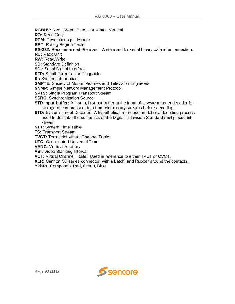
AG 6000 – User Manual
Page 90 (111)
RGBHV: Red, Green, Blue, Horizontal, Vertical RO: Read Only RPM: Revolutions per Minute RRT: Rating Region Table RS-232: Recommended Standard. A standard for serial binary data interconnection. RU: Rack Unit RW: Read/Write SD: Standard Definition SDI: Serial Digital Interface SFP: Small Form-Factor Pluggable SI: System Information SMPTE: Society of Motion Pictures and Television Engineers SNMP: Simple Network Management Protocol SPTS: Single Program Transport Stream SSRC: Synchronization Source STD input buffer: A first-in, first-out buffer at the input of a system target decoder for
storage of compressed data from elementary streams before decoding. STD: System Target Decoder. A hypothetical reference model of a decoding process
used to describe the semantics of the Digital Television Standard multiplexed bit stream.
STT: System Time Table TS: Transport Stream TVCT: Terrestrial Virtual Channel Table UTC: Coordinated Universal Time VANC: Vertical Ancillary VBI: Video Blanking Interval VCT: Virtual Channel Table. Used in reference to either TVCT or CVCT. XLR: Cannon “X” series connector, with a Latch, and Rubber around the contacts. YPbPr: Component Red, Green, Blue
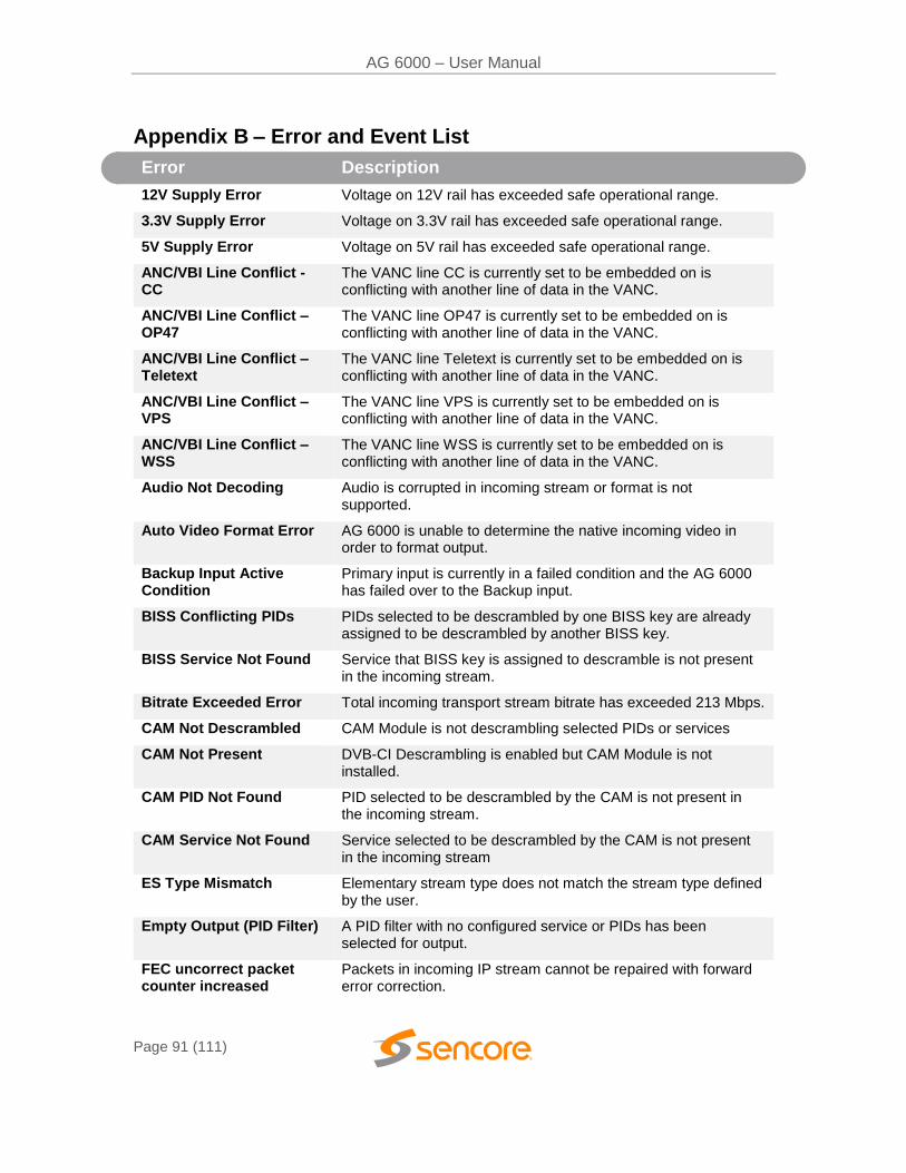
AG 6000 – User Manual
Page 91 (111)
Appendix B – Error and Event List
Error Description
12V Supply Error Voltage on 12V rail has exceeded safe operational range.
3.3V Supply Error Voltage on 3.3V rail has exceeded safe operational range.
5V Supply Error Voltage on 5V rail has exceeded safe operational range.
ANC/VBI Line Conflict - CC
The VANC line CC is currently set to be embedded on is conflicting with another line of data in the VANC.
ANC/VBI Line Conflict – OP47
The VANC line OP47 is currently set to be embedded on is conflicting with another line of data in the VANC.
ANC/VBI Line Conflict – Teletext
The VANC line Teletext is currently set to be embedded on is conflicting with another line of data in the VANC.
ANC/VBI Line Conflict – VPS
The VANC line VPS is currently set to be embedded on is conflicting with another line of data in the VANC.
ANC/VBI Line Conflict – WSS
The VANC line WSS is currently set to be embedded on is conflicting with another line of data in the VANC.
Audio Not Decoding Audio is corrupted in incoming stream or format is not supported.
Auto Video Format Error AG 6000 is unable to determine the native incoming video in order to format output.
Backup Input Active Condition
Primary input is currently in a failed condition and the AG 6000 has failed over to the Backup input.
BISS Conflicting PIDs PIDs selected to be descrambled by one BISS key are already assigned to be descrambled by another BISS key.
BISS Service Not Found Service that BISS key is assigned to descramble is not present in the incoming stream.
Bitrate Exceeded Error Total incoming transport stream bitrate has exceeded 213 Mbps.
CAM Not Descrambled CAM Module is not descrambling selected PIDs or services
CAM Not Present DVB-CI Descrambling is enabled but CAM Module is not installed.
CAM PID Not Found PID selected to be descrambled by the CAM is not present in the incoming stream.
CAM Service Not Found Service selected to be descrambled by the CAM is not present in the incoming stream
ES Type Mismatch Elementary stream type does not match the stream type defined by the user.
Empty Output (PID Filter) A PID filter with no configured service or PIDs has been selected for output.
FEC uncorrect packet counter increased
Packets in incoming IP stream cannot be repaired with forward error correction.
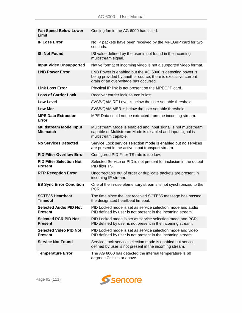
AG 6000 – User Manual
Page 92 (111)
Fan Speed Below Lower Limit
Cooling fan in the AG 6000 has failed.
IP Loss Error No IP packets have been received by the MPEG/IP card for two seconds.
ISI Not Found ISI value defined by the user is not found in the incoming multistream signal.
Input Video Unsupported Native format of incoming video is not a supported video format.
LNB Power Error LNB Power is enabled but the AG 6000 is detecting power is being provided by another source, there is excessive current drain or an overvoltage has occurred.
Link Loss Error Physical IP link is not present on the MPEG/IP card.
Loss of Carrier Lock Receiver carrier lock source is lost.
Low Level 8VSB/QAM RF Level is below the user settable threshold
Low Mer 8VSB/QAM MER is below the user settable threshold
MPE Data Extraction Error
MPE Data could not be extracted from the incoming stream.
Multistream Mode Input Mismatch
Multistream Mode is enabled and input signal is not multistream capable or Multistream Mode is disabled and input signal is multistream capable.
No Services Detected Service Lock service selection mode is enabled but no services are present in the active input transport stream.
PID Filter Overflow Error Configured PID Filter TS rate is too low.
PID Filter Selection Not Present
Selected Service or PID is not present for inclusion in the output PID filter TS.
RTP Reception Error Uncorrectable out of order or duplicate packets are present in incoming IP stream.
ES Sync Error Condition One of the in-use elementary streams is not synchronized to the PCR
SCTE35 Heartbeat Timeout
The time since the last received SCTE35 message has passed the designated heartbeat timeout.
Selected Audio PID Not Present
PID Locked mode is set as service selection mode and audio PID defined by user is not present in the incoming stream.
Selected PCR PID Not Present
PID Locked mode is set as service selection mode and PCR PID defined by user is not present in the incoming stream.
Selected Video PID Not Present
PID Locked mode is set as service selection mode and video PID defined by user is not present in the incoming stream.
Service Not Found Service Lock service selection mode is enabled but service defined by user is not present in the incoming stream.
Temperature Error The AG 6000 has detected the internal temperature is 60 degrees Celsius or above.
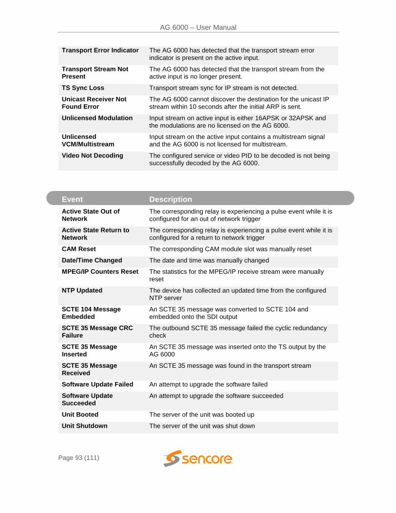
AG 6000 – User Manual
Page 93 (111)
Transport Error Indicator The AG 6000 has detected that the transport stream error indicator is present on the active input.
Transport Stream Not Present
The AG 6000 has detected that the transport stream from the active input is no longer present.
TS Sync Loss Transport stream sync for IP stream is not detected.
Unicast Receiver Not Found Error
The AG 6000 cannot discover the destination for the unicast IP stream within 10 seconds after the initial ARP is sent.
Unlicensed Modulation Input stream on active input is either 16APSK or 32APSK and the modulations are no licensed on the AG 6000.
Unlicensed VCM/Multistream
Input stream on the active input contains a multistream signal and the AG 6000 is not licensed for multistream.
Video Not Decoding The configured service or video PID to be decoded is not being successfully decoded by the AG 6000.
Event Description
Active State Out of Network
The corresponding relay is experiencing a pulse event while it is configured for an out of network trigger
Active State Return to Network
The corresponding relay is experiencing a pulse event while it is configured for a return to network trigger
CAM Reset The corresponding CAM module slot was manually reset
Date/Time Changed The date and time was manually changed
MPEG/IP Counters Reset The statistics for the MPEG/IP receive stream were manually reset
NTP Updated The device has collected an updated time from the configured NTP server
SCTE 104 Message Embedded
An SCTE 35 message was converted to SCTE 104 and embedded onto the SDI output
SCTE 35 Message CRC Failure
The outbound SCTE 35 message failed the cyclic redundancy check
SCTE 35 Message Inserted
An SCTE 35 message was inserted onto the TS output by the AG 6000
SCTE 35 Message Received
An SCTE 35 message was found in the transport stream
Software Update Failed An attempt to upgrade the software failed
Software Update Succeeded
An attempt to upgrade the software succeeded
Unit Booted The server of the unit was booted up
Unit Shutdown The server of the unit was shut down

AG 6000 – User Manual
Page 94 (111)
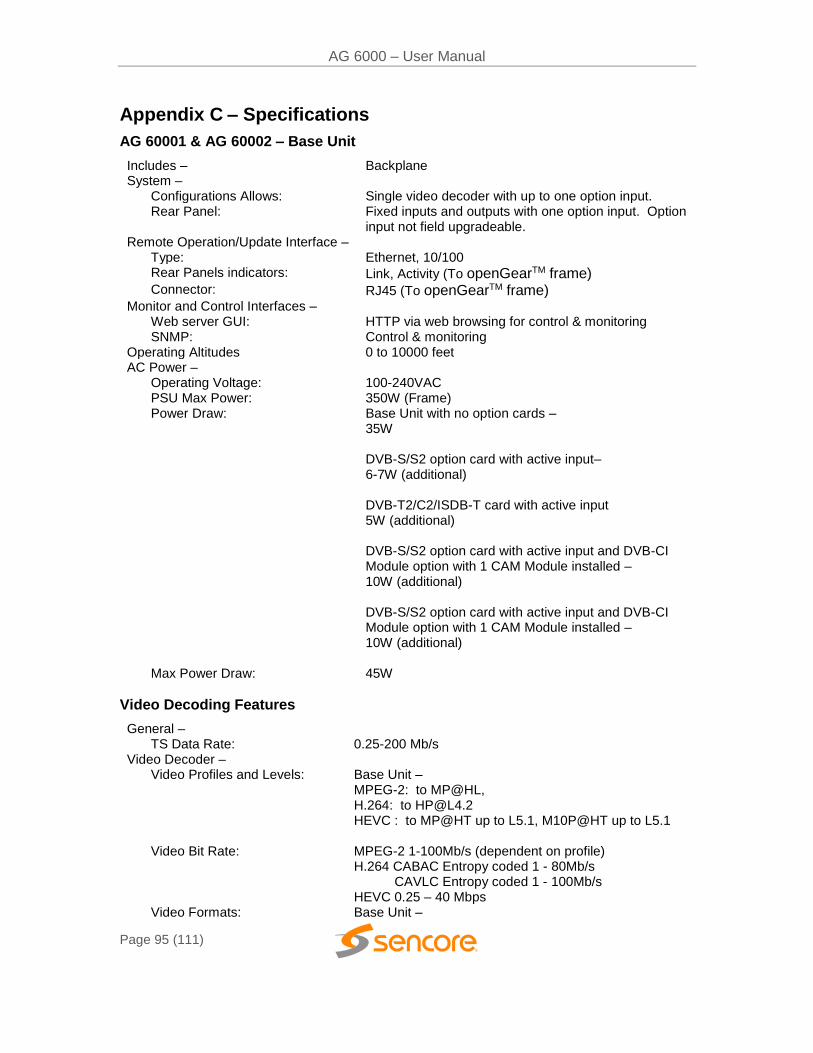
AG 6000 – User Manual
Page 95 (111)
Appendix C – Specifications
AG 60001 & AG 60002 – Base Unit
Includes – Backplane System –
Configurations Allows: Single video decoder with up to one option input. Rear Panel: Fixed inputs and outputs with one option input. Option
input not field upgradeable. Remote Operation/Update Interface –
Type: Ethernet, 10/100 Rear Panels indicators: Link, Activity (To openGearTM frame) Connector: RJ45 (To openGearTM frame)
Monitor and Control Interfaces – Web server GUI: HTTP via web browsing for control & monitoring SNMP: Control & monitoring
Operating Altitudes 0 to 10000 feet AC Power –
Operating Voltage: 100-240VAC PSU Max Power: 350W (Frame) Power Draw: Base Unit with no option cards –
35W
DVB-S/S2 option card with active input– 6-7W (additional) DVB-T2/C2/ISDB-T card with active input 5W (additional)
DVB-S/S2 option card with active input and DVB-CI
Module option with 1 CAM Module installed – 10W (additional) DVB-S/S2 option card with active input and DVB-CI Module option with 1 CAM Module installed – 10W (additional)
Max Power Draw: 45W
Video Decoding Features
General – TS Data Rate: 0.25-200 Mb/s
Video Decoder – Video Profiles and Levels: Base Unit –
MPEG-2: to MP@HL, H.264: to [email protected] HEVC : to MP@HT up to L5.1, M10P@HT up to L5.1
Video Bit Rate: MPEG-2 1-100Mb/s (dependent on profile) H.264 CABAC Entropy coded 1 - 80Mb/s CAVLC Entropy coded 1 - 100Mb/s HEVC 0.25 – 40 Mbps
Video Formats: Base Unit –
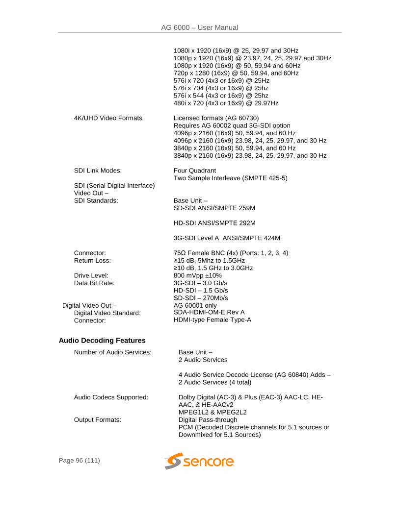
AG 6000 – User Manual
Page 96 (111)
1080i x 1920 (16x9) @ 25, 29.97 and 30Hz 1080p x 1920 (16x9) @ 23.97, 24, 25, 29.97 and 30Hz 1080p x 1920 (16x9) @ 50, 59.94 and 60Hz 720p x 1280 (16x9) @ 50, 59.94, and 60Hz 576i x 720 (4x3 or 16x9) @ 25Hz 576i x 704 (4x3 or 16x9) @ 25hz 576i x 544 (4x3 or 16x9) @ 25hz 480i x 720 (4x3 or 16x9) @ 29.97Hz
4K/UHD Video Formats Licensed formats (AG 60730) Requires AG 60002 quad 3G-SDI option 4096p x 2160 (16x9) 50, 59.94, and 60 Hz 4096p x 2160 (16x9) 23.98, 24, 25, 29.97, and 30 Hz 3840p x 2160 (16x9) 50, 59.94, and 60 Hz 3840p x 2160 (16x9) 23.98, 24, 25, 29.97, and 30 Hz
SDI Link Modes: SDI (Serial Digital Interface) Video Out –
Four Quadrant Two Sample Interleave (SMPTE 425-5)
SDI Standards: Base Unit – SD-SDI ANSI/SMPTE 259M HD-SDI ANSI/SMPTE 292M 3G-SDI Level A ANSI/SMPTE 424M
Connector: 75Ω Female BNC (4x) (Ports: 1, 2, 3, 4) Return Loss: ≥15 dB, 5Mhz to 1.5GHz
≥10 dB, 1.5 GHz to 3.0GHz Drive Level: 800 mVpp ±10% Data Bit Rate: 3G-SDI – 3.0 Gb/s
HD-SDI – 1.5 Gb/s SD-SDI – 270Mb/s
Digital Video Out – AG 60001 only Digital Video Standard: SDA-HDMI-OM-E Rev A
Connector: HDMI-type Female Type-A
Audio Decoding Features
Number of Audio Services: Base Unit – 2 Audio Services 4 Audio Service Decode License (AG 60840) Adds – 2 Audio Services (4 total)
Audio Codecs Supported: Dolby Digital (AC-3) & Plus (EAC-3) AAC-LC, HE-AAC, & HE-AACv2 MPEG1L2 & MPEG2L2
Output Formats: Digital Pass-through PCM (Decoded Discrete channels for 5.1 sources or Downmixed for 5.1 Sources)
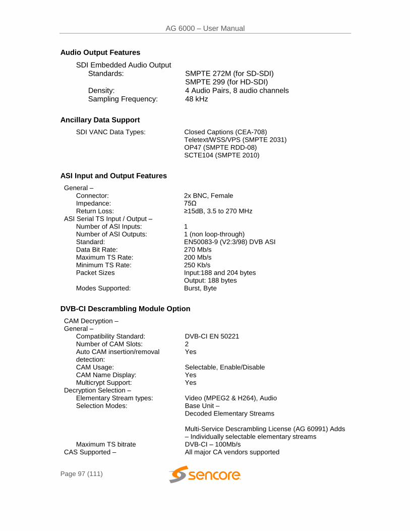
AG 6000 – User Manual
Page 97 (111)
Audio Output Features
SDI Embedded Audio Output Standards: Density: Sampling Frequency:
SMPTE 272M (for SD-SDI) SMPTE 299 (for HD-SDI) 4 Audio Pairs, 8 audio channels 48 kHz
Ancillary Data Support
SDI VANC Data Types: Closed Captions (CEA-708) Teletext/WSS/VPS (SMPTE 2031) OP47 (SMPTE RDD-08) SCTE104 (SMPTE 2010)
ASI Input and Output Features
General – Connector: 2x BNC, Female Impedance: 75Ω Return Loss: ≥15dB, 3.5 to 270 MHz
ASI Serial TS Input / Output – Number of ASI Inputs: 1 Number of ASI Outputs: 1 (non loop-through) Standard: EN50083-9 (V2:3/98) DVB ASI Data Bit Rate: 270 Mb/s Maximum TS Rate: 200 Mb/s Minimum TS Rate: 250 Kb/s Packet Sizes Input:188 and 204 bytes
Output: 188 bytes Modes Supported: Burst, Byte
DVB-CI Descrambling Module Option
CAM Decryption – General –
Compatibility Standard: DVB-CI EN 50221 Number of CAM Slots: 2 Auto CAM insertion/removal detection:
Yes
CAM Usage: Selectable, Enable/Disable CAM Name Display: Yes Multicrypt Support: Yes
Decryption Selection – Elementary Stream types: Video (MPEG2 & H264), Audio Selection Modes: Base Unit –
Decoded Elementary Streams Multi-Service Descrambling License (AG 60991) Adds – Individually selectable elementary streams
Maximum TS bitrate DVB-CI – 100Mb/s CAS Supported – All major CA vendors supported
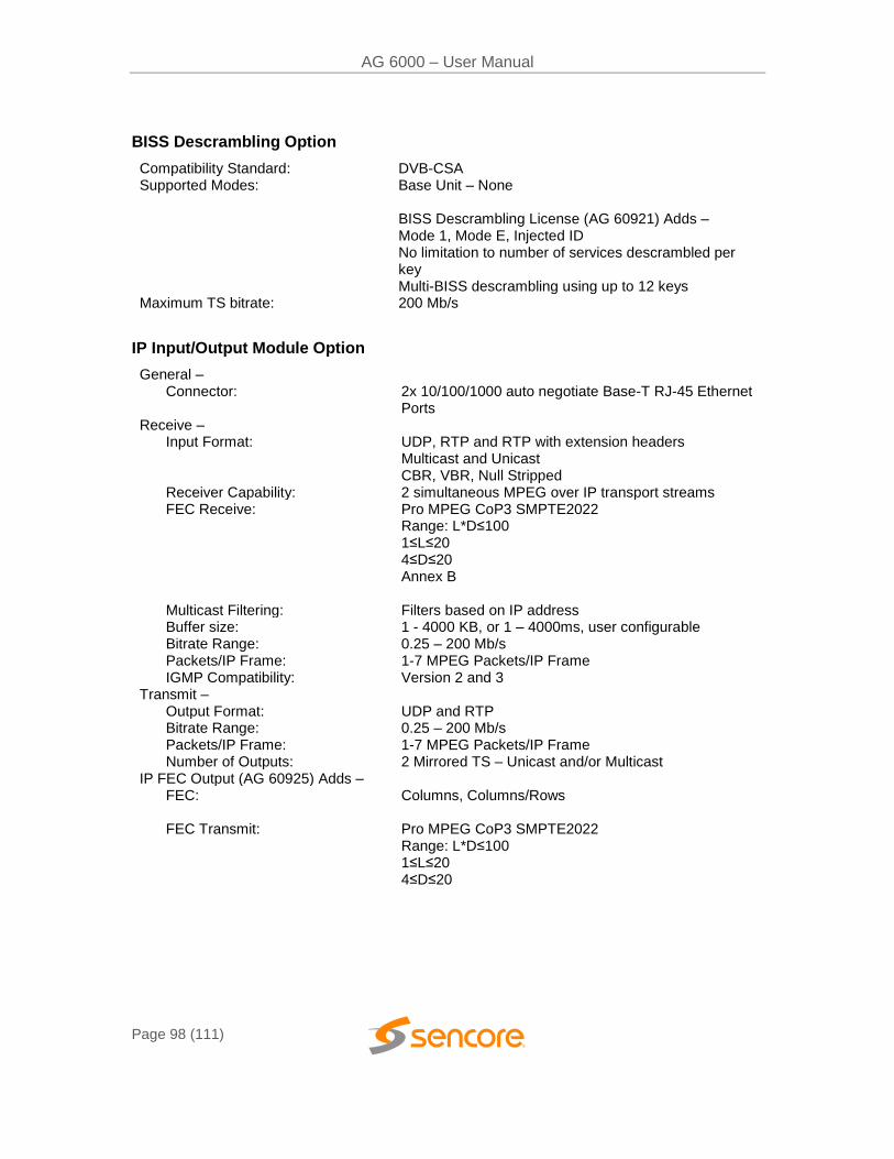
AG 6000 – User Manual
Page 98 (111)
BISS Descrambling Option
Compatibility Standard: DVB-CSA Supported Modes: Base Unit – None
BISS Descrambling License (AG 60921) Adds – Mode 1, Mode E, Injected ID No limitation to number of services descrambled per key Multi-BISS descrambling using up to 12 keys
Maximum TS bitrate: 200 Mb/s
IP Input/Output Module Option
General – Connector: 2x 10/100/1000 auto negotiate Base-T RJ-45 Ethernet
Ports Receive –
Input Format: UDP, RTP and RTP with extension headers Multicast and Unicast CBR, VBR, Null Stripped
Receiver Capability: 2 simultaneous MPEG over IP transport streams FEC Receive: Pro MPEG CoP3 SMPTE2022
Range: L*D≤100 1≤L≤20 4≤D≤20 Annex B
Multicast Filtering: Filters based on IP address Buffer size: 1 - 4000 KB, or 1 – 4000ms, user configurable Bitrate Range: 0.25 – 200 Mb/s Packets/IP Frame: 1-7 MPEG Packets/IP Frame IGMP Compatibility: Version 2 and 3
Transmit – Output Format: UDP and RTP Bitrate Range: 0.25 – 200 Mb/s Packets/IP Frame: 1-7 MPEG Packets/IP Frame Number of Outputs: 2 Mirrored TS – Unicast and/or Multicast
IP FEC Output (AG 60925) Adds – FEC: Columns, Columns/Rows
FEC Transmit: Pro MPEG CoP3 SMPTE2022
Range: L*D≤100 1≤L≤20 4≤D≤20
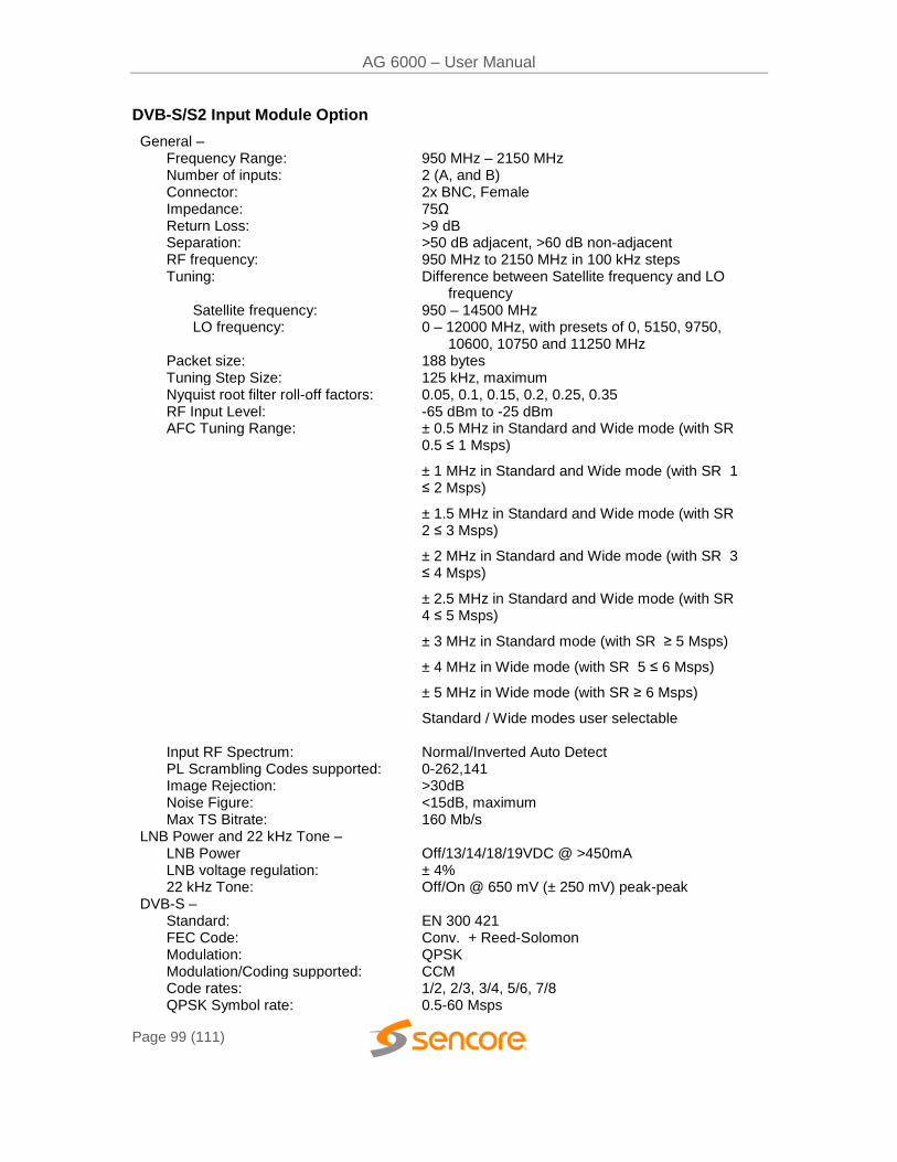
AG 6000 – User Manual
Page 99 (111)
DVB-S/S2 Input Module Option
General – Frequency Range: 950 MHz – 2150 MHz Number of inputs: 2 (A, and B) Connector: 2x BNC, Female Impedance: 75Ω Return Loss: >9 dB Separation: >50 dB adjacent, >60 dB non-adjacent RF frequency: 950 MHz to 2150 MHz in 100 kHz steps Tuning: Difference between Satellite frequency and LO
frequency Satellite frequency: 950 – 14500 MHz LO frequency: 0 – 12000 MHz, with presets of 0, 5150, 9750,
10600, 10750 and 11250 MHz Packet size: 188 bytes Tuning Step Size: 125 kHz, maximum Nyquist root filter roll-off factors: 0.05, 0.1, 0.15, 0.2, 0.25, 0.35 RF Input Level: -65 dBm to -25 dBm AFC Tuning Range: ± 0.5 MHz in Standard and Wide mode (with SR
0.5 ≤ 1 Msps)
± 1 MHz in Standard and Wide mode (with SR 1 ≤ 2 Msps)
± 1.5 MHz in Standard and Wide mode (with SR 2 ≤ 3 Msps)
± 2 MHz in Standard and Wide mode (with SR 3 ≤ 4 Msps)
± 2.5 MHz in Standard and Wide mode (with SR 4 ≤ 5 Msps)
± 3 MHz in Standard mode (with SR ≥ 5 Msps)
± 4 MHz in Wide mode (with SR 5 ≤ 6 Msps)
± 5 MHz in Wide mode (with SR ≥ 6 Msps)
Standard / Wide modes user selectable
Input RF Spectrum: Normal/Inverted Auto Detect PL Scrambling Codes supported: 0-262,141 Image Rejection: >30dB Noise Figure: Max TS Bitrate:
<15dB, maximum 160 Mb/s
LNB Power and 22 kHz Tone – LNB Power Off/13/14/18/19VDC @ >450mA LNB voltage regulation: ± 4% 22 kHz Tone: Off/On @ 650 mV (± 250 mV) peak-peak
DVB-S – Standard: EN 300 421 FEC Code: Conv. + Reed-Solomon Modulation: QPSK Modulation/Coding supported: CCM Code rates: 1/2, 2/3, 3/4, 5/6, 7/8 QPSK Symbol rate: 0.5-60 Msps
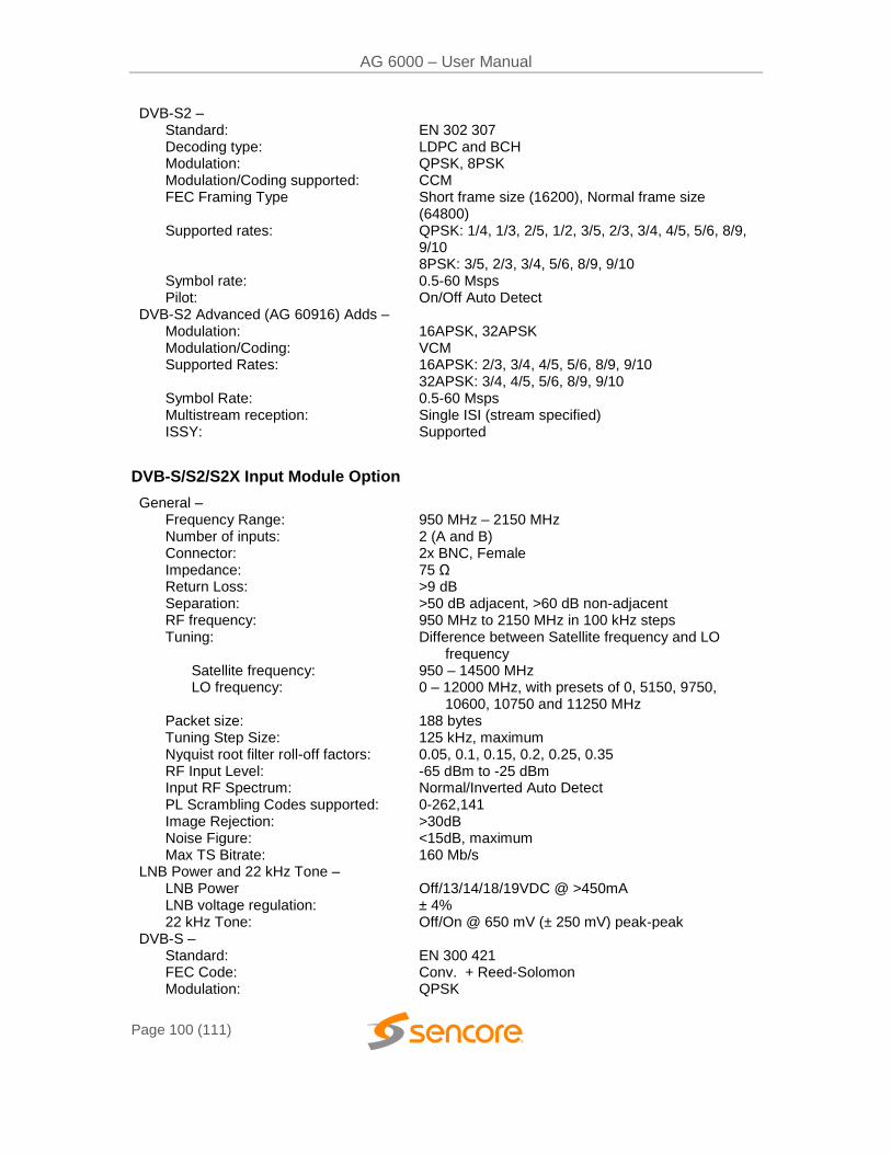
AG 6000 – User Manual
Page 100 (111)
DVB-S2 – Standard: EN 302 307 Decoding type: LDPC and BCH Modulation: QPSK, 8PSK Modulation/Coding supported: CCM FEC Framing Type Short frame size (16200), Normal frame size
(64800) Supported rates: QPSK: 1/4, 1/3, 2/5, 1/2, 3/5, 2/3, 3/4, 4/5, 5/6, 8/9,
9/10 8PSK: 3/5, 2/3, 3/4, 5/6, 8/9, 9/10
Symbol rate: 0.5-60 Msps Pilot: On/Off Auto Detect
DVB-S2 Advanced (AG 60916) Adds – Modulation: 16APSK, 32APSK Modulation/Coding: VCM Supported Rates: 16APSK: 2/3, 3/4, 4/5, 5/6, 8/9, 9/10
32APSK: 3/4, 4/5, 5/6, 8/9, 9/10 Symbol Rate: 0.5-60 Msps Multistream reception: Single ISI (stream specified) ISSY: Supported
DVB-S/S2/S2X Input Module Option
General – Frequency Range: 950 MHz – 2150 MHz Number of inputs: 2 (A and B) Connector: 2x BNC, Female Impedance: 75 Ω Return Loss: >9 dB Separation: >50 dB adjacent, >60 dB non-adjacent RF frequency: 950 MHz to 2150 MHz in 100 kHz steps Tuning: Difference between Satellite frequency and LO
frequency Satellite frequency: 950 – 14500 MHz LO frequency: 0 – 12000 MHz, with presets of 0, 5150, 9750,
10600, 10750 and 11250 MHz Packet size: 188 bytes Tuning Step Size: 125 kHz, maximum Nyquist root filter roll-off factors: 0.05, 0.1, 0.15, 0.2, 0.25, 0.35 RF Input Level: -65 dBm to -25 dBm Input RF Spectrum: Normal/Inverted Auto Detect PL Scrambling Codes supported: 0-262,141 Image Rejection: >30dB Noise Figure: Max TS Bitrate:
<15dB, maximum 160 Mb/s
LNB Power and 22 kHz Tone – LNB Power Off/13/14/18/19VDC @ >450mA LNB voltage regulation: ± 4% 22 kHz Tone: Off/On @ 650 mV (± 250 mV) peak-peak
DVB-S – Standard: EN 300 421 FEC Code: Conv. + Reed-Solomon Modulation: QPSK
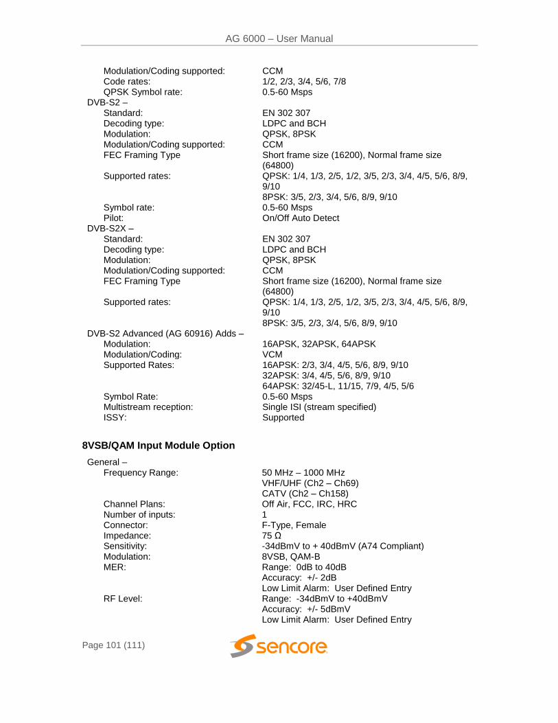
AG 6000 – User Manual
Page 101 (111)
Modulation/Coding supported: CCM Code rates: 1/2, 2/3, 3/4, 5/6, 7/8 QPSK Symbol rate: 0.5-60 Msps
DVB-S2 – Standard: EN 302 307 Decoding type: LDPC and BCH Modulation: QPSK, 8PSK Modulation/Coding supported: CCM FEC Framing Type Short frame size (16200), Normal frame size
(64800) Supported rates: QPSK: 1/4, 1/3, 2/5, 1/2, 3/5, 2/3, 3/4, 4/5, 5/6, 8/9,
9/10 8PSK: 3/5, 2/3, 3/4, 5/6, 8/9, 9/10
Symbol rate: 0.5-60 Msps Pilot: On/Off Auto Detect
DVB-S2X – Standard: EN 302 307 Decoding type: LDPC and BCH Modulation: QPSK, 8PSK Modulation/Coding supported: CCM FEC Framing Type Short frame size (16200), Normal frame size
(64800) Supported rates: QPSK: 1/4, 1/3, 2/5, 1/2, 3/5, 2/3, 3/4, 4/5, 5/6, 8/9,
9/10 8PSK: 3/5, 2/3, 3/4, 5/6, 8/9, 9/10
DVB-S2 Advanced (AG 60916) Adds – Modulation: 16APSK, 32APSK, 64APSK Modulation/Coding: VCM Supported Rates: 16APSK: 2/3, 3/4, 4/5, 5/6, 8/9, 9/10
32APSK: 3/4, 4/5, 5/6, 8/9, 9/10 64APSK: 32/45-L, 11/15, 7/9, 4/5, 5/6
Symbol Rate: 0.5-60 Msps Multistream reception: Single ISI (stream specified) ISSY: Supported
8VSB/QAM Input Module Option
General – Frequency Range: 50 MHz – 1000 MHz
VHF/UHF (Ch2 – Ch69) CATV (Ch2 – Ch158)
Channel Plans: Off Air, FCC, IRC, HRC Number of inputs: 1 Connector: F-Type, Female Impedance: 75 Ω Sensitivity: -34dBmV to + 40dBmV (A74 Compliant) Modulation: 8VSB, QAM-B MER: Range: 0dB to 40dB
Accuracy: +/- 2dB Low Limit Alarm: User Defined Entry
RF Level: Range: -34dBmV to +40dBmV Accuracy: +/- 5dBmV Low Limit Alarm: User Defined Entry
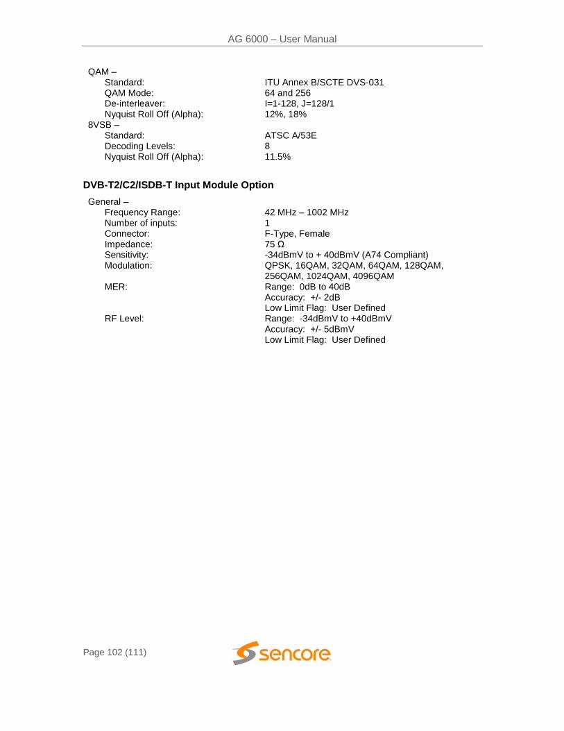
AG 6000 – User Manual
Page 102 (111)
QAM – Standard: ITU Annex B/SCTE DVS-031 QAM Mode: 64 and 256 De-interleaver: I=1-128, J=128/1 Nyquist Roll Off (Alpha): 12%, 18%
8VSB – Standard: ATSC A/53E Decoding Levels: 8 Nyquist Roll Off (Alpha): 11.5%
DVB-T2/C2/ISDB-T Input Module Option
General – Frequency Range: 42 MHz – 1002 MHz Number of inputs: 1 Connector: F-Type, Female Impedance: 75 Ω Sensitivity: -34dBmV to + 40dBmV (A74 Compliant) Modulation: QPSK, 16QAM, 32QAM, 64QAM, 128QAM,
256QAM, 1024QAM, 4096QAM MER: Range: 0dB to 40dB
Accuracy: +/- 2dB Low Limit Flag: User Defined
RF Level: Range: -34dBmV to +40dBmV Accuracy: +/- 5dBmV Low Limit Flag: User Defined
AG 6000 – User Manual
Page 103 (111)
Appendix D – AG 6000 Audio Explanation
Downmix Audio Setup
There are two primary modes of audio down mix operation for the AG 6000 receiver/decoders. These settings only affect the signal if the digital output is set to PCM. It will also affect those embedded audio channels that are set to a PCM down mix. There are no gain changes or decoding if the digital or embedded outputs are set to Pass-through. The preset modes are Monitor (the default setting) and Transmission.
The first preset, Transmission, allows no changes by the customer. Transmission is intended to provide a limited dynamic range signal to drive a set top box or a transmitter. The Transmission mode does respond to dialog normalization data. It provides a gain boost of 11 dB and has compression to prevent the signal from overdriving a modulator. The 11dB gain boost is applied to the AES digital outputs set to PCM and any embedded outputs set to PCM. It will not affect the gain of digital outputs or embedded outputs set to Pass-Through. It is intended to provide a similar audio level as a broadcast TV station signal through an RF modulator. The down mix includes the center and surrounds channels if they are present, and is represented as Lt/Rt (left total, right total).
The second preset is Monitor. It has moderate processing, no gain boost and its down mix involves left and right channels only (Lo/Ro). The mode setting is Line as the default, but may be changed to RF, Custom 0 or Custom 1. In Line mode, the Dolby Dialog Normalization data is followed along with moderate processing. The default down mix setting for Monitor is Lo/Ro. The down mix may be changed to Lt/Rt or Lt/Rt/auto. Lt/Rt auto follows the embedded data in the stream if the producer has a preferred down mix. It will switch automatically between Lo/Ro and Lt/Rt depending on the data in the stream. If no mode is specified, the down mix will be Lt/Rt. In addition, the Dual Mono modes of operation may be selected. They will only have an effect if the stream is encoded as Dual Mono. Dual Left or Dual Right applies that signal to both left and right channels of the digital service and left and right channels of any embedded stream set to PCM. Selecting RF as the compression setting will add 11 dB of gain and the same processing as the Transmission mode to the AES digital outputs set to PCM and any embedded outputs set to PCM.
There is an additional selection at the bottom of the Dolby setup pull-down menu. This allows selection between Professional Mode and Consumer Mode. In Professional Mode the built-in latency value is 32 ms for all formats. In Consumer Mode, this latency varies depending on the format. If you wish to monitor using a consumer receiver, you should choose Consumer Mode. The output sampling rate will always be 48 kHz, even in consumer. The Consumer/Pro identification bit will be set to Consumer. Normal operation in the air chain will use the Professional setting. This setting affects both Dolby Digital (AC-3) and Dolby Digital Plus.
If you want to run with no processing, choose Custom 1, Lo/Ro, and Dynamic Range disabled. This will still allow gain changes called for in the Dolby metadata via Dial-Norm settings in the stream.
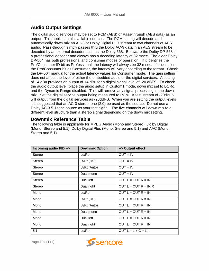
AG 6000 – User Manual
Page 104 (111)
Audio Output Settings
The digital audio services may be set to PCM (AES) or Pass-through (AES data) as an output. This applies to all available sources. The PCM setting will decode and automatically down mix an AC-3 or Dolby Digital Plus stream to two channels of AES audio. Pass-through simply passes thru the Dolby AC-3 data in an AES stream to be decoded by an external decoder such as the Dolby 568. Be aware the Dolby DP-568 is a professional decoder and always has a decoding latency of 32 msec. The older Dolby DP-564 has both professional and consumer modes of operation. If it identifies the Pro/Consumer ID bit as Professional, the latency will always be 32 msec. If it identifies the Pro/Consumer bit as Consumer, the latency will vary according to the format. Check the DP-564 manual for the actual latency values for Consumer mode. The gain setting does not affect the level of either the embedded audio or the digital services. A setting of +4 dBu provides an output of +4 dBu for a digital signal level of -20 dBFS. To check the audio output level, place the audio setup in Custom1 mode, down mix set to Lo/Ro, and the Dynamic Range disabled. This will remove any signal processing in the down mix. Set the digital service output being measured to PCM. A test stream of -20dBFS will output from the digital services as -20dBFS. When you are setting the output levels it is suggested that an AC-3 stereo tone (2.0) be used as the source. Do not use a Dolby AC-3 5.1 tone source as your test signal. The five channels will down mix to a different level structure than a stereo signal depending on the down mix setting.
Downmix Reference Table The following table is applicable for MPEG Audio (Mono and Stereo), Dolby Digital (Mono, Stereo and 5.1), Dolby Digital Plus (Mono, Stereo and 5.1) and AAC (Mono, Stereo and 5.1).
Incoming audio PID --> Downmix Option --> Output effect
Stereo Lo/Ro OUT = IN
Stereo Lt/Rt (DS) OUT = IN
Stereo Lt/Rt (Auto) OUT = IN
Stereo Dual mono OUT = IN
Stereo Dual left OUT L = OUT R = IN L
Stereo Dual right OUT L = OUT R = IN R
Mono Lo/Ro OUT L = OUT R = IN
Mono Lt/Rt (DS) OUT L = OUT R = IN
Mono Lt/Rt (Auto) OUT L = OUT R = IN
Mono Dual mono OUT L = OUT R = IN
Mono Dual left OUT L = OUT R = IN
Mono Dual right OUT L = OUT R = IN
5.1 Lo/Ro OUT L = L + C + Ls
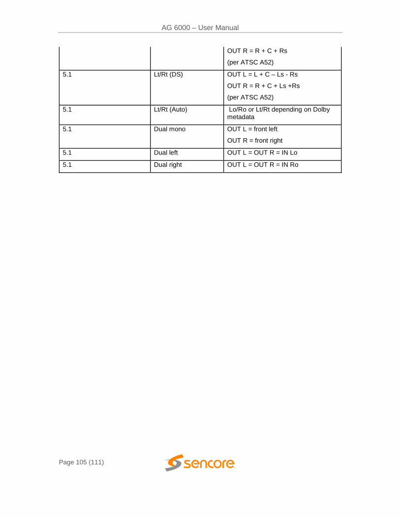
AG 6000 – User Manual
Page 105 (111)
OUT R = R + C + Rs
(per ATSC A52)
5.1 Lt/Rt (DS) OUT L = L + C – Ls - Rs
OUT R = R + C + Ls +Rs
(per ATSC A52)
5.1 Lt/Rt (Auto) Lo/Ro or Lt/Rt depending on Dolby metadata
5.1 Dual mono OUT L = front left
OUT R = front right
5.1 Dual left OUT L = OUT R = IN Lo
5.1 Dual right OUT L = OUT R = IN Ro
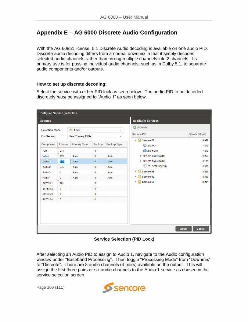
AG 6000 – User Manual
Page 106 (111)
Appendix E – AG 6000 Discrete Audio Configuration
With the AG 60851 license, 5.1 Discrete Audio decoding is available on one audio PID. Discrete audio decoding differs from a normal downmix in that it simply decodes selected audio channels rather than mixing multiple channels into 2 channels. Its primary use is for passing individual audio channels, such as in Dolby 5.1, to separate audio components and/or outputs.
How to set up discrete decoding:
Select the service with either PID lock as seen below. The audio PID to be decoded discretely must be assigned to “Audio 1” as seen below.
Service Selection (PID Lock)
After selecting an Audio PID to assign to Audio 1, navigate to the Audio configuration window under “Baseband Processing”. Then toggle “Processing Mode” from “Downmix” to “Discrete”. There are 8 audio channels (4 pairs) available on the output. This will assign the first three pairs or six audio channels to the Audio 1 service as chosen in the service selection screen.
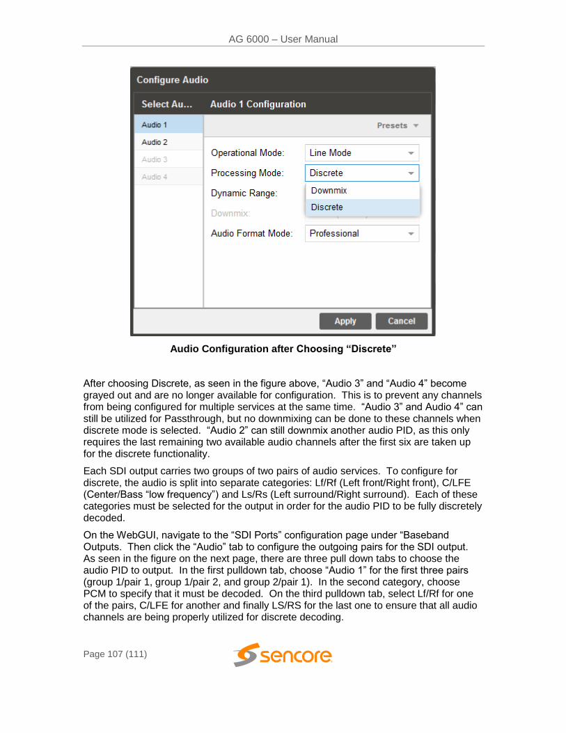
AG 6000 – User Manual
Page 107 (111)
Audio Configuration after Choosing “Discrete”
After choosing Discrete, as seen in the figure above, “Audio 3” and “Audio 4” become grayed out and are no longer available for configuration. This is to prevent any channels from being configured for multiple services at the same time. “Audio 3” and Audio 4” can still be utilized for Passthrough, but no downmixing can be done to these channels when discrete mode is selected. “Audio 2” can still downmix another audio PID, as this only requires the last remaining two available audio channels after the first six are taken up for the discrete functionality.
Each SDI output carries two groups of two pairs of audio services. To configure for discrete, the audio is split into separate categories: Lf/Rf (Left front/Right front), C/LFE (Center/Bass “low frequency”) and Ls/Rs (Left surround/Right surround). Each of these categories must be selected for the output in order for the audio PID to be fully discretely decoded.
On the WebGUI, navigate to the “SDI Ports” configuration page under “Baseband Outputs. Then click the “Audio” tab to configure the outgoing pairs for the SDI output. As seen in the figure on the next page, there are three pull down tabs to choose the audio PID to output. In the first pulldown tab, choose “Audio 1” for the first three pairs (group 1/pair 1, group 1/pair 2, and group 2/pair 1). In the second category, choose PCM to specify that it must be decoded. On the third pulldown tab, select Lf/Rf for one of the pairs, C/LFE for another and finally LS/RS for the last one to ensure that all audio channels are being properly utilized for discrete decoding.
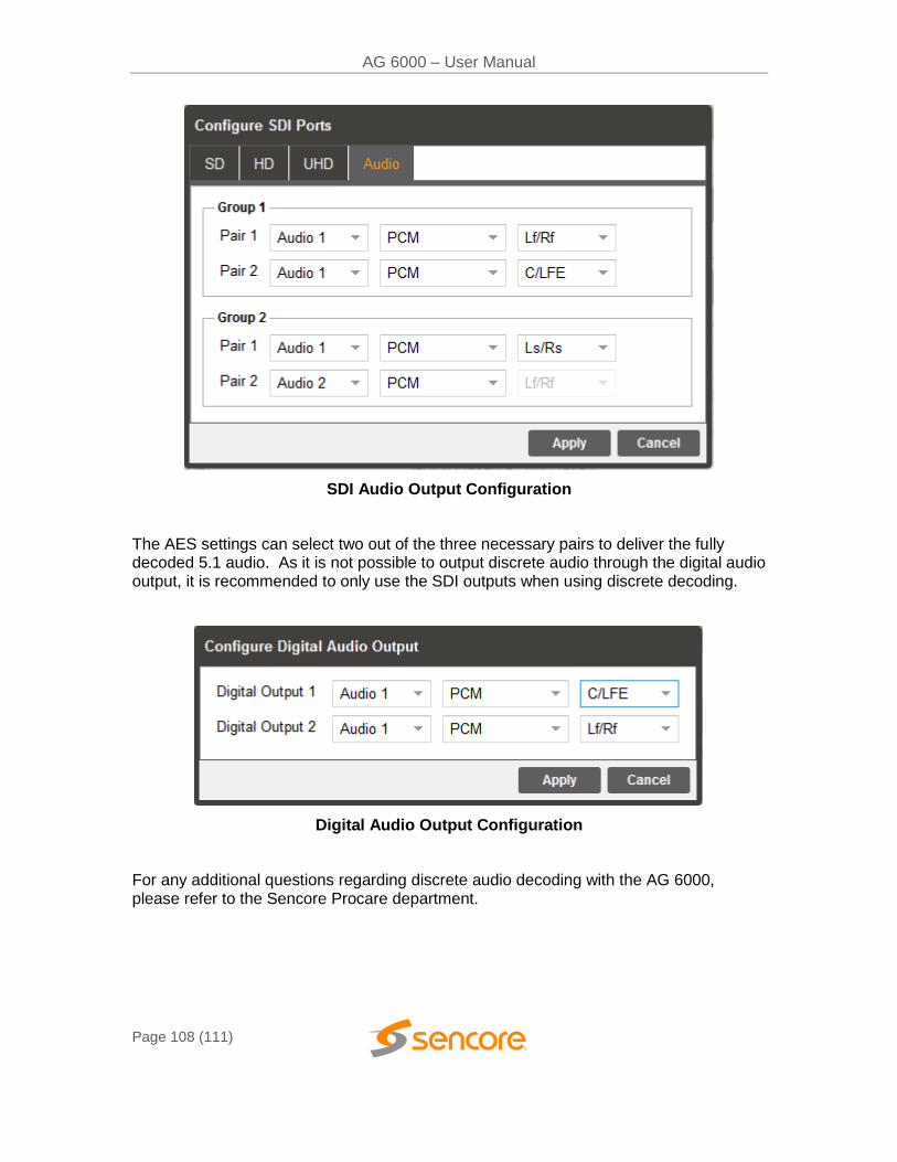
AG 6000 – User Manual
Page 108 (111)
SDI Audio Output Configuration
The AES settings can select two out of the three necessary pairs to deliver the fully decoded 5.1 audio. As it is not possible to output discrete audio through the digital audio output, it is recommended to only use the SDI outputs when using discrete decoding.
Digital Audio Output Configuration
For any additional questions regarding discrete audio decoding with the AG 6000, please refer to the Sencore Procare department.
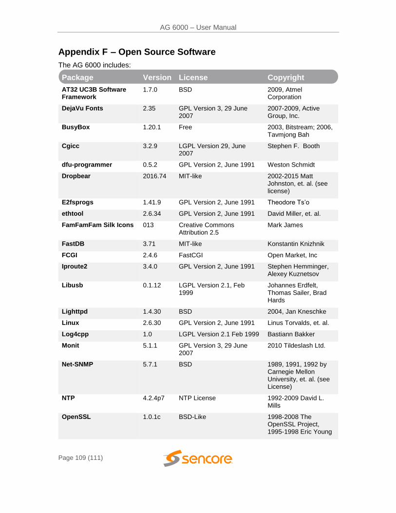
AG 6000 – User Manual
Page 109 (111)
Appendix F – Open Source Software
The AG 6000 includes:
Package Version License Copyright
AT32 UC3B Software Framework
1.7.0 BSD 2009, Atmel Corporation
DejaVu Fonts 2.35 GPL Version 3, 29 June 2007
2007-2009, Active Group, Inc.
BusyBox 1.20.1 Free 2003, Bitstream; 2006, Tavmjong Bah
Cgicc 3.2.9 LGPL Version 29, June 2007
Stephen F. Booth
dfu-programmer 0.5.2 GPL Version 2, June 1991 Weston Schmidt
Dropbear 2016.74 MIT-like 2002-2015 Matt Johnston, et. al. (see license)
E2fsprogs 1.41.9 GPL Version 2, June 1991 Theodore Ts’o
ethtool 2.6.34 GPL Version 2, June 1991 David Miller, et. al.
FamFamFam Silk Icons 013 Creative Commons Attribution 2.5
Mark James
FastDB 3.71 MIT-like Konstantin Knizhnik
FCGI 2.4.6 FastCGI Open Market, Inc
Iproute2 3.4.0 GPL Version 2, June 1991 Stephen Hemminger, Alexey Kuznetsov
Libusb 0.1.12 LGPL Version 2.1, Feb 1999
Johannes Erdfelt, Thomas Sailer, Brad Hards
Lighttpd 1.4.30 BSD 2004, Jan Kneschke
Linux 2.6.30 GPL Version 2, June 1991 Linus Torvalds, et. al.
Log4cpp 1.0 LGPL Version 2.1 Feb 1999 Bastiann Bakker
Monit 5.1.1 GPL Version 3, 29 June 2007
2010 Tildeslash Ltd.
Net-SNMP 5.7.1 BSD 1989, 1991, 1992 by Carnegie Mellon University, et. al. (see License)
NTP 4.2.4p7 NTP License 1992-2009 David L. Mills
OpenSSL 1.0.1c BSD-Like 1998-2008 The OpenSSL Project, 1995-1998 Eric Young

AG 6000 – User Manual
Page 110 (111)
OProfile 0.9.7 GPL Version 2, June 1991 John Levon, Philippe Elie, et. al.
PCRE 8.30 BSD 1997-2012 University of Cambridge et. al. (see License)
POPT 1.14 MIT 1998 Red Hat Software
qDecoder 12.0.4 BSD 2000-2012 Seungyoung Kim
Socket-CAN 1171 BSD-like, GPL Version 2, June 1991
2002-2007 Volkswagen Group Electronic Research, et. al.
Spawn-FCGI 1.6.3 BSD Jan Kneschke, Stefan Bahler
TCLAP 1.2.0 MIT 2003 Michael E Smoot
U-Boot 2009.11.1 GPL Version 2, June 1991 Wolfgang Denk, et. al.
USB-Utils 0.86 GPL Version 2, June 1991 Thomas Sailer, Johannes Erdfelt, David Brownell, Aurelien Jarno
Zlib 1.2.7 zlib/libpng License 1995-2005 Jean-loup Gailly and Mark Adler
OpenEmbedded 2011.03 MIT 2006-2009 Holger Hans Peter Freyther, et. al.
Sencore Inc.
3200 Sencore Drive
Sioux Falls, SD 57107 USA
www.sencore.com
Copyright © 2020 Sencore Inc. 1.605.978.4600
Appendix G – Warranty
Sencore One-Year Warranty
Sencore warrants this instrument against defects from any cause, except acts of God and abusive use, for a period of 1 (one) year from date of purchase. During this warranty period, Sencore will correct any covered defects without charge for parts, labor, or recalibration.
Appendix H – Support and Contact Information
Returning Products for Service or Calibration
The AG 6000 is a delicate piece of equipment and needs to be serviced and repaired by Sencore. Periodically it is necessary to return a product for repair or calibration. In order to expedite this process please carefully read the instructions below.
RMA Number
Before any product can be returned for service or calibration, an RMA number must be obtained. In order to obtain a RMA number, use the following steps:
1. Contact the Sencore service department by going online to www.sencore.com and select Support.
2. Select Service and Repair from the options given.
3. Fill in the following required information:
a. First & Last Name
b. Company
c. Email
d. Phone Number
e. Ship and Bill to Address
f. Unit Model and Serial Numbers
4. A RMA number will be emailed you shortly after completing the form with return instructions.
Shipping the Product
Once an RMA number has been issued, the unit needs to be packaged and shipped back to Sencore. It’s best to use the original box and packaging for the product but if this not available, check with the customer service representative for the proper packaging instructions.
Note: DO NOT return any power cables or accessories unless instructed to do so by the customer service representative.