digital microscope vhx-6000 user's manual 96m15258
TRANSCRIPT
Digital Microscope
VHX-6000
User’s Manual
96M15258
Read this manual before use.
Keep this manual in a safe place for future reference.
Read this manual before use.
Keep this manual in a safe place for future reference.
Introduction
This manual explains the handling and operating procedures, as well as warning information for the Digital
Microscope VHX-6000 Series (hereinafter, "VHX-6000"). To take full advantage of the features of this
microscope, read this manual thoroughly before using it. Store this manual where it can easily be
referenced by anyone using this microscope.
Symbols
In this manual, the following symbols alert you to important messages.
Be sure to read the messages.
General precautions
• No part of this manual may be reprinted in part or whole without prior written permission from KEYENCE.
• The contents of this manual are subject to change, due to improvements, without notice.
• Please direct any questions or report any errors or omissions regarding the content of this manual to
your nearest sales office listed at the end of this manual.
• KEYENCE shall replace manuals with missing pages or paging disorders.
The company names and product names used in this manual are registered trademarks or trademarks of
their respective company.
It indicates a hazardous situation which, if not avoided, will result in death or serious injury.
It indicates a hazardous situation which, if not avoided, could result in death or serious injury.
It indicates a hazardous situation which, if not avoided, could result in minor or moderate injury.
It indicates a situation which, if not avoided, could result in product damage as well as property damage.
It indicates cautions and limitations that must be followed during operation.
It indicates additional information on proper operation.
It indicates tips for better understanding or useful information.
It indicates the reference pages and items in this manual.
1
Safety information for VHX-6000 Series
96M15258
Safety information for VHX-6000 Series
Precautions for abnormalities
General Precautions
• Do not use this product for the purpose to protect a human body or a part of human body.• This product is not intended for use as explosion-proof product. Do not use this product in a hazardous
location and/or potentially explosive atmosphere.
If the equipment is used in a manner not specified by the manufacturer, the protection provided by the
equipment may be impaired.
• Check the functionality and performance of this instrument before using it.• Take any and all safety precautions prior to using the VHX-6000 to prevent potential damages should it fail.
Do not subject the VHX-6000 or any peripheral devices to sudden temperature changes which could
otherwise lead to condensation.
• KEYENCE makes no warranty against functionality or performance issues arising from usage outside the standards specified for the VHX-6000, or modifications made to the VHX-6000.
• Note that the VHX-6000 may not function correctly or may fail to fulfill performance expectations if used with other devices due to unforeseen operating conditions, environment, etc. Be sure to confirm these conditions beforehand.
• Unplug the AC power cord set if the VHX-6000 will not be used for prolonged periods.
Caution
• Be sure to turn the main power switch off when connecting cables or servicing this instrument. Failure to do so may lead to electric shock.
• Do not bend the power cable with excessive force, or place it under heavy objects. Doing so may damage the cable and cause fires and electric shock. Do not use if cable is damaged.
• Do not insert foreign objects. Doing so may result in fires, electric shock, product failure, and other hazards.
• Never remove the case cover. Touching internal parts with your hands may result in electric shock.• The power supply cord set is not provided with the VHX-6000 Series. Use the cord set, which complies
with the regulations and standards in the country or the region in which the VHX-6000 Series are used. (In North America, use the cord set, which type of cable is SVT or equivalent, 18AWG or better, rated temperature 90°C or better.)
• When installing the VHX-6000, be sure to connect the protective earthing terminal on the AC power cable to the protective earthing conductor in the building installation. Otherwise, electric shock or product damage may result.
• Do not disassemble or modify the VHX-6000. Doing so may result in fires, electric shock, product failure, and other hazards.
Potentially hazardous optical radiation is emitted from the end of the optical fiber. Do not stare at this radiation to avoid any damage to your eyes.
Shut the power off immediately in these instances. Continued use under these conditionsmay result in fires, electric shock, or product failure. Contact your nearest KEYENCE salesoffice for repair work.• When water or foreign objects enter the instrument.• When you drop the instrument or damage the case.• If you notice smoke or abnormal odor coming from the instrument.
Safety information for VHX-6000 Series
2 - Digital Microscope VHX-6000 User’s Manual -
Precautions for usage
Precautions for installation
Precautions for storage
Precautions for transportation
Other precautions
• Do not block the air vents on any of the units.• Supply the correct power voltage. Otherwise the VHX-6000 may fail.• Do not stand on the VHX-6000. Doing so may damage it.• Do not place any objects on the VHX-6000. Otherwise the VHX-6000 may fail.• Do not wipe the LCD monitor or the VHX-6000 with thinners or other organic solvents. Doing so may
damage the VHX-6000.• If the VHX-6000 becomes dirty wipe with a dry cloth.• Always turn the main power switch off before disconnecting or removing the AC power cord set, camera
unit, etc. Otherwise the VHX-6000 may fail.
To ensure correct and safe operation, the VHX-6000 must be installed in an appropriate location. Failure to observe these warnings may result in fires, electric shock, or product failure. Do not install in areas subject to:• ultraviolet rays which can cause wear on the LCD monitor, direct sunlight or strong ultraviolet rays for
prolonged periods of time.• direct vibration or shock.• ambient temperatures outside the range of 5 to 40°C.• ambient humidity outside the range of 35 to 80% (no condensation).• sharp temperature changes.• air flow from an air-conditioner vent.• volatile flammable materials and corrosive gases.• large amounts of dust, salts, irons, greasy fumes.• water, oil, and chemicals.• intense magnetic or electric fields.• large voltage fluctuations.
Avoid storing in areas subject to:• ambient temperatures outside the range of 5 to 40°C.• ambient humidity outside the range of 35 to 80% (no condensation).• direct sunlight or wind and rain.• volatile flammable materials and strong corrosive chemicals.• unstable surfaces where the microscope could fall from.
• Be sure to turn the main power switch off before disconnecting or removing cables for transporting.• Be sure to use packing material specified by KEYENCE for transporting. Otherwise the VHX-6000 may
become damaged.
• The VHX-6000 uses a hard disk drive (HDD) to store image data and measurement data.Data stored on the HDD may become lost if the VHX-6000 fails. Make a backup of the data stored on the HDD regularly. We recommend making backups immediately after acquiring important data.
• KEYENCE provides no warranty for data stored on the HDD when performing repairs.Make a backup of the data before repairing the VHX-6000.
3
Precautions on Regulations and Standards
- Digital Microscope VHX-6000 User’s Manual -
Precautions on Regulations and Standards
1 CE MarkingKeyence Corporation has confirmed that this product complies with the essential requirements of the applicable EU Directive(s), based on the following specifications. Be sure to consider the following specifications when using this
product in the Member States of European Union.
1.1 EMC Directive• Applicable Standard: EN61326-1, Class A
These specifications do not give any guarantee that the end-product with this product incorporated complies with
the essential requirements of EMC Directive. The manufacturer of the end-product is solely responsible for the compliance on the end-product itself according to EMC Directive.
1.2 Machinery Directive
• Applicable standard: EN ISO12100 EN61010-1
EN62471, Risk group 3
• Overvoltage category II• Use this product under pollution degree 2.
• Indoor use only.
• Use this product at the altitude of 2000 m or less.
• This product is designed as a Class I equipment. Be sure to connect the protective earthing terminal on the AC power cable to the protective earthing conductor in the building installation.
• The Appliance inlet is designed as a disconnecting device. Install this product so that the AC power cable can
be removed immediately from the appliance inlet when an abnormality occurs.
2 CSA CertificateThis product complies with the following CSA and UL standards and has been certified by CSA.
• Applicable standard CAN/CSA C22.2 No.61010-1
UL61010-1
Be sure to consider the following specifications when using this product as a product certified by CSA.
• Overvoltage category II
• Use this product under pollution degree 2.
• Indoor use only.
• Use this product at the altitude of 2000 m or less.
• This product is designed as a Class I equipment. Be sure to connect the protective earthing terminal on the AC
power cable to the protective earthing conductor in the building installation.
• The Appliance inlet is designed as a disconnecting device. Install this product so that the AC power cable can
be removed immediately from the appliance inlet when an abnormality occurs.
3 Best Management Practice for Perchlorate Materials - California onlyThis product uses components containing perchlorate material. When you ship this product or your end-product
installing this product to California, you must label or mark the following statement on the exterior of all outer shipping packages and on consumer packages or you must include the following statement in an instruction manual or MSDS
accompanied with the product.
“Perchlorate Material - special handling may apply, See
www.dtsc.ca.gov/hazardouswaste/perchlorate.”
Precautions on Regulations and Standards
4 - Digital Microscope VHX-6000 User’s Manual -
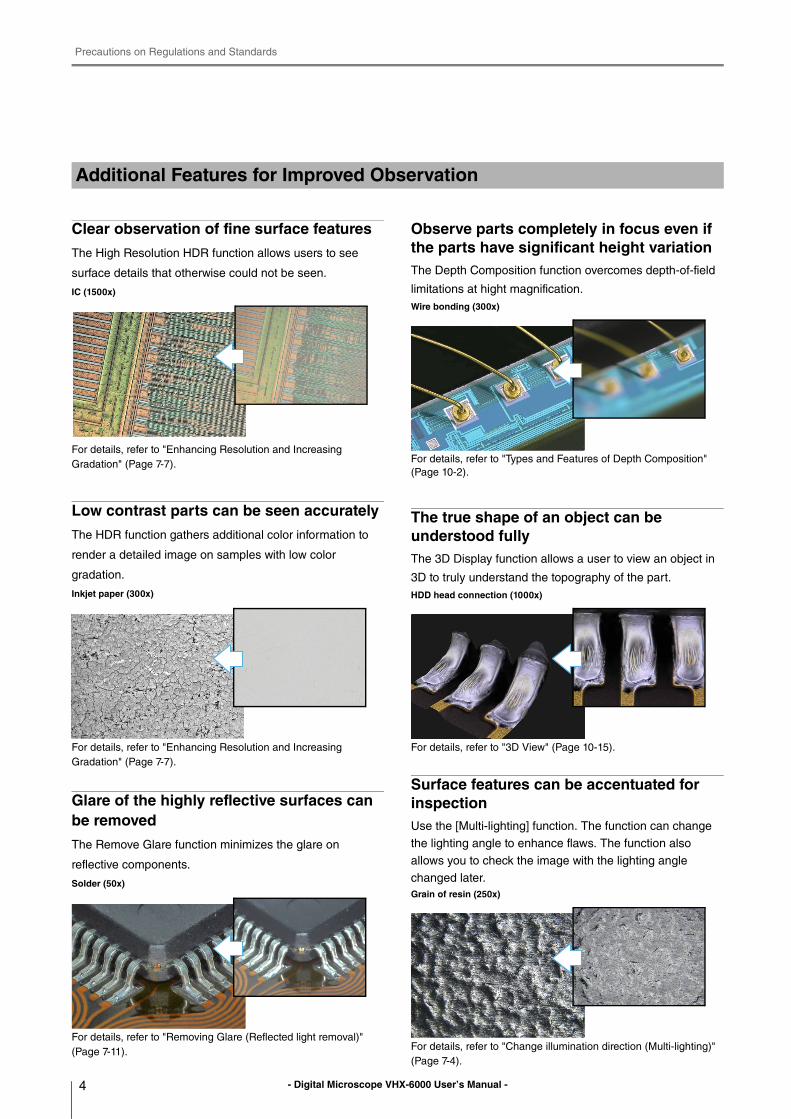
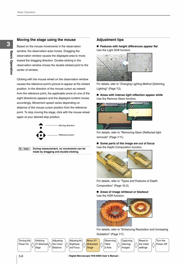
Clear observation of fine surface features
The High Resolution HDR function allows users to see
surface details that otherwise could not be seen.
IC (1500x)
For details, refer to "Enhancing Resolution and Increasing
Gradation" (Page 7-7).
Low contrast parts can be seen accurately
The HDR function gathers additional color information to
render a detailed image on samples with low color
gradation.
Inkjet paper (300x)
For details, refer to "Enhancing Resolution and Increasing
Gradation" (Page 7-7).
Glare of the highly reflective surfaces can be removed
The Remove Glare function minimizes the glare on
reflective components.
Solder (50x)
For details, refer to "Removing Glare (Reflected light removal)"
(Page 7-11).
Observe parts completely in focus even if the parts have significant height variationThe Depth Composition function overcomes depth-of-field
limitations at hight magnification.
Wire bonding (300x)
For details, refer to "Types and Features of Depth Composition"
(Page 10-2).
The true shape of an object can be understood fullyThe 3D Display function allows a user to view an object in
3D to truly understand the topography of the part.
HDD head connection (1000x)
For details, refer to "3D View" (Page 10-15).
Surface features can be accentuated for inspectionUse the [Multi-lighting] function. The function can change
the lighting angle to enhance flaws. The function also
allows you to check the image with the lighting angle
changed later.
Grain of resin (250x)
For details, refer to "Change illumination direction (Multi-lighting)"
(Page 7-4).
Additional Features for Improved Observation
Precautions on Regulations and Standards
5- Digital Microscope VHX-6000 User’s Manual -
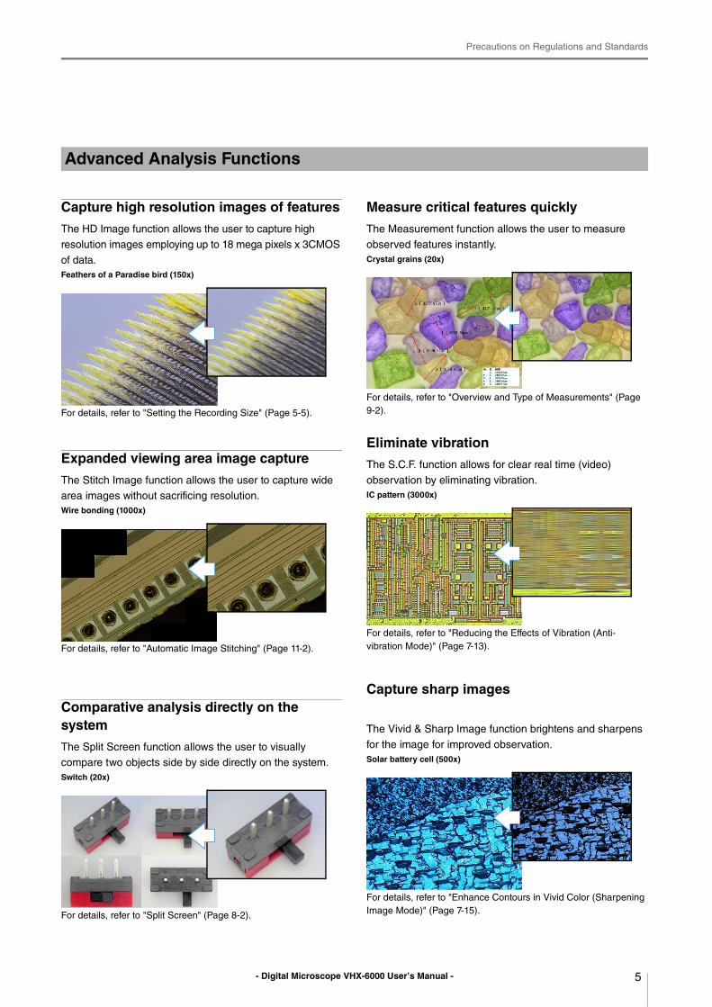
Capture high resolution images of features
The HD Image function allows the user to capture high
resolution images employing up to 18 mega pixels x 3CMOS
of data.
Feathers of a Paradise bird (150x)
For details, refer to "Setting the Recording Size" (Page 5-5).
Expanded viewing area image capture
The Stitch Image function allows the user to capture wide
area images without sacrificing resolution.
Wire bonding (1000x)
For details, refer to "Automatic Image Stitching" (Page 11-2).
Comparative analysis directly on the system
The Split Screen function allows the user to visually
compare two objects side by side directly on the system.
Switch (20x)
For details, refer to "Split Screen" (Page 8-2).
Measure critical features quickly
The Measurement function allows the user to measure
observed features instantly.
Crystal grains (20x)
For details, refer to "Overview and Type of Measurements" (Page
9-2).
Eliminate vibration
The S.C.F. function allows for clear real time (video)
observation by eliminating vibration.
IC pattern (3000x)
For details, refer to "Reducing the Effects of Vibration (Anti-
vibration Mode)" (Page 7-13).
Capture sharp images
The Vivid & Sharp Image function brightens and sharpens
for the image for improved observation.
Solar battery cell (500x)
For details, refer to "Enhance Contours in Vivid Color (Sharpening
Image Mode)" (Page 7-15).
Advanced Analysis Functions
Precautions on Regulations and Standards
6 - Digital Microscope VHX-6000 User’s Manual -
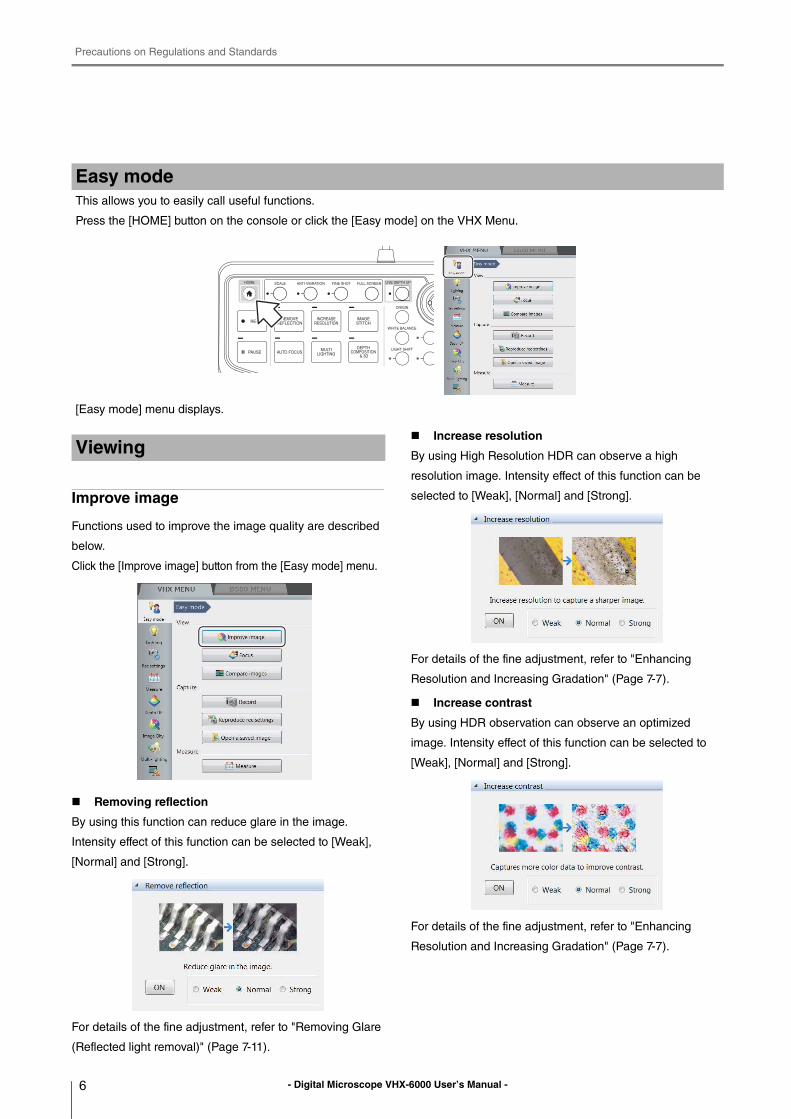
Improve image
Functions used to improve the image quality are described
below.
Click the [Improve image] button from the [Easy mode] menu.
Removing reflection
By using this function can reduce glare in the image.
Intensity effect of this function can be selected to [Weak],
[Normal] and [Strong].
For details of the fine adjustment, refer to "Removing Glare
(Reflected light removal)" (Page 7-11).
Increase resolution
By using High Resolution HDR can observe a high
resolution image. Intensity effect of this function can be
selected to [Weak], [Normal] and [Strong].
For details of the fine adjustment, refer to "Enhancing
Resolution and Increasing Gradation" (Page 7-7).
Increase contrast
By using HDR observation can observe an optimized
image. Intensity effect of this function can be selected to
[Weak], [Normal] and [Strong].
For details of the fine adjustment, refer to "Enhancing
Resolution and Increasing Gradation" (Page 7-7).
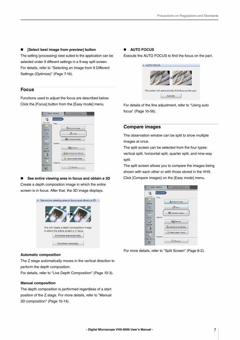
Easy modeThis allows you to easily call useful functions.
Press the [HOME] button on the console or click the [Easy mode] on the VHX Menu.
[Easy mode] menu displays.
Viewing
Precautions on Regulations and Standards
7- Digital Microscope VHX-6000 User’s Manual -
[Select best image from preview] button
The setting (processing) best suited to the application can be
selected under 9 different settings in a 9-way split screen.
For details, refer to "Selecting an Image from 9 Different
Settings (Optimize)" (Page 7-16).
Focus
Functions used to adjust the focus are described below.
Click the [Focus] button from the [Easy mode] menu.
See entire viewing area in focus and obtain a 3D
Create a depth composition image in which the entire
screen is in focus. After that, the 3D image displays.
Automatic composition
The Z stage automatically moves in the vertical direction to
perform the depth composition.
For details, refer to "Live Depth Composition" (Page 10-3).
Manual composition
The depth composition is performed regardless of a start
position of the Z stage. For more details, refer to "Manual
3D composition" (Page 10-14).
AUTO FOCUS
Execute the AUTO FOCUS to find the focus on the part.
For details of the fine adjustment, refer to "Using auto
focus" (Page 10-56).
Compare images
The observation window can be split to show multiple
images at once.
The split screen can be selected from the four types:
vertical split, horizontal split, quarter split, and nine-way
split.
The split screen allows you to compare the images being
shown with each other or with those stored in the VHX.
Click [Compare images] on the [Easy mode] menu.
For more details, refer to "Split Screen" (Page 8-2).
Precautions on Regulations and Standards
8 - Digital Microscope VHX-6000 User’s Manual -
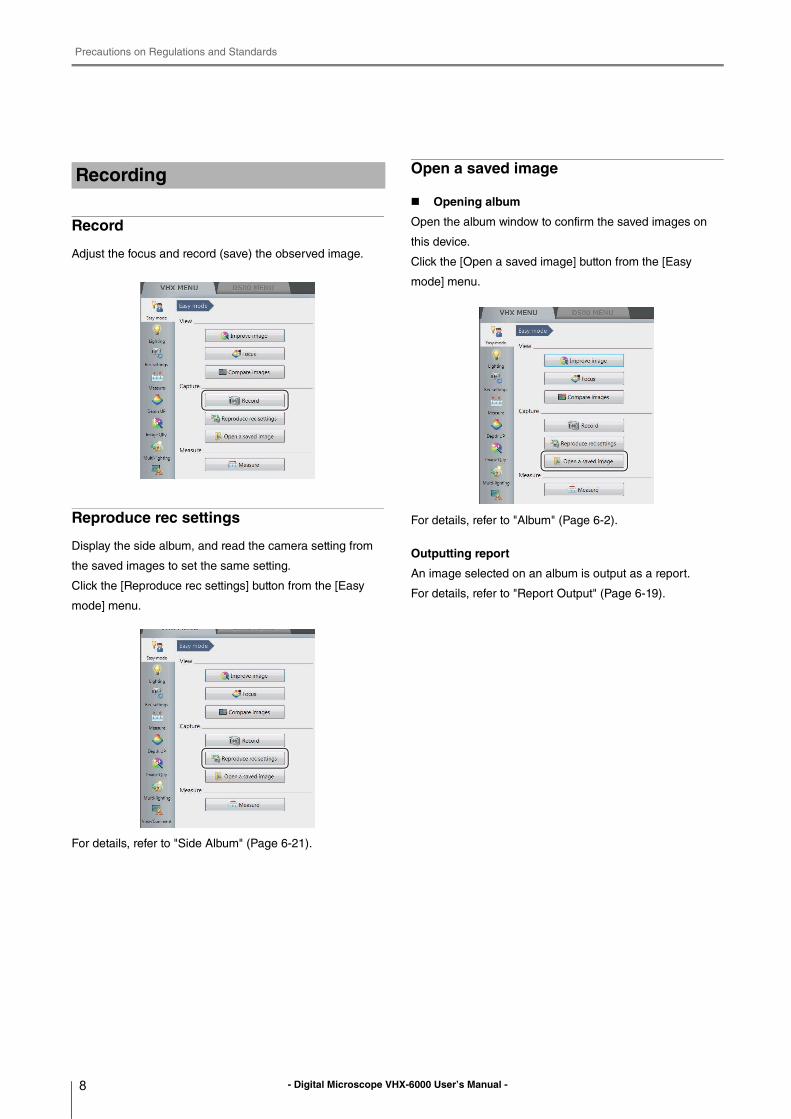
Record
Adjust the focus and record (save) the observed image.
Reproduce rec settings
Display the side album, and read the camera setting from
the saved images to set the same setting.
Click the [Reproduce rec settings] button from the [Easy
mode] menu.
For details, refer to "Side Album" (Page 6-21).
Open a saved image
Opening album
Open the album window to confirm the saved images on
this device.
Click the [Open a saved image] button from the [Easy
mode] menu.
For details, refer to "Album" (Page 6-2).
Outputting report
An image selected on an album is output as a report.
For details, refer to "Report Output" (Page 6-19).
Recording
Precautions on Regulations and Standards
9- Digital Microscope VHX-6000 User’s Manual -
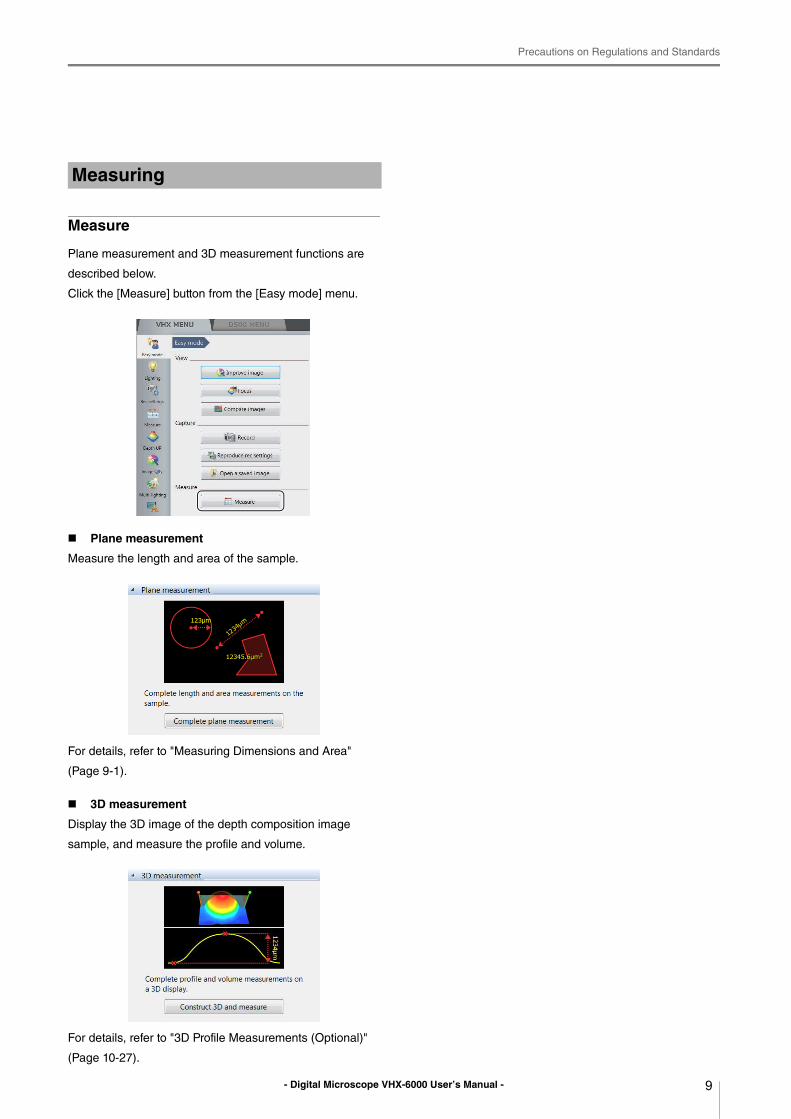
Measure
Plane measurement and 3D measurement functions are
described below.
Click the [Measure] button from the [Easy mode] menu.
Plane measurement
Measure the length and area of the sample.
For details, refer to "Measuring Dimensions and Area"
(Page 9-1).
3D measurement
Display the 3D image of the depth composition image
sample, and measure the profile and volume.
For details, refer to "3D Profile Measurements (Optional)"
(Page 10-27).
Measuring
Contents
10 - Digital Microscope VHX-6000 User’s Manual -
Contents
Introduction ........................................................2
Safety information for VHX-6000 Series ............1
General Precautions .....................................1
Caution ..........................................................1
Precautions on Regulations and Standards .......3
Additional Features for Improved
Observation .............................................4
Advanced Analysis Functions .......................5
Easy mode ....................................................6
Viewing .........................................................6
Recording ......................................................8
Measuring .....................................................9
Contents ...........................................................10
Chapter 1 Before Using the VHX-
6000
Checking the Package Contents .................... 1-2
Contents .................................................... 1-2
Camera Units ............................................ 1-3
Options ...................................................... 1-3
Part Names and Functions ............................ 1-6
Main Unit (VHX-6000) ............................... 1-6
Camera Unit (VHX-6100/6020) ................. 1-8
Console ..................................................... 1-8
Viewing the Screen ...................................... 1-10
Observation Window ............................... 1-10
VHX MENU ............................................. 1-11
Operation Area ........................................ 1-13
Information View ..................................... 1-13
Direct Buttons ......................................... 1-13
Chapter 2 Installation/Connection
Installation/Connection ................................... 2-2
System Configuration and Connection
Flow ..................................................... 2-2
Installing the VHX-6000 ............................ 2-3
Connecting the Camera Unit ..................... 2-3
Connecting the Console, Mouse, etc. ....... 2-5
Connecting Power ..................................... 2-5
Installing the VHX-S650
Free-angle Observation Base Unit ...... 2-6
Mounting and Removing the Lens ............ 2-7
Connecting the Lens/Stage Cable ............ 2-8
Chapter 3 Basic Operation
Basic Operation .............................................. 3-2
Turning the Microscope Power On ............ 3-2
Initializing XY Motorized Stage ................. 3-3
Adjusting the Color Balance
(White Balance) ................................... 3-3
Adjusting the Brightness and Focus .......... 3-4
Moving XY Stage Automatically ................ 3-5
Observing Tilted Z-Axis ............................. 3-7
Capturing (Saving) Images ....................... 3-8
Reset to the initial settings ........................ 3-8
Shutting Down the Microscope ................. 3-9
Advanced Operations .............................. 3-10
Chapter 4 Advanced Camera Settings
Adjusting the Lighting ..................................... 4-2
Using the LIGHT Button on the Console ... 4-2
Adjusting with [Lighting] of the
VHX MENU .......................................... 4-2
Adjusting Image Brightness ........................... 4-3
Adjusting with the Brightness Dial on the
Console ................................................ 4-3
Adjusting the Shutter Speed using
[Lighting] from the VHX MENU ............ 4-3
Adjusting the Gain using [Lighting] from the
VHX MENU .......................................... 4-4
Adjusting the White Balance .......................... 4-5
Adjusting the White Balance on the
Console ................................................ 4-5
Adjusting the White Balance using the
Camera Settings from the
VHX MENU .......................................... 4-5
Contents
11- Digital Microscope VHX-6000 User’s Manual -
Chapter 5 Recording (Saving) Images
Recording/Saving Still Images ....................... 5-2
Recording (Saving) from the Console ....... 5-2
Recording (Saving) using the
Direct Buttons ...................................... 5-2
Names and Functions on the Rec
Dialog Box ........................................... 5-3
Rec Settings ................................................... 5-5
Setting the Recording Size ....................... 5-5
Setting Auto Rec ....................................... 5-6
Loading Recording Settings ...................... 5-7
Setting up Timer Recording ...................... 5-8
Wide-view ...................................................... 5-9
Observing in Wide-view ............................ 5-9
Recording and Saving Videos ...................... 5-10
Names and Functions on the
[Record video] Dialog Box ................. 5-11
Chapter 6 Playing and Editing Images
Album ............................................................. 6-2
Names and Functions ............................... 6-2
Playing Files .............................................. 6-6
Displaying and Entering Properties ......... 6-10
Depth Up ................................................. 6-11
Creating Color Composition Images ....... 6-12
Searching Files ....................................... 6-14
Changing the View of the
Files Window ..................................... 6-15
Options .................................................... 6-16
Explorer ................................................... 6-18
Report Output ......................................... 6-19
Measurement Result Summary .............. 6-20
Side Album ................................................... 6-21
Launching the Side Album ...................... 6-21
Names and Functions ............................. 6-21
Playing Images ....................................... 6-22
Chapter 7 Improving Images
Changing Lighting Method
(Switching Lighting) ................................... 7-2
Changing the Lighting Method .................. 7-2
Change illumination direction
(Multi-lighting) ............................................ 7-4
Multi-lighting .............................................. 7-4
Start multi-lighting ..................................... 7-4
Checking results ........................................ 7-6
Enhancing Resolution and Increasing
Gradation .................................................. 7-7
About HDR ................................................ 7-7
About high resolution HDR ........................ 7-7
About high resolution Observation ............ 7-7
HDR Settings ............................................ 7-8
High resolution HDR Observation
Settings ................................................ 7-9
High resolution Observation Settings ...... 7-10
Removing Glare (Reflected light removal) ... 7-11
Glare removal .......................................... 7-11
Ring removal ........................................... 7-11
Remove Reflection Settings .................... 7-11
Adjusting reflected light removal ............. 7-12
Reducing the Effects of Vibration
(Anti-vibration Mode) ............................... 7-13
Anti-vibration mode Settings ................... 7-13
Record fine images (Fine shot) .................... 7-14
Fine shot Settings ................................... 7-14
Enhance Contours in Vivid Color
(Sharpening Image Mode) ...................... 7-15
Sharpening Image Mode Settings ........... 7-15
Selecting an Image from 9 Different
Settings (Optimize) .................................. 7-16
Selecting the Best Image ........................ 7-16
Image Settings ............................................. 7-18
Image Setting Procedures ....................... 7-18
Contents
12 - Digital Microscope VHX-6000 User’s Manual -
Chapter 8 Setting Image Views
Split Screen .................................................... 8-2
Types of Split Screens .............................. 8-2
Using the Split Screen .............................. 8-3
Comparing Two Images ............................ 8-3
Full Screen Image/Vision Correction Mode ... 8-4
Full Screen Image ..................................... 8-4
Vision correction mode ............................. 8-4
Enlarging the Image (Digital Zoom) ............... 8-5
Navigation ...................................................... 8-6
Creating Navigation .................................. 8-6
Specifying Observation Position on
Navigation Image ................................. 8-7
Moving vertically and horizontally ............. 8-7
Registering a Stage Position ..................... 8-7
Recording registered positions in batch .... 8-8
Chapter 9 Measuring Dimensions and
Area
Overview and Type of Measurements ........... 9-2
Measurement Types ................................. 9-2
Preparing to Measure .................................... 9-5
Lens Setting .............................................. 9-5
Calibration ................................................. 9-6
Main Measurements .................................... 9-12
Measuring Procedures ............................ 9-12
Measurement Items ................................ 9-12
Measuring High Definition Images .......... 9-18
Moving and Editing the Measurement
Point ................................................... 9-19
Auxiliary Functions .................................. 9-19
XY Measurement and Display ................ 9-20
Assist Tools ............................................. 9-21
Reference Lines ...................................... 9-22
Display Settings ...................................... 9-23
Area Measurements ..................................... 9-26
Measuring Procedures ............................ 9-26
Measurement Items ................................ 9-27
Displaying Text and Markers ....................... 9-34
List of Comments .................................... 9-34
Entering and Specifying Comment Text
and Markers ....................................... 9-35
Normal Comments .................................. 9-35
Entering and Setting Residual
Comments .......................................... 9-38
Hiding Comments .................................... 9-39
Delete All ................................................. 9-39
Displaying a Scale ........................................ 9-40
One-Click Automatic Measurement ............. 9-41
Creating a New Template ....................... 9-41
Template Recalling ................................. 9-42
Click measurement ................................. 9-44
Auto-measurement .................................. 9-45
Automatic Area Measurements .................... 9-46
Measurement Mode Selection ................ 9-46
Measurement Area Extraction ................. 9-47
Form the extracted area .......................... 9-52
Display Measurement Results ................ 9-57
Grain size analysis .................................. 9-62
Measurement Recreation ........................ 9-64
Display Settings ...................................... 9-65
Contamination analysis ................................ 9-67
Specifying an area .................................. 9-67
Setting extraction parameters ................. 9-68
Confirm results ........................................ 9-70
Display Settings ...................................... 9-72
Saving results .......................................... 9-72
Contamination analysis according to
VDA .................................................... 9-73
Maximum Area Measurement ...................... 9-76
Measurement Area Specification ............ 9-76
Perform Measurements ........................... 9-77
Display Settings ...................................... 9-78
XY Stage Measurement (Optional) .............. 9-79
Installation and Connections ................... 9-79
Preparing to Measure .............................. 9-79
XY Stage Measurement Procedures ....... 9-80
XY Stage Measurement Menu ................ 9-81
Specify Coordinates ................................ 9-82
Measuring with the XY Stage .................. 9-86
Option Settings ........................................ 9-97
Contents
13- Digital Microscope VHX-6000 User’s Manual -
Chapter 10 Observing in 3D
Types and Features of Depth
Composition ............................................ 10-2
Live Depth Composition .......................... 10-2
Quick Composition and 3D ..................... 10-2
Fine Depth Composition ......................... 10-2
Manual 3D composition .......................... 10-2
Using Depth Composition ............................ 10-3
Live Depth Composition .......................... 10-3
Quick Composition and 3D ..................... 10-4
Fine Depth Composition ......................... 10-9
Manual 3D composition ........................ 10-14
3D View ...................................................... 10-15
Playing Back and Saving 3D Images .... 10-15
Manipulating the 3D View ..................... 10-16
Using Height/Fix Z/Rotation Guide in
3D View ........................................... 10-17
Display Settings .................................... 10-17
Show Crop/Detail .................................. 10-18
Shape correction ................................... 10-19
3D File Comparison View .......................... 10-21
Displaying 2 Files to Compare .............. 10-21
Linking the 2nd Image ........................... 10-21
Differential View .................................... 10-22
Switching Sub Images .......................... 10-23
Lighting Simulations ................................... 10-24
Point height (optional) ................................ 10-25
Measuring height and distance easily ... 10-25
Measuring heights of specified points ... 10-25
Other measurement tools ..................... 10-26
Display Settings .................................... 10-26
3D Profile Measurements (Optional) .......... 10-27
Names and Functions in the Window ... 10-27
Starting Profile Measurements .............. 10-29
Setting Profile Line ................................ 10-30
Setting Measurement Intervals ............. 10-35
2 line comparison .................................. 10-40
Roughness Measurement(optional) ........... 10-42
Line roughness measurement .............. 10-42
What is Surface Roughness ................. 10-45
Surface texture parameter definitions ... 10-47
Surface roughness measurement ......... 10-50
Surface Roughness Definitions ............. 10-52
Volume Measurement (Option) .................. 10-55
Z Stage Control .......................................... 10-56
Adjusting Focus from the
VHX MENU ...................................... 10-56
Measuring the Height between
2 Points ............................................ 10-57
Chapter 11 Stitching Images
Automatic Image Stitching ........................... 11-2
Stitching 2D Images Automatically .......... 11-2
Stitching 3D Images Automatically .......... 11-5
Manual Image Stitching ................................ 11-8
Stitching 2D Images ................................ 11-8
Stitching 3D Images ................................ 11-9
Split recording ............................................ 11-12
Splitting and saving original image
before stitching ................................. 11-12
Chapter 12 Printing and Saving to a
CD/DVD
Printers ......................................................... 12-2
Connecting the Printer ............................ 12-2
Print Settings ........................................... 12-2
Printing .................................................... 12-3
Page Setup ............................................. 12-3
Saving to a CD/DVD .................................... 12-4
Formatting a CD/DVD ............................. 12-4
Writing Procedures .................................. 12-5
Contents
14 - Digital Microscope VHX-6000 User’s Manual -
Chapter 13 Configuring the Operating
Environment
Settings ........................................................ 13-2
Displaying the Settings Menu ................. 13-2
Network/Security Settings ....................... 13-2
Lens Settings ........................................ 13-14
Calibration Setup ............................... 13-14
User Setup ............................................ 13-14
Show Software Keyboard ..................... 13-16
System Initialization .............................. 13-16
Initializing Automatic XY Stage ............. 13-17
Camera mount settings ......................... 13-17
ZST vision misalignment correction ...... 13-18
Optical axis misalignment correction .... 13-20
D500 Maintenance ................................ 13-22
Options .................................................. 13-22
Version Info ........................................... 13-24
Chapter 14 Connecting to an External
PC
LAN Connection ........................................... 14-2
Overview of LAN Connection .................. 14-2
Operating Environment of the PC ........... 14-2
Flow of Preparations ............................... 14-2
PC Connection and Settings ................... 14-3
VHX-6000 Communication Software ........... 14-4
Overview of Functions ............................ 14-4
Installing the Communication Software ... 14-4
Uninstalling the Communication
Software ............................................. 14-5
Starting the VHX-6000 Communication
Software ............................................. 14-5
Names and Functions on the Window .... 14-6
Playing Images ....................................... 14-8
Measuring 2D images ........................... 14-15
Preview ................................................. 14-16
Saving ................................................... 14-17
Edit ........................................................ 14-17
View ...................................................... 14-18
Option ................................................... 14-18
Extracting CSV data .............................. 14-19
Measurement Data Tabulation .............. 14-19
FTP Server Function .................................. 14-21
Connecting using Internet Explorer ....... 14-21
File Sharing Function ................................. 14-23
Using Internet Explorer to Connect ....... 14-23
Appendix
List of Necessary Authentication Information and
Default Settings .........................................A-2
Replacing the Fuse ........................................A-3
REMOTE Connector (Capture/Pause) ...........A-4
Using the REMOTE Connector to
Capture ................................................A-4
Using the REMOTE Connector to
Pause and Release Images .................A-4
External Dimensions ......................................A-5
VHX-6000 Controller .................................A-5
VHX-6100/6020 Camera Unit ...................A-5
Specifications .................................................A-6
Specifications (Basic Performance) ..........A-6
Specifications (Various Functions) ............A-8
Specifications (Detailed Modules) ...........A-10
Software Usage Agreement .........................A-11
Usage Agreement for Operation Software ...A-12
Before asking repair and inspection .............A-17
Revision History ...........................................A-18
- Digital Microscope VHX-6000 User’s Manual - 1-1
Chapter1 Befo
re Usin
g th
e VH
X-6000
1
Before Using the VHX-6000
Package Contents and Product Overview
Checking the Package Contents ............................ Page 1-2
Contents............................................................. Page 1-2
Camera Units ..................................................... Page 1-3
Options............................................................... Page 1-3
Part Names and Functions..................................... Page 1-6
Main Unit (VHX-6000)........................................ Page 1-6
Camera Unit (VHX-6100/6020) .......................... Page 1-8
Console.............................................................. Page 1-8
Viewing the Screen .............................................. Page 1-10
Observation Window........................................ Page 1-10
VHX MENU .......................................................Page 1-11
Operation Area................................................. Page 1-13
Information View .............................................. Page 1-13
Direct Buttons................................................... Page 1-13
- Digital Microscope VHX-6000 User’s Manual -
Checking the Package Contents
1-2
Befo
re Usin
g th
e VH
X-6000
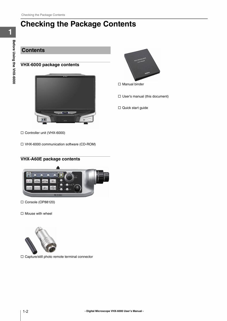
1Checking the Package Contents
VHX-6000 package contents
Controller unit (VHX-6000)
VHX-6000 communication software (CD-ROM)
VHX-A60E package contents
Console (OP88120)
Mouse with wheel
Capture/still photo remote terminal connector
Manual binder
User's manual (this document)
Quick start guide
Contents

- Digital Microscope VHX-6000 User’s Manual -
Checking the Package Contents
1-3
Befo
re Usin
g th
e VH
X-6000
1
Camera unit VHX-6100
Camera unit VHX-6020
RZ lens
High-performance low-magnification zoom lens
VH-Z00R/VH-Z00W/VH-Z00T 0x to 50x
Ultra-small compact high-performance zoom lens
VH-Z20R/VH-Z20W/VH-Z20T 20x to 200x
Universal zoom lens
VH-Z20UR/VH-Z20UW/VH-Z20UT 20x to 200x
Wide-range zoom lens
VH-Z100R/VH-Z100W/VH-Z100T 100x to 1000x
Universal zoom lens
VH-Z100UR/VH-Z100UW/VH-Z100UT 100x to 1000x
Camera Units Options
- Digital Microscope VHX-6000 User’s Manual -
Checking the Package Contents
1-4
Befo
re Usin
g th
e VH
X-6000
1
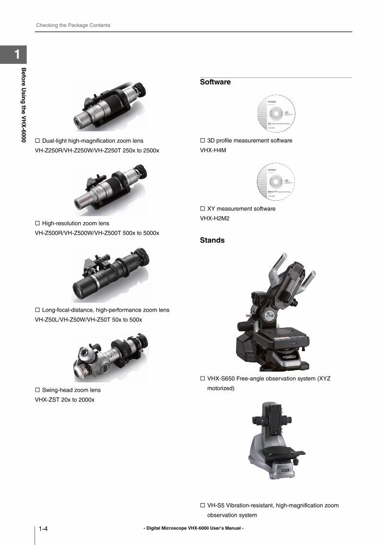
Dual-light high-magnification zoom lens
VH-Z250R/VH-Z250W/VH-Z250T 250x to 2500x
High-resolution zoom lens
VH-Z500R/VH-Z500W/VH-Z500T 500x to 5000x
Long-focal-distance, high-performance zoom lens
VH-Z50L/VH-Z50W/VH-Z50T 50x to 500x
Swing-head zoom lens
VHX-ZST 20x to 2000x
Software
3D profile measurement software
VHX-H4M
XY measurement software
VHX-H2M2
Stands
VHX-S650 Free-angle observation system (XYZ
motorized)
VH-S5 Vibration-resistant, high-magnification zoom
observation system
- Digital Microscope VHX-6000 User’s Manual -
Checking the Package Contents
1-5
Befo
re Usin
g th
e VH
X-6000
1
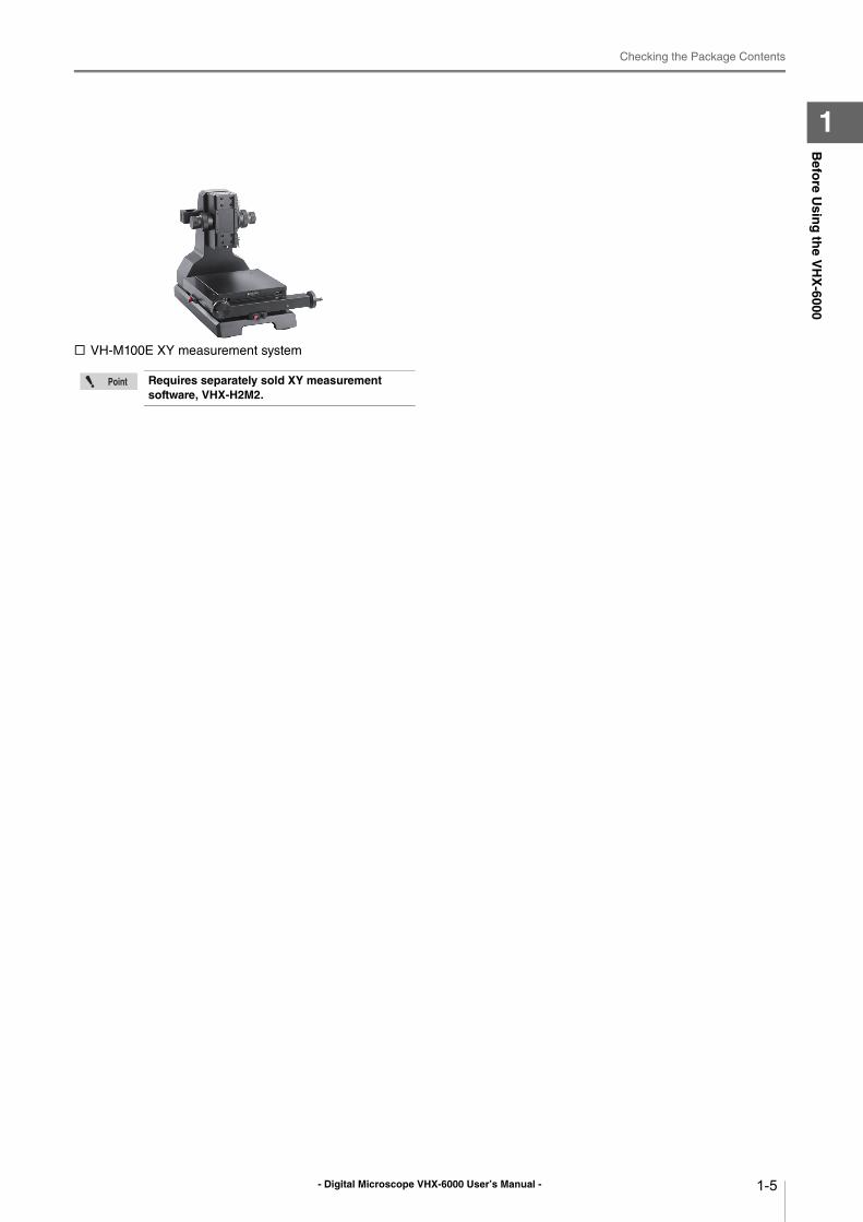
VH-M100E XY measurement system
Requires separately sold XY measurement software, VHX-H2M2.
- Digital Microscope VHX-6000 User’s Manual -
Part Names and Functions
1-6
Befo
re Usin
g th
e VH
X-6000
1Part Names and Functions
The names and functions of each part are explained below.
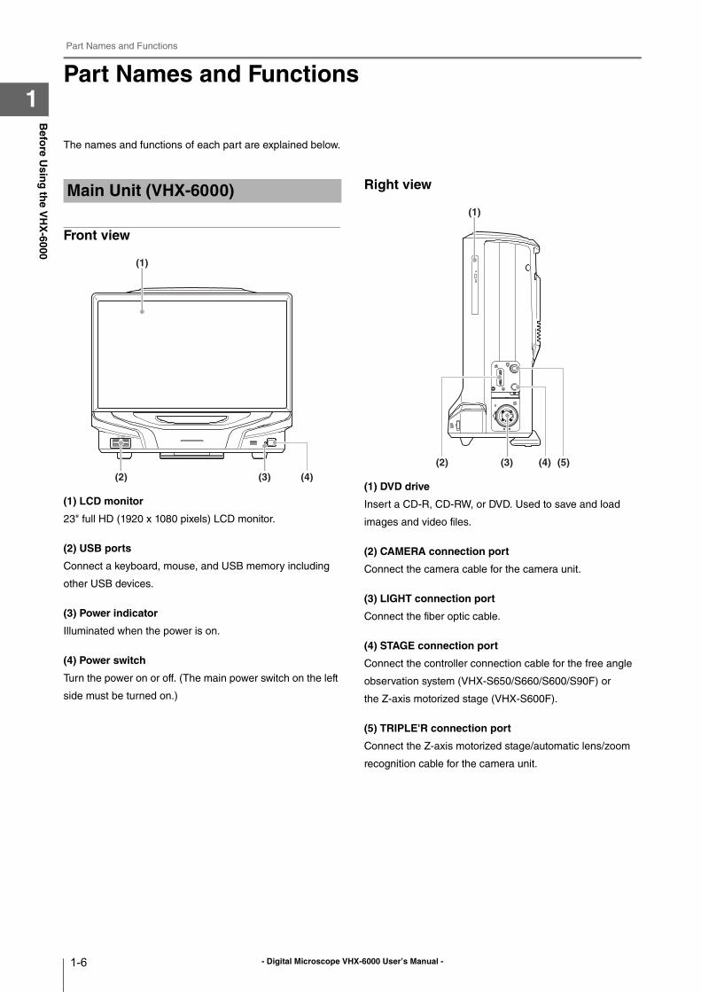
Front view
(1) LCD monitor
23" full HD (1920 x 1080 pixels) LCD monitor.
(2) USB ports
Connect a keyboard, mouse, and USB memory including
other USB devices.
(3) Power indicator
Illuminated when the power is on.
(4) Power switch
Turn the power on or off. (The main power switch on the left
side must be turned on.)
Right view
(1) DVD drive
Insert a CD-R, CD-RW, or DVD. Used to save and load
images and video files.
(2) CAMERA connection port
Connect the camera cable for the camera unit.
(3) LIGHT connection port
Connect the fiber optic cable.
(4) STAGE connection port
Connect the controller connection cable for the free angle
observation system (VHX-S650/S660/S600/S90F) or
the Z-axis motorized stage (VHX-S600F).
(5) TRIPLE'R connection port
Connect the Z-axis motorized stage/automatic lens/zoom
recognition cable for the camera unit.
Main Unit (VHX-6000)
(2) (3) (4)
(1)
(1)
(3) (4) (5)(2)
- Digital Microscope VHX-6000 User’s Manual -
Part Names and Functions
1-7
Befo
re Usin
g th
e VH
X-6000
1
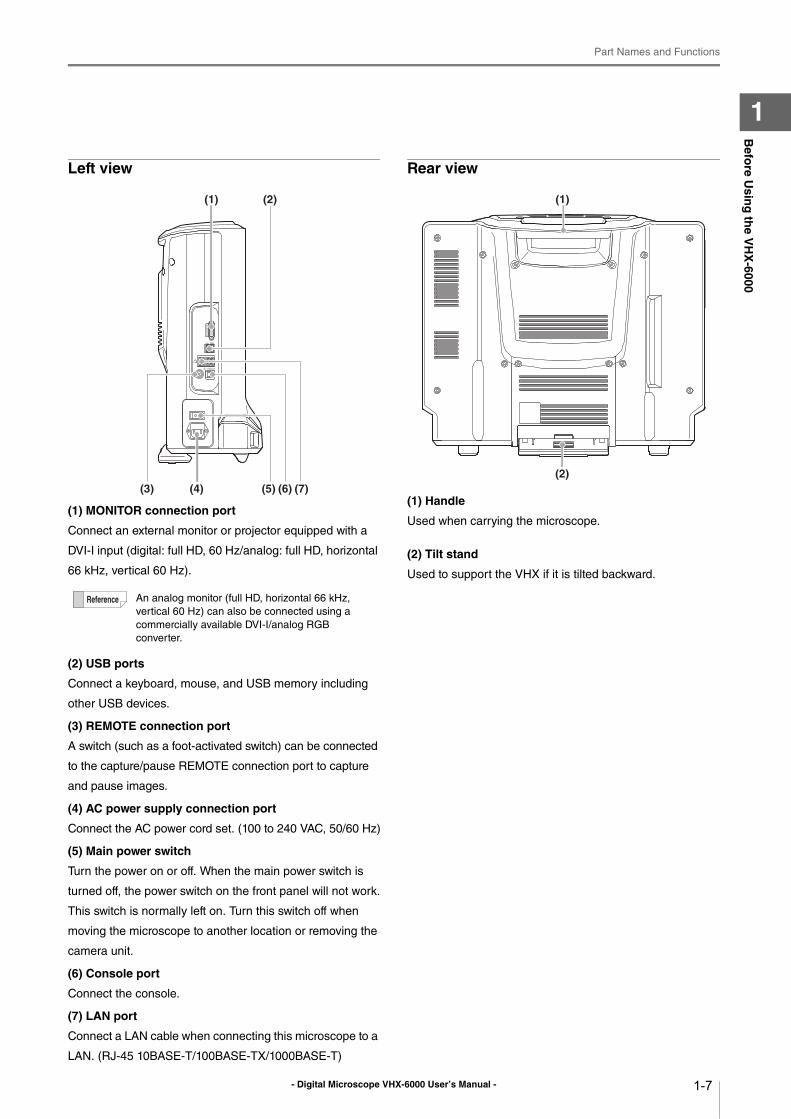
Left view
(1) MONITOR connection port
Connect an external monitor or projector equipped with a
DVI-I input (digital: full HD, 60 Hz/analog: full HD, horizontal
66 kHz, vertical 60 Hz).
(2) USB ports
Connect a keyboard, mouse, and USB memory including
other USB devices.
(3) REMOTE connection port
A switch (such as a foot-activated switch) can be connected
to the capture/pause REMOTE connection port to capture
and pause images.
(4) AC power supply connection port
Connect the AC power cord set. (100 to 240 VAC, 50/60 Hz)
(5) Main power switch
Turn the power on or off. When the main power switch is
turned off, the power switch on the front panel will not work.
This switch is normally left on. Turn this switch off when
moving the microscope to another location or removing the
camera unit.
(6) Console port
Connect the console.
(7) LAN port
Connect a LAN cable when connecting this microscope to a
LAN. (RJ-45 10BASE-T/100BASE-TX/1000BASE-T)
Rear view
(1) Handle
Used when carrying the microscope.
(2) Tilt stand
Used to support the VHX if it is tilted backward.
An analog monitor (full HD, horizontal 66 kHz,
vertical 60 Hz) can also be connected using a
commercially available DVI-I/analog RGB
converter.
(1)
(4) (5) (6)(3)
(2)
(7)
(1)
(2)
- Digital Microscope VHX-6000 User’s Manual -
Part Names and Functions
1-8
Befo
re Usin
g th
e VH
X-6000
1
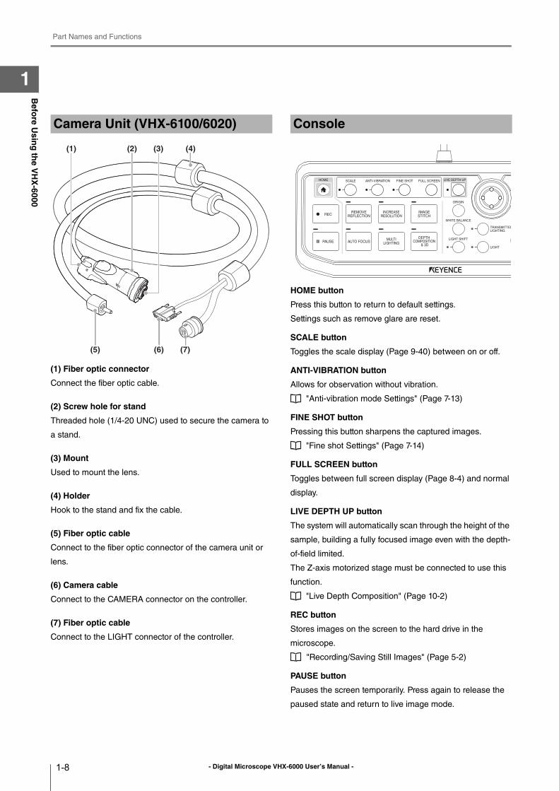
(1) Fiber optic connector
Connect the fiber optic cable.
(2) Screw hole for stand
Threaded hole (1/4-20 UNC) used to secure the camera to
a stand.
(3) Mount
Used to mount the lens.
(4) Holder
Hook to the stand and fix the cable.
(5) Fiber optic cable
Connect to the fiber optic connector of the camera unit or
lens.
(6) Camera cable
Connect to the CAMERA connector on the controller.
(7) Fiber optic cable
Connect to the LIGHT connector of the controller.
HOME button
Press this button to return to default settings.
Settings such as remove glare are reset.
SCALE button
Toggles the scale display (Page 9-40) between on or off.
ANTI-VIBRATION button
Allows for observation without vibration.
"Anti-vibration mode Settings" (Page 7-13)
FINE SHOT button
Pressing this button sharpens the captured images.
"Fine shot Settings" (Page 7-14)
FULL SCREEN button
Toggles between full screen display (Page 8-4) and normal
display.
LIVE DEPTH UP button
The system will automatically scan through the height of the
sample, building a fully focused image even with the depth-
of-field limited.
The Z-axis motorized stage must be connected to use this
function.
"Live Depth Composition" (Page 10-2)
REC button
Stores images on the screen to the hard drive in the
microscope.
"Recording/Saving Still Images" (Page 5-2)
PAUSE button
Pauses the screen temporarily. Press again to release the
paused state and return to live image mode.
Camera Unit (VHX-6100/6020)
(5) (6) (7)
(2) (3)(1) (4)
Console
- Digital Microscope VHX-6000 User’s Manual -
Part Names and Functions
1-9
Befo
re Usin
g th
e VH
X-6000
1
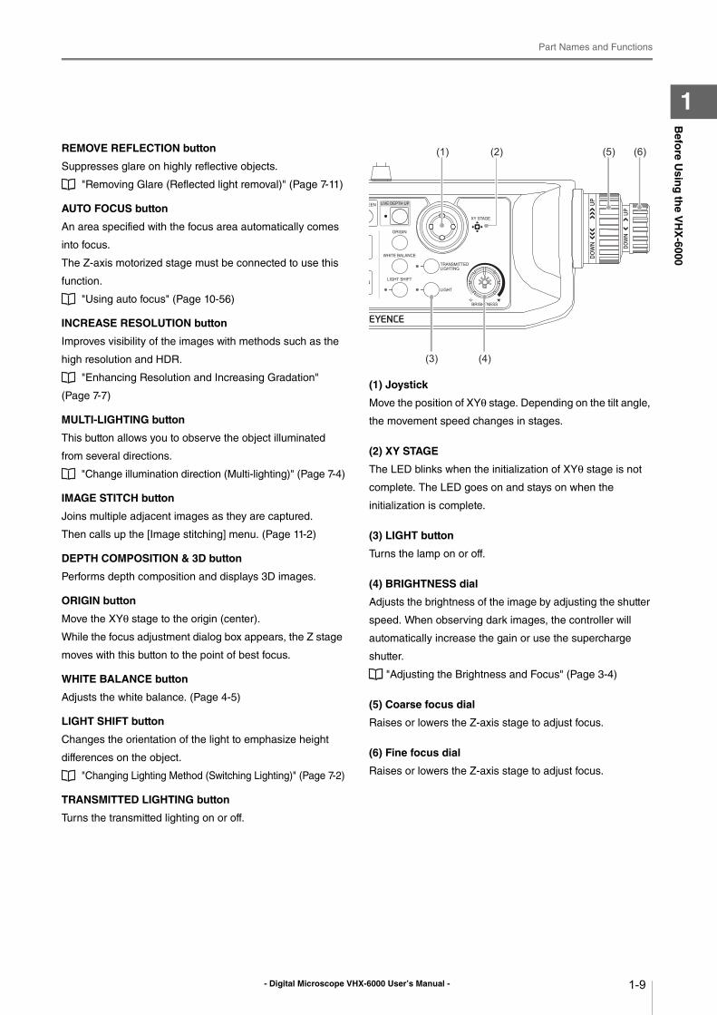
REMOVE REFLECTION button
Suppresses glare on highly reflective objects.
"Removing Glare (Reflected light removal)" (Page 7-11)
AUTO FOCUS button
An area specified with the focus area automatically comes
into focus.
The Z-axis motorized stage must be connected to use this
function.
"Using auto focus" (Page 10-56)
INCREASE RESOLUTION button
Improves visibility of the images with methods such as the
high resolution and HDR.
"Enhancing Resolution and Increasing Gradation"
(Page 7-7)
MULTI-LIGHTING button
This button allows you to observe the object illuminated
from several directions.
"Change illumination direction (Multi-lighting)" (Page 7-4)
IMAGE STITCH button
Joins multiple adjacent images as they are captured.
Then calls up the [Image stitching] menu. (Page 11-2)
DEPTH COMPOSITION & 3D button
Performs depth composition and displays 3D images.
ORIGIN button
Move the XYθ stage to the origin (center).
While the focus adjustment dialog box appears, the Z stage
moves with this button to the point of best focus.
WHITE BALANCE button
Adjusts the white balance. (Page 4-5)
LIGHT SHIFT button
Changes the orientation of the light to emphasize height
differences on the object.
"Changing Lighting Method (Switching Lighting)" (Page 7-2)
TRANSMITTED LIGHTING button
Turns the transmitted lighting on or off.
(1) Joystick
Move the position of XYθ stage. Depending on the tilt angle,
the movement speed changes in stages.
(2) XY STAGE
The LED blinks when the initialization of XYθ stage is not
complete. The LED goes on and stays on when the
initialization is complete.
(3) LIGHT button
Turns the lamp on or off.
(4) BRIGHTNESS dial
Adjusts the brightness of the image by adjusting the shutter
speed. When observing dark images, the controller will
automatically increase the gain or use the supercharge
shutter.
"Adjusting the Brightness and Focus" (Page 3-4)
(5) Coarse focus dial
Raises or lowers the Z-axis stage to adjust focus.
(6) Fine focus dial
Raises or lowers the Z-axis stage to adjust focus.
(1)
(4)(3)
(2) (5) (6)
- Digital Microscope VHX-6000 User’s Manual -
Viewing the Screen
1-10
Befo
re Usin
g th
e VH
X-6000
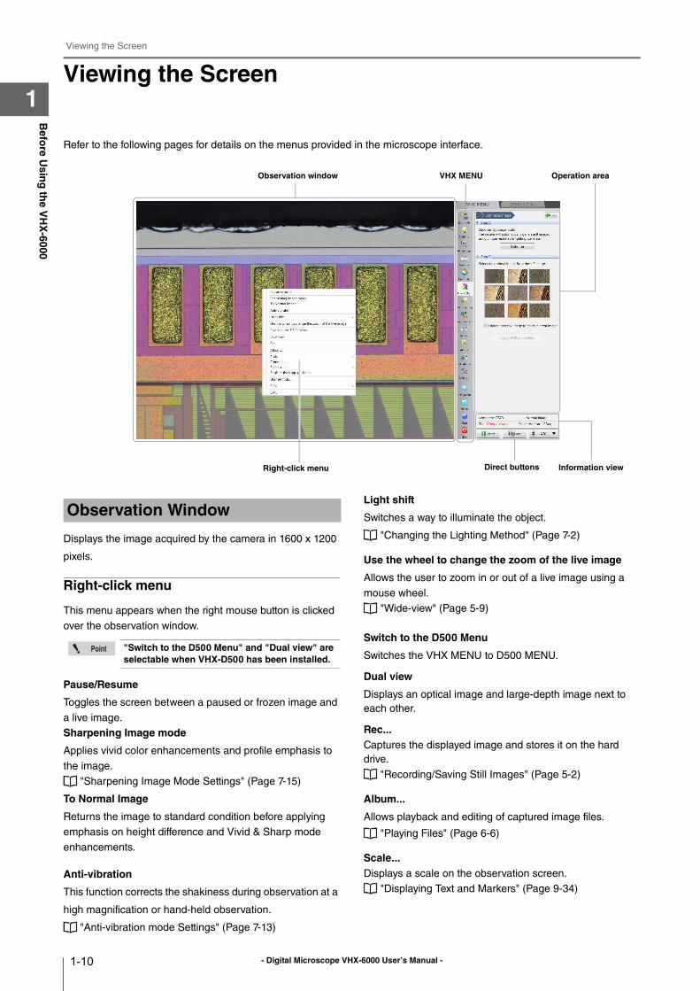
1Viewing the Screen
Refer to the following pages for details on the menus provided in the microscope interface.
Displays the image acquired by the camera in 1600 x 1200
pixels.
Right-click menu
This menu appears when the right mouse button is clicked
over the observation window.
Pause/Resume
Toggles the screen between a paused or frozen image and
a live image.
Sharpening Image mode
Applies vivid color enhancements and profile emphasis to
the image.
"Sharpening Image Mode Settings" (Page 7-15)
To Normal Image
Returns the image to standard condition before applying
emphasis on height difference and Vivid & Sharp mode
enhancements.
Anti-vibration
This function corrects the shakiness during observation at a
high magnification or hand-held observation.
"Anti-vibration mode Settings" (Page 7-13)
Light shift
Switches a way to illuminate the object.
"Changing the Lighting Method" (Page 7-2)
Use the wheel to change the zoom of the live image
Allows the user to zoom in or out of a live image using a
mouse wheel.
"Wide-view" (Page 5-9)
Switch to the D500 Menu
Switches the VHX MENU to D500 MENU.
Dual view
Displays an optical image and large-depth image next to
each other.
Rec...Captures the displayed image and stores it on the hard
drive.
"Recording/Saving Still Images" (Page 5-2)
Album...
Allows playback and editing of captured image files.
"Playing Files" (Page 6-6)
Scale... Displays a scale on the observation screen.
"Displaying Text and Markers" (Page 9-34)
VHX MENUObservation window Operation area
Direct buttonsRight-click menu Information view
Observation Window
"Switch to the D500 Menu" and "Dual view" are selectable when VHX-D500 has been installed.
- Digital Microscope VHX-6000 User’s Manual -
Viewing the Screen
1-11
Befo
re Usin
g th
e VH
X-6000
1
Comment...
Displays a toolbar for entering comments on the observed
image, such as text and markings.
"Displaying Text and Markers" (Page 9-34)
Split Screen
Splits the observation window to compare images.
"Split Screen" (Page 8-2)
User Setup...
Stores various settings on the [Camera/Image Enhancement],
[Options] menu.
"User Setup" (Page 13-14)
Exit...Turns the microscope power off.
The following commands are displayed as icons. Clicking
the icon executes the command.
Easy mode
This allows you to quickly access frequently used functions.
"Improve image" (Page 6)
"Focus" (Page 7)
"Compare images" (Page 7)
"Record" (Page 8)
"Reproduce rec settings" (Page 8)
"Open a saved image" (Page 8)
"Measuring" (Page 9)
Lighting
Use this to make advanced adjustments for images that are
too bright (or too dark), to correct the color tone, or for fast
moving objects.
"Adjusting the Lighting" (Page 4-2)
"Adjusting Image Brightness" (Page 4-3)
The following settings are available:
• Camera brightness (shutter speed, gain)
• Lighting (Epi-illumination, Transmitted illumination)
Rec Settings
Performs detailed settings and correction of capturing
images and image saving.
The setting details are as follows.
"Adjusting the White Balance" (Page 4-5)
"Setting the Recording Size" (Page 5-5)
"Setting Auto Rec" (Page 5-6)
"Setting up Timer Recording" (Page 5-8)
"Recording and Saving Videos" (Page 5-10)
"Observing Tilted Z-Axis" (Page 3-7)
"Vision correction mode" (Page 8-4)
"Anti-vibration mode Settings" (Page 7-13)
Measure
Measures distances, areas, angles, etc., of the object.
Measurements can also be made while moving the object
horizontally (XY direction) by using the VH-M100E stage.
"Main Measurements" (Page 9-12)
"Area Measurements" (Page 9-26)
"Displaying a Scale" (Page 9-40)
"One-Click Automatic Measurement" (Page 9-41)
"Automatic Area Measurements" (Page 9-46)
"Contamination analysis" (Page 9-67)
"Maximum Area Measurement" (Page 9-73)
"XY Stage Measurement (Optional)" (Page 9-76)
Depth Up
This command is used to adjust the focus on the entire
object when it has large height differences.
It combines and displays the focused parts of multiple
images with different focal points. The combined image can
be used to form a 3D image.
"Live Depth Composition" (Page 10-3)
"Quick Composition and 3D" (Page 10-4)
"Fine Depth Composition" (Page 10-9)
"Manual 3D composition" (Page 10-14)
"Z Stage Control" (Page 10-56)
VHX MENU
- Digital Microscope VHX-6000 User’s Manual -
Viewing the Screen
1-12
Befo
re Usin
g th
e VH
X-6000
1
Image Qlty
Accurately reproduces the delicate state of objects difficult
to observe normally.
"HDR Settings" (Page 7-8)
"High resolution HDR Observation Settings" (Page 7-9)
"High resolution Observation Settings" (Page 7-10)
"Remove Reflection Settings" (Page 7-11)
"Selecting an Image from 9 Different Settings
(Optimize)" (Page 7-16)
"Image Setting Procedures" (Page 7-18)
Multi-lighting
You can change the direction of illumination and observe
detailed changes that cannot be seen usually.
"Change illumination direction (Multi-lighting)" (Page 7-4)
View/Comment
Sets the image display method.
These settings allow you to zoom in on an image or zoom
out or split the screen and tile images for comparison.
"Using the Split Screen" (Page 8-3)
"List of Comments" (Page 9-34)
"Registering a Stage Position" (Page 8-7)
"Full Screen Image" (Page 8-4)
"Wide-view" (Page 5-9)
Stitching
This allows you to observe an area larger than the normal
field-of-view in its original clarity by connecting several
images.
Place the object on the XY stage and capture an image
while moving the stage.
Images can be connected to form 2D images or 3D images.
A 2D stitch creates a large image by capturing multiple images
of the object while moving the part via the stage in a
serpentine motion.
A 3D stitch creates a large 3D image using the Z-axis
motorized stage to move the lens vertically. The images are
captured and connected using the Depth Up function.
"Automatic Image Stitching" (Page 11-2)
"Split recording" (Page 11-12)
Album
Displays thumbnails of captured (saved) images for review
and management.
Double-clicking a thumbnail displays or plays the recorded
image.
Images can be printed, written to a CD/DVD, or edited using
copy and cut functions.
"Album" (Page 6-2)
Side Album
Displays the album in the operation area. This allows you to
display a screen in the observation window while viewing
the thumbnail of another image.
Double click or drag and drop a thumbnail onto the
observation window to display or play it back.
"Side Album" (Page 6-21)
Option
Sets option settings.
"Network/Security Settings" (Page 13-2)
"Lens Settings" (Page 13-14)
"Calibration Setup" (Page 13-14)
"User Setup" (Page 13-14)
"Show Software Keyboard" (Page 13-16)
"System Initialization" (Page 13-16)
"Initializing Automatic XY Stage" (Page 13-17)
"Camera mount settings" (Page 13-17)
"ZST vision misalignment correction" (Page 13-18)
"D500 Maintenance" (Page 13-22)
"Options" (Page 13-22)
"Version Info" (Page 13-24)
Navigation
Registers a wide field-of-view image as the navigation
image.
"Navigation" (Page 8-6)
Home
Resets the settings to the default values just after startup.
Restores the setting screens of the HDR and depth
composition, etc. to the initial observation status
immediately.
- Digital Microscope VHX-6000 User’s Manual -
Viewing the Screen
1-13
Befo
re Usin
g th
e VH
X-6000
1
Help
Displays a summary of operating procedures.
Exit
Turns the microscope power off. (Allows you to select
between sleep, shut down, and restart.)
"Shutting Down the Microscope" (Page 3-9)
Displays the settings of functions selected from the VHX
MENU (Page 1-11) or the console buttons.
Lens name, effects such as HDR, tilt angle, rotated angle
and playback file name are displayed.
Clicking the icon provides direct access to pause, save
(Page 5-2), and specify the lens power (Page 9-5).
Operation Area
Information View
Direct Buttons
- Digital Microscope VHX-6000 User’s Manual -
Viewing the Screen
1-14
Befo
re Usin
g th
e VH
X-6000
1
- Digital Microscope VHX-6000 User’s Manual - 2-1
Chapter2In
stallation
/Co
nn
ection
2Installation/Connection
Connecting Devices to the VHX-6000
This chapter will explain the steps from installation to
connection of the VHX-6000 Digital Microscope
with a zoom lens VH-Z20T and free-angle observation
system VHX-S650.
Installation/Connection...........................................Page 2-2
System Configuration and Connection Flow ......Page 2-2
Installing the VHX-6000 .....................................Page 2-3
Connecting the Camera Unit..............................Page 2-3
Connecting the Console, Mouse, etc. ................Page 2-5
Connecting Power ..............................................Page 2-5
Installing the VHX-S650 Free-angle Observation Base
Unit.................................................................Page 2-6
Mounting and Removing the Lens .....................Page 2-7
Connecting the Lens/Stage Cable .....................Page 2-8
- Digital Microscope VHX-6000 User’s Manual -
Installation/Connection
2-2
Installatio
n/C
on
nectio
n
2
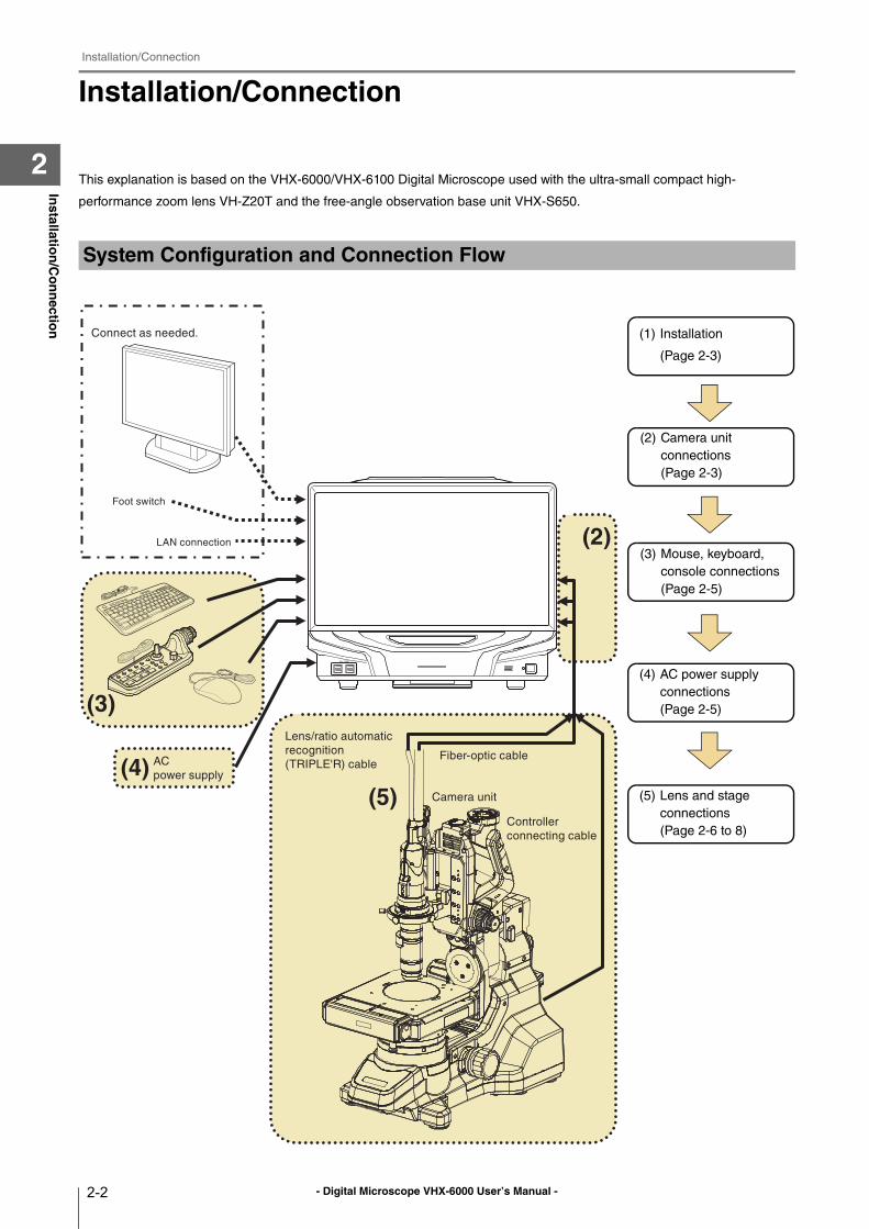
Installation/Connection
This explanation is based on the VHX-6000/VHX-6100 Digital Microscope used with the ultra-small compact high-
performance zoom lens VH-Z20T and the free-angle observation base unit VHX-S650.
System Configuration and Connection Flow
AC
power supply
Connect as needed.
Foot switch
LAN connection
(3)
(4)(5) Camera unit
Controller
connecting cable
Lens/ratio automatic
recognition
(TRIPLE'R) cable
(2)
Fiber-optic cable
(1) Installation
(Page 2-3)
(2) Camera unit
connections
(Page 2-3)
(3) Mouse, keyboard,
console connections
(Page 2-5)
(4) AC power supply
connections
(Page 2-5)
(5) Lens and stage
connections
(Page 2-6 to 8)
- Digital Microscope VHX-6000 User’s Manual -
Installation/Connection
2-3
Installatio
n/C
on
nectio
n
2
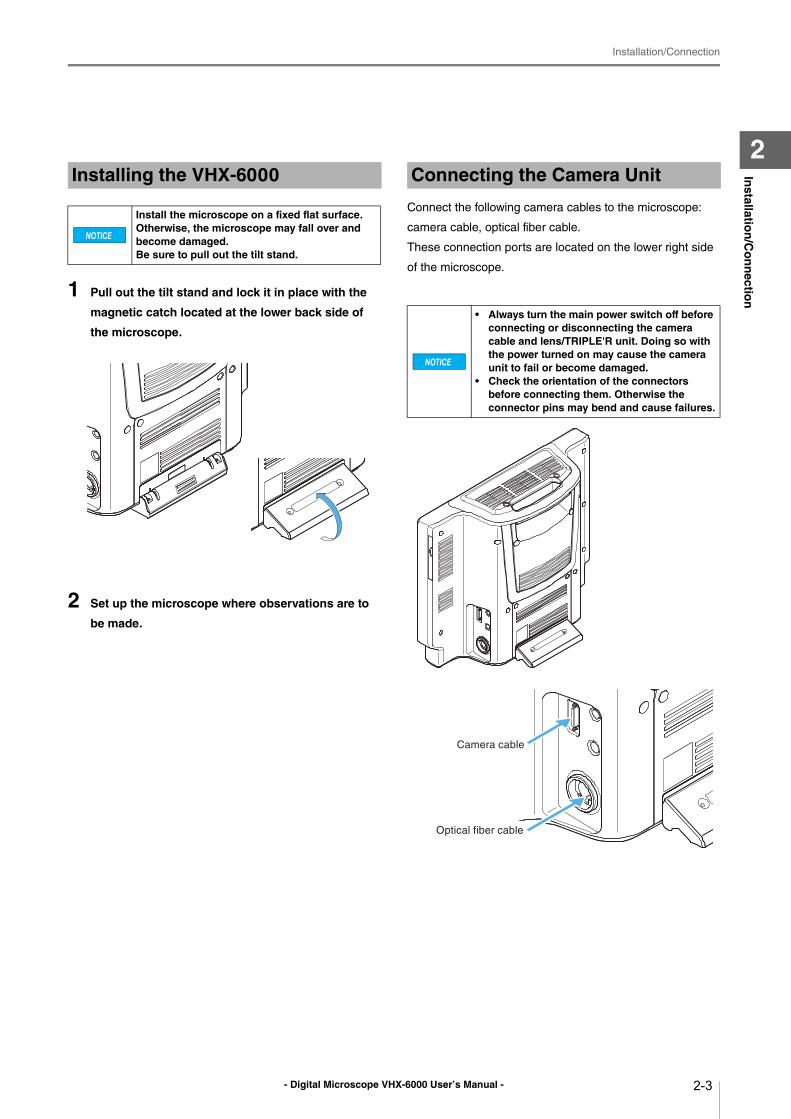
1 Pull out the tilt stand and lock it in place with the
magnetic catch located at the lower back side of
the microscope.
2 Set up the microscope where observations are to
be made.
Connect the following camera cables to the microscope:
camera cable, optical fiber cable.
These connection ports are located on the lower right side
of the microscope.
Installing the VHX-6000
Install the microscope on a fixed flat surface. Otherwise, the microscope may fall over and become damaged.Be sure to pull out the tilt stand.
Connecting the Camera Unit
• Always turn the main power switch off before connecting or disconnecting the camera cable and lens/TRIPLE'R unit. Doing so with the power turned on may cause the camera unit to fail or become damaged.
• Check the orientation of the connectors before connecting them. Otherwise the connector pins may bend and cause failures.
Optical fiber cable
Camera cable
- Digital Microscope VHX-6000 User’s Manual -
Installation/Connection
2-4
Installatio
n/C
on
nectio
n
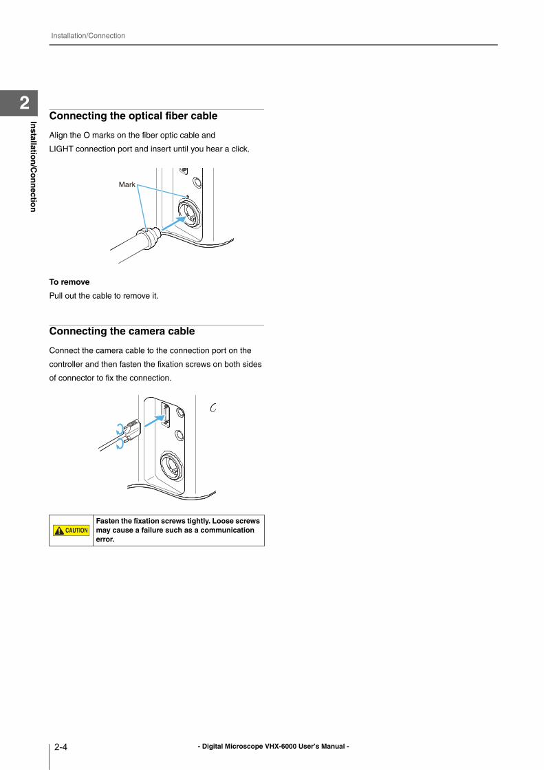
2Connecting the optical fiber cable
Align the O marks on the fiber optic cable and
LIGHT connection port and insert until you hear a click.
To remove
Pull out the cable to remove it.
Connecting the camera cable
Connect the camera cable to the connection port on the
controller and then fasten the fixation screws on both sides
of connector to fix the connection.
Fasten the fixation screws tightly. Loose screws may cause a failure such as a communication error.
Mark
- Digital Microscope VHX-6000 User’s Manual -
Installation/Connection
2-5
Installatio
n/C
on
nectio
n
2
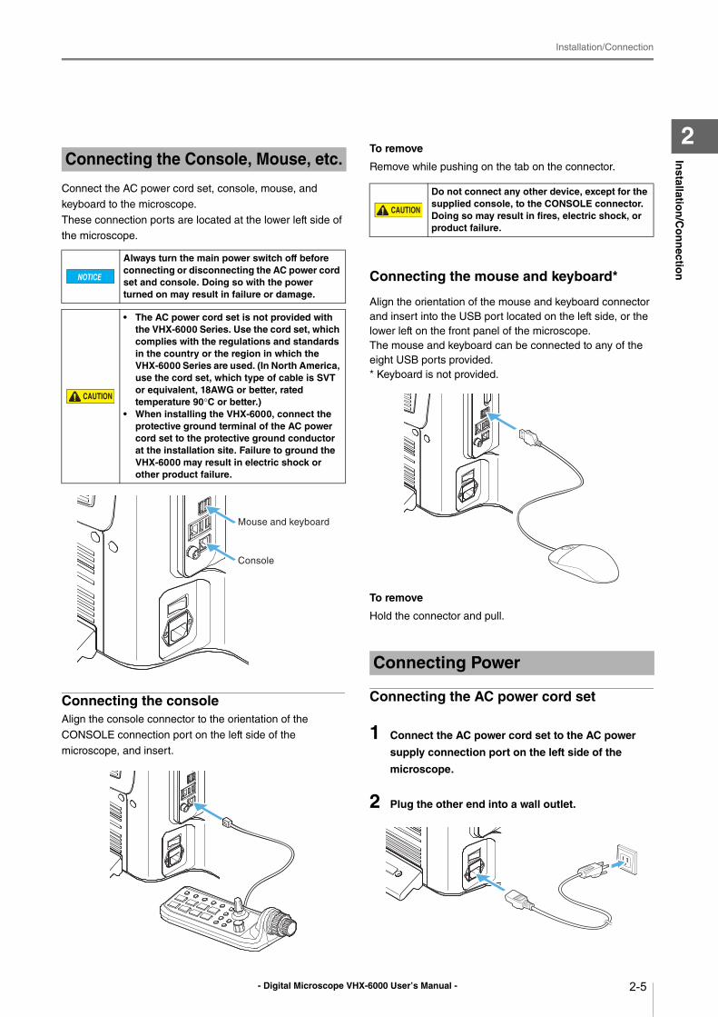
Connect the AC power cord set, console, mouse, and
keyboard to the microscope.
These connection ports are located at the lower left side of
the microscope.
Connecting the consoleAlign the console connector to the orientation of the
CONSOLE connection port on the left side of the
microscope, and insert.
To remove
Remove while pushing on the tab on the connector.
Connecting the mouse and keyboard*
Align the orientation of the mouse and keyboard connector
and insert into the USB port located on the left side, or the
lower left on the front panel of the microscope.
The mouse and keyboard can be connected to any of the
eight USB ports provided.
* Keyboard is not provided.
To remove
Hold the connector and pull.
Connecting the AC power cord set
1 Connect the AC power cord set to the AC power
supply connection port on the left side of the
microscope.
2 Plug the other end into a wall outlet.
Connecting the Console, Mouse, etc.
Always turn the main power switch off before connecting or disconnecting the AC power cord set and console. Doing so with the power turned on may result in failure or damage.
• The AC power cord set is not provided with the VHX-6000 Series. Use the cord set, which complies with the regulations and standards in the country or the region in which the VHX-6000 Series are used. (In North America, use the cord set, which type of cable is SVT or equivalent, 18AWG or better, rated temperature 90°C or better.)
• When installing the VHX-6000, connect the protective ground terminal of the AC power cord set to the protective ground conductor at the installation site. Failure to ground the VHX-6000 may result in electric shock or other product failure.
Mouse and keyboard
Console
Do not connect any other device, except for the supplied console, to the CONSOLE connector.Doing so may result in fires, electric shock, or product failure.
Connecting Power
- Digital Microscope VHX-6000 User’s Manual -
Installation/Connection
2-6
Installatio
n/C
on
nectio
n
2
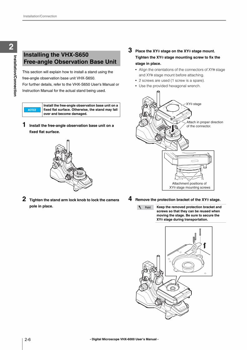
This section will explain how to install a stand using the
free-angle observation base unit VHX-S650.
For further details, refer to the VHX-S650 User's Manual or
Instruction Manual for the actual stand being used.
1 Install the free-angle observation base unit on a
fixed flat surface.
2 Tighten the stand arm lock knob to lock the camera
pole in place.
3 Place the XYθ stage on the XYθ stage mount.
Tighten the XYθ stage mounting screw to fix the
stage in place.
• Align the orientations of the connectors of XYθ stage and XYθ stage mount before attaching.
• 2 screws are used (1 screw is a spare).• Use the provided hexagonal wrench.
4 Remove the protection bracket of the XYθ stage.
Installing the VHX-S650 Free-angle Observation Base Unit
Install the free-angle observation base unit on a fixed flat surface. Otherwise, the stand may fall over and become damaged.
Keep the removed protection bracket and screws so that they can be reused when moving the stage. Be sure to secure the XYθ stage during transportation.
Attach in proper direction
of the connector.
XYθ stage
Attachment positions of
XYθ stage mounting screws
- Digital Microscope VHX-6000 User’s Manual -
Installation/Connection
2-7
Installatio
n/C
on
nectio
n
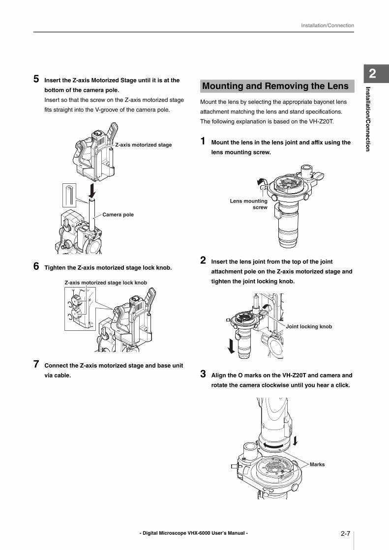
25 Insert the Z-axis Motorized Stage until it is at the
bottom of the camera pole.
Insert so that the screw on the Z-axis motorized stage
fits straight into the V-groove of the camera pole.
6 Tighten the Z-axis motorized stage lock knob.
7 Connect the Z-axis motorized stage and base unit
via cable.
Mount the lens by selecting the appropriate bayonet lens
attachment matching the lens and stand specifications.
The following explanation is based on the VH-Z20T.
1 Mount the lens in the lens joint and affix using the
lens mounting screw.
2 Insert the lens joint from the top of the joint
attachment pole on the Z-axis motorized stage and
tighten the joint locking knob.
3 Align the O marks on the VH-Z20T and camera and
rotate the camera clockwise until you hear a click.
Camera pole
Z-axis motorized stage
Z-axis motorized stage lock knob
Mounting and Removing the Lens
Lens mounting screw
Joint locking knob
Marks
- Digital Microscope VHX-6000 User’s Manual -
Installation/Connection
2-8
Installatio
n/C
on
nectio
n
2To remove
While pushing down the tab on the lens attachment, rotate
the camera counterclockwise to align the O marks on the
lens attachment then camera unit, then pull the camera out
of the bayonet.
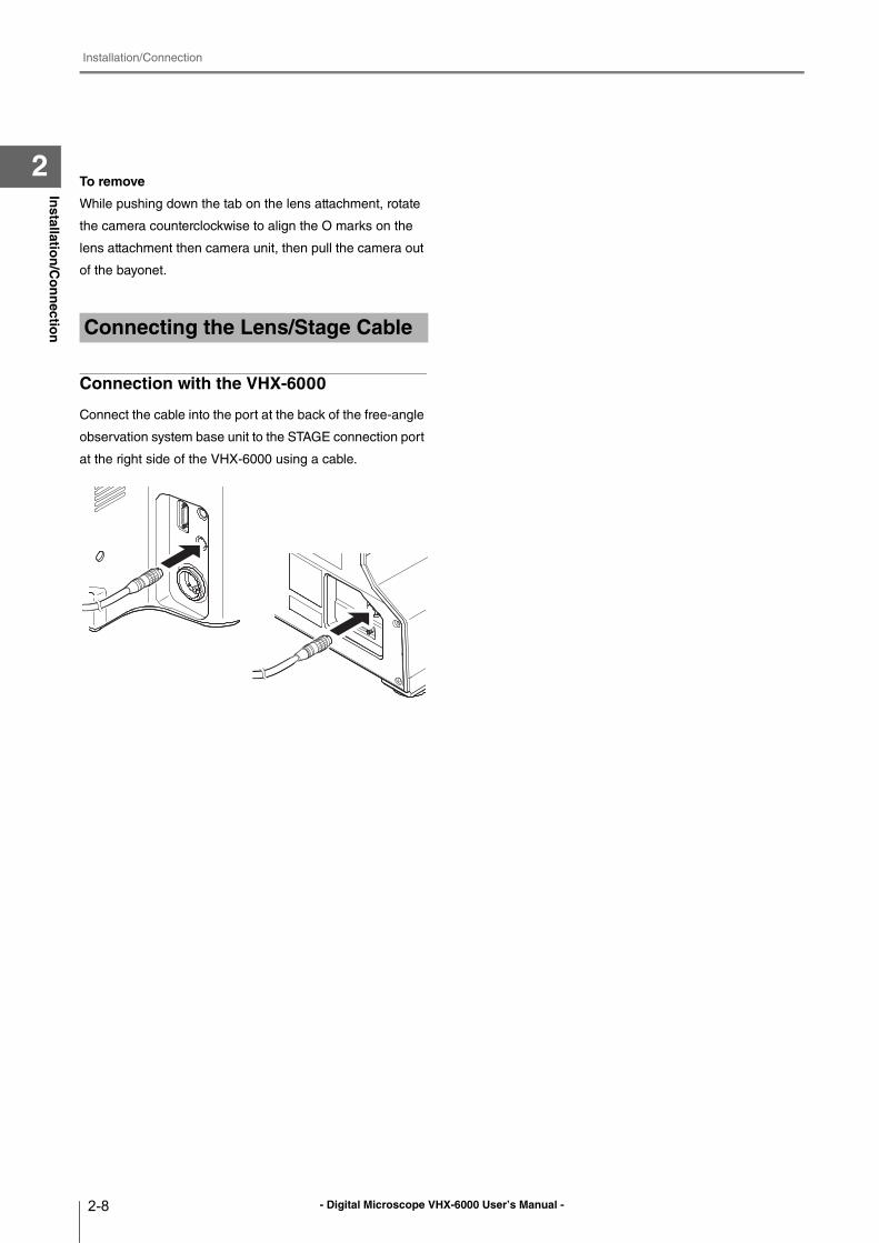
Connection with the VHX-6000
Connect the cable into the port at the back of the free-angle
observation system base unit to the STAGE connection port
at the right side of the VHX-6000 using a cable.
Connecting the Lens/Stage Cable
- Digital Microscope VHX-6000 User’s Manual - 3-1
Chapter3B
asic Op
eration
3Basic Operation
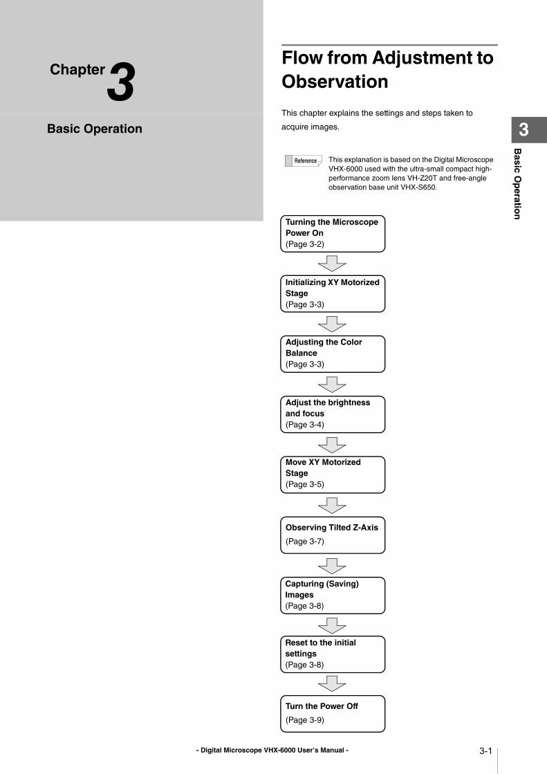
Flow from Adjustment to Observation
This chapter explains the settings and steps taken to
acquire images.
This explanation is based on the Digital Microscope
VHX-6000 used with the ultra-small compact high-
performance zoom lens VH-Z20T and free-angle
observation base unit VHX-S650.
Turning the Microscope Power On(Page 3-2)
Adjusting the Color Balance(Page 3-3)
Observing Tilted Z-Axis
(Page 3-7)
Turn the Power Off
(Page 3-9)
Adjust the brightness and focus(Page 3-4)
Initializing XY Motorized Stage(Page 3-3)
Move XY Motorized Stage(Page 3-5)
Capturing (Saving) Images(Page 3-8)
Reset to the initial settings(Page 3-8)
- Digital Microscope VHX-6000 User’s Manual -
Basic Operation
3-2
Basic O
peratio
n
3
Basic Operation
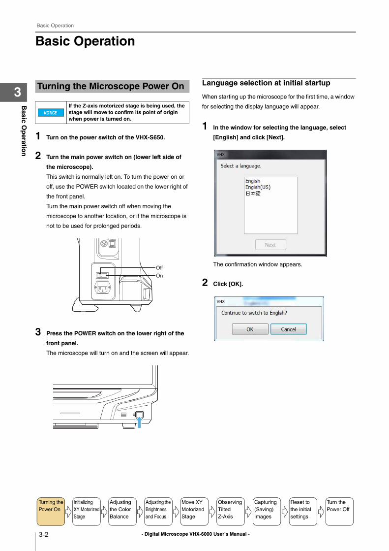
1 Turn on the power switch of the VHX-S650.
2 Turn the main power switch on (lower left side of
the microscope).
This switch is normally left on. To turn the power on or
off, use the POWER switch located on the lower right of
the front panel.
Turn the main power switch off when moving the
microscope to another location, or if the microscope is
not to be used for prolonged periods.
3 Press the POWER switch on the lower right of the
front panel.
The microscope will turn on and the screen will appear.
Language selection at initial startup
When starting up the microscope for the first time, a window
for selecting the display language will appear.
1 In the window for selecting the language, select
[English] and click [Next].
The confirmation window appears.
2 Click [OK].
Turning the Microscope Power On
If the Z-axis motorized stage is being used, the stage will move to confirm its point of origin when power is turned on.
On
Off
Turning the
Power On
Initializing
XY Motorized
Stage
Adjusting
the Color
Balance
Adjusting the
Brightness
and Focus
Move XY
Motorized
Stage
Observing
Tilted
Z-Axis
Capturing
(Saving)
Images
Turn the
Power Off
Reset to
the initial
settings
- Digital Microscope VHX-6000 User’s Manual -
Basic Operation
3-3
Basic O
peratio
n
3Initialize the XYθ stage if you are using the Free-angle
Observation Base Unit VHX-S650. If the last operation was
completed with the stage moved to the origin, initialization
will not be required upon startup.
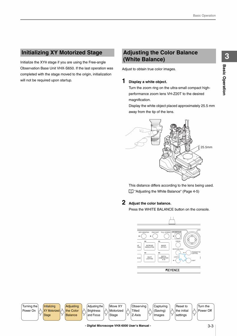
Adjust to obtain true color images.
1 Display a white object.
Turn the zoom ring on the ultra-small compact high-
performance zoom lens VH-Z20T to the desired
magnification.
Display the white object placed approximately 25.5 mm
away from the tip of the lens.
This distance differs according to the lens being used.
"Adjusting the White Balance" (Page 4-5)
2 Adjust the color balance.
Press the WHITE BALANCE button on the console.
Initializing XY Motorized Stage Adjusting the Color Balance (White Balance)
25.5mm
Turning the
Power On
Initializing
XY Motorized
Stage
Adjusting
the Color
Balance
Adjusting the
Brightness
and Focus
Move XY
Motorized
Stage
Observing
Tilted
Z-Axis
Capturing
(Saving)
Images
Turn the
Power Off
Reset to
the initial
settings
- Digital Microscope VHX-6000 User’s Manual -
Basic Operation
3-4
Basic O
peratio
n
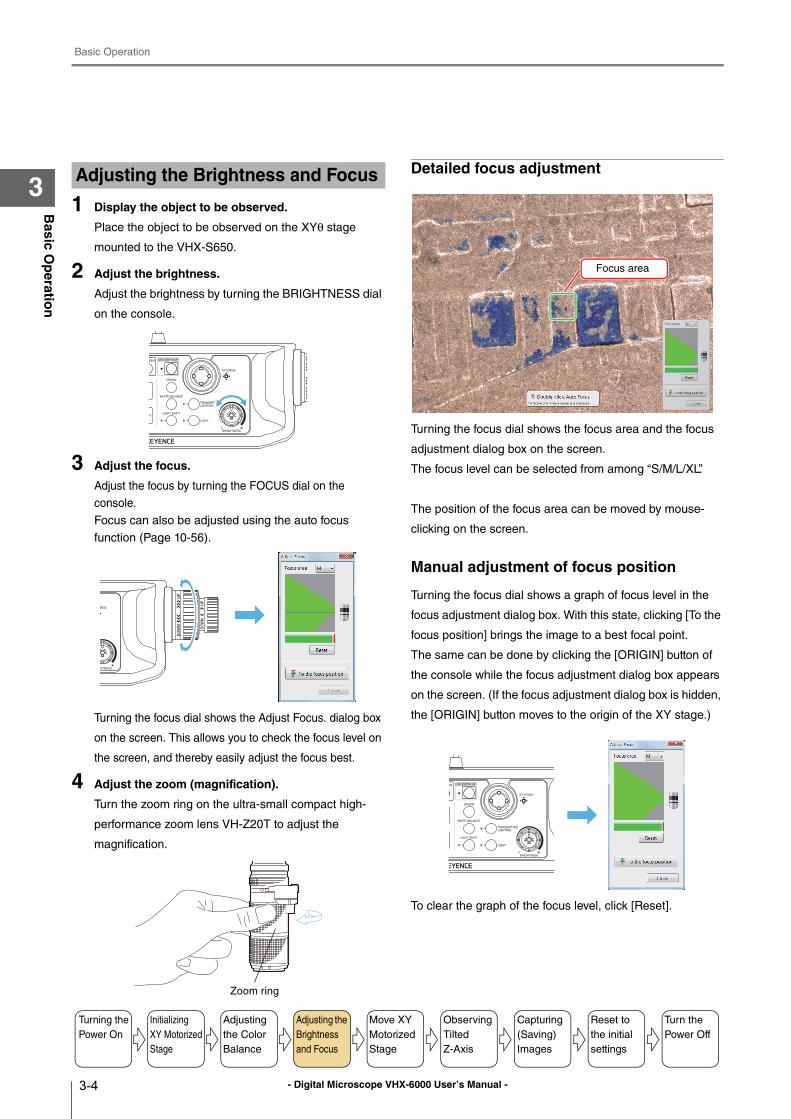
31 Display the object to be observed.
Place the object to be observed on the XYθ stage
mounted to the VHX-S650.
2 Adjust the brightness.
Adjust the brightness by turning the BRIGHTNESS dial
on the console.
3 Adjust the focus.
Adjust the focus by turning the FOCUS dial on the
console.
Focus can also be adjusted using the auto focus
function (Page 10-56).
Turning the focus dial shows the Adjust Focus. dialog box
on the screen. This allows you to check the focus level on
the screen, and thereby easily adjust the focus best.
4 Adjust the zoom (magnification).
Turn the zoom ring on the ultra-small compact high-
performance zoom lens VH-Z20T to adjust the
magnification.
Detailed focus adjustment
Turning the focus dial shows the focus area and the focus
adjustment dialog box on the screen.
The focus level can be selected from among “S/M/L/XL”.
The position of the focus area can be moved by mouse-
clicking on the screen.
Manual adjustment of focus position
Turning the focus dial shows a graph of focus level in the
focus adjustment dialog box. With this state, clicking [To the
focus position] brings the image to a best focal point.
The same can be done by clicking the [ORIGIN] button of
the console while the focus adjustment dialog box appears
on the screen. (If the focus adjustment dialog box is hidden,
the [ORIGIN] button moves to the origin of the XY stage.)
To clear the graph of the focus level, click [Reset].
Adjusting the Brightness and Focus
Zoom ring
Focus area
Turning the
Power On
Initializing
XY Motorized
Stage
Adjusting
the Color
Balance
Adjusting the
Brightness
and Focus
Move XY
Motorized
Stage
Observing
Tilted
Z-Axis
Capturing
(Saving)
Images
Turn the
Power Off
Reset to
the initial
settings
- Digital Microscope VHX-6000 User’s Manual -
Basic Operation
3-5
Basic O
peratio
n
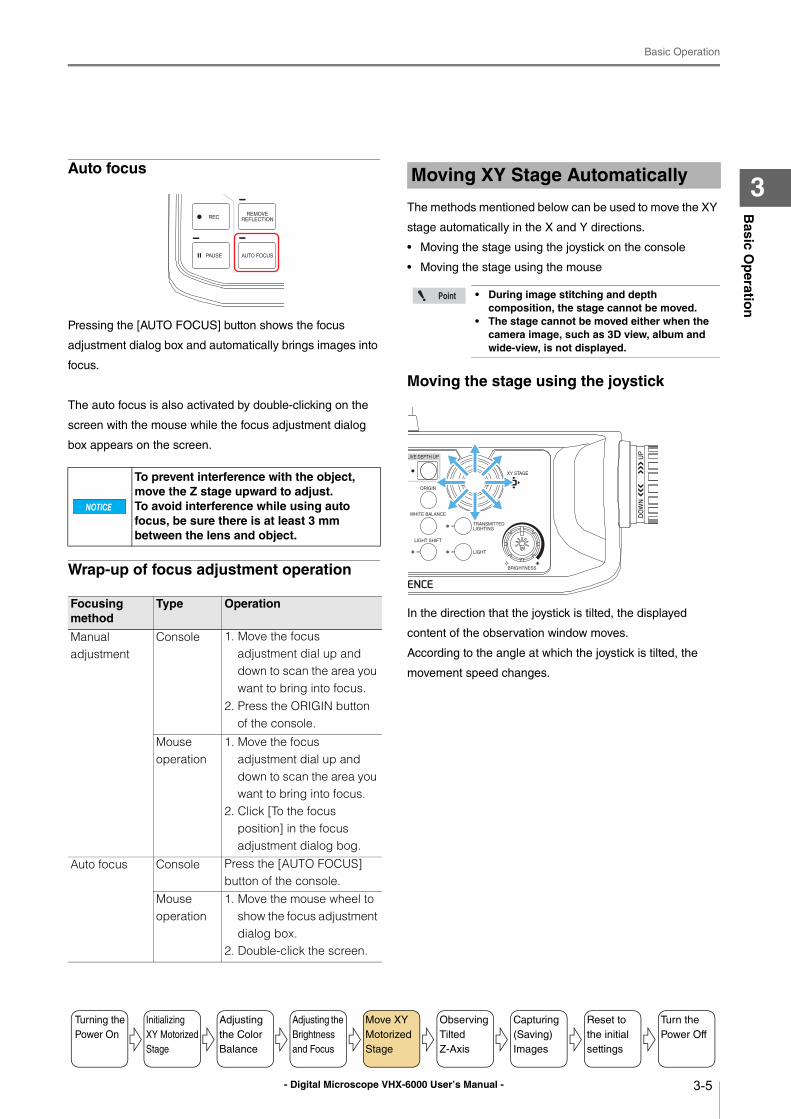
3Auto focus
Pressing the [AUTO FOCUS] button shows the focus
adjustment dialog box and automatically brings images into
focus.
The auto focus is also activated by double-clicking on the
screen with the mouse while the focus adjustment dialog
box appears on the screen.
Wrap-up of focus adjustment operation
The methods mentioned below can be used to move the XY
stage automatically in the X and Y directions.
• Moving the stage using the joystick on the console
• Moving the stage using the mouse
Moving the stage using the joystick
In the direction that the joystick is tilted, the displayed
content of the observation window moves.
According to the angle at which the joystick is tilted, the
movement speed changes.
To prevent interference with the object, move the Z stage upward to adjust. To avoid interference while using auto focus, be sure there is at least 3 mm between the lens and object.
Focusing method
Type Operation
Manual adjustment
Console 1. Move the focus adjustment dial up and down to scan the area you want to bring into focus.
2. Press the ORIGIN button of the console.
Mouse operation
1. Move the focus adjustment dial up and down to scan the area you want to bring into focus.
2. Click [To the focus position] in the focus adjustment dialog bog.
Auto focus Console Press the [AUTO FOCUS] button of the console.
Mouse operation
1. Move the mouse wheel to show the focus adjustment dialog box.
2. Double-click the screen.
Moving XY Stage Automatically
• During image stitching and depth composition, the stage cannot be moved.
• The stage cannot be moved either when the camera image, such as 3D view, album and wide-view, is not displayed.
Turning the
Power On
Initializing
XY Motorized
Stage
Adjusting
the Color
Balance
Adjusting the
Brightness
and Focus
Move XY
Motorized
Stage
Observing
Tilted
Z-Axis
Capturing
(Saving)
Images
Turn the
Power Off
Reset to
the initial
settings
- Digital Microscope VHX-6000 User’s Manual -
Basic Operation
3-6
Basic O
peratio
n
3Moving the stage using the mouse
Based on the mouse movements in the observation
window, the observation area moves. Dragging the
observation window causes the displayed area to move
toward the dragging direction. Double-clicking in the
observation window moves the double-clicked point to the
center of window.
Clicking with the mouse wheel on the observation window
causes the reference point's picture to appear at the clicked
position. In the direction of the mouse cursor as viewed
from the reference point, the applicable arrow (in one of the
eight directions) appears and the displayed content moves
accordingly. Movement speed varies depending on
distance of the mouse cursor position from the reference
point. To stop moving the stage, click with the mouse wheel
again at your desired stop position.
Adjustment tips
Features with height differences appear flatUse the Light Shift function.
For details, refer to "Changing Lighting Method (Switching
Lighting)" (Page 7-2).
Areas with intense light reflection appear whiteUse the Remove Glare function.
For details, refer to "Removing Glare (Reflected light
removal)" (Page 7-11).
Some parts of the image are out of focusUse the Depth Composition function.
For details, refer to "Types and Features of Depth
Composition" (Page 10-2).
Areas of image whiteout or blackoutUse the HDR function.
For details, refer to "Enhancing Resolution and Increasing
Gradation" (Page 7-7).
During measurement, no movements can be made by dragging and double-clicking.
Moving direction
Reference point
Turning the
Power On
Initializing
XY Motorized
Stage
Adjusting
the Color
Balance
Adjusting the
Brightness
and Focus
Move XY
Motorized
Stage
Observing
Tilted
Z-Axis
Capturing
(Saving)
Images
Turn the
Power Off
Reset to
the initial
settings
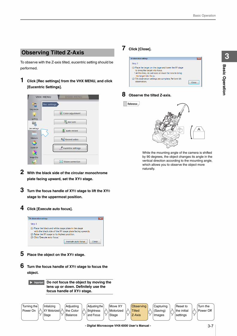
- Digital Microscope VHX-6000 User’s Manual -
Basic Operation
3-7
Basic O
peratio
n
3To observe with the Z-axis tilted, eucentric setting should be
performed.
1 Click [Rec settings] from the VHX MENU, and click
[Eucentric Settings].
2 With the black side of the circular monochrome
plate facing upward, set the XYθ stage.
3 Turn the focus handle of XYθ stage to lift the XYθ
stage to the uppermost position.
4 Click [Execute auto focus].
5 Place the object on the XYθ stage.
6 Turn the focus handle of XYθ stage to focus the
object.
7 Click [Close].
8 Observe the tilted Z-axis.
Observing Tilted Z-Axis
Do not focus the object by moving the lens up or down. Definitely use the focus handle of XYθ stage.
While the mounting angle of the camera is shifted
by 90 degrees, the object changes its angle in the
vertical direction according to the mounting angle,
which allows you to observe the object more
naturally.
Turning the
Power On
Initializing
XY Motorized
Stage
Adjusting
the Color
Balance
Adjusting the
Brightness
and Focus
Move XY
Motorized
Stage
Observing
Tilted
Z-Axis
Capturing
(Saving)
Images
Turn the
Power Off
Reset to
the initial
settings
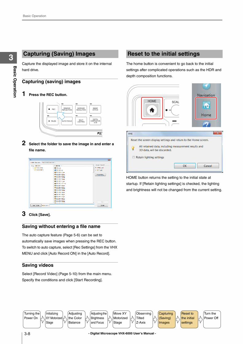
- Digital Microscope VHX-6000 User’s Manual -
Basic Operation
3-8
Basic O
peratio
n
3Capture the displayed image and store it on the internal
hard drive.
Capturing (saving) images
1 Press the REC button.
2 Select the folder to save the image in and enter a
file name.
3 Click [Save].
Saving without entering a file name
The auto capture feature (Page 5-6) can be set to
automatically save images when pressing the REC button.
To switch to auto capture, select [Rec Settings] from the VHX
MENU and click [Auto Record ON] in the [Auto Record].
Saving videos
Select [Record Video] (Page 5-10) from the main menu.
Specify the conditions and click [Start Recording].
The home button is convenient to go back to the initial
settings after complicated operations such as the HDR and
depth composition functions.
HOME button returns the setting to the initial state at
startup. If [Retain lighting settings] is checked, the lighting
and brightness will not be changed from the current setting.
Capturing (Saving) Images
Turning the
Power On
Initializing
XY Motorized
Stage
Adjusting
the Color
Balance
Adjusting the
Brightness
and Focus
Move XY
Motorized
Stage
Observing
Tilted
Z-Axis
Capturing
(Saving)
Images
Turn the
Power Off
Reset to
the initial
settings
Reset to the initial settings
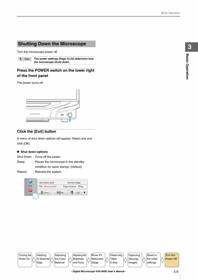
- Digital Microscope VHX-6000 User’s Manual -
Basic Operation
3-9
Basic O
peratio
n
3Turn the microscope power off.
Press the POWER switch on the lower right of the front panel
The power turns off.
Click the [Exit] button
A menu of shut down options will appear. Select one and
click [OK].
Shut down options
Shut Down : Turns off the power.
Sleep : Places the microscope in the standby
condition for quick startup. (Default)
Reboot : Reboots the system.
Shutting Down the Microscope
The power settings (Page 13-24) determine how the microscope shuts down.
Turning the
Power On
Initializing
XY Motorized
Stage
Adjusting
the Color
Balance
Adjusting the
Brightness
and Focus
Move XY
Motorized
Stage
Observing
Tilted
Z-Axis
Capturing
(Saving)
Images
Turn the
Power Off
Reset to
the initial
settings
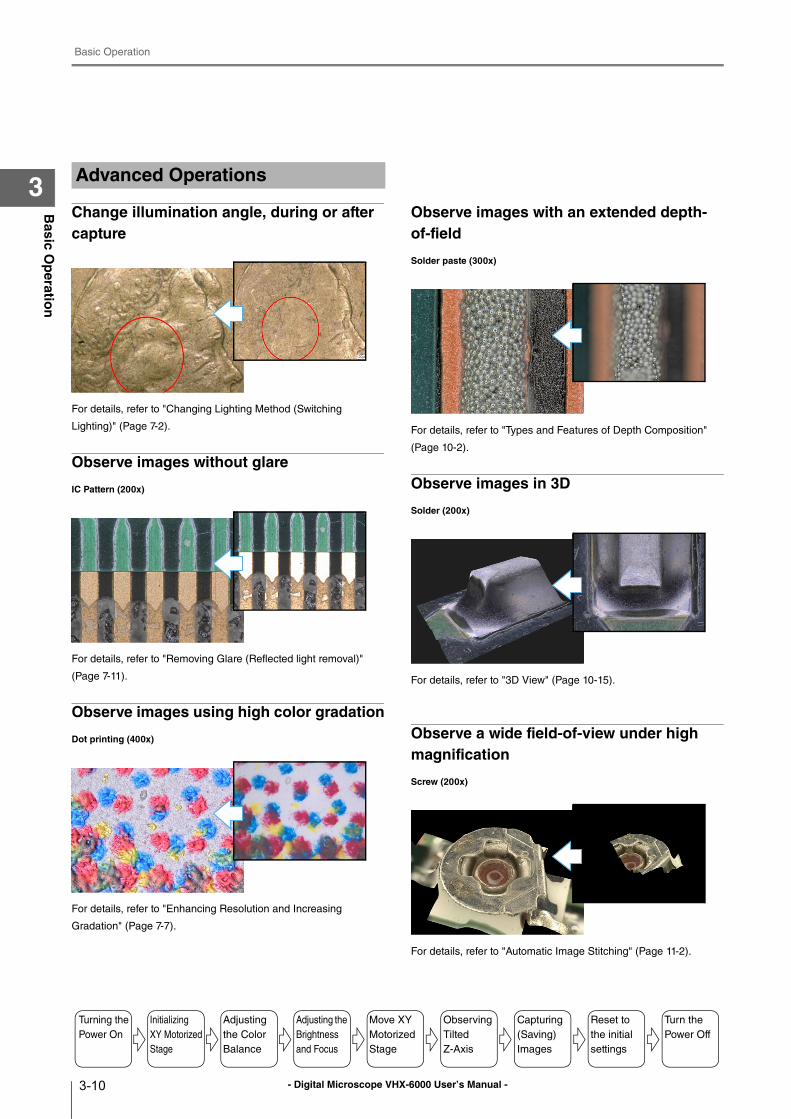
- Digital Microscope VHX-6000 User’s Manual -
Basic Operation
3-10
Basic O
peratio
n
3
Change illumination angle, during or after capture
For details, refer to "Changing Lighting Method (Switching
Lighting)" (Page 7-2).
Observe images without glare
IC Pattern (200x)
For details, refer to "Removing Glare (Reflected light removal)"
(Page 7-11).
Observe images using high color gradation
Dot printing (400x)
For details, refer to "Enhancing Resolution and Increasing
Gradation" (Page 7-7).
Observe images with an extended depth-of-field
Solder paste (300x)
For details, refer to "Types and Features of Depth Composition"
(Page 10-2).
Observe images in 3D
Solder (200x)
For details, refer to "3D View" (Page 10-15).
Observe a wide field-of-view under high magnification
Screw (200x)
For details, refer to "Automatic Image Stitching" (Page 11-2).
Advanced Operations
Turning the
Power On
Initializing
XY Motorized
Stage
Adjusting
the Color
Balance
Adjusting the
Brightness
and Focus
Move XY
Motorized
Stage
Observing
Tilted
Z-Axis
Capturing
(Saving)
Images
Turn the
Power Off
Reset to
the initial
settings
- Digital Microscope VHX-6000 User’s Manual - 4-1
Chapter4A
dvan
ced C
amera S
etting
s
4
Advanced Camera Settings
This chapter explains how to adjust the brightness, white balance, video frame rate, and lighting.Camera settings are normally adjusted with the console. To
adjust advanced settings, click [Lighting] or [Rec Settings]
on the [VHX MENU] and use the menus presented in the
operation area.
Adjusting the Lighting.............................................Page 4-2
Using the LIGHT Button on the Console............Page 4-2
Adjusting with [Lighting] of the VHX MENU .......Page 4-2
Adjusting Image Brightness ...................................Page 4-3
Adjusting with the Brightness Dial on the Console
.......................................................................Page 4-3
Adjusting the Shutter Speed using [Lighting] from the
VHX MENU ....................................................Page 4-3
Adjusting the Gain using [Lighting] from the VHX MENU
.......................................................................Page 4-4
Adjusting the White Balance ..................................Page 4-5
Adjusting the White Balance on the Console .....Page 4-5
Adjusting the White Balance using the Camera Settings
from the VHX MENU......................................Page 4-5
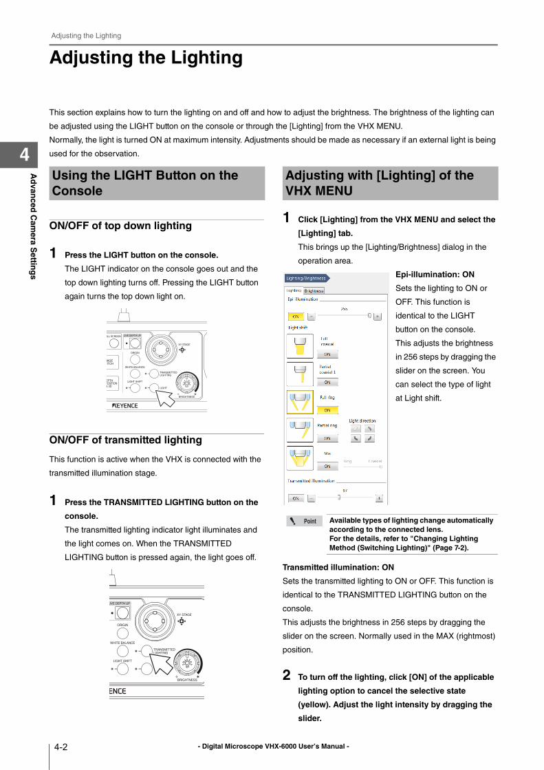
- Digital Microscope VHX-6000 User’s Manual -
Adjusting the Lighting
4-2
Ad
vanced
Cam
era Settin
gs
4
Adjusting the Lighting
This section explains how to turn the lighting on and off and how to adjust the brightness. The brightness of the lighting can
be adjusted using the LIGHT button on the console or through the [Lighting] from the VHX MENU.
Normally, the light is turned ON at maximum intensity. Adjustments should be made as necessary if an external light is being
used for the observation.
ON/OFF of top down lighting
1 Press the LIGHT button on the console.
The LIGHT indicator on the console goes out and the
top down lighting turns off. Pressing the LIGHT button
again turns the top down light on.
ON/OFF of transmitted lighting
This function is active when the VHX is connected with the
transmitted illumination stage.
1 Press the TRANSMITTED LIGHTING button on the
console.
The transmitted lighting indicator light illuminates and
the light comes on. When the TRANSMITTED
LIGHTING button is pressed again, the light goes off.
1 Click [Lighting] from the VHX MENU and select the
[Lighting] tab.
This brings up the [Lighting/Brightness] dialog in the
operation area.
Epi-illumination: ON
Sets the lighting to ON or
OFF. This function is
identical to the LIGHT
button on the console.
This adjusts the brightness
in 256 steps by dragging the
slider on the screen. You
can select the type of light
at Light shift.
Transmitted illumination: ON
Sets the transmitted lighting to ON or OFF. This function is
identical to the TRANSMITTED LIGHTING button on the
console.
This adjusts the brightness in 256 steps by dragging the
slider on the screen. Normally used in the MAX (rightmost)
position.
2 To turn off the lighting, click [ON] of the applicable
lighting option to cancel the selective state
(yellow). Adjust the light intensity by dragging the
slider.
Using the LIGHT Button on the Console
Adjusting with [Lighting] of the VHX MENU
Available types of lighting change automatically according to the connected lens.For the details, refer to "Changing Lighting Method (Switching Lighting)" (Page 7-2).
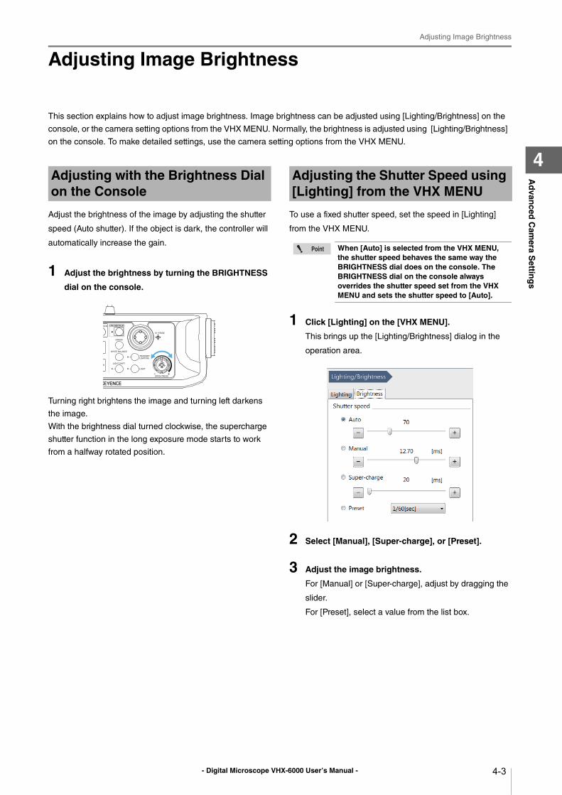
- Digital Microscope VHX-6000 User’s Manual -
Adjusting Image Brightness
4-3
Ad
vanced
Cam
era Settin
gs
4
Adjusting Image Brightness
This section explains how to adjust image brightness. Image brightness can be adjusted using [Lighting/Brightness] on the
console, or the camera setting options from the VHX MENU. Normally, the brightness is adjusted using [Lighting/Brightness]
on the console. To make detailed settings, use the camera setting options from the VHX MENU.
Adjust the brightness of the image by adjusting the shutter
speed (Auto shutter). If the object is dark, the controller will
automatically increase the gain.
1 Adjust the brightness by turning the BRIGHTNESS
dial on the console.
Turning right brightens the image and turning left darkens
the image.
With the brightness dial turned clockwise, the supercharge
shutter function in the long exposure mode starts to work
from a halfway rotated position.
To use a fixed shutter speed, set the speed in [Lighting]
from the VHX MENU.
1 Click [Lighting] on the [VHX MENU].
This brings up the [Lighting/Brightness] dialog in the
operation area.
2 Select [Manual], [Super-charge], or [Preset].
3 Adjust the image brightness.
For [Manual] or [Super-charge], adjust by dragging the
slider.
For [Preset], select a value from the list box.
Adjusting with the Brightness Dial on the Console
Adjusting the Shutter Speed using [Lighting] from the VHX MENU
When [Auto] is selected from the VHX MENU, the shutter speed behaves the same way the BRIGHTNESS dial does on the console. The BRIGHTNESS dial on the console always overrides the shutter speed set from the VHX MENU and sets the shutter speed to [Auto].
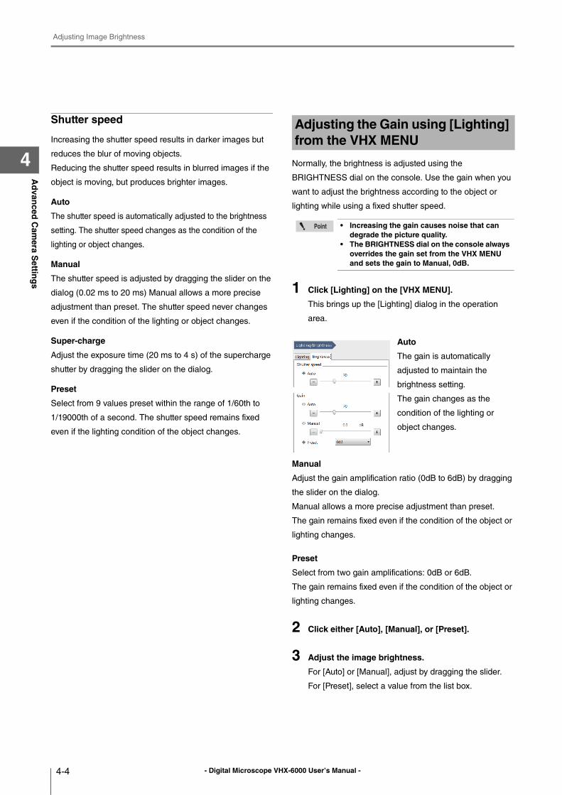
- Digital Microscope VHX-6000 User’s Manual -
Adjusting Image Brightness
4-4
Ad
vanced
Cam
era Settin
gs
4
Shutter speed
Increasing the shutter speed results in darker images but
reduces the blur of moving objects.
Reducing the shutter speed results in blurred images if the
object is moving, but produces brighter images.
Auto
The shutter speed is automatically adjusted to the brightness
setting. The shutter speed changes as the condition of the
lighting or object changes.
Manual
The shutter speed is adjusted by dragging the slider on the
dialog (0.02 ms to 20 ms) Manual allows a more precise
adjustment than preset. The shutter speed never changes
even if the condition of the lighting or object changes.
Super-charge
Adjust the exposure time (20 ms to 4 s) of the supercharge
shutter by dragging the slider on the dialog.
Preset
Select from 9 values preset within the range of 1/60th to
1/19000th of a second. The shutter speed remains fixed
even if the lighting condition of the object changes.
Normally, the brightness is adjusted using the
BRIGHTNESS dial on the console. Use the gain when you
want to adjust the brightness according to the object or
lighting while using a fixed shutter speed.
1 Click [Lighting] on the [VHX MENU].
This brings up the [Lighting] dialog in the operation
area.
Auto
The gain is automatically
adjusted to maintain the
brightness setting.
The gain changes as the
condition of the lighting or
object changes.
Manual
Adjust the gain amplification ratio (0dB to 6dB) by dragging
the slider on the dialog.
Manual allows a more precise adjustment than preset.
The gain remains fixed even if the condition of the object or
lighting changes.
Preset
Select from two gain amplifications: 0dB or 6dB.
The gain remains fixed even if the condition of the object or
lighting changes.
2 Click either [Auto], [Manual], or [Preset].
3 Adjust the image brightness.
For [Auto] or [Manual], adjust by dragging the slider.
For [Preset], select a value from the list box.
Adjusting the Gain using [Lighting] from the VHX MENU
• Increasing the gain causes noise that can degrade the picture quality.
• The BRIGHTNESS dial on the console always overrides the gain set from the VHX MENU and sets the gain to Manual, 0dB.
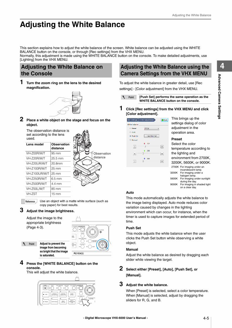
- Digital Microscope VHX-6000 User’s Manual -
Adjusting the White Balance
4-5
Ad
vanced
Cam
era Settin
gs
4
Adjusting the White Balance
This section explains how to adjust the white balance of the screen. White balance can be adjusted using the WHITE
BALANCE button on the console, or through [Rec settings] from the VHX MENU.
Normally, this adjustment is made using the WHITE BALANCE button on the console. To make detailed adjustments, use
[Lighting] from the VHX MENU.
1 Turn the zoom ring on the lens to the desired magnification.
2 Place a white object on the stage and focus on the object.
The observation distance is
set according to the lens
used.
3 Adjust the image brightness.
Adjust the image to the
appropriate brightness
(Page 4-3).
4 Press the [WHITE BALANCE] button on the console.This will adjust the white balance.
To adjust the white balance in greater detail, use [Rec
settings] - [Color adjustment] from the VHX MENU.
1 Click [Rec settings] from the VHX MENU and click [Color adjustment].
This brings up the
settings dialog of color
adjustment in the
operation area.
PresetSelect the color
temperature according to
the lighting and
environment from 2700K,
3200K, 5600K, or 9000K.
2700K For imaging under an
incandescent lamp.
3200K For imaging under a
halogen lamp.
5600K For imaging under sunlight
during the day.
9000K For imaging in shaded light
on a clear day.
Auto
This mode automatically adjusts the white balance to
the image being displayed. Auto mode reduces color
variation caused by changes in the lighting
environment which can occur, for instance, when the
timer is used to capture images for extended period of
time.
Push Set
This mode adjusts the white balance when the user
clicks the Push Set button while observing a white
object.
Manual
Adjust the white balance as desired by dragging each
slider while viewing the target.
2 Select either [Preset], [Auto], [Push Set], or
[Manual].
3 Adjust the white balance.
When [Preset] is selected, select a color temperature.
When [Manual] is selected, adjust by dragging the
sliders for R, G, and B.
Adjusting the White Balance on the Console
Lens model Observation distance
VH-Z00R/W/T 95 mm
VH-Z20R/W/T 25.5 mm
VH-Z20UR/W/T 20.8mm
VH-Z100R/W/T 25 mm
VH-Z100UR/W/T 25 mm
VH-Z250R/W/T 6.5 mm
VH-Z500R/W/T 4.4 mm
VH-Z50L/W/T 85 mm
VH-ZST 15 mm
Use an object with a matte white surface (such as
copy paper) for best results.
Adjust to prevent the image from becoming so bright that the image is saturated.
Observation
distance
Adjusting the White Balance using the Camera Settings from the VHX MENU
[Push Set] performs the same operation as the WHITE BALANCE button on the console.
- Digital Microscope VHX-6000 User’s Manual -
Adjusting the White Balance
4-6
Ad
vanced
Cam
era Settin
gs
4
- Digital Microscope VHX-6000 User’s Manual - 5-1
Chapter5R
ecord
ing
(Savin
g) Im
ages
5
Recording (Saving) Images
This chapter explains how to capture, retrieve, and edit images.
Recording/Saving Still Images ...............................Page 5-2
Recording (Saving) from the Console ................Page 5-2
Recording (Saving) using the Direct Buttons......Page 5-2
Names and Functions on the Rec Dialog Box....Page 5-3
Rec Settings...........................................................Page 5-5
Setting the Recording Size.................................Page 5-5
Setting Auto Rec ................................................Page 5-6
Loading Recording Settings ...............................Page 5-7
Setting up Timer Recording................................Page 5-8
Wide-view...............................................................Page 5-9
Observing in Wide-view .....................................Page 5-9
Recording and Saving Videos..............................Page 5-10
Names and Functions on the [Record video] Dialog Box
..................................................................... Page 5-11
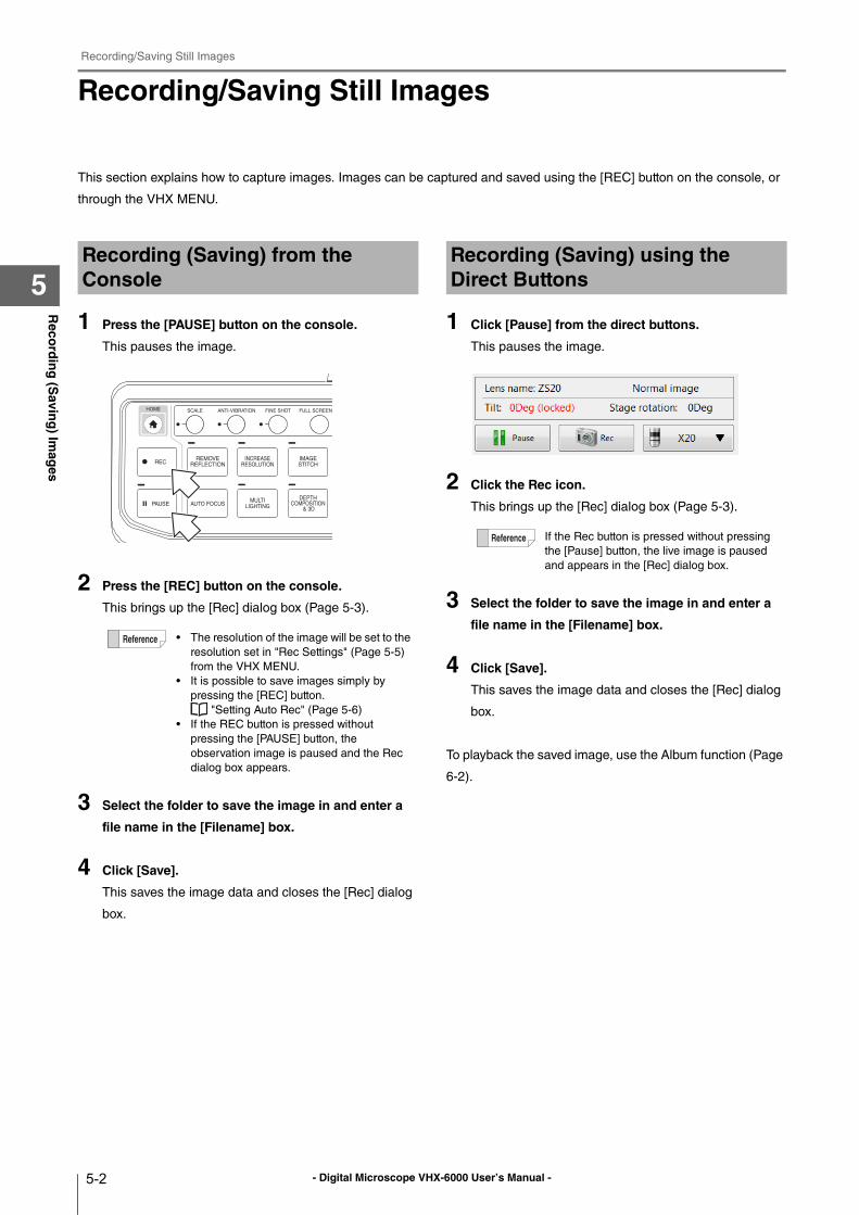
- Digital Microscope VHX-6000 User’s Manual -
Recording/Saving Still Images
5-2
Reco
rdin
g (S
aving
) Imag
es
5
Recording/Saving Still Images
This section explains how to capture images. Images can be captured and saved using the [REC] button on the console, or
through the VHX MENU.
1 Press the [PAUSE] button on the console.
This pauses the image.
2 Press the [REC] button on the console.
This brings up the [Rec] dialog box (Page 5-3).
3 Select the folder to save the image in and enter a
file name in the [Filename] box.
4 Click [Save].
This saves the image data and closes the [Rec] dialog
box.
1 Click [Pause] from the direct buttons.
This pauses the image.
2 Click the Rec icon.
This brings up the [Rec] dialog box (Page 5-3).
3 Select the folder to save the image in and enter a
file name in the [Filename] box.
4 Click [Save].
This saves the image data and closes the [Rec] dialog
box.
To playback the saved image, use the Album function (Page
6-2).
Recording (Saving) from the Console
• The resolution of the image will be set to the
resolution set in "Rec Settings" (Page 5-5)
from the VHX MENU.
• It is possible to save images simply by
pressing the [REC] button.
"Setting Auto Rec" (Page 5-6)
• If the REC button is pressed without
pressing the [PAUSE] button, the
observation image is paused and the Rec
dialog box appears.
Recording (Saving) using the Direct Buttons
If the Rec button is pressed without pressing
the [Pause] button, the live image is paused
and appears in the [Rec] dialog box.
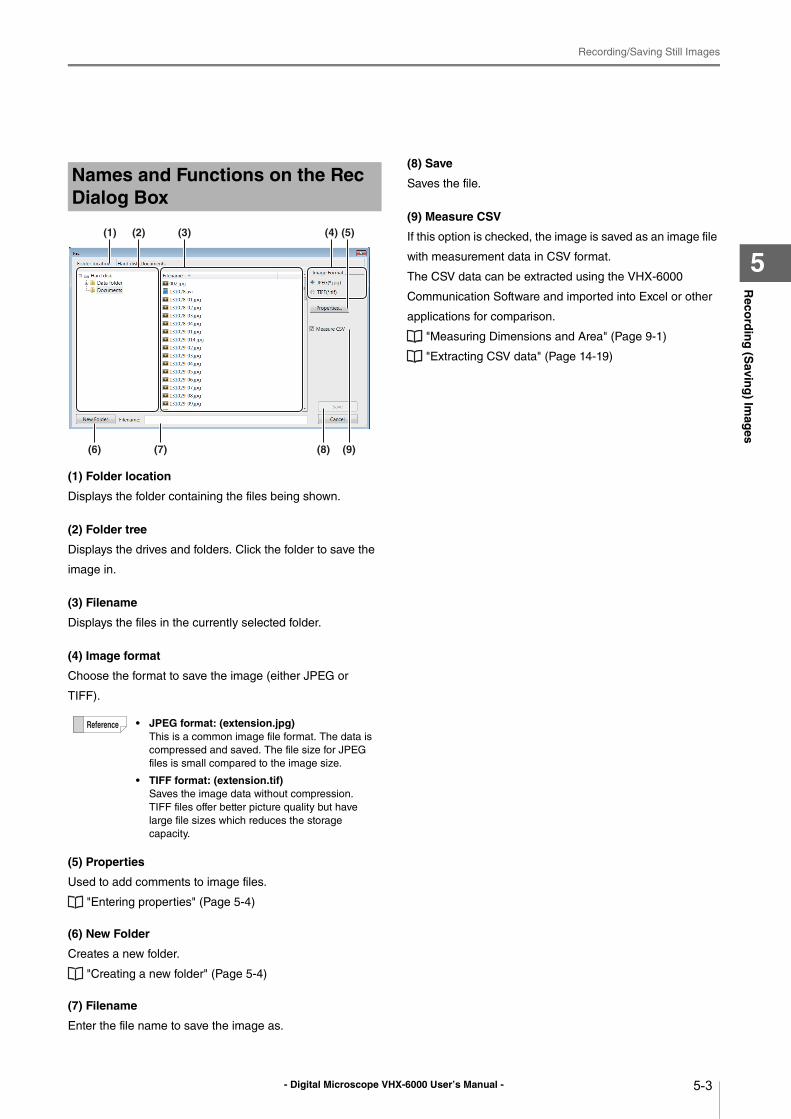
- Digital Microscope VHX-6000 User’s Manual -
Recording/Saving Still Images
5-3
Reco
rdin
g (S
aving
) Imag
es
5
(1) Folder location
Displays the folder containing the files being shown.
(2) Folder tree
Displays the drives and folders. Click the folder to save the
image in.
(3) Filename
Displays the files in the currently selected folder.
(4) Image format
Choose the format to save the image (either JPEG or
TIFF).
(5) Properties
Used to add comments to image files.
"Entering properties" (Page 5-4)
(6) New Folder
Creates a new folder.
"Creating a new folder" (Page 5-4)
(7) Filename
Enter the file name to save the image as.
(8) Save
Saves the file.
(9) Measure CSV
If this option is checked, the image is saved as an image file
with measurement data in CSV format.
The CSV data can be extracted using the VHX-6000
Communication Software and imported into Excel or other
applications for comparison.
"Measuring Dimensions and Area" (Page 9-1)
"Extracting CSV data" (Page 14-19)
Names and Functions on the Rec Dialog Box
• JPEG format: (extension.jpg)This is a common image file format. The data is
compressed and saved. The file size for JPEG
files is small compared to the image size.
• TIFF format: (extension.tif)Saves the image data without compression.
TIFF files offer better picture quality but have
large file sizes which reduces the storage
capacity.
(6) (7) (8) (9)
(4)(3)(1) (2) (5)
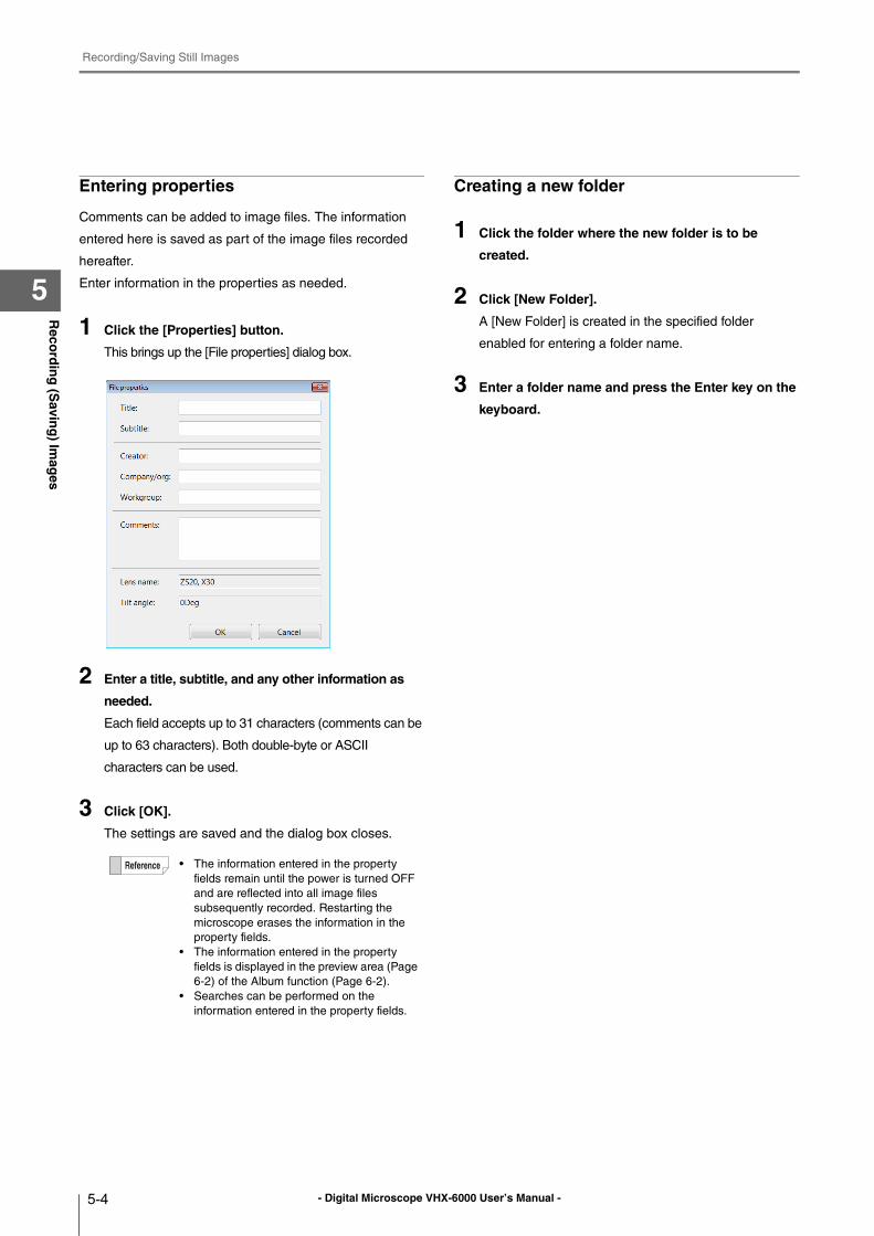
- Digital Microscope VHX-6000 User’s Manual -
Recording/Saving Still Images
5-4
Reco
rdin
g (S
aving
) Imag
es
5
Entering properties
Comments can be added to image files. The information
entered here is saved as part of the image files recorded
hereafter.
Enter information in the properties as needed.
1 Click the [Properties] button.
This brings up the [File properties] dialog box.
2 Enter a title, subtitle, and any other information as
needed.
Each field accepts up to 31 characters (comments can be
up to 63 characters). Both double-byte or ASCII
characters can be used.
3 Click [OK].
The settings are saved and the dialog box closes.
Creating a new folder
1 Click the folder where the new folder is to be
created.
2 Click [New Folder].
A [New Folder] is created in the specified folder
enabled for entering a folder name.
3 Enter a folder name and press the Enter key on the
keyboard.
• The information entered in the property
fields remain until the power is turned OFF
and are reflected into all image files
subsequently recorded. Restarting the
microscope erases the information in the
property fields.
• The information entered in the property
fields is displayed in the preview area (Page
6-2) of the Album function (Page 6-2).
• Searches can be performed on the
information entered in the property fields.
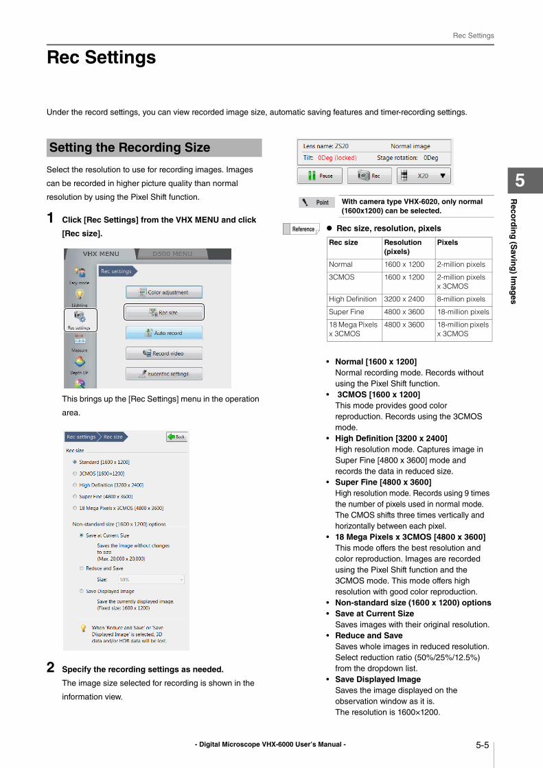
- Digital Microscope VHX-6000 User’s Manual -
Rec Settings
5-5
Reco
rdin
g (S
aving
) Imag
es
5
Rec Settings
Under the record settings, you can view recorded image size, automatic saving features and timer-recording settings.
Select the resolution to use for recording images. Images
can be recorded in higher picture quality than normal
resolution by using the Pixel Shift function.
1 Click [Rec Settings] from the VHX MENU and click
[Rec size].
This brings up the [Rec Settings] menu in the operation
area.
2 Specify the recording settings as needed.
The image size selected for recording is shown in the
information view.
Setting the Recording Size
With camera type VHX-6020, only normal (1600x1200) can be selected.
Rec size, resolution, pixels
• Normal [1600 x 1200]Normal recording mode. Records without
using the Pixel Shift function.
• 3CMOS [1600 x 1200]This mode provides good color
reproduction. Records using the 3CMOS
mode.
• High Definition [3200 x 2400]High resolution mode. Captures image in
Super Fine [4800 x 3600] mode and
records the data in reduced size.
• Super Fine [4800 x 3600]High resolution mode. Records using 9 times
the number of pixels used in normal mode.
The CMOS shifts three times vertically and
horizontally between each pixel.
• 18 Mega Pixels x 3CMOS [4800 x 3600]This mode offers the best resolution and
color reproduction. Images are recorded
using the Pixel Shift function and the
3CMOS mode. This mode offers high
resolution with good color reproduction.
• Non-standard size (1600 x 1200) options• Save at Current Size
Saves images with their original resolution.
• Reduce and SaveSaves whole images in reduced resolution.
Select reduction ratio (50%/25%/12.5%)
from the dropdown list.
• Save Displayed ImageSaves the image displayed on the
observation window as it is.
The resolution is 1600×1200.
Rec size Resolution (pixels)
Pixels
Normal 1600 x 1200 2-million pixels
3CMOS 1600 x 1200 2-million pixels x 3CMOS
High Definition 3200 x 2400 8-million pixels
Super Fine 4800 x 3600 18-million pixels
18 Mega Pixels x 3CMOS
4800 x 3600 18-million pixels x 3CMOS
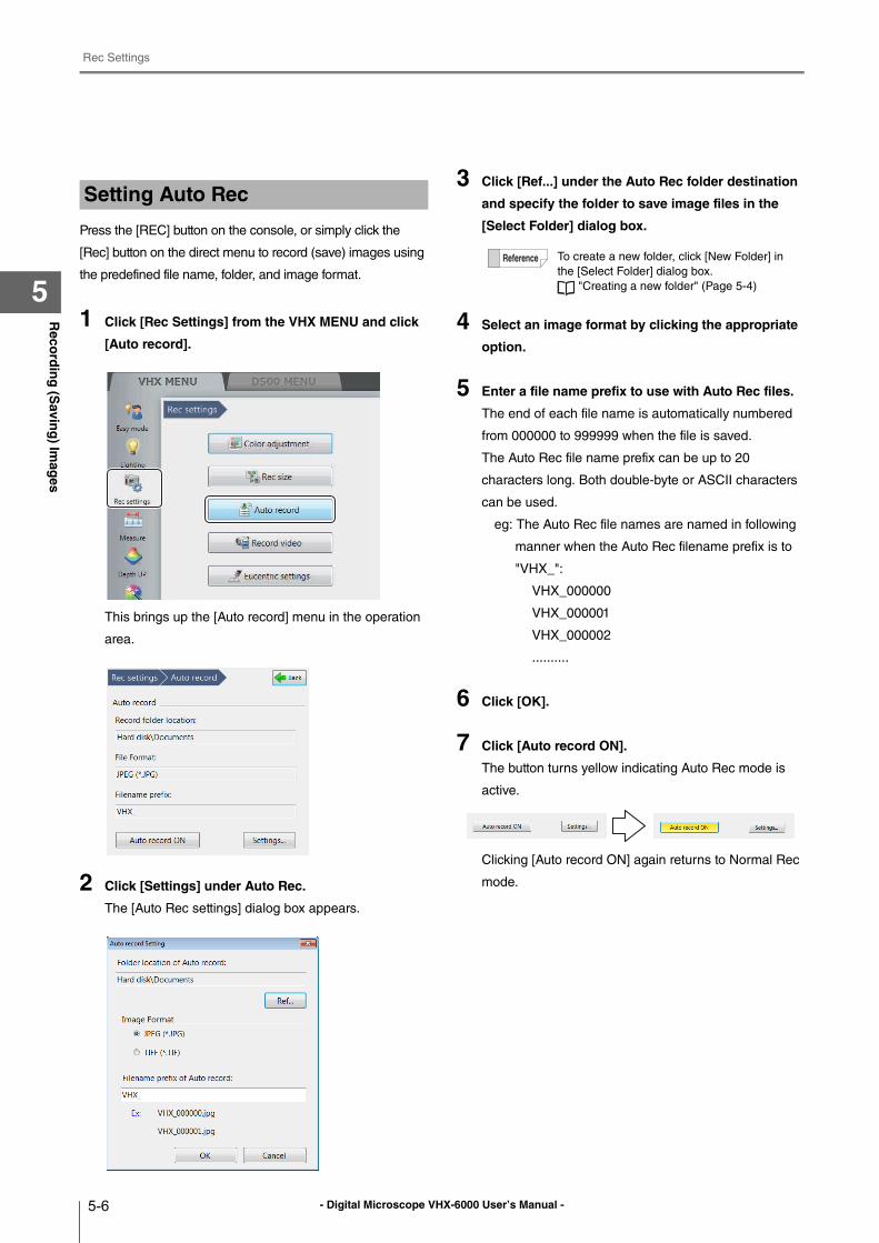
- Digital Microscope VHX-6000 User’s Manual -
Rec Settings
5-6
Reco
rdin
g (S
aving
) Imag
es
5
Press the [REC] button on the console, or simply click the
[Rec] button on the direct menu to record (save) images using
the predefined file name, folder, and image format.
1 Click [Rec Settings] from the VHX MENU and click
[Auto record].
This brings up the [Auto record] menu in the operation
area.
2 Click [Settings] under Auto Rec.
The [Auto Rec settings] dialog box appears.
3 Click [Ref...] under the Auto Rec folder destination
and specify the folder to save image files in the
[Select Folder] dialog box.
4 Select an image format by clicking the appropriate
option.
5 Enter a file name prefix to use with Auto Rec files.
The end of each file name is automatically numbered
from 000000 to 999999 when the file is saved.
The Auto Rec file name prefix can be up to 20
characters long. Both double-byte or ASCII characters
can be used.
eg: The Auto Rec file names are named in following
manner when the Auto Rec filename prefix is to
"VHX_":
VHX_000000
VHX_000001
VHX_000002
..........
6 Click [OK].
7 Click [Auto record ON].
The button turns yellow indicating Auto Rec mode is
active.
Clicking [Auto record ON] again returns to Normal Rec
mode.
Setting Auto Rec
To create a new folder, click [New Folder] in
the [Select Folder] dialog box.
"Creating a new folder" (Page 5-4)
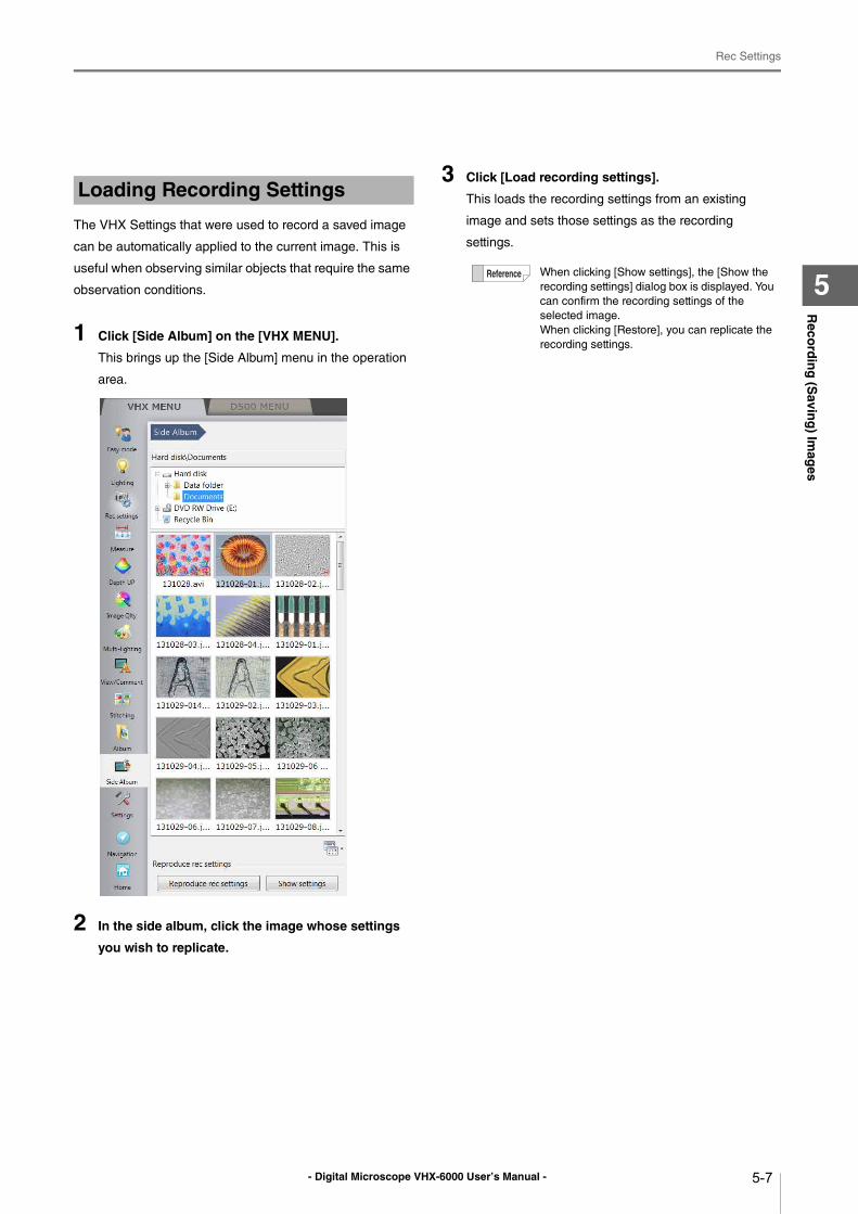
- Digital Microscope VHX-6000 User’s Manual -
Rec Settings
5-7
Reco
rdin
g (S
aving
) Imag
es
5
The VHX Settings that were used to record a saved image
can be automatically applied to the current image. This is
useful when observing similar objects that require the same
observation conditions.
1 Click [Side Album] on the [VHX MENU].
This brings up the [Side Album] menu in the operation
area.
2 In the side album, click the image whose settings
you wish to replicate.
3 Click [Load recording settings].
This loads the recording settings from an existing
image and sets those settings as the recording
settings.
Loading Recording Settings
When clicking [Show settings], the [Show the
recording settings] dialog box is displayed. You
can confirm the recording settings of the
selected image.
When clicking [Restore], you can replicate the
recording settings.
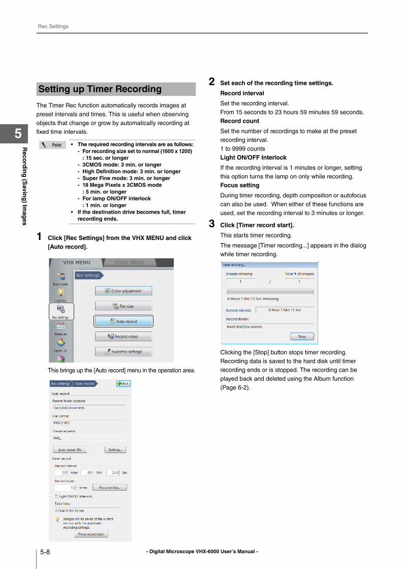
- Digital Microscope VHX-6000 User’s Manual -
Rec Settings
5-8
Reco
rdin
g (S
aving
) Imag
es
5
The Timer Rec function automatically records images at
preset intervals and times. This is useful when observing
objects that change or grow by automatically recording at
fixed time intervals.
1 Click [Rec Settings] from the VHX MENU and click [Auto record].
This brings up the [Auto record] menu in the operation area.
2 Set each of the recording time settings.
Record interval
Set the recording interval.
From 15 seconds to 23 hours 59 minutes 59 seconds.
Record count
Set the number of recordings to make at the preset
recording interval.
1 to 9999 counts
Light ON/OFF Interlock
If the recording interval is 1 minutes or longer, setting
this option turns the lamp on only while recording.
Focus setting
During timer recording, depth composition or autofocus
can also be used. When either of these functions are
used, set the recording interval to 3 minutes or longer.
3 Click [Timer record start].
This starts timer recording.
The message [Timer recording...] appears in the dialog
while timer recording.
Clicking the [Stop] button stops timer recording.
Recording data is saved to the hard disk until timer
recording ends or is stopped. The recording can be
played back and deleted using the Album function
(Page 6-2).
Setting up Timer Recording
• The required recording intervals are as follows:- For recording size set to normal (1600 x 1200)
: 15 sec. or longer- 3CMOS mode: 3 min. or longer- High Definition mode: 3 min. or longer- Super Fine mode: 3 min. or longer- 18 Mega Pixels x 3CMOS mode
: 5 min. or longer- For lamp ON/OFF interlock
: 1 min. or longer• If the destination drive becomes full, timer
recording ends.
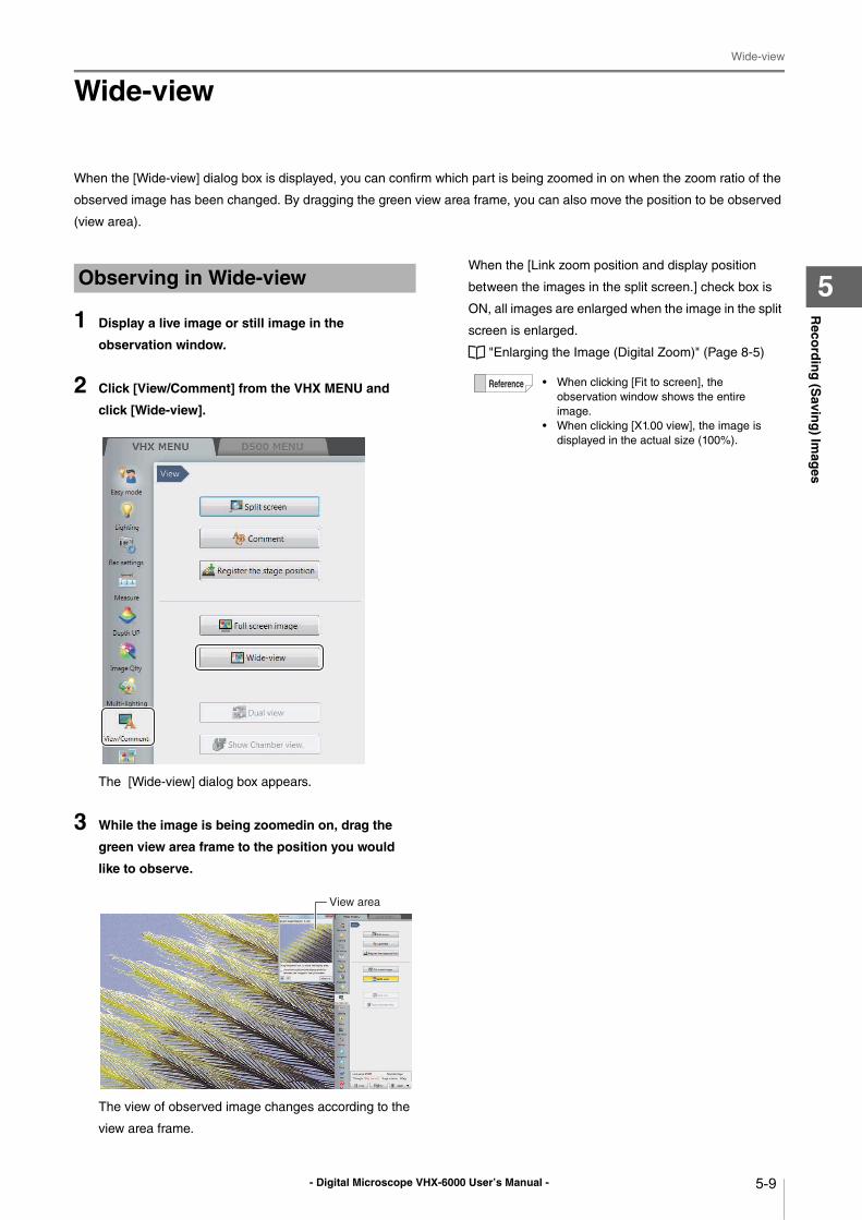
- Digital Microscope VHX-6000 User’s Manual -
Wide-view
5-9
Reco
rdin
g (S
aving
) Imag
es
5
Wide-view
When the [Wide-view] dialog box is displayed, you can confirm which part is being zoomed in on when the zoom ratio of the
observed image has been changed. By dragging the green view area frame, you can also move the position to be observed
(view area).
1 Display a live image or still image in the
observation window.
2 Click [View/Comment] from the VHX MENU and
click [Wide-view].
The [Wide-view] dialog box appears.
3 While the image is being zoomedin on, drag the
green view area frame to the position you would
like to observe.
The view of observed image changes according to the
view area frame.
When the [Link zoom position and display position
between the images in the split screen.] check box is
ON, all images are enlarged when the image in the split
screen is enlarged.
"Enlarging the Image (Digital Zoom)" (Page 8-5)
Observing in Wide-view
View area
• When clicking [Fit to screen], the
observation window shows the entire
image.
• When clicking [X1.00 view], the image is
displayed in the actual size (100%).
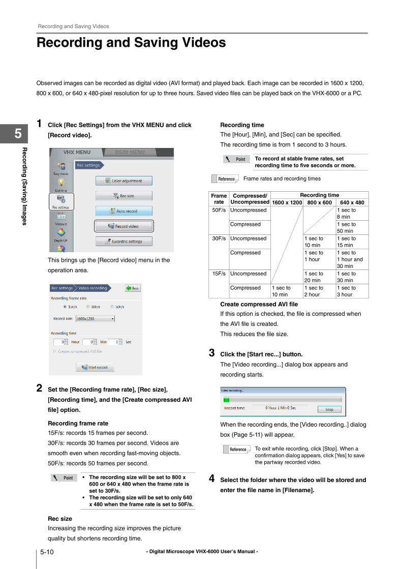
- Digital Microscope VHX-6000 User’s Manual -
Recording and Saving Videos
5-10
Reco
rdin
g (S
aving
) Imag
es
5
Recording and Saving Videos
Observed images can be recorded as digital video (AVI format) and played back. Each image can be recorded in 1600 x 1200,
800 x 600, or 640 x 480-pixel resolution for up to three hours. Saved video files can be played back on the VHX-6000 or a PC.
1 Click [Rec Settings] from the VHX MENU and click
[Record video].
This brings up the [Record video] menu in the
operation area.
2 Set the [Recording frame rate], [Rec size],
[Recording time], and the [Create compressed AVI
file] option.
Recording frame rate
15F/s: records 15 frames per second.
30F/s: records 30 frames per second. Videos are
smooth even when recording fast-moving objects.
50F/s: records 50 frames per second.
Rec size
Increasing the recording size improves the picture
quality but shortens recording time.
Recording time
The [Hour], [Min], and [Sec] can be specified.
The recording time is from 1 second to 3 hours.
Create compressed AVI file
If this option is checked, the file is compressed when
the AVI file is created.
This reduces the file size.
3 Click the [Start rec...] button.
The [Video recording...] dialog box appears and
recording starts.
When the recording ends, the [Video recording..] dialog
box (Page 5-11) will appear.
4 Select the folder where the video will be stored and
enter the file name in [Filename].
• The recording size will be set to 800 x 600 or 640 x 480 when the frame rate is set to 30F/s.
• The recording size will be set to only 640 x 480 when the frame rate is set to 50F/s.
To record at stable frame rates, set recording time to five seconds or more.
Frame rates and recording times
Frame rate
Compressed/Uncompressed
Recording time1600 x 1200 800 x 600 640 x 480
50F/s Uncompressed 1 sec to
8 min
Compressed 1 sec to
50 min
30F/s Uncompressed 1 sec to
10 min
1 sec to
15 min
Compressed 1 sec to
1 hour
1 sec to
1 hour and
30 min
15F/s Uncompressed 1 sec to
20 min
1 sec to
30 min
Compressed 1 sec to
10 min
1 sec to
2 hour
1 sec to
3 hour
To exit while recording, click [Stop]. When a
confirmation dialog appears, click [Yes] to save
the partway recorded video.
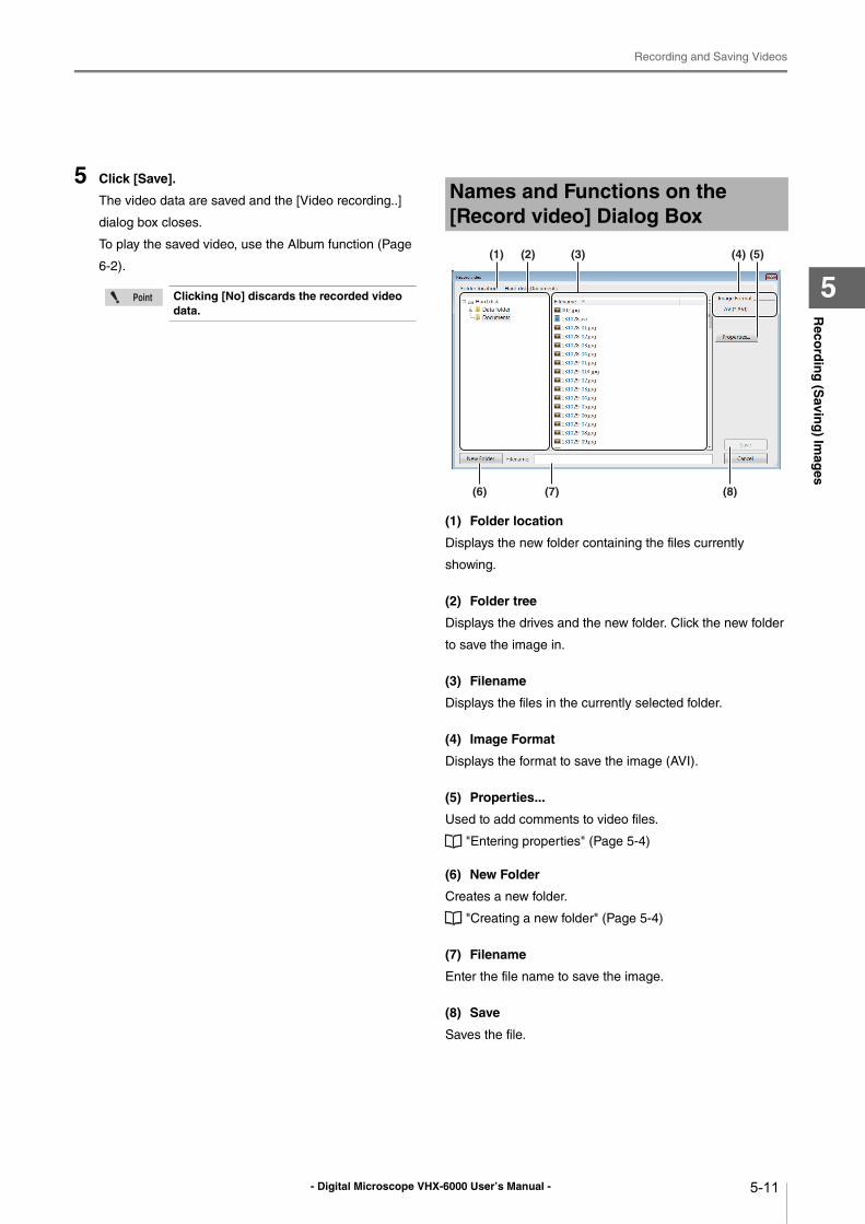
- Digital Microscope VHX-6000 User’s Manual -
Recording and Saving Videos
5-11
Reco
rdin
g (S
aving
) Imag
es
5
5 Click [Save].
The video data are saved and the [Video recording..]
dialog box closes.
To play the saved video, use the Album function (Page
6-2).
(1) Folder location
Displays the new folder containing the files currently
showing.
(2) Folder tree
Displays the drives and the new folder. Click the new folder
to save the image in.
(3) Filename
Displays the files in the currently selected folder.
(4) Image Format
Displays the format to save the image (AVI).
(5) Properties...
Used to add comments to video files.
"Entering properties" (Page 5-4)
(6) New Folder
Creates a new folder.
"Creating a new folder" (Page 5-4)
(7) Filename
Enter the file name to save the image.
(8) Save
Saves the file.
Clicking [No] discards the recorded video data.
Names and Functions on the [Record video] Dialog Box
(6) (7) (8)
(4)(3)(1) (2) (5)
- Digital Microscope VHX-6000 User’s Manual -
Recording and Saving Videos
5-12
Reco
rdin
g (S
aving
) Imag
es
5
- Digital Microscope VHX-6000 User’s Manual - 6-1
Chapter6P
laying
and
Ed
iting
Imag
es
6
Playing and Editing Images
Working with Saved Files
This chapter explains the Album function which provides
the ability to play, edit, and view thumbnail previews of
recorded (saved) still images and video files.
Album.....................................................................Page 6-2
Names and Functions ........................................Page 6-2
Playing Files.......................................................Page 6-6
Displaying and Entering Properties ..................Page 6-10
Depth Up.......................................................... Page 6-11
Creating Color Composition Images ................Page 6-12
Searching Files ................................................Page 6-14
Changing the View of the Files Window...........Page 6-15
Options.............................................................Page 6-16
Explorer............................................................Page 6-18
Report Output ..................................................Page 6-19
Measurement Result Summary .......................Page 6-20
Side Album...........................................................Page 6-21
Launching the Side Album ...............................Page 6-21
Names and Functions ......................................Page 6-21
Playing Images.................................................Page 6-22
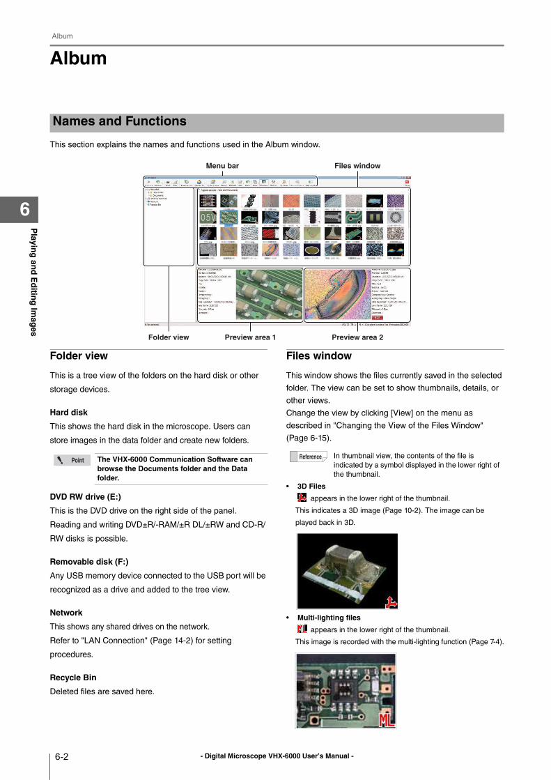
- Digital Microscope VHX-6000 User’s Manual -
Album
6-2
Playin
g an
d E
ditin
g Im
ages
6
Album
This section explains the names and functions used in the Album window.
Folder view
This is a tree view of the folders on the hard disk or other
storage devices.
Hard disk
This shows the hard disk in the microscope. Users can
store images in the data folder and create new folders.
DVD RW drive (E:)
This is the DVD drive on the right side of the panel.
Reading and writing DVD±R/-RAM/±R DL/±RW and CD-R/
RW disks is possible.
Removable disk (F:)
Any USB memory device connected to the USB port will be
recognized as a drive and added to the tree view.
Network
This shows any shared drives on the network.
Refer to "LAN Connection" (Page 14-2) for setting
procedures.
Recycle Bin
Deleted files are saved here.
Files window
This window shows the files currently saved in the selected
folder. The view can be set to show thumbnails, details, or
other views.
Change the view by clicking [View] on the menu as
described in "Changing the View of the Files Window"
(Page 6-15).
• 3D Files
appears in the lower right of the thumbnail.
This indicates a 3D image (Page 10-2). The image can be
played back in 3D.
• Multi-lighting files
appears in the lower right of the thumbnail.
This image is recorded with the multi-lighting function (Page 7-4).
Names and Functions
Folder view Preview area 1 Preview area 2
Menu bar Files window
The VHX-6000 Communication Software can browse the Documents folder and the Data folder.
In thumbnail view, the contents of the file is
indicated by a symbol displayed in the lower right of
the thumbnail.
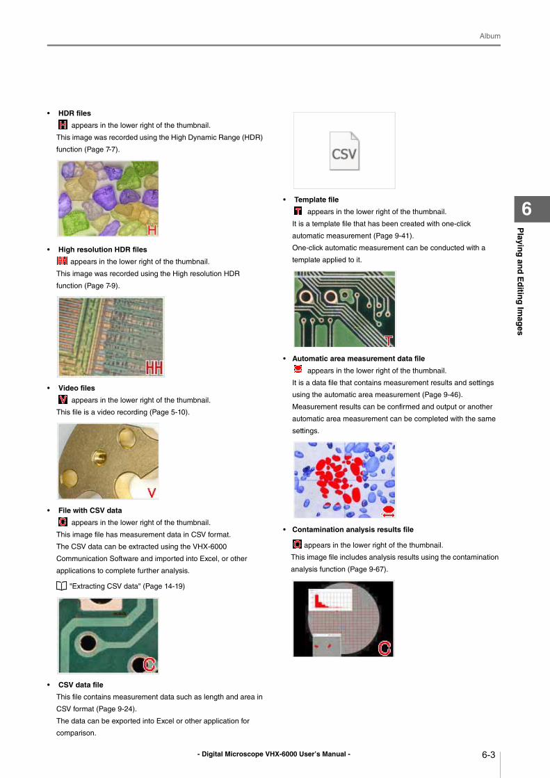
- Digital Microscope VHX-6000 User’s Manual -
Album
6-3
Playin
g an
d E
ditin
g Im
ages
6
• HDR files
appears in the lower right of the thumbnail.
This image was recorded using the High Dynamic Range (HDR)
function (Page 7-7).
• High resolution HDR files
appears in the lower right of the thumbnail.
This image was recorded using the High resolution HDR
function (Page 7-9).
• Video files
appears in the lower right of the thumbnail.
This file is a video recording (Page 5-10).
• File with CSV data
appears in the lower right of the thumbnail.
This image file has measurement data in CSV format.
The CSV data can be extracted using the VHX-6000
Communication Software and imported into Excel, or other
applications to complete further analysis.
"Extracting CSV data" (Page 14-19)
• CSV data file
This file contains measurement data such as length and area in
CSV format (Page 9-24).
The data can be exported into Excel or other application for
comparison.
• Template file
appears in the lower right of the thumbnail.
It is a template file that has been created with one-click
automatic measurement (Page 9-41).
One-click automatic measurement can be conducted with a
template applied to it.
• Automatic area measurement data file
appears in the lower right of the thumbnail.
It is a data file that contains measurement results and settings
using the automatic area measurement (Page 9-46).
Measurement results can be confirmed and output or another
automatic area measurement can be completed with the same
settings.
• Contamination analysis results file
appears in the lower right of the thumbnail.
This image file includes analysis results using the contamination
analysis function (Page 9-67).
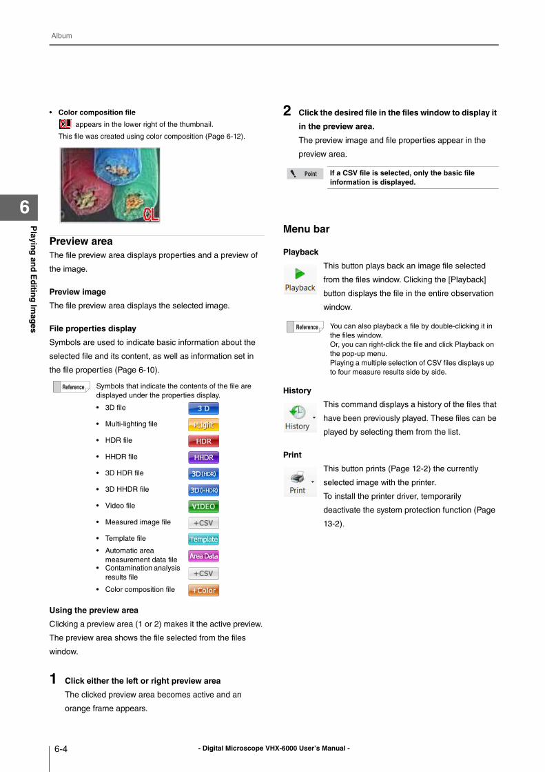
- Digital Microscope VHX-6000 User’s Manual -
Album
6-4
Playin
g an
d E
ditin
g Im
ages
6
• Color composition file
appears in the lower right of the thumbnail.
This file was created using color composition (Page 6-12).
Preview areaThe file preview area displays properties and a preview of
the image.
Preview image
The file preview area displays the selected image.
File properties display
Symbols are used to indicate basic information about the
selected file and its content, as well as information set in
the file properties (Page 6-10).
Using the preview area
Clicking a preview area (1 or 2) makes it the active preview.
The preview area shows the file selected from the files
window.
1 Click either the left or right preview area
The clicked preview area becomes active and an
orange frame appears.
2 Click the desired file in the files window to display it
in the preview area.
The preview image and file properties appear in the
preview area.
Menu bar
Playback
This button plays back an image file selected
from the files window. Clicking the [Playback]
button displays the file in the entire observation
window.
History
This command displays a history of the files that
have been previously played. These files can be
played by selecting them from the list.
This button prints (Page 12-2) the currently
selected image with the printer.
To install the printer driver, temporarily
deactivate the system protection function (Page
13-2).
Symbols that indicate the contents of the file are
displayed under the properties display.
• 3D file
• Multi-lighting file
• HDR file
• HHDR file
• 3D HDR file
• 3D HHDR file
• Video file
• Measured image file
• Template file
• Automatic area
measurement data file
• Contamination analysis
results file
• Color composition file
If a CSV file is selected, only the basic file information is displayed.
You can also playback a file by double-clicking it in
the files window.
Or, you can right-click the file and click Playback on
the pop-up menu.
Playing a multiple selection of CSV files displays up
to four measure results side by side.
- Digital Microscope VHX-6000 User’s Manual -
Album
6-5
Playin
g an
d E
ditin
g Im
ages
6
File
This button allows you to handle files.
New Folder
Creates a new folder on the hard disk in the
microscope.
Select the folder, at the folder view, where a new
folder is to be created before clicking.
Change name
Changes the name of the selected folder or file.
Delete
Move the selected file to the Recycle Bin.
Properties
You can display/set file properties (such as title
and creator) and display file information (such
as file type and size).
Save on disc
Save a selected file or folder to a disk (Page 12-
4).
Depth Up
This command combines image files recorded
at different focal points. The files can be
displayed combined or in 3D. This is useful for
viewing objects that are difficult to view
completely in focus due to large height
differences.
Refer to Page 10-2 for details on the Depth Up
function.
Color Comp
This command allows you to perform color
composition (Page 6-12) after selecting color
image and large-depth image.
Search
This command searches (Page 6-14) within the
hard disk. You can specify search criteria.
Refresh
This command refreshes the album view.
Edit
This button drops down to show the Cut, Copy,
Paste, and Select all commands.
Undo
This command undoes the most recent
command.
View
This button sets the display format (Page 6-15)
of the files window.
Preview
This button shows/hides the preview area.
Option
This button allows you to set the options (Page
6-16) of various functions.
You can create a new folder from the
menu which is displayed by right-
clicking a folder or files window.
You can change a name of a file or
folder by right-clicking a folder or file.
You can delete a file or folder from the
menu by right-clicking a folder or file.
• When a folder is selected, the
folder information is displayed.
• You can also display the file or
folder properties by right-clicking a
folder or file.
You can also search by right-clicking a folder and
clicking Search on the pop-up menu.
You can also use these commands from the pop-up
menu presented by right-clicking the folder or file.
[Undo] is allowed for only one command. Some operations cannot be undone.
Or, you can change the view format from the pop-
up menu presented by right-clicking in the files
window.
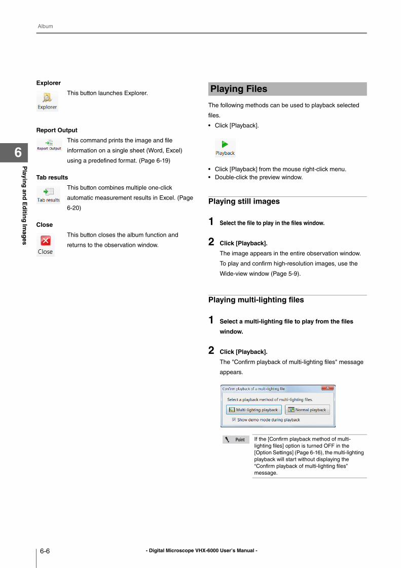
- Digital Microscope VHX-6000 User’s Manual -
Album
6-6
Playin
g an
d E
ditin
g Im
ages
6
Explorer
This button launches Explorer.
Report Output
This command prints the image and file
information on a single sheet (Word, Excel)
using a predefined format. (Page 6-19)
Tab results
This button combines multiple one-click
automatic measurement results in Excel. (Page
6-20)
Close
This button closes the album function and
returns to the observation window.
The following methods can be used to playback selected
files.
• Click [Playback].
• Click [Playback] from the mouse right-click menu.
• Double-click the preview window.
Playing still images
1 Select the file to play in the files window.
2 Click [Playback].
The image appears in the entire observation window.
To play and confirm high-resolution images, use the
Wide-view window (Page 5-9).
Playing multi-lighting files
1 Select a multi-lighting file to play from the files
window.
2 Click [Playback].
The "Confirm playback of multi-lighting files" message
appears.
Playing Files
If the [Confirm playback method of multi-
lighting files] option is turned OFF in the
[Option Settings] (Page 6-16), the multi-lighting
playback will start without displaying the
“Confirm playback of multi-lighting files”
message.
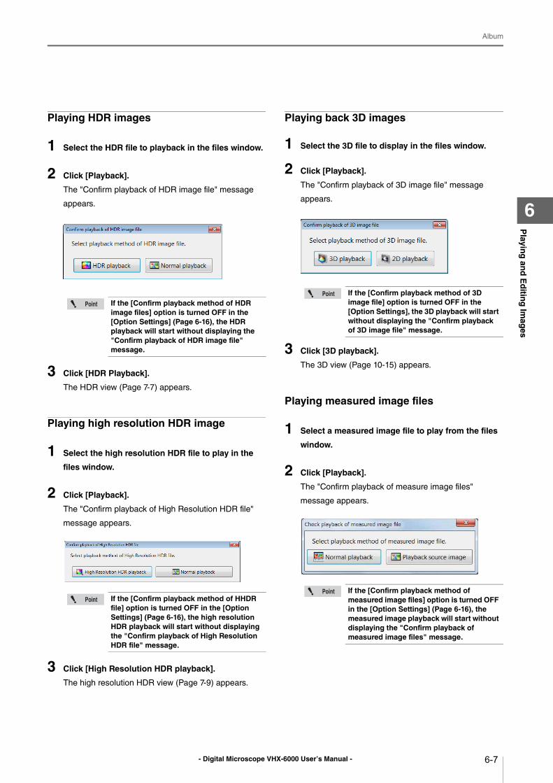
- Digital Microscope VHX-6000 User’s Manual -
Album
6-7
Playin
g an
d E
ditin
g Im
ages
6
Playing HDR images
1 Select the HDR file to playback in the files window.
2 Click [Playback].
The "Confirm playback of HDR image file" message
appears.
3 Click [HDR Playback].
The HDR view (Page 7-7) appears.
Playing high resolution HDR image
1 Select the high resolution HDR file to play in the
files window.
2 Click [Playback].
The "Confirm playback of High Resolution HDR file"
message appears.
3 Click [High Resolution HDR playback].
The high resolution HDR view (Page 7-9) appears.
Playing back 3D images
1 Select the 3D file to display in the files window.
2 Click [Playback].
The "Confirm playback of 3D image file" message
appears.
3 Click [3D playback].
The 3D view (Page 10-15) appears.
Playing measured image files
1 Select a measured image file to play from the files
window.
2 Click [Playback].
The "Confirm playback of measure image files"
message appears.
If the [Confirm playback method of HDR image files] option is turned OFF in the [Option Settings] (Page 6-16), the HDR playback will start without displaying the "Confirm playback of HDR image file" message.
If the [Confirm playback method of HHDR file] option is turned OFF in the [Option Settings] (Page 6-16), the high resolution HDR playback will start without displaying the "Confirm playback of High Resolution HDR file" message.
If the [Confirm playback method of 3D image file] option is turned OFF in the [Option Settings], the 3D playback will start without displaying the "Confirm playback of 3D image file" message.
If the [Confirm playback method of measured image files] option is turned OFF in the [Option Settings] (Page 6-16), the measured image playback will start without displaying the "Confirm playback of measured image files" message.
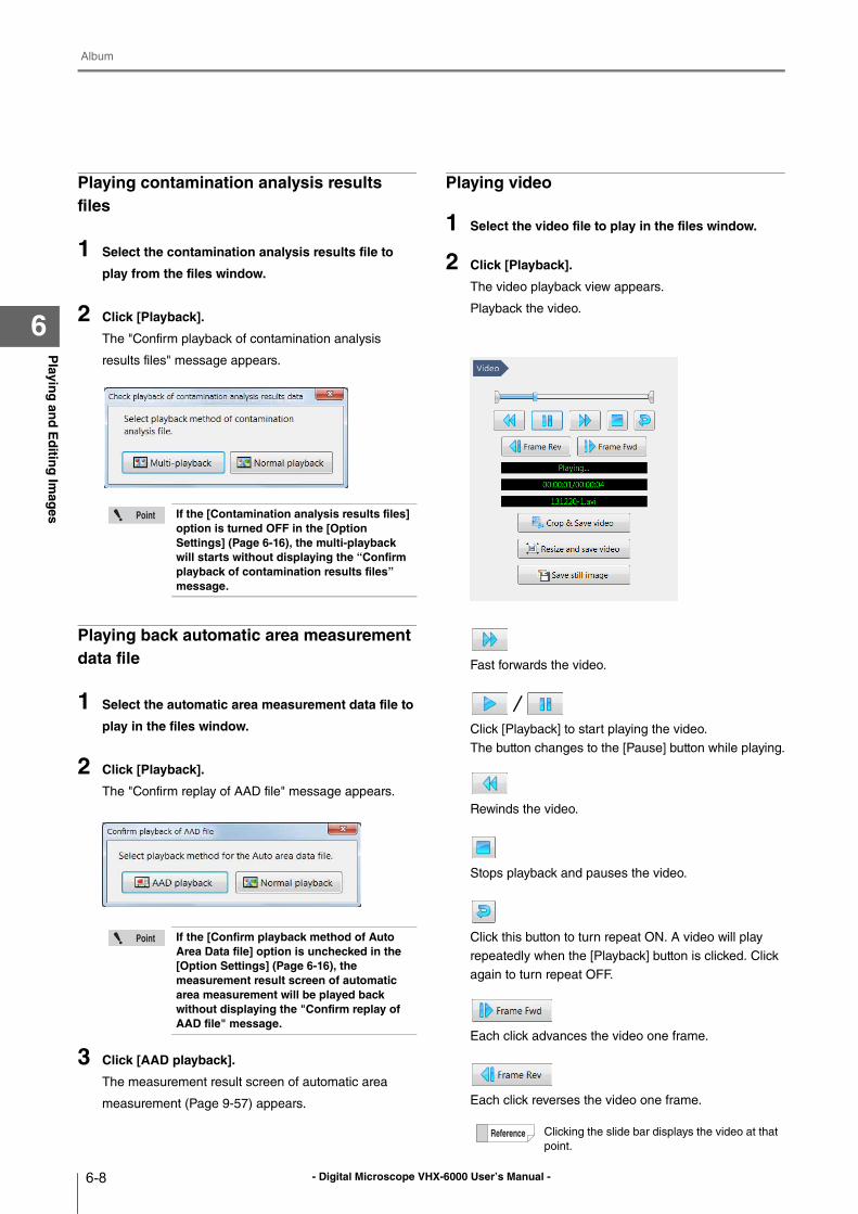
- Digital Microscope VHX-6000 User’s Manual -
Album
6-8
Playin
g an
d E
ditin
g Im
ages
6
Playing contamination analysis results files
1 Select the contamination analysis results file to
play from the files window.
2 Click [Playback].
The "Confirm playback of contamination analysis
results files" message appears.
Playing back automatic area measurement data file
1 Select the automatic area measurement data file to
play in the files window.
2 Click [Playback].
The "Confirm replay of AAD file" message appears.
3 Click [AAD playback].
The measurement result screen of automatic area
measurement (Page 9-57) appears.
Playing video
1 Select the video file to play in the files window.
2 Click [Playback].
The video playback view appears.
Playback the video.
Fast forwards the video.
Click [Playback] to start playing the video.
The button changes to the [Pause] button while playing.
Rewinds the video.
Stops playback and pauses the video.
Click this button to turn repeat ON. A video will play
repeatedly when the [Playback] button is clicked. Click
again to turn repeat OFF.
Each click advances the video one frame.
Each click reverses the video one frame.
If the [Contamination analysis results files] option is turned OFF in the [Option Settings] (Page 6-16), the multi-playback will starts without displaying the “Confirm playback of contamination results files” message.
If the [Confirm playback method of Auto Area Data file] option is unchecked in the [Option Settings] (Page 6-16), the measurement result screen of automatic area measurement will be played back without displaying the "Confirm replay of AAD file" message.
Clicking the slide bar displays the video at that
point.
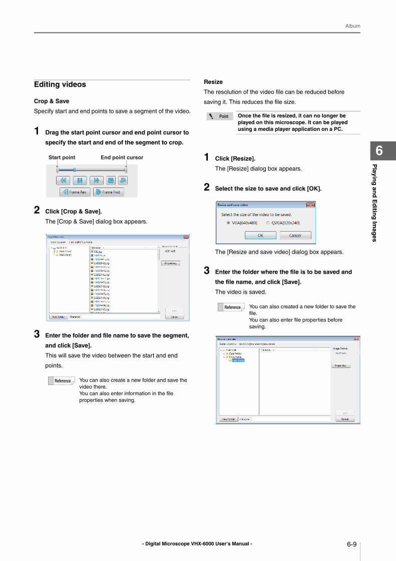
- Digital Microscope VHX-6000 User’s Manual -
Album
6-9
Playin
g an
d E
ditin
g Im
ages
6
Editing videos
Crop & Save
Specify start and end points to save a segment of the video.
1 Drag the start point cursor and end point cursor to
specify the start and end of the segment to crop.
2 Click [Crop & Save].
The [Crop & Save] dialog box appears.
3 Enter the folder and file name to save the segment,
and click [Save].
This will save the video between the start and end
points.
Resize
The resolution of the video file can be reduced before
saving it. This reduces the file size.
1 Click [Resize].
The [Resize] dialog box appears.
2 Select the size to save and click [OK].
The [Resize and save video] dialog box appears.
3 Enter the folder where the file is to be saved and
the file name, and click [Save].
The video is saved.
You can also create a new folder and save the
video there.
You can also enter information in the file
properties when saving.
Start point End point cursor
Once the file is resized, it can no longer be played on this microscope. It can be played using a media player application on a PC.
You can also created a new folder to save the
file.
You can also enter file properties before
saving.
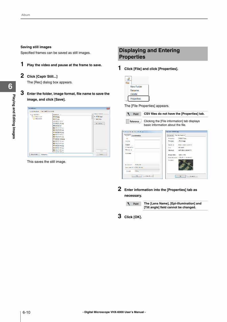
- Digital Microscope VHX-6000 User’s Manual -
Album
6-10
Playin
g an
d E
ditin
g Im
ages
6
Saving still images
Specified frames can be saved as still images.
1 Play the video and pause at the frame to save.
2 Click [Captr Still...]
The [Rec] dialog box appears.
3 Enter the folder, image format, file name to save the
image, and click [Save].
This saves the still image.
1 Click [File] and click [Properties].
The [File Properties] appears.
2 Enter information into the [Properties] tab as
necessary.
3 Click [OK].
Displaying and Entering Properties
CSV files do not have the [Properties] tab.
Clicking the [File information] tab displays
basic information about the file.
The [Lens Name], [Epi-illumination] and [Tilt angle] field cannot be changed.
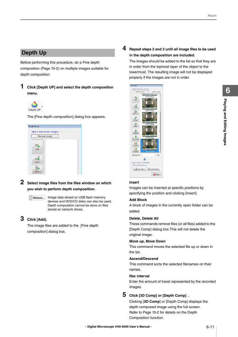
- Digital Microscope VHX-6000 User’s Manual -
Album
6-11
Playin
g an
d E
ditin
g Im
ages
6
Before performing this procedure, do a Fine depth
composition (Page 10-2) on multiple images suitable for
depth composition.
1 Click [Depth UP] and select the depth composition
menu.
The [Fine depth composition] dialog box appears.
2 Select image files from the files window on which
you wish to perform depth composition.
3 Click [Add].
The image files are added to the [Fine depth
composition] dialog box.
4 Repeat steps 2 and 3 until all image files to be used
in the depth composition are included.
The images should be added to the list so that they are
in order from the topmost layer of the object to the
lowermost. The resulting image will not be displayed
properly if the images are not in order.
Insert
Images can be inserted at specific positions by
specifying the position and clicking [Insert].
Add Block
A block of images in the currently open folder can be
added.
Delete, Delete All
These commands remove files (or all files) added to the
[Depth Comp] dialog box.This will not delete the
original image.
Move up, Move Down
This command moves the selected file up or down in
the list.
Ascend/Descend
This command sorts the selected filenames on their
names.
Rec interval
Enter the amount of travel represented by the recorded
images.
5 Click [3D Comp] or [Depth Comp] .
Clicking [3D Comp] or [Depth Comp] displays the
depth composed image using the full screen.
Refer to Page 10-2 for details on the Depth
Composition function.
Depth Up
Image data stored on USB flash memory
devices and DVD/CD disks can also be used.
Depth composition cannot be done on files
stored on network drives.
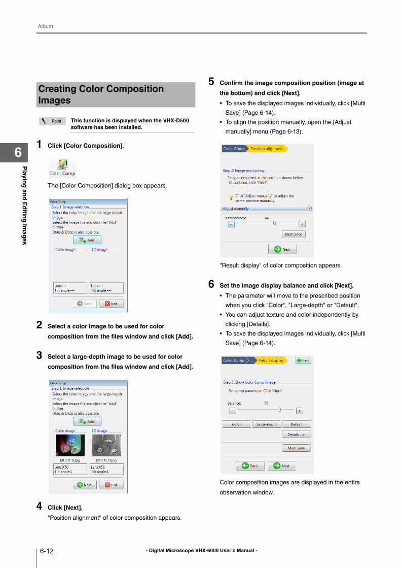
- Digital Microscope VHX-6000 User’s Manual -
Album
6-12
Playin
g an
d E
ditin
g Im
ages
61 Click [Color Composition].
The [Color Composition] dialog box appears.
2 Select a color image to be used for color
composition from the files window and click [Add].
3 Select a large-depth image to be used for color
composition from the files window and click [Add].
4 Click [Next].
"Position alignment" of color composition appears.
5 Confirm the image composition position (image at
the bottom) and click [Next].
• To save the displayed images individually, click [Multi
Save] (Page 6-14).
• To align the position manually, open the [Adjust
manually] menu (Page 6-13).
"Result display" of color composition appears.
6 Set the image display balance and click [Next].
• The parameter will move to the prescribed position
when you click "Color", "Large-depth" or "Default".
• You can adjust texture and color independently by
clicking [Details].
• To save the displayed images individually, click [Multi
Save] (Page 6-14).
Color composition images are displayed in the entire
observation window.
Creating Color Composition Images
This function is displayed when the VHX-D500 software has been installed.
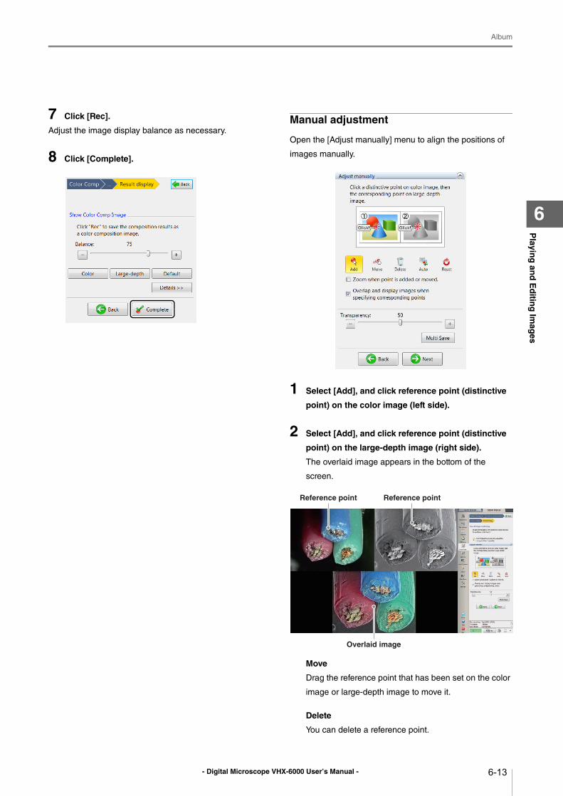
- Digital Microscope VHX-6000 User’s Manual -
Album
6-13
Playin
g an
d E
ditin
g Im
ages
6
7 Click [Rec].
Adjust the image display balance as necessary.
8 Click [Complete].
Manual adjustment
Open the [Adjust manually] menu to align the positions of
images manually.
1 Select [Add], and click reference point (distinctive
point) on the color image (left side).
2 Select [Add], and click reference point (distinctive
point) on the large-depth image (right side).
The overlaid image appears in the bottom of the
screen.
Move
Drag the reference point that has been set on the color
image or large-depth image to move it.
Delete
You can delete a reference point.
Reference point Reference point
Overlaid image
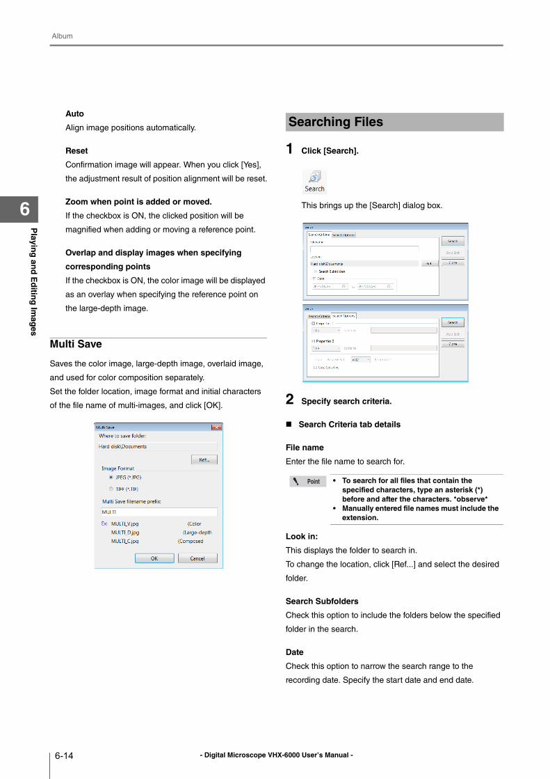
- Digital Microscope VHX-6000 User’s Manual -
Album
6-14
Playin
g an
d E
ditin
g Im
ages
6
Auto
Align image positions automatically.
Reset
Confirmation image will appear. When you click [Yes],
the adjustment result of position alignment will be reset.
Zoom when point is added or moved.
If the checkbox is ON, the clicked position will be
magnified when adding or moving a reference point.
Overlap and display images when specifying
corresponding points
If the checkbox is ON, the color image will be displayed
as an overlay when specifying the reference point on
the large-depth image.
Multi Save
Saves the color image, large-depth image, overlaid image,
and used for color composition separately.
Set the folder location, image format and initial characters
of the file name of multi-images, and click [OK].
1 Click [Search].
This brings up the [Search] dialog box.
2 Specify search criteria.
Search Criteria tab details
File name
Enter the file name to search for.
Look in:
This displays the folder to search in.
To change the location, click [Ref...] and select the desired
folder.
Search Subfolders
Check this option to include the folders below the specified
folder in the search.
Date
Check this option to narrow the search range to the
recording date. Specify the start date and end date.
Searching Files
• To search for all files that contain the specified characters, type an asterisk (*) before and after the characters. *observe*
• Manually entered file names must include the extension.
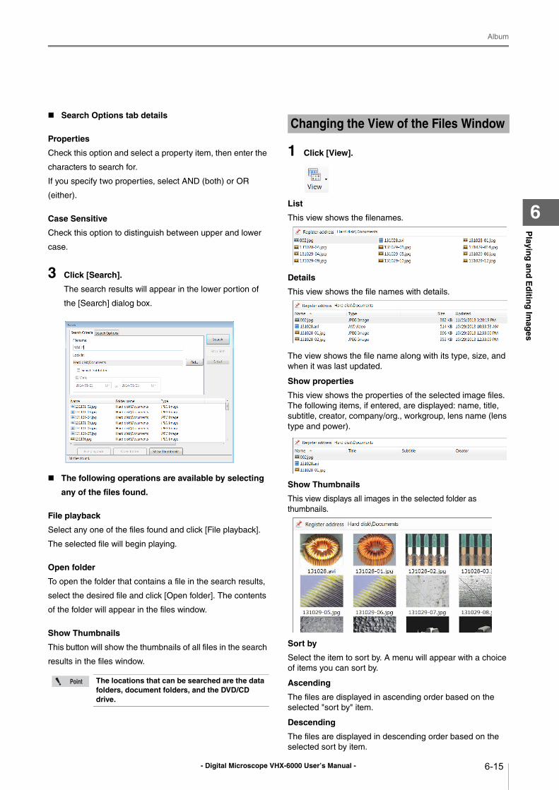
- Digital Microscope VHX-6000 User’s Manual -
Album
6-15
Playin
g an
d E
ditin
g Im
ages
6
Search Options tab details
Properties
Check this option and select a property item, then enter the
characters to search for.
If you specify two properties, select AND (both) or OR
(either).
Case Sensitive
Check this option to distinguish between upper and lower
case.
3 Click [Search].
The search results will appear in the lower portion of
the [Search] dialog box.
The following operations are available by selecting
any of the files found.
File playback
Select any one of the files found and click [File playback].
The selected file will begin playing.
Open folder
To open the folder that contains a file in the search results,
select the desired file and click [Open folder]. The contents
of the folder will appear in the files window.
Show Thumbnails
This button will show the thumbnails of all files in the search
results in the files window.
1 Click [View].
List
This view shows the filenames.
Details
This view shows the file names with details.
The view shows the file name along with its type, size, and
when it was last updated.
Show properties
This view shows the properties of the selected image files.
The following items, if entered, are displayed: name, title,
subtitle, creator, company/org., workgroup, lens name (lens
type and power).
Show Thumbnails
This view displays all images in the selected folder as
thumbnails.
Sort by
Select the item to sort by. A menu will appear with a choice
of items you can sort by.
Ascending
The files are displayed in ascending order based on the
selected "sort by" item.
Descending
The files are displayed in descending order based on the
selected sort by item.
The locations that can be searched are the data folders, document folders, and the DVD/CD drive.
Changing the View of the Files Window
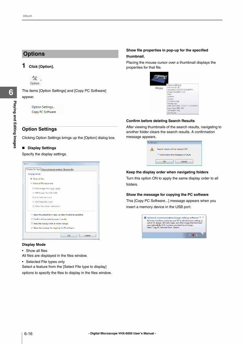
- Digital Microscope VHX-6000 User’s Manual -
Album
6-16
Playin
g an
d E
ditin
g Im
ages
6
1 Click [Option].
The items [Option Settings] and [Copy PC Software]
appear.
Option Settings
Clicking Option Settings brings up the [Option] dialog box.
Display Settings
Specify the display settings.
Display Mode
• Show all files
All files are displayed in the files window.
• Selected File types only
Select a feature from the [Select File type to display]
options to specify the files to display in the files window.
Show file properties in pop-up for the specified
thumbnail.
Placing the mouse cursor over a thumbnail displays the
properties for that file.
Confirm before deleting Search Results
After viewing thumbnails of the search results, navigating to
another folder clears the search results. A confirmation
message appears.
Keep the display order when navigating folders
Turn this option ON to apply the same display order to all
folders.
Show the message for copying the PC software
This [Copy PC Software...] message appears when you
insert a memory device in the USB port.
Options
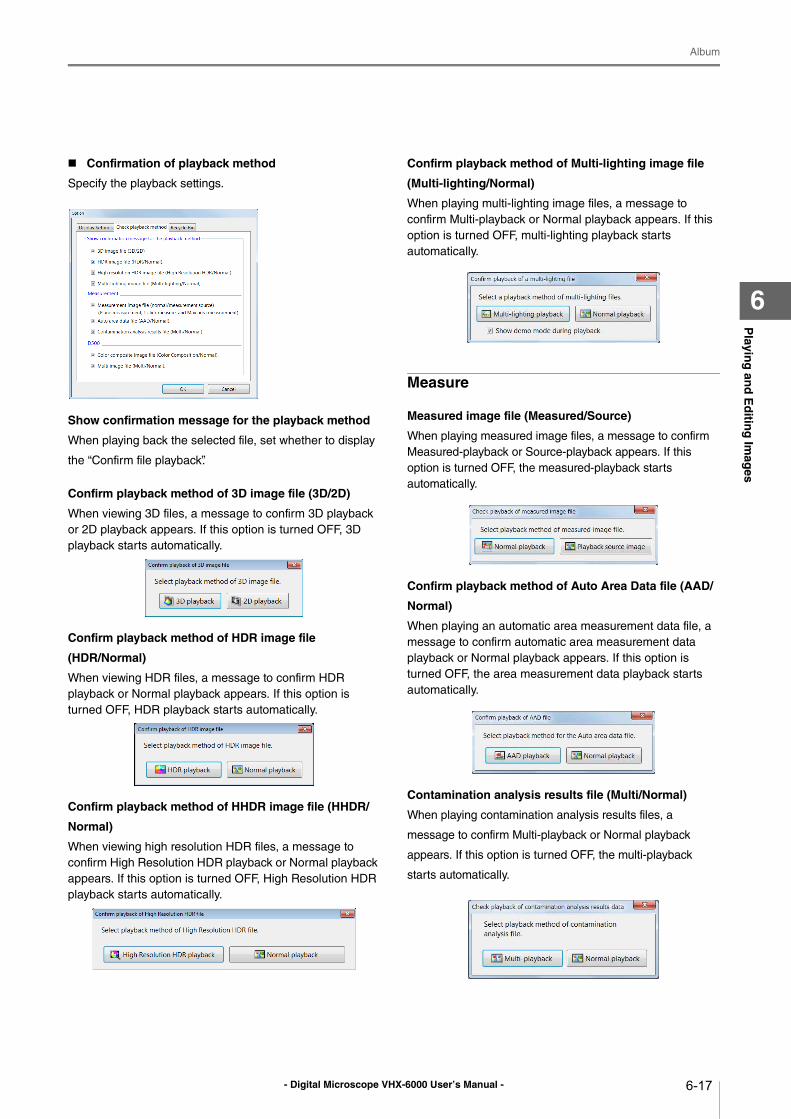
- Digital Microscope VHX-6000 User’s Manual -
Album
6-17
Playin
g an
d E
ditin
g Im
ages
6
Confirmation of playback method
Specify the playback settings.
Show confirmation message for the playback method
When playing back the selected file, set whether to display
the “Confirm file playback”.
Confirm playback method of 3D image file (3D/2D)
When viewing 3D files, a message to confirm 3D playback
or 2D playback appears. If this option is turned OFF, 3D
playback starts automatically.
Confirm playback method of HDR image file
(HDR/Normal)
When viewing HDR files, a message to confirm HDR
playback or Normal playback appears. If this option is
turned OFF, HDR playback starts automatically.
Confirm playback method of HHDR image file (HHDR/
Normal)
When viewing high resolution HDR files, a message to
confirm High Resolution HDR playback or Normal playback
appears. If this option is turned OFF, High Resolution HDR
playback starts automatically.
Confirm playback method of Multi-lighting image file
(Multi-lighting/Normal)
When playing multi-lighting image files, a message to
confirm Multi-playback or Normal playback appears. If this
option is turned OFF, multi-lighting playback starts
automatically.
Measure
Measured image file (Measured/Source)
When playing measured image files, a message to confirm
Measured-playback or Source-playback appears. If this
option is turned OFF, the measured-playback starts
automatically.
Confirm playback method of Auto Area Data file (AAD/
Normal)
When playing an automatic area measurement data file, a
message to confirm automatic area measurement data
playback or Normal playback appears. If this option is
turned OFF, the area measurement data playback starts
automatically.
Contamination analysis results file (Multi/Normal)
When playing contamination analysis results files, a
message to confirm Multi-playback or Normal playback
appears. If this option is turned OFF, the multi-playback
starts automatically.
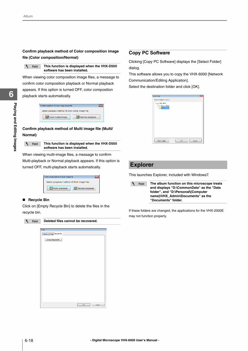
- Digital Microscope VHX-6000 User’s Manual -
Album
6-18
Playin
g an
d E
ditin
g Im
ages
6
Confirm playback method of Color composition image
file (Color composition/Normal)
When viewing color composition image files, a message to
confirm color composition playback or Normal playback
appears. If this option is turned OFF, color composition
playback starts automatically.
Confirm playback method of Multi image file (Multi/
Normal)
When viewing multi-image files, a message to confirm
Multi-playback or Normal playback appears. If this option is
turned OFF, multi-playback starts automatically.
Recycle Bin
Click on [Empty Recycle Bin] to delete the files in the
recycle bin.
Copy PC Software
Clicking [Copy PC Software] displays the [Select Folder]
dialog.
This software allows you to copy the VHX-6000 [Network
Communication/Editing Application].
Select the destination folder and click [OK].
This launches Explorer, included with Windows7.
If these folders are changed, the applications for the VHX-2000E
may not function properly.
This function is displayed when the VHX-D500 software has been installed.
This function is displayed when the VHX-D500 software has been installed.
Deleted files cannot be recovered.
Explorer
The album function on this microscope treats and displays "D:\CommonData" as the "Data folder", and "D:\Personal\(Computer name)\VHX_Admin\Documents" as the "Documents" folder.
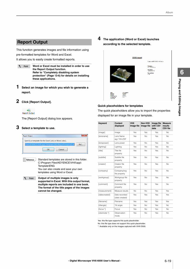
- Digital Microscope VHX-6000 User’s Manual -
Album
6-19
Playin
g an
d E
ditin
g Im
ages
6
This function generates images and file information using
pre-formatted templates for Word and Excel.
It allows you to easily create formatted reports.
1 Select an image for which you wish to generate a
report.
2 Click [Report Output].
The [Report Output] dialog box appears.
3 Select a template to use.
4 The application (Word or Excel) launches
according to the selected template.
Quick placeholders for templates
The quick placeholders allow you to import the properties
displayed for an image file in your template.
Yes: this file type supports this quick placeholder.
No: this file type does not support this quick placeholder.
*: Available only on the images captured with VHX-D500.
Report Output
Word or Excel must be installed in order to use the Report Output function.Refer to "Completely disabling system protection" (Page 13-6) for details on installing these applications.
Standard templates are stored in this folder.
C:\Program Files\KEYENCE\VHX\app\
Template\ENG
You can also create and save your own
templates using Word or Excel.
Output of multiple images is only supported in Excel. With this output format, multiple reports are included in one book. The format of the title pages of the images cannot be changed.
Keyword Content displayed
VHX Image file
Non-VHX Image file
Image file with CSV data
Measure results CSV file
[image] Image Yes Yes Yes No
[lensname] Lens Nameeg.) "VH-Z20"
Yes No Yes No
[lenspower] Lens power Yes No Yes No
[lighting] Lighting Yes No Yes No
[title] Title file property
Yes No Yes No
[subtitle] Subtitle file property
Yes No Yes No
[creator] Creator file property
Yes No Yes No
[company] Company/org: file property
Yes No Yes No
[workgroup] Workgroup file property
Yes No Yes No
[comment] Comment file property
Yes No Yes No
[measurement] Measure results No No Yes Yes
[datecreated] Date recorded (date created)
Yes Yes Yes Yes
[filename] Filename Yes Yes Yes Yes
[tiltangle] Tilt angle Yes No Yes No
[focus *] Focus Yes No Yes No
[obsmode *] Observation mode
Yes No Yes No
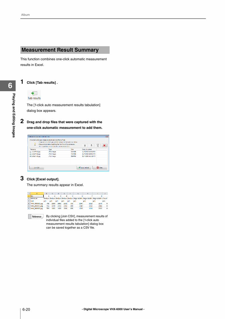
- Digital Microscope VHX-6000 User’s Manual -
Album
6-20
Playin
g an
d E
ditin
g Im
ages
6
This function combines one-click automatic measurement
results in Excel.
1 Click [Tab results] .
The [1-click auto measurement results tabulation]
dialog box appears.
2 Drag and drop files that were captured with the
one-click automatic measurement to add them.
3 Click [Excel output].
The summary results appear in Excel.
Measurement Result Summary
By clicking [Join CSV], measurement results of
individual files added to the [1-click auto
measurement results tabulation] dialog box
can be saved together as a CSV file.
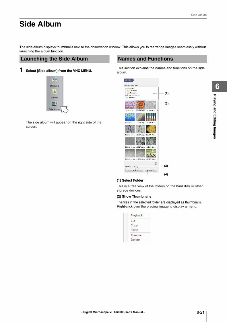
- Digital Microscope VHX-6000 User’s Manual -
Side Album
6-21
Playin
g an
d E
ditin
g Im
ages
6
Side Album
The side album displays thumbnails next to the observation window. This allows you to rearrange images seamlessly without
launching the album function.
1 Select [Side album] from the VHX MENU.
The side album will appear on the right side of the
screen.
This section explains the names and functions on the side
album.
(1) Select Folder
This is a tree view of the folders on the hard disk or other
storage devices.
(2) Show Thumbnails
The files in the selected folder are displayed as thumbnails.
Right-click over the preview image to display a menu.
Launching the Side Album Names and Functions
(1)
(2)
(3)
(4)
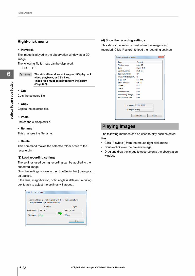
- Digital Microscope VHX-6000 User’s Manual -
Side Album
6-22
Playin
g an
d E
ditin
g Im
ages
6
Right-click menu
• Playback
The image is played in the observation window as a 2D
image.
The following file formats can be displayed.
JPEG, TIFF
• Cut
Cuts the selected file.
• Copy
Copies the selected file.
• Paste
Pastes the cut/copied file.
• Rename
This changes the filename.
• Delete
This command moves the selected folder or file to the
recycle bin.
(3) Load recording settings
The settings used during recording can be applied to the
observed image.
Only the settings shown in the [ShwSettingInfo] dialog can
be applied.
If the lens, magnification, or tilt angle is different, a dialog
box to ask to adjust the settings will appear.
(4) Show the recording settings
This shows the settings used when the image was
recorded. Click [Restore] to load the recording settings.
The following methods can be used to play back selected
files.
• Click [Playback] from the mouse right-click menu.
• Double-click over the preview image.
• Drag and drop the image to observe onto the observation
window.
The side album does not support 3D playback, video playback, or CSV files.These files must be played from the album (Page 6-2).
Playing Images
- Digital Microscope VHX-6000 User’s Manual - 7-1
Chapter7Im
pro
ving
Imag
es
7
Improving Images
Improving Image Quality
This chapter explains how to improve images easily.
Changing Lighting Method (Switching Lighting)..... Page 7-2
Changing the Lighting Method ........................... Page 7-2
Change illumination direction (Multi-lighting) ......... Page 7-4
Multi-lighting....................................................... Page 7-4
Start multi-lighting .............................................. Page 7-4
Checking results................................................. Page 7-6
Enhancing Resolution and Increasing Gradation... Page 7-7
About HDR......................................................... Page 7-7
About high resolution HDR ................................ Page 7-7
About high resolution Observation..................... Page 7-7
HDR Settings ..................................................... Page 7-8
High resolution HDR Observation Settings ........ Page 7-9
High resolution Observation Settings............... Page 7-10
Removing Glare (Reflected light removal).............Page 7-11
Glare removal....................................................Page 7-11
Ring removal .....................................................Page 7-11
Remove Reflection Settings ..............................Page 7-11
Adjusting reflected light removal....................... Page 7-12
Reducing the Effects of Vibration (Anti-vibration Mode)
......................................................................... Page 7-13
Anti-vibration mode Settings ............................ Page 7-13
Record fine images (Fine shot) ............................ Page 7-14
Fine shot Settings ............................................ Page 7-14
Enhance Contours in Vivid Color (Sharpening Image Mode)
......................................................................... Page 7-15
Sharpening Image Mode Settings.................... Page 7-15
Selecting an Image from 9 Different Settings (Optimize)
......................................................................... Page 7-16
Selecting the Best Image ................................. Page 7-16
Image Settings ..................................................... Page 7-18
Image Setting Procedures ................................ Page 7-18
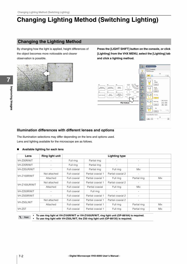
- Digital Microscope VHX-6000 User’s Manual -
Changing Lighting Method (Switching Lighting)
7-2
Imp
rovin
g Im
ages
7
Changing Lighting Method (Switching Lighting)
By changing how the light is applied, height differences of
the object becomes more noticeable and clearer
observation is possible.
Press the [LIGHT SHIFT] button on the console, or click
[Lighting] from the VHX MENU, select the [Lighting] tab
and click a lighting method.
Illumination differences with different lenses and options
The illumination selections may differ depending on the lens and options used.
Lens and lighting available for the microscope are as follows.
Available lighting for each lens
Changing the Lighting Method
Lens Ring light unit Lighting type
VH-Z00R/W/T - Full ring Partial ring - -
VH-Z20R/W/T - Full ring Partial ring - -
VH-Z20UR/W/T - Full coaxial Partial ring Full ring Mix
VH-Z100R/W/TNot attached Full coaxial Partial coaxial 1 Partial coaxial 2 -
Attached Full coaxial Partial coaxial 1 Full ring Partial ring Mix
VH-Z100UR/W/TNot attached Full coaxial Partial coaxial 1 Partial coaxial 2 -
Attached Full coaxial Partial coaxial Full ring Mix
VH-Z250R/W/T - Full coaxial Full ring - -
VH-Z500R/W/T - Full coaxial Partial coaxial 1 Partial coaxial 2 -
VH-Z50L/W/TNot attached Full coaxial Partial coaxial 1 Partial coaxial 2 -
Attached Full coaxial Partial coaxial 1 Full ring Partial ring Mix
VH-ZST - Full coaxial Partial coaxial 1 Full ring Partial ring Mix
• To use ring light at VH-Z100R/W/T or VH-Z100UR/W/T, ring light unit (OP-88164) is required.• To use ring light with VH-Z50L/W/T, the Z50 ring light unit (OP-88135) is required.
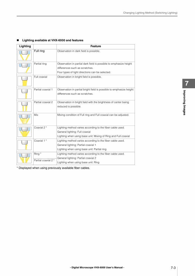
- Digital Microscope VHX-6000 User’s Manual -
Changing Lighting Method (Switching Lighting)
7-3
Imp
rovin
g Im
ages
7
Lighting available at VHX-6000 and features
* Displayed when using previously available fiber cables.
Lighting Feature
Full ring Observation in dark field is possible.
Partial ring Observation in partial dark field is possible to emphasize height
differences such as scratches.
Four types of light directions can be selected.
Full coaxial Observation in bright field is possible.
Partial coaxial 1 Observation in partial bright field is possible to emphasize height
differences such as scratches.
Partial coaxial 2 Observation in bright field with the brightness of center being
reduced is possible.
Mix Mixing condition of Full ring and Full coaxial can be adjusted.
Coaxial 2 * Lighting method varies according to the fiber cable used.
General lighting: Full coaxial
Lighting when using base unit: Mixing of Ring and Full coaxial
Coaxial 1 * Lighting method varies according to the fiber cable used.
General lighting: Partial coaxial 1
Lighting when using base unit: Partial ring
Ring * Lighting method varies according to the fiber cable used.
General lighting: Partial coaxial 2
Lighting when using base unit: RingPartial coaxial 2 *
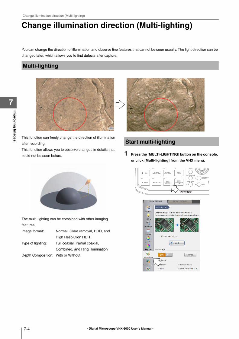
- Digital Microscope VHX-6000 User’s Manual -
Change illumination direction (Multi-lighting)
7-4
Imp
rovin
g Im
ages
7
Change illumination direction (Multi-lighting)
You can change the direction of illumination and observe fine features that cannot be seen usually. The light direction can be
changed later, which allows you to find defects after capture.
This function can freely change the direction of illumination
after recording.
This function allows you to observe changes in details that
could not be seen before.
The multi-lighting can be combined with other imaging
features.
Image format: Normal, Glare removal, HDR, and
High Resolution HDR
Type of lighting: Full coaxial, Partial coaxial,
Combined, and Ring illumination
Depth Composition: With or Without
1 Press the [MULTI-LIGHTING] button on the console,
or click [Multi-lighting] from the VHX menu.
Multi-lighting
Start multi-lighting
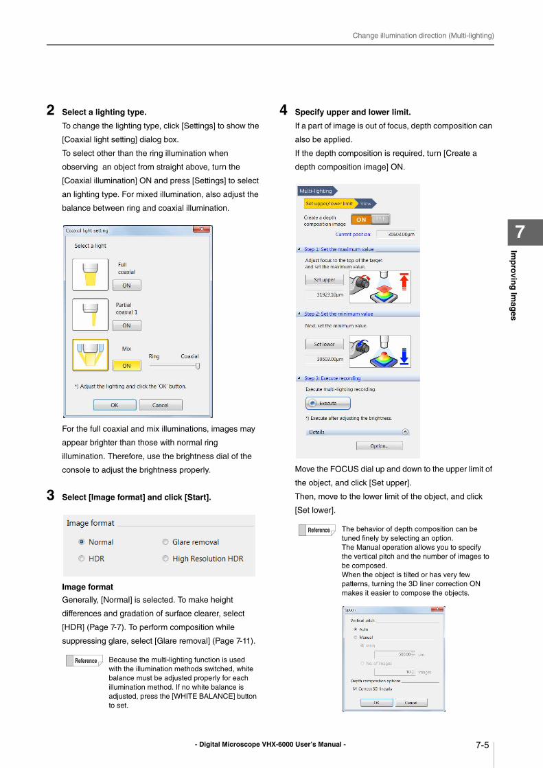
- Digital Microscope VHX-6000 User’s Manual -
Change illumination direction (Multi-lighting)
7-5
Imp
rovin
g Im
ages
7
2 Select a lighting type.
To change the lighting type, click [Settings] to show the
[Coaxial light setting] dialog box.
To select other than the ring illumination when
observing an object from straight above, turn the
[Coaxial illumination] ON and press [Settings] to select
an lighting type. For mixed illumination, also adjust the
balance between ring and coaxial illumination.
For the full coaxial and mix illuminations, images may
appear brighter than those with normal ring
illumination. Therefore, use the brightness dial of the
console to adjust the brightness properly.
3 Select [Image format] and click [Start].
Image format
Generally, [Normal] is selected. To make height
differences and gradation of surface clearer, select
[HDR] (Page 7-7). To perform composition while
suppressing glare, select [Glare removal] (Page 7-11).
4 Specify upper and lower limit.
If a part of image is out of focus, depth composition can
also be applied.
If the depth composition is required, turn [Create a
depth composition image] ON.
Move the FOCUS dial up and down to the upper limit of
the object, and click [Set upper].
Then, move to the lower limit of the object, and click
[Set lower].
Because the multi-lighting function is used
with the illumination methods switched, white
balance must be adjusted properly for each
illumination method. If no white balance is
adjusted, press the [WHITE BALANCE] button
to set.
The behavior of depth composition can be
tuned finely by selecting an option.
The Manual operation allows you to specify
the vertical pitch and the number of images to
be composed.
When the object is tilted or has very few
patterns, turning the 3D liner correction ON
makes it easier to compose the objects.
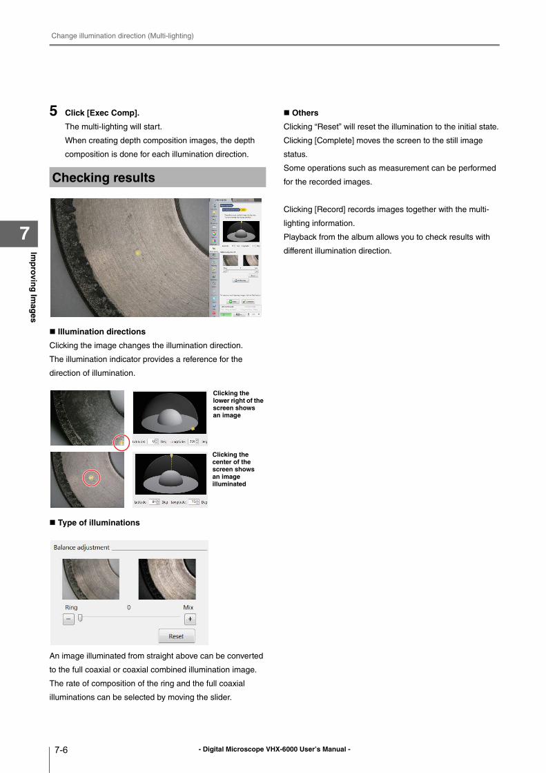
- Digital Microscope VHX-6000 User’s Manual -
Change illumination direction (Multi-lighting)
7-6
Imp
rovin
g Im
ages
7
5 Click [Exec Comp].
The multi-lighting will start.
When creating depth composition images, the depth
composition is done for each illumination direction.
Illumination directions
Clicking the image changes the illumination direction.
The illumination indicator provides a reference for the
direction of illumination.
Type of illuminations
An image illuminated from straight above can be converted
to the full coaxial or coaxial combined illumination image.
The rate of composition of the ring and the full coaxial
illuminations can be selected by moving the slider.
Others
Clicking “Reset” will reset the illumination to the initial state.
Clicking [Complete] moves the screen to the still image
status.
Some operations such as measurement can be performed
for the recorded images.
Clicking [Record] records images together with the multi-
lighting information.
Playback from the album allows you to check results with
different illumination direction.
Checking results
Clicking the lower right of the screen shows an image
Clicking the center of the screen shows an image illuminated
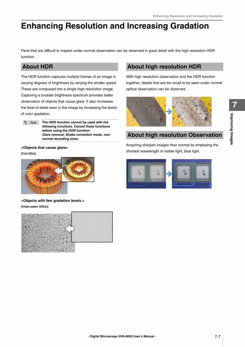
- Digital Microscope VHX-6000 User’s Manual -
Enhancing Resolution and Increasing Gradation
7-7
Imp
rovin
g Im
ages
7
Enhancing Resolution and Increasing Gradation
Parts that are difficult to inspect under normal observation can be observed in great detail with the high resolution HDR
function.
The HDR function captures multiple frames of an image in
varying degrees of brightness by varying the shutter speed.
These are composed into a single high-resolution image.
Capturing a broader brightness spectrum provides better
observation of objects that cause glare. It also increases
the level of detail seen in the image by increasing the levels
of color gradation.
<Objects that cause glare>
[Coil (20x)]
<Objects with few gradation levels.>
[Inkjet paper (300x)]
With high resolution observation and the HDR function
together, details that are too small to be seen under normal
optical observation can be observed.
Acquiring sharpen images than normal by employing the
shortest wavelength of visible light, blue light.
About HDR
The HDR function cannot be used with the following functions. Cancel these functions before using the HDR function:Glare removal, Shake correction mode, non-normal recording sizes.
About high resolution HDR
About high resolution Observation
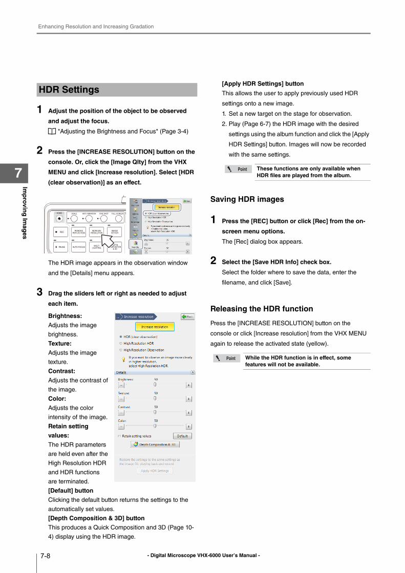
- Digital Microscope VHX-6000 User’s Manual -
Enhancing Resolution and Increasing Gradation
7-8
Imp
rovin
g Im
ages
7
1 Adjust the position of the object to be observed
and adjust the focus.
"Adjusting the Brightness and Focus" (Page 3-4)
2 Press the [INCREASE RESOLUTION] button on the
console. Or, click the [Image Qlty] from the VHX
MENU and click [Increase resolution]. Select [HDR
(clear observation)] as an effect.
The HDR image appears in the observation window
and the [Details] menu appears.
3 Drag the sliders left or right as needed to adjust
each item.
Brightness:
Adjusts the image
brightness.
Texture:
Adjusts the image
texture.
Contrast:
Adjusts the contrast of
the image.
Color:
Adjusts the color
intensity of the image.
Retain setting
values:
The HDR parameters
are held even after the
High Resolution HDR
and HDR functions
are terminated.
[Default] button
Clicking the default button returns the settings to the
automatically set values.
[Depth Composition & 3D] button
This produces a Quick Composition and 3D (Page 10-
4) display using the HDR image.
[Apply HDR Settings] button
This allows the user to apply previously used HDR
settings onto a new image.
1. Set a new target on the stage for observation.
2. Play (Page 6-7) the HDR image with the desired
settings using the album function and click the [Apply
HDR Settings] button. Images will now be recorded
with the same settings.
Saving HDR images
1 Press the [REC] button or click [Rec] from the on-
screen menu options.
The [Rec] dialog box appears.
2 Select the [Save HDR Info] check box.
Select the folder where to save the data, enter the
filename, and click [Save].
Releasing the HDR function
Press the [INCREASE RESOLUTION] button on the
console or click [Increase resolution] from the VHX MENU
again to release the activated state (yellow).
HDR Settings
These functions are only available when HDR files are played from the album.
While the HDR function is in effect, some features will not be available.
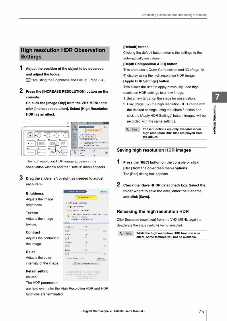
- Digital Microscope VHX-6000 User’s Manual -
Enhancing Resolution and Increasing Gradation
7-9
Imp
rovin
g Im
ages
7
1 Adjust the position of the object to be observed
and adjust the focus.
"Adjusting the Brightness and Focus" (Page 3-4)
2 Press the [INCREASE RESOLUTION] button on the
console.
Or, click the [Image Qlty] from the VHX MENU and
click [Increase resolution]. Select [High Resolution
HDR] as an effect.
The high resolution HDR image appears in the
observation window and the "Details" menu appears.
3 Drag the sliders left or right as needed to adjust
each item.
Brightness
Adjusts the image
brightness.
Texture
Adjusts the image
texture.
Contrast
Adjusts the contrast of
the image.
Color
Adjusts the color
intensity of the image.
Retain setting
values:
The HDR parameters
are held even after the High Resolution HDR and HDR
functions are terminated.
[Default] button
Clicking the default button returns the settings to the
automatically set values.
[Depth Composition & 3D] button
This produces a Quick Composition and 3D (Page 10-
4) display using the high resolution HDR image.
[Apply HDR Settings] button
This allows the user to apply previously used high
resolution HDR settings to a new image.
1. Set a new target on the stage for observation.
2. Play (Page 6-7) the high resolution HDR image with
the desired settings using the album function and
click the [Apply HDR Settings] button. Images will be
recorded with the same settings.
Saving high resolution HDR images
1 Press the [REC] button on the console or click
[Rec] from the on-screen menu options.
The [Rec] dialog box appears.
2 Check the [Save HHDR data] check box. Select the
folder where to save the data, enter the filename,
and click [Save].
Releasing the high resolution HDR
Click [Increase resolution] from the VHX MENU again to
deactivate the state (yellow) being selected.
High resolution HDR Observation Settings
These functions are only available when high resolution HDR files are played from the album.
While the high resolution HDR function is in effect, some features will not be available.
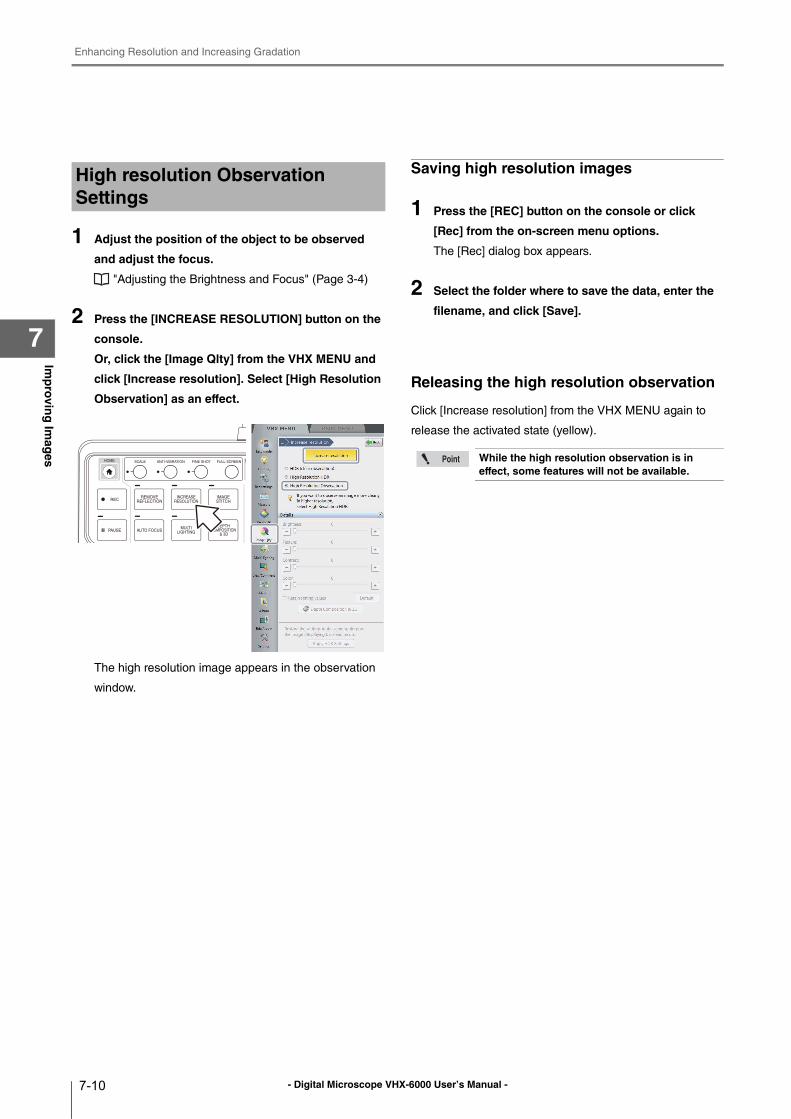
- Digital Microscope VHX-6000 User’s Manual -
Enhancing Resolution and Increasing Gradation
7-10
Imp
rovin
g Im
ages
7
1 Adjust the position of the object to be observed
and adjust the focus.
"Adjusting the Brightness and Focus" (Page 3-4)
2 Press the [INCREASE RESOLUTION] button on the
console.
Or, click the [Image Qlty] from the VHX MENU and
click [Increase resolution]. Select [High Resolution
Observation] as an effect.
The high resolution image appears in the observation
window.
Saving high resolution images
1 Press the [REC] button on the console or click
[Rec] from the on-screen menu options.
The [Rec] dialog box appears.
2 Select the folder where to save the data, enter the
filename, and click [Save].
Releasing the high resolution observation
Click [Increase resolution] from the VHX MENU again to
release the activated state (yellow).
High resolution Observation Settings
While the high resolution observation is in effect, some features will not be available.
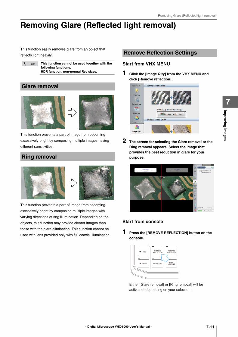
- Digital Microscope VHX-6000 User’s Manual -
Removing Glare (Reflected light removal)
7-11
Imp
rovin
g Im
ages
7
Removing Glare (Reflected light removal)
This function easily removes glare from an object that
reflects light heavily.
This function prevents a part of image from becoming
excessively bright by composing multiple images having
different sensitivities.
This function prevents a part of image from becoming
excessively bright by composing multiple images with
varying directions of ring illumination. Depending on the
objects, this function may provide clearer images than
those with the glare elimination. This function cannot be
used with lens provided only with full coaxial illumination.
Start from VHX MENU
1 Click the [Image Qlty] from the VHX MENU and click [Remove reflection].
2 The screen for selecting the Glare removal or the Ring removal appears. Select the image that provides the best reduction in glare for your purpose.
Start from console
1 Press the [REMOVE REFLECTION] button on the console.
Either [Glare removal] or [Ring removal] will be
activated, depending on your selection.
This function cannot be used together with the following functions.HDR function, non-normal Rec sizes.
Glare removal
Ring removal
Remove Reflection Settings
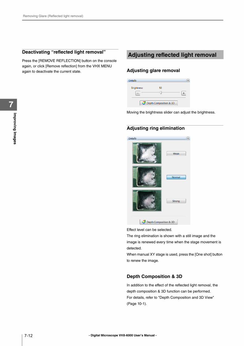
- Digital Microscope VHX-6000 User’s Manual -
Removing Glare (Reflected light removal)
7-12
Imp
rovin
g Im
ages
7
Deactivating “reflected light removal”
Press the [REMOVE REFLECTION] button on the console
again, or click [Remove reflection] from the VHX MENU
again to deactivate the current state. Adjusting glare removal
Moving the brightness slider can adjust the brightness.
Adjusting ring elimination
Effect level can be selected.
The ring elimination is shown with a still image and the
image is renewed every time when the stage movement is
detected.
When manual XY stage is used, press the [One shot] button
to renew the image.
Depth Composition & 3D
In addition to the effect of the reflected light removal, the
depth composition & 3D function can be performed.
For details, refer to "Depth Composition and 3D View"
(Page 10-1).
Adjusting reflected light removal
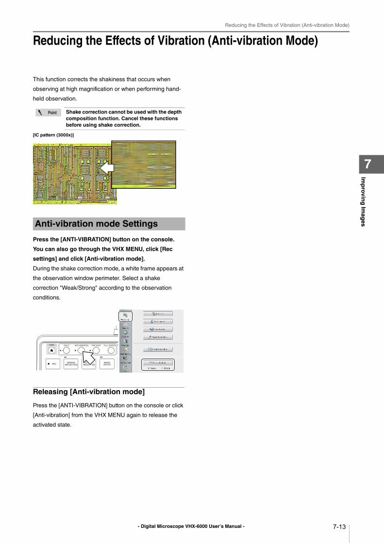
- Digital Microscope VHX-6000 User’s Manual -
Reducing the Effects of Vibration (Anti-vibration Mode)
7-13
Imp
rovin
g Im
ages
7
Reducing the Effects of Vibration (Anti-vibration Mode)
This function corrects the shakiness that occurs when
observing at high magnification or when performing hand-
held observation.
[IC pattern (3000x)]
Press the [ANTI-VIBRATION] button on the console.
You can also go through the VHX MENU, click [Rec
settings] and click [Anti-vibration mode].
During the shake correction mode, a white frame appears at
the observation window perimeter. Select a shake
correction "Weak/Strong" according to the observation
conditions.
Releasing [Anti-vibration mode]
Press the [ANTI-VIBRATION] button on the console or click
[Anti-vibration] from the VHX MENU again to release the
activated state.
Shake correction cannot be used with the depth composition function. Cancel these functions before using shake correction.
Anti-vibration mode Settings
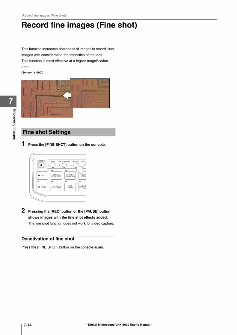
- Digital Microscope VHX-6000 User’s Manual -
Record fine images (Fine shot)
7-14
Imp
rovin
g Im
ages
7
Record fine images (Fine shot)
This function increases sharpness of images to record finer
images with consideration for properties of the lens.
This function is most effective at a higher magnification
area.
[Sensor (x1000)]
1 Press the [FINE SHOT] button on the console.
2 Pressing the [REC] button or the [PAUSE] button
shows images with the fine shot effects added.
The fine shot function does not work for video capture.
Deactivation of fine shot
Press the [FINE SHOT] button on the console again.
Fine shot Settings
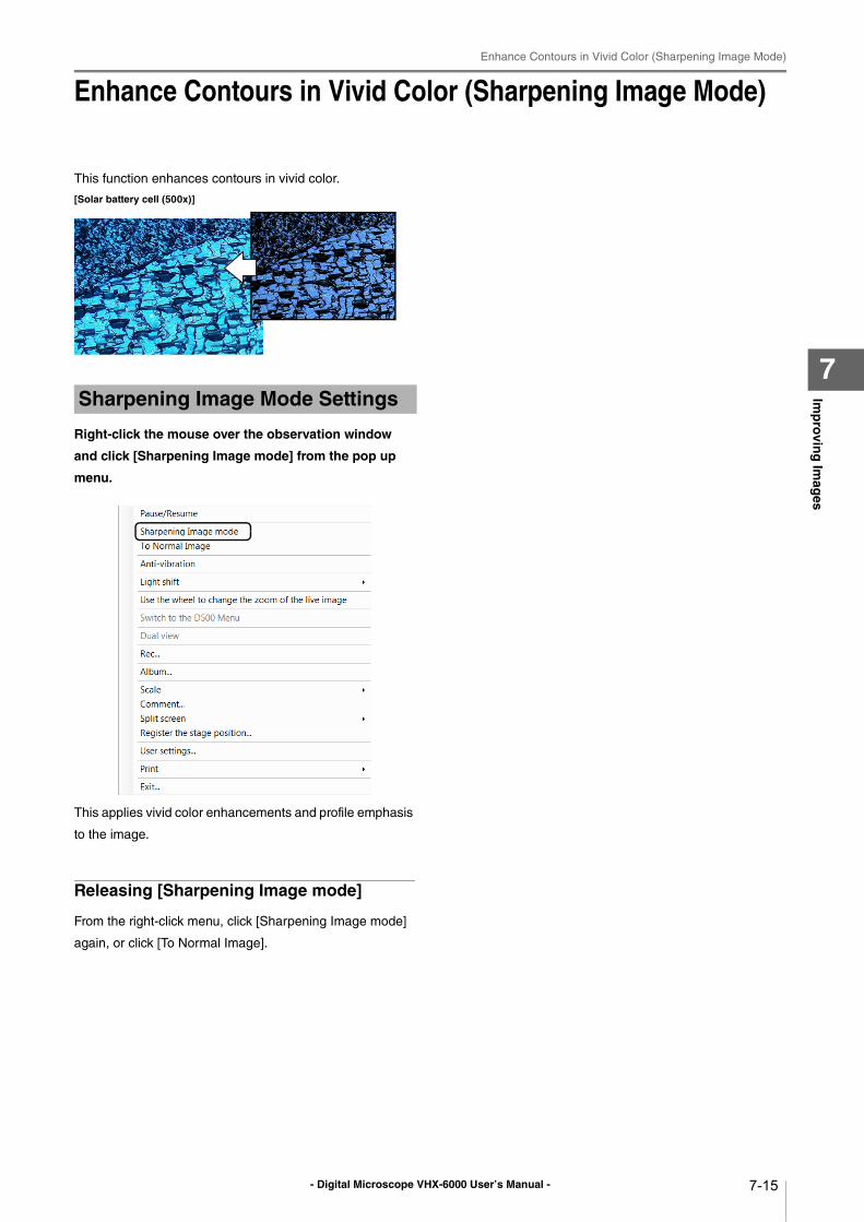
- Digital Microscope VHX-6000 User’s Manual -
Enhance Contours in Vivid Color (Sharpening Image Mode)
7-15
Imp
rovin
g Im
ages
7
Enhance Contours in Vivid Color (Sharpening Image Mode)
This function enhances contours in vivid color.
[Solar battery cell (500x)]
Right-click the mouse over the observation window
and click [Sharpening Image mode] from the pop up
menu.
This applies vivid color enhancements and profile emphasis
to the image.
Releasing [Sharpening Image mode]
From the right-click menu, click [Sharpening Image mode]
again, or click [To Normal Image].
Sharpening Image Mode Settings
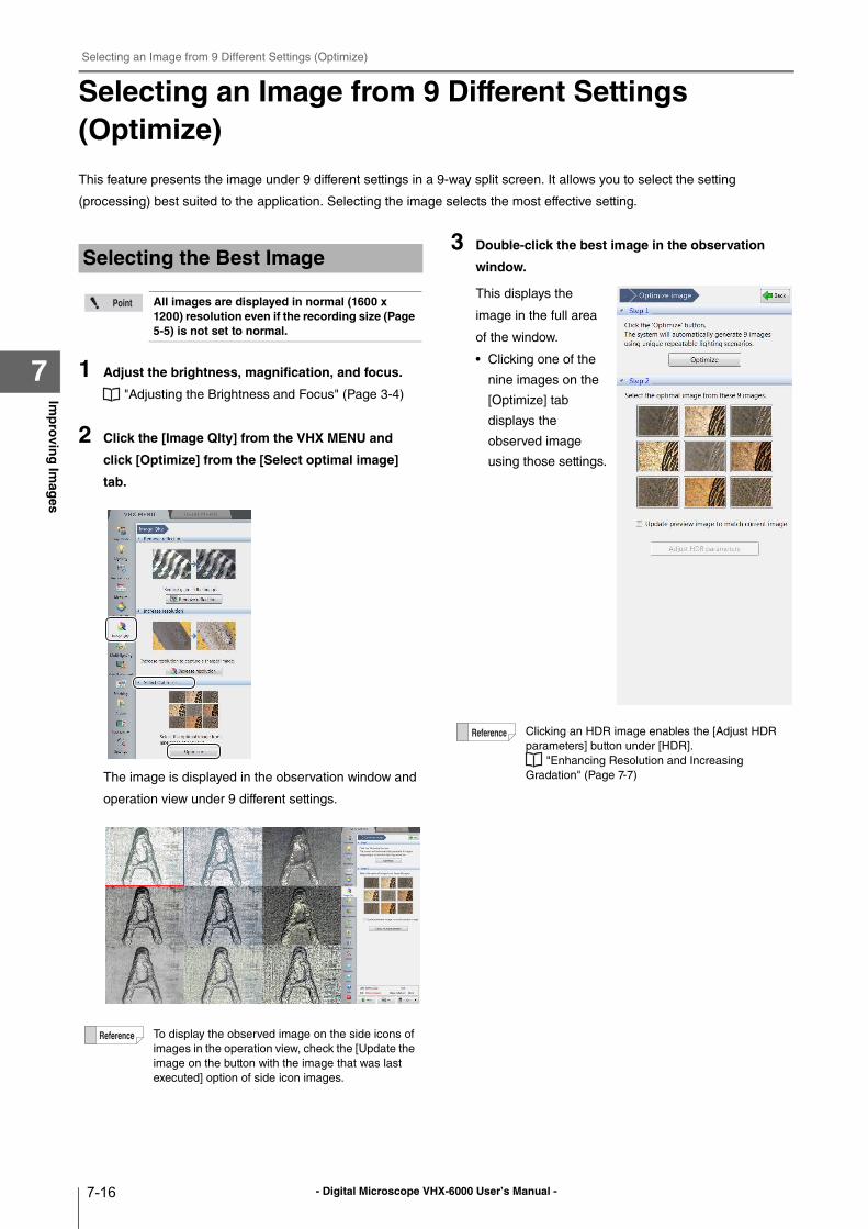
- Digital Microscope VHX-6000 User’s Manual -
Selecting an Image from 9 Different Settings (Optimize)
7-16
Imp
rovin
g Im
ages
7
Selecting an Image from 9 Different Settings (Optimize)
This feature presents the image under 9 different settings in a 9-way split screen. It allows you to select the setting
(processing) best suited to the application. Selecting the image selects the most effective setting.
1 Adjust the brightness, magnification, and focus.
"Adjusting the Brightness and Focus" (Page 3-4)
2 Click the [Image Qlty] from the VHX MENU and
click [Optimize] from the [Select optimal image]
tab.
The image is displayed in the observation window and
operation view under 9 different settings.
3 Double-click the best image in the observation
window.
This displays the
image in the full area
of the window.
• Clicking one of the
nine images on the
[Optimize] tab
displays the
observed image
using those settings.
Selecting the Best Image
All images are displayed in normal (1600 x 1200) resolution even if the recording size (Page 5-5) is not set to normal.
To display the observed image on the side icons of
images in the operation view, check the [Update the
image on the button with the image that was last
executed] option of side icon images.
Clicking an HDR image enables the [Adjust HDR
parameters] button under [HDR].
"Enhancing Resolution and Increasing
Gradation" (Page 7-7)
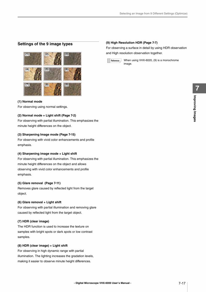
- Digital Microscope VHX-6000 User’s Manual -
Selecting an Image from 9 Different Settings (Optimize)
7-17
Imp
rovin
g Im
ages
7
Settings of the 9 image types
(1) Normal mode
For observing using normal settings.
(2) Normal mode + Light shift (Page 7-2)
For observing with partial illumination. This emphasizes the
minute height differences on the object.
(3) Sharpening Image mode (Page 7-15)
For observing with vivid color enhancements and profile
emphasis.
(4) Sharpening image mode + Light shift
For observing with partial illumination. This emphasizes the
minute height differences on the object and allows
observing with vivid color enhancements and profile
emphasis.
(5) Glare removal (Page 7-11)
Removes glare caused by reflected light from the target
object.
(6) Glare removal + Light shift
For observing with partial illumination and removing glare
caused by reflected light from the target object.
(7) HDR (clear image)
The HDR function is used to increase the texture on
samples with bright spots or dark spots or low contrast
samples.
(8) HDR (clear image) + Light shift
For observing in high dynamic range with partial
illumination. The lighting increases the gradation levels,
making it easier to observe minute height differences.
(9) High Resolution HDR (Page 7-7)
For observing a surface in detail by using HDR observation
and High resolution observation together.(1) (2) (3)
(4) (5) (6)
(7) (8) (9)
When using VHX-6020, (9) is a monochrome
image.
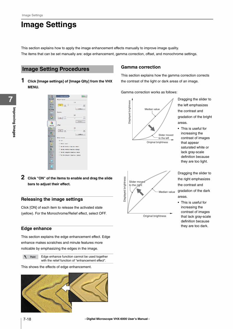
- Digital Microscope VHX-6000 User’s Manual -
Image Settings
7-18
Imp
rovin
g Im
ages
7
Image Settings
This section explains how to apply the image enhancement effects manually to improve image quality.
The items that can be set manually are: edge enhancement, gamma correction, offset, and monochrome settings.
1 Click [Image settings] of [Image Qlty] from the VHX
MENU.
2 Click "ON" of the items to enable and drag the slide
bars to adjust their effect.
Releasing the image settings
Click [ON] of each item to release the activated state
(yellow). For the Monochrome/Relief effect, select OFF.
Edge enhance
This section explains the edge enhancement effect. Edge
enhance makes scratches and minute features more
noticable by emphasizing the edges in the image.
This shows the effects of edge enhancement.
Gamma correction
This section explains how the gamma correction corrects
the contrast of the light or dark areas of an image.
Gamma correction works as follows:
Dragging the slider to
the left emphasizes
the contrast and
gradation of the bright
areas.
• This is useful for
increasing the
contrast of images
that appear
saturated white or
lack gray-scale
definition because
they are too light.
Dragging the slider to
the right emphasizes
the contrast and
gradation of the dark
areas.
• This is useful for
increasing the
contrast of images
that lack gray-scale
definition because
they are too dark.
Image Setting Procedures
Edge enhance function cannot be used together
with the relief function of "enhancement effect".
Median value
Slider moved
to the left
Original brightness
Dis
pla
yed b
rightn
ess
Median value
Slider moved Slider moved
to the rightto the right
Slider moved
to the right
Original brightness
Dis
pla
ye
d b
rig
htn
ess
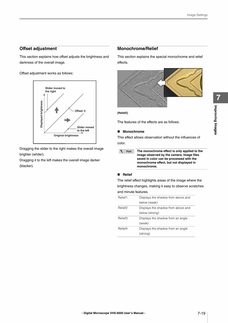
- Digital Microscope VHX-6000 User’s Manual -
Image Settings
7-19
Imp
rovin
g Im
ages
7
Offset adjustment
This section explains how offset adjusts the brightness and
darkness of the overall image.
Offset adjustment works as follows:
Dragging the slider to the right makes the overall image
brighter (whiter).
Dragging it to the left makes the overall image darker
(blacker).
Monochrome/Relief
This section explains the special monochrome and relief
effects.
[Relief2]
The features of the effects are as follows.
Monochrome
This effect allows observation without the influences of
color.
Relief
The relief effect highlights areas of the image where the
brightness changes, making it easy to observe scratches
and minute features.
Dis
pla
yed
bri
gh
tnes
s
Slider moved to the right
Slider moved to the left
Original brightness
Offset: 0
The monochrome effect is only applied to the image observed by the camera. Image files saved in color can be processed with the monochrome effect, but not displayed in monochrome.
Relief1 Displays the shadow from above and
below (weak)
Relief2 Displays the shadow from above and
below (strong)
Relief3 Displays the shadow from an angle
(weak)
Relief4 Displays the shadow from an angle
(strong)
- Digital Microscope VHX-6000 User’s Manual -
Image Settings
7-20
Imp
rovin
g Im
ages
7
- Digital Microscope VHX-6000 User’s Manual - 8-1
Chapter8S
etting
Imag
e View
s
8
Setting Image Views
This chapter explains how to use Split Screen, Full Screen, and Digital Zoom.
Split Screen............................................................Page 8-2
Types of Split Screens........................................Page 8-2
Using the Split Screen .......................................Page 8-3
Comparing Two Images .....................................Page 8-3
Full Screen Image/Vision Correction Mode............Page 8-4
Full Screen Image ..............................................Page 8-4
Vision correction mode ......................................Page 8-4
Enlarging the Image (Digital Zoom) .......................Page 8-5
Navigation ..............................................................Page 8-6
Creating Navigation............................................Page 8-6
Specifying Observation Position on Navigation Image
.......................................................................Page 8-7
Moving vertically and horizontally ......................Page 8-7
Registering a Stage Position ..............................Page 8-7
Recording registered positions in batch .............Page 8-8
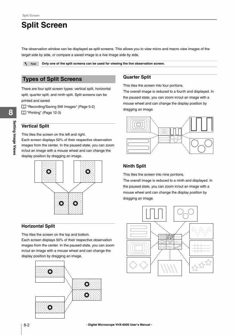
- Digital Microscope VHX-6000 User’s Manual -
Split Screen
8-2
Settin
g Im
age V
iews
8
Split Screen
The observation window can be displayed as split screens. This allows you to view micro and macro view images of the
target side by side, or compare a saved image to a live image side by side.
There are four split screen types: vertical split, horizontal
split, quarter split, and ninth split. Split screens can be
printed and saved.
"Recording/Saving Still Images" (Page 5-2)
"Printing" (Page 12-3)
Vertical Split
This tiles the screen on the left and right.
Each screen displays 50% of their respective observation
images from the center. In the paused state, you can zoom
in/out an image with a mouse wheel and can change the
display position by dragging an image.
Horizontal Split
This tiles the screen on the top and bottom.
Each screen displays 50% of their respective observation
images from the center. In the paused state, you can zoom
in/out an image with a mouse wheel and can change the
display position by dragging an image.
Quarter Split
This tiles the screen into four portions.
The overall image is reduced to a fourth and displayed. In
the paused state, you can zoom in/out an image with a
mouse wheel and can change the display position by
dragging an image.
Ninth Split
This tiles the screen into nine portions.
The overall image is reduced to a ninth and displayed. In
the paused state, you can zoom in/out an image with a
mouse wheel and can change the display position by
dragging an image.
Only one of the split screens can be used for viewing the live observation screen.
Types of Split Screens
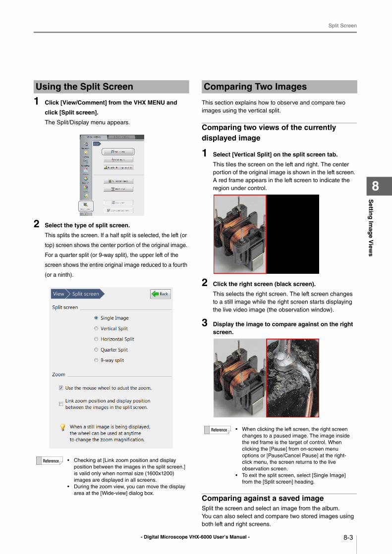
- Digital Microscope VHX-6000 User’s Manual -
Split Screen
8-3
Settin
g Im
age V
iews
8
1 Click [View/Comment] from the VHX MENU and
click [Split screen].
The Split/Display menu appears.
2 Select the type of split screen.
This splits the screen. If a half split is selected, the left (or
top) screen shows the center portion of the original image.
For a quarter split (or 9-way split), the upper left of the
screen shows the entire original image reduced to a fourth
(or a ninth).
This section explains how to observe and compare two
images using the vertical split.
Comparing two views of the currently displayed image
1 Select [Vertical Split] on the split screen tab.
This tiles the screen on the left and right. The center
portion of the original image is shown in the left screen.
A red frame appears in the left screen to indicate the
region under control.
2 Click the right screen (black screen).
This selects the right screen. The left screen changes
to a still image while the right screen starts displaying
the live video image (the observation window).
3 Display the image to compare against on the right screen.
Comparing against a saved imageSplit the screen and select an image from the album.
You can also select and compare two stored images using
both left and right screens.
Using the Split Screen
• Checking at [Link zoom position and display
position between the images in the split screen.]
is valid only when normal size (1600x1200)
images are displayed in all screens.
• During the zoom view, you can move the display
area at the [Wide-view] dialog box.
Comparing Two Images
• When clicking the left screen, the right screen
changes to a paused image. The image inside
the red frame is the target of control. When
clicking the [Pause] from on-screen menu
options or [Pause/Cancel Pause] at the right-
click menu, the screen returns to the live
observation screen.
• To exit the split screen, select [Single Image]
from the [Split screen] heading.
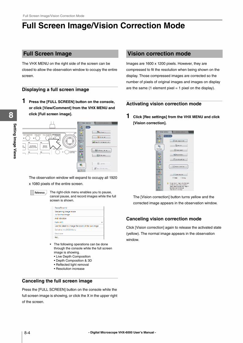
- Digital Microscope VHX-6000 User’s Manual -
Full Screen Image/Vision Correction Mode
8-4
Settin
g Im
age V
iews
8
Full Screen Image/Vision Correction Mode
The VHX MENU on the right side of the screen can be
closed to allow the observation window to occupy the entire
screen.
Displaying a full screen image
1 Press the [FULL SCREEN] button on the console,
or click [View/Comment] from the VHX MENU and
click [Full screen image].
The observation window will expand to occupy all 1920
x 1080 pixels of the entire screen.
Canceling the full screen image
Press the [FULL SCREEN] button on the console while the
full screen image is showing, or click the X in the upper right
of the screen.
Images are 1600 x 1200 pixels. However, they are
compressed to fit the resolution when being shown on the
display. Those compressed images are corrected so the
number of pixels of original images and images on display
are the same (1 element pixel = 1 pixel on the display).
Activating vision correction mode
1 Click [Rec settings] from the VHX MENU and click
[Vision correction].
The [Vision correction] button turns yellow and the
corrected image appears in the observation window.
Canceling vision correction mode
Click [Vision correction] again to release the activated state
(yellow). The normal image appears in the observation
window.
Full Screen Image
The right-click menu enables you to pause,
cancel pause, and record images while the full
screen is shown.
• The following operations can be done
through the console while the full screen
image is showing.
• Live Depth Composition
• Depth Composition & 3D
• Reflected light removal
• Resolution increase
Vision correction mode
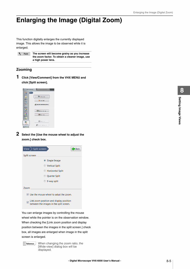
- Digital Microscope VHX-6000 User’s Manual -
Enlarging the Image (Digital Zoom)
8-5
Settin
g Im
age V
iews
8
Enlarging the Image (Digital Zoom)
This function digitally enlarges the currently displayed
image. This allows the image to be observed while it is
enlarged.
Zooming
1 Click [View/Comment] from the VHX MENU and
click [Split screen].
2 Select the [Use the mouse wheel to adjust the
zoom.] check box.
You can enlarge images by controlling the mouse
wheel while the pointer is on the observation window.
When checking the [Link zoom position and display
position between the images in the split screen.] check
box, all images are enlarged when image in the split
screen is enlarged.
The screen will become grainy as you increase the zoom factor. To obtain a cleaner image, use a high power lens.
When changing the zoom ratio, the [Wide-view] dialog box will be displayed.
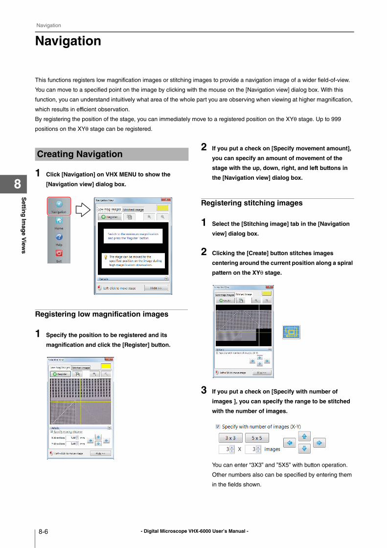
- Digital Microscope VHX-6000 User’s Manual -
Navigation
8-6
Settin
g Im
age V
iews
8
Navigation
This functions registers low magnification images or stitching images to provide a navigation image of a wider field-of-view.
You can move to a specified point on the image by clicking with the mouse on the [Navigation view] dialog box. With this
function, you can understand intuitively what area of the whole part you are observing when viewing at higher magnification,
which results in efficient observation.
By registering the position of the stage, you can immediately move to a registered position on the XYθ stage. Up to 999
positions on the XYθ stage can be registered.
1 Click [Navigation] on VHX MENU to show the
[Navigation view] dialog box.
Registering low magnification images
1 Specify the position to be registered and its
magnification and click the [Register] button.
2 If you put a check on [Specify movement amount],
you can specify an amount of movement of the
stage with the up, down, right, and left buttons in
the [Navigation view] dialog box.
Registering stitching images
1 Select the [Stitching image] tab in the [Navigation
view] dialog box.
2 Clicking the [Create] button stitches images
centering around the current position along a spiral
pattern on the XYθ stage.
3 If you put a check on [Specify with number of
images ], you can specify the range to be stitched
with the number of images.
You can enter “3X3” and ”5X5” with button operation.
Other numbers also can be specified by entering them
in the fields shown.
Creating Navigation
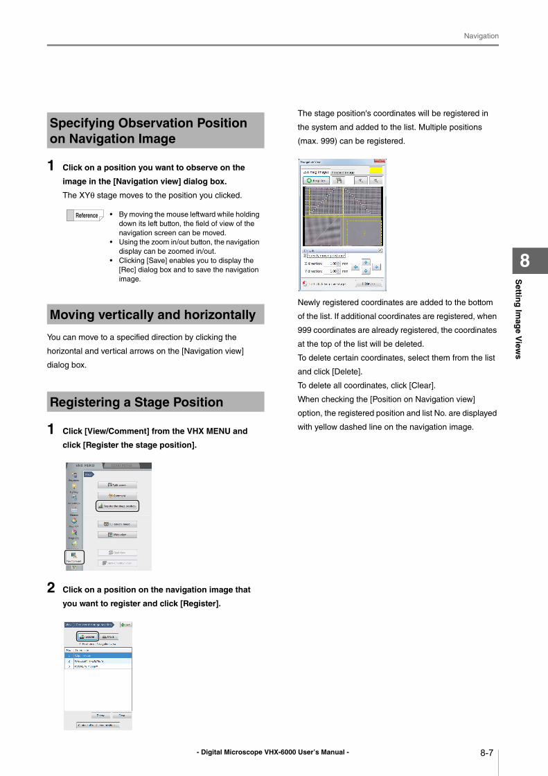
- Digital Microscope VHX-6000 User’s Manual -
Navigation
8-7
Settin
g Im
age V
iews
8
1 Click on a position you want to observe on the
image in the [Navigation view] dialog box.
The XYθ stage moves to the position you clicked.
You can move to a specified direction by clicking the
horizontal and vertical arrows on the [Navigation view]
dialog box.
1 Click [View/Comment] from the VHX MENU and
click [Register the stage position].
2 Click on a position on the navigation image that
you want to register and click [Register].
The stage position's coordinates will be registered in
the system and added to the list. Multiple positions
(max. 999) can be registered.
Newly registered coordinates are added to the bottom
of the list. If additional coordinates are registered, when
999 coordinates are already registered, the coordinates
at the top of the list will be deleted.
To delete certain coordinates, select them from the list
and click [Delete].
To delete all coordinates, click [Clear].
When checking the [Position on Navigation view]
option, the registered position and list No. are displayed
with yellow dashed line on the navigation image.
Specifying Observation Position on Navigation Image
• By moving the mouse leftward while holding
down its left button, the field of view of the
navigation screen can be moved.
• Using the zoom in/out button, the navigation
display can be zoomed in/out.
• Clicking [Save] enables you to display the
[Rec] dialog box and to save the navigation
image.
Moving vertically and horizontally
Registering a Stage Position
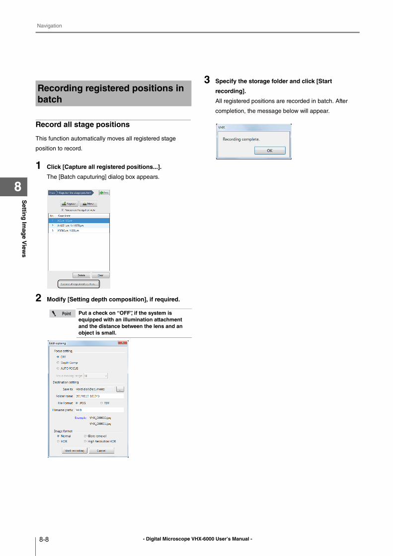
- Digital Microscope VHX-6000 User’s Manual -
Navigation
8-8
Settin
g Im
age V
iews
8
Record all stage positions
This function automatically moves all registered stage
position to record.
1 Click [Capture all registered positions...].
The [Batch caputuring] dialog box appears.
2 Modify [Setting depth composition], if required.
3 Specify the storage folder and click [Start
recording].
All registered positions are recorded in batch. After
completion, the message below will appear.
Recording registered positions in batch
Put a check on “OFF”, if the system is equipped with an illumination attachment and the distance between the lens and an object is small.
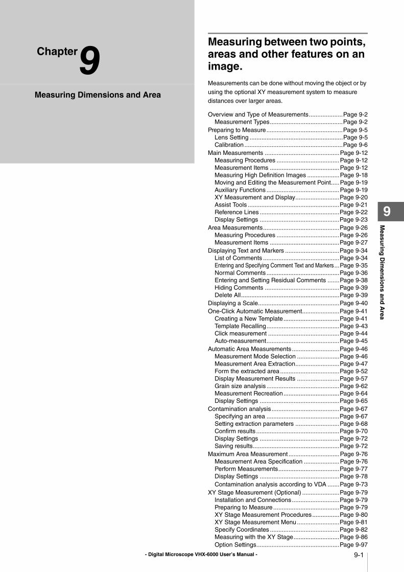
- Digital Microscope VHX-6000 User’s Manual - 9-1
Chapter9M
easurin
g D
imen
sion
s and
Area
9
Measuring Dimensions and Area
Measuring between two points, areas and other features on an image.Measurements can be done without moving the object or by
using the optional XY measurement system to measure
distances over larger areas.
Overview and Type of Measurements....................Page 9-2
Measurement Types...........................................Page 9-2
Preparing to Measure.............................................Page 9-5
Lens Setting .......................................................Page 9-5
Calibration ..........................................................Page 9-6
Main Measurements ............................................Page 9-12
Measuring Procedures .....................................Page 9-12
Measurement Items .........................................Page 9-12
Measuring High Definition Images ...................Page 9-18
Moving and Editing the Measurement Point.....Page 9-19
Auxiliary Functions ...........................................Page 9-19
XY Measurement and Display..........................Page 9-20
Assist Tools ......................................................Page 9-21
Reference Lines ...............................................Page 9-22
Display Settings ...............................................Page 9-23
Area Measurements.............................................Page 9-26
Measuring Procedures .....................................Page 9-26
Measurement Items .........................................Page 9-27
Displaying Text and Markers ................................Page 9-34
List of Comments .............................................Page 9-34
Entering and Specifying Comment Text and Markers...Page 9-35
Normal Comments ...........................................Page 9-36
Entering and Setting Residual Comments .......Page 9-38
Hiding Comments ............................................Page 9-39
Delete All..........................................................Page 9-39
Displaying a Scale................................................Page 9-40
One-Click Automatic Measurement......................Page 9-41
Creating a New Template.................................Page 9-41
Template Recalling...........................................Page 9-43
Click measurement ..........................................Page 9-44
Auto-measurement...........................................Page 9-45
Automatic Area Measurements ............................Page 9-46
Measurement Mode Selection .........................Page 9-46
Measurement Area Extraction..........................Page 9-47
Form the extracted area...................................Page 9-52
Display Measurement Results .........................Page 9-57
Grain size analysis ...........................................Page 9-62
Measurement Recreation.................................Page 9-64
Display Settings ...............................................Page 9-65
Contamination analysis ........................................Page 9-67
Specifying an area ...........................................Page 9-67
Setting extraction parameters ..........................Page 9-68
Confirm results .................................................Page 9-70
Display Settings ...............................................Page 9-72
Saving results...................................................Page 9-72
Maximum Area Measurement ..............................Page 9-76
Measurement Area Specification .....................Page 9-76
Perform Measurements....................................Page 9-77
Display Settings ...............................................Page 9-78
Contamination analysis according to VDA .......Page 9-73
XY Stage Measurement (Optional) ......................Page 9-79
Installation and Connections............................Page 9-79
Preparing to Measure .......................................Page 9-79
XY Stage Measurement Procedures................Page 9-80
XY Stage Measurement Menu .........................Page 9-81
Specify Coordinates .........................................Page 9-82
Measuring with the XY Stage...........................Page 9-86
Option Settings.................................................Page 9-97
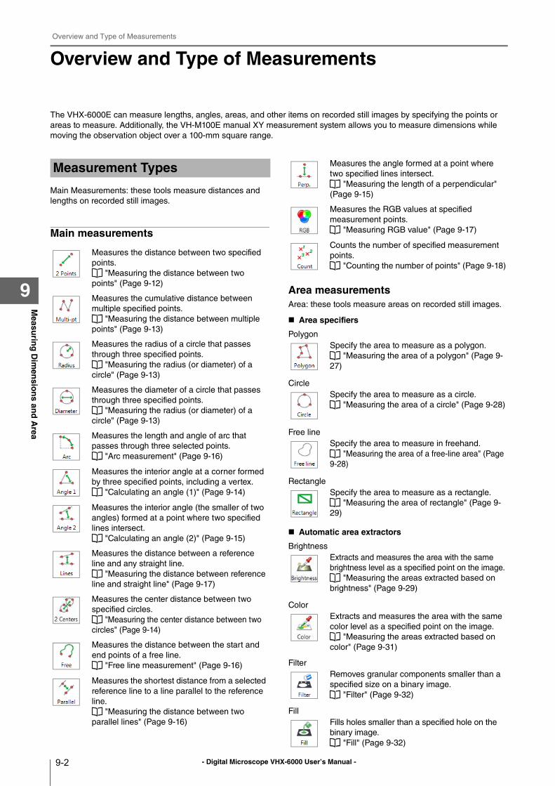
- Digital Microscope VHX-6000 User’s Manual -
Overview and Type of Measurements
9-2
Measu
ring
Dim
ensio
ns an
d A
rea
9
Overview and Type of Measurements
The VHX-6000E can measure lengths, angles, areas, and other items on recorded still images by specifying the points or
areas to measure. Additionally, the VH-M100E manual XY measurement system allows you to measure dimensions while
moving the observation object over a 100-mm square range.
Main Measurements: these tools measure distances and
lengths on recorded still images.
Main measurements
Area measurementsArea: these tools measure areas on recorded still images.
Area specifiers
Polygon
Circle
Free line
Rectangle
Automatic area extractors
Brightness
Color
Filter
Fill
Measurement Types
Measures the distance between two specified
points.
"Measuring the distance between two
points" (Page 9-12)
Measures the cumulative distance between
multiple specified points.
"Measuring the distance between multiple
points" (Page 9-13)
Measures the radius of a circle that passes
through three specified points.
"Measuring the radius (or diameter) of a
circle" (Page 9-13)
Measures the diameter of a circle that passes
through three specified points.
"Measuring the radius (or diameter) of a
circle" (Page 9-13)
Measures the length and angle of arc that
passes through three selected points.
"Arc measurement" (Page 9-16)
Measures the interior angle at a corner formed
by three specified points, including a vertex.
"Calculating an angle (1)" (Page 9-14)
Measures the interior angle (the smaller of two
angles) formed at a point where two specified
lines intersect.
"Calculating an angle (2)" (Page 9-15)
Measures the distance between a reference
line and any straight line.
"Measuring the distance between reference
line and straight line" (Page 9-17)
Measures the center distance between two
specified circles.
"Measuring the center distance between two
circles" (Page 9-14)
Measures the distance between the start and
end points of a free line.
"Free line measurement" (Page 9-16)
Measures the shortest distance from a selected
reference line to a line parallel to the reference
line.
"Measuring the distance between two
parallel lines" (Page 9-16)
Measures the angle formed at a point where
two specified lines intersect.
"Measuring the length of a perpendicular"
(Page 9-15)
Measures the RGB values at specified
measurement points.
"Measuring RGB value" (Page 9-17)
Counts the number of specified measurement
points.
"Counting the number of points" (Page 9-18)
Specify the area to measure as a polygon.
"Measuring the area of a polygon" (Page 9-
27)
Specify the area to measure as a circle.
"Measuring the area of a circle" (Page 9-28)
Specify the area to measure in freehand.
"Measuring the area of a free-line area" (Page
9-28)
Specify the area to measure as a rectangle.
"Measuring the area of rectangle" (Page 9-
29)
Extracts and measures the area with the same
brightness level as a specified point on the image.
"Measuring the areas extracted based on
brightness" (Page 9-29)
Extracts and measures the area with the same
color level as a specified point on the image.
"Measuring the areas extracted based on
color" (Page 9-31)
Removes granular components smaller than a
specified size on a binary image.
"Filter" (Page 9-32)
Fills holes smaller than a specified hole on the
binary image.
"Fill" (Page 9-32)
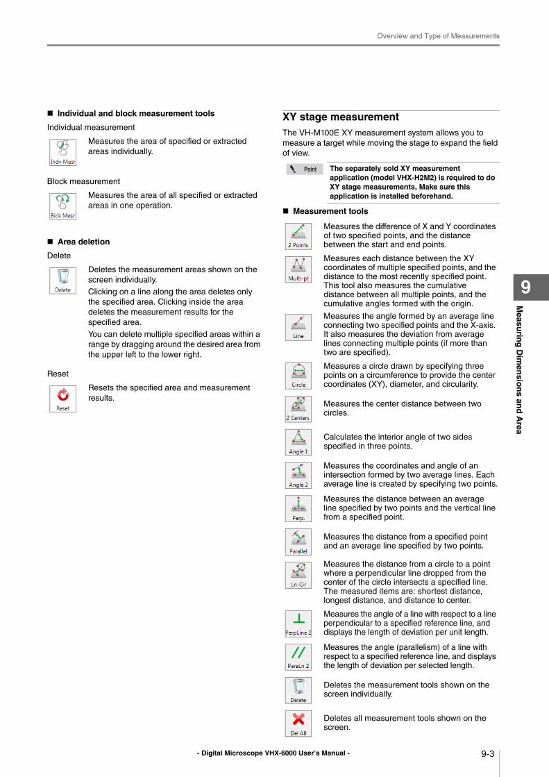
- Digital Microscope VHX-6000 User’s Manual -
Overview and Type of Measurements
9-3
Measu
ring
Dim
ensio
ns an
d A
rea
9
Individual and block measurement tools
Individual measurement
Block measurement
Area deletion
Delete
Reset
XY stage measurementThe VH-M100E XY measurement system allows you to
measure a target while moving the stage to expand the field
of view.
Measurement tools
Measures the area of specified or extracted
areas individually.
Measures the area of all specified or extracted
areas in one operation.
Deletes the measurement areas shown on the
screen individually.
Clicking on a line along the area deletes only
the specified area. Clicking inside the area
deletes the measurement results for the
specified area.
You can delete multiple specified areas within a
range by dragging around the desired area from
the upper left to the lower right.
Resets the specified area and measurement
results.
The separately sold XY measurement application (model VHX-H2M2) is required to do XY stage measurements, Make sure this application is installed beforehand.
Measures the difference of X and Y coordinates of two specified points, and the distance between the start and end points.
Measures each distance between the XY coordinates of multiple specified points, and the distance to the most recently specified point. This tool also measures the cumulative distance between all multiple points, and the cumulative angles formed with the origin.
Measures the angle formed by an average line connecting two specified points and the X-axis. It also measures the deviation from average lines connecting multiple points (if more than two are specified).
Measures a circle drawn by specifying three points on a circumference to provide the center coordinates (XY), diameter, and circularity.
Measures the center distance between two circles.
Calculates the interior angle of two sides specified in three points.
Measures the coordinates and angle of an intersection formed by two average lines. Each average line is created by specifying two points.
Measures the distance between an average line specified by two points and the vertical line from a specified point.
Measures the distance from a specified point and an average line specified by two points.
Measures the distance from a circle to a point where a perpendicular line dropped from the center of the circle intersects a specified line.The measured items are: shortest distance, longest distance, and distance to center.
Measures the angle of a line with respect to a line perpendicular to a specified reference line, and displays the length of deviation per unit length.
Measures the angle (parallelism) of a line with respect to a specified reference line, and displays the length of deviation per selected length.
Deletes the measurement tools shown on the screen individually.
Deletes all measurement tools shown on the screen.
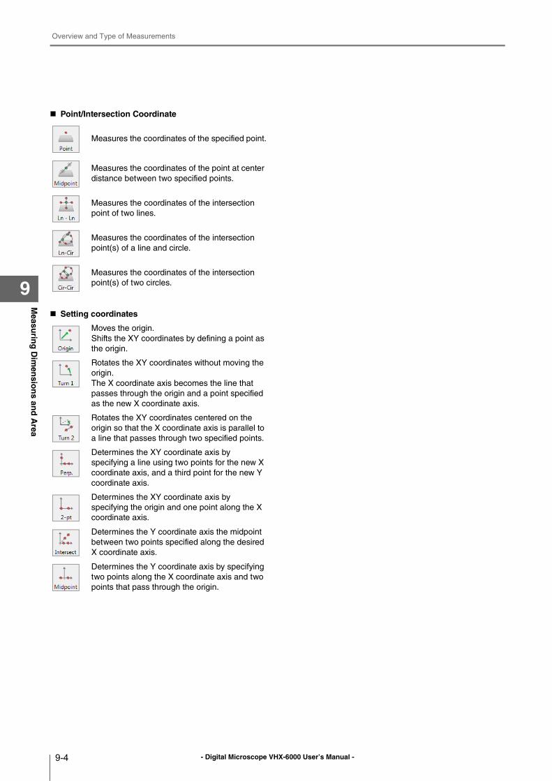
- Digital Microscope VHX-6000 User’s Manual -
Overview and Type of Measurements
9-4
Measu
ring
Dim
ensio
ns an
d A
rea
9
Point/Intersection Coordinate
Setting coordinates
Measures the coordinates of the specified point.
Measures the coordinates of the point at center
distance between two specified points.
Measures the coordinates of the intersection
point of two lines.
Measures the coordinates of the intersection
point(s) of a line and circle.
Measures the coordinates of the intersection
point(s) of two circles.
Moves the origin.
Shifts the XY coordinates by defining a point as
the origin.
Rotates the XY coordinates without moving the
origin.
The X coordinate axis becomes the line that
passes through the origin and a point specified
as the new X coordinate axis.
Rotates the XY coordinates centered on the
origin so that the X coordinate axis is parallel to
a line that passes through two specified points.
Determines the XY coordinate axis by
specifying a line using two points for the new X
coordinate axis, and a third point for the new Y
coordinate axis.
Determines the XY coordinate axis by
specifying the origin and one point along the X
coordinate axis.
Determines the Y coordinate axis the midpoint
between two points specified along the desired
X coordinate axis.
Determines the Y coordinate axis by specifying
two points along the X coordinate axis and two
points that pass through the origin.
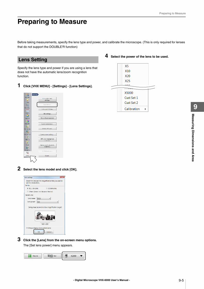
- Digital Microscope VHX-6000 User’s Manual -
Preparing to Measure
9-5
Measu
ring
Dim
ensio
ns an
d A
rea
9
Preparing to Measure
Before taking measurements, specify the lens type and power, and calibrate the microscope. (This is only required for lenses
that do not support the DOUBLE'R function)
Specify the lens type and power if you are using a lens that
does not have the automatic lens/zoom recognition
function.
1 Click [VHX MENU] - [Settings] - [Lens Settings].
2 Select the lens model and click [OK].
3 Click the [Lens] from the on-screen menu options.
The [Set lens power] menu appears.
4 Select the power of the lens to be used.Lens Setting
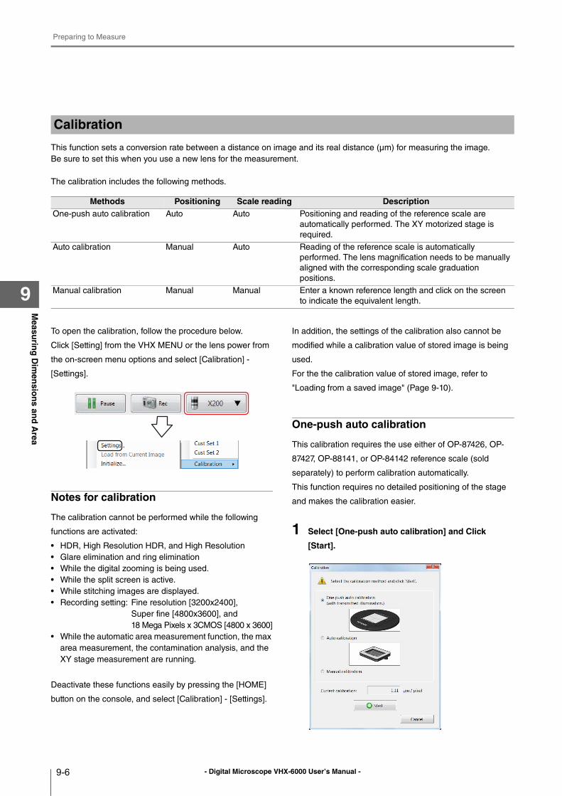
- Digital Microscope VHX-6000 User’s Manual -
Preparing to Measure
9-6
Measu
ring
Dim
ensio
ns an
d A
rea
9
This function sets a conversion rate between a distance on image and its real distance (μm) for measuring the image.
Be sure to set this when you use a new lens for the measurement.
The calibration includes the following methods.
To open the calibration, follow the procedure below.
Click [Setting] from the VHX MENU or the lens power from
the on-screen menu options and select [Calibration] -
[Settings].
Notes for calibration
The calibration cannot be performed while the following
functions are activated:
• HDR, High Resolution HDR, and High Resolution
• Glare elimination and ring elimination
• While the digital zooming is being used.
• While the split screen is active.
• While stitching images are displayed.
• Recording setting: Fine resolution [3200x2400],
Super fine [4800x3600], and
18 Mega Pixels x 3CMOS [4800 x 3600]
• While the automatic area measurement function, the max
area measurement, the contamination analysis, and the
XY stage measurement are running.
Deactivate these functions easily by pressing the [HOME]
button on the console, and select [Calibration] - [Settings].
In addition, the settings of the calibration also cannot be
modified while a calibration value of stored image is being
used.
For the the calibration value of stored image, refer to
"Loading from a saved image" (Page 9-10).
One-push auto calibration
This calibration requires the use either of OP-87426, OP-
87427, OP-88141, or OP-84142 reference scale (sold
separately) to perform calibration automatically.
This function requires no detailed positioning of the stage
and makes the calibration easier.
1 Select [One-push auto calibration] and Click
[Start].
Calibration
Methods Positioning Scale reading DescriptionOne-push auto calibration Auto Auto Positioning and reading of the reference scale are
automatically performed. The XY motorized stage is
required.
Auto calibration Manual Auto Reading of the reference scale is automatically
performed. The lens magnification needs to be manually
aligned with the corresponding scale graduation
positions.
Manual calibration Manual Manual Enter a known reference length and click on the screen
to indicate the equivalent length.
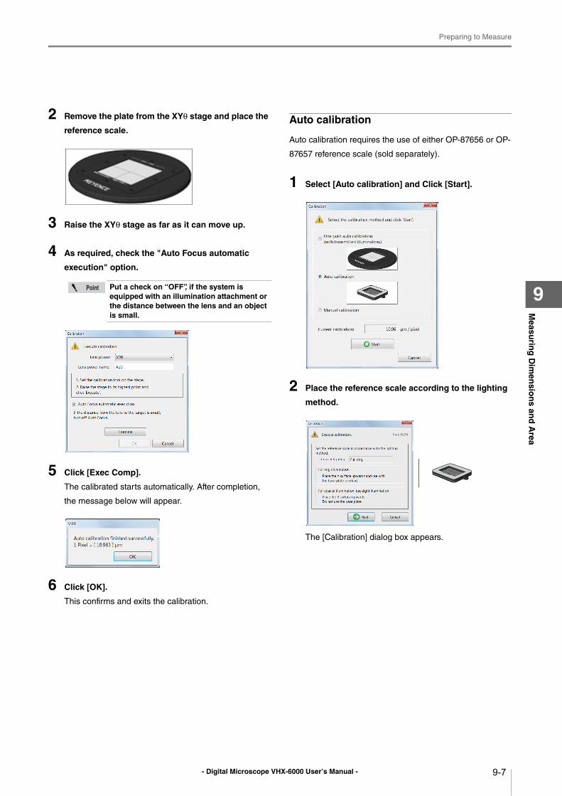
- Digital Microscope VHX-6000 User’s Manual -
Preparing to Measure
9-7
Measu
ring
Dim
ensio
ns an
d A
rea
9
2 Remove the plate from the XYθ stage and place the
reference scale.
3 Raise the XYθ stage as far as it can move up.
4 As required, check the "Auto Focus automatic
execution" option.
5 Click [Exec Comp].
The calibrated starts automatically. After completion,
the message below will appear.
6 Click [OK].
This confirms and exits the calibration.
Auto calibration
Auto calibration requires the use of either OP-87656 or OP-
87657 reference scale (sold separately).
1 Select [Auto calibration] and Click [Start].
2 Place the reference scale according to the lighting
method.
The [Calibration] dialog box appears.
Put a check on “OFF”, if the system is equipped with an illumination attachment or the distance between the lens and an object is small.
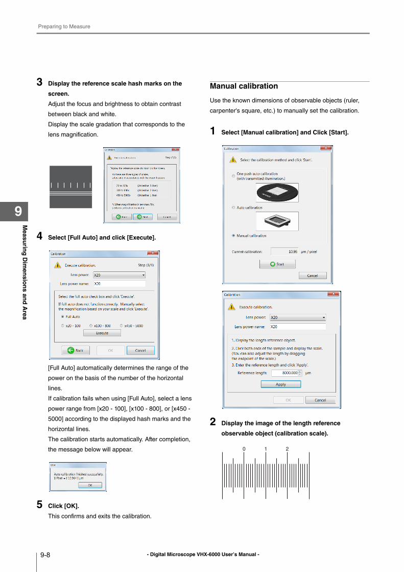
- Digital Microscope VHX-6000 User’s Manual -
Preparing to Measure
9-8
Measu
ring
Dim
ensio
ns an
d A
rea
9
3 Display the reference scale hash marks on the
screen.
Adjust the focus and brightness to obtain contrast
between black and white.
Display the scale gradation that corresponds to the
lens magnification.
4 Select [Full Auto] and click [Execute].
[Full Auto] automatically determines the range of the
power on the basis of the number of the horizontal
lines.
If calibration fails when using [Full Auto], select a lens
power range from [x20 - 100], [x100 - 800], or [x450 -
5000] according to the displayed hash marks and the
horizontal lines.
The calibration starts automatically. After completion,
the message below will appear.
5 Click [OK].
This confirms and exits the calibration.
Manual calibration
Use the known dimensions of observable objects (ruler,
carpenter's square, etc.) to manually set the calibration.
1 Select [Manual calibration] and Click [Start].
2 Display the image of the length reference
observable object (calibration scale).
0 1 2
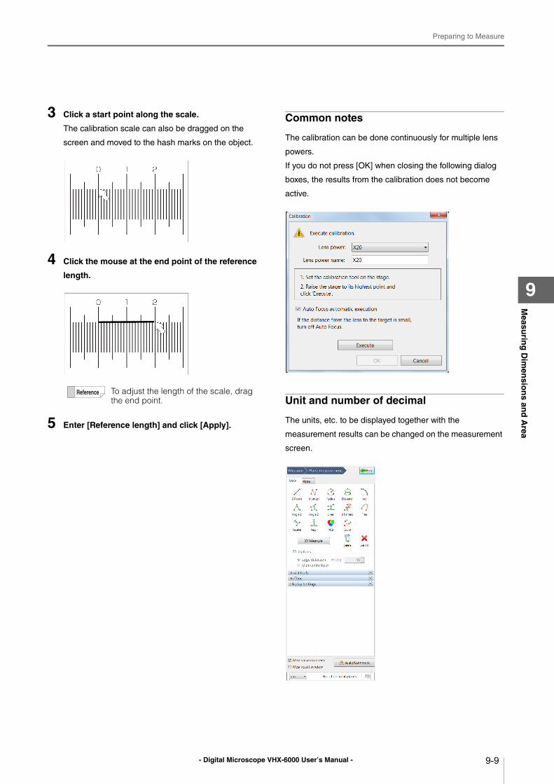
- Digital Microscope VHX-6000 User’s Manual -
Preparing to Measure
9-9
Measu
ring
Dim
ensio
ns an
d A
rea
9
3 Click a start point along the scale.
The calibration scale can also be dragged on the
screen and moved to the hash marks on the object.
4 Click the mouse at the end point of the reference
length.
5 Enter [Reference length] and click [Apply].
Common notes
The calibration can be done continuously for multiple lens
powers.
If you do not press [OK] when closing the following dialog
boxes, the results from the calibration does not become
active.
Unit and number of decimal
The units, etc. to be displayed together with the
measurement results can be changed on the measurement
screen.
To adjust the length of the scale, drag the end point.
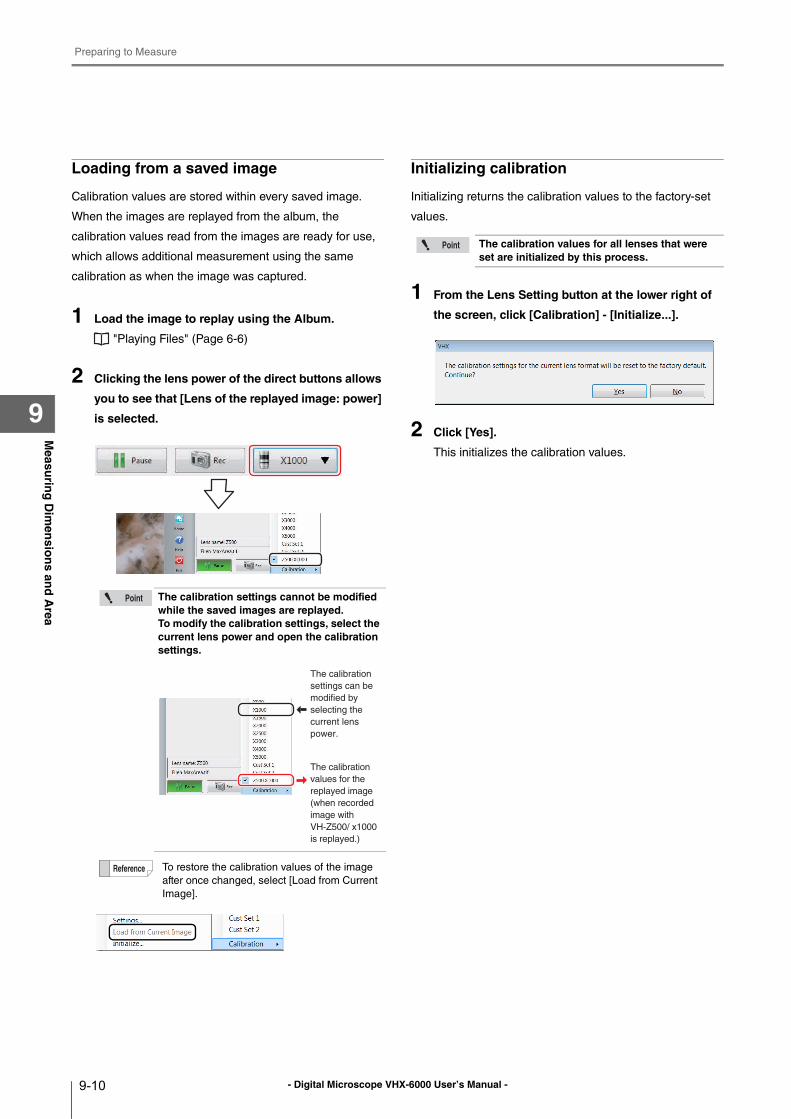
- Digital Microscope VHX-6000 User’s Manual -
Preparing to Measure
9-10
Measu
ring
Dim
ensio
ns an
d A
rea
9
Loading from a saved image
Calibration values are stored within every saved image.
When the images are replayed from the album, the
calibration values read from the images are ready for use,
which allows additional measurement using the same
calibration as when the image was captured.
1 Load the image to replay using the Album.
"Playing Files" (Page 6-6)
2 Clicking the lens power of the direct buttons allows
you to see that [Lens of the replayed image: power]
is selected.
Initializing calibration
Initializing returns the calibration values to the factory-set
values.
1 From the Lens Setting button at the lower right of
the screen, click [Calibration] - [Initialize...].
2 Click [Yes].
This initializes the calibration values.
The calibration settings cannot be modified while the saved images are replayed.To modify the calibration settings, select the current lens power and open the calibration settings.
To restore the calibration values of the image
after once changed, select [Load from Current
Image].
The calibration
settings can be
modified by
selecting the
current lens
power.
The calibration
values for the
replayed image
(when recorded
image with
VH-Z500/ x1000
is replayed.)
The calibration values for all lenses that were set are initialized by this process.
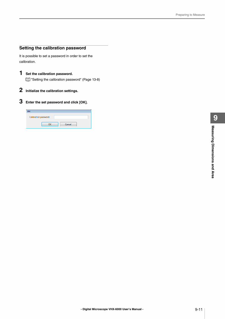
- Digital Microscope VHX-6000 User’s Manual -
Preparing to Measure
9-11
Measu
ring
Dim
ensio
ns an
d A
rea
9
Setting the calibration password
It is possible to set a password in order to set the
calibration.
1 Set the calibration password.
"Setting the calibration password" (Page 13-8)
2 Initialize the calibration settings.
3 Enter the set password and click [OK].
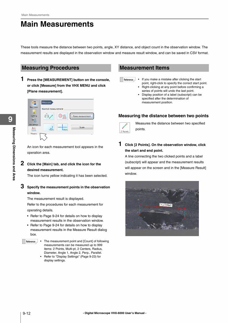
- Digital Microscope VHX-6000 User’s Manual -
Main Measurements
9-12
Measu
ring
Dim
ensio
ns an
d A
rea
9
Main Measurements
These tools measure the distance between two points, angle, XY distance, and object count in the observation window. The
measurement results are displayed in the observation window and measure result window, and can be saved in CSV format.
1 Press the [MEASUREMENT] button on the console,
or click [Measure] from the VHX MENU and click
[Plane measurement].
An icon for each measurement tool appears in the
operation area.
2 Click the [Main] tab, and click the icon for the
desired measurement.
The icon turns yellow indicating it has been selected.
3 Specify the measurement points in the observation
window.
The measurement result is displayed.
Refer to the procedures for each measurement for
operating details.
• Refer to Page 9-24 for details on how to display
measurement results in the observation window.
• Refer to Page 9-24 for details on how to display
measurement results in the Measure Result dialog
box.
Measuring the distance between two points
1 Click [2 Points]. On the observation window, click
the start and end point.
A line connecting the two clicked points and a label
(subscript) will appear and the measurement results
will appear on the screen and in the [Measure Result]
window.
Measuring Procedures
• The measurement point and [Count] of following
measurements can be measured up to 999
items: 2 Points, Multi-pt, 2 Centers, Radius,
Diameter, Angle 1, Angle 2, Perp., Parallel.
• Refer to "Display Settings" (Page 9-23) for
display settings.
Measurement Items
• If you make a mistake after clicking the start
point, right-click to specify the correct start point.
• Right-clicking at any point before confirming a
series of points will undo the last point.
• Display position of a label (subscript) can be
specified after the determination of
measurement position.
Measures the distance between two specified
points.
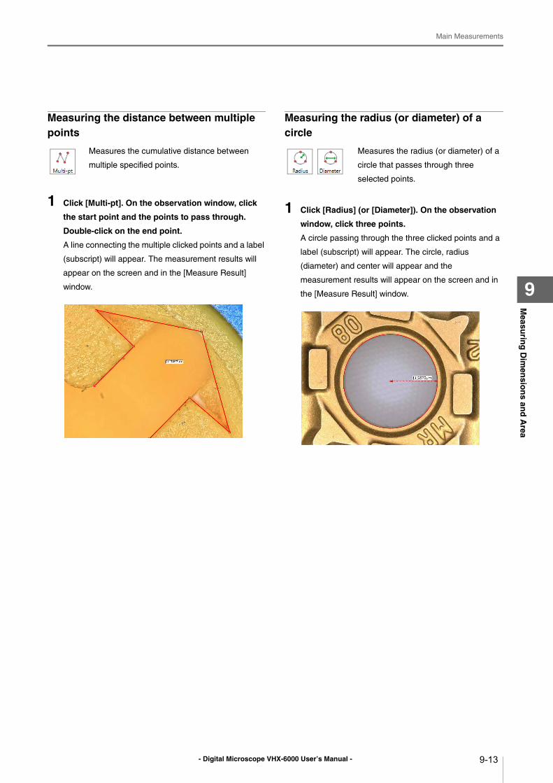
- Digital Microscope VHX-6000 User’s Manual -
Main Measurements
9-13
Measu
ring
Dim
ensio
ns an
d A
rea
9
Measuring the distance between multiple points
1 Click [Multi-pt]. On the observation window, click
the start point and the points to pass through.
Double-click on the end point.
A line connecting the multiple clicked points and a label
(subscript) will appear. The measurement results will
appear on the screen and in the [Measure Result]
window.
Measuring the radius (or diameter) of a circle
1 Click [Radius] (or [Diameter]). On the observation
window, click three points.
A circle passing through the three clicked points and a
label (subscript) will appear. The circle, radius
(diameter) and center will appear and the
measurement results will appear on the screen and in
the [Measure Result] window.
Measures the cumulative distance between
multiple specified points.
Measures the radius (or diameter) of a
circle that passes through three
selected points.
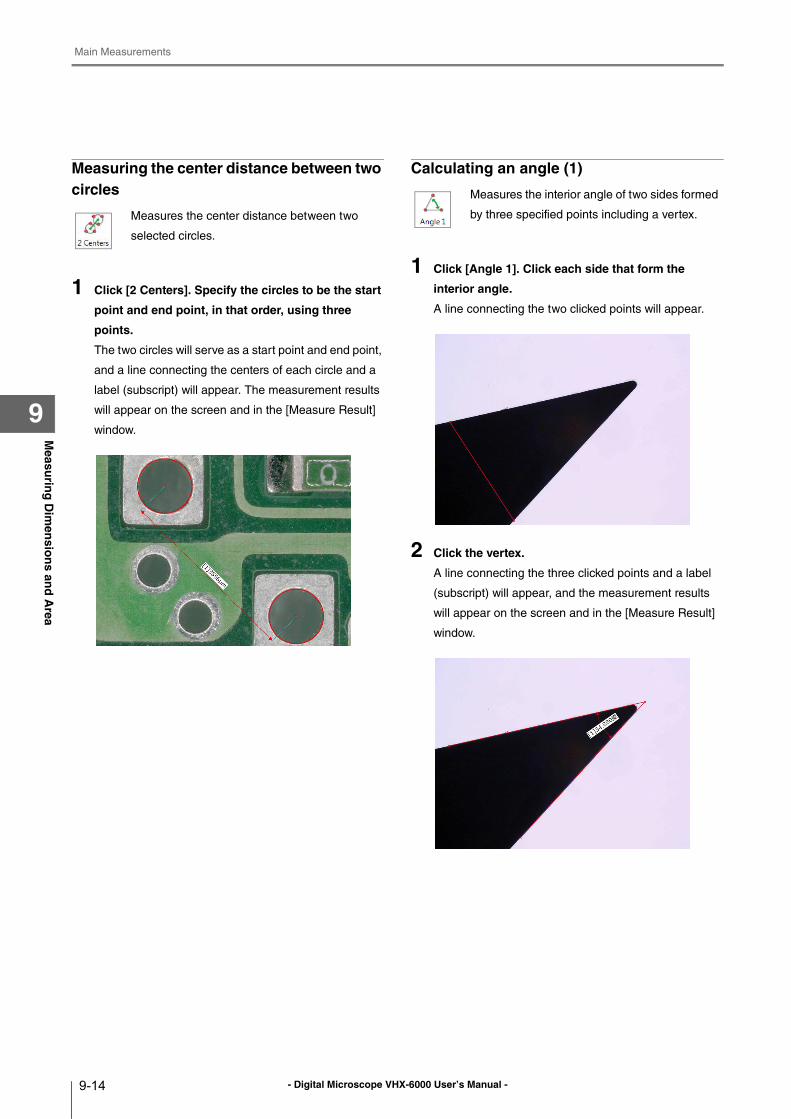
- Digital Microscope VHX-6000 User’s Manual -
Main Measurements
9-14
Measu
ring
Dim
ensio
ns an
d A
rea
9
Measuring the center distance between two circles
1 Click [2 Centers]. Specify the circles to be the start
point and end point, in that order, using three
points.
The two circles will serve as a start point and end point,
and a line connecting the centers of each circle and a
label (subscript) will appear. The measurement results
will appear on the screen and in the [Measure Result]
window.
Calculating an angle (1)
1 Click [Angle 1]. Click each side that form the
interior angle.
A line connecting the two clicked points will appear.
2 Click the vertex.
A line connecting the three clicked points and a label
(subscript) will appear, and the measurement results
will appear on the screen and in the [Measure Result]
window.
Measures the center distance between two
selected circles.
Measures the interior angle of two sides formed
by three specified points including a vertex.
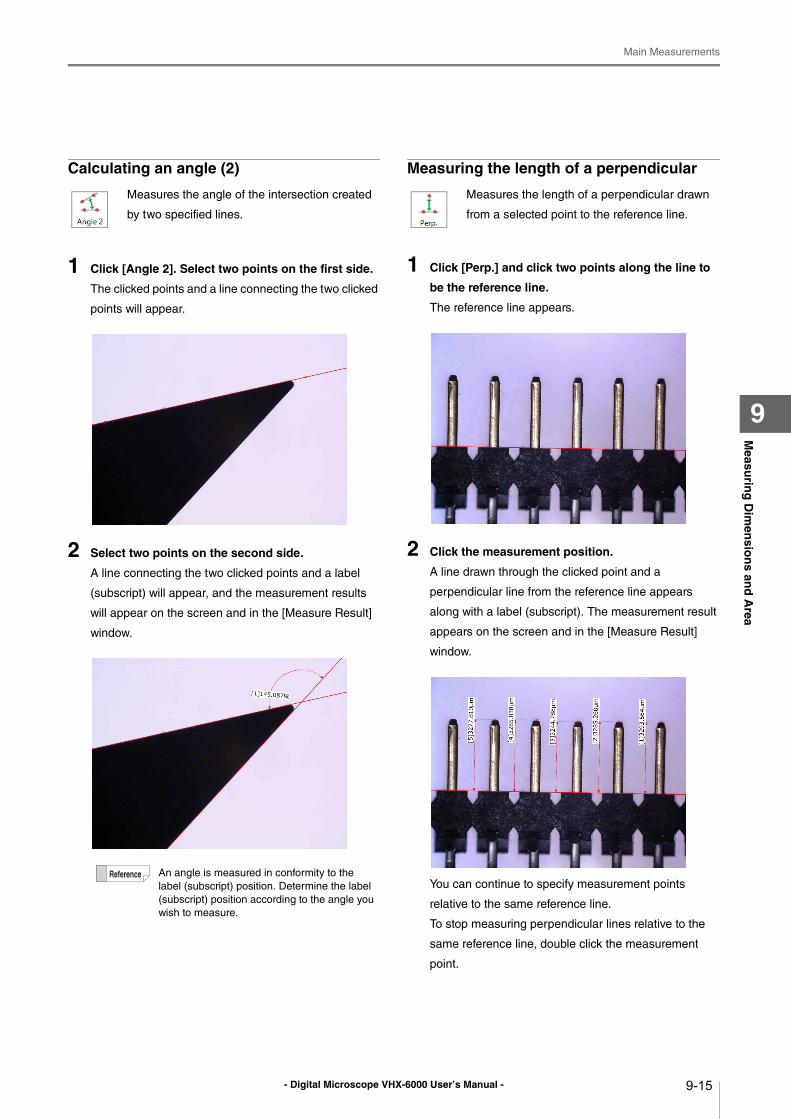
- Digital Microscope VHX-6000 User’s Manual -
Main Measurements
9-15
Measu
ring
Dim
ensio
ns an
d A
rea
9
Calculating an angle (2)
1 Click [Angle 2]. Select two points on the first side.
The clicked points and a line connecting the two clicked
points will appear.
2 Select two points on the second side.
A line connecting the two clicked points and a label
(subscript) will appear, and the measurement results
will appear on the screen and in the [Measure Result]
window.
Measuring the length of a perpendicular
1 Click [Perp.] and click two points along the line to
be the reference line.
The reference line appears.
2 Click the measurement position.
A line drawn through the clicked point and a
perpendicular line from the reference line appears
along with a label (subscript). The measurement result
appears on the screen and in the [Measure Result]
window.
You can continue to specify measurement points
relative to the same reference line.
To stop measuring perpendicular lines relative to the
same reference line, double click the measurement
point.
Measures the angle of the intersection created
by two specified lines.
An angle is measured in conformity to the
label (subscript) position. Determine the label
(subscript) position according to the angle you
wish to measure.
Measures the length of a perpendicular drawn
from a selected point to the reference line.
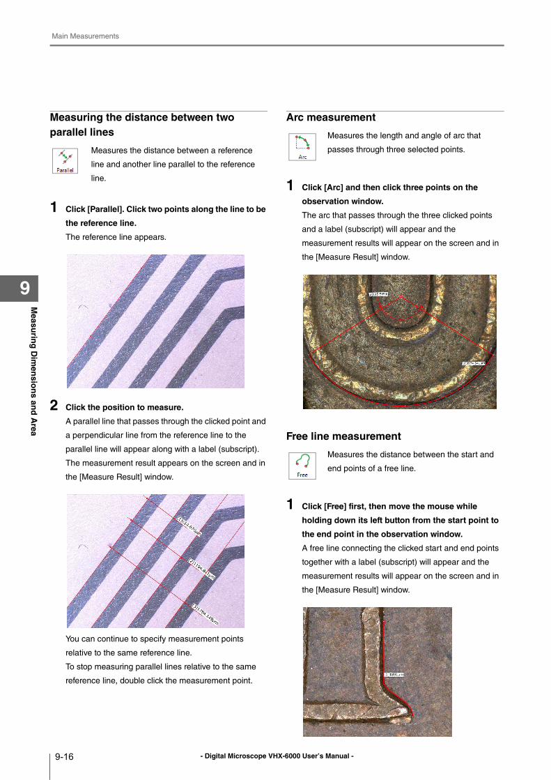
- Digital Microscope VHX-6000 User’s Manual -
Main Measurements
9-16
Measu
ring
Dim
ensio
ns an
d A
rea
9
Measuring the distance between two parallel lines
1 Click [Parallel]. Click two points along the line to be
the reference line.
The reference line appears.
2 Click the position to measure.
A parallel line that passes through the clicked point and
a perpendicular line from the reference line to the
parallel line will appear along with a label (subscript).
The measurement result appears on the screen and in
the [Measure Result] window.
You can continue to specify measurement points
relative to the same reference line.
To stop measuring parallel lines relative to the same
reference line, double click the measurement point.
Arc measurement
1 Click [Arc] and then click three points on the
observation window.
The arc that passes through the three clicked points
and a label (subscript) will appear and the
measurement results will appear on the screen and in
the [Measure Result] window.
Free line measurement
1 Click [Free] first, then move the mouse while
holding down its left button from the start point to
the end point in the observation window.
A free line connecting the clicked start and end points
together with a label (subscript) will appear and the
measurement results will appear on the screen and in
the [Measure Result] window.
Measures the distance between a reference
line and another line parallel to the reference
line.
Measures the length and angle of arc that
passes through three selected points.
Measures the distance between the start and
end points of a free line.
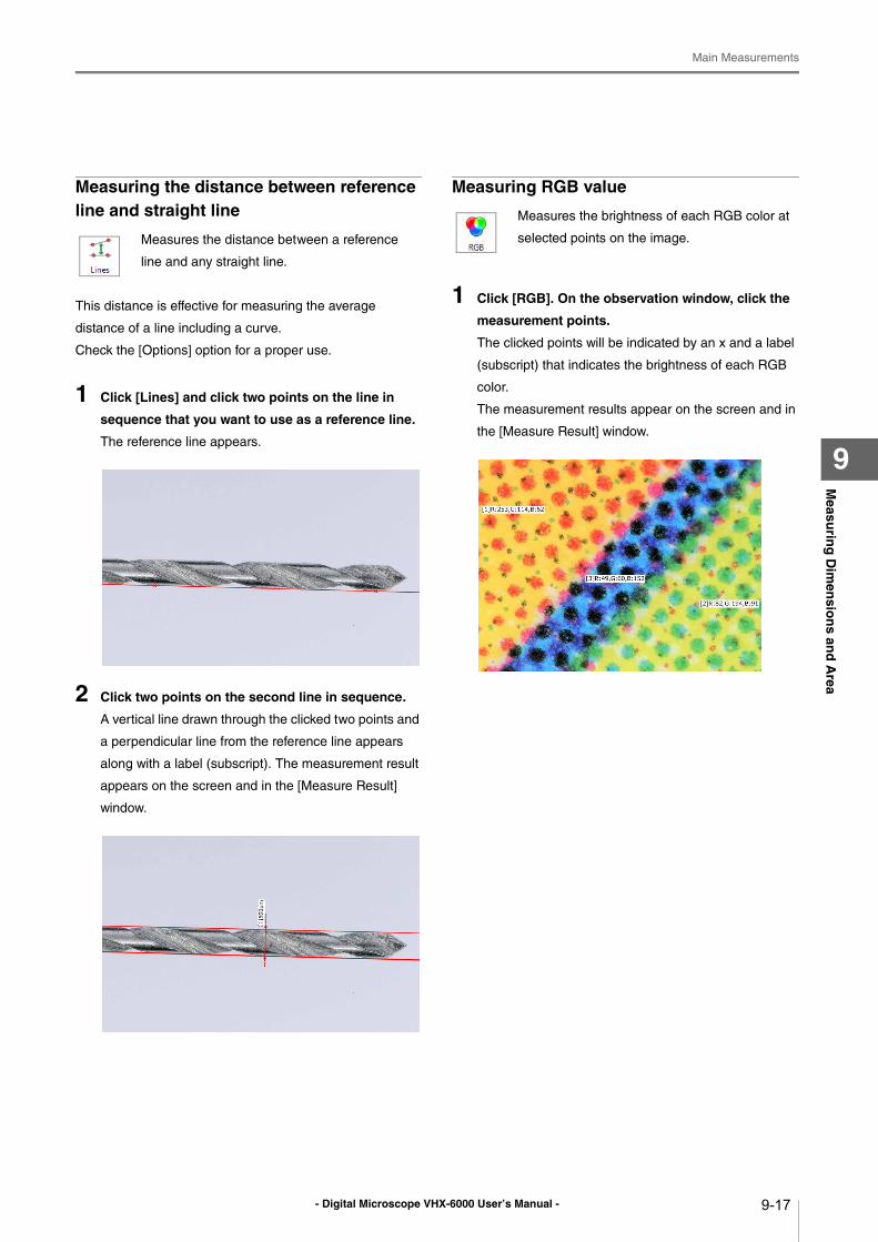
- Digital Microscope VHX-6000 User’s Manual -
Main Measurements
9-17
Measu
ring
Dim
ensio
ns an
d A
rea
9
Measuring the distance between reference line and straight line
This distance is effective for measuring the average
distance of a line including a curve.
Check the [Options] option for a proper use.
1 Click [Lines] and click two points on the line in
sequence that you want to use as a reference line.
The reference line appears.
2 Click two points on the second line in sequence.
A vertical line drawn through the clicked two points and
a perpendicular line from the reference line appears
along with a label (subscript). The measurement result
appears on the screen and in the [Measure Result]
window.
Measuring RGB value
1 Click [RGB]. On the observation window, click the
measurement points.
The clicked points will be indicated by an x and a label
(subscript) that indicates the brightness of each RGB
color.
The measurement results appear on the screen and in
the [Measure Result] window.
Measures the distance between a reference
line and any straight line.
Measures the brightness of each RGB color at
selected points on the image.
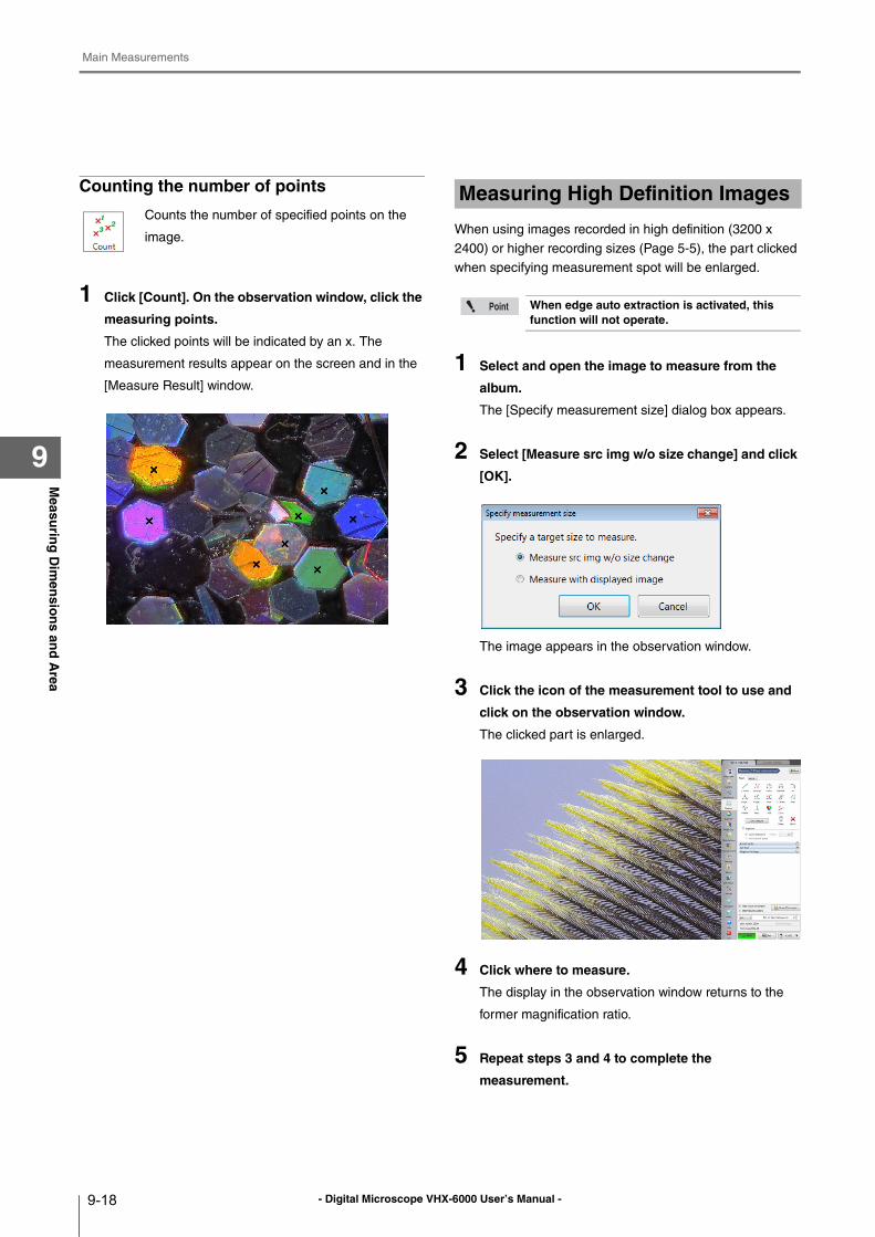
- Digital Microscope VHX-6000 User’s Manual -
Main Measurements
9-18
Measu
ring
Dim
ensio
ns an
d A
rea
9
Counting the number of points
1 Click [Count]. On the observation window, click the
measuring points.
The clicked points will be indicated by an x. The
measurement results appear on the screen and in the
[Measure Result] window.
When using images recorded in high definition (3200 x
2400) or higher recording sizes (Page 5-5), the part clicked
when specifying measurement spot will be enlarged.
1 Select and open the image to measure from the
album.
The [Specify measurement size] dialog box appears.
2 Select [Measure src img w/o size change] and click
[OK].
The image appears in the observation window.
3 Click the icon of the measurement tool to use and
click on the observation window.
The clicked part is enlarged.
4 Click where to measure.
The display in the observation window returns to the
former magnification ratio.
5 Repeat steps 3 and 4 to complete the
measurement.
Counts the number of specified points on the
image.
Measuring High Definition Images
When edge auto extraction is activated, this function will not operate.
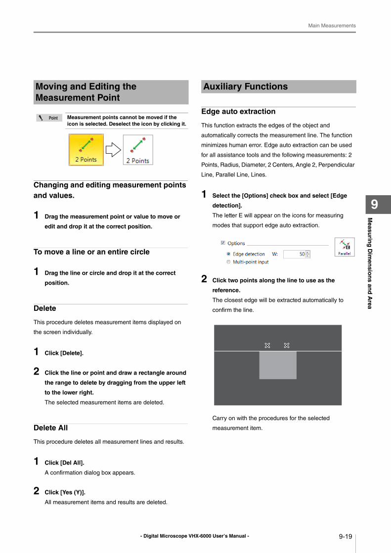
- Digital Microscope VHX-6000 User’s Manual -
Main Measurements
9-19
Measu
ring
Dim
ensio
ns an
d A
rea
9
Changing and editing measurement points and values.
1 Drag the measurement point or value to move or
edit and drop it at the correct position.
To move a line or an entire circle
1 Drag the line or circle and drop it at the correct
position.
Delete
This procedure deletes measurement items displayed on
the screen individually.
1 Click [Delete].
2 Click the line or point and draw a rectangle around
the range to delete by dragging from the upper left
to the lower right.
The selected measurement items are deleted.
Delete All
This procedure deletes all measurement lines and results.
1 Click [Del All].
A confirmation dialog box appears.
2 Click [Yes (Y)].
All measurement items and results are deleted.
Edge auto extraction
This function extracts the edges of the object and
automatically corrects the measurement line. The function
minimizes human error. Edge auto extraction can be used
for all assistance tools and the following measurements: 2
Points, Radius, Diameter, 2 Centers, Angle 2, Perpendicular
Line, Parallel Line, Lines.
1 Select the [Options] check box and select [Edge
detection].
The letter E will appear on the icons for measuring
modes that support edge auto extraction.
2 Click two points along the line to use as the
reference.
The closest edge will be extracted automatically to
confirm the line.
Carry on with the procedures for the selected
measurement item.
Moving and Editing the Measurement Point
Measurement points cannot be moved if the icon is selected. Deselect the icon by clicking it.
Auxiliary Functions
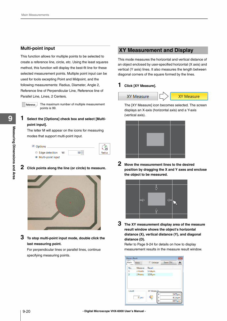
- Digital Microscope VHX-6000 User’s Manual -
Main Measurements
9-20
Measu
ring
Dim
ensio
ns an
d A
rea
9
Multi-point input
This function allows for multiple points to be selected to
create a reference line, circle, etc. Using the least squares
method, this function will display the best-fit line for these
selected measurement points. Multiple point input can be
used for tools excepting Point and Midpoint, and the
following measurements: Radius, Diameter, Angle 2,
Reference line of Perpendicular Line, Reference line of
Parallel Line, Lines, 2 Centers.
1 Select the [Options] check box and select [Multi-
point input].
The letter M will appear on the icons for measuring
modes that support multi-point input.
2 Click points along the line (or circle) to measure.
3 To stop multi-point input mode, double click the
last measuring point.
For perpendicular lines or parallel lines, continue
specifying measuring points.
This mode measures the horizontal and vertical distance of
an object enclosed by user-specified horizontal (X axis) and
vertical (Y axis) lines. It also measures the length between
diagonal corners of the square formed by the lines.
1 Click [XY Measure].
The [XY Measure] icon becomes selected. The screen
displays an X-axis (horizontal axis) and a Y-axis
(vertical axis).
2 Move the measurement lines to the desired position by dragging the X and Y axes and enclose the object to be measured.
3 The XY measurement display area of the measure result window shows the object's horizontal distance (X), vertical distance (Y), and diagonal distance (D).Refer to Page 9-24 for details on how to display
measurement results in the measure result window.
The maximum number of multiple measurement
points is 99.
XY Measurement and Display
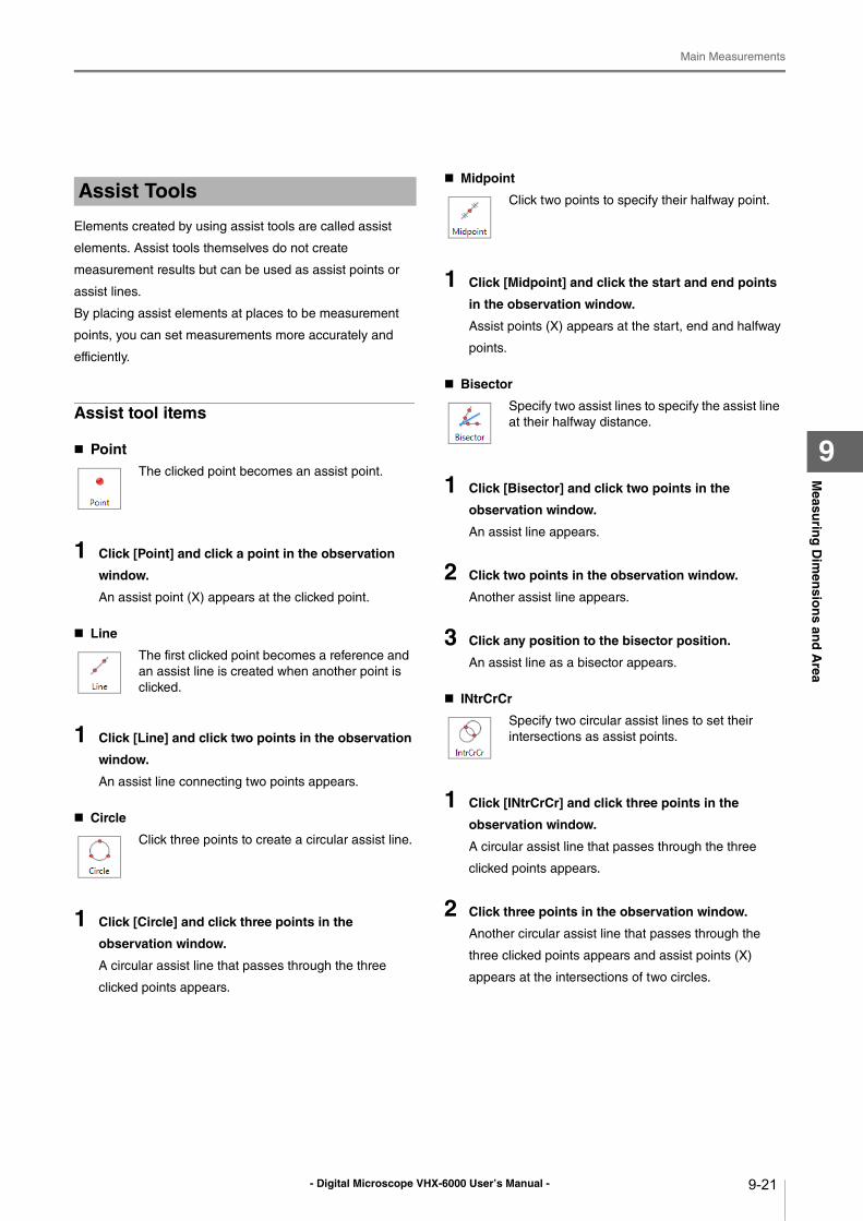
- Digital Microscope VHX-6000 User’s Manual -
Main Measurements
9-21
Measu
ring
Dim
ensio
ns an
d A
rea
9
Elements created by using assist tools are called assist
elements. Assist tools themselves do not create
measurement results but can be used as assist points or
assist lines.
By placing assist elements at places to be measurement
points, you can set measurements more accurately and
efficiently.
Assist tool items
Point
1 Click [Point] and click a point in the observation
window.
An assist point (X) appears at the clicked point.
Line
1 Click [Line] and click two points in the observation
window.
An assist line connecting two points appears.
Circle
1 Click [Circle] and click three points in the
observation window.
A circular assist line that passes through the three
clicked points appears.
Midpoint
1 Click [Midpoint] and click the start and end points
in the observation window.
Assist points (X) appears at the start, end and halfway
points.
Bisector
1 Click [Bisector] and click two points in the
observation window.
An assist line appears.
2 Click two points in the observation window.
Another assist line appears.
3 Click any position to the bisector position.
An assist line as a bisector appears.
INtrCrCr
1 Click [INtrCrCr] and click three points in the
observation window.
A circular assist line that passes through the three
clicked points appears.
2 Click three points in the observation window.
Another circular assist line that passes through the
three clicked points appears and assist points (X)
appears at the intersections of two circles.
Assist Tools
The clicked point becomes an assist point.
The first clicked point becomes a reference and
an assist line is created when another point is
clicked.
Click three points to create a circular assist line.
Click two points to specify their halfway point.
Specify two assist lines to specify the assist line
at their halfway distance.
Specify two circular assist lines to set their
intersections as assist points.

- Digital Microscope VHX-6000 User’s Manual -
Main Measurements
9-22
Measu
ring
Dim
ensio
ns an
d A
rea
9
INtrCrLn
1 Click [INtrCrLn] and click three points in the
observation window.
A circular assist line that passes through the three
clicked points appears.
2 Click two points in the observation window.
An assist line connecting the clicked points appears
and assist points (X) appears at the intersections with
the circular assist line.
INtrLnLn
1 Click [INtrLnLn] and click two points in the
observation window.
An assist line connecting the clicked points appears.
2 Click two points in the observation window.
Another assist line connecting the clicked points
appears and assist points (X) appears at the
intersections of the assist lines.
Perp.
1 Click [Perp.] and then click two points on the
observation screen.
An assist line connecting two points appears.
2 Click one point in the observation window.
Perpendicular intersect the created assist line, and the
line that connects the clicked point will appear.
When displaying the measurement line, a numeric value
can be entered as a reference length or size to simplify
comparison and determine if the object is larger or smaller
than the reference length, circle, or degree. Reference lines
can be entered for these modes: 2 Points, Radius,
Diameter, and Angle.
1 Open the [Ref line] menu.
2 Select the measurement line to use as the
reference.
3 The [Length] dialog box appears.
4 Enter the length and click [OK].
5 Click the position to display the reference line.
The reference line appears.
Specify a circular assist line and a straight
assist line to set their intersections as assist
points.
Specify two assist lines to set their intersections
as auxiliary points.
Create a line which passes through two points,
and a perpendicular line.
Reference Lines
• Move the reference line by dragging and
dropping it.
• To change the orientation for [2 Points] and
[Angle], drag the reference point (x).
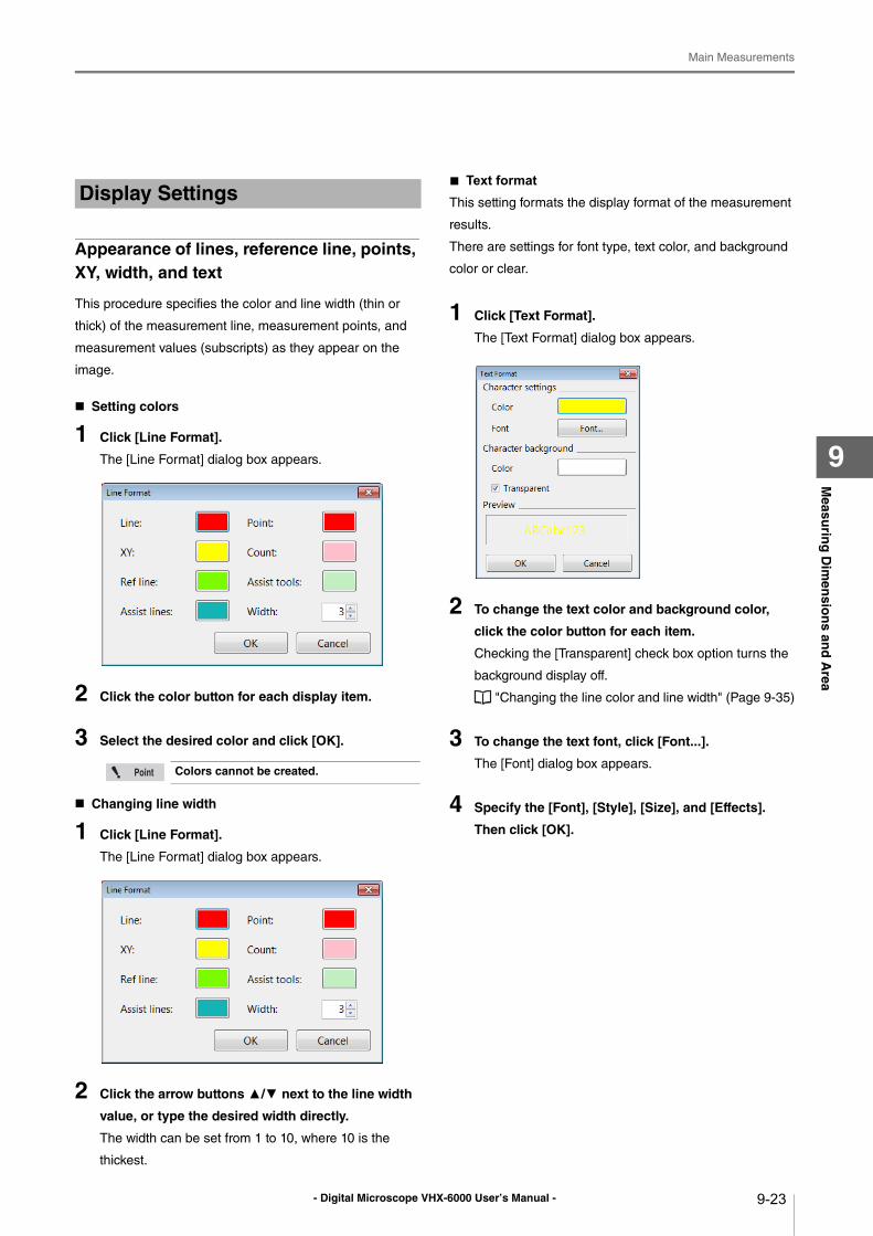
- Digital Microscope VHX-6000 User’s Manual -
Main Measurements
9-23
Measu
ring
Dim
ensio
ns an
d A
rea
9
Appearance of lines, reference line, points, XY, width, and text
This procedure specifies the color and line width (thin or
thick) of the measurement line, measurement points, and
measurement values (subscripts) as they appear on the
image.
Setting colors
1 Click [Line Format].
The [Line Format] dialog box appears.
2 Click the color button for each display item.
3 Select the desired color and click [OK].
Changing line width
1 Click [Line Format].
The [Line Format] dialog box appears.
2 Click the arrow buttons ▲/▼ next to the line width
value, or type the desired width directly.
The width can be set from 1 to 10, where 10 is the
thickest.
■ Text format
This setting formats the display format of the measurement
results.
There are settings for font type, text color, and background
color or clear.
1 Click [Text Format].
The [Text Format] dialog box appears.
2 To change the text color and background color,
click the color button for each item.
Checking the [Transparent] check box option turns the
background display off.
"Changing the line color and line width" (Page 9-35)
3 To change the text font, click [Font...].
The [Font] dialog box appears.
4 Specify the [Font], [Style], [Size], and [Effects].
Then click [OK].
Display Settings
Colors cannot be created.
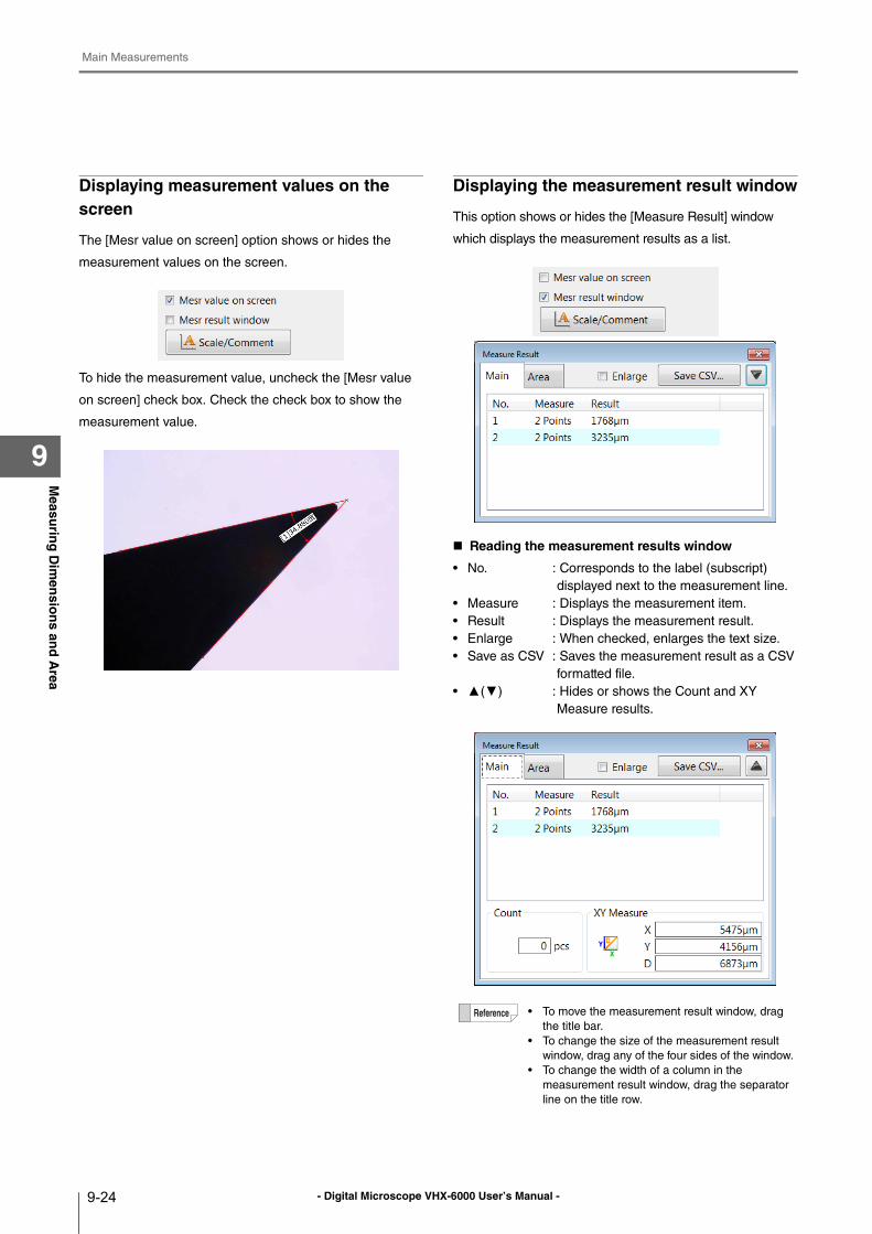
- Digital Microscope VHX-6000 User’s Manual -
Main Measurements
9-24
Measu
ring
Dim
ensio
ns an
d A
rea
9
Displaying measurement values on the screen
The [Mesr value on screen] option shows or hides the
measurement values on the screen.
To hide the measurement value, uncheck the [Mesr value
on screen] check box. Check the check box to show the
measurement value.
Displaying the measurement result window
This option shows or hides the [Measure Result] window
which displays the measurement results as a list.
Reading the measurement results window
• No. : Corresponds to the label (subscript)
displayed next to the measurement line.
• Measure : Displays the measurement item.
• Result : Displays the measurement result.
• Enlarge : When checked, enlarges the text size.
• Save as CSV : Saves the measurement result as a CSV
formatted file.
• ▲(▼) : Hides or shows the Count and XY
Measure results.
• To move the measurement result window, drag
the title bar.
• To change the size of the measurement result
window, drag any of the four sides of the window.
• To change the width of a column in the
measurement result window, drag the separator
line on the title row.
- Digital Microscope VHX-6000 User’s Manual -
Main Measurements
9-25
Measu
ring
Dim
ensio
ns an
d A
rea
9
Checking the extracted point
When [Show edge-extraction points] check box is selected,
you can check extracted points.
• Extracted point used during measurement: Yellow
• Extracted point not used during measurement: Red
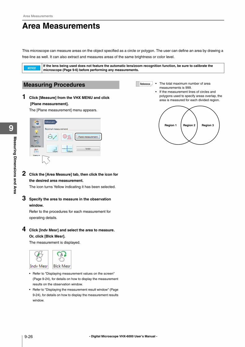
- Digital Microscope VHX-6000 User’s Manual -
Area Measurements
9-26
Measu
ring
Dim
ensio
ns an
d A
rea
9
Area Measurements
This microscope can measure areas on the object specified as a circle or polygon. The user can define an area by drawing a
free-line as well. It can also extract and measures areas of the same brightness or color level.
1 Click [Measure] from the VHX MENU and click
[Plane measurement].
The [Plane measurement] menu appears.
2 Click the [Area Measure] tab, then click the icon for
the desired area measurement.
The icon turns Yellow indicating it has been selected.
3 Specify the area to measure in the observation
window.
Refer to the procedures for each measurement for
operating details.
4 Click [Indv Mesr] and select the area to measure.
Or, click [Blck Mesr].
The measurement is displayed.
• Refer to "Displaying measurement values on the screen"
(Page 9-24), for details on how to display the measurement
results on the observation window.
• Refer to "Displaying the measurement result window" (Page
9-24), for details on how to display the measurement results
window.
If the lens being used does not feature the automatic lens/zoom recognition function, be sure to calibrate the microscope (Page 9-6) before performing any measurements.
Measuring Procedures • The total maximum number of area
measurements is 999.
• If the measurement lines of circles and
polygons used to specify areas overlap, the
area is measured for each divided region.
Region 1 Region 2 Region 3
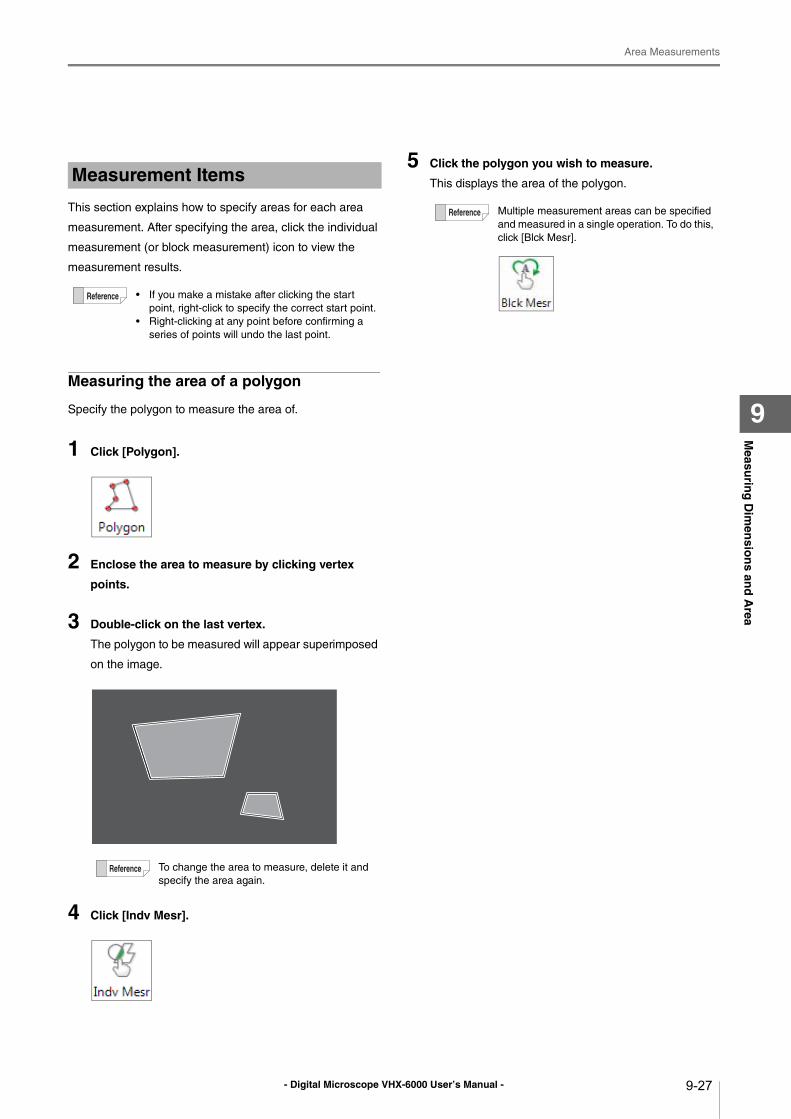
- Digital Microscope VHX-6000 User’s Manual -
Area Measurements
9-27
Measu
ring
Dim
ensio
ns an
d A
rea
9
This section explains how to specify areas for each area
measurement. After specifying the area, click the individual
measurement (or block measurement) icon to view the
measurement results.
Measuring the area of a polygon
Specify the polygon to measure the area of.
1 Click [Polygon].
2 Enclose the area to measure by clicking vertex
points.
3 Double-click on the last vertex.
The polygon to be measured will appear superimposed
on the image.
4 Click [Indv Mesr].
5 Click the polygon you wish to measure.
This displays the area of the polygon.Measurement Items
• If you make a mistake after clicking the start
point, right-click to specify the correct start point.
• Right-clicking at any point before confirming a
series of points will undo the last point.
To change the area to measure, delete it and
specify the area again.
Multiple measurement areas can be specified
and measured in a single operation. To do this,
click [Blck Mesr].
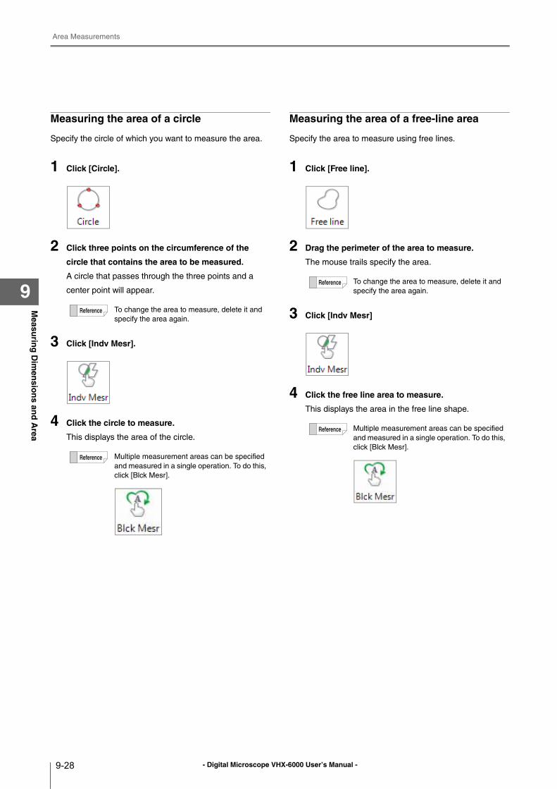
- Digital Microscope VHX-6000 User’s Manual -
Area Measurements
9-28
Measu
ring
Dim
ensio
ns an
d A
rea
9
Measuring the area of a circle
Specify the circle of which you want to measure the area.
1 Click [Circle].
2 Click three points on the circumference of the
circle that contains the area to be measured.
A circle that passes through the three points and a
center point will appear.
3 Click [Indv Mesr].
4 Click the circle to measure.
This displays the area of the circle.
Measuring the area of a free-line area
Specify the area to measure using free lines.
1 Click [Free line].
2 Drag the perimeter of the area to measure.
The mouse trails specify the area.
3 Click [Indv Mesr]
4 Click the free line area to measure.
This displays the area in the free line shape.
To change the area to measure, delete it and
specify the area again.
Multiple measurement areas can be specified
and measured in a single operation. To do this,
click [Blck Mesr].
To change the area to measure, delete it and
specify the area again.
Multiple measurement areas can be specified
and measured in a single operation. To do this,
click [Blck Mesr].
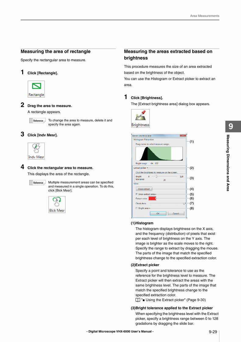
- Digital Microscope VHX-6000 User’s Manual -
Area Measurements
9-29
Measu
ring
Dim
ensio
ns an
d A
rea
9
Measuring the area of rectangle
Specify the rectangular area to measure.
1 Click [Rectangle].
2 Drag the area to measure.
A rectangle appears.
3 Click [Indv Mesr].
4 Click the rectangular area to measure.
This displays the area of the rectangle.
Measuring the areas extracted based on brightness
This procedure measures the size of an area extracted
based on the brightness of the object.
You can use the Histogram or Extract picker to extract an
area.
1 Click [Brightness].
The [Extract brightness area] dialog box appears.
(1)Histogram
The histogram displays brightness on the X axis,
and the frequency (distribution) of pixels that exist
per each level of brightness on the Y axis. The
image is brighter as the scale moves to the right.
Specify the range to extract by dragging the mouse.
The parts of the image that match the specified
brightness change to the specified extraction color.
(2)Extract picker
Specify a point and tolerance to use as the
reference for the brightness level to measure. The
Extract picker will then extract the areas with the
same brightness level. The parts of the image that
match the specified brightness change to the
specified extraction color.
"■ Using the Extract picker" (Page 9-30)
(3)Bright tolerance applied to the Extract picker
When specifying the brightness level with the Extract
picker, specify a brightness range between 0 to 128
gradations by dragging the slide bar.
To change the area to measure, delete it and
specify the area again.
Multiple measurement areas can be specified
and measured in a single operation. To do this,
click [Blck Mesr].
(1)
(2)
(3)
(5)
(4)
(6)
(7)
(8)
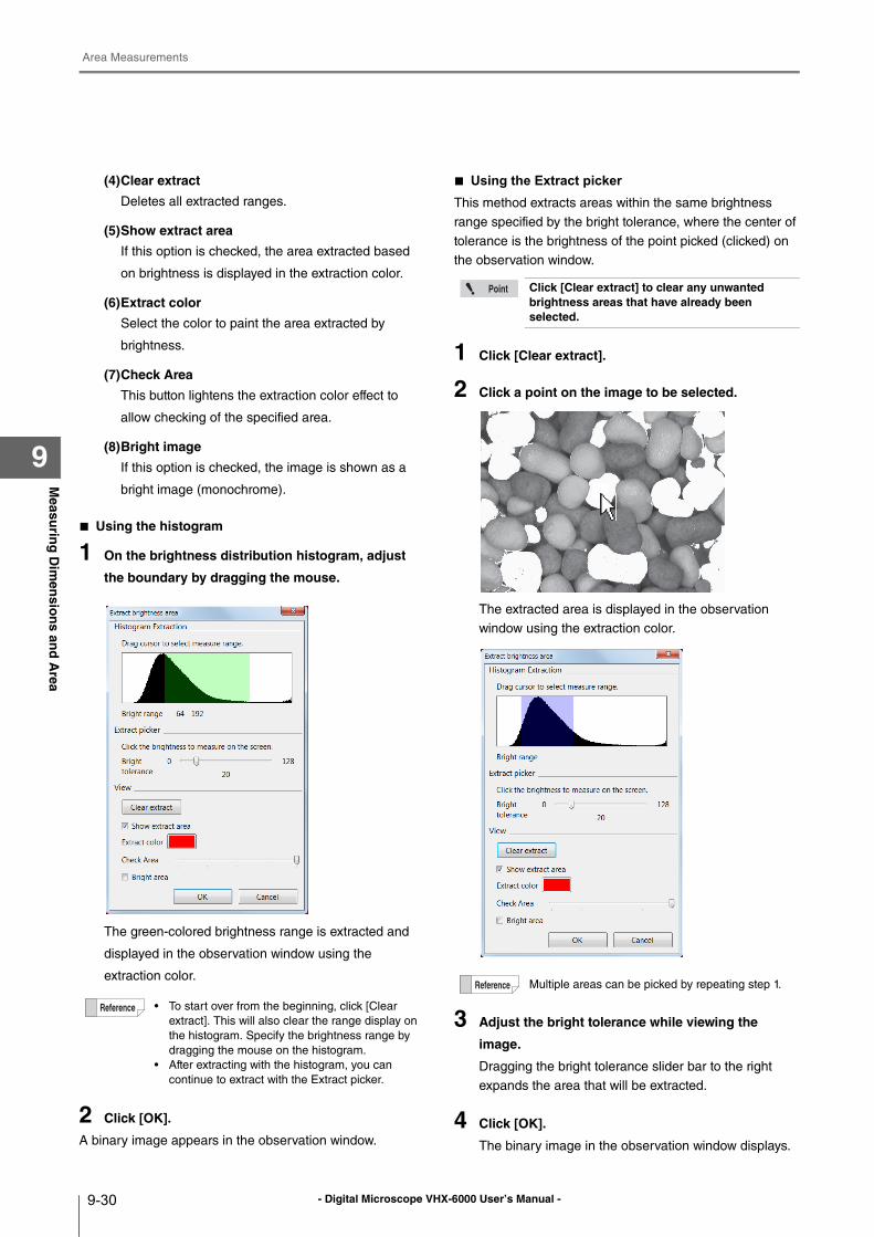
- Digital Microscope VHX-6000 User’s Manual -
Area Measurements
9-30
Measu
ring
Dim
ensio
ns an
d A
rea
9
(4)Clear extract
Deletes all extracted ranges.
(5)Show extract area
If this option is checked, the area extracted based
on brightness is displayed in the extraction color.
(6)Extract color
Select the color to paint the area extracted by
brightness.
(7)Check Area
This button lightens the extraction color effect to
allow checking of the specified area.
(8)Bright image
If this option is checked, the image is shown as a
bright image (monochrome).
■ Using the histogram
1 On the brightness distribution histogram, adjust
the boundary by dragging the mouse.
The green-colored brightness range is extracted and
displayed in the observation window using the
extraction color.
2 Click [OK].
A binary image appears in the observation window.
■ Using the Extract picker
This method extracts areas within the same brightness
range specified by the bright tolerance, where the center of
tolerance is the brightness of the point picked (clicked) on
the observation window.
1 Click [Clear extract].
2 Click a point on the image to be selected.
The extracted area is displayed in the observation
window using the extraction color.
3 Adjust the bright tolerance while viewing the
image.
Dragging the bright tolerance slider bar to the right
expands the area that will be extracted.
4 Click [OK].
The binary image in the observation window displays.
• To start over from the beginning, click [Clear
extract]. This will also clear the range display on
the histogram. Specify the brightness range by
dragging the mouse on the histogram.
• After extracting with the histogram, you can
continue to extract with the Extract picker.
Click [Clear extract] to clear any unwanted brightness areas that have already been selected.
Multiple areas can be picked by repeating step 1.
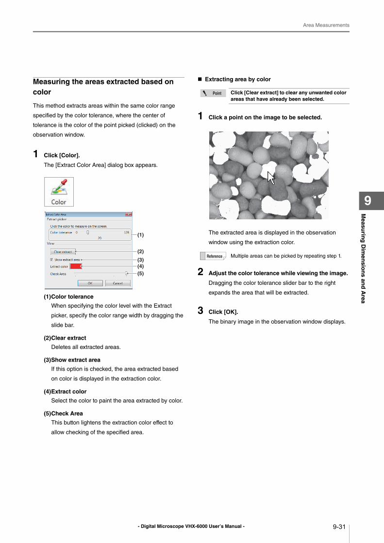
- Digital Microscope VHX-6000 User’s Manual -
Area Measurements
9-31
Measu
ring
Dim
ensio
ns an
d A
rea
9
Measuring the areas extracted based on color
This method extracts areas within the same color range
specified by the color tolerance, where the center of
tolerance is the color of the point picked (clicked) on the
observation window.
1 Click [Color].
The [Extract Color Area] dialog box appears.
(1)Color tolerance
When specifying the color level with the Extract
picker, specify the color range width by dragging the
slide bar.
(2)Clear extract
Deletes all extracted areas.
(3)Show extract area
If this option is checked, the area extracted based
on color is displayed in the extraction color.
(4)Extract color
Select the color to paint the area extracted by color.
(5)Check Area
This button lightens the extraction color effect to
allow checking of the specified area.
Extracting area by color
1 Click a point on the image to be selected.
The extracted area is displayed in the observation
window using the extraction color.
2 Adjust the color tolerance while viewing the image.
Dragging the color tolerance slider bar to the right
expands the area that will be extracted.
3 Click [OK].
The binary image in the observation window displays.
(2)
(3)(4)(5)
(1)
Click [Clear extract] to clear any unwanted color areas that have already been selected.
Multiple areas can be picked by repeating step 1.
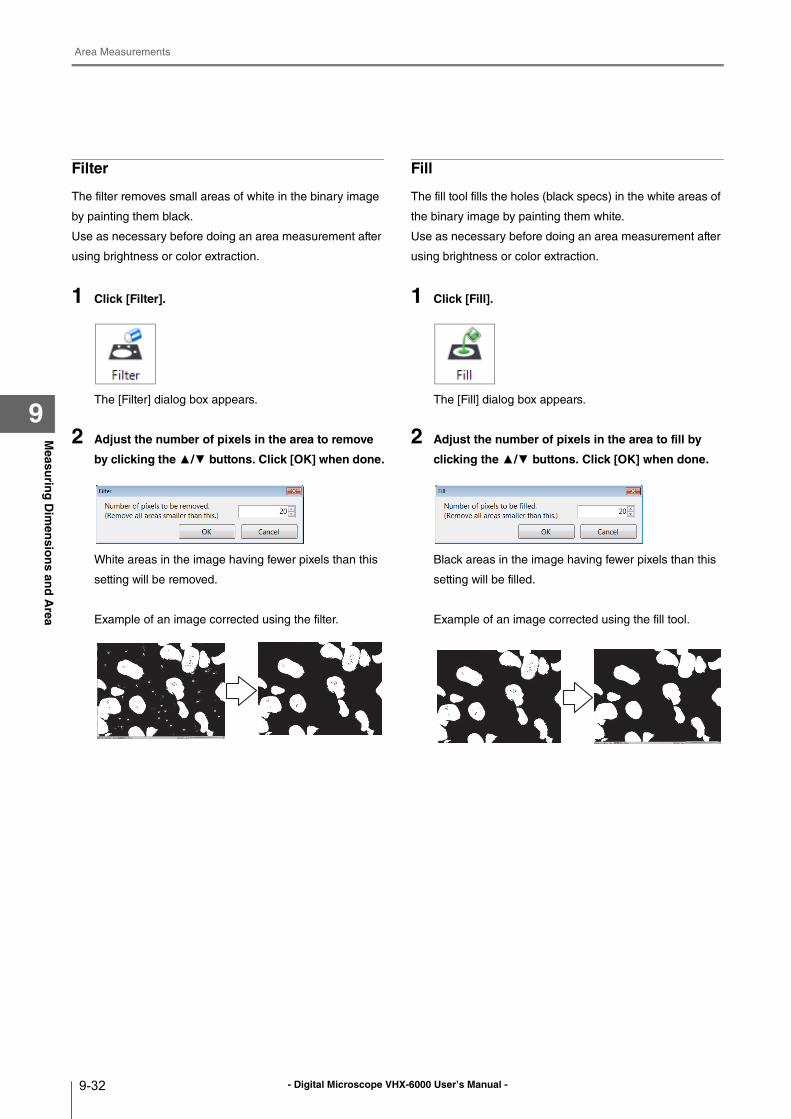
- Digital Microscope VHX-6000 User’s Manual -
Area Measurements
9-32
Measu
ring
Dim
ensio
ns an
d A
rea
9
Filter
The filter removes small areas of white in the binary image
by painting them black.
Use as necessary before doing an area measurement after
using brightness or color extraction.
1 Click [Filter].
The [Filter] dialog box appears.
2 Adjust the number of pixels in the area to remove
by clicking the ▲/▼ buttons. Click [OK] when done.
White areas in the image having fewer pixels than this
setting will be removed.
Example of an image corrected using the filter.
Fill
The fill tool fills the holes (black specs) in the white areas of
the binary image by painting them white.
Use as necessary before doing an area measurement after
using brightness or color extraction.
1 Click [Fill].
The [Fill] dialog box appears.
2 Adjust the number of pixels in the area to fill by
clicking the ▲/▼ buttons. Click [OK] when done.
Black areas in the image having fewer pixels than this
setting will be filled.
Example of an image corrected using the fill tool.
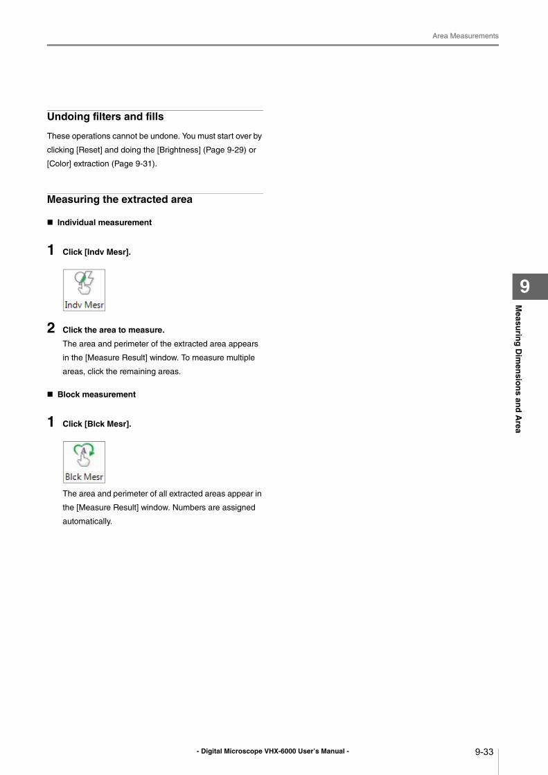
- Digital Microscope VHX-6000 User’s Manual -
Area Measurements
9-33
Measu
ring
Dim
ensio
ns an
d A
rea
9
Undoing filters and fills
These operations cannot be undone. You must start over by
clicking [Reset] and doing the [Brightness] (Page 9-29) or
[Color] extraction (Page 9-31).
Measuring the extracted area
Individual measurement
1 Click [Indv Mesr].
2 Click the area to measure.
The area and perimeter of the extracted area appears
in the [Measure Result] window. To measure multiple
areas, click the remaining areas.
Block measurement
1 Click [Blck Mesr].
The area and perimeter of all extracted areas appear in
the [Measure Result] window. Numbers are assigned
automatically.
- Digital Microscope VHX-6000 User’s Manual -
Displaying Text and Markers
9-34
Measu
ring
Dim
ensio
ns an
d A
rea
9
Displaying Text and Markers
Text comments and markers can be displayed on the observation window. When an image is recorded (saved) with the
comment display turned on, the image is saved with the comment. Comments can be [Normal Comments], which are erased
when the power is turned OFF, or [Residual Comments] which are saved even if the power is turned OFF.
List of normal comments
List of residual comments
Hide
Hides all comments.
Delete All
Deletes all comments.
When an image file is saved with comments, the text or comments cannot be edited.
List of Comments
The total maximum number of normal comments
that can be registered is 999.
Marker type How the marker is drawn Displayed image
Comments Displays the comment in the
location specified on the
screen.
Comment
Circle Draws a circle centered at the
clicked point.
[Picture]
Rectangle Draws a rectangle with one of
its corners on the clicked
point.
[Picture]
Ellipse Draws an ellipse that starts at
the clicked point.
[Picture]
Arrow Draws a line that originates at
the clicked point.The arrow
appears at the origin.
[Picture]
Arrow/Text Draws a line that originates at
the clicked point.The arrow
appears at the origin, and the
comment appears at the end
point.
[Picture]
Delete Deletes the comment
specified using the mouse.
[Residual Comments]
cannotbe deleted.
-
Delete All Deletes all normal comments.
[Residual Comments]
cannotbe deleted.
-
Line Format Color and line width for
drawing circles, rectangles,
etc., can be set.
-
Comment type
Contents Display format
Comment Displays the applicable
text.
Date Displays the date. YYYY/MM/DD
YY/MM/DD
MM/DD/YYYY
MM/DD/YY
DD/MM/YYYY
DD/MM/YY
Time Displays the current time
updated in real time.
hh:mm:ss
Lens Name Displays the lens type and
power.
Lens [type]: x
[power]
Inclination
angle
Displays the inclination
angle of the stage.
Inclination
angle: [value]
degree
Magnification Displays the magnification. Magnification: x
[magnification]
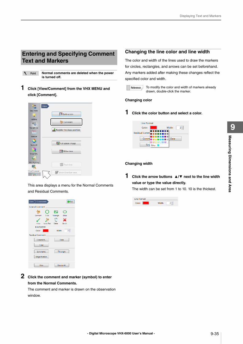
- Digital Microscope VHX-6000 User’s Manual -
Displaying Text and Markers
9-35
Measu
ring
Dim
ensio
ns an
d A
rea
9
1 Click [View/Comment] from the VHX MENU and
click [Comment].
This area displays a menu for the Normal Comments
and Residual Comments.
2 Click the comment and marker (symbol) to enter
from the Normal Comments.
The comment and marker is drawn on the observation
window.
Changing the line color and line width
The color and width of the lines used to draw the markers
for circles, rectangles, and arrows can be set beforehand.
Any markers added after making these changes reflect the
specified color and width.
Changing color
1 Click the color button and select a color.
Changing width
1 Click the arrow buttons ▲/▼ next to the line width
value or type the value directly.
The width can be set from 1 to 10. 10 is the thickest.
Entering and Specifying Comment Text and Markers
Normal comments are deleted when the power is turned off.
To modify the color and width of markers already
drawn, double-click the marker.
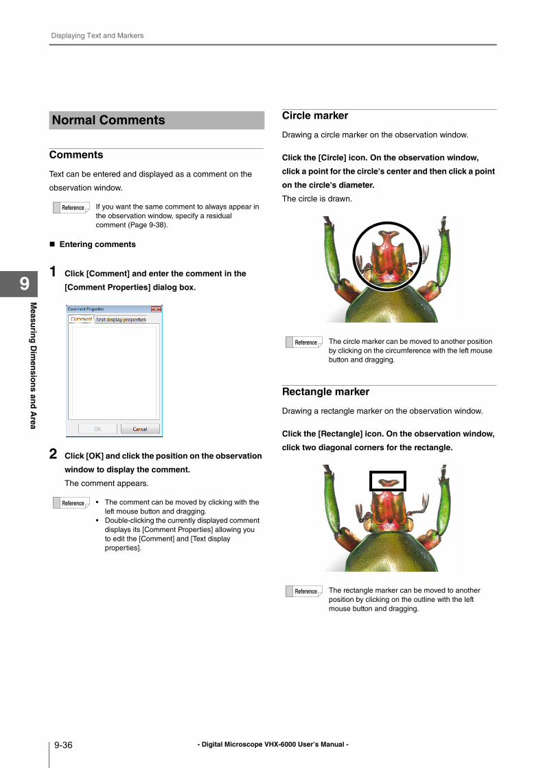
- Digital Microscope VHX-6000 User’s Manual -
Displaying Text and Markers
9-36
Measu
ring
Dim
ensio
ns an
d A
rea
9
Comments
Text can be entered and displayed as a comment on the
observation window.
Entering comments
1 Click [Comment] and enter the comment in the
[Comment Properties] dialog box.
2 Click [OK] and click the position on the observation
window to display the comment.
The comment appears.
Circle marker
Drawing a circle marker on the observation window.
Click the [Circle] icon. On the observation window,
click a point for the circle's center and then click a point
on the circle's diameter.
The circle is drawn.
Rectangle marker
Drawing a rectangle marker on the observation window.
Click the [Rectangle] icon. On the observation window,
click two diagonal corners for the rectangle.
Normal Comments
If you want the same comment to always appear in
the observation window, specify a residual
comment (Page 9-38).
• The comment can be moved by clicking with the
left mouse button and dragging.
• Double-clicking the currently displayed comment
displays its [Comment Properties] allowing you
to edit the [Comment] and [Text display
properties].
The circle marker can be moved to another position
by clicking on the circumference with the left mouse
button and dragging.
The rectangle marker can be moved to another
position by clicking on the outline with the left
mouse button and dragging.
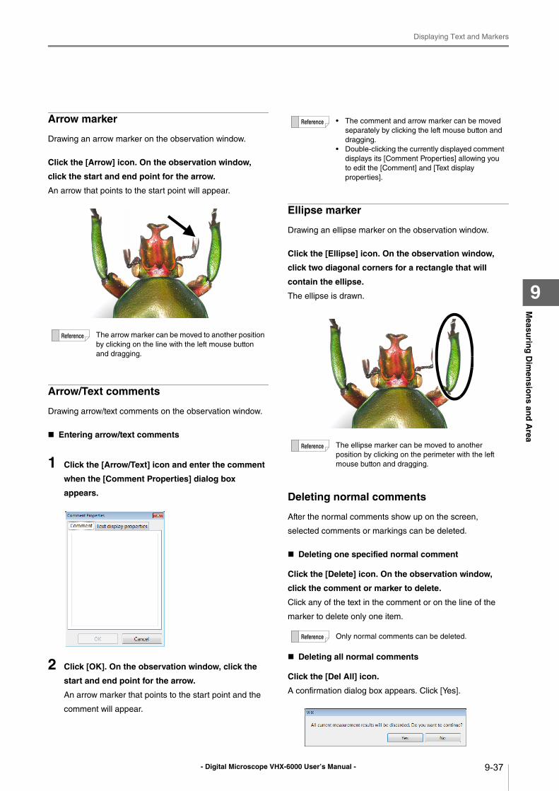
- Digital Microscope VHX-6000 User’s Manual -
Displaying Text and Markers
9-37
Measu
ring
Dim
ensio
ns an
d A
rea
9
Arrow marker
Drawing an arrow marker on the observation window.
Click the [Arrow] icon. On the observation window,
click the start and end point for the arrow.
An arrow that points to the start point will appear.
Arrow/Text comments
Drawing arrow/text comments on the observation window.
Entering arrow/text comments
1 Click the [Arrow/Text] icon and enter the comment
when the [Comment Properties] dialog box
appears.
2 Click [OK]. On the observation window, click the
start and end point for the arrow.
An arrow marker that points to the start point and the
comment will appear.
Ellipse marker
Drawing an ellipse marker on the observation window.
Click the [Ellipse] icon. On the observation window,
click two diagonal corners for a rectangle that will
contain the ellipse.
The ellipse is drawn.
Deleting normal comments
After the normal comments show up on the screen,
selected comments or markings can be deleted.
Deleting one specified normal comment
Click the [Delete] icon. On the observation window,
click the comment or marker to delete.
Click any of the text in the comment or on the line of the
marker to delete only one item.
Deleting all normal comments
Click the [Del All] icon.
A confirmation dialog box appears. Click [Yes].
The arrow marker can be moved to another position
by clicking on the line with the left mouse button
and dragging.
• The comment and arrow marker can be moved
separately by clicking the left mouse button and
dragging.
• Double-clicking the currently displayed comment
displays its [Comment Properties] allowing you
to edit the [Comment] and [Text display
properties].
The ellipse marker can be moved to another
position by clicking on the perimeter with the left
mouse button and dragging.
Only normal comments can be deleted.
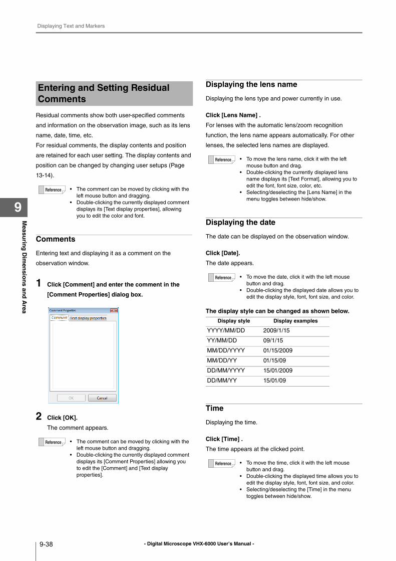
- Digital Microscope VHX-6000 User’s Manual -
Displaying Text and Markers
9-38
Measu
ring
Dim
ensio
ns an
d A
rea
9
Residual comments show both user-specified comments
and information on the observation image, such as its lens
name, date, time, etc.
For residual comments, the display contents and position
are retained for each user setting. The display contents and
position can be changed by changing user setups (Page
13-14).
Comments
Entering text and displaying it as a comment on the
observation window.
1 Click [Comment] and enter the comment in the
[Comment Properties] dialog box.
2 Click [OK].
The comment appears.
Displaying the lens name
Displaying the lens type and power currently in use.
Click [Lens Name] .
For lenses with the automatic lens/zoom recognition
function, the lens name appears automatically. For other
lenses, the selected lens names are displayed.
Displaying the date
The date can be displayed on the observation window.
Click [Date].
The date appears.
The display style can be changed as shown below.
Time
Displaying the time.
Click [Time] .
The time appears at the clicked point.
Entering and Setting Residual Comments
• The comment can be moved by clicking with the
left mouse button and dragging.
• Double-clicking the currently displayed comment
displays its [Text display properties], allowing
you to edit the color and font.
• The comment can be moved by clicking with the
left mouse button and dragging.
• Double-clicking the currently displayed comment
displays its [Comment Properties] allowing you
to edit the [Comment] and [Text display
properties].
• To move the lens name, click it with the left
mouse button and drag.
• Double-clicking the currently displayed lens
name displays its [Text Format], allowing you to
edit the font, font size, color, etc.
• Selecting/deselecting the [Lens Name] in the
menu toggles between hide/show.
• To move the date, click it with the left mouse
button and drag.
• Double-clicking the displayed date allows you to
edit the display style, font, font size, and color.
Display style Display examples
YYYY/MM/DD 2009/1/15
YY/MM/DD 09/1/15
MM/DD/YYYY 01/15/2009
MM/DD/YY 01/15/09
DD/MM/YYYY 15/01/2009
DD/MM/YY 15/01/09
• To move the time, click it with the left mouse
button and drag.
• Double-clicking the displayed time allows you to
edit the display style, font, font size, and color.
• Selecting/deselecting the [Time] in the menu
toggles between hide/show.
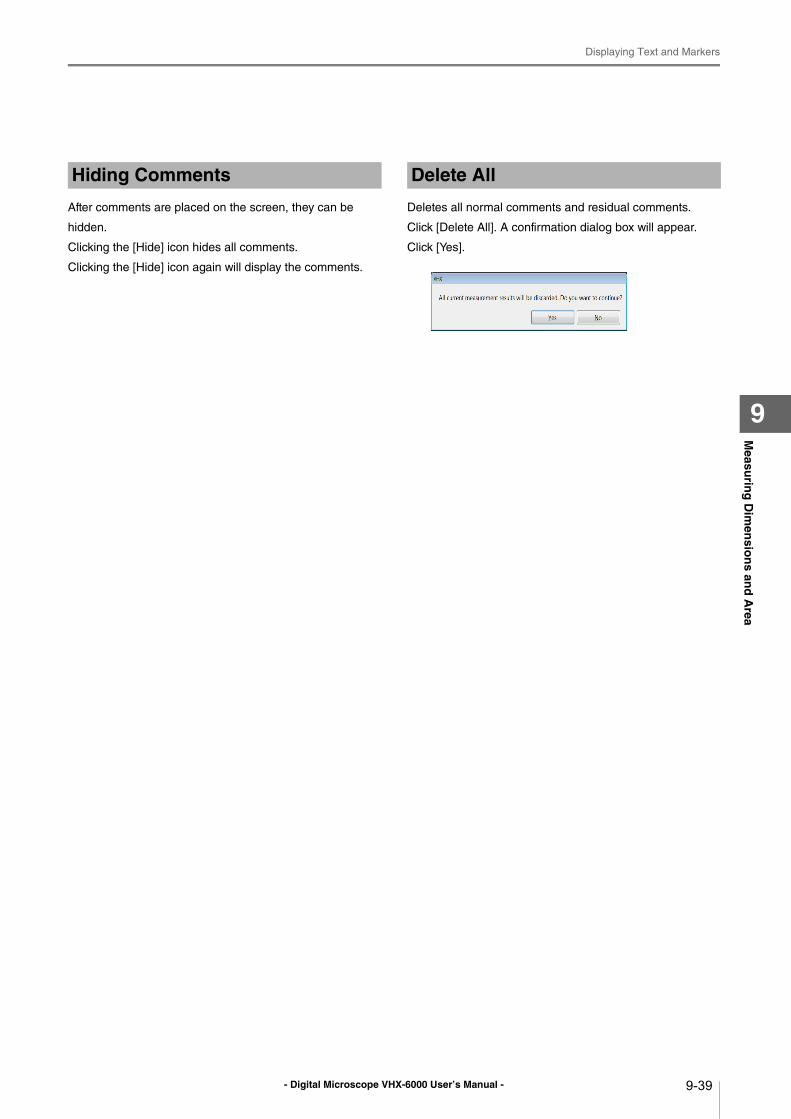
- Digital Microscope VHX-6000 User’s Manual -
Displaying Text and Markers
9-39
Measu
ring
Dim
ensio
ns an
d A
rea
9
After comments are placed on the screen, they can be
hidden.
Clicking the [Hide] icon hides all comments.
Clicking the [Hide] icon again will display the comments.
Deletes all normal comments and residual comments.
Click [Delete All]. A confirmation dialog box will appear.
Click [Yes].
Hiding Comments Delete All
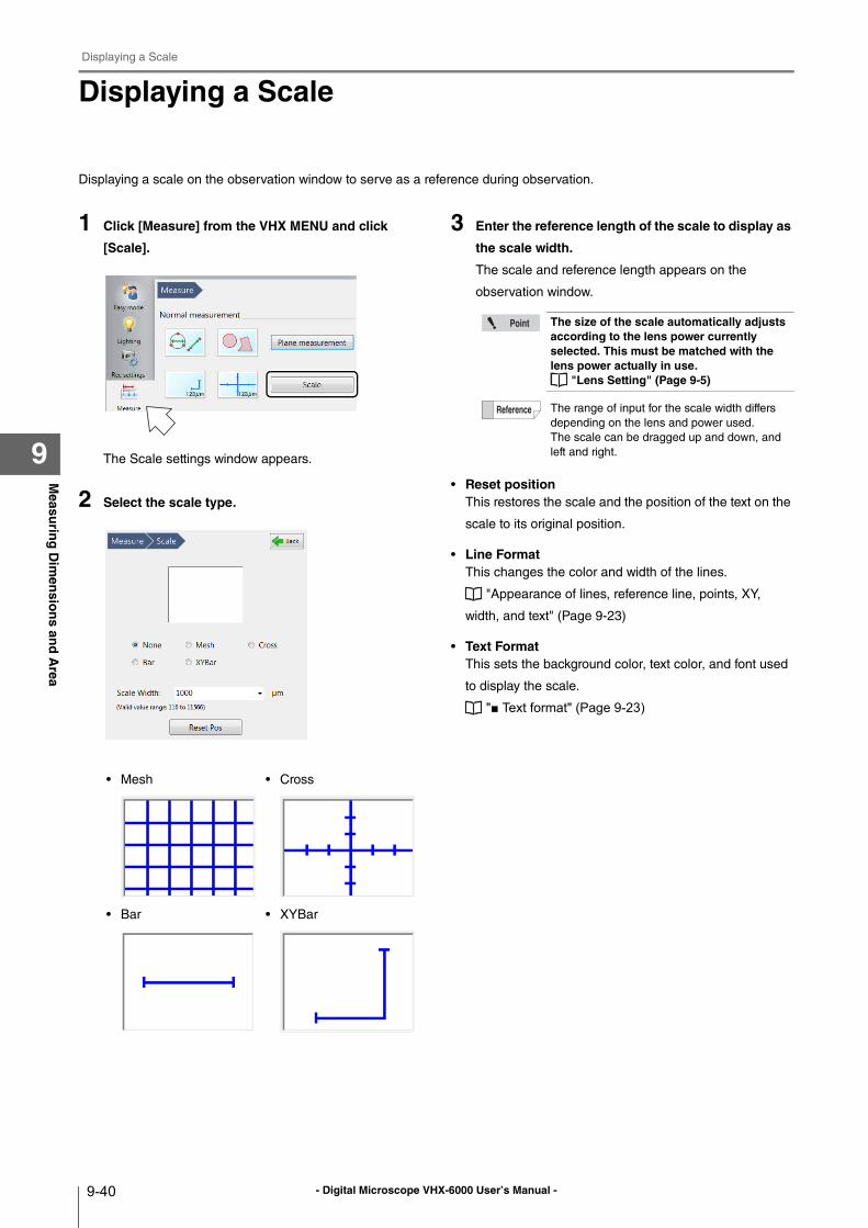
- Digital Microscope VHX-6000 User’s Manual -
Displaying a Scale
9-40
Measu
ring
Dim
ensio
ns an
d A
rea
9
Displaying a Scale
Displaying a scale on the observation window to serve as a reference during observation.
1 Click [Measure] from the VHX MENU and click
[Scale].
The Scale settings window appears.
2 Select the scale type.
3 Enter the reference length of the scale to display as
the scale width.
The scale and reference length appears on the
observation window.
• Reset positionThis restores the scale and the position of the text on the
scale to its original position.
• Line FormatThis changes the color and width of the lines.
"Appearance of lines, reference line, points, XY,
width, and text" (Page 9-23)
• Text FormatThis sets the background color, text color, and font used
to display the scale.
"■ Text format" (Page 9-23)
• Mesh • Cross
• Bar • XYBar
The size of the scale automatically adjusts according to the lens power currently selected. This must be matched with the lens power actually in use.
"Lens Setting" (Page 9-5)
The range of input for the scale width differs
depending on the lens and power used.
The scale can be dragged up and down, and
left and right.
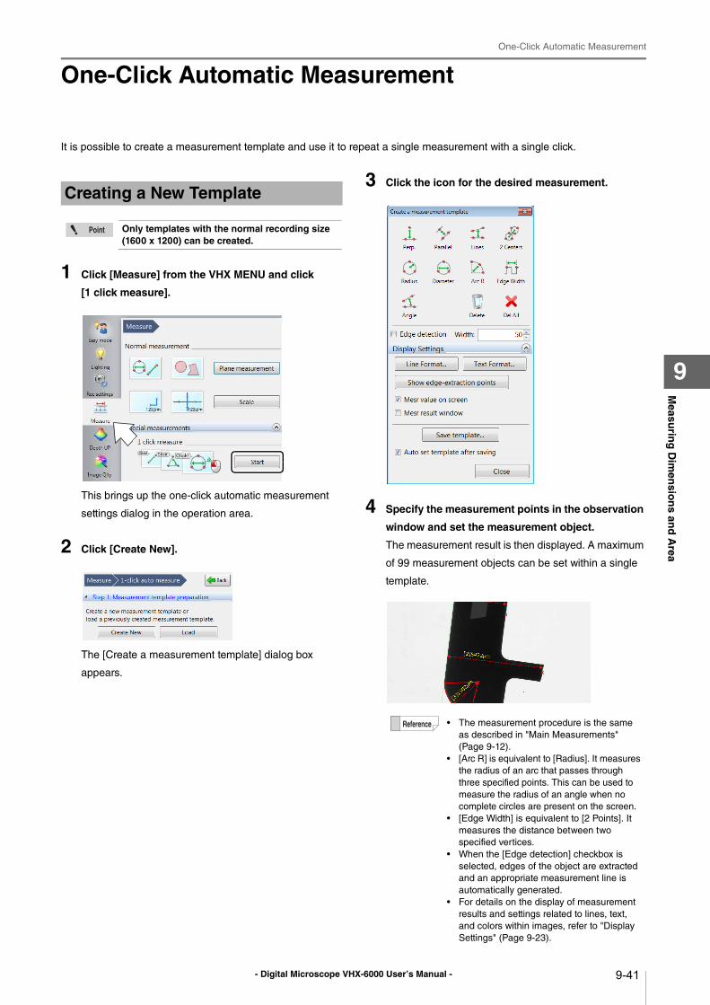
- Digital Microscope VHX-6000 User’s Manual -
One-Click Automatic Measurement
9-41
Measu
ring
Dim
ensio
ns an
d A
rea
9
One-Click Automatic Measurement
It is possible to create a measurement template and use it to repeat a single measurement with a single click.
1 Click [Measure] from the VHX MENU and click
[1 click measure].
This brings up the one-click automatic measurement
settings dialog in the operation area.
2 Click [Create New].
The [Create a measurement template] dialog box
appears.
3 Click the icon for the desired measurement.
4 Specify the measurement points in the observation
window and set the measurement object.
The measurement result is then displayed. A maximum
of 99 measurement objects can be set within a single
template.
Creating a New Template
Only templates with the normal recording size (1600 x 1200) can be created.
• The measurement procedure is the same
as described in "Main Measurements"
(Page 9-12).
• [Arc R] is equivalent to [Radius]. It measures
the radius of an arc that passes through
three specified points. This can be used to
measure the radius of an angle when no
complete circles are present on the screen.
• [Edge Width] is equivalent to [2 Points]. It
measures the distance between two
specified vertices.
• When the [Edge detection] checkbox is
selected, edges of the object are extracted
and an appropriate measurement line is
automatically generated.
• For details on the display of measurement
results and settings related to lines, text,
and colors within images, refer to "Display
Settings" (Page 9-23).
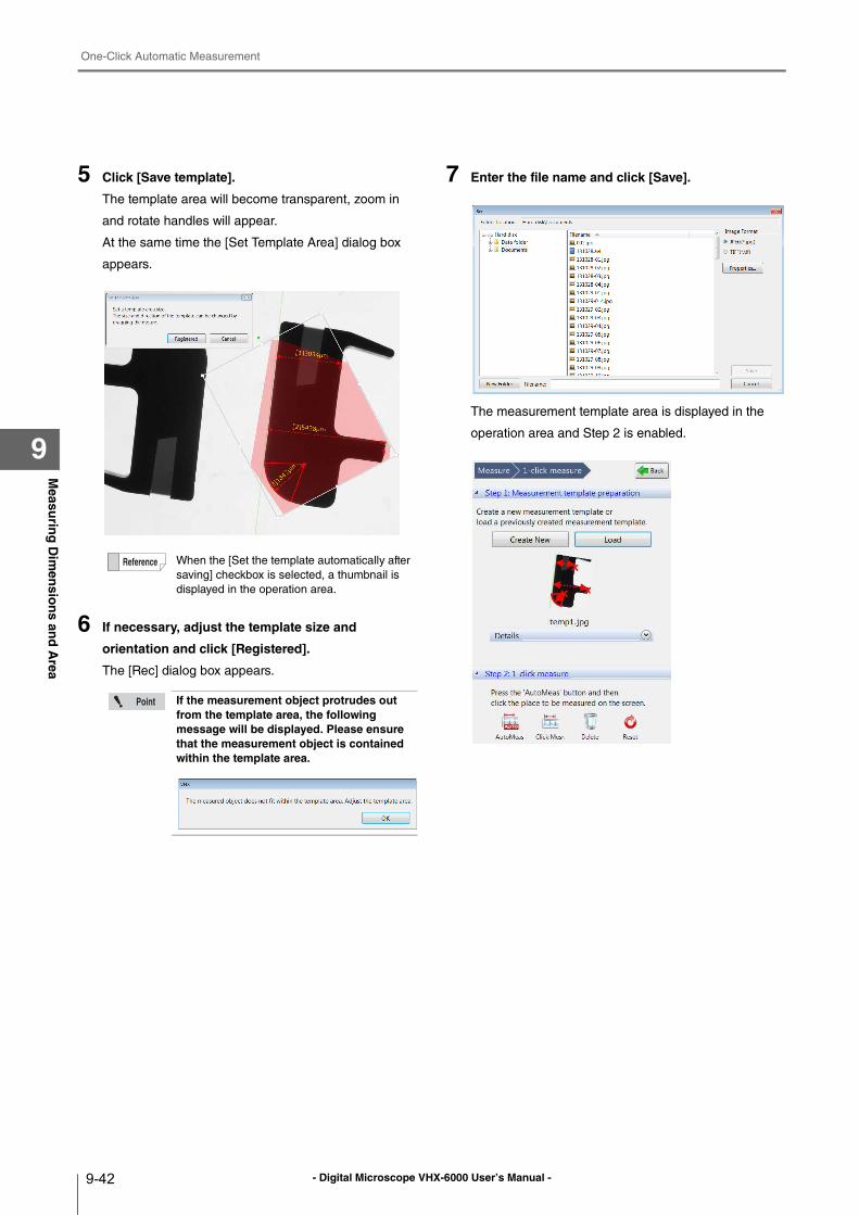
- Digital Microscope VHX-6000 User’s Manual -
One-Click Automatic Measurement
9-42
Measu
ring
Dim
ensio
ns an
d A
rea
9
5 Click [Save template].
The template area will become transparent, zoom in
and rotate handles will appear.
At the same time the [Set Template Area] dialog box
appears.
6 If necessary, adjust the template size and
orientation and click [Registered].
The [Rec] dialog box appears.
7 Enter the file name and click [Save].
The measurement template area is displayed in the
operation area and Step 2 is enabled.
When the [Set the template automatically after
saving] checkbox is selected, a thumbnail is
displayed in the operation area.
If the measurement object protrudes out from the template area, the following message will be displayed. Please ensure that the measurement object is contained within the template area.
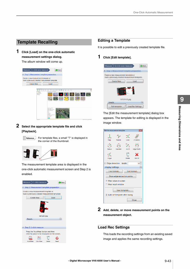
- Digital Microscope VHX-6000 User’s Manual -
One-Click Automatic Measurement
9-43
Measu
ring
Dim
ensio
ns an
d A
rea
9
1 Click [Load] on the one-click automatic
measurement settings dialog.
The album window will come up.
2 Select the appropriate template file and click
[Playback].
The measurement template area is displayed in the
one-click automatic measurement screen and Step 2 is
enabled.
Editing a Template
It is possible to edit a previously created template file.
1 Click [Edit template].
The [Edit the measurement template] dialog box
appears. The template for editing is displayed in the
image window.
2 Add, delete, or move measurement points on the
measurement object.
Load Rec Settings
This loads the recording settings from an existing saved
image and applies the same recording settings.
Template Recalling
For template files, a small "T" is displayed in
the corner of the thumbnail.
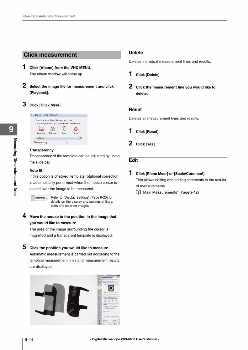
- Digital Microscope VHX-6000 User’s Manual -
One-Click Automatic Measurement
9-44
Measu
ring
Dim
ensio
ns an
d A
rea
9
1 Click [Album] from the VHX MENU.
The album window will come up.
2 Select the image file for measurement and click
[Playback].
3 Click [Click Mesr.].
Transparency
Transparency of the template can be adjusted by using
the slide bar.
Auto fit
If this option is checked, template rotational correction
is automatically performed when the mouse cursor is
placed over the image to be measured.
4 Move the mouse to the position in the image that
you would like to measure.
The area of the image surrounding the cursor is
magnified and a transparent template is displayed.
5 Click the position you would like to measure.
Automatic measurement is carried out according to the
template measurement lines and measurement results
are displayed.
Delete
Deletes individual measurement lines and results.
1 Click [Delete].
2 Click the measurement line you would like to
delete.
Reset
Deletes all measurement lines and results.
1 Click [Reset].
2 Click [Yes].
Edit
1 Click [Plane Mesr] or [Scale/Comment].
This allows editing and adding comments to the results
of measurements.
"Main Measurements" (Page 9-12)
Click measurement
Refer to "Display Settings" (Page 9-23) for
details on the display and settings of lines,
texts and color on images.
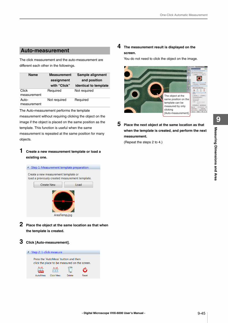
- Digital Microscope VHX-6000 User’s Manual -
One-Click Automatic Measurement
9-45
Measu
ring
Dim
ensio
ns an
d A
rea
9
The click measurement and the auto-measurement are
different each other in the followings.
The Auto-measurement performs the template
measurement without requiring clicking the object on the
image if the object is placed on the same position as the
template. This function is useful when the same
measurement is repeated at the same position for many
objects.
1 Create a new measurement template or load a
existing one.
2 Place the object at the same location as that when
the template is created.
3 Click [Auto-measurement].
4 The measurement result is displayed on the
screen.
You do not need to click the object on the image.
5 Place the next object at the same location as that
when the template is created, and perform the next
measurement.
(Repeat the steps 2 to 4.)
Auto-measurement
Name Measurement
assignment
with “Click”
Sample alignment
and position
identical to templateClick
measurement
Required Not required
Auto-
measurement
Not required Required
The object at the
same position on the
template can be
measured by only
clicking
[Auto-measurement].
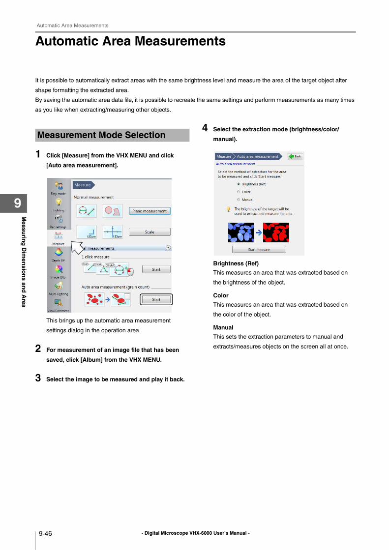
- Digital Microscope VHX-6000 User’s Manual -
Automatic Area Measurements
9-46
Measu
ring
Dim
ensio
ns an
d A
rea
9
Automatic Area Measurements
It is possible to automatically extract areas with the same brightness level and measure the area of the target object after
shape formatting the extracted area.
By saving the automatic area data file, it is possible to recreate the same settings and perform measurements as many times
as you like when extracting/measuring other objects.
1 Click [Measure] from the VHX MENU and click
[Auto area measurement].
This brings up the automatic area measurement
settings dialog in the operation area.
2 For measurement of an image file that has been
saved, click [Album] from the VHX MENU.
3 Select the image to be measured and play it back.
4 Select the extraction mode (brightness/color/
manual).
Brightness (Ref)
This measures an area that was extracted based on
the brightness of the object.
Color
This measures an area that was extracted based on
the color of the object.
Manual
This sets the extraction parameters to manual and
extracts/measures objects on the screen all at once.
Measurement Mode Selection
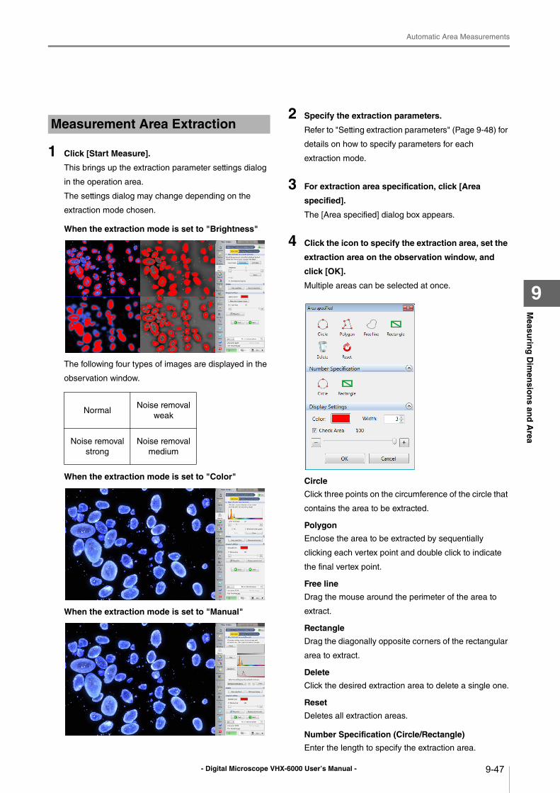
- Digital Microscope VHX-6000 User’s Manual -
Automatic Area Measurements
9-47
Measu
ring
Dim
ensio
ns an
d A
rea
9
1 Click [Start Measure].
This brings up the extraction parameter settings dialog
in the operation area.
The settings dialog may change depending on the
extraction mode chosen.
When the extraction mode is set to "Brightness"
The following four types of images are displayed in the
observation window.
When the extraction mode is set to "Color"
When the extraction mode is set to "Manual"
2 Specify the extraction parameters.
Refer to "Setting extraction parameters" (Page 9-48) for
details on how to specify parameters for each
extraction mode.
3 For extraction area specification, click [Area
specified].
The [Area specified] dialog box appears.
4 Click the icon to specify the extraction area, set the
extraction area on the observation window, and
click [OK].
Multiple areas can be selected at once.
Circle
Click three points on the circumference of the circle that
contains the area to be extracted.
Polygon
Enclose the area to be extracted by sequentially
clicking each vertex point and double click to indicate
the final vertex point.
Free line
Drag the mouse around the perimeter of the area to
extract.
Rectangle
Drag the diagonally opposite corners of the rectangular
area to extract.
Delete
Click the desired extraction area to delete a single one.
Reset
Deletes all extraction areas.
Number Specification (Circle/Rectangle)
Enter the length to specify the extraction area.
Measurement Area Extraction
NormalNoise removal
weak
Noise removal
strong
Noise removal
medium
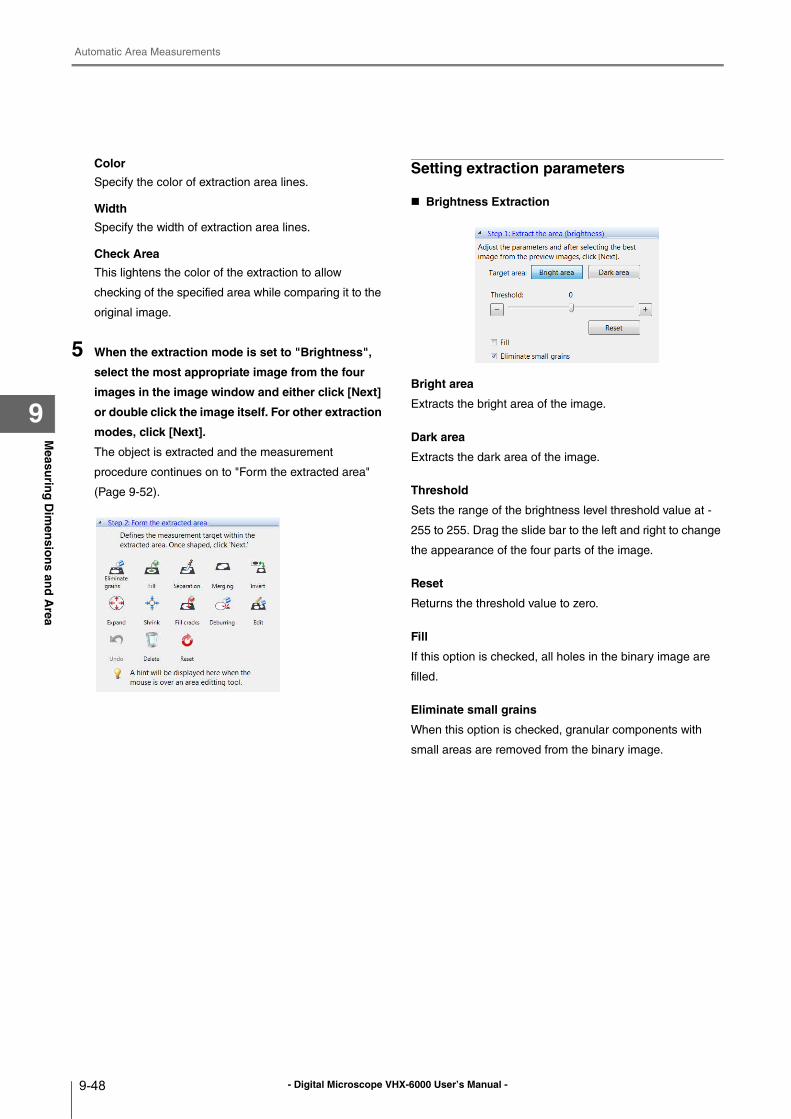
- Digital Microscope VHX-6000 User’s Manual -
Automatic Area Measurements
9-48
Measu
ring
Dim
ensio
ns an
d A
rea
9
Color
Specify the color of extraction area lines.
Width
Specify the width of extraction area lines.
Check Area
This lightens the color of the extraction to allow
checking of the specified area while comparing it to the
original image.
5 When the extraction mode is set to "Brightness",
select the most appropriate image from the four
images in the image window and either click [Next]
or double click the image itself. For other extraction
modes, click [Next].
The object is extracted and the measurement
procedure continues on to "Form the extracted area"
(Page 9-52).
Setting extraction parameters
Brightness Extraction
Bright area
Extracts the bright area of the image.
Dark area
Extracts the dark area of the image.
Threshold
Sets the range of the brightness level threshold value at -
255 to 255. Drag the slide bar to the left and right to change
the appearance of the four parts of the image.
Reset
Returns the threshold value to zero.
Fill
If this option is checked, all holes in the binary image are
filled.
Eliminate small grains
When this option is checked, granular components with
small areas are removed from the binary image.
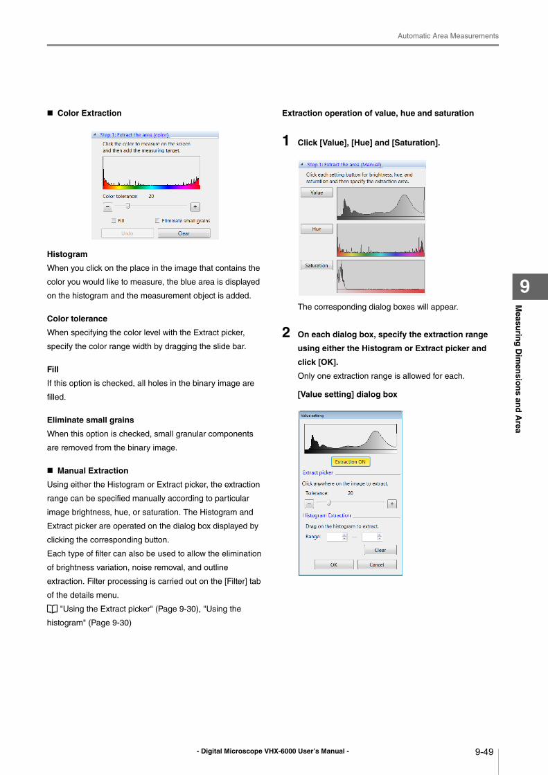
- Digital Microscope VHX-6000 User’s Manual -
Automatic Area Measurements
9-49
Measu
ring
Dim
ensio
ns an
d A
rea
9
Color Extraction
Histogram
When you click on the place in the image that contains the
color you would like to measure, the blue area is displayed
on the histogram and the measurement object is added.
Color tolerance
When specifying the color level with the Extract picker,
specify the color range width by dragging the slide bar.
Fill
If this option is checked, all holes in the binary image are
filled.
Eliminate small grains
When this option is checked, small granular components
are removed from the binary image.
Manual Extraction
Using either the Histogram or Extract picker, the extraction
range can be specified manually according to particular
image brightness, hue, or saturation. The Histogram and
Extract picker are operated on the dialog box displayed by
clicking the corresponding button.
Each type of filter can also be used to allow the elimination
of brightness variation, noise removal, and outline
extraction. Filter processing is carried out on the [Filter] tab
of the details menu.
"Using the Extract picker" (Page 9-30), "Using the
histogram" (Page 9-30)
Extraction operation of value, hue and saturation
1 Click [Value], [Hue] and [Saturation].
The corresponding dialog boxes will appear.
2 On each dialog box, specify the extraction range
using either the Histogram or Extract picker and
click [OK].
Only one extraction range is allowed for each.
[Value setting] dialog box
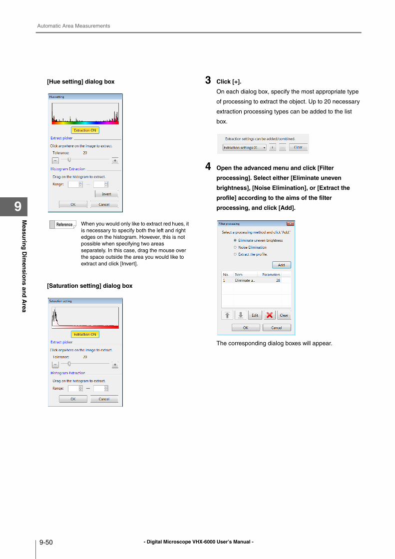
- Digital Microscope VHX-6000 User’s Manual -
Automatic Area Measurements
9-50
Measu
ring
Dim
ensio
ns an
d A
rea
9
[Hue setting] dialog box
[Saturation setting] dialog box
3 Click [+].
On each dialog box, specify the most appropriate type
of processing to extract the object. Up to 20 necessary
extraction processing types can be added to the list
box.
4 Open the advanced menu and click [Filter
processing]. Select either [Eliminate uneven
brightness], [Noise Elimination], or [Extract the
profile] according to the aims of the filter
processing, and click [Add].
The corresponding dialog boxes will appear.
When you would only like to extract red hues, it
is necessary to specify both the left and right
edges on the histogram. However, this is not
possible when specifying two areas
separately. In this case, drag the mouse over
the space outside the area you would like to
extract and click [Invert].
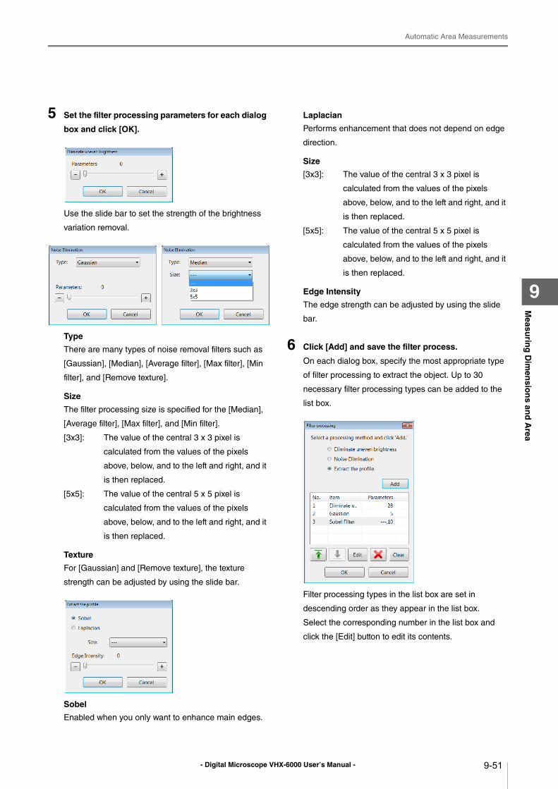
- Digital Microscope VHX-6000 User’s Manual -
Automatic Area Measurements
9-51
Measu
ring
Dim
ensio
ns an
d A
rea
9
5 Set the filter processing parameters for each dialog
box and click [OK].
Use the slide bar to set the strength of the brightness
variation removal.
Type
There are many types of noise removal filters such as
[Gaussian], [Median], [Average filter], [Max filter], [Min
filter], and [Remove texture].
Size
The filter processing size is specified for the [Median],
[Average filter], [Max filter], and [Min filter].
[3x3]: The value of the central 3 x 3 pixel is
calculated from the values of the pixels
above, below, and to the left and right, and it
is then replaced.
[5x5]: The value of the central 5 x 5 pixel is
calculated from the values of the pixels
above, below, and to the left and right, and it
is then replaced.
Texture
For [Gaussian] and [Remove texture], the texture
strength can be adjusted by using the slide bar.
Sobel
Enabled when you only want to enhance main edges.
Laplacian
Performs enhancement that does not depend on edge
direction.
Size
[3x3]: The value of the central 3 x 3 pixel is
calculated from the values of the pixels
above, below, and to the left and right, and it
is then replaced.
[5x5]: The value of the central 5 x 5 pixel is
calculated from the values of the pixels
above, below, and to the left and right, and it
is then replaced.
Edge Intensity
The edge strength can be adjusted by using the slide
bar.
6 Click [Add] and save the filter process.
On each dialog box, specify the most appropriate type
of filter processing to extract the object. Up to 30
necessary filter processing types can be added to the
list box.
Filter processing types in the list box are set in
descending order as they appear in the list box.
Select the corresponding number in the list box and
click the [Edit] button to edit its contents.
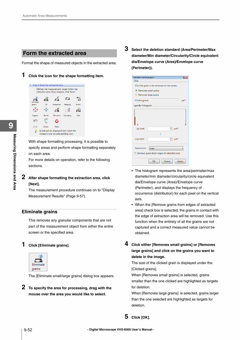
- Digital Microscope VHX-6000 User’s Manual -
Automatic Area Measurements
9-52
Measu
ring
Dim
ensio
ns an
d A
rea
9
Format the shape of measured objects in the extracted area.
1 Click the icon for the shape formatting item.
With shape formatting processing, it is possible to
specify areas and perform shape formatting separately
on each area.
For more details on operation, refer to the following
sections.
2 After shape formatting the extraction area, click
[Next].
The measurement procedure continues on to "Display
Measurement Results" (Page 9-57).
Eliminate grains
This removes any granular components that are not
part of the measurement object from either the entire
screen or the specified area.
1 Click [Eliminate grains].
The [Eliminate small/large grains] dialog box appears.
2 To specify the area for processing, drag with the
mouse over the area you would like to select.
3 Select the deletion standard (Area/Perimeter/Max
diameter/Min diameter/Circularity/Circle equivalent
dia/Envelope curve (Area)/Envelope curve
(Perimeter)).
• The histogram represents the area/perimeter/max
diameter/min diameter/circularity/circle equivalent
dia/Envelope curve (Area)/Envelope curve
(Perimeter), and displays the frequency of
occurrence (distribution) for each pixel on the vertical
axis.
• When the [Remove grains from edges of extracted
area] check box is selected, the grains in contact with
the edge of extraction area will be removed. Use this
function when the entirety of all the grains are not
captured and a correct measured value cannot be
obtained.
4 Click either [Removes small grains] or [Removes
large grains] and click on the grains you want to
delete in the image.
The size of the clicked grain is displayed under the
[Clicked grains].
When [Removes small grains] is selected, grains
smaller than the one clicked are highlighted as targets
for deletion.
When [Removes large grains] is selected, grains larger
than the one selected are highlighted as targets for
deletion.
5 Click [OK].
Form the extracted area
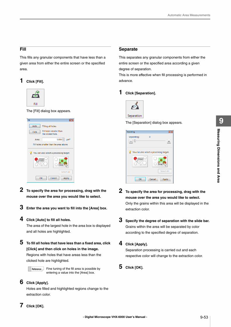
- Digital Microscope VHX-6000 User’s Manual -
Automatic Area Measurements
9-53
Measu
ring
Dim
ensio
ns an
d A
rea
9
Fill
This fills any granular components that have less than a
given area from either the entire screen or the specified
area.
1 Click [Fill].
The [Fill] dialog box appears.
2 To specify the area for processing, drag with the
mouse over the area you would like to select.
3 Enter the area you want to fill into the [Area] box.
4 Click [Auto] to fill all holes.
The area of the largest hole in the area box is displayed
and all holes are highlighted.
5 To fill all holes that have less than a fixed area, click
[Click] and then click on holes in the image.
Regions with holes that have areas less than the
clicked hole are highlighted.
6 Click [Apply].
Holes are filled and highlighted regions change to the
extraction color.
7 Click [OK].
Separate
This separates any granular components from either the
entire screen or the specified area according a given
degree of separation.
This is more effective when fill processing is performed in
advance.
1 Click [Separation].
The [Separation] dialog box appears.
2 To specify the area for processing, drag with the
mouse over the area you would like to select.
Only the grains within this area will be displayed in the
extraction color.
3 Specify the degree of separation with the slide bar.
Grains within the area will be separated by color
according to the specified degree of separation.
4 Click [Apply].
Separation processing is carried out and each
respective color will change to the extraction color.
5 Click [OK].Fine tuning of the fill area is possible by
entering a value into the [Area] box.
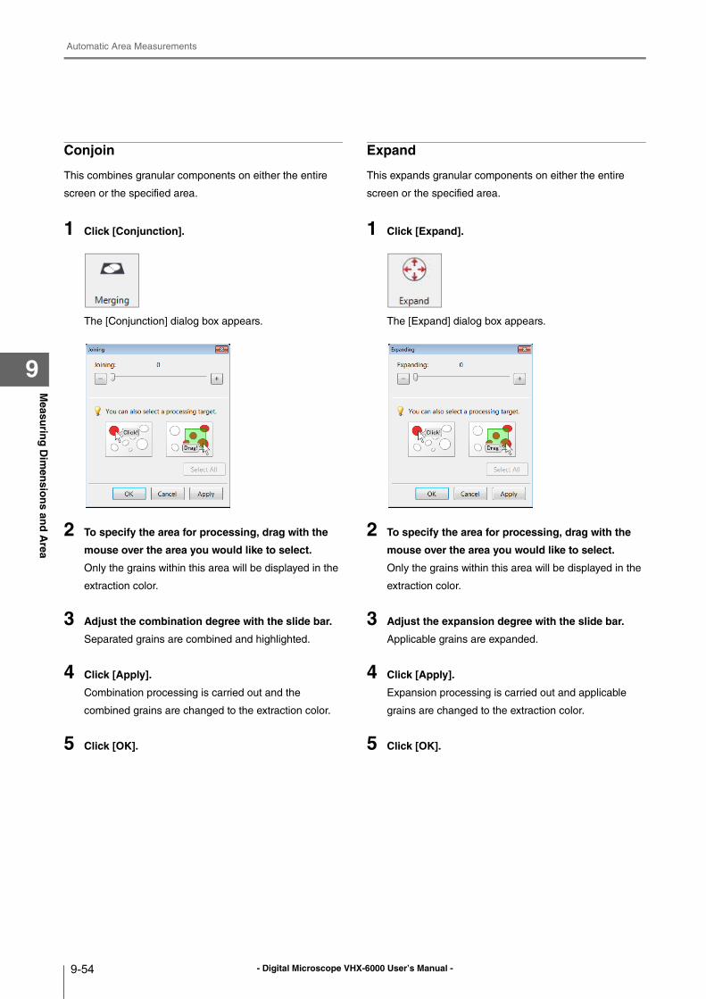
- Digital Microscope VHX-6000 User’s Manual -
Automatic Area Measurements
9-54
Measu
ring
Dim
ensio
ns an
d A
rea
9
Conjoin
This combines granular components on either the entire
screen or the specified area.
1 Click [Conjunction].
The [Conjunction] dialog box appears.
2 To specify the area for processing, drag with the
mouse over the area you would like to select.
Only the grains within this area will be displayed in the
extraction color.
3 Adjust the combination degree with the slide bar.
Separated grains are combined and highlighted.
4 Click [Apply].
Combination processing is carried out and the
combined grains are changed to the extraction color.
5 Click [OK].
Expand
This expands granular components on either the entire
screen or the specified area.
1 Click [Expand].
The [Expand] dialog box appears.
2 To specify the area for processing, drag with the
mouse over the area you would like to select.
Only the grains within this area will be displayed in the
extraction color.
3 Adjust the expansion degree with the slide bar.
Applicable grains are expanded.
4 Click [Apply].
Expansion processing is carried out and applicable
grains are changed to the extraction color.
5 Click [OK].
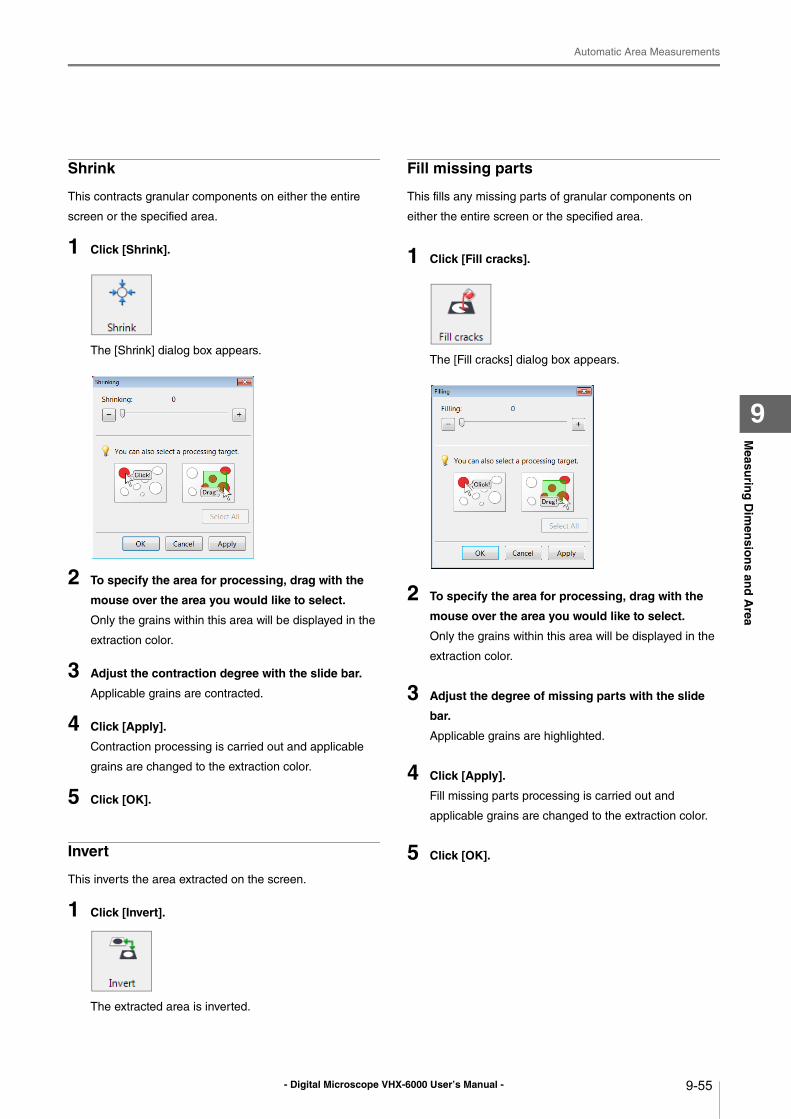
- Digital Microscope VHX-6000 User’s Manual -
Automatic Area Measurements
9-55
Measu
ring
Dim
ensio
ns an
d A
rea
9
Shrink
This contracts granular components on either the entire
screen or the specified area.
1 Click [Shrink].
The [Shrink] dialog box appears.
2 To specify the area for processing, drag with the
mouse over the area you would like to select.
Only the grains within this area will be displayed in the
extraction color.
3 Adjust the contraction degree with the slide bar.
Applicable grains are contracted.
4 Click [Apply].
Contraction processing is carried out and applicable
grains are changed to the extraction color.
5 Click [OK].
Invert
This inverts the area extracted on the screen.
1 Click [Invert].
The extracted area is inverted.
Fill missing parts
This fills any missing parts of granular components on
either the entire screen or the specified area.
1 Click [Fill cracks].
The [Fill cracks] dialog box appears.
2 To specify the area for processing, drag with the
mouse over the area you would like to select.
Only the grains within this area will be displayed in the
extraction color.
3 Adjust the degree of missing parts with the slide
bar.
Applicable grains are highlighted.
4 Click [Apply].
Fill missing parts processing is carried out and
applicable grains are changed to the extraction color.
5 Click [OK].
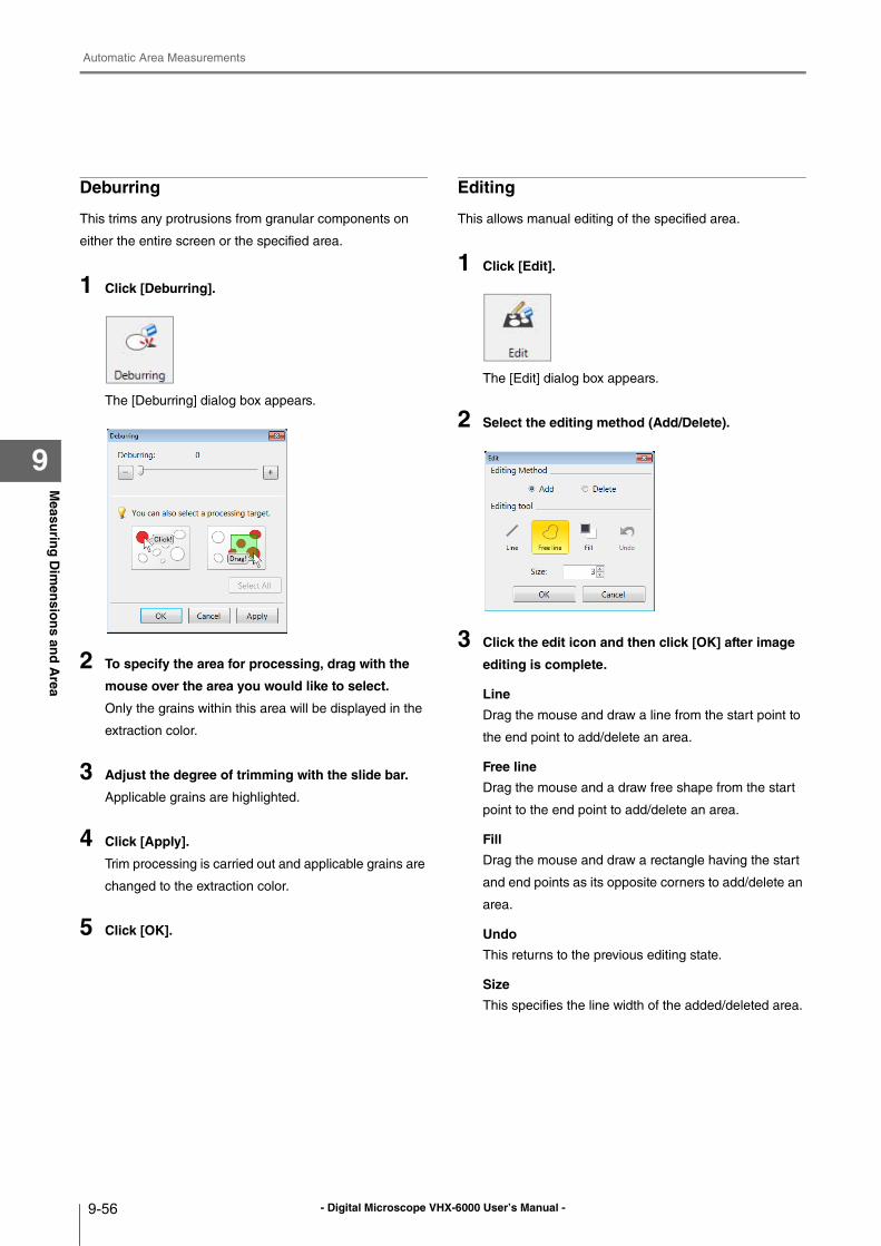
- Digital Microscope VHX-6000 User’s Manual -
Automatic Area Measurements
9-56
Measu
ring
Dim
ensio
ns an
d A
rea
9
Deburring
This trims any protrusions from granular components on
either the entire screen or the specified area.
1 Click [Deburring].
The [Deburring] dialog box appears.
2 To specify the area for processing, drag with the
mouse over the area you would like to select.
Only the grains within this area will be displayed in the
extraction color.
3 Adjust the degree of trimming with the slide bar.
Applicable grains are highlighted.
4 Click [Apply].
Trim processing is carried out and applicable grains are
changed to the extraction color.
5 Click [OK].
Editing
This allows manual editing of the specified area.
1 Click [Edit].
The [Edit] dialog box appears.
2 Select the editing method (Add/Delete).
3 Click the edit icon and then click [OK] after image
editing is complete.
Line
Drag the mouse and draw a line from the start point to
the end point to add/delete an area.
Free line
Drag the mouse and a draw free shape from the start
point to the end point to add/delete an area.
Fill
Drag the mouse and draw a rectangle having the start
and end points as its opposite corners to add/delete an
area.
Undo
This returns to the previous editing state.
Size
This specifies the line width of the added/deleted area.
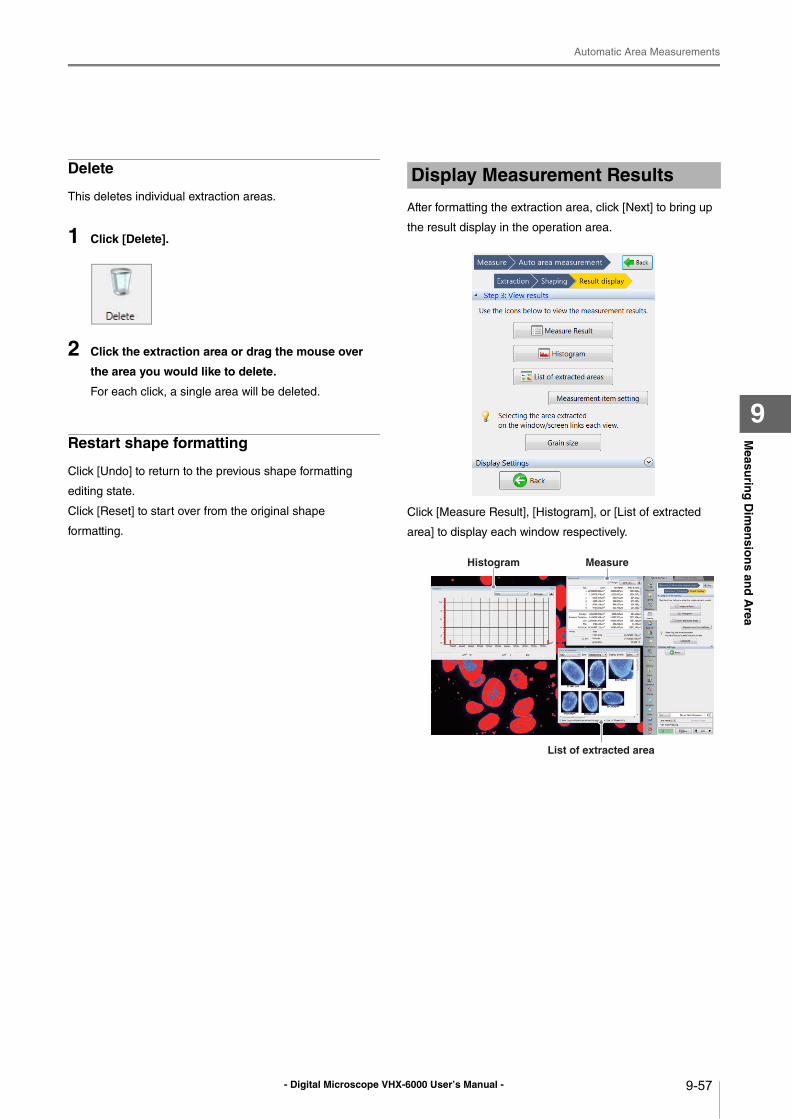
- Digital Microscope VHX-6000 User’s Manual -
Automatic Area Measurements
9-57
Measu
ring
Dim
ensio
ns an
d A
rea
9
Delete
This deletes individual extraction areas.
1 Click [Delete].
2 Click the extraction area or drag the mouse over
the area you would like to delete.
For each click, a single area will be deleted.
Restart shape formatting
Click [Undo] to return to the previous shape formatting
editing state.
Click [Reset] to start over from the original shape
formatting.
After formatting the extraction area, click [Next] to bring up
the result display in the operation area.
Click [Measure Result], [Histogram], or [List of extracted
area] to display each window respectively.
Display Measurement Results
Histogram Measure
List of extracted area
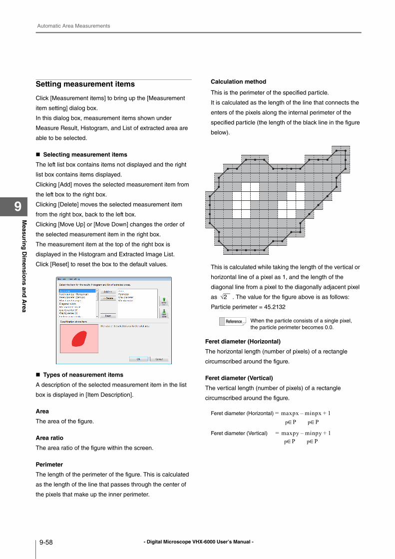
- Digital Microscope VHX-6000 User’s Manual -
Automatic Area Measurements
9-58
Measu
ring
Dim
ensio
ns an
d A
rea
9
Setting measurement items
Click [Measurement items] to bring up the [Measurement
item setting] dialog box.
In this dialog box, measurement items shown under
Measure Result, Histogram, and List of extracted area are
able to be selected.
Selecting measurement items
The left list box contains items not displayed and the right
list box contains items displayed.
Clicking [Add] moves the selected measurement item from
the left box to the right box.
Clicking [Delete] moves the selected measurement item
from the right box, back to the left box.
Clicking [Move Up] or [Move Down] changes the order of
the selected measurement item in the right box.
The measurement item at the top of the right box is
displayed in the Histogram and Extracted Image List.
Click [Reset] to reset the box to the default values.
Types of neasurement items
A description of the selected measurement item in the list
box is displayed in [Item Description].
Area
The area of the figure.
Area ratio
The area ratio of the figure within the screen.
Perimeter
The length of the perimeter of the figure. This is calculated
as the length of the line that passes through the center of
the pixels that make up the inner perimeter.
Calculation method
This is the perimeter of the specified particle.
It is calculated as the length of the line that connects the
enters of the pixels along the internal perimeter of the
specified particle (the length of the black line in the figure
below).
This is calculated while taking the length of the vertical or
horizontal line of a pixel as 1, and the length of the
diagonal line from a pixel to the diagonally adjacent pixel
as . The value for the figure above is as follows:
Particle perimeter = 45.2132
Feret diameter (Horizontal)
The horizontal length (number of pixels) of a rectangle
circumscribed around the figure.
Feret diameter (Vertical)
The vertical length (number of pixels) of a rectangle
circumscribed around the figure.
When the particle consists of a single pixel,
the particle perimeter becomes 0.0.
√2
Feret diameter (Horizontal) =
Feret diameter (Vertical) =
maxpx minpx– 1+
maxpy minpy– 1+
p∈P p∈P
p∈P p∈P
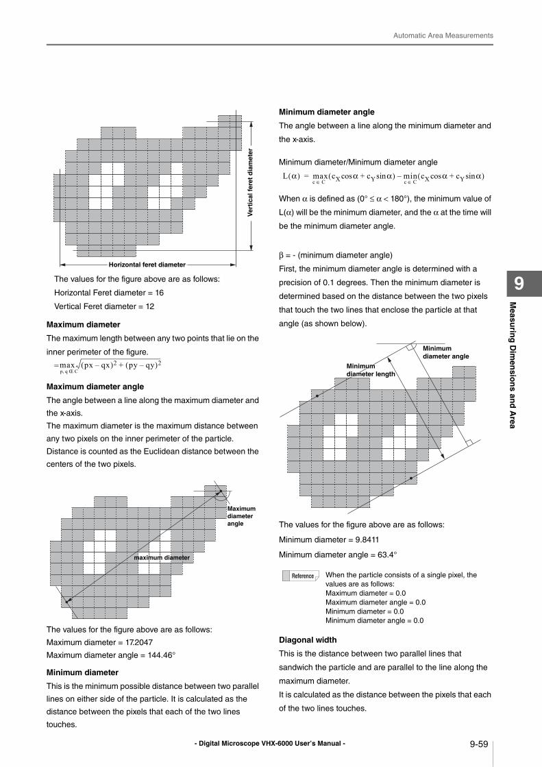
- Digital Microscope VHX-6000 User’s Manual -
Automatic Area Measurements
9-59
Measu
ring
Dim
ensio
ns an
d A
rea
9The values for the figure above are as follows:
Horizontal Feret diameter = 16
Vertical Feret diameter = 12
Maximum diameter
The maximum length between any two points that lie on the
inner perimeter of the figure.
=
Maximum diameter angle
The angle between a line along the maximum diameter and
the x-axis.
The maximum diameter is the maximum distance between
any two pixels on the inner perimeter of the particle.
Distance is counted as the Euclidean distance between the
centers of the two pixels.
The values for the figure above are as follows:
Maximum diameter = 17.2047
Maximum diameter angle = 144.46°
Minimum diameter
This is the minimum possible distance between two parallel
lines on either side of the particle. It is calculated as the
distance between the pixels that each of the two lines
touches.
Minimum diameter angle
The angle between a line along the minimum diameter and
the x-axis.
Minimum diameter/Minimum diameter angle
When α is defined as (0° ≤ α < 180°), the minimum value of
L(α) will be the minimum diameter, and the α at the time will
be the minimum diameter angle.
β = - (minimum diameter angle)
First, the minimum diameter angle is determined with a
precision of 0.1 degrees. Then the minimum diameter is
determined based on the distance between the two pixels
that touch the two lines that enclose the particle at that
angle (as shown below).
The values for the figure above are as follows:
Minimum diameter = 9.8411
Minimum diameter angle = 63.4°
Diagonal width
This is the distance between two parallel lines that
sandwich the particle and are parallel to the line along the
maximum diameter.
It is calculated as the distance between the pixels that each
of the two lines touches.
Ver
tica
l fer
et d
iam
eter
Horizontal feret diameter
max px qx–( )2 py qy–( )2+p q CŒ,
Maximum diameter angle
maximum diameter
When the particle consists of a single pixel, the
values are as follows:
Maximum diameter = 0.0
Maximum diameter angle = 0.0
Minimum diameter = 0.0
Minimum diameter angle = 0.0
L α( ) max cX αcos cY αsin+( ) min– cX αcos cY αsin+( )=c C∈ c C∈
Minimum diameter angle
Minimum Minimum diameter lengthdiameter lengthMinimum diameter length
- Digital Microscope VHX-6000 User’s Manual -
Automatic Area Measurements
9-60
Measu
ring
Dim
ensio
ns an
d A
rea
9
Gravity center X/Y
The coordinates of the center of gravity of the figure.
The X coordinate of the center of gravity
=
The Y coordinate of the center of gravity
=
Area is the particle area.
Circle equivalent dia
This is the diameter of a circle with the same area as the
figure. It is sometimes referred to as the Heywood diameter.
The circle equivalent diameter for the figure can be
shown as:
Circle equivalent diameter of the specified particle
=
Area is the particle area.
Circularity
When the figure is a perfect circle, the maximum value is
one. As it becomes long and thin, this value approaches
zero.
The degree of circularity of the figure can be shown as:
The degree of circularity of the specified particle
=
Area is the particle area.
Perimeter is the particle perimeter.
Envelope curve (Area)
This is the ratio between the area of the figure and its
convex envelope area.
This approaches one as the figure is less bumpy.
Convex envelope ratio (Area) = Area of the figure ÷ Convex
envelope area
Envelope curve (Perimeter)
This is the ratio between the perimeter of the figure and its
convex envelope perimeter.
This approaches one as the figure is less bumpy.
Convex envelope ratio (Perimeter) = Area of the figure ÷
Convex envelope area
Note: A convex envelope is defined as:
A convex polygon that tightly encloses the figure.
Convex envelope area: The area of the envelope
enclosing the figure
Convex envelope perimeter: The perimeter of the
envelope enclosing the figure
1st moment (X-axis)
The primary moment of the figure on the X-axis.
1st moment (Y-axis)
The primary moment of the figure on the Y-axis.
The primary moment of the specified particle on the
X-axis=
The primary moment of the specified particle on the
Y-axis=
2nd moment (X-axis)
The secondary moment of the figure on the X-axis.
2nd moment (Y-axis)
The secondary moment of the figure on the Y-axis.
The secondary moment of the specified particle on
the X-axis=
The secondary moment of the specified particle on
the Y-axis=
Product of inertia
The product of inertia of the figure on the X and Y axes.
The product of inertia of the specified particle on the
X and Y axes
=
When the particle consists of a single pixel,
degree of circularity of the specified particle
becomes 1.0.
pxp P∈
Area
pyp P∈
Area
4 Area⋅π
--------------------
4π Area⋅Perimeter2----------------------------
pxp P∈
pyp P∈
p2xp P∈
p2yp P∈
pxp P∈ py⋅
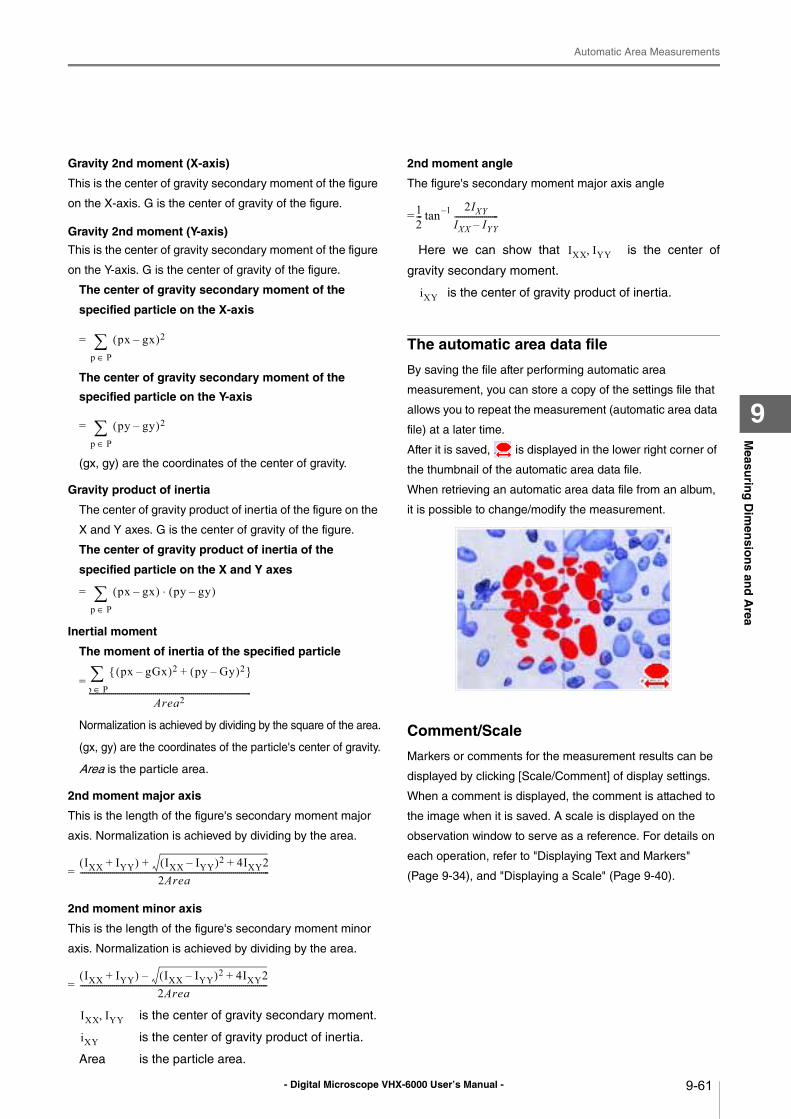
- Digital Microscope VHX-6000 User’s Manual -
Automatic Area Measurements
9-61
Measu
ring
Dim
ensio
ns an
d A
rea
9
Gravity 2nd moment (X-axis)
This is the center of gravity secondary moment of the figure
on the X-axis. G is the center of gravity of the figure.
Gravity 2nd moment (Y-axis)
This is the center of gravity secondary moment of the figure
on the Y-axis. G is the center of gravity of the figure.
The center of gravity secondary moment of the
specified particle on the X-axis
=
The center of gravity secondary moment of the
specified particle on the Y-axis
=
(gx, gy) are the coordinates of the center of gravity.
Gravity product of inertia
The center of gravity product of inertia of the figure on the
X and Y axes. G is the center of gravity of the figure.
The center of gravity product of inertia of the
specified particle on the X and Y axes
=
Inertial moment
The moment of inertia of the specified particle
=
Normalization is achieved by dividing by the square of the area.
(gx, gy) are the coordinates of the particle's center of gravity.
Area is the particle area.
2nd moment major axis
This is the length of the figure's secondary moment major
axis. Normalization is achieved by dividing by the area.
=
2nd moment minor axis
This is the length of the figure's secondary moment minor
axis. Normalization is achieved by dividing by the area.
=
is the center of gravity secondary moment.
is the center of gravity product of inertia.
Area is the particle area.
2nd moment angle
The figure's secondary moment major axis angle
= tan
Here we can show that is the center of
gravity secondary moment.
is the center of gravity product of inertia.
The automatic area data file
By saving the file after performing automatic area
measurement, you can store a copy of the settings file that
allows you to repeat the measurement (automatic area data
file) at a later time.
After it is saved, is displayed in the lower right corner of
the thumbnail of the automatic area data file.
When retrieving an automatic area data file from an album,
it is possible to change/modify the measurement.
Comment/Scale
Markers or comments for the measurement results can be
displayed by clicking [Scale/Comment] of display settings.
When a comment is displayed, the comment is attached to
the image when it is saved. A scale is displayed on the
observation window to serve as a reference. For details on
each operation, refer to "Displaying Text and Markers"
(Page 9-34), and "Displaying a Scale" (Page 9-40).
px gx–( )2
p P∈
py gy–( )2
p P∈
px gx–( )p P∈ py gy–( )⋅
px gGx–( )2 py Gy–( )2+{ }p P∈
Area2----------------------------------------------------------------------------------
IXX IYY+( ) IXX IYY–( )2 4IXY2++2Area
-----------------------------------------------------------------------------------------------
IXX IYY+( ) IXX IYY–( )2 4IXY2+–2Area
----------------------------------------------------------------------------------------------
IXX IYY,
iXY
12---
2IXYIXX IYY–----------------------1–
IXX IYY,
iXY
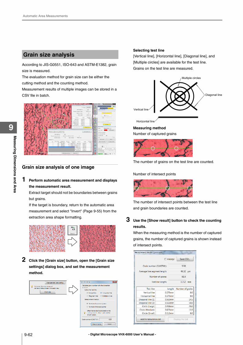
- Digital Microscope VHX-6000 User’s Manual -
Automatic Area Measurements
9-62
Measu
ring
Dim
ensio
ns an
d A
rea
9
According to JIS-G0551, ISO-643 and ASTM-E1382, grain
size is measured.
The evaluation method for grain size can be either the
cutting method and the counting method.
Measurement results of multiple images can be stored in a
CSV file in batch.
Grain size analysis of one image
1 Perform automatic area measurement and displays
the measurement result.
Extract target should not be boundaries between grains
but grains.
If the target is boundary, return to the automatic area
measurement and select "Invert" (Page 9-55) from the
extraction area shape formatting.
2 Click the [Grain size] button, open the [Grain size
settings] dialog box, and set the measurement
method.
Selecting test line
[Vertical line], [Horizontal line], [Diagonal line], and
[Multiple circles] are available for the test line.
Grains on the test line are measured.
Measuring method
Number of captured grains
The number of grains on the test line are counted.
Number of intersect points
The number of intersect points between the test line
and grain boundaries are counted.
3 Use the [Show result] button to check the counting
results.
When the measuring method is the number of captured
grains, the number of captured grains is shown instead
of intersect points.
Grain size analysis
Vertical line
Horizontal line
Diagonal line
Multiple circles
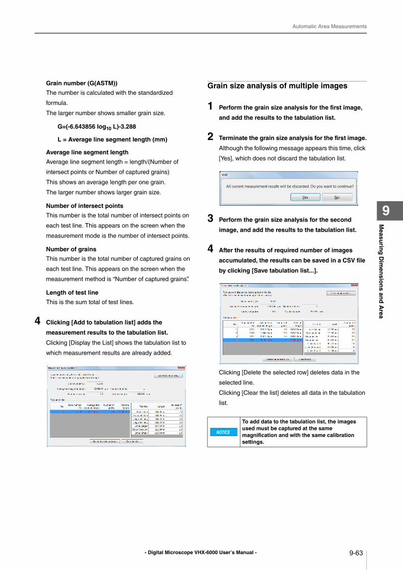
- Digital Microscope VHX-6000 User’s Manual -
Automatic Area Measurements
9-63
Measu
ring
Dim
ensio
ns an
d A
rea
9
Grain number (G(ASTM))
The number is calculated with the standardized
formula.
The larger number shows smaller grain size.
G=(-6.643856 log10 L)-3.288
L = Average line segment length (mm)
Average line segment length
Average line segment length = length/(Number of
intersect points or Number of captured grains)
This shows an average length per one grain.
The larger number shows larger grain size.
Number of intersect points
This number is the total number of intersect points on
each test line. This appears on the screen when the
measurement mode is the number of intersect points.
Number of grains
This number is the total number of captured grains on
each test line. This appears on the screen when the
measurement method is “Number of captured grains”.
Length of test line
This is the sum total of test lines.
4 Clicking [Add to tabulation list] adds the
measurement results to the tabulation list.
Clicking [Display the List] shows the tabulation list to
which measurement results are already added.
Grain size analysis of multiple images
1 Perform the grain size analysis for the first image,
and add the results to the tabulation list.
2 Terminate the grain size analysis for the first image.
Although the following message appears this time, click
[Yes], which does not discard the tabulation list.
3 Perform the grain size analysis for the second
image, and add the results to the tabulation list.
4 After the results of required number of images
accumulated, the results can be saved in a CSV file
by clicking [Save tabulation list...].
Clicking [Delete the selected row] deletes data in the
selected line.
Clicking [Clear the list] deletes all data in the tabulation
list.
To add data to the tabulation list, the images used must be captured at the same magnification and with the same calibration settings.
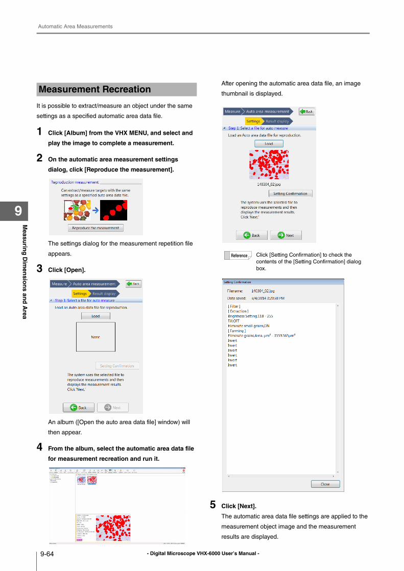
- Digital Microscope VHX-6000 User’s Manual -
Automatic Area Measurements
9-64
Measu
ring
Dim
ensio
ns an
d A
rea
9
It is possible to extract/measure an object under the same
settings as a specified automatic area data file.
1 Click [Album] from the VHX MENU, and select and
play the image to complete a measurement.
2 On the automatic area measurement settings
dialog, click [Reproduce the measurement].
The settings dialog for the measurement repetition file
appears.
3 Click [Open].
An album ([Open the auto area data file] window) will
then appear.
4 From the album, select the automatic area data file
for measurement recreation and run it.
After opening the automatic area data file, an image
thumbnail is displayed.
5 Click [Next].
The automatic area data file settings are applied to the
measurement object image and the measurement
results are displayed.
Measurement Recreation
Click [Setting Confirmation] to check the
contents of the [Setting Confirmation] dialog
box.
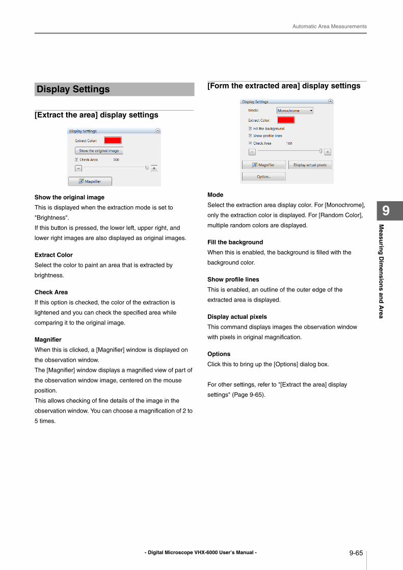
- Digital Microscope VHX-6000 User’s Manual -
Automatic Area Measurements
9-65
Measu
ring
Dim
ensio
ns an
d A
rea
9
[Extract the area] display settings
Show the original image
This is displayed when the extraction mode is set to
"Brightness".
If this button is pressed, the lower left, upper right, and
lower right images are also displayed as original images.
Extract Color
Select the color to paint an area that is extracted by
brightness.
Check Area
If this option is checked, the color of the extraction is
lightened and you can check the specified area while
comparing it to the original image.
Magnifier
When this is clicked, a [Magnifier] window is displayed on
the observation window.
The [Magnifier] window displays a magnified view of part of
the observation window image, centered on the mouse
position.
This allows checking of fine details of the image in the
observation window. You can choose a magnification of 2 to
5 times.
[Form the extracted area] display settings
Mode
Select the extraction area display color. For [Monochrome],
only the extraction color is displayed. For [Random Color],
multiple random colors are displayed.
Fill the background
When this is enabled, the background is filled with the
background color.
Show profile lines
This is enabled, an outline of the outer edge of the
extracted area is displayed.
Display actual pixels
This command displays images the observation window
with pixels in original magnification.
Options
Click this to bring up the [Options] dialog box.
For other settings, refer to "[Extract the area] display
settings" (Page 9-65).
Display Settings
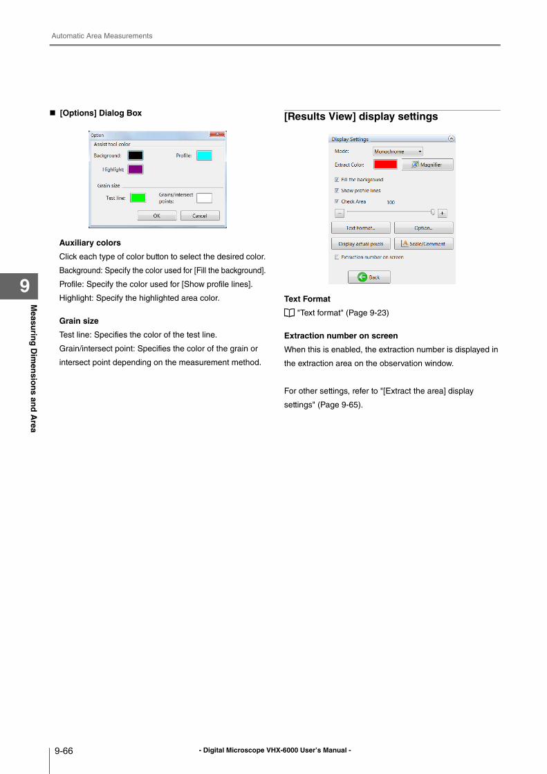
- Digital Microscope VHX-6000 User’s Manual -
Automatic Area Measurements
9-66
Measu
ring
Dim
ensio
ns an
d A
rea
9
[Options] Dialog Box
Auxiliary colors
Click each type of color button to select the desired color.
Background: Specify the color used for [Fill the background].
Profile: Specify the color used for [Show profile lines].
Highlight: Specify the highlighted area color.
Grain size
Test line: Specifies the color of the test line.
Grain/intersect point: Specifies the color of the grain or
intersect point depending on the measurement method.
[Results View] display settings
Text Format
"Text format" (Page 9-23)
Extraction number on screen
When this is enabled, the extraction number is displayed in
the extraction area on the observation window.
For other settings, refer to "[Extract the area] display
settings" (Page 9-65).
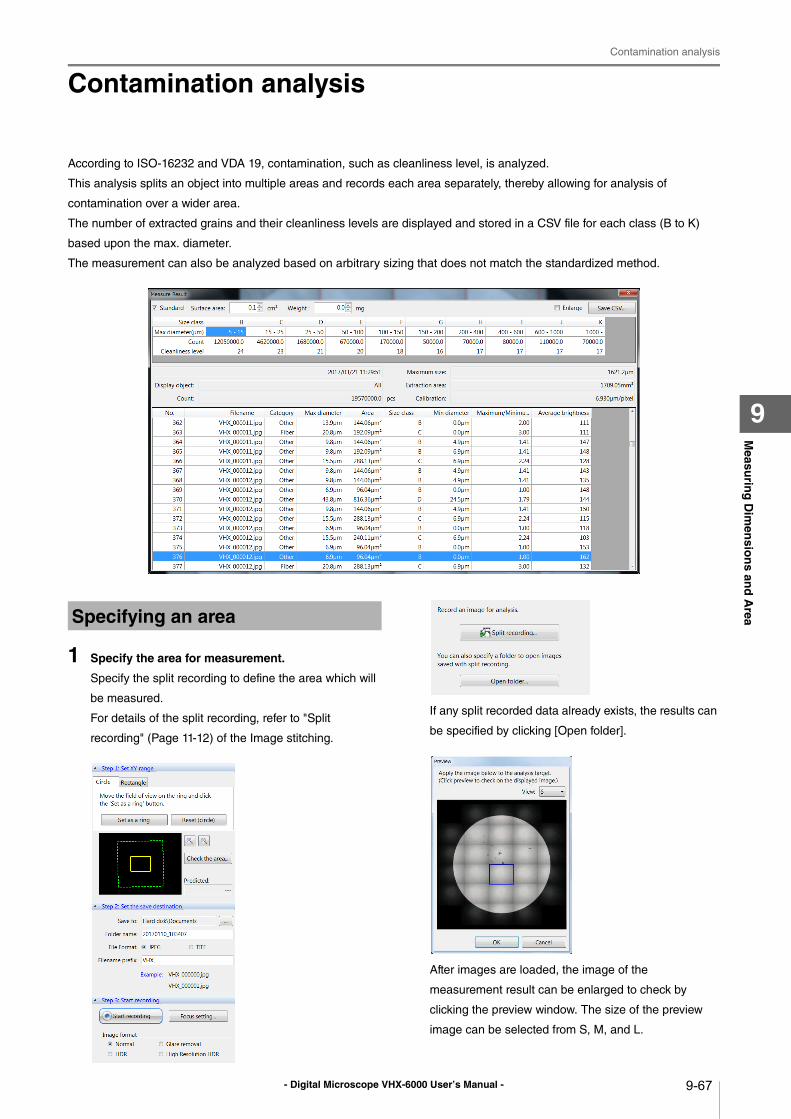
- Digital Microscope VHX-6000 User’s Manual -
Contamination analysis
9-67
Measu
ring
Dim
ensio
ns an
d A
rea
9
Contamination analysis
According to ISO-16232 and VDA 19, contamination, such as cleanliness level, is analyzed.
This analysis splits an object into multiple areas and records each area separately, thereby allowing for analysis of
contamination over a wider area.
The number of extracted grains and their cleanliness levels are displayed and stored in a CSV file for each class (B to K)
based upon the max. diameter.
The measurement can also be analyzed based on arbitrary sizing that does not match the standardized method.
1 Specify the area for measurement.
Specify the split recording to define the area which will
be measured.
For details of the split recording, refer to "Split
recording" (Page 11-12) of the Image stitching.
If any split recorded data already exists, the results can
be specified by clicking [Open folder].
After images are loaded, the image of the
measurement result can be enlarged to check by
clicking the preview window. The size of the preview
image can be selected from S, M, and L.
Specifying an area
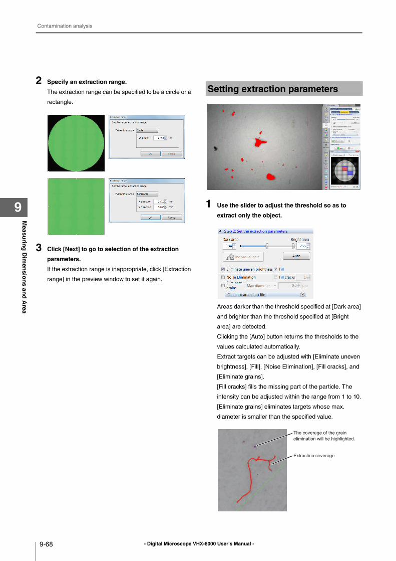
- Digital Microscope VHX-6000 User’s Manual -
Contamination analysis
9-68
Measu
ring
Dim
ensio
ns an
d A
rea
9
2 Specify an extraction range.
The extraction range can be specified to be a circle or a
rectangle.
3 Click [Next] to go to selection of the extraction
parameters.
If the extraction range is inappropriate, click [Extraction
range] in the preview window to set it again.
1 Use the slider to adjust the threshold so as to
extract only the object.
Areas darker than the threshold specified at [Dark area]
and brighter than the threshold specified at [Bright
area] are detected.
Clicking the [Auto] button returns the thresholds to the
values calculated automatically.
Extract targets can be adjusted with [Eliminate uneven
brightness], [Fill], [Noise Elimination], [Fill cracks], and
[Eliminate grains].
[Fill cracks] fills the missing part of the particle. The
intensity can be adjusted within the range from 1 to 10.
[Eliminate grains] eliminates targets whose max.
diameter is smaller than the specified value.
Setting extraction parameters
Extraction coverage
The coverage of the grain elimination will be highlighted.
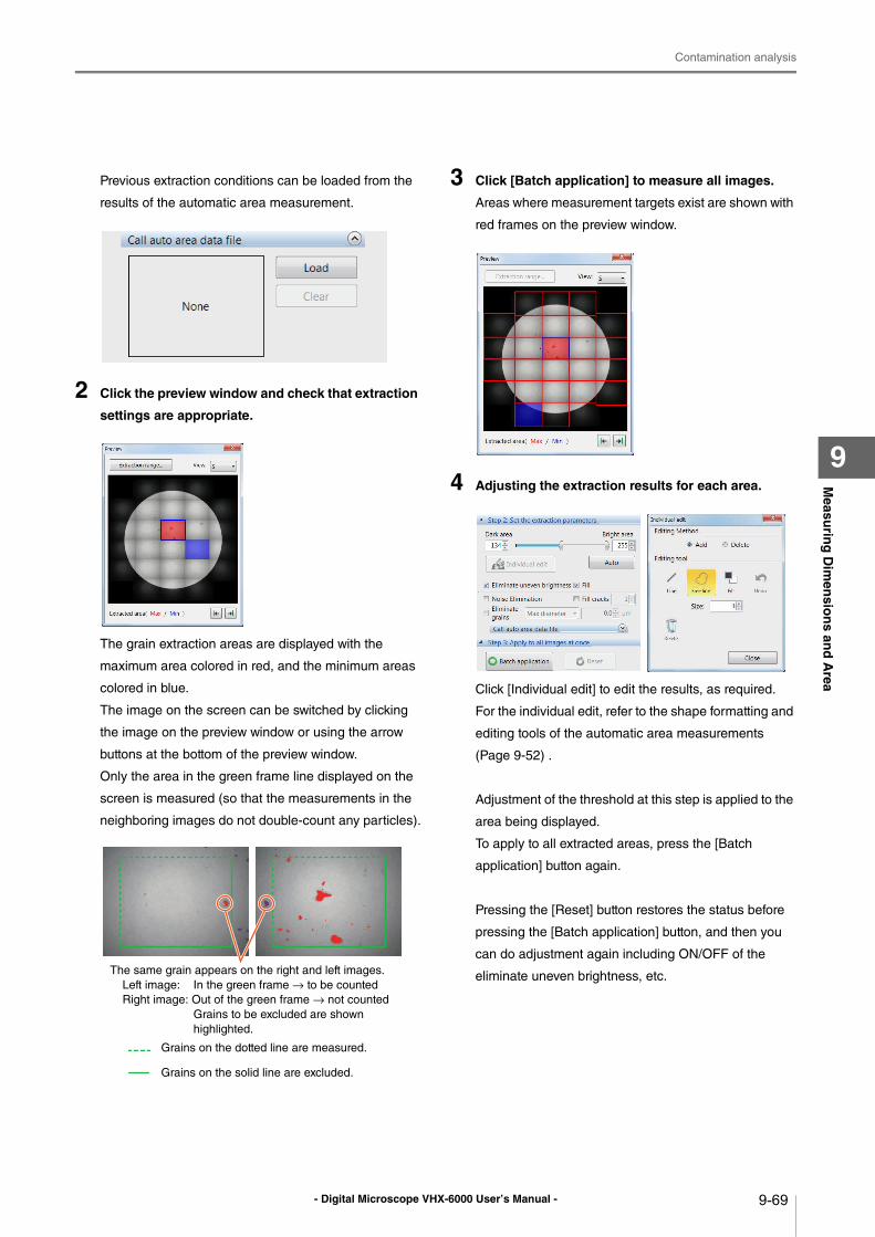
- Digital Microscope VHX-6000 User’s Manual -
Contamination analysis
9-69
Measu
ring
Dim
ensio
ns an
d A
rea
9
Previous extraction conditions can be loaded from the
results of the automatic area measurement.
2 Click the preview window and check that extraction
settings are appropriate.
The grain extraction areas are displayed with the
maximum area colored in red, and the minimum areas
colored in blue.
The image on the screen can be switched by clicking
the image on the preview window or using the arrow
buttons at the bottom of the preview window.
Only the area in the green frame line displayed on the
screen is measured (so that the measurements in the
neighboring images do not double-count any particles).
3 Click [Batch application] to measure all images.
Areas where measurement targets exist are shown with
red frames on the preview window.
4 Adjusting the extraction results for each area.
Click [Individual edit] to edit the results, as required.
For the individual edit, refer to the shape formatting and
editing tools of the automatic area measurements
(Page 9-52) .
Adjustment of the threshold at this step is applied to the
area being displayed.
To apply to all extracted areas, press the [Batch
application] button again.
Pressing the [Reset] button restores the status before
pressing the [Batch application] button, and then you
can do adjustment again including ON/OFF of the
eliminate uneven brightness, etc.The same grain appears on the right and left images.
Left image: In the green frame → to be counted
Right image: Out of the green frame → not counted
Grains to be excluded are shown
highlighted.
Grains on the dotted line are measured.
Grains on the solid line are excluded.
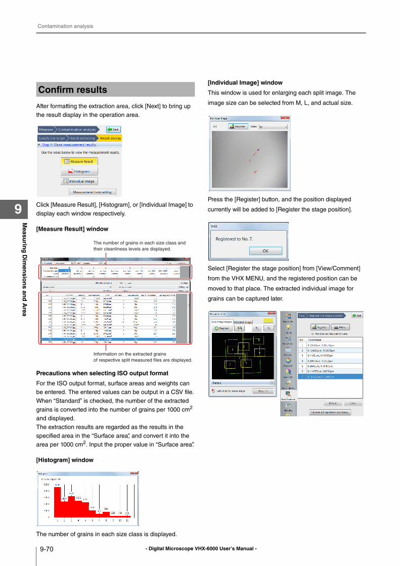
- Digital Microscope VHX-6000 User’s Manual -
Contamination analysis
9-70
Measu
ring
Dim
ensio
ns an
d A
rea
9
After formatting the extraction area, click [Next] to bring up
the result display in the operation area.
Click [Measure Result], [Histogram], or [Individual Image] to
display each window respectively.
[Measure Result] window
Precautions when selecting ISO output format
For the ISO output format, surface areas and weights can
be entered. The entered values can be output in a CSV file.
When “Standard” is checked, the number of the extracted
grains is converted into the number of grains per 1000 cm2
and displayed.
The extraction results are regarded as the results in the
specified area in the “Surface area”, and convert it into the
area per 1000 cm2. Input the proper value in “Surface area”.
[Histogram] window
The number of grains in each size class is displayed.
[Individual Image] window
This window is used for enlarging each split image. The
image size can be selected from M, L, and actual size.
Press the [Register] button, and the position displayed
currently will be added to [Register the stage position].
Select [Register the stage position] from [View/Comment]
from the VHX MENU, and the registered position can be
moved to that place. The extracted individual image for
grains can be captured later.
Confirm results
The number of grains in each size class and their cleanliness levels are displayed.
Information on the extracted grains of respective split measured files are displayed.
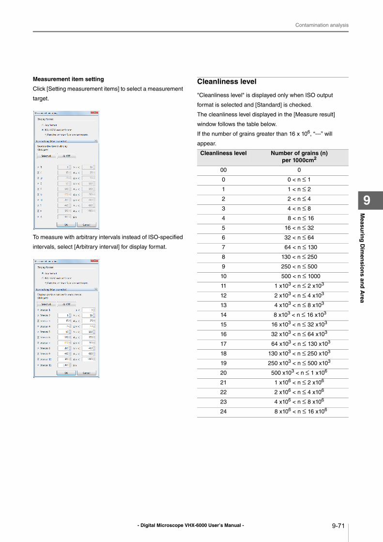
- Digital Microscope VHX-6000 User’s Manual -
Contamination analysis
9-71
Measu
ring
Dim
ensio
ns an
d A
rea
9
Measurement item setting
Click [Setting measurement items] to select a measurement
target.
To measure with arbitrary intervals instead of ISO-specified
intervals, select [Arbitrary interval] for display format.
Cleanliness level
"Cleanliness level" is displayed only when ISO output
format is selected and [Standard] is checked.
The cleanliness level displayed in the [Measure result]
window follows the table below.
If the number of grains greater than 16 x 106, “---” will
appear.
Cleanliness level Number of grains (n) per 1000cm2
00 0
0 0 < n ≤ 1
1 1 < n ≤ 2
2 2 < n ≤ 4
3 4 < n ≤ 8
4 8 < n ≤ 16
5 16 < n ≤ 32
6 32 < n ≤ 64
7 64 < n ≤ 130
8 130 < n ≤ 250
9 250 < n ≤ 500
10 500 < n ≤ 1000
11 1 x10³ < n ≤ 2 x10³
12 2 x10³ < n ≤ 4 x10³
13 4 x10³ < n ≤ 8 x10³
14 8 x10³ < n ≤ 16 x103
15 16 x103 < n ≤ 32 x103
16 32 x103 < n ≤ 64 x103
17 64 x103 < n ≤ 130 x103
18 130 x103 < n ≤ 250 x103
19 250 x103 < n ≤ 500 x103
20 500 x103 < n ≤ 1 x10⁶
21 1 x10⁶ < n ≤ 2 x10⁶
22 2 x10⁶ < n ≤ 4 x10⁶
23 4 x10⁶ < n ≤ 8 x10⁶
24 8 x10⁶ < n ≤ 16 x106
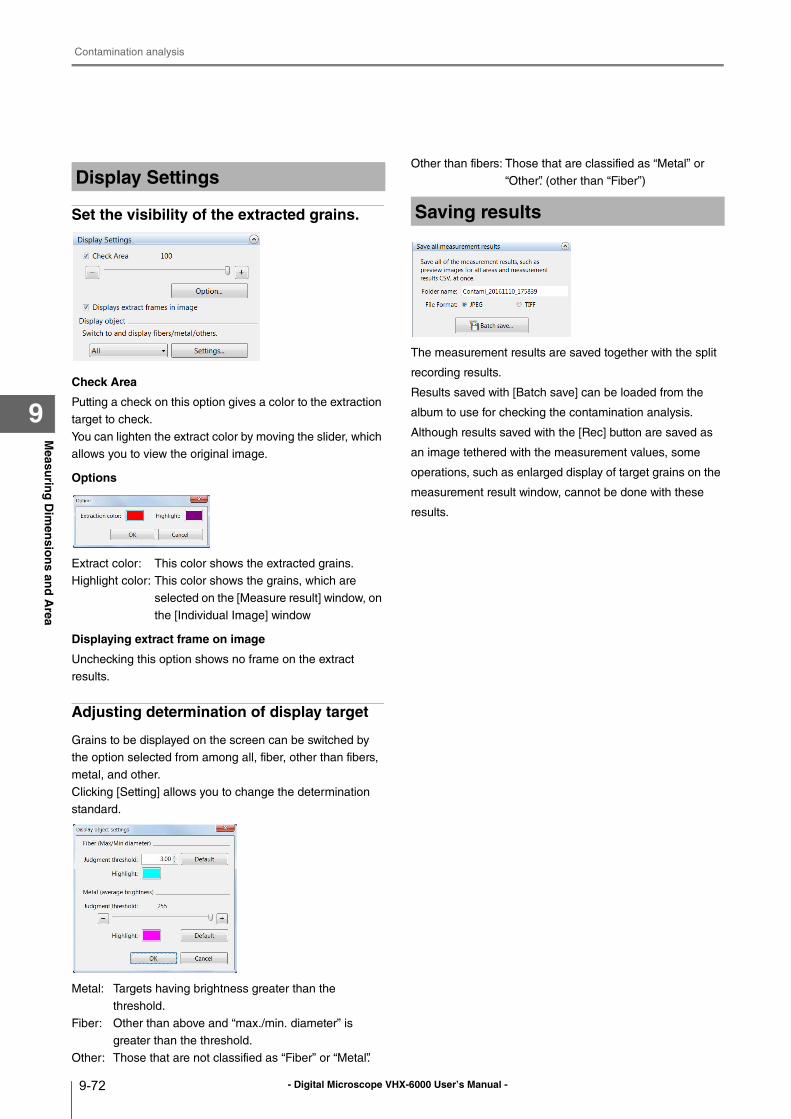
- Digital Microscope VHX-6000 User’s Manual -
Contamination analysis
9-72
Measu
ring
Dim
ensio
ns an
d A
rea
9
Set the visibility of the extracted grains.
Check Area
Putting a check on this option gives a color to the extraction
target to check.
You can lighten the extract color by moving the slider, which
allows you to view the original image.
Options
Extract color: This color shows the extracted grains.
Highlight color: This color shows the grains, which are
selected on the [Measure result] window, on
the [Individual Image] window
Displaying extract frame on image
Unchecking this option shows no frame on the extract
results.
Adjusting determination of display target
Grains to be displayed on the screen can be switched by
the option selected from among all, fiber, other than fibers,
metal, and other.
Clicking [Setting] allows you to change the determination
standard.
Metal: Targets having brightness greater than the
threshold.
Fiber: Other than above and “max./min. diameter” is
greater than the threshold.
Other: Those that are not classified as “Fiber” or “Metal”.
Other than fibers: Those that are classified as “Metal” or
“Other”. (other than “Fiber”)
The measurement results are saved together with the split
recording results.
Results saved with [Batch save] can be loaded from the
album to use for checking the contamination analysis.
Although results saved with the [Rec] button are saved as
an image tethered with the measurement values, some
operations, such as enlarged display of target grains on the
measurement result window, cannot be done with these
results.
Display Settings
Saving results
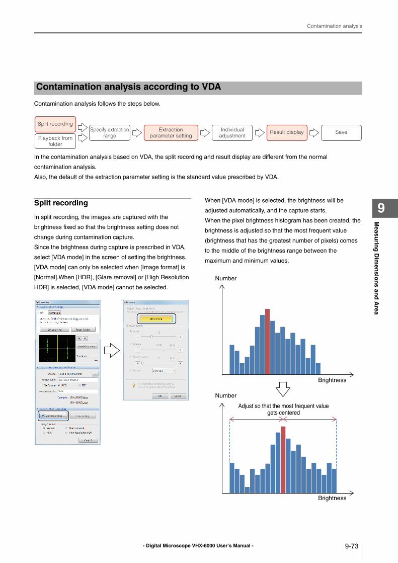
- Digital Microscope VHX-6000 User’s Manual -
Contamination analysis
9-73
Measu
ring
Dim
ensio
ns an
d A
rea
9
Contamination analysis follows the steps below.
In the contamination analysis based on VDA, the split recording and result display are different from the normal
contamination analysis.
Also, the default of the extraction parameter setting is the standard value prescribed by VDA.
Split recording
In split recording, the images are captured with the
brightness fixed so that the brightness setting does not
change during contamination capture.
Since the brightness during capture is prescribed in VDA,
select [VDA mode] in the screen of setting the brightness.
[VDA mode] can only be selected when [Image format] is
[Normal].When [HDR], [Glare removal] or [High Resolution
HDR] is selected, [VDA mode] cannot be selected.
When [VDA mode] is selected, the brightness will be
adjusted automatically, and the capture starts.
When the pixel brightness histogram has been created, the
brightness is adjusted so that the most frequent value
(brightness that has the greatest number of pixels) comes
to the middle of the brightness range between the
maximum and minimum values.
Contamination analysis according to VDA
Split recording
Playback from folder
Specify extraction range
Extraction parameter setting
Individual adjustment
Result display Save
Brightness
Brightness
Adjust so that the most frequent value
gets centered
Number
Number
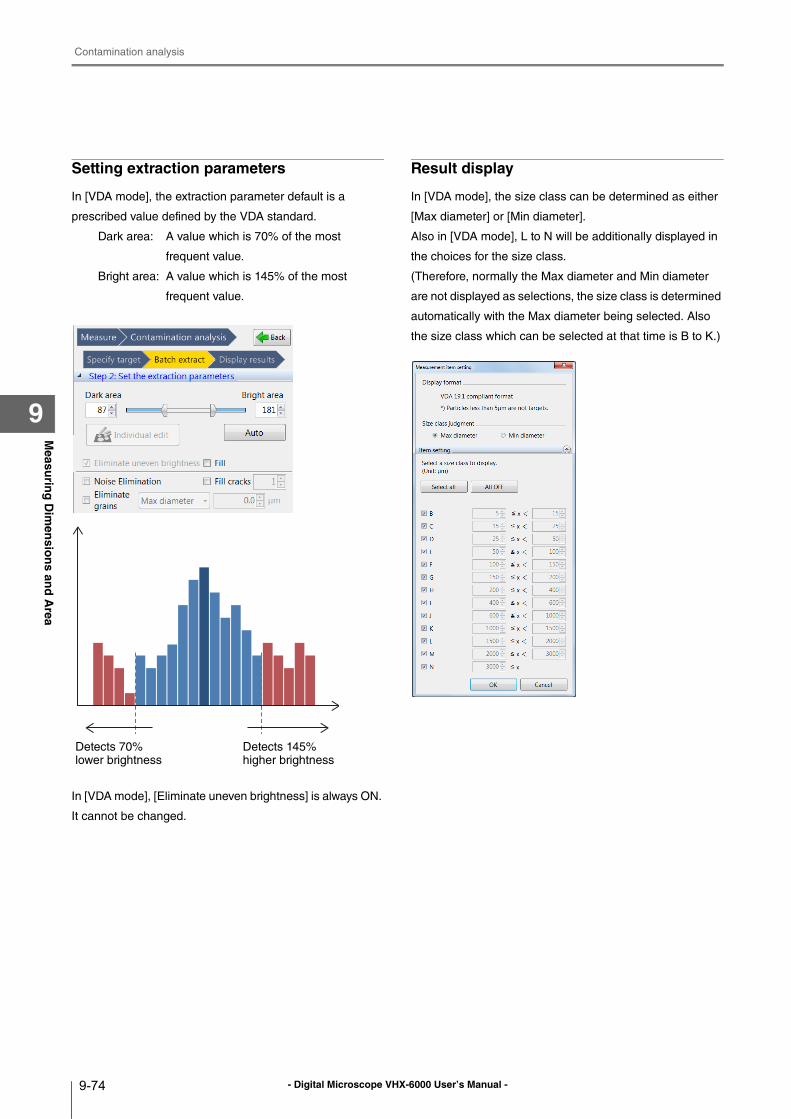
- Digital Microscope VHX-6000 User’s Manual -
Contamination analysis
9-74
Measu
ring
Dim
ensio
ns an
d A
rea
9
Setting extraction parameters
In [VDA mode], the extraction parameter default is a
prescribed value defined by the VDA standard.
Dark area: A value which is 70% of the most
frequent value.
Bright area: A value which is 145% of the most
frequent value.
In [VDA mode], [Eliminate uneven brightness] is always ON.
It cannot be changed.
Result display
In [VDA mode], the size class can be determined as either
[Max diameter] or [Min diameter].
Also in [VDA mode], L to N will be additionally displayed in
the choices for the size class.
(Therefore, normally the Max diameter and Min diameter
are not displayed as selections, the size class is determined
automatically with the Max diameter being selected. Also
the size class which can be selected at that time is B to K.)
Detects 70%
lower brightness
Detects 145%
higher brightness
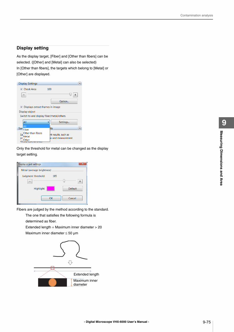
- Digital Microscope VHX-6000 User’s Manual -
Contamination analysis
9-75
Measu
ring
Dim
ensio
ns an
d A
rea
9
Display setting
As the display target, [Fiber] and [Other than fibers] can be
selected. ([Other] and [Metal] can also be selected)
In [Other than fibers], the targets which belong to [Metal] or
[Other] are displayed.
Only the threshold for metal can be changed as the display
target setting.
Fibers are judged by the method according to the standard.
The one that satisfies the following formula is
determined as fiber.
Extended length ÷ Maximum inner diameter > 20
Maximum inner diameter ≤ 50 μm
Extended length
Maximum inner diameter
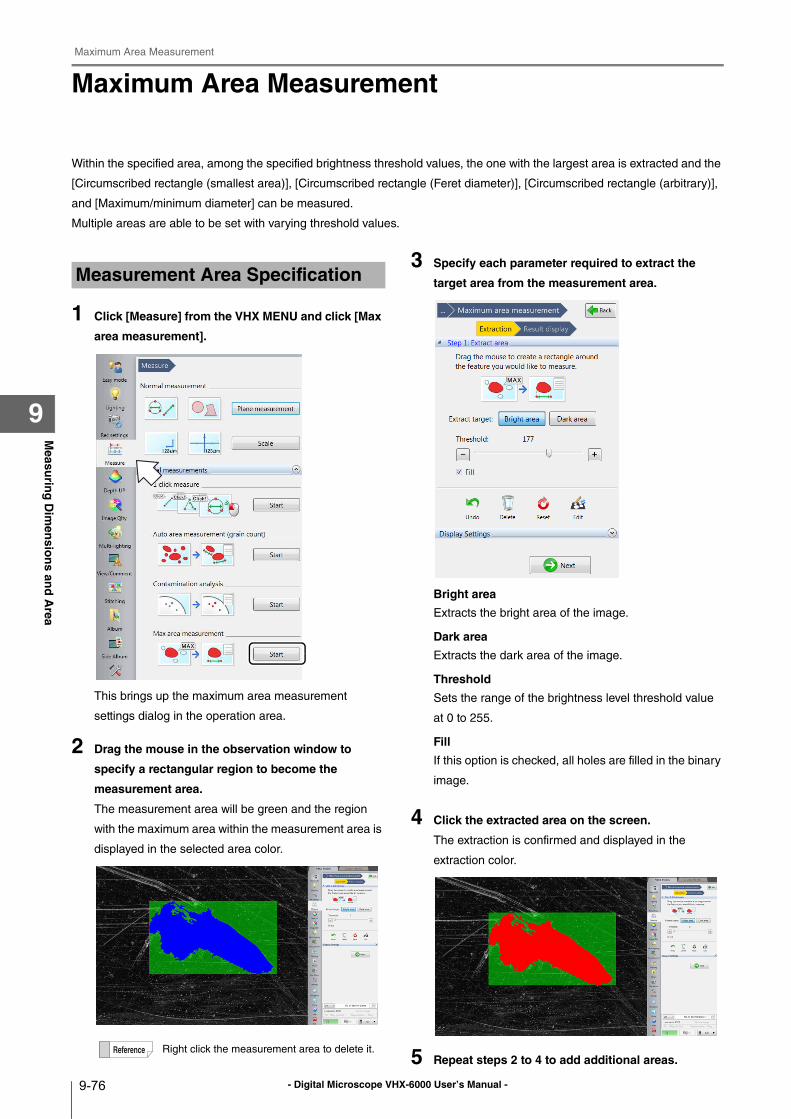
- Digital Microscope VHX-6000 User’s Manual -
Maximum Area Measurement
9-76
Measu
ring
Dim
ensio
ns an
d A
rea
9
Maximum Area Measurement
Within the specified area, among the specified brightness threshold values, the one with the largest area is extracted and the
[Circumscribed rectangle (smallest area)], [Circumscribed rectangle (Feret diameter)], [Circumscribed rectangle (arbitrary)],
and [Maximum/minimum diameter] can be measured.
Multiple areas are able to be set with varying threshold values.
1 Click [Measure] from the VHX MENU and click [Max
area measurement].
This brings up the maximum area measurement
settings dialog in the operation area.
2 Drag the mouse in the observation window to
specify a rectangular region to become the
measurement area.
The measurement area will be green and the region
with the maximum area within the measurement area is
displayed in the selected area color.
3 Specify each parameter required to extract the
target area from the measurement area.
Bright area
Extracts the bright area of the image.
Dark area
Extracts the dark area of the image.
Threshold
Sets the range of the brightness level threshold value
at 0 to 255.
Fill
If this option is checked, all holes are filled in the binary
image.
4 Click the extracted area on the screen.
The extraction is confirmed and displayed in the
extraction color.
5 Repeat steps 2 to 4 to add additional areas.
Measurement Area Specification
Right click the measurement area to delete it.
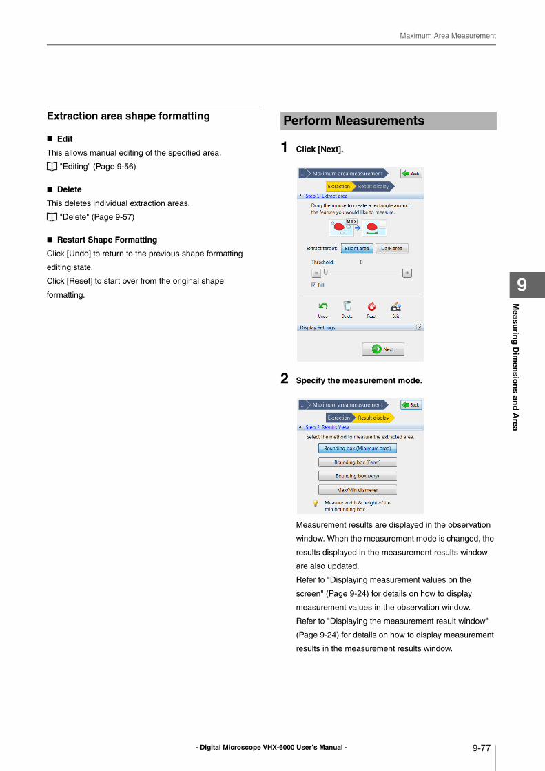
- Digital Microscope VHX-6000 User’s Manual -
Maximum Area Measurement
9-77
Measu
ring
Dim
ensio
ns an
d A
rea
9
Extraction area shape formatting
Edit
This allows manual editing of the specified area.
"Editing" (Page 9-56)
Delete
This deletes individual extraction areas.
"Delete" (Page 9-57)
Restart Shape Formatting
Click [Undo] to return to the previous shape formatting
editing state.
Click [Reset] to start over from the original shape
formatting.
1 Click [Next].
2 Specify the measurement mode.
Measurement results are displayed in the observation
window. When the measurement mode is changed, the
results displayed in the measurement results window
are also updated.
Refer to "Displaying measurement values on the
screen" (Page 9-24) for details on how to display
measurement values in the observation window.
Refer to "Displaying the measurement result window"
(Page 9-24) for details on how to display measurement
results in the measurement results window.
Perform Measurements
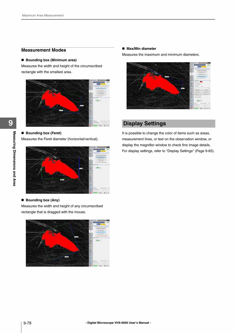
- Digital Microscope VHX-6000 User’s Manual -
Maximum Area Measurement
9-78
Measu
ring
Dim
ensio
ns an
d A
rea
9
Measurement Modes
Bounding box (Minimum area)
Measures the width and height of the circumscribed
rectangle with the smallest area.
Bounding box (Feret)
Measures the Feret diameter (horizontal/vertical).
Bounding box (Any)
Measures the width and height of any circumscribed
rectangle that is dragged with the mouse.
Max/Min diameter
Measures the maximum and minimum diameters.
It is possible to change the color of items such as areas,
measurement lines, or text on the observation window, or
display the magnifier window to check fine image details.
For display settings, refer to "Display Settings" (Page 9-65).
Display Settings
- Digital Microscope VHX-6000 User’s Manual -
XY Stage Measurement (Optional)
9-79
Measu
ring
Dim
ensio
ns an
d A
rea
9
XY Stage Measurement (Optional)
The VH-M100E XY measurement system and the VHX-S660E large free-angle observation system allows you to measure
objects while moving it over a wide range (100 x 100 mm) in the XY direction.
Installing the VHX-H2M2 XY measurement software
1 Turn on the power for the VHX-6000.
The observation window appears.
2 Insert the VHX-H2M2 disk in the DVD drive.
3 Turn off the power for the VHX-6000.
4 Turn on the power for the VHX-6000.
The installation will begin. The power will automatically
turn off during the installation.
5 After the power turns off, allow three or more
seconds and then turn the power on.
The observation window appears.
6 Eject the VHX-H2M2 disk from the DVD drive.
Installation and connections for the VH-M100E XY measurement stage
Install and connect the VH-M100E XY measurement stage
by following the supplied user's manual.
When connecting to VHX-S660E, the connection with VH-
M100E is not required.
1 Setup the lens.
Refer to "Lens Setting" (Page 9-5).
2 Perform calibration.
Refer to "Calibration" (Page 9-6).
3 Setup the options.
Setup the options for display color, line width, image
auto save, and startup settings as necessary.
Refer to "Option Settings" (Page 9-97).
The optional VH-M100E XY measurement system or VHX-S660E, and the VHX-H2M2 XY measurement software are required.
Installation and Connections
When installing the measurement software, disconnect the LAN cable and all USB cables except for the mouse, and keyboard. Attempts to access the microscope from an external device during installation may cause the installation to fail.
Installation will not erase the image data saved on your microscope, but we recommend you make a backup of all important data as a safety precaution.
Installation will take several minutes. Do not turn the power off during the installation process, and do not operate any of the buttons.
Preparing to Measure
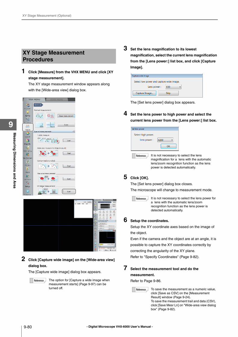
- Digital Microscope VHX-6000 User’s Manual -
XY Stage Measurement (Optional)
9-80
Measu
ring
Dim
ensio
ns an
d A
rea
9
1 Click [Measure] from the VHX MENU and click [XY
stage measurement].
The XY stage measurement window appears along
with the [Wide-area view] dialog box.
2 Click [Capture wide image] on the [Wide-area view]
dialog box.
The [Capture wide image] dialog box appears.
3 Set the lens magnification to its lowest
magnification, select the current lens magnification
from the [Lens power:] list box, and click [Capture
Image].
The [Set lens power] dialog box appears.
4 Set the lens power to high power and select the
current lens power from the [Lens power:] list box.
5 Click [OK].
The [Set lens power] dialog box closes.
The microscope will change to measurement mode.
6 Setup the coordinates.
Setup the XY coordinate axes based on the image of
the object.
Even if the camera and the object are at an angle, it is
possible to capture the XY coordinates correctly by
correcting the angularity of the XY plane.
Refer to "Specify Coordinates" (Page 9-82).
7 Select the measurement tool and do the
measurement.
Refer to Page 9-86.
XY Stage Measurement Procedures
The option for [Capture a wide image when
measurement starts] (Page 9-97) can be
turned off.
It is not necessary to select the lens
magnification for a lens with the automatic
lens/zoom recognition function as the lens
power is detected automatically.
It is not necessary to select the lens power for
a lens with the automatic lens/zoom
recognition function as the lens power is
detected automatically.
To save the measurement as a numeric value,
click [Save as CSV] on the [Measurement
Result] window (Page 9-24).
To save the measurement trail and data (CSV),
click [Save Mesr Ln] on "Wide-area view dialog
box" (Page 9-82).
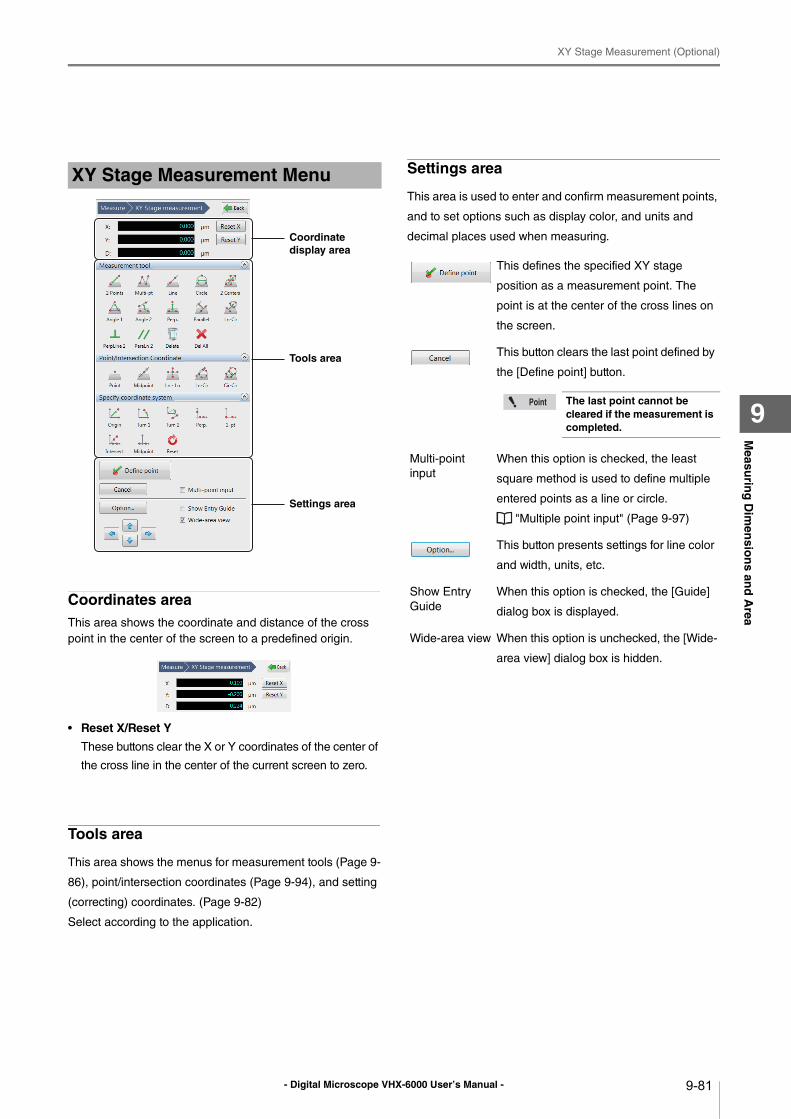
- Digital Microscope VHX-6000 User’s Manual -
XY Stage Measurement (Optional)
9-81
Measu
ring
Dim
ensio
ns an
d A
rea
9
Coordinates areaThis area shows the coordinate and distance of the cross
point in the center of the screen to a predefined origin.
• Reset X/Reset Y
These buttons clear the X or Y coordinates of the center of
the cross line in the center of the current screen to zero.
Tools area
This area shows the menus for measurement tools (Page 9-
86), point/intersection coordinates (Page 9-94), and setting
(correcting) coordinates. (Page 9-82)
Select according to the application.
Settings area
This area is used to enter and confirm measurement points,
and to set options such as display color, and units and
decimal places used when measuring.
XY Stage Measurement Menu
Coordinate display area
Tools area
Settings area
This defines the specified XY stage
position as a measurement point. The
point is at the center of the cross lines on
the screen.
This button clears the last point defined by
the [Define point] button.
Multi-point
input
When this option is checked, the least
square method is used to define multiple
entered points as a line or circle.
"Multiple point input" (Page 9-97)
This button presents settings for line color
and width, units, etc.
Show Entry
Guide
When this option is checked, the [Guide]
dialog box is displayed.
Wide-area view When this option is unchecked, the [Wide-
area view] dialog box is hidden.
The last point cannot be cleared if the measurement is completed.
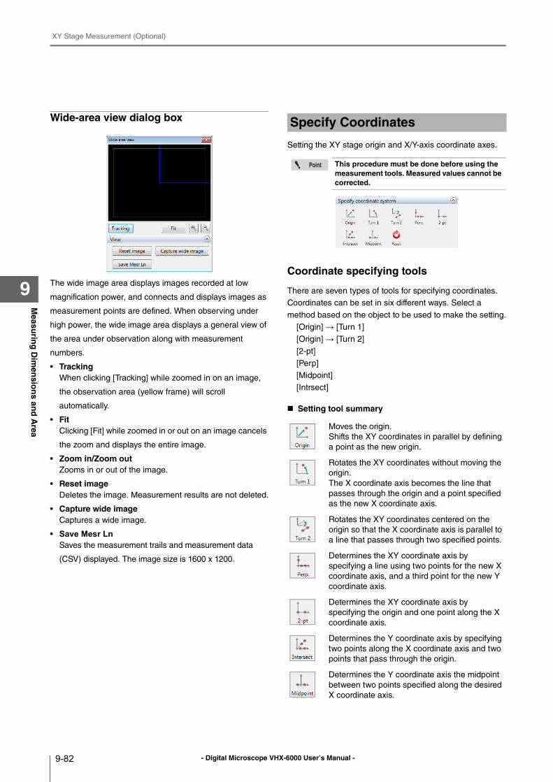
- Digital Microscope VHX-6000 User’s Manual -
XY Stage Measurement (Optional)
9-82
Measu
ring
Dim
ensio
ns an
d A
rea
9
Wide-area view dialog box
The wide image area displays images recorded at low
magnification power, and connects and displays images as
measurement points are defined. When observing under
high power, the wide image area displays a general view of
the area under observation along with measurement
numbers.
• TrackingWhen clicking [Tracking] while zoomed in on an image,
the observation area (yellow frame) will scroll
automatically.
• FitClicking [Fit] while zoomed in or out on an image cancels
the zoom and displays the entire image.
• Zoom in/Zoom outZooms in or out of the image.
• Reset imageDeletes the image. Measurement results are not deleted.
• Capture wide imageCaptures a wide image.
• Save Mesr LnSaves the measurement trails and measurement data
(CSV) displayed. The image size is 1600 x 1200.
Setting the XY stage origin and X/Y-axis coordinate axes.
Coordinate specifying tools
There are seven types of tools for specifying coordinates.
Coordinates can be set in six different ways. Select a
method based on the object to be used to make the setting.
[Origin] → [Turn 1]
[Origin] → [Turn 2]
[2-pt]
[Perp]
[Midpoint]
[Intrsect]
Setting tool summary
Specify Coordinates
This procedure must be done before using the measurement tools. Measured values cannot be corrected.
Moves the origin.
Shifts the XY coordinates in parallel by defining
a point as the new origin.
Rotates the XY coordinates without moving the
origin.
The X coordinate axis becomes the line that
passes through the origin and a point specified
as the new X coordinate axis.
Rotates the XY coordinates centered on the
origin so that the X coordinate axis is parallel to
a line that passes through two specified points.
Determines the XY coordinate axis by
specifying a line using two points for the new X
coordinate axis, and a third point for the new Y
coordinate axis.
Determines the XY coordinate axis by
specifying the origin and one point along the X
coordinate axis.
Determines the Y coordinate axis by specifying
two points along the X coordinate axis and two
points that pass through the origin.
Determines the Y coordinate axis the midpoint
between two points specified along the desired
X coordinate axis.
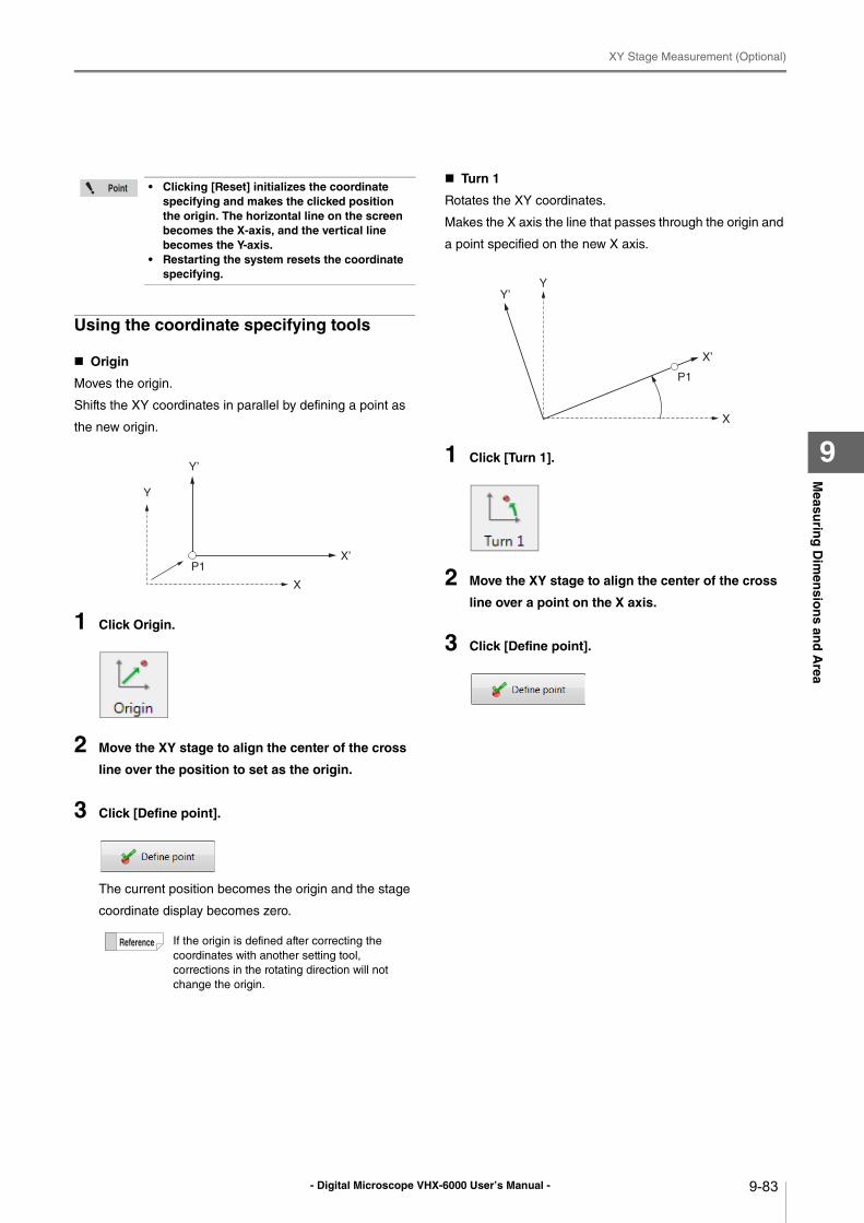
- Digital Microscope VHX-6000 User’s Manual -
XY Stage Measurement (Optional)
9-83
Measu
ring
Dim
ensio
ns an
d A
rea
9
Using the coordinate specifying tools
Origin
Moves the origin.
Shifts the XY coordinates in parallel by defining a point as
the new origin.
1 Click Origin.
2 Move the XY stage to align the center of the cross
line over the position to set as the origin.
3 Click [Define point].
The current position becomes the origin and the stage
coordinate display becomes zero.
Turn 1
Rotates the XY coordinates.
Makes the X axis the line that passes through the origin and
a point specified on the new X axis.
1 Click [Turn 1].
2 Move the XY stage to align the center of the cross
line over a point on the X axis.
3 Click [Define point].
• Clicking [Reset] initializes the coordinate specifying and makes the clicked position the origin. The horizontal line on the screen becomes the X-axis, and the vertical line becomes the Y-axis.
• Restarting the system resets the coordinate specifying.
If the origin is defined after correcting the
coordinates with another setting tool,
corrections in the rotating direction will not
change the origin.
Y’
X’
Y
X
P1
Y’
X’
Y
X
P1
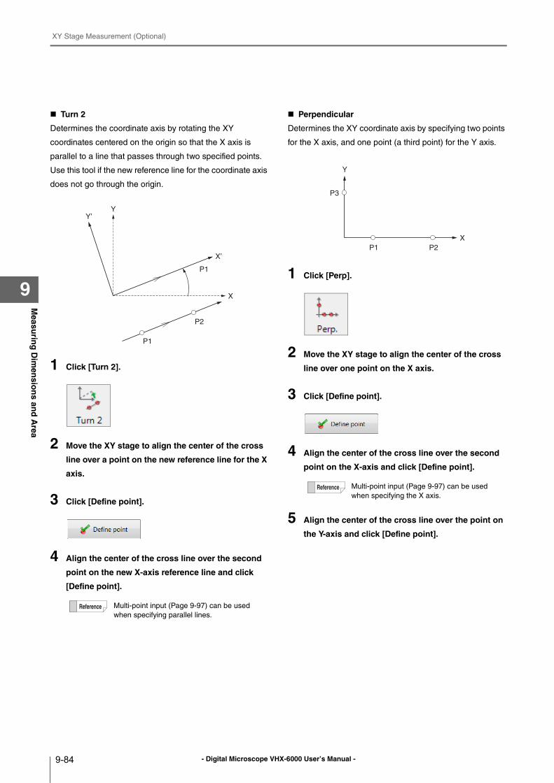
- Digital Microscope VHX-6000 User’s Manual -
XY Stage Measurement (Optional)
9-84
Measu
ring
Dim
ensio
ns an
d A
rea
9
Turn 2
Determines the coordinate axis by rotating the XY
coordinates centered on the origin so that the X axis is
parallel to a line that passes through two specified points.
Use this tool if the new reference line for the coordinate axis
does not go through the origin.
1 Click [Turn 2].
2 Move the XY stage to align the center of the cross
line over a point on the new reference line for the X
axis.
3 Click [Define point].
4 Align the center of the cross line over the second
point on the new X-axis reference line and click
[Define point].
Perpendicular
Determines the XY coordinate axis by specifying two points
for the X axis, and one point (a third point) for the Y axis.
1 Click [Perp].
2 Move the XY stage to align the center of the cross
line over one point on the X axis.
3 Click [Define point].
4 Align the center of the cross line over the second
point on the X-axis and click [Define point].
5 Align the center of the cross line over the point on
the Y-axis and click [Define point].
Multi-point input (Page 9-97) can be used
when specifying parallel lines.
Y’
X’
Y
X
P1
P1
P2
Multi-point input (Page 9-97) can be used
when specifying the X axis.
Y
X
P1 P2
P3
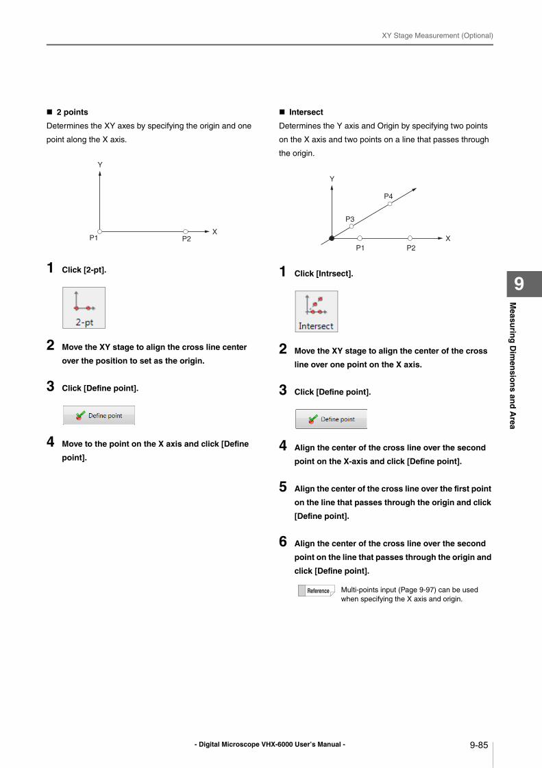
- Digital Microscope VHX-6000 User’s Manual -
XY Stage Measurement (Optional)
9-85
Measu
ring
Dim
ensio
ns an
d A
rea
9
2 points
Determines the XY axes by specifying the origin and one
point along the X axis.
1 Click [2-pt].
2 Move the XY stage to align the cross line center
over the position to set as the origin.
3 Click [Define point].
4 Move to the point on the X axis and click [Define
point].
Intersect
Determines the Y axis and Origin by specifying two points
on the X axis and two points on a line that passes through
the origin.
1 Click [Intrsect].
2 Move the XY stage to align the center of the cross
line over one point on the X axis.
3 Click [Define point].
4 Align the center of the cross line over the second
point on the X-axis and click [Define point].
5 Align the center of the cross line over the first point
on the line that passes through the origin and click
[Define point].
6 Align the center of the cross line over the second
point on the line that passes through the origin and
click [Define point].
Y
XP1 P2
Multi-points input (Page 9-97) can be used
when specifying the X axis and origin.
Y
X
P1 P2
P3
P4
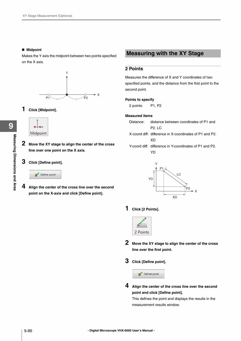
- Digital Microscope VHX-6000 User’s Manual -
XY Stage Measurement (Optional)
9-86
Measu
ring
Dim
ensio
ns an
d A
rea
9
Midpoint
Makes the Y axis the midpoint between two points specified
on the X axis.
1 Click [Midpoint].
2 Move the XY stage to align the center of the cross
line over one point on the X axis.
3 Click [Define point].
4 Align the center of the cross line over the second
point on the X-axis and click [Define point].
2 Points
Measures the difference of X and Y coordinates of two
specified points, and the distance from the first point to the
second point.
Points to specify
2 points: P1, P2
Measured items
Distance: distance between coordinates of P1 and
P2. LC
X-coord diff: difference in X-coordinates of P1 and P2.
XD
Y-coord diff: difference in Y-coordinates of P1 and P2.
YD
1 Click [2 Points].
2 Move the XY stage to align the center of the cross
line over the first point.
3 Click [Define point].
4 Align the center of the cross line over the second
point and click [Define point].
This defines the point and displays the results in the
measurement results window.
Y
XP1 P2
Measuring with the XY Stage
Y
X
P1
LC
YD
XD
P2
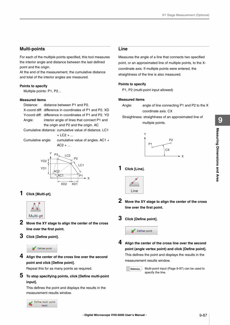
- Digital Microscope VHX-6000 User’s Manual -
XY Stage Measurement (Optional)
9-87
Measu
ring
Dim
ensio
ns an
d A
rea
9
Multi-points
For each of the multiple points specified, this tool measures
the interior angle and distance between the last defined
point and the origin.
At the end of the measurement, the cumulative distance
and total of the interior angles are measured.
Points to specifyMultiple points: P1, P2...
Measured itemsDistance: distance between P1 and P2.
X-coord diff: difference in coordinates of P1 and P2. XD
Y-coord diff: difference in coordinates of P1 and P2. YD
Angle: interior angle of lines that connect P1 and
the origin and P2 and the origin. AC
Cumulative distance: cumulative value of distance. LC1
+ LC2 + ...
Cumulative angle: cumulative value of angles. AC1 +
AC2 + ...
1 Click [Multi-pt].
2 Move the XY stage to align the center of the cross
line over the first point.
3 Click [Define point].
4 Align the center of the cross line over the second
point and click [Define point].
Repeat this for as many points as required.
5 To stop specifying points, click [Define multi-point
input].
This defines the point and displays the results in the
measurement results window.
Line
Measures the angle of a line that connects two specified
point, or an approximated line of multiple points, to the X-
coordinate axis. If multiple points were entered, the
straightness of the line is also measured.
Points to specify
P1, P2 (multi-point input allowed)
Measured items
Angle: angle of line connecting P1 and P2 to the X
coordinate axis. CX
Straightness: straightness of an approximated line of
multiple points.
1 Click [Line].
2 Move the XY stage to align the center of the cross
line over the first point.
3 Click [Define point].
4 Align the center of the cross line over the second
point (angle vertex point) and click [Define point].
This defines the point and displays the results in the
measurement results window.
Y
X
P3
LC1YD1
XD2
P1
YD2
LC2
XD1
P2
AC2
AC1
Multi-point input (Page 9-97) can be used to
specify the line.
Y
X
P1
P2
CX
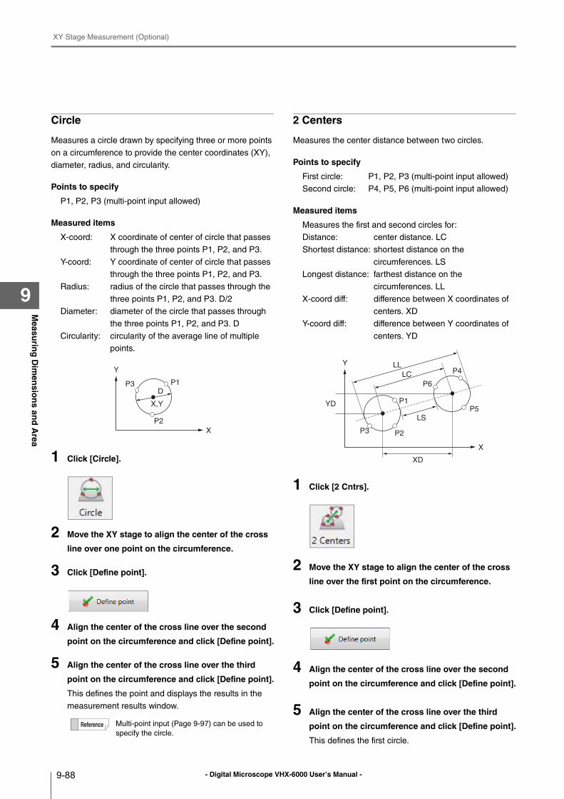
- Digital Microscope VHX-6000 User’s Manual -
XY Stage Measurement (Optional)
9-88
Measu
ring
Dim
ensio
ns an
d A
rea
9
Circle
Measures a circle drawn by specifying three or more points
on a circumference to provide the center coordinates (XY),
diameter, radius, and circularity.
Points to specify
P1, P2, P3 (multi-point input allowed)
Measured items
X-coord: X coordinate of center of circle that passes
through the three points P1, P2, and P3.
Y-coord: Y coordinate of center of circle that passes
through the three points P1, P2, and P3.
Radius: radius of the circle that passes through the
three points P1, P2, and P3. D/2
Diameter: diameter of the circle that passes through
the three points P1, P2, and P3. D
Circularity: circularity of the average line of multiple
points.
1 Click [Circle].
2 Move the XY stage to align the center of the cross
line over one point on the circumference.
3 Click [Define point].
4 Align the center of the cross line over the second
point on the circumference and click [Define point].
5 Align the center of the cross line over the third
point on the circumference and click [Define point].
This defines the point and displays the results in the
measurement results window.
2 Centers
Measures the center distance between two circles.
Points to specify
First circle: P1, P2, P3 (multi-point input allowed)
Second circle: P4, P5, P6 (multi-point input allowed)
Measured items
Measures the first and second circles for:
Distance: center distance. LC
Shortest distance: shortest distance on the
circumferences. LS
Longest distance: farthest distance on the
circumferences. LL
X-coord diff: difference between X coordinates of
centers. XD
Y-coord diff: difference between Y coordinates of
centers. YD
1 Click [2 Cntrs].
2 Move the XY stage to align the center of the cross
line over the first point on the circumference.
3 Click [Define point].
4 Align the center of the cross line over the second
point on the circumference and click [Define point].
5 Align the center of the cross line over the third
point on the circumference and click [Define point].
This defines the first circle.
Multi-point input (Page 9-97) can be used to
specify the circle.
Y
X
P1
P2
P3D
X,Y
Y
X
P1
P2P3
LL
YD
XD
P6
P4
P5
LS
LC
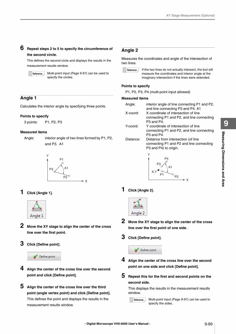
- Digital Microscope VHX-6000 User’s Manual -
XY Stage Measurement (Optional)
9-89
Measu
ring
Dim
ensio
ns an
d A
rea
9
6 Repeat steps 2 to 5 to specify the circumference of
the second circle.
This defines the second circle and displays the results in the
measurement results window.
Angle 1
Calculates the interior angle by specifying three points.
Points to specify
3 points: P1, P2, P3
Measured items
Angle: interior angle of two lines formed by P1, P2,
and P3. A1
1 Click [Angle 1].
2 Move the XY stage to align the center of the cross
line over the first point.
3 Click [Define point].
4 Align the center of the cross line over the second
point and click [Define point].
5 Align the center of the cross line over the third
point (angle vertex point) and click [Define point].
This defines the point and displays the results in the
measurement results window.
Angle 2
Measures the coordinates and angle of the intersection of
two lines.
Points to specify
P1, P2, P3, P4 (multi-point input allowed)
Measured items
Angle: interior angle of line connecting P1 and P2,
and line connecting P3 and P4. A1
X-coord: X coordinate of intersection of line
connecting P1 and P2, and line connecting
P3 and P4.
Y-coord: Y coordinate of intersection of line
connecting P1 and P2, and line connecting
P3 and P4.
Distance: Distance from intersection (of line
connecting P1 and P2 and line connecting
P3 and P4) to origin.
1 Click [Angle 2].
2 Move the XY stage to align the center of the cross
line over the first point of one side.
3 Click [Define point].
4 Align the center of the cross line over the second
point on one side and click [Define point].
5 Repeat this for the first and second points on the
second side.
This displays the results in the measurement results
window.
Multi-point input (Page 9-97) can be used to
specify the circles.
Y
X
P1
P2
P3 A1
If the two lines do not actually intersect, the tool will
measure the coordinates and interior angle at the
imaginary intersection if the lines were extended.
Multi-point input (Page 9-97) can be used to
specify the sides.
Y
X
P1P2
P3A1
P4
X,Y
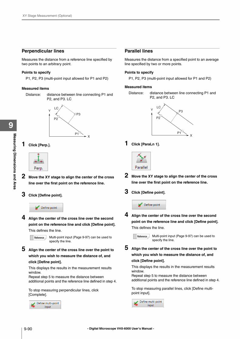
- Digital Microscope VHX-6000 User’s Manual -
XY Stage Measurement (Optional)
9-90
Measu
ring
Dim
ensio
ns an
d A
rea
9
Perpendicular lines
Measures the distance from a reference line specified by
two points to an arbitrary point.
Points to specify
P1, P2, P3 (multi-point input allowed for P1 and P2)
Measured items
Distance: distance between line connecting P1 and
P2, and P3. LC
1 Click [Perp.].
2 Move the XY stage to align the center of the cross
line over the first point on the reference line.
3 Click [Define point].
4 Align the center of the cross line over the second
point on the reference line and click [Define point].
This defines the line.
5 Align the center of the cross line over the point to
which you wish to measure the distance of, and
click [Define point].
This displays the results in the measurement results
window.
Repeat step 5 to measure the distance between
additional points and the reference line defined in step 4.
To stop measuring perpendicular lines, click
[Complete].
Parallel lines
Measures the distance from a specified point to an average
line specified by two or more points.
Points to specify
P1, P2, P3 (multi-point input allowed for P1 and P2)
Measured items
Distance: distance between line connecting P1 and
P2, and P3. LC
1 Click [ParaLn 1].
2 Move the XY stage to align the center of the cross
line over the first point on the reference line.
3 Click [Define point].
4 Align the center of the cross line over the second
point on the reference line and click [Define point].
This defines the line.
5 Align the center of the cross line over the point to
which you wish to measure the distance of, and
click [Define point].
This displays the results in the measurement results
window.
Repeat step 5 to measure the distance between
additional points and the reference line defined in step 4.
To stop measuring parallel lines, click [Define multi-
point input].
Multi-point input (Page 9-97) can be used to
specify the line.
Y
XP1
P2
P3
LC
Multi-point input (Page 9-97) can be used to
specify the line.
Y
XP1
P2
P3
LC
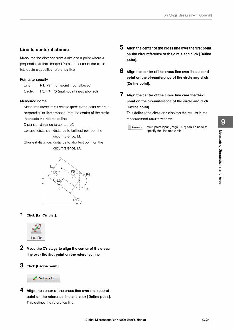
- Digital Microscope VHX-6000 User’s Manual -
XY Stage Measurement (Optional)
9-91
Measu
ring
Dim
ensio
ns an
d A
rea
9
Line to center distance
Measures the distance from a circle to a point where a
perpendicular line dropped from the center of the circle
intersects a specified reference line.
Points to specify
Line: P1, P2 (multi-point input allowed)
Circle: P3, P4, P5 (multi-point input allowed)
Measured items
Measures these items with respect to the point where a
perpendicular line dropped from the center of the circle
intersects the reference line:
Distance: distance to center. LC
Longest distance: distance to farthest point on the
circumference. LL
Shortest distance: distance to shortest point on the
circumference. LS
1 Click [Ln-Cir dist].
2 Move the XY stage to align the center of the cross
line over the first point on the reference line.
3 Click [Define point].
4 Align the center of the cross line over the second
point on the reference line and click [Define point].
This defines the reference line.
5 Align the center of the cross line over the first point
on the circumference of the circle and click [Define
point].
6 Align the center of the cross line over the second
point on the circumference of the circle and click
[Define point].
7 Align the center of the cross line over the third
point on the circumference of the circle and click
[Define point].
This defines the circle and displays the results in the
measurement results window.
Y
X
P1
P2 P3
LL
P4P5
LS
LC
Multi-point input (Page 9-97) can be used to
specify the line and circle.
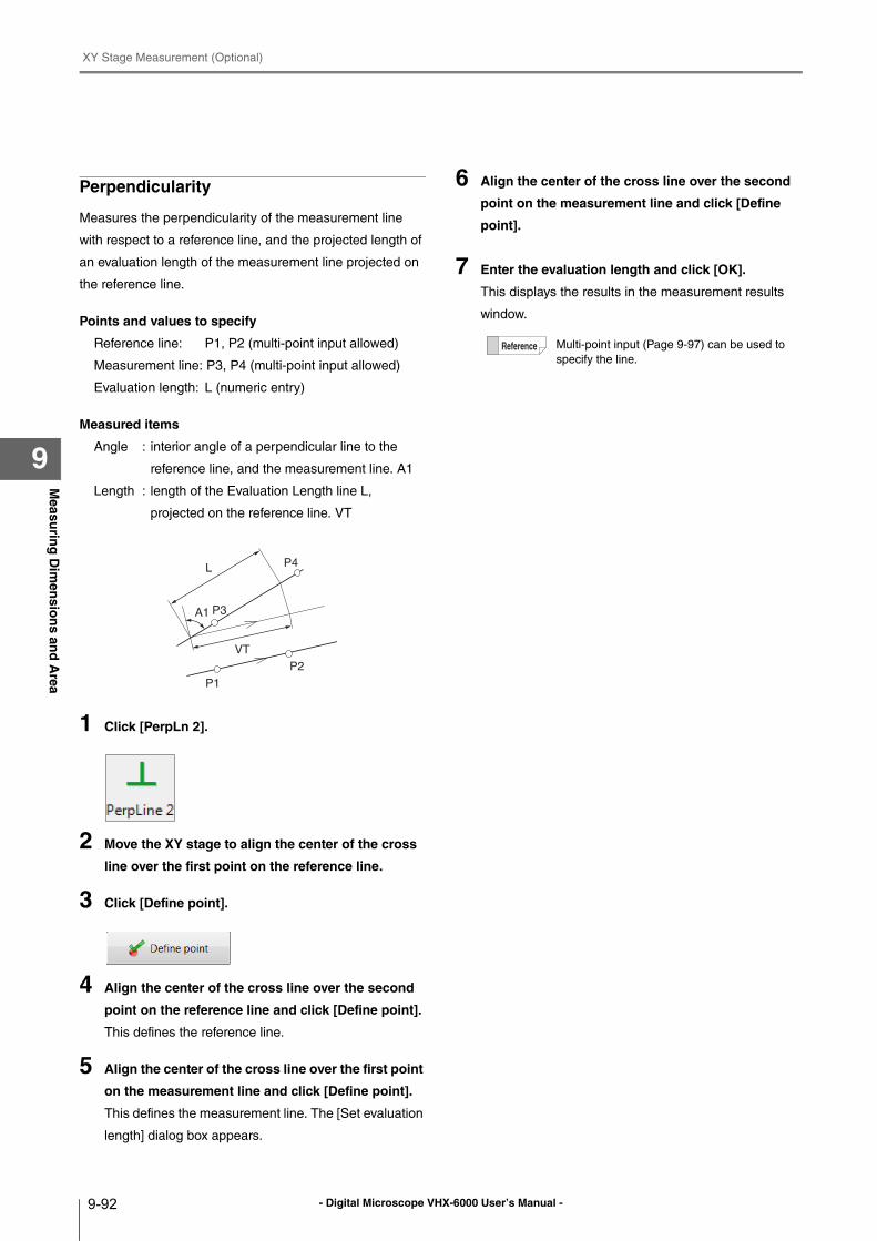
- Digital Microscope VHX-6000 User’s Manual -
XY Stage Measurement (Optional)
9-92
Measu
ring
Dim
ensio
ns an
d A
rea
9
Perpendicularity
Measures the perpendicularity of the measurement line
with respect to a reference line, and the projected length of
an evaluation length of the measurement line projected on
the reference line.
Points and values to specify
Reference line: P1, P2 (multi-point input allowed)
Measurement line: P3, P4 (multi-point input allowed)
Evaluation length: L (numeric entry)
Measured items
Angle : interior angle of a perpendicular line to the
reference line, and the measurement line. A1
Length : length of the Evaluation Length line L,
projected on the reference line. VT
1 Click [PerpLn 2].
2 Move the XY stage to align the center of the cross
line over the first point on the reference line.
3 Click [Define point].
4 Align the center of the cross line over the second
point on the reference line and click [Define point].
This defines the reference line.
5 Align the center of the cross line over the first point
on the measurement line and click [Define point].
This defines the measurement line. The [Set evaluation
length] dialog box appears.
6 Align the center of the cross line over the second
point on the measurement line and click [Define
point].
7 Enter the evaluation length and click [OK].
This displays the results in the measurement results
window.
P1
P2
P3
LP4
VT
A1
Multi-point input (Page 9-97) can be used to
specify the line.
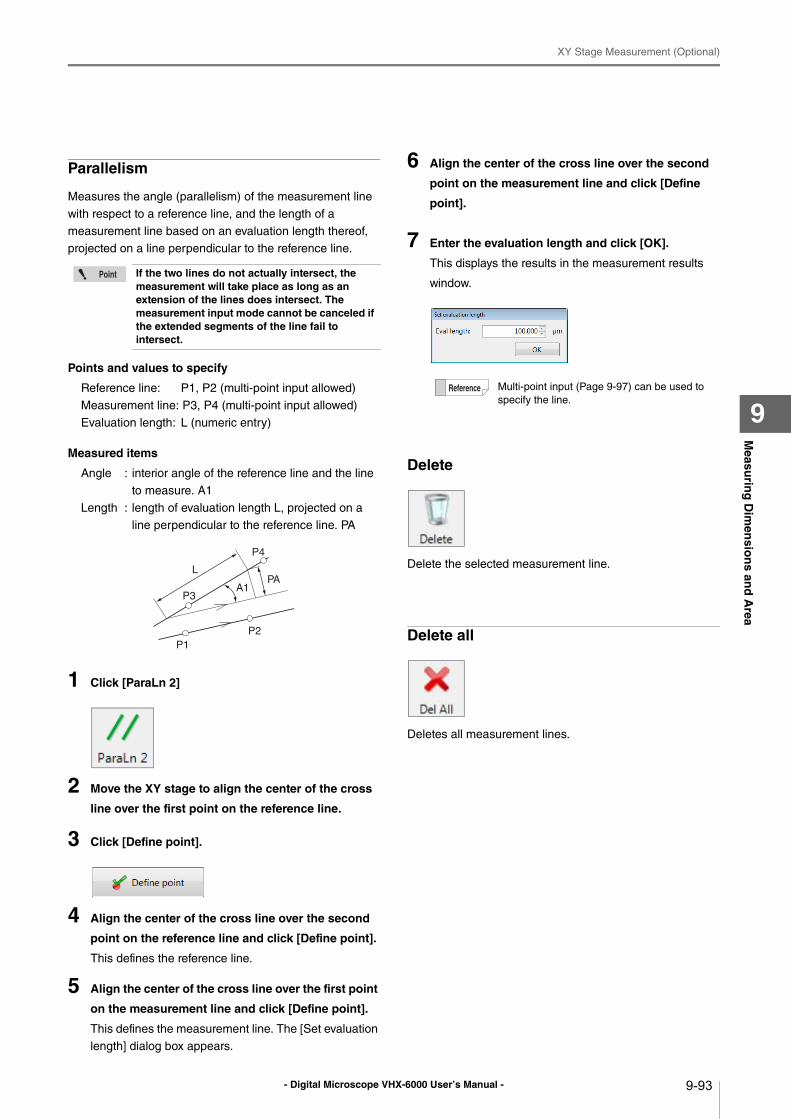
- Digital Microscope VHX-6000 User’s Manual -
XY Stage Measurement (Optional)
9-93
Measu
ring
Dim
ensio
ns an
d A
rea
9
Parallelism
Measures the angle (parallelism) of the measurement line
with respect to a reference line, and the length of a
measurement line based on an evaluation length thereof,
projected on a line perpendicular to the reference line.
Points and values to specify
Reference line: P1, P2 (multi-point input allowed)
Measurement line: P3, P4 (multi-point input allowed)
Evaluation length: L (numeric entry)
Measured items
Angle : interior angle of the reference line and the line
to measure. A1
Length : length of evaluation length L, projected on a
line perpendicular to the reference line. PA
1 Click [ParaLn 2]
2 Move the XY stage to align the center of the cross
line over the first point on the reference line.
3 Click [Define point].
4 Align the center of the cross line over the second
point on the reference line and click [Define point].
This defines the reference line.
5 Align the center of the cross line over the first point
on the measurement line and click [Define point].
This defines the measurement line. The [Set evaluation
length] dialog box appears.
6 Align the center of the cross line over the second
point on the measurement line and click [Define
point].
7 Enter the evaluation length and click [OK].
This displays the results in the measurement results
window.
Delete
Delete the selected measurement line.
Delete all
Deletes all measurement lines.
If the two lines do not actually intersect, the measurement will take place as long as an extension of the lines does intersect. The measurement input mode cannot be canceled if the extended segments of the line fail to intersect.
P1
P2
P3
L
P4
PAA1
Multi-point input (Page 9-97) can be used to
specify the line.
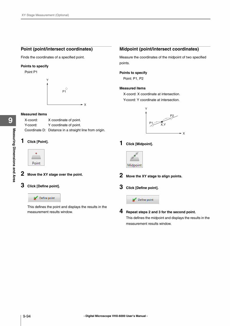
- Digital Microscope VHX-6000 User’s Manual -
XY Stage Measurement (Optional)
9-94
Measu
ring
Dim
ensio
ns an
d A
rea
9
Point (point/intersect coordinates)
Finds the coordinates of a specified point.
Points to specify
Point P1
Measured items
X-coord: X coordinate of point.
Y-coord: Y coordinate of point.
Coordinate D: Distance in a straight line from origin.
1 Click [Point].
2 Move the XY stage over the point.
3 Click [Define point].
This defines the point and displays the results in the
measurement results window.
Midpoint (point/intersect coordinates)
Measure the coordinates of the midpoint of two specified
points.
Points to specify
Point: P1, P2
Measured items
X-coord: X coordinate at intersection.
Y-coord: Y coordinate at intersection.
1 Click [Midpoint].
2 Move the XY stage to align points.
3 Click [Define point].
4 Repeat steps 2 and 3 for the second point.
This defines the midpoint and displays the results in the
measurement results window.
Y
X
P1
Y
X
P1
P2
X,Y
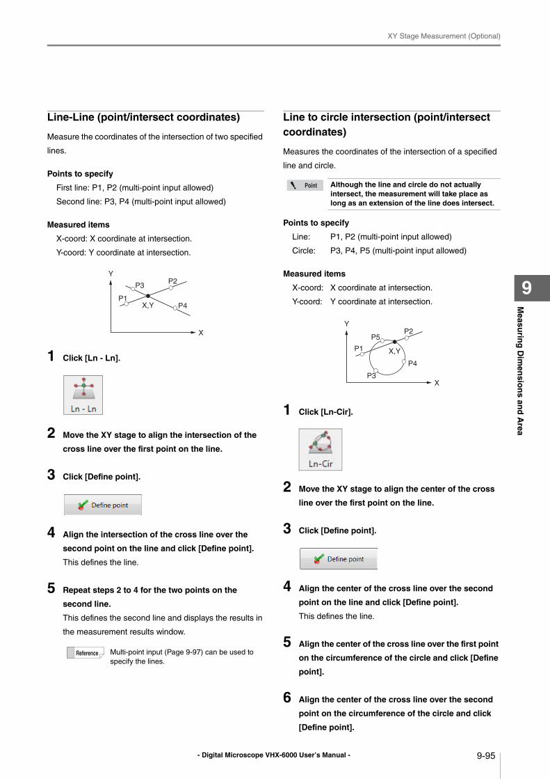
- Digital Microscope VHX-6000 User’s Manual -
XY Stage Measurement (Optional)
9-95
Measu
ring
Dim
ensio
ns an
d A
rea
9
Line-Line (point/intersect coordinates)
Measure the coordinates of the intersection of two specified
lines.
Points to specify
First line: P1, P2 (multi-point input allowed)
Second line: P3, P4 (multi-point input allowed)
Measured items
X-coord: X coordinate at intersection.
Y-coord: Y coordinate at intersection.
1 Click [Ln - Ln].
2 Move the XY stage to align the intersection of the
cross line over the first point on the line.
3 Click [Define point].
4 Align the intersection of the cross line over the
second point on the line and click [Define point].
This defines the line.
5 Repeat steps 2 to 4 for the two points on the
second line.
This defines the second line and displays the results in
the measurement results window.
Line to circle intersection (point/intersect coordinates)
Measures the coordinates of the intersection of a specified
line and circle.
Points to specify
Line: P1, P2 (multi-point input allowed)
Circle: P3, P4, P5 (multi-point input allowed)
Measured items
X-coord: X coordinate at intersection.
Y-coord: Y coordinate at intersection.
1 Click [Ln-Cir].
2 Move the XY stage to align the center of the cross
line over the first point on the line.
3 Click [Define point].
4 Align the center of the cross line over the second
point on the line and click [Define point].
This defines the line.
5 Align the center of the cross line over the first point
on the circumference of the circle and click [Define
point].
6 Align the center of the cross line over the second
point on the circumference of the circle and click
[Define point].
Multi-point input (Page 9-97) can be used to
specify the lines.
Y
X
P1
P2
P4
P3
X,Y
Although the line and circle do not actually intersect, the measurement will take place as long as an extension of the line does intersect.
Y
X
P1
P2P5
P4
P3
X,Y
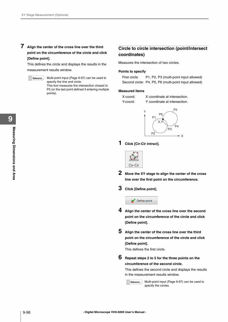
- Digital Microscope VHX-6000 User’s Manual -
XY Stage Measurement (Optional)
9-96
Measu
ring
Dim
ensio
ns an
d A
rea
9
7 Align the center of the cross line over the third
point on the circumference of the circle and click
[Define point].
This defines the circle and displays the results in the
measurement results window.
Circle to circle intersection (point/intersect coordinates)
Measures the intersection of two circles.
Points to specify
First circle: P1, P2, P3 (multi-point input allowed)
Second circle: P4, P5, P6 (multi-point input allowed)
Measured items
X-coord: X coordinate at intersection.
Y-coord: Y coordinate at intersection.
1 Click [Cir-Cir intrsct].
2 Move the XY stage to align the center of the cross
line over the first point on the circumference.
3 Click [Define point].
4 Align the center of the cross line over the second
point on the circumference of the circle and click
[Define point].
5 Align the center of the cross line over the third
point on the circumference of the circle and click
[Define point].
This defines the first circle.
6 Repeat steps 2 to 5 for the three points on the
circumference of the second circle.
This defines the second circle and displays the results
in the measurement results window.
Multi-point input (Page 9-97) can be used to
specify the line and circle.
This tool measures the intersection closest to
P5 (or the last point defined if entering multiple
points).
Multi-point input (Page 9-97) can be used to
specify the circles.
Y
X
P1
P2
P5
P4P3
X,Y
P6
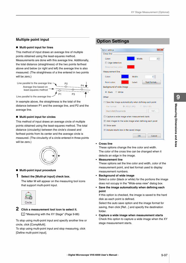
- Digital Microscope VHX-6000 User’s Manual -
XY Stage Measurement (Optional)
9-97
Measu
ring
Dim
ensio
ns an
d A
rea
9
Multiple point input
Multi-point input for lines
This method of input draws an average line of multiple
points obtained using the least-squares method.
Measurements are done with this average line. Additionally,
the total distance (straightness) of the two points farthest
above and below (or right and left) the average line is also
measured. (The straightness of a line entered in two points
will be zero.)
In example above, the straightness is the total of the
distance between P1 and the average line, and P2 and the
average line.
Multi-point input for circles
This method of input draws an average circle of multiple
points obtained using the least-squares method. The total
distance (circularity) between the circle's closest and
farthest points from its center and the average circle is
measured. (The circularity of a circle entered in three points
will be zero.)
Multi-point input procedure
1 Select the [Multi-pt input] check box.
The letter M will appear on the measuring tool icons
that support multi-point input.
2 Click a measurement tool icon to select it.
"Measuring with the XY Stage" (Page 9-86)
To stop using multi-point input and specify another line or
circle, click [CompMulti].
To stop using multi-point input and stop measuring, click
[Define multi-point input].
• Cross lineThese options change the line color and width.
The color of the cross line can be changed when it
detects an edge in the image.
• Measurement lineThese options set the line color and width, color of the
measurement point, and text format used to display
measurement numbers.
• Background of wide imageSelect a color (black or white) for the portions the image
does not occupy in the "Wide-area view" dialog box.
• Save the image automatically when defining each pointIf this option is checked, the image is saved to the hard
disk as each point is defined.
Select the auto save option and the image format for
saving, then click [Ref...] and specify the destination
folder.
• Capture a wide image when measurement startsCheck this option to capture a wide image when the XY
stage measurement starts.
P1
P2P4
P3
Line parallel to the average line
Average line based on
least-squares method
Line parallel to the average line
Option Settings
- Digital Microscope VHX-6000 User’s Manual -
XY Stage Measurement (Optional)
9-98
Measu
ring
Dim
ensio
ns an
d A
rea
9
• Add images to the wide image when defining each pointThis option links the current live observation image to the
image in the "Wide-area view" dialog box as each point is
defined.
• Show axesThis option displays the XY axes in the "Wide-area view"
dialog box. The intersection of the X and Y axes indicates
the origin.
• Include measurement results dialog when saving the imageThis option saves an image of the currently displayed
measurement results dialog with the observation image.
- Digital Microscope VHX-6000 User’s Manual - 10-1
Chapter10O
bservin
g in
3D
10
Observing in 3D
Depth Composition and 3D View
When observing tall or embedded objects, it may not be
possible to focus on the entire object. Depth composition
displays an image of the entire object in focus by
composing images of the object recorded at different
distances. This allows you to observe the image in 3D from
different angles.
Types and Features of Depth Composition ..........Page 10-2
Live Depth Composition ...................................Page 10-2
Quick Composition and 3D ..............................Page 10-2
Fine Depth Composition...................................Page 10-2
Manual 3D composition ...................................Page 10-2
Using Depth Composition ....................................Page 10-3
Live Depth Composition ...................................Page 10-3
Quick Composition and 3D ..............................Page 10-4
Fine Depth Composition...................................Page 10-9
Manual 3D composition ................................. Page 10-14
3D View.............................................................. Page 10-15
Playing Back and Saving 3D Images ............. Page 10-15
Manipulating the 3D View .............................. Page 10-16
Using Height/Fix Z/Rotation Guide in 3D View
................................................................... Page 10-17
Display Settings ............................................. Page 10-17
Show Crop/Detail ........................................... Page 10-18
Shape correction............................................ Page 10-19
3D File Comparison View...................................Page 10-21
Displaying 2 Files to Compare .......................Page 10-21
Linking the 2nd Image....................................Page 10-21
Differential View .............................................Page 10-22
Switching Sub Images....................................Page 10-23
Lighting Simulations...........................................Page 10-24
Point height (optional) ........................................Page 10-25
Measuring height and distance easily ............Page 10-25
Measuring heights of specified points ............Page 10-25
Other measurement tools...............................Page 10-26
Display Settings .............................................Page 10-26
3D Profile Measurements (Optional) ..................Page 10-27
Names and Functions in the Window.............Page 10-27
Starting Profile Measurements .......................Page 10-29
Setting Profile Line .........................................Page 10-30
Setting Measurement Intervals ......................Page 10-35
2 line comparison...........................................Page 10-40
Roughness Measurement(optional) ...................Page 10-42
Line roughness measurement........................Page 10-42
What is Surface Roughness...........................Page 10-45
Surface texture parameter definitions.............Page 10-47
Surface roughness measurement ..................Page 10-50
Surface Roughness Definitions......................Page 10-52
Volume Measurement (Option) ..........................Page 10-55
Z Stage Control ..................................................Page 10-56
Adjusting Focus from the VHX MENU ...........Page 10-56
Measuring the Height between 2 Points ........Page 10-57
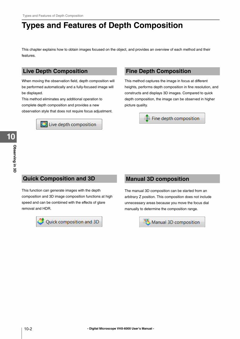
- Digital Microscope VHX-6000 User’s Manual -
Types and Features of Depth Composition
10-2
Ob
serving
in 3D
10
Types and Features of Depth Composition
This chapter explains how to obtain images focused on the object, and provides an overview of each method and their
features.
When moving the observation field, depth composition will
be performed automatically and a fully-focused image will
be displayed.
This method eliminates any additional operation to
complete depth composition and provides a new
observation style that does not require focus adjustment.
This function can generate images with the depth
composition and 3D image composition functions at high
speed and can be combined with the effects of glare
removal and HDR.
This method captures the image in focus at different
heights, performs depth composition in fine resolution, and
constructs and displays 3D images. Compared to quick
depth composition, the image can be observed in higher
picture quality.
The manual 3D composition can be started from an
arbitrary Z position. This composition does not include
unnecessary areas because you move the focus dial
manually to determine the composition range.
Live Depth Composition
Quick Composition and 3D
Fine Depth Composition
Manual 3D composition
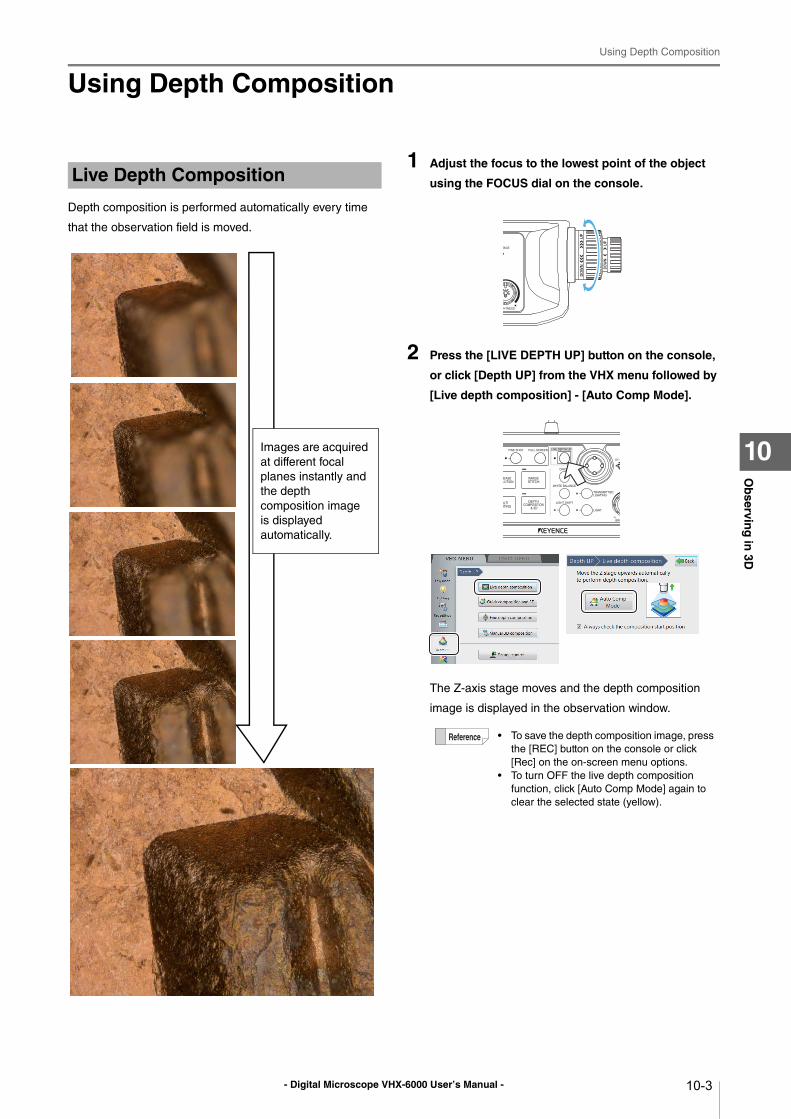
- Digital Microscope VHX-6000 User’s Manual -
Using Depth Composition
10-3
Ob
serving
in 3D
10
Using Depth Composition
Depth composition is performed automatically every time
that the observation field is moved.
1 Adjust the focus to the lowest point of the object
using the FOCUS dial on the console.
2 Press the [LIVE DEPTH UP] button on the console,
or click [Depth UP] from the VHX menu followed by
[Live depth composition] - [Auto Comp Mode].
The Z-axis stage moves and the depth composition
image is displayed in the observation window.
Live Depth Composition
Images are acquired
at different focal
planes instantly and
the depth
composition image
is displayed
automatically.
• To save the depth composition image, press
the [REC] button on the console or click
[Rec] on the on-screen menu options.
• To turn OFF the live depth composition
function, click [Auto Comp Mode] again to
clear the selected state (yellow).
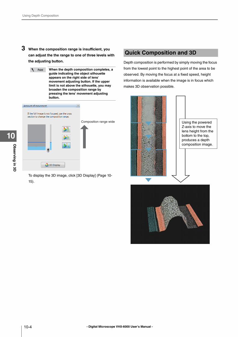
- Digital Microscope VHX-6000 User’s Manual -
Using Depth Composition
10-4
Ob
serving
in 3D
10
3 When the composition range is insufficient, you
can adjust the the range to one of three levels with
the adjusting button.
To display the 3D image, click [3D Display] (Page 10-
15).
Depth composition is performed by simply moving the focus
from the lowest point to the highest point of the area to be
observed. By moving the focus at a fixed speed, height
information is available when the image is in focus which
makes 3D observation possible.
When the depth composition completes, a guide indicating the object silhouette appears on the right side of lens' movement adjusting button. If the upper limit is not above the silhouette, you may broaden the composition range by pressing the lens' movement adjusting button.
Composition range wide
Quick Composition and 3D
Using the powered
Z-axis to move the
lens height from the
bottom to the top,
produces a depth
composition image.
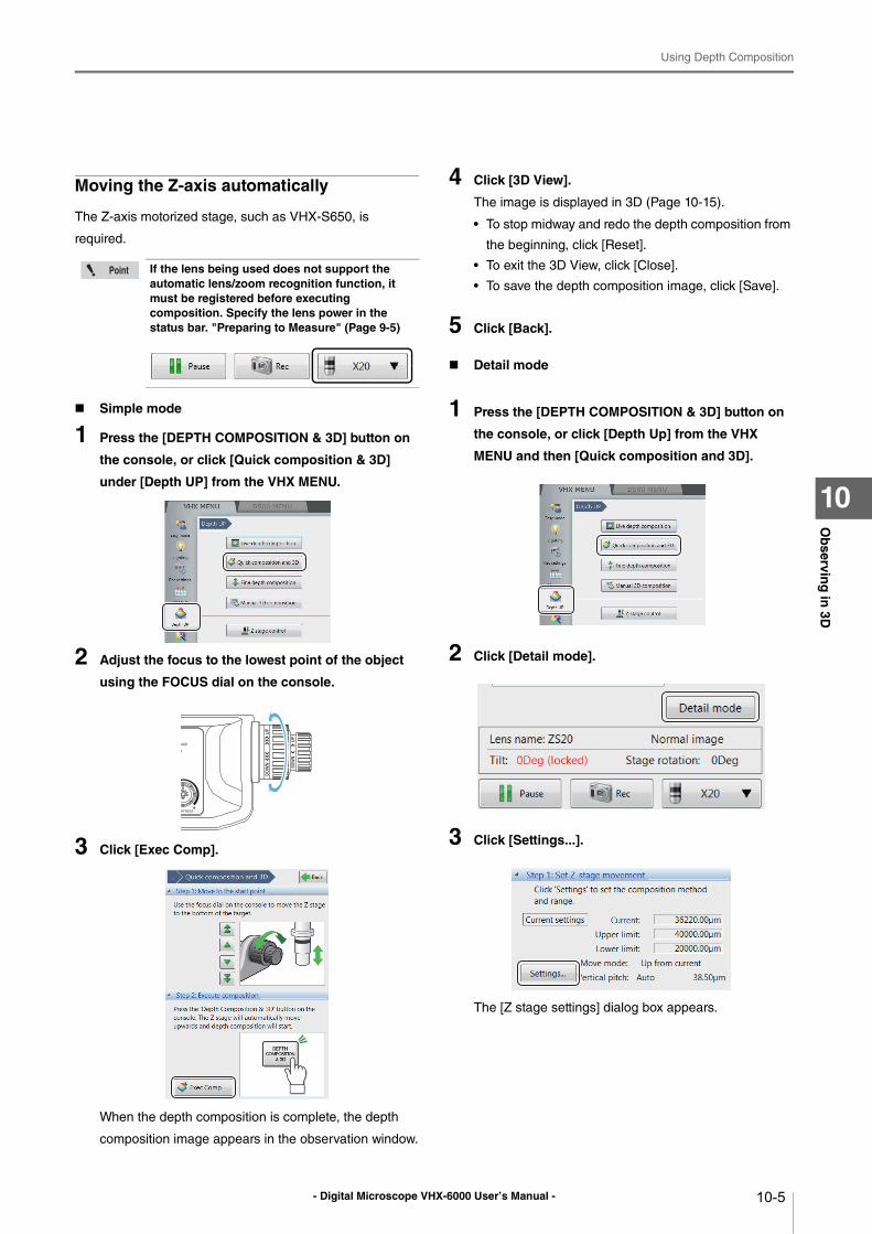
- Digital Microscope VHX-6000 User’s Manual -
Using Depth Composition
10-5
Ob
serving
in 3D
10
Moving the Z-axis automatically
The Z-axis motorized stage, such as VHX-S650, is
required.
Simple mode
1 Press the [DEPTH COMPOSITION & 3D] button on
the console, or click [Quick composition & 3D]
under [Depth UP] from the VHX MENU.
2 Adjust the focus to the lowest point of the object
using the FOCUS dial on the console.
3 Click [Exec Comp].
When the depth composition is complete, the depth
composition image appears in the observation window.
4 Click [3D View].
The image is displayed in 3D (Page 10-15).
• To stop midway and redo the depth composition from
the beginning, click [Reset].
• To exit the 3D View, click [Close].
• To save the depth composition image, click [Save].
5 Click [Back].
Detail mode
1 Press the [DEPTH COMPOSITION & 3D] button on
the console, or click [Depth Up] from the VHX
MENU and then [Quick composition and 3D].
2 Click [Detail mode].
3 Click [Settings...].
The [Z stage settings] dialog box appears.
If the lens being used does not support the automatic lens/zoom recognition function, it must be registered before executing composition. Specify the lens power in the status bar. "Preparing to Measure" (Page 9-5)
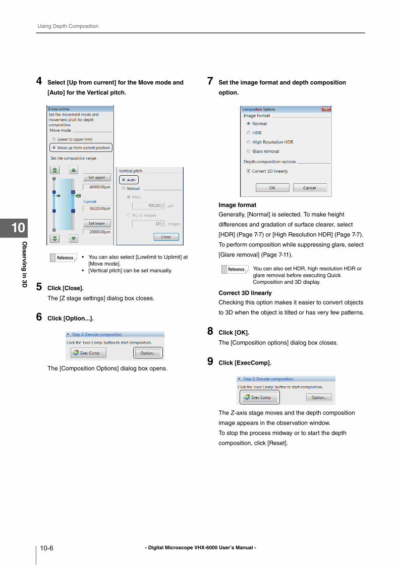
- Digital Microscope VHX-6000 User’s Manual -
Using Depth Composition
10-6
Ob
serving
in 3D
10
4 Select [Up from current] for the Move mode and
[Auto] for the Vertical pitch.
5 Click [Close].
The [Z stage settings] dialog box closes.
6 Click [Option...].
The [Composition Options] dialog box opens.
7 Set the image format and depth composition
option.
Image format
Generally, [Normal] is selected. To make height
differences and gradation of surface clearer, select
[HDR] (Page 7-7) or [High Resolution HDR] (Page 7-7).
To perform composition while suppressing glare, select
[Glare removal] (Page 7-11).
Correct 3D linearly
Checking this option makes it easier to convert objects
to 3D when the object is tilted or has very few patterns.
8 Click [OK].
The [Composition options] dialog box closes.
9 Click [ExecComp].
The Z-axis stage moves and the depth composition
image appears in the observation window.
To stop the process midway or to start the depth
composition, click [Reset].
• You can also select [Lowlimit to Uplimit] at
[Move mode].
• [Vertical pitch] can be set manually. You can also set HDR, high resolution HDR or
glare removal before executing Quick
Composition and 3D display.
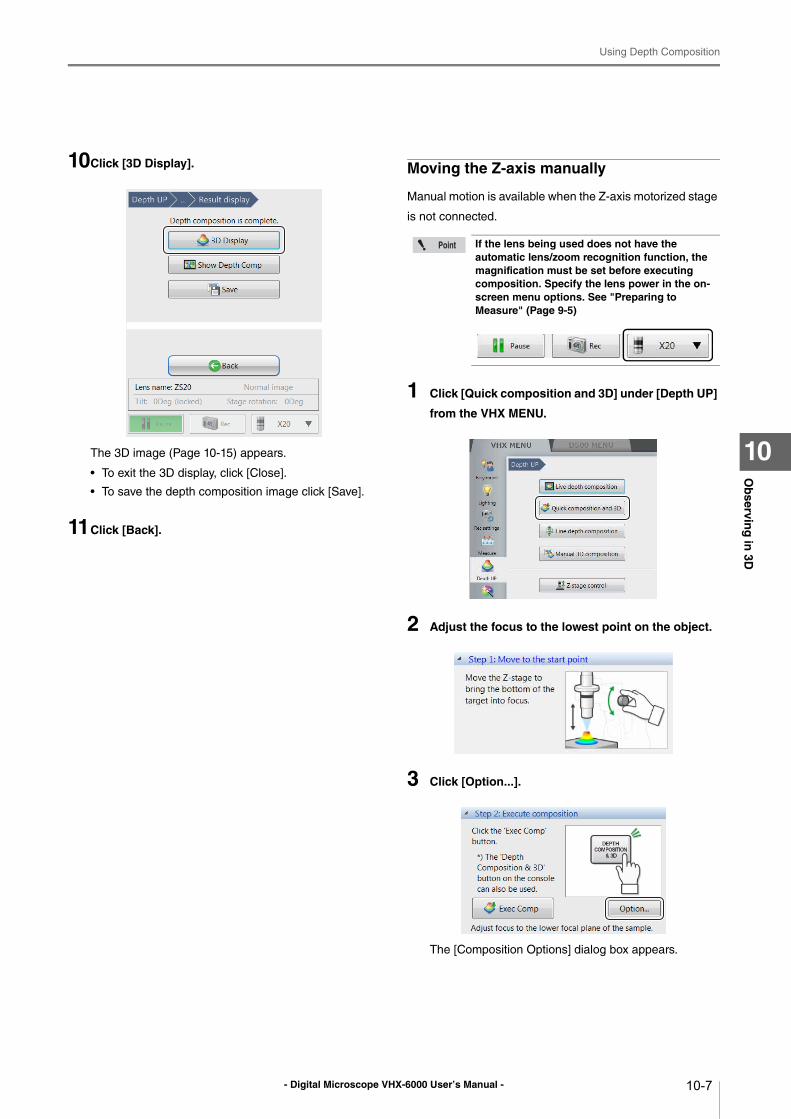
- Digital Microscope VHX-6000 User’s Manual -
Using Depth Composition
10-7
Ob
serving
in 3D
10
10Click [3D Display].
The 3D image (Page 10-15) appears.
• To exit the 3D display, click [Close].
• To save the depth composition image click [Save].
11Click [Back].
Moving the Z-axis manually
Manual motion is available when the Z-axis motorized stage
is not connected.
1 Click [Quick composition and 3D] under [Depth UP]
from the VHX MENU.
2 Adjust the focus to the lowest point on the object.
3 Click [Option...].
The [Composition Options] dialog box appears.
If the lens being used does not have the automatic lens/zoom recognition function, the magnification must be set before executing composition. Specify the lens power in the on-screen menu options. See "Preparing to Measure" (Page 9-5)
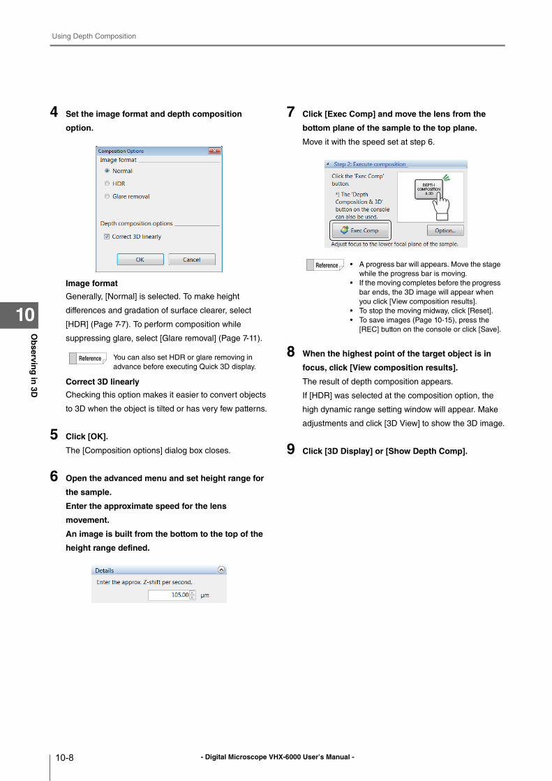
- Digital Microscope VHX-6000 User’s Manual -
Using Depth Composition
10-8
Ob
serving
in 3D
10
4 Set the image format and depth composition
option.
Image format
Generally, [Normal] is selected. To make height
differences and gradation of surface clearer, select
[HDR] (Page 7-7). To perform composition while
suppressing glare, select [Glare removal] (Page 7-11).
Correct 3D linearly
Checking this option makes it easier to convert objects
to 3D when the object is tilted or has very few patterns.
5 Click [OK].
The [Composition options] dialog box closes.
6 Open the advanced menu and set height range for
the sample.
Enter the approximate speed for the lens
movement.
An image is built from the bottom to the top of the
height range defined.
7 Click [Exec Comp] and move the lens from the
bottom plane of the sample to the top plane.
Move it with the speed set at step 6.
8 When the highest point of the target object is in
focus, click [View composition results].
The result of depth composition appears.
If [HDR] was selected at the composition option, the
high dynamic range setting window will appear. Make
adjustments and click [3D View] to show the 3D image.
9 Click [3D Display] or [Show Depth Comp].
You can also set HDR or glare removing in
advance before executing Quick 3D display.
• A progress bar will appears. Move the stage
while the progress bar is moving.
• If the moving completes before the progress
bar ends, the 3D image will appear when
you click [View composition results].
• To stop the moving midway, click [Reset].
• To save images (Page 10-15), press the
[REC] button on the console or click [Save].
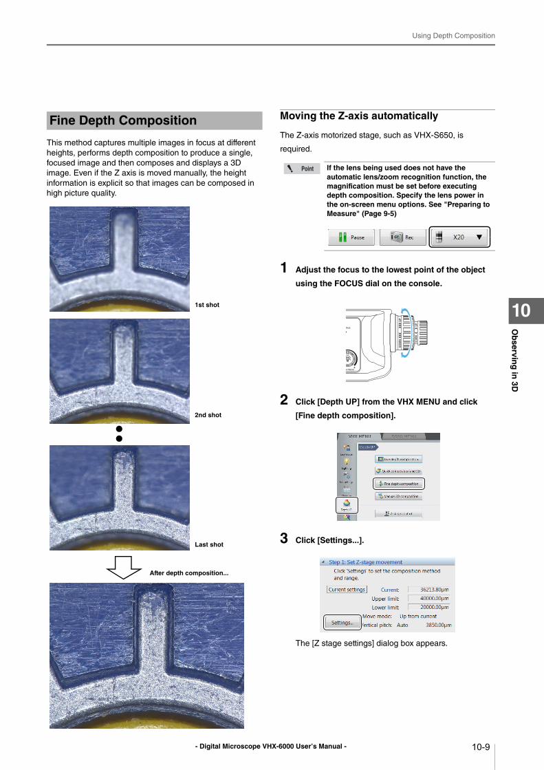
- Digital Microscope VHX-6000 User’s Manual -
Using Depth Composition
10-9
Ob
serving
in 3D
10
This method captures multiple images in focus at different
heights, performs depth composition to produce a single,
focused image and then composes and displays a 3D
image. Even if the Z axis is moved manually, the height
information is explicit so that images can be composed in
high picture quality.
Moving the Z-axis automatically
The Z-axis motorized stage, such as VHX-S650, is
required.
1 Adjust the focus to the lowest point of the object
using the FOCUS dial on the console.
2 Click [Depth UP] from the VHX MENU and click
[Fine depth composition].
3 Click [Settings...].
The [Z stage settings] dialog box appears.
Fine Depth Composition
1st shot
2nd shot
Last shot
After depth composition...
If the lens being used does not have the automatic lens/zoom recognition function, the magnification must be set before executing depth composition. Specify the lens power in the on-screen menu options. See "Preparing to Measure" (Page 9-5)
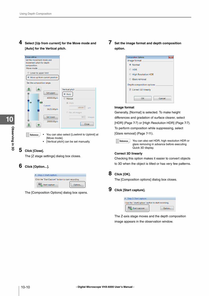
- Digital Microscope VHX-6000 User’s Manual -
Using Depth Composition
10-10
Ob
serving
in 3D
10
4 Select [Up from current] for the Move mode and
[Auto] for the Vertical pitch.
5 Click [Close].
The [Z stage settings] dialog box closes.
6 Click [Option...].
The [Composition Options] dialog box opens.
7 Set the image format and depth composition
option.
Image format
Generally, [Normal] is selected. To make height
differences and gradation of surface clearer, select
[HDR] (Page 7-7) or [High Resolution HDR] (Page 7-7).
To perform composition while suppressing, select
[Glare removal] (Page 7-11).
Correct 3D linearly
Checking this option makes it easier to convert objects
to 3D when the object is tilted or has very few patterns.
8 Click [OK].
The [Composition options] dialog box closes.
9 Click [Start capture].
The Z-axis stage moves and the depth composition
image appears in the observation window.
• You can also select [Lowlimit to Uplimit] at
[Move mode].
• [Vertical pitch] can be set manually. You can also set HDR, high resolution HDR or
glare removing in advance before executing
Quick 3D display.
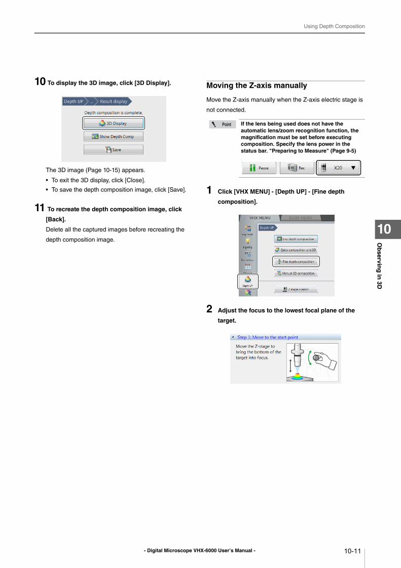
- Digital Microscope VHX-6000 User’s Manual -
Using Depth Composition
10-11
Ob
serving
in 3D
10
10 To display the 3D image, click [3D Display].
The 3D image (Page 10-15) appears.
• To exit the 3D display, click [Close].
• To save the depth composition image, click [Save].
11 To recreate the depth composition image, click
[Back].
Delete all the captured images before recreating the
depth composition image.
Moving the Z-axis manually
Move the Z-axis manually when the Z-axis electric stage is
not connected.
1 Click [VHX MENU] - [Depth UP] - [Fine depth
composition].
2 Adjust the focus to the lowest focal plane of the
target.
If the lens being used does not have the automatic lens/zoom recognition function, the magnification must be set before executing composition. Specify the lens power in the status bar. "Preparing to Measure" (Page 9-5)
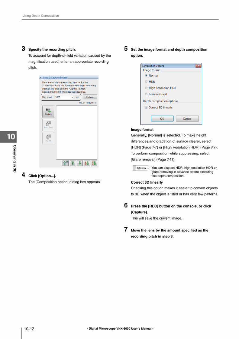
- Digital Microscope VHX-6000 User’s Manual -
Using Depth Composition
10-12
Ob
serving
in 3D
10
3 Specify the recording pitch.
To account for depth-of-field variation caused by the
magnification used, enter an appropriate recording
pitch.
4 Click [Option...].
The [Composition option] dialog box appears.
5 Set the image format and depth composition
option.
Image format
Generally, [Normal] is selected. To make height
differences and gradation of surface clearer, select
[HDR] (Page 7-7) or [High Resolution HDR] (Page 7-7).
To perform composition while suppressing, select
[Glare removal] (Page 7-11).
Correct 3D linearly
Checking this option makes it easier to convert objects
to 3D when the object is tilted or has very few patterns.
6 Press the [REC] button on the console, or click
[Capture].
This will save the current image.
7 Move the lens by the amount specified as the
recording pitch in step 3.
You can also set HDR, high resolution HDR or
glare removing in advance before executing
fine depth composition.
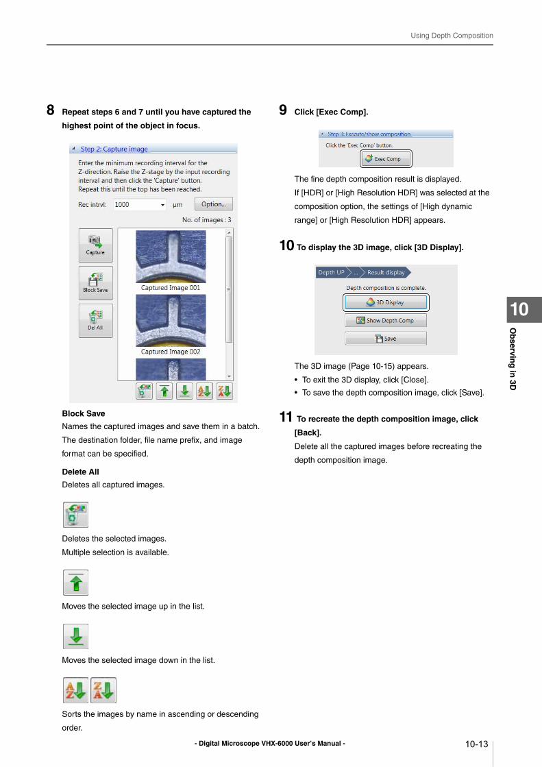
- Digital Microscope VHX-6000 User’s Manual -
Using Depth Composition
10-13
Ob
serving
in 3D
10
8 Repeat steps 6 and 7 until you have captured the
highest point of the object in focus.
Block Save
Names the captured images and save them in a batch.
The destination folder, file name prefix, and image
format can be specified.
Delete All
Deletes all captured images.
Deletes the selected images.
Multiple selection is available.
Moves the selected image up in the list.
Moves the selected image down in the list.
Sorts the images by name in ascending or descending
order.
9 Click [Exec Comp].
The fine depth composition result is displayed.
If [HDR] or [High Resolution HDR] was selected at the
composition option, the settings of [High dynamic
range] or [High Resolution HDR] appears.
10 To display the 3D image, click [3D Display].
The 3D image (Page 10-15) appears.
• To exit the 3D display, click [Close].
• To save the depth composition image, click [Save].
11 To recreate the depth composition image, click
[Back].
Delete all the captured images before recreating the
depth composition image.
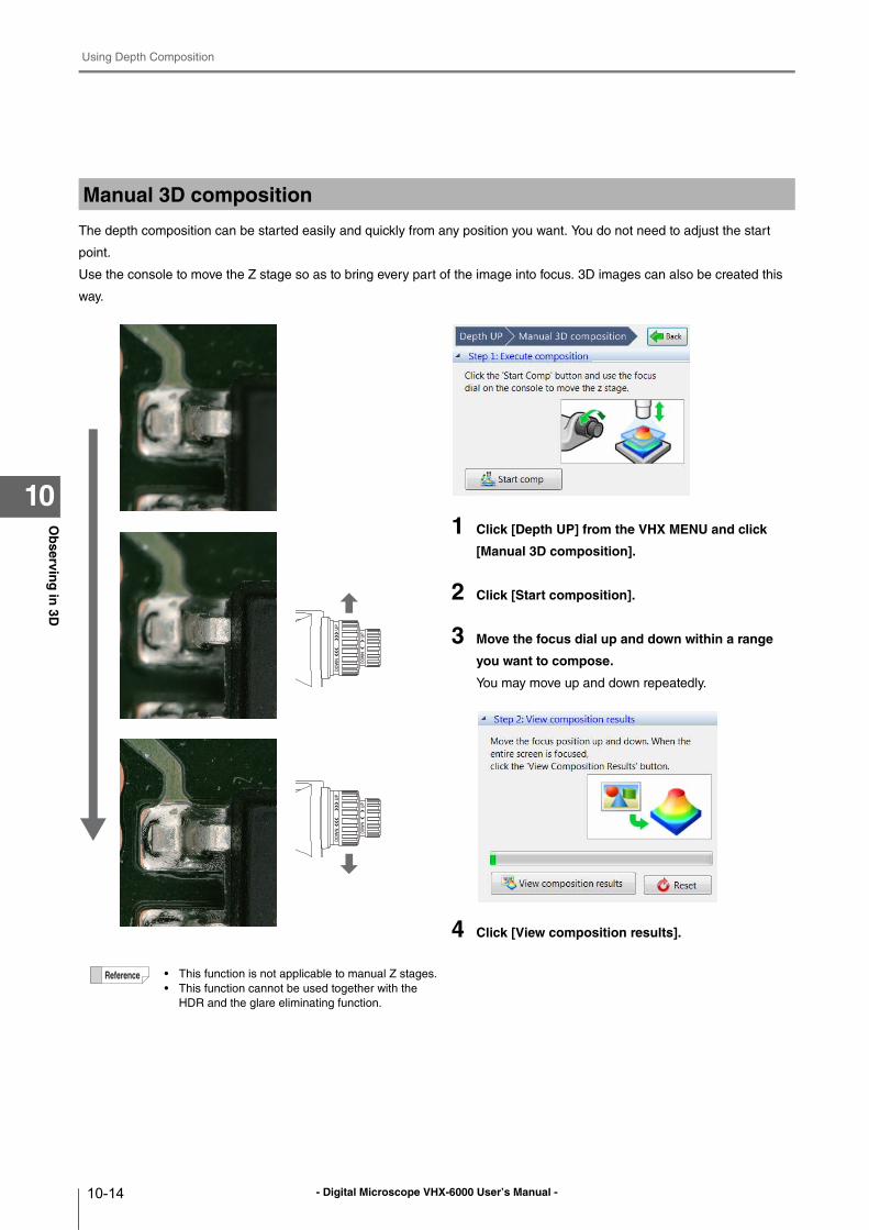
- Digital Microscope VHX-6000 User’s Manual -
Using Depth Composition
10-14
Ob
serving
in 3D
10
The depth composition can be started easily and quickly from any position you want. You do not need to adjust the start
point.
Use the console to move the Z stage so as to bring every part of the image into focus. 3D images can also be created this
way.
1 Click [Depth UP] from the VHX MENU and click
[Manual 3D composition].
2 Click [Start composition].
3 Move the focus dial up and down within a range
you want to compose.
You may move up and down repeatedly.
4 Click [View composition results].
Manual 3D composition
• This function is not applicable to manual Z stages.
• This function cannot be used together with the
HDR and the glare eliminating function.
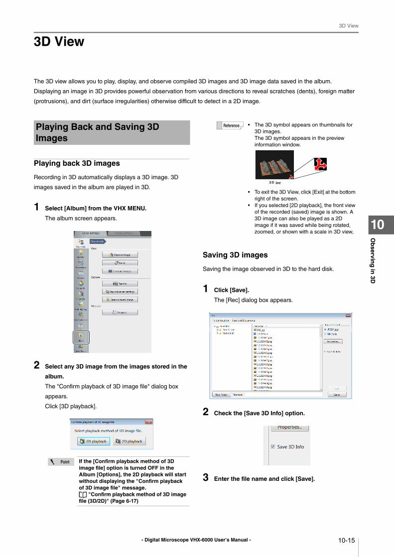
- Digital Microscope VHX-6000 User’s Manual -
3D View
10-15
Ob
serving
in 3D
10
3D View
The 3D view allows you to play, display, and observe compiled 3D images and 3D image data saved in the album.
Displaying an image in 3D provides powerful observation from various directions to reveal scratches (dents), foreign matter
(protrusions), and dirt (surface irregularities) otherwise difficult to detect in a 2D image.
Playing back 3D images
Recording in 3D automatically displays a 3D image. 3D
images saved in the album are played in 3D.
1 Select [Album] from the VHX MENU.
The album screen appears.
2 Select any 3D image from the images stored in the
album.
The "Confirm playback of 3D image file" dialog box
appears.
Click [3D playback].
Saving 3D images
Saving the image observed in 3D to the hard disk.
1 Click [Save].
The [Rec] dialog box appears.
2 Check the [Save 3D Info] option.
3 Enter the file name and click [Save].
Playing Back and Saving 3D Images
If the [Confirm playback method of 3D image file] option is turned OFF in the Album [Options], the 2D playback will start without displaying the "Confirm playback of 3D image file" message.
"Confirm playback method of 3D image file (3D/2D)" (Page 6-17)
• The 3D symbol appears on thumbnails for
3D images.
The 3D symbol appears in the preview
information window.
• To exit the 3D View, click [Exit] at the bottom
right of the screen.
• If you selected [2D playback], the front view
of the recorded (saved) image is shown. A
3D image can also be played as a 2D
image if it was saved while being rotated,
zoomed, or shown with a scale in 3D view,
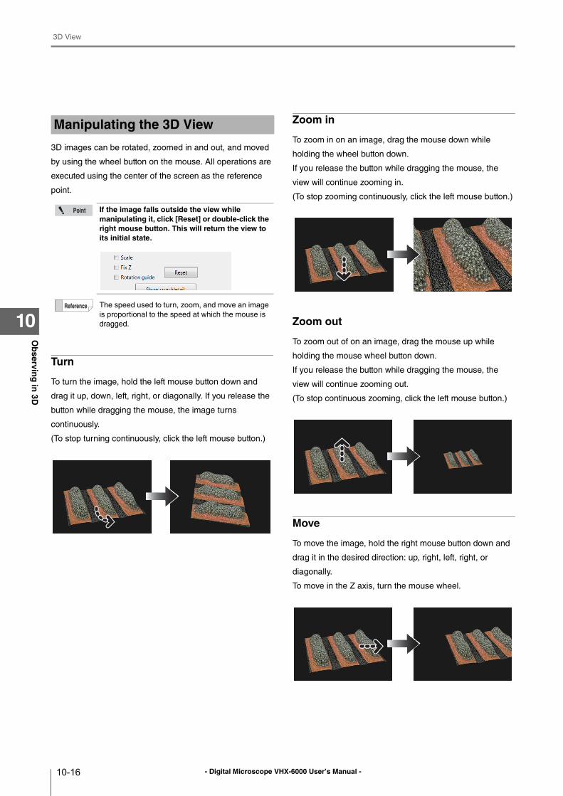
- Digital Microscope VHX-6000 User’s Manual -
3D View
10-16
Ob
serving
in 3D
10
3D images can be rotated, zoomed in and out, and moved
by using the wheel button on the mouse. All operations are
executed using the center of the screen as the reference
point.
Turn
To turn the image, hold the left mouse button down and
drag it up, down, left, right, or diagonally. If you release the
button while dragging the mouse, the image turns
continuously.
(To stop turning continuously, click the left mouse button.)
Zoom in
To zoom in on an image, drag the mouse down while
holding the wheel button down.
If you release the button while dragging the mouse, the
view will continue zooming in.
(To stop zooming continuously, click the left mouse button.)
Zoom out
To zoom out of on an image, drag the mouse up while
holding the mouse wheel button down.
If you release the button while dragging the mouse, the
view will continue zooming out.
(To stop continuous zooming, click the left mouse button.)
Move
To move the image, hold the right mouse button down and
drag it in the desired direction: up, right, left, right, or
diagonally.
To move in the Z axis, turn the mouse wheel.
Manipulating the 3D View
If the image falls outside the view while manipulating it, click [Reset] or double-click the right mouse button. This will return the view to its initial state.
The speed used to turn, zoom, and move an image
is proportional to the speed at which the mouse is
dragged.
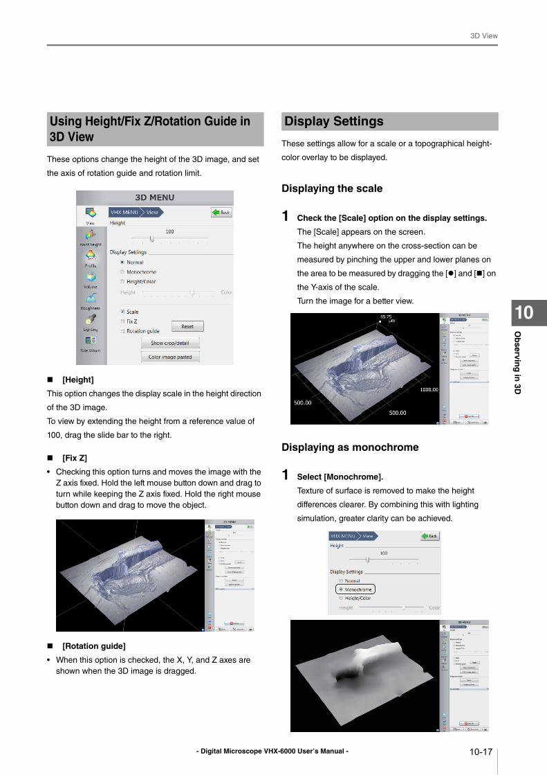
- Digital Microscope VHX-6000 User’s Manual -
3D View
10-17
Ob
serving
in 3D
10
These options change the height of the 3D image, and set
the axis of rotation guide and rotation limit.
[Height]
This option changes the display scale in the height direction
of the 3D image.
To view by extending the height from a reference value of
100, drag the slide bar to the right.
[Fix Z]
• Checking this option turns and moves the image with the
Z axis fixed. Hold the left mouse button down and drag to
turn while keeping the Z axis fixed. Hold the right mouse
button down and drag to move the object.
[Rotation guide]
• When this option is checked, the X, Y, and Z axes are
shown when the 3D image is dragged.
These settings allow for a scale or a topographical height-
color overlay to be displayed.
Displaying the scale
1 Check the [Scale] option on the display settings.
The [Scale] appears on the screen.
The height anywhere on the cross-section can be
measured by pinching the upper and lower planes on
the area to be measured by dragging the [] and [] on
the Y-axis of the scale.
Turn the image for a better view.
Displaying as monochrome
1 Select [Monochrome].
Texture of surface is removed to make the height
differences clearer. By combining this with lighting
simulation, greater clarity can be achieved.
Using Height/Fix Z/Rotation Guide in 3D View
Display Settings
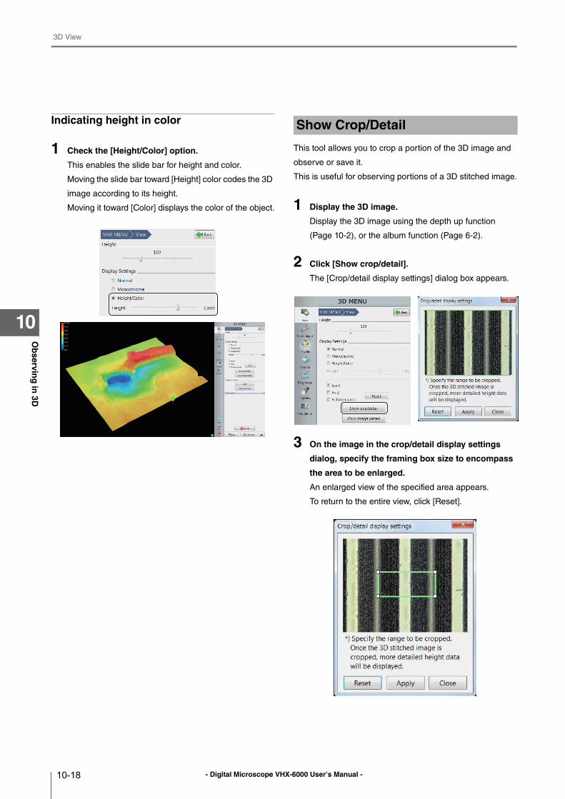
- Digital Microscope VHX-6000 User’s Manual -
3D View
10-18
Ob
serving
in 3D
10
Indicating height in color
1 Check the [Height/Color] option.
This enables the slide bar for height and color.
Moving the slide bar toward [Height] color codes the 3D
image according to its height.
Moving it toward [Color] displays the color of the object.
This tool allows you to crop a portion of the 3D image and
observe or save it.
This is useful for observing portions of a 3D stitched image.
1 Display the 3D image.
Display the 3D image using the depth up function
(Page 10-2), or the album function (Page 6-2).
2 Click [Show crop/detail].
The [Crop/detail display settings] dialog box appears.
3 On the image in the crop/detail display settings
dialog, specify the framing box size to encompass
the area to be enlarged.
An enlarged view of the specified area appears.
To return to the entire view, click [Reset].
Show Crop/Detail
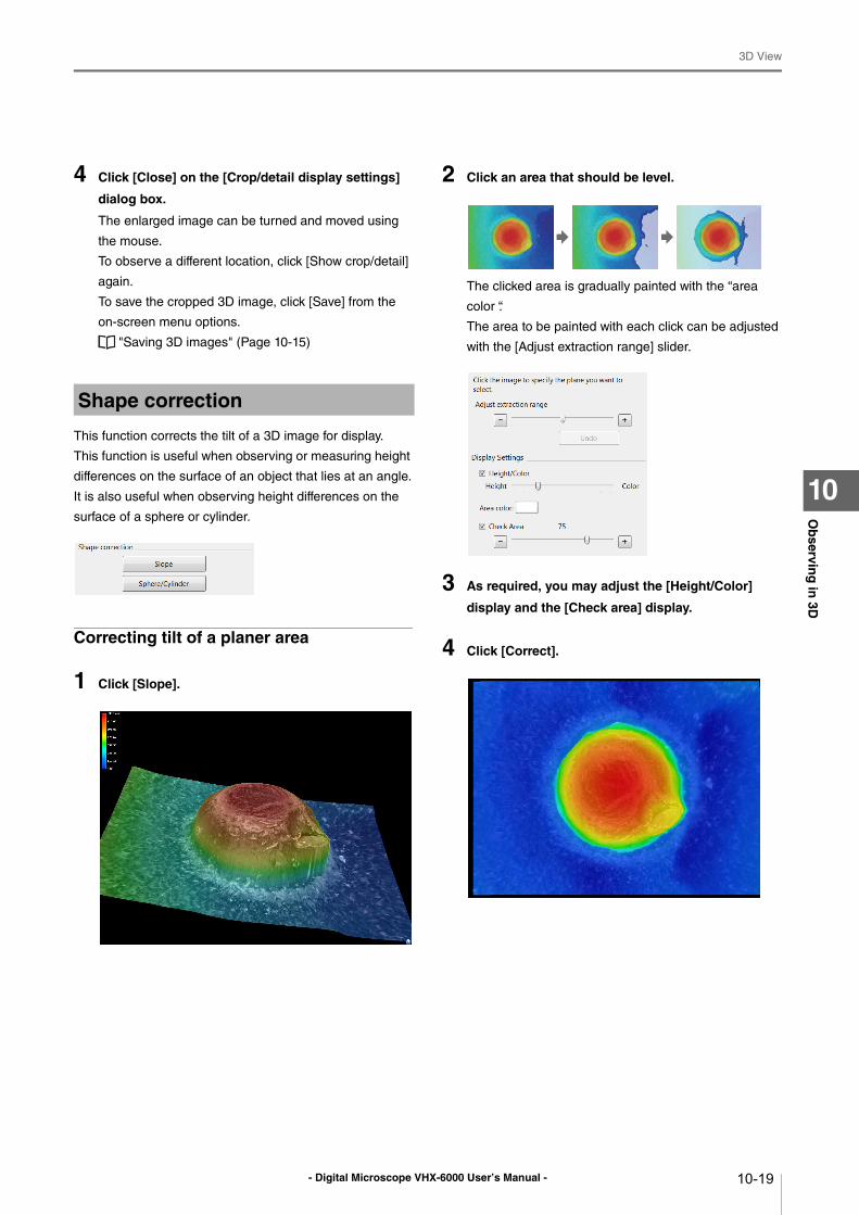
- Digital Microscope VHX-6000 User’s Manual -
3D View
10-19
Ob
serving
in 3D
10
4 Click [Close] on the [Crop/detail display settings]
dialog box.
The enlarged image can be turned and moved using
the mouse.
To observe a different location, click [Show crop/detail]
again.
To save the cropped 3D image, click [Save] from the
on-screen menu options.
"Saving 3D images" (Page 10-15)
This function corrects the tilt of a 3D image for display.
This function is useful when observing or measuring height
differences on the surface of an object that lies at an angle.
It is also useful when observing height differences on the
surface of a sphere or cylinder.
Correcting tilt of a planer area
1 Click [Slope].
2 Click an area that should be level.
The clicked area is gradually painted with the “area
color “.
The area to be painted with each click can be adjusted
with the [Adjust extraction range] slider.
3 As required, you may adjust the [Height/Color]
display and the [Check area] display.
4 Click [Correct].
Shape correction
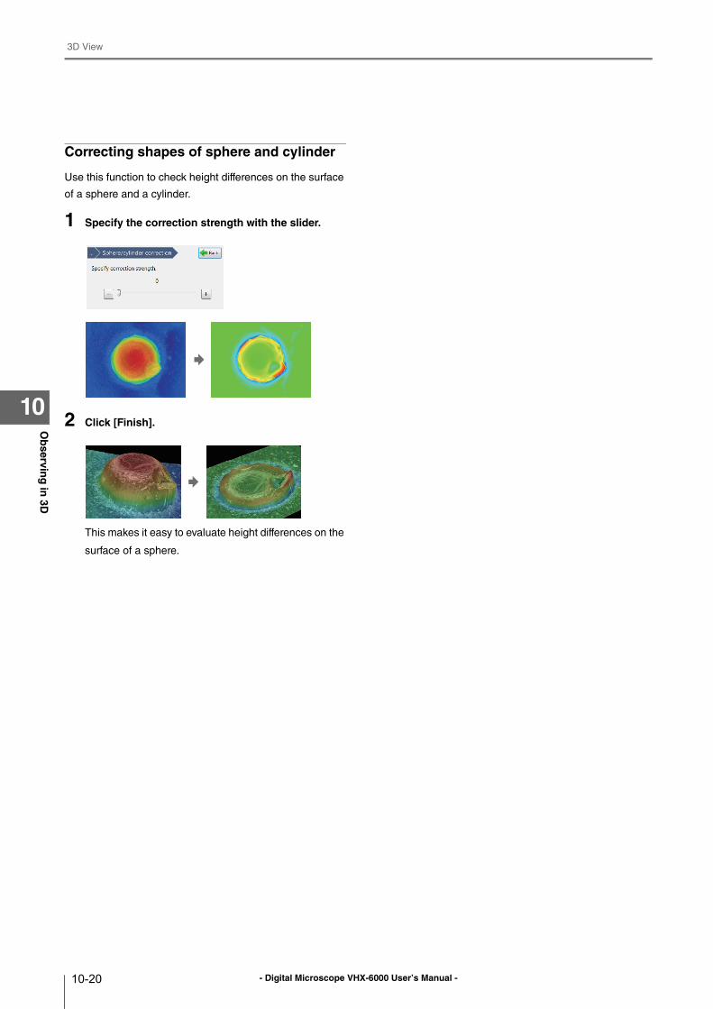
- Digital Microscope VHX-6000 User’s Manual -
3D View
10-20
Ob
serving
in 3D
10
Correcting shapes of sphere and cylinder
Use this function to check height differences on the surface
of a sphere and a cylinder.
1 Specify the correction strength with the slider.
2 Click [Finish].
This makes it easy to evaluate height differences on the
surface of a sphere.
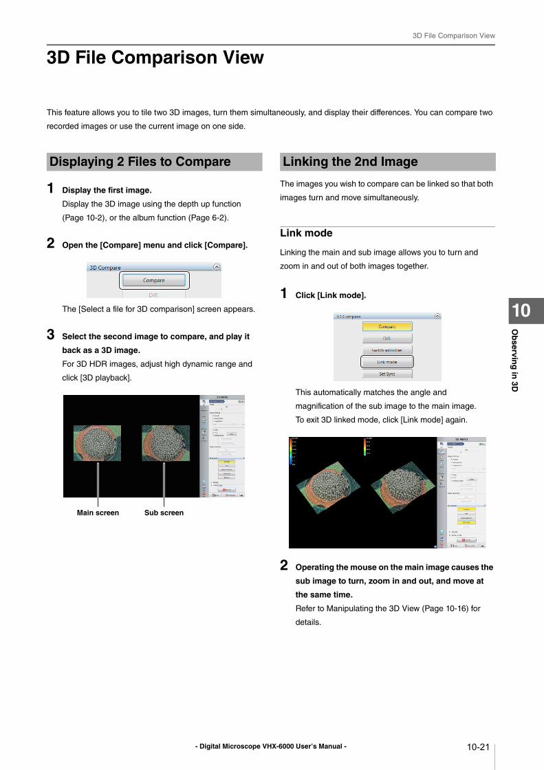
- Digital Microscope VHX-6000 User’s Manual -
3D File Comparison View
10-21
Ob
serving
in 3D
10
3D File Comparison View
This feature allows you to tile two 3D images, turn them simultaneously, and display their differences. You can compare two
recorded images or use the current image on one side.
1 Display the first image.
Display the 3D image using the depth up function
(Page 10-2), or the album function (Page 6-2).
2 Open the [Compare] menu and click [Compare].
The [Select a file for 3D comparison] screen appears.
3 Select the second image to compare, and play it
back as a 3D image.
For 3D HDR images, adjust high dynamic range and
click [3D playback].
The images you wish to compare can be linked so that both
images turn and move simultaneously.
Link mode
Linking the main and sub image allows you to turn and
zoom in and out of both images together.
1 Click [Link mode].
This automatically matches the angle and
magnification of the sub image to the main image.
To exit 3D linked mode, click [Link mode] again.
2 Operating the mouse on the main image causes the
sub image to turn, zoom in and out, and move at
the same time.
Refer to Manipulating the 3D View (Page 10-16) for
details.
Displaying 2 Files to Compare
Main screen Sub screen
Linking the 2nd Image
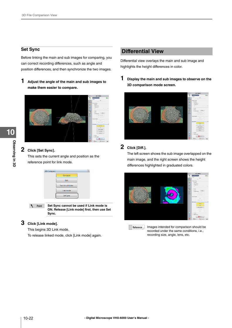
- Digital Microscope VHX-6000 User’s Manual -
3D File Comparison View
10-22
Ob
serving
in 3D
10
Set Sync
Before linking the main and sub images for comparing, you
can correct recording differences, such as angle and
position differences, and then synchronize the two images.
1 Adjust the angle of the main and sub images to
make them easier to compare.
2 Click [Set Sync].
This sets the current angle and position as the
reference point for link mode.
3 Click [Link mode].
This begins 3D Link mode.
To release linked mode, click [Link mode] again.
Differential view overlays the main and sub image and
highlights the height differences in color.
1 Display the main and sub images to observe on the
3D comparison mode screen.
2 Click [Diff.].
The left screen shows the sub image overlapped on the
main image, and the right screen shows the height
differences highlighted in graduated colors.
Set Sync cannot be used if Link mode is ON. Release [Link mode] first, then use Set Sync.
Differential View
Images intended for comparison should be
recorded under the same conditions, i.e.,
recording size, angle, lens, etc.
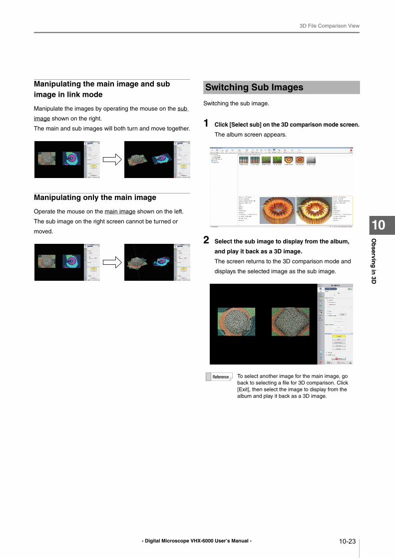
- Digital Microscope VHX-6000 User’s Manual -
3D File Comparison View
10-23
Ob
serving
in 3D
10
Manipulating the main image and sub image in link mode
Manipulate the images by operating the mouse on the sub
image shown on the right.
The main and sub images will both turn and move together.
Manipulating only the main image
Operate the mouse on the main image shown on the left.
The sub image on the right screen cannot be turned or
moved.
Switching the sub image.
1 Click [Select sub] on the 3D comparison mode screen.
The album screen appears.
2 Select the sub image to display from the album,
and play it back as a 3D image.
The screen returns to the 3D comparison mode and
displays the selected image as the sub image.
Switching Sub Images
To select another image for the main image, go
back to selecting a file for 3D comparison. Click
[Exit], then select the image to display from the
album and play it back as a 3D image.
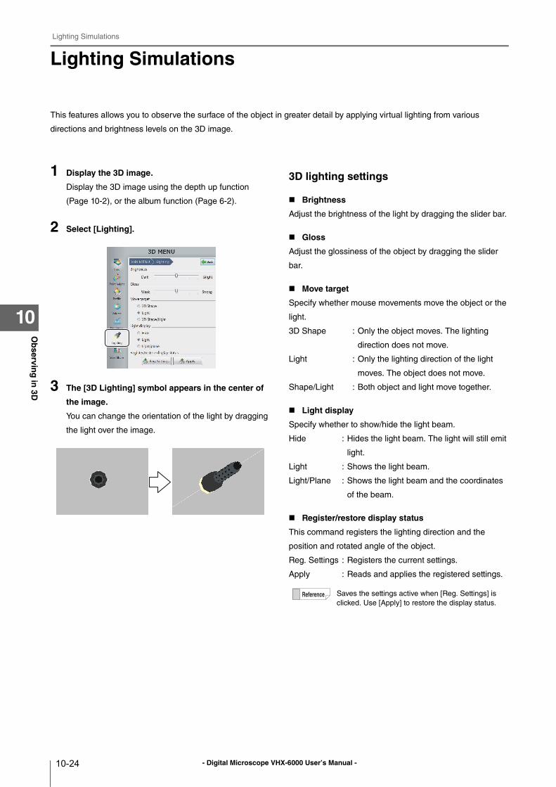
- Digital Microscope VHX-6000 User’s Manual -
Lighting Simulations
10-24
Ob
serving
in 3D
10
Lighting Simulations
This features allows you to observe the surface of the object in greater detail by applying virtual lighting from various
directions and brightness levels on the 3D image.
1 Display the 3D image.
Display the 3D image using the depth up function
(Page 10-2), or the album function (Page 6-2).
2 Select [Lighting].
3 The [3D Lighting] symbol appears in the center of
the image.
You can change the orientation of the light by dragging
the light over the image.
3D lighting settings
Brightness
Adjust the brightness of the light by dragging the slider bar.
Gloss
Adjust the glossiness of the object by dragging the slider
bar.
Move target
Specify whether mouse movements move the object or the
light.
3D Shape : Only the object moves. The lighting
direction does not move.
Light : Only the lighting direction of the light
moves. The object does not move.
Shape/Light : Both object and light move together.
Light display
Specify whether to show/hide the light beam.
Hide : Hides the light beam. The light will still emit
light.
Light : Shows the light beam.
Light/Plane : Shows the light beam and the coordinates
of the beam.
Register/restore display status
This command registers the lighting direction and the
position and rotated angle of the object.
Reg. Settings : Registers the current settings.
Apply : Reads and applies the registered settings.
Saves the settings active when [Reg. Settings] is
clicked. Use [Apply] to restore the display status.
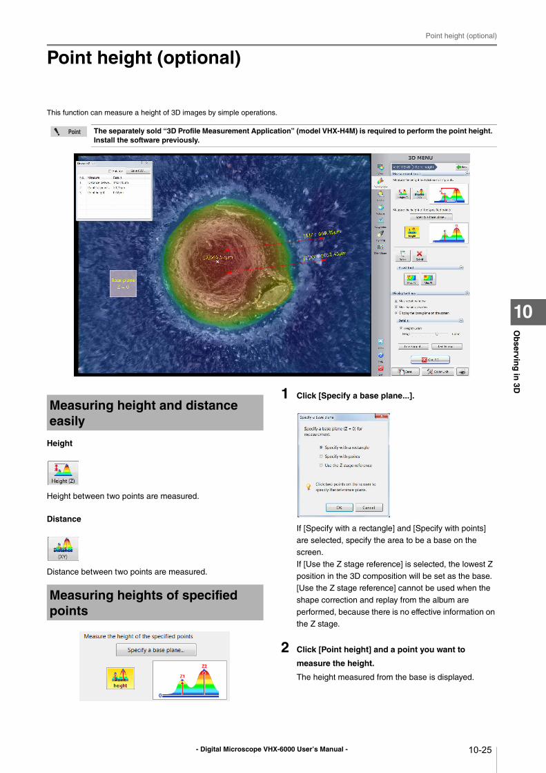
- Digital Microscope VHX-6000 User’s Manual -
Point height (optional)
10-25
Ob
serving
in 3D
10
Point height (optional)
This function can measure a height of 3D images by simple operations.
Height
Height between two points are measured.
Distance
Distance between two points are measured.
1 Click [Specify a base plane...].
If [Specify with a rectangle] and [Specify with points]
are selected, specify the area to be a base on the
screen.
If [Use the Z stage reference] is selected, the lowest Z
position in the 3D composition will be set as the base.
[Use the Z stage reference] cannot be used when the
shape correction and replay from the album are
performed, because there is no effective information on
the Z stage.
2 Click [Point height] and a point you want to
measure the height.
The height measured from the base is displayed.
The separately sold “3D Profile Measurement Application” (model VHX-H4M) is required to perform the point height. Install the software previously.
Measuring height and distance easily
Measuring heights of specified points
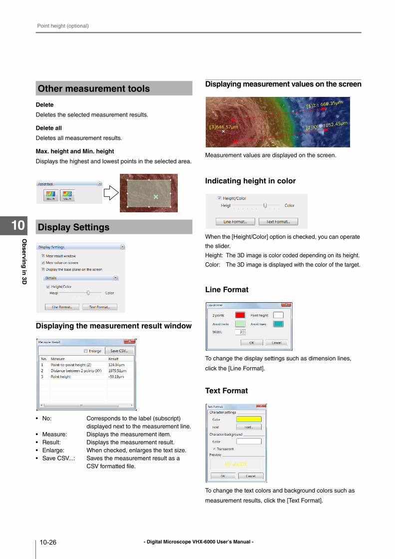
- Digital Microscope VHX-6000 User’s Manual -
Point height (optional)
10-26
Ob
serving
in 3D
10
Delete
Deletes the selected measurement results.
Delete all
Deletes all measurement results.
Max. height and Min. height
Displays the highest and lowest points in the selected area.
Displaying the measurement result window
• No: Corresponds to the label (subscript)
displayed next to the measurement line.
• Measure: Displays the measurement item.
• Result: Displays the measurement result.
• Enlarge: When checked, enlarges the text size.
• Save CSV...: Saves the measurement result as a
CSV formatted file.
Displaying measurement values on the screen
Measurement values are displayed on the screen.
Indicating height in color
When the [Height/Color] option is checked, you can operate
the slider.
Height: The 3D image is color coded depending on its height.
Color: The 3D image is displayed with the color of the target.
Line Format
To change the display settings such as dimension lines,
click the [Line Format].
Text Format
To change the text colors and background colors such as
measurement results, click the [Text Format].
Other measurement tools
Display Settings
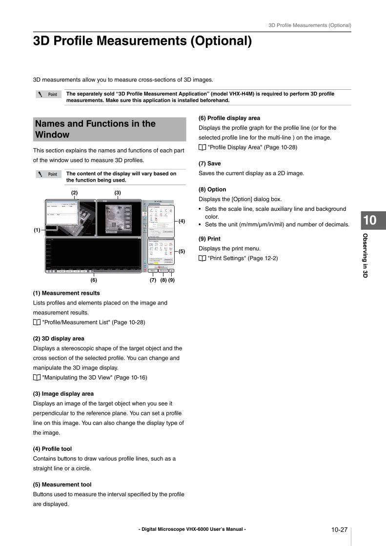
- Digital Microscope VHX-6000 User’s Manual -
3D Profile Measurements (Optional)
10-27
Ob
serving
in 3D
10
3D Profile Measurements (Optional)
3D measurements allow you to measure cross-sections of 3D images.
This section explains the names and functions of each part
of the window used to measure 3D profiles.
(1) Measurement results
Lists profiles and elements placed on the image and
measurement results.
"Profile/Measurement List" (Page 10-28)
(2) 3D display area
Displays a stereoscopic shape of the target object and the
cross section of the selected profile. You can change and
manipulate the 3D image display.
"Manipulating the 3D View" (Page 10-16)
(3) Image display area
Displays an image of the target object when you see it
perpendicular to the reference plane. You can set a profile
line on this image. You can also change the display type of
the image.
(4) Profile tool
Contains buttons to draw various profile lines, such as a
straight line or a circle.
(5) Measurement tool
Buttons used to measure the interval specified by the profile
are displayed.
(6) Profile display area
Displays the profile graph for the profile line (or for the
selected profile line for the multi-line ) on the image.
"Profile Display Area" (Page 10-28)
(7) Save
Saves the current display as a 2D image.
(8) Option
Displays the [Option] dialog box.
• Sets the scale line, scale auxiliary line and background
color.
• Sets the unit (m/mm/μm/in/mil) and number of decimals.
(9) Print
Displays the print menu.
"Print Settings" (Page 12-2)
The separately sold “3D Profile Measurement Application” (model VHX-H4M) is required to perform 3D profile measurements. Make sure this application is installed beforehand.
Names and Functions in the Window
The content of the display will vary based on the function being used.
(4)
(5)
(1)
(7) (8)(6)
(3)(2)
(9)
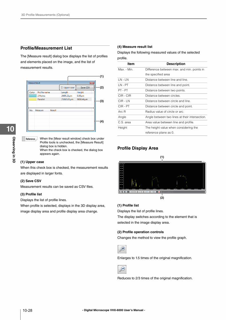
- Digital Microscope VHX-6000 User’s Manual -
3D Profile Measurements (Optional)
10-28
Ob
serving
in 3D
10
Profile/Measurement List
The [Measure result] dialog box displays the list of profiles
and elements placed on the image, and the list of
measurement results.
(1) Upper case
When this check box is checked, the measurement results
are displayed in larger fonts.
(2) Save CSV
Measurement results can be saved as CSV files.
(3) Profile list
Displays the list of profile lines.
When profile is selected, displays in the 3D display area,
image display area and profile display area change.
(4) Measure result list
Displays the following measured values of the selected
profile.
Profile Display Area
(1) Profile list
Displays the list of profile lines.
The display switches according to the element that is
selected in the image display area.
(2) Profile operation controls
Changes the method to view the profile graph.
Enlarges to 1.5 times of the original magnification.
Reduces to 2/3 times of the original magnification.
When the [Mesr result window] check box under
Profile tools is unchecked, the [Measure Result]
dialog box is hidden.
When the check box is checked, the dialog box
appears again.
(2)
(1)
(3)
(4)
Item Description
Max. - Min. Difference between max. and min. points in
the specified area
LN - LN Distance between line and line.
LN - PT Distance between line and point.
PT - PT Distance between two points.
CIR - CIR Distance between circles.
CIR - LN Distance between circle and line.
CIR - PT Distance between circle and point.
Arc R Radius value of circle or arc.
Angle Angle between two lines at their intersection.
C.S. area Area value between line and profile.
Height The height value when considering the
reference plane as 0.
(2)
(1)
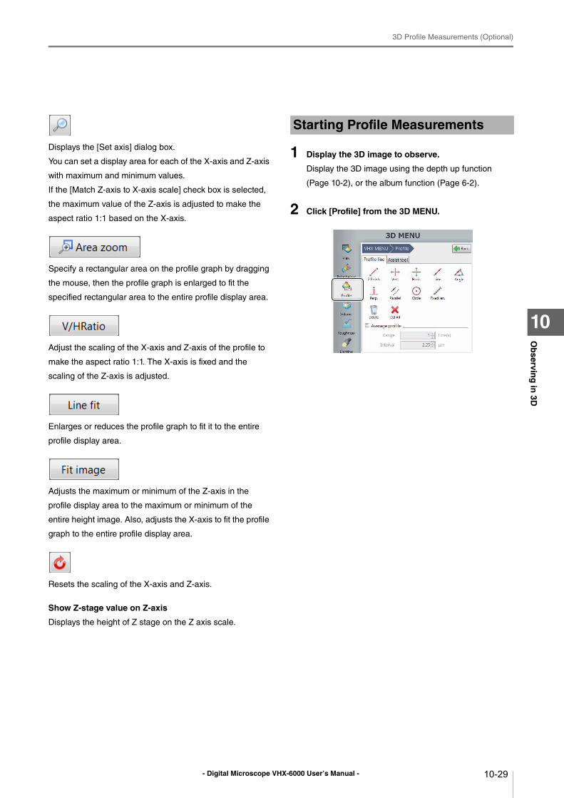
- Digital Microscope VHX-6000 User’s Manual -
3D Profile Measurements (Optional)
10-29
Ob
serving
in 3D
10
Displays the [Set axis] dialog box.
You can set a display area for each of the X-axis and Z-axis
with maximum and minimum values.
If the [Match Z-axis to X-axis scale] check box is selected,
the maximum value of the Z-axis is adjusted to make the
aspect ratio 1:1 based on the X-axis.
Specify a rectangular area on the profile graph by dragging
the mouse, then the profile graph is enlarged to fit the
specified rectangular area to the entire profile display area.
Adjust the scaling of the X-axis and Z-axis of the profile to
make the aspect ratio 1:1. The X-axis is fixed and the
scaling of the Z-axis is adjusted.
Enlarges or reduces the profile graph to fit it to the entire
profile display area.
Adjusts the maximum or minimum of the Z-axis in the
profile display area to the maximum or minimum of the
entire height image. Also, adjusts the X-axis to fit the profile
graph to the entire profile display area.
Resets the scaling of the X-axis and Z-axis.
Show Z-stage value on Z-axis
Displays the height of Z stage on the Z axis scale.
1 Display the 3D image to observe.
Display the 3D image using the depth up function
(Page 10-2), or the album function (Page 6-2).
2 Click [Profile] from the 3D MENU.
Starting Profile Measurements
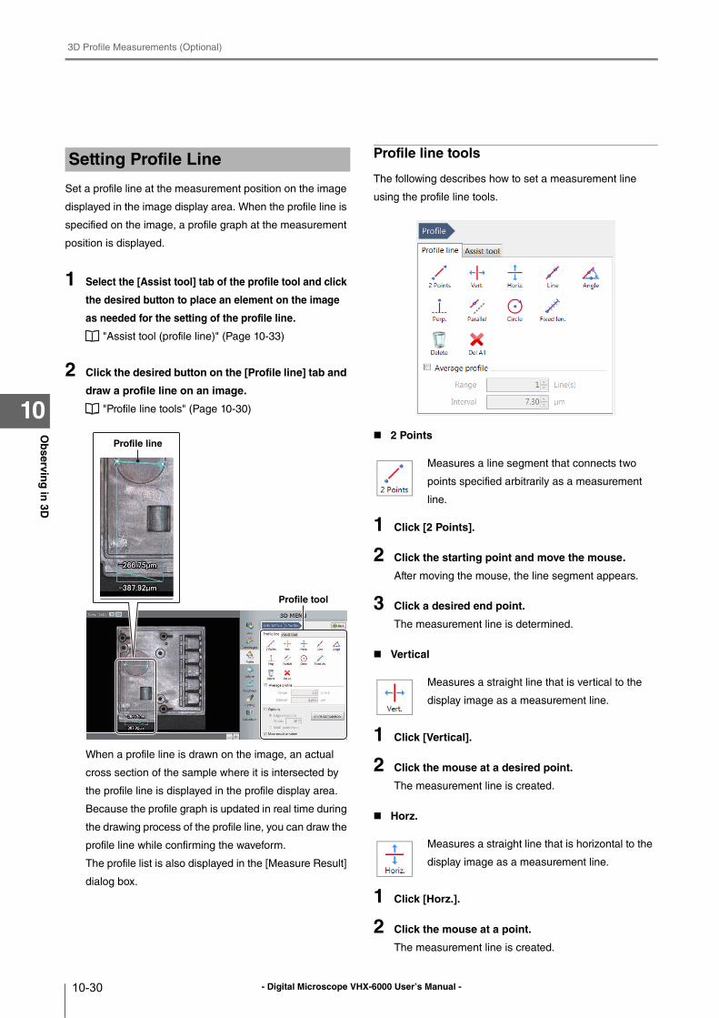
- Digital Microscope VHX-6000 User’s Manual -
3D Profile Measurements (Optional)
10-30
Ob
serving
in 3D
10
Set a profile line at the measurement position on the image
displayed in the image display area. When the profile line is
specified on the image, a profile graph at the measurement
position is displayed.
1 Select the [Assist tool] tab of the profile tool and click
the desired button to place an element on the image
as needed for the setting of the profile line.
"Assist tool (profile line)" (Page 10-33)
2 Click the desired button on the [Profile line] tab and
draw a profile line on an image.
"Profile line tools" (Page 10-30)
When a profile line is drawn on the image, an actual
cross section of the sample where it is intersected by
the profile line is displayed in the profile display area.
Because the profile graph is updated in real time during
the drawing process of the profile line, you can draw the
profile line while confirming the waveform.
The profile list is also displayed in the [Measure Result]
dialog box.
Profile line tools
The following describes how to set a measurement line
using the profile line tools.
2 Points
1 Click [2 Points].
2 Click the starting point and move the mouse.
After moving the mouse, the line segment appears.
3 Click a desired end point.
The measurement line is determined.
Vertical
1 Click [Vertical].
2 Click the mouse at a desired point.
The measurement line is created.
Horz.
1 Click [Horz.].
2 Click the mouse at a point.
The measurement line is created.
Setting Profile Line
Profile tool
Profile line
Measures a line segment that connects two
points specified arbitrarily as a measurement
line.
Measures a straight line that is vertical to the
display image as a measurement line.
Measures a straight line that is horizontal to the
display image as a measurement line.

- Digital Microscope VHX-6000 User’s Manual -
3D Profile Measurements (Optional)
10-31
Ob
serving
in 3D
10
Line
1 Click [Line].
2 Click the 1st point, and then move the mouse.
When you move the mouse, a straight line is displayed.
3 Move the mouse and click a second point.
The measurement line is created.
Angle
1 Click [Angle].
The [Specific angle] dialog box appears.
2 Enter an angle against the reference line and click
[OK].
3 Put the mouse over a position where you want to
locate the reference line, and click the position.
4 Move the mouse to rotate the reference line
through 360 degrees.
5 Select the desired position for the reference line,
then click the mouse.
The reference line is determined and a line that
intersects with the reference line at the specified angle
is displayed.
When you move the mouse, the measurement line
moves, keeping the angle against the reference line
constant.
6 Click the position you want to measure.
The measurement line is created.
Perp.
1 Click [Perp.].
2 Put the mouse over a position where you want to
locate the reference line, and click the mouse.
Move the mouse to rotate the reference line through
360 degrees.
3 Select the desired position for the reference line,
then click the mouse.
The reference line is created and a line that is
perpendicular to the reference line is displayed.
4 Place the mouse over a position where you want to
make a measurement, and click the position.
This sets the position of the line perpendicular to the
reference line.
Parallel
1 Click [Parallel].
2 Put the mouse over a position where you want to
place the reference line, and click the mouse.
Move the mouse to rotate the reference line through
360 degrees.
3 Select the desired position for the reference line,
then click the mouse.
The reference line is created and a line that is parallel
to the reference line is displayed.
4 Place the mouse over a position where you want to
make a measurement, and click the mouse.
This sets the position of the line parallel to the
reference line.
Measures a straight line that passes through
two specified points.
Measures a straight line that passes through a
point specified by the user and intersects with a
reference line at a specified angle as a
measurement line.
Measures a straight line that is vertical to a
reference line specified as a measurement line.
Measures a straight line that is parallel to a
reference line specified as a measurement line.
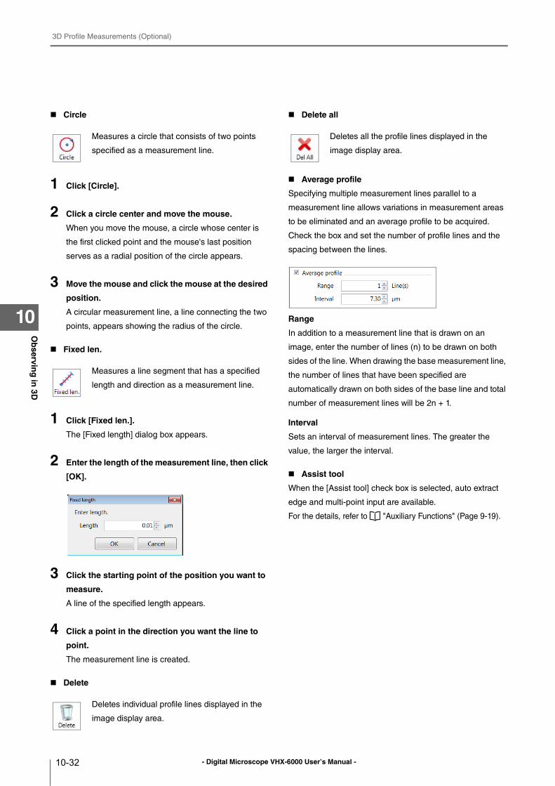
- Digital Microscope VHX-6000 User’s Manual -
3D Profile Measurements (Optional)
10-32
Ob
serving
in 3D
10
Circle
1 Click [Circle].
2 Click a circle center and move the mouse.
When you move the mouse, a circle whose center is
the first clicked point and the mouse's last position
serves as a radial position of the circle appears.
3 Move the mouse and click the mouse at the desired
position.
A circular measurement line, a line connecting the two
points, appears showing the radius of the circle.
Fixed len.
1 Click [Fixed len.].
The [Fixed length] dialog box appears.
2 Enter the length of the measurement line, then click
[OK].
3 Click the starting point of the position you want to
measure.
A line of the specified length appears.
4 Click a point in the direction you want the line to
point.
The measurement line is created.
Delete
Delete all
Average profile
Specifying multiple measurement lines parallel to a
measurement line allows variations in measurement areas
to be eliminated and an average profile to be acquired.
Check the box and set the number of profile lines and the
spacing between the lines.
Range
In addition to a measurement line that is drawn on an
image, enter the number of lines (n) to be drawn on both
sides of the line. When drawing the base measurement line,
the number of lines that have been specified are
automatically drawn on both sides of the base line and total
number of measurement lines will be 2n + 1.
Interval
Sets an interval of measurement lines. The greater the
value, the larger the interval.
Assist tool
When the [Assist tool] check box is selected, auto extract
edge and multi-point input are available.
For the details, refer to "Auxiliary Functions" (Page 9-19).
Measures a circle that consists of two points
specified as a measurement line.
Measures a line segment that has a specified
length and direction as a measurement line.
Deletes individual profile lines displayed in the
image display area.
Deletes all the profile lines displayed in the
image display area.
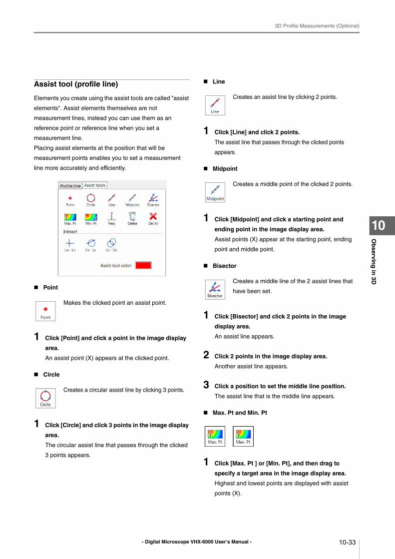
- Digital Microscope VHX-6000 User’s Manual -
3D Profile Measurements (Optional)
10-33
Ob
serving
in 3D
10
Assist tool (profile line)
Elements you create using the assist tools are called "assist
elements". Assist elements themselves are not
measurement lines, instead you can use them as an
reference point or reference line when you set a
measurement line.
Placing assist elements at the position that will be
measurement points enables you to set a measurement
line more accurately and efficiently.
Point
1 Click [Point] and click a point in the image display
area.
An assist point (X) appears at the clicked point.
Circle
1 Click [Circle] and click 3 points in the image display
area.
The circular assist line that passes through the clicked
3 points appears.
Line
1 Click [Line] and click 2 points.
The assist line that passes through the clicked points
appears.
Midpoint
1 Click [Midpoint] and click a starting point and
ending point in the image display area.
Assist points (X) appear at the starting point, ending
point and middle point.
Bisector
1 Click [Bisector] and click 2 points in the image
display area.
An assist line appears.
2 Click 2 points in the image display area.
Another assist line appears.
3 Click a position to set the middle line position.
The assist line that is the middle line appears.
Max. Pt and Min. Pt
1 Click [Max. Pt ] or [Min. Pt], and then drag to
specify a target area in the image display area.
Highest and lowest points are displayed with assist
points (X).
Makes the clicked point an assist point.
Creates a circular assist line by clicking 3 points.
Creates an assist line by clicking 2 points.
Creates a middle point of the clicked 2 points.
Creates a middle line of the 2 assist lines that
have been set.
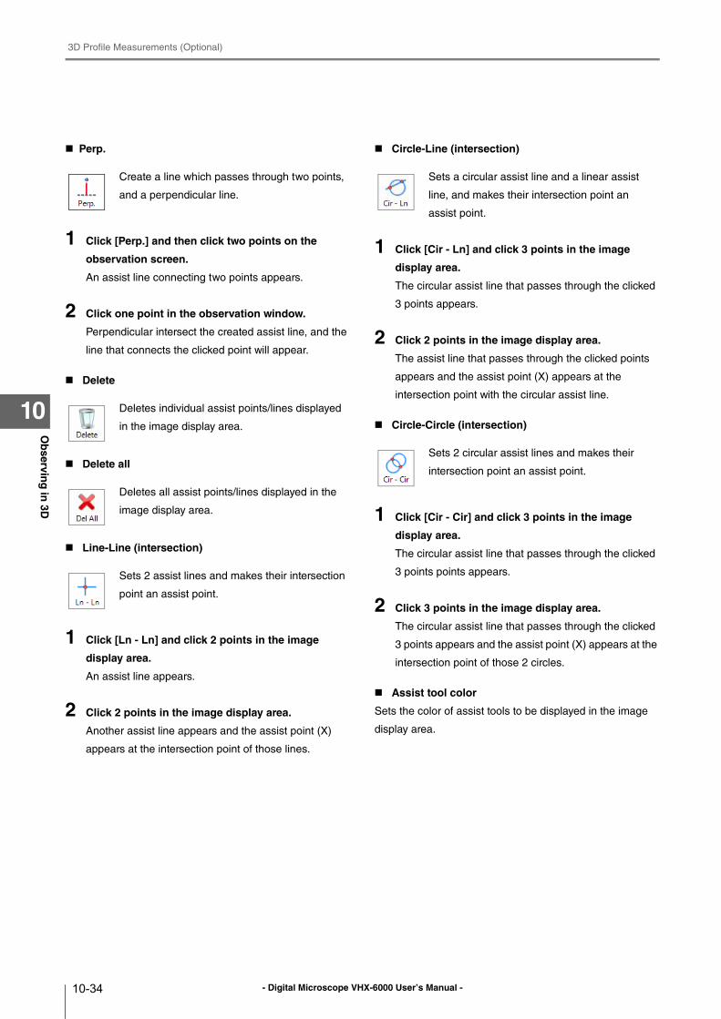
- Digital Microscope VHX-6000 User’s Manual -
3D Profile Measurements (Optional)
10-34
Ob
serving
in 3D
10
Perp.
1 Click [Perp.] and then click two points on the
observation screen.
An assist line connecting two points appears.
2 Click one point in the observation window.
Perpendicular intersect the created assist line, and the
line that connects the clicked point will appear.
Delete
Delete all
Line-Line (intersection)
1 Click [Ln - Ln] and click 2 points in the image
display area.
An assist line appears.
2 Click 2 points in the image display area.
Another assist line appears and the assist point (X)
appears at the intersection point of those lines.
Circle-Line (intersection)
1 Click [Cir - Ln] and click 3 points in the image
display area.
The circular assist line that passes through the clicked
3 points appears.
2 Click 2 points in the image display area.
The assist line that passes through the clicked points
appears and the assist point (X) appears at the
intersection point with the circular assist line.
Circle-Circle (intersection)
1 Click [Cir - Cir] and click 3 points in the image
display area.
The circular assist line that passes through the clicked
3 points points appears.
2 Click 3 points in the image display area.
The circular assist line that passes through the clicked
3 points appears and the assist point (X) appears at the
intersection point of those 2 circles.
Assist tool color
Sets the color of assist tools to be displayed in the image
display area.
Create a line which passes through two points,
and a perpendicular line.
Deletes individual assist points/lines displayed
in the image display area.
Deletes all assist points/lines displayed in the
image display area.
Sets 2 assist lines and makes their intersection
point an assist point.
Sets a circular assist line and a linear assist
line, and makes their intersection point an
assist point.
Sets 2 circular assist lines and makes their
intersection point an assist point.
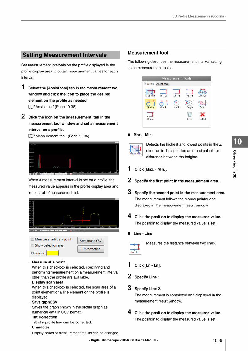
- Digital Microscope VHX-6000 User’s Manual -
3D Profile Measurements (Optional)
10-35
Ob
serving
in 3D
10
Set measurement intervals on the profile displayed in the
profile display area to obtain measurement values for each
interval.
1 Select the [Assist tool] tab in the measurement tool
window and click the icon to place the desired
element on the profile as needed.
"Assist tool" (Page 10-38)
2 Click the icon on the [Measurement] tab in the
measurement tool window and set a measurement
interval on a profile.
"Measurement tool" (Page 10-35)
When a measurement interval is set on a profile, the
measured value appears in the profile display area and
in the profile/measurement list.
• Measure at a pointWhen this checkbox is selected, specifying and
performing measurement on a measurement interval
other than the profile are available.
• Display scan areaWhen this checkbox is selected, the scan area of a
point element or a line element on the profile is
displayed.
• Save grphCSVSaves the graph shown in the profile graph as
numerical data in CSV format.
• Tilt CorrectionTilt of a profile line can be corrected.
• Character
Display colors of measurement results can be changed.
Measurement tool
The following describes the measurement interval setting
using mearsurement tools.
Max. - Min.
1 Click [Max. - Min.].
2 Specify the first point in the measurement area.
3 Specify the second point in the measurement area.
The measurement follows the mouse pointer and
displayed in the measurement result window.
4 Click the position to display the measured value.
The position to display the measured value is set.
Line - Line
1 Click [Ln - Ln].
2 Specify Line 1.
3 Specify Line 2.
The measurement is completed and displayed in the
measurement result window.
4 Click the position to display the measured value.
The position to display the measured value is set.
Setting Measurement Intervals
Detects the highest and lowest points in the Z
direction in the specified area and calculates
difference between the heights.
Measures the distance between two lines.
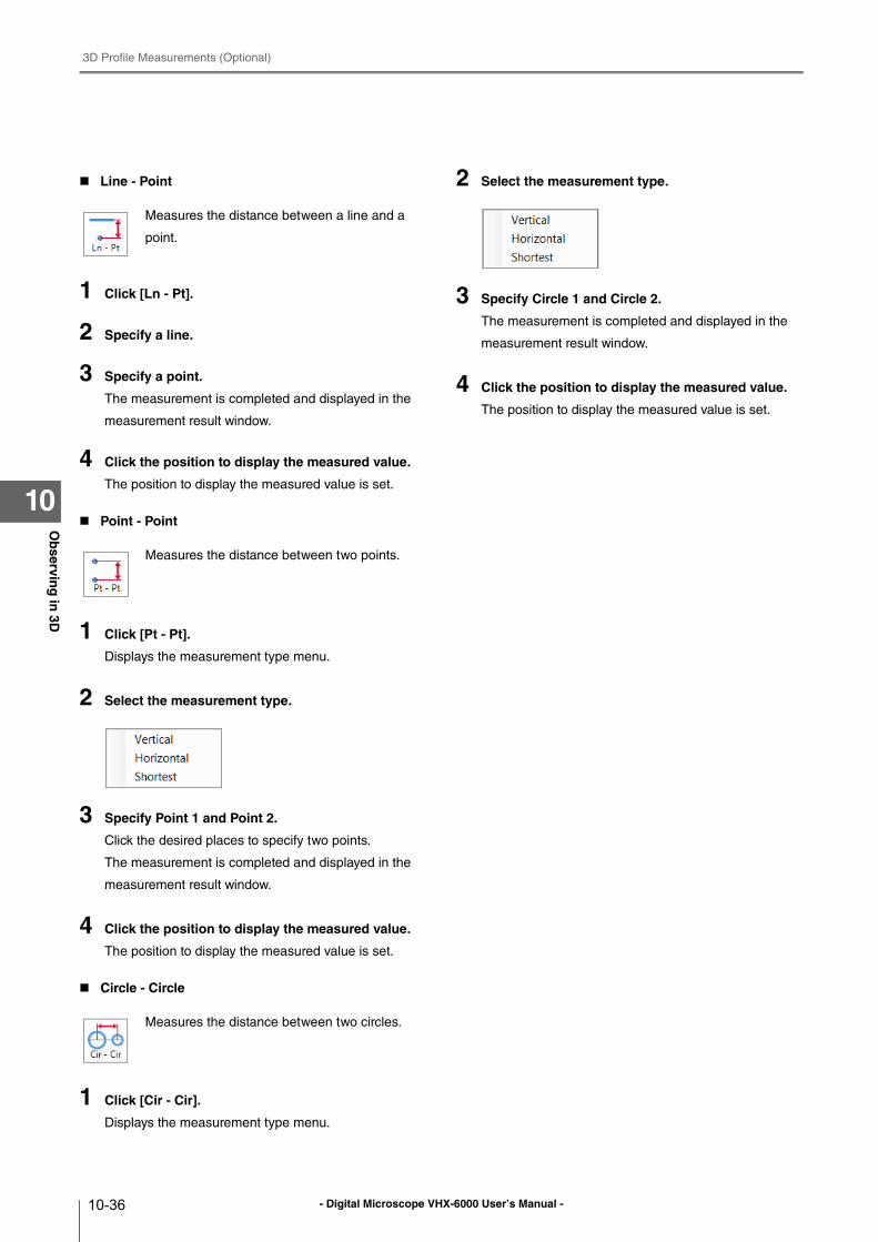
- Digital Microscope VHX-6000 User’s Manual -
3D Profile Measurements (Optional)
10-36
Ob
serving
in 3D
10
Line - Point
1 Click [Ln - Pt].
2 Specify a line.
3 Specify a point.
The measurement is completed and displayed in the
measurement result window.
4 Click the position to display the measured value.
The position to display the measured value is set.
Point - Point
1 Click [Pt - Pt].
Displays the measurement type menu.
2 Select the measurement type.
3 Specify Point 1 and Point 2.
Click the desired places to specify two points.
The measurement is completed and displayed in the
measurement result window.
4 Click the position to display the measured value.
The position to display the measured value is set.
Circle - Circle
1 Click [Cir - Cir].
Displays the measurement type menu.
2 Select the measurement type.
3 Specify Circle 1 and Circle 2.
The measurement is completed and displayed in the
measurement result window.
4 Click the position to display the measured value.
The position to display the measured value is set.
Measures the distance between a line and a
point.
Measures the distance between two points.
Measures the distance between two circles.
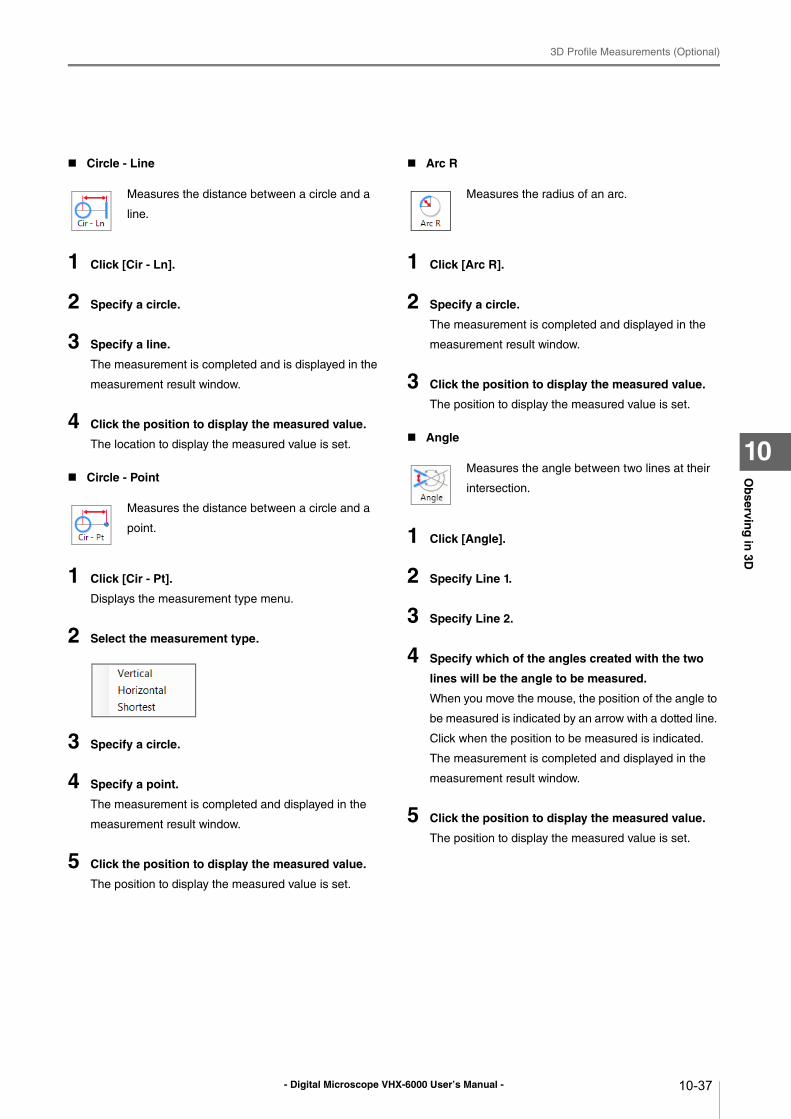
- Digital Microscope VHX-6000 User’s Manual -
3D Profile Measurements (Optional)
10-37
Ob
serving
in 3D
10
Circle - Line
1 Click [Cir - Ln].
2 Specify a circle.
3 Specify a line.
The measurement is completed and is displayed in the
measurement result window.
4 Click the position to display the measured value.
The location to display the measured value is set.
Circle - Point
1 Click [Cir - Pt].
Displays the measurement type menu.
2 Select the measurement type.
3 Specify a circle.
4 Specify a point.
The measurement is completed and displayed in the
measurement result window.
5 Click the position to display the measured value.
The position to display the measured value is set.
Arc R
1 Click [Arc R].
2 Specify a circle.
The measurement is completed and displayed in the
measurement result window.
3 Click the position to display the measured value.
The position to display the measured value is set.
Angle
1 Click [Angle].
2 Specify Line 1.
3 Specify Line 2.
4 Specify which of the angles created with the two
lines will be the angle to be measured.
When you move the mouse, the position of the angle to
be measured is indicated by an arrow with a dotted line.
Click when the position to be measured is indicated.
The measurement is completed and displayed in the
measurement result window.
5 Click the position to display the measured value.
The position to display the measured value is set.
Measures the distance between a circle and a
line.
Measures the distance between a circle and a
point.
Measures the radius of an arc.
Measures the angle between two lines at their
intersection.
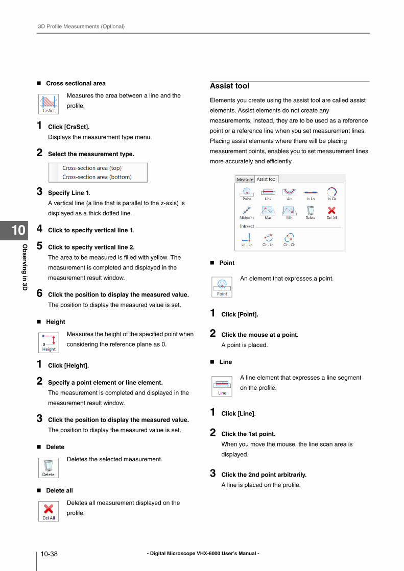
- Digital Microscope VHX-6000 User’s Manual -
3D Profile Measurements (Optional)
10-38
Ob
serving
in 3D
10
Cross sectional area
1 Click [CrsSct].
Displays the measurement type menu.
2 Select the measurement type.
3 Specify Line 1.
A vertical line (a line that is parallel to the z-axis) is
displayed as a thick dotted line.
4 Click to specify vertical line 1.
5 Click to specify vertical line 2.
The area to be measured is filled with yellow. The
measurement is completed and displayed in the
measurement result window.
6 Click the position to display the measured value.
The position to display the measured value is set.
Height
1 Click [Height].
2 Specify a point element or line element.
The measurement is completed and displayed in the
measurement result window.
3 Click the position to display the measured value.
The position to display the measured value is set.
Delete
Delete all
Assist tool
Elements you create using the assist tool are called assist
elements. Assist elements do not create any
measurements, instead, they are to be used as a reference
point or a reference line when you set measurement lines.
Placing assist elements where there will be placing
measurement points, enables you to set measurement lines
more accurately and efficiently.
Point
1 Click [Point].
2 Click the mouse at a point.
A point is placed.
Line
1 Click [Line].
2 Click the 1st point.
When you move the mouse, the line scan area is
displayed.
3 Click the 2nd point arbitrarily.
A line is placed on the profile.
Measures the area between a line and the
profile.
Measures the height of the specified point when
considering the reference plane as 0.
Deletes the selected measurement.
Deletes all measurement displayed on the
profile.
An element that expresses a point.
A line element that expresses a line segment
on the profile.
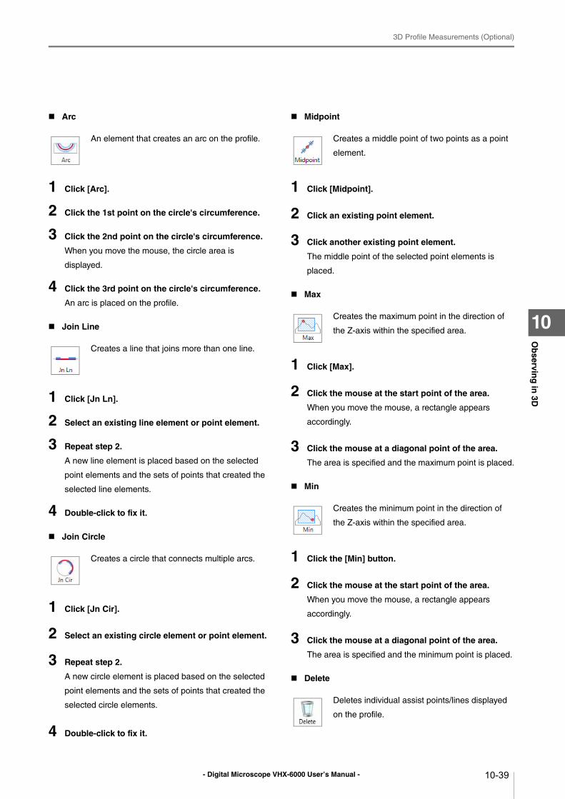
- Digital Microscope VHX-6000 User’s Manual -
3D Profile Measurements (Optional)
10-39
Ob
serving
in 3D
10
Arc
1 Click [Arc].
2 Click the 1st point on the circle's circumference.
3 Click the 2nd point on the circle's circumference.
When you move the mouse, the circle area is
displayed.
4 Click the 3rd point on the circle's circumference.
An arc is placed on the profile.
Join Line
1 Click [Jn Ln].
2 Select an existing line element or point element.
3 Repeat step 2.
A new line element is placed based on the selected
point elements and the sets of points that created the
selected line elements.
4 Double-click to fix it.
Join Circle
1 Click [Jn Cir].
2 Select an existing circle element or point element.
3 Repeat step 2.
A new circle element is placed based on the selected
point elements and the sets of points that created the
selected circle elements.
4 Double-click to fix it.
Midpoint
1 Click [Midpoint].
2 Click an existing point element.
3 Click another existing point element.
The middle point of the selected point elements is
placed.
Max
1 Click [Max].
2 Click the mouse at the start point of the area.
When you move the mouse, a rectangle appears
accordingly.
3 Click the mouse at a diagonal point of the area.
The area is specified and the maximum point is placed.
Min
1 Click the [Min] button.
2 Click the mouse at the start point of the area.
When you move the mouse, a rectangle appears
accordingly.
3 Click the mouse at a diagonal point of the area.
The area is specified and the minimum point is placed.
Delete
An element that creates an arc on the profile.
Creates a line that joins more than one line.
Creates a circle that connects multiple arcs.
Creates a middle point of two points as a point
element.
Creates the maximum point in the direction of
the Z-axis within the specified area.
Creates the minimum point in the direction of
the Z-axis within the specified area.
Deletes individual assist points/lines displayed
on the profile.
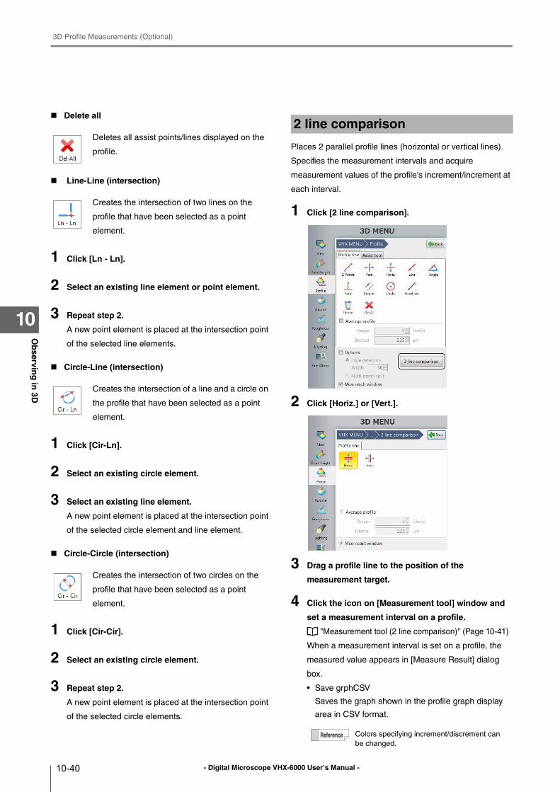
- Digital Microscope VHX-6000 User’s Manual -
3D Profile Measurements (Optional)
10-40
Ob
serving
in 3D
10
Delete all
Line-Line (intersection)
1 Click [Ln - Ln].
2 Select an existing line element or point element.
3 Repeat step 2.
A new point element is placed at the intersection point
of the selected line elements.
Circle-Line (intersection)
1 Click [Cir-Ln].
2 Select an existing circle element.
3 Select an existing line element.
A new point element is placed at the intersection point
of the selected circle element and line element.
Circle-Circle (intersection)
1 Click [Cir-Cir].
2 Select an existing circle element.
3 Repeat step 2.
A new point element is placed at the intersection point
of the selected circle elements.
Places 2 parallel profile lines (horizontal or vertical lines).
Specifies the measurement intervals and acquire
measurement values of the profile's increment/increment at
each interval.
1 Click [2 line comparison].
2 Click [Horiz.] or [Vert.].
3 Drag a profile line to the position of the
measurement target.
4 Click the icon on [Measurement tool] window and
set a measurement interval on a profile.
"Measurement tool (2 line comparison)" (Page 10-41)
When a measurement interval is set on a profile, the
measured value appears in [Measure Result] dialog
box.
• Save grphCSV
Saves the graph shown in the profile graph display
area in CSV format.
Deletes all assist points/lines displayed on the
profile.
Creates the intersection of two lines on the
profile that have been selected as a point
element.
Creates the intersection of a line and a circle on
the profile that have been selected as a point
element.
Creates the intersection of two circles on the
profile that have been selected as a point
element.
2 line comparison
Colors specifying increment/discrement can
be changed.
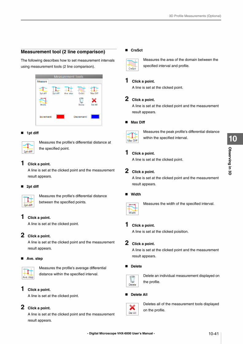
- Digital Microscope VHX-6000 User’s Manual -
3D Profile Measurements (Optional)
10-41
Ob
serving
in 3D
10
Measurement tool (2 line comparison)
The following describes how to set measurement intervals
using measurement tools (2 line comparison).
1pt diff
1 Click a point.
A line is set at the clicked point and the measurement
result appears.
2pt diff
1 Click a point.
A line is set at the clicked point.
2 Click a point.
A line is set at the clicked point and the measurement
result appears.
Ave. step
1 Click a point.
A line is set at the clicked point.
2 Click a point.
A line is set at the clicked point and the measurement
result appears.
CrsSct
1 Click a point.
A line is set at the clicked point.
2 Click a point.
A line is set at the clicked point and the measurement
result appears.
Max Diff
1 Click a point.
A line is set at the clicked point.
2 Click a point.
A line is set at the clicked point and the measurement
result appears.
Width
1 Click a point.
A line is set at the clicked poisition.
2 Click a point.
A line is set at the clicked point and the measurement
result appears.
Delete
Delete All
Measures the profile's differential distance at
the specified point.
Measures the profile's differential distance
between the specified points.
Measures the profile's average differential
distance within the specified interval.
Measures the area of the domain between the
specified interval and profile.
Measures the peak profile's differential distance
within the specified interval.
Measures the width of the specified interval.
Delete an individual measurement displayed on
the profile.
Deletes all of the measurement tools displayed
on the profile.
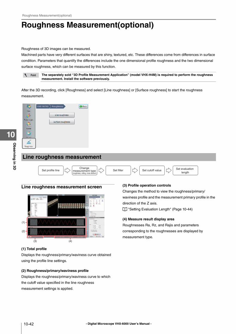
- Digital Microscope VHX-6000 User’s Manual -
Roughness Measurement(optional)
10-42
Ob
serving
in 3D
10
Roughness Measurement(optional)
Roughness of 3D images can be measured.
Machined parts have very different surfaces that are shiny, textured, etc. These differences come from differences in surface
condition. Parameters that quantify the differences include the one dimensional profile roughness and the two dimensional
surface roughness, which can be measured by this function.
After the 3D recording, click [Roughness] and select [Line roughness] or [Surface roughness] to start the roughness
measurement.
Line roughness measurement screen
(1) Total profile
Displays the roughness/primary/waviness curve obtained
using the profile line settings.
(2) Roughness/primary/waviness profile
Displays the roughness/primary/waviness curve to which
the cutoff value specified in the line roughness
measurement settings is applied.
(3) Profile operation controls
Changes the method to view the roughness/primary/
waviness profile and the measurement primary profile in the
direction of the Z axis.
"Setting Evaluation Length" (Page 10-44)
(4) Measure result display area
Roughnesses Ra, Rz, and Rajis and parameters
corresponding to the roughnesses are displayed by
measurement type.
The separately sold “3D Profile Measurement Application” (model VHX-H4M) is required to perform the roughness measurement. Install the software previously.
Line roughness measurement
Set cutoff valueSet filterChange
measurement type (roughness, rolling, cross section)
Set profile line Set evaluation length
(4)(3)
(1)
(2)
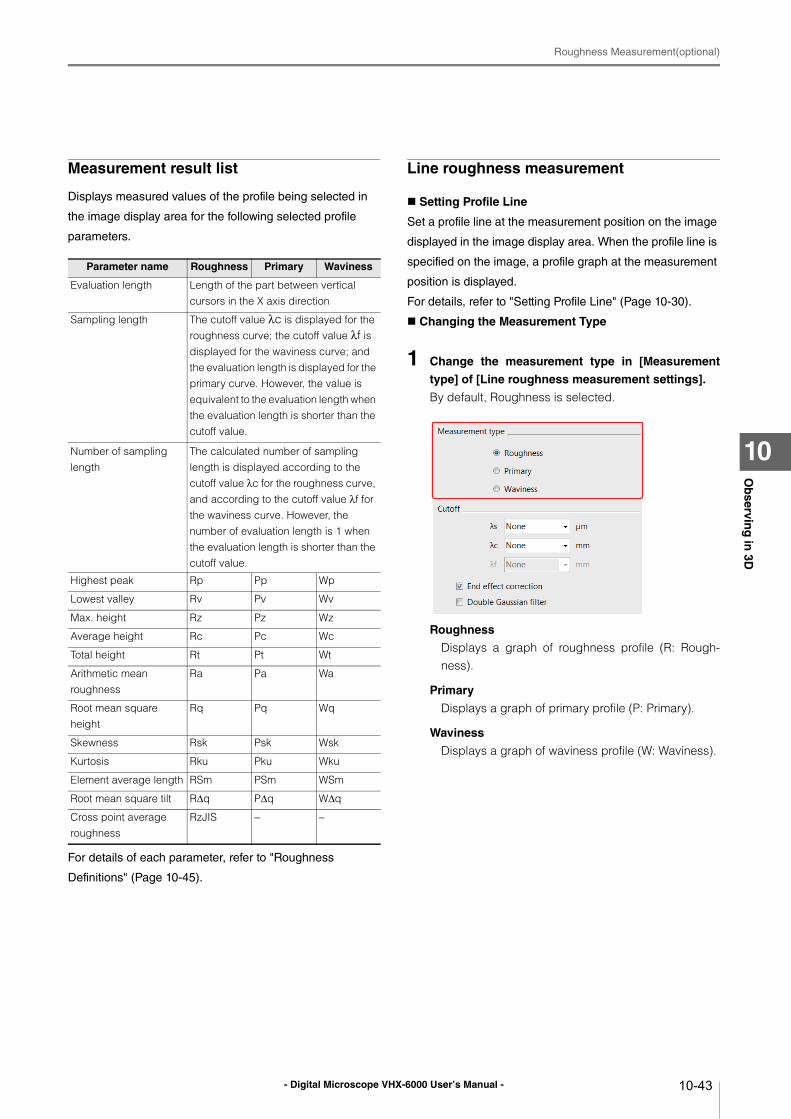
- Digital Microscope VHX-6000 User’s Manual -
Roughness Measurement(optional)
10-43
Ob
serving
in 3D
10
Measurement result list
Displays measured values of the profile being selected in
the image display area for the following selected profile
parameters.
For details of each parameter, refer to "Roughness
Definitions" (Page 10-45).
Line roughness measurement
Setting Profile Line
Set a profile line at the measurement position on the image
displayed in the image display area. When the profile line is
specified on the image, a profile graph at the measurement
position is displayed.
For details, refer to "Setting Profile Line" (Page 10-30).
Changing the Measurement Type
1 Change the measurement type in [Measurement
type] of [Line roughness measurement settings].
By default, Roughness is selected.
Roughness
Displays a graph of roughness profile (R: Rough-ness).
Primary
Displays a graph of primary profile (P: Primary).
Waviness
Displays a graph of waviness profile (W: Waviness).
Parameter name Roughness Primary Waviness
Evaluation length Length of the part between vertical cursors in the X axis direction
Sampling length The cutoff value λc is displayed for the roughness curve; the cutoff value λf is displayed for the waviness curve; and the evaluation length is displayed for the primary curve. However, the value is equivalent to the evaluation length when the evaluation length is shorter than the cutoff value.
Number of sampling length
The calculated number of sampling length is displayed according to the cutoff value λc for the roughness curve, and according to the cutoff value λf for the waviness curve. However, the number of evaluation length is 1 when the evaluation length is shorter than the cutoff value.
Highest peak Rp Pp Wp
Lowest valley Rv Pv Wv
Max. height Rz Pz Wz
Average height Rc Pc Wc
Total height Rt Pt Wt
Arithmetic mean roughness
Ra Pa Wa
Root mean square height
Rq Pq Wq
Skewness Rsk Psk Wsk
Kurtosis Rku Pku Wku
Element average length RSm PSm WSm
Root mean square tilt RΔq PΔq WΔq
Cross point average roughness
RzJIS − −
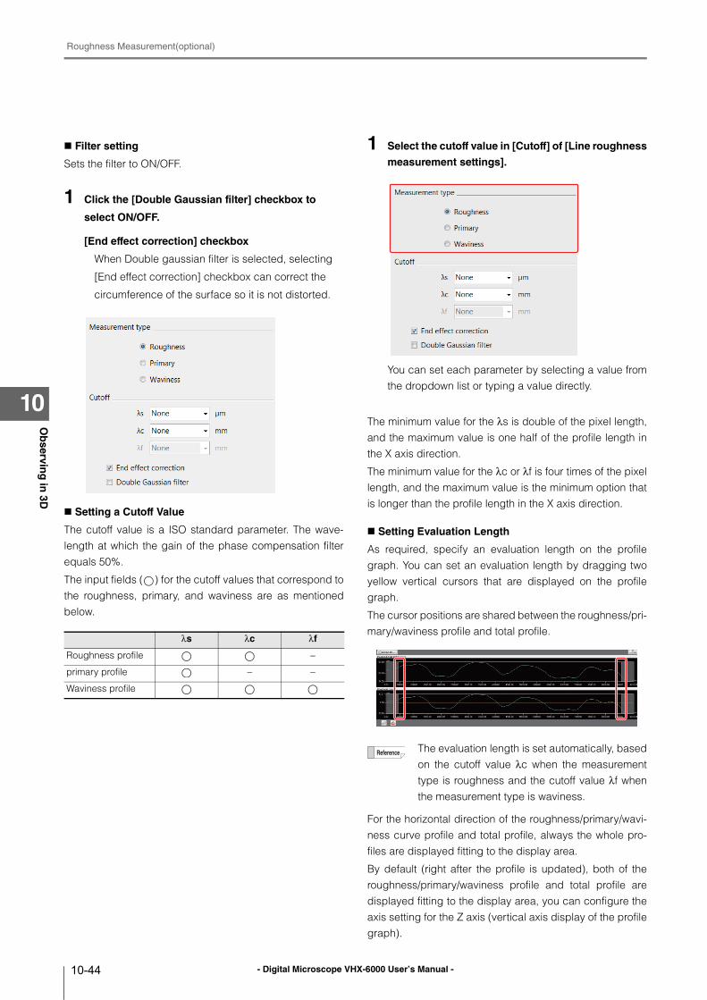
- Digital Microscope VHX-6000 User’s Manual -
Roughness Measurement(optional)
10-44
Ob
serving
in 3D
10
Filter setting
Sets the filter to ON/OFF.
1 Click the [Double Gaussian filter] checkbox to
select ON/OFF.
[End effect correction] checkbox
When Double gaussian filter is selected, selecting
[End effect correction] checkbox can correct the
circumference of the surface so it is not distorted.
Setting a Cutoff Value
The cutoff value is a ISO standard parameter. The wave-length at which the gain of the phase compensation filterequals 50%.
The input fields ( ) for the cutoff values that correspond tothe roughness, primary, and waviness are as mentionedbelow.
1 Select the cutoff value in [Cutoff] of [Line roughness
measurement settings].
You can set each parameter by selecting a value fromthe dropdown list or typing a value directly.
The minimum value for the λs is double of the pixel length,and the maximum value is one half of the profile length inthe X axis direction.
The minimum value for the λc or λf is four times of the pixellength, and the maximum value is the minimum option thatis longer than the profile length in the X axis direction.
Setting Evaluation Length
As required, specify an evaluation length on the profilegraph. You can set an evaluation length by dragging twoyellow vertical cursors that are displayed on the profilegraph.
The cursor positions are shared between the roughness/pri-mary/waviness profile and total profile.
For the horizontal direction of the roughness/primary/wavi-ness curve profile and total profile, always the whole pro-files are displayed fitting to the display area.
By default (right after the profile is updated), both of theroughness/primary/waviness profile and total profile aredisplayed fitting to the display area, you can configure theaxis setting for the Z axis (vertical axis display of the profilegraph).
λs λc λf
Roughness profile −
primary profile − −
Waviness profile
The evaluation length is set automatically, basedon the cutoff value λc when the measurementtype is roughness and the cutoff value λf whenthe measurement type is waviness.
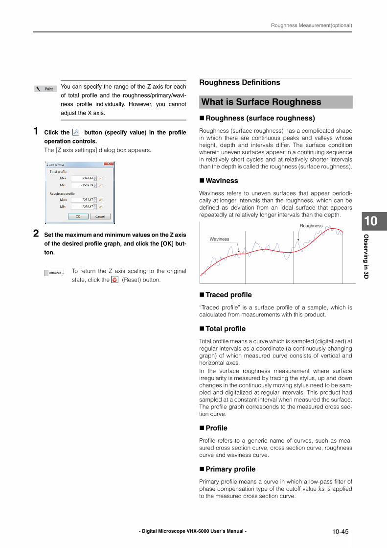
- Digital Microscope VHX-6000 User’s Manual -
Roughness Measurement(optional)
10-45
Ob
serving
in 3D
10
1 Click the button (specify value) in the profile
operation controls.
The [Z axis settings] dialog box appears.
2 Set the maximum and minimum values on the Z axis
of the desired profile graph, and click the [OK] but-
ton.
Roughness Definitions
Roughness (surface roughness)
Roughness (surface roughness) has a complicated shapein which there are continuous peaks and valleys whoseheight, depth and intervals differ. The surface conditionwherein uneven surfaces appear in a continuing sequencein relatively short cycles and at relatively shorter intervalsthan the depth is called the roughness (surface roughness).
Waviness
Waviness refers to uneven surfaces that appear periodi-cally at longer intervals than the roughness, which can bedefined as deviation from an ideal surface that appearsrepeatedly at relatively longer intervals than the depth.
Traced profile
“Traced profile” is a surface profile of a sample, which iscalculated from measurements with this product.
Total profile
Total profile means a curve which is sampled (digitalized) atregular intervals as a coordinate (a continuously changinggraph) of which measured curve consists of vertical andhorizontal axes.In the surface roughness measurement where surfaceirregularity is measured by tracing the stylus, up and downchanges in the continuously moving stylus need to be sam-pled and digitalized at regular intervals. This product hadsampled at a constant interval when measured the surface.The profile graph corresponds to the measured cross sec-tion curve.
Profile
Profile refers to a generic name of curves, such as mea-sured cross section curve, cross section curve, roughnesscurve and waviness curve.
Primary profile
Primary profile means a curve in which a low-pass filter ofphase compensation type of the cutoff value λs is appliedto the measured cross section curve.
You can specify the range of the Z axis for each
of total profile and the roughness/primary/wavi-
ness profile individually. However, you cannot
adjust the X axis.
To return the Z axis scaling to the originalstate, click the (Reset) button.
What is Surface Roughness
Roughness
Waviness
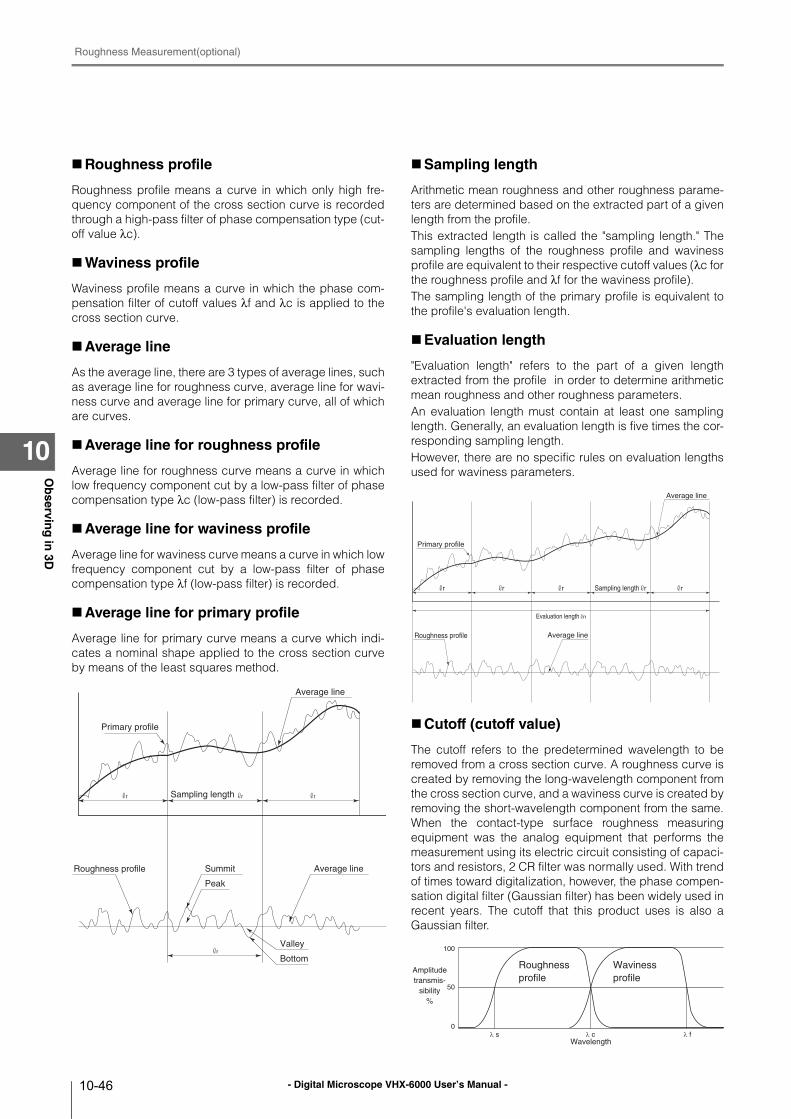
- Digital Microscope VHX-6000 User’s Manual -
Roughness Measurement(optional)
10-46
Ob
serving
in 3D
10
Roughness profile
Roughness profile means a curve in which only high fre-quency component of the cross section curve is recordedthrough a high-pass filter of phase compensation type (cut-off value λc).
Waviness profile
Waviness profile means a curve in which the phase com-pensation filter of cutoff values λf and λc is applied to thecross section curve.
Average line
As the average line, there are 3 types of average lines, suchas average line for roughness curve, average line for wavi-ness curve and average line for primary curve, all of whichare curves.
Average line for roughness profile
Average line for roughness curve means a curve in whichlow frequency component cut by a low-pass filter of phasecompensation type λc (low-pass filter) is recorded.
Average line for waviness profile
Average line for waviness curve means a curve in which lowfrequency component cut by a low-pass filter of phasecompensation type λf (low-pass filter) is recorded.
Average line for primary profile
Average line for primary curve means a curve which indi-cates a nominal shape applied to the cross section curveby means of the least squares method.
Sampling length
Arithmetic mean roughness and other roughness parame-ters are determined based on the extracted part of a givenlength from the profile.This extracted length is called the "sampling length." Thesampling lengths of the roughness profile and wavinessprofile are equivalent to their respective cutoff values (λc forthe roughness profile and λf for the waviness profile).The sampling length of the primary profile is equivalent tothe profile's evaluation length.
Evaluation length
"Evaluation length" refers to the part of a given lengthextracted from the profile in order to determine arithmeticmean roughness and other roughness parameters.An evaluation length must contain at least one samplinglength. Generally, an evaluation length is five times the cor-responding sampling length.However, there are no specific rules on evaluation lengthsused for waviness parameters.
Cutoff (cutoff value)
The cutoff refers to the predetermined wavelength to beremoved from a cross section curve. A roughness curve iscreated by removing the long-wavelength component fromthe cross section curve, and a waviness curve is created byremoving the short-wavelength component from the same.When the contact-type surface roughness measuringequipment was the analog equipment that performs themeasurement using its electric circuit consisting of capaci-tors and resistors, 2 CR filter was normally used. With trendof times toward digitalization, however, the phase compen-sation digital filter (Gaussian filter) has been widely used inrecent years. The cutoff that this product uses is also aGaussian filter.
Sampling length
Roughness profile Average lineSummit
Peak
Valley
Bottom
Primary profile
Average line
r r r
r
Roughness profile Average line
Average line
Primary profile
r r r
Evaluation length n
Sampling length r r
100
50
0
λ s λ c λ f
Roughness
profile
Waviness
profileAmplitude
transmis-
sibility
%
Wavelength
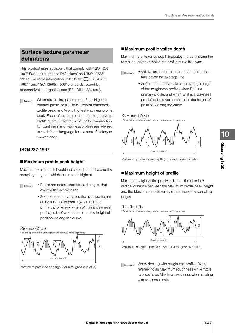
- Digital Microscope VHX-6000 User’s Manual -
Roughness Measurement(optional)
10-47
Ob
serving
in 3D
10
This product uses equations that comply with "ISO 4287: 1997 Surface roughness-Definitions" and "ISO 13565: 1996". For more information, refer to the "ISO 4287: 1997 " and "ISO 13565: 1996" standards issued by standardization organizations (BSI, DIN, JSA, etc.).
ISO4287:1997
Maximum profile peak height
Maximum profile peak height indicates the point along the sampling length at which the curve is highest.
Maximum profile valley depth
Maximum profile valley depth indicates the point along the sampling length at which the profile curve is lowest.
Maximum height of profile
Maximum height of the profile indicates the absolute vertical distance between the Maximum profile peak height and the Maximum profile valley depth along the sampling length.
Surface texture parameter definitions
When discussing parameters, Pp is Highest primary profile peak, Rp is Highest roughness profile peak, and Wp is Highest waviness profile peak. Each refers to the corresponding curve to profile curve. However, some of the parameters for roughness and waviness profiles are referred to as different language for reasons of history or convenience.
• Peaks are determined for each region that exceed the average line.
• Z(x) for each curve takes the average height of the roughness profile (when P, it is a primary profile, and when W, it is a waviness profile) to be 0 and determines the height of position x along the curve.
Rp
Rp1
Rp2
Rpi
Sampling length r
Rp max (Z(x))* Pp and Wp are used for primary profile and waviness profile respectively.
Maximum profile peak height (for a roughness profile)
• Valleys are determined for each region that falls below the average line.
• Z(x) for each curve takes the average height of the roughness profile (when P, it is a primary profile, and when W, it is a waviness profile) to be 0 and determines the height of position x along the curve.
When dealing with roughness profile, Rz is referred to as Maximum roughness while Wz is referred to as Maximum waviness when dealing with waviness profile.
Maximum profile valley depth (for a roughness profile)
Rv min (Z(x))* Pv and Wv are used for primary profile and waviness profile respectively.
Rvi
Rv
Rv2Rv1
Sampling length r
Maximum height of profile curve (for a roughness profile)
Rz Rp Rv+* Pz and Wz are used for primary profile and waviness profile respectively.
Rz
Rp
Rv
Sampling length r
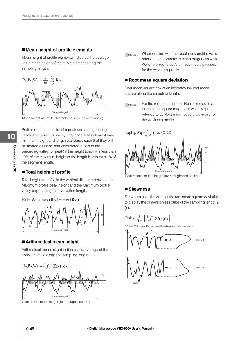
- Digital Microscope VHX-6000 User’s Manual -
Roughness Measurement(optional)
10-48
Ob
serving
in 3D
10
Mean height of profile elements
Mean height of profile elements indicates the average value of the height of the curve element along the sampling length.
Profile elements consist of a peak and a neighboring valley. The peaks (or valley) that constitutes element have minimum height and length standards such that they will be treated as noise and considered a part of the preceding valley (or peak) if the height (depth) is less than 10% of the maximum height or the length is less than 1% of the segment length.
Total height of profile
Total height of profile is the vertical distance between the Maximum profile peak height and the Maximum profile valley depth along the evaluation length.
Arithmetical mean height
Arithmetical mean height indicates the average of the absolute value along the sampling length.
Root mean square deviation
Root mean square deviation indicates the root mean square along the sampling length.
Skewness
Skewness uses the cube of the root mean square deviation to display the dimensionless cube of the sampling length Z (x).
Rc,Pc,Wc m Rti
Rt3Rt1
RtmR
t2
Rti
Sampling length r
Mean height of profile elements (for a roughness profile)
Rt,Pt,Wt max (Rpi) + max (Rvi)
Rv4
Rv2
Rt
Rp2 R
p5
Evaluation length n
r
Arithmetical mean height (for a roughness profile)
Ra,Pa,Wa Z(x) dxr1 r
0
Ra
Sampling length r
When dealing with the roughness profile, Ra is referred to as Arithmetic mean roughness while Wa is referred to as Arithmetic mean waviness for the waviness profile.
For the roughness profile, Rq is referred to as Root-mean-square roughness while Wq is referred to as Root-mean-square waviness for the waviness profile.
Root means square height (for a roughness profile)
Z²(x)dx1 r
0rRq,Pq,Wq
Rq 2
Sampling length r
Rsk Rq3
* Psk and Wsk are used for primary profile and waviness profile respectively.
Z³(x)dx1 r
0r1
Rsk < 0
Z
X
Rsk > 0
Z
X
Z(x)
Z(x)
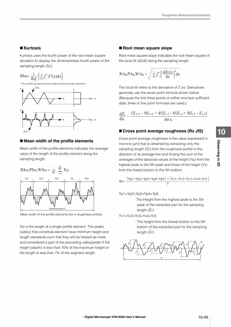
- Digital Microscope VHX-6000 User’s Manual -
Roughness Measurement(optional)
10-49
Ob
serving
in 3D
10
Kurtosis
Kurtosis uses the fourth power of the root mean square deviation to display the dimensionless fourth power of the sampling length Z(x).
Mean width of the profile elements
Mean width of the profile elements indicates the average value of the length of the profile element along the sampling length.
Xsi is the length of a single profile element. The peaks (valley) that constitute element have minimum height and length standards such that they will be treated as noise and considered a part of the preceding valley(peak) if the height (depth) is less than 10% of the maximum height or the length is less than 1% of the segment length.
Root mean square slope
Root mean square slope indicates the root mean square of the local tilt dZ/dX along the sampling length.
The local tilt refers to the derivative of Z (x). Derivatives generally use the seven-point formula shown below. (Because the first three points on either end lack sufficient data, three or five point formulae are used.)
Cross point average roughness (Rz JIS)
Cross point average roughness is the value expressed in microns (μm) that is obtained by extracting only the sampling length ( r) from the roughness profile in the direction of its average line and finding the sum of the averages of the absolute values of the height (Yp) from the highest peak to the 5th peak and those of the height (Yv) from the lowest bottom to the 5th bottom.
Yp1+Yp2+Yp3+Yp4+Yp5
: The Height from the highest peak to the 5th peak of the extracted part for the sampling length ( r)
Yv1+Yv2+Yv3+Yv4+Yv5
: The height from the lowest bottom to the 5th bottom of the extracted part for the sampling length ( r)
Rku Rq4
* Pku and Wku are used for primary profile and waviness profile respectively.
Z4(x)dx1 r
0r
Rku < 3
Rku > 3
Z
X
Z(x)
Z
X
Z(x)
Mean width of the profile elements (for a roughness profile)
RSm,PSm,WSm m Xsi
Xs1 Xs2 Xs3 Xsi Xsm
Sampling length r
RΔq,PΔq,WΔq dx1 r
0r²dZ(x)
dx
ii
dxdZ i+3 i+2(Z - 9Z i+1+ 45Z
60 xi-1- 45Z i-2+ 9Z i-3)- Z
Rz 5+ Yv1+Yv2+Yv3+Yv4+Yv5Yp1+Yp2+Yp3+Yp4+Yp5
Y p1
Y p2
Y p3
Y p4
Y p5
Y v1 Y v
2
Y v3
Y v4 Y v
5
m
r
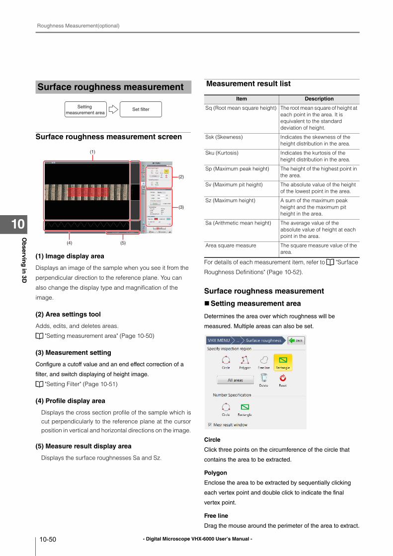
- Digital Microscope VHX-6000 User’s Manual -
Roughness Measurement(optional)
10-50
Ob
serving
in 3D
10
Surface roughness measurement screen
(1) Image display area
Displays an image of the sample when you see it from the
perpendicular direction to the reference plane. You can
also change the display type and magnification of the
image.
(2) Area settings tool
Adds, edits, and deletes areas.
"Setting measurement area" (Page 10-50)
(3) Measurement setting
Configure a cutoff value and an end effect correction of a
filter, and switch displaying of height image.
"Setting Filter" (Page 10-51)
(4) Profile display area
Displays the cross section profile of the sample which iscut perpendicularly to the reference plane at the cursorposition in vertical and horizontal directions on the image.
(5) Measure result display area
Displays the surface roughnesses Sa and Sz.
Measurement result list
For details of each measurement item, refer to "Surface
Roughness Definitions" (Page 10-52).
Surface roughness measurement
Setting measurement area
Determines the area over which roughness will be
measured. Multiple areas can also be set.
Circle
Click three points on the circumference of the circle that
contains the area to be extracted.
Polygon
Enclose the area to be extracted by sequentially clicking
each vertex point and double click to indicate the final
vertex point.
Free line
Drag the mouse around the perimeter of the area to extract.
Surface roughness measurement
Setting measurement area
Set filter
(5)(4)
(1)
(3)
(2)
Item Description
Sq (Root mean square height) The root mean square of height at each point in the area. It is equivalent to the standard deviation of height.
Ssk (Skewness) Indicates the skewness of the height distribution in the area.
Sku (Kurtosis) Indicates the kurtosis of the height distribution in the area.
Sp (Maximum peak height) The height of the highest point in the area.
Sv (Maximum pit height) The absolute value of the height of the lowest point in the area.
Sz (Maximum height) A sum of the maximum peak height and the maximum pit height in the area.
Sa (Arithmetic mean height) The average value of the absolute value of height at each point in the area.
Area square measure The square measure value of the area.
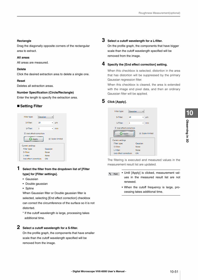
- Digital Microscope VHX-6000 User’s Manual -
Roughness Measurement(optional)
10-51
Ob
serving
in 3D
10
Rectangle
Drag the diagonally opposite corners of the rectangular
area to extract.
All areas
All areas are measured.
Delete
Click the desired extraction area to delete a single one.
Reset
Deletes all extraction areas.
Number Specification (Circle/Rectangle)
Enter the length to specify the extraction area.
Setting Filter
1 Select the filter from the dropdown list of [Filter
type] for [Filter settings].
• Gaussian
• Double gaussian
• Spline
When Gaussian filter or Double gaussian filter is
selected, selecting [End effect correction] checkbox
can correct the circumference of the surface so it is not
distorted.
* If the cutoff wavelength is large, processing takes
additional time.
2 Select a cutoff wavelength for a S-filter.
On the profile graph, the components that have smaller
scale than the cutoff wavelength specified will be
removed from the image.
3 Select a cutoff wavelength for a L-filter.
On the profile graph, the components that have bigger
scale than the cutoff wavelength specified will be
removed from the image.
4 Specify the [End effect correction] setting.
When this checkbox is selected, distortion in the areathat has distortion will be suppressed by the primaryGaussian regression filter.
When this checkbox is cleared, the area is extendedwith the image end pixel data, and then an ordinaryGaussian filter will be applied.
5 Click [Apply].
The filtering is executed and measured values in themeasurement result list are updated.
• Until [Apply] is clicked, measurement val-
ues in the measured result list are not
renewed.
• When the cutoff frequency is large, pro-
cessing takes additional time.
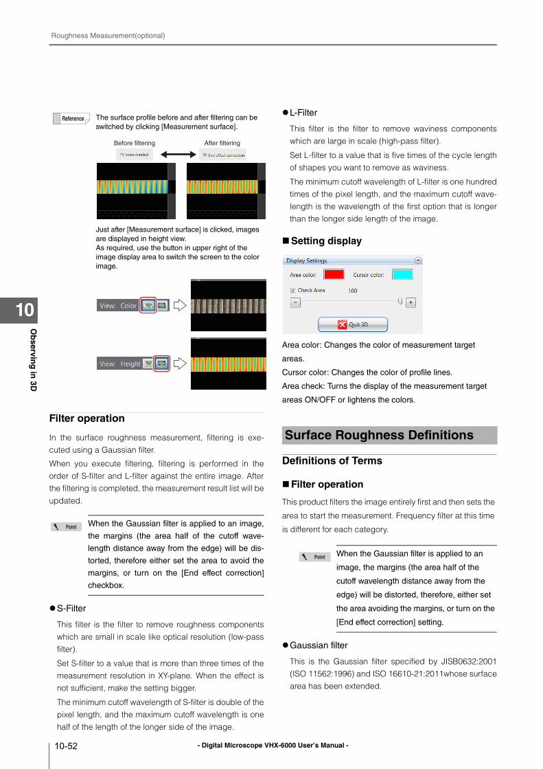
- Digital Microscope VHX-6000 User’s Manual -
Roughness Measurement(optional)
10-52
Ob
serving
in 3D
10
Filter operation
In the surface roughness measurement, filtering is exe-cuted using a Gaussian filter.
When you execute filtering, filtering is performed in theorder of S-filter and L-filter against the entire image. Afterthe filtering is completed, the measurement result list will beupdated.
S-Filter
This filter is the filter to remove roughness componentswhich are small in scale like optical resolution (low-passfilter).
Set S-filter to a value that is more than three times of themeasurement resolution in XY-plane. When the effect isnot sufficient, make the setting bigger.
The minimum cutoff wavelength of S-filter is double of thepixel length, and the maximum cutoff wavelength is onehalf of the length of the longer side of the image.
L-Filter
This filter is the filter to remove waviness componentswhich are large in scale (high-pass filter).
Set L-filter to a value that is five times of the cycle lengthof shapes you want to remove as waviness.
The minimum cutoff wavelength of L-filter is one hundredtimes of the pixel length, and the maximum cutoff wave-length is the wavelength of the first option that is longerthan the longer side length of the image.
Setting display
Area color: Changes the color of measurement target
areas.
Cursor color: Changes the color of profile lines.
Area check: Turns the display of the measurement target
areas ON/OFF or lightens the colors.
Definitions of Terms
Filter operation
This product filters the image entirely first and then sets the
area to start the measurement. Frequency filter at this time
is different for each category.
Gaussian filter
This is the Gaussian filter specified by JISB0632:2001(ISO 11562:1996) and ISO 16610-21:2011whose surfacearea has been extended.
The surface profile before and after filtering can be
switched by clicking [Measurement surface].
Just after [Measurement surface] is clicked, images
are displayed in height view.
As required, use the button in upper right of the
image display area to switch the screen to the color
image.
When the Gaussian filter is applied to an image,
the margins (the area half of the cutoff wave-
length distance away from the edge) will be dis-
torted, therefore either set the area to avoid the
margins, or turn on the [End effect correction]
checkbox.
Before filtering After filtering
Surface Roughness Definitions
When the Gaussian filter is applied to an
image, the margins (the area half of the
cutoff wavelength distance away from the
edge) will be distorted, therefore, either set
the area avoiding the margins, or turn on the
[End effect correction] setting.
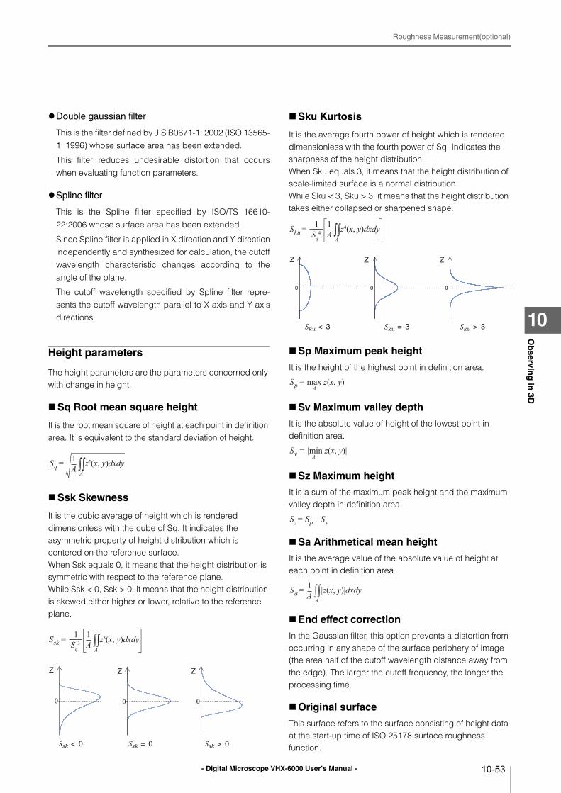
- Digital Microscope VHX-6000 User’s Manual -
Roughness Measurement(optional)
10-53
Ob
serving
in 3D
10
Double gaussian filter
This is the filter defined by JIS B0671-1: 2002 (ISO 13565-1: 1996) whose surface area has been extended.
This filter reduces undesirable distortion that occurswhen evaluating function parameters.
Spline filter
This is the Spline filter specified by ISO/TS 16610-22:2006 whose surface area has been extended.
Since Spline filter is applied in X direction and Y directionindependently and synthesized for calculation, the cutoffwavelength characteristic changes according to theangle of the plane.
The cutoff wavelength specified by Spline filter repre-sents the cutoff wavelength parallel to X axis and Y axisdirections.
Height parameters
The height parameters are the parameters concerned only with change in height.
Sq Root mean square height
It is the root mean square of height at each point in definition area. It is equivalent to the standard deviation of height.
Ssk Skewness
It is the cubic average of height which is rendered dimensionless with the cube of Sq. It indicates the asymmetric property of height distribution which is centered on the reference surface.When Ssk equals 0, it means that the height distribution is symmetric with respect to the reference plane.While Ssk < 0, Ssk > 0, it means that the height distribution is skewed either higher or lower, relative to the reference plane.
Sku Kurtosis
It is the average fourth power of height which is rendered dimensionless with the fourth power of Sq. Indicates the sharpness of the height distribution.When Sku equals 3, it means that the height distribution of scale-limited surface is a normal distribution.While Sku < 3, Sku > 3, it means that the height distribution takes either collapsed or sharpened shape.
Sp Maximum peak height
It is the height of the highest point in definition area.
Sv Maximum valley depth
It is the absolute value of height of the lowest point in definition area.
Sz Maximum height
It is a sum of the maximum peak height and the maximum valley depth in definition area.
Sa Arithmetical mean height
It is the average value of the absolute value of height at each point in definition area.
End effect correction
In the Gaussian filter, this option prevents a distortion from occurring in any shape of the surface periphery of image (the area half of the cutoff wavelength distance away from the edge). The larger the cutoff frequency, the longer the processing time.
Original surface
This surface refers to the surface consisting of height data at the start-up time of ISO 25178 surface roughness function.
Sq1A z2(x, y)dxdyA∫∫=
Ssk1A z3(x, y)dxdyA∫∫= 1
Sq3
Z Z Z
< 0 = 0 > 0
Sku1A z4(x, y)dxdyA∫∫= 1
Sq4
Z
< 3 = 3 > 3
Z Z
Sp A= max z(x, y)
Sv A= |min z(x, y)|
Sz Sp Sv= +
Sa1A |z(x, y)|dxdyA∫∫=
- Digital Microscope VHX-6000 User’s Manual -
Roughness Measurement(optional)
10-54
Ob
serving
in 3D
10
Scale-limited surface
This represents a surface obtained by applying the S-filter
and L-filter to the original surface.
S-filter
This is the filter (low-pass filter) to remove components which are small in scale.This filter is equivalent to the cutoff value λs of JIS B0601-2001. It refers to a low-pass filter for a frequency filter such as a Gaussian filter.
L-filter
This is the filter (high-pass filter) to remove components which are large in scale.This filter removes components such as waviness and extracts only roughness components. This is equivalent to the cutoff value λc of JIS B0633-2001. It refers to a high-pass filter for a frequency filter such as a Gaussian filter.
Height
It refers to a distance from the reference surface at each
point in a scale-limited surface. Points lower than the
reference surface will have negative values. In the
definitional equation, the height in coordinates (x, y) is
expressed by z (x, y).
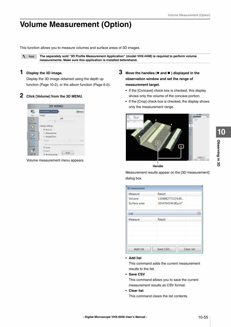
- Digital Microscope VHX-6000 User’s Manual -
Volume Measurement (Option)
10-55
Ob
serving
in 3D
10
Volume Measurement (Option)
This function allows you to measure volumes and surface areas of 3D images.
1 Display the 3D image.
Display the 3D image obtained using the depth up
function (Page 10-2), or the album function (Page 6-2).
2 Click [Volume] from the 3D MENU.
Volume measurement menu appears.
3 Move the handles ( and ) displayed in the
observation window and set the range of
measurement target.
• If the [Concave] check box is checked, this display
shows only the volume of the concave portion.
• If the [Crop] check box is checked, the display shows
only the measurement range.
Measurement results appear on the [3D measurement]
dialog box.
• Add list
This command adds the current measurement
results to the list.
• Save CSV
This command allows you to save the current
measurement results as CSV format.
• Clear list
This command clears the list contents.
The separately sold "3D Profile Measurement Application" (model VHX-H4M) is required to perform volume measurements. Make sure this application is installed beforehand.
Handle
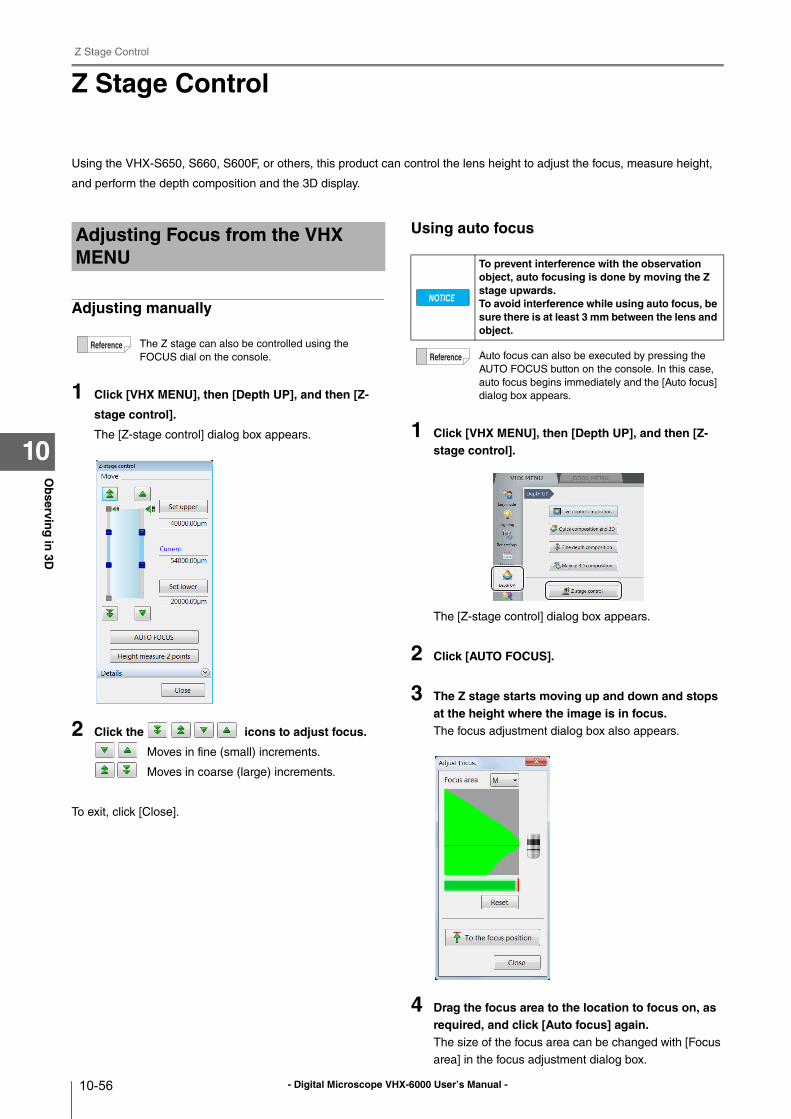
- Digital Microscope VHX-6000 User’s Manual -
Z Stage Control
10-56
Ob
serving
in 3D
10
Z Stage Control
Using the VHX-S650, S660, S600F, or others, this product can control the lens height to adjust the focus, measure height,
and perform the depth composition and the 3D display.
Adjusting manually
1 Click [VHX MENU], then [Depth UP], and then [Z-
stage control].
The [Z-stage control] dialog box appears.
2 Click the icons to adjust focus.
Moves in fine (small) increments.
Moves in coarse (large) increments.
To exit, click [Close].
Using auto focus
1 Click [VHX MENU], then [Depth UP], and then [Z-stage control].
The [Z-stage control] dialog box appears.
2 Click [AUTO FOCUS].
3 The Z stage starts moving up and down and stops at the height where the image is in focus.The focus adjustment dialog box also appears.
4 Drag the focus area to the location to focus on, as required, and click [Auto focus] again.The size of the focus area can be changed with [Focus
area] in the focus adjustment dialog box.
Adjusting Focus from the VHX MENU
The Z stage can also be controlled using the
FOCUS dial on the console.
To prevent interference with the observation object, auto focusing is done by moving the Z stage upwards.To avoid interference while using auto focus, be sure there is at least 3 mm between the lens and object.
Auto focus can also be executed by pressing the
AUTO FOCUS button on the console. In this case,
auto focus begins immediately and the [Auto focus]
dialog box appears.
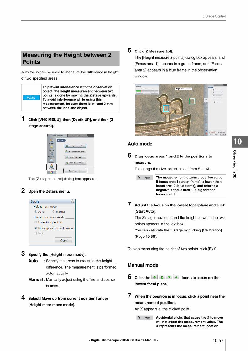
- Digital Microscope VHX-6000 User’s Manual -
Z Stage Control
10-57
Ob
serving
in 3D
10
Auto focus can be used to measure the difference in height
of two specified areas.
1 Click [VHX MENU], then [Depth UP], and then [Z-
stage control].
The [Z-stage control] dialog box appears.
2 Open the Details menu.
3 Specify the [Height mesr mode].
Auto : Specify the areas to measure the height
difference. The measurement is performed
automatically.
Manual : Manually adjust using the fine and coarse
buttons.
4 Select [Move up from current position] under
[Height mesr move mode].
5 Click [Z Measure 2pt].
The [Height measure 2 points] dialog box appears, and
[Focus area 1] appears in a green frame, and [Focus
area 2] appears in a blue frame in the observation
window.
Auto mode
6 Drag focus areas 1 and 2 to the positions to
measure.
To change the size, select a size from S to XL.
7 Adjust the focus on the lowest focal plane and click
[Start Auto].
The Z stage moves up and the height between the two
points appears in the text box.
You can calibrate the Z stage by clicking [Calibration]
(Page 10-58).
To stop measuring the height of two points, click [Exit].
Manual mode
6 Click the icons to focus on the
lowest focal plane.
7 When the position is in focus, click a point near the
measurement position.
An X appears at the clicked point.
Measuring the Height between 2 Points
To prevent interference with the observation object, the height measurement between two points is done by moving the Z stage upwards.To avoid interference while using this measurement, be sure there is at least 3 mm between the lens and object.
The measurement returns a positive value if focus area 1 (green frame) is lower than focus area 2 (blue frame), and returns a negative if focus area 1 is higher than focus area 2.
Accidental clicks that cause the X to move will not affect the measurement value. The X represents the measurement location.
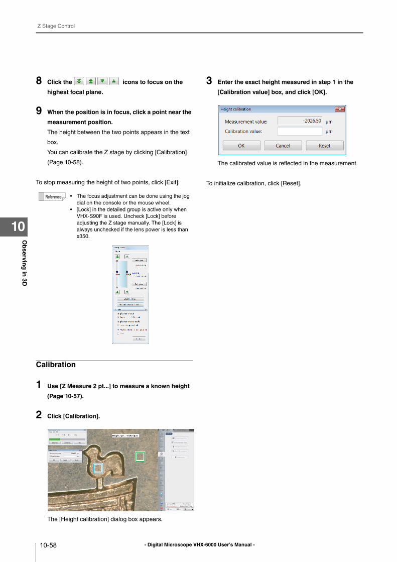
- Digital Microscope VHX-6000 User’s Manual -
Z Stage Control
10-58
Ob
serving
in 3D
10
8 Click the icons to focus on the
highest focal plane.
9 When the position is in focus, click a point near the
measurement position.
The height between the two points appears in the text
box.
You can calibrate the Z stage by clicking [Calibration]
(Page 10-58).
To stop measuring the height of two points, click [Exit].
Calibration
1 Use [Z Measure 2 pt...] to measure a known height
(Page 10-57).
2 Click [Calibration].
The [Height calibration] dialog box appears.
3 Enter the exact height measured in step 1 in the
[Calibration value] box, and click [OK].
The calibrated value is reflected in the measurement.
To initialize calibration, click [Reset].
• The focus adjustment can be done using the jog
dial on the console or the mouse wheel.
• [Lock] in the detailed group is active only when
VHX-S90F is used. Uncheck [Lock] before
adjusting the Z stage manually. The [Lock] is
always unchecked if the lens power is less than
x350.
- Digital Microscope VHX-6000 User’s Manual - 11-1
Chapter11S
titchin
g Im
ages
11
Stitching Images
2D Image Stitching and 3D Image Stitching
This function allows you to stitch images while moving the
object to obtain high-resolution wide-view images.
Image stitching can be done in both 2D and 3D.
Automatic Image Stitching ....................................Page 11-2
Stitching 2D Images Automatically....................Page 11-2
Stitching 3D Images Automatically....................Page 11-5
Manual Image Stitching ........................................Page 11-8
Stitching 2D Images..........................................Page 11-8
Stitching 3D Images..........................................Page 11-9
Split recording .....................................................Page 11-12
Splitting and saving original image before stitching
....................................................................Page 11-12
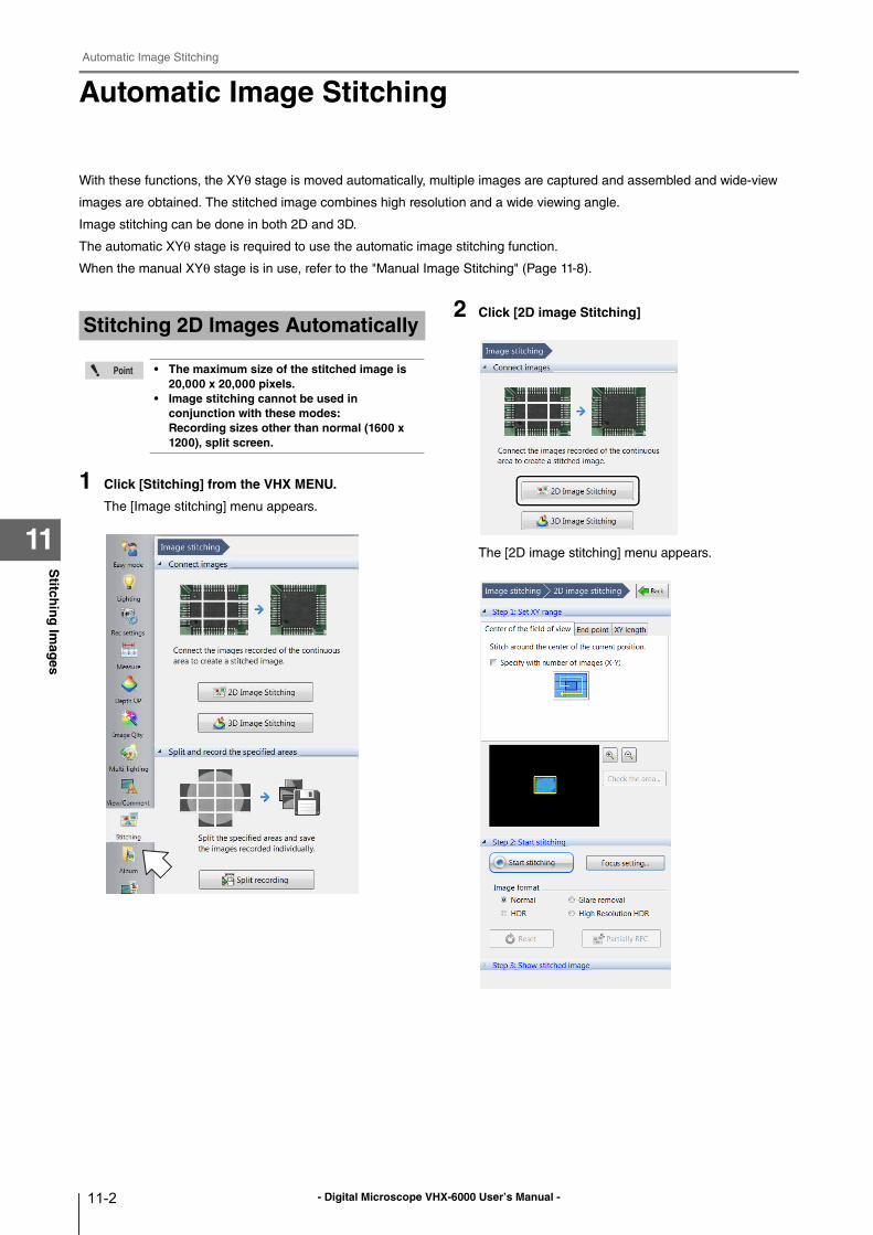
- Digital Microscope VHX-6000 User’s Manual -
Automatic Image Stitching
11-2
Stitch
ing
Imag
es
11
Automatic Image Stitching
With these functions, the XYθ stage is moved automatically, multiple images are captured and assembled and wide-view
images are obtained. The stitched image combines high resolution and a wide viewing angle.
Image stitching can be done in both 2D and 3D.
The automatic XYθ stage is required to use the automatic image stitching function.
When the manual XYθ stage is in use, refer to the "Manual Image Stitching" (Page 11-8).
1 Click [Stitching] from the VHX MENU.
The [Image stitching] menu appears.
2 Click [2D image Stitching]
The [2D image stitching] menu appears.
Stitching 2D Images Automatically
• The maximum size of the stitched image is 20,000 x 20,000 pixels.
• Image stitching cannot be used in conjunction with these modes:Recording sizes other than normal (1600 x 1200), split screen.
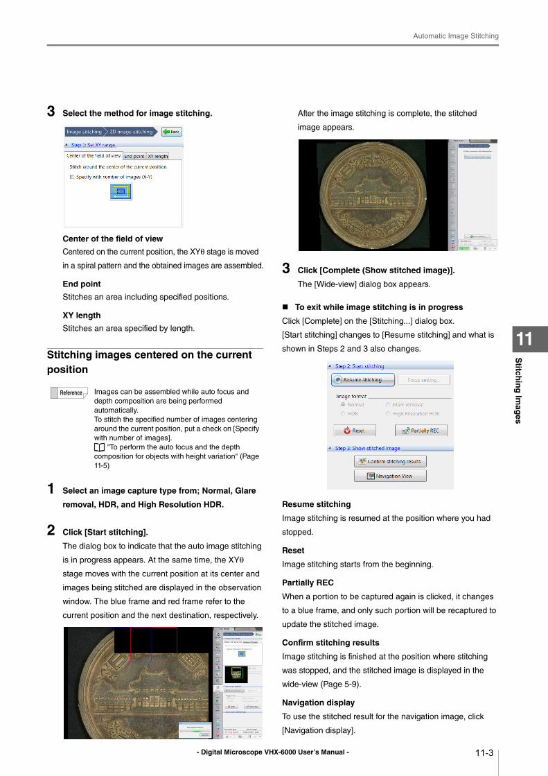
- Digital Microscope VHX-6000 User’s Manual -
Automatic Image Stitching
11-3
Stitch
ing
Imag
es
11
3 Select the method for image stitching.
Center of the field of view
Centered on the current position, the XYθ stage is moved
in a spiral pattern and the obtained images are assembled.
End point
Stitches an area including specified positions.
XY length
Stitches an area specified by length.
Stitching images centered on the current position
1 Select an image capture type from; Normal, Glare
removal, HDR, and High Resolution HDR.
2 Click [Start stitching].
The dialog box to indicate that the auto image stitching
is in progress appears. At the same time, the XYθ
stage moves with the current position at its center and
images being stitched are displayed in the observation
window. The blue frame and red frame refer to the
current position and the next destination, respectively.
After the image stitching is complete, the stitched
image appears.
3 Click [Complete (Show stitched image)].
The [Wide-view] dialog box appears.
To exit while image stitching is in progress
Click [Complete] on the [Stitching...] dialog box.
[Start stitching] changes to [Resume stitching] and what is
shown in Steps 2 and 3 also changes.
Resume stitching
Image stitching is resumed at the position where you had
stopped.
Reset
Image stitching starts from the beginning.
Partially REC
When a portion to be captured again is clicked, it changes
to a blue frame, and only such portion will be recaptured to
update the stitched image.
Confirm stitching results
Image stitching is finished at the position where stitching
was stopped, and the stitched image is displayed in the
wide-view (Page 5-9).
Navigation display
To use the stitched result for the navigation image, click
[Navigation display].
Images can be assembled while auto focus and
depth composition are being performed
automatically.
To stitch the specified number of images centering
around the current position, put a check on [Specify
with number of images].
"To perform the auto focus and the depth
composition for objects with height variation" (Page
11-5)
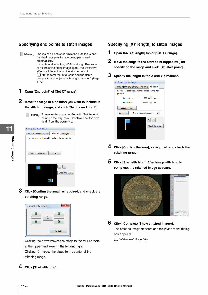
- Digital Microscope VHX-6000 User’s Manual -
Automatic Image Stitching
11-4
Stitch
ing
Imag
es
11
Specifying end points to stitch images
1 Open [End point] of [Set XY range].
2 Move the stage to a position you want to include in
the stitching range, and click [Set the end point].
3 Click [Confirm the area], as required, and check the
stitching range.
Clicking the arrow moves the stage to the four corners
at the upper and lower in the left and right.
Clicking [C] moves the stage to the center of the
stitching range.
4 Click [Start stitching].
Specifying [XY length] to stitch images
1 Open the [XY length] tab of [Set XY range].
2 Move the stage to the start point (upper left ) for
specifying the range and click [Set start point].
3 Specify the length in the X and Y directions.
4 Click [Confirm the area], as required, and check the
stitching range.
5 Click [Start stitching]. After image stitching is
complete, the stitched image appears.
6 Click [Complete (Show stitched image)].
The stitched image appears and the [Wide-view] dialog
box appears.
"Wide-view" (Page 5-9)
Images can be stitched while the auto focus and
the depth composition are being performed
automatically.
If the glare elimination, HDR, and High Resolution
HDR are selected in [Image Type], the respective
effects will be active on the stitched result.
"To perform the auto focus and the depth
composition for objects with height variation" (Page
11-5)
To narrow the area specified with [Set the end
point] on the way, click [Reset] and set the area
again from the beginning.
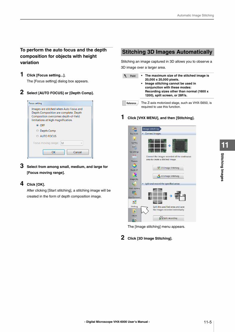
- Digital Microscope VHX-6000 User’s Manual -
Automatic Image Stitching
11-5
Stitch
ing
Imag
es
11
To perform the auto focus and the depth composition for objects with height variation
1 Click [Focus setting...].
The [Focus setting] dialog box appears.
2 Select [AUTO FOCUS] or [Depth Comp].
3 Select from among small, medium, and large for
[Focus moving range].
4 Click [OK].
After clicking [Start stitching], a stitching image will be
created in the form of depth composition image.
Stitching an image captured in 3D allows you to observe a
3D image over a larger area.
1 Click [VHX MENU], and then [Stitching].
The [Image stitching] menu appears.
2 Click [3D Image Stitching].
Stitching 3D Images Automatically
• The maximum size of the stitched image is 20,000 x 20,000 pixels.
• Image stitching cannot be used in conjunction with these modes:Recording sizes other than normal (1600 x 1200), split screen, or 28F/s.
The Z-axis motorized stage, such as VHX-S650, is
required to use this function.
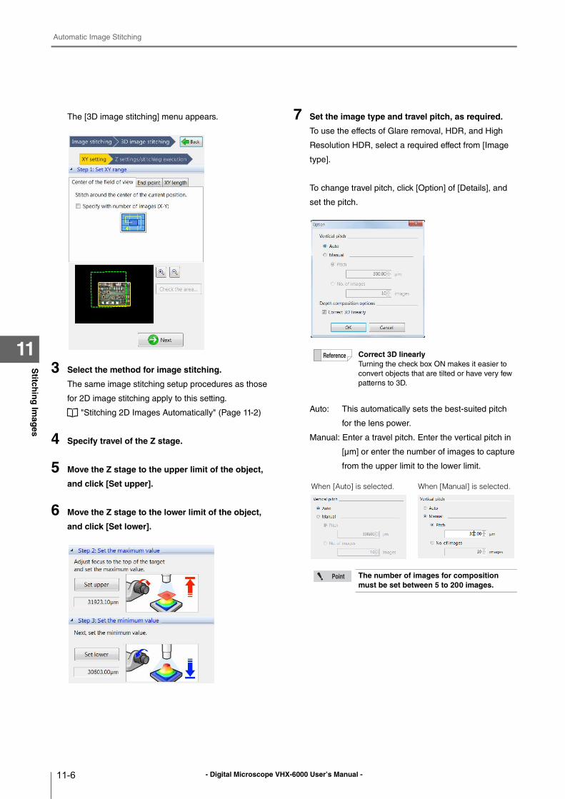
- Digital Microscope VHX-6000 User’s Manual -
Automatic Image Stitching
11-6
Stitch
ing
Imag
es
11
The [3D image stitching] menu appears.
3 Select the method for image stitching.
The same image stitching setup procedures as those
for 2D image stitching apply to this setting.
"Stitching 2D Images Automatically" (Page 11-2)
4 Specify travel of the Z stage.
5 Move the Z stage to the upper limit of the object,
and click [Set upper].
6 Move the Z stage to the lower limit of the object,
and click [Set lower].
7 Set the image type and travel pitch, as required.
To use the effects of Glare removal, HDR, and High
Resolution HDR, select a required effect from [Image
type].
To change travel pitch, click [Option] of [Details], and
set the pitch.
Auto: This automatically sets the best-suited pitch
for the lens power.
Manual: Enter a travel pitch. Enter the vertical pitch in
[μm] or enter the number of images to capture
from the upper limit to the lower limit.
Correct 3D linearlyTurning the check box ON makes it easier to
convert objects that are tilted or have very few
patterns to 3D.
The number of images for composition must be set between 5 to 200 images.
When [Auto] is selected. When [Manual] is selected.
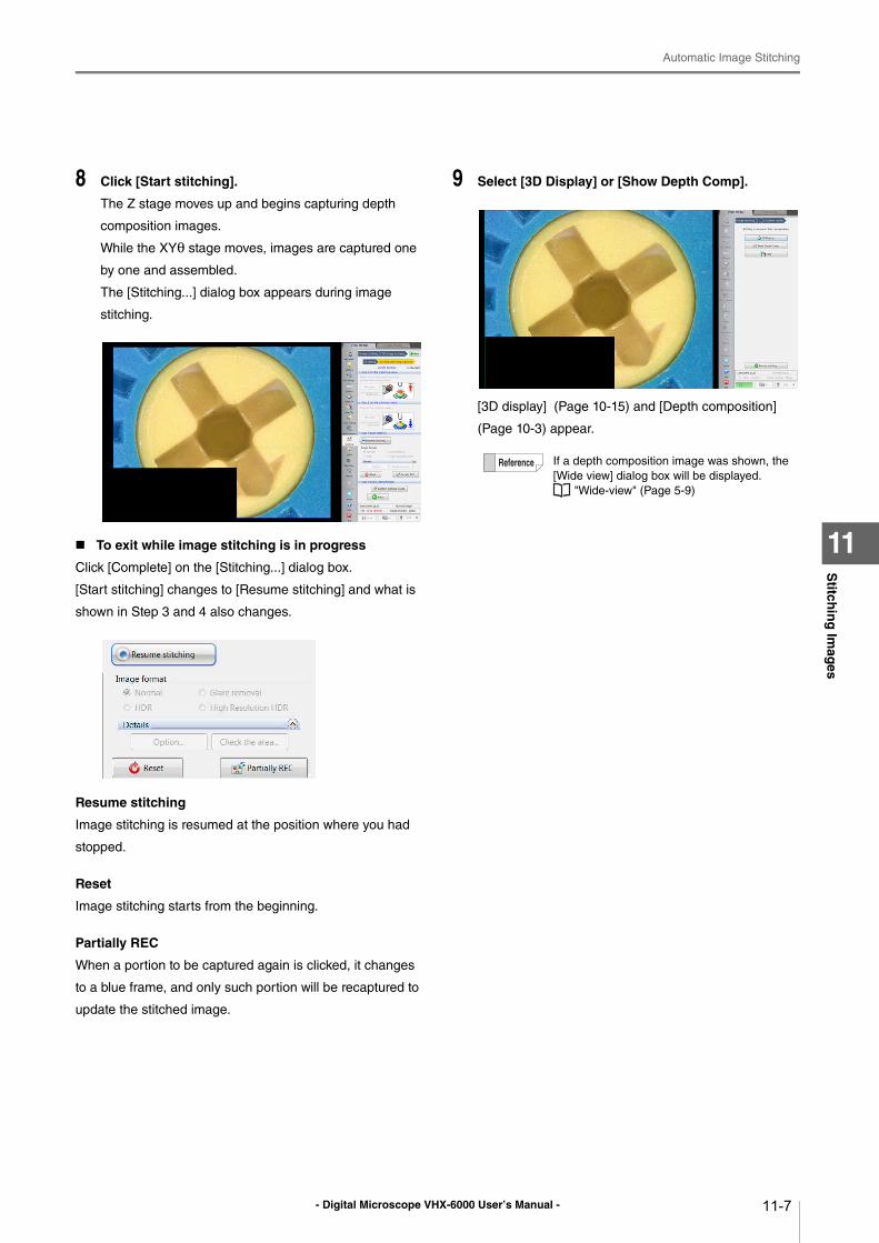
- Digital Microscope VHX-6000 User’s Manual -
Automatic Image Stitching
11-7
Stitch
ing
Imag
es
11
8 Click [Start stitching].
The Z stage moves up and begins capturing depth
composition images.
While the XYθ stage moves, images are captured one
by one and assembled.
The [Stitching...] dialog box appears during image
stitching.
To exit while image stitching is in progress
Click [Complete] on the [Stitching...] dialog box.
[Start stitching] changes to [Resume stitching] and what is
shown in Step 3 and 4 also changes.
Resume stitching
Image stitching is resumed at the position where you had
stopped.
Reset
Image stitching starts from the beginning.
Partially REC
When a portion to be captured again is clicked, it changes
to a blue frame, and only such portion will be recaptured to
update the stitched image.
9 Select [3D Display] or [Show Depth Comp].
[3D display] (Page 10-15) and [Depth composition]
(Page 10-3) appear.
If a depth composition image was shown, the
[Wide view] dialog box will be displayed.
"Wide-view" (Page 5-9)
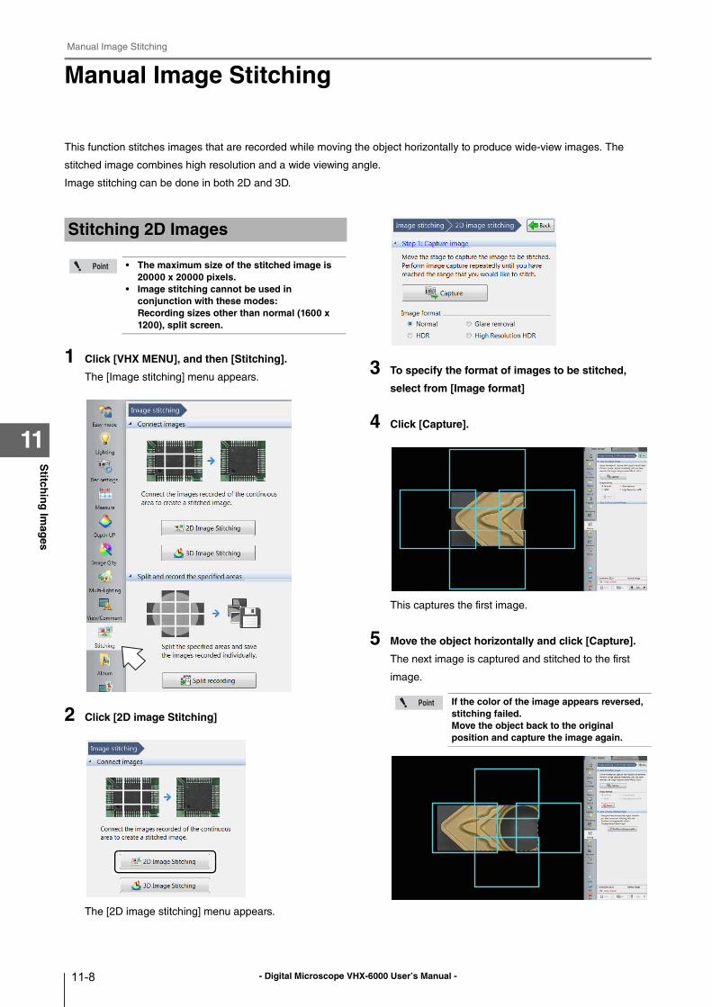
- Digital Microscope VHX-6000 User’s Manual -
Manual Image Stitching
11-8
Stitch
ing
Imag
es
11
Manual Image Stitching
This function stitches images that are recorded while moving the object horizontally to produce wide-view images. The
stitched image combines high resolution and a wide viewing angle.
Image stitching can be done in both 2D and 3D.
1 Click [VHX MENU], and then [Stitching].
The [Image stitching] menu appears.
2 Click [2D image Stitching]
The [2D image stitching] menu appears.
3 To specify the format of images to be stitched,
select from [Image format]
4 Click [Capture].
This captures the first image.
5 Move the object horizontally and click [Capture].
The next image is captured and stitched to the first
image.
Stitching 2D Images
• The maximum size of the stitched image is 20000 x 20000 pixels.
• Image stitching cannot be used in conjunction with these modes:Recording sizes other than normal (1600 x 1200), split screen.
If the color of the image appears reversed, stitching failed.Move the object back to the original position and capture the image again.
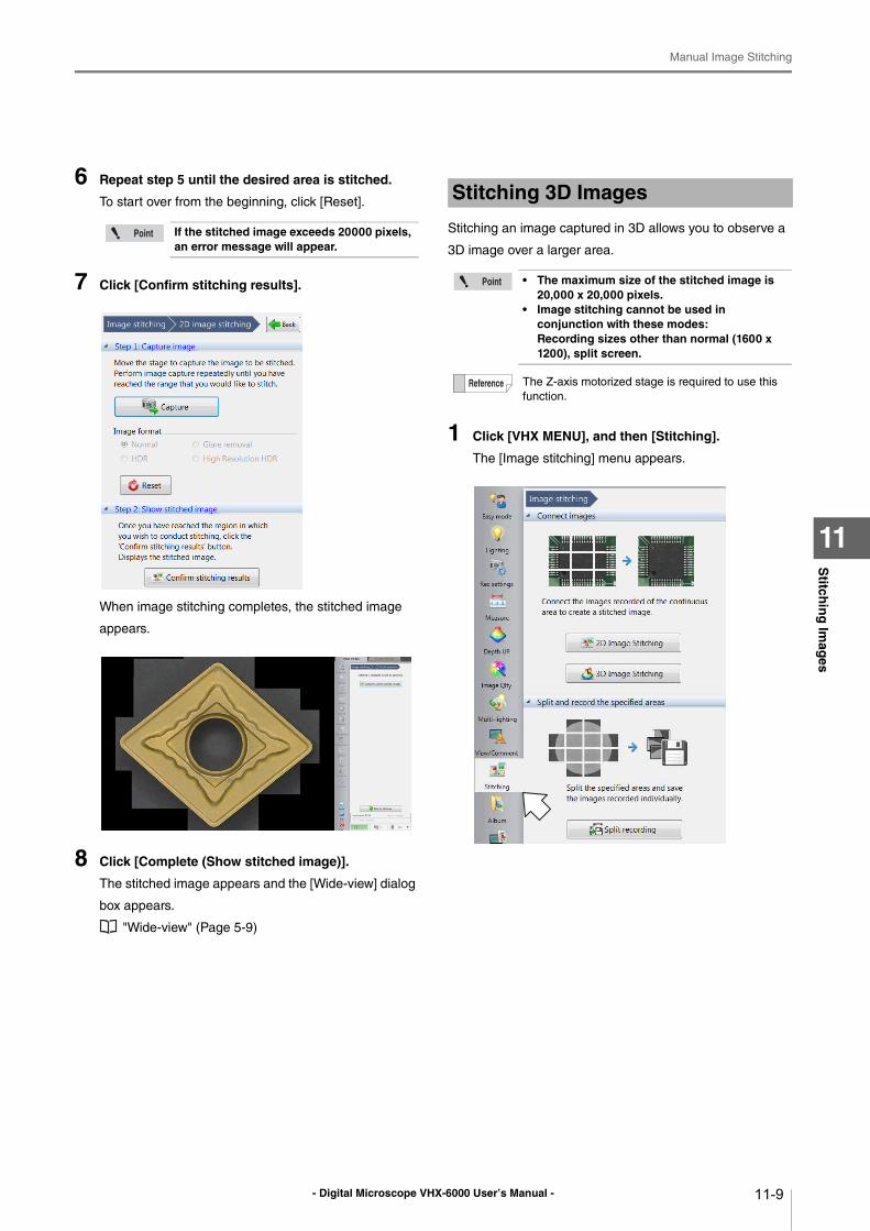
- Digital Microscope VHX-6000 User’s Manual -
Manual Image Stitching
11-9
Stitch
ing
Imag
es
11
6 Repeat step 5 until the desired area is stitched.
To start over from the beginning, click [Reset].
7 Click [Confirm stitching results].
When image stitching completes, the stitched image
appears.
8 Click [Complete (Show stitched image)].
The stitched image appears and the [Wide-view] dialog
box appears.
"Wide-view" (Page 5-9)
Stitching an image captured in 3D allows you to observe a
3D image over a larger area.
1 Click [VHX MENU], and then [Stitching].
The [Image stitching] menu appears.
If the stitched image exceeds 20000 pixels, an error message will appear.
Stitching 3D Images
• The maximum size of the stitched image is 20,000 x 20,000 pixels.
• Image stitching cannot be used in conjunction with these modes:Recording sizes other than normal (1600 x 1200), split screen.
The Z-axis motorized stage is required to use this
function.
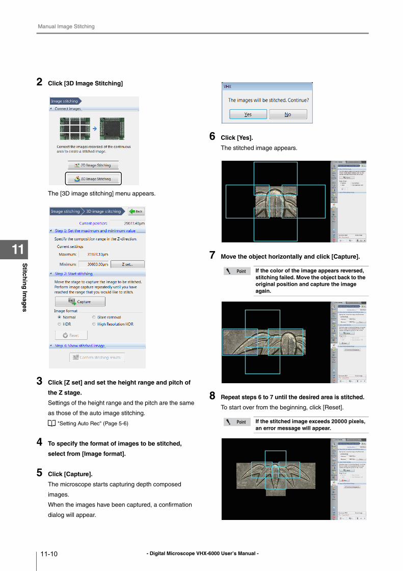
- Digital Microscope VHX-6000 User’s Manual -
Manual Image Stitching
11-10
Stitch
ing
Imag
es
11
2 Click [3D Image Stitching]
The [3D image stitching] menu appears.
3 Click [Z set] and set the height range and pitch of
the Z stage.
Settings of the height range and the pitch are the same
as those of the auto image stitching.
"Setting Auto Rec" (Page 5-6)
4 To specify the format of images to be stitched,
select from [Image format].
5 Click [Capture].
The microscope starts capturing depth composed
images.
When the images have been captured, a confirmation
dialog will appear.
6 Click [Yes].
The stitched image appears.
7 Move the object horizontally and click [Capture].
8 Repeat steps 6 to 7 until the desired area is stitched.
To start over from the beginning, click [Reset].
If the color of the image appears reversed, stitching failed. Move the object back to the original position and capture the image again.
If the stitched image exceeds 20000 pixels, an error message will appear.
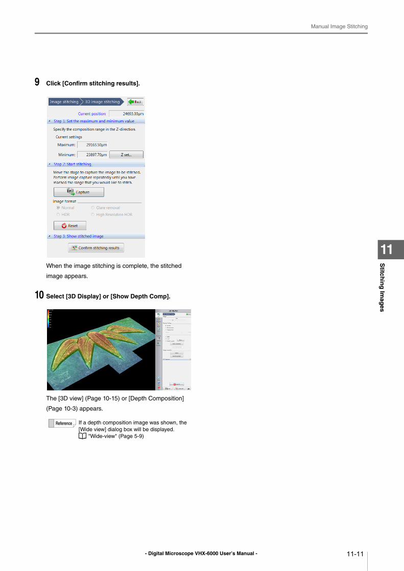
- Digital Microscope VHX-6000 User’s Manual -
Manual Image Stitching
11-11
Stitch
ing
Imag
es
11
9 Click [Confirm stitching results].
When the image stitching is complete, the stitched
image appears.
10 Select [3D Display] or [Show Depth Comp].
The [3D view] (Page 10-15) or [Depth Composition]
(Page 10-3) appears.
If a depth composition image was shown, the
[Wide view] dialog box will be displayed.
"Wide-view" (Page 5-9)
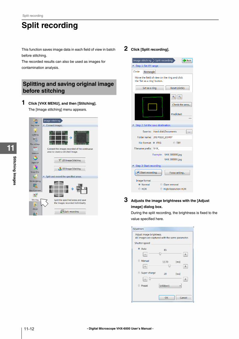
- Digital Microscope VHX-6000 User’s Manual -
Split recording
11-12
Stitch
ing
Imag
es
11
Split recording
This function saves image data in each field of view in batch
before stitching.
The recorded results can also be used as images for
contamination analysis.
1 Click [VHX MENU], and then [Stitching].
The [Image stitching] menu appears.
2 Click [Split recording].
3 Adjusts the image brightness with the [Adjust
image] dialog box.
During the split recording, the brightness is fixed to the
value specified here.
Splitting and saving original image before stitching
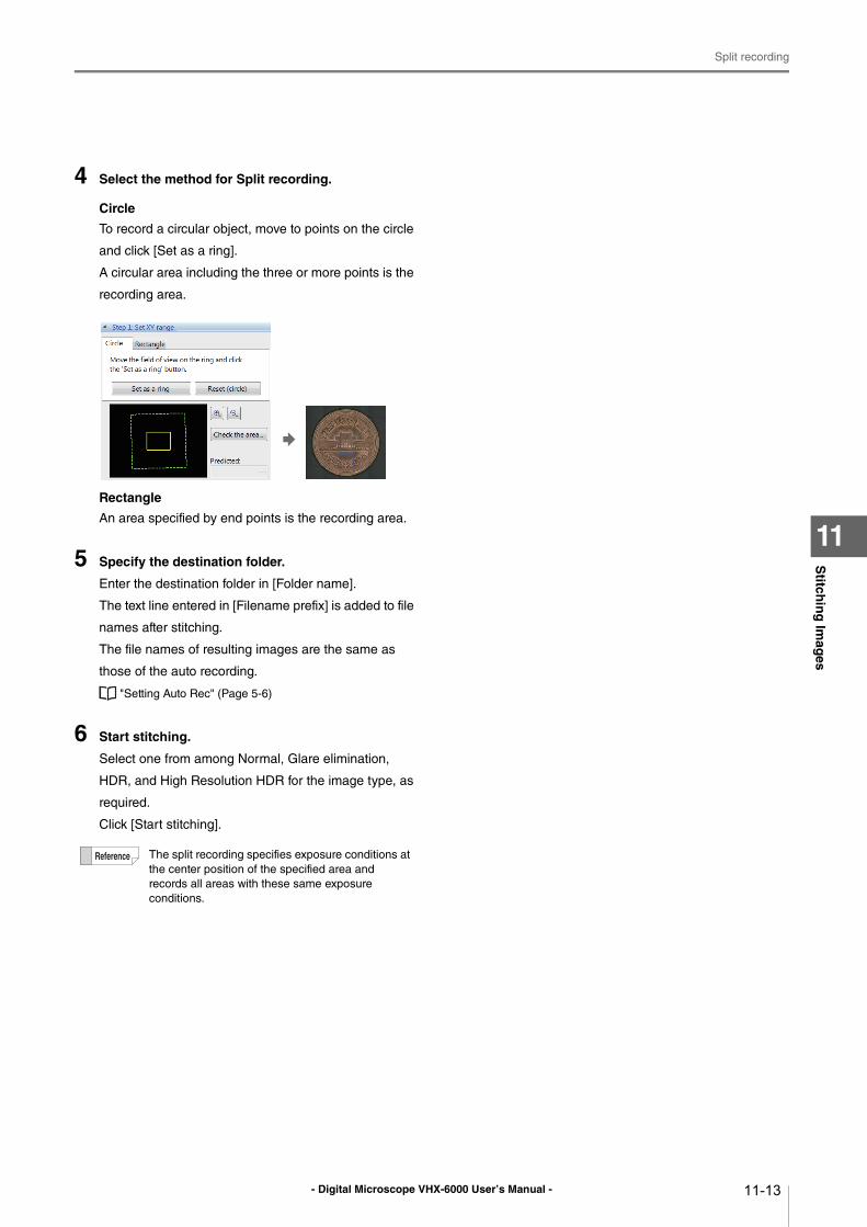
- Digital Microscope VHX-6000 User’s Manual -
Split recording
11-13
Stitch
ing
Imag
es
11
4 Select the method for Split recording.
Circle
To record a circular object, move to points on the circle
and click [Set as a ring].
A circular area including the three or more points is the
recording area.
Rectangle
An area specified by end points is the recording area.
5 Specify the destination folder.
Enter the destination folder in [Folder name].
The text line entered in [Filename prefix] is added to file
names after stitching.
The file names of resulting images are the same as
those of the auto recording.
"Setting Auto Rec" (Page 5-6)
6 Start stitching.
Select one from among Normal, Glare elimination,
HDR, and High Resolution HDR for the image type, as
required.
Click [Start stitching].
The split recording specifies exposure conditions at
the center position of the specified area and
records all areas with these same exposure
conditions.
- Digital Microscope VHX-6000 User’s Manual -
Split recording
11-14
Stitch
ing
Imag
es
11
- Digital Microscope VHX-6000 User’s Manual - 12-1
Chapter12P
rintin
g an
d S
aving
to a C
D/D
VD
12
Printing and Saving to a CD/DVD
Printing Images, Saving to a CD/DVD
Printers .................................................................Page 12-2
Connecting the Printer......................................Page 12-2
Print Settings ....................................................Page 12-2
Printing .............................................................Page 12-3
Page Setup ......................................................Page 12-3
Saving to a CD/DVD.............................................Page 12-4
Formatting a CD/DVD ......................................Page 12-4
Writing Procedures ...........................................Page 12-5
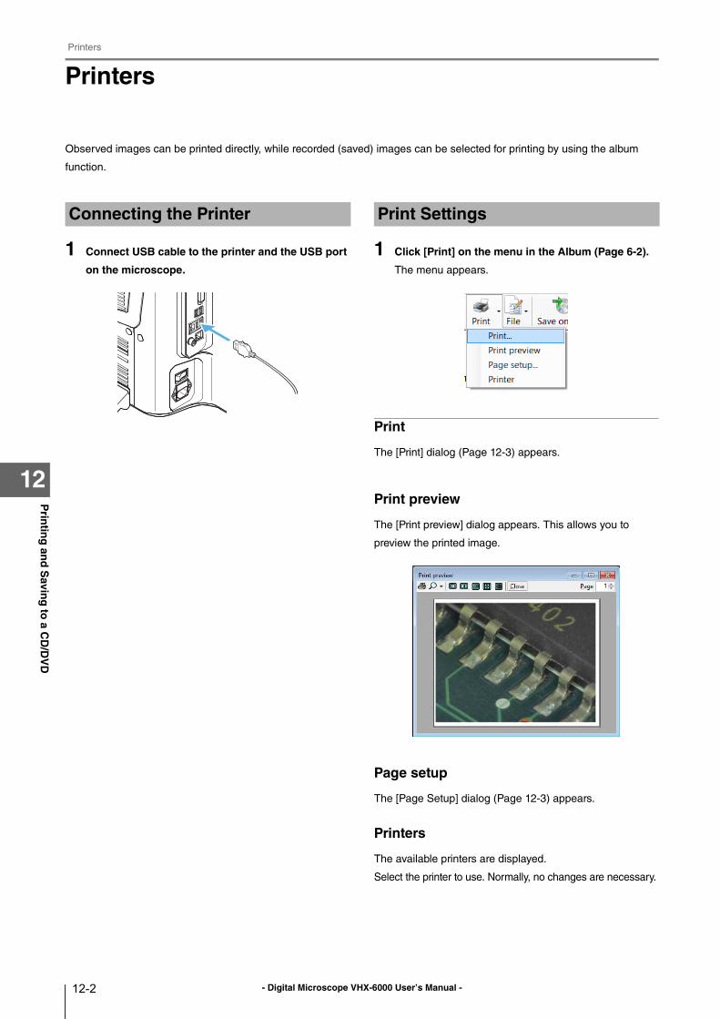
- Digital Microscope VHX-6000 User’s Manual -
Printers
12-2
Prin
ting
and
Savin
g to
a CD
/DV
D
12
Printers
Observed images can be printed directly, while recorded (saved) images can be selected for printing by using the album
function.
1 Connect USB cable to the printer and the USB port
on the microscope.
1 Click [Print] on the menu in the Album (Page 6-2).
The menu appears.
The [Print] dialog (Page 12-3) appears.
Print preview
The [Print preview] dialog appears. This allows you to
preview the printed image.
Page setup
The [Page Setup] dialog (Page 12-3) appears.
Printers
The available printers are displayed.
Select the printer to use. Normally, no changes are necessary.
Connecting the Printer Print Settings
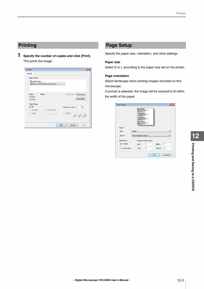
- Digital Microscope VHX-6000 User’s Manual -
Printers
12-3
Prin
ting
and
Savin
g to
a CD
/DV
D
12
1 Specify the number of copies and click [Print].
This prints the image.
Specify the paper size, orientation, and other settings.
Paper size
Select S or L according to the paper size set on the printer.
Page orientation
Select landscape when printing images recorded on this
microscope.
If portrait is selected, the image will be reduced to fit within
the width of the paper.
Printing Page Setup
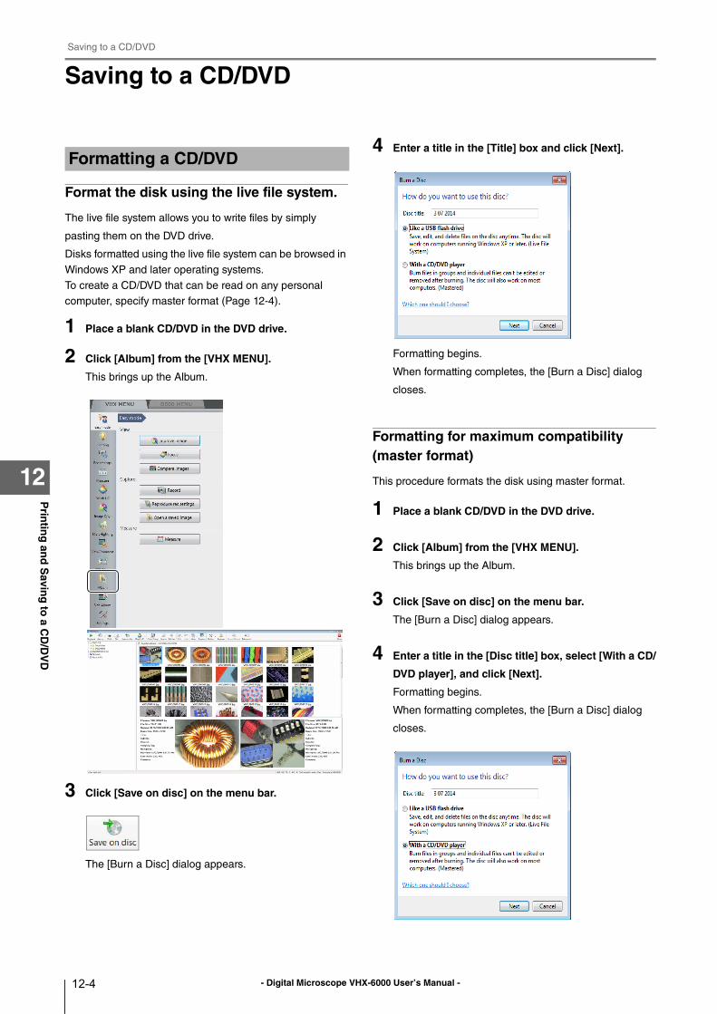
- Digital Microscope VHX-6000 User’s Manual -
Saving to a CD/DVD
12-4
Prin
ting
and
Savin
g to
a CD
/DV
D
12
Saving to a CD/DVD
Format the disk using the live file system.
The live file system allows you to write files by simply
pasting them on the DVD drive.
Disks formatted using the live file system can be browsed in
Windows XP and later operating systems.
To create a CD/DVD that can be read on any personal
computer, specify master format (Page 12-4).
1 Place a blank CD/DVD in the DVD drive.
2 Click [Album] from the [VHX MENU].
This brings up the Album.
3 Click [Save on disc] on the menu bar.
The [Burn a Disc] dialog appears.
4 Enter a title in the [Title] box and click [Next].
Formatting begins.
When formatting completes, the [Burn a Disc] dialog
closes.
Formatting for maximum compatibility (master format)
This procedure formats the disk using master format.
1 Place a blank CD/DVD in the DVD drive.
2 Click [Album] from the [VHX MENU].
This brings up the Album.
3 Click [Save on disc] on the menu bar.
The [Burn a Disc] dialog appears.
4 Enter a title in the [Disc title] box, select [With a CD/
DVD player], and click [Next].
Formatting begins.
When formatting completes, the [Burn a Disc] dialog
closes.
Formatting a CD/DVD
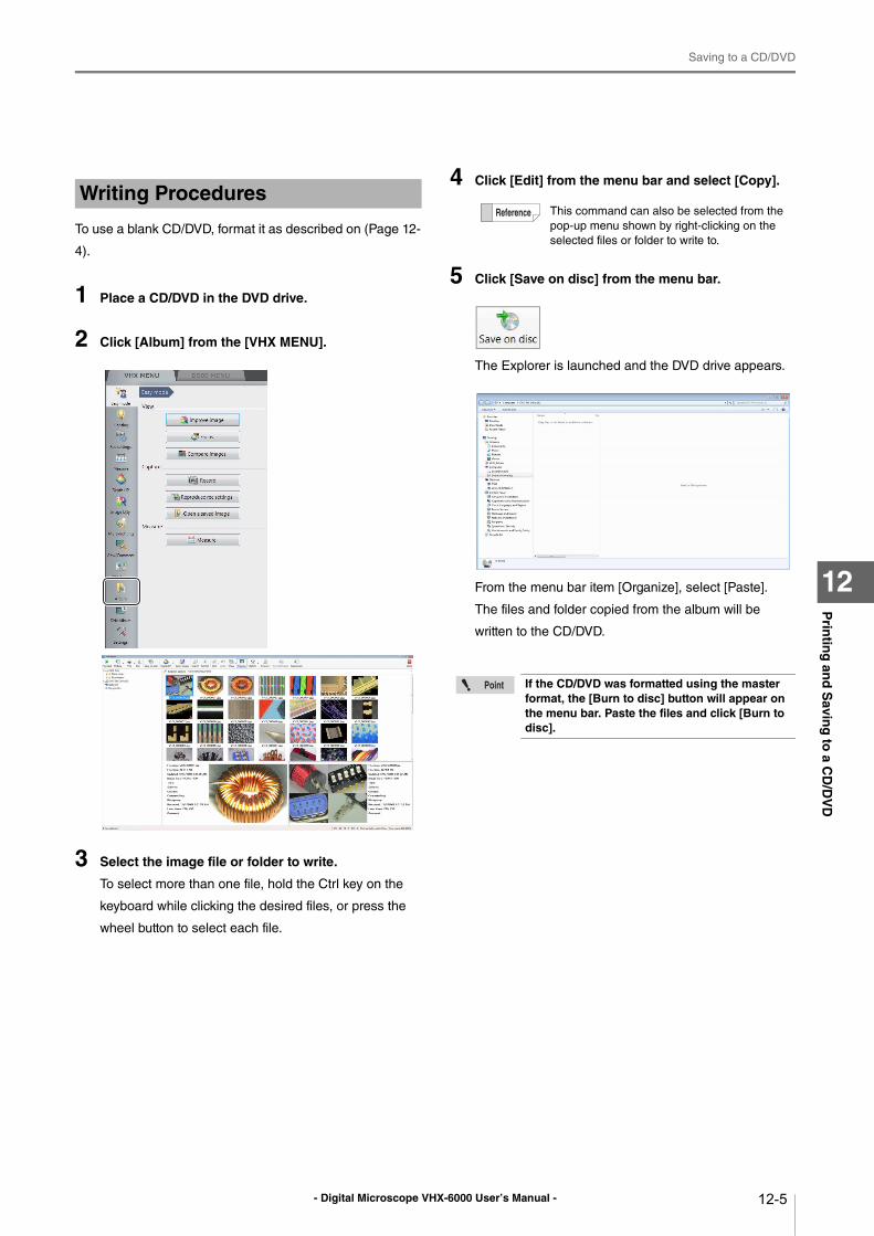
- Digital Microscope VHX-6000 User’s Manual -
Saving to a CD/DVD
12-5
Prin
ting
and
Savin
g to
a CD
/DV
D
12
To use a blank CD/DVD, format it as described on (Page 12-
4).
1 Place a CD/DVD in the DVD drive.
2 Click [Album] from the [VHX MENU].
3 Select the image file or folder to write.
To select more than one file, hold the Ctrl key on the
keyboard while clicking the desired files, or press the
wheel button to select each file.
4 Click [Edit] from the menu bar and select [Copy].
5 Click [Save on disc] from the menu bar.
The Explorer is launched and the DVD drive appears.
From the menu bar item [Organize], select [Paste].
The files and folder copied from the album will be
written to the CD/DVD.
Writing ProceduresThis command can also be selected from the
pop-up menu shown by right-clicking on the
selected files or folder to write to.
If the CD/DVD was formatted using the master format, the [Burn to disc] button will appear on the menu bar. Paste the files and click [Burn to disc].
- Digital Microscope VHX-6000 User’s Manual -
Saving to a CD/DVD
12-6
Prin
ting
and
Savin
g to
a CD
/DV
D
12
- Digital Microscope VHX-6000 User’s Manual - 13-1
Chapter13C
on
figu
ring
the O
peratin
g E
nviro
nm
ent
13
Configuring the Operating Environment
Option Settings
This chapter explains how to configure the operating
environment and network communication settings.
Settings ................................................................Page 13-2
Displaying the Settings Menu...........................Page 13-2
Network/Security Settings................................Page 13-2
Lens Settings ................................................. Page 13-14
Calibration Setup........................................ Page 13-14
User Setup ..................................................... Page 13-14
Show Software Keyboard............................... Page 13-16
System Initialization ....................................... Page 13-16
Initializing Automatic XY Stage ...................... Page 13-17
Camera mount settings .................................. Page 13-17
ZST vision misalignment correction ............... Page 13-18
Optical axis misalignment correction..............Page 13-20
D500 Maintenance.........................................Page 13-22
Options...........................................................Page 13-22
Version Info ....................................................Page 13-24
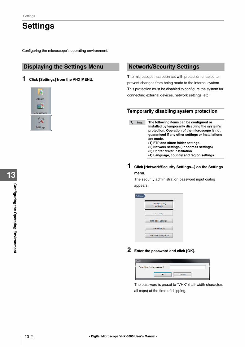
- Digital Microscope VHX-6000 User’s Manual -
Settings
13-2
Co
nfig
urin
g th
e Op
erating
En
viron
men
t
13
Settings
Configuring the microscope's operating environment.
1 Click [Settings] from the VHX MENU.
The microscope has been set with protection enabled to
prevent changes from being made to the internal system.
This protection must be disabled to configure the system for
connecting external devices, network settings, etc.
Temporarily disabling system protection
1 Click [Network/Security Settings...] on the Settings
menu.
The security administration password input dialog
appears.
2 Enter the password and click [OK].
p
The password is preset to "VHX" (half-width characters
all caps) at the time of shipping.
Displaying the Settings Menu Network/Security Settings
The following items can be configured or installed by temporarily disabling the system's protection. Operation of the microscope is not guaranteed if any other settings or installations are made.(1) FTP and share folder settings(2) Network settings (IP address settings)(3) Printer driver installation(4) Language, country and region settings
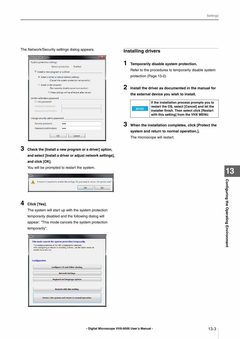
- Digital Microscope VHX-6000 User’s Manual -
Settings
13-3
Co
nfig
urin
g th
e Op
erating
En
viron
men
t
13
The Network/Security settings dialog appears.
3 Check the [Install a new program or a driver] option,
and select [Install a driver or adjust network settings],
and click [OK].
You will be prompted to restart the system.
4 Click [Yes].
The system will start up with the system protection
temporarily disabled and the following dialog will
appear: "This mode cancels the system protection
temporarily".
Installing drivers
1 Temporarily disable system protection.
Refer to the procedures to temporarily disable system
protection (Page 13-2).
2 Install the driver as documented in the manual for
the external device you wish to install.
3 When the installation completes, click [Protect the
system and return to normal operation.].
The microscope will restart.
If the installation process prompts you to restart the OS, select [Cancel] and let the installer finish. Then select click [Restart with this setting] from the VHX MENU.
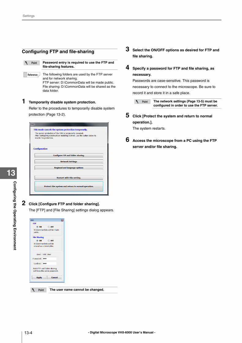
- Digital Microscope VHX-6000 User’s Manual -
Settings
13-4
Co
nfig
urin
g th
e Op
erating
En
viron
men
t
13
Configuring FTP and file-sharing
1 Temporarily disable system protection.
Refer to the procedures to temporarily disable system
protection (Page 13-2).
2 Click [Configure FTP and folder sharing].
The [FTP] and [File Sharing] settings dialog appears.
3 Select the ON/OFF options as desired for FTP and
file sharing.
4 Specify a password for FTP and file sharing, as
necessary.
Passwords are case-sensitive. This password is
necessary to connect to the microscope. Be sure to
record it and store it in a safe place.
5 Click [Protect the system and return to normal
operation.].
The system restarts.
6 Access the microscope from a PC using the FTP
server and/or file sharing.
Password entry is required to use the FTP and file-sharing features.
The following folders are used by the FTP server
and for network sharing.
FTP server: D:\CommonData will be made public.
File sharing: D:\CommonData will be shared as the
data folder.
The user name cannot be changed.
The network settings (Page 13-5) must be configured in order to use the FTP server.
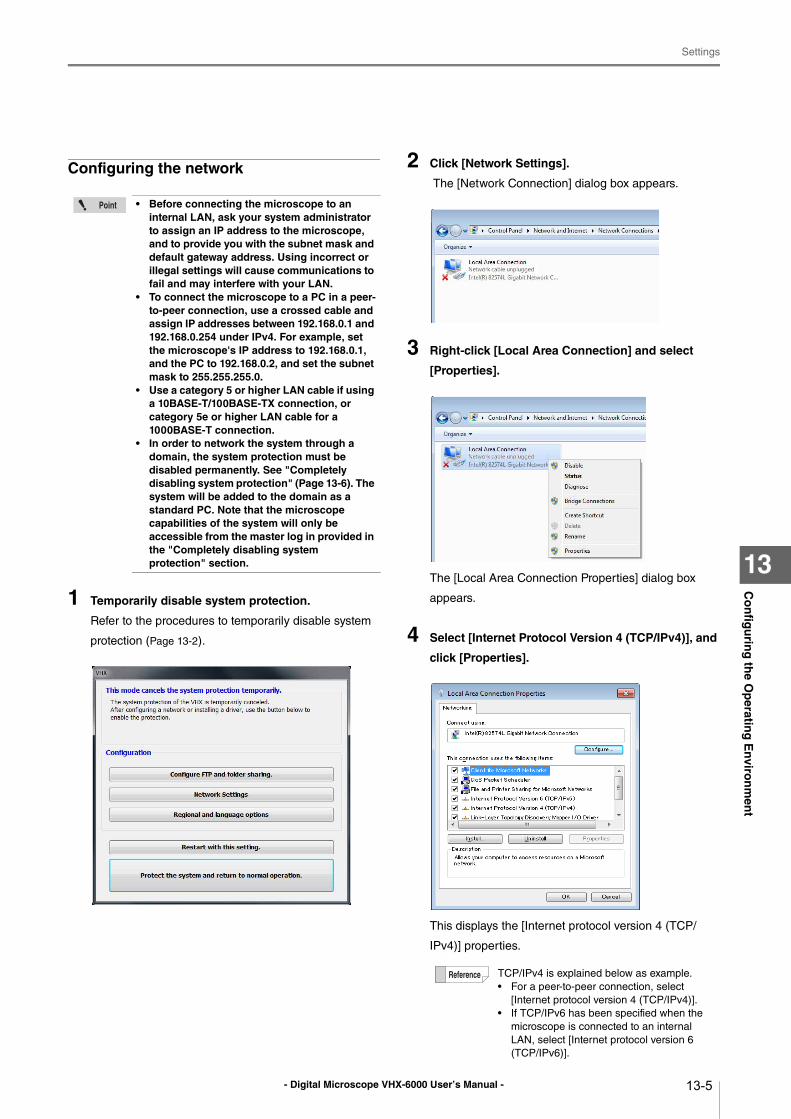
- Digital Microscope VHX-6000 User’s Manual -
Settings
13-5
Co
nfig
urin
g th
e Op
erating
En
viron
men
t
13
Configuring the network
1 Temporarily disable system protection.
Refer to the procedures to temporarily disable system
protection (Page 13-2).
2 Click [Network Settings].
The [Network Connection] dialog box appears.
3 Right-click [Local Area Connection] and select
[Properties].
The [Local Area Connection Properties] dialog box
appears.
4 Select [Internet Protocol Version 4 (TCP/IPv4)], and
click [Properties].
This displays the [Internet protocol version 4 (TCP/
IPv4)] properties.
• Before connecting the microscope to an internal LAN, ask your system administrator to assign an IP address to the microscope, and to provide you with the subnet mask and default gateway address. Using incorrect or illegal settings will cause communications to fail and may interfere with your LAN.
• To connect the microscope to a PC in a peer-to-peer connection, use a crossed cable and assign IP addresses between 192.168.0.1 and 192.168.0.254 under IPv4. For example, set the microscope's IP address to 192.168.0.1, and the PC to 192.168.0.2, and set the subnet mask to 255.255.255.0.
• Use a category 5 or higher LAN cable if using a 10BASE-T/100BASE-TX connection, or category 5e or higher LAN cable for a 1000BASE-T connection.
• In order to network the system through a domain, the system protection must be disabled permanently. See "Completely disabling system protection" (Page 13-6). The system will be added to the domain as a standard PC. Note that the microscope capabilities of the system will only be accessible from the master log in provided in the "Completely disabling system protection" section.
TCP/IPv4 is explained below as example.
• For a peer-to-peer connection, select
[Internet protocol version 4 (TCP/IPv4)].
• If TCP/IPv6 has been specified when the
microscope is connected to an internal
LAN, select [Internet protocol version 6
(TCP/IPv6)].
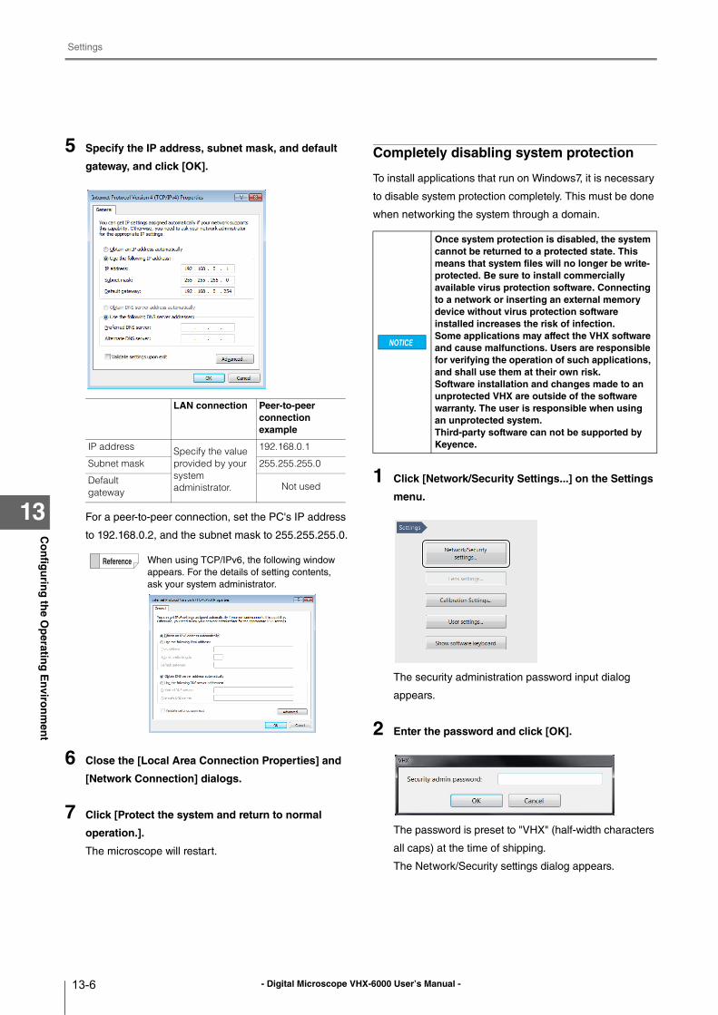
- Digital Microscope VHX-6000 User’s Manual -
Settings
13-6
Co
nfig
urin
g th
e Op
erating
En
viron
men
t
13
5 Specify the IP address, subnet mask, and default
gateway, and click [OK].
For a peer-to-peer connection, set the PC's IP address
to 192.168.0.2, and the subnet mask to 255.255.255.0.
6 Close the [Local Area Connection Properties] and
[Network Connection] dialogs.
7 Click [Protect the system and return to normal
operation.].
The microscope will restart.
Completely disabling system protection
To install applications that run on Windows7, it is necessary
to disable system protection completely. This must be done
when networking the system through a domain.
1 Click [Network/Security Settings...] on the Settings
menu.
The security administration password input dialog
appears.
2 Enter the password and click [OK].
The password is preset to "VHX" (half-width characters
all caps) at the time of shipping.
The Network/Security settings dialog appears.
LAN connection Peer-to-peer connection example
IP address Specify the value provided by your system administrator.
192.168.0.1
Subnet mask 255.255.255.0
Defaultgateway
Not used
When using TCP/IPv6, the following window
appears. For the details of setting contents,
ask your system administrator.
Once system protection is disabled, the system cannot be returned to a protected state. This means that system files will no longer be write-protected. Be sure to install commercially available virus protection software. Connecting to a network or inserting an external memory device without virus protection software installed increases the risk of infection.Some applications may affect the VHX software and cause malfunctions. Users are responsible for verifying the operation of such applications, and shall use them at their own risk.Software installation and changes made to an unprotected VHX are outside of the software warranty. The user is responsible when using an unprotected system.Third-party software can not be supported by Keyence.
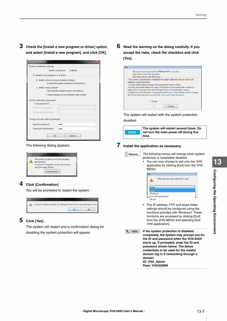
- Digital Microscope VHX-6000 User’s Manual -
Settings
13-7
Co
nfig
urin
g th
e Op
erating
En
viron
men
t
13
3 Check the [Install a new program or driver] option,
and select [Install a new program], and click [OK].
The following dialog appears.
4 Click [Confirmation]
You will be prompted to restart the system.
5 Click [Yes].
The system will restart and a confirmation dialog for
disabling the system protection will appear.
6 Read the warning on the dialog carefully. If you
accept the risks, check the checkbox and click
[Yes].
The system will restart with the system protection
disabled.
7 Install the application as necessary.
The system will restart several times. Do not turn the main power off during this time.
The following menus will change when system
protection is completely disabled.
• You can now choose to exit only the VHX
application by clicking [Exit] from the VHX
MENU.
• The IP address, FTP, and share folder
settings should be configured using the
functions provided with Windows7. These
functions are accessed by clicking [Exit]
from the VHX MENU and selecting [Exit
VHX application].
If the system protection is disabled completely, the system may prompt you for the ID and password when the VHX-6000 starts up. If prompted, enter the ID and password shown below. The below credentials to be used for the master domain log in if networking through a domain.ID: VHX_AdminPass: VHXADMIN
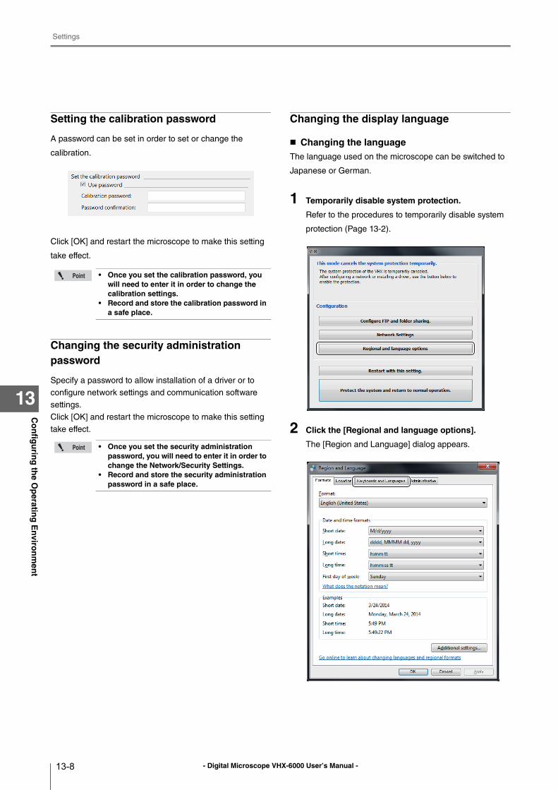
- Digital Microscope VHX-6000 User’s Manual -
Settings
13-8
Co
nfig
urin
g th
e Op
erating
En
viron
men
t
13
Setting the calibration password
A password can be set in order to set or change the
calibration.
Click [OK] and restart the microscope to make this setting
take effect.
Changing the security administration password
Specify a password to allow installation of a driver or to
configure network settings and communication software
settings.
Click [OK] and restart the microscope to make this setting
take effect.
Changing the display language
Changing the languageThe language used on the microscope can be switched to
Japanese or German.
1 Temporarily disable system protection.
Refer to the procedures to temporarily disable system
protection (Page 13-2).
2 Click the [Regional and language options].
The [Region and Language] dialog appears.
• Once you set the calibration password, you will need to enter it in order to change the calibration settings.
• Record and store the calibration password in a safe place.
• Once you set the security administration password, you will need to enter it in order to change the Network/Security Settings.
• Record and store the security administration password in a safe place.
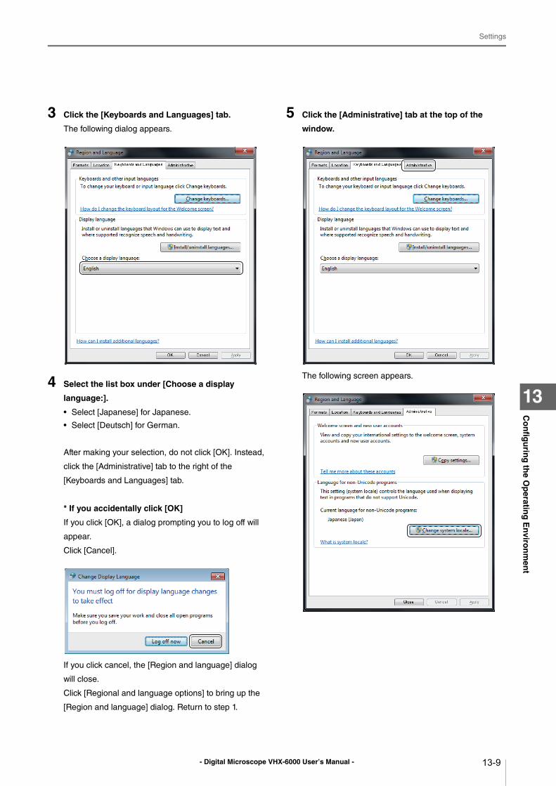
- Digital Microscope VHX-6000 User’s Manual -
Settings
13-9
Co
nfig
urin
g th
e Op
erating
En
viron
men
t
13
3 Click the [Keyboards and Languages] tab.
The following dialog appears.
4 Select the list box under [Choose a display
language:].
• Select [Japanese] for Japanese.
• Select [Deutsch] for German.
After making your selection, do not click [OK]. Instead,
click the [Administrative] tab to the right of the
[Keyboards and Languages] tab.
* If you accidentally click [OK]
If you click [OK], a dialog prompting you to log off will
appear.
Click [Cancel].
If you click cancel, the [Region and language] dialog
will close.
Click [Regional and language options] to bring up the
[Region and language] dialog. Return to step 1.
5 Click the [Administrative] tab at the top of the
window.
The following screen appears.
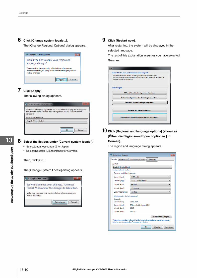
- Digital Microscope VHX-6000 User’s Manual -
Settings
13-10
Co
nfig
urin
g th
e Op
erating
En
viron
men
t
13
6 Click [Change system locale...].
The [Change Regional Options] dialog appears.
7 Click [Apply].
The following dialog appears.
8 Select the list box under [Current system locale:].
• Select [Japanese (Japan)] for Japan.
• Select [Deutsch (Deutschland)] for German.
Then, click [OK].
The [Change System Locale] dialog appears.
9 Click [Restart now].
After restarting, the system will be displayed in the
selected language.
The rest of this explanation assumes you have selected
German.
10 Click [Regional and language options] (shown as
[Öffnet die Regions-und Sprachoptionen.] in
German).
The region and language dialog appears.
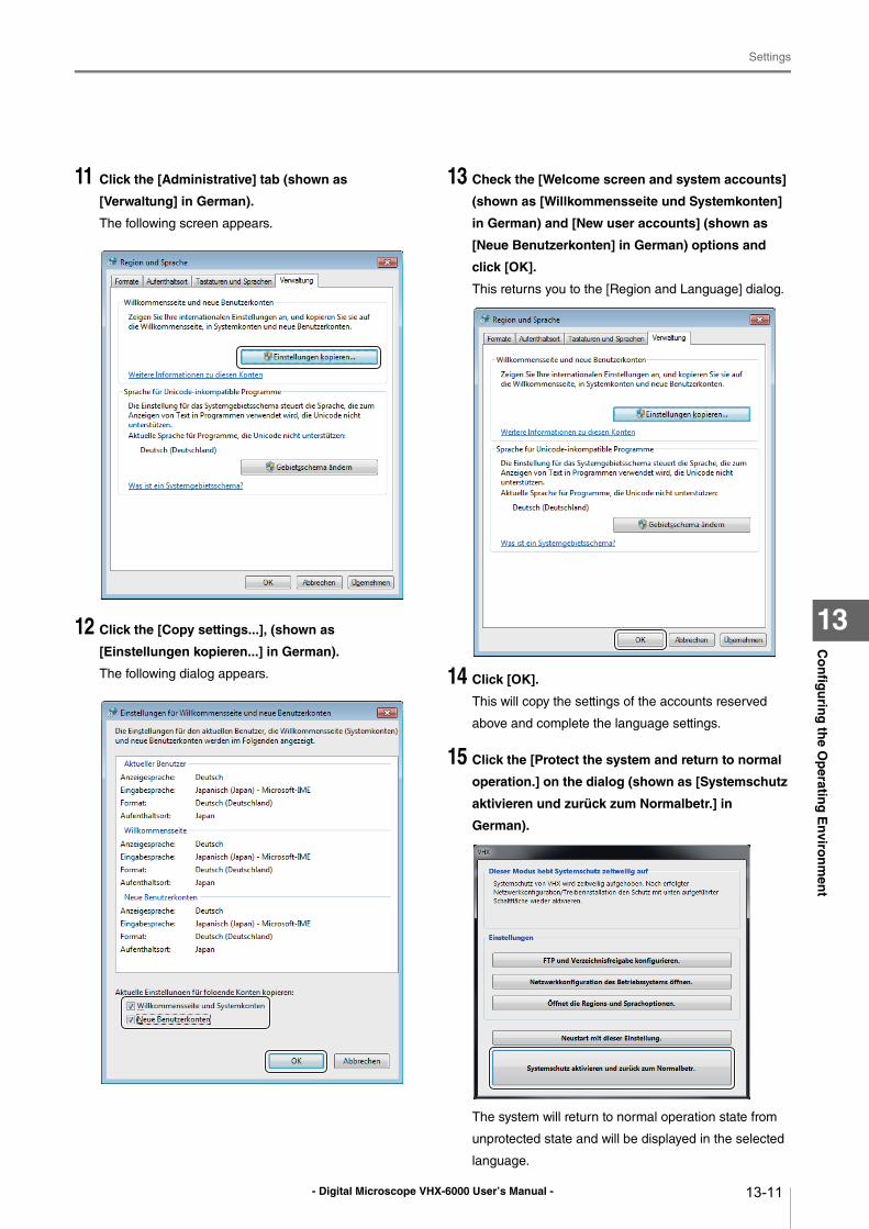
- Digital Microscope VHX-6000 User’s Manual -
Settings
13-11
Co
nfig
urin
g th
e Op
erating
En
viron
men
t
13
11 Click the [Administrative] tab (shown as
[Verwaltung] in German).
The following screen appears.
12 Click the [Copy settings...], (shown as
[Einstellungen kopieren...] in German).
The following dialog appears.
13 Check the [Welcome screen and system accounts]
(shown as [Willkommensseite und Systemkonten]
in German) and [New user accounts] (shown as
[Neue Benutzerkonten] in German) options and
click [OK].
This returns you to the [Region and Language] dialog.
14 Click [OK].
This will copy the settings of the accounts reserved
above and complete the language settings.
15 Click the [Protect the system and return to normal
operation.] on the dialog (shown as [Systemschutz
aktivieren und zurück zum Normalbetr.] in
German).
The system will return to normal operation state from
unprotected state and will be displayed in the selected
language.
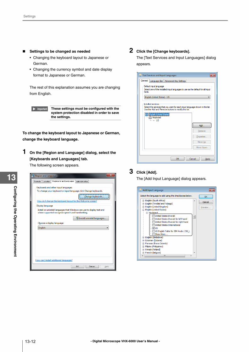
- Digital Microscope VHX-6000 User’s Manual -
Settings
13-12
Co
nfig
urin
g th
e Op
erating
En
viron
men
t
13
Settings to be changed as needed
• Changing the keyboard layout to Japanese or
German.
• Changing the currency symbol and date display
format to Japanese or German.
The rest of this explanation assumes you are changing
from English.
To change the keyboard layout to Japanese or German,
change the keyboard language.
1 On the [Region and Language] dialog, select the
[Keyboards and Languages] tab.
The following screen appears.
2 Click the [Change keyboards].
The [Text Services and Input Languages] dialog
appears.
3 Click [Add].
The [Add Input Language] dialog appears.
These settings must be configured with the system protection disabled in order to save the settings.
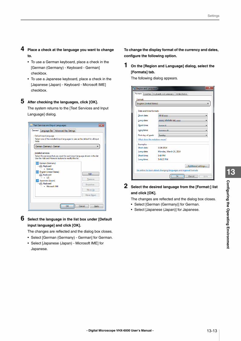
- Digital Microscope VHX-6000 User’s Manual -
Settings
13-13
Co
nfig
urin
g th
e Op
erating
En
viron
men
t
13
4 Place a check at the language you want to change
to.
• To use a German keyboard, place a check in the
[German (Germany) - Keyboard - German]
checkbox.
• To use a Japanese keyboard, place a check in the
[Japanese (Japan) - Keyboard - Microsoft IME]
checkbox.
5 After checking the languages, click [OK].
The system returns to the [Text Services and Input
Language] dialog.
6 Select the language in the list box under [Default
input language] and click [OK].
The changes are reflected and the dialog box closes.
• Select [German (Germany) - German] for German.
• Select [Japanese (Japan) - Microsoft IME] for
Japanese.
To change the display format of the currency and dates,
configure the following option.
1 On the [Region and Language] dialog, select the
[Formats] tab.
The following dialog appears.
2 Select the desired language from the [Format:] list
and click [OK].
The changes are reflected and the dialog box closes.
• Select [German (Germany)] for German.
• Select [Japanese (Japan)] for Japanese.
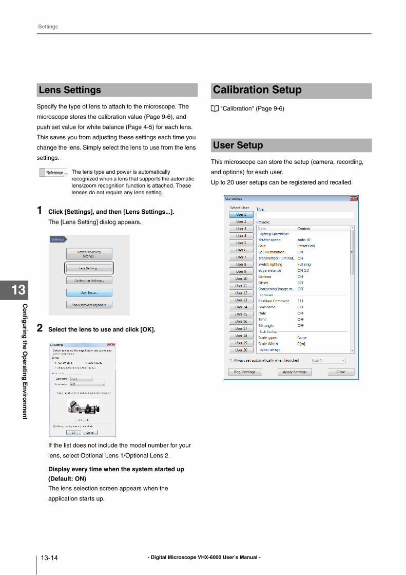
- Digital Microscope VHX-6000 User’s Manual -
Settings
13-14
Co
nfig
urin
g th
e Op
erating
En
viron
men
t
13
Specify the type of lens to attach to the microscope. The
microscope stores the calibration value (Page 9-6), and
push set value for white balance (Page 4-5) for each lens.
This saves you from adjusting these settings each time you
change the lens. Simply select the lens to use from the lens
settings.
1 Click [Settings], and then [Lens Settings...].
The [Lens Setting] dialog appears.
2 Select the lens to use and click [OK].
If the list does not include the model number for your
lens, select Optional Lens 1/Optional Lens 2.
Display every time when the system started up
(Default: ON)
The lens selection screen appears when the
application starts up.
"Calibration" (Page 9-6)
This microscope can store the setup (camera, recording,
and options) for each user.
Up to 20 user setups can be registered and recalled.
Lens Settings
The lens type and power is automatically
recognized when a lens that supports the automatic
lens/zoom recognition function is attached. These
lenses do not require any lens setting.
Calibration Setup
User Setup
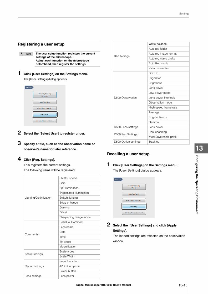
- Digital Microscope VHX-6000 User’s Manual -
Settings
13-15
Co
nfig
urin
g th
e Op
erating
En
viron
men
t
13
Registering a user setup
1 Click [User Settings] on the Settings menu.
The [User Settings] dialog appears.
2 Select the [Select User] to register under.
3 Specify a title, such as the observation name or
observer's name for later reference.
4 Click [Reg. Settings].
This registers the current settings.
The following items will be registered.
Recalling a user setup
1 Click [User Settings] on the Settings menu.
The [User Settings] dialog appears.
2 Select the [User Settings] and click [Apply
Settings].
The loaded settings are reflected on the observation
window.
The user setup function registers the current settings of the microscope.Adjust each function on the microscope beforehand, then register the settings.
Lighting/Optimization
Shutter speed
Gain
Epi-illumination
Transmitted illumination
Switch lighting
Edge enhance
Gamma
Offset
Sharpening Image mode
Comments
Residual Comment
Lens name
Date
Time
Tilt angle
Magnification
Scale SettingsScale types
Scale Width
Option settings
Sound function
JPEG Compress
Power button
Lens settings Lens power
Rec settings
White balance
Auto rec folder
Auto rec image format
Auto rec name prefix
Auto Rec mode
Vision correction
D500:Observation
FOCUS
Stigmator
Brightness
Lens power
Low-power mode
Lens power interlock
Observation mode
High-speed frame rate
Average
Edge enhance
Gamma
D500:Lens settings Lens power
D500:Rec SettingsRec. scanning
Multi Save name prefix
D500:Option settings Tracking
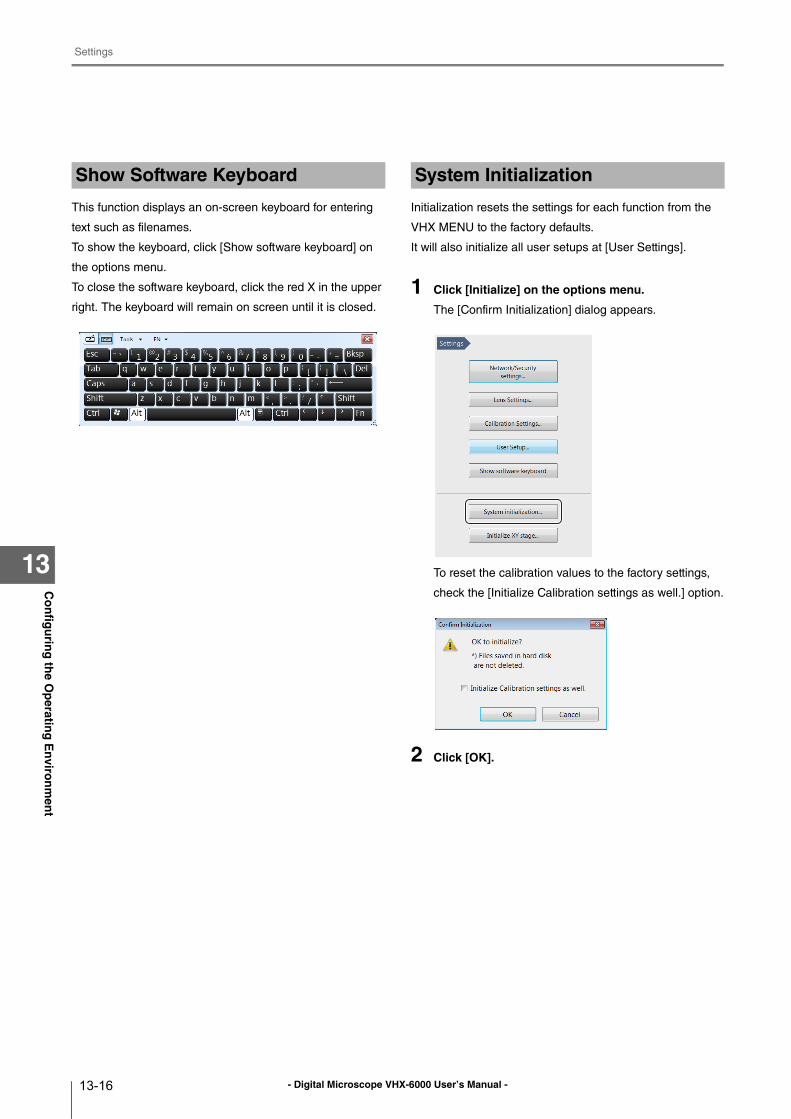
- Digital Microscope VHX-6000 User’s Manual -
Settings
13-16
Co
nfig
urin
g th
e Op
erating
En
viron
men
t
13
This function displays an on-screen keyboard for entering
text such as filenames.
To show the keyboard, click [Show software keyboard] on
the options menu.
To close the software keyboard, click the red X in the upper
right. The keyboard will remain on screen until it is closed.
Initialization resets the settings for each function from the
VHX MENU to the factory defaults.
It will also initialize all user setups at [User Settings].
1 Click [Initialize] on the options menu.
The [Confirm Initialization] dialog appears.
To reset the calibration values to the factory settings,
check the [Initialize Calibration settings as well.] option.
2 Click [OK].
Show Software Keyboard System Initialization
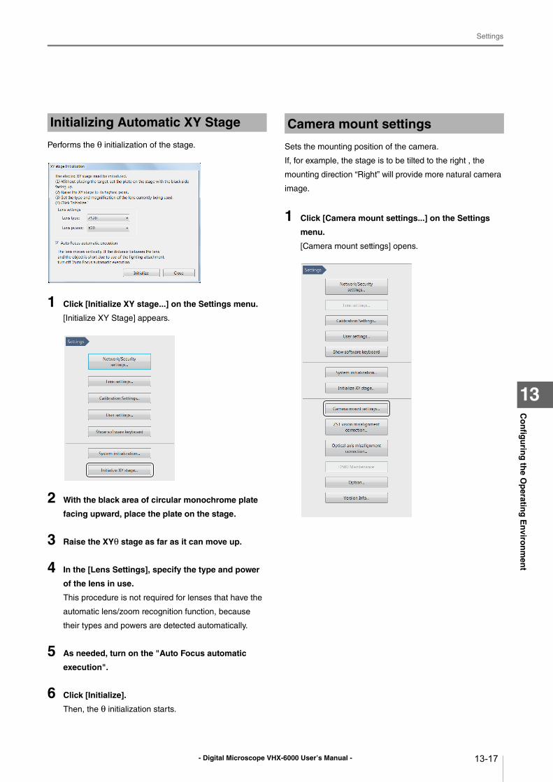
- Digital Microscope VHX-6000 User’s Manual -
Settings
13-17
Co
nfig
urin
g th
e Op
erating
En
viron
men
t
13
Performs the θ initialization of the stage.
1 Click [Initialize XY stage...] on the Settings menu.
[Initialize XY Stage] appears.
2 With the black area of circular monochrome plate
facing upward, place the plate on the stage.
3 Raise the XYθ stage as far as it can move up.
4 In the [Lens Settings], specify the type and power
of the lens in use.
This procedure is not required for lenses that have the
automatic lens/zoom recognition function, because
their types and powers are detected automatically.
5 As needed, turn on the "Auto Focus automatic
execution".
6 Click [Initialize].
Then, the θ initialization starts.
Sets the mounting position of the camera.
If, for example, the stage is to be tilted to the right , the
mounting direction “Right” will provide more natural camera
image.
1 Click [Camera mount settings...] on the Settings
menu.
[Camera mount settings] opens.
Initializing Automatic XY Stage Camera mount settings
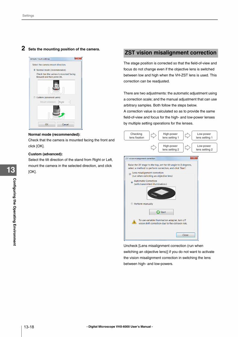
- Digital Microscope VHX-6000 User’s Manual -
Settings
13-18
Co
nfig
urin
g th
e Op
erating
En
viron
men
t
13
2 Sets the mounting position of the camera.
Normal mode (recommended):
Check that the camera is mounted facing the front and
click [OK].
Custom (advanced):
Select the tilt direction of the stand from Right or Left,
mount the camera in the selected direction, and click
[OK].
The stage position is corrected so that the field-of-view and
focus do not change even if the objective lens is switched
between low and high when the VH-ZST lens is used. This
correction can be readjusted.
There are two adjustments: the automatic adjustment using
a correction scale; and the manual adjustment that can use
arbitrary samples. Both follow the steps below.
A correction value is calculated so as to provide the same
field-of-view and focus for the high- and low-power lenses
by multiple setting operations for the lenses.
Uncheck [Lens misalignment correction (run when
switching an objective lens)] if you do not want to activate
the vision misalignment correction in switching the lens
between high- and low-powers.
ZST vision misalignment correction
High-power lens setting 2
Low-power lens setting 2
High-power lens setting 1
Checking lens fixation
Low-power lens setting 1
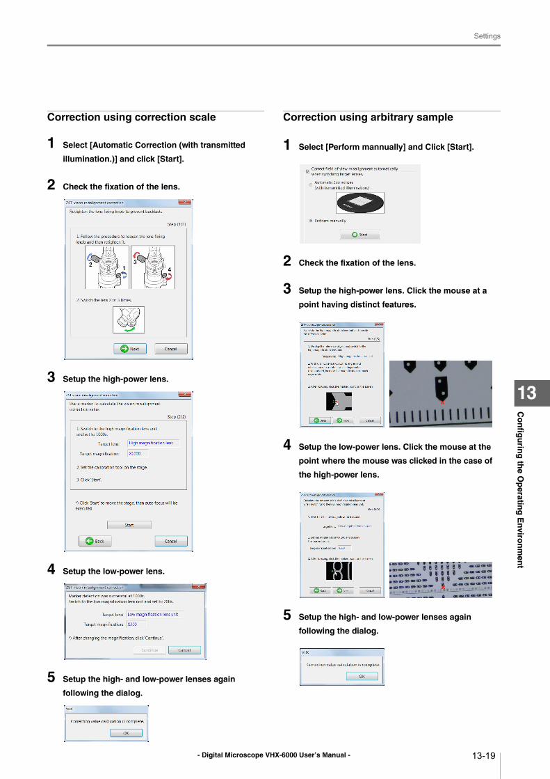
- Digital Microscope VHX-6000 User’s Manual -
Settings
13-19
Co
nfig
urin
g th
e Op
erating
En
viron
men
t
13
Correction using correction scale
1 Select [Automatic Correction (with transmitted
illumination.)] and click [Start].
2 Check the fixation of the lens.
3 Setup the high-power lens.
4 Setup the low-power lens.
5 Setup the high- and low-power lenses again
following the dialog.
Correction using arbitrary sample
1 Select [Perform mannually] and Click [Start].
2 Check the fixation of the lens.
3 Setup the high-power lens. Click the mouse at a
point having distinct features.
4 Setup the low-power lens. Click the mouse at the
point where the mouse was clicked in the case of
the high-power lens.
5 Setup the high- and low-power lenses again
following the dialog.
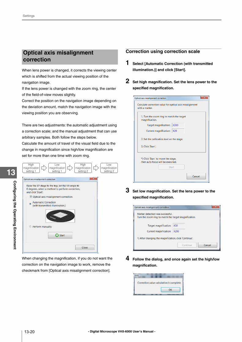
- Digital Microscope VHX-6000 User’s Manual -
Settings
13-20
Co
nfig
urin
g th
e Op
erating
En
viron
men
t
13
When lens power is changed, it corrects the viewing center
which is shifted from the actual viewing position of the
navigation image.
If the lens power is changed with the zoom ring, the center
of the field-of-view moves slightly.
Correct the position on the navigation image depending on
the deviation amount, match the navigation image with the
viewing position you are observing.
There are two adjustments: the automatic adjustment using
a correction scale; and the manual adjustment that can use
arbitrary samples. Both follow the steps below.
Calculate the amount of travel of the visual field due to the
change in magnification since high/low magnification are
set for more than one time with zoom ring.
When changing the magnification, if you do not want the
correction on the navigation image to work, remove the
checkmark from [Optical axis misalignment correction].
Correction using correction scale
1 Select [Automatic Correction (with transmitted
illumination.)] and click [Start].
2 Set high magnification. Set the lens power to the
specified magnification.
3 Set low magnification. Set the lens power to the
specified magnification.
4 Follow the dialog, and once again set the high/low
magnification.
Optical axis misalignment correction
High magnification
setting 1
Low magnification
setting 1
High magnification
setting 2
Low magnification
setting 2
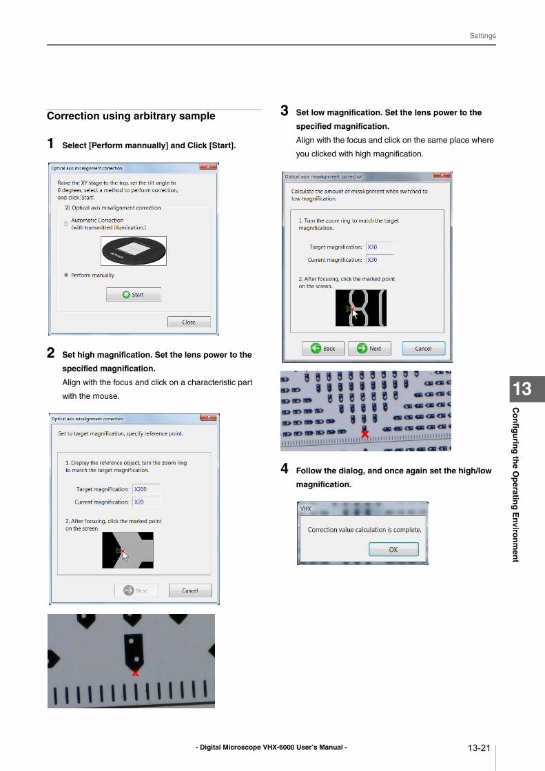
- Digital Microscope VHX-6000 User’s Manual -
Settings
13-21
Co
nfig
urin
g th
e Op
erating
En
viron
men
t
13
Correction using arbitrary sample
1 Select [Perform mannually] and Click [Start].
2 Set high magnification. Set the lens power to the
specified magnification.
Align with the focus and click on a characteristic part
with the mouse.
3 Set low magnification. Set the lens power to the
specified magnification.
Align with the focus and click on the same place where
you clicked with high magnification.
4 Follow the dialog, and once again set the high/low
magnification.
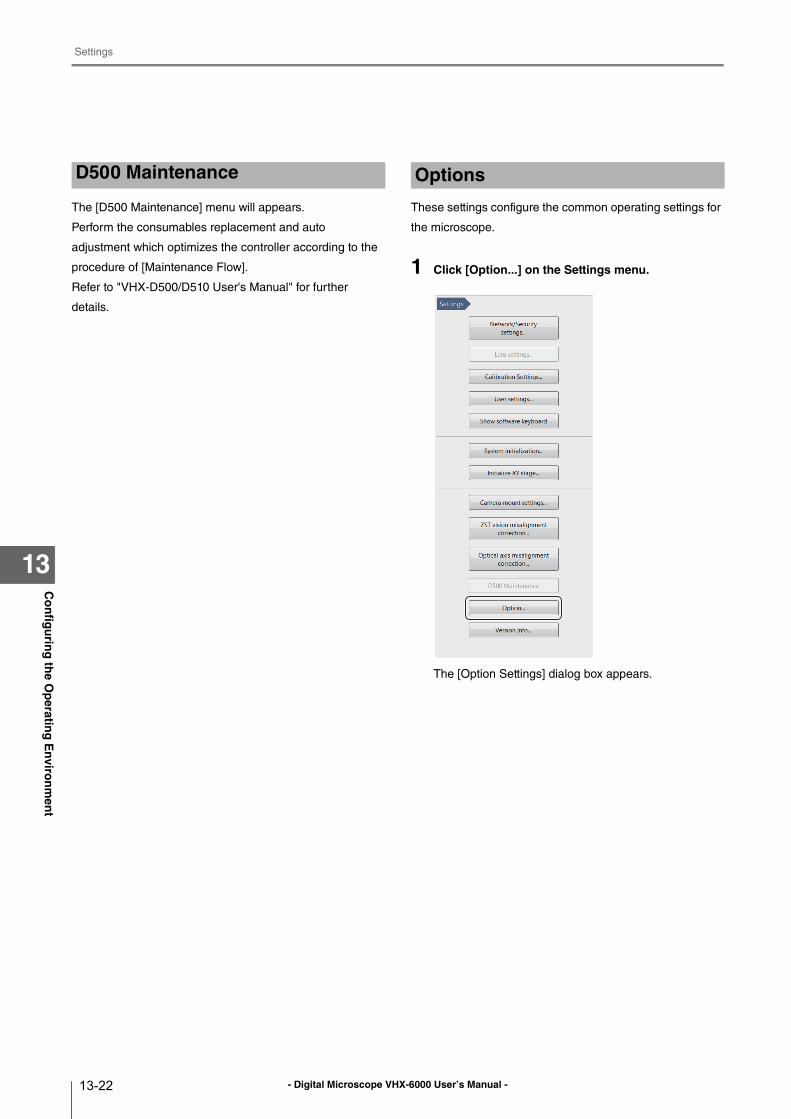
- Digital Microscope VHX-6000 User’s Manual -
Settings
13-22
Co
nfig
urin
g th
e Op
erating
En
viron
men
t
13
The [D500 Maintenance] menu will appears.
Perform the consumables replacement and auto
adjustment which optimizes the controller according to the
procedure of [Maintenance Flow].
Refer to "VHX-D500/D510 User's Manual" for further
details.
These settings configure the common operating settings for
the microscope.
1 Click [Option...] on the Settings menu.
The [Option Settings] dialog box appears.
D500 Maintenance Options
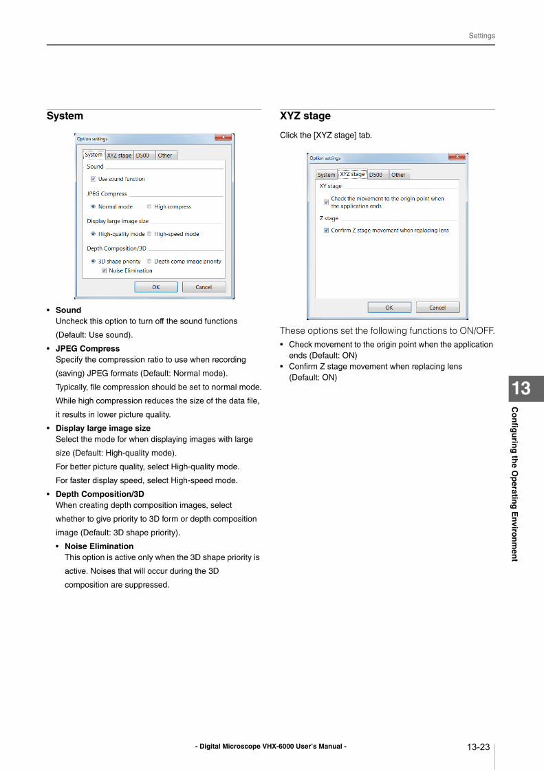
- Digital Microscope VHX-6000 User’s Manual -
Settings
13-23
Co
nfig
urin
g th
e Op
erating
En
viron
men
t
13
System
• SoundUncheck this option to turn off the sound functions
(Default: Use sound).
• JPEG CompressSpecify the compression ratio to use when recording
(saving) JPEG formats (Default: Normal mode).
Typically, file compression should be set to normal mode.
While high compression reduces the size of the data file,
it results in lower picture quality.
• Display large image sizeSelect the mode for when displaying images with large
size (Default: High-quality mode).
For better picture quality, select High-quality mode.
For faster display speed, select High-speed mode.
• Depth Composition/3DWhen creating depth composition images, select
whether to give priority to 3D form or depth composition
image (Default: 3D shape priority).
• Noise EliminationThis option is active only when the 3D shape priority is
active. Noises that will occur during the 3D
composition are suppressed.
XYZ stage
Click the [XYZ stage] tab.
These options set the following functions to ON/OFF.• Check movement to the origin point when the application
ends (Default: ON)
• Confirm Z stage movement when replacing lens (Default: ON)
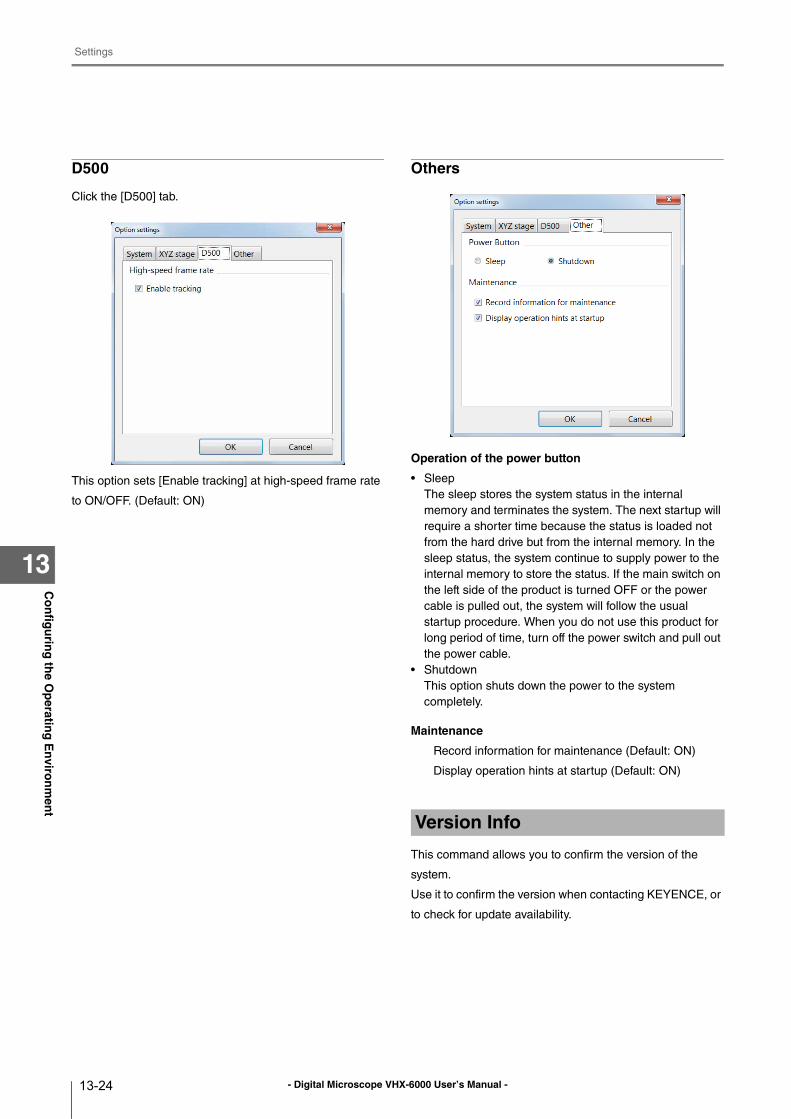
- Digital Microscope VHX-6000 User’s Manual -
Settings
13-24
Co
nfig
urin
g th
e Op
erating
En
viron
men
t
13
D500
Click the [D500] tab.
This option sets [Enable tracking] at high-speed frame rate
to ON/OFF. (Default: ON)
Others
Operation of the power button
• Sleep
The sleep stores the system status in the internal
memory and terminates the system. The next startup will
require a shorter time because the status is loaded not
from the hard drive but from the internal memory. In the
sleep status, the system continue to supply power to the
internal memory to store the status. If the main switch on
the left side of the product is turned OFF or the power
cable is pulled out, the system will follow the usual
startup procedure. When you do not use this product for
long period of time, turn off the power switch and pull out
the power cable.
• Shutdown
This option shuts down the power to the system
completely.
Maintenance
Record information for maintenance (Default: ON)
Display operation hints at startup (Default: ON)
This command allows you to confirm the version of the
system.
Use it to confirm the version when contacting KEYENCE, or
to check for update availability.
Version Info
- Digital Microscope VHX-6000 User’s Manual - 14-1
Chapter14C
on
nectin
g to
an E
xternal P
C
14
Connecting to an External PC
Connecting the Microscope to a PC
The PC can be connected to the microscope using the
VHX-6000 Communication Software, via FTP, or via a
network share.
LAN Connection...................................................Page 14-2
Overview of LAN Connection ...........................Page 14-2
Operating Environment of the PC ....................Page 14-2
Flow of Preparations ........................................Page 14-2
PC Connection and Settings ............................Page 14-3
VHX-6000 Communication Software ...................Page 14-4
Overview of Functions......................................Page 14-4
Installing the Communication Software............Page 14-4
Uninstalling the Communication Software .......Page 14-5
Starting the VHX-6000 Communication Software
.....................................................................Page 14-5
Names and Functions on the Window..............Page 14-6
Playing Images.................................................Page 14-8
Measuring 2D images .................................... Page 14-15
Preview........................................................... Page 14-16
Saving ............................................................ Page 14-17
Edit................................................................. Page 14-17
View ............................................................... Page 14-18
Option ............................................................ Page 14-18
Extracting CSV data....................................... Page 14-19
Measurement Data Tabulation ....................... Page 14-19
FTP Server Function..........................................Page 14-21
Connecting using Internet Explorer................Page 14-21
File Sharing Function .........................................Page 14-23
Using Internet Explorer to Connect ................Page 14-23
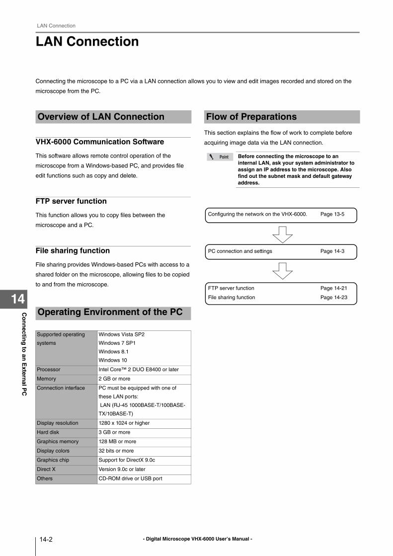
- Digital Microscope VHX-6000 User’s Manual -
LAN Connection
14-2
Co
nn
ecting
to an
Extern
al PC
14
LAN Connection
Connecting the microscope to a PC via a LAN connection allows you to view and edit images recorded and stored on the
microscope from the PC.
VHX-6000 Communication Software
This software allows remote control operation of the
microscope from a Windows-based PC, and provides file
edit functions such as copy and delete.
FTP server function
This function allows you to copy files between the
microscope and a PC.
File sharing function
File sharing provides Windows-based PCs with access to a
shared folder on the microscope, allowing files to be copied
to and from the microscope.
This section explains the flow of work to complete before
acquiring image data via the LAN connection.
Overview of LAN Connection
Operating Environment of the PC
Supported operating
systems
Windows Vista SP2
Windows 7 SP1
Windows 8.1
Windows 10
Processor Intel Core™ 2 DUO E8400 or later
Memory 2 GB or more
Connection interface PC must be equipped with one of
these LAN ports:
LAN (RJ-45 1000BASE-T/100BASE-
TX/10BASE-T)
Display resolution 1280 x 1024 or higher
Hard disk 3 GB or more
Graphics memory 128 MB or more
Display colors 32 bits or more
Graphics chip Support for DirectX 9.0c
Direct X Version 9.0c or later
Others CD-ROM drive or USB port
Flow of Preparations
Before connecting the microscope to an internal LAN, ask your system administrator to assign an IP address to the microscope. Also find out the subnet mask and default gateway address.
Configuring the network on the VHX-6000. Page 13-5
PC connection and settings Page 14-3
FTP server function Page 14-21
File sharing function Page 14-23
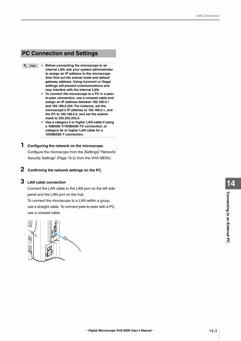
- Digital Microscope VHX-6000 User’s Manual -
LAN Connection
14-3
Co
nn
ecting
to an
Extern
al PC
14
1 Configuring the network on the microscope.
Configure the microscope from the [Settings] "Network/
Security Settings" (Page 13-2) from the VHX MENU.
2 Confirming the network settings on the PC.
3 LAN cable connection
Connect the LAN cable to the LAN port on the left side
panel and the LAN port on the hub.
To connect the microscope to a LAN within a group,
use a straight cable. To connect peer-to-peer with a PC,
use a crossed cable.
PC Connection and Settings
• Before connecting the microscope to an internal LAN, ask your system administrator to assign an IP address to the microscope. Also find out the subnet mask and default gateway address. Using incorrect or illegal settings will prevent communications and may interfere with the internal LAN.
• To connect the microscope to a PC in a peer-to-peer connection, use a crossed cable and assign an IP address between 192.168.0.1 and 192.168.0.254. For instance, set the microscope's IP address to 192.168.0.1, and the PC to 192.168.0.2, and set the subnet mask to 255.255.255.0.
• Use a category 5 or higher LAN cable if using a 10BASE-T/100BASE-TX connection, or category 5e or higher LAN cable for a 1000BASE-T connection.
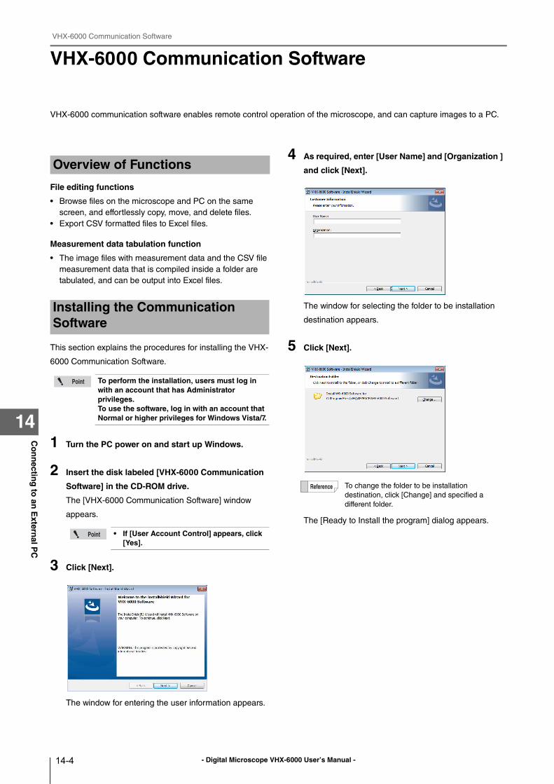
- Digital Microscope VHX-6000 User’s Manual -
VHX-6000 Communication Software
14-4
Co
nn
ecting
to an
Extern
al PC
14
VHX-6000 Communication Software
VHX-6000 communication software enables remote control operation of the microscope, and can capture images to a PC.
File editing functions
• Browse files on the microscope and PC on the same
screen, and effortlessly copy, move, and delete files.
• Export CSV formatted files to Excel files.
Measurement data tabulation function
• The image files with measurement data and the CSV file
measurement data that is compiled inside a folder are
tabulated, and can be output into Excel files.
This section explains the procedures for installing the VHX-
6000 Communication Software.
1 Turn the PC power on and start up Windows.
2 Insert the disk labeled [VHX-6000 Communication
Software] in the CD-ROM drive.
The [VHX-6000 Communication Software] window
appears.
3 Click [Next].
The window for entering the user information appears.
4 As required, enter [User Name] and [Organization ]
and click [Next].
The window for selecting the folder to be installation
destination appears.
5 Click [Next].
The [Ready to Install the program] dialog appears.
Overview of Functions
Installing the Communication Software
To perform the installation, users must log in with an account that has Administrator privileges.To use the software, log in with an account that Normal or higher privileges for Windows Vista/7.
• If [User Account Control] appears, click [Yes].
To change the folder to be installation
destination, click [Change] and specified a
different folder.
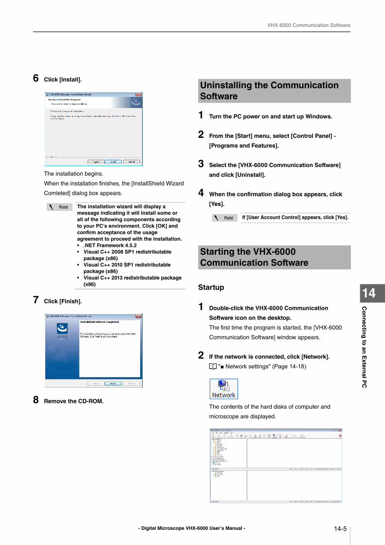
- Digital Microscope VHX-6000 User’s Manual -
VHX-6000 Communication Software
14-5
Co
nn
ecting
to an
Extern
al PC
14
6 Click [Install].
The installation begins.
When the installation finishes, the [InstallShield Wizard
Comleted] dialog box appears.
7 Click [Finish].
8 Remove the CD-ROM.
1 Turn the PC power on and start up Windows.
2 From the [Start] menu, select [Control Panel] -
[Programs and Features].
3 Select the [VHX-6000 Communication Software]
and click [Uninstall].
4 When the confirmation dialog box appears, click
[Yes].
Startup
1 Double-click the VHX-6000 Communication
Software icon on the desktop.
The first time the program is started, the [VHX-6000
Communication Software] window appears.
2 If the network is connected, click [Network].
"■ Network settings" (Page 14-18)
The contents of the hard disks of computer and
microscope are displayed.
The installation wizard will display a message indicating it will install some or all of the following components according to your PC's environment. Click [OK] and confirm acceptance of the usage agreement to proceed with the installation.• .NET Framework 4.5.2• Visual C++ 2008 SP1 redistributable
package (x86)• Visual C++ 2010 SP1 redistributable
package (x86)• Visual C++ 2013 redistributable package
(x86)
Uninstalling the Communication Software
If [User Account Control] appears, click [Yes].
Starting the VHX-6000 Communication Software
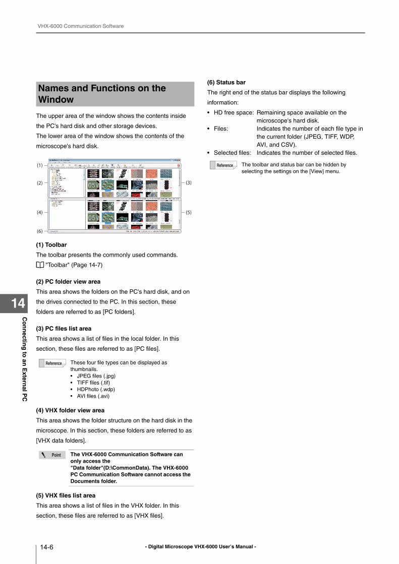
- Digital Microscope VHX-6000 User’s Manual -
VHX-6000 Communication Software
14-6
Co
nn
ecting
to an
Extern
al PC
14
The upper area of the window shows the contents inside
the PC's hard disk and other storage devices.
The lower area of the window shows the contents of the
microscope's hard disk.
(1) Toolbar
The toolbar presents the commonly used commands.
"Toolbar" (Page 14-7)
(2) PC folder view area
This area shows the folders on the PC's hard disk, and on
the drives connected to the PC. In this section, these
folders are referred to as [PC folders].
(3) PC files list area
This area shows a list of files in the local folder. In this
section, these files are referred to as [PC files].
(4) VHX folder view area
This area shows the folder structure on the hard disk in the
microscope. In this section, these folders are referred to as
[VHX data folders].
(5) VHX files list area
This area shows a list of files in the VHX folder. In this
section, these files are referred to as [VHX files].
(6) Status bar
The right end of the status bar displays the following
information:
• HD free space: Remaining space available on the
microscope's hard disk.
• Files: Indicates the number of each file type in
the current folder (JPEG, TIFF, WDP,
AVI, and CSV).
• Selected files: Indicates the number of selected files.
Names and Functions on the Window
These four file types can be displayed as
thumbnails.
• JPEG files (.jpg)
• TIFF files (.tif)
• HDPhoto (.wdp)
• AVI files (.avi)
The VHX-6000 Communication Software can only access the "Data folder"(D:\CommonData). The VHX-6000 PC Communication Software cannot access the Documents folder.
(1)
(2) (3)
(5)(4)
(6)
The toolbar and status bar can be hidden by
selecting the settings on the [View] menu.
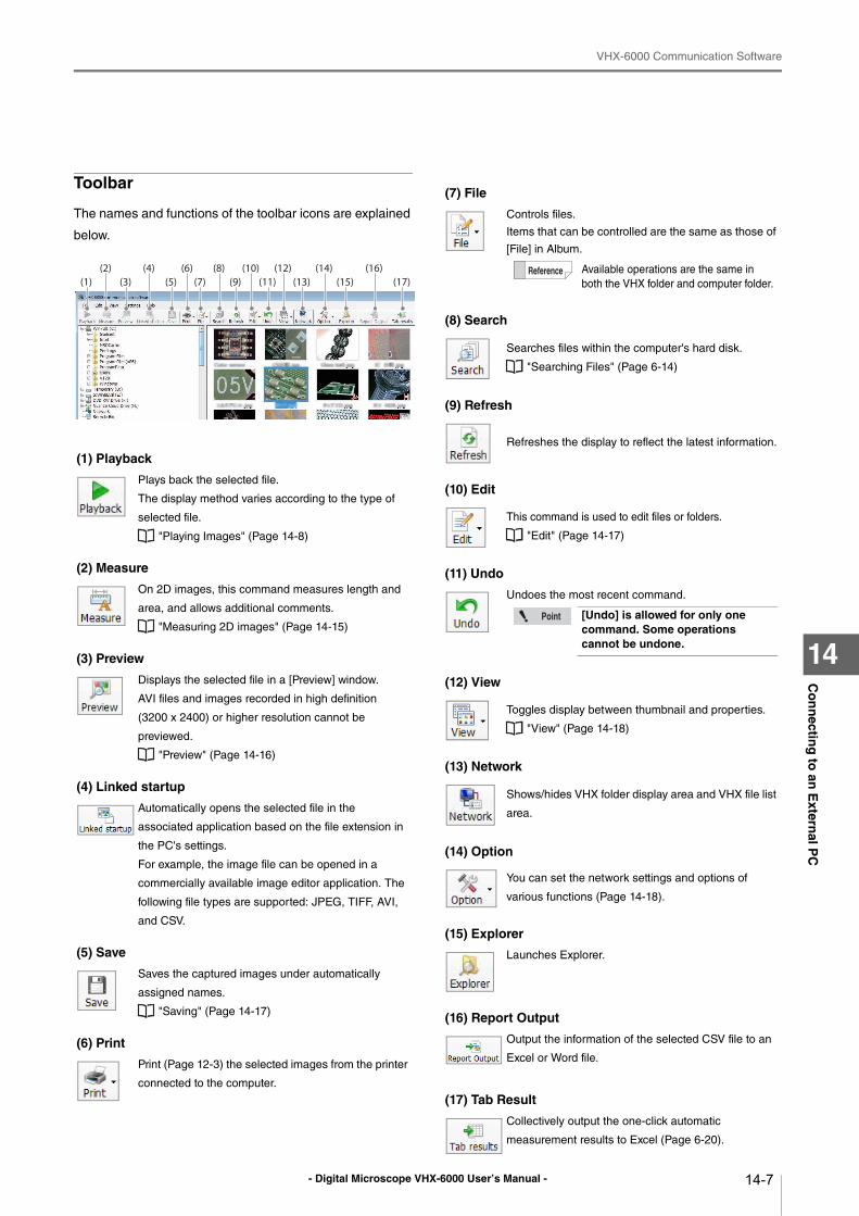
- Digital Microscope VHX-6000 User’s Manual -
VHX-6000 Communication Software
14-7
Co
nn
ecting
to an
Extern
al PC
14
Toolbar
The names and functions of the toolbar icons are explained
below.
(1) Playback
Plays back the selected file.
The display method varies according to the type of
selected file.
"Playing Images" (Page 14-8)
(2) Measure
On 2D images, this command measures length and
area, and allows additional comments.
"Measuring 2D images" (Page 14-15)
(3) Preview
Displays the selected file in a [Preview] window.
AVI files and images recorded in high definition
(3200 x 2400) or higher resolution cannot be
previewed.
"Preview" (Page 14-16)
(4) Linked startup
Automatically opens the selected file in the
associated application based on the file extension in
the PC's settings.
For example, the image file can be opened in a
commercially available image editor application. The
following file types are supported: JPEG, TIFF, AVI,
and CSV.
(5) Save
Saves the captured images under automatically
assigned names.
"Saving" (Page 14-17)
(6) Print
Print (Page 12-3) the selected images from the printer
connected to the computer.
(1)(2)
(3) (5) (7) (9) (11) (13) (15)(4) (6) (8) (10) (12) (14) (16)
(17)
(7) File
Controls files.
Items that can be controlled are the same as those of
[File] in Album.
(8) Search
Searches files within the computer's hard disk.
"Searching Files" (Page 6-14)
(9) Refresh
Refreshes the display to reflect the latest information.
(10) Edit
This command is used to edit files or folders.
"Edit" (Page 14-17)
(11) Undo
Undoes the most recent command.
(12) View
Toggles display between thumbnail and properties.
"View" (Page 14-18)
(13) Network
Shows/hides VHX folder display area and VHX file list
area.
(14) Option
You can set the network settings and options of
various functions (Page 14-18).
(15) Explorer
Launches Explorer.
(16) Report Output
Output the information of the selected CSV file to an
Excel or Word file.
(17) Tab Result
Collectively output the one-click automatic
measurement results to Excel (Page 6-20).
Available operations are the same in
both the VHX folder and computer folder.
[Undo] is allowed for only one command. Some operations cannot be undone.
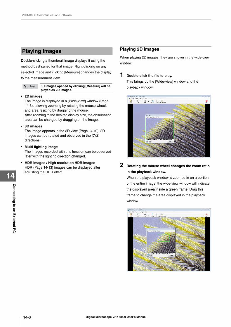
- Digital Microscope VHX-6000 User’s Manual -
VHX-6000 Communication Software
14-8
Co
nn
ecting
to an
Extern
al PC
14
Double-clicking a thumbnail image displays it using the
method best suited for that image. Right-clicking on any
selected image and clicking [Measure] changes the display
to the measurement view.
• 2D imagesThe image is displayed in a [Wide-view] window (Page
14-8), allowing zooming by rotating the mouse wheel,
and area resizing by dragging the mouse.
After zooming to the desired display size, the observation
area can be changed by dragging on the image.
• 3D imagesThe image appears in the 3D view (Page 14-10). 3D
images can be rotated and observed in the XYZ
directions.
• Multi-lighting imageThe images recorded with this function can be observed
later with the lighting direction changed.
• HDR images / High resolution HDR imagesHDR (Page 14-13) images can be displayed after
adjusting the HDR effect.
Playing 2D images
When playing 2D images, they are shown in the wide-view
window.
1 Double-click the file to play.
This brings up the [Wide-view] window and the
playback window.
2 Rotating the mouse wheel changes the zoom ratio
in the playback window.
When the playback window is zoomed in on a portion
of the entire image, the wide-view window will indicate
the displayed area inside a green frame. Drag this
frame to change the area displayed in the playback
window.
Playing Images
3D images opened by clicking [Measure] will be played as 2D images.
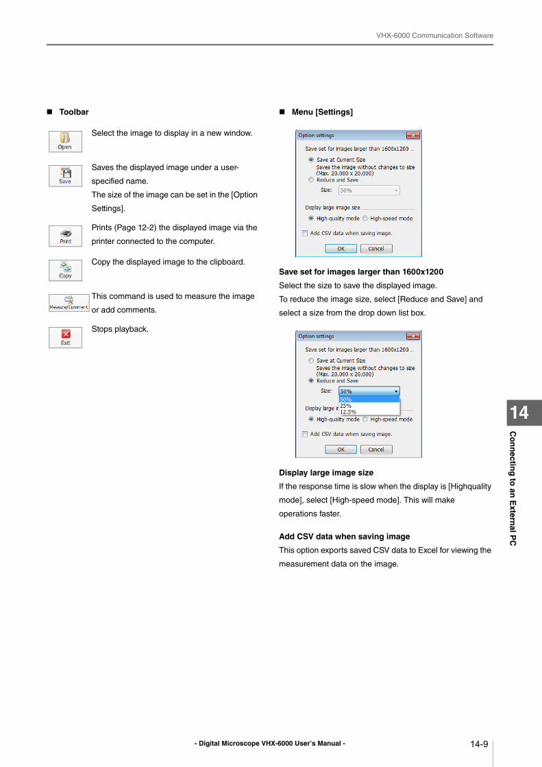
- Digital Microscope VHX-6000 User’s Manual -
VHX-6000 Communication Software
14-9
Co
nn
ecting
to an
Extern
al PC
14
Toolbar Menu [Settings]
Save set for images larger than 1600x1200
Select the size to save the displayed image.
To reduce the image size, select [Reduce and Save] and
select a size from the drop down list box.
Display large image size
If the response time is slow when the display is [Highquality
mode], select [High-speed mode]. This will make
operations faster.
Add CSV data when saving image
This option exports saved CSV data to Excel for viewing the
measurement data on the image.
Select the image to display in a new window.
Saves the displayed image under a user-
specified name.
The size of the image can be set in the [Option
Settings].
Prints (Page 12-2) the displayed image via the
printer connected to the computer.
Copy the displayed image to the clipboard.
This command is used to measure the image
or add comments.
Stops playback.
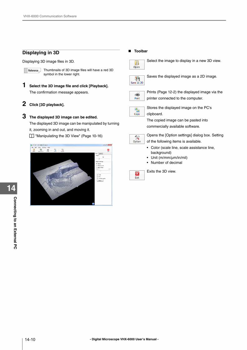
- Digital Microscope VHX-6000 User’s Manual -
VHX-6000 Communication Software
14-10
Co
nn
ecting
to an
Extern
al PC
14
Displaying in 3D
Displaying 3D image files in 3D.
1 Select the 3D image file and click [Playback].
The confirmation message appears.
2 Click [3D playback].
3 The displayed 3D image can be edited.
The displayed 3D image can be manipulated by turning
it, zooming in and out, and moving it.
"Manipulating the 3D View" (Page 10-16)
Toolbar
Thumbnails of 3D image files will have a red 3D
symbol in the lower right.
Select the image to display in a new 3D view.
Saves the displayed image as a 2D image.
Prints (Page 12-2) the displayed image via the
printer connected to the computer.
Stores the displayed image on the PC's
clipboard.
The copied image can be pasted into
commercially available software.
Opens the [Option settings] dialog box. Setting
of the following items is available.
• Color (scale line, scale assistance line,
background)
• Unit (m/mm/μm/in/mil)
• Number of decimal
Exits the 3D view.
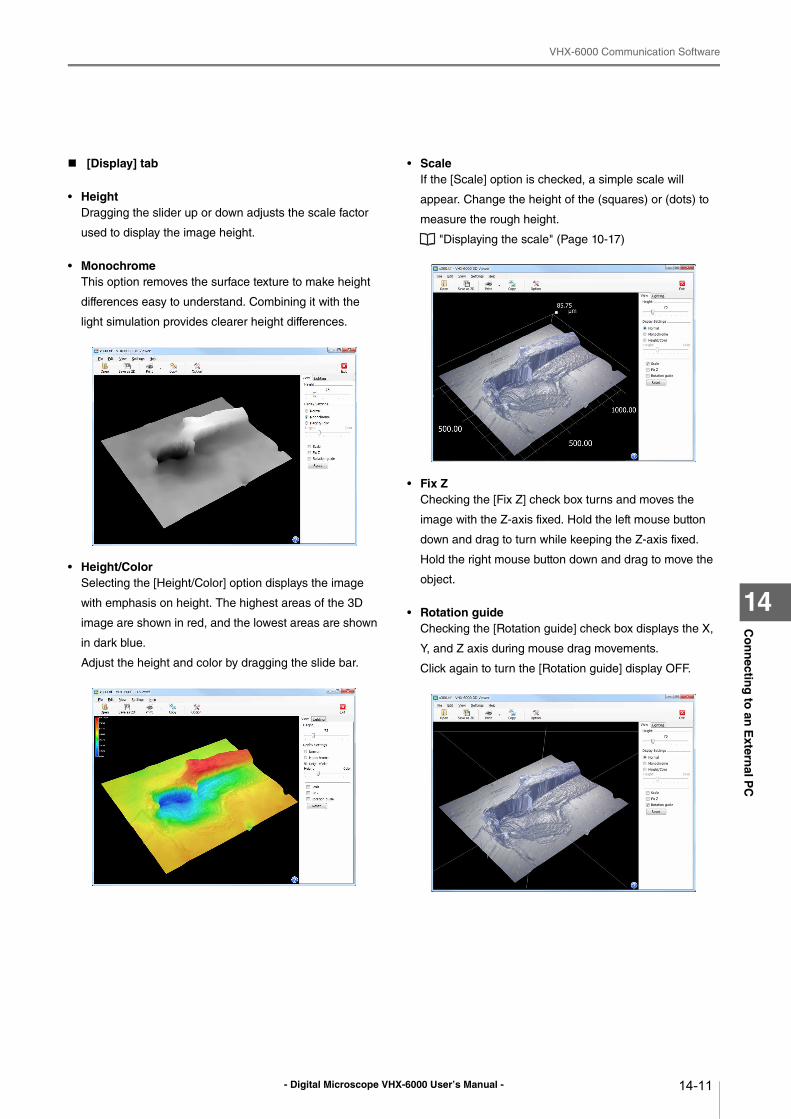
- Digital Microscope VHX-6000 User’s Manual -
VHX-6000 Communication Software
14-11
Co
nn
ecting
to an
Extern
al PC
14
[Display] tab
• HeightDragging the slider up or down adjusts the scale factor
used to display the image height.
• MonochromeThis option removes the surface texture to make height
differences easy to understand. Combining it with the
light simulation provides clearer height differences.
• Height/ColorSelecting the [Height/Color] option displays the image
with emphasis on height. The highest areas of the 3D
image are shown in red, and the lowest areas are shown
in dark blue.
Adjust the height and color by dragging the slide bar.
• ScaleIf the [Scale] option is checked, a simple scale will
appear. Change the height of the (squares) or (dots) to
measure the rough height.
"Displaying the scale" (Page 10-17)
• Fix ZChecking the [Fix Z] check box turns and moves the
image with the Z-axis fixed. Hold the left mouse button
down and drag to turn while keeping the Z-axis fixed.
Hold the right mouse button down and drag to move the
object.
• Rotation guideChecking the [Rotation guide] check box displays the X,
Y, and Z axis during mouse drag movements.
Click again to turn the [Rotation guide] display OFF.
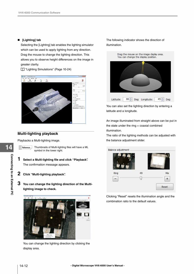
- Digital Microscope VHX-6000 User’s Manual -
VHX-6000 Communication Software
14-12
Co
nn
ecting
to an
Extern
al PC
14
[Lighting] tab
Selecting the [Lighting] tab enables the lighting simulator
which can be used to apply lighting from any direction.
Drag the mouse to change the lighting direction. This
allows you to observe height differences on the image in
greater clarity.
"Lighting Simulations" (Page 10-24)
Multi-lighting playback
Playbacks a Multi-lighting image.
1 Select a Multi-lighting file and click “Playback”.
The confirmation message appears.
2 Click “Multi-lighting playback”.
3 You can change the lighting direction of the Multi-
lighting image to check.
You can change the lighting direction by clicking the
display area.
The following indicator shows the direction of
illumination.
You can also set the lighting direction by entering a
latitude and a longitude.
An image illuminated from straight above can be put in
the state under the ring + coaxial combined
illumination.
The ratio of the lighting methods can be adjusted with
the balance adjustment slider.
Clicking “Reset” resets the illumination angle and the
combination ratio to the default values.
Thumbnails of Multi-lighting files will have a ML
symbol in the lower right.
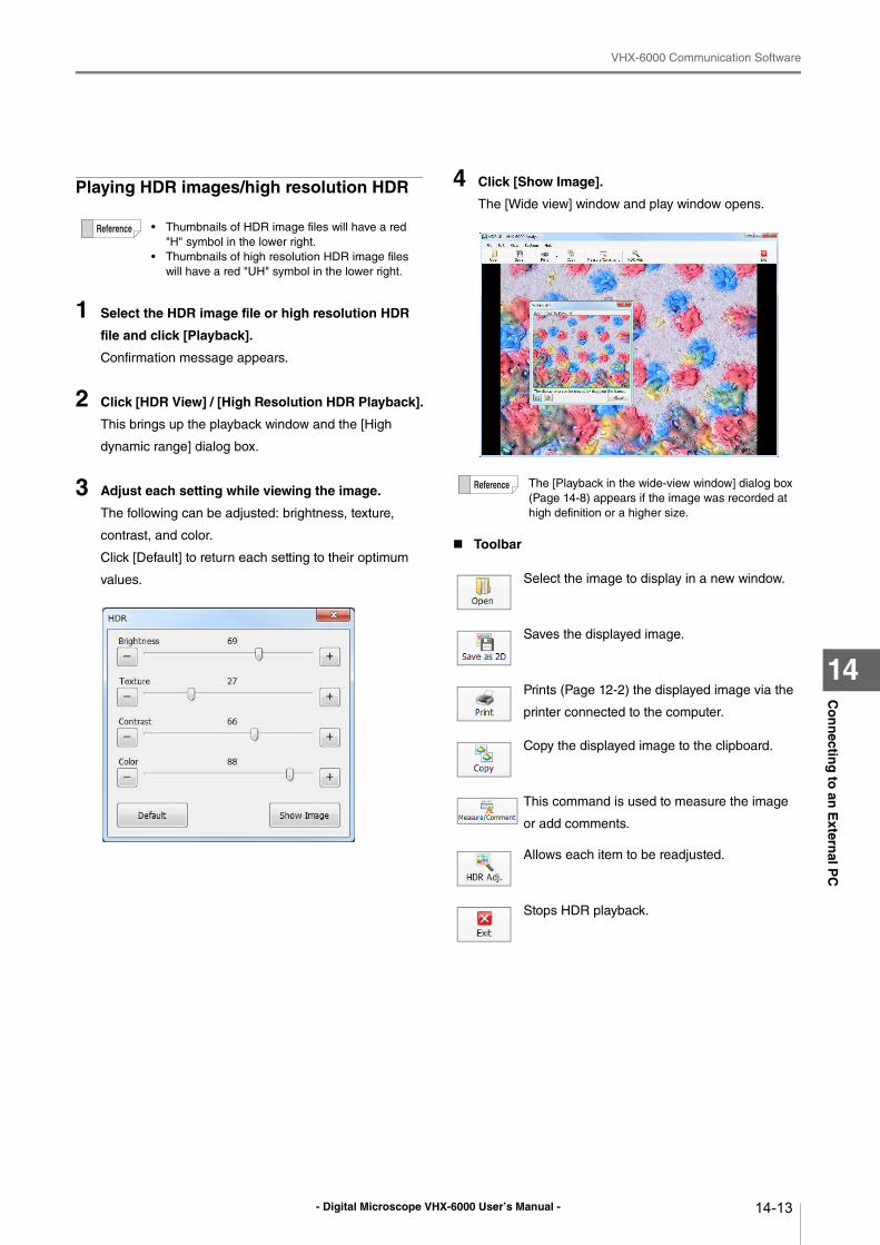
- Digital Microscope VHX-6000 User’s Manual -
VHX-6000 Communication Software
14-13
Co
nn
ecting
to an
Extern
al PC
14
Playing HDR images/high resolution HDR
1 Select the HDR image file or high resolution HDR
file and click [Playback].
Confirmation message appears.
2 Click [HDR View] / [High Resolution HDR Playback].
This brings up the playback window and the [High
dynamic range] dialog box.
3 Adjust each setting while viewing the image.
The following can be adjusted: brightness, texture,
contrast, and color.
Click [Default] to return each setting to their optimum
values.
4 Click [Show Image].
The [Wide view] window and play window opens.
Toolbar
• Thumbnails of HDR image files will have a red
"H" symbol in the lower right.
• Thumbnails of high resolution HDR image files
will have a red "UH" symbol in the lower right.
The [Playback in the wide-view window] dialog box
(Page 14-8) appears if the image was recorded at
high definition or a higher size.
Select the image to display in a new window.
Saves the displayed image.
Prints (Page 12-2) the displayed image via the
printer connected to the computer.
Copy the displayed image to the clipboard.
This command is used to measure the image
or add comments.
Allows each item to be readjusted.
Stops HDR playback.
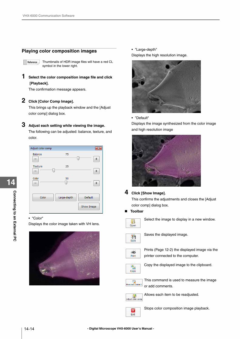
- Digital Microscope VHX-6000 User’s Manual -
VHX-6000 Communication Software
14-14
Co
nn
ecting
to an
Extern
al PC
14
Playing color composition images
1 Select the color composition image file and click
[Playback].
The confirmation message appears.
2 Click [Color Comp Image].
This brings up the playback window and the [Adjust
color comp] dialog box.
3 Adjust each setting while viewing the image.
The following can be adjusted: balance, texture, and
color.
• "Color"
Displays the color image taken with VH lens.
• "Large-depth"
Displays the high resolution image.
• "Default"
Displays the image synthesized from the color image
and high resolution image
4 Click [Show Image].
This confirms the adjustments and closes the [Adjust
color comp] dialog box.
Toolbar
Thumbnails of HDR image files will have a red CL
symbol in the lower right.
Select the image to display in a new window.
Saves the displayed image.
Prints (Page 12-2) the displayed image via the
printer connected to the computer.
Copy the displayed image to the clipboard.
This command is used to measure the image
or add comments.
Allows each item to be readjusted.
Stops color composition image playback.
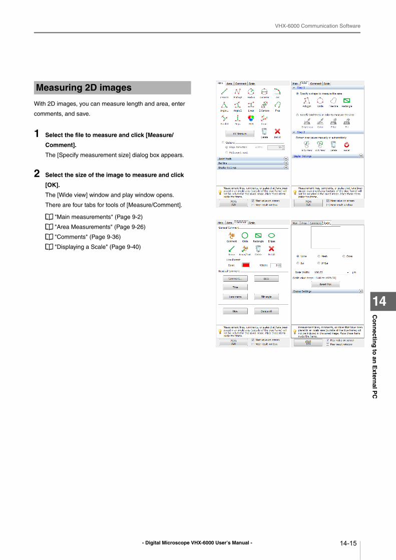
- Digital Microscope VHX-6000 User’s Manual -
VHX-6000 Communication Software
14-15
Co
nn
ecting
to an
Extern
al PC
14
With 2D images, you can measure length and area, enter
comments, and save.
1 Select the file to measure and click [Measure/
Comment].
The [Specify measurement size] dialog box appears.
2 Select the size of the image to measure and click
[OK].
The [Wide view] window and play window opens.
There are four tabs for tools of [Measure/Comment].
"Main measurements" (Page 9-2)
"Area Measurements" (Page 9-26)
"Comments" (Page 9-36)
"Displaying a Scale" (Page 9-40)
Measuring 2D images
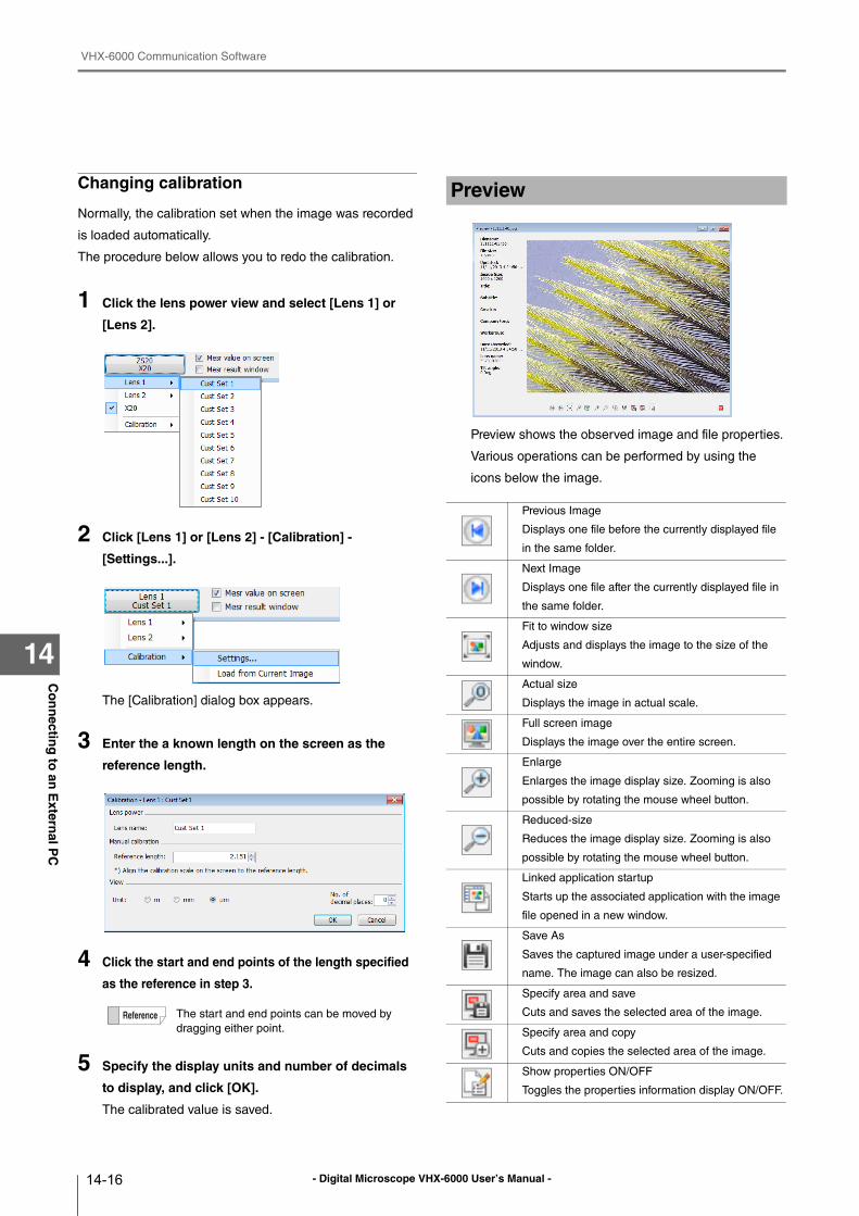
- Digital Microscope VHX-6000 User’s Manual -
VHX-6000 Communication Software
14-16
Co
nn
ecting
to an
Extern
al PC
14
Changing calibration
Normally, the calibration set when the image was recorded
is loaded automatically.
The procedure below allows you to redo the calibration.
1 Click the lens power view and select [Lens 1] or
[Lens 2].
2 Click [Lens 1] or [Lens 2] - [Calibration] -
[Settings...].
The [Calibration] dialog box appears.
3 Enter the a known length on the screen as the
reference length.
4 Click the start and end points of the length specified
as the reference in step 3.
5 Specify the display units and number of decimals
to display, and click [OK].
The calibrated value is saved.
Preview shows the observed image and file properties.
Various operations can be performed by using the
icons below the image.
The start and end points can be moved by
dragging either point.
Preview
Previous Image
Displays one file before the currently displayed file
in the same folder.
Next Image
Displays one file after the currently displayed file in
the same folder.
Fit to window size
Adjusts and displays the image to the size of the
window.
Actual size
Displays the image in actual scale.
Full screen image
Displays the image over the entire screen.
Enlarge
Enlarges the image display size. Zooming is also
possible by rotating the mouse wheel button.
Reduced-size
Reduces the image display size. Zooming is also
possible by rotating the mouse wheel button.
Linked application startup
Starts up the associated application with the image
file opened in a new window.
Save As
Saves the captured image under a user-specified
name. The image can also be resized.
Specify area and save
Cuts and saves the selected area of the image.
Specify area and copy
Cuts and copies the selected area of the image.
Show properties ON/OFF
Toggles the properties information display ON/OFF.
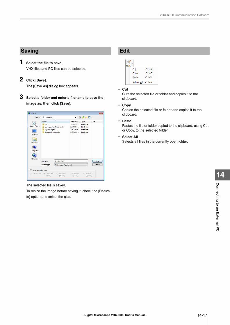
- Digital Microscope VHX-6000 User’s Manual -
VHX-6000 Communication Software
14-17
Co
nn
ecting
to an
Extern
al PC
14
1 Select the file to save.
VHX files and PC files can be selected.
2 Click [Save].
The [Save As] dialog box appears.
3 Select a folder and enter a filename to save the
image as, then click [Save].
The selected file is saved.
To resize the image before saving it, check the [Resize
to] option and select the size.
• CutCuts the selected file or folder and copies it to the
clipboard.
• CopyCopies the selected file or folder and copies it to the
clipboard.
• PastePastes the file or folder copied to the clipboard, using Cut
or Copy, to the selected folder.
• Select AllSelects all files in the currently open folder.
Saving Edit
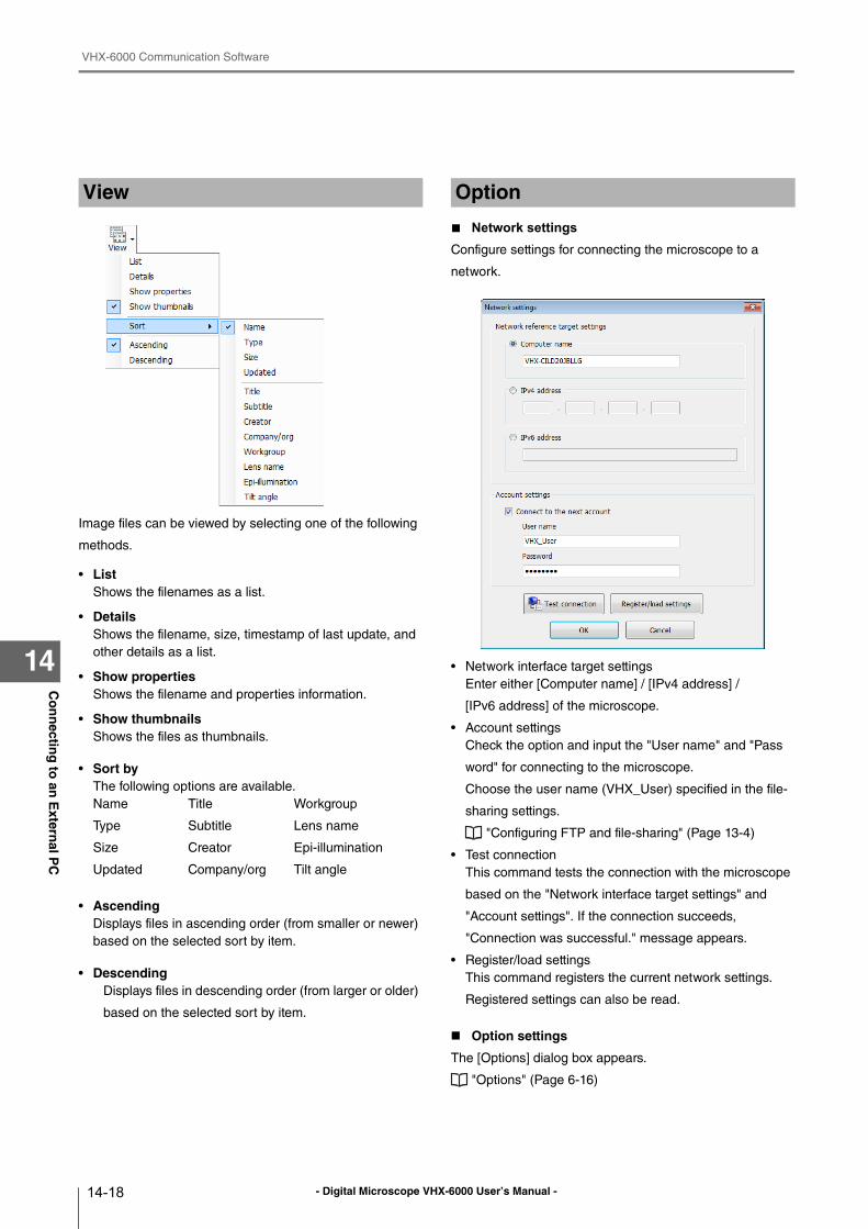
- Digital Microscope VHX-6000 User’s Manual -
VHX-6000 Communication Software
14-18
Co
nn
ecting
to an
Extern
al PC
14
Image files can be viewed by selecting one of the following
methods.
• ListShows the filenames as a list.
• DetailsShows the filename, size, timestamp of last update, and
other details as a list.
• Show propertiesShows the filename and properties information.
• Show thumbnailsShows the files as thumbnails.
• Sort byThe following options are available.
Name Title Workgroup
Type Subtitle Lens name
Size Creator Epi-illumination
Updated Company/org Tilt angle
• AscendingDisplays files in ascending order (from smaller or newer)
based on the selected sort by item.
• DescendingDisplays files in descending order (from larger or older)
based on the selected sort by item.
■ Network settings
Configure settings for connecting the microscope to a
network.
• Network interface target settings
Enter either [Computer name] / [IPv4 address] /
[IPv6 address] of the microscope.
• Account settings
Check the option and input the "User name" and "Pass
word" for connecting to the microscope.
Choose the user name (VHX_User) specified in the file-
sharing settings.
"Configuring FTP and file-sharing" (Page 13-4)
• Test connection
This command tests the connection with the microscope
based on the "Network interface target settings" and
"Account settings". If the connection succeeds,
"Connection was successful." message appears.
• Register/load settings
This command registers the current network settings.
Registered settings can also be read.
Option settings
The [Options] dialog box appears.
"Options" (Page 6-16)
View Option
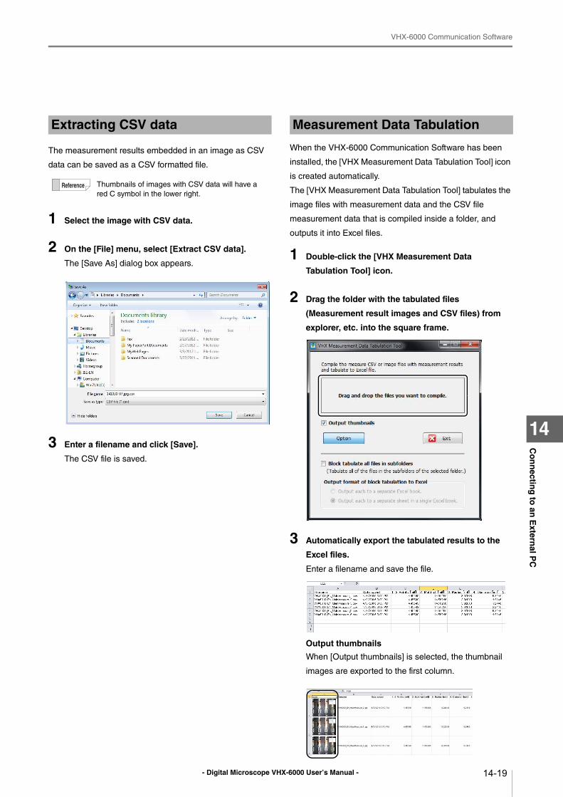
- Digital Microscope VHX-6000 User’s Manual -
VHX-6000 Communication Software
14-19
Co
nn
ecting
to an
Extern
al PC
14
The measurement results embedded in an image as CSV
data can be saved as a CSV formatted file.
1 Select the image with CSV data.
2 On the [File] menu, select [Extract CSV data].
The [Save As] dialog box appears.
3 Enter a filename and click [Save].
The CSV file is saved.
When the VHX-6000 Communication Software has been
installed, the [VHX Measurement Data Tabulation Tool] icon
is created automatically.
The [VHX Measurement Data Tabulation Tool] tabulates the
image files with measurement data and the CSV file
measurement data that is compiled inside a folder, and
outputs it into Excel files.
1 Double-click the [VHX Measurement Data
Tabulation Tool] icon.
2 Drag the folder with the tabulated files
(Measurement result images and CSV files) from
explorer, etc. into the square frame.
3 Automatically export the tabulated results to the
Excel files.
Enter a filename and save the file.
Output thumbnails
When [Output thumbnails] is selected, the thumbnail
images are exported to the first column.
Extracting CSV data
Thumbnails of images with CSV data will have a
red C symbol in the lower right.
Measurement Data Tabulation
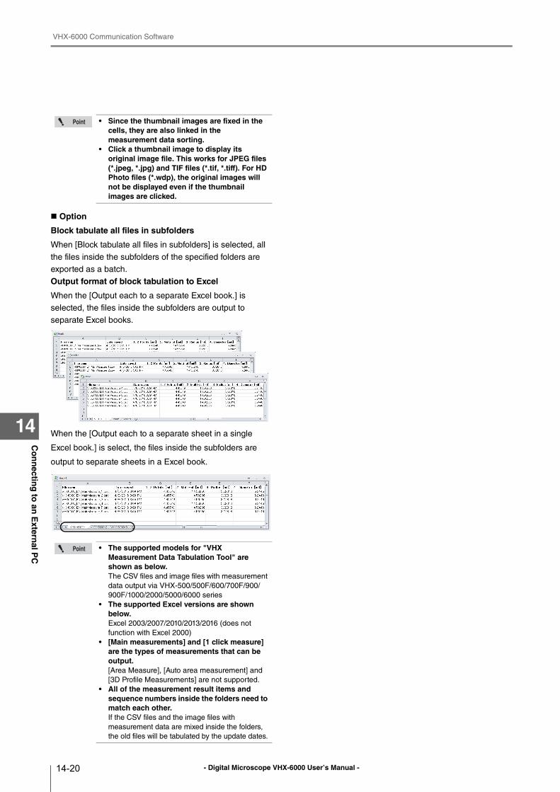
- Digital Microscope VHX-6000 User’s Manual -
VHX-6000 Communication Software
14-20
Co
nn
ecting
to an
Extern
al PC
14
Option
Block tabulate all files in subfolders
When [Block tabulate all files in subfolders] is selected, all
the files inside the subfolders of the specified folders are
exported as a batch.
Output format of block tabulation to Excel
When the [Output each to a separate Excel book.] is
selected, the files inside the subfolders are output to
separate Excel books.
When the [Output each to a separate sheet in a single
Excel book.] is select, the files inside the subfolders are
output to separate sheets in a Excel book.
• Since the thumbnail images are fixed in the cells, they are also linked in the measurement data sorting.
• Click a thumbnail image to display its original image file. This works for JPEG files (*.jpeg, *.jpg) and TIF files (*.tif, *.tiff). For HD Photo files (*.wdp), the original images will not be displayed even if the thumbnail images are clicked.
• The supported models for "VHX Measurement Data Tabulation Tool" are shown as below.The CSV files and image files with measurement
data output via VHX-500/500F/600/700F/900/
900F/1000/2000/5000/6000 series
• The supported Excel versions are shown below.Excel 2003/2007/2010/2013/2016 (does not
function with Excel 2000)
• [Main measurements] and [1 click measure] are the types of measurements that can be output.[Area Measure], [Auto area measurement] and
[3D Profile Measurements] are not supported.
• All of the measurement result items and sequence numbers inside the folders need to match each other.If the CSV files and the image files with
measurement data are mixed inside the folders,
the old files will be tabulated by the update dates.
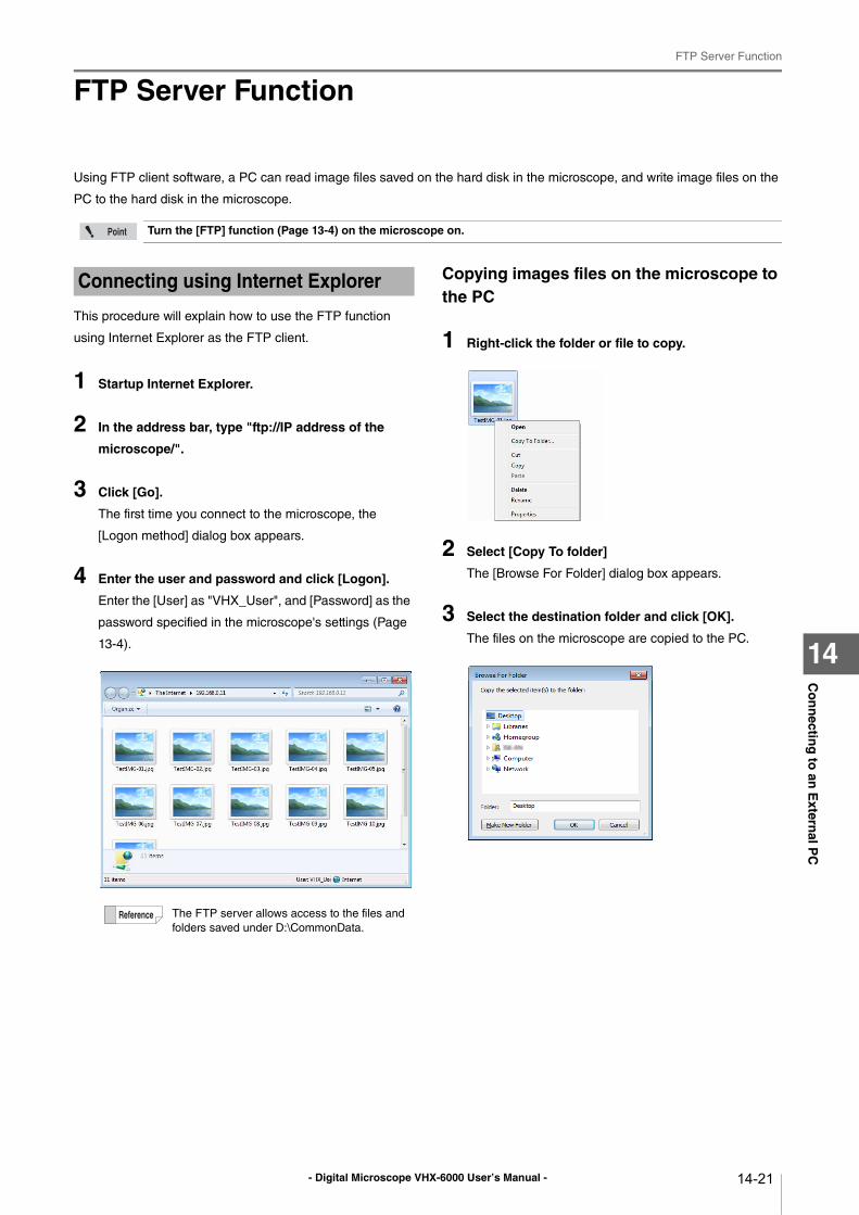
- Digital Microscope VHX-6000 User’s Manual -
FTP Server Function
14-21
Co
nn
ecting
to an
Extern
al PC
14
FTP Server Function
Using FTP client software, a PC can read image files saved on the hard disk in the microscope, and write image files on the
PC to the hard disk in the microscope.
This procedure will explain how to use the FTP function
using Internet Explorer as the FTP client.
1 Startup Internet Explorer.
2 In the address bar, type "ftp://IP address of the
microscope/".
3 Click [Go].
The first time you connect to the microscope, the
[Logon method] dialog box appears.
4 Enter the user and password and click [Logon].
Enter the [User] as "VHX_User", and [Password] as the
password specified in the microscope's settings (Page
13-4).
Copying images files on the microscope to the PC
1 Right-click the folder or file to copy.
2 Select [Copy To folder]
The [Browse For Folder] dialog box appears.
3 Select the destination folder and click [OK].
The files on the microscope are copied to the PC.
Turn the [FTP] function (Page 13-4) on the microscope on.
Connecting using Internet Explorer
The FTP server allows access to the files and
folders saved under D:\CommonData.
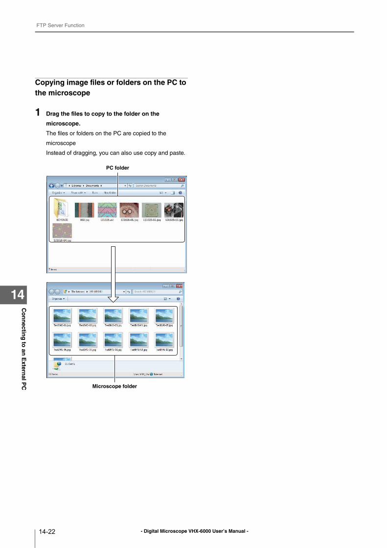
- Digital Microscope VHX-6000 User’s Manual -
FTP Server Function
14-22
Co
nn
ecting
to an
Extern
al PC
14
Copying image files or folders on the PC to the microscope
1 Drag the files to copy to the folder on the
microscope.
The files or folders on the PC are copied to the
microscope
Instead of dragging, you can also use copy and paste.
PC folder
Microscope folder
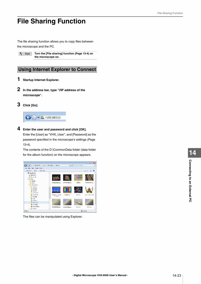
- Digital Microscope VHX-6000 User’s Manual -
File Sharing Function
14-23
Co
nn
ecting
to an
Extern
al PC
14
File Sharing Function
The file sharing function allows you to copy files between
the microscope and the PC.
1 Startup Internet Explorer.
2 In the address bar, type "//IP address of the
microscope".
3 Click [Go].
4 Enter the user and password and click [OK].
Enter the [User] as "VHX_User", and [Password] as the
password specified in the microscope's settings (Page
13-4).
The contents of the D:\CommonData folder (data folder
for the album function) on the microscope appears.
The files can be manipulated using Explorer.
Turn the [File sharing] function (Page 13-4) on the microscope on.
Using Internet Explorer to Connect
- Digital Microscope VHX-6000 User’s Manual -
File Sharing Function
14-24
Co
nn
ecting
to an
Extern
al PC
14
- Digital Microscope VHX-6000 User’s Manual - A-1
Ap
pen
dix
A
Appendix
List of Necessary Authentication Information and Default
Settings ............................................................. Page A-2
Replacing the Fuse ............................................... Page A-3
REMOTE Connector (Capture/Pause) .................. Page A-4
Using the REMOTE Connector to Capture........ Page A-4
Using the REMOTE Connector to Pause and Release
Images .......................................................... Page A-4
External Dimensions ............................................. Page A-5
VHX-6000 Controller ......................................... Page A-5
VHX-6100/6020 Camera Unit............................ Page A-5
Specifications........................................................ Page A-6
Specifications (Basic Performance) .................. Page A-6
Specifications (Various Functions) .................... Page A-8
Specifications (Detailed Modules)....................Page A-10
Software Usage Agreement .................................Page A-11
Usage Agreement for Operation Software ...........Page A-12
Before asking repair and inspection.....................Page A-17
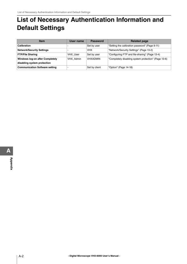
- Digital Microscope VHX-6000 User’s Manual -
List of Necessary Authentication Information and Default Settings
A-2
Ap
pen
dix
A
List of Necessary Authentication Information and Default Settings
Item User name Password Related page
Calibration - Set by user "Setting the calibration password" (Page 9-11)
Network/Security Settings - VHX "Network/Security Settings" (Page 13-2)
FTP/File Sharing VHX_User Set by user "Configuring FTP and file-sharing" (Page 13-4)
Windows log-on after Completely
disabling system protection
VHX_Admin VHXADMIN "Completely disabling system protection" (Page 13-6)
Communication Software setting - Set by client "Option" (Page 14-18)
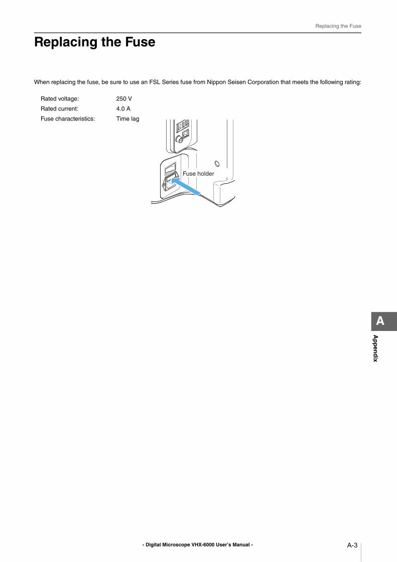
- Digital Microscope VHX-6000 User’s Manual -
Replacing the Fuse
A-3
Ap
pen
dix
A
Replacing the Fuse
When replacing the fuse, be sure to use an FSL Series fuse from Nippon Seisen Corporation that meets the following rating:
Rated voltage: 250 V
Rated current: 4.0 A
Fuse characteristics: Time lag
Fuse holder
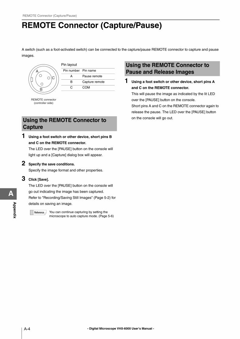
- Digital Microscope VHX-6000 User’s Manual -
REMOTE Connector (Capture/Pause)
A-4
Ap
pen
dix
A
REMOTE Connector (Capture/Pause)
A switch (such as a foot-activated switch) can be connected to the capture/pause REMOTE connector to capture and pause
images.
1 Using a foot switch or other device, short pins B
and C on the REMOTE connector.
The LED over the [PAUSE] button on the console will
light up and a [Capture] dialog box will appear.
2 Specify the save conditions.
Specify the image format and other properties.
3 Click [Save].
The LED over the [PAUSE] button on the console will
go out indicating the image has been captured.
Refer to "Recording/Saving Still Images" (Page 5-2) for
details on saving an image.
1 Using a foot switch or other device, short pins A
and C on the REMOTE connector.
This will pause the image as indicated by the lit LED
over the [PAUSE] button on the console.
Short pins A and C on the REMOTE connector again to
release the pause. The LED over the [PAUSE] button
on the console will go out.Using the REMOTE Connector to Capture
You can continue capturing by setting the
microscope to auto capture mode. (Page 5-6)
REMOTE connector
(controller side)
Pin layout
Pin number Pin name
A Pause remote
B Capture remote
C COM
Using the REMOTE Connector to Pause and Release Images
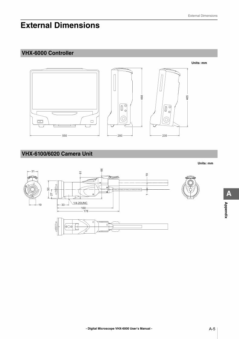
- Digital Microscope VHX-6000 User’s Manual -
External Dimensions
A-5
Ap
pen
dix
A
External Dimensions
VHX-6000 Controller
Units: mm
235200550
465
468
VHX-6100/6020 Camera Unit
Units: mm
178160
3319
31 61
66
19127
50
1/4-20UNC
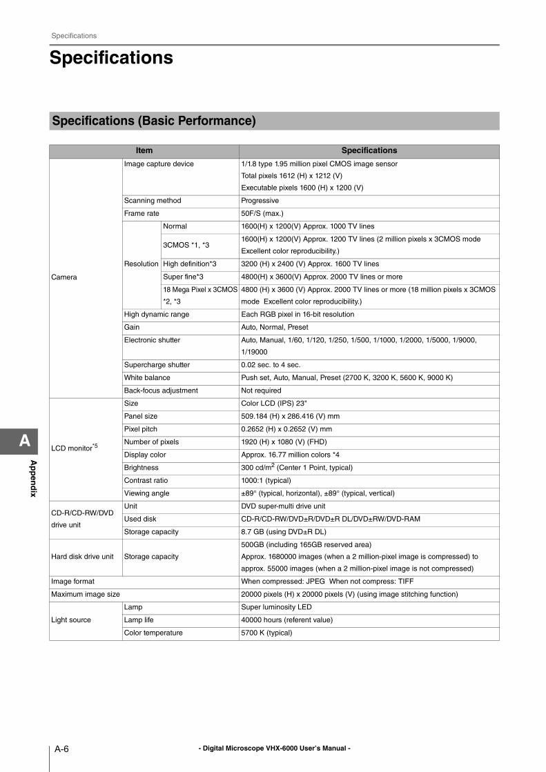
- Digital Microscope VHX-6000 User’s Manual -
Specifications
A-6
Ap
pen
dix
A
Specifications
Specifications (Basic Performance)
Item Specifications
Camera
Image capture device 1/1.8 type 1.95 million pixel CMOS image sensor
Total pixels 1612 (H) x 1212 (V)
Executable pixels 1600 (H) x 1200 (V)
Scanning method Progressive
Frame rate 50F/S (max.)
Resolution
Normal 1600(H) x 1200(V) Approx. 1000 TV lines
3CMOS *1, *31600(H) x 1200(V) Approx. 1200 TV lines (2 million pixels x 3CMOS mode
Excellent color reproducibility.)
High definition*3 3200 (H) x 2400 (V) Approx. 1600 TV lines
Super fine*3 4800(H) x 3600(V) Approx. 2000 TV lines or more
18 Mega Pixel x 3CMOS
*2, *3
4800 (H) x 3600 (V) Approx. 2000 TV lines or more (18 million pixels x 3CMOS
mode Excellent color reproducibility.)
High dynamic range Each RGB pixel in 16-bit resolution
Gain Auto, Normal, Preset
Electronic shutter Auto, Manual, 1/60, 1/120, 1/250, 1/500, 1/1000, 1/2000, 1/5000, 1/9000,
1/19000
Supercharge shutter 0.02 sec. to 4 sec.
White balance Push set, Auto, Manual, Preset (2700 K, 3200 K, 5600 K, 9000 K)
Back-focus adjustment Not required
LCD monitor*5
Size Color LCD (IPS) 23"
Panel size 509.184 (H) x 286.416 (V) mm
Pixel pitch 0.2652 (H) x 0.2652 (V) mm
Number of pixels 1920 (H) x 1080 (V) (FHD)
Display color Approx. 16.77 million colors *4
Brightness 300 cd/m2 (Center 1 Point, typical)
Contrast ratio 1000:1 (typical)
Viewing angle ±89° (typical, horizontal), ±89° (typical, vertical)
CD-R/CD-RW/DVD
drive unit
Unit DVD super-multi drive unit
Used disk CD-R/CD-RW/DVD±R/DVD±R DL/DVD±RW/DVD-RAM
Storage capacity 8.7 GB (using DVD±R DL)
Hard disk drive unit Storage capacity
500GB (including 165GB reserved area)
Approx. 1680000 images (when a 2 million-pixel image is compressed) to
approx. 55000 images (when a 2 million-pixel image is not compressed)
Image format When compressed: JPEG When not compress: TIFF
Maximum image size 20000 pixels (H) x 20000 pixels (V) (using image stitching function)
Light source
Lamp Super luminosity LED
Lamp life 40000 hours (referent value)
Color temperature 5700 K (typical)
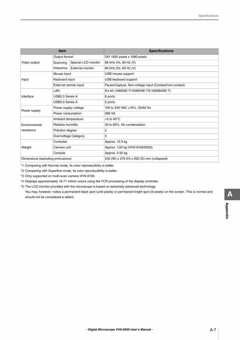
- Digital Microscope VHX-6000 User’s Manual -
Specifications
A-7
Ap
pen
dix
A
*1: Comparing with Normal mode, its color reproducibility is better.
*2: Comparing with Superfine mode, its color reproducibility is better.
*3: Only supported on multi-scan camera VHX-6100.
*4: Displays approximately 16.77 million colors using the FCR processing of the display controller.
*5: The LCD monitor provided with the microscope is based on extremely advanced technology.
You may, however, notice a permanent black spot (unlit pixels) or permanent bright spot (lit pixels) on the screen. This is normal and
should not be considered a defect.
Item Specifications
Video output
Output format DVI 1920 pixels x 1080 pixels
Scanning
frequency
Special LCD monitor 66 kHz (H), 60 Hz (V)
External monitor 66 kHz (H), 60 Hz (V)
Input
Mouse input USB mouse support
Keyboard input USB keyboard support
External remote input Pause/Capture, Non-voltage input (Contact/non-contact)
Interface
LAN RJ-45 (10BASE-T/100BASE-TX/1000BASE-T)
USB2.0 Series A 6 ports
USB3.0 Series A 2 ports
Power supplyPower supply voltage 100 to 240 VAC ±10%, 50/60 Hz
Power consumption 280 VA
Environmental
resistance
Ambient temperature +5 to 40°C
Relative humidity 35 to 80%, No condensation
Pollution degree 2
Overvoltage Category II
Weight
Controller Approx. 12.5 kg
Camera unit Approx. 1.20 kg (VHX-6100/6020)
Console Approx. 0.50 kg
Dimensions (excluding protrusions) 550 (W) x 470 (H) x 200 (D) mm (collapsed)
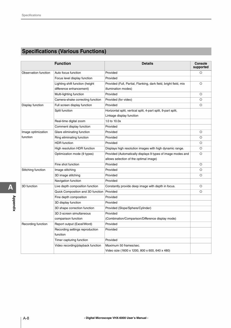
- Digital Microscope VHX-6000 User’s Manual -
Specifications
A-8
Ap
pen
dix
A
Specifications (Various Functions)
Function Details Console supported
Observation function Auto focus function Provided
Focus level display function Provided
Lighting shift function (height
difference enhancement)
Provided (Full, Partial, Flanking, dark field, bright field, mix
illumination modes)
Multi-lighting function Provided
Camera-shake correcting function Provided (for video)
Display function Full screen display function Provided
Split function Horizontal split, vertical split, 4-part split, 9-part split,
Linkage display function
Real-time digital zoom 1.0 to 10.0x
Comment display function Provided
Image optimization
function
Glare eliminating function Provided
Ring eliminating function Provided
HDR function Provided
High resolution HDR function Displays high resolution images with high dynamic range.
Optimization mode (9 types) Provided (Automatically displays 9 types of image modes and
allows selection of the optimal image)
Fine shot function Provided
Stitching function Image stitching Provided
3D image stitching Provided
Navigation function Provided
3D function Live depth composition function Constantly provide deep image with depth in focus.
Quick Composition and 3D function Provided
Fine depth composition Provided
3D display function Provided
3D shape correction function Provided (Slope/Sphere/Cylinder)
3D 2-screen simultaneous
comparison function
Provided
(Combination/Comparison/Difference display mode)
Recording function Report output (Excel/Word) Provided
Recording settings reproduction
function
Provided
Timer capturing function Provided
Video recording/playback function Maximum 50 frames/sec.
Video size (1600 x 1200, 800 x 600, 640 x 480)
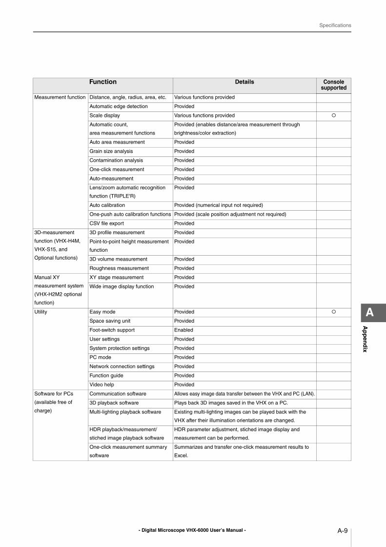
- Digital Microscope VHX-6000 User’s Manual -
Specifications
A-9
Ap
pen
dix
A
Measurement function Distance, angle, radius, area, etc. Various functions provided
Automatic edge detection Provided
Scale display Various functions provided
Automatic count,
area measurement functions
Provided (enables distance/area measurement through
brightness/color extraction)
Auto area measurement Provided
Grain size analysis Provided
Contamination analysis Provided
One-click measurement Provided
Auto-measurement Provided
Lens/zoom automatic recognition
function (TRIPLE'R)
Provided
Auto calibration Provided (numerical input not required)
One-push auto calibration functions Provided (scale position adjustment not required)
CSV file export Provided
3D-measurement
function (VHX-H4M,
VHX-S15, and
Optional functions)
3D profile measurement Provided
Point-to-point height measurement
function
Provided
3D volume measurement Provided
Roughness measurement Provided
Manual XY
measurement system
(VHX-H2M2 optional
function)
XY stage measurement Provided
Wide image display function Provided
Utility Easy mode Provided
Space saving unit Provided
Foot-switch support Enabled
User settings Provided
System protection settings Provided
PC mode Provided
Network connection settings Provided
Function guide Provided
Video help Provided
Software for PCs
(available free of
charge)
Communication software Allows easy image data transfer between the VHX and PC (LAN).
3D playback software Plays back 3D images saved in the VHX on a PC.
Multi-lighting playback software Existing multi-lighting images can be played back with the
VHX after their illumination orientations are changed.
HDR playback/measurement/
stiched image playback software
HDR parameter adjustment, stiched image display and
measurement can be performed.
One-click measurement summary
software
Summarizes and transfer one-click measurement results to
Excel.
Function Details Console supported
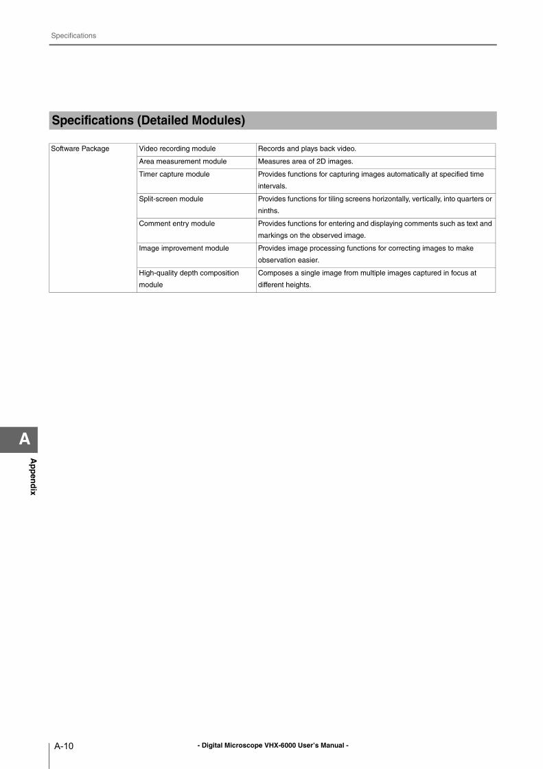
- Digital Microscope VHX-6000 User’s Manual -
Specifications
A-10
Ap
pen
dix
A
Specifications (Detailed Modules)
Software Package Video recording module Records and plays back video.
Area measurement module Measures area of 2D images.
Timer capture module Provides functions for capturing images automatically at specified time
intervals.
Split-screen module Provides functions for tiling screens horizontally, vertically, into quarters or
ninths.
Comment entry module Provides functions for entering and displaying comments such as text and
markings on the observed image.
Image improvement module Provides image processing functions for correcting images to make
observation easier.
High-quality depth composition
module
Composes a single image from multiple images captured in focus at
different heights.
- Digital Microscope VHX-6000 User’s Manual -
Software Usage Agreement
A-11
Ap
pen
dix
A
Software Usage Agreement
Software License Agreement
The use of VHX-6000 communication software (hereinafter referred to as [this software]) is subject to the terms outlined in
this software license agreement (hereinafter referred to as [this agreement]) and to the customers consent to this agreement.
The customer's use or duplication of this software, in whole or in part, constitutes the customer's consent to enter into this
agreement.
Article 1 (Usage Rights)
1 Contingent of the customer's compliance with the terms of this agreement, KEYENCE Corporation (hereinafter referred
to as KEYENCE) extends to the customer non-exclusive usage rights.
2 The customer may install this software without the limit of the number of the licenses, provided that this software is
used only in the same corporation in order to use our product you have purchased.
Article 2 (Limitations on Duplication)
The customer may make no more than 1 copy of this software for backup purposes only.
Article 3 (Prohibitions)
The customer is prohibited from doing the following with this software.
a. Additions or changes to any or all of the functions of this software.
However, installation of updates or new features provided by KEYENCE is expressly allowed.
b. Reverse compiling or reverse assembling of this software for the purposes of reverse engineering.
c. Sale, transfer, redistribution, license, rental or lease to the third party.
This does not include instances where permission has been obtained from KEYENCE in advance.
Article 4 (Copyright)
The copyrights of this software and all associated documentation are the property of KEYENCE.
Article 5 (Exemption of Liability)
KEYENCE shall not be held liable by the user or third party for any damages arising from the use of the software.
Article 6 (Support)
Based on this agreement, KEYENCE agrees to provide the customer with technical support in response to customer
questions regarding this software. However, KEYENCE makes no guarantee that the technical support offered will
meet the customer's needs.
Article 7 (Termination of Agreement)
1 Should the customer destroy this software and any backup copies, this agreement will automatically expire with the
customer's cessation of use of this software.
2 KEYENCE reserves the right to unilaterally terminate this agreement should the customer violate any of the terms of
this agreement. In this instance, this software and all copies should be immediately returned to KEYENCE for
destruction.
3 Should KEYENCE be caused damages by the customer's violation of this agreement, the customer will compensate
KEYENCE for those damages.
Article 8 (Basis in Law)
This agreement is to be adjudicated according to Japanese law.
- Digital Microscope VHX-6000 User’s Manual -
Usage Agreement for Operation Software
A-12
Ap
pen
dix
A
Usage Agreement for Operation Software
MICROSOFT SOFTWARE LICENSE TERMS
WINDOWS™ 7 ULTIMATE FOR EMBEDDED SYSTEMS
WINDOWS™ 7 PROFESSIONAL FOR EMBEDDED SYSTEMS (ALL VERSIONS)
These license terms are an agreement between you and KEYENCE. Please read them. They apply to the software included on this device. The software also includes any separate media on which you received the software.
The software on this device includes software licensed from Microsoft Corporation or its affiliate.
The terms also apply to any Microsoft
• updates,
• supplements,
• Internet-based services, and
• support services
for this software, unless other terms accompany those items. If so, those terms apply.If you obtain updates or supplements directly from Microsoft, then Microsoft, and not KEYENCE, licenses those to you.
As described below, using the software also operates as your consent to the transmission of certain computer information for Internet-based services.
By using the software, you accept these terms. If you do not accept them, do not use the software. Instead, contact KEYENCE to determine its return policy for a refund or credit.
If you comply with these license terms, you have the rights below.
1. OVERVIEW.
a. Software. The software includes desktop operating system software. This software does not include Windows Live services. Windows Live services are available from Microsoft under a separate agreement.
2. USE RIGHTS.
a. Use. The software license is permanently assigned to the device with which you acquired the software. That device is the "licensed device". You may use the software on the licensed device.
b. Processor Limit. You may use the software with no more than two processors at any one time.
c. Alternative Versions. You may only use the version of the software that is installed on the licensed device. You may not change it to any other version (such as the 32-bit or 64-bit version, or another language version).
3. ADDITIONAL LICENSING REQUIREMENTS AND/OR USE RIGHTS.
a. Specific Use. KEYENCE designed the licensed device for a specific use. You may only use the software for that use.
b. Other Software. You may use other programs with the software as long as the other programs
• directly support the specific use for the licensed device, or
• provide system utilities, resource management, or anti-virus or similar protection.
Software that provides consumer or business tasks or processes may not run on the licensed device. This includes email, word processing, spreadsheet, database, scheduling and personal finance software. The licensed device may use terminal services protocols to access such software running on a server.
c. Device Connections. You may not use the software as server software. In other words, more than one device may not access, display, run, share or use the software at the same time. You may allow up to twenty other devices to access the software to use
• File Services,
• Print Services,
• Internet Information Services, and
• Internet Connection Sharing and Telephony Services.
The twenty connection limit applies to devices that access the software indirectly through "multiplexing" or other software or hardware that pools connections. You may use unlimited inbound connections at any time via TCP/IP.
d. Remote Access Technologies. You may access and use the software remotely from another device using remote access technologies as follows.
Remote Desktop. The single primary user of the licensed device may access a session from any other device using Remote Desktop or similar technologies. A "session" means the experience of interacting with the software, directly or indirectly, through any
- Digital Microscope VHX-6000 User’s Manual -
Usage Agreement for Operation Software
A-13
Ap
pen
dix
A
combination of input, output and display peripherals. Other users may access a session from any device using these technologies, if the remote device is separately licensed to run the software.
Other Access Technologies. You may use Remote Assistance or similar technologies to share an active session.
Other Remote Uses. You may allow any number of devices to access the software for purposes other than those described in the Device Connections and Remote Access Technologies sections above, such as to synchronize data between devices.
e. Font Components. While the software is running, you may use its fonts to display and print content. You may only
• embed fonts in content as permitted by the embedding restrictions in the fonts; and
• temporarily download them to a printer or other output device to print content.
f. Icons, images and sounds. While the software is running, you may use but not share its icons, images, sounds, and media.
4. POTENTIALLY UNWANTED SOFTWARE. The software includes Windows Defender. If Windows Defender is turned on, it will search this device for "spyware," "adware" and other potentially unwanted software. If it finds potentially unwanted software, the software will ask you if you want to ignore, disable (quarantine) or remove it. Any potentially unwanted software rated "high" or "severe," will be automatically removed after scanning unless you change the default setting. Removing or disabling potentially unwanted software may result in
• other software on your computer ceasing to work, or
• your breaching a license to use other software on this device.
By using this software, it is possible that you will also remove or disable software that is not potentially unwanted software.
5. SCOPE OF LICENSE. The software is licensed, not sold. This agreement only gives you some rights to use the software. KEYENCE and Microsoft reserve all other rights. Unless applicable law gives you more rights despite this limitation, you may use the software only as expressly permitted in this agreement. In doing so, you must comply with any technical limitations in the software that allow you to use it only in certain ways. For more information, see the software documentation or contact KEYENCE. You may not:
• work around any technical limitations in the software;
• reverse engineer, decompile or disassemble the software;
• make more copies of the software than specified in this agreement;
• publish the software for others to copy;
• rent, lease or lend the software; or
• use the software for commercial software hosting services.
Except as expressly provided in this agreement, rights to access the software on this device do not give you any right to implement Microsoft patents or other Microsoft intellectual property in software or devices that access this device.
• INTERNET-BASED SERVICES. Microsoft provides Internet-based services with the software. Microsoft may change or cancel them at any time.
a. Consent for Internet-Based Services. The licensed device may contain one or more of the software features described below. These features connect to Microsoft or service provider computer systems over the Internet. In some cases, you will not receive a separate notice when they connect. For more information about these features, visit
go.microsoft.com/fwlink/?linkid=104604.
By using these features, you consent to the transmission of this information. Microsoft does not use the information to identify or contact you.
Computer Information. The following features use Internet protocols, which send to the appropriate systems computer information, such as your Internet protocol address, the type of operating system and browser, and the name and version of the software you are using. Microsoft uses this information to make the Internet-based services available to you. KEYENCE has elected to turn on the following features in the licensed device.
• Plug and Play and Plug and Play Extensions. You may connect new hardware to your device. Your device may not have the drivers needed to communicate with that hardware. If so, the update feature of the software can obtain the correct driver from Microsoft and install it on your device.
• Web Content Features. Features in the software can retrieve related content from Microsoft and provide it to you. Examples of these features are clip art, templates, online training, online assistance and Appshelp. You may choose not to use these web content features.
• Digital Certificates. The software uses x.509 version 3 digital certificates. These digital certificates confirm the identity of users sending information to each other and allow you to encrypt the information. The software retrieves certificates and updates certificate revocation lists over the Internet.
• Auto Root Update. The Auto Root Update feature updates the list of trusted certificate authorities. You can switch off this feature.
• Windows Media Digital Rights Management. Content owners use Windows Media digital rights management technology (WMDRM) to protect their intellectual property, including copyrights. This software and third party software use WMDRM to play
- Digital Microscope VHX-6000 User’s Manual -
Usage Agreement for Operation Software
A-14
Ap
pen
dix
A
and copy WMDRM-protected content. If the software fails to protect the content, content owners may ask Microsoft to revoke the software's ability to use WMDRM to play or copy protected content. Revocation does not affect other content. When you download licenses for protected content, you agree that Microsoft may include a revocation list with the licenses. Content owners may require you to upgrade WMDRM to access their content. Microsoft software that includes WMDRM will ask for your consent prior to the upgrade. If you decline an upgrade, you will not be able to access content that requires the upgrade. You may switch off WMDRM features that access the Internet. When these features are off, you can still play content for which you have a valid license.
• Windows Media Player. When you use Windows Media Player, it checks with Microsoft for
• compatible online music services in your region;
• new versions of the player; and
• codecs if your device does not have the correct ones for playing content.
For more information, go to: http://go.microsoft.com/fwlink/?linkid=104605.
• Malicious Software Removal/Clean On Upgrade. Before installation of the software, the software will check and remove certain malicious software listed at www.support.microsoft.com/?kbid=890830 ("Malware") from your device. When the software checks your device for Malware, a report will be sent to Microsoft about any Malware detected or errors that occurred while the software was checking for Malware. No information that can be used to identify you is included in the report.
• Network Awareness. This feature determines whether a system is connected to a network by either passive monitoring of network traffic or active DNS or HTTP queries. The query only transfers standard TCP/IP or DNS information for routing purposes. You can switch off the active query feature through a registry setting.
• Windows Time Service. This service synchronizes with www.time.windows.com once a week to provide your computer with the correct time. The connection uses standard NTP protocol.
b. Use of Information. Microsoft may use the computer information, error reports, and Malware reports to improve our software and services. We may also share it with others, such as hardware and software vendors. They may use the information to improve how their products run with Microsoft software.
c. Misuse of Internet-based Services. You may not use these services in any way that could harm them or impair anyone else's use of them. You may not use the services to try to gain unauthorized access to any service, data, account or network by any means.
6. VALIDATION.
a. Validation verifies that the software has been activated and is properly licensed. It also verifies that no unauthorized changes have been made to the validation, licensing, or activation functions of the software. Validation may also check for certain malicious or unauthorized software related to such unauthorized changes. A validation check confirming that you are properly licensed, permits you to continue to use the software, certain features of the software or to obtain additional benefits. You are not permitted to circumvent validation. This is to prevent unlicensed use of the software. For more information, see go.microsoft.com/fwlink/?Linkid=104610.
b. The software will from time to time perform a validation check of the software. The check may be initiated by the software or Microsoft. To enable the activation function and validation checks, the software may from time to time require updates or additional downloads of the validation, licensing or activation functions of the software. The updates or downloads are required for the proper functioning of the software and may be downloaded and installed without further notice to you. During or after a validation check, the software may send information about the software, the computer and the results of the validation check to Microsoft. This information includes, for example, the version and product key of the software, any unauthorized changes made to the validation, licensing or activation functions of the software, any related malicious or unauthorized software found and the Internet protocol address of the computer. Microsoft does not use the information to identify or contact you. By using the software, you consent to the transmission of this information. For more information about validation and what is sent during or after a validation check, see go.microsoft.com/fwlink/?Linkid=104611.
c. If, after a validation check, the software is found to be counterfeit, improperly licensed, or a non-genuine Windows product, or if it includes unauthorized changes, then the functionality and experience of using the software will be affected. For example:
Microsoft may
• repair the software, and remove, quarantine or disable any unauthorized changes that may interfere with the proper use of the software, including circumvention of the activation or validation functions of the software; or
• check and remove malicious or unauthorized software known to be related to such unauthorized changes; or
• provide notice that the software is improperly licensed or a non-genuine Windows product;
and you may
• receive reminders to obtain a properly licensed copy of the software; or
• need to follow Microsoft's instructions to be licensed to use the software and reactivate;
and you may not be able to
• use or continue to use the software or some of the features of the software; or
• obtain certain updates or upgrades from Microsoft.
- Digital Microscope VHX-6000 User’s Manual -
Usage Agreement for Operation Software
A-15
Ap
pen
dix
A
d. You may only obtain updates or upgrades for the software from Microsoft or authorized sources (including KEYENCE). For more information on obtaining updates from authorized sources see go.microsoft.com/fwlink/?Linkid=104612.
7. PRODUCT SUPPORT. Contact KEYENCE for support options. Refer to the support number provided with the device.
8. MICROSOFT .NET BENCHMARK TESTING. The software includes one or more components of the .NET Framework (".NET Components"). You may conduct internal benchmark testing of those components. You may disclose the results of any benchmark test of those components, provided that you comply with the conditions set forth at go.microsoft.com/fwlink/?LinkID=66406.Notwithstanding any other agreement you may have with Microsoft, if you disclose such benchmark test results, Microsoft shall have the right to disclose the results of benchmark tests it conducts of your products that compete with the applicable .NET Component, provided it complies with the same conditions set forth at go.microsoft.com/fwlink/?LinkID=66406.
9. BACKUP COPY. You may make one backup copy of the software. You may use it only to reinstall the software on the device.
10. DOCUMENTATION. Any person that has valid access to your computer or internal network may copy and use the documentation for your internal, reference purposes.
11. UPGRADES. To use upgrade software, you must first be licensed for the software that is eligible for the upgrade. Upon upgrade, this agreement takes the place of the agreement for the software you upgraded from. After you upgrade, you may no longer use the software you upgraded from.
12. PROOF OF LICENSE. If you acquired the software on the device, or on a disc or other media, a genuine Certificate of Authenticity label with a genuine copy of the software identifies licensed software. To be valid, this label must be affixed to the device, or included on or in KEYENCE's software packaging. If you receive the label separately, it is not valid. You should keep the label on the device or packaging to prove that you are licensed to use the software. To identify genuine Microsoft software, see http://www.howtotell.com.
13. TRANSFER TO A THIRD PARTY. You may transfer the software only with the device, the Certificate of Authenticity label, and these license terms directly to a third party. Before the transfer, that party must agree that these license terms apply to the transfer and use of the software. You may not retain any copies of the software including the backup copy.
14. NOTICE ABOUT THE H.264/AVC VISUAL STANDARD, THE VC-1 VIDEO STANDARD, THE MPEG-4 VISUAL STANDARD AND THE MPEG-2 VIDEO STANDARD. This software may include H.264/AVC, VC-1, MPEG-4 Part 2, and MPEG-2 visual compression technology. If the software includes those visual compression technologies MPEG LA, L.L.C. requires this notice:THIS PRODUCT IS LICENSED UNDER ONE OR MORE VIDEO PATENT PORTFOLIO LICENSES SUCH AS, AND WITHOUT LIMITATION, THE AVC, THE VC-1, THE MPEG-4 PART 2 VISUAL, AND THE MPEG-2 VIDEO PATENT PORTFOLIO LICENSES FOR THE PERSONAL AND NON-COMMERCIAL USE OF A CONSUMER TO (i) ENCODE VIDEO IN COMPLIANCE WITH THE ABOVE STANDARDS ("VIDEO STANDARDS") AND/OR (ii) DECODE VIDEO THAT WAS ENCODED BY A CONSUMER ENGAGED IN A PERSONAL AND NON-COMMERCIAL ACTIVITY OR WAS OBTAINED FROM A VIDEO PROVIDER LICENSED TO PROVIDE VIDEO UNDER SUCH PATENT PORTFOLIO LICENSES. NONE OF THE LICENSES EXTEND TO ANY OTHER PRODUCT REGARDLESS OF WHETHER SUCH PRODUCT IS INCLUDED WITH THIS PRODUCT IN A SINGLE ARTICLE. NO LICENSE IS GRANTED OR SHALL BE IMPLIED FOR ANY OTHER USE. ADDITIONAL INFORMATION MAY BE OBTAINED FROM MPEG LA, L.L.C. SEE WWW.MPEGLA.COM.
15. NOT FAULT TOLERANT. The software is not fault tolerant. KEYENCE installed the software on the device and is responsible for how it operates on the device.
16. RESTRICTED USE. The Microsoft software was designed for systems that do not require fail-safe performance. You may not use the Microsoft software in any device or system in which a malfunction of the software would result in foreseeable risk of injury or death to any person. This includes operation of nuclear facilities, aircraft navigation or communication systems and air traffic control.
17. THIRD PARTY PROGRAMS. The software contains third party programs. The license terms with those programs apply to your use of them.
18. NO WARRANTIES FOR THE SOFTWARE. The software is provided "as is". You bear all risks of using it. Microsoft gives no express warranties, guarantees or conditions. Any warranties you receive regarding the device or the software do not originate from, and are not binding on, Microsoft or its affiliates. When allowed by your local laws, KEYENCE and Microsoft exclude implied warranties of merchantability, fitness for a particular purpose and non-infringement.
19. LIABILITY LIMITATIONS. You can recover from Microsoft and its affiliates only direct damages up to two hundred fifty U.S. Dollars (U.S. $250.00), or equivalent in local currency. You cannot recover any other damages, including consequential, lost profits, special, indirect or incidental damages.
This limitation applies to:
• anything related to the software, services, content (including code) on third party internet sites, or third party programs, and
• claims for breach of contract, breach of warranty, guarantee or condition, strict liability, negligence, or other tort to the extent permitted by applicable law.
It also applies even if Microsoft should have been aware of the possibility of the damages. The above limitation may not apply to you because your country may not allow the exclusion or limitation of incidental, consequential or other damages.
20. EXPORT RESTRICTIONS. The software is subject to United States export laws and regulations. You must comply with all domestic and international export laws and regulations that apply to the software. These laws include restrictions on destinations, end users and end use. For additional information, see www.microsoft.com/exporting.
- Digital Microscope VHX-6000 User’s Manual -
Usage Agreement for Operation Software
A-16
Ap
pen
dix
A
21. ENTIRE AGREEMENT. This agreement, additional terms (including any printed-paper license terms that accompany the software and may modify or replace some or all of these terms), and the terms for supplements, updates, Internet-based services and support services that you use, are the entire agreement for the software and support services.
22. APPLICABLE LAW.
a. United States. If you acquired the software in the United States, Washington state law governs the interpretation of this agreement and applies to claims for breach of it, regardless of conflict of laws principles. The laws of the state where you live govern all other claims, including claims under state consumer protection laws, unfair competition laws, and in tort.
b. Outside the United States. If you acquired the software in any other country, the laws of that country apply.
- Digital Microscope VHX-6000 User’s Manual -
Before asking repair and inspection
A-17
Ap
pen
dix
A
Before asking repair and inspection
This product is mounting a hard disk.
Before giving your VHX to Keyence for repair and inspection,
Be sure to back up data in the hard disk.
In case that data remains in the hard disk, it may disappear or cannot be retrieved because of repairs or during
transportation. Please back up data in the hard disk.
When some defects are discovered in the hard disk during repair or inspection, we will replace it.
The data stored in the defective hard disk is transferred into a new hard disk.
If the data stored in the defective hard disk can be taken from it, the data will be transferred into a new hard disk as
part of the replacement work. When, however, the data cannot be taken from it, only replacement of the hard disk is
carried out.
Return of the replaced hard disk
In case that a hard disk is replaced, basically we discard the replaced hard disk. When such hard disk needs to be
returned, please inform our sales office about that in advance, or when you request repairs.
Nondisclosure of the data when repair or inspection is taken place
In case that data remains in the hard disk, we may open the data file in the hard disk to confirm or analyze the
phenomenon, and to move such data. Please delete all the data that must not be disclosed to us before requesting
repairs. We will properly manage any data in the hard disk as our customer's confidential information. We will never
disclose or leak it to any third parties, or make it available to the public.
Request for data backup
Please backup data in the hard disk regularly.
If you have any questions or concerns, please feel free to contact the nearest sales office.
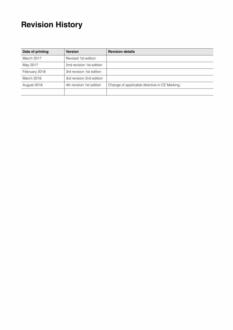
Revision History
Date of printing Version Revision details
March 2017 Revised 1st edition
May 2017 2nd revision 1st edition
February 2018 3rd revision 1st edition
March 2018 3rd revision 2nd edition
August 2018 4th revision 1st edition Change of applicable directive in CE Marking.
WARRANTIES AND DISCLAIMERS
(1) KEYENCE warrants the Products to be free of defects in materials and workmanship for a period of one (1) year from the date of shipment. If any models or samples were shown to Buyer, such models or samples were used merely to illustrate the general type and quality of the Products and not to represent that the Products would necessarily conform to said models or samples. Any Products found to be defective must be shipped to KEYENCE with all shipping costs paid by Buyer or offered to KEYENCE for inspection and examination. Upon examination by KEYENCE, KEYENCE, at its sole option, will refund the purchase price of, or repair or replace at no charge any Products found to be defective. This warranty does not apply to any defects resulting from any action of Buyer, including but not limited to improper installation, improper interfacing, improper repair, unauthorized modification, misapplication and mishandling, such as exposure to excessive current, heat, coldness, moisture, vibration or outdoors air. Components which wear are not warranted.
(2) KEYENCE is pleased to offer suggestions on the use of its various Products. They are only suggestions, and it is Buyer's responsibility to ascertain the fitness of the Products for Buyer�s intended use. KEYENCE will not be responsible for any damages that may result from the use of the Products.
(3) The Products and any samples ("Products/Samples") supplied to Buyer are not to be used internally in humans, for human transportation, as safety devices or fail-safe systems, unless their written specifications state otherwise. Should any Products/Samples be used in such a manner or misused in any way, KEYENCE assumes no responsibility, and additionally Buyer will indemnify KEYENCE and hold KEYENCE harmless from any liability or damage whatsoever arising out of any misuse of the Products/Samples.
(4) OTHER THAN AS STATED HEREIN, THE PRODUCTS/SAMPLES ARE PROVIDED WITH NO OTHER WARRANTIES WHATSOEVER. ALL EXPRESS, IMPLIED, AND STATUTORY WARRANTIES, INCLUDING, WITHOUT LIMITATION, THE WARRANTIES OF MERCHANTABILITY, FITNESS FOR A PARTICULAR PURPOSE, AND NON-INFRINGEMENT OF PROPRIETARY RIGHTS, ARE EXPRESSLY DISCLAIMED. IN NO EVENT SHALL KEYENCE AND ITS AFFILIATED ENTITIES BE LIABLE TO ANY PERSON OR ENTITY FOR ANY DIRECT, INDIRECT, INCIDENTAL, PUNITIVE, SPECIAL OR CONSEQUENTIAL DAMAGES (INCLUDING, WITHOUT LIMITATION, ANY DAMAGES RESULTING FROM LOSS OF USE, BUSINESS INTERRUPTION, LOSS OF INFORMATION, LOSS OR INACCURACY OF DATA, LOSS OF PROFITS, LOSS OF SAVINGS, THE COST OF PROCUREMENT OF SUBSTITUTED GOODS, SERVICES OR TECHNOLOGIES, OR FOR ANY MATTER ARISING OUT OF OR IN CONNECTION WITH THE USE OR INABILITY TO USE THE PRODUCTS, EVEN IF KEYENCE OR ONE OF ITS AFFILIATED ENTITIES WAS ADVISED OF A POSSIBLE THIRD PARTY�S CLAIM FOR DAMAGES OR ANY OTHER CLAIM AGAINST BUYER. In some jurisdictions, some of the foregoing warranty disclaimers or damage limitations may not apply.
BUYER'S TRANSFER OBLIGATIONS:If the Products/Samples purchased by Buyer are to be resold or delivered to a third party, Buyer must provide such third party with a copy of this document, all specifications, manuals, catalogs, leaflets and written information provided to Buyer pertaining to the Products/Samples.
E 1101-3

Copyright (c) 2018 KEYENCE CORPORATION. All rights reserved. 15257E 1088-1 96M15258 Printed in Japan