numerical investigation of the effect of infill walls on the structural response of rc frames
TRANSCRIPT

Send Orders of Reprints at [email protected]
164 The Open Construction and Building Technology Journal, 2012, 6, (Suppl 1-M11) 164-181
1874-8368/12 2012 Bentham Open
Open Access
Numerical Investigation of the Effect of Infill Walls on the Structural Response of RC Frames
P.G. Asteris and D.M. Cotsovos*
Department of Civil & Construction Engineering, School of Pedagogical & Technological Education, Athens, Greece.
Abstract: The work presented herein sets out to investigate numerically, by means of nonlinear finite element analysis,
the effect of un-reinforced concrete or masonry infill walls on the overall structural response of reinforced concrete frames
under static monotonic and seismic loading. For this purpose, a nonlinear finite element package purpose built for the
analysis of concrete structures is employed in order to predict the nonlinear behaviour of both the infill walls as well as
the surrounding frame. Specifically, the dynamic response of a bare two-storey, one-bay frame, whose behaviour has been
experimentally established in the past through shake-table testing, is first investigated via nonlinear finite element analy-
sis. Subsequently, concrete and masonry walls are introduced into the selected frame in order to investigate numerically
how important aspects of structural response such as stiffness, load-carrying capacity, deformation profile, cracking, duc-
tility and mode of failure of the frame are affected.
Keywords: Brittle materials, concrete, cracking, finite element analysis, infilled frames, masonry, seismic excitation.
1. INTRODUCTION
When designing reinforced concrete (RC) frames, it is common practice not to include the existing infill walls in the finite element models used for structural analysis, as these elements are considered to be essentially non-load bearing. In doing so, the stiffness and strength contribution of the latter elements as well as their interaction with the members of the RC frame are fully ignored. The effect of the infill walls are usually considered through the application of additional loads and masses appropriately distributed along the interfaces between the surrounding frame and the infill walls. From the available published experimental [1-17] and numerical [3, 18-30] data, it becomes clear that the masonry or concrete infill walls have a significant effect on the struc-tural performance of RC frames. Moreover, from the above data it has been established that the infill walls usually act as diagonal compression ‘struts’ within the openings of the frame, this resulting in an increase of the overall stiffness and load-carrying capacity of the structure and hence in a reduction of its natural period which affects the distribution and intensity of the inertia loads generated during seismic excitation, as well as the distribution of the internal actions developing within the structural elements. Although, the introduction of infill walls usually results in an overall in-crease of the load-carrying capacity and stiffness of the in-filled frame, it may also cause the development of stress concentrations in certain regions of the structure (e.g. joint area) leading to localized cracking or even unexpected forms of failure, which may have a detrimental effect on the overall response of the RC frame.
*Address correspondence to this author at the Department of Civil & Con-
struction Engineering, School of Pedagogical & Technological Education,
Athens, Greece; Tel: 210-8325032; E-mails: [email protected] or
Due to the difficulties and limitations, but, also, the high costs associated with the testing of RC structural forms, re-sort is frequently made to the use of nonlinear finite element analysis (NLFEA) [3, 22-29]. The use of the finite element (FE) method can provide a more detailed description of the effect of the infill walls on the response of RC frames while, at the same time, it allows the investigation to be extended to structural forms more complex than the simple RC structural elements that are usually studied experimentally (i.e. scaled models of one or two level infilled RC frames). The present study is based on the use of 3D NLFEA package purpose built for the analysis of concrete structures [31-33]. The package is employed in order to predict the non-linear be-haviour of an infill wall as well as of the surrounding rein-forced concrete frame. The validity of the above NLFEA package has been verified by comparing the numerical pre-dictions with published experimental data obtained from tests on a wide range of concrete structural members sub-jected to various regimes of static and dynamic loading [31-40].
The dynamic response of the bare, two-level RC frame investigated under seismic loading was experimentally estab-lished in the past through shake-table testing [41]. A com-parison between the experimentally established response and the numerical predictions reveal good correlation. The se-lected frame was designed in accordance with the EC2/EC8 design provisions for low ductility structures. This particular frame was adopted because it resembles existing RC frame multi-story structures designed according to previous codes of practice (based on the permissible stresses approach) which specified less transverse reinforcement than that specified by current codes of practice (EC2/EC8 which adopt the ultimate limit state approach).Such structures were built until the mid 90s and, in order to access their load-carrying capacity and to ensure that they meet the stringent perform-ance requirements of the current design codes, it is often

Numerical Investigation of the Effect of Infill Walls The Open Construction and Building Technology Journal, 2012, Volume 6 165
required that the existing masonry infill walls be taken into account in structural analysis. This is achieved by modelling the infill walls in the FE models representing the frame structure and using constitutive models capable of providing a realistic description of the nonlinear behaviour of concrete and masonry.
The work presented herein sets out to investigate numeri-cally the effect of the introduction of concrete or masonry infill walls on the overall structural response of the selected frame under static monotonic and seismic loading. Concrete and masonry infill walls are initially introduced to the lower level of the frame and, subsequently, to the upper level. The resulting composite in-filled frames are then subjected to static monotonic and seismic loading. Attention is primarily focused on investigating how certain important aspects of structural response such as stiffness, load-carrying capacity, deformation profile, cracking, ductility and mode of failure of the frame are affected by the presence of the infill panels. Furthermore, the work studies the effect of the redistribution of the internal actions developing within the structural ele-ments of the frame due to their interaction with the infill panel, as this effect can be potentially detrimental on struc-tural response leading to the development of stress concen-trations which, in turn, may result in localised damage or even collapse. It should be noted that the present investiga-tion forms the initial part of a more comprehensive investi-gation of the effect of concrete and masonry walls on the overall structural response of RC in-filled frames.
2. EXPERIMENTAL BACKGROUND
Over the last three decades a large number of experimen-tal investigations [1-13, 17, 42] have been carried out in an attempt to investigate the effect of infill walls and panels on the structural response of RC frame structures. During these investigations scaled models of one, two and even three level bare (with no infill walls) or in-filled RC frames were tested.
These specimens were subjected to static monotonic or cy-clic loading [1, 4, 5, 7, 11]or to seismic excitation through shake table testing [2, 5, 7, 11-13].From the resulting ex-perimental information (deformation profile, crack patterns, displacement, acceleration and base shear time history, modes of failure etc)it has been established that the introduc-tion of infill walls into RC frames results -in general- in an overall increase of the load-carrying capacity and stiffness. However, one needs to exercise caution when dealing with fames with irregular shapes or with openings in the infill walls, since a consequence of this may be the development of stress concentrations in certain regions of the structure (e.g. around existing openings of the infill walls, in the joint area, etc) leading to localized cracking or even unexpected modes of brittle failure of the structural elements (beams of columns) of the RC frame.
Reviewing the available published experimental data, which describe the effect of infill walls on the overall struc-tural response of the RC frames, it becomes clear that the obtained results are characterized by significant scatter due to the large number of uncertainties involved in the various investigations, which have been carried out to date. Our framework of thought is delineated by these uncertainties which are associated with:
a) the properties of the brittle materials used for the con-struction of in-filled frames (i.e. concrete and masonry); it is worth noticing that the mechanical characteristics of masonry material depict a large scatter on their values (according to the most complete experimental investiga-tion on the mechanical behaviour of brick masonry, which has been carried out by Page [43], a large disper-sion of mechanical characteristics of brick masonry has be revealed, despite the fact that all the panels have been made by the same bricklayers and under the same envi-ronmental conditions);
b) the intense anisotropic nature of masonry material; Ma-sonry exhibits distinct directional properties, due to the influence of mortar joints acting as planes of weakness. Depending upon the orientation of the joints to the stress directions, failure can occur in the joints only or simulta-neously in the joints and blocks.
c) the conditions at the interfaces between the infill walls and the surrounding frame,
d) the structural element geometry and reinforcement details
e) the stiffness of the bare RC frame relative to that of the infill wall [44],
f) the size and location of openings within the infill wall; it has been established experimentally that the size and lo-cation of gaps or openings within the infill wall can sig-nificantly effect the contribution of the latter element to the overall response of the RC frame [17]
g) the type of loading applied; the contribution of the infill wall to the lateral stiffness of frame is significantly re-duced when the structure is subjected to reversed cyclic action, as is the case for seismic loading , during which the frame structure undergoes a large number of nonlin-ear cycles. Relevant experimental findings [43] reveal a considerable reduction of the contribution of the infill wall on the response of infilled frames under seismic loading. This is owed to the rapid degradation of the stiffness and strength and low energy dissipation capac-ity, due to the brittle nature of masonry and the damage (cracking) sustained by the masonry infill walls.
As a result, it becomes evident that, although the avail-able experimental data can provide a qualitative description of the effect of the infill walls, at the same time, it has not -as yet- been possible to quantify this effect by experiment. In view of the above, the existing mathematical (numerical or analytical) models – the formulation and validation of which is based on the available experimental data – cannot be relied upon to obtain a realistic description of the structural re-sponse when employed to describe the effect of the infill walls on the overall structural behaviour of the RC frames, the latter being characterised by a high degree of uncertainty.
3. MODELLING OF BRITTLE MATERIAL BEHAV-IOUR
For the purpose of the numerical investigation, a finite-element model suitable for both static and dynamic three-dimensional (3-D) nonlinear finite element analyses (NLFEA) is employed. It is purpose-built for the analysis of concrete structures and has been found to yield realistic pre-

166 The Open Construction and Building Technology Journal, 2012, Volume 6 Asteris and Cotsovos
dictions of the behaviour of a wide-range of structural con-crete configurations under arbitrary static [32-34, 38, 40] and dynamic [31,35-38] actions. In order to describe the nonlin-ear behaviour of concrete under triaxial loading conditions, the 3-D NLFEA package incorporates a model of concrete behaviour [32, 45] which is characterised by both simplicity (fully brittle, fully defined by a single material parameter - the uniaxial cylinder compressive strength fc) and attention to the actual physical behaviour of concrete in a structure (unavoidable triaxiality which is described on the basis of experimental data of concrete cylinders under definable boundary conditions) [46-49]. This model is presently ex-tended to describe the nonlinear behaviour of masonry where the brick, mortar and brick–mortar interface are considered as an isotropic homogeneous continuum. Though this ap-proach may be described as a crude attempt to model the nonlinear behaviour of masonry, it serves as a starting point for ongoing research on the numerical investigation of the behaviour of masonry structural forms especially when con-sidering the scatter that characterises the available relative experimental data.
The 3D NLFEA package employs a unique nonlinear so-lution strategy [32, 33] (shown in Fig. 1) which ensures the numerical stability and robustness of the solution process, in spite the fully brittle concrete and masonry material models adopted. The nonlinear analysis currently employed is based
on an iterative procedure (modified Newton–Raphson method) fully described elsewhere [32]. This approach is used in order to calculate stresses, strains and residual forces. Once a load increment is imposed, the iterative procedure initiates by first checking every Gauss point in order to de-termine whether loading or unloading takes place. This is followed by a number of checks to establish whether any cracks close or open, or if any steel members yield or fail. Depending on the results of these checks, changes are intro-duced to the stress–strain matrices of the individual FEs and to the stiffness matrix of the structure. These modified matri-ces are then used to calculate deformation, strain and stress corrections. Convergence is accomplished once the above corrections become very small. Crack-formation and crack-closure is checked separately during each load step.
During the crack-closure procedure only Gauss points with cracks formed in previous load steps are checked. For a crack to close, the criterion that must be satisfied is that the strains normal to the plane of the crack are compressive. The program singles out the crack with the largest compressive strain and closes it. Owing to the closure of a crack, changes are made to the element stress–strain matrix and, conse-quently, to the stiffness matrix of the structure, leading to stresses redistribution. During the crack-closing procedure convergence is not checked, thus the residual stresses and forces are not eliminated during this stage, but are only cal-
Fig. (1). Scheme of the used by the nonlinear FE program [31].
Numerical Investigation of the Effect of Infill Walls The Open Construction and Building Technology Journal, 2012, Volume 6 167
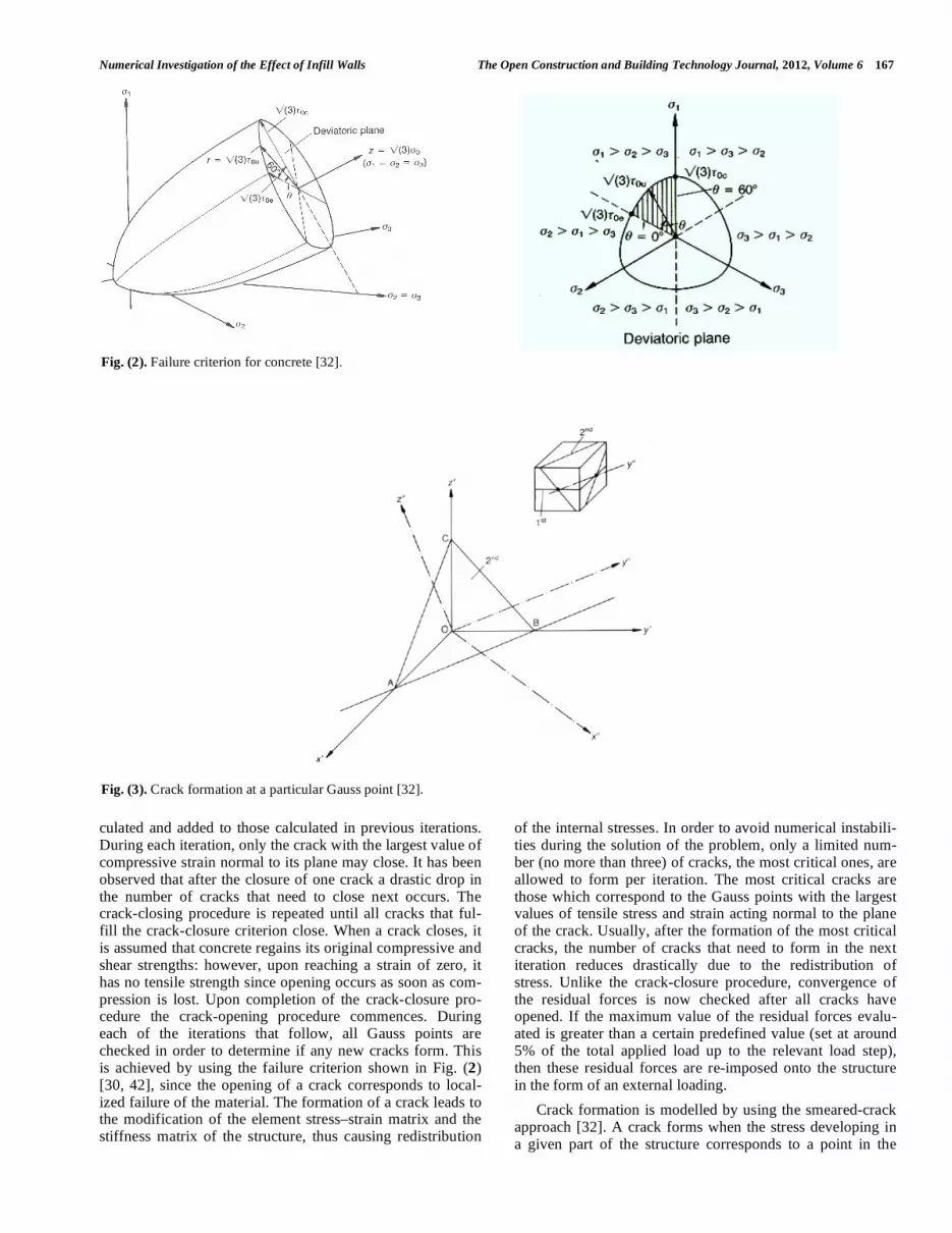
culated and added to those calculated in previous iterations. During each iteration, only the crack with the largest value of compressive strain normal to its plane may close. It has been observed that after the closure of one crack a drastic drop in the number of cracks that need to close next occurs. The crack-closing procedure is repeated until all cracks that ful-fill the crack-closure criterion close. When a crack closes, it is assumed that concrete regains its original compressive and shear strengths: however, upon reaching a strain of zero, it has no tensile strength since opening occurs as soon as com-pression is lost. Upon completion of the crack-closure pro-cedure the crack-opening procedure commences. During each of the iterations that follow, all Gauss points are checked in order to determine if any new cracks form. This is achieved by using the failure criterion shown in Fig. (2) [30, 42], since the opening of a crack corresponds to local-ized failure of the material. The formation of a crack leads to the modification of the element stress–strain matrix and the stiffness matrix of the structure, thus causing redistribution
of the internal stresses. In order to avoid numerical instabili-ties during the solution of the problem, only a limited num-ber (no more than three) of cracks, the most critical ones, are allowed to form per iteration. The most critical cracks are those which correspond to the Gauss points with the largest values of tensile stress and strain acting normal to the plane of the crack. Usually, after the formation of the most critical cracks, the number of cracks that need to form in the next iteration reduces drastically due to the redistribution of stress. Unlike the crack-closure procedure, convergence of the residual forces is now checked after all cracks have opened. If the maximum value of the residual forces evalu-ated is greater than a certain predefined value (set at around 5% of the total applied load up to the relevant load step), then these residual forces are re-imposed onto the structure in the form of an external loading.
Crack formation is modelled by using the smeared-crack approach [32]. A crack forms when the stress developing in a given part of the structure corresponds to a point in the
Fig. (2). Failure criterion for concrete [32].
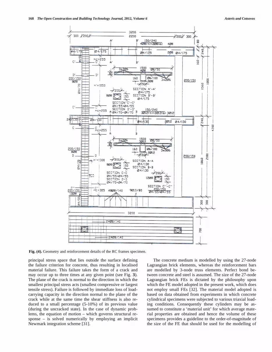
Fig. (3). Crack formation at a particular Gauss point [32].
168 The Open Construction and Building Technology Journal, 2012, Volume 6 Asteris and Cotsovos
principal stress space that lies outside the surface defining the failure criterion for concrete, thus resulting in localised material failure. This failure takes the form of a crack and may occur up to three times at any given point (see Fig. 3). The plane of the crack is normal to the direction in which the smallest principal stress acts (smallest compressive or largest tensile stress). Failure is followed by immediate loss of load-carrying capacity in the direction normal to the plane of the crack while at the same time the shear stiffness is also re-duced to a small percentage (5-10%) of its previous value (during the uncracked state). In the case of dynamic prob-lems, the equation of motion – which governs structural re-sponse – is solved numerically by employing an implicit Newmark integration scheme [31].
The concrete medium is modelled by using the 27-node Lagrangian brick elements, whereas the reinforcement bars are modelled by 3-node truss elements. Perfect bond be-tween concrete and steel is assumed. The size of the 27-node Lagrangian brick FEs is dictated by the philosophy upon which the FE model adopted in the present work, which does not employ small FEs [32]. The material model adopted is based on data obtained from experiments in which concrete cylindrical specimens were subjected to various triaxial load-ing conditions. Consequently these cylinders may be as-sumed to constitute a ‘material unit’ for which average mate-rial properties are obtained and hence the volume of these specimens provides a guideline to the order-of-magnitude of the size of the FE that should be used for the modelling of
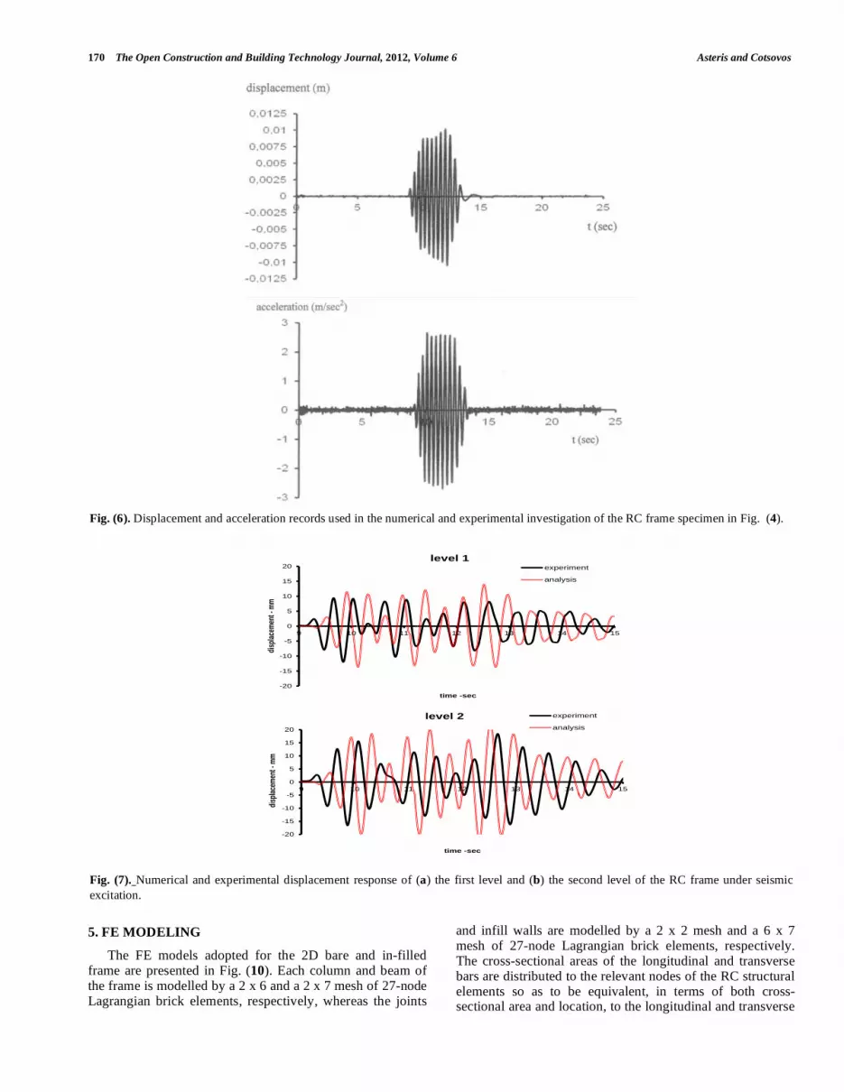
Fig. (4). Geometry and reinforcement details of the RC frames specimen.

Numerical Investigation of the Effect of Infill Walls The Open Construction and Building Technology Journal, 2012, Volume 6 169
concrete structures. This criterion is presently also extended to the 27-node Lagrangian brick elements used to model
masonry. Finally, the use of a dense FE mesh with a large number of FEs can create complications in the crack-opening and crack-closure procedure adopted by the present FE model, since the number of potential cracks (which can oc-cur in any direction to the principal axes of the element) that need to form or close during each iteration increases signifi-cantly with the increase of the Gauss points used in the FE mesh. This, in turn, increases the danger of numerical insta-bility in the solution process.
4. PROBLEM DESCRIPTION
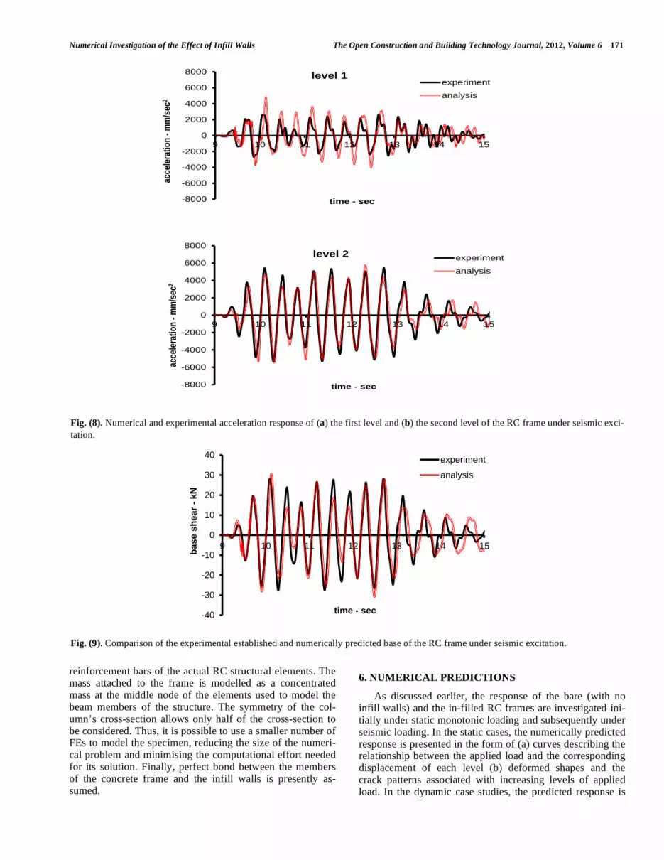
The dynamic response of the bare RC frame, which forms the basis of the present study, was originally investi-gated by experiment under seismic excitation at the National Technical University of Athens [41]. The geometry and rein-forcement detailing of the frame are presented in Fig. (4). The uniaxial cylinder compressive strength of the concrete used was fc= 50 MPa, whereas the yield stress of the rein-forcement was fy = 500 MPa. The frame (shown in Fig. 5a) was loaded with masses of 2x2.87 tons and 2x2.62 tons at the first and second levels, respectively, and subjected to the horizontal motion described by the horizontal displacement and acceleration records shown in Fig. (6). The experimen-tally established response is presented in the form of curves describing the time history variation of the displacement (Fig. 7) and acceleration (Fig. 8) of the first and second level of the frame, as well as the time history of the base shear (Fig. 9). Finally, in Fig. (5b) one can see the cracks which developed during testing mainly within the joint areas, as well as in the upper and lower regions of the columns at the first level.
The structural response of the selected bare (with no infill
walls) two-level RC frame is presently studied numerically
initially under static monotonic loading and then under seis-
mic base excitation. Subsequently, concrete and masonry
infill walls are introduced initially to the lower level of the
frame and then into the upper level (see Fig. 10). Each frame
is initially subjected to a vertical load, uniformly distributed
on each beam and equal to the weight of the mass supported
by the horizontal members. This is followed by the applica-
tion of a horizontal load which is either applied as two sepa-
rate loads P, one at each level, (case studies 1 to 3 in Fig. 10)
or as a single load 2P on the lower level (case studies 4 to 6
in Fig. 10) of the frame. The horizontal load is gradually
imposed in a large number of load increments. Its value in-
creases until the specimen’s load carrying capacity is
reached and failure occurs. Finally, the behaviour of each
specimen is investigated when subjected to a seismic excita-
tion (case studies 7 to 9) identical to that imposed onto the
actual specimen during the shake-table tests (see Fig. 6). The
numerical study of the in-filled frame considered three cases
of infill walls: (a) a weak concrete infill wall with a uniaxial
cylinder compressive strength of 5 MPa and a modulus of
elasticity of 23 GPa, (b) a masonry infill wall with a uniaxial
compressive strength of 5MP and module of elasticity Ew,c
equal to 4.5GPa (approximately 1/5 the modulus of elasticity
of the weak concrete) and (c) a masonry infill wall with a
uniaxial compressive strength of 5MP and modulus of elas-
ticity Ew,c equal to 2.3GPa (approximately 1/10 the modulus of elasticity of the weak concrete).
(a)
(b)
Fig. (5). Test specimen (a) prior and (b) after testing.
170 The Open Construction and Building Technology Journal, 2012, Volume 6 Asteris and Cotsovos
5. FE MODELING
The FE models adopted for the 2D bare and in-filled frame are presented in Fig. (10). Each column and beam of the frame is modelled by a 2 x 6 and a 2 x 7 mesh of 27-node Lagrangian brick elements, respectively, whereas the joints
and infill walls are modelled by a 2 x 2 mesh and a 6 x 7 mesh of 27-node Lagrangian brick elements, respectively. The cross-sectional areas of the longitudinal and transverse bars are distributed to the relevant nodes of the RC structural elements so as to be equivalent, in terms of both cross-sectional area and location, to the longitudinal and transverse
Fig. (6). Displacement and acceleration records used in the numerical and experimental investigation of the RC frame specimen in Fig. (4).
Fig. (7). Numerical and experimental displacement response of (a) the first level and (b) the second level of the RC frame under seismic
excitation.
-20
-15
-10
-5
0
5
10
15
20
disp
lace
men
t - m
m
9 10 11 12
time -sec
level 1
13 14
experiment
analysis
15
-20
-15
-10
-5
0
5
10
15
20
9 10 11 12 13 14 15
disp
lace
men
t - m
m
time -sec
level 2 experiment
analysis
Numerical Investigation of the Effect of Infill Walls The Open Construction and Building Technology Journal, 2012, Volume 6 171
reinforcement bars of the actual RC structural elements. The mass attached to the frame is modelled as a concentrated mass at the middle node of the elements used to model the beam members of the structure. The symmetry of the col-umn’s cross-section allows only half of the cross-section to be considered. Thus, it is possible to use a smaller number of FEs to model the specimen, reducing the size of the numeri-cal problem and minimising the computational effort needed for its solution. Finally, perfect bond between the members of the concrete frame and the infill walls is presently as-sumed.
6. NUMERICAL PREDICTIONS
As discussed earlier, the response of the bare (with no infill walls) and the in-filled RC frames are investigated ini-tially under static monotonic loading and subsequently under seismic loading. In the static cases, the numerically predicted response is presented in the form of (a) curves describing the relationship between the applied load and the corresponding displacement of each level (b) deformed shapes and the crack patterns associated with increasing levels of applied load. In the dynamic case studies, the predicted response is
Fig. (8). Numerical and experimental acceleration response of (a) the first level and (b) the second level of the RC frame under seismic exci-
tation.
Fig. (9). Comparison of the experimental established and numerically predicted base of the RC frame under seismic excitation.
-8000
-6000
-4000
-2000
0
2000
4000
6000
8000
9 10 11 12 13 14 15
acce
lera
tio
n -
mm
/sec
2
time - sec
level 1 experiment
analysis
-8000
-6000
-4000
-2000
0
2000
4000
6000
8000
9 10 11 12 13 14 15
acce
lera
tio
n -
mm
/sec
2
time - sec
level 2 experiment
analysis
-40
-30
-20
-10
0
10
20
30
40
ba
se
sh
ea
r -
kN
9 10 11 12
time - se
13
ec
14
experime
analysis
15
ent

172 The Open Construction and Building Technology Journal, 2012, Volume 6 Asteris and Cotsovos
presented in the form of curves describing the time history variation of the displacement and acceleration of the first and second level as well as time history of the base shear accom-panied by the deformed shapes and crack patterns at various stages of the dynamic loading.
6.1. Static Case Studies
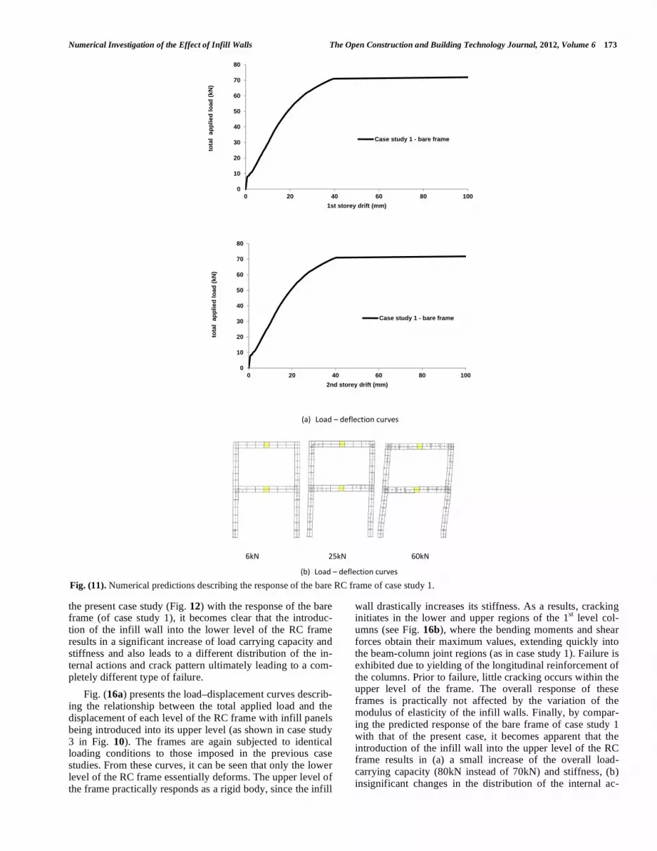
The numerical predictions for the case of the bare RC frame subjected to static loading applied monotonically at each level (see case study 1 in Fig. 10) is presented in Fig (11). From the load–displacement curves describing the rela-tionship between the applied load and displacement of each level shown in Fig. (11a), it appears that the RC frame ex-hibits ductile response and has a load carrying capacity equal to 70 KN. From the predicted deformation profile and crack patterns shown in Fig. (11b), it appears that cracks initially form in the columns of the lower level (where the bending moment and shear force obtain their maximum values) gradually extending into the beam-column joint regions. As the applied load increases, cracking extends to the columns of the second level. Failure occurs at the columns of the first level of the frame after yielding of the longitudinal rein-forcement and the formation of plastic hinges which ulti-mately result in the formation of a mechanism.
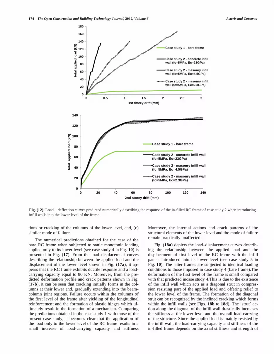
The load–displacement curves expressing the relationship between the total applied load and the displacement of each level shown in Fig. (12) describe the predicted response ex-hibited by the in-filled RC frames of case study 2 (Fig. 10) where the infill panels are introduced into the lower level of the frame. The latter frames are subjected to identical load-
ing conditions identical to those imposed in case study 1. From the load-deflection curves, it appears that, essentially, only the upper level of the RC frame deforms, sincethe de-formation predicted for the 1st level of the frame is only but a small fraction of that of the 2
nd levelirrespective of the
modulus of elasticity of the infill wall. Nevertheless it should be noted that when comparing the case studies considered in Fig. (12) the smaller the value of the modulus of elasticity of the infill wall (and hence its stiffness) the larger the deflec-tion of the first storey of the frame. This is due to the intro-duction of the infill wall which essentially acts as a diagonal strut in compression drastically increasing the stiffness and load carrying capacity of the lower level by resistingthe larg-est portion of the applied load, thus offering relief to the lower level of the frame. As a result, cracking initiates (Figs 13 to 15) in the lower and upper regions of the columns of the 2nd level of the frame, extending quickly into the beam-column joint regions. Failure occurs at the upper level col-umns after yielding of the longitudinal reinforcement of the columns and the formation of plastic hinges. Prior to failure, little cracking occurs within the columns of the lower level, since as already discussed a significant portion of the hori-zontal applied load is resisted by the diagonal compressive ‘strut’ forming within the infill wall. This diagonal ‘strut’ can be clearly recognised by the inclination of the cracks forming within the masonry infill walls as shown in Figs. (14) and (15). From the predicted behaviour shown in Figs. (12) to (15),it appears that the overall load-carrying capacity of the in-filled RC frame is hardly affected by the variation of the modulus of elasticity of the infill wall. However, when comparing to the predicted response of the infill frames of
Fig. (10). FE models representing the bare and in-filled frames adopted for the analyses.
P
P
2P
Case stu
dy 1
P
Cas
P
2P
se study 2
P
P
2P
Case studdy 3
Case study 4 Case study 5 Case study 6
Numerical Investigation of the Effect of Infill Walls The Open Construction and Building Technology Journal, 2012, Volume 6 173
the present case study (Fig. 12) with the response of the bare frame (of case study 1), it becomes clear that the introduc-tion of the infill wall into the lower level of the RC frame results in a significant increase of load carrying capacity and stiffness and also leads to a different distribution of the in-ternal actions and crack pattern ultimately leading to a com-pletely different type of failure.
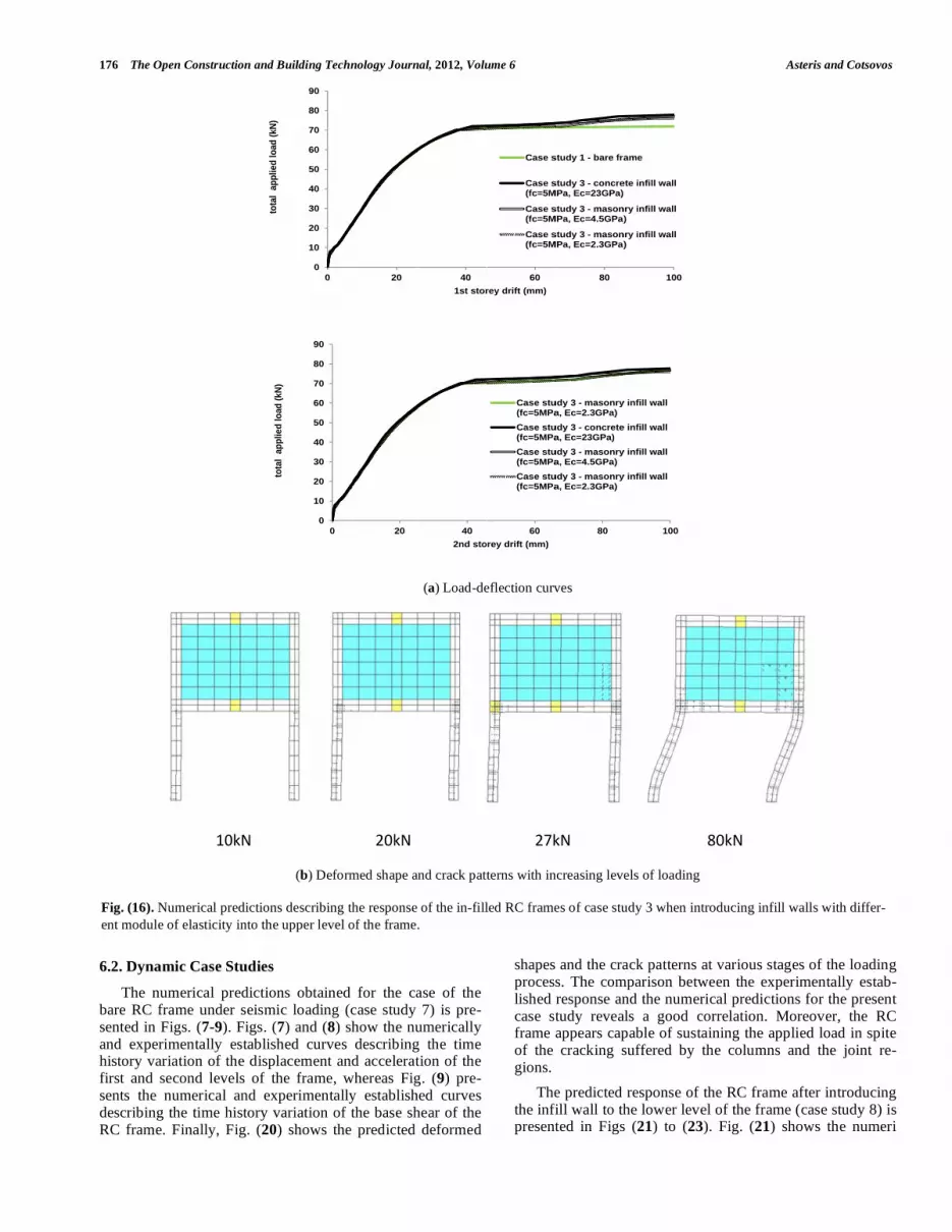
Fig. (16a) presents the load–displacement curves describ-ing the relationship between the total applied load and the displacement of each level of the RC frame with infill panels being introduced into its upper level (as shown in case study 3 in Fig. 10). The frames are again subjected to identical loading conditions to those imposed in the previous case studies. From these curves, it can be seen that only the lower level of the RC frame essentially deforms. The upper level of the frame practically responds as a rigid body, since the infill
wall drastically increases its stiffness. As a results, cracking initiates in the lower and upper regions of the 1
st level col-
umns (see Fig. 16b), where the bending moments and shear forces obtain their maximum values, extending quickly into the beam-column joint regions (as in case study 1). Failure is exhibited due to yielding of the longitudinal reinforcement of the columns. Prior to failure, little cracking occurs within the upper level of the frame. The overall response of these frames is practically not affected by the variation of the modulus of elasticity of the infill walls. Finally, by compar-ing the predicted response of the bare frame of case study 1 with that of the present case, it becomes apparent that the introduction of the infill wall into the upper level of the RC frame results in (a) a small increase of the overall load-carrying capacity (80kN instead of 70kN) and stiffness, (b) insignificant changes in the distribution of the internal ac-
Fig. (11). Numerical predictions describing the response of the bare RC frame of case study 1.
(a) Load – deflection curves
0
10
20
30
40
50
60
70
80
0 20 40 60 80 100
tota
l a
pp
lied
lo
ad
(kN
) 1st storey drift (mm)
Case study 1 - bare frame
0
10
20
30
40
50
60
70
80
0 20 40 60 80 100
tota
l a
pp
lied
lo
ad
(kN
)
2nd storey drift (mm)
Case study 1 - bare frame
6kN 25kN 60kN
(b) Load – deflection curves
174 The Open Construction and Building Technology Journal, 2012, Volume 6 Asteris and Cotsovos
tions or cracking of the columns of the lower level, and, (c) similar mode of failure.
The numerical predictions obtained for the case of the bare RC frame when subjected to static monotonic loading applied only to its lower level (see case study 4 in Fig. 10) is presented in Fig. (17). From the load–displacement curves describing the relationship between the applied load and the displacement of the lower level shown in Fig. (17a), it ap-pears that the RC frame exhibits ductile response and a load-carrying capacity equal to 80 KN. Moreover, from the pre-dicted deformation profile and crack patterns shown in Fig. (17b), it can be seen that cracking initially forms in the col-umns at their lower end, gradually extending into the beam-column joint regions. Failure occurs within the columns of the first level of the frame after yielding of the longitudinal reinforcement and the formation of plastic hinges which ul-timately result in the formation of a mechanism. Comparing the predictions obtained in the case study 1 with those of the present case study, it becomes clear that the application of the load only to the lower level of the RC frame results in a small increase of load-carrying capacity and stiffness
Moreover, the internal actions and crack patterns of the structural elements of the lower level and the mode of failure remain practically unaffected.
Fig. (18a) depicts the load–displacement curves describ-ing the relationship between the applied load and the displacement of first level of the RC frame with the infill panels introduced into its lower level (see case study 5 in Fig. 10). The latter frames are subjected to identical loading conditions to those imposed in case study 4 (bare frame).The deformation of the first level of the frame is small compared with that predicted incase study 4.This is due to the existence of the infill wall which acts as a diagonal strut in compres-sion resisting part of the applied load and offering relief to the lower level of the frame. The formation of the diagonal strut can be recognized by the inclined cracking which forms within the infill walls (see Figs. 18b to 18d). he ‘strut’ ac-tion along the diagonal of the infill wall drastically increases the stiffness at the lower level and the overall load-carrying of the structure. Since the applied load is mainly resisted by the infill wall, the load-carrying capacity and stiffness of the in-filled frame depends on the axial stiffness and strength of
Fig. (12). Load – deflection curves predicted numerically describing the response of the in-filled RC frame of case study 2 when introducing
infill walls into the lower level of the frame.
0
20
40
60
80
100
120
140
160
180
0 0.5 1 1.5 2 2.5 3
tota
l ap
plied
lo
ad
(kN
)
1st dtorey drift (mm)
Case study 1 - bare frame
Case study 2 - concrete infillwall (fc=5MPa, Ec=23GPa)
Case study 2 - masonry infillwall (fc=5MPa, Ec=4.5GPa)
Case study 2 - masonry infillwall (fc=5MPa, Ec=2.3GPa)
0
20
40
60
80
100
120
140
tota
l a
pp
lied
lo
ad
(kN
)
0 20 40
2
60 80
nd storey drift (
0 100
(mm)
Case study 1 -
Case study 2 -(fc=5MPa, Ec=
Case study 2 -(fc=5MPa, Ec=
Case study 2 -(fc=5MPa, Ec=
120
- bare frame
- concrete infill w=23GPa)
- masonry infill w=4.5GPa)
- masonry infill w=2.3GPa)
140
wall
wall
wall

Numerical Investigation of the Effect of Infill Walls The Open Construction and Building Technology Journal, 2012, Volume 6 175
the diagonal strut. From the crack patterns, it may be recog-nised that failure occurs once the strength of the diagonal strut is reached. Failure of the inclined strut results in an abrupt redistribution of internal actions and sudden transfer of load to the structural elements of the RC frame which apparently exceed their load-carrying capacity by a large margin.
Finally, the load–displacement curves describing the rela-tionship between the applied load and the displacement of 1
st
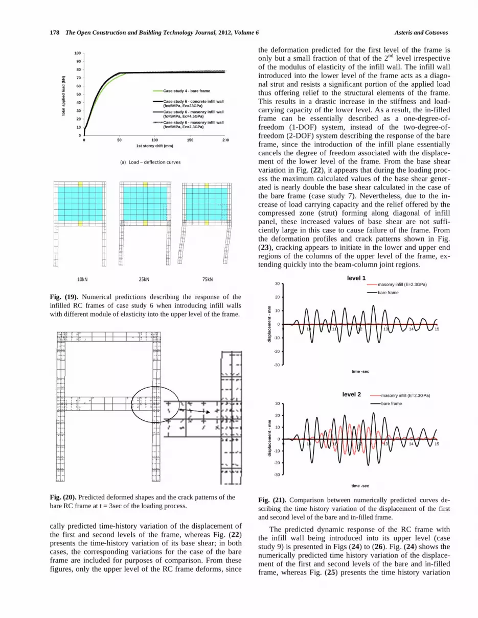
level shown in Fig. (19a) describe the behaviour of the RC frame with infill walls being introduced into the upper level (see case study 6 in Fig. 10). The response in this case is similar to the response exhibited in case study 3, where
cracking initiated in the lower and upper ends of the 1st level
columns (Fig. 19b), where the bending moments and shear forces obtain their maximum values, and extended quickly into the beam-column joint regions. Failure occurs due to yielding of the longitudinal of the columns. The overall response of these frames is practically not affected by the variation of the modulus of elasticity of the infill walls. Finally, comparing the predictions associated with case study 3 with those of the present case study, it shows that the introduction of the infill wall into the upper level of the RC frame results in a rather small increase of overall load carry- ing capacity and stiffness, and no significant changes in the distribution of the internal actions and crack patterns of the structural elements of the lower level or the mode of failure.
Fig. (13). Numerically predicted deformed shape and crack patterns with increasing levels of loading of case study 2 when introducing con-
crete infill walls with fc=5MPa and Ec=23GPa into the lower level of the frame.
Fig. (14). Numerically predicted deformed shape and crack patterns with increasing levels of loading of case study 2 when introducing ma-
sonry infill walls with fc=5MPa and Ec=4.5GPa into the lower level of the frame.
Fig. (15). Numerically predicted deformed shape and crack patterns with increasing levels of loading of case study 2 when introducing ma-
sonry infill walls with fc=5MPa and Ec=2.3GPa into the lower level of the frame.
19kN
60kN
N 130kN
1
1kN 21kkN 49kNkN 65kkN
11
1kN 18kNN 48kN 68kNN
176 The Open Construction and Building Technology Journal, 2012, Volume 6 Asteris and Cotsovos
6.2. Dynamic Case Studies
The numerical predictions obtained for the case of the bare RC frame under seismic loading (case study 7) is pre-sented in Figs. (7-9). Figs. (7) and (8) show the numerically and experimentally established curves describing the time history variation of the displacement and acceleration of the first and second levels of the frame, whereas Fig. (9) pre-sents the numerical and experimentally established curves describing the time history variation of the base shear of the RC frame. Finally, Fig. (20) shows the predicted deformed
shapes and the crack patterns at various stages of the loading process. The comparison between the experimentally estab-lished response and the numerical predictions for the present case study reveals a good correlation. Moreover, the RC frame appears capable of sustaining the applied load in spite of the cracking suffered by the columns and the joint re-gions.
The predicted response of the RC frame after introducing the infill wall to the lower level of the frame (case study 8) is presented in Figs (21) to (23). Fig. (21) shows the numeri
(a) Load-deflection curves
(b) Deformed shape and crack patterns with increasing levels of loading
Fig. (16). Numerical predictions describing the response of the in-filled RC frames of case study 3 when introducing infill walls with differ-
ent module of elasticity into the upper level of the frame.
tota
l a
pp
lied
lo
ad
(kN
) to
tal
ap
plied
lo
ad
(k
N)
0
10
20
30
40
50
60
70
80
90
0
0
10
20
30
40
50
60
70
80
90
0
pp
()
20
20
40
1st stor
40
2nd sto
60
rey drift (mm)
Case s
Case s(fc=5M
Case s(fc=5M
Case s(fc=5M
60
rey drift (mm)
Case stu(fc=5MPa
Case stu(fc=5MPa
Case stu(fc=5MPa
Case stu(fc=5MPa
80
study 1 - bare fra
study 3 - concreMPa, Ec=23GPa)
study 3 - masonMPa, Ec=4.5GPa)
study 3 - masonMPa, Ec=2.3GPa)
80
udy 3 - masonrya, Ec=2.3GPa)
udy 3 - concretea, Ec=23GPa)
udy 3 - masonrya, Ec=4.5GPa)
udy 3 - masonrya, Ec=2.3GPa)
100
ame
ete infill wall
nry infill wall)
nry infill wall)
100
y infill wall
e infill wall
y infill wall
y infill wall
10
0kN 20kN
N 27kN
80kN

Numerical Investigation of the Effect of Infill Walls The Open Construction and Building Technology Journal, 2012, Volume 6 177
(a) Load-deflection curves
(b) Deformed shape and crack patterns with increasing levels of loading
Fig. (17). Numerical predictions describing the response of the bare RC frame of case study1.
(a) Load-deflection curves
Fig. (18). Numerical predictions describing the response of the in-filled RC frames of case study 5 when introducing infill walls with different
module of elasticity into the lower level of the frame.
tota
l ap
plied
lo
ad
(k
N)
0
10
20
30
40
50
60
70
80
0
pp
()
10 200 30
1st sto
40 50
rey drift (mm)
60
Case study 4
70 80
4 - bare frame
10
0kN 40kN
N 60kN 80kN
0
100
200
300
400
500
600
0
tota
l ap
plied
lo
ad
(kN
)
0 2 4
1st store
6
ey drift (mm)
Case stu
Case stuwall (fc=
Case stuwall (fc=
Case stuwall (fc=
8
udy 4 - bare fram
udy 5 - concrete5MPa, Ec=23GP
udy 5 - masonry5MPa, Ec=4.5G
udy 5 - masonry5MPa, Ec=2.3G
10
me
e infillPa)
y infillPa)
y infillPa)
8
(b) Defo
50
(c) Defo
6kN
rmed shape a
0kN
rmed shape a
126
and crack pat
120
and crack pat
kN
tterns for the
kN
tterns for the
186kN
case of a con
250kN
case of a ma
N
ncrete infill w
N
asonry infill w
360kN
wall with Ec=23
370kN
wall with Ec=4.
3GPa
.5GPa
3
(d) Defo
8kN
rmed shape a
114
and crack pat
kN
tterns for the
320kN
case of a ma
N
asonry infill w
440kN
wall with Ec=2.
.3GPa
178 The Open Construction and Building Technology Journal, 2012, Volume 6 Asteris and Cotsovos
cally predicted time-history variation of the displacement of the first and second levels of the frame, whereas Fig. (22) presents the time-history variation of its base shear; in both cases, the corresponding variations for the case of the bare frame are included for purposes of comparison. From these figures, only the upper level of the RC frame deforms, since
the deformation predicted for the first level of the frame is only but a small fraction of that of the 2
nd level irrespective
of the modulus of elasticity of the infill wall. The infill wall introduced into the lower level of the frame acts as a diago-nal strut and resists a significant portion of the applied load thus offering relief to the structural elements of the frame. This results in a drastic increase in the stiffness and load-carrying capacity of the lower level. As a result, the in-filled frame can be essentially described as a one-degree-of-freedom (1-DOF) system, instead of the two-degree-of-freedom (2-DOF) system describing the response of the bare frame, since the introduction of the infill plane essentially cancels the degree of freedom associated with the displace-ment of the lower level of the frame. From the base shear variation in Fig. (22), it appears that during the loading proc-ess the maximum calculated values of the base shear gener-ated is nearly double the base shear calculated in the case of the bare frame (case study 7). Nevertheless, due to the in-crease of load carrying capacity and the relief offered by the compressed zone (strut) forming along diagonal of infill panel, these increased values of base shear are not suffi-ciently large in this case to cause failure of the frame. From the deformation profiles and crack patterns shown in Fig. (23), cracking appears to initiate in the lower and upper end regions of the columns of the upper level of the frame, ex-tending quickly into the beam-column joint regions.
Fig. (21). Comparison between numerically predicted curves de-
scribing the time history variation of the displacement of the first
and second level of the bare and in-filled frame.
The predicted dynamic response of the RC frame with the infill wall being introduced into its upper level (case study 9) is presented in Figs (24) to (26). Fig. (24) shows the numerically predicted time history variation of the displace-ment of the first and second levels of the bare and in-filled frame, whereas Fig. (25) presents the time history variation
Fig. (19). Numerical predictions describing the response of the
infilled RC frames of case study 6 when introducing infill walls
with different module of elasticity into the upper level of the frame.
Fig. (20). Predicted deformed shapes and the crack patterns of the
bare RC frame at t = 3sec of the loading process.
tota
l ap
plied
lo
ad
(kN
)
0
10
20
30
40
50
60
70
80
90
100
0
(
50
a) Load – de
1st stor
flection curve
100
rey drift (mm)
Case st
Case st(fc=5MP
Case st(fc=5MP
Case st(fc=5MP
es
150
tudy 4 - bare fra
tudy 6 - concretPa, Ec=23GPa)
tudy 6 - masonrPa, Ec=4.5GPa)
tudy 6 - masonrPa, Ec=2.3GPa)
200
ame
te infill wall
ry infill wall
ry infill wall
10kN
25kNN 75kN
-30
-20
-10
0
10
20
30
9 10 11 12 13 14 15
dis
pla
cem
en
t -
mm
time -sec
level 1 masonry infill (E=2.3GPa)
bare frame
-30
-20
-10
0
10
20
30
9 10 11 12 13 14 15
dis
pla
cem
en
t -
mm
time -sec
level 2 masonry infill (E=2.3GPa)
bare frame

Numerical Investigation of the Effect of Infill Walls The Open Construction and Building Technology Journal, 2012, Volume 6 179
of their base shear. Under seismic excitation essentially only the lower level of the RC frame deforms, since the upper level of the frame remains practically un-deformed due to the presence of the infill wall .As a result, the in-filled frame can be essentially described by a one-degree-of-freedom (1-DOF) system, instead of the two-degree-of-freedom (2-DOF) system describing the response of the bare frame, since the introduction of the infill plane essentially cancels the degree of freedom associated with the deformation of the upper level of the frame. From the base shear variation shown in Fig. (25), it appears that during the loading process the maximum calculated values of the base shear generated is significantly higher than that calculated in the case of the
bare frame (case study 7). These higher values of base shear cause extensive cracking of the columns at the lower level of the infill frame. As indicated in Fig. (26), cracking initiates in the lower and upper end regions of the 1
st level columns
(where the bending moments obtain their maximum values) extending quickly into the beam-column joint regions (as for case study 1). Failure occurred due to yielding of the longi-tudinal reinforcement of the columns; prior to this, little cracking occurred within the upper level of the frame.
Fig. (22). Comparison between numerically predicted curves de-
scribing the time history variation of the base shear of the bare and
in-filled frame.
Fig. (23). Predicted deformed shapes and the crack patterns of the
in-filled frame at t=3.9sec of the loading process.
Fig. (24). Comparison between numerically predicted curves de-
scribing the time history variation of the displacement of the first
and second level of the bare and in-filled frame
Fig. (25). Comparison between numerically predicted curves de-
scribing the time history variation of the base shear of the bare and
infilled frame.
-60
-40
-20
0
20
40
60
9 10 11 12 13 14 15
ba
se
sh
ea
r -
kN
time - sec
infilled frame (E=2.3GPa)
bare frame
-40
-30
-20
-10
0
10
20
30
9 10 11 12 13 14 15
dis
pla
cem
en
t -
mm
time -sec
level 1 infilled frame (E=2.3GPa)
bare frame
-40
-30
-20
-10
0
10
20
30
9 10 11 12 13 14 15
dis
pla
cem
en
t -
mm
time -sec
level 2 infilled frame (E=2.3GPa)
bare frame
-8
-6
-4
-2
2
4
6
8
ba
se
sh
ea
r -
kN
80
60
40
20
0
20
40
60
80
9 110 11 12
time - se
in
ba
13
c
nfilled frame (
are frame
14 15
(E=2.3GPa)
5

180 The Open Construction and Building Technology Journal, 2012, Volume 6 Asteris and Cotsovos
7. CONCLUDING REMARKS AND FUTURE WORK
The nonlinear procedure incorporated into the proposed FE model has been found to be reliable and numerically sta-ble in spite of the brittle characteristics of the material mod-els adopted in order to describe the behaviour of concrete and masonry; thus our nonlinear procedure could provide accurate predictions for the response of infilled frames. Ad-ditional work - which is currently ongoing - is required in order to fully calibrate the masonry material model.
The predictions obtained from the static case studies (case studies 1 to 6) clearly show that infill walls act as di-agonal compression ‘struts’, which undertakes portion of the applied load thus offering relief to certain structural elements of the frame. This action results in a significant redistribution of the internal actions developing within the structural ele-ments of the frame by essentially redirecting the loads into other regions of the structure. Although this redistribution of internal actions can result, on the one hand ,in an increase of the overall stiffness and load carrying capacity of the frame, on the other hand, it may cause stress concentrations in other regions of the structure never designed to undertake the in-ternal actions which develop due to the additional loads transferred through the diagonal strut.
Observing the dynamic case studies (case studies 7 to 9) the two storey infilled frame can be essentially described by a one-degree-of-freedom (1-DOF) system instead of the two-degree-of-freedom (2-DOF) system describing the response of the bare frame as the introduction of the infill plane essen-tially cancels the degree of freedom associated with the dis-placement of the floor level of the frame to which infilled walls was introduced. Based on the numerical predictions more damages being sustained to the structural elements of the storey of the frame which had no infill wall.
The present work needs to be extended to other frame structures with different infill length-to-height aspect ratio and more bays and storeys than the frame currently investi-gated in order to fully appreciate the full effect of the infill walls on the overall response of RC frames.
CONFLICT OF INTEREST
The authors confirm that this article content has no con-flicts of interest.
ACKNOWLEDGEMENT
None declared.
REFERENCES
[1] S.G. Buonopane, and R.N. White, “Pseudodynamic testing of ma-sonry infilled reinforced concrete frame”, J. Struct. Eng. ASCE,
vol. 125, no. 6, pp. 578-589, 1999. [2] A. Hashemi, and K.M. Mosalam, “Shake-table experiment on
reinforced concrete structure containing masonry infill wall.” Earthquake Eng. Struct., vol. 35, pp. 1827-1852, 2006.
[3] A. Madan, A.M. Reinhorn, J.B. Mander, and R. E. Valles, “Model-ing of masonry infill panels for structural analysis”, J. Struct. Eng.
ASCE, vol. 123, no. 10, pp. 1295-1302, 1997. [4] A.B. Mehrabi, P.B. Shing, M. Schuller, and J. Noland, “Experi-
mental evaluation of masonry-infilled RC frames”, J. Struct. Eng. ASCE, vol. 122, no. 3, pp. 228-237, 1996.
[5] K.M. Mosalam, R.N. White, and G. Ayala, “Response of infilled frames using pseudo-dynamic experimentation”, Earthquake Eng.
Struct. Dyn., vol. 27, no. 6, pp. 589-608, 1998. [6] S. Pujol, D. Fick, “The test of a full-scale three-story RC structure
with masonry infill walls”, Eng. Struct., vol. 32, pp. 3112-3121, 2010.
[7] M.H. Santhi, G.M.S. Knight, and K. Muthumani, “Evaluation of seismic response of soft-level infilled frames”, Comput. Concrete.,
vol. 2, no. 6, pp. 423-437, 2005a. [8] M.H. Santhi, G.M.S. Knight, and K. Muthumani, “Evaluation of
seismic performance of gravity load designed reinforced concrete frames”, J. Perform. Construct. Facil., vol. 19, no. 4, pp. 277-282,
2005b. [9] B.S. Smith, "Behavior of square infilled frames", J. Struct. Div.
ASCE, vol. ST1, pp. 381-403, 1996. [10] B.S. Smith, and C. Carter, "A method of analysis for infilled
frames", Proc. Inst. Civil Eng., vol. 44, pp. 31-48, 1969. [11] A. Stavridis, “Analytical and Experimental Study of Seismic Per-
formance of Reinforced Concrete Frames Infilled with Masonry Walls", PhD. Thesis University of California, San Diego, 2009.
[12] A. Stavridis, I. Koutromanos, and P.B. Shing, "Shake-table tests of a three-story reinforced concrete frame with masonry infill walls",
Earthquake Eng. Struct. Dyn., vol. 41, no. 6, pp1089-1108, 2012. [13] R. arni , S. Gosti , A.J. Crewe, and C.A. Taylor, “Shaking table
tests of 1:4 reduced-scale models of masonry infilled reinforced concrete frame buildings”, Earthquake Eng. Struct. Dyn., vol. 30,
no. 2, pp. 819-834, 2001. [14] P.G. Asteris, D.J. Kakaletsis, C.Z. Chrysostomou, and E.E. Smy-
rou, “Failure modes of infilled frames”, Elect. J. Struct. Eng., vol. 11, no. 1, pp. 11-20, 2011.
[15] O. Anil, and S. Altin, “An experimental study on reinforced con-crete partially infilledframes", Eng. Struct., vol. 29, pp. 449-460,
2007. [16] S. Arulselvan, and K. Subramanian, “Experimental investigation on
three dimensional RC infilled frame - RC plane frame interactions with slab for seismic resistance", Am. J. Appl. Sci., vol. 5, no. 4, pp.
328-333, 2008. [17] D.J. Kakaletsis, and C.J. Karayannis, "Influence of masonry
strength and openings on infilled R/C frames under cycling load-ing", J. Earthquake Eng., vol. 12, no. 2, pp. 197-221, 2008.
[18] P.G. Asteris, “Lateral stiffness of brick masonry infilled plane frames”, J. Struct. Eng., vol. 129, no. 8, pp. 1071-1079, 2003.
[19] P.G. Asteris, “Finite element micro-modelling of infilled frames”, Elect. J. Struct. Eng., vol. 8, pp.1-11, 2008.
[20] P.G. Asteris, S.T. Antoniou, D.S. Sophianopoulos, C.Z. Chry-sostomou, “Mathematical macromodelling of infilled frames: state
of the art”, J. Struct. Eng., vol. 137, no. 12, pp. 1508-1517, 2011. [21] P.G. Asteris, and A.D. Tzamtzis, "A finite element technique for
the analysis of infilled R/C frames", 9th North American Masonry Conference, Clemson, South Carolina, USA, 2003.
[22] G.J.W. King, and P.C. Pandey, “The analysis of infilled frames using finite elements”, Proc. Inst. Civil Eng., Part 2, vol. 65, pp.
749-760, 1978. [23] I. Koutromanos, “Numerical Analysis of Masonry-Infilled Rein-
forced Concrete Frames Subjected to Seismic Loads and Experi-mental Evaluation of Retrofit Techniques”, Ph. D. Thesis, Univer-
sity Of California, San Diego, 2011.
Fig. (26). Predicted deformed shapes and the crack patterns of the
in-filled frame at t = 3sec of the loading process.

Numerical Investigation of the Effect of Infill Walls The Open Construction and Building Technology Journal, 2012, Volume 6 181
[24] I. Koutromanos, A. Stavridis, P.B.B. Shing, K. Willam, “Numerical
modeling of masonry-infilled RC frames subjected to seismic loads”, Comput. Struct., vol. 89, pp. 1026-1037, 2011.
[25] T.C. Liauw, and K.H. Kwan, ‘‘Nonlinear analysis of multistoryin-filled frames’’, Proc. Inst. Civil Eng. Struct. Build., vol. 73, pp.
441-454, 1982. [26] T. C. Liauw, and K.H. Kwan, “Nonlinear behaviour of non-integral
infilled frames”, Comput. Struct., vol. 18, pp. 551-560, 1984. [27] A.B. Mehrabi, and P.B. Shing, “Finite element modeling of ma-
sonry-infilledrc frames,” J. Struct. Eng. ASCE, vol. 123, no. 5, pp. 604-613, 1997.
[28] A.D. Tzamtzis, and P.G. Asteris, “Finite Element Analysis of Ma-sonry Structures Part I – Review of Previous Work”, 9th North
American Masonry Conference, Clemson, South Carolina, USA, 2003.
[29] A.D. Tzamtzis, and P.G. Asteris, “Finite Element Analysis of Ma-sonry Structures Part II – Proposed 3-D Nonlinear Microscopic
Model.” 9th North American Masonry Conference, Clemson, South Carolina, USA, 2003.
[30] D. D'Ayala, J. Worth, O. Riddle, “Realistic shear capacity assess-ment of infill frames: Comparison of two numerical procedures”,
Eng. Struct., vol. 31, no. 8, pp. 1745-1761, 2009. [31] D.M. Cotsovos, “Numerical Investigation of Structural Concrete
under Dynamic (Earthquake and Impact) Loading”, Ph. D thesis, University of London, UK, 2004.
[32] M.D. Kotsovos, and M.N. Pavlovi , “Structural Concrete: Finite-element analysis and design”, Thomas Telford: London, 1995.
[33] M.D. Kotsovos, and K.V. Spiliopoulos, “Modelling of crack clo-sure for finite-element analysis of structural concrete”, Comput.
Struct., vol. 69, pp. 383-398, 1998. [34] D.M. Cotsovos, and M.N. Pavlovi , “Numerical investigation of
RC structural walls subjected to cyclic loading”, Comput. Con-crete, vol. 2, no. 3 pp. 215-38, 2005.
[35] D.M. Cotsovos, and M.N. Pavlovi , “Simplified FE model for RC structures under earthquakes” Proc. Inst. Civil Eng. Struct. Build.,
vol. 159 pp. 87-102, 2006. [36] D.M. Cotsovos, and M.N. Pavlovi , “Numerical investigation of
concrete subjected to compressive impact loading. Part 1: a funda-mental explanation for the apparent strength gain at high loading
rates”, Comput. Struct., vol. 86, no. 1-2, pp. 145-163, 2008. [37] D.M. Cotsovos, and M.N. Pavlovi , “Numerical investigation of
concrete subjected to compressive impact loading. Part 2: Paramet-
ric investigation of factors affecting behaviour at high loading
rates”, Comput. Struct., vol. 86, no. 1-2, pp.164-180, 2008. [38] D.M. Cotsovos, and M.N. Pavlovi , “Numerical investigation of
concrete subjected to high rates of uniaxial tensile loading”, Int. J. Impact. Eng., vol. 35 no. 5, pp. 319-335, 2008.
[39] I. Jelic, M.N. Pavlovi , and M.D. Kotsovos, “Performance of struc-tural-concrete members under sequential loading and exhibiting
points of inflection”, Comput. Concrete, vol. 1, no. 1, pp. 99-113, 2004.
[40] M.D. Kotsovos, and K.V. Spiliopoulos, “Evaluation of structural-concrete design-concepts based on finite-element analysis”, Com-
put. Mech., vol. 21, pp. 330-338, 1998. [41] P. Carydis, “Shaking table tests of R.C. frames”, ECOEST
PPREC8, Report vol. 8, 182, 1997. [42] CEB, “Behaviour and analysis of reinforced concrete structures
under alternate actions including inelastic response: Volume 2: Framed Structures” Bulletin D’ Information No. 220. Lausanne,
Switzerland, 1994. [43] A. W. Page, “The biaxial compressive strength of brick masonry”,
Proc. Inst. Civil Eng., Part 2, vol. 71, pp. 893-906, 1981. [44] M.M. Kose, “Parameters affecting the fundamental period of RC
buildings with infill walls”, Eng. Struct., vol. 31, pp. 93-102, 2009. [45] M.D. Kotsovos, and J.B. Newman, "Behaviour of concrete under
multiaxial stress", ACI J., vol. 74, no. 9, pp. 453-456, 1977. [46] M.D. Kotsovos, “Effect of testing techniques on the post-ultimate
behaviour of concrete in compression”, Mater. Struct., RILEM, vol. 16, pp. 3-12, 1983.
[47] J.G.M. Van Mier, “Strain-softening of concrete under multaxial loading conditions”, Ph. D thesis, Eindhoven University of Tech-
nology, 1984. [48] J.G.M. Van Mier, S.P. Shah, M. Armand, J.P. Balayssac, A. Bas-
coul, S. Choi, D. Dasenbrock, G. Ferrara, C. French, M.E. Gobbi, B.L. Karihaloo, G. Konig, M.D. Kotsovos, J. Labuz, D. Lange-
Korbar, G. Markeset, M.N. Pavlovi , G. Simsch, K-C. Thienel, A. Turatsinze, M. Ulmer, H.J.G.M. van Geel, M.R.A. van Vliet, and
D. Zissopoulos, “Strain softening of concrete in uniaxial compres-sion”, Mater. Struct., RILEM, vol. 30, pp. 195-209, 1997.
[49] P.M. Zissopoulos, M.D. Kotsovos, and M.N. Pavlovi , “Deforma-tional behaviour of concrete specimens in uniaxial compression
under different boundary conditions”, Cem. Concrete Res. Perga-mon, vol. 30, pp. 153-159, 2000.
Received: January 24, 2012 Revised: April 29, 2012 Accepted: April 30, 2012
© Asteris and Cotsovos; Licensee Bentham Open.
This is an open access article licensed under the terms of the Creative Commons Attribution Non-Commercial License (http://creativecommons.org/-
licenses/by-nc/3.0/) which permits unrestricted, non-commercial use, distribution and reproduction in any medium, provided the work is properly cited.