investigation of fiber-reinforced polymer for seismic rehabilitation of concrete structural frames...
TRANSCRIPT

0 >^
LJJ O
i\»i
O 0 o a:
20030822 090 Investigation of Fiber-Reinforced Polymer for Seismic Rehabilitation of Concrete Structural Frames With Unreinforced Masonry Infill Ghassan K. Al-Chaar, Justin B. Berman, and Steven C. Sweeney
May 2003
"(ro a
Approved for public release; distribution is unlimited.

m >»
LU O
o x: 3 o a. '^
HH" CQ (0 O c (0 o 0) O DC
I i
us Army Corps of Engineers® Engineer Research and Development Center
Investigation of Fiber-Reinforced Polymer for Seismic Rehabilitation of Concrete Structural Frames With Unreinforced Masonry Infill Ghassan K. Al-Chaar, Justin B. Berman, and Steven C. Sweeney
IVIay 2003
Approved for public release; distribution is unlimited.
ERDC/CERLTR-03-10
Preface This study was conducted for Headquarters, U.S. Army Corps of Engineers, under Project 4A162784AT41, "Military Facilities Engineering Technology"; Work Unit CFM-AOll, "Seismic Rehabilitation of Concrete Frames with Infill." The technical
monitor was David C. Bohl, CECW-EW.
The work was performed by the Materials and Structures Branch (CF-M) of the Fa- cilities Division (CF), Construction Engineering Research Laboratory (CERL). The CERL Principal Investigator was Ghassan K. Al-Chaar. The technical editor was Gordon L. Cohen, Information Technology Laboratory - Champaign. Martin J. Sa- voie is Chief, CEERD-CF-M]], and L. Michael Gohsh is Chief, CEERD-CF. The Technical Director of the Facilities Acquisition and Revitalization business area is Dr. Paul A. Howdyshell, CEERD-CV-ZT, and the Director of CERL is Dr. Alan W.
Moore.
Contributions to this work by Donny R. Lester are gratefully acknowledged.
CERL is an element of the Engineer Research and Development Center (ERDC), U.S. Army Corps of Engineers. The Commander and Executive Director of ERDC is COL John W. Morris III, EN, and the Director is Dr. James R. Houston.
DISCLAIMER: The contents of this report are not to be used for advertising, pubKcation, or promotional purposes Citation of trade names does not constitute an official endorsement or approval of the use of such commercial products. All product names and trademarks cited are the property of their respective owners. The findings of this report are not to be construed as an official Department of the Army position unless so designated by other authorized documents.
DESTROY THIS REPORT WHEN IT IS NO LONGER NEEDED. DO NOT RETURN IT TO THE ORIGINATOR.
ERDC/CERLTR-03-10
Contents Preface 2
List of Figures and Tables 5
1 Introduction 11
1.1 Background 11 1.2 Objectives 12 1.3 Approach .....12 1.4 Mode of Technology Transfer 13
2 Literature Review 14
3 Test Program 20
3.1 Program Overview 20 3.2 Scaling 20 3.3 Test Setup 33 3.4 Instrumentation and Data Acquisition 34 3.5 Material Properties 39 3.6 Loading 47
4 Frame Element Testing 51
4.1 Overview 51 4.2 Materials, Specimen Configuration, and Preparation 51
4.3 Testing Procedure 53 4.4 Results and Discussion 55 4.5 Conclusions 58
5 Performance of Fully Infilled Concrete Frame (Test 1) 59
5.1 Overview 59 5.2 Crack Formation and Propagation 59 5.3 Load/Displacement Behavior 64 5.4 Strain Distribution in the Masonry Panels 71 5.5 Strain Distribution in the Reinforcing Steel 73
5.6 Conclusion •• 75
6 Performance of Model Used in Test 1 as Rehabilitated With CFRP (Test 2) 77
6.1 Overview 77 6.2 CFRP Retrofit Application 77 6.3 Crack Formation and Propagation 81 6.4 Load/Displacement Behavior 87 6.5 Strain Distribution in Masonry Panels 94

ERDC/CERLTR-03-10
6.6 Strain Distribution in Reinforcement • 96 6.7 Conclusion 98
7 Performance of Concrete Frame With Infill Panel Openings (Test 3) 99
7.1 Overview 99 7.2 Cracl< Formation and Propagation 100 7.3 Load/Dispiacement Beiiavior 104 7.4 Strain Distribution in Masonry Panels 110 7.5 Strain Distribution in Reinforcing Steel 111 7.6 Conclusion ^''4
8 Performance of Model Used in Test 3 as Rehabilitated With CFRP (Test 4) 115
8.1 Overview IIS 8.2 CFRP Retrofit Application 115 8.3 Craci< Formation and Propagation : 118 8.4 Load/Displacement Behiavior 123 8.5 Strain Distribution in Masonry Panels 131 8.6 Strain Distribution in Reinforcing Steel 133 8.7 Conclusion 135
9 Comparison of Performance Results from Tests 1 and 2 136 9.1 Crack Formation and Propagation Comparison 136 9.2 Load/Displacement Beliavior Comparison 137 9.3 Masonry Panel Strain Distribution Comparison 141 9.4 Reinforcement Strain Distribution Comparison 141 9.5 Conclusion • 142
10 Comparison of Performance Results from Tests 3 and 4 143 10.1 Crack Formation and Propagation Comparison 143 10.2 Load/Displacement Behavior Comparison 144 10.3 Masonry Panel Strain Distribution Comparison 148 10.4 Reinforcement Strain Distribution Comparison 149 10.5 Conclusion 149
11 Summary and Conclusions 151
References • "'53
Appendix: Ultrasound Inspection of a Fiber-Reinforced Polymer Retrofitted Unrelnforced Masonry Structure 156

ERDC/CERLTR-03-10
8.9. Cracks appearing during cycles 32 tiirough 34 121
8.10. Cracks appearing during cycles 35 through 37 121
8.11. Cracks appearing during cycles 38 through 40 122
8.12. Cracks found at the completion of the test 122
8.13. Load/displacement behaviors for each floor of Model 4 123
8.14. Hysteresis with backbone curves for each floor. 126
8.15 Stiffness degradation for each floor. 127
8.16. Load/displacement with and without lead weights 128
8.17. Load/displacement with and without center first floor bay. 129
8.18. Combined load/displacement without modification 130
8.19. Combined load/displacement with modification 130
8.20. Location of strain gages and LVDTs 132
8.21. Panel strain distribution for peak load at cycle 32 132
8.22. Strain distribution during peak load positive stroke 133
8.23. Strain distribution during peak load negative stroke 134
8.24. Strain distribution during peak deflection positive stroke 134
8.25. Strain distribution during peak deflection negative stroke 134
9.1. Load/deformation behavior for each story of Models 1 and 2 138
9.2. Base shear during each primary cycle for both the original and the rehabilitated test structures 139
9.3. Stiffness of each floor during primary cycles for both the original and rehabilitated test structures 140
10.1. Load/deformation behavior for each story of Model 3 and Model 4 144
10.2. Base shear during each primary cycle for Models 3 and 4 147
10.3. Stiffness of each floor during primary cycles for Models 3 and 4 148
Tables
3.1. Dimensional scaling for model and prototype 23
3.2. Reinforcement for model and prototype 24
3.3. Equivalent seismic load per floor. 25
3.4. Moment ratio summaries 27
3.5. Instrumentation plan 34
3.6. Summary of concrete compressive strength 39
3.7. Summary of concrete flexural strength (modulus of rupture) 40
3.8. Engineering properties of reinforcing steel 41
3.9. Summary of mortar compressive strength 43
3.10. Summary of engineering properties for masonry prisms 45
3.11. Summary of engineering properties for CFRP. 46
ERDC/CERLTR-03-10
List of Figures and Tables
Figures
3.1. The four experimental models 21
3.2. Photograph of Castle Building 1211 21
3.3. Location of Merced County, CA 22
3.4. Full-scale experimental model 22
3.5. Joint locations 26
3.6. Half-scale experimental Model 1 and 2 plans 32
3.7. Half-scale experimental Model 3 and 4 plans 32
3.8. Completed half-scale experimental model 33
3.9. Actuator beam assembly. 34
3.10. Instrumentation location diagram for Test 1 and 2 37
3.11. Instrumentation location diagram for Test 3 and 4 37
3.12. Functional block diagram of instrumentation, data acquisition, and test control systems 38
3.13. Concrete flexural specimen for 4-point bending test (a) before test and (b) after test 40
3.14. Stress/strain curve for #3 bars 41
3.15. Stress/strain curve for D2 bars 42
3.16. Stress/strain curve for 6 gage bars 42
3.17. Stress/strain curve for #2 bars 42
3.18. Photo of mortar cube test failure 44
3.19. Photo of CMU test setup 44
3.20. Compression test setup and failure mode for masonry prisms 45
3.21. Diagonal tension test setup for masonry prism 46
3.22. Stress vs strain relationships for Model 2 CFRP coupons 47
3.23. Stress vs strain relationships for Model 4 CFRP coupons 47
3.24. Modified CUREE loading history. 49
3.25. El Centre, plot of displacement vs time 50
4.1. Instrumentation on atypical beam-column joint 53
4.2. Beam configuration and testing setup 54
4.3. Testing of beam specimen 54
4.4. Testing of column specimen •. 54

ERDC/CERLTR-03-10
4.5. Loading cycles for typical beam-column joint testing 55
4.6. Test setup (a) and failure mode (b) of wrapped beam-column joint 55
4.7. Load/displacement response of wrapped and unwrapped beams 56
4.8. Axial load/displacement response of wrapped and unwrapped columns 56
4.9. Load vs displacement response of unwrapped beam-column joint 57
4.10. Load vs displacement response of CFRP wrapped beam-column joint 57
5.1. Identification scheme 60
5.2. First cracks, cycles 21 tfirough 24 60
5.3. Cracks appearing during cycles 25 through 28 62
5.4. Cracks appearing during cycles 29 through 31 62
5.5. Cracks appearing during cycles 32 through 34 62
5.6. Cracks appearing during cycles 35 through 37 63
5.7. Cracks appearing during cycles 38 through 40 64
5.8. Cracks found after completion of test 64
5.9. Story shear vs drift ratio behavior for each floor 65
5.10. Hysteresis with backbone curves for each floor. 69
5.11. Stiffness degradation for each floor. 71
5.12. Location of strain gages and LVDTs 72
5.13. Panel strain distribution for Cycle 21 72
5.14. Panel strain distribution for Cycle 29 73
5.15. Reinforcement strain distribution at peak load, positive stroke 74
5.16. Reinforcement strain distribution at peak load, negative stroke 75
5.17. Maximum reinforcement strain distribution 75
6.1. CFRP rehabilitation placement on Model 2 78
6.2. Dimensions and CFRP placement of T-beam section 78
6.3. Stress vs strain relationships for CFRP coupons 80
6.4. Photograph of stories two and three of the rehabilitated frame 81
6.5. First cracks, cycles 21 through 24 84
6.6. Cracks appearing during cycles 25 through 28 84
6.7. Cracks appearing during cycles 29 through 31 85
6.8. Cracks appearing during cycles 32 through 34 85
6.9. Cracks appearing during cycles 35 through 37 85
6.10. Cracks appearing during cycles 38 through 40 86
6.11. Cracks found after completion of the Test 2 86
6.12. Cracks found after test of first and second stories 86
6.13. Cracks found after test of first story 87
6.14. Load/displacement behavior for each floor of the rehabilitated model 89

ERDC/CERLTR-03-10
6.15. Joint 1c after main portion of Test 2 90
6.16. Stiffness degradation for each floor. 91
6.17. Hysteretic behavior of the first and second floors at large drifts 92
6.18. Hysteretic behavior of the first floor at large drifts 93
6.19. Panel 1C after completion of Test 2 93
6.20. Panel 1B after completion of Test 2 94
6.21. Masonry panel identification 95
6.22. Location of strain gages and LVDTs 95
6.23. Panel strain distribution for cycle 32 96
6.24. Reinforcement strain distribution at peak load, positive stroke 97
6.25. Reinforcement strain distribution at peak load, negative stroke 97
6.26. Maximum reinforcement strain distribution 98
7.1. Model 3 beam, column, and bay identification scheme (panel openings not shown) 99
7.2. First cracks, cycles 25 through 28 100
7.3. Cracks appearing during cycles 29 through 31 101
7.4. Cracks appearing during cycles 32 through 34 102
7.5. Cracks appearing during cycles 35 through 37 102
7.6. Cracks appearing during cycles 38 through 40 103
7.7. Cracks found at the completion of the test 104
7.8. Load/displacement behavior for each floor for Model 3 105
7.9. Hysteresis with backbone curves for each floor of Model 3 108
7.10. Stiffness degradation for each floor. 109
7.11. Location of strain gages and LVDTs in Model 3 110
7.12. Panel strain distribution for cycle 35 111
7.13. Strain distribution of reinforcement in cycle 35 positive stroke 112
7.14. Strain distribution of cycle 35 negative stroke 112
7.15. Strain distribution of cycle 38 positive stroke 113
7.16. Strain distribution cycle 38 negative stroke 113
8.1. Rehabilitation of whole structure 116
8.2. Repairing of the third story column and beam 116
8.3. Location of frame elements where CFRP was applied 117
8.4. Stress vs strain relationship for CFRP coupons 118
8.5. Identification scheme for Model 4 119
8.6. First cracks, cycles 21 through 24 119
8.7. Cracks appearing during cycles 25 through 28 120
8.8. Cracks appearing during cycles 29 through 31 120

ERDC/CERL TR-03-10
3.12. Floor loading ratios 50
4.1. Mix proportions of concrete 52
4.2. Properties of carbon fiber sheet 52
4.3. Specimen configuration and wrapping condition 52
5.1. Peak load and corresponding story shear and drift ratio for each floor. 66
5.2. Maximum drift ratio and corresponding story shear for each floor. 66
5.3. Lateral load, story shear, and vertical load distribution 67
5.4. Relative displacement (fraction of third floor displacement) before and after cracking 68
5.5. Summary of average stiffness for each floor. 70
6.1. CFRP engineering properties 79
6.2. Values used for ultimate moment calculations 80
6.3. Rehabilitated moment capacity summary. 80
6.4. Peak load and corresponding and story shear and drift ratio for each floor. 88
6.5. Maximum drift ratio and corresponding story shear for each floor. 88
6.6. Average stiffness of each floor. 90
7.1. Peak loads and corresponding story shear and drift ratio 106
7.2. Lateral load, story shear, and vertical load distribution 106
7.3. Relative displacement (fraction of 3"^ floor displacement) before and after cracking 107
7.4. Summary of average stiffness for each floor. 109
8.1. Peak loads and corresponding story shears and drift ratios 124
8.2. Lateral loads, story shear, and vertical load distribution 124
8.3. Interstory displacement before cracking occurred and after peak displacement 125
8.4. Summary of the average stiffness for each floor. 127
8.5. Peak loads and corresponding story shears and drift ratios 131
8.6. Maximum drift ratio and corresponding story shear 131
9.1. Comparative summary of load, shear, and drift values for Models 1 and 2 138
9.2. Average stiffness (kips/in) for each story of Model 1 and 2 140
9.3. Maximum panel displacements for Test 1 and Test 2 141
10.1. Comparative summary of load, shear, and drift values for Models 3 and 4 145
10.2. Modified capacities for each floor of Models 3 and 4 146
10.3. Average stiffness (kips/in) for each story of Models 3 and 4 147
10.4. Maximum panel displacements for Tests 3 and 4 149
ERDC/CERL TR-03-10 11
1 Introduction
1.1 Background
The U.S. Army cxirrently operates approximately 1300 older buildings that use masomy-infiUed concrete frames as their principal structural system. About 700 of these buildings do not meet current seismic code requirements and are considered vulnerable to damage during an earthquake. To protect hiiman life and safety, it could cost up to $400 million to mitigate these seismic deficiencies using standard structural retrofit techniques.
Older masonry-infilled concrete frame buildings are known to have two structxiral
deficiencies:
1. The concrete frames typically were not designed to resist the large lateral loads imposed by earthquakes.
2. The infill panels were not designed to cany any significant structural loads.
Emerging retrofit rehabilitation techniques that use fiber-reinforced polymer (FRP) materials may be effective in addressing both types of seismic vulnerability. The U.S. Army Engineer Research and Development Center, Construction Engineering Research Laboratory (ERDC/CERL) has completed a large experimental program in which masonry-infilled reinforced concrete (R/C) frames were rehabiHtated with FRP composites, tested in a structural load frame, and subjected to detailed per- formance analyses. Longitudinal frames found in a 1950s-era three-story barracks structure at Castle Afr Force Base (AFB), Merced, CA, provided the real-world de- sign basis for the models used in this testing program.
In the continental United States.
12 ERDC/CERL TR-03-10
1.2 Objectives
The primary objective of this research was to investigate the performance of FRP composite materials when used to rehabilitate masonry-infilled concrete frame sys- tems. A secondary objective was to investigate the seismic performance of mtdti- bay, mxilti-story masonry-infiUed concrete fi-ame systems similar to those still in use on Army installations in U.S. areas of high seismicity.
1.3 Approach
The structural behavior of masonry-infilled R/C frames depends on the infiU proper- ties, infill configviration, nimiber of bays, number of stories, and the ntmiber of open- ings in the infill panels. In this experimental study, the researchers selected three- story, three-bay models representative of Army dormitory structures now being used in the field. An important technical reason for using this model configuration was to test all combinations of bay confinements (i.e., comer, exterior, and center
panels).
The models used in this study were half-scale in order to conform to the physical limitations of the testing facility. Four experimental tests were conducted on two physical models, as explained in Chapter 3. The models were constructed and
tested as follows:
1. The first physical model, referred to as Model 1 throughout this report, was R/C frame fully infilled with unreinforced masonry (URM) panels. The tension rein- forcement was designed to force flexural failure in the beams. This model was instrumented and tested to failure.
2. The first model was then rehabilitated, and is designated as Model 2 in this re- port. Cracks were repaired, and damaged firame members and infill panels were replaced to restore the strength and the stifihess of the first model in its original state. FRP composite material was appKed to beams and exterior columns, and the rehabilitated model was then tested to evaluate the effectiveness of the reha-
bilitation. 3. Model 3 was a pristine specimen constructed in the same manner as Model 1 ex-
cept that the reinforcement was slightly modified, and the infill panels were grouted to force shear failure in the fi-ame. This model was instrumented and
tested to failure. 4. The damaged Model 3 was rehabilitated and re-designated as Model 4. As with
the first physical model, damaged frame elements and infill panels were re- placed, hi this case, however, only the first-story columns were rehabilitated

ERDC/CERLTR-03-10 13
with FRP. As before, the model was tested to determine the effectiveness of the rehabilitation system and design.
Seismic behavior of the models was tested using slow cyclic loading that simulates the demands of light, moderate, and strong seismic motion. Test results are dis- cussed in terms of strength, stiffness, and deformation capacity measurements as well as observed damage patterns and apparent performance limit states. Propaga- tion of cracks in the concrete frame and masonry infill during the loading was illus- trated and is discussed in terms of the force and deflection histories. Measured shear strains in each of the nine infill panels were correlated with the progression of damage to infer the distribution of lateral force to each infill panel.
The effectiveness of FRP reinforcement on frame elements (beams, columns, and joints) was tested and is discussed in Chapter 4.
The main portion of the experimental program had a twofold purpose:
1. to study the effects of two styles of infill panel — one in the form of a soHd ma- sonry panel and the other incorporating openings representing windows and doors —: on the behavior and failure mechanisms of a non-ductile concrete frame (NDCF)
2. to evaluate the effectiveness of the selected FRP composite system for rehabilitat- ing damaged concrete frames.
Foiir test series were conducted, each of which is documented in Chapters 5-8. Chapter 9 presents a comparison of the results for Tests 1 and 2; and Chapter 10 presents a comparison of the results for Tests 3 and 4.
The Appendix to this report discusses a C-scan nondestructive evaluation technique that was demonstrated dviring this research program to be capable of detecting problems (e.g., debonding, delamination) with composite reinforcement materials affixed to concrete.
1.4 Mode of Technology Transfer
As a restdt of this effort and related work, a set of guidelines was proposed for prac- titioners developing CFRP rehabihtation designs for infilled R/C frame construction. Those guidelines have been pubhshed as ERDC/CERL Technical Report (TR)-02-33, Design of FRP for Rehabilitation of Infilled R/C Structures.
14 ERDC/CERLTR-03-10
2 Literature Review
Conventional methods for rehabilitating R/C frames include ferrocement coating with wire mesh, grouting CMU cells, external post-tensioning of beams and col- umns, damping devices, and fQling openings or removing partial infills. In recent years the use of FRP composite wrappings and lay-up materials for rehabilitation of structural R/C has gained growing acceptance, in large part due to its high strength-to-weight ratio as compared with the conventional repair techniques. Be- cause the composite overlay alters the behavior of members and systems, research- ers have become interested in examining all design and analysis methods, proce- dures, and theories that apply to both reinforced concrete and masonry.
Over the past decade research has focused on the use of FRP on R/C structural ele- ments such as beams, columns, and joints, or masonry panels of different configura- tions. This research has also addressed structiu-al components of three-bay, three- story R/C frames infilled with masonry panels. This chapter presents highMghts of significant research findings that are most pertinent to the objectives of the project documented here.
Researchers have foxmd a substantial increase in strength where FRP is used to re- habilitate structural members, but this strength increase usually comes with an undesirable increase in stiffness. However, researchers have discovered that FRP applications can be designed to increase in strength without an increase in stiffness [2] and [5]. This useftd result was achieved by applying the FRP at 45 degrees with respect to the longitudinal axis of flexural members, and this phenomenon is of great importance for buildings in high seismic zones.
Effective design of R/C members requires that the steel reinforcement yield before concrete fails in compression. This requirement is intended to prevent brittle fail- ure. Taly and GangaRao [31] concluded that the design of a member using FRP should be based on the compression failure of concrete, not on the yielding of the
steel, in order to avoid a brittle failure of the FRP.
Zhang et al. [33] examined the seismic performance of existing R/C columns reha- bilitated with carbon fiber-reinforced polymer (CFRP). Quantity, retrofitting types, and kinds of continuous fiber sheets were adopted as the experimental variables. The research demonstrated that FRP retrofit materials can change the failtu-e mode

ERDC/CERLTR-03-10 15
of the coliimns from shear to flexural failiore. However, if there are not enough plies of continuous fiber sheet the columns collapse due to poor ductility because the con- crete cnishes just after the longitudinal rebar yields.
Catbas [8] investigated the performance of FRP-rehabilitated R/C beams. He found that shear became the primary mode of failure if FRP is apphed to the tension face. This shift in failure mode from flexural (ductile) to shear (brittle) is imdesirable; the preferred mode of failure for the composite system is by compressive crushing of the concrete. Therefore, to retain the preferred ductile mode of failure, FRP should be applied along the sides of beams to provide additional shear reinforcement.
Grace et al. [11] investigated the use of FRP sheets to strengthen positive and nega- tive moment regions of continuous beams. It was concluded that the use of FRP laminates to strengthen continuous beams is effective in reducing deflections and increasing their load-carrying capacity. Fxirthermore, it was observed that local flexural failiire in R/C beams will resxilt in few large cracks, whQe failure of beams wrapped with composite overlay will result in many small, distributed tension cracks, the latter response being structurally desirable.
In a number of studies it was observed that the composite overlay significantly en- hanced the ductihty of structural members. Shmoldas [30] found that ductiMty about the strong axis of a column is greater than the ductihty about the weak axis.
Pantelides et al. [27] found that a system with FRP composite yielded displacement ductility more than twice the system without FRP. In addition, the peak lateral load capacity was increased by 16 percent.
Matsuzaki et al. [23] evaluated the performance of continuous composite fiber sheets in seismic rehabflitation. They fotmd that apphcation of FRP improved the flexural and shear capacities of structural members. A regular colimm that was shear-strengthened using carbon fiber sheeting had changed faflxire modes from shear to flexural failure, and it improved in ductflity as the amount of shear rein- forcement was increased.
Khalifa et al. [18] investigated the shear behavior and modes of failure of two-span continuous R/C beams strengthened with FRP sheets. The test results indicated that the externally bonded reinforcement coiild be used to enhance the shear capac- ity of the beams in positive and negative moment regions. Test results also indi- cated that the FRP contribution enhanced beams without stirrups more than beams with adequate steel shear reinforcement. This observation indicates that the FRP composite and shear steel reinforcement may not necessarily engage in composite-

16 ERDC/CERLTR-03-10
action resisting shear. It is most likely the FRP has to fail before the shear rein- forcement will engage in resisting shear forces.
Juvantes et al. [15] concluded that the strengthening of R/C structures with exter- nally bonded composite laminates rehes upon the force transfer between concrete and composite material at the interface. A detailed study of the state of deteriora- tion of the concrete surface must be performed before any structural rehabilitation in order to assiire an efficient interface bond. Testing consisted of CFRP externally bonded to a series of sound and deteriorated concrete beams to check bond stress distribution dependence on bond length variation.
Lee et al. [21] studied concrete tension specimens made with CFRP, paying particu- lar attention to the bond/shp behavior at the interface. It was found that the slip modulus influences load transfer and crack propagation.
Nanni et al. [25] presented the design of R/C members subjected to flexure design ultimate state using the classical failiire mode of steel yielding followed by concrete crushing or FRP rupture.
Parvin et al. [28] presented a preUminary study of the use of FRP overlays to en- hance the strength of an exterior beam-column connection.
ChaaUal et al. [9] carried out an experimental investigation of the response of R/C beams strengthened in flexure and in shear using externally epoxy bonded unidirec- tional CFRP strips.
Blaschlo et al. [6] tested concrete members strengthened in flexure with externally bonded FRP and showed bond failures that can occur in the interface between the FRP and concrete. The failure modes are described and classified.
To experimentally evaluate confining effects of CFRP sheets mainly on bond split- ting failxire, Kono et al. [19] tested concrete cylinders in compression, Schmidt-Thro tjrpe specimens, and beam specimens.
Harmon et al. [13] used the fi-iction-based model to derive moments-curvature rela- tionships and correct the shortcomings of energy-based models. Upper and lower bound models were proposed to predict both moment curvature and circimiferential
strain in the wrap.
ERDC/CERLTR-03-10 H
Harmon et al. [12] presented efforts to model the behavior of confined concrete based on a mechanistic model for the uniaxial monotonic behavior of confined con-
crete.
Haroim et al. [14] tested half-scale R/C coltimns, with and without lap spHces, built in accordance with old seismic design code. Two types of retrofit FRP jackets were used in this study — one a wet-lay-up carbon/epoxy laminate; the other a machine- woimd carbon/epoxy jacket. CycUc loading tests demonstrated that the performance of such existing coltmms can be improved dramatically due to the enhancement of concrete confinement provided by composite jackets.
Elhassan [10] presented the design and analysis procedures used in two projects to strengthen existing coltmms and slabs with externally applied FRP materials to re- sist the imposed gravity and earthquake loads.
In effort to investigate the effectiveness of CFRP in increasing flexural capacity and glass fiber reinforced polymer (GFRP) to increase the shear capacity, McCurry and Kachlakev [24] conducted four-point bending experiments on test specimens. The specimens were rephcated fi"om an existing bridge that was considered substantially deficient in shear strength.
Kurtz and Balaguru [20] compared the performance of CFRP using inorganic and organic matrix materials and appHed externally to strengthen R/C beams. Specifi- cally, strength, stiffness, ductility, failure pattern, and cracking were compared. The results indicate that CFRP fabricated using an inorganic matrix is as effective in increasing the strength and stiffness of R/C beams as CFRP using an organic ma- trix, but with a minor reduction in ductihty. The failure mechanism for the organic- based composite was sheet delamination; for the inorganic-based composite the fail- ure mechanism was sheet ruptxu-e.
Blaszak and Gold [7] compared the material properties of different types of FRP systems, addressirjg different uses, appMcation techniques, system constituent ma-
terials.
Khalifa and Nanni [16] examined the failure modes and shear performance of full- scale T-beams strengthened externally with CFRP sheets. The shear capacity was shown to be dependent on the degree of concrete svuface roughness prior to CFRP application, CFRP axial rigidity, CFRP end anchorage, and the nimaber of steel stir-
rups embedded.
18 ERDC/CERLTR-03-10
Khalifa and Nanni [17] also tested full-scale, simply supported beam specimens with different configurations of externally bonded CFRP. The parameters investi- gated included wrapping scheme, amoimt of reinforcement, ply orientation, and CFRP end anchorage. The results indicated that the most effective reinforcement configuration was U-shaped wrapping with end anchorage. The experimental re- sults confirmed the vahdity of a design approach, proposed by the authors in a pre- vious study, for predicting the shear capacity of the T-section beams.
Raghu, Myers, and Nanni [29] investigated the shear performance and failure modes of R/C T-joists, strengthened with externally bonded CFRP sheets, under nonxmiform loading. An innovative end anchor system, which allowed a better ex- ploitation of the strengthening system, was also tested.
Al-Chaar [4] tested fi-ame elements (beams, columns, joints, masonry walls) fully wrapped and unwrapped. Joints were tested under cychc loads, and beams and col- umns were tested under monotonic loads. An increase in strength and change in stiffness was reported to result fi-om the appHcation of CFRP.
Zamic and Tomazevic [32] evaluated fundamental parameters of lateral resistance and deformability of masonry-infilled R/C fi-ames subjected to cyclic lateral loading. The use of FRP for repair and strengthening techniques was tested. The effect of different types of vmreinforced and reinforced infill on lateral load-carrying capacity and stiffness, ductility, strength, and stiffness degradation and deterioration, and energy absorption and dissipation capacity also were investigated.
Al-Chaar et al. [3] carried out uniaxial and triaxial seismic shake table testing of masonry bearing and shear walls. The test specimens were URM walls retrofitted with GFRP appHed as an overlay to only one side of the walls. The study produced recommendations on using the FRP for seismic rehabilitation and retrofit of imrein- forced masonry walls.
The research efforts cited here address many important issues related to the use of the FRP on R/C and masonry structural elements. However, various fundamental issues related to system performance have not yet been investigated. One issue re- quiring attention is the ACI strong colimin / weak beam requirement. This re- quirement, embodied in ACI 318-89, Building Code Requirements for Reinforced Concrete [1], needs to be reexamined to determine if it is applicable to R/C frames that include masonry infill. If the piu-pose of ACI 318-89 is to prevent brittle fail- ures, masonry-infilled panels may be exempt fi"om associated requirements because they exhibit ductile failure properties. However, if this is not the purpose of the
ERDC/CERLTR-03-16 19
ACI requirement, then rehabilitation techniques must be designed in conformance with the strong column / weak beam requirement.
Another issue requiring study is guidance from the Federal Emergency Manage- ment Agency (FEMA) that requires flexio-al and shear strength of R/C colvman or beam members adjacent to infill panels to exceed demand forces from the infill pan- els. Design should residt in the formation of plastic hinges before a failure in shear (FEMA 273 [26]). The properties of surface-apphed FRP materials are expected to meet this FEMA requirement. As the FRP is appMed to structural members, a change in the primary mode of failxire is expected. In the case of a column adjacent to an infill panel, the use of FRP as a rehabilitation technique will prevent shear failures widely observed during earthquakes. FRP applied to coltunns alters the failxire mode from shear to flexure.

20 ERDC/CERLTR-03-10
3 Test Program
3.1 Program Overview
This chapter describes the experimental test program that was carried out by ERDC/CERL to evaluate the performance of a three-bay, three-story reinforced con- crete frame structural system with masonry infill panels. The testing program util- ized four experimental models, which are shown in Figure 3.1.
■ Model 1 was Mly infilled and tested according to a cycUc loading protocol. ■ After Model 1 was tested and evaluated, it was repaired to restore its original
strength and then retrofitted with FRP composite materials. This rehabili- tated model is referred to as Model 2.
■ Model 3 consisted of a completely separate R/C frame. The masonry infill panels were configured to include a variety of rectangular openings. This model was tested according to a cyclic loading protocol, and the results evaluated.
■ After Model 3 was restored and retrofitted with composite reinforcement, the model was again tested. This rehabilitated model is referred to as Model 4.
Scaling concepts, experimental material properties, test setup, instrumentation, data acquisition, and loading protocols are discussed below.
3.2 Scaling
The concrete frames of the test specimen were scaled from longitudinal frames of Castle Building 1211, a three-story barracks constructed in the 1950s (Figure 3.2). The building is a dormitory for airmen stationed at Castle Air Force Base, Merced, CA (Figure 3.3), a region of high seismicity. The structural system of the barracks is R/C frames infilled with concrete blocks.

ERDC/CERLTR-03-10 21
Model 1
Model 3 Model 4
Figure 3.1. The four experimental models.
Figure 3.2. Photograph of Castle Building 1211.
Building 1211 is rectangular in plan, with dimensions of 37 ft, 4 in. along the trans- verse direction and 220 ft in the longitudinal direction. In the transverse direction there are three bays — a 5 ft, 6 in. corridor flanJced by two exterior bays measuring 15 ft, 6 in. wide. A typical bay in the longitudinal direction is 13 ft vnde. The three- story structure encloses a gross area of approximately 8400 sq ft per floor. In addi- tion to using the configuiration of Building 1211 as the point of departure for the ex- perimental prototype, the researchers drew extensively on 1951ACI Code for mate- rial specifications since this was the specification in effect when the barracks was erected. The resulting full-scale R/C frame is shown in Figure 3.4.

22 ERDC/CERLTR-03-10
Figure 3.3. Location of lUlerced County, CA.
LCL
'•.-(IE-
.2.25
Full-Scale Mod.
.32"-
27 dia. (56'dla, ACI5 j
. 3-=15
7€£
,l2t(niin)
1-41 (min)
Reinforcerient Details
W^' IN-PLANE T-BEAH SECHllN
J.14"
•I A
TYPICAL CaUJMN CRD^S-SECTIDN
Figure 3.4. Fuli-scale experimental model.
ERDC/CERL TR-03-10 23
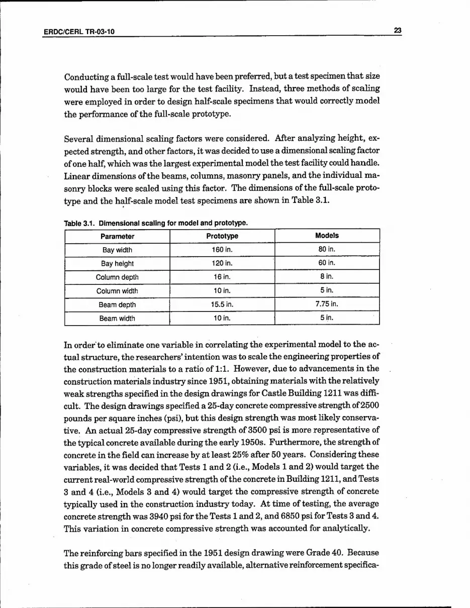
Conducting a full-scale test would have been preferred, but a test specimen that size would have been too large for the test facihty. Instead, three methods of scaling were employed in order to design half-scale specimens that would correctly model
the performance of the full-scale prototype.
Several dimensional scaling factors were considered. After analyzing height, ex- pected strength, and other factors, it was decided to use a dimensional scaling factor of one half, which was the largest experimental model the test facility could handle. Linear dimensions of the beams, columns, masonry panels, and the individual ma- sonry blocks were scaled using this factor. The dimensions of the full-scale proto- type and the half-scale model test specimens are shown in Table 3.1.
Table 3.1. Dimensional scaling for model and prototype.
Parameter Prototype Models
Bay width 160 in. 80 in.
Bay height 120 in. 60 in.
Column depth 16 in. Sin.
Column width 10 in. 5 in.
Beam depth 15.5 in. 7.75 in.
Beam width 10 in. 5 in.
In order to eliminate one variable in correlating the experimental model to the ac- tual structure, the researchers' intention was to scale the engineering properties of the construction materials to a ratio of 1:1. However, due to advancements in the construction materials industry since 1951, obtaining materials with the relatively weak strengths specified in the design drawings for Castle Building 1211 was diffi- cult. The design drawings specified a 25-day concrete compressive strength of 2500 potmds per square inches (psi), but this design strength was most hkely conserva- tive. An actual 25-day compressive strength of 3500 psi is more representative of the typical concrete available dviring the early 1950s. Fiirthermore, the strength of concrete in the field can increase by at least 25% after 50 years. Considering these variables, it was decided that Tests 1 and 2 (i.e., Models 1 and 2) would target the current real-world compressive strength of the concrete in Building 1211, and Tests 3 and 4 (i.e., Models 3 and 4) would target the compressive strength of concrete typically used in the construction industry today. At time of testing, the average concrete strength was 3940 psi for the Tests 1 and 2, and 6850 psi for Tests 3 and 4. This variation in concrete compressive strength was accoxmted for analytically.
The reinforcing bars specified in the 1951 design drawing were Grade 40. Because this grade of steel is no longer readily available, alternative reinforcement specifica-

24 ERDC/CERLTR-03-10
tions were developed. Longitudinal reinforcement for the columns consisted of four #3 bars with a yield strength of 62 ksi. Bottom reinforcement in the beams of Mod- els 1 and 2 consisted of #D2 4 mm wire with a yield strength of 47 ksi, which ap- proximates the property of Grade 40 rebar. This strength value was achieved by annealing the cold-drawn wire at 1200 -F for about 60 minutes. The top steel of the beams for Models 1 and 2 was similar to the bottom reinforcement. The longitudi- nal reinforcement for the beams of Models 3 and 4 consisted of #2 bars. The stir- rups employed in the beams and coltuims of both models were manufactured from 6- gage wire. Due to the narrow selection of stirrups of this size, wire with a yield strength of 58 kilopotmds (or kips) per square inches (ksi) was used. Even though this value is significantly higher than the specified Grade 40 rebar, the elastic be- havior of the members tmder shear was not extensively altered because shear resis- tance was dominated by the concrete shear strength. The reinforcement used for the full-scale structure and both of the half-scale models is presented in Table 3.2.
Table 3.2. Reinforcement for model and prototype.
Parameter Prototype Model
Center of Members End of Members
Column longitudinal 4-#6 4-#3 4-#3
reinforcement 40 ksi 62 ksi 62 ksi
Column ties #2at10ln. O.C. 6 gage wire at Sin. 6 gage wire at 5ln.
40 ksi O.C. O.C.
Beam longitudinal 2-#6 top, 40 ksi Model 1 & 2 Exterior Joint
reinforcement 2-#6 bottom, 40 ksi 2-#D2 top, 47 ksi Model 1 & 2 2-#D2 bottom, 47 ksi 2-#3 top, 62 ksi
Model 3 & 4 2-#D2 bottom, 47 ksi
2-#2 top, 60 ksi Model 3 & 4 2-#2 bottom, 60 ksi 2-#3 top, 62 ksi
2-#2 bottom, 60 ksi Interior Joint Model 1 & 2 3-#3 top, 62 ksi 2-#D2 bottom, 47 ksi Model 3&4
Beam ties #3 at 12 in. O.C. 6 gage at 6 in. 6 gage at 6 in.
40 ksi 58 ksi 58 ksi
Note that the reinforcement described above does not represent half scale in terms of its dimensions. Furthermore, the cross-sectional area and the grade of steel also vary from the amovmt used in Building 1211. This is because the half-scale model was designed to behave similarly to the full-scale structtu-e regardless of the dimen- sions and grade of the reinforcement steel.

ERDC/CERLTR-03-10 25
Like the dimensions and material properties, the behavior and failure modes of a scale model also must accurately represent the structure being modeled. In this case, linearly elastic finite element models representing both full- and half-scale, three-story, three-bay concrete frames were created. For the first floor, the moment demand-to-capacity ratios (Qa) for joints, arising from the combination of full dead, Hve, and seismic loads, were compared. Similarly, the service-to-seismic-moment ratios (Qb) for these joints were also evaluated. For the purposes of this discussion, service load represents the combined effects of the full dead and live loads. The use of the Qa and Qb ratios represent one method to quantify the behavior of a particu-
lar structural system.
The mathematical models were created in order to determine the demands on the first floor joints due to dead, live, and seismic loadings. The dead weight consisted of the dead weight of the fi*ame plois the superimposed dead weight ft-om the tribu- tary area of the out-of-plane slab. This tributary area was based on design draw- ings of Castle Building 1211. The live load imposed on both the full- and half-scale models was 20 pounds per square foot (psf), placed over the entire tributary area. Because earthquake loads were not assinned in the original design, the seismic loading was based on the 2000 edition of the International Building Code (IBC). A response modification of 3 (IBC Table 1617.6) was used in calculating these forces. The resulting seismic loads for each model are summarized in Table 3.3.
Table 3.3. Equivalent seismic load per floor.
Full-scale Model Half-Scale Models
Floor Load (K)) Floor Load (K)
3 28.87 3 4.57
2 19.87 2 3.13
1 9.94 1 1.56
These seismic loads represent eqmvalent static loads, following IBC 2000, and were placed at the midspan of the middle-bay beams of each floor. This placement of the seismic loads to the finite element models corresponded to the location of loading during the actual experiment.
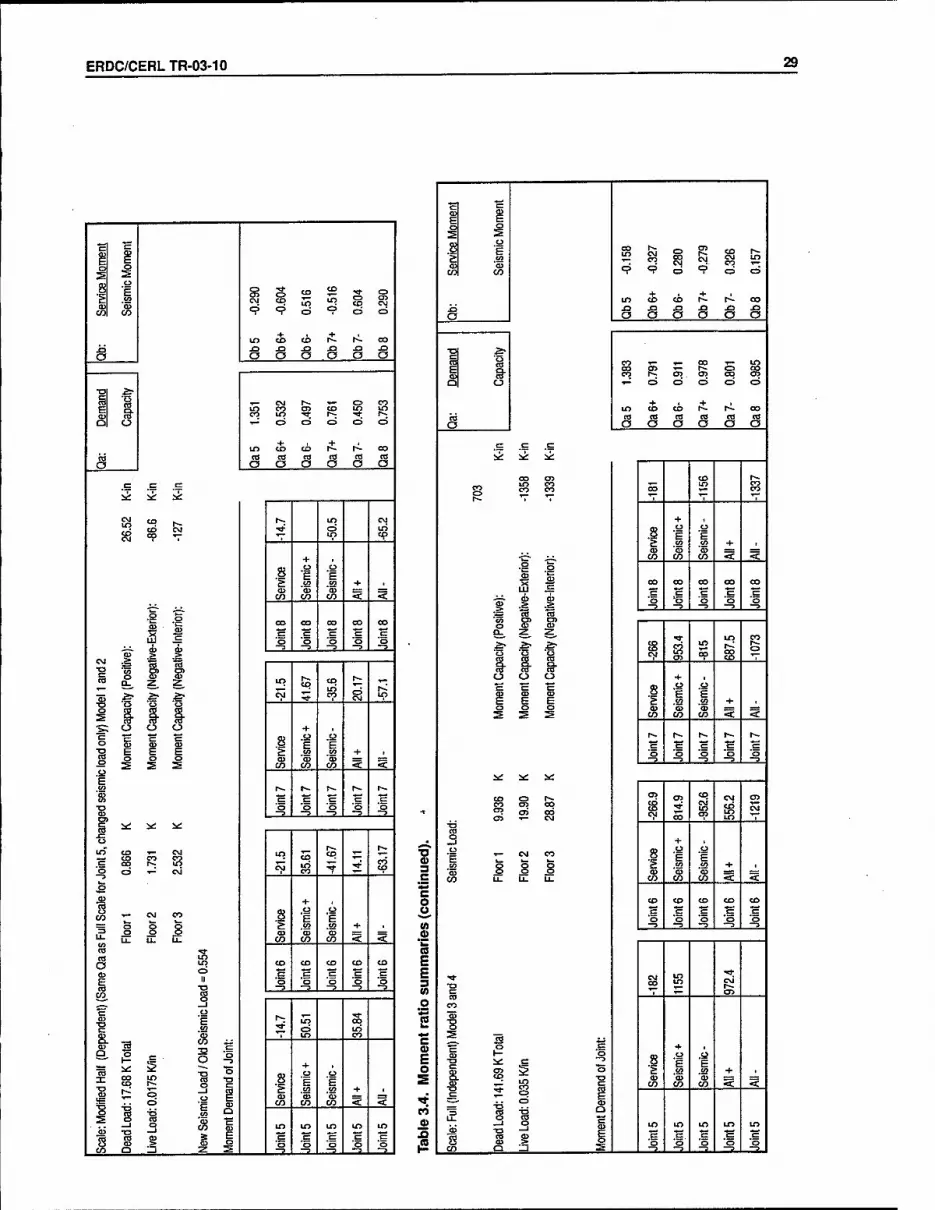
A summary of residts from these finite element analyses is presented in Table 3.4 for Models 1, 2, 3, and 4. The first analysis gave the ratios of Qa and Qb, as de- scribed earHer, for the full-scale model. Subsequent runs on the half-scale models will be compared to the full-scale analysis. The first half-scale analysis consisted of an area of reinforcement, which equaled exactly one-fourth of the area of steel in the full-scale model. This model is referred to subsequently as the true half-scale model, and was used as a benchmark. If analyses using the proposed reinforce- ment, as described earlier, gave ratios similar to both the true half-scale model and

26 ERDC/CERLTR-03-10
the full-scale model, then the suggested reinforcement design would be adopted. Half-scale computer models using the proposed reinforcement scheme are subse- quently referred to as the modified half-scale models. Consequently, three other analyses were performed for Models 1 and 2 using the modified half-scale models. The first of these final three computer simulations analyzed the model without any modification of forces. The second analysis modified the hve and seismic loading in order to achieve the same Qa and Qb values for joint 5 as for the full-scale model. The third analysis only modified the seismic loading in order to achieve the same Qa value for joint 5 as for the full-scale model. Joint 5 was used as a reference point because the Qa ratio, moment demand over capacity, in the fxill-scale model for this joint was the largest and therefore controlled the design. Figure 3.5 shows the loca- tion of joint 5. Referring to Table 3.4, the second analysis of the modified half-scale model with the proposed reinforcement gave similar Qa and Qb ratios as both the full-scale model and the true half-scale model. Therefore, the proposed reinforcing scheme was implemented for Model 1 and 2. Similar analyses were performed for Models 3 and 4 to account for the slight difference in the reinforcement and concrete strength.
ll3 f 114 ^ ^ r ll5 I Il6 1 1
-r„:.r:.rr,rr-:r:}::J rr::;::::::[:l:r:.j:±r±: ;~|:rrrc;:i:-.; t.r'r
12 s^.m,s 3i:SEs| ±DE2:S:EH: r
E}E:nEr:x:::i:f-::: 1 !
'■■■ :■-■■,- :••■'■
8
„,.,..,,.„j,.,...^„.^.. .....-,...-,...■....
ms.m .1 .......1 :. : :...„..
m.m^ 1——1 1—1
aE:H™x= ■xv„"..' i;'.!;;.,;.v.;j;:;i."rx'?.v.^ •V—:i—r:;r[.,::::T;:'
4 -, -i r-^ -■■- 1
mrnm S^^-ESE ;S=E£i±--
Figure 3.5. Joint locations.

ERDC/CERLTR-03-10 27
(0 « n E E 3 (0 _o
2 = c a> E o
CO 0)
IQ
■p "E $^
F E
S ^ s £
CO
CO
'cD
.,. CO o ^ o c=>
m o
in CD CD it hi- CO
JD XI J3 XI J3 X3 J3
o a a O o u o
a-
1 OO CO CO 00 i CO
m le s ex> Si s? "=■ O 1— 1- C3 o o
+ ir> CD CD t-i- OO
m nj as c« rt CO CO
O
n .£
O O o O u o
c= 5«: i^
CD r^
£3 15; m CO LO fe«
ir> ^7 "V ,.. "V
+
8 F O
£ CO t/> + . (U <u CD
CO CO CO < < ,o a>
52 C=
C30 CO CO CO CO
S c c c = d
o o o o o
¥ "cO ■Jo
-? -^ 1
f^ S" g" a. -^ in £?
CO in CD
E5 CD
.^ eg ?
o o O + , CD o
F i 1 ,o o
CO +
:^ > S CO CO CO < <
t-. h- h- h- h-
c .= Q o
CO
-5 -D
C35 o> CD CM CT>
CJJ CX)
oo
§3 CSJ -<}•
m cp CJ
-j + , o F '- CM CO 8 ■| •i
_cn g 8 8 .sa _L C/3 II U- u. CO CO CO < <-
CD CD CD CD CD
c c c: C Q O -= 1 j 1 . -^ L_U -5
CO
i 03
TZ c CO
T—
X 2 75 ,
l2 1 o u
i s ^ o o
(S <K < 5
if s o m ID E ^ CO 03 s 'o *o o •^ *o
CO _1 -:3- _::2. _=!_ _=!. _=1_
"c
n E c 2 ^
1 1 5 m 5 =? e=
CM
C3
CO
tn CD CD it ri 00 X} XI x> ja r-» X3
o O O U O —ii- a
*•
a- r-- c> CO en
b CM g in S So s
Ql o ■,- o c>
+
C=i o
to CO CO r-- r- OO
nt c8 m CO co co CO o
c {=
O O a O U O
cr i^
CO
id
C\J h- CM CD
58
+
1 u u
.52 y> + 1
CD CO CO CO < <
o (U s CO OO OO OO 00
S "m" ? a; —3 —3
> I 1 .._.. ._
Q_ z z ^ ??, CO f2 <N
t .f O
CSJ K2 "? S ^
o o o + , c m H 8 .o
^ E E ?> .a CO + , o
^ ^ <s CD
CO 0?
CO § 1
h* h- r- r^ r»- .= .1= c c .= o o o o o
CO C3 m ^y <y> P" to
CO :^ CM s t^ ? cp
—1 + , — CM CO .8 •p •p
CO o s o £ t/> w* + 1
a> o (D 03 03 CO LI. U- U- CO CO CO < <
CD CO CO CO CD
, ,.:.2,. -^
CM r^ CO M ''S-
OT fe CD
:>
O)
E .£2 ■s 1
^ £=
§
c:
5 1 E + , OO CD S ■p
CO CO CO < < ea -p <=? E
"S s J_. °
—1 g in to m m in E s 03 > S o o o o o O —1 _3. _=. -=!. -3. -3.

28 ERDC/CERLTR-03-10
H
i i J
E tn
S CO T— CO
CD i CD
in di 9* s> O "? o C3
m CD CD rt ri- OO X3 X3 X3 J3 .o x>
o o o o U U a
■F f CD CO CO CO CD fie CD CD fey
D o CM ■>—
+
o
+
O
ID CD CD r^ rd <T) ctf CO nJ «
o
c; c:
O O o O O o
c
CO r-- CVl g
^ <=p T-
+
1 _o ,o
.52 .S2 + • C/3 CO CO < <
■^ -S oo oo oo oo
s ^ H = c d ■E o o
1 CO
•^ -= -? -5
■fi, S' iri' a. S- z LO CO
15 ". f:.' CM 1 t 1
^ s CO S^
o o o + , cz "H c: 1 1
.S5 E +
^ •^ S CO CO CO 1 <J^
r^ r- r- r— r^ c: c:
ii: -^ -^
CTi CO 05 ^ ^ CO ..cr
cvj (5 5 ^
+ , .a E tn
CO 1
CM CO
<s .y E
+ < <
CD CO CD CD CD
."= .= o o O O O _,
-?„ -3
CJ
t^ CO CVJ
T— ^
« ', cr> r--
^
« s. +
1 s ,o .O
1 i "o m '55 '55 + =
?S ■o CO CO CO < <
E
o o CD
•p: o m in ITS in ID
CD e S
d S ^ s o o ■Q o O —1 .2.. -=3- -.2- -5
■D 0)
C o
(0 .£ n E E 3 (0 ,o
2 *^ c a> E o
■'T
CO
o Si
"c c
^ i ^ ^
1 .o
^ co E5
en s CO
+ m CD CD rt
o o
oo XI X3 .O JD X3 X2
O a a tJ O o a
£:- T- CD ^ T}* CM CJ> ID CD CD
TO CO I-: CO 03 CO in
O o -.- o
m CD
o
<6
O
+
O o
oo rd ctJ CO ns « «
o
c c:
a o o O O O
a
^
K ?M f2 CD CM
CO CTJ
Si ? 'V -r 'T
+ S •^ o
r» in CO + ( i^ ^ CO < <
•g O CO OO OO CO CO
ii c: .S .£
1 ■■w
—D -3 -3 -3
.i Q-
a' S
in CD t;; CD
.-s- # 1 cr> ^ C^ CM CO
1 CM O o o 4- «
CD F ■p B
CO + CD tD G>
1 ^ :&
^ CO CO CO <a. <
h- r-- r^ r-- 1^
.= E= o O o o o
o —3 -3
is i^ ^ i^
<P f^ en •* •r- ^ in
CO CD
!^ CM
CO C75 ^ ^ CD
CM ^
ro +
1 R
CJ CO
s _o
'5 4- .
O oB
u. •^ LI.
h-.
CO CO CO < <
CD
o "^ CD CD CD CD II o o O
^ O 1 —3
_j -3 -3
g II 1 f2 in t3- <=9
d
S 5 .■a "? ^ LO
CO
Q. ^ 1 3 o o
a: oo CD
33 O 1
3 ■p _g o
*F o F
-o s £ CO <o + t
E E s=
+ c> CO CO CO < <3^
"S t^ "O Q o c
_J 1 CO m in m LO
o n CD ?2 g s 'o 'o 'o *o o CO O _l .^^_ ^ -=2- _^2» _=. -7, 1
ERDC/CERLTR-03-10 29
c 1 J
g s CO CO ^ o .S2 CM CO u> m s ^
CO " ■? =? o V o o
lO CO c^ .t h^ oo JO J3 ^ JD .o fi
_o o o o U CJ o
■o ^
1 ■*- CM r-. ^_ o CO b CO m -^ h-
D " •.- o C3 c:> o o
lf> CD CD ■t ri CO
m as n) CO CO CO to a
c= c=
a o o <J U a
cr it
to CO
lO o in
^ <=p ■V
+
8 .^ .o
£ so .52 + I ^ CO CO CO < <
09 o
CO oo OO CO oo
o J^ <j> cu -3 -^ J -=
CM 1 1 1 LO fo CD f- _
s 1 1 ..§• •£5
04 *»* CO "?
o o O + 1
c s c s •^ O
^ g E E £ .«" CO + , S S= 21 CO CO CO < <
r- 1^ r^ t^ r- !K E= c .=
O o o o o
i<: N^ ^ -3 -y -9 -3 ->
O
oo o s CNJ
C\j in CO ¥ ■* CO
CO
■R + ,
CO
3 I CJ CO
o E E +
en Li- "- u. Tt
CO CO CO < <
o LO CO CD CD O c
o O O o
oS ? -? ^ ->
_i
T3 .i2
h- •^ LD CO to
& [£
fG
CO i^
E 1 Id X CO
CD
5 ^ CO TD
a> F
.£2
a E
r- o —< £5 CO 'CD
CO *a> _!.
o CO CO CO <■ <
—j 5 tn LO LO lO in
^ Q 5 z , s ^ ■^ ^ -^ o
■o 0)
c
E o S
n a>
|2
tr ^
F E o 5
8 1 g EM ir- CO
c O) CO r~- d •s ^ OJ CO
CO S cp c?
-t-
o
+
o o
in CO CO ^ XI S3 J3 ^ J3
o o a <J a o a
•a ^^
1 CO ■»- ,_ oo .,— i g? ?? CJ5 OJ ^ d " I- o o o o o
+ m CO CD ^ t^ oo to CO to to CO CO
o
c .5
O O u o o a
c:
^
oo
^
CD r^
55 CO §? 00 LO y^
^ • < •
+ g. CJ C3 .Q g E £ tA CO -♦- 1
CD tu 0} ^
1 1 CO CO CO <: <
00 oo 00 cx> CO LLI
1 1 1 o ■B ■Q "o o ^ -?
o S" s* a. z
1 1 1 1 lO
5p Eg fe
o O o + , c ■£ "c 1 u .a ^ E E £2 CO + , o « CD Z
^ ^ CO CO < <
T^ (-~ r~- I-- r^ c= cz o o
i«; ^ 5*:
-3 -3
«» Oi '". CM CD
CT5 en
OQ
CM ^ ^ § C\J
„y + , ,o - CM CO 8 E E
g o o CO
" u. CO CO CO <c <
CO CO CD CO CD
o o O o O ^ ,^,. „„,Z?,„ -^.. 3»
CO i m
m •** pi CD
CO
<u X ^ s
1 |2
S i i + ^ s
o i CO CO CO <c <
"S -o Q 11 iS c ii in m in LO lO
S f? s S •g .S.
. «■> Q -=2. _=2. -=2.

30 ERDC/CERLTR-03-10
"c "c
p^ i 1 ^
.u S S g CO
g s m <;« 0 c? 0 =? 0 0
m CO CO it r^ CO
.0 0 o 0 s 8 & s
■p f CD LO CO in
^ CD CD 00 m m
C\J CO to s
0 0 0 0 CD CD 0 0
+ m CD CO ^ r^ 00
rt a CS iS 0
c=
o 0 0 <-> 0 0
.£ c it ^
s <N g CO V
+
3. .a u
£ CO .!2 + .
f 0 •cr
<r> CO CO «t <^
CO 00 00 CO 00
.^-^ 9? QJ 0 0 0 0 .s -^ -3 ~3 Ta CtJ
0 «' ^' D: z
1 1 ;5 CO OJ
0 0 0 4- ■
I a> H 8 E •p
f- £ £ CO ." -4- 1
^ i
^ CO CO CO -t < r- r^ r~ t-- r-
c 0 0 0
^ ;«: ^t::
-? -= "^ 1
cr> f3 ^, F3
-0 ? CM
CO 10 cy s s? ^
s + ,
E .S2 I CM CO
1 .y
-1- . CO
"" U. Li_ CO CO CO < <
CO CD CO CO CD
tz .c: .= 0 0 0 0
■o-
1
CO r- ^ CO m
CO
"S ', en
s
i 1 1 + . ■0 ::^ "0
p C/3
E 4-
ii^ 00 LO QJ 0 03 =r
s 1 CO CO CO < < X 0
1 —J
Q
10 in LO ir> tr> 09
A 1 .i 0 S '0
"5
.s ^ "o
c 1 i 2
en '03 CO
m CO
CM
CD
CM
+
0
hi.
C3
CO
X3 J3 J3 x> JZl J3
0 O O 0 0 0 (J
^ CD CO in CO
^' to ta CM
Q 0
m CD
0
CO rt
0
CO
re re m re re iS 0
c= c
0 0 0 U 0 0
C
^ ^
1^ <N CD r^ CVl ■*t
CO «p M^ '■,
+ Q? 0 P Q E £ v> w + t
OI <D = =
■f ' 0 CO CO CO < <
GO CO CO CO CO
cr cz -J-i. ay a> w 0 ;l .a -3 -3 -3 f. 0 a. z
1 0
1 .s- in
C\j le ? CM
+
I C= c 8 •^ F E E S CO CO + )
a> (U 0) rrr-
^ > S CO CO CO < <
r^ I-- r- i-~ I*.-
E= .= 0
it:
s i2
CD CO
CO
-3 -:'
12 C\J s
S3 §? 5
?2 CO CD
s + . .a E CO
'55 CO
s CM CO
<D
.&3 E 0
+ . LI. U- a. CO CO CO < <
CD CD CD CD CD
c: = 0 0
-a- T3
-3 —? .. -3
cB CO
■s r^ 00 CM
0 CD ^ '7 CD
s. ■S s c + ,
5«: 2 0 1 U 0
'E + 5S
1 r^ 5 0 1
CO CO CO < <•
re "H , . —1 " in in in ID in
E 0 2
re 03 g *o '0 •§ *o '0
CO Q _J _:2- j -=2J ' "^ '

ERDC/CERLTR-03-10 31
T3 <U 3
_C
c o
(0 .2 'kl n E E 3 (0 o
c 0) E o
>*■
CO
F .^
i ;§ ^
1 E
CO
T- CO
0
CO tn
CO C3
00 in
C3
m CD CD it li 00
n J2 .0 XI i3 ^ X3
O o 0 0 0 0 0
£?
re o> 1^ ,,_ CD cn m 05 in CO CD CJ> m
Q " 0 c=> 0 0 0 0
in CD CD ft r^ 00 CO cd cct CO to rtJ to
a c c
0 0 a 0 0 0
.= ^ ^ ^
^ r^ Si f2 CD
CNJ en CO 00 'P T
+ S .a
F U
r- en e/> + t
co CO CO <• <■
•s 0 00 00 00 00 CO
0 0 0 -3- s ? -?
H ■TS
n° ^' ^' s m 0 r?; «?
^ ■t •t CT> CO ^ ^' ■?
% ^ '^ ■^ 0 0 0 + ,
CO
"c ffi
C= 8 0 *F ■p
^ h E >• V3 .<" + , 0 0 <D 0? 0)
a> s i ^
CO CO CO «. <
h- 1^ r~- r^ r^ in
0
is i<: ii Sit:
-3 -3
■i 1 =3
U- 0
g «?
0 10
tn
i CO en
5
CO tn -f- 1
CD
a 8
CM CO E CO
■(D + _;_
"" *" "■
ED
CO CO CO < <
o ra- CO CD CD CD CD 0
s? cr 0 0 0 0
52 5 T3 -3 -3 -i -5
■£ ri u F2
r^ ■*
c
s ^
1 E
.52
0 -?
CO GO
S3
TO n: 00 CO
0 T3 0
•5^ p
8 0
"F
+■ 1 is CO i :^ ±i 3 is 1 in in in m in
S E P! cr c 0
_£il 0 -' '^ Z S _=. -=2. .-a. -::^ _3.
'c _
i g ^ 8
<s E CO
'03 CO
t=3 •«3-
t=> CI>
to en 0
CD
in
+
s 0
0
in CD CD t^ t» ^ JD J3 J:I J:3 x>
a 0 0 <J 0 0 0
1 re ^
Tt 1^ CD r- b 5> CO s^ in 5 IS: 0 0 0 0 0 0 0 0
in CD CD +
ri 00 ta CO CO re to to
0
c: =
0 0 0 0 <J 0
c i*;
00
i^
^ =M r^ r?i -^ C=> m
CO °? in <9
+
1 u ,0
tn tii + 1 tu
CO CO CO < <
1 0 CO CO 00 tn 00
c .c: c .=: 0 0 0
"oT ?j » -> -3 -= ^ •^ "Si to
g 0 a. z: z: in h- CD r- ^ CO
■t ■t CJ cvi 5 a h-
"?
g 0 0 0 + , "E "c c 8 .« .a
0 F T> E E E g .52 u> + ,
03 tD CD
^ > ^ CO CO CO < <
r~ h~ r-. r^ r*. S? = c
c:
0 Q 0 0 0
^ ^ V -3 -3 -3
nl t3 in fs CM ■n CD » r-
h*
c= '0 0 CM CVJ S3 Y "ta- ^
,,aj + , c^ - CM CO 8 u .^
s g 0 !- u. LU LL-
S CO CO CO < <
^ m CO CD CD CD CD 0 c:
^ ^ ■^ -3 -3
r--
1 1 SI in
t»
1 C= s i 00 CD g E 8 0
*F -^
.93 h- <=> ° « £ w CO + 1
■- § tD 0 (U r-: =:=
"^ 0 ■0
CO CO CO < < q "S c
CD ±i in in in tn in
S s a '0 '0 '0 '0 0 "> 0 —1 -=3. _2- ...JS*.. -:3- -2.
32 ERDC/CERL TR-03-10
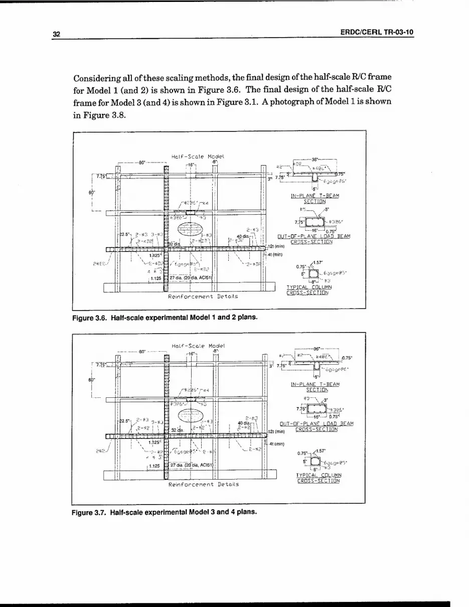
Considering all of these scaling methods, the final design of the half-scale R/C frame for Model 1 (and 2) is shown in Figure 3.6. The final design of the half-scale R/C frame for Model 3 (and 4) is shown in Figure 3.1. A photograph of Model 1 is shown
in Figure 3.8.
I B0-—
E Half-Scale Model
r-16"-!
■!2.6"i P-if3 3-tJ
^ i;i25''
r^m-r^^
i>2%t'-' I ~'S;j
3132 dia irrrrTrrnrr?
1.125 IlSTdia. (20!dla, ACI51i
T^^rn
40 dia.." \
tfjj.'
3' ^^11
—36"
zz=m^^^- IN-PLANE T-BEAM
SECTION
t!5—^ /-S"
7.t5-
■'6- J 0.75-1 nUT-DF-PLANE LOAD BEAM
CRDSS-SECTIDN ,12t(min)
!i(-4t (min)
AS,T
n-''3-9"^^'
Reinforcement Details
TYPICAL COLUMN CROSS-SECTIDN
Figure 3.6. Half-scale experimental Model 1 and 2 plans.
fT^tlC
Half-Scale Model r16"n
40 dia.-i \ ,E-»2i i ;
IZZlJ^I^^e.,-
IN-PLANE T-BCAM SECTION
\ <-3"
7.751
1 16" ^' 0.75"'
OUT-OE-PLANE LOAD BEAM
,121 (min) CROSS-SECTION
■41 (min)
0.75"-T<^
Reinforcenent Detoils
r--6aiQe35-
TYPICAL COLUMN CROSS-SECTION
Figure 3.7. Half-scale experimental Model 3 and 4 plans.

ERDC/CERLTR-03-10 33
Figure 3.8. Completed half-scale experimental model.
3.3 Test Setup
The three-bay, three-story models were constructed on a stiff reinforced concrete base beam that was bolted to the strong floor of the ERDC/CERL high-bay labora- tory. The reinforced concrete frame Was cast in a series of three Hffcs, one Hft per floor. After the concrete frames were allowed to cure, the masonry infill was laid in place. The concrete masonry units (CMUs) of Model 1 (and 2) were laid in place with a full mortar bed and were vmgrouted. The CMUs for Model 3 (and 4) were fully grouted. Actuators were installed at each floor of the models. The first two floors had 25-kip actuators and the third floor had a 50-kip actuator. Each of the actuators was bolted to two actuator beams. These actuator beams were through- bolted to a thickened section of the floor beams at each side and in the center of the model. An illustration of the model loading assembly is presented in Figure 3.9, Slippage was minimized between the connected elements of the actuator assembly. A reinforced concrete strong wall supported each of the actuators, and the models were braced to prevent any out-of-plane movement.

34 ERDC/CERLTR-03-10
-3
. r "• STRONG WALL',
" o -3 "
.3 d* ■ < ^
^ " :
■ .■' , ^ % <-l- ^ " c:o Kip -1 "11 t ■-: .
II W//////////////////////////////////////////////^^ 1 * ACTUATOR BEAM
-
Figure 3.9. Actuator beam assembly.
3.4 Instrumentation and Data Acquisition
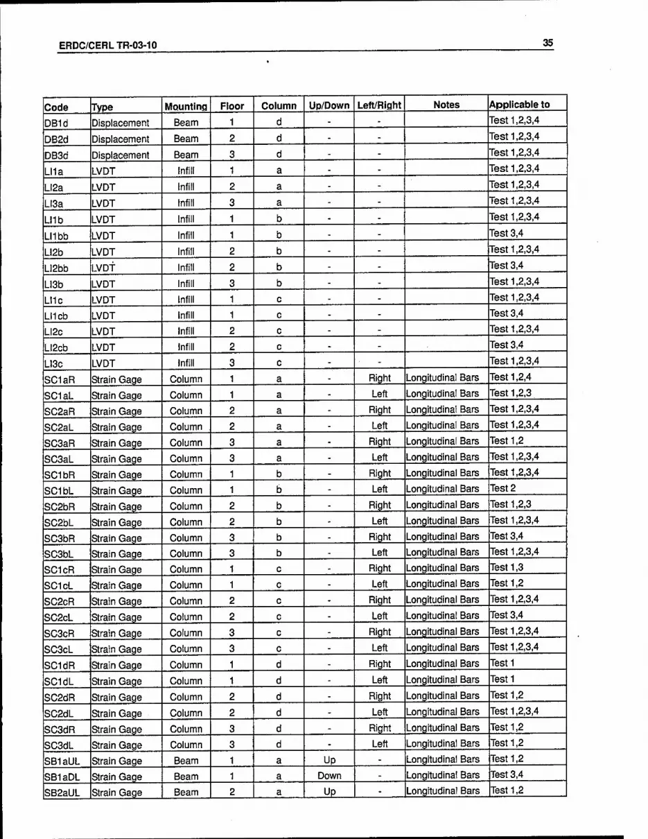
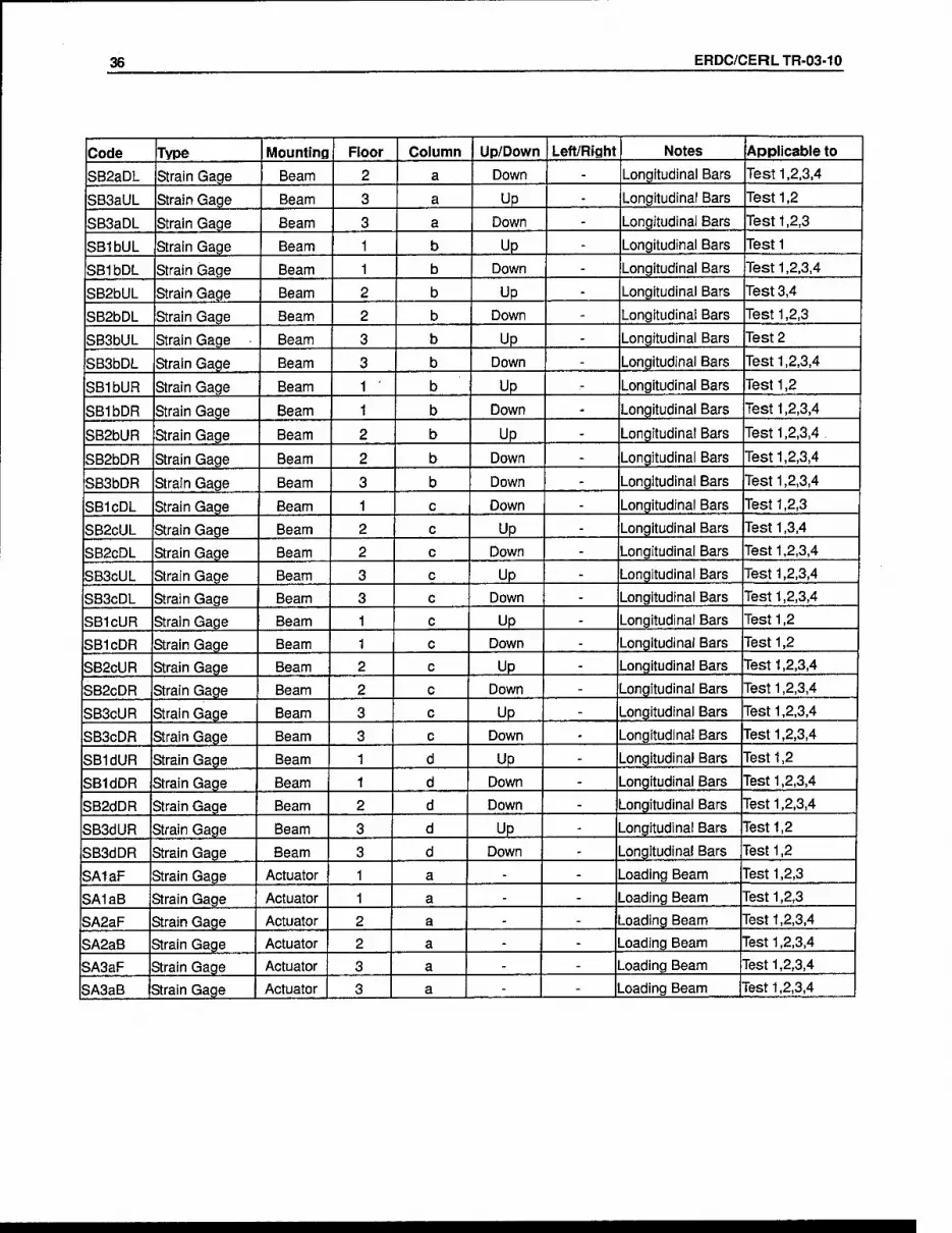
Three t3rpes of instruments were employed dtiring the tests to measure the response of the experimental model: electrical resistance strain gages, linear variable dis- placement transducers (LVDTs), and Unear resistive displacement transducers (LRDTs). Six LRDTs were used to measure the displacement at the middle and end of the test specimen for each floor. Two LRDTs were employed to measure any va\- foreseen displacement in the base beam or the strong wall. Nine LVDTs were used to meastu-e the diagonal shortening and lengthening of each masonry panel experi- enced dming testing. Six strain gages were attached to each load beam in order to measure the strains induced during the experiment. Twenty-four strain gages were attached to the reinforcing bar in the coltimns and thirty-six strain gages were at- tached to the steel in the beams in order to detect the strain distributions in the frame elements dvuing the test. The applied load and displacement of the three hy- draulic actuators were also measured. Table 3.5 shows the instrumentation plan. Figure 3.10 and Figure 3.11 illustrate the location of the instrumentation on the test specimens.
Table 3.5. Instrumentation plan.
Code Type Mounting Floor Column Up/Down Left/Right Notes Applicable to
PB1 Load Beam 1 a - - Test 1,2,3,4
PB2 Load Beam 2 a - - Test 1,2,3,4
PBS Load Beam S a - - Test 1,2,3,4
STB1 Stroke Beam 1 a - - Test 1,2,3,4
STB2 Stroke Beam 2 a - - Test 1,2,3,4
STBS Stroke Beam 3 a - - Test 1,2,3,4
DB1a Displacement Beam 1 - - - On Beam btw b,c Test 1,2,3,4
DB2a Displacement Beam 2 - - On Beam btw b,c Test 1,2,3,4
DBSa Displacement Beam 3 - - On Beam btw b,c Test 1,2,3,4
ERDC/CERLTR-03-10 35
Code Type MQunting Floor Column Up/Down Left/Right Notes Applicable to
DB1d Displacement Beam 1 d - - Test 1,2,3,4
DB2d Displacement Beam 2 d - Test 1,2,3,4
DB3d Displacement Beam 3 d - Test 1,2,3,4
LI1a LVDT infill 1 a - Test 1,2,3,4
LI2a LVDT Infill 2 a - Test 1,2,3,4
LI3a LVDT Infill 3 a - Test 1,2,3,4
LMb LVDT infill 1 b - Test 1,2,3,4
LMbb LVDT infill 1 b - Test 3,4
LI2b LVDT Infill 2 b - Test 1,2,3,4
LI2bb LVDT infill 2 b - Test 3,4
LI3b LVDT Infill 3 b - Test 1,2,3,4
LI1c LVDT Infill 1 c - Test 1,2,3,4
LUcb LVDT Infill 1 c - Test 3,4
Li2c LVDT Infill 2 c - Test 1,2,3,4
LI2cb LVDT Infill 2 c - Test 3,4
LI3c LVDT Infill 3 c - Test 1,2,3,4
SC1aR Strain Gage Column 1 a Right Longitudinal Bars Test 1,2,4
SC1aL Strain Gage Column 1 a Left Longitudinal Bars Test 1,2,3
SC2aR Strain Gage Column 2 a Right Longitudinal Bars Test 1,2,3,4
SC2aL Strain Gage Column 2 a Left Longitudinal Bars Test 1,2,3,4
SC3aR Strain Gage Column 3 a Right Longitudinal Bars Test 1,2
SC3aL Strain Gage Column 3 a Left Longitudinal Bars Test 1,2,3,4
SC1bR Strain Gage Column 1 b Right Longitudinal Bars Test 1,2,3,4
SC1bL Strain Gage Column 1 b Left Longitudinal Bars Test 2
SC2bR Strain Gage Column 2 b Right Longitudinal Bars Test 1,2,3
SC2bL Strain Gage Column 2 b Left Longitudinal Bars Test 1,2,3,4
SC3bR Strain Gage Column 3 b Right Longitudinal Bars Test 3,4
SC3bL Strain Gage Column 3 b Left Longitudinal Bars Test 1,2,3,4
SC1cR Strain Gage Column 1 c Right Longitudinal Bars Test 1,3
SC1cL Strain Gage Column 1 c Left Longitudinal Bars Test 1,2
SC2cR Strain Gage Column 2 c Right Longitudinal Bars Test 1,2,3,4
SC2cL Strain Gage Column 2 c Left Longitudinal Bars Test 3,4
SC3cR Strain Gage Column 3 c Right Longitudinal Bars Test 1,2,3,4
SC3cL Strain Gage Column 3 c Left Longitudinal Bars Test 1,2,3,4
SC1dR Strain Gage Column 1 d Right Longitudinal Bars Testi
SC1dL Strain Gage Column 1 d Left Longitudinal Bars Testi
SC2dR Strain Gage Column 2 d Right Longitudinal Bars Test 1,2
SC2dL Strain Gage Column 2 d Left Longitudinal Bars Test 1,2,3,4
SC3dR Strain Gage Column 3 d - Right Longitudinal Bars Test 1,2
SC3dL Strain Gage Column 3 d - Left Longitudinal Bars Test 1,2
SBIaUL Strain Gage Beam 1 a Up - Longitudinal Bars Test 1,2
SBIaDL Strain Gage Beam 1 a Down - Longitudinal Bars Test 3,4
SB2aUL Strain Gage Beam 2 a Up - Longitudinal Bars Test 1,2
36 ERDC/CERLTR-03-10
Code Type Mounting Floor Column Up/Down Left/Right Notes Applicable to
SB2aDL Strain Gage Beam 2 a Down - Longitudinal Bars Test 1,2,3,4
SB3aUL Strain Gage Beam 3 a Up - Longitudinal Bars Test 1,2
SBSaDL Strain Gage Beam 3 a Down - Longitudinal Bars Test 1,2,3
SBIbUL Strain Gage Beam 1 b Up - Longitudinal Bars Test1
SBIbDL Strain Gage Beam 1 b Down - Longitudinal Bars Test 1.2,3,4
SB2bUL Strain Gage Beam 2 b Up - Longitudinal Bars Test 3,4
SB2bDL Strain Gage Beam 2 b Down - Longitudinal Bars Test 1,2,3
SB3bUL Strain Gage ■ Beam 3 b Up - Longitudinal Bars Test 2
SBSbDL Strain Gage Beam 3 b Down - Longitudinal Bars Test 1,2,3,4
SBIbUR Strain Gage Beam 1 • b Up ,- Longitudinal Bars Test 1,2
SBIbDR Strain Gage Beam 1 b Down - Longitudinal Bars Test 1,2,3,4
SB2bUR Strain Gage Beam 2 b Up - Longitudinal Bars Test 1,2,3,4,
SB2bDR Strain Gage Beam 2 b Down - Longitudinal Bars Test 1,2,3,4
SB3bDR Strain Gage Beam 3 b Down - Longitudinal Bars Test 1,2,3,4
SBIcDL Strain Gage Beam 1 c Down - Longitudinal Bars Test 1,2,3
SB2cUL Strain Gage Beam 2 c Up - Longitudinal Bars Test 1,3,4
SB2cDL Strain Gage Beam 2 c Down - Longitudinal Bars Test 1,2,3,4
SBScUL Strain Gage Beam 3 c Up - Longitudinal Bars Test 1,2,3,4
SBScDL Strain Gage Beam 3 c Down - Longitudinal Bars Test 1,2,3,4
SBIcUR Strain Gage Beam 1 c Up - Longitudinal Bars Test 1,2
SBIcDR Strain Gage Beam 1 c Down - Longitudinal Bars Test 1,2
SB2cUR Strain Gage Beam 2 c Up - Longitudinal Bars Test 1,2,3,4
SB2cDR Strain Gage Beam 2 c Down - Longitudinal Bars Test 1,2,3,4
SBScUR Strain Gage Beam 3 c Up - Longitudinal Bars Test 1,2,3,4
SBScDR Strain Gage Beam 3 c Down - Longitudinal Bars Test 1,2,3,4
SBIdUR Strain Gage Beam 1 d Up - Longitudinal Bars Test 1,2
SBIdDR Strain Gage Beam 1 d Down - Longitudinal Bars Test 1,2,3,4
SB2dDR Strain Gage Beam 2 d Down - Longitudinal Bars Test 1,2,3,4
SBSdUR Strain Gage Beam 3 d Up - Longitudinal Bars Test 1,2
SBSdDR Strain Gage Beam 3 d Down - Longitudinal Bars Test 1,2
SAIaF Strain Gage Actuator 1 a - - Loading Beam Test 1,2,3
SAlaB Strain Gage Actuator 1 a - - Loading Beam Test 1,2,3
SA2aF Strain Gage Actuator 2 a - - Loading Beam Test 1,2,3,4
SA2aB Strain Gage Actuator 2 a - - Loading Beam Test 1,2,3,4
SA3aF Strain Gage Actuator 3 a - - Loading Beam Test 1,2,3,4
SA3aB Strain Gage Actuator 3 a - - Loading Beam Test 1,2,3,4

ERDC/CERLTR-03-10 37
"xx"
0
\
(6) Load and Stroke
(6) Displacement (60) Strain gage (9) LVDT (6) Strain gage on loading beams
-■Beam3=
Col.d
sb3dur
Cole Col.b Cola
I:
iBeanT?.J3g"
=Beam.-3=^[
I i
X"
-r-| 1
\
\j
\
jr\ _. I I
=i2_
K _ „ _ V I
is. t. , t T
r
1
:i I
-^^
xr
Figure 3.10. Instrumentation location diagram for Test 1 and 2.
Col.d
"xx"
0
\
(6) Load and Stroke
(6) Displacement (60) Strain gage (13) LVDT (6) Strain gage on loading beams
Col. c Col.b
:;:Beam^3;-W^
scBdl
::::Beai«r2-pST -
sc2dli
-Bearol "IW
scldl
-^ddr-^-^biScdll sbScdr sbSbdll sfjSbdr-;--sb3adl
isc3dn_-X*._sca!cii i sc-lcL _L_.-im3bl i i
^ddr -•:
sb3dur sbSculMsbScur
sb2cnl
sc2dr^ f^ gb-hdtir
sb2cdl
s; Sbjddr ; sblcdl -v-^^
-r'fer ■ \ I -1 f X -
iscldr I 1 -scTfcli
^/ ■m sb2cur
S^cdr:r-:sb2bdi
''^?^.>^ sc2bTi
kbtSffl 'sfr'1%61
-T-g) |-
r-L
Mcdr • sblbdl
scicV. --\^. '/6~
sb2^drrrrsb2adir
Col. a
sb3aul
^« ̂__sc3ali
sb2bur -. sb"2a'BJ
Pb3
sc3ar
s'c2br
iblBui
% sc2al| I
ibKull
Mxlbdn
izziz:
isblbr- -srfali
Pb2
sc2ar
Pbl
isclar
Figure 3.11. Instrumentation location diagram for Test 3 and 4.

38 ERDC/CERLTR-03-10
Figure 3.12 is a functional block diagram of the instrumentation, data acquisition, and test control systems. All of the transducer output signals were connected to Pa- cific Instruments Model 6000 DAS ADC Controller.* The system was controlled by a desktop computer through an instrument controller interface bus. The record channels were scanned at a predetermined sampling rate, and the data were re- corded as text files on the desktop computer.
The loading system consisted of three CGS/Lawerencet Model 307-25 electro- hydraxilic actuators controlled by closed-loop servo controllers and a function gen- erator. The top actuator was operated in a displacement control mode. The first- and second-floor actuators were operated in a load control mode. The actuators also include load transducers that measure the appHed load.
CGS/Lll«erenc<? 307-50 8, 307-S5 Hydraulic Actuotors
Concrp-te Frane with Masonry InFiLl
T y
i__i_i
LVDTs Schoevit? 200HR
SRC KBEOD
Stroln Gages Meosutenents Group Ii
CE;/1-06-!35UN-350
Absolute Dispiocenent Celesco rotary pctentioneters
PTIOI-IO and PTI01-20A
RDP nodel 600 AC Conditioner
^QCific nodel 6033 Trandsucer Interface and ADC Cord
PoclP[C nodel 6033 Trandsucer "interface and ADC :Qrd
Pocific Instruments Model 6000 DAS ADC Controler
Dota Acquistion Conputer
Test Control Conputer
Figure 3.12. Functional blocl< diagram of instrumentation, data acquisition, and test control systems.
Pacific Instruments, Inc., Concord, CA 94520.
t The CGS/Lawrence brand is owned by Instron Schenck Testing Systems Corp., Soutlifield, Ml 48075.
ERDC/CERLTR-03-10 39
3.5 Material Properties
Comprehensive material testing was undertaken in order to find the engineering properties of the various construction materials used for the experimental models. Material tests conforming to ASTM* standards were performed on the concrete, re- inforcement bar, CMUs, and mortar. These tests were conducted shortly after com- pleting each of the full-scale tests on the experimental models.
Concrete tests were performed for each batch of concrete poured (i.e., batches for aU three floors of each test specimen). All of the cylinders and beams were made ac- cording to ASTM specifications, cured with moistened burlap, and covered with
plastic.
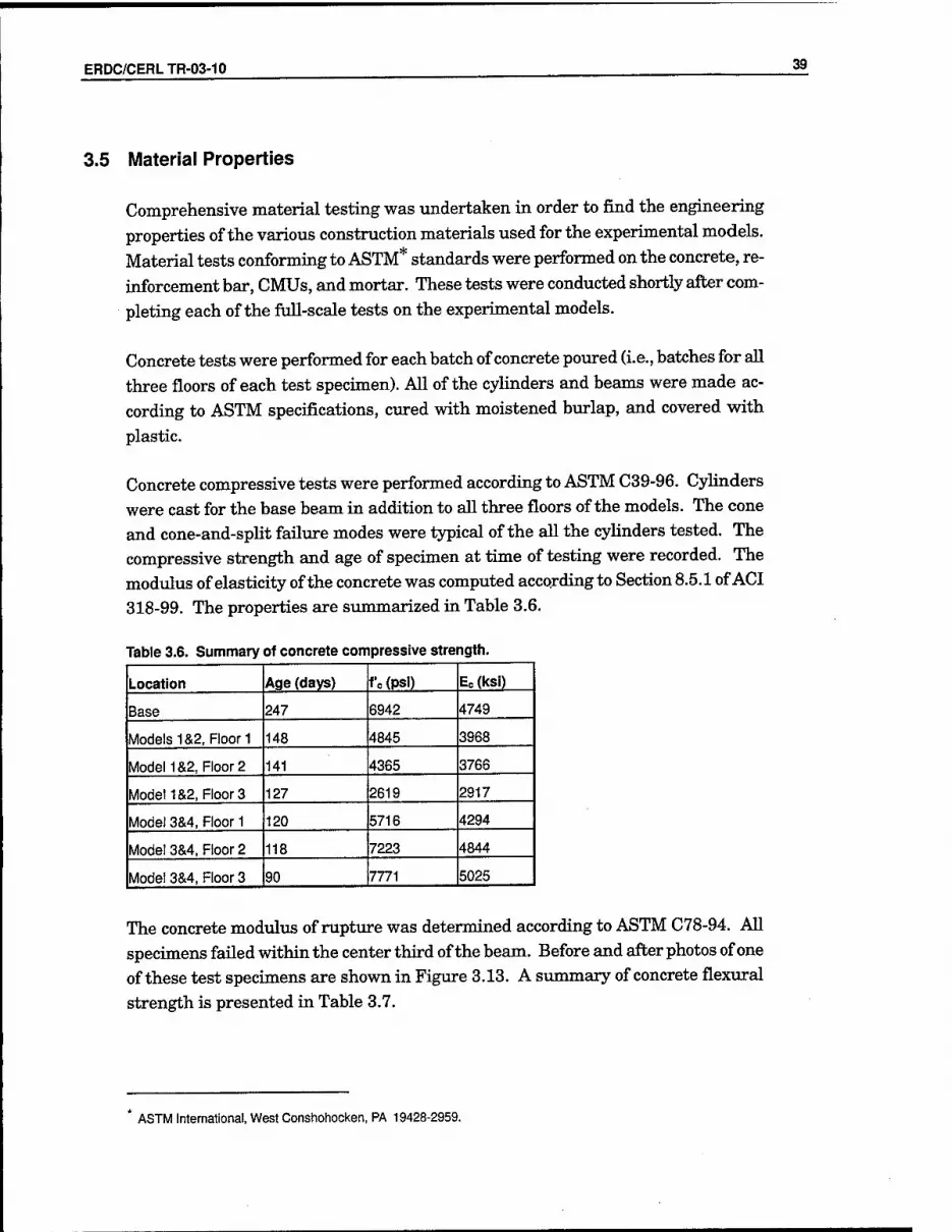
Concrete compressive tests were performed according to ASTM C39-96. Cylinders were cast for the base beam in addition to all three floors of the models. The cone and cone-and-spUt failxire modes were typical of the all the cyHnders tested. The compressive strength and age of specimen at time of testing were recorded. The modulus of elasticity of the concrete was computed according to Section 8.5.1 of ACI 318-99. The properties are summarized in Table 3.6.
Table 3.6. Summary of concrete compressive strength.
Location Age (days) fc(psi) Eo(ksi)
Base 247 6942 4749
Models 1&2,Floor1 148 4845 3968
Model 1&2, Floor 2 141 4365 3766
Model 1&2, Floors 127 2619 2917
Model 3&4, Floor 1 120 5716 4294
Mode! 3&4, Floor 2 118 7223 4844
Mode! 3&4, Floor 3 90 7771 5025
The concrete modulus of rupture was determined according to ASTM C78-94. All specimens failed within the center third of the beam. Before and after photos of one of these test specimens are shown in Figure 3.13. A summary of concrete flexural
strength is presented in Table 3.7.
* ASTM International, West Conshohocken, PA 19428-2959.

40 ERDC/CERLTR-03-10
Table 3.7. Summary of concrete flexural strength (modulus of rupture).
Location Age (days) fr(psr)
Mode!1&2, Floor 1 154 910
Model1&2, Floor2 147 903
Model1&2, Floors 133 716
Model 3&4, Floor 1 122 1708
Model 3&4, Floor 2 109 1997
Model 3&4, Floor 3 81 2131
Figure 3.13. Concrete flexural specimen for 4-point bending test (a) before test and (b) after test.
A split cylinder test following ASTM C496-96 was also performed for the concrete ia the third floor of Model 1. The concrete was 138 days old at time of testing and had a tensile strength of 316 psi.

ERDC/CERLTR-03-10 41
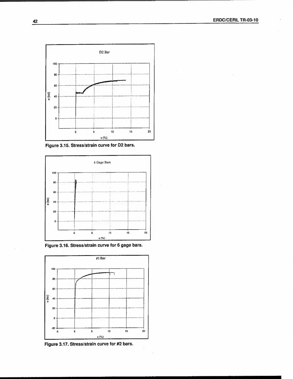
Steel reinforcement was tested according to ASTM A615/A615M-96a and ASTM E8- 98. Fovir different sizes of reinforcing steel were used in the experimental model: D2, #2, #3, and 6 gage. The D2, #2, and #3 bars were used for longitudinal reinforc- ing while the 6 gage bars were utihzed for stirrups. All bar sizes were tested for yield strength, ultimate strength, and modxilus of elasticity. These properties, along with the nominal area for each bar size, are summarized in Table 3.8. For the 6 gage reinforcing bar, the yield stress was found from a 0.02% offset since a well- defined yield point was not present; these values were taken in the stress range of 20 - 40 ksi. For the remaining reinforcing bars, the values for yield stress and modulus of elasticity were found using conventional techniques. The stress/strain curves for the #3, D2, 6 gage reinforcing bar, and #2 are given in Figures 3.14, 3,15,
3.16, and 3.17, respectively.
Table 3.8. Engineering properties of reinforcing steel.
Bar Nominal Area (sq in.) ay (l<si) au (ksi) Es (ksi)
D2 0.02 47 68 47200
#2 0.05 84 91 28680
#3 0.11 62 93 27650
6 gage 0.028 58 84 26800
Figure 3.14. Stress/strain curve for #3 bars.
42 ERDC/CERLTR-03-10
D2Bar
eo-
60-
'w £. 40- e
20-
0-
0
^'
c 6 10 15 2
Figure 3.15. Stress/strain curve for 02 bars.
6 Gage Bare
0
60 -
1 40. 0
0-
0 6 10 15 2
Figure 3.16. Stress/strain curve for 6 gage bars.
Figure 3.17. Stress/strain curve for #2 bars.

ERDC/CERLTR-03-10 43
Masonry tests were performed on a representative sample of the CMU as well as the mortar used in each floor of the experimental models.
The compressive strength tests of the mortar were executed following ASTM C109/C109M-99. The cone failure mode was typical of all cubes tested; a pictiire of this failure mode is shown in Figure 3.18. Compressive strength and age at testing
of the mortar are siuimiarized in Table 3.9.
Table 3.9. Summary of mortar compressive strength.
Location Age (days) Compressive Strengtii (psi)
Model 1&2 Ficon 119 478
Model 1&2 Floor 2 117 682
Model 1&2 Floor 3 113 548
Model 3&4 Floor 1 90 550
Model 3&4 Floor 2 88 697
Model 3&4 Floor 3 86 793
The compressive strength tests of the CMU were performed in accordance with ASTM C140-99b; a picture of the test setup is shown in Figiu-e 3.19. The average weight of the CMU used for Model 1( and 2) was 2.88 lb. The average weight of the CMU used for Model 3 (and 4) was 3.72 lb. This increase in density resulted in higher compressive strength for the CMU used in Model 3 (and 4). Compressive strength was calculated using the average net area of the block (15.13 sq in.); this value was foimd to be 774 psi for Models 1 and 2, and 852 psi for Models 3 and 4.
Prisms for each floor were constructed and tested according to ASTM C1314-00. The age, compressive strength, and modulus of elasticity for each floor for each model are simamarized in Table 3.10. Compressive strength was calculated using a net area of 10.5 sq in. The modulus of elasticity was calculated as Em = 750 f m. All specimens failed from a single tensile crack that propagated down the center of the prism, which was oriented in the longitudinal direction of the CMU. Pictures of the test setup and mode of failure for the masonry prism are shown in Figure 3.20.
Diagonal tension testing on a 24 x 24 in. specimen was conducted per ASTM E519- 81 (reapproved 1999); a picture of this test setup is shown in Figure 3.21. The CMU and mortar samples were from the second floor of Model 1. The tests were per- formed at 129 days of age and the average shear strength was foimd to be 117 psi. The shear strength was calculated using an effective thickness of 1.375 in. and a net
area of 46.67 sq in.

44 ERDC/CERLTR-03-10
fcfe'l^t-yl^fei; :■':''
Figure 3.18. Photo of mortar cube test failure.
Figure 3.19. Photo of CMU test setup.

ERDC/CERLTR-03-10 45
Table 3.10. Summary of enqineering properties for masonry prisms
Location Age (days) f'm(psi) Em (ksl)
Model 1&2 Floor 1 119 787 590
Model1&2Floor2 117 978 734
Model 1&2 Floor 3 113 873 655
Model 3&4 Floor 1 90 1599 1199
Model 3&4 Floor 2 88 1497 1123
Model 3&4 Floor 3 86 1425 1068
Figure 3.20. Compression test setup and faliure mode for masonry prisms.

46 ERDC/CERLTR-03-10
Figure 3.21. Diagonal tension test setup for masonry prism.
As described previously, CFRP with a +45 / -45 degree fiber orientation was used to strengthen the R/C fi-ame of Model 1 and Model 3 after testing. Each model was rehabilitated according to the extent of the damage. The goal of the CFRP rehabili- tation was to enhance the original tdtimate moment and shear capacities of the beams and columns in the undamaged frame. CFRP thickness, tensile strength, and modvdus of elasticity are shown in Table 3.11. Stress-versus-strain relation- ships were observed for four CFRP coupons, with the average values for ultimate stress and modulus of elasticity taken to represent all CFRP used for rehabilitation of the model. The stress-versus-strain relationships are illustrated in Figure 3.22 and Figure 3.23 for each of the four CFRP coupons tested.
Table 3.11. Summary of engineering properties for CFRP.
Tliickness (in) Tensile Strength (ksi) Modulus of Elasticity (ksi)
Model 2 samples 0.0371 10.85 1281
Model 4 samples 0.0464 5.38 1357

ERDC/CERLTR-03-10 47
Coupon c-45-1-2 Stress vs. Strain
12000
10000
, 8000
6000
4000
2000
1 V ̂ "^ X
/ / y = 137226bx-140
f 0.01 0.02 0.03
Strain (in/in.)
0.04
-Seriesi -Series2 —^ Linear (Series2) |
Coupon c-45-1-3 Stress vs. Strain
12000
_ 10000
\ 8000
]» 6000
£ 4000
" 2000
0
_^ ^^^^
X / / v = 14075il0x-56
f 0.01 0.02 0.03
Strain (in/in.)
0.04 0.05
-Seriesi -»-Series2 ■^—Linear(Series2)|
Coupon c-45-1-4 Stress vs. Strain
12000
, 10000
, 8000
6000
4000
2000
A / / 5844X+-14 f
■ -y Vh^
0.02 0.03
Strain (in/in.)
0.05
-Seriesi -»-Series2 -^Linear (Series2)|
Coupon c-45-1-5 Stress vs. Strain
12000
_ 10000
1 8000 » 6000
£ 4000
" 2000
0
MMMMJ '~*
X X / /=116856bx+147
/ 0.00 0.01 0.02 0.03
Strain (in/in.)
0.04 0.05
-Seriesi -»-Series2 Linear (SeriesZ) |
Figure 3.22. Stress vs strain relationships for IVlodel 2 CFRP coupons.
I 7000
6000
5000
4000
3000
2000
1000
0
Coupon c-45-1-3 Stress vs Stra in
_
^ y
0.000 0.002
y = 151363 8x +25
0.004 0.006
Stnain(in/in)
I Coupon c-45-1-4 Stress vs Strai n
'-'"^^
.X /
/ /
7000
6000
5000
4000
3000
2O0O
1000
0 0.000 0.002
y=2028694x+528 0.004 0.006 Strain (in/in)
I 7000
6000
5000
4000
3000
2000
1000
0
Coupon c-45-1-5 Stress vsStra" n
^^_^ ^.^.--'-^
y / y y
0.000 0.002
y=1024550x-43
0.004 0.006
Strain (in/in)
Figure 3.23. Stress vs strain relationships for Model 4 CFRP coupons.
3.6 Loading
In addition to the self-weight of the experimental models, several different means of loading were used in testing program. Additional vertical loading was achieved by

48 ERDC/CERLTR-03-10
placing weights on each floor to represent additional dead and live load from the
tributary area of the slab. Lateral loading on the third floor was based on a dis-
placement-controlled cyclic loading protocol, which represented demands that would
be imposed by an earthquake. The lateral loads on the first and second floors were
force-controlled and followed a loading ratio that was dependent upon force bearing
on the third floor resulting from the cyclic loading history.
In order to represent the worst-case scenario, the building being modeled was as-
sumed to have full dead and live load acting during the design earthquake. Lead
ingots were placed on each floor of the half-scale specimen, resulting in approxi-
mately 300 lb/ft of additional vertical load per floor. Once the lead ingots were in
place, a cyclic loading protocol for the third floor was chosen.
Several methods were considered, but the CUREE method was determined to be
most suitable for testing R/C frames with masonry infill. The CUREE method in-
corporates trailing cycles that stabilize the force / displacement relationship before
reaching the next primary cycle.
A few modifications of the CUREE method were implemented to meet the needs of
the current testing program. Adjustments were made to allow for a 3-hour test du-
ration and a 3 in. maximum third floor displacement while maintaining the 40 cy-
cles specified by CUREE. The 3 in. maximum third floor displacement was incorpo-
rated to ensure that sufficient degradation of strength had occurred by the
completion of the test. The 3-hour test length was specified to allow adequate time
to monitor test data and specimen performance during the test. In order to keep the
total number of cycles equal to 40 while increasing the length of the test, the dura-
tion of each cycle was changed. Rather than maintaining a constant cyclic fre-
quency, a constant displacement velocity of 0.5 in./minute was used. This displace-
ment velocity substantially increased the time needed to complete the largest cycles.
This enabled researchers ample time to document model behavior during the cycles
that caused the most damage. The resulting cychc loading history is presented in
Figure 3.24. The drift ratio, as used in this figure, refers to the third floor dis-
placement over the entire height of the half-scale model.
* A seismic loading standard for structural testing developed by the Consortium of Universities for Research in
Earthquake Engineering (CUREE) / Caltech Wood Frame Project.

ERDC/CERLTR-03-10 49
In Figure 3.25, a graph illustrating the results of a dynamic analysis is presented. A finite element model of the physical model was created. The computer model was then subjected to the accelerations recorded during the benchmark El Centro, CA, earthquake of 18 May 1940. The peak displacements from that earthquake oc- curred within the first 12 seconds. Most damage to the model occurred during these 40 cycles. Therefore, the proposed loading history of 40 cycles is representative of
an actual earthquake.
3.5 3
2.5 2
§ 0.5 i 0 M -0.5 .^ -1 «-1.5
-2 -2.5
-3 -3.5
{
Modified CUREe 40 cycles
S i ji i ^ LA
1 1 .. h »AI L r^iu(i A L Al\ ■^p Mimn \ L LL Lj
1 '"iffV U V 1 ilLL '
) 20 40 60 80 100 120 140 160 180
Time (min)
Figure 3.24. Modified CUREE loading history.

50 ERDC/CERLTR-03-10
Displacement vs. Time during El Centre Earthquake
42 cycles
I < o
a Hi a u
10
Time (sec)
Figure 3.25. El Centro, plot of displacement vs time.
After choosing a displacement history for the third floor, a method of force- controlled loading was established for the first and second floors. As the third floor was displaced according to the modified CUREE loading history, the ratio of load placed on the first and second floors relative to the third floor was kept constant. This ratio was obtained by applying IBC 2000. The ratio is based on the vertical distribution of mass contributing to seismic forces. The load ratios give an ap- proximate inverse triangular vertical distribution of lateral seismic force. These ratios are illustrated in Table 3.12.
Table 3.12. Floor loading ratios.
Loading Ratios Floor Load Ratio (%)
3 48.9
2 34.1
1 17.0
Total 100.0
During each test, the actual load ratios only approximated the specified values in Table 3.12. This was due mostly to the processing speed of the computer and its ability to maintain the desired force on a complex system that constantly changed. At any given time, however, the greatest error in these ratios was less than 5%. Therefore, any computer error affecting the load ratios can be neglected.
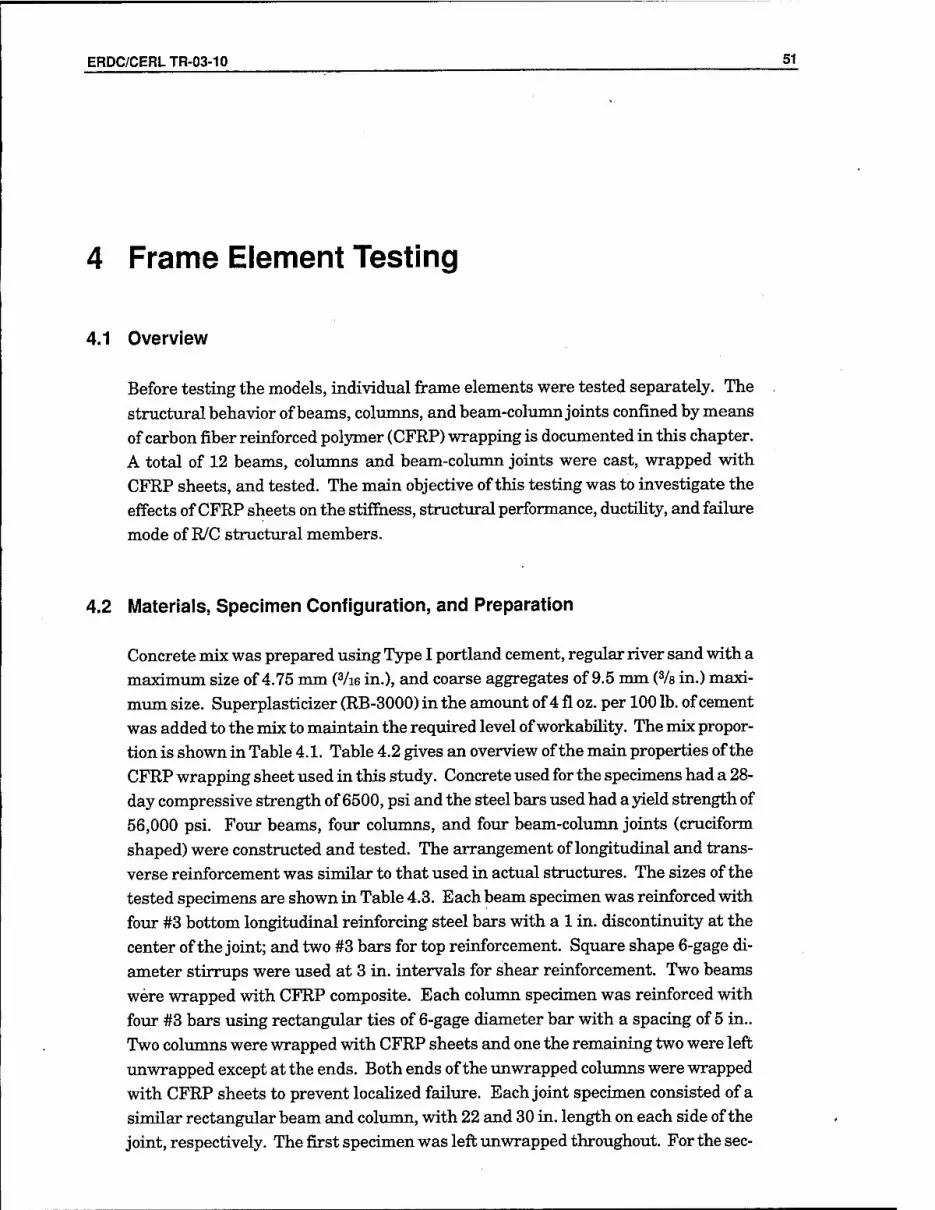
ERDC/CERLTR-03-10 51
4 Frame Element Testing
4.1 Overview
Before testing the models, individual frame elements were tested separately. The structviral behavior of beams, columns, and beam-column joints confined by means of carbon fiber reinforced polymer (CFRP) wrapping is documented in this chapter. A total of 12 beams, columns and beam-coltram joints were cast, wrapped with CFRP sheets, and tested. The main objective of this testing was to investigate the effects of CFRP sheets on the stiffness, structural performance, ductihty, and failure mode of R/C structural members.
4.2 Materials, Specimen Configuration, and Preparation
Concrete mix was prepared using Type I portland cement, regular river sand with a maximum size of 4.75 mm (Vie in.), and coarse aggregates of 9.5 mm (% in.) maxi- mum size. Superplasticizer (RB-3000) in the amount of 4 fl oz. per 100 lb. of cement was added to the mix to maintain the required level of workabihty. The mix propor- tion is shown in Table 4.1. Table 4.2 gives an overview of the main properties of the CFRP wrapping sheet used in this study. Concrete used for the specimens had a 28- day compressive strength of 6500, psi and the steel bars used had a yield strength of 56,000 psi. Four beams, four coliunns, and four beam-column joints (cruciform shaped) were constructed and tested. The arrangement of longitudinal and trans- verse reinforcement was similar to that used in actual structures. The sizes of the tested specimens are shown in Table 4.3. Each beam specimen was reinforced with four #3 bottom longitudinal reinforcing steel bars with a 1 in. discontinuity at the center of the joint; and two #3 bars for top reinforcement. Square shape 6-gage di- ameter stirrups were used at 3 in. intervals for shear reinforcement. Two beams were wrapped with CFRP composite. Each column specimen was reinforced with four #3 bars using rectangular ties of 6-gage diameter bar with a spacing of 5 in.. Two colimins were wrapped with CFRP sheets and one the remaining two were left xmwrapped except at the ends. Both ends of the unwrapped coltmins were wrapped with CFRP sheets to prevent locaUzed failure. Each joint specimen consisted of a sinfiilar rectangular beam and column, with 22 and 30 in. length on each side of the joint, respectively. The first specimen was left unwrapped throughout. For the sec-

52 ERDC/CERLTR-03-10
ond specimen, the beam and column were wrapped, while for the third specimen the beam, coltmm, and one side of the joint were wrapped with CFRP. The fourth specimen was completely (beam, colmnn, and joint) wrapped with CFRP sheet. Al- though joints that can be completely wrapped are not typically found in structiores, this specimen was included for completeness of the study.
Table 4.1. Mix proportions of concrete.
Ingredients lUIix proportions for 1 yd^
Cement, lb. 575
Water, lb. 316
Coarse aggregate, lb. 1772
Fine aggregate, lb. 1176
RB 3000 superplasticlzer, fl oz 23
Table 4.2. Properties of carbon fiber sheet.
Properties Values
Tensile strength 530 ksi
Tensile modulus 33.5x10®psi
Density 0.064 lb./in^
Elongation at breal< 1.4%
Elastic recovery 100%
Filaments/strand 12,000
Slieet thickness 0.026 in
Table 4.3. Specimen configuration and wrapping condition.
Structural member
Designation Size of tfie specimen Wrapping condition
Beam Bare
Size: 5" x 7.75" x 88"
Unwrapped throughout
Wrapped Fuliy wrapped with 1 layer of CFRP sheet
Column Bare
Size: 5" x 8" x 68"
Unwrapped throughout except the ends
Wrapped Fully wrapped with 1 layer of CFRP sheet
B/C joint
Bare 1 Beam: 5" x 7.75"with 22" on both sides
Column: 5" x 8" with 30" on both sides
Beam, column and joint unwrapped throughout
Wrapped 0 Beam and column wrapped, but the joint unwrapped
Wrapped 1 Beam, column and one side of the joint wrapped
Wrapped 2 Beam, column and joint wrapped throughout
Comers of the rectangular specimen were smoothed with a ciirvatixre to reduce stress concentrations on the CFRP sheets. After 28 days from casting time, the CFRP sheet was applied to the specimens. The surfaces of the beam, colimtm, and

ERDC/CERLTR-03-10 53
joint were prepared by sandblasting until the coarse aggregate was slightly exposed. To assure adequate bonding between the concrete and CFRP, the diist was removed from the concrete surface using air pressure. Abase of epoxy resin was mixed with a hardener using a hand-powered mixer. Epoxy was applied to the concrete surface and CFRP sheet simultaneously. Then, the specimen was wrapped with a thin layer of CFRP sheet. One side of the CFRP sheet was placed on the specimen and pressed while a second person applied the remainder of the sheet arranging it in one con- tinuous movement. To remove any trapped air, the surface of the CFRP sheet was pressed with a small hand roller. Afterwards, specimens were allowed to cure at laboratory temperature and humidity imtil testing began. In addition, cyhnders were circularly wrapped with one layer of CFRP sheet, providing a 3 in. overlap.
4.3 Testing Procedure
Strain gages and rosettes were mounted at critical locations to measure the strain. The layout of strain gages and rosettes for a typical beam-colimin joint is shown in Figure 4.1. LVDTs were installed to measure the displacements. Beam specimens were tested using foxir-point loading, as shown in Figure 4.2 and Figure 4.3. Load was appHed in a displacement-control mode at a rate of 0.01 in. / minute. Columns were subjected to axial loading as shown in Figure 4.4. In beam-colvmm joint test- ing, the loading pattern was a cyclic type with alternating displacement reversals (Figure 4.5). The beam was connected to an actuator and subjected to push and pull; the colimm was simxiltaneously subjected to a constant axial load of 50 kips, which is about 20% of the ultimate compressive load for the coltmm. The test setup and failure mode for typical beam-column joint is shown in Figure 4.6. Load, deflec- tion, and strain readings were recorded, and crack development and mode of failure were monitored throughout the tests.
Beam
BTRD65 BTLSG4
nrpen BLTS6S
CUS70 CTUS71
H.aTC51 CTOS69 CLfB68 CTrS72
Column
RF57 RR58 RBS
X Front Rosett
Figure 4.1. Instrumentation on a typical beam-column joint.

54 ERDC/CERLTR-03-10
P/2 P/2
r i -■ ^.^'T^
1 r 5" ,
■■■^ .".^ ;^. .^.^.^. ^ ,
7777^7
Wrapped and un-wrapped beam specification
Beaml:a = 18",b = 80" Beam 2: a = 12", b = 70"
Figure 4.2. Beam configuration and testing setup.
Figure 4.3. Testing of beam specimen.
Figure 4.4. Testing of column specimen.
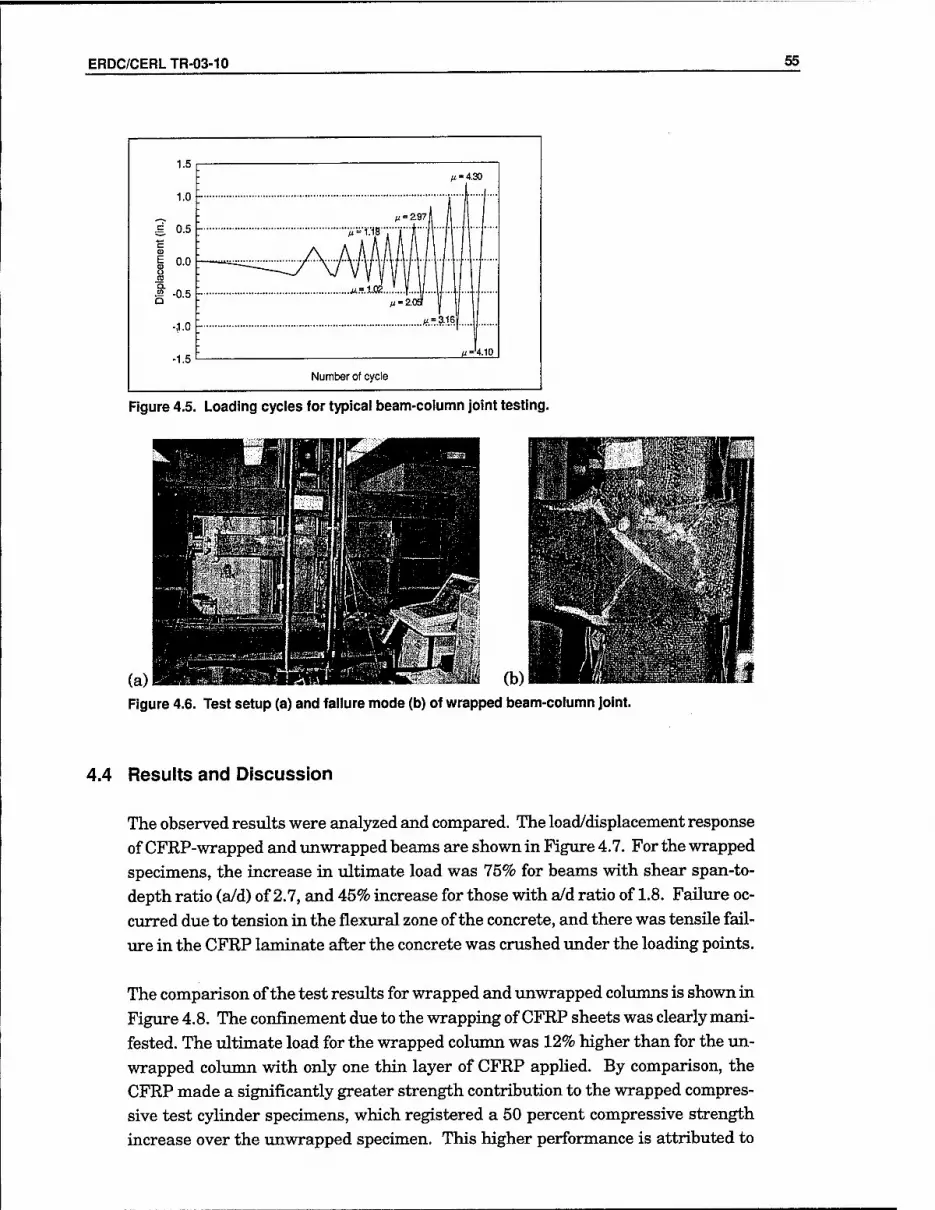
ERDC/CERLTR-03-10 55
M-4.30
n='^.W
Number of cycle
Figure 4.5. Loading cycles for typical beam-column joint testing.
(a) MKPt.fflaSaIlKWIIFHnWiii. ^.-i (b) Figure 4.6. Test setup (a) and failure mode (b) of wrapped beam-column joint
4.4 Results and Discussion
The observed results were analyzed and compared. The load/displacement response of CFRP-wrapped and tinwrapped beams are shown in Figure 4.7. For the wrapped specimens, the increase in xiltimate load was 75% for beams with shear span-to- depth ratio (a/d) of 2.7, and 45% increase for those with a/d ratio of 1.8. Failure oc- curred due to tension in the flexural zone of the concrete, and there was tensile fail- ure in the CFRP laminate after the concrete was crushed under the loading points.
The comparison of the test results for wrapped and unwrapped columns is shown in Figiu-e 4.8. The confinement due to the wrapping of CFRP sheets was clearly mani- fested. The ultimate load for the wrapped column was 12% higher than for the tm- wrapped coliunn with only one thin layer of CFRP appHed. By comparison, the CFRP made a significantly greater strength contribution to the wrapped compres- sive test cyUnder specimens, which registered a 50 percent compressive strength increase over the unwrapped specimen. This higher performance is attributed to

56 ERDC/CERLTR-03-10
the fact that a circular cross section member wrapped with CFRP fails with less stress concentration on the CFRP fibers, and therefore it can resist a greater load than a CFRP-wrapped rectangular cross section.
Un-wrapped beam Wrapped beam
Un-wrapped beam Wrapped beam
0 10 20 30 40 50 60 Deflection (mm)
(a) Span length = 70 in.
0 10 20 30 40 50 60 Deflection (mm)
(b) Span length = 80 in.
Figure 4.7. Load/displacement response of wrapped and unwrapped beams.
300 /
250 - //
^200 ;
// f 150 - //
Axi
al
o
o
i '/ —— Wrapped column f Unwrapped column
: , • . . 0' 0.00 0,10 0.20 0.30
Axial displacement (in.)
Figure 4.8. Axial load/displacement response of wrapped and unwrapped columns.
The load/displacement hysteresis curves for imwrapped and wrapped beam-column joints are shown in Figure 4.9 and Figure 4.10, respectively. During testing, more damage was noticed in the pull cycle than in the push cycle for the same level of load. This difference is attributed to the extra confinement on the compression side during push loading. The shearing strength of the wrapped joint was 13% higher than that of the unwrapped joint. It is necessary to keep in mind that a very thin

ERDC/CERLTR-03-10 57
layer of CFRP sheet was added in wrapping the joint. The ultimate failure in the unwrapped joint specimen was due to shearing of the beam, while in the case of wrapped joint, the -ultimate failure was within the joint at an angle of 45 degrees, as shown in Figure 4.6(b). It was observed that wrapped specimens could resist more loading cycles than xmwrapped specimens. It was also observed that the wrapped specimen cotdd imdergo 86% more displacement than the unwrapped specimen, as illustrated in Figure 4.9 and Figure 4.10. The observed ductihty for the wrapped specimen was 4.3, while for the xmwrapped specimen, the ductility was 3.02. It is worth noting that the beam-column joints employed in this study were well confined
by ties and shear reinforcement.
-1.50 -1.00 -0.50 0.00 0.50
Displacement (in.)
1.00 1.50
Figure 4.9. Load vs displacement response of unwrapped beam-column joint.
24
16
8
0
-8
-18
^1.1^ ||=2.02 ig.
Displacement (in.)
'p=-4.<iO-
1.50
Figure 4.10. Load vs displacement response of CFRP wrapped beam-column joint.

58 ERDC/CERLTR-03-10
4.5 Conclusions
Based on the results of the frame element tests, the following conclusions may be
drawn:
■ Externally strengthened beams demonstrated a substantial increase in ulti- mate load carrying capacity. For wrapped specimens, the increase in ulti- mate strengths was 75% for beams with shear span-depth ratio (a/d) of 2.7,
and 45% for those with a/d ratio of 1.8. ■ The vdtimate load of the rectangular coliunn wrapped with one thin layer of
CFRP was 12% higher than that of the tmwrapped rectangular column. How- ever, the compressive strength of the wrapped cylinder was 50 percent higher
than that of the unwrapped cylinder. ■ It was observed that wrapped joints coxild resist more loading cycles than
xmwrapped joints. The observed ductility for the wrapped specimen was 4.30, while for the tmwrapped specimen the ductihty was 3.02.
■ The shear strength of the joint wrapped with one thin layer of CFRP was 13% higher than that of the tmwrapped joint.
■ The test resvdts provided strong evidence that retrofit using CFRP compos- ites is a viable option for improving the seismic performance of reinforced
concrete structures.

ERDC/CERLTR-03-10 ^
5 Performance of Fully Infilled Concrete Frame (Test 1)
5.1 Overview
Test results for Model 1 are discussed with respect to measurements of strength, stiffness, and deformation capacity as well as observed damage patterns and appar- ent performance Hmit states. Propagation of cracks in the concrete frame and ma- sonry infill during the loading is illustrated and discussed with respect to measured histories of force and deflection. Measured shear strains in each of the nine infiU panels is correlated with the progression of damage to infer the distribution of lat- eral force to each infill panel.
5.2 Crack Formation and Propagation
Using the identification scheme shown in Figure 5.1, Model 1 was loaded using a modified CUREE method, cracking the wall throughout 40 cycles spread over 3 hoxirs. The first cracks appeared during the positive stroke of cycle 21 at a maxi- mimi test load of 14.17 kips on the top floor. All but one of the cracks occurred on the second level, and most of those were diagonal cracks on the left half of the three panels, as shown in Figure 5.2. A nxmiber of the diagonal cracks were a combina- tion of stair-stepping cracks through the mortar and cracked CMUs — mostly at an angle through comers. At this time, the first indication of the masonry separating from the colvmxn appeared in the upper-right comer of panel 2B, where a vertical crack formed between colimin B and the CMUs. Throughout the rest of the test the second floor continued to crack the most, with the highest crack propagation occur- ring in the comers of the bottom six panels and along bed joints.

60 ERDC/CERLTR-03-10
Figure 5.1. Identification sciieme.
c ( : E 3 / \
Beam 31
1
1 1
-- ■
Beam i!i 1 -U
■ 1 Beam l i — —.
j
Figure 5.2. First craclcs, cycles 21 thirough 24.
Two forms of data are available to correlate cracking with loading: LVDT data and drift ratios. LVDT readings show that panel 2A was the most strained panel, at 0.06 in., dxiring cycle 21. The rest of the second floor LVDT readings reached at least 72 percent of the value panel 2A. The first and third floors had much less di- agonal strain, reaching a maximxmi of about 60% of panel 2A. The drift ratios are also an indication of why the second floor cracked first. The second floor had a drift ratio of 0.21%, more than twice as much as the first floor (0.098%) and nearly three times as much as the third (0.07%). The higher drift ratio means more localized displacements that translated into higher strains and corresponding damage.

ERDC/CERLTR-03-10 61
As the test progressed from cycle 25 - 28, the cracking pattern remained mostly in
the same panels and quadrants as the earlier cycles. Again the majority of cracks
were stair steps, either continuations of existing cracks or new ones. They were
typically found in the bottom half of the panels moving upward toward the center,
visually indicating strut action of the CMUs. Figure 5.3 shows how the cracks had
propagated toward the toe of the second-floor panels during the negative stroke.
These cracks would not propagate any further during the test. During these cycles,
the first slab and beam cracks formed at the middle two joints along the second
floor, where the stress concentrations were highest.
Cycle 29 was the last cycle for which LVDT data are available. During this cycle,
every second-floor panel achieved 0.2 in. of diagonal displacement, the maximum
reading available for the LVDTs. Average readings for the first and third floor were
approximately one half and one tenth, respectively, of the second floor value, as re-
flected by the relative amount of cracking on each floor at this time. Floor three had
yet to crack and the first floor sustained minimal damage, with the exception of a
spalled CMU block in panel lA, depicted in Figure 5.4. Drift ratio data again corre-
sponded to the damage: the first and third floors had drifted 0.338% and 0.136%,
respectively, while the second floor drifted 0.56%. Note how most of the damage
through cycle 31 was located on the outside perimeters of the damaged panels. At
this point, no evidence of bed joint sliding or crushing of the toe was observed, and
the center region was acting as a 'survival zone.'
The next major peak, cycle 32, cracked all the panels on the first floor and continued
to damage the second floor, as depicted in Figure 5.5. The increased stair-stepping
and CMUs cracking correlated to drift ratio values that were almost double those
measured during cycle 29. Despite the second story drifting more than 1% during
the positive stroke of cycle 32, there was no loss of strength to the frame, and in fact
the load capacity increased slightly compared to cycle 29.
The following series of cycles, 35 - 37, continued to damage the infilled frame. With
the drift ratios over 1% in both the first and second floors, the load capacity dropped
from 13.48 kips in the positive stroke of cycle 32 to 12.02 kips in the positive stroke
of cycle 35 for the third story, the largest drop in load yet. During this series, stair-
stepped cracks in the third-story CMUs were observed while columns IB, IC, and
ID sustained flexural cracks (Figure 5.6). The top of column 2C, which was initially
cracked in shear during cycle 32, accumulated further damage. There was also
some evidence of bed joint sliding in the bottom six panels, but none of these cracks
had propagated farther than two or three CMU lengths. The last major change was
the development of cracks in the first and second beams. The first beam cracks took
place early, during cycle 29, and four more major cracks appeared after cycle 32.
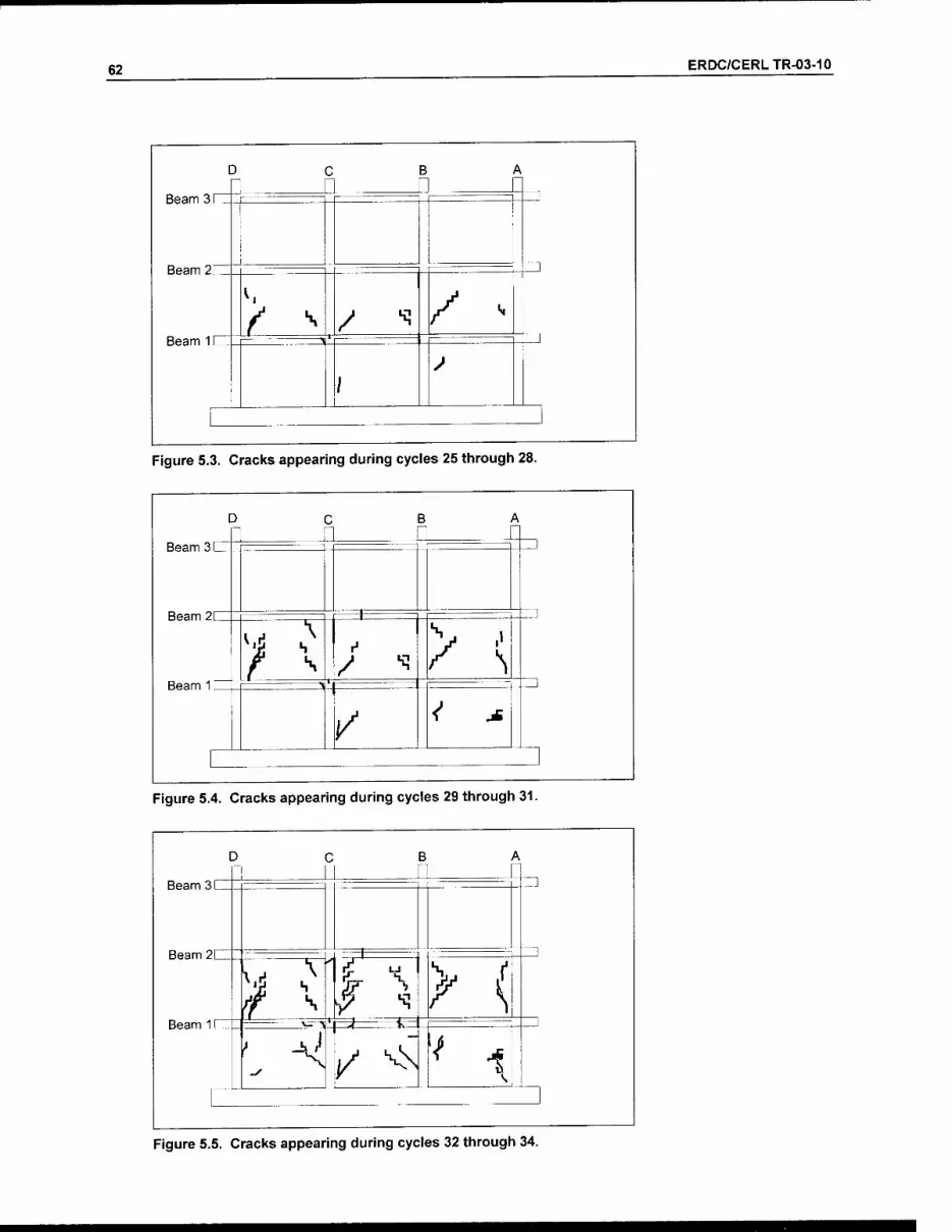
62 ERDC/CERLTR-03-10
D c ; E 5 / \
Beam 31
Beam 21
^
f ^ / '^ / ^ Beam 1 >
/ ^
!
Figure 5.3. Cracks appearing during cycles 25 tlirough 28.
Beam 3C
Beam 2[
Beam 1 [ 1
T
^: / -^
/
Figure 5.4. Cracks appearing during cycles 29 tliroughi 31.
Beam 311
Beam 2[_
Beam 1 [
\A
A rsEiai.
^ V / FT ^z^E^
(/ X
/^ ^
Figure 5.5. Cracks appearing during cycles 32 through 34.
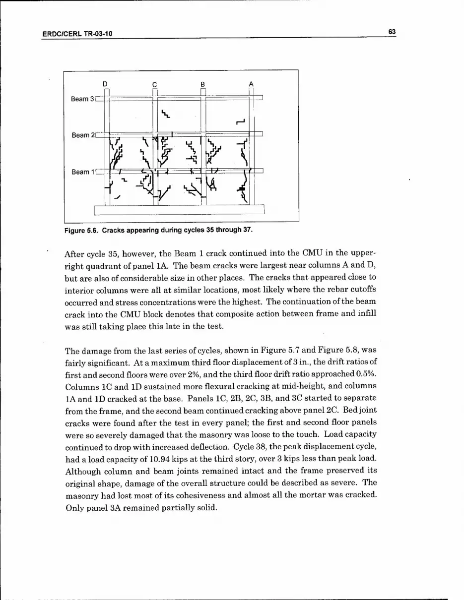
ERDC/CERLTR-03-10 63
Beam 3 [
Beam 2C
Beam 1 (
D n
J
IS ^
V
3:
C \ -^ /
/ ^-
f x ^
^
^
Figure 5.6. Cracks appearing during cycles 35 through 37.
After cycle 35, however, the Beam 1 crack continued into the CMU in the upper-
right quadrant of panel lA. The beam cracks were largest near columns A and D,
but are also of considerable size in other places. The cracks that appeared close to
interior columns were all at similar locations, most likely where the rebar cutoffs
occurred and stress concentrations were the highest. The continuation of the beam
crack into the CMU block denotes that composite action between frame and infill
was still taking place this late in the test.
The damage from the last series of cycles, shown in Figure 5.7 and Figure 5.8, was
fairly significant. At a maximum third floor displacement of 3 in., the drift ratios of
first and second floors were over 2%, and the third floor drift ratio approached 0.5%.
Columns IC and ID sustained more flexural cracking at mid-height, and columns
lA and ID cracked at the base. Panels IC, 2B, 2C, 3B, and 3C started to separate
from the frame, and the second beam continued cracking above panel 2C. Bed joint
cracks were found after the test in every panel; the first and second floor panels
were so severely damaged that the masonry was loose to the touch. Load capacity
continued to drop with increased deflection. Cycle 38, the peak displacement cycle,
had a load capacity of 10.94 kips at the third story, over 3 kips less than peak load.
Although column and beam joints remained intact and the frame preserved its
original shape, damage of the overall structure could be described as severe. The
masonry had lost most of its cohesiveness and almost all the mortar was cracked.
Only panel 3A remained partially solid.

64 ERDC/CERLTR-03-10
Beam 3 C
Beam 2C
Beam 11
J
^r
\
^\
s. •"^
/
1
^
v-\ f 1 .^5 ̂
Figure 5.7. Cracks appearing during cycles 38 through 40.
Beam 3
Beam2IIZ^
Beam 1
Figure 5.8. Cracl<s found after completion of test.
5.3 Load/Displacement Behavior
Applying the modified CUREE loading protocol to the test specimen resulted in the
load/displacement behavior plotted in Figure 5.9. The load plotted on the ordinate
is the accumulated story shear for each level. The drift ratio, plotted on the ab-
scissa, is defined as the interstory displacement divided by the story height. The
hysteresis for each floor is discussed in order to explain the behavior of the test
specimen.

ERDC/CERLTR-03-10 65
40
20
S 0 en
^ -20
-40
-3
40
^ 20
« 0
£<
I -20
-40
-3
40
20
S 00
-20
-40
Fbor 3
-1
Floor 2
Floor 1
-1 0 1
Drift Ratio (%)
Figure 5.9. Story shear vs drift ratio behavior for each floor.

66 ERDC/CERLTR-03-10
The peak lateral load for the experimental model occurred during the cycle 21 at a
corresponding first floor story shear of 32.21 kips. The second and third floors had
story shears of 24.90 and 14.17 kips, respectively, during the positive stroke of this
cycle. During the negative stroke, the story shears for the first, second, and third
floors were 29.02, 23.08, and 13.90 kips, respectively. The corresponding drift ratios
at peak load in the positive stroke direction were 0.12%, 0.22%, and 0.07%. For the
negative stroke direction, values of 0.088%, 0.354%, and 0.054% drift ratio occurred
in the first, second, and third floors, respectively. These drift ratios corresponded to
absolute third floor displacements of 0.23 and -0.30 in. for each direction. The peak
loads and corresponding story shears and drift ratios for each floor are summarized
in Table 5.1.
The remaining 19 cycles, up to an absolute displacement of 3 in. in the third floor,
were sufficient in reaching the residual strength of the test specimen. The drift ra-
tios and associated story shears during the last primary cycle (cycle 38) are summa-
rized in Table 5.2. The maximum drift ratio for the first floor in the positive stroke
direction was 18 times the drift obtained during the peak load, while the first floor
story shear fell to 77% of its peak value.
Table 5.1. Peak load and corresponding story shear and drift ratio for each floor.
Peak Load (kips) Story Shear (kips) Drift Ratio (%)
Floor + - + - + -
3 14.17 13.90 14.17 13.90 0.07 0.05
2 10.73 9.18 24.90 23.08 0.21 0.35
1 7.31 5.94 32,21 29.02 0.12 0.09
Note: + + and - refer to the stroke direction towards (+) and away (-) from the reaction structure.
Table 5.2. Maximum drift ratio and corresponding story shear for each floor.
Maximum Drift Ratio {%) Story Shear kips)
Floor + _ + -
3 0.49 0,19 10.89 10.51
2 2.08 2,67 18.98 17.31
1 2.09 1,98 24.73 21.50
From Figure 5.9, the drift ratio of the third floor after achieving the peak load was
much lower than the values observed in the first or second floors. The main cause
of this behavior was the prescribed inverse-triangular distribution of lateral forces
specified in IBC 2000; the resulting story shear distribution is shown in Table 5.3.
The story shear on the first and second floors was roughly double the value applied
to the third floor. This load distribution caused the drift ratio of the first and second

ERDC/CERLTR-03-10 67
floors to be much greater than the third floor. The relatively high values for drift ratio in the lower levels caused these panels to crack first. Once cracked, the differ- ence in drift ratio between the third floor and the lower levels was amplified.
Table 5.3. Lateral load, story shear, and vertical load distribution.
Floor Approx. Lateral Load Distribution (% of V)
Approx. Story Shear Distribution (% of V)
Approx. Vertical Load Distribution (% of V)
3 46% 46% 33%
2 33% 79% 67%
1 21% 100% 100%
Note: V represents the base shear and P symbolizes the total applied vertical load
The prescribed distribution of story shear was also one of the causes of the first ma- sonry cracks developing on the second floor rather than the first floor at the peak load. During the peak load, cracks emerged in every masonry panel on the second floor, while only one crack appeared in the masonry on the first floor. In addition to the vertical distribution of story shear, probably a more important factor causing this behavior was the distribution of vertical load from the dead weight of the test specimen and the lead ingots. Each floor was loaded similarly, leading to the verti- cal load distribution, normalized to the third floor, given in Table 5.3.
The total vertical load on the first floor was 1.5 times the value for the second floor. However, the story shear for the first floor was only 1.27 times the value for the sec- ond. The large increase in accumulated vertical load relative to story shear from the second to the first floor is one possible explanation why only one crack appeared in the first floor during the peak load. Conversely, the second floor, with two-thirds the total vertical load, still experienced a relatively large story shear — approxi- mately 79% of the first floor value. This large story shear, in conjunction with a smaller vertical load, decreased the lateral load capacity of the second floor. Conse- quently, significant cracking occurred on this level during the peak load.
After cracking occurred in the first and second floors, the displacement imposed on the third floor from the modified CUREE loading protocol was mostly taken by these lower levels. The cracking of the masonry panels in the lower levels caused a significant loss in stiffness in the first and second floors. This caused most of the displacement imposed on the third floor to be captured by the first and second floors. The large increase in drift ratio of the first and second floors after peak load, and the relatively small increases in drift ratio for the third floor during this time (as shown in Figure 5.9) can be explained by this phenomenon. In addition, the ob- servation of relatively few cracks in the third floor during testing is consistent with the small drift ratio values achieved on this floor. Furthermore, the relative distri-

68 ERDC/CERLTR-03-10
bution of displacements as a percentage of the third floor displacement, before and
after cracking, is shown in Table 5.4. After cracking, the relative displacement in-
creased by 74% and 21% in the first and second floors, respectively. This illustrates
that the accumulation of displacements in the first and second floors after cracking
caused the minimal additional increase of drift in the third floor after the peak load.
Table 5.4. Relative displacement (fraction of third floor displacement) before and after cracking.
Relative Displacement
Floor Before Cracking After Cracking Percent Increase
3 100% 100% 0%
2 80% 97% 21%
1 23% 40% 74%
The significant cracking in the first and second floors also caused the hysteresis of
the third floor to become asymmetric, as shown in Figure 5.9. The negative drift
ratio of the third floor hysteresis was much lower than the drift ratio in the positive
direction. The main cause of this asymmetry was the effects of considerable crack-
ing in the lower-left quadrant of the second floor masonry panels, as previously il-
lustrated in Figures 5.2 through 5.8. These cracks near the toe of the masonry pan-
els caused a considerable decrease in stiffness of the second floor in the negative
stroke direction, away from the reaction structure. In effect, the second floor at-
tracted the most interstory displacement in the negative stroke direction after
cracking. This phenomenon left the third floor with Httle of the additional drift that
was needed to comply with the specified displacement from the loading protocol.
In Figure 5.10, backbone curves are plotted in red directly over the hysteresis
curves for all three floors. The backbone curve is one way to view the stiffness deg-
radation of a structural system. Backbone curves are typically drawn through the
intersection of the first cycle curve for each deformation step with the second cycle
curve of the previous deformation step for every step. However, following this pro-
cedure using the modified CUREE loading protocol resulted in an underestimation
of load resistance. This observation was due to the small load values that occurred
during the traihng cycles for each deformation step. Therefore, points on the back-
bone were plotted through the intersection of the first cycle (primary cycle) curve for
each deformation step with the primary cycle curve of the previous deformation step
for every step. Using this convention, a more reasonable and accurate portrayal of
the structural system behavior was achieved.

ERDC/CERLTR-03-10 69
40
a 20
I 0 00
oo -20
-40 -2 0 2
Drift Ratio (%)
-2 0 2
Drift Ratio (%)
'2
-2 0 2 Drift Ratio (%)
Figure 5.10. Hysteresis witli backbone curves for eacli floor.
The backbone curves for first and third floors are very similar in shape. After an
initial linear portion, a peak value of load was achieved followed by a fairly smooth
decline in load in which the residual strength was substantial although lower than
the peak strength. Therefore, the R/C frame with URM infill acts as a ductile sys-

70 ERDC/CERLTR-03-10
tem that is capable of absorbing considerable amounts of energy. This is significant
considering the lack of ductile reinforcement detailing in the R/C frame. This be-
havior is represented as Type 1 general component behavior curve per FEMA 273.
The shape of the backbone curve for the second floor was slightly different than
those of the first and third floors. After the initial hnear portion, the load essen-
tially levels off. Consequently, there was no clear peak load as was present for the
other two floors. However, the tafl of the backbone curve for the second floor still
gives the residual strength considering the large drifts present on this level. There-
fore, the second floor backbone curve could also be classified as Type 1.
Besides examining the hysteresis curves, another method was used to examine the
stiffness degradation. Stiffness for each primary cycle, starting with cycle 14, was
calculated by measuring the slope of a straight hne connecting the peak load during
that cycle to the origin of a story shear versus interstory displacement plot. Using
this method, values of'stiffness' for each primary cycle, for both stroke directions,
were computed and summarized in Table 5.5 as well as shown graphically in Figure
5.11 The average stiffness was computed as the average stiffness in the positive
and negative directions.
Table 5.5. Summary of average stiffness for eacli floor.
First Floor Second Floor Third Floor Cycle No.
positive
1351.5
negative
999.4
average
1175.5
positive negative
383.3 309.5
average
346.4
positive negative average
691.0 584.4 637.7 14
21 486.1 543.0 514.6 210.9 108.2 159.6 342.4 422.1 382.3
25 215.5 249.4 232.5 114.6 70.7 92.7 185.6 348.0 266.8
29 148.3 165.2 156.8 68.6 45.5 57.1 159.9 276.2 218.1
32 70.6 100.6 85.6 39.7 25.1 32.4 91.3 174.7 133.0
35 37.6 42.0 39.8 24.7 15.8 20.3 52.5 111.6 82.1
38 19.9 18.7 19.3 15.3 11.0 13.2 37.1 91.6 64.3
This table iUustrates the stiffness degradation that occurred over the duration of
the test. All floors showed significant loss of stiffness by the completion of the test.
The percentage of final stiffness remaining by cycle 38 for the first, second, and
third floors were 1.4%, 4.5%, and 7.7%, respectively. This exemplifies the concen-
tration of damage to the first and second floors, while the third floor remained
mostly intact. One interesting note: the initial stiffness of the second floor is con- siderably lower than that of the first and third floors. No obvious explanation can
be given in view of the fact that the material tests performed for the second floor
showed no signs of weak materials.
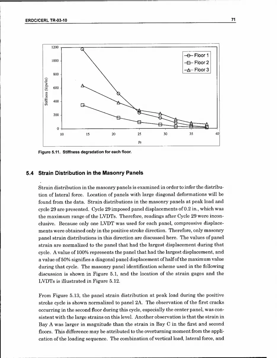
ERDC/CERLTR-03-10 71
1200
1000
800
3 600
400 -
200
-e- Floor 1
-B-Floor 2
-A-Floor 3
10 40
Figure 5.11. Stiffness degradation for each floor.
5.4 Strain Distribution in the IVIasonry Panels
Strain distribution in the masonry panels is examined in order to infer the distribu- tion of lateral force. Location of panels with large diagonal deformations will be found from the data. Strain distributions in the masonry panels at peak load and cycle 29 are presented. Cycle 29 imposed panel displacements of 0.2 in., which was the maximum range of the LVDTs. Therefore, readings after Cycle 29 were incon- clusive. Because only one LVDT was used for each panel, compressive displace- ments were obtained only in the positive stroke direction. Therefore, only masonry panel strain distributions in this direction are discussed here. The values of panel strain are normalized to the panel that had the largest displacement during that cycle. A value of 100% represents the panel that had the largest displacement, and a value of 50% signifies a diagonal panel displacement of half of the maximum value during that cycle. The masonry panel identification scheme used in the following discussion is shown in Figure 5.1, and the location of the strain gages and the LVDTs is illustrated in Figure 5.12.
From Figure 5.13, the panel strain distribution at peak load during the positive stroke cycle is shown normalized to panel 2A. The observation of the first cracks occurring in the second floor during this cycle, especially the center panel, was con- sistent with the large strains on this level. Another observation is that the strain in Bay A was larger in magnitude than the strain in Bay C in the first and second floors. This difference may be attributed to the overturning moment from the apph- cation of the loading sequence. The combination of vertical load, lateral force, and

72 ERDC/CERLTR-03-10
overturning moment cause strains in the lower levels of Bay A to be appreciably
larger than the corresponding strains in Bay C. The strain in Panel 2A was 38%
larger than the value for Panel 2C. On the first floor, where the overturning mo-
ment was at a maximum, the strain in Panel lA was roughly 170% larger than the
value in Panel IC. Conversely, in the third story, where the vertical and lateral
load was at a minimum, the overturning moment was negligible, resulting in rela-
tively similar strains in Panels 3A and 3C.
"xx" (6) Load and Stroke
0 (6) Displacement (60) Strain gage
\ (9) LVDT (6) Strain gage on loading beams
Col. d Col.c Col. b Col. a
Beam 3
Beam 2 [
Beam I
T^T
Figure 5.12. Location of strain gages and LVDTs.
c ) C ; E
j ^—p-—
j A
Beam 31
Room 0 1
' 23.2% ' 45.9% ' ' 11.1% 1
i
' 72.3% 98.8% ' ' 100% 1
Beam 1i
21.0% 1
45.7% 1 1
56.8% 1 1
Figure 5.13. Panel strain distribution for Cycle 21.

ERDC/CERLTR-03-10 73
Figure 5.14 gives the panel strain distribution for cycle 29. Diagonal panel dis- placements of 0.2 in., the maximum range of the LVDTs, were achieved during this cycle. The strain in each panel was normalized to panel 2A, which had the highest recorded displacement value.
The strain distribution during cycle 29 mimics the behavior seen during the peak load. The largest deformations once again occurred on the second floor. Further- more, the lopsided distribution of panel strain due to overturning moment effects was also present. However, this effect was only appreciable in the first story during this cycle, where Panel lA had almost three times the deformation of Panel IC. At cycle 29 the third floor masonry panels still remain generally unaffected by the loading, exhibiting relatively small strains and no overturning moment effects.
Beam 3C
Beam 2[
Beam 1C
9.6%
91.8%
23.4%
15.7%
=1 F
96.9%
37.7%
4.8%
100%
62.1%
1]L~
Figure 5.14. Panel strain distribution for Cycle 29.
5.5 Strain Distribution in the Reinforcing Steel
The data were examined to locate the reinforcing bars that yielded. The strain dis- tribution at peak load (cycle 21) and during the maximum displacement (cycle 38) are illustrated for the reinforcing bars. The strain values for the reinforcing steel were normalized to each bar's yield strength. Therefore, a value of 1.00 signifies a measured strain equal to the yield strain. Figure 5.15 and Figure 5.16 illustrate the strain distributions in the reinforcing steel at peak load for the positive and nega- tive stroke, respectively. The values represent actual strain over yield strain. Therefore, a value greater than unity signifies that yielding has occurred. During the cycle in which the peak load was applied, few reinforcing bars yielded in either stroke direction. However, the more important information given by these two fig-

74 ERDC/CERLTR-03-10
ures is the location of the reinforcement steel that did yield. The bottom steel that
yielded was in the beams located left of the load application point and on the right
side of beam/column joints (Figure 5.15). These joints were under large positive
moment due to the applied lateral force. Furthermore, the bars that yielded along
column D in the first and second floors had higher positive moment due to overturn-
ing moment effects. This same type of behavior was observed for the negative
stroke, as shown in Figure 5.16. However, since the stroke direction was reversed,
the bars that yielded were on the right side of the load application point. Besides
the bottom steel yielding, one of the top bars also yielded during the peak negative
load. This bar was located on the right side of the beam/column joint on the second
floor for column B. This region was under high stress from negative moment that
caused the large strain. Most likely, this particular bar yielded due to local effects,
i.e., its close proximity to the applied load and/or locaHzed cracking, considering
that no other top steel had yielded in either stroke direction.
In Figure 5.17, the maximum strain that occurred in the reinforcing bars during
loading is shown. By the completion of the test, nearly all of the reinforcement in
the first and second floors had yielded. The first and second floors experienced the
most story shear and were expected to have yielded by the end of the tests. The
third floor, having less apphed lateral and vertical force, did not experience as much
strain in the beams and columns and, consequently, most of the reinforcement at
this level did not yield. Surprisingly, the bottom reinforcement, which was discon-
tinuous in the joints as was typical construction practice in the 1950s, achieved
yielding. This reinforcement was expected to be susceptible to pullout and, there-
fore, not to reach its yield strength.
D 0.00 0.01
C 0.03
** 1 i Ij
B 0.00
A
Beam 3 - 0.03 0.04 1.26 0.14 " 0.00 0.01
0.01 0.01 0.01
0.02
0.02
0.01
0.00 1
0.01
0.01
0.02
0.00
Beam 'ii j [ _ - J: 1.04 0.12 0.04 0.20 0.03 0.07
0.51 i 0.05 0.01 0.03 0.34 0.04 0.03
0.14 0.01 0.04 0.01 0.17 —^1 Rp?9m 11 1
1.91 0.06 0.04 0.22 0.12
0.19 0.06 0.10 1 0.02 0.04 1 0.33
I
1 ^ d
Figure 5.15. Reinforcement strain distribution at peal< load, positive stroke.

ERDC/CERLTR-03-10 75
D B
Beam 3[
0.01 I
Beam 2(1
0.51
Beam 1C
0.19
0.00 0.01
0.03
0.01 0.01
0.02
1.26
i ^0.02
0.01
1.04
0.05
0.14
0.12
1.91
0.06
0.06
0.10
0.03
0.14
0.00 I il
o:o4
10.01
0.01
0.20
0.03
0.04
0.04 0.22
0:00
0.00
0.01
inn"
0.01
0.02
10:03
0.34
0.01
0.07
0.04
0.17
0.12
0.02 0.04
0.00
0.03
0.33
Figure 5.16. Reinforcement strain distribution at peak load, negative strolce.
B
Beam 3 [
0.36 i
Beam 2 [
1.01
Beam 1c
iP.02 0.04„l
0.03
0.59
~U7t2
0.51
Q.74.
1.43
0.29
4.82
1.79
2.30 15.43
4.57i il8.64 6JiL!
[JL22^ 5:86
0.46
ILKL
1.74
0.61
1.49
0.43
1189_
0.10
11-43
IZZ
10.47
0.3311
1.72
1.08 3.83
JLOgJ
1.38 1
-JL8£
2.30
0.42
1.13
3.22
0.3; I
3.0{
1.44
il8.Q3 7.54 H .99
0.30
0.64
Figure 5.17. IVIaximum reinforcement strain distribution.
5.6 Conclusion
Based on the results of Test 1, the following conclusions may be drawn:
1. Behavior was dominated by the R/C frame, with cracking of the unreinforced con-
crete masonry infills following distortions of the fi-ame. Thus, destructive forces
were not perceivably transferred from the infill panels to the fi^-ames, as may
have proved to be the case with stronger, stiffer panels.

76 ERDC/CERLTR-03-10
2. Damage to the R/C frame consisted of flexural and shear cracking of the concrete,
and yielding of reinforcement in the beams and columns.
3. Despite the non-ductile detaihng of frame reinforcement, the shape of the overall
force/deflection relations was similar to those for frames with more modern de-
taUing. However, strength and stiffness deterioration was more pronounced with
the 1950-vintage construction than would be expected using modern detaihng.

ERDC/CERLTR-03-10 77
6 Performance of Model Used in Test 1 as Rehabilitated With CFRP (Test 2)
6.1 Overview
After Model 1 was damaged in Test 1, it was repaired and rehabilitated to near- original condition. First, the CMU infill materials in the first and second floors were removed, allowing sufficient access to the R/C beams and columns to repair cracks and apply CFRP reinforcement materials (as described below). Next, the visible cracks in the frame members were injected with high strength epoxy. Fi- nally, the CMU panels were reconstructed in the first and second floor openings. The third floor CMU panels were intact after Test 1 and replacement was not nec- essary.
The objective of Test 2 was to compare performance with the Test 1 model. It was assumed that the CFRP reinforcement was the only variable between the two tests (i.e., between the two models). However, it is also understood that the restoration process would not exactly replicate the virgin state of the concrete frame. For ex- ample, small cracks or other hidden damage may have an effect on the performance of Model 2. Such effects have been accounted for analytically.
6.2 CFRP Retrofit Application
Before application of the CFRP, the tension and shear cracks in the beams were re- paired by first sealing the bottom and sides of the cracks with Dayton Superior Sure-Anchor I (J-51) Fast Setting, Epoxy Gel Adhesive, and then filling the cracks with Dayton Superior Sure-lnject (J-56) High Mod, Low Viscosity Injection Epoxy. Both the application procedure and the epoxies used for crack rehabihtation comply withASTMC-881.*
Dayton Superior Corp., Kansas City, KS 66106.

78 ERDC/CERLTR-03-10
CFRP was applied to the R/C frame as illustrated in Figure 6.1. At the first and
second floors, the exterior columns were completely wrapped; at the third floor, the
fabric was wrapped around the exterior columns in a U-shape because the infill on
that level was not removed to accommodate complete wrapping. The stems of the
first floor and second floor T-beams were wrapped as shown in Figure 6.2. As noted
previously, the third story did not sustain significant damage to warrant infill re-
moval or reinforcement of the horizontal beam.
Beam 3 c
Col.d Col. c Col.b Col. a
am 2 L Beam yyvi<<Siv»»^>wyysiyv
Beam 1 c
Figure 6.1. CFRP rehabilitation placement on Model 2.
<- 36"
-^
/\
\/
3" ̂ i^ ^ -a « «_
-Ji
K- 5"
->
FRP
Figure 6.2. Dimensions and CFRP placement of T-beam section.
The CFRP on the first and second floor beams was installed according ACI 440-00,
Chapter 9. The assumptions made to determine the flexural resistance when exter-
nally applying FRP to a R/C section are as follows (ACI 440-00, Section 9.1.1):
Design calculations are based on the actual dimensions, reinforcing steel ar-
rangement, and material properties of the member being strengthened.

ERDC/CERLTR-03-10 79
■ The strains in the reinforcement and concrete are directly proportional to the
distance from the neutral axis (i.e., a plane section before loading remains
plane after loading).
■ The maximum useable compressive strain in the concrete is 0.003;
■ The tensile strength of concrete is neglected.
■ The FRP reinforcement has a linear elastic stress/strain relationship to fail-
ure, but this assumption is only used for preUminary calculation and it not
true for FRP orientation of ±45 degrees.
■ Perfect bond exists between the concrete and FRP reinforcement.
The goal of the CFRP rehabihtation was to regain the original ultimate moment ca-
pacities of the beams in the undamaged frame (on the order of 20 - 26 kip-in. de-
pending on f c). Therefore, the moment capacities were calculated using Equation
6.1 for the damaged T-beams with stems wrapped using one ply of 0.037 in. thick
CFRP (see Figure 6.2). The CFRP properties are shown in Table 6.1.
Where:
y/f - reduction factor to account for decreased reliability of FRP compared to steel {Q.?>5) Eq 6.1
A, = area of FRP
ffg = FRP stress
Table 6.1. CFRP engineering properties.
Thiclcness (in.) Ultimate Stress (ksi) Modulus of Elasticity (ksi)
0.037 10.85 1281
These properties were determined experimentally. Stress-versus-strain relation-
ships were observed for four CFRP coupons, with the average values of ultimate
stress and modulus of elasticity taken to represent all CFRP used for rehabihtation
of the model. The stress-versus-strain relationships are plotted in Figure 6.3 for
each of the four CFRP coupons tested.
These properties for the CFRP, along with the T-beam dimensions and properties
listed in Table 6.2, were applied to the equations outlined in ACl 440-00, Chapter 9.
The resulting ultimate moment capacities calculated were on the order of 35 kip-in.,
as shown for the first and second floors in Table 6.3. These values are acceptable
since they exceed the original moment capacities of the beams for each story. The
apparent excess in bending strength does not pose a modeling problem because not
all factors of safety were applied in the calculation and, more importantly, because a
method has yet to be developed that can predict the strength of FRP-rehabilitated
beams to a high degree of certainty.
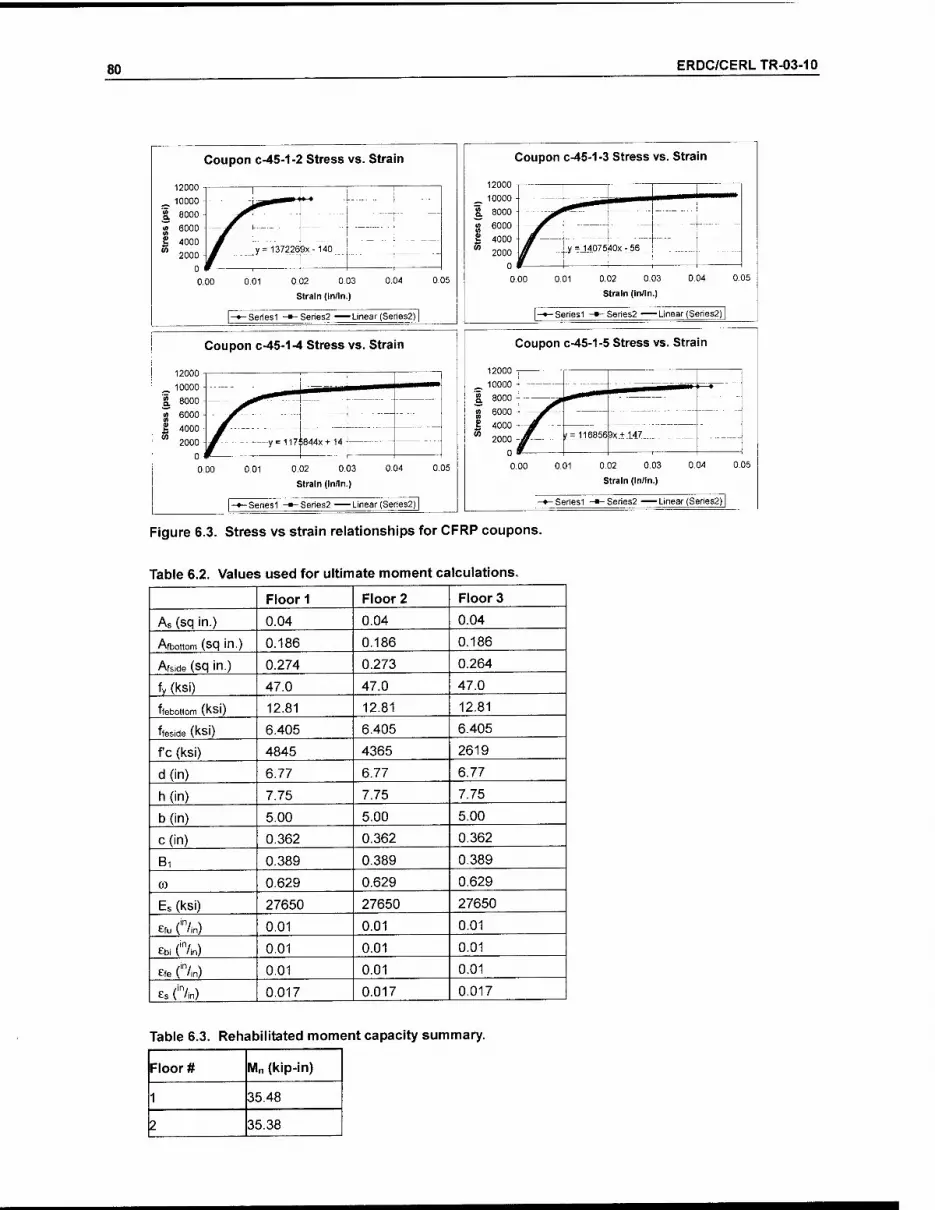
80 ERDC/CERLTR-03-10
Coupon c-45-1-2 Stress vs. Strain
:y= 137226gx-140
0,02 0,03
Strain (In/In.)
-Sehesl -Series2 Linear (Series2) |
Coupon c-45-1-3 Stress vs. Strain
0,02 0.03
Strain (in/in.)
- Seriesi -»-Series2 ^—Linear (Series2) |
Coupon c-45-1-4 Stress vs. Strain
_ 10000 -
g 8000 -
'^ 6000 ■ S 4000 ■ " 2000 z' --y=117
^- i844x+14: -
0, DO 001 0,02 0.03 0,04
Strain (in/In.)
0. 35
|-»-Seriesi -•-Series2 Linear (Series2) |
Coupon c-45-1-5 Stress vs. Strain
0.02 0.03
Strain (In/In.)
-Seriesi -»"Series2 Linear(Series2)|
Figure 6.3. Stress vs strain relationships for CFRP coupons.
Table 6.2. Values used for ultimate moment calculations.
Floor 1 Floor 2 Floor 3
As (sq in.) 0.04 0.04 0.04
Afbottom (sq in.) 0.186 0.186 0.186
Afside (sq in.) 0.274 0.273 0.264
fy (ksi) 47.0 47.0 47.0
ffebottom (kSi) 12.81 12.81 12,81
ffeside (ksi) 6.405 6.405 6.405
f c (ksi) 4845 4365 2619
d(in) 6.77 6.77 6.77
h(in) 7.75 7.75 7.75
b(in) 5.00 5.00 5.00
c(in) 0,362 0.362 0.362
Bi 0.389 0.389 0.389
(0 0.629 0.629 0.629
Es (ksi) 27650 27650 27650
efu ('"/in) 0.01 0.01 0.01
ebi ('"/in) 0.01 0,01 0.01
efe ('"/in) 0.01 0,01 0.01
es ('"/in) 0,017 0,017 0.017
Table 6.3. Rehabilitated moment capacity summary.
Floor # Mn (kip-in)
1 35.48
2 35,38

ERDC/CERLTR-03-10 81
As noted above, the outside columns were completely wrapped at the first two sto-
ries and U-wrapped around three sides at the third story.
Figure 6.4 shows a photograph of a portion of the rehabilitated frame. The CFRP
appears black and spans the lower portion of the beams, and the gray bands on the
beams are the J-51 epoxy sealant. The J-56 injection epoxy is clear and not visible
in the photograph.
Figure 6.4. Photograph of stories two and three of the rehabilitated frame.
6.3 Crack Formation and Propagation
Model 2 was subjected to the same modified CUREE loading protocol used in Test 1,
cracking the wall throughout 40 cycles spread over 3 hours. Crack formation and
propagation in the masonry and R/C frame members is discussed below, but crack-
ing of members wrapped with CFRP could not be inspected visually.
The first cracks appeared during the positive stroke of cycle 21, at a base shear of
16.63 kips. Cracks occurred on all three levels, but most of them were diagonal
cracks forming in panel 2B, as shown in Figure 6.5. A number of the diagonal
cracks were a combination of stair-stepping cracks through the mortar and cracked
CMUs orientated at approximately 45 degrees. Throughout the rest of the test, the
second floor continued to crack the most, with the highest crack propagation in the
bottom six panels.
Two forms of data are available to correlate cracking with deformation demand:
LVDT readings and drift ratios. LVDT data show that Panel 3C was the most
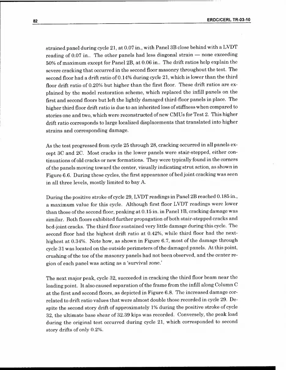
82 ERDC/CERLTR-03-10
strained panel during cycle 21, at 0.07 in., with Panel 3B close behind with a LVDT
reading of 0.07 in.. The other panels had less diagonal strain — none exceeding
50% of maximum except for Panel 2B, at 0.06 in.. The drift ratios help explain the
severe cracking that occurred in the second floor masonry throughout the test. The
second floor had a drift ratio of 0.14% during cycle 21, which is lower than the third
floor drift ratio of 0.20% but higher than the first floor. These drift ratios are ex-
plained by the model restoration scheme, which replaced the infill panels on the
first and second floors but left the lightly damaged third-floor panels in place. The
higher third floor drift ratio is due to an inherited loss of stiffness when compared to
stories one and two, which were reconstructed of new CMUs for Test 2. This higher
drift ratio corresponds to large localized displacements that translated into higher
strains and corresponding damage.
As the test progressed from cycle 25 through 28, cracking occurred in all panels ex-
cept 3C and 2C. Most cracks in the lower panels were stair-stepped, either con-
tinuations of old cracks or new formations. They were typically found in the corners
of the panels moving toward the center, visually indicating strut action, as shown in
Figure 6.6. During these cycles, the first appearance of bed joint cracking was seen
in all three levels, mostly limited to bay A.
During the positive stroke of cycle 29, LVDT readings in Panel 2B reached 0.185 in.,
a maximum value for this cycle. Although first floor LVDT readings were lower
than those of the second floor, peaking at 0.15 in. in Panel IB, cracking damage was
similar. Both floors exhibited further propagation of both stair-stepped cracks and
bed-joint cracks. The third floor sustained very Uttle damage during this cycle. The
second floor had the highest drift ratio at 0.42%, while third floor had the next-
highest at 0.34%. Note how, as shown in Figure 6.7, most of the damage through
cycle 31 was located on the outside perimeters of the damaged panels. At this point,
crushing of the toe of the masonry panels had not been observed, and the center re-
gion of each panel was acting as a 'survival zone.'
The next major peak, cycle 32, succeeded in cracking the third floor beam near the
loading point. It also caused separation of the frame from the infill along Column C
at the first and second floors, as depicted in Figure 6.8. The increased damage cor-
related to drift ratio values that were almost double those recorded in cycle 29. De-
spite the second story drift of approximately 1% during the positive stroke of cycle
32, the ultimate base shear of 32.39 kips was recorded. Conversely, the peak load
during the original test occurred during cycle 21, which corresponded to second
story drifts of only 0.2%.

ERDC/CERLTR-03-10 83
The next series of cycles, 35 through 37, continued to damage the infilled frame. With drift ratios over 1% in both the first and second floors, the frame load capacity dropped to 30.04 kips during the positive stroke of cycle 35. During this series, stair-stepped cracks in the third story masonry were observed, while column IC ex- perienced further shear cracking that formed an x-type pattern near the top of the column. A flexural crack also formed at the base of column IB. These cracks are shown in Figure 6.9. Cracking in panels 2A and 2C was severe, with cracks appear- ing throughout the masonry panels.
The damage from the last series of cycles, shown in Figure 6.10 and Figure 6.11, was fairly significant. At a maximum third floor displacement of 3 in., the drift ra- tios of the first and second floors were over 2%, and the third floor drift ratio ex- ceeded 0.5%. Column IC sustained more shear cracking at the top. Panels IC, 2C, and 3C started to separate from the frame, and bed joint cracks were found in every panel after the test. Cracking in the panels IB and IC could be described as com- plete; these panels were cracked along almost every bed joint and the stair-step cracks were numerous. Load capacity continued to drop with increasing drift. Cy- cle 38, the peak displacement cycle, had a load capacity of 26.27 kips; more than 6 kips below peak load. Although column and beam joints remained intact, the frame experienced permanent inelastic deformation.
For the next three cycles, the third floor actuator was disengaged in order to work around the actuator's 3 in. stroke limitation and develop the largest possible defor- mation of the first and second floors. Without doing this, the actuators for the bot- tom two floors would be restricted in stroke due to the 'structural configuration' of the overall wall failure. Upon disengaging the third floor actuator, lateral loads continued on the first and second floors only. The damage induced by these cycles is illustrated in Figure 6.12. At a maximum second floor displacement of nearly 2.8 in., the first and second floor drift ratios each exceeded 2.3%. Few new cracks formed in the masonry, but significant cracking occurred in the lower columns. The top of column IC experienced yet another shear crack while the top of column IB was severely damaged from diagonal cracking. The peak load imposed during this series was 21.81 kips, applied over only two stories rather than three.
During the final three cycles, for the same reasons described in the previous para- graph, the second floor actuator was disengaged. This resulted in a lateral load be- ing applied to the first floor only. Figure 6.13 illustrates the damage induced by these final cycles. A first floor load of 26.10 kips led to a maximum displacement exceeding 2.6 in., which corresponded to a drift ratio of almost 4.4%. Noticeable separation between the masonry and the overlasdng beam occurred in the first floor. In addition, further damage to both the top and bottom of columns IB and IC was

84 ERDC/CERLTR-03-10
observed, resulting in failure of both interior columns. By the conclusion of the test,
the model had sustained extensive damage, nearly depleting its residual strength
and stiffness.
c ) C : E i A
] n Beam 31
a i"
Beam 21
/■^ L
r 1
Figure 6.5. First cracks, cycles 21 through 24.
: ) C : E i f
I beam ai
CD
J ^^
Beam 21
" Hfe-
'y \ s
Figure 6.6. Cracks appearing during cycles 25 through 28.

ERDC/CERLTR-03-10 85
Beam 3 [
Beam 2 [
Beam 1c
V iv^'
■/S /■v
\
I .
-^ U I
Figure 6.7. Cracks appearing during cycles 29 through 31.
Beam 3C
Beam 2C
Beam
U^
x^ "? ^■^
V
\^,
V -n-
Figure 6.8. Cracks appearing during cycles 32 through 34.
Beam 3[
Beam 2 [
Beam t
^ -^J
JF'^^ >•■
>^
y . Vi* w CHMMMMJEA
^i^
■^ >
uv-
Figure 6.9. Cracks appearing during cycles 35 through 37.

86 ERDC/CERLTR-03-10
Beam 3[
Beam 2[
Beam 1[
Figure 6.10. Cracks appearing during cycles 38 through 40.
Beam 3[
Beam 2 [
Beam 1r '^i
/ -f^
£■•" r^ 5 —-X. ifS
■)^
Figure 6.11. Cracl<s found after completion of the Test 2.
Beam 3IZI>
Beam 2 [
Beam 1r
n—r
1^ / >
^/
&^
Figure 6.12. Cracks found after test of first and second stories.
ERDC/CERLTR-03-10 87
Beam 3[
Beam 2 C
Beam 1CZ jfejfe
Figure 6.13. Cracks found after test of first story.
6.4 Load/Displacement Behavior
This section compares the load/displacement response of Model 2 with that of Model 1 to determine the effectiveness of the rehabilitation scheme. Story shear, drift ra- tio, and stiffness during relevant cycles are discussed.
The hysteretic behavior of Model 2 is shown in Figure 6.14. The peak lateral load occurred during the cycle 32 at a corresponding base shear of 32.39 kips in the posi- tive stroke direction. In the negative stroke direction, a shghtly smaller base shear of 29.53 kips was observed. These values are very similar to the Model 1 results, where the peak values of base shear in the positive and negative directions were 32.21 kips and -29.02 kips, respectively. However, for Model 1 the peak lateral load occurred during cycle 21, with corresponding absolute third floor displacements of 0.23 and -0.30 in. for each direction; for Model 2 they were 1.206 and -1.24 in. dur- ing peak load. This represents an approximate fivefold increase in third floor displacement for Model 2 before reaching maximum base shear. The fact that the peak load for Model 2 occurred so late in the test versus Model 1 was due to the fact that the rehabilitation did not fully restore the frame's initial stiffness. Table 6.4 and Table 6.5 summarize the values of applied lateral load, story shear, and drift ratio during the cycles when the peak load and maximum drift occurred.

88 ERDC/CERLTR-03-10
Table 6.4. Peak load and corresponding and story shear and drift ratio for each floor.
Floor Peak Load (kips) Story Shear (kips) Drift ratio (%)
+ + - + -
3 15.47 13.28 15.47 13.28 0.47 0.41
2 11.01 8.86 26.48 22.14 0.87 0.78
1 5,91 7.39 32.39 29.53 0.66 0.92
Note: + and - refers to the stroke direction towards and away from the reaction structure
Table 6.5. Maximum drift ratio and corresponding story shear for each floor.
Floor Maximum Drift Ratio(%) Story Shear (kips)
+ - + -
3 0.56 0.57 12.51 11.95
2 2.31 2.06 21.57 20.02
1 1.80 2.97 26.24 26.27
Also noticeable from Figure 6.14 is the relatively large first floor drift that occurred
during the final negative primary cycle. This magnified first story translation could
be attributed to a sharp decline in lateral stiffness resulting from severe shear
cracking near the top of column IC during the preceding positive stroke. Figure
6.15 shows the joint shortly after completion of Test 2 but before the third floor ac-
tuator was disengaged to extend load testing of the first and second floors.
The first and second floors of Model 2 regained some, but not afl, of their initial
stiffness in Model 1. Recall that these two floors were carefully rehabihtated with
injected epoxy and CFRP reinforcements. The third floor, however, regained almost
none of its initial stiffness, which was to be expected considering limited rehabilita-
tive measures employed on that floor (i.e., three sides of the exterior columns were
wrapped with CFRP). The most important factor affecting the initial stiffness of the
third floor was the damaged CMUs that had been left in place. The CMUs contrib-
ute much to the frame's in-plane stiffness. As the number of cycles increased and
approached the final primary cycle, the stiffness of all three floors nearly matched
the stiffness inherent in the original model during those same cycles.

ERDC/CERLTR-03-10 89
-1 0 1
Drift Ratio (%)
-1 0 1 Drift Ratio (%)
-40 -3 -1 0 1
Drift Ratio (%)
Figure 6.14. Load/displacement behavior for each floor of the rehabilitated model.

90 ERDC/CERLTR-03-10
Figure 6.15. Joint 1c after main portion of Test 2.
The stiffness of this structure is displayed in Table 6.6 and Figure 6.16. The stiff-
ness for each primary cycle was calculated measuring the slope of a line connecting
the peak load at that cycle to the origin of the story shear versus interstory dis-
placement plot. Stiffness values for both stroke directions were found using this
method and summarized on Table 6.6, and shown graphically on Figure 6.16. The
average stiffness was computed by taking the average of the positive and negative
directions stiffnesses.
Table 6.6. Average stiffness of each floor.
Cycle First Floor Second Floor Third Floor
No. pos neg avg pos neg avg pos neg avg
7 798 494 646 273 262 268 107 60 84
14 341 536 439 158 292 225 59 71 65
21 303 251 277 167 186 177 69 75 72
25 242 159 201 121 141 131 70 70 70
29 160 107 134 87 93 90 61 65 63
32 81 54 68 50 48 49 55 53 54
35 73 30 52 30 29 30 48 44 46
38 24 16 20 16 18 17 37 35 36
Table 6.6 shows the stiffness degradation of the structure through the length of the
test. All floors had significant loss of stiffness by the end of the test. The final per-
centage of original stiffness of each floor, at cycle 38, was 3.1%, 6.3%, and 42.9% for
the first, second, and third floors, respectively. These values show that most of the
damage occurred on the first and second floor, with much less damage on the third

ERDC/CERLTR-03-10 91
floor. Note that the third floor retained much of its original stiffness even though it
began the test with a lower stiffness value for the reasons discussed previously.
500
450
400
•.' 350 ^ a. S 300
I 250 1/2 2-200 o ^ 150 H
100
50
0
-e-Fborl -2As-Fbor2
-e-Ffoor3
14 21 25 29 Cycle No.
Figure 6.16. Stiffness degradation for each floor.
As explained previously, additional lateral load testing of Model 2 was conducted
after completion of the 40-cycle modified CUREE loading protocol. The third floor
actuator was disengaged in order to test the lower two levels at higher drifts, un-
constrained by the displacement hmits imposed on them by the third floor actuator.
Keeping the ratio offeree between the first and second levels constant at the same
value as before, Model 2 was subjected to three additional cycles. The first cycle
subjected the second floor to an absolute displacement of 3 in. The following two
cycles were trailing cycles of smaller magnitude, in accordance with the modified
CUREE loading protocol described previously. Figure 6.17 illustrates the hysteretic
behavior of the first and second floors under these large demands. At this point, the
rehabilitated model had lost much of its stiffness. The model can only resist consid-
erable load at large drifts. When the lateral drift exceeded 2%, the rehabilitated
model retained much of its residual strength by resisting a base shear of approxi-
mately 20 kips. The hysteresis curves of the second floor are especially pinched dur-
ing these cycles signifying low energy dissipation.

92 ERDC/CERLTR-03-10
15
10 -
5 -
"S OH CD O
-5 -
-10
-15
30
-30
20 -
10
o
-10
-20 -
Floor 2
Floor 1
-1 0 1
Drift Ratio (%)
Figure 6.17. Hysteretic behavior of thie first and second floors at large drifts.
A similar procedure was followed in order to maximize demand on the first floor.
The load/deformation behavior of the lower level during these three cycles is shown
in Figure 6.18. During these cycles, a maximum drift ratio of approximately 4%
was achieved along with a corresponding base shear of about 25 kips. Note that the
hysteresis loops were fairly open for these three cycles, indicating considerable ine-
lastic behavior. Significant damage to both the frame and the infiU occurred during
this time. After completing these three cycles, permanent inelastic deformation was
evident in the first floor. Photographs showing the final damage to panels IC and
IB (the most damaged regions in the model) are located in Figure 6.19 and Figure
6.20, respectively.

ERDC/CERLTR-03-10 93
Figure 6.18. Hysteretic behavior of the first floor at large drifts.
Figure 6.19. Panel 1C after completion of Test 2.
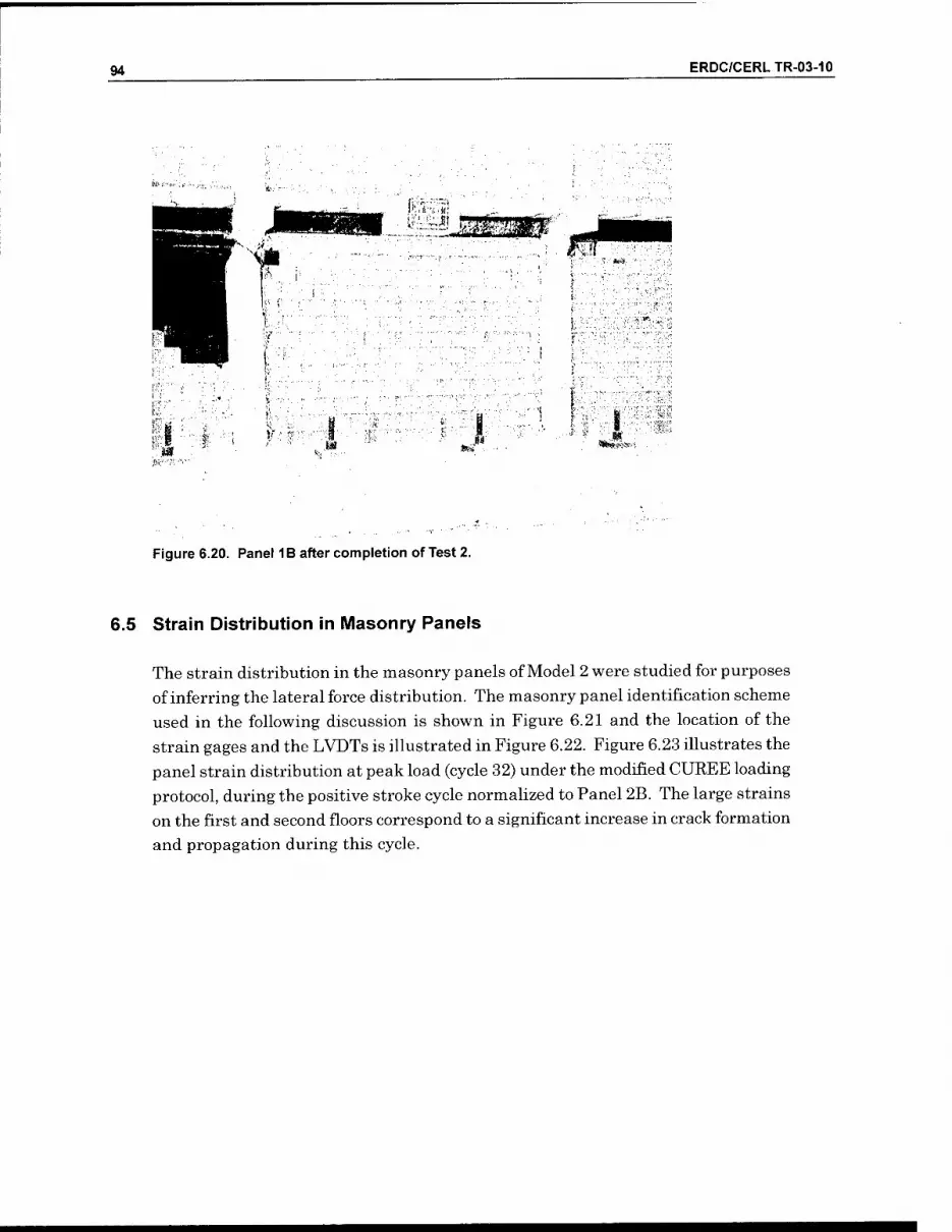
94 ERDC/CERLTR-03-10
m m ^^
Figure 6.20. Panel 1B after completion of Test 2.
6.5 Strain Distribution in Masonry Panels
The strain distribution in the masonry panels of Model 2 were studied for purposes
of inferring the lateral force distribution. The masonry panel identification scheme
used in the following discussion is shown in Figure 6.21 and the location of the
strain gages and the LVDTs is illustrated in Figure 6.22. Figure 6.23 illustrates the
panel strain distribution at peak load (cycle 32) under the modified CUREE loading
protocol, during the positive stroke cycle normalized to Panel 2B. The large strains
on the first and second floors correspond to a significant increase in crack formation
and propagation during this cycle.

ERDC/CERLTR-03-10 95
Figure 6.21. Masonry panel identification.
Col.d
"xx"
0
\
(6) Load and Stroke
(6) Displacement (60) Strain gage (9) LVDT (6) Strain gage on loading beams
Beam 3
Beam 2
Beam 1
Col. c
t I
31^1
Col.b
331
TW¥
Col. a
j][=
Figure 6.22. Location of strain gages and LVDTs.
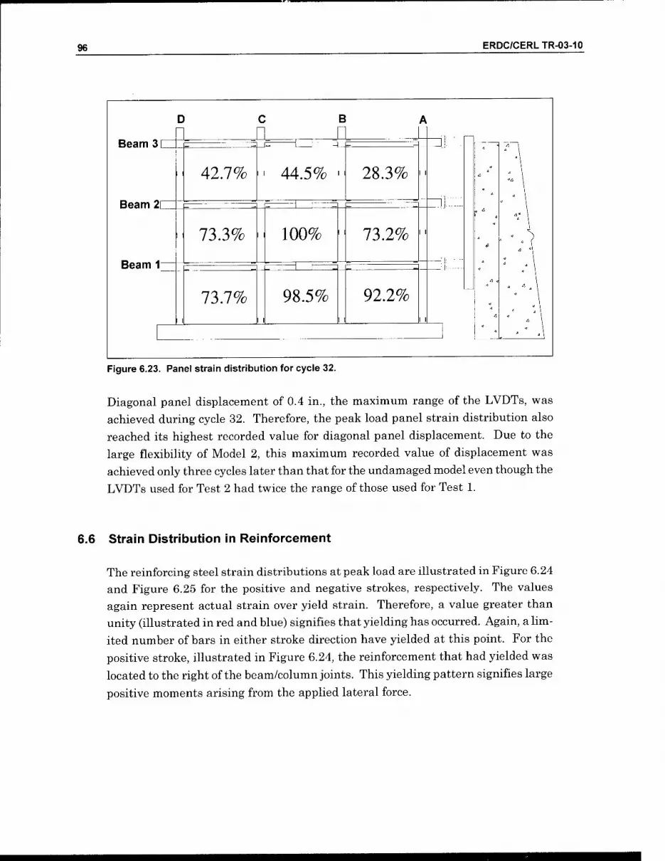
96 ERDC/CERLTR-03-10
Beam 3 L
Beam 2E
Beam Ir
C a
42.7%
73.3%
73.7%
B II
44.5%
11
100%
98.5%
28.3%
73.2%
92.2%
11
Figure 6.23. Panel strain distribution for cycle 32.
Diagonal panel displacement of 0.4 in., the maximum range of the LVDTs, was
achieved during cycle 32. Therefore, the peak load panel strain distribution also
reached its highest recorded value for diagonal panel displacement. Due to the
large flexibility of Model 2, this maximum recorded value of displacement was
achieved only three cycles later than that for the undamaged model even though the
LVDTs used for Test 2 had twice the range of those used for Test 1.
6.6 Strain Distribution in Reinforcement
The reinforcing steel strain distributions at peak load are illustrated in Figure 6.24
and Figure 6.25 for the positive and negative strokes, respectively. The values
again represent actual strain over yield strain. Therefore, a value greater than
unity (illustrated in red and blue) signifies that yielding has occurred. Again, a hm-
ited number of bars in either stroke direction have yielded at this point. For the
positive stroke, illustrated in Figure 6.24, the reinforcement that had yielded was
located to the right of the beam/column joints. This yielding pattern signifies large
positive moments arising from the applied lateral force.

ERDC/CERLTR-03-10 97
D
Beam 3C
O.Qlf
Beam 2 11
0.30
Beam 111
B IQAA (L32. 0.45
0.04 O.OTti
0.05
^.01
0.02
3.01 0.41
0 19*
1.70
0.18
0.15
0.55
0.02>
^:93
0.30
Q.35_
IZE 0.10
0.39|<
JL3i
0.28 0.13
0.03i
0.05
lp-09
2.72
I i|8.64
0.21
0.21
0.04 0-5c|i il flJI
Figure 6.24. Reinforcement strain distribution at peak load, positive stroke.
D B
Beam 3
0.08 I
Beam 2 C
0.31
Beam 1C
liL2Q QAS, 0.33
0.04
X2^
0.3£li
p:oi
0.12
[0.02
1.82
2.66 0.16
oia
T:25
0.09
ILll-
QJiS_ niE 0.42
0.231
0.05
0.32
lp.44
1—F
m
1.02
0.11
O.Sgl
0.06 3.00
022
10.14
0.02i iO.27
0-19^1
O.Oii
0.3J
0.23
0.27
0.53
0.16
0.12! I
0.5t
0.47
JLQflLJ
Figure 6.25. Reinforcement strain distribution at peak load, negative stroke.
Similar behavior was observed for the negative stoke case illustrated in Figure 6.25.
However, since the stroke direction was reversed, the bars that yielded were on the
left side of the beam/column joints. In addition, bottom steel to the right of the
beam/column joints also yielded on the first floor of column D and the third floor of
column C. These two steel reinforcing bars most likely experienced permanent de-
formations greater than the yield strain due to the large inelastic strains that oc-
curred during the preceding positive stroke cycle.
Figure 6.26 illustrates the maximum strain that occurred in the reinforcing bars
throughout the duration of the entire modified CUREE loading protocol for all three
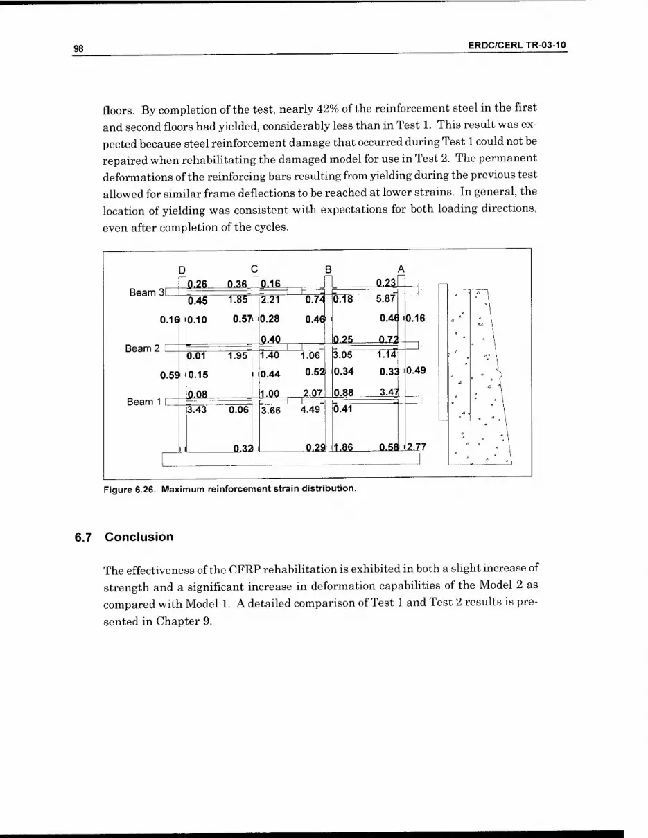
98 ERDC/CERLTR-03-10
floors. By completion of the test, nearly 42% of the reinforcement steel in the first
and second floors had yielded, considerably less than in Test 1. This result was ex-
pected because steel reinforcement damage that occurred during Test 1 could not be
repaired when rehabilitating the damaged model for use in Test 2. The permanent
deformations of the reinforcing bars resulting from yielding during the previous test
allowed for similar frame deflections to be reached at lower strains. In general, the
location of yielding was consistent with expectations for both loading directions,
even after completion of the cycles.
Beam 311
0.1$
Beam 2 L
0.59
Beam 1 C
0.45
i0.10
I I
■26 0.36_
0.571
0.01
0.15
OJiB-
1.95
3.43 0.06
Q-32 i
2.21
0.28
IL4Q_
QJ16_
0.74
0.46'
1.40
0.44
iUJO EZE
1.06
0.52J
2.07
3.66 4.49
0.18
0.2S_
0.291 ill .86
3.05
0.34
0.88
0.41
Figure 6.26. Maximum reinforcement strain distribution.
6.7 Conclusion
JL23
5.87
0.48 I
0.72
1.14
0.33 1
3.47
0.16
0.49
JLSaJl.77
The effectiveness of the CFRP rehabilitation is exhibited in both a shght increase of
strength and a significant increase in deformation capabihties of the Model 2 as
compared with Model 1. A detailed comparison of Test 1 and Test 2 results is pre-
sented in Chapter 9.

ERDC/CERLTR-03-10 99
7 Performance of Concrete Frame With Infill Panel Openings (Test 3)
7.1 Overview
Model 3 used the same beam, column, and bay identification scheme employed for Model 1 (Figure 7.1). In basic form this model was similar to Model 1. However, the infill panels were designed with openings to represent windows, doors, and other apertures typically found in this type of construction (illustrated in Figure 7.2 and others). Also unlike Model 1, the CMUs were grouted in place. Other differ- ences were the use of concrete with higher compressive strength and larger longitu- dinal positive reinforcement and spacer reinforcement — #2 instead of D2 (see Figure 3.7). As in the previous two tests, Model 3 was loaded using the modified CUREE method described previously (see Figure 3.24).
Beam 3
D
11
B
3C 3B 3A i >
Beam 2
11
Beam 1
2C 2B 2A
IC IB lA
i t
Figure 7.1. Model 3 beam, column, and bay identification scheme (panel openings not shown).

100 ERDC/CERLTR-03-10
7.2 Crack Formation and Propagation
The first cracks appeared during cycle 25 with a maximum load of 23.0 kips on the
third floor. Figure 7.2 shows that cracks appeared in all but panel 3A. Most of the
cracks occurred in the mortar. Cycle 25 is also when the masonry started to sepa-
rate from the columns and beams in panels IB, IC, 2A, 2C, SB, and 3C. Through-
out the remainder of the test, the first floor cracked the most, with a majority of
these cracks initiating out of the corners of the window openings.
[ ) C : i 3 A
Beam 3| 1 I 1
Beam 21 j •T-\ 1
Beam 1L 1 \ i 1
f
\
1.
Figure 7.2. First cracl<s, cycles 25 througli 28.
The LVDT at panel 2A was the most strained panel at cycle 25, at 0.02 in., with the
remainder of the second floor less than 82% of the strain value for panel 2A. The first and third floors had less strain, reaching about 18% of the maximum strain in
panel 2A. Another indicator of the cracks in the panels was the drift ratio. The first
and second floors had drift ratios of 0.11% and 0.19%, respectively, indicating why
they cracked more than the third floor, which had a drift ratio of 0.09%. The higher
drift ratio means more localized displacements, thus greater strains and corre-
sponding damage.
As the testing continued through cycle 29, the damage propagated in a similar
manner: more masonry separated from the concrete frame and more cracks formed
and grew in the mortar. The cracks were typically found near the corners of the
openings, where the stress concentrations were large. Figure 7.3 shows the first
cracks forming in the concrete frame, and these appear to be shear cracks. These

ERDC/CERLTR-03-10 101
cracks appeared in concrete contiguous to bays 3B and 3C at points where there was
no masonry to help support the concrete.
: ) C / E 3 A
Beam 31 1 1 f 1 1 j
Beam 21 1 1 j ]
-\ k. r—1
Beam 11 1 1 1 1 1 1 1 /
/" \
L
-
Figure 7.3. Cracks appearing during cycles 29 through 31.
New cracks formed in the panels through cycle 32. At this point many of the new
cracks, and extensions of the existing ones, started to propagate through the bricks
instead of following the mortar joints. The first floor had the greatest number of
new cracks (Figure 7.4) due to the rapid increase in the strain in the panels. While
the first and second floors had of cracks forming in the panels, the third floor had
slight separation of the panels from the concrete frames. The third floor did not
have enough strain to initiate any cracks in the masonry panels, but the drift ratio
of the third floor was about 0.05% — enough to cause the panels to separate from
the concrete frame.
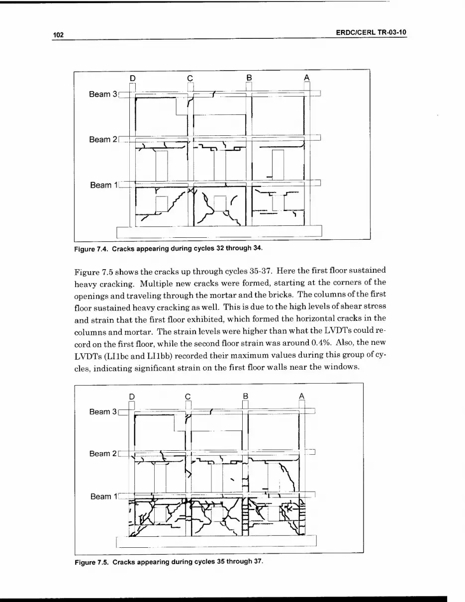
102 ERDC/CERLTR-03-10
D
Beam 3 [
Beam 2 [
Beam 1[
C B
;-> ^> .-^iT-i-^ N
"7"
Figure 7.4. Cracks appearing during cycles 32 through 34.
Figure 7.5 shows the cracks up through cycles 35-37. Here the first floor sustained
heavy cracking. Multiple new cracks were formed, starting at the corners of the
openings and traveling through the mortar and the bricks. The columns of the first
floor sustained heavy cracking as well. This is due to the high levels of shear stress
and strain that the first floor exhibited, which formed the horizontal cracks in the
columns and mortar. The strain levels were higher than what the LVDTs could re-
cord on the first floor, while the second floor strain was around 0.4%. Also, the new
LVDTs (Lllbc and Lllbb) recorded their maximum values during this group of cy-
cles, indicating significant strain on the first floor walls near the windows.
Beam 3[
Beam 2 C
Beam 111
Figure 7.5. Cracks appearing during cycles 35 through 37.

ERDC/CERLTR-03-10 103
The first floor panels continued to crack during cycles 38 - 40, as shown in Figure 7.6. While the strain on the first floor was still greater than what the LVDTs could record, it was not as severe as before and there was less cracking. The second floor also had new cracking because of the high levels of stress (around 0.39%). Several of the new cracks caused sections of the panel to fall out, and the masonry was loose to the touch in many of the panels. The load capacity continued to drop with the increased deflections. At peak displacement of 2.76 in., the load carried by the top floor was only 19.3 kips — much less than the maximum carried load of 32.2 kips. Although the frame was still in its original shape, the damage done to the structure as a composite was severe: the masonry had lost most of its cohesiveness and the mortar was cracked. Only the third floor panels remained intact, although they had partially detached from the concrete frame in many places.
Beam 3
Beam 2
Beam 1
Figure 7.6. Cracks appearing during cycles 38 through 40.

104 ERDC/CERLTR-03-10
Beam 3 c
Beam 2 [
Beam IE
B A
y.
Wz. Figure 7.7. Cracks found at the completion of the test.
7.3 Load/Displacement Behavior
The test specimen load/displacement behavior with the modified CUREE loading
protocol is plotted in Figure 7.8. The load plotted on the ordinate is the story shear
for each level. The drift ratio, plotted on the abscissa, is defined as the interstory
displacement divided by the story height. The hysteresis for each floor is discussed
to help explain the behavior of the test specimen.
The peak lateral load for the model occurred during the 35'^ cycle with a first floor
peak story shear of 71.6 kips in the positive stroke. The second and third floors had
story shears of 56.5 kips and 33.6 kips in the positive stroke, respectively. The
negative stroke story shears of the first, second, and third floors were 66.08 kips,
51.49 kips, and 30.07 kips, respectively. The drift ratios for the associated peak
loads in the positive stroke direction were 0.8%, 1.2%, and 0.53% for the first, sec-
ond and third floor, respectively. For the negative directions, the drift ratio of the
first, second, and third floors were 0.6%, 1.1%, and 0.55%, respectively. The third
floor absolute displacements were 1.67 in the positive stroke and-1.61 in the nega- tive stroke. The peak loads and corresponding story shears and drift ratios are
summarized in Table 7.1

ERDC/CERLTR-03-10 105
-4.00 -3.00 -2.00 -1.00 0.00 1.00 2.00 3.00 4.00
Drift Ratio (%)
-2-10 1 Drift Ratb (%)
-3 -2 -1 0 1 Drift Ratio (%)
Figure 7.8. Load/displacement behavior for each floor for Model 3.

106 ERDC/CERLTR-03-10
Table 7.1. Peak loads and corresponding story shear and drift ratio.
Peak Load (kips) Story Shear kips) Drift Ratio (%)
Floor + - + - + -
3 33.6 -30.07 33.6 30.07 0.53 0.55
2 22.8 -21.42 56.4 51.49 1.2 1.1
1 15.1 -14.59 71.5 66.08 0.8 0.6
Note: + and - refer to the stroke direction towards (+) and away (-) from the reaction structure.
Figure 7.8 shows that the drift ratio for the third floor after reaching peak load was
less than for the first and second floors. The main cause for this behavior was the
inverse triangular distribution of lateral forces prescribed by IBC 2000. The story
shear of the first and second floor was roughly double that of the third floor (Table
7.2). These relatively high values of drift for the first and second floor were what
caused these panels to crack first. After they had cracked, the difference in the drift
ratios between the third floor and the first and second floor was amplified.
Table 7.2. Lateral load, story shear, and vertical load distribution.
Floor Approx. Lateral Load Distribution (% of V)
46
33
21
Approx. Story Shear Distribution (% of V)
46
79
100
Approx. Vertical Load Distribution (% of V)
33
67
100
The prescribed distribution of story shear was one of the causes of the first masonry
cracks developing on the second floor rather than the first floor at the peak load.
During the peak load, cracks emerged in every masonry panel on the first and sec-
ond floor, while only one crack appeared in the masonry on the third floor. The
cracks in the masonry panels were due to the vertical distribution of story shear and
the distribution of vertical load from the dead weight of the test specimen and the
lead ingots. Each floor was loaded similarly, leading to the vertical load distribu-
tion that was then normalized to the third floor, as shown in Table 7.3.
The total vertical load on the first floor was 1.5 times the value for the second floor.
Also, the story shear in the first floor was 1.27 times the value for the second. This
explains why the first floor experienced a large amount of cracking. Conversely, the
second floor, with one-third less total vertical load, experienced a relatively large
story shear — approximately 79% of the first floor value. This large story shear,
coupled with a smaller vertical load, decreased the lateral load capacity of the sec-
ond floor and caused an increase in cracking.
After cracking occurred in the first and second floors, the displacement imposed on
the third floor by the modified CUREE loading protocol was mostly taken by the

ERDC/CERLTR-03-10 107
lower levels. The cracking of the masonry panels in the lower levels caused a sig- nificant loss in first- and second-floor stiffness. The majority of the displacement required of the third floor had to be captured by the first and second floors. This phenomenon explains the large increase in drift ratio of the first and second floors after peak load and the relatively small increases in drift ratio of the third floor dur- ing this time (see Figure 7.8). In addition, the relatively few cracks observed in the third floor during testing was consistent with the small values of drift ratio occur- ring on this floor. The relative distribution of displacements before and after crack- ing as is shown a percentage of the third floor displacement in Table 7.3.
Table 7.3. Relative displacement (fraction of 3'^'' floor displacement) before and after cracking.
Displacement Distribution
Floor Before Cracking After Cracking Percent Increase
3 100% 100% 0%
2 80% 90% 12.5%
1 32% 70% 119%
The significant cracking of the first story caused the large increase in displacement. The uniform cracking of the first floor panels contributed to the symmetry of the hysteresis for the first floor. The first floor had the largest increase in displacement since about 80% of the total cracking happened on the first floor (see Figure 7.7). Because of this, the other floors did not have to crack much to reach the desired dis- placement of 3 in. for the prescribed loading protocol.
In Figure 7.9, backbone curves are plotted directly on the hysteresis curves for each floor. As in Test l(see page 68), when used with the modified CUREE protocol, the standard technique for plotting backbone curves resulted in an underestimation of load resistance due to the small load values that occurred during the trailing cycles for each deformation step. Therefore, as for Test 1, points on the backbone were plotted through the intersection of the first cycle (primary cycle) curve for each de- formation step with the primary cycle curve of the previous deformation step con- tinued for every step. Using this convention, a more accurate portrayal of the struc- tural system behavior resulted.
The backbone curves for the first and second floors are similar in shape. After an initial linear portion, a peak value load is achieved, followed by a decline in load where the residual strength is less than the peak load but still substantial. There- fore, Model 3 acts as a ductile system that is capable of absorbing significant amounts of energy, which is significant because of the lack of ductile reinforcement detailing in the R/C frame. This behavior is represented as a Type 1 general com- ponent behavior curve per FEMA 273, with the first floor being deformation- controlled and the second floor being force-controlled.

108 ERDC/CERLTR-03-10
-4 -2-10 1 Drift Ratio (%)
-3 -2-10 1 Drift Ratio (%)
-4 -1 0 1 Drift Ratio (%)
Figure 7.9. Hysteresis with backbone curves for each floor of IWodel 3.
The shape of the third floor backbone curve is different than those of the other two
floors. After an initial peak load the backbone curve drops off. There is some strain

ERDC/CERLTR-03-10 109
hardening happening before the floor loses strength, as represented by a Type 2 general component behavior curve per FEMA 273, with the floor being force- controlled.
The stiffness degradation was examined along with the hysteresis curves. The stiffness for each primary cycle, starting with cycle 7, was calculated by measuring the slope between the peak load during that cycle to the origin of the story shear versus interstory displacement plot. Using this method, values of the 'stiffness' for each primary cycle, in both the positive and negative directions, were computed and summarize in Table 7.4, as well as shown in Figure 7.10.
Table 7.4. Summary of average stiffness for each floor.
Cycle First Floor Second Floor Third Floor No. positive negative average positive negative average positive negative average
7 366 426 396 313 303 308 515 295 405
14 431 520 475 350 280 315 337 284 310
21 520 437 479 243 224 233 321 233 277
25 438 353 395 198 181 189 253 142 197
29 339 283 311 157 149 153 215 106 161
32 267 250 258 122 110 116 198 100 149
35 147 179 163 80 80 80 106 91 99
38 40 36 38 45 51 48 93 62 77
500
400
S. 300 2
I 200
100
-©—Floor 1
-A—Floor 2
-B—Floor 3
10 15 20 25
Cycle No.
30 35 40
Figure 7.10. Stiffness degradation for each floor.
Table 7.4 shows the amount of stiffness degradation that occurred during the length of the test. All of the floors showed significant loss in stiffness by the completion of the test. By cycle 38 the final stiffness percentages, as compared with the initial
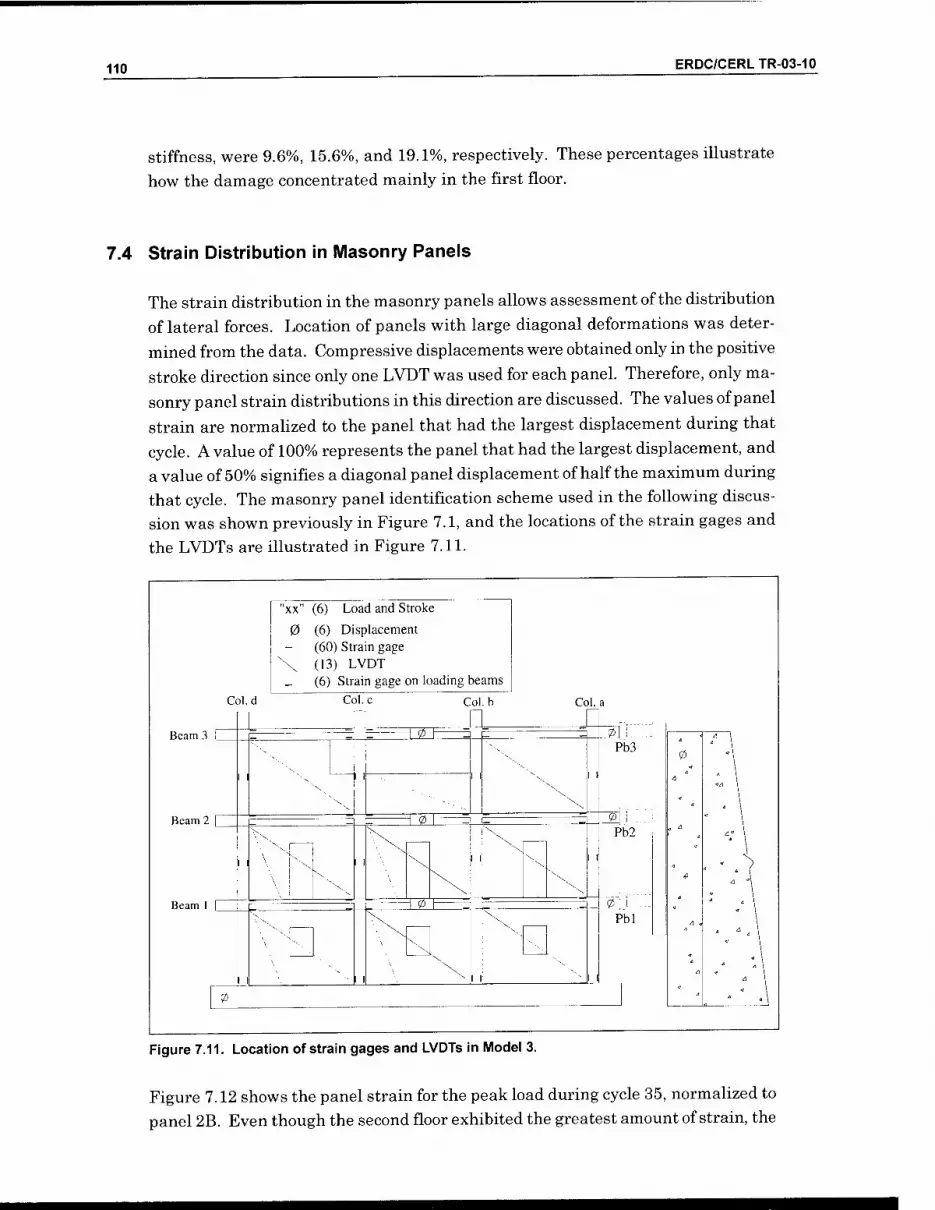
110 ERDC/CERLTR-03-10
Stiffness, were 9.6%, 15.6%, and 19.1%, respectively. These percentages illustrate
how the damage concentrated mainly in the first floor.
7.4 Strain Distribution in Masonry Panels
The strain distribution in the masonry panels allows assessment of the distribution
of lateral forces. Location of panels with large diagonal deformations was deter-
mined from the data. Compressive displacements were obtained only in the positive
stroke direction since only one LVDT was used for each panel. Therefore, only ma-
sonry panel strain distributions in this direction are discussed. The values of panel
strain are normahzed to the panel that had the largest displacement during that
cycle. A value of 100% represents the panel that had the largest displacement, and
a value of 50% signifies a diagonal panel displacement of half the maximum during
that cycle. The masonry panel identification scheme used in the following discus-
sion was shown previously in Figure 7.1, and the locations of the strain gages and
the LVDTs are illustrated in Figure 7.11.
"xx" (6) Load and Stroke
0 (6) Displacement - (60) Strain gage
\ (13) LVDT
- (6) Strain gage on loading beams
Col.d Col.c Col. b Col. a
Beam 3
Beam 2
Beam 1 [
Figure 7.11. Location of strain gages and LVDTs in Model 3.
Figure 7.12 shows the panel strain for the peak load during cycle 35, normahzed to
panel 2B. Even though the second floor exhibited the greatest amount of strain, the

ERDC/CERLTR-03-10 111
first floor had the most crack propagation. This is probably an effect arising from the openings in the panels. Most of the cracks on the second floor appeared at the corners of the doors, thus allowing the panels to become more flexible and undergo greater displacements with fewer cracks. On the first floor, however, the windows did not allow much flexibihty in the panels; instead the corners of the windows cre- ated stress concentrations that led to an increase in the number of cracks.
\ 3C 3B ^v 3A \4
^V 2C \^\ 2B ^\ 2A
^^\ IC \ lA
Figure 7.12. Panel strain distribution for cycle 35.
The strain distribution was also different between the first floor and the second and third floors. On the first floor the level of strain decreased the farther away from the actuator the measurement was made. On the second and third floors, the low- est amount of strain was recorded in bay A and the highest amount was recorded in bay B, while bay C had the second highest amount of strain. The third floor showed a very small amount of strain compared with the other two floors, either because of the amount of cracking in the lower floors or because the third floor required very little displacement to reach the target of 3 in. of displacement.
7.5 Strain Distribution in Reinforcing Steel
The location of the yielding reinforcing bars was observed from the data. The strain distribution at peak load, cycle 35, and at peak displacement, cycle 38, is illustrated for the reinforcing bars in Figure 7.13 and Figure 7.14. The strain values for each bar are normahzed to the yield strength of the bar. A value of 1 indicates a meas- ured strain equal to the yield strain while a value greater than 1 indicates yielding

112 ERDC/CERLTR-03-10
has occurred. During the peak load few bars yielded, but the interesting informa-
tion is the placement of those bars that did yield. In Figure 7.13, the steel that did
yield was in the columns, along the right side of the structure. Possibly this is be-
cause of the uplifting force the applied load had on the structure. A reinforcing bar
on the bottom of the third beam also yielded, possibly due to local influences. The
cracks in the column or the lack of masonry close by could also have contributed to
the yielding. Figure 7.14 shows the yielding during the negative stroke at peak
load. The majority of the bars that yielded were along the outside columns and
beams. This stroke also caused the bars to pull out from the concrete, and this can
be seen in the rest of the cycles.
Beam 3 [
Beam 2 [
0.72
Beam 1L
0.06
c 0.421 |009
O.OS I I
iorSSl
-0.01
0.03
0.72
5.40 -0.17
[1.04
■0^42-
0.17
-o.ie
-6:371 I
0.03
0.07
I 10.64
-0.01
1.28}
-O.Tf
0.35
-0.15
0.39
-0.05
-0.05
-0.01
0.08
1.09
-0.17
-0.081
0.01
I 11.39
-0.07
1.3411 I
0.26
Figure 7.13. Strain distribution of reinforcement in cycle 35 positive stroke.
Beam 3C
Beam 2 [
0.37
Beam 1[
•0.07
11.60
-0.02
-3.07
0.32
0.15
-0.01
1.14
0.07
0.21
0.43
0.13 0.15
-0.02
0.84
3IZE
1.22
0.93
-0.04
19.57
0.631 I
O.30
0.50
-0.08
0.43
'0.15
■0.11
1.34
0.38
0:661
1.04
0.36
-19.56
10.99
Figure 7.14. Strain distribution of cycle 35 negative stroke.

ERDC/CERLTR-03-10 113
Figure 7.15 and Figure 7.16 show the strain distribution at peak displacement of
the structure. The reinforcing bar strain for the positive cycle, Figure 7.15, is simi-
lar to that of the peak load. One main difference is that the bottom right corner re-
inforcement bar had a puUout from the concrete. Figure 7.16 shows the reinforcing
bar strain for the negative stroke. Here the only bar that showed any yielding was
on the ground floor along column D. This could be accounted for by some perma-
nent deformation that may have occurred during previous cycles. Figure 7.16 also
shows a number of bar puUouts. Most of these happened in places that had previ-
ously yielded. The only different puUout occurred at the joint between column C
and beam 2, and this may be explained by either poor bonding or local effects.
D B
Beam 3 t
Beam 2
Beam 1
Figure 7.15. Strain distribution of cycle 38 positive stroke.
D
Beam 3L
Beam, 2 C
0.4''
Beam 1 C
■0.07
■2.23
C
-o.i4nn.o.3
-0.04
JL2.52
-0.09
i0;4r
fi.22_
0.10
TIE
1-0.03
0.61
IZI
0.5(i
19.57
0.4ii
IZE 0.2!
0.04 0.65
'0.04
10.17
0.65 -19.6J2
0.80 0.09
U6
o.6i; i
■0.15 0.31
' I L ,
I in 7.1 19.6f(i
jj.—
r 0.13
Figure 7.16. Strain distribution cycle 38 negative stroke.
114 ERDC/CERLTR-03-10
7.6 Conclusion
Test 3 was carried out successfully; shear failure occurred in the columns of the first
story, as was expected based on model design. Detailed comparison between Test 1
and Test 3 are presented in Chapter 11.

ERDC/CERLTR-03-10 115
8 Performance of Model Used in Test 3 as Rehabilitated With CFRP (Test 4)
8.1 Overview
After the conclusion of Test 3, Model 3 was repaired and rehabilitated to near- original condition using methods similar to those used in rehabilitating Model 1 af- ter the conclusion of Test 1. First, the CMUs in the first floor were removed. Sec- ond, the four columns of the first story were totally replaced. Next, the large cracks in the frame members were injected with epoxy to seal the voids. The columns of the first floor were wrapped with CFRP, as described below. As a result of Test 3, one large crack appeared on the short column and one on the center beam of the third floor; these members were wrapped with CFRP as a repair (not rehabilitation) measure. Finally, CMU panels with openings were reconstructed on the first floor.
8.2 CFRP Retrofit Application
Before application of the CFRP, the flexural and shear cracks in the beams were repaired using the techniques described in Chapter 6, Section 6.2, which comply with applicable portions of ASTM C-881. Figure 8.1 and Figure 8.2 show photo- graphs of portions of the rehabilitated frame. The CFRP is the black material cov- ering the beams, and the J-51 sealant is the gray material covering the beam cracks.

116 ERDC/CERLTR-03-10
1. ; t
( J jt - j I
IK-- >• » r (
' Til ', ill
:•«'■
Figure 8.1. Rehabilitation of whole structure.
Figure 8.2. Repairing of the third story column and beam.

ERDC/CERLTR-03-10 117
CFRP with a fiber orientation of +45/-45 degrees was used to strengthen the R/C frame according to ACI 440-00, as illustrated in Figure 8.3. The first floor columns were completely wrapped, along with the top half of Column C on the third floor. Also, the stem of Beam 3, a T-beam, was wrapped adjacent to the openings in ma-
sonry panels 3B and 3C.
The CFRP was applied using a wet lay-up system. The dry carbon-fiber sheets were cut to the correct dimensions and impregnated with a saturating resin. The satu- rating resin, along with the compatible primer and putty, was used to bond the car- bon fiber to the concrete surface. The primer was used to penetrate the surface of the concrete providing improved adhesive bond for the saturating resin. The putty filler was utilized to smooth rough corners and fill voids in the concrete in order to provide a more reliable bond between the carbon fiber and the concrete. The satu- rating resin provides a load path between the concrete and the carbon fibers as well as between the fibers themselves. The stress versus strain relationships for each of the four coupons tested are shown in Figure 8.4.
The first floor and the third floor columns were completely wrapped, while beam 3 was U-wrapped around the three sides of its stem. Calculations were not performed to determine the rehabilitated shear, bending, or axial strengths, but it is reason- able to assume that these values for Model 4 should exceed the undamaged capaci- ties of Model 3 (from which Model 4 was reconstructed). After the frame itself was rehabihtated with CFRP, the first floor CMU infill panel was replaced.
Beam 31
Beam 211
Beam 1C
Figure 8.3. Location of frame elements where CFRP was applied.

118 ERDC/CERLTR-03-10
Coupon c-45-1-2 Stress vs Strain
■| 6000
1 4000
1 2000
0 0.(
^^—^
00 0.002 0.004 0.006 0.008 0.010 y = 862092x +151.71
Strain (In/In)
Coupon c-45-1-3 Stress vs Strain
0.000 0.002 0.004 0.006 0.008 0.010 y = 1513638x + 26
Strain (In/In)
Coupon c-45-1-4 Stress vs Strain
0.000 0.002 0.004 0.006
Strain (In/In)
Coupon c-45-1-5 Stress vs Strain
0.000 0.002 0.004 0.006 ^O^O^^^^^O-^^
Strain (in/ln)
Figure 8.4. Stress vs strain relationship for CFRP coupons.
8.3 Crack Formation and Propagation
Model 4 is discussed in terms of the element identification scheme illustrated previ-
ously and repeated in Figure 8.5. As in Tests 1-3, the model was loaded using the
previously described modified CUREE protocol. The first cracks appeared during
cycle 21, with a maximum load of 9.2 kips acting on the third floor. Figure 8.6
shows the cracks appearing at the joints between column B and beam 2, and be-
tween column C and beam 2. Throughout the rest of the test, the second floor con-
tinued to form a majority of the cracks.
Figure 8.7 shows the cracks that formed during cycles 25 through 28. Panels lA,
2A, 2B, 3C all cracked, and most of these cracks traveled along the mortar joints.
However, in panel 2A the crack propagated through bricks as well as mortar. Also
the lower left side of panel 2A disconnected from the concrete frame. The concrete frame also formed two new cracks — one in Beam 3 above panel 3B, contiguous to
the opening, and one at the top of column D.
The cracks that appeared during cycles 29 through 31 are shown in Figure 8.8.
Here the second floor received most of the new cracks, with the only other crack ap-
pearing in panel lA. Two of the cracks in the second floor were continuations of
previous cracks, but there were also new cracks. Panel 2C cracked for the first time
above the doorway, while in panel 2B all the cracks that occurred previously joined
together.

ERDC/CERLTR-03-10 119
Figure 8.5. Identification scheme for IVIodel 4.
Beam 3 I
Beam 2 C
Beam
x:
-|—rt «=tt==t
Figure 8.6. First cracks, cycles 21 thirough 24.
Z]
J

120 ERDC/CERLTR-03-10
D
Beam 3 I
Beam 2 I
Beam 1E
^^-
x=cr
^^
/
Figure 8.7. Cracks appearing during cycles 25 through 28.
D
Beam 3 1
Beam 2 C
Beam 1[
^
C B
B
:l--Jit
'^. ^ WTT
Figure 8.8. Cracks appearing during cycles 29 through 31.
Figure 8.9 shows the crack propagation during cycles 32 through 34. During this
test the second floor had an increase in the number of cracks. All three panels de-
veloped new cracks, with most of these occurring in panel 2A around the corners of
the doorway, where stress concentrations were very high. Most of the cracks in
panel 2C occurred along the border between the panel and the concrete frame. Two
panels, SB and IB, cracked for the first time, with the cracks travehng through both
mortar and brick. Also the concrete frame developed a number of new cracks, most
of them near joints.

ERDC/CERLTR-03-10 121
Beam 3 C
Beam 21
Beam 1[
f
r-H f
^ \r-xr^ K I * \ I ^tjt
Figure 8.9. Cracks appearing during cycles 32 tliroughi 34.
Cycles 35 through 37 (Figure 8.10)show more new cracks, with many of them occur-
ring in panel 2A. Here the cracks occurred in the same places as previously; only
the density of cracks increased. Also, the first floor had an increase in the number
of cracks, with some panel separation happening in panel lA, a new stair-step crack
happening at the window corner in panel IB, and panel IC having its first crack at
the corner of a window. Panel 3B showed some separation from the frame on both
sides, along with a new crack at the right side. Also, the joints at columns B and C
and beam 2 had a large number of cracks occur.
Beam 3 C
Beam 2 C
Beam 1[
C B
f IQ' ■_= ^S.
\ \x w=i=
/
\ ' 1
Figure 8.10. Cracks appearing during cycles 35 through 37.

122 ERDC/CERLTR-03-10
Figure 8.11 displays the cracks occurring during cycles 38 through 40. Most of the
cracks were near the top of the panel, or they were continuations of previous cracks.
Panel lA developed a new crack. Most of the cracks that formed were in the col-
umns along the second floor, with some in beams 2 and 3.
Beam 3
Beam 2
Beam 1
Figure 8.11. Cracks appearing during cycles 38 through 40.
Figure 8.12 shows all the cracks found at the completion of the test. Only a few new
cracks were discovered. All the new panel cracks formed in the second floor. Panel
2B had the most new cracks, with the right side of the panel showing large new
cracks while panel 2A had only one small new crack. Also, the columns showed
some new cracks near the joints. Column A had a crack near its joint with beam 2,
and column B had a crack near beam 2 as well.
D
Beam 3 I
Beam 2 UZ
Beam 1[
;=;=a;
-OEE:
aO'
C B
Figure 8.12. Cracks found at the completion of the test.

ERDC/CERLTR-03-10 123
8.4 Load/Displacement Behavior
The load/displacement behavior of Model 4 under the modified CUREE loading pro- tocol is plotted in Figure 8.13. The load plotted on the ordinate is the story shear for each level. The drift ratio, defined as the interstory displacement divided by the story height, is plotted on the abscissa. The hysteresis for each floor is discussed in
order to explain the behavior of the model.
2
«5-&_
o
Floor 1
^&
-60
--3&
-60
-90-
Drift Ratio (»/)
Floor 2
Drift Ratio (%)
Floor 3
Drift Ratio (<%)
Figure 8.13. Load/displacement behaviors for each floor of IVIodel 4.

124 ERDC/CERLTR-03-10
The peak lateral load for the model occurred during the 35* cycle, with a peak story
shear of 64.6 kips on the first floor, 50.5 kips on the second floor, and 30.4 kips on
the third floor, all in the positive stroke. The negative stroke story shear was 63.5
kips for the first floor, 50.0 kips for the second floor, and 29.0 kips for the third floor.
The drift ratios for the associated peak loads in the positive direction were 0.288%
for the first floor, 2.205% for the second floor, and 0.477% for the third floor. For
the negative stroke, the drift ratios were 0.212% for the first floor, 2.01% for the
second floor, and 0.767% for the third floor. The third floor had an absolute dis-
placement of 1.78 in. in the positive stroke and 1.79 in. in the negative stroke. The
peak loads and associated story shears and drift ratios are summarized in Table 8.1.
Table 8.1. Peak loads and corresponding story shears and drift ratios.
Peak Load kips) Story Shear (kips) Drift Ratio (%)
Floor + . + . + -
3 30.4 29.0 30.4 29,0 0.477 0.767
2 20.1 21.0 50.5 50,0 2.205 2.01
1 14.1 13.5 64.6 63.5 0.288 0.212
Note: + and - refer to the stroke direction towards (+) and away (-) from the reaction structure
Figure 8.13 shows the drift ratio of the third floor at peak load to be lower than that
of the second and first floors. The main cause for this behavior is inverse triangular
distribution of lateral forces specified by IBC 2000. From this loading distribution
the resulting story shear distribution is shown in Table 8.2 with the story shears of
the first and second floors roughly double that of the third floor. These relatively
high values of drift for the first and second floors indicate why these panels were
the first to crack.
Table 8.2. Lateral loads, story shear, and vertical load distribution.
Floor Approx. Lateral Load Distribution (% of V)
Approx. Story Shear Distribution {% of V)
Approx. Vertical Load Distribution (% of V)
3 46 46 33
2 33 79 67
1 21 100 100
The interstory displacement data also help to describe crack production where dis-
placement occurred on a floor independently of the displacements of the other floors.
Table 8.3 shows the interstory displacement for each floor before cracking occurred,
and at peak displacement. Even before cracks formed the second story showed the
largest amount of interstory displacement, which helps explain why it cracked first.
Then, at peak displacement, the second floor had an increase in interstory dis-
placement of about 683%,or 2.13 in., compared with displacements of 0.18 in. for the
first floor and 0.32 in. for the second floor. This is similar to what the cracks show:

ERDC/CERLTR-03-10 125
the first and third floors had about the same amount of displacement increase, and thus had about the same amount of cracking, while the second floor had a large in- crease in displacement and the most cracking.
Table 8.3. Interstory displacement before cracking occurred and after peak displacement.
Floor
Interstory Displacement
Before Cracking
0.13
0.27
0.06
Peak Displacement
0.32
2.13
0.18
Percent Increase
156%
683%
187%
Figure 8.14 shows the backbone curves plotted directly on the hysteresis curves for all three floors. As in the previous tests, the backbone curve method was modified to avoid underestimation of load resistance. Points on the backbone were plotted through the intersection of the first cycle (primary cycle) curve for each deformation step, with the primary cycle curve of the previous deformation step for every step. Using this convention, a more accurate representation of structural system behavior
was developed.
The backbone curve for the first and third floors are similar in shape. After an ini- tial linear portion, a peak value load is achieved, followed by a rapid drop. There- fore, the R/C frame with URM infill behaved in a brittle manner on the first and third floors, represented by a Type 3 general component behavior curve per FEMA 273, with the floors being force-controlled.
The backbone curve shape of the second floor is different from the other two floors. After an initial linear portion and peak load, the curve indicates some strain hard- ening before strength decreases. Therefore, on the second floor, the R/C frame with URM infill behaved as a ductile system that is capable of absorbing significant amounts of energy. This is significant because of the lack of ductile reinforcement detailing in the R/C frame. This behavior is represented by Type 1 general compo- nent behavior curve per FEMA 273, with the floor being deformation-controlled.
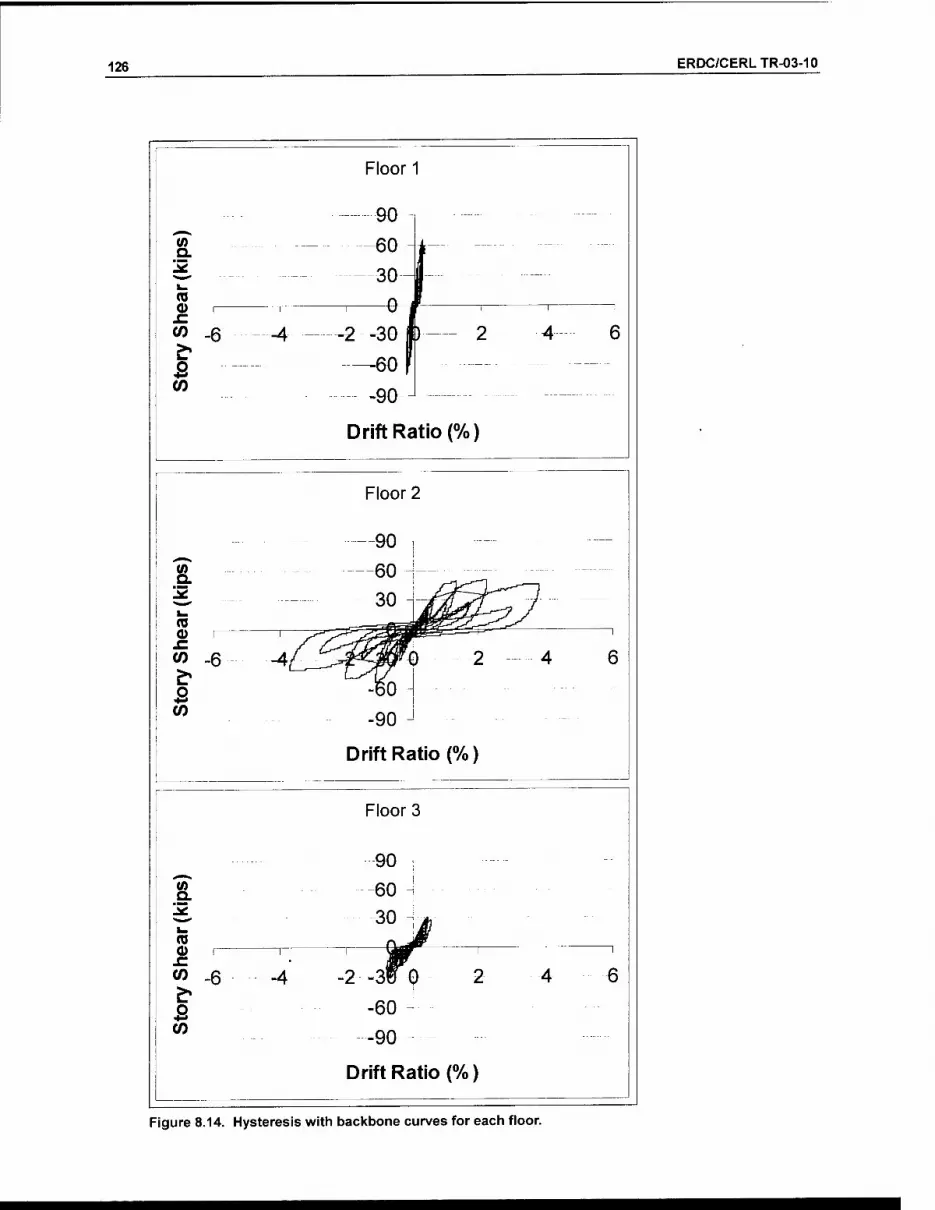
126 ERDC/CERLTR-03-10
Floor 1
Floor 2
90 n " " " — ,^^
^ 60 — .__ —
^ 30 ""^^f^^^^"^ —
t- ^[JrcLfi^^-L—*—^ /^ (0 _—^i5c=;S ■^^^^^^^^''^"0-^ 0) 1 ! ^-^,^ -<:e=W«t«=^= ^ sz / /^-"nynm V) -6 -4/ ^.^i^^^-m^k ) 2 4 6 ^ ^~^n o -60 -
"t-* w -90 ^
Drift Ratio (%)
1^ (0 o SI (0 .6
CO
-4
Floor 3
Figure 8.14. Hysteresis with backbone curves for each floor.
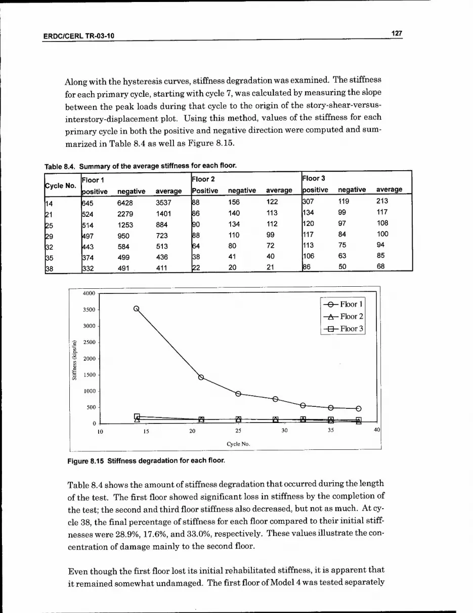
ERDC/CERLTR-03-10 127
Along with the hysteresis curves, stiffness degradation was examined. The stiffness for each primary cycle, starting with cycle 7, was calculated by measuring the slope between the peak loads during that cycle to the origin of the story-shear-versus- interstory-displacement plot. Using this method, values of the stiffness for each primary cycle in both the positive and negative direction were computed and sum-
marized in Table 8.4 as well as Figure 8.15.
Table 8.4. Summary of the average stiffness for each floor.
Floor 1 Floor 2 Floor 3 Cycle No.
positive negative average Positive negative average positive negative average
14 645 6428 3537 88 156 122 307 119 213
21 524 2279 1401 86 140 113 134 99 117
25 514 1253 884 90 134 112 120 97 108
29 497 950 723 88 110 99 117 84 100
32 443 584 513 64 80 72 113 75 94
35 374 499 436 38 41 40 106 63 85
38 332 491 411 22 20 21 86 50 68
4000
3500
3000
a 2500
f 2000
s S 1500
1000
500
0
-e- Floor 1 -A- Floor 2 -e-Floor 3
-e- -O
& -e- -H- iHr =s= ^ =B- 10 15 20 25
Cycle No.
30 35 40
Figure 8.15 Stiffness degradation for each floor.
Table 8.4 shows the amount of stiffness degradation that occurred during the length of the test. The first floor showed significant loss in stiffness by the completion of the test; the second and third floor stiffness also decreased, but not as much. At cy- cle 38, the final percentage of stiffness for each floor compared to their initial stiff- nesses were 28.9%, 17.6%, and 33.0%, respectively. These values illustrate the con- centration of damage mainly to the second floor.
Even though the first floor lost its initial rehabilitated stiffness, it is apparent that it remained somewhat undamaged. The first floor of Model 4 was tested separately

128 ERDC/CERLTR-03-10
to failure. The second and third floor actuators were removed and the first floor was
loaded cyclically to failure. Three separate trials where made in order to obtain sig-
nificant displacements and reduce the stiffness. The first of these trials was unsuc-
cessful (run 9). The actuator stalled out at 60 kips. To reduce the capacity, all of
the lead weights were removed and the model was tested again (run 11). This trial
was also unsuccessful in creating significant displacements. The final effort to re-
duce the capacity of the model was to remove the infill from bay IB (run 12). This
final trial was completed and significant displacements were achieved. The results
from the final trial in which the center bay and lead weights had been removed
must be compared with previous tests. To do so, the capacity must be adjusted to
represent the removal of the lead weights and the removal of the center masonry
panel. The effects of removing these two components are considered separately.
To understand the effect of removing the lead weights, the load/displacement curves
from run 9 and run 11 are compared. Run 9 included the weights and run 10 did
not. Run 9 included cycles 25-31, which were not completed. The 50 kip actuator
stalled out at 60 kips on cycles 25 and 29, which are the 0.6 in. and 0.8 in. cycles,
respectively. Run 10 included cycles 25 - 32. The actuator again stalled at 60 kips,
and the cycles did not reach their target displacements. However run 9 and run 10
can be used to examine the effect of removing the lead weights. The successful cy-
cles in each run also can be compared (i.e., cycles 26, 27, and 28). After comparing
the hysteresis curves of the runs it was determined that by removing the lead
weights, the capacity of the model decreased by 43.8% (see Figure 8.16).
Test 4 Level 1, run 9 and run 11, overlapping cycles(26-28 only), for weight comparison QA _.._ _
60 - - - - -
40 -
a
§ -c _i
20 n
--^^
4 .6 '^■'^/C^^^^^^^^^y^y^^ ) 0.2 0
-60-
on
-n
_ \
Deflection (inches)
Figure 8.16. Load/displacement with and without lead weights.

ERDC/CERLTR-03-10 129
Most of the load imposed on the structure by the lead weights transfers to the foun- dation through the columns because of the way the infill masonry was constructed. Therefore, the capacity of the columns was increased by 43.8% for test runs 11 and 12, resulting in an additional load capacity of 11 kips. Adding 11 kips to the peak load in run 11 resulted in an increase of 18.6%. This increase was used for both run
11 and 12.
The effect of removing the infill from bay IB was a significant reduction in the ca- pacity of the structure. Three different methods were used to determine the effect. The first method was to compare the load/displacement curves of the overlapping cycles from runs 11 and 12. The cycles that overlap were cycles 29 - 32. Run 11 was before the center panel was removed and run 12 was after the center panel was removed. By comparing these load/displacement curves it was calculated that the capacity of the model was reduced by approximately 14% (see Figure 8.17).
60- : \,\ .. ^^ i i.^. ^
40 - : 1/^ In ■^ 20- ^ il J 1- ra 0) 0 - : y^M^^ O -20-
55 -40 ■ ^ 7^1^ : i : Run 11, without dead weights
-60 - ^ ; Run 12, without middle t )ay on level 1
-80 - 1 i 1 i i 1
-4-3-2-1 0 1
1 i 1
2 3 4
Drift Ratio (%)
Figure 8.17. Load/displacement with and without center first floor bay.
The second method used was computer modehng. A 3 x 3 model using equivalent struts was created and a pushover analysis was performed. In this same model the strut was removed from the middle bay on the lower level. The pushover curves were then compared for each model, and it was calculated that the capacity of the model was reduced by approximately 28.4%.
The third method was to calculate the shear capacity theoretically. Using the re- sults from racking tests it was possible to calculate the shear capacity of the panel. The capacity of the concrete frame wrapped with CFRP was calculated according to ACl 440, section 10.3. From these calculations it was found that the panel contrib-

130 ERDC/CERLTR-03-10
uted to 23.2% of the model's shear capacity. The average of the results from these
three analytical approaches is 21.5%. Therefore run 12 was increased by 21.5% to
account for the removal of the center panel.
Based on observations and the results from these analyses, the load/displacement
curves for run 11 are magnified 18.6% and the load/displacement curves for run 12
are magnified by a total of 40.1% to account for the removal of the lead weights and
the removal of the first floor center bay. The original and modified hystereses are
presented in Figure 8.18 and Figure 8.19, respectively. Peak load and correspond-
ing story shear and drift are summarized in Table 8.5. Maximum drift ratio and
corresponding story shear are summarized in Table 8.6.
80
60
20
Run 9 Run 11, without dead weights Run 12, without middle bay on ievel 1
Drift Ratio (%)
Figure 8.18. Combined load/displacement without modification.
Run 9 Run 11, without dead weights Run 12, without middle bay on level 1
Drift Ratio (%:
Figure 8.19. Combined load/displacement with modification.
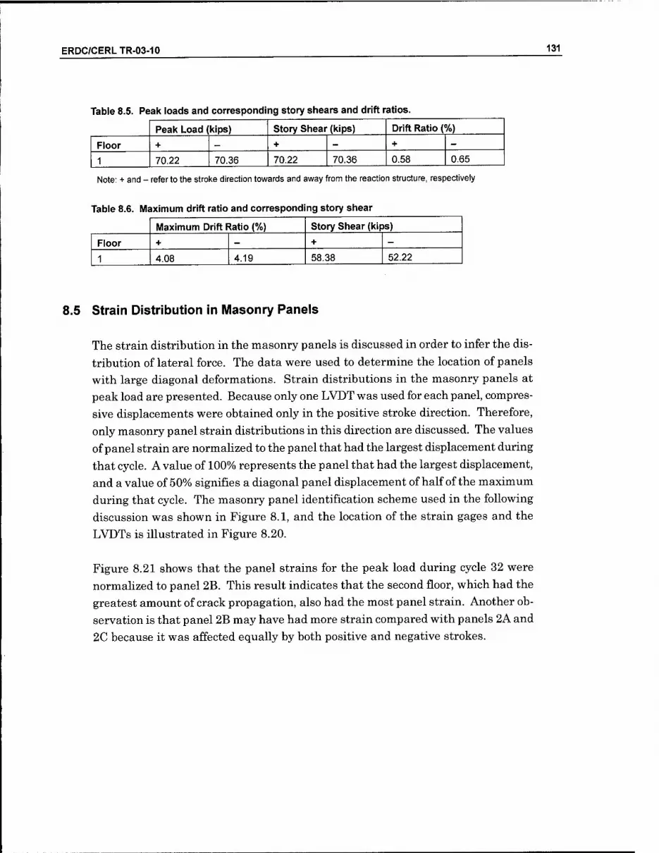
ERDC/CERLTR-03-10 131
Table 8.5. Peak loads and corresponding story shears and drift ratios.
Peak Load (kips) Story Shear (kips) Drift Ratio (%)
Floor + _ + - + -
1 70.22 70.36 70.22 70.36 0.58 0.65
Note: + and - refer to the stroke direction towards and away from the reaction structure, respectively
Table 8.6. Maximum drift ratio and corresponding story shear
Maximum Drift Ratio (%) Story Shear (kips)
Floor + — + -
1 4.08 4.19 58.38 52.22
8.5 Strain Distribution in (Masonry Panels
The strain distribution in the masonry panels is discussed in order to infer the dis-
tribution of lateral force. The data were used to determine the location of panels
with large diagonal deformations. Strain distributions in the masonry panels at
peak load are presented. Because only one LVDT was used for each panel, compres-
sive displacements were obtained only in the positive stroke direction. Therefore,
only masonry panel strain distributions in this direction are discussed. The values
of panel strain are normalized to the panel that had the largest displacement during
that cycle. A value of 100% represents the panel that had the largest displacement,
and a value of 50% signifies a diagonal panel displacement of half of the maximum
during that cycle. The masonry panel identification scheme used in the following
discussion was shown in Figure 8.1, and the location of the strain gages and the
LVDTs is illustrated in Figure 8.20.
Figure 8.21 shows that the panel strains for the peak load during cycle 32 were
normalized to panel 2B. This result indicates that the second floor, which had the
greatest amount of crack propagation, also had the most panel strain. Another ob-
servation is that panel 2B may have had more strain compared with panels 2A and
2C because it was affected equally by both positive and negative strokes.

132 ERDC/CERLTR-03-10
"xx"
0
(6) Load and Stroke
(6) Displacement (60) Strain gage (13) LVDT (6) Strain gage on loading beams
Col. d
Beam 3
Beam 2
Beam I
Col. c Col. b
TKE
Col. a
Pb3
Pb2
Pbl
Figure 8.20. Location of strain gages and LVDTs.
Test 4, Cycle 32 w
\ 3C
\ 0
3B \ 3A
\Qrb_
\ X^ \\ 2B
\ O \
\ 2
^ IC \ \>
\o N
\X IB
Figure 8.21. Panel strain distribution for peak load at cycle 32.

ERDC/CERLTR-03-10 133
8.6 Strain Distribution in Reinforcing Steel
The strain distributions for peak load, cycle 32, and peak displacement, cycle 38, are illustrated in Figures 8.22 through 8.25. The strain value for each bar is normal- ized to the nominal yield strain of the steel, so a value greater than 1 indicates a bar has yielded. The strain distributions for the peak loads are shown in Figure 6.22 and Figure 8.23 for positive and negative stroke, respectively. At peak load, few bars yielded. In fact, the only bars that did yield were in bay B, possibly because bay B was subjected to the most constant amount of strain compared with the other bays. Also, Figure 8.23 shows that there was a bar puUout at the joint between col- umn C and beam 2. Possible reasons for this could be local effects such as cracking of the frame or poor adhesion between the concrete and reinforcement.
Figure 8.24 and Figure 8.25 show the reinforcement bar strain distribution during peak displacement, cycle 38, in positive and negative stroke, respectively. Figure 8.24 shows that only 3 bars yielded at peak displacement. Two of these bars were on the second floor, which experienced the most cracking, and the third bar was at the joint of column C and beam 3, contiguous with the opening in panel 3B. Also, Figure 8.24 shows that a bar has pulled out of the frame. This is probably due to local effects between the reinforcement steel and concrete frame. Figure 8.25 shows the negative stroke at peak displacement. During this stroke, only the second floor experienced any yielding, possibly due to all the cracking that occurred on that floor. Also during this cycle, two bars pulled out of the concrete. At the corner of column D and beam 2 the reinforcement bar provided no support for either the posi- tive or negative stroke, while at the joint between column C and beam 2 the rein- forcement did provide support during the positive strokes.
c 0.34 ri-n.T^
Beam3L
Beami
0.»t
Beam iC
0.08
-0.01
0.57i
-0.41
0.0!>
-0.18
0.06
1.43
-0.15
0.26
I
».05
'0.53
a
-0.12
0.5(.
0.11 lft.07
-1.49
vJ ^ j -0.06
0.06
'0.75
0.04
0.22
«:6a=
-0.04
-0.03
-0.16
0.06
0.48
jlrz
MMO
Figure 8.22. Strain distribution during pealc load positive stroke.

134 ERDC/CERLTR-03-10
Beam 3^
Beam2C
0.1! •
Beam 1
-0.07
-0.04
-O;loi I
IflOS^
J2.0S..
-0.14 0.70
iTlS ^02^
uQa_ _iua
•0.02 0.0$
0.93
-0.29 rc=5ZE
LJ
0.00
0.57 -1.71
0.10
-0.04
0.87 0.27
iu3 . 0.09 _ 0.87
!o.95
-0.05 033
O.^'i
0.89
Lifl.31
Figure 8.23. Strain distribution during peak load negative stroke.
Beam 3 L
Beam 2 [
i.i;i
Beam 1
C
0.50_n-0.02
0.01
o.8r
19.60
0.05
1.14 -0.12 0.04
'0.55 -0.08
ll).31 O.lg b-21
o.it o-os
-0.33 '0.32
3IZE
-1.49
-0.08
0.01 -0.16
-0.31
0.21 -0.06
> in.68
0.81
iU4
Figure 8.24. Strain distribution during peak deflection positive stroke.
Beam 3 L
Beam 2 [Z_
0.3*
Beam 1
0.04
-0.05
-6m
_J22.iJl
I0J3^
-0.16 0.97 0.01
0*t :0:i9j 10.58
-0.03 JiMJili-
19.6(1 0.1(t)
0.57
0.11
IZZ
0.02
0.96
IZJz
-1.86
TTE. 0.09
0.24
0.04 1.08
0.59
-0.03 0.48
mTf.?.
]l:;-^
I '0.66
Ufi.25
Figure 8.25. Strain distribution during peak deflection negative stroke.

ERDC/CERLTR-03-10 135
8.7 Conclusion
The data and observations from Test 4 strongly indicate that the external applica- tion of CFRP material to the concrete frame provided effective shear reinforcement for the columns.

136 ERDC/CERLTR-03-10
9 Comparison of Performance Results from Tests 1 and 2
9.1 Crack Formation and Propagation Comparison
After Test 1, the masonry panels on the first and second floors of the damaged
model were replaced, and the beams and columns were rehabiUtated as described in
Chapter 6. This rehabilitated specimen is referred to as Model 2, and the test series
conducted on it is referred to as Test 2. The comparison of cracking behavior be-
tween Tests 1 and 2 focuses on the masonry panels rather than the concrete, be-
cause the cracks in the rehabilitated concrete frame were not visible for inspection
beneath the CFRP wrapping.
During both Tests 1 and 2, the first signs of cracking occurred during the positive
stroke of the cycle 21. The prescribed displacement for cycle 21 was 0.4 in. at the
third floor, or 13.3% of its maximum displacement. In both models, initial cracking
of the masonry occurred mainly around the second floor. In Model 1, the initial
cracking was spread between all three bays on the second floor, but in Model 2 the
initial cracking focused primarily on the middle bay of the second floor (panel 2B).
In Model 1, the cracks appearing during cycles 25 and 28 concentrated in the second
floor, with a few cracks in the first floor. In Model 2, however, at the same point in
the modified CUREE protocol the cracks were spread throughout all three levels.
The main difference between Model 1 and 2 at this point was the presence of signifi-
cant horizontal bedding cracks in panels lA and IC of Model 2.
In Model 1, the cracks appearing during cycles 29 through 31 were still concen-
trated on the second floor, and in Model 2 the cracks appearing during these same
cycles continued to be distributed more evenly throughout all three floors. Signifi-
cant bedding cracks and stair-stepping cracks appeared in most of the panels in Model 2, but the cracks appearing in the Model 1 were still primarily stair-stepping
and diagonal cracks. At this point in the testing sequence, more cracking had ap-
peared in Model 2 than in Model 1.

ERDC/CERLTR-03-10 137
As the test continued through cycle 34, Model 2 continued to experience more crack- ing than Model 1. Through cycle 37, little or no cracking had developed at the cen- ter of Model I's infill panels, but in Model 2 there was significant cracking in this same region of the panels. Through cycle 40, Model 1 had developed httle cracking in the centers of its panels while Model 2 developed more bedding cracks that ex- tended through most of the panels. At the completion of both tests, there had been considerably more cracking on the first and second floors than on the third floor.
9.2 Load/Displacement Behavior Comparison
The hysteretic behavior of Models 1 and 2 is presented in Figure 9.1. The blue hnes represent the load/displacement response of Model 2 and the black lines illustrate the behavior of Model 1. The peak lateral load for Model 2 occurred during cycle 32 at a corresponding base shear of 32.39 kips in the positive stroke direction. In the negative stroke direction for Model 2, a slightly smaller base shear of 29.53 kips was observed. These values were slightly higher than for Model 1, where the peak val- ues for base shear in each direction were 32.21 kips (positive) and 29.02 kips (nega- tive). However, during Test 1, the peak lateral load occurred during cycle 21, with corresponding absolute third floor displacements of 0.234 and -0.298 in. for the posi- tive and negative directions, respectively. Conversely, the displacements of Model 2 during peak load were 1.206 and -1.263 in., representing approximately a fivefold increase over third floor displacement before reaching the maximum base shear. The reason the peak load for Model 2 occurred so late in the test sequence, as com- pared with Model 1, is that the rehabilitation did not fully restore Model I's initial stiffness or strength. Table 9.1 summarizes the values of applied lateral load, story shear, and drift ratio during the cycles when the peak load and maximum drift oc- curred for both Models 1 and 2.
The values for base shear during each primary cycle for Models 1 and 2 are shown in Figure 9.2. This graph shows that Model 1 achieved peak load during cycle 21 whfle Model 2 did not reach ultimate load untfl cycle 32. Furthermore, the lack of initial stiffness in Model 2 is also evident by the fact that the base shear values re- corded for the primary cycles up to cycle 29 are lower than those recorded for Model 1. Also, during the last primary cycle (cycle 38), Model 2 had more residual strength than Model 1. This observation is directly related to how late in the load- ing protocol the peak load occurred for Model 2 because after that point very few cycles remained to erode the value of peak load. Apart from the loss of initial stiff- ness, the overall load/displacement behavior of Model 2 was quite similar to that of Model 1. For example, the peak load in either direction was within 2% of the origi- nal value. Therefore, the CFRP rehabilitation was successful in terms of strength.

138 ERDC/CERLTR-03-10
40
20
£•-20
-40
40
,,2 0 & 3
i 0
& o «>20
-40
40
-40
Floor 3
1 0 1 Drift Ratio (%)
Floor 2
I 0 Drift Ratio (% )
Floor 1
-2 -1 0 1
Drift Ratio (% )
Figure 9.1. Load/deformation behavior for each story of Models 1 and 2.
Table 9.1. Comparative summary of load, shear, and drift values for Models 1 and 2.
Peak Load (kips)
Story Shear (kips)
Drift Ratio at Peak(%)
Maximum Drift Ratio, %
Story Shear at Max. Drift (kips)
Model 1
Floor + _ + _ + — + - + -
3 14.17 13.90 14.17 13.90 0.069 0.054 0.488 0.186 10.89 10.51
2 10.73 9.18 24.90 23.08 0.207 0.354 2.083 2.667 18.98 17.31
1 7.31 5.94 32.21 29.02 0.115 0.088 2.088 1.979 24.73 21.50
Model 2
Floor + _ + _ + _ + - + -
3 15.47 13.28 15.47 13.28 0.468 0.413 0.560 0.572 12.51 11.95
2 11.01 8.86 26.48 22.14 0.874 0.777 2.306 2.059 21.57 20.02
1 5.91 7.39 32.39 29.53 0.660 0.915 1.802 2.970 26.24 26.27
Note: + and - refer to the stroke direction.

ERDC/CERLTR-03-10 139
40
30
20
.9- 10
0 0
O-10
-20
-40 -
-•-- Original
-A— Relnabililated
5 10 15 20 25 30 35 4D
Primary Cycle
Figure 9.2. Base shear during each primary cycle for both the original and the rehabilitated test structures.
The small values of initial stiffness relative to Test 1 are illustrated in Figure 9.3
and given in Table 9.2. In Figure 9.3, the stiffness of each story during primary cy-
cles is shown for both Models 1 and 2. The first and second floors of Model 2 re-
gained some of their initial stiffness, but not all of it. As described in Chapter 6, the
cracks in those two floors were sealed with epoxy, the masonry infill was replaced,
exterior columns were fully wrapped with CFRP, and the undersides of the T-beams
wrapped with CFRP. The third story regained almost none of its initial stiffness,
which is consistent with the Hmited rehabilitative measures employed on that floor.
As explained in Chapter 6, the only rehabihtation performed on the third floor was
wrapping the exterior columns on three sides with CFRP, but the most important
factor affecting the initial stiffness of the third story of Model 2 was the damaged
CMU infill that was left in place. Figure 9.3 confirms that Model 2 began its testing
cycle with considerably less stiffness than Model 1. However, by the final cycles of
Test 2, the stiffness values for all three stories nearly matched the values returned
during those same cycles of Test 1. In other words, Model 1 was inherently stiffer
than Model 2, but it also lost its initial stiffness considerably sooner in the modified
CUREE testing sequence than Model 2 — especially in the first and third stories.

140 ERDC/CERLTR-03-10
1200
1000
800
600
400 -
200
Primary Cycle
Figure 9.3. Stiffness of each floor during primary cycles for both the original and rehabilitated test structures.
Table 9.2. Average stiffness (kips/in) for each story of Model 1 and 2.
Floor 1 Floor 2 Floor 3
Cycle # Model 1 Model 2 Model 1 Model 2 Model 1 Model 2
14 1175,5 438 346.4 225 637.7 65
21 514.6 277 159,6 176 382.3 72
25 232.4 201 92.6 131 266.8 70
29 156.8 133 57.1 90 218 63
32 85.6 68 32.4 49 133 54
35 39.8 36 20.3 30 82 46
38 19,3 20 13.1 17 64.3 36
Even though the rehabihtated model had small values for initial stiffness relative to
the original model, the rehabilitated model had an ultimate capacity of equal value
to the original. Furthermore, at large displacements (after cycle 32), the rehabili-
tated model had greater values of strength and stiffness than the original. There-
fore, the small values of initial stiffness would be inconsequential to the structure
during a moderate to severe earthquake where large ground motions would be pre-
sent. The only possible consequence of a small initial stiffness would be more dam-
age to nonstructural elements during relatively minor ground motions compared to
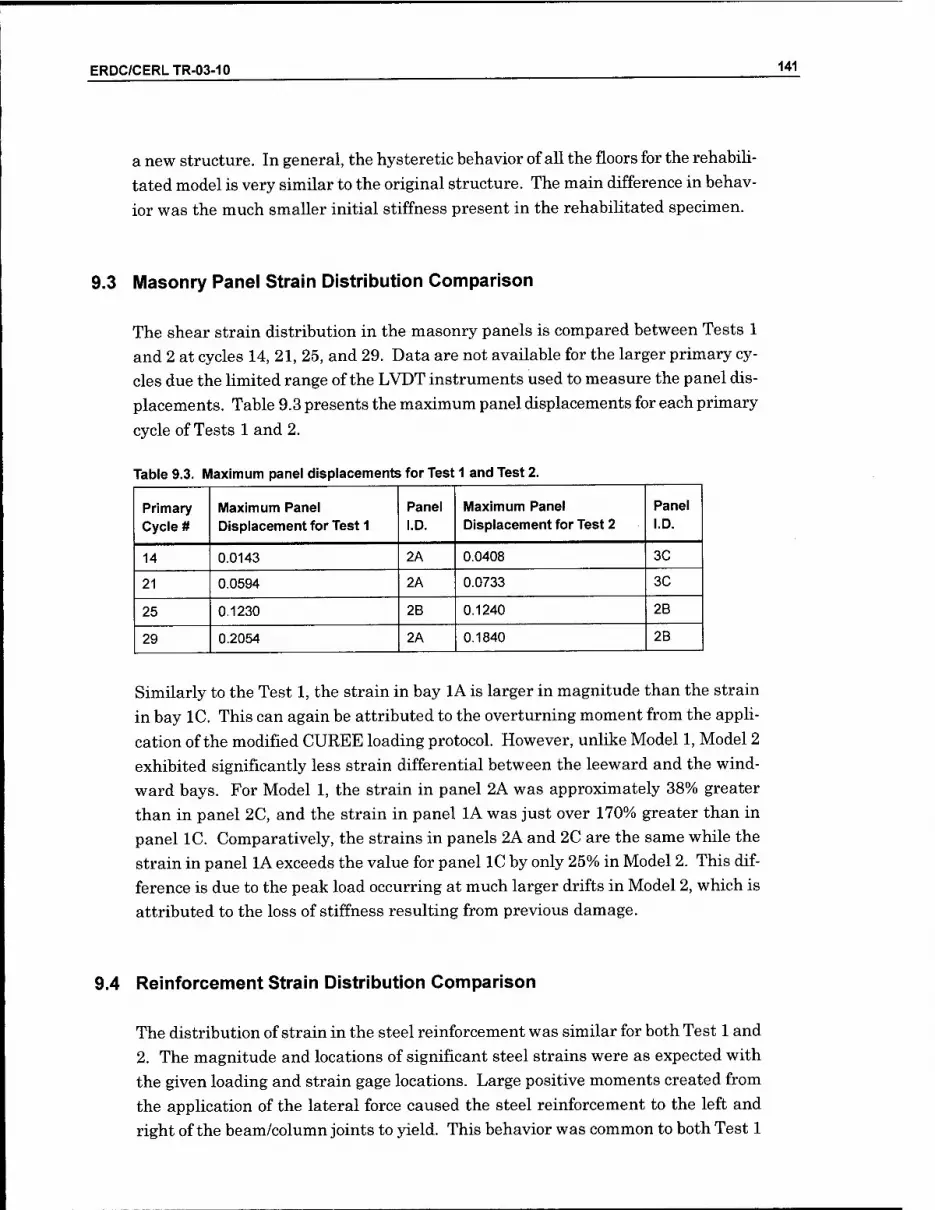
ERDC/CERLTR-03-10 141
a new structure. In general, the hysteretic behavior of all the floors for the rehabiU- tated model is very similar to the original structure. The main difference in behav- ior was the much smaller initial stiffness present in the rehabilitated specimen.
9.3 Masonry Panel Strain Distribution Comparison
The shear strain distribution in the masonry panels is compared between Tests 1 and 2 at cycles 14, 21, 25, and 29. Data are not available for the larger primary cy- cles due the limited range of the LVDT instruments used to measure the panel dis- placements. Table 9.3 presents the maximum panel displacements for each primary
cycle of Tests 1 and 2.
Table 9.3. Maximum panel displacements for Test 1 and Test 2.
Primary Cycle #
Maximum Panel Displacement for Test 1
Panel I.D.
Maximum Panel Displacement for Test 2
Panel I.D.
14 0.0143 2A 0.0408 3C
21 0.0594 2A 0.0733 3C
25 0.1230 2B 0.1240 2B
29 0.2054 2A 0.1840 2B
Similarly to the Test 1, the strain in bay lA is larger in magnitude than the strain in bay IC. This can again be attributed to the overturning moment from the appli- cation of the modified CUREE loading protocol. However, unlike Model 1, Model 2 exhibited significantly less strain differential between the leeward and the wind- ward bays. For Model 1, the strain in panel 2A was approximately 38% greater than in panel 2C, and the strain in panel lA was just over 170% greater than in panel IC. Comparatively, the strains in panels 2A and 2C are the same while the strain in panel lA exceeds the value for panel IC by only 25% in Model 2. This dif- ference is due to the peak load occurring at much larger drifts in Model 2, which is attributed to the loss of stiffness resulting from previous damage.
9.4 Reinforcement Strain Distribution Comparison
The distribution of strain in the steel reinforcement was similar for both Test 1 and 2. The magnitude and locations of significant steel strains were as expected with the given loading and strain gage locations. Large positive moments created from the application of the lateral force caused the steel reinforcement to the left and right of the beam/column joints to yield. This behavior was common to both Test 1

142 ERDC/CERLTR-03-10
and Test 2. In Test 1, nearly all of the steel reinforcement on the first and second
floors yielded. In Test 2, only half of the steel reinforcement on the first and second
floors yielded. The steel strain in the third floor of Model 1 was well below yielding,
for the most part, except for the bottom steel located to the right of column C during
the positive stroke. Unlike Test 1, the steel strains on the third floor exceeded the
yield strain in many locations, particularly to the left and right of the beam/column
joints.
9.5 Conclusion
The following conclusions were drawn from this comparative analysis:
The adhered CFRP wraps provided a shght increase in the strength of Model 1
compared with Model 2. Most importantly, the peak load for Model 2 occurred at a
higher drift ratio and more cycles than in Model 1.
Model 2 became nearly unstable at 4.4% drift ratio while maintaining lateral
strength equal to 25 kips (77% of its capacity). By comparison, the original test
structure became nearly unstable at only 2.6% drift and maintained strength of only
18 kips (56% of its capacity). The CFRP rehabihtation clearly resulted in more de-
sirable performance by increasing structural flexibility and residual strength
(strength beyond peak load at maximum drift) at near-collapse performance levels.
Although initial stiffness of Model 1 was higher than that of Model 2, at later load-
ing cycles in the modified CUREE protocol, the lateral stiffness of each test struc-
ture was similar. Thus the design objective of increasing lateral strength without
increasing stiffness was met.

ERDC/CERLTR-03-10 143
10 Comparison of Performance Results from Tests 3 and 4
10.1 Crack Formation and Propagation Comparison
Model 3 remained uncracked until cycle 25. Most of the cracks that appeared at the
early stages of Test 3 were at the masonry panel and concrete frame interface.
Model 4 began cracking during cycle 21. Most of the initial cracks during Test 4 oc-
curred in beam 1 and throughout the columns on the second floor, with Httle crack-
ing in the masonry. Comparing the cracks observed during cycle 25 of Tests 3 and
4, it is observed that Model 3 had little or no cracking in the concrete frame while
Model 4 had much cracking in its concrete frame plus some cracks in its masonry
infill panels. This was the main difference in the initial cracking of Models 3 and 4.
As loading progressed through cycle 29, the concrete frame of Model 3 remained vir-
tually uncracked with the exception of one shear crack located at the top of column
C where the column is exposed on all sides of its upper half. The upper portion of
this particular column was repaired before Test 4 so the effect of the existing crack
would be minimized. The masonry panels in Model 3 continued to crack with sig-
nificant separation between the panels and concrete frame. Conversely, httle sepa-
ration between the masonry panels and concrete frame was observed at this point in
Model 4. Model 4 went from cracking the beams and columns in cycle 21 to cracking
the masonry panels in cycle 29 ,with the majority of this cracking occurring on the
second floor.
The most numerous and significant cracks up to this point formed in both Model 3
and 4 during cycle 32. The new cracks in Model 3 during cycle 32 appeared in the
first floor. Unlike Model 3, the cracks appearing in Model 4 at this point in the
modified CUREE protocol were primarily in the second floor. Both models experi-
enced shear cracks at the beam/column joints.
The cracking trend for both models was consistent throughout the rest of the test.
The most significant and numerous cracks in Model 3 appeared on the first floor
while Model 4 cracked mostly on the second floor. This change in behavior appears
to be a result of the rehabilitation method used on the first floor after Test 3.

144 ERDC/CERLTR-03-10
10.2 Load/Displacement Behavior Comparison
The hysteretic behavior of Models 3 and 4 is presented in Figure 10.1. The red lines
represent the load/deformation response of Model 3 and the sohd hnes illustrate the
behavior of Model 4. The peak lateral load for Test 3 occurred at cycle 35 at a corre-
sponding base shear of 71.5 kips in the positive stroke direction. The peak value of
base shear in Test 4 was 68.6 kips, which occurred during the negative stroke of cy-
cle 32. The corresponding absolute third floor displacement in Test 3 was 1.51 in.
Similarly, the third floor displacement of Model 4 during peak load was 1.21 in. The
maximum load for the rehabilitated Model 4 occurred at an earlier cycle and with
slightly less displacement when compared with Model 3. Table 10.1 summarizes
the values of applied lateral load, story shear, and drift ratio during the cycles when
the peak load and maximum drift occurred for both Models 3 and 4.
eo
j n 0 ji l-" w^
-fin
80
\-- 1 ,, -'~~i
1 Lff r 1 /
r" .„. r-
^^ ^■^ / /
> 0. c
'^ -n
/ '7 /v ^^'M
.ftn V"'\ r
80
\ y- n
_^.-^—1
n ^r^A y. > I f- ^ "^-^ ̂ -J^^ 1-20 /-
/ ^1 1 1 .Rn
^ \
DlittR.WIf Ci I
Figure 10.1. Load/deformation behavior for each story of IVIodel 3 and IVIodel 4.

ERDC/CERLTR-03-10 145
Table 10.1. Comparative summary of load, shear, and drift values for Models 3 and 4.
Peak Load (kips)
Story Shear (kips)
Drift Ratio at Peak (%)
Maximum Drift Ratio, %
Story Shear at Max. Drift (kips)
Model 3
Floor + _ + — + — + - + -
3 33.6 30.1 33.6 30.1 0.53 0.55 0.53 0.55 33.6 30.1
2 22.8 21.4 56.4 51.5 1.18 1.07 1.56 1.07 42.4 51.5
1 15.1 14.6 71.5 66.1 0.81 0.61 2.26 1.76 53.7 38.5
1 Model 4 Floor + _ + - + - + - + -
3 30.4 31.2 30.4 31.2 0.286 0.693 0.565 0.788 27.8 23.4
2 20.1 22.5 50.5 53.7 2.215 1.124 3.807 3.691 46.1 40.3
1 14.1 14.5 64.6 68.2 0.473 0.195 0.303 0.214 59.0 51.3
Note: + and - refer to the stroke direction.
Model 3 had failed at the first floor and therefore it was repaired and rehabilitated before Test 4, and the results show that the rehabilitation was successful. The sec- ond and third floors of Model 3 also were repaired in an attempt to restore the model's initial strength and stiffness. The weakest story in shear, which was the first floor for Test 3, moved to the second floor in Test 4. However, Model 4 did not reach the capacity of Model 3 even though the first floor was rehabilitated exten- sively. This reduction of capacity is due to the fact that the second and third floors were not restored to their initial strength. If the first floor was rehabilitated and the failure then showed up on the second floor of the rehabilitated model, the ulti- mate capacity of Model 4 should increase compared with Model 3 unless the upper floors were not restored to their initial strength after Test 3. After analyzing data from Tests 3 and 4 it was determined that the decrease in lateral load capacity of the second and third floors was approximately 8.3%. Table 10.2 shows the modified capacity values of the two models, accounting for softening of the second and third floors of Model 4.
The base shears for Models 3 and 4 during the positive and negative stroke for each primary cycle are plotted in Figure 10.2. This plot illustrates that the peak load for Model 3 was achieved during cycle 35 and the peak load for Model 4 was achieved during the negative stroke of cycle 32. However, in the positive strokes up to cycle 35, Model 4 continued to resist more load. It is clear that the initial stiffness of Model 4 was lower than that of Model 3. The strength of the rehabilitated Model 4 exceeded the ultimate strength of Model 3 in the negative stroke direction but did not quite reach the capacity of Model 3 in the positive stroke direction.
The stiffness of each story during primary cycles is presented in Table 10.3. The first floor of the rehabihtated Model 4 regained all of Model 3's initial stiffness plus

146 ERDC/CERLTR-03-10
more as a result of wrapping the columns with CFRP and replacing the masonry
infill. The second and third floors were not rehabiUtated as extensively as the first
floor. Figure 10.3 reflects this by illustrating that the initial stiffness of the second
and third floors is only half of the original stiffness of Model 3. After Test 4, the
stiffness of the second and third floors essentially matched the stiffness of Model 3.
The first floor of Model 4 remained relatively stiff after the 40 cycle loading protocol.
Table 10.2. IVIodified capacities for each floor of Models 3 and 4.
Peak Load (kips)
Story Shear (kips)
Drift Ratio at Peak (%)
Maximum Drift Ratio, %
Story Shear at Max. Drift (kips)
1 Model 3
Floor + . + . + . + - + -
3 33.6 30.1 33.6 30.1 0.53 0.55 0.53 0.55 33.6 30,1
2 22.8 21.4 56.4 51.5 1.18 1.07 1,56 1.07 42.4 51,5
1 15.1 14.6 71.5 66.1 0.81 0.61 2.26 1.76 53.7 38.5
1 Model 4
Floor + . + . + . + - + -
3 30.4 31.2 30.4 31.2 0.286 0.693 0.565 0,788 27.8 23.4
2 20.1 22.5 50.5 53.7 2.215 1.124 3.807 3,691 46,1 40.3
1 14.1 13.5 64.6 67.2 0,473 0.195 0.303 0,214 59,0 51,3
Model 4 (modific sd for sof tening)
Floor + - + - + - + - + -
3 32.9 33.8 32.9 33.8 0.286 0.693 0.565 0.788 27,8 23,4
2 21.7 24.4 54.7 58.2 2.215 1.124 3,807 3.691 46,1 40.3
1 14.1 14.5 68.8 72.7 0.473 0.195 0,303 0.214 59.0 51,3
Note: + and - refer to the stroke direction

ERDC/CERLTR-03-10 147
Primary Cycle
Figure 10.2. Base shear during each primary cycle for IVIodels 3 and 4.
Table 10.3. Average stiffness (kips/in) for each story of Models 3 and 4.
Cycle #
Floor 1 Floor 2 Floor 3 1
Model 3 Model 4 Model 3 Model 4 Model 3 Model 4
7 395.9 1353.8 308.2 118.6 405.2 196.5
14 475.3 1507.1 314.7 118.7 310.4 165.8
21 478.8 941.0 233.5 111.0 277.2 112.2
25 395.2 767.5 189.2 110.6 197.4 105.9
29 311.0 662.1 153.2 98.4 160.7 97.1
32 258.4 506.3 116.0 71.0 148.8 89.8
35 163.3 426.9 79.9 39.7 98.6 79.6
38 38.0 390.8 48.1 20.9 77.4 64.9

148 ERDC/CERLTR-03-10
1600
1400
1200
o c
1 (A (A 0) C it
1000 ■
600
400
— -
!
--- —
■ - o - ■ Model 3 First Floor
i \ - • D - ■ Model 3 Second Floor
-■A--Model 3 Third Floor \ \ —•—Model 4 First Floor
1 ' \ —■— Model 4 Second Floor
--- 1 -- 1 \
X ,
odel 4 Third Floor
j 1
-- -- -
! ^ N^ — —
-- —4.j; ;_::
.. -e --0..
^^■c-,. ^ —•
'■■H-.,'■--.
- ^ — _ ■ ■—'' -—■ ~~T-i
1
i^ ^
^"^^"^^^ iSil 15 20 25
Primary Cycle
30 35
Figure 10.3. Stiffness of eacli floor during primary cycles for Models 3 and 4.
10.3 Masonry Panel Strain Distribution Comparison
The masonry panels of this type of structure are a significant source of in-plane
stiffness. The strain distribution throughout the panels indicates which panels are
absorbing and transferring the lateral load. The shear strains in the masonry pan-
els of Models 3 and 4 are compared at peak load. As noted previously, the peak load
for Model 3 occurred during cycle 35, and Model 4 achieved peak load during cycle
32. The second floor of each model behaved similarly. At peak load for both models,
panel 2B recorded the most strain. In general, the second floor of both models re- corded most of the strain at peak load. The main difference between Models 3 and 4 was the strain distribution in the first floor. The first floor of Model 3 received a
significant amount of the shear strain. Specifically, panels lA, IB, and IC received
73%, 57%, and 24%, respectively, of the maximum stain. However, the first floor of
Model 4 recorded only 5%, 17%, and 7 % for panels lA, IB, and IC, respectively.
These data indicate that the first floor remained significantly stiffer than the other
two floors. Also, the third floor of each model behaved similarly in Tests 3 and 4.
Table 10.4 presents the maximum panel displacements for each primary cycle of
Tests 3 and 4.

ERDC/CERLTR-03-10 149
Table 10.4. Maximum panel displacements for Tests 3 and 4.
Primary Cycle #
Maximum Panel Displace- ment for Test 3
Panel I.D.
Maximum Panel Displace- ment for Test 4
Panel I.D.
14 0.0167 2B 0.0291 2C
21 0.0527 2A 0.0707 2C
25 0.0922 2B 0.1220 28
29 0.1350 2B 0.1730 28
10.4 Reinforcement Strain Distribution Comparison
At peak load, the steel reinforcement strain was very similar in Models 3 and 4 dur-
ing the positive stroke. In fact, the two reinforcing bars that yielded in Test 3 also
yielded in Test 4. A third bar also yielded in Model 4. However, the negative stroke
corresponding to peak load induced a different strain distribution for Models 3 and
4. Model 3 recorded approximately six reinforcement strains that exceeded their
measured yield strain, but Model 4 behaved quite differently with only three steel
reinforcing strains exceeding yield. Also, the reinforcement bar that yielded during
the peak load of the negative stroke in Test 3 did not yield in Test 4.
10.5 Conclusion
In Test 3, most damage was observed in the first floor, which received the maximum
shear. After applying the CFRP on the columns for Test 4, the unprotected second
floor exhibited the most damage while the first floor remained relatively intact.
This observation confirms the effectiveness of CFRP in resisting shear forces.
Not only did the overall capacity of the frame increase after rehabilitation, but the
deformation performance also improved significantly.
The overall stiffness of the frame in Tests 3 and 4 remained fairly constant through
cycle 28. Near maximum capacity, the stiffness of Model 4 slightly deviated from
the stiffness value for Model 3.
ERDC/CERLTR-03-10 151
11 Summary and Conclusions
This report has documented a multi-year research program addressing the use of
fiber-reinforced composite materials to rehabilitate masonry-infilled concrete frame
structural systems of a type still in common use throughout the Army and many
Federal agencies. The overall purpose of the work was to compare the structural
performance of masonry-infilled three-story, three-bay R/C frames, both in their
conventional configuration as constructed during the 1950s and as rehabilitated
with CFRP.
Chapters 5 through 8 describe how two different concrete frame models were con-
structed, load-tested to failure, and then repaired, rehabiHtated with CFRP, and
retested as two new and different structures. Model 1 was a conventional scale
model of a masonry-infilled R/C frame; Model 2 was a repaired and CFRP-
rehabilitated reuse of Model 1; Model 3 was a conventional scale model similar to
Model 1, but with openings in the infiU to represent windows, doors, and other aper-
tures; Model 4 was a repaired and CFRP-rehabilitated reuse of Model 3. Each
model number corresponds to the same test number, as discussed in text.
The results of all four tests were analyzed and compared to determine the influence
of their distinguishable variables. Chapters 9 and 10 present these comparisons
and interpret the findings. The general conclusion drawn from these studies is that
CFRP overlay material can be bonded to concrete to provide effective rehabilitation
of masonry-infilled concrete frames. The test results indicate that CFRP can im-
prove structural strength and deformation capabilities. The main observations from
each test were as follow:
■ Test 1 model behavior was dominated by the R/C frame, with cracking of the
URM infills following distortions in the frame. In this case, undesirable
forces were not perceivably transferred from the infills to the frames, which
could have been the case with stronger, stiffer panels. Damage to the R/C
frame consisted of flexural and shear cracking of the concrete, and yielding of
reinforcement steel in the beams and columns. Despite the non-ductile de-
tailing of frame reinforcement, the shape of the overall force/deflection rela-
tions was similar to those for frames with more modern detailing.
■ Test 2 exhibited the effectiveness of the CFRP retrofit through a slight in-
crease in strength and a significant increase in the deformation capabilities
i52 ERDC/CERLTR-03-10
of Model 2. Detailed comparison of the results of Tests 1 and 2 is presented
in Chapter 9. ■ Test 3 concluded in shear failure observed in the columns of the first floor.
■ Test 4 showed that applying the CFRP as external shear reinforcement for
the columns was effective. Detailed comparison of the results of Tests 3 and
4 is presented in Chapter 10.
Comparison of Test 1 and 2 results showed a slight strength increase in Model 1
compared with the strength of Model 2. The peak load of Model 2 occurred at a
higher drift ratio and more loading cycles than it did in Model 1. Although the ini-
tial stiffness of Model 1 was greater than that of Model 2, at later loading cycles the
lateral stiffness of both test structures was similar. Thus the design objective of in-
creasing lateral strength without increasing stiffness was met.
In Test 3, most of the damage was observed in the first story, which received the
most shear. After applying the CFRP onto the first-story columns for Test 4, the
unprotected second story exhibited the most damage while the first story remained
fairly intact. This observation confirmed the effectiveness of CFRP in resisting
shear.

ERDC/CERLTR-03-10 153
References 1. ACI 318-89, Building Code Requirements for Reinforced Concrete (American Concrete
Institute, 1989).
2. Al-Chaar, Ghassan K., Daniel P. Abrams, Gregory E. Lamb, and Jonathan C. Trovillion, "Rehabilitation Of Infilled Nonductile Concrete Frames Using CFRP," 3rd International Conference on Composite in Infrastructure (San Francisco, 12 June 2002).
3. Al-Chaar, Ghassan K., and Husein A. Hasan, "Dynamic Response and Seismic Testing of CMU Walls Rehabilitated with Composite Material Applied to Only One Side," Proceedings of the Institution of Civil Engineers, Structures and Buildings 152, no. 2, pp 135-146.
4. Al-Chaar, Ghassan, "Seismic Rehabilitation of Existing Reinforced Concrete and Masonry Structures Using the Composite Overlay Materials," Scientific Research proceeding (University of Sharjah, 2000).
5. Al-Chaar, Ghassan K., Daniel P. Abrams, Gregory E. Lamb, and Jonathan C. Trovillion, "Rehabilitation Of Infilled Nonductile Concrete Frames Using Carbon Fiber Reinforced Polymer," 3rd International Conference on Composite Infrastructures (2001).
6. Blaschlko, M., R. Niedermeier, and K. ZUch., "Bond Failure Modes of Flexural Members Strengthened with FRP," Fiber Composites in Infrastructure - ICCT98 Vol. /(University of Arizona, Tucson, 1998), pp 315-327.
7. Blaszak, G., and W. Gold, "Strengthening Structures with FRP Systems," Advanced Seismic Retrofit Systems (81(^.32, March 2000), pp 10-19.
8. Catbas, K. H, Performance of Beams Externally Reinforced with Carbon Fiber Reinforced Plastic Laminates, Master's Thesis (Department of Civil and Environmental Engineering, University of Cincinnati, 1997), pp 92.
9. Chaallal, 0., and J. NoUet, "Use of CFRP Strips for Flexure and Shear Strengthening of RC Members," Fiber Composites in Infrastructure - ICCI'OS Vol. /(University of Arizona, Tucson,
1998), pp 249-260.
10. Elhassan, R. M., "The Retrofit Design of Concrete Columns and Slabs with Externally Applied Fiber-Reinforced Polymer (FRP) Composite Materials," Innovative Systems for Seismic Repair & Rehabilitation of Structures {SRRS2, March 2000), pp 96-107.
11. Grace, N.F., A.K. Sohman, G. Abdel-Sayed, and K.R. Saleh, "Strengthening of Continuous Beams Using Fiber Reinforced Polymer Laminates," Proceedings of the Fourth International Symposium on Fiber Reinforced Polymer Reinforcement for Reinforced Concrete Structures
(ACI International, 1999), SP 188-57, pp 647-657.

-154 ERDC/CERLTR-03-10
12. Harmon, T. G., P. L. Bould, E. Wang, and S. Ramakrishnan, "Behavior of Confined Concrete under Cyclic Loading," Fiber Composites in Infrastructure - ICCT98 Vol. /(University of
Arizona, Tucson, 1998), pp 398-410.
13. Harmon, T. G., S. Ramakrishnan, and E. H. Wang., "Moment-Curvature Relationships for Confined Concrete Columns," Fiber Composites in Infrastructure - ICCI'QS Vol. /(University
of Arizona, Tucson, 1998), pp 385-397.
14. Haroun, M., M. Feng, and M Youssef "Seismic Retrofit of Reinforced Concrete Columns Using FRP Composite Laminates," Innovative Systems for Seismic Repair & Rehabilitation of
Structures (SRRS2, March 2000), pp 85-95.
15. Juvantes, L., J. A. Figueriras, and A. T. Marques, "Performance of Concrete Beams Strengthened With CFRP Laminates," Fiber Composites in Infrastructure - ICCI'QS Vol I
(University of Arizona, Tucson, 1998), pp 126-137.
16. Khalifa, A., and A. Nanni, Advanced Composites for Shear Reinforcement ofRCFlexural Members (Center for Infrastructure Engineering Studies 99-14, RoUa, Missouri, December
1999).
17. Khalifa, A., and A. Nanni, Improving Shear Capacity ofRC T-Section Beams Using CFRP Composites (Center for Infi-astructure Engineering Studies 99-14, RoUa, Missouri, December
1999).
18. Khalifa, A., G. Tumialan, A. Nanni, and A. Belarbi, "Shear Strengthening of Continuous Reinforced Concrete Beams Using Externally Bonded Carbon Fiber Reinforced Polymer Sheets," Proceedings of the Fourth International Symposium on Fiber Reinforced Polymer Reinforcement for Reinforced Concrete Structures (ACT International, 1999,) SP 188-84, pp
995-1008.
19. Kono, S., M. Inazumi, and T. Kaku, "Evaluation of Confining Effects of CFRP Sheets on Reinforced Concrete Members," Fiber Composites in Infrastructure - ICCIW Vol. I (University of Arizona, Tucson, 1998), pp 343-355.
20. Kurtz, Stephen, and P. Balaguru, "Comparison of Inorganic and Organic Matrices for Strengthening of RC Beams with Carbon Sheets," Journal of Structural Engineering Vol 127
No. 1 (ASCE, January 2001), pp 35-42.
21. Lee, Y. J., J. M. Tripi, T. E. Boothby, C. E. Bakis, and A. Nanni, "Tension Stiffening Model for FRP Sheets Bonded to Concrete," Fiber Composites in Infrastructure - ICCIW Vol I
(University of Arizona, Tucson, 1998), pp 175-186.
22. Maruyama, K., Ueda, T., Hoshijima, T., and Uemura, M.: Japan Society of Civil Engineers Activity on Continuous Fiber Sheet for Retrofit of Concrete Structures. Proceedings of the Fourth International Symposium on Fiber Reinforced Polymer Reinforcement for Reinforced
Concrete Structures, Eds. Charles et. al., ACI International, 1999, pp 151-157.
23. Matsuzaki, Y., K. Nakano, S. Fujii, and H. Fukuyama, "Japanese State of the Art on Seismic Retrofit by Fiber Wrapping for Building Structures: Research," Proceedings of the Fourth International Symposium on Fiber Reinforced Polymer Reinforcement for Reinforced Concrete
Structures (ACI International, 1999), SP 188-75, pp 879-893.

ERDC/CERLTR-03-10 155
24. McCurry, D. D., and D. I. Kachlakev, "Strengthening of Full-Scale Reinforced Concrete Beams Using FRP Laminates and Monitoring with Fiber Optic Strain Gauges," Innovative Systems for Seismic Repair & Rehabilitation of Structures, (SRRS2, March 2000), pp 131-140.
25. Nanni, A., F. Focacci, and C. A. Cobb, "Proposed Procedure for the Design of RC Flexural Members Strengthened with FRP Sheets," Fiber Composites in Infrastructure - ICCI'OS Vol. I
(University of Arizona, Tucson), 1998, pp 187-201.
26. NEHRP Guidelines for the Seismic Rehabilitation of Buildings, Federal Emergency Management Agency [FEMA] 273 (October 1997), chapter 7.5.2.2.B.
27. Pantelides, C.P., J. Gergely, L.D. Reaveley, and V.A. Volnyy, "Retrofit of Reinforced Concrete Bridges with Carbon Fiber Reinforced Polymer Composites," Proceedings of the Fourth International Symposium on Fiber Reinforced Polymer Reinforcement for Reinforced Concrete
Structures (ACI International, 1999), SP 188-40, pp 441-453.
28. Parvin, A., and P. Granata, "Use of FRP Overlays at Beam-Column Connections," Fiber Composites in Infrastructure - ICCI'QS Vol. /(University of Arizona, Tucson), 1998, pp 213-
220.
29. Raghu, A., J. Myers, and A. Nanni, In-Situ Shear and Flexure Strengthening of Reinforced Concrete Members with Advanced Composites (Center for Infrastructure Engineering Studies
99-11, Rolla, Missouri, December 1999).
30. Shmoldas, A., G. Schleifer, F. Seible, and D. Innamorato, Carbon Fiber Retrofit of the Arroyo Seco Spandrel Column, Report No. SSRP-97/13 (Division of Structural Engineering, University of California, San Diego, 1997).
31. Taly, N., and H.V.S. GangaRao, "Guidelines for Design of Concrete Structures Reinforced with FRP Materials." 44"' International SAMPE Symposium, May 23-27, 1999, pp 1689-1696.
32. Zarnic, R., and M. Tomazevic, "An Experimentally Obtained Method for Evaluation of the Behavior of Masonry Infilled R/C Frames," Proceedings of Ninth World Conference on Earthquake Engineering, Tokyo, Japan, vol VI (August 1988), pp 163-168.
33. Zhang, A., T. Yamakawa, P. Zhong, and T. Oka, "Experimental Study on Seismic Performance of Reinforced Concrete Columns Retrofitted with Composite-Materials Jackets," Proceedings of the Fourth International Symposium on Fiber Reinforced Polymer Reinforcement for Reinforced Concrete Structures, (ACI International, 1999), SP 188-24, pp 269-278.
156 ERDC/CERLTR-03-10
Appendix: Ultrasound Inspection of a Fiber-Reinforced Polymer Retrofitted Unreinforced Masonry Structure
Preface
This Appendix was prepared by Dr. Valery Godinez-Azcuaga, Mr. Richard Finlay-
son, and Dr. Ron Miller from the Physical Acoustics Corporation (PAC) under Small
Business Innovative Research (SBIR) contract DACA42-01-C-0008, entitled "Field
Portable Infrastructure Fiber-Reinforced Polymer Composite Inspection and
Evaluation System Using Ultrasound Technologies." This work demonstrated the
feasibility of using low-frequency, obHque-incidence guided wave acousto-ultrasonics
(AU) to detect and image defects in FRP-to-concrete interfaces. This includes spe-
cific theoretical and experimental studies to assess the detectability of a simulated
0.004 in. thick delamination defect between an FRP composite laminate and a con-
crete substrate. The investigations was applied to beam and column sections of
Test 2 (Chapter 6) using both nondestructive and destructive evaluation techniques.
Introduction
For FRP materials used in infrastructure applications it is important to have the
ability to accurately predict damage within and under the FRP laminate. Unlike
concrete, which often shows visible features upon damage, FRP materials often hide
their damage under layers of material that appears intact. Hence it is important to
design and develop a portable FRP composite inspection and evaluation system that
can be used in the field to rapidly assess infrastructure reinforced with composites. Under a Small Business Innovative Research (SBIR) project with ERDC/CERL, a
prototype system is being developed utilizing acousto-ultrasound (AU) technologies
that will be capable of inspecting 0.5 in thick glass, carbon and aramid reinforced
polymer systems used as upgrades to existing infrastructure or as new structural
elements. The inspection and evaluation system must be able to identify flaws or
damage in multiple damage situations including debonding between the composite

ERDC/CERLTR-03-10 157
and a brick/concrete substrate, delamination within the composite or cracking that
can lead to incipient failure. The inspection and evaluation system should include a
simple cable-free, battery powered, hand-held device for rapid repair and replace-
ment assessment of structural composites.
This Appendix presents the feasibility of applying guided wave AU to the inspection
of FRP/concrete interfaces. This includes a thorough discussion of the research ac-
tivities, the results obtained and the conclusions discussing the application of
Guided Wave AU to the inspection of an FRP-retrofitted section of a concrete col-
umn and beam removed from the multistory and multibay frame-infill system pre-
viously discussed in the report. Also, a discussion regarding the post-inspection de-
structive evaluation of the column section is included.
Acousto-Ultrasound Theory
The theoretical model used in this section is based on a plane wave propagation
model, which employs the Thomson-HaskeU transfer matrix for multilayered media
to obtain the internal distribution of the energy vector within a layered composite.
These results were used to predict the acoustic response of the FRP/concrete system
in the frequency domain. The model can be used to analyze the ultrasonic response
from general multi-layered structures. The algorithm provides control over the fol-
lowing parameters:
1. number of layers in the structure 2. degree of anisotropy of each layer (up to 21 independent elastic constants)
3. orientation of each layer
4. lay-up of the structure
5. level of viscoelasticity
6. plane of incidence
7. ultrasonic frequency.
The algorithm also provides ultrasonic response in the following forms of output:
1. reflection and transmission coefficient plots as a function of angle of incidence,
azimuthal angle, and frequency of the ultrasonic wave.
2. displacement and stress distribution within the structure
3. energy (power flow) magnitudes and direction within the structure
4. radio frequency (RF) signal response to simulate reahstic ultrasonic transducers
(both narrow and broad banded)
5. plate wave dispersion cvirves.

158 ERDC/CERLTR-03-10
Figure A. 1 shows tlie experimental setup in whicli the model is based. The system is
an FRP layer of 0.118 in. thickness laid on top of a 3.94 in. concrete substrate, with
a delamination located between the layer and the substrate.
Reflected Acoustic Wave
FRP Layer
Delamination
Incident Acoustic Wave
^ Concrete Substrate
Figure A.1. Setup used for the theoretical simulation of wave propagation on FRP/concrete structures.
Elastic Constants Calculation
The first step in the simulation was to calculate the elastic constants for concrete.
The method used was one proposed by Wu et al. [1995] to extract the elastic con-
stants of a concrete specimen from longitudinal and Rayleigh wave velocity meas-
urements. The elastic constants for the graphite-epoxy FRP used in the model are
reported by Rokhhn and Chimenti, and are presented in Table A. 1 together with the
concrete elastic constants. [Rokhhn and Chimenti 1990]. Graphite-epoxy FRP was
selected for the modulation, since this type of composite was available to PAC for
sample fabrication. However, low-grade carbon or glass FRP reinforced concrete
can also be simulated.
Table A.1. Elastic constants of the materials used in the wave propagation simulation.
Material Cii
[Msi] C22
[Msi] C33
[Msi] C12
[Msi]
Cl3
[Msi] C23
[Msi]
C44
[Msi] C55
[Msi]
066
[Msi]
Graphite- epoxy
19.3 1.87 2.31 0.54 0.26 0.80 0.61 1.25 1.09
Concrete 5.90 5.90 5.90 1.78 1.78 1.78 2.06 2.06 2.06

ERDC/CERLTR-03-10 159
Wave Propagation Analysis
Propagation of acoustic waves in structures that contain FRP materials are very sensitive to the presence of delaminations at incidence angles below 20 degrees and ultrasonic frequencies lower than 300 kHz [Godinez et al. 2001a; Godinez et al. 2001b]. Thus it was decided to simulate the propagation of acoustic waves with these ranges of incidence angle and frequency. Figure A.2 shows a plot of the reflec- tion coefficient for acoustic waves propagating on an FRP/concrete layered structure without delaminations.
Reflection Coefficient for a FRP Concrete Block without Delaminations 20
250 Frequency [KHz]
Figure A.2. Reflection coefficient of an FRP/concrete layered structure without delaminations (wave propagation along fiber direction).
In this first simulation, the propagation direction was selected to be along the fibers of the FRP. In this plot, the areas in bright red indicate a very high reflection coef- ficient, with a maximum value of 1.0, and the dark blue areas indicate very low re- flection. Acoustic waves with a combination of frequency-incidence angle that lie on the bright red areas will be reflected almost completely whereas acoustic waves
■ with a combination of frequency-incidence angle that lie on the blue spots will not present a high reflection. This type of plot is very useful when analyzing the changes in the reflection coefficient produced by the presence of a delamination in the structure. Figure A.3 shows a similar plot but this time a delamination was in- troduced between the layer of FRP and the concrete substrate. The delamination is introduced in the model as an intermediate layer of a material with very low strength between the FRP and the concrete, usually a fluid with low density and thickness of 0.004 in.
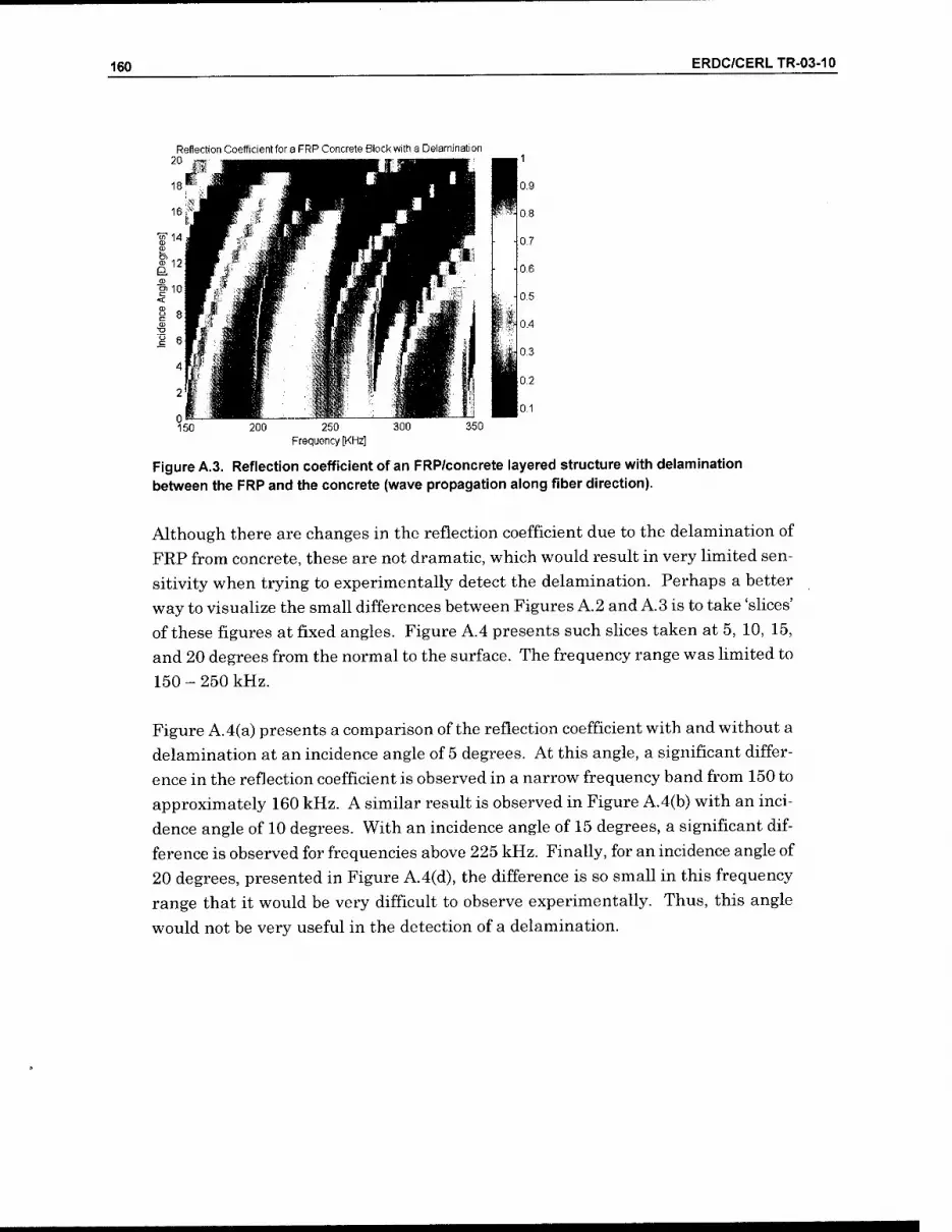
160 ERDC/CERLTR-03-10
Reflection Coefficient for a FRP Concrete Block with a Delamination
250 Frequency [KHz]
Figure A, between
3. Reflection coefficient of an FRP/concrete layered structure with delamination the FRP and the concrete (wave propagation along fiber direction).
Although there are changes in the reflection coefficient due to the delamination of
FRP from concrete, these are not dramatic, which would result in very limited sen-
sitivity when trying to experimentally detect the delamination. Perhaps a better
way to visualize the small differences between Figures A.2 and A.3 is to take 'slices'
of these figures at fixed angles. Figure A.4 presents such slices taken at 5, 10, 15,
and 20 degrees from the normal to the surface. The frequency range was limited to
150-250 kHz.
Figure A. 4(a) presents a comparison of the reflection coefficient with and without a
delamination at an incidence angle of 5 degrees. At this angle, a significant differ-
ence in the reflection coefficient is observed in a narrow frequency band from 150 to
approximately 160 kHz. A similar result is observed in Figure A.4(b) with an inci-
dence angle of 10 degrees. With an incidence angle of 15 degrees, a significant dif-
ference is observed for frequencies above 225 kHz. Finally, for an incidence angle of
20 degrees, presented in Figure A.4(d), the difference is so small in this frequency
range that it would be very difficult to observe experimentally. Thus, this angle
would not be very useful in the detection of a delamination.

ERDC/CERLTR-03-10 161
5 < 0.(
£.0.8
S
liTtid^nce angte 5 degrees
„"J1" Nodelaminaiion Deiami nation bctweisn FRP and concret&
\! r t
v 200
Frequency [KHz]
(a) Incidence angle 15 degrees
'^i .7
200 Frequency [KHz]
(c)
Incidence angle 10 degrees
200 Frequency [KHz]
(b) Incidence angle 20 degrees
5 £.08
7777 No delaminatJon Delamination between FRP and concrete
__, --r ---_
A"'
\ \
■
200 Frequency [KHz]
(d)
Figure A.4. Comparison between reflection coefficients for an FRP/concrete layered structure with and without a delamination as a function of frequency for a fixed incidence angle, (a) Incidence angle 5 degrees, (b) Incidence angle 10 degrees, (c) Incidence angle 15 degrees, and (d) Incidence angle 20 degrees. Wave propagation is along fiber direction.
The theoretical model predicts that acoustic waves propagating along the fiber di- rection in the FRP/concrete system will not be sensitive to the presence of a delami- nation, and therefore will not be effective as a tool for the detection of this type of
discontinuity.
The next case studied using the theoretical model was that of acoustic waves propa- gating in the direction normal to the fibers. Figures A.5 and A.6 show the acoustic wave reflection coefficient for the FRP/concrete layered structure with and without a delamination.

162 ERDC/CERLTR-03-10
Reflection Coefficient for a FRP Concrete Biocl< without Delanninations 20 ^^^^^^^^^^^^^^^^m^^^^^^ ^B1
250 Frequency [KHz]
Figure A.5. Reflection coefficient of an FRP/concrete layered structure without delamination between the FRP and the concrete (wave propagation across fiber direction).
Reflection Coefficient for a FRP Concrete Block witfi a Delamination
250 Frequency [KHz]
Figure A.6. Reflection coefficient of an FRP/concrete layered structure with a delamination between the FRP and the concrete (wave propagation across fiber direction).
The results in this case are dramatically different from the results obtained when
propagation was along the fiber direction. The reflection coefficient is extremely
sensitive to the presence of a delamination between the FRP and the concrete.
These differences are very clearly shown in Figure A.7, which presents the reflec-
tion coefficients at incidence angles of 5, 10, 15, and 20 degrees. The frequency
range was limited to 150 - 250 kHz again.
From Figure A.7(a), 5 degrees incidence angle, it is clear that the difference in re- flection coefficients is at least 0.5 along the plotted frequency range, except for the
dip in the delamination data at approximately 160 kHz, and a very narrow spike at 200 kHz. The same is observed in Figure A.7(b), 10 degrees incidence angle, al-

ERDC/CERLTR-03-10 163
though in this case the first dip appears to be centered around 175 kHz, and the spike has moved to a frequency sHghtly higher than 200 kHz.
1.2 Incidence angle 5 degrees
Nodelamination OelammationbetvveenFPP and concrete
1
S 1 0,6
g
\
/' ij '■■■--. .--"''' 1 "" ■ \ / jl
02 1 . -•V - - r^
1,2 Incidence angle 10 degrees
No delamination Delamination between FRP end concrete
1
a.08
G
1 0,6 o
1 04 a
02
^ ■'■'' ^
s 1
■
200 Frequency p<Hz]
(a)
Incidence angle 15 degrees
200 Frequency {KHz]
(b)
12 Nodelamination Delamiralion beh'^39n FRP and concrete
1
< 08
g
1 06 (J
I"- - !\
)5 e 1 01
'--■''
02 A " J _y V
12 Incidence angle 20 degrees
Delaminadon be%veen FRP and concrete
1
"=1 < 0 8
S '""■- -—-_._
1 06 "■^"■■-.^
O X
|o^ v_,.--
02
- ~- "^^ 200
Frequency [KHz]
200 Frequency IKHz]
(c) (d)
Figure A.7. Comparison between reflection coefficients for an FRP/concrete layered structure with and without a delamination as a function of frequency for a fixed incidence angle, (a) Incidence angle 5 degrees, (b) Incidence angle 10 degrees, (c) Incidence angle 15 degrees, and (d) Incidence angle 20 degrees. Wave propagation is across the fiber direction.
For an incidence angle of 15 degrees, Figure A.7(c), there is no spike on the delami- nation reflection coefficient, the dip moved to 200 kHz, and a sharp spike at ap- proximately 170 kHz. Finally for an incidence angle of 20 degrees, Figure A.7(d), the difference is very smooth with a minimum value of 0.4 and a maximum value of
0.7.
The simulation results shown in Figures A.4 and A.7 indicate that the wave propa- gation direction with respect to the fiber direction is a very important parameter that can change the sensitivity of the technique to the presence of defects. In the case of FRP used in the field, the fibers are arranged in stitched or woven patterns with fibers going in the two perpendicular directions, generally [0/90] or [±45] ar-
rays.

164 ERDC/CERLTR-03-10
The difference between the reflection coefficient for the delaminated and the non-
delaminated structure is an indicator of the abihty to detect the delamination. This
difference can be thought of as a 'contrast index' (CI) for the delamination.
Figure A.8 presents the contrast index for the delamination between the FRP and
the concrete for acoustic waves propagating across the fiber direction. The contrast
index presented in this figure suggests that the best incident angles to inspect the
FRF/concrete system modeled are 15 and 20 degrees at frequencies between 210
and 250 kHz. In fact, the best angle according to the mathematical model would be
20 degrees. At this angle, the contrast index shows a smooth curve in the presented
frequency range with an almost-constant value of 0.65.
1
0,9
0.8
0.7
Delamination Contrast Index at Different Incidence Angles 1 1 1 1 1 p
0.5
O0.4
0,3
0,2
0.1
yi A
V
5 degrees 10 degrees 15 degrees 20 degrees
X'
150 160 170 180 190 200 210 220 Frequency [KHz]
230 240 250
Figure A.8. Delamination contrast index as a function of frequency for different incidence angles. Wave propagation is across the fiber direction.
Results and Discussion
The guided wave AU system was used to preliminarily inspect the FRF-retrofitted
concrete beam and column sections of Model 2, as discussed earlier in the report. The preliminary inspection of this sample was carried out in order to demonstrate
that AU could be applied in the inspection of real samples [Godinez et al. 2001c].

ERDC/CERLTR-03-10 165
Preliminary FRP Upgraded Concrete Beam and Column NDE Results
As a preliminary test it was important to use the Guided Wave AU system to in- spect a section from an FRP-reinforced concrete column described by [Al-Chaar et al. 2002 ]. Figure A.9 shows a schematic of this structure indicating the position of
the column section.
The loading process created cracking in some of the structural components, among them the column section shown in Figure A.9. In order to examine the condition of the bonding between the FRP and the concrete column, C-scan images of five differ- ent sections of the column were generated, as also indicated in Figure A.9. Figure A. 10 shows a picture of the multi-sensor probe mounted on the scanning bridge while inspecting the FRP retrofitted column.
Col. b
Figure A.9. FRP/concrete section of ERDC/CERL column from Model 2. The areas Indicated on the column section were Inspected with the guided wave AU system.
: 1/
(a) (b)
Figure A.10. Guided wave AU Inspection of a FRP wrapped concrete column: (a) computer controlled scanning bridge with multi-sensor probe; (b) detail of the multi-sensor probe while scanning a section of the column.

166 ERDC/CERLTR-03-10
The C-scans shown in Figure A. 11(a) were generated with the pulsing and receiving
sensors oriented at an angle of 15 degrees. The scans in Figure A. 11(b) were gener-
ated with the pulsing sensor at oriented at 15 degrees and with the receiving sensor
oriented at 20 degrees. In both cases the sensor was excited with a 10 cycle burst of
4 volts peak to peak amphtude and frequency of 225 kHz. The original plan was to
perform the largest possible scans allowed by the scanning bridge, which are scans
of 15 in. long. However, the surface of the column section presented areas that were
very uneven, in which the scanning probe could not be positioned. Due to the design
of the current probe, these areas could be as large as 3 in. making it impossible to
overlap the C-scans.
The C-scans in Figure A. 11(a) show areas with very high reflected amplitudes, in
bright green, which are indicative of delamination between the FRP and the con-
crete column. The C-scans in Figure A. 11(b) confirm the presence of delamination
in the concrete column, particularly in sections (a) and (d) where there are areas
with high reflected signals detected with the 20 degrees receiver sensor.
A second FRP-reinforced piece was inspected — in this case, a section of a deck from
the multistory structure, whose position is shown in Figure A. 12(a). Figure A. 12(b)
shows a detail of the inspection performed with the scanning bridge. The results of
the inspection are shown in Figure A. 13.

ERDC/CERLTR-03-10 167
^6.5 in
-Section (a)
-Section (b)
Section (c)
Section (d)
Section (e)
(a) (b)
11 in
7 in
+ 4 in
Figure A.11. C-scans of different sections of the ERDC/CERL FRP wrapped concrete column. In all cases the pulsing sensor was oriented at an incidence angle of 15 degrees and the receiving sensors were oriented at (a) 15 degrees or (b) 20 degrees.

168 ERDC/CERLTR-03-10
Col. d Col. c Col.b Col. a
Benin .1
Beam 2
Beam I
3ZIE
(a)
(b)
Figure A.12. Location of the deck section inspected (a); guided wave AU inspection of an FRP- reinforced deck (b).

ERDC/CERLTR-03-10 169
3.5 in
•« Section 1
(a)
Section 2
(b)
8.5 in
7.5 in
Figure A.13. C-scans of two different sections of the ERDC/CERL FRP reinforced concrete decl< (also referred to as the beam section). The pulsing sensor was oriented at an incidence angle of 15 degrees and the receiving sensors were oriented at (a) 15 degrees or (b) 20 degrees.
The results of the preliminary inspection of the column section indicated that in two areas of the sample the FRP wrap was separated from the concrete substrate, that is delamination was present. Also, the preliminary results indicated that, using the guided wave AU technique, it might be possible to locate the internal steel reinforc- ing stirrups, which together with the rebar, form the skeleton of the column.

170 ERDC/CERLTR-03-10
As in the case of the FRP-wrapped column, the FRP wrapped beam C-scans re-
vealed sections of the FRP that are separated from the concrete. The results ob-
tained with the receiver sensors at 15 and 20 degrees are virtually identical, which
indicates the magnitude of the debond between the concrete deck and the FRP.
Final FRP Upgraded Concrete Column NDE Results
In order to confirm the preliminary observations of section A-4.1, a thorough inspec-
tion of the column section was performed. Due to schedule and budget constraints,
the thorough inspection of the beam section was not conducted at the same time.
The column inspection produced C-scans of two sides, labeled side V and side W.
Figure A. 14 shows sides V and W of the column as well as their dimensions.
As documented previously in the report, ERDC/CERL provided the column with
steel reinforcing stirrups located at approximately 5" intervals along the column.
The areas with possible delaminations were approximately 3" in diameter and lo-
cated the V side of the column. Figure A. 15 shows a drawing of side V of the column
section with the approximate location of the delaminated areas and the reinforcing
stirrups.
The C-scans were generated with the same guided wave AU system used in the pre-
liminary discussion in the previous section (A-4.1). A first set of C-scans was gener-
ated with the pulsing sensor oriented at 10 degrees from the normal to the FRP sur-
face and using two receivers oriented at 10 and 15 degrees. A second set of C-scan
images was generated by combining the pulser oriented at 15 degrees with the re-
ceivers oriented at 10 and 15 degrees. In all cases, the pulsing sensor was excited
using a narrow band tone-burst signal of 10 cycles at 225 kHz.
■ -^ ^
^^'^^ steel Reinforcing Brackets Delamination Between FRP and Concrete
Figure A.14. Dimensions of the FRP-retrofitted column removed from the multistory structure subjected to simulated seismic excitation.

ERDC/CERLTR-03-10 171
Figure A.I5. Location of delamination and steel reinforced stirrups in the -retrofitted column.
Side V is shown.
Four sections of side V of the column section were scanned. These sections were 9.25 in. (A), 9.0 in. (B), 9.25 in. (C), and 12 in. (D) long and 4 in. wide, as shown in Figure A. 16(a). These sections were chosen because the FRP surface roughness and ripples were smaller than 0.0625". Ripples higher than 0.0625 in. made good cou- phng between the sensor probe and the FRP very difficult. Also, five sections were scanned on side W as shown in Figure A. 16(b). The dimensions of these sections were 5.0 in. (A), 10.0 in. (B), 10.0 in. (C), 10.0 in. (D), and 8.0 in. (E) long and 3.5 in.
wide.
Figures A. 17(a) and A. 17(b) show the C-scan images of side V obtained when using the pulser oriented at 10 degrees and receiving the signal with sensors oriented at
10 and 15 degrees, respectively.

172 ERDC/CERLTR-03-10
T 8.0"
i
L_ J Steel Reinforcing Brackets J
Delamination
^ 5.0" [«-
T 4.0"
\-
K 5.0" -H . L_ L
A-r., ^,B ^ c T E
"-- 1 r
4.0
9.25" *\< ^. 9.0" ^r >l 9.25" >H- 12"
Areas Inspected
(a) steel Reinforcing Brackets
K 5.0" H
.•^.5
5.0" -^-< 10.0" —-*-k- 10.0" —>-K r- 10.0" %- 8.0"
Areas Inspected
(b)
Figure A.I6. Dimensions and location of tlie areas inspected on the FRP-retrofitted column section: (a) side V and (b) side W.
The C-scans in Figure A. 17 (a) and (b) show high-ampHtude reflected AU signals in
green tones, medium-amphtude signals in red tones, and low-amplitude signals in
blue tones.
Figure A. 17(a) shows mostly green tones in the inspected areas, with some areas in
red tones and two evident blue spots on sections A and B. The locations of these
spots correspond to the position of the delaminations shown in Figure A. 15. It is
important to note that the scans of section A and B did not cover the delaminated
areas completely because of the surface condition of the FRP, as discussed earlier in
this section of the report. Also, there was a sudden change in amplitude at the line
dividing the section A and section B images, caused by the rougher condition of the
surface on section A. In sections C and D, also in Figure A. 17(a), three thin strips
— mostly in red with a few spots in blue tones — can be distinguished, the most no-
ticeable being the one located on the middle of section D.
These strips are aligned with the position of the steel reinforcing stirrups in that
area of the column, except for the stripe in the middle of section C, which is dis-
placed slightly to the right of the nominal stirrup position. The fact that the sec-
tions scanned with this combination of pulser and receiver (10 degrees pulser, 10
degrees receiver) present mostly high-amplitude signals indicates that the AU
pulses penetrate through the FRP into the concrete and reflect back to the receiver.

ERDC/CERLTR-03-10 173
When a delamination is present, the AU pulses are forced to propagate along the
FRP, which causes a severe loss of energy due to the FRP structure, thus the low
amplitude detected at the receiver end.
The three medium-amplitude stripes aligned with the reinforcing stirrup position
are caused by dispersion of the AU signals at the concrete/stirrup interface. The C-
scan images of Figure A. 17(b) show more clearly the three stripes, now in blue
tones, already observed in Figure A. 17(a). In addition, a fourth stripe is now ob-
served on the left-hand side of section C, which corresponds to the position of an-
other reinforcing stirrup. In this case, the stripe is not aligned with the direction of
the stirrup, which may be an indication of the real orientation of the reinforcing
stirrup. The same is observed for another stripe now visible on the right-hand side
of section D, where there is another reinforcing stirrup.
The C-scan images of sections A and B in Figure A. 17(b) show also three stripes,
corresponding to the locations of steel stirrups although the ahgnment is off. The
first one is located on the right-hand side of section B to the left of the delamination,
and the second on the left-hand side of the section. The third one is on section A, to
the left of a wide blue area between the two stirrup positions. This wide blue area,
also visible in red tones in Figure A. 17(a), is the result of a coupling loss between
the sensor and the FRP caused by the extremely uneven surface of the FRP in that
particular location.
T 8.0"
i
|<- 7.0" -*\
Delamination
T 8.0"
1
|<- 7.0" -*\
Delamination
Steel Reinforcing Brackets > 1.3" * K 5.0" -*\
Section A Section B Delamination Section C Section D
Steel Reinforcing Brackets K 5.0" -A
\t 9.25" >\< 9.0" —
Section A Section B Delamination Section C
(b)
Section D
Figure A.17. C-scan images of the areas inspected on side V of the FRP-retrofitted column section. The scans were generated by pulsing with a sensor oriented at 10 degrees and receiving with (a) receiver oriented at 10 degrees and (b) receiver oriented at 15 degrees.
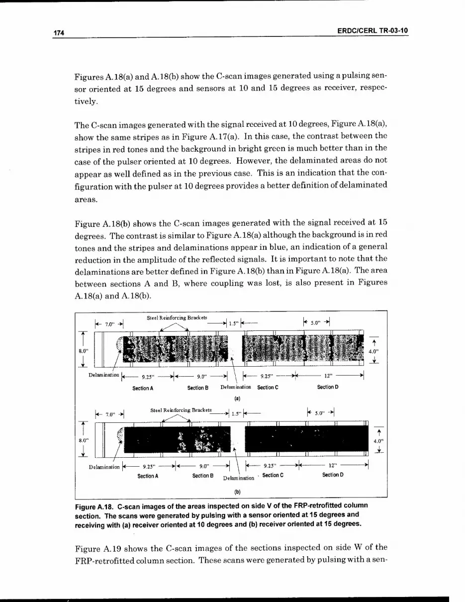
174 ERDC/CERLTR-03-10
Figures A. 18(a) and A. 18(b) show the C-scan images generated using a pulsing sen-
sor oriented at 15 degrees and sensors at 10 and 15 degrees as receiver, respec-
tively.
The C-scan images generated with the signal received at 10 degrees, Figure A. 18(a),
show the same stripes as in Figure A. 17(a). In this case, the contrast between the
stripes in red tones and the background in bright green is much better than in the
case of the pulser oriented at 10 degrees. However, the delaminated areas do not
appear as well defined as in the previous case. This is an indication that the con-
figuration with the pulser at 10 degrees provides a better definition of delaminated
areas.
Figure A. 18(b) shows the C-scan images generated with the signal received at 15
degrees. The contrast is similar to Figure A. 18(a) although the background is in red
tones and the stripes and delaminations appear in blue, an indication of a general
reduction in the amplitude of the reflected signals. It is important to note that the
delaminations are better defined in Figure A. 18(b) than in Figure A. 18(a). The area
between sections A and B, where couphng was lost, is also present in Figures
A. 18(a) and A. 18(b).
|<- 7.0" -*\
8.0"
1
Steel Reinforcing Brackets K 5.0" -H
Delamination
Section A
|«- 7.0" ->|
Sections Delamination Section C
(a)
Steel Reinforcing Brackets J
Section D
K 5.0" H
8.0"
1 Delamination
Section A Sections Delamination ' SectionC
(b)
Section D
Figure A.18. C-scan images of the areas inspected on side V of the FRP-retrofitted column section. The scans were generated by pulsing with a sensor oriented at 15 degrees and receiving with (a) receiver oriented at 10 degrees and (b) receiver oriented at 15 degrees.
Figure A. 19 shows the C-scan images of the sections inspected on side W of the
FRP-retrofitted column section. These scans were generated by pulsing with a sen-

ERDC/CERLTR-03-10 175
sor oriented at 10 degrees and receiving with a sensor oriented at 10 degrees, Figure A. 19(a); and a sensor oriented at 15 degrees, Figure A. 19(b).
The positions of the reinforcing stirrups are clearly seen in Figure A. 19(a), as stripes in red tones over a bright green background in sections B, C, and D. Section A also shows a red stripe over the position of a stirrup, although not as well defined as the stripes in the other sections. The stripes in sections C and D show particu- larly good contrast, followed by the stripes in section B, with the stripe on section A showing the worst contrast. The left-hand side of the section C image shows a very well defined blue stripe, which seems to be caused by a delamination between the concrete and the FRP. The data for section E were damaged and a C-scan image for
this section could not be generated.
Figure A. 19(b) shows the C-scan images generated with the receiver sensor oriented at 15 degrees. The contrast is similar to that observed in Figure A. 19(a) and the features shown by the images are basically the same. The only difference is the overall amplitude of the reflected signals, which is lower for this case. This reflects in the red background with a few green spots, while the reinforcing stirrups are
shown in blue tones.
Steel Reinforcing Brackets
Section A Section B
H ^■«" h
Section C
(a)
Steel Reinforcing Braclcets
Section D Section E
K 5.0" -H
Section E
Figure A.19. C-scan images of tlie areas inspected on side W of the FRP-retrofitted column section. Tlie scans were generated by pulsing with a sensor oriented at 10 degrees and receiving with (a) receiver oriented at 10 degrees and (b) receiver oriented at 15 degrees.
The last set of C-scans is shown in Figures A.20(a) and A.20(b) and it corresponds to images generated with the pulsing sensor oriented at 15 degrees and the receivers oriented at 10 and 15 degrees, respectively. These C-scan images show similar
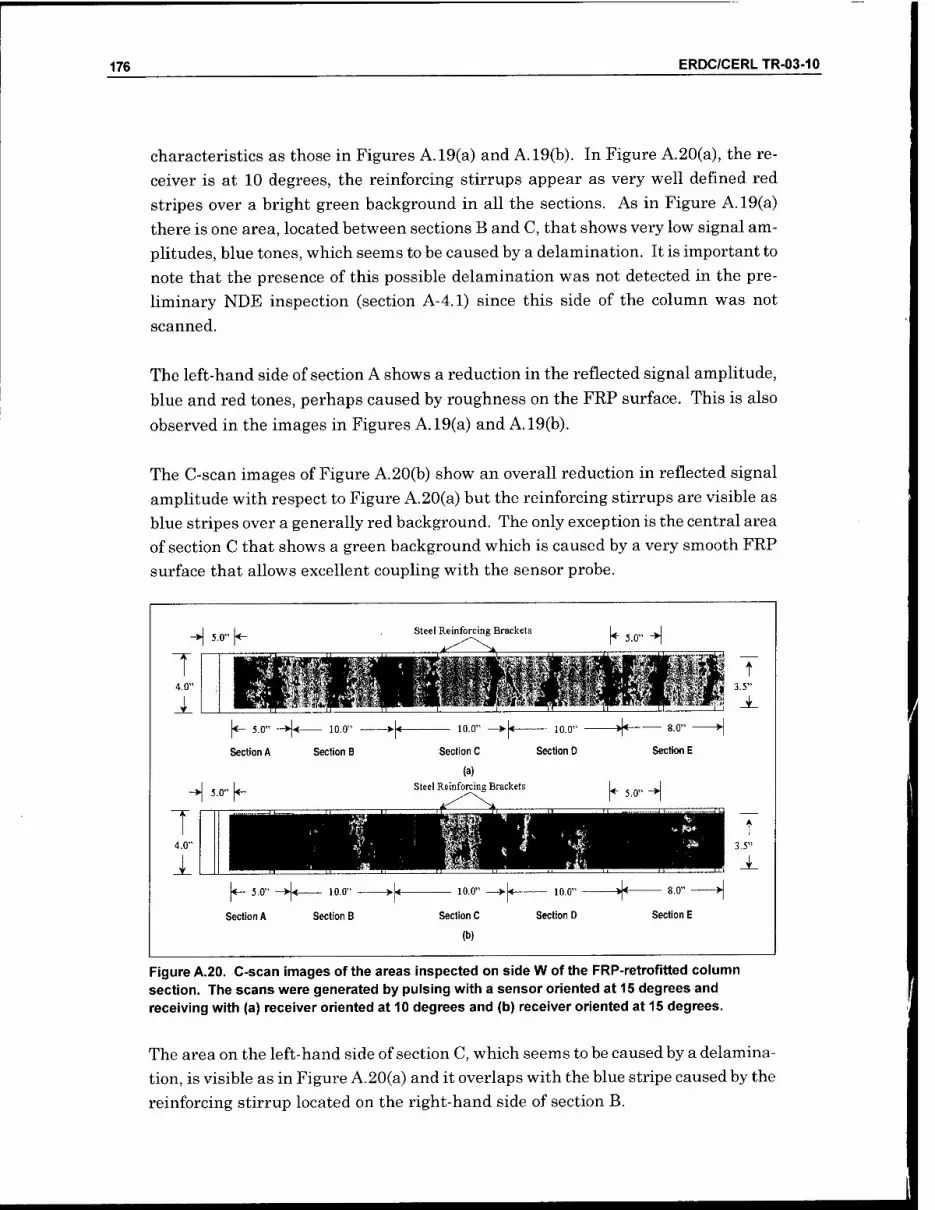
176 ERDC/CERLTR-03-10
characteristics as those in Figures A. 19(a) and A. 19(b). In Figure A.20(a), the re-
ceiver is at 10 degrees, the reinforcing stirrups appear as very well defined red
stripes over a bright green background in all the sections. As in Figure A. 19(a)
there is one area, located between sections B and C, that shows very low signal am-
plitudes, blue tones, which seems to be caused by a delamination. It is important to
note that the presence of this possible delamination was not detected in the pre-
liminary NDE inspection (section A-4.1) since this side of the column was not
scanned.
The left-hand side of section A shows a reduction in the reflected signal amplitude,
blue and red tones, perhaps caused by roughness on the FRP surface. This is also
observed in the images in Figures A. 19(a) and A. 19(b).
The C-scan images of Figure A.20(b) show an overall reduction in reflected signal
amplitude with respect to Figure A.20(a) but the reinforcing stirrups are visible as
blue stripes over a generally red background. The only exception is the central area
of section C that shows a green background which is caused by a very smooth FRF
surface that allows excellent coupling with the sensor probe.
H ^-o" h
T 4.0"
A.
steel Reinforcing Brackets K 5.0" -H
— 10.0"
Section B
10.0"
Section C
10.0"
Section D
8.0"
Section E
H 5.0" ^ (a)
Steel Reinforcing Brackets ^ 5.0" H
T 4.0"
1 |<- 5.0" -►|< lO.D" >■[♦
Section A Section B Section C
(b)
Section D Section E
Figure A.20. C-scan images of the areas inspected on side W of the FRP-retrofitted column section. The scans were generated by pulsing with a sensor oriented at 15 degrees and receiving with (a) receiver oriented at 10 degrees and (b) receiver oriented at 15 degrees.
The area on the left-hand side of section C, which seems to be caused by a delamina-
tion, is visible as in Figure A.20(a) and it overlaps with the blue stripe caused by the
reinforcing stirrup located on the right-hand side of section B.

ERDC/CERLTR-03-10 IZI
The C-scans shown in Figures A. 17, to A.20, show that the best contrast for the im- ages is achieved with the pulsing sensor oriented at 15 degrees. This is in agree- ment with the theoretical model presented in section A-3 where incident angles of 15 and 20 degrees are predicted for optimal contrast.
Final FRP-Upgraded Concrete Column Destructive Evaluation Results
In order to determine if the stripes observed in the C-scan images of sides V and W correspond with the positions of the reinforcing stirrups, and the spots on side W corresponds with delaminations, a destructive evaluation was performed on the col-
umn sample.
This destructive evaluation consisted of cutting the column section in the places where the C-scan images show either a delamination or reinforcing steel stirrups in order to confirm their presence. Figure A.21 presents a picture of the column sec- tion showing the locations where the cuts were made and the dimensions of the dif- ferent resulting pieces. It is important to note that the positions of the cuts were determined based on the C-scan images obtained for side V of the column, with pulser and receiver oriented at 15 degrees as shown in Figure A. 18(b).
A total often cuts were made, eight of them in places where the C-scans of Figure A. 18(b) show indications of the presence of reinforcing stirrups, and the remaining two in the middle of the locations where Figure A. 18(b) showed evidence of delami- nation. As a result of this process, the column was cut into 11 pieces.
Figures A.22(a) and A.22(c) show pictures of the cross-section of pieces 1 and 5, both containing delaminations on side V of the column. The close-up pictures clearly show the delaminations between the FRP wrap and the concrete column. Figure A.22(b) shows the cross-section of piece 4, with the delamination detected on side W, visible as a clear blue area on Figure A.20(b), pulser and receiver oriented at 15 de- grees.

178 ERDC/CERLTR-03-10
1.625"
_^ 5,25" |*_ _>| 5.375" \t >|2.25"|< >| 4.875" |< >| 4.375" |<— ^ |<-
If!
^M it',!'
9.0" >| 4.0" \*—*\ 3.125"|<— >| 4.375" ^ 3.625" h
Delamination Between FRP and Concrete Steel Reinforcing Brackets
Figure A.21. Location of tlie cuts performed on tfie column section. Ttie position of tiie cuts was determined according to the delaminations and stirrup positions on side V.
(a) (b) (c)
Figure A.22. Cuts on ttie column section sliown the delaminations detected in the column section using the AU C-scan images of side V and W: (a) First delamination on side V, (b) delamination detected on side W, and (c) second delamination on side V.
Figure A.23 presents cross section and close-up pictures of the 8 pieces of the cut
column that contained steel reinforcing stirrups. These pieces were numbered 2, 3,
4, 6, 8, 9, 10, and 11. In every one of the pictures, the steel stirrups are revealed.

ERDC/CERLTR-03-10 179
(a)
..trj^W,"
(b)
Figure A.23. Cuts on the column section showing the steel reinforcing stirrups detected using the AU C-scan images of side V.
Pieces 3, 4, 6, 8, 9, and 10 revealed the stirrups right on the position of the cuts, without any need for removing extra material. This indicates that the location of the stirrups, extracted from the C-scan images of side V were accurate within 0.125 in., which is the thickness of the cutting blade used. For pieces 2 and 11, it was necessary to remove about 0.250 in. of material to uncover the reinforcing stirrups.
180 ERDC/CERLTR-03-10
Based on the C-scan images, this is primarily due to sHght stirrup misalignment
and only partially due to destructive cutting misalignment. This also explains the
apparent difference between the position of the cuts and the actual location of the
stirrups.
Conclusions
The work presented in the Appendix above confirms that guided wave acousto-
ultrasonics can be used to inspect FRP-retrofitted concrete infrastructure, and the
results of the inspection can be displayed as C-scan images. Coupled with the de-
structive evaluation, this study also provides some important insight into the post-
damage state of the FRP after the experiments conducted in this report. Several
conclusions can be formulated from both the theoretical and experimental results.
The presented acousto-ultrasound guided wave theory offers four points:
1. In the cases using unidirectional composite lay-ups, the model predicts that the
wave propagation direction should be perpendicular to the fiber direction in order
to maximize the delamination detection sensitivity.
2. Optimal values for the incidence angle and frequency range for guided wave AU
inspection were chosen based on the results predicted by the theoretical model.
3. The theoretical model predicted the reflection coefficient of a delamination lo-
cated between the FRP layer and the concrete substrate.
4. Low frequency, obHque incidence acousto-ultrasound is feasible for the inspection
of FRP-wrapped concrete structures.
The presented FRP-retrofitted column NDE and destructive evaluation offers four
points:
1. Preliminary C-scan images were generated by scanning FRP/concrete beam and
column samples previously subjected to simulated seismic loads, and possible de-
laminations were located. 2. Refined C-scan images of the column section show the location of delaminations
between the FRP and the concrete substrate, and also the location of the steel re-
inforcing stirrups embedded within the concrete.
3. Destructive evaluation of the column section, performed by cutting at the posi-
tions indicated in the C-scan images, physically confirmed the location of the de-
laminations and the steel reinforcing stirrups.

ERDC/CERLTR-03-10 HL
4. Gmded wave AU is sensitive to FRP surface roughness, and in cases where sur- face discontinuities are larger than 0.0625 in., acoustic coupling between the FRP
and the sensor probe becomes very difficult.
References for this Appendix
Al-Chaar G. K, Daniel A. P., Lamb G., Trovillion J. 'Tlehabilitation Of Infilled Nonductile Concrete Frames Using Carbon Fiber Reinforced Polymer," Proceedings of the Third International Conference on Composite in Infrastructure, 12 Jxme 2002, San Francisco, CA.
Godlnez, V.F., R.D. Finlayson, R.K Miller, and B.B. Raju. 2001a. "Acousto-Ultrasonic Inspection of Hybrid Composite Armor Plate," Review Progress in Quantitative Nondestructive Evaluation, Vol. 20, American Institute of Physics, New York, 2001.
Godinez, V.F., R.D. Finlayson, and R.K. Miller. 2002. "Field Portable Infrastructure Fiber- Reinforced Polymer Composite Inspection & Evaluation System Using Ultrasound Technologies." SBIR Phase I Option Final Report, Physical Acoustic Corporation, February, 2002.
Godlnez, V.F., M.F. Carlos, M. Delamere, W. Hoch, C. Fotopoulos, and B.B. Raju. 2001b. "Acousto-Ultrasonic System for the Inspection of Composite Armored Vehicles," Review Progress in Quantitative Nondestructive Evaluation, Vol. 20, American Institute of Physics, New York, 2001.
Godlnez, V.F., R.D. Finlayson, and R.K. Miller. 2001c. "Field Portable Infrastructure Fiber- Reinforced Polymer Composite Inspection & Evaluation System Using Ultrasoimd Technologies." SBIR Phase I Final Report, Physical Acoustic Corporation, August, 2001.
Rokhlin, S.I., and D.E. Chimenti. 1990. "Reconstruction of Elastic Constants from Ultrasonic Reflectiblity Data in a Fluid Coupled Composite Plate," Review Progress in Quantitative Nondestructive Evaluation, Vol. 9, Plenum Press, New York, NY.
Wu, T.-T., J.-S. Fang, G.-Y. Liu, and M.-K Kuo. 1995. "Determination of Elastic Constants of a Concrete Specimen using Transient Elastic Waves," Journal of the Acoustical Society of America, Vol. 98, No. 4, pp. 2142-2148.

REPORT DOCUMENTATION PAGE Form Approved
OMBNo. 0704-0188 Public reporting burden for this collection of information Is estimated to average 1 hour per response, including the time (or reviewing instructions, searching existing data sources, gathering and maintaining the data needed and completing and reviewing this collection of Infomiation. Send comments regarding this burden estimate or any other aspect of this collection of information, including suggestions for reducing this burden to Department of Defense, Washington Headquarters Services, Directorate for Information Operations and Reports (0704-0188), 1215 Jefferson Davis Highway, Suite 1204, Arlington, VA 22202- 4302 Respondents should be aware that notwithstanding any other provision of law, no person shall be subject to any penalty for falling to connply with a collection of information If it does not display a currently valid OMB control number. PLEASE DO NOT RETURN YOUR FORM TO THE ABOVE ADDRESS.
1. REPORT DATE (DD-MM-YYYY) 05-2003
2. REPORT TYPE Final
4. TITLE AND SUBTITLE Investigation of Fiber-Reinforced Polymer for Seismic Rehabilitation of Concrete Structural Frames With Unreinforced Masonry Infill fill
6. AUTHOR(S) Ghassan K. Al-Chaar, Justin B. Berman, and Steven C. Sweeney
7. PERFORMING ORGANIZATION NAME(S) AND ADDRESS(ES) U.S. Army Engineer Research and Development Center (ERDC) Construction Engineering Research Laboratory (CERL) PO Box 9005 Champaign, IL 61826-9005
9. SPONSORING / MONITORING AGENCY NAME(S) AND ADDRESS(ES)
Headquarters, U.S. Army Corps of Engineers (HQUSACE) 441GSt.,NW. Washington, DC 20314-1000
3. DATES COVERED (From - To)
5a. CONTRACT NUMBER
5b. GRANT NUMBER
5C. PROGRAM ELEMENT NUMBER
5d. PROJECT NUMBER 4A162784AT41 5e. TASK NUMBER
5f. WORK UNIT NUMBER CFM-AOll 8. PERFORMING ORGANIZATION REPORT
NUMBER
ERDC/CERLTR-03-10
10. SPONSOR/MONITOR'S ACRONYM(S) CECW-EW
11. SPONSOR/MONITOR'S REPORT NUMBER(S)
12. DISTRIBUTION / AVAILABILITY STATEMENT Approved for public release; distribution is unlimited.
13. SUPPLEMENTARY NOTES Copies are available from the National Technical Information Service, 5285 Port Royal Road, Springfield, VA 22161.
14. ABSTRACT
The U.S. Army currently operates approximately 1300 older buildings that use masomy-mfiUed concrete frames as their principal structural system. About 700 of these buildings do not meet current seismic code requirements and are considered vulnerable to dam- age during an earthquake.
The primary objective of this research was to investigate the performance of FRP composite materials when used to rehabilitate ma- sonry-infilled concrete frame systems. A secondary objective was to investigate the seismic performance of multi-bay, multi-story ma- sonry-infilled concrete frame systems similar to those still in use on Army installations in U.S. areas of high seismicity.
The models used in this study were half-scale in order to conform to the physical limitations of the testing facility. Four expermiental tests were conducted on two physical models.
The results of four tests were analyzed and compared to determine the influence of their distmguishable variables. The general conclu- sion drawn from these studies is that CFRP overiay material can be bonded to concrete to provide effective rehabilitation of masonry- mfilled concrete frames. The test results indicate that CFRP can improve structural sfrength and deformation capabilities^
15. SUBJECT TERMS carbon fiber-reinforced polymer (CFRP), infill panels, carbon-reinforced polymer (FRP), masonry, reinforced concrete, siesmic vulnerability, structural relaibility, seismic testing 16. SECURITY CLASSIFICATION OF:
a. REPORT Unclassified
b. ABSTRACT Unclassified
C. THIS PAGE Unclassified
17. LIMITATION OF ABSTRACT
SAR
18. NUMBER OF PAGES
182
19a. NAME OF RESPONSIBLE PERSON Ghassan K. Al-Chaar
19b. TELEPHONE NUMBER (in- clude area code)
NSN 7540-01-280-5500 Standard Form 298 (Rev. 8-98) Prescribed by ANSI Std. 239.18