masonry confinement using steel cords
TRANSCRIPT


Masonry Confinement Using Steel CordsAntonio Borri1; Giulio Castori2; and Marco Corradi3
Abstract: The objective of this study is to investigate the effectiveness of an alternative technique for strengthening masonry columns, basedon the use of steel cords. Although fiber-reinforced polymer (FRP) strips or jackets are successfully used as strengthening elements for thiskind of application, such a strengthening method represents a new opportunity to restore ambit, with considerable development in unrein-forced masonry wrapping. Thus, to assess the potential of steel cord wrapping, this paper presents the results of an experimental programconsisting of 48 solid-brick specimens subjected to uniaxial compression load. Different cross-section geometry (octagonal, square, andrectangular) and different amounts and different schemes for confining reinforcement were investigated. The primary experimental outcomesare presented and discussed in the paper considering the mechanical behavior of specimens and the axial stress–axial strain relationships. Testresults have shown that the investigated confining systems are able to provide significant gains, both in the compressive strength and in thedeformation capacity of masonry columns. DOI: 10.1061/(ASCE)MT.1943-5533.0000753. © 2013 American Society of Civil Engineers.
CE Database subject headings: Columns; Confinement; Masonry; Steel.
Author keywords: Columns; Confinement; Masonry; Reinforcement; Steel cords.
Introduction
A large number of existing masonry structures shows damage re-sulting from a wide range of events (i.e., inadequate constructiontechniques and materials, foundation settlements, seismic loads,and environmental deterioration). Even when these structures arenot affected by strong signals of deterioration, they often needto be upgraded to meet new mandatory seismic design requirementsor to allow a change of use of the building. Thus, seismic retrofitand strengthening of masonry structures is of primary importancefor maintenance of the Italian and European architectural culturalheritage. This was verified by the recent earthquakes that producedinestimable damage in central Italy. The problem of masonry ele-ments subjected to compressive overloads resulting from static orseismic forces is of primary importance to avoid sudden brittle fail-ure. The solutions adopted should restore structural safety withoutchanging the architectural value, the shape, and the weight of theelements.
In recent decades, reinforced concrete (Kog et al. 2001), or steeljacketing, were largely used to increase both the axial strength andthe deformation capacity of masonry columns through confine-ment. These well-known techniques have proven to be effective,but are often short-lived, labor-intensive, and usually violate theaesthetic, conservation, and restoration requirements. Moreover,the mass added by that kind of intervention could generate a
significant extra weight, inducing an increase in seismic actionand static demand to the foundation system.
Consequently, to overcome these limitations, the interest of re-searchers and practitioners in this field has become increasinglydevoted to the development of fiber-reinforced polymer (FRP)composites in the form of epoxy bonded strips or jackets. As foundin literature (Micelli et al. 2004; Aiello et al. 2007), confinementof masonry columns with FRP laminates could imply significantadvantages when compared to traditional techniques, such as neg-ligible increase in both cross-sectional dimensions and membermass and a faster and easier installation procedure. However,later studies by Corradi et al. (2007), Aiello et al. (2009), andDi Ludovico et al. (2010) have shown that the effectiveness ofthe FRP wraps is significantly affected by the corner radius ofcolumns, without considering that FRP jacketing needs the appli-cation of epoxy resins with considerable and unsolved problems interms of high temperature and long-term behavior, compatibility,and reversibility.
A possibly interesting development in the use of composites re-garding innovative materials, based on ultra high-strength steelfilaments (Hardwire LLC 2002) twisted to form cords and em-bedded in either an epoxy [referred to as steel-reinforced polymer(SRP)] or mortar [referred to as steel-reinforced grout (SRG)]matrix. Inherent shear strength of steel cords promotes effective-ness of reinforcement and delays premature material failure asso-ciated with sharp corners. However, SRP and SRG are fairly newtechnologies and, at present, no specific design guidelines exist forsuch materials, and few studies are available on their use asstrengthening systems (Cancelli et al. 2007; Micelli and La Tegola2007; Borri et al. 2009a, b; Capozucca 2010; Grande et al. 2011;Borri et al. 2011).
As a result of such considerations, the present paper aims toprove, through experimental tests, the potential of masonry con-finement by using steel cords. Different cross-section geometry(octagonal, square, and rectangular) and different amounts anddifferent schemes of confining reinforcement were investigated. Inparticular, two different strengthening techniques were considered,namely wrapping with continuous (or discontinuous) SRP sheetsand hooping with stainless steel cords.
1Professor, Dept. of Civil and Environmental Engineering, Univ. ofPerugia, via Duranti 93, 06125 Perugia, Italy.
2Ph.D. Researcher, Dept. of Civil and Environmental Engineering,Univ. of Perugia, via Duranti 93, 06125 Perugia, Italy (correspondingauthor). E-mail: [email protected]
3Assistant Professor, Dept. of Civil and Environmental Engineering,Univ. of Perugia, via Duranti 93, 06125 Perugia, Italy.
Note. This manuscript was submitted on August 2, 2012; approved onDecember 5, 2012; published online on December 7, 2012. Discussion per-iod open until May 1, 2014; separate discussions must be submitted forindividual papers. This paper is part of the Journal of Materials in CivilEngineering, Vol. 25, No. 12, December 1, 2013. © ASCE, ISSN 0899-1561/2013/12-1910-1919/$25.00.
1910 / JOURNAL OF MATERIALS IN CIVIL ENGINEERING © ASCE / DECEMBER 2013

Description of the Strengthening Techniques
As mentioned previously, pure compression tests were carried outon masonry columns confined with either steel-reinforced compo-sites or stainless steel cords. Concerning composite materials,columns strengthened by wrapping with continuous (or discontinu-ous) SRP sheets were tested. Other tests were realized on columnsreinforced with an alternative technique, which consists of theapplication of thin stainless steel cords that hoops the column ata relatively close spacing. In both cases the purpose of the testswas to analyze the effectiveness of the intervention, primarily asa way to increase the axial capacity of masonry through confine-ment. A description of each retrofitting method is reported in thefollowing sections.
Wrapping
Referring to wrapping, a 90° fiber direction with respect to the lon-gitudinal column axis was used. More specifically, two differentstrengthening schemes were considered: wrapping with continuousor discontinuous SRP sheets.
In the first case the confinement was provided by a continuouslaminate composed of two 300-mm-wide SRP strips; in the secondcase the confinement was provided by three 100-mm-wide SRPstrips, spaced 115 mm apart. In both cases, the finishing end ofthe sheet overlapped the starting end by approximately 200 mm.SRP strips were installed following the recommendations ofACI 440.2R-02 (ACI 440) provisions for FRP materials. The ma-sonry surface was cleaned with abrasive paper to remove defectsand possible wet parts. With the surface roughened and cleaned,a first layer of a low viscosity epoxy resin was used on the surfaceof the specimens before wrapping with the SRP sheets. Afterwrapping, a second layer of epoxy resin was applied and a rollerused to remove any air voids and to assure an effective impregna-tion of the resin. SRP sheets were not bonded in the regions close tothe steel plates used to transfer the load at the heads of the column;this avoided local transversal buckling of the SRP sheet in theextreme regions of the column, resulting from the application ofcompression load.
Hooping
With regard to the second strengthening scheme (hooping), thissection presents the results of the development and evolution ofan innovative confining technique recently proposed by Jurina(Jurina 2010) for reinforcing masonry columns, when the fair facemasonry must be kept. It consists of the application of small diam-eter (1–3 mm) stainless steel cords to provide overlapping hoops incorrespondence with mortar joints. Because the lime mortars of an-cient buildings are known to have a greater deformability with re-spect to that of the bricks or stone blocks, the application of a ringthat reinforces the mortar joint significantly increases the capacityof the column.
In such a context, the effectiveness of the method can be im-proved further by pretensioning the cords. Thanks to the prestress-ing force, the reinforcement can work as an “active system,” able tobe engaged even for service loads and for low-intensity seismicactivity, providing extra tension strength to the structure. Therefore,for the steel cords used in this study, a prestressing level of approx-imately 10% of the ultimate strength of the cords (resulting inapproximately 140 MPa) appeared be a maximum value thatcould be achieved practically on site. This is because the directcontact between masonry joints and cords, especially at the higherprestressing levels and consequently under the resulting higher
interacting pressure between mortar and cords, may cause somelocal damage to masonry joints during the prestressing procedure.
The installation procedure involved the following steps (Fig. 1):Mortar joints were carefully raked out to a maximum depth of10–20 mm (being careful to remove only the damaged mortar).After a first repointing with fiber-reinforced mortar, Φ1.6-mmstainless steel cords were inserted into each joint. Next, the mortarjoints were filled with fiber-reinforced mortar or epoxy resin, whichcompletely covers the reinforcement.
In contrast, for the prestressing application, a Φ3-mm stainlesssteel cord was inserted into each joint to provide single or overlap-ping hoops. In this case, after the cord was wrapped around thecolumn, its ends were first inserted into a predrilled hole, passingthrough the core of the column (Fig. 2a), and then anchored to theprestressing device. The prestressing force was achieved with ahand-held device (Fig. 2b) without the need for power-operated hy-draulic jacks or any other type of sophisticated equipment. Thecord was then anchored to the column by injecting the predrilledhole (Fig. 2c), and after approximately 24 h of curing time, theprestressing device was removed. Steel angles were located aroundeach corner to prevent damage and to allow the cord to slide freelyduring prestressing.
Experimental Program
Test Specimens
A total of 48 model masonry column specimens in four series wereprepared using solid clay bricks (250 × 125 × 55 mm) bondedtogether with a mortar containing cement and lime as binder, ata water∶cement∶lime∶sand ratio equal to 0.9∶1∶3∶7.5 by weight.
The cross-sectional area of the specimens was octagonal (sideaverage dimension equal to 100 mm, aspect ratio 1∶1) in the firstseries, 360 × 360 mm (aspect ratio 1∶1) in the second, 360 ×240 mm in the third (aspect ratio 1.5∶1), and 480 × 240 mm (aspectratio 2∶1) in the fourth. Each specimen was 530-mm high, corre-sponding to eight courses of clay bricks with seven bed joints inbetween, as shown in Fig. 3. The thickness of the mortar bed was13 mm, and the corners of all specimens of the second, third, andfourth series were rounded at a radius of 20 mm to reduce anydetrimental effect of the sharp corners on the effectiveness of con-finement. Finally, to avoid size effect, a paraffin wax, which is ableto reduce friction with the adjacent steel platens of the testingmachine, was applied to the top and bottom ends of each column.
Removal of damaged mortar
6 stainless steel cords (Ø1.6 mm)
Repointing with fiber reinforced mortar
Reinforced mortar or resin, as protection
Fig. 1. Hooping with stainless steel cords: Application
JOURNAL OF MATERIALS IN CIVIL ENGINEERING © ASCE / DECEMBER 2013 / 1911

Details about the model columns in each series are given inTable 1. The specimens are identified by a three index code, inwhich the first indicates the cross-section geometry (OC, octago-nal; SQ, square; RS, rectangular with a cross-section aspect ratioof 1.5∶1; RL, rectangular with cross-section aspect ratio of 2∶1);the second code indicates the type of intervention carried out(UN, unreinforced; WC, continuous wrapping; WD, discontinuouswrapping; HC, hooping with steel cords; HP, hooping with preten-sioned steel cords); and the third index indicates the identificationnumber of the specimen.
Material Properties
Three types of steel cords were used in this research. Type 1 ismade by twisting three ultra-high-strength steel filaments togetherat a longer than usual lay length and then overwrapping thebundle with a single filament. The cords are arranged parallel toone another and held together by a polyester mesh and have a
brass-AO (adhesion optimized) coating that enhances the corrosionresistance. In contrast, types 2 and 3 are made by twisting 49 and 19stainless steel filaments together, respectively. Characterization testresults (according to ACI 440) were used to specify the propertiesof the steel cords (Table 2).
The mortar used to make the whole set of columns was com-posed of Portland cement (10% in volume), sand (80% in volume),and hydraulic lime (10% in volume). The mechanical propertieswere derived from bending and compression tests (accordingto ASTM C348 and ASTM C349): three 40 × 40 × 160 mmmortar prisms were tested in flexure with three-point bendingand six cubes, obtained from failed mortar specimens in flexure,and were subjected to compression tests. The 28-day averagestrength results were 3.53 MPa for flexural tests and 10.1 MPafor compression tests.
The mechanical characteristics of solid clay bricks were ob-tained by the compression and bending tests (according to ASTMC1314 and ASTM C1006). Uniaxial compression tests, carried
Fig. 2.Hooping with pretensioned steel cords: Application (a) inserting the cord ends into the predrilled hole; (b) prestressing device; (c) injecting thepredrilled hole
530
250
250
250
100
(a)
360
36053
0
360
(b)
360
240
530
360
(c)
530
480
480
240
(d)
Fig. 3. Specimen details (dimensions in mm): (a) first series; (b) second series; (c) third series; (d) fourth series
1912 / JOURNAL OF MATERIALS IN CIVIL ENGINEERING © ASCE / DECEMBER 2013

out on six orthogonal prisms (250 × 250 × 120 mm each), gave amean strength of 20.99 MPa, whereas the mean value of thebending tensile strength, computed on six orthogonal prisms(55 × 55 × 250 mm each), was 6.75 MPa.
Test Setup
The main objective of testing was to record the axial stress-straincurve and the failure mode of all the masonry specimens, whichwere subjected to axial loading applied monotonically under a dis-placement control mode in a compression testing machine of1200 kN capacity. Loads were measured using a load cell, and dis-placements were obtained using four external linear variable differ-ential transducers (LVDTs) mounted on the columns, at a gaugelength of 215 mm in the middle part of each specimen.
Test Results
In the following, the results of the experimental tests carried out onthe columns are grouped according to the schemes of confiningreinforcement.
Unconfined Columns
Despite the fact that material properties were quite similar, speci-mens with square cross-sections (series SQ) exhibited a lower com-pressive strength than the octagonal (series OC) or rectangular(series RS and RL) ones (Table 3). Such a result can be linked
to the presence of undesirable variables (such as handwork) thatmay have arisen from the construction of the masonry columns.The mortar workability and the presence of defects (sedimentaryinclusions, regularity of geometry, etc.) may cause stress concen-tration that is able to produce a premature failure. In all cases, thecracking pattern (Fig. 4) was quite regular. Vertical cracks formedat low load level, and then they propagated along the principal axisof the column in directions that were almost parallel to the loadingdirection.
The axial stress–axial strain relationships (Fig. 5) first show alinear upward trend up to the maximum load. After the maximumload was achieved, the failure mechanism started to occur and asudden drop in the stress-strain curves was observed, except forspecimens OC-UN-03 and RL-UN-01, for which a decreasingbranch (“softening”) was recorded.
Continuous Wrapping
Because SRP wrapping enables masonry columns to carry substan-tial tensile stresses, the presence of external confinement dramati-cally changed the behavior of the specimens. Failure of theconfined columns was initiated by the local buckling of externalwrapping [Figs. 6(a and c)], resulting from both the significant levelof axial strains and the cracking of masonry under the effect of thehighly tri-axial stress state induced by the vertical compression andthe external jacket. Consequently, a load reduction was observedduring the last phase of the tests, followed by tensile rupture ofthe SRP sheets at the mid height or near the bottom of the specimen(Fig. 6b). A significant increase in strength with respect to uncon-fined masonry was obtained in both specimens with octagonaland square cross-sections. The average value of normalized strength,defined as the ratio of peak stress of confined columns to that ofunconfined columns, exceeded 2 (fifth column in Table 4) in bothcases. RS and RL specimens, characterized by a rectangular cross-section and an aspect ratio of 1.5∶1 and 2∶1, respectively, showedinstead a less significant increase in the ultimate capacity, as a com-pressive strength of 18.65 (þ56%) and 15.56 MPa (þ27%)was found.
Stress-strain curves for columns confined with continuouswrapping are shown in Fig. 7. The tests highlighted a modified
Table 1. Test Matrix
SeriesSpecimenseries
Number ofspecimens Reinforcement Reinforcement ratio (%)
Octagonal (OC) UN 3 —WC 2 Steel cords (type 1) 0.48WD 4 Steel cords (type 1) 0.24HCa 5 Steel cords (type 2) 0.11HP 6 Steel cords (type 3) 0.11 (specimens from 01 to 03)
0.22 (specimens from 04 to 06)Square (SQ) UN 2 — —
WC 5 Steel cords (type 1) 0.49WD 6 Steel cords (type 1) 0.24HP 4 Steel cords (type 3) 0.07 (specimens 01 and 02)
0.14 (specimens 03 and 04)Rectangular (RS) UN 1 — —
WC 2 Steel cords (type 1) 0.42WD 2 Steel cords (type 1) 0.21
Rectangular (RL) UN 1 — —WC 1 Steel cords (type 1) 0.37HP 4 Steel cords (type 3) 0.08 (specimens 01 and 02)
0.16 (specimens 03 and 04)aIn specimens OC-HC-04 and OC-HC-05 resin was used rather than mortar as protection.
Table 2. Mechanical Properties of Reinforcement
Property
High-strengthsteel cords
Stainlesssteel cords
Type 1 Type 2 Type 3
Cord diameter (mm) 1.02 1.60 3.00Cross-sectional area (mm2) 0.561 0.904 5.372Elastic modulus (MPa) 143000 73500 117000Tensile strength (N=mm2) 2396 1470 1211Strain to failure (%) 1.16 2.00 1.03
JOURNAL OF MATERIALS IN CIVIL ENGINEERING © ASCE / DECEMBER 2013 / 1913

Fig. 4. Failure modes of unconfined columns: (a) OC series; (b) SQ series; (c) RS series
Fig. 5. Axial stress-strain relationship for unconfined columns (positive values of strain on both sides of x-axis)
Fig. 6. Failure modes of columns confined with continuous wrapping: (a) OC series; (b) SQ series; (c) RS series
1914 / JOURNAL OF MATERIALS IN CIVIL ENGINEERING © ASCE / DECEMBER 2013

behavior for SRP-confined octagonal and square columns withrespect to plain masonry: a plastic branch is evident after the peakload, and application of load (after the peak value, which corre-sponds to the maximum capacity) showed the ability of thewrapped columns to deform along the principal axis at constantload. Conversely, in RS and RL specimens, after the maximumload was achieved, a sudden drop in the stress-strain curves wasrecorded and no plastic branch was observed.
Discontinuous Wrapping
The columns strengthened with discontinuous wrapping failed formasonry rupture, which caused the expulsion of materials from theunwrapped zones. This aspect of the columns was observed aftermechanical testing and it was evident, in all cases, that the presenceof damaged regions, when not effectively confined, experienced thespalling of masonry cracked pieces from the core (Fig. 8). Becausethe reduced spacing between the strips did not cause extended un-confined regions (which are the weak link in the discontinuousconfining system), the confinement result was very effective. Moreprecisely, the better structural performances were observed for OCand SQ columns (Table 5), where the average strength increaserelated to the respective control specimens was approximately 108%(compressive strength 25.24 MPa) for octagonal columns, andapproximately 72% (compressive strength 12.77 MPa) for squarecolumns. Conversely, a smaller advantage in terms of strength wasobtained with RS columns, because an average strength increase of59% (compressive strength 19.03 MPa) was found.
Table 3. Unstrengthened Columns: Experimental Results
Specimen seriesNumber ofspecimens
Maximumstress (MPa)
Ultimate axialstrain average (−)
OC-UN 3 12.11 0.0042SQ-UN 2 7.44 0.0042RS-UN 1 11.96 0.0061RL-UN 1 9.91 0.0073
Fig. 7. Axial stress-strain relationship for columns confined with continuous wrapping (positive values of strain on both sides of x-axis)
Fig. 8. Failure modes of columns confined with discontinuous wrapping: (a) OC series; (b) SQ series; (c) RS series
JOURNAL OF MATERIALS IN CIVIL ENGINEERING © ASCE / DECEMBER 2013 / 1915

Finally, Fig. 9 illustrates a comparison between the stress-straincurves obtained from the experimental tests on the WD columns. Inall cases, except for RS specimens that behave linearly to failure,the typical bilinear stress-strain relationship, growing up to failure,was recorded. More precisely, the overall shape of the responseshows a first linear upward trend up to the maximum load followedby a second decreasing branch.
Hooping
The columns strengthened with steel hooping showed a differentmechanical behavior when compared to the specimens previouslydescribed. This result was expected, because the difference inthe deformability under pressure of the masonry bricks and ofthe mortar joints exerts an important influence on the masonrystrength. The mortar has a higher deformation capacity than themasonry bricks and, consequently, it tends to expand radiallythrough the joints. Because this tendency is restrained by the
steel hoops and adhesion forces of the masonry bricks, this trans-versal deformability difference produces tensile stresses in thebricks. When the tensile strength limit in the bricks was reached,vertical cracks formed within the specimens, and they increasedin number and propagated with the applied load until failure.Compared with the crack pattern found in control columns, insuch specimens a more widespread and diffused crack patternwas found, with thinner cracks distributed along the entire column(Fig. 10).
As shown in Table 6, the results present a different ultimate loadcapacity despite having shown the same failure mode. Specifically,the average strength increments related to the respective controlspecimens were between 24 and 38% for OC specimens and be-tween 30 and 50% for SQ specimens, whereas lower strength gainswere achieved on RL specimens (no more than 12%).
Important information is also provided by the analysis ofthe LVDT readings. The stress-strain curves [Figs. 11(a and b)]for octagonal, square, and rectangular columns revealed a different
Fig. 9. Axial stress-strain relationship for columns confined with discontinuous wrapping (positive values of strain on both sides of x-axis)
Fig. 10. Failure modes of columns confined with steel hooping: (a) OC Series; (b) SQ Series; (c) RL Series
1916 / JOURNAL OF MATERIALS IN CIVIL ENGINEERING © ASCE / DECEMBER 2013
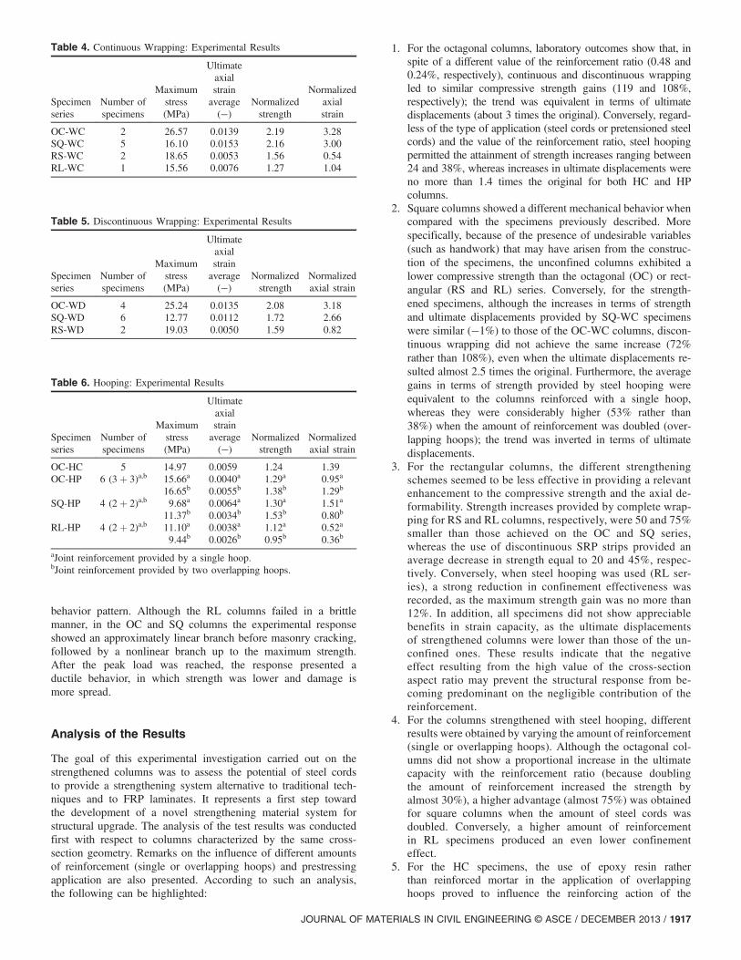
behavior pattern. Although the RL columns failed in a brittlemanner, in the OC and SQ columns the experimental responseshowed an approximately linear branch before masonry cracking,followed by a nonlinear branch up to the maximum strength.After the peak load was reached, the response presented aductile behavior, in which strength was lower and damage ismore spread.
Analysis of the Results
The goal of this experimental investigation carried out on thestrengthened columns was to assess the potential of steel cordsto provide a strengthening system alternative to traditional tech-niques and to FRP laminates. It represents a first step towardthe development of a novel strengthening material system forstructural upgrade. The analysis of the test results was conductedfirst with respect to columns characterized by the same cross-section geometry. Remarks on the influence of different amountsof reinforcement (single or overlapping hoops) and prestressingapplication are also presented. According to such an analysis,the following can be highlighted:
1. For the octagonal columns, laboratory outcomes show that, inspite of a different value of the reinforcement ratio (0.48 and0.24%, respectively), continuous and discontinuous wrappingled to similar compressive strength gains (119 and 108%,respectively); the trend was equivalent in terms of ultimatedisplacements (about 3 times the original). Conversely, regard-less of the type of application (steel cords or pretensioned steelcords) and the value of the reinforcement ratio, steel hoopingpermitted the attainment of strength increases ranging between24 and 38%, whereas increases in ultimate displacements wereno more than 1.4 times the original for both HC and HPcolumns.
2. Square columns showed a different mechanical behavior whencompared with the specimens previously described. Morespecifically, because of the presence of undesirable variables(such as handwork) that may have arisen from the construc-tion of the specimens, the unconfined columns exhibited alower compressive strength than the octagonal (OC) or rect-angular (RS and RL) series. Conversely, for the strength-ened specimens, although the increases in terms of strengthand ultimate displacements provided by SQ-WC specimenswere similar (−1%) to those of the OC-WC columns, discon-tinuous wrapping did not achieve the same increase (72%rather than 108%), even when the ultimate displacements re-sulted almost 2.5 times the original. Furthermore, the averagegains in terms of strength provided by steel hooping wereequivalent to the columns reinforced with a single hoop,whereas they were considerably higher (53% rather than38%) when the amount of reinforcement was doubled (over-lapping hoops); the trend was inverted in terms of ultimatedisplacements.
3. For the rectangular columns, the different strengtheningschemes seemed to be less effective in providing a relevantenhancement to the compressive strength and the axial de-formability. Strength increases provided by complete wrap-ping for RS and RL columns, respectively, were 50 and 75%smaller than those achieved on the OC and SQ series,whereas the use of discontinuous SRP strips provided anaverage decrease in strength equal to 20 and 45%, respec-tively. Conversely, when steel hooping was used (RL ser-ies), a strong reduction in confinement effectiveness wasrecorded, as the maximum strength gain was no more than12%. In addition, all specimens did not show appreciablebenefits in strain capacity, as the ultimate displacementsof strengthened columns were lower than those of the un-confined ones. These results indicate that the negativeeffect resulting from the high value of the cross-sectionaspect ratio may prevent the structural response from be-coming predominant on the negligible contribution of thereinforcement.
4. For the columns strengthened with steel hooping, differentresults were obtained by varying the amount of reinforcement(single or overlapping hoops). Although the octagonal col-umns did not show a proportional increase in the ultimatecapacity with the reinforcement ratio (because doublingthe amount of reinforcement increased the strength byalmost 30%), a higher advantage (almost 75%) was obtainedfor square columns when the amount of steel cords wasdoubled. Conversely, a higher amount of reinforcementin RL specimens produced an even lower confinementeffect.
5. For the HC specimens, the use of epoxy resin ratherthan reinforced mortar in the application of overlappinghoops proved to influence the reinforcing action of the
Table 4. Continuous Wrapping: Experimental Results
Specimenseries
Number ofspecimens
Maximumstress(MPa)
Ultimateaxialstrainaverage(−)
Normalizedstrength
Normalizedaxialstrain
OC-WC 2 26.57 0.0139 2.19 3.28SQ-WC 5 16.10 0.0153 2.16 3.00RS-WC 2 18.65 0.0053 1.56 0.54RL-WC 1 15.56 0.0076 1.27 1.04
Table 5. Discontinuous Wrapping: Experimental Results
Specimenseries
Number ofspecimens
Maximumstress(MPa)
Ultimateaxialstrainaverage(−)
Normalizedstrength
Normalizedaxial strain
OC-WD 4 25.24 0.0135 2.08 3.18SQ-WD 6 12.77 0.0112 1.72 2.66RS-WD 2 19.03 0.0050 1.59 0.82
Table 6. Hooping: Experimental Results
Specimenseries
Number ofspecimens
Maximumstress(MPa)
Ultimateaxialstrainaverage(−)
Normalizedstrength
Normalizedaxial strain
OC-HC 5 14.97 0.0059 1.24 1.39OC-HP 6 (3þ 3)a,b 15.66a 0.0040a 1.29a 0.95a
16.65b 0.0055b 1.38b 1.29b
SQ-HP 4 (2þ 2)a,b 9.68a 0.0064a 1.30a 1.51a
11.37b 0.0034b 1.53b 0.80b
RL-HP 4 (2þ 2)a,b 11.10a 0.0038a 1.12a 0.52a
9.44b 0.0026b 0.95b 0.36b
aJoint reinforcement provided by a single hoop.bJoint reinforcement provided by two overlapping hoops.
JOURNAL OF MATERIALS IN CIVIL ENGINEERING © ASCE / DECEMBER 2013 / 1917

steel cords. Columns with epoxy resin as protection(columns OC-HC-04 and OC-HC-05) permitted the attain-ment of strength increases ranging between 1.36 and 1.43times the original, whereas the maximum increase obtainedwith reinforced mortar (columns OC-HC-01, OC-HC-02, and OC-HC-03) was no more than 1.13 times theoriginal.
6. The application of pretensioned steel cords appears to have anontrivial influence in the column behavior, particularly when
comparing columns with mortar joints filled with reinforcedmortar rather than epoxy resin.
A comparison between columns with equivalent reinforcementratio highlights that columns strengthened with pretensioned steelcords (columns OC-HP-01, OC-HP-02, and OC-HP-03) providedan ultimate strength approximately 20% larger than that of thespecimens strengthened with steel cords (columns OC-HC-01,OC-HC-02, and OC-HC-03), with displacements approximately40% smaller.
Fig. 11.Axial stress-strain relationship for columns confined with steel hooping: (a) HC series; (b) HP series (positive values of strain on both sides ofx-axis)
1918 / JOURNAL OF MATERIALS IN CIVIL ENGINEERING © ASCE / DECEMBER 2013

Conclusions
This experiment was developed to investigate the potential ofmasonry confinement by using steel cords. Although FRP stripsor jackets are successfully used as strengthening elements forthis kind of application, such a strengthening method representsa new opportunity to restore ambit, with considerable develop-ment in unreinforced masonry wrapping. Two different strength-ening techniques were considered: wrapping with continuous(or discontinuous) SRP sheets and hooping with stainless steelcords. Four series of uniaxial compression tests, a total of 48 col-umns, were conducted on specimens using these three variables:cross-section geometry, reinforcement ratio, and application of pre-tensioned steel cords.
The experimental outcomes show the following:• Wrapping with continuous (or discontinuous) SRP sheets is
effective when confinement of masonry compressed elementsis necessary. The confinement provided by SRP sheets con-siderably improves both the load-carrying capacity and thedeformability of octagonal and square columns. Lower gains,particularly in terms of ultimate displacements, are obtainedin the case of rectangular columns. A key factor that may ex-plain such a discrepancy is the value of the cross-section aspectratio. In spite of a similar amount of reinforcement, a largervalue of the cross-section aspect ratio seems to prevent the straincapacity of rectangular columns from becoming predominant onthe negligible contribution of the reinforcement.
• Even if columns strengthened by steel hooping exhibited lowermechanical properties (as expected from previous tests), from aqualitative point of view, the confinement result was also veryeffective in these cases. The tests highlight a modified behaviorfor HC and HP columns with respect to plain masonry; Exceptfor rectangular columns (which behave linearly up to failure), aplastic branch is evident after the peak load, and application ofload after the peak value that corresponds to the maximumcapacity showed the ability of the reinforced columns to deformalong the principal axis at constant load without steel cords rup-ture. Far from being exhaustive, such results indicate that theconfinement effect of steel cords contributes to the modificationof the static scheme of the structure, forming a “reinforcementskeleton” aimed at integrating the masonry rather than trans-forming it. Regardless, because the cords can be put under lighttension, they also provide an “active” confinement to the col-umn already for service loads.
• As for the HP specimens, different results were obtained byvarying the amount of reinforcement (single or overlappinghoops). More specifically, doubling the amount of reinforce-ment was beneficial to the strength capacity of square speci-mens, whereas it resulted in being negligible or even harmfulfor both octagonal and rectangular columns.
• As for the HC specimens, epoxy resin behaved well in bondingthe steel cords to the mortar joints and provided an overall betterperformance in terms of ultimate load capacity than the rein-forced mortar.
Acknowledgments
The experimental work was developed within the research pro-gram funded by the Department of Civil Protection “ConsorzioReLUIS.” The authors would like to acknowledge FIDIA s.r.l.for providing the high-strength steel cords, and KIMIA s.p.a. forproviding the stainless steel cords. The authors also thank theLASTRU Laboratory technicians for their assistance during theexperimental tests.
References
Aiello, M. A., Micelli, F., and Valente, L. (2007). “Structural upgrading ofmasonry columns by using composite reinforcements.” J. Compos.Construct., 11(6), 650–658.
Aiello, M. A., Micelli, F., and Valente, L. (2009). “FRP confine-ment of square masonry columns.” J. Compos. Construct., 13(2),148–158.
Borri, A., Castori, G., and Grazini, A. (2009a). “Retrofitting of masonrybuilding with reinforced masonry ring-beam.” Construct. Build. Mater.,23(5), 1892–1901.
Borri, A., Castori, G., Casadei, P., and Hammond, J. (2009b). “Strengthen-ing of brick masonry arches with externally bonded steel reinforcedcomposites.” J. Compos. Construct., 13(6), 468–475.
Borri, A., Castori, G., and Corradi, M. (2011). “Masonry columns confinedby steel fiber composite wraps.” Materials, 4(12), 311–326.
Cancelli, A. N., Aiello, M. A., and Casadei, P. (2007). “Experimental in-vestigation on bond properties of SRP/SRG-Masonry systems.” T. C.Triantafillou, ed., Proc., Fiber-Reinforced Polymer Reinforcementfor Concrete Structures (FRPRCS-8), Patras, Greece.
Capozucca, R. (2010). “Experimental FRP/SRP–historic masonry delami-nation.” Compos. Struct., 92(4), 891–903.
Corradi, M., Grazini, A., and Borri, A. (2007). “Confinement of brickmasonry columns with FRP materials.” Compos. Sci. Tech., 67(9),1772–1783.
Di Ludovico, M., D’Ambra, C., Prota, A., and Manfredi, G. (2010).“FRP confinement of tuff and clay brick columns: Experimental studyand assessment of analytical models.” J. Compos. Construct., 14(5),583–596.
Grande, E., Imbimbo, M., and Sacco, E. (2011). “Bond behavior of histori-cal clay bricks strengthened with steel reinforced polymers (SRP).”Materials, 4(12), 585–600.
Hardwire LLC. (2002). “What is hardwire.” Technical Sheet, ⟨http://www.hardwirellc.com⟩ (Mar. 2, 2008).
Jurina, L. (2010). “Tecniche di cerchiatura di colonne in muratura.” Struc-tural, 164, 38–49.
Kog, Y. C., Ong, K. C. G., Yu, C. H., and Sreekanth, P. V. (2001). “Re-inforced concrete jacketing for masonry columns with axial loads.” ACIMater. J., 98(2), 650–658.
Micelli, F., De Lorenzis, L., and La Tegola, A. (2004). “FRP-confined ma-sonry columns under axial loads: Analytical model and experimentalresults.” Masonry Int. J., 17(3), 95–108.
Micelli, F., and La Tegola, A. (2007). “Structural strengthening of masonrycolumns: A comparison between steel strands and FRP composites.”ICE Construct. Mater., 160(2), 47–55.
JOURNAL OF MATERIALS IN CIVIL ENGINEERING © ASCE / DECEMBER 2013 / 1919

Copyright of Journal of Materials in Civil Engineering is the property of American Society ofCivil Engineers and its content may not be copied or emailed to multiple sites or posted to alistserv without the copyright holder's express written permission. However, users may print,download, or email articles for individual use.