numerical model of trm-reinforced masonry
TRANSCRIPT
NUMERICAL MODEL OF TRM-REINFORCED MASONRY WALLS UNDER LATERAL IN-PLANE LOADS
SALVADOR IVORRA1, DAVID BRU1, FRANCISCO JAVIER BAEZA1, BENJAMÍN TORRES1 & DORA FOTI2
1University of Alicante, Spain 2Politecnico di Bari, Italy
ABSTRACT The development of Textile Reinforced Mortar (TRM) has offered new potential for a number of applications in the field of structural strengthening. Its advantages over other strengthening techniques – such as compatibility with substrates, lower costs, better performance at high temperatures and high ductility – make the TRM vital for unreinforced masonry structures which are most vulnerable to seismic loadings. This paper presents a non-linear numerical simulation with a 2D finite element analysis (FEA) of TRM reinforced masonry walls under lateral in-plane loading. Simulations include the modelling of walls with and without openings; walls were modelled through a non-linear shell-layered element; brick masonry wall was modelled as a continuous material using two overlapping layers with different mechanical characteristics. The TRM was defined as a single shell of material for the mortar matrix and the mesh glass fibre applied through two layers that make up the reinforced plaster applied to the two faces of the wall. The increment of the maximum horizontal load and the high increment of ductility of the TRM retrofitted have been observed. Results provide a prediction of the plane’s structural behaviour in order to propose a reinforcement method for masonry structures using a TRM. Keywords: cement composite, masonry, push-over, FEM, retrofitting.
1 INTRODUCTION Masonry buildings constitute most of the South European Heritage. Most of them are also artistic and valuable goods and are considered among the most popular structural systems in the European continent. The seismic retrofitting of these structures has become a topic of great relevance given their usually high vulnerability and, above all, the result of the latest and devastating seismic events. Therefore, the reinforcement of existing structures today is becoming one of the major activities in the field of civil engineering. The development of research and technology in recent decades has enabled us to use composite materials that best meet performance requirements. They are a valid alternative to traditional reinforcement and refurbishment techniques. To date, the use of composite materials is increasing in professional practice. However, being recently introduced, these materials require studies and experimental tests to carefully evaluate the benefits of their application [1], [2]. Innovative and sustainable materials have been recently proposed for the reinforcement of concrete, such as the use of PET from recycled waste bottles [3]–[5]. For masonry structures, Textile Reinforced Mortars (TRM) appeared as an alternative for the seismic retrofitting of URM walls [6], [7]. These materials comprise a fiber mesh and a cement mortar with different additives for higher ductility. The textile material is usually a bidirectional grid of glass, carbon or basalt fibers. The main advantage of TRM is a better compatibility with masonry, which could avoid the aforementioned bonding or permeability issues. In addition, TRM can also improve masonry’s strength and ductility [6]. TRM seemed to provide a significant improvement of masonry’s strength and deformability [8]. Numerical modelling of masonry structures with FEM is a very computationally time demanding task due to: (i) Complex typological characteristic of masonry structures, (ii) non-
Earthquake Resistant Engineering Structures XII PII-3
www.witpress.com, ISSN 1743-3509 (on-line) WIT Transactions on The Built Environment, Vol 185, © 2019 WIT Press
doi:10.2495/ERES190011

linearity in material behaviour and (iii) the lack of reliable experimental data to characterize the material can be counted as thereof the several reasons. Masonry consists of brick units and mortar as a bonding material. Because of its complex geometric nature, it is necessary to assume convenient material behaviour (stress–strain) and conduct the analysis with numerical techniques, to obtain the global response of the structure. The addition of some retrofitting elements can increment the computational time and the complexity of the analysis. The present paper focuses on the use of textile-reinforced mortars (TRM). Some studies have also been carried out by the authors on the use of reinforced resins for the retrofitting of concrete columns [8]–[10]. A new simplified formulation and implementation of a FEM model for the analysis of walls reinforced by mean of textile-reinforced mortar (TRM) is here proposed. The objective of such numerical analysis is, of course, the prediction of the behavior of real walls in order to propose a reinforcement method for masonry structures using a TRM composite. The research is part of a wider experimental project at the University of Alicante (Spain) with the aim of analyzing the behavior of masonry walls against seismic actions in order to propose a reinforcement method using TRM composite material [11].
2 FE MODEL Two specimens with 0.25 m thickness have been considered. Both have the same dimensions, but one has an opening for a door. Fig. 1 shows the geometric characteristics of the specimens.
(a) (b)
Figure 1: Dimensions of the specimens. (a) Without openings; and (b) With an opening for a door.
In this study, in-plane behaviour of the specimens has been simulated. Two different loading conditions of compressive vertical loads have been analyzed. Both can be similar to the gravity load caused by the weight of several floors. For this reason, 150 kN and 300 kN have been considered. Under these load conditions, maximum horizontal load and its displacement have been analyzed. For boundary conditions, the base of the specimens is constrained (each node has restrained its vertical and horizontal displacements) and the top where load is applied is free. There are several modeling strategies that can be classified into micro-modeling and macro-modeling. Micro-modeling considers the masonry as a material composed of bricks and mortar joints molded continuously, in which the interface represents a point of discontinuity. Therefore,
PII-4 Earthquake Resistant Engineering Structures XII
www.witpress.com, ISSN 1743-3509 (on-line) WIT Transactions on The Built Environment, Vol 185, © 2019 WIT Press

there is a large number of parameters that come into play in the construction of the model: (i) properties of blocks and mortar, (ii) block geometry, (iii) characteristics of joints, (iv) block-mortar interface, etc. Therefore, the application of micro-models for the entire structure is prohibitive due to the too high number of variables [12]. Results with these numerical simulations can present a very approximation to the crack pattern of a real masonry wall. The macro-modeling, instead, considers the masonry as a homogeneous continuous that replaces the two materials (blocks–mortar). In this paper, a macro-modelling strategy has been considered. The aim of this study is to evaluate the effect of TRM on the in-plane behavior of masonry walls by a macro-elements FEM developed with a commercial software [13]. To this aim, masonry wall has been simulated with a non-linear behavior and the structural response of the specimen loaded in its own plane has been obtained. The following section provides a description of the modelling procedure and some theoretical aspects related to the constitutive laws of the materials adopted.
2.1 Modelling strategy
The wall was modeled through a non-linear shell-layered element. In particular, two different layers have been considered, each of which is characterized by its own constitutive equation (stress–strain curve). The shell-layered allows defining any number of layers in the thickness direction; each layer is identified by its position, thickness. Fig. 2 shows the arrangement of the material that is characterized by its own stress–strain relationship in the case of masonry wall with reinforcement. This modeling strategy implies a perfect adhesion between the reinforcing material and the masonry.
Figure 2: Numerical model layered shell for the TRM-reinforced wall.
The anisotropy of masonry will be modeled by two different stress strain curves. Each of them will represent respectively vertical and horizontal stresses, and shear stress: S11 and S22 stress–strain curves will show the same behavior. In both specimens, the constitutive equations of the masonry have been considered as a nonlinear layered shell. For specimen with an opening door, the beam has been modelled as an elastic material to simulate timber material. Fig. 3 shows a general view of the FEM developed with a 0.10 m squared mesh. The wall has been constrained at the base, each node has restrained its vertical and horizontal displacements. Moreover, in order to reduce local effects during the pushover analysis a singular element has been modelled with the same thickness as the wall but of a material having the following characteristics:
Earthquake Resistant Engineering Structures XII PII-5
www.witpress.com, ISSN 1743-3509 (on-line) WIT Transactions on The Built Environment, Vol 185, © 2019 WIT Press

Zero self-weight; Same modulus of elasticity as the masonry; Elastic behaviour.
With this configuration, an incremental horizontal displacement has been applied in point B according the recommendations of Foti [14] and Bilgin and Korini [15].
Figure 3: Numerical model of the complete wall.
2.1.1 Brick masonry material The brick masonry wall was modelled as a continuous material. For it, two overlapping layers with different mechanical characteristics in compression/tension and shear were used. According the Italian seismic code [16], Appendix C8.A of this Standard identifies that it is possible to define the values of the mechanical parameters of the masonry by referring to Table C8A.2.1: “Reference values of the mechanical parameters (minimum and maximum) and average specific weight for different typologies of masonry”. The use of this table presupposes the framing of the specific case in one of the pre-constituted types of masonry. For this case study, the values related to the type of masonry “solid brick and lime mortar masonry” was decided to use. For it, the mean of the suggested range of values were adopted for compressive and shear strength, respectively. The density of masonry was considered of 1800 kg/m3 according these Standards. Fig. 4 shows the compression and tension stress–strain diagram of the masonry used in this paper. Fig. 5 show the shear stress–strain diagram.
2.1.2 Timber material Timber beam is considered as an elastic and linear material with a maximum tension/compression strength of 14.0 MPa and an ultimate strain for tension and compression of 0.0019 mm/mm.
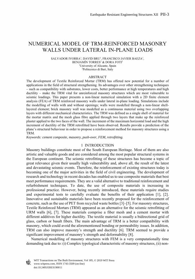
2.1.3 TRM material TRM reinforcement (mortar matrix and mesh glass fiber) was defined as a single shell and was applied at two faces of the wall. Table 1 shows the mechanical properties for the TRM reinforcement and Fig. 6 shows its constitutive behavior.
PII-6 Earthquake Resistant Engineering Structures XII
www.witpress.com, ISSN 1743-3509 (on-line) WIT Transactions on The Built Environment, Vol 185, © 2019 WIT Press

Figure 4: Compression-tension constitutive behaviour of masonry.
Figure 5: Shear constitutive behaviour of masonry.
Table 1: Mechanical characteristics of the TRM reinforcement.
Fibre Mortar TRM
σf Ef Vf* εf σmt Em σTRM ε1 ε2≡εf ETRM
MPa MPa MPa MPa MPa - - MPa
Tension 1200 7.2E+3 3.75E-3 16.7E-3 1.1 8E+3 5.60 0.679E-3 16.7E-3 8240
Compression 1200 7.2E+3 3.75E-3 16.7E-3 16 8E+3 20.44 2.481E-3 4.96E-3 8240
-3.5
-2.5
-1.5
-0.5
0.5
1.5
2.5
-0.015 -0.010 -0.005 0.000 0.005 0.010 0.015
Str
ess
(N/m
m2)
Strain (mm/mm)
-0.20
-0.10
0.00
0.10
0.20
-0.002 -0.001 -0.001 0.000 0.001 0.001 0.002
Str
ess
(N/m
m2)
Strain (mm/mm)
Earthquake Resistant Engineering Structures XII PII-7
www.witpress.com, ISSN 1743-3509 (on-line) WIT Transactions on The Built Environment, Vol 185, © 2019 WIT Press
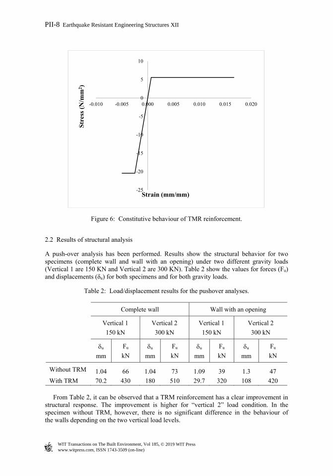
Figure 6: Constitutive behaviour of TMR reinforcement.
2.2 Results of structural analysis
A push-over analysis has been performed. Results show the structural behavior for two specimens (complete wall and wall with an opening) under two different gravity loads (Vertical 1 are 150 KN and Vertical 2 are 300 KN). Table 2 show the values for forces (Fu) and displacements (δu) for both specimens and for both gravity loads.
Table 2: Load/displacement results for the pushover analyses.
Complete wall Wall with an opening
Vertical 1
150 kN
Vertical 2
300 kN
Vertical 1
150 kN
Vertical 2
300 kN
u
mm
Fu
kN
u
mm
Fu
kN
u
mm
Fu
kN
u
mm
Fu
kN
Without TRM 1.04 66 1.04 73 1.09 39 1.3 47
With TRM 70.2 430 180 510 29.7 320 108 420 From Table 2, it can be observed that a TRM reinforcement has a clear improvement in structural response. The improvement is higher for “vertical 2” load condition. In the specimen without TRM, however, there is no significant difference in the behaviour of the walls depending on the two vertical load levels.
-25
-20
-15
-10
-5
0
5
10
-0.010 -0.005 0.000 0.005 0.010 0.015 0.020
Str
ess
(N/m
m2 )
Strain (mm/mm)
PII-8 Earthquake Resistant Engineering Structures XII
www.witpress.com, ISSN 1743-3509 (on-line) WIT Transactions on The Built Environment, Vol 185, © 2019 WIT Press
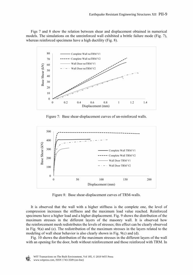
Figs 7 and 8 show the relation between shear and displacement obtained in numerical models. The simulations on the unreinforced wall exhibited a brittle failure mode (Fig. 7), whereas reinforced specimens have a high ductility (Fig. 8).
Figure 7: Base shear-displacement curves of un-reinforced walls.
Figure 8: Base shear-displacement curves of TRM-walls.
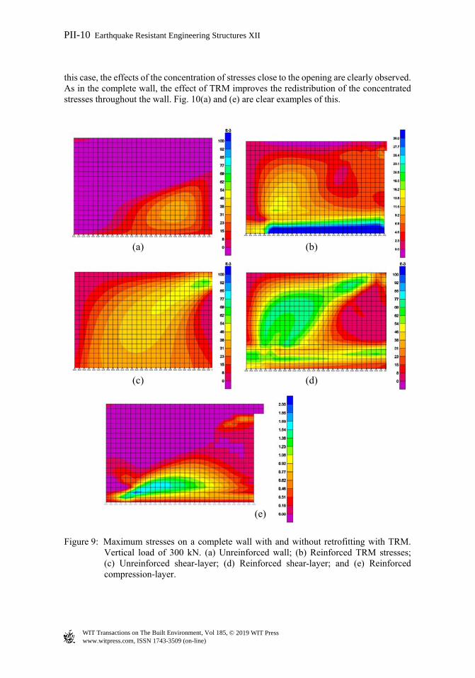
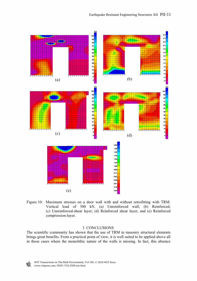
It is observed that the wall with a higher stiffness is the complete one, the level of compression increases the stiffness and the maximum load value reached. Reinforced specimens have a higher load and a higher displacement. Fig. 9 shows the distribution of the maximum stresses in the different layers of the masonry wall. It is observed how the reinforcement mesh redistributes the levels of stresses; this effect can be clearly observed in Fig. 9(a) and (e). The redistribution of the maximum stresses in the layers related to the modeling of wall shear behavior is also clearly shown in Fig. 9(c) and (d). Fig. 10 shows the distribution of the maximum stresses in the different layers of the wall with an opening for the door, both without reinforcement and those reinforced with TRM. In
0
10
20
30
40
50
60
70
80
0 0.2 0.4 0.6 0.8 1 1.2 1.4
Bas
e S
hear
(kN
)
Displacement (mm)
Complete Wall noTRM V1
Complete Wall noTRM V2
Wall Door noTRM V1
Wall Door noTRM V2
0
100
200
300
400
500
0 50 100 150 200
Bas
e S
hear
(kN
)
Displacement (mm)
Complete Wall TRM V1
Complete Wall TRM V2
Wall Door TRM V1
Wall Door TRM V2
Earthquake Resistant Engineering Structures XII PII-9
www.witpress.com, ISSN 1743-3509 (on-line) WIT Transactions on The Built Environment, Vol 185, © 2019 WIT Press
this case, the effects of the concentration of stresses close to the opening are clearly observed. As in the complete wall, the effect of TRM improves the redistribution of the concentrated stresses throughout the wall. Fig. 10(a) and (e) are clear examples of this.
(a) (b)
(c) (d)
(e)
Figure 9: Maximum stresses on a complete wall with and without retrofitting with TRM. Vertical load of 300 kN. (a) Unreinforced wall; (b) Reinforced TRM stresses; (c) Unreinforced shear-layer; (d) Reinforced shear-layer; and (e) Reinforced compression-layer.
PII-10 Earthquake Resistant Engineering Structures XII
www.witpress.com, ISSN 1743-3509 (on-line) WIT Transactions on The Built Environment, Vol 185, © 2019 WIT Press
(a) (b)
(c) (d)
(e)
Figure 10: Maximum stresses on a door wall with and without retrofitting with TRM. Vertical load of 300 kN. (a) Unreinforced wall; (b) Reinforced; (c) Unreinforced-shear layer; (d) Reinforced shear layer; and (e) Reinforced compression-layer.
3 CONCLUSIONS The scientific community has shown that the use of TRM in masonry structural elements brings great benefits. From a practical point of view, it is well suited to be applied above all in those cases where the monolithic nature of the walls is missing. In fact, this absence
Earthquake Resistant Engineering Structures XII PII-11
www.witpress.com, ISSN 1743-3509 (on-line) WIT Transactions on The Built Environment, Vol 185, © 2019 WIT Press

undermines the basis of a good seismic behavior of a structure, since it can make even null the presence of suitable characteristics, such as a good cohesion between elements. The more traditional reinforcement techniques aim to increase the seismic capacity by improving the connection between the different elements, reducing the action of any pushing roofs or the excessive deformability of the floors. TRM therefore, for what previously obtained, is configured as a valid alternative or addition among the available possibilities. In this work layered numerical shell elements models have been presented as an alternative to other complex numerical models to simulate masonry walls reinforced with TRM. The purpose of these numerical models is to estimate the structural behavior in masonry walls, with and without door opening. The layered non-linear shell element has been presented as a good option to simulate this type of retrofitting. The increment of the maximum horizontal load and the high increment of ductility of the TRM retrofitted walls have been simulated with a high level of coherence for different walls and different vertical compression loads. The full reliability of the utilized modelling technique will be verified by comparing the above results with the results obtained by an ongoing experimental campaign on samples tested in laboratory at the Civil Engineering Laboratory of the University of Alicante.
ACKNOWLEDGEMENT The authors acknowledge the Spanish Ministry of Economy and Competitiveness who partially supported this study by the grant BIA2015-69952-R
REFERENCES [1] Foti, D., Innovative techniques for concrete reinforcement with polymers.
Construction Building Materials, 112, pp. 202–209, 2016. [2] Foti, D. & Vacca, S., Comportamiento mecánico de columnas de hormigón armado
reforzadas con mortero reoplástico. Materiales de Construcción, 63(310), pp. 267–282, 2013.
[3] Foti, D., Use of recycled waste pet bottles fibers for the reinforcement of concrete. Composite Structures, 96, pp. 396–404, 2013.
[4] Foti, D. & Paparella, F., Impact behavior of structural elements in concrete reinforced with PET grids. Mechanics Research Communications, 57, pp. 57–66, 2014.
[5] Koutas, L., Bousias, S.N. & Triantafillou, T.C., Seismic strengthening of masonry-infilled RC frames with TRM: Experimental study. Journal of Composites Construction, 19(2), 2015.
[6] Babatunde, S.A., Review of strengthening techniques for masonry using fiber reinforced polymers. Composite Structures, 161, pp. 246–255, 2017.
[7] Bernat, E., Gil, L., Roca, P. & Escrig, C., Experimental and analytical study of TRM strengthened brickwork walls under eccentric compressive loading. Construction and Building Materials, 44, pp. 35–47, 2013.
[8] Papanicolaou, C.G., Triantafillou, T.C., Karlos, K. & Papathanasiou, M., Textile reinforced mortar (TRM) versus FRP as strengthening material of URM walls: in-plane cyclic loading. Materials and Structures, 40(10), pp. 1081–1097, 2007.
[9] Bournas, D.A., Triantafillou, T.C., Zygouris, K. & Stavropoulos, F., Textile-reinforced mortar versus FRP jacketing in seismic retrofitting of RC columns with continuous or lap-spliced deformed bars. Journal of Composites for Construction, 13(5), pp. 360–371, 2009.
[10] Bernat, E., Roca, P. & Gil, L., Experimental study of brick masonry walls strengthened with textile reinforced mortar. Key Engineering Materials, 624, pp. 397–404, 2016.
PII-12 Earthquake Resistant Engineering Structures XII
www.witpress.com, ISSN 1743-3509 (on-line) WIT Transactions on The Built Environment, Vol 185, © 2019 WIT Press

[11] Ivorra, S., Bru, D., Galvañ, A., Silvestri, S., Apera, C. & Foti. D., TRM reinforcement of masonry specimens for seismic areas. International Journal of Safety Security Engineering, 7(4), pp. 463–474, 2017.
[12] Gisbert, J.I., Bru, D., Gonzalez, A. & Ivorra, S., Masonry micromodels using high order 3D elements. Procedia Structural Integrity, 11, pp. 428–435, 2018.
[13] CSI, SAP2000, Computers and Structures, Inc. Structural Software for analysis and Design, 2014.
[14] Foti, D., A new experimental approach to the pushover analysis of masonry buildings. Computers & Structures, 147, pp. 165–171, 2015.
[15] Bilgin, H. & Korini, O., A new modeling approach in the pushover analysis of masonry structures. International Students’ Conference Civil Engineeing, ISCCE, EpokaUniversity, Tirana, Albania, 10–11 May 2012.
[16] NTC2008, Norme tecniche per le costruzioni, D.M. 14/01/2008, Gazz. Uff. 29, 2008.
Earthquake Resistant Engineering Structures XII PII-13
www.witpress.com, ISSN 1743-3509 (on-line) WIT Transactions on The Built Environment, Vol 185, © 2019 WIT Press