in-situ out-of-plane testing of unreinforced masonry wall segment in wintec block f building
TRANSCRIPT

11th Canadian Masonry Symposium, Toronto, Ontario, May 31- June 3, 2009
IN-SITU OUT-OF-PLANE TESTING OF UNREINFORCED MASONRY PARTITION WALLS
D. Dizhur1, H. Derakhshan2, J.M. Ingham3 and M.C Griffith4
1 PhD Candidate, Department of Civil and Environmental Engineering, University of Auckland, Auckland, New Zealand, [email protected]
2 PhD Candidate, Department of Civil and Environmental Engineering, University of Auckland, Auckland, New Zealand [email protected],
3 Associate Professor, Department of Civil and Environmental Engineering, University of Auckland, Auckland, New Zealand, [email protected]
4 Associate Professor, School of Civil, Environmental and Mining Engineering, University of Adelaide, Adelaide, Australia, [email protected]
ABSTRACT Most of the research considering out-of-plane seismic assessment of URM walls has been conducted using laboratory-based studies with artificial boundary conditions. Thus, in-situ testing is required to provide data with which to validate the accuracy of laboratory-based studies of out-of-plane walls. An in-situ testing program was developed by performing airbag tests on 2 non-load bearing partition walls of the William Weir Wing of Weir House in the city of Wellington, New Zealand. The 3 storey building was constructed in 1932 and is comprised of reinforced concrete perimeter walls with cement plaster and terracotta masonry interior facing with unreinforced terracotta masonry partition walls. One wall was tested in the as-built condition and the second wall was retrofitted with Carbon Fibre Reinforced Polymers (CFRP) using the Near Surface Mounting (NSM) technique. The pseudo-static tests were performed on the surface of the 1-leaf clay brick terracotta masonry walls by applying uniform pressure. The test walls, having dimensions of 3600 mm by 4100 mm, were supported at four sides and acted in a two-way bending mode. The test procedure and measured strength and stiffness properties of the two walls are presented. KEYWORDS: Out-of-plane, Near Surface Mounting testing, URM seismic retrofit, Fibre Reinforced Polymers, In-situ testing, Field testing INTRODUCTION New Zealand’s high seismicity results in many of the country’s heritage buildings having inadequate seismic strength, and New Zealand’s unreinforced masonry (URM) buildings and building components are recognised to be the structural form that is most susceptible to damage during an earthquake. This was demonstrated during the 1931 Hawke's Bay earthquake, which resulted in the devastating damage and collapse of many URM buildings in the earthquake-

affected area (Dowrick 1998). The popularity of such construction prior to the 1931 earthquake has resulted in numerous URM buildings remaining throughout New Zealand, many of which are now considered to have significant national heritage value (Russell et al. 2007 and 2008). URM walls are commonly used as interior partitions or exterior perimeter walls in steel or concrete framed buildings. These walls often have insufficient strength to resist lateral earthquake forces in high and moderate seismic zones and lack the ability to dissipate energy. One of the most critical deficiencies of URM buildings is their out-of-plane seismic response (Griffith et al. 2003). Most research considering out-of-plane seismic assessment of URM walls has been conducted using laboratory-based studies with artificial boundary conditions. Thus, in-situ testing is required to provide data with which to validate the accuracy of laboratory-based studies on out-of-plane wall behaviour. In 2008 a testing opportunity emerged when the lateral resisting system of the Weir House was scheduled to undergo seismic strengthening. The 3 storey building is located in Wellington, New Zealand, was built in 1932, and is comprised of reinforced concrete perimeter walls with cement plaster and terracotta masonry interior facing with unreinforced terracotta masonry partition walls. Same size partitions were tested, one in the as-build condition and the second retrofitted with vertically Near Surface Mounted (NSM) Carbon Fibre Reinforced Polymers (CFRP) strips. Due to the heritage value of the building, the partition walls were not allowed to be excessively damaged during testing. The in-situ testing results of the as-built and the NSM retrofitted URM partition subject to out-of-plane loading in the elastic range are presented. CASE STUDY BUILDING
BUILDING DESCRIPTION Weir House is comprised of three main buildings. The William Weir (WW) Wing was built in 1932 and is the original structure of the complex (see Figure 1). The William Weir wing is registered as a heritage building and as such, any strengthening and securing works had to be sensitive to the existing building fabric and be designed in consultation with Wellington City Council. The original Weir House building comprises a main rectangular block that has footprint dimensions of 56 m x 11 m. This block is primarily a 3 storey building with the front section on the eastern side containing a part basement level. A 3 storey western wing structure approximately 21 m x 11 m extends to the west, forming the ‘T’ shaped building (see Figure 2). The original drawings show the perimeter wall structure to be formed from unreinforced brick masonry walls. However, site investigations revealed that the perimeter walls are actually constructed from 170 mm reinforced concrete with exterior plaster and an interior facing with 90 mm terracotta masonry. The wall structures are typically punctured with windows and typically respond with frame action to provide the lateral load resisting system in both the long (north-south) and short (east-west) directions. Internal partition walls are constructed from terracotta masonry lined with cement plaster.

Figure 1: Weir House, case study building
(Facing south-east) TEST SPECIMENS Only out-of-plane testing of the URM partition walls was conducted at the Weir House. The partitions are non-load bearing 1-leaf clay brick terracotta masonry walls that are lined with 12-15 mm thick cement plaster finish on both sides. Two walls B3 and B17 (see Figure 2) were selected for testing. The walls had identical dimentions of 4.1 m long by 3.6 m high.
Figure 2: Floor plan and test locations
Figure 3 illustrates the masonry type present in the Weir House. Because of the heritage characteristics of the building, destructive testing was not permitted and no masonry samples were obtained to determine accurate material properties. The New Zealand Society for Earthquake Engineering (2006) provides guidelines for estimating strength parameters of masonry based on visual characteristics and hand tests, as summarised in Table 1.

Table 1: Estimated material properties
Visual Characteristics Stress (MPa) Young’s
Modulus (GPa) fmc fbc fbt E
Mortar: Stiff
High Portland cement content 8 12
Brick: Hard
Dense, well fired, hard surface, dark reddish 20-30 2-3 18
fmc - compressive strength of mortar, fbc - compressive strength of bricks, fbt - direct tensile strength of brick
As suggested by the guidelines, the compressive strength of masonry, fc was assumed to be twice the compressive strength of the mortar, fmc.
Figure 3: a) Exposed masonry construction b) Terracotta brick dimensions
EXPERIMENTAL PROGRAM AND SET-UP Wall B3 was tested in the as-build condition whereas wall B17 was retrofitted prior to testing using the NSM technique with vertical CFRP strips. The purpose of the testing was to observe what effect the NSM retrofit technique had on wall strength and stiffness. The walls were loaded and unloaded several times to examine if stiffness degradation occurred. Single and three 0.25 mm thick Bigfoot vinyl airbag arrangements, symmetrically and centrally positioned against the wall, were trialed to determine the effect that the loading arrangement had on the wall stiffness. No excessive damage to the walls was allowed due to the historic nature of the building. Loading was applied by gradually inflating the Bigfoot vinyl airbags. When fully deflated, each airbag had dimensions of 2.1 m x 1.2 m. To accommodate the airbags, a gap of 50-75 mm was left between the wall and the plywood backing. As a result the contact area, used for calculating the face pressure between the airbag and the wall face, was approximately 80 % of the airbag’s

deflated area. The load was generated and gradually increased between the wall surface and the plywood backing, as illustrated in Figure 4a. To ensure that the three airbags were inflated to an equal pressure level, a slow rate of inflation was adopted. The plywood backing, measuring 3.4 m x 2.4 m, consisted of an assemblage of plywood sheets and steel angles. The plywood backing was supported by a reaction frame which consisted of large vertical and diagonal steel members bolted to the concrete floor. The applied load was transferred from the airbags to the plywood backing and to the reaction frame using six S-type 1000 N load cells, as shown in Figure 4b. The loads cells were attached between the plywood backing and reaction frame and provided horizontal stability to the plywood backing. To ensure that the entire load was transferred through the load cells, frictionless plates were used underneath the plywood backing. The experimental set-up is shown in Figure 4c. The set-up closely resembled the set-up used to conduct laboratory out-of-plane testing on URM walls at the University of Adelaide (Griffith et al. 2007) and the University of Auckland (Derakhshan and Ingham 2008).
Figure 4: a) Airbag’s position b) S-type load cell c) Experimental set-up
Out-of-plane displacement was measured using 5 Linear Variable Differential Transducers (LVDT) mounted on the opposite side of the wall. One LVDT was placed mid-height and at the wall centreline, two were placed 750 mm above and below the wall centreline and two were located 450 mm left and right of the centre. Figure 5 shows LVDT locations.
The data from load cells and LVDTs was collected at 50 Hz using a National Instruments data acquisition system.
Load cell
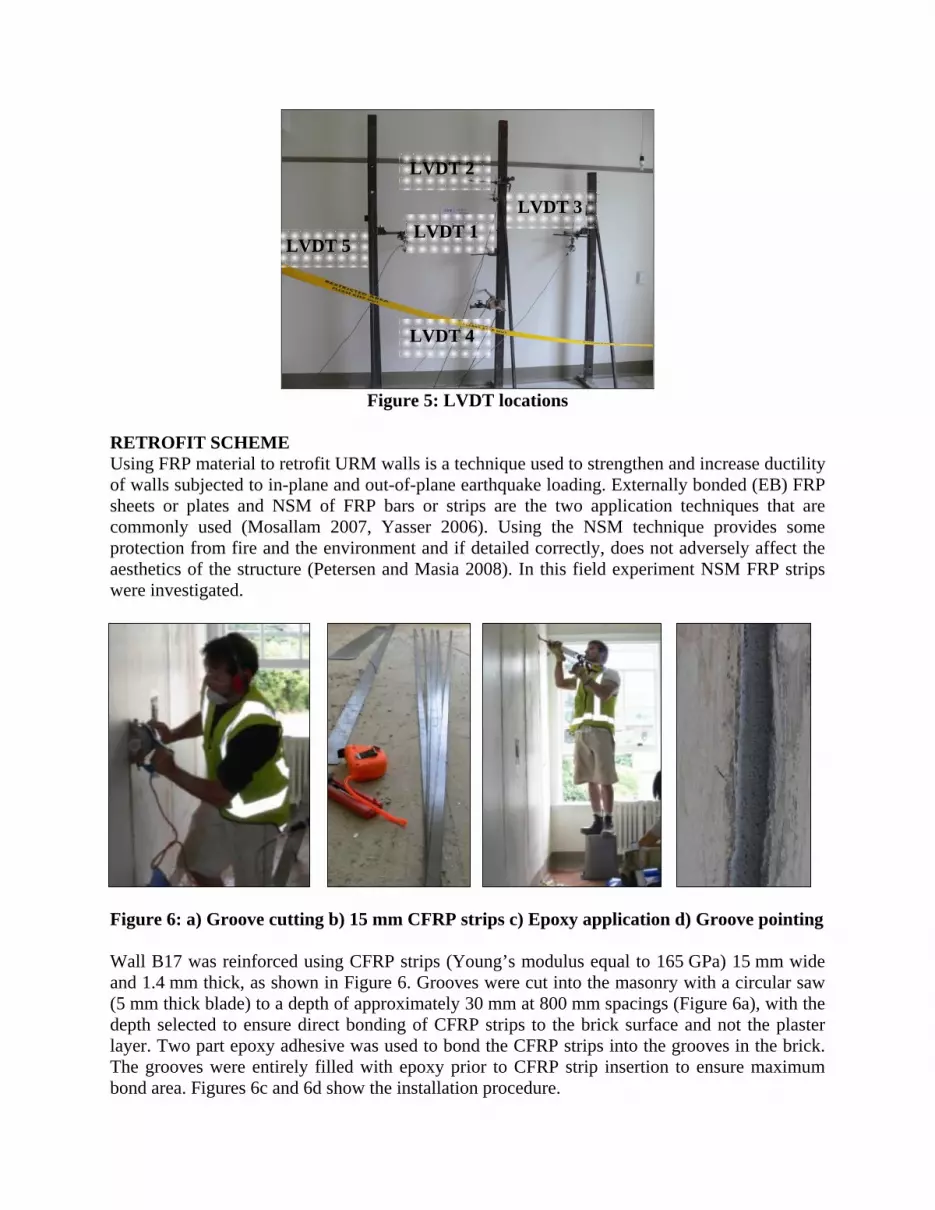
Figure 5: LVDT locations
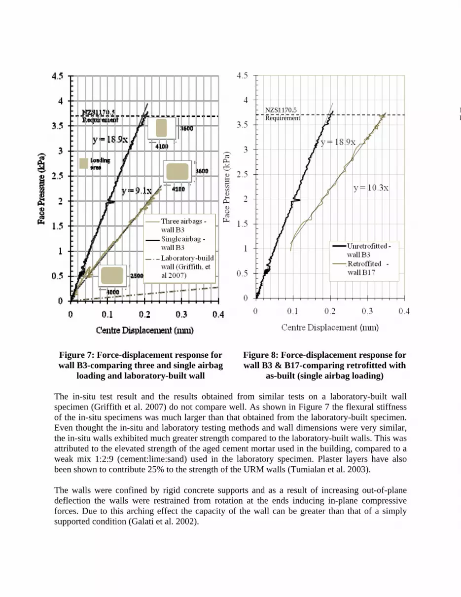
RETROFIT SCHEME Using FRP material to retrofit URM walls is a technique used to strengthen and increase ductility of walls subjected to in-plane and out-of-plane earthquake loading. Externally bonded (EB) FRP sheets or plates and NSM of FRP bars or strips are the two application techniques that are commonly used (Mosallam 2007, Yasser 2006). Using the NSM technique provides some protection from fire and the environment and if detailed correctly, does not adversely affect the aesthetics of the structure (Petersen and Masia 2008). In this field experiment NSM FRP strips were investigated.
Figure 6: a) Groove cutting b) 15 mm CFRP strips c) Epoxy application d) Groove pointing Wall B17 was reinforced using CFRP strips (Young’s modulus equal to 165 GPa) 15 mm wide and 1.4 mm thick, as shown in Figure 6. Grooves were cut into the masonry with a circular saw (5 mm thick blade) to a depth of approximately 30 mm at 800 mm spacings (Figure 6a), with the depth selected to ensure direct bonding of CFRP strips to the brick surface and not the plaster layer. Two part epoxy adhesive was used to bond the CFRP strips into the grooves in the brick. The grooves were entirely filled with epoxy prior to CFRP strip insertion to ensure maximum bond area. Figures 6c and 6d show the installation procedure.
LVDT 1
LVDT 2
LVDT 3
LVDT 4
LVDT 5

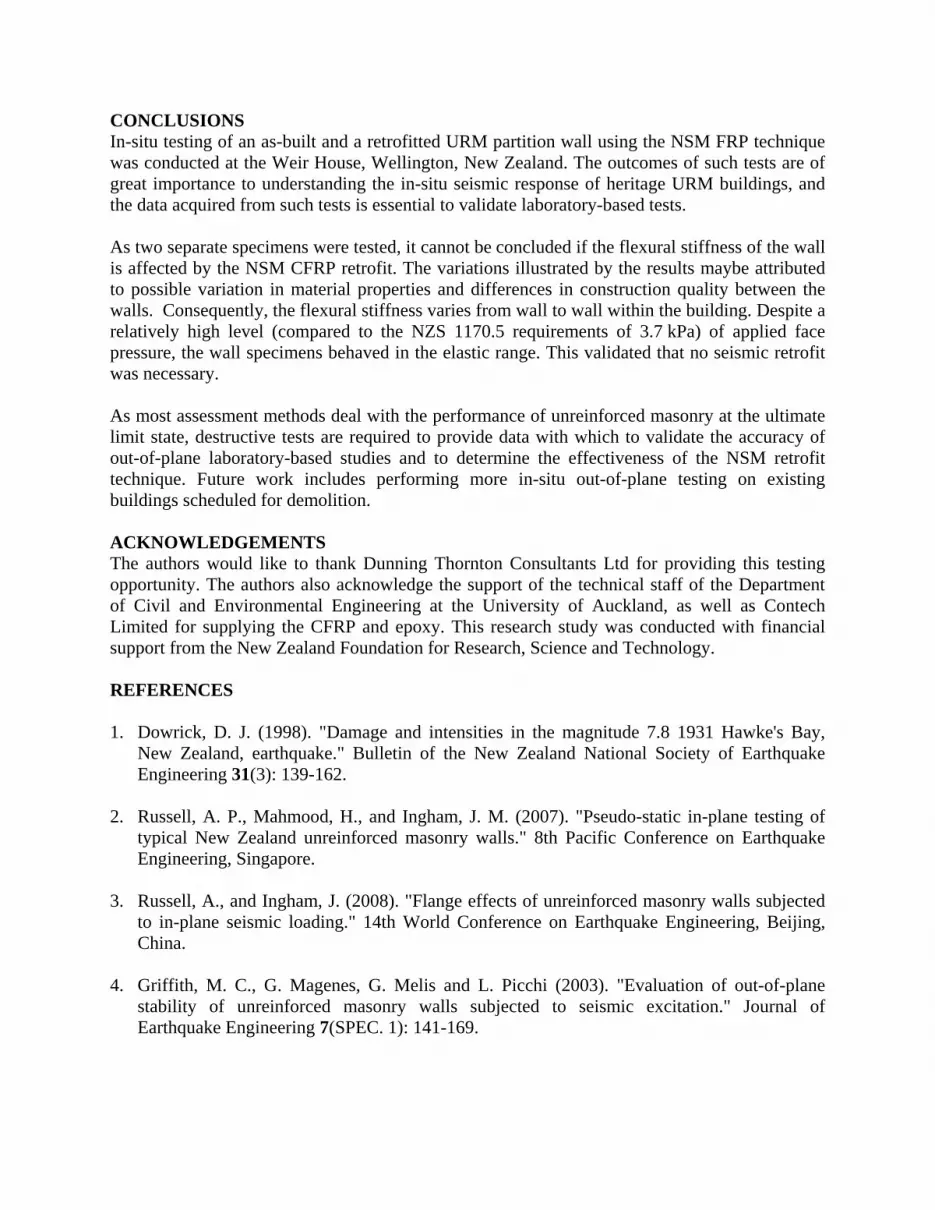
EXPERIMENTAL RESULTS Due to the limitations of the data acquisition system the load measured by load cell was not recorded above a certain value. Even though it was estimated that the testing continued until 7-8 kPa, a maximum face pressure of approximately 4 kPa was recorded. At the maximum loading pressure no evidence of wall movement at the boundaries and no cracks were visually detected on the wall surface. Due to a potential explosive brittle failure of the wall, attributed to the sudden release of potential energy stored in the airbags, the airbag pressure was not further increased. Consequently, the obtained results were all in the elastic range. The first test was conducted on the as-built partition (Wall B3). The pressure in the airbag was slowly and uniformly increased and the total force exerted by the airbags onto the wall was calculated by summing the readings from the 6 measuring load cells. For comparison purposes the pressure acting on the wall was determined using the total force and the respective loading area. Comparison between single and three airbag arrangements is shown in the force-displacement plot in Figure 7. From the graphs it is evident that the flexural stiffness for the single airbag loading was 2.1 times that of the three airbag loading (and consequently the deflections are reduced by a factor of 2.1). The deflection ratio obtained from numerically modelling the two loading arrangements was shown to equal the experimental value. Using the New Zealand Standard, NZS 1170.5:2004 - Earthquake Actions (SNZ 2004), assuming a shallow soil site, an annual probability of exceedance of 1/500 and a near-fault factor of 1.0, the partition wall would encounter a face pressure loading of 3.7 kPa during a design level earthquake. From Figure 7 and 8 it is clear that during testing the face pressure value specified by NZS 1170:5 was exceeded. Figure 8 shows a comparison between the force-displacement plots of wall B17 (retrofitted) and wall B3 (as-built). Surprisingly, the flexural stiffness of the retrofitted wall was less than that of the as-built wall. Because of identical dimensions for wall B3 and B17, the difference in flexural stiffness of the walls was attributed to the possible variation in material properties and difference in quality of construction between the walls. Due to time constraints the testing of the as-built partition wall and then the retrofit of the same wall was prevented. Therefore, direct comparison of the results is not possible. Loading and unloading of the wall was repeated up to 6 times, with the resulting force-displacement plots closely follow a straight line, indicating that the flexural stiffness remains constant throughout these semi-cycles. For clarity, the complete loading history has been omitted from Figure 7 and 8.
The in-situ test result and the results obtained from similar tests on a laboratory-built wall specimen (Griffith et al. 2007) do not compare well. As shown in Figure 7 the flexural stiffness of the in-situ specimens was much larger than that obtained from the laboratory-built specimen. Even thought the in-situ and laboratory testing methods and wall dimensions were very similar, the in-situ walls exhibited much greater strength compared to the laboratory-built walls. This was attributed to the elevated strength of the aged cement mortar used in the building, compared to a weak mix 1:2:9 (cement:lime:sand) used in the laboratory specimen. Plaster layers have also been shown to contribute 25% to the strength of the URM walls (Tumialan et al. 2003). The walls were confined by rigid concrete supports and as a result of increasing out-of-plane deflection the walls were restrained from rotation at the ends inducing in-plane compressive forces. Due to this arching effect the capacity of the wall can be greater than that of a simply supported condition (Galati et al. 2002).
Figure 7: Force-displacement response for wall B3-comparing three and single airbag
loading and laboratory-built wall
Figure 8: Force-displacement response for wall B3 & B17-comparing retrofitted with
as-built (single airbag loading)
NR
NZS1170.5 Requirement
CONCLUSIONS In-situ testing of an as-built and a retrofitted URM partition wall using the NSM FRP technique was conducted at the Weir House, Wellington, New Zealand. The outcomes of such tests are of great importance to understanding the in-situ seismic response of heritage URM buildings, and the data acquired from such tests is essential to validate laboratory-based tests. As two separate specimens were tested, it cannot be concluded if the flexural stiffness of the wall is affected by the NSM CFRP retrofit. The variations illustrated by the results maybe attributed to possible variation in material properties and differences in construction quality between the walls. Consequently, the flexural stiffness varies from wall to wall within the building. Despite a relatively high level (compared to the NZS 1170.5 requirements of 3.7 kPa) of applied face pressure, the wall specimens behaved in the elastic range. This validated that no seismic retrofit was necessary. As most assessment methods deal with the performance of unreinforced masonry at the ultimate limit state, destructive tests are required to provide data with which to validate the accuracy of out-of-plane laboratory-based studies and to determine the effectiveness of the NSM retrofit technique. Future work includes performing more in-situ out-of-plane testing on existing buildings scheduled for demolition. ACKNOWLEDGEMENTS The authors would like to thank Dunning Thornton Consultants Ltd for providing this testing opportunity. The authors also acknowledge the support of the technical staff of the Department of Civil and Environmental Engineering at the University of Auckland, as well as Contech Limited for supplying the CFRP and epoxy. This research study was conducted with financial support from the New Zealand Foundation for Research, Science and Technology. REFERENCES 1. Dowrick, D. J. (1998). "Damage and intensities in the magnitude 7.8 1931 Hawke's Bay,
New Zealand, earthquake." Bulletin of the New Zealand National Society of Earthquake Engineering 31(3): 139-162.
2. Russell, A. P., Mahmood, H., and Ingham, J. M. (2007). "Pseudo-static in-plane testing of typical New Zealand unreinforced masonry walls." 8th Pacific Conference on Earthquake Engineering, Singapore.
3. Russell, A., and Ingham, J. (2008). "Flange effects of unreinforced masonry walls subjected to in-plane seismic loading." 14th World Conference on Earthquake Engineering, Beijing, China.
4. Griffith, M. C., G. Magenes, G. Melis and L. Picchi (2003). "Evaluation of out-of-plane
stability of unreinforced masonry walls subjected to seismic excitation." Journal of Earthquake Engineering 7(SPEC. 1): 141-169.

5. New Zealand Society for Earthquake Engineering. (2006). "Assessment and improvement of the structural performance of buildings in earthquakes." Recommendations of a NZSEE Study Group on Earthquake Risk Buildings.
6. Griffith, M. C., J. Vaculik, N. T. K. Lam, J. Wilson and E. Lumantarna (2007). "Cyclic
testing of unreinforced masonry walls in two-way bending." Earthquake Engineering and Structural Dynamics 36(6): 801-821.
7. Derakhshan, H., and Ingham J.M. (2008). "Out-of-Plane testing of an unreinforced masonry wall subjected to one-way bending." The Australian Earthquake Engineering Society Conference, Ballarat.
8. Mosallam, A. S. (2007). "Out-of-plane flexural behavior of unreinforced red brick walls
strengthened with FRP composites." Composites Part B: Engineering 38(5-6): 559-574.
9. Yasser, K. and D. Robert (2006). "Rehabilitation of Masonry Walls Using Unobtrusive FRP Techniques for Enhanced Out-of-Plane Seismic Resistance." Journal of Composites for Construction 10(3): 213-222.
10. Petersen, R. B., Masia M.J. (2008). "Experimental Verification of Finite Element Model to
Predict the Shear Behaviour of NSM FRP Strengthened Masonry Walls." Proceedings of the 14th International Brick and Block Masonry Conference, Sydney, Australia, 17-20 February, 2008.
11. SNZ (2004) “NZS 1170.5:2004 Earthquake Actions – New Zealand.” Standards New
Zealand.
12. Tumialan, J.G., Galati N. and Nanni A. (2003). "Field Assessment of Unreinforced Masonry Walls Strengthened with Fiber Reinforced Polymer Laminates." Journal of Structural Engineering 129(8): 1047-1056.
13. Galati N., Tumialan J.G., La Tegola A., and Nanni A. (2002), “Influence of Arching
Mechanism in Masonry Walls Strengthened with FRP Laminates,” ICCI 2002, San Francisco, CA, June 10-12, 10 pp. CD-ROM