failure mode identification of masonry infilled rc frames
TRANSCRIPT

Emirates Journal for Engineering Research Emirates Journal for Engineering Research
Volume 24 Issue 1 Article 1
1-9-2019
Failure Mode Identification of Masonry Infilled RC Frames Failure Mode Identification of Masonry Infilled RC Frames
Rabab Allouzi University of Jordan, [email protected]
Ayhan Irfanoglu Purdue University, [email protected]
Follow this and additional works at: https://scholarworks.uaeu.ac.ae/ejer
Part of the Civil Engineering Commons, and the Structural Engineering Commons
Recommended Citation Recommended Citation Allouzi, Rabab and Irfanoglu, Ayhan (2019) "Failure Mode Identification of Masonry Infilled RC Frames," Emirates Journal for Engineering Research: Vol. 24 : Iss. 1 , Article 1. Available at: https://scholarworks.uaeu.ac.ae/ejer/vol24/iss1/1
This Article is brought to you for free and open access by Scholarworks@UAEU. It has been accepted for inclusion in Emirates Journal for Engineering Research by an authorized editor of Scholarworks@UAEU. For more information, please contact [email protected].
FAILURE MODE IDENTIFICATION OF MASONRY INFILLED RC
FRAMES
Rabab Allouzi1 and Ayhan Irfanoglu2
1Assistant Professor – Department of Civil Engineering – University of Jordan–Jordan 2 Associate Professor – Lyles School of Civil Engineering – Purdue University – USA
(Received 18th November 2018 and Accepted January 9th2019)
المعبأة بجدران الطوب المسلحة الخرسانية الهياكل تحديد طبيعة فشل
ملخص
طبيعة الفشل النهائية للهياكل الخرسانية المسلحة بسبب وجود جدران الطوب. الطريقة المقترحة هذه المقالة تقدم طريقة جدبدة في تحديدالطوب. وسيلة جدار -نسب التسليح و خواص المواد المستخدمة في العناصر المكونة للهيكل الخرساني االبعاد الفيزيائية, تعتمد على
كانت يف اذا لهيكل الخرساني يمكن اعتمادها لتعر لجدار الطوب بالتسبة لقوة ال تسبةصالبة و الهندسية بسيطة معبر عنها بداللة نسبة ا, يجب تفاديهالقص باالعمدةش, المعروف بفشل الفشل اله طبيعة .ةاو لدن ةكون هشست ل بقوة عاليةاز طبيعة الفشل خالل تعرضها لزل
مبنية بناءا على تفحص عدة أليات للفشل المحتملة بما في ذلك المقترحة هنا الطريقة واصالح المبنية حاليا.خالل مرحلة التصميم كلة من عمدة قصيرة. البيانات المشالتعرض لزلزال قوي كتشكل اليات الفشل التي ممكن ان تتشكل بسبب وجود جدران الطوب خالل ا
الطريقة المقترحة.ثالثة وعشرون عينة المفحوصة في المختبر من قبل باحثين اخرين استخدمت لمعايرة
Abstract
This paper presents a new method to identify the ultimate failure mode of reinforced concrete (RC) frames due to the presence of masonry infill walls. The proposed method is based on simple geometry, reinforcement ratios and material properties of the elements involved in the frame-wall assembly. A simple engineering tool, expressed in terms of infill wall-to-RC frame stiffness and strength ratios, is developed to estimate whether the ultimate failure mode that would evolve during strong earthquake ground shaking in the infilled RC frame is brittle or ductile. The brittle failure mode, that is, shear failure in columns, should be avoided in design and mitigated in existing structures. The method checks various possible failure mechanisms including those that may develop depending on how the infill wall may fail during strong shaking such as the formation of captive columns. Data from twenty three laboratory specimens tested by other researchers are used in developing the engineering tool.
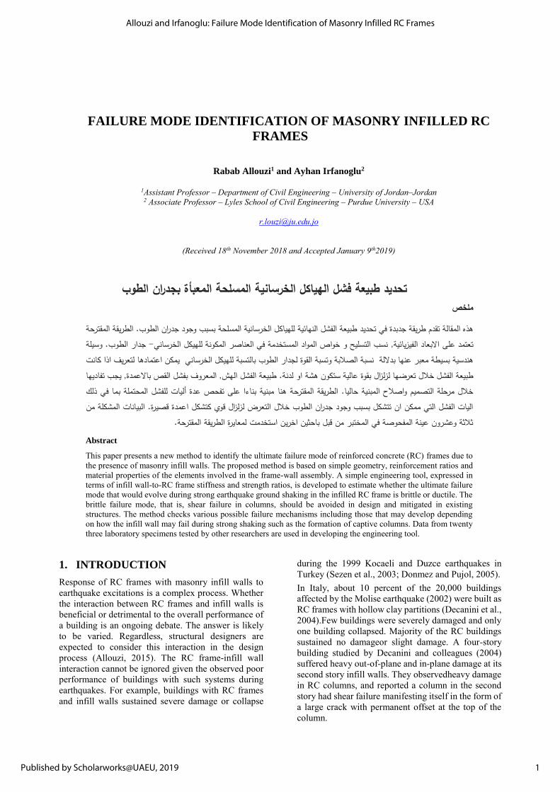
1. INTRODUCTION Response of RC frames with masonry infill walls to earthquake excitations is a complex process. Whether the interaction between RC frames and infill walls is beneficial or detrimental to the overall performance of a building is an ongoing debate. The answer is likely to be varied. Regardless, structural designers are expected to consider this interaction in the design process (Allouzi, 2015). The RC frame-infill wall interaction cannot be ignored given the observed poor performance of buildings with such systems during earthquakes. For example, buildings with RC frames and infill walls sustained severe damage or collapse
during the 1999 Kocaeli and Duzce earthquakes in Turkey (Sezen et al., 2003; Donmez and Pujol, 2005). In Italy, about 10 percent of the 20,000 buildings affected by the Molise earthquake (2002) were built as RC frames with hollow clay partitions (Decanini et al., 2004).Few buildings were severely damaged and only one building collapsed. Majority of the RC buildings sustained no damageor slight damage. A four-story building studied by Decanini and colleagues (2004) suffered heavy out-of-plane and in-plane damage at its second story infill walls. They observedheavy damage in RC columns, and reported a column in the second story had shear failure manifesting itself in the form of a large crack with permanent offset at the top of the column.
1
Allouzi and Irfanoglu: Failure Mode Identification of Masonry Infilled RC Frames
Published by Scholarworks@UAEU, 2019

It is indicated that this large crack could be a result of the interaction between the column and the infill wall (Decanini et al., 2004). Substantial damage is observed after the 2003 Bingol, Turkey earthquake in several RC frame buildings with masonry infill walls (Ozcebe et al., 2004). The damage was mainly concentrated in columns in the form of core crushing and buckling of longitudinal bars causing local collapse and shear cracks at the column ends(Ozcebe et al., 2004).While there were numerous cases of column failures due to captive column condition (Gur et al, 2009; Irfanoglu, 2009), the effects of the material quality, detailing, and structural configuration including soft story besides captive column were obvious (Ozcebe et al., 2004).The contribution of the infill walls to the lateral load resistance was confirmed because many buildings suffered only damage to their infill walls. Buildings that had solid clay brick infill walls were observed to perform better than the buildings with hollow clay brick infill walls (Ozcebe et al., 2004). The field data collected after the 2008 Wenchuan earthquake in China show that most of the RC frame buildings did not perform as designed per the current Chinese code (Zhao et al.,2009). Most of the failures developed in the columns in the form of shear failure or excessive deformation demands at the first level columns causing soft-story mechanisms leading to partial or full collapse of buildings (Zhao et al., 2009). Based on field inspection of nearly 170 buildings after the 2010 Haiti earthquake, O’Brien et al. (2011) found that RC buildings with weaker structural systems sustained severe damage with 60% higher likelihood if the buildings had captive columns, i.e. columns restrained by infill walls, preventing the columns from deflecting freely, and failing prematurely in a brittle manner. Several researchers did laboratory experiments to investigate the RC frame and infill wall interaction (Fiorato, Sozen, and Gamble (1970), Klingner and Bertero (1978), Bertero and Brokken (1983), Schmidt (1989),Mehrabi et al. (1994, 1996), Al-Chaar (1998), Colangelo (2005), Hashemi and Mosalam (2006), Stavridis (2009), and Zovkic et al. (2013)). In this paper, observations from studying twenty three of those RC frame-infill wall specimens and their response to monotonic and cyclic are presented. It is found that RC frames designed to fail in flexure could fail either in flexure or in shear when they interact with infill walls. RC frames with masonry walls that fail in flexure (so-called “flexure-critical”) have higher stiffness and strength compared to RC frame alone and can sustain drift ratios comparable to the RC frame alone (Fig. 1). On the other hand, RC frames with masonry walls that are vulnerable to fail in shear (so-called “shear-critical”) in at least one of the columns have lower deformation capacities and reduced axial load
carrying capacity in the failed column(s) despite the increase in their stiffness and strength (Fig. 1). This categorization is found by the writers to be crucial to judge whether filling a specific RC frame with a certain masonry wall will improve the performance under lateral loads or not. The motivation is to develop a tool for engineering practice to identify the ultimate failure mode of RC frames when infilled with masonry walls; i.e. if the structure is shear-critical or flexure-critical. 2. Research Significance
A new engineering tool is developed to estimate the nature of ultimate failure mode (brittle versus ductile) that would evolve in reinforced concrete frame buildings with infill walls during strong earthquake ground shaking.
Fig. 1 - Lateral response of bare RC frame compared to its response when filled with weak infill wall (flexure-critical) and when filled with strong infill wall (shear-critical). Adopted from Mehrabi et al. (1994). This identification is vital since, under in-plane lateral loading, RC frames that would have failed in flexure by themselves may fail either in flexure or in shear when infilled with masonry walls. Columns that fail in shear have limited, if any, axial load carrying capacity. It would not be safe to depend on them for structural stability. A simple means to identify infilled RC frames that are vulnerable to brittle, shear failure prior to ground shaking that would push them to limit is what motivated the development of the presented engineering tool. Once such frames are identified, necessary measures may be taken to alter them and have their ultimate failure happen in a ductile, flexural manner or to limit the detrimental impact of
2
Emirates Journal for Engineering Research, Vol. 24 [2019], Iss. 1, Art. 1
https://scholarworks.uaeu.ac.ae/ejer/vol24/iss1/1
their brittle failure on the overall integrity of the building. 3. Failure Mode Identification
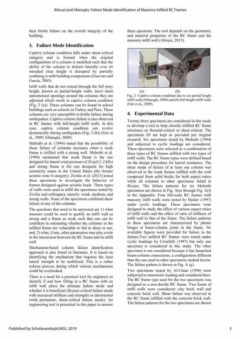
Captive column condition falls under shear-critical category and is formed when the original configuration of a column is modified such that the ability of the column to deform laterally over its intended clear height is disrupted by partially confining it with building components (Guevara and Garcia, 2005). Infill walls that do not extend through the full story height, known as partial-height walls, leave short unrestrained openings around the columns they are adjoined which result in captive column condition (Fig. 2 (a)). These columns can be found in school buildings such as schools in Turkey and Peru. These columns are very susceptible to brittle failure during earthquakes. Captive column failure is also observed in RC frames with full-height infill walls. In this case, captive column condition can evolve dynamically during earthquakes (Fig. 2 (b)) (Gur et al., 2009; Irfanoglu, 2009). Mehrabi et al. (1994) stated that the possibility of shear failure of columns increases when a weak frame is infilled with a strong wall. Mehrabi et al. (1994) mentioned that weak frame is the one designed for lateral wind pressure of 26 psf (1.2 kPa) and strong frame is the one designed for high seismicity zones in the United States (the former seismic zone 4 category). Zovkic et al. (2013) tested three specimens to investigate the behavior of frames designed against seismic loads. Three types of walls were used to infill the specimens tested by Zovkic and colleagues, namely: weak, medium, and strong walls. None of the specimens exhibited shear failure in any of the columns. The questions that need to be answered are 1) what measure could be used to qualify an infill wall as strong and a frame as weak such that one can be confident in estimating whether the columns in the infilled frame are vulnerable to fail in shear or not; and, 2) what, if any, other parameters may play a role in the interaction between the RC frame and its infill wall. Mechanism-based column failure identification approach is also found in literature. It is based on identifying the mechanism that requires the least lateral strength to be mobilized. This is a rather tedious process during which various mechanisms could be overlooked. There is a need for a practical tool for engineers to identify if and how filling in a RC frame with an infill wall alters the ultimate failure mode and whether it is beneficial (flexure-critical failure mode with increased stiffness and strength) or detrimental (with premature, shear-critical failure mode). An engineering tool is presented in this paper to answer
these questions. The tool depends on the geometric and material properties of the RC frame and the masonry infill wall (Allouzi, 2015).
(a) (b) Fig. 2- Captive column condition due to (a) partial height infill walls (Irfanoglu, 2009) and (b) full height infill walls (Gur et al., 2009). 4. Experimental Data
Twenty three specimens are considered in this study to develop a tool to help classify infilled RC frame structures as flexural-critical or shear-critical. The specimens ID are kept as provided per original research. Six specimens tested by Mehrabi (1994) and subjected to cyclic loadings are considered. These specimens were selected as a combination of three types of RC frames infilled with two types of infill walls. The RC frame types were defined based on the design procedure for lateral resistance. The shear mode of failure of at least one column was observed in the weak frames infilled with the wall composed from solid bricks for both aspect ratios while all columns in other specimens failed in flexure. The failure patterns for six Mehrabi specimens are shown in Fig. A(a) through Fig. A(f) in the Appendix. Four full-scale RC frames with masonry infill walls were tested by Haider (1997) under cyclic loadings. These specimens were designed to study the effect of various aspect ratios of infill walls and the effect of ratio of stiffness of infill wall to that of the frame. The failure patterns in these specimens are characterized by plastic hinges at beam-column joints in the frame. No available figures were provided for failure in the frames.Two infilled RC frames were tested under cyclic loadings by Crisafulli (1997) but only one specimen is considered in this study. The other specimen is not considered because it has haunched beam-column connections, a configuration different than the one used in other specimens studied herein. The failure pattern is shown in Fig. A (g). Two specimens tested by Al-Chaar (1998) were subjected to monotonic loading and considered here. The RC frame type used for the two specimens was designed as a non-ductile RC frame. Two forms of infill walls were considered: clay brick wall and concrete brick wall. Shear failure was observed in the RC frame infilled with the concrete brick wall. The failure patterns for the two specimens are shown
3
Allouzi and Irfanoglu: Failure Mode Identification of Masonry Infilled RC Frames
Published by Scholarworks@UAEU, 2019
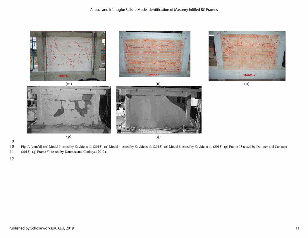
in Figs. A(h) and A(i).Three specimens tested pseudo-dynamically by Colangelo (2005) are used in this study. These specimens represent a one-half scaled first story of a four story building. Specimens U21 and V22are designed for gravity loads only while specimen L2 is designed according to the ENV version of seismic Eurocode 8 as a medium ductility structure and peak ground acceleration is assumed to be 0.25 g. The failure patterns of these specimens were not mentioned explicitly by Colangelo and no clear photo was provided except for specimen L21 (Fig. A(j)). A sliding along an inclined crack in the column and a drop in lateral strength as much as 40% was stated for specimens U21 and V22. Based on these reasons, herein it is assumed that a shear failure had taken place just for specimen V22. Two non-ductile RC frames with masonry infill walls from a research project discussed in Stavridis (2009) are used for failure mode identification: a small-scale RC frame with a solid infill wall tested at Stanford University and one large-scale RC frame with a solid infill wall (CU1) tested at University of Colorado, Boulder. The infill wall is built from solid clay brick units. Both specimens had a shear type of failure. The failure pattern for the two specimens are shown in Figs. A(k) and A(l).Three specimens tested by Zovkic et al. (2013) subjected to cyclic loading are considered in this study for failure mode identification. The RC frames were designed for seismic loads. Three types of infill walls were considered: high strength hollow clay brick wall, medium strength hollow clay brick wall, and low strength lightweight Aerated Autoclaved concrete brick wall. No shear failure was observed and the failure patterns for the three specimens are shown in Figs. A(m) through A (o).Two four-story one-bay infilled RC frames were tested by Donmez and Cankaya (2013) under pseudo-static loads. The two frames failed in different failure modes when they reached their capacities. The frame that failed in flexure in both columns was designed as a brittle frame while the frame that failed in shear in both columns was designed as a ductile frame. The reason for shear failure occurring in columns with ductile design is because the infilled frame sustained higher load. Since the bricks were not scaled in size in the same manner the frame was scaled, bricks at corners were crushed before the wall reached its cracking load and, in turn, caused brittle failure in the columns. The failure modes of these specimens are shown in Fig. A(p) and A(q). 5. Proposed Method
The interaction between a frame and its infill wall when subjected to earthquake ground motion excitation depends on various factors: RC frame dimensions and material properties, infill wall dimensions and material properties, gravity load on
the structure, aspect ratio of the structure, and ground shaking characteristics. When the ultimate mode of failure is of concern, the ground shaking characteristics is assumed to push the structure to reach its failure mechanism. In this paper, these factors are studied to present a simple tool to identify the ultimate failure mode of RC frame when infilled with masonry wall. The twenty three specimens from Mehrabi et al., (1994), Haider (1995), Crisafulli (1997), Al-Chaar (1998), Colangelo (2005), Stavridis (2009), Zovkic et al. (2013), and Donmez and Cankaya (2013) are studied to in search for a threshold expression distinguishing between ductile, flexure-critical behavior and brittle, shear-critical ones. Parameters
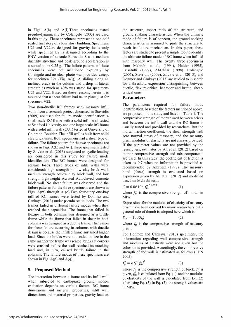
The parameters required for failure mode identification, based on the factors mentioned above, are proposed in this study and listed in Table 1. The compressive strength of mortar used between bricks and between the infill wall and the RC frame is usually tested and provided by researchers. But the mortar friction coefficient, the shear strength with zero normal stress of masonry, and the masonry prism modulus of elasticity are not always provided. If the parameter values are not provided by the researchers, estimates by Ali et al. (2012) based on mortar compressive strength and mix components are used. In this study, the coefficient of friction is taken as 0.7 when no information is provided as recommended by Amrhein (1998). The masonry bond (shear) strength is evaluated based on expression given by Ali et al. (2012) and modified based on Mehrabi tests: 𝐶 = 0.06194 𝑓𝑚
′ 0.6633 (1) where 𝑓𝑚
′ is the compressive strength of mortar in MPa Expressions for the modulus of elasticity of masonry prism have been derived by many researchers but a general rule of thumb is adopted here which is 𝐸𝑤 = 1000𝑓𝑝
, (2) where 𝑓𝑝
, is the compressive strength of masonry prism. For Donmez and Cankaya (2013) specimens, the information regarding wall compressive strength and modulus of elasticity were not given but the cohesion is provided. Accordingly, the compressive strength of the wall is estimated as follows (CEN 2005):
𝑓𝑝′ = 𝑘𝑓𝑏
′𝛼𝑓𝑚
′ 𝛽 (3) where 𝑓𝑏
′ is the compressive strength of brick. 𝑓𝑏′ is
given, 𝑓𝑚′ is calculated from Eq. (1), and the modulus
of elasticity of the wall is calculated from Eq. (2) after using Eq. (3).In Eq. (3), the strength values are in MPa.
4
Emirates Journal for Engineering Research, Vol. 24 [2019], Iss. 1, Art. 1
https://scholarworks.uaeu.ac.ae/ejer/vol24/iss1/1
Kaushik et al. (2007) used k, α and βto be equal to 0.63, 0.49 and 0.32 respectively based on their experiments by testing four various brick types and three different mortar grades. These values are adopted in this study. Twenty two parameters listed in Table 1 are considered crucial for failure mode identification. The values of these parameters of the specimens discussed before are provided in Table A in the Appendix. The failure mode could not be identified in a simple way by studying these parameters separately. Accordingly, more compact expressions that have a behavioral meaning should be used. The ratio ofstiffness of the infill wall to thatof the RC frame alone developed by Smith (1969) is one of the most common expressions used over the last decades. Here, the ratio of shear strength of the infill wall to that of the RC frame alone is proposed to be another representative expression. This expression involves the effect of gravity force applied on the story under consideration. Stiffness Ratio
The ratio of stiffness of the infill wall to that of the frame is estimated based on an expression given by Smith (1969) which is defined similar to the one used in “beam on elastic foundation” theory (Hetenyi, 1946). This similarity is based on the analogy between beams on elastic foundation and the frames and infill walls in which each system is
represented by interacting flexure and plane stress members (Smith, 1969). The infill wall-to-frame stiffness ratio is given as:
𝑅𝐾 = √ℎ4𝐸𝑤𝑡𝑤𝑠𝑖𝑛(2𝜃)
4𝐸𝑐𝐼𝑐ℎ𝑤
4 (4)
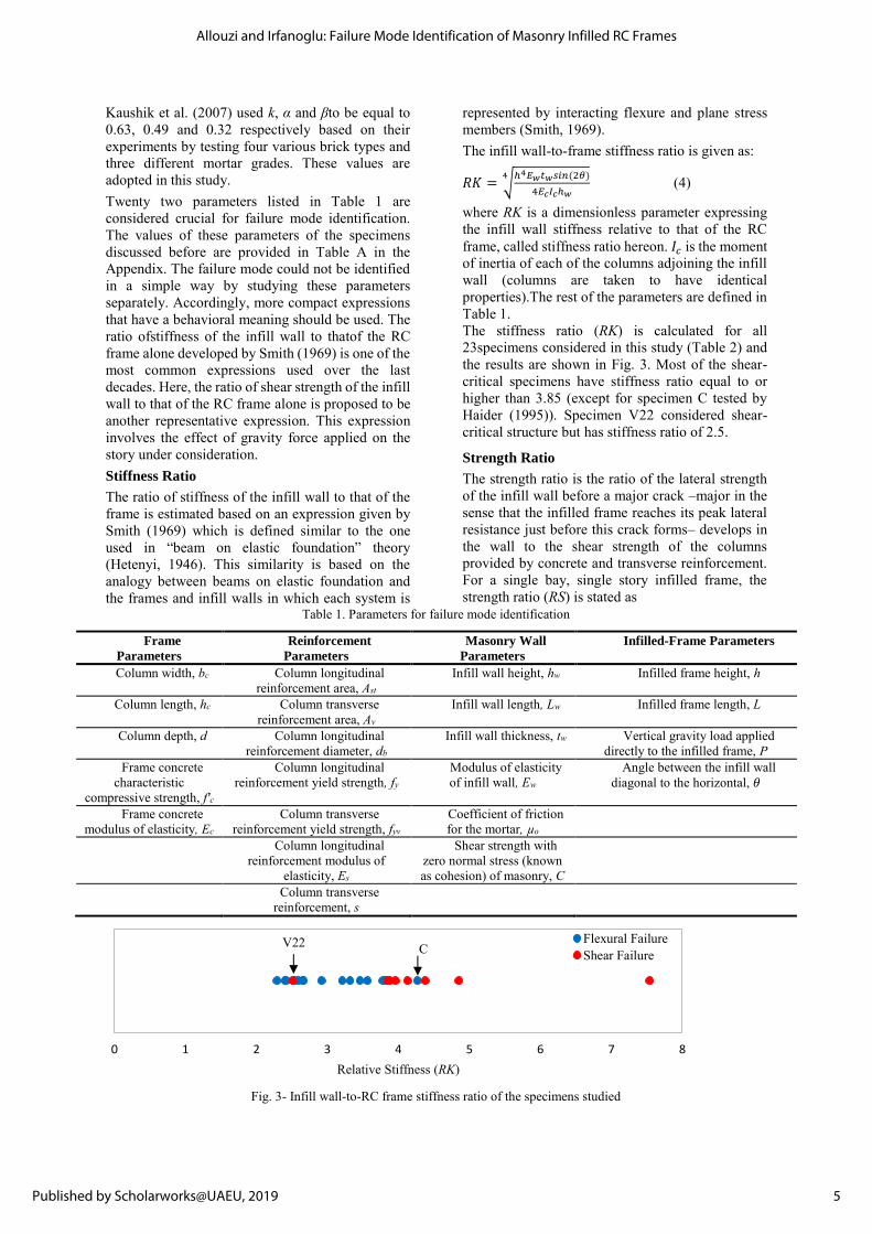
where RK is a dimensionless parameter expressing the infill wall stiffness relative to that of the RC frame, called stiffness ratio hereon. 𝐼𝑐 is the moment of inertia of each of the columns adjoining the infill wall (columns are taken to have identical properties).The rest of the parameters are defined in Table 1. The stiffness ratio (RK) is calculated for all 23specimens considered in this study (Table 2) and the results are shown in Fig. 3. Most of the shear-critical specimens have stiffness ratio equal to or higher than 3.85 (except for specimen C tested by Haider (1995)). Specimen V22 considered shear-critical structure but has stiffness ratio of 2.5.
Strength Ratio
The strength ratio is the ratio of the lateral strength of the infill wall before a major crack –major in the sense that the infilled frame reaches its peak lateral resistance just before this crack forms– develops in the wall to the shear strength of the columns provided by concrete and transverse reinforcement. For a single bay, single story infilled frame, the strength ratio (RS) is stated as
Table 1. Parameters for failure mode identification
Frame
Parameters Reinforcement
Parameters Masonry Wall
Parameters Infilled-Frame Parameters
Column width, bc Column longitudinal reinforcement area, Ast
Infill wall height, hw Infilled frame height, h
Column length, hc Column transverse reinforcement area, Av
Infill wall length, Lw Infilled frame length, L
Column depth, d Column longitudinal reinforcement diameter, db
Infill wall thickness, tw Vertical gravity load applied directly to the infilled frame, P
Frame concrete characteristic
compressive strength, f'c
Column longitudinal reinforcement yield strength, fy
Modulus of elasticity of infill wall, Ew
Angle between the infill wall diagonal to the horizontal, 𝜃
Frame concrete modulus of elasticity, Ec
Column transverse reinforcement yield strength, fyv
Coefficient of friction for the mortar, µo
Column longitudinal
reinforcement modulus of elasticity, Es
Shear strength with zero normal stress (known as cohesion) of masonry, C
Column transverse reinforcement, s
Fig. 3- Infill wall-to-RC frame stiffness ratio of the specimens studied
0 1 2 3 4 5 6 7 8
Relative Stiffness (RK)
Flexural FailureShear Failure
V22 C
5
Allouzi and Irfanoglu: Failure Mode Identification of Masonry Infilled RC Frames
Published by Scholarworks@UAEU, 2019
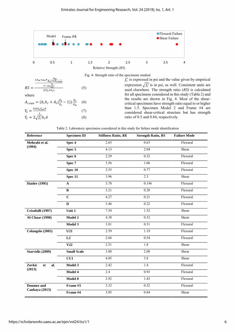
Fig. 4- Strength ratio of the specimens studied
𝑅𝑆 =
𝐶𝐴𝑤+𝜇𝑜𝑃𝐴𝑤
𝐴𝑤+2𝐴𝑐,𝑒𝑞𝑢
(1−𝜇𝑜ℎ
2𝐿)
2(𝑉𝑠+𝑉𝑐) (5)
where
𝐴𝑐,𝑒𝑞𝑢 = (𝑏𝑐ℎ𝑐 + 𝐴𝑠(𝐸𝑠
𝐸𝑐− 1))
𝐸𝑐
𝐸𝑤 (6)
𝑉𝑠 =0.8𝐴𝑣𝑓𝑦𝑣𝑑
𝑠 (7)
𝑉𝑐 = 2√𝑓𝑐′𝑏𝑐𝑑 (8)
𝑓𝑐′ is expressed in psi and the value given by empirical
expression √𝑓𝑐′ is in psi, as well. Consistent units are
used elsewhere. The strength ratio (RS) is calculated for all specimens considered in this study (Table 2) and the results are shown in Fig. 4. Most of the shear-critical specimens have strength ratio equal to or higher than 1.5. Specimen Model 2 and Frame #4 are considered shear-critical structure but has strength ratio of 0.5 and 0.84, respectively.
Table 2. Laboratory specimens considered in this study for failure mode identification
0 0.5 1 1.5 2 2.5 3 3.5 4
Relative Strength (RS)
Flexural FailureShear Failure
Reference Specimen ID Stiffness Ratio, RK Strength Ratio, RS Failure Mode
Mehrabi et al.
(1994)
Spec 4 2.65 0.63 Flexural
Spec 5 4.13 2.04 Shear
Spec 6 2.29 0.32 Flexural
Spec 7 3.56 1.06 Flexural
Spec 10 2.55 0.77 Flexural
Spec 11 3.96 2.3 Shear
Haider (1995) A 3.78 0.146 Flexural
B 3.21 0.28 Flexural
C 4.27 0.21 Flexural
D 3.46 0.22 Flexural
Crisafulli (1997) Unit 1 7.54 1.52 Shear
Al-Chaar (1998) Model 2 4.38 0.52 Shear
Model 3 3.81 0.31 Flexural
Colangelo (2005) U21 2.59 1.19 Flexural
L2 2.66 0.54 Flexural
V22 2.51 1.8 Shear
Starvidis (2009) Small Scale 3.88 2.08 Shear
CU1 4.85 3.8 Shear
Zovkic et al.
(2013)
Model 3 2.42 1.4 Flexural
Model 4 2.4 0.93 Flexural
Model 8 2.92 1.43 Flexural
Donmez and
Cankaya (2013)
Frame #3 3.32 0.52 Flexural
Frame #4 3.85 0.84 Shear
Model2
Frame #4
6
Emirates Journal for Engineering Research, Vol. 24 [2019], Iss. 1, Art. 1
https://scholarworks.uaeu.ac.ae/ejer/vol24/iss1/1

Neither stiffness ratio nor strength ratio alone is sufficient to establish a clear threshold to separate shear-critical infilled RC frames from flexural-critical ones. The results show a better trend when stiffness ratio and strength ratio are considered together, as shown in Fig. 5. It appears that a simple relationship that separates shear-critical (brittle) specimens and flexure-critical (ductile) specimens exists. Chosen to be conservative, the line above which lain most of the infilled RC frames with at least one column failed in shear (Fig. 5) is expressed as 𝑅𝐾 + 𝑅𝑆 = 4 (9)
Fig. 5- Failure mode versus strength and stiffness ratios of the infilled RC frame specimens considered
6. SUMMARY AND CONCLUSIONS
Experimental research on the response of RC frames with infill walls is rich with specimens that experience columns failing in flexure. Much less data are available for cases with shear type of failure. Still, existing data help identify the factors that affect the response and are used further in this paper to develop a practical engineering tool to recognize when a ductile bare RC frame with ultimate failure mode in flexure might become brittle with ultimate failure mode in shear when infilled with a masonry wall. The infill wall-to-RC frame stiffness ratio RK and strength ratio RS are found to be the key parameters. These parameters are meaningful to an engineer and incorporate the effects of material properties and frame-infill configuration of the system. They can be calculated rather easily, as discussed in this paper. RK+RS=4 is proposed as a threshold to separate the shear-critical (brittle) and flexure-critical (ductile) cases with infill RC frames with RS and RK exceeding
the threshold expression to be considered susceptible to fail in shear in at least one of its columns. This particular threshold line is proposed based on study of results from twenty-three RC frames with unreinforced infill walls tested in laboratory under in-plane monotonic, cyclic, or pseudo-dynamic loads. The wall height-to-length aspect ratio hw/Lw considered herein ranges from 1/2 to 3/4. The masonry prism strength ranges from 0.24 ksi (1.7 MPa) to 3.5 ksi (24.1 MPa). The mortar compressive strength ranges from 0.7 ksi (4.8 MPa) to 3.6 ksi (24.8 MPa). Concrete compressive strength ranges from 3.6 ksi (24.8 MPa) to 7.5 ksi (51.7 MPa).
REFERENCES
Al-Chaar, G.,“Non-Ductile behavior of reinforced concrete frames with masonry infill panels subjected to in-plane loading.” USACERL Technical Manuscript, 1998, 99/18. Ali, Q., Badrashi, Y. I, Ahmad, N, Alam, B., Rehman, S., and Banori, F. A., “Experimental Investigation on the Characterization of Solid Clay Brick Masonry for Lateral Shear Strength Evaluation.” International Journal of Earth Sciences and Engineering, 2012, Volume 5, No. 4. Allouzi, R., “Seismic in-plane response of reinforced concrete frames with masonry infill walls.” PhD Thesis. Purdue University, USA, 2015. Amrhein, J.E., “Reinforced Masonry Engineering Handbook: Clay and Concrete Masonry.” MIA and CRC Press, Los Angeles, Calif., Fifth Edition, 1998. Bertero, V.V. and Brokken, S.T., “Infills in Seismic Resistant Building.”J. of Structural Eng., Proc. of the ASCE, ST6, 1983, 109 (6):1337-1361. CEN, “Eurocode 6: Design of masonry structures - Part 1-1: General rules for reinforced and unreinforced masonry structures.” EN 1996-1-1:2005, European Committee for Standardization, Brussels, Belgium. Colangelo, F., “Pseudo-dynamic seismic response of reinforced concrete frames infilled with non-structural brick masonry.” Earthquake Engng Struct. Dyn., 2005, 34:1219–1241. Crisafulli, F. J., “Seismic behaviour of reinforced concrete structures with masonry infills.” PhD Thesis. University of Canterbury, Christchurch, New Zealand, 1997. Decanini, L. D., De Sortis, A., Goretti, A., Liberatore, L., Mollaioli, F., a Bazzurro, P., “Performance of reinforced concrete buildings during the 2002 Molise, Italy, earthquake.” Earthquake Spectra, 2004, 20(S1), S221-S255.
0
1
2
3
4
5
6
7
8
0 1 2 3 4 5 6 7 8
Rel
ativ
e st
iffne
ss (R
K)
Relative strength (RS)
Flexural FailureShear Failure
7
Allouzi and Irfanoglu: Failure Mode Identification of Masonry Infilled RC Frames
Published by Scholarworks@UAEU, 2019
Donmez, C., and Çankaya, M. A., “Effect of Infill Walls on the Drift Behavior of Reinforced Concrete Frames Subjected to Lateral-Load Reversals.” Journal of Earthquake Engng, 2013, 17(5), 611-636. Donmez, C., and Pujol, S., “Spatial distribution of damage caused by the 1999 earthquakes in Turkey.” Earthquake Spectra, 2005, 21(1), 53-69. Fiorato, A.E., Sozen, M.A., and Gamble, W. L., “An investigation of the interaction of reinforced concrete frames with masonry filler walls.” Technical Report No. UILU-ENG 70-100, University of Illinois, Urbana-Champaign, USA, 1970. Guevara, L. T., and Garcia, L.E., “The captive- and short-column effects.”Earthquake Spectra, 2005, 21(1):141-160. Gur, T., Pay, A.C., Ramirez, J.A., Sozen, M.A., Johnson, A. M., Irfanoglu, A., and Bobet, A., “Performance of school buildings in Turkey during the 1999 Düzce and the 2003 Bingöl earthquakes.” Earthquake Spectra, 2009, 25(2): 239-256. Hashemi, A., and Mosalam, K.H., “Shake-table experiment on reinforced concrete structure containing masonry infill wall.” Earthquake EngngStrDyn, 2006, 35(14):1827-1852. Hetenyi, M., “Beams on elastic foundation.” University of Michigan Press, Ann Arbor, 1946. Irfanoglu, A., “Performance of template school buildings during earthquakes in Turkey and Peru.”J Performance of Constructed Facilities, 2009, 23(1), 5-14. Kaushik, H. B., Rai, D. C., and Jain, S. K., “Stress-Strain Characteristics of Clay Brick Masonry under Uniaxial Compression.”J Materials in Civil Engng, 2007, 19(9), 728-738. Klingner, R.E. and Bertero, V.V., “Earthquake Resistance of Infilled Frames.”J Structural Division, Proc. of the ASCE, ST6, 1978, 104 (6):973-989. Mehrabi, A.B., Shing, P.B., Schuller, M.P., and Noland, J. L., “Performance of masonry-infilled RIC frames under in-plane lateral loads.” Report CU/SR-94-6, Dept. of Civ., Envir. and Arch. Engng., Univ. of Colorado, Boulder, CO, 1994. Mehrabi, A.B., Shing, P.B., Schuller, M.P., and Noland, J. L., “Experimental evaluation of masonry-infilled RC frames.”J Structural Engng, Proc. of the ASCE, 1996, 122(3):228-237. O’Brien, P., Eberhard, M., Haraldsson, O., Irfanoglu, A., Lattanzi, D., Lauer, S., and Pujol, S., “Measures of the seismic vulnerability of reinforced concrete buildings in Haiti.” Earthquake Spectra, 2011, 27(S1): 373-386. Ozcebe, G., Ramirez, J., Wasti, S. T., and Yakut, A., “1 May 2003 Bingöl earthquake engineering
report.” TUBITAK Structural Engng Research Unit, Pub. No: 2004-01, Turkey. Schmidt, T., “Experiments on the nonlinear behavior of masonry infilled reinforced concrete frames.” Darmstadt Concrete, Annual Journal on Concrete and Concrete Structures, Vol. 4, Darmstadt, Germany, 1989. Smith, B.S. and Carter, C., “A method of analysis for infilled frames.” Proceedings of the Institution of Civil Engineers, 1969, vol. 44, paper 7218. Stavridis, A., “Analytical and experimental study of seismic performance of reinforced concrete frames infilled with masonry walls.” Ph.D. Thesis, Univ. of California, San Diego, CA, 2009. Sezen, H., Whittaker, A. S., Elwood, K. J., and Mosalam, K. M., “Performance of reinforced concrete buildings during the August 17, 1999 Kocaeli, Turkey earthquake, and seismic design and construction practice in Turkey.” Engineering Structures, 2003, 25(1), 103-114. Zhao, B., Taucer, F., and Rossetto, T., “Field investigation on the performance of building structures during the 12 May 2008 Wenchuan earthquake in China.” Engineering Structures, 2009, 31(8), 1707-1723. Zovkic, J., Sigmund, V., Guljas, I., “Cyclic testing of reinforced concrete frames with various types of masonry infill. Earthquake.”Engng Struct Dyn., 2013, 42(8):1131-1149.
8
Emirates Journal for Engineering Research, Vol. 24 [2019], Iss. 1, Art. 1
https://scholarworks.uaeu.ac.ae/ejer/vol24/iss1/1

1
APPENDIX 2
(a) (b) (c)
(d) (e) (f)
Fig. A- Failure pattern of (a) specimen 4 tested by Mehrabi et al. (1994); (b) specimen 5 tested by Mehrabi et al. (1994);(c) specimen 6 tested by Mehrabi et al. (1994); (d) specimen 7 tested 3 by Mehrabi et al. (1994); (e) specimen 10 tested by Mehrabi et al. (1994); (f) specimen 11 tested by Mehrabi et al. (1994) 4
5
9
Allouzi and Irfanoglu: Failure Mode Identification of Masonry Infilled RC Frames
Published by Scholarworks@UAEU, 2019

(g) (h) (i)
(j) (k) (l)
Fig. A [cont’d]-(g) Unit 1 tested by Crisafulli (1997); (h) Model 2 tested by Al-Chaar (1998); (i) Model 3 tested by Al-Chaar (1998); (j) L2 tested by Colangelo (2005); (k) small scale specimen 6 tested by Stavridis (2009); (l) specimen CU1 tested by Stavridis (2009) 7
8
10
Emirates Journal for Engineering Research, Vol. 24 [2019], Iss. 1, Art. 1
https://scholarworks.uaeu.ac.ae/ejer/vol24/iss1/1
(m) (n) (o)
(p) (q) 9
Fig. A [cont’d]-(m) Model 3 tested by Zovkic et al. (2013); (n) Model 4 tested by Zovkic et al. (2013); (o) Model 8 tested by Zovkic et al. (2013); (p) Frame #3 tested by Donmez and Cankaya 10 (2013); (q) Frame #4 tested by Donmez and Cankaya (2013). 11
12
618 C. Dönmez and M. Alper Çankaya
FIGURE 4 The damage in the 1st story of Frame #3 after the 5th loading group.
place at the top corners. No damage was observed in the ini�ll walls of the upper l�oorsexcept separation cracks at the frame ini�ll wall interfaces.
The cumulative energy dissipation of the tested bare frames is presented in Fig. 6a. Thedifference in the reinforcement detailing was evident both in the magnitude and the sustain-ability of the energy dissipated under repeated cycles at the same drift levels. Frame #2 hada higher and sustained energy dissipation compared to Frame #1. Similarly, cumulativeenergy dissipated in the frames with ini�ll walls is presented in Fig. 6b. Frame #3 presenteda stable energy dissipation that kept its rate under increasing drift values. Frame #4 startedwith a higher rate that decreased with increasing drift values. Repeated cycles showed thatthe frames could not sustain their energy dissipation capacity. Although they failed underdifferent failure mechanisms, both frames dissipated similar amounts of energy. If bare andini�ll frames are compared, the frames with ini�ll walls dissipated higher amounts of energyat the corresponding drift values at the 1st story.
The stiffness degradations of the tested frames for both loading cycles at each driftlevel are presented in Fig. 7. The stiffness values presented in the i�gure are normalizedby the initial stiffness of each frame. The ini�ll frames started with higher stiffness valuesbut these values decreased faster than those of the bare frames. The secondary loadingcycles had lower stiffness values. Except for Frame #1, the stiffness degradation of theframes in the secondary cycles remained roughly parallel to the primary loading cycles.The secondary cycles of Frame #1 had increasing differences. It should be noted that atabout 2% interstory drift ratio, even after sustaining heavy damages, the stiffness values ofthe ini�ll frames are about twice as much as those of the bare frames.
The envelope curves of the lateral load hysteresis for both bare and ini�ll frame cou-ples are presented in Fig. 8. Bare frames do not show any major deterioration except forthe last cycle of Frame #1. A strength deterioration of 16% between the primary and sec-ondary loading cycles took place. The frames with ini�ll walls have higher deteriorationswithin their pry cycles and between their primary and secondary cycles. The maximum
Dow
nloa
ded
by [I
zmir
Yuk
sek
Tekn
olog
i Ens
titus
u] a
t 06:
47 1
6 M
ay 2
013
Infill Walls Effect on Drift Behavior of Frames 619
FIGURE 5 The damage in the 1st story of Frame #4 after the 6th loading group. The i�guresat the bottom are pictures of the corresponding joints from the other face.
1600
Fr#1 Primary Cyc.
Fr#2 Primary Cyc.
Fr#1 Secondary Cyc.
Fr#2 Secondary Cyc.
Fr#3 Primary Cyc.
Fr#4 Primary Cyc.
Fr#3 Secondary Cyc.
Fr#4 Secondary Cyc.
1400
1200
1000
800
600
400
200
00.5 1 1.5
Inter. Drift Rat. of 1st Floor (%)
Cu
mula
tive
En
erg
y D
issip
atio
n (
kN
.m)
2 2.5 30 3.5
1600
1400
1200
1000
800
600
400
200
00.5 1 1.5
Inter. Drift Rat. of 1st Floor (%)
Cu
mula
tive
En
erg
y D
issip
atio
n (
kN
.m)
2 2.5 30 3.5
FIGURE 6 The cumulative energy dissipation in the tested frames.
Dow
nloa
ded
by [I
zmir
Yuk
sek
Tekn
olog
i Ens
titus
u] a
t 06:
47 1
6 M
ay 2
013
11
Allouzi and Irfanoglu: Failure Mode Identification of Masonry Infilled RC Frames
Published by Scholarworks@UAEU, 2019
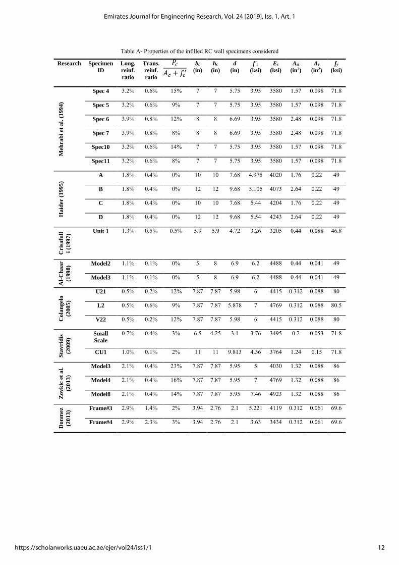
Table A- Properties of the infilled RC wall specimens considered Research Specimen
ID
Long.
reinf.
ratio
Trans.
reinf.
ratio
bc
(in)
hc
(in)
d
(in)
f'c
(ksi)
Ec
(ksi)
Ast
(in2)
Av
(in2)
fy
(ksi)
Meh
rab
i et
al.
(1
99
4)
Spec 4 3.2% 0.6% 15% 7 7 5.75 3.95 3580 1.57 0.098 71.8
Spec 5 3.2% 0.6% 9% 7 7 5.75 3.95 3580 1.57 0.098 71.8
Spec 6 3.9% 0.8% 12% 8 8 6.69 3.95 3580 2.48 0.098 71.8
Spec 7 3.9% 0.8% 8% 8 8 6.69 3.95 3580 2.48 0.098 71.8
Spec10 3.2% 0.6% 14% 7 7 5.75 3.95 3580 1.57 0.098 71.8
Spec11 3.2% 0.6% 8% 7 7 5.75 3.95 3580 1.57 0.098 71.8
Ha
ider
(1
99
5)
A 1.8% 0.4% 0% 10 10 7.68 4.975 4020 1.76 0.22 49
B 1.8% 0.4% 0% 12 12 9.68 5.105 4073 2.64 0.22 49
C 1.8% 0.4% 0% 10 10 7.68 5.44 4204 1.76 0.22 49
D 1.8% 0.4% 0% 12 12 9.68 5.54 4243 2.64 0.22 49
Cri
safu
ll
i (1
99
7) Unit 1 1.3% 0.5% 0.5% 5.9 5.9 4.72 3.26 3205 0.44 0.088 46.8
Al-
Ch
aa
r
(199
8) Model2 1.1% 0.1% 0% 5 8 6.9 6.2 4488 0.44 0.041 49
Model3 1.1% 0.1% 0% 5 8 6.9 6.2 4488 0.44 0.041 49
Co
lan
gel
o
(200
5)
U21 0.5% 0.2% 12% 7.87 7.87 5.98 6 4415 0.312 0.088 80
L2 0.5% 0.6% 9% 7.87 7.87 5.878 7 4769 0.312 0.088 80.5
V22 0.5% 0.2% 12% 7.87 7.87 5.98 6 4415 0.312 0.088 80
Sta
vri
dis
(200
9)
Small
Scale
0.7% 0.4% 3% 6.5 4.25 3.1 3.76 3495 0.2 0.053 71.8
CU1 1.0% 0.1% 2% 11 11 9.813 4.36 3764 1.24 0.15 71.8
Zo
vk
ic e
t a
l.
(201
3)
Model3 2.1% 0.4% 23% 7.87 7.87 5.95 5 4030 1.32 0.088 86
Model4 2.1% 0.4% 16% 7.87 7.87 5.95 7 4769 1.32 0.088 86
Model8 2.1% 0.4% 14% 7.87 7.87 5.95 7.46 4923 1.32 0.088 86
Do
nm
ez
(201
3) Frame#3 2.9% 1.4% 2% 3.94 2.76 2.1 5.221 4119 0.312 0.061 69.6
Frame#4 2.9% 2.3% 3% 3.94 2.76 2.1 3.63 3434 0.312 0.061 69.6
𝑃𝑐
𝐴𝑐 + 𝑓𝑐′
12
Emirates Journal for Engineering Research, Vol. 24 [2019], Iss. 1, Art. 1
https://scholarworks.uaeu.ac.ae/ejer/vol24/iss1/1
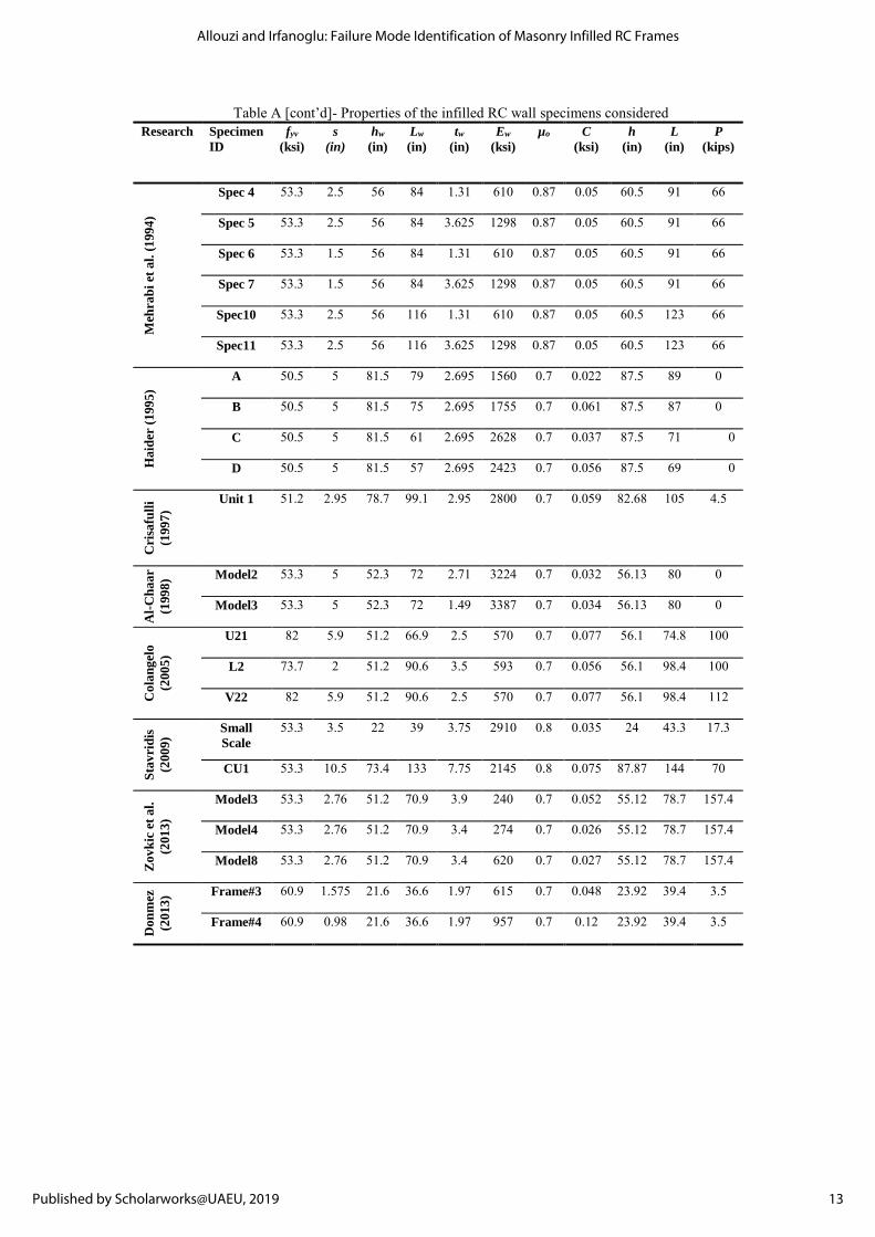
Table A [cont’d]- Properties of the infilled RC wall specimens considered Research Specimen
ID
fyv
(ksi)
s
(in)
hw
(in)
Lw
(in)
tw
(in)
Ew
(ksi)
µo C
(ksi)
h
(in)
L
(in)
P
(kips) M
ehra
bi
et a
l. (
199
4)
Spec 4 53.3 2.5 56 84 1.31 610 0.87 0.05 60.5 91 66
Spec 5 53.3 2.5 56 84 3.625 1298 0.87 0.05 60.5 91 66
Spec 6 53.3 1.5 56 84 1.31 610 0.87 0.05 60.5 91 66
Spec 7 53.3 1.5 56 84 3.625 1298 0.87 0.05 60.5 91 66
Spec10 53.3 2.5 56 116 1.31 610 0.87 0.05 60.5 123 66
Spec11 53.3 2.5 56 116 3.625 1298 0.87 0.05 60.5 123 66
Ha
ider
(1
99
5)
A 50.5 5 81.5 79 2.695 1560 0.7 0.022 87.5 89 0
B 50.5 5 81.5 75 2.695 1755 0.7 0.061 87.5 87 0
C 50.5 5 81.5 61 2.695 2628 0.7 0.037 87.5 71 0
D 50.5 5 81.5 57 2.695 2423 0.7 0.056 87.5 69 0
Cri
safu
lli
(199
7)
Unit 1 51.2 2.95 78.7 99.1 2.95 2800 0.7 0.059 82.68 105 4.5
Al-
Ch
aa
r
(199
8) Model2 53.3 5 52.3 72 2.71 3224 0.7 0.032 56.13 80 0
Model3 53.3 5 52.3 72 1.49 3387 0.7 0.034 56.13 80 0
Co
lan
gel
o
(200
5)
U21 82 5.9 51.2 66.9 2.5 570 0.7 0.077 56.1 74.8 100
L2 73.7 2 51.2 90.6 3.5 593 0.7 0.056 56.1 98.4 100
V22 82 5.9 51.2 90.6 2.5 570 0.7 0.077 56.1 98.4 112
Sta
vri
dis
(200
9)
Small
Scale
53.3 3.5 22 39 3.75 2910 0.8 0.035 24 43.3 17.3
CU1 53.3 10.5 73.4 133 7.75 2145 0.8 0.075 87.87 144 70
Zo
vk
ic e
t a
l.
(201
3)
Model3 53.3 2.76 51.2 70.9 3.9 240 0.7 0.052 55.12 78.7 157.4
Model4 53.3 2.76 51.2 70.9 3.4 274 0.7 0.026 55.12 78.7 157.4
Model8 53.3 2.76 51.2 70.9 3.4 620 0.7 0.027 55.12 78.7 157.4
Do
nm
ez
(201
3) Frame#3 60.9 1.575 21.6 36.6 1.97 615 0.7 0.048 23.92 39.4 3.5
Frame#4 60.9 0.98 21.6 36.6 1.97 957 0.7 0.12 23.92 39.4 3.5
13
Allouzi and Irfanoglu: Failure Mode Identification of Masonry Infilled RC Frames
Published by Scholarworks@UAEU, 2019