behavior of reinforced concrete infilled frames under cyclic loading 1 behavior of reinforced...
TRANSCRIPT
Behavior of Reinforced Concrete Infilled Frames under Cyclic Loading
1
Behavior of Reinforced Concrete Infilled Frames under Cyclic Loading
Y. M. Hashem1, A. A. Mahmoud2, M. Adam3, and A.S. Shanour4
1 Professor of R.C. Structures, Civil Eng. Dept., Faculty of Engineering, Shoubra, Benha Univ., Egypt. 2 Professor of R.C. Structures, , Civil Eng. Dept., Faculty of Engineering , Shoubra, Benha Univ., Egypt. 3 Associate Professor, Civil Eng. Dept., Faculty of Engineering, Shoubra, Benha Univ., Egypt. 4 Demonstrator, Civil Eng. Dept., Faculty of Engineering, Shoubra, Benha Univ., Egypt. ARTICLE HISTORY Received: xx/xx/2010 Accepted xx/xx/2010
ABSTRACT
A numerical procedure for the nonlinear analysis of infilled frames based on the finite element method is presented. The infill panel material nonlinearities due to cracking and crushing are considered using ANSYS® Program. An extensive survey of published work on general concepts of infilled frames under cyclic loading is presented. Numerical parametric studies have been conducted to investigate different factors affecting the behavior of reinforced concrete infilled frames under cyclic loading. A rational approach for equivalent diagonal strut is developed which can help in the design of reinforced concrete infilled frames.
Keywords
Masonry Infill Panels; Reinforced Concrete; Infilled Frames; Material Nonlinearity; Interface Element; Finite Element; Cyclic Loading.
Introduction In the past, numerous studies were conducted on the performance of masonry walls as well as RC infilled frames. The masonry infill itself may fail in various modes, most often involving some combination of bed joint sliding, diagonal cracking, and corner crushing. The exact mode of failure depends on material properties, such as compressive strength, shear strength, and coefficient of friction. Sivarama, et. al., (2003), tested ten different prototypes of confined masonry panels for ductility under in-plane loads. It was found that the ultimate lateral load has been governed by shear failure when compared with flexural capacity, even in the case of fully reinforced brick wall panel systems. Haide, (2007), used finite element model (employing ABAQUS) for the analysis of masonry shear walls with and without reinforcement. He found that the average
experimental value of load for the reinforced walls at the peak and at the ultimate load stages was 34% higher than that for the walls without reinforcement. Hemant, et. al. (2007), studied the uniaxial monotonic compressive stress-strain behavior and estimated the modulus of elasticity of bricks, mortar, and masonry as 300, 200, and 550 times their compressive strengths, respectively.
The infilled frames experiments were performed by Tarek (on full- scale frames with masonry infill. He concluded that the presence of the infill material in the frame either with or without shear connector led to an increase in the lateral stiffness of the frame. Frames with strong and weak masonry infill have been experimentally investigated by Mehrabi (1996). Specimens
Ain Shams Journal of Civil Engineering (ASJCE)
Vol. 2. September, 2010, pp. 169-182
Y. M. Hashem, A. A. Mahmoud, M. Adam, and A.S. Shanour
2
Several researchers studied the effects of opening in the infill panel, Abdel-Mooty, et. al. (1999) and EL Nesr, et. al. (2001), studied the effect of opening size and location and framing around openings on the lateral load resistance, stiffness, ductility and energy dissipation capacity. It was found that, increasing the opening size significantly reduces the lateral load resistance and the stiffness of the infilled frames. The behavior of infilled frames under cyclic loading has been investigated through many researches, Bertero, et. al. (1983) performed experimental investigation on a series of quasi-static cyclic and monotonic load tests on 1/3-scale models. Harry, et. al. (1993), examined the problem of retrofitting existing lightly reinforced concrete frames (LRCF) with compatible strength block masonry infill to resist moderate earthquake loading. Madan, et. al. (1997), proposed an numerical macromodel based on an equivalent strut approach integrated with a smooth hysteretic model for representing masonry infill panels in nonlinear analysis of the frame structure. Multi-story infilled frames were studied by Gostic, et. al. (1999) and Mehmet, et. al. (2006). It was found that the redistribution of strength and
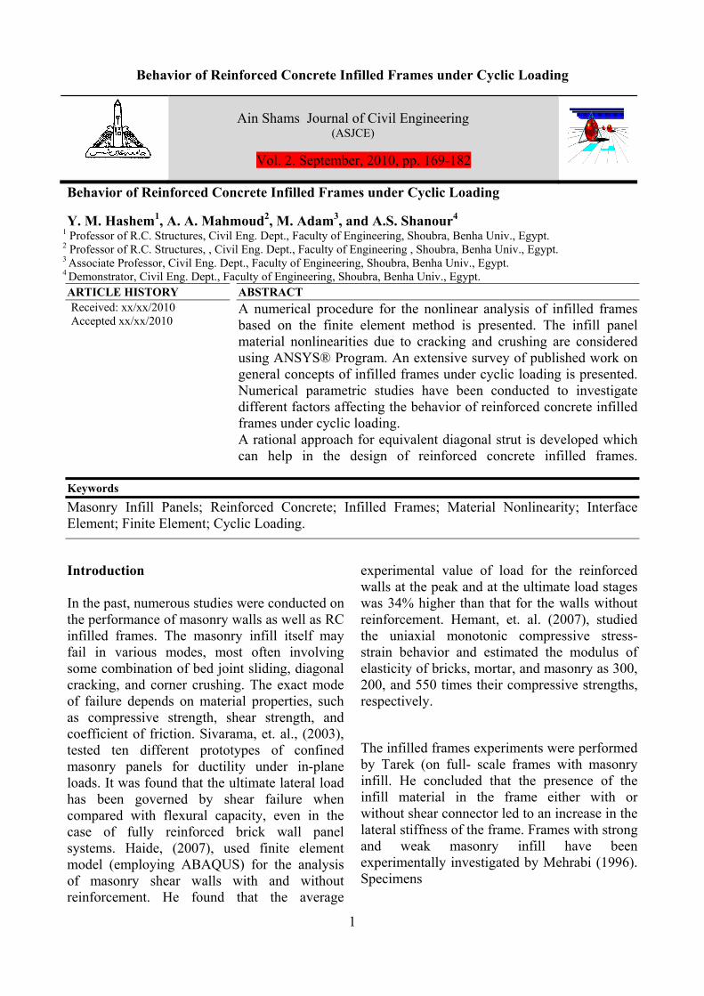
stiffness induced additional loading to the frame columns in the lower story. In addition, the strength and ductility inadequacies of the frame members influenced the lateral performance of the frame strengthened by partial infills. Finite Element Modeling and Material Modeling All elements used in the numerical analysis are idealized according to the elements available in ANSYS® program. The used elements are: Solid 65 -3-D to represent Reinforced Concrete and Masonry, Link 8 for Steel Reinforcement, and Contact 52 to model Concrete-Masonry interface. The concrete and masonry material model assigned for Solid65 element is characterized by its capability to predict the failure of brittle materials. Both cracking and crushing failure modes are accounted for. The CONTAC52 element assigned for the infill/frame interface material model. The element is capable of supporting compression only in the direction normal to the surfaces and shear (Coulomb friction) in the tangential direction. Figure (1) shows the force-deflection relationship of CONTAC52 element. .
(a) Kn (normal stiffness) Representation (b) Ks (shear stiffness) Representation
Fig. 1. CONTAC52 Force-Deflection Relationship (ANSYS®)
Kn
1 1
Ks
(Un)J- (Un)I+ GAP (Us)J- (Us)I
μ│Fn │
μ│Fn │
For Fn<0, and no reversed loading
Fn Fs
(a) (b)
Y. M. Hashem, A. A. Mahmoud, M. Adam, and A.S. Shanour
4
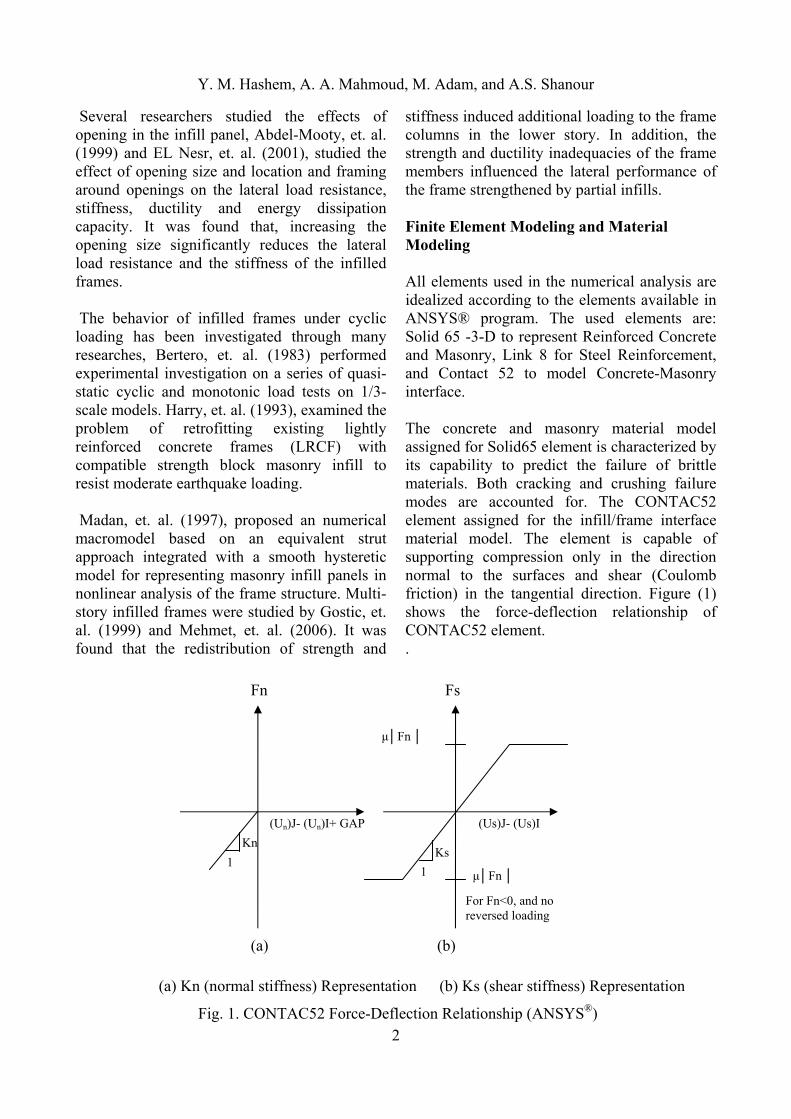
Implementation and Numerical Evaluation The correlation between experimental and numerical results is based on comparisons of failure modes, cracking patterns and plastic hinge locations as well as load-displacement curves. The bare frame tested by Mehrabi et. al. (1996) is considered as the first illustrative example. The load-displacement curves obtained from analysis and experiment are shown in Figure (2). The ultimate load predicted by the current analysis is slightly higher than that from the experimental results, where, the numerical and experimental loads are 115.0 KN and 112.0 KN respectively with difference about 2.6 %. The current numerical load-displacement curve gives high stiffness than the experimental at initial loading stages until reach to yield of steel reinforcement
0
10
2030
40
50
6070
80
90100
110
120
130140
150
160
0 5 10 15 20 25 30 35 40 45 50 55 60 65 70 75 80 85
Lateral displacement (mm)
Lat
eral
load
(KN
)
Experimental (Mehrabi (1996))
Numerical (Current Study)
Numerical (Mehrabi (1996))
Fig. 2. Load – Displacement curves for the experimental (Mehrabi (1996)) and current study results of the bare frame.
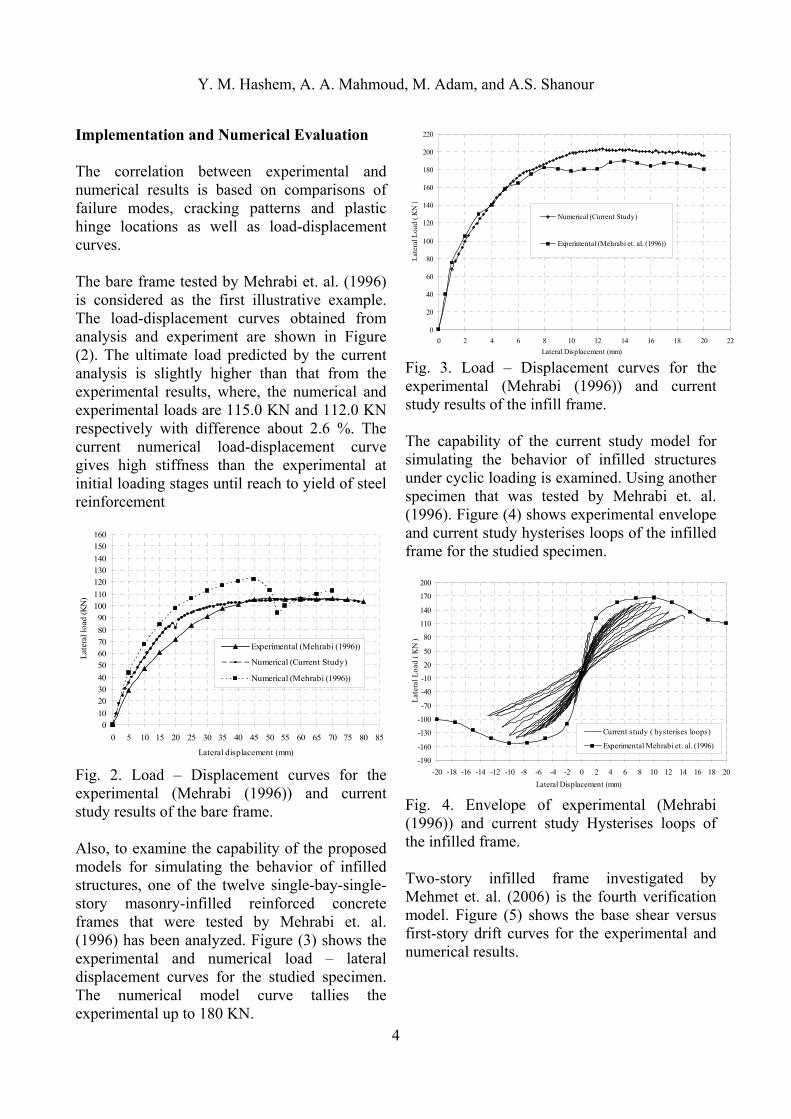
Also, to examine the capability of the proposed models for simulating the behavior of infilled structures, one of the twelve single-bay-single-story masonry-infilled reinforced concrete frames that were tested by Mehrabi et. al. (1996) has been analyzed. Figure (3) shows the experimental and numerical load – lateral displacement curves for the studied specimen. The numerical model curve tallies the experimental up to 180 KN.
0
20
40
60
80
100
120
140
160
180
200
220
0 2 4 6 8 10 12 14 16 18 20 22
Lateral Displacement (mm)
Lat
eral
Loa
d ( K
N )
Numerical (Current Study)
Experimental (Mehrabi et. al. (1996))
Fig. 3. Load – Displacement curves for the experimental (Mehrabi (1996)) and current study results of the infill frame. The capability of the current study model for simulating the behavior of infilled structures under cyclic loading is examined. Using another specimen that was tested by Mehrabi et. al. (1996). Figure (4) shows experimental envelope and current study hysterises loops of the infilled frame for the studied specimen.
-190
-160
-130
-100
-70
-40
-10
20
50
80
110
140
170
200
-20 -18 -16 -14 -12 -10 -8 -6 -4 -2 0 2 4 6 8 10 12 14 16 18 20
Lateral Displacement (mm)
Lat
eral
Loa
d ( K
N )
Current study ( hysterises loops)
Experimental Mehrabi et. al. (1996)
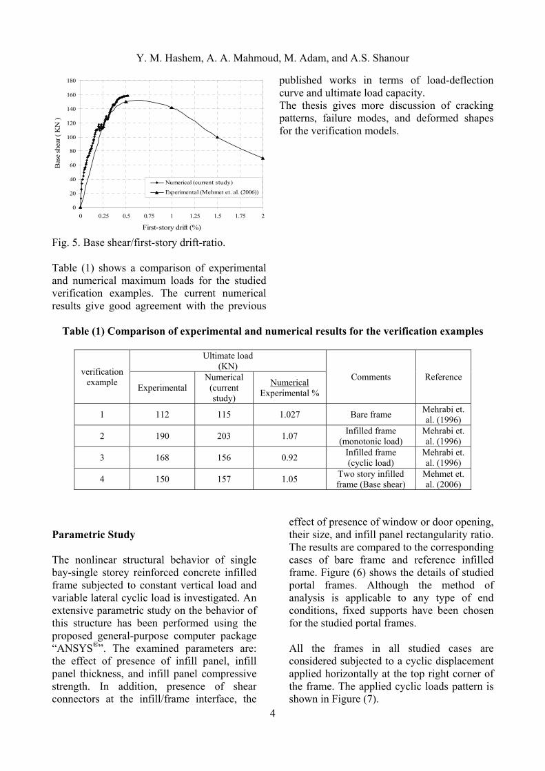
Fig. 4. Envelope of experimental (Mehrabi (1996)) and current study Hysterises loops of the infilled frame. Two-story infilled frame investigated by Mehmet et. al. (2006) is the fourth verification model. Figure (5) shows the base shear versus first-story drift curves for the experimental and numerical results.
Y. M. Hashem, A. A. Mahmoud, M. Adam, and A.S. Shanour
4
0
20
40
60
80
100
120
140
160
180
0 0.25 0.5 0.75 1 1.25 1.5 1.75 2
First-story drift (%)
Bas
e sh
ear ( K
N )
Numerical (current study)
Experimental (Mehmet et. al. (2006))
Fig. 5. Base shear/first-story drift-ratio. Table (1) shows a comparison of experimental and numerical maximum loads for the studied verification examples. The current numerical results give good agreement with the previous
published works in terms of load-deflection curve and ultimate load capacity. The thesis gives more discussion of cracking patterns, failure modes, and deformed shapes for the verification models.
Table (1) Comparison of experimental and numerical results for the verification examples
verification example
Ultimate load (KN)
Comments Reference Experimental
Numerical (current study)
Numerical Experimental %
1 112 115 1.027 Bare frame Mehrabi et. al. (1996)
2 190 203 1.07 Infilled frame
(monotonic load) Mehrabi et. al. (1996)
3 168 156 0.92 Infilled frame (cyclic load)
Mehrabi et. al. (1996)
4 150 157 1.05 Two story infilled frame (Base shear)
Mehmet et. al. (2006)
Parametric Study The nonlinear structural behavior of single bay-single storey reinforced concrete infilled frame subjected to constant vertical load and variable lateral cyclic load is investigated. An extensive parametric study on the behavior of this structure has been performed using the proposed general-purpose computer package “ANSYS®”. The examined parameters are: the effect of presence of infill panel, infill panel thickness, and infill panel compressive strength. In addition, presence of shear connectors at the infill/frame interface, the
effect of presence of window or door opening, their size, and infill panel rectangularity ratio. The results are compared to the corresponding cases of bare frame and reference infilled frame. Figure (6) shows the details of studied portal frames. Although the method of analysis is applicable to any type of end conditions, fixed supports have been chosen for the studied portal frames. All the frames in all studied cases are considered subjected to a cyclic displacement applied horizontally at the top right corner of the frame. The applied cyclic loads pattern is shown in Figure (7).
Y. M. Hashem, A. A. Mahmoud, M. Adam, and A.S. Shanour
4
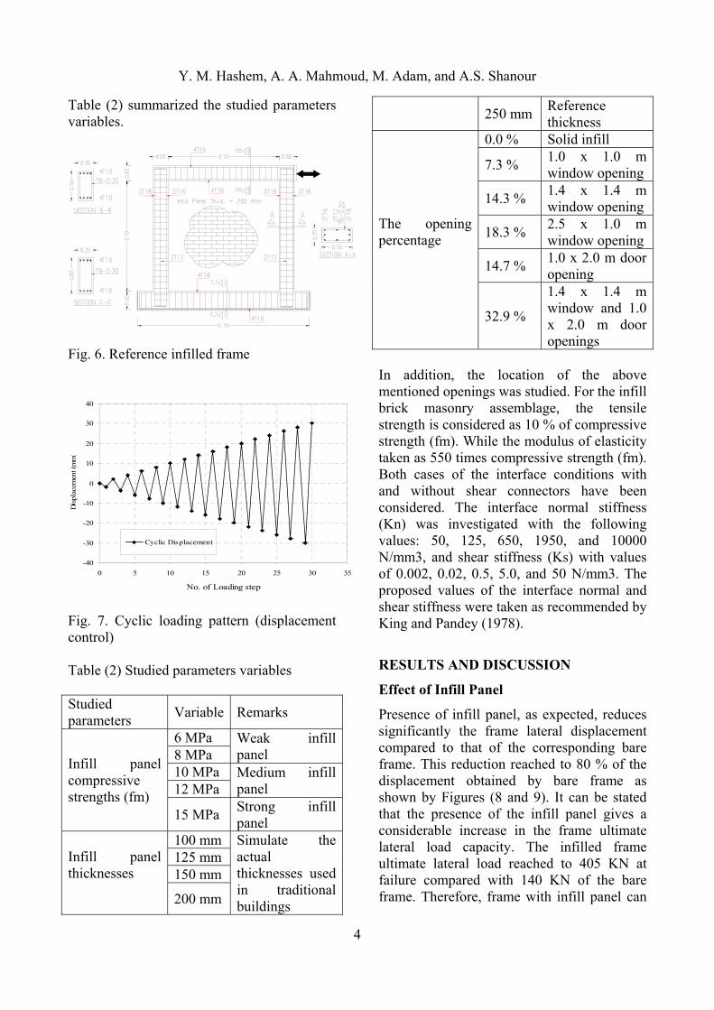
Table (2) summarized the studied parameters variables.
Fig. 6. Reference infilled frame
-40
-30
-20
-10
0
10
20
30
40
0 5 10 15 20 25 30 35
No. of Loading step
Dis
plac
emen
t (m
m)
Cyclic Displacement
Fig. 7. Cyclic loading pattern (displacement control) Table (2) Studied parameters variables Studied parameters
Variable Remarks
Infill panel compressive strengths (fm)
6 MPa Weak infill panel 8 MPa
10 MPa Medium infill panel 12 MPa
15 MPa Strong infill panel
Infill panel thicknesses
100 mm Simulate the actual thicknesses used in traditional buildings
125 mm 150 mm
200 mm
250 mm Reference thickness
The opening percentage
0.0 % Solid infill
7.3 % 1.0 x 1.0 m window opening
14.3 % 1.4 x 1.4 m window opening
18.3 % 2.5 x 1.0 m window opening
14.7 % 1.0 x 2.0 m door opening
32.9 %
1.4 x 1.4 m window and 1.0 x 2.0 m door openings
In addition, the location of the above mentioned openings was studied. For the infill brick masonry assemblage, the tensile strength is considered as 10 % of compressive strength (fm). While the modulus of elasticity taken as 550 times compressive strength (fm). Both cases of the interface conditions with and without shear connectors have been considered. The interface normal stiffness (Kn) was investigated with the following values: 50, 125, 650, 1950, and 10000 N/mm3, and shear stiffness (Ks) with values of 0.002, 0.02, 0.5, 5.0, and 50 N/mm3. The proposed values of the interface normal and shear stiffness were taken as recommended by King and Pandey (1978).
RESULTS AND DISCUSSION
Effect of Infill Panel
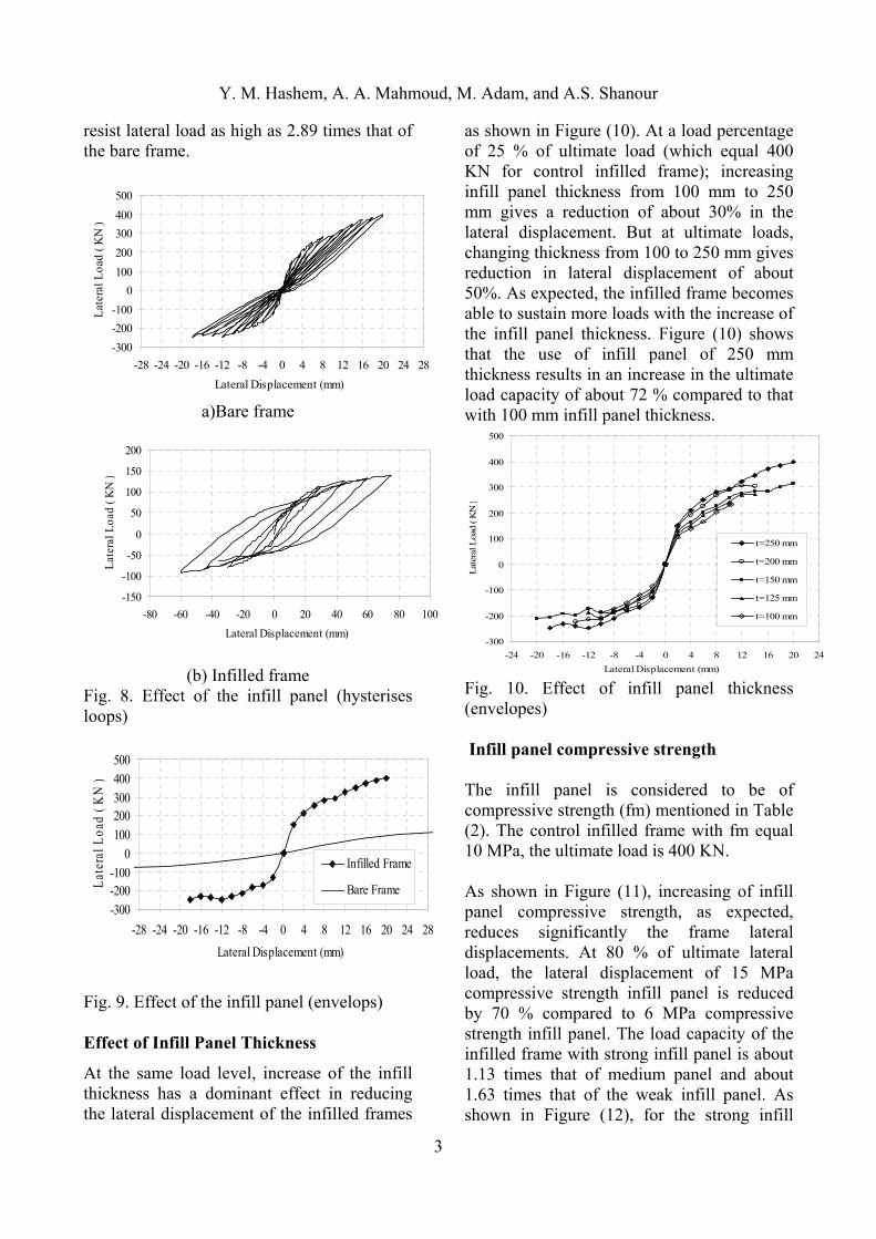
Presence of infill panel, as expected, reduces significantly the frame lateral displacement compared to that of the corresponding bare frame. This reduction reached to 80 % of the displacement obtained by bare frame as shown by Figures (8 and 9). It can be stated that the presence of the infill panel gives a considerable increase in the frame ultimate lateral load capacity. The infilled frame ultimate lateral load reached to 405 KN at failure compared with 140 KN of the bare frame. Therefore, frame with infill panel can
Y. M. Hashem, A. A. Mahmoud, M. Adam, and A.S. Shanour
3
resist lateral load as high as 2.89 times that of the bare frame.
-300
-200
-100
0
100
200
300
400
500
-28 -24 -20 -16 -12 -8 -4 0 4 8 12 16 20 24 28
Lateral Displacement (mm)
Lat
eral
Loa
d ( K
N )
a)Bare frame
-150
-100
-50
0
50
100
150
200
-80 -60 -40 -20 0 20 40 60 80 100
Lateral Displacement (mm)
Lat
eral
Loa
d ( K
N )
(b) Infilled frame Fig. 8. Effect of the infill panel (hysterises loops)
-300
-200-100
0
100
200300
400500
-28 -24 -20 -16 -12 -8 -4 0 4 8 12 16 20 24 28
Lateral Displacement (mm)
Lat
eral
Loa
d ( K
N )
Infilled Frame
Bare Frame
Fig. 9. Effect of the infill panel (envelops) Effect of Infill Panel Thickness
At the same load level, increase of the infill thickness has a dominant effect in reducing the lateral displacement of the infilled frames
as shown in Figure (10). At a load percentage of 25 % of ultimate load (which equal 400 KN for control infilled frame); increasing infill panel thickness from 100 mm to 250 mm gives a reduction of about 30% in the lateral displacement. But at ultimate loads, changing thickness from 100 to 250 mm gives reduction in lateral displacement of about 50%. As expected, the infilled frame becomes able to sustain more loads with the increase of the infill panel thickness. Figure (10) shows that the use of infill panel of 250 mm thickness results in an increase in the ultimate load capacity of about 72 % compared to that with 100 mm infill panel thickness.
-300
-200
-100
0
100
200
300
400
500
-24 -20 -16 -12 -8 -4 0 4 8 12 16 20 24
Lateral Displacement (mm)
Lat
eral
Loa
d ( K
N )
t=250 mm
t=200 mm
t=150 mm
t=125 mm
t=100 mm
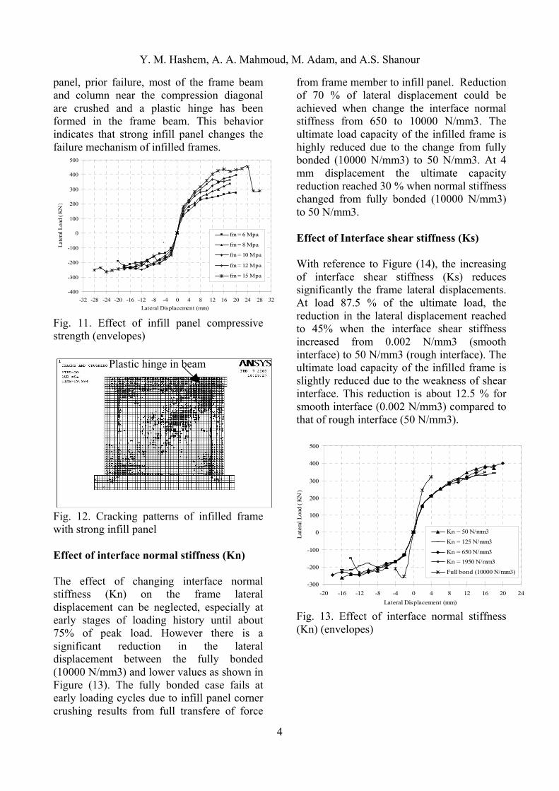
Fig. 10. Effect of infill panel thickness (envelopes) Infill panel compressive strength The infill panel is considered to be of compressive strength (fm) mentioned in Table (2). The control infilled frame with fm equal 10 MPa, the ultimate load is 400 KN. As shown in Figure (11), increasing of infill panel compressive strength, as expected, reduces significantly the frame lateral displacements. At 80 % of ultimate lateral load, the lateral displacement of 15 MPa compressive strength infill panel is reduced by 70 % compared to 6 MPa compressive strength infill panel. The load capacity of the infilled frame with strong infill panel is about 1.13 times that of medium panel and about 1.63 times that of the weak infill panel. As shown in Figure (12), for the strong infill
Y. M. Hashem, A. A. Mahmoud, M. Adam, and A.S. Shanour
4
panel, prior failure, most of the frame beam and column near the compression diagonal are crushed and a plastic hinge has been formed in the frame beam. This behavior indicates that strong infill panel changes the failure mechanism of infilled frames.
-400
-300
-200
-100
0
100
200
300
400
500
-32 -28 -24 -20 -16 -12 -8 -4 0 4 8 12 16 20 24 28 32
Lateral Displacement (mm)
Lat
eral
Loa
d ( K
N )
fm = 6 Mpa
fm = 8 Mpa
fm = 10 Mpa
fm = 12 Mpa
fm = 15 Mpa
`
Fig. 11. Effect of infill panel compressive strength (envelopes)
Fig. 12. Cracking patterns of infilled frame with strong infill panel Effect of interface normal stiffness (Kn) The effect of changing interface normal stiffness (Kn) on the frame lateral displacement can be neglected, especially at early stages of loading history until about 75% of peak load. However there is a significant reduction in the lateral displacement between the fully bonded (10000 N/mm3) and lower values as shown in Figure (13). The fully bonded case fails at early loading cycles due to infill panel corner crushing results from full transfere of force
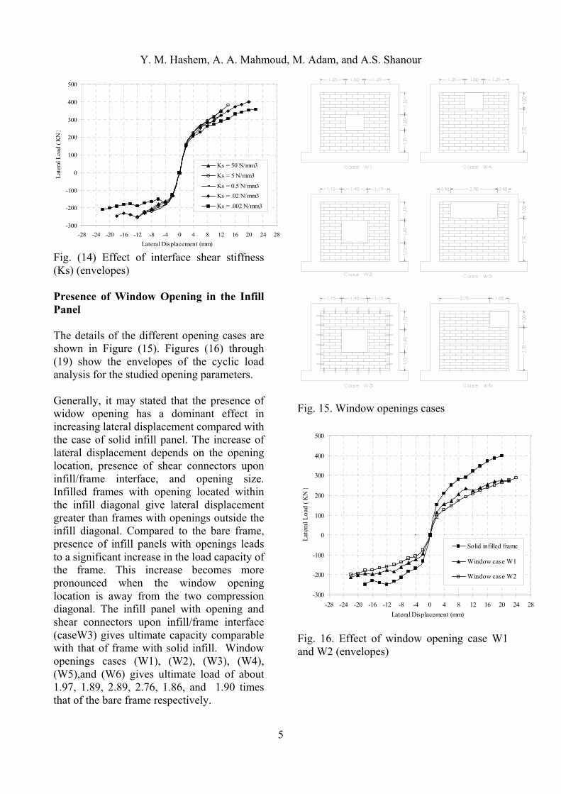
from frame member to infill panel. Reduction of 70 % of lateral displacement could be achieved when change the interface normal stiffness from 650 to 10000 N/mm3. The ultimate load capacity of the infilled frame is highly reduced due to the change from fully bonded (10000 N/mm3) to 50 N/mm3. At 4 mm displacement the ultimate capacity reduction reached 30 % when normal stiffness changed from fully bonded (10000 N/mm3) to 50 N/mm3. Effect of Interface shear stiffness (Ks) With reference to Figure (14), the increasing of interface shear stiffness (Ks) reduces significantly the frame lateral displacements. At load 87.5 % of the ultimate load, the reduction in the lateral displacement reached to 45% when the interface shear stiffness increased from 0.002 N/mm3 (smooth interface) to 50 N/mm3 (rough interface). The ultimate load capacity of the infilled frame is slightly reduced due to the weakness of shear interface. This reduction is about 12.5 % for smooth interface (0.002 N/mm3) compared to that of rough interface (50 N/mm3).
-300
-200
-100
0
100
200
300
400
500
-20 -16 -12 -8 -4 0 4 8 12 16 20 24
Lateral Displacement (mm)
Lat
eral
Loa
d ( K
N )
Kn = 50 N/mm3
Kn = 125 N/mm3
Kn = 650 N/mm3
Kn = 1950 N/mm3
Full bond (10000 N/mm3)
Fig. 13. Effect of interface normal stiffness (Kn) (envelopes)
Plastic hinge in beam
Y. M. Hashem, A. A. Mahmoud, M. Adam, and A.S. Shanour
5
-300
-200
-100
0
100
200
300
400
500
-28 -24 -20 -16 -12 -8 -4 0 4 8 12 16 20 24 28
Lateral Displacement (mm)
Lat
eral
Loa
d ( K
N )
Ks = 50 N/mm3
Ks = 5 N/mm3
Ks = 0.5 N/mm3
Ks = .02 N/mm3
Ks = .002 N/mm3
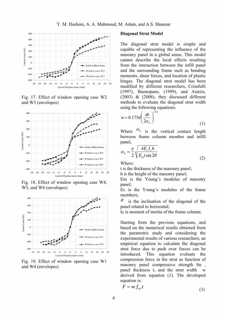
Fig. (14) Effect of interface shear stiffness (Ks) (envelopes) Presence of Window Opening in the Infill Panel The details of the different opening cases are shown in Figure (15). Figures (16) through (19) show the envelopes of the cyclic load analysis for the studied opening parameters. Generally, it may stated that the presence of widow opening has a dominant effect in increasing lateral displacement compared with the case of solid infill panel. The increase of lateral displacement depends on the opening location, presence of shear connectors upon infill/frame interface, and opening size. Infilled frames with opening located within the infill diagonal give lateral displacement greater than frames with openings outside the infill diagonal. Compared to the bare frame, presence of infill panels with openings leads to a significant increase in the load capacity of the frame. This increase becomes more pronounced when the window opening location is away from the two compression diagonal. The infill panel with opening and shear connectors upon infill/frame interface (caseW3) gives ultimate capacity comparable with that of frame with solid infill. Window openings cases (W1), (W2), (W3), (W4), (W5),and (W6) gives ultimate load of about 1.97, 1.89, 2.89, 2.76, 1.86, and 1.90 times that of the bare frame respectively.
Fig. 15. Window openings cases
-300
-200
-100
0
100
200
300
400
500
-28 -24 -20 -16 -12 -8 -4 0 4 8 12 16 20 24 28
Lateral Displacement (mm)
Lat
eral
Loa
d ( K
N )
Solid infilled frame
Window case W1
Window case W2
Fig. 16. Effect of window opening case W1 and W2 (envelopes)
Y. M. Hashem, A. A. Mahmoud, M. Adam, and A.S. Shanour
4
-300
-200
-100
0
100
200
300
400
500
-28 -24 -20 -16 -12 -8 -4 0 4 8 12 16 20 24 28
Lateral Displacement (mm)
Lat
eral
Loa
d ( K
N )
Solid infilled frame
Window case W2
Window case W3
Fig. 17. Effect of window opening case W2 and W3 (envelopes)
-300
-200
-100
0
100
200
300
400
-28 -24 -20 -16 -12 -8 -4 0 4 8 12 16 20 24 28
Lateral Displacement (mm)
Lat
eral
Loa
d ( K
N )
Solid infilled frame
Window case W4
Window case W5
Window case W6
Fig. 18. Effect of window opening case W4, W5, and W6 (envelopes)
-300
-200
-100
0
100
200
300
400
-28 -24 -20 -16 -12 -8 -4 0 4 8 12 16 20 24 28
Lateral Displacement (mm)
Lat
eral
Loa
d ( K
N )
Solid infilled frame
Window case W1
Window case W4
Fig. 19. Effect of window opening case W1 and W4 (envelopes)
Diagonal Strut Model The diagonal strut model is simple and capable of representing the influence of the masonry panel in a global sense. This model cannot describe the local effects resulting from the interaction between the infill panel and the surrounding frame such as bending moments, shear forces, and location of plastic hinges. The diagonal strut model has been modified by different researchers, Crisafulli (1997), Buonopane, (1999), and Asteris, (2003) & (2008), they discussed different methods to evaluate the diagonal strut width using the following equations:
4.0
2175.0
h
hdw
(1)
Where h is the vertical contact length between frame column member and infill panel,
42sin
4
2
tE
hIE
m
cch
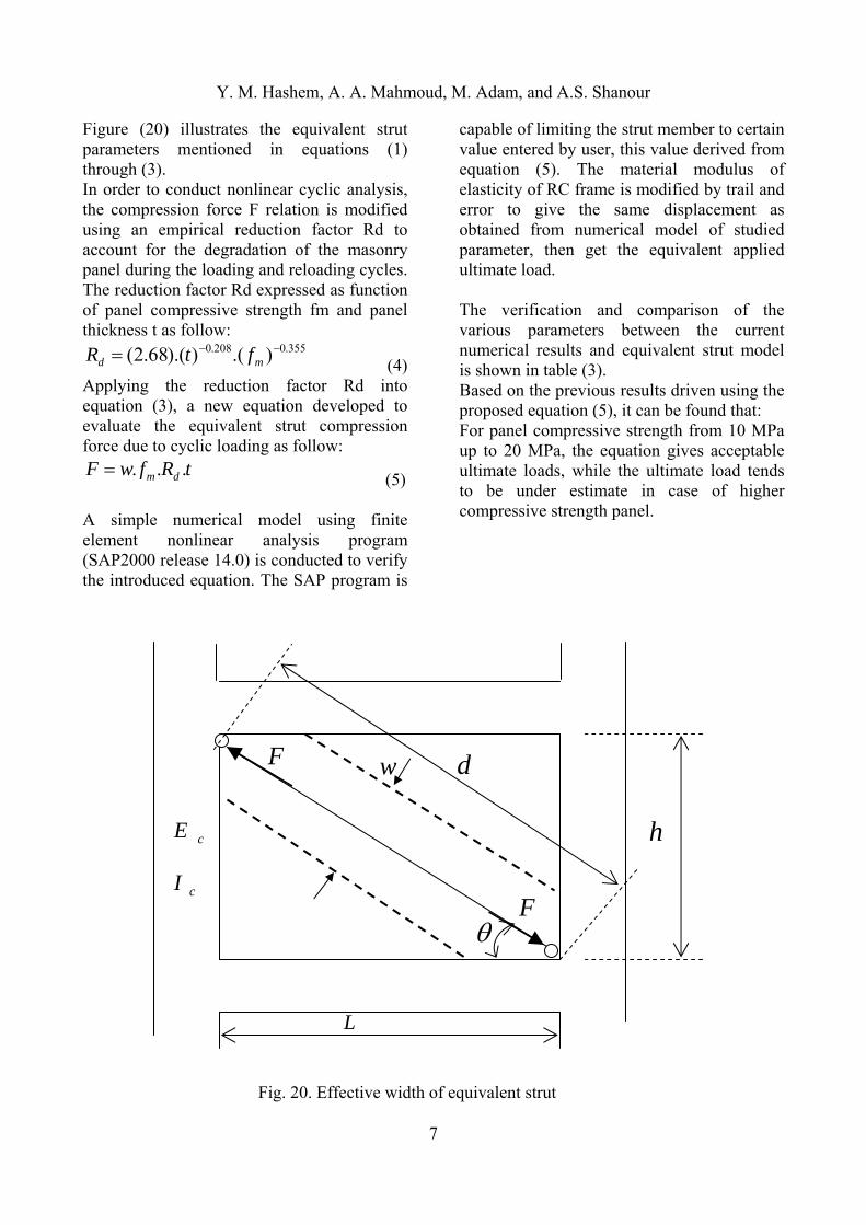
(2) Where: t is the thickness of the masonry panel; h is the height of the masonry panel; Em is the Young’s modulus of masonry panel; Ec is the Young’s modulus of the frame members; is the inclination of the diagonal of the panel related to horizontal; Ic is moment of inertia of the frame column. Starting from the previous equations, and based on the numerical results obtained from the parametric study and considering the experimental results of various researchers; an empirical equation to calculate the diagonal strut force due to push over forces can be introduced. This equation evaluate the compression force in the strut as function of masonry panel compressive strength fm , panel thickness t, and the strut width w derived from equation (1). The developed equation is:
tfwF m ..
(3)
Y. M. Hashem, A. A. Mahmoud, M. Adam, and A.S. Shanour
7
Figure (20) illustrates the equivalent strut parameters mentioned in equations (1) through (3). In order to conduct nonlinear cyclic analysis, the compression force F relation is modified using an empirical reduction factor Rd to account for the degradation of the masonry panel during the loading and reloading cycles. The reduction factor Rd expressed as function of panel compressive strength fm and panel thickness t as follow:
355.0208.0 ).()).(68.2( md ftR (4)
Applying the reduction factor Rd into equation (3), a new equation developed to evaluate the equivalent strut compression force due to cyclic loading as follow:
tRfwF dm ... (5)
A simple numerical model using finite element nonlinear analysis program (SAP2000 release 14.0) is conducted to verify the introduced equation. The SAP program is
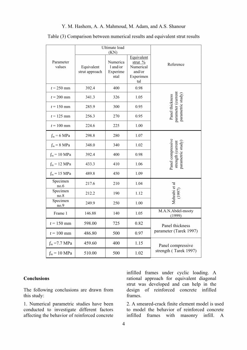
capable of limiting the strut member to certain value entered by user, this value derived from equation (5). The material modulus of elasticity of RC frame is modified by trail and error to give the same displacement as obtained from numerical model of studied parameter, then get the equivalent applied ultimate load. The verification and comparison of the various parameters between the current numerical results and equivalent strut model is shown in table (3). Based on the previous results driven using the proposed equation (5), it can be found that: For panel compressive strength from 10 MPa up to 20 MPa, the equation gives acceptable ultimate loads, while the ultimate load tends to be under estimate in case of higher compressive strength panel.
Fig. 20. Effective width of equivalent strut
dwF
F
h
L
cI
cE
Y. M. Hashem, A. A. Mahmoud, M. Adam, and A.S. Shanour
4
Table (3) Comparison between numerical results and equivalent strut results
Parameter values
Ultimate load (KN)
Reference Equivalent
strut approach
Numerical and/or
Experimental
Equivalent strut %
Numerical and/or
Experimental
t = 250 mm 392.4 400 0.98
Pan
el th
ickn
ess
para
met
er (
curr
ent
para
met
ric
stud
y)
t = 200 mm 341.3 326 1.05
t = 150 mm 285.9 300 0.95
t = 125 mm 256.3 270 0.95
t = 100 mm 224.6 225 1.00
fm = 6 MPa 298.8 280 1.07
Pane
l com
pres
sive
st
reng
th (
curr
ent
para
met
ric
stud
y)
fm = 8 MPa 348.0 340 1.02
fm = 10 MPa 392.4 400 0.98
fm = 12 MPa 433.3 410 1.06
fm = 15 MPa 489.8 450 1.09
Specimen no.6
217.6 210 1.04
Meh
rabi
et a
l (1
997)
Specimen no.8
212.2 190 1.12
Specimen no.9
249.9 250 1.00
Frame 1 146.88 140 1.05 M.A.N.Abdel-mooty
(1999)
t = 150 mm 598.00 725 0.82 Panel thickness parameter (Tarek 1997) t = 100 mm 486.80 500 0.97
fm =7.7 MPa 459.60 400 1.15 Panel compressive strength ( Tarek 1997) fm = 10 MPa 510.00 500 1.02
Conclusions The following conclusions are drawn from this study:
1. Numerical parametric studies have been conducted to investigate different factors affecting the behavior of reinforced concrete
infilled frames under cyclic loading. A rational approach for equivalent diagonal strut was developed and can help in the design of reinforced concrete infilled frames.
2. A smeared-crack finite element model is used to model the behavior of reinforced concrete infilled frames with masonry infill. A
Y. M. Hashem, A. A. Mahmoud, M. Adam, and A.S. Shanour
2
constitutive model for interface element has been used for modeling the interface behavior of reinforced concrete frames and infill. It is proved that the finite element models are able to simulate the failure mechanisms exhibited by infilled frames including crushing, cracking of concrete frames and masonry panels. Presence of infill panel reduces significantly the frame lateral displacement at least five times less compared to that of the corresponding bare frame.
3. The presence of infill panel leads to a significant increase in the frame capacity compared to that of the bare frame by about three times depending on many factors. This clearly indicates the significance of the infill walls in attracting most of the lateral loads in frame structures and shows why infill walls with or without opening should be accounted for in design.
4. Based on the current study, the optimum value of the interface normal stiffness (Kn) can be taken equal to 650 N/mm3. Also, the optimum value of the interface shear stiffness (Ks) can be taken equal to 0.20 N/mm3 in which this values give some agreement with the values given by other researchers.
5. The presence of shear connectors at the infill/frame interfaces leads to a 60 % reduction in the frame lateral displacement compared with the corresponding values of infilled frames without shear connectors.
6. The ultimate load capacity of the infilled frames with shear connectors experienced increase of 51 % compared to infilled frames without shear connectors.
7. The presence of openings in the infill panel leads to a considerable increase in the frame lateral displacement, this increase reached 5.5 times solid infill. The ultimate load capacity of the frame reduced by about 32 % compared with the solid infilled frame.
References 1. Abdel Mooty, M.A.N., Abdel-Gawad, S., Shaheen, H.H., and Issa, M.E., (1999), ” Experimental Evaluation of Cyclic Behavior of
Masonry Infilled Reinforced Concrete Frames with and without Openings”, Journal Engineering and Applied Science, Faculty of Engineering, Cairo University Vol. 46. No. 2, April 1999, pp.217-236.
2. ANSYS®, (2004), “Engineering Analysis System User's Manual, Vol. 1 & 2, and Theoretical Manual,” Revision 8.0, Swanson Analysis System Inc., Houston, Pennsylvania.
3. Asteris, (2008), “Finite Element Micro-Modeling of Infilled Frames” Electronic Journal of Structural Engineering (8) 2008. 4. Bertero, V.V. and Brokken, S., (1983) “Infills in Seismic Resistant Building”, ASCE, Journal of Structural Engineering, Vol. 109, No. 6, Jun 1983, pp.1337-1361. 5. Dhanasekar M., Haidera W., (2007), “Explicit Finite Element Analysis of Lightly Reinforced Masonry Shear Walls ” Computers and Structures, Volume 86, Issues 1-2, pp. 1-196. 6. El-Nesr, O.M. and Mostafa, M.A., (2001),”Nonlinear Behavior of Masonry Infilled Reinforced Concrete Frames”, Scientific Bulletin, Ain Shams University, Faculty of Engineering, Vol. 36, No. 2, pp. 61-72, June 2001. 7. F.J.Crisafulli (1997), “Seismic Behavior of Reinforced Concrete Structure With Masonry Infill” Ph.D. Thesis, University of Canterbury, Christchurch, New Zealand, 1997. 8. Gostic, S., and Zarnic, R., (1999), “Cyclic Lateral Response of Masonry Infilled Reinforced Concrete Frames and Confined Masonry Walls”, Proceedings of the 8 th North American Masonry Conference Austin, Texas June, 1999. 9. Haider W., (2007) “In-plane Response of Wide Spaced Reinforced Masonry Shear Walls”, Ph. D. Thesis, Central Queensland University, Australia, February 2007.
Y. M. Hashem, A. A. Mahmoud, M. Adam, and A.S. Shanour
3
10. Harry. G. Harris, Georges R. Balluoz, and Kenneth W. Kopatz, ( 1993), “ Preliminary Studies in Seismic Retrofiting of Lightly Reinforced Concrete Frames Using Masonry Infills”, The Sixth North American Masonry Conference, June 6-9, 1993, Philadelphia, Pennsylvania. 11. Hemant B. Kaushik1; Durgesh C. Rai2; and Sudhir K. Jain, (2007), “Stress-Strain Characteristics of Clay Brick Masonry under Uniaxial Compression”, Journal of Materials in Civil Engineering, Vol. 19, No. 9, ASCE, pp. 728-739. 12. King, G.J.W. and Pandey, P.C., (1978), “The Analysis of Infilled Frames Using Finite Elements”, Proceedings of the Institution of Civil Engineers, Vol. 65, Part 2, December 1978, pp. 749-760. 13. Madan A., Reinhorn, Fellow, and Mander J. B., (1997), “Modeling of Masonry Infill Panels for Structure Analysis”, Journal of the Structural Engineering, ASCE, Volume 123, No. 10, October 1997, pp. 1295-1302. 14. Mehmet E. K. and Sinan A., (2006), “Behavior of Reinforced Concrete Frames with Reinforced Concrete Partial Infills” ACI Structural Journal, V. 103, No. 5, September-October 2006, pp. 701-709. 15. Mehrabi, A.B., Shing, P.B., Schuller, M., and Noland, J. (1996), “Expermintal Evaluation of Masonry-Infilled Frames”, Journal of the Structural Engineering, ASCE, Volume 122, No. 3, March 1996, pp. 228-237. 16. Sivarama S., H. G. Sreenath, N. G. Bhagavan, A. R. Murthy, and V. Vimalanandam ), (2003), “Experimental Studies on In-Plane Ductility of Confined Masonry Panels”, ACI Structural Journal, V. 100, No. 3, May-June 2003, pp. 330-336. 17. Tarek A. T. E (1988), “Elastic Structure Behavior of Infill Portal Frames”, M. Sc.
Thesis, Faculty of Engineering, Ain shams University, Egypt, 1988.
Y. M. Hashem, A. A. Mahmoud, M. Adam, and A.S. Shanour
4
Professor Youssef Mohammed Hashem Hammad, is a professor of reinforced concrete structures, Faculty of Engineering, Benha University, Egypt
ملخص البحث في التحليل اإلنشائي للمباني يتم إھمال حوائط الطوب المستخدمة مع اإلطارات الخرسانية المسلحة و ذلك في مقاومةاألحمال األفقية الناتجة عن الزالزل أو األحمال الراسية الناتجة عن أحمال تشغيل المنشاء مع أن ھذه الحوائط تقوم بتغير سلوك و مقاومة المنشات األطارية و مرونتھا و ھذا ما سوف يتم
حيث تم توظيف طريقة العناصر ھذه الرسالةدراسته نظريا في خدما عناصر ربط بين اإلطارات المحددة في عملية التحليل مست
.الخرسانية المسلحة وحوائط الطوب علي مسح شامل لألعمال المنشورة المتعلقة ھذه الرسالةحتوي ت
بموضوع البحث و استنتاج طريقة عامة و دقيقة لدراسة السلوك الغير خطي لإلطارات الخرسانية المسلحة المحشوة بمادة مالئة
تبار اختالف ظروف التالمس بين من الطوب مع اآلخذ في االعاإلطار و المادة المالئة و العالقة الغير خطية بين اإلجھاد و االنفعال لمادتي الخرسانة وحديد التسليح و تأثير الشروخ و كذلك تصرف عناصر االتصال بين اإلطار والمادة المالئة من حيث التالمس و االنفصال و االنزالق ووجود عناصر قص
.اإلطار و المادة المالئة رابطة بين
لتحليل ابرنامج أستخدامللوصول إلى ھذه األھداف فقد تم لنظاملتمثيل ا ®ANSYS-علي الحاسب اآللي -اإلنشائي إلطارات الخرسانية المسلحة المحشوة بالطوب حيث ل االنشائي
يعتمد البرنامج علي زيادة الحمل المؤثر علي المنشأ تدريجيا لى الحمل المسبب لالنھيار مستخدما في ذلك حتى الوصول إ
وباستخدام ھذا البرنامج يتم الحصول ية التكرار االزاحةطريقة علي عالقة بين الحمل المؤثر واإلزاحة الناتج عنه و كذلك شكل الشروخ و تسلسل حدوثھا و بالتالي تحديد نوع االنھيار و كفاءة
.و قدرة ھذا النظام اإلنشائي
خدام البرنامج في تحليل العديد من اإلطارات وقد تم استالخرسانية المسلحة المستوية والمختلفة في الشكل والنظام اإلنشائي و المحشوة بالطوب بأنواع ذات خواص مختلفة للتأكد
يل ال من مدي كفاءة البرنامج في تحليل مثل ھذه المنشات تحلوقد تم مقارنة الحلول الناتجة من البرنامج مع نتائج . خطي
وقد أظھرت . التجارب المعملية من أبحاث أخرى منشورة النتائج أن التحليل اإلنشائي قريب جدا من النتائج المعملية
.المنشورة
كذلك تم عمل دراسة تحليلية نظرية نمطية علي نماذج من لحة المستوية المحشوة بالطوب اإلطارات الخرسانية المس
لدراسة العديد من العوامل المختلفة المؤثرة علي تصرف تلك ومن نتائج ھذه الدراسة تبين أن تأثير وجود الحوائط .المنشات
في التحليل اإلنشائي لإلطارات مؤثرا تأثيرا كبيرا في تصرفھا قشة وفي نھاية البحث توجد منا .و يتغير كثيرا بتغير عدة عوامل
للنتائج باإلضافة إلى مجموعة من االستنتاجات العامة و الھامة المستنبطة من الدراسة مع تقديم بعض التوصيات التي تستخدم
.في التصميم