modicon quantum automation platform
TRANSCRIPT

Automation & ControlModicon Quantumautomation platformUnity, Concept & ProWORX 32
CatalogueJuly
04
Mod
icon
Qua
ntum
auto
mat
ion
plat
form
07-04
ART. 802621 July 2004
MK
TE
D20
4071
ENSchneider Electric Industries SAS
Headquarters
89, bd Franklin RooseveltF - 92506 Rueil Malmaison Cedex
http://www.schneider-electric.comhttp://www.telemecanique.com
Owing to changes in standards and equipment, the characteristicsgiven in the text and images in this document are not binding us untilthey have been confirmed with us.
Production: Schneider Electric IndustriesPhotos: Schneider Electric IndustriesPrinted by: Pozzo Gros Monti - Italy

To be issued
Control and Protection,Detection,Automation,Human/Machine dialogue
Panel-building and cabling accessoriesAutomation
Art. 67341 - MKTED203111EN
Art. 802731 - MKTED204073EN
Art. 55053 - MKTED203041EN
Human/Machine dialogueCommunication
An overviewof the product range
Art. 70455 - MKTED204011EN
Art. 70263 - MKTED203113EN
2004
Safety solutionsusing Preventa
2001
Telemecanique
Components forHuman-Machine interfaces
2003
AS-Interfacecabling system
Automation and controlMounting systems
2004 Automation and controlInterfaces, I/O splitter boxesand power supplies
2003Automation and controlAutomation and relay functions
2003
Terminals and display unitsArt. 96949 - MKTED2040401EN
Automation and controlHuman/Machine interfaces
2004
Control and Protection,Detection,Automation,Human/Machine dialogue,Communication
Human/Machine dialogueSupervision
Control and signalling unitsArt. 28697 - MKTED299014EN
Ethernet TCP/IPTransparent Factory
2004
Control and protection,
Detection,
Automation,
Human/Machine dialogue,
Communication,
Supervision,
Panel-building and cablingaccessories

Art. 61233 - DIA7ED2030902EN
Art. 66692 - DIA7ED20310006EN
Control and protection
AUTC201104124EN
Art. 802621 - MKTED204071EN
Art. 802625 - MKTED204072EN
Art. 70984 - MKTED204012EN
Art. 27501 - MKTED201001EN
Art. 802660 - MKTED204091EN
Automation,Communication
AUTC201108140EN
Detection
Art. 54752 - MKTED203031EN
Distributed I/OAdvantys STB
2003 Modicon Momentumautomation platform
2002
Motion controlLexium
2004Twin LineMotion control
2003
2004
Soft starters andvariable speed drives
2001
Motor starter solutionsControl and protectioncomponents
Art. 960015 - DIA1ED2040506EN
Automation and controlTelemecaniqueThe essential
2004
Automation and controlAutomation platformModicon Quantumand Unity - ConceptProworx software2004
Automation and controlAutomation platformModicon Premiumand Unity - PL7 software
2004 Automation platformModicon TSX Microand PL7 software
2004
2003
Global Detection
Electronic andelectromechanical sensors

4
General contents 0 Modicon Quantum automation platform
Welcome to the world of Telemecanique . . . . . . . . . . . . . . . . . . . . . . . . . . page 6
New features in Unity Quantum . . . . . . . . . . . . . . . . . . . . . . . . . . . . . . . . . page 8
1 – Modicon Quantum processors1-1 Quantum processors - Unity . . . . . . . . . . . . . . . . . . . . . . . . . . . . . . . . page 1/2
1-2 Quantum processors - Concept/ProWORX 32 . . . . . . . . . . . . . . . . page 1/12
2 – Backplanes, I/O architectures and power suppliesBackplanes . . . . . . . . . . . . . . . . . . . . . . . . . . . . . . . . . . . . . . . . . . . . . . . . . page 2/2
I/O architecture . . . . . . . . . . . . . . . . . . . . . . . . . . . . . . . . . . . . . . . . . . . . . . page 2/4
Power supply modules . . . . . . . . . . . . . . . . . . . . . . . . . . . . . . . . . . . . . . page 2/16
3 – Discrete and analog I/O3-1 Discrete I/O modules . . . . . . . . . . . . . . . . . . . . . . . . . . . . . . . . . . . . . . page 3/2
3-2 Analog I/O modules . . . . . . . . . . . . . . . . . . . . . . . . . . . . . . . . . . . . . . page 3/44
3-3 Distributed I/O modules. . . . . . . . . . . . . . . . . . . . . . . . . . . . . . . . . . . page 3/62
3-4 Tego Power installation system . . . . . . . . . . . . . . . . . . . . . . . . . . . . page 3/70
4 – Application specific modules4-1 Intrinsically safe I/O . . . . . . . . . . . . . . . . . . . . . . . . . . . . . . . . . . . . . . . page 4/2
4-2 Counter and special purpose modules . . . . . . . . . . . . . . . . . . . . . . page 4/16
4-3 Motion control . . . . . . . . . . . . . . . . . . . . . . . . . . . . . . . . . . . . . . . . . . page 4/34
4-4 Hot Standby system - Unity Pro . . . . . . . . . . . . . . . . . . . . . . . . . . . . page 4/50
4-5 Hot Standby system - Concept/ProWORX 32 . . . . . . . . . . . . . . . . . page 4/58
5 – CommunicationSelection guide . . . . . . . . . . . . . . . . . . . . . . . . . . . . . . . . . . . . . . . . . . . . . .page 5/2
5-1 Ethernet TCP/IP network - Transparent Ready . . . . . . . . . . . . . . . . . page 5/4
5-2 AS-Interface bus. . . . . . . . . . . . . . . . . . . . . . . . . . . . . . . . . . . . . . . . . page 5/46
5-3 Modbus Plus network and Profibus DP/INTERBUS buses . . . . . . . . page 5/52
5-4 Asynchronous serial links. . . . . . . . . . . . . . . . . . . . . . . . . . . . . . . . . page 5/64
6 – Software6-1 Unity software page 6/2
6-2 Concept software . . . . . . . . . . . . . . . . . . . . . . . . . . . . . . . . . . . . . . . . page 6/48
6-3 ProWORX 32 software . . . . . . . . . . . . . . . . . . . . . . . . . . . . . . . . . . . . page 6/66

5
7 – Human/Machine Interfaces Magelis display units and terminals . . . . . . . . . . . . . . . . . . . . . . . . . . . . page 7/2
Magelis iPC graphic terminals . . . . . . . . . . . . . . . . . . . . . . . . . . . . . . . . . page 7/6
HMI software . . . . . . . . . . . . . . . . . . . . . . . . . . . . . . . . . . . . . . . . . . . . . . . page 7/8
OFS data server software . . . . . . . . . . . . . . . . . . . . . . . . . . . . . . . . . . . . page 7/10
Tego Dial for Human/Machine Interfaces . . . . . . . . . . . . . . . . . . . . . . . page 7/14
8 – Connection interfaces and power supplies8-1 Telefast 2 pre-wired system . . . . . . . . . . . . . . . . . . . . . . . . . . . . . . . . page 8/2
8-2 Phaseo power supplies for d.c. control circuits . . . . . . . . . . . . . . page 8/20
9 – ServicesTechnical information
Modicon Quantum main characteristics . . . . . . . . . . . . . . . . . . . . . . . . page 9/1Optional conformal coating . . . . . . . . . . . . . . . . . . . . . . . . . . . . . . . . . . page 9/2Documentation . . . . . . . . . . . . . . . . . . . . . . . . . . . . . . . . . . . . . . . . . . . page 9/4Automation product certifications . . . . . . . . . . . . . . . . . . . . . . . . . . . . . page 9/6
Schneider Electric worldwideAddresses . . . . . . . . . . . . . . . . . . . . . . . . . . . . . . . . . . . . . . . . . . . . . . . page 9/8
IndexProduct reference index . . . . . . . . . . . . . . . . . . . . . . . . . . . . . . . . . . . page 9/14

6
Welcome Modicon Quantum automation platform 0
To the world of Telemecanique
Modicon is the family name for a set of complementary automation platforms. They are characterized by their extendable memory capacity and increasing execution speed.
Premium, an optimized platform for complex machinery, factory automation applications and infrastructure b Up to 7 Mb of program memory b Compact size and high density I/O modulesb Extension racks for multirack architectures b Extensive catalog of sensor/actuator buses, machine buses and fieldbuses b Integrated Ethernet TCP/IP port on many CPUsb Motion control, electronic cam, weighing and machine safety modules
Quantum, an optimized platform for batch/process applications, with high levels of availabilityb Up to 7 Mb of program memory b Powerful process control library b Supports fieldbuses for batch/process applications b Integrated Ethernet TCP/IP port on new CPUsb High performance Hot Standby solutionb Special treatment to resist corrosive atmospheres
Atrium, the slot PLC meeting PC Based requirementsb All the functionality of a PLC integrated in a PC b No compromise of ruggedness or HMI integration
Modicon automation platformsA family of specialist automation platforms
Discrete Automation
PC based control applications
Process Applications

7
Welcome (continued) Modicon Quantum automation platform 0
To the world of Telemecanique
A new organizer environment for high end Modicon platforms
To complement the existing software catalog, Unity offers a common environment for Modicon Premium, Quantum and Atrium platforms. Based on the best standards in existing software offers, Unity is a high performance programming tool that can significantly increase productivity by means of: b State-of-the-art functionalityb Optimum standardization enabling re-use of developmentsb Numerous tools for testing the program and improving system operationb New integrated diagnostic services
The Unity software catalog also offers specialist software representing another major step towards “Collaborative Automation”: b Management of distributed control architecture projectsb Design and generation of batch/process applications with PLC/HMI integrationb Openness to developments in C language or in VBA (Visual Basic for Applications)
Web technology serving automation solutions
Let us introduce you to the world of Transparent Ready - a world where products are compatible, interoperable and easy to maintain.
With Transparent Ready, you can: b Use Ethernet in infrastructures from field level to MES level b Gain competitive advantage through the adoption of tried and tested technology b Reduce downtime via Web-based diagnosticsb Create secure inter-factory communication worldwide b Control costs through the use of standards
The new world of automation
b Rather than opting for proprietary systems, Telemecanique has adopted market standards such as IEC languages, Ethernet TCP/IP, Modbus IDA, XML, OPC, IT standards, etc. b Partnerships with recognized leading hardware and software specialists have been developed within the scope of the Collaborative Automation Partner Program in an effort to share technology more effectively. b You will be assured of designing the best solution without compromising on ease of integration.
Unity software
Transparent Ready
Collaborative Automation

8
Welcome (continued) Modicon Quantum automation platform 0
New features in Unity Quantum
With Unity, the range has been complemented by new, faster CPUs with additional memory extension capability.
Extension of the range b New high-performance 140 CPU 651 50 and 140 CPU 651 60 processorsb New entry level 140 CPU 311 10 processor b High-performance 140 CPU 671 60 processor dedicated to Hot Standby redundant applications
Optimum execution speed b Entry level 140 CPU 311 10 processor, 4 times faster than Concept (140 CPU11302) b New CPU architecture with: v “Intel inside” Pentium dual processor structure v High-performance multitask structure b Optimum performance with 140 CPU 651/671 pp processors: v 52 ns for a Boolean instruction v 45 ns for a numerical instruction Memory enhancements b Program memory extension up to 7 Mb per PCMCIA card b File storage on PCMCIA card b Customizable program download to the PLC (with or without source code, binary, symbols, etc).
Communication enhancements b USB programming port on high-end CPUs b Integrated Ethernet port with active Web server and automatic E-mail transmission on event b Enhanced Ethernet performance b New Profibus DP V1 fieldbus partner module
High performance Hot Standby solution b Plug and Play configuration b Excellent switching performance (speed and application size) b Keypad/display for diagnostics and control
New CPUs
140 CPU 651 pp

9
Welcome (continued) Modicon Quantum automation platform 0
New features in Unity Quantum
Unity Pro, a seamless continuation of Concept Unity Pro has been designed primarily to ensure continuity with Concept in order to cut training costs to a minimum. In addition, the Concept IEC application converter is included as standard in Unity Pro.
ProWORX 32 remains the “easy to use” software chosen as the reference software for Modicon LL984 language.
Unity Pro boosts software productivity by means of b Development made easier by: v a graphic hardware configuration v use of all editors in parallel while maintaining consistency of data b Increased quality during testing and startup phases with the addition of new dedicated tools b Reduction in machine downtimes during use: v direct access to the functional view and the function modules v runtime screens v integrated application diagnostics with tracking of operator actions b Simplified integration of third-party tools: v hyperlinks to any level of the project v XML import/export on any project element v access to the Unity Pro database and server
Advanced Unity Pro specialist software b Unity Studio has the task of structuring distributed applications where several applications and devices communicate with one another via Ethernet. Unity Studio is particularly suitable for the needs of the manufacturing industry and of infrastructure.b Unity Application Generator (UAG) is specialist software for developing and generating process control applications. Unity Application Generator is particularly suitable for the needs of continuous control in batch/process industries. b Unity Developer's Edition (UDE) is specialist software providing static or dynamic access to all Unity servers based on development in VBA, VB or C++. b Unity EFB Toolkit is specialist software for development in C language of tailor-made functions destined for integration in Unity Pro function libraries. b Unity SFC View is an Active X component designed for monitoring and diagnostics of SFC sequential applications from an HMI station.
New software

1/0
1

1/1
1
Contents 1 - Modicon Quantum processors 1
1.1 - Quantum processors - UnitySelection guide . . . . . . . . . . . . . . . . . . . . . . . . . . . . . . . . . . . . . . . . . . . . . page 1/2
b Quantum processors
v Presentation. . . . . . . . . . . . . . . . . . . . . . . . . . . . . . . . . . . . . . . . . . . . . page 1/4
v Description . . . . . . . . . . . . . . . . . . . . . . . . . . . . . . . . . . . . . . . . . . . . . . page 1/5
v Memory structure . . . . . . . . . . . . . . . . . . . . . . . . . . . . . . . . . . . . . . . . . page 1/6
v Characteristics . . . . . . . . . . . . . . . . . . . . . . . . . . . . . . . . . . . . . . . . . . . page 1/8
v References . . . . . . . . . . . . . . . . . . . . . . . . . . . . . . . . . . . . . . . . . . . . . page 1/9
b PCMCIA memory extension cards . . . . . . . . . . . . . . . . . . . . . . . . . . . . page 1/10
1.2 - Quantum processors - Concept/ProWORX 32Selection guide . . . . . . . . . . . . . . . . . . . . . . . . . . . . . . . . . . . . . . . . . . . . page 1/12
b Quantum processors
v Presentation. . . . . . . . . . . . . . . . . . . . . . . . . . . . . . . . . . . . . . . . . . . . page 1/14
v Description . . . . . . . . . . . . . . . . . . . . . . . . . . . . . . . . . . . . . . . . . . . . . page 1/15
v Characteristics . . . . . . . . . . . . . . . . . . . . . . . . . . . . . . . . . . . . . . . . . . page 1/16
v References . . . . . . . . . . . . . . . . . . . . . . . . . . . . . . . . . . . . . . . . . . . . page 1/17

1/2
1
1.1
Selection guide Modicon Quantum automationplatform 1
Unity processors
Automation platform for Unity Pro software offer Simple applications Simple and complexapplications
Complex applications
Number of racks2/3/4/6/10/16 slots
Local I/O 2 racks (1 main + 1 extension)
Remote I/O (RIO) 31 stations with 2 racksDistributed I/O (DIO) 3 networks with 63 single-rack stations
Maximum discrete I/O (1) Local I/O No limit (max. 27 slots)
Remote I/O (RIO) 31,744 input channels and 31,744 output channelsDistributed I/O (DIO) 8000 input channels and 8000 output channels per network
Maximum analog I/O (1) Local I/O No limit (max. 27 slots)
Remote I/O (RIO) 1984 input channels and 1984 output channelsDistributed I/O (DIO) 500 input channels and 500 output channels per network
Application-specific modules Intrinsically safe I/O, high-speed counter, axis control, interrupt inputs, serial link, accurate timestamping
Number of communicationmodules and axes (in localrack)
Ethernet TCP/IP, Modbus Plus,Profibus DP, SY/Max Ethernet,SERCOS, all combinations
2 6
Bus connections Modbus 2 integrated RS 232/485Modbus slave RTU/ASCIIports
2 integrated RS 232 Modbus slave RTU/ASCII ports
AS-Interfaceactuator/sensor bus
Limited number on local rack (max. 27 slots), 4 on remote rack (RIO), 2 on distributed rack (DIO)
Profibus DP/SERCOS MMS (2) Profibus DP/SERCOS MMS,2 “option” modules on localrack
Profibus DP/SERCOS MMS, 6 “option” modules on local rack
Network connections Modbus Plus 1 integrated port, 2 “option”modules on local rack
1 integrated port, 6 “option” modules on local rack (3)
Ethernet TCP/IP 2 “option” modules on localrack
6 “option” modules on local rack
USB –
Process control Control loops (4) 20 to 40 programmablechannels
40 to 80 programmablechannels
60 to 100 programmablechannels
Redundancy Power supplies, remote I/O network, Modbus Plus modules, Ethernet TCP/IP modulesHot Standby availability –
Memory capacity withoutPCMCIA card
IEC program 400 Kb 800 Kb 2716 KbLocated data (State RAM) 20 Kb 128 Kb
Memory extension withPCMCIA card
Program and data storage –
Data storage –
Quantum CPU 140 CPU 311 10 140 CPU 434 12 U 140 CPU 534 14 U
Pages 1/9(1) Modbus Plus modules: Only the first 2 of the 6 modules feature the full range of functions.(2) The maximum values for the number of discrete I/O and analog I/O are not cumulative.(3) Usage values, including memory resources and processor power.(4) The number of loops is limited according to their complexity (volume of associated data to be transferred from Normal to Standby).(5) Profibus DP modules by our partner Prosoft.

1/3
1
1.1
1
Complex applications Applications with redundancy(Hot Standby)
2 racks (1 main + 1 extension)
31 stations with 2 racks (1 main + 1 extension)3 networks with 63 single-rack stationsNo limit (max. 26 slots)
31,744 input channels and 31,744 output channels8000 input channels and 8000 output channels per networkNo limit (max. 26 slots)
1984 input channels and 1984 output channels500 input channels and 500 output channels per networkIntrinsically safe I/O, high-speed counter, axis control, interrupt inputs, serial link, accurate time stamping
6
1 integrated RS 232/485 Modbus slave RTU/ASCII port
Limited number on local rack (max. 26 slots), 4 on remote rack (RIO), 2 on distributed rack (DIO)
Profibus DP/SERCOS MMS, 6 “option” modules on local rack
1 integrated port, 6 “option” modules on local rack (3)
1 integrated port (10BASE-T/100BASE-TX), 6 “option” modules on local rack 1 integrated 100BASE-FX Hot Standby port,6 “option” modules on local rack
1 port reserved for programming PC
20 to 60 programmable channels > 60 programmable channels > 60 programmable channels (5)Power supplies, remote I/O network, Modbus Plus modules, Ethernet TCP/IP modules
– Yes
512 Kb 768 Kb
128 KbUp to 7168 Mb
8192 Mb
140 CPU 651 50 140 CPU 651 60 140 CPU 671 60
1/9(1) Modbus Plus modules: Only the first 2 of the 6 modules feature the full range of functions.(2) The number of loops is limited according to their complexity (volume of associated data to be transferred from Normal to Standby).(3) The maximum values for the number of discrete I/O and analog I/O are not cumulative.(4) Usage values, including memory resources and processor power.(5) Profibus DP modules by our partner Prosoft.

1/4
1
1.1
Presentation Modicon Quantum automationplatform 1
Unity processors
Modicon Quantum CPUs are a family of high-performance programmable controllersbased on 486, 586 and Pentium processors, and are compatible with Unity Prosoftware. Some of the features implemented in these CPUs include:b Superior scan times and I/O throughput.b Ability to handle interrupts, timed and I/O based.b Handling of Fast task, as well as a Master task.b Memory expansion through PCMCIA cards.b Multiple communication interfaces embedded in the CPU.b A user-friendly diagnostic and operation LCD display on the front panel of high-endmodels.
The processors offered can be differentiated by their memory capacities, processingspeeds and communication options.
The CPUs store the application program in a battery-backed internal RAM. Thebattery is located on the front of the module and can be serviced while the CPU isrunning.To protect the application program from inadvertent changes during operation, theprocessors feature a key switch on the front panel. This key switch can also be usedto start and stop the CPU. The 140 CPU 311 10 processor only has amemory-protect slide switch.A memory protection bit, to be set in configuration mode, is also available to lock anyprogram modification (via the programming PC or downloads).
High-end processors 140 CPU 651 50/60 and 140 CPU 671 60 have 2 slots for aPCMCIA card:b An upper slot (no. 0) to receive memory extension cards (programs, symbols,constants and/or data files).b A lower slot (no. 1) to receive memory extension cards specific to the data files.
Quantum CPUs support:b Two Modbus RS 232 ports (Modbus RS 485 with 140 CPU 651 p0 and140 CPU 671 60 processors)b One Modbus Plus portDepending on the model, Quantum processors can include:b A 10BASE-T/100BASE-TX Ethernet TCP/IP port (RJ45 connection)b A USB port for connecting a programming terminal
Some CPU models have an LCD display (2 lines of 16 characters) with brightnessand contrast controls. Through a keypad and the display the CPUs can bediagnosed, some configuration parameters can be set and the CPUs can be startedand stopped.
The Quantum 140 CPU 671 60 processor is dedicated to managing Hot Standbyfunctionality. It has an Ethernet 100 Mbps fiber optic link and the Hot Standbyfunction can be diagnosed through the LCD display.
Installation of these Quantum processors requires:b Unity Pro Large or Extra Large programming software. This software is compatiblewith the Premium platform.b Optionally, as required:v The Unity Studio software suite, used to design distributed applicationsv Unity Application Generator (UAG) specialist software for modeling and generatingprocess applicationsv Unity EFB toolkit software for developing EF and EFB function block libraries in Clanguagev Unity SFC View software for display and diagnostics of applications written inSequential Function Chart (SFC) language
Presentation
Memory backup, protection and expansion
Built-in communication ports
LCD display
Hot Standby (redundancy)
Quantum application design and installation

1/5
1
1.1
Description Modicon Quantum automationplatform 1
Unity processors
The 140 CPU 311 10, 140 CPU 434 12U and 140 CPU 534 14U processor frontpanels comprise:1 A display unit consisting of 7 LEDs:
v Ready LED (green): the CPU has passed the power-up diagnostic testsv Run LED (green): the CPU has been started and is solving logicv Modbus LED (green): communications are active on the Modbus portv Modbus Plus LED (green): communications are active on the Modbus Plus portv Mem Prt LED (orange): write-protected memory (activated memory protectionswitch)v Bat Low LED (red): the battery needs replacing or is not presentv Error A LED (red): indicates communications error on the Modbus Plus port
2 One backup battery slot3 One slide switch for selecting the Modbus port communication parameters
v One slide switch (140 CPU 311 10 model) to write-protect the memory.4 One key-operated switch (140 CPU 434 12U/534 14U models):
v Stop position: the programmable controller is stopped and programmodifications are not authorizedv Mem Prt position: the programmable controller is either stopped or is runningand program modifications are not authorizedv Start position: the programmable controller is either stopped or is running andprogram modifications are authorized
5 Two 9-pin female SUB-D connectors for connecting to the Modbus bus6 One 9-pin female SUB-D connector for connecting to the Modbus Plus network7 A removable, hinged door with customer identification label.
The 140 CPU 651 50, 140 CPU 651 60 and 140 CPU 671 60 processor front panelscomprise:1 An LCD display cover, providing access to:2 A key switch:
v Unlocked: all system menu operations are able to be invoked and allchangeable module parameters are able to be modified by the operator via theLCD and keypad, memory protection is off.v Locked: no system menu operations are able to be invoked and all changeablemodule parameters are read only, memory protection is on.
3 One backup battery slot.4 One reset button (Restart).5 An LCD display (2 lines of 16 characters) with brightness and contrast controls.6 A 5-button keypad with 2 LEDs (ESC, ENTER, MOD,S,C).7 An RJ45 connector for connecting to the Modbus bus.8 A type B female USB connector for connecting the programming PC terminal.9 One 9-pin female SUB-D connector for connecting to the Modbus Plus network.10 Two slots for PCMCIA memory extension cards.11 Two LEDs:
v COM LED (green): indicates Ethernet activity (140 CPU 651 50/60 models),indicates Hot Standby primary or secondary station activity (140 CPU 671 60model)v ERR LED (red): indicates Ethernet collision (140 CPU 651 50/60 models),indicates communications error between Hot Standby primary and secondarystations (140 CPU 671 60 model).
12 An RJ45 connector for connecting to the Ethernet network (140 CPU 651 50/60model).v One MT-RJ fiber optic connector for interconnecting the primary and secondaryPLCs in the Hot Standby architecture (140 CPU 671 60 model).
DescriptionBasic processors
1
2
3
4
5
6
7
140 CPU 434 12U/534 14U
High-performance processors
1 [2, 3, 4]
5
6
8
7
10
1112
9
140 CPU 651 50/60

1/6
1
1.1
Memory structure Modicon Quantum automationplatform 1
Unity processors
The application memory is divided into memory areas physically distributed in theinternal RAM memory and on 1 or 2 PCMCIA memory extension cards (only on140 CPU 651 50/60 and 140 CPU 671 60 processors):
1 Application data area always in the internal RAM. This area is broken down into2 types of data to be used according to the user’s habits and choices:v Located data corresponding to data defined by an address (for example,%MW237) with which a symbol may be associated (for example,Counting_rejects)v Unlocated data corresponding to data defined only by a symbol. This type ofaddressing removes the memory “mapping” management constraints becauseaddresses are assigned automaticallyv DFB unlocated data corresponding to DFB user function blocks. The size of thisobject zone is limited only by the available memory in integrated RAM.
2 Application program and symbols area in the internal RAM or in the PCMCIAmemory card (descriptor, executable code of tasks and application symboldatabase).
3 Constants area in the internal RAM or in the PCMCIA memory card (constantwords, initial values and configuration).
4 Area for storing additional data that can be used for distributed applications tostore information such as production data and manufacturing recipes (only on140 CPU 651 50/60 and 140 CPU 671 60 processors).
According to the application memory size requirements, two memory structures arepossible depending on whether the Quantum processor (140 CPU 651 50/60 or140 CPU 671 60 models) has 0, 1 or 2 PCMCIA memory extension cards:
b Application in internal RAM, the application is completely loaded into theprocessor’s battery-backed internal RAM (2), the capacity of which depends on theprocessor model.
b Application in the PCMCIA card, whereby the internal RAM is reserved for theapplication data. The PCMCIA memory card contains the program space (programareas, symbols and constants). Certain types of PCMCIA memory card also utilizethe data file storage area.
The presence of the symbols area with the program area is optional. Having theapplication symbols database on the PLC means that, when connected to aprogramming terminal not containing any applications, all the elements needed todebug or upgrade this PLC are available within the PLC.
(1) Only for 140 CPU 311 10/434 12U/534 14U processors.(2) The internal RAM memory is backed up by a cadmium nickel battery. The RAM memory cards
are protected by a Lithium battery.
Memory structure
1
1
2
3
Internal RAM
2or
4M
bProcessor without a PCMCIA memory card
Located data
Global and DFB unlocateddata
Program and symbols
ConstantsOperating system (1)
1
1
2
3
4
1
Internal RAM
PCMCIA card(slot no. 0)
Located data
Processor with PCMCIA memory card in slot no. 0
768
to71
68K
b
Global unlocated data
Program and symbols
Constants
Data storage
2M
b
DFB unlocated data
1
1
2
3
4
Internal RAM
Data storagePCMCIA card(slot no. 0)
Located data
2M
b40
96or
8192
Kb
Processor with data storage type memory card in slot no. 0
Program and symbols
Global and DFBunlocated data
Data storage
Constants

1/7
1
1.1
Memory structure (continued) Modicon Quantum automationplatform 1
Unity processors
With the TSX MRP F004M/F008M file storage memory cards (4096 or 8192 Kb):
b A file storage area can be provided when the application is completely loaded inthe internal RAM.
b The memory space can be freed up for the program when the application is in thePCMCIA card.
The Unity Pro programming software assists the application designer withmanagement of the structure and the occupation of memory space in the QuantumPLC.
Whatever the PLC memory structure:
b The application located in the internal RAM or in the PCMCIA card can beprotected in order to prohibit its access (read or modify program) in online mode withUnity Pro.
b A memory protection bit, to be set in configuration mode, is also available to lockany program modification (via the programming terminal or downloads).
Memory structure (continued)
Extension of the file storage area
1
1
2
3
4
4
1
Located data
Global unlocated data
Program and symbols
Constants
Data storage (zone A)
Data storage (zone B)
Internal RAM
Data storage PCMCIAcard (slot no. 0)
Data storagePCMCIA card(slot no. 1)
Processor with 2 PCMCIA memory cards in slots no. 0 andno. 1
2M
b76
8to
7168
Kb
4096
or81
92K
b
DFB unlocated data
Protecting the application

1/8
1
1.1
Characteristics Modicon Quantum automationplatform 1
Unity processors
Quantum programmable controllers have been developed to comply with the main national and international standards in respect of theelectronic equipment used in process automation. See pages 9/2 to 9/7 “Standards, certification and environmental conditions”.
Characteristics and performanceType of processor 140 CPU
311 10140 CPU434 12U
140 CPU534 14U
140 CPU651 50
140 CPU651 60
140 CPU671 60
Maximumconfiguration
No. of rackswith2/3/4/6/10/16slots
Local I/O 2Remote I/O 31 drops x 2 racksDistributed I/O 63 drops x 1 rack/3 networks
Inputs/Outputs Discrete I/O(1)
Local I/O Unlimited (27 slots max.) Unlimited (26 slots max.)Remote I/O 31,744 inputs and 31,744 outputs
Distributed I/O 8000 inputs and 8000 outputs per networkAnalog I/O(1)
Local I/O Unlimited (27 slots max.) Unlimited (26 slots max.)Remote I/O 1984 inputs and 1984 outputs
Distributed I/O 500 inputs and 500 outputs per networkApplication-specific I/O
Intrinsic safety, counter, motion control I/O, high-speed interrupt inputs, serial link, accurate timestamping
Communications No. of optionmodules(in local rack)
Ethernet, Modbus Plus,Profibus DP, SERCOS,SY/Max
2 6
Maximum no. ofconnections
Modbus 2 integratedRS(2)
2 integrated RS 232Modbus/ASCII
1 integrated RS 232/485 Modbus/ASCII
Modbus Plus 1 integrated,2 max. in localrack
1 integrated, 6 max. in local rack
Ethernet TCP/IP 2 max. in localrack
6 max. in local rack 1 integrated, 6 max. in local rack
Profibus DP 2 max. in localrack
6 max. in local rack
AS-Interface Unlimited (27 slots max.) in local rack, 4 inremote drop, 2 in distributed drop
Unlimited (26 slots max.) in local rack, 4 inremote drop, 2 in distributed drop
USB – 1 port reserved for programming PC
Functions Redundancy Power supplies, remote I/O networks, Modbus Plus, Ethernet TCP/IP, CPUsProcess control YesHot Standby – Yes
MemorycapacitywithoutPCMCIA card
Internal RAM Mb 2 4 2Program and unlocated data (min.) Kb 400 800 2716 512 768Located data and config. (max.) Kb 148 256
Memorycapacity withPCMCIA card
Program Kb – 7168Configuration and located/unlocateddata (max.)
Kb – 512 1024
Maximum sizeof memoryobject areas
Flash Kb 1152 –
Located internal bits (%Mi) bits 51,712 65,528Located internal data Kb 19.3 130Unlocated internal data Kb 548 1056 2972 512/768
(with/noPCMCIA)
1024
Key switch Start/Stop/Mem prot – Yes –Mem prot on/off – Yes
Slide switch Mem prot/off Yes –Com port: ASCII/RTU/Mem Yes –
Applicationstructure
Master task 1 cyclic/periodic
Fast task 1 periodicAuxiliary tasks 0 4Interrupt tasks Max. number 64 128
I/O Interrupt 64 128Timer Interrupt 16 32
Execution timefor oneinstruction(3)
Boolean µs 0.12...0.585 0.08...0.585 0.0525...0.075
On word µs 0.12...0.585 0.08...0.585 0.045...0.06On fixed-point arithmetic µs 0.10...0.27 0.07...0.27 0.045...0.06Floating point µs 0.10...0.27 0.07...0.27 0.48...0.56 0.40...0.50
No. ofKinstructionsexecuted by ms
100% boolean Kins/ms 1.86 1.97 10.2865% boolean and 35% numerical Kins/ms 2.49 2.61 9.91 10.07
Systemoverhead
MAST task ms 1FAST task ms 0.2
(1) The maximum values of number of discrete and analog I/O are not cumulative.(2) 2 RS 232/485 Modbus/ASCII integrated links(3) Threshold values according to the type of instructions.

1/9
1
1.1
References Modicon Quantum automationplatform 1
Unity processors
Unity CPUsProcessor Memory (max.) Communication
portsReference Weight
kg
Clockspeed
MHz
Coprocessor RAM
Mb
Program
Kb
Program withPCMCIA card.
Kb66 Built-in math
processor2 548 – 2 Modbus RS 232
1 Modbus Plus140 CPU 311 10 –
Built-in mathprocessor
2 1056 – 2 Modbus RS 2321 Modbus Plus
140 CPU 434 12U –
133 Built-in mathprocessor
4 2972 – 2 Modbus RS 2321 Modbus Plus
140 CPU 534 14U –
166 Yes, built-inEthernetTCP/IP
2 768 7168 1 Modbus (1)1 Modbus Plus1 USB1 Ethernet TCP/IP
140 CPU 651 50 –
266 Yes, built-inEthernetTCP/IP
2 1024 7168 1 Modbus (1)1 Modbus Plus1 USB1 Ethernet TCP/IP
140 CPU 651 60 –
1 Modbus (1)1 Modbus Plus1 USB1 Hot Standby port(100 Mbps)
140 CPU 67160 –
(1) Modbus RS 232/RS 485 port.
PCMCIA memory extension cards
Quantum 140 CPU 651 50/60 and 140 CPU 671 60 processors can accept up to 2 memory extension cards.However, the useful memory capacity is limited to the maximum size defined for the processor model. Seepages 1/10 and 1/11.Connection cablesDescription Use Length Reference Weight
kgFrom processor To PC portConnection cables for PCterminal
9-pin SUB-D Modbus portfor 140 CPU 311 10,140 CPU 434 12U,140 CPU 534 14U
RS 232(9-pin SUB-Dconnector)
3.7 m 990 NAA 263 20 0.300
15 m 990 NAA 263 50 1.820
RJ45 Modbus port for140 CPU 6p1 p0
RJ45 connector 1 m 110 XCA 282 01 –
3 m 110 XCA 282 02 –
6 m 110 XCA 282 03 –
USB port for 140 CPU 6p1 USB port 3.3 m UNY XCA USB 033 –
Connection cables forModbus Plus network
9-pin SUB-D Modbus portfor 140 CPU 311 10,140 CPU 434 12U,140 CPU 534 14U
Modbus Plus tap 2.4 m 990 NAD 211 10 –
6 m 990 NAD 211 30 –
9-pin SUB-D Modbus portfor 140 CPU 6p1 p0
Modbus Plus tap 2.4 m 990 NAD 218 10 –
6 m 990 NAD 218 30 –
Adapter RJ45 connector for140 CPU 6p1 p0
RS 232(9-pin SUB-Dconnector)
– 110 XCA 203 00 –
140 CPU 651 p0
140 CPU 311 10

1/10
1
1.1
Presentation Modicon Quantum automation platform 1
PCMCIA memory extension cards
PCMCIA memory extension cards make it possible to extend the RAM memory capacity of high-performance Quantum processors.Depending on the model, these cards are designed to accommodate:b The program, symbols and constants of the applicationb The additional data of the applicationb Or both
All the cards fit into PCMCIA slots in the Quantum 140 CPU 651 p0/671 60 processors.
These cards provide three different storage types:b Storage of the application: program, symbols and constants in a common space 512 Kb to 4096 Kb: TSX MFP PpppK/M for Flash EPROM memories.
b Storage of the application and additional data, comprising:v application area from 192 Kb to 7 Mbv data storage area 7 Mb to 0 Kb for additional data storage.The limit between these 2 spaces is configurable. The configurable cards are:v TSX MRP CpppK/M for SRAM memoriesv TSX MCP CpppK/M for Flash EPROM and SRAM memories.
b Storage of additional data, provided by SRAM TSX MRP F004M/008M memory cards with 4 or 8 Mb.
These cards use 2 technologies:
b Battery-backed SRAMUsed particularly in the application program design and debugging phases. These cards provide:v all of the application’s transfer and modification services in online modev additional data storage
The memory is protected by a removable battery built into the PCMCIA card. A second auxiliary battery is present to enable the main battery to be replaced without loss of data.
b Flash EPROMUsed when debugging of the application program is complete. This is used to:v overcome battery lifetime restrictionsv perform one global application transferWhen in use, it is impossible to carry out modifications to the application in online mode.
Only those extension cards in which the program is stored in SRAM memory (TSX MRP CpppK/M) allow you to perform program modifications in online mode.
A user with a processor fitted with a memory extension card and who wishes to make modifications or additions to the program in online mode must structure the application program in several reasonably sized sections.
Presentation
PCMCIA memory extension cards
Program modification in online mode

1/11
1
1.1
References Modicon Quantum automation platform 1
PCMCIA memory extension cards
Quantum 140 CPU 651 50, 140 CPU 651 60 and 140 CPU 671 60 processors can receive the following memory extension cards.
There are two types of memory limit:b One associated with the type of processor.b One associated with the selected PCMCIA memory card.The lowest of these two limits defines the memory capacity accessible to users for their applications.
References
PCMCIA memory extension cardsDescription Memory size Reference Weight
kgApplication Data filesConfigurable SRAM application/files memory extension
192…768 Kb 576…0 Kb TSX MRP C768K –
192…1024 Kb 832…0 Kb TSX MRP C001M –
192…1792 Kb 1600…0 Kb TSX MRP C01M7 –
192…2048 Kb 1856…0 Kb TSX MRP C002M –
192…3072 Kb 2880…0 Kb TSX MRP C003M –
192…7168 Kb 6976…0 Kb TSX MRP C007M –
Flash EPROM application memory extensions
512 Kb – TSX MFP P512K –
1024 Kb – TSX MFP P001M r –
2048 Kb – TSX MFP P002M r –
4096 Kb – TSX MFP P004M r –
Configurable Flash EPROM and SRAM application/files memory extensions
512 Kb 512 Kb TSX MCP C512K r –
2048 Kb 1024 Kb TSX MCP C002M r –
SRAM files memory extensions (1)
– 4096 Kb TSX MRP F004M r –
– 8192 Kb TSX MRP F008M –
Replacement partsDescription Use Type Reference Weight
kgBackup battery SRAM PCMCIA
memory cardMain TSX BAT M02 0.010
Auxiliary TSX BAT M03 –
Handle PCMCIA memory card – TSX P CAP 0.030
(1) Intended for the storage of manufacturing recipes and production data. Capacity depends on the PCMCIA card model.
r Launch planned for November 2004

1/12
1
1.2
Selection guide Modicon Quantum automationplatform 1
ProcessorsConcept - ProWORX 32
Automation platform for Concept and ProWORXsoftware offer
Simple applications
Number of racks2/3/4/6/10/16 slots
Local I/O 2 racks (1 main + 1 extension)
Remote I/O (RIO) 31 stations with 2 racks (1 main + 1 extension)Distributed I/O (DIO) 3 networks with 63 single-rack stations
Maximum discrete I/O (1) Local I/O 1024 input channels and 1024 output channels (max. 27 slots)
Remote I/O (RIO) 31,744 input channels and 31,744 output channelsDistributed I/O (DIO) 8000 input channels and 8000 output channels per network
Maximum analog I/O (1) Local I/O 64 input channels and 64 output channels (max. 27 slots)
Remote I/O (RIO) 1984 input channels and 1984 output channelsDistributed I/O (DIO) 500 input channels and 500 output channels per network
Application-specific modules Intrinsically safe I/O, high-speed counter, axis control, interrupt inputs, serial link, accurate timestamping
Number of communicationmodules and axes (in localrack)
Ethernet TCP/IP, Modbus Plus,Profibus DP, Sy/Max Ethernet,SERCOS, all combinations
2
Bus connections Modbus 1 integrated RS 232 Modbus master or ASCII port via EFB XXMIT on Concept or XMIT moduleon ProWORX
AS-Interfaceactuator/sensor bus
4 on local rack, 4 on remote rack (RIO), 2 on distributed rack (DIO)
INTERBUS Generation 3 – 3Generation 4 – 2
Profibus DP/SERCOS MMS Profibus DP/SERCOS MMS, 2 “option” modules on local rack
Network connections Modbus Plus 1 integrated port, 2 “option” modules on local rackEthernet TCP/IP 2 “option” modules on local rack
Process control Control loops (3) 10 to 20 programmable channelsRedundancy Power supplies, remote I/O network, Modbus Plus modules, Ethernet TCP/IP modulesHot Standby availability Hot Standby LL984 Yes
Hot Standby IEC –
Memory capacity LL984 program (max.) 8 Kwords 16 Kwords
IEC program (max.) 109 Kb 368 KbLocalized data(State RAM)
I/O bits (max.) 8192 input bits and 8192 output bits16-bit I/O words(max.)
9999 I/O words
Quantum CPU 140 CPU 113 02 140 CPU 113 03
Pages 1/17(1) The maximum values for the number of discrete I/O and analog I/O are not cumulative.(2) CPU able to migrate from Concept to Unity Pro.(3) Usage values, including memory resources and processor power.

1/13
1
1.2
1
Simple and complex applications Complex applications
2 racks (1 main + 1 extension)
31 stations with 2 racks (1 main + 1 extension)3 networks with 63 single-rack stations1024 input channels and 1024 output channels (max. 27 slots)
31,744 input channels and 31,744 output channels8000 input channels and 8000 output channels per network64 input channels and 64 output channels (max. 27 slots)
1984 input channels and 1984 output channels500 input channels and 500 output channels per networkIntrinsically safe I/O, high-speed counter, axis control, interrupt inputs, serial link, accurate time stamping
6
2 integrated RS 232 Modbus master or ASCII ports on port no. 1 via EFB XXMIT on Concept or XMIT module on ProWORX
Not limited on local rack (max. 27 slots), 4 on remote rack (RIO), 2 on distributed rack (DIO)
36Profibus DP/SERCOS MMS, 6 “option” modules on local rack
1 integrated port, 6 “option” modules on local rack6 “option” modules on local rack
40 to 80 programmable channels 60 to 100 programmable channelsPower supplies, remote I/O network, Modbus Plus modules, Ethernet TCP/IP modulesYes
Yes
64 Kwords
896 Kb 2.5 Mb64 Kbps I/O57 Kwords I/O
140 CPU 434 12 A(2)
140 CPU 534 14 A(2)
1/17

1/14
1
1.2
Presentation Modicon Quantum automation platformProcessorsConcept - ProWORX 32
Quantum CPUs, which are compatible with Concept and ProWORX software, are single-slot programmable controllers with built-in executive memory, application memory and communication ports. With all memory components on-board, you do not need extra chips or cartridges for configuration. Some of the Quantum CPU’s are programmed with Unity.
Quantum CPUs use flash memory technology to support the CPU’s executive memory and instruction set. Flash is a state-of-the-art, non-volatile memory technology that enables field upgrades by downloading files over the Modbus or Modbus Plus port as new features and maintenance updates become available.
The CPUs store the application program in battery-backed RAM. The battery is located on the front of the module and can be serviced while the CPU is running. To protect the application program from inadvertent changes during operation, the CPUs feature a memory-protect slide switch. An LED goes on when this switch is activated.
For math-intensive applications, a math coprocessor is available on select CPU models. The coprocessor significantly improves execution times for the 984 Process Control Function Library (PCFL) and Equation Editor, as well as math operations in the IEC languages. Improved floating point execution times mean more power for processing process algorithms and math calculations.
Controller write protection minimizes the possibility of a programmer inadvertently writing from a source controller to a memory area in a destination controller. Whatever data is not enabled is prevented from writing, both locally and over the network. This data protection option provides security against data transfer errors.
All CPUs support Modbus and Modbus Plus networking strategies. Simple rotary switches on the back of the modules are used to define the network address of the Modbus Plus port(s). Each device on a Modbus Plus network must have a unique address in the range 1...64. Modbus port settings include: baud rate, parity, number of data bits, number of stop bits, protocol and Slave address. By default, these settings are 9600 bps, even parity, 8 data bits, 1 stop bit, RTU mode and address 1.
A switch on the front of the CPUs can be used to configure the Modbus port as a modem communication interface (2400 bps, even parity, 7 data bits, 1 stop bit, ASCII mode and address 1).
The 140 CPU 434 12 A and 140 CPU 534 14A processors have 2 serial Modbus ports:b Modbus port 1, with full modem interfacing ability.b Modbus port 2, with RTS/CTS flow control (does not support modem connection).
Presentation
Flash-based executive memory
Memory backup and protection
Math coprocessor
Write protection
Communication ports

1/15
1
1.2
Description Modicon Quantum automation platformProcessorsConcept - ProWORX 32
The 140 CPU ppp processor front panel comprises:1 Model number and color code2 LED array3 Removable, hinged door and customer identification label4 Battery slot5 Two slide switches6 One Modbus port7 One Modbus Plus port A8 One Modbus Plus port B
Nota : The 140 CPU 113 0p CPUs have one Modbus and one Modbus Plus communication port.
Each of the two slide switches has three-position functionality:
The left slide switch activates the memory write-protect. In the upper position, write protection is enabled; in the middle position, write protection is disabled.
The right slide switch determines the startup communication parameters for the Modbus port. The middle position, RTU, is the factory-set default. The upper position, ASCII, is for modem communications (1). If you need to set special startup parameters for the Modbus port – for example, if your Modbus address is not 1 – you can set application-specific parameters in memory and set the slide switch in the bottom position.
Quantum’s 5 IEC 61131-3 languages are: b Sequential Functional Chart: provides overall structure and coordination for process or machine control applications.b Function Block Diagram: particularly well suited to process control applications.b Ladder Diagram: excellent for combinational and interlocking logic.b Structured Text: higher level language which is a terrific solution for complex algorithms and data manipulation.b Instruction List: low level language for optimizing the size of the program code generated.
A high performance, low level language whose application source code resides in the controller.A full set of over 80 instructions is included with every Quantum CPU. The 984 instruction set ensures compatibility and easy integration paths for installed Modicon applications, including: b Immediate I/O access and interrupt servicingb Equation editor
(1) 2400 bps, even parity, 7 data bits, 1 stop bit, ASCII mode and address 1.
Description1
2
3
4
5
6
7
8
Slide switches
ASCII
RTU
mem
mem prt
off
not used
Language choices
Advanced IEC 61131-3 languages
984 Ladder Logic

1/16
1
1.2
Characteristics Modicon Quantum automation platform 1
ProcessorsConcept - ProWORX 32
CharacteristicsModule type 140 CPU 113 02 140 CPU 113 03 140 CPU 434 12A 140 CPU 534 14A
Processors 80186 80486 80586
Math coprocessor No Yes
Clock speed MHz 20 66 133
User logic Max. IEC program 109 Kb 368 Kb 896 Kb 2.5 Mb
Max. LL 984 program 8 Kwords 16 Kwords 64 Kwords
Capacity Bits bps 8192 in/8192 out 64 K any mix
Registers words 9999 max. 57 K max.
Extended memory words – 96 K
Logic solve time (984 LL instructions) ms/K 0.3…1.4 0.1…0.5
Watchdog timer ms 250 (software-adjustable)
TOD clock accuracy s/day ± 8 @ 0…60°C
Local I/O Maximum I/O words 64 I/64 Q
Remote I/O (RIO) I/O words/drop 64 I/64 Q
Number of drops 31
Number of networks 2
Distributed I/O (DIO) I/O words/drop 30 I/32 Q
I/O words/network 500 I/500 Q
Drops/network 63
Number of networks 3
Battery Type Lithium
Service life mAh 1200
Lifetime yrs 10
Load current, typical µA 5 7 14
Load current, max. µA 110 210 420
Communication ports Modbus (RS 232) 1 2
Modbus Plus 1
Maximum number of NOM, NOE, CRP or MMS modules
2 6
Key switch No Yes
Bus current required mA 780 790 1250
Approvals UL 508, CSA 22,2-142, C UL, FM Class 1 Div. 2, e

1/17
1
1.2
References Modicon Quantum automation platform 1
ProcessorsConcept - ProWORX 32
As both the 140 CPU 434 12A and 534 14A Quantum CPUs are compatible with Concept or ProWORX software, they can be upgraded to be compatible with the Unity Pro software without any hardware modification. This process of migrating from Concept to Unity Pro is achieved by updating the CPU operating system.This update is performed with the aid of the OS-Loader tool included with Unity Pro (see page 6/25).
The 2 upgraded processors (140 CPU 434 12U/534 14U) are then equivalent to the corresponding Unity processors.
(1) Add one of the following digits at the end of the reference: 0: English, 1: French, 2: German, 3: Spanish.
Migration of Quantum CPUs
CPUsMemory (total) Coprocessors Reference Weight
kg256 Kbytes No 140 CPU 113 02 0.300
512 Kbytes No 140 CPU 113 03 0.300
2 Mbytes Integrated 140 CPU 434 12A 0.850
4 Mbytes Integrated 140 CPU 534 14A 0.850
AccessoriesDescription Length
Reference(1)
Weightkg
Programming cable for Modbus interface
3.7 m 990 NAA 263 20 0.300
15 m 990 NAA 263 50 1.820
Backup battery – 990 XCP 980 00 –
Quantum automation series hardware reference guide
– 840 USE 100 0p –

2/0
2

2/1
2
Contents 2 - Backplanes, I/O architecture and power supply modules 2
Backplanesb Backplanes
v Presentation, description . . . . . . . . . . . . . . . . . . . . . . . . . . . . . . . . . . page 2/2
v References . . . . . . . . . . . . . . . . . . . . . . . . . . . . . . . . . . . . . . . . . . . . . page 2/3
v Dimensions . . . . . . . . . . . . . . . . . . . . . . . . . . . . . . . . . . . . . . . . . . . . . page 2/3
I/O architectures b Presentation . . . . . . . . . . . . . . . . . . . . . . . . . . . . . . . . . . . . . . . . . . . . . . page 2/4
b Local I/O . . . . . . . . . . . . . . . . . . . . . . . . . . . . . . . . . . . . . . . . . . . . . . . . . page 2/5
b Remote I/O
v Presentation . . . . . . . . . . . . . . . . . . . . . . . . . . . . . . . . . . . . . . . . . . . . page 2/6
v Topologies . . . . . . . . . . . . . . . . . . . . . . . . . . . . . . . . . . . . . . . . . . . . . page 2/7
v Characteristics . . . . . . . . . . . . . . . . . . . . . . . . . . . . . . . . . . . . . . . . . . page 2/9
v References . . . . . . . . . . . . . . . . . . . . . . . . . . . . . . . . . . . . . . . . . . . . page 2/10
b Distributed I/O
v Presentation . . . . . . . . . . . . . . . . . . . . . . . . . . . . . . . . . . . . . . . . . . . page 2/12
v Description . . . . . . . . . . . . . . . . . . . . . . . . . . . . . . . . . . . . . . . . . . . . page 2/13
v Characteristics . . . . . . . . . . . . . . . . . . . . . . . . . . . . . . . . . . . . . . . . . page 2/14
v References . . . . . . . . . . . . . . . . . . . . . . . . . . . . . . . . . . . . . . . . . . . . page 2/15
Power supply modules Selection guide: power supply modules . . . . . . . . . . . . . . . . . . . . . . . page 2/16
b Power supply modules
v Presentation, functions . . . . . . . . . . . . . . . . . . . . . . . . . . . . . . . . . . . page 2/18
v Description . . . . . . . . . . . . . . . . . . . . . . . . . . . . . . . . . . . . . . . . . . . . page 2/19
v Characteristics . . . . . . . . . . . . . . . . . . . . . . . . . . . . . . . . . . . . . . . . . . page 2/20
v References, wiring . . . . . . . . . . . . . . . . . . . . . . . . . . . . . . . . . . . . . . page 2/21

2/2
2
Presentation,description
Modicon Quantum automationplatform 2
Backplanes
The Modicon Quantum modules mount easily into backplanes in industry-standardelectrical cabinets or on 19-inch racks. Optional mounting brackets are available forrack-mounting. A backplane provides the control signals and distributes the powernecessary to operate the installed modules.
Six different backplane models are available (with 2, 3, 4, 6, 10, or 16 slots).Backplane slots are universal (in other words, any module may fit into any slot).Almost all Quantum modules are designed to fit into single slots on a Quantumbackplane.(1)
There are no slot dependencies in a Quantum system, although we do recommendthat power supply modules use the outermost slot position for optimum heatdissipation. The only limits on the backplane are available module power andaddressing space. Any backplane may be used in any of the three systemarchitectures supported by Quantum (standalone with local I/O, remote I/O ordistributed I/O). Your service inventory can be reduced because there are no specialbackplanes for different I/O architectures.
In a Quantum system, module addressing and configuration is handled by panelsoftware. There are no DIP switches or other hardware settings.
The backplanes 140 XBP 0pp 00 include:1 A metal frame.2 A backplane connector.3 Tapped holes for affixing modules.4 Mounting holes.5 Grounding terminals.
The 140 XBE 100 00 Quantum backplane expander module allows I/O in anadjacent, “secondary” backplane to communicate with the CPU or RIO drop adapterin the “primary” backplane over a custom communications cable. A backplaneexpander module must be installed in each backplane and each backplane shouldhave it’s own power supply. The backplane expander cable transmits all the datacommunication signals between the two backplanes. Only a single backplaneexpander module can be added to each backplane.
The backplane expander module features the following flexible characteristics:
b The same 140 XBE 100 00 backplane expander modules are used for the primaryand secondary backplanes. A complete backplane expander system consists of two140 XBE 100 00 modules and an expander cable, available in 3, 6, and 9-footlengths.b The system can use any type of Quantum power supply. Each backplane can havea different type of power supply.b Loss of power in the secondary backplane will not shut down the entire drop. Onlymodules located in the secondary backplane will lose power.b Backplane expander modules can be located in any slot in the backplane, and donot have to be placed in corresponding slots in the primary and secondarybackplanes.b The backplane expander module is not recognized by the programming panelsoftware. It appears as an unfilled slot in the I/O map.b All Quantum backplane sizes are supported.b The backplane expander system supports Local I/O, providing a low-cost way toexpand to a second rack without moving to RIO.b The backplane expander system supports Remote I/O, including full 31 RemoteI/O drop support.b The backplane expander module supports all existing Quantum digital and analogI/O modules, along with both Quantum high-speed counters.
(1) Except 140 CPU 651p0/671 60 high performance processors and MMS SERCOS motionmodules: requires 2 slots.
Presentation
Description
5 3
1
24
Backplane expander module
Primary backplane
Secondary backplane

2/3
2
References,dimensions
Modicon Quantum automationplatform 2
Backplanes
ReferencesDescription Number of slots Reference Weight
kg (lb)Racks for:Local I/O modulesRemote I/O modulesDistributed I/O modules
2 140 XBP 002 00 0.230(0.5)
3 140 XBP 003 00 0.340(0.75)
4 140 XBP 004 00 0.450(1.0)
6 140 XBP 006 00 0.640(1.4)
10 140 XBP 010 00 1.000(2.2)
16 140 XBP 016 00 1.600(3.5)
Backplane accessoriesDescription Length Reference Weight
kg (lb)Backplane expander – 140 XBE 100 00 –
Backplane expander cables 1 m 140 XCA 717 03 –
2 m 140 XCA 717 06 –
3 m 140 XCA 717 09 –
19 in front rail mounting bracket for140 XBP 010 00
125 mm (4.92 in)depth
140 XCP 401 00 –
19 in rear rail mounting bracket for140 XBP 010 00
20 mm (0.79 in)depth
140 XCP 402 00 –
Dimensions140 XBP 0pp 00Front view
102 143 184 265
671428
290
290
290
290
290
290
2 slots 3 slots 4 slots 6 slots
10 slots 16 slots
Deep with modules : 104 mm

2/4
2
Overview Modicon Quantum automationplatform 2
I/O architectures
The Modicon Quantum Automation Series provides a flexible architecture thatensures a cost-effective and high performance control solution, regardless of theconfiguration. From centralized systems to highly distributed systems to networkeddistributed control schemes, Quantum provides the right solution.Quantum I/O can be used in three major architectures to meet control systemrequirements:b Local I/O.b Remote I/O (RIO).b Distributed I/O (DIO).
Overview
Quantum Distributed I/O on Modbus Plus
Momentum I/O
DIO
DIO
Local I/O
Modbus PlusModbus Plus
Local I/O
Remote I/O
Remote I/O
Remote I/O
Quantum Remote I/O
I/O architecture selection Local I/O Remote I/O Distributed I/O
Media – Coax Twisted pair
Maximum distance without repeaters – 15,000 ft (4,572 m) 1,500 ft (457 m)Speed – 1.5 MHz 1 MHzScan synched I/O servicing – Yes No
Hot standby support No Yes NoMomentum I/O support – No YesModbus Plus compatible – No Yes
Maximum Drops per network – 31 63I/O words per network – 1,984 in/1,984 out 500 in/500 outDiscretes per network – 31,744 in/31,744 out 7,840 in/7,840 out
Analogs per network – 1,984 in/1,984 out 500 in/500 outI/O words per drop 64 in/64 out 64 in/64 out 30 in/32 out
Discretes per drop 1024 in/1024 out 1024 in/1024 out 480 in/512 outAnalogs per drop 64 in/64 out 64 in/64 out 30 in/32 out
Networks per controller – 1 3
Typical backplanes 6, 10, 16 slots 10, 16 slots 2, 3, 4 slots

2/5
2
Local I/O Modicon Quantum automationplatform 2
I/O architectures
The Quantum automation platform provides local I/O support for control systemswhere the wiring is most effectively brought from the fieldto the main control cabinet.Local I/O can comprise as few as one I/O module or as many as 14 modules alongwith a programmable logic controller (a Quantum CPU) and a power supply modulein a single backplane. Local I/O can support up to 1344 I/O points in a 1845 cm2
(286 in2) panel space. Local I/O can also be expanded to a second backplane withthe use of a backplane expander.
If required for the application, system option modules can also be installed in thelocal backplane. Available system option modules include RIO processors (one/CPUsupported) or Modbus Plus network interfaces (two/CPU supported). All otheravailable modules are considered and configured as I/O modules.Selection of theappropriate backplane depends on the required number of modules for the system.Backplanes are available in 2-, 3-, 4-, 6-, 10-, and 16-slot versions.
If required, communications and networking modules can be installed in the localbackplane. Most communication and networking modules require the local CPU tobe present.Available Quantum communications and network modules include:b Modbus Plus and Modbus modules.b Ethernet modules for TCP/IP, SY/MAX.b Remote I/O modules.b Hot Standby modules (Concept/ProWORX).b SERCOS multi-axis servo motion control modules.b INTERBUS modules (Concept/ProWORX).b Lonworks modules.b Profibus DP modules.b AS-Interface modules.
In certain applications, I/O needs to be updated faster than the normally scheduledscan time. Quantum provides interrupt I/O services for this type of applications.These services include time interrupt processing, interrupt input, and immediate I/Oupdates that support high-speed throughput of critical I/O located in the localbackplane. The services are driven by instructions embedded in Quantum's Ladderlogic 984 language. The instructions can be programmed via Unity Pro, Concept orProWORX programming software; they update the I/O immediately within the CPU.Utilizing a subroutine section in the CPU, the updated I/O table can be used to updatelogic only, or write to any local output module.
When you configure a local I/O sytstem, consider the following four characteristics:b Available backplane slots for modules.b Available power for the installed modules.b Available addressing words to configure the modules.b Available option module slots.
A local I/O system can support up to 14 slots for option processors and I/O modulesin a 16-slot backplane. Empty modules (140 XCP 500 00) are available to occupyunused slots.Every CPU, option module and I/O module requires power from the backplane. Toensure a valid configuration, simply add up the required backplane current (in mA)for all modules in the local backplane, and ensure that the total current is less thanthat provided by the selected power supply.A Quantum CPU in a local I/O drop can handle up to 64 input words and 64 outputwords of I/O addressing. A 16-bit input or output module is equal to one word. Simplyadd up the addressing requirements for each module to ensure that the limit is notexceeded.
Local I/O
High performance interrupt functions
Local I/O configuration rules

2/6
2
Presentation Modicon Quantum automationplatform 2
I/O architecturesRemote I/O
For applications that require I/O drops remotely mounted, highest I/O performance,and/or connectivity to existing Modicon remote I/O installations, the ModiconQuantum provides a remote I/O (RIO) architecture solution.Based on the S908 remote I/O network technology, this network is compatible withexisting installations of Modicon I/O products, including the 800 and 200 Series I/Omodules and Sy/Max I/O. New installations can incorporate an installed base ofthese devices for reduced installation costs.
RIO architecture on a coaxial cabling scheme that provides long-distance capability,up to 4,572 km (15,000 ft) with CATV cable or longer with optional fiber optic cable.It is a high-performance network at 1,544 Mbit/s for high I/O data throughput.The RIO cable system consists of a linear trunk line, with line taps and drop cablesrunning to each remote drop. Up to 31 remote drops are configurable. Each drop cansupport up to 128 I/O words (64 words in/64 words out).
The Modicon segment scheduler complements the high performance of the RIOnetwork by interleaving I/O servicing and logic solving to create the fastest systemthroughput available.The segment scheduler breaks application programs into logical segments, thenschedules I/O servicing to occur in conjunction with the segment's associated logicsolving. Inputs are read prior to logic being solved and outputs are written after logicis solved. This eliminates the need to wait for an entire scan before outputs are set,giving a faster system response than comparable control systems. As a result, thereis no performance penalty for using RIO - it is as fast as local I/O. For most systems,throughput of local or remote I/O can be estimated at no less than two times scan(assumes measurement of input and output times through 24 V d.c. modules). Allanalog and register values are updated automatically, as fast as discrete I/O, withoutuser programming.
For forward integration from existing Modicon systems, the Quantum AutomationSeries is compatible with the 800 and 200 Series I/O products. Using the same RIOhead end interface, it connects to 800 Series I/O via the P890300 RIO adapter, andto 200 Series I/O via the P453/J290 and P451/J291 RIO adapters.Other standard Modicon components are also compatible with this system, includingnetwork taps (MA-0185-100) and splitters (MA-0186-100). Quantum remote I/O alsosupports drops of Sy/Max I/O.
To ensure a valid configuration, add up the required backplane current (in mA) for allmodules at each I/O remote location, and ensure the total is less than the availablepower in the selected power supply.
Presentation
Quantum RIO drop with140 CRA 931 adapter
800 series RIO drop withAS-J890-101 adapter
200 series RIO drop withAS-P453 adapter Sy/Max I/O
Quantum head-end withCPU and 140 CRP 931adapter
Modicon segment scheduler
Compatibility with the 800 and 200 Series I/O products
Rules of configuration
Topologies:pages 2/7 and 2/8
Characteristics:page 2/9
References:pages 2/10 and 2/11

2/7
2
Topologies Modicon Quantum automationplatform 2
I/O architecturesRemote I/O
An MA-0185-100 tap is required for every drop on the system to electrically isolatethe drop from the trunk and protect the system from impedance mismatches andcable disconnections. A minimum signal strength of 14dB is required between thetrunk and each drop to ensure correct operation. The signal loss on the trunk cableas it crosses the tap is less than 1dB. A total of 35 dB is available from the head-endRIO processor. The entire cabling architecture must not exceed this system limit.For systems that require high availability, a redundant-cable option is available toprotect the system from cable breaks and damaged connectors. With two cablesconnected between the host and each drop, a single cable break does not disruptcommunications. If a cable break occurs, a health bit is set to indicate the problemnode and faulty cable. For preventative maintenance, the system also provides retrycounters for all communication transactions to all nodes. High retry counts on a cablein a specific node could indicate connection problems that can be scheduled andcorrected prior to unwanted downtime.
RIO cable topologiesA single-cable RIO topology
Quantum CPU with 140 CRP 931 00 adapter
RIO drop 1, with a140 CRA 931 00adapter
Unconfiguredexpansion droplocation
52-0401-000 Fconnector
MA-0185-100tap
MA 0185-100 tapwith 52-0402-000port terminator
MA-0185-100tap
MA-0185-100 tap with52-0422-000 trunkterminator
97-5951-000 RG-11trunk cable
97-5750-000 RG-6drop cables
RIO drop 2, with a140 CRA 931 00adapter
Last RIO drop, with a140 CRA 931 00adapter
Local I/O
Line length max.:4.572 km (15.000 ft)
A redundant-cable RIO topology
Last RIO drop, with a140 CRA 932 00adapter
Quantum CPU with 140 CRP 932 00 adapter
Two trunk cables
Two F connectorsRIO drop 1, with a140 CRA 932 00adapter
RIO drop 2, with a140 CRA 932 00adapter
Two cablesper drop
Both sets of tapscorrectly terminated
Two taps per drop
Local I/O
Line length max.:4.572 km (15.000 ft)
Presentation:page 2/6
Characteristics:page 2/9
References:pages 2/10 and 2/11

2/8
2
Topologies (continued) Modicon Quantum automationplatform 2
I/O architecturesRemote I/O
Fiber optic repeaters are available to enhance network noise immunity andincrease cable distance to as much as 15 km (9.3 miles). These optic repeatersconvert the twisted-pair cable to standard 62.5/125 µm fiber optic while maintainingthe full dynamic range of the network.
Multiple 490 NRP 954 00 fiber optic repeaters can be interconnected in a closed loopring so that if a break occurs anywhere in the ring the network can reconfigure itself.The RIO signal is sent down both legs of the ring by the drop repeater to the headrepeaters. When a signal is received on one Rx line, the other Rx channel is blanked,this prevents the same signal from being transmitted twice in the ring. The maximumlength of fiber cable allowed in a self-healing ring is 10 km (32 000 ft).
Point-to-point RIO communications with fiber optic repeaters
Quantum head-end CPU with 140 CRP 931 00 adapter
Tap Tap Tap with52 0422-000trunk terminator
RG-6 coaxdrop cable
RG-11 coaxtrunk cable
RIO drop 1 RIO drop 2 Last RIO drop
490 NRP 954 00fiber optic drop
490 NRP 954 00fiber optic drop
Fiber optic Rx and Tx cables
Tap with 52-0422-000trunk terminator
RG-6 coax drop cable
RG-11 coax trunk cable
Line length max.:15 km (9.3 miles)
A “self-healing” ring topology with fiber optic repeaters
Presentation:page 2/6
Characteristics:page 2/9
References:pages 2/10 and 2/11
Quantum head-end
RIO drop 2
RIO drop 1
Terminatedtap
Terminatedtap
Terminatedtap
RIO drop 3
Repeaters
Repeater
Terminatedtap
RIO drop 4
Drop repeaterRepeater
Terminated tap
Line length max.:10 km (6.2 miles)

2/9
2
Characteristics Modicon Quantum automationplatform 2
I/O architecturesRemote I/O
To use a fiber optic link in a RIO network, consider the following when selecting fiberoptic cable from a vendor:
b For most applications, 62.5/125 µm fiber is recommended because of its relativelylow loss and low signal distortion. However, in high optical power applications, suchas those that use splitters or star couplers, the 100/140 µm fiber should be used.
b Wherever possible, select a multiconductor cable. It is inexpensive; it provides abackup path in case a cable gets cut in the process of pulling it; and you can use theextra path for voice, video, or other communications.
Head-end and drop adapter characteristicsModel 140 CRP 931 00 140 CRP 932 00 140 CRA 931 00 140 CRA 932 00
Type Head-end Drop adapter
Drop type Quantum, 200/500/800 series or Symax (anymix)
–
I/O type – Quantum
Modules/drop 31 drop adapters max. 27 I/O modules max.
Words/drop 64 in/64 out words
ASCII 2 ports per drop, 32 ports (16 drops), max.(requires use of AS-P892-000,AS-J892-101/102, or AS-J290-0X0 at the RIOdrops).
–
Coax termination Ω Internal 75
Coax shield Tied to chassis ground Capacitor to ground
Data transfer rate Mbit/s 1.544
Dynamic range dB 35
Isolation c 500 V coaxial cable, center conductor to ground
Cable connections Single cable One “F” type female connector ( right angle adapter)
Redundant cable Two “F” type female connectors (right angle adapter)
General Holdup time – Software configurableNOTE: In the event of a communication losswith the remote processor, output modulesduring this time will retain their last operatingstate. Input module data will be held in thesystem controlling CPU. After this time, outputmodules will assume their predefined timeoutstates and inputs will be zeroed by the CPU.
Diagnostics Power UpMemory checkLAN controller check
Power Up and RuntimeExecutive checksumRAM address/data
Maximum number of CRPsupported by the controller
1 head-end per Quantum CPU –
Bus current requirement mAmA
One channel: 600Dual channel: 750
Power dissipation WW
One channel: 3Dual channel: 3.8
Agency approvals UL 508, CSA 22.2-142, cUL, FM Class 1 Div.2, e
Fiber optic cable considerations
Presentation:page 2/6
Topologies:pages 2/7 and 2/8
References:pages 2/10 and 2/11

2/10
2
References Modicon Quantum automationplatform 2
I/O architecturesRemote I/O
(1) For backplanes 12…16 slots, see page 2/3.
Adapter modulesDescription Cable Reference Weight
kg (lb)Quantum RIO head-end adapter(1 max.)
Single-cable 140 CRP 931 00 –
Redundant-cable
140 CRP 932 00 –
Quantum RIO drop adapter(31 max.)
Single-cable 140 CRA 931 00 –
Redundant-cable
140 CRA 932 00 –
RIO drop Fiber optic 490 NRP 954 00 –
Connection cablesDescription Use/length Reference Weight
kg (lb)RG-6 coaxial quad shield cable(sold by the roll)
Drop cable320 m(1000 ft)/roll
97 5750 000 –
RG-11 coaxial quad shield cable(sold by the roll)
Trunk cable320 m(1000 ft)/roll
97 5951 000 –
Preassembled drop cable(with F connectors, self-terminatingF adapter, and quad shield RG-6cable)
15 m (50 ft) AS MBII 003 –
42 m (140 ft) AS MBII 004 –
Backplane accessories (1)Description Use/length Reference Weight
kg (lb)Backplane expander module – 140 XBE 100 00 –
Expander cables module 1 m 140 XCA 717 03 –
2 m 140 XCA 717 06 –
3 m 140 XCA 717 09 –
Presentation:page 2/6
Topologies:pages 2/7 and 2/8
Characteristics:page 2/9

2/11
2
References (continued) Modicon Quantum automationplatform 2
I/O architecturesRemote I/O
Connection accessoriesDescription Quantity Reference Weight
kg (lb)Tap (connects the drop cable to the trunkcable)
1 MA 0185 100 –
Heand-end repeater (a signal from a singlecable for two-cable use) for ring topology
– MA 0186 100 –
Tap terminator (for unused drop locations) 1 52 0402 000 –
Trunk terminator (for last tap on thenetwork)
1 52 0422 000 –
F connectorcassette
For RG-6 cable 10 MA 0329 001 –
For RG-11 cable 6 490 RIO 002 11 –
Right-angle F adapter for semi-rigidcable
1 52 0480 000 –
BNC connector for RG-6 cable 1 043509446 –
F-to-BNC adapter for RG-11 cable 1 52 0614 000 –
BNC jack to male F connector(with J890/J892 drop adapters)
1 j 52 0724 000 –
Cabling accessoriesBNC in-line terminator 1 60 0513 000 –
Ground block 1 60 0545 000 –
Coaxial cablestripping tool
For RG-6 cable 1 490 RIO 004 00 –
For RG-11 cable 1 490 RIO 0S4 11 –
Replacement bladepack
RG-6 cable 2 b 490 RIO 004 06 –
RG-11 cable – Consult our regionalsales office
–
Crimping tools F connector on RG-6cable
1 60 0544 000 –
F connector onRG-11 cable
1 490 RIO 0C4 11 –
BNC connector onRG-6 cable
1 043509432 –
Cable cutter 1 60 0558 000 –
Presentation:page 2/6
Topologies:pages 2/7 and 2/8
Characteristics:page 2/9

2/12
2
Presentation Modicon Quantum automationplatform 2
I/O architecturesDistributed I/O
The Modicon Quantum platform DIO architecture (Distributed I/O) uses the same I/Omodules as a local or remote I/O (RIO) subsystem, and reduces installation costs byusing low-cost, twisted-pair cables.
A special DIO drop adapters with a built-in power supply is used at each drop. TheQuantum DIO drop adapter is specifically designed to link I/O modules to the headvia twisted-pair shielded cable. A drop adapter also provides the I/O with power(maximum 3A) from a 24 V d.c. or 115/230 V a.c. source. DIO drops may also bepowered by standard 8 A power supply modules. In this case the 3 A supply builtinto the drop adapter is not used.
The DIO architecture supports up to three network heads per CPU and up to 1800 m(6000 ft) per network (using RR85 repeaters). Even greater distances can beachieved using fiber optic repeaters.
The DIO architecture is based on Modbus Plus technology. Each DIO network cansupport 32 nodes over 472 m(1500 ft) (with repeaters, 64 nodes over 2000 m(6000 ft)).Up to three DIO networks are supported, one is native to the CPU itself,and the other two by adding optional 140 NOM 211 p0/212 p0 network interfacemodules into the local Quantum backplane. DIO can be combined with RIO in thesame CPU system for significantly larger I/O counts.
All products that currently support Modbus Plus (for example IHM equipment) cancoexist on the DIO network. For example, a programming panel can be connected tothe DIO network to monitor and troubleshoot an operating control system from theremote site, without running a separate communication link.
Presentation
Typical Multi-Network Distributed I/O System
INPUT
OUTPUT+–
INPUT
OUTPUT+–
A
B
A
B
Modbus Plusto hostinterface
I/O only DIO network n°1 at 32 drops- (63 with repeater)
DIO DIO
DIO Momentum AltivarVariable speedAC drive
PC
Advantys STB
Multifunction DIO network n°2 at 32 drops (63 with repeater)
Quantum with CPUs and140 NOM 21p00DIO head-end adapters
DIO drop with140 CRA 211 p0drop adapter
Line length:472 m (1500 ft) max.1800 m (5900 ft) max.with repeaters

2/13
2
Presentation (continued),description
Modicon Quantum automationplatform 2
I/O architecturesDistributed I/O
Modbus Plus can be used as the fieldbus for a distributed I/O network under thecontrol of a Quantum CPU. The Modbus Plus master at the head end of the networkis a Quantum CPU with a built-in Modbus Plus interface or a 140 NOM 21p module.A 140 CRA 211 p module must reside in each distributed I/O drop on the network.A 140 CRA 211 p0 module acts as both a distributed I/O adapter and a power supplyfor the drop (no additional power supply modules are required). Each DIO drop canaddress up to 30 input words and 32 output words.
A single or redundant cable topology may be employed in the distributed I/O system.Depending on your system's requirements, one of the following modulecombinations can be used to set up a Modbus Plus-based DIO system:
The 140 NOM 211/212 00 Modbus Plus for DIO network nb 2 or nb 3 (1) compriseon the front panel:
1 A model number and color code,2 A LED Status indicators comprising:v Ready (green),v Fault (red),v Pwr ok (green),v Modbus + (green),v Error A (red),v Error B (red),3 A removable, hinged door with customer identification label,4 A microswitch,5 A Modbus port,6 A Modbus Plus.
(1) The Modbus Plus embedded in the 140 CPU processor is used for the D10 network nb 1.
Presentation (continued)
Using Modbus Plus for distributed I/O
Head-endnetwork n° 1
Head-end networkn° 2 or n° 3
DIO drop Type of DIO system
CPU withModbus Plus
DIO adapter140 NOM 211 00
140 CRA 211 10 Single cable with115/230 V a.c. power at the drop
CPU withModbus Plus
DIO adapter140 NOM 211 00
140 CRA 211 20 Single cable with24 V d.c. power at the drop
– DIO adapter140 NOM 212 00
140 CRA 212 10 Redundant cable with115/230 V a.c. power at the drop
– DIO adapter140 NOM 212 00
140 CRA 212 20 Redundant cable with24 V d.c. at the drop
Description1
2
3
4
5
6

2/14
2
Characteristics Modicon Quantum automationplatform 2
I/O architecturesDistributed I/O
Drop adapters characteristicsModel 140 CRA 211 10 140 CRA 212 10 140 CRA 211 20 140 CRA 212 20
Function DIO drop interface a source voltage DIO drop interface c source voltage
Cable connections Single (1 port) Redundant (2 ports) Single (1 port) Redundant (2 ports)
Input voltage a 85…276 V c 20…30 V
Frequency range Hz 47…63 –
Input current A 0.4 at a 115 V, 0.2 at a 230 V 1.6
Inrush current A 10 at a 115 V, 20 at a 230 V 30
Power input VA 50 –
Buffer time 0.5 cycle at full load and minimum linevoltage/frequency and less than 1 s betweeninterrupts
Max.1 ms
Fusing A 1.5 external 2.5 external
Bus output Voltage c 5,1 V
Current A 3
Minimum load A 0
Protection Against over-current and over-voltage
I/O words per DIO 30 I/32 O (two additional input words are reserved for I/O drop status)
Typical backplanes 2, 3 or 4 positions
Diagnostics startup RAM Yes
RAM address Yes
Checksum Yes
Processor –
Run time RAM Yes
RAM address Yes
Checksum Yes
Processor –
Field wiring Terminal block, 7-pole (043 503 328 terminal block included)
Power dissipation W 11

2/15
2
Characteristics (continued),references
Modicon Quantum automationplatform 2
I/O architecturesDistributed I/O
(1) Head-end Nb 0 is included in each 140 CPU (see pages 1/5 and 1/15).
(1) See pages 1/9 and 1/17.
Head-end modules characteristics (Nb 2 and Nb 3) (1)Model 140 NOM 211 00 140 NOM 212 00 140 NOM 252 00
Function DIO head-end interface
Cable connection Single copper(twisted-pair cable)
Redundant copper(twisted-pair cable)
Single fiber optic cable(2 TX/RX fibers)
Built-in communication ports 1 Modbus (RS 232)1 Modbus Plus (RS 485)
1 Modbus (RS 232)2 Modbus Plus (RS 485)
1 Modbus (RJ 45)1 Modbus Plus (fiber opticcable)
Words 30 I/32 O (two additional input words are reserved for I/O drop status)
Diagnostics RAM YesRAM address YesChecksum Yes
Processeur Yes
Bus current required mA 780 750
Power dissipation W 4 4
Data rate Mbit/s 1 1
Pulse width distortion/jitter ns – 5 or better
Wavelength nm – 820
Power loss budget(including 3dB margin)
50/125 mm fiber dB – 6.562,5/125 mm fiber dB – 11
100/140 mm fiber dB – 16.5
Optical transmission 50/125 mm fiber dBm – - 12.8…- 19.862,5/125 mm fiber dBm – - 9…- 16100/140 mm fiber dBm – - 3.5…110.5
Rise/fall time ns – 20 or better
Optical receiver Sensibility dBm – 30 or better
Dynamique range dB – 20Detected silence dBm – - 36
ReferencesDescription Medium Number and type
of portsReference Weight
kgDIO drop adapters(including power supply)
Single a 115/230 140 CRA 211 10 –
c 24 140 CRA 211 20 –
Redundant a 115/230 140 CRA 212 10 –
c 24 140 CRA 212 20 –
Quantum CPUsDIO head-end Nb 1
Single – 140 CPU ppp (1) –
DIO head-end adaptersNb 2 et Nb 3
Single Twisted-pair cable 140 NOM 211 00 –
Redundant Twisted-pair cable 140 NOM 212 00 –
Single Fiber optic cable 140 NOM 252 00 –

2/16
2
Selection guide Modicon Quantum automationplatform 2
Power supply modules
Type Standalone Summable
Input voltage a 100…276 V c 20…30 V c 100…150 V a 93…138 V ora 170…264 V
Frequency 47…63 Hz – 47…63 Hz
Input current 0.4 A at a 115 V0.2 A at a 230 V
1.6 A 0.4 A 1.3 A at a 115 V0.75 A at a 230 V
Output current 3.0 A max. Standalone : 11 A at60 °C (140 °F)Summable : 20 A at60 °C (140 °F)
External fusing 1.5 A slow-blow 2.5 A slow-blow 0.7 A slow-blow 2.0 A slow-blow
Maximum power interruption 1/2 cycle at full load 1 ms 1 ms 1/2 cycle at full load
Alarm relay contact No
Model 140 CPS111 00
140 CPS211 00
140 CPS511 00
140 CPS114 20
Page 2/21

2/17
2
2
Summable Redundant
c 20…30 V c 48…60 V a 93…138 V ora 170…276 V
c 20…30 V c 48…60 V c 100…150 V
– 47…63 Hz –
3.8 A max. 1.1 A at a 115 V0.6 A at a 230 V
3.8 A max. 0.5 A at c 125 V
8.0 A 8 A at 60 °C (140 °F)(CPS 124 00)11 A at 60 °C (140 °F)(CPS 124 20)
8.0 A
5.0 A slow-blow 2.0 A medium time lag 2.0 A slow-blow 5.0 A slow-blow 2.0 A medium time lag 2.0 A slow-blow
1 ms 13 ms 1/2 cycle at full load 1 ms 13 ms 1 ms
Yes 140 CPS 124 00 : No140 CPS 124 20 : Yes
Yes No
140 CPS214 00
140 CPS414 00
140 CPS124 p0
140 CPS224 00
140 CPS424 00
140 CPS524 00
2/21

2/18
2
Presentation,functions
Modicon Quantum automationplatform 2
Power supply modules
Quantum power supply modules serve two purposes-they provide power to thesystem backplane and protect the system from noise and nominal voltage swings.All power supplies feature over-current and over-voltage protection. They operate inmost electrically noisy environments without the need for external isolationtransformers. In the event of an unforseen loss of power, the power supplies ensurethat the system has adequate time for a safe and orderly shutdown.
A power supply converts the incoming power source to a regulated +5 V d.c. tosupport the CPU, the local I/O and any communication option modules mounted inthe backplane. Power between the field sensors/actuators and the Quantum I/Opoints is not provided by these power supply modules.
If your Quantum system is being used in a standalone (local I/O) or remote I/O controlarchitecture, three types of power supplies are available:b Low-power standalone power supplies.b High-power summable power supplies.b High-power redundant power supplies.
If your Quantum system is being used in a distributed I/O architecture, speciallow-power standalone power supplies, which are dedicated to distributed architecturesand are integrated into distributed I/O adapter modules, are available. Distributedpower supplies are described in the DIO architecture section of this catalog.
A standalone power supply delivers 3 A of current to a Quantum backplane.Whenthe control system has low-power requirements, a standalone power supply is aneconomical choice. Standalone supplies are available for 115/230 V a.c., 24 V d.c.and 125 V d.c. source voltages.
A summable power supply delivers 8 A or 11 A (depending on the model) of currentto a Quantum backplane. Summable supplies can operate in either a standalone orsummable mode. Whenever two summable supplies are combined in the samebackplane, they automatically operate in summable mode-delivering 16 A or 20 A(depending on the model) of power to the backplane. In summable mode, the twosupplies must be the same model and they should be placed in the left and right edgeslots of the backplane for maximum life. If one of the two supplies fails, power is lostto the backplane.
If only one summable power supply is placed in a backplane, it functions instandalone mode-delivering 8 A or 11 A (depending on the model) to the backplane.
Summable power supplies are available for 115/230 V a.c., 24 V d.c. and48/60 V d.c. source voltages.
A redundant power supply delivers 8 A or 11 A (depending on the model) of currentto a Quantum backplane. For high-availability applications, two redundant powersupplies in a backplane deliver 8 A or 11 A (depending on the model) of redundantcurrent. In the event that one supply fails, the healthy one maintains the necessarypower so that backplane processing and active communications are not affected.Each redundant supply has a status bit that can be monitored by the CPU'sapplication program or by a supervisory system so that you respond quickly in theevent of a power supply failure.
If additional power is required in a redundant power supply configuration, a thirdredundant supply module can be added to the backplane-increasing the totalredundant power capacity to 16 A or 20 A (depending on the model). Should one ofthe three supplies fail, the two healthy modules will revert to the standard redundantmode-delivering 8 A or 11 A (depending on the model) of redundant current to thebackplane.A single redundant power supply module may be used as a standalone supply if youneed to reduce your stockroom requirements.Redundant power supplies are available for 115/230 V a.c., 24 V d.c., 48/60 V d.c.and 125 V d.c. source voltages.
Presentation
FunctionsStandalone power supplies
Summable power supplies
Redundant power supplies

2/19
2
Description Modicon Quantum automationplatform 2
Power supply modules
The 140 CPS ppp p0 power supply modules comprise on front panel:
1 Model number and color code.2 LED array.3 Removable, hinged door and customer identification label.4 Terminal block, 7 points (degree of protection < IP 20 rated).
To be ordered separately if necessary:v 140 XTS 005 00 terminal block, 7 points (degree of protection < IP 20 rated).
The buffer processing times for the 140 CPS 214 00/224 00/414 00/424 00 powersupplies can be increased by adding V d.c. electrolytic capacitors at terminals 5and 6. Respective capacitor ratings are shown in this diagram.
Description1
2
3
4
Maximum power interruption
22 24 26 28 30
100
90
80
70
60
50
40
30
20
10
02120 23 25 27 29
100 68 47
22
105.84.72.210
Capacitor size (mF)
Input voltage (V)
Time (ms)

2/20
2
Characteristics Modicon Quantum automationplatform 2
Power supply modules
CharacteristicsModel 140 CPS 111 00
standalone140 CPS 114 20summable
140 CPS 124 p0redundant
Input requirements Input voltage a V 100 ... 276 93 ... 132 or 170 ... 264 93 ... 138 or 170 ... 276Input frequency Hz 47 ... 63
Input current At a 230 V A 0.2 0.75 0.6At a 115 V A 0.4 1.3 1.1
Inrush current At a 230 V A 20 19
At a 115 V A 10 38Rating VA 50 130External fusing A 1.5 slow-blow 2.0 slow-blow
Input power interruption 1/2 cycle at full and minimum line voltage/frequency, and less than 1s betweeninterrupts
Harmonic distortion % Less than 10 of fundamental rms valueOutput-to-bus Voltage c V 5.1
Current A 3 max., 0.3 min. Summable: 20 at 60 °C(140 °F)Standalone: 11 at 60 °C(140 °F)
8 at 60 °C (140 °F)(140 CPS 124 00)11 at 60 °C (140 °F)(140 CPS 124 20)
Protection Over-current, over-rangeGeneral Internal power dissipation W 2.0 + (3 x I
OUT) where I
OUTis
in A6.0 + (1.5 x I
OUT) where I
OUTis in A
Model 140 CPS 211 00standalone
140 CPS 214 00summable
140 CPS 224 00redundant
Requirement Input voltage c V 20 ... 30
Input currrent A 1.6 3.8 maxInrush current A 30 25 at c 24 V, 14 at c 20 V
Input ripple c V – 94 ... 189 HzInput power interruption ms 1.0 at c 20 V
20.0 at c 25 V 100 ms maxi with external condensator
External fusing (recommended) A 2.5 slow-blow 5.0 slow-blowOutput-to-bus Voltage c V 5.1
Current A 3 max., 0.3 min. 8.0
Protection Over-current, over-rangeGeneral Surge withstand c V – 2.3 x max rated input
voltage for 1.3 msInternal power dissipation W 2 + (3 x I
OUT), where I
OUTis A 6 + (1.8 x I
OUT), where I
OUTis A
Alarm relay No Yes
Agency approval UL 508, CSA 22.2-142, c UL, FM Class 1 Div. 2, e
Model 140 CPS 414 00summable
140 CPS 424 00redundant
140 CPS 511 00standalone
140 CPS 524 00redundant
Requirement Input voltage c V 48 ... 60 100 ... 150Input currrent A 3.8 max 0.4 0.5 at c 125 V
Inrush current A 14 at c 40 V 10 28 at c 125 VInput power interruption ms 13.0 at c 48 V 1.0 maxExternal fusing (recommended) A 2.0, medium time lag 3/4 slow-blow 2 slow-blow
Output-to-bus Voltage c V 5.1Current A 8.0 3 max, 0.3 min 8.0Protection Over-current, over range
General Internal power dissipation W 15.6 at 8 A 17.2 at 8 A 2 + (3 x IOUT
) whereI
OUTis A
6 + (1.5 x IOUT
)where I
OUTis A
Alarm relay Yes NoAgency approval UL 508, CSA 22.2-142, c UL, FM Class 1 Div. 2, e

2/21
2
References,wiring
Modicon Quantum automationplatform 2
Power supply modules
ReferencesPower suppliesInput voltage/power Output current Type Reference Weight
kg(lb)a 120/230 V 3 A Standalone 140 CPS 111 00 0.650
(1.43)
a 115/230 V 11 A Summable 140 CPS 114 20 0.650(1.43)
a 120/230 V 8 A Redondante 140 CPS 124 00 0.650(1.43)
a 115/230 V 11 A Redondante 140 CPS 124 20 0.650(1.43)
c 24 V 3 A Standalone 140 CPS 211 00 0.650(1.43)
8 A Summable 140 CPS 214 00 0.650(1.43)
Redondante 140 CPS 224 00 0.650(1.43)
c 48…60 V 8 A Summable 140 CPS 414 00 0.650(1.43)
Redondante 140 CPS 424 00 0.650(1.43)
c 125 V 3 A Standalone 140 CPS 511 00 0.650(1.43)
8 A Redondante 140 CPS 524 00 0.650(1.43)
Separate partsInput voltage/power Degree of protection Reference Weight
kg(lb)Terminal block 7 points IP 20 140 XTS 005 00 0.150
(0.33)
Wiring140 CPS 111 00 140 CPS 114 20
140 CPS 124 20140 CPS 124 00 140 CPS 211 00
140 CPS 214/224 00 140 CPS 414/424 00 140 CPS 511 00 140 CPS 524 00
1
2
3
4
5
6
7
X
X
X
X
X
X
X
a.c.L
a.c.N
1
2
3
4
5
6
7
X
X
X
X
X
X
X
Internallyconnected. Do notwire externally
Install jumper (for a115 V only)
a.c.L
a.c.N
1
2
3
4
5
6
7
X
X
X
X
X
X
X
a.c.L
a.c.N
Install jumper (for a115 V only)
Internallyconnected. Do notwire externally
1
2
3
4
5
6
7
X
X
X
X
X
X
X
- 24 V d.c.(common)
+ 24 V d.c.
1
2
3
4
5
6
7
X
X
X
X
X
X
X
+ 24 V d.c.
- 24 V d.c. (common)
Power loss alarm
Capacitor(optional)
1
2
3
4
5
6
7
X
X
X
X
X
X
X
Power loss alarm
Capacitor(optional)
- 48 V…- 60 Vd.c. (common)
+ 48 V…+ 60 Vd.c.
+ 125 V d.c.
- 125 V d.c.(common)
1
2
3
4
5
6
7
X
X
X
X
X
X
X
Internallyconnected. Do notwire externally
1
2
3
4
5
6
7
X
X
X
X
X
X
X
- 125 V d.c.(common)
+ 125 V d.c.

3/0
3

3/1
3
Contents 3 - Discrete and analog I/O 3
3.1 - Discrete I/O modules Selection guide: Input modules . . . . . . . . . . . . . . . . . . . . . . . . . . . . . . . . page 3/2
Selection guide: Output modules . . . . . . . . . . . . . . . . . . . . . . . . . . . . . . page 3/6
Selection guide: Input/output modules. . . . . . . . . . . . . . . . . . . . . . . . . page 3/10
b Discrete I/O modules
v Presentation, description . . . . . . . . . . . . . . . . . . . . . . . . . . . . . . . . . . page 3/12
v Characteristics . . . . . . . . . . . . . . . . . . . . . . . . . . . . . . . . . . . . . . . . . . page 3/14
v References . . . . . . . . . . . . . . . . . . . . . . . . . . . . . . . . . . . . . . . . . . . . page 3/26
v Wiring. . . . . . . . . . . . . . . . . . . . . . . . . . . . . . . . . . . . . . . . . . . . . . . . . page 3/28
3.2 - Analog I/O modulesSelection guide: I/O modules . . . . . . . . . . . . . . . . . . . . . . . . . . . . . . . . . page 3/44
b Analog I/O modules
v Presentation, description . . . . . . . . . . . . . . . . . . . . . . . . . . . . . . . . . . page 3/46
v Characteristics . . . . . . . . . . . . . . . . . . . . . . . . . . . . . . . . . . . . . . . . . . page 3/48
v References . . . . . . . . . . . . . . . . . . . . . . . . . . . . . . . . . . . . . . . . . . . . page 3/55
v Wiring. . . . . . . . . . . . . . . . . . . . . . . . . . . . . . . . . . . . . . . . . . . . . . . . . page 3/56
3.3 - Distributed I/OSelection guide: IP 20 distributed I/O system . . . . . . . . . . . . . . . . . . . page 3/62
Selection guide: IP 67 splitter boxes and modules . . . . . . . . . . . . . . . page 3/62
b Discrete I/O IP 65 on INTERBus bus . . . . . . . . . . . . . . . . . . . . . . . . . . . page 3/66
3.4 - Specialized I/Ob Tego Power installation system
v Presentation. . . . . . . . . . . . . . . . . . . . . . . . . . . . . . . . . . . . . . . . . . . . page 3/70
v Associations with Modicon automation platforms . . . . . . . . . . . . . . . page 3/72

3/2
3
3.1
Selection guide Modicon Quantum automation platform 3
Discrete I/O VDC input modules
Type c
Input voltage 5 V/TTL 24 V
Number of points 32
Number of groups 4
Points/commun 8
Isolation By group
Addressing requirements 2 input words
Bus power required 170 mA 330 mA
Logic Source Sink Source
Model 140 DDI 153 10 140 DDI 353 00 140 DDI 353 10
Page 3/26

3/3
3
3.1
3
c
24 V 125 V 10…60V 20…30 V
96 24 16 32
6 3 8 4
16 8 2 8
By group
6 input words 2 input words 1 input word 2 input words 4 input words
270 mA 200 mA 300 mA 250 mA
Sink
140 DDI 364 00 (1)
140 DDI 673 00 140 DDI 841 00 140 DDI 853 00 140 DSI 353 00
3/26
(1) Requires Telefast 2 connector, see page 8/9.

3/4
3
3.1
Selection guide (continued) Modicon Quantum automation platform 3
Discrete I/O VAC input modules
Type a
Input voltage 24 V 48 V
Number of points 16 32 16 32
Number of groups 16 4 16 4
Points/commun 1 8 1 8
Isolation Individual points By group Individual points By group
Addressing requirements 1 input word 2 input words 1 input word 2 input words
Bus power required 180 mA 250 mA 180 mA 250 mA
Logic 140 DAI 340 00 140 DAI 353 00 140 DAI 440 00 140 DAI 453 00
Model 3/26

3/5
3
3.1
3
a
115 V 230 V
16 32 16 32
16 2 4 16 4
1 8 1 8
Individual points By group Individual points By group
1 input word 2 input words 1 input word 2 input words
180 mA 250 mA 180 mA 250 mA
140 DAI 540 00 140 DAI 543 00 140 DAI 553 00 140 DAI 740 00 140 DAI 753 00
3/26

3/6
3
3.1
Type c
Output voltage/Relay type 5 V/TTL 24 V 19.2…30 V
Number of points 32 96
Number of groups 4 6
Points/common 8 16
Maximum load Current/point 75 mA 0.5 A 0.5 A
Current/group 600 mA 4 A 3.2 A
Current/module 2.4 A 16 A 19.2 A
Addressing requirement 2 output words 6 output words
Bus power required 350 mA 330 mA 250 mA
Logic Sink Source Sink Source
Model 140 DDO 153 10 140 DDO 353 0p 140 DDO 353 10 140 DDO 364 00(1)
Page 3/26
(1) Requires Telefast connector, see page 3/67.
Modicon Quantum automationplatform 3
Discrete I/OVDC and relay output modules
Selection guide

3/7
3
3.1
3
c c Verified Output Relay
10…60 V source 24…125 V source 10…30 V Normally open Normally open/Normallyclosed
16 12 32 16 8
2 2 4 16 8
8 6 8 1
2 A 0.75 A 0.5 A 2 A 5 A
6 A 3 A 4 A N/A N/A
12 A 6 A 16 A N/A N/A
1 output word 1 input word1 output word
2 input words2 output words
1 output word 0.5 output word
160 mA 375 mA @ 6 points650 mA @ 12 points
500 mA 1100 mA 560 mA
Source
140 DDO 843 00 140 DDO 885 00 140 DVO 853 00 140 DRA 840 00 140 DRC 830 00
3/26

3/8
3
3.1
Type a
Output voltage 24 ... 230 V 24 V ... 115 V
Number of points 16
Number of groups 16
Points/common 1
Maximum load Current/point 4 A @ 20-132 VAC, 3 A @ 170-253 VAC 4 A @ 20-132 VAC
Current/group N/A N/A
Current/module 16 A 16 A
Addressing requirement 1 output word
Bus power required 350 mA
Model 140 DAO 840 00 140 DAO 840 10
Page 3/26
Modicon Quantum automationplatform 3
Discrete I/OVAC output modules
Selection guide

3/9
3
3.1
a
100…230 V 24…48 V 24…230 V
16 32
4
4 8
4 A @ 85-132 VAC, 3 A @ 170-253 VAC 4 A @ 20-56 VAC 1 A
4 A 4 A 4 A
16 A 16 A 16 A
1 output word 2 output words
350 mA 320 mA
140 DAO 842 10 140 DAO 842 20 140 DAO 853 00
3/26
3

3/10
3
3.1
Output voltage a 85...132 V c 19.2...30 V
Input voltage a 115 V c 24 V
Number of points 16 input / 8 output
Number of groups Two 8-point inputsTwo 4-point outputs
Maximum load Current/point 4 A 0.5 A
Current/group 4 A 2 A
Current/module 8 A 4 A
Addressing requirement 1 input word0.5 output word
Bus power required 250 mA 330 mA
Model 140 DAM 590 00 140 DDM 390 00
Page 3/27
Modicon Quantum automationplatform 3
Discrete I/OVAC/VDC input/output modules
Selection guide

3/11
3
3.1
c 19.2...156.2 V
c 156.2 V
4 input, 4 isolated output
One 4 point inputsFour output points
4 A
N/A
16 A
1 input word1 output word
350 mA
140 DDM 690 00
3/27
3

3/12
3
3.1
The Module Quantum Automation Series supports a full range of discrete I/Omodules designed to interface with a wide variety of field devices. All modules meetinternationally accepted IEC electrical standards that ensure reliability in harshoperating environments. For even better protection and extended life in extremelyharsh environments, you can have your modules conformally coated.
All Quantum I/O modules can be completely configured using Unity Pro, Concept orProWORX. The ability to specify an I/O address for each module in software makesit easy to add or change modules in your configuration without physically changingthe application program.
Quantum gives you the ability to predefine how a discrete output point will respond iffor any reason the module stops being serviced. You can configure the module insoftware so that the outputs:
b Turn off.b Go to a predefined safe state.b Hold the last value they received before the watchdog timer expired.
Failure modes can be defined on a point-by-point basis. In the event of a completemodule failure, the fail state settings you have specified can be sent to thereplacement module.
Optionally, you can insert mechanical keys between the I/O module and the terminalstrip to ensure that the field wiring and the module type are properly matched. Keyingcodes are unique for each module type. You can also implement mechanical keyingfor unique slot locations so that a rack full of similar modules with similar keyingcodes will not be incorrectly connected. Keys are shipped with the I/O modules. Theydo not need to be ordered separately.
Each I/O module requires an I/O connector (P/N 140 XTS 002 00), which has to beordered separately. The same connector can be used with all modules, except forIntrinsically safe modules.
140 Dpp discrete I/O comprise on the front panel:
1 A model number and color code,2 A LED indicator panel,3 A removable, hinged door and customer identification label,4 A 140 XTS 002 00 terminal block, 40-pole (to be ordered separately).
General
Fully software-configurable
Defining the failure mode of an output module
Mechanical keying for added securit
I/O connectors
Description
1
2
3
4
General,description
Modicon Quantum automationplatform 3
Discrete I/O

3/13
3
3.1
Extensive LED information is available on each module. Information includes activityon the I/O points and specific module features such as field wiring fault indication andblown fuses. Visual indication of comunication health is provided on an Activedisplay, which can be used for troubleshooting.
Visual status and diagnostic information
32-point discrete I/O modulesLED Color Indication when on
Active green Bus communication is present
F red External fault detected
1…32 green The respective input/output isturned on
1
2
3
4
5
6
7
8
Active
9
10
11
12
13
14
15
16
17
18
19
20
21
22
23
24
F
25
26
27
28
29
30
31
32
16-Point discrete I/O modulesLED Color Indication when on
Active green Bus communication is present beendetected
F red A fault (external to the module) hasbeen detected
1…16 green The indicated point or channel isturned on
1…16 red There is a fault on the indicatedpoint or channel
Active F1 9 1 9
2 10 2 10
3 11 3 11
4 12 4 12
5 13 5 13
6 14 6 14
7 15 7 15
8 16 8 16
Discrete Bi-directional modulesLED Color Indication when on
Active green Bus communication is present
F red No voltage supply for outputs orinputs out of tolerance
1 and 2left row
green Output is turned on
1 and 2middlerow
red Fault detected on the output point
1…4rightrow
red Fault detected on the input point
1
2
Active
1
2
F
1
2
3
4
Modicon Quantum automationplatform 3
Discrete I/O
Description (continued)

3/14
3
3.1
Modicon Quantum automationplatform 3
Discrete I/O
CharacteristicsV a.c. input module characteristicsModel 140 DAI 540 00 140 DAI 543 00 140 DAI 553 00 140 DAI 740 00 140 DAI 753 00
Number of inputs 1616
32 16 32
Number of groups 16 2 4 16 4
Inputs/group 1 8 8 1 8
Input voltage a V 115 230
LEDs Active1…16 (green)
Active1…32 (green)
Active1…16 (green)
Active1…32 (green)
Addressing requirements words 1 input 2 inputs 1 input 2 inputs
Operating input 50 Hz On a V 85…132 175…264
Off a V 0...20 0...40
Current mA 11.1 max. 9.7 max.
Impedance kΩ 14.4 capacitive 31.8 capacitive 32
60 Hz On a V 79…132 165...264 165...264
Off a V 0...20 0...40
Current mA 13.2 max. 11.5 max.
Impedance kΩ 12 capacitive 26.5 capacitive 27
Frequency range Hz 47…63
Maximum leakage current mA 2.1 2.6
Absolute maximum input Continuous a V 132 264
10 s a V 156 300 312
One cycle a V 200 400
Response time Off - on Minimum ms 4.9
Maximum ms 0.75 x line cycle
Off - on Minimum ms 7.3
Maximum ms 12.3
Isolation a V 1780 for1 minute input-to-input1780 for1 minute input-to-bus
1780 for 1 minute group-to-group1780 for 1 minute group-to-bus
1780 for1 minute input-to-input1780 for1 minute input-to-bus
1780 for1 minute group-to-group1780 for1 minute group-to-bus
Bus current requirement mA 180 250 180 250
Power dissipation W 5.5 max. 10.9 max. 5.5 max. 5 max.
Fusing Internal –
External User discretion
Agency approvals UL 508, CSA 22.2-142, e, FM Class1 Div. 2, c UL UL 508,CSA 22.2-142,e,FM class1Div. 2(pending),c UL
Characteristics0

3/15
3
3.1
Modicon Quantum automationplatform 3
Discrete I/O
Characteristics (continued)
V d.c. input module characteristicsModel 140 DDI 364 00 140 DSI 353 00
Number of inputs 96 32
Number of groups 6 4
Points/group 16 8
Input voltage c V 24
LEDs Active1…32, 23…64, 65…96 (green) indicatesinput state
Active (2 green),Failure (1 red)1…32 (green) indicates input state
Addressing requirements 96 points or 6 words 4 input words
Voltage On voltage c V + 15…+ 30 11 min.
Off voltage c V + 5 5 max.
On current mA 2.5 min. 2.5 min.
Off current mA 0.7 max. 1.2 max., 0.3 min.
Absolute maximum input Continuous c V 30
Surge c V 50, dropping pulse 45 for 10 ms @ - 3…30
Response time Off - On ms 2 max. 2.2
On - Off ms 3 max. 3.3
Fault sensing – Broken wire detection below 0.15 mA Offcurrent
Fault status – Broken wire detection for each input
Internal resistance Ω 6.7 –
Isolation Point to point – No
Inputs to backplane aV (rms)
– Yes, 1780 for 1 minute, group to bus
Group to group aV (rms)
500 for 1 minute Yes, 500 for 1 minute
Operating temperature °C (°F) – 0…60 (32…140)
Bus current requirement mA < 270 250
Power dissipation W 1.35 + (0.13 x nbr of ON inputs) –
External power supply a V 19.2…30 20…30 @ 20 mA per group
Agency approvals – UL 508, CSA 22.2-142, e,FM Class1 Div. 2 (pending), c UL
Characteristics (continued)

3/16
3
3.1
Modicon Quantum automationplatform 3
Discrete I/O
Characteristics (continued)
V d.c. input module characteristicsModel 140 DDI 841 00 140 DDI 853 00 140 DDI 673 00
Number of inputs 16 32 24
Number of groups 8 4 3
Points/group 2 8
Input voltage c V 10...60 88…150
LEDs Active1…16 (green)
Active1….32 (green)
Active1….24 (green)
Addressing requirements 1 input word 2 input words
On state current c 12 V mA 5...10 2.5 min. @ c 125 V
c 24 V mA 6...30
c 48 V mA 2...15
c 60 V mA 1...5
Group supply/tolerance on state off state on state off statec 12 V / + / - 5 % V 9...12 0...1.8 9...12 0...1.8 –
c 24 V / - 15...+ 20 % V 11...24 0...5 11...24 0...5 –
c 48 V / - 15...+ 20 % V 34...48 0...10 34...48 0...10 –
c 60 V / - 15...+ 20 % V 45...60 0...9 45...60 0...12.5 –
Absolute maximum input V c 75 a 156.25 including ripple
Response time Off - on ms 4 0.7 (defaults filter) 1.5(optional filter)
On - off ms 4 0.7 (defaults filter) 1.5(optional filter)
Switching frequency Hz 100 max. –
Isolation Group-to-group V (rms) c 700 for 1 minute a 1780 for 1 minute
Group-to-bus V 2500 for 1 minute
Bus current requirement mA 200 300 200
Power dissipation W 1 + (0.62 x # of points on)
External power (Us) c V 10...60 (group supply), not required for this module
Fusing Internal –
External User discretion
Logic Sink
Agency approvals UL 508, CSA 22.2-142, e, FM Class1 Div. 2, c UL
Characteristics (continued)

3/17
3
3.1
Modicon Quantum automationplatform 3
Discrete I/O
Characteristics (continued)
V a.c. input module characteristicsModel 140 DAI 340 00 140 DAI 353 00 140 DAI 440 00 140 DAI 453 00
Number of inputs 16 32 16 32
Number of groups 16 4 16 4
Points/group 1 8 1 8
Input voltage a V 24 24 48
LEDs Active1…16 (green)
Active1…32 (green)
Active1…16 (green)
Active1…32 (green)
Addressing requirements words 1 input 2 inputs 1 input 2 inputs
Operating input 50 Hz On a V 14…30 34…56
Off V 0...5 0...10
Current mA 11.1 max. 9.8 max.
Impedance kΩ 3.1 capacitive 6.8 capacitive
60 Hz On a V 12…30 29…56
Off V 0...5 0...10
Current mA 13.2 max. 11.7 max.
Impedance kΩ 2.6 capacitive 5.6 capacitive
Frequency range Hz 47…63
Maximum leakage current mA 1.9 1.7
Absolute maximum input Continuous a V 30 56
10 s V 32 63
One cycle V 50 100
Response time Off - On Minimum ms 4.9
Maximum ms 0.75 x line cycle
On - Off Minimum ms 7.3
Maximum ms 12.3
Isolation a V 1780 for 1 minuteinput-to-input1780 for 1 minuteinput-to-bus
1780 for 1 minutegroup-to-group1780 for 1 minutegroup-to-bus
1780 for 1 minuteinput-to-input1780 for 1 minuteinput-to-bus
1780 for 1 minutegroup-to-group1780 for 1 minutegroup-to-bus
Bus current requirement mA 180 250 180 250
Power dissipation W 5.5 max. 10.9 max. 5.5 max. 10.9 max.
Fusing Internal –
External User discretion
Agency approvals UL 508, CSA 22.2-142, e, FM Class1 Div. 2, c UL
Characteristics (continued) 0

3/18
3
3.1
Modicon Quantum automationplatform 3
Discrete I/O
Characteristics (continued)
V d.c. input module characteristicsModel 140 DDI 153 10 140 DDI 353 00 140 DDI 353 10
Number of inputs 32
Number of groups 4
Points/group 8
Input voltage c V 5 TTL 24
LEDs Active1…32 (green) - indicates point status
Addressing requirements 2 input words
Operating input Voltage on c V 0.8 15...30 - 15...- 30 (reference fromgroup supply)
Voltage off V 4 min. @ US= 5.5 V - 3...+ 5 0...- 5 (reference from
group supply)Current on mA 4.0 @ U
S= 5.5 V and U
IN= 0 2.0 min. 2.5 min. @ U = - 14 V
Current off mA – 0.5 max.
Internal resistance kΩ 7.5 2.5 2.4
Leakage current mA 200 @ US = 5.5 V and UIN=4 V
Absolute maximum input Continuous c V 5.5 30
1.0 ms V – 50 (decaying pulse)
1.3 ms V 15 (decaying pulse) 56 (decaying pulse) –
Response time Off - on ms 250 max. 1000 max.
On - off ms 500 max. 1000 max.
Input protection Resistor limited
Isolation Group-to-group cV (rms)
500 for 1 minute
Group-to-bus V (rms) 1780 for 1 minute
Bus current requirement mA 170 330
Power dissipation W 5 1.7 + (0.36 x # of points on) 1.5 + (0.26 x # of points on)
External power (US) c V 4.5...5.5 – 19.2...30
Fusing Internal –
External User discretion
Logic Source Sink Source
Agency approvals UL 508, CSA 22.2-142, e, FM Class1 Div. 2, c UL
Characteristics (continued)

3/19
3
3.1
Modicon Quantum automationplatform 3
Discrete I/O
Characteristics (continued)
V a.c. output module characteristicsModel 140 DAO 840 00 140 DAO 842 10 140 DAO 842 20 140 DAO 853 00
Number of outputs 16 16 32
Number of groups 16 4
Points/group 1 4 8
Voltage (rms) Working a V 20...253 85...253 20...56 20...253Frequency Hz 47...63On state drop/point a V 1.5
LEDs Active1...16 (green) -indicates pointstatus
ActiveF1...16 (green) - indicates points status1 - 4, 5 - 8, 9 - 12, 13 - 16 (red) - indicatesgroup blew a fuse or no field power
Active1...32 (green) -indicates pointstatus
Addressing requirements 1 output word 2 outputs words
Operating output (rms) Working a V 20...253 85...253 20...56 –On state drop/point 1.5 –
Frequency range Hz 47...63
Absolute maximum output a V 300 for 10 s400 for 1 cycle
63 for 10 s100 for 1 cycle111 peak for 1.3 ms
300 for 10 s400 for 1 cycle
Minimum load current (rms) mA 5 10Maximum load current (rms) Per point A 4 continuous,
20...132 V3 continuous,170...253 V
4 continuous,85...132 V3 continuous,170...253 V
4 continuous,20...56 V
1 continuous,20...253 V
Four contiguous points A 4 continuous –Per group A – 4 continuousPer module A 16 continuous
Off state leakage/ point (max) mA 2.5 @ 230 V2.0 @ 115 V1.0 @ 48 V1.0 @ 24 V
2.5 @ 230 V2.0 @ 115 V
1.0 2 @ 230 V1.1 @ 115 V0.4 @ 48 V0.2 @ 24 V
Maximum surge current (rms)One cycle A
Per point30
Per point Pergroup30 45
Per group45
Per point15
Two cycles A 20 20 30 30 12Three cycles A 10 10 25 25 8
Applied DV/DT a 400 V/ms
Response time Off - on ms .50 max. of one line cycle
On - off ms .50 max. of one line cycleOutput protection (internal) RC snubber suppressionIsolation (rms) Group-to-group a V – 1000 for 1 minute, galvanically isolated 1780 for 1 minute
Output-to-output a V 1500 for 1 minute –Output-to-bus a V 1780 for 1 minute
Fault detection – Blown fuse detect, loss of field power –
Bus current requirement mA 350 320
Power dissipation W 1.85 + (1.1 V x total module load current) 1.60 + (1.0 V x totalmodule loadcurrent)
External power (rms) a V – 85...253 20...56 –Fusing Internal – 5 A fuse for each group 4 A, 250 V for each
groupExternal 5 A/point
recommended(part # 043502405or equivalent)
User discretion
Agency approvals UL 508, CSA 22.2-142, e, FM Class1 Div. 2, c UL
Characteristics (continued)

3/20
3
3.1
Characteristics (continued)
V a.c. and TTL output module characteristicsModel 140 DAO 840 10 140 DDO 153 10
Number of outputs 16 isolated 32 (four groups of 8)
LEDs Active1...16 (green) - indicates point status
ActiveF1...32 (green) - indicates point status
Addressing requirements 1 output word 2 output words
Voltage (rms) Working V a 20...132 c 5 TTL
Absolute maximum a 156 for 10 s200 for 1 cycle
–
Frequency Hz 47...63 –
On state drop/point a V 1.5 –
Output ratings On level c V – 0.2 max. @75 mA sink
Off level c – V out = Us - 1.25 V @ 1 mA sourceV out = Us - 3.2 V (min) @ 1 mA,Us = 4.5 V
Internal pullup resistor Ω – 440
Minimum load current (rms) mA 5 –
Maximum load current (rms) Each point mA 4 continuous, 20...132 V 75 (sink)
Each group mA – 600Any 4 contiguous pts A 4 max. continuous for the sum of the four
points–
Per module A 16 continuous 2.4Off state leakage/points mA 2 @ 115 V max.
1 @ 48 V max.1 @ 24 V max.
–
Surge current maximum (rms) Per pointOne cycle A 30 –
Two cycles A 20 –
Three cycles A 10 –
Each point mA – 750 @ 500 µs duration (no more than 6per minute)
Applied DV/DT a 400 V/µs –
Response time Off - on 0.50 of one line cycle max. 250 µs (max.) resistive loadsOn - off 0.50 of one line cycle max. 250 µs (max.) resistive loads
Output protection (internal) RC snubber suppression, varistor Transient voltage suppression
Isolation (rms) Output-to-output a V 1500 for 1 minute –
Group-to-group a V – 500 for 1 minute
Output-to-bus a V 1780 for 1 minute
Fault detection – Blown fuse detect, loss of field power
Bus current required mA 350
Power dissipation W 1.85 + 1.1 x total module load current 4
External power (Us) c V – 4.5...5.5 continuous
Absolute voltage (Us) max c V – 15 for 1.3 ms decaying voltage pulse
External power supply current mA – 400 + load current per point
Fusing Internal – Yes
External Each output point must be fused with anexternal fuse. The recommended fuse is a5 A fuse or any other fuse with an I2t ratingof less than 87
–
Agency approvals UL 508, CSA 22.2-142, e, FM Class1 Div. 2, c UL
Modicon Quantum automationplatform 3
Discrete I/O
Characteristics (continued)

3/21
3
3.1
Modicon Quantum automationplatform 3
Discrete I/O
Characteristics (continued)
V d.c. output module characteristicsModel 140 DDO 364 00 140 DDO 885 00 140 DVO 853 00
Number of outputs 96 12 32
Number of groups 6 2 4
Points/group 16 6 8
LEDs Active32…641...32 (green) - indicatesoutput state
ActiveFailure 1 red1...12 (green) - indicatespoint or channel is On1...12 (red) - indicatesoutput point has an over-current condition
Active (1 green)Failure 1 red1...32 (green) - indicatesoutput state
Addressing requirements 96 points or 6 output words 1 output word and 1 inputword
2 input words and 2 outputwords
Voltage Output c V – 24…125 10....30Absolute (max.) c V – – 50 for 1.0 ms decaying
voltage pulseWorking c V – 19.2…156.2 including
ripple–
On state drop/point c V < 0.5 @ 0.5 A 0.75 @ 0.5 A 0.4 @ 0.5 A
Maximum load current Each point A 0.5 0.75 @ < 40 °C 0.5Each group A 3.2 3.0 @ 0…60 °C 4.0Per module A 19.2 6.0 @ 0…60 °C 16.0
Surge current maximum Each point A 2 (internally limited) 4 @ 1 ms pulse (no morethan 6 per minute)
2.5 @ 1 ms pulse (no morethan 6 per minute)
Response time(resistive loads)
Off - on ms < 0.1 1 1 typical, 2 maxOn - off ms < 0.1 1 1 typical, 2 max
Type of output Electronic, protectedagainst short circuit andoverheating
–
Type of signal c Current source –
Leakage current mA 1 @ c 24 V –Output protection (internal) Thermal overload and short
circuitGroup varsitor andindividual point overcurrentsense
Transient voltagesuppression short circuitprotection
Load inductance maximum Henry 0.5 @ 4 Hz switchfrequency or:L = 0.5
I2Fwhere:L = Load Inductance(Henry)I= LoadCurrent(A)F = Switching Frequency(Hz)
No limit (internal diodeprotected)
0.5 @ 4 Hz switchfrequency or:L = 0.5
I2Fwhere:L = Load Inductance(Henry)I= LoadCurrent(A)F = Switching Frequency(Hz)
Tungsten load maximumper point
W – 46 @ c 130 V 2.5 @ c 10 V– 41 @ c 115 V 3 @ c 12 V
– 8 @ c 24 V 6 @ c 24 VSwitching frequency Hz – 50 maximum –Isolation Field-to-bus a
V (rms)500 for 1 minute 2500 for 1 minute –
Group-to-group – 1200 for 1 minute 500 for 1 minuteGroup-to-bus – – 1780 for 1 minute
Fault Detection Group indication: loss offield power/faulted point(short circuit or overload)
Over current Blown fuse, loss of powerincorrect output state
Sensing Yes –Reporting Yes –
Bus current requirement mA < 250 375 (6 points On)650 (12 points On)
500
External power c V 19.2...30 – 10...30Fusing Internal – 4 A 5 A fuse per group
External User discretion –
Power dissipation W 7 (all points on) 1 + (0.77 x # points on) 2.5 + (0.1x # points on) +(0.4 x total load current)
Agency approvals UL 508, CSA 22.2-142, e,FM Class1 Div. 2(pending),c UL
UL 508, CSA 22.2-142, e,FM Class1 Div. 2, c UL
UL 508, CSA 22.2-142, e,FM Class1 Div. 2(pending),c UL
Characteristics (continued)

3/22
3
3.1
Modicon Quantum automationplatform 3
Discrete I/O
Characteristics (continued)
V d.c. output module characteristicsModel 140 DDO 353 00 140 DDO 353 10/
140 DDO 353 01140 DDO 843 00
Number of outputs 32 (4 groups of 8) 16 (2 groups of 8)
LEDs ActiveF1...32 (green) - indicates point status
Active1...16 (green) - indicatespoint status
Addressing requirements 2 output words 1 output word
Voltage Operating (max) c V 19.2...30 10.2...72
Absolute (max) c V 56 for 1.3 ms decayingvoltage pulse
– 72 (continuous)
1.0 ms c V – 50 decaying pulse –
on state drop/point c V 0.4 @ 0.5 A 1 max. @ 2 A
Maximum load current Each point A 0.5 2Each group A 4 6Per module A 16 12
Off state leakage/point mA 0.4 @ 30 V DDO 353 10: 0.4…30 VDCDDO 353 01: < 1…24 VDC
1 @ 60 V max
Surge current maximum Each point A 5 @ 500 µs duration (nomore than 6 per minute)
DDO 353 10: 5 @ 1 msduration (no more than 6per minute).DDO 353 01: 2 (limitedinternally).
7.5 @ 50 ms duration (nomore than 20 per minute)
Response time (resistiveloads)
Off - on ms 1 (max.) 1
On - off ms 1 (max.) DDO 353 10: < 1DDO 353 01: < 0.1
1
Output protection (internal) Transient voltagesuppression
DDO 353 10: transientvoltage suppressionDDO 353 01: Overload andshort-circuit-proof throughtemperature supervision
Over voltage (suppressiondiode)
Load inductance maximum Henry 0.5 @ 4 switch frequency orL = 0.5 where: L = Load Inductance (Henry)
I2F I = Load Current (A)F = Switching Frequency (Hz)
–
Load capacitance maximum µF 50 –
Tungsten load maximum W – DDO 353 10: 12 @ 24 V –Isolation Group-to-group c 500 V rms for 1 minute 700 V for 1 minute
Output-to-bus c 1780 V rms for 1 minute –
Group-to-bus c – 2500 V for 1 minute
Fault detection Blown fuse detect, loss of field power –Bus current requirement mA 330 330 (max) 160
Power dissipation W 1.75 + (0.4 V x total moduleload current)
DDO 353 10: 2.0 + (0.4 V xtotal load current)DDO 353 01: 5 (all points)
1 + (1 V x total module loadcurrent)
External power c 19.2...30 V 10...60 VFusing Internal A 5 per group 8 per group time-lag
External A 5 per groupThe group fuse is not guaranteed to protect each outputswitch for all possible overload conditions.
3 A per point recommended
8 per groupThe group fuse is notguaranteed to protect eachoutput switch for allpossible overloadconditions.2 A per point recommended
Logic Source DDO 353 10: sinkDDO 353 01: source
Source
Agency approvals UL 508, CSA 22.2-142, e,FM Class1 Div. 2, c UL
DDO 353 10: UL 508,CSA 22.2-142, e,FM Class1 Div. 2, c UL.DDO 353 01: UL 508,CSA 22.2-142, e,FM Class1 Div. 2(pending), c UL
UL 508, CSA 22.2-142, e,FM Class1 Div. 2, c UL
Characteristics (continued)

3/23
3
3.1
Modicon Quantum automationplatform 3
Discrete I/O
Characteristics (continued)
Relay output module characteristicsModel 140 DRA 840 00 140 DRC 830 00
Number of outputs 16 (normally open) 8 (normally open/normally closed pairs)
LEDs Active1...16 (green) - indicates point status
Active1...8 (green) - indicates point status
Addressing requirements 1 output word 0.5 output word
Voltage Working a Vc Vc V
20...2505...3030...150 (reduced load current)
Maximum load current Each point A 2 max., at a 250 V or c 30 V @ 60°Cambient resistive load1 tungsten lamp load1 @ a power factor of 0.41/8 hp @ a 125/250 V
5 max., at a 250 V, c 30 V @ 60°Cambient resistive load2 tungsten lamp load3 @ a power factor of 0.41/4 hp @ a 125/250 V
Each point (30...150 V) c mA 300 (resistive load)100 (L/R = 10 msec)
300 (resistive)100 (L/R = 10 msec)
Maximum module current A – 40
Minimum load current
Per point
mA
A
50Note: Minimum load current if the contactis used at rated loads ofc 5...30 V or a 20...250 V2 max., at a 250 V or c 30 V @ 60°Cambient resistive load
–
Maximum frequency (F) Hz – 30 resistive loadsorF= 0.5 where:L = Load Inductance(Henry)
I²L I = Load Current (A)
Surge current maximum Per point A 10 capacitive load @ t = 10 ms 20 capacitive load @ t = 10 ms
Switching capability VA 500 resistive load 1250 resistive load
Response time (resistiveloads)
Off - on ms 10 (max.)
On - off ms 20 (max.)
Relay contact life Mechanical operations 10,000,000
Electrical operations 200,000 (resistive load @ max. voltage and current) 100,000 (resistive load @ max.voltage and current)
Electrical operations(c 30...150 V)
100,000, 300 mA (resistive load)50,000, 500 mA (resistive load)100,000, 100 mA (L/R = 10 msec)100,000 Interposing relay
Relay typeRelay type Form A Form C, NO / NC contacts
Contact protection Varistor, 275 V (internal)
Isolation Channel-to-channel V (rms) a 1780 for 1 minute
Field-to-bus V (rms) a 1780 for 1 minutec 2500 for 1 minute
Bus current requirement mA 1100 560
Power dissipation W 5.5 + 0.5 x N = Watts(where N = the number of points on)
2.75 + 0.5 x N = Watts(where N = the number of points on)
External power –
Fusing Internal –
External User discretion
Agency approvals UL 508, CSA 22.2-142, e, FM Class1 Div. 2, c UL
Characteristics (continued)

3/24
3
3.1
Modicon Quantum automationplatform 3
Discrete I/O
Characteristics (continued)
Combo module characteristicsModel 140 DAM 590 00 140 DDM 390 00 140 DDM 690 00
Number of inputs 16 (2 groups of 8) 4 (1 group of 4)
Number of outputs 8 (2 groups of 4) 4 isolatedLEDs Active
F (red) - no power applied to the group(s) or blown fuse1…16 (green - right two columns) - indicates input status1...8 (green - left column) - indicates output status
ActiveF (red) - over currentcondition on any point1…4 (green - left column) -indicates output point isturned on1...4 (red - middle column) -indicates output point hasan over current condition1...4 (green - right column) -indicates intput point isturned on
Addressing requirements 1 in/0.5 out word 1 in/1 out wordInputs Operating voltage On V a 85...132 @ 50 Hz
a 79...132 @ 60 Hzc +15...+30 c 88 ... 156.2, including
rippleOff V a 0...20 c -3...+5 c 0 ... +36Impedance kΩ 14.4 capacitive 2.5 –
Current On mA 11.1 max. @ 50 Hz13.2 max. @ 60 Hz
2.0 min. 2.0 min.
Off mA 0.5 max. 0.5 max. 1.2 max.
Maximum leakage current from an externaldevice recognized as an off condition
mA 2.1 –
Absolute maximuminput voltage
Continuous V a 132 c 30 c 156.2 including ripple
10 s a V 156 1 max. –
1 cycle a V 200 1 max. –
1.3 ms c V – 56 (decaying pulse) –
Response time Off - on ms min. 4.9 / max. 0.75 linecycle
– 0.5 or 1.5 depending on thefilter
On - off ms min. 7.3/ max. 12.3 – 0.5 or 1.5 depending on thefilter
Outputs Voltage Operating (max.) c V – 19.2...30 19.2 ...156.2 includingripple
Absolute (max.) c V – 56 for 1.3 ms decayingpulse
–
On state drop/point c V – 0.4 @ 0.5 A 0.75 @ 4 AAbsolute maximumoutputs
Continuous a V 85...132 –
10 s a V 156 –
1 cycle a V 200 –
On state drop/point a V 1.5 –
Minimum load current (rms) mA 5 –
Maximum loadcurrent (rms)
Per point A 4 continuous 0.5 4 continuousPer group A 4 continuous 2 –Per module A 8 continuous 4 16 continuous
Off state leakage/point mA 2 @ a 115 V (max) 0.4 @ c 30 VSurge current maximum (rms) One cycle A Per point Per group
30 45 –Two cycles A 20 30 –
Three cycles A 10 25 –
Per point A – – 5 for 500 µs(no more than 6/min)
30 for 500 ms
Characteristics (continued)

3/25
3
3.1
Modicon Quantum automationplatform 3
Discrete I/O
Characteristics (continued)
Combo module characteristicsModel 140 DAM 590 00 140 DDM 390 00 140 DDM 690 00
Outputs (continued)Load inductance max
Henry – 0.5 @ 4 Hz switchfrequency or
L = 0.5I2F
where:L = load inductanceI = load current (A)F = switching frequency(Hz)
For switching intervals > 15seconds per ANSI/IEEEC37.90-1978/1989):L < 9
I2
For repetitive switching:L < 0,7
I²Fwhere:L = load inductance (Henry)I = load current (A)F = switching frequency(Hz)
Load capacitance max µF – 50 0.1 @ c 150 V0.6 @ c 24 V
Applied DV/DT V/µs 400 –
Output protection RC snubber suppression (internal) –
Common Frequency Hz 47 ... 63 –
I/O response time On-off ms 0.5 of 1 cycle max. 1 (max) resistive loadoutput
–
Off-on ms 0.5 of 1 cycle max. 1 (max) resistive loadoutput
–
Module protection Inputs – Resistor-limited
Outputs – Transient voltage suppression (internal)
Isolation Group-to-group a 1000 V for 1 min 500 V rms for 1 min –
Point-to-bus a 1780 V for 1 min –
Group-to-bus a – 1780 V for 1 min 2500 V rms for 1 min
Input group-to-output a – 1780 V rms for 1 min
Output-to-output a – 1780 V rms for 1 min
Fault detection Input –
Output Blown-fuse detect, loss of field power Over current-each point
Bus current required mA 250 330 350
Power dissipation W 5.5 + 1.1 x total moduleload current
1.75 + 0.36 x input pointson + 1.1 V x total outputload currents
0.4 W x (1.0) x number ofinput points ON + (0.75) xtotal module output current
External power a 85 ... 132 V for outputgroups
– Not required for this module
Fusing Input Internal –
External User discretion
Output Internal 5 A fuse for each group
External User discretion 5 A for each group toprotect the module fromcatastrophic failure.Not guaranteed to protecteach out-switch for allpossible over-loadconditions–we recommendthat each point be fusedwith a 1.25 A fuse.
Each output is protected byan electronic shutdown:For current output surgesbetween 4 A and 30 A, theinput point will shut downafter 0.5 s. For currentsurges greater than 30 A,the output will shut downimmediately.
Agency approvals UL 508, CSA 22.2-142, e, FM Class1 Div. 2, c UL
Characteristics (continued)

3/26
3
3.1
Modicon Quantum automationplatform 3
Discrete I/O
(1) Protected against short-circuits and overloads by thermal supervision.
ReferencesDiscrete input modulesVoltage Description Logic Reference Weight
kg (lb)a 24 V 16 isolated inputs – 140 DAI 340 00 0.300
(0.66)
4 groups of 8 inputs – 140 DAI 353 00 0.340(0.75)
a 48 V 16 isolated inputs – 140 DAI 440 00 0.300(0.66)
4 groups of 8 inputs – 140 DAI 453 00 0.300(0.66)
a 120 V 16 isolated inputs – 140 DAI 540 00 0.310(0.68)
2 groups of 8 inputs – 140 DAI 543 00 0.300(0.66)
4 groups of 8 inputs – 140 DAI 553 00 0.330(0.73)
a 230 V 16 isolated inputs – 140 DAI 740 00 0.350(0.77)
4 groups of 8 inputs – 140 DAI 753 00 0.300(0.66)
c 5 V TTL 4 groups of 8 inputs Source 140 DDI 153 10 0.450(0.99)
c 24 V 4 groups of 8 inputs Sink 140 DDI 353 00 0.300(0.66)
Source 140 DDI 353 10 0.300(0.66)
c 24 V 6 groups of 16 inputs Sink 140 DDI 364 00 0,300(0.66)
c 125 V 3 groups of 8 inputs Sink 140 DDI 673 00 0.300(0.66)
c 10…60 V 8 groups of 2 inputs Sink 140 DDI 841 00 0.300(0.66)
4 groups of 8 inputs Sink 140 DDI 853 00 0.295(0.65)
c 24 V 4 groups of 8 inputs Sink 140 DSI 353 00 0.300(0.66)
Discrete output modulesVoltage Description Logic Reference Weight
kg (lb)a 24…230 V 16 isolated outputs – 140 DAO 840 00 0.485
(1.07)
a 24…115 V 16 isolated outputs – 140 DAO 840 10 0.485(1.07)
a 100…230 V 4 groups of 4 outputs – 140 DAO 842 10 0.450(0.99)
a 24…48 V 4 groups of 4 outputs – 140 DAO 842 20 0.450(0.99)
a 24…230 V 4 groups of 8 outputs – 140 DAO 853 00 0.450(0.99)
c 5 V TTL 4 groups of 8 outputs Sink 140 DDO 153 10 0.450(0.99)
c 24 V 4 groups of 8 outputs Source 140 DDO 353 00 0.450(0.99)
SourceProtected outputs(1)
140 DDO 353 01 0.450(0.99)
Sink 140 DDO 353 10 0.450(0.99)
c 19.2...30V 6 groups of 16 outputs Source 140 DDO 364 00 0.450(0.99)
c 24...125V 2 groups of 6 outputs Source 140 DDO 885 00 0.450(0.99)
c 10…60 V 2 groups of 8 outputs Source 140 DDO 843 00 0.450(0.99)
c 150 V/a 250Vrelay
16 relay outputs “F” 140 DRA 840 00 0.410(0.90)
8 relay outputs “O” and “F” 140 DRC 830 00 0.300(0.66)
c 10…30 V 4 groups of 8 outputs Source 140 DVO 853 00 0.300(0.66)
References
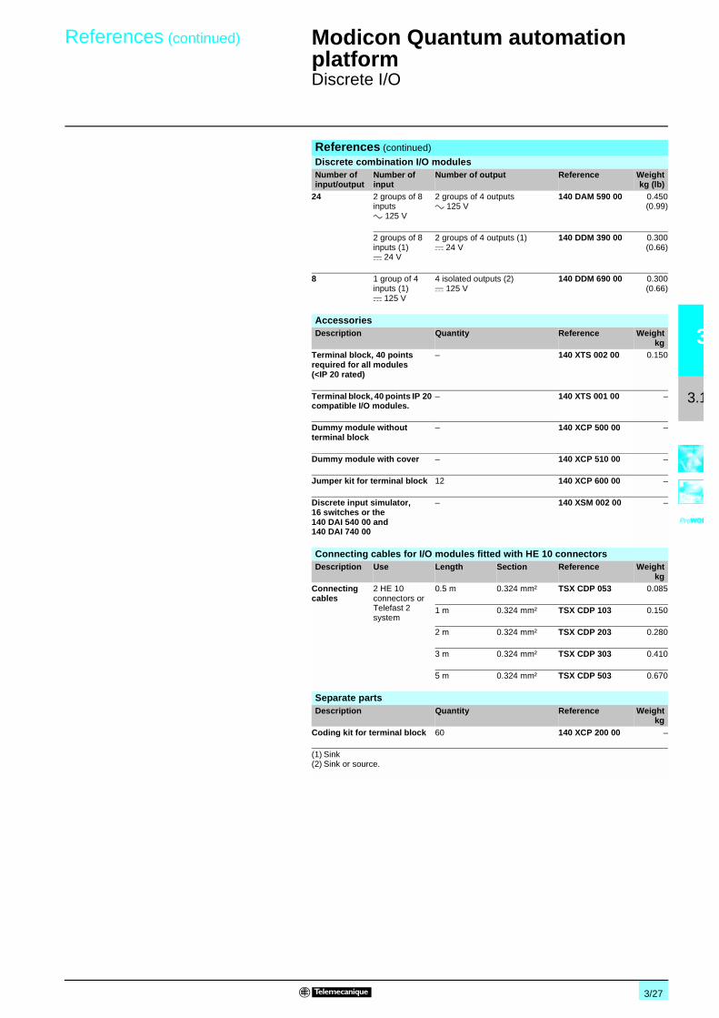
3/27
3
3.1
Modicon Quantum automationplatform 3
Discrete I/O
References (continued)
Discrete combination I/O modulesNumber ofinput/output
Number ofinput
Number of output Reference Weightkg (lb)
24 2 groups of 8inputsa 125 V
2 groups of 4 outputsa 125 V
140 DAM 590 00 0.450(0.99)
2 groups of 8inputs (1)c 24 V
2 groups of 4 outputs (1)c 24 V
140 DDM 390 00 0.300(0.66)
8 1 group of 4inputs (1)c 125 V
4 isolated outputs (2)c 125 V
140 DDM 690 00 0.300(0.66)
AccessoriesDescription Quantity Reference Weight
kgTerminal block, 40 pointsrequired for all modules(<IP 20 rated)
– 140 XTS 002 00 0.150
Terminal block, 40 points IP 20compatible I/O modules.
– 140 XTS 001 00 –
Dummy module withoutterminal block
– 140 XCP 500 00 –
Dummy module with cover – 140 XCP 510 00 –
Jumper kit for terminal block 12 140 XCP 600 00 –
Discrete input simulator,16 switches or the140 DAI 540 00 and140 DAI 740 00
– 140 XSM 002 00 –
Connecting cables for I/O modules fitted with HE 10 connectorsDescription Use Length Section Reference Weight
kgConnectingcables
2 HE 10connectors orTelefast 2system
0.5 m 0.324 mm² TSX CDP 053 0.085
1 m 0.324 mm² TSX CDP 103 0.150
2 m 0.324 mm² TSX CDP 203 0.280
3 m 0.324 mm² TSX CDP 303 0.410
5 m 0.324 mm² TSX CDP 503 0.670
Separate partsDescription Quantity Reference Weight
kgCoding kit for terminal block 60 140 XCP 200 00 –
(1) Sink(2) Sink or source.
References (continued)

3/28
3
3.1
Input modules140 DAI 340 00/140 DAI 440 00/140 DAI 740 00 140 DAI 353 00/140 DAI 453 00
2
1
4
3
6
5
8
7
10
9
12
11
14
13
16
15
18
17
20
19
22
21
24
23
26
25
28
27
30
29
32
31
34
33
36
35
38
37
40
39
L (13)
N (13)
L (14)
N (14)
L (15)
N (15)
L (16)
N (16)
group 1
input 13
common 13
input 14
common 14
common 16
input 15
common 15
input 16
group 2
group 3
group 4
group 5
group 6
group 7
group 8
group 9
group 10
group 11
group 12
group 13
group 14
group 15
group 16
input 9
common 9
input 10
common 10
common 12
input 11
common 11
input 12
input 5
common 5
input 6
common 6
common 8
input 7
common 7
input 8
L (1)
N (1)
L (2)
N (2)
L (3)
N (3)
L (4)
N (4)
input 1
common 1
input 2
common 2
common 4
input 3
common 3
input 4
2
1
4
3
6
5
8
7
10
9
12
11
14
13
16
15
18
17
20
19
22
21
24
23
26
25
28
27
30
29
32
31
34
33
36
35
38
37
40
39
L (4)
N (4)
group 1
input 25
input 26
input 27
input 28
input 32
input 29
input 30
input 31
group 2
group 3
group 4
common
input 17
input 18
input 19
input 20
input 24
input 21
input 22
input 23
common
input 9
input 10
input 11
input 12
input 16
input 13
input 14
input 15
common
L (1)
N (1)
input 1
input 2
input 3
input 4
input 8
input 5
input 6
input 7
common
Wiring Modicon Quantum automation platform 3
Discrete I/OInput module wiring diagrams

3/29
3
3.1
Input modules140 DAI 540 00 140 DAI 543 00
2
1
4
3
6
5
8
7
10
9
12
11
14
13
16
15
18
17
20
19
22
21
24
23
26
25
28
27
30
29
32
31
34
33
36
35
38
37
40
39
L (13)
N (13)
L (14)
N (14)
L (15)
N (15)
L (16)
N (16)
group 1
input 13
common 13
input 14
common 14
common 16
input 15
common 15
input 16
group 2
group 3
group 4
group 5
group 6
group 7
group 8
group 9
group 10
group 11
group 12
group 13
group 14
group 15
group 16
input 9
common 9
input 10
common 10
common 12
input 11
common 11
input 12
input 5
common 5
input 6
common 6
common 8
input 7
common 7
input 8
L (1)
N (1)
L (2)
N (2)
L (3)
N (3)
L (4)
N (4)
input 1
common 1
input 2
common 2
common 4
input 3
common 3
input 4
2 1
4 3
6 5
8 7
10 9
12 11
14 13
16 15
18 17
20 19
22 21
24 23
26 25
28 27
30 29
32 31
34 33
36 35
38 37
40 39
input 16
input 9
input 10
input 11
input 12
input 15
N/C
input 13
input 14
group B common
L Ninput 1
input 2
input 3
input 4
input 7
N/C
input 5
input 6
group A common
input 8
N/C
N/C
N/C
N/C
N/C
N/C
N/C
N/C
N/C
N/C
N/C
N/C
N/C
N/C
N/C
N/C
N/C
N/C
N/C
N/C
Wiring (continued) Modicon Quantum automation platform 3
Discrete I/OInput module wiring diagrams

3/30
3
3.1
Modicon Quantum automation platform 3
Discrete I/OInput module wiring diagrams
Input modules140 DAI 553 00/140 DAI 753 00 140 DDI 153 10
2
1
4
3
6
5
8
7
10
9
12
11
14
13
16
15
18
17
20
19
22
21
24
23
26
25
28
27
30
29
32
31
34
33
36
35
38
37
40
39
L (4)
N (4)
group 1
input 25
input 26
input 27
input 28
input 32
input 29
input 30
input 31
group 2
group 3
group 4
common
input 17
input 18
input 19
input 20
input 24
input 21
input 22
input 23
common
input 9
input 10
input 11
input 12
input 16
input 13
input 14
input 15
common
L (1)
N (1)
input 1
input 2
input 3
input 4
input 8
input 5
input 6
input 7
common
2 1
4 3
6 5
8 7
10 9
12 11
14 13
16 15
18 17
20 19
22 21
24 23
26 25
28 27
30 29
32 31
34 33
36 35
38 37
40 39
+ –
N/C
input 25input 26
input 27input 28
input 32
input 29input 30
input 31
N/C
N/C
N/Cgroup D supply
input 17input 18
input 19input 20
input 24
input 21input 22
input 23
group C supply
input 9input 10
input 11input 12
input 16
input 13input 14
input 15
group B supply
input 1input 2
input 3input 4
input 8
input 5input 6
input 7
group A supply
5 Vdc
Open collector
TTL
Wiring (continued)

3/31
3
3.1
Input modules140 DDI 353 00 140 DDI 353 10
2
1
4
3
6
5
8
7
10
9
12
11
14
13
16
15
18
17
20
19
22
21
24
23
26
25
28
27
30
29
32
31
34
33
36
35
38
37
40
39
UB (4)
M (4)
group 1
input 25
input 26
input 27
input 28
input 32
input 29
input 30
input 31
group 2
group 3
group 4
M 4
input 17
input 18
input 19
input 20
input 24
input 21
input 22
input 23
M 3
input 9
input 10
input 11
input 12
input 16
input 13
input 14
input 15
M 2
UB (1)
M (1)
input 1
input 2
input 3
input 4
input 8
input 5
input 6
input 7
M 1
2 1
4 3
6 5
8 7
10 9
12 11
14 13
16 15
18 17
20 19
22 21
24 23
26 25
28 27
30 29
32 31
34 33
36 35
38 37
40 39
+–
N/C
input 25input 26
input 27input 28
input 32
input 29input 30
input 31
N/C
N/C
N/Cgroup D supply
input 17input 18
input 19input 20
input 24
input 21input 22
input 23
group C supply
input 9input 10
input 11input 12
input 16
input 13input 14
input 15
group B supply
input 1input 2
input 3input 4
input 8
input 5input 6
input 7
group A supply
Wiring (continued) Modicon Quantum automation platform 3
Discrete I/OInput module wiring diagrams

3/32
3
3.1
Modicon Quantum automation platform 3
Discrete I/OInput module wiring diagrams
Input modules140 DDI 364 00 140 DDI 673
Note : connection requires Telefast terminal block.
A
4
6
10
12
8
0
2
1415
5
7
11
13
9
1
3
+–
2
43
6
8
12
14
10
5
7
11
13
9
2019
1615
17 18
1
2 1
4 3
6 5
8 7
10 9
12 11
14 13
16 15
18 17
20 19
22 21
24 23
26 25
28 27
30 29
32 31
34 33
36 35
38 37
40 39
+ –
group C common
N/C
N/C
N/C
group B common
input 17
input 19
input 21
input 23
input 9
input 11
input 13
input 15
input 1
input 3
input 5
input 7
group A common
N/C
N/C
N/C
input 18
input 20
input 24
input 22
input 10
input 12
input 16
input 14
input 2
input 4
input 8
input 6
N/C
N/C
N/C
N/C
N/C
N/C
N/C
Wiring (continued)

3/33
3
3.1
Modicon Quantum automation platform 3
Discrete I/OInput module wiring diagrams
Input modules140 DDI 841 00 140 DDI 853 00
2
1
4
3
6
5
8
7
10
9
12
11
14
13
16
15
18
17
20
19
22
21
24
23
26
25
28
27
30
29
32
31
34
33
36
35
38
37
40
39
group 1
group 2
M (1)
UB (1)
input 1
input 2
M 1
common 1
common 2
input 3
input 4
M 2
input 5
input 6
M 3
common 3
common 4
input 7
input 8
M 4
input 9
input 10
M 5
common 5
common 6
input 11
input 12
M 6
input 13
input 14
M 7
common 7
common 8
input 15
input 16
M 8
group 3
group 4
group 5
group 6
group 7
group 8
M (2)
UB (2)
M (7)
UB (7)
M (8)
UB (8)
2 1
4 3
6 5
8 7
10 9
12 11
14 13
16 15
18 17
20 19
22 21
24 23
26 25
28 27
30 29
32 31
34 33
36 35
38 37
40 39
+ –input 1
input 3
input 5
input 7
group A common
input 9
input 11
input 13
input 15
group B common
input 19
input 17
input 21
input 23
group C common
input 25
input 27
input 29
input 31
group D common
input 2
input 4
input 6
input 8
group A supply
input 10
input 12
input 14
input 16
group B supply
input 18
input 20
input 22
input 24
group C supply
input 26
input 28
input 30
input 32
group D supply
Wiring (continued)

3/34
3
3.1
Modicon Quantum automation platform 3
Discrete I/OInput module wiring diagrams
Input module140 DSI 353 00
(1) Recommended resistor value for c 24 V.
2
1
4
3
6
5
8
7
10
9
12
11
14
13
16
15
18
17
20
19
22
21
24
23
26
25
28
27
30
29
32
31
34
33
36
35
38
37
40
39
+-
input 2
input 4
input 6
input 8
group A
ext. supply
input 10
input 12
input 14
input 16
group B
ext. supply
input 18
input 20
input 22
input 24
group C
ext. supply
input 26
input 28
input 30
input 32
group D
ext. supply
- input 1
- input 3
- input 5
- input 7
group A common
- input 9
- input 11
- input 13
- input 15
group B common
- input 19
- input 17
- input 21
- input 23
group C common
- input 25
- input 27
- input 29
- input 31
group D common
56 kΩ (1)
Wiring (continued)

3/35
3
3.1
Modicon Quantum automation platform 3
Discrete I/OOutput module wiring diagrams
Output modules140 DAO 840 00/140 DAO 840 10 140 DAO 842 10/140 DAO 842 20
2
1
4
3
6
5
8
7
10
9
12
11
14
13
16
15
18
17
20
19
22
21
24
23
26
25
28
27
30
29
32
31
34
33
36
35
38
37
40
39
1
2
3
4
13
14
15
16
N (13)
L (13)
N (14)
L (14)
N (15)
L (15)
N (16)
L (16)
group 1
output 13
L 13
output 14
L 14
L 16
output 15
L 15
output 16
group 2
group 3
group 4
group 5
group 6
group 7
group 8
group 9
group 10
group 11
group 12
group 13
group 14
group 15
group 16
output 9
L 9
output 10
L 10
L 12
output 11
L 11
output 12
output 5
L 5
output 6
L 6
L 8
output 7
L 7
output 8
N (1)
L (1)
N (2)
L (2)
N (3)
L (3)
N (4)
L (4)
output 1
L 1
output 2
L 2
L 4
output 3
L 3
output 4
2
1
4
3
6
5
8
7
10
9
12
11
14
13
16
15
18
17
20
19
22
21
24
23
26
25
28
27
30
29
32
31
34
33
36
35
38
37
40
39
1
2
3
4
13
14
15
16
L (4)
N (4)
group 1
group 2
group 3
group 4
common
common
L (1)
N (1)
output 1
output 2
output 3
output 4
common
L
output 5
output 6
output 7
output 8
L
L
output 9
output 10
output 11
output 12
common
L
output 13
output 14
output 15
output 16
Wiring (continued)

3/36
3
3.1
Output modules140 DAO 853 00 140 DDO 353 00/140 DDO 153 10/140 DDO 353 10
2 1
4 3
6 5
8 7
10 9
12 11
14 13
16 15
18 17
20 19
22 21
24 23
26 25
28 27
30 29
32 31
34 33
36 35
38 37
40 39
L
group C common
group B common
output 2
output 4
output 6
output 8
group A common
output 10
output 12
output 14
output 16
output 18
output 20
output 22
output 24
group D common
output 26
output 28
output 30
output 32
output 1
output 3
output 5
output 7
output 9
output 11
output 13
output 15
output 17
output 19
output 21
output 23
output 25
output 27
output 29
output 31
N/C
N/C
N/C
N/C
Optional fuse
N
2
1
4
3
6
5
8
7
10
9
12
11
14
13
16
15
18
17
20
19
22
21
24
23
26
25
28
27
30
29
32
31
34
33
36
35
38
37
40
39
1
2
3
7
5
4
6
8
9
10
11
15
13
12
14
16
17
18
19
23
21
20
22
24
25
26
27
32
29
28
30
32
group 1
output 25
output 26
output 27
output 28
output 32
output 29
output 30
output 31
group 2
group 3
group 4
M 4
output 17
output 18
output 19
output 20
output 24
output 21
output 22
output 23
M 3
output 9
output 10
output 11
output 12
output 16
output 13
output 14
output 15
M 2
US (1)
M (1)
output 1
output 2
output 3
output 4
output 8
output 5
output 6
output 7
M 1
US
US (2)
M (2)
US
US (3)
M (3)
US
US (4)
M (4)
US
Modicon Quantum automation platform 3
Discrete I/OOutput module wiring diagrams
Wiring (continued)

3/37
3
3.1
Modicon Quantum automation platform 3
Discrete I/OOutput module wiring diagrams
Output modules140 DDO 353 01 140 DDO 364 00
Note : connection requires Telefast terminal block.
2
1
4
3
6
5
8
7
10
9
12
11
14
13
16
15
18
17
20
19
22
21
24
23
26
25
28
27
30
29
32
31
34
33
36
35
38
37
40
39
1
2
3
7
5
4
6
8
9
10
11
15
13
12
14
16
17
18
19
23
21
20
22
24
25
26
27
32
29
28
30
32
group 1
output 25
output 26
output 27
output 28
output 32
output 29
output 30
output 31
group 2
group 3
group 4
M 4
output 17
output 18
output 19
output 20
output 24
output 21
output 22
output 23
M 3
output 9
output 10
output 11
output 12
output 16
output 13
output 14
output 15
M 2
US (1)
M (1)
output 1
output 2
output 3
output 4
output 8
output 5
output 6
output 7
M 1
US
US (2)
M (2)
US
US (3)
M (3)
US
US (4)
M (4)
US
A
4
6
10
12
8
0
2
1415
5
7
11
13
9
1
3
–+
2
43
6
8
12
14
10
5
7
11
13
9
20
1615
17 18
1
19
Wiring (continued)

3/38
3
3.1
Modicon Quantum automation platform 3
Discrete I/OOutput module wiring diagrams
Output module140 DDO 885 00
2
1
4
3
6
5
8
7
10
9
12
11
14
13
16
15
18
17
20
19
22
21
24
23
26
25
28
27
30
29
32
31
34
33
36
35
38
37
40
39
+–
+ –
output 1
N/C
output 2
output 3
output 4
group A return
N/C
output 5
output 6
output 7
output 9
group B return
output 10
N/C
output 11
output 12
N/C
N/C
N/C
N/C
N/C
N/C
N/C
group A supply
N/C
N/C
N/C
N/C
N/C
Group A
Group B
N/C
N/C
N/C
N/C
N/C
group B supply
N/C
N/C
N/C
N/C
output 8
Wiring (continued)

3/39
3
3.1
Modicon Quantum automation platform 3
Discrete I/OOutput module wiring diagrams
Output modules140 DDO 843 00
2
1
4
3
6
5
8
7
10
9
12
11
14
13
16
15
18
17
20
19
22
21
24
23
26
25
28
27
30
29
32
31
34
33
36
35
38
37
40
39
1
2
4
3
5
6
8
7
9
10
12
11
13
14
16
15
output 1
output 2
output 3
output 4
US
output 5
output 6
output 7
output 8
output 9
output 10
output 11
output 12
output 13
output 14
output 15
output 16
M2M2
US (1)
M 1M (1)
US 2US (2)
group 1
group 2
Wiring (continued)

3/40
3
3.1
Relay output modules140 DRA 840 00 140 DRC 830 00
2
1
4
3
6
5
8
7
10
9
12
11
14
13
16
15
18
17
20
19
22
21
24
23
26
25
28
27
30
29
32
31
34
33
36
35
38
37
40
39
1
2
3
4
13
14
15
16
M1/N (1)
output 16
US/L (1)
M1/N (2)
US/L (2)
M1/N (3)
US/L (3)
M1/N (4)
US/L (4)
M1/N (13)
US/L (13)
M1/N (14)
US/L (14)
M1/N (15)
US/L (15)
M1/N (16)
US/L (16)
output 15
output 14
output 13
output 12
output 11
output 10
output 9
output 8
output 7
output 6
output 5
output 4
output 3
output 2
output 1NO 1
COM 1
NO 2
COM 2
COM 4
NO 3
COM 3
NO 4
NO 5
COM 5
NO 6
COM 6
COM 8
NO 7
COM 7
NO 8
NO 9
COM 9
NO 10
COM 10
COM 12
NO 11
COM 11
NO 12
NO 13
COM 13
NO 14
COM 14
COM 16
NO 15
COM 15
NO 16
2
1
4
3
6
5
8
7
10
9
12
11
14
13
16
15
18
17
20
19
22
21
24
23
26
25
28
27
30
29
32
31
34
33
36
35
38
37
40
39
1
1
2
2
7
7
8
8
M1/N (1)
M1/N (1)
US/L (1)
M1/N (2)
M1/N (2)
US/L (2)
M1/N (7)
M1/N (7)
US/L (7)
M1/N (8)
M1/N (8)
US/L (8)
output 8
output 7
output 6
output 5
output 4
output 3
output 2
output 1NO 1
NO 1
COM 1
COM 2
NO 2
NO 2
NO 3
NO 3
COM 3
COM 4
NO 4
NO 4
NO 5
NO 5
COM 5
COM 6
NO 6
NO 6
NO 7
NO 7
COM 7
COM 8
NO 8
NO 8
Modicon Quantum automation platform 3
Discrete I/ORelay output module wiring diagrams
Wiring (continued)

3/41
3
3.1
Modicon Quantum automation platform 3
Discrete I/ORelay output module wiring diagrams
Relay output modules140 DVO 853 00
Nota : When driving a load from different points, a blocking diode is required for each point. These diode (shown above) will present false fault reporting when only one of the points is commanded ON.
2
1
4
3
6
5
8
7
10
9
12
11
14
13
16
15
18
17
20
19
22
21
24
23
26
25
28
27
30
29
32
31
34
33
36
35
38
37
40
39
+–
output 2
group A supply
output 4
output 6
output 8
output 1
output 3
output 5
output 7
group A common
output 10
output 9
output 12
output 11
output 14
output 13
output 16
output 15
output 18
output 17
output 20
output 19
output 22
output 21
output 24
output 23
output 26
output 25
output 28
output 27
output 30
output 29
output 32
output 31
output 1
output 3
0.75 A
0.75 A
group B supply
group B common
group C supply
group C common
group D supply
group D common
Wiring (continued)

3/42
3
3.1
Combo modules140 DAM 590 00 140 DDM 390 00
2
1
4
3
6
5
8
7
10
9
12
11
14
13
16
15
18
17
20
19
22
21
24
23
26
25
28
27
30
29
32
31
34
33
36
35
38
37
40
39
1
2
4
3
5
6
8
7
group 1
input 9
input 10
input 11
input 12
input 16
input 13
input 14
input 15
group 2
group 3
group 4
common
input 1
input 2
input 3
input 4
input 8
input 5
input 6
input 7
common
output 5
output 6
output 7
output 8
common
L (1)
N (1)
output 1
output 2
output 3
output 4
common
L
L (2)
N (2)
L
L (3)
N (3)
L (4)
N (4)
2
1
4
3
6
5
8
7
10
9
12
11
14
13
16
15
18
17
20
19
22
21
24
23
26
25
28
27
30
29
32
31
34
33
36
35
38
37
40
39
1
2
3
4
5
6
7
8
group 1
input 9
input 10
input 11
input 12
input 16
input 13
input 14
input 15
group 2
group 3
group 4
input 1
input 2
input 3
input 4
input 8
input 5
input 6
input 7
output 5
output 6
output 7
output 8
US (1)
M1 (1)
output 1
output 2
output 3
output 4
US (2)
M1 (2)
UB (3)
M (3)
UB (4)
M (4)
Wiring (continued) Modicon Quantum automation platform 3
Discrete I/OCombo module wiring diagrams

3/43
3
3.1
Combo module140 DDM 690 00
Caution:The output points are not protected against reverse polarity. Reverse polarity will turn an output point ON.
Nota : Each output has terminals for multiple wire connections. N/C = Not Connected.
2
1
4
3
6
5
8
7
10
9
12
11
14
13
16
15
18
17
20
19
22
21
24
23
26
25
28
27
30
29
32
31
34
33
36
35
38
37
40
39
+-
-+
- +
output sourcing
output sinking
output 1 (+)
output 1 (+)
output 1 (-)
output 1 (-)
N/C
N/C
N/C
N/C
N/C
N/C
output 2 (+)
output 2 (+)
output 2 (-)
output 2 (-)
output 3 (+)
output 3 (-)
output 3 (+)
output 3 (-)
N/C
N/C
N/C
N/C
N/C
N/C
output 4 (+)
output 4 (+)
output 4 (-)
output 4 (-)
N/C
N/C
c 125 input 2
c 125 input 1
c 125 input 3
c 125 input 4
N/C
N/C
N/C
N/C
N/C
input group B common
Wiring (continued) Modicon Quantum automation platform 3
Discrete I/OCombo module wiring diagrams

3/44
3
3.2
Selection guide Modicon Quantum automation platform 3
Analog I/O
Type Input modules
Number of channels 8 16 differentiel or 16 externally tied single
8
Operating range 4…20 mA1…5 V
0…25 mA0…20 mA4…20 mA
0…25 mA, ±20 mA 4…20 mA0…10 V, ± 10 V0…5 V, ± 5 V1…5 V
RTD (2-,3-, or 4-wire), Pt, Ni
Interfaces 1
Resolution 12 bits 0…25 000 counts 0…20 000 counts 0…16 000 counts (default)
Up to 16 bits 12 bits + sign
Isolation (channel-to-channel) 30 V 200 V 300 V peak-to-peak
Addressing requirement 9 input words 17 input words 9 input words
Bus power required 240 mA 360 mA 280 mA 200 mA
Module 140 ACI 030 00 140 ACI 040 00 140 AVI 030 00 140 ARI 030 10
Page 3/55

3/45
3
3.2
3
Input modules Output modules Combined I/O
8 4 8 4 4 in/2 out
Thermocouples type B, E, J, K, R, S, T, mV
4…20 mA 0…25 mA0…20 mA4…20 mA
0…10 V, ± 10 V0…5 V, ± 5 V
Multi-range in/current out
1 4 in/1 out
16 bits 12 bits 0…25 000 counts 0…20 000 counts 0…16 000 counts (default) 0…4095 counts
12 bits 16 in/12 out
a 220 V @ 47…63 Hz or c 300 V max.
a 500 V@ 47…63 Hz or c 750 V for 1 minute
– a 500 V for 1 minute Input : a ± 40 V max. Output : a 500 V c 750 V for 1 minute
10 input words 4 output words 8 output words 4 output words 5 input words 2 output words
280 mA 480 mA 550 mA 700 mA 350 mA
140 ATI 030 00 140 ACO 020 00 140 ACO 130 00 140 AVO 020 00 140 AMM 090 00
3/55

3/46
3
3.2
Modicon Quantum automationplatform 3
Analog I/O
The Modicon Quantum automation platform supports a full range of analog I/Omodules designed to interface with a wide variety of field devices. All modules meetinternationally accepted IEC electrical standards that ensure reliability in harshoperating environments. For even better protection and extended life in extremelyharsh environments, you can have your modules conformally coated.
All Quantum I/O modules can be completely configured using Unity Pro, Concept orProWORX. The ability to specify an I/O address for each module in software makesit easy to add or change modules in your configuration without physically changingthe application program.
Analog and special-purpose modules frequently require that you specify particularmodal or operational parameters for different functions in addition to the standard I/Oaddressing requirements. Quantum's ability to configure multi-function modules viasoftware eliminates the need for traditional hardware DIP switches or complexapplication programming. A software capability called I/O Map zooming allows youto zoom into a setup screen where you can initialize or change the module'soperating parameters. This I/O Map zoom technique is used on multi-function analoginput modules, high-speed counters, single-axis motion modules andtemperature-sensing modules such as thermocouples and RTDs.
Quantum gives you the ability to predefine how an analog output channel willrespond if for any reason the module stops being serviced. You can configure themodule in software so that the output channels:
b Go to zero.b Go to a predefined safe state.b Hold the last value they received before the watchdog timer expired.
Failure modes can be defined on a channel-by-channel basis. In the event of acomplete module failure, the fail state settings you have specified can be sent to thereplacement module.
Optionally, you can insert mechanical keys between the I/O module and the terminalstrip to ensure that the field wiring and the module type are properly matched. Keyingcodes are unique for each module type. You can also implement mechanical keyingfor unique slot locations so that a rack full of similar modules with similar keyingcodes will not be incorrectly connected. Keys are shipped with the I/O modules. Theydo not need to be ordered separately.
Each I/O module requires an I/O connector (P/N 140 XTS 002 00), which can beordered separately. The same connector can be used with all modules, except forintrinsically safe modules.
Description
Fully software-configurable
I/O Map zooming
Defining the failure mode of an output module
Mechanical keying for added security
I/O connectors
Presentation

3/47
3
3.2
Modicon Quantum automationplatform 3
Analog I/O
The front panel of 140 ApI/ApO/AMM analog input or output modules comprises:
1 A model number and color code.
2 A LED indicator panel.v Active (green): bus communication is present been detected,v F (red): a fault (external to the module) has been detected,v 1…16 (green): the indicated point or channel is turned on,v 1…16 (red): there is a fault on the indicated point or channel.
3 A removable, hinged door and customer identification label.
4 A terminal block,40-pole (140 XTS 002 00) must be ordered separately.
Description
Description
1
2
3
4

3/48
3
3.2
Modicon Quantum automationplatform 3
Analog I/O
Input module characteristicsModel 140 ACI 030 00 140 AVI 030 00
Number of channels 8 differential
Addressing requirements 9 input words
Input ranges(selectable on a perchannel basis)
Bipolar – c ± 10 V c ± 5 V ± 20 mA
Unipolar – c 0...10 V c 0...5 V 0...20 mA
Unipolar w/offset – c 1... 5 V 4...20 mA
Voltage input Linear measuring range c 1...5 V (input range) x 1.024
Absolute maximum c V 50
Impedance MΩ > 20
Current input Linear measuring range mA 4...20 (input range) x 1.024
Absolute maximum mA 25
Impedance Ω 250 ± 0.03%
Absolute accuracyerror @ 25° C(voltage mode)
Typical ± 0.05% of full scale ± 0.03%
Maximum ± 0.1% of full scale ± 0.05% of full scale
Linearity ± 0.04% ± 0.008%
Accuracy driftw/temperature
Typical ± 0.0025% of full scale / °C ± 0.0015% of full scale / °C
Maximum ± 0.005% of full scale / °C ± 0.004% of full scale / °C
Common mode rejection dB > - 72 @ 60 Hz > - 80 @ 60 Hz
Input filter Single pole low pass, - 3 dB cutoff@ 15 Hz, ± 20%
Single pole low pass, - 3 dB cutoff @ 847 Hz,± 20%
Isolation Channel-to-bus z c 1000 V, 3000 Vpp, for 1 minute c 750 V, a 500 V rms, for 1 minute
Channel-to-channel z c 30 V max. c 200 V, a 135 V rms max.
Update time ms 5 for a all channels 10 for a all channels
Fault detection Broken wire (4...20 mA mode) orunder voltage range (1...5 V)
Broken wire in 4...20 mA modeOut of range @ 1…5 V
Bus current requirement mA 240 280
Power dissipation W 2 2.2
External power –
Resolution bits 12 16 for ± c 10 V, c 0…10 V.15 for ± c 5 V, c 0…5 V, ± 20 mA, 0…20 mA.14 for c 1…5 V, 4…20 mA
Agency approvals UL 508, CSA 22.2-142,FM Class1 Div.2, e, cUL (pending)
UL 508, CSA 22.2-142, FM Class1 Div.2, e,cUL
Characteristics

3/49
3
3.2
Modicon Quantum automationplatform 3
Analog I/O
Input module characteristicsModel 140 ARI 030 10 140 ACI 040 00
Number of channels 8 16 differential or 16 externally tied singleended
Addressing requirements 9 input words 17 input words
RTD types (configurable)°C - 200... + 850 –IEC platinum
Americanplatinum Nickel
Pt 100, Pt 200, Pt 500, Pt 1000
Pt 100, Pt 200, Pt 500, Pt 1000 °C - 100... + 450 –
Ni 100, Ni 200, Ni 500, Ni 1000 °C - 60... + 180 –
Measurementcurrent
Pt 100, Pt 200, Ni 100, Ni 200 mA 2.5 –
Pt 500, Pt 1000, Ni 500, Ni 1000 mA 0.5 –
Input impedance MΩ >10 250 Nominal
Module ranges and resolution 0.1 °C 0.0…25 mA, 0…25,000 counts0.0…20 mA, 0…20,000 counts4.0…20 mA, 0…16,000 counts (defaultrange)4.0…20 mA, 0…4,095 counts
Accuracy error @ 25 °C – ± 0.125% of full scale
Linearity (0 ... 60 °C) ± 0.01% of full scale± 0.5 °C
± 12 µA max. 4…20 mA range, 0…4,095counts± 6 µA max. 0…25 mA range, 0…25,000counts± 6 µA max. 0…20 mA range, 0…20,000counts± 6 µA max. 4…20 mA range, 0…16,000counts
Absolute maximum input mA – 30
Absolute drift w/temperature °C ± 0.5 (25 °C)± 0.9 (0…60 °C)
Typical: 0.0025% of full scaleMaximum: 0.0050% of full scale
Isolation Channel-to-channel 300 V peak-to-peak –
Channel-to-bus a 1780 V @ 47…63 Hz for 1 minute orc 2500 V for 1 minute
a 1780 V for 1 minute
Working voltage c – 30
Input filter – Single pole low pass, - 3 dB cutoff @ 34 Hz,± 25%
Common mode rejection – > - 90 dB @ 60 Hz
Update time(all channels)
2-wire/4-wire ms 640 15 for all 16 channels
3-wire s 1.2 –
Fault detection Out of range or 8 red LEDs to indicate brokenwire conditions
Open circuit in 4 ... 20 mA mode. Specificchannel is identified when an open circuit isdetected and is reported back to the controllerin the 17th input Word.
Bus current requirement mA 200 360
Power dissipation W 1 5.0
Agency approvals UL 508, CSA 22.2-142, FM Class1 Div.2, e,cUL
UL 508, CSA 22.2-142, FM Class1 Div.2, e,cUL (pending)
Characteristics (continued)

3/50
3
3.2
Modicon Quantum automationplatform 3
Analog I/O
(1) Open circuit detect can be disabled on these ranges.
Input module characteristicsModel 140 ATI 030 00
Number of channels 8
Addressing requirements 10 input words
TC types and ranges J °C - 210 ... +760
K °C - 270 ... +1370
E °C - 270 ... +1000
T °C - 270 ... + 400
S °C - 50 ... +1665
R °C - 50 ... +1665
B °C - 130 ... +1820
Millivolt ranges mV - 100 ... +100 (1)- 25... + 25 (1)
TC resistance /Max Source Resistance W 200 max. for rated accuracy
Input impedance MΩ > 1
Input filter Single low pass @ nominal 20 Hz, plus notch filter @ 50/60 Hz
Normal noise rejection dB 120 min. @ 50 or 60 Hz
Cold junction compensation (CJC) Internal CJC operates between 0 ... 60 °C (errors are included in the accuracyspecification).The connector door must be closed.
Remote CJC can be implemented by connecting a thermocouple (which monitorsthe external junction block temperature) to channel 1. Types of thermocouples J, K,and T are recommended for remote CJC.
Resolution TC ranges Choice of : 1 °C (default), 0.1 °C, 1 °F, 0.1 °F
Millivolt ranges 100 mV range, 3.05 µV (16 bits)25 mV range, 0.76 µV (16 bits)
TC absolute accuracy Types J, K, E, T ± 2 °C plus + 0.1% of reading
Types S, R, B ± 4 °C plus + 0.1% of reading
Millivolt absoluteaccuracy
@ 25 °C ± 20 µV + 0.1 % of reading
Accuracy drift w/temperature 0.15 µV / °C + 0.0015% of reading / °C max
Isolation Channel-to-bus a 1780 V @ 47... 63 Hz for 1 minute or c 2500 V for 1 minute
Channel-to-channel a 220 V @ 47... 63 Hz or c 300 V max.
Update time (all channels) s 1
Fault detection 8 red LEDs to indicate out of range or broken wire conditions
Bus current requirement mA 280
Power dissipation W 1.5
External power –
Agency approvals UL 508, CSA 22.2-142, FM Class1 Div.2, e, cUL
Characteristics (continued)

3/51
3
3.2
Modicon Quantum automationplatform 3
Analog I/O
(1) For a loop voltage supply < 30 V: RMIN = 0 Ω.(2) Up to 60 V with an external loop resistor.
Output module characteristics (continued)Model 140 ACO 020 00 140 AVO 020 00
Number of channels 4
Addressing requirements 4 out words
Loop voltage c 12...30 V –
Loop resistance RMIN
(1) =VLoop - 30 Vdc0.02A
RMax
=VLoop - 7 Vdc0.02A
No external resistor isrequired for loop voltagesupply < c 30 V (2)
* For a loopsupply lessthan 30 volts,R
MINis zero
ohms.
–
Internal voltage drop c 7 V min., 30 V max. @ 20 mA –
Voltage outputranges
Bipolar c – ± 10 V (mi.n load resistance = 1 kΩ)(Jumper between reference - controlterminals)± 5 V (min. load resistance = 500 Ω)(Jumper between reference - control andoutput - R terminals)
Unipolar c – 0...10 V (min. load resistance = 1 kΩ)(Jumper between output - R terminals)0...5 V (min. load resistance = 500 Ω) (Jumper between output - R and control- R terminals)
Output current – + 10 mA max any range (outputs are shortcircuit-proof)
Source resistance – 0.1 Ω
Resolution 12 bits
Accuracy error @ 25 °C ± 0.20% of full scale ± 0.15% of full scale
Linearity ±1 LSB
Accuracy driftw/temperature
Typical ± 0.004% of full scale / °C –
Maximum ± 0.007% of full scale / °C –
Unipolar ranges – 0.003% of full scale / °C typical0.005% of full scale / °C max.
Bipolar ranges – 0.004% of full scale / °C typical0.007% of full scale / °C max.
Isolation Channel-to-channel a 500 V @ 47...63 Hz or c 750 V for1 minute
a 500 V @ 47...63 Hz for 1 minute
Channel-to-bus a 1780 V @ 47...63 Hz or c 2500 V for1 minute
a 1780 V @ 47...63 Hz for 1 minute
Update time ms 3 for all channels (simultaneous update) 3 for all channels
Setting time µs 900 to ± 0.1% of the final value 700 to ± 0.1% of the final value (max.)
Fault detection Open circuit in 4...20 mA mode. Specificchannel is identified when an open circuitis detected through the red channel LED
–
Wire length m – 400 max.
Characteristics (continued)

3/52
3
3.2
Modicon Quantum automationplatform 3
Analog I/O
(1) An internal fuse is required on the master override signal when it is connected to an externalsource.
Output module characteristicsModel 140 ACO 020 00 140 AVO 020 00 140 ACO 130 00
Number of channels See page 3/53 8
Addressing requirements Words See page 3/53 8 output
Module ranges and resolution See page 3/53 0…25 mA, 0…25,000counts0…20 mA, 0…20,000counts4…20 mA, 0…16,000counts (default range)4…20 mA, 0…4,095counts
Loop voltage c V See page 3/53 6 ... 30 max
Internal voltage drop c V See page 3/53 6 min, 30 max. @ 25 mA
Accuracy error @ 25 °C See page 3/53 ± 0.2% of full scale
Linearity See page 3/53 ± 4 µA 0…25 mA,0 ... 25,000 counts± 4 µA 4…20 mA,0…16,000 counts± 12 µA 4…20 mA,0…4,095 counts± 4 µA 0…20 mA,0…20,000 counts
Absolute drift w/temperature See page 3/53 Typical: 0.004% of fullscaleMaximum: 0.007% of fullscale
Isolation Channel-to-channel See page 3/53 None
Field-to-bus See page 3/53 a 1780 V for 1 minute
Update time ms See page 3/53 5 for all 8 channels
Settling time full scale step change ms See page 3/53 1.6 to 5% of the final value3.2 to 0.1%of the finalvalue
Fault detection See page 3/53 Open circuit in 4…20 mAmode. Specific channel isidentified by the redchannel LED.Also reported back to thecontroller in the I/O MAPstatus byte.
Bus current required mA 480 700 550
Power dissipation W 5.3 max. 4.5 max. 5.0
External power See loop voltage onprevious page
Not required for thismodule
See loop voltage above
Fusing Internal –
External – 0.063 A, 250 V (1)Fuse type : 3 AG fastacting
–
Voltage Monitor Range 1...5 V (main current loopmust be active)
–
Scaling VOUT
(Volts) = ILOOP
(mA) x0.25
–
Output impedance Ω 300 typical –
Wire length m 1 max –
Agency approvals UL 508, CSA 22.2-142, FM Class1 Div.2, e, cUL UL 508, CSA 22.2-142,FM Class1 Div.2, e,cUL (pending)
Characteristics (continued)

3/53
3
3.2
Modicon Quantum automationplatform 3
Analog I/O
Combo module characteristicsModel 140 AMM 090 00
Number of input channels 4 input/2 isolated output
Addressing requirements 5 input words/2 output words
Inputs operatingranges
Bipolar c ± 10 V ± 5 V, ± 20 mA –
Unipolar c 0...10 V 0...5 V, 0...20 mA –
Unipolar w/offset c – 1...5 V, 4...20 mA
Resolution bits 16 in/12 out16 for ± c 10 V, c 0…10 V.15 for ± c 5 V, c 0…5 V, ± 20 mA, 0…20 mA.14 for c 1…5 V, 4…20 mA
Voltage Linear measuring range 2.4% over and under range
Absolute maximum c V ± 50
Impedance in range MΩ > 10
Impedance over range Ω > 0.5
Current Iinear measuring range c + 2.4% over range, and - 9.6% under range
Absolute maximum mA ± 25
Impedance Ω 250
Absolute accuracyerror @ 25° C(voltage mode)
Typical ± 0.03 %
Maximum ± 0.05% of full scale
Linearity Monotonic ± 1 LSB
Offset 0...60 °C %/°C ± 0.0014 of full scale max.
Gain shift 0...60 °C ± 0.002 of full scale max.
Common mode rejection dB > 80 @ 50 or 60 Hz
Input filter dB - 3 @ 21 Hz (+ 20%), single-pole low-pass
Operating voltage Channel-to-channel c V ± 40 max.
Isolation Channel-to-bus a 500 V, c 750 V, for 1 minute
Input channel-to-output channel a 500 V, c 750 V, for 1 minute
Update time ms 320 for 4 channels
Fault detection Open circuit in 4...20 mA range, or over range, or under range in bipolar modes only.
Characteristics (continued)

3/54
3
3.2
Modicon Quantum automationplatform 3
Analog I/O
(1) No RMIN is required for loop voltage less than a 30 V.
Combo module characteristicsModel 140 AMM 090 00
Outputs Loop voltage c 7...30 V; up to 60 V with an external resistor
Loop resistance RMIN
* =VLoop - 30 Vdc (1)0.020 A
RMax
=VLoop - 7 Vdc0.020 A
Internal voltage drop c V 7 min, 30 max @ 20 mA
Resolution bits 12
Accuracy error ± 0.20% of full scale @ 25°C
Linearity Monotonic +1 LSB
Accuracy error0...60 °C
Typical %/°C ± 0.004 of full scale
Maximum %/°C ± 0.007 of full scale
Isolation Channel-to-channel a 500 V, c 750 V, for 1 minute
Channel-to-bus a 500 V, c 750 V, for 1 minute
Output channel-to-input channel a 500 V, c 750 V, for 1 minute
Update time ms 15 for 2 channels
Settling time µs 900 to ± 0.1% of the final value
Fault detection Open circuit indicator light and status byte
External power See loop voltage above
Voltmeter monitor Range 1…5 V (main current loop must be active)
Scaling Iout (mA) x 0.250 = Vout (V)
Output impedance Ω 300 typical
Max wire length m 1
Common words 5 in /2 out
Bus current required mA 350
Fusing Internal –
External User discretion
Agency approvals UL 508, CSA 22.2-142, FM Class1 Div.2, e, cUL
Characteristics (continued)

3/55
3
3.2
Modicon Quantum automationplatform 3
Analog I/O
Analog input modulesDescription Range Reference Weight
kg (lb)8 channels, 12-bit,single-pole
4 ... 20 mA or a 1 ... 5 V 140 ACI 030 00 0.300 (0.66)
16 channels, 0…25,000counts max.
0 ... 20 mA0 ... 25 mA4 ... 20 mA
140 ACI 040 00 0.300 (0.66)
8 channels, 13-bit, RTD Ni or Pt 100, 200, 500, 1000 140 ARI 030 10 0.300 (0.66)
8 channels,16-bit,thermocouple
Type J, K, E, T, S, R, Band mV
140 ATI 030 00 0.300 (0.66)
8 channels, 16-bit,two-pole
c ± 10 V, ± 5 V, 0...10 V,0...5 V, 1...5 V,or ± 20 mA, 0...20 mA,4...20 mA
140 AVI 030 00 0.300 (0.66)
Analog output modulesDescription Reference Weight
kg (lb)4 channels, 12-bit 4 ... 20 mA 140 ACO 020 00 0.300 (0.66)
8 channels, 0…25,000counts
0 ... 20 mA0 ... 25 mA4 ... 20 mA
140 ACO 130 00 0.300 (0.66)
4 channels, 12-bit c ± 5 V, ± 10 V0…5 V, or 0…10 V
140 AVO 020 00 0.300 (0.66)
Analog I/O moduleDescription Reference Weight
kg (lb)4 inputs,2 outputs
c ± 5 V, ±10 V,0…5 V, 0…10 V, 1...5 V,or ± 20 mA, 4 ... 20 mA,0...20 mA
140 AMM 090 00 0.900 (1.98)
AccessoriesDescription Sold in
lots ofUnitreference
Weightkg (lb)
Terminal block, 40 pointsrequired for all modules
– 140 XTS 002 00 0.150 (0.33)
Terminal block, 40 points (IP 20) for I/Oanalog modules
140 XTS 001 00 –
Coding kit for terminal block 60 140 XCP 200 00 –
Analog I/O simulator,one 0…5 V meter and two 10-turnpotentiometers for140 ApI 030 00 input modules,140 ApO 020 00 output modules,140 AMM 090 00 I/O modules
– 140 XSM 010 00 –
References

3/56
3
3.2
Modicon Quantum automationplatform 3
Analog I/O
Wiring diagrams140 ACI 030 00 140 ACO 020 00
2
1
4
3
6
5
8
7
10
9
12
11
14
13
16
15
18
17
20
19
22
21
24
23
26
25
28
27
30
29
32
31
34
33
36
35
38
37
40
39
-+U
I-+
-+U
I-+
input 1
input 2
input 3
input 5
input 6
input 7
input 8
input 8+
input 8-
sense 8
input 7+
input 7-
sense 7
input 6+
input 6-
sense 6
input 5+
input 5-
sense 5
input 4+
input 4-
sense 4
input 3+
input 3-
sense 3
input 2+
input 2-
sense 2
input 1+
input 1-
sense 1
input 4
2
1
4
3
6
5
8
7
10
9
12
11
14
13
16
15
18
17
20
19
22
21
24
23
26
25
28
27
30
29
32
31
34
33
36
35
38
37
40
39
-+U
-+
+
-
-+U
-+
+
-
Connections
output 1
monitor 1
source 1-
source 1-
output 2
output 3
output 4
sink 1+
source 1-
source 2-
monitor 2
sink 2+
source 2-
source 3-
monitor 3
source 2-
source 3-
sink 3+
source 3-
source 4-
monitor 4
source 4-
sink 4+
source 4-
load 1
max.
60 V
U = 1…5 V
load 4
max.
60 V
U = 1…5 V

3/57
3
3.2
2
1
4
3
6
5
8
7
10
9
12
11
14
13
16
15
18
17
20
19
22
21
24
23
26
25
28
27
30
29
32
31
34
33
36
35
38
37
40
39
-+U
I-+
-+U
I-+
2
1
4
3
6
5
8
7
10
9
12
11
14
13
16
15
18
17
20
19
22
21
24
23
26
25
28
27
30
29
32
31
34
33
36
35
38
37
40
39
-+
+
-
-+
-+
+
-
-+
Modicon Quantum automationplatform 3
Analog I/O
Wiring diagrams140 AVI 030 00 140 AVO 020 00
Connections (continued)
input 1
input 2
input 3
input 4
input 5
input 6
input 7
input 8
input 8+
input 8-
sense 8
input 7+
input 7-
sense 7
input 6+
input 6-
sense 6
input 5+
input 5-
sense 5
Input 4+
Input 4-
sense 4
input 3+
input 3-
sense 3
input 2+
input 2-
sense 2
input 1+
input 1-
sense 1
output 1
output 1
common 1
R 1
output 2
output 3
output 4
reference 1
max.
10 V
common 1
control 1
master 1
common 1
output 2
common 2
R 2
reference 2
common 2
control 2
master 2
common 2
Ret 2
output 3
common 3
R 3
reference 3
common 3
control 3
master 3
common 3
max.
10 V
Output 4
Comon 4
R 4
reference 4
shield 4
control 4
master 4
common 4
The various wiring options are:channel 1 for 0…+ 5 V d.c.,channel 2 for 0…+ 10 V d.c.,channel 3 for - 5…+ 5 V d.c.,channel 4 for - 10…+10 V d.c.

3/58
3
3.2
Modicon Quantum automationplatform 3
Analog I/O
Wiring diagrams140 AMM 090 00
Output Section 2 ChannelsTypical Wiring Outputs
Channel 1 - The output shows a connection to anexternal field device and optional monitor.
Channel 2 - The output shows a connection to anexternal field device and the input of channel 1.
Input Section4 ChannelsTypical Wiring Inputs
Channel 1 - Channel 1 shows 4 - 20 mA current inputcontrolled by output section channel 2.
Channel 4 - The input shows a connection to a voltageoutput sensor.
b Pins 1...20 are outputsb Pins 21...40 are inputsb N / C = Not Connectedb Jumpers are required between IN (+) and SENSEterminals for all current input ranges.
2
1
4
3
6
5
8
7
10
9
12
11
14
13
16
15
18
17
20
19
22
21
24
23
26
25
28
27
30
29
32
31
34
33
36
35
38
37
40
39
+
–
V
–+
–
+
Current source (-) 1
Current source (-) 1
Current source (-) 1
Current source (-) 2
Current source (-) 2
Current source (-) 2
N/C
N/C
N/C
N/C
N/C
N/C
N/C
N/C
N/C
N/C
IN (-)1
IN (-)2
IN (-)3
IN (-)4
N/C
Sense 4
N/C
N/C
Sense 3
IN (+) 4
Sense 2
IN (+) 2
Sense 1
IN (+) 1
IN (+) 3
Current
sink (+) 2
N/C
N/C
Monitor 2
Current
sink (+) 1
N/C
N/C
N/C
Monitor 1
Optional monitor voltmeter
1V = 4 mA
5 V = 20 mA24 Vdc
Field supply
Field supply
Field supply
4 - 20 mA current
4 - 20 mA current
Sensor
0 -10 V
output
Connections (continued)

3/59
3
3.2
Modicon Quantum automationplatform 3
Analog I/O
Wiring diagrams140 ARI 030 10 140 ATI 030 00
b The module is calibrated per:IEC Publication 751 for platinum RTDs: 100 Ω @ 0 °C, TCR(a) = 0.00385Ω/Ω/°CDIN 43760 for nickel RTDsAmerican Platinum RTDs:100 Ω @ 0 °C, TCR(a) = 0.00392Ω/Ω/°C
b Terminals labeled shield are not connected internally; shields should be groundedat the field device end.
b When using 2-wire configurations, the temperature equivalent of twice the leadresistance of one leg must be subtracted from the temperature reading.
b Either shielded or unshielded TCs may be used.(The user should consider using shielded wire in anoisy environment.) Shielded types should have ashield tied to earth ground near the signal source end.
b Connections marked Not used are not electricallyconnected within the module. These points are used asa thermal link to ambient air. They are notrecommended as electrical tie points as this couldaffect the accuracy of cold junction compensation.
2
1
4
3
6
5
8
7
10
9
12
11
14
13
16
15
18
17
20
19
22
21
24
23
26
25
28
27
30
29
32
31
34
33
36
35
38
37
40
39
4-Wire
RTD
2-Wire
RTD
3-Wire
RTD
I source 1 (+)
V sense 1 (+)
I source 2 (+)
V sense 2 (+)
Shield 2
I source 3 (+)
V sense 3 (+)
I source 4 (+)
V sense 4 (+)
Shield 4
I source 5 (+)
V sense 5 (+)
I source 6 (+)
V sense 6 (+)
Shield 6
I source 7 (+)
V sense 7 (+)
I source 8 (+)
V sense 8 (+)
Shield 8
I source 1 (-)
V sense 1 (-)
I source 2 (-)
V sense 2 (-)
Shield 1
I source 3 (-)
V sense 3 (-)
I source 4 (-)
V sense 4 (-)
Shield 3
I source 5 (-)
V sense 5 (-)
I source 6 (-)
V sense 6 (-)
Shield 5
I source 7 (-)
V sense 7 (-)
I source 8 (-)
V sense 8 (-)
Shield 7
2
1
4
3
6
5
8
7
10
9
12
11
14
13
16
15
18
17
20
19
22
21
24
23
26
25
28
27
30
29
32
31
34
33
36
35
38
37
40
39
+
–
+
–
+
–
+
–
+
–
+
–
+
–
+
–
Not used
Not used
Not used
Not used
Not used
Not used
Not used
Not used
Not used
Not used
Not used
Not used
Not used
Not used
Not used
Not used
Not used
Not used
Not used
Not used
Not used
Not used
Not used
Not used
Connections (continued)

3/60
3
3.2
Modicon Quantum automationplatform 3
Analog I/O
b Either shielded or unshielded signal cables may be used. In noisy environments,twisted sheilded cable is recommended. Shielded cable should have a shield tied toearth ground near the signal source end.
b Unused inputs may cause the activation of the F LED. To avoid this occurance,the unused channels should be configured in the 0 to 25 mA range.
b The maximum channel-to-channel working voltage cannot exceed c 30 V.
N/C = Not Connected
Wiring diagrams140 ACI 040 00
2
1
4
3
6
5
8
7
10
9
12
11
14
13
16
15
18
17
20
19
22
21
24
23
26
25
28
27
30
29
32
31
34
33
36
35
38
37
40
39
+–
+–
Input 1 (+)
Input 2 (+)
Input 3 (+)
Input 4 (+)
N/C
Input 5 (+)
Input 6 (+)
Input 7 (+)
Input 8 (+)
N/C
Input 9 (+)
Input 10 (+)
Input 11 (+)
Input 12 (+)
N/C
Input 13 (+)
Input 14 (+)
Input 15 (+)
Input 16 (+)
N/C
Input 1 (-)
Input 2 (-)
Input 3 (-)
Input 4 (-)
N/C
Input 5 (-)
Input 6 (-)
Input 7 (-)
Input 8 (-)
N/C
Input 9 (-)
Input 10 (-)
Input 11 (-)
Input 12 (-)
N/C
Input 13 (-)
Input 14 (-)
Input 15 (-)
Input 16 (-)
N/C
Differential input
Current source
Current source
Single ended input
Connections (continued)

3/61
3
3.2
Connections (continued) Modicon Quantum automationplatform 3
Analog I/O
b VM is an optional voltmeter that can be connected to read voltage that isproportional to the current. Wiring to this terminal is limited to 1 meter maximum.b Either shielded or unshielded signal cables may be used. In noisy environments,twisted sheilded cable is recommended. Shielded cable should have a shield tied toearth ground near the signal source end.b Unused outputs may cause the activation of the F (fault) LED. To avoid thisoccurance, it is recommended that the unused channels be configured in the 0 to 25mA range.b All terminals labeled "Return" are common inside the module.b N / C = Not Connected.b At power up, the channel outputs are all at 0 (zero) current.
Wiring diagrams140 ACO 130 00
2
1
4
3
6
5
8
7
10
9
12
11
14
13
16
15
18
17
20
19
22
21
24
23
26
25
28
27
30
29
32
31
34
33
36
35
38
37
40
39+
–
VM
VM VM
Field device
Field device
Field device
Field device
Field device
Field device
Field device
Field device
Loop supply
Return
Output 1 sink
Return
Output 2 sink
N/C
Return
Output 3 sink
Return
Output 4 sink
N/C
Return
Output 5 sink
Return
Output 6 sink
N/C
Return
Output 7 sink
Return
Output 8 sink
N/C
Monitor 1
N/C
Monitor 2
N/C
N/C
Monitor 3
N/C
Monitor 4
N/C
N/C
Monitor 5
N/C
Monitor 6
N/C
N/C
Monitor 7
N/C
Monitor 8
N/C
N/C

3/62
3
3.3
Selection guide Modicon Quantum automation platform 3
IP 20 distributed I/O system
Applications Momentum distributed I/O
Type of bus or network Ethernet Modbus PlusFipio DeviceNet Profibus DP INTERBUS
Max. nunber per connexion points 1 base
Max. number of connexion points 126 to 512 points depending on the type of bus or network
Discrete inputs/outputs Number of channels 16 I, 32 I, 8 O, 16 O, 32 O, 10 I/8 O, 16 I/8 O, 16 I/12 O et 16 I/16 O
Input voltage c 24 V, a 120 V and a 230 V
Output voltage c 24 V, a 120 V and a 230 V and relaiy
Analogue inputs/outputs Bases 4 I, 8 I, 16 I and 4 O
Counting Base 2 channels 10 kHz/200 kHz
Other types 6 I/3 O a 120 V and 1 Modbus port moduleM1 processeur module (programming under Concept or ProWORX)
Type of distributed I/O 170 ADp
Pages Consult our catalogue “Momentum automation platform”

3/63
3
3.3
3
Advantys OTB distributed I/O Advantys STB distributed I/O solution
EthernetCANopenModbus SL (RS 485)
Ethernet CANopen Modbus PlusFipio DeviceNet Profibus DP INTERBUS
1 module + 7 Twido I/O expansion modules 32 modules
12 I/8 O, 8 I, 16 I, 8 O, 16 O, 4 I/4 O and 16 I/8 O 2 I, 4 I, 6 I, 2 O, 4 O, 6 O
c 24 V, a 120 V c 24 V, a 115 V and a 230 V
c 24 V and relay c 24 V, a 115/230 V and relay
Modules 4 I, 8 I, 2 O et 2 I/1 O Modules 2 I and 2 O
– Module 1 channel 40 kHz
– Parallel interface module for Tego Power applications Parallel interface module for TeSys modèle U starter-controllers
OTB 1pO DM9LP r STB Dpp/App
Consult our catalogue “Advantys OTB distributed I/O” Consult our catalogue “Advantys STB distributed I/O”

3/64
3
3.3
Selection guide Modicon Quantum automation platform 3
IP 65/67 splitter boxes and modules
Splitter box and module type Passive splitter boxes Monobloc I/O splitter boxes and modules
Telefast, ABE9 splitter boxes Advantys, FTB splitter boxes
Fielbus type – CANopenDeviceNetProfibus DPINTERBUS
Number of inputs/outputs 8 I/O, 16 I/O 16 I, 8 I + 8 O, 12 I + 4 O, 16 I/O, 8 I + 8 I/O
Type of signal c 24 V digital
Functions Connection of 1 to 16 sensors/actuators
Type of input/output connectors M12
Degree of protection IP 67
Housing type Plastic Plastic and metal
Module type ABE 9 FTB 1
Pages Consult our catalogue “IP 67 splitter boxes”

3/65
3
3.3
3
Monobloc I/O splitter boxes and modules Modular I/O splitter boxes
170 EDp, I/O modules Modules on AS-Interface cabling system Advantys, FTM splitter boxes
INTERBUS AS-Interface CANopenDeviceNetProfibus DP
16 I or 16 O 4 I or 2 I4 O or 2 O
4 I 4 I or 2 I4 O or 2 O
8 I, 16 I, 8 I/O and 16 I/O discrete4 I or 4 O analogues
c 24 V discrete and analogue
Connection of 1 to 8 sensors/actuators Connection of 1 to 256 sensors/actuators per bus module
M8 M12 M8 M8 and M12
IP 65 IP 67
Metal Plastic
170 EDI/EDO ASI MEp+ ASI Bp
ASI MMOp XZ SpA FTM 1r
3/69 Consult our catalogue “AS-Interface cabling system”
Consult our catalogue “IP 67 splitter boxes”r Available 1st half 2004

3/66
3
3.3
Decentralising the I/O meets the requirements of both users and machinemanufacturers while maintaining performance comparable with that of a centralisedstructure.
Momentum dust and damp proof distributed I/O modules (IP 65) are used to create,via the INTERBUS bus, distributed control systems, which offer increased availabilityof installations. They also offer the possibility of locating the I/O interfaces close tothe process or machines, in harsh environments (water jets, dust, etc).
These 170 EDp modules must be controlled by an INTERBUS master module, suchas the TSX IBY 100 Premium PLC module or TSX IBX 100 coprocessor. They areonly connected to an installation remote bus. The installation remote bus terminalmodule is used for the tap link to this installation remote bus.
Momentum dust and damp proof distributed I/O modules with 16 x c 24 V inputs or16 x 0.5 A/c 24 V outputs offer:b Compact interface elements.b Easy setup and connection.
Momentum dust and damp proof distributed I/O modules have been designed toconform with the main international standards concerning electronic industrial controlequipment:b Specific requirements for programmable controllers: operating characteristics,immunity, ruggedness, safety etc.b NF C 63 850, IEC 1131 2.b Immunity to electrostatic discharges: IEC 801.2 level 4.
These products, marked e, satisfy the requirements of the European directives andconform to the applicable harmonised standards.These products are approved by the INTERBUS club.
Momentum dust and damp proof distributed I/O modules 170 EDp 346 00 aremonobloc type in an IP 65 casing and comprise :
1 A 9-way connector for connection to the installation remote bus (in).
2 A 9-way connector for connection to the installation remote bus (out).
3 16 status indicator lamps for inputs or outputs.
4 Two holes for fixing the module on a mounting plate.
5 Eight connectors for input or output channels.
6 A c 24 V auxiliary power supply connector (for the 170 ED0 346 00 outputmodule).
7 Three or four diagnostics indicators (depending on the model).
8 Space for self-adhesive identification label.
Connector to be ordered separately:v For output modules, TBX BAS 10 dust and damp proof power supply connector.
Presentation
Description
1 8 2
4
3
4
5
6
7
Characteristics:page 3/68
References:page 3/69
Connections:page 3/69
Dimensions:page 3/69
Modicon Quantum automationplatform 3
Discrete I/O IP 65 modules on INTERBUS bus
Presentation,description

3/67
3
3.3
Momentum dust and damp proof distributed I/O modules are connected to theinstallation remote bus of an INTERBUS bus. This installation remote bus is a tap linkof the remote bus to which a c 24 V power supply is added via an installation remotebus terminal module.
The number of I/O modules on the installation remote bus is limited by the currentconsumption of the modules and connected sensors. Total consumption should notexceed 4.5 A. The current consumption of the actuators is not included in thecalculation, since these are supplied separately.
The maximum length of the installation remote bus cable is:b Between the installation remote bus terminal module and the first I/O module:50 m.b Between two I/O modules: 50 m.b Between the installation remote bus terminal module and the last I/O module:50 m.
1 Installation remote bus terminal module 170 ENO 396 00.
2 Dust and damp proof distributed I/O module 170 EDp 346 00.
3 Sealing plug 170 XTS 050 00.
Connection principle
Premium
TSX SUP
TSX SUP
Momentum
d < 400 m
d < 400 m
d < 50 m
d < 50 m
2 21
122 2 2
3
Installation remote bus
Installationremote bus
Characteristics:page 3/68
References:page 3/69
Connections:page 3/69
Dimensions:page 3/69
Modicon Quantum automationplatform 3
Discrete I/O IP 65 modules on INTERBUS bus
Connection principle

3/68
3
3.3
Modicon Quantum automationplatform 3
Discrete I/O IP 65 modules on INTERBUS bus
Type of input module 170 EDI 346 00Modularity 16
Nominal inputvalues
Voltage c V 24Current mA 100 (0 % active inputs), 640 (100 % active inputs)
Sensor supply (ripple included) c V 19.2…30
Input limit values At state 1 Voltage V ≥ 11Current mA 2.5…10
At state 0 Voltage V < 5
Current mA < 2Input impedance kΩ 3.6
Logic Positive
Response time Change from state 0 to state 1 ms 5Change from state 1 to state 0 ms 5
Dissipated power Per module W 1.9 (0 % active inputs), 2.5 (100 % active inputs)
Per channel W 0.3
Compatibility with INTERBUS output module Yes
Isolation Dielectric strength between inputs and earth c V 750 for 1 minInsulation resistance MΩ > 10 at c 500 V
Temperature Operation °C 0…60Storage °C - 25…+ 70
Relative humidity Without condensation 5…95 %
Altitude m 0…2000
Degree of protection IP 65
Type of output module 170 EDO 346 00Modularity 16
Loads Voltage c V 24Nominal current A 0.5
Limit values Voltage (ripple included) c V 19.2…30
Logic Positive
Response time Change from state 0 to state 1 ms 5
Change from state 1 to state 1 ms 5
Leakage current At state 0 mA < 1
Residual voltage At state 1 V < 0.5
Built-in protection Against short- circuits Yes (thermal)Against overloads Automatic reset
Typical currentsconsumed
Mains power supply mA 200 (0 % active outputs), 380 (100 % active outputs)Auxiliary power supply mA 180 (0 % active outputs), 220 (100 % active outputs)
Dissipated power Per module W 1.9 (0 % active outputs), 3 (100 % active outputs)
Compatibility with INTERBUS input module Yes
Isolation Dielectric strength between inputs and earth c V 750 for 1 minInsulation resistance MΩ > 10 at c 500 V
Temperature Operation °C 0…60
Storage °C - 25…+ 70Relative humidity Without condensation 5…95 %
Altitude m 0…2000
Degree of protection IP 65
References:page 3/69
Connections:page 3/69
Dimensions:page 3/69
Characteristics

3/69
3
3.3
ReferencesDust and damp proof monobloc distributed discrete I/O modulesType ofmodule
Operatingvoltage
Modularity(nb of chan.)
IEC 1131 2Conformity
Reference (1) Weightkg
Inputs c 24 V (pos.log.) 16 isolatedinputs
Type 1 170 EDI 346 00 0.520
Outputs c 24 V 16 protected0.5 A outputs
Yes 170 EDO 346 00 0.580
Accessoires de raccordementDescription Use Reference (1) Weight
kgInstallation remote busterminal module (1)
Tap-off from remote bus toinstallation remote busEnables communication ofdistributed I/O and INTERBUS
master module
170 ENO 396 00 –
Sealing plug To be fitted at end of installationremote bus
170 XTS 050 00 0.140
Dust and damp proof powersupply connector for outputmodule
c 24 V preactuator powersupply for 170 EDO 346 00output module
TBX BAS 10 0.120
Connection cablesDescription Length Reference (1) Weight
kgInstallation remote buscables preformed with dustand damp proof M23connectors, composite purematerial
0.4 m TSX IBI CP DD9 004 –1 m TSX IBI CP DD9 010 –3 m TSX IBI CP DD9 030 –
7 m TSX IBI CP DD9 070 –12 m TSX IBI CP DD9 120 –
25 m TSX IBI CP DD9 250 –
DocumentationDescription Language Reference Weight
kgInstallation manual English 870 USE 100 00 –
(1) Product supplied with multilingual Quick Reference Guide .
Connections, dimensions, mounting170 EDI 346 00 inputsMechanical contacts 2-wire sensors 3-wire sensors
170 EDO 346 00 outputsDirect wiring Wiring with amplification Preactuator supply via TBX BAS 10
connectorDimensions, mounting
(1) For 170 EDO 346 00 module.
(2) 2 holes for M4 x 16 screws.
2 1
3 4
5
2 1
3 4
5
+
-
-
2 1
3 4
5
+
-
+
-
2 1
3 4
5
-
+
-
+
2 1
3 4
5
-
+4 1
3 2
+
-
52
163
80
175
192,1 (1)
(2)
Characteristics:page 3/68
Modicon Quantum automationplatform 3
Discrete I/O IP 65 modules on INTERBUS bus
References,connections,dimensions,mounting
170 EDI 346 00
170 EDO 346 00

3/70
3
3.3
Presentation Modicon Quantum automationplatform 3
Installation systemTego Power for motor starter components
Tego Power is a modular system which standardises and simplifies theimplementation of motor starters with its prewired control and power circuits.Installation of a motor starter is therefore quick, simple, safe and flexible, with nowires needed for connection. In addition, this system enables the motor starter to becustomised at a later date, reduces maintenance time and optimises panel space byreducing the number of terminals and intermediate interfaces and the amount ofducting.Quickfit technology for TeSys motor starter components with spring terminals isdesigned for use with model d contactors (9 to 25 A) and with GV2-ME motorcircuit-breakers.
The motor starters concerned are those formed by combining:b GV2-ME circuit-breakers,b with 9 to 25 A model d contactors (LC1).Consisting of simple parts, Tego Power with Quickfit technology can be used to buildmotor starter assemblies up to 11.5 kW/400 V.
The main components which make up this range are:
b For the power circuitv a power kit comprising, for each starter, a plate 1 for mounting the contactor andthe circuit-breaker and two power connection modules 2,v a power splitter box 5 for 2 or 4 starters,v an upstream terminal block 6 for a power supply up to 63 A (16 mm2),v a downstream terminal block 7 for connection of the motor power supply cablesand the earth cables (6 mm2).
b For the control circuitv a control splitter box 3 for 2 or 4 starters, with control-command data on HE 10connector. The data on 4 to 8 starters can be fed back directly to the PLC via an8I/8O or 16I/8O Telefast cable, or to a fieldbus module (AS-Interface, Fipio,CANopen, DeviceNet, INTERBus, Profibus) (see opposite page).v a control circuit connection module 4 which plugs directly into the contactor andthe circuit-breaker on each starter. This module concentrates the motor startercontrol-command data. It incorporates the circuit-breaker status data in the prewiringof the contactor control circuit.
General presentation
System using Quickfit technology, for TeSys motor starters with springterminals
7
2
2
5
4
1 63

3/71
3
3.3
Presentation (continued) Modicon Quantum automationplatform 3
Installation systemTego Power for motor starter components
Communication modules are used to send I/O data from a Tego Power motor starterconfiguration to the PLC.The communication module is selected according to the type of connection required:b either in parallel mode (modules, terminal blocks or HE 10),b or in serial mode on the bus (AS-Interface bus, INTERBus, Fipio, Profibus DP,CANopen or DeviceNet modules).
Motor starters can be connected to a PLC or a bus in two ways:b by direct connection from the control splitter box 3 with 4 starters, using oneHE 10 connector (8I/8O) or two HE 10 connectors (16I and 8O),b by a Tego Power module 1 using an APP 2CX adapter plate 2.
Communication modulesGeneral
Modules in a TeSys motor starter system with spring terminals
1 32

3/72
3
3.3
Compatibility Modicon Quantum automationplatform 3
Tego Dial/Tego Power installation system
Tego Dial for Human-Machine interfaces and Tego Power for motor power-starter componentsAutomation platform Tego Dial components Tego Power components
Type Modularity ofconnection to thePLC
Compatible I/Omodules
Tego Dialbase 8 I/8 O Tiego Dialbase 16 I Communication module or control splitterbox with 8 I/8 O
APE 1B24M APE 1B24E APP 1CH, APP 2R4H1/H3
TSX Micro platform
Tego Dial 8 inputs+ 8 outputs
TSX DMZ 16DTK 1
16 inputs+ 16 outputs
TSX DMZ 64DTK 1 (1)
16 inputs TSX DMZ64DTK/28DTK
1
Tego Power 8 inputs+ 8 outputs
TSX DMZ 16DTK 1
16 inputs+ 16 outputs
TSX DMZ 64DTK 1
Premium platform
Tego Dial 16 inputs+ 16 outputs
TSX DEY16FK/32D2K/64D2KTSX DSY32T2K/64T2K
1 (1)
16 inputs TSX DEY16FK/32D2K/64D2K
Tego Power 16 inputs+ 16 outputs
TSX DEY32D2K/64D2K/16FK
1
TSX DSY32T2K/64T2K
Quantum platform
Tego Dial 32 inputs+ 32 outputs
140 DDI 353 00/10,140 DDI 853 00,140 DD0 353 00/10
1 (1)
32 inputs 140 DDI 353 00/10,140 DDI 853 00
1
Tego Power 32 inputs+ 32 outputs
140 DDI 353 00/10,140 DDI 853 00
1
140 DD0 353 00/10
Advantys STB discrete I/O
Tego Power 16 inputs+ 8 outputs
STB EPI 1145
(3) For the connection of a second Dialbase APE 1B24M, use 2 x TSX DP pp3 connecting cables.

3/73
3
3.3
3
Connection accessories
Control splitter box16 I/16 O
Control splitter box Splitter box16 I + 16 Oin 2 x (8E + 8S)
Splitter box16 to 2 x 8
Telefast connecting cables
APP 2RH2/H4 APE 1R1628 ABE 7ACC 02 TSX CDP pp3 ABF M32Hpp0 STB XCA 300p
1
1 2
1
1
1 (2) 3
1 1 (3) 3
1 2
2
1 (2) 3
1 1 (3) 3
1 1 2
1
1 (2) 1 2
1 1 (3) 1 2
APP 2R2E(2 motor-starters)
APP 2R4E(4 motor-starters)(4)
1
(4) 8 I + 8 O remain available. To connect a second APP 1CH module or APP 2ppp 8 E + 8 S control splitter box, use a additional TSX CDP pp4 cable.(5) 8 O remain available on ABE 7ACC02. To connect them a second AAP 2ppp 16 I/8 O control splitter box, use a additional TSX CDP pp3 cable.(6) For 8 motor-starters, to use 2 APP 2R4E control and power splitters.

4/0
4

4/1
4
Contents 4 - Application specific modules 4
4.1 - Intrinsically safe I/OSelection guide: I/O modules . . . . . . . . . . . . . . . . . . . . . . . . . . . . . . . . . page 4/2
b Intrinsically safe I/O module
v Presentation, description . . . . . . . . . . . . . . . . . . . . . . . . . . . . . . . . . . . page 4/4
v Characteristics . . . . . . . . . . . . . . . . . . . . . . . . . . . . . . . . . . . . . . . . . . . page 4/5
v References . . . . . . . . . . . . . . . . . . . . . . . . . . . . . . . . . . . . . . . . . . . . . page 4/9
v Wiring. . . . . . . . . . . . . . . . . . . . . . . . . . . . . . . . . . . . . . . . . . . . . . . . . page 4/10
4.2 - Counter and special purpose modulesSelection guide: modules. . . . . . . . . . . . . . . . . . . . . . . . . . . . . . . . . . . . page 4/16
b High-speed counter modules. . . . . . . . . . . . . . . . . . . . . . . . . . . . . . . . . page 4/18
b Latch/interrupt module . . . . . . . . . . . . . . . . . . . . . . . . . . . . . . . . . . . . . . page 4/22
b Accurate time stamping . . . . . . . . . . . . . . . . . . . . . . . . . . . . . . . . . . . . . page 4/26
b LonWorks communication module (Concept/ProWORX 32) . . . . . . . . . page 4/30
b Quantum-Sy/Max integration . . . . . . . . . . . . . . . . . . . . . . . . . . . . . . . . . page 4/32
4.3 - Motion controlSelection guide: Lexium motion control . . . . . . . . . . . . . . . . . . . . . . . . page 4/34
b Lexium offer, presentation . . . . . . . . . . . . . . . . . . . . . . . . . . . . . . . . . . . page 4/36
b Single-axis motion control module for servomotors. . . . . . . . . . . . . . . . page 4/38
b SERCOS motion control modules for servomotors . . . . . . . . . . . . . . . . page 4/42
4.4 - Hot Standby system (Unity Pro) b Presentation/architecture. . . . . . . . . . . . . . . . . . . . . . . . . . . . . . . . . . . . page 4/50
b Functions . . . . . . . . . . . . . . . . . . . . . . . . . . . . . . . . . . . . . . . . . . . . . . . . page 4/53
b Description. . . . . . . . . . . . . . . . . . . . . . . . . . . . . . . . . . . . . . . . . . . . . . . page 4/55
b Characteristics/references . . . . . . . . . . . . . . . . . . . . . . . . . . . . . . . . . . . page 4/56
4.5 - Hot Standby system (Concept/ProWORX 32) b Presentation/description . . . . . . . . . . . . . . . . . . . . . . . . . . . . . . . . . . . . page 4/58
b Topologies . . . . . . . . . . . . . . . . . . . . . . . . . . . . . . . . . . . . . . . . . . . . . . . page 4/59
b Characteristics/references . . . . . . . . . . . . . . . . . . . . . . . . . . . . . . . . . . . page 4/60

4/2
4
4.1
Selection guide Modicon Quantum automation platform 4
Intrinsically safe I/O
Type Analog input modules
Number of channels 8
Operating range RTD: Platinum - 200 °C to + 850 °C (-328 to 1562 °F)Nickel - 60 °C to + 180 °C (-40 to 356 °F)Thermocouple:Types J,K,E,T,S,R,B-100…+100 mV, -25…+25 mV
Current input4…20 mA0…20 mA0…25 mA
Resolution RTD: 12 bits plus sign (0.1 °C)TC: 1 °C (default) 0.1 °C, 1 °F, 0.1 °F
Up to 25,000 counts
Isolation (channel to bus) 1780 VAC @ 47…63 Hz or 2500 VDC for 1 min.
Accuracy error at 25 °C (77 °F) RTD: ± 0.5 °C (32.9 °F)TC: (types J,K,E,T) ± 2 °C, ± 0.1 % of reading types S,R,B) ± 4 °C, ± 0.1 % of reading
Typical: ± 0.05% of full scale; maximum: ± 0.1% of full scale
Bus power required 400 mA 1.5 A
Addressing requirement 10 input words 9 input words
Type of module 140 AII 330 00 140 AII 330 10
Page 4/9

4/3
4
4.1
4
Intrinsically safeAnalog output module
Intrinsically safeDiscrete input module
Intrinsically safeDiscrete output module
4…210 mA (0 to 4095)4…20 mA (0 to 16,000)0…20 mA(0 to 20,000)0…25 mA(0 to 25,000)
No load voltage: 8 VDCShort circuit current: 8 mASwitching point: 1.2 mA…2.1 mASwitching hysteresis: 0.2 mA
Load current max:each point: 45 mA @ 11 VDCeach module: 360 mAOff state leakage per point: 0.4 mAOutput voltage 24 VDC (open)
15 bits within 4…20 mA –
± 0.2% of full scale
2.5 A 400 mA 2.2 A, full load
8 output words 0.5 output words 0.5 output words
140 AIO 330 00 140 DII 330 00 140 DIO 330 00
4/9

4/4
4
4.1
The Quantum Automation Platform supports a full range of intrinsically safe I/Omodules designed to interface with a wide variety of field devices.
Intrinsic safety is a technique for ensuring that electrical energy supplied to circuitsin a hazardous area is too low to ignite volatile gases either by spark or by thermalmeans. Intrinsically safe circuits use energy-limiting devices, known as intrinsicallysafe barriers, to prevent excess electrical energy from being applied to electricalequipment located in the hazardous area. These galvanically isolated barriersprevent the module from releasing sufficient energy to ignite volatile gases or vaporsin the hazardous area.
Galvanic isolation, in the form of opto-isolators and DC/DC converters, is providedbetween the field side output circuitry and the Quantum bus circuitry. The DC/DCconverters provide intrinsically safe power to field devices located in hazardousareas. No external field power is required where these modules are installed.
I/O intrinsically safe modules are designed to fit into a standard Quantum backplane.They can be mounted in any slot position in any slot size (3…16 slots) Quantum140 XBP 0pp 00 backplane.
Each intrinsically safe I/O module requires an I/O connector (140 XTS 332 00). Theconnector's field wiring terminal strip is color-coded blue to identify it as anintrinsically safe connector. The terminal strip is keyed to prevent the wrongconnector from being applied to the module.
Intrinsically safe wiring between the intrinsically safe I/O modules and the fielddevices located in the hazardous area must be separated from all other wiring. Thiscan be accomplished by any one of the following methods:
b Separate blue wire ducts, raceways, or conduitsb Grounded metal or insulated partitions between the intrinsically safe andnon-intrinsically safe wiringb A separation of two inches (50 mm) of air space between the intrinsically safe andnon-intrinsically safe wiring. With this method, intrinsically safe and non-intrinsicallysafe wires must be tied in separate bundles to maintain the required separation.
The 140 AII/AIO/DII/DIO 330 p0 intrinsically safe modules comprise in front panel:
1 A model number and color code.
2 A LED indicator panel.
3 A removable, hinged door and customer identification label.
4 Terminal block,40-pole. (To be ordered separately).
Presentation
I/O connectors
Wiring considerations
Description1
2
3
4
Modicon Quantum automationplatform 4
Intrinsically safe I/O
Presentation,description

4/5
4
4.1
Modicon Quantum automationplatform 4
Intrinsically safe I/O
(1) All TC ranges have an open TC detect and upscale. This results in a reading 7FFFh or 32767decimal when an open TC is detected
(2) Open circuit detect can be disabled on these ranges.
RTD/resistance and thermocouple/millivolt Input moduleModel 140 AII 330 00 (RTD) 140 AII 330 00 (Thermocouple)
Numbers of channels 8
LEDs Active-1 (Green)F-1 (Red)1 ... 8 (Red) - Indicated channel is out of range (includes broken wire & short circuitconditions)
RTD types(configurable)
Platinum (American &European)
PT 100, PT 200,PT 500, PT 1000
°C - 200 to + 850 –
Nickel N 100, N 200, N 500,N 1000
°C - 60 to + 180 –
Ranges TC (1) J °C – - 210 ... + 760
K °C – - 270 ... + 1370
E °C – - 270 ... + 1000
T °C – - 270 ... + 400
S °C – - 50 ... + 1665
R °C – - 50 ... + 1665
B °C – - 130 ... + 1820
Millivolt mV – - 100 ... + 100 (2)- 25 ... + 25
Measurementcurrent
PT 100, PT 200, N 100, N 200 mA 2.5 –
PT 500, PT 1000, N 500, N 1000 mA 0.5 –
TC circuit resistance/max source resistance Ω – 200 max. for rated accuracy
Input impedance MΩ > 10 > 1
Input filter – Single low pass @ nominal 20 Hz. Plusnotch filter at 50/60 Hz
Normal noise rejection dB > 100 @ 50/60 Hz 120 dB min. @ 50 or 60 Hz
Cold junction compensation (CJC) – Internal CJC operates 0 ... 60° C (errosare included in the accury specification).The connector door must be closed.Remote CJC can be implemented byconnecting the TC (which monitors theexternal junction block temperature) tochannel 1.Types J, K, and T arerecommended for best accuracy.
Linearity ± 0.003% of full scale (0 to 60° C) –
Resolution RTD 12 bits + sign (0.1° C) –
TC – Choice of : 1°C (default), 0.1°C, 1 °F,0.1°F
Millivolt – ± 100 mV range, 3.05 µV (16 bits)± 25 mV range, 0.76 µV (16 bits)
Characteristics

4/6
4
4.1
Modicon Quantum automationplatform 4
Intrinsically safe I/O
RTD/resistance and thermocouple/millivolt Input moduleModel 140 AII 330 00 (RTD) 140 AII 330 00 (Thermocouple)
Absoluteaccuracy
RTD °C ± 0.5 (25 °C)± 0.9 (0 ... 60 °C)
–
TC – Absolute accuracy includes all errors from theinternal CJC, TC curvature, offset plus gain, formodule temperature of 0 ... 60 °C. User supliedTC errors not inclued. For type J and K, add1.5 °C inaccuracy for temperatures below- 100 °C. Type B cannot be used below 130 °C.
Types J, K, E, T °C – ± 2 °C + 0.1% of reading
Types S, R, B °C – ± 4 °C + 0.1% of reading
Millivolt @ 25 °C µV – ± 20 µV + 0.1% of reading
Accurary error@ 25 °C
Typical ± 0.05% of full scale –
Maximum ± 0.1% of full scale –
Accuracy drift w/temperature µV/°C – 0.15 µV/°C + 0.0015% of reading/°C maximum
Update Time (allchannels)
3-wire s 1.35 Sec –
2 or 4-wire ms 750 m Sec –
TC/millivolt s – 1 Sec
Isolation Channel-to-channel –
Channel-to-bus a 1780 @ 47-63 or c 2500 V for 1 minute
Bus current required mA 400
Fault detection Out of range or broken wire conditions
External power –
Power dissipation W 2
Hot swap Not allowed per intrinsic safty standards
Fusing Internal-not user accessible
Programming software Unity Pro, Concept version 2.2 or higher
Agency approvals CSA 22.2-142, FM Class1 Div.2, e, cUL
Characteristics (continued)

4/7
4
4.1
Modicon Quantum automationplatform 4
Intrinsically safe I/O
Current input and analog output modulesModel 140 AII 330 10 140 AIO 330 00
Number of channels 8
Linear measuring range mA 4…200…200…25
–
Absolute maximum input mA 25 internally limited –
Input impedance Ω 100 ± 0.1% between V + and signalterminals
–
Resolution 4…20 mA, 0 to 4,095 counts4 …20 mA, 0 to 16,000 counts0 …20 mA, 0 to 20,000 counts0 …25 mA, 0 to 25,000 counts
15 bits within 4…20 mA
Loop resistance Ω – 500 maximum
Ranges mA – 4…20 (0 to 4095)4 …20 (0 to 16,000)0…20 (0 to 20,000)0…25 (0 to 25,000)
Available voltage Terminals V+, V-, : c 14.5 V @ 25 mATerminals V+, signal : c 13.6 V @ 20 mA
–
Accuracy error @ 25 °C Typical ± 0.05% of full scale ± 0.2% of full scale
Maximum ± 0.1% of full scale –
Accuracy drift w/temperature Typical ± 0.0025% of full scale / °C 40 PPM/ °C
Maximum ± 0.005% of full scale / °C 70 PPM/ °C
Linearity + 0.003% of full scale ± 1 LSB
Common mode rejection >100 dB @ 50/60 Hz –
Input filter Single pole low pass, - 3 dB cutoff @ 15 Hz,± 20%
–
Update time (for all channels) ms 750 4
Settling time ms – 1 ms to ± 0.1% of the final value
Voltmeter monitorspecifications
Range V – 0.250…1.250
Scaling – Vout (Volts) = Iloop (mA) x 0.0625
Output impedance Ω – 62.5 typical
Wire length m – 1 maximum
Isolation Channel-to-channel –
Channel-to-bus A 1780 V @ 47-63 Hzor c 2500 V for 1 minute
A 1780 V RMS for 1 minute
Bus current required A 1.5 2.5
Fault detection Broken wire (4 ... 20 mA mode) Open circuit in 4 … 20 mA range
External power –
Power dissipation W 7.5 12.5
Hot swap Not allowed per intrinsic safety standards
Fusing Internal-not user accessible
Programming software Unity Pro, Concept, version 2.2 or higher, ProWORX
Agency approvals UL 508, CSA 22.2-142, FM Class1 Div.2, e
Characteristics (continued)

4/8
4
4.1
Modicon Quantum automationplatform 4
Intrinsically safe I/O
Digital input and output moduleModel 140 Dll 330 00 140 DIO 330 00
Number of points 8 input 8 output
Output voltage V – 24 (open)
Operating voltages& currents
No load voltage (between input +and input -)
c V 8 –
Short circuit current mA 8 –
Switching point mA 1.2 ... 2.1 –
Switching hysteresis mA 0.2 –
Switching frequency Hz 100 maximum –
Maximum load current Each point mA – 45
Per module mA – 360
Off state leakage/point mA – 0.4
Response (resistive loads) Off-on ms 1
On-off ms 1
Output protection (internal) – Transient voltage sippression
Internal resistance KΩ 2.5 –
Input protection Resistor limited
Isolation Channel-to-channel –
Channel-to-bus a 1780 V, 47-63 Hz or c 2500 V for 1 minute
Bus current required A 0.4 2.2 (full load)
Fault detection Resistor limited –
External power –
Power dissipation W 2 5 (full load)
Hot swap Not allowed per intrinsic safety standards
Fusing Internal-not user accessible
Programming software Unity Pro, Concept, version 2.2 or higher, ProWORX
Agency approvals UL 508, CSA 22.2-142, cUL, e
Characteristics (continued)

4/9
4
4.1
Modicon Quantum automationplatform 4
Intrinsically safe I/O
Intrinsically safe input modulesDescription/resolution Range Reference Weight
kg (lb)8 channels, up to 25,000 counts(4096…2500 points)
4 ... 20 mA, 0 ... 20 mA,0 ... 25 mA
140 AII 330 10 0.300(0.66)
8 channels,12-bits plus sign, RTD
Ni or PT 100, 200, 500, 1000 140 AII 330 00 0.300(0.66)
8 channels,12-bits plus sign, thermocouple
Types J, K, E, T, S, R, B and mV 140 AII 330 00 0.300(0.66)
8 channels 1.2 mA ... 2.1 mA switch pt.current
140 DII 330 00 0.300(0.66)
Intrinsically safe output modulesDescription/resolution Range Reference Weight
kg (lb)8 analog channels, 15-bit 4 ... 20 mA, 0 ... 20 mA,
0 ... 25 mA140 AIO 330 00 0.300
(0.66)
8 I/O DIO, 12-bit c ± 5 V, ± 10 V0 … 5 V, or 0 … 10 V
140 DIO 330 00 0.450(0.99)
AccessoriesDescription Reference Weight
kg (lb)Connector 40-points; blue color (IP20 rated) 140 XTS 332 00 0.150
(0.33)
User Documentation (contained in Quantum Hardware ReferenceGuide)
840 USE 100 00 –
References

4/10
4
4.1
2
1
4
3
6
5
8
7
10
9
12
11
14
13
16
15
18
17
20
19
22
21
24
23
26
25
28
27
30
29
32
31
34
33
36
35
38
37
40
39
Modicon Quantum automationplatform 4
Instrinsically safe modules
RTD/resistance input module wiring diagram140 All 330 00
(1) Only shielded twisted pair cables should be used for connections. Shields should be left open at the field end and connected to chassis ground at the groundscrews on the backplane.
Wiring
I Source 1 (+)
V Sense 1 (+)
V Sense 2 (+)
N / C
I Source 2 (+)
V Sense 3 (+)
I Source 3 (+)
N / C
V Sense 4 (+)
I Source 4 (+)
V Sense 5 (+)
I Source 5 (+)
N / C
V Sense 6 (+)
I Source 6 (+)
V Sense 7 (+)
I Source 7 (+)
N / C
V Sense 8 (+)
I Source 8 (+)
Chassis
Ground
Hazardous Location Class 1,
Division 1 Group A, B, C, D
(1)
Chassis
Ground
Non-hazardous
Location
I Source 1 (-)
V Sense 1 (-)
V Sense 2 (-)
N / C
I Source 2 (-)
V Sense 3 (-)
I Source 3 (-)
N / C
V Sense 4 (-)
I Source 4 (-)
V Sense 5 (-)
I Source 5 (-)
N / C
V Sense 6 (-)
I Source 6 (-)
V Sense 7 (-)
I Source 7 (-)
N / C
V Sense 8 (-)
I Source 8 (-)
I.S. Module
Blue Terminal Strip
(1)
(1)
Chassis
Ground
4-wire RTD/resistor
connection
3-wire RTD/resistor
connection
2-wire RTD/resistor
connection

4/11
4
4.1
Modicon Quantum automationplatform 4
Instrinsically safe modules
(1) Only shielded twisted pair cables should be used for connections. Shields should be left open at the field end and connected to chassis ground atthe ground screws on the backplane.(2) Pins marked “N/C” (Not Connected) are not electronically connected to the module.
RTD/resistance input module wiring diagram140 All 330 00
2
1
4
3
6
5
8
7
10
9
12
11
14
13
16
15
18
17
20
19
22
21
24
23
26
25
28
27
30
29
32
31
34
33
36
35
38
37
40
39
(+)
(–)
Hazardous Location
Class 1, Division 1 Group A,
B, C, D
Thermocouple Type J, K, E, T, R, S, B (2)
(1)
Non-hazardous
Location
Chassis
Ground
(1)
Source mV
Chassis
Ground
I Source 1 (-)
V Sense 1 (-)
V Sense 2 (-)
N / C
I Source 2 (-)
V Sense 3 (-)
I Source 3 (-)
N / C
V Sense 4 (-)
I Source 4 (-)
V Sense 5 (-)
I Source 5 (-)
N / C
V Sense 6 (-)
I Source 6 (-)
V Sense 7 (-)
I Source 7 (-)
N / C
V Sense 8 (-)
I Source 8 (-)
I.S. Module
Blue Terminal Strip
I Source 1 (+)
V Sense 1 (+)
V Sense 2 (+)
N / C
I Source 2 (+)
V Sense 3 (+)
I Source 3 (+)
N / C
V Sense 4 (+)
I Source 4 (+)
V Sense 5 (+)
I Source 5 (+)
N / C
V Sense 6 (+)
I Source 6 (+)
V Sense 7 (+)
I Source 7 (+)
N / C
V Sense 8 (+)
I Source 8 (+)
Wiring (continued)

4/12
4
4.1
Modicon Quantum automationplatform 4
Intrinsically safe modules
(1) Only shielded twisted pair cables should be used for connections. Shields should be left open at the field end and connected to chassis ground at the groundscrews on the backplane.(2) A dropping resistor of 100 Ohms is across the Signal and V (-) pins of each channel. V(-) is internally connected to I.S. ground.(3) Three (3) wire transmitters should be provided power only from the module. An external power supply should not be used.
Digital input module wiring diagram140 All 330 10
2
1
4
3
6
5
8
7
10
9
12
11
14
13
16
15
18
17
20
19
22
21
24
23
26
25
28
27
30
29
32
31
34
33
36
35
38
37
40
39
V1 (-)
N / C
V2 (-)
N/C
N/C
V3 (-)
N/C
V4 (-)
N/C
N/C
V5 (-)
N/C
V6 (-)
N/C
N/C
V7 (-)
N/C
V8 (-)
N/C
N/C
Signal 1
V1 (+)
V2 (+)
Signal 2
N/C
Signal 3
V3 (+)
V4 (+)
Signal 4
N/C
Signal 5
V5 (+)
V6 (+)
Signal 6
N/C
Signal 7
V7 (+)
V8 (+)
Signal 8
N/C
Non-hazardous
Location
Hazardous Location Class 1,
Division 1 Group A, B, C, D
I.S 3 Wire
Transmitter
(3)
I.S 2 Wire
Transmitter
I.S. +14.5 Vdc
Chassis
Ground
(1)
Chassis
Ground
(1)
Module
Blue Terminal Strip
(1)
(1)
(2)
Wiring (continued)

4/13
4
4.1
Modicon Quantum automationplatform 4
Instrinsically safe modules
(1) Only shielded cables should be used for connections. Shields should be left open at the field end and connected to chassis ground at the module end.(2) More than one device can be connected as long as they have differential input and total input resistance is less than 500 ohms.(3) The voltmeter is optional and reads voltage proportional to the current. Length of wiring to this terminal is limited to 1 Meter.(4) Unused channels will show open loop unless outputs are shorted as shown for channel 8.
Analog output module wiring diagram140 AIO 330 00
2
1
4
3
6
5
8
7
10
9
12
11
14
13
16
15
18
17
20
19
22
21
24
23
26
25
28
27
30
29
32
31
34
33
36
35
38
37
40
39
V
+
Hazardous Location Class 1, Division 1 Group A, B, C, D
(1)
I.S FieldDevice
R = 500 Ω Max
(2)
Chassis Ground
Non-hazardous
Location
Output 1 (-)
N/C
N/C
N/C
Output 2 (-)
Output 3 (-)
Output 4 (-)
N/C
N/C
N/C
N/C
Output 5 (-)
N/C
N/C
N/C
Output 6 (-)
Output 7 (-)
Output 8 (-)
N/C
N/C
I.S. Module
Blue Terminal Strip
(4)
(3)
Monitor 1 (-)
Monitor 2 (-)
Output 3 (+)
N/C
N/C
N/C
N/C
Output 5 (+)
Output 6 (+)
Output 7 (+)
Output 8 (+)
Output 1 (+)
Output 2 (+)
Monitor 3 (-)
Monitor 4 (-)
Output 4 (+)
Monitor 5 (-)
Monitor 6 (-)
Monitor 7 (-)
Monitor 8 (-)
Wiring (continued)

4/14
4
4.1
(1) Only shielded twisted pair cables should be used for connections. Shields should be left open at the field end and connected to chassis ground at the groundscrews on the backplane.(2) All “Input” (-)s" are connected together internally.
Digital input module wiring diagram140 Dll 330 00
2
1
4
3
6
5
8
7
10
9
12
11
14
13
16
15
18
17
20
19
22
21
24
23
26
25
28
27
30
29
32
31
34
33
36
35
38
37
40
39
Module
Blue Terminal Strip
Chassis Ground
(1)
Non-hazardous
Location
Hazardous Location Class 1,
Division 1 Group A, B, C, D
(1)
Input 1 (+)
N/C
N/C
N/C
N/C
Input 2 (+)
Input 3 (+)
Input 4 (+)
N/C
N/C
N/C
N/C
Input 5 (+)
N/C
N/C
N/C
Input 6 (+)
Input 7 (+)
Input 8 (+)
N/C
Input 1 (-)
N/C
Input 2 (-)
N/C
Input 3 (-)
N/C
Input 4 (-)
N/C
N/C
N/C
N/C
N/C
N/C
Input 5 (-)
N/C
N/C
N/C
Input 6 (-)
Input 7 (-)
Input 8 (-)
Intrinsically Safe Field
Device
(2)
Modicon Quantum automationplatform 4
Intrinsically safe modules
Wiring (continued)

4/15
4
4.1
Modicon Quantum automationplatform 4
Intrinsically safe modules
(1) Only shielded twisted pair cables should be used for connections. Shields should be left open at the field end and connected to chassis ground at the groundscrews on the backplane.(2) All “Output” (-)s" are connected together internally.
Digital output module wiring diagram140 DIO 330 00
(1)
2
1
4
3
6
5
8
7
10
9
12
11
14
13
16
15
18
17
20
19
22
21
24
23
26
25
28
27
30
29
32
31
34
33
36
35
38
37
40
39
(2)
Chassis Ground
(1)
Non-hazardous
Location
Hazardous Location Class 1,
Division 1 Group A, B, C, D
Intrinsically Safe
Field DeviceOutput 1 (-)
N/C
Output 2 (-)
N/C
Output 3 (-)
N/C
Output 4 (-)
N/C
N/C
N/C
N/C
N/C
Output 5 (-)
Output 6 (-)
N/C
Output 7 (-)
N/C
Output 8 (-)
N/C
N/C
Output 1 (+)
N/C
Output 2 (+)
N/C
Output 3 (+)
N/C
Output 4 (+)
N/C
N/C
N/C
N/C
N/C
Output 5 (+)
Output 6 (+)
N/C
Output 7 (+)
N/C
Output 8 (+)
N/C
N/C
Module
Blue terminal strip
(1)
(2)
Wiring (continued)

4/16
4
4.2
Selection guide Modicon Quantum automationplatform 4
Counter and special purpose modules
Type High-speed counter modules
Functions 5 channels for incrémental encoder
- Frequency on counter inputs 100 kHz(c 5 V) or 20 kHz (c 24 V)- Counting16 bits (65635 points) or 32 bits(2 147 483 647 points)- 8 ouputs c 24 V
5 channels for incrémental encoder
- Frequency on counter inputs 500 kHz(c 5/24 V)- Counting16 bits (65635 points) or 32 bits(2 147 483 647 points)- 4 outputs c 24 V
Unity Pro software compatibility Yes
Adressing requirement (words) 13 in/13 out 6 in/6 out
Bus current required 250 mA 650 mA
Model 140 EHC 105 00 140 EHC 202 00
Pages 4/19

4/17
4
4.2
4
Latch/interrupt module “Time Stamp” systemClock synchronization module
“Time Stamp” systemMultifonction input module
- 16 channels c 24 V
3 operating modes:- Interrupt handling mode on rising edge or fallingedge (priority order : depends on adressingmodule and No. of channel module)- Automatic latch/unlatch mode on rising edge (30µs min.) or falling edge (130 µs min.)-High-speed input mode on rising edge (30 µsmin.) or falling edge (130 µs min.)
1 DCF input c 24 V for GPS external time receiver(470 GPS 001 00) or DCF external time receiver(DCF 77E)
- Clock synchonisation (day of week, month, year)and time data (ms, min, hour)- Periodic or event time stamping
32 discrete inputs c 24...125 V
- Response time 0...255 ms (configurable)
5 operating modes:- Discrete inputs processed cyclically- Event inputs (4096 time-stamped events bymodule)- Counting inputs 32 bits, 500 Hz- Periodic time stamping- Time-delayed switching
Yes
16 in – –
400 mA 300 mA 300 mA
140 HLI 340 00 140 DCF 077 00 140 ERT 854 10
4/24 4/29

4/18
4
4.2
1
2
3
4
The Quantum Automation Series offers two processor-controlled high-speedcounter modules–the 140 EHC 105 00 and the 140 EHC 202 00. These modulesindependently count pulses at speeds much faster than a Quantum CPU alone canhandle. They automatically report the count to the CPU on every scan, and, if thecounter is placed in the local backplane,they can update the CPU asynchronous tothe scan (via the IMOD instruction in 984 ladder logic).
The 140 EHC 105 00 is a five -channel counter, with four operating modes that canbe configured for the channels. The module is best suited for the incremental high-speed counting of pulses up to 100 kHz at 5 V d.c. or 20 kHz at 24 V d.c. Theoperating mode for each channel can be configured easily via the I/O map zoomscreen in Unity Pro, Concept or ProWORX 32. Operating modes can be set on thechannels as follows:b 32-bit event counters on any or all channels, with a latched or timed output modesspecified.b A 32-bit difference counter that uses two channels/function–the differencebetween the counts on each channels is reported to the CPU. A module can be setto handle two difference counters, two channels/function.b 16-bit repeat counters on any or all channels; the counter repeats the count afterit hits a setpoint.b 32-bit rate counters on any or all channels; the rate is sampled over a time intervalspecified as either 1 s or 100 ms.
The counter configuration also includes 8 outputs, each of which can be triggered bya setpoint or by a programmable count prior to the setpoint in up-count/down-countoperations. Each of the outputs can be configured as follows:b Output turns on at setpoint, either latched or as a one-shot.b Output turns on at a terminal count, either latched or as a one-shot.b Output inverted for leading edge/trailing edge applications.b Output turns on after a specified time delay from a terminal count, with a timerange up to 16 383 ms.
The 140 EHC 202 00 is a 2-channel module best suited for high-speed countingapplications up to 500 kHz or for applications that require a quadrature counterinterface. The operating mode for each channel can be configured easily via the I/Omap zoom screen in Unity Pro, Concept or ProWORX 32. Operating modes can beset on the channels as follows:b 16-bit counters on one or both channels with two outputs, configurable forincremental or quadrature mode.b A 32-bit counter that uses both channels with two outputs, configurable forincremental or quadrature mode.b 32-bit counters on one or both channels with no outputs, configurable forincremental or quadrature mode.b 16-bit counters on one or both channels with no outputs, in rate-sample mode forincremental or quadrature encoders.
When the counter configuration includes outputs, each can be triggered by a setpointor by a programmable count prior to the setpoint in up-count/down-count operations.Each of the outputs can be configured as follows:b Output latched on at setpoint.b Output latched on at a terminal count.b Output timed on at setpoint, with a time range of 0 ... 16 383 ms (only one of thefour possible outputs can be configured for this mode).b Output timed on at a terminal count, with a time range of 0...16 383 ms (only oneof the four possible outputs can.b be configured for this mode).
1 A model number and color code,2 A LED indicator panel,3 A removable, hinged door and customer identification label,4 A terminal block,40-pole 140 XTS 002 00/001 00, to be ordered separately.
Presentation
140 EHC 105 00 module
140 EHC 202 00 module
Description
Modicon Quantum automationplatform 4
High-speed counter modules
Presentation,description

4/19
4
4.2
Modicon Quantum automationplatform 4
High-speed counter modules
CharacteristicsModel 140 EHC 105 00 140 EHC 202 00
Number of channels 5 2
Number of inputs 8 –
Number of outputs 8 4 (2/channel)
Addressing requirement 12 in/12 out words 6 in/6 out words
Data Formats 16-bit counter dec 65 53532-bit counter dec 2 147 483 647
Counter inputs Input current mA 7 –Duty cycle 1:1 –Operating mode Discrete incremental counter Incremental or quadratureInput voltage c 30 V max continuous
Discrete inputs Operating modes – Incremental or quadratureInput voltage c – 30 V max continuousInput current mA 5 –Input resistance kΩ – 10
Input threshold single-ended mode
c 5 VREF c – 0…2.0 V on state3.5…5.0 off state
c 12 VREF c – 0…0 V on state7.0…2.0 V off state
c 24 VREF c - 3.0...+ 5.0 V off state/15.0…30.0 V onstate
0…11.0 V on state13.0…24.0 V off state
Differential mode c – 1.8 minimum
Discrete outputs FET switch on c 20…30 V Supply - 0.4 VFET switch off c 0 V (ground reference)Load current mA 210/output max 500/output maxOff state leakage mA 0.1 max @ c 30 V 0.4 max @ 30 VOn state voltage drop c 1.25 V @ 0.5 A 0.4 V @ 0.5 AOutput protection – 36 V transorb for transient voltage
suppressionMiscellaneous Isolation a 500 V rms channel-to-bus for 1 minute 1780 V rms channel-to-bus for 1 minute
Fault detection Loss of output field power; output shortcircuit
Blown fuse detect; loss of 1A, 1B 2A, 2Boutput field power
Power dissipation W u 6 4 + (0.4 x total module load current)
Bus current required mA 250 650
External power supply c 19. 2…30 V, 24 V nominal, 60 mA + loadcurrent for each output
19. 2…30 V, 24 V nominal, 50 mA + loadcurrent for each output
Fusing Internal A – 2.5 (P/N 043503948 or equivalent)
External User discretion
Backplane support Local, remote and distributed
ReferencesDescription Reference Weight
kg (lb)Counter module, 5 channels,counter frequency, max. 100 kHz
140 EHC 105 00 0.350 (0.75)
Counter module, 2 channels Max.counter frequency, 500 KHz
140 EHC 202 00 0.350 (0.75)
Terminal block, 40-pole, < IP 20 rated 140 XTS 002 00 0.150 (0.33)
Terminal block, 40-pole, IP 20 rated 140 XTS 001 00 0.150 (0.33)
140 EHC 105 00 high-speed counter user guide 840 USE 443 00 –
140 EHC 202 00 contained in Quantum hardwarereference guide
840 USE 100 00 –
Characteristics,references

4/20
4
4.2
Modicon Quantum automationplatform 4
High-speed counter modules
High-speed counter modules wiring diagram140 EHC 105 00
b N / C = Not Connectedb Terminals 29 and 30 are common and are jumpered together
2
1
4
3
6
5
8
7
10
9
12
11
14
13
16
15
18
17
20
19
22
21
24
23
26
25
28
27
30
29
32
31
34
33
36
35
38
37
40
39
+ –
+ –
+ –
+ –
c 5 V counter
input signals (C1…C5)
c 5 V
To M11
c 24 V
c 24 Vinput signals(IN1…N8)
c 24 V
external power supply
c 24 Voutput signals(OUT1 ... OUT8)
To M11
c 24 V
c 24 V counter input
signals (C1…C5)
5 Vdc C1
24 Vdc C1
IN1
5 Vdc C2
5 Vdc C3
5 Vdc C4
5 Vdc C5
24 Vdc C2
24 Vdc C3
24 Vdc C4
24 Vdc C5
IN3
IN5
IN7
Common
OUT1
OUT3
OUT5
OUT7
Return
N / C
M11
IN2
OUT2
N / C
N / C
N / C
N / C
M12
M13
M14
M15
IN4
IN6
IN8
Common
OUT4
OUT6
OUT8
Connections

4/21
4
4.2
Modicon Quantum automationplatform 4
High-speed counter modules wiring diagram
High-speed counter modules wiring diagram140 ECH 202 00
Basic wiring diagram showing single ended connections for:Terminal 1 Pulse encoder input (sinking device)Terminal 3 Input 1B count UP directionTerminal 5 Unused hardwire Preset tied highTerminal 7 Output Reset tied high, not required; outputs not usedTerminal 11 Hardware enabled (software enable also required using predefined Modzoom or 4X registerTerminal 17 Required VRef+ connectionTerminal 21, 23, 25, 31, 37 Counter 2 not used. These terminals must be connected VRef+Terminal 39 Required Output Supply ReturnTerminal 40 Required Output Supply
2
1
4
3
6
5
8
7
10
9
12
11
14
13
16
15
18
17
20
19
22
21
24
23
26
25
28
27
30
29
32
31
34
33
36
35
38
37
40
39
+ –
+ –
...
+ –
c 24 V
Input 1A -
Output Supply
Input 1B -
Preset 1C -
Output Reset 10 -
Enable 1 -
N / C
Output 1A
Lo Filter Sel 1
N / C
Input 2A -
Input 2B -
Preset 2C -
Output Reset 20 -
N / C
Enable 2 -
N / C
Output 2A
Lo Filter Sel 2
N / C
VRef1
Output 2B
VRef2
Return
Input 1A +
N / C
Enable 2 +
N / C
Output Reset 20 +
Input 2B +
Input 2A +
N / C
Output 1B
N / C
Enable 1 +
N / C
Output
Reset 10 +
Preset 1C +
Input 1B +
Preset 2C +
Pulse
- VRef
- 0V
Connections

4/22
4
4.2
The Quantum 140 HLI 340 00 module is a multipurpose, high-performance devicethat combines hardware/latch/interrupt capabilities for use in time-criticalapplications. It can be used only in the local backplane, not in remote or distributeddrops.The module has 16 independently programmable 24 V d.c. inputs (with source orsink field devices). When it is programmed via 984 ladder logic or IEC, the moduletakes advantage of several special interrupt-handling instructions (IMOD, ITMR, IE,ID and BMDI) and an immmediate I/O (IMIO) instruction to update its inputsasynchronously with respect to normal I/O scanning. The inputs are also updated atthe end of the logic segment as part of the normal logic solving process.
The 140 HLI 340 00 module is channel-configurable to any of three operating modes:b MOD interrupt handling mode.b Automatic latch/unlatch mode.b High-speed input mode.
In IMOD interrupt mode, a physical real-world interrupt signal will stop the CPU fromsolving the main application program and active a subroutine called an interrupthandler. Interrupt data coming to the CPU is serviced nearly instantaneously.Handshaking on the local backplane guarantees that the interrupt data will be solved.Each input can be configured to cause an interrupt whenever it is turned on, off orboth. Multiple interrupts on the same local backplane are priority-handled in thefollowing manner:b Two interrupts on two different 140 HLI 340 00 modules in the same backplanegenerate interrupts simultaneously, the slot position in the backplane determines itspriority. An interrupt from the module in slot #3 has priority over an interruptgenerated by the module in slot #4 ... 16.b If two interrupts from the same 140 HLI 340 00 module are generatedsimultaneously, the number of the inputs generating the interrupts determines theirpriority. An interrupt generated by input #1 would have priority over all otherinterrupts.b If an interrupt occurs while another interrupt handler is being serviced, the CPU willtake into account the new interrupt, finish servicing the current interrupt handler, thenservice the next-priority interrupt.
A latch signal is guaranteed to be read by the CPU, at which time it automaticallyunlatches the input signal. In latch mode, the 140 HLI 340 00 module can latch/unlatch inputs. The inputs cannot generate interrupts in latch mode.
The latching feature is used in applications where the input time pulse is shorter thanthe CPU's scan time. Data from latch inputs is serviced using the normal I/O updatemethod with no special user programming required.
If a 140 HLI 340 00 module is configured in split mode (where some inputs arelatched and others are used for interrupts), any latch input data is read and clearedat the interrupt service time and may not be valid at the end of scan.In order to latch an input on, the signal pulse must be at least 30 µs long. To latch aninput off, the signal pulse width must be at least 130 µs long.
Presentation
FunctionsIMOD interrupt mode
Latch mode
Modicon Quantum automationplatform 4
Latch/interrupt module
Presentation,functions

4/23
4
4.2
When an input point on the 140 HLI 340 00 module is not configured for an interruptor for latching, it can operate as a normal high-speed input (this is the defaultoperating mode for all input points on the module).Data from high-speed inputs is serviced via normal I/O updating methods and isupdated at the end of a segment of programme. These inputs are often consideredauxiliary process inputs to an interrupt operation that requires some combination ofinterrupts, latches and normal inputs. Response times for high-speed inputs are asfast as 30 µs from off to on and 130 µs from on to off.
Another major form of interrupt processing available in the Quantum AutomationSeries can be accomplished by using the CPU's internal clock to generate interruptsignals based on timing (this method of interrupt generation does not require thepresence of additional hardware such as the 140 HLI 340 00 module). The interrupttiming is user-programmable.These timer interrupts can be used when the application program needs to see orupdate data events at extremely predictable or regular intervals and when theservicing period is faster than the CPU's scan time. Timer interrupts can beprogrammed down to 1 ms (the resolution of the CPU clock). Be aware, however,that if your interrupt handler is longer than 1 ms and you ask the CPU to generate aninterrupt that calls this routine every 1 ms, you will overrun the watchdog timer andstop the controller.
The Quantum CPU handles both timer interupts and interrupts generated by the140 HLI 340 00 module in the same manner–by executing the interrupt handler in thesubroutine segment of the 984 ladder logic application or the corresponding IEC logic(Concept 2.6 and later). The logic in the interrupt handler determines what stepsneed to occur to handle the interrupt. The IMIO (immediate I/O) instruction can beused to read additional inputs or write additional outputs in the interupt handler. IMIOinstructions can read or write real-world I/O information from the local backplane.
For example, if an interrupt has been generated and the interrupt handler logic needsto acquire the current value in a high-speed counter module, the IMIO instruction canbe activated to read the position asynchronous to the scan. This information couldthen be used by the interrupt handler to make a logical decision based on currentvalue. At the end of the interrupt handler routine, the information can be used toupdate a local backplane output module.
A984LL programme is broken down into sections called segments. Real-world inputsare read just prior to segments being solved, and real-world outputs are written justafter the segment is solved. This happens in a parallel process where I/O is updatedduring the scan of the Quantum CPU. Within a Quantum CPU, there can be up to 32segments of ladder logic that form the boundaries for logic and define the limits of theprogramme for logic solving during normal I/O servicing.
Functions (continued)
High-speed input mode
InterruptsTimer-based interrupts
Built-in 984LL and IEC interrupt logic instructions
Modicon Quantum automationplatform 4
Latch/interrupt module
Functions (continued),interrupts

4/24
4
4.2
Modicon Quantum automationplatform 4
Latch/interrupt module
Interrupts allow I/O to be updated within a segment, not at the end of the segment asis normally done. When an interrupt occurs, an ITMR or IMOD instruction providesthe CPU with a pointer to a specific subroutine designed to service thatinterrupt.Subroutines reside in separate segments of ladder logic, and individualsubroutines may be called into service multiple times in a single scan or only onceover many scans.To ensure rapid execution of interrupt handler subroutines, certain ladder logicinstruction must not be used within them. The following instructions inside aninterrupt handler will cause the subroutine to abort:b MSTR (for reading and writing over a Modbus Plus network.)b ASCII READ/WRIT strings PCFL (floating point process control library.)b Equation networks.b T1.0, T0.1 and T.01 timers.b User loadables.
For most applications, the impact of interrupt handlers on scan time is minimal evenwhen interupts are generated multiple times per scan. Interrupt handlers allow criticalpart of the application to be serviced faster than the overall application. However, beaware that you can overtax the CPU's ability to service interrupts. We recommendthat you create a timing diagram to ensure that interrupts do not consume more than40% of the CPU's processing time. The duty cycle (the amount of time an interruptrequires for servicing) is critical to analyzing scan time impact.The amount of time it takes to solve an interrupt handler subroutine can be calculatedby adding the instruction execution times for the logic in the subroutine. Theoverhead for adding an IMOD or ITMR instruction to the CPU is 60 µs/scan; this isthe amount of time it takes the CPU to constantly check to see if a timer has beentriggered or if a hardware interrupt needs processing time. There is no incrementaloverhead for adding a second IMOD or ITMR instruction to the CPU.
Interrupt handler performance is measured from the time the input signal arrives at theinput module to the time an output point is commanded to change state. Themeasurement takes into consideration module latency times, CPU overhead forservicing interrupts, and the size of the interrupt handler.
Interrupts (continued)
PerformanceHow interrupts impact scan time
General performance
CharacteristicsModel 140 HLI 340 00
Number of input points 16 isolated
Operating voltages On c 15...30 V
Off c - 3 ... + 5 V
Operating currents On mA 2.0...8.0
Off mA 0...0.5
Absolute maximum input c 30 V continuous
Response On-off µs 30 max
Off-on µs 130 max
Input protection c 30 V reverse polarity
Isolation Point-to-point a 500 V rms for 1 min
Point-to-bus a 1780 V rms for 1 min
Bus current requirement mA 400
Power dissipation W 2.0 + (0.3 x number of points on)
Fusing Internal None
External User discretion
Backplane support Local only
Interrupts (continued),performance,characteristics

4/25
4
4.2
Connections
(1) Either shielded or unshielded signal cables may be used (the user should consider usingshielded wire in a noisy environment). Shielded types should have a shield tied to earthground near the signal source end.
ReferencesDescription Nr. of channels Functions Reference Weight
kg (lb)Latch/interruptmodule
16 I c 24 V InterruptLatchingFast inputs
140 HLI 340 00 –
140 HLI 340 00Interrupt moduleuser guide
– – 840 USE 112 00 –
Latch/interrupt module wiring diagram140 HLI 340 00
2
1
4
3
6
5
8
7
10
9
12
11
14
13
16
15
18
17
20
19
22
21
24
23
26
25
28
27
30
29
32
31
34
33
36
35
38
37
40
39
+ –
+ –
INPUT 1 (+)
INPUT 2 (+)
INPUT 3 (+)
INPUT 2 (-)
INPUT3 (-)
INPUT 1 (-)
INPUT 4 (-)
INPUT 5 (-)
INPUT 4 (+)
INPUT 5 (+)
INPUT 6 (+)
INPUT 7 (+)
INPUT 8 (+)
INPUT 6 (-)
INPUT 7 (-)
INPUT 8 (-)
N/C
N/C
N/C
INPUT 9 (-)
INPUT 10 (-)
INPUT 11 (-)
INPUT 12 (-)
N/C
INPUT 13 (-)
INPUT 14 (-)
INPUT 15 (-)
INPUT 16 (-)
N/C
N/C
INPUT 9 (+)
INPUT 10 (+)
INPUT 11 (+)
INPUT 12 (+)
N/C
INPUT 13 (+)
INPUT 14 (+)
INPUT 15 (+)
INPUT 16 (+)
N/C
Sinking Field Device
Sourcing Field Device
c 24 V
c 24 V
Modicon Quantum automationplatform 4
Latch/interrupt module

4/26
4
4.2
Presentation,operation
Modicon Quantum automationplatform 4
Accurate time stampingPLC clock synchronization module and multifunction input module
Both the 140 DCF 077 00 PLC clock synchronization module and the140 ERT 854 10 multifunction input module are designed for time and date stampedevent logging applications.
The 140 DCF 077 00 PLC clock synchronization module provides the applicationprogram with accurate time and date stamped information, so that it can beassociated with the occurrence of an event. The accuracy of discrimination thereforedepends directly on the scan time.This module is designed for the following areas of application:b Time and date stamping of eventsb Periodic time and date stamping of process valuesb Time-based tables
The 140 ERT 854 10 multifunction input module is suitable for combining time anddate stamping with variations of discrete inputs quickly and accurately.This module can also be used for counting operations (maximum frequency of500 Hz) on its discrete inputs.This module is designed for the following areas of application:b Status monitoring on discrete inputsb Time and date stamped event loggingb Counting
Where necessary, the 140 ERT 854 10 multifunction input module offers the PLCapplication an image of the external clock fitted on this module. This user will be ableto use this date/time information for the following areas of application:b Periodic time and date stamping of process valuesb Time-based tables
For the PLC clock synchronization module or for the multifunction input module, theinformation, time and date stamped in real time, made available to the application orused to operate event logging, is generated from a GPS or DCF signal, supplied byan external time receiver.The GPS signal indicates Greenwich Mean Time, broadcast by GPS satellites. Thisdate/time information is converted to DCF format, for example, by the470 GPS 001 00 receiver CPU.The DCF signal indicates Central European Time. It is broadcast on long wave by atransmitter located near Frankfurt. This date/time information is captured andtransmitted in the form of a DCF signal, for example, via a DCF 77E receiver.
The 140 DCF 077 00 PLC clock synchronization module provides the Quantumautomation platform with the following time-based data:b Milliseconds, minutes, hoursb Day of week, day of monthb Month, year
This module is able to perform the following tasks:b Time and date stamping of process states and messages in real timeb Periodic time and date stamping of process values, measurements and/or countervaluesb Time-based tables: adjustment of actuator commands
The 140 ERT 854 10 multifunction input module is a module with 32 discrete inputs,c 24 V to 125 V, integrating the following functions:b Discrete inputs: scanned inputs transferred cyclically to the PLC programb Event-triggered inputs:v Time and date stamped event logs on a FIFO memory buffer, integrated in thecard, which can contain 4096 of these time and date stamped events concurrentlyv Validation by the user of transmission of these time and date stamped events tothe PLC memory, checked by the application program
Presentation
PLC rack with aclock synchronization module
Aerial
GPSreceiver
Operation
Configuration 1All ERT 854 10 modules on the samePLC Aerial
GPS receiver
Configuration 2ERT 854 10 moduleson several PLCs
Configuration 3ERT 854 10 modules on several RIOstations on the same PLC

4/27
4
4.2
Operation (continued),description
Modicon Quantum automationplatform 4
Accurate time stampingPLC clock synchronization module and multifunction input module
b Counter inputs: counting on 32 event bits appearing at a maximum frequency of500 Hz. Cyclical transfer of these counter values to the PLC memory.b Periodic time and date stamping of process values and logging of countervalues according to the stated time intervals.b Time-based tables: special actions on the process actuators depending on thetime. States consecutive to these actions can be logged by the multifunction inputmodule.Up to nine 140 ERT 854 10 multifunction input modules can be installed on the samerack, local or remote.If the PLC configuration includes a 140 ERT 854 10 multifunction input module, it isnot necessary to install a 140 DCF 077 00 PLC clock synchronization module for theapplication to have accurate date/time information.
The 140 DCF 077 00 PLC clock synchronization module front panel comprises:1 Module number and color code2 A display unit consisting of 7 LEDs:v R (green): module runningv Active (green): communication on the busv F (red): faultv DCF 77 (green): reception of date/time information, flashes in time with the inputsignalv Status (yellow): lights up once the signal supplied by the time receiver has beensynchronizedv Error 1 (red): lights up when the signal supplied by the time receiver has not beensynchronized for at least 60 minutesv Error 2 (red): lights up when the signal supplied by the time receiver has not beensynchronized3 A standard Quantum module casing4 An identification label (slipped inside the module door)5 A flap for accessing the connectors and the terminal block6 A reset button7 A screw terminal block for connecting the external supply voltage, and also the
signal provided by the time receiver (connector supplied with the module)8 A module fixing screw
The 140 ERT 854 10 multifunction input module front panel comprises:1 Module number and color code2 A display unit consisting of 35 LEDs:v status LEDs for the 32 discrete inputs (1 to 32)v R (green): self-test OK, module readyv Active (green): communication on the busv F (red): fault3 A connection block for the discrete inputs (to be ordered separately)4 An identification label (slipped inside the module door)5 An access flap for the connection block6 A standard Quantum module casing7 A module fixing screw
To be ordered separately:b A screw connection block with 40 terminals 140 XTS 002 00b A backup battery holder (optional) for 140 XCP 900 00 for storing, in the event ofa power cut, time and date stamped events logged in the internal buffers of the140 ERT 854 10 multifunction input modules (a module has one Quantum-format slotper rack)
Operation (continued)
DescriptionDescription of the 140 DCF 077 00 PLC clock synchronization module1
2
34
56
7
8
Description of the 140 ERT 854 10 multifunction input module1
2
3
4
5
6
7
6

4/28
4
4.2
Characteristics Modicon Quantum automationplatform 4
Accurate time stampingPLC clock synchronization module and multifunction input module
Characteristics of the PLC clock synchronization moduleModule type 140 DCF 077 00
Power supply DCF receiver link c V 24, max. 30 mA
Internal, via the system bus c V 5, max. 300 mA
DCF input Number 1Input voltage c V 24Insulation Optocoupler
Processor Micro-controller 80C32-25
Clock frequency MHz 22.1184
Memories RAM Kb 256, for data and the program + 2 for the DPM (? ? ?)Flash Kb 128, for the program and the firmware
Connection Time receiver (DCF or GPS) 1 plug-in connector with 6 screw terminals
Characteristics of the multifunction input moduleModule type 140 ERT 854 10
Power supply Reference voltage, for each group of inputs c V 24…125 (max. 18…256), current consumption per group: max. 3 mAInternal, via the system bus c V 5, max. 300 mACurrent consumption for data backup mA 0.07 max, drawn on the batteries in the 140 XCP 900 00 module
Process inputs Number 32, divided into 2 groups
Input supply voltage c V 24…125Insulation between channels and bus YesInsulation between groups of channels Yes (optocoupler)
Anti-bounce filtering Configurable from 0 to 255 msInversion of input states Configurable
Maximum cable length m 400 with unshielded cable, 600 with shielded cableLevel of switching Nominal input voltage c V 24 48 60 125
Min. current/signal atstate “1”
mA 6 2.5 2.5 1
Level 0 (OFF state) Nominal 0% of the reference input voltage for the group, max. + 15%, min. – 5%
Level 1 (ON state) Nominal 100% of the reference input voltage for the group, max. 125%, min. 75%Internal power consumption of the processinputs
W 7.5 max.
Clock signal input Number 1 input, data format complying with standard DCF 77, controlled for example by aDCF 77E receiver, or by a 470 GPS 001 00 receiver
Input power supply c V 24Insulation OptocouplerResolution (time and date stamping) ms 1
Current required mA 5
Connection Process inputs By a screw terminal block, 40 terminals (140 XTS 002 00)

4/29
4
4.2
References Modicon Quantum automationplatform 4
Accurate time stampingPLC clock synchronization module and multifunction input module
(1) To order this product, contact our partner OHP:OHP Automatisierungssysteme GmbHGutenbergstr. 16D-63110 Rodgau 1Germany
Tel: +49 6106 8 49 55 -0Fax: +49 6106 8 49 55 20E-mail: [email protected]: www.ohp.de
ReferencesDescription Functions Reference Weight
kgPLC clock synchronizationmodule
Receives a DCF 77 signalSupplies the PLC applicationprogram with the current time anddate stamped information:milliseconds, minutes, hours, day,date, month, year
140 DCF 077 00 0.450
Multifunction input modules 32 discrete inputs,supplied at between c 24 V and125 VStatus logging Counting 500 Hz
140 ERT 854 10 0.450
140 DCF 077 00
140 ERT 584 10
Separate partsDescription Functions Reference Weight
kgDFC 77 clock signalreceiver/generator
Receives, demodulates andamplifies the DCF 77 signal(built-in aerial)
DCF 77E (1) –
Receives a GPS satellite signaland converts it to DCF 77 format
470 GPS 001 00 (1) –
GPS aerial For 470 GPS 001 00 receiver 470GPA 001 00 (1) –
GPS aerial cable(12 m long)
Connectionbetween 470 GPA 001 00 aerialand 470 GPS 001 00 receiver
470 XCA 646 00(1) –
Cable for PC(3 m long)
Connection between PC and470 GPS 001 00 receiverfor configuration
470 XCA 323 00(1) –
Screw connection block(40 terminals)
Connection of the140 ERT 854 10 module inputs
140 XTS 002 00 –
Backup battery holdermodule
For backing up logs operated by140 ERT 854 10 module(s)
140 XCP 900 00 –

4/30
4
4.2
Modicon Quantum automation platforms provide support for LonWorks by means of its NOL option module, the 140 NOL 911 10. LonWorks technology is a local operating network developed by Echelon Corporation as an open control architecture that follows the seven-layer collision avoidance OSI model for networking. As an OSI compliant device, communication messaging is very open. It is also non-deterministic by design. As such, LonWorks has been well received within the building automation business, which is compatible with over 2,500 vendors, primarily building automation devices and products. Both Motorola and Toshiba support LonWorks chip technology, which gets embedded within the device.
This network is made up of nodes that can talk to each other on a peer-to-peer network. Within each node there exists all the necessary elements needed to make that node operate and talk:b a processor called a Neuronb transceiverb I/O interfaceb communication interfaceb complete user program.
Each node manages a small number of local I/O points, and contains the necessary Neuron program to support that device, from I/O management to event processing, message passing, and distributed data objects. The end devices which contain the Neuron chip normally come to the user already programmed with an industry standard program for that device type. This standard program is called an SNVT or Standard Network Variable Type. Users or OEMs can customize the device's Neuron program by creating a CNVT, or Custom Network Variable Type, using Neuron® C programming language and tools.
The Quantum control system can utilize the LonWorks technology to enable customers to tie the industrial process, controlled by Quantum, to the building automation system. Such tight cooperation between the process and plant allow for tighter overall control and integration of all aspects of the industrial process, now inclusive of the plant itself. The large number of vendors who support the LonWorks technology within their devices ensures simple and cost effective connectivity.
The NOL module supports up to 240 SNVTs, as well as user-defined CNVTs, which are mapped to native Quantum variables providing transparent integration of LonWorks data with the Quantum application program. Multiple modules may be present in the same Quantum controller for highly flexible architecture choices.
The front panel of 140 NOL 911 10 Lon Works communications modules comprises:
1 A LED display,2 An RS-232 serial configuration port,3 A service pin,4 A reset button,5 An auxilliary LonWorks communications port (1),6 A primary LonWorks communications port.
(1) Not intended to be connected to any public telecommunications network.
Presentation
Description
Modicon Quantum automation platform 4
Lon Works communications module
Presentation, description
1
2
3
4
5
6

4/31
4
4.2
Modicon Quantum automation platform 4
Lon Works communications module
CharacteristicsModel 140 NOL 911 10
Temperature range Operating °C 0…+ 60
Storage °C - 40…+ 85
Operating humidity range 20…95%, non-condensing at 0…60 °C
Ventilation Convection only
Shocks 15 gn half sine, 11 millisecond duration
Vibrations IEC68-2-6, sinusoidal 10Hz to 150Hz (operating) .075mm amplitude, 1.0 gn 10 sweeps
Flammability PCB material UL-94V0. UL recognized components
Emissions Radiated Compliance to EN55011, class A
Conducted All systems AC mains tested per EN55011, class A, group 1
ESD Immunity Compliance to IEC 1000-4-2, 8kV air discharge, 4kV contact discharge, both polarities
Susceptibility Radiated RF Compliance to IEC 1000-4-3, 80MHz to 1,000MHz: 10V/m test level, 80% AM @ 1kHz.Also 1.89 GHz PM @ 100 Hz, 50% duty cycle
Conducted RF Compliance to IEC 1000-4-6, table 1, test level 3.Use of ferrite clamp preferred.
Fast transient Compliance to IEC 1000-4-4, table 1, test level 3.Capacitive clamp preferred for use on communications ports.
Electrical surge Compliance to IEC 1000-4-5, table 1, installation class 3.5 surges each line, line-line and line-earth.Use of capacitive test clamp preferred.
Voltage dips, interruptions,and voltage variations Compliance to IEC 1000-4-11. Voltage deviations to be applied to system AC mains input line.
Input voltage Module draws power from the Quantum backplane for operation.No external power required.
Power consumption 250 milliamps typical, with 400 milliamps maximum (surge at power up) from the Quantum backplane.
ReferencesTransceiver type
Configuration Rate Reference Weightkg (lb)
TP/XF-78 Linear topology, twisted pair, transformer isolated
78 Kbit/s 140 NOL 911 10 0.900 (2.0)
140 NOL 911 10 User guide 840 USE 109 00 0.900 (2.0)
Characteristics, references

4/32
4
4.2
Quantum-Sy/Max integration products are designed to help Sy/Max users gradually upgrade their installations to Quantum control systems at a comfortable and cost-effective pace. These products allow users to protect their investments in communication networks, application programs, I/O installations and training.They allow Sy/Max users to move gradually toward Quantum where they can take advantage of:
b Structured programming with Unity Pro and Concept's IEC 1131 languages.b Faster logic-solve times and larger CPU memory sizes.b More flexibility in terms of network choices, including Modbus, Modbus Plus, TCP/IP Ethernet, Quantum remote I/O (RIO).b The high availability of hot standby control.b A wide variety of choices from our Partners Collaborative Automation.
Upgrading Sy/Max processorsModicon's Ladder Translation Service takes existing Sy/Max application programs and converts them into 984 ladder logic. The translations include comments and rung and ladder header files as well as fully functioning application logic. Contact our regional agency to know the availability of this service.
Upgrading Sy/Max I/O networksA Class 8030 Type CRM931 remote I/O adapter can be placed in slot #1 of a Sy/Max remote I/O drop. This adapter enables Class 8030 discrete and intelligent I/O in that drop to operate under the control of a Quantum CPU over a Quantum RIO coaxial cable network. The 8030 CRM931 adapter can reside in any Class 8030 Type RRK-100, -200 or -300 register rack or any Class 8030 Type HRK-100, -150, or -200 digital rack.
The original Sy/Max I/O wiring remains intact. Because the I/O is now on a Quantum RIO network, it can take advantage of the 1.544 Mbit/s data transfer rate with 16-bit CRC.
Each drop has 128 addressable registers (64 in and 64 out).
PresentationIntegration solutions
Upgrading strategies
Sy/Max I/O with CRM931 adapter at RIO drop #3
Sy/Max I/O with CRM931 adapter at RIO drop #4
Quantum head-end with CPU and RIO adapter
Sy/Max I/O with CRM931 adapter at RIO drop #1
Sy/Max I/O with CRM931 adapter at RIO drop #2
Presentation Modicon Quantum automation platform 4
Quantum-Sy/Max integration

4/33
4
4.2
Modicon Quantum automation platform 4
Quantum-Sy/Max integration
Sy/Max communication networksThe NW BM85Y422 Modbus Plus-to-Sy/Max gateway provides a bridge for information exchange between Sy/Max or PowerLogic® systems and a Modbus Plus local area network. Modbus Plus gives the system connectivity to many HMI, motion and products as well as small distributed PLCs.The NW BM85Y422 gateway supports the following protocols: b Sy/Max point-to-point.b Sy/Max net-to-net.b PowerLogic NIM.
The gateway has one Modbus Plus port and four configurable (RS 422) ports for direct pinout to Sy/Max devices. Each RS 422 port supports communications from 300…14.4 Kbaud. DIP(switch settings determine the gateway's mode of operation) configuration mode or protocol conversion mode. Configuration mode allows you to program communication parameters (baud and time-out values, for example) and store them in the gateway's Flash memory. Gateway parameters can be set in any of three ways: b with an ASCII panel or a PC that has a terminal emulation program on serial port Nr.1.b with MSTR ladder logic instructions.b with Sy/Max TREAD or TWRTE instructions via serial ports Nr. 2, 3 or 4.
An MEB Modbus Plus-to-Sy/Max NIM module is also available from partner Niobrara R&D Corporation. This module fits in a Sy/Max RRK rack. It exchanges data between the existing Sy/Max network and a Modbus Plus network. Visit Niobrara’s web site (www.niobrara.com) for more information.
(1) To order this product, consult our Niobrara partner : www.niobrara.com
Presentation (continued)
Upgrading strategies (continued)
CharacteristicsModel 8030CRM931 NW-BM85Y422
Electrical Current on Sy/Max power supply mA 750 typical, 900 max –
Undervoltage lockout circuit Halts and resets the module and removes it from the RIO network when d.c. supply falls below aproximately c 4.6 V
–
Power – a 115/230 V or c 24 V
Ambient temperature Operational °C (F) 0…60 0…60
Storage °C (F) - 25…80 - 40…80
Humidity % 5…95 noncondensing 0…95 noncondensing
Agency compliance UL 508, CSA C22-2, FM Class 1 division 2 UL ML file number 532F (industrial control equipment) CSA ML file number LR326 e
ReferencesDescription Connection type References Weight
kg (lb)Quantum RIO adapter module (1) – 8030CRM931 –
Modbus Plus-to-Sy/Max NIM gateway
– NW-BM85Y422 –
Niobrara Modbus Plus-to-Sy/MaxNIM brige module
BNC Ethernet2 RS 485 ports
MEB TCP D (1) –
Niobrara Modbus Plus-to-Sy/MaxNIM brige module
– MEB TCP T (1) –
Presentation (continued), characteristics, references

4/34
4
4.3
Selection guide Modicon Quantum automation platform 4
Lexium motion control
Applications Single-axis Motion module for servomotors. Compatible with Lexium servodrive through an analog interface
Drive interface Counter inputs: incremental encoder, c 5 V, (RS 422) 2 channelsEncoder feedback : ± 10 V, 12 bits
Programming Methodology Using MMDS motion configuration software, with Concept or ProWORX 32 software
Features Multiplication of counter frequency (x4)Automatic brake controlConfigurable discrete I/O inputs (including one high-speed input) Configurable discrete/analog I/O outputs
Axis Count 1 real axis 1 remote axis (for master signal)
Special Functions Master/slave position captureSynchronization of master/slave axesPoint lock
Model 140 MSB 101 00
Page 4/40

4/35
4
4.3
4
Multi-axis Motion control modules for servomotors. Compatible with Lexium servodrive via SERCOS link
Via SERCOS link
Library of Motion Function Block under Concept softwareThe development of all other special function is possible with the assistance of our application services
Electronic gearingMulti-axis interpolation Cam profiles execution from Register Table
With MMF Start programmer's kit- 8 real axes- 4 imaginary axes- 4 remote axes- 4 coordinate sets (with linear interpolation of 8 axes maximum)- 4 follower sets- Cam profiles
With MMF Start programmer's kit- 8 real axes- 4 imaginary axes- 4 remote axes- 4 coordinate sets (with linear interpolation of 8 axes maximum)- 4 follower sets- Cam profiles
The evolution, up to- 16 real axes- 22 axes/axis setsis possible with the Motion Open C kit requiring the assistance of our Application Department
The evolution, up to- 22 real axes - 32 axes/axis setsis possible with the Motion Open C kit requiring the assistance of our Application Department
Point lock position and point lock timeMeasure partCount probeFast indexRegistration moveRotary knife
141 MMS 425 01 141 MMS 535 02
4/48

4/36
4
4.3
The axis control offer is intended for machines which simultaneously require high performance servo motion control, associated with PLC sequential control.
Modicon Premium and Modicon Quantum automation platforms offer a range of interfaces including axis control modules providing a position control function. These modules are:
b Analog output modules:v TSX CAY, multi-axis control (2 to 4 axes) for Premium,v 140 MSB, single-axis control for Quantum
b Modules with SERCOS digital link:v TSX CSY, controls up to 16 servodrives for Premium,v 141 MMS, controls up to 22 servodrives for Quantum.
Lexium servodrives provide solid state switching, current (or torque), speed and position control.Three types of servodrive, each available in 7 current ratings (1.5, 3, 6, 10, 20, 40 and 70 A permanent rms), are available:b + 10 V analog setpoint, controlled by position control module of PLC.b Stand alone mode with integral position indexer, controlled by:v discrete inputs/outputs (1), v CANopen bus, v Modbus Plus network, Fipio bus or Profibus DP bus (1).b SERCOS high speed digital link (1) allows Lexium servodrives to be controlled by PLC position control module.
Brushless motors are synchronous, 3-phase motors. They are equipped with a built-in sensor which can be a resolver or a SinCos Hiperface absolute encoder. They are provided with or without holding brake. Two ranges of motors are available:
Their design, with samarium cobalt permanent magnets, ensures perfect rotation even at low speed. Depending on the model, they have:b IP 65 or IP 67 protection (IP 54 for BPH 055 motor).b Keyed or smooth shaft ends.
Motion control applications are designed and installed using:b PL7 Junior/Pro (for Premium PLCs) software.b Concept (for Quantum PLCs) software.b Unity Pro (for Premium or Quantum PLCs) software.
Unilink user software, in association with Lexium servodrives, provides configuration and adjustment of the parameters for these servodrives.
(1) Requires use of an optional card (one slot available per MHDA servodrive).(2) Shaft end with key for the model without a gearbox, please contact our Regional Sales Office.
Position control system
Lexium MHDA servodrive
Lexium brushless motors
SER motorsThey are equipped with Neodynium Iron Borium (NdFeB) magnets and provide a high power density within a confined space, as well as large velocity dynamic that meet all machine requirements. They have:b IP 41 or IP 56 protection.b With or without gearbox. These gearboxes are offered with three speed reduction ratios 3:1, 5:1 and 8:1.b Smooth shaft end (2) (for the model without gearbox) or with key (for the model with gearbox).
BPH motors
Configuration and installation
Lexium offer Modicon Quantum automation platform 4
Lexium motion controlPresentation
Analog setpoint or digital link mode
Stand alone mode with integral position indexer

4/37
4
4.3
Lexium offer Modicon Quantum automation platform 4
Lexium motion controlAssociation of brushless motors and Lexium servodrives
SER brushless motors (IP 41 or IP 56)
Digital Lexium MHDA servodrives Lexium BPH brushless motors(IP 65 or IP 67)
MHDA 1004p00
MHDA 1008p00
MHDA 1017p00
MHDA 1028p00
MHDA 1056p00
MHDA 1112A00
MHDA 1198A00
1.5 A rms 3 A rms 6 A rms 10 A rms 20 A rms 40 A rms 70 A rms
0.4/1.1 Nm 8,000 rpm BPH 0552 S
0.9/1.9 Nm 1.3/3.4 Nm 6,000 rpm BPH 0751 N
SER 39A 4L7S 6,000 rpm 1.1/2.5 Nm 1.1/4 Nm
SER 39B 4L3S 6,000 rpm 2.2/4.4 Nm 2.2/8.0 Nm
1.3/2.5 Nm 2.3/4.8 Nm 6,000 rpm BPH 0752 N
SER 39C 4L3S 6,000 rpm 2.9/4.7 Nm 2.9/9.4 Nm
3.7/7.2 Nm 4.3/13.4 Nm 6,000 rpm BPH 0952 N
SER 3BA 4L3S 6,000 rpm 4.6/9.2 Nm 4.6/15.3 Nm
SER 3BA 4L5S 6,000 rpm 4.6/8.2 Nm 4.6/15 Nm
6.0/13.4 Nm 6.0/20.3 Nm 6,000 rpm BPH 0953 N
SER 3BB 4L3S 6,000 rpm 6.6/12 Nm 6.6/20 Nm
SER 3BB 4L5S 6,000 rpm 6.6/15.8 Nm 6.6/25 Nm
7.4/13.6 Nm 7.4/19.3 Nm 6,000 rpm BPH 1152 N
6.8/13.5 Nm 10.5/19 Nm 6,000 rpm BPH 1153 N
SER 3BC 4L5S 6,000 rpm 10/17 Nm 10/28 Nm
SER 3BC 4L7S 3,000 rpm 10/16 Nm 10/32 Nm
11.4/18 Nm 12/30 Nm 4,000 rpm BPH 1422 N
SER 3BD 4L5D 6,000 rpm 13.4/29 Nm
SER 3BD 4L7S 3,000 rpm 13.4/24 Nm 13.4/38 Nm
14.5/24 Nm 17/42 Nm 4,000 rpm BPH 1423 N
25/37.5 Nm 4,000 rpm BPH 1902 N
36/57 Nm 4,000 rpm BPH 1903 K
46/76.2 Nm 4,000 rpm BPH 1904 K
75/157 Nm 4,000 rpm BPH 1907 K
90/163 Nm 100/230 Nm 4,000 rpm BPH 190A K
1.1/2.5 Nm For a SER motor, the 1st value corresponds to continuous stall torque max., the 2nd value corresponds to peak stall torque max.1.3/3.4 Nm For a SER/Lexium BPH motor, the 1st value corresponds to continuous stall torque max., the 2nd value corresponds to peak stall torque max.Example: The SER 3BB 4L3S motor associated with the MHDA1017 servodrive meets the requirements of applications requiring a 6.6 Nm continuous stall torque max, 12 Nm peak stall torque max. and 6,000 rpm mechanical speed.

4/38
4
4.3
Presentation,description
Modicon Quantum automation platform 4
140 MSB 101 00 single-axis motion module for servomotors
The 140 MSB 101 00 single-axis motion module is designed for applications with one axis requiring a strong integration with the sequential program of the machine. The analog output of this module can drive the speed reference of the Lexium MHDA servodrive, or any other servodrive with an analog interface. See characteristics on page 4/39.
The module, using encoder feedback input, receives a signal from an incremental encoder which represents the position of the machine axis. After calculation, this information, depending on the movement driven by the application program, delivers a speed reference of ± 10 V to the servodrive.
The 140 MSB 101 00 module is designed as follows: b 8 digital inputs of 24 VDC, configurable in stops or in motion-specific functions. The inputs not used in the axis control application can be used as standard inputs for the application program.b 3 outputs of 24 VDC and one ± 10 V analog output, which can be programmed as a real-time image of the internal parameters of the axis under control.
These inputs and outputs require an external 24 V power supply. The module includes a ± 10 V analog input.
The incremental encoder's multiplication of impulses is integrated in the 140 MSB 101 00 module, which accepts a second auxiliary encoder feedback signal as an image of the master axis. The 690 MCB 000 00 breakout box allows connection between the 141 MSB 101 00 motion module and the Lexium MHDA servodrive, to simplify the system cabling.
The 140 MSB 101 00 is comprised of:
1 A rugged outer rugged shell ensures the following: v PCB card support.v closing and locking of module into position.
2 Module diagnostic LEDs, including a digital Modbus status indicator.
3 A SUB-D 9 connector for RS 232 Modbus link.
4 A SUB-D 50 port for connection to the servodrive.
5 A clear access door to hold the user label.
Presentation
Description
4
3
5
2
1
Characteristics: page 4/39
References:page 4/40
Connections: page 4/41

4/39
4
4.3
Characteristics Modicon Quantum automation platform 4
140 MSB 101 00 single-axis motion module for servomotors
Operating characteristicsAxe Type Automatic control of linear, rotary, or continuous axes
Synchronization of master/slave speed and positionNumber 1 real axis, 1 remote axis
Positioning range
Maximum 4 294 967 296 points (32 bits)Units inches, mm or orther units
Speed Range 1...4 294 967 296 points (32 bits)Units counts/s, inches/s, mm/s, rpm…
Update Position loop ms 1
Speed loop ms 0.5Motion Homing, absolute, relative, or continuous movement
28 traversing programs650 flash memory commands
Controls Environnement Encoder interface, position captures (stops)
Motion Logical stops, loop position control, point window
Register words 3 input words and 4 output words
Electrical characteristicsEncoder feedback (2 channels)
Incremental encoder
Type DifferentialVoltage c V 5 ± 20 %
Impedance W > 500 at 5 V nominalFrequency x 1 kHz 200 nominal, 500 maximumFrequency x 4 kHz 2000 maximum (internal counting)
Maximum system accuracy
0.5 arc/minute, encoder-dependent
Servo interface Analogue outputs
Type BipolarRange V + 10,24Resolution 11 bits + sign
Drive-enable output
Voltage V 24 nominal, 30 maximum
Current mA 500 (resistive maximum under 30 V)
Drive-fault input True high, 5 V TTL-compatible
I/O Discrete inputs Number 7Voltage c V 24 + 20 %
Discrete outputs
Number 3Voltage c V 24 + 20 %
Current mA 150 maximum
Analog inputs Voltage V ± 10.24Resolution 9 bits + signImpedance kΩ 30
Analog outputs Voltage V ± 10.24
Maximum current mA 3 Resolution 11 bits + sign
High-speed input
Position capture time ms 250Pulse width ms 25
Time between two captures
ms 20 minimum
OT inputs Dry contact
Communication ports
Serial ports Type RS 232 D
Protocol Modbus slaveBaud rate Bits/s 300...9600, software selectable
Power requirements
From the backplane c 5 V - 1000 mA
External (power process) c 24 V + 20 % at - 500 mA max (for auxiliary I/O)
Description:page 4/38
References:page 4/40
Connections: page 4/41

4/40
4
4.3
References Modicon Quantum automation platform 4
140 MSB 101 00 single-axis motion module for servomotors
All types of Quantum CPUs support the 140 MSB 101 00 single-axis motion module. The module performs the same regardless of rack selected (primary, RI/O, or DI/O).
References
Designation For Encoder inputs
Functions Reference Weightkg
Motion module for one controlled axis
Servodrive via analog reference
2 encoder inputs c 5 V, 500 kHz
Closed-loop control of linear, rotary and continuous axes. Synchronization of master-slave axes.
140 MSB 101 00 0.450
Connection accessoriesDesignation Use No.
(1)Reference Weight
kg
Breakout box(2)
Connection between the 141 MSB 101 00 module and the servodrive: speed reference, auxiliary I/O, and simulated encoder feedback
3 690 MCB 000 00 –
Connector cablesDesignation Use No.
(1)Length Reference Weight
kg
Supplied cables Connection between the 140 MSB 101 00 module and the 690 MCB 000 00 breakout box. Cable comes with SUB-D 50 connectors on each end.
4 0,3 m(1 ft)
690 MCI 000 01 –
0,9 m(3 ft)
690 MCI 000 03 –
1,8 m(6 ft)
690 MCI 000 06 –
Connection between the breakout box 690 MCB 000 00 and Lexium MHDA servodrive (simulated encoder feedback). Cable comes with SUB-D 9 connector on one end
5 6 m(20 ft)
690 MCI 002 06 –
Configuration softwareDesignation Description Reference Weight
kgMMDS configuration and programming software
Configuration and programming software for the 140 MSB 101 00 motion moduleUse with ProWORX 32 or Concept
SW MMDS 1DB 0.525
(1) See page 4/41 for key. (2) For e conformity, you must order the breakout box field wiring kit (690 MCB 101 00).
Description:page 4/38
Characteristics: page 4/39
Connections: page 4/41
140 MSB 101 00

4/41
4
4.3
Connections Modicon Quantum automation platform 4
140 MSB 101 00 single-axis motion module for servomotors
1 140 MSB 101 00: single-axis motion module 140 MSB 101 00.
2 MHDA 1pppN00/A00: Lexium servodrive for Lexium SER or BPH motor.
3 690 MCB 000 00: breakout box (speed reference, auxiliary I/O, and simulated encoder feedback).
4 690 MCI 000 0p: breakout box cable (0p indicates cable length).
5 690 MCI 002 06: cable with connector for simulated encoder feedback.
6 Cable (not included; flying lead cable with connections to terminal strips on each end).
Connections
1
4
3
5
2
6
Description:page 4/38
Characteristics: page 4/39
References:page 4/40

4/42
4
4.3
Presentation Modicon Quantum automation platform 4
SERCOS 141 MMS motion control modules
SERCOS MMS motion control modules are used to build a distributed automation solution, tightly integrating axis command applications with control applications, based on Quantum PLCs. The motion control modules and Quantum CPUs communicate either through the Quantum backplane or via the Modbus Plus network. The data transfer is transparent, and does not need any additional application program.The physical interface between the motion control module and speed servodrives is provided by the SERCOS network, using fiber optic cable. This optic link is entirely digital, and provides communication parameters for the tuning, diagnostics and operation of both motion control modules and servodrives.
The SERCOS offer, based on the Quantum platform contains:b Two multi-axis modules, 141 MMS 425 01/535 02, that can drive up to 8 real axes (1), each one connected to a Lexium servodrive using the SERCOS ring network. All these modules perform the trajectory calculation, synchronization or interpolation of several axes.b Lexium MHDA (with optional SERCOS card) servodrives with a SERCOS digital link from 1.5 A to 70 A. These drives manage the position, speed and torque loops, and convert the power that drives the motor. Feedback from the motor sensors or external encoders (such as usual position and actual speed) are sent to the servodrive.b SER/Lexium BPH brushless motors. These devices are equipped with magnets which deliver a high power-to-weight ratio, resulting in a wide range of speed within low overall dimensions.The Lexium range includes all necessary accessories (filter chokes, braking resistors, etc.) and connection elements.
The 141 MMS SERCOS motion modules are double-width Quantum modules. They provide high-performance motion control functions, while being integrated with the Quantum PLC and via a real-time multi-task system. In addition to communicating with the Quantum CPU via the internal bus, each 141 MMS module has a Modbus Plus communications port. The availability of program libraries simplifies configuration of the motion controls for high-performance applications requiring highly dynamic and high-precision position tracking algorithms.
This integration is used to fulfill motion control applications requiring a large number and great diversity of inputs and outputs. The solution makes it possible to share a single database between the Quantum CPU and the SERCOS motion control module. The SERCOS ring network corresponds to a widely developed standard used in closed-loop position and speed applications. It complies with the European standard EN 61491.The SERCOS solution, compared to analog interface solutions, offers the following benefits: b Efficient diagnostics, supplied in the motion control modules and the Quantum CPU, can send feedback to the upper levels of the control hierarchy for action. This minimizes machine downtime.b The distributed architecture significantly reduces cabling costs and simplifies the installation.b The SERCOS digital network eliminates the low-resolution analog interface (12 or 14-bits) between the servodrive and the motion control module.b Fiber optic connections increase immunity from electromagnetic interference found in harsh industrial environments.b It is easy to expand the number of axes in one machine using the ring network.
(1) The use of the Motion Open C kit (requiring the assistance of our applications team) enables you to extend the capacities of these modules: 141 MMS 425 01, up to 16 real axes and 141 MMS 535 02, up to 22 real axes.
Presentation
SERCOS offer
Quantum motion modules
SERCOS motion control built into Quantum PLCs
Descritpion: page 4/44
Characteristics: pages 4/46 and 4/47
References: pages 4/48 and 4/49
Connections: page 4/49

4/43
4
4.3
SERCOS architecture, system overview
Modicon Quantum automation platform 4
SERCOS 141 MMS motion control modules
SERCOS (SERiaI COmmunication System) is a communication standard defining the digital link (medium and exchange protocol) between the motion control module and intelligent servodrives. It is defined by European standard EN 61491.
The use of SERCOS distributed architecture enables the connection of input/output devices (position encoder, Emergency stop, etc.) directly with the intelligent servodrives, thereby reducing connection costs.
The fiber optic digital medium enables high-speed exchange (2 or 4 M bauds), yet provides a high level of noise immunity in high-interference industrial environments.
The system overview presents the various functions performed by the different parts of the multi-axis control system.
SERCOS architecture
Fiber optic cables
Quantum
Lexium MHDA servodrives (with optional SERCOS card)
SER Lexium BPH motors
SERCOS ring network
System overview
Lexium MDHA Servodrives(with SERCOS)
Interpretation of commands Position loop, speed loop, current loop, Power conversion
SERCOS modules 141 MMS 425 01/141 MMS 535 02
Independent or continuous axesInterpolation linearFollower sets by gearing or camming
PLCor
ModbusPlus
Quantum PLC CPU
Application program
SERCOS ring(to drives network)
Position and speed
SER/Lexium BPH motor
UniLinksoftware
Concept Unity Prosoftware
Descritpion: page 4/44
Characteristics: pages 4/46 and 4/47
References: pages 4/48 and 4/49
Connections: page 4/49

4/44
4
4.3
System overview (continued), description
Modicon Quantum automation platform 4
SERCOS 141 MMS motion control modules
Concept or Unity Pro software (via the Modbus Plus communications port) enable you to:
b Register the SERCOS 141 MMS module(s) in the Quantum module configuration table.b Configure functions and parameterize used axes.b Program activities in the PLC application.b Adjust parameters through operating codes (parameters for 141 MMS module, and Lexium MHDA servodrives) (1).b Test and update the application.
The UniLink software via the PC port of the Lexium MHDA servodrive allows you to:
b Define the Lexium MHDA drive and SER/Lexium BPH motor types.b Adjust the Lexium MHDA drive parameters, save them into the drive's EEprom memory and store them on a PC.
The 141 MMS pp5 0p double-width SERCOS axis modules are equipped with:
1 A SMA-type connector, marked Tx, for connecting the servodrives using the SERCOS ring fiber optic transmission cable.
2 A SMA-type connector, marked Rx, for connecting the servodrives using the SERCOS ring fiber optic reception cable.
3 Hard outer casing, performing the following functions:b Electronic card support.b Attachment and locking of the module in its slot.
4 Module diagnostics indicator lamps:b READY: when lit, indicates the module as successfully passed power-up tests.b RUN lamp: v Steady, indicates the motion controller is in run mode, the SERCOS ring is complete, and the motion controller is accepting commands from the PLC to control the servodrives.v Blinking, indicates that the motion controller is attempting to go into run mode, but the SERCOS ring has not been established due to a physical disconnection or an incorrect address setting.v Off, indicates the motion controller is stopped.b MODBUS PLUS: normal Modbus Plus indicator codes.
5 A RUN/ RESET keyswitch.
6 COM 1 port with SUB-D 9 connectors - for Schneider Electric use only.
7 COM 2 port with SUB-D 9 connectors - for Schneider Electric use only.
8 Modbus Plus port with SUB-D 9 connectors.
(1) Lexium MHDA servodrive equipped with AM0 SER 001V000 SERCOS option card.
System overview (continued)
Description
3
4
512
6
7
8
Characteristics: pages 4/46 and 4/47
References: pages 4/48 and 4/49
Connections: page 4/49

4/45
4
4.3
Software setup Modicon Quantum automation platform 4
SERCOS 141 MMS motion control modules
The configuration of the multi-axis motion modules are carried out by Concept or Unity Pro software and the MMFStart Programmer’s kit, 396 MMC 500 04. They are used to configure the multi-axis applications by the creation of a common database (between Quantum PLC and the 141 MMS motion control modules). It simplifies the access to a library of motion-specific function blocks.
Movements are initiated using function blocks in the Concept or Unity Pro application program (Quantum CPU).
The function blocks can be written in IEC Ladder or Function Block Diagrams.
Function blocks are available for each specific move type: incremental, absolute, or continuous. In addition, function blocks are available to set parameters and configure objects (axes, sets, cam profiles, and special application functions).
The sequence of events or movements can be controlled by using the Sequential Function Chart (Grafcet) defined by IEC standard 61131-3.
Application-specific functions, such as Continuous Registration, are set up using the MMF_SUB function block (see screen opposite).
Software setup
Programming motion and special functions
Descritpion: page 4/44
Characteristics: pages 4/46 and 4/47
References: pages 4/48 and 4/49
Connections: page 4/49

4/46
4
4.3
Characteristics Modicon Quantum automation platform 4
SERCOS 141 MMS motion control modules
(1) Please consult our Regional Sales Offices. (2) Special functions require version 1.2 of the MMFStart 396 MMC 500 04 multi-axis
programming kit.
Functional characteristics of modules 141 MMS 425 01/535 02Type of module 141 MMS 425 01 141 MMS 535 02
Software kit 396 MMC 500 04 With the assistance of our application services (1)
396 MMC 500 04 With the assistance of our application services (1)
Number of axes – 22 max – 32 max
Type of axes Actual axes(connected to Lexium drives)
8 16 8 22
Imaginary axes 4 Up to 22 axes/sets of axes
4 Up to 32 axes/sets of axes
Remote axes 4, for interpretation of remote position by encoder
Up to 22 axes/sets of axes
4, for interpretation of remote position by encoder
Up to 32 axes/sets of axes
Set of axes Coordinates 4 allowed in each group for the linear interpolation of up to 8 axes (max.)
Up to 22 axes/sets of axes
4 allowed in each group for the linear interpolation of up to 8 axes (max.)
Up to 32 axes/sets of axes
Followers 4 groups up to 8 axes maximum
Up to 22 axes/sets of axes
4 groups up to 8 axes maximum
Up to 32 axes/sets of axes
Cam profile 8 profiles which can be changed from PLC registers
Any number up to the memory limitation of 64 K points on all cam profiles
8 profiles which can be changed from PLC registers
Any number up to the memory limitation of 64 K points on all cam profiles
Main functionsProgramming Movements Homing, absolute, relative, or continuous
Immediate movement, or queued, toward a given positionSpeed override possible
Special functions b Point lock position and point lock time: synchronizes a Slave axis with a Slave position target and a Master position target using parametersb Measure part: measures the distance between two edges on a discrete input on the drive This can be applied to a real or auxiliary axis (position measurement via external encoder)b Count probe (2): counts the edges on a discrete input on the drive within a period of timeb Fast index (2): starts a movement on an event.b Registration move (2): position reading on the edge of a discrete input on the driveb Rotary knife: cuts using a rotary knife. Synchronizes a circular axis on a linear axis and controls a discrete output on the drive
Other special functions The development of all other special functions is possible with the use of a Motion Open C kit requiring the assistance of our application services (1).
Stop/start functions Rapid stop, stop following configured deceleration profileTemporary stopRestart of stopped movement
Configuration/adjustment SERCOS ring Bus cycle time, traffic on the bus, optical power on the fiber, SERCOS loop diagnostics
Acceleration/deceleration Ramp values, ramp type (rectangular, triangular, and trapezoidal), unit choices, maximum acceleration adjustment
Speed Speed units, default speed, maximum speed, speed modulation coefficient
Other setting Target window, rollover, software limits
Groups of Slave axes Tracking of master axis by ratio or by cam (cam profile), threshold position of tracking master, value of the Bias during synchronization of an axis, monitoring of Master/Slave positions, master offset for a slave axis
Groups of coordinate axes Linear interpolation
Cam profile Values of a point existing from a cam profile, number of points (5,000 maximum), type of interpolation, table addresses
State of an activity or axis Movement in acceleration, in deceleration, in homing, servodrive fault…
Diagnostics Drive fault, tracking error, overvoltage, undervoltage, current overload, power supply fault
Descritpion: page 4/44
References: pages 4/48 and 4/49
Connections: page 4/49

4/47
4
4.3
Characteristics (continued) Modicon Quantum automation platform 4
SERCOS 141 MMS motion control modules
Electrical characteristics of modules 141 MMS 425 01/535 02Type of module 141 MMS 425 01 141 MMS 535 02
Processor MHz 66 133
PLC registers 10 000 60 000
Memory Application Mb 2 4
Static RAM Mb 2 4
Dynamic RAM Mb 8 8
SERCOS network Nature Industrial support complying with standard EN 61491
Topology Ring
Medium Fiber optic cable
Baud rate M bauds 4
Cycle time ms 2 to 4, configurable
Number of segments 9 max 23 max
Length of segment m 38 max with plastic fiber optic cable150 max with glass fiber optic cable (230 µm)
Communication ports
Serial links Number 2 RS 232 D
Protocol Modbus slave
Data rate Bit/s 300…9600
Network interface 1 Modbus Plus
Consumption mA 2000 at c 5 V 2500 at c 5 V
Descritpion: page 4/44
References: pages 4/48 and 4/49
Connections: page 4/49

4/48
4
4.3
References Modicon Quantum automation platform 4
SERCOS 141 MMS motion control modules
Any of the Quantum PLC processors can be used with the SERCOS 141 MMS motion modules. To obtain optimum performances, the cycle time of the Quantum processor should not exceed 10 ms. The maximum number of 141 MMS modules in a configuration depends on the processor type:
(1) The Motion Open C kit requires the assistance of our applications services. Consult our Regional Sales Offices.
(2) Connectors to be used exclusively for connecting SERCOS motion control modules in the same electrical cabinet.
References
Type of processors 140 CPU 113 02 140 CPU 113 03 140 CPU 434 12A 140 CPU 534 14AMaximum number of MMS, NOE or NOM modules
2 2 6 6
Description Functions Number of axes with: Reference Weightkg396 MMC 500 04
Programmer’s kitMotion Open C kit (1)
Multi-axis control modules SERCOS digital servodrive control
8 real axes4 imaginary axes8 sets of axes
16 real axes22 axes/sets of axes
141 MMS 425 01 0.520
8 real axes8 imaginary axes8 sets of axes
22 real axes32 axes/sets of axes
141 MMS 535 02 0.520
Connection accessoriesDescription Connection Length Reference Weight
kgPlastic fiber optic cables fitted with SMA-type connectors(curvature radius: 25 mm minimum)
Lexium MHDA 1pppN00, MHDA 1pppA00 servodrive
0.3 m (1 ft) 990 MCO 000 01 0.050
0.9 m (3 ft) 990 MCO 000 03 0.180
1.5 m (5 ft) 990 MCO 000 05 0.260
4.5 m (15 ft) 990 MCO 000 15 0.770
16.5 m (55 ft) 990 MCO 000 55 2.830
22.5 m (75 ft) 990 MCO 000 75 4.070
37.5 m (125 ft) 990 MCO 001 25 5.940
Set of plastic fiber optic connectionsDescription Composition Reference Weight
kgSet of fiber optic cables and SMA-type connectors (2)
12 SMA-type connectors12 insulating sleevesPlastic fiber optic cable, length 30 m
990 MCO KIT 01 –
Equipment for installation of fiber optic cables Tools for making up cables to required length from a 990 MCO KIT 01 kitIncludes stripping tool, crimping pliers, 25 W/110 V cutting tool, and instructions for use
990 MCO KIT 00 –
Descritpion: page 4/44
Characteristics: pages 4/46 and 4/47
Connections: page 4/49
141 MMS 425 01
141 MMS 535 02

4/49
4
4.3
References (continued), connections
Modicon Quantum automation platform 4
SERCOS 141 MMS motion control modules
1 141 MMS 425 01/535 02: Quantum multi-axis control module.
2 MHDA 1pppN00/A00: Lexium drives (equipped with the optional SERCOS card AM0 SER 001V000) for SER/Lexium BPH motor.
3 990 MCO 000ppp: plastic fiber optic cables fitted with SMA-type connectors.
Tx Transmission.Rx Reception.
References (continued)
Concept programming and configuration softwareDescription Type of user
licenseReference Weight
kgConcept packagesConcept XL version 2.6
Single-user license 372 SPU 474 01 V26 –
3-user license 372 SPU 474 11 V26 –
10-user license 372 SPU 474 21 V26 –
Network license 372 SPU 474 31 V26 –
SERCOS multi-axis motion control softwareDesignation Description Reference Weight
kgMulti-Axis MMF startprogrammer’s kit
Concept library and MMF Start Shared data base creationBackup and restoration functions for maintenance personnel.Configuration software.
396 MMC 500 04 –
Connections
1
3
3
2
Tx
Rx
Rx Tx Rx Tx Rx Tx Rx Tx Rx Tx3 3 3 3
2 2 2 2
Servodrive 4Servodrive 2Servodrive 5Servodrive 3 Servodrive 1
SERCOS ring network
Descritpion: page 4/44
Characteristics: pages 4/46 and 4/47

4/50
4
4.4
Presentation Modicon Quantum automation platform 4
Hot Standby systemUnity Pro
The Hot Standby system is compatible with Unity Pro software, and provides Quantum CPUs with the high level of availability required by critical process applications, in terms of their control/command system.
At the center of the system are two Quantum PLC racks, commonly known as the “Primary” PLC and the “Standby” PLC. Their hardware configurations must be identical (same modules in each local rack). The key element, on each of them, is the 140 CPU 671 60 processor, specially designed for Hot Standby architectures with Unity Pro software. This processor is a double-slot module that combines the Central Processor Unit function with that of the redundant coprocessor in the same enclosure.
The “Primary” PLC executes the application program and controls the I/O. The “Standby” PLC stays in the background, ready to take over if necessary. The “Standby” PLC is connected to the “Primary” PLC via a high speed fiber optic link (100 Mbps) integrated in the CPU.This fiber optic link (62.5/125 multimode) can be extended to 2 km without any additional special equipment. It is via this that the user application data is updated cyclically on the “Standby” PLC.
In the event of an unexpected failure affecting the “Primary” PLC, the standby system switches over automatically, changing execution of the application program and control of the I/O over to the Standby PLC, with an up-to-date data context. Once they have changed over, the “Standby” PLC becomes the “Primary” PLC. Once the faulty PLC has been repaired and reconnected to the standby system, it takes the role of the “Standby” PLC.
Using the Hot Standby system with Unity Pro software means a smooth changeover from primary to standby at the outputs. The changeover is transparent for the process, which will continue to be managed without any permanent ill-effects from the occurrence of a hardware failure. The Hot Standby system with Unity Pro software therefore increases productivity by minimizing downtime.
Presentation

4/51
4
4.4
Architecture Modicon Quantum automation platform 4
Hot Standby systemUnity Pro
Time-critical processes: remote I/O architecture (RIO)
For sensitive processes, requiring an I/O control takeover time within the region of the PLC scan time, an I/O architecture based on RIO (Remote I/O) native topology should be chosen by default. These I/O drops, consisting of Quantum modules, are recognized and configured from the Unity Pro software programming environment. They benefit from scanning which is in synch with the scan time. A splitter box 1 (MA 0186 100) is used to exchange the RIO drop 2 I/O with the “Primary” 3 and “Standby” 4 PLCs. The line impedances 5 (990 XCA 656 09) can be used to maintain a suitable line when it is necessary to disconnect one of the I/O CPUs. The optional earthing terminals 6 (60 0545 000) are used to maintain the earthing of the coaxial cable in these conditions.The availability of this I/O system can be reinforced by using a dual-medium I/O wiring system. It is possible to transpose these I/O drops on a (dual) optical ring, using optical transceivers.
Architecture
1
2
3 4
5
6
5
6 2 2
5 6
1
Earthing terminal
Line impedance
Primary PLC Standby PLC
RIO drop
Coaxial cable
Te
Splitter
Fiber optic link
RIO dropRIO drop
Coaxial cableTerminator
5
6

4/52
4
4.4
Architecture (continued) Modicon Quantum automation platform 4
Hot Standby systemUnity Pro
Non time-critical processes: mixed architecture
For processes where times are less critical, from the point of view of the delay in controlling the I/O, it is possible to adopt a mixed architecture, combining both distribution of RIO type I/O (Remote I/O) on at least one drop and distribution of devices on Ethernet TCP/IP.
From an operational point of view, client type devices (PLC modules, Human-Machine interfaces, etc), and Modbus TCP server type devices (Momentum I/O blocks, Advantys STB I/O islands, ATV variable speed drives, etc) can in fact coexist on a single Ethernet TCP/IP network. With regard to client-server type exchanges, between the PLC module and devices communicating in Modbus TCP protocol, the I/O Scanning mechanism is ideal. This can be used to define up to 128 periodic read or write exchanges via the configuration, on tables of word type variables, on these target devices. This I/O Scanning mechanism is a function available as standard with Quantum 140 NOE 771 01 and 140 NOE 771 11 Ethernet modules. This function also works in a Quantum Hot Standby architecture with Unity Pro.
As far as Ethernet network topology elements for connection between PLC modules and distributed devices are concerned, it is better to use switches rather than hubs. The topology adopted can be bus or ring type, copper wire or fiber optic, as appropriate.
Architecture (continued)
INPUT
OUTPUT+–
INPUT
OUTPUT+–
A
B
A
B
INPUT
OUTPUT+–
INPUT
OUTPUT+–
A
B
A
B
Earthing terminal
Line impedance
PrimaryPLC
Standby PLC RIO drop RIO drop
Coaxial cable Te Te
Splitter
Fiber optic link
Ethernet 10/100 Mbps
Ethernet TCP/IP (Modbus TCP Protocol) client/server devices
Terminator

4/53
4
4.4
Functions Modicon Quantum automation platform 4
Hot Standby systemUnity Pro
b Application program memory spaceAll the memory space reserved for the application program can be managed by the Hot Standby system with Unity Pro. With an embedded RAM memory of 768 Kb, the RAM memory for the 140 CPU 671 60 processor, dedicated to Hot Standby applications, can be increased to 7.168 Mb by the addition of a PCMCIA format memory card.b ConfigurationInstallation of the application program does not differ fundamentally from installing a simple PLC program. It essentially uses the information provided by a dedicated dialog box, entered at the configuration stage.b Mini-terminal on front panelThe 140 CPU 671 60 processor, like any Quantum CPU, comes in the form of a dual-slot module, and offers a mini-terminal at the top of the front panel. Equipped with an LCD screen and browse buttons, it has a special sub-menu for the standby system. It can be used for example to check the status of the PLC machine, to force it into connected or disconnected mode, with regard to the standby system. b System registersControl of the standby system is managed by an internal register called the Command Register, carried by a system word. This Command Register accepts user requests, expressed via the configuration dialog box and/or via the mini-terminal on the front panel. This Command Register can be used in particular to disable acknowledgement of commands made from the mini-terminal.Feedback on the status of this redundant system is given by a Status Register, which is also carried by a system word. b Function blocksStandard function blocks are made available in the Unity Pro programming environment, making it possible to operate in read/write mode on the Command Register and in read mode on the Status Register, by identifying individually each of the bits carrying a particular function.b Cyclic transfer of the application contextAt the start of each scan cycle, the content of the data memory in the “Primary” PLC is transferred to the “Standby” PLC via the fiber optic link, at the same time as the content of the tables that are images of the input and output states. The Hot Standby system is thus able to transfer all the 128 Kb made available to receive the located variables (RAM State) from the “Primary” PLC to the “Standby” PLC. As far as unlocated application variables are concerned, and also application data such as DFB instance data, for example, not less than 512 Kb can be transferred. The principle of exchanges, as well as exchange times according to the volume of data, are described in the diagram below:
Functions
InputsInputs
Hot Standby Hot Standby
1st section of applicationprogram
OutputsOutputs
Application program
Data (coprocessor)
Data(coprocessor)
“Standby” PLC“Primary” PLC
5 msfor 100 Kb
30 msfor 100 Kb

4/54
4
4.4
Functions (continued) Modicon Quantum automation platform 4
Hot Standby systemUnity Pro
b Monitoring of program discrepanciesThe majority of redundant PLC applications expect identical application programs on both CPUs. To this end, a comparison is made of the resident user program on both PLCs. It takes place immediately on power-up, and is repeated constantly while the redundancy system remains connected. By default, the “Standby” PLC will disconnect itself from the redundancy system as soon as a difference in program is detected. In order to maximize control/command system availability, including during interventions on the user program, it is however possible, via the configurator dialog box or via the command register, to authorize the continued connection of the redundancy system with applications whose program code and/or database are different.
b Ensuring consistency of the content of the PLC memoriesOn powering up the secondary PLC rack, consistency of the content of the PLC memory in relation to that of the primary PLC rack is ensured automatically (Plug and Play) in some cases. Specially when this secondary PLC is empty, or even when it contains a different configuration. At the end of the transfer, the redundancy system is connected, the primary PLC then takes the “Primary” role and the secondary the “Standby” role. The user can upgrade the Standby PLC via the mini-terminal, which can be accessed from the front panel of the “Primary” PLC, especially after a modification has been made to the application. This operation on the mini-terminal can be performed by a maintenance engineer, without needing a programming terminal. This function is also available via a Command Register bit.
b Upgrading operating systemsA Command Register bit, accessed from the configuration dialog box of the Hot Standby system, is used for sequential upgrading of the operating systems of both PLC machines, while maintaining control of the process by the application program.
b Automatic exchange of communication port addressesWhen the redundancy system changes over, the respective addresses of the equivalent communication ports are exchanged automatically on the “Primary” and “Standby” PLCs. This exchange of addresses is unconditional for Ethernet and Modbus Plus ports. It occurs conditionally for the local Modbus port on the 140 CPU 671 60 processor. This function (automatic exchange of the communication port addresses) greatly simplifies the task of the developer on supervisory control systems (HMI, SCADA, etc). In effect, a data address thus characterizes an “operational” PLC (“Primary” or “Standby”) and not a physical PLC.
b Automatic exchange mechanisms during communicationIrrespective of the I/O architectures used (RIO remote I/O or mixed I/O), the Hot Standby system automatically manages the exchange mechanisms between the I/O and the PLC performing the “Primary” function.
Functions (continued)

4/55
4
4.4
Description Modicon Quantum automation platform 4
Hot Standby systemUnity Pro
The 140 CPU 671 60 processor front panel comprises:
1 An LCD display cover, providing access to:2 A key switch:v Unlocked: All system menu operations are able to be invoked and all changeable module parameters can be modified by the operator via the LCD and keypad, memory protection is off.v Locked: No system menu operations are able to be invoked and all changeable module parameters are read only, memory protection is on.3 One battery backup slot4 One reset button (Restart)5 An LCD display (2 lines of 16 characters) with adjustable brightness and contrast
controls6 A 5-button keypad with 2 LEDs (ESC, ENTER, MOD, Z, C)7 An RJ45 connector for connecting to the Modbus bus8 A type B female USB connector for connecting the programming PC terminal9 One 9-pin female SUB-D connector for connecting to the Modbus Plus network10 Two slots for PCMCIA memory extension cards11 Two LEDs:v COM LED (green): activity on the Hot Standby primary or secondary dropv ERR LED (red): communication error between the Hot Standby primary and secondary drops12 One MTRJ fiber optic connector for interconnecting the primary and secondary
PLCs in the Hot Standby architecture
The mini operator dialog terminal, located on the front of the 140 CPU 671 60 processor, offers the user direct indication (RUN, STOP, No Conf) of the PLC status, without a programming terminal.It can also be used to display, and if necessary to modify, a certain number of operating parameters, using the following browse buttons:v ESCv ENTERv MODv Z v C
Four main command functions are accessible from a menu/sub-menu tree structure:v Quantum PLC operating mode: PLC Operationsv Communication port parameter settings: Communicationsv System information: System Infov LCD screen settings: LCD Settings
The PLC Operations menu is used to execute the following commands:b Start PLC b Stop PLC b Init PLC It can also be used to go into the Hot Standby sub-menu offering commands specific to the redundancy system.
It is possible to display (State sub-menu) the connected/disconnected state (with regard to redundancy) of the PLC which the user is working on, and this sub-menu also offers the option of forcing (Mode sub-menu) this PLC in connected/ disconnected state.
The other sub-menus are:b Order: delivers topological information on the current PLC b Diag: gives, if necessary, error information on the state of the standby systemb Transfer: is used to transfer the content of the memory in the “Primary” PLC to that of the “Standby” PLC, for updating.
Description of the 140 CPU 671 60 processor
Mini operator dialog terminal
1 [2, 3, 4]
5
6
8
7
1011
12
9
140 CPU 671 60

4/56
4
4.4
Characteristics Modicon Quantum automation platform 4
Hot Standby systemUnity Pro
CharacteristicsType of processor 140 CPU 671 60
Dimensions Number of slots Primary 2
Standby 2Microprocessor Pentium 266 MHzMemory backup Battery Type 3 V Lithium
Service mAh 1200Retention years 10, with 0.5% loss of capacity per yearPower off charge µA 14 typical, 420 max.
Calendar clock Drift s/day 8.0 to 60°CMaximum configuration
No. of racks with 2/3/4/6/10/16 slots
Main drop(s) 1 “Primary” rack/1 “Standby” rackRemote drops 31 I/O drops x 2 racks (primary rack + extension rack)
Inputs/Outputs No. of discrete I/O points
Remote I/O drops 64 input words + 64 output words per I/O dropie. 1024 inputs and 1024 outputs per I/O drop (max.)ie. 31,744 inputs and 31,744 outputs in total (max.)
No. of analog I/O points
Remote I/O drops 64 input words + 64 output words per I/O dropie. 64 inputs and 64 outputs per I/O drop (max.)ie. 1984 inputs and 1984 outputs (max.)
Special purpose modules Intrinsic safety I/O, high-speed counting, ASCII, accurate time stampingCommunications No. of optional
modulesEthernet, Modbus Plus
6
Max. no. of ports
Modbus 1 port integrated in the Quantum CPU (RS 232/485)As-Interface 4 on remote rack (drop)
Modbus Plus 1 port integrated in the Quantum CPU 6 ports max. on additional modules
Ethernet 1 x 100 Mbps port integrated in the Quantum CPU used exclusively for the Primary/Standby link 6 x 10/100 Mbps ports max. on additional modules
USB 1 programming port onlyFunctions Mini operator dialog terminal Integrated on the front panel
Redundancy Power supplies (option), RIO wiring (option), Modbus Plus (option)
Process control YesHot Standby Redundant coprocessor integrated in the Quantum CPU
Primary/Standby link on integrated100 Mbps fiber optic portMemory Configuration data - max. Kb 128
Program Kb 768 possible extension to 7168 with PCMCIA card (upper slot)
Unlocated variables + internal data Kb 512 max.
Located variables (max.) (RAM State)
Kb 128
Located internal bits (%Mi) bits 64 K all I/O combinationsFile storage Mb Up to 8 Mb on PCMCIA card (lower slot)
Application structure
Master task (FAST) 1 cyclic/periodic
Fast task (FAST) (2) 1 periodic (4) Auxiliary task (2) 4 (4)Software interrupt task (3) 32 (4)
Execution time for one instruction (1)
Boolean µs 0.0525…0.075On words or fixed point arithmetic µs 0.0450…0.060On floating point µs 0.400…0.500
No. of Kinstructions executed per ms (1)
100% Boolean Kinst/ms
10.28
65% Boolean and 35% numerical Kinst/ms
10.07
System overhead Master task (FAST) ms 1Fast task (FAST) ms 0.2
(1) Variable values according to the type of instruction.(2) It is recommended that only a MAST task is used for Hot Standby applications with Unity Pro. The use of FAST and AUX tasks is not however totally prohibited.
Nonetheless, if you wish to do so, an exhaustive detailed analysis of the possible effects of their use should be undertaken.(3) Resorting to a multi-task organization may involve modifications of the image data tables within a single scan, even during transfer of data from Primary to
Standby; as a matter of principle, these modifications take place asynchronously in relation to the PLC scan cycle. For these reasons, it is therefore recommended that only a MAST task is used for Hot Standby applications with Unity Pro.
(4) Use not recommended with the Hot Standby system.

4/57
4
4.4
References Modicon Quantum automation platform 4
Hot Standby systemUnity Pro
ReferencesHot Standby CPU with Unity ProHot Standby CPU Memory (max.) Communication
portsReference Weight
kgClock speed
Coprocessor RAM Program (with located variables)
Program with PCMCIA card.
266 MHz Yes, integrated Ethernet TCP/IP, use reserved for Hot Standby
2 Mb 896 Kb 7168 Kb 1 Modbus (1)1 Modbus Plus1 USB1 Ethernet 100 Mbps port, used as Hot Standby port
140 CPU 671 60 –
Associated modulesDescription Topology Reference Weight
kgRIO central control unit modules
Simple cable 140 CRP 931 00 –
Redundant cable 140 CRP 932 00 –
AccessoriesDescription Use/composition Length Reference Weight
kgSplitter Tee for joining sections of coaxial cable
coming from 2 central control unit modules (140 CRP 93p 00). Constitutes the start of the RIO I/O backbone.
– MA 0186 100 –
Line impedance for coaxial cable RG-6/RG-11
Impedance for RIO coaxial cable. Used to maintain a suitable RIO line on disconnection of the cable coming from the central control unit (140 CRP 93p 00). Connection at both ends on female connector.
– 990 XCA 656 09 –
Earthing terminal for coaxial cable RG-6/RG-11
Earthing terminal for RIO coaxial cable. Used to maintain earthing of the RIO line on disconnection of the cable coming from the central control unit (140 CRP 93p 00). Connection at both ends on female connector.
– 60 0545 000 –
Jumpers for fiber optic cable
62.5/125 multimode fiber optic cable, equipped with MT-RJ connectors. Designed to connect the100 Mbps Ethernet ports of 140 CPU 671 60 processors (“Primary” and “Standby”), in order to make up the data update channel.
3 m 490 NOR 000 03 –
5 m 490 NOR 000 05 –
15 m 490 NOR 000 15 –
(1) Modbus RS 232/RS 485 port

4/58
4
4.5
Presentation,description
Modicon Quantum automation Platform 4
Hot Standby modulesConcept - ProWORX 32
The Hot Standby option, compatible with Concept and ProWORX software, provides Quantum series CPUs with the high dependability that security-critical applications demand. Central to the system is a standby controller–a second Quantum system configured identically with the primary control system with special hot standby modules mounted in both backplanes. The standby controller uses a high-speed fiber optic link to constantly maintain the current system status of the primary controller. In the event of an unexpected failure in the primary controller, system control automatically switches over to the standby controller. Critical processes running on a remote I/O network remain intact, unaffected by controller hardware failures. The result is higher productivity with reduced down-time.
At the beginning of every primary controller scan, the current register and I/O state table is transferred to the standby controller across a secure, high-speed fiber optic link. If switchover is triggered, the standby controller takes control of the system with up-to-date I/O and register status for a bumpless, controlled transfer with minimal process impact. At switchover, the standby controller becomes the primary controller and, when the downed controller is restored to good health, it becomes the standby.
Most applications demand that identical logic programs reside in the two controllers. User logic comparisons between the two controllers are performed at startup and during runtime. By default, the standby controller is taken offline if a logic mismatch is detected. It is possible to allow logic mismatches to coexist for high availability during maintenance periods. If minor process changes are required. The user can make them without disturbing standby operations.
In the event that the standby controller does not have the application program, it can be copied from the primary controller. Copying the program is a simple two-step procedure that uses the keyswitch and update button on the front of the standby controller. This task can be accomplished by a maintenance person without the use of a programming panel.
For ease of ordering and installation, Schneider offers three preconfigured kits for hot standby applications. b The 140 CHS 210 00 kit includes all the products necessary to add the hot standby to an existing system. b The other two kits, 140 CHS 410 10 and 140 CHS 410 20, contain hot standby, backplanes, power supplies, and Quantum controllers.
The Hot Standby module 140 CHS 110 00 comprises on the front panel:
1 A model number and color code.
2 A LED array.v Ready (green) - module has completed start-up diagnostic ,blinks to indicate transmission errors.v Com Act (green) - communicating with I/O bus, blinks to indicate transmission errors).v Primary (green) - module controls the process.v Com Err (red) - indicates transmission errors, or connection interrupted.v Standby (amber) - module in standby mode; blinks during the update process.
3 A removable, hinged door and customer identification label.
4 A selector switches.
5 A micro switch.
6 An update pushbutton.
7 A fiber optic transmit cable connector.
8 A fiber optic receive cable connector.
Presentation
Description
1
2
3
8
7
6
54
Topologie:page 4/59
Characteristics:page 4/60
References:page 4/61

4/59
4
4.5
Topologies Modicon Quantum automation platform 4
Hot Standby modulesConcept - ProWORX 32
A hot standby system controls the I/O drops on a remote I/O (RIO) network. The local backplanes for the primary and standby controllers each require a Quantum CPU, an RIO head-end adapter module and a 140 CHS 110 00 Hot Standby module. Critical I/O should never be used in the local backplane because it will not be switched over when primary control shifts from one controller to the other.
The two 140 CHS 110 00 Hot Standby modules are connected to each other by a special fiber optic cable. This link allows the standby controller to maintain the current system status of the primary controller. The two RIO head-end adapter modules connect to the RIO trunk cable via an MA-0186-100 splitter.
A hot standby system can also support a redundant RIO cable topology. The coaxial cables running from the two cable ports on the 140 CRP 932 00 head-end adapters in the two controllers are connected to the redundant RIO cable by separate MA-0186-100 splitters.
Hot standby cable topologies
Primary PLC Standby PLC
Fiber optic cable
Splitter
Coaxial cable
Self-terminatingF-adapter
Self-terminatingF-adapter
RIO drop 1 RIO drop 2 Last RIO drop
Tap Tap Terminated tap
Primary PLC Standby PLC
Fiber optic cable
Splitter
RIO drop 1 RIO drop 2 Last RIO dropSplitter
Presentation, description:page 4/58
Characteristics:page 4/60
References:page 4/61

4/60
4
4.5
Characteristics Modicon Quantum automation platform 4
Hot Standby modulesConcept - ProWORX 32
CharacteristicsModel 140 CHS 110 00
Common ports 2 connectors (transmit and receive) for fiber optic link
RFI immunity (per IEC 60801-3) MHz 27…1000, 10 V/m
Bus current mA 700 (typical)
Electrostatic discharge (per IEC 60801-2) kV 8 air, 4 contact
Compatibility Software ProWORX NxT V2.0 or Concept Version u 2.0
Quantum CPUs All, 984 ladder logic; IEC, 140 CPU 434 12A/534 14A
Input/output type Quantum, 800 Series, and Sy/Max (remote I/O only)
Fiber optic ports 1 transmit; 1 recept
Programming software ProWORX NxT V2.0 or Concept Version u 2.0
Quantum controllers All, 984 ladder logic; IEC, 140 CPU 434 12A/534 14A
CHS loadable software requirements Version u 2.0
Loadable function block performance CHS blocks (included with le kit Hot Standby 140 CHS 210 00)
Switchover time ms 13 to 48 for hot standby to assume control after primary fault detected
Scan impact communications ms 3 + 6 per kB of configured state RAM
CHS communications rate Mbit/s 10
Cables between Quantum systems m 3, fiber optic
Current requirements mA 700
Presentation, description:page 4/58
Topologies:page 4/59
References:page 4/61

4/61
4
4.5
References Modicon Quantum automation platform 4
Hot Standby modulesConcept - ProWORX 32
ReferencesDescription Components Reference Weight
kg (lb)Hot Standby module
– 140 CHS 110 00 1.06(2.33)
Hot Standby kit for open configuration
2 CHS Hot Standby modules1 fiber optic (3m) hot standby cable1 CHS loadable software package1 S908 terminator kitCHS installation manual
140 CHS 210 00 –
Hot Standby kit for Quantum CPU 140 113 02
2 140 CPU 113 02 Quantum CPUs, 2 140 CHS 110 00 Hot Standby processors 2 140 CRP 931 01 remote I/O processors2 140 CPS 111 00 power supplies2 140 XBP 006 00 backplanes1 CHS loadable software package1 fiber optic (3m) hot standby cable1 S908 terminator kitCHS installation manual
140 CHS 410 10 –
Hot Standby kit for Quantum CPU 113 03
2 140 CPU 113 03 Quantum CPUs, 2 140 CHS 110 00 Hot Standby processors 2 140 CRP 931 01 remote I/O processors2 140 CPS 111 00 power supplies2 140 XBP 006 00 backplanes1 CHS loadable software package1 fiber optic (3m) hot standby cable1 S908 terminator kitCHS installation manual
140 CHS 410 20 –
User documentation
Quantum Hot Standby System Planning and Installation Guide
840 USE 106 00 –
Associated modulesDescription Topology Reference Weight
kgRIO head-end adapter module
Single cable 140 CRP 931 00 –
Redundant cable 140 CRP 932 00 –
AccessoriesDescription Use/component Length Reference Weight
kgSplitter Tee for joining sections of coaxial
cable coming from 2 central control unit modules (140 CRP 93p 00). Constitutes the start of the RIO I/O backbone.
– MA 0186 100 –
Line impedance for coaxial cable RG-6/RG-11
Impedance for RIO coaxial cable. Used to maintain a suitable RIO line on disconnection of the cable coming from the central control unit (140 CRP 93p 00). Connection at both ends on female connector.
– 990 XCA 656 09 –
Earthing terminal for coaxial cable RG-6/RG-11
Earthing terminal for RIO coaxial cable. Used to maintain earthing of the RIO line on disconnection of the cable coming from the central control unit (140 CRP 93p 00). Connection at both ends on female connector.
– 60 0545 000 –
Presentation, description:page 4/58
Topologies:page 4/59
Characteristics:page 4/60

5/0
5

5/1
5
Contents 5 - Communication 5
Selection guide networks and buses . . . . . . . . . . . . . . . . . . . . . . . . . . . page 5/2
5.1 - Ethernet TCP/IP network - Transparent Readyb Architectures. . . . . . . . . . . . . . . . . . . . . . . . . . . . . . . . . . . . . . . . . . . . . . . page 5/4
b Presentation . . . . . . . . . . . . . . . . . . . . . . . . . . . . . . . . . . . . . . . . . . . . . . page 5/6
v Standard Web server. . . . . . . . . . . . . . . . . . . . . . . . . . . . . . . . . . . . . . page 5/8
v FactoryCast Web server . . . . . . . . . . . . . . . . . . . . . . . . . . . . . . . . . . page 5/10
v FactoryCast HMI Web server . . . . . . . . . . . . . . . . . . . . . . . . . . . . . . page 5/12
b Ethernet TCP/IP communication services
v Presentation. . . . . . . . . . . . . . . . . . . . . . . . . . . . . . . . . . . . . . . . . . . . page 5/18
v Standard Ethernet services . . . . . . . . . . . . . . . . . . . . . . . . . . . . . . . page 5/19
v I/O Scanning service . . . . . . . . . . . . . . . . . . . . . . . . . . . . . . . . . . . . . page 5/22
v FDR replacement service for faulty devices . . . . . . . . . . . . . . . . . . . page 5/23
v Global Data service . . . . . . . . . . . . . . . . . . . . . . . . . . . . . . . . . . . . . . page 5/24
v NTP time synchronization service (Unity Pro) . . . . . . . . . . . . . . . . . . page 5/25
v SMTP electronic mail notification service (Unity Pro) . . . . . . . . . . . . page 5/26
v SNMP service protocol . . . . . . . . . . . . . . . . . . . . . . . . . . . . . . . . . . . page 5/27
b Performances . . . . . . . . . . . . . . . . . . . . . . . . . . . . . . . . . . . . . . . . . . . . page 5/28
b Processors with integrated Ethernet port . . . . . . . . . . . . . . . . . . . . . . . . . . . .page 5/32
b Ethernet infrastructure ConneXium wiring system
v Presentation, installation principles . . . . . . . . . . . . . . . . . . . . . . . . . . page 5/34
v Hubs, transceivers, switches, gateways and cables . . . . . . . . . . . . . page 5/40
5.2 - AS-Interface busb AS-Interface bus master module . . . . . . . . . . . . . . . . . . . . . . . . . . . . . page 5/46
b Phaseo regulated switch mode power supplies for AS-Interface . . . . . page 5/48
5.3 - Network and fieldbusb Modbus Plus network
v Presentation, topology . . . . . . . . . . . . . . . . . . . . . . . . . . . . . . . . . . . . page 5/52
v Application services . . . . . . . . . . . . . . . . . . . . . . . . . . . . . . . . . . . . . . page 5/54
v Connections. . . . . . . . . . . . . . . . . . . . . . . . . . . . . . . . . . . . . . . . . . . . page 5/56
v References . . . . . . . . . . . . . . . . . . . . . . . . . . . . . . . . . . . . . . . . . . . . page 5/58
b Profibus DP fieldbus . . . . . . . . . . . . . . . . . . . . . . . . . . . . . . . . . . . . . . . page 5/60
b INTERBUS fieldbus (Concept/ProWORX) . . . . . . . . . . . . . . . . . . . . . . . . page 5/62
5.4 - Serial link b Asynchronous serial link module . . . . . . . . . . . . . . . . . . . . . . . . . . . . . . page 5/64

5/2
5
Selection guide Modicon Quantum automationplatform 0
Networks and buses
Type of network and bus Ethernet TCP/IP Modbus TCP Modbus Plusnetwork
Physical interface 10BASE-T/100BASE-TX(copper cable)
10BASE-T/100BASE-TX (copper cable)100BASE-FX (fiber optic cable)
Single or dual(redundant) coppercableFiber optic cable
Access method CSMA-CD Token ring
Data rate 10/100 Mbps 10/100 Mbps (copper cable),100 Mbps (fiber optic cable)
1 Mbps
Medium Shielded twisted paircables
Shielded twisted pair cablesFiber optic cable
Twisted pair
Functions, main services - Standard Webservice- Modbus TCPmessaging- I/O Scanningservices- Global Data- FDR client - SNMPmanagement- SMTP services(e-mail)
- StandardWeb/FactoryCastservice depending onmodel- Modbus TCPmessaging- I/O Scanningservices- Global Datadepending on model- FDR client- SNMP management- SMTP services(e-mail) depending onmodel
- FactoryCast HMIactive Web service- Modbus TCPmessaging- SNMP agent
- Reading/writing ofvariables- Global Data service- Peer Cop service- Distributed I/O (DIO)service
Compatibility CPU Unity CPUs All CPUs
Software Unity Pro V2.0 Unity Pro V2.0ConceptProWORX 32
Power consumption – 1000 mA 1300…3800 mAdepending on140 CPU model780 mA for 140 NOM
Type of module 140 CPU651 50/601 integrated port
140 NOE 771 pp 140 NWM 100 00 140 CPU1 integrated port140 NOM 2pp 00
Pages or website 1/9 5/33 1/9, 1/17 and 5/58

5/3
5
0
AS-Interfaceactuator/sensor bus
Modbus SL bus Profibus DP V0 bus Profibus DP V1 bus INTERBUS bus Asynchronous seriallinks
2-wire unshielded cable Single copper cable Single RS 485 cable Single RS 485 cable(full-duplex)
2 non-isolated RS 232channels
Master/slave, M2 profile(AS-Interface V1)
Master/slave Class 1 master Generation 3 or 4 masterdepending on model
–
167 Kbps 19.2 Kbps 9.6 Kbps…12 Mbps depending on distance(1200…100 m without repeaters)
500 Kbps 19.2 Kbps
Ribbon cable Shielded twisted paircable
Shielded twisted pair or fiber optic cable Fiber optic shieldedtwisted pair cable
Shielded cable
- Standard addressingwith 31 slaves (4I/4Q"discrete")- Local diagnostics(slave devices, channelstatus, etc.)
Modbus slave protocol- Reading/writing of PLCvariables- Programming- Download- 1 or 2 RS 232/485 portsdepending on modelModbus master protocol- Max. 247 slaves
- Cyclic I/O exchange- Broadcastcommunication- Multicastcommunication
- Cyclic exchanges(4096 discrete inputs/4012 discrete outputs)- Acyclic communicationfor parametertransmission (in parallelwith cyclic exchanges)- Management of fallbackmodes- “Sync and Freeze”modes- Extended diagnostics
- Cyclic I/O exchanges(256 subscriber,4096 I/O)- Configuration check- PCP V1.5 or V2.0protocol depending onmodel- Remote bus technology
- Reading/writing ofASCII sequences, 7 or8 bits, controlled by PLCapplication program- Application of messageformats to characterstrings- Integrated commandinterpreter
All CPUs All CPUs except140 CPU 113 02 (2)
All CPUs
Unity Pro V2.0ConceptProWORX 32
Unity Pro V2.0ConceptProWORX 32
Concept V2.2 (min.)ProWORX 32Configuration software:SyCon
Unity Pro V2.0Concept V2.6 (min.)ProWORX 32Configuration software:AnyBus NetTool (1)
Generation 3:Concept V2.2 (min.) andProWORX 32Configuration software:ULEXGeneration 4:Concept V2.5 (min.)Configuration software:SyCon
Unity Pro V2.0Concept V2.2 (min.)ProWORX 32
250 mA 1300…3800 mAdepending on140 CPU model780 mA for 140 NOM
800 mA 1000 mA 800 mA 300 mA
140 EIA 921 00 140 CPU1 or 2 integrated ports140 NOM 2pp 00
140 CRP 811 00 PTQ DPM MV1(1)
140 NOA611 10 (generation 3)622 00 (generation 4)
140 ESI 062 10
5/47 1/9, 1/17 and 5/58 5/61 www.prosoft-technology.com
5/63 5/65
(1) Products by our partner Prosoft Technology (e-mail: [email protected]).(2) Generation 4 module, 140 NOA 622 00: Only compatible with 140 CPU 113 03/434 12A/534 14A CPUs.

5/4
5
5.1
Architecture Modicon Quantum automation platform 0
Ethernet TCP/IP network, Transparent ReadyLogical Ethernet communication architecture
Company
Enterprise
Factory
Workshop
MES: Manufacturing Execution System (production management system)ERP: Enterprise Resource Planning (integrated management software packages)HMI/SCADA: Human/Machine Interface/Supervision Control And Data AcquisitionGateway: Bridge to sensor/actuator bus, to installed base network, field bus, etc.
Internet
Site 1
Site 2
Site 3
MES ERP
Unix Windows Linux
HMI + SCADA
Industrial PC
Quantum Quantum
Quantum
Quantum
Momentum M1E
Robot
Servodrive
Inputs/outputs
Workshop 2Workshop 1
Distributed I/O
Gateway
PLC
Dialog terminal
Premium
Intranet
ET
HE
RN
ET
TC
P/IP

5/5
5
5.1
Architecture (continued) Modicon Quantum automation platform 0
Ethernet TCP/IP network, Transparent ReadyPhysical Ethernet communication architecture
(1) In general, several collision domains should be defined in order to increase the architecture surface and improve performance. See pages 5/34 to 5/39.
Public telecommunications network, ADSL Site 1
100 mmax.
100 mmax.
100 mmax.
210 m maximum
Hub
100 mmax.
Switch Redundant optical ring ERP
MES
Specialized linkFrame RelayATM
Switches (VLAN)or routers
Switch
100 mmax.
3,100 mmax.
Collision domain 2
Hub
Switch
Site 3Router
Site 2RouterWAN
Provider
Router Firewall
Quantum
Quantum
Premium
Premium
TSX Micro
Hub Hub
Collision domain 3(1)AS-Interface bus
ATV58
Momentum M1ETransceiver
Magelis iPCVijeoLook
Third-party device
Gateway
Momentum
Switch
Switch
RAS
(max. 50 switches)
100BASE-FX
Collision domain 1
Full Duplex Half Duplex
100BASE-TX
Fiber optics
Internet Provider
Robot

5/6
5
5.1
In line with the Transparent Ready approach, TSX Micro, Premium, Quantum, Momentum, Advantys STB distributed I/O and ATV drive automation platforms provide transparent access to data in realtime using Web-based technologies via their Ethernet TCP/IP or FactoryCast communication module.
The Transparent Ready communication modules in automation platforms integrate Ethernet TCP/IP services (Modbus TCP/IP messaging, SNMP network management functions, etc.) and provide the following Web functions:b Standard Web serverb FactoryCast Web serverb FactoryCast HMI Web service
Standard Web services can be used to execute diagnostic and maintenance functions on automation system installations locally or remotely using a simple Internet browser:b PLC system and I/O module diagnostics, PLC error display (“Rack Viewer” pages ready to use)b Display and adjustment of PLC variables (“Data Editor” pages ready to use)
The embedded Web server is a realtime PLC data server. All the data can be presented in the form of standard Web pages in HTML format and can therefore be accessed using any Internet browser that supports the integrated Java code. The standard functions provided by the Web server are supplied “ready to use” and therefore do not require any programming at either PLC level or at the level of the PC device supporting the Internet browser.
In addition to providing standard Web services, the FactoryCast Web server can be used to control and monitor automation system installations both locally and remotely. The following functions are available:b Management of system alarms and PLC application with partial or global acknowledgment (“ready to use” pages for the “Alarm Viewer” function)b Application graphics diagnostics (customized graphical views created by the user using the “Graphic Data Editor” function)b Graphics control via animated Web pages created by the user and stored in the FactoryCast module
FactoryCast Web servers can also be used to customize control, diagnostics and maintenance interfaces via user-defined Web pages and Web pages transferred to the module using FactoryCast configuration software (maximum available memory required is 8 Mb).
In addition to the FactoryCast Web functions, the FactoryCast HMI Web server provides HMI Web functions, which are executed in the module itself:b Realtime HMI database management, independent of the PLC processorb Arithmetic and logical calculations based on HMI datab Connectivity with relational databasesb Transmission of electronic messages (e-mail)
FactoryCast HMI is an active Web server, which can be used to execute HMI functions integrated in a PLC module. This eliminates the need for communication via polling to update the HMI/SCADA database.In FactoryCast HMI modules, the HMI functions are executed without affecting the PLC application program and therefore the cycle time.
Presentation
Standard Web server
FactoryCast Web server
FactoryCast HMI Web server user
Ethernet TCP/IP PLC module services
Standard Web server
FactoryCast Web server
FactoryCast HMI Web server
Presentation Modicon Quantum automation platform 0
Ethernet TCP/IP network, Transparent ReadyEmbedded Web servers

5/7
5
5.1
Selection Modicon Quantum automation platform 0
Ethernet TCP/IP network, Transparent Ready Embedded Web servers
FactoryCast is a range of PLC modules associated with their configuration software and combines the following features:b Realtime communication functions based on Ethernet TCP/IPb Predefined Web pages, which enable advanced installation diagnosticsb The capacity to store dynamic user-defined Web pages
(1) Electrical Distribution products of Merlin Gerin.
Selection of Telemecanique Transparent Ready modules (1)Products Reference Web server integrated
StandardClass B20
FactoryCast Class C20/C30
FactoryCast HMIClass D10
Quantum automation platform
Processors 140 CPU 651 50
140 CPU 651 60
Modules 140 NOE 771 01
140 NOE 771 11
140 NWM 100 00
Premium automation platform
Processors TSX P57 2623 M
TSX P57 2823 M
TSX P57 3623 M
TSX P57 4823 M
TSX P57 1634 M
TSX P57 2634 M
TSX P57 3634 M
TSX P57 4634 M
TSX P57 5634 M
Modules TSX ETY 4103
TSX ETY 110WS
TSX ETY 5103
TSX WMY 100
TSX Micro automation platform
Modules TSX ETZ 410
TSX ETZ 510
Momentum automation platform
M1E processors
171 CCC 960 20
171 CCC 960 30
171 CCC 980 20
171 CCC 980 30
Module 170 ENT 110 01
170 ENT 110 02
Advantys STB distributed I/O
STB NIP 2212
Altivar ATV 38/58 variable speed drive
Card VW3 A58310

5/8
5
5.1
Functions Modicon Quantum automationplatform 0
Ethernet TCP/IP network, Transparent ReadyEmbedded Web servers, standard Web services
“Rack Viewer” and “Data Editor” functions are supported by the Ethernet TCP/IPmodules of the following:b TSX Micro platformb Premium platformb Quantum platformb Momentum platformb Advantys STB distributed I/Osb FactoryCast modulesSee module reference on page 5/7.
These functions can be accessed using a standard Internet browser connected to thenetwork. They are “ready to use” and secure (password-protected).
They can be used locally or remotely via:b Intranetb A modem and RAS serverb Internet.
Standard Web services
Internet
Firewall
Intranet
Remote Web clients
“Thin Client” PCWeb client
Premium + Web server
Quantum + Web server
TSX Micro + Web server
“Thin Client” Web client
MagelisSmart iPC

5/9
5
5.1
Functions (continued) Modicon Quantum automationplatform 0
Ethernet TCP/IP network, Transparent ReadyEmbedded Web servers, standard Web services
The “Rack Viewer” function (PLC rack display) can be used for PLC system and I/Odiagnostics. It displays the following in realtime:
b LED status on the front panel of the PLCb The PLC versionb The hardware configuration of the PLC including the status of the system bits andwordsb Detailed diagnostics of all I/O module channels or application-specific channels inthe configuration
The “Data Editor” function can be used to create tables of animated variables forrealtime read/write access to lists of PLC data.
The variables to be displayed can be entered and displayed either symbolically(S_Pump 234) or by their address (%MW99).
These variables only support write access if this option has been enabled using theFactoryCast configuration software. A second password must be entered andverified when writing a value to a variable.
Various animation tables containing specific application variables to be monitored ormodified can be created by the user and saved in the Ethernet TCP/IP module.
“Rack Viewer” PLC diagnostics function
Quantum hardware configuration
Premium main rack hardware configuration
“Data Editor” read/write function for PLC data and variables
Variables table

5/10
5
5.1
Functions Modicon Quantum automationplatform 0
Ethernet TCP/IP network, Transparent ReadyEmbedded Web servers, FactoryCast Web server
In addition to standard Web services, FactoryCast modules (see selection table onpage 5/6) support the following functions:b Alarm Viewerb Creation and display of graphical views via an online graphics editor (Graphic DataEditor supplied)b Hosting and display of Web pages created by the user
FactoryCast configuration software (supplied with FactoryCast modules) is requiredfor the last 2 functions.
“Alarm Viewer” is a ready-to-use password-protected function. Based on thediagnostics buffer managed in the PLCs (specific memory area used to store alldiagnostic events), this function is available with the Premium/Atrium platforms (withPL7 or Unity software) and the Quantum platform (with Unity software).
This function can be used to process alarms (display, acknowledgment and deletion)managed at PLC level by the system or using diagnostic function blocks known asDFBs (system-specific diagnostic function blocks and application-specific diagnosticfunction blocks created by the user).
The diagnostics viewer is a Web page comprising a list of messages, which displaysthe following information for each alarm:b Its stateb The type of associated diagnostic function block (DFB)b Its geographical areab The dates and times of the occurrence/removal of a fault.
FactoryCast Web server
Intranet
Internet
Remote Web client
Firewall
Premium + Web serverQuantum + Web server
TSX Micro + Web server
Modem+RAS server
“Thin Client” Web client
MagelisSmart iPC
Alarm Viewer function
Alarm Viewer page

5/11
5
5.1
Functions (continued) Modicon Quantum automationplatform 0
Ethernet TCP/IP network, Transparent ReadyEmbedded Web servers, FactoryCast Web server
This function can be used to create graphical views online, animated by PLCvariables.
These views are created using a library of graphic objects, which are predefined bysimple copy/paste operations. The object parameters are set according to userrequirements (color, PLC variables, labels, etc.). The graphic objects provided,which are the basic elements of the view, are as follows:b Analog and digital indicatorsb Horizontal and vertical bar chartsb Boxes for displaying messages and entering valuesb Pushbutton boxesb Functions for recording trendsb etc.
The views created can be saved in the FactoryCast modules.
These customized graphic objects can be reused in user Web pages that have beencreated using standard software for editing HTML pages.
In addition, FactoryCast Web modules have 8 Mbytes of memory (1), which isaccessed in the same way as a hard drive and can be used to host user-defined Webpages.These Web pages can be created using any standard tool (2) that enables creationand editing in HTML format. These pages can be enhanced by inserting animatedgraphic objects linked to PLC variables. These animated objects are provided in theGraphic Data Editor supplied with FactoryCast.
The Web pages created can be used, for example, to:b Display and modify all PLC variables in realtimeb Create hyperlinks to other external Web servers (documentation, suppliers, etc.)
This function is particularly suitable for creating graphic screens used for thefollowing purposes:b Display, monitoring, diagnosticsb Generation of realtime production reportsb Maintenance helpb Operator guides
The configuration software for FactoryCast Web servers is supplied on CD-ROM withevery FactoryCast module (TSX Micro, Premium or Quantum).
The software is used for the configuration and administration of the Web serverembedded in these modules. The software is compatible with Windows 95/98,Windows 2000, Windows NT 4.0 and Windows XP operating systems. It offers thefollowing functions:b Access security managementb Definition of user names and associated passwords for accessing Web pagesb Definition of access to variables authorized for modificationb Saving/restoration of an entire websiteb Transfer of Web pages created locally by the user on their PC workstation to theFactoryCast module and vice versa.
(1) Memory is not affected in the event of power outages or if the PLC is reinitialized.(2) For example, Microsoft FrontPage.
FactoryCast Web server (continued)
Graphic Data Editor function
Function for hosting and displaying user Web pages
Configuration software for FactoryCast Web servers

5/12
5
5.1
Presentation Modicon Quantum automationplatform 0
Ethernet TCP/IP network, Transparent ReadyEmbedded Web servers, FactoryCast HMI Web server
The FactoryCast HMI range comprises two Web server modules embedded in thePLC (one for the Premium platform and one for the Quantum platform) andFactoryCast HMI application development software (to be ordered separately).
These modules have the same Web functions as FactoryCast modules, namely:b Ethernet TCP/IP communication functions:v TCP/IP messaging service with Modbus TCP and Uni-TE TCP protocolsv SNMP agent for standardized network management, which supports standardMIB II and private Transparent Ready MIB.
b Standard Web and FactoryCast services:v “Rack Viewer” PLC diagnostics functions, see page 5/7v “Data Editor” read/write functions for PLC variables, see page 5/7v “Alarm Viewer” alarm display functions, see page 5/10v “Graphic Data Editor” online graphical editor functions, see page 5/11v Function for hosting and displaying user Web pages, see page 5/10
FactoryCast HMI modules also provide the following specialized HMI Web services:b Realtime database management specific to the module, combining PLC dataacquisition and the management of local internal variables.
b Arithmetic and logical calculations for pre-processing data.
b E-mail with automatic transmission triggered by a specific process event.
b Connection to the SQL Server, MySQL and Oracle relational databases forarchiving data for tracking or logging.
By simply setting parameters, the FactoryCast HMI application developmentsoftware can be used to set up these functions in an intuitive and user-friendly way.A simulation mode, which is integrated in the software, can be used to test theoperation of the FactoryCast HMI application without a module and without the needfor a physical connection to a PLC, thereby simplifying debugging.
FactoryCast HMI Web services
Functions:Pages 5/14 to 5/16
Description:Page 5/17
Characteristics:Page 5/17
References:Page 5/17

5/13
5
5.1
Presentation Modicon Quantum automationplatform 0
Ethernet TCP/IP network, Transparent ReadyEmbedded Web servers, FactoryCast HMI Web server
FactoryCast HMI Web servers can be integrated in various architectures:
b Installations that require a flexible and cost-effective HMI solution.b “Hybrid” architectures supplementing conventional SCADA systems.b Architectures where a direct link is required between automation systems andinformation management levels (IT link).
The use of Web-based technologies means that FactoryCast HMI can replaceconventional HMI or SCADA solutions in applications where architectures require aflexible multistation HMI, thus providing a temporary “nomadic” remote controlfunction.
These architectures consist of:b Several PLCs networked on Ethernet, which have FactoryCast HMI Web servermodules.b One or more PC terminals with “Thin Client” interface equipped with a simple Webbrowser.b If necessary, a relational database in which FactoryCast HMI can archive datadirectly from the automation system.
FactoryCast HMI modules read PLC data and execute HMI services (E-mail,interpreted calculations, connection to relational databases, updating Web pages) atsource in the PLC, without affecting the PLC program or the scan time.
This solution provides:b A reliable HMI application, which is executed at source in a robust PLC device.b An integrated multistation interface and remote access that is easy andcost-effective to set up (“Thin Client” terminal).b An HMI application that is easy to maintain (the application is housed in a singlelocation on the server side).b Preventive maintenance via E-mail.b Greater availability of data archiving done from source.
In this type of architecture, FactoryCast HMI supplements conventional SCADAsystems. SCADA Vijeo Look or Monitor Pro software meets the requirement forcentralizing information for global supervision from a central site.
Combining a FactoryCast HMI solution and a conventional SCADA solution enables:b Simplification of the SCADA application by locating some of the SCADAprocessing at source, at PLC level.b Increased availability of the traceability function due to the direct connectionbetween FactoryCast HMI modules and relational databases.b Powerful “ready to use” remote diagnostics capacities.b “Nomadic” stations to be connected to the Intranet or Internet via “Thin Client” PCor PDA devices.
Architectures
Relational database
Ethernet TCP/IP
Thin Client
IPC
Premium+ Web server Quantum + Web server
TSX MicroPremium
Flexible Web HMI solution
SCADA Vijeo Look
MIS IT links
NomadHMI
Intranet
Quantum + Web serverPremium + Web server
Hybrid architectures
Functions:Pages 5/14 to 5/16
Description:Page 5/17
Characteristics:Page 5/17
References:Page 5/17

5/14
5
5.1
Functions Modicon Quantum automationplatform 0
Ethernet TCP/IP network, Transparent ReadyEmbedded Web servers, FactoryCast HMI Web server
In this type of architecture FactoryCast HMI eliminates the need for intermediatedevices (gateways), which are expensive to install and maintain, by establishing adirect link between the automation levels and the global information managementlevels (MES, ERP, etc).The PLC directly archives information from the automation system in relationaldatabases, which allows a “collaborative” automation system to be set up, making iteasier to share data in real time.
This solution results in:b Simplified architecturesb Lower installation, development and maintenance costsb Increased reliability of information (the data is collected at source)b Greater availability of data archiving
With an internal architecture similar to that of an HMI/SCADA system, FactoryCastHMI modules manage their own variable database in realtime, independently of thePLC program. It is this variable database that is used to execute various functions,including internal processing, archiving, alarm, E-mail, etc.Variables in this realtime database are updated using the automation system dataacquisition service.This service becomes operational once the following parameters have been set inthe FactoryCast HMI software:b Direct import of PLC variable/symbol databases (no double entry).b Definition of the frequency of acquisition (period at which this variable is updated).
Note: A FactoryCast HMI application running in a Premium configured FactoryCast HMI modulecan access also the remote PLC variables in the architecture via a transparent network(X-Way/Uni-TE transparent protocols).
Characteristics:b Maximum number of I/O variables per application: 1000 variables from PLCsb Maximum number of internal variables per application: 100b Acquisition frequency: 500 ms, minimum
Direct links with the information management levels
Quantum + Web serverPremium + Web server
NomadHMI
Intranet
MIS IT links
Specialized HMI servicesPLC acquisition and realtime database
PLC data
FactoryCastHMI realtime
database
FactoryCast HMI modules
Transmissionof E-mail
Thin Client
Relational database
Web pagedisplay
Databaseconnection
Interpretedcalculations
MagelisSmart iPC
Description:Page 5/17
Characteristics:Page 5/17
References:Page 5/17

5/15
5
5.1
Functions (continued) Modicon Quantum automationplatform 0
Ethernet TCP/IP network, Transparent ReadyEmbedded Web servers, FactoryCast HMI Web server
The FactoryCast HMI module can, on a specific event, send E-mail completelyautonomously to a predefined list of E-mail addresses. This function is executedindependently of the PLC program.
The event that triggers the E-mail may be associated with the following:b A PLC variable (I/O, internal variable)b An alarm, a threshold overshootb A machine or process stateb An operator action, etc.
When an E-mail is sent to a destination E-mail address, it must pass through anSMTP (Simple Mail Transfer Protocol) server. This server receives the E-mail andwaits for the recipient to acknowledge it. The E-mail service is compatible with allSMTP servers. A return address can be defined should delivery to the destinationaddress fail.
Characteristics:b Configuration of the SMTP server: Compatible with all SMTP serversb Maximum number of E-mail: 100b Contents of E-mail messages: Free text with embedded dynamic variable values(from the PLC) and hypertext links (unlimited)
The FactoryCast HMI module can be connected directly and completelyautonomously to the following remote relational databases:b SQL Serverb MySQLb Oracle
This connection enables all internal or process data to be archived so that it can belogged and traced.
The data can be archived (written) periodically and/or on a specific event. Thesevariables can either be from PLCs (I/O bits, internal bits, internal words and registers)or local to the module. The FactoryCast HMI “Roll Over” function checks the size oftables by managing the maximum number of records. This circular data archivingfunction automatically deletes the oldest data and can be accessed by simply settingparameters in the FactoryCast HMI software.
Characteristics:b Number of databases that can be connected: 3b Number of tables that can be written per database: 10, maximumb Number of columns per table: 50, maximumb Type of database supported: Oracle, SQL Server and MySQLb Automatic table creation: The FactoryCast HMI server automatically creates atable in the database if one does not already exist
The FactoryCast HMI server can carry out various arithmetic and logical operationson a combination of variables from the HMI database and does this independently ofthe PLC processor. These calculations include, for example, scaling, formatting,logic processing for event triggering, etc.
This calculation function is provided in the form of spreadsheets where the formulaeare defined in cells. The spreadsheets are interpreted and processed by the server.The result of each formula is associated with a new internal variable. The processingof each spreadsheet is initiated by a trigger.
Specialized HMI services (continued)
E-mail transmission
Connection to relational databases
Calculation functions
Presentation:Pages 5/12 to 5/14
Description:Page 5/17
Characteristics:Page 5/17
References:Page 5/17

5/16
5
5.1
Functions (continued) Modicon Quantum automationplatform 0
Ethernet TCP/IP network, Transparent ReadyEmbedded Web servers, FactoryCast HMI Web server
FactoryCast HMI application development software, referencedTLX CD FCHMI V1M, provides multiproject management and complete control ofFactoryCast HMI applications, during both the development and the debuggingphases, thanks to the online mode and simulation mode (operational when thesystem is offline) options.
This software enables the intuitive and user-friendly setup of HMI functions by simplysetting parameters using a tree structure of the application and can be used forcomplete management of the Web site:
b Setting parameters for HMI functions:v Configuration of PLC interfaces: Import symbol databases and set parameters forthe acquisition periodv Configuration of spreadsheetsv Configuration of E-mailv Configuration of connections to databases
b Management of the Web site:v Management of the Web site tree structure (creation/deletion of HTML foldersand files)v Management of default Web site pagesv Management of user Web site pages (1)v Graphic object editor for animating Web pagesv Launch of the system editor for HTML pages (FrontPage or similar)v Up/downloading/comparison of Web pages in online modev Debugging of Web pages in online mode or in simulation mode (includinganimations and Java beans)
b Simulation modeThe application and the Web site (including animations and Java beans) can bedebugged in either online or simulation mode, which enables operation to be testedwithout a FactoryCast HMI module and without a physical connection to a PLC, thussimplifying debugging.
An integrated graphics editor in the FactoryCast HMI software can be used to easilycustomize the following graphic objects: bar charts, gauges, LEDs, curves, cursors,operator input fields, alphanumeric display fields, buttons, etc.User Web pages are created graphically using an external HTML editor (FrontPageor similar, not supplied).FactoryCast HMI includes a plug-in for FrontPage 2000. This plug-in makes it easierto set up animations, which enable PLC variables to be accessed in realtime in theHTML pages created by the user. They are created in the HTML editor by simplyinserting customized graphic objects (FactoryCast Java beans).
(1) Creation of user Web pages: User Web pages created in the FactoryCast HMI environmentare actual animated supervision screens and can be used to monitor your process. Based onHMI Web technology, they enable realtime access to PLC variables thanks to the FactoryCastgraphic objects library (FactoryCast Java beans).
FactoryCast HMI application development software
Presentation:Pages 5/12 to 5/14
Description:Page 5/17
Characteristics:Page 5/17
References:Page 5/17

5/17
5
5.1
Description,characteristics,references
Modicon Quantum automationplatform 0
Ethernet TCP/IP network, Transparent ReadyEmbedded Web servers, FactoryCast HMI Web server
The TSX WMY 100 (for Premium platform) and 140 NWM 100 00 (for Quantumplatform) modules are equipped with the following on the front panel:
1 A display block, which indicates the module status and the transmission status ofthe Ethernet TCP/IP network.
2 An RJ45 connector (with Premium/Quantum) and an MTRJ connector for a100BASE-FX interface (with Quantum).
To be ordered separately: Accessories and connecting cables, see EthernetConneXium wiring system (see page 5/40).
(1) Includes documentation in electronic format.
Description
1
2
TSX WMY 100
CharacteristicsFactoryCast HMI module type TSX WMY 100 140 NWM 100 00
Modicon automation platform Premium Quantum
Communication servicesInterface 10BASE-T/100BASE-TX 100BASE-TX and 100BASE-FXConnection type Point-to-point connection (via a standard RJ45 connector), which enables the formation of a
(10BASE-T/100BASE-TX) star network (the stations are linked to ConneXium hubs orswitches).
Number of stations 64 stations maximum per networkTransmission speed 10/100 Mbit/s with automatic speed recognition
Ethernet communication servicesNetwork management SNMP agent, supports standard MIB II and private Transparent Ready MIB
TCP/IP services Uni-TE v Client/server modev Client/server requests of 256 bytes
(synchronous mode)v Client/server requests of 1 K byte
(asynchronous mode)
–
Modbus v Client/server modev Asynchronous requests of 256 bytes
X-Way services v X-Way inter-network routingv X-Way/Uni-Telway routingv Module diagnostics
–
Web server servicesEmbedded Web server Standard services v “Rack Viewer” PLC diagnostics
v “Data Editor” access to PLC data and variablesFactoryCast services v “Alarm Viewer” alarm display
v “Graphic Data Editor” graphic object editorv Display of user Web pages (8 Mb available)
FactoryCast HMI services v HMI database (1000 variables, maximum)v E-mail transmission (100, maximum)v Connection to SQL Server, MySQL and Oracle databases: connection to 3 databases max.,
10 tables maximum in write mode per database;v Interpreted arithmetic and logical calculationsv Simulator for debugging the HMI application offline
ReferencesEthernet TCP/IP Transparent Ready modulesEmbedded Webserver
Name anddescription
Speed Reference Weightkg
FactoryCast HMI FactoryCast HMIPremium module
10/100 Mbit/s TSX WMY 100 0.340
FactoryCast HMIQuantum module
100 Mbit/s 140 NWM 100 00 -
TSX WMY 100
140 NWM 100 00
FactoryCast HMI installation software (to be ordered separately)
Name anddescription
Use Operatingsystem
Reference Weightkg
MultilingualFactoryCast HMI (1)
Development anddebugging of the HMIapplication
Windows 2000,Windows XP
TLX CD FCHMI V1M 0.340
Presentation:Pages 5/12 to 5/14
Functions:Pages 5/14 to 5/16
140 NWM 100 00

5/18
5
5.1
Presentation Modicon Quantum automationplatform 0
Ethernet TCP/IP network, Transparent ReadyEthernet TCP/IP communication service
Transparent Ready products allow transparent communication on a single EthernetTCP/IP network.
In addition to universal Ethernet services (HTTP, BOOTP/DHCP, FTP, etc), theTransparent Ready device communication services designed for use in automationapplications include:b Modbus TCP messaging for class 10, 20 or 30 devices.b I/O Scanning service for class 30 devices.b FDR (Faulty Device Replacement) for class 10, 20 or 30 devices.b SNMP (Simple Network Management Protocol) network administration for class20 or 30 devices.b Global Data, for class 30 devices.b Pass band management for class 30 devices (see performance levels on pages5/28 to 5/31).b NTP (Network Time Protocol) time synchronization for class 30 devices.b Notification of SMTP events via E-mail for class 30 devices.b TCP Open, optional, for class 30 devices.
The following pages present the various options available through all of theseservices in order to facilitate the optimum choice of solutions when defining a systemintegrating Transparent Ready devices.
Presentation
Services
Applica-tions
Transport
Link
Physical
Networkmanage-ment
GlobalData
Automatic FDR reconfiguration Webserver
Messagehandling
ModbusI/OScanning
SNMP RTPS DHCP TFTP FTP HTTP Modbus
UDP TCP
IP
Ethernet 802.3 and Ethernet II
MIB
Tra
nsp
aren
tR
ead
y
TCP OpenE-mail
SMTP
Timesynchroni-zation
NTP

5/19
5
5.1
Functions Modicon Quantum automationplatform 0
Ethernet TCP/IP network, Transparent ReadyEthernet TCP/IP communication service
The HTTP protocol (Hypertext Transfer Protocol) is used for transmitting Web pagesbetween a server and a browser. HTTP has been used on the Web since 1990.
Web servers embedded into Ethernet TF devices are at the heart of the TransparentReady concept, and are used to provide easy access to devices anywhere in theworld from a standard browser such as Internet Explorer or Netscape Navigator.
BOOTP/DHCP is used to automatically provide the devices with the IP parameters.This avoids having to manage the addresses of each device individually.Management is instead performed in a dedicated IP address server.DHCP protocol (Dynamic Host Configuration Protocol) is used to automaticallyassign the devices their configuration parameters. DHCP is an extension of BOOTP.DHCP protocol is made up of 2 components:b One for providing the IP network address,b One for providing the IP parameters specific to the device from a DHCP server.
Telemecanique devices can be:b BOOTP clients allowing automatic recovery of an IP address from a server,b BOOTP servers enabling a device to distribute IP addresses to the networkstations.Telemecanique uses standard BOOTP/DHCP protocols for its Faulty DeviceReplacement service (FDR).
File Transfer Protocol (FTP) provides basic file sharing elements. Many systems useFTP protocol to exchange files between devices.
Transparent Ready devices implement FTP for transferring certain data to or fromdevices, in particular when downloading firmware or user Web pages.
FunctionsStandard Ethernet servicesHTTP “Hypertext Transfer Protocol” (RFC1945)
BOOTP/DHCP (RFC1531)
FTP “File Transfer Protocol” (RFCs 959, 2228, et 2640)

5/20
5
5.1
Functions (continued) Modicon Quantum automationplatform 0
Ethernet TCP/IP network, Transparent ReadyEthernet TCP/IP communication service
NTP (Network Time Protocol) is used to synchronize the time of a client or serverdevice from a time server. Depending on the network used, it provides the followingtime precisions based on the UTC:b Several milliseconds on a local area network (LAN).b Several tens of milliseconds on a wide area network (WAN).
SMTP (Simple Mail Transfer Protocol) is an E-mail transmission service. It is used tosend E-mail between a sender and a recipient via an SMTP E-mail server.
The Internet community developed standard SNMP for managing the differentcomponents of a network through a single system. The network management systemcan exchange data with SNMP agent devices. This function enables the manager toview the status of the network and devices, modify their configuration and feed backalarms in the event of failure.
Transparent Ready devices are SNMP-compatible and can be integrated naturally ina network managed via SNMP.
COM/DCOM (Distributed Component Object Model) or OLE (Object Linking andEmbedding) is the name of the technology used in Windows components. Thisenables Windows applications to communicate transparently.
These technologies are used in the OFS Data server software.
Functions (continued)
Standard Ethernet services (continued)NTP “Network Time Protocol” (RFC 1305)
SMTP “Simple Mail Transfer Protocol” (RFC 0821)
SNMP “Simple Network Management Protocol” (RFCs 1155, 1156 et 1157)
COM/DCOM “Distributed Component Object Model”

5/21
5
5.1
Functions (continued) Modicon Quantum automationplatform 0
Ethernet TCP/IP network, Transparent ReadyEthernet TCP/IP communication service
Modbus, the industrial communication standard since 1979, has been combined withEthernet TCP/IP, which supports the Internet revolution, to make Modbus TCP/IP, acompletely open Ethernet protocol. The development of a connection to ModbusTCP/IP requires no proprietary component or license purchase.This protocol may be easily combined with any device supporting a standard TCP/IPcommunication stack. Specifications can be obtained free of charge from thewebsite: www.modbus-ida.org.
The Modbus application layer is very simple and universally recognized. Thousandsof manufacturers are already implementing this protocol. Many have alreadydeveloped a Modbus TCP/IP connection and many products are currently available.The simplicity of Modbus TCP/IP enables any small field team, such as an I/Omodule, to communicate over Ethernet without the need for a powerfulmicro-processor or a lot of internal memory.
Because of the simplicity of its protocol and the high speed of 100 M bits/s Ethernet,Modbus TCP/IP delivers excellent performance. This means it is possible to use thistype of network in real-time applications such as I/O Scanning.
An identical application protocol is used for Modbus serial link, Modbus Plus orModbus TCP. This therefore makes it possible to route messages from a network toanother without changing protocol.As Modbus is implemented above the TCP/IP layer, users can also benefit from theIP routing which enables devices located anywhere in the world to communicatewithout having to worry about the distance between them.Schneider offers an entire range of gateways for interconnecting a Modbus TCP/IPnetwork to already existing Modbus Plus or Modbus serial link networks. For furtherdetails, consult our regional sales office.The IANA institute (Internet Assigned Numbers Authority) has assigned Schneiderport TCP 502 (Well known port), which is reserved for the Modbus protocol. Thisprotocol will shortly be also subject to an RFC (Request For Comments), documentswhich form standard references within the Internet community.
Maximum size of data:b Read: 125 words or registers.b Write: 100 words or registers.
Functions (continued)
Modbus communication standardModbus TCP/IP function codes dec hexaBits access Read of n input bits 02 02
Read of n output bits 01 01
Exceptional read status 07 07Write 1 output bit 05 05Write of n output bits 15 0F
Read of 1 input word 04 04Read of n input words 03 03Write 1 output word 06 06
Write of n output words 16 10Read device ID 43/14 2B/0E
Example of Modbus TCP/IP function codes supported foraccessing data and diagnostics
Modbus TCP, simple and open
Modbus TCP, high-performance
Modbus TCP/IP, one standard
Modbus TCP/IP characteristics

5/22
5
5.1
Functions (continued) Modicon Quantum automationplatform 0
Ethernet TCP/IP network, Transparent ReadyEthernet TCP/IP communication service
The I/O Scanning service can be used to manage the exchange of distributed I/Oson the Ethernet network after a simple configuration operation, with no need forspecial programming.The I/Os are scanned transparently by means of read/write requests according to theModbus Master/Slave protocol on the TCP/IP profile. This principle of scanning viaa standard protocol enables communication with any device which supports aModbus server on TCP/IP.This service can be used to define:b An %MW word zone reserved for reading inputs.b An %MW word zone reserved for writing outputs.b Refresh periods independent of the PLC scan.During operation, the module:b Manages the TCP/IP connections with each of the distributed devices.b Scans the devices and copies the I/Os into the configured %MW word zone.b Feeds back status words so that correct operation of the service can be monitoredfrom the PLC application.b Applies the preconfigured fallback values in the event of a communicationproblem.
An offer of hardware and software products which enable the I/O Scanning protocolto be implemented on any type of product which can be connected to the Ethernetnetwork (please consult: www.modbus-ida.org).
Characteristics:b Each station can exchange a maximum of 120 words.b Maximum size in the PLC managing the service:v 2 K words %MW in inputs and 2 K words %MW in outputs with manager PLC(64 stations max.),v 4 K words %MW in inputs and 4 K words %MW in outputs with manager PLC(128 stations max.).
I/O Scanning service diagnostics can be performed in 3 ways:b By the application program from a data field specific to the PLC.b From the debugging screen in the installation software.b From the PLC system diagnostics function viewed with the Internet browser on aPC station.
Functions (continued)
I/O Scanning service
INPUT
OUTPUT+–
INPUT
OUTPUT+–
A
B
A
B
Word table
Read Write
Ethernet TCP/IP
Input wordsOutput words ofdevices
I/O Scanning service diagnostics

5/23
5
5.1
Functions (continued) Modicon Quantum automationplatform 0
Ethernet TCP/IP network, Transparent ReadyEthernet TCP/IP communication service
The Faulty Device Replacement service uses the standard BOOTP, DHCP, filemanagement and TFTP technologies with the objective of simplifying Ethernetdevice maintenance.
It enables a faulty device to be replaced by a new product while guaranteeing itsdetection, reconfiguration, and automatic restart by the system, without difficultmanual intervention.
The principal steps are:b A device using the FDR service is faulty.b Another similar device is taken from the maintenance pool, preconfigured with the“role_name” (or identifier) of the device that is out of service, then reinstalled on thenetwork.b The FDR server can be:v Premium processor with embedded Ethernet,v Quantum processor with embedded Ethernet,v Premium Ethernet module: TSX ETY,v Quantum Ethernet module: 140 NOE 771,detects the new addition, configures its IP address and transfers all configurationparameters to it.
The substituted device verifies if all the parameters are indeed compatible with itsown characteristics, then switches to operating mode.
Functions (continued)
Replacement service for faulty devices (Faulty Device Replacement)

5/24
5
5.1
Functions (continued) Modicon Quantum automationplatform 0
Ethernet TCP/IP network, Transparent ReadyEthernet TCP/IP communication service
Characteristics: A maximum of 64 stations can participate in Global Data within thesame distribution group.Each station can:b Publish one 1024-byte variable. The publication period can be configured from1 to n periods of the MAST task of the processor.b Subscribe to between 1 and 64 variables. Validity for each variable is controlled byHealth Status Bits, linked to a refresh timeout configurable between 50 ms and 1 s.Access to a variable element is not possible. The total size of the subscribedvariables reaches 4 K contiguous bytes.In order to optimize Ethernet network performance further still, Global Data can beconfigured with the “multicast filtering” option, which together with switches in theConneXium range, perform data broadcasting only on Ethernet ports, where there isa Global Data service subscriber station. If these switches are not used, Global Datais transmitted in “multicast” on all switch ports
The diagnostics screens use a color code to show Global Data status:b Configured/not configured/faulty.b Published/subscribed.
The Unity Studio software suite is the key component required on design officeworkstations used for designing and structuring distributed industrial automationprojects.
The Unity Studio Global Data view enables the definition of Global Data distributiongroups and the configuration of settings for published and subscribed stationvariables. During generation at each station level, this setting configuration is savedautomatically to station files, thereby ensuring:
b Guaranteed consistency of communication between the distributed applications inquestion.b Maximum productivity with respect to station configuration tasks.b Minimized risk of errors.
Functions (continued)
Global Data service
The Global Data service ensures data exchanges inreal time between stations belonging to the samedistribution group. It is used to synchronize remoteapplications, or share a common database amongseveral distributed applications.The exchanges are based on a standardproducer/consumer protocol, guaranteeing optimalperformance while maintaining a minimum networkload. This RTPS (Real Time Publisher Subscriber)protocol is promoted by the IDA (Interface ForDistributed Automation) organization, and has alreadybeen adopted as a standard by several manufacturers.
INPUT
OUTPUT+–
INPUT
OUTPUT+–
A
B
A
B
Distribution group 1Data exchange of 4 Ko max.
Data exchange of 4 Ko max.Distribution group 2
IP multicast 239.255.255.251
IP multicast 239.255.255.250
Ethernet TCP/IP
Global Data service diagnostics
Unity Studio software suite: single Global Data entry point
Editeur de Global Data

5/25
5
5.1
Functions (continued) Modicon Quantum automationplatform 0
Ethernet TCP/IP network, Transparent ReadyEthernet TCP/IP communication service
The time synchronization service is based on the NTP (Network Time Protocol)which is used to synchronize the time of a client or a server on Ethernet TCP/IP froma server or another reference time source (radio, satellite, etc).
The Ethernet TCP/IP communication modules in the Modicon Quantum Unity V2 andPremium Unity V2 automation platforms have an NTP client component. Thesemodules can connect to an NTP server using a client request (unicast), in order toupdate their local time. The module clock is updated periodically (1 to 120 seconds)with an error of less than 10 ms for standard processors and less than 5 ms for highperformance processors. If the NTP server cannot be reached, the Ethernet TCP/IPmodule switches to a standby NTP server.
(1) Time difference between field input and central NTP server.(2) Assuming input connected to the interrupt module.
The PLC processor clock is therefore itself updated with a precision of 5 ms forstandard processors and 1 ms for high performance processors. A function block isavailable for reading this clock. In each PLC application, events or variables can betime-stamped.
The Ethernet module is configured via a Web page. The time zone can beconfigured. A time synchronization service (NTP) diagnostic Web page is alsoavailable.
Information on the time synchronization service (NTP) is also available in theTransparent Ready private MIB, which can be accessed via the SNMP networkmanagement service (see above).
Functions (continued)
NTP time synchronization servicePresentation
Powersupply
Processor Ethernetmodule
Internalclock
Ethernet network
NTPserver
Premium/QuantumNTP response
NTP request
(S)NTPclient
Operation
Unity module and processor used Predicted typical time service precisionEthernet modules Ethernet modules with Unity
processorClock synchronisation (1) Event synchronisation Time stamping (2)
TSX ETY 4103TSX ETY 5103
TSX P57 0244MTSX P57 1p4MTSX P57 2p4MTSX P57 3p4M
± 1 ms typical± 10 ms max.
=Clock
synchronisationprecision
+
Fast task time
+
I/O time
=Clock
synchronisationprecision
+
I/O time
TSX P57 4p4MTSX P57 5p4M
± 1 ms typical± 5 ms max.
140 NOE 771 01140 NOE 771 11
140 CPU 311 10140 CPU 434 12U140 CPU 534 14U
± 1 ms typical± 10 ms max.
140 CPU 651 50140 CPU 651 60140 CPU 671 60
± 1 ms typical± 5 ms max.

5/26
5
5.1
Functions (continued) Modicon Quantum automationplatform 0
Ethernet TCP/IP network, Transparent ReadyEthernet TCP/IP communication service
This simple mail notification service is a programmed service that allows PLCapplications to report by exception conditions monitored by the PLC. The automationcontroller can automatically and dynamically create electronic mail to alert specifiedusers with data, alarms and events - whether the recipients are local or remote.
Note: This service is available on the latest Premium and Quantum Ethernet modules& CPUs, when operating with Unity Pro software. A more comprehensive mailservice, independent of the PLC application, is available on the FactoryCast HMIactive web server modules (see page 5/15).
A simple yet powerful mechanism is used. Predefined email headers are linkedtogether with the body of the mail which is created dynamically from the latestinformation in the automation application.
The user logic program can trigger the message based on a predefined event orcondition. Using a function block, one of 3 predefined headers is selected and anemail message with variable information and text (up to a maximum of 240 bytes) iscreated and sent directly from the PLC.
Each of the three mail headers contains these common predefined items –emailrecipient list, sender name and subject. This information can be defined and updatedby an authorized administrator using the configuration web pages.
The PLC application selects the appropriate header. The system architect maydefine the mail headers to indicate differing importance levels. For example :b Header 1 could be “URGENT problem reported by PLC 10”,b Header 2 might be “WARNING at substation 10”,b Header 3 could be “INFO message from water system”.
Differing lists of recipients between the three headers help to ensure that the rightinformation quickly flows to the right recipients. The application can then addpertinent information to the body of the mail message such as the specific device,process or location.
Completed mail is then sent to an electronic mail server for expeditious distributionto the interested parties. These recipients could be engineers, managers, processowners etc.
Each mail message can be protected by an optional login and password that isauthenticated by the SMTP mail server. If, for additional security, the site’s mailinstallation has changed the TCP port number from the default of 25, the port numbercan be changed in the PLC email configuration (via secured web page access).
An authorized administrator can use a web page to easily configure the mail service.For each of the three mail headers, the sender; recipient list and subject messagecan be defined. The electronic mail server connection information such as IP addressand security information can also be set from the web page.
As all other Ethernet services in Premium and Quantum systems, the Mail Servicehas a Diagnostic Web page showing the complete, up to the second, status.
These products provide diagnostic information for remote management applicationsfollowing the SNMP network management standard. Information for the mail serviceis included in the Schneider Electric private MIB which is publicly available.
Functions (continued)
Electronic mail notification SMTP serviceIntroduction
Usage
Message creation and delivery
Security
Configuration
Diagnostics
Remote Monitoring

5/27
5
5.1
Functions (continued) Modicon Quantum automationplatform 0
Ethernet TCP/IP network, Transparent ReadyEthernet TCP/IP communication service
The SNMP (Simple Network Management Protocol) protocol is used, from a networkmanagement station, to monitor and control all Ethernet architecture componentsand thus ensure rapid diagnostics if a problem occurs.It is used to:b Query devices such as computer stations, routers, switches, bridges or terminaldevices (DTE) in order to view their status.b Obtain statistics for the network on which the devices are connected.
This management software respects the traditional Client/Server model. However, inorder to avoid confusion with other communication protocols using this terminology,we prefer to use the expression:b Network manager for the Client application running on the computer station.b SNMP agent for the server application that runs on the device.Transparent Factory can be managed by any SNMP network manager, includingHP Openview or IBM Netview.
Standard SNMP (Simple Network Management Protocol) is used to accessconfiguration and management objects included in the MIB (ManagementInformation Base) for the devices. These MIBs must comply with certain standardsin order to be accessed by all managers on the market. However, depending on thedevice complexity, manufacturers can add certain objects to the private databases.
The Transparent Factory private MIB includes management objects specific to theTelemecanique offer. These objects simplify installation, implementation, andmaintenance for Transparent Factory products in an open environment usingstandard network management tools.The Transparent Factory products support 2 SNMP network management levels:b Standard MIB II, a first level of network management, can be accessed via thisinterface. It lets the manager identify the devices forming the architecture andretrieve general information on the configuration and operation of the EthernetTCP/IP interfaces.b MIB Transparent Factory interface; management of the Transparent Factorydevices is improved via this interface. This MIB includes a set of data that enablesthe network management system to supervise all the Transparent Factory services.The Transparent Factory private MIB can be downloaded from the Web server fromany Ethernet Transparent Factory module in a PLC.
Functions (continued)
SNMP service protocol

5/28
5
5.1
Performances Modicon Quantum automation platform 0
Ethernet TCP/IP network, Transparent ReadyPerformances
When selecting an architecture, it is advisable to take performance into account at the earliest possible stage.For this, the designer must:1 Have a clear idea of his needs as regards:v quantity and type of devices to be interconnected,v volume and type of exchanges,v expected response times,v environment.2 Compare his needs with the characteristics of the offers available and be aware
that the precise performance level between any 2 points on an architecture is dependent on the weakest link in the chain, which can be:
v a function of the hardware,v but also a function of the applications (size, architecture, OS, machine power, etc.) which are often poorly defined at this stage of project.3 Select the most suitable architecture.
The objective of the following pages is to answer the second point by explaining the performance of the different components which constitute an Ethernet architecture, concentrating on the following 2 aspects:b Processing capacity in terms of volume of exchanges (see pages 5/29 and 5/30).b Application response time (see page 5/31).
As in any communication system, the performance of an Ethernet architecture is linked to numerous parameters which depend on the: b Hardware used:v network bandwidth,v resources of module or CPU with Ethernet embedded,v processor resources (PLC, PC or other CPUs).b Application services used:v Modbus (or Uni-TE) industrial messaging handling service,v Global Data service, data scanning between PLC, v I/O Scanning service, data scanning of distributed I/O,v Others (Web access, TCP Open communication). The difficulty in determining the correct size of an architecture is due to the fact that the majority of these parameters are linked.
Nota : For purposes of simplification, the values shown in the tables which follow have been reduced. If these are adhered to, correct operation of the architecture is ensured. If the performance levels obtained are not sufficient, please consult our Regional Sales Office for a more detailed study.
Nota : The performance levels indicated depend relatively little on the size of messages. Limiting factors have much more to do with the number of messages. It is therefore necessary to group as much useful information as possible within the same message using the most suitable Modbus request.
The methodology presented below in 4 steps can be used to determine the message processing capacity on Ethernet TCP/IP.
Using the tables below, calculate the exchanges necessary for the application, i.e. for each station on the architecture and for each service used, the number of messages to be transmitted and received per second.
Selecting the communication architecture
Introduction
Processing capacity in terms of volume of exchanges
Step 1: calculation of exchanges necessary for the application
Messages transmitted per second from Total number of messages received per station
Station A Station B Station N
Messages per second sent to
Station A R1Station B R2Station N Ri
Total number of messages transmitted per station
E1 E2 Ei Network loadCru = Σ [R1…Ri, E1…Ei]
Not applicable

5/29
5
5.1
Performances (continued) Modicon Quantum automation platform 0
Ethernet TCP/IP network, Transparent ReadyPerformances
Using the table below, compare the total number of messages received via the Modbus and Uni-TE service for each station (value R1, R2 or Ri) with the station processor processing capacity. If the result of this initial calculation is positive, go to step 3.
For each station, compare the total number of messages received (Σ [values Ri, Rj] and the total number of messages transmitted (Σ [values Ei, Ej] for station N, for example) with the bus or network processing capacity shown below. If the result of this second calculation is positive, go to step 4.
b Modbus requests:v 125 words or registers in read access,v 100 words or registers in write access.b Global Data: 1024-word published variable, subscription to a maximum of 64 variables, with a maximum size of 2 K %MW.b I/O Scanning with maximum size in the PLC managing the service: v 2 K %MW in input and 2 K %MW in output with manager PLC limited to 64 stations,v 4 K %MW in output and 4 K %MW in output with manager PLC limited to 128 stations (TSX P57 50, 140 CPU 65 150/160 and 140 CPU 67 160).
(1) A temporary overload on several PLC cycles, due, for example, to an adjustment terminal or the temporary connection of an Internet browser, is acceptable.
(2) Only with Unity Pro.(3) Only with Concept/ProWORX.(4) With Unity Pro version V2.0, 1 message/cycle with version V1.0.(5) I/O Scanning and Global Data services are not available for TSX WMY 100 and
140 NWM 100 00.
Step 2: station processor processing capacity, system requests
Premium or Atrium platform Messages being received Messages being transmitted
Communication by EFs or EFBs (PL7 or Unity Pro)
Modbus requests (1)
TSX 57 10 4 mes/cyc Does not constitute a limiting factorTSX 57 20 8 mes/cyc
TSX 57 30 12 mes/cyc
TSX 57 40 16 mes/cycTSX 57 50 (2) 16/20 mes/cyc
Quantum platform Messages being received Messages being transmitted
Communication by EFs or EFBs (Concept, ProWORX or Unity Pro)
Modbus requests (1)
CPU 113 02/03 (3) 1 mes/cyc 4 mes/cycCPU 311 10 (2) 1 mes/cyc 4 mes/cycCPU 434 12p 1 mes/cyc 4 mes/cyc
CPU 534 14p 1 mes/cyc 4 mes/cycCPU 651 p0 (2) 16 mes/cyc (4) 4 mes/cycCPU 671 60 (2) 16 mes/cyc (4) 4 mes/cyc
mes/cyc: number of messages being received per cycle from the PLC master task (typical cycle from 50 to 100 ms).
Step 3: bus or network module processing capacity
Processing capacity of Ethernet connections
Premium Ethernet TCP/IP Quantum Ethernet TCP/IPTSX ETY 110/210TSX ETY 110WS
TSX ETY 4103/5103TSX WMY 100 (5)TSX P57 10/20/30/40
TSX P57 50 140 NOE 771 pp140 NWM 100 00 (5)
140 CPU 65 150/160140 CPU 67 160
Message transactions 60 transactions/s 450 transactions/s 500 transactions/s 350 transactions/s 350 transactions/s
Scanning I/O polling Service not available 2000 transactions/s 2000 transactions/s 2000 transactionsIs 2000 transactions/s
Global Data subscriptions 800 transactions/s 800 transactions/s 800 transactions/s 800 transactions/s
Characteristics summary

5/30
5
5.1
Performances (continued) Modicon Quantum automation platform 0
Ethernet TCP/IP network, Transparent ReadyPerformances
The bandwidth management service shows load level for the Ethernet module. This enables the user to monitor any drift and anticipate possible problems.Ethernet module load is indicated in 3 ways:b Anticipated load in the PL7 configuration screen.b Actual load in the PL7 diagnostics/debugging screen, as well as in Web diagnostics pages. The load is displayed as a bar graph, animated in real time.b In the SNMP interface for access to the SNMP network manager.The bandwidth is shown as a percentage for each of the following services:b Modbus (and Uni-TE) message handling.b I/O Scanning.b Global Data.b Other.
In spite of the large bandwidth of an Ethernet Network (100 Mbit/s), the user must ensure that the actual application load does not exceed 25 to 30 % of the hypothetical network capacity. If this should occur, this load must be reduced via a switched architecture (use of switches). See page 5/38.
PLC-module processor exchanges are synchronous with the PLC cycle, in the same manner as the input/output exchanges. When an event appears, (input switching to 1 for example), a message can only be transmitted after this input has been taken into consideration (start of the following cycle) and the PLC program has been executed, i.e. approximately 1.5 cycles after the event has appeared.
Network access time (NAT) shown in the table below as ms, totals the module transit time and the delay before the message can be transmitted across the network.
Transaction time TT includes the delay between the transmission of a message from a client station 1, its reception by a server station 2, processing the request, sending back the response and its acceptance by station 1 (update of an output for example).As the block diagram above shows:
The transaction time (TT) includes the delay between publication of a Global Data by station 1, its reception and processing by remote station 2 and its retransmission to the initial station 1: For an exchanged variable:
Step 3: bus or network module processing capacity (continued)Network bandwidth management in the Ethernet TCP/IP modules
Step 4: network load
Application response timeFor the Modbus (or Uni-TE) messaging handling service
Station 1
Event
CT1
NAT NAT
CT2 CT2 Station 2
Report
TT
CT1 CT1 CT1
Action
Processing Modbus message requests
Premium Ethernet TCP/IP Quantum Ethernet TCP/IPTSX ETY 110/210TSX ETY 110WS
TSX ETY 4103/5103TSX WMY 100TSX P57 10...57 50
140 NOE 771 pp140 CPU 113/311 pp140 CPU 434/534 1p
140 CPU 65 150/160140 CPU 67 160
Network access time NAT < 25 ms < 10 ms < xx ms < 10 ms
b The duration of the transaction will be between:TT = 2 x CT1 + 2 x NAT < TT < 4 x CT1 + CT2 + 2 x NAT
b Average duration is:TTave = 3 x CT1 + 0.5 x CT2 + 2 x NAT
For the Global Data service
b If CT < 5 ms, transaction time: TT = 5 to 6 x CT
b If CT u 10 ms, transaction time: TT = 3 x CT
Station 1
Top synchro
CT CT CT
NAT NAT
CT CT Station 2
Return synchro
TTTransaction time
Publication
PublicationSubscription

5/31
5
5.1
Performances (continued) Modicon Quantum automation platform 0
Ethernet TCP/IP network, Transparent ReadyPerformances
The RT application response time include the delay between getting data from a remote input and up dating remote output. It includes PLC application treatment time.
This RT response time is composed of following parameters:
b TMod In and TMod Out: response time of the read/written device excluding the input circuit transition (TMod depends of the device, but commonly between 1 to 8 ms).b TIOS In and TIOS Out: time between two scanning of the same read device (0.3 ms x number of device scanned and at least the pooling rate configured. TIOS is executed in parallel of the CPU cycle time, so could be hidden for the RT response time).b N: number of PLC CPU cycles.b CycleT: CPU cycle time.b Tnet: propagation time on the network (depending of the application, but commonly Tnet is 0.05 ms at 10 Mbit/s and 0.005ms at 100 Mbit/s).
The RT response time could be estimated using the following formulas:
b TRmin, minimal response time with TIOS hidden and 1 CycleT:TRmin = Tmod In + 0 x TIOS In + Tnet + 1 x CycleT + 0 x TIOS Out + Tnet + TMod Out
b TRtypic, typical response time (with 0,5 TIOS hidden and 2 CycleT:TRtypic = TMod In + 0.5 x TIOS In + Tnet + 2 x CycleT + 0.5 x TIOS Out + Tnet + TMod Out
b TRmax, maximal response time with TIOS not hidden and 3 CycleT:TRmax = TMod In + TIOS In + Tnet + 3 x CycleT + TIOS Out + Tnet + TMod Out
The TMod In and TMod out response time are shown below:
The TIOS In and TIOS Out times mesured between two scanning are shown below:
Application response time (continued)
I/O Scanning service
Type of distributed I/O Response time Mini Typical MaxiMomentum 170 ENT 110 02 TMod In 1 ms 1 ms 1 ms
TMod Out 5 ms 5 ms 5 ms
Momentum 170 ENT 110 01 TMod In or TMod Out 4 ms 6 ms 8 msAdvantys STB NIP 2212 TMod In or TMod Out 2 ms 3 ms 4 ms
Device 1
Device 2
Manager
Hub
Input
Output
CT
RT
Ethernet TCP/IP
Response time (RT)
Input
Output
TMod In
TMod Out
TIOS In
TNet
NxCycleTTIOS Out
TNet
0
5
10
15
20
25
1 5 10 20 30 40 50 60
Mesured TIOS(Network with switches)
Number of scanning products
Tim
e (m
s)

5/32
5
5.1
Presentation,characteristics,references
Modicon Quantum automationplatform 0
Processors with integrated Ethernet port
The 140 CPU 651 50 and 140 CPU 651 60 processors have the following on the frontpanel:1 An LCD display cover, providing access to:v A key switch for locking system operations that may be requested and all thepermitted parameters that may be modified via the LCD display (2) and 5-buttonkeypad (3).v A slot for the backup battery.v A “Restart” pushbutton.2 An LCD display (2 lines of 16 characters) with brightness and contrast controls.3 A 5-button keypad with LEDs (ESC, ENTER, MOD, ÎI, =>).4 An RJ45 connector for connection to the Modbus bus.5 A type B female USB connector for connecting the programming PC.6 A 9-way female SUB-D connector for connection to the Modbus Plus network.7 Two slots for PCMCIA memory extension cards.8 Two LEDS marked COM and ERR.9 An RJ45 connector for connection to the Ethernet network.
Description
1
2
345
6
7
9
8
CharacteristicsType of module Unity Pro software 140 CPU 651 50 140 CPU 651 60
TransparentReadyservices
Class B30Standard Web server “Rack Viewer” access to the product description and status and to the PLC diagnostics
“Data editor” access to the configuration functions and PLC variablesStandard Ethernet TCP/IP communicationservice
Modbus TCP messaging (read/write data words)
Ethernet TCP/IPadvancedcommunicationservices
I/O Scanning Yes (between 128 stations)
Global Data YesFDR client Automatic assignment of IP address and network parameters
SMTP e-mail notification YesSNMP network administrator YesPass band management Yes
Structure Physical interface 10BASE-T/100BASE-TX (RJ45)Data rate 10/100 Mbps with automatic recognitionMedium Twisted pair
Quantumprocessor
No. of discrete I/O Local: 26 slots, decentralized: 31744 I/31744 Q, distributed: 8000 I/8000 Q/networkNo. of analog I/O Local: 26 slots, decentralized: 1984 I/31984 Q, distributed: 500 I/500 Q/networkMax. no. of communication modules 6 in local rack
Max. memorycapacities
Program 7168 KbLocalized/non-localized data 512 Kb 1024 Kb (768 Kb with no PCMCIA card)Data storage 8192 Kb
Operating temperature 0…+ 60°CRelative humidity 10...95% non condensing during operationDegree of protection IP 20
Power supply Via the power supply of the rack supporting the processorConformity to standards UL 508, cUL, CSA 22.2-142, FM Class 1 Division 2, eLED indicators Activity on the Ethernet port (COM), collision detection (ERR)
ReferencesDescription Processor
clockfrequency
Program/datacapacity (1)
Reference Weightkg
Processors withintegratedEthernet linkClass B30
166 MHz 7168 Kb/512 Kb 140 CPU 651 50 –
266 MHz 7168 Kb/1024 Kb 140 CPU 651 60 –
(1) With PCMCIA card.For further information: Please consult our “Modicon Quantum and Unity software automationplatform” catalog.140 CPU 651 50/60

5/33
5
5.1
Presentation,characteristics,references
Modicon Quantum automationplatform 0
Ethernet modules
Ethernet 140 NOE 771 p1/NWM 100 00 Ethernet network modules are single formatmodules for installing in the local rack slots of a Modicon Quantum PLCconfiguration.A configuration can take from 2 to 6 application-specific modules, including networkmodules, depending on the type of processor.
The front panel of TCP/IP 140 NOE 771 01/771 11 and 140 NWM10000 Ethernetmodules comprises:
1 A display block, which indicates the module status and the transmission status onthe network.
A hinged cover for access to:2 A connector for 100BASE-FX optical interface (MT-RJ).3 A standard (RJ45) connector for 10BASE-T/100BASE-TX interface.
Presentation
Description1
23
CharacteristicsType of module 140 NOE 771 00 140 NOE 771 10 140 NOE 771 01 140 NOE 771 11 140 NWM 100 00
TransparentReady services
Class B20 C20 B30 C30 D10Standard Web server “Rack Viewer” access to the product description and status and to the PLC diagnostics
“Data editor” access to the configuration functions and variablesFactoryCastconfigurableWeb server
Editor for creating Web pagemimics
– Yes – Yes
User Web page hosting(available size)
– Yes – Yes (8 Mb)
FactoryCast HMI active Web server – Yes (1)
Standard Ethernet TCP/IP communicationservices
Modbus TCP messaging (read/write data words)
EthernetTCP/IPadvancedcommunicationservices
I/O Scanning Yes – Yes (between 128 stations) –Global Data – – YesFDR server – – Automatic assignment of IP address
and network parameters–
NTP time synchronization Yes Yes –
SMTP e-mail notification Yes Yes –SNMP network administrator Yes SNMP agentPass band management – Yes –
Redundancy service Compatible with Hot Standby redundant architecture –
Structure Physical interface 10BASE-T/100BASE-TX (RJ45) or 100BASE-FX (MT/RJ)Data rate 10/100 Mbit/sMedium Twisted pair/optical fiber
Networkmodule
Operating temperature 0…+ 60°CRelative humidity 10...95% non condensing during operationDegree of protection IP 20
Power supply Via the power supply of the rack supporting the processorConformity to standards UL 508, cUL, CSA 22.2-142, FM Class 1 Division 2, eLED indicators Rack operational (Active), module ready (Ready), network active (Link)
Ethernet network status (Run), download mode (Kernel), Full-duplex mode (Fduplex)Transmission/reception activity (TxAct/RxAct), 10 Mbps or 100 Mbps data rate (10MB/100MB)Collision detection (Coll), Ethernet module fault (Fault)
(1) Database management, arithmetic and logiccalculations, automatic e-mail transmission on processevent, connection to relational databases.
ReferencesDescription Data rate Transparent Ready
classReference Weight
kgEthernet TCP/IPmodules
10/100 Mbps B20 140 NOE 771 00 0.345
C20 140 NOE 771 10 0.345
B30 140 NOE 771 01 0.345
C30 140 NOE 771 11 0.345
D10 140 NWM 100 00 0.345
140 NOE 771 p1/NWM 100 00

5/34
5
5.1
Presentation,characteristics
Modicon Quantum automation platformEthernet TCP/IP network, Transparent ReadyConneXium wiring system
Industrial Ethernet networks can use various standards. In each case, a set of rules must be respected when determining what topology will be produced and with what performance level.
The ConneXium offer comprises a complete family of industrial products used to build a network architecture: hubs, switches, transceivers and cables. Wiring rules pertaining to the ConneXium offer are described on pages 5/34 to 5/39.
(1) SFTP cables (Shielded and Foiled Twisted Pair) are available in 2 versions:v UL 1581 vertical tray, NFC 32070 level C1, IEC 332-1.v Reaction to fire compliant with NFC 32 070 # class C2 and IEC 332-1, Low Smoke Zero Halogen (LSZH) and UL 1581 VW1.
(2) The mutimode fiber is Low Smoke Zero Halogen as per HD.624-7, with reaction to fire complying with NFC 32 070 # class C2 and IEC 332-1.
The Ethernet 802.3 Link Layer is based on a collision detection mechanism (CSMA CD). Each station (DTE, Data Terminal Equipment) sends its data when necessary and verifies if the frame has been correctly propagated. If a collision with a frame sent by another station is detected, the station repeats the message after a timeout, which increases the network load and thus the probability that another collision will occur.
The transceivers or hubs (repeaters) are used to regenerate the signal once the physical limits of the medium have been reached. They also propagate collisions, if there are any.
Because of the transmission time needed to send data from one end of the network to the other, a maximum network length exists, beyond which collisions might not be detected by the sender. For this reason, and for each technology, a network size limit has been set. This is described as the “maximum network diameter” within a same collision domain.
Presentation
CharacteristicsGeneral characteristics for industrial Ethernet standardsStandard Date rate
(Mbit/s)Medium Type of connector Useable bandwidth
(on automation network)
Advantages
10BASE5 10 Thick coaxial cable (yellow)
15-way SUB-D (AUI) 8 %, i.e. 800 Kbit/s Cost, Ethway compatibility
10BASE-T 10 Twisted shielded pair (SFTP) (1)
RJ45 8 %, i.e. 800 Kbit/s Cost
10BASE-FL 10 Fibre optic (generally 62.5/125 multimode 1300 µm (2)
ST or MT-RJ 8 %, i.e. 800 Kbit/s Immunity, confidentiality
100BASE-TX 100 Shielded twisted pair (SFTP)
RJ45 40 %, i.e. 40 Mbit/s Data rate (x 50)
100BASE-FX 100 Fibre optics SC or MT-RJ 40 %, i.e. 40 Mbit/s Immunity
Installation principles
Presentation:page 5/34
Installation rules:pages 5/34 to 5/39

5/35
5
5.1
Installation rules Modicon Quantum automation platformEthernet TCP/IP network, Transparent ReadyConneXium wiring system
Various architectures may exist, depending on each standard:
b Line or bus topology, using transceivers.b Star network topology, using hubs.b Tree network topology, using hubs.
Transceivers are also used for transmitting signals between 2 dissimilar media such as fiber optic and twisted pair cables.In addition, the hubs (or concentrators) are also used to transmit signals among several media (ports). The transceivers and hubs are “plug and play” devices.
Note: in the information that follows, the terms “hubs” and “repeaters” are used interchangeably.
Depending on the Ethernet standard employed, the network size can vary. To define the correct architecture, the 2 constraints of maximum segment length and maximum network diameter must be respected. The Schneider Electric ConneXium performances make it possible, in some situations, to surpass the limits of the 802.3 standard.
(1) Depends on the optical budget and fiber attenuation.
Architectures in a same collision domain
10BASE5 10BASE-T, 10BASE-F, 100BASE-TX, 100BASE-FX
10BASE-T, 10BASE-F, 100BASE-TX, 100BASE-FX
DTE
DTEDTE
Line or bus topology
Transceiver
DTE DTE
DTE DTE
Star topology
Hub
DTE DTE
Tree topology
Hub
Rule 1: to respect the “maximum network diameter” within a same collision domain
Ethernet standard
Maximum segment length (physical limit)
Maximum network diameter (limited by collisions)
Type According to standard 802.3
With ConneXium products
According to standard 802.3
With ConneXium products
10BASE5 500 m(50 m for a drop cable)
1.800 m(2.800 m with fiber optic segment)
10BASE-T 100 m 500 m 1.000 m
10BASE-FL or mixed (FL and T)
2.000 m 3.100 m(1)
2.500 m 3.100 m(1)
100BASE-TX 100 m 200 m
100BASE-FX in Half Duplex
412 m 228 m or 412 m between 2 DTE devices
100BASE-FX in Full Duplex
2.000 m 3,000 m with multimode15.000 m with monomode(1)
228 m or 412 m between 2 DTE devices
Presentation:page 5/34
Installation rules:pages 5/34 to 5/39

5/36
5
5.1
Installation rules (continued) Modicon Quantum automation platformEthernet TCP/IP network, Transparent ReadyConneXium wiring system
Between 2 DTE (Data Terminal Equipment) devices, a maximum of 2 repeaters or 1 repeater with 2 half-repeaters (half-repeaters ensure transmission between a copper and a fiber optic medium):b Drop cable, 50 m length max.,b One segment, 500 m length max.,b Between 2 fiber optic half-repeaters, 1000 m length max.
Examples:b All copper, 1,800 m length max.
b Mixed copper/fiber optic, 2,800 m length max.
Between 2 DTE devices, a maximum of 5 segments and 4 hubs (or repeaters).
b Topology of 5 segments and 4 hubs (or repeaters): each 10BASE-FL segment must have a length of < 500 m.b Topology of 4 segments and 3 hubs (or repeaters): the 10BASE-FL inter-repeater segments must have a length of < 1,000 m, and the 10BASE-FL segments between hub and DTE devices must have a length of < 400 m.Examples:In the following 2 topologies, distances are usually given for the 10BASE-T standard, with distances for the 10BASE-F standard within parentheses.
Installation rules (continued)
Rule 2: for each technology, respect the following rules within the same collision domain10BASE5
DTE DTE
Segment Segment Segment
Hub/repeater Hub/repeater
500 m 500 m 500 m
50 m 50 m 50 m 50 m 50 m 50 m
DTE DTE
Segment Segment Segment
Hub/repeater Half-repeater Half-repeater
500 m 500 m 500 m
1,000 m
50 m 50 m 50 m 50 m 50 m 50 m
10BASE-T/10BASE-F
Maximum 500 m in 10BASE-T, 2,500 m in 10BASE-F.
Maximum 400 m in 100BASE-TX, 2,800 m in 100BASE-FX
DTE DTE
Hub/repeater Hub/repeater
Hub/repeater Hub/repeater
100 m (500 m)
100 m (500 m)
100 m (500 m)
100 m (500 m)
100 m (500 m)
DTE DTE
Hub/repeater
Hub/repeater Hub/repeater
100 m (400 m)100 m (400 m)
100 m(1,000 m)
100 m(1,000 m)
Presentation:page 5/34
Installation rules:pages 5/34 to 5/39

5/37
5
5.1
Installation rules (continued) Modicon Quantum automation platformEthernet TCP/IP network, Transparent ReadyConneXium wiring system
This Ethernet standard defines 2 classes of hubs (or repeaters):
b Class 1 hubs: Maximum of 1 hub in a same collision domain.b Class 2 hubs (for ConneXium repeaters): Maximum of 2 hubs in a same collision domain.
Examples:
In the following 4 topologies, distances are usually given for the 100BASE-TX standard, with distances for the 100BASE-FX standard within parentheses.
Installation rules (continued)
Rule 2: for each technology, respect the following rules within the same collision domain (continued)100BASE-TX/100BASE-FX
200 m max. in 100BASE-TX, 300 m in mixed 320 m max. in 100BASE-FX
205 m max. in 100BASE-TX, 216 m in mixed
228 m max. in 100BASE-FX
DTE DTE
Class 1 hub/repeater
100 m 100 m(200 m)
DTE DTE
Class 1 hub/repeater
160 m 160 m
DTE DTE 5 m100 m 100 m
(111 m)
Class 2 hub/repeater Class 2 hub/repeater
DTE DTE
Class 2 hub/repeater Class 2 hub/repeater
100 m 100 m 28 m
Presentation:page 5/34
Installation rules:pages 5/34 to 5/39

5/38
5
5.1
Installation rules (continued) Modicon Quantum automation platformEthernet TCP/IP network, Transparent ReadyConneXium wiring system
Switched devices enable the limits of the above-described architectures to be increased. Switches are used for communicating between 2 or more collision domains. Communication for the upper layers is guaranteed among the different ports and collisions at the link layer level are not propagated (filtering).
Switches are “plug and play” devices that can be remotely administered via SNMP or HTTP. They essentially contribute 2 functions:
b Extension of the architecture to surpass the “maximum network diameter”.b Improvement of performance by a better allocation of bandwidth due to reduction in collisions and network load. In addition, switches in the ConneXium range support multicast filtering via the standard GARP/GMRP protocol, which optimizes performances of the Global Data service. With these products, multicast frames are transmitted only on switch ports where stations subscribing to the Global Data service are connected. ConneXium switches also support the Faulty Device Replacement (FDR) service, as well as the Transparent Ready private MIB for managing devices via the SNMP network management protocol.
b Switches are DTE devices that can be connected to hubs or directly connected to devices. Rules 1 and 2, mentioned previously, thus apply.b When 2 switches are connected, the line can be in Full Duplex, which removes the risk of collisions and allows the effective data rate to be doubled. The rules related to the collision domain thus do not apply, and only those imposed by the physical limits should be observed.For example, 2 switches may be connected on their 100BASE-FX ports via a fiber optic cable 3,000 m in length.
Examples:
Maximum distances:b 100BASE-TX: 100 m between 2 switches. b 100BASE-FX: 2,000 m between 2 switches, 3,000 m with ConneXium switches and up to 40 km using monomode optical fiber (outside supply).
Architectures with several collision domains
Rule 3: to be respected when switches are used
Switch used to isolate several collision domains (reduction of the network load in order to improve performance).
Switches used to extend the architecture to provide a link between 2 buildings, for example.
DTE
DTEDTE
DTE DTE
DTE DTE
DTE DTE
Collision domain 1 Collision domain 2
Collision domain 3
Switch
DTE
DTEDTE
DTE DTE
DTE DTE
DTE DTE
DTE
DTEDTE
DTE DTE
DTE DTE
DTE DTE
Switch 1 Switch 2
Site 1 Site 2
Presentation:page 5/34
Installation rules:pages 5/34 to 5/39

5/39
5
5.1
Installation rules (continued) Modicon Quantum automation platformEthernet TCP/IP network, Transparent ReadyConneXium wiring system
In general, routers are used at the Enterprise's network level, in order to link different units or sites. They are sometimes associated with security functions such as firewalls for filtering remote access.
A router must be configured to enable it to recognize where messages must be routed. Routing mechanisms are based on the IP address. Stations are grouped on the same subnet according to their IP addresses and their subnet mask.
Every message addressed to a remote network will be transmitted to the router, which ensures routing to the correct destination.
All of our Ethernet modules can be configured with a default gateway address and a subnet mask, complying with the IP standard.
On the factory floor level, a switch is less expensive than a router, performs better, and is easier to install (“plug and play”).
The architectures previously described can be created to have greater availability by using hubs or specific switches, linked to redundant copper or fiber optic rings. If the ring is broken, communication is seamlessly restored in less than 500 ms.These products are available with the possibility to create a redundant power supply.
Associated with the Warm or Hot Standby offers, they guarantee maximum availability of the automation installations.
The various possible redundant topologies are:
1 10 Mbit/s copper or fiber optic redundant ring topology, with redundant hubs.
2 100 Mbit/s fiber optic ring redundant topology with redundant switches: maximum commutation time from the “normal” line to the “emergency” line of 500 ms for a redundant ring with 50 switches.
3 100 Mbit/s redundant fiber optic multiple ring topology with redundant switches: maximum commutation time from the “normal” line to the “emergency” line of 500 ms.
Routers
Redundancy
1 2 3
DTEDTE
DTEDTE DTE DTE
10 Mbit/s copper or fiber optic redundant ring
Redundant hubs
DTE
DTEDTE
DTE DTE
DTE
DTEDTE
DTE DTE
DTE DTE
100 Mbit/s fiber optic ring
Redundant switches
1,100 Mbit/s fiber optic ring
Fiber optic ring 2 Fiber optic ring 3
Presentation:page 5/34
Installation rules:pages 5/34 to 5/39

5/40
5
5.1
Presentation,characteristics,references
Modicon Quantum automation platform 0
Ethernet TCP/IP network, Transparent ReadyConneXium hubs
Hubs (or concentrators) are used for transmitting signals between several media (ports). Hubs are “plug and play” devices that do not need any configuration.The use of hubs (or concentrators) makes it possible to create the following topologies:b Star topology using hubs.b Tree topology using hubs.See “Cabling system” page 5/35.
(1) Depends on the optical budget and fiber attenuation.
Presentation
DTE DTE
DTE DTE DTE DTEDTE
DTEDTE
Star topology Ring topology(with 499 NOH 105 10)
Tree topology
Hub
Hub
HubHub
Hub
Hub Hub
Characteristics and references
HubsInterfaces Copper cable ports Number and type 4 x 10BASE-T ports 4 x 100BASE-TX ports 3 x 10BASE-T ports
Shielded connectors RJ45
Medium Shielded twisted pairLine length 100 m
Optical fiber ports Number and type – 2 x 10BASE-FL portsConnectors – ST (BFOC)
Medium – Multimode optical fiberLine length – 3100 m (10 170 ft) (1)Optical budget – With 50/125 or 62.2/125 µm
fiber: 11.5 dB:Topology Number of cascaded hubs 4 max. 2 max. 4 max.
Number of hubs in a ring – 11 max.Redundancy P1 and P2 redundant power supplies P1 and P2 redundant power
supplies, redundant optical ring
Power supply Voltage c 24 V (18…32 V), safety extra low voltage (SELV)Power consumption 80 mA (130 max. at c 24 V) 210 mA (270 max. at c 24 V) 160 mA (350 max. at c 24 V) Removable terminal 5-pin
Operating temperature 0…+ 60 °C (32…140 °F)Relative humidity 10…95% non condensingDegree of protection IP30 IP20
Dimensions W x H x D mm (in) 40 x 125 x 80 (1.57 x 4.92 x 3.14)
47 x 135 x 111(3.15 x 5.51 x 3.35)
80 x 140 x 85 (1.85 x 5.31 x 4.37)
Weight kg (lbs) 0.530 (1.17) 0.240 (0.53) 0.900 kgConformity to standards cUL 60950, UL 508 and CSA 142, UL 1604 and CSA 213 Class 1 Division 2, e, GL
FM 3810, FM 3611 Class 1 Division 2
– FM 3810, FM 3611 Class 1 Division 2
LED indicators Power, activity, link Power, activity, link, error Power, activity, link, collision
Alarm contact Power supply failure, permanent fault in hub, faulty link status of TP port (volt-free contact 1 A max. under c 24 V)
Reference 499 NEH 104 10 499 NEH 111 00 499 NOH 105 10

5/41
5
5.1
Presentation,characteristics,references
Modicon Quantum automation platform 0
Ethernet TCP/IP network, Transparent ReadyConneXium transceivers
The use of ConneXium transceivers makes it possible to perform the following: b Creation of linear fiber optic bus topologies, for products with twisted pair cable Ethernet connection.b Interfacing products with twisted pair cable Ethernet connection with fiber optic cable.
Transceivers are “plug and play” devices that do not need any configuration. See “Cabling system” page 5/35.
ConneXium transceivers provide fiber optic connections for transmission in areas subject to interference (high levels of electromagnetic interference) and for long distance communications.
(1) Depends on the optical budget and fiber attenuation.
Presentation
DTE
DTEDTE
Linear topology on optical fiber
Characteristics and references
TransceiversInterfaces Copper cable port Number and type 1 x 10BASE-T port 1 x 100BASE-TX port
Shielded connectors RJ45
Medium Shielded twisted pairLine length 100 m (328 ft)
Optical fiber ports Number and type 1 x 10BASE-FL port 1 x 100BASE-FX port
Connectors ST (BFOC) SCMedium Multimode optical fiberLine length 3100 m (10 170 ft) (1)
Signal attenuation 11.5 dB with 50/125 µm fiber11.5 dB with 62.5/125 µm fiber
8 dB with 50/125 µm fiber11 dB with 62.5/125 µm fiber
Redundancy P1 and P2 redundant power suppliesPower supply Voltage c 24 V (18…32), safety extra low voltage (SELV)
Power consumption 80 mA (100 max. at c 24 V) 160 mA (190 max. at c 24 V)
Removable terminal 5-pinOperating temperature 0…+ 60 °C (32…140 °F)Relative humidity 10…95% non condensing
Degree of protection IP30 IP20Dimensions W x H x D mm (in) 40 x 134 x 80 (1.57 x 5.47 x 3.14) 47 x 135 x 111 (3.15 x 5.51 x 3.35)Weight kg (lbs) 0.520 (1.15) 0.230 (0.50)
Conformity to standards cUL 60950, UL 508 and CSA 142, UL 1604 and CSA 213 Class 1 Division 2, e, GLFM 3810, FM 3611 Class 1 Division 2 –
LED indicators P1 and P2 power supplies, Ethernet link/port status
Alarm contact Power supply failure, permanent fault in hub, faulty link status of TP port (volt-free contact 1 A max. under c 24 V)
Reference 499 NTR 100 10 499 NTR 101 00

5/42
5
5.1
Presentation,characteristics,references
Modicon Quantum automation platform 0
Ethernet TCP/IP network, Transparent ReadyConneXium switches
Presentation
Switches (see “Cabling system” page 5/38) are used to increase the limits of architectures based on hubs or transceivers, by separating collision domains. Higher layer communication is provided between the ports, and collisions at link layer are not propagated (filtering). They therefore improve performance by better allocation of the pass band due to the reduction of collisions and the network load.Certain Connexium switches also enable redundant architectures to be created on twister pair copper or fiber optic ring.Switches are “plug & play” devices that do not need any configuration. They can also be administered remotely via the SNMP or HTTP protocols for monitoring and diagnostics purposes.
Characteristics and references
Switches Unmanaged basic
Shielded twisted pair and optical fiber, unmanaged
Interfaces Copper cable ports Number and type 5 x 10BASE-T/100BASE-TX ports
4 x 10BASE-T/100BASE-TX ports
3 x 10BASE-T/100BASE-TX ports
4 x 10BASE-T/100BASE-TX ports
3 x 10BASE-T/100BASE-TX ports
Shielded connectors RJ45 Medium Shielded twisted pair
Max. distances 100 m (328 ft)Optical fiber ports Number and type – 1 x 100BASE-FX
port2 x 100BASE-FX ports
1 x 100BASE-FX port
2 x 100BASE-FX ports
Connectors – SCMedium – Multimode fiber Monomode fiber
Fiber length – 3100 m (10 170 ft) (1) 15 000 m (49 210 ft) (1)Optical budget – 8 dB with 50/125 µm fiber 16 dB with 10/125 µm fiber
Topology Number of switches Cascaded –Redundant in a ring –
Power supply redundancy – P1 and P2 redundant power supplies
Power supply Voltage c 24 V (19.2…30 V)
c 24 V (18…32 V), safety extra low voltage (SELV)
Power consumption 100 mA (120 max.) 5.4 W 5.9 W 5.4 W 5.9 WRemovable terminals 3-pin 5-pin
Operating temperature 0…+ 60°C (32…140 °F)
Relative humidity 10…95% non condensing
Max. 95% non condensing
Degree of protection IP20Dimensions W x H x D mm (in) 75.2 x 143 x 43
(2.96 x 5.63 x 1.69)
47 x 135 x 111 (3.15 x 5.51 x 3.35)
Weight kg (lbs) 0.190 (0.42) 0.330 (0.72) 0.335 (0.74) 0.330 (0.72) 0.335 (0.74)Conformity to standards UL 508, CSA 1010,
EN 61131-2cUL 60950, UL 508 and CSA 142, UL 1604 and CSA 213 Class 1 Division 2, e, GL
LED indicators Power supply, ETH link status, 10/100 Mbps
P1 and P2 power supplies, Ethernet link status, transmission activity
Alarm contact Power supply failure, permanent fault in hub, faulty link status of TP port (volt-free contact 1 A max. under c 24 V)
Reference 499 NES 251 00 499 NMS 251 01 r
499 NMS 251 02 r
499 NSS 251 01 r
499 NSS 251 02 r
r Available later(1) Depends on the optical budget and fiber attenuation.
DTE
DTEDTE
DTE DTE
DTE DTE
DTE DTE
DTE
DTEDTE
DTE DTE
DTE
DTEDTE
DTE DTE
DTE DTE
100 Mbit/s optical ring
Collision domain 1 Collision domain 2
Collision domain 3

5/43
5
5.1
Presentation,characteristics,references (continued)
Modicon Quantum automation platform 0
Ethernet TCP/IP network, Transparent ReadyConneXium switches
Characteristics and references (continued)
Switches Unmanaged, copper Managed, copper Managed, copper + fiberInterfaces Copper cable ports Number and type 8 x 10BASE-T/
100BASE-TX ports5 x 10BASE-T/ 100BASE-TX ports2 x 100BASE-TX ports
5 x 10BASE-T/100BASE-TX ports
Shielded connectors RJ45 Medium Shielded twisted pair
Max. distances 100 m (328 ft)Optical fiber ports Number and type – 2 x 100BASE-FX ports
Connectors – SC
Medium – Multi mode optical fiberFiber length – 3100 m (10 170 ft) (1)Optical budget – 8 dB with 50/125 µm fiber (2)
11 dB with 62.5/125 µm fiberEthernet services – FDR client, multicast filtering for optimization of the Global Data
protocol (3)Topology Number of switches Cascaded – 2 max.
Redundant in a ring – 50 max.Redundancy P1 and P2 redundant power suppliesPower supply Voltage c 18…32 V, safety extra low voltage (SELV)
Power consumption 125 mA (290 max.) 7.5 W 9 WRemovable terminals 5-pin
Operating temperature 0…+ 60°C 0…+ 55°C
Relative humidity 10…95% non condensingDegree of protection IP20Dimensions W x H x D mm (in) 47 x 135 x 111
(3.15 x 5.51 x 3.35)110 x 131 x 111 mm (4.33 x 5.16 x 4.37)
Weight kg (lbs) 0.230 (0.72) 0.460 (1.00)
Conformity to standards cUL 60950, UL 508 and CSA 14, UL 1604 and CSA 213 Class 1 Division 2, e, GLLED indicators P1 and P2 power
supplies, Ethernet link status,
P1 and P2 power supplies, Ethernet link status, redundancy management
Alarm contact Power supply failure, permanent fault in hub, faulty link status of TP port (volt-free contact 1 A max. under c 24 V)
Reference 499 NES 181 00 499 NES 171 00 499 NOS 171 00(1) Depends on the optical fiber budgt and fiber attenuation.(2) Or 11 dB with 32.5/125 µm fiber.(3) With for 499 NES 271 00 : VLAN, Portpriority, IGMP Snooping, SNTP, SNMP V2e and V3,
RSTP (Rapid Spanning Tree Protocol).

5/44
5
5.1
Presentation,characteristics,references
Modicon Quantum automation platform 0
Ethernet TCP/IP network, Transparent ReadyConneXium gateways
ConneXium communication gateways are used for interconnecting the following:b Modbus/Ethernet TCP/IPb Modbus Plus/Ethernet TCP/IPby providing multiple ports to adapt to the different architectures.
Presentation
Characteristics and references
GatewaysFunctions Communication gateway Ethernet/Modbus serial link Ethernet/Modbus Plus
Interface for programming Ethernet/Modbus Ethernet Ethernet/Modbus Plus
Standard Ethernet TCP/IP communication services
Modbus TCP messaging SNMP Agent
Modbus TCP messaging Modbus TCP messaging SNMP Agent
Modbus SL (RS 232/RS 485 serial link) RTU/ASCII frameData rate 0.3 K…115.2 Kbps
–
Modbus Plus (RS 485 network) – Token bus, HDLC synchronous modeData rate 1 Mbps
Configuration Local or remote by Telnet in hyper terminal mode
Local using DOS Local or remote (1)
Interfaces Ethernet TCP/IP port Type 1 x 10BASE-T/100BASE-TX 1 x 10BASE-T1 x 10BASE21 x 10BASE5
1 x 10BASE-T/100BASE-TX
Shielded connectors RJ45 RJ45, BNC and AUI RJ45
Medium Shielded twisted pairMax. distances 100 m (327 ft)
Serial port Type 1 x Modbus SL 1 x Modbus Plus
Shielded connectors RJ45 9-way SUB-D connectorMedium Shielded twisted pair Shielded twisted pair (single or double)
Power supply Voltage c 9…30 V, a 9 …24 V
a 110/220 V (a 93.5 V…242 V), 47…63 Hz
Power consumption 3 W 1 A
Operating temperature 0…+ 60°C 0…+ 50°CRelative humidity 20…90% non condensing 10…95% non condensingDegree of protection IP20
Dimensions W x H x D mm (in) 35 x 95 x 60 (1.38 x 3.74 x 2.36)
122 x 229 x 248 (4.80 x 9.0 x 9.80)
Weight kg (lbs) 0.500 (1.10) 4.260 (9.40)Conformity to standards UL, CSA, FM 3611 Class 1
Division 2 UL 508, CSA 142, e
LED indicators Activity, status, diagnostics PowerReference 174 CEV 300 20 174 CEV 200 30 174 CEV 200 40 r
r Available later(1) Local with additional keyboard and monitor, via a dedicated screen for basic diagnostic and
configuration. Remote, via intuitive Web pages for full configuration and diagnostic.

5/45
5
5.1
Presentation,references
Modicon Quantum automation platform 0
Ethernet TCP/IP network, Transparent ReadyConneXium connection cables
ConneXium shielded connection cables are available in two versions to meet current standards and approvals:
b Standard EIA/TIA 568 shielded twisted pair cables: These cables conform to the EIA/TIA-568 standard, category 5, IEC 11801/EN 50173 class D. Their fire behavior conforms to NFC 32070# class C2 and IEC 322/1, Low Smoke Zero Halogen (LSZH).
b UL and CSA 22.1 approved shielded twisted pair cables:These cables are UL and CSA 22.1 approved. Their fire resistance conforms to NFPA 70.
Presentation
490 NTp 000 pp
ReferencesStandard EIA/TIA 568 shielded twisted pair cablesDescription Pre-equipped at both ends Length
m (ft)Reference Weight
kgStraight-through shielded twisted pair cables
2 RJ45 connectorsFor connection to terminal devices (DTE)
2 (6.56) 490 NTW 000 02 –
5 (16.4) 490 NTW 000 05 –12 (39.4) 490 NTW 000 12 –40 (131.2) 490 NTW 000 40 –
80 (262.5) 490 NTW 000 80 –
Description Pre-equipped at both ends Length Reference Weightkg
Crossed cord shielded twisted pair cables
2 RJ45 connectorsFor connections between hubs, switches and transceivers
5 (16.4) 490 NTC 000 05 –15 (49.2) 490 NTC 000 05 –
40 (131.2) 490 NTC 000 40 –80 (262.5) 490 NTC 000 80 –
UL and CSA 22.1 approved shielded twisted pair cablesDescription Pre-equipped at both ends Length Reference Weight
kgStraight-through shielded twisted pair cables
2 RJ45 connectorsFor connection to terminal devices (DTE)
2 (6.56) 490 NTW 000 02U –5 (16.4) 490 NTW 000 05U –12 (39.4) 490 NTW 000 12U –
40 (131.2) 490 NTW 000 40U –80 (262.5) 490 NTW 000 80U –
Description Pre-equipped at both ends Length Reference Weightkg
Crossed cord shielded twisted pair cables
2 RJ45 connectorsFor connections between hubs, switches and transceivers
5 (16.4) 490 NTC 000 05U –15 (49.2) 490 NTC 000 05U –
40 (131.2) 490 NTC 000 40U –80 (262.5) 490 NTC 000 80U –
Fiber optic cablesDescription Pre-equipped at both ends Length
m (ft)Reference Weight
kgGlass fiber optic cables for terminal devices (DTE) to hubs, switches and transceivers
1 SC connector and 1 MT-RJ connector
5 (16.4) 490 NOC 000 05 –
1 ST (BFOC) connector and 1 MT-RJ connector
5 (16.4) 490 NOT 000 05 –
2 MT-RJ connectors 5 (16.4) 490 NOR 000 05 –
490 NOC 000 05
490 NOR 000 05
490 NOT 000 05

5/46
5
5.2
Presentation,description
Modicon Quantum automation platform 0
AS-Interface bus master module
The actuator sensor Interface (AS-Interface) is used in low-level automation systems as a digital replacement for conventional parallel wiring. This digital serial interface is comprised of a single, unshielded two-wire cable permitting communications to field-level devices (sensors and actuators) with internal intelligence. The technology is compatible with any fieldbus or device network including CAN, Profibus, Interbus, FIP, LON, RS 485 and RS 232.
The 140 EIA 921 00 Quantum AS-Interface module is a single-slot module with one AS-Interface channel per module. The Quantum I/O map interface makes the module useable in local, remote and distributed Quantum I/O drops. This module supports immediate I/O servicing from Quantum CPU for high speed applications such as grain handling, conveyors, press control, weld control, and PC board manufacture.
AS-Interface uses an unshielded 2-wire cable for data and energy. The protocol is based on a master/slave hierarchy and allows up to 31 slave devices to be connected on a single network. This bus operates up to 100 meters, although additional distances can be achieved through the use of repeaters. AS-Interface is less complex than many of the other open digital communication protocols in the market, since it is tailored to the needs of the devices such as actuators and sensors where connection cost is of greater importance than complexity of the data to be handled.
The topology of the AS-Interface bus is totally flexible and can be adapted to users’ requirements (point-to-point, line, and tree structure topology). In all cases, the total length of all the branches of the bus must not exceed 100 meters without using repeaters.
The AS-Interface cable is a two-wire link on which communication and power are transmitted to the connected devices. It is not necessary for the link to be twisted, and the wire cross-section can be 2 X 0.75 mm2, 2 X 1.5 mm2, or 2 X 2.5 mm2, depending on the current consumption of the devices.
b Useable with all Quantum CPUs.b Module parameter setup through Unity Pro, Concept 2.5 and ProWORX 2.1.b Quantum I/O map interface allows 4 modules per local drop, 4 per remote drop, and 2 per distributed I/O drop.b Enhanced LED Matrix of 32 LEDs displays slave addresses and state of slave input/output bits.b Hot swap function available without damage for all Quantum I/O racks.b Protected against reverse polarity of AS-Interface bus inputs.b Less commissioning time and increased diagnostic capability reduces the overall cost of an automated system.b Automated device reconfiguration (addresses and parameters).
The 140 EIA 921 00 AS-Interface bus module is comprised of the following:
1 Model number and color code.
2 LED indicators.
3 Removable clear hinged door.
4 AS-Interface bus communication port.
Presentation
Network media and topology
Benefits of the Quantum AS-Interface module
Description1
2
3
4

5/47
5
5.2
Characteristics,references
Modicon Quantum automation platform 0
AS-Interface bus master module
CharacteristicsModel 140 EIA 921 00
AS-Interface bus1.0AS-Interface version supported
AS-Interface master profile M2
Maximum bus cycle time ms 5
Maximum bus length m 100
Maximum no. of I/O points 124 inputs et 124 outputs
Maximum no. of slaves on the bus 31
Nominal supply bus voltage c V 30
AS-Interface scan time for “n” slaves µs 156 x (n+2) if n < 31 slaves156 x (n+1) if n = 31 slaves
Transmission rate K bits/s 167 approx.
Quantum AS-Interface Module
4Number of modules per
Local drop
Remote drop 4
Distribute drop 2
Bus current consumption at 30 V mA 60 typical, 100 max.
Degree of protection IP 20
Polarity reserval protection Yes
Operating temperature °C (°F) 0...+ 60 (+ 32...+ 140)
Agency approvals UL, CSA, e
140 EIA 921 00
ReferencesDescription Protocol and profile Reference Weight
kg (lb)Quantum AS-Interface master module
AS-Interface M2 140 EIA 921 00 0.450(0.990)
AS-Interface bus master module user guide
– 840 USE 117 01 –

5/48 Schneider Electric
5
5.2
Presentation 0 Modicon Quantum automation platform 0
Phaseo regulated switch mode power supplies for AS-Interface
Consistent with the standard Phaseo line, the range of ASI ABL power supplies isdesigned to deliver a d.c. voltage, as required by networks operating under theAS-Interface protocol. Three versions are available to meet all needs encountered inindustrial applications, in enclosures, cells or floor-standing enclosures. Thesesingle-phase, electronic, switch mode power supplies guarantee the quality of theoutput current, in accordance with the electrical characteristics and conforming tostandard EN 50295.
b ASI ABLB300pOperating on a 100 to 240 V a.c. supply, this powersupply delivers a voltage of 30 V d.c. Available in 2.4and 4.8 A ratings, the parallel output terminal blocksallow the bus to be connected separately to the slavesand the master. Input and output LEDs allow fast andcontinuous diagnostics.
b ASI ABLD300pOperating on a 100 to 240 V a.c. supply, this powersupply delivers a voltage of 30 V d.c. Available in 2.4and 4.8 A ratings, it allows diagnosis and managementof earth faults on AS-Interface networks. In the eventof an earth fault, the Phaseo power supply trips out,thus stopping dialogue on the bus. Restarting is onlypossible after deliberate acknowledgement of thefault. Two I/O are provided, which may be used tomonitor status. The parallel output terminal blocks areused to connect the bus separately to the slaves andthe AS-Interface master. Input, output and fault LED’sallow fast and continuous diagnostics.
Warning: the earth (GND) (2) connection must be made. In the event of disconnection, the built-in detector becomes inoperative. To obtain earth connection diagnostics, it is recommended that an ASI ABLB300p power supply be used together with insulation relay RMO PAS 101.
b ASI ABLM3024Operating on a 100 to 240 V a.c. supply, this productdelivers two d.c. outputs which are totally independent inthe way they operate. Two output voltages - 30 V d.c./2.4 A (AS-Interfacesupply) and 24 V d.c./3 A - are available, so making itpossible to supply the control equipment without anadditional power supply. Input and output LEDs allowfast and continuous diagnostics. (1) Recommended connection.(2) Compulsory connection.
Power supplies for AS-Interface
AS-Interface master module
AS-Interface
(1)
PE N L
100-240V
24 V
AS-i : 2,4 A
ASI ABLB3002
AS-i + AS-i GNDAS-i + AS-i GND
PE N L
100-240V
24 V
AS-i : 2,4 A
ASI ABLD3002
AS-i + AS-i GNDAS-i + AS-i GND
Fault +Fault
ONOFF
TEST
RESET
+ 1 2
Reset Fault
Earth fault
Reset
AS-Interface master module
AS-Interface
(2)
+
PE N L
24 30,5 V
100-240V
24 V
AS-i : 4,8 A
ASI ABLM3024
24 V - 3 A
AS-i + AS-i GND
AS-i
AS-i + AS-i GND
24 V d.c.control
AS-Interface master module
AS-Interface
(1)
Characteristics:page 5/49
References:page 5/51
Dimensions:page 5/51

5/49Schneider Electric
5
5.2
Characteristics 0 Modicon Quantum automation platform 0
Phaseo regulated switch mode power supplies for AS-Interface
Technical characteristicsType of power supply ASI ABLB3002 ASI ABLB3004 ASI ABLD3002 ASI ABLD3004 ASI ABLM3024Functions Supply to the AS-Interface system 24 V c
supplyProduct certifications UL 508, CSA 22-2 n° 950
Conforming to standards Safety EN 60950, TÜVEMC EN 50081-1, IEC 61000-6-2, EN 55022 class BLow frequency harmonic currents
No
Input circuitLED indication Orange LEDInput voltage Rated values V a 100…240
Permissible values V a 85…264
Permissible frequencies Hz 47…63Efficiency at nominal load % > 83 > 80Current consumption 0.5 1 0.5 1
Current at switch-on A < 30Power factor > 0.65
Output circuitLED indication Green LEDNominal output voltage V c 30 (AS-Interface) c 24 Nominal output current A 2.4 4.8 2.4 4.8 2.4 3
Precision Adjustable output voltage V – 100 to 120 %
Line and load regulation 3 %Residual ripple - interference mV 300 - 50
Micro-breaks Holding time for I max and Ve min
ms 10
Protection Short-circuit Permanent/automatic restart after elimination of the faultOverload 1.1 InOvervoltage Tripping if U > 1.2 Un U > 1.5
UnUndervoltage Tripping if U < 0.95 Un U < 0.8
Un
Operating characteristicsConnections Input mm2 2 x 2.5 screw terminals + earth
Output mm2 2 x 2.5 screw terminals + earth, multiple outputEnvironment Storage temperature °C - 25 to + 70
Operating temperature °C 0 to + 60 (derating from 50)Maximum relative humidity 95 % (without condensation or dripping water)Degree of protection IP 20 (conforming to IEC 529)
Vibration EN 61131-2Operating position VerticalMTBF h > 100000 (conforming to Bell core, at 40 °C)
Dielectric strength Input/output 3000 V/50 Hz/1 mmInput/earth 3000 V/50 Hz/1 mmOutput/earth (and input/output) 500 V/50 Hz/1 mm
Input fuse incorporated Yes (not interchangeable)Emissions Conducted/radiated Class B (conforming to EN 55022)Immunity Electrostatic discharge EN 61000-4-2 (4 kV contact/8 kV air)
Electromagnetic EN 61000-4-3 level 3 (10 V/m)Conducted interference EN 61000-4-4 level 3 (2 kV), EN 61000-4-6 (10 V)Mains interference EN 61000-4-11
Presentation:page 5/48
References:page 5/51
Dimensions:page 5/51

5/50 Schneider Electric
5
5.2
Characteristics, selection 0
Modicon Quantum automation platform 0
Phaseo regulated switch mode power supplies for AS-Interface
The ambient temperature is a determining factor which limits the power that anelectronic power supply can deliver continuously. If the temperature around theelectronic components is too high, their life will be significantly reduced.The graph below shows the power (in relation to the nominal power) which the powersupply can deliver continuously, according to the ambient temperature.
(1) 30 ms min.(2) 15 ms.(3) 20 ms.(4) Warning: the earth fault detector will only operate if the earth (GND) terminal is connected.
Output characteristicsDerating
00 10 20 30 40 50 60 70
20
40
60
80
100
120
140P/Pn (%)
Maximum operating temperature (°C)
Presentation:page 5/48
Characteristics:page 5/49
References:page 5/51
Dimensions:page 5/51
SelectionUpstream protection of power supplies for use on the AS-Interface systemMains supply a 115 V single-phase a 230 V single-phaseType of protection
Thermal-magneticcircuit-breaker
Ggfuse
Thermal-magneticcircuit-breaker
Ggfuse
Single-pole GB2 CBpp2-pole GB2 DBpp C60N GB2 DBpp C60NASI ABLB3002 GB2 pB07 MG24517 (1) 2 A GB2 DB06 MG24516 (1) 2 A
ASI ABLB3004 GB2 pB08 MG24518 (1) 4 A GB2 DB07 MG17453 (1) 2 AASI ABLD3002 GB2 pB07 MG24517 (1) 2 A GB2 DB06 MG24516 (1) 2 AASI ABLD3004 GB2 pB08 MG24518 (1) 4 A GB2 DB07 MG17453 (1) 2 A
ASI ABLM3024 GB2 pB07 MG24517 (1) 2 A GB2 DB06 MG17453 (1) 2 A(1) UL certified circuit-breaker.
Function diagram
N L
24 V
AS-i : 2,4 A
AS-i + AS-i GNDAS-i + AS-i GND
+ 1 2
10
67
89
5
1
43
2
(1)
(1)
(3) (3) (3) (3)(2) (2) (2) (2)
ON/OFF DDT
AS-i + AS-i –
AS-i +
AS-i –
Reset
(1)Reset
Test
Fault
Fault –
Fault +AS-i
1
2
4
5
6789
Supply
Relay offRelay onInput at state 0 or contact openInput at state 1 or contact closed
LED offLED on
, and GND (4)
3or10

5/51Schneider Electric
5
5.2
References, dimensions, schemes 0
Modicon Quantum automation platform 0
Phaseo regulated switch mode power supplies for AS-Interface
ASI ABL regulated switch mode power suppliesMains input voltage47…63 Hz
Outputvoltage
Nominal power
Nominal current
Auto-protectreset
Earth fault detection Reference Weight
V c V W A kg
100…240single-phasewide range
30 72 2.4 auto no ASI ABLB3002 0.800
145 4.8 auto no ASI ABLB3004 1.300
72 2.4 auto yes ASI ABLD3002 0.800
145 4.8 auto yes ASI ABLD3004 1.300
30 + 24 2 x 72 2.4 + 3 auto no ASI ABLM3024 1.300
DimensionsCommon side view ASI ABLB3002 ASI ABLM3024Mounting on 35 and 75 mm rails ASI ABLD3002 ASI ABLp3004
120 54
120
81
120
SchemesASI ABLB300p ASI ABLD300p ASI ABLM3024
AS
-i
AS
-i +
AS
-i
AS
-i +
LN
GN
D
GN
D
Filter
AS
-i
AS
-i +
AS
-i
GN
D
GN
D
AS
-i +
L 1 2N
ON/OFF
Set
+
Filter
Fault detector
AS
-i
AS
-i +
AS
-i
AS
-i +
LN+
24 V
GN
D
GN
D
Filter
Presentation:page 5/48
Characteristics:page 5/49
Selection:page 5/50

5/52
5
5.3
Presentation Modicon Quantum automationplatform 0
CommunicationsModbus Plus
All Quantum CPUs contain a Modbus Plus port. Modbus Plus combines high-speedpeer-to-peer communication with easy implementation to simplify data sharing bynodes across a network. It is a local area network that facilitates communicationsbetween CPUs, host computers and other data sources via twisted-pair cable oroptional fiber optic cable. Communications happen at up to 1 Mbaud.
Typical applications include interlocking on control networks, data acquisition,uploading/downloading software, remote on-line programming, connecting tooperator interfaces and host computer data collection. Modbus Plus is able to handlecommunications for real-time control devices like I/O and drives, and its performanceis not degraded due to loading or traffic.
A standard Modbus Plus network based on twisted-pair cable supports up to 32 peerprocessors and can communicate over distances up to 450 m. If an applicationsrequires more drops or longer distances, an RR85 Modbus Plus repeater betweennetwork links allows 64 addresses and a distances up to 900 m. As many as threerepeaters can be used, supporting distances of up to 1800 m. The maximum numberof network addresses support is 64.
If an application requires more than 64 drops, a BP85 Modbus Plus gateway can beused to connect two Modbus Plus networks. Bridge devices allow many smallnetworks to be connected in order to achieve maximum performance.
If your application requires that a Modbus device, such as a programming panel,operator interface or third-party computer, needs access to data from a Modbus Plusnetwork, you can accomplish this with a BM85 Modbus Plus bridge/MUX. The BM85offers four Modbus-compatible serial RS232 ports, which allow Modbus master orModbus slave devices to tie into a Modbus Plus network. The bridge/MUXconnections enable data exchange between the Modbus devices as well as over theModbus Plus network.
Presentation
Topology
450 m32 nodes
1800 m, 64 drops max.
Terminal RR85 RR85 RR85 Terminal
BP85
Node
Node
Network A
Nework B
Node Node
Node Node
BM85
Programmingthird-party PC
Modbusdrop
Modbusdrop
Modbusdrop
Node Node Node

5/53
5
5.3
Presentation (continued),
installationModicon Quantum automationplatform 0
CommunicationsModbus Plus network
Your application program can initiate event-driven communications and integratenetwork diagnostics using either the MSTR ladder logic instruction or an equivalentIEC 1131 function. A host computer can implement Modbus Plus withNetBioscompatible software libraries that are called from the host applicationprogram.Appropriate libraries are provided for each host computer interface, which are offeredfor all major platforms and operating systems.
Modbus Plus is a self-establishing network that establishes communication overinexpensive twisted-pair cables. It is a genuinely plug-and-play network. ModbusPlus connectivity is available across many Modicon controller families, withadditional connectivity provided through our ModConnect Partners program.Modbus Plus delivers up to 20 000 registers/second in a predictable, deterministicmanner. Special features include global data and a peer-to-peer data table for easysetup and initialization.Diagnostic programs and visual LED indicators help you troubleshoot the network.
For high-availability applications, Schneider Automation offers a series of ModbusPlus network components and options for redundant operation. Redundant cablingenables Modbus Plus communication over two independent cable systems, withcable health being checked and validated on every message transfer. If one cablefails, the system automatically switches to the other cable. The defective cable isidentified in the network statistics. If, for any reason, a cable stops functioning, thenetwork continues operation on the second cable while the defective cable is beingrepaired.
Presentation (continued)
Installation
Redundant cables
Quantum with140 NOM 212 p0
Momentum M1 with172 PNN 260 22optional module
Cable A
PC
Monitor Pro
416 NHM 300 32adaptator PCI bus
AM SA85 030adaptator
Cable B

5/54
5
5.3
Global data,peer cop
Modicon Quantum automationplatform 0
CommunicationsModbus Plus
Global data allows you to share global variables across a Modbus Plus network ofprogrammable logic controllers. It is an easy way for CPUs to keep track ofprocess-sensitive information, and because the global database is broadcast,updating of global information happens extremely fast.Each CPU has as many as 32 registers of global data; Modbus Plus nodes cansupport 2048 registers (32 registers x 64 CPUs) of global data. Each of up to 64CPUs on the network is responsible for updating its own 32 registers of global datausing an MSTR instruction. Each CPU also has the ability to read the 32 globalregisters from all the other CPUs on the network. When a CPU updates its globaldata, this information is broadcast automatically to all other CPUs on the network.Each receiving controller collects the new global data and stores it in its networkinterface memory. A CPU looking to read another peer's global data is actuallypulling the information out of its own network interface.Global data works only within a single layer of the Modbus Plus network. It cannot betransmitted through a NW BM85 C00p bridge MUX or NW BPBP85 002 bridge plusdevice.
Peer cop is a software utility in Modsoft and Concept that enables you to definepoint-to-point data transactions between a CPU and other nodes across a ModbusPlus network. Peer cop uses defined data references (such as discretes or registers)as sources and destinations. A block of registers could constitute the data source forthe transmitting node, and another block of registers could be the destination for thereceiving device. A maximum of 32 words can be addressed in a CPU via peer cop,where a 16-point discrete module equals one word.Peer cop offers two methods of data transaction–global and specific. Because allModbus Plus nodes monitor the network, any one device can extract the dataaddressed specifically to it. Likewise, all nodes can extract global data. Peer copenables the Modbus Plus device currently holding the token to direct specific data toindividual nodes and broadcast global data to all nodes as part of its token frame.Each sending node can specify unique references as data sources, and eachreceiving node can specify the same or different references as data definitions. Whennodes receive global data, each node can index to specific locations in the incomingdata and extract specific lengths of data from those points. Data transactions cantherefore happen quickly as part of the token rotation and can be directly mappedbetween data references in the sending and receiving nodes.Network and data security are obtained with the CPU's write-protect feature. You canconfigure sections of references within the CPU as read-only so that thosereferences cannot be corrupted over the network.Peer cop, like global data, works only within a single layer of the Modbus Plusnetwork.
Global data
Peer Cop
Modbus Plus network
Global data structure
Processor 1 application
Processor 2 Global data
Processor 3 Global data
Processor 1
Processor 1 Global data
Data Processor 1
Automatic update broadcasting
Processor 2
Processor 1 Global data
Processor 2 Global data
Processor 3 Global data
Data Processor 2
Processor 2 application Processor 3 application
Data Processor 3
Processor 3 Global data
Processor 2 Global data
Processor 1 Global data
Processor 3

5/55
5
5.3
Fiber optics Modicon Quantum automationplatform 0
CommunicationsModbus Plus
Optional fiber optic cabling is available for a Modbus Plus network. With fiber optics,the total length of the network can be increased to as much as 3 km. The fiber opticmedium provides intrinsically safe links, which may be required in certain hazardousenvironments. Fiber cabling is not susceptible to the effects of electromagneticinterference, RF interference or lightning. It also provides total isolation betweenterminal points on the link.
A point-to-point link between CPUs on a Modbus Plus network allows safecommunications in a harsh environment over distances up to 3 km.
You can create a self-healing ring in a mixed fiber/twisted pair network by connectingthe unused fiber optic ports of the first and last 140 NOM 252 00 modules, eitherdirectly or through the fiber optic repeater. This type of configuration maintains all theadvantages previously described including built-in redundancy. A broken connectionbetween any two Quantum modules in the ring will automatically reconfigure thenetwork to the bus configuration and continue communicating.
Fiber optic network
A point-to-point configuration
CP
U
I/O NO
M
P/S
CP
U
I/O NO
M
P/S
Node # 2
140 NOM 252 00
Node # 1
Fiber optic cables
Up to 3 km
A self-healing ring
P/S CPU I/ONOM I/O P/S CPU I/OI/O I/O
P/S CPU I/ONOM I/O P/S CPU I/ONOM I/O
INPUT
OUTPUT+–
INPUT
OUTPUT+–
A
B
A
B
Quantum node # 1
Node # 3 Node # 4
Fiber optic repeater490 NRP 254
Modbus Plus cable
490 NAA 271 ppMB + tap w/terminator
Tap
Multimode fiber optic
Premium node # 2 (with TSX MBP 100)
211
00
MB
P10
0
252
00
252
00
RX TX
Advantys STB
Altivar ATV
Quantum

5/56
5
5.3
Network Modicon Quantum automationplatform 0
Modbus Plus network
1 140 NOM 212 00: Quantum Modbus Plus Head-end Interface, redundant support,twisted pair cable.
2 140 NOM 252 00: Quantum Modbus Plus Head-end Interface, single-cablesupport, fiber optic cable (TX/RX).
3 140 CPU: Quantum Modbus Plus Head-end Interface, single-cable support,twisted pair cable.
4 140 CRA 212 10: Quantum Modbus Plus Drop Interface and power supply,redundant support, 115/230 VAC.
5 140 CRA 211 10: Quantum Modbus Plus Drop Interface and power supply,single-cable support, 115/230 VAC.
6 170 PNT 160 20: Momentum Modbus Plus Communication Adapter, redundantnetwork, IEC support.
7 170 NEF 160 21: Momentum Modbus Plus Communication Adapter, redundantnetwork, 984 support.
8 170 NEF 110 21: Momentum Modbus Plus Communication Adapter,non-redundant network, 984 support.
9 170 PNT 110 20: Momentum Modbus Plus Communication Adapter,non-redundant network, IEC support.
10490 NRP 254 00: Modbus Plus Repeater, line/drop, fiber optic support.11490 NRP 253 00: Modbus Plus Repeater, point-to-point, fiber optic support.12NW-BM85C-002: Modbus Plus Bridge/Multiplexer, panel or shelf mount, 4
Modbus Plus ports.13NW-RR85-001: Modbus Plus Repeater, coaxial cable.14AM-SA85-030: Modbus Plus ISA PC Adapter Card, single port.15416 NHM 300 30: Modbus Plus PCI PC Adapter Card, single port.16SW-MXDS-001: Modbus Plus Driver Suite.
Quantum redundant Modbus Plus network
Network with PC cards for Modbus Plus
32
1
17
67
25
21
4
2
22
RX TX
3
1416 15
18
10
Fiber optic
EthernetTCP/IP

5/57
5
5.3
Network (continued) Modicon Quantum automationplatform 0
Modbus Plus network
17 990 NAD 230 11: Modbus Plus Ruggedized Tap Terminators.18 74 CEV 300 20: Modbus Plus-to-Ethernet Bridge.19 16 NHM 212 33: Modbus Plus Type III PCMCIA Card, single port.20 416 NHM 212 34: Modbus Plus Type III PCMCIA Card, single port with
Plug-and-Play capability.21 990 NAD 230 00: Modbus Plus Tap, IP20.22 990 NAD 230 10: Modbus Plus Tap, IP65.23 AS-MBKT-085: AS-MBKT-085 Modbus Plus Inline Connector.24 AS-MBKT-185: AS-MBKT-185 Modbus Plus Terminating Connector.25 990 NAD 211 10: Modbus Plus Drop Cable, 2.4 m (8 ft).26 990 NAD 215 10: Plus Ruggedized Tap Programming Cable, 3.05 m (10 ft).27 170 MCI 021 20: Modbus Plus RJ45 cable, 3.05 m (10 ft).28 170 XTS 020 00: Modbus Plus “T” Connector (DB9 base).29 170 MCI 020 10: Modbus Plus RS 485 cable, 25 cm (10 in).30 170 MCI 020 80: Modbus Plus RJ45 cable, double-ended, 10 m (30 ft).31 170 XTS 021 00: Modbus Plus RJ45 Terminator.32 416 NHM 300 32: Modbus Plus PCI PC Adapter Card, dual ports.33 NW-BP85-002: Modbus Plus Bridge Plus, 4 Modbus Plus ports.
Modbus Plus network for Quantum and Momentum
5 19
2627
28
9
29 30 31
2122
Fiber opticFiber optic
Modbus Plus bridges, repeaters and taps
824
11
23 12 33
20
13
21
10
Fiber optic
Fiber opticModbus

5/58
5
5.3
References Modicon Quantum automationplatform 0
Modbus Plus network
(1) Other devices: TSX Micro/Premium, Advantys STB, … see our catalogues.(2) See pages 1/9 and 1/17.
ReferencesModbus Plus bridges and repeatersDescription Supply Support No and type
of portsRep. Reference Weight
kg(lb)Modbus PlusBridgemultiplexer
a 115/220 Vor c 24 V
Panel orshelf
2 Modbus Plus4 RS 232Modbus
12 NW BM85C002 –
a 115/220 V Rack-mount
1 Modbus Plus4 RS 232Modbus
– NW BM85000 –
c 24 V orc 115V
Rack-mount 19"
2 Modbus Plus4 RS 232Modbus
– NW BM85D008 –
Modbus Plusprogrammablebridge/multiplexers
a 115/220 Vor c 24 V
Panel orshelf
2 Modbus Plus4 RS 232
– NW BM85S232 –
2 Modbus Plus4 RS 485
– NW BM85S485 –
Modbus Plusbridge Plus
a 115/220 Vor c 24 V
Panel orshelf
4 Modbus Plus 33 NW BP85 002 –
Modbus Plusrepeater
Coaxial cable 13 NW RR85 001 –
Point-to-point Fiber optic/copper 11 490 NRP 253 00 –Line/drop Fiber optic/copper 10 490 NRP 254 00 –
Modbus Plus communication devices (1)
Description Support Type Rep. Reference Weightkg(lb)
QuantumModbus Plus
Drop interfaceand powersupply
Single-cable
a 115/230 5 140 CRA 211 10 –c 24 – 140 CRA 211 20 –
Redundant a 115/230 4 140 CRA 212 10 –c 24 – 140 CRA 212 20 –
QuantumCPUHead-endinterface n#1
Single-cable
– 3 140 CPU (2) –
Head-endinterface n#2and n#3
Single-cable
Twisted paircable
– 140 NOM 211 00 –
Redundant Twisted paircable
1 140 NOM 212 00 –
Single-cable
Fiber opticcable
2 140 NOM 252 00 –
MomentumModbus Plus
Communica-tion adapter
Nonredundant
IEC support 9 170 PNT 110 20 –
Network 984 support 8 170 NEF 110 21 –
Redundant 984 support 6 170 PNT 160 20 –
Network 984 support 7 170 NEF 160 21 –
PC Interface KitsDescription Sold by lot of Rep. Reference Weight
kg(lb)Modbus Plus ISA PCAdapter Card
1 14 AM SA85 030 –2 – AM SA85 032 –
Modbus Plus PCI PCAdapter Card
1 15 416 NHM 300 30 –
2 32 416 NHM 300 32 –
Modbus Plus Type IIPCMCIA Card
1 – 416 NHM 212 30 –
Modbus Plus Type IIIPCMCIA Card
1 19 416 NHM 212 33 –
Modbus Plus Type IIIPnP PCMCIA Card
1 20 416 NHM 212 34 –

5/59
5
5.3
References (continued) Modicon Quantum automationplatform 0
Modbus Plus network
References (continued)
CablesDescription Lenght
in m (ft)Rep. Reference Weight
kg (lb)Standard ModbusPlus Cable
30.5 (100) – 490 NAA 271 01 –152.5 (500) – 490 NAA 271 02 –305 (1000) – 490 NAA 271 03 –
457 (1500) – 490 NAA 271 04 –1525 (5000) – 490 NAA 271 06 –
Modbus Plus Drop Cable 2.4 (8) 25 990 NAD 211 10 –6 (20) – 990 NAD 211 30 –
Modbus Plus Ruggedized TapProgramming Cable
3.05 (10) 26 990 NAA 215 10 –
Modbus Plus RS 485 cable 25 cm (10 in) 29 170 MCI 020 10 –1 (3) – 170 MCI 020 36 –
Modbus Plus RS 485 masterCommunication Cable(RJ45/RJ45)
0.3 (1) – 170 MCI 041 10 –
Modbus Plus RJ45 cable 3 (10) 27 170 MCI 021 20 –Modbus Plus RJ45 cable,double-ended
3 (10) – 170 MCI 021 80 –
10 (30) 30 170 MCI 020 80 –Cable (RJ45/RJ45) 1 (3) – 110 XCA 282 01 –
3 (10) – 110 XCA 282 02 –
6 (20) – 110 XCA 282 03 –
Wiring accessoriesDescription Type Rep. Reference Weight
kg (lb)Field Power Connector IP 20 rated – 140 XTS 005 00 –Modbus Plus D-shell Adapterfor AT serial port
RJ45 to 9-pin, adapterfor AT serial port
– 110 XCA 203 00 –
Modbus Plus D-shell Adapterfor XT serial port
RJ45 to 25-pin D shelladapter for XT serialport
– 110 XCA 204 00 –
Cable toolsDescription Rep. Reference Weight
kg (lb)Modbus Plus network cableinstallation tool
– – AS MBPL 001 –
RJ crimping tool – – 170 XTS 023 00 –Ground Clamp – – 424 244 739 –
ConnectorsDescription Sold by lot of Rep. Reference Weight
kg (lb)Modbus Plus inline 1 per kit 23 AS MBKT 085 –Modbus Plus “T” connector(DB9 base)
2 per kit 24 AS MBKT 185 –
RJ 45 terminator 1 28 170 XTS 020 00 –
RS 485 (DB9 base) cableconnector “T” for RJ 45
2 per kit 31 170 XTS 021 00 –
RJ 45 shielded connectors – – 170 XTS 040 00 –RS 485 (RJ485) cableconnector “T” for RJ 45
20 per kit – 170 XTS 022 00 –
RS 485 multi-master RJ 45shunt plugs
1 – 170 XTS 041 00 –
Modbus Plus “T” connector(DB9 base)
2 – 170 XTS 042 00 –
TapsDescription Sold by lot of Rep. Reference Weight
kg (lb)Modbus Plus tap, IP 20 1 21 990 NAD 230 00 –Modbus Plus ruggedized tap,IP 65
1 22 990 NAD 230 10 –
Modbus Plus ruggedized tapterminators
2 per kit 17 990 NAD 230 11 –
Modbus Plus ruggedized tapDIN rail mounting bracketassembly
1 – 990 NAD 230 12 –
Modbus Plus lightningarrestor
1 – 490 NAC 721 00 –

5/60
5
5.3
Presentation,description
Modicon Quantum automation platform 0
Profibus DPConcept - ProWORX 32
Profibus DP (Distributed Process Periphery) is an enhanced, high-speed fieldbus which conforms to industrial communication requirements. Profibus DP combines two media access methods:b The decentralized method, which uses the token-passing principle.b The centralized method, which uses the master-slave principle.Only master stations, called "active stations" have access rights to the bus. The slave, or "passive station", can only respond to prompts.
Profibus DP is an optimum alternative to cost-intensive parallel signal transfers at 24 V and measurement value transfers in 4 (0...20 mA) technology. It is designed for fast data exchange at sensor/actuator level. The physical connection is single-shielded twisted-pair cable, but fiber optic interfaces are available to create tree, star, or ring structures.
The 140 CRP 811 00 Profibus DP module front panel comprises:
1 Model number and color code
2 LED array
3 RS 232C port
4 PCMCIA card with Profibus DP protocol (467 NHP 911)
The Profibus modules include a tap connection (490 NAE 911 00) off the main bus. This tap can be placed at distances of up to 20 cm on a DIN rail.
PresentationProfibus DP
CPS 114 20140
Xxxx IxxxCPU 343 00140
Xxxx IxxxDAI 343 00140
Xxxx IxxxDDO 334 00140
Xxxx IxxxDDO 334 00140
Xxxx IxxxDDO 334 00140
Xxxx IxxxDDO 334 00140
Xxxx IxxxDDO 334 00140
Xxxx IxxxDDO 334 00140
Xxxx IxxxCPS 343 00140
Xxxx Ixxx
DP-Master Quantum with CRP 811 DP-Slave Compact with DEA 203
Actuators, Sensors DP-Slaves Distributed inputs/outputs (DIO) DP-Slaves
Profibus DP
Description1
2
4
3
Characteristics, references:page 5/61

5/61
5
5.3
Characteristics,references
Modicon Quantum automation platform 0
Profibus DPConcept - ProWORX 32
CharacteristicsModule type 140 CRP 811 00
Profibus DP VO
LEDs Active (green), Ready (green), Fault (red), Backplane (green), Profibus (green), DP S/R (green), FMS S/R (green) – not used, Load (yellow)
Number of Quantum CRP modules Dependent on CPU design and other communication modules (see CPU)Update time with 32 slaves (per 16 input bits, 16 output bits)
ms 12
Configuration software Sycon SYS SPU LFp CD28MData interface Profibus RS 485 for bus connection
RS 232C Per DIN 66020, 19.2 Kbps non-isolated for configuration toolRS 232C cable length m 3 max. (shielded)
Power output W 6.5
Compatibility CPUs All Quantum CPUs compatible with Concept/ProWORXSoftware Concept version u 2.2, ProWORX NxT version u 2.0, ProWORX 32 version u 1.0 SR1
References
Presentation, description:page 5/60
Profibus DP module (1)
Description Reference Weightkg
Profibus DP VO communication module including Tap (490 NAE 911 00) and PCMCIA card (467 NHP 811 00)
140 CRP 811 00 –
AccessoriesDescription Type of device Reference Weight
kgSycon configuration software
Single (1 station) SYS SPU LFU CD28M –
Group (3 stations) SYS SPU LFG CD28MTeam (10 stations) SYS SPU LFT CD28MSite (>10 stations) SYS SPU LFF CD28M
Description Length (m) Reference Weightkg
Profibus cables 100 TSX PBS CA100 –400 TSX PBS CA400 –By the meter KAB PROFIB –
RS 232 programming cables
3.7 990 NAA 263 20 –
15.5 990 NAA 263 50 –
Description Type Color Reference Weightkg
Profibus connectors
Line termination Yellow 490 NAD 911 03 –In-line connector Gray 490 NAD 911 04 –
In-line connector and terminal port
Gray 490 NAD 911 05 –
Replacement partsDescription Reference Weight
kgMain bus tap 490 NAE 911 00 –
PCMCIA card 467 NHP 811 00 –
(1) Profibus DP V1 module, compatible with Unity Pro V2.0, Concept V2.6, ProWORX NT V u 2.0 and ProWORX 32 u 1.0 software: reference PTQ DPP MV1 from our partner Prosoft, www.prosoft-technology.com.

5/62
5
5.3
Presentation,description
Modicon Quantum automation platform 0
INTERBUSConcept - ProWORX 32
INTERBUS is a fieldbus, designed for distributing sensor and actuator devices in a master/slave topology. The I/O slaves are serviced in a deterministic manner over a twisted-pair network. INTERBUS is best suited for talking to groups of I/O rather than individual I/O points. As such, INTERBUS slaves are typically available in 8, 16 or 32-channel blocks.In the Quantum Automation Series, two INTERBUS master modules are available – 140 NOA 611 10 (generation 3) and 140 NOA 622 00 (generation 4). These Quantum INTERBUS masters can control Momentum slave devices (with INTERBUS communication module), as well as third-party products designed to operate on the fieldbus. Over 300 industrial vendors provide INTERBUS-compatible products, assuring open, cost-effective and wide-ranging connectivity.The Quantum INTERBUS master modules interface with up to 4096 input and output points distributed over as many as 512 slave devices on the fieldbus. The INTERBUS data rate is 500 kbps, with data transferred to the Quantum CPU for logic processing on every scan. Up to three INTERBUS master modules can be supported in a local Quantum backplane.INTERBUS products use the remote bus technique, which enables data transfers over 12.8 km (8 miles) across all 512 devices.Electrical voltage levels on the Quantum remote bus are RS-485, with full-duplex mode communications. INTERBUS command words are pre-programmed in the INTERBUS master module. This is an INTERBUS standard that supports 16-function programmability. Four pre-programmed bits are defined: b Startup with configuration checkb Start networkb Stop networkb Clear display
An additional INTERBUS feature provided in the Quantum master is the peripheral communications protocol (PCP), which supports limited data communications to intelligent devices. PCP version 1.5 allows word communications to intelligent slaves, for advanced functions such as drive setup, parameterization or non-I/O data transfer. Many third-party slave devices available today do not support PCP capability, but it is supported in the Quantum master modules.
The 140 NOA 611 10/622 00 INTERBUS module front panels comprise:1 Model number and color code2 LED array consisting of:v R (green) Ready. The firmware is running correctly and the module is ready for service.v Active (green). Communication with the Quantum CPU is active.v F (red). Fault on the module.v IB-S Run (green). The INTERBUS is functioning normally and carrying data.v BS Off (yellow). One or more bus segments are shut down.v Master (red). Processor fault. Fault on the INTERBUS processor, or the communication processor has failed.v RBUS (red). Remote bus fault. The remote bus has been diagnosed as defective.v LBUS (red). Peripheral bus fault. The peripheral bus has been diagnosed as defective.v Slave (red). An INTERBUS node has reported a (module) fault.v DEA202 (red). Initialization fault with the DEA 202.v Memory (red). Memory fault. v Start Up (red). The INTERBUS master is not operational.3 Removable, hinged door and customer identification label.4 RS 232C port.5 INTERBUS port.
Presentation
Description1
2
3
4
5
Software:page 5/63
Characteristics:page 5/63
References:page 5/63

5/63
5
5.3
Software,characteristics,references
Modicon Quantum automation platform 0
INTERBUSConcept - ProWORX 32
The 140 NOA 611 00 INTERBUS generation 3 module requires a loadable driver called ULEX, an intelligent module driver that provides 256 input data registers and 256 output data registers per logic scan. One ULEX instruction can support up to three 140 NOA 611 10 modules. ULEX is provided with the Quantum INTERBUS user manual (840 USE 419 00) (in English).The Quantum INTERBUS master module can take advantage of various software packages for full-feature performance. PCP communications utilize two other 984 Ladder Logic loadable instructions – ICNT and ICOM. ICNT establishes a connection link to a slave device; ICOM communicates with the slave device.
The 140 NOA 622 00 generation 4 INTERBUS module is configured with SYCON software, reference SYC SPU LFpCD28M (sold separately).
(1) Compatible with Concept/ProWORX programming software.(2) Compatible with Concept programming software.
Loadable software
CharacteristicsModule type 140 NOA 611 10 140 NOA 622 00
INTERBUS compatibility Generation 3 Generation 4Type INTERBUS master, PCP V1.5 INTERBUS master, PCP V2.0
Data interface INTERBUS RS 485, isolated (test voltage 500 V)RS 232C Per DIN 66.020, non-isolated for configuration toolCable length m 20 maximum (shielded)
Data transfer frequency Kbps 500 Memory RAM bytes 256 K + 32 for data; 2 K dual-port RAM; 64 K multi-port RAM
EPROM bytes 128 K + 256 K firmware
EEPROM bytes 64 K INTERBUS command sequenceBus current required mA 800Max. number of modules in INTERBUS local rack 3 2 with 140 CPU 113 03
6 with 140 CPU 434 12A and CPU 534 14A
Rack type LocalPower dissipation W 4Compatibility CPUs All CPUs, version 2.0 or higher, except the
140 CPU 113 02140 CPU 113 03140 CPU 434 12A or 140 CPU 534 14A
Software Concept version 2.1 or higher, ProWORX NxT version 2.0 or higher, ProWORX 32 version 1.0 SR1 or higher
Concept version 2.5 SR2 or higher
Approvals e, UL/CSA e, cUL
ReferencesDescription Type Reference Weight
kgINTERBUS master module Generation 3 (1) 140 NOA 611 10 0.900
Generation 4 (2) 140 NOA 622 00 0.900
Connection accessories and documentationDescription Length Reference Weight
kgPreconnected cables 0.25 m 170 MCI 025 00 –
1.00 m 170 MCI 100 01 –
Remote bus cables 100 m TSX IBS CA 100 –400 m TSX IBS CA 400 –
By the meter KAB 3225 LI –
INTERBUS female/9-pin connector for remote bus cables
– 170 XTS 009 00
SYCON configuration software, single-user license for 140 NOA 622 00 module, compatible with Concept
– SYS SPU LFU CD28M –
RS 232 programming cables 3.7 990 NAA 263 20 –15.5 990 NAA 263 50 –
140 NOA 611 10 user manual – 840 USE 419 00 –
140 NOA 622 00 user manual – 840 USE 497 01 –
Presentation, description:page 5/62

5/64
5
5.4
Presentation,description
Modicon Quantum automation platform 0
Asynchronous serial link module
The 140 ESI 062 10 asynchronous serial link module is a general-purpose ASCII interface module that can be used to exchange data messages with third-party devices.
This module is particularly suitable for use in applications with printers, bar code readers and scanners, or even devices communicating via a serial link, such as weigh scales, meters or other measurement devices.
This module has been designed for relatively simple point-to-point ASCII communications. A resident command interpreter can be used primarily to specify the formats and baud rate of the communication ports in operational mode, using a serial link management utility such as Microsoft® HyperTerminal. This interpreter can also be used to enter ASCII message formats, which will be stored in this module.
These message formats constitute the base around which communication is organized. Thus, using an appropriate syntax, these formats define for example, for transmissions, the fixed characters which will be sent down the communication line. These transmission message formats can also be used to specify the sending of data that is an image of the card registers, in accordance with a particular representation (binary, integer, ASCII, etc).
For reception, the message formats used are usually limited to specifying a wait for a certain number of values or characters, directed to the module internal data registers. Unlike transmission, the specifiers used on these reception message formats can be used to define the numerical base(s).
The Quantum controller application program communicates with the asynchronous serial link module via the mailbox registers. These registers submit commands to the module and translate the responses. The communication commands are processed by requesting transmission on one port, through the use of a message format. Conversely, it is possible to listen for reception on this port, through the use of a message format.
If the exchange mailboxes between the controller and the module are not large enough to carry all the application data required for a transaction, at the same time as the transmission and reception commands, additional commands (Get/Put) will be called on for exchanges between the controller database and the module internal registers.
Note: In LL984 programming mode, with Concept and ProWORX programming software, it is possible to call on an additional instruction (ESI), which is intended to simplify the management of data exchange sequences between the controller application and the asynchronous serial link module. This programming software also requires integration of special software (NSUP and ESI) during controller configuration (IEC Concept only uses ESI software). The ESI software is provided on floppy disk, supplied together with the asynchronous serial link module hardware reference guide.
The 140 ESI 062 10 asynchronous serial link module front panel comprises:
1 Module number and color code
2 LED array
3 A removable, hinged door and customer identification label
4 A 9-pin SUB-D connector (RS 232C comm port 1)
5 A reset button
6 A 9-pin SUB-D connector (RS 232C comm port 2)
Presentation
Description
1
2
3
6
5
4

5/65
5
5.4
Characteristics,references
Modicon Quantum automation platform 0
ASCII interface module
CharacteristicsModule type 140 ESI 062 10
Data interface Serial ports 2 RS 232C ports, per DIN 66020, non isolated, 9-pin SUB-D connector
Burst speed Kbps 19.2 each port
Continuous speed Application-dependent
Cable m 20 (shielded)
Firmware Message nesting 8 levels
Buffer size bytes 255 I/255 Q
Number of messages 255
Message length bytes 127 characters + 1 checksum max.
Calendar clock Hours/Minutes/SecondsDay of week/Month/Day of month/Year
Memory RAM Kb 32 (16 384 16-bit registers)
Flash Kb 128 (for firmware)
Backup in the event of power outage
Battery holder module 140 XCP 900 00
Power dissipation W 2 max.
Bus current required mA 300
Addressing requirement 12 input words and 12 output words
Compatibility Software Unity Pro version u 2.0, ProWORX NxT version u 2.0, ProWORX 32 or Concept u 2.0
Quantum CPU Any type
ReferencesDescription Characteristic Reference Weight
kgASCII serial link module with 2 RS 232 C ports 19.2 Kbps 140 ESI 062 10 0.300
Backup battery holder module 2 C type lithium batteries,3 V
140 XCP 900 00 –
Cables for programming terminal with Modbus interface
3.7 m 990 NAA 263 20 0.300
15 m 990 NAA 263 50 1.820
140 ESI 062 10 user manual (including loadable ESI for Concept and ProWORX software)
In English 840 USE 108 00 –

6/0
6

6/1
6
Contents 6 - Software 6
6.1 - Unity softwareSelection guide Unity software . . . . . . . . . . . . . . . . . . . . . . . . . . . . . . . . page 6/2
b Unity Pro software
v Presentation, setup . . . . . . . . . . . . . . . . . . . . . . . . . . . . . . . . . . . . . . . page 6/4
v Software structure . . . . . . . . . . . . . . . . . . . . . . . . . . . . . . . . . . . . . . . . page 6/7
v IEC languages . . . . . . . . . . . . . . . . . . . . . . . . . . . . . . . . . . . . . . . . . . page 6/10
v Functions . . . . . . . . . . . . . . . . . . . . . . . . . . . . . . . . . . . . . . . . . . . . . . page 6/16
v References . . . . . . . . . . . . . . . . . . . . . . . . . . . . . . . . . . . . . . . . . . . . page 6/26
b Unity EFB Toolkit software . . . . . . . . . . . . . . . . . . . . . . . . . . . . . . . . . . page 6/28
b Unity SFC View software . . . . . . . . . . . . . . . . . . . . . . . . . . . . . . . . . . . . page 6/30
b Unity Studio software suite
v Presentation. . . . . . . . . . . . . . . . . . . . . . . . . . . . . . . . . . . . . . . . . . . . page 6/34
v Functions . . . . . . . . . . . . . . . . . . . . . . . . . . . . . . . . . . . . . . . . . . . . . . page 6/35
v References . . . . . . . . . . . . . . . . . . . . . . . . . . . . . . . . . . . . . . . . . . . . . page 6/41
b Unity Application Generator (UAG) . . . . . . . . . . . . . . . . . . . . . . . . . . . . . . . . . . . .
v Presentation. . . . . . . . . . . . . . . . . . . . . . . . . . . . . . . . . . . . . . . . . . . . page 6/42
v References . . . . . . . . . . . . . . . . . . . . . . . . . . . . . . . . . . . . . . . . . . . . . page 6/47
6.2 - Concept softwareSelection guide Concept software. . . . . . . . . . . . . . . . . . . . . . . . . . . . . page 6/48
b Concept programming software
v Presentation. . . . . . . . . . . . . . . . . . . . . . . . . . . . . . . . . . . . . . . . . . . . page 6/50
v Functions . . . . . . . . . . . . . . . . . . . . . . . . . . . . . . . . . . . . . . . . . . . . . . page 6/51
v References . . . . . . . . . . . . . . . . . . . . . . . . . . . . . . . . . . . . . . . . . . . . page 6/55
b Concept SFC View software . . . . . . . . . . . . . . . . . . . . . . . . . . . . . . . . . page 6/56
b Unity Application Generator (UAG) . . . . . . . . . . . . . . . . . . . . . . . . . . . . . . . . . . . .
v Presentation. . . . . . . . . . . . . . . . . . . . . . . . . . . . . . . . . . . . . . . . . . . . page 6/60
v References . . . . . . . . . . . . . . . . . . . . . . . . . . . . . . . . . . . . . . . . . . . . . page 6/65
6.3 - ProWORX 32 softwareb ProWORX 32 programming software
v Presentation. . . . . . . . . . . . . . . . . . . . . . . . . . . . . . . . . . . . . . . . . . . . page 6/66
v References . . . . . . . . . . . . . . . . . . . . . . . . . . . . . . . . . . . . . . . . . . . . page 6/69

6/2
6
6.1
Selection guide Modicon Quantum automation platform 0
Unity software
Unity Pro programming software
IEC 61131-3 languages
Instruction List (IL) A - P A - P - Q A - P - QLadder (LD) A - P A - P - Q A - P - QStructured Text (ST) A - P A - P - Q A - P - QFunction Block Diagram (FBD) A - P A - P - Q A - P - QSequential Function Chart (SFC)/Grafcet A - P A - P - Q A - P - Q
Programming services
Multitask programming (Master, fast and event-triggered)
A - P A - P - Q A - P - Q
Multitask programming (Master, fast, auxiliary and event-triggered)
P (TSX P57 5p) - Q (140 CPU 651/671)
Functional view and function modules A - P A - P - Q A - P - QDFB editor A - P A - P - Q A - P - QDDT compound data editor A - P A - P - Q A - P - QData structure instances and tables A - P A - P - Q A - P - QUse of DFB instances A - P A - P - Q A - P - QEF function block libraries and EFB function blocks
A - P A - P - Q A - P - Q
User-definable control loops A (TSX PCI 2p) - P (TSX P57 2p)
A (TSX PCI 2p/3p) - P (TSX P57 2p/3p/4p)
P (TSX P57 2p/3p/4p/5p)
Programmable control loops (with function block libraries)
P (TSX P57 4p) - Q P (TSX P57 4p/5p) - Q
Hot Standby PLC redundancy system Q (140 CPU 67 160) System diagnostics A - P A - P - Q A - P - QApplication diagnostics A - P A - P - Q A - P - QDiagnostics with location of error source A - P A - P - Q A - P - Q
Debugging and display services
PLC simulator A - P A - P - Q A - P - QHypertext link animations in graphic languages
A - P A - P - Q A - P - Q
Step by step execution, breakpoint A - P A - P - Q A - P - QWatchpoint A - P A - P - Q A - P - QRuntime screens A - P A - P - Q A - P - QDiagnostic viewers A - P A - P - Q A - P - Q
Other services Creation of hyperlinks A - P A - P - Q A - P - QXML import/export A - P A - P - Q A - P - QApplication converters (Concept, PL7) A - P A - P - Q A - P - QUtilities for updating PLC operating systems A - P A - P - Q A - P - QCommunication drivers for Windows 2000/XP
A - P A - P - Q A - P - Q
Compatible Modicon platforms
Atrium slot-PLCs A TSX PCI 204M TSX PCI 204MTSX PCI 354M
TSX PCI 204MTSX PCI 354M
Premium CPUs P TSX P57 Cp 0244/0244MTSX P57 104/1634/154MTSX P57 204/2634/254M
TSX P57 Cp 0244/0244MTSX P57 104/1634/154MTSX P57 204/2634/254MTSX P57 304/3634/354MTSX P57 4634/454M
TSX P57 Cp 0244/0244MTSX P57 104/1634/154MTSX P57 204/2634/254MTSX P57 304/3634/354MTSX P57 4634/454MTSX P57 5634/554M
Quantum CPUs Q – 140 CPU 311 10140 CPU 434 12/534 14U
140 CPU 311 10140 CPU 434 12/534 14U140 CPU 651 50/60140 CPU 671 60
Software name Unity Pro Medium Unity Pro Large Unity Pro Extra Large
Unity Pro software type UNY SPU MFp CD 20 UNY SPU LFp CD 20 UNY SPU EFp CD 20
Pages 6/27

6/3
6
6.1
0
EF/EFB function development software in C language
“Collaborative Control” distributed project development software
Software for designing and generating batch/process applications
SFC View application diagnostic and monitoring software
Pack for developing specific solutions
Enhancement of EF and EFB function block libraries:v Creation of familiesv Development of functions in C language v Access to all data and variable typesv Debugging functions (step by step, breakpoint)v Use of functions created in all languages
Supplied with Microsoft Visual C++
Software suite for managing distributed and multi-application projects:v Used for developing and structuring control system applications in a “Collaborative Automation” environmentv Ensures consistency when synchronizing applications on Ethernetv Based on the MS Visio 2003 graphic software, the software suite includes:v Unity Studio Managerv Unity Pro XLv OFS (communication)v PowerSuite (drives and motor starters)v XBT-L1000 (user interface)v VBA (Visual Basic for Applications)
UAG specialist software for designing and generating batch/process applications in a “Collaborative Automation” environment. It provides the unique project database:v process and control (PLCs)v HMI user interface (Magelis)v SCADA supervision (Monitor Pro V7.2)
Based around re-usable objects (PID, valves, etc) and complying with standard ISA S88, UAG generates the PLC code and the elements required for the HMI system. Complies with the GAMP standard (Good Automation Manufacturing Practice)
ActiveX control component for monitoring and diagnostics of chart status (SFC or Grafcet) in sequential applications:v Overview of charts and detailed viewsv Can be integrated in human/machine interface (HMI) applicationsv Access to PLC data via OFS (OPC Factory Server)
Includes EFB function block library for Unity Pro
Specialist software for developing made-to-order solutions (for example interfaces with an electrical CAD system, automatic application generator, etc):v Access to Unity Pro object serversv Reserved for IT development engineers using Visual Basic or C++
UDE software only supplied after signature of a specific contract with Schneider Electric
Compatible with:v Unity Pro Medium, Large and Extra Largev All Atrium slot-PLCsv All Premium Unity CPUsv All Quantum Unity CPUs
Compatible with:v Unity Pro Medium, Large and Extra Largev All Atrium slot-PLCsv All Premium Unity CPUsv All Quantum Unity CPUs
Compatible with:v Unity Pro Large and Extra Largev TSX P57 4634/454M and TSX P57 5634/554M Premium Unity CPUsv All Quantum Unity CPUs
Compatible with:v Unity Pro Medium, Large and Extra Largev All Atrium slot-PLCsv All Premium Unity CPUsv All Quantum Unity CPUs
Compatible with:v Unity Pro Medium, Large and Extra Largev All Atrium slot-PLCsv All Premium Unity CPUsv All Quantum Unity CPUs
Unity EFB Toolkit Unity Studio Unity Application GeneratorUAG Medium/Large
Unity SFC View Unity Developer’s Edition
UNY SPU ZFU CD20E UNY SEW pF UNY SEW pFp CD21 UNY SDU MFp CD20 Please consult your Regional Sales Office
6/27 6/27 6/47 6/33 6/26

6/4
6
6.1
Presentation Modicon Quantum automationplatform 0
Unity Pro software
Unity Pro’s welcome screen provides access to all available tools in a user-friendlyformat that has been redesigned on the basis of feedback received from users ofConcept and PL7 Junior/Pro application design software.
This welcome screen consists of a general view made up of a number of windowsand toolbars, which can be arranged as required on the screen:1 Menu bar from which all functions can be accessed2 Toolbar consisting of icons from which the most frequently used functions can be
accessed3 Application browser, which can be used to browse the application based on a
conventional and/or a functional view4 Editor windows area, which can be used to view a number of editors at the same
time (configuration editor, Structured Text/Ladder etc. language editors, dataeditor)
5 Tabs for direct access to editor windows6 Information window with tabs (User Errors, Import/Export, Search/Replace, etc.)7 Status bar
All functions can be accessed via drop-down menus from the menu bar. The toolbar,which consists of icons, provides more rapid access to the most frequently usedfunctions. This toolbar, which is displayed by default, can be customized to meet therequirements associated with the various uses of Unity Pro software and is dividedinto three groups:b Main toolbars, which are visible at all timesb Contextual toolbar, which is displayed when the corresponding editor is selectedb Toolbar with zoom functions (in and out), full-screen view for editor window
They are classified according to the category of functions available:b File management (New Project, Open, Save, Print)b Edit (Undo, Redo, Confirm, Go To)b Application services (Analyze Project, Build Project, Browse, Find, Access Library)b Automation platform operating mode (Upload/Download Project, Online/Offline,Run/Stop, Animate, PLC/Simulation Mode)b Debug mode (Set/Remove Breakpoint, etc.)b Window display (Cascade, Horizontal, Vertical)b Online help (non-contextual or contextual)
Users can create their own toolbars and insert icons from the main and contextualtoolbars into them.
User interface
Accessing functions
“File/Edit” toolbar
FBD language editor contextual toolbar
“PLC” toolbar for debug mode
Toolbar with zoom (in and out)
Setup:pages 6/5 and 6/6
Software structure:pages 6/7 to 6/9
IEC language:pages 6/10 to 6/15
Functions:pages 6/16 to 6/26
References:pages 6/26 and 6/27

6/5
6
6.1
Setup Modicon Quantum automationplatform 0
Unity Pro software
The project browser can be used:b To display the content of an Atrium, Premium or Quantum PLC projectb To move between the different components of the application (configuration,program, variables, communication, DFB user function blocks, DDT derived functionblocks) created by the user
The project can be displayed using two types of view:b The structural view, which provides an overall view of the various components ofthe application. This representation provides a view of the order in which the programsections are processed in the PLC.b The functional view, which provides a view of the project based on specificfunction modules. This representation provides a breakdown according to consistentfunctions in relation to the process to be controlled.These two types of view, which are available at any time, can be displayed separatelyor at the same time (horizontal or vertical windows) by clicking on the icons in thetoolbar.
This conventional view allows you to access all the different components of theapplication (configuration, programming, function blocks, debugging, etc.) via theapplication browser.
The browser gives an overall view of the program and offers fast access to allapplication components.1 Configuration editor2 DFB (user function block) and DDT (Derived Data Type) editors3 Communication networks editor4 Program editor5 Variables editor6 Animation tables editor7 Runtime screens editor8 Documentation editor
From any level in the tree structure, you can:9 Create a hyperlink to a comment or description10 Create a directory for storing hyperlinks used to access a set of user foldersFrom this level, it is also possible to zoom in and only view the detailed levels for acomponent on this level.
Unity Pro software applications support the creation of an application structure forAtrium, Premium and Quantum platforms based on function modules comprising:b Sections (program code)b Animation tablesb Runtime screens
The designer can define a multi-level tree structure for the application, independentlyof the multitask structure of the PLC.Program sections written in Ladder (LD), Structured Text (ST), Instruction List (IL),Function Block Diagram (FBD) or Sequential Function Chart (SFC) language can beassociated with each level, along with animation tables and runtime screens..
All or part of the tree structure can be exported to function modules. In this case, allprogram sections on the various module levels are exported.
Utilities make it easy to reuse these modules in new applications by means of dataand module name reassignment services.
Project browser
Structural view
3
4
9
78
Structural view
6
1
2
5
10
Functional view
Functional view
Exporting/Importing function modules
Presentation:page 6/4
Software structure:pages 6/7 to 6/9
IEC language:pages 6/10 to 6/15
Functions:pages 6/16 to 6/26
References:pages 6/26 and 6/27

6/6
6
6.1
Setup (continued) Modicon Quantum automationplatform 0
Unity Pro software
The first step when creating an automation project based on an Atrium, Premium orQuantum platform is to select the processor for which a rack and power supply aredefined by default.The configuration editor supports the intuitive and graphics-based modification andextension of this configuration with the following elements:b Racks, power supplyb PCMCIA memory or communication cards (Atrium/Premium) on the processorb Discrete I/O, analog I/O or application-specific modulesb Etc
The user has two options:1 Select the reference for the module chosen from the catalog list and drag it to an
available slot in the rack.2 Insert a new module into a free slot from the contextual file.
From the configuration screen for Atrium, Premium or Quantum racks, theparameters screen displayed for the module concerned can be used to define theoperating characteristics and parameters for the selected application, e.g.:b Filter values for discrete I/Ob Voltage or current range for analog I/Ob Threshold counter valuesb Trajectory of axes for position controlb Weigher calibration for weighingb Transmission speed for communicationb Presymbolization for variables associated with modulesb Etc
The “Communication” folder in the structural view can be used to define the list ofnetworks connected to the PLC station. Then, the parameters for all elementsrequired for networks to function correctly can be set by:b Creating a logical network to which comments can be associatedb Configuring a logical network defining the various associated network services.Once the network module has been created in the configuration, it must then beassociated with one of the logical networks.Ethernet TCP/IP, Modbus Plus and Fipway network modules are all configured in thisway.The Unity Studio software suite provides the same parameter-setting services for theglobal automation project, see page 6/36.
The following information can be accessed at any time during configuration:
b The power consumption statistics for the power supply in each of the racks in thePLC configuration, for all the different voltages provided by each of these powersuppliesb The number of inputs/outputs configured (with Atrium or Premium platform)
Configuration editorHardware configuration
2 1
Configuration and parameter settings for I/O and application-specificmodules
Configuration and parameter settings for communication networks
Configuration check
Presentation:page 6/4
Software structure:pages 6/7 to 6/9
IEC language:pages 6/10 to 6/15
Functions:pages 6/16 to 6/26
References:pages 6/26 and 6/27

6/7
6
6.1
Software structure Modicon Quantum automationplatform 0
Unity Pro software
The Atrium, Premium and Quantum platforms set up by Unity Pro software supporttwo types of application structure:
b Single-task: This is the more simple default structure, in which only the master taskis executed.b Multitask: This structure, which is more suitable for high-performance real-timeevents, consists of a master task, a fast task, periodic tasks, and high-priorityevent-triggered tasks.
The master, fast and periodic tasks are made up of sections and subroutines. Thesections and subroutines can be programmed in any of the following languages:Structured Text (ST), Instruction List (IL), Ladder (LD) or Function Block Diagram(FBD) (1). The event-triggered tasks use the same languages. Sequential FunctionChart (SFC) or Grafcet language is reserved for master task sections.
The table below lists the possible program tasks for Atrium, Premium and Quantumtype processors respectively.
The tasks of a Unity Pro program for Atrium, Premium or Quantum platforms arecomposed of several parts known as sections and subroutines. Each of thesesections can be programmed in the most appropriate language for the process to beexecuted.
Such division into sections enables a structured program to be created and programmodules to be generated or added with ease.
Subroutines can be called from any section of the task to which they belong or fromother subroutines in the same task.
Compatibility of languages compliant with IEC standard 61131-3: Unity Prosoftware can be configured (Tools/Project Settings/Language Extensions menu) toensure that applications generated are compliant with IEC standard 61131-3.Furthermore, as long as you use only the standard instruction libraries, you will beable to reuse programs created in this way on any Atrium, Premium or Quantumplatform.
Software structure
Platform Premium Atrium QuantumTSX P 57 1p4M TSX P 57 2p(3)4M
TSX P 57 3p(3)4MTSX P 57 4p(3)4M
TSX P 57 554MTSX P 57 564M
TSX PCI 57 204 MTSX PCI 57 454 M
140 CPU 31110140 CPU 434 12A140 CPU 534 14A
140 CPU 651 p0140 CPU 671 60
Cyclic or periodicmaster task
Yes Yes Yes Yes Yes Yes
Periodic fast task Yes Yes Yes Yes Yes Yes
Periodic auxiliarytasks
– – 4 – – 4
Event-triggeredtasks (from modules)
32 64 128 64 64 128
Event-triggeredtasks (from timers)
– – 32 – 16 32
Total number ofevent-triggeredtasks
32 64 128 64 64 128
(1) Premium TSX P57 1p4M processors do not support Function Block Diagram (FBD) language.
Structure, modular and portable programming
Airlock (LD)
Oven_1 (SFC)
Tunnel_1 (SFC)
Extractor (FBD)
Cleaning (ST)
Airlock_Alarm (LD)
Mon_Sec (LD)
Oven_Alarm (ST)
Cleaning_Alarm (ST)SR0 SR0
Presentation:page 6/4
Software structure:pages 6/7 to 6/9
IEC language:pages 6/10 to 6/15
Functions:pages 6/16 to 6/26
References:pages 6/26 and 6/27
Master task Fast task

6/8
6
6.1
Memory structure (continued) Modicon Quantum automationplatform 0
Unity Pro software
Two types of cyclic execution are supported:b Normal cyclic execution. This is the default option.b Periodic execution. This type of execution, as well as the period, are selected bythe user during programming when the task parameters are set (master task).
At the end of each scan, the PLC system launches a new scan. The execution timeof each scan is monitored by a software watchdog whose value is defined by the user(max. 1500 ms).
In the event of overrun, a fault occurs causing:b The scan to stop immediately (STOP)b A fault state to be displayed on the front panel of the processorb The alarm relay for the main rack power supply to be set to 0
A new scan is executed at the end of each period. The execution time of the scanmust be less than the time of the period defined (max. 255 ms). In the event ofoverrun, the latter is stored in a system bit (%S19), which can be reset to 0 by theuser (via the program or terminal).A software watchdog, which can be configured by the user (max. 1500 ms), monitorsthe scan time. In the event of overrun, an execution fault is indicated (see normalexecution). The scan execution times (the last scan, the longest scan and theshortest scan) are stored in system words %SW 30/31/32.
Atrium, Premium and Quantum platforms support a multitask structure comprising:b 1 master task (divided into several sections programmed in ST, IL, LD, FBD, andSFC languages)b 1 fast task (divided into sections)b 0 to 4 auxiliary tasks (divided into sections) (1)b 1 or more event-triggered tasks (only one section per task)These tasks are independent and are executed in parallel, with the PLC processormanaging their execution priority. When an event occurs, or at the start of the fasttask scan:b If any lower-priority tasks are currently being executed, they are suspended.b The event-triggered task or fast task is executed.b The interrupted task resumes once execution of the priority task has beencompleted.
This structure optimizes the way in which processing power is employed and can beused to structure the application and simplify design and debugging, as each taskcan be written and debugged independently of the others.
(1) Tasks reserved for top-of-the-range Premium TSX P57 5p4M and Quantum140 CPU 651 p0/67160 processors.
Single-task memory structure
Cyclic execution
Internal processing
Input acquisition(%I)
Updating of outputs(%O)
Program processing
RUN STOP
Periodic execution
Programprocessing
Updating of outputs(%O)
Internal processing
End of period
Input acquisition(%I)
Start ofperiod
STOPRUNNormal execution (cyclic)
Periodic execution
Multitask software structure
Event-triggered tasks Fast task Master task Auxiliary tasks (1)
Timer_1
EVT1
EVT0Outside limits
Airlock_Alarm (IL)
Mon_Dry (LD)
Oven_Alarm (ST)
Cleaning_Alarm (ST)
Airlock (LD)
Oven_1 (SFC)
Tunnel_1 (SFC)
Extractor (FBD)
Drying (LD)
SR0SR0
Fast MastAux1
Aux0Process value(FBD)
Oven Diag (ST)
Temp. (FBD)
SR0
Priority +…-
Presentation:page 6/4
Setup:pages 6/5 and 6/6
IEC language:pages 6/10 to 6/15
Functions:pages 6/16 to 6/26
References:pages 6/26 and 6/27

6/9
6
6.1
Memory structure (continued) Modicon Quantum automationplatform 0
Unity Pro software
This task, which can be periodic or cyclic, executes the main program. It is activatedsystematically.Each of its component sections and subroutines can be programmed in Ladder (LD),Function Block Diagram (FBD), Structured Text (ST) or Instruction List (IL) language.Several sections of the master task can be programmed in Sequential Function Chart(SFC) or Grafcet language.
This task, which has a higher priority than the master task, is periodic in order to allowtime for tasks with lower priorities to be executed. It should be used when fastperiodic changes in discrete inputs need to be monitored and acknowledged.The execution of the master task (lower priority) is suspended while the fast task isbeing executed. Processing operations in this task must be as short as possible inorder to avoid adversely affecting master task processing operations.Each of the component sections and subroutines of the fast task can be programmedin Instruction List, Structured Text, Ladder or Function Block Diagram language (ST,IL, LD or FBD).
These tasks, which are available on top-of-the-range Premium TSX P57 5p4M andQuantum 140 CPU 651 p0/67160 processors, are designed for use with slower typesof processing operation such as measurement, process control, HMI, applicationdiagnostics, etc.Periodic type auxiliary tasks have the lowest level of priority and are executed oncethe higher-priority periodic tasks (master and fast) have completed their scan.Each of the component sections and subroutines of the fast task can be programmedin Instruction List, Structured Text, Ladder or Function Block Diagram language (ST,IL, LD or FBD).
Unlike the tasks described above, these tasks are not linked to one period. Theexecution of these tasks is triggered asynchronously by:An event from certain application-specific modules (e.g.: overrun of a counterthreshold, change of state of a discrete input)An event from the event timersThese tasks are processed before all other tasks and are thus suitable for processingrequiring very short reaction times in comparison to the arrival of the event.Atrium, Premium or Quantum platforms have 3 levels of priority (these are, indescending order, module event EVT0, module events EVTi and timer eventsTimeri).These tasks, each comprised of a single section, can be programmed in InstructionList, Structured Text, Ladder or Function Block Diagram language (ST, IL, LD orFBD).
Each of the master, fast or event-triggered tasks reads (at the start of the scan) andwrites (at the end of the scan) the inputs assigned to it. By default, they are assignedto the master task.
For the Quantum platform, the remote inputs/outputs (RIO) are only assigned to themaster task (these assignments can be made per station or for each of thecomponent sections of the task), while the distributed inputs/outputs (DIO) are allassigned to the master task (without assignment to its component sections).
For event-triggered tasks, it is possible to assign input/output channels (1) other thanthose relating to the event. Exchanges are then performed implicitly at the start ofprocessing for inputs and at the end of processing for outputs.
(1) These channel assignments are made per I/O module for Quantum and per channel forAtrium/Premium inputs/outputs.
Multitask memory structure (continued)
Master task
Fast task
Auxiliary tasks
Event-triggered tasks
Input acquisition
Program processing
Updating of outputs
Assignment of I/O channels to tasks
Presentation:page 6/4
Setup:pages 6/5 and 6/6
IEC language:pages 6/10 to 6/15
Functions:pages 6/16 to 6/26
References:pages 6/26 and 6/27

6/10
6
6.1
IEC language Modicon Quantum automationplatform 0
Unity Pro software
The five graphical or textual languages available in Unity Pro are used forprogramming Atrium, Premium and Quantum automation platforms.
The 3 graphical languages are:b Ladder (LD)b Function Block Diagram (FBD)b Sequential Function Chart (SFC) or Grafcet
The 2 textual languages are:b Structured Text (ST)b Instruction List (IL)
For these 5 languages, you can use the standard set of instructions compliant withIEC standard 61131-3 to create applications, which can be transferred from oneplatform to another. Unity Pro software also provides extensions to this standard setof instructions. As they are specific to Atrium/Premium and Quantum PLCs, theseextensions support the development of more complex applications in order tomaximize the potential of the specific features of each of these platforms.
The editors for each of the 5 languages provide a number of common tools used forwriting, reading and analyzing programs in a user-friendly manner:
b The text editors for Instruction List (IL) and Structured Text (ST) support:v Text entry in insert or overwrite modev The use of dialog boxes for the assisted entry of variables, functions, functionblocks or assignment instructionsv Checks on data entry to detect syntax or semantics errors. The user is informed ofthe result of this check by red “wavy” underlining or by a change in the color of thetext concerned.v Access to a set of colors, which can be used to facilitate reading by distinguishingtext (black) from operators (red), language key words (blue), and program comments(green)
b The graphics editors for Ladder (LD) language, Function Block Diagram (FBD)language and Sequential Function Chart (SFC) language feature:v A set of graphic elements for direct access to the various graphic symbols in thelanguage via the mouse or keyboardv A pop-up menu, which can be accessed by right-clicking with the mouse
b Unlimited number and length of comments. These comments can be positioned astext objects in any cell (graphical languages) or at any point in expressions (textuallanguages).
b Assisted data entry functions for:v Accessing DFB function libraries, the variables editor or the text object for enteringcommentsv Initializing a variable referencev Initializing the animation table on selected variablesv Displaying and modifying the properties of the selected variablev Creating variables in real time without having to use the data editor
b “Cut”, “Copy”, “Paste”, “Delete”, “Move”, etc.
b Setting bookmarks on lines of text or in the margin so that you can:v Easily locate lines in important program sectionsv Browse in an editor by bookmark, label or line and column number
The five IEC languages
Functionalities common to all five language editors
Presentation:page 6/4
Setup:pages 6/5 and 6/6
Software structure:pages 6/7 to 6/9
Functions:pages 6/16 to 6/26
References:pages 6/26 and 6/27

6/11
6
6.1
IEC languages (continued) Modicon Quantum automationplatform 0
Unity Pro software
Each section or subroutine using Ladder language consists of a series of rungs,which are executed sequentially by the PLC. Each rung consists of graphic objects(placed in cells arranged in columns and lines) corresponding to contacts, links, coils,operation blocks, EF/EFB/DFB function blocks, jumps, SR calls, etc.
Each Ladder language section may contain:
b Between 11 and 64 columns (number set by user)b Up to 2000 lines (for all rungs in the section)
Graphics palette in the Ladder language editor
“Mixed Display” mode supports the unrestricted display of comments, addresses andsymbols for the variables used for rungs.
Ladder (LD) language
Program structure (section or subroutine)
Presentation:page 6/4
Setup:pages 6/5 and 6/6
Software structure:pages 6/7 to 6/9
Functions:pages 6/16 to 6/26
References:pages 6/26 and 6/27

6/12
6
6.1
IEC languages (continued) Modicon Quantum automationplatform 0
Unity Pro software
Function Block Diagram language is a graphical language based on function blocksassociated with variables or parameters, which are linked together. This language isparticularly suitable for process control applications.
The graphical language FBD supports three types of function block:b Elementary blocks (EFs)b Elementary Function Blocks (EFBs), sorted into different libraries depending ontheir type of useb Derived Function Blocks (DFBs), which have a structure identical to that of EFBsbut are created by the user with the ST, IL, LD or FBD programming languages
Within the same section, subroutines can be called using a specific block. Programjumps to a block instance can also be programmed.
A section programmed in FBD language contains the equivalent of a grid with 30columns and 23 rows. The blocks are positioned on this grid in minimum steps of1/10 of a column and 1/10 of a line (called halftone dot).
Function Block Diagram (FBD) language, with Unity Pro Large and
X Large version
Program structure (section or subroutine)
Presentation:page 6/4
Setup:pages 6/5 and 6/6
Software structure:pages 6/7 to 6/9
Functions:pages 6/16 to 6/26
References:pages 6/26 and 6/27
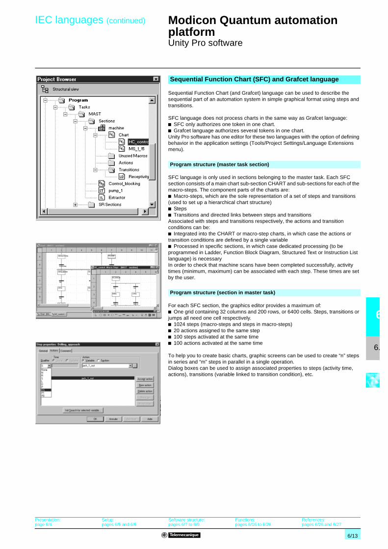
6/13
6
6.1
IEC languages (continued) Modicon Quantum automationplatform 0
Unity Pro software
Sequential Function Chart (and Grafcet) language can be used to describe thesequential part of an automation system in simple graphical format using steps andtransitions.
SFC language does not process charts in the same way as Grafcet language:b SFC only authorizes one token in one chart.b Grafcet language authorizes several tokens in one chart.Unity Pro software has one editor for these two languages with the option of definingbehavior in the application settings (Tools/Project Settings/Language Extensionsmenu).
SFC language is only used in sections belonging to the master task. Each SFCsection consists of a main chart sub-section CHART and sub-sections for each of themacro-steps. The component parts of the charts are:b Macro-steps, which are the sole representation of a set of steps and transitions(used to set up a hierarchical chart structure)b Stepsb Transitions and directed links between steps and transitionsAssociated with steps and transitions respectively, the actions and transitionconditions can be:b Integrated into the CHART or macro-step charts, in which case the actions ortransition conditions are defined by a single variableb Processed in specific sections, in which case dedicated processing (to beprogrammed in Ladder, Function Block Diagram, Structured Text or Instruction Listlanguage) is necessaryIn order to check that machine scans have been completed successfully, activitytimes (minimum, maximum) can be associated with each step. These times are setby the user.
For each SFC section, the graphics editor provides a maximum of:b One grid containing 32 columns and 200 rows, or 6400 cells. Steps, transitions orjumps all need one cell respectively.b 1024 steps (macro-steps and steps in macro-steps)b 20 actions assigned to the same stepb 100 steps activated at the same timeb 100 actions activated at the same time
To help you to create basic charts, graphic screens can be used to create “n” stepsin series and “m” steps in parallel in a single operation.Dialog boxes can be used to assign associated properties to steps (activity time,actions), transitions (variable linked to transition condition), etc.
Sequential Function Chart (SFC) and Grafcet language
Program structure (master task section)
Program structure (section in master task)
Presentation:page 6/4
Setup:pages 6/5 and 6/6
Software structure:pages 6/7 to 6/9
Functions:pages 6/16 to 6/26
References:pages 6/26 and 6/27

6/14
6
6.1
IEC languages (continued) Modicon Quantum automationplatform 0
Unity Pro software
Structured Text language is a sophisticated algorithmic type language, which isparticularly suitable for programming complex arithmetic functions, table operations,message handling, etc.
Structured Text language, which can be used to directly transcribe an analysis basedon an organization chart, is structured into expressions composed of a series ofinstructions organized in lines.There is no limit to the number of characters an instruction line may contain (the onlylimit is the program memory available for the Premium and Quantum platforms,except on TSX P57 10…40 processors, where the limit is 64 Kb). The length of thesection is only limited by the size of the application memory.
Four preformatted expression structures can be called up directly from the toolbar:b Conditional action : IF…THEN…ELSIF…THEN…ELSE…END-IF;b Iterative conditional action: WHILE…DO…END_WHILE;REPEAT…UNTIL…END_REPEAT;b Repetitive action: FOR…TO…BY…DO…END_FOR;b Selective action: CASE…OF…ELSE…END_CASE;
The operands used in the expressions are bit variables, word variables or variableslinked to function blocks.To make the expressions easier to read, different colors are used to identify objects,language key words and program comments.
Structured Text (ST) language
Program structure (section or subroutine)
Presentation:page 6/4
Setup:pages 6/5 and 6/6
Software structure:pages 6/7 to 6/9
Functions:pages 6/16 to 6/26
References:pages 6/26 and 6/27

6/15
6
6.1
IEC languages (continued) Modicon Quantum automationplatform 0
Unity Pro software
Instruction List language is a language representing the equivalent of a Ladderdiagram in text form. It can be used to write Boolean and arithmetic equations usingall the functions available in the Unity Pro language (calling of functions and functionblocks, assignment of variables, creation of program jumps, branching tosubroutines within a program section, etc.).
A program in Instruction List language comprises a sequence of instructionsclassified into the following different families:b Bit instructions, e.g. read input: LD overspeedb Function block instructions, e.g. call timer: CAL MOTOR_TIMERb Numerical instructions using single, double and floating point integers, e.g.: LDResult ADD Surplus ST Archiveb Word table or character string instructions, e.g. make assignment: LDResult:10:=Setpoint:10b Program instructions, e.g. SR call: CALL SR10The operands used in the expressions are bit variables, word variables or variableslinked to function blocks.
Instruction List (IL) language
Program structure (section or subroutine)
Presentation:page 6/4
Setup:pages 6/5 and 6/6
Software structure:pages 6/7 to 6/9
Functions:pages 6/16 to 6/26
References:pages 6/26 and 6/27

6/16
6
6.1
Functions Modicon Quantum automationplatform 0
Unity Pro software
The data editor, which can be accessed from the structural view of the project,provides a single tool for performing the following editing tasks:
b Declaration of data including variables and function blocks (declaration of theirtype, instants and attributes)b Use and archiving of function block data types in different librariesb Hierarchical view of data structuresb Searching, sorting and filtering of datab Creation of a hyperlink to access a description from any variable comment
The data is displayed under four tabs:
b “Variables” tab for the creation and management of the following data instances:bits, words, double words, inputs/outputs, tables, and structuresb “DDT Types” tab for the creation of derived data types (tables and structures)b “Function Blocks” tabs for the declaration of EFB and DFB function blocksb “DFB Types” for the creation of DFB user function block data types
Each data instance has several attributes, of which:b The name and type of the variable are mandatoryb The comment, physical address in the memory or initial values are optional
The data editor columns can be configured (number of columns, order). All theattributes associated with a variable can be displayed in a properties window.
This editor can be accessed at any time during programming by selecting variablesfor data modification or creation.
Data editor
Presentation:page 6/4
Setup:pages 6/5 and 6/6
Software structure:pages 6/7 to 6/9
IEC language:pages 6/10 to 6/15
References:pages 6/26 and 6/27

6/17
6
6.1
Functions (continued) Modicon Quantum automationplatform 0
Unity Pro software
The user can create his own function blocks for specific application requirements onAtrium, Premium and Quantum platforms using Unity Pro software.Once created and saved in the library, these user function blocks can be reused aseasily as EFBs (Elementary Function Blocks).These user function blocks can be used to structure an application. They are usedwhen a program sequence is repeated several times in the application or for fixing astandard programming routine. They can be read-only protected orread/write-protected. They can be exported to all other Unity Pro applications.Using a DFB function block in one or more applications:b Simplifies program design and entryb Improves program readability and understandingb Facilitates program debugging (all variables handled by the DFB block function areidentified in the data editor)b Enables the use of private variables specific to the DFBs, which are independentof the applicationA DFB function block is set up in several phases:b The DFB is designed by assigning a name, a set of parameters (inputs, outputs,public and private internal variables) and a comment to it via the data editor.b The code is created in one or more sections of the program, with the followinglanguages selected according to requirements: Structured Text, Instruction List,Ladder or Function Block Diagram (ST, IL, LD or FBD).b The DFB may be stored in a library with an associated version number.b A DFB instance is created in the data editor or when the function is called in theprogram editor.b This instance is used in the program in the same way as an EFB (ElementaryFunction Block). (The instance can be created from within the program.)
DFB user function blocks
Main characteristicsInputs 32 max. (1)
Outputs 32 max. (2)Inputs/outputs 32 max. (1) (2)Public internal variables Unlimited (can be accessed via the application program)
Private internal variables Unlimited (cannot be accessed via the application program)
Comment 1024 characters max.Program sections Unlimited, each section can be programmed independently in
one of the 4 languages (IL, ST, LD, and FBD).(1) The maximum cumulative total of inputs and inputs/outputs is 32.(2) The maximum cumulative total of outputs and inputs/outputs is 32.
Presentation:page 6/4
Setup:pages 6/5 and 6/6
Software structure:pages 6/7 to 6/9
IEC language:pages 6/10 to 6/15
References:pages 6/26 and 6/27

6/18
6
6.1
Functions (continued) Modicon Quantum automationplatform 0
Unity Pro software
The function and function block libraries manager contains all the elements providedwith Unity Pro software. The functions and function blocks are organized intolibraries, which themselves consist of families. Depending on the type of PLCselected and the model of processor, the user will have a sub-set of these librariesavailable to write his/her applications. However, the “Base Lib” library contains a setof functions and function blocks, the majority of which are compatible with allplatforms. In particular, it contains the blocks compliant with IEC 61131-3.The “Base Lib” library is structured into families:b Timers and countersb Internal process controlb Array managementb Comparisonb Date and time managementb Logic processingb Mathematical processingb Statistical processingb Character string processingb Type-to-type data conversion
This library, which covers standard automation functions, is supplemented by other,more application-specific libraries, which are platform-specific:
b Management library for motion control and fast countingb Process control library. The CONT_CTL library can be used to set upprocess-specific control loops. In particular, it offers controller, derivative and integralcontrol functions.b Communication library, providing an easy means of integrating communicationprograms from PLCs with those used by HMIs from the PLC application program.Like other function blocks, these EFBs can be used in all languages to share data orto deliver data to be displayed on an HMI.b Extended library, providing additional algorithms, e.g.: EFBs for calculating meanvalues, selecting a maximum value, performing movements with first-orderinterpolation, detecting edges or assigning a hysteresis to process variables, etc.b Diagnostics library, which can be used to monitor actuators and contains EFBsfor active diagnostics, reactive diagnostics, interlocking diagnostics, permanentprocess condition diagnostics, dynamic diagnostics, monitoring of signal groups, etc.b “System” library, which provides EFBs for the execution of system functions:evaluation of scan time, availability of several different system clocks, SFC sectionmonitoring, display of system state, etc.b Finally, a library named “obsolete” containing all function blocks used by legacyprogramming software needed to perform application conversions
Users may create libraries and families in order to store their own DFB functionblocks and DDT data structures. This enhancement allows users to take advantageof programming standards adapted to their needs, along with version management.This means that it is possible to:b Check the version of the elements used in an application program against thosestored in the libraryb Perform an upgrade, if necessary
Function block libraries
Management of user standards
Presentation:page 6/4
Setup:pages 6/5 and 6/6
Software structure:pages 6/7 to 6/9
IEC language:pages 6/10 to 6/15
References:pages 6/26 and 6/27

6/19
6
6.1
Functions (continued) Modicon Quantum automationplatform 0
Unity Pro software
Unity Pro software offers a complete set of tools for debugging Atrium, Premium orQuantum applications. A tool palette provides direct access to the main functions:b Dynamic program animationb Setting of watchdogs or breakpoints (not authorized in event-triggered tasks)b Step-by-step program execution. A function in this mode enablessection-by-section execution. Instruction-by-instruction execution can be launchedfrom the previous breakpoint. Three execution commands are therefore possiblewhen the element to be processed is a subroutine (SR) or DFB user block:v Detailed step-by-step or “Step Into”. This command is used to move to the firstelement of the SR or DFB.v Overall step-by-step or “Step Over”. This command is used to process the entireSR or DFB.v Outgoing step-by-step or “Step Out”. This command is used to move to the nextinstruction after the SR or DFB element.b Independent execution of the master (MAST), fast (FAST), auxiliary (AUX), andevent-triggered (EVTi) tasks.
Dynamic animation is managed section by section. A button in the toolbar is used toactivate or deactivate animation for each section.When the PLC is in RUN, this mode can be used to view, simultaneously:b The animation of a program section, regardless of the language usedb The variables window containing the application objects created automaticallyfrom the section viewedSeveral windows can be displayed and animated simultaneously. The “Tool tip”function, which uses help balloons, can be used to view a variable and its contentsimultaneously when the object is selected with the mouse (or other pointing device).
Two types of animation are supported:b Standard: The variables of the active section are refreshed at the end of the mastertask (MAST).b Synchronized: The watchpoint can be used to synchronize the display of animatedvariables with a program element in order to determine their value at this precisepoint in the program.
Tables containing the variables of the application to be monitored or modified can becreated by data entry or initialized automatically from the selected program section.In addition to data animation it is possible to:b Modify bit variables or force them to 0 or 1b Change the display formatb Copy or move variablesb Search by cross-referenceb Display the list of forced bitsThese tables can be stored in the application and retrieved from there at a later date.
The parameters and public variables of these blocks are displayed and animated inreal time using animation tables, with the possibility of modifying and forcing therequired objects.In exactly the same way as with other program elements, the watchpoint, breakpoint,step-by-step execution, and program code diagnostics functions can be used toanalyze the behavior of DFBs. Setting a breakpoint in a DFB user function blockinstance stops the execution of the task containing this block.
Debugging tools
Animation of program elements
Animation of ST program
Animation tableAnimation table
Debugging of DFB user function blocks
Presentation:page 6/4
Setup:pages 6/5 and 6/6
Software structure:pages 6/7 to 6/9
IEC language:pages 6/10 to 6/15
References:pages 6/26 and 6/27
Execution command
Insertion/removal of watchpoint

6/20
6
6.1
Functions (continued) Modicon Quantum automationplatform 0
Unity Pro software
The various debugging tools are also available in SFC language. However, unlikeother sections (IL, ST, LD or FBD) an SFC section executed step by step does notstop execution of the task but instead freezes the SFC chart. Several breakpointscan be declared simultaneously within a single SFC section.Numerous commands are available in this debugging mode via the control panel:b Deactivate active step(s)b Activate initial step(s)b Disable step execution timesb Freeze chart regardless of transition conditionsb Stop processing of stepsb Move to the next step taking account of the transition conditionsb Enable transition and move to next step(s) (detailed step-by-step command, “StepInto”)b Enable transition in order to execute the end of the macro-step (outgoingstep-by-step command, “Step Out”)b Preposition chart on steps for which markers have been set, etc.
The simulator integrated in Unity Pro can be used to test the application program forAtrium, Premium or Quantum PLCs from the PC terminal without having to connectto the PLC processor. The functions provided by the debugging tools are availablefor debugging the master, fast and auxiliary tasks.As the simulator does not manage the PLC I/O, animation tables can be used tosimulate the state of inputs by forcing them to 0 or 1.The simulator can be connected to third-party applications via an OPC server withOFS (OPC Factory Server) software.
The documentation editor is built around the Documentation Browser, which showsthe file structure in tree form.It allows all or part of the application file to be printed on any graphics printeraccessible under Windows and using True Type technology, in A4 or US letter printformat.The documentation editor supports the creation of user-specific documentation filesusing the following headings:b Title pageb Contentsb General informationb Title blockb Configurationb EF, EFB and DFB type function blocksb User variablesb Communicationb Project structureb Programb Animation tables and cross-referencesb Runtime screens
The documentation editor can generate the documentation file based on two differentstructures:b Structural view: All the objects in the project are associated with theircorresponding headings.b Functional view: The objects in the project are associated with the functionmodules to which they belong.
The documentation file can be created and saved as the project progresses, fromone Unity Pro session to another.
Debugging in Sequential Function Chart (SFC) language
SFC control panel
PLC simulator
Simulator control panel
Documentation editor
Access to documentation editor
Presentation:page 6/4
Setup:pages 6/5 and 6/6
Software structure:pages 6/7 to 6/9
IEC language:pages 6/10 to 6/15
References:pages 6/26 and 6/27

6/21
6
6.1
Functions (continued) Modicon Quantum automationplatform 0
Unity Pro softwareIntegrated diagnostics
The system diagnostics for the Atrium, Premium and Quantum platforms supports themonitoring of system bits/words, I/O modules and activity times (minimum/maximum)of SFC steps. By simply choosing the relevant option in the application configuration,any event will result in time-stamped messages being generated automatically withoutthe need for any additional programming thanks to these diagnostics viewers (1).
With the assistance of Unity Pro's integrated diagnostics, this function can be used toperform 1st level diagnostics of the elements in the configuration, up to and includingeach I/O module channel.
(1) Diagnostics viewers are tools used to display and acknowledge error messages relating todiagnostics. They are supplied as standard with Unity Pro, Vijeo Look and Monitor Prosoftware and with Magelis terminals.
PresentationDiagnostics integrated into Atrium, Premium and Quantum automation platforms
The diagnostics offer for Atrium, Premium and Quantum platforms is based on threecomponents:b System diagnosticsb DFB and EFB diagnostic function blocks (for system and application diagnostics)b Error message display system or viewers supplied as standard with MagelisXBT/T XBT terminals, Vijeo Look/ Monitor Pro supervisory software and Unity Prosetup software.
FunctionsSystem diagnostics
Processor forsystem bits andwords
In-rack I/Omodules
Remote I/Omoduleson Fipio
Higher-levelM.E.S.
Cell level
Machine level
Unity Pro
Diagnostics viewersSystem diagnostics
Application diagnostics
Ethernet TCP/IP
Vijeo LookMonitor Pro
Magelis XBT/T XBTPremium
Quantum
PC
Configuration level Module level
Channel levelViewer window (example with Unity Pro software)

6/22
6
6.1
Functions (continued) Modicon Quantum automationplatform 0
Unity Pro softwareIntegrated diagnostics
Unity Pro software also has a library of function blocks for monitoring, called diagnosticDFBs and EFBs. The library of diagnostic function blocks contains:
b Manufacturer blocks for system diagnosticsv IO_DIA input/output fault, which is used to monitor the state of inputs/outputs.v ASI_DIA, which monitors whether an error has occurred on the AS-i bus (moduleor bus fault, no slave, slave not configured or faulty).
b Manufacturer blocks for application diagnostics, for example:v EV_DIA, which monitors whether an event (bit status) has the correct value at agiven time (no notion of timing).v MV_DIA, D_GRP, D_REA, which monitor whether an event (change in the status ofa bit) occurs in accordance with the specified time conditions.v ALRM_DIA, which monitors the combination of the status of 2 bits.v NEPO_DIA and TEPO_DIA, which can be used to check, control and performdiagnostics for elements in the working part of the system made up of thecombination of 2 actuators and 2 sensors.
b Open diagnostics blocksThese enable users to create their own diagnostic function blocks to meet thespecific requirements of their applications and therefore to supplement themanufacturer DFBs and EFBs described above. They can be created from 2 modelblocks, which must be written in Ladder (LD), Structured Text (ST), Function BlockDiagram (FBD) or Instruction List (IL) language.
Furthermore, when a fault occurs, Unity Pro analyzes the program sectionsconcerned and opens a second window displaying the causes and probable sourcesof the fault.
The user or process operator is guided though the fault-finding process, enablingmachine downtimes to be reduced.
The configuration module or instruction, which is the source of the fault, can also beaccessed via the diagnostics viewer integrated into Unity Pro, directly from the alarmin the viewer output window (see page 6/23).
Application diagnostics
ED
COND ERROR
STATUSAREA_NROP_CTRL
Usrst_dia
Outputs
Inputs
Diagnostics with fault finding
Presentation:page 6/4
Setup:pages 6/5 and 6/6
Software structure:pages 6/7 to 6/9
IEC language:pages 6/10 to 6/15
References:pages 6/26 and 6/27

6/23
6
6.1
Functions (continued) Modicon Quantum automationplatform 0
Unity Pro softwareIntegrated diagnostics
All the diagnostic events processed by Atrium, Premium and Quantum platforms viadiagnostic DFBs/EFBs are stored in a buffer (specific data memory area on the PLC).The information contained in this buffer is sent (transparently for the user) to viewersfor automatic display and for management of faults and alarms. The viewer functionis supplied as standard with:b Vijeo Look and Monitor Pro V7 supervisory softwareb Unity Pro programming softwareb Magelis XBT F and Magelis iPC HMI terminals (function only available withPremium PLCs)
The integrated viewer in Unity Pro can also be used to access the instruction ormodule, which is the source of the fault. See “Diagnostics with fault finding”, page6/22.Atrium, Premium and Quantum platforms have multiviewer capability (can be usedwith a maximum of 15 viewers). A PC-compatible station with the viewer function canbe multi-PLC (can be used with a maximum of 15 Atrium/Premium/Quantumplatforms).
The buffer/viewer structure supports:b A single point for fault management in each applicationb Time-stamping of the occurrence of faults at sourceb Storage of intermittent faults in memoryb Independence with regard to the viewer functions. The frame sent from the PLCbuffer is identical for all viewers.b Automatic archiving of all error messages
Output windowThe diagnostics viewer takes the form of an output window divided into 2 sections:b A message list indicating, for each alarm: state, DFB type, geographical zone,dates and times of appearance/disappearance, associated message and statusb An area for additional information about the selected message: type, comment,date of appearance, specific data, variables in error state, etc.
The runtime screen tool is integrated into Unity Pro. The runtime screens aredesigned to facilitate the operation of automated processes during debugging,startup and maintenance. The runtime screens provide a set of information(explanatory texts, display of dynamic values, push buttons, and synoptics), enablingusers to act quickly and easily to modify and dynamically monitor PLC variables.
The runtime screens editor provides all the HMI (Human/Machine Interface)elements needed for the animated design and viewing of processes. It enables thesescreens to be designed using specific tools:b Screen: Creation of runtime screens, which can be classified according to family.b Message: Creation of messages to be displayed.b Objects: Creation of a graphic objects library using:v Geometrical elements (line, rectangle, ellipse, incorporation of images, controllerfront panels, etc.)v Control elements (buttons, data entry fields, screen browsing controls, etc.)v Animation elements (colors, flashing elements, bar graphs, etc.)When the station on which Unity Pro has been installed is connected to the PLC, theuser can obtain a dynamic display of the screens according to the state of theprocess. Screen sequencing is possible, depending on the priority attributed, eithervia the keyboard or a PLC request.When online, the Unity Pro application program can be accessed directly from theruntime screens by clicking on the selected object in a synoptic screen view. It is alsopossible to activate the animation table or cross-reference functions by selecting oneor more variables on the screen. To make the display easier to read, the synopticviews can be displayed in full-screen view.
Diagnostics viewers
Viewer
Runtime screens
Presentation:page 6/4
Setup:pages 6/5 and 6/6
Software structure:pages 6/7 to 6/9
IEC language:pages 6/10 to 6/15
References:pages 6/26 and 6/27

6/24
6
6.1
Functions (continued) Modicon Quantum automationplatform 0
Unity Pro software
Unity Pro enables changes to be made to the program when the PLC connected tothe programming terminal is in RUN. These modifications are made by performingthe following operations:b Where necessary, transferring the application in the PLC to the PC terminalrunning Unity Pro.b Preparing the program changes offline. These program modifications can be ofany type and in any language (IL, ST, LD, FBD, and SFC), for exampleadding/deleting SFC steps or actions. Furthermore, modifications can be made to thecode of a DFB user function block (although its interface cannot be modified).b Updating the program in the PLC (in RUN) to reflect these program changes.
This function allows program code and data in different parts of the application to beadded or modified in a single modification session (thus making modification unifiedand consistent with regard to the controlled process). This increased flexibility comesat a cost in terms of the program memory volume required.
The Unity Pro Cross-References function, which is available in standalone mode(offline) and when connected to the PLC (online), allows users to view all theelements of a PLC application by searching for variables of any type. This viewindicates where the declared variable is used as well as the mode in which it is used(write, read, etc.).This function also provides access to the Search/Replace function for variablenames.The variables search can be initialized from any editor (language, data, runtimescreen, animation table, etc.).
The import/export function available in Unity Pro supports the following operationsfrom the structural and functional project views:b Via the import function, to reuse all or part of a project created previously in thecurrent projectb Via the export function, to copy all or part of the current project to a file forsubsequent reuse
The files generated on export are generally in XML format (1). However, variablescan be exported or imported in the following formats in addition to XML:b .xvm format compatible with OFS data server softwareb Source format, in a .scy file compatible with PL7 design softwareb Text format with separator (TAB), in a .txt file for compatibility with any othersystem
On import, data can be assigned to new instances of the following elements via anassistant:b DFB function blocksb DDT data structuresb Simple dataFurthermore, when importing a function module, the data associated with animationtables and runtime screens is also reassigned.
The XML import function also supports the transfer of an Atrium, Premium orQuantum PLC configuration prepared in the SIS Pro costing and configuration toolfor use in the creation of a project in Unity Pro.This import function means that the user does not have to repeat the PLCconfiguration process when this has already been completed in the SIS Pro tool.
(1) XML language: Open text-based language providing structural and semantic information.
Modifying the program with the PLC in RUN
Cross-References functions
Import/export function
Presentation:page 6/4
Setup:pages 6/5 and 6/6
Software structure:pages 6/7 to 6/9
IEC language:pages 6/10 to 6/15
References:pages 6/26 and 6/27

6/25
6
6.1
Functions (continued) Modicon Quantum automationplatform 0
Unity Pro software
Unity Pro's integrated conversion tools can be used to convert PLC applicationscreated with Concept and PL7 programming and setup software in Unity Proapplications.
The conversion can be performed from a Concept V2.5 application (possible in V2.11or later but only once it has been updated to version V2.5). In order to perform theconversion, the application must be exported to an ASCII file in Concept.The export file is converted into Unity Pro source files automatically. Thissource file is then analyzed by Unity Pro. At the end of the procedure, a conversionreport is generated and an output window displays any conversion errors from whichthe part of the program to be modified can be accessed directly.The Concept application converter converts the application into Unity Pro but doesnot guarantee that it will operate correctly in real time. It is therefore essential to testor debug any converted application.
The conversion can be performed from a PL7 application V4 or later (Premium PLCor Atrium slot PLC). In order to perform the conversion, the source file (completeapplication) or source file (user function block) must be exported in PL7.The conversion procedure is similar to that of the Concept conversion describedabove.
OS-Loader software is designed for updating operating systems on Atrium, Premiumand Quantum platforms and is supplied with Unity Pro software.It can be used to update the following for compatibility with Unity Pro:b Premium TSX P57 2p3M/2623M and TSX P57 3p3M/3623M processorsb Quantum 140 CPU 434 12A and 140 CPU 534 14A processors (requires PV 04 orlater)b Ethernet TCP/IP TSX ETY and 140 NOE 771 communication modulesThese operating system updates are performed as follows for the various types ofprocessor:b Uni-Telway RS 485 terminal link for Premium processorsb Modbus or Modbus Plus terminal link for Quantum processorsb Ethernet TCP/IP network for integrated Ethernet port on Premium processors andEthernet Premium and Quantum processors
The drivers used most frequently on the Atrium, Premium and Quantum platformsare installed at the same time as the Unity Pro software.Furthermore, Unity Pro also includes the following communication drivers, which canbe installed as required:
Application converters
Concept/Unity Pro converter (Quantum PLC)
PL7/Unity Pro converter (Premium and Atrium slot PLC)
Operating system update utilities
Communication drivers
Driver type Windows XPWindows 2000
Windows NT Windows 98Millennium
Windows 95 OSS/2 DOS
Uni-Telway V1.6 IE17 V1.9 IE17 V1.6 IE17 V7.8 IE18 – V7.4 IE14
TSX FPC10 V1.3 IE05 V1.3 IE08 V1.3 IE05 V2.4 IE14 V2.4 IE13 V2.2 IE11TSX FPC20 V1.2 IE03 V1.3 IE08 V1.2 IE04 V1.2 IE04 V1.5 IE05 –TSX SCP 114 V1.1 IE04 V1.1 IE04 V1.1 IE04 V1.1 IE04 – –
Ethway V1.1 IE02 V1.1 IE03 V2.6 IE06 V2.6 IE06 V2.6 IE22 –ISAway V1.2 IE04 V1.5 IE06 V1.2 IE04 V1.2 IE09 – –PCIway V1.0 IE06 – – – – –
XIP V1.7 IE13 V1.7 IE13 V1.7 IE13 V1.7 IE13 – –Modbus V1.1 IE06 V1.1 IE06 V1.1 IE06 V1.1 IE06 – –USB for mini-DINterminal port
Included withPL7
– – – – –
USB for USB terminal port V1.0 IE14 – – – – –
Presentation:page 6/4
Setup:pages 6/5 and 6/6
Software structure:pages 6/7 to 6/9
IEC language:pages 6/10 to 6/15
References:pages 6/26 and 6/27

6/26
6
6.1
Functions (continued),references
Modicon Quantum automationplatform 0
Unity Pro software
Advanced openness, which is reserved for experienced IT engineers, supports thedevelopment of interfaces between Unity and expert tools as well as specificuser-defined functions.
This type of development requires expert IT knowledge in the following areas:
b C++ or Visual Basic languagesb Client/server architecturesb XML and COM/DCOM technologiesb Issues relating to data synchronization
As a supplement to the Unity Studio software suite, the UDE (Unity Developer'sEdition) development tool can be used to set up made-to-order solutions. In additionto a development kit, it includes the Unity servers, training, documentation, andtechnical support.
This UDE development tool can only be supplied once a specific contract has beensigned with Schneider Electric. Please consult your Regional Sales Office.
The software is available in 3 versions:b Unity Pro Medium for programming and setting up Unity automation platforms:v Atrium TSX PCI 57 20v Premium TSX 57 0p, 57 10 and 57 20b Unity Pro Large for programming and setting up automation platforms:v Atrium TSX PCI 57 20 and 57 30v Premium TSX 57 0p, 57 10, 57 20, 57 30 and 57 40v Quantum with 140 CPU 311 10, 434 12U and 534 14U processorsb Unity Pro Extra Large for programming and setting up all Unity automationplatforms:v Atrium TSX PCI 57 20 and 57 30v Premium TSX 57 0p, 57 10, 57 20, 57 30, 57 40 and 57 50v Quantum with 140 CPU 311 10, 434 12U, 534 14U, 651 50, 651 60 and HotStandby 140 CPU 671 60 processorsFurthermore, Unity Pro can be used to design and run programmable process controlloops on Premium TSX 57 40 and 57 50 platforms and Quantum platforms with 140CPU 651 50, 651 60 and 671 60 processors (access to CONT_CTL process controlfunction block library).
Users who have already purchased these installed base software programs andhave a current subscription may purchase Unity Pro version V2.0 software atvastly reduced prices. These upgrades are only possible for licenses of the sametype (from Concept XL group license to Unity Pro Extra Large group license).
Unity Pro multilingual software is compatible with Windows 2000 Professional andWindows XP operating systems.It comprises:b Documentation in electronic format in 4 languages (English, French, German, andSpanish)This documentation can be ordered separately in paper format.b Converters for converting applications created with Concept and PL7 Proprogramming softwareb PLC simulatorCables for connecting the processor to the programming PC must be orderedseparately.
Advanced openness for experienced IT engineers
Example of a made-to-order solution, which canbe set up with UDE
ReferencesUnity Pro Medium, Large and Extra Large software packages
Upgrade kits for Concept, PL7 Pro and ProWORX software
OS Windows composition and compatibility
Presentation:page 6/4
Setup:pages 6/5 and 6/6
Software structure:pages 6/7 to 6/9
IEC language:pages 6/10 to 6/15
Functions:pages 6/16 to 6/26

6/27
6
6.1
References (continued) Modicon Quantum automationplatform 0
Unity Pro software
References (continued)
Unity Pro Medium version 2.0 software packagesFor PLCs Description Type of license Reference Weight
kgTSX 57 0p…57 20TSX PCI 57 20
Unity Pro Medium softwarepackages
Single-station UNY SPU MFU CD 20 –Group (3 stations) UNY SPU MFG CD 20 –
Software upgrades from:- Concept M- PL7 Junior
Single-station UNY SPU MZU CD 20 –
Group (3 stations) UNY SPU MZG CD 20 –
Unity Pro Large version 2.0 software packagesFor PLCs Description Type of license Reference Weight
kgTSX 57 0p…57 40TSX PCI 57 20/30140 CPU 311 10140 CPU 434 12U140 CPU 534 14U
Unity Pro Large softwarepackages
Single-station UNY SPU LFU CD 20 –Group (3 stations) UNY SPU LFG CD 20 –Team (10 stations) UNY SPU LFT CD 20 –
Site (> 10 stations) UNY SPU LFF CD 20 –Software upgrades from:- Concept M- PL7 Junior
Single-station UNY SPU LZU CD 20 –Group (3 stations) UNY SPU LZG CD 20 –
Team (10 stations) UNY SPU LZT CD 20 –Site (> 10 stations) UNY SPU LZF CD 20 –
Unity Pro Extra Large version 2.0 software packagesFor PLCs Description Type of license Reference Weight
kgTSX 57 0p…57 50TSX PCI 57 20/30140 CPU 311 10140 CPU 434 12U140 CPU 534 14U140 CPU 651 50/60140 CPU 671 60
Unity Pro Extra Large softwarepackages
Single-station UNY SPU EFU CD 20 –Group (3 stations) UNY SPU EFG CD 20 –
Team (10 stations) UNY SPU EFT CD 20 –Site (> 10 stations) UNY SPU EFF CD 20 –
Software upgrades from:- Concept M- PL7 Junior- ProWORX NxT- ProWORX 32
Single-station UNY SPU EZU CD 20 –Group (3 stations) UNY SPU EZG CD 20 –Team (10 stations) UNY SPU EZT CD 20 –
Site (> 10 stations) UNY SPU EZF CD 20 –
Documentation for Unity Pro version 2.0For PLCs Description Type of license Reference Weight
kgGetting Started manuals(on CD-ROM)
Assisted creation of a firstUnity Pro application
English UNY USE 100 10E –
French UNY USE 100 10E –
Hardware and softwaremanuals (on CD-ROM)
Platform setup for:- Atrium/Premium- Quantum- Momentum- Electromagnetic compatibilityof networks and fieldbusesSoftware setup for:- Unity Pro- EF/EFB/DFB function blockslibrary
Multilingual: English, French,German, and Spanish
UNY USE 909 CD M –
Separate partsDescription Use from processor To PC port Length Reference Weight
kgPC terminal connectioncables
Mini-DIN port forPremium TSx 57 1p/2p/3p/4pAtrium TSX PCI 57
RS 232D (15-waySUB-D connector)
2.5 m TSX PCX 1031 0.170
USB port 2.5 m TSX PCX 3030 0.150Modbus port15-way SUB-D Quantum140 CPU 311 10140 CPU 434 12A140 CPU 534 14A
RS 232D (15-waySUB-D connector)
3.7 m 990 NAA 263 20 0.30015 m 990 NAA 263 50 0.180
RJ45 connector for Modbusport Quantum 140 CPU 6p1
RJ45 connector 1 m 110 XCA 282 01 –3 m 110 XCA 282 02 –
6 m 110 XCA 282 03 –USB port Premium TSX 57 5p Quantum 140 CPU 6p1
USB port 3.3 m UNY XCA USB 033 –
TSX PCX 1031
Presentation:page 6/4
Setup:pages 6/5 and 6/6
Software structure:pages 6/7 to 6/9
IEC language:pages 6/10 to 6/15
Functions:pages 6/16 to 6/26

6/28
6
6.1
Presentation,setup
Modicon Quantum automation platform 0
Unity EFB Toolkit software
Unity EFB Toolkit is the software for developing EF functions and EFB function blocks in C language and is optional software for Unity Pro. It can be used to develop new functions (whose internal code is written in C language) to extend and complete the set of functions proposed as standard in Unity Pro. This software comes with Microsoft Visual C++ @.Net which can be used to debug the functions used on the Unity Pro PLC simulator. Unity EFB Toolkit also includes a service for creating and managing families of functions, with a view to their integration in the Unity Pro function libraries.
C language development software is a proper tool for managing the whole function while it is being performed:b A user-friendly creation interface, integrated in Unity Pro, with automatic file organizationb Powerful tools for testing and debuggingb Management of compatibilities and software versions of created functionsb Generation of files for subsequent installation of functions on other development stations
The software can be used to define different function families. These functions, also known as EFs/EFBs, are stored in families, making it possible to create an organized library of functions written in C language.Once created, these families can be distributed and integrated in the Unity Pro libraries. They are:b Arranged in families/functionsb Used in all languages with the same flexibility as standard functions (data entry wizard)b Managed by the Unity Pro library tool (version management)
The various tabs in the EFB Toolkit software editor allow the user to create the function by:b Declaring the interface, all data types are possible (elementary, structures, tables)b Supporting public and private variables
Writing the source code file in C languageA function written in C language can access numerous internal PLC services such as the real-time clock, PLC variables, system words, math functions. In particular, it is possible to perform numerical processing in floating point format.
Presentation
Setup
Managing function families
Editing functions

6/29
6
6.1
Setup(continued), reference
Modicon Quantum automation platform 0
Unity EFB Toolkit software
The function created can be tested after insertion in an application and loading into the Unity Pro PLC simulator.The Microsoft Visual C++ tool is used to debug the function. It is used to:b Insert breakpointsb Perform step by step executionb Display the code with the breakpoints visibleb Display manipulated data
As the function has been debugged, it can be generated and distributed, and the updating tool supplied with Unity Pro can be used to enhance the libraries on a user station.Version management means that at any time the user knows the level of functions installed on a station and can update the application with the latest existing versions.
The “companion” software for Unity Pro, Unity EFB Toolkit can be used to create EF elementary blocks and EFB elementary function blocks. These are developed in Visual C++ language and are integrated in Unity Pro function block libraries.The Unity EFB Toolkit software and its documentation are supplied in electronic form on CD-ROM in English.
Setup (continued) Debugging functions
Enhancing the function library
References
Description Type of license
Language Reference Weightkg
Unity EFB Toolkit, kit for developing EF and EFB blocks
Single (1 station)
English (software and electronic documentation)
UNY SPU ZFU CD 20E –
Unity EFB Toolkit subscription renewal
UNY CSP SPU ZBU –

6/30
6
6.1
Presentation Modicon Quantum automation platform 0
Unity SFC View software
Unity SFC View is integrated in human/machine interface (HMI) applications for monitoring Unity Pro sequential applications written in sequential function chart language (SFC or Grafcet) executed by a PLC. Set up in the same way as an ActiveX control component, Unity SFC View is used to display status information relating to SFC charts executed by a Premium or Quantum PLC. Installed on an HMI station, Unity SFC View monitors and controls the status of SFC charts in real time, supplying detailed diagnostic data.
Unity SFC View reads the necessary data from the Unity project database in offline mode. The PLC data is accessed online via the OFS (OPC Factory Server).
Without needing to recreate SFC charts in the HMI environment, Unity SFC View reads the structure of the SFC charts directly from the Unity project database. Modifications made to the SFC application are detected and updated at any time. In online mode, Unity SFC View accesses the PLC diagnostic data, thus enabling awareness and tracking of the occurrence of the first fault and subsequent faults. System downtime is much reduced since Unity SFC View enables maintenance staff to locate the source of the problem much more quickly.
Unity SFC View is designed for end users and system designers who wish to integrate this control into their HMI system. Unity SFC View is compatible with most HMI platforms handling ActiveX Control components such as Vijeo Look control software or Monitor Pro supervisory software or in a programming environment such as Visual Basic.
Presentation

6/31
6
6.1
Presentation (continued) Modicon Quantum automation platform 0
Unity SFC View software
Unity SFC View offers 3 views: b An overview for managing selection of SFC chartsb Two detailed views presenting the status and diagnostic data of the selected SFC chart
The overview provides a general view of all the SFC charts in a Unity project. It contains real-time data such as current step, simultaneous steps, chart error with indication of the SFC chart status. The overview makes it easy to browse through SFC charts and switch quickly to the detailed view of the desired SFC chart in the Unity Pro application.
The simple detailed view shows the elementary data on the active step (or selected step) of the SFC chart in real time. The data displayed may include the name, comment, chart and step status, as well as the activity times (min, max, actual). You can also enable the chart navigation option.
Because of the compact size of the simple detailed view, it is possible to place several instances of it on a single HMI screen relating to a certain part of the process. From this simple detailed mode, you can navigate between HMI screens with SFC View controls and display the detailed view of SFC charts.
The detailed view illustrates the details of an SFC chart in real time. The display indicates the current step, the transition awaiting activation and the next step. The actions associated with the steps are displayed along with sequence selections or parallel branches. The detailed diagnostic data includes analysis of the causes of the fault at transition level. Depending on the diagnostic mode, the error grid contains the causes of errors or all the variables assigned to the transition logic. The current state of the various variables and selected errors are identified by different colors.
Transition logic diagnostics is a key function of Unity SFC View. It minimizes system downtimes in the event of a fault.
Two different diagnostic modes are available:
b Unity SFC View reads the data in the Unity PLC diagnostic buffer. It provides information about faulty or missing events that are preventing the transition from being enabled. This mode does not require any configuration or additional programming in the PLC program.
b Unity SFC View monitors the internal logic of the transition conditions “back to front”. This mode provides diagnostic data concerning all the inputs connected to the transition (not limited to faulty inputs). In this mode, Unity SFC View uses specific EFB function blocks linked to the transition conditions. The library for these blocks is supplied with the Unity SFC View software.
Unity SFC View offers a programming interface which can be used to integrate the ActiveX Control component in an HMI application and customize its functions and its operator interface.
The ActiveX Control component in Unity SFC View can be customized. It accepts properties, methods and events (all the properties have a default value).The properties pages simplify configuration. Unity SFC View accepts scripts with methods such as browsing through charts, status control of charts, and also events such as error notification or chart selection. This data can be used to launch programs or operator screens.
The 3 Unity SFC View views
Overview
Simple detailed view
Detailed view
Diagnostic mode
Customization
SFC View properties page

6/32
6
6.1
Presentation (continued) Modicon Quantum automation platform 0
Unity SFC View software
Unity SFC View is used in a configuration where the OFS and Unity Pro software reside on the same PC platform as the HMI application.
In a distributed configuration, the OFS and Unity Pro software can be installed on different servers.
Possible architectures
Operator station with HMI application and Unity Pro, OFS and SFC View programs and projects
Quantum, Premium with Unity SFC program
Basic architecture
Distributed architecture
Operator station with HMI application and SFC View projects
Ethernet TCP/IP
Unity projects
OFS serverP Server (Unity)
PLC network
COM or DCOM
Quantum, Premium with Unity SFC program

6/33
6
6.1
Presentation (continued) Modicon Quantum automation platform 0
Unity SFC View software
When integrated in an HMI application, Unity SFC View can be used to monitor and control charts in applications developed in Sequential Function Chart (SFC) language running on Premium/Quantum Unity PLCs.
The HMI station, compatible with Windows 2000 or Windows XP Professional operating systems, must support ActiveX Control components. Unity SFC View V2.0 requires: b Unity Pro V2.0 (M, L or XL), to be ordered separatelyb OFS V3.1 data server software, to be ordered separately
Unity SFC View multilingual software, supplied on a CD-ROM, includes: b The SFC View ActiveX Control componentb The EFB function block library for Unity Pro V2.0b An example of how to integrate SFC View in Unity Pro projectsb The electronic documentation (English, French, German and Spanish)
The Unity SFC View integration example illustrates the main possibilities offered by Unity SFC View. This is an executable program which does not need HMI software in order to run. It helps the user understand how to configure and use the Unity SFC View ActiveX Control component.
References
Description Type of license Reference Weightkg
Unity SFC View software packages (version V2.0)
Single (1 station) UNY SDU MFU CD20 –
Team (10 stations) UNY SDU MFT CD20 –
Site (100 stations) UNY SDU MFF CD20 –

6/34
6
6.1
Presentation Modicon Quantum automationplatform 0
Unity Studio software suiteGeneral presentation
The Unity Studio software suite is the key component on design office workstationsused for designing and structuring automation applications in a collaborativeenvironment. This type of project consists of creating an automation applicationcomprising various devices:1 Communication networks2 Automation platforms and distributed I/O3 Variable speed drives, motion control4 Human machine interfaces (HMIs)
Based on a horizontal approach, the software suite supports:b Project management for distributed control applicationsb Application and device managementb The consistency and synchronization of Ethernet TCP/IP communication betweendevices
The Unity Studio software suite offers designers of industrial automation distributedcontrol projects the possibility of using all these tools in conjunction. From the designphase on, everyone involved has easy, user-friendly access to a single, sharedrepresentation of the project.
The objective of the Unity Studio software suite is to:b Provide a unique structural representation of the project shared by experts in allapplication-specific domainsb Increase the productivity of each expert
Unity Studio V2.0 is an “all-in-one” software suite based on Microsoft's Visio 2003Professional graphic design tool. It is supplied with the following software asstandard:b Unity Studio Manager V2.0 for managing distributed control applicationsb Unity Pro XL V2.0 for programming Atrium, Premium and Quantum platformsb OFS V3.1 (OPC Factory Server) for accessing and exchanging data in thearchitectureb PowerSuite V1.5 for setting up drives and motor startersb XBT-L1000 V4.30 for creating Magelis HMI applicationsb Microsoft VBA (Visual Basic for Applications) for developing customized functionsb MS Visio 2003 Professional, depending on the type of software license
Unity Studio V2.0 is the ideal tool for integrating and configuring Transparent Readyproducts.
Unity Studio Manager tools allow you to create direct links with other SchneiderElectric applications or with third-party software applications.
In addition, the Unity Developer's Edition (UDE) software package provides anadvanced open development solution for the programming of user functions and thedevelopment of interactive interfaces with other software applications (programmingin C++, VBA, VBA macros, etc.), see page 6/26.
The Unity Studio software suite is the ideal software engineering platform fordistributed control applications.
Unity Studio for the development of a distributed project
1
1 2
2
4
3
2
“All-in-one” software suite
Functions:Pages 6/35 to 6/40
References:page 6/41

6/35
6
6.1
In conjunction with the Visio 2003 graphics editor, the Unity Studio software suite canbe used to create project views in specific pages:
b Process or machine view: A unique representation shared by all specialistexperts/consultants working on the project (mechanical, hydraulic, electricalengineering, etc.).
b View of the distributed automation architecture: A graphical representation ofthe project's automation devices and communication networks.
These views are composed using application-specific object libraries (construction,mechanical, hydraulic, electrical engineering, etc.). The Schneider component libraryextends the scope of the Visio libraries. Graphical views are created by dragging anddropping objects from the libraries to the tabbed pages.
Objects, their links and related properties composing the project views are enteredonce into the graphical views and shared with:b Other viewsb Other Unity Studio suite software and external software applications
Based on the Visio 2003 editor, the graphical views are easy to use thanks to thestandard user interface (Microsoft office tools). Graphic elements can be integratedfrom other market-standard CAD software (AutoCAD, Micro Station, etc.).
The functional view is a structured tree diagram of the entire set of machine orprocess functions. It is taken from the graphical view of the process or machine.
This hierarchical structure comprises functional entities in the form of folders that canbe nested at different levels.
The project designer associates functional entities with stations making up theproject.
After “generation” (see page 6/39), the corresponding functional entities are madeavailable in the structural view (configuration entity) of Unity Pro applications forAtrium/Premium/Quantum platforms.
The topological view is composed using the control architecture graphical view. Thistopological view displays the communication networks and connected devices in afolder structure.
In a similar fashion, after “generation” (see page 6/39), elements of the topologicalview are made available in the structural view (communication element) of eachUnity Pro application for the Modicon Atrium/Premium/Quantum platforms in thedistributed automation architecture. Network names and the names and types ofstations defined in the graphical view of Unity Studio are sent to Unity Proapplications.
Project viewsGraphical project views
Graphical process or machine view
Graphical view of the distributed automation architecture
Functional view
Functional view
Topological view
Topological view
Presentation:page 6/34
References:page 6/41
Functions Modicon Quantum automationplatform 0
Unity Studio software suite

6/36
6
6.1
Functions (continued) Modicon Quantum automationplatform 0
Unity Studio software suite
The communication view enables PLCs to be synchronized and data to beexchanged with the following types of distributed product:v Altivar drivesv Advantys STB, Momentum distributed I/Ov Or any other productconnected to the Ethernet architecture, including those connected viaEthernet/Modbus Plus or Ethernet/Modbus gateways.
Set using the symbolic variables editor in Unity Studio, parameters forcommunication services between the various devices or products (Global Data andI/O Scanning services) are loaded automatically in the files for each station duringgeneration (see page 6/39), thereby ensuring that all stations benefit from:b Ensured communication consistency between the distributed applicationsconcernedb Maximum productivity based on station configurationb Reduction in the risk of errors
The I/O Scanning service can be used to manage the exchange of remote I/O stateson the Ethernet TCP/IP network following simple configuration, with no need forspecific programming.I/O scanning is transparent and is carried out via read/write requests sent by theAtrium, Premium and Quantum automation platforms in accordance with the ModbusTCP client/server protocol. This technique of scanning via a standard protocolenables communication with any product that supports a Modbus server on TCP/IP.
Unity Studio can define a number of communication frames for each station. Eachcommunication frame, reserved for reading inputs and writing outputs, is limited to100 consecutive words.
See page 5/22 for more information about the I/O Scanning service.
The Global Data service on Ethernet TCP/IP communication networks can be usedto exchange data between connected stations in real time.
This service enables a common database to be synchronized and shared between64 stations. Each of the 64 stations in a distribution group can:b Publish a 1024-byte variable on the networkb Subscribe to between 1 and 64 published variables
The Global Data view in Unity Studio can be used to define Global Data distributiongroups and set parameters for variables published and subscribed to by the stations.
See page 5/24 for more information about the Global Data service.
Communication view
Communication view
I/O Scanning
Global DataEthernet TCP/IPVariable AVariable BVariable C
Publication
Application 1
Subscription
Application 2
SubscriptionPublication
Application n

6/37
6
6.1
Functions (continued) Modicon Quantum automationplatform 0
Unity Studio software suite
The Unity Studio software suite supplies open libraries of objects that can be re-usedin graphical views:b Visio 2003 librariesb Schneider Electric automation product library
Objects found in these libraries are of 2 types:b Process objects for the creation of a graphical view of a process or machine(motors, valves, actuators, pumps, etc.)b Automation objects for the creation of a control architecture view (PLCs,networks, drives, HMI terminals, Ethernet hubs, etc.)
Each object can be given its own parameters (type of valve, etc.) using predefinedproperties or enhanced by applying customized properties.
The numerous libraries supplied can be expanded as needed by:b Downloading Visio objects available online, covering all industrial fields (MicrosoftVisio site, product reseller sites or sites specializing in Visio objects)b Creation of objects by the user
A customized object can be created by:b Integrating a graphical thumbnail of your choice (.bmp format) into the libraryb Defining customized object propertiesb Creating XML-format rules for complex objects
Complex objects (for automation devices) can be created by writing usage rules (forinstance, the possibility of connecting a type of automation device to a type ofcommunication network) in standard eXtensible Markup Language (XML) format.
Hyperlinks can be defined from the objects in order to launch a software applicationor to open a document related to the object (see next page).
Object libraries
Schneider Electricautomation product library
Process library
Adding new objects
PLCsNetworksHMIVariablespeeddrivesMotor startersHubsSwitchesetc.
XML-format rules
Thumbnails
Parameters
Rules
Process objects(sensors, actuators, etc.)
Automation objects(components, etc.)
Presentation:page 6/34
References:page 6/41

6/38
6
6.1
Functions (continued) Modicon Quantum automationplatform 0
Unity Studio software suite
From the Unity Studio project views, it is possible to create hyperlinks at any time to:
b All document types in .xls, .doc, .pdf, etc. formatsb Web pages via a URL addressb Software tools, for example for configuration, network diagnostics, productionmanagement, etc.
The project is described in Unity Studio by different views, which:b Provide specific types of characteristic informationb Provide access to associated information
1 Assignment of an automation application to each station in the architecture2 Launch of the application from the topological or functional view3 Creation and location of files for each station4 Assignment of functional process or machine entities to station applications
Direct-access hyperlinks
Creation of a link from anobject
Direct access to theconfiguration software toolrelative to the object
Managing distributed control applications
124 3
Presentation:page 6/34
References:page 6/41

6/39
6
6.1
Functions (continued) Modicon Quantum automationplatform 0
Unity Studio software suite
In order to detect any errors as early as possible, the Unity Studio software suiteanalyzes application coherence and consistency. A report indicates any possibleerrors in the form of alarms. Checks are performed on:b Station addressingb The types of station definedb Data exchanged in real time on the Ethernet network between PLC stations via theI/O Scanning and Global Data services (reserved word zones, group, published andsubscribed variables)b The hierarchical structure of functional entities
Following the analysis (and after any corrections have been made to render theapplication compliant), generation using the Unity Pro software suite enables you tocreate specific parameter settings for each station in each corresponding station file.The parameter settings generated - consistent with the global project - are listed inthe table below for each type of station.For PLC stations (Atrium, Premium and Quantum), this generation includes thecreation of the functional view, the program structure and the parameter settings forthe Global Data and I/O Scanning services.
The check verifies the consistency of the project parameter settings with the files foreach station.
The update updates the parameter settings in the station files to correspond to thosein Unity Studio (see table above). Any modifications made on the stations arechecked and replicated at all other project levels. The existing parameter settings fora station added to the project are updated in Unity Studio (in the event of the re-useof an existing station).
Project analysis operations
Generation for each individual station
Type of data generated UnityPro
XBTL1000
PowerSuite
Concept PL7 OFS
Application NameProject file
Device NameFormat
Network Routing path
Link NameFormatAddress
Functionalentity
NameStructure
Group Name
Multicast addressGlobal Data Variable name
Variable type
Producer/consumerI/O Scanning Variable name
Variable type
I/O Scanner setting
Data generated using Unity Studio with consistency check and updates
Data created in Unity StudioXML data generated using Unity Pro
Generation in Unity Pro
Creation of Unity Pro program structures
Consistency check and update operations
Presentation:page 6/34
References:page 6/41

6/40
6
6.1
Functions (continued) Modicon Quantum automationplatform 0
Unity Studio software suite
The Unity Studio software suite is a single publishing resource for creating globalproject documentation including information about the following different levels:
b Project (topology, networks, global data, functional modules, Visio graphicalviews, VBA macros)
b Stations (station applications), see “Unity Pro documentation editor”, page 6/19
This documentation can be viewed on screen or printed.
The inherent openness of Unity Studio means that project object models can beaccessed for the purpose of using and extending their services. This adaptation ofgeneric functions to meet user-specific requirements is achieved by:b Importing/exporting components in standard XML formatb Launching VBA macros (Microsoft Visual Basic)b The option to include hyperlinks to third-party documents and software (MES,ERP, web, configurators, maintenance guide, etc.)b The use of COM/DCOM technologyb The use of the UDE (Unity Developer's Edition) development tool, see page 6/27
The Unity Studio software suite is supplied with productivity examples based on VBAtechnology for creating language objects designed to enhance the Unity Pro designsoftware.
Unity software applications combine the assurance of overall project consistencywith the freedom to select project design and debugging methods. A number ofapproaches are possible:
b The top-down approach: In the Unity Studio software suite, this approachcorresponds to the creation of graphical representations, the declaration ofapplications, the configuration of communications, the generation of station files(particularly in the Unity Pro setup software) and the publishing of globaldocumentation.
b The bottom-up approach: Based on applications created at each station level,this approach enables all parameter settings to be updated to match those atUnity Studio project level.
b The unrestricted approach: In the Unity Studio software suite, this approachallows users to freely select the design method for a distributed automation project.Information entered at one level is automatically replicated and distributed at otherlevels of the project.
This design freedom facilitates, for example:b The integration of existing applications into the project with upgrading to Unity Prosoftware and Unity Studio global project levelb The incorporation of modifications made to each application following testing andstart-up or maintenance operations
Global project documentation
Presentation:page 6/34
References:page 6/41
Openness of the Unity Studio software suiteBetter customer solutions with Unity Studio
Top-downapproach
Bottom-upapproach
Unrestrictedapproach
Unrestricted design approach

6/41
6
6.1
References Modicon Quantum automationplatform 0
Unity Studio software suite
The multilingual Unity Studio software suite, compatible with the Windows 2000Professional and Windows XP Professional operating systems, can be used todesign and structure distributed automation projects.
The Unity Studio software suite includes the following software applications:b Depending on the software offer, Microsoft Visio 2003 Professional for graphicdesignb Unity Studio Manager V2.0 for the management of distributed applicationsb Unity Pro Extra Large V2.0 for the programming and debugging of Atrium,Premium and Quantum automation platformsb OFS V3.1 (OPC Factory Server) for accessing and exchanging data in thearchitectureb PowerSuite V1.50 for setting up drives and motor startersb XBT-L1000 V4.30 for creating Magelis applicationsb Microsoft VBA (Visual Basic for Applications) for developing customized functionsb Communication drivers (see detailed information on page 6/26).
Documentation is supplied in electronic format.Processor/PC programming terminal connection cables must be ordered separately(see page 6/27).
(1) Defines the language for Visio 2003 Professional and the electronic documentation.r Launch planned for 4th quarter of 2004
References
Description MS Visio 2003 Type of license Language(1)
Reference Weightkg
Unity Studiodevelopmentsoftware suite
Included Single-station French UNY SEW XFU CD20F r –
English UNY SEW XFU CD20E r –German UNY SEW XFU CD20D r –Spanish UNY SEW XFU CD20S r –
Italian UNY SEW XFU CD20T r
Not included Single-station Multilingual UNY SEW LFU CD20 r –Group (3 stations) Multilingual UNY SEW LFG CD20 r –
Team (10 stations) Multilingual UNY SEW LFT CD20 r –Site (unlimited) Multilingual UNY SEW LFF CD20 r
Upgrade fromUnity Pro toUnity Studio
Not included Single-station Multilingual UNY SEW LYU CD20 r –
Presentation:page 6/34
Functions:pages 6/35 to 6/40

6/42
6
6.1
Presentation Modicon Quantum automation platform 0
Unity Application Generator
Unity Application Generator (UAG) is a specialized software productivity tool for modeling and generating process applications in a collaborative environment.
For process type applications, UAG provides a single database containing all the project information (process model, control configuration and SCADA integration). Using an approach based on reusable control devices (PID, motor, valve,etc.), UAG which complies with the standard ISA S88 and generates the PLC code (Unity Pro & Concept), plus all the elements required by the HMI monitoring system (Magelis) or SCADA (Monitor Pro V7.2 (1) or third-party supervision system).
Single entry and central information management ensure data consistency and the integration of the control (PLC) and monitoring (HMI/SCADA) systems.
Process components and logical structureation of the process are based on the ISA S88 standard.Adopting the ISA S88 standard provides the following benefits:b Considerable process flexibility.b Significant reduction in development and delivery timescales.b A standardized, uniform solution.b Reuse of sub-elements.
UAG offers the 6 structural levels from the ISA S88 standard (site, area, process cell, unit, equipment module and control module):These levels can be found again within the applications structure (supervision andPLC) generated by UAG. Process parameters for control devices, such as motors, control loops and valves, are set at control module level.
In a Collaborative Control environment, UAG can be applied to the entire process’ control, monitoring and supervision topology. The topological view includes all devices with I/O points, as well as the communication channels between these devices.UAG supports:b Architectures comprising automation platforms.v Modicon Quantum, Premium and Atrium with Unity Pro.v Modicon Quantum and Momentum with Concept.b SCADA systems (Monitor Pro, iFix or generic), Magelis panels.b Ethernet TCP/IP and Modbus Plus communication networks.b Third-party devices.
The process for configuration of networks, PLC applications with their I/O and otherdevices of the topological model , takes place directly in UAG.
The physical and topological models are independent and can be created inparallel by independent process and automation experts.The models are integrated via simple drag & drop operations between the two views.. This integration simply involves assigning PLC I/O points to control devices(valves, motors, etc.).
Unity Application Generator for designing and generating process applications
Process modelsPhysical model (process view)
Topological model (automation view)
Complet model (project view)

6/43
6
6.1
Presentation (continued) Modicon Quantum automation platform 0
Unity Application Generator
UAG software is an object-oriented tool based on these Smart Control Devices.These elements describe a part of the process, including all the aspects of the process control system:b Links to the PLC logic.b Links to the graphic representation in the supervisory system.b Description of I/O interfaces.b Description of interfaces intended for HMI/SCADA supervisory.b Information related for handling alarms and events.b Documentation.
In UAG these multi-faceted elements are called SCoDs (Smart Control Devices).They are created using UAG’s specific SCoD editor.
A SCoD is defined for each control devices, and is created with the help of the SCoD editor by:b Using the DFB or EFB interface of the PLC logic (Unity Pro/Concept) by importing FBD Language.b Assigning a supervisory graphic reference (Monitor Pro (1) or others).b Defining the Smart control Device parameters and their behavior in the process control system:v control device parameters and attributes from the process side (operating modes, threshold limits, alarm texts, etc.).v I/O parameters and attributes for PLC logic,v parameters and attributes for HMI/SCADA supervisory.b Defining configuration screens for the UAG user interface.b Defining default or initial parameters.
This means that you can integrate your process expertise and know-how in your own SCoD libraries and reuse them again and again in all your UAG applications.
UAG can be used to define your own standards and apply them. It provides a uniform solution based on your standards, and prepares for validation operations.During the design phase, the risk of error is kept to a minimum, thereby reducing debugging and maintenance costs too.
UAG can be used to customize:b The selection of SCoD libraries.b The symbols nomenclature used in UAG.b The selection of PLC platforms and modules.b The definition of access levels, display formats, units of measurement, etc. used for HMI/SCADA supervisory.b The user documentation.b Security.
This means that you can integrate your process expertise and standards in all your UAG applications.
Integrating your expertise in UAGSmart Control Devices (SCoDs)
Documentation
PLC Logic Maintenance
DiagnosticLocking
Documentation
Security I/O interfaces
Alarms/events
Graphic representation
PLC
IHM
Flow loop control
Customization

6/44
6
6.1
Presentation (continued) Modicon Quantum automation platform 0
Unity Application Generator
Once you have created the customization based on your standards and chosen your SCoD libraries, UAG offers you a simple, user-friendly, application-specific method of working.The process is defined using the physical model (process view), exploiting the expertise provided at customization and SCoD library creation stages. This means that the process behavior and the process configuration screens match exactly your requirements.The process control is defined using the topological model (automation view), again, in accordance with your customization.
b Process design using UAG is made easy through functional analyses. It allows the user to reliably track the exact project status. In order to be able to detect any error or oversight as soon as possible, UAG analyzes the project and flags any bugs at the various levels of the project, for instance:b At physical model level:v SCoD instance attributes that are missing or over limit,v invalid or missing interlock parameters.b At topological model level:v Communication channels between devices that are not defined,v invalid or missing communication parameters.b At project level:v SCoD data is being transmitted from another PLC, but communication with this device has not been configured,v the SCoD data is not assigned to any PLC I/O variable,v behavior on response time for I/O variables that is not defined.
This means that your process expertise and know-how is made available to be used in UAG, ensuring consistent process application modeling.
UAG provides at a single point all the process information intended for the project’s multiple applications (PLCs, HMI/SCADA), along with the communication parameters.When applications are generated this information is used to create the configuration and part of the control logic in using IEC 61131-3 FBD functional language. The following items are generated:b At PLC level:v Hardware configuration,v localized and non-localized data with its initial value and symbol,v initialization,v inter-PLC communication and distributed I/O (I/O Scanning on Ethernet or Peer Coop on Modbus Plus),v DFB/EFB block data (information from SCoDs),v interlocks.b At HMI/SCADA level:v Data for graphic animations,v localized data with its corresponding symbol (display, alarm, archiving information, etc.),v user access rights.b At communication level:v Communication driver configuration (Monitor Pro (1) and iFIX),v configuration data for third-party devices (via an XML interface).
The generation process in UAG is incremental, which makes it possible to supplement the various applications with their dedicated tools outside UAG withoutany risk.Incremental generation in UAG only impacts changed elements within the applications, which ensures that any additions made using the dedicated tools are stored permanently.
This means that your process expertise and know-how is quickly operational in your process without any errors or oversights.
Integrating your expertise in UAG (continued)Modeling process applications
Generating process applications

6/45
6
6.1
Presentation (continued) Modicon Quantum automation platform 0
Unity Application Generator
UAG is a specialized functional tool for process experts and has been developed to comply with the following process standards:b ISA S88.b GAMP (Good Automation Manufacturing Practice).
UAG uses ISA S88 standard terminology for batch control and adopts the GAMP methodology for creating an automated system.The inclusion of these two standards provides major support in the task of approving and validating processes. Validation according to FDA 21CFR Part 11 regulations is simplified by UAG, as it provides:b All process information at a single point, based on functional analysis.b Automatic generation of process applications by UAG.b Archiving in compliance with FDA regulations.b A log of all interactions by UAG.b Electronic documentation.
UAG tracks and documents every modification made. The version control system, in compliance with regulation FDA 21 CFR Part 11, ensures simple, straightforward validation.
Compatible with third-party toolsUAG arranges existing information according to your operating objectives and constraints. Open import/export interfaces are available at every level, facilitating the connection of third-party tools at any time. This means that you can share your expertise by reusing, for example, data from your CAD tools.Total user accessibilityWith its multi-user environment and common language, UAG facilitates sharing among process and PLC developers, as well as maintenance engineers and operating staff.
UAG ensures optimum productivity throughout your application’s entire life cycle.
ValidationValidation
Related to
System build
Implementing validation procedures
Related to
Related to
Process control system documentation Validation Qualification (IQ, OQ)
Software Design Specification
PLC/HMI Application Software
User requirement specification
Performances qualification
Functional specification
Operational qualification
Design specification
Installation qualification
Good Automation Manufacturing Practice
Active collaboration

6/46
6
6.1
Presentation (continued) Modicon Quantum automation platform 0
Unity Application Generator
UAG can openly interface with many of the SCADA systems currently available onthe market.
Direct integration by UAG automatically generates the Monitor Pro V7.2 supervisory application elements, which are:b Variables with symbol and attributes.b Alarm server configuration.b Trend server configuration (real time and historical).b Mimics (graphic objects) of the devices.b Configuration of the Modbus TCP/IP communication driver.
In addition, for each modification by UAG, the Monitor Pro V7.2 application is automatically updated without any conflicts or risk of disruption of added or changed elements.UAG therefore ensures data consistency between the automation control and the supervory level.
This type of direct integration is also available with the iFix supervisory and control system (GE Fanuc).
Open integration is based on all the UAG application information made available via XML file format. This XML file is generated by UAG and can be imported into many third-party SCADA systems, once it has been customized using the XLS style sheets specific to the third-party system.
Regardless of whether direct or open integration is involved, UAG provides you with total consistency within your control, monitoring and supervision system throughout the application’s entire life.
Interfacing with SCADA applications
Direct integration
Open integration

6/47
6
6.1
References Modicon Quantum automation platform 0
Unity Application Generator
This specialized software program UAG (Unity Application Generator) is multilingual (available in English, French and German) and is compatible with the Windows 2000 Professional and Windows XP operating systems.
UAG can be used to model and generate process applications in a collaborative environment. It generates the PLC code (Unity Pro & Concept) and the elements required by the HMI monitoring system (Magelis), SCADA (Monitor Pro V7.2 or third-party supervision systems).
There are two types of software license available for UAG: Medium (M) and Large (L). They are determined by the functional level of the HMI integration:b The Medium version generates HMI information using customizable XML files (XSL style sheets).b The Large version also provides customizable XML files, direct integration for Monitor Pro and iFix supervision systems featuring the generation of SCADA applications with variables and attributes, mimics (graphic objects), alarm tables and communication driver configuration.
Documentation is supplied in electronic format.
r Available later
References
UAG software suitesDescription Type
Code generatedLicense type Reference Weight
kgUAG software suites(Unity Application Generator)
Medium Single (1 machine)
UAG SEW MFUCD 21 r
–
Site UAG SEW MFFCD 21r
–
Large Single (1 machine)
UAG SEW LFUCD 21 r
–
Site UAG SEW LFFCD 21r
–

6/48
6
6.2
Selection guide Modicon Quantum automation platform 0
Concept software
Concept programming software
IEC 61131-3 languages
Instruction List (IL) MI MI - C MI - C - QLadder (LD) MI MI - C MI - C - QStructured Text (ST) MI MI - C MI - C - QFunction Block Diagram (FBD) MI MI - C MI - C - QSequential Function Chart (SFC) MI MI - C MI - C - Q
LL984 Ladder Logic language ML ML - C ML - C - Q
Programming services
Multitask programming (Master, fast and event-triggered)
MI - ML MI - ML - C MI - ML - C - Q
DFB editor MI - ML MI - ML - C MI - ML - C - QData structure instances and tables MI - ML MI - ML - C MI - ML - C - QUse of DFB instances MI - ML MI - ML - C MI - ML - C - QDDT compound data editor MI - ML MI - ML - C MI - ML - C - QEF function block libraries and EFB function blocks
MI - ML MI - ML- C MI - ML - C - Q
Programmable control loops (with function block libraries)
MI - ML MI - ML- C MI - ML- C - Q
Hot Standby PLC redundancy system
IEC Q (140 CPU 43 412/534 14)LL 984 Q
System diagnostics MI - ML MI - ML - C MI - ML - C - QApplication diagnostics MI - ML MI - ML - C MI - ML - C - QDiagnostics with location of error source MI - ML MI - ML - C MI - ML - C - Q
Debugging and display services
PLC simulator MI - ML MI - ML - C MI - ML- C - QStep by step execution, breakpoint MI - ML MI - ML - C MI - ML - C - QWatchpoint MI - ML MI - ML - C MI - ML - C - QDiagnostic viewers MI - ML MI - ML - C MI - ML - C - Q
Other services Modsoft application converter MI - ML MI - ML - C MI - ML - C - Q
Compatibles Modicon platforms
Quantum processors Q – 140 CPU 113 02140 CPU 113 03140 CPU 434 12A140 CPU 534 14A
Momentum M1 et M1E processors Mp 171 CCS 700 00 ML171 CCS 700 10 ML171 CCS 780 00 ML171 CCS 760 00 ML - MI171 CCC 760 10 ML - MI171 CCC 780 10 ML - MI171 CCC 980 20 ML171 CCC 980 30 ML - MI171 CCC 960 20 ML171 CCC 960 30 ML - MI
Compact processors C – PC E984 258PC E984 265PC E984 275PC E984 285
Software name Concept S Concept M Concept XL
Concept software type 372 SPU 471 01 V26 372 SPU 472 01 V26 372 SPU 474 p1 V26
Pages 6/55

6/49
6
6.2
0
EF/EFB function development software in C language
Logiciel Concept version exploitation/maintenance
Software for designing and generating batch/process applications
SFC View application diagnostic and monitoring software
Enhancement of EF and EFB function block libraries:v Creation of familiesv Development of functions in C language v Access to all data and variable typesv Use of functions created in all languages
Supplied with Borland C++ software
Logiciel destiné aux techniciens de maintenance pour les applications en exploitation pour :v Téléchargement de programmev Surveillance et diagnostic des applications
Ne donne pas accès à la modification de programme
UAG specialist software for designing and generating batch/process applications in a “Collaborative Automation” environment. It provides the unique project database:v process and control (PLCs)v HMI user interface (Magelis)v SCADA supervision (Monitor Pro V7.2)
Based around re-usable objects (PID, valves, etc) and complying with standard ISA S88, UAG generates the PLC code and the elements required for the HMI system. Complies with the GAMP standard (Good Automation Manufacturing Practice)
ActiveX control component for monitoring and diagnostics of chart status (SFC or Grafcet) in sequential applications:v Overview of charts and detailed viewsv Can be integrated in human/machine interface (HMI) applicationsv Access to PLC data via OFS (OPC Factory Server)
Includes EFB function block library for Concept
Compatible with:v Concept S, M and XLv All processors for Concept
Compatible with all processors for Concept
Version V2.0 compatible with:v Concept S, M and XL (V2.6)v All Quantum processors for Concept
Version V2.1, available 4e trimestre 2004
Compatible with:v Concept S, M and XLv All processors for Concept
Concept EFB Toolkit Concept Application Loader Unity Application GeneratorUAG Medium/Large
Concept SFC View
372 SPU 470 01 V26 372 SPU 477 01 V26 UNY SEW pFp CD20/21 372 SFV 160p0 V20
6/55 6/55 6/65 6/59

6/50
6
6.2
Concept is a software configuration and application programming tool for theautomation platform. It is a Windows-based software that can be run on a standardpersonal computer. The configuration task can be carried out online (with the PCconnected to the CPU) or offline (PC only). Concept supports the configuration byrecommending only permissible combinations, thereby preventing misconfiguration.During online operation, the configured hardware is checked immediately for validity,and illegal statements are rejected.
When the connection between programming unit (PC) and CPU is established, theconfigured values (e.g., from the variables editor) are checked and compared withactual hardware resources. If a mismatch is detected, an error message is issued.
Concept editors support five IEC programming languages:b Function block diagram (FBD).b Ladder diagram (LD).b Sequential function chart (SFC).b Instruction list (IL).b Structured text (ST).as well as Modsoft-compatible ladder logic (LL984). IEC 61131-3 compliant datatypes are also available. With the data type editor, custom data types can beconverted to and from the IEC data types.
The basic elements of the FBD programming language are functions and functionblocks that can be combined to create a logical unit. The same basic elements areused in the LD programming language; additionally, LD provides contact and coilelements. The SFC programming language uses basic step, transition, connection,branch, join and jump elements. The IL and ST text programming languages useinstructions, expressions, and key words. The LL984 programming language usesan instruction set and contact and coil elements.
You can write your control program in logical segments. A segment can be a functionalunit, such as conveyor belt control. Only one programming language is used within agiven segment. You build the control program, which the automation device uses tocontrol the process, by combining segments within one program. Within the program,IEC segments (written in FBD, LD, SFC, IL and ST) can be merged. The LL984segments are always processed as a block by the IEC segments. Concept'ssophisticated user interface uses windows and menus for easy navigation.Commands can be selected and executed quickly and easily using a mouse.Context-sensitive help is available at each editing step.
Variables for linking basic objects within one section are not required by the graphicprogramming languages (FBD, LD, SFC and LL984) since these links are created byconnections. These connections are managed by the system, which eliminates anyconfiguration effort. Other variables, such as variables for data transfers betweendifferent sections, are configured with the variables editor. With the data type editor,custom data types can be derived from existing data types.
Presentation
PLC hardware configuration
Modicon Quantum automationplatform 0
Concept programming software
Presentation

6/51
6
6.2
Concept provides an editor for each programming language. These editors containcustom menus and tool bars. You can select the editor to be used as you create eachprogram segment.
In addition to the language editors, Concept provides a data type editor, a variableseditor and a reference data editor.
With the IEC 61131-3 function block diagram language, you can combine elementaryfunctions, elementary function blocks (EFBs) and derived function blocks (all three ofwhich are known as FFBs) with variables in an FBD. FFBs and variables can becommented. Text can be freely placed within the graphic. Many FFBs offer an optionfor input extensions.
Concept provides various block libraries with predefined EFBs for programming anFBD. EFBs are grouped in the libraries according to application types to facilitate thesearch.
In the FBD editor, you can display, modify and load initial values; current values canbe displayed. The CLC and CLC_PRO libraries allow you to display animateddiagrams of the FFBs and a graph of the current values.
For custom function blocks (DFBs), the Concept-DFB editor is used. In this editor, youcan create your own function blocks from EFBs or existing DFBs. DFBs created in theFBD editor can be recalled in the LD, IL and ST editors, and DFBs created in the LD, ILand ST editors can be used in the FBD editor.
With the IEC 61131-3 ladder diagram language, you can build an LD program withelementary functions, function blocks and derived function blocks (all of which areknown as FFBs), along with contacts, coils and variables. FFBs, contacts, coils andvariables can be commented. Text can be placed freely within the graphics. ManyFFBs offer an option for input extensions.The structure of an LD segment corresponds to that of a current path for relaycircuits. On its left side is a left bus bar, which corresponds to the phase (L conductor)of a current path. As with a current path, only the LD objects (contacts, coils) connectedto a power supply (i.e., connected to the left bus bar) are processed in LDprogramming. The right bus bar, which corresponds to the neutral conductor, is notvisible. However, all coils and FFB outputs are internally connected to it in order tocreate a current flow.The same EFB block libraries available for the FBD editor can be used in the LDeditor to program a ladder diagram.
In the LD editor, inital values can be displayed, modified and loaded; current valuescan be displayed. For the EFBs in libraries CLC and CLC_PRO, animated diagramsof the FFBs and a graph of the current values can be displayed.
For custom function blocks (DFBs), the Concept-DFB editor is used. With this editor,you can create your own function blocks from EFBs or existing DFBs. DFBs created inthe LD editor can be recalled in the FBD, IL and ST editors, and DFBs created in theFBD, IL and ST editors can be used in the LD editor.
Functions
Function block diagram (FBD)
Ladder diagram (LD)
Modicon Quantum automationplatform 0
Concept programming software
Functions

6/52
6
6.2
With the IEC 61131-3 sequential function chart (SFC) language, you can define aseries of SFC objects that comprise a control sequence. Steps, transitions and jumpsin the sequence can be commented. You can place text freely within graphics. Youcan assign any number of actions to every step. A series of monitoring functions–e.g., maximum and minimum monitoring time–can be integrated into each step'scharacteristics. The actions can be assiged an attribute symbol (as required by IEC)to control the action's performance after it has been activated–e.g., a variable can beset to remain active after exiting.
With the IEC 61131-3 IL language, you can call entire functions and function blocksconditionally or unconditionally, execute assignments and make conditional andunconditional jumps within a program segment.
IL is a text-based language, and standard Windows word processing tools can beused to generate code. The IL editor also provides several word processingcommands. Keywords, separators and comments are spell-checked automatically asthey are entered. Errors are highlighted in color.
For custom function blocks (DFBs), the Concept-DFB editor is used. In this editor, youcan create your own function blocks from EFBs or existing DFBs. DFBs created in theIL editor can be recalled in the ST, LD and FBD editors, and DFBs created in the ST,LD and FBD editors can be used in the IL editor.
With the IEC 61131-3 ST language, you can call function blocks, exectute functionsand assignments and conditionally execute and repeat instructions. The STprogramming environment is similar to Pascal. It is a text-based language, andWindows word processing functions can be used to enter code. The ST editor itselfalso provides several word processing commands. Keywords, separators, andcomments are spell-checked automatically as they are entered. Errors arehighlighted in color.
Custom function blocks (DFBs) created with the ST editor can be called in the IL, LDand FBD editors; DFBs created in the IL, LD and FBD editors can be used in the STeditor.
Functions (continued)Sequential function chart (SFC)
Instruction list (IL)
Structured text (ST)
Modicon Quantum automationplatform 0
Concept programming software
Functions (continued)

6/53
6
6.2
Modicon Quantum automationplatform 0
Concept programming software
The data type editor defines new derived data types. Any elementary data types andderived data types already existing in a project can be used for defining new datatypes. With derived data types, various block parameters can be transferred as oneset. Within the program, this set is divided again into single parameters, processed,then output as either a parameter set or individual parameters. Derived data typesare defined in text format, and standard Windows word processing tools can be used.The data type editor also provides several word processing commands.
The variables editor contains input options for:
b The variable type (located variable, unlocated variable, constant).
b The symbolic name.
b The data type.
b Direct address (explicit, if desired).
b Comments.
b Identification as human-machine interface (HMI) variable for data exchange.
In online mode, the reference data editor displays, forces and controls variables.The editor contains the following options:
b Default values for the variable.
b Status display for the variable.
b Various format definitions.
b The ability to isolate the variable from the process.
Functions (continued)Data type editor
Variables editor
Reference data editor
Functions (continued)

6/54
6
6.2
Modicon Quantum automationplatform 0
Concept programming software
The IEC library contains the EFBs defined in IEC 61131-3 (calculations, counters,timers, etc).
The extended library contains useful supplements to various libraries. It provides EFBsfor mean value creation, maximum value selection, negation, triggering, converting,building a traverse with interpolation of the first order, edge detection anddetermination of the neutral range for process variables.
The system library contains EFBs in support of system functions. It provides EFBs forcycle time detection, utilization of various system clocks, control of SFC sections andsystem status display.
The CLC library is used for defining process-specific control loops. It containscontrol, differentiation, integration and polygon graph EFBs. The CLC_PRO librarycontains the same EFBs as the CLC library along with data structures.
The communication libraries of built-in function blocks provide easy integration ofprograms which allow communication between PLCs or HMI devices from within thePLC's application program. Like other function blocks, these EFBs can be used in alllanguages to share data, or provide data to the HMI device for display to the operator.
The diagnostics library is used for troubleshooting the control program. It containsEFBs for action, reaction,interlocking, and process prerequisite diagnostics, alongwith signal monitoring.
The LIB984 library provides common function blocks used in both the 984 ladder logiceditor and the IEC languages. This allows for easy transition of portions of applicationcode from the 984LL environment to the IEC environment.
The fuzzy library contains EFBs for fuzzy logic.
The ANA_IO library is used to process analog values.
Functions (continued)
LibrariesEC Library
Extended Library
System Library
CLC and CLC_PRO Library
Communication Library
Diagnostics Library
LIB984 Library
Fuzzy Logic Library
Analog I/O Library
Functions (continued)
0
6/55
6
6.2
Modicon Quantum automationplatform 0
Concept programming software
(1) p = 0 in this position indicates english language, 1 indicates french language, 2 indicatesgerman language and 3 indicates spanish language.
ReferencesConcept packagesDescription License type Reference Weight
kgConcept S Version 2.6 Single-user license 372 SPU 471 01 V26 –
Concept M Version 2.6 Single-user license 372 SPU 472 01 V26 –
Concept XL Version 2.6 Single-user license 372 SPU 474 01 V26 –
Three-user license 372 SPU 474 11 V26 –
10-user license 372 SPU 474 21 V26 –
Network license 372 SPU 474 31 V26 –
Concept EFB ToolkitVersion 2.6
– 332 SPU 470 01 V26 –
Concept upgradesDescription License type Reference Weight
kgConcept XL V x.xto Concept XL V 2.6
Single-user license 372 ESS 474 01 –
Three-user license 372 ESS 474 03 –
10-user license 372 ESS 474 10 –
Network license 372 ESS 474 00 –
Concept S V x.xto Concept S V 2.6
Single-user license 372 ESS 471 01 –
Concept M V x.xto Concept M V 2.6
Single-user license 372 ESS 472 01 –
Modsoft V x.xto Concept XL V 2.6
Depends on number of users 372 ESS 485 01 –
Concept EFB ToolkitV x.x to V 2.6
– 372 ESS 471 01 –
DocumentationDescription Number of volumes Reference
(1)Weight
kgConcept InstallationInstructions
1 840 USE 492 0p –
Concept User Manual 3 840 USE 493 0p –
Concept IEC Block Library 13 840 USE 494 0p –
Concept 984 LL Block Library 2 840 USE 496 0p –
Concept EFB Tool UserManual
1 840 USE 495 01 –
References

6/56
6
6.2
Presentation Modicon Quantum automation platform 0
Concept SFC View software
Concept SFC View is integrated in human/machine interface (HMI) applications for monitoring Concept sequential applications written in sequential function chart language (SFC or Grafcet) executed by a PLC. Set up in the same way as an ActiveX control component, Concept SFC View is used to display status information relating to SFC charts executed by a Premium or Quantum PLC. Installed on an HMI station, Concept SFC View monitors and controls the status of SFC charts in real time, supplying detailed diagnostic data.
Concept SFC View reads the necessary data from the Concept project database in offline mode. The PLC data is accessed online via the OFS (OPC Factory Server).
Without needing to recreate SFC charts in the HMI environment, Concept SFC View reads the structure of the SFC charts directly from the Concept project database. Modifications made to the SFC application are detected and updated at any time. In online mode, Concept SFC View accesses the PLC diagnostic data, thus enabling awareness and tracking of the occurrence of the first fault and subsequent faults. System downtime is much reduced since Concept SFC View enables maintenance staff to locate the source of the problem much more quickly.
Concept SFC View is designed for end users and system designers who wish to integrate this control into their HMI system. Concept SFC View is compatible with most HMI platforms handling ActiveX Control components such as Vijeo Look control software or Monitor Pro supervisory software or in a programming environment such as Visual Basic.
Presentation

6/57
6
6.2
Presentation (continued) Modicon Quantum automation platform 0
Concept SFC View software
Concept SFC View offers 3 views: b An overview for managing selection of SFC chartsb Two detailed views presenting the status and diagnostic data of the selected SFC chart
The overview provides a general view of all the SFC charts in a Concept project. It contains real-time data such as current step, simultaneous steps, chart error with indication of the SFC chart status. The overview makes it easy to browse through SFC charts and switch quickly to the detailed view of the desired SFC chart in the Concept application.
The simple detailed view shows the elementary data on the active step (or selected step) of the SFC chart in real time. The data displayed may include the name, comment, chart and step status, as well as the activity times (min, max, actual). You can also enable the chart navigation option.
Because of the compact size of the simple detailed view, it is possible to place several instances of it on a single HMI screen relating to a certain part of the process. From this simple detailed mode, you can navigate between HMI screens with SFC View controls and display the detailed view of SFC charts.
The detailed view illustrates the details of an SFC chart in real time. The display indicates the current step, the transition awaiting activation and the next step. The actions associated with the steps are displayed along with sequence selections or parallel branches. The detailed diagnostic data includes analysis of the causes of the fault at transition level. Depending on the diagnostic mode, the error grid contains the causes of errors or all the variables assigned to the transition logic. The current state of the various variables and selected errors are identified by different colors.
Transition logic diagnostics is a key function of Concept SFC View. It minimizes system downtimes in the event of a fault.
Two different diagnostic modes are available:
b Concept SFC View reads the data in the Concept PLC diagnostic buffer. It provides information about faulty or missing events that are preventing the transition from being enabled. This mode does not require any configuration or additional programming in the PLC program.
b Concept SFC View monitors the internal logic of the transition conditions “back to front”. This mode provides diagnostic data concerning all the inputs connected to the transition (not limited to faulty inputs). In this mode, Concept SFC View uses specific EFB function blocks linked to the transition conditions. The library for these blocks is supplied with the Concept SFC View software.
Concept SFC View offers a programming interface which can be used to integrate the ActiveX Control component in an HMI application and customize its functions and its operator interface.
The ActiveX Control component in Concept SFC View can be customized. It accepts properties, methods and events (all the properties have a default value).The properties pages simplify configuration. Concept SFC View accepts scripts with methods such as browsing through charts, status control of charts, and also events such as error notification or chart selection. This data can be used to launch programs or operator screens.
The 3 Concept SFC View views
Overview
Simple detailed view
Detailed view
Diagnostic mode
Customization
SFC View properties page

6/58
6
6.2
Presentation (continued) Modicon Quantum automation platform 0
Concept SFC View software
Concept SFC View is used in a configuration where the OFS and Concept software reside on the same PC platform as the HMI application.
In a distributed configuration, the OFS and Concept software can be installed on different servers.
Possible architectures
Operator station with HMI application and Concept, OFS and SFC View programs and projects
Quantum with Concept SFC program
Basic architecture
Distributed architecture
Operator station with HMI application and SFC View projects
Ethernet TCP/IP
Concept projects
OFS serverP Server (Concept)
PLC network
COM or DCOM
Quantum with Concept SFC program

6/59
6
6.2
Presentation (continued) Modicon Quantum automation platform 0
Concept SFC View software
When integrated in an HMI application, Concept SFC View can be used to monitor and control charts in applications developed in Sequential Function Chart (SFC) language running on Quantum Concept PLCs.
The HMI station, compatible with Windows 2000 or Windows XP Professional operating systems, must support ActiveX Control components. Concept SFC View V3.0 requires: b Concept V2.2 SR2, V2.5 SR2 or V2.6 SR1, to be ordered separatelyb OFS V > 2.2 data server software, to be ordered separately
Concept SFC View multilingual software, supplied on a CD-ROM, includes: b The SFC View ActiveX Control componentb The EFB function block library for Conceptb An example of how to integrate SFC View in Concept projectsb The electronic documentation (English, French, German and Spanish)
The Concept SFC View integration example illustrates the main possibilities offered by Concept SFC View. This is an executable program which does not need HMI software in order to run. It helps the user understand how to configure and use the Concept SFC View ActiveX Control component.
References
Description Type of license Reference Weightkg
Concept SFC View software packages (version V3.0)
Single (1 station) 372 SFV 16000 V30 –
Team (10 stations) 372 SFV 16020 V30 –
Site (100 stations) 372 SFV 16030 V30 –

6/60
6
6.2
Presentation Modicon Quantum automation platform 0
Unity Application Generator
Unity Application Generator (UAG) is a specialized software productivity tool for modeling and generating process applications in a collaborative environment.
For process type applications, UAG provides a single database containing all the project information (process model, control configuration and SCADA integration). Using an approach based on reusable control devices (PID, motor, valve,etc.), UAG which complies with the standard ISA S88 and generates the PLC code (Unity Pro (1) & Concept), plus all the elements required by the HMI monitoring system (Magelis) or SCADA (Monitor Pro V7.2 (1) or third-party supervision system).
Single entry and central information management ensure data consistency and the integration of the control (PLC) and monitoring (HMI/SCADA) systems.
Process components and logical structureation of the process are based on the ISA S88 standard.Adopting the ISA S88 standard provides the following benefits:b Considerable process flexibility.b Significant reduction in development and delivery timescales.b A standardized, uniform solution.b Reuse of sub-elements.
UAG offers the 6 structural levels from the ISA S88 standard (site, area, process cell, unit, equipment module and control module):These levels can be found again within the applications structure (supervision andPLC) generated by UAG. Process parameters for control devices, such as motors, control loops and valves, are set at control module level.
In a Collaborative Control environment, UAG can be applied to the entire process’ control, monitoring and supervision topology. The topological view includes all devices with I/O points, as well as the communication channels between these devices.UAG supports:b Architectures comprising automation platforms.v Modicon Quantum, Premium and Atrium with Unity Pro (1).v Modicon Quantum and Momentum with Concept.b SCADA systems (Monitor Pro, iFix or generic), Magelis panels.b Ethernet TCP/IP and Modbus Plus communication networks.b Third-party devices.
The process for configuration of networks, PLC applications with their I/O and otherdevices of the topological model , takes place directly in UAG.
The physical and topological models are independent and can be created inparallel by independent process and automation experts.The models are integrated via simple drag & drop operations between the two views.. This integration simply involves assigning PLC I/O points to control devices(valves, motors, etc.).
(1) Available with UAG version V2.1.
Unity Application Generator for designing and generating process applications
Process modelsPhysical model (process view)
Topological model (automation view)
Complet model (project view)

6/61
6
6.2
Presentation (continued) Modicon Quantum automation platform 0
Unity Application Generator
UAG software is an object-oriented tool based on these Smart Control Devices.These elements describe a part of the process, including all the aspects of the process control system:b Links to the PLC logic.b Links to the graphic representation in the supervisory system.b Description of I/O interfaces.b Description of interfaces intended for HMI/SCADA supervisory.b Information related for handling alarms and events.b Documentation.
In UAG these multi-faceted elements are called SCoDs (Smart Control Devices).They are created using UAG’s specific SCoD editor.
A SCoD is defined for each control devices, and is created with the help of the SCoD editor by:b Using the DFB or EFB interface of the PLC logic (Unity Pro/Concept) by importing FBD Language.b Assigning a supervisory graphic reference (Monitor Pro (1) or others).b Defining the Smart control Device parameters and their behavior in the process control system:v control device parameters and attributes from the process side (operating modes, threshold limits, alarm texts, etc.).v I/O parameters and attributes for PLC logic,v parameters and attributes for HMI/SCADA supervisory.b Defining configuration screens for the UAG user interface.b Defining default or initial parameters.
This means that you can integrate your process expertise and know-how in your own SCoD libraries and reuse them again and again in all your UAG applications.
(1) Available with UAG version V2.1.
UAG can be used to define your own standards and apply them. It provides a uniform solution based on your standards, and prepares for validation operations.During the design phase, the risk of error is kept to a minimum, thereby reducing debugging and maintenance costs too.
UAG can be used to customize:b The selection of SCoD libraries.b The symbols nomenclature used in UAG.b The selection of PLC platforms and modules.b The definition of access levels, display formats, units of measurement, etc. used for HMI/SCADA supervisory.b The user documentation.b Security.
This means that you can integrate your process expertise and standards in all your UAG applications.
Integrating your expertise in UAGSmart Control Devices (SCoDs)
Documentation
PLC Logic Maintenance
DiagnosticLocking
Documentation
Security I/O interfaces
Alarms/events
Graphic representation
PLC
IHM
Flow loop control
Customization

6/62
6
6.2
Presentation (continued) Modicon Quantum automation platform 0
Unity Application Generator
Once you have created the customization based on your standards and chosen your SCoD libraries, UAG offers you a simple, user-friendly, application-specific method of working.The process is defined using the physical model (process view), exploiting the expertise provided at customization and SCoD library creation stages. This means that the process behavior and the process configuration screens match exactly your requirements.The process control is defined using the topological model (automation view), again, in accordance with your customization.
b Process design using UAG is made easy through functional analyses. It allows the user to reliably track the exact project status. In order to be able to detect any error or oversight as soon as possible, UAG analyzes the project and flags any bugs at the various levels of the project, for instance:b At physical model level:v SCoD instance attributes that are missing or over limit,v invalid or missing interlock parameters.b At topological model level:v Communication channels between devices that are not defined,v invalid or missing communication parameters.b At project level:v SCoD data is being transmitted from another PLC, but communication with this device has not been configured,v the SCoD data is not assigned to any PLC I/O variable,v behavior on response time for I/O variables that is not defined.
This means that your process expertise and know-how is made available to be used in UAG, ensuring consistent process application modeling.
UAG provides at a single point all the process information intended for the project’s multiple applications (PLCs, HMI/SCADA), along with the communication parameters.When applications are generated this information is used to create the configuration and part of the control logic in using IEC 61131-3 FBD functional language. The following items are generated:b At PLC level:v Hardware configuration,v localized and non-localized data with its initial value and symbol,v initialization,v inter-PLC communication and distributed I/O (I/O Scanning on Ethernet or Peer Coop on Modbus Plus),v DFB/EFB block data (information from SCoDs),v interlocks.b At HMI/SCADA level:v Data for graphic animations,v localized data with its corresponding symbol (display, alarm, archiving information, etc.),v user access rights.b At communication level:v Communication driver configuration (Monitor Pro (1) and iFIX),v configuration data for third-party devices (via an XML interface).
The generation process in UAG is incremental, which makes it possible to supplement the various applications with their dedicated tools outside UAG withoutany risk.Incremental generation in UAG only impacts changed elements within the applications, which ensures that any additions made using the dedicated tools are stored permanently.
This means that your process expertise and know-how is quickly operational in your process without any errors or oversights.
(1) Available with UAG version V2.1.
Integrating your expertise in UAG (continued)Modeling process applications
Generating process applications

6/63
6
6.2
Presentation (continued) Modicon Quantum automation platform 0
Unity Application Generator
UAG is a specialized functional tool for process experts and has been developed to comply with the following process standards:b ISA S88.b GAMP (Good Automation Manufacturing Practice).
UAG uses ISA S88 standard terminology for batch control and adopts the GAMP methodology for creating an automated system.The inclusion of these two standards provides major support in the task of approving and validating processes. Validation according to FDA 21CFR Part 11 regulations is simplified by UAG, as it provides:b All process information at a single point, based on functional analysis.b Automatic generation of process applications by UAG.b Archiving in compliance with FDA regulations.b A log of all interactions by UAG.b Electronic documentation.
UAG tracks and documents every modification made. The version control system, in compliance with regulation FDA 21 CFR Part 11, ensures simple, straightforward validation.
Compatible with third-party toolsUAG arranges existing information according to your operating objectives and constraints. Open import/export interfaces are available at every level, facilitating the connection of third-party tools at any time. This means that you can share your expertise by reusing, for example, data from your CAD tools.Total user accessibilityWith its multi-user environment and common language, UAG facilitates sharing among process and PLC developers, as well as maintenance engineers and operating staff.
UAG ensures optimum productivity throughout your application’s entire life cycle.
ValidationValidation
Good Automation Manufacturing Practice
Related to
System build
Implementing validation procedures
Related to
Related to
Process control system documentation Validation Qualification (IQ, OQ)
Software Design Specification
PLC/HMI Application Software
User requirement specification
Performances qualification
Functional specification
Operational qualification
Design specification
Installation qualification
Active collaboration

6/64
6
6.2
Presentation (continued) Modicon Quantum automation platform 0
Unity Application Generator
UAG can openly interface with many of the SCADA systems currently available onthe market.
Direct integration by UAG automatically generates the Monitor Pro V7.2 supervisory application elements, which are:b Variables with symbol and attributes.b Alarm server configuration.b Trend server configuration (real time and historical).b Mimics (graphic objects) of the devices.b Configuration of the Modbus TCP/IP communication driver.
In addition, for each modification by UAG, the Monitor Pro V7.2 application is automatically updated without any conflicts or risk of disruption of added or changed elements.UAG therefore ensures data consistency between the automation control and the supervory level.
This type of direct integration is also available with the iFix supervisory and control system (GE Fanuc).
Open integration is based on all the UAG application information made available via XML file format. This XML file is generated by UAG and can be imported into many third-party SCADA systems, once it has been customized using the XLS style sheets specific to the third-party system.
Regardless of whether direct or open integration is involved, UAG provides you with total consistency within your control, monitoring and supervision system throughout the application’s entire life.
Interfacing with SCADA applications
Direct integration
Open integration

6/65
6
6.2
References Modicon Quantum automation platform 0
Unity Application Generator
This specialized software program UAG (Unity Application Generator) is multilingual (available in English, French and German) and is compatible with the Windows 2000 Professional and Windows XP operating systems.
UAG can be used to model and generate process applications in a collaborative environment. It generates the PLC code (Unity Pro & Concept) and the elements required by the HMI monitoring system (Magelis), SCADA (Monitor Pro V7.2 (1) or third-party supervision systems).
There are two types of software license available for UAG: Medium (M) and Large (L). They are determined by the functional level of the HMI integration:b The Medium version generates HMI information using customizable XML files (XSL style sheets).b The Large version also provides customizable XML files, direct integration for Monitor Pro and iFix supervision systems featuring the generation of SCADA applications with variables and attributes, mimics (graphic objects), alarm tables and communication driver configuration.
Documentation is supplied in electronic format.
r Available later (1) Monitor Pro V7.2 integration with UAG version 2.1.(2) To order before 4th quarter 2004: replace p at the end of reference by 0 (UAG version V2.0),
to order from 4th quarter 2004: replace p by 1 (UAG version V2.1).
References
UAG software suitesDescription Type
Code generatedLicense type Reference Weight
kgUAG software suites(Unity Application Generator)
Medium Single (1 machine)
UAG SEW MFUCD 2p r (2)
–
Site UAG SEW MFFCD 2pr (2)
–
Large Single (1 machine)
UAG SEW LFUCD 2pr (2)
–
Site UAG SEW LFFCD 2pr (2)
–

6/66
6
6.3
Modicon Quantum automation platform 0
ProWORX 32 programming software
ProWORX 32 programming software is a full-featured, Modicon PLC programming software that is compatible with Windows platforms (98/NT/2000/XP) that gives you the power to program all your Modicon controllers online or offline, manage your I/O subsystems, and analyze your plant’s activity in realtime.
Some of the new ProWORX 32 features:32-bit processing. With 32-bit processing, ProWORX 32 is an even more powerful solution than its predecessors, ProWORX Plus and ProWORX NxT. 32-bit processing lets you utilize the power of state-of-the-art operating systems for optimal development and operational performance.A comprehensive suite of tools. ProWORX 32 provides everything you will need to start, configure, test and complete your project, quickly, reliably and professionally. And with its improved suite of standard utilities, ProWORX 32 is a virtual “one stop shop” for your Automation Journey. No more searching on the web for special features or functions, they’re all included to save you time and increase your productivity.A powerful offer. In addition, ProWORX 32 will simplify and speed up your system development and commissioning time with powerful diagnostics, easier integration, and greater openness and flexibility.Easier integration. Using standard Microsoft components for the basis of ProWORX 32 opens up a wealth of user data. Import and export capabilities have been enhanced to provide a variety of integration options for HMI and third party devices, such as a built in “Alliance Tool” which allows users to create hardware profiles for newly developed devices. The profiles can even be sent electronically to Schneider Electric for inclusion in future product releases.
The familiar Windows-based programming environment means you spend less time learning how to do things, and more time being productive. ProWORX uses familiar Windows features like user-defined screens, drag-and-drop, cut and paste, search, and global replace.
484 to 984 in one step! The most flexible conversion tools available in the automation industry. That is the reputation ProWORX products have always enjoyed, and ProWORX 32 is no exception. With the ability to convert from older project databases to this latest tool, ProWORX 32 supports almost 30 years of PLC heritage.
Imagine the time and effort you could save by testing a new project with an existing project while it is running live. Now you can with the Multiple Projects function of ProWORX 32, even with two PLCs running simultaneously! Perform diagnostic checks to validate interdependencies between your emulated project and your live applications, all in real time, so you can go live with total confidence.
A powerful analysis tool, the Data Watch Window shows you information from your plant in realtime, or logs it to disk for in-depth historical analysis later on. Easily get the data you need to make informed, effective production decisions. View and edit data in full page display, see trends and track data points against time in a spreadsheet, and monitor any combinations of discretes and analogs.
Save hours of painstaking effort with ProWORX 32’s I/O Drawing Generator, which automatically creates wiring diagrams for the I/O cards defined in the Traffic Cop. Generate necessary drawings all at once or just one card at a time – simply select an address the I/O card uses with the Network Editor, then click the drawing button on the Hardware Back Referencing panel to display the diagram, and if desired, save it as an AUTOCAD-compatible .DXF file or prints it.
Presentation
Windows environment
Conversion
Multiple projects
Intuitive Register Editor
I/O drawing generator
Presentation

6/67
6
6.3
Modicon Quantum automation platform 0
ProWORX 32 programming software
With the Network Editor, ProWORX 32 reduces development time by using the same commands and instructions for every controller. Simply cut, copy, and paste networks from one platform to any other.
ProWORX is first-class software with first-class program documentation. Use one of the many standard templates to get started, and progress to assemble your own custom documentation. For better references and easier-to-use documentation, we have provided annotation down to the “Bit” level to allow longer comments and more lines of text. Even simple things like using Windows O/S fonts to eliminate printer issues demonstrates that every detail has been considered.
Find the controller you need fast and simplify network diagnostics with ProWORX 32's powerful Network Scan feature. Network Scan searches your Modbus or Modbus Plus networks, then identifies and graphically displays each device found and shows its status.
To effectively control your operation, you need to see your operation in action. The built-in HMI allows you to build a simple representation of your application to visualize the entire operation. With the “Data Watch Window”, you can see values in realtime and perform “Data Logging” for later data analysis. The “Trending” tool is a simple built-in chart recorder to help you visualize performance factors without having to crunch hard data. And “Diagnostic Trace” helps to easily solve complicated issues such as network element interdependencies.
Ensure that the I/O card you are configuring in the software matches the one on your plant floor with ProWORX 32's graphical Traffic Cop. It displays I/O cards on your screen the same way they look in real life, eliminating all confusion. To place a card, just select it from the convenient drop down menu and then drag it into the controller slot you want. To save even more time, the Traffic Cop automatically associates the card's I/O points with a block of free addresses in your controller. Once configured, manage your I/O with Pro WORX 32's complete documentation tools, with references for each head, drop, rack, slot and address. And the Traffic Cop's graphical display shows you at a glance that your I/O is healthy.
Presentation (continued)
Network editor
Program Documentation
Realtime network status
Powerful diagnostics
Advanced I/O management
Presentation (continued)

6/68
6
6.3
Modicon Quantum automation platform 0
ProWORX 32 programming software
ProWORX 32 allows projects to be developed in a collaborative environment without sacrificing control and security by utilizing the ProWORX 32 server as the central repository for projects, the center for security, and the hub for communications. The system administrator has total control over user accounts, user groups, passwords, rights, and auditing policies and can grant access when and where needed.
The client/server relationship allows projects to be skillfully managed and controlled. The server can be used to keep “Master” versions of PLC projects for editing (subject to rights), while editing is achieved using the client. This can be done via a standalone PC or even on the server since both client and server can reside on the same PC.
The server has the capability to schedule software backups of the controller, detect software modifications and store multiple versions. Even more powerful is the ability to communicate from the client to the server using either Ethernet TCP/IP or Modbus Plus.
The project emulator is a very powerful tool that will help save considerable time in the design and testing of your system. It provides the ability to test projects prior to running them in the PLC run-time environment to ensure your system will run at peak efficiency immediately upon commissioning. Two emulators are provided that test interdependent projects with one another, giving you complete confidence and peace of mind before going live.
Want a shopping list for your PLC equipment? The Material List Generation function automatically creates a list for the project, either online or offline, even taking into account the contents of the Traffic Cop. Add prices and comments once the list is generated, saving you time and insuring that all required components are fully documented and identified.
Presentation (continued)
Client/Server Tools
Project Emulator
Material List Generation
Presentation (continued)

6/69
6
6.3
Modicon Quantum automation platform 0
ProWORX 32 programming software
ProWORX Client/Server softwareProWORX packagesDescription User Reference Weight
kgProWORX 32 Server 372 SPU 780 01 PSEV –
Client/Server Suite 372 SPU 780 01 PSSV –
Offline/Online Client 372 SPU 780 01 PDEV –
3 Multi-user Client License 372 SPU 780 01 PSTH –
10 Multi-user Client License 372 SPU 780 01 PSTE –
Site License 372 SPU 780 01 SITE –
Online Client 372 SPU 781 01 PONL –
ProWORX 32 Lite Offline/Online Client 372 SPU 710 01 PLDV –
3 Multi-user Client License 372 SPU 710 01 PLTH –
10 Multi-user Client License 372 SPU 710 01 PLTE –
Legacy ProductUpgrade to ProWORX 32
Client 372 SPU 784 01 LPUP –
3 Multi-user Client License 372 SPU 784 01 LPTH –
10 Multi-user Client License 372 SPU 784 01 LPTE –
Multiuser Incremental Addition 372 SPU 784 01 SEAT –
DocumentationDescription Language Reference Weight
kgProWORX 32 User Manual English 372 SPU 780 01 EMAN –
French 372 SPU 780 01 FMAN –
German 372 SPU 780 01 DMAN –
Spanish 372 SPU 780 01 SMAN –
References

7/0
7

7/1
7
Contents 7 - Human/Machine Interfaces 7
7 - Human/Machine InterfacesSelection guide Magelis display units and terminals . . . . . . . . . . . . . . page 7/2
Selection guide Magelis graphic terminals . . . . . . . . . . . . . . . . . . . . . . page 7/4
Selection guide Magelis iPC industrial PCs . . . . . . . . . . . . . . . . . . . . . . page 7/6
Software and Web servers . . . . . . . . . . . . . . . . . . . . . . . . . . . . . . . . . . . . page 7/8
b OFS data server software . . . . . . . . . . . . . . . . . . . . . . . . . . . . . . . . . . . page 7/10
b Tego Dial for Human-Machine interfaces
v Presentation, description . . . . . . . . . . . . . . . . . . . . . . . . . . . . . . . . . . page 7/14
v Tego Dial/Tego Power installation system. . . . . . . . . . . . . . . . . . . . . page 7/16

7/2
7
Selection guide 7 Operator dialogue terminals 7
Magelis display units and terminals
Applications Display of text messages Display of text messages and/or semi-graphics
Type of unit Compact display units Display units
Display Type Back-lit green LCD, height 5.5 mmorBack-lit green, orange or red LCD, height 4.34…17.36 mm
Fluorescent green matrix (5 x 7 pixels), height 5 mmorBack-lit LCD (5 x 7 pixels), height 9 mm
Back-lit monochrome matrix LCD (240 x 64 pixels),height 5.3 or 10.6 mm
Capacity 2 lines of 20 characters or 1 to 4 lines of 5 to 20 characters
2 lines of 20 characters 4 to 8 lines of 20 to 40 characters
Data entry Via keypad with8 keys (4 with changeable legends)
Display onlyorvia keypad with 4 function keys + 1 service keyor5 service keys
Memory capacity Application 512 Kb Flash 128 Kb/256 Kb Flash 384 Kb Flash EPROM
Extension via type II PCMCIA –
Functions Maximum number of pages 128/200 application pages256 alarm pages
100/200 application pages128/256 alarm pages256 print-out form pages (1)
600 application pages256 alarm pages256 print-out form pages (1)
Variables per page 40…50 50Representation of variables Alphanumeric Alphanumeric, bargraph, gauge
Recipes –Curves –Alarm logs – Depending on model
Real-time clock Access to the PLC real-time clockAlarm relay – No
Communication Asynchronous serial link RS 232 C/RS 485 RS 232 C/RS 485/RS 422Downloadable protocols Uni-Telway, Modbus Uni-Telway, Modbus, AEG and for PLC brands: Allen Bradley, GE
Fanuc, Omron, Siemens
Bus and networks – AS-Interface using 22.5 pitch modulePrinter link – RS 232 C asynchronous serial link (1)
Development software XBT L1001 and XBT L1003 (under Windows 98, 2000 and XP)
Operating systems Magelis
Type of terminal XBT N XBT H XBT HM
Pages Consult our catalog “Automation and Control-Human/Machine Interfaces”
(1) Depending on model.

7/3
7
77
Display of text messagesControl and parametering of data
Display of text messages and/or semi-graphicsControl and parametering of data
Terminals
Fluorescent green matrix (5 x 7 pixels), height 5 mmorBack-lit LCD (5 x 7 pixels), height 9 mm
Fluorescent green matrix (5 x 7 pixels), height 5 mmorBack-lit LCD (5 x 7 pixels), height 5 mm
Back-lit monochrome matrix LCD (240 x 64 pixels),height 5.3 or 10.6 mm
2 lines of 20 characters 2 or 4 lines of 40 characters 4 to 8 lines of 20 to 40 characters
Via keypad with8 function keys + 9 service keysorkeypad with 12 function keys+ 10 service keys + 12 numeric keys
Via keypad with24 function keys+ 10 service keys+ 12 alphanumeric keys
Via keypad with12 function keys10 service keys12 numeric keys4 soft function keys
256 Kb Flash EPROM 384 Kb Flash EPROM 512 Kb Flash EPROM
–
400 application pages256 alarm pages256 print-out form pages (1)
800 application pages256 alarm pages256 print-out form pages (1)
800 application pages256 alarm pages256 print-out form pages (1)
50Alphanumeric Alphanumeric, bargraph, gauge
––Depending on model
Access to the PLC real-time clock Built-in Access to the PLC real-time clockNo Yes No
RS 232 C/RS 485/RS 422Uni-Telway, Modbus, AEG and for PLC brands: Allen Bradley, GE Fanuc, Omron, Siemens
AS-Interface using 22.5 pitch module – AS-Interface using 22.5 pitch moduleRS 232 C asynchronous serial link (1)
XBT L1001 and XBT L1003 (under Windows 98, 2000 and XP)
Magelis
XBT P XBT E XBT PM
Consult our catalog “Automation and Control-Human/Machine Interfaces”

7/4
7
Selection guide 7 Operator dialogue terminals 7
Magelis graphic terminals
Applications Display of text messages and graphic objectsControl and parametering of data
Type of unit Graphic terminals
Display Type Back-lit monochrome LCD (320 x 240 pixels)or Colour LCD STN with touch-sensitive screen (320 x 240 pixels) with optimum viewing angle (1)
Capacity 5.7"
Data entry Via touch-sensitive screen4 tactile feedback keys (XBT-FC)
Via keypad with10 static function keys 8 soft function keys12 service keys12 alphanumeric keys
Memory capacity Application 8 Mb Flash EPROM (via PCMCIA type II card)
Extension By PCMCIA type II card, 8 or 16 Mb
Functions Maximum number of pages 50 to 720 application, alarm, help and print-out form pages depending on the memory card used (512 alarms maximum)
Variables per page 64
Representation of variables Alphanumeric, bitmap, bargraph, gauge, potentiometer, selector
Recipes 125 records maximum with 5000 values maximumCurves 16
Alarm logs YesReal-time clock Access to the PLC real-time clockAlarm relay Yes
Communication Asynchronous serial link RS 232 C/RS 485/RS 422Downloadable protocols Uni-Telway, Modbus, AEG and for PLC brands: Allen Bradley, GE Fanuc, Omron, Siemens
Bus and networks Modbus Plus, Fipio/Fipway with add-on PCMCIA type III card, Ethernet 10/100 TCP/IP (1) (2)
Printer link RS 232 C asynchronous serial link (depending on model)
Development software XBT L1003 (under Windows 98, 2000 and XP)
Operating systems Magelis
Type of terminal XBT F01/F03/FC
Pages Consult our catalog “Automation and Control-Human/Machine Interfaces”(1) Depending on model.(2) TCP/IP with Modbus protocol for XBT F.(3) Uni-Telway version V2 for Nano/Micro/Premium PLCs.

7/5
7
77
New Technology touch-sensitive graphic terminals
Back-lit monochrome LCD (640 x 480 pixels)or Back-lit colour LCD TFT (640 x 480 pixels) with optimum viewing angle (1)
Back-lit monochrome (blue or black and white mode) or colour LCD STN or LCD TFT (320 x 240 pixels) or Back-lit colour LCD TFT (640 x 480 pixels or 800 x 600 pixels)or Back-lit colour LCD STN (640 x 480 pixels)
9.5" (monochrome)10.4" (colour)
5.7" (monochrome or colour)7.4", 10.4" and 12.1" (colour)
Via touch-sensitive screen8, 12 or 16 tactile feedback keys (XBT-FC) (1)
Via keypad with12 static function keys 10 soft function keys12 service keys12 alphanumeric keys
Via touch-sensitive screen (1)
4…8 Mb (1)
By "Compact Flash" card, 16 or 32 Mb
30 to 480 application, alarm, help and print-out form pages depending on the memory card used(512 alarms maximum)
Limited by the internal Flash memory capacity or "Compact Flash" card memory capacity
Unrestricted
Alphanumeric, bitmap, bargraph, gauge, button, light, clock, flashing light, keypad
–
Yes, with log
Built-in
–
RS 232 C/RS 485
Uni-Telway (3), Modbus, Modbus TCP/IP
Ethernet (1), IEEE 802.3 10BaseT, RJ 45
For future use
VJD SPUL FUCDV10M (under Windows 2000 and XP)
Magelis (CPU 100 MHz RISC)
XBT F02/F03/FC XBT G
Consult our catalog “Automation and Control-Human/Machine Interfaces”

7/6
7
Selection guide 7 Magelis iPC industrial PCs 7
Applications “All in One” compact products
Screen 12”SVGA (800 x 600),Data entry
By keyboard
By keyboard and touch screen
By touch screen
Screen 15”XGA (1024 x 768)Data entry
By keyboard
By keyboard and touch screen
By touch screen p p
Page –
Control box
For modular products, touse with 1 front panelscreen or in stand-alone(1)
Type Smart iPC Compact iPC
Processor VIA 667 MHz Intel Pentium 4 Mobile1.7 GHz
Internal hard disk – u 20 Gb
RAM memory 256 Mb extendable to 512 Mb 256 Mb extendable to 512 Mb
CD-Rom drive – Yes
Floppy disk drive – Yes
Extension slots 2 PCMCIA slots 1 PCI bus slot,2 PCMCIA slots and 1 Compact Flash slot
Ethernet TCP/IP network 1 x 10BASE-T/100BASE-TX (RJ45)
Input/output ports 2 x USB, 1 x COM1,1 x COM2, 1 x parallel
2 x USB, 1 x COM1, 1 x COM2, 1 x COM3, 1 x parallel
1 x PS/2 keyboard 1 x USB on front panel, 1 x PS/2 keyboard, 1 x PS/2 pointingdevice
Operating system Windows XPe integratedoperating system
Windows 2000 pre-installed operating system
Pre-installed software orsoftware package
Transparent ReadyWeb browser
–Vijeo Look
–Vijeo Look
Supply voltage c 24 V a 115...230 V
Type of PC or Control box MPC ST5 2NDJ 00T MPC KT5 2NAA 00p MPC KT5 5NAA 00p
Pages Consult our catalog “Automation and Control-Human/Machine Interfaces”

7/7
7
77
Modular productsControl box to use with 1 front panel screen or in stand-alone (1)
MPC NA2 0NNN 00NMPC NA2 0NNN 00N
MPC NA2 0NNN 00N
MPC NA5 0NNN 00NMPC NA5 0NNN 00N
MPC NA5 0NNN 00N
–
Modular iPC Small Modular iPC Medium Modular iPC Large
Intel Celeron 566 MHz Intel Pentium III850 MHz
Intel Celeron 566 MHz Intel Pentium III 850 MHz
u 20 Gb, removable
Optionnal Yes, removable
Yes, removable
– 1 ISA bus slot, 1 PCI bus slot and1 ISA/PCI bus slot
2 ISA bus slots, 3 PCI bus slots and 1 ISA/PCI bus slot
2 x USB, 1 x COM1, 1 x COM4 and 1 x parallel
1 x external VGA video screen, 1 x PS/2 keyboard (2), 1 x PS/2 pointing device (2)
Windows pre-installed operating system (Windows 2000 or Windows XPe)
Pack A – Pack A, B, C or D(a 115…230 V)
– Pack E (a 115…230 V model)
a 115...230 V c 24 V a 115…230 V ou c 24 V depending on model
MPC AN02NAp 00N
MPC AN02NDp 00N
MPC BN02NpA 00N
MPC BN05NpA 00N
MPC CN0 2NpA 00N MPC CN0 5NpA 00N
Consult our catalog “Automation and Control-Human/Machine Interfaces”
(1) To use the Control box without a front panel, you will require the MPC NP0 0NNN 00N mounting panel.(2) Port not operational when the Control box is used with the front panel screen.

7/8
7
Selection guide 7 Softwares and Web servers 7
Applications Traditional architecture, HMI executed on dedicated terminal or PC platform
Configuration software for user interface applications
Target products Type Magelis XBT N/H/P/EMagelis XBT HM/PMMagelis XBT F/FC (1)
Magelis XBT G (1)
Operating system on terminals Proprietary Magelis operating system
Functions Reading/writing of PLC variables YesDisplay of variables YesData processing – Yes, with Java programming
Sharing of variables between HMI applications
–
Saving of variables to external database
–
Development of graphics applications
Native library of graphic objects YesContainer Active X –
Java Beans – Yes
Curves and alarms Yes, with XBT F/FC terminal Yes, with logScripts VBA –
Java – Yes
Online modification of applications –
Communication between PLCs and HMI application Via I/O drivers
Uploading of applications Yes No
Simulation of HMI applications Yes
Redundancy –
Recipe management Yes No
Report printing Form, historical data and alarm pages –
Access security Linked to user profiles
Software compatible with OS Windows 98, 2000 or XP Windows 2000 or XP
Type of software XBT L1000 Vijeo Designer
Pages Consult our catalog “Automation and Control-Human/Machine Interfaces”(1) Magelis XBT terminals behave transparently on restoration of power.

7/9
7
77
Web architecture, embedded HMI in PLC
SCADA supervisory software Ethernet TCP/IP modules with embedded Web server
Magelis Compact iPC industrial PCs Magelis Modular iPC industrial PCsPC micro-computers
Magelis Modular iPC industrial PCs PC micro-computers
TSX Micro TSX ETZPremium TSX ETYQuantum 140 NOE 771
Premium TSX WMY 100Quantum 140 NWM 100 00
Microsoft Windows
Yes Yes Application tasks
– Yes
YesClient/server architecture
–
YesMSDE 2000 interface supplied (2)
YesSQL server 2000 interface supplied
– Yes + e-mail transmission triggered by event
Yes –– Yes
Alarms via diagnostics buffer (3)Yes Yes + compiled math and logic –
–
Yes – Yes
Via OFS data server Via OFS data server or I/O drivers Via internal bus on Premium/Quantum platforms
Yes
– Yes
Yes –
Yes –
Alarms and setpoints All information in the real-time database
–
Windows 98, 2000, NT or XP Windows 2000 or XP
Vijeo Look Monitor Pro FactoryCast FactoryCast HMI
Consult our catalog “Automation and Control-Human/Machine Interfaces”(2) Compatible with SQL server 2000 interface.(3) Specific memory area with Modicon Premium (with PL7 or Unity Pro software) and Quantum (with Unity Pro software) PLC platforms.

7/10
7
Presentation 7 Softwares and Web servers 7
OFS data server software
OPC Factory Server (OFS) version 3.0 software uses the OLE for Process Control (OPC) standard, allowing "Client" software applications (supervisors, databases, spreadsheet programs) to access the following data:b Internal variables (words, bits) and inputs/outputs of Modicon Premium/Quantum PLCs.b Internal variables (words, bits) of Modicon TSX Micro PLCs, Modicon Momentum/Quantum PLCs (1), TSX Series 7 and April PLCs.
OFS software is a multi-PLC data Server that enables several communication protocols to be used by providing Client application programs with a set of services for accessing the control system variables.
This software is aimed at two types of user in particular:b “End” users who seek to develop applications on a PC and require access to PLC data. In this context, it is possible, for example, to create Client applications (supervisory control screens, Excel tables, etc.) with access to a number of PLCs connected to the PC supporting these applications.b “Suppliers” of control system or industrial data processing products (supervision, Human/Machine Interfaces, etc.) seeking to develop, within their standard products, an OPC Client application capable of accessing data stored in PLCs via the OPC Server.
The OFS offer comprises:b A tool for configuring the OPC Server.b An OPC Server software application that receives requests from an OPC Client and retransmits them to the PLCs.b Low-level drivers for communication with Modicon PLCs.b An OPC Client enabling verification of Client/Server communication between the various connected elements.b A simulator enabling verification of operation of one or more Clients, without a connected PLC.b The electronic setup documentation.
(1) With Concept/ProWORX software.
Presentation
Setup:page 7/11
Functions:page 7/12
References:page 7/13

7/11
7
Setup 7 Softwares and Web servers 7
OFS data server software
OFS software can be integrated into control system architectures such as the one shown above:1 PC running OFS software including the OPC Server. 2 PC running the Client application, which accesses the PLC data via OFS.3 Communication networks linking the PC, running OFS software, with the PLCs.4 OPC communication protocol.5 Modbus on TCP/IP communication protocol.6 Uni-TE on TCP/IP communication protocol.7 OFS software program accesses Unity Pro project variables directly. Additionally,
it conducts a check to verify that these variables are consistent with those of the Premium or Quantum PLC.
Depending on the usage, the Client application and OFS software can be located on the same PC or on two different PCs 1 and 2, linked by a TCP/IP Ethernet network 7.
Nota : Depending on the software used for Modicon PLCs:
- PL7 software generates PLC variable symbol export files. These export files (symbols.scy) should be integrated in the OPC Server.- Concept: the variables can be accessed directly in the project (file.prj) of the Concept application. This direct link requires Concept (version > V2.0) to be installed on the OFS station 1.- Unity Pro programming software generates export files from PLC variable symbols. These export files (.xvm symbols) should be integrated into the OPC Server when the Unity Pro project development station 8 is not accessible via the OFS station. If the Unity Pro project station is permanently accessible via the OFS station, the former exchanges directly with the variables of the Unity Pro project (via P. server).
Setup
7
3
1
2
6
5
47
8
Ethernet TCP/IP
OFS Station (V3.0)
Databases
symbols.xvm (Unity Pro)symbols.prj (Concept)symbols.scy (PL7)
Premium
TSX MicroMomentum
QuantumEthernet TCP/IP
Unity Pro project station
Presentation:page 7/10
Functions:page 7/12
Reference numbers:page 7/13

7/12
7
Functions 7 Softwares and Web servers 7
OFS data server software
OFS software has two interfaces:
b OPC Automation interface.Particularly suitable for “end” users, it enables the development of OPC Client applications in Visual Basic, in Visual Basic for Excel, but also in C++.b OPC Custom interface.Used primarily by “suppliers” of automated control system or industrial IT products. It enables the development of applications in C++ in order to access the OFS software OPC Server. This interface is aimed at software development experts in particular, so that they can integrate the Client application into their standard products. This is the interface with the highest performance, in terms of access time, to data stored in the OPC Server but it requires extensive knowledge of C++ programming.
The various OFS software services enable:
b Access to the Server in local or remote mode. Symbols are accessed either:v via an .xvm/.prj/.scy-format export file (depending on the software used), v or via direct access to the Unity Pro project in the case where it is accessible via the OFS station.b With Unity Pro software, when accessing the Unity Pro project directly, the OFS software program transparently manages the consistency of the Unity Pro project symbol database with that of the Premium or Quantum PLC. In the event of inconsistency, three types of operation are possible:v "strict" mode, which stops exchanges,v "symbolic" mode, which signals an alert to the user,v "debug" mode, which does not hold up debugging of the architecture.b Access to variables in the form of addresses or symbols.b Reading and writing of variables to one or more PLCs present on the communication network connected to the PC running the OFS software. These variables can be:v the sum of all variables belonging to the Unity Pro projects (bits, words, spreadsheets, DDT/IODDT-type compound data),v system variables (OPC System Group: PLC status, diagnostics, etc.),v internal variables representing the PLC words or registers (OPC User Group).b Use of a notification mechanism that transmits change of status values to the Client. Communication between the OPC Server and the PLC uses polling or can be initiated by the PLC in order to decrease the volume of exchanges (“push data”).b Definition of dead bands for measurement noise filtering (floating variables).
The various variables contained in the PLCs are accessed via standard Telemecanique communication protocols using the following:
b Uni-Telway bus and Ethernet/Fipway networks, Uni-TE protocol on TCP/IP, as well as the PCIway communication driver when TSX PCI 57 Atrium coprocessors (with Unity Pro) are used.b Modbus serial link, Ethernet/Modbus Plus networks and Modbus protocol on TCP/IP.
The various corresponding communication drivers are supplied in the OFS software (except Modbus Plus driver, which is supplied with the PC Modbus Plus card).
FunctionsDevelopment of Client applications
OFS software services
Communication with PLCs
Presentation:page 7/10
Setup:page 7/11
References:page 7/13

7/13
7
References 7 Softwares and Web servers 7
OFS data server software
OFS software for PC compatible stations (minimum configuration: Pentium 266 MHz processor, 64 Mb of RAM) running Windows 2000 Professional or Windows XP.
The OFS offer comprises:
b OPC Server software, compatible with the OPC Data Access 2.0 standard. b OPC Server simulator (for debugging the application when no PLCs are present).b A tool for configuring the Server on the PC.b A example of OPC Client for setting up applications.b The setup documentation on CD-Rom.
Supplied on CD-Rom, this software operates independently on a PC. Nevertheless, export files for variables generated by PL7 or ProWORX development software are required. The direct link with Concept applications requires Concept software (version > 2.0) to be installed on the same station.
References
Description Function Type of license
Reference Weightkg
OFS data server software (version V3.0)
Enables the development of Client applications, accessing data of Premium and Quantum (with Unity Pro) via the OFS Server.Also compatible with:- TSX Micro/Premium (with PL7), - Momentum/Quantum (with Concept/ProWORX),- TSX Series 7 and April PLCs
Single station TLX CD OFS 30M –
10 stations TLX CD 10OFS 30M –
200 stations TLX CD UNOFS 30M –
OFS software update
Enables you to update a previous version of OFS data server software
– Consult your Regional Sales Office.
Presentation:page 7/10
Setup:page 7/11
Functions:page 7/12

7/14 Schneider Electric
7
H = 50 mm, L = 75 mm
4 L
4 L
4 L 2 L
9 H
6 H
3 H
9 H
6 L
9 H
6 L
3 H
The modular Tego Dial system is used to define human-machine interfaces. It facilitates the installation of Ø 22, Ø 16 and Ø 30 mm control and signalling units,DIN format display units, Magelis terminals and display units, XBL keypads and other products.Tego Dial simplifies an HMI application by :- definition of the application by Tego Dial Design software,- quick assembly of dialogue and display units, through the use of modular elements,- standard connections from the dialogue units to PLCs, bus and other products,- facilitates the integration of the dialogue application into the machine, control panel, enclosure, machine housing or intermediate suspension arm.
pTego Dial Design definition softwareThis software on CD-ROM facilitates graphical definition ofthe dialogue application in relation to the control units, pilotlights and display units necessary for the device.It selects the correct Tego Dial components that are requiredfor the application and also features a legend design andprinting function, both for the front panel and the connections.
pDialboard front panels 1The front panels basically comprise a grey, RAL 7016,painted aluminium frame which is covered by a polycarbonatefilm. Six sizes are available based on a modular pattern ofheight H = 50 mm and width W = 75 mm 2. The sizes are 3Hx 4W, 3H x 6W, 6H x 4W, 9H x 2W, 9H x 4W and 9H x 6W.
pDialpack control console enclosers 3Four control consoles are available in the following modularsizes: 3H x 4W, 6H x 4W, 9H x 4W and 9H x 6W.The Dialpack console is an assembly comprising a Dialboardtype front panel and a sheet steel folded and welded enclosure,painted with textured grey RAL 7016.The front panel is hinged and can be opened to 120°. Closingis by a 1/4-turn device, with stop, and locking by Ronis keyno. 455. Double bar or CNOMO triangular key locks are alsoavailable. A customising component in 2 versions - yellow orunpainted - enhances the Dialpack unit and makes it moreergonomic. A Dialpack S version in stainless steel type 304is available for corrosive environments. This versionconforms to enclosure standard EN 50298.
pPlates and cross-pieces 4A range of modular dimensioned plates facilitates theinstallation of all combinations of control and signalling units,operator dialogue terminals and other devices. Theseplates are attached directly to the framework of the frontpanel.The plates, made from sheet steel and painted grey RAL7016, are designed for the following product ranges :- Ø 22, Ø 16 and Ø 30 control and signalling units,- DIN format display units,- Electronic operator terminals and displays (Magelis andothers),- keypads,- other units: joystick controllers, cam switches, etc.Cross-pieces aid vertical mounting of several rows ofplates.Cut-outs in the plates are dimensioned to suit the dialogue ordisplay units that are to be installed. Some plate versions for Ø22 units are available with knock-outs, which need to beremoved before mounting the unit. Other versions incorporatecut-outs for the transparent polycarbonate legend holders(included with the plate).Alternatively, solid plates are also available for mountingany special equipment required.
pToolkit 5The installation of dialogue and display units requires cut-outsto be made through the polycarbonate film. To simplify thisoperation, the plate is marked with cut-out guides and a toolkitis available, comprising : a mallet, cutting tools and replacementblades.
pPre-assembled kitsDialboard and Dialpack with pre-assembled plates andcross-pieces are available.
Presentation
Description
Presentation, description Installation system 7
Tego Dial for Human-Machine interfaces
1 3
2
45

7/15Schneider Electric
7
P O N M L K J I H G F E D C B A
P O N M L K J I H G F E D C B A
APE1B230 Dialbase 16 points Ue = 230Vac
105108
104101
1
201301
204 205206
4Q1
Q4
Presentation
Tego Dial offers a range of interface components andcabling accessories that simplify connections betweencontrol and signalling units and PLCs, buses and otherproducts.The main components which make up this range are :- prefabricated connection cables and insulationdisplacement connectors 1, 5 mm pitch, for connectingcontrol and signalling units to Dialbase interfaces,- Dialbase 8I/8O or 16I interfaces 2 with integratedcommons, for connecting control and signalling units toPLCs via prefabricated Telefast connection cables 5,- an active splitter block 7 for connecting a Dialbase 8I/8Ointerface to PLCs with a connection modularity greater than8I/8O,- a Dialbase 230 V interface 3 for connecting control andsignalling units to any product up to 230V,- a Dialbase AS-i 4I/4O interface 4 with integrated commons,for connecting control and signalling units to the AS-i bus.
The selection guide on page 7/16 indicates the type andquantity of components (Dialbase interfaces, active splitterblock, Telefast connection cables) required to connect thecontrol and signalling units to the various types of PLC. Themost efficient connection is achieved using the Dialbase 8I/8O interface and the Telemecanique TSX Micro PLCTSX DMZ16DTK card 6.
Dialpack control consoles can be fitted directly using 4adjustable lugs, ref. AE3-FX122. However, for improvedergonomy, they are usually mounted on a suspension arm.This can either be fixed (Dialfix) or moving (Dialmove).Dialfix fixed armsTwo versions are available :- a straight fixed arm kit, comprising a straight Ø 70 mm tube,500 or 1000 mm in length, and a pair of clamps (one for eachend). Depending on the positioning of the clamps, aninclination of ±15° from the natural position can be achieved,- an elbowed (90°) fixed arm kit, 500 mm in length. This kit alsoincludes the pair of clamps described above.Arms for corrosive environmentsThe arms are in 304 type stainless steel and provide 350°rotation on the Dialpack fixing side. Two models areavailable:- straight arm kit, length 1000 mm,- 90° elbowed arm kit, length 500 mm.Dialmove moving armThis arm enables an extensive choice of mountingconfigurations. The cabling runs through the elements, whichhave removable side covers for easy access.Numerous configuration possibilities can be achieved bycombining the following components:- straight tubes (100 to 1000 mm long),- fixed 90° joint,- wall fixing bracket (straight or elbowed, fixed or mobile),- straight fixing plates (one fixed, other rotating) for Dialpack,- 15° tilted joints,- pivoting joint (-90° to +90° in the same plane).
Standard connections
Dialfix and Dialmove suspension arms
Installation system 7
Tego Dial for Human-Machine interfaces
Otherproducts
AS-i bus
2
3
7
5
5
5
1
1
4
6

7/16
7
Compatibility Modicon Quantum automation platform 7
Tego Dial/Tego Power installation system
Tego Dial for Human-Machine interfaces and Tego Power for motor power-starter componentsAutomation platforms Tego Dial components Tego Power components
Type Modularity of connection to the PLC
Compatible I/O modules
Tego Dialbase 8 I/8 O
Tego Dialbase 16 I Communication module or control splitter box with 8 I/8 O
APE-1B24M APE-1B24E APP-1CH, APP-2R4H1/H3
Micro platform
Tego Dial 8 inputs+ 8 outputs
TSX DMZ 16DTK 1
16 inputs + 16 outputs
TSX DMZ 64DTK 1 (1)
16 inputs TSX DMZ 64DTK/28DTK
1
Tego Power 8 inputs+ 8 outputs
TSX DMZ 16DTK 1
16 inputs + 16 outputs
TSX DMZ 64DTK 1
Premium platform
Tego Dial 16 inputs + 16 outputs
TSX DEY 16FK/32D2K/64D2KTSX DSY 32T2K/64T2K
1 (1)
16 inputs TSX DEY16FK/32D2K/64D2K
Tego Power 16 inputs + 16 outputs
TSX DEY32D2K/64D2K/16FKTSX DSY32T2K/64T2K
1
Quantum platform
Tego Dial 32 inputs + 32 outputs
140 DDI 353 00/10, 140 DDI 853 00, 140 DD0 353 00/10
1 (1)
32 inputs 140 DDI 353 00/10,140 DDI 853 00
1
Tego Power 32 inputs + 32 outputs
140 DDI 353 00/10, 140 DDI 853 00, 140 DD0 353 00/10
1
(1) For the connection of a second Dialbase APE-1B24M, use 2 x TSX DP pp3 connecting cables.

7/17
7
7
Connecting components
Control splitter box 16 I/8 O Splitter box 16 I + 16 O to 2 x (8 I+8 O)
Splitter box16 to 2 x 8
Telefast connecting cables
APP-2RH2/H4 APE-1R1628 ABE-7ACC02 TSX CDP pp3 ABF-M32Hpp0
1
1 2
1
1
1 (2) 3
1 1 (3) 3
1 2
2
1 (2) 3
1 1 (3) 3
1 1 2
1
1 (2) 1 2
1 1 (3) 1 2
(2) 8 I + 8 O remain available. To connect a second APP-1CH module or APP-2ppp 8 E + 8 S control splitter box, use a additional TSX CDP pp4 cable.(3) 8 O remain available on ABE-7ACC02. To connect them a second AAP-2ppp 16 I/8 O control splitter box, use a additional TSX CDP pp3 cable.

8/0
8

8/1
8
Contents 8 - Connection interfaces and power supplies 8
8.1 - Telefast 2 pre-wired systemSelection guide Telefast 2 pre-wired system . . . . . . . . . . . . . . . . . . . . . page 8/2
b Presentation . . . . . . . . . . . . . . . . . . . . . . . . . . . . . . . . . . . . . . . . . . . . . . page 8/8
b References
v Passive connection sub-bases for discrete signals . . . . . . . . . . . . . page 8/10
v Sub-bases with soldered solid state . . . . . . . . . . . . . . . . . . . . . . . . . page 8/12
v Sub bases equipped with plug-in relays . . . . . . . . . . . . . . . . . . . . . . page 8/13
v Sub-bases for analogue channels . . . . . . . . . . . . . . . . . . . . . . . . . . . page 8/16
b Dimensions . . . . . . . . . . . . . . . . . . . . . . . . . . . . . . . . . . . . . . . . . . . . . . page 8/18
8.2 - Power supplies for d.c. control circuitsSelection guide Phaseo regulated switch mode power supplies. . . . page 8/20
b Presentation . . . . . . . . . . . . . . . . . . . . . . . . . . . . . . . . . . . . . . . . . . . . . page 8/22
b Selection . . . . . . . . . . . . . . . . . . . . . . . . . . . . . . . . . . . . . . . . . . . . . . . . page 8/24
b Characteristics . . . . . . . . . . . . . . . . . . . . . . . . . . . . . . . . . . . . . . . . . . . . page 8/26
b References . . . . . . . . . . . . . . . . . . . . . . . . . . . . . . . . . . . . . . . . . . . . . . page 8/31
b Dimensions and schemes . . . . . . . . . . . . . . . . . . . . . . . . . . . . . . . . . . . page 8/32

8/2
8
8.1
Selection guide 8 Connection interfaces 8
Telefast® 2 pre-wired systemDiscrete input and/or output sub-bases
Applications Discrete input or output
Relay amplification –
Equipped with relay –
Control voltage c 24 V
Output voltage c 24 V
Output current per channel 0.5 A
Modularity 16 8 -12 -16
No. of terminals per channel 1 1 to 3 1 2
Type of connection terminals Signal Signal, common(configurablec 24 V or 0 V)
Signal Signal, Common(configurable c 24 V or 0 V)
Connectors 20-way HE10 connector
Terminal blockRemovable No No
Type ofterminals
Screw Screw or spring
Additional or optional*function
Low cost versionfitted with cable
Miniature sub-bases Compact size * Type 2 input *(1)
Isolator *
Device type ABE-7H20Eppp 7H32Eppp
ABE-7H16Cpp
ABE-7HppR1p 7HppR50
ABE-7HppR2p
ABE-7HppS21
Pages 8/10 8/11
(1) For TSX Micro and Premium PLCs.
8174
37
8174
38
8174
36

8/3
8
8.1
88
Discrete input and output
– Removable electromechanical or solid state
– No Yes
c 24 V
c 24 V c 24 V (solid state)c 5... 24 V, a 230 V (electromechanical)
0.5 A 0.5 A 5 A (E.M.), 2 A (solid state) 5 A (th)
16 168 passive inputs8 relay outputs
1 2 1
Signal,2 common connections betweenthe inputs and the outputs.
Signal, common,2 common connections betweenthe inputs and the outputs.
1 N/O contact and common, 4 output channels2 input connection points
20-way HE10 connectors
No
Screw
Miniature sub-baseSynergy with Tego Power and API Micro PLC
Miniature sub-base - Common per 4 channelsSynergy with Tego Power and API Micro PLC
ABE-7H16CM11 ABE-7H16CM21 ABE-7P16M111 ABE-7R16M111
8/10 8/14 8/13
8174
32
5215
00

8/4
8
8.1
Selection guide (continued) 8 Connection interfaces 8
Telefast® 2 pre-wired systemDiscrete input and output sub-bases
Applications Discrete output
Relay amplification Electromechanical, fixed Electromechanical or solid state
Equipped with relay Yes Yes No No
Control voltage c 24 V
Output voltage c 5 V... 30 Va 230 V
c 5 V... 150 Va 230 V
c 24 V (solid state)c 5 V... 24 V, a 230 V (E.M.)
c 5 V... 150 Va 230 V
Output current per channel 2 A (th) 3 A (th) 5 A (th) 2 A (solid state),6 A (electromechanical)
Depends onrelay mounted0.5 to 10 A
Modularity 8 8 - 16 16 8 or 16
No. of terminals per channel 2 1 2 1 2 to 3
Type of connection terminals 1 N/O contactand commonVolt-free
1 N/O contact 1 N/O contactand common
1 N/O contact Signal,Polarities
Connectors 20-way HE 10 connector
Terminal blockRemovable Yes Yes Yes No No
Type ofterminals
Screw or spring Screw Screw or spring
Additional or optional*function
Miniaturesub-baseBistable relay
Volt-freeor common per 8 channels
Miniature sub-basesCommon per 4 channels
Isolator and fuse
Device type ABE-7R08S216p
ABE-7RppS1pp
ABE-7RppS2pp
ABE-7R16T111
ABE-7P16T111
ABE-7P16T2ppp7P08T3ppp
Pages 8/12 8/13 8/14
(1) For TSX Micro and Premium PLCs.
8174
40

8/5
8
8.1
88
Discrete input
Electromechanical, removable Solid state, fixed – – Solid state, fixed Solid state,removable
Yes Yes – – Yes No
From c 24 Vto a 230 V
From 5 V TTLto a 230 V
c 5 V... 150 Va 230 V
c 24 V
5A (th) 8 A (th) from 0.5 to 2 A 125 mA 0.5 A 125 mA 12 mA
16
2 to 3 2 to 6 2 3 2
1 C/O contact or1 N/O contactand common
1 C/O contact or2 C/O contactsand common
Signal and 0 V Signalc 24 V and 0 V
Signal can beisolated, Protectedcommon
Signal Signaland common
No Yes No No Yes No
Screw Screw or spring Screw Screw or spring
Volt-free or common per: Fault signal Isolator and fuse(indicator)
3-wire proximitysensor
Isolator and fuse(indicator)
–
8 channels 4 channels
ABE-7R16T2pp
ABE-7R16T3pp
ABE-7SppS2Bp
ABE-7H16F43
ABE-7H16R3p
ABE-7H16S43
ABE-7S16E2pp
ABE-7P16F31p
8/13 8/12 8/11 8/12 8/15
8174
39

8/6
8
8.1
Selection guide (continued) 8 Connection interfaces 8
Telefast® 2 pre-wired systemAnalogue sub-bases
Applications Analogue signals and special functions
Compatibility TSX Micro Premium Standard
Type of signal Counter inputsand analogue I/O
Counter inputsAxis controlPosition control
Analogue inputsCurrentVoltagePt 100
Analogue outputsCurrentVoltage
Functions Passive connection, point-to-point with shield continuity
Modularity 1 counter channel or 8 analogue inputs + 2 analogue outputs 8 channels 4 channels
Control voltage c 24 V
Output voltage c 24 V
Output currentper channel
25 mA
Number of terminalsper channel
2 2 or 4 2 or 4
Type of connector 15-way SUB-D + 9-way SUB-D 25-way SUB-D
Terminal blockRemovable No No
Type of terminals Screw Screw
Device type ABE-7CPA01 ABE-7CPA02 ABE-7CPA21
Pages 8/16
8174
31

8/7
8
8.1
88
PremiumTSX AEY810
PremiumTSX CAYp1TSX CTY2C
PremiumTSX AEY1614
PremiumTSX PAY2p2
Analogue inputsCurrentVoltagePt 100
Isolated analogue inputs InputsCounter
Inputs for thermocouples I/O
Distribution of sensorpower supplies per limiter(25 mA)
Distribution of isolated sensorpower supplies per converter
Acquisition of value froman absolute encoder
Connection of16 thermocouples withcold junction compensation
Safety module(BG)
8 channels 8 channels 1 channel 16 channels 12 Emergency stops
–
– 2 or 4 1
25-way SUB-D 25-way SUB-D 15-way SUB-D 25-way SUB-D 50-way SUB-D
No No No No No
Screw Screw or spring Screw Screw Screw
ABE-7CPA03 ABE-7CPA31p ABE-7CPA11 ABE-7CPA12 ABE-7CPA13
8174
35
8174
34
8174
35

8/8
8
8.1
Connection interfaces 8
Telefast® 2 pre-wired systemConnector cables for Modicon PLCs
1-2 Cabled connectors combine a standard terminal block equipped with screw terminals, two multicore (AWG 22)cables and two 20-way HE 10 connectors. Two cabled connectors are available for the Quantum range and twoothers for the 984-A120-Compact range.The 4 products have the following functions:- ABF-M32Hpp0 1 for Quantum relay inputs or outputs, with 2 x HE 10 connectors each integrating 16 channels.- ABF-M32Hpp1 2 for outputs directly connected to the Quantum, with 2 x HE 10 connectors each integrating 16channels and an external power supply with a direct connection to the output terminal marked 1.- ABF-M16Hpp0 for 984-A120-Compact inputs or relay outputs, with 1 x HE 10 connector each integrating 16 channels.- ABF-M16Hpp1 for 984-A120-Compact directly connected outputs, with 2 x HE 10 connectors each integrating 8 channels.
3 The splitter sub-base ABE-7ACC02 may be used to connect sub-bases with 8-channel modularity.
4 A single type of cable equipped with 20-way HE 10 connectors irrespective of the 8, 12 or 16-channel modularity.The HE 10 connectors may be moulded (TSX-CDPppp) or self-perforating (ABF-H20Hppp).
5 8 and 16-channel sub-bases from the Telefast 2 range.(1) The c 24 V power supply is connected using Telefast 2 sub-bases only. The c 0 V connections must be equipotential.
0 1 2 3 4 5 6 7 8 9 10 11 12 13 14 15
1
25
5
5
55
3
4
4
0 1 2 3 4 5 6 7 8 9 10 11 12 13 14 15
0 1 2 3 4 5 6 7 8 9 10 11 12 13 14 15
01
23
45
67
89
1011
1213
1415
8165
75
Presentation

8/9
8
8.1
Connection interfaces 8
Telefast® 2 pre-wired systemModicon PLC and NUM numerical control I/O modules with interface sub-bases
(1) With Telefast 2 sub-bases with no channel LED.(2) With the splitter sub-base ABE-7ACC02.(3) Only with module DDI 853.(4) Only with module DDI 353.(5) With the splitter sub-base ABE-7ACC02 or with a cabled connector ABF-M16Hpp1 directly.(6) 2 sub-bases are required.
I/O modules Modicon PLCs NUM numerical controllers
984-A120-Compact Quantum NUM 1050/1060
NUM 1020
Inputs Outputs TOR TOR Analogue Inputs/Outputs
Inputs/OutputsIn-
putOutputs In-
putOut-put
Inputs Outputs
16 E 16 S 32 E 32 S 96 E 96 S 8 E 16E 4 S 8 S 64 E + 48 S 32 E + 24 SDEP220DEO216DEP216
DEP217
DAO216DAP216
DAO216DAP216
DAP217
DDI353DDI853
DDO353
DDI364
DDO364
140AVI03000140ACI03000
140 ACI04000
140AVO02000
140ACO02000
140ACO13000
64 I 48 O 32 I 24 O
Connection terminal blocks Included NUM cables not suppliedCabled connectors ABF- M16
Hpp0M16Hpp1
M32Hpp0
M32Hpp1
– M08S201
M16 S201
M04S200
M04S201
M08 S202
– – – –– – – –
Splitter sub-bases ABE-7 – – – – CDPppp3 – ACC04 ACC05 ACC04 ACC05
Connection sub-bases(1)
8 channels ABE-7H08Rpp (5) (5) (1) (2) (2) (2) (2)
ABE-7H08S21 (5) (2) (2) (2)
12 channels ABE-7H12Rpp
ABE-7H12S21
16 channels ABE-7H16Rpp/H16Cpp (1)
ABE-7H16S21
ABE-7H16R23 (4)
ABE-7H16F43
ABE-7H16S43 (3)
Input adaptor sub-bases
16 channels ABE-7S16E2pp/7P16F3pp
ABE-7P08T330 (2)
Output adaptor sub-bases
8 channels ABE-7S08S2pp (2)
ABE-7R08Sppp/7P08T330 (2) (2)
16 channels ABE-7R16Sppp
ABE-7R16Tppp/7P16Tppp
ABE-7S16Sppp
Sub-bases for analogue/counter I/O
ABE-7CPA01
ABE-7CPA02 (6)
ABE-7CPA03 (6)
ABE-7CPA21
ABE-7CPA31 (6)
Pre-wired cabled connectors
Compatibility

8/10
8
8.1
References Connection interfaces 8
Telefast® 2 pre-wired systemPassive connection sub-bases
Passive connection sub-bases for discrete signals
"Low cost" sub-basesFunction No. No. of terminals For PLCs Length Type Reference Weight
of per on of PLC ofchan- chan- row connection connectionnels nel number cable
m kg
Input 16 1 2 Modicon TSX 1 Screw ABE-7H20E100 0.330or Micro/PremiumOutput
2 Screw ABE-7H20E200 0.410
3 Screw ABE-7H20E300 0.480
Siemens S7 1.5 Screw ABE-7H32E150 0.360
3 Screw ABE-7H32E300 0.460
"Miniature" sub-basesFunction No. No. of terminals LED Polarity Type Reference Weight
of per on per distribution ofchan- chan- row chan- connectionnels nel number nel kg
Input 16 1 1 No No Screw ABE-7H16C10 0.160orOutput
Yes No Screw ABE-7H16C11 0.160
2 2 Yes 0 or 24 V Screw ABE-7H16C21 0.205
3 3 Yes 0 and 24 V Screw ABE-7H16C31 0.260
Input 16 1 1 Yes No Screw ABE-7H16CM11 0.160andOutput(1)
2 2 Yes 0 or 24 V Screw ABE-7H16CM21 0.200
(1) 8 I + 8 Q: these products have 2 commons connections which enable inputs and outputs to be connected to the samesub-base at the same time.
8164
61
ABE-7H20Eppp
8164
60
ABE-7H16C21
8164
62
ABE-7H16CM21
8164
63

8/11
8
8.1
Connection interfaces 8
Telefast® 2 pre-wired systemPassive connection sub-bases
(2) With LED to indicate blown fuse.
Passive connection sub-bases for discrete signals (continued)
Function No. No. of terminals LED Polarity Isolator (I) Type of Reference Weightof per on per distribution Fuse (F) connectionchan- chan- row chan- pernels nel number nel channel kg
Input 8 1 1 No No – Screw ABE-7H08R10 0.187orOutput Yes No – Screw ABE-7H08R11 0.187
2 2 Yes 0 or 24 V – Screw ABE-7H08R21 0.218
I Screw ABE-7H08S21 0.245
12 1 1 No No – Screw ABE-7H12R10 0.274
Yes No – Screw ABE-7H12R11 0.274
2 No No – Screw ABE-7H12R50 0.196
2 2 No 0 or 24 V – Screw ABE-7H12R20 0.300
Yes 0 or 24 V – Screw ABE-7H12R21 0.300
I Screw ABE-7H12S21 0.375
16 1 1 No No – Screw ABE-7H16R10 0.274
Yes No – Screw ABE-7H16R11 0.274
Spring ABE-7H16R11E 0.274
2 No No – Screw ABE-7H16R50 0.196
Spring ABE-7H16R50E 0.196
2 2 No 0 or 24 V – Screw ABE-7H16R20 0.300
Yes 0 or 24 V – Screw ABE-7H16R21 0.300
Spring ABE-7H16R21E 0.300
I Screw ABE-7H16S21 0.375
Spring ABE-7H16S21E 0.375
3 3 No 0 and 24 V – Screw ABE-7H16R30 0.346
Yes 0 and 24 V – Screw ABE-7H16R31 0.346
Type 2 16 2 2 Yes 0 and 24 V – Screw ABE-7H16R23 0.320input (1)
Input 16 2 1 Yes 24 V I, F (2) Screw ABE-7H16S43 0.640
Output 16 2 1 Yes 0 V I, F (2) Screw ABE-7H16F43 0.640
(1) For Modicon TSX Micro, Premium and Numerical Controller NUM 1020/1060.
8164
6481
6465
8164
66
References
ABE-7H16R50
ABE-7H16R31
ABE-7H16p43

8/12
8
8.1
References Connection interfaces 8
Telefast® 2 pre-wired systemConnection sub-bases with soldered relays and plug-interminal blocks
Sub-bases with soldered solid state inputs, plug-in terminal blocks
Number No. of Isolation Voltage Type Reference Weightof terminals PLC/application ofchannels per channel V connection kg
16 2 Yes c 24 Screw ABE-7S16E2B1 0.370
Spring ABE-7S16E2B1E 0.370
c 48 Screw ABE-7S16E2E1 0.370
Spring ABE-7S16E2E1E 0.370
a 48 Screw ABE-7S16E2E0 0.386
Spring ABE-7S16E2E0E 0.386
a 110 Screw ABE-7S16E2F0 0.397
Spring ABE-7S16E2F0E 0.397
a 230 Screw ABE-7S16E2M0 0.407
Spring ABE-7S16E2M0E 0.407
Sub-bases with soldered solid state outputs, plug-in terminal blocks
No. of Isolation Output Output Fault Type Reference Weightchannels PLC/ voltage current detection of
application V A signal (1) connection kg
8 No c 24 0.5 Yes (2) Screw ABE-7S08S2B0 0.252
Spring ABE-7S08S2B0E 0.252
2 Yes (2) Screw ABE-7S08S2B1 0.448
Spring ABE-7S08S2B1E 0.448
16 No c 24 0.5 Yes (2) Screw ABE-7S16S2B0 0.405
Spring ABE-7S16S2B0E 0.405
No Screw ABE-7S16S1B2 0.400
Spring ABE-7S16S1B2E 0.400
Sub-bases with soldered electromechanical relays, plug-in terminal blocks
No. of Relay No. of Output Polarity Type Reference Weightchannels width contacts current distribution/ of
mm A application connection kg
8 5 1 “N/O” 2 Contact common Screw ABE-7R08S111 0.244per groupof 4 channels Spring ABE-7R08S111E 0.244
Bistable 2 Volt-free Screw ABE-7R08S216 0.250
Spring ABE-7R08S216E 0.250
10 1 “N/O” 5 Volt-free Screw ABE-7R08S210 0.352
Spring ABE-7R08S210E 0.352
16 5 1 “N/O” 2 Contact common Screw ABE-7R16S11 0.352per groupof 8 channels Spring ABE-7R16S111E 0.352
10 1 “N/O” 5 Volt-free Screw ABE-7R16S210 0.547Spring ABE-7R16S210E 0.547
Common per Screw ABE-7R16S212 0.547group of 8 chan. Spring ABE-7R16S212E 0.547on both poles
(1) A fault on a sub-base output Qn will set PLC output Qn to safety mode which will be detected by the PLC.(2) Can only be used with modules with protected outputs.
ABE-7S16E2pp
8164
67
ABE-7R08S216
8164
68

8/13
8
8.1
Connection interfaces 8
Telefast® 2 pre-wired systemPlug-in relay sub-bases
Sub-bases for plug-in solid state input relays (1)
No. of Term- For Isolation Input Type Reference Weightchan- inals/ relay PLC/ connection ofnels channel type application connection kg
16 2 ABS-7E Yes Volt-free Screw ABE-7P16F310 0.850ABR-7ABS-7S33E
Spring ABE-7P16F310E 0.850
Polarity distribution Screw ABE-7P16F312 0.850
Output sub-bases, equipped with plug-in electromechanical relays (2)
No. of Relay Type No. and Polarity Reference Weightchan- width of type of distribution/nels mm relay contacts application kg
16 5 ABR-7S11 1 N/O Contact common ABE-7R16T111 0.600per group of 4 channels
Contact common ABE-7R16M111 (3) 0.600per group of 4 output channels+ 2 input common terminals
10 ABR-7S21 1 N/O Volt-free ABE-7R16T210 0.735
Common ABE-7R16T212 0.730on both poles (4)
ABR-7S23 1 C/O Contact common (4) ABE-7R16T231 0.730
Volt-free ABE-7R16T230 0.775
12 ABR-7S33 1 C/O Volt-free ABE-7R16T330 1.300
Common ABE-7R16T332 1.200on both poles (5)
ABR-7S37 2 C/O Volt-free ABE-7R16T370 1.300
(1) Not equipped with relays.(2) Both technologies (electromechanical and solid state) may be combined on the same sub-base.(3) 2 connection methods are available, enabling inputs and outputs to be connected to the same sub-base at the sametime.(4) Per group of 8 channels.(5) Per group of 4 channels.
ABE-7R16M111
8164
71
ABE-7R16T210
8164
69
References

8/14
8
8.1
Connection interfaces 8
Telefast® 2 pre-wired systemPlug-in relay sub-bases
Sub-bases for solid state and/or electromechanical output relays, plug-in (1)
No. of Relay For Isolator Fuse Polarity Type Reference Weightchan- width relay per per distribution/ ofnels type channel channel application connection
mm kg
16 5 ABR-7S11 No No Contact common ABE-7P16T111 0.550ABS-7SC1B per group of 4 channels
Contact common ABE-7P16M111 (2) 0.550per group of 4 outputchannels and 2 commoninput terminals
10 ABR-7S2p No No Volt-free Screw ABE-7P16T210 (3) 0.615ABS-7SA2pABS-7SC2p ABE-7P16T230 (3) 0.655ABE-7ACC20
Spring ABE-7P16T230E (3) 0.655
Yes Volt-free Screw ABE-7P16T214 0.675
No Common Screw ABE-7P16T212 0.615on bothpoles (4)
Yes Common Screw ABE-7P16T215 0.670on bothpoles (4)
8 12 ABR-7S33 No No Volt-free Screw ABE-7P08T330 0.450ABS-7SA3pABS-7SC3ppABE-7ACC21
Spring ABE-7P08T330E 0.450
16 12 ABR-7S33 No No Volt-free Screw ABE-7P16T330 0.900ABS-7SA3pABS-7SC3ppABE-7ACC21
Spring ABE-7P16T330E 0.900
Common Screw ABE-7P16T332 0.900on bothpoles (5)
ABR-7S33 No Yes Volt-free Screw ABE-7P16T334 0.900ABS-7SA3MABS-7SC3EABE-7ACC21
Yes Yes Common Screw ABE-7P16T318 1.000on bothpoles (5)
Spring ABE-7P16T318E 1.000
(1) Not equipped with relays(2) 2 connection methods are available, enabling inputs and outputs to be connected to the same sub-base at the same time.(3) With relay ABR-7S21 for sub-base ABE-7P16T210, with relay ABR-7S23 for sub-base ABE-7P16T230p.(4) Per group of 8 channels.(5) Per group of 4 channels.
ABE-7P16T2pp
8164
73References

8/15
8
8.1
Connection interfaces 8
Telefast® 2 pre-wired systemPlug-in relays
(1) See characterics table for specifications of relays in the sub-bases
Plug-in solid state relays (Order in multiples of 4)
Relay Func- Input circuit Output circuit Unit Weightwidth tions Current Nominal Current (1) Nominal reference
voltage voltagemm V A V kg
5 Output c 24 2 c 24 ABS-7SC1B 0.010
10 Output c 24 0.5 c 5…48 ABS-7SC2E 0.016
a 24…240 ABS-7SA2M 0.016
12 Input c 5 TTL c 24 ABS-7EC3AL 0.014
24 Type 2 – c 24 ABS-7EC3B2 0.014
48 Type 2 – c 24 ABS-7EC3E2 0.014
a 50 Hz 48 – c 24 ABS-7EA3E5 0.014
a 60 Hz 110…130 – c 24 ABS-7EA3F5 0.014
a 50 Hz 230…240 – c 24 ABS-7EA3M5 0.014
Output c 24 2 c 24 ABS-7SC3BA 0.016Self-protected
1.5 c 5…48 ABS-7SC3E 0.016
1.5 a 24…240 ABS-7SA3MA 0.016
Plug-in electromechanical relays
Relay Control Output No. of Order in Unit Weightwidth voltage current (1) contacts multiples of referencemm V A (Ith) kg
5 c 24 5 1 N/O 4 ABR-7S11 0.005
10 c 24 5 1 N/O 4 ABR-7S21 0.008
1 C/O 4 ABR-7S23 0.008
12 c 24 10 1 C/O 4 ABR-7S33 0.017
8 2 C/O 4 ABR-7S37 0.017
c 48 8 1 C/O 4 ABR-7S33E 0.017
Accessory
Description Reference Weightkg
Extractor for 5 mm miniature relays ABE-7ACC12 0.010
ABS-7SC1B
8164
75
ABR-7S2p
8164
76
ABR-7S3p
8164
74
References

8/16
8
8.1
Connection interfaces 8
Telefast® 2 pre-wired systemConnection sub-bases for counter and analogue channels
Connection sub-bases for counter and analogue channels
Functions For Compatible Type of Type of Reference WeightModicon modules connection connectionPLCs Telefast 2 side kg
Counting and TSX Micro Integrated 15-way SUB-D Screw ABE-7CPA01 0.300analogue analogue
and counterTSX 37.22TSX CTZpA
Counting Premium TSX CTYpA 15-way SUB-D Screw ABE-7CPA01 0.300Axis control TSX CAYp1Position control
Parallel output Premium TSX CTYpA 15-way SUB-D Screw ABE-7CPA11 0.330absolute TSX CAYp1encoderconnection
Distribution Premium TSX AEY1614 25-way SUB-D Screw ABE-7CPA12 0.300of 16thermocouples
Passive Premium TSX ASY810 25-way SUB-D Screw ABE-7CPA02 0.290distribution TSX AEY1600of 8 channels TSX ApY800on screw Quantum 140 AVI 03000terminal block 140 ACI 03000with shielding 140 ACI 04000continuity 140 ACO 13000
Distribution Premium TSX ASY410 25-way SUB-D Screw ABE-7CPA21 0.210of 4 analogue TSX AEY420output Quantum 140 AVO 02000channels 140 ACO 02000
Distribution Premium TSX AEM8p1 25-way SUB-D Screw ABE-7CPA03 0.330and supply TSX AEM16ppof 8 analogue TSX AEY800channels TSX AEY1600with limitation Quantum 140 AVI 03000of each 140 ACI 03000current loop 140 ACI 04000
Distribution Premium TSX AEY810 25-way SUB-D Screw ABE-7CPA31 0.410and supply Quantum 140 AVI 03000of 8 analogue 140 ACI 03000input channels 140 ACI 04000isolated fromeach other Spring ABE-7CPA31E 0.410with 25 mA/channel limiter
Safety Premium TSX PAY2p2 25-way SUB-D Screw ABE-7CPA13 0.290
ABE-7CPA01
8164
78
ABE-7CPA02
8164
77References

8/17
8
8.1
Connection interfaces 8
Telefast® 2 pre-wired system Accessories for connection sub-bases
blocks
Software
Description Operating system Reference Weightkg
Software for Under Windows ABE-7LOGV10 0.350client label marking version 3.1 or 95
Pack of 25 pre-cut label – ABE-7LOGF25 0.200sheets (160 labels)
Accessories
Description No. of Characteristics Order in Unit Weightchannels multiples of reference kg
Kit for fixingon solid plate – – 10 ABE-7ACC01 0.008
Splitter sub-base – 16 as 2 x 8 channels 1 ABE-7ACC02 0.075Redundant output sub-base – 16 as 2 x 16 channels 1 ABE-7ACC10 0.075
Redundant input sub-base 16 as 2 x 16 channels 1 ABE-7ACC11 0.075
Removable continuity – 10 mm wide 4 ABE-7ACC20 0.007
ABE-7ACC02
8164
83
– 12 mm wide 4 ABE-7ACC21 0.010Locating device for removable terminal block – – 100 ABE-7ACC30 0.100
Enclosure feedthrough 32 40-way 1 ABE-7ACC80 0.300with industrial connector
Plug-in 40-way 32 For mounting on 1 ABE-7ACC81 0.370male connector ABE-7ACC80
Enclosure feedthrough 16 19-way 1 ABE-7ACC82 0.150with CNOMO M23 connector (1 x 20-way HE 10 8 and 12 19-way 1 ABE-7ACC83 0.150connector, PLC end)
Impedance adaptor – Used with ABE-7ACC82 1 ABE-7ACC85 0.012for Type 2 compatibility and ABE-7ACC83
IP 65 cable gland – For 3 cables 1 ABE-7ACC84 0.300
Additional snap-on 8 10 screw terminals 5 ABE-7BV10 0.030terminal blocks(shunted terminals) 10 spring terminals 5 ABE-7BV10E 0.030
16 20 screw terminals 5 ABE-7BV20 0.060
20 spring terminals 5 ABE-7BV20E 0.060
I/O simulator 16 Display, forcing 1 ABE-7TES160 0.350sub-base inhibition, continuity
Adhesive label holder – For 6 characters 50 AR1-SB3 0.001
Fast blow fuses – 0.125 A 10 ABE-7FU012 0.0105 x 20, 250 V, UL 0.5 A 10 ABE-7FU050 0.010
1 A 10 ABE-7FU100 0.0102 A 10 ABE-7FU200 0.0104 A 10 ABE-7FU400 0.0106.3 A 10 ABE-7FU630 0.010
ABE-7ACC80 + ABE-7ACC81
8164
80
ABE-7BV20
8164
81
2
2
0 1
0123456
7
8910
11
12
13
14
15
0 1
ABE-7TES160
8164
82
AR1-SB3
8164
79
“Flexible commoning links” accessories
Description For Colour Distance between Reference Weightcommon cable ends kg
cm
Flexible Coil White 12 ABF-C08R12W 0.020commoning 2 ABF-C08R02W 0.010links a Red 12 ABF-C08R12R 0.020Modularity 2 ABF-C08R02R 0.0108 x 1 mm2 c Blue 12 ABF-C08R12B 0.020
2 ABF-C08R02B 0.010
ABF-C08Rppp
8164
84
References

8/18
8
8.1
70
5867
35
143
89
150
55
bb
c
c + 9
35
b1
15841
a
1
11
77
206
70
b +
12
b
125
c
c1
35
b1
15
1
74
83
35
15 272
58
89
89
64
73
35
15 211
58
Connection interfaces 8
Telefast® 2 pre-wired system
Common side view
Common side view ABE-7H20Eppp ABE-7H16R50, ABE-7H12R50, ABE-7H16Cpp/ABE-7H16CMpp, ABE-7H32Eppp ABE-7H08R1p, ABE-7H08R21, ABE-7p16M111/ABE-7p16T111
ABE-7R08S111/S111E,ABE-7H08S21, ABE-7CPA21
ABE- 7H20E/7H32Eppp 7Hppppp/CPA21 7R08S111p ABE- 7H16Cpp/CMpp 7p16M111/T111b 67 70 77 a 106 110b1 56 58 58 b 49 89c 59 58 58 b1 41,5 581 Additional shunt terminal block ABE-7BV10/7BV20 c 60 54Common side view ABE-7H16R2p, ABE-7H12R2p, ABE-7H16R3p, ABE-7R16S21p, ABE-7H16p43
ABE-7H16R1p, ABE-7H12R1p, ABE-7H12S21, ABE-7S16S2B0/S2B02E, ABE-7H16S2p, ABE-7R16S11p, ABE-7R08S210, ABE-7S16E2pp/S16E2ppE, ABE-7S08S2B0, ABE-7CPA02, ABE-7CPA03 ABE-7S08S2B1/S08S2B1EABE7S16S1B2, ABE-7R08S216 ABE-7CPA31
ABE- 7pppppp 7pR08S210p, 7S16S1B2p, 7R08S216 All sub-basesb 70 77 b1 58b1 58 58 c 58c 58 581 Additional shunt terminal block ABE-7BV10/7BV20ABE-7R16T2pp, ABE-7P16T2pp ABE-7CPA01, ABE-7CPA11/CPA12/CPA13
Note:details of the front view are the same as for the ABE-7CPA01.
ABE-7R16T3pp, ABE-7P16T3pp, ABE-7P16F31p ABE-7P08T330
Dimensions

8/19
8
8.1
G = a-12 6
H =
b+
12
b
a
88
89
BA C D
48
57
35
15
58
25 34
88
65 5250
48
57
50
7035
15
A B C
58
66
89
BA
C D
48
57
35
15
58
64,5
43
54
42
74
140
112
130
32
35
80 103
32
304372
54
120
59
50
35
15 170
89
58
Connection interfaces 8
Telefast® 2 pre-wired system
ABE-7ACC02 ABE-7ACC03 ABE-7ACC04, ABE-7ACC05ABE-7ACC10, ABE-7ACC11
Note: Drawing representing ABE-7ACC04 and ABE-7ACC05
ABE-7ACC80 ABE-7ACC82, ABE-7ACC83
ABE-7ACC84 ABE-7TES160
Fixing centres for sub-bases using mounting kit ABE-7ACC01
ABE-7 G H ABE-7 G H ABE-7 G HACC02 38 82 H12R1p 113 82 H16F43 194 82ACC03 53 101 H12R2p 113 82 H16S43 194 82ACC04 53 101 H16R1p 113 82 S16E2pp 194 82ACC05 53 101 H16R2p 113 82 S16S1B2 113 82ACC10/11 53 101 H16R3p 113 82 S16S2pp 194 82H08Rpp 72 82 H12S21 113 82 R16T2pp 199 101H08S21 72 82 H16S21 113 82 P16T2pp 199 101H12R50 72 82 R08S210 113 82 R16T3pp 260 101H16R50 72 82 R16S111 113 82 P08T330 150 101R08S111 72 82 R16S21p 194 82 P16T3pp 260 101CPA01 131 82 S08S2B0 113 82 P16F3pp 260 101CPA02 113 82 S08S2B1 194 82CPA1p 131 82CPA03 113 82
Dimensions

8/20
8
8.2
Selection guide 8 Power supplies and transformers 8
Power supplies for d.c. control circuits
Functions Supplies for d.c. control circuits
Type of product Single-phase, modularswitch mode power supplies
Single-phase, regulated switch mode power supplies
Applications Industrial, commercial orresidential applications.Modular format allowingintegration into panels.
Simple,low powerequipment.
Industrialapplications,low and mediumpower.Machineequipmentapplications.
Industrial orcommercialapplications on sitessensitive to mainsinterference.Protection againstaccidental restarting.
Nominal power 22 W 30 W 7 W…30 W 48…240 W 60…240 W
Input voltage a 100…240 V single-phase a 100…240 Vsingle-phasec 110…220 Vcompatible (1)
a 100…240 Vsingle-phase
a 100…240 Vsingle-phase,c 110…220 Vcompatible (1)
Output voltage c 12 Vadjustable
c 24 Vadjustable
c 24 Vadjustable
c 24 Vadjustable
c 12, 24 V or48 V adjustable
Technology Primary switch mode electronic power supplies.
Secondary protection Integrated, against overloads and short-circuits, with automatic reset. Integrated, againstoverloads andshort-circuits,with manual andautomatic reset.
Signalling Output indicator lamp. Output and input indicator lamp.
Other characteristics – Connection by lug-clamps possible
– Anti-harmonicdistortion filter
Mounting Direct on 7 rail Direct, on 7 railand on panel
Direct on 7 rail
Disturbance (conforming to EN55011/22)Conducted and radiated cl.B cl.A (7/15 W)
cl.B (30 W)cl.B
Conforming to standards EN 50081-1, IEC 61000-6-2(EN 50082-2), IEC 950,EN61131-2/A11
EN 50081-2,IEC 61000-6-2,EN 60950
EN 50081-1,IEC 61000-6-2,(EN 50082-2),IEC 950
EN 50081-1,IEC 61000-6-2,(EN 50082-2),IEC 950, 61000-3-2
Approvals UL, CSA, TÜV cULus, TÜV UL, CSA, TÜV, CTick
Device type ABL-7RM ABL-7CEM ABL-7RE ABL-7RP
Pages Please consult our catalog:“Automation & Control,Interfaces, I/O splitter boxes andpower supplies”
8/22
(1) Compatible input voltage, not indicated on the product.

8/21
8
8.2
88
2-phase regulated switch mode power supplies 3-phase regulated switch mode power supplies Regulated switch mode power suppliesfor AS-Interface
Industrial applications. Industrial applications.In-line continuous process equipment, machinetools, injection presses, etc.
Industrial applications.Supply of d.c. voltage necessary for AS-Interfacesystems.
120 and 240 W 240 and 480 W 120 W 240…960 W 72 W 145 W 2 x 72 W
a 2 x 380…415 V 2-phase a 3 x380…415 V3-phase
a 3 x400…520 V3-phase
a 3 x400…520 V3-phase
a 100…240 V single-phase
c 24 Vadjustable
c 30 V c 24 Vadjustable
Primary switch mode electronic power supplies.
Integrated, against overloads and short-circuits, with manual and automatic reset. Integrated, against overloads and short-circuits,overvoltage and undervoltage.
Output indicator lamp. Output and input indicator lamps.
– – Anti-harmonicdistortion filter
–
Direct on 7 rail Direct on 7 rail(except ABL-7UPS 24200 and ABL-7UPS24400)
Direct on 7 rail
cl.B cl.B cl.B
EN 50081-1, EN 50082-2, EN 60950 EN 50081-1, EN 50082-2,EN 60950
EN 50081-1,EN 50082-2,EN 60950,IEC 61000-3-2
EN 50081-1, IEC 61000-6-2, EN 55022 class B
– – cULus, c us UL, CSA, TÜV
ABL-7REQ ABL-7UEQ ABL-7UES ABL-7UPS ASI-ABL
8/22 8/22 Please consult our catalog“AS-Interface cabling system”

8/22
8
8.2
Presentation 8 Power supplies and transformers 8
Power supplies for d.c. control circuitsPhaseo regulated switch mode power supplies
ABL-7 power suppliesThe ABL-7 range of power supplies is designed to provide the d.c. voltage necessary for the control circuits of automation system equipment. Split into three families, this range meets all the needs encountered in industrial, commercial and residential applications. Single-phase or 3-phase, of the electronic switch mode type, they provide a quality of output which is suitable for the loads supplied and compatible with the mains supply available in the equipment. Clear guidelines are given for selecting protection devices which are often used with them and thus a comprehensive solution is provided, which can be used in total safety.
Phaseo switch mode power supplies
These switch mode power supplies are totally electronic and regulated. The use of electronics makes it possible to significantly improve the performance of these power supplies, which offer:- very compact size,- integrated overload, short-circuit, overvoltage and undervoltage protection,- a very wide range of permissible input voltages, without any adjustment,- a high degree of output voltage stability,- good performance,- LED indicators on the front panel.
Phaseo power supplies are available in single-phase and 3-phase versions. They deliver a voltage which is precise to 3%, whatever the load and whatever the type of mains supply, within a range of 85 to 264 V for single-phase, or 360 to 550 V for 3-phase. Conforming to IEC standards and UL and CSA certified, they are suitable for universal use. The inclusion of overload and short-circuit protection makes downstream protection unnecessary if discrimination is not required.
ABL-7 RE and ABL-7 RP supplies are also equipped with an output undervoltage control which causes the product to trip if the output voltage drops below 19 V, in order to ensure that the voltage delivered is always usable by the actuators being supplied. All the products are fitted with an output voltage adjustment potentiometer in order to be able to compensate for any line voltage drops in installations with long cable runs. Most of our power supplies are designed for direct mounting on 35 and 75 mm 7 rails.
These power supplies are available in single-phase and 3-phase versions and are split into three families:Compact single-phase supply ABL-7CEM:b power less than or equal to 30 W (1.2 A),b compact size,b for all low power equipment,b suitable for use in automation system environments based on the Nano and Twido platforms, or in any automation system configuration requiring a c 24 V supply.
Universal single-phase supplies ABL-7RE and ABL-7RP: b ABL-7REv power between 48 W (2 A) and 240 W (10 A),v compact size,v for all machine equipment,v suitable for use in automation system environments based on the Micro and Premium platforms, or in any automation system configuration requiring a c 24 V supply.b ABL-7RPv power between 60 W (2.5 A) and 240 W (10 A),v output voltage available: c 12, 24 and 48 V,v input filter (PFC) for commercial and residential environments (conforming to standard EN 61000-3-2),v two operating modes possible for handling of overload and short-circuit faults:- "AUTO" mode which provides automatic restarting of the power supply on elimination of the fault,- "MANU" mode which requires manual resetting of the power supply to restart. Resetting is achieved by switching off the mains power.
ABL 7CEM
ABL-7RP
Characteristics :pages 8/26 to 8/29
References :page 8/31
Dimensions :page 8/32
Schemes :page 8/33

8/23
8
8.2
Presentation (continued) 8 Power supplies and transformers 8
Power supplies for d.c. control circuitsPhaseo regulated switch mode power supplies
Phaseo switch mode power supplies (continued)3-phase and single-phase process supplies ABL-7U and ABL-7REQ: b ABL-7UEv power between 120 W (5 A) and 480 W (20 A),v compact size,v voltages between 3 x 380 V and 3 x 500 V,v for use in industrial applications, for all in-line or continuous process equipment, machine tools and injection presses, etc.v suitable for use in automation system environments based on the Premium and Quantum platforms, or in any automation system configuration requiring a c 24 V supply.b ABL-7UPSv power between 120 W (10 A) and 960 W (40 A).Identical to the ABL-7UE range, this power supply differs in that it includes a filter (PFC) which means that it can be connected directly to the public mains supply, in compliance with standard EN 61000-3-2. This product, for world-wide use, is UL certified.b ABL-7 REQv power between 120 W (5 A) and 240 W (10 A),v compact size,v can be connected to 2-phase input voltages between 380 V and 415 V, to replace older power supplies connected by only two wires. Economical, more competitive, yet with a smaller input voltage range it can, in certain cases, be used in place of the 3-phase versions.
Using c 24 Vb Using c 24 V enables so-called protection installations (PELV) to be built. Using PELV is a measure designed to protect people from direct and indirect contact. Measures relating to these installations are defined in publication NF C 12-201 and in standard IEC 364-4-41.b The application of these measures to the electrical equipment in machines is defined in standard NF EN 60204-1 and requires:v that the voltage used is below 60 V d.c. in dry environments and below 30 V in damp environments,v the connection of one side of the PELV circuit, or one point of the source, to the equipotential protection circuit associated with higher voltages,v the use of switchgear and control gear on which measures have been taken to ensure "safety separation" between power circuits and control circuits.b A safety separation is necessary between power circuits and control circuits in PELV circuits. Its aim is to prevent the appearance of dangerous voltages in c 24 V safety circuits.b The reference standards involved are:v IEC 61558-2-6 and EN 61558-2-6 (safety transformers),v IEC 664 (coordination of isolation).Telemecanique power supplies meet these requirements.b Moreover, to ensure that these products will operate correctly in relation to the demands of their reinforced isolation, it is recommended that they be mounted and wired as indicated below:v they should be placed on an earthed mounting plate or rail,v they should be connected using flexible cables, with a maximum of two wires per connection, and tightened to the nominal torque,v conductors of the correct insulation class must be used.b If the d.c. circuit is not connected to an equipotential protection conductor, an earth leakage detector will indicate any accidental earth faults (please consult your Regional Sales Office).
Operating voltageb The permissible tolerances for the operating voltage are listed in publications IEC 1131-2 and DIN 19240.b For nominal voltage Un = c 24 V, the extreme operating values are from - 15 % to + 20 % of Un, whatever the supply fluctuations in the range -10 % to + 6 % (defined by standard IEC 38) and load variations in the range 0-100 % of In.All Telemecanique c 24 V power supplies are designed to provide a voltage within this range.b It may be necessary to use a voltage measurement relay to detect when the normal voltage limits are being surpassed and to deal with the consequences of this (please consult your Regional Sales Office).
ABL-7UPS
1083
87-2
5-M
ABL-7REQ
5308
94
Characteristics :pages 8/26 to 8/29
References :page 8/31
Dimensions :page 8/32
Schemes :page 8/33

8/24
8
8.2
Selection 8 Power supplies and transformers 8
Power supplies for d.c. control circuitsPhaseo regulated switch mode power supplies
Selection of power suppliesThe characteristics to be taken into account when selecting a power supply are:- the required output voltage and current,- the mains voltage available in the installation.An initial selection can be made using the table opposite. This may however result in several products being selected as suitable.Other selection criteria must therefore be taken into account.
b The quality of the mains power supplyThe Phaseo range is the solution because it guarantees precision to 3% of the output voltage, whatever the load current and the input voltage. In addition, the wide input voltage range of Phaseo power supplies allows them to be connected to all mains supplies within the nominal range, without any adjustment.The Phaseo RP family can also be connected to c 110 and 220 V emergency supplies.
b Harmonic pollution (power factor)The current drawn by a power supply is not sinusoidal. This leads to the existence of harmonic currents which pollute the mains supply. European standard EN 61000-3-2 limits the harmonic currents produced by power supplies. This standard covers all devices between 75 W and 1000 W, drawing up to 16 A per phase, and connected directly to the public mains power supply. Devices connected downstream of a private, low voltage general transformer are therefore excluded.Regulated switch mode supplies always produce harmonic currents; a filter circuit (Power Factor Correction or PFC) must therefore be added to comply with standard EN 61000-3-2.Phaseo ABL-7RP and ABL-7UPS power supplies conform to standard EN 61000-3-2 and can therefore be connected directly to public mains power supplies.
b Electromagnetic compatibilityLevels of conducted and radiated emissions are defined in standards EN 55011 and EN 55022.The majority of products in the Phaseo range have class B certification and can be used without any restrictions due to their low emissions.ABL-7CEM24003 and ABL-7CEM24006 power supplies have class A certification. It is recommended that they should not be used in the following equipment: trains, aircraft, nuclear applications and in any environment where malfunctioning could cause serious injuries or lead to death. These products are designed for use in industrial equipment and are not suitable for use in residential environments.
b Behaviour in the event of short-circuitsPhaseo power supplies are equipped with an electronic protection device. This protection device resets itself automatically on elimination of the fault (around 1 second for ABL-7 RE/RP, around 3 seconds for ABL-7 UE/UP/REQ) which avoids having to take any action or change a fuse. In addition, the Phaseo ABL-7RP/U/REQ ranges allow the user to select the reset mode in the event of a fault: - in the "AUTO" position, resetting is automatic,- in the "MANU" position, resetting occurs after elimination of the fault and after switching the mains power off and back on.This feature allows Phaseo ABL-7RP/U/REQ power supplies to be used in installations where the risks associated with untimely restarting are significant.
b Behaviour in the event of phase failureIn the event of failure of one phase, all Phaseo 3-phase power supplies switch to relaxation mode for as long as the input voltage is < 450 V.For operation on higher voltages (e.g. 480 V), use of an upstream GV2 type residual current protection device is recommended.
b Selection of reset modev on the ABL-7RP family of products:By microswitch on the front panel of the product.v on the ABL-7U/REQ family of products:By jumper on the front panel. Warning: selection of the function is only possible after the mains power supply has been switched off for at least 5 minutes. The jumper is moved using a pair of insulated, flat-nose pliers.
Presentation :pages 8/22 and 8/23
Characteristics :pages 8/26 to 8/29
References :page 8/31
Dimensions :page 8/32
Schemes :page 8/33

8/25
8
8.2
Selection (continued) 8 Power supplies and transformers 8
Power supplies for d.c. control circuitsPhaseo regulated switch mode power supplies
Selection according to application characteristicsType of mains supply Single-phase 2-phase 3-phase
Rated mains supply voltage
a 100…240 V 50/60 Hzc 110… 220 V (1)Wide range
100…240 V50/60 HzWide range
2 x 380…415 V50/60 Hz
3 x 380…415 V50/60 Hz
3 x 400…520 V50/60 HzWide range
3 x 380…520 V50/60 HzWide range
Permissible variation 85…264 V, 47…63 Hz c 100...250 V (1), c 105...370 V (2)
85…264 V47…63 Hz
340…460 V47…63 Hz
340…460 V47…63 Hz
360…550 V47…63 Hz
340…550 V47…63 Hz
Output voltage 12 V 48 V 24 V 24 V 24 V 24 V 24 V 24 V
Output current 0.3 A ABL-7CEM24003
0.6 A ABL-7CEM24006
1.2 A ABL-7CEM24012
2 A ABL-7RE2402
2.5 A ABL-7RP4803
3 A ABL- ABL-7RP2403 7RE2403
5 A ABL- ABL- ABL- ABL- ABL-7RP1205 7RP2405 7RE2405 7REQ24050 7UES24050
10 A ABL- ABL- ABL- ABL- ABL-7RP2410 7RE2410 7REQ24100 7UEQ24100 7UPS24100
20 A ABL- ABL-7UEQ24200 7UPS24200
40 A ABL-7UPS24400
Conforming to EN 61000-3-2 Yes (not applicable for ABL-7CEM) No No No No Yes
Integrated automatic protection
YesAutomatic or manual restart on ABL-7RPAutomatic restart only on ABL-7CEM
YesAutomatic restart
YesAutomatic or manual restart
(1) Values for ABL-7RP power supplies, not indicated on the product.(2) Values for ABL-7CEM power supplies, not indicated on the product.
Presentation :pages 8/22 and 8/23
Characteristics :pages 8/26 to 8/29
References : page 8/31
Dimensions :page 8/32
Schemes :page 8/33

8/26
8
8.2
Characteristics 8 Power supplies and transformers 8
Power supplies for d.c. control circuitsPhaseo regulated switch mode power supplies
Technical characteristicsType of power supply ABL-7CEM ABL-7RE ABL-7RP
Product certifications cULus, TÜV UL, CSA, TÜV, CTick
Conforming to standards UL 508 UL 508, CSA 22.2 n° 950Safety IEC/EN 60950, FELV IEC/EN 61496-1-2, FELVEMC EN 50081-2, EN 50082-2 EN 50081-1, IEC 61000-6-2 (EN 50082-2)
Low frequency harmonic currents – – EN 61000-3-2
Input circuitLED indication – Orange LED Orange LED
Input voltages Rated values V a 100…240, c 110…220 compatible (1)
a 100…240 a 100…240, c 110…220 compatible (1)
Permissible values V a 85…264, c 105…370 compatible (1)
a 85…264 single-phase a 85…264, c 100…250 compatible (1)
Permissible frequencies Hz 47…63Efficiency at nominal load > 70 % > 85 %Current consumption
Ue = 240 V A 0.1 (7 W)/0.2 (15 W)/0.45 (30 W)
0.6 (48 W)/0.83 (72 W)1.2 (120 W)/2.5 (240 W)
0.4 (72 W)/0.6 (120 W)1.3 (240W)
Ue = 100 V A 0.17 (7 W)/0.3 (15 W)/0.68 (30 W)
1.2 (48 W)/1.46 (72 W)1.9 (120 W)/3.6 (240 W)
0.8 (72 W)/1 (120 W)/2.8 (240 W)
Current at switch-on A < 50 < 30
Power factor 0.45 approx. 0.65 approx. 0.98 approx.
Output circuitLED indication Green LED Green LED Green LED
Nominal output voltage (U out) V c 24 12, 24 and 48Nominal output current A 0.3/0.6/1.2 2/3/5/10 2.5/5/10Precision Output voltage Adjustable from 90 to 110 % Adjustable from 100 to 120 %
Line and load regulation 2 % max ± 3 %Residual ripple - interference mV < 200 (peak-peak)
Micro-breaks Holding time at I max and Ve min ms > 20 > 10 > 20Temporary overloads Permissible inrush current (U out >19V) See curves page 8/29Protection Short-circuit Permanent/automatic
restartPermanent/automatic restart
Permanent/automatic restart or restart after switching off mains power
Overload 1.05 In 1.1 InOvervoltage U > 1.2 Tripping if U > 1.5 Un
Undervoltage – Tripping if U < 0.8 Un
Operating and environmental characteristicsConnections Input mm2 2 x 2.5 + earth
Output mm2 2 x 2.5 2 x 2.5 + earth, multiple output, depending on modelAmbient conditions Storage temperature °C - 25… + 70
Operating temperature °C - 10… + 60 (derating as from 50° C, mounted vertically)
0… + 60 (derating as from 50° C, mounted vertically)
Max. relative humidity 20…90 % 95 % without condensation or dripping waterDegree of protection IP 20 conforming to IEC 529
Vibrations Conforming to IEC 61131-2Operating position Vertical and horizontal
(see derating curve, page 8/28)
Vertical
MTBF at 40° > 100 000 h Connections Series Possible (see page 8/29)
Parallel No Possible (max. temperature 50° C)
Dielectric strength Input/output 3000 V/50 and 60 Hz 1 min 3000 V/50 and 60 Hz 1 minInput/earth 2000 V/50 and 60 Hz 1 min 3000 V/50 and 60 Hz 1 minOutput/earth (and output/output) 500 V/50 and 60 Hz 1 min 500 V/50 and 60 Hz 1 min
Input fuse incorporated Yes (not interchangeable)Disturbance EN 50081-2 (generic) EN 50081-1
Conducted EN 55011/EN 55022 class A (7 and 15 W) EN 55011/EN 55022 class B (30W)
EN 55011/EN 55022 class B
Radiated EN 55011/EN 55022 class BImmunity IEC 61000-6-2 (generic)
Electrostatic discharge EN 61000-4-2 (4 kV contact/8 kV air)Electromagnetic EN 61000-4-3 level 3 (10 V/m)Conducted interference EN 61000-4-4 level 3 (2 kV) , EN 61000-4-5, EN 61000-4-6 level 3, EN 61000-4-8 level 4
Mains interference EN 1000-4-11 (voltage drops and cuts)(1) Compatible input voltage, not indicated on the product.
Presentation :pages 8/22 and 8/23
References :page 8/31
Dimensions :page 8/32
Schemes :page 8/33

8/27
8
8.2
Characteristics (continued) 8 Power supplies and transformers 8
Power supplies for d.c. control circuitsPhaseo regulated switch mode power supplies
Technical characteristicsType of power supply ABL-7REQ24p ABL-7UEQ24p ABL-7UES24p ABL-7UPS24pProduct certifications – cULus, c us
Conforming to standardsSafety EN 60950, FELV EMC EN 50081-1, EN 50082-2
Low frequency harmonic currents – EN 61000-3-2
Input circuitLED indication –
Input voltagesRated values V a 2 x 380…415 a 3 x 380…415 a 3 x 400…520 a 3 x 400…520Permissible values V a 2 x 340…460 a 3 x 340…460 a 3 x 360…550 a 3 x 360…550
Permissible frequencies Hz 50…60Efficiency at nominal load > 85 % > 90 %Current consumption
Ue = 400 V A 0.65 (120 W)/1.2 (240 W)
0.75 (240 W)/1.5 (480 W)
0.7 (240 W)/1.2 (480 W)/1.7 (960 W)
Current at switch-on A < 35Power factor 0.6 0.55 0.7 0.7/0.9 (960 W)
2-phase operating mode V – Relaxation if input voltage < a 450
Output circuitLED indication Green LEDNominal output voltage (U out) V c 24
Nominal output current A 5/10 10/20 5 10/20/40Precision
Output voltage Adjustable from 100 to 116%
Line and load regulation 1 % maxResidual ripple - interference mV < 200 (peak-peak)
Micro-breaksHolding time for I max and Ve min ms 15 10 Between 8 and 13
Temporary overloadsPermissible inrush current (U out >19V) See curves, page 8/29
ProtectionShort-circuit Permanent/automatic or normal restart
Overload 1.20 In < 50 msOvervoltage V 28.5 typicalUndervoltage V 19 typical
Operating and environmental characteristicsConnections Input mm2 2 x 1.5…2.5 mm2 + earth
Output mm2 4 x 1.5…2.5 mm2 4 x 4…6 mm2 4 x 1.5…2.5 mm2 4 x 1.5…2.5 mm2 + earth (240 W)4 x 4…6 mm2 + earth (480 W)4 x 4…10 mm2 + earth (960 W)
Ambient conditions
Storage temperature °C - 25…+ 70Operating temperature °C 0° C…+ 60° CMaximum relative humidity 30…90 %
Degree of protection IP 20 or IP XXBVibrations Conforming to IEC 61131-2
Operating position Vertical
MTBF > 100 000 h Connections Series Possible
Parallel See page 8/29
Dielectric strength
Input/output 3750 V/50 and 60 Hz 1 minInput/earth 3500 V/50 and 60 Hz 1 min
Output/earth (and output/output) 500 V/50 and 60 Hz 1 minInput fuse incorporated NoDisturbance Conducted/radiated EN 55011/EN 5022 - class B
Immunity Electrostatic discharge EN 61000-4-2 (4 kV contact/8 kV air)Electromagnetic EN 61000-4-3 level 3 (10 V/m)Conducted interference EN 61000-4-4 level 3 (2 kV) , EN 61000-4-5, EN 61000-4-6 level3, EN 61000-4-8 level 4 (for
ABL-7RE/RP)Mains interference EN 61000-4-11 (voltage drops and cuts)
Presentation :pages 8/22 and 8/23
References :page 8/31
Dimensions :page 8/32
Schemes :page 8/33

8/28
8
8.2
Output characteristics 8 Power supplies and transformers 8
Power supplies for d.c. control circuitsPhaseo regulated switch mode power supplies
The ambient temperature is a determining factor which limits the power that an electronic power supply can deliver continuously. If the temperature around the electronic components is too high, their life will be significantly reduced. Conversely, a power supply can deliver more than its nominal power if the ambient temperature remains largely below the rated operating temperature.
The rated ambient temperature for Phaseo power supplies is 50 °C. Above this, derating is necessary up to a maximum temperature of 60 °C.
The graph below shows the power (in relation to the nominal power) which the power supply can deliver continuously, according to the ambient temperature.
1 ABL-7RE, ABL-7RP, ABL-7U mounted vertically2 ABL-7CEM mounted vertically3 ABL-7CEM mounted horizontally
Derating should be considered in extreme operating conditions:
- intensive operation (output current permanently close to the nominal current, combined with a high ambient temperature),- output voltage set above 24 V (to compensate for line voltage drops, for example), - parallel connection to increase the total power.
In all cases, there must be adequate convection round the products to ensure easier cooling. There must be a clear space of 50 mm above and below Phaseo power supplies and of 15 mm at the sides.
Derating
00 10 20 30 40 50 60 70
20
40
50
60
80
100
120
140
123
Maximum operating temperature (°C)
General rules to be complied with
Intensive operation See derating on above graph.Example for ABL-7RE:- without derating, from 0 °C to 50 °C,- derating of nominal current by 2%, per additional °C, up to 60 °C.
Rise in output voltage
The nominal power is fixed.Increasing the output voltage means that the current delivered must be reduced
Parallel connection to increase the power (except ABL-7CEM)
The total power is equal to the sum of the power supplies used, but the maximum ambient temperature for operation is 50 °C.To improve heat dissipation, the power supplies must not be in contact with each other
Presentation :pages 8/22 and 8/23
References :page 8/31
Dimensions :page 8/32
Schemes :page 8/33
P/Pn (%)

8/29
8
8.2
Output characteristics (continued) 8
Power supplies and transformers 8
Power supplies for d.c. control circuitsPhaseo regulated switch mode power supplies
Load limitABL-7CEM24ppp ABL-7RE24pp/ABL-7RPpppp
ABL-7Upp24pp/ABL-7REQpppp
1 ABL-7RE24pp/ABL-7RPpppp2 ABL-7Upp24pp/ABL-7REQpppp
Temporary overloadsABL-7CEM ABL-7RE/ABL-7RP
ABL-7U
Example: For an ABL-7UPS24ppp power supply with 50 % loading. (I out = 50 %), this power supply can absorb a current peak of 1.6 x In for 250 ms with an output voltage u 19 V.
Series or parallel connectionSeries connection Parallel connection
Family Series Parallel
ABL-7CEM 2 products max (1) No
ABL-7RE/RP 2 products max 2 products max
ABL-7U/REQ 2 products max 2 products max
(1) 2 Shottky diodes 2 A/100 V on ABL-7CEM only.
1,2 x InIn
I out
U out (%)100 %
50 %
1,2 x In1,1 x In I out
U out
19 V
1 2
x In
01,8 2 2,2 2,4 2,6
10
20
30
40
50
60
70
80
90
100T (ms)
I out:(0...100%)
I out
1,2 1,3 1,4 1,5 1,6 1,7 1,8x In
0
10
12
14
16
18
20T (ms)
I out:(0...100%)
I out
0
100
1,2 1,3 1,4 1,5 1,6 1,7 1,8x In
200250300
400
500
600
700
800T (ms)
I out=0%
I out=50%
I out=80%
I out=100%
+ +
ABL 7 ABL 7
(1) (1)
2 x c 24 V / I out
+ +
ABL 7 ABL 7
c 24 V / 2 x I out
Presentation :pages 8/22 and 8/23
References : page 8/31
Dimensions :page 8/32
Schemes :page 8/33

8/30
8
8.2
Selection 8 Power supplies and transformers 8
Power supplies for d.c. control circuitsPhaseo regulated switch mode power suppliesUpstream protection
ABL-7CEM, ABL-7RE and ABL-7RP power supplies: protection of the power supply lineType of mains supply a 115 V single-phase a 230 V single-phase
Type of protection Thermal-magnetic circuit-breaker gG fuse Thermal-magnetic circuit-breaker gG fuse
GB2 C60N GB2 C60N
ABL-7CEM24003 GB2-CD06 24183MG24516 (1)
2A GB2-CD07 24184MG24517 (1)
2 A
ABL-7CEM24006 GB2-CD07 24184MG24517 (1)
2A GB2-CD08 24185MG24518 (1)
2 A
ABL-7CEM24012 GB2-CD07 24184MG24517 (1)
2A GB2-CD08 24185MG24518 (1)
2 A
ABL-7RE2402 GB2-pB07 MG24517 (1) 2A GB2-DB06 MG24516 (1) 2 A
ABL-7RE2403 GB2-pB07 MG24517 (1) 2 A GB2-DB06 MG24516 (1) 2 A
ABL-7RE2405 GB2-pB08 MG24518 (1) 4 A GB2-DB07 MG17453 (1) 2 A
ABL-7RE2410 GB2-pB12 MG17454 (1) 6 A GB2-DB08 MG24518 (1) 4 A
ABL-7RP2403 GB2-pB07 MG24517 (1) 2 A GB2-DB07 MG24516 (1) 2 A
ABL-7RP2405 GB2-pB07 MG24517 (1) 2 A GB2-DB07 MG24516 (1) 2 A
ABL-7RP2410 GB2-pB09 MG24519 (1) 4 A GB2-DB07 MG24516 (1) 2 A
ABL-7RP4803 GB2-pB07 MG24517 (1) 2 A GB2-DB07 MG24516 (1) 2 A
ABL-7REQ power supplies: protection of the power supply lineType of mains supply a 400 V 2-phase
Type of protection Thermal-magnetic circuit-breaker gG fuse
2-pole GB2-DBpp C60N
ABL-7REQ24050 DB07 24100 10 A
ABL-7REQ24100 DB08 24100 10 A
ABL-7UEQ, ABL-7UES and ABL-7UPS power supplies: protection of the power supply lineType of mains supply a 400…480 V 3-phase
Type of protection Thermal-magnetic circuit-breaker gG fuse
2-pole GV2-MEpp C60N
ABL-7UEQ24100 GV2-ME08 (1) 24212 4 A
ABL-7UEQ24200 GV2-ME08 (1) 24213 6 A
ABL-7UES24050 GV2-ME08 (1) 24210 2 A
ABL-7UPS24100 GV2-ME08 (1) 24210 2 A
ABL-7UPS24200 GV2-ME08 (1) 24211 3 A
ABL-7UPS24400 GV2-ME08 (1) 24212 4 A
(1) UL certified circuit-breaker.
Presentation :pages 8/22 and 8/23
References : page 8/31
Dimensions : page 8/32
Schemes : page 8/33

8/31
8
8.2
References 8 Power supplies and transformers 8
Power supplies for d.c. control circuitsPhaseo regulated switch mode power supplies
ABL 7CEM single-phase regulated switch mode power suppliesMainsinput voltage47...63 Hz
Output voltage
Nominal power
Nominal current
Auto-protect reset
Conforming to standardEN 61000-3-2
Reference Weight
V c V W A kg
a 100…240single-phasewide rangec 110…220 (1)
24 7 0.3 auto no ABL-7CEM24003 0.150
15 0.6 auto no ABL-7CEM24006 0.180
30 1.2 auto no ABL-7CEM24012 0.220
ABL-7RE single-phase regulated switch mode power suppliesMains input voltage47...63 Hz
Output voltage
Nominal power
Nominal current
Auto-protect reset
Conforming to standardEN 61000-3-2
Reference Weight
V c V W A kg
a 100…240single-phasewide range
24 48 2 auto no ABL-7RE2402 0.520
72 3 auto no ABL-7RE2403 0.520
120 5 auto no ABL-7RE2405 1.000
240 10 auto no ABL-7RE2410 2.200
ABL-7RP single-phase regulated switch mode power suppliesMainsinput voltage47...63 Hz
Output voltage
Nominal power
Nominal current
Auto-protect reset
Conforming to standardEN 61000-3-2
Reference Weight
V c V W A kg
a 100...240 single-phasewide rangec 110...220 (1)
12 60 5 auto/man yes ABL-7RP1205 1.000
24 72 3 auto/man yes ABL-7RP2403 0.520
120 5 auto/man yes ABL-7RP2405 1.000
240 10 auto/man yes ABL-7RP2410 2.200
48 144 2.5 auto/man yes ABL-7RP4803 1.000
ABL-7REQ 2-phase regulated switch mode power suppliesMains input voltage47...63 Hz
Output voltage
Nominal power
Nominal current
Auto-protect reset
Conforming to standardEN 61000-3-2
Reference Weight
V c V W A kg
a 380…415 24 120 5 auto/man no ABL-7REQ24050 0.850
240 10 auto/man no ABL-7REQ24100 1.200
ABL-7U 3-phase regulated switch mode power suppliesMains input voltage47...63 Hz
Output voltage
Nominal power
Nominal current
Auto-protect reset
Conforming to standardEN 61000-3-2
Reference Weight
V c V W A kg
a 3x380…415 24 240 10 auto/man no ABL-7UEQ24100 1.200
480 20 auto/man no ABL-7UEQ24200 2.100
a 3x400…520 24 120 5 auto/man no ABL-7UES24050 1.300
240 10 auto/man yes ABL-7UPS24100 1.300
480 20 auto/man yes ABL-7UPS24200 2.300
960 40 auto/man yes ABL-7UPS24400 4.500(1) Compatible input voltage, not indicated on the product.
ABL-7CEM
1087
00-1
3-M
ABL-7RE2405ABL-7RP2405ABL-7RP4803
4336
7-15
-M
ABL-7REQ
5308
94
ABL-7UPS
1083
87-2
5-M
Presentation :pages 8/22 and 8/23
Characteristics : pages 8/26 to 8/29
Dimensions : page 8/32
Schemes : page 8/33

8/32
8
8.2
Dimensions 8 Power supplies and transformers 8
Power supplies for d.c. control circuitsPhaseo regulated switch mode power supplies
ABL-7RE24pp/ABL-7RPppppCommon side viewMounting on 35 and 75 mm rails
ABL-7RE2402/2403ABL-7RP2403
ABL-7RE2405ABL-7RP1205/2405/4803
ABL-7RE2410ABL-7RP2410
ABL-7CEM24pppABL-7CEM24003
ABL-7CEM24006/ABL-7CEM24012
Common front view
ABL-7REQ24ppp/ABL-7UEQ24100/ABL-7UES24050/ABL-7UPS24100
Panel mounting
ABL- P mm
amm
7REQ24050 130 –7REQ24100 154 –7UEQ24100 154 –
7UES24050 171 157UPS24100 171 15
(1) 2 x M4 or 2 x Ø4.5
ABL-7UEQ24200 ABL-7UPS24200
ABL-7UPS24400
120 27
120
54
120
135
120
70
120
(1)
60
(62,
5)
35 (38,5)
95 45
75
P 6a
127
68
170
84201 6 240
197
209
84
60
242
81
275 106
230
Presentation :pages 8/22 and 8/23
Characteristics :pages 8/26 to 8/29
References :page 8/31
Schemes :page 8/33

8/33
8
8.2
Schemes 8 Power supplies and transformers 8
Power supplies for d.c. control circuitsPhaseo regulated switch mode power supplies
ABL-7RE2402/2403 ABL-7RE2405 ABL-7RE2410
ABL-7RP2403 ABL-7RP1205/2405/4803 ABL-7RP2410
ABL-7CEM24ppp
ABL-7REQ24ppp ABL-7UEppppp ABL-7UPppppp
+LN
++
LN
++ +
LN
+L/
+
N/
Filter+–+ –
L/+
N/
Filter
+–+ – + –
L/+
N/
Filter
+
LNN
C
+
L
N
++
L2
L1
L3
++
L2
L1
L3
+
Presentation :pages 8/22 and 8/23
Characteristics :pages 8/26 to 8/29
References :page 8/31
Schemes :page 8/32

9/0
9

9/1
9
Contents 9 - Services 9
Technical informationb Modicon Quantum automation platform main characteristics . . . . . . . . . page 9/2
b Optional conformal coating . . . . . . . . . . . . . . . . . . . . . . . . . . . . . . . . . . . page 9/3
b Documentation . . . . . . . . . . . . . . . . . . . . . . . . . . . . . . . . . . . . . . . . . . . . page 9/4
b Automation product certifications . . . . . . . . . . . . . . . . . . . . . . . . . . . . . . page 9/6
b Community regulations . . . . . . . . . . . . . . . . . . . . . . . . . . . . . . . . . . . . . page 9/7
Schneider Electric worldwideb Adresses . . . . . . . . . . . . . . . . . . . . . . . . . . . . . . . . . . . . . . . . . . . . . . . . . page 9/8
Indexb Product reference index . . . . . . . . . . . . . . . . . . . . . . . . . . . . . . . . . . . . page 9/14

9/2
9
Specifications Modicon Quantum automation platform 9
Introduction
Mechanical specificationsWeight/module kg 1.0 max.
lb 2 max.
Dimensions (H x D x W) mm 250 x 103.85 x 40.34
inch 9.84 x 4.09 x 1.59
Wire size mm 0.5…2.0 one wire, 0.5…1.3 two wires
AWG 14 one wire, 16 two wires, 20 max
Material (chassis and cover) Flame-retardant polycarbonate
Space in the backplane slots 1/ module typical, 2 / some CPUs and MMS modules
Electrical specificationsElectrostatic discharge (IEC 801-2)
Air kV 8
Contact kV 4
RFI immunity (IEC 801-3) MHz 80…1000, 10 V/m
Ground surge (IEC 801-5) kV 2, shield-to-ground
Environmental specificationsTemperature Operating °C 0…+60 (32…140 °F)
Storage °C -40…+85 (- 40…+ 185 °F)
Relative humidity % 0…95 non-condensing @ 60 °C (140 °F)
Altitude m up to 5000 (16,4000 ft), full operation. When the altitude exceeds 2000 m (6562 ft), the specified operating ambient temperature of 60 °C (140 °F) should be reduced by 6°C (14 °F) per 1000 m (3281 ft) of additional elevation.
Shock G ±15 peak for 11 ms, half-sine wave
Flammability V-O 94, connector and module
Free fall m 1
ft 3
Agency approvals UL 508, c UL, CSA 22.2-142, CSA Class 1 Div 2, Factory Mutual, Class 1, Div 2, Maritime approvals, e

9/3
9
Aggressive environments protection
Modicon Quantum automation platform 9
Introduction
If your control system needs to operate in a corrosive environment, Quantum modules can be ordered with a conformal coating applied to components of the product. Conformal coating will extend its life and enhance its environmental performance capabilities.
All Quantum backplanes, power supplies, I/O modules, special-purpose modules and CPUs are available in conformal coated modules. Almost all the Quantum communication adapters are available in conformal coated modules, the only exceptions are the 140 CRP 811 pp Profibus-DP and the 140 EIA 921 00 AS-Interface modules.
To order a Quantum module or backplane with conformal coating applied, simply append a C to the standard catalog number. For example, if you want to order a 140 CPS 114 20 power supply with conformal coating, the new catalog number is 140 CPS 114 20C. For more information contact your Regional Sales Office.
Mixed flowing gas (power on)Standard Pollutant Parts/billion Quantum's performanceEIA 364-65 level III
CI2
20 (±5) Meets the standardNO
2200 (±50) Exceeds standard (1250 parts/billion)
H2S 100 (±20) Meets standard
ISA-S71.04 GX severe
CI2
10 Exceeds standard (20 parts/billion)
NO2
1250 Meets standardH
2S 50 Exceeds standard (100 parts/billion)
SO2
300 Meets standard
Humidity (operating)Standard Concentration (%) Quantum's performanceIEC-68-2-3 93 @ 60 °C (140 °F) Meets standard
Salt mist (non-operating)Standard Concentration (%) Quantum's performanceIEC 68-2-11 5 (±1) Exceeds standard (5.7%)
Fungus resistanceStandard Quantum's performanceMIL-I-46058C Designed to meet standard
Temperature cycling (operating)Standard Cycles Quantum's performanceIEC 68-2-14 100 @ 0…60 °C (32…140 °F) Meets standard
Dust (non-operating)Standard Pollutant Weight (%) Quantum's performanceEIA 364-TP91 (pending)
Silica 36 Meets standard
Calcite 29 Meets standardIron oxide 12 Meets standardAlumina 8 Meets standard
Gypsum 5 Meets standardPaper fiber 3 Meets standardCotton fiber 3 Meets standard
Polyester fiber 2 Meets standardCarbon black 1 Meets standardHuman hair 0.5 Meets standard
Cigarette ash 0.5 Meets standard
Availability
How to order conformal coated modules

9/4
9
References Modicon Quantum automation platform 9
Documentation
An electronic documentation (hardware and software) in 4 languages (English, French, German and Spanish) is included in the software package (1). Each software includes online contextual help in 4 languages.
These electronic documentation are added to following paper documentation:b B7 format multilingual data sheet (93 x 127 mm), supplied with each application-specific module and communication module.b Kit of manuals (178 x 216 mm) for hardware installation of:v Quantum processors,v discrete I/O modules,v analog I/O modules,v communication overview,v grounding and cabling system installation.b Unity Pro quick start manual.
(1) Only with Unity Pro software.
Unity documentation manualsDescription Use Reference Weight
kgQuantum reference manual : bases, discrete/analog modules, I/O architecture, grounding and cabling system installation
To be ordered separately UNY USE 10010 V20E –
Unity Pro quick start manual
To be ordered separately UNY USE 40010 V20E –
Concept documentation manuals Description Use Reference Weight
kgQuantum reference manual : bases, discrete/analog modules, I/O architecture
To be ordered separately 840 USE 100 00 –
Concept V2.6 manual installation instructions
To be ordered separately 840 USE 502 00 –
Concept V2.6 software user guide
To be ordered separately 840 USE 503 00 –
Concept V2.6 software IEC library user guide
To be ordered separately 840 USE 504 00 –
Concept V2.6 software EFB Toolkit user guide
To be ordered separately 840 USE 505 00 –
Manuel Concept V2.6 software 984 Ladder Logic block library user guide
To be ordered separately 840 USE 506 00 –
ProWORX 32 documentation manuals Description Use Reference
(1)Weight
kgManuel ProWORX 32 user manual
To be ordered separately 372 SPU 780 01 EMAN –
Langage Ladder Logic library Ver4.0
To be ordered separately 840 USE 101 00 –
Documentation on CD-RomDésignation Utilisation Référence Masse
kgFull documentation, hardware (Atrium, Premium and Quantum) and Unity software
4 languages (English, French, German and Spanish)To be ordered separately
UNY USE 909 CDM –

9/5
9
References (continued) Modicon Quantum automation platform 9
Documentation
Modules and solutions documentation manuals (178 x 216 mm)Description Use Reference Weight
kgHot Standby solution forUnity Pro user guide
To be ordered separately UNY USE 10710 V20E –
Hot Standby solution for Concept/LL984 user guide
To be ordered separately 840 USE 106 00 –
Remote I/O cable system planning and installation guide
To be ordered separately 890 USE 101 00 –
Distributed I/O cable system planning and installation guide
To be ordered separately 840 USE 104 00 –
Grounding and cabling system installation guide
To be ordered separately UNY USE 10010 V11E –
Embedded Web server user guide
To be ordered separately 840 USE 115 00 –
Ethernet TCP/IP modules 140 NOE 771 pp user guide
To be ordered separately 840 USE 116 00 –
Modbus Plus network planning and installation guide
To be ordered separately 890 USE 100 00 –
AS-Interface module 140 EIA 921 00 user guide
To be ordered separately 840 USE 117 00 –
Profibus DP V0 module 140 CRP 811 00 user guide (non compatible with Unity V2.0)
To be ordered separately 840 USE 468 00 –
INTERBUS module 140 NOA 611 10 user guide, generation 3 (non compatible with Unity V2.0)
To be ordered separately 840 USE 418 00 –
INTERBUS module 140 NOA 622 00 user guide, generation 4 (non compatible with Unity V2.0)
To be ordered separately 840 USE 497 00 –
LonWorks module 140 NOL 911 10 user guide (non compatible with Unity V2.0)
To be ordered separately 840 USE 109 00 –
Latch/interrupt module 140 HLI 340 00 user guide
To be ordered separately 840 USE 112 00 –
Clock synchronisation module 140 DCF 077 00 user guide
To be ordered separately 840 USE 470 00 –

9/6
9
Technical information 9
Automation products certifications
In some countries, certification of certain electrical components is enforced by law. A standard conformity certificate is then issued by the official organization. Each certified product must carry approval symbols when enforced.Use on board merchant navy vessels generally requires prior approval (= certification) of an electrical device by certain marine classification authorities.
The table below shows the situation as of the 01.07.2004 for certifications obtained or pending from organizations for base PLCs. An overview of certificates for Telemecanique products is available on our Internet web site : www.telemecanique.com
Key Certification body CountryCSA Canadian Standards Association CanadaC-Tick Australian Communication Authority AustraliaUL Underwriters Laboratories USA
Key Classification authority CountryABS American Bureau of Shipping USABV Bureau Veritas France
DNV Det Norske Veritas NorwayGL Germanischer Lloyd GermanyGOST Institut de recherche Scientifique Gost Standardt C.I.S., Russia
LR Lloyd's Register United-KingdomRINA Registro Italiano Navale ItaliyRMRS Register of Shipping C.I.S.
Product certifications Certifications
C-Tick
Certified HazardouslocationsClass 1 Div 2 (1)
Pending certification UL CSA ACA SIMTARS GOST
USA Canada Australia Australia CEI, Russia USAdvantys STBConneXium (2)Lexium MHD/BPHMagelis iPCMagelis XBT-F/FCMagelis XBT-G/H/P/E/HM/PMMomentumPremium PL7
Unity CSAQuantum Concept
Unity FMTBXTelefast 2TSX MicroTSX/PMX 47 à 107Twido (2)Twin Line
(1) Hazardous locations: CSA 22.2 no. 213, certified products are suitable for use in Class I, division 2, groups A, B, C and D or non-hazardous locations only.
(2) Depending on product, see pages 5/40 to 5/45.(3) cULus north-american certification (Canada and US).
Local certifications BG Germany TSX DPZ 10D2A safety module (TSX Micro)
TSX PAY 262/282 safety modules (Premium)
AS-Interface Europe TSX SAZ 10 master module (TSX Micro) TSX SAY 100/1000 master modules (Premium)TBX SAP 10 Fipio bus/AS-Interface bus gateway

9/7
9
Technical information 9
Automation products certifications Community regulations
The opening of European markets implies a harmonization of regulations in the various European Union member states.European Directives are documents used to remove obstacles to the free movement of goods and their application is compulsory in all states of the European Union.Member states are obliged to transcribe each Directive into their national legislation and, at the same time, to withdraw any conflicting regulations.The Directives, particularly those of a technical nature with which we are concerned, only set objectives, called “general requirements”.The manufacturer must take all necessary measures to ensure that his products conform to the requirements of each Directive relating to his equipment.As a general rule, the manufacturer affirms that his product conforms to the necessary requirements of the Directive(s) by applying the e label to his product.e marking is applied to Telemecanique products where relevant.
b e marking on a product means that the manufacturer certifies that his product conforms to the relevant European Directives ; it is necessary in order that a product which is subject to a Directive(s) can be marketed and freely moved within the European Union.b e marking is intended solely for the national authorities responsible for market regulation.
For electrical equipment, only conformity of the product to standards indicates that it is suitable for use, and only a guarantee by a recognised manufacturer can ensure a high level of quality.One or more Directives, as appropriate, may apply to our products, in particular :b The Low Voltage Directive 72/23/EEC amended by Directive 93/68/EEC : e marking under the terms of this Directive is compulsory as of 1 January 1997.b The Electromagnetic Compatibility Directive 89/336/EEC, amended by Directives 92/31/EEC and 93/68/EEC : e marking on the products covered by this Directive has been compulsory since 1 January 1996.
The system designer must use devices external to the SCADA to protect against active faults, which are not indicated and are judjed to be dangerous to the application.This may require solutions from various different technologies such as mechanical, electromechanical, pneumatic or hydraulic devices (for example, directly wiring a limit switch and emergency stop switches to the coil of a movement control contactor).
Marine classificationMarine classification des authorities
Certified
Pending certification ABS BV DNV GL LR RINA RMRS
USA France Norway Germany Unit.-Kingdom Italiy C.I.S.
Advantys STBConneXium (1)
Lexium MHD/BPHMagelis iPCMagelis XBT-F/FCMagelis XBT-H/P/E/HM/PMMomentumPremium PL7
Unity (2)
Quantum ConceptUnity (2)
TBXTelefast 2TSX MicroTSX/PMX 47 à 107TwidoTwin Line
(1) Depending on product, see pages 5/40 to 5/45.(2) Request for Marine certifications forecast 4th quarter 2004.
Community regulations European directives
The significance of e marking
d

9/8
9
Schneider Electric worldwide 9
Afghanistan Contacts are assured by Schneider Electric India
Albania Contacts are assured by Schneider Electric Austria
Algeria b Schneider Electric voie A Lot C22Zone industrielle Rouiba - Alger
Tel. : +213 21 92 97 02 à 09Fax : +213 21 92 97 00 à 01
Andorra Contacts are assured by Schneider Electric France
Angola Contacts are assured by Schneider Electric South Africa
Anguilla Contacts are assured by Schneider Electric Dominican Rep.
Antartica Contacts are assured by Schneider Electric Brazil
Antigua & Barbuda Contacts are assured by Schneider Electric Dominican Rep.
Argentina b Schneider Argentina Viamonte 2850 - 1678 Caseros(provincia Buenos Aires)
Tel.: +54 1 716 88 88Fax: +54 1 716 88 33
www.schneider-electric.com.ar
Armenia Contacts are assured by Schneider Electric Russian Fed.
Aruba Contacts are assured by Schneider Electric Dominican Rep.
Australia b Schneider Electric (Australia) Pty. Limited
2 Solent CircuitNorwest Business ParkBaulkham Hill _ NSW 2153
Tel.: +61 298 51 28 00Fax: +61 296 29 83 40
www.schneider.com.au
Austria b Schneider Austria Ges.m.b.H. Birostrasse 111239 Wien
Tel.: +431 610 540Fax: +431 610 54 54
www.schneider-electric.at
Azerbaijan Contacts are assured by Schneider Electric Russian Fed.
Bahamas b Schneider Electric Union VillagePO Box 3901 - Nassau
Tel. : +1 242 327 42 91Fax : +1 242 327 42 91
www.squared.com
Bahrain b Schneider Electric Floor 1 - Juma BuildingAbu Horaira AvenuePO Box 355 - 304 Manama
Tel.: +97 322 7897Fax: +97 321 8313
Bangladesh Contacts are assured by Schneider Electric India
Barbados Contacts are assured by Schneider Electric Dominican Rep.
Belarus b Schneider Electric Industries SA Prospect Macherova 5, of. 202220004 Minsk
Tel. : +375 172 23 75 50Fax : +375 172 23 97 61
Belgium b Schneider Electric nv/sa Dieweg 3B - 1180 Brussels
Tel.: +3223737711Fax: +3223753858
www.schneider-electric.be
Belize Contacts are assured by Schneider Electric USA
Benin Contacts are assured by Schneider Electric Ivory Coast
Bermuda Contacts are assured by Schneider Electric Dominican Rep.
Bhutan Contacts are assured by Schneider Electric India
Bolivia Contacts are assured by Schneider Electric Chile
Bosnia and Herzegovina Contacts are assured by Schneider Electric Croatia
Botswana Contacts are assured by Schneider Electric South Africa
Bouvet island Contacts are assured by Schneider Electric Dominican Rep.
Brazil b Schneider Electric Brazil Ltda. Avenida Das Nações Unidas 23223Jurubatuba - CEP 04795-907São Paulo-SP
Tel.: +55 55 24 52 33Fax: +55 55 22 51 34
www.schneider-electric.com.br
Brunei (Darussalam) Contacts are assured by Schneider Electric Singapore
Bulgaria b Schneider Electric Expo 2000, Boulevard Vaptzarov1407 Sofiav
Tel.: +3592 919 42Fax: +3592 962 44 39
www.schneiderelectric.bg
Burkina Faso Contacts are assured by Schneider Electric Ivory Coast
Burundi Contacts are assured by Schneider Electric Kenya
Cambodia Contacts are assured by Schneider Electric Viet Nam
Cameroon b Schneider Electric Cameroon 166, rue de l'Hôtel de VilleBP12087 - Douala
Tel.: +237 343 38 84Fax: +237 343 11 94
Canada b Schneider Canada 19, Waterman AvenueM4 B1Y2 Toronto - Ontario
Tel.: +1 416 752 8020Fax: +1 416 752 4203
www.schneider-electric.ca
Cape Verde Contacts are assured by Schneider Electric Senegal
Caribee Contacts are assured by Schneider Electric Dominican Rep.
Cayman islands Contacts are assured by Schneider Electric Dominican Rep.
Central African Republic Contacts are assured by Schneider Electric Cameroon
Chad Contacts are assured by Schneider Electric Cameroon
Chile b Schneider Electric Chile S.A. Avda. Pdte Ed. Frei Montalva, 6001-31 Conchali - Santiago
Tel.: +56 2 444 3000Fax: +56 2 423 9335
www.schneider-electric.co.cl
China b Schneider Beijing Landmark bldg-Room 18018 North Dong Sanhuan RdChaoyang District 100004 Beijing
Tel.: +86 10 65 90 69 07Fax: +86 10 65 90 00 13
www.schneider-electric.com.cn
Up-dated: 30-07-2003

Schneider Electric worldwide 0
Up-dated: 30-07-2003
9/9
9
Christmas island Contacts are assured by Schneider Electric Australia
Cocos (Keeling) islands Contacts are assured by Schneider Electric Australia
Colombia b Schneider Electric de Colombia S.A.
Calle 45A #102-48Bogota DC
Tel.: +57 1 426 97 00Fax: +57 1 426 97 40
Comoros Contacts are assured by Schneider Electric la Reunion
Congo Contacts are assured by Schneider Electric Cameroon
Cook islands Contacts are assured by Schneider Electric Australia
Costa Rica b Schneider Centroamérica Ltda. 1.5 kmts oeste de la Embajada Americana,Pavas, San José, Costa Rica C.A.Apartado: 4123-1000 San Jose
Tel.: +506 232-60-55Fax: +506 232-04-26
www.schneider-ca.com
Croatia b Schneider Electric SA Fallerovo Setaliste 22HR - 10000 Zagreb
Tel.: +385 1 367 100Fax: +385 1 367 111
Cuba b Schneider Electric Bureau de Liaison de La HavaneCalle 36- N°306-Apto1Entre 3ra y 5ta Avenida MiramarPlaya Habana
Tel.: +53 724 15 59Fax: +53 724 12 17
Cyprus b Schneider Electric Cyprus 28 General Timayia AvenueKyriakos Building, Block #A301Larnaca 6046
Tel.: +00357 248 12646Fax: +00357 246 37382
Czech Republic b Schneider Electric CZ, s.r.o. Thámova 13Praha 8 - 186 00
Tel.: +420 2 810 88 111Fax: +420 2 24 81 08 49
www.schneider-electric.cz
Democratic Rep. of Congo Contacts are assured by Schneider Electric Cameroon
Denmark b Schneider Electric A/S Baltorpbakken 14DK-2750 Ballerup
Tel.: +45 44 73 78 88Fax: +45 44 68 5255
www.schneider-electric.dk
Djibouti Contacts are assured by Schneider Electric Egypt
Dominican Republic b Schneider Electric Calle Jacinto ManonEsq. Federico GeraldinoEdificio D' Roca Plaza Suite 402,Ens. Paraiso - Santo Domingo
Tel.: +1 809 334 66 63Fax: +1 809 334 66 68
Ecuador b Schneider Electric Ecuador SA Av.Republica del Salvador 1082 y Nac Edificio Mansion Blanca-Quito
Tel. : +593 2 224 42 42Fax : +593 2 224 42 94
Egypt b Schneider Electric Egypt sae 68, El Tayaran StreetNasr City, 11371 - Cairo
Tel.: +20 24 01 01 19Fax: +20 24 01 66 87
www.schneider.com.eg
El Salvador Contacts are assured by Schneider Electric USA
Equatorial Guinea Contacts are assured by Schneider Electric Cameroon
Eritrea Contacts are assured by Schneider Electric Egypt
Estonia b Lexel Electric Ehitajate tee 110EE 12618 Talinn
Tel. : +372 650 97 00Fax : +372 650 97 22
Ethiopia Contacts are assured by Schneider Electric Egypt
Falkland islands Contacts are assured by Schneider Electric Brazil
Faroe islands Contacts are assured by Schneider Electric Australia
Fiji Contacts are assured by Schneider Electric Australia
Finland b Schneider Electric Oy Sinimäentie 1402630 Espoo
Tel. : +358 9 527 000Fax : +358 9 5270 0376
www.schneider-electric.fi
France b Schneider Electric SA 5, rue Nadar92500 Rueil Malmaison
Tel.: +33 (0)1 41 29 82 00Fax: +33 (0)1 47 51 80 20
www.schneider-electric.fr
French Polynesia Contacts are assured by Schneider Electric Australia
French West Indies Contacts are assured by Schneider Electric Dominican Rep.
Gabon Contacts are assured by Schneider Electric Cameroon
Gambia Contacts are assured by Schneider Electric Senegal
Georgia Contacts are assured by Schneider Electric Russian Fed.
Germany b Schneider Electric GmbH Gothaer Straße 29D-40880 Ratingen
Tel.: +49210 240 40Fax: +492 10 240 49 256
www.schneiderelectric.de
Ghana b Schneider Electric Ghana PMB Kia3rd Floor Opeibea HouseAirport Commercial CenterLiberation road - Accra
Tel. : +233 21 70 11 687Fax : +233 21 77 96 22
Gilbraltar Contacts are assured by Schneider Electric Spain
Greece b Schneider Electric AE 14th km - RN Athens-LamiaGR - 14564 Kifissia
Tel.: +302 106 29 52 00Fax: +302 106 29 52 10
www.schneider-electric.com.gr
Greenland Contacts are assured by Schneider Electric United States
Grenada Contacts are assured by Schneider Electric Dominican Rep.
Guadeloupe Contacts are assured by Schneider Electric Martinique
Guam Contacts are assured by Schneider Electric Australia

Schneider Electric worldwide 0
Up-dated: 30-07-2003
9/10
9
Guatemala Contacts are assured by Schneider Electric United States
Guinea-Bissau Contacts are assured by Schneider Electric Sénégal
Guinea Contacts are assured by Schneider Electric Ivory Coast
Guyana Contacts are assured by Schneider Electric United States
Haiti Contacts are assured by Schneider Electric Dominican Rep.
Heard & Mac Donald isl. Contacts are assured by Schneider Electric Australia
Honduras Contacts are assured by Schneider Electric United States
Hong Kong b Schneider Electric (Hong Kong) Ltd
Room 3108-28, 31th Floor,Sun Hung Kai Centre,30 Harbour Road, Wanchai
Tel.: +852 25 65 06 21Fax: +852 28 11 10 29
Hungary b Schneider Electric Hungária Villamossági Rt.
Fehérvári út 108 – 112H-1116 Budapest
Tel.: +36 1 382 26-06Fax: +36 1 206 1429
www.schneider-electric.hu
Iceland Contacts are assured by Schneider Electric Denmark
India b Schneider Electric India Max House, 1 Dr Jha Marg, Okhla110 020 New Dehli
Tel. : +91 11 631 85 84Tel. : +91 11 631 71 61
www.schneiderelectric-in.com
Indonesia b P.T. Schneider Indonesia Ventura Building 7th FloorJalan R.A. Kartini Kav.26Cilandak - 12430 Jakarta
Tel.: +62 +21 750 44 06Fax: +62 +21 750 44 15/ 16
www.schneider-electric.co.id
Iran (Islamic Republic of) b Telemecanique Iran 1047 Avenue VALI ASSRP.O. Box 15875-3547 15116 Teheran
Tel.: +98 218 71 01 42Fax: +98 218 71 81 87
Irak b Schneider Electric Industries SA 38050 Grenoble Cedex 9 Tel.: +33 04 76 60 54 27Fax: +33 04 76 60 56 60
Ireland b Schneider Electric Ireland Maynooth RoadCellbridge - Co. Kildare
Tel.: +353+0 1 6012200Fax: +353+0 1 6012201
www.schneiderelectric.ie
Italy b Schneider Electric S.p.A. Centro Direzionale ColleoniPalazzo Sirio - Viale Colleoni, 720041 Agrate Brianza (Mi)
Tel.: +39 39 655 8111Fax: +39 39 605 6237
www.schneiderelectric.it
Ivory Coast b Schneider Electric Afrique de l'Ouest
Rue Pierre et Marie Curie18 BP 2027 Abidjan 18
Tel.: +225 21 75 00 10Fax: +225 21 75 00 30
Jamaica b Schneider Electric Shop#5, Plaza Dunrobin30 Dunrobin Avenue - Kingstown
Tel. : +1876 755 41 27Tel. : +931 87 74
Japan b Schneider Electric Japan Ltd Torigoe F. Bldg1-8-2, TorigoeTaito-Ku - 111-0054 Tokyo
Tel.: +81 358 35 35 81Fax: +81 358 35 35 85
www.schneider-electric.co.jp
Jordan b Schneider Electric Industr. Jordan Jordan University StreetAbu Al Haj Commercial Complex2nd Floor - Office # 202 - Amman
Tel.: 962 65 16 78 87Fax: 962 65 16 79 1
Kazakstan b Schneider Electric Kazakhstan Liaison Office
Prospekt Abaia 157 off 9480009 Almaty
Tel. : +7 327 250 93 88Tel. : +7 327 250 63 70
Kenya b Schneider East Africa Power Technics ComplexMonbasa Road - PO Box 46345Nairobi
Tel. : +254 2.824.156Fax : +254 2.824.157
Kiribati Contacts are assured by Schneider Electric Australia
Korea b Schneider Electric Korea Ltd 3Floor, Cheil Bldg., 94-46, 7-KaYoungdeungpodong, Youngdeungpo-ku150-037 Seoul
Tel. : +82 2 2630 9700Fax : +82 2 2630 9800
www.csinfo.co.kr/schneider/
Kuwait b Schneider Electric Kuwait Al Gaas Tower - Sharq 2nd FloorPO Box 20092 - 13 061 Safat
Tel.: +965 240 75 46Fax: +965 240 75 06
Kyrgyz Republic Contacts are assured by Schneider Electric Russian Fed.
Laos Contacts are assured by Schneider Electric Thailand
Latvia b Lexel Electric 60A A.Deglava str.LV1035 Riga
Tel. : +371 780 23 74/75Fax : +371 754 62 80
Lebanon b Schneider Electric Liban Tabaris, Avenue Charles MalekImmeuble Ashada, 8P.O. Box 166223 - Beyrouth
Tel. : +961 1 20 46 20Tel. : +961 1 20 31 19
Lesotho Contacts are assured by Schneider Electric South Africa
Liberia Contacts are assured by Schneider Electric Ghana
Libya Contacts are assured by Schneider Electric Tunisia
Liechtenstein Contacts are assured by Schneider Electric Switzerland
Lithuania b Lexel Electric 44, Verkiu str.LT-2012 Vilnius
Tel. : +370 278 59 59/61Fax : +370 278 59 60
Loro Sae Contacts are assured by Schneider Electric Australia
Luxembourg b Schneider Electric Industrie SAS Agence de Metz1, Rue Graham Bell - BP n° 3519057075 Metz cedex 3 - France
Tel.: 33 03 87 39 06 03Fax: 33 03 87 74 25 96
www.schneider-electric.fr
Macau Contacts are assured by Schneider Electric China

Schneider Electric worldwide 0
Up-dated: 30-07-2003
9/11
9
Macedonia Contacts are assured by Schneider Electric Bulgaria
Madagascar Contacts are assured by Schneider Electric la Reunion
Malawi Contacts are assured by Schneider Electric South Africa
Malaysia b Schneider Electric (Malaysia) Sdn Bhd
No.11 Jalan U1/19, Seksyen U1Hicom-Glenmarie Industrial Park40150 Shah AlamSelangor Darul Ehsan
Tel. : (603) 7883 6333Fax : (603) 7883 6188
www.schneider-electric.com.my
Maldives Contacts are assured by Schneider Electric Reunion
Mali Contacts are assured by Schneider Electric Senegal
Malta Contacts are assured by Schneider Electric Tunisia
Marshall islands Contacts are assured by Schneider Electric Australia
Martinique b Schneider Electric Schneider ElectricImmeuble Cottrell - ZI de la Lézarde97232 Le Lamentin
Tel.: +05 96 51 06 00Fax: +05 96 51 11 26
Mauritania Contacts are assured by Schneider Electric Senegal
Mauritius b Schneider Electric Route côtièreCalodyne - Mauritius
Tel.: 230 282 18 83Fax: 230 282 18 84
Mayotte Contacts are assured by Schneider Electric Reunion
Mexico b Groupe Schneider Mexico Calz. Rojo Gomez N° 1121-ACol. Guadalupe del MoralMéxico, D.F. - C.P. 09300
Tel.: +525 686 30 00Fax: +525 686 24 09
www.schneider-electric.com.mx
Micronesia Contacts are assured by Schneider Electric Australia
Moldova Contacts are assured by Schneider Electric Romania
Monaco Contacts are assured by Schneider Electric France
Mongolia Contacts are assured by Schneider Electric Russian Fed.
Montserrat Contacts are assured by Schneider Electric Dominican Rep.
Morocco b Schneider Electric Morocco 26, rue Ibnou KhalikaneQuartier Palmiers20100 Casablanca
Tel.: +212 299 08 48 to 57Fax: +212 299 08 67 and 69
www.schneider.co.ma
Mozambique Contacts are assured by Schneider Electric South Africa
Myanmar Contacts are assured by Schneider Electric Singapore
Namibia Contacts are assured by Schneider Electric South Africa
Nauru Contacts are assured by Schneider Electric Australia
Nepal Contacts are assured by Schneider Electric India
Netherlands b Schneider Electric BV Waarderweg 40 - Postbus 8362003 RV Haarlem
Tel.: +31 23 512 4124Fax: +31 23 512 4100
www.schneider-electric.nl
Netherlands Antilles Contacts are assured by Schneider Electric Dominican Rep.
New Caledonia Contacts are assured by Schneider Electric Australia
New Zealand b Schneider Electric (NZ) Ltd 14 Charann Place AvondaleP.O. Box 15355 - New LynnAuckland
Tel. : +64 9 829 04 90Fax : +64 9 829 04 91
www.schneider-electric.co.nz
Nicaragua Contacts are assured by Schneider Electric United States
Niger Contacts are assured by Schneider Electric Ivory Coast
Nigeria b Schneider Electric Nigeria Limited Biro plaza - 8th Floor - Plot 634Abeyemo Alakija StreetVictoria Islan - Lagos
Tel. : +234 1 2702973Fax : +234 1 2702976
Niue Contacts are assured by Schneider Electric Australia
Norfolk island Contacts are assured by Schneider Electric Australia
North Korea Contacts are assured by Schneider Electric China
Northern Mariana islands Contacts are assured by Schneider Electric Australia
Norway b Schneider Electric Norge A/S Solgaard Skog 2Postboks 128 - 1501 Moss
Tel.: +47 6924 9700Fax: +47 6925 7871
www.schneider-electric.no
Oman b Schneider Electric CA c/o Arab Development CoPO Box 439 - 113 Muscat
Tel.: +968 77 163 64Fax: +968 77 104 49
Pakistan b Schneider Electric Pakistan 43-L, 2nd floor, M.M. Alam Road,Gulberg II - Lahore
Tel.: +92 42 5754471 à 73Fax: +92 42 5754474
Palau Contacts are assured by Schneider Electric Australia
Panama Contacts are assured by Schneider Electric United States
Papua New Guinea Contacts are assured by Schneider Electric Australia
Paraguay Contacts are assured by Schneider Electric Uruguay
Peru b Schneider Electric Peru S.A. Los Telares n°231 Urb. Vulcano, Ate Lima 03
Tel.: +511 348 44 11Fax: +511 348 05 23
www.schneider-electric.com.pe

Schneider Electric worldwide 0
Up-dated: 30-07-2003
9/12
9
Philippines b Schneider Electric Philippines, Inc 5th Floor, ALCO Building391 Sen, Gil Puyat AvenueMakati 1209
Tel. : +632 896 6063Fax : +632 896 7229
Pitcairn Contacts are assured by Schneider Electric Australia
Poland b Schneider Electric Polska Sp.zo.o. ul. Lubinowa 4a03-878 - Warszawa
Tel.: +48 22 511 8 200Fax: +48 22 511 8 210
www.schneider-electric.pl
Portugal b Schneider Electric Portugal Av.do Forte, 3Edificio Suécia II, Piso 3-ACP 2028 Carnaxide2795 Linda-A-Velha
Tel.: +351 21 416 5800Fax: +351 21 416 5857
www.schneiderelectric.pt
Puerto Rico Contacts are assured by Schneider Electric United States
Qatar b Schneider Electric Qatar Branch c/o Khalifa BinFahred Al ThaniTrad.and Co - P.O. Box 4484Doha
Tel.: +97 4424358Fax: +97 4424358
Reunion b Schneider Electric Immeuble Futura, 190, rue des 2 canonsBP 646 - 97497 Sainte Clothilde
Tel.: +262 28 14 28Fax: +262 28 39 37
Romania b Schneider Electric Bd Ficusului n°42Apimondia, Corp.A, et.1, Sector 1Bucuresti
Tel.: +401 203 06 50Fax: +401 232 15 98
www.schneider-electric.ro
Russian Federation b Schneider Electric ZAO Enisseyskaya 37129 281 Moscow
Tel.: +7095 797 40 00Fax: +7095 797 40 03
www.schneider-electric.ru
Rwanda Contacts are assured by Schneider Electric Kenya
Samoa Contacts are assured by Schneider Electric Australia
San Marino Contacts are assured by Schneider Electric Italy
Sandwich & Georgia island Contacts are assured by Schneider Electric Australia
Sao Tome & Principe Contacts are assured by Schneider Electric Senegal
Saudi Arabia b Schneider Electric Second Industrial CityP.O. Box 89249 - 11682 Riyadh
Tel.: +966 1 265 1515Fax: +966 1 265 1860
Senegal b Schneider Electric Sénégal BP 15952 - Dakar-FannRond point N'Gor - Dakar
Tel.: +221 820 68 05Fax: +221 820 58 50
Seychelles Contacts are assured by Schneider Electric Reunion
Sierra Leone Contacts are assured by Schneider Electric Ghana
Singapore b Schneider Electric Singapore Pte Ltd
10 Ang Mo Kio Street 65#02-17/20 TechPointSingapore 569059
Tel.: +65 484 78 77Fax: +65 484 78 00
www.schneider-electric.com.sg
Slovak Republic b Schneider Electric Slovakia spol s.r.o.
Borekova 10SK-821 06 Bratislava
Tel. : +02 45 52 40 10 and 40 30Fax : +02 45 52 40 00
www.schneider-electric.sk
Slovenia b Schneider Electric, d.o.o. Dunasjka 471000 Ljubljana
Tel. : +386 1 23 63 555Fax : +386 1 23 63 559
www.schneider-electric.si
Solomon islands Contacts are assured by Schneider Electric Australia
Somalia Contacts are assured by Schneider Electric Egypt
South Africa b Schneider Electric South Africa (PTY) Ltd
Private Bag X139Halfway House1685 - Midrand.
Tel.: +27 11 254 6400Fax: +27 11 315 8830
www.schneider-electric.co.za
Spain b Schneider Electric España, S.A. Pl. Dr. Letamendi, 5-708007 Barcelona
Tel.: +34 93 484 3100Fax: +34 93 484 3308
www.schneiderelectric.es
Sri Lanka b Schneider Electric Industries SA Liaison office SRI LankaLevel 3B Valiant towers46/7 Nawam Mawatha-Colombo 2
Tel. : +94 77 48 54 89 www.schneiderelectric-in.com
St Helena Contacts are assured by Schneider Electric Italy
St Kitts & Nevis Contacts are assured by Schneider Electric Dominican Rep.
St Lucia Contacts are assured by Schneider Electric Dominican Rep.
St Pierre et Miquelon Contacts are assured by Schneider Electric Dominican Rep.
St Vincent & Grenadines Contacts are assured by Schneider Electric Dominican Rep.
Sudan Contacts are assured by Schneider Electric Egypt
Suriname Contacts are assured by Schneider Electric United States
Svalbard & Jan Mayen isl. Contacts are assured by Schneider Electric Denmark
Swaziland Contacts are assured by Schneider Electric South Africa
Sweden b Schneider Electric AB Djupdalsvägen 17/1919129 Sollentuna
Tel.: +46 8 623 84 00Fax: +46 8 623 84 85
www.schneider-electric.se
Switzerland b Schneider Electric (Switzerland) S.A.
Schermenwaldstrasse 11CH - 3063 Ittigen
Tel.: +41 31 917 3333Fax: +41 31 917 3355
www.schneider-electric.ch
Syrian Arab Republic b Schneider Electric Syria Elba Street - MalkiGheibeh and Qassas bldg, 1st floorPO Box 33876-Damascus
Tel. : +963 11 37 49 88 00Fax : +963 11 37 17 55 9

Schneider Electric worldwide 0
Up-dated: 30-07-2003
9/13
9
Taiwan, Republic of China b Schneider Electric Taiwan Co Ltd 2FI., N°37, Ji-Hu Road, Nei-Hu Dist.,Taipei 114
Tel. : +886 2 8751 6388Fax : +886 2 8751 6389
www.schneider-electric.com.tw
Tajikistan Contacts are assured by Schneider Electric Russian Fed.
Tanzania, United Rep. of Contacts are assured by Schneider Electric Kenya
Thailand b Schneider (Thailand) Ltd 20th Floor Richmond Building75 Sukhumvit 26 Road, KlongtoeyBangkok 10110
Tel.: +662 204 9888Fax: +662 204 9816
www.schneider-electric.co.th
Togo Contacts are assured by Schneider Electric Ivory Coast
Tokelau Contacts are assured by Schneider Electric Australia
Tonga Contacts are assured by Schneider Electric Australia
Trinidad & Tobago b Schneider Electric 6, 1st Street West Ext.Beaulieu AvenueTrincity Trinidad West Indies
Tel.: 1868 640 42 04Fax: 1868 640 42 04
Tunisia b Schneider Electric Tunisia Rue du Lac Oubeira1053 Les Berges du Lac - Tunis
Tel.: +216 71 960 477Fax: +216 71 960 342
Turkey b Schneider Elektrik Sanayi Ve Ticaret A.S.
Tütüncü Mehmet Efendi Cad. N°:110 Kat 1-2 - 81080 Göztepe – Istanbul
Tel.: +90 21 63 86 95 70 Fax: +90 21 63 86 38 75
www.schneiderelectric.com.tr
Turkmenistan b Schneider Electric Turkmenistan Liaison Office
rue Neitralny Turkmenistan 28,off.326/32774 000 Achgabad
Tel. : +993 12 46 29 52Fax : +993 12 46 29 52
Turks & Caicos islands Contacts are assured by Schneider Electric Dominican Rep.
Tuvalu Contacts are assured by Schneider Electric Australia
Uganda Contacts are assured by Schneider Electric Kenya
Ukraine b Schneider Electric Rue Krechtchalik 2252601 Kiev
Tel.: +380 44 462 04 25Fax: +380 44 462 04 24
www.schneider-electric.com.ua
United Arab Emirates b Schneider Electric Abu Dhabi PO Box 29580Office Floor 2/Lulu StreetAl Marina Plaza TowerAbu Dhabi
Tel.: +9712 6 339444Fax: +9712 6 316606
United Kingdom b Schneider Electric Ltd Braywick House EastWindsor Road - MaidenheadBerkshire SL6 1 DN
Tel.: +44 (0)1 628 508 500Fax: +44 (0)1 628 508 508
www.schneider.co.uk
United States b Schneider Electric North American Division1415 Roselle RoadPalatine - IL 60067
Tel.: +1 847 397 2600Fax: +1 847 925 7500
www.squared.com
Uruguay b Schneider Electric Uruguay S.A. Ramon Masini 3190Montevideo
Tel. : +59 82 707 2392 Fax : +59 82 707 2184
Uzbekistan Contacts are assured by Schneider Electric Russian Fed.
Vanuatu Contacts are assured by Schneider Electric Australia
Vatican city St./Holy See Contacts are assured by Schneider Electric Italy
Venezuela b Schneider Mg SD TE, S.A Calle 162/ Piso 2Edificio Centro CynamidLa Urbina, 1070 - 75319 Caracas
Tel.: +58 2 241 13 44Fax: +58 2 243 60 09
www.schneider-electric.com.ve
Viet Nam b R.R.O. of Schneider Electric Industries S.A.S. in Viet Nam
Unit 2.9, 2nd Floor, e-Town Building364 Cong Hoa StreetTan Binh District - Ho Chi Minh City
Tel.: +84 8 8103 103Fax: +84 8 8120 477
Virgin islands Contacts are assured by Schneider Electric Dominican Rep.
Wallis & Futuna islands Contacts are assured by Schneider Electric Australia
Western Sahara Contacts are assured by Schneider Electric Morocco
Yemen Contacts are assured by Schneider Electric U.A.E.
Yugoslavia b Schneider Electric Jugoslavija d.o.o.
Ratarski put 27d11186 Belgrade
Tel.: +381 11 192 414Fax: +381 11 107 125
Zambia b Schneider Zambia Zambia Officec/o Matipi Craft Center BuildingPlot 1036 - Accra RoadPO Box 22792 - Kitwe
Tel.: +260 222 22 52Fax: +260 222 83 89
Zimbabwe b Schneider Electric Zimbabwe Liaison Office75A Second Street(corner Livingstone Avenue)Harare
Tel.: +263 4 707 179/180Fax: +263 4 707 176

9/14
9
Product reference index 9
0043509432 2/11043509446 2/11
110110 XCA 203 00 1/9 et
5/59110 XCA 204 00 5/59110 XCA 282 01 1/9 et
5/59110 XCA 282 01 6/27110 XCA 282 02 1/9,
5/59 et6/27
110 XCA 282 03 1/9,5/59 et
6/27
140140 ACI 030 00 3/55140 ACI 040 00 3/55140 ACO 020 00 3/55140 ACO 130 00 3/55140 AII 330 00 4/9140 AII 330 10 4/9140 AIO 330 00 4/9140 AMM 090 00 3/55140 ARI 030 10 3/55140 ATI 030 00 3/55140 AVI 030 00 3/55140 AVO 020 00 3/55140 CHS 110 00 4/61140 CHS 210 00 4/61140 CHS 410 10 4/61140 CHS 410 20 4/61140 CPU 113 02 1/17 et
2/17140 CPU 113 03 1/17 et
2/17140 CPU 311 10 1/9140 CPU 434 12A 1/17140 CPU 434 12A 2/17140 CPU 434 12U 1/9140 CPU 534 14A 1/17 et
2/17140 CPU 534 14U 1/9140 CPU 651 50 1/9 et
5/32140 CPU 651 60 1/9 et
5/32140 CPU 671 60 1/9 et
4/57140 CRA 211 10 2/15 et
5/58140 CRA 211 20 2/15 et
5/58140 CRA 212 10 2/15 et
5/58140 CRA 212 20 2/15 et
5/58140 CRA 931 00 2/10140 CRA 932 00 2/10140 CRP 811 00 5/61140 CRP 931 00 2/10,
4/57 et4/61
140 CRP 932 00 2/10,4/57 et
4/61140 DAI 340 00 3/26140 DAI 353 00 3/26140 DAI 440 00 3/26140 DAI 453 00 3/26140 DAI 540 00 3/26140 DAI 543 00 3/26140 DAI 553 00 3/26140 DAI 740 00 3/26140 DAI 753 00 3/26
140 DAM 590 00 3/24,3/27
140 DAO 840 00 3/26140 DAO 840 10 3/26140 DAO 842 10 3/26140 DAO 842 20 3/26140 DAO 853 00 3/26140 DCF 077 00 4/29140 DDI 153 10 3/26140 DDI 353 00 3/26140 DDI 353 10 3/26140 DDI 364 00 3/15 et
3/26140 DDI 673 00 3/16 et
3/26140 DDI 841 00 3/16 et
3/26140 DDI 853 00 3/16 et
3/26140 DDM 390 00 3/24 et
3/27140 DDM 690 00 3/24 et
3/27140 DDO 153 10 3/26140 DDO 353 00 3/26140 DDO 353 01 3/26140 DDO 353 10 3/26140 DDO 364 00 3/26140 DDO 843 00 3/26140 DDO 885 00 3/26140 DII 330 00 4/9140 DIO 330 00 4/9140 DRA 840 00 3/23 et
3/26140 DRC 830 00 3/23 et
3/26140 DSI 353 00 3/15 et
3/26140 DVO 853 00 3/26140 EHC 105 00 4/19140 EHC 202 00 4/19140 EIA 921 00 5/47140 ERT 854 10 4/29140 ESI 062 10 5/65140 HLI 340 00 4/25140 MSB 101 00 4/40140 NOA 611 10 5/63140 NOA 622 00 5/63140 NOE 771 00 5/33140 NOE 771 01 5/33140 NOE 771 10 5/33140 NOE 771 11 5/33140 NOL 911 10 4/31140 NOM 211 00 2/15 et
5/58140 NOM 212 00 2/15 et
5/58140 NOM 252 00 2/15 et
5/58140 NWM 100 00 5/17
et 5/33140 XBE 100 00 2/3 et
2/10140 XBP 002 00 2/3140 XBP 003 00 2/3140 XBP 004 00 2/3140 XBP 006 00 2/3140 XBP 010 00 2/3140 XBP 016 00 2/3140 XCA 717 03 2/3 et
2/10140 XCA 717 06 2/3 et
2/10140 XCA 717 09 2/3 et
2/10140 XCP 200 00 3/27 et
3/55140 XCP 401 00 2/3
140 XCP 402 00 2/3140 XCP 500 00 3/27140 XCP 510 00 3/27140 XCP 600 00 3/27140 XCP 900 00 4/29140 XCP 900 00 5/65140 XSM 002 00 3/27140 XSM 010 00 3/55140 XTS 001 00 3/27,
3/55 et4/19
140 XTS 002 00 3/27,3/55,
4/19 et4/29
140 XTS 005 00 5/59140 XTS 332 00 4/9
141141 MMS 425 01 4/48141 MMS 535 02 4/48
170170 EDI 346 00 3/69170 EDO 346 00 3/69170 ENO 396 00 3/69170 MCI 020 10 5/59170 MCI 020 36 5/59170 MCI 020 80 5/59170 MCI 021 20 5/59170 MCI 021 80 5/59170 MCI 025 00 5/63170 MCI 041 10 5/59170 MCI 100 01 5/63170 NEF 110 21 5/58170 NEF 160 21 5/58170 PNT 110 20 5/58170 PNT 160 20 5/58170 XTS 009 00 5/63170 XTS 020 00 5/59170 XTS 021 00 5/59170 XTS 022 00 5/59170 XTS 023 00 5/59170 XTS 040 00 5/59170 XTS 041 00 5/59170 XTS 042 00 5/59170 XTS 050 00 3/69
332SPU 470 01 V26 6/55
372ESS 470 01 6/55ESS 471 01 6/55ESS 472 01 6/55ESS 474 00 6/55ESS 474 01 6/55ESS 474 03 6/55ESS 474 10 6/55ESS 485 01 6/55HVA 160 30V25 6/55SFV 16000 V30 6/59SFV 16020 V30 6/59SFV 16030 V30 6/59SPU 471 01 V26 6/55SPU 472 01 V26 6/55SPU 474 01 V26 4/49 et
6/55SPU 474 11 V26 4/49 et
6/55SPU 474 21 V26 4/49 et
6/55SPU 474 31 V26 4/49 et
6/55SPU 477 01 V26 6/55SPU 710 01 PLDV 6/69SPU 710 01 PLTE 6/69
SPU 710 01 PLTH 6/69SPU 780 01 DMAN 6/69SPU 780 01 EMAN 6/69SPU 780 01 FMAN 6/69SPU 780 01 PDEV 6/69SPU 780 01 PSEV 6/69SPU 780 01 PSSV 6/69SPU 780 01 PSTE 6/69SPU 780 01 PSTH 6/69SPU 780 01 SITE 6/69SPU 780 01 SMAN 6/69SPU 781 01 PONL 6/69SPU 784 01 LPTE 6/69SPU 784 01 LPTH 6/69SPU 784 01 LPUP 6/69SPU 784 01 SEAT 6/69
396396 MMC 500 04 4/49
4pp416 NHM 212 30 5/58416 NHM 212 33 5/58416 NHM 212 34 5/58416 NHM 300 30 5/58416 NHM 300 32 5/58424 244 739 5/59467 NHP 811 00 5/61470 GPA 001 00 4/29470 GPS 001 00 4/29470 XCA 323 00 4/29470 XCA 646 00 4/29490 NAA 271 01 5/59490 NAA 271 02 5/59490 NAA 271 03 5/59490 NAA 271 04 5/59490 NAA 271 06 5/59490 NAC 721 00 5/59490 NAD 911 03 5/61490 NAD 911 04 5/61490 NAD 911 05 5/61490 NAE 911 00 5/61490 NOC 000 05 5/45490 NOR 000 03 4/57490 NOR 000 05 5/45 et
4/57490 NOR 000 15 4/57490 NOT 000 05 5/45490 NRP 253 00 5/58490 NRP 254 00 5/58490 NRP 954 00 2/10490 NTC 000 02 5/45490 NTC 000 02U 5/45490 NTC 000 05 5/45490 NTC 000 05U 5/45490 NTC 000 12 5/45490 NTC 000 12U 5/45490 NTC 000 40 5/45490 NTC 000 40U 5/45490 NTC 000 80 5/45490 NTC 000 80U 5/45490 NTW 000 02 5/45490 NTW 000 02U 5/45490 NTW 000 05 5/45490 NTW 000 05U 5/45490 NTW 000 12 5/45490 NTW 000 12U 5/45490 NTW 000 40 5/45490 NTW 000 40U 5/45490 NTW 000 80 5/45490 NTW 000 80U 5/45490 RIO 002 11 2/11490 RIO 004 00 2/11490 RIO 004 06 2/11490 RIO 0C4 11 2/11490 RIO 0S4 11 2/11
52052 0402 000 2/1152 0422 000 2/1152 0480 000 2/1152 0614 000 2/1152 0724 000 2/1152 0402 000 2/11
6pp60 0513 000 2/1160 0544 000 2/1160 0545 000 2/1160 0545 000 4/57 et
4/6160 0558 000 2/11690 MCB 000 00 4/40690 MCI 000 01 4/40690 MCI 000 03 4/40690 MCI 000 06 4/40690 MCI 002 06 4/40
8pp8030 CRM 931 4/33840 USE 100 0p 1/17,
2/17,4/9 et4/19
840 USE 106 00 4/61840 USE 108 00 5/65840 USE 109 00 4/31840 USE 112 00 4/25840 USE 117 01 5/47840 USE 419 00 5/63840 USE 443 00 4/19840 USE 492 0p 6/55840 USE 493 0p 6/55840 USE 494 0p 6/55840 USE 495 01 6/55840 USE 496 0p 6/55840 USE 497 01 5/63870 USE 100 00 3/69
9pp97 5750 000 2/1097 5951 000 2/10990 MCO 000 01 4/48990 MCO 000 03 4/48990 MCO 000 05 4/48990 MCO 000 15 4/48990 MCO 000 55 4/48990 MCO 000 75 4/48990 MCO 001 25 4/48990 MCO KIT 00 4/48990 MCO KIT 01 4/48990 NAA 215 10 5/59990 NAA 263 20 1/17,
1/9,2/17,5/61,5/63,
5/65 et6/27
990 NAA 263 50 1/17,1/9,
2/17,5/61,5/63,
5/65 et6/27
990 NAD 211 10 1/9 et5/59
990 NAD 211 30 1/9 et5/59
990 NAD 218 10 1/9990 NAD 218 30 1/9990 NAD 230 00 5/59990 NAD 230 10 5/59990 NAD 230 11 5/59

9/15
9
Product reference index 9
990 NAD 230 12 5/59990 XCA 656 09 4/57 et
4/61990 XCP 980 00 1/17 et
2/17
ABEABE 7ACC01 8/17ABE 7ACC02 8/17ABE 7ACC10 8/17ABE 7ACC11 8/17ABE 7ACC12 8/15ABE 7ACC20 8/17ABE 7ACC21 8/17ABE 7ACC30 8/17ABE 7ACC80 8/17ABE 7ACC81 8/17ABE 7ACC82 8/17ABE 7ACC83 8/17ABE 7ACC84 8/17ABE 7ACC85 8/17ABE 7BV10 8/17ABE 7BV10E 8/17ABE 7BV20 8/17ABE 7BV20E 8/17ABE 7CPA01 8/16ABE 7CPA01 8/16ABE 7CPA02 8/16ABE 7CPA03 8/16ABE 7CPA11 8/16ABE 7CPA12 8/16ABE 7CPA13 8/16ABE 7CPA21 8/16ABE 7CPA31 8/16ABE 7CPA31E 8/16ABE 7FU012 8/17ABE 7FU050 8/17ABE 7FU100 8/17ABE 7FU200 8/17ABE 7FU400 8/17ABE 7FU630 8/17ABE 7H08R10 8/11ABE 7H08R11 8/11ABE 7H08R21 8/11ABE 7H08S21 8/11ABE 7H12R10 8/11ABE 7H12R11 8/11ABE 7H12R20 8/11ABE 7H12R21 8/11ABE 7H12R50 8/11ABE 7H12S21 8/11ABE 7H16C10 8/10ABE 7H16C11 8/10ABE 7H16C21 8/10ABE 7H16C31 8/10ABE 7H16CM11 8/10ABE 7H16CM21 8/10ABE 7H16F43 8/11ABE 7H16R10 8/11ABE 7H16R11 8/11ABE 7H16R11E 8/11ABE 7H16R20 8/11ABE 7H16R21 8/11ABE 7H16R21E 8/11ABE 7H16R23 8/11ABE 7H16R30 8/11ABE 7H16R31 8/11ABE 7H16R50 8/11ABE 7H16R50E 8/11ABE 7H16S21 8/11ABE 7H16S21E 8/11ABE 7H16S43 8/11ABE 7H20E100 8/10ABE 7H20E200 8/10ABE 7H20E300 8/10ABE 7H32E150 8/10
ABE 7H32E300 8/10ABE 7LOGF25 8/17ABE 7LOGV10 8/17ABE 7P08T330 8/14ABE 7P08T330E 8/14ABE 7P16F310 8/13ABE 7P16F310E 8/13ABE 7P16F312 8/13ABE 7P16M111 8/14ABE 7P16T111 8/14ABE 7P16T210 8/14ABE 7P16T212 8/14ABE 7P16T214 8/14ABE 7P16T215 8/14ABE 7P16T230 8/14ABE 7P16T230E 8/14ABE 7P16T318 8/14ABE 7P16T318E 8/14ABE 7P16T330 8/14ABE 7P16T330E 8/14ABE 7P16T332 8/14ABE 7P16T334 8/14ABE 7R08S111 8/12ABE 7R08S111E 8/12ABE 7R08S210 8/12ABE 7R08S210E 8/12ABE 7R08S216 8/12ABE 7R08S216E 8/12ABE 7R16M111 8/13ABE 7R16S111 8/12ABE 7R16S111E 8/12ABE 7R16S210 8/12ABE 7R16S210E 8/12ABE 7R16S212 8/12ABE 7R16S212E 8/12ABE 7R16T111 8/13ABE 7R16T210 8/13ABE 7R16T212 8/13ABE 7R16T230 8/13ABE 7R16T231 8/13ABE 7R16T330 8/13ABE 7R16T332 8/13ABE 7R16T370 8/13ABE 7S08S2B0 8/12ABE 7S08S2B0E 8/12ABE 7S08S2B1 8/12ABE 7S08S2B1E 8/12ABE 7S16E2B1 8/12ABE 7S16E2B1E 8/12ABE 7S16E2E0 8/12ABE 7S16E2E0E 8/12ABE 7S16E2E1 8/12ABE 7S16E2E1E 8/12ABE 7S16E2F0 8/12ABE 7S16E2F0E 8/12ABE 7S16E2M0 8/12ABE 7S16E2M0E 8/12ABE 7S16S1B2 8/12ABE 7S16S1B2E 8/12ABE 7S16S2B0 8/12ABE 7S16S2B0E 8/12ABE 7TES160 8/17
ABpABF C08R02B 8/17ABF C08R02R 8/17ABF C08R02W 8/17ABF C08R12B 8/17ABF C08R12R 8/17ABF C08R12W 8/17ABL 7CEM24003 8/31ABL 7CEM24006 8/31ABL 7CEM24012 8/31ABL 7RE2402 8/31ABL 7RE2403 8/31ABL 7RE2405 8/31
ABL 7RE2410 8/31ABL 7REQ24050 8/31ABL 7REQ24100 8/31ABL 7RP1205 8/31ABL 7RP2403 8/31ABL 7RP2405 8/31ABL 7RP2410 8/31ABL 7RP4803 8/31ABL 7UEQ24100 8/31ABL 7UEQ24200 8/31ABL 7UES24050 8/31ABL 7UPS24100 8/31ABL 7UPS24200 8/31ABL 7UPS24400 8/31ABR 7S11 8/15ABR 7S21 8/15ABR 7S23 8/15ABR 7S33 8/15ABR 7S33E 8/15ABR 7S37 8/15ABR 7S11 8/15ABR 7S21 8/15ABR 7S23 8/15ABR 7S33 8/15ABR 7S33E 8/15ABR 7S37 8/15ABS 7EA3E5 8/15ABS 7EA3F5 8/15ABS 7EA3M5 8/15ABS 7EC3AL 8/15ABS 7EC3B2 8/15ABS 7EC3E2 8/15ABS 7SA2M 8/15ABS 7SA3MA 8/15ABS 7SC1B 8/15ABS 7SC2E 8/15ABS 7SC3BA 8/15ABS 7SC3E 8/15
AMAM SA85 030 5/58AM SA85 032 5/58
AR1AR1 SB3 8/17
ASpAS MBII 003 2/10AS MBII 004 2/10AS MBKT 085 5/59AS MBKT 185 5/59AS MBPL 001 5/59AS MBII 003 2/10AS MBII 004 2/10AS MBKT 085 5/59AS MBKT 185 5/59AS MBPL 001 5/59AS MBII 003 2/10AS MBII 004 2/10AS MBKT 085 5/59AS MBKT 185 5/59AS MBPL 001 5/59AS MBII 003 2/10AS MBII 004 2/10AS MBKT 085 5/59AS MBKT 185 5/59AS MBPL 001 5/59ASI ABLB3002 5/51ASI ABLB3004 5/51ASI ABLD3002 5/51ASI ABLD3004 5/51ASI ABLM3024 5/51
DDCF 77E 4/29
KKAB 3225 LI 5/63KAB PROFIB 5/61
MMA 0185 100 2/11MA 0186 100 2/11MA 0186 100 4/57MA 0186 100 4/61MA 0329 001 2/11MEB TCP D 4/33MEB TCP T 4/33
NNW BM85000 5/58NW BM85C002 5/58
NW BM85D008 5/58NW BM85S232 5/58NW BM85S485 5/58NW BM85Y422 4/33NW BP85 002 5/58NW RR85 001 5/58SW MMDS 1DB 4/40
SYSSPU LFF CD28M 5/61SPU LFG CD28M 5/61SPU LFT CD28M 5/61SPU LFU CD28M 5/61SPU LFU CD28M 5/63
TBXTBX BAS 10 3/69
TLX CD 10OFS 30M 7/13CD FCHMI V1M 5/17CD OFS 30M 7/13CD UNOFS 30M 7/13
TSXBAT M02 1/11BAT M03 1/11CDP 053 3/27CDP 103 3/27CDP 203 3/27CDP 303 3/27CDP 503 3/27IBI CP DD9 004 3/69IBI CP DD9 010 3/69IBI CP DD9 030 3/69IBI CP DD9 070 3/69IBI CP DD9 120 3/69IBI CP DD9 250 3/69IBS CA 100 5/63IBS CA 400 5/63MCP C002M 1/11MCP C512K 1/11MFP P001M 1/11MFP P002M 1/11MFP P004M 1/11MFP P512K 1/11MRP C001M 1/11MRP C002M 1/11MRP C003M 1/11MRP C007M 1/11MRP C01M7 1/11MRP C768K 1/11MRP F004M 1/11MRP F008M 1/11P CAP 1/11PBS CA100 5/61PBS CA400 5/61PCX 1031 6/27PCX 3030 6/27
WMY 100 5/17
UAGSEW LFFCD 2p 6/47 et
6/65SEW LFUCD 2p 6/47 et
6/65SEW MFFCD 2p 6/47 et
6/65SEW MFUCD 2p 6/47 et
6/65
UNYCSP SPU ZBU 6/29SDU MFF CD20 6/33SDU MFT CD20 6/33SDU MFU CD20 6/33
UNYSEW LFF CD20 6/41SEW LFG CD20 6/41SEW LFT CD20 6/41SEW LFU CD20 6/41SEW LYU CD20 6/41SEW XFU CD20D 6/41SEW XFU CD20E 6/41SEW XFU CD20F 6/41SEW XFU CD20S 6/41SEW XFU CD20T 6/41SPU EFF CD 20 6/27SPU EFG CD 20 6/27SPU EFT CD 20 6/27SPU EFU CD 20 6/27SPU EZF CD 20 6/27SPU EZG CD 20 6/27SPU EZT CD 20 6/27SPU EZU CD 20 6/27SPU LFF CD 20 6/27SPU LFG CD 20 6/27SPU LFT CD 20 6/27SPU LFU CD 20 6/27SPU LZF CD 20 6/27SPU LZG CD 20 6/27SPU LZT CD 20 6/27SPU LZU CD 20 6/27SPU MFG CD 20 6/27SPU MFU CD 20 6/27SPU MZG CD 20 6/27SPU MZU CD 20 6/27SPU ZFU CD 20E 6/29USE 100 10E 6/27USE 100 10E 6/27USE 909 CD M 6/27XCA USB 033 1/9 et
6/27

Automation & ControlModicon Quantumautomation platformUnity, Concept & ProWORX 32
CatalogueJuly
04
Mod
icon
Qua
ntum
auto
mat
ion
plat
form
07-04
ART. 802621 July 2004
MK
TE
D20
4071
ENSchneider Electric Industries SAS
Headquarters
89, bd Franklin RooseveltF - 92506 Rueil Malmaison Cedex
http://www.schneider-electric.comhttp://www.telemecanique.com
Owing to changes in standards and equipment, the characteristicsgiven in the text and images in this document are not binding us untilthey have been confirmed with us.
Production: Schneider Electric IndustriesPhotos: Schneider Electric IndustriesPrinted by: Pozzo Gros Monti - Italy