fwaecodr3sgp01vrsms.pdf - eu automation
TRANSCRIPT
ECODRIVE03Drive for General Automation
With SERCOS-, Analog- and Parallelinterface
DOK-ECODR3-SGP-01VRS**-FKB1-EN-P
Functional Description: SGP 01VRS
mannesmannRexroth
engineering
Indramat279095
About this documentation ECODRIVE03 SGP-01VRS
DOK-ECODR3-SGP-01VRS**-FKB1-EN-P
ECODRIVE03 Drive for General Automation With SERCOS-, Analog- andParallelinterface
Functional Description
DOK-ECODR3-SGP-01VRS**-FKB1-EN-P
• Mappe 72-01V-EN
• Based on: SGP 01VRS
• 209-0088-4322-01
The following documentation describes the functions of the firmwareFWA-ECODR3-SGP-01VRS.
This documentation serves:
• for Description of all functional features
• for parameterization of the drive controller
• for data security of the drive parameter
• for error diagnosis and error removal
Document identification ofprevious and presend output
ReleaseDate
Remarks
DOK-ECODR3-SGP-01VRS**-FKB1-EN-P 01.99 First edition
INDRAMAT GmbH, 1999
Transmission as well as reproduction of this documentation, commercialuse or communication of its contents will not be permitted withoutexpressed written permission. Violation of these stipulations will requirecompensation. All rights reserved for the issuance of the patent orregistered design. (DIN 34-1)
All rights are reserved with respect to the content of this documentationand the availability of the product.
INDRAMAT GmbH • Bgm.-Dr.-Nebel-Str. 2 • D-97816 Lohr a. Main
Telephone 09352/40-0 • Tx 689421 • Fax 09352/40-4885
Dept. END (OS/TH)
This document is printed on chlorine-free bleached paper.
Title
Type of Documentation
Dokumentation Type
Internal Filing Notation
What is the purpose of thisdocumentation?
Cource of modification
Copyright
Validity
Published by
Note
ECODRIVE03 SGP-01VRS
DOK-ECODR3-SGP-01VRS**-FKB1-EN-P
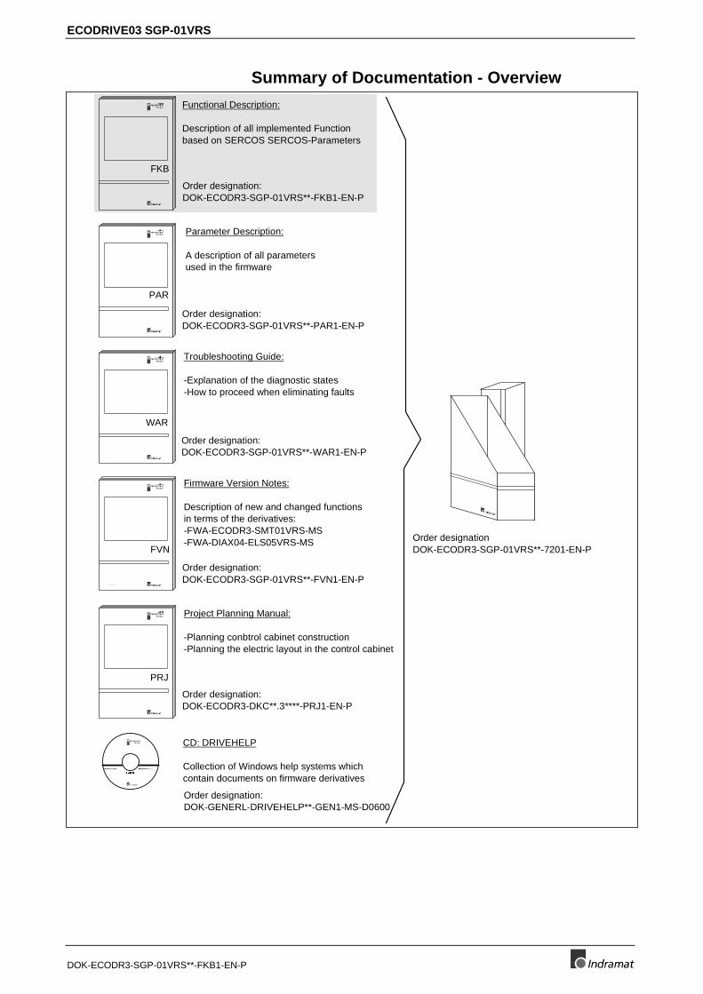
Summary of Documentation - Overview
Order designation:DOK-ECODR3-SGP-01VRS**-FKB1-EN-P
Order designation:DOK-ECODR3-SGP-01VRS**-PAR1-EN-P
Order designation:DOK-ECODR3-SGP-01VRS**-WAR1-EN-P
Order designation:DOK-ECODR3-SGP-01VRS**-FVN1-EN-P
Order designation:DOK-ECODR3-DKC**.3****-PRJ1-EN-P
2 8 2 8 0 1
FKB
2 8 2 8 0 1
PAR
2 8 2 8 0 1
WAR
2 8 2 8 0 1
FVN
2 8 2 8 0 1
PRJ
Functional Description:
Description of all implemented Functionbased on SERCOS SERCOS-Parameters
Parameter Description:
A description of all parametersused in the firmware
Troubleshooting Guide:
-Explanation of the diagnostic states-How to proceed when eliminating faults
Firmware Version Notes:
Description of new and changed functionsin terms of the derivatives:-FWA-ECODR3-SMT01VRS-MS-FWA-DIAX04-ELS05VRS-MS
Project Planning Manual:
-Planning conbtrol cabinet construction-Planning the electric layout in the control cabinet
Order designationDOK-ECODR3-SGP-01VRS**-7201-EN-P
part number:282411Version:01Win3.1 andWin95&NT
(6-:),)04
CD: DRIVEHELP
Collection of Windows help systems whichcontain documents on firmware derivatives
Order designation:DOK-GENERL-DRIVEHELP**-GEN1-MS-D0600

About this documentation ECODRIVE03 SGP-01VRS
DOK-ECODR3-SGP-01VRS**-FKB1-EN-P
ECODRIVE03 SGP-01VRS Contents I
DOK-ECODR3-SGP-01VRS**-FKB1-EN-P
Contents1 System Overview 1-1
1.1 ECODRIVE03 - the Universal Drive Solution for Automation .............................................................. 1-1
1.2 ECODRIVE03 - a Drive Family ............................................................................................................ 1-1
1.3 Drive Controllers and Motors ............................................................................................................... 1-2
1.4 Function Overview: FWA-ECODR3-SGP-01VRS-MS......................................................................... 1-3
Command Communications Interface .......................................................................................... 1-3
Possible Operating Modes ............................................................................................................ 1-3
Supported Types of Motors........................................................................................................... 1-3
Supported Measuring Systems ..................................................................................................... 1-3
General Functions......................................................................................................................... 1-4
2 Safety Instructions for Electrical Drives 2-12.1 Introduction .......................................................................................................................................... 2-1
2.2 Hazards by improper use..................................................................................................................... 2-2
2.3 General ................................................................................................................................................ 2-3
2.4 Protection against contact with electrical parts and not grounded enclosures .................................... 2-4
2.5 Protection by protective low voltage (PELV) against electrical shock............................................ 2-5
2.6 Protection against dangerous movements........................................................................................... 2-6
2.7 Protection against magnetic and electromagnetic fields during operations and mounting .................. 2-7
2.8 Protection against contact with hot parts ............................................................................................. 2-8
2.9 Protection during handling and installation .......................................................................................... 2-8
2.10 Battery safety ..................................................................................................................................... 2-9
3 General Instructions for Installation 3-13.1 Definition of Terms, Introduction .......................................................................................................... 3-1
Parameter ..................................................................................................................................... 3-1
Data Storage ................................................................................................................................. 3-2
Password....................................................................................................................................... 3-4
Commands.................................................................................................................................... 3-6
Operating Modes........................................................................................................................... 3-8
Warnings ....................................................................................................................................... 3-8
Error .............................................................................................................................................. 3-9
IDN List of Parameters................................................................................................................ 3-10
3.2 Parametrization Mode - Operating Mode........................................................................................... 3-11
Checks in the Transition Commands .......................................................................................... 3-12
3.3 Commissioning Guidelines ................................................................................................................ 3-16
3.4 Diagnostic Configurations .................................................................................................................. 3-20
Overview of Diagnostic Configurations ....................................................................................... 3-20
Drive-Internal Diagnostics ........................................................................................................... 3-20
Diagnostic Message Composition............................................................................................... 3-21
Permanently-Configured Collective Indication ............................................................................ 3-23
II Contents ECODRIVE03 SGP-01VRS
DOK-ECODR3-SGP-01VRS**-FKB1-EN-P
3.5 Language Selection ........................................................................................................................... 3-27
3.6 Firmware Update with the Dolfi Program........................................................................................... 3-27
Error Message in the Firmware Loader....................................................................................... 3-27
Additional Problems when Loading Firmware............................................................................. 3-30
4 Communication Through the SERCOS-interface 4-14.1 Overview of SERCOS Communication................................................................................................ 4-1
4.2 Data Transfer Cycle through SERCOS................................................................................................ 4-1
Master Control Word ..................................................................................................................... 4-2
Drive enable .................................................................................................................................. 4-2
Drive Status Word ......................................................................................................................... 4-3
Acknowledge of the Drive Enable ................................................................................................. 4-4
4.3 Real-Time Control and Status Bits....................................................................................................... 4-5
4.4 Transmission of non-cyclical Data through SERCOS.......................................................................... 4-5
4.5 Startup for the SERCOS Interface ....................................................................................................... 4-5
Adjustments of the SERCOS Interface ......................................................................................... 4-6
Connecting the Fiber Optic Cables of the SERCOS Interface...................................................... 4-7
Setting the Drive Address of the SERCOS Interface .................................................................... 4-7
Checking the Distortion Indicator of the SERCOS Interface......................................................... 4-8
Using the Distortion Indicator ........................................................................................................ 4-8
Transmission Rate of the SERCOS interface ............................................................................... 4-9
Setting the optical Transmission Power ...................................................................................... 4-10
Checking the Fiber Optics........................................................................................................... 4-10
4.6 SERCOS Telegram Configuration ..................................................................................................... 4-10
Configuration of the Telegram Send and Receive Times ........................................................... 4-10
Configuration of Telegram Contents ........................................................................................... 4-11
4.7 SERCOS Interface Error.................................................................................................................... 4-12
Diagnostic of the interface Status ............................................................................................... 4-12
Error Count for Telegram Interrupts ............................................................................................ 4-12
4.8 Multiplex Channel............................................................................................................................... 4-12
Overview ..................................................................................................................................... 4-12
Pertinent Parameters .................................................................................................................. 4-13
Functional Principle Multiplex Channel ....................................................................................... 4-13
Diagnostic Messages .................................................................................................................. 4-16
5 Command Communications with Analog Interface 5-15.1 Overview .............................................................................................................................................. 5-1
5.2 Pertinent Parameters ........................................................................................................................... 5-1
5.3 How it works......................................................................................................................................... 5-1
Digital inputs.................................................................................................................................. 5-1
Digital Outputs............................................................................................................................... 5-2
Acknowledge of the Drive Enable ................................................................................................. 5-2
5.4 Connecting Signals to DKCxx.3........................................................................................................... 5-3
6 Command Communication Using Parallel Interface 6-16.1 Overview .............................................................................................................................................. 6-1
6.2 Pertinent Parameters ........................................................................................................................... 6-1
ECODRIVE03 SGP-01VRS Contents III
DOK-ECODR3-SGP-01VRS**-FKB1-EN-P
6.3 How it works......................................................................................................................................... 6-1
Configurable outputs ..................................................................................................................... 6-1
Configurable Inputs ....................................................................................................................... 6-2
Application: Stepper Motor Mode with Parallel Interface............................................................... 6-2
Application: Positioning Block Mode with Parallel Interface.......................................................... 6-2
Application: Analog Main Spindle with Parallelinterface................................................................ 6-3
7 Motor Configuration 7-17.1 Characteristics of the Different Motor Types........................................................................................ 7-1
Motor Feedback-Data Memory ..................................................................................................... 7-2
Linear-Rotational ........................................................................................................................... 7-2
Synchronous-Asynchronous ......................................................................................................... 7-3
Temperature Monitoring................................................................................................................ 7-3
Load Default Feature .................................................................................................................... 7-4
7.2 Setting the Motor Type......................................................................................................................... 7-4
Automatic Setting of the Motor Type for Motors with Feedback Memory ..................................... 7-4
Setting of the Motor Type through P-0-4014, Motor Type............................................................. 7-4
7.3 Asynchronous Motors .......................................................................................................................... 7-5
Basics for the Asynchronous Motor .............................................................................................. 7-5
Torque Evaluation ......................................................................................................................... 7-6
User-defined Settings for the Asynchronous Motor ...................................................................... 7-7
7.4 Synchronous Motors ............................................................................................................................ 7-8
Determining the commutation offset ............................................................................................. 7-9
7.5 Motor Holding Brake .......................................................................................................................... 7-13
Setting the Motor Brake Type...................................................................................................... 7-13
Setting the Motor Brake Integral Action Time ............................................................................. 7-14
Setting Maximum Decel Time ..................................................................................................... 7-14
Connecting the Motor Holding Brake .......................................................................................... 7-15
8 Operating Modes 8-18.1 Setting the Operating Mode Parameters ............................................................................................. 8-1
8.2 Determining/detecting the active mode................................................................................................ 8-1
8.3 Operating Mode: Torque Control ......................................................................................................... 8-2
Pertinent Parameters .................................................................................................................... 8-2
Torque Control .............................................................................................................................. 8-2
Diagnostic Messages .................................................................................................................... 8-3
Torque Control with Analog Command Communications ............................................................. 8-3
8.4 Mode: Velocity Control......................................................................................................................... 8-4
Pertinent Parameters .................................................................................................................... 8-4
Command value processing Velocity control ................................................................................ 8-4
Velocity Controller ......................................................................................................................... 8-5
Current Controller.......................................................................................................................... 8-6
Diagnostic Messages .................................................................................................................... 8-6
Velocity Control with Analog Command Communications............................................................ 8-7
8.5 Mode: Position Control......................................................................................................................... 8-7
Command value processing : Position Control ............................................................................. 8-8
Position Controller......................................................................................................................... 8-8
IV Contents ECODRIVE03 SGP-01VRS
DOK-ECODR3-SGP-01VRS**-FKB1-EN-P
Position Command Value Monitoring............................................................................................ 8-9
Setting Position Command Value Monitoring.............................................................................. 8-10
8.6 Operating Mode: Drive Internal Interpolation ..................................................................................... 8-11
Functional principle Drive Internal Interpolation .......................................................................... 8-11
Monitoring in mode: "Drive-internal interpolation" ....................................................................... 8-12
Status messages during operating mode "Drive-internal interpolation"...................................... 8-12
8.7 Mode: Relative drive-internal interpolation......................................................................................... 8-14
Pertinent Parameters .................................................................................................................. 8-14
Function principle: Relative drive-internal interpolation............................................................... 8-15
Diagnostic Messages .................................................................................................................. 8-15
Status messages during operating mode "Relative drive-internal interpolation"......................... 8-16
8.8 Positioning Block Mode...................................................................................................................... 8-16
Pertinent Parameters .................................................................................................................. 8-17
How it works................................................................................................................................ 8-17
Activating Positioning Blocks....................................................................................................... 8-18
Positioning Block Modes ............................................................................................................. 8-18
Parametrization notes for positioning blocks............................................................................... 8-33
Acknowledge positioning block selected..................................................................................... 8-35
Status Messages in "Positioning Block Mode"............................................................................ 8-36
Positioning block mode with parallel interface ............................................................................ 8-36
Diagnostic messages .................................................................................................................. 8-37
8.9 Operating Mode: Stepper Motor Operations...................................................................................... 8-37
Pertinent Parameters .................................................................................................................. 8-38
Stepper motor signal processing................................................................................................. 8-38
Diagnostic Messages .................................................................................................................. 8-39
Connecting the Parallel Interface ................................................................................................ 8-39
8.10 Operating Mode: Jogging................................................................................................................. 8-39
Pertinent Parameters .................................................................................................................. 8-39
How it works................................................................................................................................ 8-39
Diagnostic Messages .................................................................................................................. 8-40
Hardware Requirements for operating mode jogging ................................................................. 8-40
8.11 Operating mode: velocity synchronization with virtual master axis.................................................. 8-41
Pertinent Parameters .................................................................................................................. 8-41
Command Value Preparation for Velocity Synchronization with Virtual Master Axis.................. 8-41
8.12 Operating mode: velocity synchronization with real master axis...................................................... 8-43
Pertinent Parameters .................................................................................................................. 8-43
Functional Principle..................................................................................................................... 8-43
8.13 Operating mode: phase synchronization with virtual master axis.................................................... 8-44
Pertinent Parameters .................................................................................................................. 8-44
Command value preparation with phase synchronization with virtual master axis ..................... 8-44
8.14 Operating mode: phase synchronization with real master axis........................................................ 8-50
Pertinent Parameters .................................................................................................................. 8-50
Functional Principle..................................................................................................................... 8-50
8.15 Operating mode: electronic cam shaft with virtual master axis........................................................ 8-51
Pertinent Parameters .................................................................................................................. 8-51
Command Value Preparation for Electronic Cam ....................................................................... 8-52
8.16 Operating mode: electronic cam shaft with real master axis ........................................................... 8-55
ECODRIVE03 SGP-01VRS Contents V
DOK-ECODR3-SGP-01VRS**-FKB1-EN-P
Pertinent Parameters .................................................................................................................. 8-55
Functional Principle..................................................................................................................... 8-55
9 Basic Drive Functions 9-19.1 Physical Values Display Format........................................................................................................... 9-1
Adjustable Scaling for Position, Velocity, and Acceleration Data.................................................. 9-1
Display Format of Position Data.................................................................................................... 9-2
Velocity Data Display Format........................................................................................................ 9-4
Acceleration Data Display Format................................................................................................. 9-5
Command Polarities and Actual Value Polarities.......................................................................... 9-5
Mechanical Transmission Elements ............................................................................................. 9-7
Modulo Feature ............................................................................................................................. 9-8
9.2 Setting the Measurement System...................................................................................................... 9-10
Motor Encoder............................................................................................................................. 9-12
Optional encoder......................................................................................................................... 9-15
Actual Feedback Values of Non-Absolute Measurement Systems After Initialization ................ 9-19
Drive-internal format of position data .......................................................................................... 9-20
9.3 Other Settings for Absolute Measurement Systems.......................................................................... 9-24
Encoder Types and Pertinent Interfaces..................................................................................... 9-24
Absolute encoder range and absolute encoder evaluation......................................................... 9-25
Absolute Encoder Monitoring ...................................................................................................... 9-26
Moduleo Analysis with two absolute encoders............................................................................ 9-27
Actual Feedback Values of Absolute Measurement Systems After Initialization ........................ 9-28
9.4 Drive Limitations................................................................................................................................. 9-28
Current Limit................................................................................................................................ 9-28
Torque Limit ................................................................................................................................ 9-32
Limiting Velocity .......................................................................................................................... 9-34
Travel Range Limits .................................................................................................................... 9-35
9.5 Master Axis Feedback Analysis ......................................................................................................... 9-39
The Functional Principle of Master Axis Feedback Analysis....................................................... 9-39
Parameterizing the Master Axis Feedback ................................................................................. 9-40
Referencing the master axis encoder ......................................................................................... 9-41
9.6 Drive Error Reaction........................................................................................................................... 9-43
Best Possible Deceleration ......................................................................................................... 9-43
Power off on error ....................................................................................................................... 9-49
NC Response in Error Situation .................................................................................................. 9-51
Emergency stop feature .............................................................................................................. 9-51
9.7 Control Loop Settings......................................................................................................................... 9-53
General Information for Control Loop Settings............................................................................ 9-53
Load Default ................................................................................................................................ 9-55
Setting the Current Controller...................................................................................................... 9-57
Setting the Velocity Controller..................................................................................................... 9-57
Velocity Control Loop Monitoring ................................................................................................ 9-62
Setting the position controller...................................................................................................... 9-63
Position Control Loop Monitoring ................................................................................................ 9-64
Setting the Acceleration Feed Forward....................................................................................... 9-65
Setting the Velocity Mix Factor.................................................................................................... 9-67
VI Contents ECODRIVE03 SGP-01VRS
DOK-ECODR3-SGP-01VRS**-FKB1-EN-P
9.8 Automatic Control Loop Settings ....................................................................................................... 9-68
General Preliminary Comments .................................................................................................. 9-68
Prerequisites for Starting Automatic Control Loop Settings........................................................ 9-68
Executing Automatic Control Loop Settings................................................................................ 9-70
Chronological Sequence for Automatic Control Loop Settings ................................................... 9-72
The Results of the Automatic Control Loop Setting .................................................................... 9-73
9.9 Drive Halt ........................................................................................................................................... 9-74
Pertinent Parameters .................................................................................................................. 9-74
The Functional Principle of Drive Halt......................................................................................... 9-74
Connecting the drive halt input.................................................................................................... 9-76
9.10 Drive-Controlled Homing.................................................................................................................. 9-76
Pertinent Parameter .................................................................................................................... 9-76
Setting the referencing parameters............................................................................................. 9-77
Overview of the Type and Allocation of Reference Marks of Non-Absolute Measuring Systems9-78
Functional Principle of Drive-Controlled Referencing in Non-Absolute Measuring Systems...... 9-79
Functional Principle of Drive-Guided Referencing with Absolute Measuring Systems ............... 9-80
Sequence control "Drive-Controlled Homing" ............................................................................. 9-80
Commissioning with "Evaluation of reference marker/home switch edge" ................................. 9-82
Commissioning with "Evaluation of distance-coded reference marker" ...................................... 9-89
Functions of the Control During "Drive-Controlled Homing" ....................................................... 9-92
Possible Error Messages During "Drive-Controlled Homing"...................................................... 9-92
Configuration of the Home switch ............................................................................................... 9-92
Connection of the Home switch .................................................................................................. 9-93
Homing of Gantry axis................................................................................................................. 9-94
9.11 Set Absolute Measuring................................................................................................................. 9-100
Function Principle Set Absolute Measuring............................................................................... 9-100
Diagnostic messages ................................................................................................................ 9-102
10 Optional Drive Functions 10-110.1 Configurable Signal Status Word..................................................................................................... 10-1
Pertinent Parameters .................................................................................................................. 10-1
Configuration of the Signal Status Words ................................................................................... 10-1
Diagnostic / Error Messages ....................................................................................................... 10-2
Hardware Dependencies............................................................................................................. 10-3
10.2 Configurable Signal Control Word ................................................................................................... 10-3
Involved Parameters ................................................................................................................... 10-3
Configuring the Signal Control Word........................................................................................... 10-4
Diagnostic / Error Messages ....................................................................................................... 10-5
10.3 Analog Output .................................................................................................................................. 10-6
Possible output functions ............................................................................................................ 10-6
Direct analog outputs .................................................................................................................. 10-6
Analog output of existing parameters.......................................................................................... 10-7
Outputting pre-set signals ........................................................................................................... 10-7
Bit and byte outputs of the data memory..................................................................................... 10-8
Terminal assignment - analog output.......................................................................................... 10-9
10.4 Analog Inputs ................................................................................................................................... 10-9
Pertinent Parameters .................................................................................................................. 10-9
ECODRIVE03 SGP-01VRS Contents VII
DOK-ECODR3-SGP-01VRS**-FKB1-EN-P
Functional principle of the analog inputs................................................................................... 10-10
Analog Inputs - Connection....................................................................................................... 10-11
10.5 Oscilloscope Feature ..................................................................................................................... 10-11
Main Functions of the Oscilloscope Feature ............................................................................. 10-12
Parameterizing the Oscilloscope Feature ................................................................................. 10-12
10.6 Probe Input Feature ....................................................................................................................... 10-19
Main Function of the Probe Analysis......................................................................................... 10-20
Signal Edge Selection for the Probe Inputs............................................................................... 10-21
Signal Selection for the Probe Inputs........................................................................................ 10-22
Connecting the Probe Inputs..................................................................................................... 10-22
10.7 Command - detect marker position................................................................................................ 10-23
Functional principle of command detect marker position.......................................................... 10-23
10.8 Command Parking Axis ................................................................................................................. 10-23
The functional principle of the command parking axis .............................................................. 10-24
10.9 Programmable Limit Switch ........................................................................................................... 10-24
Pertinent Parameters ................................................................................................................ 10-24
Function diagram for the Programmable Limit Switch .............................................................. 10-24
Parameterizing the Programmable Limit Switch ...................................................................... 10-27
10.10 Encoder Emulation....................................................................................................................... 10-27
Pertinent Parameters ................................................................................................................ 10-28
Activating Encoder Emulation ................................................................................................... 10-28
Functional principle: Incremental Encoder Emulation............................................................... 10-28
Diagnostic Messages with Incremental Encoder Emulation ..................................................... 10-30
Functional Principle: Absolute Encoder Emulation ................................................................... 10-31
10.11 Measuring wheel operation mode................................................................................................ 10-33
Pertinent Parameters ................................................................................................................ 10-33
How it Works ............................................................................................................................. 10-33
Diagnostic Messages ................................................................................................................ 10-34
11 Glossary 11-1
12 Index 12-1
Supplement A: Serial Communications
Sales & Service Facilities

8 Contents ECODRIVE03 SGP-01VRS
DOK-ECODR3-SGP-01VRS**-FKB1-EN-P
Notes
ECODRIVE03 SGP-01VRS System Overview 1-1
DOK-ECODR3-SGP-01VRS**-FKB1-EN-P
1 System Overview
1.1 ECODRIVE03 - the Universal Drive Solution forAutomation
The universal automation system ECODRIVE03 is an especially cost-effective solution for drive and control tasks.
Exceptional power data, extensive functions and an excellent price-performance ratio are characteristic of this system.
Further features of ECODRIVE03 are its easy assembly and installation,extreme machine accessing and the elimination of system components.
ECODRIVE03 can be used to implement numerous drive tasks in themost varying of applications. Typical applications are:
• machine tools
• printing and paper processing machines
• handling systems
• packaging and food processing machines
• handling and assembly systems
1.2 ECODRIVE03 - a Drive Family
There are three application-related firmware variants available for theECODRIVE03 family:
• Drive for Machine Tool Applications With SERCOS-, Analog- andParallelinterface
• Drive for General Automation With SERCOS-, Analog- andParallelinterface
• Drive for General Automation With Profibus-Interface withFieldbusinterface
The following function description relates to the firmware variant:
• Drive for General Automation With SERCOS-, Analog- andParallelinterface
For each listed variant, there is individual documentation.
FWA-ECODR3-SMT-0xVRS-MS
FWA-ECODR3-SGP-0xVRS-MS
FWA-ECODR3-FGP-0xVRS-MS
FWA-ECODR3-SGP-01VRS-MS
1-2 System Overview ECODRIVE03 SGP-01VRS
DOK-ECODR3-SGP-01VRS**-FKB1-EN-P
1.3 Drive Controllers and Motors
The drive controller family of the ECODRIVE03 generation is at presentmade up of four different units. These differentiate primarily in terms ofwhich interface is used command communications.
• DKC 1.3 Parallel interface
• DKC 2.3 SERCOS interface
• DKC 3.3 Profibus interface
• DKC 11.3 analog interface
Each of these drive controllers is, in turn, available in a 40 A or a 100 Aversion.
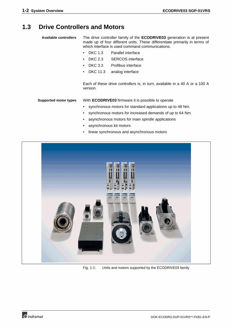
With ECODRIVE03 firmware it is possible to operate
• synchronous motors for standard applications up to 48 Nm.
• synchronous motors for increased demands of up to 64 Nm.
• asynchronous motors for main spindle applications
• asynchronous kit motors
• linear synchronous and asynchronous motors
Fig. 1-1: Units and motors supported by the ECODRIVE03 family
Available controllers
Supported motor types
ECODRIVE03 SGP-01VRS System Overview 1-3
DOK-ECODR3-SGP-01VRS**-FKB1-EN-P
1.4 Function Overview: FWA-ECODR3-SGP-01VRS-MS
Command Communications Interface• SERCOS-Interface
• Parallel-Interface
• Analog-Interface.
Possible Operating Modes• torque control
• velocity control
• Velocity Control
• position control
• drive-internal interpolation
• relative drive-internal interpolation
• jogging
• positioning block mode
• Stepper motor mode
• Velocity synchronization with real or virtuel master axis
• Phase synchronization with real or virtuel master axis
• Electronic cam shaft with real or virtuel master axis
Supported Types of Motors
• MKD • MHD• 2AD • ADF• 1MB • MBW• LAF • LAR• MKE• Rotary synchronous kit motor • Linear synchronous kit motor
Supported Measuring Systems
• HSF/LSF
• resolver
• sine encoder with 1Vss signals
• encoder with EnDat-Interface
• resolver without feedback data memory
• resolver without feedback data memory with incremental sine encoder
• gearwheel encoder with 1Vss signals
Which combination is possible, is outlined in section: "Setting theMeasurement System"
1-4 System Overview ECODRIVE03 SGP-01VRS
DOK-ECODR3-SGP-01VRS**-FKB1-EN-P
General Functions
• Extensive diagnostics options
• Basic parameter block that can be activated for a defined setting ofthe drive parameters to default values.
• Customer passwords
• Error memory and operating hour counter
• Supports five (5) languages for parameter names and units anddiagnoses (S-0-0095)
• German
• English
• French
• Spanish
• Italian
• comfortable tool to upload the firmware
• Settable drive-internal position resolution
• Evaluation of option (load-side) encoder for position and/or velocitycontrol
• Master axis feedback analysis
• Evaluates absolute measuring system with setting of absolutedimension
• Modulo function
• Parametrizable torque limit
• Current limit
• Velocity limit
• Travel range limit:
via travel range limit switch and/or position limit values
• Drive-side error reactions:
error reaction "return limit"
bet possible standstill "velocity command to zero"
best possible standstill "Torque free"
best possible standstill "velocity command to zero withramp and filter
power shutdown with fault
NC reaction with fault
E-Stop function
• Control loop settings
base load function
acceleration precontrol
velocity mix factor
velocity precontrol
automatic control loop settings
• Velocity control loop monitor
• Positoin control loop monitor
• Drive halt
ECODRIVE03 SGP-01VRS System Overview 1-5
DOK-ECODR3-SGP-01VRS**-FKB1-EN-P
• Command "Drive-Controlled Homing"
• Command "Set Absolute Measuring"
• Free configurable signal status word
• Free configurable signal control word
• Analog output
• Analog input
• Oscilloscope function
• Probe function
• Command "Detect marker position“
• Command "Parking axis"
• Programmable Limit Switch
• Encoder emulation
absolute encoder emulation (SSI format)
incremental encoder emulation
• Measuring wheel operation mode

1-6 System Overview ECODRIVE03 SGP-01VRS
DOK-ECODR3-SGP-01VRS**-FKB1-EN-P
Notes
ECODRIVE03 SGP-01VRS Safety Instructions for Electrical Drives 2-1
DOK-ECODR3-SGP-01VRS**-FKB1-EN-P
2 Safety Instructions for Electrical Drives
2.1 Introduction
These instructions must be read and understood before the equipment isused to minimize the risk of personal injury and / or property damage.Follow these safety instructions at all times.
Do not attempt to install, use or service this equipment without firstreading all documentation provided with the product. Please read andunderstand these safety instructions, and all user documentation of theequipment, prior to working with the equipment at any time. You mustcontact your local Indramat representative if you cannot locate the userdocumentation for your equipment. A listing of Indramat offices issupplied in the back of this manual. Request that your representativesend this documentation immediately to the person or personsresponsible for the safe operation of this equipment.
If the product is resold, rented and/or otherwise transferred or passed onto others, then these safety instructions must accompany it.
WARNING
Improper use of this equipment, failure to follow theattached safety instructions, or tampering with theproduct, including disabling of safety device, mayresult in personal injury, severe electrical shock,death, or property damage!
2-2 Safety Instructions for Electrical Drives ECODRIVE03 SGP-01VRS
DOK-ECODR3-SGP-01VRS**-FKB1-EN-P
2.2 Hazards by improper use
DANGER
High voltage and high discharge current!
Danger to life, risk of severe electrical shock and risk ofinjury!
DANGER
Dangerous movements!
Danger to life and risk of injury or equipment damage byunintentional motor movements!
WARNING
High electrical voltages due to incorrectconnections!
Danger to life, severe electrical shock and serious bodilyinjury!
WARNING
Health hazard for persons with heart pacemakers,metal implants and hearing aids in proximity toelectrical equipment!
CAUTION
Surface of machine housing could be extremely hot!Danger of injury! Danger of burns!
CAUTION
Risk of injury due to incorrect handling!
Bodily injury caused by crushing, shearing, cutting andthrusting movements!
CAUTION
Risk of injury due to incorrect handling of batteries!
ECODRIVE03 SGP-01VRS Safety Instructions for Electrical Drives 2-3
DOK-ECODR3-SGP-01VRS**-FKB1-EN-P
2.3 General
• INDRAMAT GmbH is not liable for damages resulting from failure toobserve the warnings given in these instructions.
• Operating, maintenance and safety instructions in English must beordered and received before initial start-up, if the instructions in thelanguage provided are not understood perfectly.
• Proper and correct transport, storage, assembly, and installation aswell as care in operation and maintenance are prerequisites foroptimal and safe operation of this equipment.
• Trained and qualified personnel in electrical equipment:
Only trained and qualified personnel may work on this equipment orwithin its proximity. Personnel are qualified if they have sufficientknowledge of the assembly, installation, and operation of the productas well as an understanding of all warnings and precautionarymeasures noted in these instructions.
Furthermore, they should be trained, instructed, and qualified toswitch electrical circuits and equipment on and off, to ground them,and to mark them according to the requirements of safe workpractices and common sense. They must have adequate safetyequipment and be trained in first aid.
• Use only spare parts approved by the manufacturer.
• All safety regulations and requirements for the specific applicationmust be followed as practiced in the country of use.
• The equipment is designed for installation on commercial machinery.
• Start-up is only permitted once it is sure that the machine in which theproduct is installed complies with the requirements of national safetyregulations and safety specifications of the application.
European countries: see Directive 89/392/EEC (Machine Guideline).
• Operation is only permitted if the national EMC regulations for theapplication are met.
The instructions for installation in accordance with EMC requirementscan be found in the INDRAMAT document "EMC in Drive and ControlSystems“.
The machine builder is responsible for compliance with the limitingvalues as prescribed in the national regulations and specific EMCregulations for the application.
European countries: see Directive 89/336/EEC (EMC Guideline).
U.S.A.: See National Electrical Codes (NEC), National ElectricalManufacturers Association (NEMA), and local building codes. Theuser of this equipment must consult the above noted items at alltimes.
• Technical data, connections, and operational conditions are specifiedin the product documentation and must be followed.
2-4 Safety Instructions for Electrical Drives ECODRIVE03 SGP-01VRS
DOK-ECODR3-SGP-01VRS**-FKB1-EN-P
2.4 Protection against contact with electrical parts and notgrounded enclosures
Note: This section pertains to equipment and drive components withvoltages over 50 Volts.
Touching live parts with potentials of 50 volts and higher applied to themor touching not grounded enclosures can be dangerous and causesevere electrical shock. In order for electrical equipment to be operated,certain parts must have dangerous voltages applied to them.
DANGER
High Voltage!Danger to life, severe electrical shock and risk of injury!
⇒ Only those trained and qualified to work with or onelectrical equipment are permitted to operate, maintainand / or repair this equipment.
⇒ Follow general construction and safety regulationswhen working on electrical installations.
⇒ Before switching on power, the ground wire must bepermanently connected to all electrical units accordingto the connection diagram.
⇒ At no time may electrical equipment be operated if theground wire is not permanently connected, even forbrief measurements or tests.
⇒ Before beginning any work, disconnect mains or thevoltage source from the equipment. Lock theequipment against being switched on while work isbeing performed.
⇒ Wait five (5) minutes after switching off power to allowcapacitors to discharge before beginning work.Measure the voltage on the capacitors beforebeginning work to make sure that the equipment issafe to touch.
⇒ Never touch the electrical connection points of acomponent while power is turned on.
⇒ Before switching the equipment on, install thosecovers and guards provided with the equipment toprevent contact with live parts. Before operating, coverand guard live parts properly so they cannot betouched.
⇒ A residual-current-operated protective device (r.c.d.)must not be used on an AC drive! Indirect contactmust be prevented by other means, for example, by anovercurrent protective device.
European countries: according to EN 50178/ 1994.⇒ Electrical components with exposed live parts must be
installed in a control cabinet to prevent direct contact.European countries: according to EN 50178/ 1994.U.S.A: See National Electrical Codes (NEC), NationalElectrical Manufacturers Association (NEMA), andlocal building codes. The user of this equipment mustconsult the above noted items at all times.
ECODRIVE03 SGP-01VRS Safety Instructions for Electrical Drives 2-5
DOK-ECODR3-SGP-01VRS**-FKB1-EN-P
DANGER
High housing voltage! High leakage current!Danger to life and limb, danger of injury from electricshock!
⇒ Prior to powering up, connect the electrical equipment,the housing of all electrical units and motors to theprotective conductor at the grounding points or groundthem. This applies even to brief tests.
⇒ The protective conductor of the electrical equipmentand units must always be connected to the supplynetwork. Leakage current exceeds 3.5 mA.
⇒ Use at least a 10 mm2 copper conductor cross sectionfor this protective connection over its entire course!
⇒ Prior to startups, even for brief tests, always connectthe protective conductor or connect with ground wire.High voltage levels can occur on the housing thatcould lead to severe electrical shock and personalinjury.
European countries: EN 50178 / 1994, section 5.3.2.3.USA: See National Electrical Codes (NEC), NationalElectrical Manufacturers Association (NEMA), and localbuilding codes. The user of this equipment must consultthe above noted items at all times.
2.5 Protection by protective low voltage (PELV) againstelectrical shock
All connections and terminals with voltages ranging between 5 and 50volts on INDRAMAT products are protective low voltages designed inaccordance with the following standards on contact safety:
• International: IEC 364-4-411.1.5
• EU countries: see EN 50178/1994, section 5.2.8.1.
WARNING
High electrical voltages due to incorrect connections!Danger to life, severe electrical shock and/or seriousbodily injury!
⇒ Only that equipment or those electrical componentsand cables may be connected to all terminals andclamps with 0 to 50 volts that are of the protective lowvoltage type (PELV = Protective Extra Low Voltage).
⇒ Only connect those voltages and electrical circuits thatare safely isolated. Safe isolation is achieved, forexample, with an isolating transformer, anoptoelectronic coupler or when battery-operated.
2-6 Safety Instructions for Electrical Drives ECODRIVE03 SGP-01VRS
DOK-ECODR3-SGP-01VRS**-FKB1-EN-P
2.6 Protection against dangerous movements
Dangerous movements can be caused when units have bad interfaces ormotors are connected incorrectly.
There are various causes of dangerous movements:
• Improper or incorrect wiring or cable connections
• equipment is operated incorrectly
• probe parameters or encoder parameters are set incorrectly
• malfunctioning components
• errors in software or firmware
Dangerous movements can occur immediately after equipment isswitched on or even after an unspecified time of trouble-free operation.
Although the monitoring circuits in the drive components make improperoperation almost impossible, personnel safety requires that proper safetyprecautions be taken to minimize the risk of personal injury and/orproperty damage. This means that unexpected motion must beanticipated since safety monitoring built into the equipment might bedefeated by incorrect wiring or other faults.
DANGER
Dangerous movements!Danger to life and risk of injury or equipment damage!
⇒ In the drive component monitoring units, every effort ismade to avoid the possibility of faulty operation inconnected drives. Unintended machine motion or othermalfunction is possible if monitoring units are disabled,bypassed or not activated.
⇒ Safe requirements of each individual drive applicationmust be considered on a case-by-case basis by usersand machine builders.
Avoiding accidents, personal injury and/or propertydamage:
⇒ Keep free and clear of the machine’s range of motionand moving parts. Prevent people from accidentallyentering the machine’s range of movement:- use protective fences- use protective railings- install protective coverings- install light curtains / barriers
⇒ Fences should be strong enough to withstandmaximum possible momentum.
⇒ Mount the Emergency Stop (E-stop) switch in theimmediate reach of the operator. Verify that theemergency stop works before startup. Do not operatethe machine if it is not working.
⇒ Isolate the drive power connection by means of anemergency stop circuit or use a start inhibit system toprevent unintentional start-up.
ECODRIVE03 SGP-01VRS Safety Instructions for Electrical Drives 2-7
DOK-ECODR3-SGP-01VRS**-FKB1-EN-P
⇒ Make sure that the drives are brought to standstillbefore accessing or entering the danger zone.
⇒ Disconnect electrical power to the equipment using amaster lock-out and secure against reconnection for:- maintenance and repair work- cleaning of equipment- long periods of discontinued equipment use
⇒ Avoid operating high-frequency, remote control, andradio equipment near equipment electronics andsupply leads. If use of such equipment cannot beavoided, verify the system and the plant for possiblemalfunctions at all possible positions of normal usebefore the first start-up. If necessary, perform aspecial Electromagnetic Compatibility (EMC) test onthe plant.
2.7 Protection against magnetic and electromagnetic fieldsduring operations and mounting
Magnetic and electromagnetic fields in the vicinity of current-carryingconductors and permanent motor magnets represent a serious healthhazard to persons with heart pacemakers, metal implants and hearingaids.
WARNING
Health hazard for persons with heart pacemakers,metal implants and hearing aids in proximity toelectrical equipment!⇒ Persons with pacemakers and metal implants are not
permitted to have access to the following areas:− Areas in which electrical equipment and parts are
mounted, being operated or started up.− Areas in which parts of motors with permanent
magnets are being stored, repaired or mounted.⇒ If it is necessary for a person with a pacemaker to
enter into such an area, then a physician must beconsulted prior to doing so.
⇒ Persons with metal implants or hearing aids must takecare prior to entering into areas described above. It isassumed that metal implants or hearing aids will beaffected by such areas: A physician must be consultedprior to working in and/or entering such areas.
2-8 Safety Instructions for Electrical Drives ECODRIVE03 SGP-01VRS
DOK-ECODR3-SGP-01VRS**-FKB1-EN-P
2.8 Protection against contact with hot parts
CAUTION
Surface of machine housing could be extremely hot!Danger of injury! Danger of burns!
⇒ Do not touch housing surface near the source ofheat! Danger of burns!
⇒ Prior to accessing a unit, wait ten (10) minutes toallow the unit to cool off.
⇒ If hot parts of the equipment are touched, such as theunit housing in which heatsink and resistor arelocated, then this can cause burns.
2.9 Protection during handling and installation
All INDRAMAT products should be handled and assembled according tothe instructions in the documentation.
CAUTION
Risk of injury due to incorrect handling!Bodily injury caused by crushing, shearing, cutting, andthrusting movements!
⇒ Observe installation instructions and safety regulationsbefore handling and working on the product.
⇒ Use suitable lifting or moving equipment duringinstallation. Refer to the user manual for the product.
⇒ Take precautions to avoid pinching and crushing.⇒ Only use suitable tools specified in the user manuals
and use them according the instructions.⇒ Use lifting devices and tools correctly and safely.⇒ Wear appropriate protective clothing, e.g., protective
goggles, safety shoes, protective gloves.⇒ Never stand under suspended loads.⇒ Clean up liquids form the floor to prevent personnel
from slipping.
ECODRIVE03 SGP-01VRS Safety Instructions for Electrical Drives 2-9
DOK-ECODR3-SGP-01VRS**-FKB1-EN-P
2.10 Battery safety
Batteries contain reactive chemicals. Incorrect handling can result ininjury or equipment damage.
CAUTION
Risk of injury due to incorrect handling!
⇒ Do not attempt to reactivate dead batteries by heatingor other methods (danger of explosion and corrosion).
⇒ Never charge batteries (danger from leakage andexplosion).
⇒ Never throw batteries into a fire.⇒ Do not take batteries apart.⇒ Handle carefully. Incorrect extraction or installation of a
battery can damage equipment.
Note: Environmental protection and disposal! The batteries containedin the product should be considered as hazardous material forland, air and sea transport in the sense of the legal requirements(Danger of explosion). Dispose of batteries separately from otherrefuse. Observe the legal requirements in the country ofinstallation.

2-10 Safety Instructions for Electrical Drives ECODRIVE03 SGP-01VRS
DOK-ECODR3-SGP-01VRS**-FKB1-EN-P
Notes
ECODRIVE03 SGP-01VRS General Instructions for Installation 3-1
DOK-ECODR3-SGP-01VRS**-FKB1-EN-P
3 General Instructions for Installation
3.1 Definition of Terms, Introduction
It is helpful to explain the terms used in this document so that they willbe better understood.
ParameterCommunication with the drive occurs (with a few exceptions) with thehelp of parameters. They can be used for
• Setting the configuration
• Parameterizing the control/drive settings
• Accessing control/drive functions and commands
• Cyclical or acyclical (depending on requirements) transmission ofcommand and actual values
Note: All of the drive’s operating data are identified by ID numbers.
Each parameter is provided with a data status, which can also be read. Itserves the following purposes:
• Identifying the validity/invalidity of the parameter
• Contains the command acknowledgment if the parameter acts as acommand (see Commands")
Each parameter has 7 different data block elements that can be read orwritten by a SERCOS control system.
Data BlockStructure:Element No.:
Designation: Remarks:
1 ID Number Parameter identification
2 Name can be changed in languageselection
3 Attribute contains data length, type anddecimal places
4 Unit can be changed in languageselection
5 Minimum Input Value contains the minimum inputvalue of the operating data
6 Maximum Input Value contains the maximum inputvalue of the operating data
7 Operating Data actual parameter valueFig. 3-1: Data blocks or parameter structure
The Data Status
Paramter structure
3-2 General Instructions for Installation ECODRIVE03 SGP-01VRS
DOK-ECODR3-SGP-01VRS**-FKB1-EN-P
Only the operating data can be changed; all other elements can only beread.
The operating data can be write-protected either continuously ortemporarily.
The write accessing of the operating data depends on the relevantcommunications phase.
Possible Error Messages when Reading and Writing theOperating Data
Error: Reason:
0x7002, datatransmitted too short
0x7003, datatransmitted too long
0x7004, Data notchangeable
The operating data is write-protected
0x7005, Datacurrently write-protected
The operating data cannot be written to in thiscommunication phase (see Supplement A: Writingto Parameters)
0x7006, Data smallerthan minimum value
The operating data is smaller than its minimal inputvalue
0x7007, Data largerthan maximum value
The operating data is larger than its maximum inputvalue
0x7008, Data is notcorrect
The value could not be accepted as written becauseinternal tests lead to a negative result
0x7009, data writeprotected withpassword
The parameter cannot be write accessed asthe customer password was activated inparameter S-0-0267, Password. Allparameters listed in S-0-0192, IDN-list ofbackup operation data are therefore locked.
Fig. 3-2: Error messages while reading/writing operating data
Data Storage
Non-Volatile Parameter Storage RegistersVarious non-volatile parameter storage registers that buffer operatingdata are contained in the drive.
The operating data apply to:
• setting the configuration or
• parameterizing the control drive settings
Each time operating data is written to it is stored.
The following modules contain non-volatile memory:
• Control drive
• Motor feedback (optional)
• Programming module
Write Accessibility
ECODRIVE03 SGP-01VRS General Instructions for Installation 3-3
DOK-ECODR3-SGP-01VRS**-FKB1-EN-P
All operating data that apply only to the drive controller and that cannotbe changed by the user are stored in the digital drive. This consists of thefollowing parameters:
• S-0-0110, Amplifier Peak Current
• S-0-0112, Amplifier Nominal Current
• S-0-0140, Controller Type
• P-0-0518, Amplifier Nominal Current 2
• P-0-0519, Amplifier Peak Current 2
• P-0-4002, Current-Amplify-Trim Phase U
• P-0-4003, Current-Amplify-Trim Phase V
• P-0-4015, Intermediate Voltage
• P-0-4035, Trim-Current
• P-0-4059, Braking resistor data
Parameter Storage in Motor FeedbackAll motor-dependent parameters are stored in the motor feedback withMHD, MKD and MKE motors.
Additionally, parameters for the "load default" function and the motorfeedback are stored here.
All parameters stored in the motor feedback data memory are there withboth parameter block number 0 and 7.
In parameter block 7 (e.g., S-7-0100) the original data without writeaccess are stored in the motor feedback data memory. These are copiedafter powering up into the parameters of parameter block 0 (e.g., S-0-0100) .
Note: The parameters of parameter block 0 take effect.
All application parameters are stored in the programming module (controlloop, mechanical system, interface parameters and so on).
All ID numbers backed up in this module are listed in parameter S-0-0192, IDN-list of backup operation data.
If the programming module is exchanged then these applicationparameters must be read out before hand so that they can be written intothe new module after the exchange.
Note: By switching the programming module when devices areexchanged, the characteristics of the device that has beenexchanged can be easily transferred to the new device.
Data SavingTo save the data of the axis, all important and changeable parameters ofthe axis are stored in the list S-0-0192, IDN-List of backup operationdata. By saving the parameters listed there with the control orparametrization surface, you can obtain a complete data backup of thisaxis after the first setup (Backup&Restore-function).
Parameter Buffer ModeThe drive controller is capable of storing data that is transmitted via theuser data channel (e.g., service channel) either temporarily orpermanently.
Parameters Stored in the DigitalDrive
Parameters Stored in DSMProgramming Module
3-4 General Instructions for Installation ECODRIVE03 SGP-01VRS
DOK-ECODR3-SGP-01VRS**-FKB1-EN-P
Note: Parameter S-0-0269, Parameter buffer mode is insignificantas of version FGP-02vrs as all the parameters are backed upfrom that point on in a NOVRAM.
Basic parameter blockThe drive parameters are fixed at delivery at the factory. By executing thecommand P-0-4094, C800 Command Base-parameter load it ispossible to reproduce this state at any time. The basic parameter block isconstructed so that
• all optional drive functions are deactivated
• limit values for position are deactivated
• limit values for torque/force are set to high values
• and limit values for velocity and acceleration are set to lower values
Velocity control is the mode set.
Note: The basic parameter block does not guarantee a matching ofthe drive to the machine as well as, in some cases, to themotor connected and the measuring systems. The relevantsettings must be made when first starting up the axis.
(See also: Basic Drive Functions" and Commissioning Guidelines".)
Running the "load basic parameter block" functionautomaticallyThe drive firmware is on the programming module. In the event of afirmware exchange, the drive controller will detect this the next time themachine is switched on. In this case, the message "PL" appears on the7-segment display. By pressing the "S1" key, the basic parameter blockis activated.
Note: Any previous parameter settings are lost with the replacementof the firmware followed by "load base parameter block". Ifthis is to be prevented, then the parmeters must be storedprior to an exchange and must be reloaded after exchangeand load base parameter block.
Note: As long as the drive displays "PL" and the command is active,then communications via the serial interface (with DriveTop)is not possible.
PasswordAll important axis-specific parameters are stored in the programmingmodule. If, e.g., a controller is replaced because of a defect then thefeatures can be transferred to the new controller by simply using the oldmodule.
ECODRIVE03 SGP-01VRS General Instructions for Installation 3-5
DOK-ECODR3-SGP-01VRS**-FKB1-EN-P
The affected parameters are stored in S-0-0279, IDN-list of password-protected operation data. To secure these parameters againstunwanted or non-authorized changes, the customer password can beactivated.
By editing S-0-0279, IDN-list of password-protected operation datathe user can select the parameter which are to be protected with apassword.
Note: The default value of S-0-0279, IDN-list of password-protectedoperation data corresponds to the contents of S-0-0192, IDN-list of backup operation data.
The password is accessed with parameter S-0-0267, Password.
The password has to have:
• at least 3 symbols
• no more than ten symbols
• can only use the letters a - z and A - Z
• and the numbers 0 to 9.
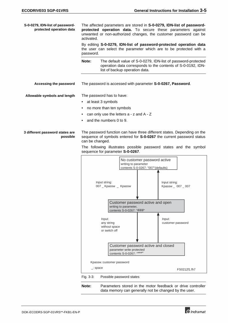
The password function can have three different states. Depending on thesequence of symbols entered for S-0-0267 the current password statuscan be changed.
The following illustrates possible password states and the symbolsequence for parameter S-0-0267.
FS0212f1.fh7_: space
Input:customer password
Input:any stringwithout spaceor switch off
Input string:007 _ Kpassw _ Kpassw
Kpassw.:customer password
Input string:Kpassw _ 007 _ 007
Customer password active and openwriting to parameter,contents S-0-0267: "###"
No customer password activewriting to parametercontents S-0-0267: "007"(defaults)
Customer password active and closedparameter write protectedcontents S-0-0267: "***"
Fig. 3-3: Possible password states
Note: Parameters stored in the motor feedback or drive controllerdata memory can generally not be changed by the user.
S-0-0279, IDN-list of password-protected operation data
Accessing the password
Allowable symbols and length
3 different password states arepossible
3-6 General Instructions for Installation ECODRIVE03 SGP-01VRS
DOK-ECODR3-SGP-01VRS**-FKB1-EN-P
CommandsCommands are used to control complex functions in the drive. Forexample, the functions "Drive-Controlled Homing Procedure" or"Transistion Check for Communication Phase 4" are defined ascommands.
Each command that is startedmust also be cleared.
A primary control can start, interrupt or erase a command.
Each command has a parameter with which the command can becontrolled.
While a command is being executed, the diagnostic message "Cx" or"dx" appears in the H1 display, where x is the number of the command.
All commands used are stored in parameter S-0-0025, IDN-list of allprocedure commands.
Command TypesThere are 3 command types.
• Drive-Controlled Command- Eventually leads to an automatic drive operation or motion- Can be started only when controller enable is set- Deactivates the active operating mode during its operation
• Monitor Command- Activates or deactivates monitors or features in the control drive
• Management Command- executes management tasks; is not interruptable
Command Input and AcknowledgmentControl and monitoring of command execution occurs via the commandinput and command acknowlegment. The command input tells the drive ifthe command should be started, interrupted or ended. The commandedvalue is the operating data of the applicable parameter. The commandinput value can be
• not set and enabled ( 0 )
• interrupted ( 1 )
• set and enabled ( 3 )
The drive gives the current condition of the command execution in theacknowledgment. It is contained in the data status of the commandparameter.
See also chapter: "Data Block Structure"
Note: You get the command status through a write access on theparameter’s element 1 (IDN).
The condition can be
• not set and enabled ( 0 )
• in process ( 7 )
• error, command execution not possible ( 0xF)
• command execution interrupted ( 5 )
• command properly executed ( 3 )
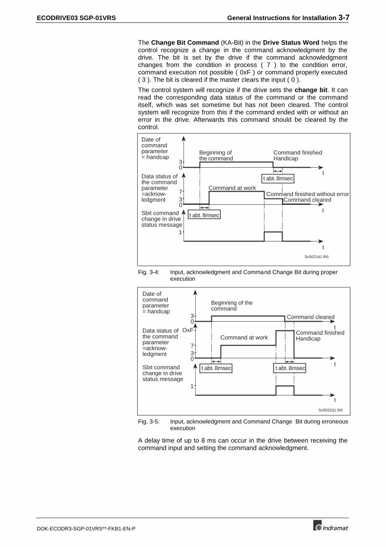
ECODRIVE03 SGP-01VRS General Instructions for Installation 3-7
DOK-ECODR3-SGP-01VRS**-FKB1-EN-P
The Change Bit Command (KA-Bit) in the Drive Status Word helps thecontrol recognize a change in the command acknowledgment by thedrive. The bit is set by the drive if the command acknowledgmentchanges from the condition in process ( 7 ) to the condition error,command execution not possible ( 0xF ) or command properly executed( 3 ). The bit is cleared if the master clears the input ( 0 ).
The control system will recognize if the drive sets the change bit. It canread the corresponding data status of the command or the commanditself, which was set sometime but has not been cleared. The controlsystem will recognize from this if the command ended with or without anerror in the drive. Afterwards this command should be cleared by thecontrol.
30
30
7
1
t
t
t
Sv5021d1.fh5
Beginning ofthe command
Command finishedHandicap
Command at work
Date ofcommandparameter= handcap
Data status ofthe commandparameter=acknow-ledgment
Sbit commandchange in drivestatus message
Command finished without error Command cleared
t abt. 8msec
t abt. 8msec
Fig. 3-4: Input, acknowledgment and Command Change Bit during properexecution
t abt. 8msec
30
30
7
1
t
OxF
t
t
Sv5022d1.fh5
Date ofcommandparameter= handcap
Data status ofthe commandparameter=acknow-ledgment
Sbit commandchange in drivestatus message
Beginning of thecommand
Command finishedHandicapCommand at work
Command cleared
t abt. 8msec
Fig. 3-5: Input, acknowledgment and Command Change Bit during erroneousexecution
A delay time of up to 8 ms can occur in the drive between receiving thecommand input and setting the command acknowledgment.
3-8 General Instructions for Installation ECODRIVE03 SGP-01VRS
DOK-ECODR3-SGP-01VRS**-FKB1-EN-P
Operating ModesOperating modes define which command values will be processed inwhich format, leading to the desired drive motion. They do not define howthese command values will be transmitted from a control system to thedrive.
One of the four selectable operating modes (S-0-0032 ... S-0-0035) isactive when
• the control and power supply is ready for operation and
• the controller enable signal is positive.
The drive displays "AF" in the H1 display.
All implemented operating modes are stored in parameter S-0-0292, Listof all operation modes.
See also chapter: "Operating Modes"
Warnings
Warnings do not causeautomatic shutdowns
Many areas are monitored in connection with operating modes andparameter settings. A warning will be generated if a state is detected thatallows proper operation for the time being, but will eventually generate anerror and thereby lead to a shutdown of the drive if this state continues.
Warning Classes
The warning class is evidentfrom the diagnostic message
Warnings can be separated into 2 classes. They are differentiated bywhether the drive executes an automatic reaction when the warningappears.
Warning Class:Diagnostic Message: Drive Response:
With drive response E8xx reacts on its own specificallyin terms of any occurringwarnings
Without drive response E2xx --Fig. 3-6: Breakdown of the Warning Classes
Note: Warnings cannot be cleared. They stay until the conditionwhich has triggered the warning is not fulfilled any more..
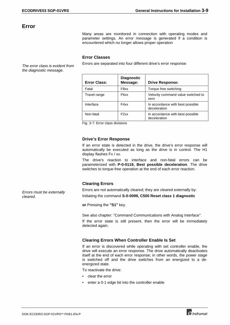
ECODRIVE03 SGP-01VRS General Instructions for Installation 3-9
DOK-ECODR3-SGP-01VRS**-FKB1-EN-P
ErrorMany areas are monitored in connection with operating modes andparameter settings. An error message is generated if a condition isencountered which no longer allows proper operation
Error Classes
The error class is evident fromthe diagnostic message.
Errors are separated into four different drive’s error response:
Error Class:DiagnosticMessage: Drive Response:
Fatal F8xx Torque free switching
Travel range F6xx Velocity command value switched tozero
Interface F4xx In accordance with best possibledeceleration
Non-fatal F2xx In accordance with best possibledeceleration
Fig. 3-7: Error class divisions
Drive’s Error ResponseIf an error state is detected in the drive, the drive’s error response willautomatically be executed as long as the drive is in control. The H1display flashes Fx / xx.
The drive’s reaction to interface and non-fatal errors can beparameterized with P-0-0119, Best possible deceleration. The driveswitches to torque-free operation at the end of each error reaction.
Clearing Errors
Errors must be externallycleared.
Errors are not automatically cleared; they are cleared externally by:
Initiating the command S-0-0099, C500 Reset class 1 diagnostic
or Pressing the "S1" key.
See also chapter: "Command Communications with Analog Interface".
If the error state is still present, then the error will be immediatelydetected again.
Clearing Errors When Controller Enable Is SetIf an error is discovered while operating with set controller enable, thedrive will execute an error response. The drive automatically deactivatesitself at the end of each error response; in other words, the power stageis switched off and the drive switches from an energized to a de-energized state.
To reactivate the drive:
• clear the error
• enter a 0-1 edge bit into the controller enable
3-10 General Instructions for Installation ECODRIVE03 SGP-01VRS
DOK-ECODR3-SGP-01VRS**-FKB1-EN-P
Note: To reactivate the drive after an error has been detected, not onlymust the error be cleared, but a 0-1 edge bit of the controllerenable signal must also follow.
Error memory and operating hour counterOnce errors are cleared, they are stored in an error memory. The last 19errors are stored there and the times they occurred.
Errors caused by a shutdown of the control voltage (e.g., F870 +24VoltDC error ) are not stored in the error memory.
Simultaneously, there is an operating hour counter for control and powersections of the drive controller. This function has the followingparameters:
• P-0-0190, Operating hours control section
• P-0-0191, Operating hours power section
• P-0-0192, Error recorder diagnosis number
• P-0-0193, Error recorder, operating hours control section
IDN List of ParametersThere are parameters in the drive that, in turn, contain ID numbers ofdrive parameters. These support the handling of the drive parameterswith parametrization programs (e.g., Drivetop, Serctop, and so on).
S-0-0017, IDN-list of all operation dataThe ID numbers of all parameters in the drive are in this parameter. Thislist supports, for example, the parametrization program in the menu ofwhich "All drive parameters" the information as to which ID number is inthis drive firmware is stored.
S-0-0192, IDN-list of backup operation dataIn parameter S-0-0192, IDN-list of backup operation data the IDnumbers of all those parameters are stored, that are stored in theprogramming module. These are the parameters that are needed for aproper operation of the drive. The control or the parametrization programuses this ID number list to secure a copy of the drive parameters.
S-0-0021, IDN-list of invalid op. data for comm. Ph. 2In the data of these ID lists, the drive enters the ID numbers out ofparameter S-0-0018, IDN-list of operation data for CP2 which arerecognized as invalid in command S-0-0127, C100 Communicationphase 3 transition check. Parameters are recognized as invalid if:
• their checksums, that are stored together with the operating data in anon-resident memory (programming module, amplifier or motorfeedback data memory), do not fit to the operating data,
• their operating data is outside of the minimum/maximum input rangeor
• their operating data has violated the plausibility rules.
In any event, the parameters entered upon negative acknowledgement ofcommand S-0-0127, C100 Communication phase 3 transition checkin S-0-0021, IDN-list of invalid op. data for comm. Ph. 2 must becorrected.
Error memory
Operating hour counter
ECODRIVE03 SGP-01VRS General Instructions for Installation 3-11
DOK-ECODR3-SGP-01VRS**-FKB1-EN-P
S-0-0022, IDN-list of invalid op. data for comm. Ph. 3The drive enters the ID numbers out of parameter S-0-0019, IDN-list ofoperation data for CP3 into the data of this ID list, which were detectedin command S-0-0128, C200 Communication phase 4 transitioncheck as invalid. Parameters are detected as invalid if:
• their checksum, stored together with the operating data in a non-resident memory (programming module, amplifier or motor feedbackdata memory) do not match the operating data,
• their operating data are outside of the minimum/maximum input limitsor
• their operating data has violated the plausibility rules.
In any event, the parameters entered upon negative acknowledgement ofcommand S-0-0128, C100 Communication phase 4 transition checkin S-0-0022, IDN-list of invalid op. data for comm. Ph. 3 must becorrected..
S-0-0018, IDN-list of operation data for CP2The ID numbers that were checked for validity in command S-0-0127,C100 Communication phase 3 transition check are stored in S-0-0018, IDN-list of operation data for CP2.
S-0-0019, IDN-list of operation data for CP3The ID numbers that were checked for validity in command S-0-0128,C200 Communication phase 4 transition check are stored in S-0-0019, IDN-list of operation data for CP3.
S-0-0025, IDN-list of all procedure commandsThe ID numbers of all the commands in the drive are stored in thisparameter.
3.2 Parametrization Mode - Operating Mode
Command communicationsets the communicationsphase and therefore theparametrization or operatingmodes
Given drive controllers without command communications interface or ifthe command communications is not active (command communications= could be SERCOS), then the drive switches automatically intooperating mode after the control voltage is switched on.
If the command communications is active, then the drive controller doesnot automatically switch into operating mode after the control voltage isswitched on. Only the command communications master can switchbetween parametrization modes and operating modes.
Parametrization surfaces that communicate with the drive controller vuathe RS232/485 can switch from parametrization and operating mode aslong as the drive is not in control mode and command communications isnot active.
The switch from parametrization to operating mode is controlled bystarting and ending commands
• S-0-0127, C100 Communication phase 3 transition check,
• S-0-0128, C200 Communication phase 4 transition check
• P-0-4023, C400 Communication phase 2 transition
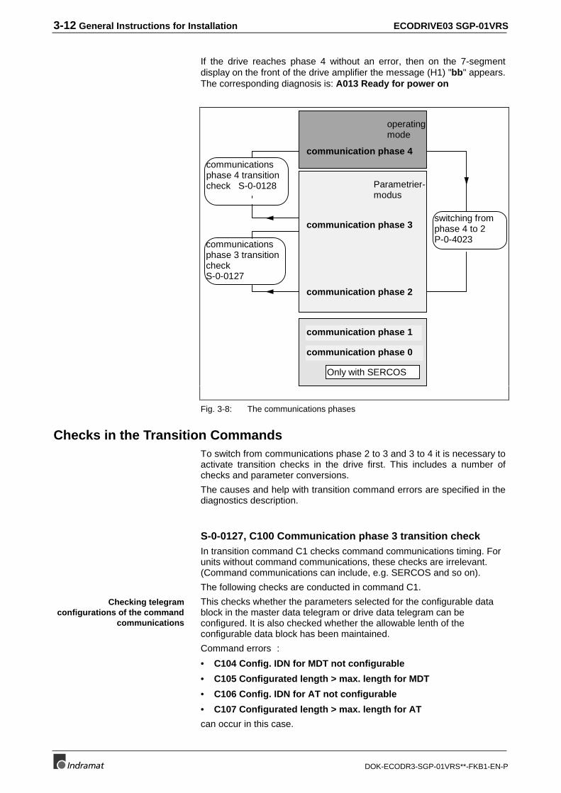
3-12 General Instructions for Installation ECODRIVE03 SGP-01VRS
DOK-ECODR3-SGP-01VRS**-FKB1-EN-P
If the drive reaches phase 4 without an error, then on the 7-segmentdisplay on the front of the drive amplifier the message (H1) "bb" appears.The corresponding diagnosis is: A013 Ready for power on
Parametrier-modus
communication phase 2
communication phase 3
communication phase 4
operatingmode
communicationsphase 3 transitioncheckS-0-0127
communicationsphase 4 transitioncheck S-0-0128
switching fromphase 4 to 2P-0-4023
communication phase 1
communication phase 0
Only with SERCOS
Fig. 3-8: The communications phases
Checks in the Transition CommandsTo switch from communications phase 2 to 3 and 3 to 4 it is necessary toactivate transition checks in the drive first. This includes a number ofchecks and parameter conversions.
The causes and help with transition command errors are specified in thediagnostics description.
S-0-0127, C100 Communication phase 3 transition checkIn transition command C1 checks command communications timing. Forunits without command communications, these checks are irrelevant.(Command communications can include, e.g. SERCOS and so on).
The following checks are conducted in command C1.
This checks whether the parameters selected for the configurable datablock in the master data telegram or drive data telegram can beconfigured. It is also checked whether the allowable lenth of theconfigurable data block has been maintained.
Command errors :
• C104 Config. IDN for MDT not configurable
• C105 Configurated length > max. length for MDT
• C106 Config. IDN for AT not configurable
• C107 Configurated length > max. length for AT
can occur in this case.
Checking telegramconfigurations of the command
communications

ECODRIVE03 SGP-01VRS General Instructions for Installation 3-13
DOK-ECODR3-SGP-01VRS**-FKB1-EN-P
If a parameter needed for transition to phase 3 has never been writteninto or the backup is faulty, then command error
• C101 Invalid communication parameter (S-0-0021)
is generated. The ID no. of the faulty parameters are listed in:
• S-0-0021, IDN-list of invalid op. data for comm. Ph. 2
They are made valid by writing into them.
If during the extreme value check of the parameters relevant tocommand communications an error is generated, then command error
• C102 Limit error communication parameter (S-0-0021)
is generated. The ID numbers of the faulty parameters are listed in
• S-0-0021, IDN-list of invalid op. data for comm. Ph. 2
and must be corrected.
Check timing parameters of command communications in phases 3 and4 for plausibilit and maintaining marginal conditions.
Command errors
• C108 Time slot parameter > Sercos cycle time (only with Sercos)
• C109 Position of data record in MDT (S-0-0009) even (only withSercos)
• C110 Length of MDT (S-0-0010) odd (only with Sercos)
• C111 ID9 + Record length - 1 > length MDT (S-0-0010) (only withSercos)
• C112 TNcyc (S-0-0001) or TScyc (S-0-0002) error
• C113 Relation TNcyc (S-0-0001) to TScyc (S-0-0002) error
• C114 T4 > TScyc (S-0-0002) - T4min (S-0-0005)
• C115 T2 too small (only with Sercos)
can occur.
S-0-0128, C200 Communication phase 4 transition checkDuring this command, the following checks are run.
If in parameter P-0-4014, Motor type 1 (MHD) or 5 (MKD/MKE) areselected and the motor feedback data memory has not found that type,then command error
• C204 Motor type P-0-4014 incorrect
is generated.
If a parameter needed for transition to phase 4 has never been writteninto, and its backup is faulty, then command error
• C201 Invalid parameter(s) (->S-0-0022)
is generated. The ID number of the faulty parameters are listed in
• S-0-0022, IDN-list of invalid op. data for comm. Ph. 3
and are made valid by writing into.
Checking validity ofcommunications parameters
Extreme value check ofcommunications parameters
Checking plausibility andmaintaining marginal
conditions of commandcommunications
Checking P-0-4014 forplausibility
Checking validity
3-14 General Instructions for Installation ECODRIVE03 SGP-01VRS
DOK-ECODR3-SGP-01VRS**-FKB1-EN-P
The drive controller reads the EEPROM memory of the drive controlleroperating data. If an error occurs during this process, then commanderror:
• C212 Invalid amplifier data (->S-0-0022) appears.
The ID number of the faulty parameter is written in
• S-0-0022, IDN-list of invalid op. data for comm. Ph. 3.
Checking, as per operating mode parameters S-0-0032..35 orreferencing parameter S-0-0147, whether a second encoder is neededbut there isn’t one, as 0 is entered in parameter P-0-0075, Feedbacktype 2. The faulty operating parameters or referencing parameters arelisted in:
• S-0-0022, IDN-list of invalid op. data for comm. Ph. 3
Command error
• C210 Feedback 2 required (->S-0-0022) appears.
Check whether a motor encoder is available (P-0-0074, Feedback type1 = 0) and no "2" is entered in function parameter P-0-0185, Function ofencoder 2 for load-side motor encoder. If this is the case, thencommand error
• C236 Feedback 1 required (P-0-0074)
is generated.
If the encoder parametrized in parameter P-0-0074, Feedback type 1 isnot available, or its data cannot be read, then this error message isgenerated
• C217 Feedback1 data reading error
If the encoder interface selected in parameter P-0-0075, Feedback type2 is already occupied by the motor encoder, then this error message isgenerated:
• C234 Encoder combination not possible
If a second encoder with feedback data memory is used, but its datacannot be read, then error message
• C218 Feedback 2 data reading error
is generated. If "load side motor encoder" has been selected inparameter P-0-0185, Function of encoder 2 but no rotary asynchronousmotor is available, then error message
• C235 Load-side motor encoder with inductance motor only
is generated.
The parameters stored in the memory of motors with feedback datamemory are read. If an error occurs during this process, then commanderror
• C211 Invalid feedback data (->S-0-0022) is generated.
Check whether an internal position resolution has been set via parameterS-0-0278, Maximum travel range which guarantees the correctcommutation of the motor. If not, then this command error appears:
• C223 Input value for max. range too high.
Reading the controller memory
Checking whether optionalencoder is needed
Checking whether motorencoder is availablet
Checking motor encodersettings
Checking optional encodersettings
Reading out feedback datamemory
Checking maximum travelrange
ECODRIVE03 SGP-01VRS General Instructions for Installation 3-15
DOK-ECODR3-SGP-01VRS**-FKB1-EN-P
Check internal ability to illustrate conversioni factors from display formatto an internal one and vice versa for scaling-dependent dta. If an erroroccurs, then one of the following command errors can be generated:
• C213 Position data scaling error
• C214 Velocity data scaling error
• C215 Acceleration data scaling error
• C216 Torque/force data scaling error
All parameters are checked for maintaining extreme values orpermissible bit combinations. If can error occurs, then command error
• C202 Parameter limit error (->S-0-0022)
is generated. The ID number o the faulty parameter is listed in
• S-0-0022, IDN-list of invalid op. data for comm. Ph. 3
and must be corrected.
Checking whether an activated modulo scaling of the position ofparameter S-0-0103, Modulo value can be processed. If so, thencommand error
• C227 Modulo range error
is generated.
The physical values of parameters (input format with decimal places andunits) are converted to internal formats. This conversion is monitored. Ifincongruencies are detected during this process, then command error
• C203 Parameter calculation error (->S-0-0022)
is generated. The ID number of the faulty parameter is listed in
• S-0-0022, IDN-list of invalid op. data for comm. Ph. 3
and must be corrected.
Encoder initialization is listed. Errors can occur depending on encodertype (e.g., index length wrong in DSF feedback). Then one of thefollowing command errors
• C220 Feedback 1 initializing error
• C221 Feedback 2 initializing error
are generated.
Depnding on controller type, various internal settings are performed. ifparameter S-0-0140, Controller type cannot be read, then commanderror
• C228 Controller type S-0-0140 wrong
is generated.
If the actual position of an absolute encoder is outside of the range of thelast actual position +/- prior to the last shutdown, P-0-0097, Absoluteencoder monitoring window, then error
• F276 Absolute encoder out of allowed window
is generated. The transition command is wrongly acknowledged, butinstead the error must be cleared with the execution of command S-0-0099, C500 Reset class 1 diagnostic.
(Also see section: "Clear error").
Checking scaling
Checking all parameters forextreme values and possible bit
combinations
Checking modulo range
Checking the conversion ofinternal formats
Checking encoder initialization
Checking controller type
Absolute encoder monitoring
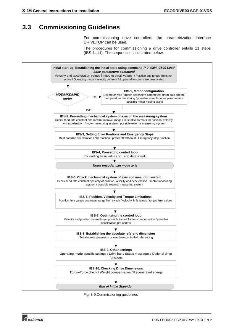
3-16 General Instructions for Installation ECODRIVE03 SGP-01VRS
DOK-ECODR3-SGP-01VRS**-FKB1-EN-P
3.3 Commissioning Guidelines
For commissioning drive controllers, the parametrization interfaceDRIVETOP can be used.
The procedures for commissioning a drive controller entails 11 steps(IBS-1..11). The sequence is illustrated below.
IBS-1, Motor configuration Set motor type / motor-dependent parameters (from data sheet) /
temperature monitoring / possible asynchronous parameters / possible motor holding brake
MDD/MKD/MHD motor
IBS-2, Pre-setting mechanical system of axia dn the measuring system Gears, feed rate constant and maximum travel range / illustrative formats for position, velocity
and acceleration / motor measuring system / possible external measuring system
IBS-3, Setting Error Reations and Emergency StopsBest possible deceleration / NC reaction / power off with fault / Emergency-stop function
IBS-4, Pre-setting control loopby loading base values or using data sheet
IBS-5, Check mechanical system of axis and meauring system Gears, feed rate constant / polarity of position, velocity and acceleration / motor measuring
system / possible external measuring system
IBS-7, Optimizing the control loop Velocity and position control loop / possible torque friction compensation / possible
acceleration pre-control
IBS-6, Position, Velocity and Torque LimitationsPosition limit values and travel range limit switch / velocity limit values / torque limit values
IBS-8, Establishing the absolute referenc dimension Set absolute dimension or use drive-controlled referencing
IBS-9, Other settingsOperating mode-specific settings / Drive halt / Status messages / Optional drive
functions
no
yes
Initial start-up, Establishing the initial state using command P-0-4094, C800 Load base parameters command
Velocity and acceleration values limited to small values / Position and torque limits not active / Operating mode - velocity control / All optional functions are deactivated
Motor encoder can move axis
End of Initial Start-Up
IBS-10, Checking Drive DimensionsTorque/force check / Weight compensation / Regenerated energy
Fig. 3-9:Commissioning guidelines

ECODRIVE03 SGP-01VRS General Instructions for Installation 3-17
DOK-ECODR3-SGP-01VRS**-FKB1-EN-P
IBS-1, Motor configurationThese guidelines are needed in the case where the motor used does nothave a motor feedback memory. It is necessary with these motors
• to enter the parameters for motor features (peak current, maximumvelocity, etc.) using the data sheet or with DRIVETOP using data fromthe motor data bank.
• The parameters for the motor temperature warning and off thresholdsmust be parametrized as well
• and giving a motor holding brake, these must be properly set also.
Those motors with data memory such as
• MHD and
• MKD motors
are recognized by the drive and motor parameters are automatically set.
(See also chapter: "Setting the Motor Type"“.)
IBS-2, Determining the Operating ModeIn this step, the main and auxiliary operating modes are selected.
Operating-mode specific settings must be made.
In particular, necessary limit values, optionally usable filters and theavailable operating modes must be defined.
(Also see section: "Operating Modes")
IBS-3, Pre-setting the axis mechanics and measuring systemsIn this step, the parameters needed for determining and processingposition, velocity and acceleration data are set. These include thefollowing parameters for the following settings:
• mechanical gear ratio between motor and load as well as any existingfeedrate constants of the drive of linear slides
• scaling settings for showing position, velocity and accelerationparameters of the drive. This sets, for example, whether the data ismotor shaft or load related and which LSB valence these have, e.g.,position data with 0.001 degrees or 0.0001 inches and so on.
• Interfaces, rotational directions and the resoluton of the motorencoder, and where available, optional encoders.
(See also chapter : -"Physical Values Display Format"
-"Mechanical Transmission Elements" and
-"Setting the Measurement System").
IBS-4, Setting the error reactions and E-stopIn this step, the reaction of the drive in the event of an error is set as wellas the triggering of the drive's own E-stop input. The followingparametrizations must be performed:
• type and mode of error reactions in drive
• selection whether NC reaction in error case should happen
• selection whether and when the power supply is switched off andwhether a package reaction is to be conducted
• Configuration of the E-stop input
(See also chapter: "Drive Error Reaction"“)
3-18 General Instructions for Installation ECODRIVE03 SGP-01VRS
DOK-ECODR3-SGP-01VRS**-FKB1-EN-P
IBS-5, Pre-setting Control LoopThe parameters for current, velocity and position control loops are set inthis step. This is done either by:
• Execute command P-0-0162, D900 Command Automatic controlloop adjust orDuring the execution of the command, the setting for the velocitycontroller and the position controller is determined as well as the loadinertia.
• Execute command S-0-0262, C700 Command basic load or
• by inputting the controller values specified in the data sheet.
Setting the control loop in this way makes ensures a good level of qualityfor most applications. Should additional optimization of the control loopparameters become necessary (velocity and position control loopparameters, compensation functions and precontrol), then usecommissioning step no. 8.
(See also chapter: "Control Loop Settings".)
IBS-6, Checking axis mechanics and measuring systemThe presettings made in IBS 2 are checked here and modified, ifnecessary. This means that the axis must be moved by jogging. Thefollowing checks must be made:
• check the rotational direction of the motor encoder. With non-invertedposition polaritiy (S-0-0055, Position polarities = 0), the values inparameter S-0-0051, Position feedback 1 value should have a risingorder with a clockwise rotation of the motor. (This check need not beperformed in MDD and MKD motors. If this is not the case, then bit 2in S-0-0277, Position feedback 1 type must be inverted.
• By moving the axes and examining the position feedback value of themotor encoder in parameter S-0-0051, Position feedback 1 value itcan be controlled whether a distance in this process is correctlydisplayed. If not, then the settings for mechanical gear ratio, feedrateconstants and encoder resolution must be checked.
• Given a second encoder, by moving the axis and examining theposition feedback value of the external encoder in parameter S-0-0053, Position feedback 2 value it can be checked whether adistance is correctly displayed with this process. S-0-0051, Positionfeedback 1 value and S-0-0053, Position feedback 2 value shouldrun parallel when jogging a specific path. If not, then check thesettings in P-0-0075, Feedback type 2, S-0-0117, Feedback 2Resolution, S-0-0115, Position feedback 2 type and P-0-0185,Function of encoder 2.
(See also chapter : -"Physical Values Display Format"
-"Mechanical Transmission Elements" and
-"Setting the Measurement System").
ECODRIVE03 SGP-01VRS General Instructions for Installation 3-19
DOK-ECODR3-SGP-01VRS**-FKB1-EN-P
IBS-7, Limits for position, velocity and torqueThe limits for the travel range are conducted by setting
• position limits values and/or
• travel range limit switches
as well as the limit values for the axis velocity and maximum drivetorque/force are parametrized also.
(See also chapter: -"Torque/Force Limiting",
-"Travel Range Limits" and
-"Limiting Velocity".)
IBS-8, Optimizing the control loopThis step is only necessary if the settings for velocity and position controlloops in IBS 4 did not achieve the needed quality. As such, optimize thecontrol behavior as follows:
• modify the parameter for velocity and position control loops
• possibly activate the acceleration pre-control
• possibly activate the velocity mixture and
• possibly activate the notch filter.
(See also chapter: "Basic Drive Functions - Control LoopSettings"“.)
IBS-9, Establishing absolute reference measuringHere the absolute reference measuring is set in terms of the machinezero point of the position feedback value from motor encoder andpossibly optional encoder. The position feedback values at first showany, not machine zero point related values. By conducting
• setting absolute measuring (with absolute encoders) or
• drive-controlled homing
the coordinate systems of the position encoder and the coordinatesystem of the machine are made congruent.
(See also chapter: -"Drive-Controlled Homing" and
-"Set Absolute Measuring")
IBS-10, Other settingsHere
• drive halt function is parametrized,
• the language selected,
• general status message settings and
• the optional drive function settings are conducted.
(See also chapter: -"Drive Halt/Start"
-"S-0-0013, Class 3 diagnostics"
-"S-0-0182, Manufacturer class 3 diagnostics"
-"Optional Drive Functions"
-"Language Selection"
3-20 General Instructions for Installation ECODRIVE03 SGP-01VRS
DOK-ECODR3-SGP-01VRS**-FKB1-EN-P
IBS-11, Controlling drive dimensionsThe power-related drive checks are conducted here. It is checkedwhether the continuous and peak power of drive amplifier and motormeet the requirements. The following checks are conducted for thispurpose:
• generated torque/force of motor is checked. At a constant speed 60%and in rapid traverse 75% of the continuous torque at standstill of themotor should not be exceeded
• during the acceleration phase 80% of the maximum torque of themotor/controller combination may not be exceeded
• the thermal load of the drive amplifier should equal a maximum of80%
(See also chapter: "Monitoring the Thermal Load of the drivecontroller"
With vertical axis, the weight compensation must be set so that thecurrent consumption with upwards and downwards motions of the axeshave the same minimum value.
Check the regenerated peak power and regenerated continuous power.
3.4 Diagnostic Configurations
Overview of Diagnostic ConfigurationsThe diagnostics are configured into 2 groups:
• Abilities to recognize the actual state of operation of the prioritydependent, drive internal diagnostic monitor
• Collective display for various states
Additionally, there are parameters for all important operating data thatcan be transmitted both via the command communications (SERCOS,Profibus, ...) as well as the parametrization interface (RS-232/485 in theASCII protocol or SIS serial Indramat protocol).
Drive-Internal DiagnosticsThe current operating condition of the drive is evident by which errors,warnings, commands and drive stop signals are available and whichoperating mode is active. Whether the drive is in preparation foroperation or in parameter mode also is displayed.
The current operating condition can be determined from
• the 2-part seven-segment display (H1 display)
• the diagnostic parameter S-0-0095, Diagnostic Message
• the parameter S-0-0390, Diagnostic Message Number
• the parameter P-0-0009, Error Message Number
• the parameter S-0-0375, List of diagnostic numbers
The following display items show always the actual diagnostic with thehighest priority:
• H1 display
• S-0-0095, Diagnostic Message
• S-0-0390, Diagnostic Message Number
The parameter P-0-0009, Error Message Number will contain a valueunequal to 0 if an error is present.
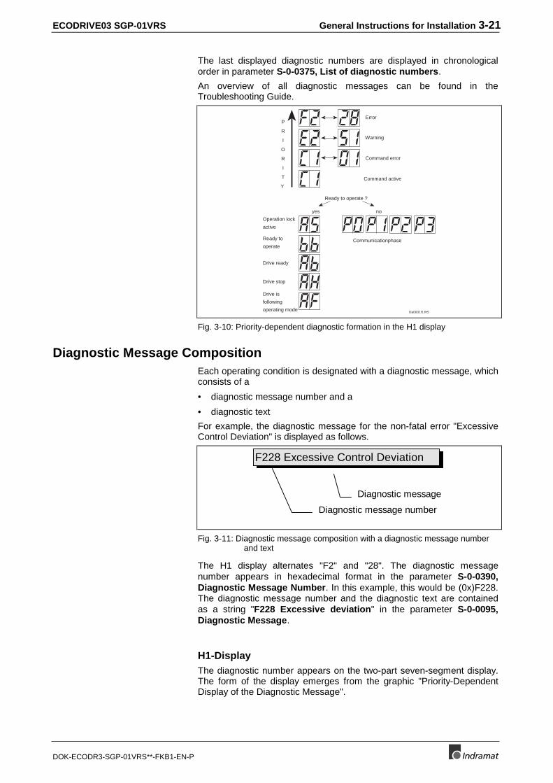
ECODRIVE03 SGP-01VRS General Instructions for Installation 3-21
DOK-ECODR3-SGP-01VRS**-FKB1-EN-P
The last displayed diagnostic numbers are displayed in chronologicalorder in parameter S-0-0375, List of diagnostic numbers.
An overview of all diagnostic messages can be found in theTroubleshooting Guide.
Da0001f1.fh5
Communicationphase
P
R
I
O
R
I
T
Y
Ready to operate ?
yes no
Error
Warning
Command error
Command active
Operation lock
active
Ready to
operate
Drive ready
Drive stop
Drive is
following
operating mode
Fig. 3-10: Priority-dependent diagnostic formation in the H1 display
Diagnostic Message CompositionEach operating condition is designated with a diagnostic message, whichconsists of a
• diagnostic message number and a
• diagnostic text
For example, the diagnostic message for the non-fatal error "ExcessiveControl Deviation" is displayed as follows.
F228 Excessive Control Deviation
Diagnostic message number
Diagnostic message
Fig. 3-11: Diagnostic message composition with a diagnostic message numberand text
The H1 display alternates "F2" and "28". The diagnostic messagenumber appears in hexadecimal format in the parameter S-0-0390,Diagnostic Message Number. In this example, this would be (0x)F228.The diagnostic message number and the diagnostic text are containedas a string "F228 Excessive deviation" in the parameter S-0-0095,Diagnostic Message.
H1-DisplayThe diagnostic number appears on the two-part seven-segment display.The form of the display emerges from the graphic "Priority-DependentDisplay of the Diagnostic Message".
3-22 General Instructions for Installation ECODRIVE03 SGP-01VRS
DOK-ECODR3-SGP-01VRS**-FKB1-EN-P
With the help of this display, it is possible to quickly determine the currentoperating status without using a communication interface.
The operating mode cannot be seen on the H1-Display. If the drivefollows the operating mode and no command was activated, then thesymbol "AF" appears on the display.
Diagnostic MessageThe diagnostic message contains the diagnostic number followed by thediagnostic text, as shown in the example, "Excessive Control Deviation."It can be read with the parameter S-0-0095, Diagnostic Message anddirectly displays the operation status on an operator interface.
The diagnostic message language can be changed.
Diagnostic Message NumberThe diagnostic message number contains only the diagnostic numberwithout the text. It can be read with the parameter S-0-0390, DiagnosticMessage Number .
Error NumberThe error number contains only the error number without the diagnostictext. It can be read with the parameter P-0-0009, Error MessageNumber and can indicate an error condition without a language barrier.This parameter contains a value unequal to "0" if an error is present inthe drive.
An error is formed from the bottom 3 digits of the diagnostic number. Forexample, the error "F228 Excessive deviation" with the diagnosticmessage number "(0x)F228" would produce the error number "228."
List of diagnostic numbersThe 50 previously displayed diagnostic numbers are displayed inchronological order in parameter S-0-0375, List of diagnostic numbers.Every change in contents of S-0-0390, Diagnostic message numbermeans that the old contents are transfered into S-0-0375, List ofdiagnostic numbers. If S-0-0375, List of diagnostic numbers is read,then the last replaced diagnostic number appears in the first element; thediagnotic number displayed penultimately is displayed in the secondelement and so on.
The following illustrated explains the relationship between S-0-0375, Listof diagnostic numbers and S-0-0390. Diagnostic message numberwith the use of an example.
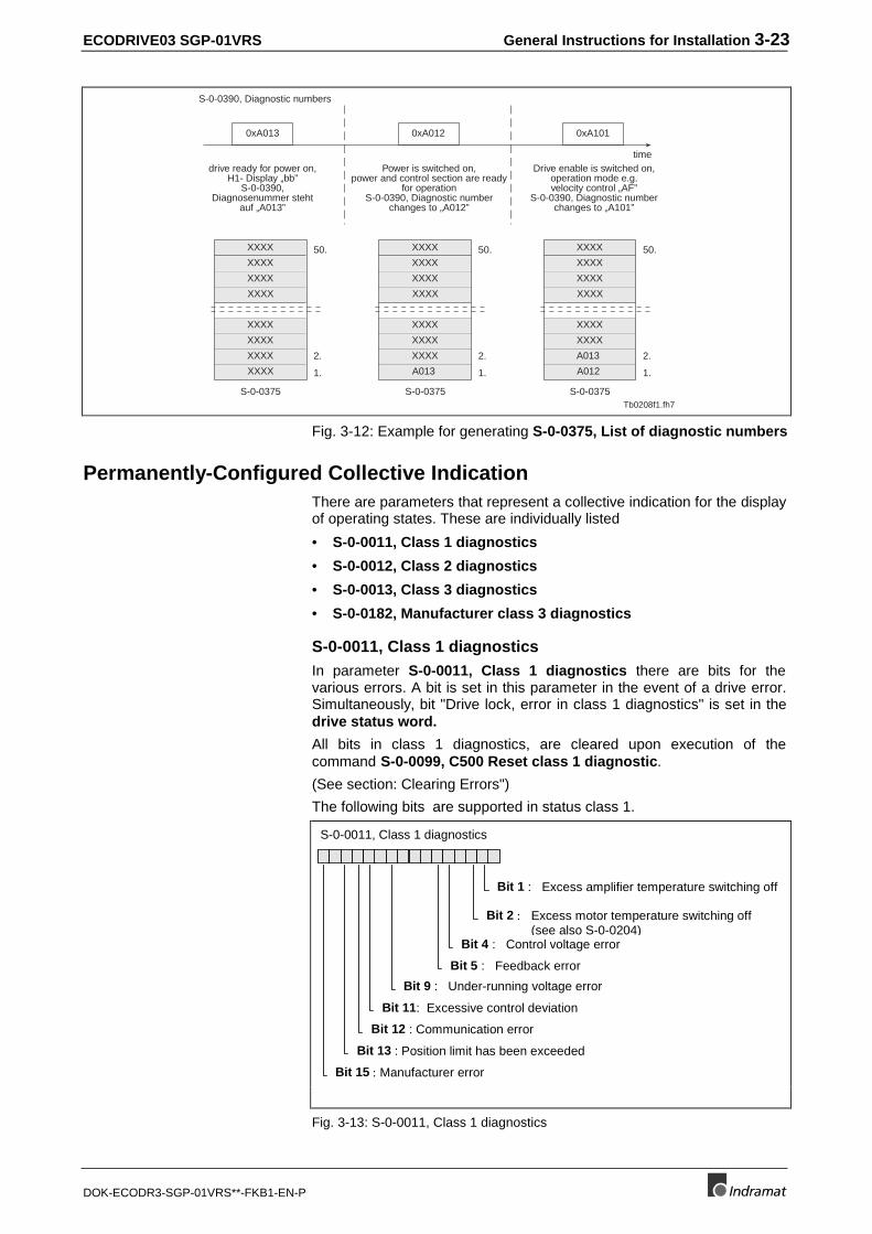
ECODRIVE03 SGP-01VRS General Instructions for Installation 3-23
DOK-ECODR3-SGP-01VRS**-FKB1-EN-P
S-0-0390, Diagnostic numbers
drive ready for power on,H1- Display „bb”
S-0-0390,Diagnosenummer steht
auf „A013”
Power is switched on,power and control section are ready
for operationS-0-0390, Diagnostic number
changes to „A012”
Drive enable is switched on,operation mode e.g.velocity control „AF”
S-0-0390, Diagnostic numberchanges to „A101”
0xA013 0xA012 0xA101
time
Tb0208f1.fh7
50.
2.
1.
S-0-0375
XXXX
XXXX
XXXX
XXXX
XXXX
XXXX
XXXX
XXXX 50.
2.
1.
S-0-0375
XXXX
XXXX
A013
XXXX
XXXX
XXXX
XXXX
XXXX 50.
2.
1.
S-0-0375
XXXX
A013
A012
XXXX
XXXX
XXXX
XXXX
XXXX
Fig. 3-12: Example for generating S-0-0375, List of diagnostic numbers
Permanently-Configured Collective IndicationThere are parameters that represent a collective indication for the displayof operating states. These are individually listed
• S-0-0011, Class 1 diagnostics
• S-0-0012, Class 2 diagnostics
• S-0-0013, Class 3 diagnostics
• S-0-0182, Manufacturer class 3 diagnostics
S-0-0011, Class 1 diagnosticsIn parameter S-0-0011, Class 1 diagnostics there are bits for thevarious errors. A bit is set in this parameter in the event of a drive error.Simultaneously, bit "Drive lock, error in class 1 diagnostics" is set in thedrive status word.
All bits in class 1 diagnostics, are cleared upon execution of thecommand S-0-0099, C500 Reset class 1 diagnostic.
(See section: Clearing Errors")
The following bits are supported in status class 1.
Bit 4 : Control voltage error
S-0-0011, Class 1 diagnostics
Bit 5 : Feedback error
Bit 1 : Excess amplifier temperature switching off
Bit 2 : Excess motor temperature switching off(see also S-0-0204)
Bit 9 : Under-running voltage error
Bit 11: Excessive control deviation
Bit 12 : Communication error
Bit 13 : Position limit has been exceeded
Bit 15 : Manufacturer error
Fig. 3-13: S-0-0011, Class 1 diagnostics
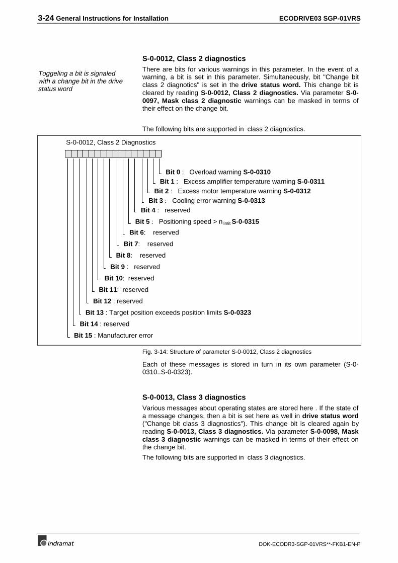
3-24 General Instructions for Installation ECODRIVE03 SGP-01VRS
DOK-ECODR3-SGP-01VRS**-FKB1-EN-P
S-0-0012, Class 2 diagnostics
Toggeling a bit is signaledwith a change bit in the drivestatus word
There are bits for various warnings in this parameter. In the event of awarning, a bit is set in this parameter. Simultaneously, bit "Change bitclass 2 diagnotics" is set in the drive status word. This change bit iscleared by reading S-0-0012, Class 2 diagnostics. Via parameter S-0-0097, Mask class 2 diagnostic warnings can be masked in terms oftheir effect on the change bit.
The following bits are supported in class 2 diagnostics.
S-0-0012, Class 2 Diagnostics
Bit 4 : reserved
Bit 5 : Positioning speed > nlimit S-0-0315
Bit 1 : Excess amplifier temperature warning S-0-0311Bit 2 : Excess motor temperature warning S-0-0312
Bit 9 : reserved
Bit 11: reserved
Bit 12 : reserved
Bit 13 : Target position exceeds position limits S-0-0323
Bit 15 : Manufacturer error
Bit 0 : Overload warning S-0-0310
Bit 14 : reserved
Bit 10: reserved
Bit 8: reserved
Bit 7: reserved
Bit 6: reserved
Bit 3 : Cooling error warning S-0-0313
Fig. 3-14: Structure of parameter S-0-0012, Class 2 diagnostics
Each of these messages is stored in turn in its own parameter (S-0-0310..S-0-0323).
S-0-0013, Class 3 diagnosticsVarious messages about operating states are stored here . If the state ofa message changes, then a bit is set here as well in drive status word("Change bit class 3 diagnostics"). This change bit is cleared again byreading S-0-0013, Class 3 diagnostics. Via parameter S-0-0098, Maskclass 3 diagnostic warnings can be masked in terms of their effect onthe change bit.
The following bits are supported in class 3 diagnostics.
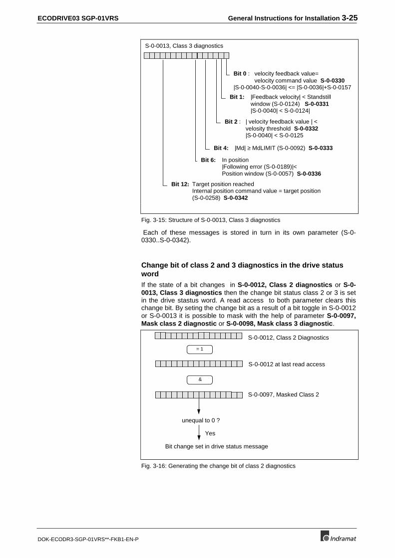
ECODRIVE03 SGP-01VRS General Instructions for Installation 3-25
DOK-ECODR3-SGP-01VRS**-FKB1-EN-P
S-0-0013, Class 3 diagnostics
Bit 1: |Feedback velocity| < Standstillwindow (S-0-0124) S-0-0331|S-0-0040| < S-0-0124|
Bit 12: Target position reachedInternal position command value = target position(S-0-0258) S-0-0342
Bit 6: In position|Following error (S-0-0189)|<Position window (S-0-0057) S-0-0336
Bit 4: |Md| ≥ MdLIMIT (S-0-0092) S-0-0333
Bit 2 : | velocity feedback value | < velosity threshold S-0-0332
|S-0-0040| < S-0-0125
Bit 0 : velocity feedback value= velocity command value S-0-0330|S-0-0040-S-0-0036| <= |S-0-0036|+S-0-0157
Fig. 3-15: Structure of S-0-0013, Class 3 diagnostics
Each of these messages is stored in turn in its own parameter (S-0-0330..S-0-0342).
Change bit of class 2 and 3 diagnostics in the drive statuswordIf the state of a bit changes in S-0-0012, Class 2 diagnostics or S-0-0013, Class 3 diagnostics then the change bit status class 2 or 3 is setin the drive stastus word. A read access to both parameter clears thischange bit. By seting the change bit as a result of a bit toggle in S-0-0012or S-0-0013 it is possible to mask with the help of parameter S-0-0097,Mask class 2 diagnostic or S-0-0098, Mask class 3 diagnostic.
= 1
&
S-0-0012, Class 2 Diagnostics
S-0-0012 at last read access
S-0-0097, Masked Class 2
unequal to 0 ?
Yes
Bit change set in drive status message
Fig. 3-16: Generating the change bit of class 2 diagnostics
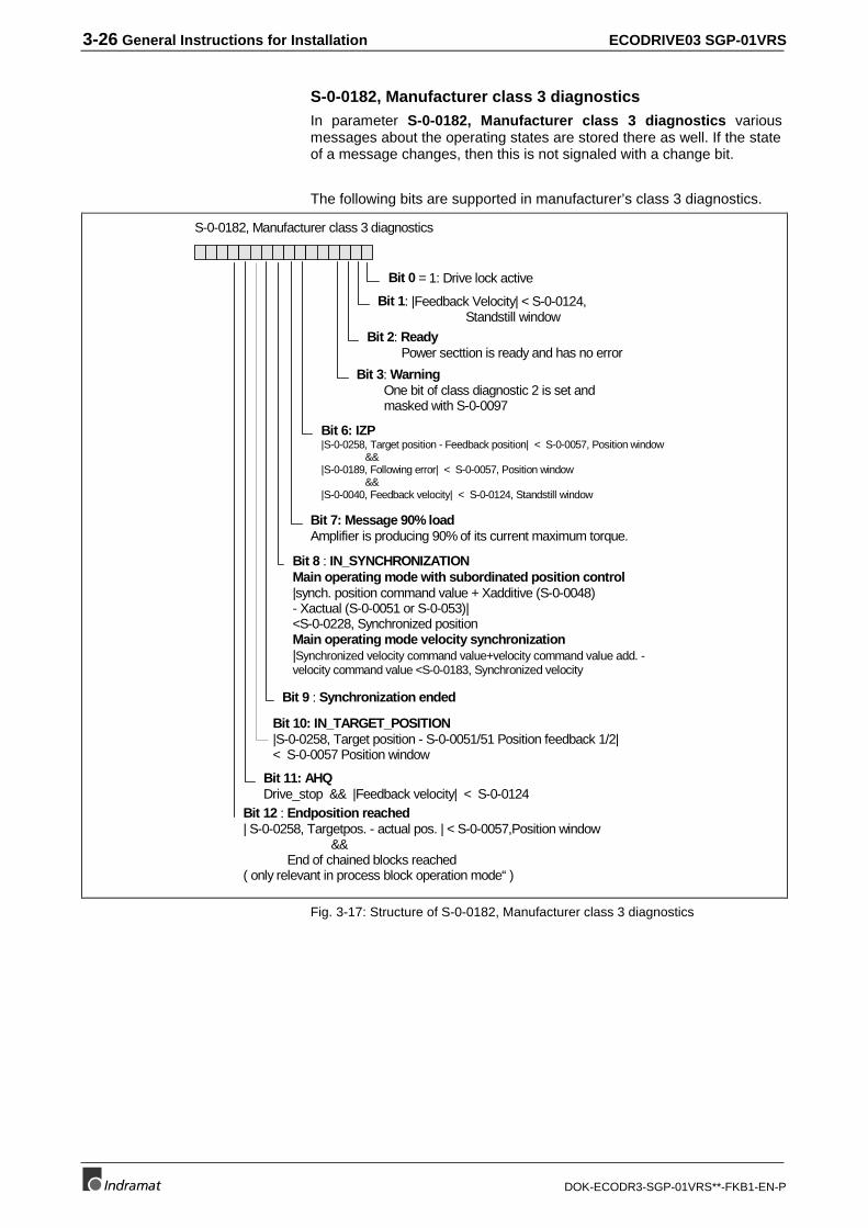
3-26 General Instructions for Installation ECODRIVE03 SGP-01VRS
DOK-ECODR3-SGP-01VRS**-FKB1-EN-P
S-0-0182, Manufacturer class 3 diagnosticsIn parameter S-0-0182, Manufacturer class 3 diagnostics variousmessages about the operating states are stored there as well. If the stateof a message changes, then this is not signaled with a change bit.
The following bits are supported in manufacturer’s class 3 diagnostics.
Bit 0 = 1: Drive lock active
Bit 6: IZP|S-0-0258, Target position - Feedback position| < S-0-0057, Position window
&&|S-0-0189, Following error| < S-0-0057, Position window
&&|S-0-0040, Feedback velocity| < S-0-0124, Standstill window
Bit 11: AHQDrive_stop && |Feedback velocity| < S-0-0124
Bit 1: |Feedback Velocity| < S-0-0124,Standstill window
Bit 7: Message 90% loadAmplifier is producing 90% of its current maximum torque.
Bit 10: IN_TARGET_POSITION|S-0-0258, Target position - S-0-0051/51 Position feedback 1/2|< S-0-0057 Position window
Bit 8 : IN_SYNCHRONIZATIONMain operating mode with subordinated position control|synch. position command value + Xadditive (S-0-0048)- Xactual (S-0-0051 or S-0-053)|<S-0-0228, Synchronized positionMain operating mode velocity synchronization|Synchronized velocity command value+velocity command value add. -velocity command value <S-0-0183, Synchronized velocity
Bit 9 : Synchronization ended
Bit 12 : Endposition reached| S-0-0258, Targetpos. - actual pos. | < S-0-0057,Position window
&&End of chained blocks reached
( only relevant in process block operation mode“ )
Bit 2: Ready Power secttion is ready and has no error
Bit 3: Warning One bit of class diagnostic 2 is set and masked with S-0-0097
S-0-0182, Manufacturer class 3 diagnostics
Fig. 3-17: Structure of S-0-0182, Manufacturer class 3 diagnostics
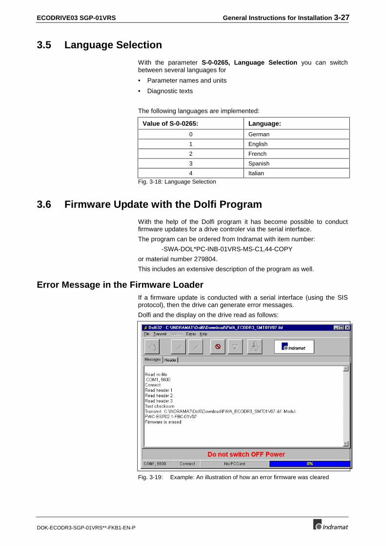
ECODRIVE03 SGP-01VRS General Instructions for Installation 3-27
DOK-ECODR3-SGP-01VRS**-FKB1-EN-P
3.5 Language Selection
With the parameter S-0-0265, Language Selection you can switchbetween several languages for
• Parameter names and units
• Diagnostic texts
The following languages are implemented:
Value of S-0-0265: Language:
0 German
1 English
2 French
3 Spanish
4 ItalianFig. 3-18: Language Selection
3.6 Firmware Update with the Dolfi Program
With the help of the Dolfi program it has become possible to conductfirmware updates for a drive controler via the serial interface.
The program can be ordered from Indramat with item number:
-SWA-DOL*PC-INB-01VRS-MS-C1,44-COPY
or material number 279804.
This includes an extensive description of the program as well.
Error Message in the Firmware LoaderIf a firmware update is conducted with a serial interface (using the SISprotocol), then the drive can generate error messages.
Dolfi and the display on the drive read as follows:
Fig. 3-19: Example: An illustration of how an error firmware was cleared
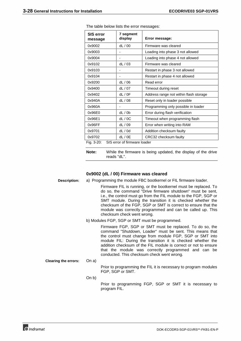
3-28 General Instructions for Installation ECODRIVE03 SGP-01VRS
DOK-ECODR3-SGP-01VRS**-FKB1-EN-P
The table below lists the error messages:
SIS errormessage
7 segmentdisplay Error message:
0x9002 dL / 00 Firmware was cleared
0x9003 - Loading into phase 3 not allowed
0x9004 - Loading into phase 4 not allowed
0x9102 dL / 03 Firmware was cleared
0x9103 - Restart in phase 3 not allowed
0x9104 - Restart in phase 4 not allowed
0x9200 dL / 06 Read error
0x9400 dL / 07 Timeout during reset
0x9402 dL / 0F Address range not within flash storage
0x940A dL / 08 Reset only in loader possible
0x960A - Programming only possible in loader
0x96E0 dL / 0b Error during flash verification
0x96E1 dL / 0C Timeout when programming flash
0x96FF dL / 09 Error when writing into RAM
0x9701 dL / 0d Addition checksum faulty
0x9702 dL / 0E CRC32 checksum faultyFig. 3-20: SIS error of firmware loader
Note: While the firmware is being updated, the display of the drivereads "dL".
0x9002 (dL / 00) Firmware was cleareda) Programming the module FBC bootkernel or FIL firmware loader.
Firmware FIL is running, or the bootkernel must be replaced. Todo so, the command "Drive firmware shutdown“ must be sent,i.e., the control must go from the FIL module to the FGP, SGP orSMT module. During the transition it is checked whether thechecksum of the FGP, SGP or SMT is correct to ensure that themodule was correctly programmed and can be called up. Thischecksum check went wrong.
b) Modules FGP, SGP or SMT must be programmed.
Firmware FGP, SGP or SMT must be replaced. To do so, thecommand "Shutdown, Loader“ must be sent. This means thatthe control must change from module FGP, SGP or SMT intomodule FIL: During the transition it is checked whether theaddition checksum of the FIL module is correct or not to ensurethat the module was correctly programmed and can beconducted. This checksum check went wrong.
On a)
Prior to programming the FIL it is necessary to program modulesFGP, SGP or SMT.
On b)
Prior to programming FGP, SGP or SMT it is necessary toprogram FIL.
Description:
Clearing the errors:
ECODRIVE03 SGP-01VRS General Instructions for Installation 3-29
DOK-ECODR3-SGP-01VRS**-FKB1-EN-P
0x9003 Loading into phase 3 not allowedThe drive is in phase 3. A change to the firmware loader is necessarybecause the firmware is to be replaced. This can only be done in phase2.
Switch the drive into phase 2.
0x9004 Loading into phase 4 not allowedThe drive is in phase 4. A change to the firmware loader is necessarybecause the firmware is to be replaced. This can only be done in phase2.
Switch the drive into phase 2.
0x9102 (dL / 03) Firmware was clearedThe drive firmware is to be restarted after the firmware was replaced.The programming of modules FGP, SGP or SMT was incomplete(addition checksum check went wrong).
Modules FGP, SGP or SMT must be reprogrammed.
0x9103 Restart in phase 3 not allowedThe drive is in phase 3 and the drive firmware must be restarted. Thiscan only be done in phase 2.
Switch the drive into phase 2.
0x9104 Restart in phase 4 not allowedThe drive is in phase 4 and the drive firmware must be restarted. Thiscan only be done in phase 2.
Switch the drive into phase 2.
0x9200 (dL / 06) Read errorA memory module is to be read. An error occurred while making theattempt.
Check address range in the *.ibf file. If it is alright, i.e., a memory moduleis actually at that address, then the error can only be cleared by replacingthe firmware module ESF02.1.
0x9400 (dL / 07) Timeout during resetAn error occurred while trying to reset a flash.
Repeat the reset command. If the error continues to appear, then it canonly be cleared by replacing firmware module ESF02.1.
0x9402 (dL / 0F) Address range not in flashAn address range not in the flash must be cleared.
Correct address range in the SIS or check the range in the *.ibf file.
0x940A Reset only possible in loaderDrive firmware is running and the flash is to be cleared.
Change into firmware loader.
Description:
Clearing errors:
Description:
Clearing errors:
Description:
Clearing errors:
Description:
Clearing errors:
Description:
Clearing errors:
Description:
Clearing errors:
Description:
Clearing errors:
Description:
Clearing errors:
Description:
Clearing errors:
3-30 General Instructions for Installation ECODRIVE03 SGP-01VRS
DOK-ECODR3-SGP-01VRS**-FKB1-EN-P
0x96E0 (dL / 0b) Error when verifying the flashAn error occurred during the programming process. A memory cell in theflash could not be write accessed.
The flash must be cleared prior to the programming command. If theerror continues, then the firmware module ESF02.1 must be replaced.
0x96E1 (dL / 0C) Timeout when programming the flashAn error occurred during programming. A memory cell in the flash couldnot be write accessed.
Programming command repeated. If the error continues, then thefirmware module ESF02.1 must be replaced.
0x96FF (dL / 09) Error when write accessing the RAMAn error occurred during programming. A memory cell in the flash couldnot be write accessed.
Check whether the target address is actually in the RAM. If the errorcontinues, then the firmware module ESF02.1 must be replaced.
0x9701 (dL / 0d) Wrong checksumThe programmed checksum is checked at the end of the updating of thefirmware module. This check went wrong.
Reprogram the module, check the checksum of the source file (*.ibf).
0x9702 (dL / 0e) CRC32 checksum faultyThe programmed CRC32 checksum is checked at the end of theupdating of the firmware module. This check went wrong.
Reprogram the module, check the checksum of the source file (*.ibf).
Additional Problems when Loading Firmware
The programming of a module was terminatedProblems on the serial interface can lead to the termination of atransmission.
In the event that the loading procedure of the FBC module wasterminated, then do not switch the unit off. This module is responsible forstarting the firmware and therefore absolutely necessary.
A module that has not been completely programmed can simply bereprogrammed (open ibf file, press transmit button, in the "Send" window,select Module single and by skipping, find the right module. Now pressthe send button).
After the unit is switched on, the display reads dLThe last programming procedure with Dolfi was not correctly completed.
To leave the firmware loader on one or all of the modules of an *.ibf filemust be programmed with Dolfi. The drive firmware is started by pressingthe separate button.
Description:
Clearing errors:
Description:
Clearing errors:
Description:
Clearing errors:
Description:
Clearing errors:
Description:
Clearing errors:
ECODRIVE03 SGP-01VRS General Instructions for Installation 3-31
DOK-ECODR3-SGP-01VRS**-FKB1-EN-P
Dolfi can be used to establish a connectiona) A baud rate other than Dolfi was set in parameter P-0-4021.
P-0-4021, Baud Rate RS-232/485:
Baud rate [Baud] Setting in parameter P-0-4021
9600 0
19200 1
It is advisable to set parameter P-0-4021 to 0 for "Connecting process“(=9600 Baud). The baudrate for the download can be set to a differentvalue in Dolfi.
If the programming of a module was terminated, e.g., due to interferenceat a serial interface, then the baud rate for the download is still set in aDKC. For Dolfi to be able to re-establish a connection, it is necessary toset the connect rate to the same value with which the most recentdownload occurred.
If the unit was switched back on and if the display reads dL, then a baudrate of 9,600 is always set.
b) The receiver and unit address is not identical with the address set atthe controler via switches S2 and S3.
Dolfi can not open the ibf fileDolfi signals "Wrong ibf format“ when opening the ibf file.
The ibf file was generated with a different release and the ibf format haschanged.
To open the file the correct Dolfi version must be used. This can beobtained from the manufacturer.
Dolfi signals timeoutTimeout messages appear while the ibf files are being transmitted.Interference at the serial connections could be the problem or thedeactivated COM interface FIFO.
This can be activated as follows:
Windows 95:
Start → Settings → System control → System → Unit manager →Connections (COM and LPT) → COM connections (COMx) →Connection settings → Expanded
→ Activate FIFO, Use standard setting
Windows NT:
Start → Settings → System control → Connections → COMx → Settings→ Expanded
→ Activate FIFO
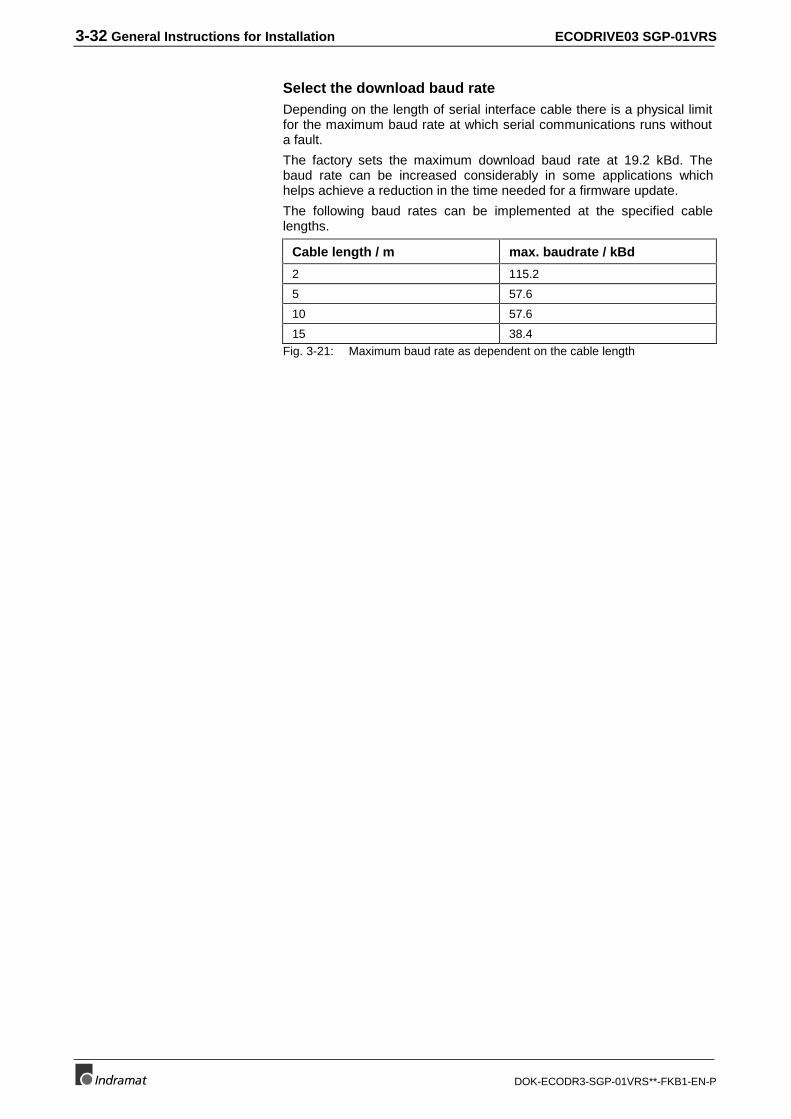
3-32 General Instructions for Installation ECODRIVE03 SGP-01VRS
DOK-ECODR3-SGP-01VRS**-FKB1-EN-P
Select the download baud rateDepending on the length of serial interface cable there is a physical limitfor the maximum baud rate at which serial communications runs withouta fault.
The factory sets the maximum download baud rate at 19.2 kBd. Thebaud rate can be increased considerably in some applications whichhelps achieve a reduction in the time needed for a firmware update.
The following baud rates can be implemented at the specified cablelengths.
Cable length / m max. baudrate / kBd
2 115.2
5 57.6
10 57.6
15 38.4Fig. 3-21: Maximum baud rate as dependent on the cable length
ECODRIVE03 SGP-01VRS Communication Through the SERCOS-interface 4-1
DOK-ECODR3-SGP-01VRS**-FKB1-EN-P
4 Communication Through the SERCOS-interface
4.1 Overview of SERCOS Communication
The basic features of the SERCOS interface are:
• Data exchange cycle of set and actual values with exact timeequidistance
• Synchronization of measurement point and commandvalue input
• Overall synchronization of all drives connected to the control
• Minimum cycle time 0.5 ms / maximum cycle time 65 ms
• Baud rate selectable, either 2 or 4 MBaud
• Service channel for settings and diagnostics
• Data transfer through fiber optic ring
• Configuration of the telegram contents
• SERCOS compatibility class C, Granularity 1, i.e., a multiple of1000 usec can be programmed as cycle time.
The features of the interface are mentioned here briefly. More detailedinformation is included in the SERCOS interface specification.
4.2 Data Transfer Cycle through SERCOS
To synchronize the drives in a ring, the Master SynchronizationTelegram (MST) is sent at the beginning of every SERCOS cycle. TheMST contains only the preset communication phase information from themaster.
You can configure the masterdata and drive telegram.
Once during every Sercos cycle, a Master Data Telegram (MDT) is sentfrom the control to every drive. The master control word, the servicechannel and a configurable data block are included here. In this datablock, the command and limit values are contained, which are sent by thecontrol according to the operation mode of the drive. The contents of thisdata block can be configured through the telegram settings.
The master data telegram is received by all drives in the ring at the sametime.
In addition, a Drive Telegram (AT) is sent during each Sercos cycletime from every drive to the control. The drive status word, the servicechannel and a configurable data block are contained here. This datablock contains mainly actual and status values, which are needed tooperate the corresponding drives by the control.
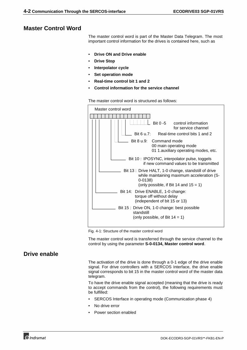
4-2 Communication Through the SERCOS-interface ECODRIVE03 SGP-01VRS
DOK-ECODR3-SGP-01VRS**-FKB1-EN-P
Master Control WordThe master control word is part of the Master Data Telegram. The mostimportant control information for the drives is contained here, such as
• Drive ON and Drive enable
• Drive Stop
• Interpolator cycle
• Set operation mode
• Real-time control bit 1 and 2
• Control information for the service channel
The master control word is structured as follows:
Bit 13 : Drive HALT, 1-0 change, standstill of drivewhile maintaining maximum acceleration (S-0-0138)(only possible, if Bit 14 and 15 = 1)
Bit 14: Drive ENABLE, 1-0 change: torque off without delay(independent of bit 15 or 13)
Bit 15 : Drive ON, 1-0 change: best possible standstill(only possible, of Bit 14 = 1)
Master control word
Bit 10 : IPOSYNC, interpolator pulse, toggelsif new command values to be transmitted
Bit 8 u.9: Command mode00 main operating mode01 1.auxiliary operating modes, etc.
Bit 6 u.7: Real-time control bits 1 and 2
Bit 0 -5 control informationfor service channel
Fig. 4-1: Structure of the master control word
The master control word is transferred through the service channel to thecontrol by using the parameter S-0-0134, Master control word.
Drive enableThe activation of the drive is done through a 0-1 edge of the drive enablesignal. For drive controllers with a SERCOS Interface, the drive enablesignal corresponds to bit 15 in the master control word of the master datatelegram.
To have the drive enable signal accepted (meaning that the drive is readyto accept commands from the control), the following requirements mustbe fulfilled:
• SERCOS Interface in operating mode (Communication phase 4)
• No drive error
• Power section enabled
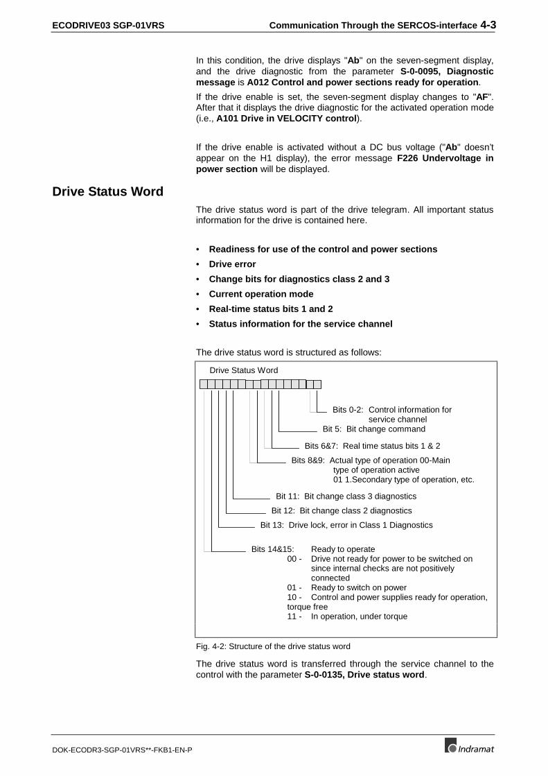
ECODRIVE03 SGP-01VRS Communication Through the SERCOS-interface 4-3
DOK-ECODR3-SGP-01VRS**-FKB1-EN-P
In this condition, the drive displays "Ab" on the seven-segment display,and the drive diagnostic from the parameter S-0-0095, Diagnosticmessage is A012 Control and power sections ready for operation.
If the drive enable is set, the seven-segment display changes to "AF".After that it displays the drive diagnostic for the activated operation mode(i.e., A101 Drive in VELOCITY control).
If the drive enable is activated without a DC bus voltage ("Ab" doesn’tappear on the H1 display), the error message F226 Undervoltage inpower section will be displayed.
Drive Status WordThe drive status word is part of the drive telegram. All important statusinformation for the drive is contained here.
• Readiness for use of the control and power sections
• Drive error
• Change bits for diagnostics class 2 and 3
• Current operation mode
• Real-time status bits 1 and 2
• Status information for the service channel
The drive status word is structured as follows:
Bit 13: Drive lock, error in Class 1 Diagnostics
Bits 14&15: Ready to operate00 - Drive not ready for power to be switched on
since internal checks are not positively connected
01 - Ready to switch on power10 - Control and power supplies ready for operation, torque free11 - In operation, under torque
Drive Status Word
Bit 12: Bit change class 2 diagnostics
Bits 8&9: Actual type of operation 00-Main type of operation active01 1.Secondary type of operation, etc.
Bits 6&7: Real time status bits 1 & 2
Bits 0-2: Control information forservice channel
Bit 11: Bit change class 3 diagnostics
Bit 5: Bit change command
Fig. 4-2: Structure of the drive status word
The drive status word is transferred through the service channel to thecontrol with the parameter S-0-0135, Drive status word.
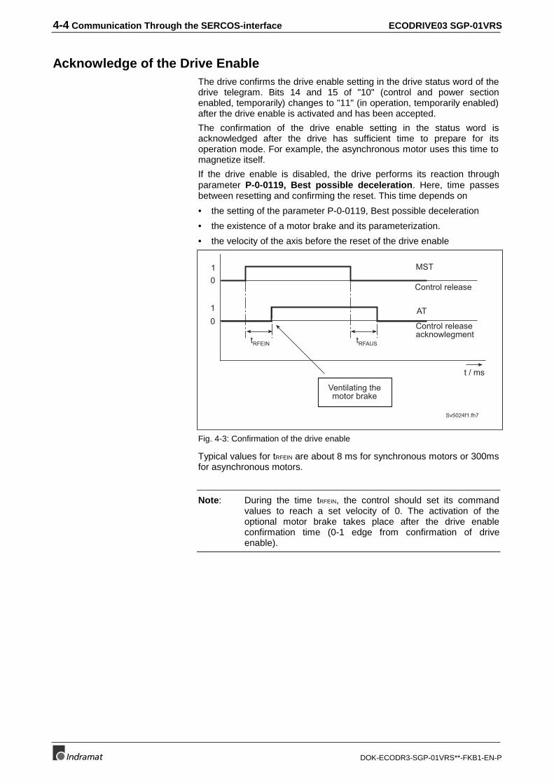
4-4 Communication Through the SERCOS-interface ECODRIVE03 SGP-01VRS
DOK-ECODR3-SGP-01VRS**-FKB1-EN-P
Acknowledge of the Drive EnableThe drive confirms the drive enable setting in the drive status word of thedrive telegram. Bits 14 and 15 of "10" (control and power sectionenabled, temporarily) changes to "11" (in operation, temporarily enabled)after the drive enable is activated and has been accepted.
The confirmation of the drive enable setting in the status word isacknowledged after the drive has sufficient time to prepare for itsoperation mode. For example, the asynchronous motor uses this time tomagnetize itself.
If the drive enable is disabled, the drive performs its reaction throughparameter P-0-0119, Best possible deceleration. Here, time passesbetween resetting and confirming the reset. This time depends on
• the setting of the parameter P-0-0119, Best possible deceleration
• the existence of a motor brake and its parameterization.
• the velocity of the axis before the reset of the drive enable
0
01
1
Sv5024f1.fh7
t / ms
Ventilating themotor brake
tRFEIN tRFAUS
Control release
Control releaseacknowlegment
MST
AT
Fig. 4-3: Confirmation of the drive enable
Typical values for tRFEIN are about 8 ms for synchronous motors or 300msfor asynchronous motors.
Note: During the time tRFEIN, the control should set its commandvalues to reach a set velocity of 0. The activation of theoptional motor brake takes place after the drive enableconfirmation time (0-1 edge from confirmation of driveenable).
ECODRIVE03 SGP-01VRS Communication Through the SERCOS-interface 4-5
DOK-ECODR3-SGP-01VRS**-FKB1-EN-P
4.3 Real-Time Control and Status Bits
In the master control and drive status words, there are 2 configurablereal-time bits. The configuration of these binary signals is achievedthrough parameters
• S-0-0301, Allocation of real-time control Bit 1
• S-0-0303, Allocation of real-time control Bit 2
• S-0-0305, Allocation of real-time status Bit 1
• S-0-0307, Allocation of real-time status Bit 2
The parameter number that will be assigned to the corresponding real-time status bit is set here. Bit 0 of this parameter will be sent cyclically tothe master or the drive via the real-time status or control bit.
4.4 Transmission of non-cyclical Data through SERCOS
The non-cyclical data (data that is not time-critical) is transmitted via theservice channel.
The transmission via the service channel is done in several steps for theMDT and AT, and the transmission of an element could last over severalSercos cycles.
The service channel is used for
• Parameterization and
• Diagnostic
4.5 Startup for the SERCOS Interface
To start the interface you have to:
• connect the fiber optic cable
• set the drive address
• check the distortion indicator
• set the transmission rate
• set the transmission power
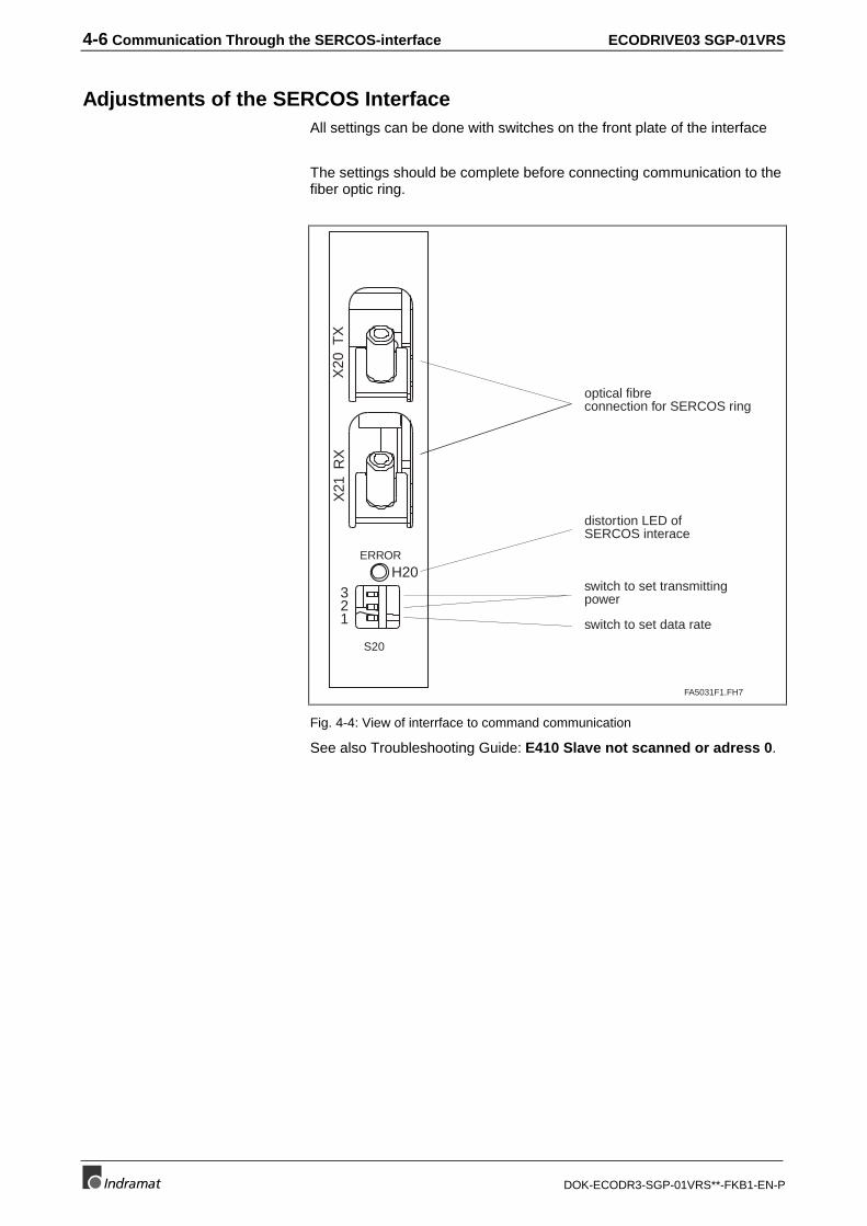
4-6 Communication Through the SERCOS-interface ECODRIVE03 SGP-01VRS
DOK-ECODR3-SGP-01VRS**-FKB1-EN-P
Adjustments of the SERCOS InterfaceAll settings can be done with switches on the front plate of the interface
The settings should be complete before connecting communication to thefiber optic ring.
FA5031F1.FH7
H20ERROR
321
S20
X20
TX
X21
RX
switch to set transmittingpower
distortion LED ofSERCOS interace
optical fibreconnection for SERCOS ring
switch to set data rate
Fig. 4-4: View of interrface to command communication
See also Troubleshooting Guide: E410 Slave not scanned or adress 0.
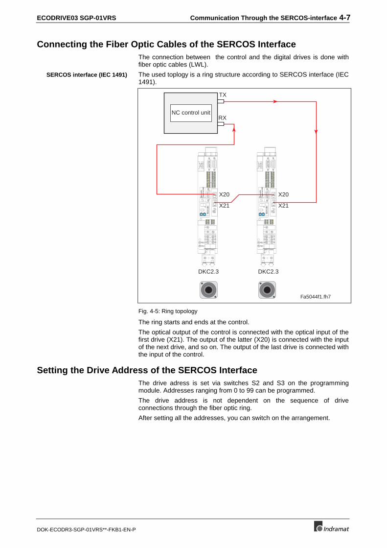
ECODRIVE03 SGP-01VRS Communication Through the SERCOS-interface 4-7
DOK-ECODR3-SGP-01VRS**-FKB1-EN-P
Connecting the Fiber Optic Cables of the SERCOS InterfaceThe connection between the control and the digital drives is done withfiber optic cables (LWL).
The used toplogy is a ring structure according to SERCOS interface (IEC1491).
Bar
code
0 1
23
456
78
90 1
23
456
78
9
H1
S1
S3 S2
Bar
code
Type
nsch
ild
12
34
56
78
91
23
4
111213
141516
1718
56
78
12
34
56
78
XE2
XE1
L+
L-
L1
L2
L3
A1
A2
A3
H3ERROR
321
Bar
code
0 1
23
456
78
90 1
23
456
78
9
H1
S1
S3 S2
Bar
code
Type
nsch
ild
12
34
56
78
91
23
4
111213
141516
1718
56
78
12
34
56
78
XE2
XE1
L+
L-
L1
L2
L3
A1
A2
A3
H3ERROR
321
Fa5044f1.fh7
DKC2.3 DKC2.3
TX
RXNC control unit
X20
X21
X20
X21
Fig. 4-5: Ring topology
The ring starts and ends at the control.
The optical output of the control is connected with the optical input of thefirst drive (X21). The output of the latter (X20) is connected with the inputof the next drive, and so on. The output of the last drive is connected withthe input of the control.
Setting the Drive Address of the SERCOS InterfaceThe drive adress is set via switches S2 and S3 on the programmingmodule. Addresses ranging from 0 to 99 can be programmed.
The drive address is not dependent on the sequence of driveconnections through the fiber optic ring.
After setting all the addresses, you can switch on the arrangement.
SERCOS interface (IEC 1491)
4-8 Communication Through the SERCOS-interface ECODRIVE03 SGP-01VRS
DOK-ECODR3-SGP-01VRS**-FKB1-EN-P
Checking the Distortion Indicator of the SERCOS InterfaceThe next step is to check whether every station gets a sufficient opticalsignal level , in other words whether the receiver is not under- oroverloaded.
For normal operation, the distortion indicator LED H20 stays dark.
If it’s lit, examine the transmission path in front of that station.
To do so, the distortion display of the drives are checked in signal flowdirection starting from the sender output of the master (control). (See Fig.4-4: View of interrface to command communication).
The distortion display of the drives is the LED "H20“.
At first, check the 1st drive in the ring. If its distortion indicator is dark, goto the next drive. Do this up to the last drive and then at the master’sinput (control).
If one of the indicators is lit, check the following:
• Is the transmission (baud) rate set correctly?
• Is the transmission power of the predecessor in the ring correct? (ortoo high or too low)
• Is the fiber optic cable to the predecessor defective?
Using the Distortion IndicatorA distortion indicator H20 lights in the following cases:
• wrong transmission (baud) rate
• wrong transmission power
• fiber optic connection defective
Therefore, in the case of a lit distortion indicator lamp, check thefollowing:
Check the transmission rate at the control and at the implicated drive.
Check the transmision power at the control and at the physicalpredecessor of the implicated drive. (See
Distortion indicator may not belit nor glow (flicker)!
Check distortion indicator in"direction of the light“
Checking the transmission rate
Checking thetransmission power
ECODRIVE03 SGP-01VRS Communication Through the SERCOS-interface 4-9
DOK-ECODR3-SGP-01VRS**-FKB1-EN-P
Setting the optical Transmission Power).
Check the fiber optic cable and its connectors from the physicalpredecessor to the implicated drive.
Transmission Rate of the SERCOS interfaceThe baud rate is set at factory to 2Mbaud. It can be programmed viaswitch S20,1 on the interface module .
Baud rate: Switch S20,1: Comment
2 Mbaud OFF state at delivery
4 Mbaud ONFig. 4-6: Programming the transmisison rate
Checking the fiber optics
4-10 Communication Through the SERCOS-interface ECODRIVE03 SGP-01VRS
DOK-ECODR3-SGP-01VRS**-FKB1-EN-P
Setting the optical Transmission PowerTransmission power is set via switches S20,2 and S20,3 on the interfacemodule.
LW length 0 .. 15 m 15 m ..30 m 30 m .. 50 m
S20,2 = OFF
S20,3 = OFF
S20,2 = ON
S20,3 = OFF
S20,2= ON
S20,3 = ONFig. 4-7: Setting transmission power with plastic LWLs
LWL length 0 .. 500 m
S20,2 = ON / S20,3 = ONFig. 4-8: Setting the transmisiosn power with glass LWLs
Checking the Fiber OpticsWhen the transmission rate and power are correctly set, and there is stillno communication, the LWL (fiber optic connection) can be defective. Inthis case, the distortion indicator lamp will light, too.
Reason for a faulty LWL can be damage or bad manufacturing(connector mounting, ...).
Perhaps you can recognize a defective LWL when hardly some lightcomes out at its end, or that, for example, the optical fiber has been tornback into the connector (check the face of the connector). Furtherexaminations cannot be done with simple means.
The only remedy is an exchange of the defective LWL cable.
4.6 SERCOS Telegram Configuration
To operate the drive properly, the settings of the telegram send andreceive times, their lengths, and content have to be transmitted from theSERCOS master to the drive.
Configuration of the Telegram Send and Receive TimesThe requirements to calculate the time slot parameter (telegram sendand receive times) are stored in the following parameters within the drive:
• S-0-0003, Minimum AT transmit starting time (T1min)
• S-0-0004, Transmit/receive transition time (TATMT)
• S-0-0005, Minimum feedback acquisition time(T4min)
• S-0-0088, Receive to receive recovery time (TMTSG)
• S-0-0090, Command value transmit time (TMTSG)
The SERCOS Master calculates from the information received from alldrives the time slot parameters for the operation of the communicationphase 3. Those values are transferred to the drive in communicationphase 2 through the parameters
• S-0-0002, SERCOS Cycle time (Tscyc)
• S-0-0006, AT Transmission starting time (T1)
• S-0-0007, Feedback acquisition starting time (T4)
• S-0-0008, Command valid time (T3)
ECODRIVE03 SGP-01VRS Communication Through the SERCOS-interface 4-11
DOK-ECODR3-SGP-01VRS**-FKB1-EN-P
• S-0-0009, Beginning address in master data telegram
• S-0-0010, Length of master data telegram
• S-0-0089, MDT Transmit starting time (T2)
The drive checks these settings while processing the commandS-0-0127, C100 Communication phase 3 transition check. Thefollowing error messages may appear:
• C101 Invalid communication parameter (S-0-0021)
• C108 Time slot parameter > Sercos cycle time
• C109 Position of data record in MDT (S-0-0009) even
• C110 Length of MDT (S-0-0010) odd
• C111 ID9 + Record length - 1 > length MDT (S-0-0010)
• C112 TNcyc (S-0-0001) or TScyc (S-0-0002) error
• C113 Relation TNcyc (S-0-0001) to TScyc (S-0-0002) error
• C114 T4 > TScyc (S-0-0002) - T4min (S-0-0005)
• C115 T2 too small
Configuration of Telegram ContentsThe telegram contents are set through these parameters:
• S-0-0015, Telegram Type Parameter
• S-0-0016, Custom Amplifier Telegram Configuration List
• S-0-0024, Config. List of the Master Data Telegram
However, the drive-directed conditions for the type and number ofconfigured data must be in the set range. Those are provided by thedrive in
• S-0-0185, Length of the configurable data record in the AT
• S-0-0186, Length of the configurable data record in the MDT
• S-0-0187, List of configurable data in the AT
• S-0-0188, List of configurable data in the MDT
The drive checks these settings while processing the commandS-0-0127, C100 Communication phase 3 transition check. Thefollowing error messages may appear:
• C104 Config. IDN for MDT not configurable
• C105 Configurated length > max. length for MDT
• C106 Config. IDN for AT not configurable
• C107 Configurated length > max. length for AT
Note: Parameter S-0-0188, List of configurable data in the MDTis also used for the configuration of the multiplex channel.There are therefore parameters in S-0-0188 that have avariable data length (list parameters). These can, however,only be used as multiplex data. Such IDNs may not beentered in S-0-0024, Config. list of the master datatelegram. If such are entered, then C104 Config. IDN forMDT not configurable is generated.
4-12 Communication Through the SERCOS-interface ECODRIVE03 SGP-01VRS
DOK-ECODR3-SGP-01VRS**-FKB1-EN-P
4.7 SERCOS Interface Error
If conditions are detected in the drive that prevent the correct operation ofthe interface, or if error values are recognized during the initializationphase, the drive responds by resetting to communication phase 0. Thismeans that no drive telegrams will be sent. The drive proceeds with theprogrammed error reaction (see P-0-0119, Best possible deceleration )and waits for the reinitialization of the SERCOS ring through the master.
Possible errors could be:
• F401 Double MST failure shutdown
• F402 Double MDT failure shutdown
• F403 Invalid communication phase shutdown
• F404 Error during phase progression
• F405 Error during phase regression
• F406 Phase switching without ready signal
Diagnostic of the interface StatusThe parameter S-0-0014, Interface status is used to analyze theexisting initialization error and the current communication phase.
Error Count for Telegram InterruptsThe drive checks every received master synchronization and master datatelegram for
• the correct receive time set point,
• the assigned telegram length and
• the correct CRC check sum
A telegram interrupt is registered with an incrementation in the errorcounter. For this purpose, these two parameters are used: S-0-0028,MST error counter and S-0-0029, MDT error counter.
These parameters are cancelled by switching the communication phasefrom 2 to 3 (S-0-0028) or from 3 to 4 (S-0-0029).
4.8 Multiplex Channel
OverviewThe multiplex channel makes it possible to update a limited cyclical datachannel. This also enables cyclical list element accessing with indexchanges.
Note: To be able to use the mechanism it is necessary to usecommand communications via SERCOS or Profibus andconfigure the multiplex parameter in the cyclical telegrams.
With the help of the multiplex channel it is possible:
• to cyclically exchange more parameter contents despite limitedmaximum number of transmittable bytes in the master data telegramand drive telegram
• to access individual list elements using both indices S-0-0362 and S-0-0366
ECODRIVE03 SGP-01VRS Communication Through the SERCOS-interface 4-13
DOK-ECODR3-SGP-01VRS**-FKB1-EN-P
• by incrementing index S-0-0368 to transmit in each cycle themultiplexed data with a cycle time of Tscyc * number of multiplex dataor
• to structure the index in terms of the operating mode and thus totransmit only those parameters needed for the activated mode
Pertinent ParametersThe following parameters are used:
• S-0-0360, MDT Data container A
• S-0-0362, List index, MDT data container A
• S-0-0364, AT Data container A
• S-0-0366, List index, AT data container A
• S-0-0368, Addressing for data container A
• S-0-0370, Configuration list for the MDT data container
• S-0-0371, Configuration list for the AT data container
Functional Principle Multiplex Channel
ConfigurationThe IDNs are entered in parameter S-0-0370, Configuration list for theMDT data container which are dependent on the index in S-0-0368,Addressing for data container A, low byte, and transmitted to S-0-0360, MDT Data container A. Write accessing S-0-0370 is only possiblein communications phase 2.
The IDNs are entered in parameter S-0-0371, Configuration list for theAT data container A that are dependent on indices in S-0-0368,Addressing for data container A, (high byte), and transmitted to S-0-0364, AT Data container A. Write accessing S-0-0371 is only possible incommunications phase 2.
Note: A maximum of 32 IDNs can be configured in S-0-0371.
Addressing the Data ContainerParameter S-0-0368, Addressing for data container A contains indicesfor the selection of the parameters transmitted in the data container.
The graph below illustrates the configuraiton lists with the maximumnumber of elements (32).
S-0-0370, Configuration list forthe MDT data container
S-0-0371, Configuration list forthe AT data container
S-0-0368, Addressing datacontainer A
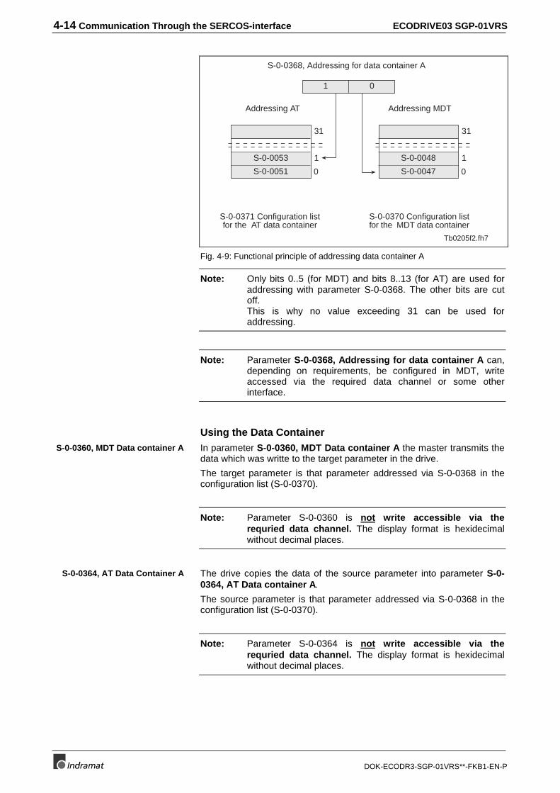
4-14 Communication Through the SERCOS-interface ECODRIVE03 SGP-01VRS
DOK-ECODR3-SGP-01VRS**-FKB1-EN-P
S-0-0053
S-0-0051
31
1
0
S-0-0048
S-0-0047
31
1
0
1 0
S-0-0368, Addressing for data container A
S-0-0371 Configuration listfor the AT data container
Tb0205f2.fh7
Addressing AT Addressing MDT
S-0-0370 Configuration listfor the MDT data container
Fig. 4-9: Functional principle of addressing data container A
Note: Only bits 0..5 (for MDT) and bits 8..13 (for AT) are used foraddressing with parameter S-0-0368. The other bits are cutoff.This is why no value exceeding 31 can be used foraddressing.
Note: Parameter S-0-0368, Addressing for data container A can,depending on requirements, be configured in MDT, writeaccessed via the required data channel or some otherinterface.
Using the Data ContainerIn parameter S-0-0360, MDT Data container A the master transmits thedata which was writte to the target parameter in the drive.
The target parameter is that parameter addressed via S-0-0368 in theconfiguration list (S-0-0370).
Note: Parameter S-0-0360 is not write accessible via therequried data channel. The display format is hexidecimalwithout decimal places.
The drive copies the data of the source parameter into parameter S-0-0364, AT Data container A.
The source parameter is that parameter addressed via S-0-0368 in theconfiguration list (S-0-0370).
Note: Parameter S-0-0364 is not write accessible via therequried data channel. The display format is hexidecimalwithout decimal places.
S-0-0360, MDT Data container A
S-0-0364, AT Data Container A
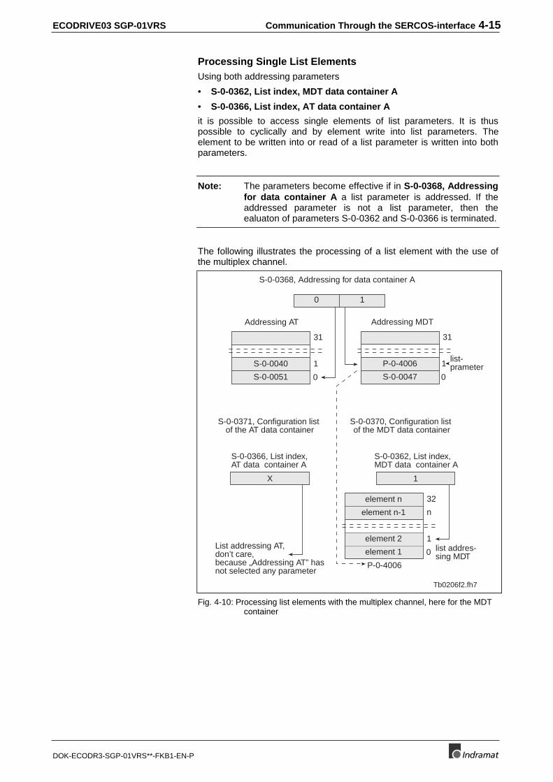
ECODRIVE03 SGP-01VRS Communication Through the SERCOS-interface 4-15
DOK-ECODR3-SGP-01VRS**-FKB1-EN-P
Processing Single List ElementsUsing both addressing parameters
• S-0-0362, List index, MDT data container A
• S-0-0366, List index, AT data container A
it is possible to access single elements of list parameters. It is thuspossible to cyclically and by element write into list parameters. Theelement to be written into or read of a list parameter is written into bothparameters.
Note: The parameters become effective if in S-0-0368, Addressingfor data container A a list parameter is addressed. If theaddressed parameter is not a list parameter, then theealuaton of parameters S-0-0362 and S-0-0366 is terminated.
The following illustrates the processing of a list element with the use ofthe multiplex channel.
S-0-0040
S-0-0051
31
1
0
P-0-4006
S-0-0047
31
1
0
0 1
S-0-0368, Addressing for data container A
S-0-0371, Configuration listof the AT data container
Tb0206f2.fh7
Addressing AT Addressing MDT
element 2
element 1
32
n
1
0
P-0-4006
S-0-0366, List index,AT data container A
element n
element n-1
List addressing AT,don’t care,because „Addressing AT” hasnot selected any parameter
X 1
list addres-sing MDT
list-prameter
S-0-0370, Configuration listof the MDT data container
S-0-0362, List index,MDT data container A
Fig. 4-10: Processing list elements with the multiplex channel, here for the MDTcontainer
4-16 Communication Through the SERCOS-interface ECODRIVE03 SGP-01VRS
DOK-ECODR3-SGP-01VRS**-FKB1-EN-P
Diagnostic MessagesIn conjunction with the multiplex channel, various checks are conducted:
Checking the Configured IDN OrderThe temporal sequence of the processing of cyclical MDT data in thedrive has an order specified with which the configured IDNs are enteredin parameter S-0-0024, Config. list of the master data telegram.
If both the parameter S-0-0360, MDT Data container A and S-0-0368,Addressing for data container A are configured in the MDT, then theMDT data container will only be properly processed if the addressing waspreviously processed.
To maintain the correct order when configuring the MDT, the drivechecks in command S-0-0127, C100 Communication phase 3transition check whether the IDN S-0-0368 is configured before S-0-0360. If not, then the drive generates a command error message.
• C118, MDT order for configuration faulty
Checking the Configuration ListsIt must be ensured that the ID numbers in the configuration lists can becyclically configured.
This is why it is checked in command S-0-0127, C100 Communicationphase 3 transition check, whether ID numbers in S-0-0187, List ofconfigurable data in the AT or S-0-0188, List of configurable data inthe MDT are contained in the list.
The following errors are possible:
If list S-0-0370, Configuration list for the MDT data container has oneor more IDNs which are not available are not in S-0-0188 ,List ofconfigurable data in the MDT then error message
• C104 Configured ID number for MDT not configurable
is generated.
If list S-0-0371, Configuration list for the AT data container containsone ore more IDNs that are not available or not in S-0-0187, List ofconfigurable data in the AT then error message:
• C106 Configurated ID numbers for AT not configurable
is generated.
Checking for Existing ID NumbersWhen inputting S-0-0370 and S-0-0371 the following checks areconducted:
• It is checked whether the entered IDN is available. If not, thenrequired data channel error message "0x1001, ID number notavailable“ is generated.
• It is checked whether the entered IDN in parameter S-0-0188, List ofconfigurable data in the MDT is available. If not, then required datachannel error message "0x7008, Data not correct“ is generated.
Checks in transition command
Checking the input
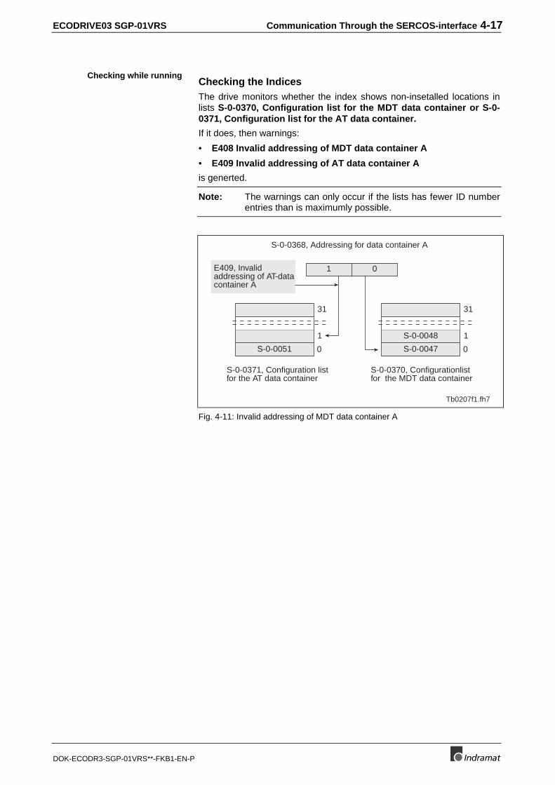
ECODRIVE03 SGP-01VRS Communication Through the SERCOS-interface 4-17
DOK-ECODR3-SGP-01VRS**-FKB1-EN-P
Checking the IndicesThe drive monitors whether the index shows non-insetalled locations inlists S-0-0370, Configuration list for the MDT data container or S-0-0371, Configuration list for the AT data container.
If it does, then warnings:
• E408 Invalid addressing of MDT data container A
• E409 Invalid addressing of AT data container A
is generted.
Note: The warnings can only occur if the lists has fewer ID numberentries than is maximumly possible.
S-0-0051
31
1
0
S-0-0048
S-0-0047
31
1
0
1 0
S-0-0368, Addressing for data container A
S-0-0371, Configuration listfor the AT data container
S-0-0370, Configurationlistfor the MDT data container
Tb0207f1.fh7
E409, Invalidaddressing of AT-datacontainer A
Fig. 4-11: Invalid addressing of MDT data container A
Checking while running

ECODRIVE03 SGP-01VRS Command Communications with Analog Interface 5-1
DOK-ECODR3-SGP-01VRS**-FKB1-EN-P
5 Command Communications with Analog Interface
5.1 Overview
In DKC01.3 or DKC11.3 the drive enable, drive halt and clear errors arespecified via a digital input. Diagnoses such as drive errors and warningsare output via digital outputs.
Note: If the Sercos Interface is not active with a DKC02.3 or thefieldbus interface with the DKC03.3, then the analog interfacecan be used in both of these units as well.
5.2 Pertinent Parameters
• S-0-0134, Master control word
• S-0-0135, Drive status word
• S-0-0099, C500 Reset class 1 diagnostic
5.3 How it works
Digital inputsDigital inputs are read in every 500us and filtered with a digital filter sothat the drive can detect a signal change within 2ms. Due to the digitalprocessing, the signals are active in the drive within 10ms.
The digital input signals are stored in parameter S-0-0134, Mastercontrol word.
See section: Master Control Word"
The drive is activated via a 0-1 edge of the drive enable signal which isdisplayed in bit 15 of the master control word.
For the drive enable signal to be accepted, i.e., for the drive to switchfrom an off to an on state, the following conditions must be met:
• no drive error
• power section must be on
The drive displays "Ab" in this state. The diagnosis via parameter S-0-0095, Diagnostic message reads A012 Control and power sectionsready for operation.
Once the drive enable is set, then the 7-segment display reads "AF". Thediagnosis then shows the activated state, e.g., A101 Drive in VELOCITYcontrol.
The signal is dependent on the state and zero active which means that ifthe signal = 0V , then the drive is in "Drive halt“. The input signal isillustrated in the master control word bit 13.
See Section: "Drive Halt/Start".
An 0-1 edge at the error input starts the reset error command. Activatingthe error clear command resets all drive errors.
Drive enable
Drive Halt
Clear error
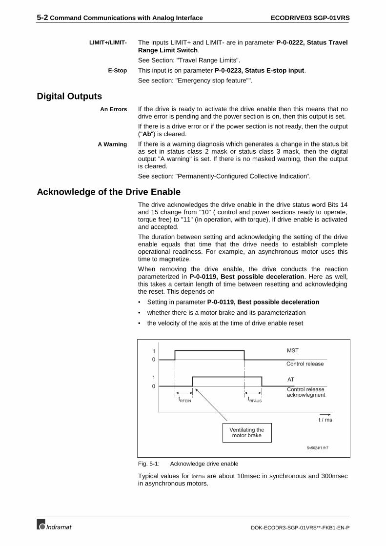
5-2 Command Communications with Analog Interface ECODRIVE03 SGP-01VRS
DOK-ECODR3-SGP-01VRS**-FKB1-EN-P
The inputs LIMIT+ and LIMIT- are in parameter P-0-0222, Status TravelRange Limit Switch.
See Section: "Travel Range Limits".
This input is on parameter P-0-0223, Status E-stop input.
See section: "Emergency stop feature"".
Digital OutputsIf the drive is ready to activate the drive enable then this means that nodrive error is pending and the power section is on, then this output is set.
If there is a drive error or if the power section is not ready, then the output("Ab") is cleared.
If there is a warning diagnosis which generates a change in the status bitas set in status class 2 mask or status class 3 mask, then the digitaloutput "A warning" is set. If there is no masked warning, then the outputis cleared.
See section: "Permanently-Configured Collective Indication".
Acknowledge of the Drive EnableThe drive acknowledges the drive enable in the drive status word Bits 14and 15 change from "10" ( control and power sections ready to operate,torque free) to "11" (in operation, with torque), if drive enable is activatedand accepted.
The duration between setting and acknowledging the setting of the driveenable equals that time that the drive needs to establish completeoperational readiness. For example, an asynchronous motor uses thistime to magnetize.
When removing the drive enable, the drive conducts the reactionparameterized in P-0-0119, Best possible deceleration. Here as well,this takes a certain length of time between resetting and acknowledgingthe reset. This depends on
• Setting in parameter P-0-0119, Best possible deceleration
• whether there is a motor brake and its parameterization
• the velocity of the axis at the time of drive enable reset
0
01
1
Sv5024f1.fh7
t / ms
Ventilating themotor brake
tRFEIN tRFAUS
Control release
Control releaseacknowlegment
MST
AT
Fig. 5-1: Acknowledge drive enable
Typical values for tRFEIN are about 10msec in synchronous and 300msecin asynchronous motors.
LIMIT+/LIMIT-
E-Stop
An Errors
A Warning
ECODRIVE03 SGP-01VRS Command Communications with Analog Interface 5-3
DOK-ECODR3-SGP-01VRS**-FKB1-EN-P
Note: During time tRFEIN the drive should set the command value sothat a command speed of 0 results. Any cooling of an existingmotor brake does not occur until after the point in time whendrive enable is acknowledged (tRFEIN + brake delay time).
5.4 Connecting Signals to DKCxx.3
See Project Planning Manual.
Section: Electrical connections unit type dependent.

5-4 Command Communications with Analog Interface ECODRIVE03 SGP-01VRS
DOK-ECODR3-SGP-01VRS**-FKB1-EN-P
Notes
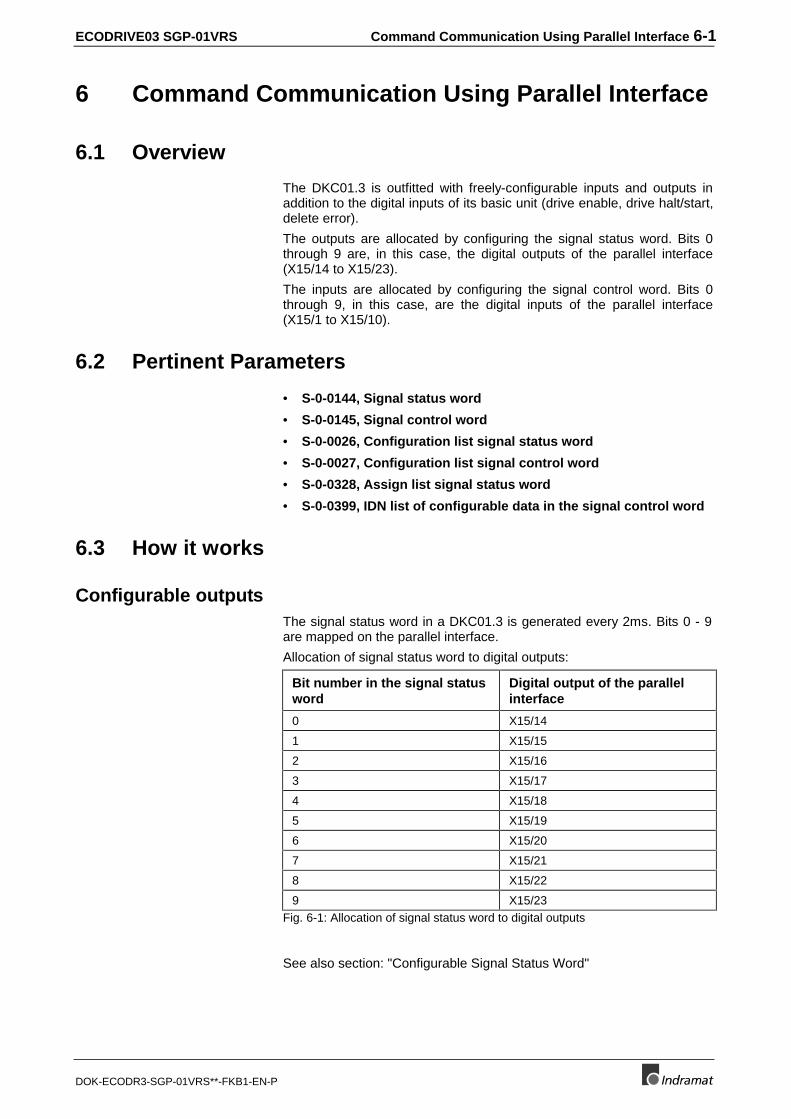
ECODRIVE03 SGP-01VRS Command Communication Using Parallel Interface 6-1
DOK-ECODR3-SGP-01VRS**-FKB1-EN-P
6 Command Communication Using Parallel Interface
6.1 Overview
The DKC01.3 is outfitted with freely-configurable inputs and outputs inaddition to the digital inputs of its basic unit (drive enable, drive halt/start,delete error).
The outputs are allocated by configuring the signal status word. Bits 0through 9 are, in this case, the digital outputs of the parallel interface(X15/14 to X15/23).
The inputs are allocated by configuring the signal control word. Bits 0through 9, in this case, are the digital inputs of the parallel interface(X15/1 to X15/10).
6.2 Pertinent Parameters
• S-0-0144, Signal status word
• S-0-0145, Signal control word
• S-0-0026, Configuration list signal status word
• S-0-0027, Configuration list signal control word
• S-0-0328, Assign list signal status word
• S-0-0399, IDN list of configurable data in the signal control word
6.3 How it works
Configurable outputsThe signal status word in a DKC01.3 is generated every 2ms. Bits 0 - 9are mapped on the parallel interface.
Allocation of signal status word to digital outputs:
Bit number in the signal statusword
Digital output of the parallelinterface
0 X15/14
1 X15/15
2 X15/16
3 X15/17
4 X15/18
5 X15/19
6 X15/20
7 X15/21
8 X15/22
9 X15/23Fig. 6-1: Allocation of signal status word to digital outputs
See also section: "Configurable Signal Status Word"
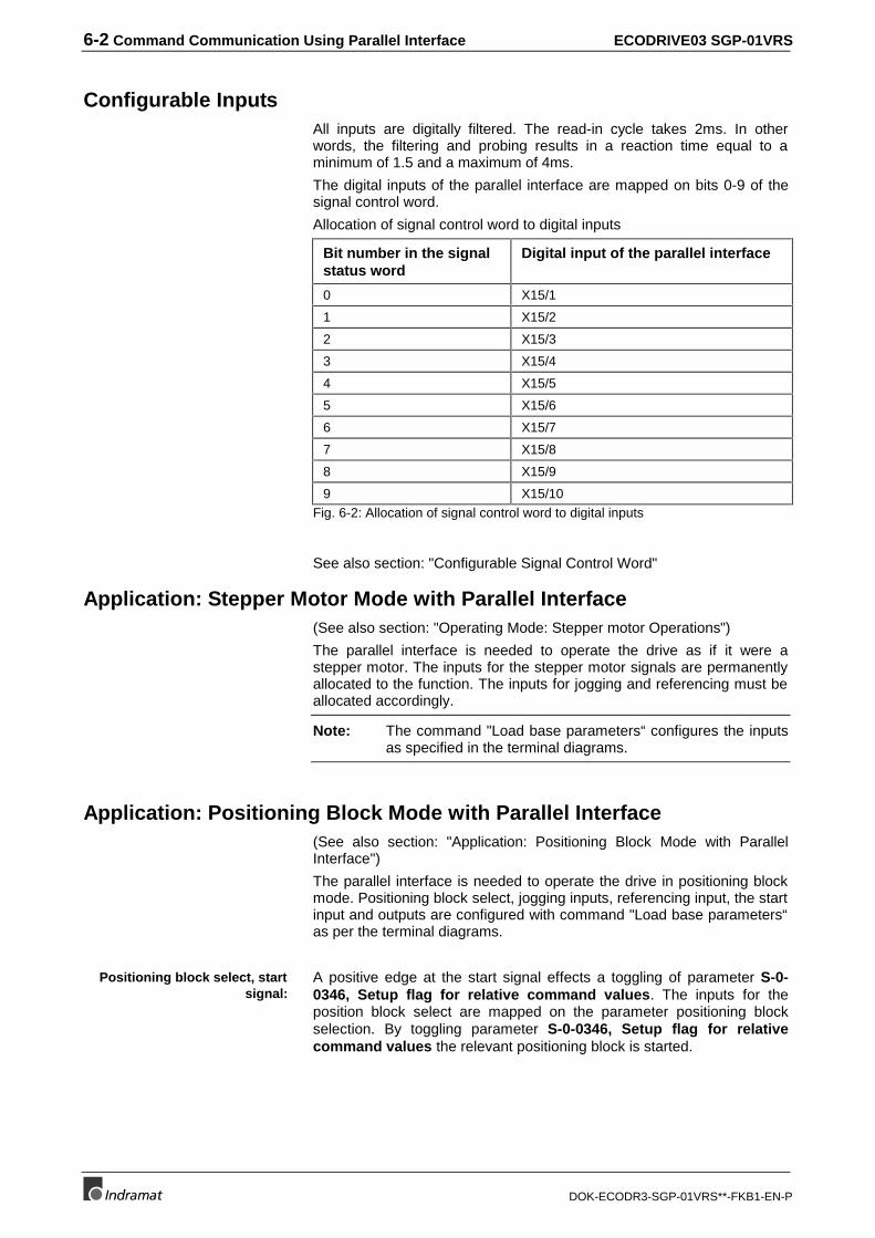
6-2 Command Communication Using Parallel Interface ECODRIVE03 SGP-01VRS
DOK-ECODR3-SGP-01VRS**-FKB1-EN-P
Configurable InputsAll inputs are digitally filtered. The read-in cycle takes 2ms. In otherwords, the filtering and probing results in a reaction time equal to aminimum of 1.5 and a maximum of 4ms.
The digital inputs of the parallel interface are mapped on bits 0-9 of thesignal control word.
Allocation of signal control word to digital inputs
Bit number in the signalstatus word
Digital input of the parallel interface
0 X15/1
1 X15/2
2 X15/3
3 X15/4
4 X15/5
5 X15/6
6 X15/7
7 X15/8
8 X15/9
9 X15/10Fig. 6-2: Allocation of signal control word to digital inputs
See also section: "Configurable Signal Control Word"
Application: Stepper Motor Mode with Parallel Interface(See also section: "Operating Mode: Stepper motor Operations")
The parallel interface is needed to operate the drive as if it were astepper motor. The inputs for the stepper motor signals are permanentlyallocated to the function. The inputs for jogging and referencing must beallocated accordingly.
Note: The command "Load base parameters“ configures the inputsas specified in the terminal diagrams.
Application: Positioning Block Mode with Parallel Interface(See also section: "Application: Positioning Block Mode with ParallelInterface")
The parallel interface is needed to operate the drive in positioning blockmode. Positioning block select, jogging inputs, referencing input, the startinput and outputs are configured with command "Load base parameters“as per the terminal diagrams.
A positive edge at the start signal effects a toggling of parameter S-0-0346, Setup flag for relative command values. The inputs for theposition block select are mapped on the parameter positioning blockselection. By toggling parameter S-0-0346, Setup flag for relativecommand values the relevant positioning block is started.
Positioning block select, startsignal:
ECODRIVE03 SGP-01VRS Command Communication Using Parallel Interface 6-3
DOK-ECODR3-SGP-01VRS**-FKB1-EN-P
The acknowledgement of the block selection ensues as soon as thepositioning block isset. The in-pos message is simultaneously updated.
Selecting the jogging inputs effects an internal switch to jogging mode.The switch can only be made every 8 ms which means that the reactiontime to a jog input can equal up to 12 ms.
Application: Analog Main Spindle with Parallelinterface(See also section:: "Spindle Positioning")
To operate as an analog unit with main spindle functions, the spindlepositioning command can be allocated to an input. The main spindlemessages must be allocated to the digital outputs.
Block select acknowledgment,In-Pos message:
Jogging input:

6-4 Command Communication Using Parallel Interface ECODRIVE03 SGP-01VRS
DOK-ECODR3-SGP-01VRS**-FKB1-EN-P
Notes
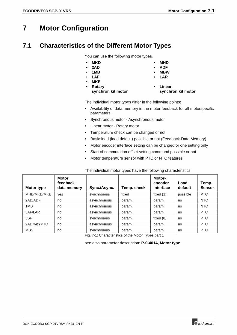
ECODRIVE03 SGP-01VRS Motor Configuration 7-1
DOK-ECODR3-SGP-01VRS**-FKB1-EN-P
7 Motor Configuration
7.1 Characteristics of the Different Motor Types
You can use the following motor types.
• MKD • MHD• 2AD • ADF• 1MB • MBW• LAF • LAR• MKE• Rotary
synchron kit motor• Linear
synchron kit motor
The individual motor types differ in the following points:
• Availability of data memory in the motor feedback for all motorspecificparameters
• Synchronous motor - Asynchronous motor
• Linear motor - Rotary motor
• Temperature check can be changed or not.
• Basic load (load default) possible or not (Feedback-Data Memory)
• Motor encoder interface setting can be changed or one setting only
• Start of commutation offset setting command possible or not
• Motor temperature sensor with PTC or NTC features
The individual motor types have the following characteristics
Motor type
Motorfeedbackdata memory Sync./Async. Temp. check
Motor-encoderinterface
Loaddefault
Temp.Sensor
MHD/MKD/MKE yes synchronous fixed fixed (1) possible PTC
2AD/ADF no asynchronous param. param. no NTC
1MB no asynchronous param. param. no NTC
LAF/LAR no asynchronous param. param. no PTC
LSF no synchronous param. fixed (8) no PTC
2AD with PTC no asynchronous param. param. no PTC
MBS no synchronous param. param. no PTCFig. 7-1: Characteristics of the Motor Types part 1
see also parameter description: P-0-4014, Motor type
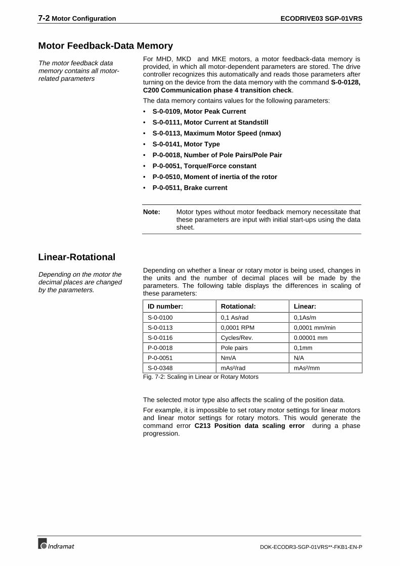
7-2 Motor Configuration ECODRIVE03 SGP-01VRS
DOK-ECODR3-SGP-01VRS**-FKB1-EN-P
Motor Feedback-Data Memory
The motor feedback datamemory contains all motor-related parameters
For MHD, MKD and MKE motors, a motor feedback-data memory isprovided, in which all motor-dependent parameters are stored. The drivecontroller recognizes this automatically and reads those parameters afterturning on the device from the data memory with the command S-0-0128,C200 Communication phase 4 transition check.
The data memory contains values for the following parameters:
• S-0-0109, Motor Peak Current
• S-0-0111, Motor Current at Standstill
• S-0-0113, Maximum Motor Speed (nmax)
• S-0-0141, Motor Type
• P-0-0018, Number of Pole Pairs/Pole Pair
• P-0-0051, Torque/Force constant
• P-0-0510, Moment of inertia of the rotor
• P-0-0511, Brake current
Note: Motor types without motor feedback memory necessitate thatthese parameters are input with initial start-ups using the datasheet.
Linear-Rotational
Depending on the motor thedecimal places are changedby the parameters.
Depending on whether a linear or rotary motor is being used, changes inthe units and the number of decimal places will be made by theparameters. The following table displays the differences in scaling ofthese parameters:
ID number: Rotational: Linear:
S-0-0100 0,1 As/rad 0,1As/m
S-0-0113 0,0001 RPM 0,0001 mm/min
S-0-0116 Cycles/Rev. 0.00001 mm
P-0-0018 Pole pairs 0,1mm
P-0-0051 Nm/A N/A
S-0-0348 mAs²/rad mAs²/mmFig. 7-2: Scaling in Linear or Rotary Motors
The selected motor type also affects the scaling of the position data.
For example, it is impossible to set rotary motor settings for linear motorsand linear motor settings for rotary motors. This would generate thecommand error C213 Position data scaling error during a phaseprogression.
ECODRIVE03 SGP-01VRS Motor Configuration 7-3
DOK-ECODR3-SGP-01VRS**-FKB1-EN-P
Synchronous-AsynchronousSpecific parameters are used only for synchronous motors, others onlyfor asynchronous motors.
There are differences in the use and review of the parameters in thecommand S-0-0128, C200 Communication phase 4 transition check.
They are:
Synchronous:
• P-0-4004, Magnetizing current is set to 0
• P-0-0508, Commutation offset is checked for validity
Asynchronous:
• P-0-4004, Magnetizing current is initialized
• P-0-0508, Commutation offset is not checked
Temperature Monitoring
The switch-off limit for themotor temperature check isfixed at one point for MHD-,MKD, MKE motors.
The following parameters are used to monitor the motor temperature : :
S-0-0201, Motor warning temperature
S-0-0204, Motor shutdown temperature
For MHD, MKD and MKE motors, the parameter default values are:
S-0-0201, Motor warning temperature = 145,0°C
S-0-0204, Motor shutdown temperature = 155,0°C
Those default values can be used to help set the parameters for all othermotor types. However, you must ensure that the switch-off limit is not sethigher than the maximum permissible temperature of the motor.
The maximum input value for S-0-0201, Motor warning temperature isS-0-0204, Motor shutdown temperature.
If the temperature of the motor exceeds the value in S-0-0201, Motorwarning temperature, the warning message E251 Motor overtemp.prewarning is generated.
If the temperature rises to the motor switch-off temperature, the errormessage F219 Motor overtemp. shutdown is displayed.
The minimum input value for S-0-0204, Motor shutdown temperatureis S-0-0201, Motor warning temperature.
Note: To display the motor temperature, the parameter S-0-0383,Motor Temperature is used.
The drive controller checks for proper functioning of the motortemperature monitoring system. If discrepancies occur (temperaturedrops below -10 degrees), the warning E221 Warning Motor temp.surveillance defective will be displayed for 10 seconds. After that, theerror message F221 Error Motor temp. surveillance defective isgenerated.
7-4 Motor Configuration ECODRIVE03 SGP-01VRS
DOK-ECODR3-SGP-01VRS**-FKB1-EN-P
Load Default FeatureMHD, MKD and MKE motors have a data memory in their feedbacks.The data memory contains a set of default control parameters in additionto all motor-dependent parameters.
These parameters are activated with the load default feature.
(See also "Load Default"feature.)
7.2 Setting the Motor Type
The setting of the motor type is done either
• depending from the applied motor,
• automatically by reading the motor feedback memory, or
• through the input of the parameter P-0-4014, Motor Type.
The motor type should be set before start up because the motor typeaffects the drive functions:
See also Chapter: "Characteristics of the Different Motor Types".
Automatic Setting of the Motor Type for Motors with Feedback MemoryMHD, MKD and MKE motors have a motor feedback data memory, inwhich the motor type is stored (along with other information). The drivecontroller recognizes these motor types automatically and the following isexecuted:
• the value of the parameter P-0-4014, Motor Type is set to its propervalue and will be write-protected.
• the value of the parameter P-0-0074, Interface Feedback 1 is set tothe defined value for the corresponding motor type.
• all bits except bit 6 are set for absolute/not-absolute to "0" in theparameter S-0-0277, Position feedback 1 type parameter.
• all motor-dependent parameters are read out of the motor feedbackdata storage (see Motor Feedback-Data Memory"). The parameter inthe motor feedback memory are set with parameter block number 7.These are fetched and copied into the relevant parameters withparameter block number 0.
• the value of S-0-0201, Motor warning temperature will be set to145,0°C, and the S-0-0204, Motor shutdown temperature will be setto 155,0°C.
• The value of P-0-0525, Type of motor brake is set to "0". The valueof P-0-0526, Brake control delay is set to 150 ms.
This procedure is followed right after switching on as in the command S-0-0128, C200 Communication phase 4 transition check. Thecommand error message, C204 Motor type P-0-4014 incorrect, will begenerated in case an MHD, MKD and MKE motor is selected in P-0-4014, Motor type but the corresponding character sequence cannot befound in the motor feedback data memory.
Setting of the Motor Type through P-0-4014, Motor TypeFor motors without motor feedback data memory, you have to set themotor type through P-0-4014, Motor type.
See also: Characteristics of the Different Motor Types"
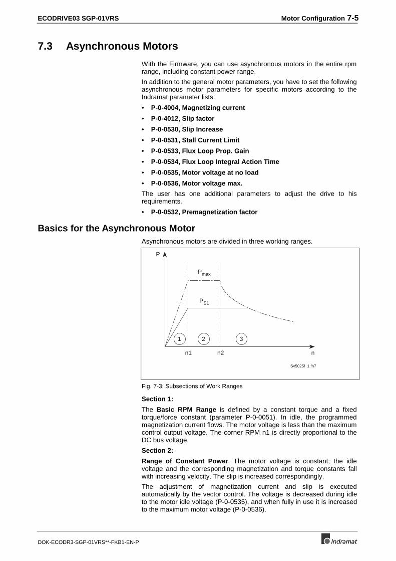
ECODRIVE03 SGP-01VRS Motor Configuration 7-5
DOK-ECODR3-SGP-01VRS**-FKB1-EN-P
7.3 Asynchronous Motors
With the Firmware, you can use asynchronous motors in the entire rpmrange, including constant power range.
In addition to the general motor parameters, you have to set the followingasynchronous motor parameters for specific motors according to theIndramat parameter lists:
• P-0-4004, Magnetizing current
• P-0-4012, Slip factor
• P-0-0530, Slip Increase
• P-0-0531, Stall Current Limit
• P-0-0533, Flux Loop Prop. Gain
• P-0-0534, Flux Loop Integral Action Time
• P-0-0535, Motor voltage at no load
• P-0-0536, Motor voltage max.
The user has one additional parameters to adjust the drive to hisrequirements.
• P-0-0532, Premagnetization factor
Basics for the Asynchronous MotorAsynchronous motors are divided in three working ranges.
n
P
Sv5025f 1.fh7
1 2 3
n2n1
Pmax
PS1
Fig. 7-3: Subsections of Work Ranges
Section 1:
The Basic RPM Range is defined by a constant torque and a fixedtorque/force constant (parameter P-0-0051). In idle, the programmedmagnetization current flows. The motor voltage is less than the maximumcontrol output voltage. The corner RPM n1 is directly proportional to theDC bus voltage.
Section 2:
Range of Constant Power. The motor voltage is constant; the idlevoltage and the corresponding magnetization and torque constants fallwith increasing velocity. The slip is increased correspondingly.
The adjustment of magnetization current and slip is executedautomatically by the vector control. The voltage is decreased during idleto the motor idle voltage (P-0-0535), and when fully in use it is increasedto the maximum motor voltage (P-0-0536).
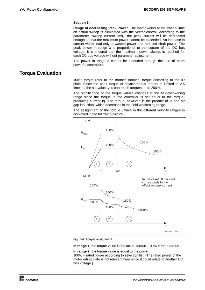
7-6 Motor Configuration ECODRIVE03 SGP-01VRS
DOK-ECODR3-SGP-01VRS**-FKB1-EN-P
Section 3:
Range of decreasing Peak Power. The motor works at the sweep limit;an actual sweep is eliminated with the vector control. According to theparameter "sweep current limit," the peak current will be decreasedenough so that the maximum power cannot be exceeded. An increase incurrent would lead only to wasted power and reduced shaft power. Thepeak power in range 3 is proportional to the square of the DC busvoltage. It is ensured that the maximum power always is reached foreach DC bus voltage without parameter adjustment.
The power in range 3 cannot be extended through the use of morepowerful controllers.
Torque Evaluation100% torque refer to the motor’s nominal torque according to the IDplate. Since the peak torque of asynchronous motors is limited to 2.5times of the set value, you can reach torques up to 250%.
The significance of the torque values changes in the field-weakeningrange since the torque in the controller is set equal to the torque-producing current Iq. The torque, however, is the product of Iq and airgap induction, which decreases in the field-weakening range.
The assignment of the torque values in the different velocity ranges isdisplayed in the following picture:
In this case160 per centcorresponds to theeffective peak current
n
Mmax
Sv5026f 1.fh5
1 2 3
160
M
160
100
100
n
Pmax
1 2 3
n2n1
160
Pn
P
100100
<160
<100
<100
Fig. 7-4: Torque assignment
In range 1, the torque value is the actual torque. 100% = rated torque.
In range 2, the torque value is equal to the power.100% = rated power according to selection list. (The rated power of themotor rating plate is not relevant here since it could relate to another DCbus voltage.)
ECODRIVE03 SGP-01VRS Motor Configuration 7-7
DOK-ECODR3-SGP-01VRS**-FKB1-EN-P
Range 3 is similar to the evaluation of range 2, except that the presettorque decreases in correspondence to the increasing velocity of thepeak power. For high velocity, the maximum torque value can drop below100%.
In braking mode, you can reach 50% higher torque values in this rangethan in driving mode.
User-defined Settings for the Asynchronous MotorTo operate an asynchronous motor, you have to set the specific motorparameters in the controller. The Parameters are stored in theParameterstorage and are therefore transferable to another controller.
Note: Motor-specific parameters are used by all controls in thesame manner. The resulting power characteristics curvedepends on the current and especially on the DC bus voltage.Several additional parameters are available so the user canoptimize the drive to his requirements.
Scaling Factor Pre-MagnetizingWith P-0-0532, Premagnetization factor you can set the activemagnetization current.
The following applies:
Effective magnetization current = magnetization voltage •scaling factor pre-magnetizing
Fig. 7-5: Calculation of the Effective Magnetization Current
If the pre-magnetizing scaling factor is at 100%, the motor is completelymagnetized. There is a linear connection between set current and torqueaccording to the torque constant P-0-0051. The torque builds up withoutdelay. The drive has perfect servo properties.
The disadvantages are the high iron loss and the higher noise level inidle and in work mode, especially at 4kHz switching frequency, when thefull magnetization current is flowing. For main spindle applications, it hasproven successful to reduce the pre-magnetizing scaling factor to 50%.Through this procedure, the motor stays cooler and is not as noisy, whilepeak power is maintained. The extended start control time (only forjumps that exceed half the peak torque) and the missing linearity oftorque and voltage do not distort the main spindle drives.
The qualitative connection between the pre-magnetizing scaling factorand drive behavior is displayed in the following graphic:
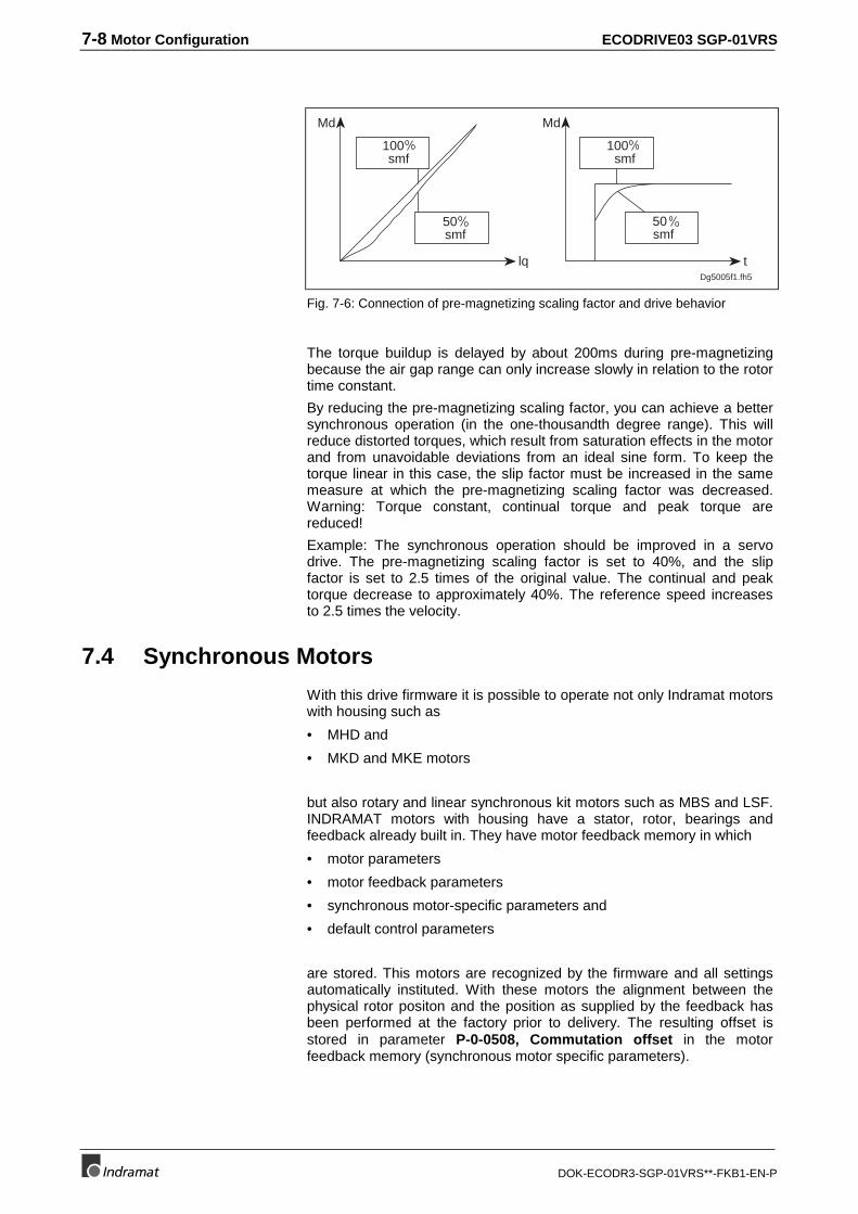
7-8 Motor Configuration ECODRIVE03 SGP-01VRS
DOK-ECODR3-SGP-01VRS**-FKB1-EN-P
lq
Md
100 smf
50 smf
Md
tDg5005f1.fh5
100 smf
50 smf
Fig. 7-6: Connection of pre-magnetizing scaling factor and drive behavior
The torque buildup is delayed by about 200ms during pre-magnetizingbecause the air gap range can only increase slowly in relation to the rotortime constant.
By reducing the pre-magnetizing scaling factor, you can achieve a bettersynchronous operation (in the one-thousandth degree range). This willreduce distorted torques, which result from saturation effects in the motorand from unavoidable deviations from an ideal sine form. To keep thetorque linear in this case, the slip factor must be increased in the samemeasure at which the pre-magnetizing scaling factor was decreased.Warning: Torque constant, continual torque and peak torque arereduced!
Example: The synchronous operation should be improved in a servodrive. The pre-magnetizing scaling factor is set to 40%, and the slipfactor is set to 2.5 times of the original value. The continual and peaktorque decrease to approximately 40%. The reference speed increasesto 2.5 times the velocity.
7.4 Synchronous Motors
With this drive firmware it is possible to operate not only Indramat motorswith housing such as
• MHD and
• MKD and MKE motors
but also rotary and linear synchronous kit motors such as MBS and LSF.INDRAMAT motors with housing have a stator, rotor, bearings andfeedback already built in. They have motor feedback memory in which
• motor parameters
• motor feedback parameters
• synchronous motor-specific parameters and
• default control parameters
are stored. This motors are recognized by the firmware and all settingsautomatically instituted. With these motors the alignment between thephysical rotor positon and the position as supplied by the feedback hasbeen performed at the factory prior to delivery. The resulting offset isstored in parameter P-0-0508, Commutation offset in the motorfeedback memory (synchronous motor specific parameters).
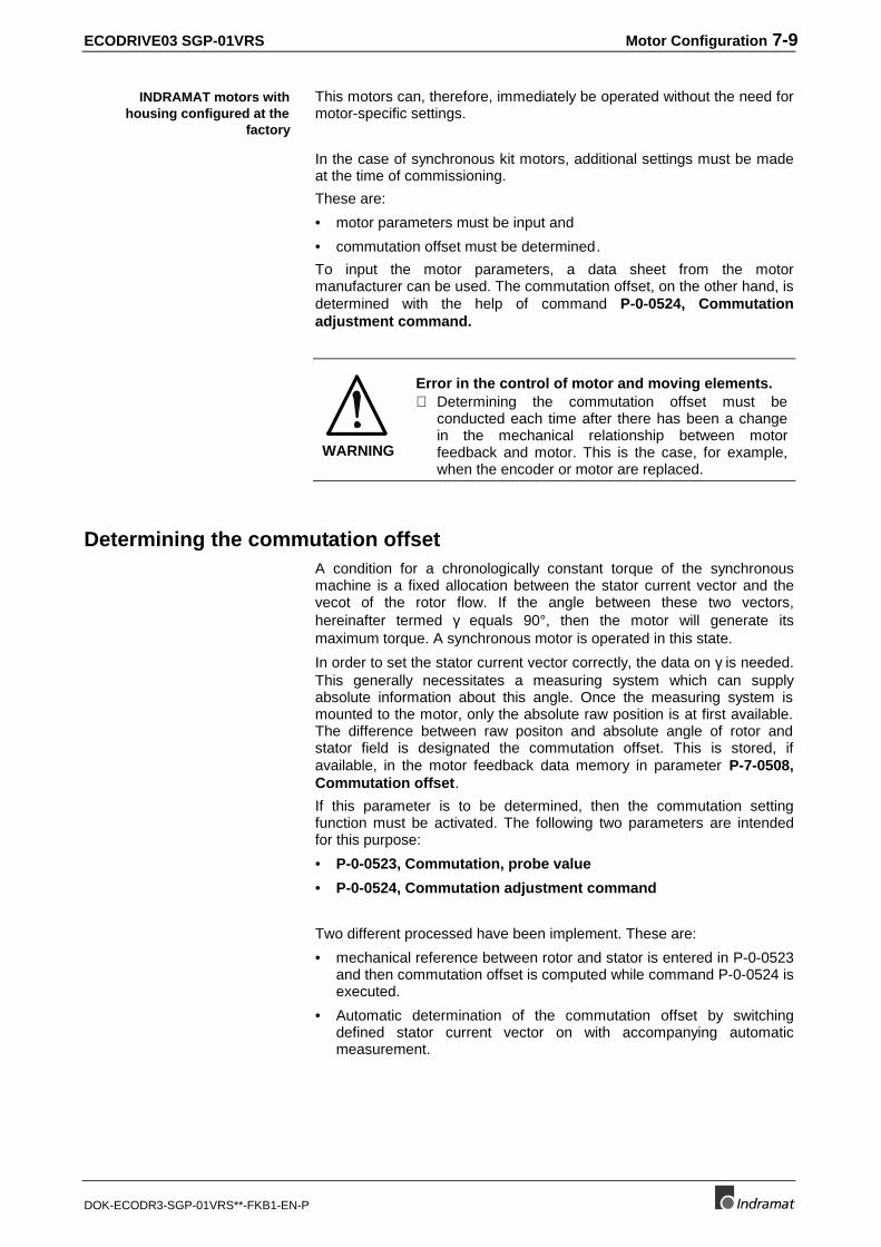
ECODRIVE03 SGP-01VRS Motor Configuration 7-9
DOK-ECODR3-SGP-01VRS**-FKB1-EN-P
This motors can, therefore, immediately be operated without the need formotor-specific settings.
In the case of synchronous kit motors, additional settings must be madeat the time of commissioning.
These are:
• motor parameters must be input and
• commutation offset must be determined.
To input the motor parameters, a data sheet from the motormanufacturer can be used. The commutation offset, on the other hand, isdetermined with the help of command P-0-0524, Commutationadjustment command.
WARNING
Error in the control of motor and moving elements.⇒ Determining the commutation offset must be
conducted each time after there has been a changein the mechanical relationship between motorfeedback and motor. This is the case, for example,when the encoder or motor are replaced.
Determining the commutation offsetA condition for a chronologically constant torque of the synchronousmachine is a fixed allocation between the stator current vector and thevecot of the rotor flow. If the angle between these two vectors,hereinafter termed γ equals 90°, then the motor will generate itsmaximum torque. A synchronous motor is operated in this state.
In order to set the stator current vector correctly, the data on γ is needed.This generally necessitates a measuring system which can supplyabsolute information about this angle. Once the measuring system ismounted to the motor, only the absolute raw position is at first available.The difference between raw positon and absolute angle of rotor andstator field is designated the commutation offset. This is stored, ifavailable, in the motor feedback data memory in parameter P-7-0508,Commutation offset.
If this parameter is to be determined, then the commutation settingfunction must be activated. The following two parameters are intendedfor this purpose:
• P-0-0523, Commutation, probe value
• P-0-0524, Commutation adjustment command
Two different processed have been implement. These are:
• mechanical reference between rotor and stator is entered in P-0-0523and then commutation offset is computed while command P-0-0524 isexecuted.
• Automatic determination of the commutation offset by switchingdefined stator current vector on with accompanying automaticmeasurement.
INDRAMAT motors withhousing configured at the
factory
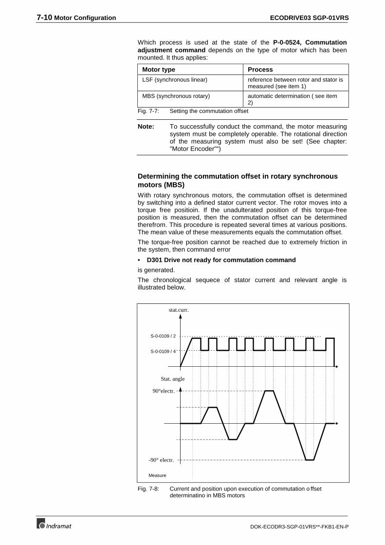
7-10 Motor Configuration ECODRIVE03 SGP-01VRS
DOK-ECODR3-SGP-01VRS**-FKB1-EN-P
Which process is used at the state of the P-0-0524, Commutationadjustment command depends on the type of motor which has beenmounted. It thus applies:
Motor type Process
LSF (synchronous linear) reference between rotor and stator ismeasured (see item 1)
MBS (synchronous rotary) automatic determination ( see item2)
Fig. 7-7: Setting the commutation offset
Note: To successfully conduct the command, the motor measuringsystem must be completely operable. The rotational directionof the measuring system must also be set! (See chapter:"Motor Encoder"“)
Determining the commutation offset in rotary synchronousmotors (MBS)With rotary synchronous motors, the commutation offset is determinedby switching into a defined stator current vector. The rotor moves into atorque free positioin. If the unadulterated position of this torque-freeposition is measured, then the commutation offset can be determinedtherefrom. This procedure is repeated several times at various positions.The mean value of these measurements equals the commutation offset.
The torque-free position cannot be reached due to extremely friction inthe system, then command error
• D301 Drive not ready for commutation command
is generated.
The chronological sequece of stator current and relevant angle isillustrated below.
S-0-0109 / 2
Measure
S-0-0109 / 4
Stat. angle
stat.curr.
90°electr.
-90° electr.
Fig. 7-8: Current and position upon execution of commutation o ffsetdeterminatino in MBS motors
ECODRIVE03 SGP-01VRS Motor Configuration 7-11
DOK-ECODR3-SGP-01VRS**-FKB1-EN-P
At command start, the drive must be in mode torque control. If not, thencommand error
• D301 Drive not ready for commutation command
is generated.
In order to be able to re-establish the relationship between motorencoder and rotor after power voltage is switched back on, only thosemotor encoders are permitted with have an absolute positoin of at leastequal to one pole pair.
The following input values for parameter P-0-0074, Feedback type 1 arepermitted:
Possible values forP-0-0074, Feedback type 1with motor type MBS (rotarysynchronous kit motor) Motor encoder interface
1 digital servo feedback DSFor resolver with feedback datastorage
8 Heidenhain encoder with EndatInterface
10 Resolver without feedback data storage*)
11 Resolver + incremental encoder withsine signals without feedback datamemory *)
Fig. 7-9: Possible motor encoders with motor types "rotary synchronous kit“
Note: *) This motor encoder type has no feedback data memory.Commutation offset is therefore stored in parameter P-0-0508, Commutation offset in the programming module.Upon replacement of the module, the value of parameter P-0-0508, Commutation offset must be re-entered or theparameter must be stored and loaded out of the previousmodule.
Determining the commutation offset in linear synchronousmotors (LSF)
The commutation offset in linear synchronous motors (LSF) is fixed bymeasuring the distance between front end of primary part and settingdevice of the secondary part. This value plus the motor type dependentprimary nominal value is entered in parameter P-0-0523, Commutation,probe value. Then the command P-0-0524, Commutation adjustmentcommand is started. The drive computes the commutation offset fromthe measured value. To successfully conduct the command, the followingconditions must be met:
• The direction of movement of the measuring system must be set sothat if the primary part is moving towards the front end at which thepower cable of the motor branches off (front end 1, see picture 2),then S-0-0051, Position feedback 1 value is moving in a positivedirection. (With inverted position polarity!) If this is not the case, thenthe direction of movement of the motor encoder must be inverted. Dothis in bit 3 of S-0-0277, Position feedback 1 type.
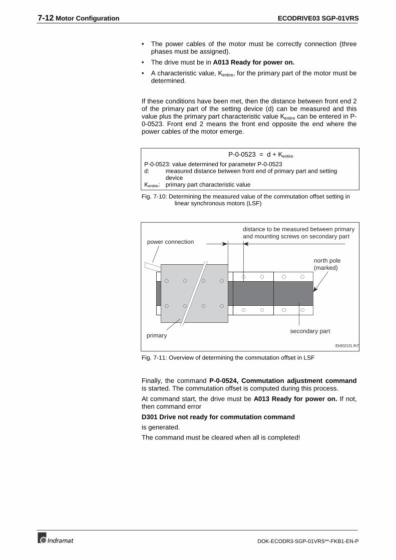
7-12 Motor Configuration ECODRIVE03 SGP-01VRS
DOK-ECODR3-SGP-01VRS**-FKB1-EN-P
• The power cables of the motor must be correctly connection (threephases must be assigned).
• The drive must be in A013 Ready for power on.
• A characteristic value, Kentire, for the primary part of the motor must bedetermined.
If these conditions have been met, then the distance between front end 2of the primary part of the setting device (d) can be measured and thisvalue plus the primary part characteristic value Kentire can be entered in P-0-0523. Front end 2 means the front end opposite the end where thepower cables of the motor emerge.
P-0-0523 = d + Kentire
P-0-0523: value determined for parameter P-0-0523d: measured distance between front end of primary part and setting deviceKentire: primary part characteristic value
Fig. 7-10: Determining the measured value of the commutation offset setting inlinear synchronous motors (LSF)
Ek5021f1.fh7
distance to be measured between primaryand mounting screws on secondary part
primarysecondary part
north pole(marked)
power connection
Fig. 7-11: Overview of determining the commutation offset in LSF
Finally, the command P-0-0524, Commutation adjustment commandis started. The commutation offset is computed during this process.
At command start, the drive must be A013 Ready for power on. If not,then command error
D301 Drive not ready for commutation command
is generated.
The command must be cleared when all is completed!
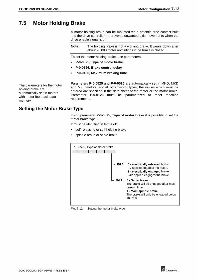
ECODRIVE03 SGP-01VRS Motor Configuration 7-13
DOK-ECODR3-SGP-01VRS**-FKB1-EN-P
7.5 Motor Holding Brake
A motor holding brake can be mounted via a potential-free contact builtinto the drive controller . It prevents unwanted axis movements when thedrive enable signal is off.
Note: The holding brake is not a working brake. It wears down afterabout 20,000 motor revolutions if the brake is closed.
To set the motor holding brake, use parameters
• P-0-0525, Type of motor brake
• P-0-0526, Brake control delay
• P-0-0126, Maximum braking time
The parameters for the motorholding brake areautomatically set in motorswith motor feedback datamemory
Parameters P-0-0525 and P-0-0526 are automatically set in MHD, MKDand MKE motors. For all other motor types, the values which must beentered are specified in the data sheet of the motor or the motor brake.Parameter P-0-0126 must be parametrized to meet machinerequirements.
Setting the Motor Brake TypeUsing parameter P-0-0525, Type of motor brake it is possible to set themotor brake type.
It must be identified in terms of:
• self-releasing or self-holding brake
• spindle brake or servo brake
P-0-0525, Type of motor brake
Bit 0 : 0 - electrically released brake0V applied engages the brake.1 - electrically engaged brake24V applied engages the brake.
Bit 1 : 0 - Servo brakeThe brake will be engaged after max.braking time.1 - Main spindle brakeThe brake will only be engaged below10 Rpm.
Fig. 7-12: Setting the motor brake type
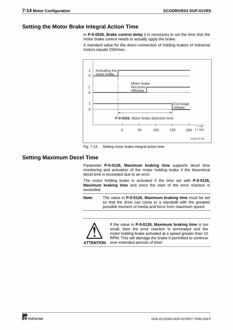
7-14 Motor Configuration ECODRIVE03 SGP-01VRS
DOK-ECODR3-SGP-01VRS**-FKB1-EN-P
Setting the Motor Brake Integral Action TimeIn P-0-0526, Brake control delay it is necessary to set the time that themotor brake control needs to actually apply the brake.
A standard value for the direct connection of holding brakes of Indramatmotors equals 150msec.
0
0
01
1
1
Sv5027f1.fh5
t / ms50 100 1500 200
P-0-0526, Motor brake distortion time
Motor brakebecomeseffective
End stagerelease
Activating themotor brake
Fig. 7-13: Setting motor brake integral action time
Setting Maximum Decel TimeParameter P-0-0126, Maximum braking time supports decel timemonitoring and activation of the motor holding brake if the theoreticaldecel time is exceeded due to an error.
The motor holding brake is activated if the time set with P-0-0126,Maximum braking time and since the start of the error reaction isexceeded.
Note: The value in P-0-0126, Maximum braking time must be setso that the drive can come to a standstill with the greatestpossible moment of inertia and force from maximum speed.
ATTENTION
If the value in P-0-0126, Maximum braking time is toosmall, then the error reaction is terminated and themotor holding brake activated at a speed greater than 10RPM. This will damage the brake if permitted to continueover extended periods of time!
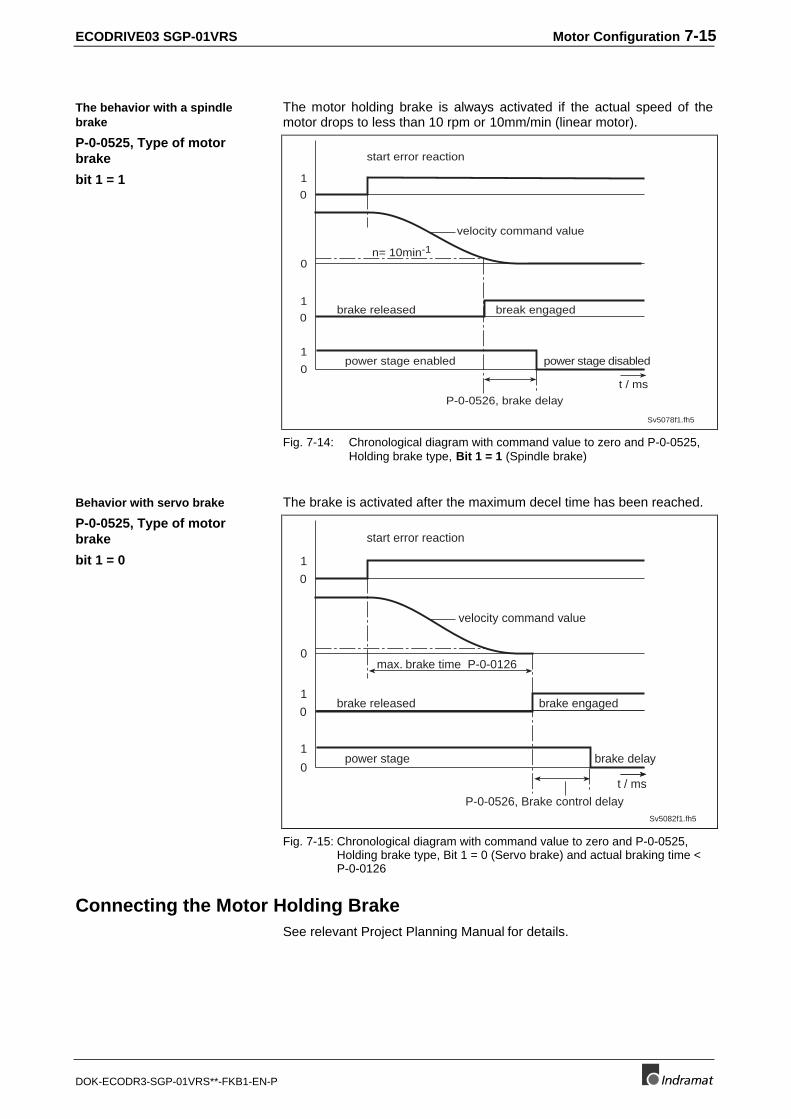
ECODRIVE03 SGP-01VRS Motor Configuration 7-15
DOK-ECODR3-SGP-01VRS**-FKB1-EN-P
The motor holding brake is always activated if the actual speed of themotor drops to less than 10 rpm or 10mm/min (linear motor).
0
0
0
1
1
0
1
P-0-0526, brake delay
brake released
velocity command value
Sv5078f1.fh5
start error reaction
n= 10min-1
power stage disabledpower stage enabled
break engaged
t / ms
Fig. 7-14: Chronological diagram with command value to zero and P-0-0525,Holding brake type, Bit 1 = 1 (Spindle brake)
The brake is activated after the maximum decel time has been reached.
0
0
0
1
1
0
1
P-0-0526, Brake control delay
brake released
Sv5082f1.fh5
start error reaction
max. brake time P-0-0126
brake delaypower stage
brake engaged
t / ms
velocity command value
Fig. 7-15: Chronological diagram with command value to zero and P-0-0525,Holding brake type, Bit 1 = 0 (Servo brake) and actual braking time <P-0-0126
Connecting the Motor Holding BrakeSee relevant Project Planning Manual for details.
The behavior with a spindlebrake
P-0-0525, Type of motorbrake
bit 1 = 1
Behavior with servo brake
P-0-0525, Type of motorbrake
bit 1 = 0
7-16 Motor Configuration ECODRIVE03 SGP-01VRS
DOK-ECODR3-SGP-01VRS**-FKB1-EN-P
Notes
ECODRIVE03 SGP-01VRS Operating Modes 8-1
DOK-ECODR3-SGP-01VRS**-FKB1-EN-P
8 Operating Modes
8.1 Setting the Operating Mode Parameters
Depending on the type of command communications used differentnumbers of operating modes are available.
If the drive is controlled via parallel command communicationst, then twodifferent modes can be used, namely:
• Primary Mode of Operation and
• Secondary Operating Mode 1.
The main operating mode is defined in parameter S-0-0032, Primarymode of operation.
Auxiliary operating mode 1 is permanently set to jog. The drive switchesfrom main to auxiliary modes if input "jog positive" or "jog negative" isactuated.
If analog command communication is used, then the drive can only beoperated in the main operating mode.
If a command communication via SERCOS is used, then using thefollowing four parameters:
• S-0-0032, Primary Mode of Operation
• S-0-0033, Secondary Operating Mode 1
• S-0-0034, Secondary Operating Mode 2
• S-0-0035, Secondary Operating Mode 3
four different operating modes can be simultaneously preselected.
The above parameters are listed in an overview and specify the inputvalue for each parameter.
8.2 Determining/detecting the active mode
Depending on the type of command communication parameter S-0-0134,Master control word has various definitions.
If an analog or parallel command communication are used, then bits 8and 9 in the master control word display which mode is actually working.
If command communication via SERCOS is used then bits 8 and 9 in themaster control word are used to determine which of the four pre-selectedmodes is actually working.
Command communicationsparallel interface
Command communicationanalog interface
Command communication viaSERCOS
Command communicationanalog interface or parallel
interface
Command communication viaSERCOS
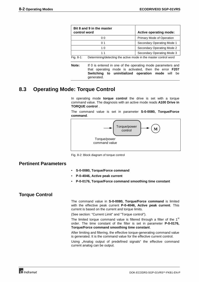
8-2 Operating Modes ECODRIVE03 SGP-01VRS
DOK-ECODR3-SGP-01VRS**-FKB1-EN-P
Bit 8 and 9 in the mastercontrol word Active operating mode:
0 0 Primary Mode of Operation
0 1 Secondary Operating Mode 1
1 0 Secondary Operating Mode 2
1 1 Secondary Operating Mode 3Fig. 8-1: Determining/detecting the active mode in the master control word
Note: If 0 is entered in one of the operating mode parameters andthat operating mode is activated, then the error F207Switching to uninitialized operation mode will begenerated.
8.3 Operating Mode: Torque Control
In operating mode torque control the drive is set with a torquecommand value. The diagnosis with an active mode reads A100 Drive inTORQUE control .
The command value is set in parameter S-0-0080, Torque/Forcecommand.
Torque/powercommand value
Torque/powercontrol M
Fig. 8-2: Block diagram of torque control
Pertinent Parameters• S-0-0080, Torque/Force command
• P-0-4046, Active peak current
• P-0-0176, Torque/Force command smoothing time constant
Torque ControlThe command value in S-0-0080, Torque/Force command is limitedwith the effective peak current P-0-4046, Active peak current. Thiscurrent is based on the current and torque limits.
(See section: "Current Limit" and "Torque control").
The limited torque command value is filtered through a filter of the 1st
order. The time constant of the filter is set in parameter P-0-0176,Torque/Force command smoothing time constant.
After limiting and filtering, the effective torque-generating command valueis generated. It is the command value for the effective current control.
Using „Analog output of predefined signals“ the effective commandcurrent analog can be output.
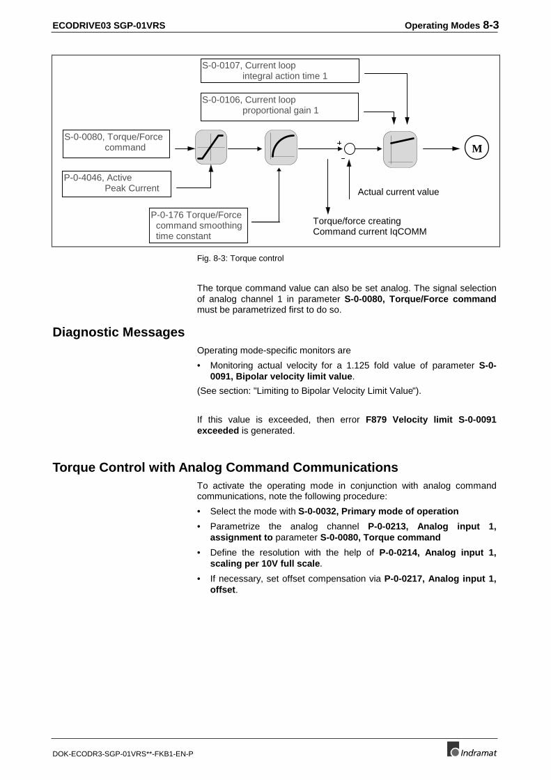
ECODRIVE03 SGP-01VRS Operating Modes 8-3
DOK-ECODR3-SGP-01VRS**-FKB1-EN-P
Actual current value
M
S-0-0106, Current loop proportional gain 1
S-0-0107, Current loop integral action time 1
S-0-0080, Torque/Force command
Torque/force creatingCommand current IqCOMM
P-0-4046, Active Peak Current
P-0-176 Torque/Force command smoothing time constant
Fig. 8-3: Torque control
The torque command value can also be set analog. The signal selectionof analog channel 1 in parameter S-0-0080, Torque/Force commandmust be parametrized first to do so.
Diagnostic MessagesOperating mode-specific monitors are
• Monitoring actual velocity for a 1.125 fold value of parameter S-0-0091, Bipolar velocity limit value.
(See section: "Limiting to Bipolar Velocity Limit Value").
If this value is exceeded, then error F879 Velocity limit S-0-0091exceeded is generated.
Torque Control with Analog Command CommunicationsTo activate the operating mode in conjunction with analog commandcommunications, note the following procedure:
• Select the mode with S-0-0032, Primary mode of operation
• Parametrize the analog channel P-0-0213, Analog input 1,assignment to parameter S-0-0080, Torque command
• Define the resolution with the help of P-0-0214, Analog input 1,scaling per 10V full scale.
• If necessary, set offset compensation via P-0-0217, Analog input 1,offset.
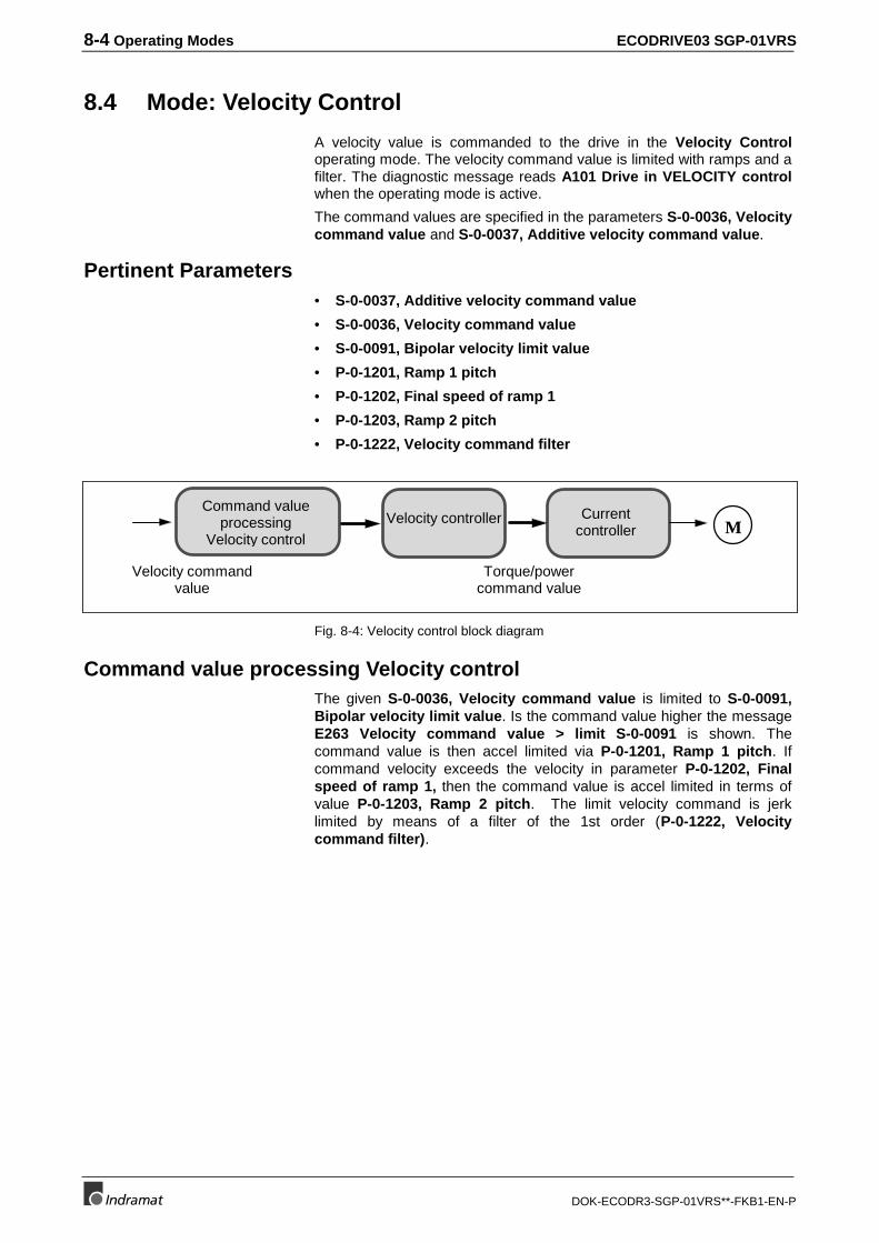
8-4 Operating Modes ECODRIVE03 SGP-01VRS
DOK-ECODR3-SGP-01VRS**-FKB1-EN-P
8.4 Mode: Velocity Control
A velocity value is commanded to the drive in the Velocity Controloperating mode. The velocity command value is limited with ramps and afilter. The diagnostic message reads A101 Drive in VELOCITY controlwhen the operating mode is active.
The command values are specified in the parameters S-0-0036, Velocitycommand value and S-0-0037, Additive velocity command value.
Pertinent Parameters• S-0-0037, Additive velocity command value
• S-0-0036, Velocity command value
• S-0-0091, Bipolar velocity limit value
• P-0-1201, Ramp 1 pitch
• P-0-1202, Final speed of ramp 1
• P-0-1203, Ramp 2 pitch
• P-0-1222, Velocity command filter
Velocity controller
Velocity commandvalue
Torque/powercommand value
Currentcontroller M
Command valueprocessing
Velocity control
Fig. 8-4: Velocity control block diagram
Command value processing Velocity controlThe given S-0-0036, Velocity command value is limited to S-0-0091,Bipolar velocity limit value. Is the command value higher the messageE263 Velocity command value > limit S-0-0091 is shown. Thecommand value is then accel limited via P-0-1201, Ramp 1 pitch. Ifcommand velocity exceeds the velocity in parameter P-0-1202, Finalspeed of ramp 1, then the command value is accel limited in terms ofvalue P-0-1203, Ramp 2 pitch. The limit velocity command is jerklimited by means of a filter of the 1st order (P-0-1222, Velocitycommand filter).
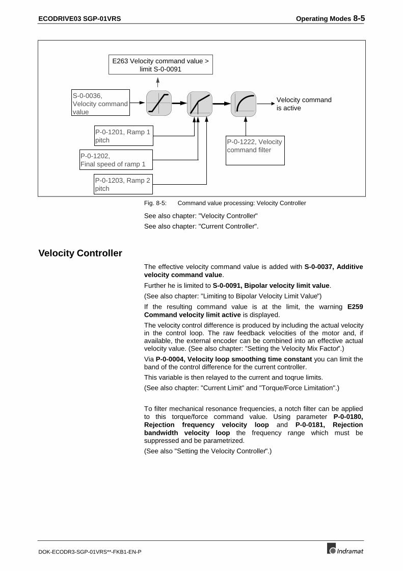
ECODRIVE03 SGP-01VRS Operating Modes 8-5
DOK-ECODR3-SGP-01VRS**-FKB1-EN-P
E263 Velocity command value >limit S-0-0091
Velocity commandis active
P-0-1201, Ramp 1pitch P-0-1222, Velocity
command filter
S-0-0036,Velocity commandvalue
P-0-1203, Ramp 2pitch
P-0-1202,Final speed of ramp 1
Fig. 8-5: Command value processing: Velocity Controller
See also chapter: "Velocity Controller"
See also chapter: "Current Controller".
Velocity ControllerThe effective velocity command value is added with S-0-0037, Additivevelocity command value.
Further he is limited to S-0-0091, Bipolar velocity limit value.
(See also chapter: "Limiting to Bipolar Velocity Limit Value")
If the resulting command value is at the limit, the warning E259Command velocity limit active is displayed.
The velocity control difference is produced by including the actual velocityin the control loop. The raw feedback velocities of the motor and, ifavailable, the external encoder can be combined into an effective actualvelocity value. (See also chapter: "Setting the Velocity Mix Factor".)
Via P-0-0004, Velocity loop smoothing time constant you can limit theband of the control difference for the current controller.
This variable is then relayed to the current and toqrue limits.
(See also chapter: "Current Limit" and "Torque/Force Limitation".)
To filter mechanical resonance frequencies, a notch filter can be appliedto this torque/force command value. Using parameter P-0-0180,Rejection frequency velocity loop and P-0-0181, Rejectionbandwidth velocity loop the frequency range which must besuppressed and be parametrized.
(See also "Setting the Velocity Controller".)
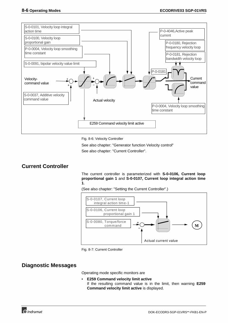
8-6 Operating Modes ECODRIVE03 SGP-01VRS
DOK-ECODR3-SGP-01VRS**-FKB1-EN-P
S-0-0037, Additive velocitycommand value
P-0-0181, Rejectionbandwidth velocity loop
E259 Command velocity limit active
Actual velocity
S-0-0101, Velocity loop integralaction time
S-0-0100, Velocity loopproportional gain P-0-0180, Rejection
frequency velocity loopP-0-0004, Velocity loop smoothingtime constant
Velocity-command value
Currentcommandvalue
S-0-0091, bipolar velocity value limit
P-0-4046,Active peakcurrent
P-0-0004, Velocity loop smoothingtime constant
P-0-0181
Fig. 8-6: Velocity Controller
See also chapter: "Generator function Velocity control"
See also chapter: "Current Controller".
Current ControllerThe current controller is parameterized with S-0-0106, Current loopproportional gain 1 and S-0-0107, Current loop integral action time1.
(See also chapter: "Setting the Current Controller".)
Actual current value
M
S-0-0106, Current loop proportional gain 1
S-0-0107, Current loop integral action time-1
S-0-0080, Torque/force command
Fig. 8-7: Current Controller
Diagnostic MessagesOperating mode specific monitors are
• E259 Command velocity limit activeIf the resulting command value is in the limit, then warning E259Command velocity limit active is displayed.
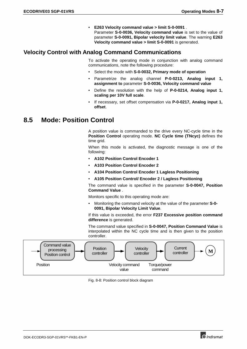
ECODRIVE03 SGP-01VRS Operating Modes 8-7
DOK-ECODR3-SGP-01VRS**-FKB1-EN-P
• E263 Velocity command value > limit S-0-0091 .Parameter S-0-0036, Velocity command value is set to the value ofparameter S-0-0091, Bipolar velocity limit value. The warning E263Velocity command value > limit S-0-0091 is generated.
Velocity Control with Analog Command CommunicationsTo activate the operating mode in conjunction with analog commandcommunications, note the following procedure:
• Select the mode with S-0-0032, Primary mode of operation
• Parametrize the analog channel P-0-0213, Analog input 1,assignment to parameter S-0-0036, Velocity command value
• Define the resolution with the help of P-0-0214, Analog input 1,scaling per 10V full scale.
• If necessary, set offset compensation via P-0-0217, Analog input 1,offset.
8.5 Mode: Position Control
A position value is commanded to the drive every NC-cycle time in thePosition Control operating mode. NC Cycle time (TNcyc) defines thetime grid.
When this mode is activated, the diagnostic message is one of thefollowing:
• A102 Position Control Encoder 1
• A103 Position Control Encoder 2
• A104 Position Control Encoder 1 Lagless Positioning
• A105 Position Control/ Encoder 2 / Lagless Positioning
The command value is specified in the parameter S-0-0047, PositionCommand Value .
Monitors specific to this operating mode are:
• Monitoring the command velocity at the value of the parameter S-0-0091, Bipolar Velocity Limit Value.
If this value is exceeded, the error F237 Excessive position commanddifference is generated.
The command value specified in S-0-0047, Position Command Value isinterpolated within the NC cycle time and is then given to the positioncontroller.
Velocitycontroller
Position Velocity commandvalue
Torque/powercommand
Currentcontroller
Positioncontroller
Command valueprocessing
Position controlM
Fig. 8-8: Position control block diagram
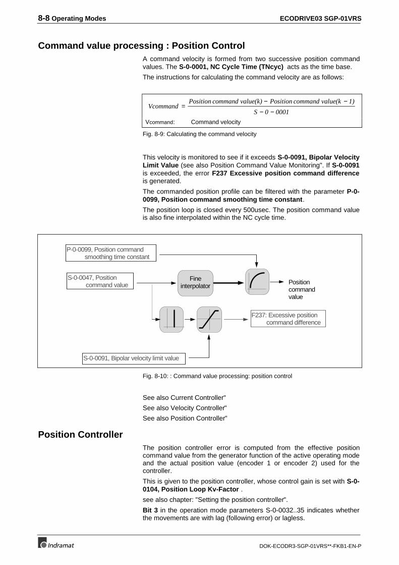
8-8 Operating Modes ECODRIVE03 SGP-01VRS
DOK-ECODR3-SGP-01VRS**-FKB1-EN-P
Command value processing : Position ControlA command velocity is formed from two successive position commandvalues. The S-0-0001, NC Cycle Time (TNcyc) acts as the time base.
The instructions for calculating the command velocity are as follows:
VcommandPosition command value(k) Position command value(k 1)
S 0 0001=
− −− −
Vcommand: Command velocity
Fig. 8-9: Calculating the command velocity
This velocity is monitored to see if it exceeds S-0-0091, Bipolar VelocityLimit Value (see also Position Command Value Monitoring". If S-0-0091is exceeded, the error F237 Excessive position command differenceis generated.
The commanded position profile can be filtered with the parameter P-0-0099, Position command smoothing time constant.
The position loop is closed every 500usec. The position command valueis also fine interpolated within the NC cycle time.
S-0-0047, Position command value
S-0-0091, Bipolar velocity limit value
P-0-0099, Position command smoothing time constant
Positioncommandvalue
Fineinterpolator
F237: Excessive position command difference
Fig. 8-10: : Command value processing: position control
See also Current Controller"
See also Velocity Controller"
See also Position Controller"
Position ControllerThe position controller error is computed from the effective positioncommand value from the generator function of the active operating modeand the actual position value (encoder 1 or encoder 2) used for thecontroller.
This is given to the position controller, whose control gain is set with S-0-0104, Position Loop Kv-Factor .
see also chapter: "Setting the position controller".
Bit 3 in the operation mode parameters S-0-0032..35 indicates whetherthe movements are with lag (following error) or lagless.
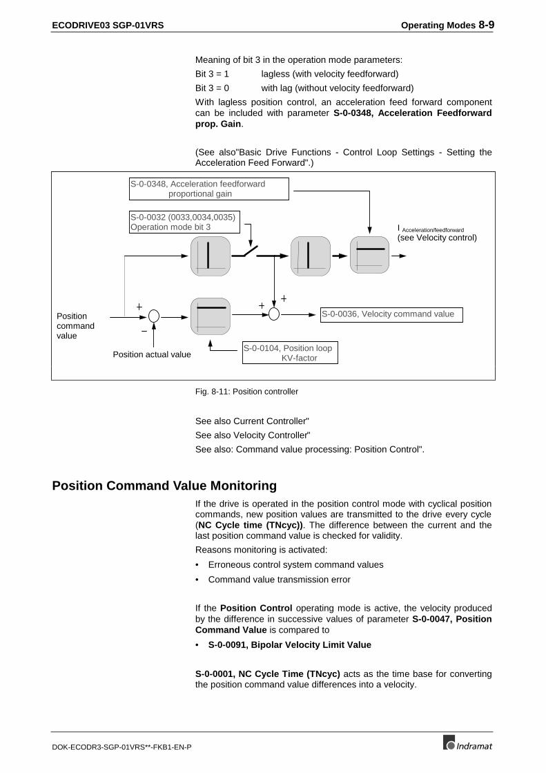
ECODRIVE03 SGP-01VRS Operating Modes 8-9
DOK-ECODR3-SGP-01VRS**-FKB1-EN-P
Meaning of bit 3 in the operation mode parameters:
Bit 3 = 1 lagless (with velocity feedforward)
Bit 3 = 0 with lag (without velocity feedforward)
With lagless position control, an acceleration feed forward componentcan be included with parameter S-0-0348, Acceleration Feedforwardprop. Gain.
(See also"Basic Drive Functions - Control Loop Settings - Setting theAcceleration Feed Forward".)
Positioncommandvalue
S-0-0036, Velocity command value
Position actual value
S-0-0032 (0033,0034,0035)Operation mode bit 3
S-0-0104, Position loop KV-factor
I Acceleration/feedforward
(see Velocity control)
S-0-0348, Acceleration feedforward proportional gain
Fig. 8-11: Position controller
See also Current Controller"
See also Velocity Controller"
See also: Command value processing: Position Control".
Position Command Value MonitoringIf the drive is operated in the position control mode with cyclical positioncommands, new position values are transmitted to the drive every cycle(NC Cycle time (TNcyc)). The difference between the current and thelast position command value is checked for validity.
Reasons monitoring is activated:
• Erroneous control system command values
• Command value transmission error
If the Position Control operating mode is active, the velocity producedby the difference in successive values of parameter S-0-0047, PositionCommand Value is compared to
• S-0-0091, Bipolar Velocity Limit Value
S-0-0001, NC Cycle Time (TNcyc) acts as the time base for convertingthe position command value differences into a velocity.
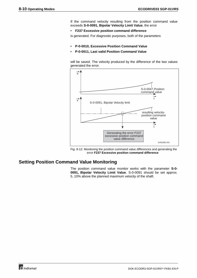
8-10 Operating Modes ECODRIVE03 SGP-01VRS
DOK-ECODR3-SGP-01VRS**-FKB1-EN-P
If the command velocity resulting from the position command valueexceeds S-0-0091, Bipolar Velocity Limit Value, the error
• F237 Excessive position command difference
is generated. For diagnostic purposes, both of the parameters
• P-0-0010, Excessive Position Command Value
• P-0-0011, Last valid Position Command Value
will be saved. The velocity produced by the difference of the two valuesgenerated the error.
S-0-0047,Positioncommand value
resulting velocity-position command
value
Sv5028f1.fh5
S-0-0091, Bipolar Velocity limit
Generating the error F237excessive position command
value difference
t
t
s
v
Fig. 8-12: Monitoring the position command value differences and generating theerror F237 Excessive position command difference
Setting Position Command Value MonitoringThe position command value monitor works with the parameter S-0-0091, Bipolar Velocity Limit Value. S-0-0091 should be set approx.5..10% above the planned maximum velocity of the shaft.
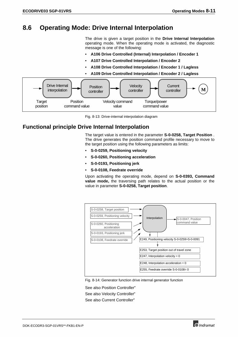
ECODRIVE03 SGP-01VRS Operating Modes 8-11
DOK-ECODR3-SGP-01VRS**-FKB1-EN-P
8.6 Operating Mode: Drive Internal Interpolation
The drive is given a target position in the Drive Internal Interpolationoperating mode. When the operating mode is activated, the diagnosticmessage is one of the following:
• A106 Drive Controlled (Internal) Interpolation / Encoder 1
• A107 Drive Controlled Interpolation / Encoder 2
• A108 Drive Controlled Interpolation / Encoder 1 / Lagless
• A109 Drive Controlled Interpolation / Encoder 2 / Lagless
Velocitycontroller
Positioncommand value
Targetposition
Velocity commandvalue
Torque/powercommand value
Currentcontroller
Positioncontroller
Drive Internalinterpolation M
Fig. 8-13: Drive-internal interpolation diagram
Functional principle Drive Internal InterpolationThe target value is entered in the parameter S-0-0258, Target Position .The drive generates the position command profile necessary to move tothe target position using the following parameters as limits:
• S-0-0259, Positioning velocity
• S-0-0260, Positioning acceleration
• S-0-0193, Positioning jerk
• S-0-0108, Feedrate override
Upon activating the operating mode, depend on S-0-0393, Commandvalue mode, the traversing path relates to the actual position or thevalue in parameter S-0-0258, Target position.
S-0-0258, Target position
S-0-0259, Positioning velocity
S-0-0260, Positioning acceleration
S-0-0193, Positioning jerk
Interpolation S-0-0047, Positioncommand value
E249, Positioning velocity S-0-0259>S-0-0091
E253, Target position out of travel zone
S-0-0108, Feedrate override
E247, Interpolation velocity = 0
E248, Interpolation acceleration = 0
E255, Feedrate override S-0-0108= 0
Fig. 8-14: Generator function drive internal generator function
See also Position Controller"
See also Velocity Controller"
See also Current Controller"
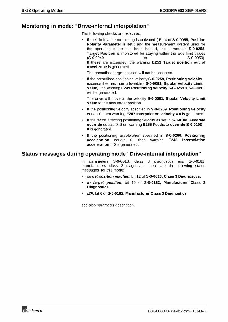
8-12 Operating Modes ECODRIVE03 SGP-01VRS
DOK-ECODR3-SGP-01VRS**-FKB1-EN-P
Monitoring in mode: "Drive-internal interpolation"The following checks are executed:
• If axis limit value monitoring is activated ( Bit 4 of S-0-0055, PositionPolarity Parameter is set ) and the measurement system used forthe operating mode has been homed, the parameter S-0-0258,Target Position is monitored for staying within the axis limit values(S-0-0049 or S-0-0050).If these are exceeded, the warning E253 Target position out oftravel zone is generated.
The prescribed target position will not be accepted.
• If the prescribed positioning velocity S-0-0259, Positioning velocityexceeds the maximum allowable ( S-0-0091, Bipolar Velocity LimitValue), the warning E249 Positioning velocity S-0-0259 > S-0-0091will be generated.
The drive will move at the velocity S-0-0091, Bipolar Velocity LimitValue to the new target position.
• If the positioning velocity specified in S-0-0259, Positioning velocityequals 0, then warning E247 Interpolation velocity = 0 is generated.
• If the factor affecting positioning velocity as set in S-0-0108, Feedrateoverride equals 0, then warning E255 Feedrate-override S-0-0108 =0 is generated.
• If the positioning acceleration specified in S-0-0260, Positioningacceleration equals 0, then warning E248 Interpolationacceleration = 0 is generated.
Status messages during operating mode "Drive-internal interpolation"In parameters S-0-0013, class 3 diagnostics and S-0-0182,manufacturers class 3 diagnostics there are the following statusmessages for this mode:
• target position reached, bit 12 of S-0-0013, Class 3 Diagnostics.
• In target position, bit 10 of S-0-0182, Manufacturer Class 3Diagnostics
• IZP, bit 6 of S-0-0182, Manufacturer Class 3 Diagnostics
see also parameter description.
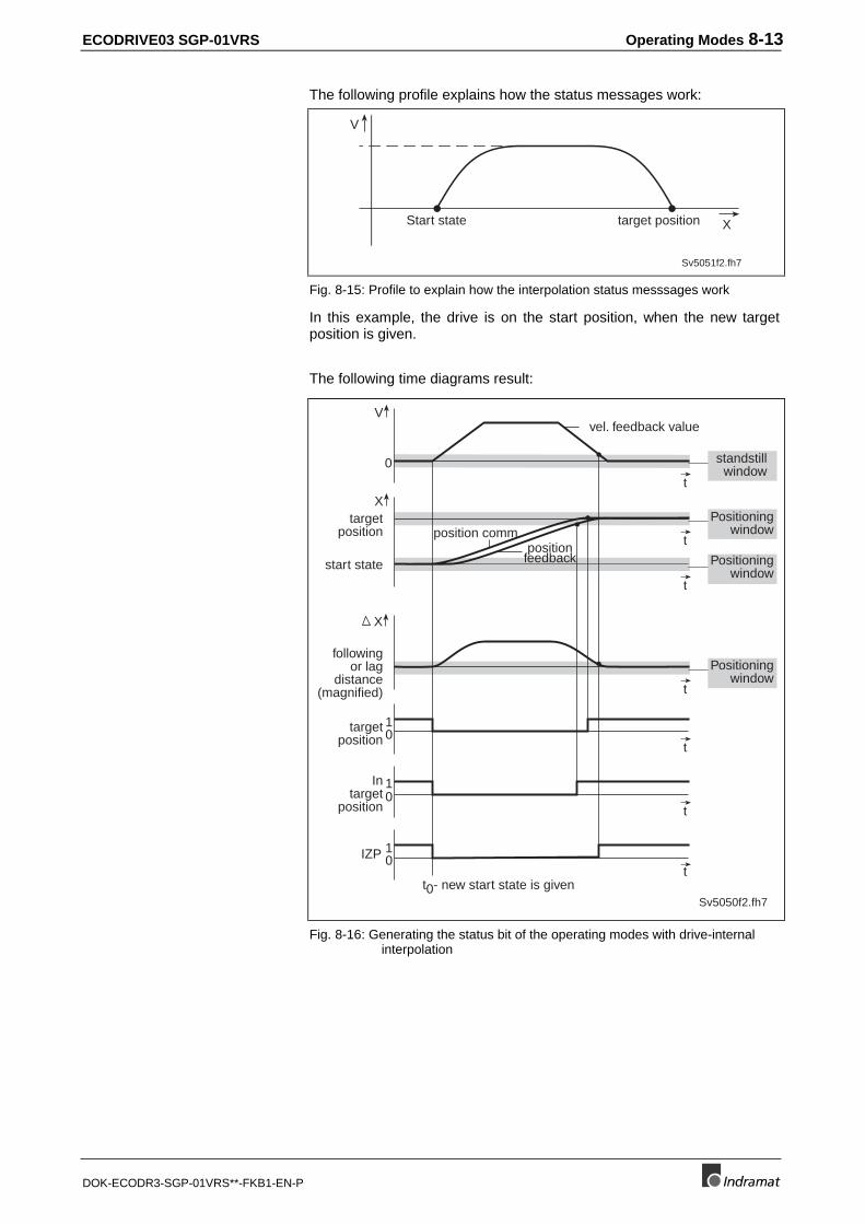
ECODRIVE03 SGP-01VRS Operating Modes 8-13
DOK-ECODR3-SGP-01VRS**-FKB1-EN-P
The following profile explains how the status messages work:
Sv5051f2.fh7
V
target positionStart state X
Fig. 8-15: Profile to explain how the interpolation status messsages work
In this example, the drive is on the start position, when the new targetposition is given.
The following time diagrams result:
X
V
0
X
10
10
10
t
t
t
t
t
t
tIZP
targetposition
positionfeedbackstart state
followingor lag
distance(magnified)
targetposition
Intarget
position
t0- new start state is given
position comm.
vel. feedback value
standstillwindow
Positioningwindow
Positioningwindow
Positioningwindow
Sv5050f2.fh7
Fig. 8-16: Generating the status bit of the operating modes with drive-internalinterpolation
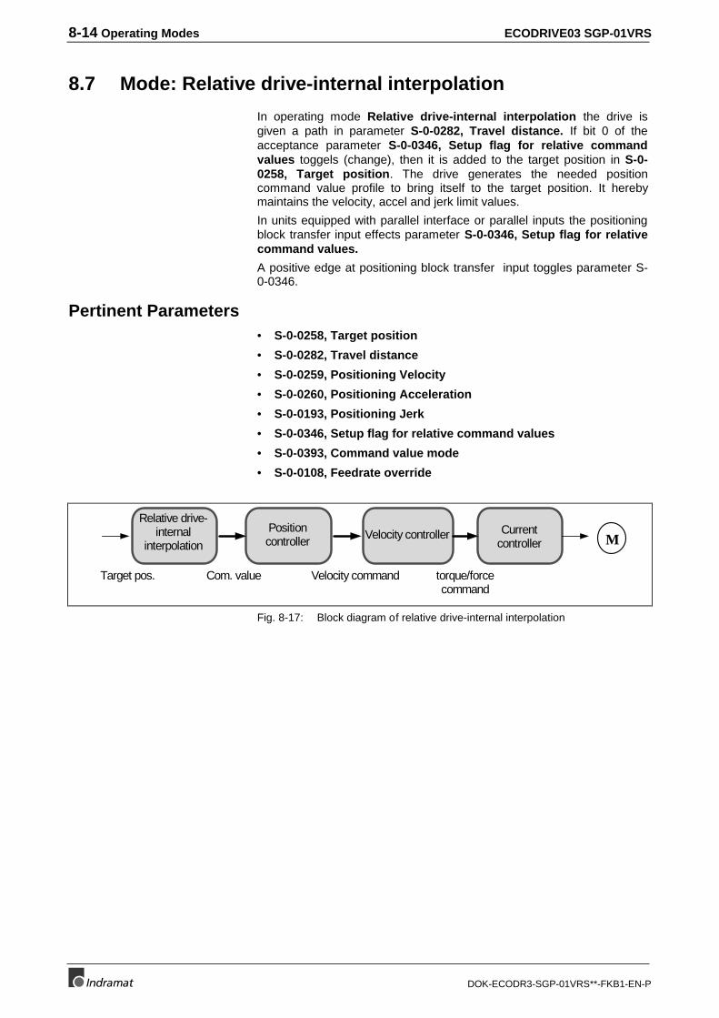
8-14 Operating Modes ECODRIVE03 SGP-01VRS
DOK-ECODR3-SGP-01VRS**-FKB1-EN-P
8.7 Mode: Relative drive-internal interpolation
In operating mode Relative drive-internal interpolation the drive isgiven a path in parameter S-0-0282, Travel distance. If bit 0 of theacceptance parameter S-0-0346, Setup flag for relative commandvalues toggels (change), then it is added to the target position in S-0-0258, Target position. The drive generates the needed positioncommand value profile to bring itself to the target position. It herebymaintains the velocity, accel and jerk limit values.
In units equipped with parallel interface or parallel inputs the positioningblock transfer input effects parameter S-0-0346, Setup flag for relativecommand values.
A positive edge at positioning block transfer input toggles parameter S-0-0346.
Pertinent Parameters• S-0-0258, Target position
• S-0-0282, Travel distance
• S-0-0259, Positioning Velocity
• S-0-0260, Positioning Acceleration
• S-0-0193, Positioning Jerk
• S-0-0346, Setup flag for relative command values
• S-0-0393, Command value mode
• S-0-0108, Feedrate override
Velocity controller
Com. valueTarget pos. Velocity command torque/forcecommand
Currentcontroller
Positioncontroller
Relative drive-internal
interpolation M
Fig. 8-17: Block diagram of relative drive-internal interpolation
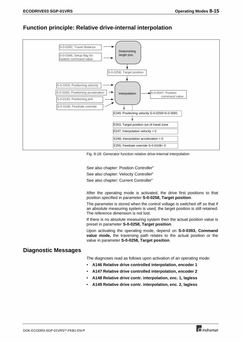
ECODRIVE03 SGP-01VRS Operating Modes 8-15
DOK-ECODR3-SGP-01VRS**-FKB1-EN-P
Function principle: Relative drive-internal interpolation
S-0-0259, Positioning velocity
S-0-0260, Positioning acceleration
S-0-0193, Positioning jerk
Interpolation S-0-0047, Position command value
S-0-0108, Feedrate override
S-0-0258, Target position
Determiningtarget pos.
S-0-0282, Travel distance
S-0-0346, Setup flag forrelative command value
E249, Positioning velocity S-0-0259>S-0-0091
E253, Target position out of travel zone
E247, Interpolation velocity = 0
E248, Interpolation acceleration = 0
E255, Feedrate override S-0-0108= 0
Fig. 8-18: Generator function relative drive-internal interpolation
See also chapter: Position Controller"
See also chapter: Velocity Controller"
See also chapter: Current Controller"
After the operating mode is activated, the drive first positions to thatposition specified in parameter S-0-0258, Target position.
The parameter is stored when the control voltage is switched off so that ifan absolute measuring system is used, the target position is still retained.The reference dimension is not lost.
If there is no absolute measuring system then the actual position value ispreset in parameter S-0-0258, Target position.
Upon activating the operating mode, depend on S-0-0393, Commandvalue mode, the traversing path relates to the actual position or thevalue in parameter S-0-0258, Target position.
Diagnostic MessagesThe diagnoses read as follows upon activation of an operating mode:
• A146 Relative drive controlled interpolation, encoder 1
• A147 Relative drive controlled interpolation, encoder 2
• A148 Relative drive contr. interpolation, enc. 1, lagless
• A149 Relative drive contr. interpolation, enc. 2, lagless
8-16 Operating Modes ECODRIVE03 SGP-01VRS
DOK-ECODR3-SGP-01VRS**-FKB1-EN-P
Given an activated operating mode, the followng checks are conducted:
• E253 Target position out of travel range If position limit value monitor is active (bit 4 of S-0-0055, PositionPolarity Parameter is set) and the measuring system used for themode is in reference (S-0-0403, Position feedback value status =1), then the sum of S-0-0282, Travel distance and S-0-0258, TargetPosition is monitored to ensure that it maintains the position limitvalue. Otherwise, the sum of the overtravelling of the drive-internallydepicted numeric range (visible in the minimum and maximum inputvalues of the travel distance parameter) is monitored. In either case, ifthe allowable range is exceeded, the warning E253 Target positionout of travel zone is generated. The set travel path is not accepted ifthe acceptance toggles.
• E249 Positioning velocity S-0-0259 > S-0-0091If the positioning velocity set in S-0-0259, Positioning velocityexceeds maximum allowable velocity set in S-0-0091, BipolarVelocity Limit Value then the warning E249 Positioning velocity S-0-0259 > S-0-0091 is generated. The set travel path is not accepted ifthe acceptance toggels.
• E247 Interpolation velocity = 0If the positioning velocity set in S-0-0259, Positioning velocityequals 0, then warning E247 Interpolation velocity = 0 is generated.
• E255 Feedrate-override S-0-0108 = 0If the factor affecting the positioning velocity in S-0-0108, Feedrateoverride equals 0, then warning E255 Feedrate-override S-0-0108 =0 is generated.
• E248 Interpolation acceleration = 0If the positioning acceleratiion set in S-0-0260, Positioningacceleration equals 0, then the warning E248 Interpolationacceleration = 0 is generated.
Status messages during operating mode "Relative drive-internalinterpolation"
see chapter: "Status messages during operating mode "Drive-internalinterpolation""
8.8 Positioning Block Mode
Positioning blocks that have been preprogrammed can be run with thismode. The drive runs position controll to a target position, whilemaintaining speed, acceleration and jerk limits as defined for each block.
The positioning blocks are actuated by the block selection.
Digital inputs can be used to select the blocks in units with positioninginterface (DKC01.3).
Following block processing permits execution of several positioningblocks processed in direct sequence without having to re-issue a startsignal each time.
Typical applications are positioning processes which cover longdistances at high speeds (rapid traverse) and then position at endposition at low speeds without any intermediate stops.
• Taking up or putting down transport goods by robots.
• Execution of joining processes in assembly facilities
ECODRIVE03 SGP-01VRS Operating Modes 8-17
DOK-ECODR3-SGP-01VRS**-FKB1-EN-P
A following block chain is made up of a start block and one or morefollowing blocks. The start block is selected and activated in the usualmanner. The transition to a following block, however, can vary.
Note: Following block mode is possible with absolute and relativepositioning blocks. The distance remaining is stored. The finalblock of a chain is not defined as a following block. Thisidentifies the end of the chain.
Pertinent ParametersP-0-4006, Process block target position
P-0-4007, Process block velocity
P-0-4008, Process block acceleration
P-0-4009, Process block jerk
P-0-4019, Process block mode
P-0-4026, Process block selection
P-0-4051, Process block acquittance
P-0-4052, Positioning block, last accepted
P-0-4057, Positioning block, input linked blocks
P-0-4060, Process block control word
S-0-0346, Setup flag for relative command values
S-0-0182, Manufacturer class 3 diagnostics
S-0-0259, Positioning Velocity
How it worksA positioning block is defined with:
• P-0-4006, Process block target position,
• P-0-4007, Process block velocity,
• P-0-4008, Process block acceleration,
• P-0-4009, Process block jerk,
• P-0-4019, Process block mode.
and fixes how the target position is to be processed (absolute, relative).
Note: Each parameter has 64 elements, whereby the elements ofthe same number write this number into the travel profile ofthe positioning block.
With parameter P-0-4060, Process block control word the positioningspeed can be limited to the value set in parameter S-0-0259,Positioning Velocity. Otherwise, the speed set in P-0-4007, Processblock velocity is used.
If a positioning block is completed, then bit 12 is set in parameter
S-0-0182, Manufacturer class 3 diagnostics
(È |target position-actual positon value| < positioning window).
Positioning block elements
Positioning block control word
8-18 Operating Modes ECODRIVE03 SGP-01VRS
DOK-ECODR3-SGP-01VRS**-FKB1-EN-P
Activating Positioning Blocks"Positioning block mode" must be entered as the main mode. Byactivating drive enable and setting drive halt =1 the drive is in primarymode of operation.
A positioning block is started by
• Toggling parameter S-0-0346, Setup flag for relative commandvalues
Note: As long as the parameter is not toggled, the drive will remainon the actual position or brought to a position controlledstandstill.
In positioning block mode, a positioning block is selected
• by writing into P-0-4026, Process block selection
• or via the parallel inputs with parallel interface in the DKC.
Also see: Application: Positioning Block Mode with Parallel Interface".
Note: To monitor the block selection lines with parallel control, theacknowledgement P-0-4051, Process block acquittancemust be evaluated.
Positioning Block ModesParameter P-0-4019, Process block mode is used to set the manner inwhich the target position is processed in parameter P-0-4006, Processblock target position.
Possible positioning block modes:
• Absolute Positioning
• Relative Positioning
• Relative Positioning with residual path memory
• Infinite travel in positive / negative direction
• Following block processing
Absolute PositioningPrerequisite: Parameter P-0-4019, Process block mode = 1
In an absolute positioning block, the target position is a fixed (absolute)position within the machine coordinate system.
• The drive must be referenced.
• The travel range can be limited with position limit value. Absolutepositioning blocks are only executed if the target position lies withinthe allowable travel range.
Absolute positioning with target position = 700
Block selection
Prerequisites for the executionof absolute positioning blocks:
Example
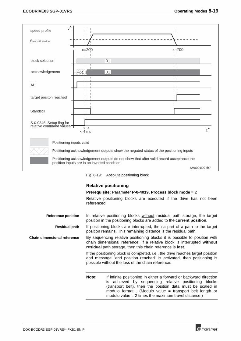
ECODRIVE03 SGP-01VRS Operating Modes 8-19
DOK-ECODR3-SGP-01VRS**-FKB1-EN-P
SV0001D2.fh7
Standstill window
block selection
acknowledgement
AH
target positon reached
Standstill
S-0-0346, Setup flag forrelative command values
speed profile
Positioning inputs valid
Positioning acknowledgement outputs show the negated status of the positioning inputs
Positioning acknowledgement outputs do not show that after valid record acceptance theposition inputs are in an inverted condition
x=200 x=700
v
t
~01
01
01
< 4 ms
Fig. 8-19: Absolute positioning block
Relative positioningPrerequisite: Parameter P-0-4019, Process block mode = 2
Relative positioning blocks are executed if the drive has not beenreferenced.
In relative positioning blocks without residual path storage, the targetposition in the positioning blocks are added to the current position.
If positioning blocks are interrupted, then a part of a path to the targetposition remains. This remaining distance is the residual path.
By sequencing relative positioning blocks it is possible to position withchain dimensional reference. If a relative block is interrupted withoutresidual path storage, then this chain reference is lost.
If the positioning block is completed, i.e., the drive reaches target positionand message "end position reached" is activated, then positioning ispossible without the loss of the chain reference.
Note: If infinite positioning in either a forward or backward directionis achieved by sequencing relative positioning blocks(transport belt), then the position data must be scaled inmodulo format . (Modulo value = transport belt length ormodulo value = 2 times the maximum travel distance.)
Reference position
Residual path
Chain dimensional reference
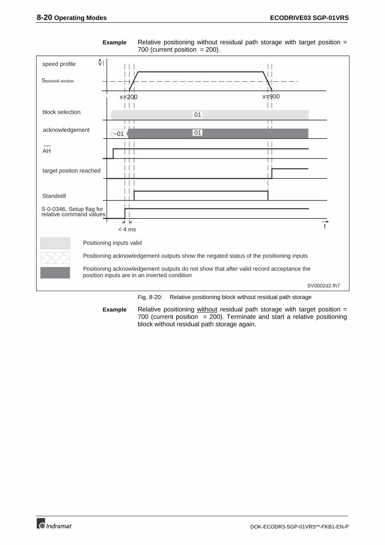
8-20 Operating Modes ECODRIVE03 SGP-01VRS
DOK-ECODR3-SGP-01VRS**-FKB1-EN-P
Relative positioning without residual path storage with target position =700 (current position = 200).
v
t
SV0002d2.fh7
x=200 x=900
< 4 ms
~01
01
01
Standstill window
block selection
acknowledgement
AH
target positon reached
speed profile
Positioning inputs valid
Positioning acknowledgement outputs show the negated status of the positioning inputs
Positioning acknowledgement outputs do not show that after valid record acceptance theposition inputs are in an inverted condition
Standstill
S-0-0346, Setup flag forrelative command values
Fig. 8-20: Relative positioning block without residual path storage
Relative positioning without residual path storage with target position =700 (current position = 200). Terminate and start a relative positioningblock without residual path storage again.
Example
Example
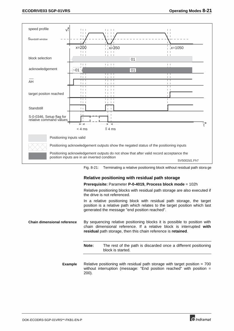
ECODRIVE03 SGP-01VRS Operating Modes 8-21
DOK-ECODR3-SGP-01VRS**-FKB1-EN-P
Standstill window
block selection
acknowledgement
AH
target positon reached
speed profile
Positioning inputs valid
Positioning acknowledgement outputs show the negated status of the positioning inputs
Positioning acknowledgement outputs do not show that after valid record acceptance theposition inputs are in an inverted condition
Standstill
S-0-0346, Setup flag forrelative command values
SV5002d1.Fh7
v
t
x=200 x=1050
< 4 ms
x=350
~01
< 4 ms=
01
01
Fig. 8-21: Terminating a relative positioning block without residual path stora ge
Relative positioning with residual path storagePrerequisite: Parameter P-0-4019, Process block mode = 102h
Relative positioning blocks with residual path storage are also executed ifthe drive is not referenced.
In a relative positioning block with residual path storage, the targetposition is a relative path which relates to the target position which lastgenerated the message "end position reached".
By sequencing relative positioning blocks it is possible to position withchain dimensional reference. If a relative block is interrupted withresidual path storage, then this chain reference is retained.
Note: The rest of the path is discarded once a different positioningblock is started.
Relative positioning with residual path storage with target position = 700without interruption (message: "End position reached" with position =200).
Chain dimensional reference
Example
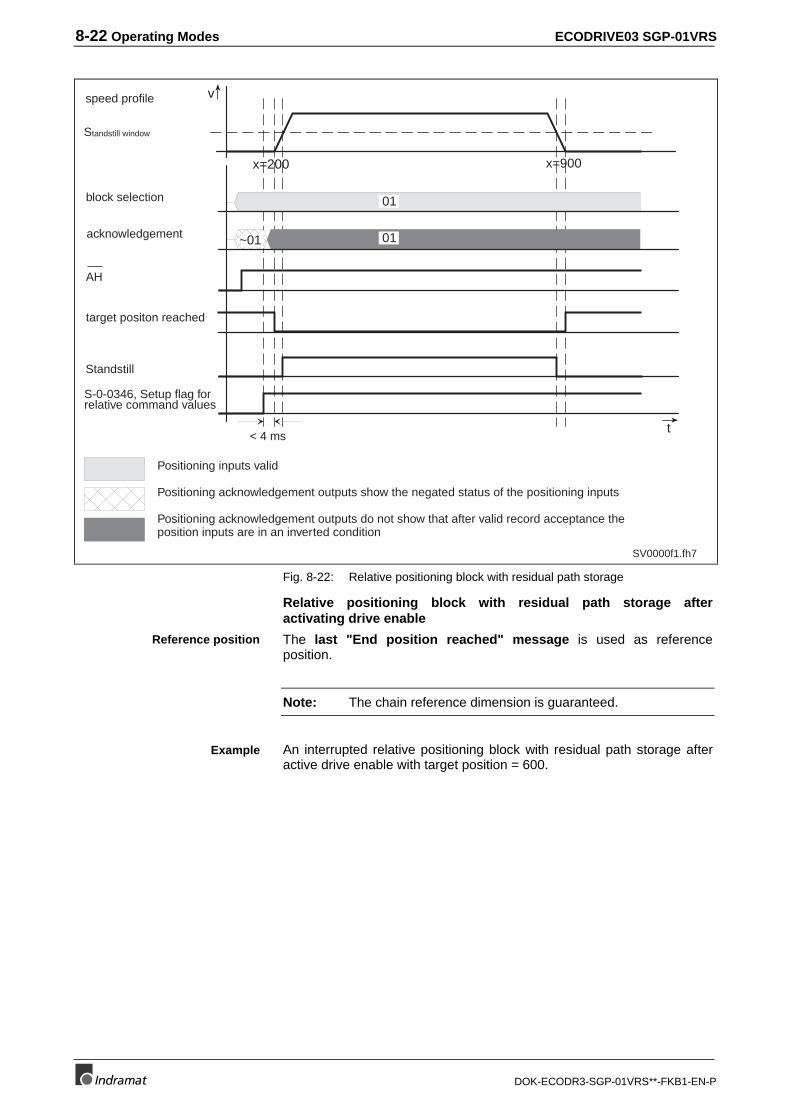
8-22 Operating Modes ECODRIVE03 SGP-01VRS
DOK-ECODR3-SGP-01VRS**-FKB1-EN-P
SV0000f1.fh7
Standstill window
block selection
acknowledgement
AH
target positon reached
speed profile
Positioning inputs valid
Positioning acknowledgement outputs show the negated status of the positioning inputs
Positioning acknowledgement outputs do not show that after valid record acceptance theposition inputs are in an inverted condition
v
t
x=200 x=900
< 4 ms
~01
01
01
Standstill
S-0-0346, Setup flag forrelative command values
Fig. 8-22: Relative positioning block with residual path storage
Relative positioning block with residual path storage afteractivating drive enable
The last "End position reached" message is used as referenceposition.
Note: The chain reference dimension is guaranteed.
An interrupted relative positioning block with residual path storage afteractive drive enable with target position = 600.
Reference position
Example
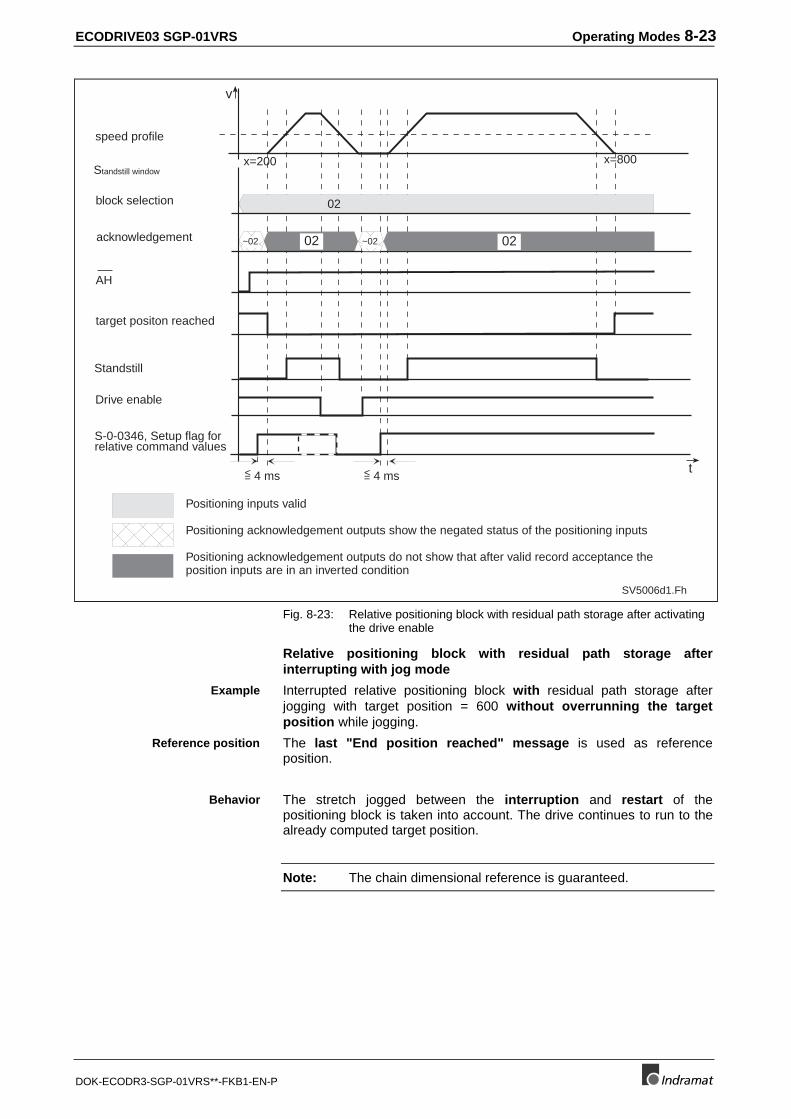
ECODRIVE03 SGP-01VRS Operating Modes 8-23
DOK-ECODR3-SGP-01VRS**-FKB1-EN-P
Standstill window
block selection
acknowledgement
AH
target positon reached
speed profile
Positioning inputs valid
Positioning acknowledgement outputs show the negated status of the positioning inputs
Positioning acknowledgement outputs do not show that after valid record acceptance theposition inputs are in an inverted condition
Drive enable
Standstill
S-0-0346, Setup flag forrelative command values
x=800
v
t
SV5006d1.Fh
02
x=200
~02
< 4 ms= < 4 ms=
02
~02 02
Fig. 8-23: Relative positioning block with residual path storage after activatingthe drive enable
Relative positioning block with residual path storage afterinterrupting with jog mode
Interrupted relative positioning block with residual path storage afterjogging with target position = 600 without overrunning the targetposition while jogging.
The last "End position reached" message is used as referenceposition.
The stretch jogged between the interruption and restart of thepositioning block is taken into account. The drive continues to run to thealready computed target position.
Note: The chain dimensional reference is guaranteed.
Example
Reference position
Behavior
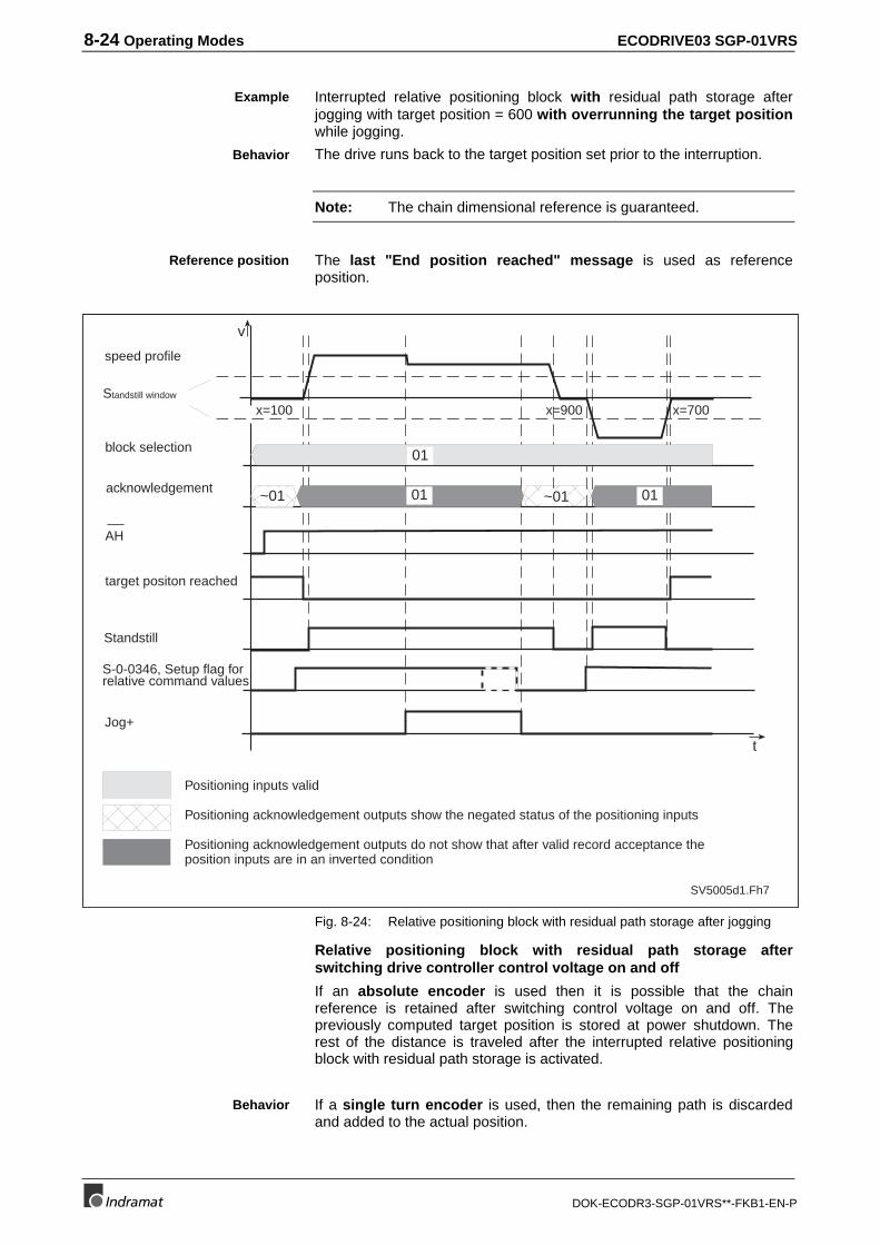
8-24 Operating Modes ECODRIVE03 SGP-01VRS
DOK-ECODR3-SGP-01VRS**-FKB1-EN-P
Interrupted relative positioning block with residual path storage afterjogging with target position = 600 with overrunning the target positionwhile jogging.
The drive runs back to the target position set prior to the interruption.
Note: The chain dimensional reference is guaranteed.
The last "End position reached" message is used as referenceposition.
Standstill window
block selection
acknowledgement
AH
target positon reached
speed profile
Positioning inputs valid
Positioning acknowledgement outputs show the negated status of the positioning inputs
Positioning acknowledgement outputs do not show that after valid record acceptance theposition inputs are in an inverted condition
Jog+
Standstill
S-0-0346, Setup flag forrelative command values
x=900 x=700
v
t
SV5005d1.Fh7
x=100
~01 01 ~01
01
01
Fig. 8-24: Relative positioning block with residual path storage after jogging
Relative positioning block with residual path storage afterswitching drive controller control voltage on and off
If an absolute encoder is used then it is possible that the chainreference is retained after switching control voltage on and off. Thepreviously computed target position is stored at power shutdown. Therest of the distance is traveled after the interrupted relative positioningblock with residual path storage is activated.
If a single turn encoder is used, then the remaining path is discardedand added to the actual position.
Example
Behavior
Reference position
Behavior
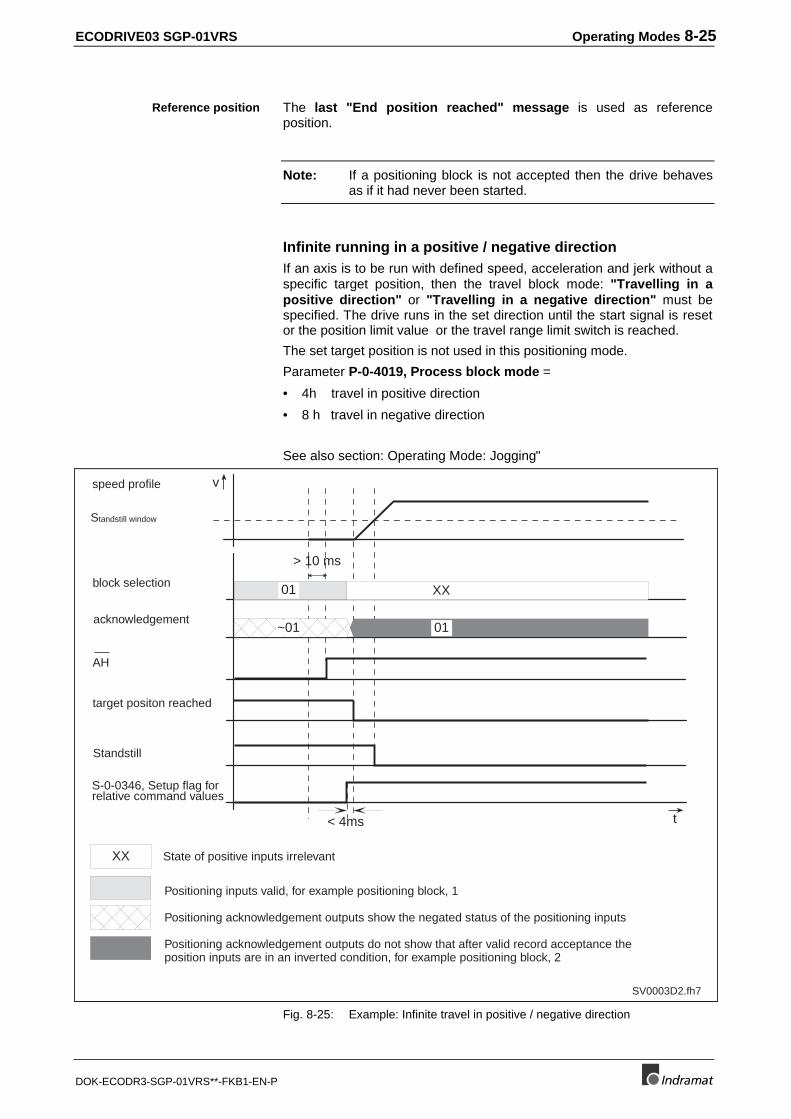
ECODRIVE03 SGP-01VRS Operating Modes 8-25
DOK-ECODR3-SGP-01VRS**-FKB1-EN-P
The last "End position reached" message is used as referenceposition.
Note: If a positioning block is not accepted then the drive behavesas if it had never been started.
Infinite running in a positive / negative directionIf an axis is to be run with defined speed, acceleration and jerk without aspecific target position, then the travel block mode: "Travelling in apositive direction" or "Travelling in a negative direction" must bespecified. The drive runs in the set direction until the start signal is resetor the position limit value or the travel range limit switch is reached.
The set target position is not used in this positioning mode.
Parameter P-0-4019, Process block mode =
• 4h travel in positive direction
• 8 h travel in negative direction
See also section: Operating Mode: Jogging"
SV0003D2.fh7
XX State of positive inputs irrelevant
Standstill window
block selection
acknowledgement
AH
target positon reached
speed profile
Positioning inputs valid, for example positioning block, 1
Positioning acknowledgement outputs show the negated status of the positioning inputs
Positioning acknowledgement outputs do not show that after valid record acceptance theposition inputs are in an inverted condition, for example positioning block, 2
v
t
> 10 ms
XX01
~01 01
< 4ms
Standstill
S-0-0346, Setup flag forrelative command values
Fig. 8-25: Example: Infinite travel in positive / negative direction
Reference position
8-26 Operating Modes ECODRIVE03 SGP-01VRS
DOK-ECODR3-SGP-01VRS**-FKB1-EN-P
Following block processingSelecting and activating a block with following block is performed in theusual manner. The following block is that block with the next highestblock number. A following block can also have a following block so thatafter a start block up to 63 following blocks can be set. The potentialfollowing block of the block with number 63 is block 0.
There are two possibilities for continuing block mode. These are alsobroken down into:
1) Position-dependent continue block mode
With position-dependent continue block mode, the following block isswitched into at the target position of the start block.
There are three different types of block transitions:
a) Block transition at old positioning speed (Mode 1)
P-0-4019, Process block mode =11h: absolute block with following block
P-0-4019, Process block mode =12h: relative block with following block
P-0-4019, Process block mode =14h: infinite block in positive directionwith following block
P-0-4019, Process block mode: infinite block in negative direction withfollowing block
In this mode, the target position of the start block is run through at thespeed of the start block and then switched to the positioning speed of thefollowing block.
Selecting and activating afollowing block
Conditions to continue infollowing block mode
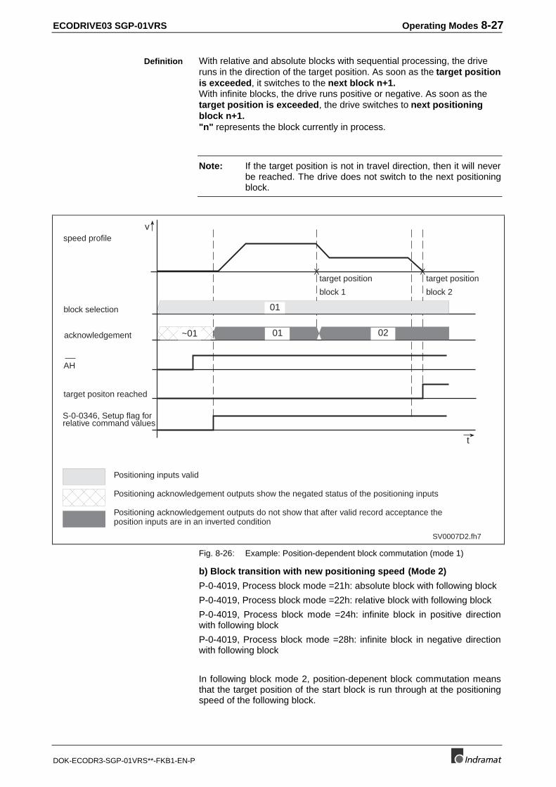
ECODRIVE03 SGP-01VRS Operating Modes 8-27
DOK-ECODR3-SGP-01VRS**-FKB1-EN-P
With relative and absolute blocks with sequential processing, the driveruns in the direction of the target position. As soon as the target positionis exceeded, it switches to the next block n+1.With infinite blocks, the drive runs positive or negative. As soon as thetarget position is exceeded, the drive switches to next positioningblock n+1."n" represents the block currently in process.
Note: If the target position is not in travel direction, then it will neverbe reached. The drive does not switch to the next positioningblock.
SV0007D2.fh7
block selection
acknowledgement
AH
target positon reached
speed profile
Positioning inputs valid
Positioning acknowledgement outputs show the negated status of the positioning inputs
Positioning acknowledgement outputs do not show that after valid record acceptance theposition inputs are in an inverted condition
v
t
~01 01 02
01
X X
S-0-0346, Setup flag forrelative command values
target position
block 1
target position
block 2
Fig. 8-26: Example: Position-dependent block commutation (mode 1)
b) Block transition with new positioning speed (Mode 2)
P-0-4019, Process block mode =21h: absolute block with following block
P-0-4019, Process block mode =22h: relative block with following block
P-0-4019, Process block mode =24h: infinite block in positive directionwith following block
P-0-4019, Process block mode =28h: infinite block in negative directionwith following block
In following block mode 2, position-depenent block commutation meansthat the target position of the start block is run through at the positioningspeed of the following block.
Definition
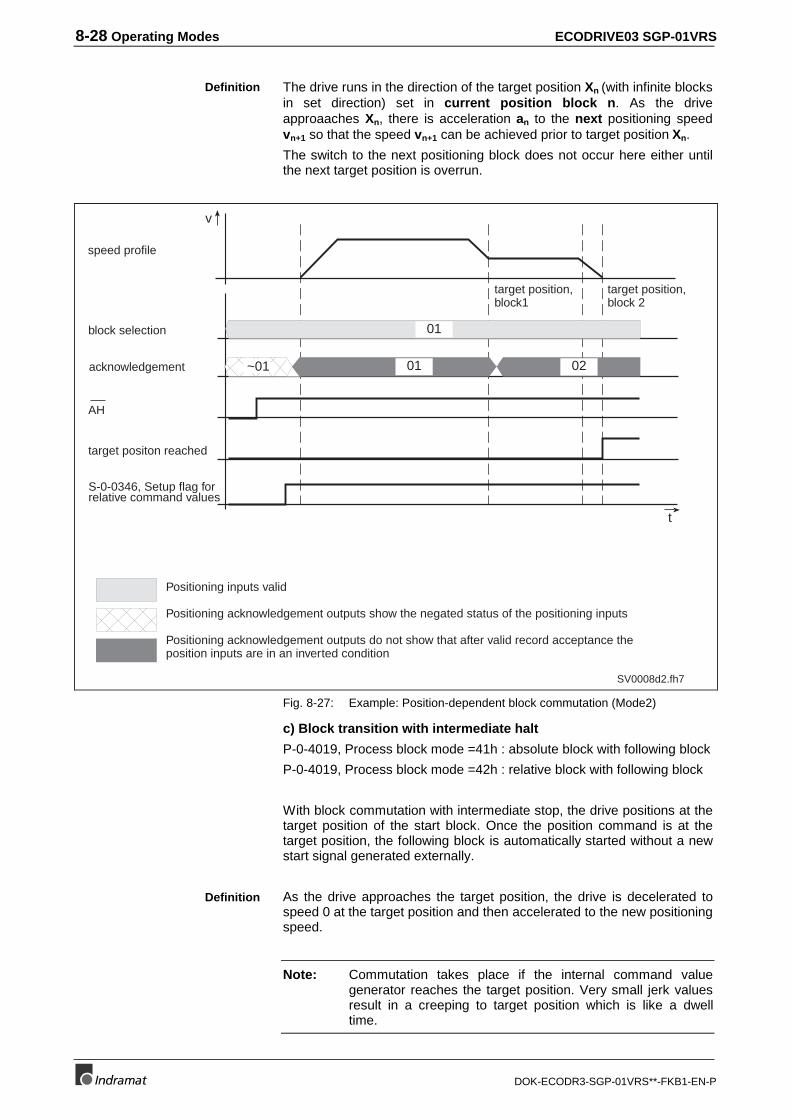
8-28 Operating Modes ECODRIVE03 SGP-01VRS
DOK-ECODR3-SGP-01VRS**-FKB1-EN-P
The drive runs in the direction of the target position Xn (with infinite blocksin set direction) set in current position block n. As the driveapproaaches Xn, there is acceleration an to the next positioning speedvn+1 so that the speed vn+1 can be achieved prior to target position Xn.
The switch to the next positioning block does not occur here either untilthe next target position is overrun.
v
t
SV0008d2.fh7
01
~01 01 02
block selection
acknowledgement
AH
target positon reached
speed profile
Positioning inputs valid
Positioning acknowledgement outputs show the negated status of the positioning inputs
Positioning acknowledgement outputs do not show that after valid record acceptance theposition inputs are in an inverted condition
S-0-0346, Setup flag forrelative command values
target position,block1
target position,block 2
Fig. 8-27: Example: Position-dependent block commutation (Mode2)
c) Block transition with intermediate halt
P-0-4019, Process block mode =41h : absolute block with following block
P-0-4019, Process block mode =42h : relative block with following block
With block commutation with intermediate stop, the drive positions at thetarget position of the start block. Once the position command is at thetarget position, the following block is automatically started without a newstart signal generated externally.
As the drive approaches the target position, the drive is decelerated tospeed 0 at the target position and then accelerated to the new positioningspeed.
Note: Commutation takes place if the internal command valuegenerator reaches the target position. Very small jerk valuesresult in a creeping to target position which is like a dwelltime.
Definition
Definition
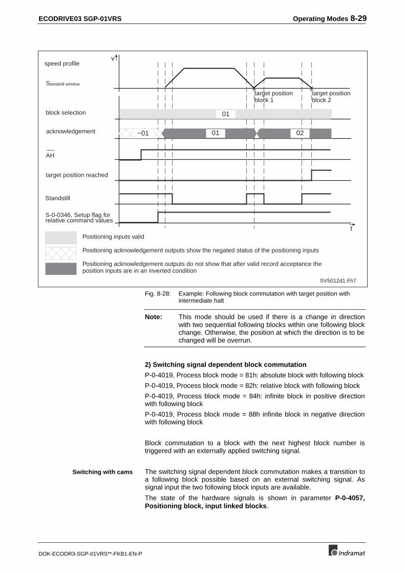
ECODRIVE03 SGP-01VRS Operating Modes 8-29
DOK-ECODR3-SGP-01VRS**-FKB1-EN-P
block selection
acknowledgement
AH
Positioning inputs valid
Positioning acknowledgement outputs show the negated status of the positioning inputs
Positioning acknowledgement outputs do not show that after valid record acceptance theposition inputs are in an inverted condition
Standstill window
speed profile
target position reached
Standstill
S-0-0346, Setup flag forrelative command values
SV5012d1.Fh7
v
t
01
~01 01 02
target positionblock 1
target positionblock 2
X X
Fig. 8-28: Example: Following block commutation with target position withintermediate halt
Note: This mode should be used if there is a change in directionwith two sequential following blocks within one following blockchange. Otherwise, the position at which the direction is to bechanged will be overrun.
2) Switching signal dependent block commutation
P-0-4019, Process block mode = 81h: absolute block with following block
P-0-4019, Process block mode = 82h: relative block with following block
P-0-4019, Process block mode = 84h: infinite block in positive directionwith following block
P-0-4019, Process block mode = 88h infinite block in negative directionwith following block
Block commutation to a block with the next highest block number istriggered with an externally applied switching signal.
The switching signal dependent block commutation makes a transition toa following block possible based on an external switching signal. Assignal input the two following block inputs are available.
The state of the hardware signals is shown in parameter P-0-4057,Positioning block, input linked blocks.
Switching with cams
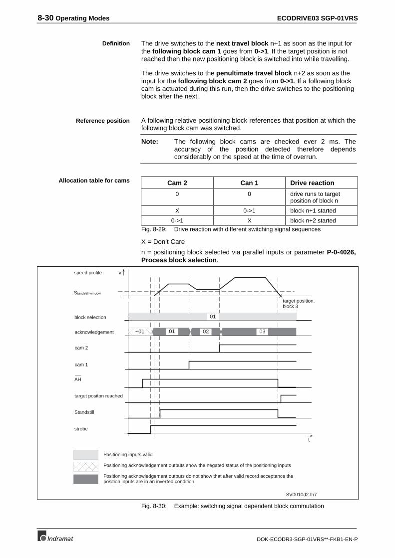
8-30 Operating Modes ECODRIVE03 SGP-01VRS
DOK-ECODR3-SGP-01VRS**-FKB1-EN-P
The drive switches to the next travel block n+1 as soon as the input forthe following block cam 1 goes from 0->1. If the target position is notreached then the new positioning block is switched into while travelling.
The drive switches to the penultimate travel block n+2 as soon as theinput for the following block cam 2 goes from 0->1. If a following blockcam is actuated during this run, then the drive switches to the positioningblock after the next.
A following relative positioning block references that position at which thefollowing block cam was switched.
Note: The following block cams are checked ever 2 ms. Theaccuracy of the position detected therefore dependsconsiderably on the speed at the time of overrun.
Cam 2 Can 1 Drive reaction
0 0 drive runs to targetposition of block n
X 0->1 block n+1 started
0->1 X block n+2 startedFig. 8-29: Drive reaction with different switching signal sequences
X = Don’t Care
n = positioning block selected via parallel inputs or parameter P-0-4026,Process block selection.
v
t
SV0010d2.fh7
01
~01 01 02 03
X
block selection
acknowledgement
AH
target positon reached
strobe
Positioning inputs valid
Positioning acknowledgement outputs show the negated status of the positioning inputs
Positioning acknowledgement outputs do not show that after valid record acceptance theposition inputs are in an inverted condition
Standstill
Standstill window
cam 2
cam 1
speed profile
target position,block 3
Fig. 8-30: Example: switching signal dependent block commutation
Definition
Reference position
Allocation table for cams
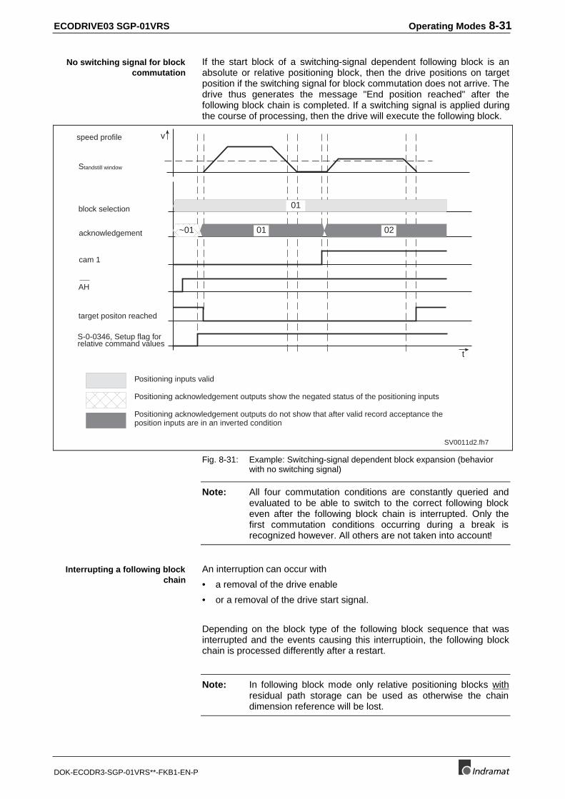
ECODRIVE03 SGP-01VRS Operating Modes 8-31
DOK-ECODR3-SGP-01VRS**-FKB1-EN-P
If the start block of a switching-signal dependent following block is anabsolute or relative positioning block, then the drive positions on targetposition if the switching signal for block commutation does not arrive. Thedrive thus generates the message "End position reached" after thefollowing block chain is completed. If a switching signal is applied duringthe course of processing, then the drive will execute the following block.
v
t
SV0011d2.fh7
01
~01 01 02
block selection
acknowledgement
AH
target positon reached
Positioning inputs valid
Positioning acknowledgement outputs show the negated status of the positioning inputs
Positioning acknowledgement outputs do not show that after valid record acceptance theposition inputs are in an inverted condition
Standstill window
cam 1
speed profile
S-0-0346, Setup flag forrelative command values
Fig. 8-31: Example: Switching-signal dependent block expansion (behaviorwith no switching signal)
Note: All four commutation conditions are constantly queried andevaluated to be able to switch to the correct following blockeven after the following block chain is interrupted. Only thefirst commutation conditions occurring during a break isrecognized however. All others are not taken into account!
An interruption can occur with
• a removal of the drive enable
• or a removal of the drive start signal.
Depending on the block type of the following block sequence that wasinterrupted and the events causing this interruptioin, the following blockchain is processed differently after a restart.
Note: In following block mode only relative positioning blocks withresidual path storage can be used as otherwise the chaindimension reference will be lost.
No switching signal for blockcommutation
Interrupting a following blockchain
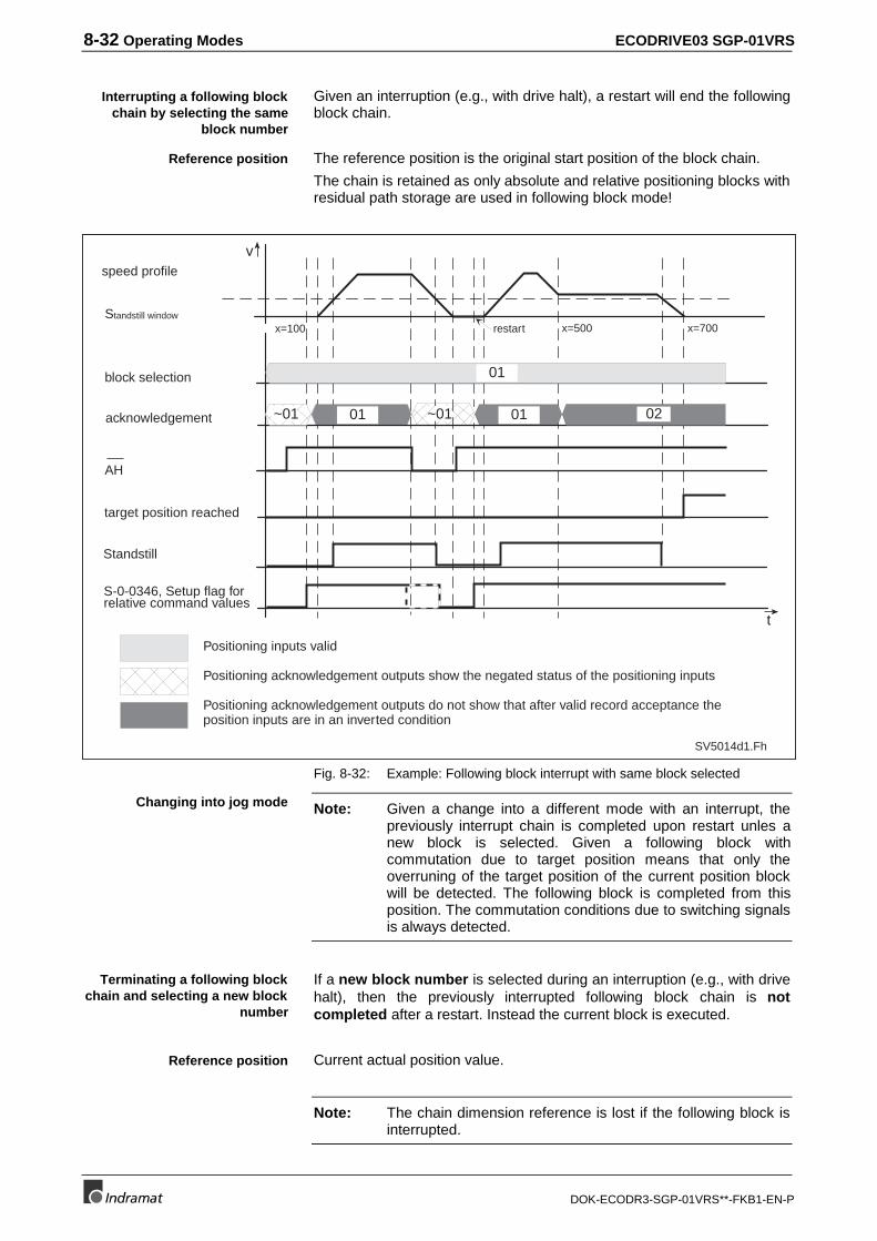
8-32 Operating Modes ECODRIVE03 SGP-01VRS
DOK-ECODR3-SGP-01VRS**-FKB1-EN-P
Given an interruption (e.g., with drive halt), a restart will end the followingblock chain.
The reference position is the original start position of the block chain.
The chain is retained as only absolute and relative positioning blocks withresidual path storage are used in following block mode!
block selection
acknowledgement
AH
Positioning inputs valid
Positioning acknowledgement outputs show the negated status of the positioning inputs
Positioning acknowledgement outputs do not show that after valid record acceptance theposition inputs are in an inverted condition
Standstill window
speed profile
target position reached
Standstill
S-0-0346, Setup flag forrelative command values
v
t
SV5014d1.Fh
01
x=100 x=700x=500restart
~01 02~0101 01
Fig. 8-32: Example: Following block interrupt with same block selected
Note: Given a change into a different mode with an interrupt, thepreviously interrupt chain is completed upon restart unles anew block is selected. Given a following block withcommutation due to target position means that only theoverruning of the target position of the current position blockwill be detected. The following block is completed from thisposition. The commutation conditions due to switching signalsis always detected.
If a new block number is selected during an interruption (e.g., with drivehalt), then the previously interrupted following block chain is notcompleted after a restart. Instead the current block is executed.
Current actual position value.
Note: The chain dimension reference is lost if the following block isinterrupted.
Interrupting a following blockchain by selecting the same
block number
Reference position
Changing into jog mode
Terminating a following blockchain and selecting a new block
number
Reference position
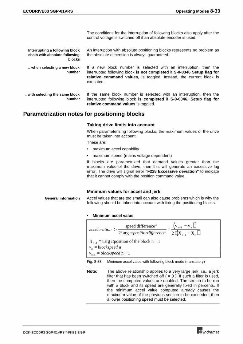
ECODRIVE03 SGP-01VRS Operating Modes 8-33
DOK-ECODR3-SGP-01VRS**-FKB1-EN-P
The conditions for the interruption of following blocks also apply after thecontrol voltage is switched off if an absolute encoder is used.
An interuption with absolute positioning blocks represents no problem asthe absolute dimension is always guaranteed.
If a new block number is selected with an interruption, then theinterrupted following block is not completed if S-0-0346 Setup flag forrelative command values, is toggled. Instead, the current block isexecuted.
If the same block number is selected with an interruption, then theinterrupted following block is completed if S-0-0346, Setup flag forrelative command values is toggled.
Parametrization notes for positioning blocks
Taking drive limits into accountWhen parameterizing following blocks, the maximum values of the drivemust be taken into account.
These are:
• maximum accel capability
• maximum speed (mains voltage dependent)
If blocks are parametrized that demand values greater than themaximum value of the drive, then this will generate an excessive lagerror. The drive will signal error "F228 Excessive deviation" to indicatethat it cannot comply with the position command value.
Minimum values for accel and jerkAccel values that are too small can also cause problems which is why thefollowing should be taken into account with fixing the positioning blocks.
• Minimum accel value
( )( )a
speed difference
2
v v
X Xn+1 n
n+1 n
ccelerationt etpositiondifference
> =−
⋅ −
2 2
2arg
X etn+ =1 t position of the block n + 1argv lockspeedn = b nv lockspeedn+ =1 b n + 1
Fig. 8-33: Minimum accel value with following block mode (translatory)
Note: The above relationship applies to a very large jerk, i.e., a jerkfilter that has been switched off ( = 0 ). If such a filter is used,then the computed values are doubled. The stretch to be runwith a block and its speed are generally fixed in percents. Ifthe minimum accel value computed already causes themaximum value of the previous section to be exceeded, thena lower positioning speed must be selected.
Interrupting a following blockchain with absolute following
blocks
.. when selecting a new blocknumber
.. with selecting the same blocknumber
General information
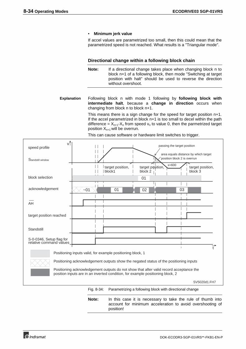
8-34 Operating Modes ECODRIVE03 SGP-01VRS
DOK-ECODR3-SGP-01VRS**-FKB1-EN-P
• Minimum jerk value
If accel values are parametrized too small, then this could mean that theparametrized speed is not reached. What results is a "Triangular mode".
Directional change within a following block chain
Note: If a directional change takes place when changing block n toblock n+1 of a following block, then mode "Switching at targetposition with halt" should be used to reverse the directionwithout overshoot.
Following block n with mode 1 following by following block withintermediate halt, because a change in direction occurs whenchanging from block n to block n+1.
This means there is a sign change for the speed for target position n+1.If the accel parametrized in block n+1 is too small to decel within the pathdifference = Xn+1-Xn from speed vn to value 0, then the parmetrized targetposition Xn+1 will be overrun.
This can cause software or hardware limit switches to trigger.
block selection
acknowledgement
AH
Positioning inputs valid, for example positioning block, 1
Positioning acknowledgement outputs show the negated status of the positioning inputs
Positioning acknowledgement outputs do not show that after valid record acceptance theposition inputs are in an inverted condition, for example positioning block, 2
Standstill window
speed profile
target position reached
target position,block1
target position,block 2
target position,block 3
Standstill
S-0-0346, Setup flag forrelative command values
v
t
SV5020d1.FH7
x=600
passing the target position
~01 01 0302
01
area equals distance by which targetposition block 2 is overrun
Fig. 8-34: Parametrizing a following block with directional change
Note: In this case it is necessary to take the rule of thumb intoaccount for minimum acceleration to avoid overshooting ofposition!
Explanation
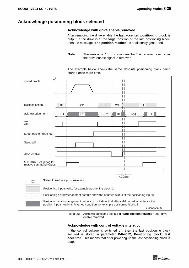
ECODRIVE03 SGP-01VRS Operating Modes 8-35
DOK-ECODR3-SGP-01VRS**-FKB1-EN-P
Acknowledge positioning block selected
Acknowledge with drive enable removedAfter removing the drive enable the last accepted positioning block isoutput. If the drive is at the target position of the last positioning block,then the message "end position reached" is additionally generated.
Note: The message "End position reached" is retained even afterthe drive enable signal is removed.
The example below shows the same absolute positioning block beingstarted once more time.
v
SV0006D2.fh7
XX XX 01
~01 01 ~02 0101 ~01
<10ms
XX
0201
t
State of positive inputs irrelevant
block selection
acknowledgement
AH
target positon reached
speed profile
Positioning inputs valid, for example positioning block, 1
Positioning acknowledgement outputs show the negated status of the positioning inputs
Positioning acknowledgement outputs do not show that after valid record acceptance theposition inputs are in an inverted condition, for example positioning block, 2
drive enable
Standstill
S-0-0346, Setup flag forrelative command values
Fig. 8-35: Acknowledging and signalling "End position reached" after driveenable removed
Acknowledge with control voltage interruptIf the control voltage is switched off, then the last positioning blocksecured is stored in parameter P-0-4052, Positioning block, lastaccepted. This means that after powering up the last positioning block isoutput.
8-36 Operating Modes ECODRIVE03 SGP-01VRS
DOK-ECODR3-SGP-01VRS**-FKB1-EN-P
If an Absolute encoder is used, then it can be decided after the controlvoltage is switched off and on whether the drive is at the target position ofthe last positioning block (IN-POS message active).
The INPOS message is fixed as soon as the drive is ready to operateagain (bb contact closed).
If a Singleturn encoder is used, then the IN-POS message is not clearlydefined after a power interrupt until the first target position is approachedor referenced.
Note: The INPOS message is only retained if the axis is not movingduring the interruption. If the axis is moved into the positioningwindow during the interruption, then the INPOS message willalso be generated. After activating the drive enable,positioning block acknowledge changes to as described in"Acknowledge with drive enable removed".
Status Messages in "Positioning Block Mode"In addition to the messages lised in section: "Status messages duringdrive-internal interpolation", the following status messages are alsogenerated in positioning block mode:
• End position reached, Bit 12 of S-0-0182, Manufacturer statusclass 3 is "1", it applies if: message "In-target position" (S-0-0182, Bit10) is active and no slaveblock has been selected.
Positioning block mode with parallel interfaceParallel interface with DKC means that special hardware, acknowledgeand status messages are available.
With a parallel interface, ten freely configurable digital inputs and tenfreely-configurable digital outputs are available. By configuringparameters S-0-0145, Signal control word and S-0-0144, Signalstatus word the positioning interface is determined.
The signal control word and status word must be configured with ahardware allocation to connector X20 (parallel interace).
Configuration signal control word
• Bits 0-5 of positioning block select (P-0-4026 Bit 0-5)
• Bit 6 S-0-0346 bit 0
• Bit 7 command drive-guided referencing (S-0-0148)
• Bit 8 and 9 jogging input (P-0-4056 bit 0 and 1)
Configuration signal status word
• Bit 0-5 positioning block, acknowledge (P-0-4051 Bit 0-5)
• Bit 6 S-0-0182 Bit 12 "End position reached“
• Bit 7 S-0-0182 Bit 1 "Standstill“
• Bit 8 S-0-0403 position status bit 0
• Bit 9 S-0-0059 position switch point bit 0
Absolute encoder
Singleturn encoder
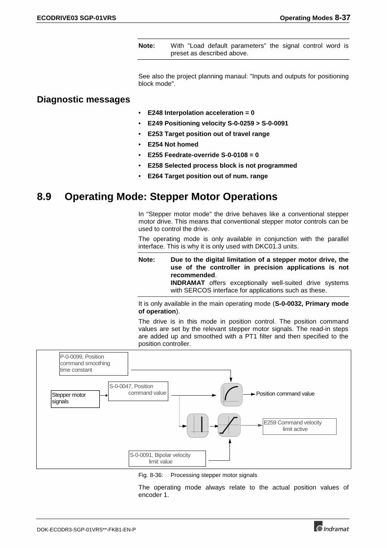
ECODRIVE03 SGP-01VRS Operating Modes 8-37
DOK-ECODR3-SGP-01VRS**-FKB1-EN-P
Note: With "Load default parameters" the signal control word ispreset as described above.
See also the project planning manaul: "Inputs and outputs for positioningblock mode".
Diagnostic messages• E248 Interpolation acceleration = 0
• E249 Positioning velocity S-0-0259 > S-0-0091
• E253 Target position out of travel range
• E254 Not homed
• E255 Feedrate-override S-0-0108 = 0
• E258 Selected process block is not programmed
• E264 Target position out of num. range
8.9 Operating Mode: Stepper Motor Operations
In "Stepper motor mode" the drive behaves like a conventional steppermotor drive. This means that conventional stepper motor controls can beused to control the drive.
The operating mode is only available in conjunction with the parallelinterface. This is why it is only used with DKC01.3 units.
Note: Due to the digital limitation of a stepper motor drive, theuse of the controller in precision applications is notrecommended.INDRAMAT offers exceptionally well-suited drive systemswith SERCOS interface for applications such as these.
It is only available in the main operating mode (S-0-0032, Primary modeof operation).
The drive is in this mode in position control. The position commandvalues are set by the relevant stepper motor signals. The read-in stepsare added up and smoothed with a PT1 filter and then specified to theposition controller.
S-0-0047, Position command value
S-0-0091, Bipolar velocity limit value
P-0-0099, Positioncommand smoothingtime constant
Position command value
E259 Command velocity limit active
Stepper motorsignals
Fig. 8-36: Processing stepper motor signals
The operating mode always relate to the actual position values ofencoder 1.
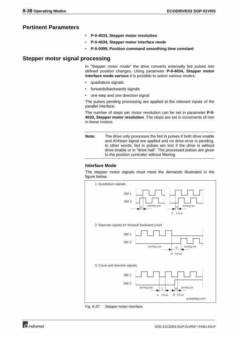
8-38 Operating Modes ECODRIVE03 SGP-01VRS
DOK-ECODR3-SGP-01VRS**-FKB1-EN-P
Pertinent Parameters• P-0-4033, Stepper motor resolution
• P-0-4034, Stepper motor interface mode
• P-0-0099, Position command smoothing time constant
Stepper motor signal processingIn "Stepper motor mode" the drive converts externally fed pulses intodefined position changes. Using parameter P-0-4034, Stepper motorinterface mode various it is possible to select various modes:
• quadrature signals
• forwards/backwards signals
• one step and one direction signal
The pulses pending processing are applied at the relevant inputs of theparallel interface.
The number of steps per motor revolution can be set in parameter P-0-4033, Stepper motor resolution. The steps are set in increments of mmin linear motors.
Note: The drive only processes the fed in pulses if both drive enableand AH/start signal are applied and no drive error is pending.In other words, fed in pulses are lost if the drive is withoutdrive enable or in "drive halt". The processed pulses are givento the position controller without filtering.
Interface ModeThe stepper motor signals must meet the demands illustrated in thefigure below.
SV0200d1.Fh7
1: Quadrature-signals
2: Seperate signals for forward/ backward count
3: Count and direction signals
SM 1
SM 2
SM 1
SM 2
SM 2
SM 1
turning ccw t1
t2
t3tL
turning ccw turning cw
turning ccw turning cw
t2 5,6 µs
t3 5,6 µstL 2,8 µs
t1 1,4 µs
turning cwt1
Fig. 8-37: Stepper motor interface
ECODRIVE03 SGP-01VRS Operating Modes 8-39
DOK-ECODR3-SGP-01VRS**-FKB1-EN-P
Diagnostic MessagesWith the step motor mode it makes sense to put the message"In-Position" (S-0-0013, Class 3 diagnostics, Bit 6: lag error < positioningwindow) on the signal status word and thus on the digital output.
Also see section: "Configurable Signal Status Word".
Connecting the Parallel InterfaceThe allocation of the parallel interface connections is described in detailin the Project Planning Manuals.
See Project Planning Manual; Control inputs for Stepper MotorOperations.
8.10 Operating Mode: Jogging
Operating mode is used to run an axis in "Manual mode", i.e., without theuse of the control program.
In units with positioning interface or step-motor interface, it is possible tomount circuits at the jogging inputs which can be moved to use the axes.
The drive switches into jogging automatically if these inputs are actuated.The state of the inputs is reflected in parameter P-0-4056, jogginginputs.
Also see section: "Command Communication Using Parallel Interface"
Pertinent Parameters• P-0-4030, Jog velocity
• P-0-4056, Jog inputs
• S-0-0260, Positioning Acceleration
• S-0-0193, Positioning Jerk
• S-0-0403, Position feedback value status
• S-0-0055, Position polarities
• S-0-0049, Positive position limit value
• S-0-0050, Negative position limit value
How it works
Activating the operating mode ogging:The bit strip
1100,0000,0001,1011 b
must be entred in parameter S-0-0033, Secondary operation mode 1.
The mode can only be entered as 1 auxiliary mode.
Additional parameters
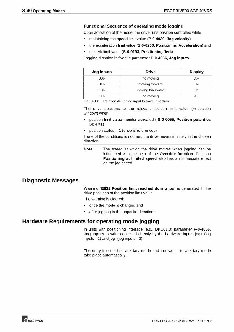
8-40 Operating Modes ECODRIVE03 SGP-01VRS
DOK-ECODR3-SGP-01VRS**-FKB1-EN-P
Functional Sequence of operating mode joggingUpon activation of the mode, the drive runs position controlled while
• maintaining the speed limit value (P-0-4030, Jog velocity),
• the acceleration limit value (S-0-0260, Positioning Acceleration) and
• the jerk limit value (S-0-0193, Positioning Jerk).
Jogging direction is fixed in parameter P-0-4056, Jog inputs.
Jog inputs Drive Display
00b no moving AF
01b moving forward JF
10b moving backward Jb
11b no moving AFFig. 8-38: Relationship of jog input to travel direction
The drive positions to the relevant position limit value (+/-positionwindow) when:
• position limit value monitor activated ( S-0-0055, Position polaritiesBit 4 =1)
• position status = 1 (drive is referenced)
If one of the conditions is not met, the drive moves infinitely in the chosendirection.
Note: The speed at which the drive moves when jogging can beinfluenced with the help of the Override function. FunctionPositioning at limited speed also has an immediate effecton the jog speed.
Diagnostic MessagesWarning "E831 Position limit reached during jog“ is generated if thedrive positions at the position limit value.
The warning is cleared:
• once the mode is changed and
• after jogging in the opposite direction.
Hardware Requirements for operating mode joggingIn units with positioning interface (e.g., DKC01.3) parameter P-0-4056,Jog inputs is write accessed directly by the hardware inputs jog+ (joginputs =1) and jog- (jog inputs =2).
The entry into the first auxiliary mode and the switch to auxiliary modetake place automatically.
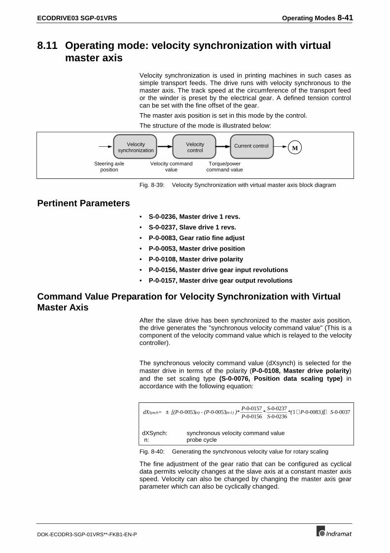
ECODRIVE03 SGP-01VRS Operating Modes 8-41
DOK-ECODR3-SGP-01VRS**-FKB1-EN-P
8.11 Operating mode: velocity synchronization with virtualmaster axis
Velocity synchronization is used in printing machines in such cases assimple transport feeds. The drive runs with velocity synchronous to themaster axis. The track speed at the circumference of the transport feedor the winder is preset by the electrical gear. A defined tension controlcan be set with the fine offset of the gear.
The master axis position is set in this mode by the control.
The structure of the mode is illustrated below:
Velocitycontrol
Steering axleposition
Velocity commandvalue
Torque/powercommand value
Current controlVelocitysynchronization M
Fig. 8-39: Velocity Synchronization with virtual master axis block diagram
Pertinent Parameters• S-0-0236, Master drive 1 revs.
• S-0-0237, Slave drive 1 revs.
• P-0-0083, Gear ratio fine adjust
• P-0-0053, Master drive position
• P-0-0108, Master drive polarity
• P-0-0156, Master drive gear input revolutions
• P-0-0157, Master drive gear output revolutions
Command Value Preparation for Velocity Synchronization with VirtualMaster Axis
After the slave drive has been synchronized to the master axis position,the drive generates the "synchronous velocity command value" (This is acomponent of the velocity command value which is relayed to the velocitycontroller).
The synchronous velocity command value (dXsynch) is selected for themaster drive in terms of the polarity (P-0-0108, Master drive polarity)and the set scaling type (S-0-0076, Position data scaling type) inaccordance with the following equation:
dX = [(P- - - (P- - )*P- -
P- -*
S- -
S- -*( P- - )] S- -Synch (n) (n- )± + +0 0053 0 0053
0 0157
0 0156
0 0237
0 02361 0 0083 0 00371
dXSynch: synchronous velocity command valuen: probe cycle
Fig. 8-40: Generating the synchronous velocity value for rotary scaling
The fine adjustment of the gear ratio that can be configured as cyclicaldata permits velocity changes at the slave axis at a constant master axisspeed. Velocity can also be changed by changing the master axis gearparameter which can also be cyclically changed.
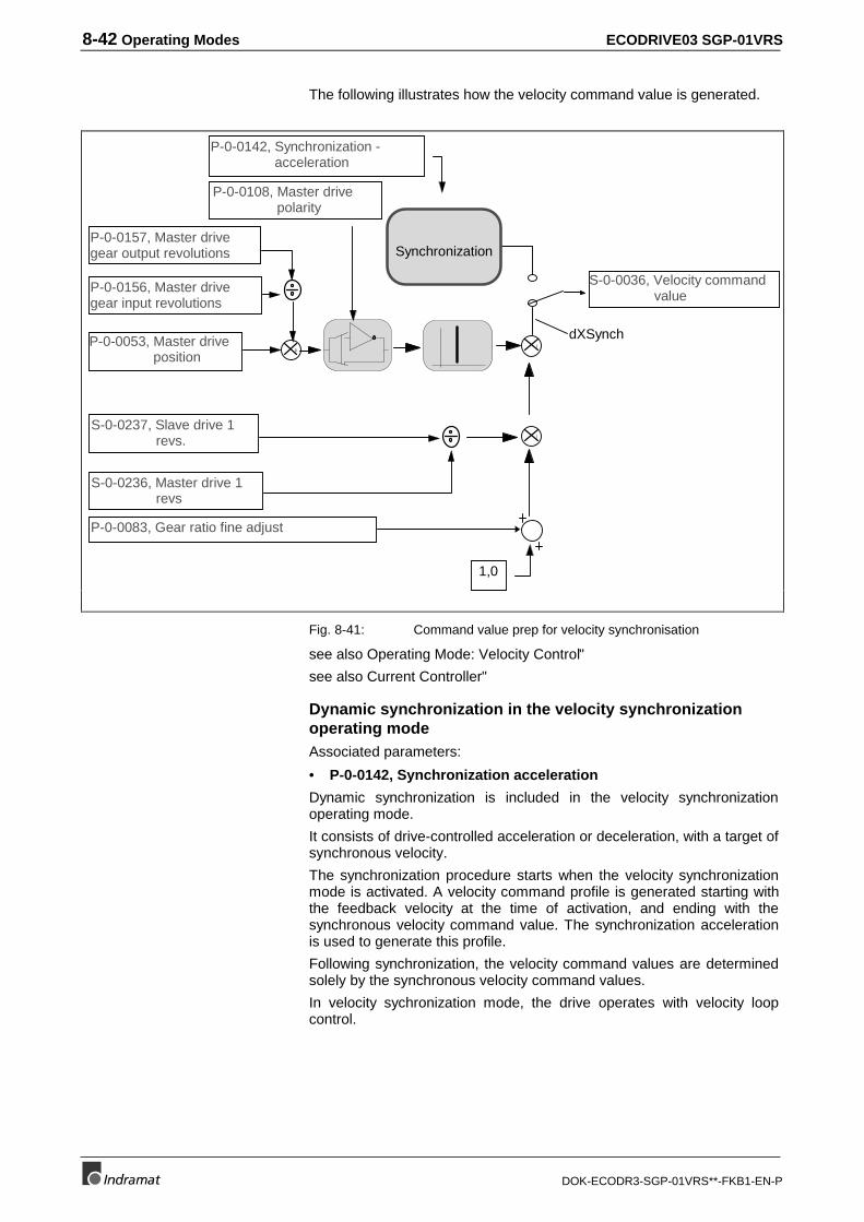
8-42 Operating Modes ECODRIVE03 SGP-01VRS
DOK-ECODR3-SGP-01VRS**-FKB1-EN-P
The following illustrates how the velocity command value is generated.
P-0-0053, Master drive position
S-0-0236, Master drive 1 revs
S-0-0237, Slave drive 1 revs.
P-0-0083, Gear ratio fine adjust
1,0
S-0-0036, Velocity command value
P-0-0108, Master drive polarity
P-0-0142, Synchronization - acceleration
Synchronization
dXSynch
P-0-0156, Master drivegear input revolutions
P-0-0157, Master drivegear output revolutions
Fig. 8-41: Command value prep for velocity synchronisation
see also Operating Mode: Velocity Control"
see also Current Controller"
Dynamic synchronization in the velocity synchronizationoperating modeAssociated parameters:
• P-0-0142, Synchronization acceleration
Dynamic synchronization is included in the velocity synchronizationoperating mode.
It consists of drive-controlled acceleration or deceleration, with a target ofsynchronous velocity.
The synchronization procedure starts when the velocity synchronizationmode is activated. A velocity command profile is generated starting withthe feedback velocity at the time of activation, and ending with thesynchronous velocity command value. The synchronization accelerationis used to generate this profile.
Following synchronization, the velocity command values are determinedsolely by the synchronous velocity command values.
In velocity sychronization mode, the drive operates with velocity loopcontrol.
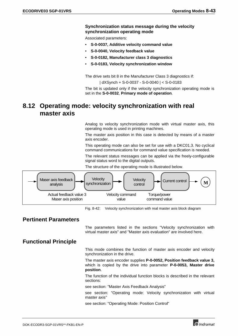
ECODRIVE03 SGP-01VRS Operating Modes 8-43
DOK-ECODR3-SGP-01VRS**-FKB1-EN-P
Synchronization status message during the velocitysynchronization operating modeAssociated parameters:
• S-0-0037, Additive velocity command value
• S-0-0040, Velocity feedback value
• S-0-0182, Manufacturer class 3 diagnostics
• S-0-0183, Velocity synchronization window
The drive sets bit 8 in the Manufacturer Class 3 diagnostics if:
| dXSynch + S-0-0037 - S-0-0040 | < S-0-0183
The bit is updated only if the velocity synchronization operating mode isset in the S-0-0032, Primary mode of operation.
8.12 Operating mode: velocity synchronization with realmaster axis
Analog to velocity synchronization mode with virtual master axis, thisoperating mode is used in printing machines.
The master axis position in this case is detected by means of a masteraxis encoder.
This operating mode can also be set for use with a DKC01.3. No cyclicalcommand communications for command value specification is needed.
The relevant status messages can be applied via the freely-configurablesignal status word to the digital outputs.
The structure of the operating mode is illustrated below.
Velocitycontrol
Actual feedback value 3Maser axis position
Velocity commandvalue
Torque/powercommand value
Current controlVelocitysynchronization
Maser axis feedbackanalysis M
Fig. 8-42: Velocity synchronization with real master axis block diagram
Pertinent ParametersThe parameters listed in the sections "Velocity synchronization withvirtual master axis" and "Master axis evaluation" are involved here.
Functional PrincipleThis mode combines the function of master axis encoder and velocitysynchronization in the drive.
The master axis encoder supplies P-0-0052, Position feedback value 3,which is copied by the drive into parameter P-0-0053, Master driveposition.
The function of the individual function blocks is described in the relevantsections:
see section: "Master Axis Feedback Analysis"
see section: "Operating mode: Velocity synchronization with virtualmaster axis"
see section: "Operating Mode: Position Control"

8-44 Operating Modes ECODRIVE03 SGP-01VRS
DOK-ECODR3-SGP-01VRS**-FKB1-EN-P
see section: "Operating Mode: Velocity Control"
see section: "Current Controller"
Note: If the master axis encoder is not homed then zero pulsedetection is automatically activated. As soon as the zero pulseis generated, there is a position jump to the value P-0-0087,Offset position feedback value 3. The resulting velocityjump is suppressed.
8.13 Operating mode: phase synchronization with virtualmaster axis
In machining processes that need absolute phase synchronization, e.g.,printing, punching or perforating in printing machines, then the positionrelevant to the master axis is established in operating mode phasesynchronization.
The drive synchronizes in this mode to one of the master axis positionsset by the control (virtual) (P-0-0053).
The structure of the phase synchronization mode with virtual master axisis illustrated below:
Velocitycontrol
Positioncommand value
Master axisposition
Velocity commandvalue
Torque/powercommand value
Current controlPositioncontrol
Command value prep.Phase synchronization M
Fig 8-43: Virtual phase synchronization block diagram
Pertinent Parameters• S-0-0048, Position command value additional
• S-0-0236, Master drive 1 revs.
• S-0-0237, Slave drive 1 revs.
• P-0-0053, Master drive position
• P-0-0108, Master drive polarity
• P-0-0156, Master drive gear input revolutions
• P-0-0157, Master drive gear output revolutions
• P-0-0159, Slave drive feed travel
Command value preparation with phase synchronization with virtualmaster axis
In phase synchronization mode with a virtual master axis the positioncommand value is generated by adding the synchronous position commandvalue (XSynch) and S-0-0048, Position command value additional.
S-0-0047, Position command value =XSynch + S-0-0048, Position command value additional
XSynch: synchronous position command value
Fig. 8-44: Generating the position command value
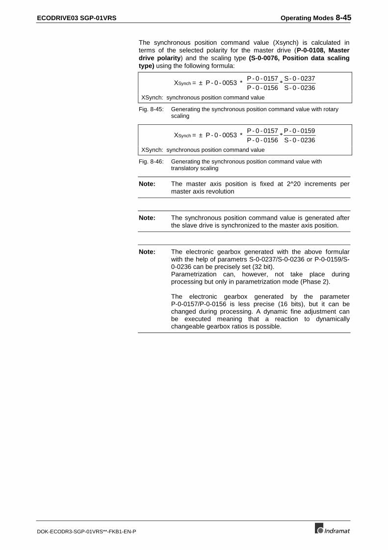
ECODRIVE03 SGP-01VRS Operating Modes 8-45
DOK-ECODR3-SGP-01VRS**-FKB1-EN-P
The synchronous position command value (Xsynch) is calculated interms of the selected polarity for the master drive (P-0-0108, Masterdrive polarity) and the scaling type (S-0-0076, Position data scalingtype) using the following formula:
X = P - 0 - 0053 * P - 0 - 0157P - 0 - 0156
S- 0 - 0237S- 0 - 0236
Synch ± *
XSynch: synchronous position command value
Fig. 8-45: Generating the synchronous position command value with rotaryscaling
X = P - 0 - 0053 * P - 0 - 0157P - 0 - 0156
P - 0 - 0159S- 0 - 0236
Synch ± *
XSynch: synchronous position command value
Fig. 8-46: Generating the synchronous position command value withtranslatory scaling
Note: The master axis position is fixed at 2^20 increments permaster axis revolution
Note: The synchronous position command value is generated afterthe slave drive is synchronized to the master axis position.
Note: The electronic gearbox generated with the above formularwith the help of parametrs S-0-0237/S-0-0236 or P-0-0159/S-0-0236 can be precisely set (32 bit).Parametrization can, however, not take place duringprocessing but only in parametrization mode (Phase 2).
The electronic gearbox generated by the parameterP-0-0157/P-0-0156 is less precise (16 bits), but it can bechanged during processing. A dynamic fine adjustment canbe executed meaning that a reaction to dynamicallychangeable gearbox ratios is possible.
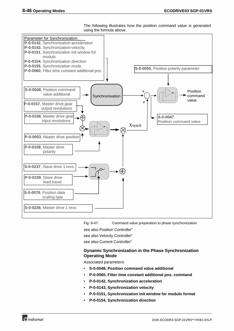
8-46 Operating Modes ECODRIVE03 SGP-01VRS
DOK-ECODR3-SGP-01VRS**-FKB1-EN-P
The following illustrates how the position command value is generatedusing the formula above.
S-0-0047,Position command value
Positioncommandvalue
S-0-0236, Master drive 1 revs.
P-0-0108, Master drive polarity
P-0-0053, Master drive position
S-0-0237, Slave drive 1 revs.
Xsynch
Parameter for Synchronization:P-0-0142, Synchronization-accelerationP-0-0143, Synchronization-velocityP-0-0151, Synchronization init window for moduloP-0-0154, Synchronization directionP-0-0155, Synchronization modeP-0-0060, Filter time constant additional pos.
S-0-0048, Position command value additional Synchronisation
S-0-0055, Position polarity parameter
P-0-0159, Slave drive feed travel
S-0-0076, Position data scaling type
P-0-0156, Master drive gear input revolutions
P-0-0157, Master drive gear output revolutions
Fig. 8-47: Command value preparation to phase synchronization
see also Position Controller"
see also Velocity Controller"
see also Current Controller"
Dynamic Synchronization in the Phase SynchronizationOperating ModeAssociated parameters:
• S-0-0048, Position command value additional
• P-0-0060, Filter time constant additional pos. command
• P-0-0142, Synchronization acceleration
• P-0-0143, Synchronization velocity
• P-0-0151, Synchronization init window for modulo format
• P-0-0154, Synchronization direction
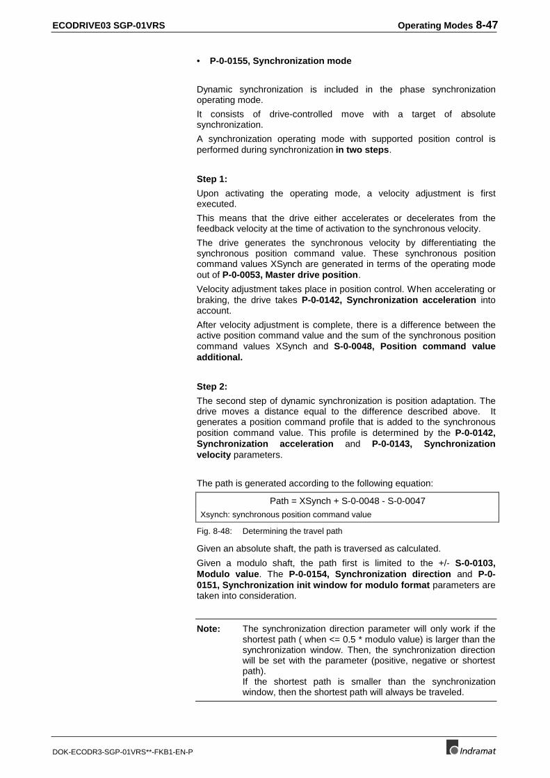
ECODRIVE03 SGP-01VRS Operating Modes 8-47
DOK-ECODR3-SGP-01VRS**-FKB1-EN-P
• P-0-0155, Synchronization mode
Dynamic synchronization is included in the phase synchronizationoperating mode.
It consists of drive-controlled move with a target of absolutesynchronization.
A synchronization operating mode with supported position control isperformed during synchronization in two steps.
Step 1:
Upon activating the operating mode, a velocity adjustment is firstexecuted.
This means that the drive either accelerates or decelerates from thefeedback velocity at the time of activation to the synchronous velocity.
The drive generates the synchronous velocity by differentiating thesynchronous position command value. These synchronous positioncommand values XSynch are generated in terms of the operating modeout of P-0-0053, Master drive position.
Velocity adjustment takes place in position control. When accelerating orbraking, the drive takes P-0-0142, Synchronization acceleration intoaccount.
After velocity adjustment is complete, there is a difference between theactive position command value and the sum of the synchronous positioncommand values XSynch and S-0-0048, Position command valueadditional.
Step 2:
The second step of dynamic synchronization is position adaptation. Thedrive moves a distance equal to the difference described above. Itgenerates a position command profile that is added to the synchronousposition command value. This profile is determined by the P-0-0142,Synchronization acceleration and P-0-0143, Synchronizationvelocity parameters.
The path is generated according to the following equation:
Path = XSynch + S-0-0048 - S-0-0047
Xsynch: synchronous position command value
Fig. 8-48: Determining the travel path
Given an absolute shaft, the path is traversed as calculated.
Given a modulo shaft, the path first is limited to the +/- S-0-0103,Modulo value. The P-0-0154, Synchronization direction and P-0-0151, Synchronization init window for modulo format parameters aretaken into consideration.
Note: The synchronization direction parameter will only work if theshortest path ( when <= 0.5 * modulo value) is larger than thesynchronization window. Then, the synchronization directionwill be set with the parameter (positive, negative or shortestpath).If the shortest path is smaller than the synchronizationwindow, then the shortest path will always be traveled.
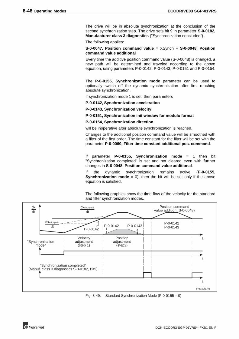
8-48 Operating Modes ECODRIVE03 SGP-01VRS
DOK-ECODR3-SGP-01VRS**-FKB1-EN-P
The drive will be in absolute synchronization at the conclusion of thesecond synchronization step. The drive sets bit 9 in parameter S-0-0182,Manufacturer class 3 diagnostics ("Synchronization concluded“).
The following applies:
S-0-0047, Position command value = XSynch + S-0-0048, Positioncommand value additional
Every time the additive position command value (S-0-0048) is changed, anew path will be determined and traveled according to the aboveequation, using parameters P-0-0142, P-0-0143, P-0-0151 and P-0-0154.
The P-0-0155, Synchronization mode parameter can be used tooptionally switch off the dynamic synchronization after first reachingabsolute synchronization.
If synchronization mode 1 is set, then parameters
P-0-0142, Synchronization acceleration
P-0-0143, Synchronization velocity
P-0-0151, Synchronization init window for modulo format
P-0-0154, Synchronization direction
will be inoperative after absolute synchronization is reached.
Changes to the additional position command value will be smoothed witha filter of the first order. The time constant for the filter will be set with theparameter P-0-0060, Filter time constant additional pos. command.
If parameter P-0-0155, Synchronization mode = 1 then bit"Synchronization completed" is set and not cleared even with furtherchanges in S-0-0048, Position command value additional.
If the dynamic synchronization remains active (P-0-0155,Synchronization mode = 0), then the bit will be set only if the aboveequation is satisfied.
The following graphics show the time flow of the velocity for the standardand filter synchronization modes.
P-0-0143
"Synchronisationmode"
t
t
t
Sv5029f1.fh5
P-0-0142
dxsoll, synch
dtdxdt
dxsoll, synch
dtP-0-0142P-0-0143
Position commandvalue addition (S-0-0048)
P-0-0142
Velocityadjustment
(step 1)
Positionadjustment
(step2)
"Synchronization completed"(Manuf. class 3 diagnostics S-0-0182, Bit9)
Fig. 8-49: Standard Synchronization Mode (P-0-0155 = 0)
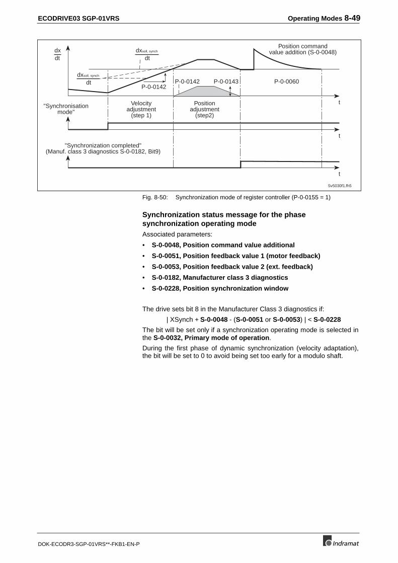
ECODRIVE03 SGP-01VRS Operating Modes 8-49
DOK-ECODR3-SGP-01VRS**-FKB1-EN-P
P-0-0143
t
t
t
Sv5030f1.fh5
P-0-0142
dxsoll, synch
dtdxdt
dxsoll, synch
dtP-0-0142
P-0-0060
"Synchronisationmode"
Position commandvalue addition (S-0-0048)
Velocityadjustment
(step 1)
Positionadjustment
(step2)
"Synchronization completed"(Manuf. class 3 diagnostics S-0-0182, Bit9)
Fig. 8-50: Synchronization mode of register controller (P-0-0155 = 1)
Synchronization status message for the phasesynchronization operating modeAssociated parameters:
• S-0-0048, Position command value additional
• S-0-0051, Position feedback value 1 (motor feedback)
• S-0-0053, Position feedback value 2 (ext. feedback)
• S-0-0182, Manufacturer class 3 diagnostics
• S-0-0228, Position synchronization window
The drive sets bit 8 in the Manufacturer Class 3 diagnostics if:
| XSynch + S-0-0048 - (S-0-0051 or S-0-0053) | < S-0-0228
The bit will be set only if a synchronization operating mode is selected inthe S-0-0032, Primary mode of operation.
During the first phase of dynamic synchronization (velocity adaptation),the bit will be set to 0 to avoid being set too early for a modulo shaft.
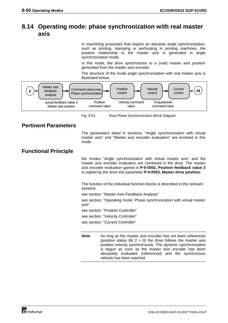
8-50 Operating Modes ECODRIVE03 SGP-01VRS
DOK-ECODR3-SGP-01VRS**-FKB1-EN-P
8.14 Operating mode: phase synchronization with real masteraxis
In machining processes that require an absolute angle synchronization,such as printing, stamping or perforating in printing machines, theposition relationship to the master axis is generated in anglesynchronization mode.
In this mode, the drive synchronizes to a (real) master axis positiongenerated from the master axis encoder.
The structure of the mode angle synchronization with real master axis isillustrated below:
Master axisfeedbackanalysis
Velocitycontrol
Positioncommand value
actual feedback value 3Master axis position
Velocity commandvalue
Torque/powercommand value
Currentcontrol
Positioncontrol
Command value prep.Phase synchronization
MF
Fig. 8-51: Real Phase Synchronization Block Diagram
Pertinent ParametersThe parameters listed in sections: "Angle synchronization with virtualmaster axis" and "Master axis encoder evaluation" are involved in thismode.
Functional Principlethe modes "Angle synchronization with virtual master axis“ and themaster axis encoder evaluation are combined in the drive. The masteraxis encoder evaluation gained in P-0-0052, Position feedback value 3is copied by the drive into parameter P-0-0053, Master drive position.
The function of the individual function blocks is described in the relevantsections.
see section: "Master Axis Feedback Analysis"
see section: "Operating mode: Phase synchronization with virtual masteraxis"
see section: "Position Controller"
see section: "Velocity Controller"
see section: "Current Controller"
Note: As long as the master axis encoder has not been referenced(position status Bit 2 = 0) the drive follows the master axisposition velocity synchronously. The dynamic synchronizationis begun as soon as the master axis encoder has beenabsolutely evaluated (referenced) and the synchronousvelocity has been reached.
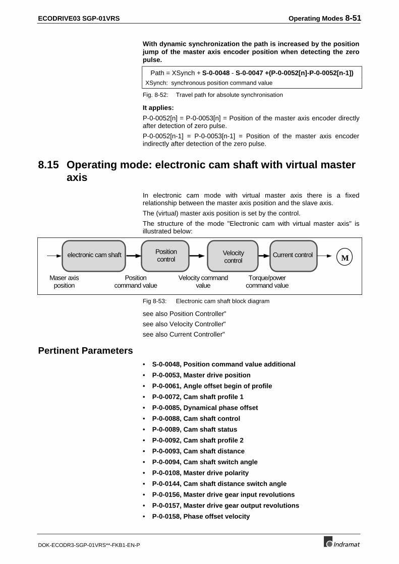
ECODRIVE03 SGP-01VRS Operating Modes 8-51
DOK-ECODR3-SGP-01VRS**-FKB1-EN-P
With dynamic synchronization the path is increased by the positionjump of the master axis encoder position when detecting the zeropulse.
Path = XSynch + S-0-0048 - S-0-0047 +(P-0-0052[n]-P-0-0052[n-1])XSynch: synchronous position command value
Fig. 8-52: Travel path for absolute synchronisation
It applies:
P-0-0052[n] = P-0-0053[n] = Position of the master axis encoder directlyafter detection of zero pulse.
P-0-0052[n-1] = P-0-0053[n-1] = Position of the master axis encoderindirectly after detection of the zero pulse.
8.15 Operating mode: electronic cam shaft with virtual masteraxis
In electronic cam mode with virtual master axis there is a fixedrelationship between the master axis position and the slave axis.
The (virtual) master axis position is set by the control.
The structure of the mode "Electronic cam with virtual master axis" isillustrated below:
Velocitycontrol
Positioncommand value
Maser axisposition
Velocity commandvalue
Torque/powercommand value
Current controlPositioncontrol
electronic cam shaft M
Fig 8-53: Electronic cam shaft block diagram
see also Position Controller"
see also Velocity Controller"
see also Current Controller"
Pertinent Parameters• S-0-0048, Position command value additional
• P-0-0053, Master drive position
• P-0-0061, Angle offset begin of profile
• P-0-0072, Cam shaft profile 1
• P-0-0085, Dynamical phase offset
• P-0-0088, Cam shaft control
• P-0-0089, Cam shaft status
• P-0-0092, Cam shaft profile 2
• P-0-0093, Cam shaft distance
• P-0-0094, Cam shaft switch angle
• P-0-0108, Master drive polarity
• P-0-0144, Cam shaft distance switch angle
• P-0-0156, Master drive gear input revolutions
• P-0-0157, Master drive gear output revolutions
• P-0-0158, Phase offset velocity
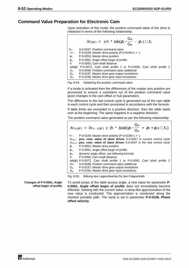
8-52 Operating Modes ECODRIVE03 SGP-01VRS
DOK-ECODR3-SGP-01VRS**-FKB1-EN-P
Command Value Preparation for Electronic CamUpon activation of this mode, the position command value of the drive isinitialized in terms of the following relationship.
X = h * tab(GG
- F( )a
eϕ ϕ ϕL L V vX± +* )
XF : S-0-0047, Position command value+/- : P-0-0108, Master drive polarity (P-0-0108=1 > -)ϕL : P-0-0053, Master drive positionϕV : P-0-0061, Angle offset begin of profileh: P-0-0093, Cam shaft distancetab(ϕ): P-0-0072, Cam shaft profile 1 or P-0-0092, Cam shaft profile 2Xv: S-0-0048, Position command value additionalGa: P-0-0157, Master drive gear output revolutionsGe: P-0-0156, Master drive gear input revolutions
Fig. 8-54: Initializing the position command value
If a mode is activated then the differences of the master axis position areprocessed to ensure a consistent run of the position command valuegiven changes in the cam offset or hub parameters.
The difference to the last control cycle is generated out of the cam tablein each control cycle and then processed in accordance with the formula.
If table limits are exceeded in a positive direction, then the table startsover at the beginning. The same happens in a negative direction.
The position command value generated as per the following relationship:
X = X (h * tab(GG
+ + )F ( ) F ( )a
e(n) (n - 1)ϕ ϕ ϕ ϕ ϕL L L V d vX± +∆ * )
+/- : P-0-0108, Master drive polarity (P-0-0108=1 > -)XF(n) : pos. com. value of slave drives S-0-0047 in current control cycleXF(n-1) : pos. com. value of slave drives S-0-0047 in the last control cycleϕL : P-0-0053, Master drive positionϕV : P-0-0061, Angle offset begin of profileϕd : dynamic angle offset, see following formulah: P-0-0093, Cam shaft distancetab(ϕ): P-0-0072, Cam shaft profile 1 or P-0-0092, Cam shaft profile 2Xv: S-0-0048, Position command value additionalGa: P-0-0157, Master drive gear output revolutionsGe: P-0-0156, Master drive gear input revolutions
Fig. 8-55: Bildung des Lagesollwertes für den Folgeantrieb
To avoid jumps of the table access angle, a new value for parameter P-0-0061, Angle offset begin of profile does not immediately becomeeffective. Starting with the current value, a ramp-like approximation of thenew value is conducted. The approximation is conducted along theshortest possible path. The ramp is set in parameter P-0-0158, Phaseoffset velocity.
Changes of P-0-0061, Angleoffset begin of profile
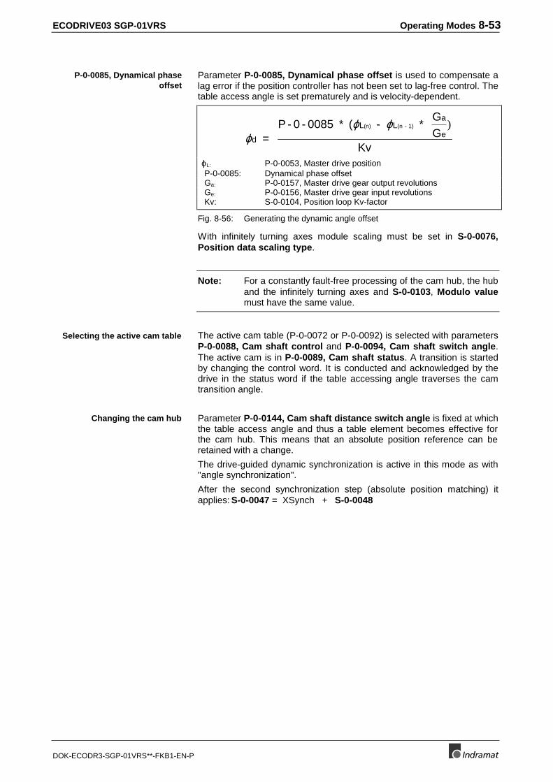
ECODRIVE03 SGP-01VRS Operating Modes 8-53
DOK-ECODR3-SGP-01VRS**-FKB1-EN-P
Parameter P-0-0085, Dynamical phase offset is used to compensate alag error if the position controller has not been set to lag-free control. Thetable access angle is set prematurely and is velocity-dependent.
ϕϕ ϕ
d
L La
e = P - 0 - 0085 * ( - *
GG
Kv
(n) (n - 1) )
ϕL: P-0-0053, Master drive positionP-0-0085: Dynamical phase offsetGa: P-0-0157, Master drive gear output revolutionsGe: P-0-0156, Master drive gear input revolutionsKv: S-0-0104, Position loop Kv-factor
Fig. 8-56: Generating the dynamic angle offset
With infinitely turning axes module scaling must be set in S-0-0076,Position data scaling type.
Note: For a constantly fault-free processing of the cam hub, the huband the infinitely turning axes and S-0-0103, Modulo valuemust have the same value.
The active cam table (P-0-0072 or P-0-0092) is selected with parametersP-0-0088, Cam shaft control and P-0-0094, Cam shaft switch angle.The active cam is in P-0-0089, Cam shaft status. A transition is startedby changing the control word. It is conducted and acknowledged by thedrive in the status word if the table accessing angle traverses the camtransition angle.
Parameter P-0-0144, Cam shaft distance switch angle is fixed at whichthe table access angle and thus a table element becomes effective forthe cam hub. This means that an absolute position reference can beretained with a change.
The drive-guided dynamic synchronization is active in this mode as with"angle synchronization".
After the second synchronization step (absolute position matching) itapplies: S-0-0047 = XSynch + S-0-0048
P-0-0085, Dynamical phaseoffset
Selecting the active cam table
Changing the cam hub
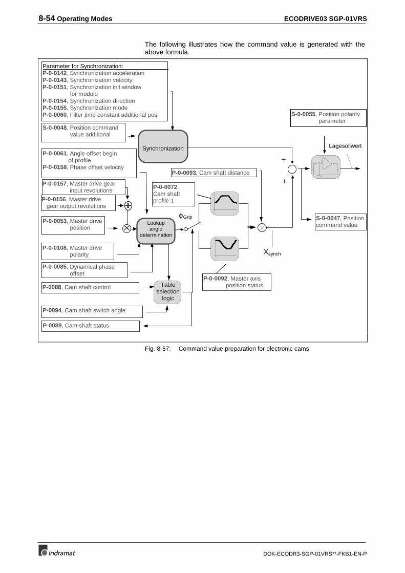
8-54 Operating Modes ECODRIVE03 SGP-01VRS
DOK-ECODR3-SGP-01VRS**-FKB1-EN-P
The following illustrates how the command value is generated with theabove formula.
P-0-0085, Dynamical phase offset
P-0-0108, Master drive polarity
P-0-0053, Master drive position
P-0-0061, Angle offset begin of profileP-0-0158, Phase offset velocity
P-0-0093, Cam shaft distance
P-0-0092, Master axis position status
P-0-0072,Cam shaftprofile 1
Xsynch
Lookupangle
determination
P-0088, Cam shaft control
P-0094, Cam shaft switch angle
P-0089, Cam shaft status
Tableselection
logic
ϕGrip
Parameter for Synchronization:P-0-0142, Synchronization accelerationP-0-0143, Synchronization velocityP-0-0151, Synchronization init window for moduloP-0-0154, Synchronization directionP-0-0155, Synchronization modeP-0-0060, Filter time constant additional pos.
S-0-0048, Position command value additional
Synchronization
S-0-0047, Positioncommand value
Lagesollwert
S-0-0055, Position polarity parameter
P-0-0156, Master drive gear output revolutions
P-0-0157, Master drive gear input revolutions
Fig. 8-57: Command value preparation for electronic cams
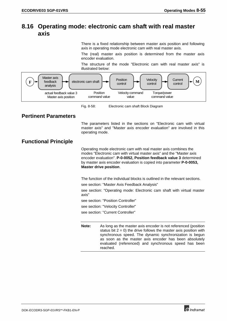
ECODRIVE03 SGP-01VRS Operating Modes 8-55
DOK-ECODR3-SGP-01VRS**-FKB1-EN-P
8.16 Operating mode: electronic cam shaft with real masteraxis
There is a fixed relationship between master axis position and followingaxis in operating mode electronic cam with real master axis.
The (real) master axis position is determined from the master axisencoder evaluation.
The structure of the mode "Electronic cam with real master axis" isillustrated below:
Master axisfeedbackanalysis
Velocitycontrol
Positioncommand value
actual feedback value 3Master axis position
Velocity commandvalue
Torque/powercommand value
Currentcontrol
Positioncontrol
electronic cam shaft MF
Fig. 8-58: Electronic cam shaft Block Diagram
Pertinent ParametersThe parameters listed in the sections on "Electronic cam with virtualmaster axis" and "Master axis encoder evaluation" are involved in thisoperating mode.
Functional PrincipleOperating mode electronic cam with real master axis combines themodes "Electronic cam with virtual master axis" and the "Master axisencoder evaluation". P-0-0052, Position feedback value 3 determinedby master axis encoder evaluation is copied into parameter P-0-0053,Master drive position.
The function of the individual blocks is outlined in the relevant sections.
see section: "Master Axis Feedback Analysis"
see section: "Operating mode: Electronic cam shaft with virtual masteraxis"
see section: "Position Controller"
see section: "Velocity Controller"
see section: "Current Controller"
Note: As long as the master axis encoder is not referenced (positionstatus bit 2 = 0) the drive follows the master axis position withsynchronous speed. The dynamic synchronization is begunas soon as the master axis encoder has been absolutelyevaluated (referenced) and synchronous speed has beenreached.
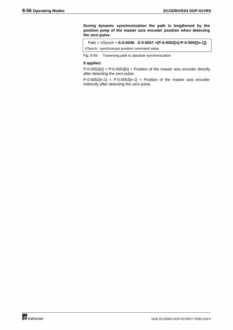
8-56 Operating Modes ECODRIVE03 SGP-01VRS
DOK-ECODR3-SGP-01VRS**-FKB1-EN-P
During dynamic synchronization the path is lengthened by theposition jump of the master axis encoder position when detectingthe zero pulse.
Path = XSynch + S-0-0048 - S-0-0047 +(P-0-0052[n]-P-0-0052[n-1])XSynch: synchronous position command value
Fig. 8-59: Traversing path to absolute synchronization
It applies:
P-0-0052[n] = P-0-0053[n] = Position of the master axis encoder directlyafter detecting the zero pulse.
P-0-0052[n-1] = P-0-0053[n-1] = Position of the master axis encoderindirectly after detecting the zero pulse.
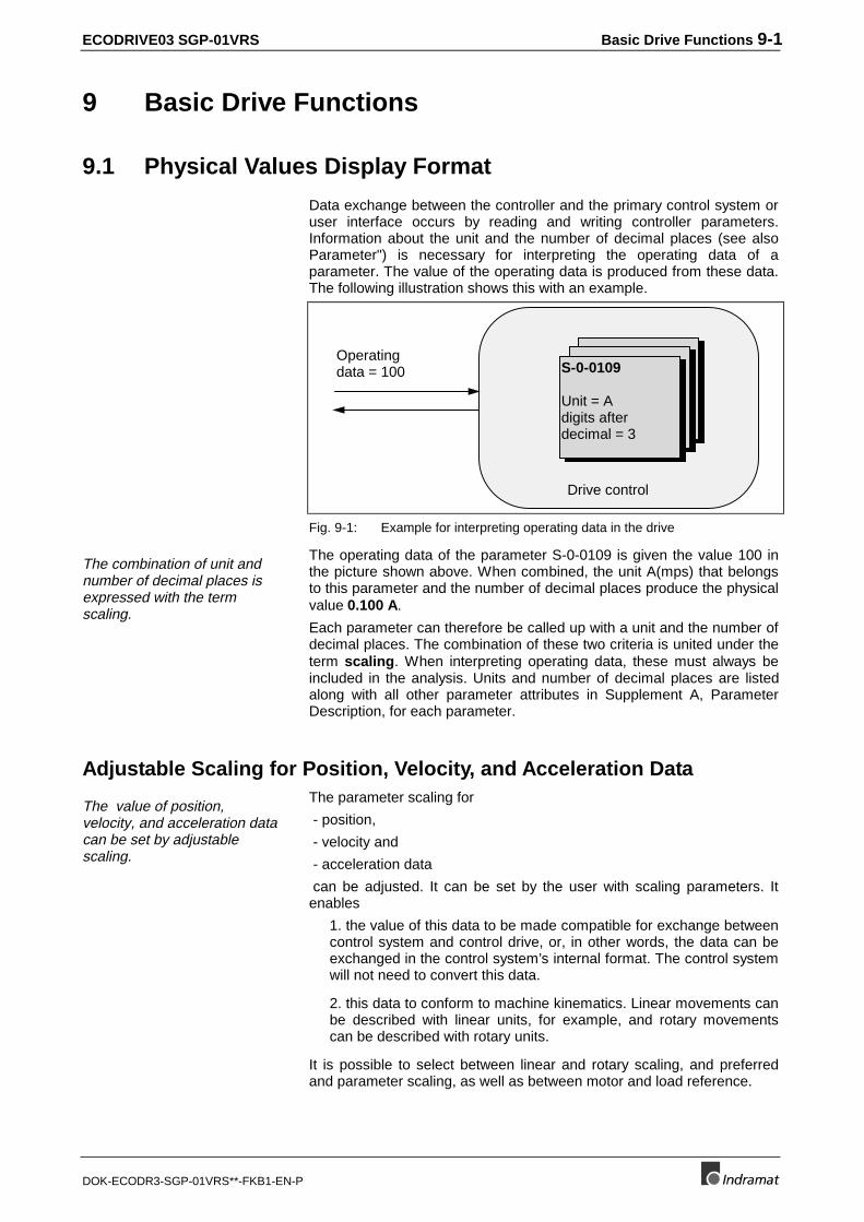
ECODRIVE03 SGP-01VRS Basic Drive Functions 9-1
DOK-ECODR3-SGP-01VRS**-FKB1-EN-P
9 Basic Drive Functions
9.1 Physical Values Display Format
Data exchange between the controller and the primary control system oruser interface occurs by reading and writing controller parameters.Information about the unit and the number of decimal places (see alsoParameter") is necessary for interpreting the operating data of aparameter. The value of the operating data is produced from these data.The following illustration shows this with an example.
Operatingdata = 100 S-0-0109
Unit = Adigits afterdecimal = 3
Drive control
Fig. 9-1: Example for interpreting operating data in the drive
The combination of unit andnumber of decimal places isexpressed with the termscaling.
The operating data of the parameter S-0-0109 is given the value 100 inthe picture shown above. When combined, the unit A(mps) that belongsto this parameter and the number of decimal places produce the physicalvalue 0.100 A.
Each parameter can therefore be called up with a unit and the number ofdecimal places. The combination of these two criteria is united under theterm scaling. When interpreting operating data, these must always beincluded in the analysis. Units and number of decimal places are listedalong with all other parameter attributes in Supplement A, ParameterDescription, for each parameter.
Adjustable Scaling for Position, Velocity, and Acceleration Data
The value of position,velocity, and acceleration datacan be set by adjustablescaling.
The parameter scaling for
- position,
- velocity and
- acceleration data
can be adjusted. It can be set by the user with scaling parameters. Itenables
1. the value of this data to be made compatible for exchange betweencontrol system and control drive, or, in other words, the data can beexchanged in the control system’s internal format. The control systemwill not need to convert this data.
2. this data to conform to machine kinematics. Linear movements canbe described with linear units, for example, and rotary movementscan be described with rotary units.
It is possible to select between linear and rotary scaling, and preferredand parameter scaling, as well as between motor and load reference.
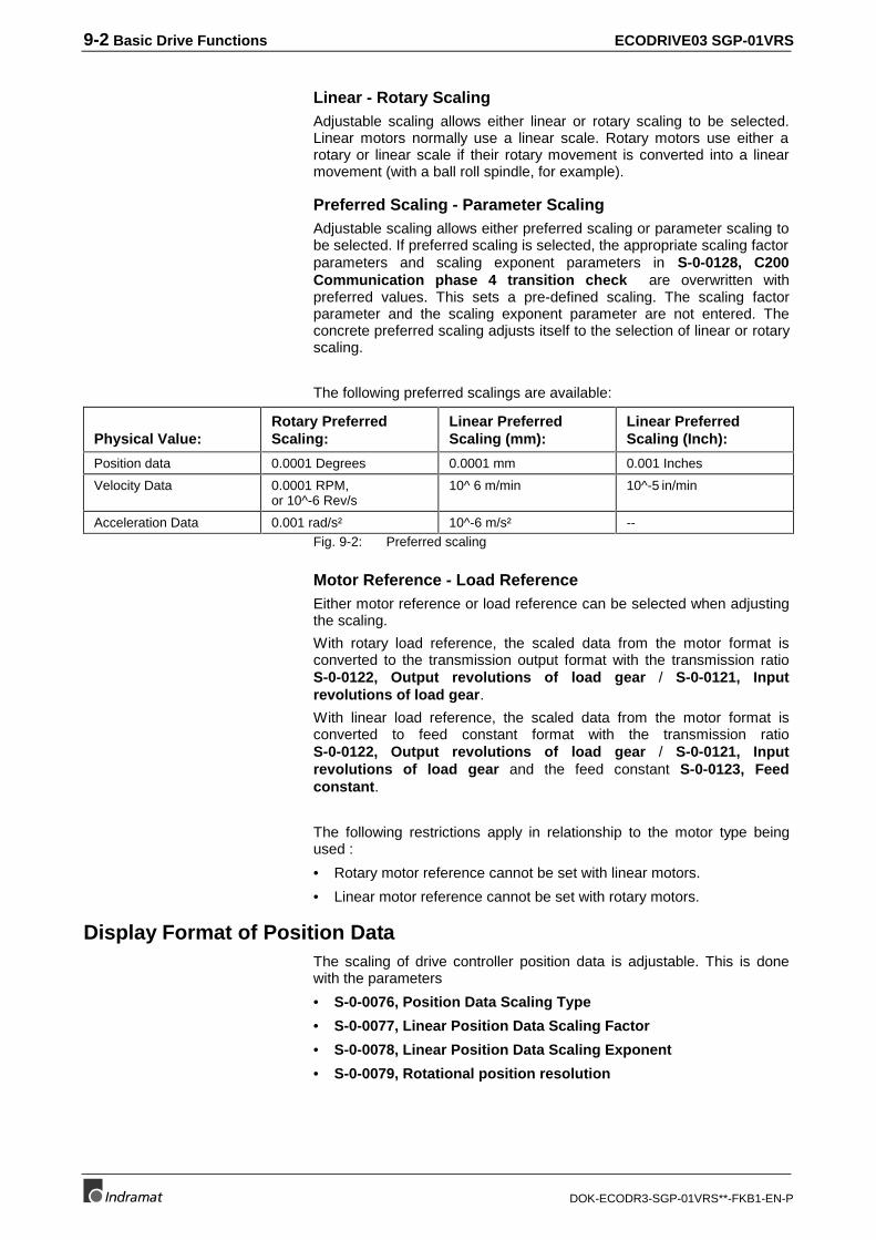
9-2 Basic Drive Functions ECODRIVE03 SGP-01VRS
DOK-ECODR3-SGP-01VRS**-FKB1-EN-P
Linear - Rotary ScalingAdjustable scaling allows either linear or rotary scaling to be selected.Linear motors normally use a linear scale. Rotary motors use either arotary or linear scale if their rotary movement is converted into a linearmovement (with a ball roll spindle, for example).
Preferred Scaling - Parameter ScalingAdjustable scaling allows either preferred scaling or parameter scaling tobe selected. If preferred scaling is selected, the appropriate scaling factorparameters and scaling exponent parameters in S-0-0128, C200Communication phase 4 transition check are overwritten withpreferred values. This sets a pre-defined scaling. The scaling factorparameter and the scaling exponent parameter are not entered. Theconcrete preferred scaling adjusts itself to the selection of linear or rotaryscaling.
The following preferred scalings are available:
Physical Value:Rotary PreferredScaling:
Linear PreferredScaling (mm):
Linear PreferredScaling (Inch):
Position data 0.0001 Degrees 0.0001 mm 0.001 Inches
Velocity Data 0.0001 RPM,or 10^-6 Rev/s
10^ 6 m/min 10^-5 in/min
Acceleration Data 0.001 rad/s² 10^-6 m/s² --Fig. 9-2: Preferred scaling
Motor Reference - Load ReferenceEither motor reference or load reference can be selected when adjustingthe scaling.
With rotary load reference, the scaled data from the motor format isconverted to the transmission output format with the transmission ratioS-0-0122, Output revolutions of load gear / S-0-0121, Inputrevolutions of load gear.
With linear load reference, the scaled data from the motor format isconverted to feed constant format with the transmission ratioS-0-0122, Output revolutions of load gear / S-0-0121, Inputrevolutions of load gear and the feed constant S-0-0123, Feedconstant.
The following restrictions apply in relationship to the motor type beingused :
• Rotary motor reference cannot be set with linear motors.
• Linear motor reference cannot be set with rotary motors.
Display Format of Position DataThe scaling of drive controller position data is adjustable. This is donewith the parameters
• S-0-0076, Position Data Scaling Type
• S-0-0077, Linear Position Data Scaling Factor
• S-0-0078, Linear Position Data Scaling Exponent
• S-0-0079, Rotational position resolution
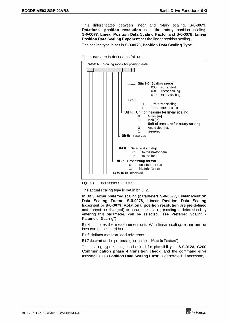
ECODRIVE03 SGP-01VRS Basic Drive Functions 9-3
DOK-ECODR3-SGP-01VRS**-FKB1-EN-P
This differentiates between linear and rotary scaling. S-0-0079,Rotational position resolution sets the rotary position scaling.S-0-0077, Linear Position Data Scaling Factor and S-0-0078, LinearPosition Data Scaling Exponent set the linear position scaling.
The scaling type is set in S-0-0076, Position Data Scaling Type.
The parameter is defined as follows:
S-0-0076, Scaling mode for position data
Bit 4: Unit of measure for linear scaling 0: Meter [m] 1: Inch [in]
Unit of measure for rotary scaling 0: Angle degrees 1: reserved
Bit 5: reserved
Bit 7: Processing format 0: Absolute format 1: Modulo format
Bit 6: Data relationship 0: to the motor cam 1: to the load
Bit 3: 0: Preferred scaling 1: Parameter scaling
Bits 2-0: Scaling mode 000: not scaled 001: linear scaling 010: rotary scaling
Bits 15-8: reserved
Fig. 9-3: Parameter S-0-0076
The actual scaling type is set in bit 0..2.
In Bit 3, either preferred scaling (parameters S-0-0077, Linear PositionData Scaling Factor, S-0-0078, Linear Position Data ScalingExponent or S-0-0079, Rotational position resolution are pre-definedand cannot be changed) or parameter scaling (scaling is determined byentering this parameter) can be selected. (see Preferred Scaling -Parameter Scaling")
Bit 4 indicates the measurement unit. With linear scaling, either mm orinch can be selected here.
Bit 6 defines motor or load reference.
Bit 7 determines the processing format (see Modulo Feature")
The scaling type setting is checked for plausibility in S-0-0128, C200Communication phase 4 transition check, and the command errormessage C213 Position Data Scaling Error is generated, if necessary.
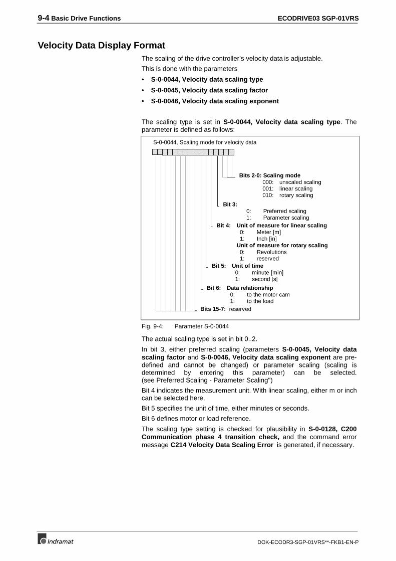
9-4 Basic Drive Functions ECODRIVE03 SGP-01VRS
DOK-ECODR3-SGP-01VRS**-FKB1-EN-P
Velocity Data Display FormatThe scaling of the drive controller’s velocity data is adjustable.
This is done with the parameters
• S-0-0044, Velocity data scaling type
• S-0-0045, Velocity data scaling factor
• S-0-0046, Velocity data scaling exponent
The scaling type is set in S-0-0044, Velocity data scaling type. Theparameter is defined as follows:
S-0-0044, Scaling mode for velocity data
Bit 4: Unit of measure for linear scaling 0: Meter [m] 1: Inch [in]Unit of measure for rotary scaling 0: Revolutions 1: reserved
Bit 5: Unit of time 0: minute [min] 1: second [s]
Bits 15-7: reserved
Bit 6: Data relationship 0: to the motor cam 1: to the load
Bit 3: 0: Preferred scaling 1: Parameter scaling
Bits 2-0: Scaling mode 000: unscaled scaling 001: linear scaling 010: rotary scaling
Fig. 9-4: Parameter S-0-0044
The actual scaling type is set in bit 0..2.
In bit 3, either preferred scaling (parameters S-0-0045, Velocity datascaling factor and S-0-0046, Velocity data scaling exponent are pre-defined and cannot be changed) or parameter scaling (scaling isdetermined by entering this parameter) can be selected.(see Preferred Scaling - Parameter Scaling")
Bit 4 indicates the measurement unit. With linear scaling, either m or inchcan be selected here.
Bit 5 specifies the unit of time, either minutes or seconds.
Bit 6 defines motor or load reference.
The scaling type setting is checked for plausibility in S-0-0128, C200Communication phase 4 transition check, and the command errormessage C214 Velocity Data Scaling Error is generated, if necessary.
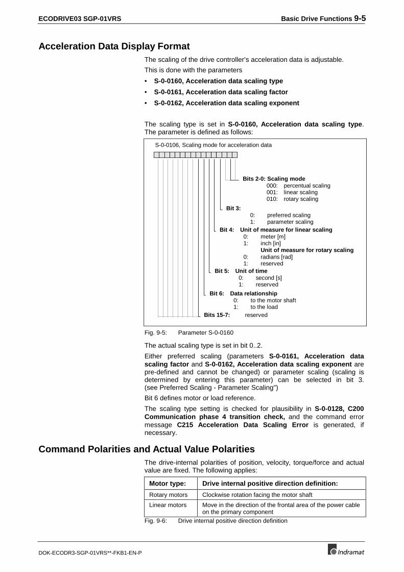
ECODRIVE03 SGP-01VRS Basic Drive Functions 9-5
DOK-ECODR3-SGP-01VRS**-FKB1-EN-P
Acceleration Data Display FormatThe scaling of the drive controller’s acceleration data is adjustable.
This is done with the parameters
• S-0-0160, Acceleration data scaling type
• S-0-0161, Acceleration data scaling factor
• S-0-0162, Acceleration data scaling exponent
The scaling type is set in S-0-0160, Acceleration data scaling type.The parameter is defined as follows:
S-0-0106, Scaling mode for acceleration data
Bit 4: Unit of measure for linear scaling 0: meter [m] 1: inch [in]
Unit of measure for rotary scaling 0: radians [rad] 1: reserved
Bit 5: Unit of time 0: second [s] 1: reserved
Bits 15-7: reserved
Bit 6: Data relationship 0: to the motor shaft 1: to the load
Bit 3: 0: preferred scaling 1: parameter scaling
Bits 2-0: Scaling mode 000: percentual scaling 001: linear scaling 010: rotary scaling
Fig. 9-5: Parameter S-0-0160
The actual scaling type is set in bit 0..2.
Either preferred scaling (parameters S-0-0161, Acceleration datascaling factor and S-0-0162, Acceleration data scaling exponent arepre-defined and cannot be changed) or parameter scaling (scaling isdetermined by entering this parameter) can be selected in bit 3.(see Preferred Scaling - Parameter Scaling")
Bit 6 defines motor or load reference.
The scaling type setting is checked for plausibility in S-0-0128, C200Communication phase 4 transition check, and the command errormessage C215 Acceleration Data Scaling Error is generated, ifnecessary.
Command Polarities and Actual Value PolaritiesThe drive-internal polarities of position, velocity, torque/force and actualvalue are fixed. The following applies:
Motor type: Drive internal positive direction definition:
Rotary motors Clockwise rotation facing the motor shaft
Linear motors Move in the direction of the frontal area of the power cableon the primary component
Fig. 9-6: Drive internal positive direction definition
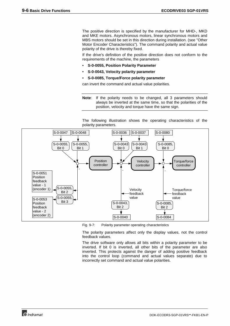
9-6 Basic Drive Functions ECODRIVE03 SGP-01VRS
DOK-ECODR3-SGP-01VRS**-FKB1-EN-P
The positive direction is specified by the manufacturer for MHD-, MKDand MKE motors. Asynchronous motors, linear synchronous motors andMBS motors should be set in this direction during installation. (see "OtherMotor Encoder Characteristics"). The command polarity and actual valuepolarity of the drive is thereby fixed.
If the drive’s definition of the positive direction does not conform to therequirements of the machine, the parameters
• S-0-0055, Position Polarity Parameter
• S-0-0043, Velocity polarity parameter
• S-0-0085, Torque/Force polarity parameter
can invert the command and actual value polarities.
Note: If the polarity needs to be changed, all 3 parameters shouldalways be inverted at the same time, so that the polarities of theposition, velocity and torque have the same sign.
The following illustration shows the operating characteristics of thepolarity parameters.
Positioncontroller
Velocitycontroller
Torque/forcecontroller
S-0-0047 S-0-0048
S-0-0055,Bit 0
S-0-0055,Bit 1
-S-0-0051Positionfeedbackvalue - 1(encoder 1)
S-0-0053Positionfeedbackvalue - 2(encoder 2)
S-0-0055,Bit 2
S-0-0055,Bit 3
S-0-0036
S-0-0043Bit 0
Velocityfeedbackvalue
S-0-0043,Bit 2
S-0-0040
-
S-0-0037
S-0-0043Bit 1
Torque/forcefeedbackvalue
S-0-0085,Bit 2
S-0-0084
S-0-0085,Bit 0
S-0-0080
-
Fig. 9-7: Polarity parameter operating characteristics
The polarity parameters affect only the display values, not the controlfeedback values.
The drive software only allows all bits within a polarity parameter to beinverted. If bit 0 is inverted, all other bits of the parameter are alsoinverted. This protects against the danger of adding positive feedbackinto the control loop (command and actual values separate) due toincorrectly set command and actual value polarities.
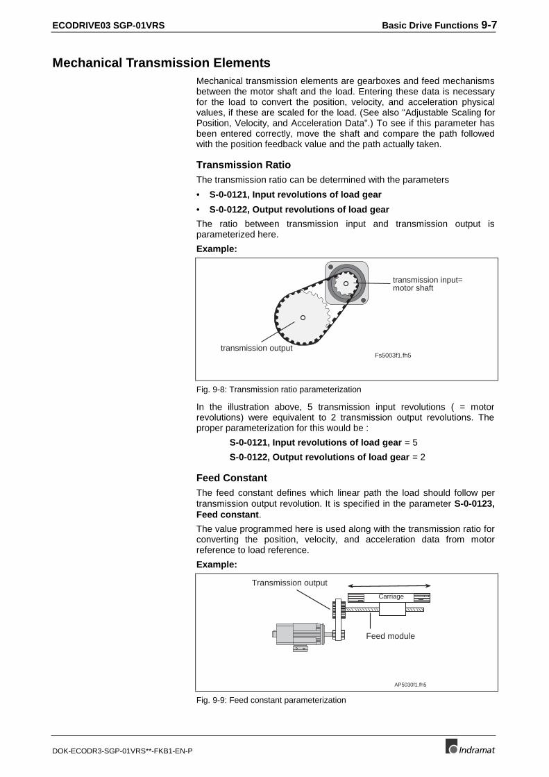
ECODRIVE03 SGP-01VRS Basic Drive Functions 9-7
DOK-ECODR3-SGP-01VRS**-FKB1-EN-P
Mechanical Transmission ElementsMechanical transmission elements are gearboxes and feed mechanismsbetween the motor shaft and the load. Entering these data is necessaryfor the load to convert the position, velocity, and acceleration physicalvalues, if these are scaled for the load. (See also "Adjustable Scaling forPosition, Velocity, and Acceleration Data".) To see if this parameter hasbeen entered correctly, move the shaft and compare the path followedwith the position feedback value and the path actually taken.
Transmission RatioThe transmission ratio can be determined with the parameters
• S-0-0121, Input revolutions of load gear
• S-0-0122, Output revolutions of load gear
The ratio between transmission input and transmission output isparameterized here.
Example:
Fs5003f1.fh5
transmission input=motor shaft
transmission output
Fig. 9-8: Transmission ratio parameterization
In the illustration above, 5 transmission input revolutions ( = motorrevolutions) were equivalent to 2 transmission output revolutions. Theproper parameterization for this would be :
S-0-0121, Input revolutions of load gear = 5
S-0-0122, Output revolutions of load gear = 2
Feed ConstantThe feed constant defines which linear path the load should follow pertransmission output revolution. It is specified in the parameter S-0-0123,Feed constant.
The value programmed here is used along with the transmission ratio forconverting the position, velocity, and acceleration data from motorreference to load reference.
Example:
AP5030f1.fh5
Transmission output
Feed module
Carriage
Fig. 9-9: Feed constant parameterization
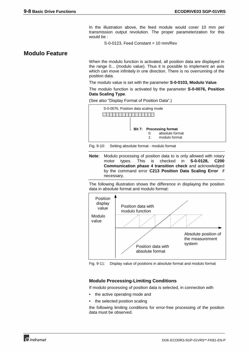
9-8 Basic Drive Functions ECODRIVE03 SGP-01VRS
DOK-ECODR3-SGP-01VRS**-FKB1-EN-P
In the illustration above, the feed module would cover 10 mm pertransmission output revolution. The proper parameterization for thiswould be :
S-0-0123, Feed Constant = 10 mm/Rev
Modulo FeatureWhen the modulo function is activated, all position data are displayed inthe range 0... (modulo value). Thus it is possible to implement an axiswhich can move infinitely in one direction. There is no overrunning of theposition data.
The modulo value is set with the parameter S-0-0103, Modulo Value.
The modulo function is activated by the parameter S-0-0076, PositionData Scaling Type.
(See also "Display Format of Position Data".)
S-0-0076, Position data scaling mode
Bit 7: Processing format 0: absolute format 1: modulo format
Fig. 9-10: Setting absolute format - modulo format
Note: Modulo processing of position data to is only allowed with rotarymotor types. This is checked in S-0-0128, C200Communication phase 4 transition check and acknowledgedby the command error C213 Position Data Scaling Error ifnecessary.
The following illustration shows the difference in displaying the positiondata in absolute format and modulo format:
Positiondisplayvalue
Modulovalue
Position data withmodulo function
Position data withabsolute format
Absolute position ofthe measurementsystem
Fig. 9-11: Display value of positions in absolute format and modulo format
Modulo Processing-Limiting ConditionsIf modulo processing of position data is selected, in connection with
• the active operating mode and
• the selected position scaling
the following limiting conditions for error-free processing of the positiondata must be observed.
ECODRIVE03 SGP-01VRS Basic Drive Functions 9-9
DOK-ECODR3-SGP-01VRS**-FKB1-EN-P
The limiting conditions are as follows:
• The modulo range S-0-0103, Modulo Value may not be greater thanhalf the maximum travel range. The maximum travel range dependson the motor feedback being used (see also "Drive-internal format ofposition data").
• If rotary or linear position scaling with load reference and withoutangle synchronization is used as the operating mode, the product ofS-0-0103, Modulo Value, S-0-0116, Resolution of motor feedbackand S-0-0121, Input revolutions of load gear must be smaller than2^63.
• If rotary position scaling with load reference and angle synchronizationis used as the operating mode, the product ofS-0-0237, Slave drive 1 revs., S-0-0116, Resolution of motorfeedback and S-0-0121, Input revolutions of load gear must besmaller than 2^63.
• If the angle synchronization operating mode is used, linear positionscaling may not be selected.
If, in addition to this, an external measurement system is used, theadditional requirements are:
• If rotary position scaling with motor reference and no anglesynchronization operating mode is used, the product of S-0-0103,Modulo Value, S-0-0117, Feedback 2 Resolution andS-0-0122, Output revolutions of load gear must be smaller than2^63.
• If rotary position scaling with motor reference and anglesynchronization operating mode is used, the product of S-0-0237,Slave drive 1 revs., S-0-0117, Feedback 2 Resolution and S-0-0122, Output revolutions of load gear must be smaller than 2^63.
Compliance with the limiting conditions is checked in S-0-0128, C200Communication phase 4 transition check, and the command isterminated with the error C227 Modulo Range Error if necessary.
Processing Command Values in Modulo Format, ShortestPath - Direction SelectionThe interpretation of position command values such as S-0-0047,Position Command Value and S-0-0258, Target Position when themodulo function has been activated is dependent on the selected mode.
The following possibilities exist:
• Shortest Path
• Positive Direction
• Negative Direction
Parameter S-0-0393, Command value mode is used to set the mode.This parameter is effective only if modulo format has been activated in S-0-0076, Position data scaling type.
9-10 Basic Drive Functions ECODRIVE03 SGP-01VRS
DOK-ECODR3-SGP-01VRS**-FKB1-EN-P
The following settings can be entered:
Modulo Mode "Shortest Path"
The next command value is reached with the shortest path. If thedifference between two successive command values is greater than halfof the modulo value, the drive moves toward the command value in theopposite direction.
Modulo Mode "Positive Direction"
The command value is always approached in a positive direction,regardless of whether or not the difference between two successivecommand values is greater than half of the modulo value.
Modulo Mode "Negative Direction"
The command value is always approached in a negative direction,regardless of whether or not the difference between two successivecommand values is greater than half of the modulo value.
9.2 Setting the Measurement System
The drive controller is equipped with two permanently installed encoderinterfaces, i.e., X4 and X8.
The encoder interface 1 (X4) is designed so that the following encodertypes can be evaluated:
• digital servo feedback (DSF, HSF)
• resolver
• resolver without feedback data memory
Using encoder interface 2 (X8) it is possible to evaluate the followingencoder types:
• incremental encoder with sine signals 1Vss
• incremental encoder with square-wave signals (TTL)
• measuring system with EnDat interface
• gearwheel encoder with 1Vss signals
Both encoder interfaces can be used to connect either a motor or anoptional encoder.
At which interface the motor encoder should be connected and what typeit is is set in parameter P-0-0074, Feedback type 1.
If an optional encoder is also to be used, the paramete P-0-0075,Feedback type 2.
must be used to define encoder interface and encoder type.
S-0-0393 = 0
S-0-0393 = 1
S-0-0393 = 2
Encoder interface 1:
Encoder interface 2:
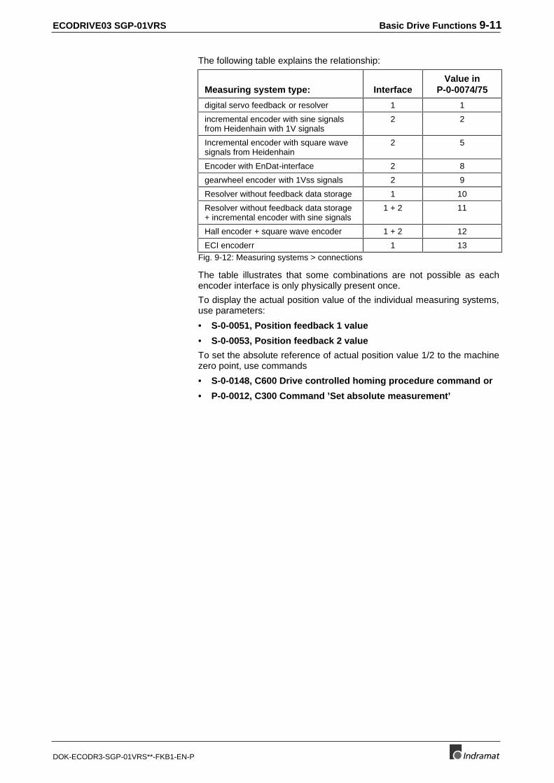
ECODRIVE03 SGP-01VRS Basic Drive Functions 9-11
DOK-ECODR3-SGP-01VRS**-FKB1-EN-P
The following table explains the relationship:
Measuring system type: InterfaceValue in
P-0-0074/75
digital servo feedback or resolver 1 1
incremental encoder with sine signalsfrom Heidenhain with 1V signals
2 2
Incremental encoder with square wavesignals from Heidenhain
2 5
Encoder with EnDat-interface 2 8
gearwheel encoder with 1Vss signals 2 9
Resolver without feedback data storage 1 10
Resolver without feedback data storage+ incremental encoder with sine signals
1 + 2 11
Hall encoder + square wave encoder 1 + 2 12
ECI encoderr 1 13Fig. 9-12: Measuring systems > connections
The table illustrates that some combinations are not possible as eachencoder interface is only physically present once.
To display the actual position value of the individual measuring systems,use parameters:
• S-0-0051, Position feedback 1 value
• S-0-0053, Position feedback 2 value
To set the absolute reference of actual position value 1/2 to the machinezero point, use commands
• S-0-0148, C600 Drive controlled homing procedure command or
• P-0-0012, C300 Command ’Set absolute measurement’
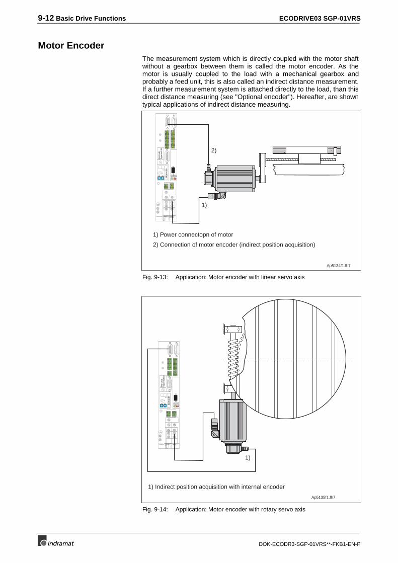
9-12 Basic Drive Functions ECODRIVE03 SGP-01VRS
DOK-ECODR3-SGP-01VRS**-FKB1-EN-P
Motor EncoderThe measurement system which is directly coupled with the motor shaftwithout a gearbox between them is called the motor encoder. As themotor is usually coupled to the load with a mechanical gearbox andprobably a feed unit, this is also called an indirect distance measurement.If a further measurement system is attached directly to the load, than thisdirect distance measuring (see "Optional encoder"). Hereafter, are showntypical applications of indirect distance measuring.
Ap5134f1.fh7
1)
2)
Bar
code
0 1
23
456
78
90 1
23
456
78
9
H1
S1
S3 S2
Bar
code
Type
nsch
ild
12
34
56
78
91
23
4
111213
141516
1718
56
78
12
34
12
34
56
78
H30
H31
H32
H33
1) Power connectopn of motor
2) Connection of motor encoder (indirect position acquisition)
Fig. 9-13: Application: Motor encoder with linear servo axis
Bar
code
0 1
23
456
78
90 1
23
456
78
9
H1
S1
S3 S2
Bar
code
Type
nsch
ild
12
34
56
78
91
23
4
111213
141516
1718
56
78
12
34
12
34
56
78
H30
H31
H32
H33
1)
1) Indirect position acquisition with internal encoder
Ap5135f1.fh7
Fig. 9-14: Application: Motor encoder with rotary servo axis
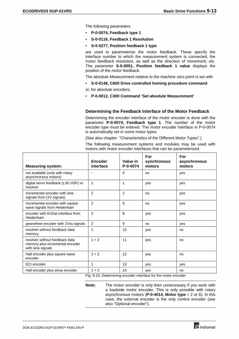
ECODRIVE03 SGP-01VRS Basic Drive Functions 9-13
DOK-ECODR3-SGP-01VRS**-FKB1-EN-P
The following parameters
• P-0-0074, Feedback type 1
• S-0-0116, Feedback 1 Resolution
• S-0-0277, Position feedback 1 type
are used to parameterize the motor feedback. These specify theinterface number to which the measurement system is connected, themotor feedback resolution, as well as the direction of movement, etc.The parameter S-0-0051, Position feedback 1 value displays theposition of the motor feedback.
The absolute Measurement relative to the machine zero point is set with
• S-0-0148, C600 Drive controlled homing procedure command
or, for absolute encoders,
• P-0-0012, C300 Command ’Set absolute Measurement’
Determining the Feedback Interface of the Motor FeedbackDetermining the encoder interface of the motor encoder is done with theparameter P-0-0074, Feedback type 1. The number of the motorencoder type must be entered. The motor encoder interface in P-0-0074is automatically set in some motor types.
(See also chapter: "Characteristics of the Different Motor Types".)
The following measurement systems and modules may be used withmotors with motor encoder interfaces that can be parameterized.
Measuring system:Encoderinterface
Value inP-0-0074
Forsynchronousmotors
Forasynchronousmotors
not available (only with rotaryasynchronous motors)
- 0 no yes
digital servo feedback (LSF,HSF) orresolver
1 1 yes yes
Incremental encoder with sinesignals from (1V signals)
2 2 no yes
Incremental encoder with squarewave signals from Heidenhain
2 5 no yes
encoder with EnDat interface fromHeidenhain
2 8 yes yes
gearwheel encoder with 1Vss signals 2 9 no yes
resolver without feedback datamemory
1 10 yes no
resolver without feedback datamemory plus incremental encoderwith sine signals
1 + 2 11 yes no
Hall encoder plus square waveencoder
1 + 2 12 yes no
ECI encoder 1 13 yes yes
Hall encoder plus sinus encoder 1 + 2 14 yes noFig. 9-15: Determining encoder interface for the motor encoder
Note: The motor encoder is only then unnecessary if you work witha loadside motor encoder. This is only possible with rotaryasynchronous motors (P-0-4014, Motor type = 2 or 6). In thiscase, the external encoder is the only control encoder (seealso "Optional encoder").
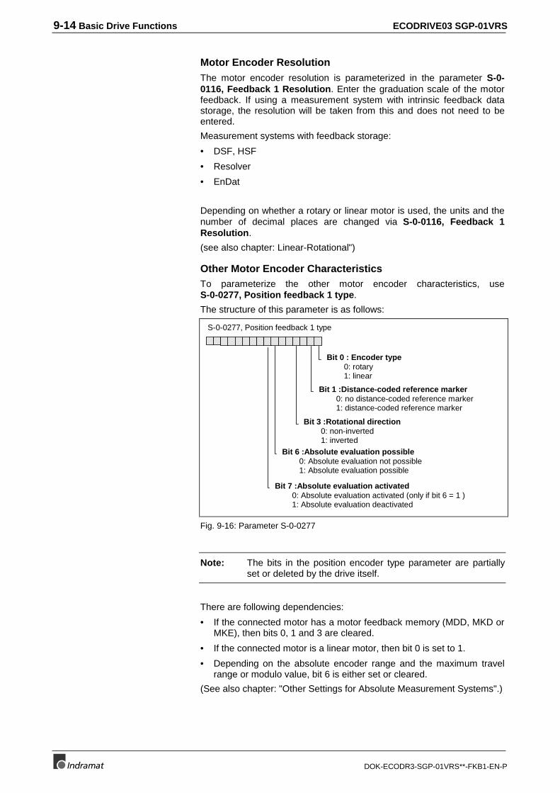
9-14 Basic Drive Functions ECODRIVE03 SGP-01VRS
DOK-ECODR3-SGP-01VRS**-FKB1-EN-P
Motor Encoder ResolutionThe motor encoder resolution is parameterized in the parameter S-0-0116, Feedback 1 Resolution. Enter the graduation scale of the motorfeedback. If using a measurement system with intrinsic feedback datastorage, the resolution will be taken from this and does not need to beentered.
Measurement systems with feedback storage:
• DSF, HSF
• Resolver
• EnDat
Depending on whether a rotary or linear motor is used, the units and thenumber of decimal places are changed via S-0-0116, Feedback 1Resolution.
(see also chapter: Linear-Rotational")
Other Motor Encoder CharacteristicsTo parameterize the other motor encoder characteristics, useS-0-0277, Position feedback 1 type.
The structure of this parameter is as follows:
S-0-0277, Position feedback 1 type
Bit 0 : Encoder type0: rotary1: linear
Bit 1 :Distance-coded reference marker0: no distance-coded reference marker1: distance-coded reference marker
Bit 3 :Rotational direction0: non-inverted1: inverted
Bit 6 :Absolute evaluation possible0: Absolute evaluation not possible1: Absolute evaluation possible
Bit 7 :Absolute evaluation activated0: Absolute evaluation activated (only if bit 6 = 1 )1: Absolute evaluation deactivated
Fig. 9-16: Parameter S-0-0277
Note: The bits in the position encoder type parameter are partiallyset or deleted by the drive itself.
There are following dependencies:
• If the connected motor has a motor feedback memory (MDD, MKD orMKE), then bits 0, 1 and 3 are cleared.
• If the connected motor is a linear motor, then bit 0 is set to 1.
• Depending on the absolute encoder range and the maximum travelrange or modulo value, bit 6 is either set or cleared.
(See also chapter: "Other Settings for Absolute Measurement Systems".)
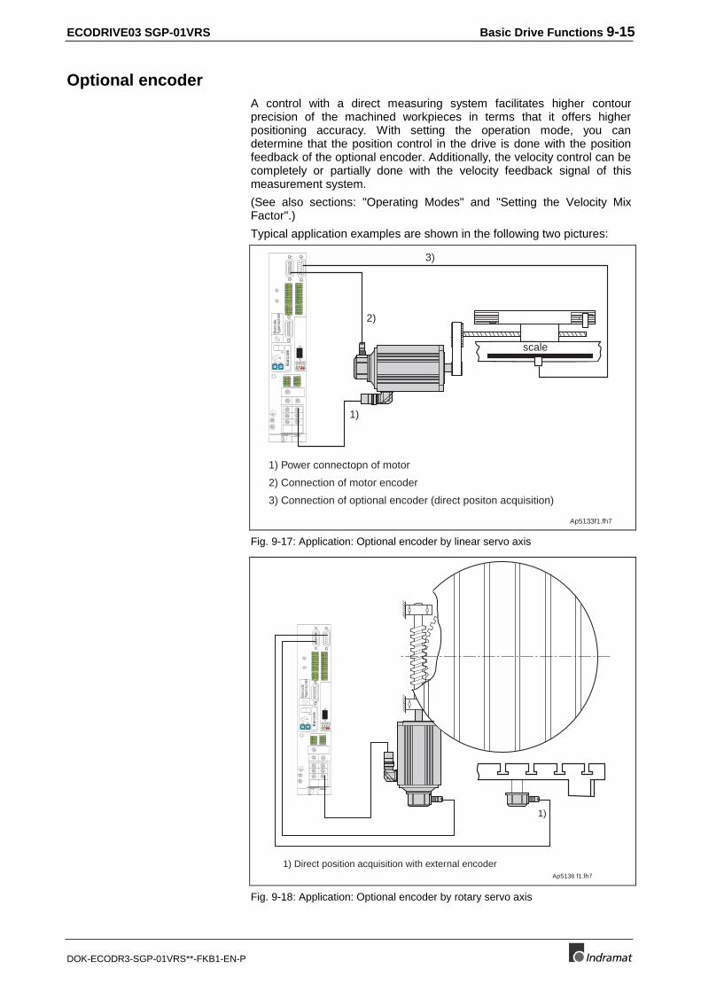
ECODRIVE03 SGP-01VRS Basic Drive Functions 9-15
DOK-ECODR3-SGP-01VRS**-FKB1-EN-P
Optional encoderA control with a direct measuring system facilitates higher contourprecision of the machined workpieces in terms that it offers higherpositioning accuracy. With setting the operation mode, you candetermine that the position control in the drive is done with the positionfeedback of the optional encoder. Additionally, the velocity control can becompletely or partially done with the velocity feedback signal of thismeasurement system.
(See also sections: "Operating Modes" and "Setting the Velocity MixFactor".)
Typical application examples are shown in the following two pictures:
Ap5133f1.fh7
1) Power connectopn of motor
2) Connection of motor encoder
3) Connection of optional encoder (direct positon acquisition)
1)
scale
2)
3)
Bar
code
0 1
23
456
78
90 1
23
456
78
9
H1
S1
S3 S2
Bar
code
Type
nsch
ild
12
34
56
78
91
23
4
111213
141516
1718
56
78
12
34
12
34
56
78
H30
H31
H32
H33
Fig. 9-17: Application: Optional encoder by linear servo axis
1)
1) Direct position acquisition with external encoderAp5136 f1.fh7
Bar
code
0 1
23
456
78
90 1
23
456
78
9
H1
S1
S3 S2
Bar
code
Type
nsch
ild
12
34
56
78
91
23
4
111213
141516
1718
56
78
12
34
12
34
56
78
H30
H31
H32
H33
Fig. 9-18: Application: Optional encoder by rotary servo axis
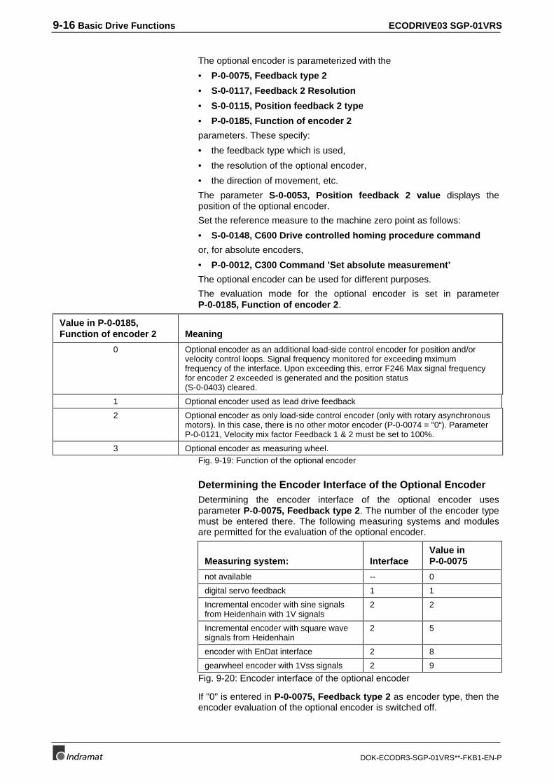
9-16 Basic Drive Functions ECODRIVE03 SGP-01VRS
DOK-ECODR3-SGP-01VRS**-FKB1-EN-P
The optional encoder is parameterized with the
• P-0-0075, Feedback type 2
• S-0-0117, Feedback 2 Resolution
• S-0-0115, Position feedback 2 type
• P-0-0185, Function of encoder 2
parameters. These specify:
• the feedback type which is used,
• the resolution of the optional encoder,
• the direction of movement, etc.
The parameter S-0-0053, Position feedback 2 value displays theposition of the optional encoder.
Set the reference measure to the machine zero point as follows:
• S-0-0148, C600 Drive controlled homing procedure command
or, for absolute encoders,
• P-0-0012, C300 Command ’Set absolute measurement’
The optional encoder can be used for different purposes.
The evaluation mode for the optional encoder is set in parameterP-0-0185, Function of encoder 2.
Value in P-0-0185,Function of encoder 2 Meaning
0 Optional encoder as an additional load-side control encoder for position and/orvelocity control loops. Signal frequency monitored for exceeding mximumfrequency of the interface. Upon exceeding this, error F246 Max signal frequencyfor encoder 2 exceeded is generated and the position status(S-0-0403) cleared.
1 Optional encoder used as lead drive feedback
2 Optional encoder as only load-side control encoder (only with rotary asynchronousmotors). In this case, there is no other motor encoder (P-0-0074 = "0“). ParameterP-0-0121, Velocity mix factor Feedback 1 & 2 must be set to 100%.
3 Optional encoder as measuring wheel.Fig. 9-19: Function of the optional encoder
Determining the Encoder Interface of the Optional EncoderDetermining the encoder interface of the optional encoder usesparameter P-0-0075, Feedback type 2. The number of the encoder typemust be entered there. The following measuring systems and modulesare permitted for the evaluation of the optional encoder.
Measuring system: InterfaceValue inP-0-0075
not available -- 0
digital servo feedback 1 1
Incremental encoder with sine signalsfrom Heidenhain with 1V signals
2 2
Incremental encoder with square wavesignals from Heidenhain
2 5
encoder with EnDat interface 2 8
gearwheel encoder with 1Vss signals 2 9
Fig. 9-20: Encoder interface of the optional encoder
If "0" is entered in P-0-0075, Feedback type 2 as encoder type, then theencoder evaluation of the optional encoder is switched off.
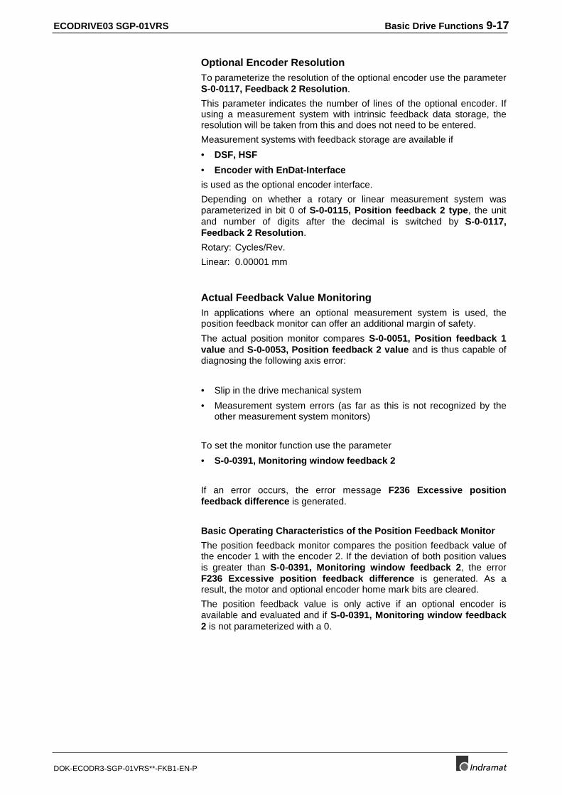
ECODRIVE03 SGP-01VRS Basic Drive Functions 9-17
DOK-ECODR3-SGP-01VRS**-FKB1-EN-P
Optional Encoder ResolutionTo parameterize the resolution of the optional encoder use the parameterS-0-0117, Feedback 2 Resolution.
This parameter indicates the number of lines of the optional encoder. Ifusing a measurement system with intrinsic feedback data storage, theresolution will be taken from this and does not need to be entered.
Measurement systems with feedback storage are available if
• DSF, HSF
• Encoder with EnDat-Interface
is used as the optional encoder interface.
Depending on whether a rotary or linear measurement system wasparameterized in bit 0 of S-0-0115, Position feedback 2 type, the unitand number of digits after the decimal is switched by S-0-0117,Feedback 2 Resolution.
Rotary: Cycles/Rev.
Linear: 0.00001 mm
Actual Feedback Value MonitoringIn applications where an optional measurement system is used, theposition feedback monitor can offer an additional margin of safety.
The actual position monitor compares S-0-0051, Position feedback 1value and S-0-0053, Position feedback 2 value and is thus capable ofdiagnosing the following axis error:
• Slip in the drive mechanical system
• Measurement system errors (as far as this is not recognized by theother measurement system monitors)
To set the monitor function use the parameter
• S-0-0391, Monitoring window feedback 2
If an error occurs, the error message F236 Excessive positionfeedback difference is generated.
Basic Operating Characteristics of the Position Feedback Monitor
The position feedback monitor compares the position feedback value ofthe encoder 1 with the encoder 2. If the deviation of both position valuesis greater than S-0-0391, Monitoring window feedback 2, the errorF236 Excessive position feedback difference is generated. As aresult, the motor and optional encoder home mark bits are cleared.
The position feedback value is only active if an optional encoder isavailable and evaluated and if S-0-0391, Monitoring window feedback2 is not parameterized with a 0.
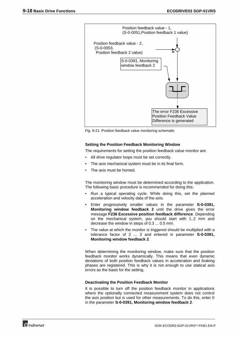
9-18 Basic Drive Functions ECODRIVE03 SGP-01VRS
DOK-ECODR3-SGP-01VRS**-FKB1-EN-P
S-0-0391, Monitoringwindow feedback 2
The error F236 ExcessivePosition Feedback ValueDifference is generated
Position feedback value - 2, (S-0-0053, Position feedback 2 value)
Position feedback value - 1,(S-0-0051,Position feedback 1 value)
Fig. 9-21: Position feedback value monitoring schematic
Setting the Position Feedback Monitoring Window
The requirements for setting the position feedback value monitor are:
• All drive regulator loops must be set correctly.
• The axis mechanical system must be in its final form.
• The axis must be homed.
The monitoring window must be determined according to the application.The following basic procedure is recommended for doing this:
• Run a typical operating cycle. While doing this, set the plannedacceleration and velocity data of the axis.
• Enter progressively smaller values in the parameter S-0-0391,Monitoring window feedback 2 until the drive gives the errormessage F236 Excessive position feedback difference. Dependingon the mechanical system, you should start with 1..2 mm anddecrease the window in steps of 0.3 ... 0.5 mm.
• The value at which the monitor is triggered should be multiplied with atolerance factor of 2 ... 3 and entered in parameter S-0-0391,Monitoring window feedback 2.
When determining the monitoring window, make sure that the positionfeedback monitor works dynamically. This means that even dynamicdeviations of both position feedback values in acceleration and brakingphases are registered. This is why it is not enough to use statical axiserrors as the basis for the setting.
Deactivating the Position Feedback Monitor
It is possible to turn off the position feedback monitor in applicationswhere the optionally connected measurement system does not controlthe axis position but is used for other measurements. To do this, enter 0in the parameter S-0-0391, Monitoring window feedback 2.
ECODRIVE03 SGP-01VRS Basic Drive Functions 9-19
DOK-ECODR3-SGP-01VRS**-FKB1-EN-P
Other Optional Encoder CharacteristicsTo parameterize any other characteristics of the optional encoder, useS-0-0115, Position feedback 2 type
The structure of this parameter is as follows:
S-0-0115, Position feedback 2 type
Bit 0 : Encoder type0: rotary1: linear
Bit 1 : Distance-coded reference mark0: no distance-coded reference mark1: distance-coded reference mark
Bit 3 : Rotational direction0: non-inverted1: inverted
Bit 6 : Absolute evaluation possible0: Absolute evaluation not possible1: Absolute evaluation possible
Bit 7 : Absolute evaluation deactivated0: Absolute evaluation activated (only if bit 6 = 1 )1: Absolute evaluation deactivated
Fig. 9-22: Parameter S-0-0115
Note: The bits in the position encoder type parameter are partly setor cleared by the drive itself. There is following dependency:
• Depending on the absolute encoder range and the maximum travelrange or modulo value, bit 6 is either set or cleared.
(See also chapter: "Other Settings for Absolute Measurement Systems".)
Actual Feedback Values of Non-Absolute Measurement Systems AfterInitialization
If there is no absolute measuring system then the initialization value canbe changed via parameter P-0-0019, Position start value.
It hereby applies:
If the parameter is write accessed in either phase 2 or 3 then this value isassumed as the initialization value:
P-0-0019written:
Position feedbackvalue 1
Position feedbackvalue 2
no init. motor encoder raw value init. motor encoder raw value
yes position start value position start valueFig. 9-23: Non-absolute measurement system position feedback values after
initialization
9-20 Basic Drive Functions ECODRIVE03 SGP-01VRS
DOK-ECODR3-SGP-01VRS**-FKB1-EN-P
Warning
No valid position feedback values exist before themeasurement system is initialized.Initialization is performed during the transition checkfor communication phase 4.
Some measurement systems have limitationsconcerning the maximum velocity during theirinitialization.
Measurement system Maximum initialization velocity
DSF/HSF 300 rpm
EnDat Initialization should occur at standstill
Multiturn resolver 300 rpmFig. 9-24: Velocity allowed during initialization
Drive-internal format of position dataThere are two different formats in the drive used to display position data.We differentiate between
• display format and
• drive-internal format.
The display format defines the unit, i.e., the value with which theposition data are exchanged between drive and control/surface. When aposition data parameter is read, it is sent in the display format to thecontrol. The display format is set with parameter S-0-0076, PositionData Scaling Type, S-0-0077, Linear Position Data Scaling Factor, S-0-0078, Linear Position Data Scaling Exponent and S-0-0079,Rotational position resolution. The control generally sets the format.
(See also "Physical Values Display Format"“.)
The drive-internal format determines the value, the position commandand feedback value editing as well as how the position control loop in thedrive is performed. The drive uses the value of parameterS-0-0278, Maximum travel range to calculate the drive-internal format.
Note: If the value set in S-0-0278, Maximum travel range is usedas set at delivery, then the drive-internal format generallymeets most demands given a sufficiently high resolution. Onlyif excessively high demands are made of the drive-internalformat of the position data or with very long travel ranges itbecomes necessary to optimize the setting.
Functional principle of the drive-internal position dataformatsPosition data processing in the drive has a constant data width fromwhich the resolution of the position data to cover the travel range of theaxis depends.
It applies:
Note: The longer the distance to be represented, the smaller thedrive-internal position resolution.
The drive-internal positonresolution depends on the
travel range to be described
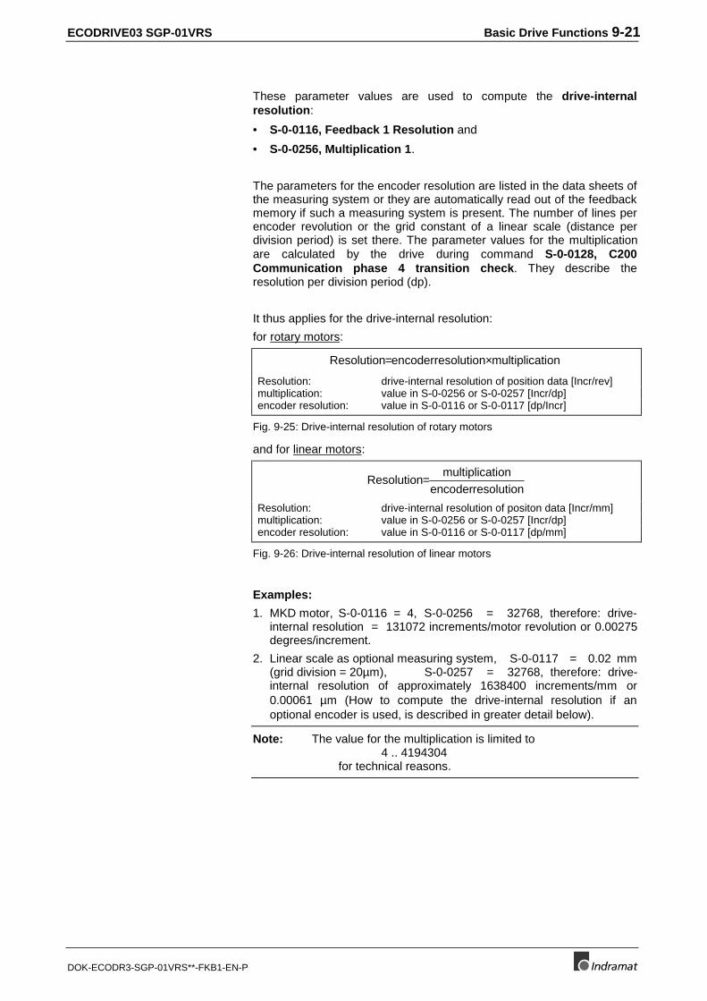
ECODRIVE03 SGP-01VRS Basic Drive Functions 9-21
DOK-ECODR3-SGP-01VRS**-FKB1-EN-P
These parameter values are used to compute the drive-internalresolution:
• S-0-0116, Feedback 1 Resolution and
• S-0-0256, Multiplication 1.
The parameters for the encoder resolution are listed in the data sheets ofthe measuring system or they are automatically read out of the feedbackmemory if such a measuring system is present. The number of lines perencoder revolution or the grid constant of a linear scale (distance perdivision period) is set there. The parameter values for the multiplicationare calculated by the drive during command S-0-0128, C200Communication phase 4 transition check. They describe theresolution per division period (dp).
It thus applies for the drive-internal resolution:
for rotary motors:
Resolution encoder resolution multiplication = ×
Resolution: drive-internal resolution of position data [Incr/rev]multiplication: value in S-0-0256 or S-0-0257 [Incr/dp]encoder resolution: value in S-0-0116 or S-0-0117 [dp/Incr]
Fig. 9-25: Drive-internal resolution of rotary motors
and for linear motors:
Resolution multiplication
encoder resolution=
Resolution: drive-internal resolution of positon data [Incr/mm]multiplication: value in S-0-0256 or S-0-0257 [Incr/dp]encoder resolution: value in S-0-0116 or S-0-0117 [dp/mm]
Fig. 9-26: Drive-internal resolution of linear motors
Examples:
1. MKD motor, S-0-0116 = 4, S-0-0256 = 32768, therefore: drive-internal resolution = 131072 increments/motor revolution or 0.00275degrees/increment.
2. Linear scale as optional measuring system, S-0-0117 = 0.02 mm(grid division = 20µm), S-0-0257 = 32768, therefore: drive-internal resolution of approximately 1638400 increments/mm or0.00061 µm (How to compute the drive-internal resolution if anoptional encoder is used, is described in greater detail below).
Note: The value for the multiplication is limited to4 .. 4194304
for technical reasons.
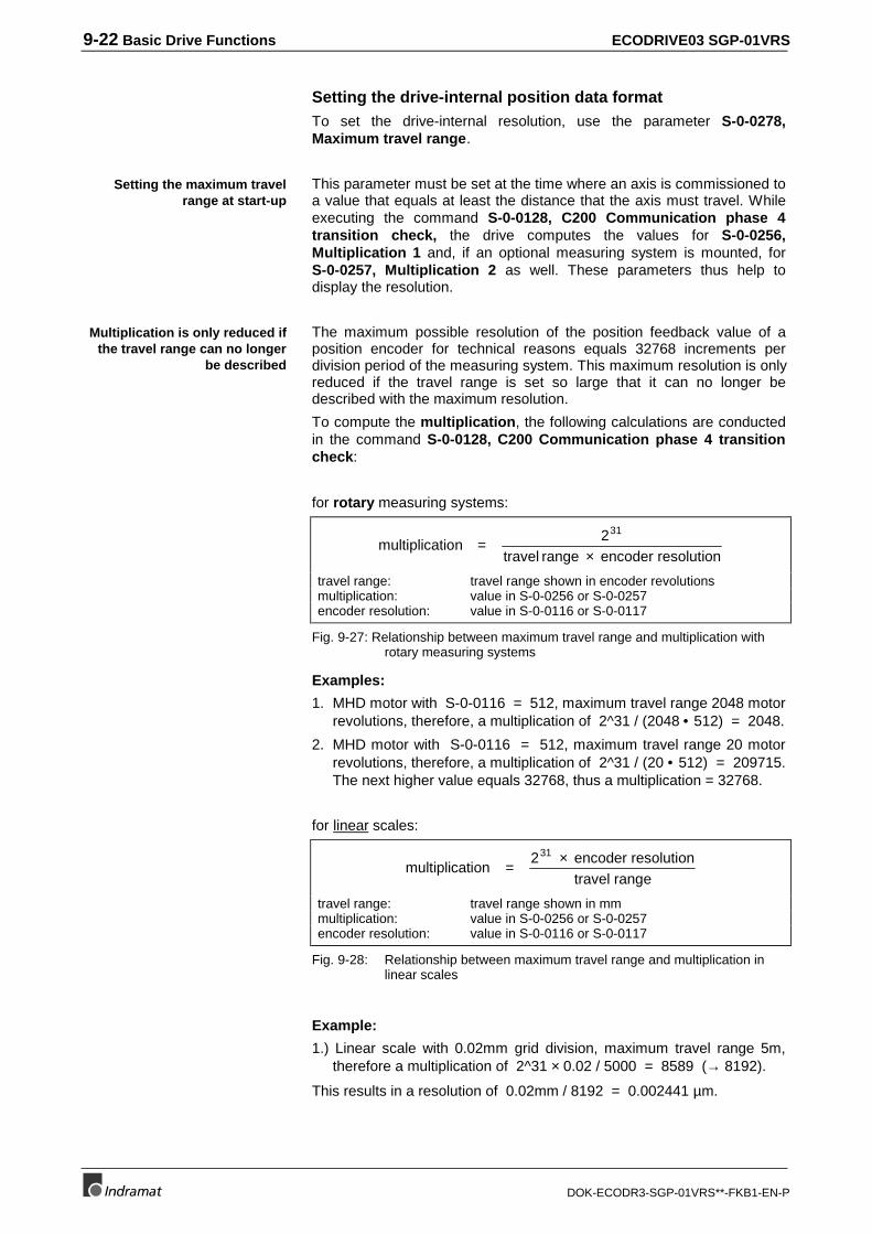
9-22 Basic Drive Functions ECODRIVE03 SGP-01VRS
DOK-ECODR3-SGP-01VRS**-FKB1-EN-P
Setting the drive-internal position data formatTo set the drive-internal resolution, use the parameter S-0-0278,Maximum travel range.
This parameter must be set at the time where an axis is commissioned toa value that equals at least the distance that the axis must travel. Whileexecuting the command S-0-0128, C200 Communication phase 4transition check, the drive computes the values for S-0-0256,Multiplication 1 and, if an optional measuring system is mounted, forS-0-0257, Multiplication 2 as well. These parameters thus help todisplay the resolution.
The maximum possible resolution of the position feedback value of aposition encoder for technical reasons equals 32768 increments perdivision period of the measuring system. This maximum resolution is onlyreduced if the travel range is set so large that it can no longer bedescribed with the maximum resolution.
To compute the multiplication, the following calculations are conductedin the command S-0-0128, C200 Communication phase 4 transitioncheck:
for rotary measuring systems:
multiplication =2
travel range encoder resolution
31
×
travel range: travel range shown in encoder revolutionsmultiplication: value in S-0-0256 or S-0-0257encoder resolution: value in S-0-0116 or S-0-0117
Fig. 9-27: Relationship between maximum travel range and multiplication withrotary measuring systems
Examples:
1. MHD motor with S-0-0116 = 512, maximum travel range 2048 motorrevolutions, therefore, a multiplication of 2^31 / (2048 • 512) = 2048.
2. MHD motor with S-0-0116 = 512, maximum travel range 20 motorrevolutions, therefore, a multiplication of 2^31 / (20 • 512) = 209715.The next higher value equals 32768, thus a multiplication = 32768.
for linear scales:
multiplication2 encoder resolution
travel range
31
=×
travel range: travel range shown in mmmultiplication: value in S-0-0256 or S-0-0257encoder resolution: value in S-0-0116 or S-0-0117
Fig. 9-28: Relationship between maximum travel range and multiplication inlinear scales
Example:
1.) Linear scale with 0.02mm grid division, maximum travel range 5m,therefore a multiplication of 2^31 × 0.02 / 5000 = 8589 (→ 8192).
This results in a resolution of 0.02mm / 8192 = 0.002441 µm.
Setting the maximum travelrange at start-up
Multiplication is only reduced ifthe travel range can no longer
be described
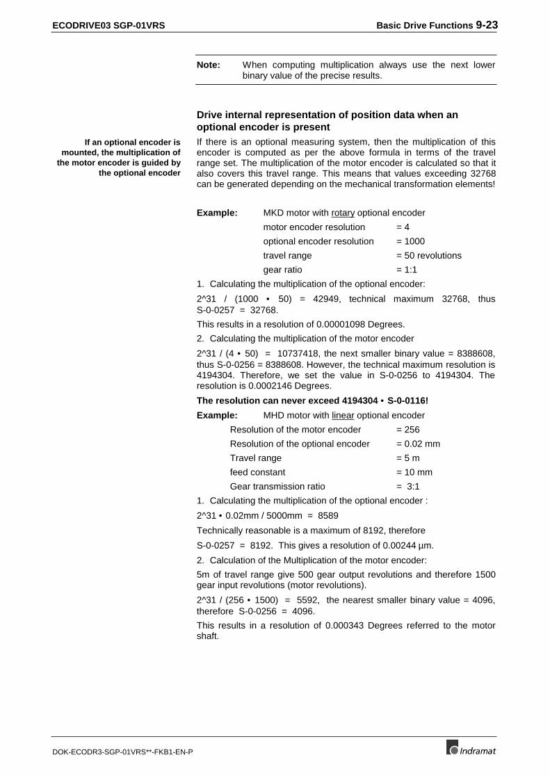
ECODRIVE03 SGP-01VRS Basic Drive Functions 9-23
DOK-ECODR3-SGP-01VRS**-FKB1-EN-P
Note: When computing multiplication always use the next lowerbinary value of the precise results.
Drive internal representation of position data when anoptional encoder is presentIf there is an optional measuring system, then the multiplication of thisencoder is computed as per the above formula in terms of the travelrange set. The multiplication of the motor encoder is calculated so that italso covers this travel range. This means that values exceeding 32768can be generated depending on the mechanical transformation elements!
Example: MKD motor with rotary optional encoder
motor encoder resolution = 4
optional encoder resolution = 1000
travel range = 50 revolutions
gear ratio = 1:1
1. Calculating the multiplication of the optional encoder:
2^31 / (1000 • 50) = 42949, technical maximum 32768, thusS-0-0257 = 32768.
This results in a resolution of 0.00001098 Degrees.
2. Calculating the multiplication of the motor encoder
2^31 / (4 • 50) = 10737418, the next smaller binary value = 8388608,thus S-0-0256 = 8388608. However, the technical maximum resolution is4194304. Therefore, we set the value in S-0-0256 to 4194304. Theresolution is 0.0002146 Degrees.
The resolution can never exceed 4194304 • S-0-0116!
Example: MHD motor with linear optional encoder
Resolution of the motor encoder = 256
Resolution of the optional encoder = 0.02 mm
Travel range = 5 m
feed constant = 10 mm
Gear transmission ratio = 3:1
1. Calculating the multiplication of the optional encoder :
2^31 • 0.02mm / 5000mm = 8589
Technically reasonable is a maximum of 8192, therefore
S-0-0257 = 8192. This gives a resolution of 0.00244 µm.
2. Calculation of the Multiplication of the motor encoder:
5m of travel range give 500 gear output revolutions and therefore 1500gear input revolutions (motor revolutions).
2^31 / (256 • 1500) = 5592, the nearest smaller binary value = 4096,therefore S-0-0256 = 4096.
This results in a resolution of 0.000343 Degrees referred to the motorshaft.
If an optional encoder ismounted, the multiplication of
the motor encoder is guided bythe optional encoder
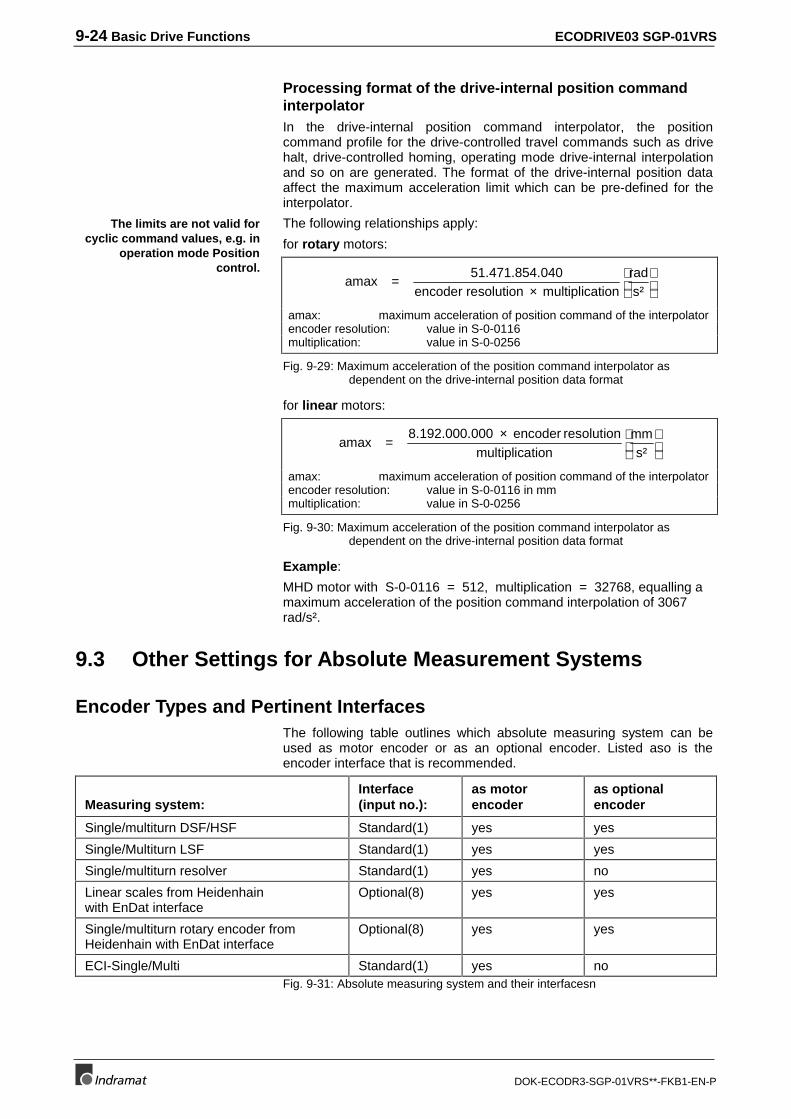
9-24 Basic Drive Functions ECODRIVE03 SGP-01VRS
DOK-ECODR3-SGP-01VRS**-FKB1-EN-P
Processing format of the drive-internal position commandinterpolatorIn the drive-internal position command interpolator, the positioncommand profile for the drive-controlled travel commands such as drivehalt, drive-controlled homing, operating mode drive-internal interpolationand so on are generated. The format of the drive-internal position dataaffect the maximum acceleration limit which can be pre-defined for theinterpolator.
The following relationships apply:
for rotary motors:
amax51.471.854.040
encoder resolution multiplicationrads²
=×
amax: maximum acceleration of position command of the interpolatorencoder resolution: value in S-0-0116multiplication: value in S-0-0256
Fig. 9-29: Maximum acceleration of the position command interpolator asdependent on the drive-internal position data format
for linear motors:
amax8.192.000.000 encoder resolution
multiplicationmms²
=×
amax: maximum acceleration of position command of the interpolatorencoder resolution: value in S-0-0116 in mmmultiplication: value in S-0-0256
Fig. 9-30: Maximum acceleration of the position command interpolator asdependent on the drive-internal position data format
Example:
MHD motor with S-0-0116 = 512, multiplication = 32768, equalling amaximum acceleration of the position command interpolation of 3067rad/s².
9.3 Other Settings for Absolute Measurement Systems
Encoder Types and Pertinent InterfacesThe following table outlines which absolute measuring system can beused as motor encoder or as an optional encoder. Listed aso is theencoder interface that is recommended.
Measuring system:Interface(input no.):
as motorencoder
as optionalencoder
Single/multiturn DSF/HSF Standard(1) yes yes
Single/Multiturn LSF Standard(1) yes yes
Single/multiturn resolver Standard(1) yes no
Linear scales from Heidenhainwith EnDat interface
Optional(8) yes yes
Single/multiturn rotary encoder fromHeidenhain with EnDat interface
Optional(8) yes yes
ECI-Single/Multi Standard(1) yes noFig. 9-31: Absolute measuring system and their interfacesn
The limits are not valid forcyclic command values, e.g. in
operation mode Positioncontrol.
ECODRIVE03 SGP-01VRS Basic Drive Functions 9-25
DOK-ECODR3-SGP-01VRS**-FKB1-EN-P
Absolute encoder range and absolute encoder evaluation
Motor and/or optionalencoders can be used asabsolute encoders
As motor and/or optional measuring system those measuring systemscan be used that supply absolute position information within one orseveral revolutions (single or multiturn encoder) or a within a specifictraversing distance (absolute linear scales).
The information about which range (absolute encoder range) ameasuring system can supply absolute position information about isstored in the ata memory of the measuring system or the drive software.Absolute measuring systems do not have to be homed after initializationof the drive firmware. The actual position value lies within the absoluteencoder range, machine zero related, after initialization. It is onlynecessasry to conduct a single setup procedure (setting absolutedimension).
Whether a motor or an optional measuring system are to be evaluated asencoders, depends on the following variables:
• the absolute encoder range (S-0-0378, Absolute encoder 1, range /S-0-0379, Absolute encoder 2, range) of the relevant encoder.
• the set position scaling (position data represented absolute or inmodulo formats) in S-0-0076, Position data scaling type
• the travel range set in S-0-0278, Maximum travel range or
• the modulo value set in parameter S-0-0103, Moduleo value.
Note the following relationships:
Position scaling(Bit 6 of S-0-0076)
S-0-0278, Max.travel range S-0-0103, Moduleo value
Absolute encoderevaluation possible
Absolute format <= ½ * S-0-0378 or½ * S-0-0379
not relevant yes
> ½ * S-0-0378or ½ * S-0-0379
not relevant no
Modulo format >=S-0-0103 <= S-0-0378 or S-0-0379 yes
>=S-0-0103 > S-0-0378 or S-0-0379 noFig. 9-32: Absolute encoder evaluation as depends on position format, modulo
format and maximum travel range
The check whether a measuring system can be evaluated as an absolutesystem is conducted during command S-0-0128, C200 Communicationphase 4 transition check. The results are displayed in bit 6 of therelevant position encoder type parameter (S-0-0277 / S-0-0115).
If the absolute evaluation of a measuring system is possible but notwanted, this can be deselected in bit 7 of the position encoder typeparameter. The measuring system is then treated as if it were a non-absolute (single turn) encoder.
The position encoder type parameter is structured as follows:
Activating the absolute encoderevaluation
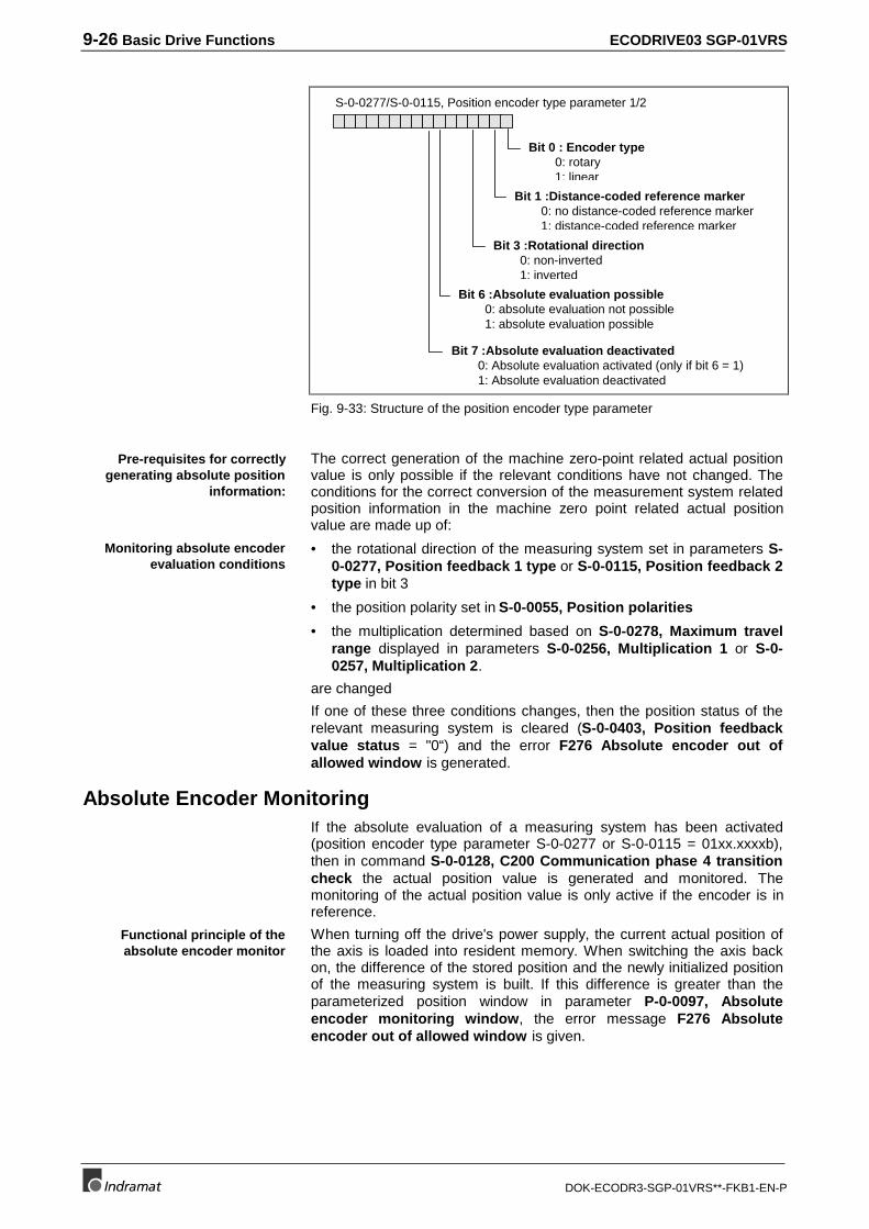
9-26 Basic Drive Functions ECODRIVE03 SGP-01VRS
DOK-ECODR3-SGP-01VRS**-FKB1-EN-P
S-0-0277/S-0-0115, Position encoder type parameter 1/2
Bit 0 : Encoder type0: rotary1: linear
Bit 1 :Distance-coded reference marker0: no distance-coded reference marker1: distance-coded reference marker
Bit 3 :Rotational direction0: non-inverted1: inverted
Bit 6 :Absolute evaluation possible0: absolute evaluation not possible1: absolute evaluation possible
Bit 7 :Absolute evaluation deactivated0: Absolute evaluation activated (only if bit 6 = 1)1: Absolute evaluation deactivated
Fig. 9-33: Structure of the position encoder type parameter
The correct generation of the machine zero-point related actual positionvalue is only possible if the relevant conditions have not changed. Theconditions for the correct conversion of the measurement system relatedposition information in the machine zero point related actual positionvalue are made up of:
• the rotational direction of the measuring system set in parameters S-0-0277, Position feedback 1 type or S-0-0115, Position feedback 2type in bit 3
• the position polarity set in S-0-0055, Position polarities
• the multiplication determined based on S-0-0278, Maximum travelrange displayed in parameters S-0-0256, Multiplication 1 or S-0-0257, Multiplication 2.
are changed
If one of these three conditions changes, then the position status of therelevant measuring system is cleared (S-0-0403, Position feedbackvalue status = "0“) and the error F276 Absolute encoder out ofallowed window is generated.
Absolute Encoder MonitoringIf the absolute evaluation of a measuring system has been activated(position encoder type parameter S-0-0277 or S-0-0115 = 01xx.xxxxb),then in command S-0-0128, C200 Communication phase 4 transitioncheck the actual position value is generated and monitored. Themonitoring of the actual position value is only active if the encoder is inreference.
When turning off the drive's power supply, the current actual position ofthe axis is loaded into resident memory. When switching the axis backon, the difference of the stored position and the newly initialized positionof the measuring system is built. If this difference is greater than theparameterized position window in parameter P-0-0097, Absoluteencoder monitoring window, the error message F276 Absoluteencoder out of allowed window is given.
Pre-requisites for correctlygenerating absolute position
information:
Monitoring absolute encoderevaluation conditions
Functional principle of theabsolute encoder monitor
ECODRIVE03 SGP-01VRS Basic Drive Functions 9-27
DOK-ECODR3-SGP-01VRS**-FKB1-EN-P
The absolute encoder monitor is appropriate for the followingapplications:
• The motor is equipped with a holding brake.
• The drive mechanical system is self-locking and cannot be movedmanually.
Setting the Absolute Encoder MonitorThe absolute encoder monitoring window must be set by the user.Always select greater than the maximum allowable motion of the axiswhen shutdown. Assuming that the axis has a brake or is self-locking,you can enter 0.1 motor revolutions (36° in reference to the motor shaft)as a standard value for the parameter P-0-0097, Absolute encodermonitoring window.
Absolute encoder monitoring with two absolute encodersIf there are absolute measuring systems and the absolute encodermonitor of the position data is activated, then the following restrictionapplies:
If both motor and optional encoder are evaluated absolutely, then onlythat one is monitored as an absolute encoder that has been set in bit 3 ofparameter S-0-0147, Homing parameter.
See also chapter: Absolute Encoder Monitoring".
Deactivating the Absolute Encoder MonitorThe absolute encoder monitor cannot be effectively used with axis thatcan or must be moved manually when switched off. The absoluteencoder monitor should be turned off in such situations in order toprevent unnecessary error conditions.
The absolute encoder monitor can be turned off by writing 0 to P-0-0097.
Moduleo Analysis with two absolute encodersIf measuring systems are evaluated absolutely and modulo evaluation ofthe position data is activated, then the following restrictions apply:
If both motor encoder and optional encoder are to be evaluatedabsolutely, then only that one is evaluated as an absolute encoder, whichis set in bit 3 of parameter S-0-0147, Homing parameter.
(See also chapter: "Modulo Feature" ).
9-28 Basic Drive Functions ECODRIVE03 SGP-01VRS
DOK-ECODR3-SGP-01VRS**-FKB1-EN-P
Actual Feedback Values of Absolute Measurement Systems AfterInitialization
The condition of the position feedback values of the motor feedback and,if available, of the optional feedback after initializing in the command S-0-0128, C200 Communication phase 4 transition check depends on:• Bit 3 in S-0-0147, Homing parameter
• Availability of an absolute feedback as the motor or optional feedback.
Motorfeedback:
Optionalfeedback:
S-0-0147Bit 3:
S-0-0051, Positionfeedback value 1:
S-0-0053, Positionfeedback value 2:
S-0-0403,Pos. status:
absolute not absolute 0 absolute value ofmotor feedback
absolute value ofmotor feedback
1
absolute not absolute 1 absolute value ofmotor feedback
absolute value ofmotor feedback
0
not absolute absolute 0 absolute value ofoptional feedback
absolute value ofoptional feedback
0
not absolute absolute 1 absolute value ofoptional feedback
absolute value ofoptional feedback
1
absolute absolute arbitrary absolute value ofmotor feedback
absolute value ofoptional feedback
1
Fig. 9-34: Position feedback values of absolute measurement systems afterinitialization
Note: Absolute position is lost with changes in polarity, scaling,gearbox and so on.
9.4 Drive Limitations
Current LimitControllers, motors and machines are subject to various limits to protectthem against damage from overload. This protection is based on adynamic drop of the current computed for the output stage of thecontroller and the motor, in addition to parameters set by the user foranother purpose.
The maximum current that may flow for a short period of time or that isavailable as continuous current is specified in the relevant parameters
• P-0-4046, Active peak current and
• P-0-4045, Active permanent current.
Pertinent Parameters
• S-0-0110, Amplifier peak current
• P-0-4004, Magnetizing current
• S-0-0109, Motor peak current
• S-0-0111, Motor current at standstill
• S-0-0092, Bipolar torque/force limit value
• P-0-0109, Torque/force peak limit
• P-0-4011, Switching frequency
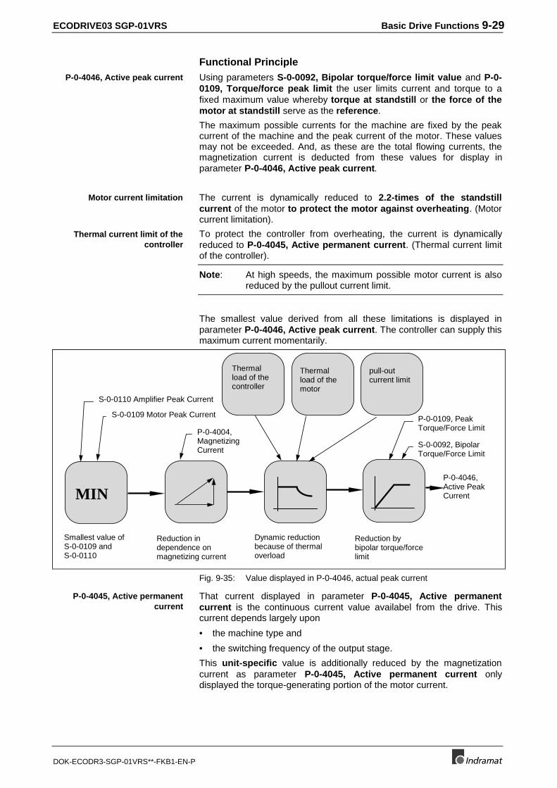
ECODRIVE03 SGP-01VRS Basic Drive Functions 9-29
DOK-ECODR3-SGP-01VRS**-FKB1-EN-P
Functional PrincipleUsing parameters S-0-0092, Bipolar torque/force limit value and P-0-0109, Torque/force peak limit the user limits current and torque to afixed maximum value whereby torque at standstill or the force of themotor at standstill serve as the reference.
The maximum possible currents for the machine are fixed by the peakcurrent of the machine and the peak current of the motor. These valuesmay not be exceeded. And, as these are the total flowing currents, themagnetization current is deducted from these values for display inparameter P-0-4046, Active peak current.
The current is dynamically reduced to 2.2-times of the standstillcurrent of the motor to protect the motor against overheating. (Motorcurrent limitation).
To protect the controller from overheating, the current is dynamicallyreduced to P-0-4045, Active permanent current. (Thermal current limitof the controller).
Note: At high speeds, the maximum possible motor current is alsoreduced by the pullout current limit.
The smallest value derived from all these limitations is displayed inparameter P-0-4046, Active peak current. The controller can supply thismaximum current momentarily.
Smallest value ofS-0-0109 andS-0-0110
S-0-0109 Motor Peak Current
Reduction independence onmagnetizing current
P-0-4004,MagnetizingCurrent
MIN
S-0-0110 Amplifier Peak Current
Dynamic reductionbecause of thermaloverload
Reduction bybipolar torque/forcelimit
S-0-0092, BipolarTorque/Force Limit
P-0-4046,Active PeakCurrent
P-0-0109, PeakTorque/Force Limit
Thermalload of thecontroller
Thermalload of themotor
pull-outcurrent limit
Fig. 9-35: Value displayed in P-0-4046, actual peak current
That current displayed in parameter P-0-4045, Active permanentcurrent is the continuous current value availabel from the drive. Thiscurrent depends largely upon
• the machine type and
• the switching frequency of the output stage.
This unit-specific value is additionally reduced by the magnetizationcurrent as parameter P-0-4045, Active permanent current onlydisplayed the torque-generating portion of the motor current.
P-0-4046, Active peak current
Motor current limitation
Thermal current limit of thecontroller
P-0-4045, Active permanentcurrent
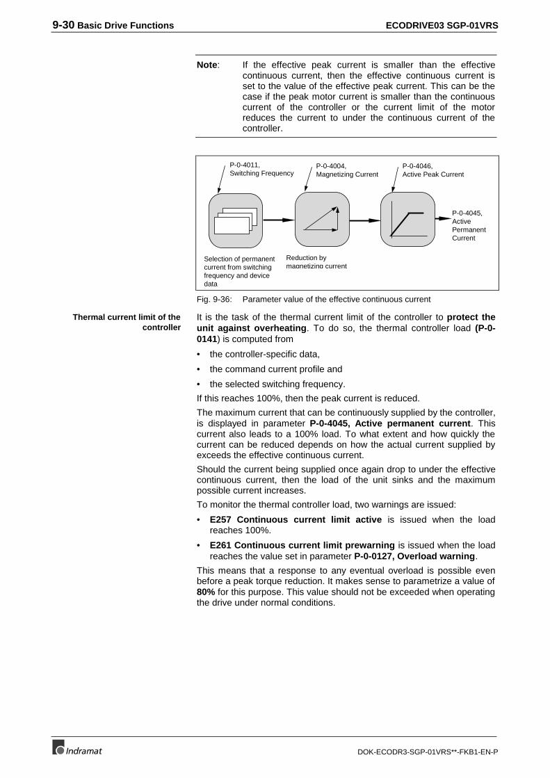
9-30 Basic Drive Functions ECODRIVE03 SGP-01VRS
DOK-ECODR3-SGP-01VRS**-FKB1-EN-P
Note: If the effective peak current is smaller than the effectivecontinuous current, then the effective continuous current isset to the value of the effective peak current. This can be thecase if the peak motor current is smaller than the continuouscurrent of the controller or the current limit of the motorreduces the current to under the continuous current of thecontroller.
P-0-4011,Switching Frequency
Selection of permanentcurrent from switchingfrequency and devicedata
P-0-4004,Magnetizing Current
Reduction bymagnetizing current
P-0-4046,Active Peak Current
P-0-4045,ActivePermanentCurrent
Fig. 9-36: Parameter value of the effective continuous current
It is the task of the thermal current limit of the controller to protect theunit against overheating. To do so, the thermal controller load (P-0-0141) is computed from
• the controller-specific data,
• the command current profile and
• the selected switching frequency.
If this reaches 100%, then the peak current is reduced.
The maximum current that can be continuously supplied by the controller,is displayed in parameter P-0-4045, Active permanent current. Thiscurrent also leads to a 100% load. To what extent and how quickly thecurrent can be reduced depends on how the actual current supplied byexceeds the effective continuous current.
Should the current being supplied once again drop to under the effectivecontinuous current, then the load of the unit sinks and the maximumpossible current increases.
To monitor the thermal controller load, two warnings are issued:
• E257 Continuous current limit active is issued when the loadreaches 100%.
• E261 Continuous current limit prewarning is issued when the loadreaches the value set in parameter P-0-0127, Overload warning.
This means that a response to any eventual overload is possible evenbefore a peak torque reduction. It makes sense to parametrize a value of80% for this purpose. This value should not be exceeded when operatingthe drive under normal conditions.
Thermal current limit of thecontroller
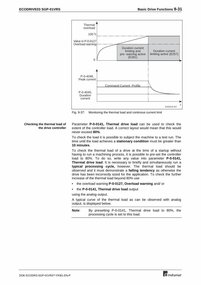
ECODRIVE03 SGP-01VRS Basic Drive Functions 9-31
DOK-ECODR3-SGP-01VRS**-FKB1-EN-P
t
0
Value in P-0-0127Overload warning
100
Command Current Profile
Duration currentlimiting active (E257)
P-0-4046,Peak current
P-0-4045,Durationcurrent
Duration currentlimiting and
pre- warning active(E261)
Thermaloverload
Sv5031f1.fh7
Fig. 9-37: Monitoring the thermal load and continous current limit
Parameter P-0-0141, Thermal drive load can be used to check theextent of the controller load. A correct layout would mean that this wouldnever exceed 80%.
To check the load it is possible to subject the machine to a test run. Thetime until the load achieves a stationary condition must be greater than10 minutes.
To check the thermal load of a drive at the time of a startup withouthaving to run a machining process, it is possible to pre-set the controllerload to 80%. To do so, write any value into parameter P-0-0141,Thermal drive load. It is necessary to briefly and simultaneously run atypical processing cycle, however. The thermal load should beobserved and it must demonstrate a falling tendency as otherwise thedrive has been incorrectly sized for the application. To check the furtherincrease of the thermal load beyond 80% use
• the overload warning P-0-0127, Overload warning and/ or
• the P-0-0141, Thermal drive load output
using the analog output.
A typical curve of the thermal load as can be observed with analogoutput, is displayed below.
Note: By presetting P-0-0141, Thermal drive load to 80%, theprocessing cycle is set to this load.
Checking the thermal load ofthe drive controller
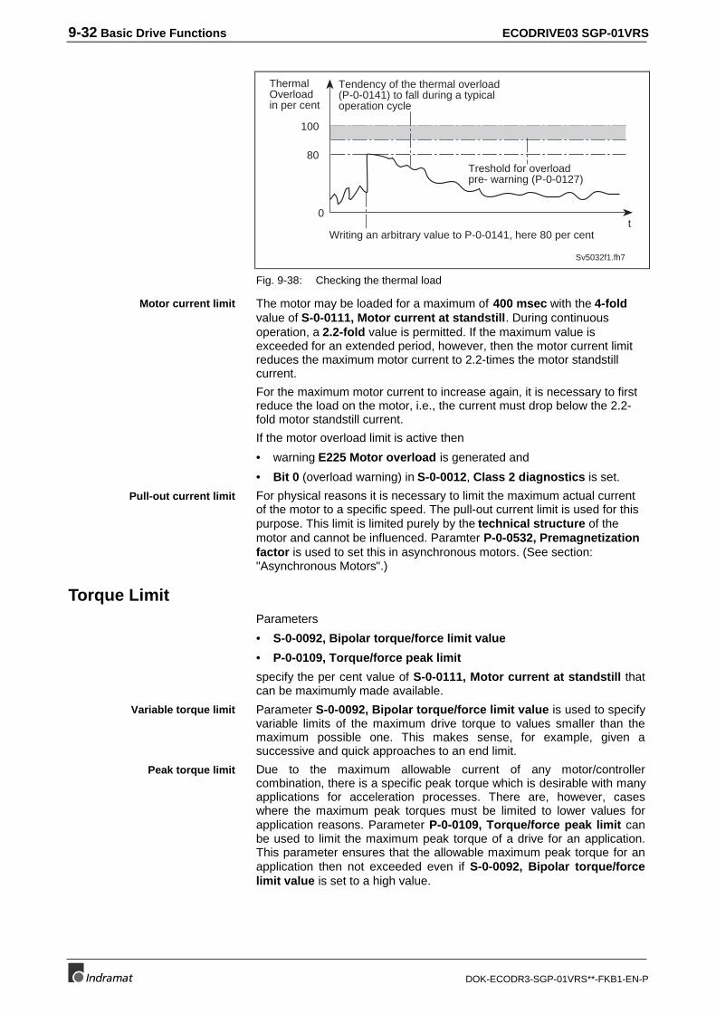
9-32 Basic Drive Functions ECODRIVE03 SGP-01VRS
DOK-ECODR3-SGP-01VRS**-FKB1-EN-P
100
0t
80
Sv5032f1.fh7
ThermalOverloadin per cent
Tendency of the thermal overload(P-0-0141) to fall during a typicaloperation cycle
Treshold for overloadpre- warning (P-0-0127)
Writing an arbitrary value to P-0-0141, here 80 per cent
Fig. 9-38: Checking the thermal load
The motor may be loaded for a maximum of 400 msec with the 4-foldvalue of S-0-0111, Motor current at standstill. During continuousoperation, a 2.2-fold value is permitted. If the maximum value isexceeded for an extended period, however, then the motor current limitreduces the maximum motor current to 2.2-times the motor standstillcurrent.
For the maximum motor current to increase again, it is necessary to firstreduce the load on the motor, i.e., the current must drop below the 2.2-fold motor standstill current.
If the motor overload limit is active then
• warning E225 Motor overload is generated and
• Bit 0 (overload warning) in S-0-0012, Class 2 diagnostics is set.
For physical reasons it is necessary to limit the maximum actual currentof the motor to a specific speed. The pull-out current limit is used for thispurpose. This limit is limited purely by the technical structure of themotor and cannot be influenced. Paramter P-0-0532, Premagnetizationfactor is used to set this in asynchronous motors. (See section:"Asynchronous Motors".)
Torque LimitParameters
• S-0-0092, Bipolar torque/force limit value
• P-0-0109, Torque/force peak limit
specify the per cent value of S-0-0111, Motor current at standstill thatcan be maximumly made available.
Parameter S-0-0092, Bipolar torque/force limit value is used to specifyvariable limits of the maximum drive torque to values smaller than themaximum possible one. This makes sense, for example, given asuccessive and quick approaches to an end limit.
Due to the maximum allowable current of any motor/controllercombination, there is a specific peak torque which is desirable with manyapplications for acceleration processes. There are, however, caseswhere the maximum peak torques must be limited to lower values forapplication reasons. Parameter P-0-0109, Torque/force peak limit canbe used to limit the maximum peak torque of a drive for an application.This parameter ensures that the allowable maximum peak torque for anapplication then not exceeded even if S-0-0092, Bipolar torque/forcelimit value is set to a high value.
Motor current limit
Pull-out current limit
Variable torque limit
Peak torque limit
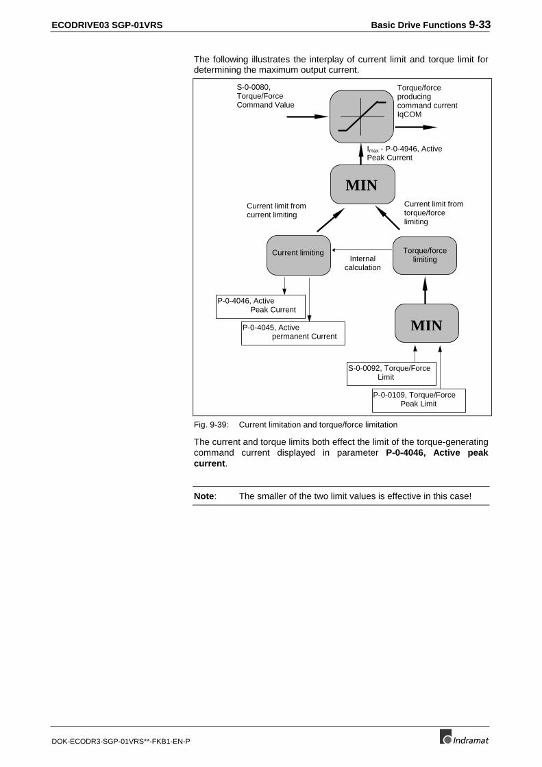
ECODRIVE03 SGP-01VRS Basic Drive Functions 9-33
DOK-ECODR3-SGP-01VRS**-FKB1-EN-P
The following illustrates the interplay of current limit and torque limit fordetermining the maximum output current.
S-0-0080,Torque/ForceCommand Value
MIN
Imax - P-0-4946, ActivePeak Current
Current limiting Torque/forcelimiting
Torque/forceproducingcommand currentIqCOM
Current limit fromcurrent limiting
Current limit fromtorque/forcelimiting
MIN
P-0-4046, Active Peak Current
P-0-4045, Active permanent Current
S-0-0092, Torque/Force Limit
P-0-0109, Torque/Force Peak Limit
Internalcalculation
Fig. 9-39: Current limitation and torque/force limitation
The current and torque limits both effect the limit of the torque-generatingcommand current displayed in parameter P-0-4046, Active peakcurrent.
Note: The smaller of the two limit values is effective in this case!
9-34 Basic Drive Functions ECODRIVE03 SGP-01VRS
DOK-ECODR3-SGP-01VRS**-FKB1-EN-P
Limiting VelocityThe following parameters limit the velocity of the drive:
• S-0-0113, Maximum Motor Speed (nmax)
• S-0-0091, Bipolar Velocity Limit Value
The parameter S-0-0091, Bipolar Velocity Limit Value is designed toallow variable limits of the maximum velocity to values smaller than themaximum allowable velocity during operation.
The parameter S-0-0113, Maximum Motor Speed (nmax) designatesthe maximum possible motor velocity. It is contained in the motorencoder data storage of MHD-, MKD and MKE motors and does notneed to be entered, but with other types of motors this value must betaken from the motor parameter specifications.
Limiting to Maximum Motor VelocityThe maximum motor velocity defines the maximum velocity of the drive.It becomes active and is included in the calculation of
• the maximum value entered in the parameter S-0-0091, BipolarVelocity Limit Value
Limiting to Bipolar Velocity Limit ValueThe bipolar velocity limit value defines the maximum velocity of the drivefor the user. It becomes active as
• the monitor of the encoder velocity in the torque control operating mode
• the limit for the resulting command value in the velocity controller
• the monitor of the position command value difference in the positioncontrol operating mode (see also "Position Command ValueMonitoring")
• the limit of S-0-0036, Velocity Command Value in the velocitycontrol operating mode
Monitoring the Feedback Velocity in the Torque Control OperatingMode
Monitoring the Feedback Velocity in the Torque Control operating modeoccurs at 1.125 times the value of S-0-0091, Bipolar Velocity LimitValue. If this value is exceeded, the fatal error
• F879 Velocity limit S-0-0091 exceeded
is generated. The drive switches to torque-free operation afterwards.
Limiting the Resulting Command Value in the Velocity Controller
In all operating modes in which the velocity controller is active (alloperating modes except for Torque Control), the given velocitycommand value is limited to the value of S-0-0091, Bipolar VelocityLimit Value. If this condition is reached, the warning
• E259 Command Velocity Limit active
is generated.
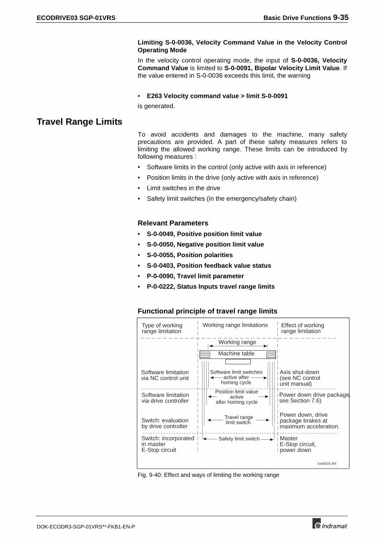
ECODRIVE03 SGP-01VRS Basic Drive Functions 9-35
DOK-ECODR3-SGP-01VRS**-FKB1-EN-P
Limiting S-0-0036, Velocity Command Value in the Velocity ControlOperating Mode
In the velocity control operating mode, the input of S-0-0036, VelocityCommand Value is limited to S-0-0091, Bipolar Velocity Limit Value. Ifthe value entered in S-0-0036 exceeds this limit, the warning
• E263 Velocity command value > limit S-0-0091
is generated.
Travel Range LimitsTo avoid accidents and damages to the machine, many safetyprecautions are provided. A part of these safety measures refers tolimiting the allowed working range. These limits can be introduced byfollowing measures :
• Software limits in the control (only active with axis in reference)
• Position limits in the drive (only active with axis in reference)
• Limit switches in the drive
• Safety limit switches (in the emergency/safety chain)
Relevant Parameters
• S-0-0049, Positive position limit value
• S-0-0050, Negative position limit value
• S-0-0055, Position polarities
• S-0-0403, Position feedback value status
• P-0-0090, Travel limit parameter
• P-0-0222, Status Inputs travel range limits
Functional principle of travel range limits
Xx0002f1.fh5
Working range
Machine table
Working range limitationsType of workingrange limitation
Effect of workingrange limitation
Software limit switchesactive after
homing cycle
Position limit valueactive
after homing cycle
Travel rangelimit switch
Safety limit switch
Software limitationvia NC control unit
Software limitationvia drive controller
Switch: evaluationby drive controller
Switch: incorporatedin masterE-Stop circuit
Axis shut-down(see NC controlunit manual)
Power down drive package,see Section 7.6)
Power down, drivepackage brakes atmaximum acceleration.
MasterE-Stop circuit,power down
Fig. 9-40: Effect and ways of limiting the working range
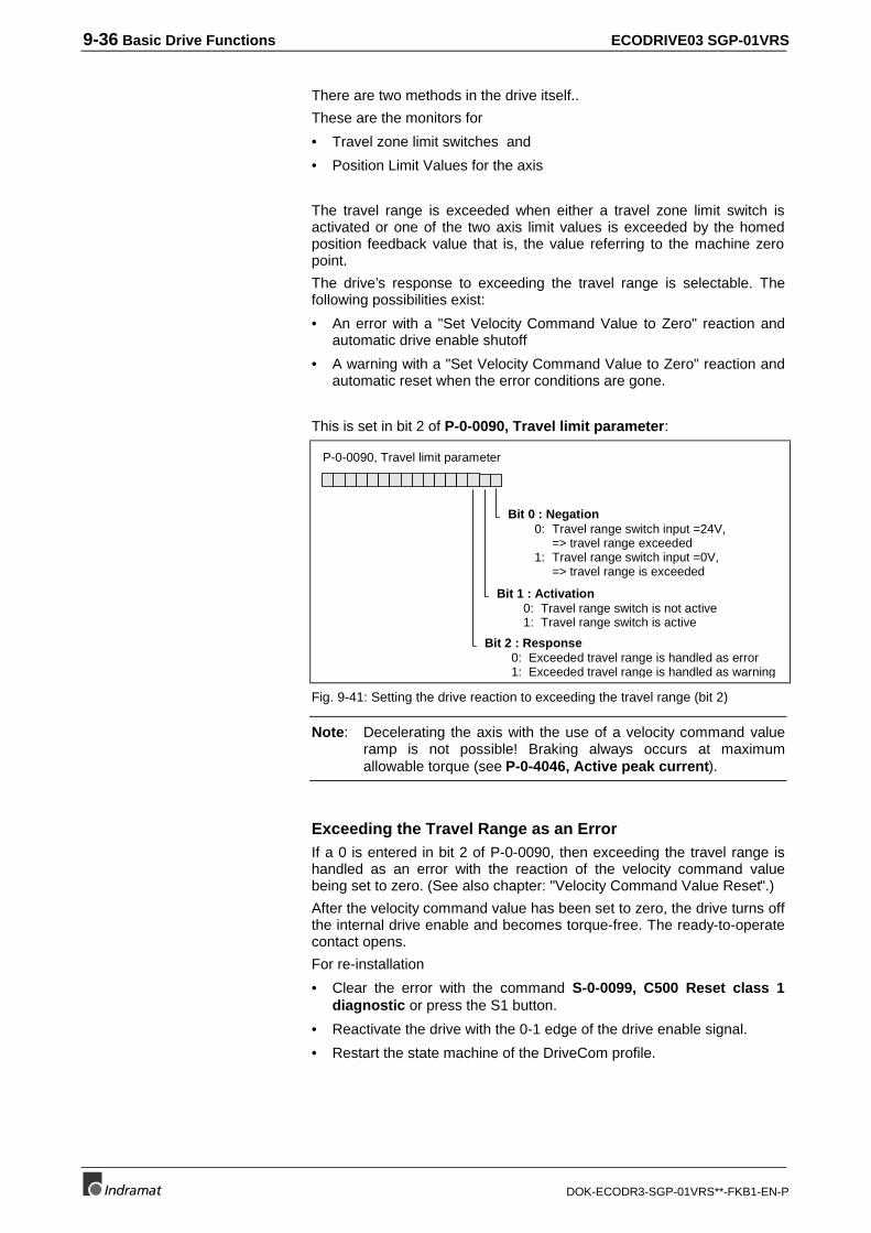
9-36 Basic Drive Functions ECODRIVE03 SGP-01VRS
DOK-ECODR3-SGP-01VRS**-FKB1-EN-P
There are two methods in the drive itself..
These are the monitors for
• Travel zone limit switches and
• Position Limit Values for the axis
The travel range is exceeded when either a travel zone limit switch isactivated or one of the two axis limit values is exceeded by the homedposition feedback value that is, the value referring to the machine zeropoint.
The drive’s response to exceeding the travel range is selectable. Thefollowing possibilities exist:
• An error with a "Set Velocity Command Value to Zero" reaction andautomatic drive enable shutoff
• A warning with a "Set Velocity Command Value to Zero" reaction andautomatic reset when the error conditions are gone.
This is set in bit 2 of P-0-0090, Travel limit parameter:
Bit 0 : Negation0: Travel range switch input =24V,
=> travel range exceeded1: Travel range switch input =0V,
=> travel range is exceeded
Bit 1 : Activation0: Travel range switch is not active1: Travel range switch is active
Bit 2 : Response0: Exceeded travel range is handled as error1: Exceeded travel range is handled as warning
P-0-0090, Travel limit parameter
Fig. 9-41: Setting the drive reaction to exceeding the travel range (bit 2)
Note: Decelerating the axis with the use of a velocity command valueramp is not possible! Braking always occurs at maximumallowable torque (see P-0-4046, Active peak current).
Exceeding the Travel Range as an ErrorIf a 0 is entered in bit 2 of P-0-0090, then exceeding the travel range ishandled as an error with the reaction of the velocity command valuebeing set to zero. (See also chapter: "Velocity Command Value Reset".)
After the velocity command value has been set to zero, the drive turns offthe internal drive enable and becomes torque-free. The ready-to-operatecontact opens.
For re-installation
• Clear the error with the command S-0-0099, C500 Reset class 1diagnostic or press the S1 button.
• Reactivate the drive with the 0-1 edge of the drive enable signal.
• Restart the state machine of the DriveCom profile.
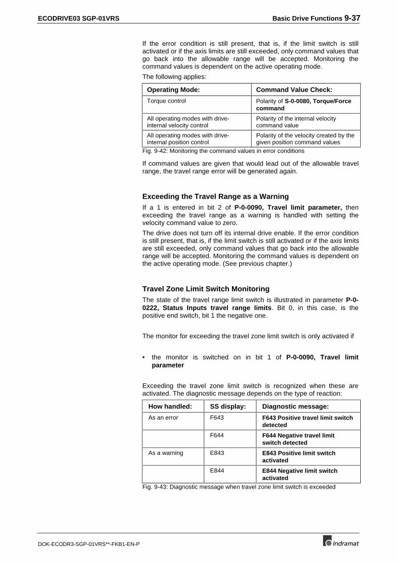
ECODRIVE03 SGP-01VRS Basic Drive Functions 9-37
DOK-ECODR3-SGP-01VRS**-FKB1-EN-P
If the error condition is still present, that is, if the limit switch is stillactivated or if the axis limits are still exceeded, only command values thatgo back into the allowable range will be accepted. Monitoring thecommand values is dependent on the active operating mode.
The following applies:
Operating Mode: Command Value Check:
Torque control Polarity of S-0-0080, Torque/Forcecommand
All operating modes with drive-internal velocity control
Polarity of the internal velocitycommand value
All operating modes with drive-internal position control
Polarity of the velocity created by thegiven position command values
Fig. 9-42: Monitoring the command values in error conditions
If command values are given that would lead out of the allowable travelrange, the travel range error will be generated again.
Exceeding the Travel Range as a WarningIf a 1 is entered in bit 2 of P-0-0090, Travel limit parameter, thenexceeding the travel range as a warning is handled with setting thevelocity command value to zero.
The drive does not turn off its internal drive enable. If the error conditionis still present, that is, if the limit switch is still activated or if the axis limitsare still exceeded, only command values that go back into the allowablerange will be accepted. Monitoring the command values is dependent onthe active operating mode. (See previous chapter.)
Travel Zone Limit Switch MonitoringThe state of the travel range limit switch is illustrated in parameter P-0-0222, Status Inputs travel range limits. Bit 0, in this case, is thepositive end switch, bit 1 the negative one.
The monitor for exceeding the travel zone limit switch is only activated if
• the monitor is switched on in bit 1 of P-0-0090, Travel limitparameter
Exceeding the travel zone limit switch is recognized when these areactivated. The diagnostic message depends on the type of reaction:
How handled: SS display: Diagnostic message:
As an error F643 F643 Positive travel limit switchdetected
F644 F644 Negative travel limitswitch detected
As a warning E843 E843 Positive limit switchactivated
E844 E844 Negative limit switchactivated
Fig. 9-43: Diagnostic message when travel zone limit switch is exceeded
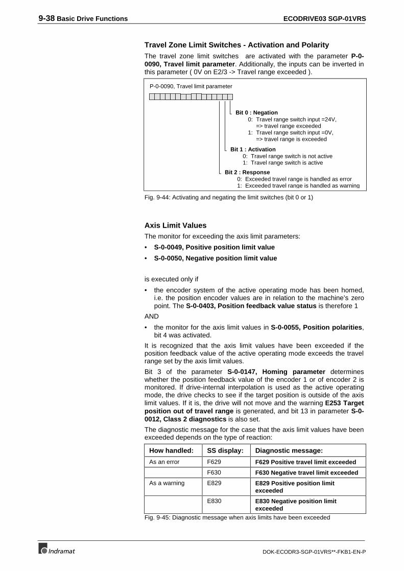
9-38 Basic Drive Functions ECODRIVE03 SGP-01VRS
DOK-ECODR3-SGP-01VRS**-FKB1-EN-P
Travel Zone Limit Switches - Activation and PolarityThe travel zone limit switches are activated with the parameter P-0-0090, Travel limit parameter. Additionally, the inputs can be inverted inthis parameter ( 0V on E2/3 -> Travel range exceeded ).
Bit 0 : Negation0: Travel range switch input =24V,
=> travel range exceeded1: Travel range switch input =0V,
=> travel range is exceeded
Bit 1 : Activation0: Travel range switch is not active1: Travel range switch is active
Bit 2 : Response0: Exceeded travel range is handled as error1: Exceeded travel range is handled as warning
P-0-0090, Travel limit parameter
Fig. 9-44: Activating and negating the limit switches (bit 0 or 1)
Axis Limit ValuesThe monitor for exceeding the axis limit parameters:
• S-0-0049, Positive position limit value
• S-0-0050, Negative position limit value
is executed only if
• the encoder system of the active operating mode has been homed,i.e. the position encoder values are in relation to the machine’s zeropoint. The S-0-0403, Position feedback value status is therefore 1
AND
• the monitor for the axis limit values in S-0-0055, Position polarities,bit 4 was activated.
It is recognized that the axis limit values have been exceeded if theposition feedback value of the active operating mode exceeds the travelrange set by the axis limit values.
Bit 3 of the parameter S-0-0147, Homing parameter determineswhether the position feedback value of the encoder 1 or of encoder 2 ismonitored. If drive-internal interpolation is used as the active operatingmode, the drive checks to see if the target position is outside of the axislimit values. If it is, the drive will not move and the warning E253 Targetposition out of travel range is generated, and bit 13 in parameter S-0-0012, Class 2 diagnostics is also set.
The diagnostic message for the case that the axis limit values have beenexceeded depends on the type of reaction:
How handled: SS display: Diagnostic message:
As an error F629 F629 Positive travel limit exceeded
F630 F630 Negative travel limit exceeded
As a warning E829 E829 Positive position limitexceeded
E830 E830 Negative position limitexceeded
Fig. 9-45: Diagnostic message when axis limits have been exceeded
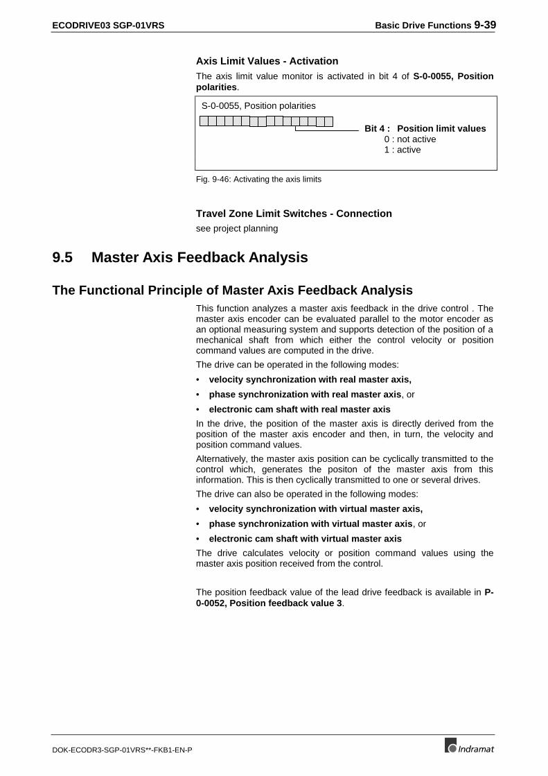
ECODRIVE03 SGP-01VRS Basic Drive Functions 9-39
DOK-ECODR3-SGP-01VRS**-FKB1-EN-P
Axis Limit Values - ActivationThe axis limit value monitor is activated in bit 4 of S-0-0055, Positionpolarities.
S-0-0055, Position polarities
Bit 4 : Position limit values0 : not active1 : active
Fig. 9-46: Activating the axis limits
Travel Zone Limit Switches - Connectionsee project planning
9.5 Master Axis Feedback Analysis
The Functional Principle of Master Axis Feedback AnalysisThis function analyzes a master axis feedback in the drive control . Themaster axis encoder can be evaluated parallel to the motor encoder asan optional measuring system and supports detection of the position of amechanical shaft from which either the control velocity or positioncommand values are computed in the drive.
The drive can be operated in the following modes:
• velocity synchronization with real master axis,
• phase synchronization with real master axis, or
• electronic cam shaft with real master axis
In the drive, the position of the master axis is directly derived from theposition of the master axis encoder and then, in turn, the velocity andposition command values.
Alternatively, the master axis position can be cyclically transmitted to thecontrol which, generates the positon of the master axis from thisinformation. This is then cyclically transmitted to one or several drives.
The drive can also be operated in the following modes:
• velocity synchronization with virtual master axis,
• phase synchronization with virtual master axis, or
• electronic cam shaft with virtual master axis
The drive calculates velocity or position command values using themaster axis position received from the control.
The position feedback value of the lead drive feedback is available in P-0-0052, Position feedback value 3.
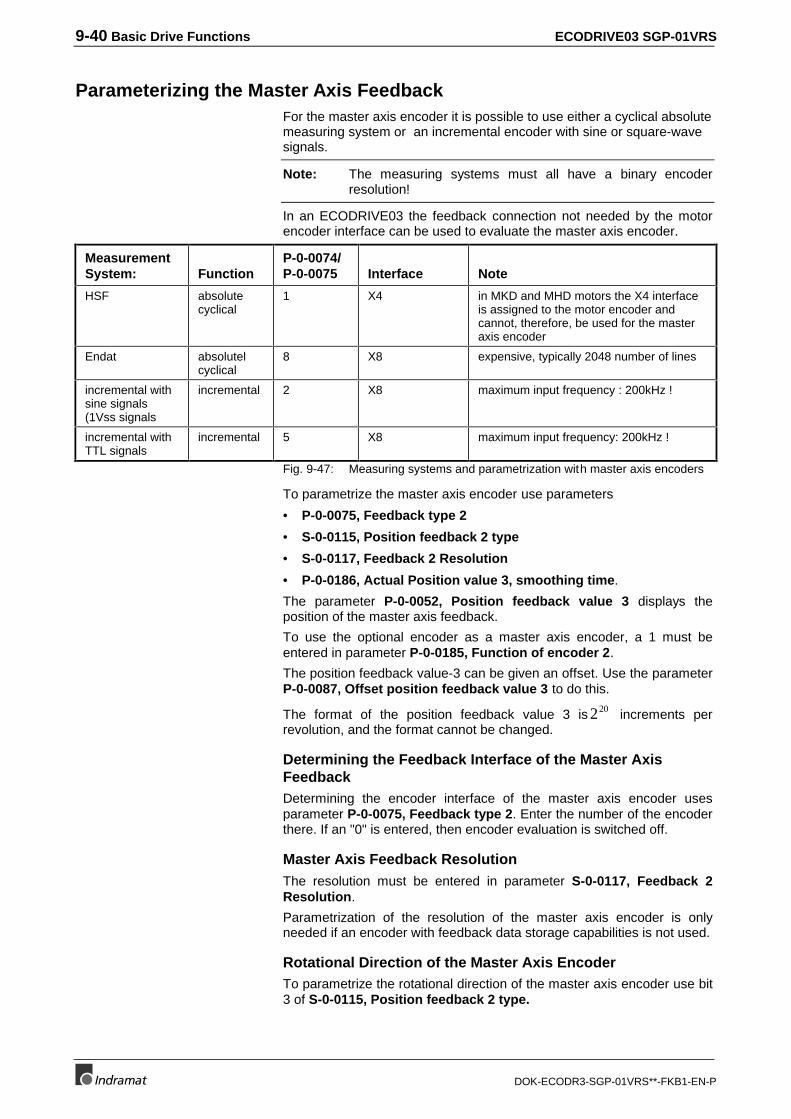
9-40 Basic Drive Functions ECODRIVE03 SGP-01VRS
DOK-ECODR3-SGP-01VRS**-FKB1-EN-P
Parameterizing the Master Axis FeedbackFor the master axis encoder it is possible to use either a cyclical absolutemeasuring system or an incremental encoder with sine or square-wavesignals.
Note: The measuring systems must all have a binary encoderresolution!
In an ECODRIVE03 the feedback connection not needed by the motorencoder interface can be used to evaluate the master axis encoder.
MeasurementSystem: Function
P-0-0074/P-0-0075 Interface Note
HSF absolutecyclical
1 X4 in MKD and MHD motors the X4 interfaceis assigned to the motor encoder andcannot, therefore, be used for the masteraxis encoder
Endat absolutelcyclical
8 X8 expensive, typically 2048 number of lines
incremental withsine signals(1Vss signals
incremental 2 X8 maximum input frequency : 200kHz !
incremental withTTL signals
incremental 5 X8 maximum input frequency: 200kHz !
Fig. 9-47: Measuring systems and parametrization with master axis encoders
To parametrize the master axis encoder use parameters
• P-0-0075, Feedback type 2
• S-0-0115, Position feedback 2 type
• S-0-0117, Feedback 2 Resolution
• P-0-0186, Actual Position value 3, smoothing time.
The parameter P-0-0052, Position feedback value 3 displays theposition of the master axis feedback.
To use the optional encoder as a master axis encoder, a 1 must beentered in parameter P-0-0185, Function of encoder 2.
The position feedback value-3 can be given an offset. Use the parameterP-0-0087, Offset position feedback value 3 to do this.
The format of the position feedback value 3 is 220 increments perrevolution, and the format cannot be changed.
Determining the Feedback Interface of the Master AxisFeedbackDetermining the encoder interface of the master axis encoder usesparameter P-0-0075, Feedback type 2. Enter the number of the encoderthere. If an "0" is entered, then encoder evaluation is switched off.
Master Axis Feedback ResolutionThe resolution must be entered in parameter S-0-0117, Feedback 2Resolution.
Parametrization of the resolution of the master axis encoder is onlyneeded if an encoder with feedback data storage capabilities is not used.
Rotational Direction of the Master Axis EncoderTo parametrize the rotational direction of the master axis encoder use bit3 of S-0-0115, Position feedback 2 type.
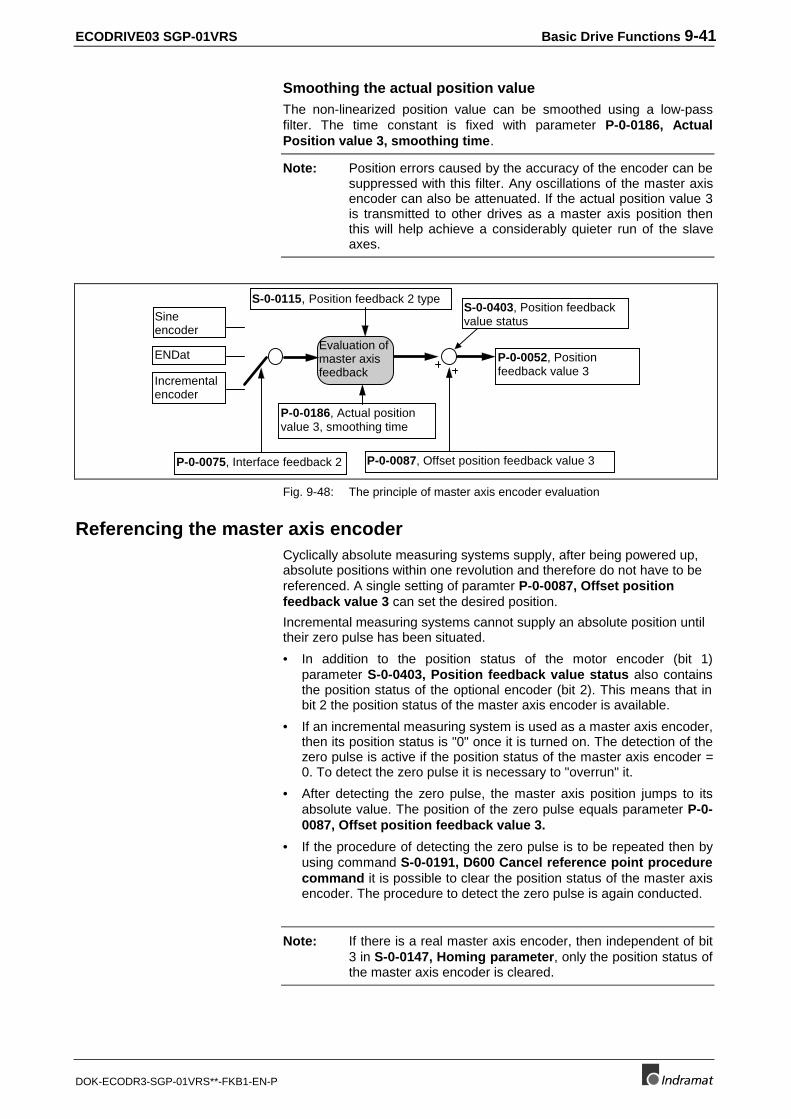
ECODRIVE03 SGP-01VRS Basic Drive Functions 9-41
DOK-ECODR3-SGP-01VRS**-FKB1-EN-P
Smoothing the actual position valueThe non-linearized position value can be smoothed using a low-passfilter. The time constant is fixed with parameter P-0-0186, ActualPosition value 3, smoothing time.
Note: Position errors caused by the accuracy of the encoder can besuppressed with this filter. Any oscillations of the master axisencoder can also be attenuated. If the actual position value 3is transmitted to other drives as a master axis position thenthis will help achieve a considerably quieter run of the slaveaxes.
Sineencoder
S-0-0115, Position feedback 2 type
Evaluation ofmaster axisfeedback
ENDat
Incrementalencoder
P-0-0186, Actual positionvalue 3, smoothing time
P-0-0075, Interface feedback 2 P-0-0087, Offset position feedback value 3
P-0-0052, Positionfeedback value 3
S-0-0403, Position feedbackvalue status
Fig. 9-48: The principle of master axis encoder evaluation
Referencing the master axis encoderCyclically absolute measuring systems supply, after being powered up,absolute positions within one revolution and therefore do not have to bereferenced. A single setting of paramter P-0-0087, Offset positionfeedback value 3 can set the desired position.
Incremental measuring systems cannot supply an absolute position untiltheir zero pulse has been situated.
• In addition to the position status of the motor encoder (bit 1)parameter S-0-0403, Position feedback value status also containsthe position status of the optional encoder (bit 2). This means that inbit 2 the position status of the master axis encoder is available.
• If an incremental measuring system is used as a master axis encoder,then its position status is "0" once it is turned on. The detection of thezero pulse is active if the position status of the master axis encoder =0. To detect the zero pulse it is necessary to "overrun" it.
• After detecting the zero pulse, the master axis position jumps to itsabsolute value. The position of the zero pulse equals parameter P-0-0087, Offset position feedback value 3.
• If the procedure of detecting the zero pulse is to be repeated then byusing command S-0-0191, D600 Cancel reference point procedurecommand it is possible to clear the position status of the master axisencoder. The procedure to detect the zero pulse is again conducted.
Note: If there is a real master axis encoder, then independent of bit3 in S-0-0147, Homing parameter, only the position status ofthe master axis encoder is cleared.

9-42 Basic Drive Functions ECODRIVE03 SGP-01VRS
DOK-ECODR3-SGP-01VRS**-FKB1-EN-P
Notes
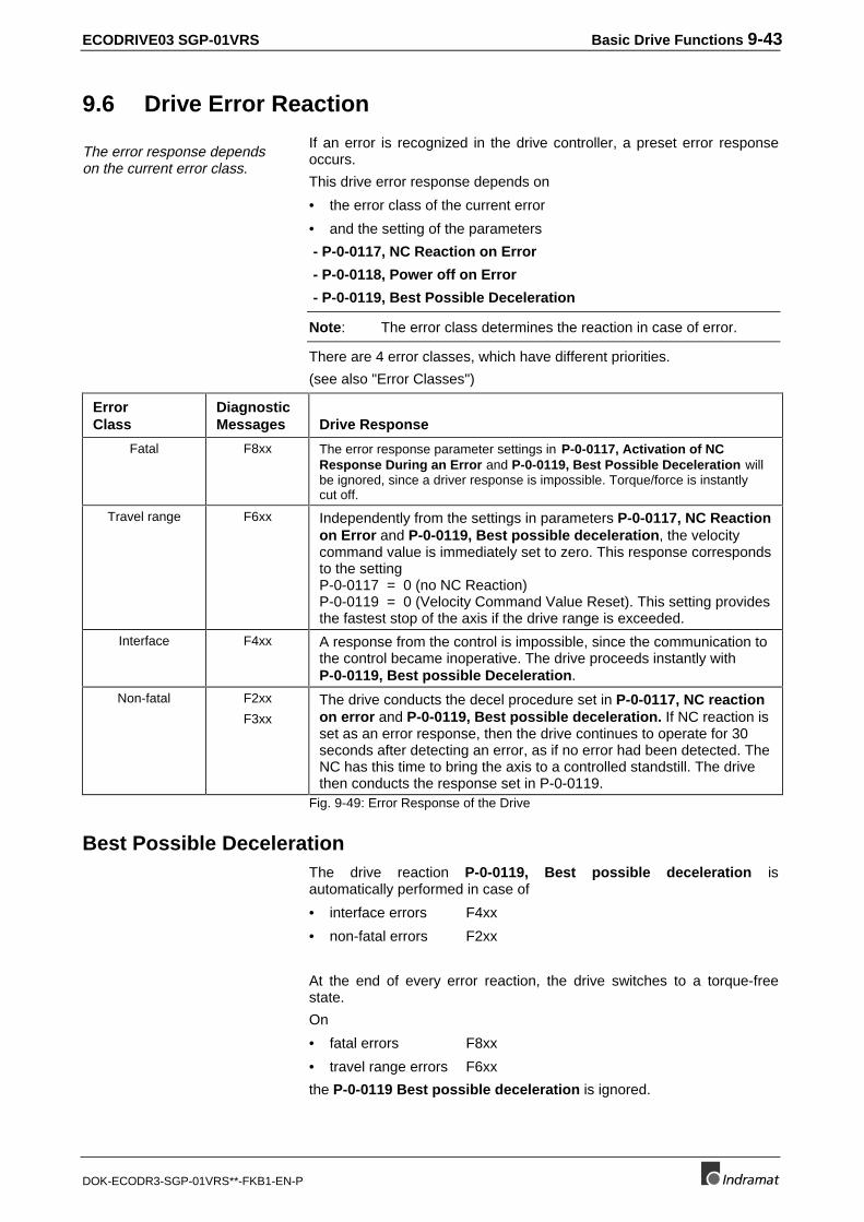
ECODRIVE03 SGP-01VRS Basic Drive Functions 9-43
DOK-ECODR3-SGP-01VRS**-FKB1-EN-P
9
9.6 Drive Error Reaction
The error response dependson the current error class.
If an error is recognized in the drive controller, a preset error responseoccurs.
This drive error response depends on
• the error class of the current error
• and the setting of the parameters
- P-0-0117, NC Reaction on Error
- P-0-0118, Power off on Error
- P-0-0119, Best Possible Deceleration
Note: The error class determines the reaction in case of error.
There are 4 error classes, which have different priorities.
(see also "Error Classes")
ErrorClass
DiagnosticMessages Drive Response
Fatal F8xx The error response parameter settings in P-0-0117, Activation of NCResponse During an Error and P-0-0119, Best Possible Deceleration willbe ignored, since a driver response is impossible. Torque/force is instantlycut off.
Travel range F6xx Independently from the settings in parameters P-0-0117, NC Reactionon Error and P-0-0119, Best possible deceleration, the velocitycommand value is immediately set to zero. This response correspondsto the settingP-0-0117 = 0 (no NC Reaction)P-0-0119 = 0 (Velocity Command Value Reset). This setting providesthe fastest stop of the axis if the drive range is exceeded.
Interface F4xx A response from the control is impossible, since the communication tothe control became inoperative. The drive proceeds instantly withP-0-0119, Best possible Deceleration.
Non-fatal F2xx
F3xxThe drive conducts the decel procedure set in P-0-0117, NC reactionon error and P-0-0119, Best possible deceleration. If NC reaction isset as an error response, then the drive continues to operate for 30seconds after detecting an error, as if no error had been detected. TheNC has this time to bring the axis to a controlled standstill. The drivethen conducts the response set in P-0-0119.
Fig. 9-49: Error Response of the Drive
Best Possible DecelerationThe drive reaction P-0-0119, Best possible deceleration isautomatically performed in case of
• interface errors F4xx
• non-fatal errors F2xx
At the end of every error reaction, the drive switches to a torque-freestate.
On
• fatal errors F8xx
• travel range errors F6xx
the P-0-0119 Best possible deceleration is ignored.
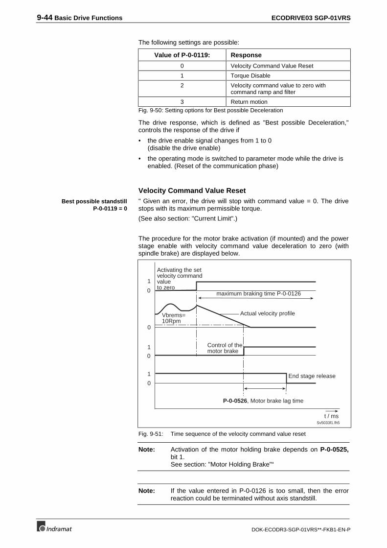
9-44 Basic Drive Functions ECODRIVE03 SGP-01VRS
DOK-ECODR3-SGP-01VRS**-FKB1-EN-P
The following settings are possible:
Value of P-0-0119: Response
0 Velocity Command Value Reset
1 Torque Disable
2 Velocity command value to zero withcommand ramp and filter
3 Return motionFig. 9-50: Setting options for Best possible Deceleration
The drive response, which is defined as "Best possible Deceleration,"controls the response of the drive if
• the drive enable signal changes from 1 to 0(disable the drive enable)
• the operating mode is switched to parameter mode while the drive isenabled. (Reset of the communication phase)
Velocity Command Value Reset" Given an error, the drive will stop with command value = 0. The drivestops with its maximum permissible torque.
(See also section: "Current Limit".)
The procedure for the motor brake activation (if mounted) and the powerstage enable with velocity command value deceleration to zero (withspindle brake) are displayed below.
0
0
0
1
1
0
1
Sv5033f1.fh5
t / ms
P-0-0526, Motor brake lag time
Control of themotor brake
Actual velocity profile
Activating the setvelocity commandvalueto zero
Vbrems=10Rpm
maximum braking time P-0-0126
End stage release
Fig. 9-51: Time sequence of the velocity command value reset
Note: Activation of the motor holding brake depends on P-0-0525,bit 1.See section: "Motor Holding Brake"“
Note: If the value entered in P-0-0126 is too small, then the errorreaction could be terminated without axis standstill.
Best possible standstillP-0-0119 = 0
ECODRIVE03 SGP-01VRS Basic Drive Functions 9-45
DOK-ECODR3-SGP-01VRS**-FKB1-EN-P
WARNING
If P-0-0126, Maximum braking time is set too low:Danger of damaging the motor brake
⇒ The value for P-0-0126, Maximum braking timemust always be set higher than the time neededto decelerate the axis with the velocity commandvalue reset, taking maximum possible velocityinto account.
Disable TorqueIn the event of an error, the drive goes torque free and is braked only bythe frictional force, i.e., it "coasts". The actual time to standstill can beconsiderable.
Note: The error reaction "Torque disable“ is absolutely necessarywith fatal errors (F8xx) because braking with a defective endstage or feedback is no longer possible!
DANGER
Drive continues to move unbraked with error!Danger to life from parts in motion if safety doors areopen at the machining cells!
⇒ Check drive for motion (e.g., using S-0-0040,Velocity feedback value, if possible) and awaitstandstill!
Note: Activation of the motor holding brake depends on P-0-0525,bit 1.See section: "Motor Holding Brake"“.
The temporal behavior of the brake in conjunction with an error reactiondepends on the brake.
The motor holding brake is not activated until the motor speed dropsbelow 10min-1.
Best possible standstillP-0-0119 = 1or fatal error
Spindle brake
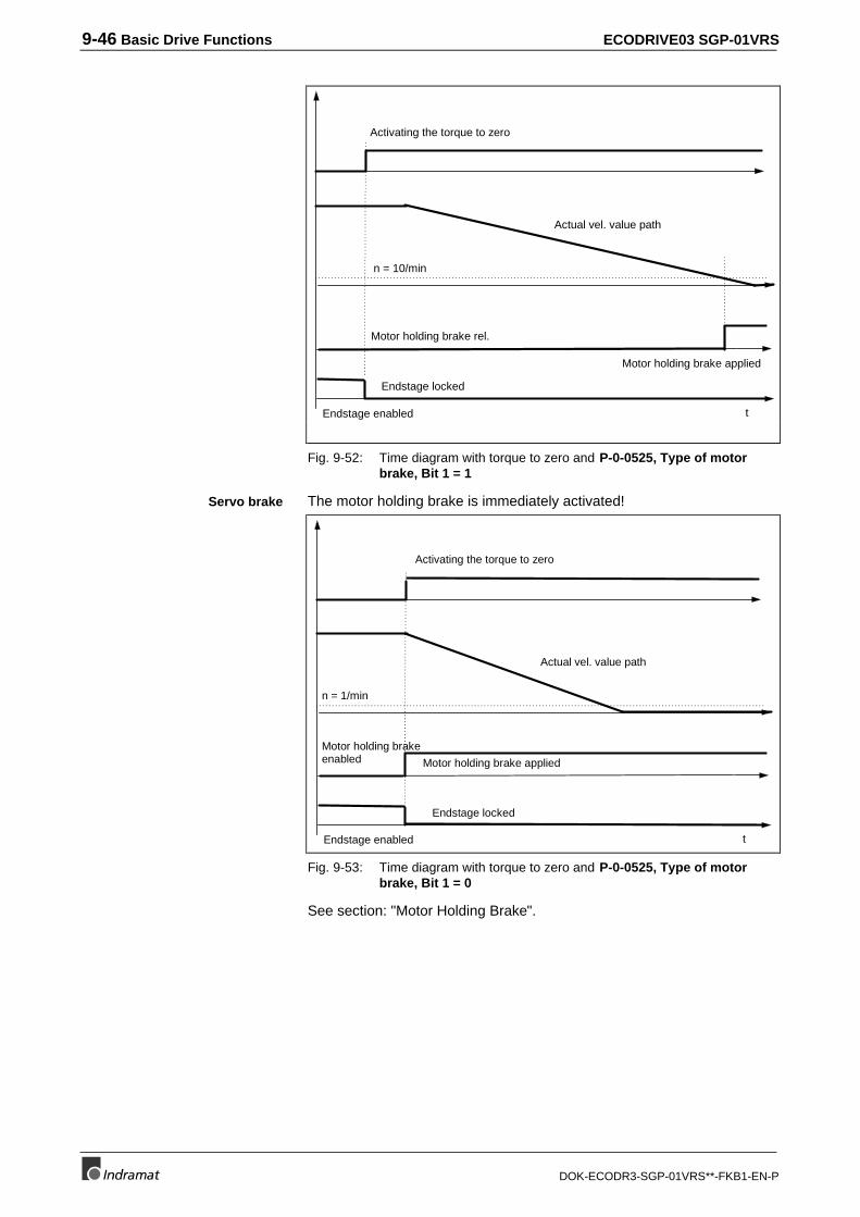
9-46 Basic Drive Functions ECODRIVE03 SGP-01VRS
DOK-ECODR3-SGP-01VRS**-FKB1-EN-P
t
Activating the torque to zero
Motor holding brake rel.
Endstage enabled
n = 10/min
Endstage locked
Actual vel. value path
Motor holding brake applied
Fig. 9-52: Time diagram with torque to zero and P-0-0525, Type of motorbrake, Bit 1 = 1
The motor holding brake is immediately activated!
t
Activating the torque to zero
Motor holding brakeenabled
Endstage enabled
n = 1/min
Endstage locked
Actual vel. value path
Motor holding brake applied
Fig. 9-53: Time diagram with torque to zero and P-0-0525, Type of motorbrake, Bit 1 = 0
See section: "Motor Holding Brake".
Servo brake
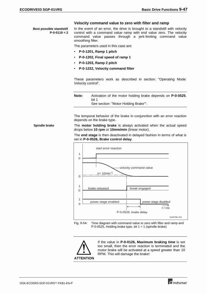
ECODRIVE03 SGP-01VRS Basic Drive Functions 9-47
DOK-ECODR3-SGP-01VRS**-FKB1-EN-P
Velocity command value to zero with filter and rampIn the event of an error, the drive is brought to a standstill with velocitycontrol with a command value ramp with end value zero. The velocitycommand value passes through a jerk-limiting command valuesmoothing filter.
The parameters used in this case are:
• P-0-1201, Ramp 1 pitch
• P-0-1202, Final speed of ramp 1
• P-0-1203, Ramp 2 pitch
• P-0-1222, Velocity command filter
These parameters work as described in section: "Operating Mode:Velocity control".
Note: Activation of the motor holding brake depends on P-0-0525,bit 1See section: "Motor Holding Brake"“.
The temporal behavior of the brake in conjunction with an error reactiondepends on the brake type.
The motor holding brake is always activated when the actual speeddrops below 10 rpm or 10mm/min (linear motor).
The end stage is then deactivated in delayed fashion in terms of what isset in P-0-0526, Brake control delay.
0
0
0
1
1
0
1
P-0-0526, brake delay
brake released
velocity command value
Sv5078f1.fh5
start error reaction
n= 10min-1
power stage disabledpower stage enabled
break engaged
t / ms
Fig. 9-54: Time diagram with command value to zero with filter and ramp andP-0-0525, Holding brake type, bit 1 = 1 (spindle brake)
ATTENTION
If the value in P-0-0126, Maximum braking time is settoo small, then the error reaction is terminated and themotor brake will be activated at a speed greater than 10RPM. This will damage the brake!
Best possible standstillP-0-0119 = 2
Spindle brake
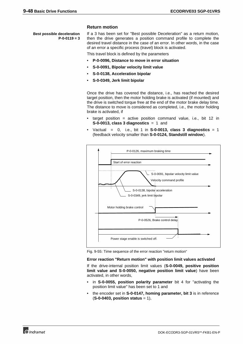
9-48 Basic Drive Functions ECODRIVE03 SGP-01VRS
DOK-ECODR3-SGP-01VRS**-FKB1-EN-P
Return motionIf a 3 has been set for "Best possible Deceleration" as a return motion,then the drive generates a position command profile to complete thedesired travel distance in the case of an error. In other words, in the caseof an error a specific process (travel) block is activated.
This travel block is defined by the parameters
• P-0-0096, Distance to move in error situation
• S-0-0091, Bipolar velocity limit value
• S-0-0138, Acceleration bipolar
• S-0-0349, Jerk limit bipolar
Once the drive has covered the distance, i.e., has reached the desiredtarget position, then the motor holding brake is activated (if mounted) andthe drive is switched torque free at the end of the motor brake delay time.The distance to move is considered as completed, i.e., the motor holdingbrake is activated, if
• target position = active position command value, i.e., bit 12 inS-0-0013, class 3 diagnostics = 1 and
• Vactual = 0, i.e., bit 1 in S-0-0013, class 3 diagnostics = 1(feedback velocity smaller than S-0-0124, Standstill window).
S-0-0349, jerk limit bipolar
S-0-0138, bipolar acceleration
S-0-0091, bipolar velocity limit value
Motor holding brake control
Power stage enable is switched off.
P-0-0526, Brake control delay
P-0-0126, maximum braking time
Velocity command profile
Start of error reaction
Fig. 9-55: Time sequence of the error reaction "return motion“
Error reaction "Return motion" with position limit values activated
If the drive-internal position limit values (S-0-0049, positive positionlimit value and S-0-0050, negative position limit value) have beenactivated, in other words,
• in S-0-0055, position polarity parameter bit 4 for "activating theposition limit value" has been set to 1 and
• the encoder set in S-0-0147, homing parameter, bit 3 is in reference(S-0-0403, position status = 1),
Best possible decelerationP-0-0119 = 3
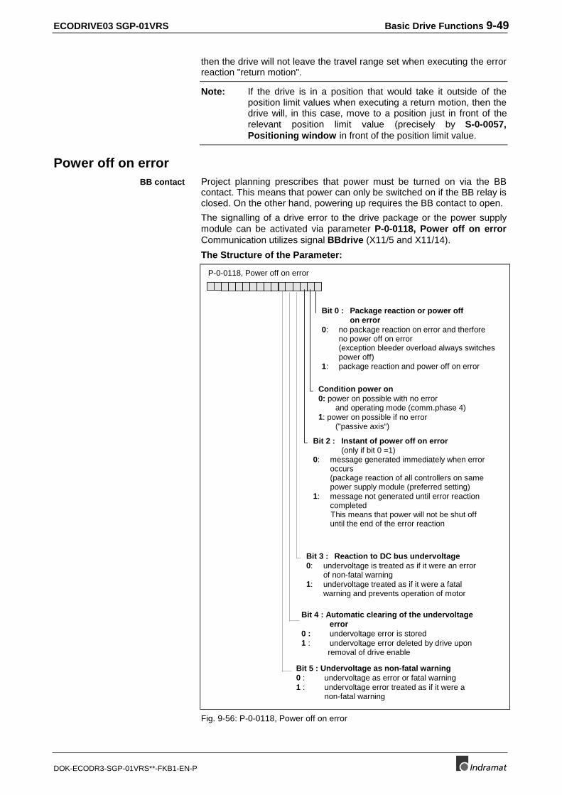
ECODRIVE03 SGP-01VRS Basic Drive Functions 9-49
DOK-ECODR3-SGP-01VRS**-FKB1-EN-P
then the drive will not leave the travel range set when executing the errorreaction "return motion".
Note: If the drive is in a position that would take it outside of theposition limit values when executing a return motion, then thedrive will, in this case, move to a position just in front of therelevant position limit value (precisely by S-0-0057,Positioning window in front of the position limit value.
Power off on errorProject planning prescribes that power must be turned on via the BBcontact. This means that power can only be switched on if the BB relay isclosed. On the other hand, powering up requires the BB contact to open.
The signalling of a drive error to the drive package or the power supplymodule can be activated via parameter P-0-0118, Power off on errorCommunication utilizes signal BBdrive (X11/5 and X11/14).
The Structure of the Parameter:
Bit 0 : Package reaction or power offon error
0: no package reaction on error and therforeno power off on error
(exception bleeder overload always switches power off)
1: package reaction and power off on error
P-0-0118, Power off on error
Condition power on0: power on possible with no error
and operating mode (comm.phase 4)1: power on possible if no error
("passive axis“)
Bit 2 : Instant of power off on error(only if bit 0 =1)
0: message generated immediately when error occurs(package reaction of all controllers on same power supply module (preferred setting)
1: message not generated until error reactioncompleted
This means that power will not be shut offuntil the end of the error reaction
Bit 3 : Reaction to DC bus undervoltage0: undervoltage is treated as if it were an error
of non-fatal warning1: undervoltage treated as if it were a fatal
warning and prevents operation of motor
Bit 4 : Automatic clearing of the undervoltageerror
0 : undervoltage error is stored1 : undervoltage error deleted by drive upon removal of drive enable
Bit 5 : Undervoltage as non-fatal warning0 : undervoltage as error or fatal warning1 : undervoltage error treated as if it were a
non-fatal warning
Fig. 9-56: P-0-0118, Power off on error
BB contact
9-50 Basic Drive Functions ECODRIVE03 SGP-01VRS
DOK-ECODR3-SGP-01VRS**-FKB1-EN-P
Power off and package reaction on errorIn the case of drive packages (this is defined as a collection of multipledrives that have a power supply common to all and which can executeerrors commonly), it is possible to inform the individual controllers andany power supply module which may be present as to whether the drivehas detected an error as a result of which the power source must beshutdown. This communication utilizes signal line "BBdrive" (x11/5 andX11/14).
If the controllers without error detect the error state on the signal line BBdrive, then they will, in turn, also conduct the error reaction and shutpower off.
The point in time at which the drive package is signalled (at start or endof the error reaction) is set in bit 2.
Condition for Power OnUsing bit 1 of P-0-0118, Power off on error it is possible to set that pointin time at which the drive signals its readiness to operate and therefore atwhich power can be switched on.
If bit1 = 1, then power can be switched on immediately after initializationof the drive, in other words, in communication phase 0 ("passive axis“).
If bit1 = 0, then the drive must be in communications phase 4 andwithout error before the power can be switched on for the first time.
In units that cannot release energy generated during brake (by means ofbleeders or a mains-regenerated power supply) bit 2 should be set to 1 toprevent the drive coasting.
Reaction to Undervoltage (DC bus voltage too small)Bits 3, 4 and 5 of P-0-0118, Power off on error offer various options onhow to handle Undervoltage.
Undervoltage is present if the drive has been enabled (subject to torque)and the DC bus voltage drops below the minimum value (about 75% ofthe mean value of a periodic quantity).
Using Bit3 = 1 treats undervoltage as a "fatal warning".
This makes sense if the energy in the DC bus must be retained for thatperiod of time which a control needs to start a synchronized decelerationof several drives.
The drive does not signal a class 1 diagnostics error and the reactionparametrized in P-0-0119, Best possible deceleration is also notconducted.
Switching the motor off leads to a slower drop in the DC bus voltage.This means that asynchronous motors can still have a magnetic fieldwhen the control starts the synchronized deceleration of the drive.Braking then takes place in generator mode.
If undervoltage is treated as an error (bit 3, 5 = 0), then bit 4 can be usedto set an automatic delete of the error once the control removes the driveenable signal.
This makes sense if the error occurs even with normal shutdowns andthe cause is simply that the drive does not remove the enable fastenough.
Using Bit5 = 1 it is possible to switch off every response to undervoltagein the DC bus, mains errors or mains section errors (in the case ofseparate mains sections). Only one warning is generated.
Signal line "BBdrive"
passive axis
Undervoltage as fatal warning
Mains error as fatal warning
Mains section error as fatalwarning
Automatic deleting of theundervoltage
Undervoltage as warning
ECODRIVE03 SGP-01VRS Basic Drive Functions 9-51
DOK-ECODR3-SGP-01VRS**-FKB1-EN-P
If the mains section or controller detects undervoltage on the mainssupply (mains error), then the softstart of the mains section is initiated forthe power supply (mains coupling via a bleeder resistor). If the controldoes not response to this warning by shutting the machine down, thenerror F220 Bleeder overload shutdown could be generated.
NC Response in Error Situation
NC response during an errorsituation is only possibleduring non-fatal errors.Otherwise the drive reactsimmediately with an errorresponse.
If the drive control device recognizes an error, it sends a message to thecontrol (CNC) . The control can then decelerate the servo axis of themachine without possible damage.
If this is desired, you have to delay the drive error reaction to allow theaxis to continue movement to the values set by the control. This isachived by setting the time delay between the recognition of the error andthe drive’s error reaction. This can be set in parameter P-0-0117, NCReaction on Error.
The following applies:
Value of P-0-0117 Function
0 Drive proceeds the error reaction immediatelyafter recognition of the error.
1 Drive continues for 30 sec in the selectedoperating mode, then follows the "best possibledeceleration".
Fig. 9-57: NC Reaction on Error
Note: Activating the "NC Reaction on Error" is only recommendedfor controls that have a corresponding error reactionprocedure.
Emergency stop featureThe E-Stop function supports the braking of the drive via a hardwareinput on the drive controller. It thus represents the option of shuttingdown the drive parallel to command communication, in an emergency.
Activation and the how to set the deceleration:
The following parameters are used:
• P-0-0008, Activation E-Stop function
• P-0-0223, Status Input E-Stop function
Functional principle of the E-Stop function
By activating the E-Stop function (bit 0 = 1) the drive executes, uponactuation of the E-stop input, the selected reaction for deceleration. Thisreaction depends on bit 2 of P-0-0008.
After activation of the E-Stop Input (bit 0 = 1), the drive is prompted toperform the selected procedure to shutdown the drive. This reaction atfirst depends on bit 2 of P-0-0008.
Mains error
Mains section error
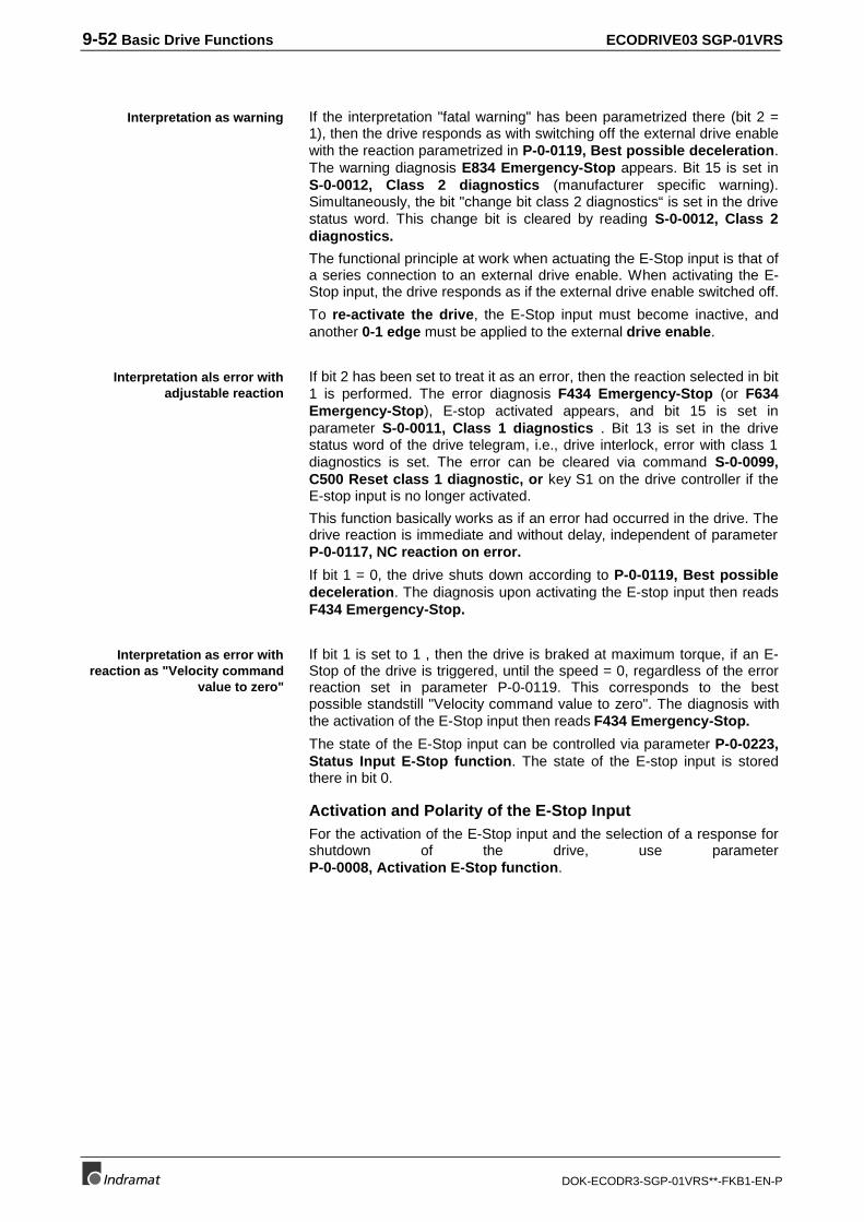
9-52 Basic Drive Functions ECODRIVE03 SGP-01VRS
DOK-ECODR3-SGP-01VRS**-FKB1-EN-P
If the interpretation "fatal warning" has been parametrized there (bit 2 =1), then the drive responds as with switching off the external drive enablewith the reaction parametrized in P-0-0119, Best possible deceleration.The warning diagnosis E834 Emergency-Stop appears. Bit 15 is set inS-0-0012, Class 2 diagnostics (manufacturer specific warning).Simultaneously, the bit "change bit class 2 diagnostics“ is set in the drivestatus word. This change bit is cleared by reading S-0-0012, Class 2diagnostics.
The functional principle at work when actuating the E-Stop input is that ofa series connection to an external drive enable. When activating the E-Stop input, the drive responds as if the external drive enable switched off.
To re-activate the drive, the E-Stop input must become inactive, andanother 0-1 edge must be applied to the external drive enable.
If bit 2 has been set to treat it as an error, then the reaction selected in bit1 is performed. The error diagnosis F434 Emergency-Stop (or F634Emergency-Stop), E-stop activated appears, and bit 15 is set inparameter S-0-0011, Class 1 diagnostics . Bit 13 is set in the drivestatus word of the drive telegram, i.e., drive interlock, error with class 1diagnostics is set. The error can be cleared via command S-0-0099,C500 Reset class 1 diagnostic, or key S1 on the drive controller if theE-stop input is no longer activated.
This function basically works as if an error had occurred in the drive. Thedrive reaction is immediate and without delay, independent of parameterP-0-0117, NC reaction on error.
If bit 1 = 0, the drive shuts down according to P-0-0119, Best possibledeceleration. The diagnosis upon activating the E-stop input then readsF434 Emergency-Stop.
If bit 1 is set to 1 , then the drive is braked at maximum torque, if an E-Stop of the drive is triggered, until the speed = 0, regardless of the errorreaction set in parameter P-0-0119. This corresponds to the bestpossible standstill "Velocity command value to zero". The diagnosis withthe activation of the E-Stop input then reads F434 Emergency-Stop.
The state of the E-Stop input can be controlled via parameter P-0-0223,Status Input E-Stop function. The state of the E-stop input is storedthere in bit 0.
Activation and Polarity of the E-Stop InputFor the activation of the E-Stop input and the selection of a response forshutdown of the drive, use parameterP-0-0008, Activation E-Stop function.
Interpretation as warning
Interpretation als error withadjustable reaction
Interpretation as error withreaction as "Velocity command
value to zero"
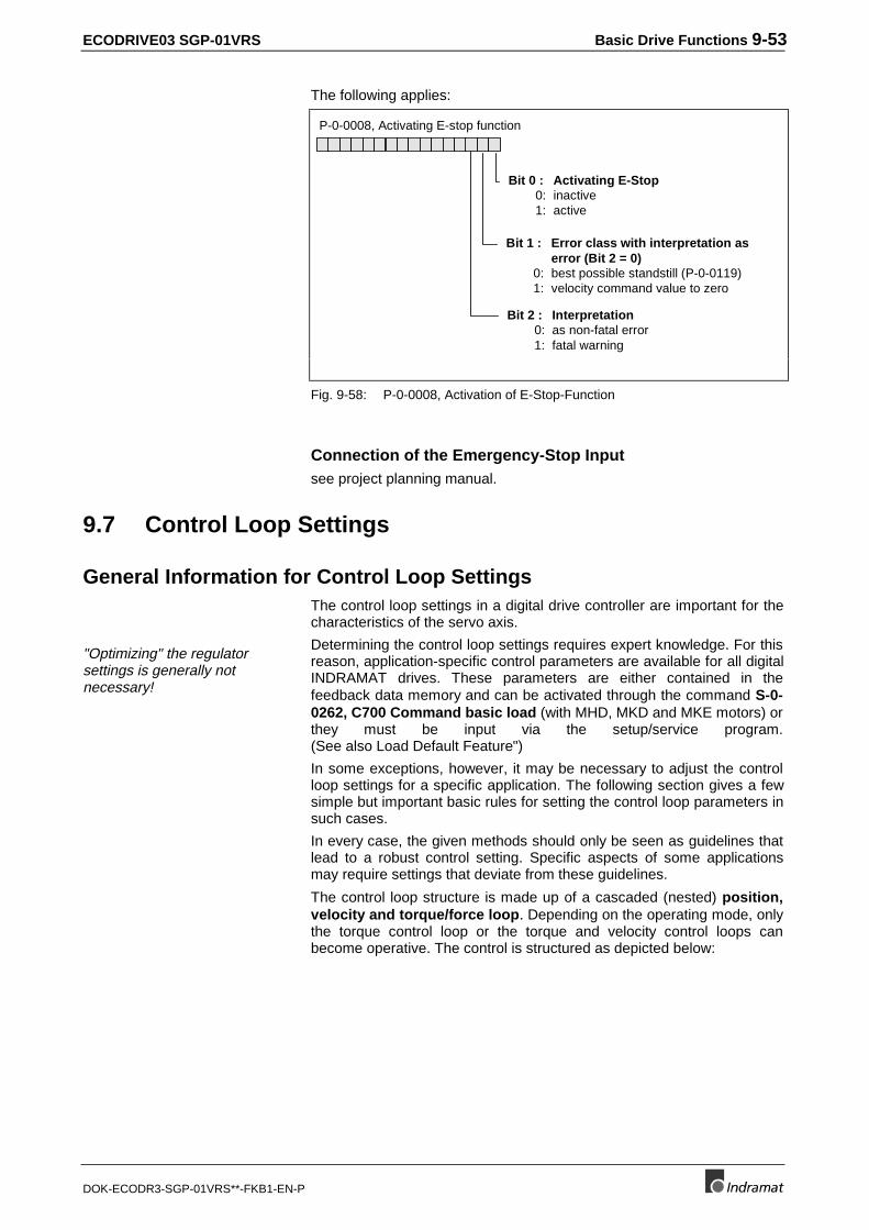
ECODRIVE03 SGP-01VRS Basic Drive Functions 9-53
DOK-ECODR3-SGP-01VRS**-FKB1-EN-P
The following applies:
P-0-0008, Activating E-stop function
Bit 0 : Activating E-Stop0: inactive1: active
Bit 1 : Error class with interpretation as error (Bit 2 = 0)
0: best possible standstill (P-0-0119)1: velocity command value to zero
Bit 2 : Interpretation0: as non-fatal error1: fatal warning
Fig. 9-58: P-0-0008, Activation of E-Stop-Function
Connection of the Emergency-Stop Inputsee project planning manual.
9.7 Control Loop Settings
General Information for Control Loop SettingsThe control loop settings in a digital drive controller are important for thecharacteristics of the servo axis.
"Optimizing" the regulatorsettings is generally notnecessary!
Determining the control loop settings requires expert knowledge. For thisreason, application-specific control parameters are available for all digitalINDRAMAT drives. These parameters are either contained in thefeedback data memory and can be activated through the command S-0-0262, C700 Command basic load (with MHD, MKD and MKE motors) orthey must be input via the setup/service program.(See also Load Default Feature")
In some exceptions, however, it may be necessary to adjust the controlloop settings for a specific application. The following section gives a fewsimple but important basic rules for setting the control loop parameters insuch cases.
In every case, the given methods should only be seen as guidelines thatlead to a robust control setting. Specific aspects of some applicationsmay require settings that deviate from these guidelines.
The control loop structure is made up of a cascaded (nested) position,velocity and torque/force loop. Depending on the operating mode, onlythe torque control loop or the torque and velocity control loops canbecome operative. The control is structured as depicted below:
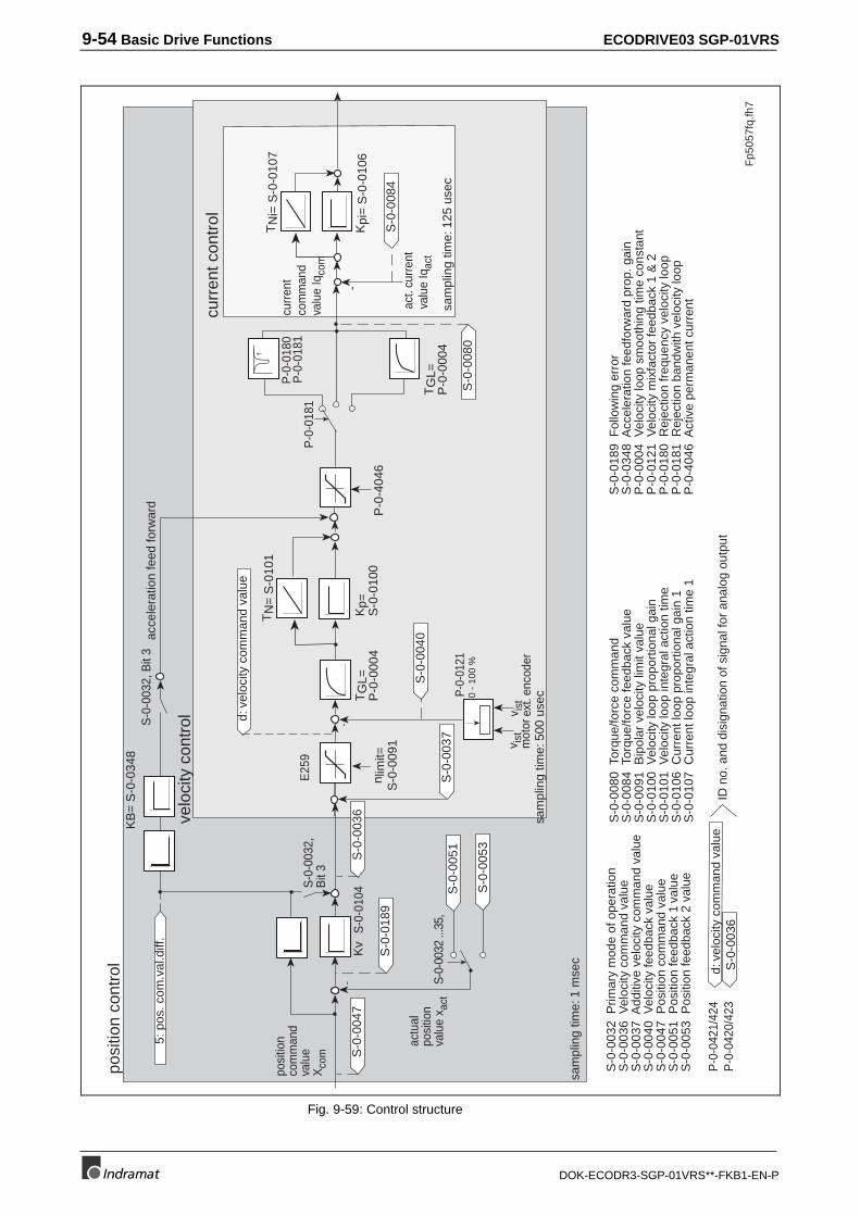
9-54 Basic Drive Functions ECODRIVE03 SGP-01VRS
DOK-ECODR3-SGP-01VRS**-FKB1-EN-P
posi
tion
cont
rol
sam
plin
g tim
e: 1
mse
c
Fp5
057f
q.fh
7
velo
city
con
trol
sam
plin
g tim
e: 5
00 u
sec
curr
ent c
ontr
ol
-K
v
KB
= S
-0-0
348
S-0
-010
4S-0
-003
2,B
it 3
S-0
-003
2, B
it 3
-K
pi=
S-0
-010
6
TN
i= S
-0-0
107
sam
plin
g tim
e: 1
25 u
sec
S-0
-003
2 ...
35,
P-0
-018
0P
-0-0
181
S-0
-005
3
TG
L=P
-0-0
004
P-0
-018
1
f
S-0
-004
7
5: p
os. c
om.v
al.d
iff.
S-0
-003
6
S-0
-008
4S
-0-0
189
d: v
eloc
ity c
omm
and
valu
eS
-0-0
036
-
P-0
-404
6n l
imit=
S-0
-009
1
Kp=
S-0
-010
0
TN
= S
-010
1
P-0-
0121
d: v
eloc
ity c
omm
and
valu
e
TG
L=P
-0-0
004
S-0
-004
0
S-0
-008
0
S-0
-003
7
0 -
100
%
curr
ent
com
man
dva
lue
Iqco
mE
259
posi
tion
com
man
dva
lue
Xco
m
actu
alpo
sitio
nva
lue
x act
v ist
mot
orv i
stex
t. en
code
r
act.
curr
ent
valu
e Iq
act
S-0
-005
1
S-0
-003
2 P
rimar
y m
ode
of o
pera
tion
S-0
-003
6 V
eloc
ity c
omm
and
valu
eS
-0-0
037
Add
itive
vel
ocity
com
man
d va
lue
S-0
-004
0 V
eloc
ity fe
edba
ck v
alue
S-0
-004
7 P
ositi
on c
omm
and
valu
eS
-0-0
051
Pos
ition
feed
back
1 v
alue
S-0
-005
3 P
ositi
on fe
edba
ck 2
val
ue
S-0
-008
0 T
orqu
e/fo
rce
com
man
dS
-0-0
084
Tor
que/
forc
e fe
edba
ck v
alue
S-0
-009
1 B
ipol
ar v
eloc
ity li
mit
valu
eS
-0-0
100
Vel
ocity
loop
pro
port
iona
l gai
nS
-0-0
101
Vel
ocity
loop
inte
gral
act
ion
time
S-0
-010
6 C
urre
nt lo
op p
ropo
rtio
nal g
ain
1S
-0-0
107
Cur
rent
loop
inte
gral
act
ion
time
1
S-0
-018
9 F
ollo
win
g er
ror
S-0
-034
8 A
ccel
erat
ion
feed
forw
ard
prop
. gai
nP
-0-0
004
Vel
ocity
loop
sm
ooth
ing
time
cons
tant
P-0
-012
1 V
eloc
ity m
ixfa
ctor
feed
back
1 &
2P
-0-0
180
Rej
ectio
n fr
eque
ncy
velo
city
loop
P-0
-018
1 R
ejec
tion
band
with
vel
ocity
loop
P-0
-404
6 A
ctiv
e pe
rman
ent c
urre
nt
P-0
-042
1/42
4ID
no.
and
dis
igna
tion
of s
igna
l for
ana
log
outp
utP
-0-0
420/
423
acce
lera
tion
feed
forw
ard
Fig. 9-59: Control structure
ECODRIVE03 SGP-01VRS Basic Drive Functions 9-55
DOK-ECODR3-SGP-01VRS**-FKB1-EN-P
Load DefaultWith the command Basic Load, you can activate the default controlparameters for motor types with motor feedback data memory such as
• MHD
• MKD
• MKE
With these parameters, the relevant control parameters for theappropriate motor type used can be set.
Note: The parameters are pre-defined by the manufacturer for themoment of inertia relationship of Jown = Jload.
Most applications can work with these values.
Default values can be set for the following parameters:
• S-0-0106, Current loop proportional gain 1
• S-0-0107, Current loop integral action time 1
• S-0-0100, Velocity loop proportional gain
• S-0-0101, Velocity loop integral action time
• P-0-0004, Smoothing Time Constant
• S-0-0104, Position loop Kv-factor
• P-0-0181, Rejection bandwidth velocity loop
The feature Load Default Settings can be activated in two different ways:
• Automatic activation during the command procedure S-0-0128, C200Communication phase 4 transition check for the first operation ofthis motor type with this drive.
• With the command procedure S-0-0262, C700 Basic Load
Automatic Execution of the Load Default FeatureIf a controller has been operated with a specific type of motor, then thecontroller will detect this from that point forward. During the execution ofcommand S-0-0128, C200 Communication phase 4 transition check itcompares parameter S-7-141, Motor type, which is read out of the datamemory, with the value for parameter S-0-0141, Motor type which isbacked up in the parameter memory of the controller. If these twoparameters are different, then error F208 UL The motor type haschanged is generated. "UL" appears in the 7-segment display.
Note: Before the user can reset the error and thus start the baseload function, the option of secure a specific set of controllerparameters is available.
Error F208 UL The motor type has changed can be reset in threedifferent ways:
1.) executing the command S-0-0099, C500 Reset class 1 diagnostic
2.) Actuating key S1
3.) Applying 24 V at error reset input
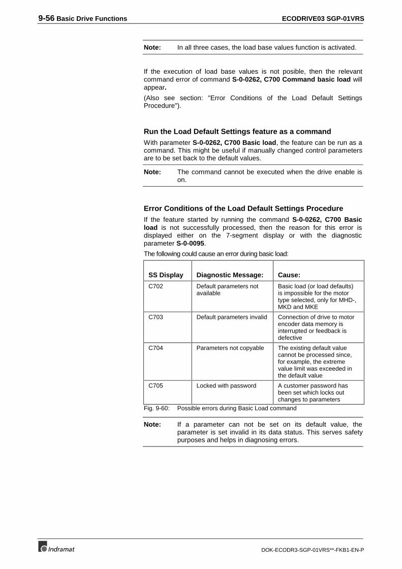
9-56 Basic Drive Functions ECODRIVE03 SGP-01VRS
DOK-ECODR3-SGP-01VRS**-FKB1-EN-P
Note: In all three cases, the load base values function is activated.
If the execution of load base values is not posible, then the relevantcommand error of command S-0-0262, C700 Command basic load willappear.
(Also see section: "Error Conditions of the Load Default SettingsProcedure").
Run the Load Default Settings feature as a commandWith parameter S-0-0262, C700 Basic load, the feature can be run as acommand. This might be useful if manually changed control parametersare to be set back to the default values.
Note: The command cannot be executed when the drive enable ison.
Error Conditions of the Load Default Settings ProcedureIf the feature started by running the command S-0-0262, C700 Basicload is not successfully processed, then the reason for this error isdisplayed either on the 7-segment display or with the diagnosticparameter S-0-0095.
The following could cause an error during basic load:
SS Display Diagnostic Message: Cause:
C702 Default parameters notavailable
Basic load (or load defaults)is impossible for the motortype selected, only for MHD-,MKD and MKE
C703 Default parameters invalid Connection of drive to motorencoder data memory isinterrupted or feedback isdefective
C704 Parameters not copyable The existing default valuecannot be processed since,for example, the extremevalue limit was exceeded inthe default value
C705 Locked with password A customer password hasbeen set which locks outchanges to parameters
Fig. 9-60: Possible errors during Basic Load command
Note: If a parameter can not be set on its default value, theparameter is set invalid in its data status. This serves safetypurposes and helps in diagnosing errors.
ECODRIVE03 SGP-01VRS Basic Drive Functions 9-57
DOK-ECODR3-SGP-01VRS**-FKB1-EN-P
Setting the Current ControllerThe parameters for the current loop are set by INDRAMAT and cannotbe adjusted for specific applications. The parameter values set at thefactory are activated with the command S-0-0262, C700 Commandbasic load for MKD/MHD motors or must be retrieved from the motordata sheet.
The parameters for the current controller are set via the parameters
• S-0-0106, Current loop proportional gain
• S-0-0107, Current Loop Integral Action Time
Warning
Changing the values defined by INDRAMATcan result in damages to the motor and the drivecontroller.
⇒ Changes to the current controller parameters are notpermitted.
Setting the Velocity ControllerPre-requisites:
The current control must be correctly set.
The velocity controller is set via the parameters
• S-0-0100, Velocity Loop Proportional Gain
• S-0-0101, Velocity Loop Integral Action Time
• P-0-0004, Smoothing Time Constant
as well as the parameters
• P-0-0180, Rejection frequency velocity loop
• P-0-0181, Rejection bandwidth velocity loop
The setting can be done by
• executing once the command "Basic load"
• the procedure described as follows
• starting the automatic control loop tuning
Preparations for Setting the Velocity ControllerA number of preparations must be made in order to be able to set thevelocity loop (controller):
• The mechanical system must be set up in its final form in order tohave original conditions while setting the parameters.
• The drive controller must be properly connected as described in theuser manual.
• The safety limit switches must be checked for correct operation (ifavailable)
• The velocity control operating mode must be selected in the drive.
9-58 Basic Drive Functions ECODRIVE03 SGP-01VRS
DOK-ECODR3-SGP-01VRS**-FKB1-EN-P
The controller setting must be selected for the start of parameterizationas follows:
S-0-0100, Velocity Loop Proportional Gain = default value of theconnected motor.
S-0-0101, Velocity Loop Integral Action Time = 6500 ms (no I-Part)
P-0-0004, Smoothing Time Constant = Minimum value (= 500µs)
P-0-0181, Rejection bandwidth velocity loop = 0 Hz (deactivated)
Note: When determining the velocity control parameters, nocompensation function should be active.
Definition of the Critical Proportional Gain and SmoothingTime Constant
• After turning on the controller enable, let the drive move at a lowvelocity. Rotational motors: 10...20RPM, linear-Motors: 1...2 m/min)
• Raise the S-0-0100, Velocity loop-proportional gain until unstablebehavior (continuous oscillation) begins.
• Determined the frequency of the oscillation by oscilloscoping theactual velocity (see also "Analog Output"). If the frequency of theoscillation is much higher than 500Hz, raise the P-0-0004,Smoothing Time Constant until the oscillation ends. After this,increase the S-0-0100, Velocity Control Proportional Gain until itbecomes unstable again.
• Reduce the S-0-0100, Velocity loop proportional gain until theoscillation ends by itself.
The value found using this process is called the "critical velocity loopproportional gain".
Determining the Critical Integral Action Time
• Set S-0-0100, Velocity Loop Proportional Gain = 0.5 x criticalproportional gain
• Lower S-0-0101, Velocity controller integral action time untilunstable behavior results.
• Raise S-0-0101, Velocity controller integral action time untilcontinuous oscillation vanishes.
The value found using this process is called the "Critical Integral ActionTime."
Determining the Velocity Controller SettingThe critical values determined before can be used to derive a controlsetting with the following features:
• Independent from changes to the axis since there is a large enoughsafety margin to the stability boundaries.
• Safe reproduction of the characteristics in series productionmachines.
Initial settings
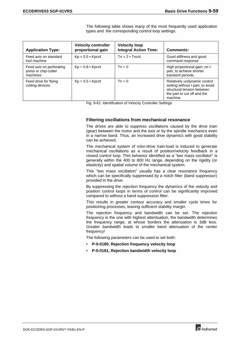
ECODRIVE03 SGP-01VRS Basic Drive Functions 9-59
DOK-ECODR3-SGP-01VRS**-FKB1-EN-P
The following table shows many of the most frequently used applicationtypes and the corresponding control loop settings.
Application Type:Velocity controllerproportional gain
Velocity loopIntegral Action Time: Comments:
Feed axis on standardtool machine
Kp = 0.5 • Kpcrit Tn = 2 • Tncrit Good stiffness and goodcommand response
Feed axis on perforatingpress or chip-cuttermachines
Kp = 0.8 • Kpcrit Tn = 0 High proportional gain; no I-part, to achieve shortertransient periods.
Feed drive for flyingcutting devices
Kp = 0.5 • Kpcrit Tn = 0 Relatively undynamic controlsetting without I-part, to avoidstructural tension betweenthe part to cut off and themachine.
Fig. 9-61: Identification of Velocity Controller Settings
Filtering oscillations from mechanical resonanceThe drives are able to suppress oscillations caused by the drive train(gear) between the motor and the axis or by the spindle mechanics evenin a narrow band. Thus, an increased drive dynamics with good stabilitycan be achieved.
The mechanical system of rotor-drive train-load is induced to generatemechanical oscillations as a result of position/velocity feedback in aclosed control loop. This behavior identified as a "two mass oscillator" isgenerally within the 400 to 800 Hz range, depending on the rigidity (orelasticity) and spatial volume of the mechanical system.
This "two mass oscillation" usually has a clear resonance frequencywhich can be specifically suppressed by a notch filter (band suppressor)provided in the drive.
By suppressing the rejection frequency the dynamics of the velocity andposition control loops in terms of control can be significantly improvedcompared to without a band suppression filter.
This results in greater contour accuracy and smaller cycle times forpositioning processes, leaving sufficient stability margin.
The rejection frequency and bandwidth can be set. The rejectionfrequency is the one with highest attentuation, the bandwidth determinesthe frequency range, at whose borders the attenuation is 3dB less.Greater bandwidth leads to smaller band attenuation of the centerfrequency!
The following parameters can be used to set both:
• P-0-0180, Rejection frequency velocity loop
• P-0-0181, Rejection bandwidth velocity loop
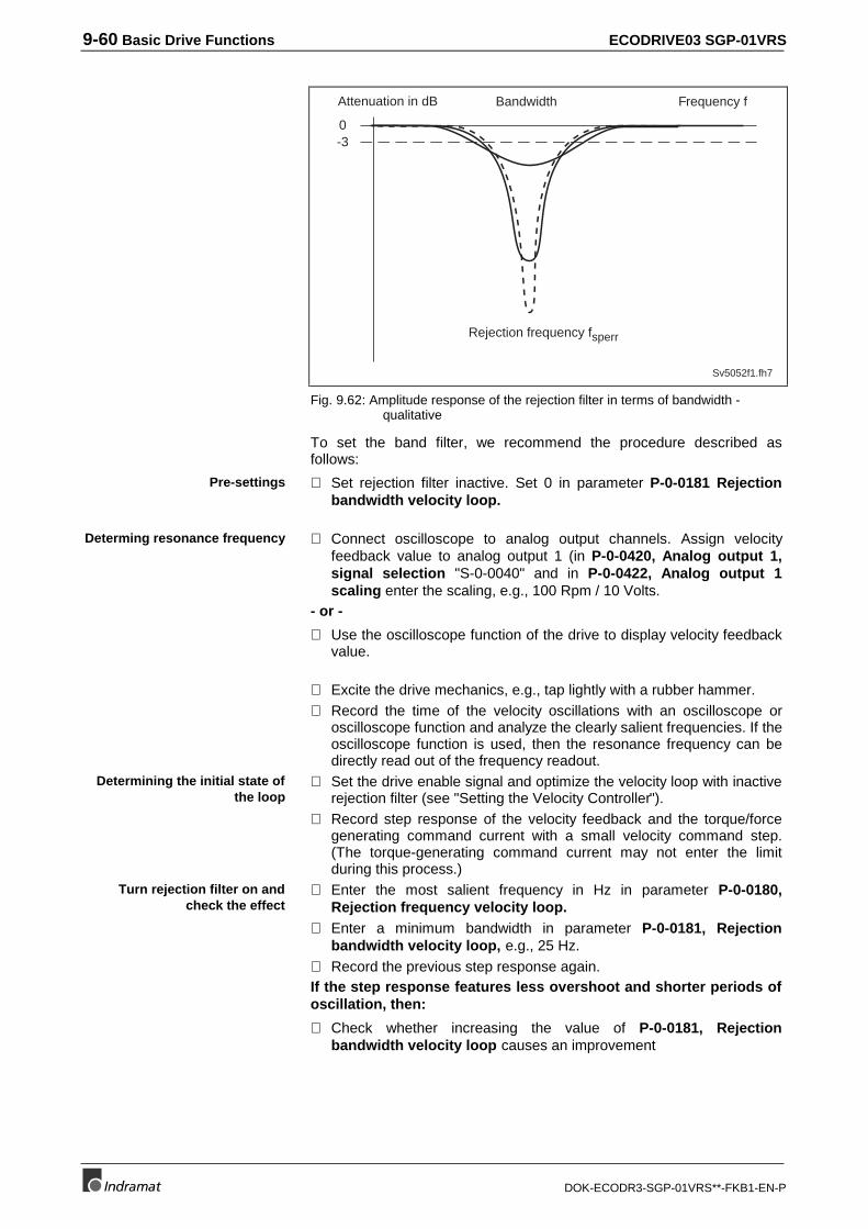
9-60 Basic Drive Functions ECODRIVE03 SGP-01VRS
DOK-ECODR3-SGP-01VRS**-FKB1-EN-P
Sv5052f1.fh7
Rejection frequency fsperr
0-3
Attenuation in dB Frequency fBandwidth
Fig. 9.62: Amplitude response of the rejection filter in terms of bandwidth -qualitative
To set the band filter, we recommend the procedure described asfollows:
⇒ Set rejection filter inactive. Set 0 in parameter P-0-0181 Rejectionbandwidth velocity loop.
⇒ Connect oscilloscope to analog output channels. Assign velocityfeedback value to analog output 1 (in P-0-0420, Analog output 1,signal selection "S-0-0040" and in P-0-0422, Analog output 1scaling enter the scaling, e.g., 100 Rpm / 10 Volts.
- or -
⇒ Use the oscilloscope function of the drive to display velocity feedbackvalue.
⇒ Excite the drive mechanics, e.g., tap lightly with a rubber hammer.⇒ Record the time of the velocity oscillations with an oscilloscope or
oscilloscope function and analyze the clearly salient frequencies. If theoscilloscope function is used, then the resonance frequency can bedirectly read out of the frequency readout.
⇒ Set the drive enable signal and optimize the velocity loop with inactiverejection filter (see "Setting the Velocity Controller").
⇒ Record step response of the velocity feedback and the torque/forcegenerating command current with a small velocity command step.(The torque-generating command current may not enter the limitduring this process.)
⇒ Enter the most salient frequency in Hz in parameter P-0-0180,Rejection frequency velocity loop.
⇒ Enter a minimum bandwidth in parameter P-0-0181, Rejectionbandwidth velocity loop, e.g., 25 Hz.
⇒ Record the previous step response again.If the step response features less overshoot and shorter periods ofoscillation, then:
⇒ Check whether increasing the value of P-0-0181, Rejectionbandwidth velocity loop causes an improvement
Pre-settings
Determing resonance frequency
Determining the initial state ofthe loop
Turn rejection filter on andcheck the effect
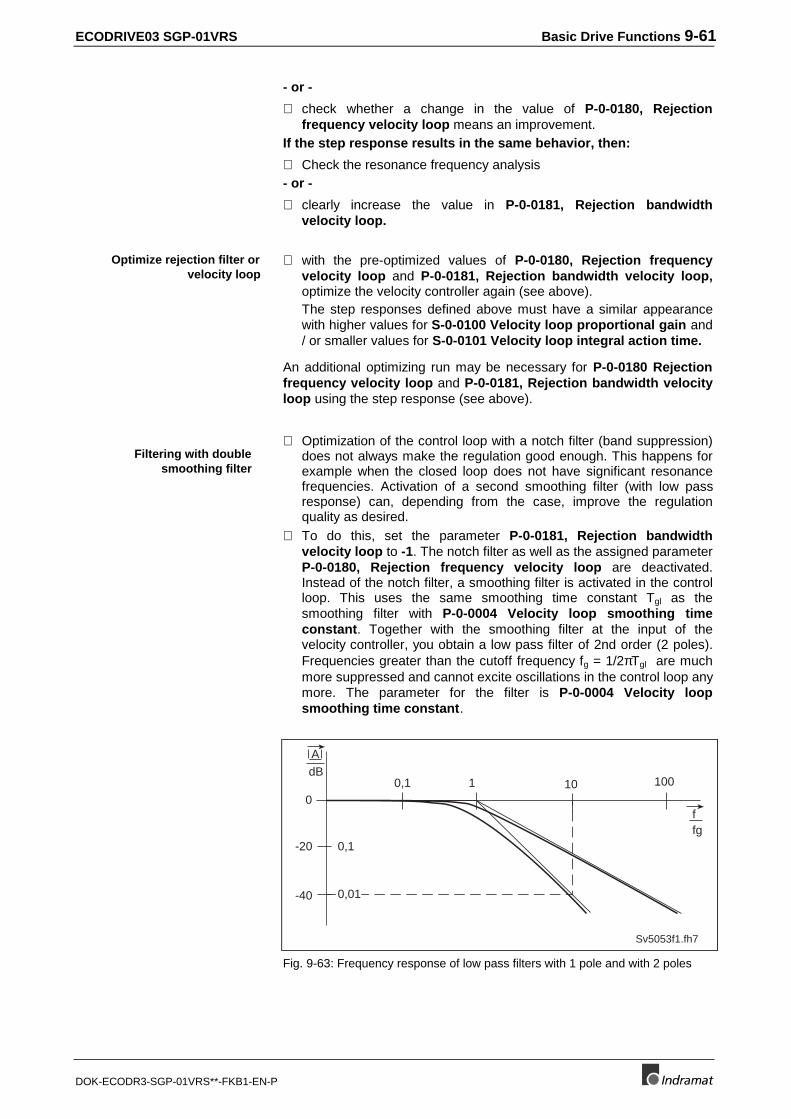
ECODRIVE03 SGP-01VRS Basic Drive Functions 9-61
DOK-ECODR3-SGP-01VRS**-FKB1-EN-P
- or -
⇒ check whether a change in the value of P-0-0180, Rejectionfrequency velocity loop means an improvement.
If the step response results in the same behavior, then:
⇒ Check the resonance frequency analysis- or -
⇒ clearly increase the value in P-0-0181, Rejection bandwidthvelocity loop.
⇒ with the pre-optimized values of P-0-0180, Rejection frequencyvelocity loop and P-0-0181, Rejection bandwidth velocity loop,optimize the velocity controller again (see above).The step responses defined above must have a similar appearancewith higher values for S-0-0100 Velocity loop proportional gain and/ or smaller values for S-0-0101 Velocity loop integral action time.
An additional optimizing run may be necessary for P-0-0180 Rejectionfrequency velocity loop and P-0-0181, Rejection bandwidth velocityloop using the step response (see above).
⇒ Optimization of the control loop with a notch filter (band suppression)does not always make the regulation good enough. This happens forexample when the closed loop does not have significant resonancefrequencies. Activation of a second smoothing filter (with low passresponse) can, depending from the case, improve the regulationquality as desired.
⇒ To do this, set the parameter P-0-0181, Rejection bandwidthvelocity loop to -1. The notch filter as well as the assigned parameterP-0-0180, Rejection frequency velocity loop are deactivated.Instead of the notch filter, a smoothing filter is activated in the controlloop. This uses the same smoothing time constant Tgl as thesmoothing filter with P-0-0004 Velocity loop smoothing timeconstant. Together with the smoothing filter at the input of thevelocity controller, you obtain a low pass filter of 2nd order (2 poles).Frequencies greater than the cutoff frequency fg = 1/2πTgl are muchmore suppressed and cannot excite oscillations in the control loop anymore. The parameter for the filter is P-0-0004 Velocity loopsmoothing time constant.
0,1 10
-40
0
100
-20
1
0,1
0,01
f
Sv5053f1.fh7
fg
A
dB
Fig. 9-63: Frequency response of low pass filters with 1 pole and with 2 poles
Optimize rejection filter orvelocity loop
Filtering with doublesmoothing filter
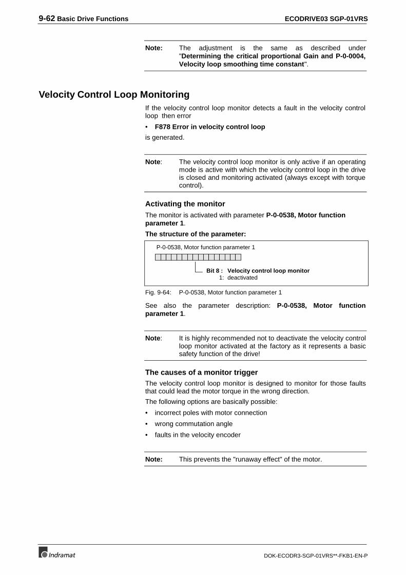
9-62 Basic Drive Functions ECODRIVE03 SGP-01VRS
DOK-ECODR3-SGP-01VRS**-FKB1-EN-P
Note: The adjustment is the same as described under"Determining the critical proportional Gain and P-0-0004,Velocity loop smoothing time constant".
Velocity Control Loop MonitoringIf the velocity control loop monitor detects a fault in the velocity controlloop then error
• F878 Error in velocity control loop
is generated.
Note: The velocity control loop monitor is only active if an operatingmode is active with which the velocity control loop in the driveis closed and monitoring activated (always except with torquecontrol).
Activating the monitorThe monitor is activated with parameter P-0-0538, Motor functionparameter 1.
The structure of the parameter:
P-0-0538, Motor function parameter 1
Bit 8 : Velocity control loop monitor1: deactivated
Fig. 9-64: P-0-0538, Motor function parameter 1
See also the parameter description: P-0-0538, Motor functionparameter 1.
Note: It is highly recommended not to deactivate the velocity controlloop monitor activated at the factory as it represents a basicsafety function of the drive!
The causes of a monitor triggerThe velocity control loop monitor is designed to monitor for those faultsthat could lead the motor torque in the wrong direction.
The following options are basically possible:
• incorrect poles with motor connection
• wrong commutation angle
• faults in the velocity encoder
Note: This prevents the "runaway effect" of the motor.
ECODRIVE03 SGP-01VRS Basic Drive Functions 9-63
DOK-ECODR3-SGP-01VRS**-FKB1-EN-P
Criteria for Triggering the MonitorThe following four criteria must be met for the velocity control loopmonitor to be triggered :
• Current command value in the limit
• motor accelerating in the wrong direction
• control deviation > 0.1*nMax
• and actual velocity control value is > 0.0125*nMax
Setting the position controllerPre-requisite:
Current and speed control must be correctly set.
The position controller can be set with the parameter
• S-0-0104, Position Controller Kv Factor
This can be set by either executing the load default settings procedure orby following the process below.
Preparations for Setting the Position Control LoopA number of preparations must be made in order to be able to set theposition controller properly:
• The mechanical system must completely assembled and ready foroperation.
• The drive controller must be properly connected as described in theuser manual.
• The safety limit switches must be checked for correct operation (ifavailable)
• Operate the drive in a mode that closes the position loop in the drive(position control).
• The velocity controller must be properly tuned. The start value chosenfor the Kv-factor should be relatively small (Kv = 1).
• For the determination of the position controller parameter, nocompensation function should be activated.
Determing the Critical Position Controller Gain
• Move axis at a slow velocity, i.e., with a jog function at a connectedNC Control (Rotating Motors: 10...20 Rpm, linear-Motors: 1...2m/min).
• Raise the Kv-factor until instability appears.
• Reduce the Kv-factor until the continuous oscillation ends by itself.
The Kv factor determined through this process is the "Critical positioncontrol loop gain".
Determining the Position Controller SettingIn most applications, an appropriate position controller setting will liebetween 50% and 80% of the critical position controller loop gain.
This means: S-0-0104, Position Loop KV-Factor = 0.5..0.8 • Kvcrit
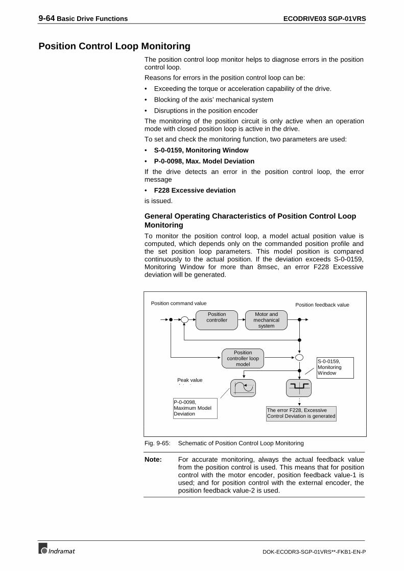
9-64 Basic Drive Functions ECODRIVE03 SGP-01VRS
DOK-ECODR3-SGP-01VRS**-FKB1-EN-P
Position Control Loop MonitoringThe position control loop monitor helps to diagnose errors in the positioncontrol loop.
Reasons for errors in the position control loop can be:
• Exceeding the torque or acceleration capability of the drive.
• Blocking of the axis’ mechanical system
• Disruptions in the position encoder
The monitoring of the position circuit is only active when an operationmode with closed position loop is active in the drive.
To set and check the monitoring function, two parameters are used:
• S-0-0159, Monitoring Window
• P-0-0098, Max. Model Deviation
If the drive detects an error in the position control loop, the errormessage
• F228 Excessive deviation
is issued.
General Operating Characteristics of Position Control LoopMonitoringTo monitor the position control loop, a model actual position value iscomputed, which depends only on the commanded position profile andthe set position loop parameters. This model position is comparedcontinuously to the actual position. If the deviation exceeds S-0-0159,Monitoring Window for more than 8msec, an error F228 Excessivedeviation will be generated.
Motor andmechanical
system
Positioncontroller
Positioncontroller loop
model S-0-0159,MonitoringWindow
P-0-0098,Maximum ModelDeviation
The error F228, ExcessiveControl Deviation is generated
Position command value
Peak valued t t
Position feedback value
Fig. 9-65: Schematic of Position Control Loop Monitoring
Note: For accurate monitoring, always the actual feedback valuefrom the position control is used. This means that for positioncontrol with the motor encoder, position feedback value-1 isused; and for position control with the external encoder, theposition feedback value-2 is used.
ECODRIVE03 SGP-01VRS Basic Drive Functions 9-65
DOK-ECODR3-SGP-01VRS**-FKB1-EN-P
Setting the Position Control Loop MonitorRequirements for the setup of the position loop monitoring are
• Check the velocity and position control loops for their appropriatesettings.
• The axis in question should be checked mechanically.
The position control loop monitor settings are performed:
• Through the connected control, you should proceed in a typicaloperation cycle. In this mode, move at the maximum projectedvelocity.
• In parameter P-0-0098, Max. Model Deviation, the maximumdeviation between the actual feedback value and the expectedfeedback value is always displayed. (Note: The contents of thisparameter are not saved. After enabling the drive, this parameterequals zero.)
• This value can be used to help set the monitoring window. ParameterS-0-0159, Monitoring Window should be set to P-0-0098, Max.Model Deviation multiplied by a safety factor. A safety factorbetween 1.5 and 2.0 is recommended.
Example:
Content of P-0-0098, Maximum Model Deviation:
0.1 mm
⇒ Determination for the parameter S-0-159, Monitoring Window:
0.2 mm (= 2 x 0.1 mm)
Example:
Content of P-0-0098, Maximum Model Deviation:
0.1 mm
⇒ Determination for the parameter S-0-159, Monitoring Window:
0.2 mm (= 2 x 0.1 mm)
Deactivation of the Position Control Loop MonitoringIt is strongly recommended to activate the position loop monitoring.However, there are exceptions for which the position loop monitoringmust be deactivated. You can do that with the parameter S-0-0159,Monitoring Window, if it is set to very high values.
Note: The position control loop monitoring is default deactivated
Setting the Acceleration Feed ForwardFor Servo applications, where high precision at high speeds counts, youhave the option to improve by far the precision of an axis duringacceleration and brake phases through activation of the acceleration feedforward.
Typical applications for the use of the acceleration feed forward:
• Free form surface milling
• Grinding
Requirements
Settings
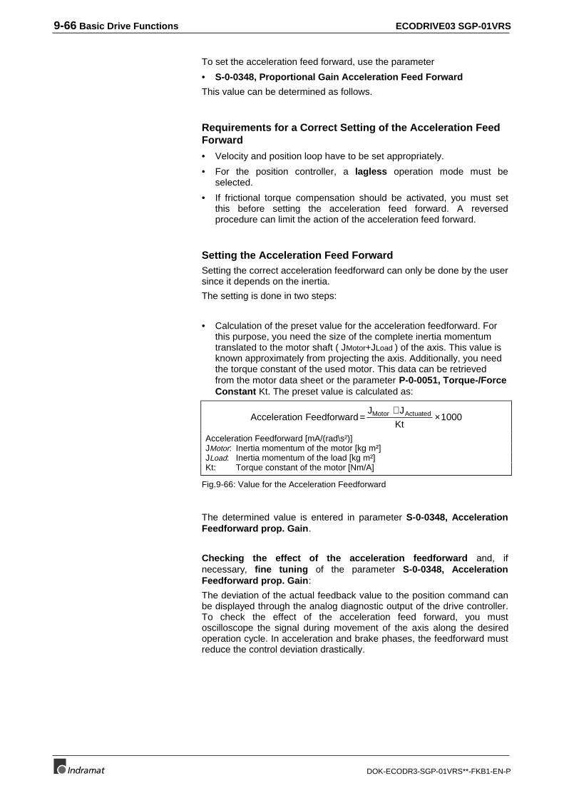
9-66 Basic Drive Functions ECODRIVE03 SGP-01VRS
DOK-ECODR3-SGP-01VRS**-FKB1-EN-P
To set the acceleration feed forward, use the parameter
• S-0-0348, Proportional Gain Acceleration Feed Forward
This value can be determined as follows.
Requirements for a Correct Setting of the Acceleration FeedForward
• Velocity and position loop have to be set appropriately.
• For the position controller, a lagless operation mode must beselected.
• If frictional torque compensation should be activated, you must setthis before setting the acceleration feed forward. A reversedprocedure can limit the action of the acceleration feed forward.
Setting the Acceleration Feed ForwardSetting the correct acceleration feedforward can only be done by the usersince it depends on the inertia.
The setting is done in two steps:
• Calculation of the preset value for the acceleration feedforward. Forthis purpose, you need the size of the complete inertia momentumtranslated to the motor shaft ( JMotor+JLoad ) of the axis. This value isknown approximately from projecting the axis. Additionally, you needthe torque constant of the used motor. This data can be retrievedfrom the motor data sheet or the parameter P-0-0051, Torque-/ForceConstant Kt. The preset value is calculated as:
Acceleration FeedforwardJ J
KtMotor Actuated=
+×1000
Acceleration Feedforward [mA/(rad\s²)]JMotor: Inertia momentum of the motor [kg m²]JLoad: Inertia momentum of the load [kg m²]Kt: Torque constant of the motor [Nm/A]
Fig.9-66: Value for the Acceleration Feedforward
The determined value is entered in parameter S-0-0348, AccelerationFeedforward prop. Gain.
Checking the effect of the acceleration feedforward and, ifnecessary, fine tuning of the parameter S-0-0348, AccelerationFeedforward prop. Gain:
The deviation of the actual feedback value to the position command canbe displayed through the analog diagnostic output of the drive controller.To check the effect of the acceleration feed forward, you mustoscilloscope the signal during movement of the axis along the desiredoperation cycle. In acceleration and brake phases, the feedforward mustreduce the control deviation drastically.
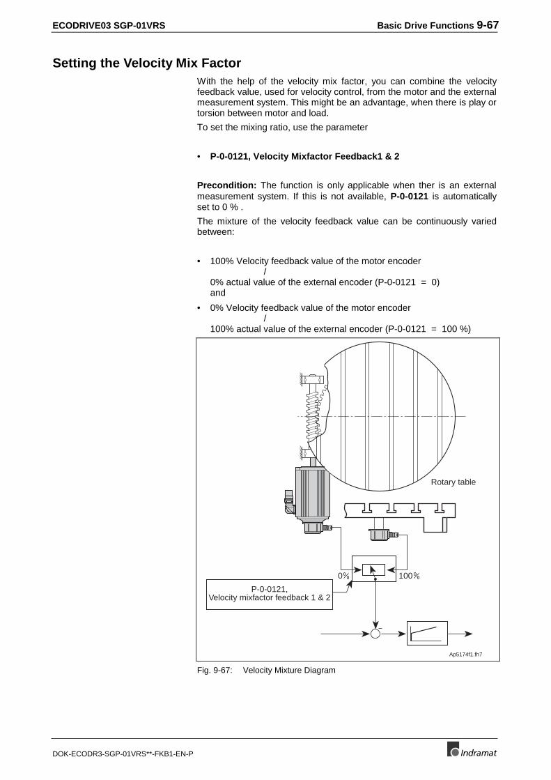
ECODRIVE03 SGP-01VRS Basic Drive Functions 9-67
DOK-ECODR3-SGP-01VRS**-FKB1-EN-P
Setting the Velocity Mix FactorWith the help of the velocity mix factor, you can combine the velocityfeedback value, used for velocity control, from the motor and the externalmeasurement system. This might be an advantage, when there is play ortorsion between motor and load.
To set the mixing ratio, use the parameter
• P-0-0121, Velocity Mixfactor Feedback1 & 2
Precondition: The function is only applicable when ther is an externalmeasurement system. If this is not available, P-0-0121 is automaticallyset to 0 % .
The mixture of the velocity feedback value can be continuously variedbetween:
• 100% Velocity feedback value of the motor encoder/
0% actual value of the external encoder (P-0-0121 = 0)and
• 0% Velocity feedback value of the motor encoder/
100% actual value of the external encoder (P-0-0121 = 100 %)
1000
P-0-0121,Velocity mixfactor feedback 1 & 2
Ap5174f1.fh7
Rotary table
Fig. 9-67: Velocity Mixture Diagram
9-68 Basic Drive Functions ECODRIVE03 SGP-01VRS
DOK-ECODR3-SGP-01VRS**-FKB1-EN-P
9.8 Automatic Control Loop Settings
General Preliminary CommentsTo make parametrization of the drive easier, the firmware offers anautomatic control loop setting with which the user need only specify,using a socalled damping factor, the control loop dynamics.Determining control parmeters to achieve these dynamics is set in thedrive by starting Command automatic control loop settings.
Note hereby that the drive must be moved to execute an automaticcontrol loop setting.
Prerequisites for Starting Automatic Control Loop Settings
WARNING
⇒ The emergency stop sequence function and thetravel range limit switch operation must be checkedand ascertained.
Also see Section: Safety Guidelines
⇒ During command D900, the drive moves itselfwithout any external command value settings.
Travel range limits P-0-0166 and P-0-0167Both travel range limits:
• P-0-0166, Lower position limit for autom. control loop adjust
• P-0-0167, Upper position limit for autom. control loop adjust
are only effective with command "Automatic control loop settings" andonly prevent the command from becoming active until the drive movesout over the set limits.
When inputting both limits, it must be noted that:
• upper limit P-0-0167 > lower limit P-0-0166
• def. travel path = upper limit - lower limit > 6 revolutions
as the drive pendels during automatic control loop settings around thecenter position between upper and lower limits.
If one of the previously stated conditions is not met, then the command iscompleted with error D905 Position range invalid, P-0-0166 & P-0-0167.
Actual position at startThe actual position must be within the travel range defined by the twoaforementioned limits.
Otherwise, command error D906 Position range exceeded will begenerated immediately at command start.
Control Loop SettingsThere must be a stable cotrol loop setting. This is generally achievedwith the default parameters stored in the motor feedback.
ECODRIVE03 SGP-01VRS Basic Drive Functions 9-69
DOK-ECODR3-SGP-01VRS**-FKB1-EN-P
If this is not the case, however, then a very undynamic control loopsetting (small P-gain and large integral action time) in the velocitycontroller leads to a basic setting that the automatic control loop settingcan use.
If necessary, the value of the actual velocity value filter is reduced to500µs.
Drive enable or drive startThe oscillating motions and thus the automatic control loop settings areonly executed if
• drive enable is available
and
• drive start is given.
If there is no drive enable at command start, command error D901 Startrequires drive enable is generated.
Command SettingsAll parameters involved in the commands must be set before thecommand is started to become effective with the automatic control loopsetting.
• P-0-0163, Damping factor for autom. control loop adjustThe desired control loop dynamics are selected herewith.
• P-0-0164, Application for autom. control loop adjust
• P-0-0165, Selection for autom. control loop adjust
Numeric value Definition
0 Determining mass moment of inertia P-0-4020 andsetting velocity and position control loops
1 Also determining accel precontrol S-0-0348Fig. 9-68: Variants of automatic control loop settings
• S-0-0092, Bipolar torque/force limit valueThe maximum motor torque effective with automatic control loopsettings can be effected via parameter S-0-0092, Bipolar torque vaue.This can limit the torque and prevent mechanical wear.
• S-0-0108, Feedrate overrideFeedrate override makes it possible to effect the velocity withautomatic control loop settings via the analog channel (Poti). Thefunction must be activated for this to be so, however.
• S-0-0259, Positioning VelocityThis parameter sets the velocity effective with automatic control loopsettings.
• S-0-0260, Positioning AccelerationWith the maximum positioning velocity parameter the acceleration forthe automatic control loop is set.If the value set is too small, then this can cause problems whendetermining the moment of inertia as the velocity changes and currentvalues may be too small.
If command error D903 Inertiadetection failed is generated,
then this means that one of theparameters listed on the right
have been incorrectlyparametrized.
In other words, velocity,acceleratoin or torque for the
automatic control loop settings aretoo small
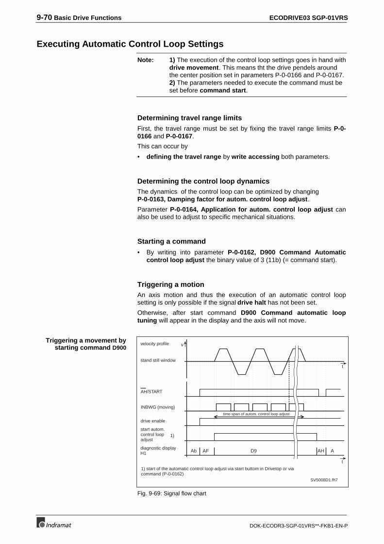
9-70 Basic Drive Functions ECODRIVE03 SGP-01VRS
DOK-ECODR3-SGP-01VRS**-FKB1-EN-P
Executing Automatic Control Loop Settings
Note: 1) The execution of the control loop settings goes in hand withdrive movement. This means tht the drive pendels aroundthe center position set in parameters P-0-0166 and P-0-0167.2) The parameters needed to execute the command must beset before command start.
Determining travel range limitsFirst, the travel range must be set by fixing the travel range limits P-0-0166 and P-0-0167.
This can occur by
• defining the travel range by write accessing both parameters.
Determining the control loop dynamicsThe dynamics of the control loop can be optimized by changingP-0-0163, Damping factor for autom. control loop adjust.
Parameter P-0-0164, Application for autom. control loop adjust canalso be used to adjust to specific mechanical situations.
Starting a command
• By writing into parameter P-0-0162, D900 Command Automaticcontrol loop adjust the binary value of 3 (11b) (= command start).
Triggering a motionAn axis motion and thus the execution of an automatic control loopsetting is only possible if the signal drive halt has not been set.
Otherwise, after start command D900 Command automatic looptuning will appear in the display and the axis will not move.
AH/START
INBWG (moving)
drive enable
start autom.control loopadjust
diagnostic displayH1
velocity profile
t
v
t
Ab AF AH AD9
time span of autom. control loop adjust
stand still window
SV5008D1.fh7
1)
1) start of the automatic control loop adjust via start buttom in Drivetop or viacommand (P-0-0162)
Fig. 9-69: Signal flow chart
Triggering a movement bystarting command D900
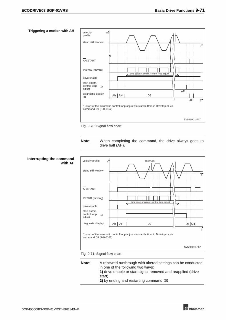
ECODRIVE03 SGP-01VRS Basic Drive Functions 9-71
DOK-ECODR3-SGP-01VRS**-FKB1-EN-P
AH/START
INBWG (moving)
drive enable
start autom.control loopadjust
diagnostic displayH1
velocityprofile
t
v
Ab AH
AH
AFD9
time span of autom. control loop adjust
stand still window
SV5010D1.Fh7
1)
1) start of the automatic control loop adjust via start buttom in Drivetop or viacommand D9 (P-0-0162)
t
Fig. 9-70: Signal flow chart
Note: When completing the command, the drive always goes todrive halt (AH).
AH/START
INBWG (moving)
drive enable
start autom.control loopadjust
diagnostic display
velocity profile
t
v
t
Ab AF AHAFD9
time span of autom. control loop adjust
stand still window
SV5009D1.Fh7
1)
1) start of the automatic control loop adjust via start buttom in Drivetop or viacommand D9 (P-0-0162)
interrupt
Fig. 9-71: Signal flow chart
Note: A renewed runthrough with altered settings can be conductedin one of the following two ways:1) drive enable or start signal removed and reapplied (drivestart)2) by ending and restarting command D9
Triggering a motion with AH
Interrupting the commandwith AH
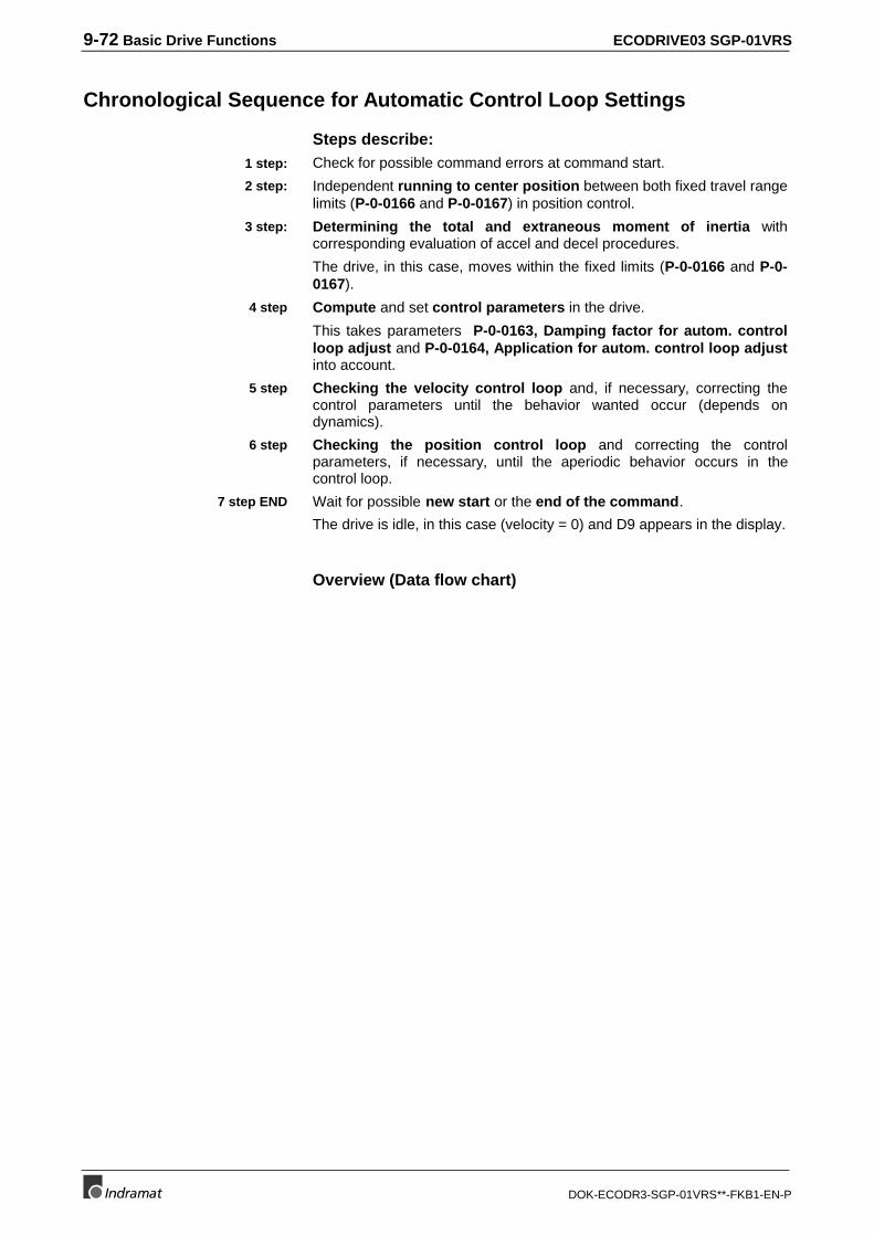
9-72 Basic Drive Functions ECODRIVE03 SGP-01VRS
DOK-ECODR3-SGP-01VRS**-FKB1-EN-P
Chronological Sequence for Automatic Control Loop Settings
Steps describe:Check for possible command errors at command start.
Independent running to center position between both fixed travel rangelimits (P-0-0166 and P-0-0167) in position control.
Determining the total and extraneous moment of inertia withcorresponding evaluation of accel and decel procedures.
The drive, in this case, moves within the fixed limits (P-0-0166 and P-0-0167).
Compute and set control parameters in the drive.
This takes parameters P-0-0163, Damping factor for autom. controlloop adjust and P-0-0164, Application for autom. control loop adjustinto account.
Checking the velocity control loop and, if necessary, correcting thecontrol parameters until the behavior wanted occur (depends ondynamics).
Checking the position control loop and correcting the controlparameters, if necessary, until the aperiodic behavior occurs in thecontrol loop.
Wait for possible new start or the end of the command.
The drive is idle, in this case (velocity = 0) and D9 appears in the display.
Overview (Data flow chart)
1 step:
2 step:
3 step:
4 step
5 step
6 step
7 step END
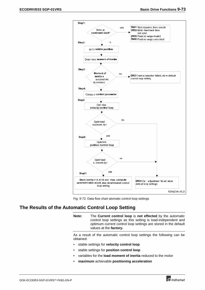
ECODRIVE03 SGP-01VRS Basic Drive Functions 9-73
DOK-ECODR3-SGP-01VRS**-FKB1-EN-P
�(UURU�DW��FRPPDQG�VWDUW"
'����6WDUW�UHTXLUHV�GULYH�HQDEOH'����0RWRU�IHHGEDFN�GDWD����������QRW�YDOLG'����3RVLWLRQ�UDQJH�LQYDOLG'����3RVLWLRQ�UDQJH�H[FHHGHG
JR�WR�PLGGOH�SRVLWLRQ�
���0RPHQW�RI�LQHUWLD�V
�����������VXFFHVVIXOO\���������������GHWHUPLQHG
'����,QHUWLD�GHWHFWLRQ�IDLOHG��VWRUH�GHIDXOW�FRQWURO�ORRS�VHWWLQJ�
'HWHUPLQH�PRPHQW�RI�LQHUWLD
QR
\HV
QR
&RPSXWH�FRQWURO�SDUDPHWHU
2SWLPL]H�YHORFLW\�FRQWURO�ORRS
2SWLPL]HG�VXFFHVVIXOO\"
2SWLPL]H�SRVLWLRQ�FRQWURO�ORRS
2SWLPL]HG�VXFFHVVIXOO\"
'����*DLQ�DGMXVWPHQW�IDLOHG��VWRUH�GHIDXOW�ORRS�VHWWLQJV
6WRUH�LQHUWLD�3��������DQG��PD[��FRPSXWH�SDUDPHWUL]DEOH�DFFHO��DOVR�GHWHUPLQDWHG�FRQWURO�
ORRS�VHWWLQJ
QR
QR
\HV
\HV
6WHS��
6WHS��
6WHS��
6WHS��
6WHS��
6WHS��
6WHS��
)'����;��)/2
Fig. 9-72: Data flow chart atomatic control loop settings
The Results of the Automatic Control Loop Setting
Note: The Current control loop is not effected by the automaticcontrol loop settings as this setting is load-independent andoptimum current control loop settings are stored in the defaultvalues at the factory.
As a result of the automatic control loop settings the following can beobtained:
• stable settings for velocity control loop
• stable settings for position control loop
• variables for the load moment of inertia reduced to the motor
• maximum achievable positioning acceleration
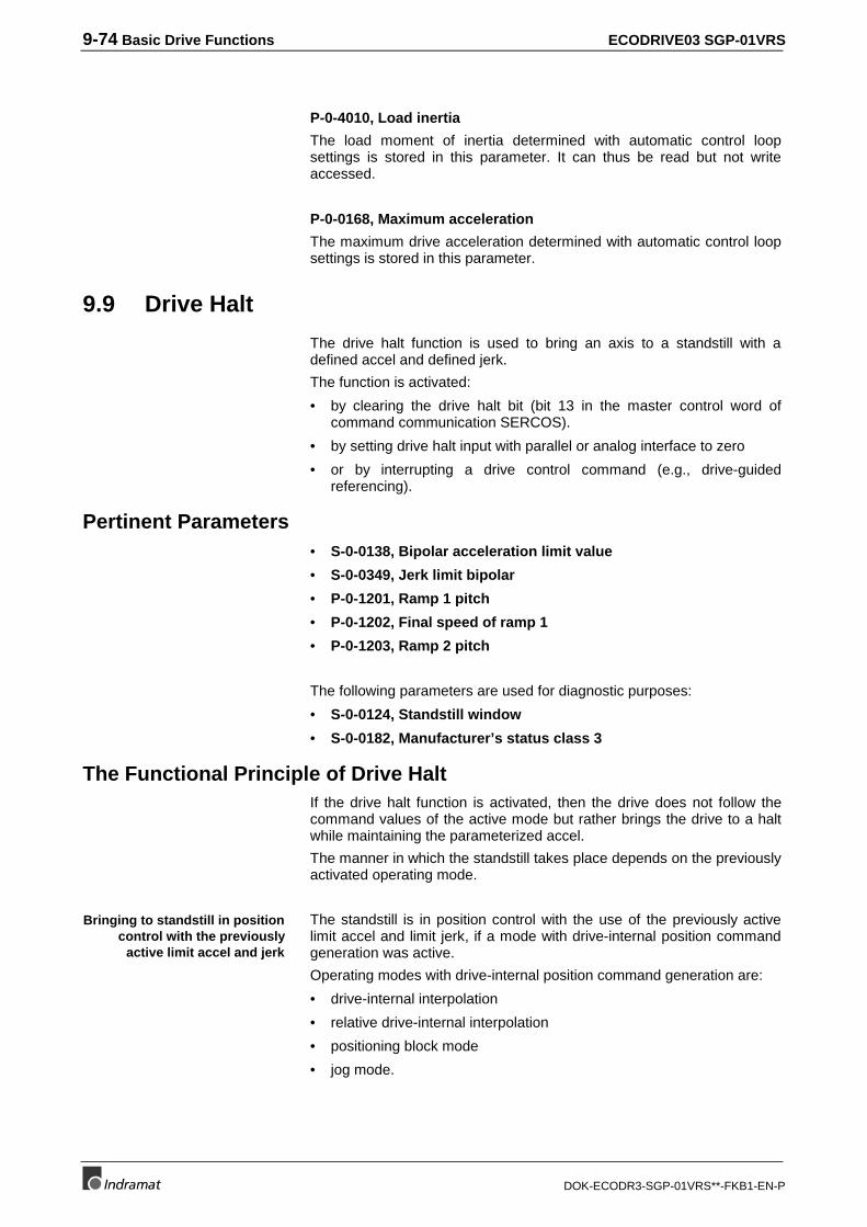
9-74 Basic Drive Functions ECODRIVE03 SGP-01VRS
DOK-ECODR3-SGP-01VRS**-FKB1-EN-P
P-0-4010, Load inertia
The load moment of inertia determined with automatic control loopsettings is stored in this parameter. It can thus be read but not writeaccessed.
P-0-0168, Maximum acceleration
The maximum drive acceleration determined with automatic control loopsettings is stored in this parameter.
9.9 Drive Halt
The drive halt function is used to bring an axis to a standstill with adefined accel and defined jerk.
The function is activated:
• by clearing the drive halt bit (bit 13 in the master control word ofcommand communication SERCOS).
• by setting drive halt input with parallel or analog interface to zero
• or by interrupting a drive control command (e.g., drive-guidedreferencing).
Pertinent Parameters• S-0-0138, Bipolar acceleration limit value
• S-0-0349, Jerk limit bipolar
• P-0-1201, Ramp 1 pitch
• P-0-1202, Final speed of ramp 1
• P-0-1203, Ramp 2 pitch
The following parameters are used for diagnostic purposes:
• S-0-0124, Standstill window
• S-0-0182, Manufacturer’s status class 3
The Functional Principle of Drive HaltIf the drive halt function is activated, then the drive does not follow thecommand values of the active mode but rather brings the drive to a haltwhile maintaining the parameterized accel.
The manner in which the standstill takes place depends on the previouslyactivated operating mode.
The standstill is in position control with the use of the previously activelimit accel and limit jerk, if a mode with drive-internal position commandgeneration was active.
Operating modes with drive-internal position command generation are:
• drive-internal interpolation
• relative drive-internal interpolation
• positioning block mode
• jog mode.
Bringing to standstill in positioncontrol with the previously
active limit accel and jerk
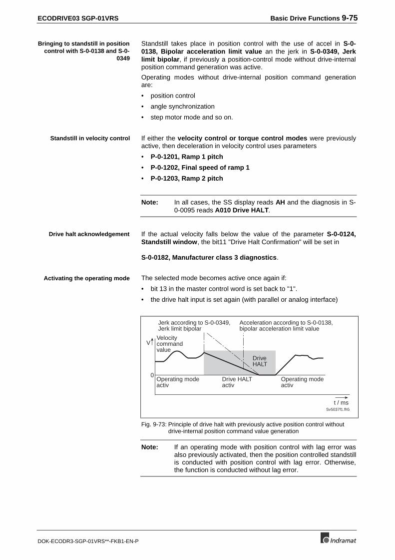
ECODRIVE03 SGP-01VRS Basic Drive Functions 9-75
DOK-ECODR3-SGP-01VRS**-FKB1-EN-P
Standstill takes place in position control with the use of accel in S-0-0138, Bipolar acceleration limit value an the jerk in S-0-0349, Jerklimit bipolar, if previously a position-control mode without drive-internalposition command generation was active.
Operating modes without drive-internal position command generationare:
• position control
• angle synchronization
• step motor mode and so on.
If either the velocity control or torque control modes were previouslyactive, then deceleration in velocity control uses parameters
• P-0-1201, Ramp 1 pitch
• P-0-1202, Final speed of ramp 1
• P-0-1203, Ramp 2 pitch
Note: In all cases, the SS display reads AH and the diagnosis in S-0-0095 reads A010 Drive HALT.
If the actual velocity falls below the value of the parameter S-0-0124,Standstill window, the bit11 "Drive Halt Confirmation" will be set in
S-0-0182, Manufacturer class 3 diagnostics.
The selected mode becomes active once again if:
• bit 13 in the master control word is set back to "1".
• the drive halt input is set again (with parallel or analog interface)
0
V
Sv5037f1.fh5
t / ms
Velocitycommandvalue
Operating modeactiv
DriveHALT
Jerk according to S-0-0349,Jerk limit bipolar
Acceleration according to S-0-0138,bipolar acceleration limit value
Drive HALTactiv
Operating modeactiv
Fig. 9-73: Principle of drive halt with previously active position control withoutdrive-internal position command value generation
Note: If an operating mode with position control with lag error wasalso previously activated, then the position controlled standstillis conducted with position control with lag error. Otherwise,the function is conducted without lag error.
Bringing to standstill in positioncontrol with S-0-0138 and S-0-
0349
Standstill in velocity control
Drive halt acknowledgement
Activating the operating mode
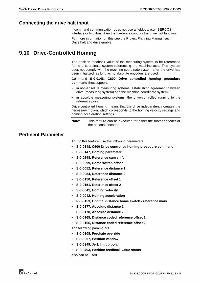
9-76 Basic Drive Functions ECODRIVE03 SGP-01VRS
DOK-ECODR3-SGP-01VRS**-FKB1-EN-P
Connecting the drive halt inputIf command communication does not use a fieldbus, e.g., SERCOSinterface or Profibus, then the hardware controls the drive halt function.
For more information on this see the Project Planning Manual, sec.:Drive halt and drive enable.
9.10 Drive-Controlled Homing
The position feedback value of the measuring system to be referencedforms a coordinate system referencing the machine axis. This systemdoes not comply with the machine coordinate system after the drive hasbeen initialized, as long as no absolute encoders are used.
Command S-0-0148, C600 Drive controlled homing procedurecommand thus supports
• in non-absolute measuring systems, establishing agreement betweendrive (measuring system) and the machine coordinate system;
• in absolute measuring systems, the drive-controlled running to thereference point
Drive-controlled homing means that the drive independently creates thenecessary motion, which corresponds to the homing velocity settings andhoming acceleration settings.
Note: This feature can be executed for either the motor encoder orthe optional encoder.
Pertinent ParameterTo run this feature, use the following parameters:
• S-0-0148, C600 Drive controlled homing procedure command
• S-0-0147, Homing parameter
• S-0-0298, Reference cam shift
• S-0-0299, Home switch offset
• S-0-0052, Reference distance 1
• S-0-0054, Reference distance 2
• S-0-0150, Reference offset 1
• S-0-0151, Reference offset 2
• S-0-0041, Homing velocity
• S-0-0042, Homing acceleration
• P-0-0153, Optimal distance home switch - reference mark
• S-0-0177, Absolute distance 1
• S-0-0178, Absolute distance 2
• S-0-0165, Distance coded reference offset 1
• S-0-0166, Distance coded reference offset 2
The following parameters
• S-0-0108, Feedrate override
• S-0-0057, Position window
• S-0-0349, Jerk limit bipolar
• S-0-0403, Position feedback value status
also can be used.
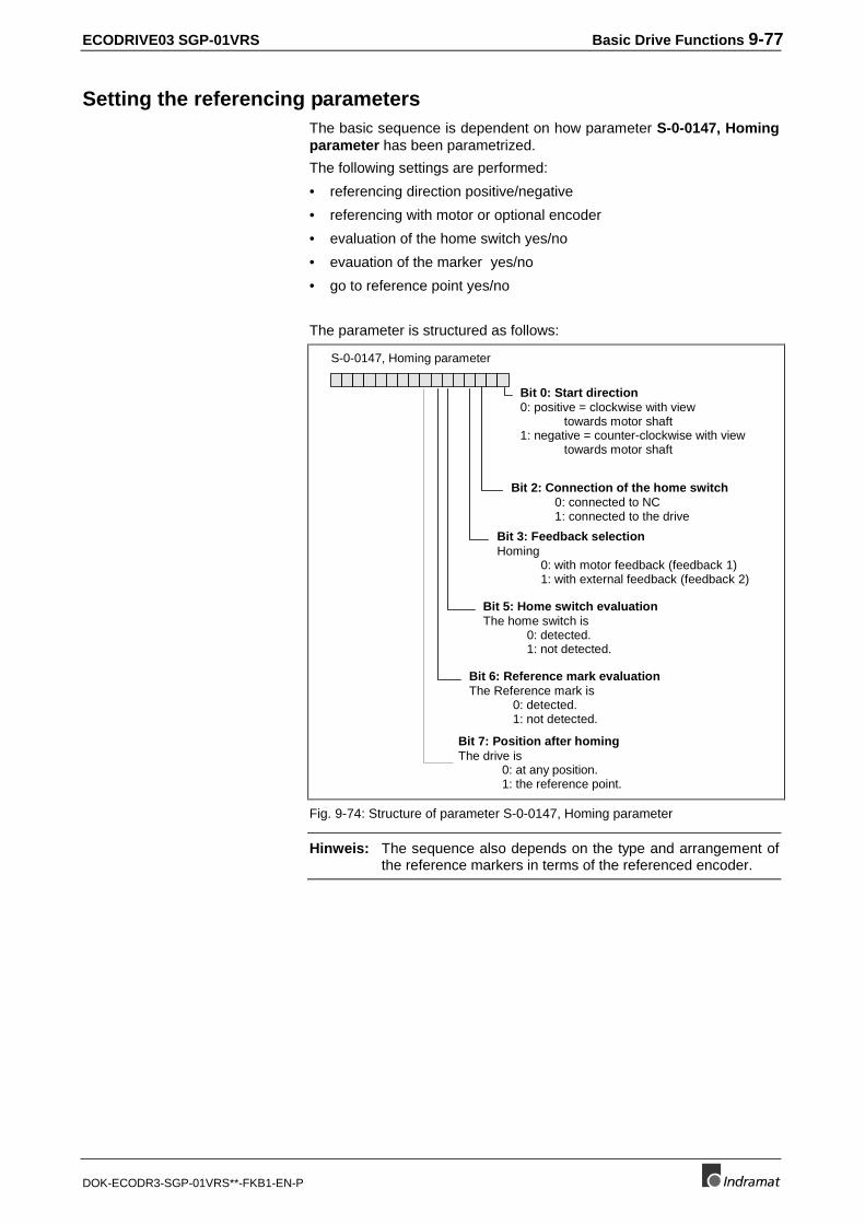
ECODRIVE03 SGP-01VRS Basic Drive Functions 9-77
DOK-ECODR3-SGP-01VRS**-FKB1-EN-P
Setting the referencing parametersThe basic sequence is dependent on how parameter S-0-0147, Homingparameter has been parametrized.
The following settings are performed:
• referencing direction positive/negative
• referencing with motor or optional encoder
• evaluation of the home switch yes/no
• evauation of the marker yes/no
• go to reference point yes/no
The parameter is structured as follows:
Bit 0: Start direction0: positive = clockwise with view
towards motor shaft1: negative = counter-clockwise with view
towards motor shaft
Bit 3: Feedback selectionHoming
0: with motor feedback (feedback 1)1: with external feedback (feedback 2)
Bit 6: Reference mark evaluationThe Reference mark is
0: detected.1: not detected.
Bit 5: Home switch evaluationThe home switch is
0: detected.1: not detected.
Bit 7: Position after homingThe drive is
0: at any position.1: the reference point.
S-0-0147, Homing parameter
Bit 2: Connection of the home switch0: connected to NC1: connected to the drive
Fig. 9-74: Structure of parameter S-0-0147, Homing parameter
Hinweis: The sequence also depends on the type and arrangement ofthe reference markers in terms of the referenced encoder.
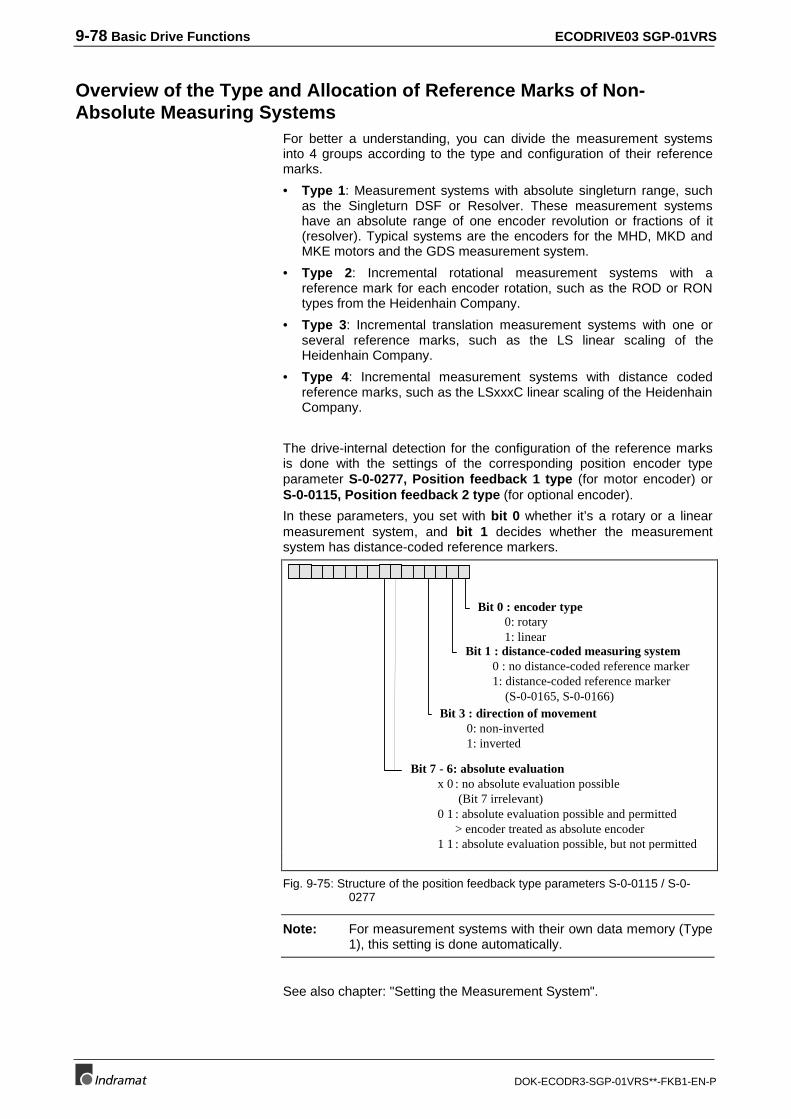
9-78 Basic Drive Functions ECODRIVE03 SGP-01VRS
DOK-ECODR3-SGP-01VRS**-FKB1-EN-P
Overview of the Type and Allocation of Reference Marks of Non-Absolute Measuring Systems
For better a understanding, you can divide the measurement systemsinto 4 groups according to the type and configuration of their referencemarks.
• Type 1: Measurement systems with absolute singleturn range, suchas the Singleturn DSF or Resolver. These measurement systemshave an absolute range of one encoder revolution or fractions of it(resolver). Typical systems are the encoders for the MHD, MKD andMKE motors and the GDS measurement system.
• Type 2: Incremental rotational measurement systems with areference mark for each encoder rotation, such as the ROD or RONtypes from the Heidenhain Company.
• Type 3: Incremental translation measurement systems with one orseveral reference marks, such as the LS linear scaling of theHeidenhain Company.
• Type 4: Incremental measurement systems with distance codedreference marks, such as the LSxxxC linear scaling of the HeidenhainCompany.
The drive-internal detection for the configuration of the reference marksis done with the settings of the corresponding position encoder typeparameter S-0-0277, Position feedback 1 type (for motor encoder) orS-0-0115, Position feedback 2 type (for optional encoder).
In these parameters, you set with bit 0 whether it’s a rotary or a linearmeasurement system, and bit 1 decides whether the measurementsystem has distance-coded reference markers.
Bit 0 : encoder type0: rotary1: linear
Bit 1 : distance-coded measuring system0 : no distance-coded reference marker1: distance-coded reference marker
(S-0-0165, S-0-0166)Bit 3 : direction of movement
0: non-inverted1: inverted
Bit 7 - 6: absolute evaluationx 0 : no absolute evaluation possible
(Bit 7 irrelevant)0 1 : absolute evaluation possible and permitted
> encoder treated as absolute encoder1 1 : absolute evaluation possible, but not permitted
Fig. 9-75: Structure of the position feedback type parameters S-0-0115 / S-0-0277
Note: For measurement systems with their own data memory (Type1), this setting is done automatically.
See also chapter: "Setting the Measurement System".
ECODRIVE03 SGP-01VRS Basic Drive Functions 9-79
DOK-ECODR3-SGP-01VRS**-FKB1-EN-P
Functional Principle of Drive-Controlled Referencing in Non-AbsoluteMeasuring Systems
To establish congruency between drive (measuring system) and machinecoordinate system it is necessary that the drive has precise informationabout its relative position within the machine coordinate system. Thedrive receives this information by detecting the home switch edge and/orthe reference mark.
Note: To evaluate only the home switch is not recommended as theposition of the home switch edge has a lesser precisioncompared to the detection of the reference mark!
Coordinate system compensation is achieved by comparing the desiredfeedback position at a specific point within the machine coordinatesystem with the actual feedback position ("old" drive coordinate system).A differentiation in this case is made between "Evaluation of a referencemark/home switch edge" (type 1 .. 3) and "Evaluation of distance-codedreference marks".
• With "Evaluation of a reference mark/home switch edge" the"specific" point within the coordinate system is the so-called referencepoint. The desired feedback position is set at this point via parameterS-0-0052, Reference distance 1 (for motor encoders) or S-0-0054,Reference distance 2 (for optional encoders). The physical positionof the reference point derives from the position of the referencemarker plus the value in S-0-0150, Reference offset 1 or S-0-0151,Reference offset 2. Once the reference marker is detected, the driveknows the position of this marker and therefore also that of thereference point in the "old" drive coordinate system. The desiredposition is in parameter S-0-0052/ S-0-0054.
• With "Evaluation of distance-coded reference marks" the "specific"point is the zero point (position of the first reference mark) of thedistance-coded measuring system. By detecting the positiondifference between two adjacent reference marks the position of thefirst reference marker in the "old" drive coordinate system can bedetermined. The desired feedback position at this point is defined bythe position of the first reference mark in the machine coordinatesystem at this point plus the value in S-0-0177, Absolute distance 1(for motor encoders) or S-0-0178, Absolute distance 2 (for optionalencoders).
In both cases, the difference between both coordinate systems is addedto the "old" drive coordinate system. The coordinate systems will thencomply.
By switching the position command and feedback value, S-0-0403,Position feedback value status is set to 1. This means that thefeedback position value now refers to the machine zero point.
Note: If the drive, once the reference command has beenconducted, is in parameter mode again, then parameterS-0-0403, Position feedback value status is set to 0,because the feedback values in command S-0-0128, C200Communication phase 4 transition check are re-initialized.
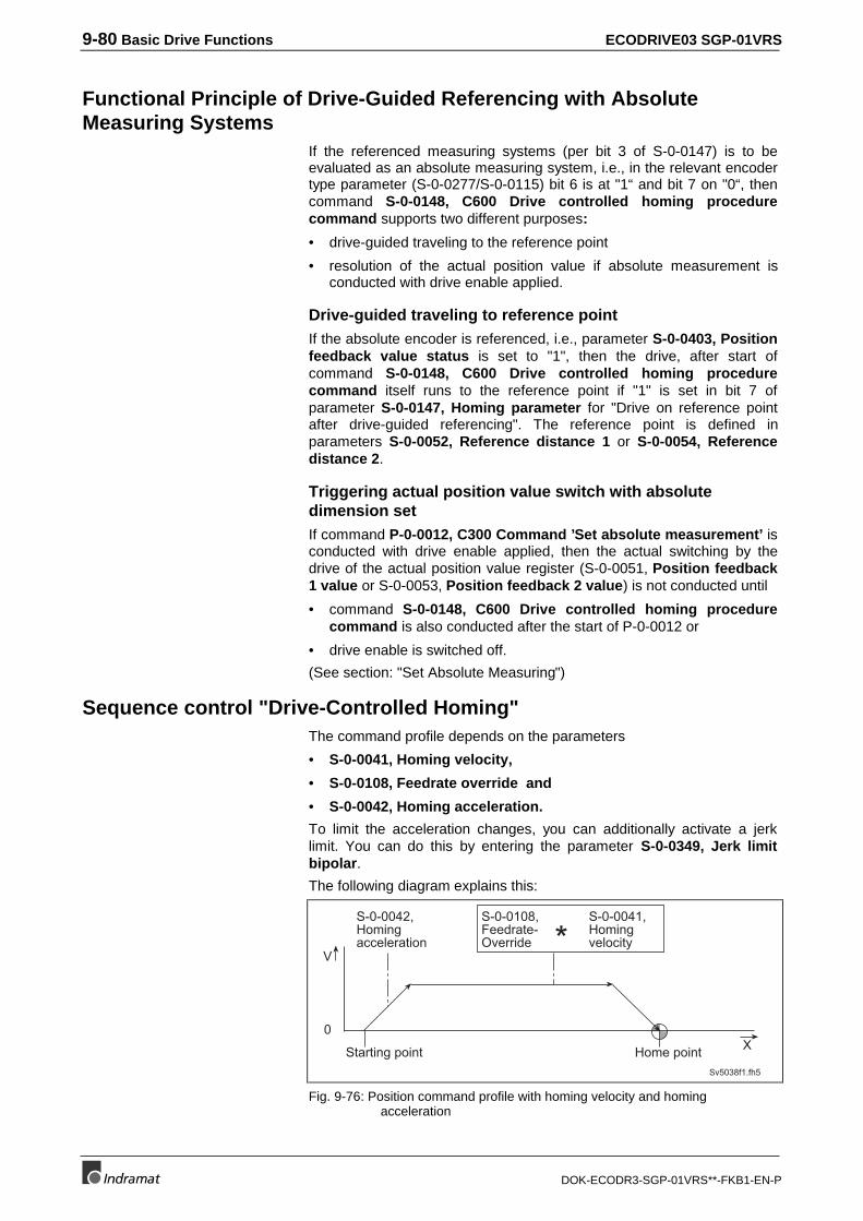
9-80 Basic Drive Functions ECODRIVE03 SGP-01VRS
DOK-ECODR3-SGP-01VRS**-FKB1-EN-P
Functional Principle of Drive-Guided Referencing with AbsoluteMeasuring Systems
If the referenced measuring systems (per bit 3 of S-0-0147) is to beevaluated as an absolute measuring system, i.e., in the relevant encodertype parameter (S-0-0277/S-0-0115) bit 6 is at "1“ and bit 7 on "0“, thencommand S-0-0148, C600 Drive controlled homing procedurecommand supports two different purposes:
• drive-guided traveling to the reference point
• resolution of the actual position value if absolute measurement isconducted with drive enable applied.
Drive-guided traveling to reference pointIf the absolute encoder is referenced, i.e., parameter S-0-0403, Positionfeedback value status is set to "1", then the drive, after start ofcommand S-0-0148, C600 Drive controlled homing procedurecommand itself runs to the reference point if "1" is set in bit 7 ofparameter S-0-0147, Homing parameter for "Drive on reference pointafter drive-guided referencing". The reference point is defined inparameters S-0-0052, Reference distance 1 or S-0-0054, Referencedistance 2.
Triggering actual position value switch with absolutedimension setIf command P-0-0012, C300 Command ’Set absolute measurement’ isconducted with drive enable applied, then the actual switching by thedrive of the actual position value register (S-0-0051, Position feedback1 value or S-0-0053, Position feedback 2 value) is not conducted until
• command S-0-0148, C600 Drive controlled homing procedurecommand is also conducted after the start of P-0-0012 or
• drive enable is switched off.
(See section: "Set Absolute Measuring")
Sequence control "Drive-Controlled Homing"The command profile depends on the parameters
• S-0-0041, Homing velocity,
• S-0-0108, Feedrate override and
• S-0-0042, Homing acceleration.
To limit the acceleration changes, you can additionally activate a jerklimit. You can do this by entering the parameter S-0-0349, Jerk limitbipolar.
The following diagram explains this:
0
V*
Sv5038f1.fh5
X
S-0-0042,Homingacceleration
S-0-0108,Feedrate-Override
Starting point Home point
S-0-0041,Homingvelocity
Fig. 9-76: Position command profile with homing velocity and homingacceleration
ECODRIVE03 SGP-01VRS Basic Drive Functions 9-81
DOK-ECODR3-SGP-01VRS**-FKB1-EN-P
The maximum velocity is influenced, like with all drive-controlledfunctions, by the feedrate. The effective maximum velocity is the result ofthe product of S-0-0041, Homing velocity and S-0-0108, Feedrateoverride.
Note: The maximum velocity is influenced, like with all drive-controlled functions, by the feedrate. The effective maximumvelocity is the result of the product of S-0-0041, Homingvelocity and S-0-0108, Feedrate override.
The motional process during drive-controlled homing of non-absoluteencoders can be made up of up to three processes:
• If the home switch evaluation process has been activated and thereare no distance-coded reference markers, then the drive acceleratesto the homing velocity in the selected homing direction until thepositive home switch edge is detected. If the drive is already on thehome switch at the start of drive-controlled referencing (S-0-0400,Home switch = 1), the drive at first accelerates in the oppositedirection until the negative home switch edge is detected, and thenreverses the direction.
WARNING
⇒ Make sure that the home switch edge is within thereachable travel range.
• If reference markers are available (type 2 to 4, see above), and if thereference marker evaluation is activated, then the drive runs inhoming direction until it detects a reference marker. In distance-codedmeasuring systems (type 4), two sequential reference markers mustbe passed. The reference markers are always evaluated there(independent of bit 6 in S-0-0147).
• The further action depends on how bit 7 has been set in S-0-0147,Homing parameter. If bit 7 = 0 is programmed ("any position afterhoming"), then the drive brakes with the programmed homingacceleration up to standstill. If the value of the velocity feedback isless than the value set in S-0-0124, Standstill window, then thecoordinate system of the referenced encoder is set, and thecommand is signalled as completed.
• If a 1 is set in bit 7, ("Drive travels to reference point“), then the drivepositions to the reference point. The reference point in encoders ofthe types 1 to 3 is defined by the position of the reference mark plusthe relevant reference offset (S-0-0150 / S-0-0151). In the case ofdistance-coded reference markers, the drive runs to the seconddetected mark. The coordinate system switch and the completionmessage of the command are generated as soon as the drive-internalposition command has reached the target value and the differencebetween feedback and target value is less than the value set in S-0-0057, Position window.
maximum velocity
motional process
S-0-0147, Bit 7 = 0
S-0-0147, Bit 7 = 1
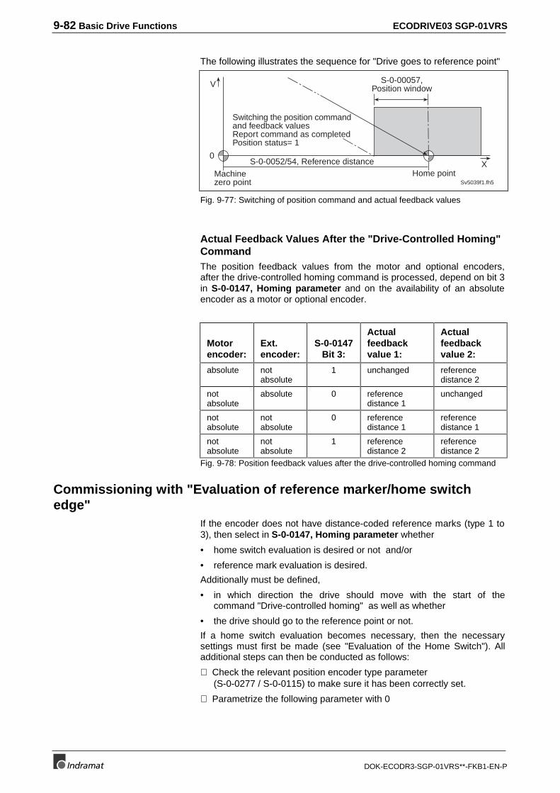
9-82 Basic Drive Functions ECODRIVE03 SGP-01VRS
DOK-ECODR3-SGP-01VRS**-FKB1-EN-P
The following illustrates the sequence for "Drive goes to reference point"
0
V
Sv5039f1.fh5
X
S-0-00057,Position window
Home pointMachinezero point
S-0-0052/54, Reference distance
Switching the position commandand feedback valuesReport command as completedPosition status= 1
Fig. 9-77: Switching of position command and actual feedback values
Actual Feedback Values After the "Drive-Controlled Homing"CommandThe position feedback values from the motor and optional encoders,after the drive-controlled homing command is processed, depend on bit 3in S-0-0147, Homing parameter and on the availability of an absoluteencoder as a motor or optional encoder.
Motorencoder:
Ext.encoder:
S-0-0147Bit 3:
Actualfeedbackvalue 1:
Actualfeedbackvalue 2:
absolute notabsolute
1 unchanged referencedistance 2
notabsolute
absolute 0 referencedistance 1
unchanged
notabsolute
notabsolute
0 referencedistance 1
referencedistance 1
notabsolute
notabsolute
1 referencedistance 2
referencedistance 2
Fig. 9-78: Position feedback values after the drive-controlled homing command
Commissioning with "Evaluation of reference marker/home switchedge"
If the encoder does not have distance-coded reference marks (type 1 to3), then select in S-0-0147, Homing parameter whether
• home switch evaluation is desired or not and/or
• reference mark evaluation is desired.
Additionally must be defined,
• in which direction the drive should move with the start of thecommand "Drive-controlled homing" as well as whether
• the drive should go to the reference point or not.
If a home switch evaluation becomes necessary, then the necessarysettings must first be made (see "Evaluation of the Home Switch"). Alladditional steps can then be conducted as follows:
⇒ Check the relevant position encoder type parameter(S-0-0277 / S-0-0115) to make sure it has been correctly set.
⇒ Parametrize the following parameter with 0
ECODRIVE03 SGP-01VRS Basic Drive Functions 9-83
DOK-ECODR3-SGP-01VRS**-FKB1-EN-P
• S-0-0052, Reference distance 1 or
• S-0-0054, Reference distance 2
• S-0-0150, Reference offset 1 or
• S-0-0151, Reference offset 2.
⇒ Set parameters S-0-0041, Homing velocity and S-0-0042, Homingacceleration to small values (e.g., S-0-0041 = 10 Rpm, S-0-0042 =10 rad/s².
⇒ Conduct the drive-controlled homing command.
Note: If the command is cleared, then the original operating modebecomes active. If drive-internal interpolation is set, thenthe drive immediately runs to the value set in S-0-0258,Target position. This value relates to the new (machine zeropoint) coordinate system!
The command should be completed without error. The machine zeropoint is at the position of the home switch or the referencing point as thereference distances (S-0-0052/54) have been parametrized with 0. Theposition feedback value in S-0-0051, Position feedback 1 value or S-0-0053, Position feedback 2 value should now have absolute reference tothis preliminary machine zero point.
To set the correct machine zero point, you can now conduct the followingsteps:
⇒ Run the axis to the desired machine zero point and set the feedbackposition value displayed there with opposite sign in S-0-0052,Reference distance 1 or S-0-0054, Reference distance 2.
Or:
⇒ Run the axis to position feedback value = 0, measure the distancebetween the current position and the desired machine zero point.Enter the distance in S-0-0052, Reference distance 1 or S-0-0054,Reference distance 2.
Once the drive-controlled reference command is again completed, theposition feedback value should refer to the desired machine zero point.
The reference point can be shifted relatively to the reference mark (see"Consideration of the Reference Offset").
Parameter S-0-0041, Homing velocity and S-0-0042, Homingacceleration can now be set to their final values.
Consideration of the Reference OffsetIf the evaluation of the reference mark is activated in the homingparameter, then the reference point is always set on the position of theselected reference mark. If a measurement system of type 1..3 is present(not distance-coded), you can shift the position of the reference pointrelatively to the reference marker. Doing so, you can select any positionafter homing.
The offset is set with the parameters
• Reference Offset 1 (for motor encoder)
• Reference Offset 2 (for optional encoder)
Result of the Drive-ControlledHoming-Command
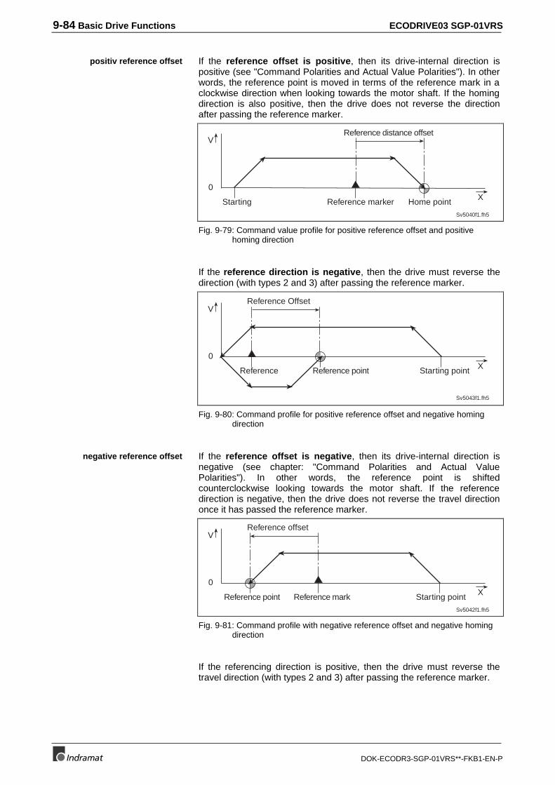
9-84 Basic Drive Functions ECODRIVE03 SGP-01VRS
DOK-ECODR3-SGP-01VRS**-FKB1-EN-P
If the reference offset is positive, then its drive-internal direction ispositive (see "Command Polarities and Actual Value Polarities"). In otherwords, the reference point is moved in terms of the reference mark in aclockwise direction when looking towards the motor shaft. If the homingdirection is also positive, then the drive does not reverse the directionafter passing the reference marker.
0
V
Sv5040f1.fh5
X
Reference distance offset
Starting Home pointReference marker
Fig. 9-79: Command value profile for positive reference offset and positivehoming direction
If the reference direction is negative, then the drive must reverse thedirection (with types 2 and 3) after passing the reference marker.
0
V
Sv5043f1.fh5
X
Reference Offset
Starting pointReference pointReference
Fig. 9-80: Command profile for positive reference offset and negative homingdirection
If the reference offset is negative, then its drive-internal direction isnegative (see chapter: "Command Polarities and Actual ValuePolarities"). In other words, the reference point is shiftedcounterclockwise looking towards the motor shaft. If the referencedirection is negative, then the drive does not reverse the travel directiononce it has passed the reference marker.
0
V
Sv5042f1.fh5
X
Reference offset
Starting pointReference point Reference mark
Fig. 9-81: Command profile with negative reference offset and negative homingdirection
If the referencing direction is positive, then the drive must reverse thetravel direction (with types 2 and 3) after passing the reference marker.
positiv reference offset
negative reference offset
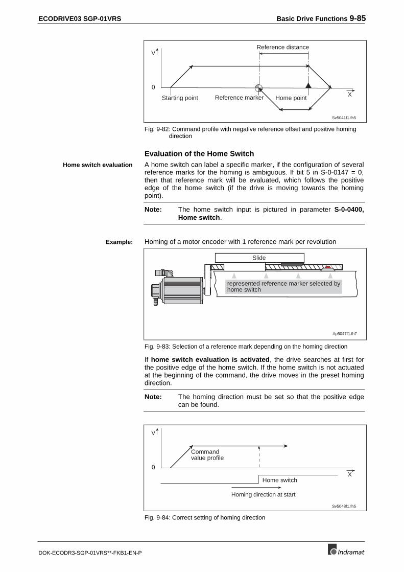
ECODRIVE03 SGP-01VRS Basic Drive Functions 9-85
DOK-ECODR3-SGP-01VRS**-FKB1-EN-P
0
V
Sv5041f1.fh5
X
Reference distance
Starting point Reference marker Home point
Fig. 9-82: Command profile with negative reference offset and positive homingdirection
Evaluation of the Home SwitchA home switch can label a specific marker, if the configuration of severalreference marks for the homing is ambiguous. If bit 5 in S-0-0147 = 0,then that reference mark will be evaluated, which follows the positiveedge of the home switch (if the drive is moving towards the homingpoint).
Note: The home switch input is pictured in parameter S-0-0400,Home switch.
Homing of a motor encoder with 1 reference mark per revolution
Slide
Ap5047f1.fh7
represented reference marker selected byhome switch
Fig. 9-83: Selection of a reference mark depending on the homing direction
If home switch evaluation is activated, the drive searches at first forthe positive edge of the home switch. If the home switch is not actuatedat the beginning of the command, the drive moves in the preset homingdirection.
Note: The homing direction must be set so that the positive edgecan be found.
0
V
Sv5048f1.fh5
XHome switch
Commandvalue profile
Homing direction at start
Fig. 9-84: Correct setting of homing direction
Home switch evaluation
Example:
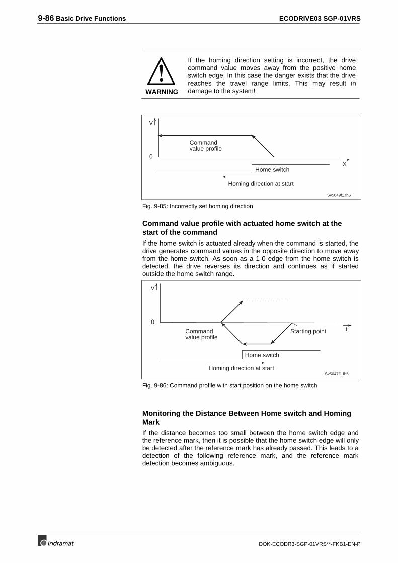
9-86 Basic Drive Functions ECODRIVE03 SGP-01VRS
DOK-ECODR3-SGP-01VRS**-FKB1-EN-P
WARNING
If the homing direction setting is incorrect, the drivecommand value moves away from the positive homeswitch edge. In this case the danger exists that the drivereaches the travel range limits. This may result indamage to the system!
0
V
Sv5049f1.fh5
XHome switch
Commandvalue profile
Homing direction at start
Fig. 9-85: Incorrectly set homing direction
Command value profile with actuated home switch at thestart of the commandIf the home switch is actuated already when the command is started, thedrive generates command values in the opposite direction to move awayfrom the home switch. As soon as a 1-0 edge from the home switch isdetected, the drive reverses its direction and continues as if startedoutside the home switch range.
0
V
Sv5047f1.fh5
t
Home switch
Commandvalue profile
Homing direction at start
Starting point
Fig. 9-86: Command profile with start position on the home switch
Monitoring the Distance Between Home switch and HomingMarkIf the distance becomes too small between the home switch edge andthe reference mark, then it is possible that the home switch edge will onlybe detected after the reference mark has already passed. This leads to adetection of the following reference mark, and the reference markdetection becomes ambiguous.
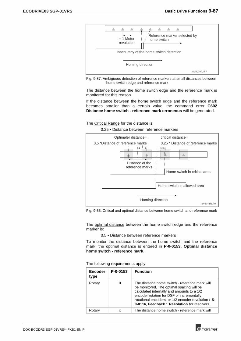
ECODRIVE03 SGP-01VRS Basic Drive Functions 9-87
DOK-ECODR3-SGP-01VRS**-FKB1-EN-P
SV5070f1.fh7
Reference marker selected byhome switch
Inaccuracy of the home switch detection
= 1 Motorrevolution
Homing direction
Fig. 9-87: Ambiguous detection of reference markers at small distances betweenhome switch edge and reference mark
The distance between the home switch edge and the reference mark ismonitored for this reason.
If the distance between the home switch edge and the reference markbecomes smaller than a certain value, the command error C602Distance home switch - reference mark erroneous will be generated.
The Critical Range for the distance is:
0.25 • Distance between reference markers
SV5071f1.fh7
Optimaler distance=
0,5 *Distance of reference marks
Distance of thereference marks
critical distance=
0,25 * Distance of reference marks
Home switch in critical area
Home switch in allowed area
Homing direction
Fig. 9-88: Critical and optimal distance between home switch and reference mark
The optimal distance between the home switch edge and the referencemarker is:
0.5 • Distance between reference markers
To monitor the distance between the home switch and the referencemark, the optimal distance is entered in P-0-0153, Optimal distancehome switch - reference mark.
The following requirements apply:
Encodertype
P-0-0153 Function
Rotary 0 The distance home switch - reference mark willbe monitored. The optimal spacing will becalculated internally and amounts to a 1/2encoder rotation for DSF or incrementallyrotational encoders, or 1/2 encoder revolution / S-0-0116, Feedback 1 Resolution for resolvers.
Rotary x The distance home switch - reference mark will
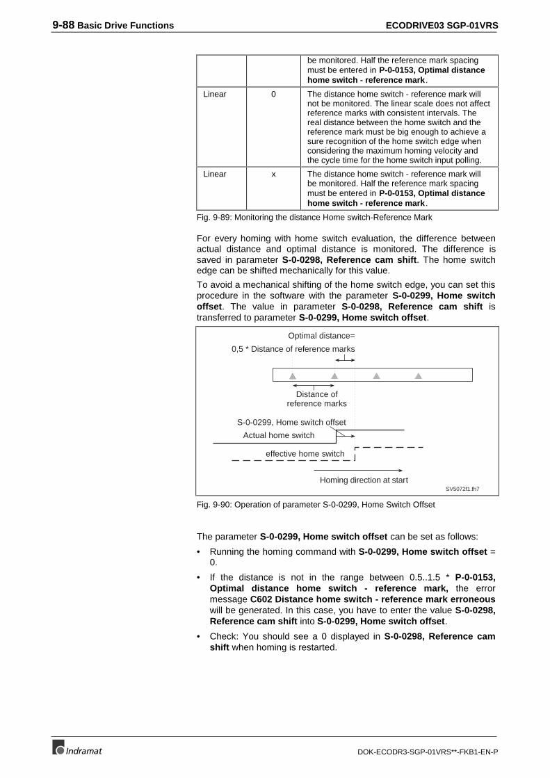
9-88 Basic Drive Functions ECODRIVE03 SGP-01VRS
DOK-ECODR3-SGP-01VRS**-FKB1-EN-P
be monitored. Half the reference mark spacingmust be entered in P-0-0153, Optimal distancehome switch - reference mark .
Linear 0 The distance home switch - reference mark willnot be monitored. The linear scale does not affectreference marks with consistent intervals. Thereal distance between the home switch and thereference mark must be big enough to achieve asure recognition of the home switch edge whenconsidering the maximum homing velocity andthe cycle time for the home switch input polling.
Linear x The distance home switch - reference mark willbe monitored. Half the reference mark spacingmust be entered in P-0-0153, Optimal distancehome switch - reference mark .
Fig. 9-89: Monitoring the distance Home switch-Reference Mark
For every homing with home switch evaluation, the difference betweenactual distance and optimal distance is monitored. The difference issaved in parameter S-0-0298, Reference cam shift. The home switchedge can be shifted mechanically for this value.
To avoid a mechanical shifting of the home switch edge, you can set thisprocedure in the software with the parameter S-0-0299, Home switchoffset. The value in parameter S-0-0298, Reference cam shift istransferred to parameter S-0-0299, Home switch offset.
SV5072f1.fh7
Optimal distance=
0,5 * Distance of reference marks
Distance ofreference marks
Homing direction at start
Actual home switch
effective home switch
S-0-0299, Home switch offset
Fig. 9-90: Operation of parameter S-0-0299, Home Switch Offset
The parameter S-0-0299, Home switch offset can be set as follows:
• Running the homing command with S-0-0299, Home switch offset =0.
• If the distance is not in the range between 0.5..1.5 * P-0-0153,Optimal distance home switch - reference mark, the errormessage C602 Distance home switch - reference mark erroneouswill be generated. In this case, you have to enter the value S-0-0298,Reference cam shift into S-0-0299, Home switch offset.
• Check: You should see a 0 displayed in S-0-0298, Reference camshift when homing is restarted.
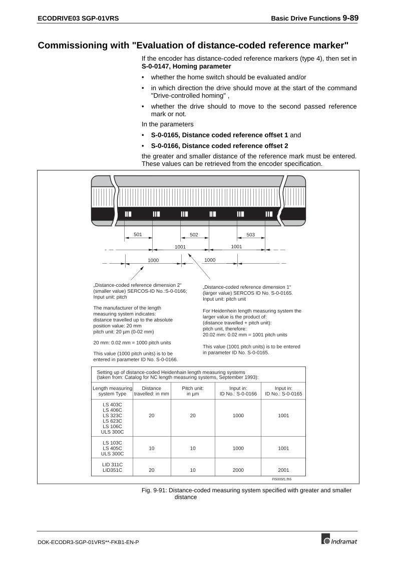
ECODRIVE03 SGP-01VRS Basic Drive Functions 9-89
DOK-ECODR3-SGP-01VRS**-FKB1-EN-P
Commissioning with "Evaluation of distance-coded reference marker"If the encoder has distance-coded reference markers (type 4), then set inS-0-0147, Homing parameter
• whether the home switch should be evaluated and/or
• in which direction the drive should move at the start of the command"Drive-controlled homing" ,
• whether the drive should to move to the second passed referencemark or not.
In the parameters
• S-0-0165, Distance coded reference offset 1 and
• S-0-0166, Distance coded reference offset 2
the greater and smaller distance of the reference mark must be entered.These values can be retrieved from the encoder specification.
Pi5005f1.fh5
501 502 503
1001 1001
1000
„Distance-coded reference dimension 2“(smaller value) SERCOS-ID No.:S-0-0166;Input unit: pitch
The manufacturer of the lengthmeasuring system indicates:distance travelled up to the absoluteposition value: 20 mmpitch unit: 20 µm (0-02 mm)
20 mm: 0.02 mm = 1000 pitch units
This value (1000 pitch units) is to beentered in parameter ID No. S-0-0166.
„Distance-coded reference dimension 1“(larger value) SERCOS ID No. S-0-0165.Input unit: pitch unit
For Heidenhein length measuring system thelarger value is the product of:(distance travelled + pitch unit):pitch unit, therefore:20.02 mm: 0.02 mm = 1001 pitch units
This value (1001 pitch units) is to be enteredin parameter ID No. S-0-0165.
1000
Setting up of distance-coded Heidenhain length measuring systems(taken from: Catalog for NC length measuring systems, September 1993):
Length measuringsystem Type
LS 403CLS 406CLS 323CLS 623CLS 106C
ULS 300C
LS 103CLS 405C
ULS 300C
LID 311CLID351C
Distancetravelled: in mm
20
10
20
Pitch unit:in µm
20
10
10
Input in:ID No.: S-0-0166
1000
1000
2000
Input in:ID No.: S-0-0165
1001
1001
2001
Fig. 9-91: Distance-coded measuring system specified with greater and smallerdistance
9-90 Basic Drive Functions ECODRIVE03 SGP-01VRS
DOK-ECODR3-SGP-01VRS**-FKB1-EN-P
In S-0-0165, Distance coded reference offset 1 the greater distance isentered, in S-0-0166, Distance coded reference offset 2 the smallerdistance. The unit of these two parameters is (division) periods. Typicalvaues for a linear scale with distance-coded reference marks are 20.02mm for the greater distance and 20.00 mm for the smaller distances witha resolution of 0.02mm. In parameter S-0-0165/166 enter the value 1001or 1000.
The further steps are outlined below.
⇒Check the relevant position encoder type parameter (S-0-0277/S-0-0115) to the correct setting.
⇒The parameters S-0-0177, Absolute distance 1 or S-0-0178,Absolute distance 2 must be parametrized with 0.
⇒The parameters S-0-0041, Homing velocity and S-0-0042, Homingacceleration must be set to smaller values (e.g., S-0-0041 = 10 rpm,S-0-0042 = 10 rad/s².
⇒Execute command drive-controlled reference
Note: If the command is cleared, then the original operating modebecomes active again. If drive-internal interpolation is set,then the drive immediately goes to the value set in S-0-0258,Target position. This value relates to the new (machine zeropoint related) coordinate system!
The command should be completed without error. The machine zeropoint is at the position of the first reference mark of the distance-codedmeasuring system as the absolute offset (S-0-0177/0178) wasparametrized with 0. The relevant position feedback value in S-0-0051,Position feedback 1 value or S-0-0053, Position feedback 2 valueshould now have the absolute reference to this preliminary machine zeropoint. To set the correct machine zero point, the following steps can beconducted:
⇒ Move the axis to the desired machine zero point and enter the positionfeedback value displayed there with the opposite qualifying sign inS-0-0177, Absolute distance 1 or S-0-0178, Absolute distance 2.
Or:
⇒ Run the axis to position feedback value = 0 and measure the distancebetween the current position and the desired machine zero point.Enter the distance in S-0-0177, Absolute distance 1 or S-0-0178,Absolute distance 2.
Once the drive-controlled reference command is again completed, theposition feedback value should refer to the desired machine zero point.
Parameters S-0-0041, Homing velocity and S-0-0042, Homingacceleration can now be set to their final values.
Home switch Evaluation with Distance coded ReferenceMarkersTo evaluate a home switch together with homing of a distance codedmeasuring system is only for one purpose: staying within the allowedtravel range.
Result ot the Drive-Controlled-Home Command
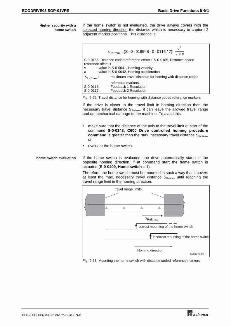
ECODRIVE03 SGP-01VRS Basic Drive Functions 9-91
DOK-ECODR3-SGP-01VRS**-FKB1-EN-P
If the home switch is not evaluated, the drive always covers with theselected homing direction the distance which is necessary to capture 2adjacent marker positions. This distance is
sv
afRe max ( )= ∗ + ×S - 0 - 0165 S - 0 - 0116 / 72
2
S-0-0165: Distance coded reference offset 1 S-0-0165, Distance codedreference offset 1v : value in S-0-0041, Homing velocitya : value in S-0-0042, Homing accelerations fRe max : maximum travel distance for homing with distance coded
reference markersS-0-0116: Feedback 1 ResolutionS-0-0117: Feedback 2 Resolution
Fig. 9-92: Travel distance for homing with distance coded reference markers
If the drive is closer to the travel limit in homing direction than thenecessary travel distance SRefmax, it can leave the allowed travel rangeand do mechanical damage to the machine. To avoid this,
• make sure that the distance of the axis to the travel limit at start of thecommand S-0-0148, C600 Drive controlled homing procedurecommand is greater than the max. necessary travel distance SRefmax,or
• evaluate the home switch.
If the home switch is evaluated, the drive automatically starts in theopposite homing direction, if at command start the home switch isactuated (S-0-0400, Home switch = 1).
Therefore, the home switch must be mounted in such a way that it coversat least the max. necessary travel distance SRefmax until reaching thetravel range limit in the homing direction.
SV5074f1.fh7Homing direction
incorrect mounting of the home switch
correct mounting of the home switch
travel range limits
SRefmax
Fig. 9-93: Mounting the home switch with distance coded reference markers
Higher security with ahome switch
home switch evaluation
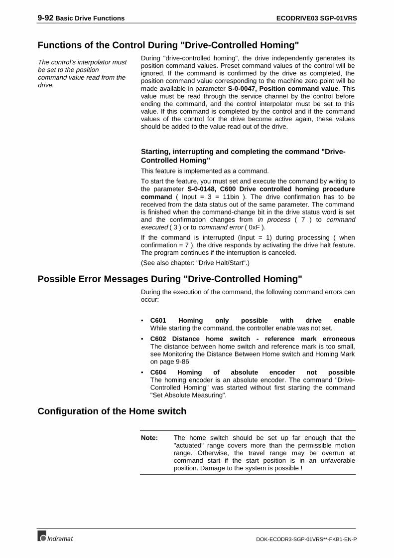
9-92 Basic Drive Functions ECODRIVE03 SGP-01VRS
DOK-ECODR3-SGP-01VRS**-FKB1-EN-P
Functions of the Control During "Drive-Controlled Homing"
The control’s interpolator mustbe set to the positioncommand value read from thedrive.
During "drive-controlled homing", the drive independently generates itsposition command values. Preset command values of the control will beignored. If the command is confirmed by the drive as completed, theposition command value corresponding to the machine zero point will bemade available in parameter S-0-0047, Position command value. Thisvalue must be read through the service channel by the control beforeending the command, and the control interpolator must be set to thisvalue. If this command is completed by the control and if the commandvalues of the control for the drive become active again, these valuesshould be added to the value read out of the drive.
Starting, interrupting and completing the command "Drive-Controlled Homing"This feature is implemented as a command.
To start the feature, you must set and execute the command by writing tothe parameter S-0-0148, C600 Drive controlled homing procedurecommand ( Input = 3 = 11bin ). The drive confirmation has to bereceived from the data status out of the same parameter. The commandis finished when the command-change bit in the drive status word is setand the confirmation changes from in process ( 7 ) to commandexecuted ( 3 ) or to command error ( 0xF ).
If the command is interrupted (Input = 1) during processing ( whenconfirmation = 7 ), the drive responds by activating the drive halt feature.The program continues if the interruption is canceled.
(See also chapter: "Drive Halt/Start".)
Possible Error Messages During "Drive-Controlled Homing"During the execution of the command, the following command errors canoccur:
• C601 Homing only possible with drive enableWhile starting the command, the controller enable was not set.
• C602 Distance home switch - reference mark erroneousThe distance between home switch and reference mark is too small,see Monitoring the Distance Between Home switch and Homing Markon page 9-86
• C604 Homing of absolute encoder not possibleThe homing encoder is an absolute encoder. The command "Drive-Controlled Homing" was started without first starting the command"Set Absolute Measuring".
Configuration of the Home switch
Note: The home switch should be set up far enough that the"actuated" range covers more than the permissible motionrange. Otherwise, the travel range may be overrun atcommand start if the start position is in an unfavorableposition. Damage to the system is possible !
ECODRIVE03 SGP-01VRS Basic Drive Functions 9-93
DOK-ECODR3-SGP-01VRS**-FKB1-EN-P
SV5073f1.fh7
Homing direction at start
Incorrect home switch order
Correct home switch order
Travel range limits
Fig. 9-94: Configuration of the home switch in reference to the travel range
Connection of the Home switchsee project planning manual.
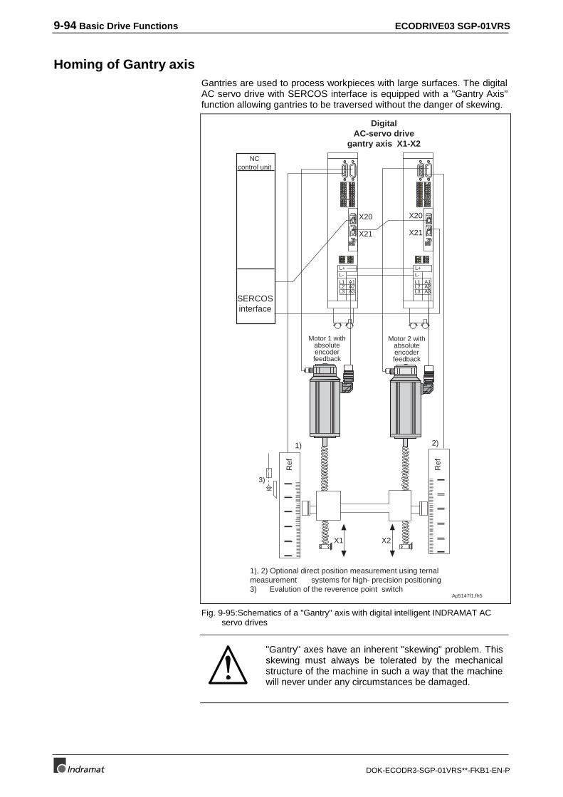
9-94 Basic Drive Functions ECODRIVE03 SGP-01VRS
DOK-ECODR3-SGP-01VRS**-FKB1-EN-P
Homing of Gantry axisGantries are used to process workpieces with large surfaces. The digitalAC servo drive with SERCOS interface is equipped with a "Gantry Axis"function allowing gantries to be traversed without the danger of skewing.
12
34
56
78
91
23
4
111213
141516
1718
56
78
12
34
56
78
L+L-L1L2L3
A1A2A3
H3ERROR
321
X20
X21
12
34
56
78
91
23
4
111213
141516
1718
56
78
12
34
56
78
L+L-L1L2L3
A1A2A3
H3ERROR
321
X20
X21
Ap5147f1.fh5
Ref
X2X1
Ref
1) 2)
3)
1), 2) Optional direct position measurement using ternalmeasurement systems for high- precision positioning3) Evalution of the reverence point switch
Motor 1 withabsoluteencoderfeedback
DigitalAC-servo drive
gantry axis X1-X2
SERCOSinterface
Motor 2 withabsoluteencoderfeedback
NCcontrol unit
Fig. 9-95:Schematics of a "Gantry" axis with digital intelligent INDRAMAT ACservo drives
"Gantry" axes have an inherent "skewing" problem. Thisskewing must always be tolerated by the mechanicalstructure of the machine in such a way that the machinewill never under any circumstances be damaged.
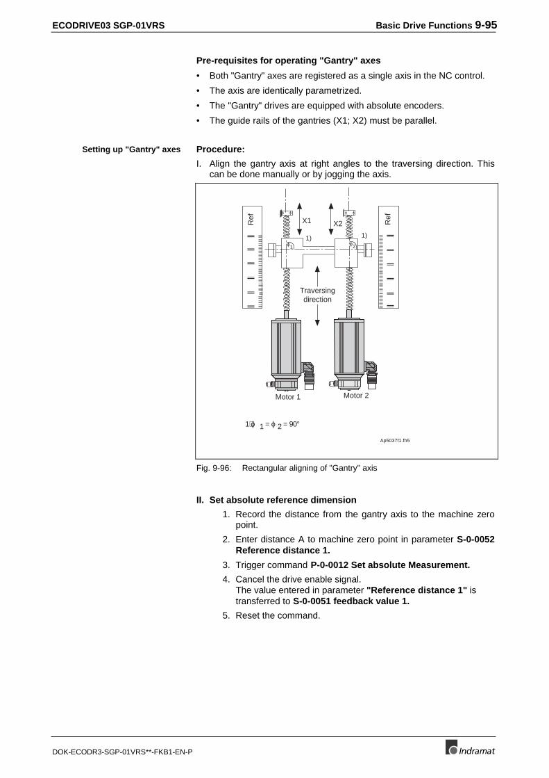
ECODRIVE03 SGP-01VRS Basic Drive Functions 9-95
DOK-ECODR3-SGP-01VRS**-FKB1-EN-P
Pre-requisites for operating "Gantry" axes
• Both "Gantry" axes are registered as a single axis in the NC control.
• The axis are identically parametrized.
• The "Gantry" drives are equipped with absolute encoders.
• The guide rails of the gantries (X1; X2) must be parallel.
Procedure:
I. Align the gantry axis at right angles to the traversing direction. Thiscan be done manually or by jogging the axis.
Ap5037f1.fh5
Motor 1 Motor 2
X2X1
Traversingdirection
Ref
Ref
1) ϕ 1 = ϕ 2 = 90°
ϕ1 ϕ21) 1)
Fig. 9-96: Rectangular aligning of "Gantry" axis
II. Set absolute reference dimension
1. Record the distance from the gantry axis to the machine zeropoint.
2. Enter distance A to machine zero point in parameter S-0-0052Reference distance 1.
3. Trigger command P-0-0012 Set absolute Measurement.
4. Cancel the drive enable signal.The value entered in parameter "Reference distance 1" istransferred to S-0-0051 feedback value 1.
5. Reset the command.
Setting up "Gantry" axes
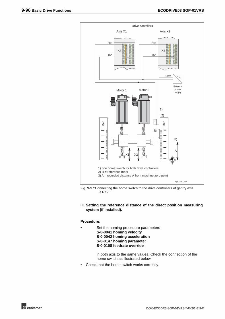
9-96 Basic Drive Functions ECODRIVE03 SGP-01VRS
DOK-ECODR3-SGP-01VRS**-FKB1-EN-P
Ap5148f1.fh7
Motor 1 Motor 2
X2X1
1)
+24V
2)
3)
A
12
34
56
78
91
23
4
111213
141516
1718
56
78
12
34
56
78
91
23
4
111213
141516
1718
56
78
Ref
0V
Ref
0VX3 X3
Ref
Ref
Drive contollers
Axis X1 Axis X2
1) one home switch for both drive controllers2) R = reference mark3) A = recorded distance A from machine zero point
Externalpowersupply
Fig. 9-97:Connecting the home switch to the drive controllers of gantry axisX1/X2
III. Setting the reference distance of the direct position measuringsystem (if installed).
Procedure:
• Set the homing procedure parametersS-0-0041 homing velocityS-0-0042 homing accelerationS-0-0147 homing parameterS-0-0108 feedrate override
in both axis to the same values. Check the connection of thehome switch as illustrated below.
• Check that the home switch works correctly.
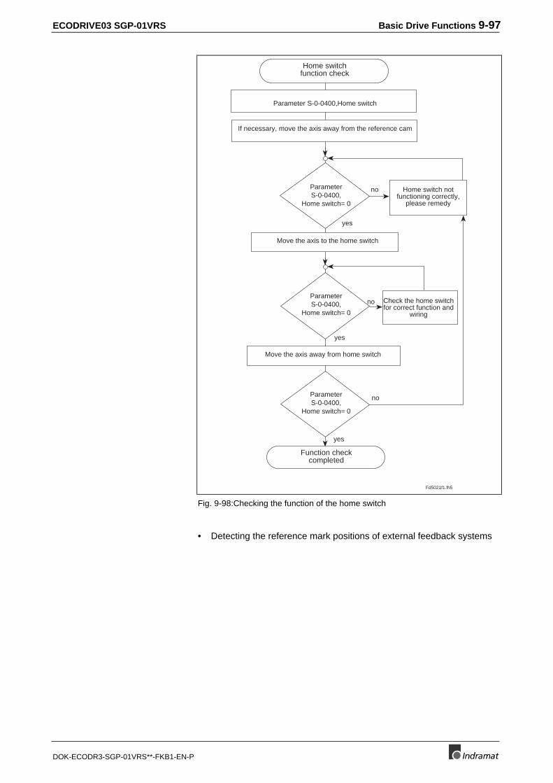
ECODRIVE03 SGP-01VRS Basic Drive Functions 9-97
DOK-ECODR3-SGP-01VRS**-FKB1-EN-P
Fd5021f1.fh5
Function checkcompleted
Move the axis to the home switch
Home switchfunction check
Move the axis away from home switch
ParameterS-0-0400,
Home switch= 0
yes
no
yes
no Check the home switchfor correct function and
wiring
Parameter S-0-0400,Home switch
If necessary, move the axis away from the reference cam
yes
no
Home switch notfunctioning correctly,
please remedy
ParameterS-0-0400,
Home switch= 0
ParameterS-0-0400,
Home switch= 0
Fig. 9-98:Checking the function of the home switch
• Detecting the reference mark positions of external feedback systems
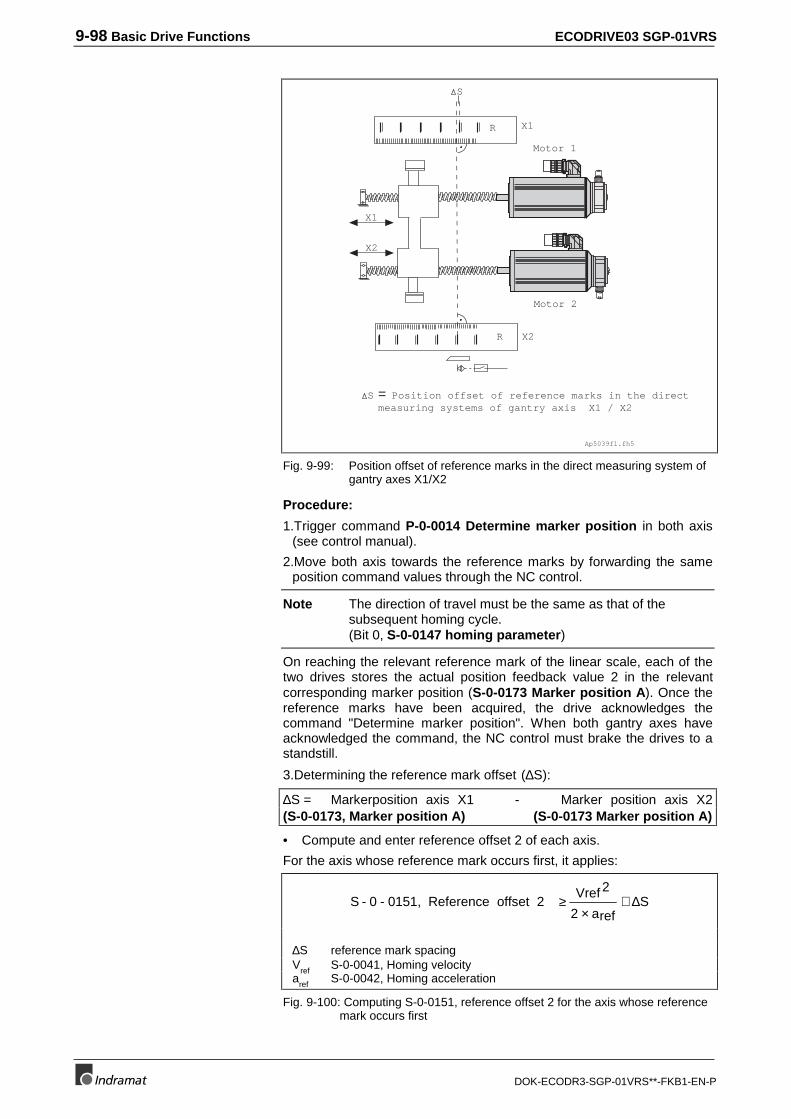
9-98 Basic Drive Functions ECODRIVE03 SGP-01VRS
DOK-ECODR3-SGP-01VRS**-FKB1-EN-P
X2
Ap5039f1.fh5
= Position offset of reference marks in the directmeasuring systems of gantry axis X1 / X2
Motor 1
Motor 2
X2
X1
X1
S
R
R
S
Fig. 9-99: Position offset of reference marks in the direct measuring system ofgantry axes X1/X2
Procedure:
1.Trigger command P-0-0014 Determine marker position in both axis(see control manual).
2.Move both axis towards the reference marks by forwarding the sameposition command values through the NC control.
Note The direction of travel must be the same as that of thesubsequent homing cycle.(Bit 0, S-0-0147 homing parameter)
On reaching the relevant reference mark of the linear scale, each of thetwo drives stores the actual position feedback value 2 in the relevantcorresponding marker position (S-0-0173 Marker position A). Once thereference marks have been acquired, the drive acknowledges thecommand "Determine marker position". When both gantry axes haveacknowledged the command, the NC control must brake the drives to astandstill.
3.Determining the reference mark offset (∆S):
∆S = Markerposition axis X1 - Marker position axis X2(S-0-0173, Marker position A) (S-0-0173 Marker position A)
• Compute and enter reference offset 2 of each axis.
For the axis whose reference mark occurs first, it applies:
S - 0 - 0151, Reference offset 2 Vref 2
ref2 aS≥ ∆
×+
∆S reference mark spacingV
refS-0-0041, Homing velocity
aref
S-0-0042, Homing acceleration
Fig. 9-100: Computing S-0-0151, reference offset 2 for the axis whose referencemark occurs first
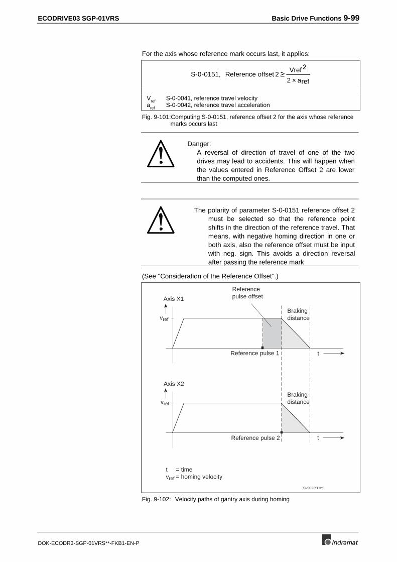
ECODRIVE03 SGP-01VRS Basic Drive Functions 9-99
DOK-ECODR3-SGP-01VRS**-FKB1-EN-P
For the axis whose reference mark occurs last, it applies:
S-0 0151, Reference offset 2Vref 2
ref2 a- ≥
×
Vref
S-0-0041, reference travel velocitya
refS-0-0042, reference travel acceleration
Fig. 9-101:Computing S-0-0151, reference offset 2 for the axis whose referencemarks occurs last
Danger:A reversal of direction of travel of one of the twodrives may lead to accidents. This will happen whenthe values entered in Reference Offset 2 are lowerthan the computed ones.
The polarity of parameter S-0-0151 reference offset 2must be selected so that the reference pointshifts in the direction of the reference travel. Thatmeans, with negative homing direction in one orboth axis, also the reference offset must be inputwith neg. sign. This avoids a direction reversalafter passing the reference mark
(See "Consideration of the Reference Offset".)
Sv5023f1.fh5
Axis X1
t
vref
Reference pulse 1
Brakingdistance
Referencepulse offset
Axis X2
t
vref
t = timevref = homing velocity
Brakingdistance
Reference pulse 2
Fig. 9-102: Velocity paths of gantry axis during homing
9-100 Basic Drive Functions ECODRIVE03 SGP-01VRS
DOK-ECODR3-SGP-01VRS**-FKB1-EN-P
9.11 Set Absolute Measuring
When an absolute measuring system is installed, its position feedbackvalue displays a value that is arbitrary and has no relationship to themachine’s zero point. In this case, the value of the S-0-0403, Positionfeedback value status parameter is 0.
In contrast to non-absolute measuring systems, the absolute dimensionsin absoute measuring systems are established only once at the initialstart-up of an axis.
The position feedback value of this measurement system can be set tothe desired value with the command "Set Absolute Measuring." Afterabsolute measuring (dimension) is set, the position feedback value of theencoder has a defined relationship to the machine’s zero point.
All information will be available after reset because all necessary datafrom the absolute dimension system is stored in encoder data memory orin parameter data memory. The position feedback value retains itsreference to the machine’s zero point.
The following parameter is available for executing the function:
• P-0-0012, C300 Command ’Set absolute Measurement’
In addition, the following parameters are needed or are affected by thefunction:
• S-0-0147, Homing Parameter
• S-0-0052, Reference distance 1
• S-0-0054, Reference distance 2
• S-0-0403, Position feedback value status
Function Principle Set Absolute MeasuringThe feedback connected to the mechanical system is brought to anexactly measured position. The value desired for the position feedbackvalue of the measurement system is entered in the parameter S-0-0052,Reference distance 1 (for motor encoder) or S-0-0054, Referencedistance 2 (for optional encoder). Then the command P-0-0012, C300Command ’Set absolute Measurement’ is started. The positionfeedback value is set to the value in the respective reference distanceand the position status becomes 1.
If only one absolute measurement system is available, the commandautomatically refers to this measurement system. If 2 absolutemeasurement systems are connected, the selection is conductedaccording to bit 3 of S-0-0147, Homing Parameter.
When the command is executed, 3 different cases can be distinguished :
1. Set absolute measuring without drive enable.
2. Set absolute measuring with drive enable, function executed bysubsequently starting the command "Drive Controlled HomingProcedure".
3. Set absolute measuring with drive enable, function executed bysubsequently clearing the drive enable.
ECODRIVE03 SGP-01VRS Basic Drive Functions 9-101
DOK-ECODR3-SGP-01VRS**-FKB1-EN-P
Set absolute measuring without controller enableWhen absolute measuring is set without drive enable, the axis is movedto the exactly measured position and, while the drive enable is turned off,the command P-0-0012, C300 Command ’Set absolute Measurement’is started, after the reference distance has been written with the desiredposition feedback value at this position.
The command immediately sets the position feedback value of themeasurement system to the reference distance, and the position statusbecomes 1. The command is finished in the drive and can be cleared.
Normally, this simple method of executing the command is all you need.However, if the application is dealing with a "vertical axis" (vertical) or ifthe approached position cannot be held without drive enable for anotherreason, the command can also be done with drive enable under specificconditions.
(See 2. or 3. from: Set Absolute Measuring Functional Principle.)
Setting Absolute Dimension Under Controller Enable andSubsequent "Drive-Controlled Homing"Homing: Setting absolute dimension command, the position feedbackvalue of a controlled axis can be changed. This may be necessary with"vertical axis," for example.
The procedure is as follows :
• Move the axis to the measured position.
• Enter the desired position feedback value in the appropriate referencedistance parameter.
• Start the command P-0-0012, C300 Command ’Set absoluteMeasurement’ The position data will not be switched yet.
• Start the command S-0-0148, C600 Drive controlled homingprocedure command this feature recognizes that it is dealing with anabsolute measurement system and executes "Set AbsoluteDimension" or, in other words, the position feedback value is set tothe reference distance. The position command value (S-0-0147,Homing Parameter) is simultaneously set to the same value. As witheach execution of "drive-controlled homing," the position commandvalue is read via the service channel and the control system’s positioncommand value is set to this value before the homing command iscleared.
Warning:Make sure that the encoder to be set is selected in bit 3 of S-0-0147,Homing Parameter
• Clear the command P-0-0012, C300 Command ’Set absoluteMeasurement’
Set absolute dimension (measuring) during controller enable,then turn off the controller enable Setting absolute measuring: with CE and subsequent CE switch off, theposition feedback value of a controlled axis can be changed. Switchingthe position feedback value occurs after the drive enable is turned off.
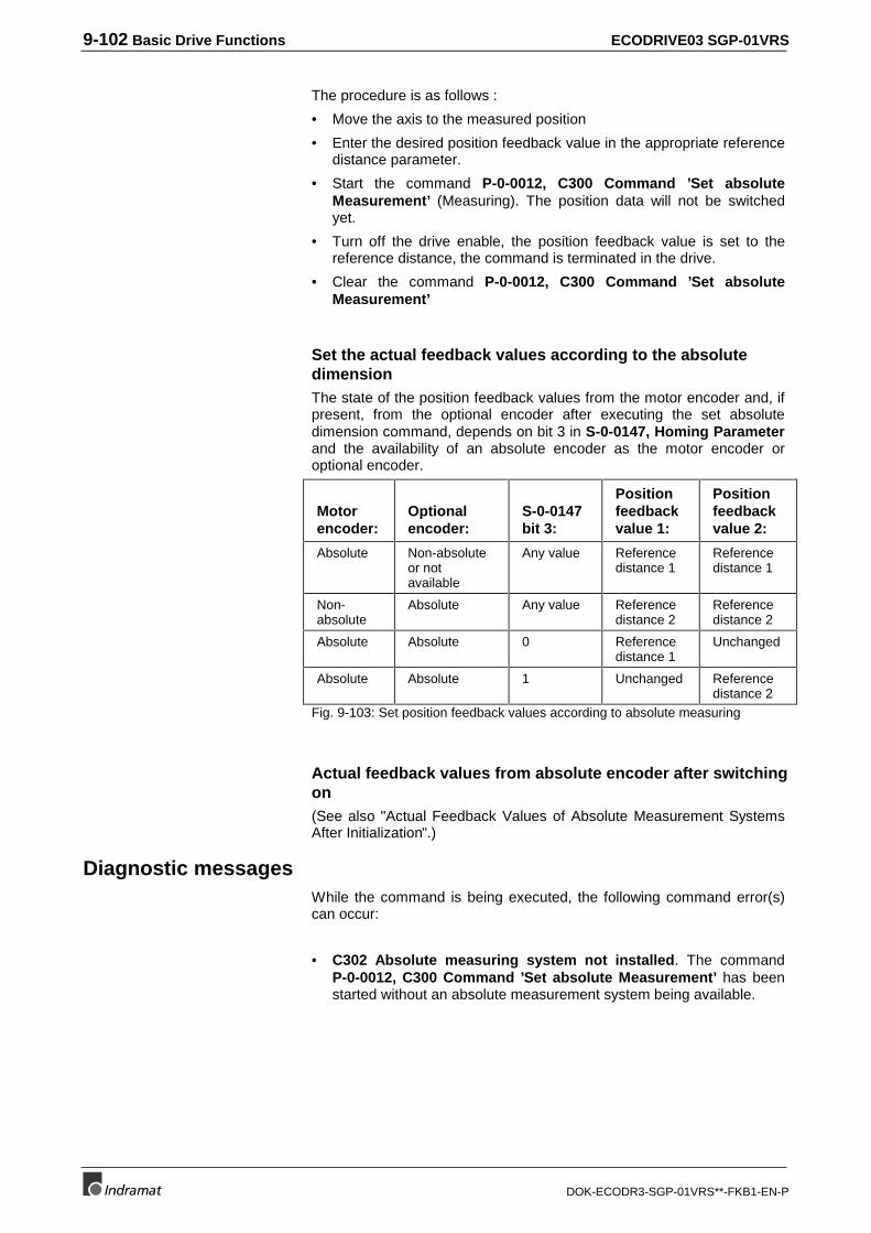
9-102 Basic Drive Functions ECODRIVE03 SGP-01VRS
DOK-ECODR3-SGP-01VRS**-FKB1-EN-P
The procedure is as follows :
• Move the axis to the measured position
• Enter the desired position feedback value in the appropriate referencedistance parameter.
• Start the command P-0-0012, C300 Command ’Set absoluteMeasurement’ (Measuring). The position data will not be switchedyet.
• Turn off the drive enable, the position feedback value is set to thereference distance, the command is terminated in the drive.
• Clear the command P-0-0012, C300 Command ’Set absoluteMeasurement’
Set the actual feedback values according to the absolutedimensionThe state of the position feedback values from the motor encoder and, ifpresent, from the optional encoder after executing the set absolutedimension command, depends on bit 3 in S-0-0147, Homing Parameterand the availability of an absolute encoder as the motor encoder oroptional encoder.
Motorencoder:
Optionalencoder:
S-0-0147bit 3:
Positionfeedbackvalue 1:
Positionfeedbackvalue 2:
Absolute Non-absoluteor notavailable
Any value Referencedistance 1
Referencedistance 1
Non-absolute
Absolute Any value Referencedistance 2
Referencedistance 2
Absolute Absolute 0 Referencedistance 1
Unchanged
Absolute Absolute 1 Unchanged Referencedistance 2
Fig. 9-103: Set position feedback values according to absolute measuring
Actual feedback values from absolute encoder after switchingon(See also "Actual Feedback Values of Absolute Measurement SystemsAfter Initialization".)
Diagnostic messagesWhile the command is being executed, the following command error(s)can occur:
• C302 Absolute measuring system not installed. The commandP-0-0012, C300 Command ’Set absolute Measurement’ has beenstarted without an absolute measurement system being available.
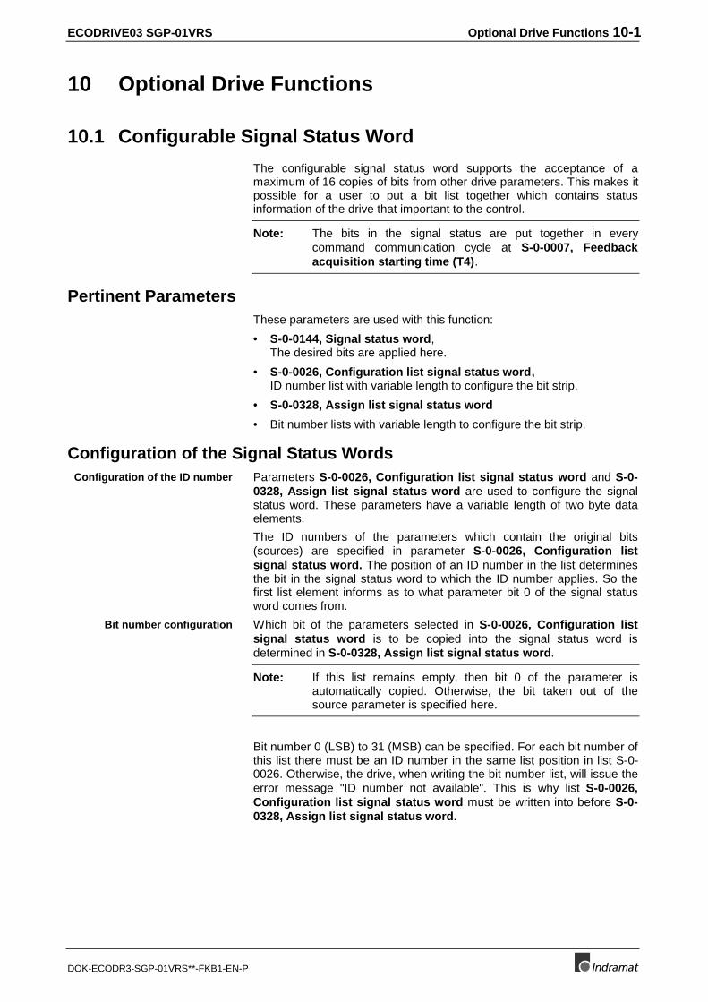
ECODRIVE03 SGP-01VRS Optional Drive Functions 10-1
DOK-ECODR3-SGP-01VRS**-FKB1-EN-P
10 Optional Drive Functions
10.1 Configurable Signal Status Word
The configurable signal status word supports the acceptance of amaximum of 16 copies of bits from other drive parameters. This makes itpossible for a user to put a bit list together which contains statusinformation of the drive that important to the control.
Note: The bits in the signal status are put together in everycommand communication cycle at S-0-0007, Feedbackacquisition starting time (T4).
Pertinent ParametersThese parameters are used with this function:
• S-0-0144, Signal status word,The desired bits are applied here.
• S-0-0026, Configuration list signal status word, ID number list with variable length to configure the bit strip.
• S-0-0328, Assign list signal status word
• Bit number lists with variable length to configure the bit strip.
Configuration of the Signal Status WordsParameters S-0-0026, Configuration list signal status word and S-0-0328, Assign list signal status word are used to configure the signalstatus word. These parameters have a variable length of two byte dataelements.
The ID numbers of the parameters which contain the original bits(sources) are specified in parameter S-0-0026, Configuration listsignal status word. The position of an ID number in the list determinesthe bit in the signal status word to which the ID number applies. So thefirst list element informs as to what parameter bit 0 of the signal statusword comes from.
Which bit of the parameters selected in S-0-0026, Configuration listsignal status word is to be copied into the signal status word isdetermined in S-0-0328, Assign list signal status word.
Note: If this list remains empty, then bit 0 of the parameter isautomatically copied. Otherwise, the bit taken out of thesource parameter is specified here.
Bit number 0 (LSB) to 31 (MSB) can be specified. For each bit number ofthis list there must be an ID number in the same list position in list S-0-0026. Otherwise, the drive, when writing the bit number list, will issue theerror message "ID number not available". This is why list S-0-0026,Configuration list signal status word must be written into before S-0-0328, Assign list signal status word.
Configuration of the ID number
Bit number configuration
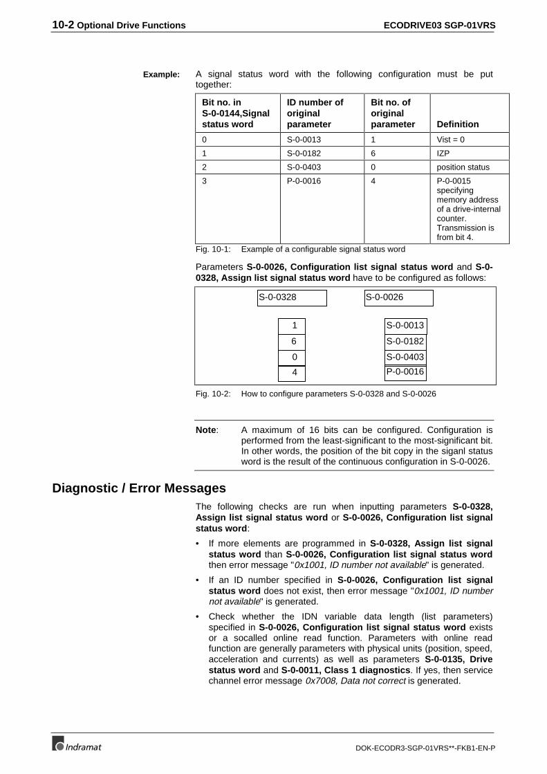
10-2 Optional Drive Functions ECODRIVE03 SGP-01VRS
DOK-ECODR3-SGP-01VRS**-FKB1-EN-P
A signal status word with the following configuration must be puttogether:
Bit no. inS-0-0144,Signalstatus word
ID number oforiginalparameter
Bit no. oforiginalparameter Definition
0 S-0-0013 1 Vist = 0
1 S-0-0182 6 IZP
2 S-0-0403 0 position status
3 P-0-0016 4 P-0-0015specifyingmemory addressof a drive-internalcounter.Transmission isfrom bit 4.
Fig. 10-1: Example of a configurable signal status word
Parameters S-0-0026, Configuration list signal status word and S-0-0328, Assign list signal status word have to be configured as follows:
1
6
0
4
S-0-0328
S-0-0013
S-0-0182
S-0-0403
P-0-0016
S-0-0026
Fig. 10-2: How to configure parameters S-0-0328 and S-0-0026
Note: A maximum of 16 bits can be configured. Configuration isperformed from the least-significant to the most-significant bit.In other words, the position of the bit copy in the siganl statusword is the result of the continuous configuration in S-0-0026.
Diagnostic / Error MessagesThe following checks are run when inputting parameters S-0-0328,Assign list signal status word or S-0-0026, Configuration list signalstatus word:
• If more elements are programmed in S-0-0328, Assign list signalstatus word than S-0-0026, Configuration list signal status wordthen error message "0x1001, ID number not available" is generated.
• If an ID number specified in S-0-0026, Configuration list signalstatus word does not exist, then error message "0x1001, ID numbernot available" is generated.
• Check whether the IDN variable data length (list parameters)specified in S-0-0026, Configuration list signal status word existsor a socalled online read function. Parameters with online readfunction are generally parameters with physical units (position, speed,acceleration and currents) as well as parameters S-0-0135, Drivestatus word and S-0-0011, Class 1 diagnostics. If yes, then servicechannel error message 0x7008, Data not correct is generated.
Example:
ECODRIVE03 SGP-01VRS Optional Drive Functions 10-3
DOK-ECODR3-SGP-01VRS**-FKB1-EN-P
Note: In each of these cases, only those inputs up to the faultyelement are accepted!
Hardware DependenciesVarious digital outputs are freely configured using the signal status worddepending on the unit type.
The digital outputs can be assigned as needed at connector X15. (Seesection: "Command Communication Using Parallel Interface").
The default setting corresponds to the assignment of the parallelinterfaces.
Outputs X3.8 and X3.10 can be assigned as needed. Bit 0 of the signalstatus word is copied onto output X3.8 and bit 1 onto output X3.10.
The default setting puts the ready or warning bit (see S-0-0182,Manufacturer class 3 diagnostics) at the outputs.
The digital outputs cannot be freely assigned.
10.2 Configurable Signal Control Word
With the signal control word it is possible to write access single controlbits in the various parameters by using a freely-configurable collectiveparameter.
The configurable signal control word supports acceptance of a maximumof16 copies of bits from other drive parameters.
This mechanism can be used, for example, for
• positioning block mode via parallel interface
• main spindle mode via parallel interface
Depending on the command communications parameter S-0-0145,Signal control word is accessed in various ways:
• With parallel interface (DKC01.3) the 10 digital inputs on the lowestten bits are copied into the signal control word!
• With SERCOS and fieldbus interface,S-0-0145, Signal control wordmust be relevantly configured in cyclical data so that the mechanismcan be used.
Note: The bits in the signal control word are effective in eachinterface cycle at S-0-0008, Command valid time (T3).
Involved ParametersThe following parameters are used for the funtions
• S-0-0027, Configuration list signal control word
• S-0-0329, Assign list signal control word
• S-0-0145, Signal control word
• S-0-0399, IDN list of configurable data in the signal control word
DKC01.3:
DKC02.3:
DKC11.3:
Application
Accessing signal control word
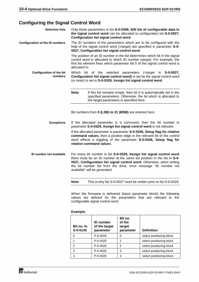
10-4 Optional Drive Functions ECODRIVE03 SGP-01VRS
DOK-ECODR3-SGP-01VRS**-FKB1-EN-P
Configuring the Signal Control WordOnly those parameters in list S-0-0399, IDN list of configurable data inthe signal control word can be allocated to configuration list S-0-0027,Configuration list signal control word.
The ID numbers of the parameters which are to be configured with thehelp of the signal control word (=target) are specified in parameter S-0-0027, Configuration list signal control word.
The position of an ID number in the list determines which bit in the signalcontrol word is allocated to which ID number (target). For example, thefirst list element fixes which parameter bit 0 of the signal control word isallocated to.
Which bit of the selected parameters (=target in S-0-0027,Configuration list signal control word) is set by the signal control word(or reset) is set in S-0-0329, Assign list signal control word.
Note: If this list remains empty, then bit 0 is automatically set in thespecified parameters. Otherwise, the bit which is allocated tothe target parameters is specified here.
Bit numbers from 0 (LSB) to 31 (MSB) are entered here.
If the allocated parameter is a command, then the bit number inparameter S-0-0329, Assign list signal control word is not relevant.
If the allocated parameter is parameter S-0-0346, Setup flag for relativecommand values, then a positive edge in the relevant bit of the controlword effects a toggling of the parameter S-0-0346, Setup flag forrelative command values.
For every bit number in list S-0-0329, Assign list signal control wordthere must be an ID number at the same list position in the list in S-0-0027, Configuration list signal control word. Otherwise, when writingthe bit number list from the drive, error message "ID number notavailable" will be generated.
Note: This is why list S-0-0027 must be written prior to list S-0-0329.
When the firmware is delivered (basic parameter block) the followingvalues are defined for the parameters that are relevant to theconfigurable signal control word.
Example:
Bit no. InS-0-0145
ID numberof the targetparameter
Bit no.of thetargetparameter Definition
0 P-0-4026 0 select positioning block
1 P-0-4026 1 select positioning block
2 P-0-4026 2 select positioning block
3 P-0-4026 3 select positioning block
4 P-0-4026 4 select positioning block
Selection lists
Configuration of the ID numbers
Configuration of the bitnumbers
Exceptions
ID number not available
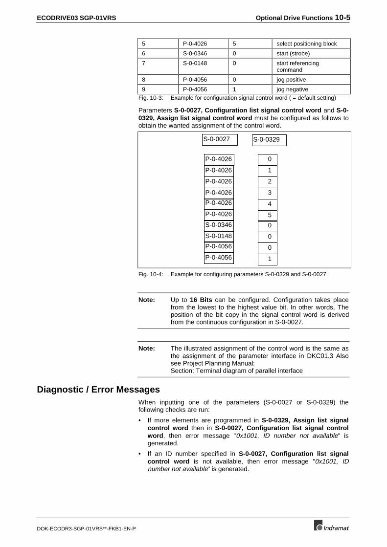
ECODRIVE03 SGP-01VRS Optional Drive Functions 10-5
DOK-ECODR3-SGP-01VRS**-FKB1-EN-P
5 P-0-4026 5 select positioning block
6 S-0-0346 0 start (strobe)
7 S-0-0148 0 start referencingcommand
8 P-0-4056 0 jog positive
9 P-0-4056 1 jog negativeFig. 10-3: Example for configuration signal control word ( = default setting)
Parameters S-0-0027, Configuration list signal control word and S-0-0329, Assign list signal control word must be configured as follows toobtain the wanted assignment of the control word.
0
1
2
3
4
5
S-0-0329
P-0-4026
P-0-4026
P-0-4026
P-0-4026
P-0-4026
P-0-4026
S-0-0027
0
0
0
1
S-0-0346
S-0-0148
P-0-4056
P-0-4056
Fig. 10-4: Example for configuring parameters S-0-0329 and S-0-0027
Note: Up to 16 Bits can be configured. Configuration takes placefrom the lowest to the highest value bit. In other words, Theposition of the bit copy in the signal control word is derivedfrom the continuous configuration in S-0-0027.
Note: The illustrated assignment of the control word is the same asthe assignment of the parameter interface in DKC01.3 Alsosee Project Planning Manual: Section: Terminal diagram of parallel interface
Diagnostic / Error MessagesWhen inputting one of the parameters (S-0-0027 or S-0-0329) thefollowing checks are run:
• If more elements are programmed in S-0-0329, Assign list signalcontrol word then in S-0-0027, Configuration list signal controlword, then error message "0x1001, ID number not available" isgenerated.
• If an ID number specified in S-0-0027, Configuration list signalcontrol word is not available, then error message "0x1001, IDnumber not available" is generated.
10-6 Optional Drive Functions ECODRIVE03 SGP-01VRS
DOK-ECODR3-SGP-01VRS**-FKB1-EN-P
• If an ID number specified in S-0-0027, Configuration list signalcontrol word is not on the list of the configured data S-0-0399 thenerror message "0x7008, Data not correct" is generated.
Note: In each of these cases, only that input prior to the faultyelement will be accepted!
10.3 Analog Output
With the help of the function "Analog output" drive-internal signals andstate variables can be generated as analog voltage signals. These canbe examined with an oscilloscope connected to the analog outputs.
The conversion of the digital values from the drive is done via two 8 bitdigital-to-analog converters. The maximum output voltage equals +/- 10volts. There is an output every 500 usec.
Possible output functions1. Direct writing into the analog outputs
2. Assigning ID numbers to analog outputs
3. Output of pre-set signals
4. Byte output of RAM memory cell
5. Bit output of RAM memory cells
To parametrize the function, the following parameters are available:
• P-0-0139, Analog output 1
• P-0-0140, Analog output 2
• P-0-0420, Analog output 1, signal selection
• P-0-0421, Analog output 1, expanded signal selection
• P-0-0422 Analog output 1, scaling
• P-0-0423, Analog output 2, signal selection
• P-0-0424, Analog output 2, expanded signal selection
• P-0-0425, Analog output 2, scaling
• P-0-0426 Analog outputs, IDN list of assignable parameters
Direct analog outputsWith the parameters P-0-0139, Analog output 1 and P-0-0140, Analogoutput 2 it is possible for the control to use the two 8 bit digital/analogconverters of the drive. Voltage values written into these parameters,ranging between -10.000 volts and +10.000 volts, are output by the driveto the analog outputs. The quantization equals 78 mV.
A precondition for the use of an analog output is that the signal selection(P-0-0420 or P-0-0423) and the expanded signal selection (P-0-0421 orP-0-0424) were deactivated by inputting 0 for the used channel.
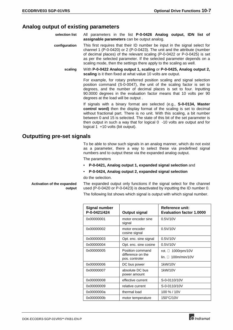
ECODRIVE03 SGP-01VRS Optional Drive Functions 10-7
DOK-ECODR3-SGP-01VRS**-FKB1-EN-P
Analog output of existing parametersAll parameters in the list P-0-0426 Analog output, IDN list ofassignable parameters can be output analog.
This first requires that their ID number be input in the signal select forchannel 1 (P-0-0420) or 2 (P-0-0423). The unit and the attribute (numberof decimal places) of the relevant scaling (P-0-0422 or P-0-0425) is setas per the selected parameter. If the selected parameter depends on ascaling mode, then the settings there apply to the scaling as well.
With P-0-0422 Analog output 1, scaling or P-0-0425, Analog output 2,scaling is it then fixed at what value 10 volts are output.
For example, for rotary preferred position scaling and signal selectionposition command (S-0-0047), the unit of the scaling factor is set todegrees, and the number of decimal places is set to four. Inputting90.0000 degrees in the evaluation factor means that 10 volts per 90degrees at the load will be output .
If signals with a binary format are selected (e.g., S-0-0134, Mastercontrol word) then the display format of the scaling is set to decimalwithout fractional part. There is no unit. With this scaling, a bit numberbetween 0 and 15 is selected. The state of this bit of the set parameter isthen output in such a way that for logical 0 -10 volts are output and forlogical 1 +10 volts (bit output).
Outputting pre-set signalsTo be able to show such signals in an analog manner, which do not existas a parameter, there a way to select these via predefined signalnumbers and to output these via the expanded analog output.
The parameters
• P-0-0421, Analog output 1, expanded signal selection and
• P-0-0424, Analog output 2, expanded signal selection
do the selection.
The expanded output only functions if the signal select for the channelused (P-0-0420 or P-0-0423) is deactivated by inputting the ID number 0.
The following list shows which signal is output with which signal number.
Signal numberP-0-0421/424 Output signal
Reference unit:Evaluation factor 1.0000
0x00000001 motor encoder sinesignal
0.5V/10V
0x00000002 motor encodercosine signal
0.5V/10V
0x00000003 Opt. enc. sine signal 0.5V/10V
0x00000004 Opt. enc. sine cosine 0.5V/10V
0x00000005 Position commanddifference on thepos. controler
rot. ⇒ 1000rpm/10V
lin. ⇒ 100m/min/10V
0x00000006 DC bus power 1kW/10V
0x00000007 absolute DC buspower amount
1kW/10V
0x00000008 effective current S-0-0110/10V
0x00000009 relative current S-0-0110/10V
0x0000000a thermal load 100 % / 10V
0x0000000b motor temperature 150°C/10V
selection list
configuration
scaling
Activation of the expandedoutput
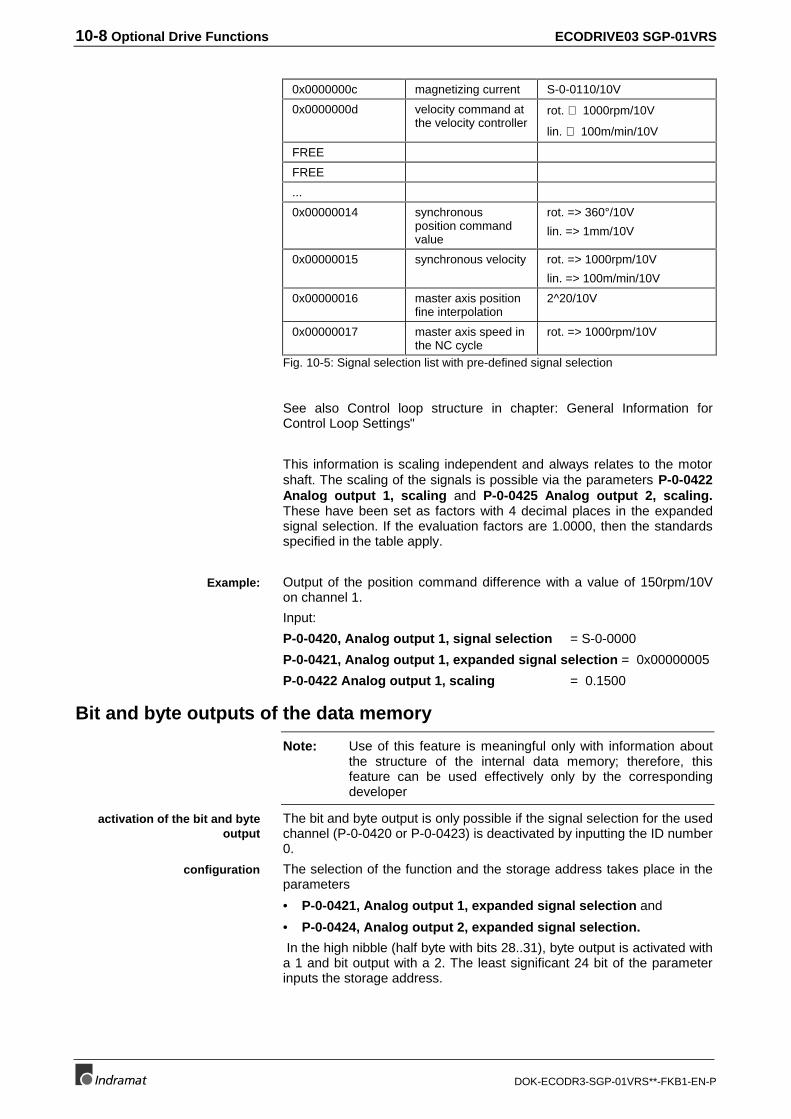
10-8 Optional Drive Functions ECODRIVE03 SGP-01VRS
DOK-ECODR3-SGP-01VRS**-FKB1-EN-P
0x0000000c magnetizing current S-0-0110/10V
0x0000000d velocity command atthe velocity controller
rot. ⇒ 1000rpm/10V
lin. ⇒ 100m/min/10V
FREE
FREE
...
0x00000014 synchronousposition commandvalue
rot. => 360°/10V
lin. => 1mm/10V
0x00000015 synchronous velocity rot. => 1000rpm/10V
lin. => 100m/min/10V
0x00000016 master axis positionfine interpolation
2^20/10V
0x00000017 master axis speed inthe NC cycle
rot. => 1000rpm/10V
Fig. 10-5: Signal selection list with pre-defined signal selection
See also Control loop structure in chapter: General Information forControl Loop Settings"
This information is scaling independent and always relates to the motorshaft. The scaling of the signals is possible via the parameters P-0-0422Analog output 1, scaling and P-0-0425 Analog output 2, scaling.These have been set as factors with 4 decimal places in the expandedsignal selection. If the evaluation factors are 1.0000, then the standardsspecified in the table apply.
Output of the position command difference with a value of 150rpm/10Von channel 1.
Input:
P-0-0420, Analog output 1, signal selection = S-0-0000
P-0-0421, Analog output 1, expanded signal selection = 0x00000005
P-0-0422 Analog output 1, scaling = 0.1500
Bit and byte outputs of the data memory
Note: Use of this feature is meaningful only with information aboutthe structure of the internal data memory; therefore, thisfeature can be used effectively only by the correspondingdeveloper
The bit and byte output is only possible if the signal selection for the usedchannel (P-0-0420 or P-0-0423) is deactivated by inputting the ID number0.
The selection of the function and the storage address takes place in theparameters
• P-0-0421, Analog output 1, expanded signal selection and
• P-0-0424, Analog output 2, expanded signal selection.
In the high nibble (half byte with bits 28..31), byte output is activated witha 1 and bit output with a 2. The least significant 24 bit of the parameterinputs the storage address.
Example:
activation of the bit and byteoutput
configuration
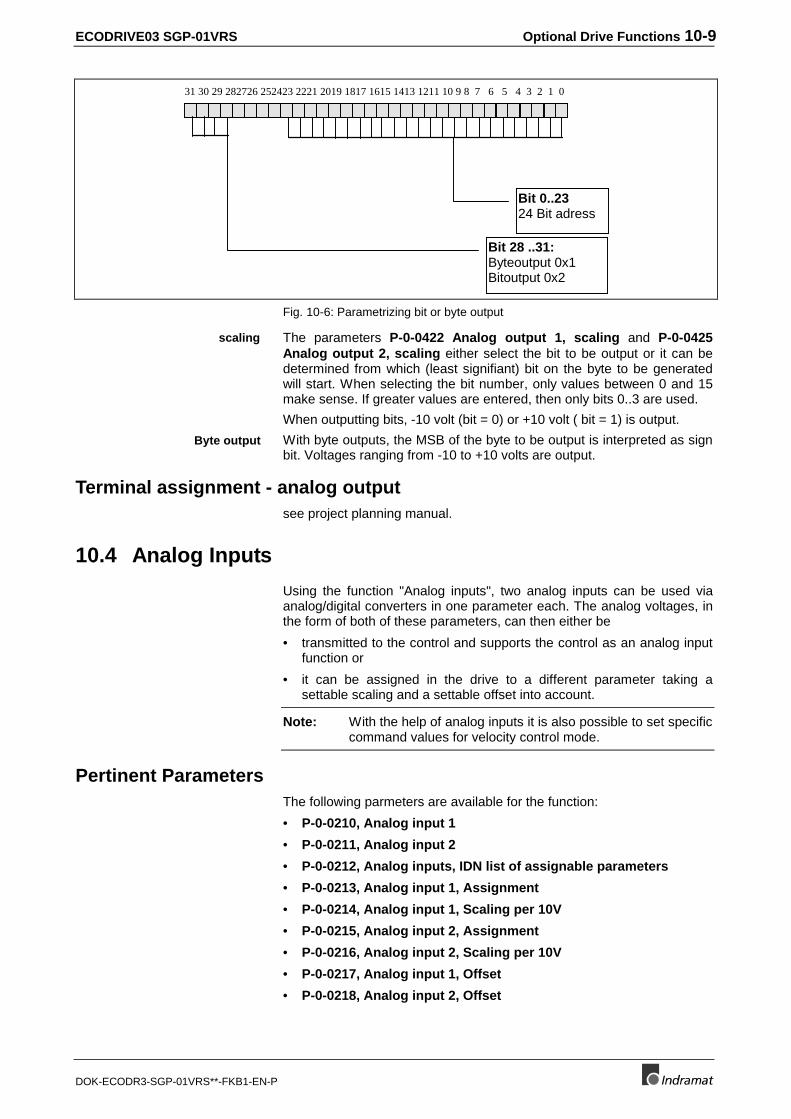
ECODRIVE03 SGP-01VRS Optional Drive Functions 10-9
DOK-ECODR3-SGP-01VRS**-FKB1-EN-P
31 30 29 282726 252423 2221 2019 1817 1615 1413 1211 10 9 8 7 6 5 4 3 2 1 0
Bit 28 ..31:Byteoutput 0x1Bitoutput 0x2
Bit 0..2324 Bit adress
Fig. 10-6: Parametrizing bit or byte output
The parameters P-0-0422 Analog output 1, scaling and P-0-0425Analog output 2, scaling either select the bit to be output or it can bedetermined from which (least signifiant) bit on the byte to be generatedwill start. When selecting the bit number, only values between 0 and 15make sense. If greater values are entered, then only bits 0..3 are used.
When outputting bits, -10 volt (bit = 0) or +10 volt ( bit = 1) is output.
With byte outputs, the MSB of the byte to be output is interpreted as signbit. Voltages ranging from -10 to +10 volts are output.
Terminal assignment - analog outputsee project planning manual.
10.4 Analog Inputs
Using the function "Analog inputs", two analog inputs can be used viaanalog/digital converters in one parameter each. The analog voltages, inthe form of both of these parameters, can then either be
• transmitted to the control and supports the control as an analog inputfunction or
• it can be assigned in the drive to a different parameter taking asettable scaling and a settable offset into account.
Note: With the help of analog inputs it is also possible to set specificcommand values for velocity control mode.
Pertinent ParametersThe following parmeters are available for the function:
• P-0-0210, Analog input 1
• P-0-0211, Analog input 2
• P-0-0212, Analog inputs, IDN list of assignable parameters
• P-0-0213, Analog input 1, Assignment
• P-0-0214, Analog input 1, Scaling per 10V
• P-0-0215, Analog input 2, Assignment
• P-0-0216, Analog input 2, Scaling per 10V
• P-0-0217, Analog input 1, Offset
• P-0-0218, Analog input 2, Offset
scaling
Byte output
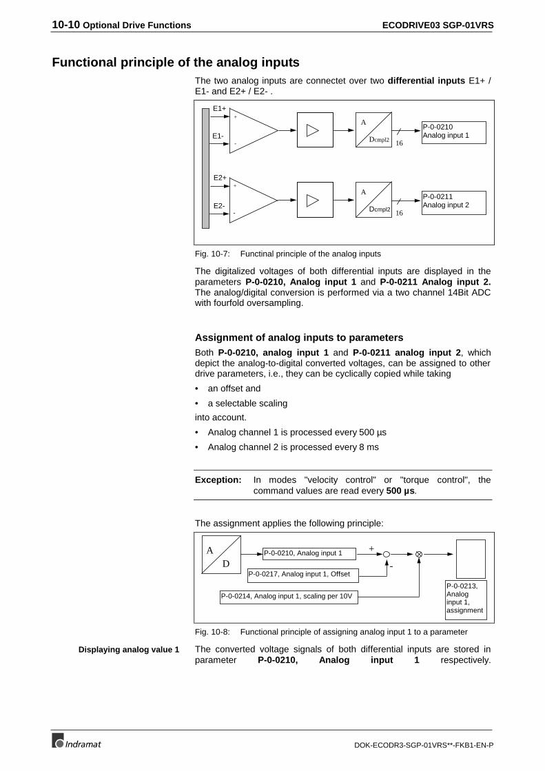
10-10 Optional Drive Functions ECODRIVE03 SGP-01VRS
DOK-ECODR3-SGP-01VRS**-FKB1-EN-P
Functional principle of the analog inputsThe two analog inputs are connectet over two differential inputs E1+ /E1- and E2+ / E2- .
A
Dcmpl2 16
P-0-0210Analog input 1
A
Dcmpl2 16
P-0-0211Analog input 2
E1+
E1-
E2+
E2-
+
+
-
-
Fig. 10-7: Functinal principle of the analog inputs
The digitalized voltages of both differential inputs are displayed in theparameters P-0-0210, Analog input 1 and P-0-0211 Analog input 2.The analog/digital conversion is performed via a two channel 14Bit ADCwith fourfold oversampling.
Assignment of analog inputs to parametersBoth P-0-0210, analog input 1 and P-0-0211 analog input 2, whichdepict the analog-to-digital converted voltages, can be assigned to otherdrive parameters, i.e., they can be cyclically copied while taking
• an offset and
• a selectable scaling
into account.
• Analog channel 1 is processed every 500 µs
• Analog channel 2 is processed every 8 ms
Exception: In modes "velocity control" or "torque control", thecommand values are read every 500 µs.
The assignment applies the following principle:
P-0-0210, Analog input 1
P-0-0217, Analog input 1, Offset-
+AD
P-0-0214, Analog input 1, scaling per 10VP-0-0213,Analoginput 1,assignment
Fig. 10-8: Functional principle of assigning analog input 1 to a parameter
The converted voltage signals of both differential inputs are stored inparameter P-0-0210, Analog input 1 respectively.
Displaying analog value 1
ECODRIVE03 SGP-01VRS Optional Drive Functions 10-11
DOK-ECODR3-SGP-01VRS**-FKB1-EN-P
An assignment of an analog input to a parameter is activated if inparameter P-0-0213, Analog input 1, assignment a value not equal toS-0-0000 has been parametrized. The contents of P-0-0210, Analoginput 1 minus the contents of P-0-0217, Analog input 1, Offset isscaled with the scaling factor set in P-0-0214, Analog input 1, Scalingper 10V and then copied into the parameter with the ID number set forthe assignment in P-0-0213, Analog input 1, Assignment.
The unit of the parameter P-0-0214, Analog input 1, Scaling per 10Vcomplies with the unit of the assigned parameter.
Only those parameters can be assigned that are listed in P-0-0212,Analog inputs, IDN list of assignable parameters.
Note: The configuration or allocation of analog input 2 can beconducted accordingly.
Assignment of analog input 1 to S-0-0036, velocity command valuewith 10 V equal to 1000 rpm
Parameter setting:
P-0-0213, analog input 1 = S-0-0036
P-0-0214, analog input 1, evaluation per 10V = 1000.0000 rpm
Analog Inputs - ConnectionSee project planning manual.
10.5 Oscilloscope Feature
The oscilloscope feature is used to diagram internal and external signalsand output variables. Its function is comparable to a 2-channeloscilloscope. The following parameters are available to set theoscilloscope feature:
• P-0-0021, List of Scope Data 1 (always 4-byte data)
• P-0-0022, List of Scope Data 2 (always 4-byte data)
• P-0-0023, Signal Select Scope Channel 1
• P-0-0024, Signal Select Scope Channel 2
• P-0-0025, Trigger Source
• P-0-0026, Trigger Signal Selection
• P-0-0027, Trigger Level for Position Data
• P-0-0028, Trigger Level for Velocity Data
• P-0-0029, Trigger Level for Torque/Force Data
• P-0-0030, Trigger Edge
• P-0-0031, Timebase
• P-0-0032, Size of Memory
• P-0-0033, Number of Samples after Trigger
• P-0-0035, Delay from Trigger to Start (cannot be written)
• P-0-0036, Trigger Control Word
• P-0-0037, Trigger Status Word
• P-0-0145, Expanded Trigger Level
• P-0-0146, Expanded Trigger Address
• P-0-0147, Expanded Signal K1 Address
Configuring the analog input 1
Evaluation parameter unit
Selection list
Configuring analog input 2
Example:
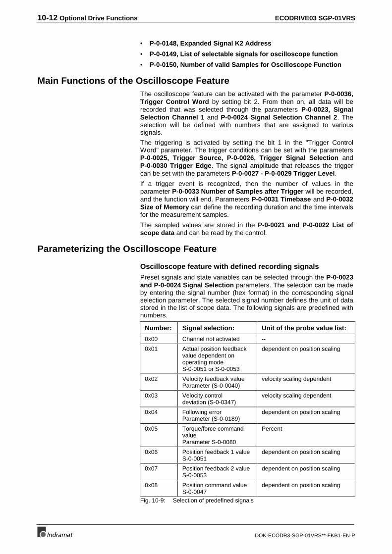
10-12 Optional Drive Functions ECODRIVE03 SGP-01VRS
DOK-ECODR3-SGP-01VRS**-FKB1-EN-P
• P-0-0148, Expanded Signal K2 Address
• P-0-0149, List of selectable signals for oscilloscope function
• P-0-0150, Number of valid Samples for Oscilloscope Function
Main Functions of the Oscilloscope FeatureThe oscilloscope feature can be activated with the parameter P-0-0036,Trigger Control Word by setting bit 2. From then on, all data will berecorded that was selected through the parameters P-0-0023, SignalSelection Channel 1 and P-0-0024 Signal Selection Channel 2. Theselection will be defined with numbers that are assigned to varioussignals.
The triggering is activated by setting the bit 1 in the "Trigger ControlWord" parameter. The trigger conditions can be set with the parametersP-0-0025, Trigger Source, P-0-0026, Trigger Signal Selection andP-0-0030 Trigger Edge. The signal amplitude that releases the triggercan be set with the parameters P-0-0027 - P-0-0029 Trigger Level.
If a trigger event is recognized, then the number of values in theparameter P-0-0033 Number of Samples after Trigger will be recorded,and the function will end. Parameters P-0-0031 Timebase and P-0-0032Size of Memory can define the recording duration and the time intervalsfor the measurement samples.
The sampled values are stored in the P-0-0021 and P-0-0022 List ofscope data and can be read by the control.
Parameterizing the Oscilloscope Feature
Oscilloscope feature with defined recording signalsPreset signals and state variables can be selected through the P-0-0023and P-0-0024 Signal Selection parameters. The selection can be madeby entering the signal number (hex format) in the corresponding signalselection parameter. The selected signal number defines the unit of datastored in the list of scope data. The following signals are predefined withnumbers.
Number: Signal selection: Unit of the probe value list:
0x00 Channel not activated --
0x01 Actual position feedbackvalue dependent onoperating modeS-0-0051 or S-0-0053
dependent on position scaling
0x02 Velocity feedback valueParameter (S-0-0040)
velocity scaling dependent
0x03 Velocity controldeviation (S-0-0347)
velocity scaling dependent
0x04 Following errorParameter (S-0-0189)
dependent on position scaling
0x05 Torque/force commandvalueParameter S-0-0080
Percent
0x06 Position feedback 1 valueS-0-0051
dependent on position scaling
0x07 Position feedback 2 valueS-0-0053
dependent on position scaling
0x08 Position command valueS-0-0047
dependent on position scaling
Fig. 10-9: Selection of predefined signals
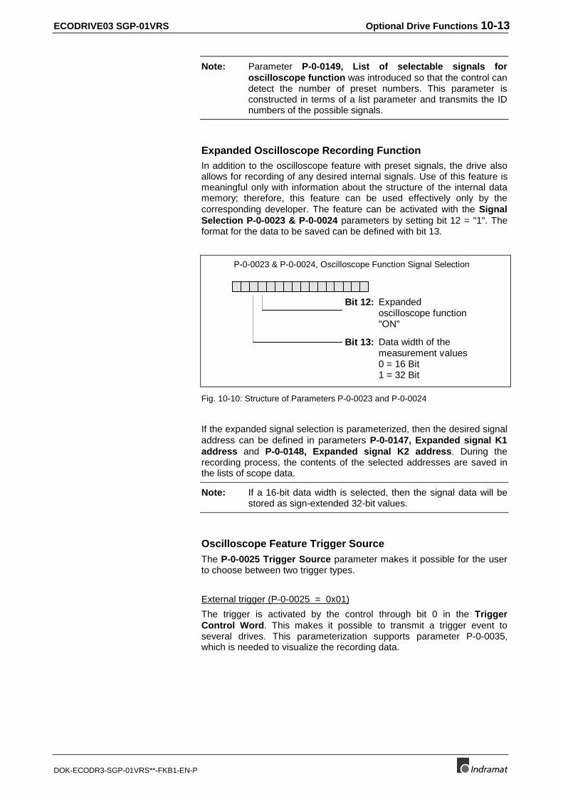
ECODRIVE03 SGP-01VRS Optional Drive Functions 10-13
DOK-ECODR3-SGP-01VRS**-FKB1-EN-P
Note: Parameter P-0-0149, List of selectable signals foroscilloscope function was introduced so that the control candetect the number of preset numbers. This parameter isconstructed in terms of a list parameter and transmits the IDnumbers of the possible signals.
Expanded Oscilloscope Recording FunctionIn addition to the oscilloscope feature with preset signals, the drive alsoallows for recording of any desired internal signals. Use of this feature ismeaningful only with information about the structure of the internal datamemory; therefore, this feature can be used effectively only by thecorresponding developer. The feature can be activated with the SignalSelection P-0-0023 & P-0-0024 parameters by setting bit 12 = "1". Theformat for the data to be saved can be defined with bit 13.
Bit 12: Expandedoscilloscope function"ON"
P-0-0023 & P-0-0024, Oscilloscope Function Signal Selection
Bit 13: Data width of themeasurement values0 = 16 Bit1 = 32 Bit
Fig. 10-10: Structure of Parameters P-0-0023 and P-0-0024
If the expanded signal selection is parameterized, then the desired signaladdress can be defined in parameters P-0-0147, Expanded signal K1address and P-0-0148, Expanded signal K2 address. During therecording process, the contents of the selected addresses are saved inthe lists of scope data.
Note: If a 16-bit data width is selected, then the signal data will bestored as sign-extended 32-bit values.
Oscilloscope Feature Trigger SourceThe P-0-0025 Trigger Source parameter makes it possible for the userto choose between two trigger types.
External trigger (P-0-0025 = 0x01)
The trigger is activated by the control through bit 0 in the TriggerControl Word. This makes it possible to transmit a trigger event toseveral drives. This parameterization supports parameter P-0-0035,which is needed to visualize the recording data.
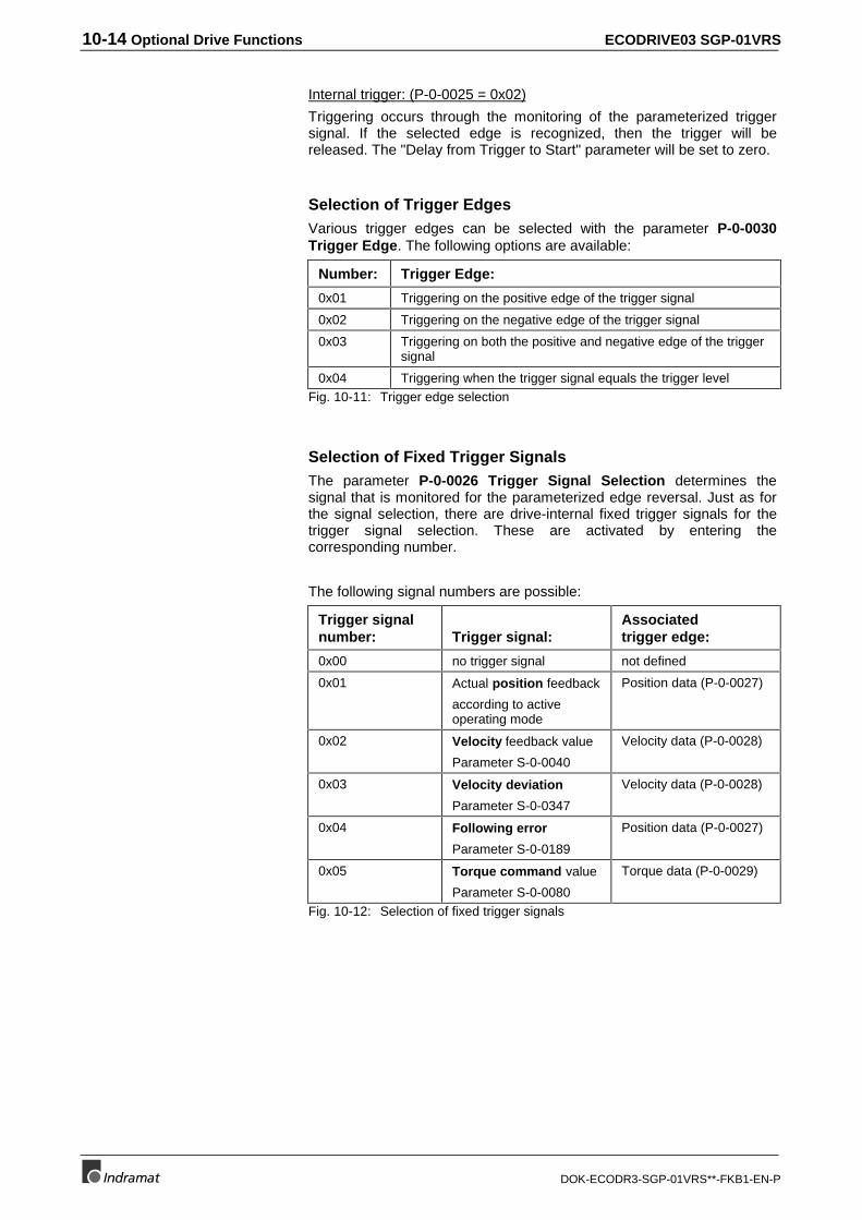
10-14 Optional Drive Functions ECODRIVE03 SGP-01VRS
DOK-ECODR3-SGP-01VRS**-FKB1-EN-P
Internal trigger: (P-0-0025 = 0x02)
Triggering occurs through the monitoring of the parameterized triggersignal. If the selected edge is recognized, then the trigger will bereleased. The "Delay from Trigger to Start" parameter will be set to zero.
Selection of Trigger EdgesVarious trigger edges can be selected with the parameter P-0-0030Trigger Edge. The following options are available:
Number: Trigger Edge:
0x01 Triggering on the positive edge of the trigger signal
0x02 Triggering on the negative edge of the trigger signal
0x03 Triggering on both the positive and negative edge of the triggersignal
0x04 Triggering when the trigger signal equals the trigger levelFig. 10-11: Trigger edge selection
Selection of Fixed Trigger SignalsThe parameter P-0-0026 Trigger Signal Selection determines thesignal that is monitored for the parameterized edge reversal. Just as forthe signal selection, there are drive-internal fixed trigger signals for thetrigger signal selection. These are activated by entering thecorresponding number.
The following signal numbers are possible:
Trigger signalnumber: Trigger signal:
Associatedtrigger edge:
0x00 no trigger signal not defined
0x01 Actual position feedback
according to activeoperating mode
Position data (P-0-0027)
0x02 Velocity feedback value
Parameter S-0-0040
Velocity data (P-0-0028)
0x03 Velocity deviation
Parameter S-0-0347
Velocity data (P-0-0028)
0x04 Following error
Parameter S-0-0189
Position data (P-0-0027)
0x05 Torque command value
Parameter S-0-0080
Torque data (P-0-0029)
Fig. 10-12: Selection of fixed trigger signals
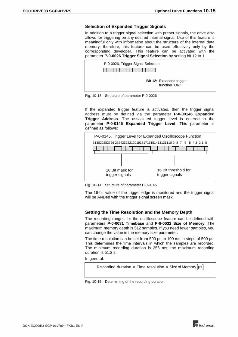
ECODRIVE03 SGP-01VRS Optional Drive Functions 10-15
DOK-ECODR3-SGP-01VRS**-FKB1-EN-P
Selection of Expanded Trigger SignalsIn addition to a trigger signal selection with preset signals, the drive alsoallows for triggering on any desired internal signal. Use of this feature ismeaningful only with information about the structure of the internal datamemory; therefore, this feature can be used effectively only by thecorresponding developer. This feature can be activated with theparameter P-0-0026 Trigger Signal Selection by setting bit 12 to 1.
Bit 12: Expanded triggerfunction "ON"
P-0-0026, Trigger Signal Selection
Fig. 10-13: Structure of parameter P-0-0026
If the expanded trigger feature is activated, then the trigger signaladdress must be defined via the parameter P-0-00146 ExpandedTrigger Address. The associated trigger level is entered in theparameter P-0-0145 Expanded Trigger Level. This parameter isdefined as follows:
313029282726 25242322212019181716151413121110 9 8 7 6 5 4 3 2 1 0
16 Bit threshold fortrigger signals
16 Bit mask fortrigger signals
P-0-0145, Trigger Level for Expanded Oscilloscope Function
Fig. 10-14: Structure of parameter P-0-0145
The 16-bit value of the trigger edge is monitored and the trigger signalwill be ANDed with the trigger signal screen mask.
Setting the Time Resolution and the Memory DepthThe recording ranges for the oscilloscope feature can be defined withparameters P-0-0031 Timebase and P-0-0032 Size of Memory. Themaximum memory depth is 512 samples. If you need fewer samples, youcan change the value in the memory size parameter.
The time resolution can be set from 500 µs to 100 ms in steps of 500 µs.This determines the time intervals in which the samples are recorded.The minimum recording duration is 256 ms; the maximum recordingduration is 51.2 s.
In general:
[ ]Recording duration Time resolution Sizeof Memory s= × µ
Fig. 10-15: Determining of the recording duration
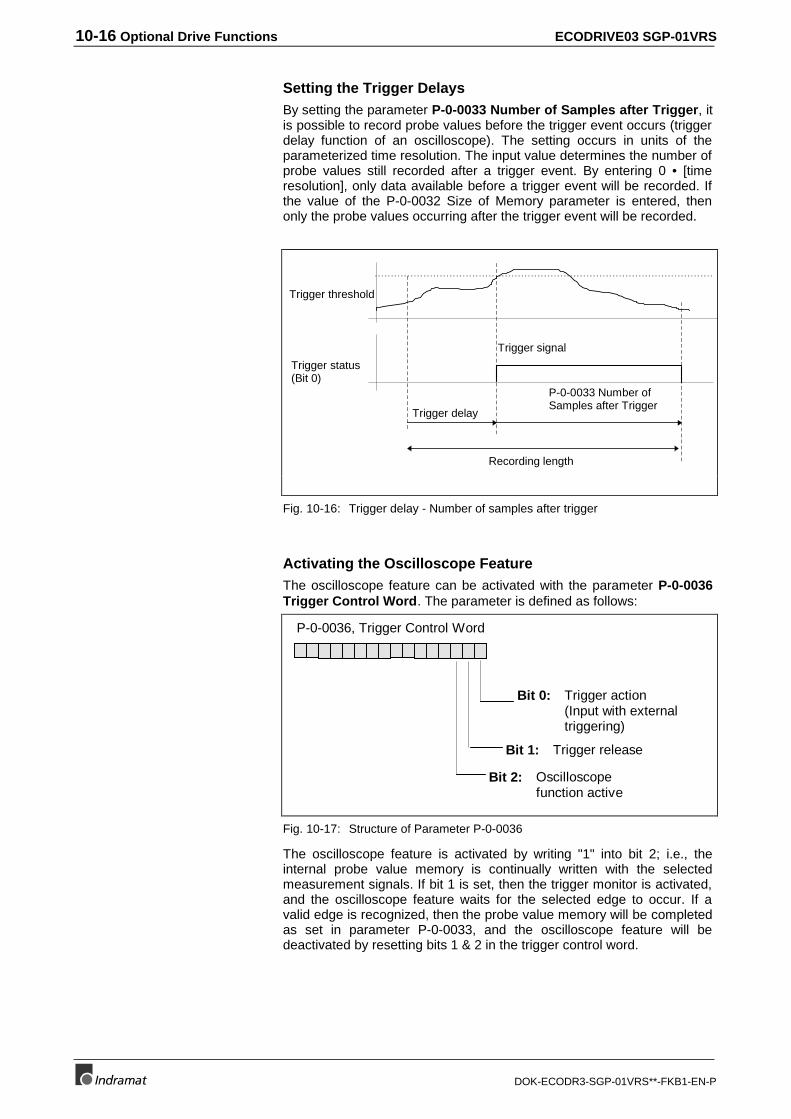
10-16 Optional Drive Functions ECODRIVE03 SGP-01VRS
DOK-ECODR3-SGP-01VRS**-FKB1-EN-P
Setting the Trigger DelaysBy setting the parameter P-0-0033 Number of Samples after Trigger, itis possible to record probe values before the trigger event occurs (triggerdelay function of an oscilloscope). The setting occurs in units of theparameterized time resolution. The input value determines the number ofprobe values still recorded after a trigger event. By entering 0 • [timeresolution], only data available before a trigger event will be recorded. Ifthe value of the P-0-0032 Size of Memory parameter is entered, thenonly the probe values occurring after the trigger event will be recorded.
Trigger signal
Trigger threshold
Trigger status(Bit 0)
Trigger delay
Recording length
P-0-0033 Number ofSamples after Trigger
Fig. 10-16: Trigger delay - Number of samples after trigger
Activating the Oscilloscope FeatureThe oscilloscope feature can be activated with the parameter P-0-0036Trigger Control Word. The parameter is defined as follows:
P-0-0036, Trigger Control Word
Bit 0: Trigger action(Input with externaltriggering)
Bit 1: Trigger release
Bit 2: Oscilloscopefunction active
Fig. 10-17: Structure of Parameter P-0-0036
The oscilloscope feature is activated by writing "1" into bit 2; i.e., theinternal probe value memory is continually written with the selectedmeasurement signals. If bit 1 is set, then the trigger monitor is activated,and the oscilloscope feature waits for the selected edge to occur. If avalid edge is recognized, then the probe value memory will be completedas set in parameter P-0-0033, and the oscilloscope feature will bedeactivated by resetting bits 1 & 2 in the trigger control word.
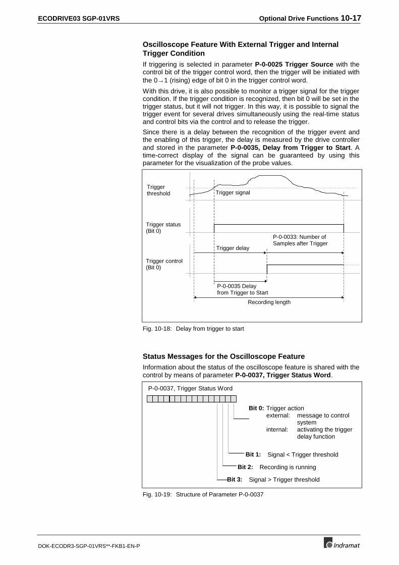
ECODRIVE03 SGP-01VRS Optional Drive Functions 10-17
DOK-ECODR3-SGP-01VRS**-FKB1-EN-P
Oscilloscope Feature With External Trigger and InternalTrigger ConditionIf triggering is selected in parameter P-0-0025 Trigger Source with thecontrol bit of the trigger control word, then the trigger will be initiated withthe 0→1 (rising) edge of bit 0 in the trigger control word.
With this drive, it is also possible to monitor a trigger signal for the triggercondition. If the trigger condition is recognized, then bit 0 will be set in thetrigger status, but it will not trigger. In this way, it is possible to signal thetrigger event for several drives simultaneously using the real-time statusand control bits via the control and to release the trigger.
Since there is a delay between the recognition of the trigger event andthe enabling of this trigger, the delay is measured by the drive controllerand stored in the parameter P-0-0035, Delay from Trigger to Start. Atime-correct display of the signal can be guaranteed by using thisparameter for the visualization of the probe values.
Trigger signalTriggerthreshold
Trigger status(Bit 0)
Trigger control(Bit 0)
P-0-0035 Delayfrom Trigger to Start
Trigger delay
Recording length
P-0-0033: Number ofSamples after Trigger
Fig. 10-18: Delay from trigger to start
Status Messages for the Oscilloscope FeatureInformation about the status of the oscilloscope feature is shared with thecontrol by means of parameter P-0-0037, Trigger Status Word.
P-0-0037, Trigger Status Word
Bit 0: Trigger actionexternal: message to control
systeminternal: activating the trigger
delay function
Bit 1: Signal < Trigger threshold
Bit 3: Signal > Trigger threshold
Bit 2: Recording is running
Fig. 10-19: Structure of Parameter P-0-0037
10-18 Optional Drive Functions ECODRIVE03 SGP-01VRS
DOK-ECODR3-SGP-01VRS**-FKB1-EN-P
Number of Valid Probe ValuesAs soon as bit 2 is set by the P-0-0036, Trigger Control Word, the drivestarts to record probe values.
If the trigger event is recognized after the bit is set, the oscilloscopefeature records the number of samples after the trigger event and thenstops recording.
The total probe value memory for the current measurement will notalways be written, dependent on the memory size setting, the timeresolution, the number of samples after trigger and the time when thetrigger event occurs.
This means that the memory can contain samples which are not valid forthe measurement.
The parameter P-0-0150, Number of valid Samples indicates thenumber of valid samples for the current recording.
ECODRIVE03 SGP-01VRS Optional Drive Functions 10-19
DOK-ECODR3-SGP-01VRS**-FKB1-EN-P
10.6 Probe Input Feature
Two digital inputs are available for measuring positions and times. Themeasured values are determined at the time of the positive and negativeedge.
The following measured values can be determined:
• actual position value 1
• actual position value 2
• relative internal time in [usec]
• master axis position
• actual feedback value 3
Note: The probe inputs are probed every 1 usec. The measuredsignals are generated every 500 µsec. Linear interiminterpolation takes place between these two steps with anaccuracy of 1 µsec.
You can read the absolute values of these signals at the time of apositive or negative edge as well as their difference by parameters.
The following parameters are available for the feature:
• S-0-0170, Probing cycle procedure command
• S-0-0401, Probe 1
• S-0-0402, Probe 2
• S-0-0169, Probe control parameter
• P-0-0200, Signal select probe 1
• P-0-0201, Signal select probe 2
• P-0-0204, Start position for active probe
• P-0-0205, End position for active probe
• S-0-0405, Probe 1 enable
• S-0-0406, Probe 2 enable
• S-0-0130, Probe value 1 positive edge
• S-0-0131, Probe value 1 negative edge
• S-0-0132, Probe value 2 positive edge
• S-0-0133, Probe value 2 negative edge
• P-0-0202, Difference Probe Values 1
• P-0-0203, Difference Probe Values 2
• S-0-0409, Probe 1 positive latched
• S-0-0410, Probe 1 negative latched
• S-0-0411, Probe 2 positive latched
• S-0-0412, Probe 2 negative latched
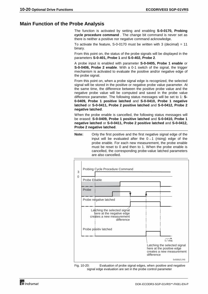
10-20 Optional Drive Functions ECODRIVE03 SGP-01VRS
DOK-ECODR3-SGP-01VRS**-FKB1-EN-P
Main Function of the Probe AnalysisThe function is activated by setting and enabling S-0-0170, Probingcycle procedure command . The change bit command is never set asthere is neither a positive nor negative command acknowledge.
To activate the feature, S-0-0170 must be written with 3 (decimal) = 11binary.
From this point on, the status of the probe signals will be displayed in theparameters S-0-401, Probe 1 and S-0-402, Probe 2.
A probe input is enabled with parameter S-0-0405, Probe 1 enable orS-0-0406, Probe 2 enable. With a 0-1 switch of the signal, the triggermechanism is activated to evaluate the positive and/or negative edge ofthe probe signal.
From this point on, when a probe signal edge is recognized, the selectedsignal will be stored in the positive or negative probe value parameter. Atthe same time, the difference between the positive probe value and thenegative probe value will be computed and saved in the probe valuedifference parameter. The following status messages will be set to 1: S-0-0409, Probe 1 positive latched and S-0-0410, Probe 1 negativelatched or S-0-0411, Probe 2 positive latched and S-0-0412, Probe 2negative latched.
When the probe enable is cancelled, the following status messages willbe erased: S-0-0409, Probe 1 positive latched and S-0-0410, Probe 1negative latched or S-0-0411, Probe 2 positive latched and S-0-0412,Probe 2 negative latched.
Note: Only the first positive and the first negative signal edge of theinput will be evaluated after the 0→1 (rising) edge of theprobe enable. For each new measurement, the probe enablemust be reset to 0 and then to 1. When the probe enable iscancelled, the corresponding probe-value latched parametersare also cancelled.
0
3
Sv5081f1.fh5
Probing Cycle Procedure Command
t / ms
Probe Enable
Probe
Probe negative latched
Probe positiv latched
Latching the selected signalhere at the negative edge
creates a new measurementdifference
Latching the selected signalhere at the positive edgecreates a new measurementdifference
Fig. 10-20: Evaluation of probe signal edges, when positive and negativesignal edge evaluation are set in the probe control parameter
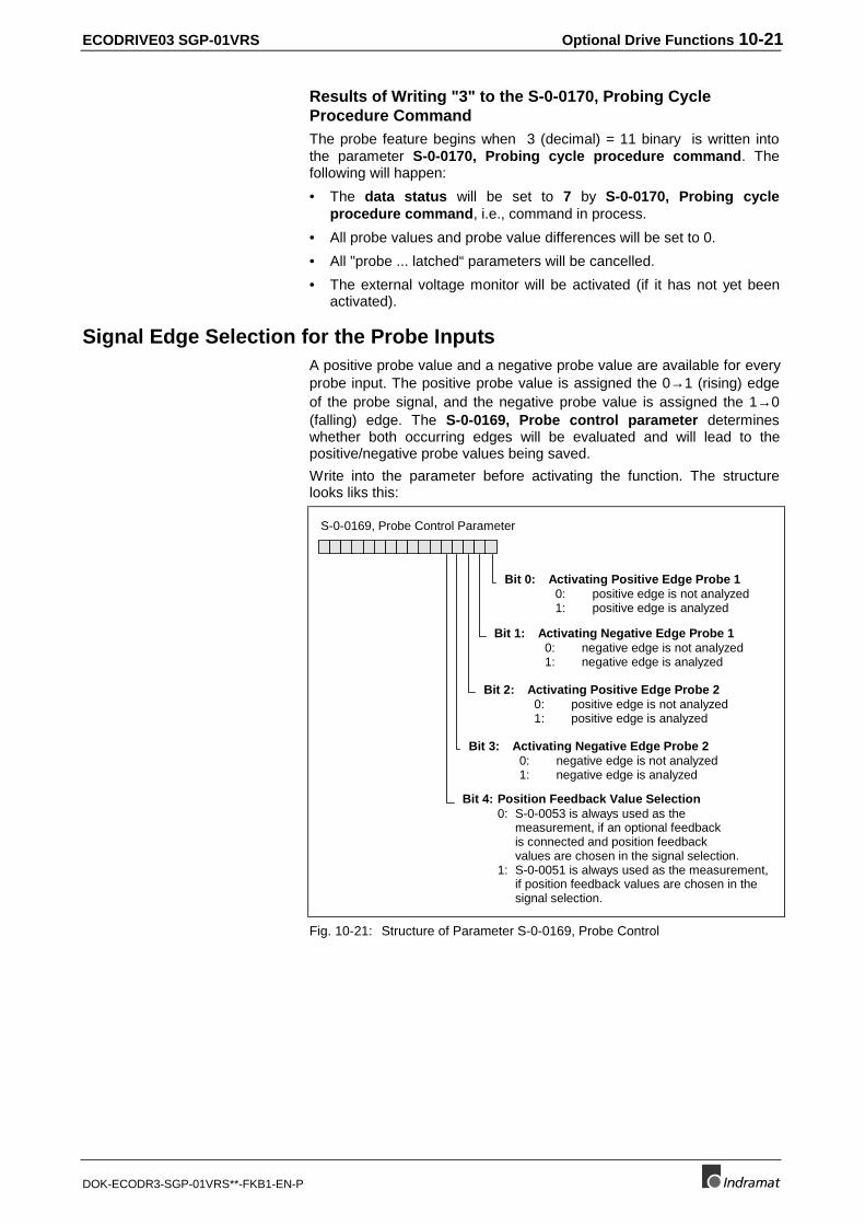
ECODRIVE03 SGP-01VRS Optional Drive Functions 10-21
DOK-ECODR3-SGP-01VRS**-FKB1-EN-P
Results of Writing "3" to the S-0-0170, Probing CycleProcedure CommandThe probe feature begins when 3 (decimal) = 11 binary is written intothe parameter S-0-0170, Probing cycle procedure command. Thefollowing will happen:
• The data status will be set to 7 by S-0-0170, Probing cycleprocedure command, i.e., command in process.
• All probe values and probe value differences will be set to 0.
• All "probe ... latched“ parameters will be cancelled.
• The external voltage monitor will be activated (if it has not yet beenactivated).
Signal Edge Selection for the Probe InputsA positive probe value and a negative probe value are available for everyprobe input. The positive probe value is assigned the 0→1 (rising) edgeof the probe signal, and the negative probe value is assigned the 1→0(falling) edge. The S-0-0169, Probe control parameter determineswhether both occurring edges will be evaluated and will lead to thepositive/negative probe values being saved.
Write into the parameter before activating the function. The structurelooks liks this:
S-0-0169, Probe Control Parameter
Bit 0: Activating Positive Edge Probe 1 0: positive edge is not analyzed 1: positive edge is analyzed
Bit 1: Activating Negative Edge Probe 1 0: negative edge is not analyzed 1: negative edge is analyzed
Bit 2: Activating Positive Edge Probe 2 0: positive edge is not analyzed 1: positive edge is analyzed
Bit 3: Activating Negative Edge Probe 2 0: negative edge is not analyzed 1: negative edge is analyzed
Bit 4: Position Feedback Value Selection0: S-0-0053 is always used as the
measurement, if an optional feedbackis connected and position feedbackvalues are chosen in the signal selection.
1: S-0-0051 is always used as the measurement,if position feedback values are chosen in thesignal selection.
Fig. 10-21: Structure of Parameter S-0-0169, Probe Control
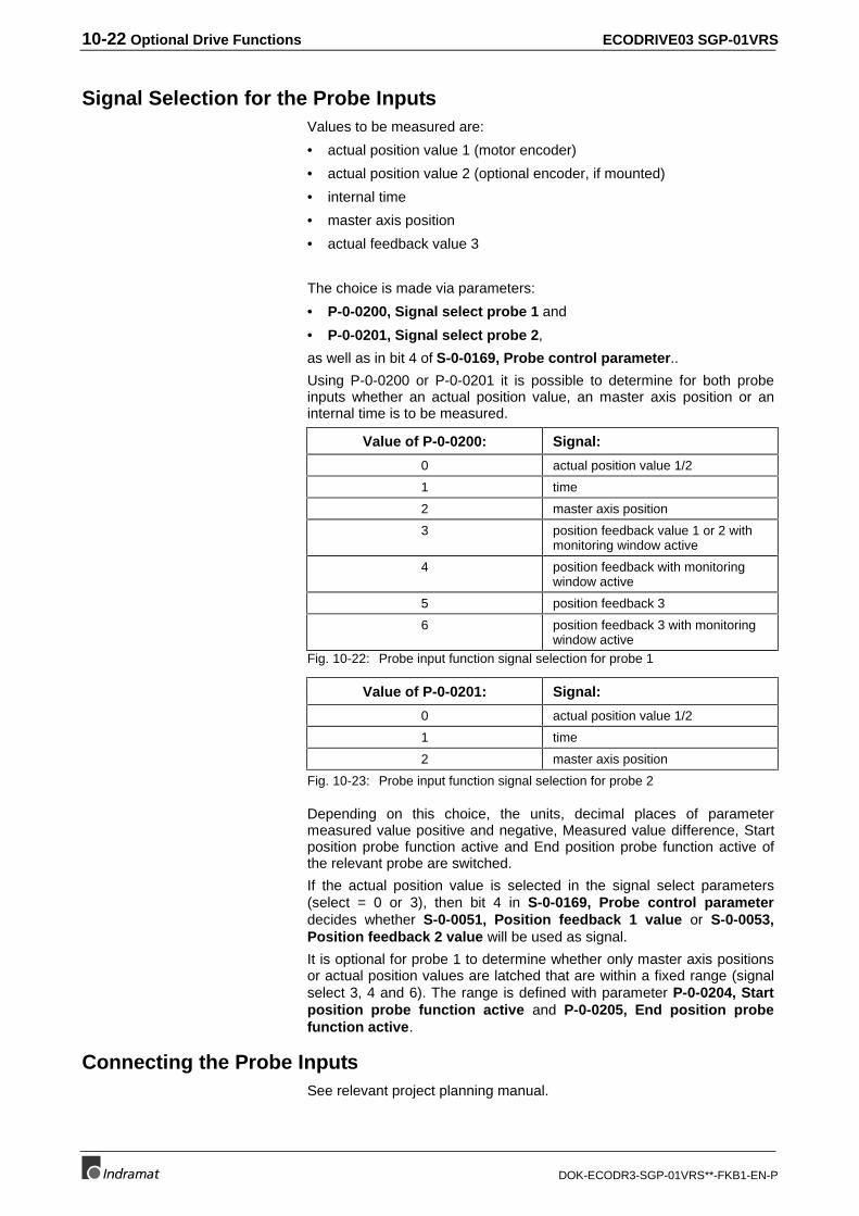
10-22 Optional Drive Functions ECODRIVE03 SGP-01VRS
DOK-ECODR3-SGP-01VRS**-FKB1-EN-P
Signal Selection for the Probe InputsValues to be measured are:
• actual position value 1 (motor encoder)
• actual position value 2 (optional encoder, if mounted)
• internal time
• master axis position
• actual feedback value 3
The choice is made via parameters:
• P-0-0200, Signal select probe 1 and
• P-0-0201, Signal select probe 2,
as well as in bit 4 of S-0-0169, Probe control parameter..
Using P-0-0200 or P-0-0201 it is possible to determine for both probeinputs whether an actual position value, an master axis position or aninternal time is to be measured.
Value of P-0-0200: Signal:
0 actual position value 1/2
1 time
2 master axis position
3 position feedback value 1 or 2 withmonitoring window active
4 position feedback with monitoringwindow active
5 position feedback 3
6 position feedback 3 with monitoringwindow active
Fig. 10-22: Probe input function signal selection for probe 1
Value of P-0-0201: Signal:
0 actual position value 1/2
1 time
2 master axis position
Fig. 10-23: Probe input function signal selection for probe 2
Depending on this choice, the units, decimal places of parametermeasured value positive and negative, Measured value difference, Startposition probe function active and End position probe function active ofthe relevant probe are switched.
If the actual position value is selected in the signal select parameters(select = 0 or 3), then bit 4 in S-0-0169, Probe control parameterdecides whether S-0-0051, Position feedback 1 value or S-0-0053,Position feedback 2 value will be used as signal.
It is optional for probe 1 to determine whether only master axis positionsor actual position values are latched that are within a fixed range (signalselect 3, 4 and 6). The range is defined with parameter P-0-0204, Startposition probe function active and P-0-0205, End position probefunction active.
Connecting the Probe InputsSee relevant project planning manual.
ECODRIVE03 SGP-01VRS Optional Drive Functions 10-23
DOK-ECODR3-SGP-01VRS**-FKB1-EN-P
10.7 Command - detect marker position
The command "Detect marker position" supports
• the control of a faultless detection of the reference marker in anincremental measuring system or
• determining the position of the reference marker if the referencingprocedure is conducted by the control. In this case, this information isused to switch the coordinate system in the control.
A reference switching evaluation is not run with this command.
The following parameters are provided for this function:
• S-0-0173, Marker position A
• P-0-0014, D500 Command determine marker position
Functional principle of command detect marker positionOnce the command P-0-0014, D500 Command determine markerposition is activated, the following is done:
• The diagnosis D500 detect marker position command is generated.
• If an incremental measuring system is selected, then the detection ofa reference marker is activated, and the drive waits for the nextreference marker.
• If a reference marker is detected, i.e., the position of a referencemarker has been runover, then its position feedback value is stored inparameter S-0-0173, Marker position A. This command is nowsignalled as completed.
Note: The drive generates no command values. The mode active atcommand start remains unchanged. To override thereference marker, the control must generate command values(e.g., by jogging), that cause a motion in the direction in whichthe reference markers are to be detected.
Additional uses of parameter "S-0-0173, Marker position A"In parameter S-0-0173, Marker position A, the position of the referencemarker is also stored during the command S-0-0148, C600 Drivecontrolled homing procedure command. This relates, however, to the"old" coordinate system (before the coordinate system was switchedwhile performing a homing function).
10.8 Command Parking Axis
The command "Parking Axis" supports the operational decoupling of anaxis. This may, for example, be necessary if an axis is temporarilybrought to a standstill. The start of the command switches off allmonitoring functions of the measuring system and the control loops.
The following parameter is available for this function:
• S-0-0139, D700 Command parking axis
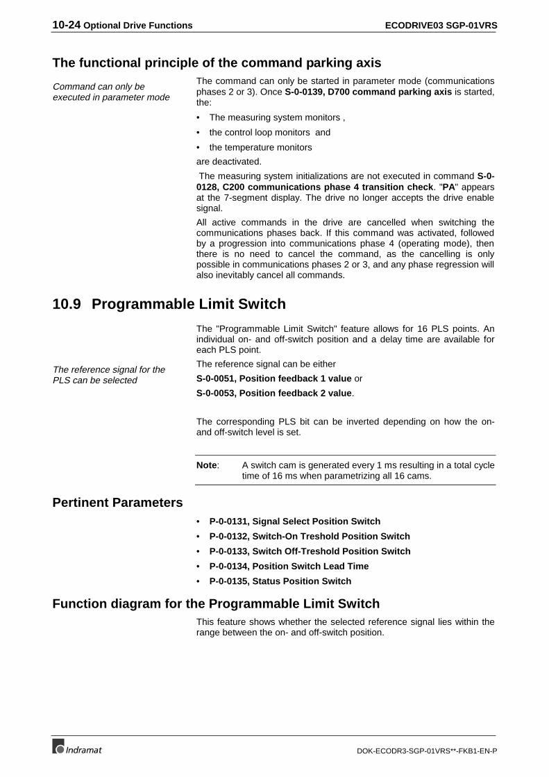
10-24 Optional Drive Functions ECODRIVE03 SGP-01VRS
DOK-ECODR3-SGP-01VRS**-FKB1-EN-P
The functional principle of the command parking axis
Command can only beexecuted in parameter mode
The command can only be started in parameter mode (communicationsphases 2 or 3). Once S-0-0139, D700 command parking axis is started,the:
• The measuring system monitors ,
• the control loop monitors and
• the temperature monitors
are deactivated.
The measuring system initializations are not executed in command S-0-0128, C200 communications phase 4 transition check. "PA" appearsat the 7-segment display. The drive no longer accepts the drive enablesignal.
All active commands in the drive are cancelled when switching thecommunications phases back. If this command was activated, followedby a progression into communications phase 4 (operating mode), thenthere is no need to cancel the command, as the cancelling is onlypossible in communications phases 2 or 3, and any phase regression willalso inevitably cancel all commands.
10.9 Programmable Limit Switch
The "Programmable Limit Switch" feature allows for 16 PLS points. Anindividual on- and off-switch position and a delay time are available foreach PLS point.
The reference signal for thePLS can be selected
The reference signal can be either
S-0-0051, Position feedback 1 value or
S-0-0053, Position feedback 2 value.
The corresponding PLS bit can be inverted depending on how the on-and off-switch level is set.
Note: A switch cam is generated every 1 ms resulting in a total cycletime of 16 ms when parametrizing all 16 cams.
Pertinent Parameters• P-0-0131, Signal Select Position Switch
• P-0-0132, Switch-On Treshold Position Switch
• P-0-0133, Switch Off-Treshold Position Switch
• P-0-0134, Position Switch Lead Time
• P-0-0135, Status Position Switch
Function diagram for the Programmable Limit SwitchThis feature shows whether the selected reference signal lies within therange between the on- and off-switch position.
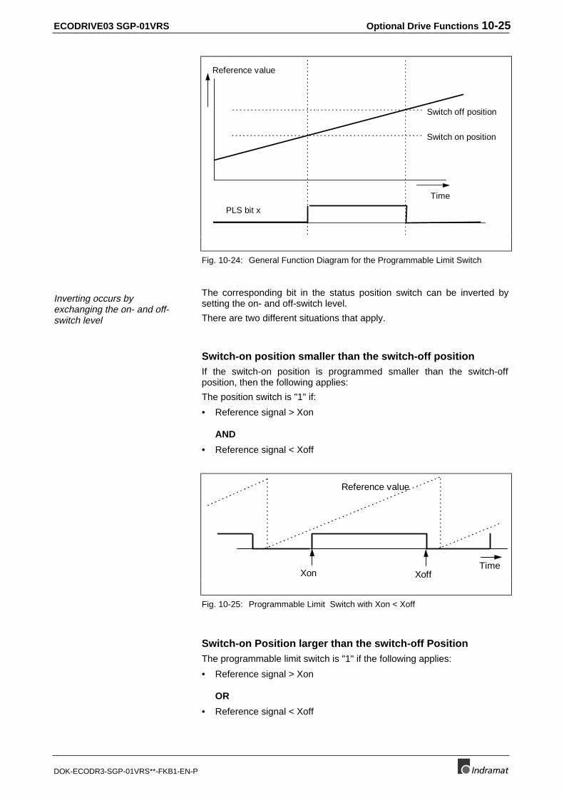
ECODRIVE03 SGP-01VRS Optional Drive Functions 10-25
DOK-ECODR3-SGP-01VRS**-FKB1-EN-P
Reference value
Time
Switch on position
Switch off position
PLS bit x
Fig. 10-24: General Function Diagram for the Programmable Limit Switch
Inverting occurs byexchanging the on- and off-switch level
The corresponding bit in the status position switch can be inverted bysetting the on- and off-switch level.
There are two different situations that apply.
Switch-on position smaller than the switch-off positionIf the switch-on position is programmed smaller than the switch-offposition, then the following applies:
The position switch is "1" if:
• Reference signal > Xon
AND
• Reference signal < Xoff
Xon Xoff
Reference value
Time
Fig. 10-25: Programmable Limit Switch with Xon < Xoff
Switch-on Position larger than the switch-off PositionThe programmable limit switch is "1" if the following applies:
• Reference signal > Xon
OR
• Reference signal < Xoff
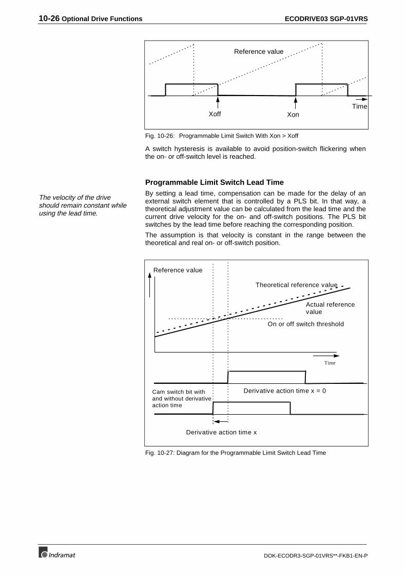
10-26 Optional Drive Functions ECODRIVE03 SGP-01VRS
DOK-ECODR3-SGP-01VRS**-FKB1-EN-P
XonXoff
Reference value
Time
Fig. 10-26: Programmable Limit Switch With Xon > Xoff
A switch hysteresis is available to avoid position-switch flickering whenthe on- or off-switch level is reached.
Programmable Limit Switch Lead Time
The velocity of the driveshould remain constant whileusing the lead time.
By setting a lead time, compensation can be made for the delay of anexternal switch element that is controlled by a PLS bit. In that way, atheoretical adjustment value can be calculated from the lead time and thecurrent drive velocity for the on- and off-switch positions. The PLS bitswitches by the lead time before reaching the corresponding position.
The assumption is that velocity is constant in the range between thetheoretical and real on- or off-switch position.
Reference value
Time
On or off switch threshold
Derivative action time x
Cam switch bit withand without derivativeaction time
Derivative action time x = 0
Actual referencevalue
Theoretical reference value
Fig. 10-27: Diagram for the Programmable Limit Switch Lead Time
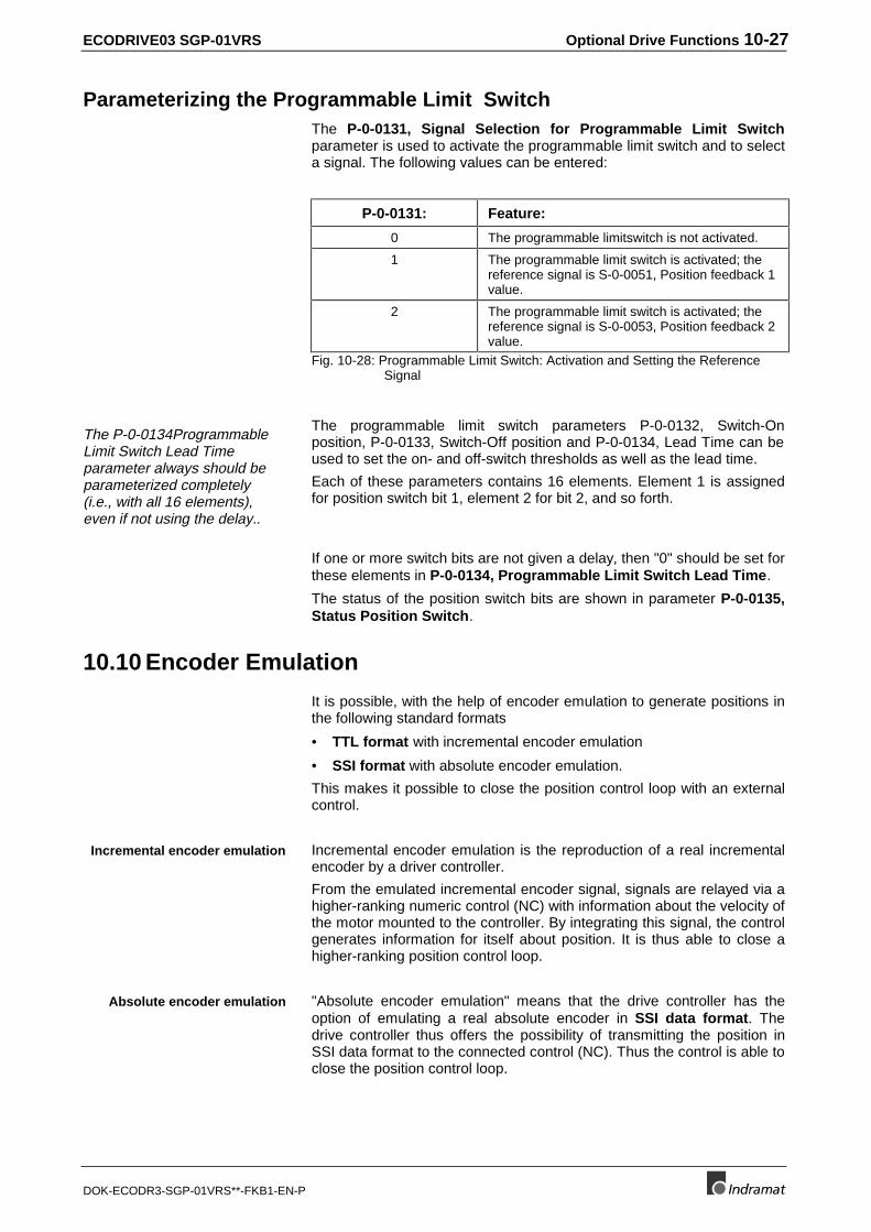
ECODRIVE03 SGP-01VRS Optional Drive Functions 10-27
DOK-ECODR3-SGP-01VRS**-FKB1-EN-P
Parameterizing the Programmable Limit SwitchThe P-0-0131, Signal Selection for Programmable Limit Switchparameter is used to activate the programmable limit switch and to selecta signal. The following values can be entered:
P-0-0131: Feature:
0 The programmable limitswitch is not activated.
1 The programmable limit switch is activated; thereference signal is S-0-0051, Position feedback 1value.
2 The programmable limit switch is activated; thereference signal is S-0-0053, Position feedback 2value.
Fig. 10-28: Programmable Limit Switch: Activation and Setting the ReferenceSignal
The P-0-0134ProgrammableLimit Switch Lead Timeparameter always should beparameterized completely(i.e., with all 16 elements),even if not using the delay..
The programmable limit switch parameters P-0-0132, Switch-Onposition, P-0-0133, Switch-Off position and P-0-0134, Lead Time can beused to set the on- and off-switch thresholds as well as the lead time.
Each of these parameters contains 16 elements. Element 1 is assignedfor position switch bit 1, element 2 for bit 2, and so forth.
If one or more switch bits are not given a delay, then "0" should be set forthese elements in P-0-0134, Programmable Limit Switch Lead Time.
The status of the position switch bits are shown in parameter P-0-0135,Status Position Switch.
10.10 Encoder Emulation
It is possible, with the help of encoder emulation to generate positions inthe following standard formats
• TTL format with incremental encoder emulation
• SSI format with absolute encoder emulation.
This makes it possible to close the position control loop with an externalcontrol.
Incremental encoder emulation is the reproduction of a real incrementalencoder by a driver controller.
From the emulated incremental encoder signal, signals are relayed via ahigher-ranking numeric control (NC) with information about the velocity ofthe motor mounted to the controller. By integrating this signal, the controlgenerates information for itself about position. It is thus able to close ahigher-ranking position control loop.
"Absolute encoder emulation" means that the drive controller has theoption of emulating a real absolute encoder in SSI data format. Thedrive controller thus offers the possibility of transmitting the position inSSI data format to the connected control (NC). Thus the control is able toclose the position control loop.
Incremental encoder emulation
Absolute encoder emulation
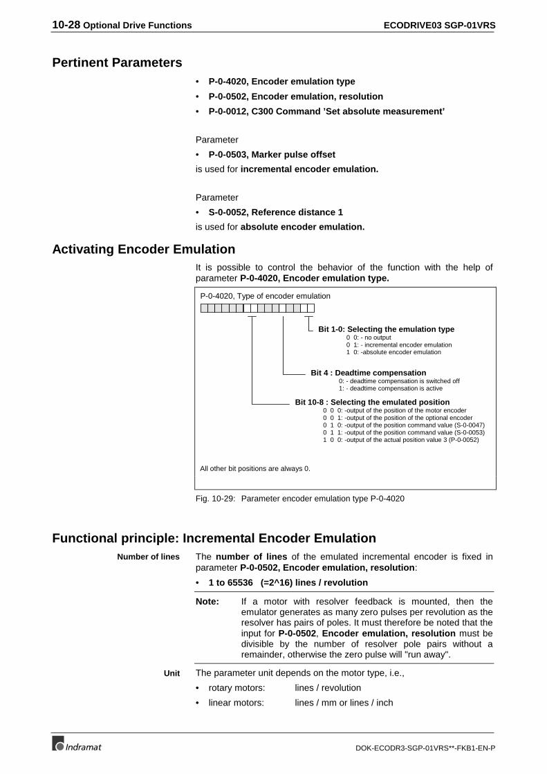
10-28 Optional Drive Functions ECODRIVE03 SGP-01VRS
DOK-ECODR3-SGP-01VRS**-FKB1-EN-P
Pertinent Parameters• P-0-4020, Encoder emulation type
• P-0-0502, Encoder emulation, resolution
• P-0-0012, C300 Command ’Set absolute measurement’
Parameter
• P-0-0503, Marker pulse offset
is used for incremental encoder emulation.
Parameter
• S-0-0052, Reference distance 1
is used for absolute encoder emulation.
Activating Encoder EmulationIt is possible to control the behavior of the function with the help ofparameter P-0-4020, Encoder emulation type.
P-0-4020, Type of encoder emulation
Bit 1-0: Selecting the emulation type0 0: - no output0 1: - incremental encoder emulation1 0: -absolute encoder emulation
Bit 4 : Deadtime compensation0: - deadtime compensation is switched off1: - deadtime compensation is active
Bit 10-8 : Selecting the emulated position0 0 0: -output of the position of the motor encoder0 0 1: -output of the position of the optional encoder0 1 0: -output of the position command value (S-0-0047)0 1 1: -output of the position command value (S-0-0053)1 0 0: -output of the actual position value 3 (P-0-0052)
All other bit positions are always 0.
Fig. 10-29: Parameter encoder emulation type P-0-4020
Functional principle: Incremental Encoder EmulationThe number of lines of the emulated incremental encoder is fixed inparameter P-0-0502, Encoder emulation, resolution:
• 1 to 65536 (=2^16) lines / revolution
Note: If a motor with resolver feedback is mounted, then theemulator generates as many zero pulses per revolution as theresolver has pairs of poles. It must therefore be noted that theinput for P-0-0502, Encoder emulation, resolution must bedivisible by the number of resolver pole pairs without aremainder, otherwise the zero pulse will "run away".
The parameter unit depends on the motor type, i.e.,
• rotary motors: lines / revolution
• linear motors: lines / mm or lines / inch
Number of lines
Unit
ECODRIVE03 SGP-01VRS Optional Drive Functions 10-29
DOK-ECODR3-SGP-01VRS**-FKB1-EN-P
Position of the Zero Pulse as Relates to Motor PositionWith motor encoders that achieve an absolute position within one motorrevolution after initialization, or within one electrical revolution withresolvers, the zero pulse is always generated at the same motor positioneach time the unit is switched on.
Non-absolut encoders do not have an automatic method of determiningposition after powering up. This is why it is necessary to home. Hominguses the incremental encoder emulator zero pulse.
With non-absolut encoders, e.g., sine, gearwheel encoders, the followingoccurs automatically with each progression of phases 2 to 4 (in otherwords after each powering up of the drive controller):
• The detection of the motor encoder internal reference point isactivated.
• The zero pulse output of the incremental encoder emulator is locked.
• The increment output is activated.
It is assumed that the motor can now be run via the position control loopby the control (homing, going to zero or referencing).
The drive can also conduct drive-guided referencing if the control permitsit.
As soon as the motor encoder internal reference point is detected, thefollowing is conducted:
• general release of zero pulse output
• immediate output of a zero pulse by the emulator
• initialization of zero pulse so that it is always output at this absolutemotor position.
Note: The output of the zero pulse occurs after referencing issuccessfully completed. It is output at the same position,however, (reference marker).
With rotary motors it is possible to offset the zero pulse using P-0-0503,Marker pulse offset within a (electrical or mechanical) rotation in aclockwise direction.
The unit of P-0-0503 is degrees. The input range for motor encodersthat are absolute after their initialization with unequivoal positions within amotor revolution of 0..359.9999 degrees.
The input range for resolvers with an absolute, unequivocal positionwithin an electrical revolution is
0 ... 359.9999 degrees /number of pole pairs.
Limiting Incremental Encoder EmulationIn contrast to the conventional incremental encoder with which the pulseoutput frequency is practically infinitely seperated into very fineincrements (i.e., the pulses are allocated to a fixed position), emulatedincremental encoder signals are subject to certain restrictions. These areprimarily the result of how the digital process of the drive controllerworks.
Absolute encoder
Non-absolut encoder
Drive-guided referencing
Zero pulse offset
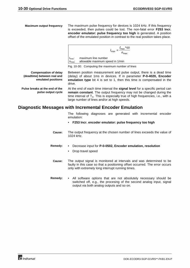
10-30 Optional Drive Functions ECODRIVE03 SGP-01VRS
DOK-ECODR3-SGP-01VRS**-FKB1-EN-P
The maximum pulse frequency for devices is 1024 kHz. If this frequencyis exceeded, then pulses could be lost. The non-fatal error F253 Incr.encoder emulator: pulse frequency too high is generated. A positionoffset of the emulated position in contrast to the real position takes place.
If
nmaxmax
max=
∗60
Imax: maximum line numbernmax: allowable maximum speed in 1/min
Fig. 10-30: Computing the maximum number of lines
Between position measurement and pulse output, there is a dead time(delay) of about 1ms in devices. If in parameter P-0-4020, Encoderemulation type bit 4 is set to 1, then this time is compensated in thedrive.
At the end of each time interval the signal level for a specific period canremain constant. The output frequency may not be changed during thetime interval of TA. This is especially true of high frequencies, i.e., with alarge number of lines and/or at high speeds.
Diagnostic Messages with Incremental Encoder EmulationThe following diagnoses are generated with incremental encoderemulation:
• F253 Incr. encoder emulator: pulse frequency too high
The output frequency at the chosen number of lines exceeds the value of1024 kHz.
• Decrease input for P-0-0502, Encoder emulation, resolution
• Drop travel speed
The output signal is monitored at intervals and was determined to befaulty in this case so that a positioning offset occurred. The error occursonly with extremely long interrupt running times.
• All software options that are not absolutely necessary should beswitched off, e.g., the procesing of the second analog input, signaloutput via both analog outputs and so on.
Maximum output frequency
Compensation of delay(deadtime) between real and
emulated positions
Pulse breaks at the end of thepulse output cycle
Cause:
Remedy:
Cause:
Remedy:
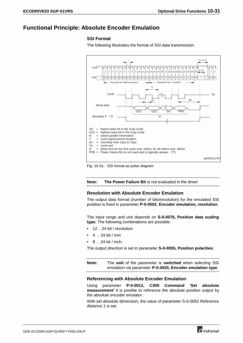
ECODRIVE03 SGP-01VRS Optional Drive Functions 10-31
DOK-ECODR3-SGP-01VRS**-FKB1-EN-P
Functional Principle: Absolute Encoder Emulation
SSI FormatThe following illustrates the format of SSI data transmission.
1 2 3 4 5 6 7 8 9 10 11 12 13 14 15 16 17 18 19 20 21 22 23 24
G23 G22 G21 G20 G19 G18 G17 G16 G15 G14 G13 G12 G11 G10 G9 G8 G7 G6 G5 G4 G3 G2 G1 G0
25
PFB 0 111
Cycle +tm-T/2
T
Data
1 2
G23 G221
Cycle
Serial data
Monoflop P / S
G23 G22 G0 PFB
tm
T
m
tv
Tp
ap5002d1.fh7
G0 = lowest value bit in the Gray-CodeG23 = highest value bit in the Gray-Codem = saved parallel informationT = cycle signal period durationtm = monoflop time 15µs to 25µsTp = cycle resttv = delay time for the first cycle max. 540ns, for all others max. 360nsPFB = Power Failure Bit (is not used and is logically always... "0")
Tp >tm-T/2
Resolution for 1 revolutionResolution for 4096 revolutions
Fig. 10-31: SSI format as pulse diagram
Note: The Power Failure Bit is not evaluated in the drive!
Resolution with Absolute Encoder EmulationThe output data format (number of bits/revolution) for the emulated SSIposition is fixed in parameter P-0-0502, Encoder emulation, resolution.
The input range and unit depends on S-0-0076, Position data scalingtype. The following combinations are possible:
• 12 .. 24 bit / revolution
• 4 .. 24 bit / mm
• 8 .. 24 bit / inch.
The output direction is set in parameter S-0-0055, Position polarities.
Note: The unit of the parameter is switched when selecting SSIemulation via parameter P-0-4020, Encoder emulation type.
Referencing with Absolute Encoder EmulationUsing parameter P-0-0012, C300 Command ’Set absolutemeasurement’ it is posible to reference the absolute position output bythe absolute encoder emulator .
With set absolute dimension, the value of parameter S-0-0052 Referencedistance 1 is set.
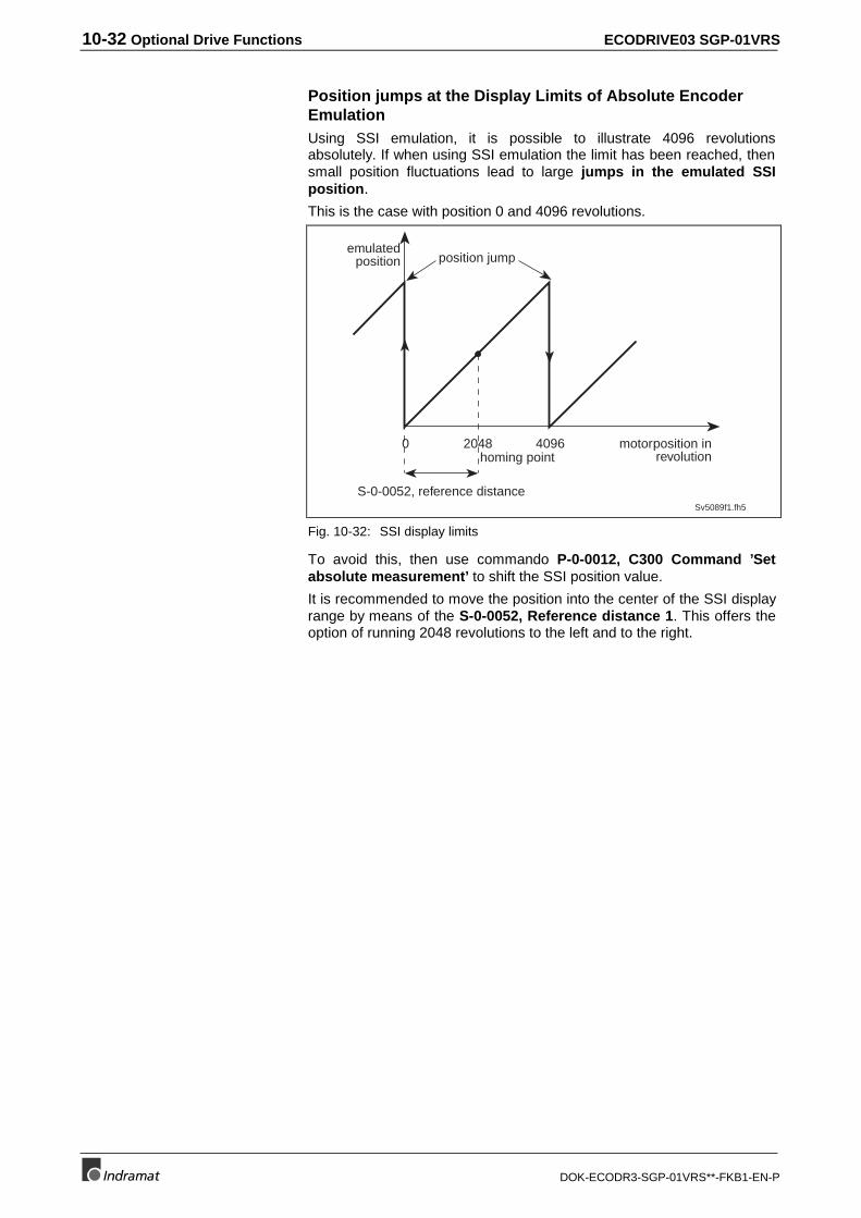
10-32 Optional Drive Functions ECODRIVE03 SGP-01VRS
DOK-ECODR3-SGP-01VRS**-FKB1-EN-P
Position jumps at the Display Limits of Absolute EncoderEmulationUsing SSI emulation, it is possible to illustrate 4096 revolutionsabsolutely. If when using SSI emulation the limit has been reached, thensmall position fluctuations lead to large jumps in the emulated SSIposition.
This is the case with position 0 and 4096 revolutions.
Sv5089f1.fh5
motorposition inrevolution
emulatedposition
2048 40960
position jump
S-0-0052, reference distance
homing point
Fig. 10-32: SSI display limits
To avoid this, then use commando P-0-0012, C300 Command ’Setabsolute measurement’ to shift the SSI position value.
It is recommended to move the position into the center of the SSI displayrange by means of the S-0-0052, Reference distance 1. This offers theoption of running 2048 revolutions to the left and to the right.
ECODRIVE03 SGP-01VRS Optional Drive Functions 10-33
DOK-ECODR3-SGP-01VRS**-FKB1-EN-P
10.11 Measuring wheel operation mode
Roll feed drives move material that is being machined or processsedfurther down the line (e.g., the cutting of tin). The motor encoder, in thiscase, is not suited for measuring material lengths if lag occurs betweenthe material and the drive. In cases such as these, it is possible to use anexternal encoder, a measuring wheel encoder. Ideally, there is no slipbetween machine and material so that sections of length can be preciselymeasured.
CAUTION
If the measuring wheel encoder no longer hascontact to the material
then the position control loop is open via encoder 2 andthe drive can move uncontrolled.
⇒ Only start up measuring wheel mode if encoder 2 isconnected to the material.
Pertinent Parameters• P-0-0185, Function of encoder 2
• P-0-0220, D800 Command Measuring wheel operation mode
• P-0-0221, Actual position filter time const. for measuring wheelmode
How it Works• The optional encoder must be registered as a measuring wheel
encoder in parameter P-0-0185, Function of encoder 2.
• Material must be in the feed roll and under the measuring wheel.
• The feed roll must be closed.
• The measuring wheel encoder is pressed against the material.
The function is activated with command P-0-0220, D800 CommandMeasuring wheel operation mode.
At the start of the command, the drive sets actual position value 2(measuring wheel encoder) to actual position value 1.
The active mode determines all further behavior of the drive.
The drive switches to position control with encoders 1 and 2.
Note: The absolute positon of the encoder is not relevant as theposition of the encoder is always re-initialized.
Negative effects resulting from poor coupling of encoder 2 to the motorshaft (only with material) should be modified by attenuating the actualposition value difference. Filter 1 smooths the difference. The filter timeconstant is set in parameter P-0-0221, Actual position filter timeconst. for measuring wheel mode.
Pre-requisite
Activation
Drive in position control
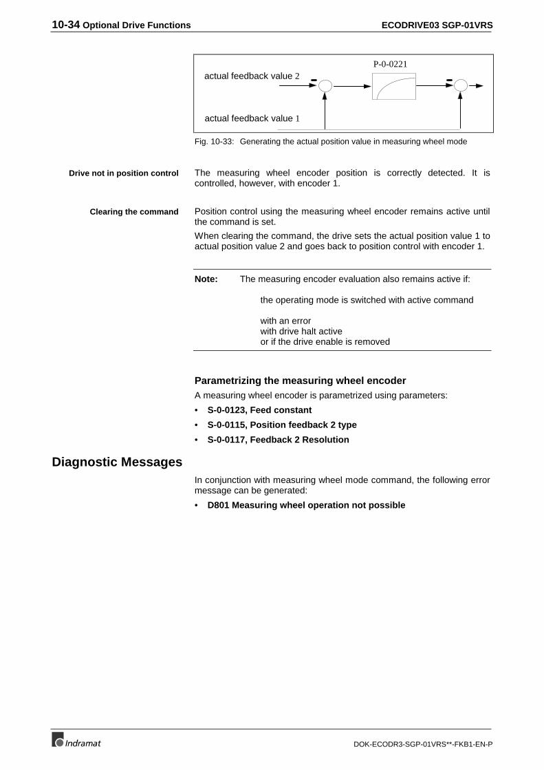
10-34 Optional Drive Functions ECODRIVE03 SGP-01VRS
DOK-ECODR3-SGP-01VRS**-FKB1-EN-P
actual feedback value 2
actual feedback value 1
P-0-0221
Fig. 10-33: Generating the actual position value in measuring wheel mode
The measuring wheel encoder position is correctly detected. It iscontrolled, however, with encoder 1.
Position control using the measuring wheel encoder remains active untilthe command is set.
When clearing the command, the drive sets the actual position value 1 toactual position value 2 and goes back to position control with encoder 1.
Note: The measuring encoder evaluation also remains active if:
the operating mode is switched with active command
with an error with drive halt active or if the drive enable is removed
Parametrizing the measuring wheel encoderA measuring wheel encoder is parametrized using parameters:
• S-0-0123, Feed constant
• S-0-0115, Position feedback 2 type
• S-0-0117, Feedback 2 Resolution
Diagnostic MessagesIn conjunction with measuring wheel mode command, the following errormessage can be generated:
• D801 Measuring wheel operation not possible
Drive not in position control
Clearing the command
ECODRIVE03 SGP-01VRS Glossary 11-1
DOK-ECODR3-SGP-01VRS**-FKB1-EN-P
11 Glossary
Data status
Every parameter has at its disposal a data status. It can be read by thecontrol via the required data channel. The information on the validity ofthe parameter or the command acknowledgment of the command arecontained therein.
Error reaction or response
If an error is detected in the drive, then the drive reacts independently byexecuting an error reaction. At the end of each error reaction there is adeactivation of the drive. The error reaction type is dependent on theerror class of the error that occurred as well as the setting in parametersP-0-0117..119.
E-Stop
E-Stop (Emergency Stop) is the determination for a hardware input at thedrive controller. It is used to trigger the emergency stop function in thedrive.
External encoder
An external measuring system is optional. It is generally mounted directlyto the load. The actual feedback value of the encoder can be seen in S-0-0053, Actual feedback value 2. By activating the position controloperating mode with encoder 2, the position control loop is closed withthe help of the actual feedback value of the external encoder.
Ident Number
Every parameter is designated unambiguously by its ident number (IDN).It consists of these 3 components: S-Sercos/P-Product specific,parameter set (0..7) and a number (1..4096).
Load default or basic load
The control parameters are stored in the motor feedback data memory inboth MDD and MKD motors. This makes it possible for the drivecontroller to work trouble-free with this motor. The control parametershave not been optimized for the application.
Modulo format
Both actual feedback and command values can be processed in moduloor absolute format. If modulo processing has been set, then the positiondata move within the range of 0..S-0-0103, modulo value. With thisfunction, it is possible to realize an endlessly turning axis.
Motor encoder
The motor encoder is the measuring system that is used duringcommutation. A measuring system is absolutely necessary. The actualfeedback value of the encoder can be seen in S-0-0051, Actual positionvalue 1. By activating the position control operating mode with encoder 1,the position control loop is closed with the help of the actual position ofthe motor encoder.
Operating data
The operating data is data block element 7 of a parameter. The value ofthe parameter is stored there.
11-2 Glossary ECODRIVE03 SGP-01VRS
DOK-ECODR3-SGP-01VRS**-FKB1-EN-P
Operating mode
Operating mode is set in parameters S-0-0032..35. It determines in whatway a command value is processed in the drive and eventually initiatesan axis movement. The operating mode does not define how thecommand value reaches the drive.
Parameterization mode
The drive is in parameterization mode if communication phases 1..3 havebeen set. The drive cannot be activated (drive enable signal applied).Operating mode must first be switched into. Some parameters can onlybe written into during parameterization mode.
Programming module
The programming module contains the software and parameter memory.It is mounted in slot U5. When exchanging the controller, a simpleinsertion of the programming module out of the old into the new unitmeans that the features of the replaced unit have been transferred to thenew one.
Home Switch
If during the command S-0-0148, C600 Drive controlled homingseveral reference marks can be reached within the travel range, it’s thehome switch which must specify one singular mark. The home switch isconnected to the respective input at the drive and activated by bit 5 in S-0-0147, Homing Parameter. This input is mirrored in the parameter S-0-0400, Home switch.
Scaling
The combination of unit and number of decimal places of a parameterare defined as scaling. It can be set for position, velocity and accelerationdata.
SERCOS-INTERFACE
Digital interface for communication between control and drives innumerically controlled machines. One or multiple ring structures areimplemented. The physical connection of the participants generallyimplements a fiber optic cable.
Service Channel
The non-cyclic reading and writing of parameters via the SERCOS-Interface is done in the service channel
ECODRIVE03 SGP-01VRS Index 12-1
DOK-ECODR3-SGP-01VRS**-FKB1-EN-P
12 Index
00x1001, ID number not available 10-5
0x7008, Data not correct 10-6
0x9002 (dL / 00) Firmware was cleared 3-28
0x9003 Loading into phase 3 not allowed 3-29
0x9004 Loading into phase 4 not allowed 3-29
0x9102 (dL / 03) Firmware was cleared 3-29
0x9103 Restart in phase 3 not allowed 3-29
0x9104 Restart in phase 4 not allowed 3-29
0x9200 (dL / 06) Read error 3-29
0x9400 (dL / 07) Timeout during reset 3-29
0x9402 (dL / 0F) Address range not in flash 3-29
0x940A Reset only possible in loader 3-29
0x96E0 (dL / 0b) Error when verifying the flash 3-30
0x96E1 (dL / 0C) Timeout when programming the flash 3-30
0x96FF (dL / 09) Error when write accessing the RAM 3-30
0x9701 (dL / 0d) Wrong checksum 3-30
0x9702 (dL / 0e) CRC32 checksum faulty 3-30
11MB 7-1
22AD 7-1
77-Segment Display
Diagnostic Number 3-22
AAbsolute encoder
modulo evaluation 9-27
Absolute encoder emulation 10-31
Absolute encoder emulation 10-31, 10-32
Absolute encoder evaluation 9-25
Absolute Encoder Monitor
Deactivating 9-27
Absolute encoder monitoring 9-26
checking transition command 3-15
Absolute encoder monitoring with two absolute encoders 9-27
Absolute measuring system encoder types 9-24
Absolute measuring systems
Modulo evaluation 9-27
Absolute measuring systems interface 9-24
Absolute Positioning 8-18
Acceleration Feed Forward
Setting 9-65
Access angle 8-52
12-2 Index ECODRIVE03 SGP-01VRS
DOK-ECODR3-SGP-01VRS**-FKB1-EN-P
Acknowledge of the Drive Enable 4-4
Acknowledge the drive enable with analog interface 5-2
Acknowledge with control voltage interrupt with positioning block mode 8-35
Acknowledge with drive enable removed in positioning block mode 8-35
Activating encoder emulation 10-28
Activating the Oscilloscope Feature 10-16
Activating the velocity control loop monitor 9-62
Activation of the E-Stop Input 9-52
Actual Feedback Value Monitoring 9-17
Actual feedback values from absolute encoder after switching on 9-102
Actual Feedback Values of Non-Absolute Measurement Systems After Initialization 9-19
Actual position at start of automatic control loop settings 9-68
Addition checksum faulty 3-28
Additional Problems when Loading Firmware 3-30
Additional uses of parameter "S-0-0173, Marker position A" 10-23
Address range not within flash storage 3-28
Addressing the data container with multiplex channel 4-13
After switching the unit on the display reads dL 3-30
Amplifier overtemperature shutdown 3-23
Amplifier overtemperature warning 3-24
Analog Inputs 10-9
Analog Inputs - Connection 10-11
Analog output
bit and byte output 10-8
function principle 10-6
Relevant parameters 10-6
terminal assignment 10-9
Assignment of analog inputs to parameters 10-10
Automatic control loop settings 9-68
actual position at start 9-68
prerequisites 9-68
Automatic Execution of the Load Default Feature 9-55
Axis Limit Values
Monitoring the allowable travel range 9-36
Axis Limit Values 9-38
Axis Limit Values - Activation 9-39
BBaud rate 3-32
bb 3-12
BB contact 9-49
BB relay 9-49
BB-contact 9-49
Best Possible Deceleration
as velocity command value decelerated to zero 9-44
Drive Error Reaction 3-9
SERCOS Interface Error 4-12
Best possible standstill
Torque disable 9-45
Best possible standstill as speed command to zero with filter and ramp 9-47
Bipolar Velocity Limit
Limiting the Command Value 8-5
Bipolar Velocity Limit Value
Limiting Velocity 9-34
Block transition 8-26
ECODRIVE03 SGP-01VRS Index 12-3
DOK-ECODR3-SGP-01VRS**-FKB1-EN-P
Block transition at old positioning speed 8-26
Block transition with intermediate halt 8-28
Block transition with new positioning speed 8-27
Brake
with velocity command value set to zero 9-44
CChecking for existing ID numbers in multiplex channel 4-16
Checking the configuration list with multiplex channel 4-16
Checking the configured IDN order with multiplex channel 4-16
Checking the indices of multiplex channel 4-17
Checking the thermal load of the drive controller 9-31
Checks in the transition commands 3-12
Chronological sequence of the automatic control loop setting 9-72
Class 1 diagnostics 3-23
class 2 diagnostics 3-24
Class Diagnostics
Reset Class 1 Diagnostics 3-9
Clear error with analog interface 5-1
Clearing Errors 3-9
Clearing Errors When Controller Enable Is Set 3-9
Collective indication 3-23
Command - detect marker position 10-23
Command communications interface 1-3
Command Communications with Analog Interface 5-1
Command error 3-12
Command Input and Acknowledgment 3-6
Command Polarities and Actual Value Polarities 9-5
Command settings with automatic control loop settings 9-69
Command Types 3-6
Command Value Preparation for electronic cam 8-52
Command value preparation for velocity synchronization with virtual master axis 8-41
Command value processing
Position Control 8-8
Command value processing Velocity control 8-4
Command value profile with actuated home switch at the start of the command 9-86
Commands 3-6
Automatic control loop settings 9-68
Change Bit Command 3-7
Command Input and Acknowledgment 3-6
Command Types 3-6
Load Default Command 9-55
Probing Cycle Procedure Command 10-21
Commissioning Guidelines 3-16
Commissioning instructions 3-16
Communications error 3-23
Communications phase
operating mode 3-11
parametrization phase 3-11
Communications phase 3 transition check 3-12
Communications phase 4 transition check 3-13
commutation offset 7-9
Condition for Power On 9-50
Configurable inputs of the parallel interface 6-2
Configurable outputs of the parallel interface 6-1
12-4 Index ECODRIVE03 SGP-01VRS
DOK-ECODR3-SGP-01VRS**-FKB1-EN-P
Configurable signal control word 10-3
Configurable signal status word 10-1
Configuration of the Home switch 9-92
Configuration of the signal status word 10-1
Configuration with multiplex channel 4-13
Configuring the signal control word 10-4
Connecting Signals to DKCxx.3 5-3
Connecting the motor holding brake 7-15
Connecting the parallel interface in stepper motor operations 8-39
Connecting the Probe Inputs 10-22
Connection of drive halt input 9-76
Connection of the Emergency-Stop Input 9-53
Connection of the Home switch 9-93
Control loop dynamics 9-68
Control loop dynamics with automatic control loop settings 9-70
Control Loop Settings 9-68
Control voltage error 3-23
Cooling error 3-24
CRC32-checksum faulty 3-28
Criteria for triggering the monitor 9-63
Current Controller
Associated Parameters 8-6
Block diagram 8-6
Setting the Current Controller 9-57
Current Limit 9-28
DData Block Structure 3-1
Data container 4-13
Data flow chart for automatic control loop settings 9-72
Data Saving 3-3
Deactivation of the Position Control Loop Monitoring 9-65
Definition of the Critical Proportional Gain and P-0-0004, Smoothing Time Constant 9-58
Detect marker position 10-23
Determing the Critical Position Controller Gain 9-63
Determining encoder interface of optional encoder 9-16
Determining the commutation offset 7-9
Determining the Critical Integral Action Time 9-58
Determining the Encoder Interface of the Optional Encoder 9-16
Determining the Feedback Interface of the Master Axis Feedback 9-40
Determining the Feedback Interface of the Motor Feedback 9-13
Determining the Position Controller Setting 9-63
Determining the Velocity Controller Setting 9-58
Determining/detecting the active mode 8-1
Diagnostic / error messages with system status word 10-2
Diagnostic Message 3-22
Composition of the Diagnostic Message 3-21
Diagnostic Message Display 3-20
Diagnostic Number 3-22
Diagnostic Message Number 3-22
Diagnostic Messages
Diagnostic of the Interface Condition 4-12
Diagnostic messages in multiplex channel 4-16
Diagnostic Messages Measuring wheel operation mode 10-34
ECODRIVE03 SGP-01VRS Index 12-5
DOK-ECODR3-SGP-01VRS**-FKB1-EN-P
Diagnostic messages of jog mode 8-40
Diagnostic messages of the stepper mode 8-39
Diagnostic messages when setting the absolute dimension 9-102
Diagnostic messages with configurable signal control word 10-5
Digital inputs with analog interface 5-1
digital servo feedback 9-11
Directional change within a following block chain 8-34
Disable Torque 9-45
Display Format
of the Acceleration Data 9-5
of the Position Data 9-2
of the Velocity Data 9-4
Distortion display 4-8
Dolfi 3-27
Dolfi can be used to establish a connection 3-31
Dolfi cannot open the ibf file 3-31
Dolfi signals timeout 3-31
Drive Controllers and Motors 1-2
Drive enable 4-2
Drive enable with analog interface 5-1
Drive enable with automatic control loop settings 9-69
Drive halt
pertinent parameters 9-74
Drive halt with analog interface 5-1
Drive Internal Interpolation
Associated Parameters 8-11
Block Diagram 8-11
Diagnostic Messages 8-11
Drive start with automatic control loop settings 9-69
Drive status word 3-25
Structure 4-3
Drive-Controlled Homing 9-82
Drive’s Error Response 3-9
DSF 9-10
Dynamic Synchronization in the Phase Synchronization Operating Mode 8-46
Dynamic synchronization in the velocity synchronization operating mode 8-42
EECI encoder 9-11
ECODRIVE03 - a Drive Family 1-1
ECODRIVE03 - the Universal Drive Solution for Automation 1-1
Effect of jog signals 8-40
Electronic cam shaft 8-51, 8-55
Emergency-Stop
Activation 9-52
Encoder emulation 10-27
Encoder interface 9-40
Encoder intialization 3-15
Encoder with EnDat interface 9-11
EnDat 9-11
Error
Cancel Error 3-9
Drive Error Reaction 3-9
Error Classes 3-9
Error Counter for Telegram Interrupts 4-12
12-6 Index ECODRIVE03 SGP-01VRS
DOK-ECODR3-SGP-01VRS**-FKB1-EN-P
Exceeding the Travel Range 9-36
Error Classes 3-9
Error Conditions of the Load Default Settings Procedure 9-56
Error during flash verification 3-28
Error message in Firmware loader 3-27
Error messages
during drive-controlled homing 9-92
when reading and writing the operating data 3-2
when setting absolute dimension 9-102
Error messages in multiplex channel 4-16
Error messages when configuring signal control word 10-4
Error messages with configurable signal control word 10-5
Error Number 3-22
Error Reaction
Drive Error Reaction 3-9
NC Response in Error Situation 9-51
power off 9-49
SERCOS Interface Error 4-12
to velocity command value deceleration to zero 9-44
Error when writing into RAM 3-28
E-Stop
Activation 9-52
functional principle 9-51
relevant parameters 9-51
Evaluation of the Home Switch 9-85
Exceeding the Travel Range
Warning 9-37
Exceeding the Travel Range as a Warning 9-37
Exceeding the Travel Range as an Error 9-36
Excessive control deviation 3-23
Executing automatic control loop settings 9-70
Expanded Oscilloscope Recording Function 10-13
Explanation of Terms 3-1
FFeed Constant 9-7
Feedback error 3-23
Fiber optics
connection to a SERCOS interface 4-7
Firmware loader 3-27
Firmware Update with the Dolfi program 3-27
Firmware was cleared 3-28
Following block chain
interruption 8-31
Following block mode 8-17, 8-26
for write access 3-2
Frictional Torque Compensation 9-66
Function diagram for the Programmable Limit Switch 10-24
Function Overview
FWA-ECODR3-SGP-01VRS-MS 1-3
Function principle Drive Internal Interpolation 8-11
Functional principle drive halt 9-74
Functional principle master axis encoder evaluation 9-39
Functional principle multiplex channel 4-13
Functional principle of angle synchronization with real master axis 8-50
ECODRIVE03 SGP-01VRS Index 12-7
DOK-ECODR3-SGP-01VRS**-FKB1-EN-P
Functional principle of command detect marker position 10-23
Functional principle of the analog inputs 10-10
Functional principle of the current limits 9-29
Functional principle of the electronic cam with real master axis 8-55
Functional Principle of the Measuring Wheel Mode 10-33
Functional Principle Set Absolute Measuring 9-100
Funtional principle
E-stop function 9-51
GGearwheel encoder 9-11
General comments on automatic control loop settings 9-68
General functions 1-4
General information about jogging 8-39
General Operating Characteristics of Position Control Loop Monitoring 9-64
Generator function
Relative drive-internal interpolation 8-15
Glass LWLs 4-10
HH1-Display 3-21
Hall encoder 9-11
Hardware Dependencies for the Configurable Signal Status Word 10-3
Home switch
Connection to the connector X3 9-93
Use during Homing 9-85
Homing
Error Messages 9-92
Home switch 9-85
Position Feedback Values 9-82
Reference Offset 9-83
How it works
Command Communications with Analog Interface 5-1
How velocity synchronization with real master axis works 8-43
HSF 9-10
IID number not available 10-4
IDN List of Parameters 3-10
Incremental encoder emulation 10-27, 10-28
Incremental encoder with sine signals from Heidenhain with 1V signals 9-11
Incremental encoder with square wave signals from Heidenhain 9-11
Index with multiplex channel 4-13
Integral action time 7-14
Determing the Critical Integral Action Time 9-58
Interface
Start Up for the SERCOS Interface 4-5
Interface Error
SERCOS Interface Error 4-12
Interface mode 8-38
JJogging mode functional sequence 8-40
12-8 Index ECODRIVE03 SGP-01VRS
DOK-ECODR3-SGP-01VRS**-FKB1-EN-P
LLAF 7-1
Lag error 3-25
Language Selection 3-27
LAR 7-1
Limit- 5-2
Limit+ 5-2
Limiting the incremental encoder emulation 10-29
Limiting the Velocity
of the command value in the velocity controller 9-34
Limiting to Bipolar Velocity Limit Value 9-34
Limiting to Maximum Motor Velocity 9-34
Limiting Velocity
Associated Parameters 9-34
Bipolar Velocity Limit Value 9-34
Maximum Motor Velocity 9-34
Monitoring 9-34
Linear - Rotary Scaling 9-2
List elements of multiplex channel 4-15
List of diagnostic numbers 3-22
Load 9-31
Loading into phase 3 not allowed 3-28
Loading into phase 4 not allowed 3-28
LSF 7-1
MMain Function of the Probe Analysis 10-20
Main spindle functions with Parallel Interface 6-3
Manufacturer class 3 diagnostics 3-26
Manufacturer specific error 3-23
Manufacturer’s class 3 diagnostics 3-26
Master axis 8-41
Master axis encoder 8-50, 8-55
features 9-40
function principle of evaluation 9-39
interface 9-40
Master axis encoder parametrization 9-40
Master axis encoder resolution 9-40
Master Axis Feedback Analysis 9-39
Master Axis Feedback Resolution 9-40
Master Control Word
Structure 4-2
Measuring wheel operation mode 10-33
MHD
Automatic Setting of the Motor Type 7-4
Temperature Monitoring 7-3
Minimum values for accel and jerk with positioning blocks 8-33
MKD
Automatic Setting of the Motor Type 7-4
Temperature Monitoring 7-3
MKE
Motor feedback-data memory 7-2
Mode
Relative drive-internal interpolation 8-14
Velocity Control 8-4
ECODRIVE03 SGP-01VRS Index 12-9
DOK-ECODR3-SGP-01VRS**-FKB1-EN-P
Modulo Feature 9-8
Command Value Processing 9-9
Modulo Processing-Limiting Conditions 9-8
Modulo format 8-19
Modulo function
modulo function absolute measuring system 9-27
Modulo range error 3-15
Modulo Processing-Limiting Conditions 9-8
Modulo value 8-19
Monitor
velocity control loop 9-62
Monitoring
Axis Limit Values 9-38
Position Command Values 8-9
Position Feedback Value 9-17
Position Loop 9-64
Monitoring actual velocity in torque control 8-3
Monitoring the Distance Between Home switch and Homing Mark 9-86
Monitoring the thermal load of the controller 9-30
Motor Brake
with velocity command value set to zero 9-44
Motor current limit 9-32
Motor Encoder 9-12
Characteristics 9-14
Encoder Interface 9-13
Parameterization 9-13
Resolution 9-14
Motor Encoder Resolution 9-14
Motor feedback
Saved parameters 7-2
Motor holding brake 7-13
integral actoin time 7-14
type of brake 7-13
Motor holding brake connection 7-15
Motor overtemperature 3-24
Motor Reference - Load Reference 9-2
Motor Types
Characteristics of the Motors 7-1
Linear-Rotary 7-2
Setting the Motor Type 7-4
Supported Motor Types 7-1
Synchronous-Asynchronous 7-3
Multiplex Channel 4-12
Multiplex Channel Overview 4-12
NNon-Volatile Parameter Storage Registers 3-2
notch filter 8-5
NTC 7-1
Number of Valid Probe Values 10-18
OOperating mode 3-11
electronic cam shaft with real master axis 8-55
electronic cam shaft with virtual master axis 8-51
12-10 Index ECODRIVE03 SGP-01VRS
DOK-ECODR3-SGP-01VRS**-FKB1-EN-P
jogging 8-39
torque control 8-2
velocity synchronization with real master axis 8-43
velocity synchronization with virtual master axis 8-41
Operating modes 3-8, 8-1
Optional Encoder
Characteristics 9-19
encoder interface 9-16
Parameterization 9-16
Resolution 9-17
Optional Encoder Resolution 9-17
Oscilloscope Feature
Activating the Feature 10-16
defined recording signals 10-12
Expanded Function 10-13
Expanded Trigger Signals 10-15
External Trigger and Internal Trigger Condition 10-17
Fixed Trigger Signals 10-14
Functional Principle 10-12
Status Messages 10-17
Trigger Delay 10-16
Trigger Edge 10-14
Triggering 10-13
Oscilloscope Feature Trigger Source 10-13
Oscilloscope feature with defined recording signals 10-12
Oscilloscope Feature With External Trigger and Internal Trigger Condition 10-17
Other Motor Encoder Characteristics 9-14
Other Optional Encoder Characteristics 9-19
Overload warning 3-24
Parametrize the pre-warn threshold 9-31
Overview
Command Communications with Analog Interface 5-1
Overview about Command Communication Using Parallel Interface 6-1
PParallel Interface 6-1, 8-36
Parameter 3-1
Parameter Buffer Mode 3-3
Parameter involved when configuring signal control word 10-3
Parameter Storage in Motor Feedback 3-3
Parameterizing the Master Axis Feedback 9-40
Parameters pertinent in encoder emulation 10-28
Parameters pertinent in the multiplex channel 4-13
Parameters Stored in DSM Programming Module 3-3
Parameters Stored in the Digital Drive 3-3
Parametrization / operating mode 3-11
Parametrization mode 3-11
Parametrization notes for positioning blocks 8-33
Parametrizing the measuring wheel encoder 10-34
Paramter structure 3-1
Password 3-4
Peak current
Saving in the motor feedback 7-2
Peak torque 9-32
Pertinent parameter of phase synchronization with virtual master axis 8-44
Pertinent parameter with current limits 9-28
ECODRIVE03 SGP-01VRS Index 12-11
DOK-ECODR3-SGP-01VRS**-FKB1-EN-P
Pertinent Parameter with Drive-Controlled Homing 9-76
Pertinent Parameters Command Communications with Analog Interface 5-1
Pertinent parameters for angle synchronization with real master axis 8-50
Pertinent Parameters for jogging mode 8-39
Pertinent parameters for velocity synchronization with virtual master axis 8-41
Pertinent Parameters Measuring wheel operation mode 10-33
Pertinent parameters of stepper motor mode operations 8-38
Pertinent Parameters of the analog inputs 10-9
Pertinent parameters of the parallel interface 6-1
Pertinent parameters with dynamic cam switch group 10-24
Pertinent parameters with electronic cam with real master axis 8-55
Pertinent parameters with electronic cam with virtual master axis 8-51
Pertinent parameters with system status word 10-1
Pertinent parameters with velocity synchronization with real master axis 8-43
Phase synchronization
structure 8-44
PL 3-4
Plastic LWL 4-10
Polarity
Actual Value Polarity 9-5
Command Value Polarity 9-5
Pos. limit vaue exceeded 3-23
Position Command Value Interpolator
Associated Parameters 8-8
Block diagram 8-8
Position Command Value Monitoring 8-9
Position Control
Associated Diagnostic Messages 8-7
Block diagram 8-7
Setting the Position Controller 9-63
Position Controller 8-8
Associated Parameters 8-8
Block diagram 8-8
Critical Position Controller Gain 9-63
Setting the Acceleration Feed Forward 9-65
position feedback values
after switching on 9-28
Position limit value 8-18, 8-25
Position of the zero pulse as relates to motor position 10-29
Position switch
function principles 10-24
lead time 10-26
parameterizing 10-27
parameters 10-24
switch-off level 10-25
switch-on level 10-25
Positioning block mode 6-2, 8-16
Acknowledge positioning block selected 8-35
Activating positioning blocks 8-18
Diagnostic messages 8-37
Following block mode 8-26
How it works 8-17
Infinite running in a positive / negative direction 8-25
Parallel interface 8-36
Pertinent Parameters 8-17
Position-dependent continue block mode 8-26
Positioning block modes 8-18
12-12 Index ECODRIVE03 SGP-01VRS
DOK-ECODR3-SGP-01VRS**-FKB1-EN-P
status messages 8-36
positioning block transfer 8-14
Positioning velocity > Ngrenz 3-24
Positioning window 3-25
Possible Error Messages when Reading and Writing the Operating Data 3-2
Possible operating modes 1-3
Power Failure Bit 10-31
Power off
power off on error 9-49
Power off and package reaction on error 9-50
Power off on error 9-49
Preferred Scaling - Parameter Scaling 9-2
Preparations for Setting the Position Control Loop 9-63
Preparations for Setting the Velocity Controller 9-57
Prerequisites for automatic control loop settings 9-68
Prerequisites for the execution of absolute positioning blocks 8-18
Probe
Main Function 10-20
Probing Cycle Procedure Command 10-21
Relevant parameters 10-19
Signal Edge Selection 10-21
Probe functions 10-19
Probe signal select 10-22
Processing Command Values in Modulo Format, Shortest Path - Direction Selection 9-9
Processing single list elements of multiplex channel 4-15
Profile 8-52
Programmable Limit Switch 10-24
Programmable Limit Switch Lead Time 10-26
Programming only possible in loader 3-28
Proportional Gain
Determining the Critical Proportional Gain 9-58
PTC 7-1
Pull-out current limit 9-32
RRamp 9-47
Rated current
Saving in the motor feedback 7-2
Reaction to undervoltage 9-50
Reaction to Undervoltage (DC bus voltage too small) 9-50
Read access 3-25
Read error 3-28
real master axis 8-43, 8-55
Real-Time Control Bit 4-5
Real-Time Status Bit 4-5
Referencing
parametrization 9-77
reference marker 9-77
Referencing the master axis encoder 9-41
Referencing with absolute encoder emulation 10-31
rejection filter 9-61
Relative drive-internal interpolation 8-14
diagnostic messages 8-15
pertinent parmeters 8-14
Relative positioning block with residual path after activating drive enable 8-22
ECODRIVE03 SGP-01VRS Index 12-13
DOK-ECODR3-SGP-01VRS**-FKB1-EN-P
Relative positioning block with residual path storage 8-21
Relative positioning block with residual path storage after switching drive controller controlvoltage on and off 8-24
Relative positioning block with residual path storge after interrupting with jog mode 8-23
Relative positioning blocks without residual path storage 8-19
Relevant parameters of the E-Stop function 9-51
Requirements for a Correct Setting of the Acceleration Feed Forward 9-66
Reset only in loader possible 3-28
Resolution 9-21
Resolution with absoute encoder emulation 10-31
Resolver 9-11
Resolver without feedback data storage 9-11
Resolver without feedback data storage + incremental encoder with sine signals 9-11
Restart in phase 3 not allowed 3-28
Restart in phase 4 not allowed 3-28
Results of automatic control loop settings 9-73
Results of Writing 10-21
ring structure 4-7
Rotational direction of the master axis encoder 9-40
Run the Load Default Settings feature as a command 9-56
Running the "load basic parameter block" function automatically 3-4
SS-0-0012, Class 2 diagnostics 3-24
S-0-0013, Class 3 diagnostics 3-24
S-0-0127, C100 Communication phase 3 transition check 3-12
S-0-0128, C200 Communication phase 4 transition check 3-13
S-0-0182, Manufacturer class 3 diagnostics 3-26
S1 3-4
Safety Instructions 2-1
Battery safety 2-9
General 2-3
Hazards by improper use 2-2
Protection against contact with electrical parts and not grounded enclosures 2-4
Protection against dangerous movements 2-6
Protection against magnetic and electromagnetic fields during operations and mounting 2-7
Protection by protective low voltage (PELV) against electrical shock 2-5
Protection during handling and installation 2-8
Safety Instructions for Electrical Drives 2-1
Scaling
Linear - Rotary 9-2
Motor Reference - Load Reference 9-2
of the Acceleration Data 9-5
of the Position Data 9-2
of the Velocity Data 9-4
Preferred Scaling - Parameter Scaling 9-2
Scaling Factor Pre-Magnetizing 7-7
Select the download baud rate 3-32
Selection of Trigger Edges 10-14
Sequence of the automatic control loop settings 9-72
SERCOS compatibility class C 4-1
SERCOS Interface
Allocation of Real-Time Control Bit 4-5
Allocation of Real-Time Status Bit 4-5
connection of fiber optic cables 4-7
Drive Status Word 4-3
12-14 Index ECODRIVE03 SGP-01VRS
DOK-ECODR3-SGP-01VRS**-FKB1-EN-P
Master Control Word 4-2
transmission rate 4-9
SERCOS-Interface
Start Up for the SERCOS Interface 4-5
Set Absolute Dimension
Error Messages 9-102
Functional Principle 9-100
without drive enable 9-101
Set absolute dimension (measuring) during controller enable, then turn off the controllerenable 9-101
Set absolute measuring without controller enable 9-101
Set the actual feedback values according to the absolute dimension 9-102
Setting absolute dimension
with CE and subsequent homing 9-101
Setting Absolute Dimension Under Controller Enable and Subsequent 9-101
Setting Maximum Decel Time 7-14
Setting Position Command Value Monitoring 8-10
Setting the Absolute Encoder Monitor 9-27
Setting the Acceleration Feed Forward 9-66
Setting the measuring system 9-10
Setting the Motor Brake Integral Action Time 7-14
Setting the Motor Brake Type 7-13
Setting the Operating Mode Parameters 8-1
Setting the Position Control Loop Monitor 9-65
Setting the Time Resolution and the Memory Depth 10-15
Setting the Trigger Delays 10-16
Signal control word 10-3
Signal Edge Selection for the Probe Inputs 10-21
Signal Selection for the Probe Inputs 10-22
Signal status word 10-1
Smoothing the actual position value 9-41
Smoothing Time Constant
Determining the Smoothing Time Constant 9-58
Limiting the command value for current control 8-5
Square wave encoder 9-11
SSI format 10-31
Standstill window 3-25
Starting a command with automatic control loop settings 9-70
Starting, interrupting and completing the command 9-92
Status class
class 1 diagnostics 3-23
class 2 diagnostics 3-24
class 3 diagnostics 3-24
mask class 2 diagnostics 3-25
mask class 3 diagnostics 3-25
Status Messages for the Oscilloscope Feature 10-17
Stepper motor controls 8-37
Stepper motor mode 6-2, 8-37
Stepper motor signal processing 8-38
Stop 5-2
Supplementary settings for absolute measuring systems 9-24
Supported measuring systems 1-3
Supported motor types 1-3
Switching signal dependent block commutation 8-29
Switching to zero 9-47
Switch-on Position larger than the switch-off Position 10-25
ECODRIVE03 SGP-01VRS Index 12-15
DOK-ECODR3-SGP-01VRS**-FKB1-EN-P
Switch-on position smaller than the switch-off position 10-25
synchronization 8-42, 8-51, 8-53, 8-56
Synchronization status message during the velocity synchronization operating mode 8-43
Synchronization status message for the phase synchronization operating mode 8-49
Synchronous motor (MBS) 7-10
Synchronous Motors 7-8
System Overview 1-1
TTaking drive limits into account with following blocks 8-33
Telegram Configuration
SERCOS Telegram Configuration 4-10
Telegram Contents 4-11
Telegram Transmit and Receive Times 4-10
Temperature check 7-1
Temperature Monitoring
of the motor temperature 7-3
The Data Status 3-1
The programming of a module was terminated 3-30
Thermal overload
Controller check 9-31
Timeout during reset 3-28
Timeout when programming flash 3-28
Torque control 8-2
diagnostic messages 8-3
limiting the command value 8-2
monitoring the actual velocity 8-3
pertinent parameters 8-2
relevant diagnosis 8-2
structure 8-2
Torque limit 9-32
Torque limit of maximum allowable torque 9-33
Transmission
Feed Constant 9-7
Transmission Ratio 9-7
Transmission power 4-10
Transmission Ratio 9-7
Travel range limit switch
monitor 9-37
Travel range limit switch in positioning block mode 8-25
Travel Range Limits 9-35
Monitoring as a Warning 9-37
Parameterization 9-36
Relevant parameters 9-35
Travel range limits determined 9-70
Travel range limits P-0-0166 and P-0-0167 9-68
Travel range limits with automatic control loop settings 9-68, 9-70
Travel Zone Limit Switch
Activation and Polarity 9-38
Connection 9-39
Monitoring 9-37
Monitoring the allowable travel range 9-36
Trigger causes of the velocity control loop monitor 9-62
Triggering a motion with automatic control loop 9-70
12-16 Index ECODRIVE03 SGP-01VRS
DOK-ECODR3-SGP-01VRS**-FKB1-EN-P
UUndervoltage 9-50
Undervoltage error 3-23
Using the data container with multiplex channel 4-14
VVelocity Command Value Reset 9-44
Velocity Command Value Set to Zero
Time Elapsed 9-44
Velocity Control
diagnostic messages 8-6
Diagnostic Messsages 8-4
Limiting the Command Value 8-4
pertinent parameters 8-4
Velocity control loop monitor 9-62
trigger causes 9-62
Triggering causes 9-63
Velocity Controller 8-5, 8-6
Settings 9-57
Velocity Limit of the Command Value in the Velocity Controller 8-5
Velocity limit value bipolar
monitoring actual velocity in torque control 8-3
Velocity loop control
criteria for triggering 9-63
Velocity Mix Factor
Functional Principle 9-67
Velocity synchronization 8-41, 8-43
velocity synchronization with real master axis 8-43
Velocity threshold 3-25
Virtual master axis 8-41, 8-51
WWarning Classes 3-8
Warnings 3-8
Exceeding the Travel Range 9-37
Warning Classes 3-8
XX3
Connection of the Emergency-Stop Input 9-53
ZZero pulse 10-29
ECODRIVE03Drive for General Automation
With SERCOS-, Analog- and Parallelinterface
Supplement A:Serial Communications
SGP 01VRS
DOK-ECODR3-SGP-01VRS**-FKB1-EN-P

About this documentation ECODRIVE03 SGP-01VRS
DOK-ECODR3-SGP-01VRS**-FKB1-EN-P
ECODRIVE03 SGP-01VRS Contents I
DOK-ECODR3-SGP-01VRS**-FKB1-EN-P
Contents
1 Serial Communications 1-11.1 An Overview......................................................................................................................................... 1-1
1.2 Parameters Involved ............................................................................................................................ 1-1
1.3 Function Principle................................................................................................................................. 1-1
Basic State once the Control Voltage is Switched On................................................................... 1-1
Setting the Drive Address.............................................................................................................. 1-2
Communications via RS232 Interface........................................................................................... 1-3
Communications via RS485 Interface........................................................................................... 1-4
1.4 Transmission Protocols........................................................................................................................ 1-6
ASCII Protocol............................................................................................................................... 1-6
SIS protocol................................................................................................................................... 1-6
1.5 Communications procedures ............................................................................................................... 1-9
General Information on the Parameter Structure .......................................................................... 1-9
Communicating with an ASCII Protocol ...................................................................................... 1-10
Communicating with the SIS protocol ......................................................................................... 1-20
1.6 Error Messages.................................................................................................................................. 1-24
Error with ASCII Communication ................................................................................................ 1-25
Error with SIS Communication .................................................................................................... 1-25
1.7 Application Examples (Changing Position Block Data)...................................................................... 1-27
ASCII Protocol............................................................................................................................. 1-27
SIS Protocol ................................................................................................................................ 1-28
1.8 Connection Techniques ..................................................................................................................... 1-32
2 Index 2-1

2 Contents ECODRIVE03 SGP-01VRS
DOK-ECODR3-SGP-01VRS**-FKB1-EN-P
Notes
ECODRIVE03 SGP-01VRS Supplement A: Serial Communications 1-1
DOK-ECODR3-SGP-01VRS**-FKB1-EN-P
1 Serial Communications
1.1 An Overview
The drive controller is equipped with a serial interface. It supports theparametrization of the drive. Using this interface, it is possible to alter:
• Parameters
• Commands and
• Diagnoses
The interface can be operated in either
• RS232 mode or
• RS485 mode
Two (2) different protocols are supported:
• the Indramat SIS protocolThe usable data are transmitted in INTEL format.
• and an ASCII protocol
Its precise structure is outlined in the following section.
Note: If an ASCII protocol is used, then the number of bytes differsfrom the data length in the parameter description (internalnumber format).
1.2 Parameters Involved
The data exchange which implements the serial interface is controlled bymeans of the following parameters:
• P-0-4021, Baud rate RS-232/485
• P-0-4022, Drive address
• P-0-4050, Delay answer RS-232/485
1.3 Function Principle
Basic State once the Control Voltage is Switched OnAfter the control voltage is switched on, serial communications in thedrive is in "Passive mode“. Communications is not possible in passivemode.
To be able to take up serial communications with the drive it is necessaryto set the communications mode (protocol)
• with a "Change Drive“ command (with ASCII protocol )
• or a valid Start telegram (with SIS protocol ).
Interface mode
Interface protocol
Selecting a Protocol
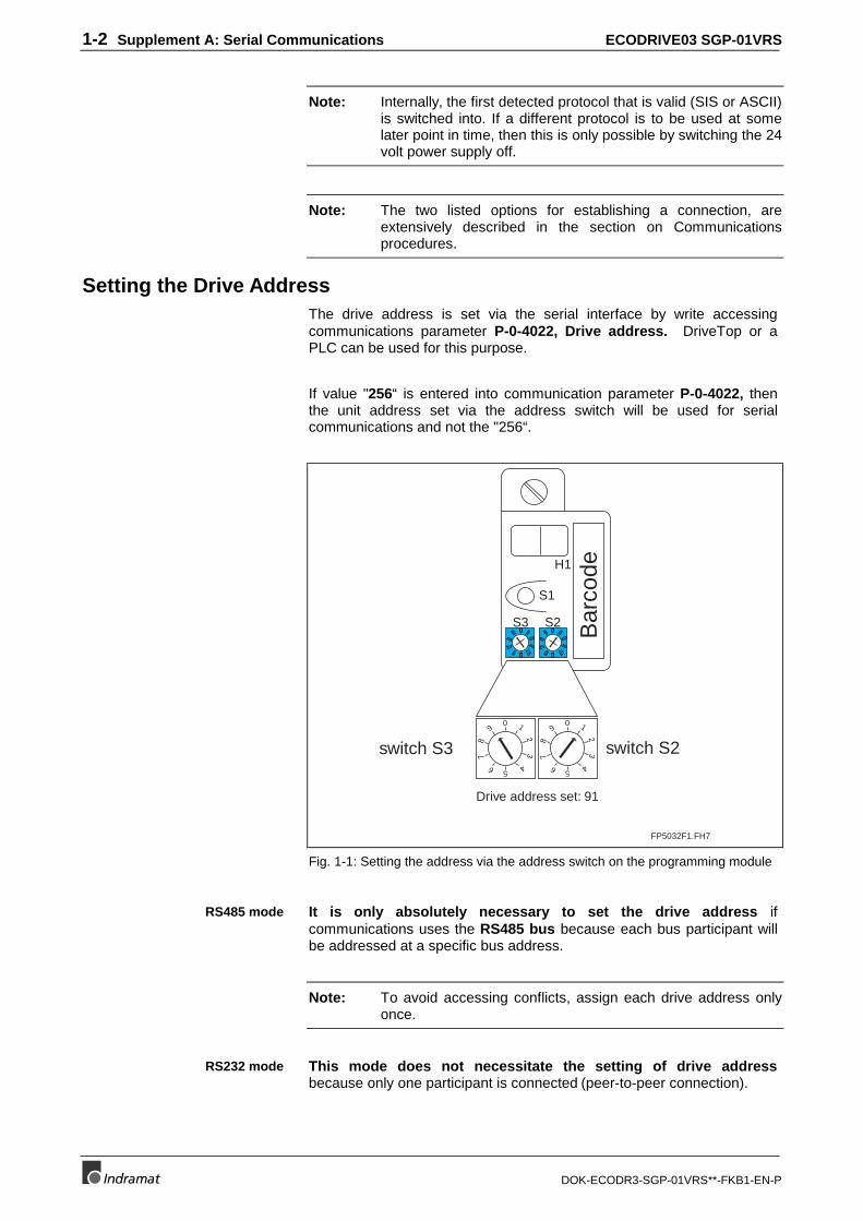
1-2 Supplement A: Serial Communications ECODRIVE03 SGP-01VRS
DOK-ECODR3-SGP-01VRS**-FKB1-EN-P
Note: Internally, the first detected protocol that is valid (SIS or ASCII)is switched into. If a different protocol is to be used at somelater point in time, then this is only possible by switching the 24volt power supply off.
Note: The two listed options for establishing a connection, areextensively described in the section on Communicationsprocedures.
Setting the Drive AddressThe drive address is set via the serial interface by write accessingcommunications parameter P-0-4022, Drive address. DriveTop or aPLC can be used for this purpose.
If value "256“ is entered into communication parameter P-0-4022, thenthe unit address set via the address switch will be used for serialcommunications and not the "256“.
FP5032F1.FH7
switch S3 switch S2
Bar
code
0 1
23
456
78
90 1
23
456
78
9
H1
S1
S3 S2
Drive address set: 91
0 1
23
456
78
90 1
23
456
78
9
Fig. 1-1: Setting the address via the address switch on the programming module
It is only absolutely necessary to set the drive address ifcommunications uses the RS485 bus because each bus participant willbe addressed at a specific bus address.
Note: To avoid accessing conflicts, assign each drive address onlyonce.
This mode does not necessitate the setting of drive addressbecause only one participant is connected (peer-to-peer connection).
RS485 mode
RS232 mode
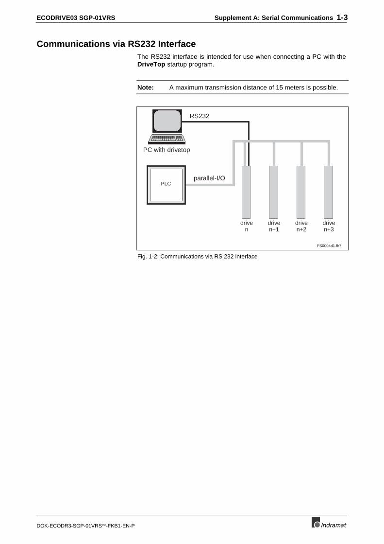
ECODRIVE03 SGP-01VRS Supplement A: Serial Communications 1-3
DOK-ECODR3-SGP-01VRS**-FKB1-EN-P
Communications via RS232 InterfaceThe RS232 interface is intended for use when connecting a PC with theDriveTop startup program.
Note: A maximum transmission distance of 15 meters is possible.
PC with drivetop
RS232
parallel-I/O
FS0004d1.fh7
PLC
driven
driven+1
driven+2
driven+3
Fig. 1-2: Communications via RS 232 interface
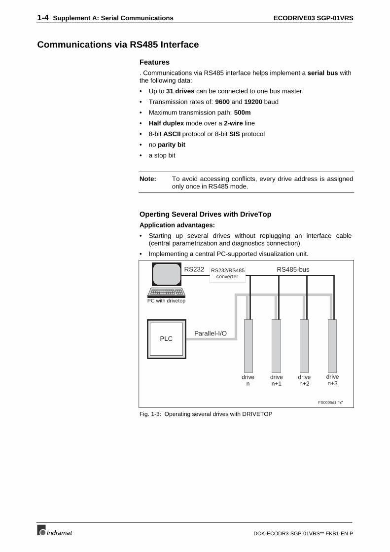
1-4 Supplement A: Serial Communications ECODRIVE03 SGP-01VRS
DOK-ECODR3-SGP-01VRS**-FKB1-EN-P
Communications via RS485 Interface
Features. Communications via RS485 interface helps implement a serial bus withthe following data:
• Up to 31 drives can be connected to one bus master.
• Transmission rates of: 9600 and 19200 baud
• Maximum transmission path: 500m
• Half duplex mode over a 2-wire line
• 8-bit ASCII protocol or 8-bit SIS protocol
• no parity bit
• a stop bit
Note: To avoid accessing conflicts, every drive address is assignedonly once in RS485 mode.
Operting Several Drives with DriveTopApplication advantages:
• Starting up several drives without replugging an interface cable(central parametrization and diagnostics connection).
• Implementing a central PC-supported visualization unit.
PC with drivetop
RS232
Parallel-I/O
FS0005d1.fh7
PLC
RS232/RS485converter
RS485-bus
driven
driven+1
driven+2
driven+3
Fig. 1-3: Operating several drives with DRIVETOP
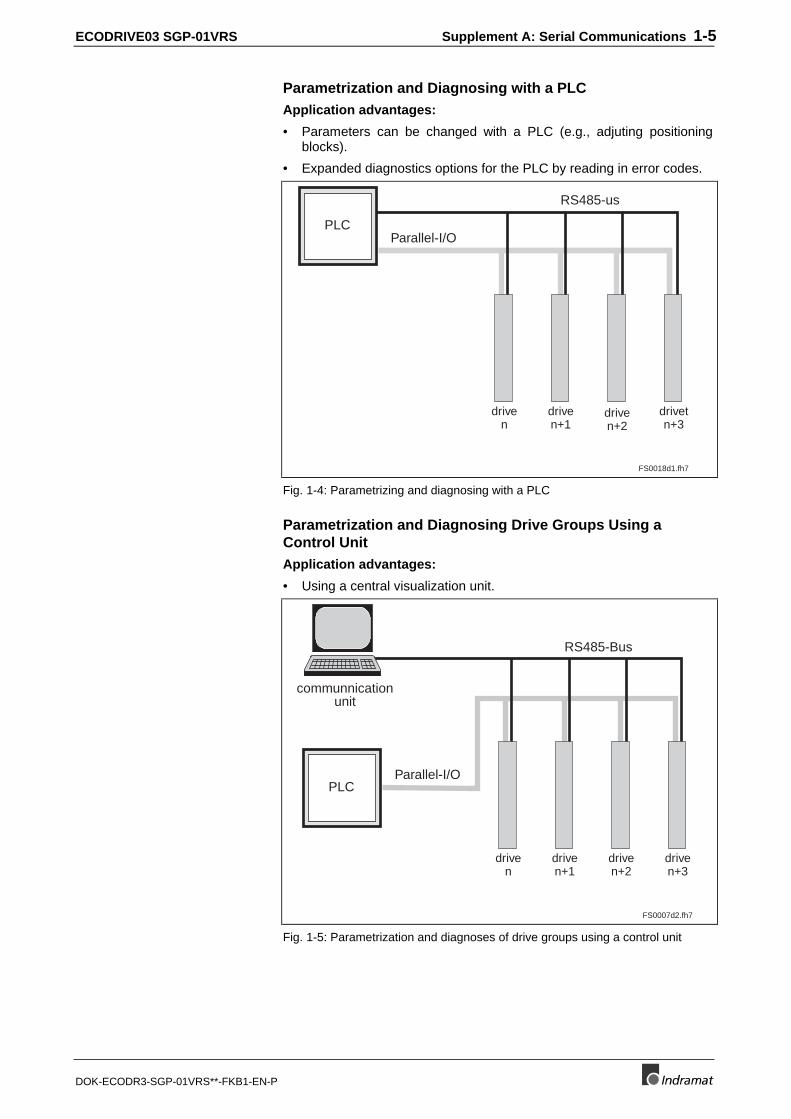
ECODRIVE03 SGP-01VRS Supplement A: Serial Communications 1-5
DOK-ECODR3-SGP-01VRS**-FKB1-EN-P
Parametrization and Diagnosing with a PLCApplication advantages:
• Parameters can be changed with a PLC (e.g., adjuting positioningblocks).
• Expanded diagnostics options for the PLC by reading in error codes.
FS0018d1.fh7
Parallel-I/OPLC
RS485-us
driven
driven+1
driven+2
drivetn+3
Fig. 1-4: Parametrizing and diagnosing with a PLC
Parametrization and Diagnosing Drive Groups Using aControl UnitApplication advantages:
• Using a central visualization unit.
FS0007d2.fh7
Parallel-I/OPLC
RS485-Bus
communnicationunit
driven
driven+1
driven+2
driven+3
Fig. 1-5: Parametrization and diagnoses of drive groups using a control unit
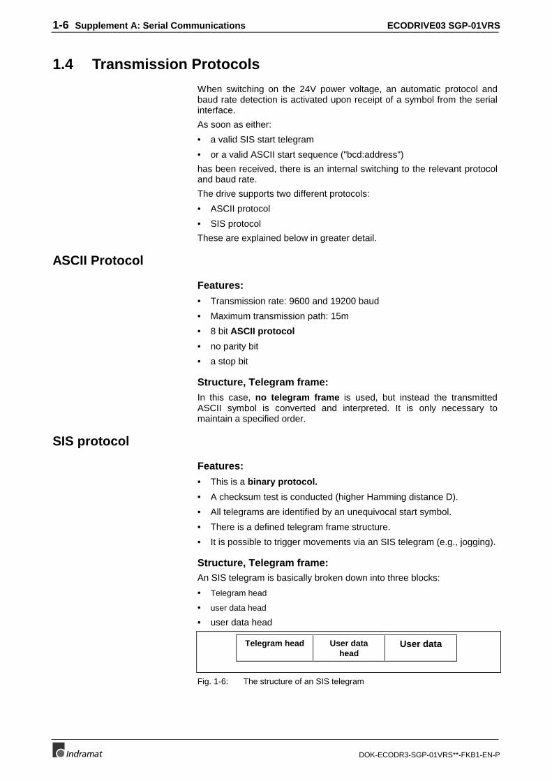
1-6 Supplement A: Serial Communications ECODRIVE03 SGP-01VRS
DOK-ECODR3-SGP-01VRS**-FKB1-EN-P
1.4 Transmission Protocols
When switching on the 24V power voltage, an automatic protocol andbaud rate detection is activated upon receipt of a symbol from the serialinterface.
As soon as either:
• a valid SIS start telegram
• or a valid ASCII start sequence ("bcd:address")
has been received, there is an internal switching to the relevant protocoland baud rate.
The drive supports two different protocols:
• ASCII protocol
• SIS protocol
These are explained below in greater detail.
ASCII Protocol
Features:
• Transmission rate: 9600 and 19200 baud
• Maximum transmission path: 15m
• 8 bit ASCII protocol
• no parity bit
• a stop bit
Structure, Telegram frame:In this case, no telegram frame is used, but instead the transmittedASCII symbol is converted and interpreted. It is only necessary tomaintain a specified order.
SIS protocol
Features:
• This is a binary protocol.
• A checksum test is conducted (higher Hamming distance D).
• All telegrams are identified by an unequivocal start symbol.
• There is a defined telegram frame structure.
• It is possible to trigger movements via an SIS telegram (e.g., jogging).
Structure, Telegram frame:An SIS telegram is basically broken down into three blocks:
• Telegram head
• user data head
• user data head
Telegram head User datahead
User data
Fig. 1-6: The structure of an SIS telegram
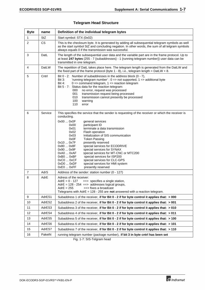
ECODRIVE03 SGP-01VRS Supplement A: Serial Communications 1-7
DOK-ECODR3-SGP-01VRS**-FKB1-EN-P
Telegram Head Structure
Byte name Definition of the individual telegram bytes
1 StZ Start symbol: STX (0x02)
2 CS This is the checksum byte. It is generated by adding all subsequential telegram symbols as wellas the start symbol StZ and concluding negation. In other words, the sum of all telgram symbolsalways equals 0 if the transmission was successful.
3 DatL The length of the subsequential user data and the variable part are in the frame protocol. Up toat least 247 bytes (255 - 7 {subaddresses} - 1 {running telegram number}) user data can betransmitted in one telegram.
4 DatLW The repetition of DatL takes place here. The telegram length is generated from the DatLW andthe fixed part of the frame protocol (byte 1 - 8), i.e., telegram length = DatLW + 8.
5 Cntrl Bit 0 - 2: Number of subaddresses in the address block (0 - 7),Bit 3: ’running telegram number’ : 0 => not supported, 1 => additional byteBit 4: 0 => command telegram, 1 => reaction telegramBit 5 - 7: Status data for the reaction telegram: 000 no error, request was processed 001 transmission request being processed 010 transmission cannot presently be processed 100 warning 110 error
6 Service This specifies the service that the sender is requesting of the receiver or which the receiver isconducting.
0x00 ... 0x0F general services 0x00 participant ID 0x01 terminate a data transmission 0x02 Flash operation 0x03 Initialization of SIS communication 0x0F Token Passing0x10 ... 0x7F presently reserved0x80 ... 0x8F special services for ECODRIVE0x90 ... 0x9F special services for SYNAX0xA0 ... 0xAF special services for MT-CNC or MTC2000xB0 ... 0xBF special services for ISP2000xC0 ... 0xCF special services for CLC-GPS0xD0 ... 0xDF special services for HMI system0xE0 ... 0xFF presently reserved
7 AdrS Address of the sender: station number (0 - 127)
8 AdrE Adress of the receiver:AdrE = 0 - 127 ==> specifies a single station,AdrE = 128 - 254 ==> addresses logical groups,AdrE = 255 ==> fixes a broadcastTelegrams with AdrE = 128 - 255 are not answered with a reaction telegram.
9 AdrES1 Subaddress 1 of the receiver, if for Bit 0 - 2 if for byte control it applies that: > 000
10 AdrES2 Subaddress 2 of the receiver, if for Bit 0 - 2 if for byte control it applies that: > 001
11 AdrES3 Subaddress 3 of the receiver, if for Bit 0 - 2 if for byte control it applies that: > 010
12 AdrES4 Subaddress 4 of the receiver, if for Bit 0 - 2 if for byte control it applies that: > 011
13 AdrES5 Subaddress 5 of the receiver, if for Bit 0 - 2 if for byte control it applies that: > 100
14 AdrES6 Subaddress 6 of the receiver, if for Bit 0 - 2 if for byte control it applies that: > 101
15 AdrES7 Subaddress 7 of the receiver, if for Bit 0 - 2 if for byte control it applies that: > 110
16 PaketN running telegram number (package number), if bit 3 in byte cntrl has been setFig. 1-7: SIS-Telgram head
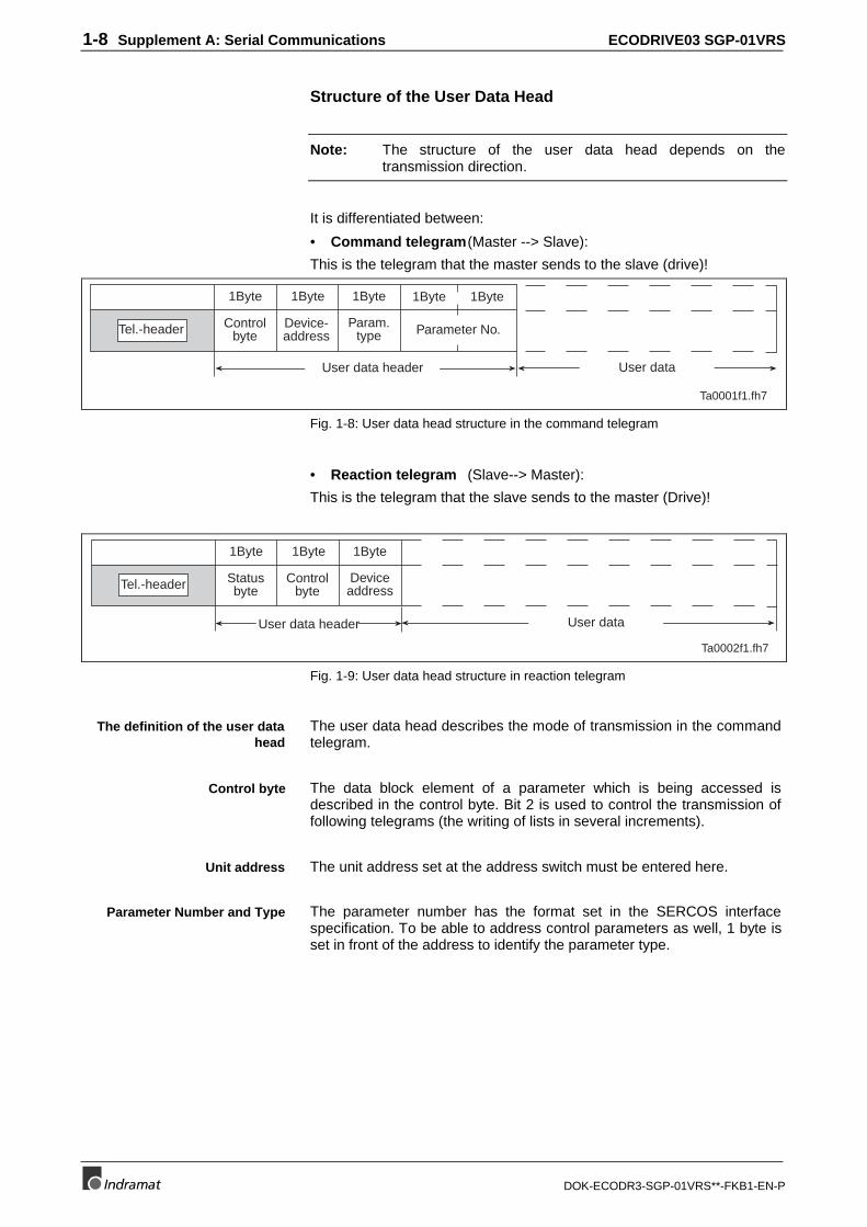
1-8 Supplement A: Serial Communications ECODRIVE03 SGP-01VRS
DOK-ECODR3-SGP-01VRS**-FKB1-EN-P
Structure of the User Data Head
Note: The structure of the user data head depends on thetransmission direction.
It is differentiated between:
• Command telegram(Master --> Slave):
This is the telegram that the master sends to the slave (drive)!
Tel.-header Controlbyte
Device-address
Param.type Parameter No.
User data header User data
1Byte 1Byte 1Byte 1Byte 1Byte
Ta0001f1.fh7
Fig. 1-8: User data head structure in the command telegram
• Reaction telegram (Slave--> Master):
This is the telegram that the slave sends to the master (Drive)!
Ta0002f1.fh7
User data
Tel.-header Statusbyte
Controlbyte
Deviceaddress
User data header
1Byte 1Byte 1Byte
Fig. 1-9: User data head structure in reaction telegram
The user data head describes the mode of transmission in the commandtelegram.
The data block element of a parameter which is being accessed isdescribed in the control byte. Bit 2 is used to control the transmission offollowing telegrams (the writing of lists in several increments).
The unit address set at the address switch must be entered here.
The parameter number has the format set in the SERCOS interfacespecification. To be able to address control parameters as well, 1 byte isset in front of the address to identify the parameter type.
The definition of the user datahead
Control byte
Unit address
Parameter Number and Type
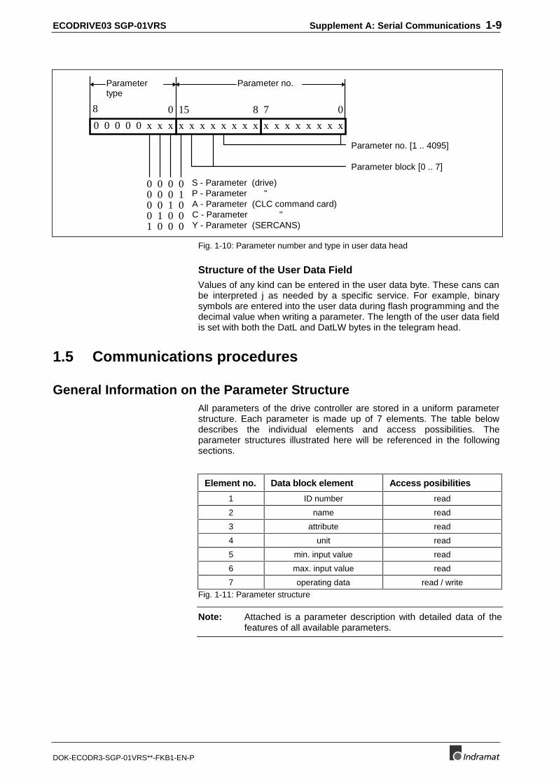
ECODRIVE03 SGP-01VRS Supplement A: Serial Communications 1-9
DOK-ECODR3-SGP-01VRS**-FKB1-EN-P
x x x x x x x x
7 0
Parameter no. [1 .. 4095]
x x x x x x x x
15 8
Parameter block [0 .. 7]
S - Parameter (drive)P - Parameter "
01
0 0 0 0 x x x
8 0
0 0 0000
0 0 1 0 A - Parameter (CLC command card)
0
0 1 0 0 C - Parameter "1 0 0 0 Y - Parameter (SERCANS)
Parameter no.Parametertype
Fig. 1-10: Parameter number and type in user data head
Structure of the User Data FieldValues of any kind can be entered in the user data byte. These cans canbe interpreted j as needed by a specific service. For example, binarysymbols are entered into the user data during flash programming and thedecimal value when writing a parameter. The length of the user data fieldis set with both the DatL and DatLW bytes in the telegram head.
1.5 Communications procedures
General Information on the Parameter StructureAll parameters of the drive controller are stored in a uniform parameterstructure. Each parameter is made up of 7 elements. The table belowdescribes the individual elements and access possibilities. Theparameter structures illustrated here will be referenced in the followingsections.
Element no. Data block element Access posibilities
1 ID number read
2 name read
3 attribute read
4 unit read
5 min. input value read
6 max. input value read
7 operating data read / writeFig. 1-11: Parameter structure
Note: Attached is a parameter description with detailed data of thefeatures of all available parameters.
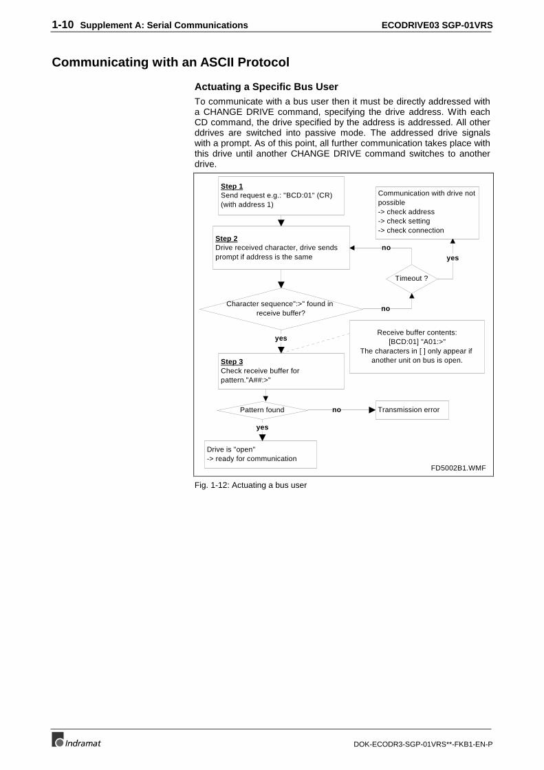
1-10 Supplement A: Serial Communications ECODRIVE03 SGP-01VRS
DOK-ECODR3-SGP-01VRS**-FKB1-EN-P
Communicating with an ASCII Protocol
Actuating a Specific Bus UserTo communicate with a bus user then it must be directly addressed witha CHANGE DRIVE command, specifying the drive address. With eachCD command, the drive specified by the address is addressed. All otherddrives are switched into passive mode. The addressed drive signalswith a prompt. As of this point, all further communication takes place withthis drive until another CHANGE DRIVE command switches to anotherdrive.
Step 1Send request e.g.: "BCD:01" (CR) (with address 1)
Step 2Drive received character, drive sends prompt if address is the same
Character sequence":>" found in receive buffer?
Pattern found Transmission error
Drive is "open"-> ready for communication
Step 3Check receive buffer for pattern."A##:>"
yes
yes
no
Receive buffer contents:[BCD:01] "A01:>"
The characters in [ ] only appear if another unit on bus is open.
Timeout ?
no
no
Communication with drive not possible-> check address-> check setting-> check connection
yes
FD5002B1.WMF
Fig. 1-12: Actuating a bus user
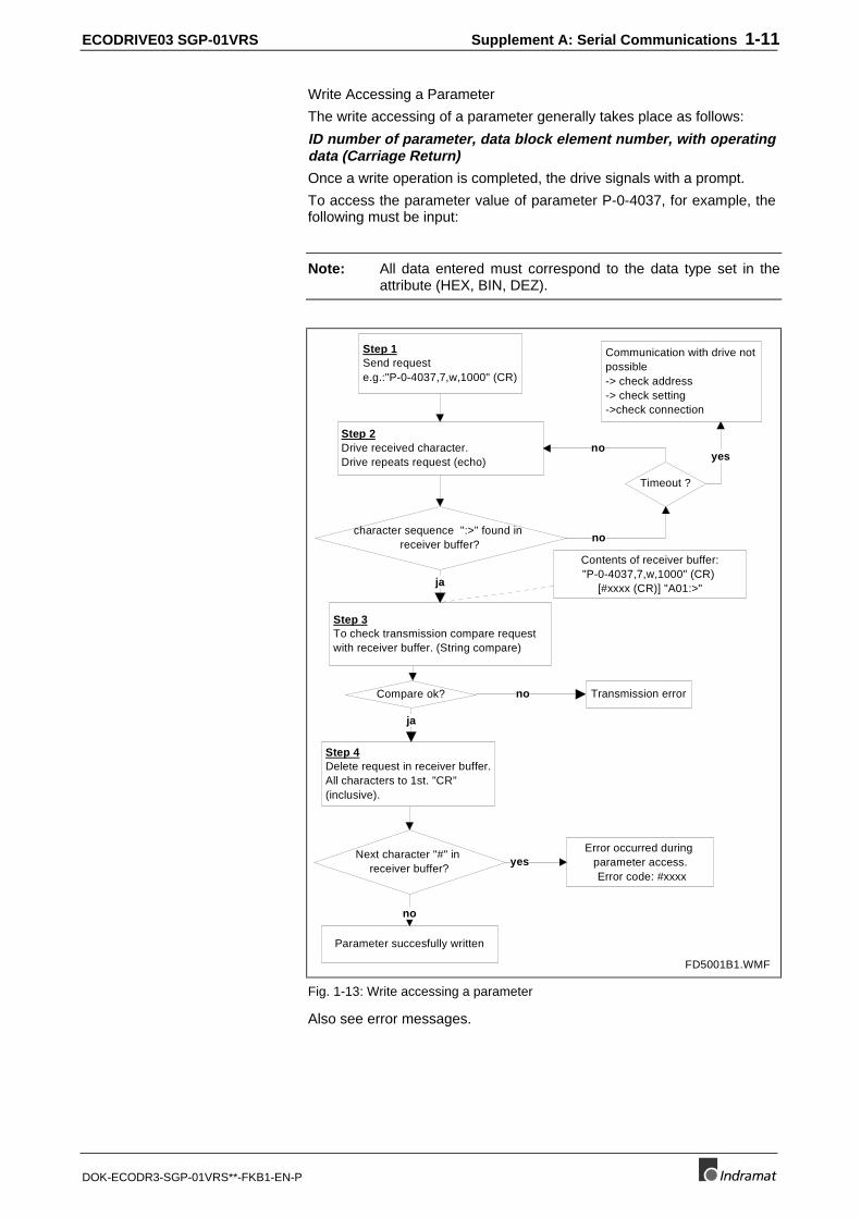
ECODRIVE03 SGP-01VRS Supplement A: Serial Communications 1-11
DOK-ECODR3-SGP-01VRS**-FKB1-EN-P
Write Accessing a Parameter
The write accessing of a parameter generally takes place as follows:
ID number of parameter, data block element number, with operatingdata (Carriage Return)
Once a write operation is completed, the drive signals with a prompt.
To access the parameter value of parameter P-0-4037, for example, thefollowing must be input:
Note: All data entered must correspond to the data type set in theattribute (HEX, BIN, DEZ).
Step 1Send request e.g.:"P-0-4037,7,w,1000" (CR)
Step 2Drive received character.Drive repeats request (echo)
character sequence ":>" found in receiver buffer?
Compare ok? Transmission error
Step 4 Delete request in receiver buffer. All characters to 1st. "CR" (inclusive).
Step 3To check transmission compare request with receiver buffer. (String compare)
ja
ja
no
Next character "#" in receiver buffer?
Parameter succesfully written
no
yes
Contents of receiver buffer:"P-0-4037,7,w,1000" (CR)
[#xxxx (CR)] "A01:>"
Error occurred during parameter access. Error code: #xxxx
Communication with drive not possible-> check address-> check setting->check connection
Timeout ?
no
no
yes
FD5001B1.WMF
Fig. 1-13: Write accessing a parameter
Also see error messages.
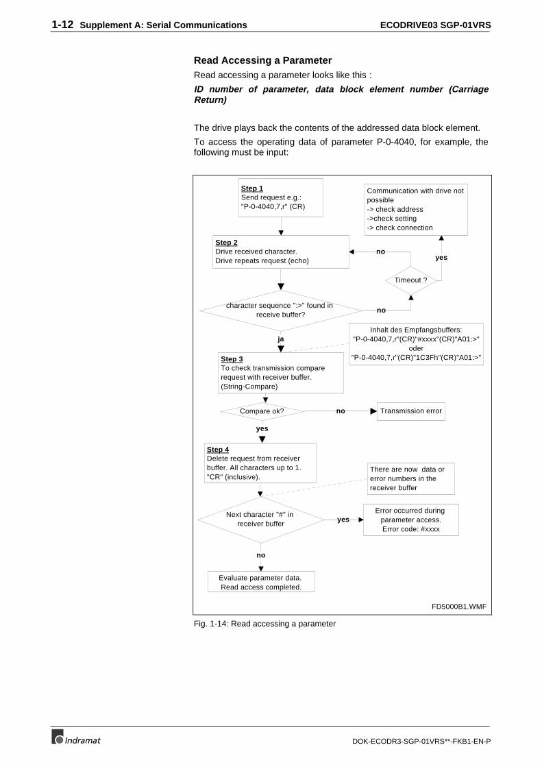
1-12 Supplement A: Serial Communications ECODRIVE03 SGP-01VRS
DOK-ECODR3-SGP-01VRS**-FKB1-EN-P
Read Accessing a ParameterRead accessing a parameter looks like this :
ID number of parameter, data block element number (CarriageReturn)
The drive plays back the contents of the addressed data block element.
To access the operating data of parameter P-0-4040, for example, thefollowing must be input:
Step 1Send request e.g.: "P-0-4040,7,r" (CR)
Step 2Drive received character.Drive repeats request (echo)
character sequence ":>" found in receive buffer?
Compare ok? Transmission error
Step 4 Delete request from receiver buffer. All characters up to 1. "CR" (inclusive).
There are now data or error numbers in the receiver buffer
Step 3To check transmission compare request with receiver buffer. (String-Compare)
ja
yes
no
Next character "#" in receiver buffer
Evaluate parameter data. Read access completed.
no
Inhalt des Empfangsbuffers:"P-0-4040,7,r"(CR)"#xxxx"(CR)"A01:>"
oder"P-0-4040,7,r"(CR)"1C3Fh"(CR)"A01:>"
Timeout ?
Communication with drive not possible-> check address->check setting-> check connection
no
no
yes
FD5000B1.WMF
Error occurred during parameter access.Error code: #xxxx
yes
Fig. 1-14: Read accessing a parameter
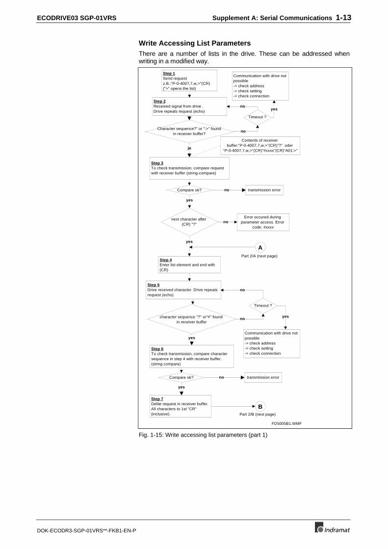
ECODRIVE03 SGP-01VRS Supplement A: Serial Communications 1-13
DOK-ECODR3-SGP-01VRS**-FKB1-EN-P
Write Accessing List ParametersThere are a number of lists in the drive. These can be addressed whenwriting in a modified way.
Step 1Send request z.B.:"P-0-4007,7,w,>"(CR) (">" opens the list)
Step 2Received signal from drive .Drive repeats request (echo)
Character sequence?" or ":>" found in receiver buffer?
Compare ok? transmission error
Step 4 Enter list element and end with (CR)
Step 3To check transmission, compare request with receiver buffer (string-compare)
ja
no
Contents of receiver buffer:"P-0-4007,7,w,>"(CR)"?" oder
"P-0-4007,7,w,>"(CR)"#xxxx"(CR)"A01:>"
Communication with drive not possible-> check address-> check setting-> check connection
Timeout ?
no
no
yes
Step 5Drive received character. Drive repeats request (echo)
character sequence "?" or"#" found in receiver buffer
Compare ok? transmission error
Step 7 Delite request in receiver buffer. All characters to 1st "CR" (inclusive).
Step 6To check transmission, compare character sequence in step 4 with receiver buffer. (string compare)
yes
yes
no
Timeout ?
Communication with drive not possible-> check address-> check setting-> check connection
no
yes
FD5005B1.WMF
next character after (CR) "?"
Error occured during parameter access. Error
code: #xxxxno
yes
yes
A
B
Part 2/A (next page)
Part 2/B (next page)
no
Fig. 1-15: Write accessing list parameters (part 1)
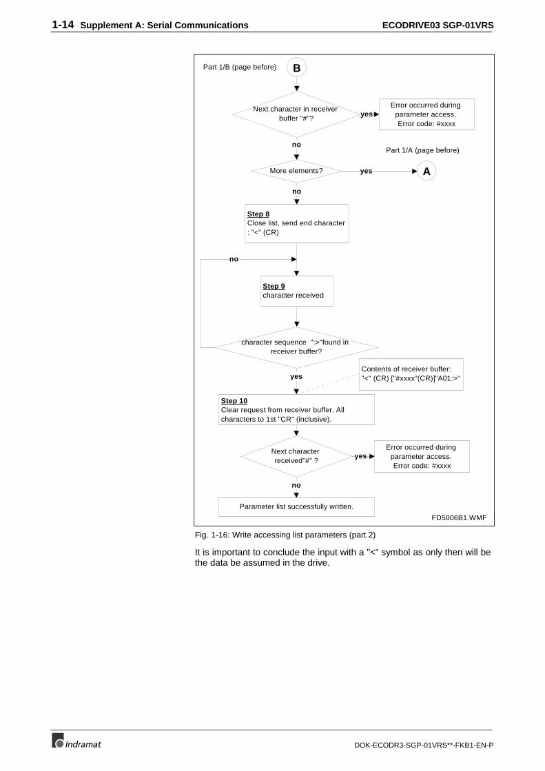
1-14 Supplement A: Serial Communications ECODRIVE03 SGP-01VRS
DOK-ECODR3-SGP-01VRS**-FKB1-EN-P
Step 8Close list, send end character : "<" (CR)
Step 9character received
character sequence ":>"found in receiver buffer?
Step 10 Clear request from receiver buffer. All characters to 1st "CR" (inclusive).
Next character received"#" ?
Parameter list successfully written.
yes
no
no
B
FD5006B1.WMF
Part 1/B (page before)
Error occurred during parameter access. Error code: #xxxx
yes
Next character in receiver buffer "#"?
AMore elements?
Part 1/A (page before)no
Error occurred during parameter access. Error code: #xxxx
yes
no
yes
Contents of receiver buffer: "<" (CR) ["#xxxx"(CR)]"A01:>"
Fig. 1-16: Write accessing list parameters (part 2)
It is important to conclude the input with a "<" symbol as only then will bethe data be assumed in the drive.
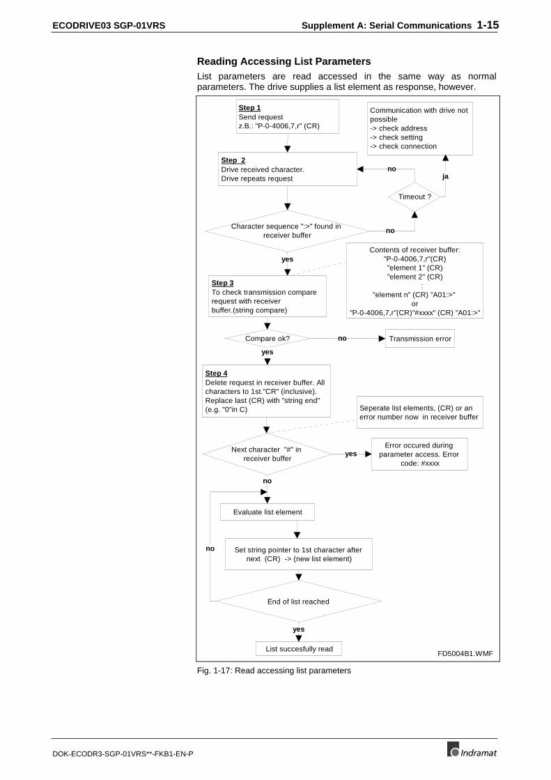
ECODRIVE03 SGP-01VRS Supplement A: Serial Communications 1-15
DOK-ECODR3-SGP-01VRS**-FKB1-EN-P
Reading Accessing List ParametersList parameters are read accessed in the same way as normalparameters. The drive supplies a list element as response, however.
Step 1 Send request z.B.: "P-0-4006,7,r" (CR)
Step 2 Drive received character. Drive repeats request
Character sequence ":>" found in receiver buffer
Compare ok? Transmission error
Step 4 Delete request in receiver buffer. All characters to 1st."CR" (inclusive). Replace last (CR) with "string end" (e.g. "0"in C) Seperate list elements, (CR) or an
error number now in receiver buffer
Step 3 To check transmission compare request with receiver buffer.(string compare)
yes
no
Next character "#" in receiver buffer
Evaluate list element
Contents of receiver buffer: "P-0-4006,7,r"(CR) "element 1" (CR) "element 2" (CR)
: "element n" (CR) "A01:>"
or "P-0-4006,7,r"(CR)"#xxxx" (CR) "A01:>"
End of list reached
Set string pointer to 1st character after next (CR) -> (new list element)
no
List succesfully read
yes
Timeout ?
Communication with drive not possible -> check address -> check setting -> check connection
no
no
ja
FD5004B1.WMF
Error occured during parameter access. Error
code: #xxxx
no
yes
yes
Fig. 1-17: Read accessing list parameters
1-16 Supplement A: Serial Communications ECODRIVE03 SGP-01VRS
DOK-ECODR3-SGP-01VRS**-FKB1-EN-P
Starting a CommandNumerous commands can be conducted in the drive controller .Command execution takes place automatically in the drive. There arecommands for:
• Switching between operating and parametrization modes:S-0-0127, C100 Communication phase 3 transition checkS-0-0128, C200 Communication phase 4 transition checkP-0-4023, C400 Communication phase 2 transition
• S-0-0262, C700 Command basic load
• S-0-0099, C500 Reset class 1 diagnostic
• S-0-0148, C600 Drive controlled homing procedure command
• P-0-0012, C300 Command ’Set absolute measurement
• P-0-4032, C3 Command set emulation absolute value
A command can be started, terminated and completed via the serialinterface. The status of command execution can also be read.
A command is triggered as follows:
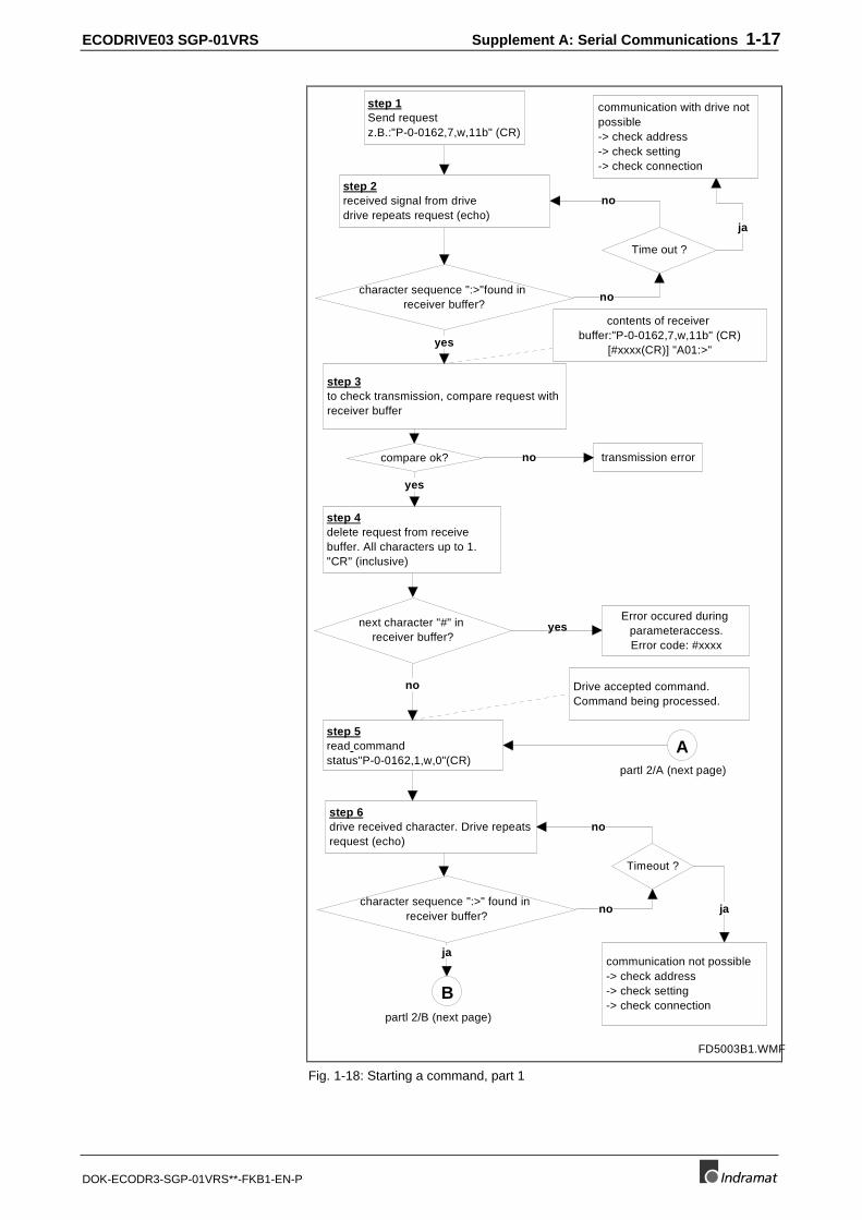
ECODRIVE03 SGP-01VRS Supplement A: Serial Communications 1-17
DOK-ECODR3-SGP-01VRS**-FKB1-EN-P
step 1 Send request z.B.:"P-0-0162,7,w,11b" (CR)
step 2 received signal from drive drive repeats request (echo)
character sequence ":>"found in receiver buffer?
compare ok? transmission error
step 4 delete request from receive buffer. All characters up to 1. "CR" (inclusive)
step 3 to check transmission, compare request with receiver buffer
yes
yes
no
next character "#" in receiver buffer?
Drive accepted command. Command being processed.
contents of receiver buffer:"P-0-0162,7,w,11b" (CR)
[#xxxx(CR)] "A01:>"
communication with drive not possible -> check address -> check setting -> check connection
Time out ?
no
no
ja
FD5003B1.WMF
Error occured during parameteraccess. Error code: #xxxx
yes
step 6 drive received character. Drive repeats request (echo)
character sequence ":>" found in receiver buffer?
communication not possible -> check address -> check setting -> check connection
Timeout ?
no
no
step 5 read command status"P-0-0162,1,w,0"(CR)
Bpartl 2/B (next page)
Apartl 2/A (next page)
ja
no
ja
Fig. 1-18: Starting a command, part 1
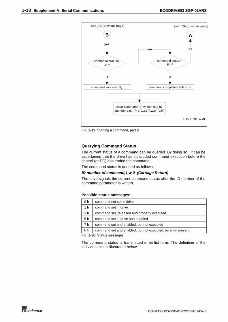
1-18 Supplement A: Serial Communications ECODRIVE03 SGP-01VRS
DOK-ECODR3-SGP-01VRS**-FKB1-EN-P
command status= 3h ?
command status= Fh ?
command completed with errorcommand successfully
no
ja ja
clear command:"0" written into ID number e.g.: "P-0-0162,7,w,0" (CR)
FD5007B1.WMF
B
part 1/B (previous page)
yes
A
partl 1/A (previous page)
no
Fig. 1-19: Starting a command, part 2
Querying Command StatusThe current status of a command can be queried. By doing so, it can beascertained that the drive has concluded command execution before thecontrol (or PC) has ended the command.
The command status is queried as follows:
ID number of command,1,w,0 (Carriage Return)
The drive signals the current command status after the ID number of thecommand parameter is written.
Possible status messages:
0 h command not set in drive
1 h command set in drive
3 h command set, released and properly executed
5 h command set in drive and enabled
7 h command set and enabled, but not executed
F h command set and enabled, but not executed, as error presentFig. 1-20: Status messages
The command status is transmitted in bit list form. The definition of theindividual bits is illustrated below.
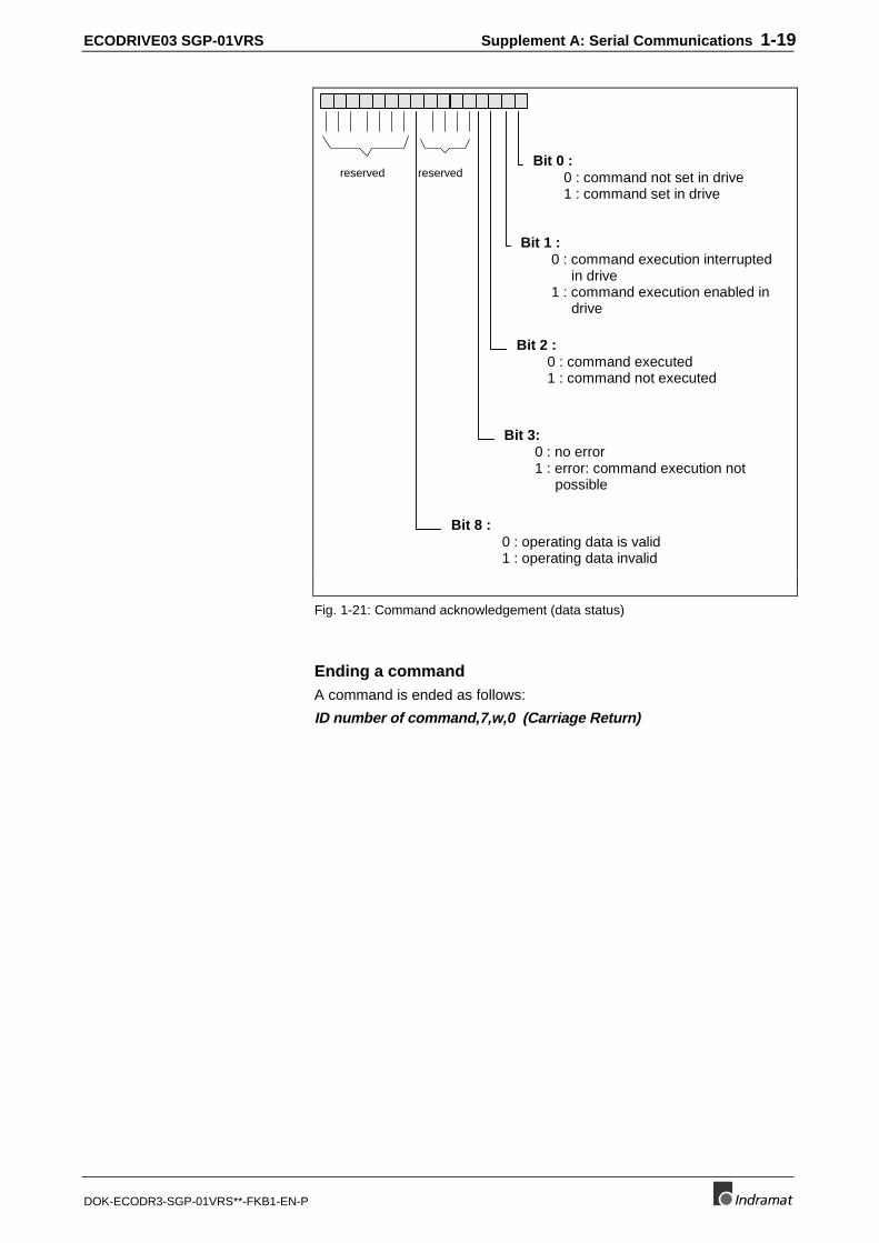
ECODRIVE03 SGP-01VRS Supplement A: Serial Communications 1-19
DOK-ECODR3-SGP-01VRS**-FKB1-EN-P
Bit 2 :0 : command executed1 : command not executed
Bit 8 :0 : operating data is valid1 : operating data invalid
Bit 3:0 : no error1 : error: command execution not
possible
Bit 1 :0 : command execution interrupted
in drive1 : command execution enabled in
drive
Bit 0 :0 : command not set in drive1 : command set in drive
reserved reserved
Fig. 1-21: Command acknowledgement (data status)
Ending a commandA command is ended as follows:
ID number of command,7,w,0 (Carriage Return)
1-20 Supplement A: Serial Communications ECODRIVE03 SGP-01VRS
DOK-ECODR3-SGP-01VRS**-FKB1-EN-P
Communicating with the SIS protocol
Actuating a Drive via an SIS protocolWhen communicating with SISprotocols, a difference is made betweencomand telegram and reaction telegramm depending on transmissiondirection. A user can only be addressed if a specific telegram format(frame) is maintained at his address (see programming module).
Note: To be able to communicate with the drive via SIS telegrams,an initialization telegram must first be sent to the drive (e.g.,service 0x00 identifying all users). Only after the drive hasreceived at least a valid SIS telegram is the SIS channel freefor further communications.
The individual access modes are described briefly below before theindividual services are explained.
If a command telegram is used to start a read of a parameter, then thedrive checks whether a following telegram is needed. In this case, thereaction telegram in the control byte is retained in
Bit 2 (running / final transmission) at "0“ until the final reaction telegramis sent. Bit 2 is set to 1 herein.
The transmission of a following reaction telegram is triggered by therenewed transmission of an unchanged command telegram.
If write or read of a parameter is started in the drive with a followingtelegram, then this must be concluded of terminated before a differentservice can be started. If a different service was started anyway, thenerror code 0x800C "unallowed access “ is sent in the reaction telegram.The previously started service with following telegrams can then beprocessed as usual in the next command telegram, or terminated.
A difference is made between
• general and
• special services.
Service 0x00 Identifying all users
• Enter 0x00 in telegram heads.
• enter 0x80 of the drive in the group designation of the user data
• Enter the version number of the drive in the user data. It containsinformation about the drive single-axis and fieldbus software enteredin the drive as well as the hardware used.
General information about readaccessing
General information forfollowing telegram accessing
Command telegram
Reaction telegram
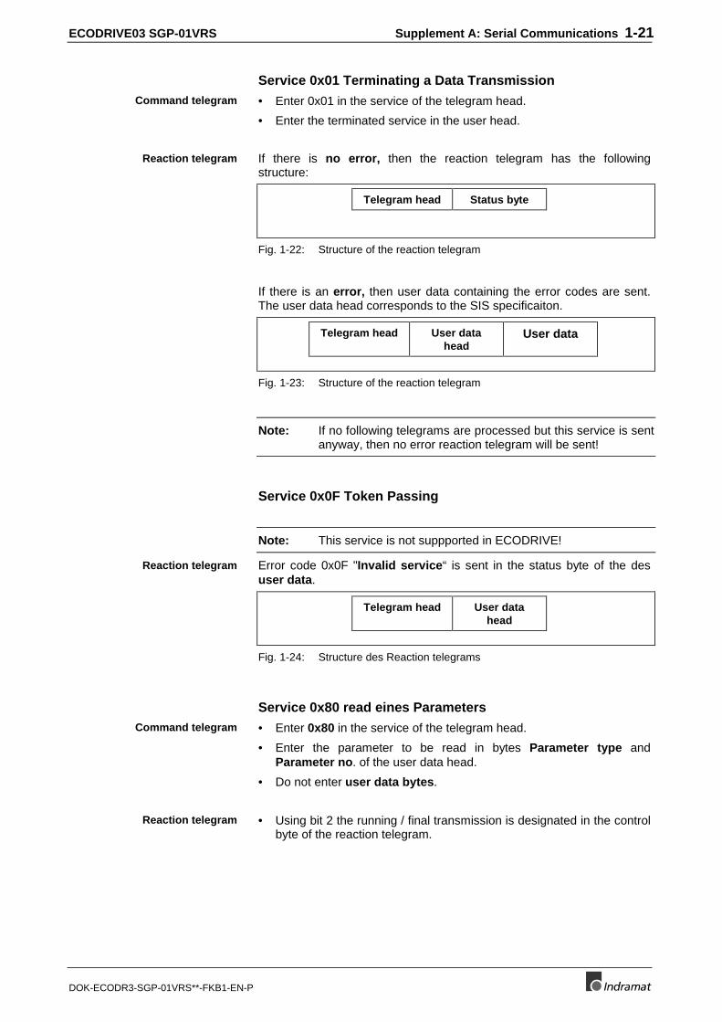
ECODRIVE03 SGP-01VRS Supplement A: Serial Communications 1-21
DOK-ECODR3-SGP-01VRS**-FKB1-EN-P
Service 0x01 Terminating a Data Transmission
• Enter 0x01 in the service of the telegram head.
• Enter the terminated service in the user head.
If there is no error, then the reaction telegram has the followingstructure:
Telegram head Status byte
Fig. 1-22: Structure of the reaction telegram
If there is an error, then user data containing the error codes are sent.The user data head corresponds to the SIS specificaiton.
Telegram head User datahead
User data
Fig. 1-23: Structure of the reaction telegram
Note: If no following telegrams are processed but this service is sentanyway, then no error reaction telegram will be sent!
Service 0x0F Token Passing
Note: This service is not suppported in ECODRIVE!
Error code 0x0F "Invalid service“ is sent in the status byte of the desuser data.
Telegram head User datahead
Fig. 1-24: Structure des Reaction telegrams
Service 0x80 read eines Parameters
• Enter 0x80 in the service of the telegram head.
• Enter the parameter to be read in bytes Parameter type andParameter no. of the user data head.
• Do not enter user data bytes.
• Using bit 2 the running / final transmission is designated in the controlbyte of the reaction telegram.
Command telegram
Reaction telegram
Reaction telegram
Command telegram
Reaction telegram
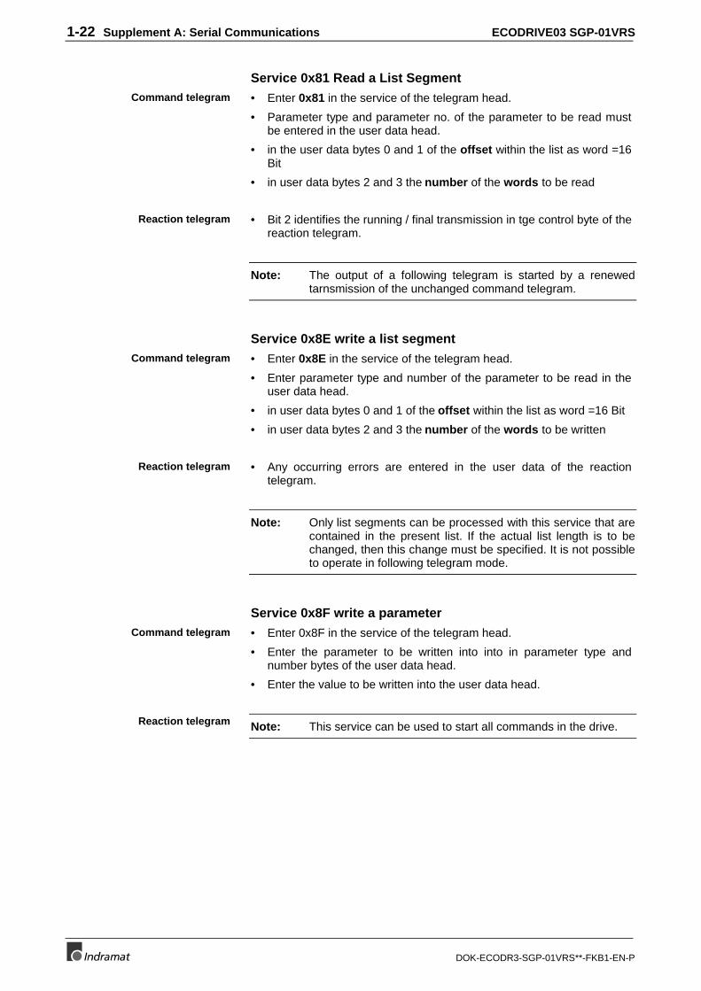
1-22 Supplement A: Serial Communications ECODRIVE03 SGP-01VRS
DOK-ECODR3-SGP-01VRS**-FKB1-EN-P
Service 0x81 Read a List Segment
• Enter 0x81 in the service of the telegram head.
• Parameter type and parameter no. of the parameter to be read mustbe entered in the user data head.
• in the user data bytes 0 and 1 of the offset within the list as word =16Bit
• in user data bytes 2 and 3 the number of the words to be read
• Bit 2 identifies the running / final transmission in tge control byte of thereaction telegram.
Note: The output of a following telegram is started by a renewedtarnsmission of the unchanged command telegram.
Service 0x8E write a list segment
• Enter 0x8E in the service of the telegram head.
• Enter parameter type and number of the parameter to be read in theuser data head.
• in user data bytes 0 and 1 of the offset within the list as word =16 Bit
• in user data bytes 2 and 3 the number of the words to be written
• Any occurring errors are entered in the user data of the reactiontelegram.
Note: Only list segments can be processed with this service that arecontained in the present list. If the actual list length is to bechanged, then this change must be specified. It is not possibleto operate in following telegram mode.
Service 0x8F write a parameter
• Enter 0x8F in the service of the telegram head.
• Enter the parameter to be written into into in parameter type andnumber bytes of the user data head.
• Enter the value to be written into the user data head.
Note: This service can be used to start all commands in the drive.
Command telegram
Reaction telegram
Command telegram
Reaction telegram
Command telegram
Reaction telegram
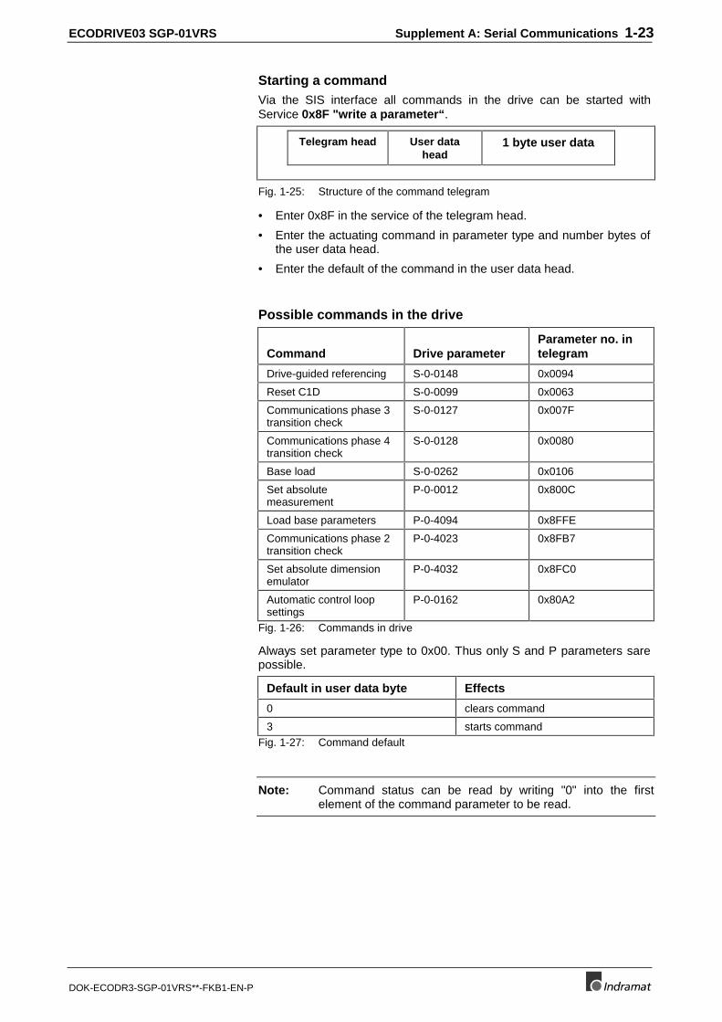
ECODRIVE03 SGP-01VRS Supplement A: Serial Communications 1-23
DOK-ECODR3-SGP-01VRS**-FKB1-EN-P
Starting a commandVia the SIS interface all commands in the drive can be started withService 0x8F "write a parameter“ .
Telegram head User datahead
1 byte user data
Fig. 1-25: Structure of the command telegram
• Enter 0x8F in the service of the telegram head.
• Enter the actuating command in parameter type and number bytes ofthe user data head.
• Enter the default of the command in the user data head.
Possible commands in the drive
Command Drive parameterParameter no. intelegram
Drive-guided referencing S-0-0148 0x0094
Reset C1D S-0-0099 0x0063
Communications phase 3transition check
S-0-0127 0x007F
Communications phase 4transition check
S-0-0128 0x0080
Base load S-0-0262 0x0106
Set absolutemeasurement
P-0-0012 0x800C
Load base parameters P-0-4094 0x8FFE
Communications phase 2transition check
P-0-4023 0x8FB7
Set absolute dimensionemulator
P-0-4032 0x8FC0
Automatic control loopsettings
P-0-0162 0x80A2
Fig. 1-26: Commands in drive
Always set parameter type to 0x00. Thus only S and P parameters sarepossible.
Default in user data byte Effects
0 clears command
3 starts commandFig. 1-27: Command default
Note: Command status can be read by writing "0" into the firstelement of the command parameter to be read.
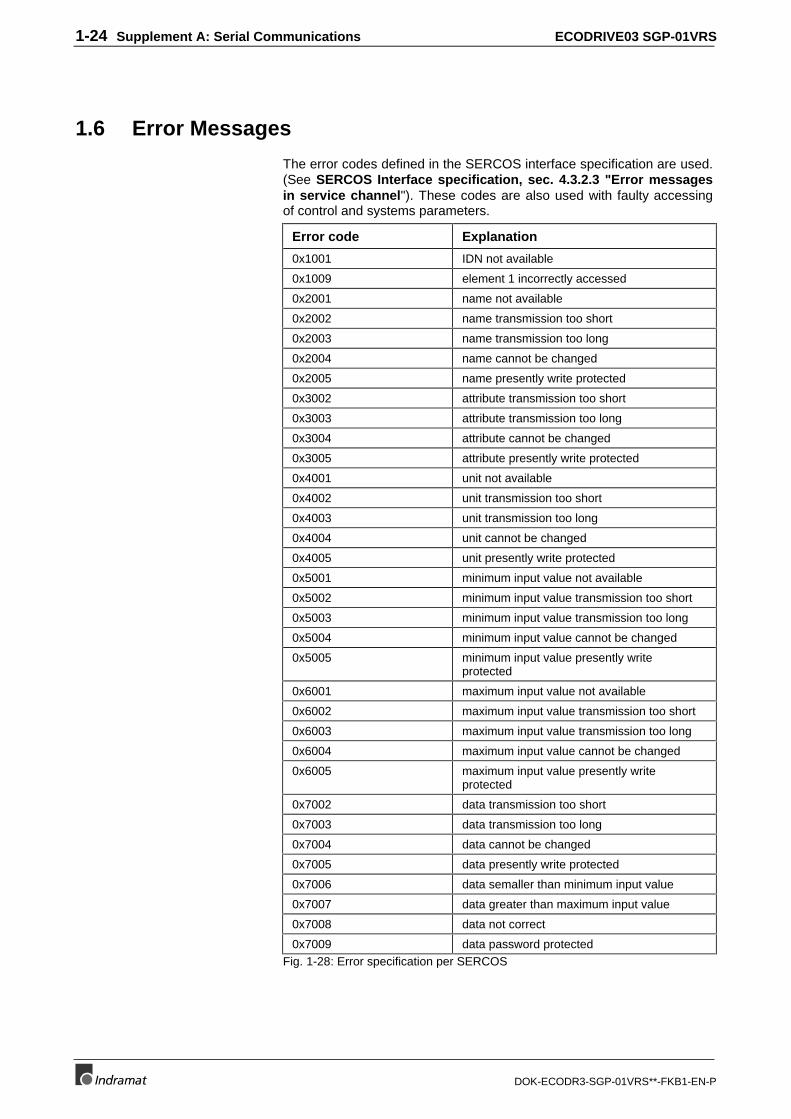
1-24 Supplement A: Serial Communications ECODRIVE03 SGP-01VRS
DOK-ECODR3-SGP-01VRS**-FKB1-EN-P
1.6 Error Messages
The error codes defined in the SERCOS interface specification are used.(See SERCOS Interface specification, sec. 4.3.2.3 "Error messagesin service channel"). These codes are also used with faulty accessingof control and systems parameters.
Error code Explanation
0x1001 IDN not available
0x1009 element 1 incorrectly accessed
0x2001 name not available
0x2002 name transmission too short
0x2003 name transmission too long
0x2004 name cannot be changed
0x2005 name presently write protected
0x3002 attribute transmission too short
0x3003 attribute transmission too long
0x3004 attribute cannot be changed
0x3005 attribute presently write protected
0x4001 unit not available
0x4002 unit transmission too short
0x4003 unit transmission too long
0x4004 unit cannot be changed
0x4005 unit presently write protected
0x5001 minimum input value not available
0x5002 minimum input value transmission too short
0x5003 minimum input value transmission too long
0x5004 minimum input value cannot be changed
0x5005 minimum input value presently writeprotected
0x6001 maximum input value not available
0x6002 maximum input value transmission too short
0x6003 maximum input value transmission too long
0x6004 maximum input value cannot be changed
0x6005 maximum input value presently writeprotected
0x7002 data transmission too short
0x7003 data transmission too long
0x7004 data cannot be changed
0x7005 data presently write protected
0x7006 data semaller than minimum input value
0x7007 data greater than maximum input value
0x7008 data not correct
0x7009 data password protectedFig. 1-28: Error specification per SERCOS
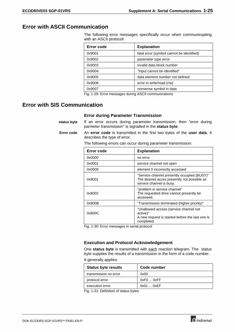
ECODRIVE03 SGP-01VRS Supplement A: Serial Communications 1-25
DOK-ECODR3-SGP-01VRS**-FKB1-EN-P
Error with ASCII CommunicationThe following error messages specifically occur when communicqatingwith an ASCII protocol!
Error code Explanation
0x9001 fatal error (symbol cannot be identified)
0x9002 parameter type error
0x9003 invalid data block number
0x9004 "Input cannot be identified"
0x9005 data element number not defined
0x9006 error in write/read (r/w)
0x9007 nonsense symbol in dataFig. 1-29: Error messages during ASCII communications
Error with SIS Communication
Error during Parameter TransmissionIf an error occurs during parameter transmission, then "error duringparmeter transmission" is signalled in the status byte.
An error code is transmitted in the first two bytes of the user data. Itdescribes the type of error.
The following errors can occur during parameter transmission:
Error code Explanation
0x0000 no error
0x0001 service channel not open
0x0009 element 0 incorrectly accessed
0x8001"Service channel presently occupied (BUSY)"The desired acces presently not possible asservice channel is busy.
0x8002"problem in service channel"The requested drive cannot presently beaccessed.
0x800B "Transmission terminated (higher priority)"
0x800C"Unallowed access (service channel notactive)"A new request is started before the last one iscompleted.
Fig. 1-30: Error messages in serial protocol
Execution and Protocol AcknowledgementOne status byte is transmitted with each reaction telegram. The statusbyte supplies the results of a transmission in the form of a code number.
It generally applies:
Status byte results Code number
transmission no error 0x00
protocol error 0xF0 ... 0xFF
execution error 0x01 ... 0xEFFig. 1-31: Definition of status bytes
status byte
Error code
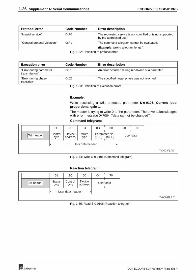
1-26 Supplement A: Serial Communications ECODRIVE03 SGP-01VRS
DOK-ECODR3-SGP-01VRS**-FKB1-EN-P
Protocol error Code Number Error description
"Invalid service“ 0xF0 The requested service is not specified or is not supportedby the addressed user.
"General protocol violation“ 0xF1 The command telegram cannot be evaluated.
(Example: wrong telegram length)
Fig. 1-32: Definition of protocol error
Execution error Code Number Error description
"Error during parametertransmission“
0x01 An error occurred during read/write of a parmeter
"Error during phasetransition“
0x02 The specified target phase was not reached
Fig. 1-33: Definition of execution errors
Example:
Write accessing a write-protected parameter S-0-0106, Current loopproportional gain 1:
The master is trying to write 0 to the parameter. The drive acknowledgeswith error message 0x7004 ("data cannot be changed").
Command telegram:
Tel.-header Controlbyte
Deviceaddress
Param.type
Parameter No.(LSB) (MSB)
User data header
3C 00 04 0B 00
Ta0003f1.fh7
User data
00 00
Fig. 1-34: Write S-0-0106 (Command telegram)
Reaction telegram:
Ta0004f1.fh7
Tel. header Statusbyte
Controlbyte
Deviceaddress
User data header
01 3C 00
User data
04 70
Fig. 1-35: Read S-0-0106 (Reaction telegram)
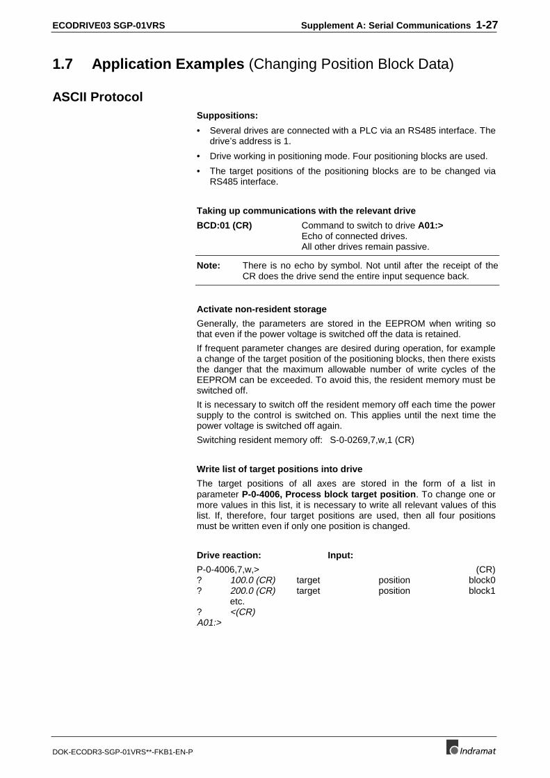
ECODRIVE03 SGP-01VRS Supplement A: Serial Communications 1-27
DOK-ECODR3-SGP-01VRS**-FKB1-EN-P
1.7 Application Examples (Changing Position Block Data)
ASCII ProtocolSuppositions:
• Several drives are connected with a PLC via an RS485 interface. Thedrive’s address is 1.
• Drive working in positioning mode. Four positioning blocks are used.
• The target positions of the positioning blocks are to be changed viaRS485 interface.
Taking up communications with the relevant drive
BCD:01 (CR) Command to switch to drive A01:>Echo of connected drives.All other drives remain passive.
Note: There is no echo by symbol. Not until after the receipt of theCR does the drive send the entire input sequence back.
Activate non-resident storage
Generally, the parameters are stored in the EEPROM when writing sothat even if the power voltage is switched off the data is retained.
If frequent parameter changes are desired during operation, for examplea change of the target position of the positioning blocks, then there existsthe danger that the maximum allowable number of write cycles of theEEPROM can be exceeded. To avoid this, the resident memory must beswitched off.
It is necessary to switch off the resident memory off each time the powersupply to the control is switched on. This applies until the next time thepower voltage is switched off again.
Switching resident memory off: S-0-0269,7,w,1 (CR)
Write list of target positions into drive
The target positions of all axes are stored in the form of a list inparameter P-0-4006, Process block target position. To change one ormore values in this list, it is necessary to write all relevant values of thislist. If, therefore, four target positions are used, then all four positionsmust be written even if only one position is changed.
Drive reaction: Input:
P-0-4006,7,w,> (CR)? 100.0 (CR) target position block0? 200.0 (CR) target position block1
etc.? <(CR)A01:>
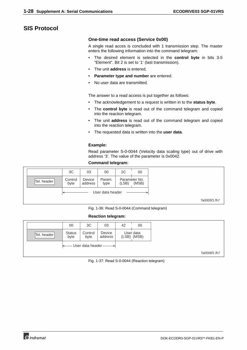
1-28 Supplement A: Serial Communications ECODRIVE03 SGP-01VRS
DOK-ECODR3-SGP-01VRS**-FKB1-EN-P
SIS Protocol
One-time read access (Service 0x00)A single read acces is concluded with 1 transmission step. The masterenters the following information into the command telegram:
• The desired element is selected in the control byte in bits 3-5"Element". Bit 2 is set to ’1’ (last transmission).
• The unit address is entered.
• Parameter type and number are entered.
• No user data are transmitted.
The answer to a read access is put together as follows:
• The acknowledgement to a request is written in to the status byte.
• The control byte is read out of the command telegram and copiedinto the reaction telegram.
• The unit address is read out of the command telegram and copiedinto the reaction telegram.
• The requested data is written into the user data.
Example:
Read parameter S-0-0044 (Velocity data scaling type) out of drive withaddress ‘3’. The value of the parameter is 0x0042.
Command telegram:
Tel. header Controlbyte
Deviceaddress
Param.type
Parameter No.(LSB) (MSB)
User data header
3C 03 00 2C 00
Ta0005f1.fh7
Fig. 1-36: Read S-0-0044 (Command telegram)
Reaction telegram:
Ta0006f1.fh7
Tel. header Statusbyte
Controlbyte
Deviceaddress
User data header
00 3C 03
User data(LSB) (MSB)
42 00
Fig. 1-37: Read S-0-0044 (Reaction telegram)
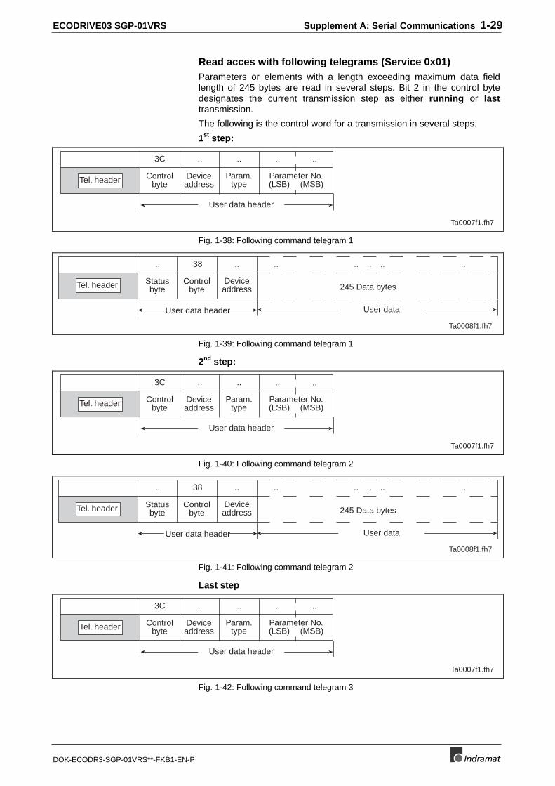
ECODRIVE03 SGP-01VRS Supplement A: Serial Communications 1-29
DOK-ECODR3-SGP-01VRS**-FKB1-EN-P
Read acces with following telegrams (Service 0x01)Parameters or elements with a length exceeding maximum data fieldlength of 245 bytes are read in several steps. Bit 2 in the control bytedesignates the current transmission step as either running or lasttransmission.
The following is the control word for a transmission in several steps.
1st step:
Tel. header Controlbyte
Deviceaddress
Param.type
Parameter No.(LSB) (MSB)
User data header
3C .. .. .. ..
Ta0007f1.fh7
Fig. 1-38: Following command telegram 1
Ta0008f1.fh7
User data
Tel. header Statusbyte
Controlbyte
Deviceaddress
User data header
.. 38 .. .. .. .. .. ..
245 Data bytes
Fig. 1-39: Following command telegram 1
2nd step:
Tel. header Controlbyte
Deviceaddress
Param.type
Parameter No.(LSB) (MSB)
User data header
3C .. .. .. ..
Ta0007f1.fh7
Fig. 1-40: Following command telegram 2
Ta0008f1.fh7
User data
Tel. header Statusbyte
Controlbyte
Deviceaddress
User data header
.. 38 .. .. .. .. .. ..
245 Data bytes
Fig. 1-41: Following command telegram 2
Last step
Tel. header Controlbyte
Deviceaddress
Param.type
Parameter No.(LSB) (MSB)
User data header
3C .. .. .. ..
Ta0007f1.fh7
Fig. 1-42: Following command telegram 3
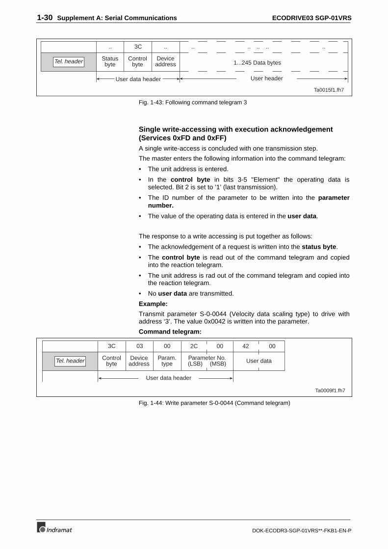
1-30 Supplement A: Serial Communications ECODRIVE03 SGP-01VRS
DOK-ECODR3-SGP-01VRS**-FKB1-EN-P
Ta0015f1.fh7
User header
Tel. header Statusbyte
Controlbyte
Deviceaddress
User data header
.. 3C .. .. .. .. .. ..
1...245 Data bytes
Fig. 1-43: Following command telegram 3
Single write-accessing with execution acknowledgement(Services 0xFD and 0xFF)A single write-access is concluded with one transmission step.
The master enters the following information into the command telegram:
• The unit address is entered.
• In the control byte in bits 3-5 "Element" the operating data isselected. Bit 2 is set to ’1’ (last transmission).
• The ID number of the parameter to be written into the parameternumber.
• The value of the operating data is entered in the user data.
The response to a write accessing is put together as follows:
• The acknowledgement of a request is written into the status byte.
• The control byte is read out of the command telegram and copiedinto the reaction telegram.
• The unit address is rad out of the command telegram and copied intothe reaction telegram.
• No user data are transmitted.
Example:
Transmit parameter S-0-0044 (Velocity data scaling type) to drive withaddress ‘3’. The value 0x0042 is written into the parameter.
Command telegram:
Tel. header Controlbyte
Deviceaddress
Param.type
Parameter No.(LSB) (MSB)
User data header
3C 03 00 2C 00
Ta0009f1.fh7
User data
42 00
Fig. 1-44: Write parameter S-0-0044 (Command telegram)
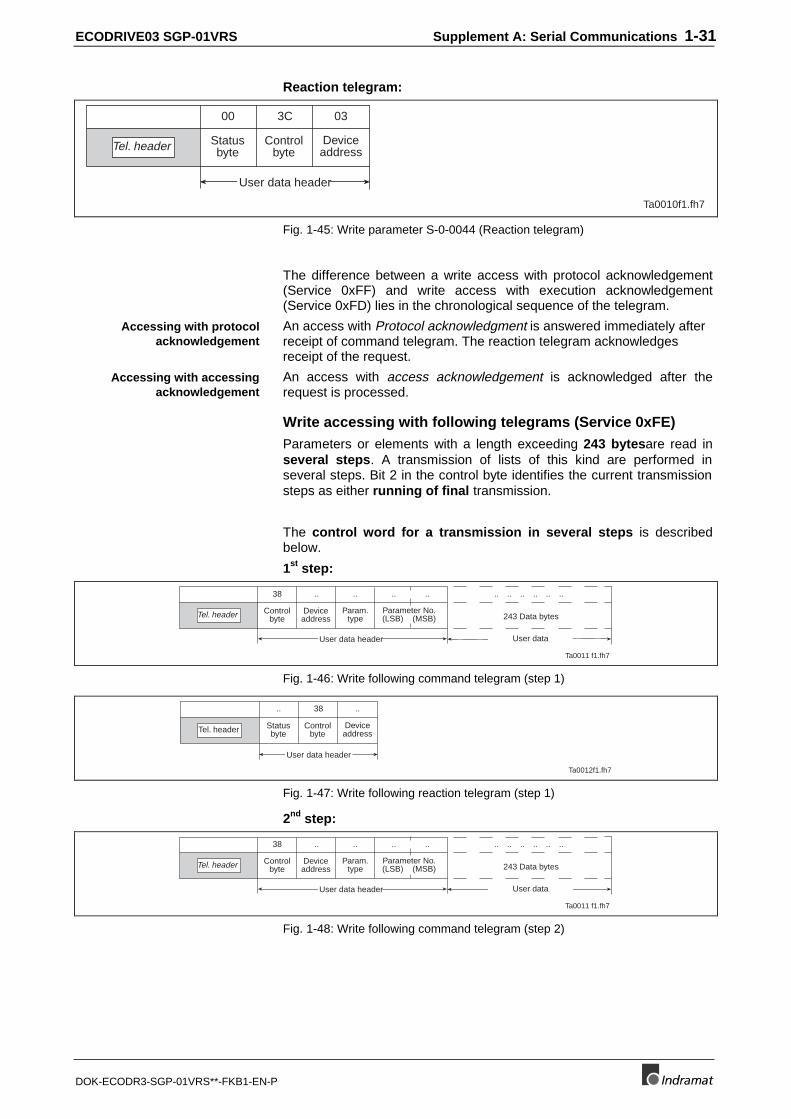
ECODRIVE03 SGP-01VRS Supplement A: Serial Communications 1-31
DOK-ECODR3-SGP-01VRS**-FKB1-EN-P
Reaction telegram:
Ta0010f1.fh7
Tel. header Statusbyte
Controlbyte
Deviceaddress
User data header
00 3C 03
Fig. 1-45: Write parameter S-0-0044 (Reaction telegram)
The difference between a write access with protocol acknowledgement(Service 0xFF) and write access with execution acknowledgement(Service 0xFD) lies in the chronological sequence of the telegram.
An access with Protocol acknowledgment is answered immediately afterreceipt of command telegram. The reaction telegram acknowledgesreceipt of the request.
An access with access acknowledgement is acknowledged after therequest is processed.
Write accessing with following telegrams (Service 0xFE)Parameters or elements with a length exceeding 243 bytesare read inseveral steps. A transmission of lists of this kind are performed inseveral steps. Bit 2 in the control byte identifies the current transmissionsteps as either running of final transmission.
The control word for a transmission in several steps is describedbelow.
1st step:
Ta0011 f1.fh7
User data
Tel. header Controlbyte
Deviceaddress
Param.type
User data header
38 .. .. .. .. .. ..
243 Data bytes
..
Parameter No.(LSB) (MSB)
.. .. ..
Fig. 1-46: Write following command telegram (step 1)
Ta0012f1.fh7
Tel. header Statusbyte
Controlbyte
Deviceaddress
User data header
.. 38 ..
Fig. 1-47: Write following reaction telegram (step 1)
2nd step:
Ta0011 f1.fh7
User data
Tel. header Controlbyte
Deviceaddress
Param.type
User data header
38 .. .. .. .. .. ..
243 Data bytes
..
Parameter No.(LSB) (MSB)
.. .. ..
Fig. 1-48: Write following command telegram (step 2)
Accessing with protocolacknowledgement
Accessing with accessingacknowledgement
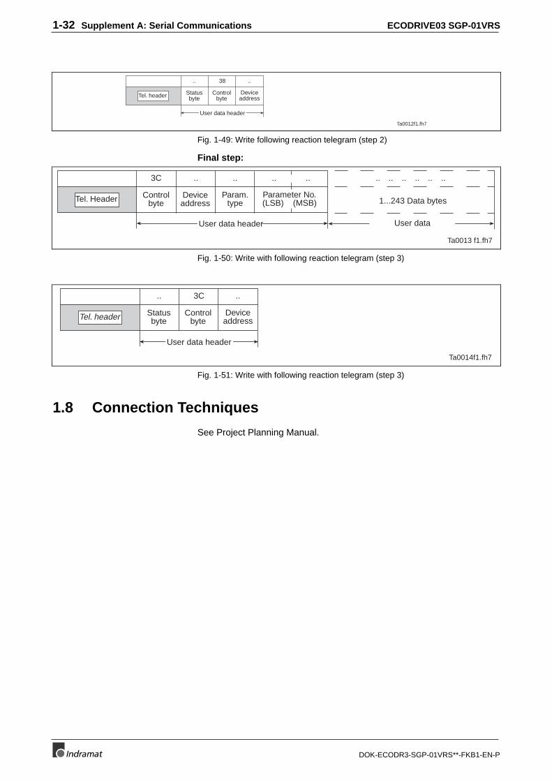
1-32 Supplement A: Serial Communications ECODRIVE03 SGP-01VRS
DOK-ECODR3-SGP-01VRS**-FKB1-EN-P
Ta0012f1.fh7
Tel. header Statusbyte
Controlbyte
Deviceaddress
User data header
.. 38 ..
Fig. 1-49: Write following reaction telegram (step 2)
Final step:
Ta0013 f1.fh7
User data
Tel. Header Controlbyte
Deviceaddress
Param.type
User data header
3C .. .. .. .. .. ..
1...243 Data bytes
..
Parameter No.(LSB) (MSB)
.. .. ..
Fig. 1-50: Write with following reaction telegram (step 3)
Ta0014f1.fh7
Tel. header Statusbyte
Controlbyte
Deviceaddress
User data header
.. 3C ..
Fig. 1-51: Write with following reaction telegram (step 3)
1.8 Connection Techniques
See Project Planning Manual.
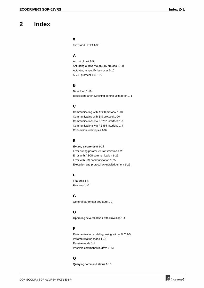
ECODRIVE03 SGP-01VRS Index 2-1
DOK-ECODR3-SGP-01VRS**-FKB1-EN-P
2 Index
00xFD and 0xFF) 1-30
AA control unit 1-5
Actuating a drive via an SIS protocol 1-20
Actuating a specific bus user 1-10
ASCII protocol 1-6, 1-27
BBase load 1-16
Basic state after switching control voltage on 1-1
CCommunicating with ASCII protocol 1-10
Communicating with SIS protocol 1-20
Communications via RS232 interface 1-3
Communications via RS485 interface 1-4
Connection techniques 1-32
EEnding a command 1-19
Error during parameter transmission 1-25
Error with ASCII communication 1-25
Error with SIS communication 1-25
Execution and protocol acknowledgement 1-25
FFeatures 1-4
Features: 1-6
GGeneral parameter structure 1-9
OOperating several drives with DriveTop 1-4
PParametrization and diagnosing with a PLC 1-5
Parametrization mode 1-16
Passive mode 1-1
Possible commands in drive 1-23
QQuerying command status 1-18
2-2 Index ECODRIVE03 SGP-01VRS
DOK-ECODR3-SGP-01VRS**-FKB1-EN-P
RRead accessing a parameter 1-12
Read accessing list parameters 1-15
Read accessing with following telegrams (Service 0x01) 1-29
RS232 mode 1-1
RS485 mode 1-1
SService 0x00 Identifying all users 1-20
Service 0x01 Terminating a data transmission 1-21
Service 0x0F Token Passing 1-21
Service 0x80 read parameter 1-21
Service 0x81 read a list segment 1-22
Service 0x8E write a list segment 1-22
Service 0x8F write eines Parameters 1-22
Set absolute measurement 1-16
Setting the drive address 1-2
Single read access (Service 0x00) 1-28
SIS protocol 1-6, 1-28
Starting a command 1-16, 1-23
Structure of the user data field 1-9
Structure of the user data head 1-8
Structure, Telegram frame: 1-6
TTelegram Head Structure 1-7
WWrite access with following telegrams (Service 0xFE) 1-31
Write accessing list parameters 1-13
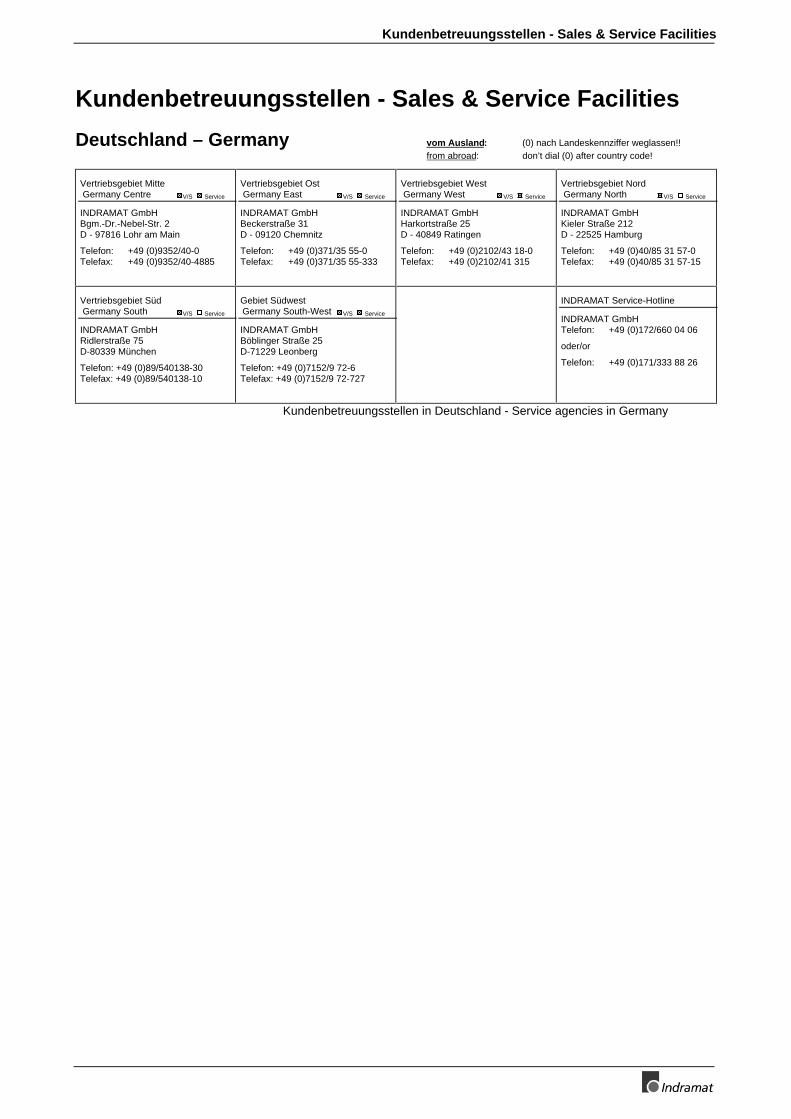
Kundenbetreuungsstellen - Sales & Service Facilities
Kundenbetreuungsstellen - Sales & Service Facilities
Deutschland – Germany vom Ausland: (0) nach Landeskennziffer weglassen!!from abroad: don’t dial (0) after country code!
Vertriebsgebiet Mitte Germany Centre V/S Service
INDRAMAT GmbHBgm.-Dr.-Nebel-Str. 2D - 97816 Lohr am Main
Telefon: +49 (0)9352/40-0Telefax: +49 (0)9352/40-4885
Vertriebsgebiet Ost Germany East V/S Service
INDRAMAT GmbHBeckerstraße 31D - 09120 Chemnitz
Telefon: +49 (0)371/35 55-0Telefax: +49 (0)371/35 55-333
Vertriebsgebiet West Germany West V/S Service
INDRAMAT GmbHHarkortstraße 25D - 40849 Ratingen
Telefon: +49 (0)2102/43 18-0Telefax: +49 (0)2102/41 315
Vertriebsgebiet Nord Germany North V/S Service
INDRAMAT GmbHKieler Straße 212D - 22525 Hamburg
Telefon: +49 (0)40/85 31 57-0Telefax: +49 (0)40/85 31 57-15
Vertriebsgebiet Süd Germany South V/S Service
INDRAMAT GmbHRidlerstraße 75D-80339 München
Telefon: +49 (0)89/540138-30Telefax: +49 (0)89/540138-10
Gebiet Südwest Germany South-West V/S Service
INDRAMAT GmbHBöblinger Straße 25D-71229 Leonberg
Telefon: +49 (0)7152/9 72-6Telefax: +49 (0)7152/9 72-727
INDRAMAT Service-Hotline
INDRAMAT GmbHTelefon: +49 (0)172/660 04 06
oder/or
Telefon: +49 (0)171/333 88 26
Kundenbetreuungsstellen in Deutschland - Service agencies in Germany
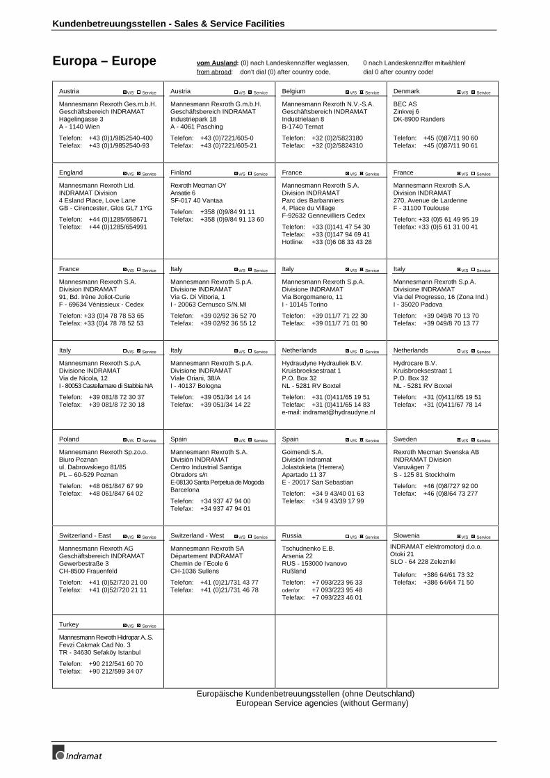
Kundenbetreuungsstellen - Sales & Service Facilities
Europa – Europe vom Ausland: (0) nach Landeskennziffer weglassen, 0 nach Landeskennziffer mitwählen!from abroad: don’t dial (0) after country code, dial 0 after country code!
Austria V/S Service
Mannesmann Rexroth Ges.m.b.H.Geschäftsbereich INDRAMATHägelingasse 3A - 1140 Wien
Telefon: +43 (0)1/9852540-400Telefax: +43 (0)1/9852540-93
Austria V/S Service
Mannesmann Rexroth G.m.b.H.Geschäftsbereich INDRAMATIndustriepark 18A - 4061 Pasching
Telefon: +43 (0)7221/605-0Telefax: +43 (0)7221/605-21
Belgium V/S Service
Mannesmann Rexroth N.V.-S.A.Geschäftsbereich INDRAMATIndustrielaan 8B-1740 Ternat
Telefon: +32 (0)2/5823180Telefax: +32 (0)2/5824310
Denmark V/S Service
BEC ASZinkvej 6DK-8900 Randers
Telefon: +45 (0)87/11 90 60Telefax: +45 (0)87/11 90 61
England V/S Service
Mannesmann Rexroth Ltd.INDRAMAT Division4 Esland Place, Love LaneGB - Cirencester, Glos GL7 1YG
Telefon: +44 (0)1285/658671Telefax: +44 (0)1285/654991
Finland V/S Service
Rexroth Mecman OYAnsatie 6SF-017 40 Vantaa
Telefon: +358 (0)9/84 91 11Telefax: +358 (0)9/84 91 13 60
France V/S Service
Mannesmann Rexroth S.A.Division INDRAMATParc des Barbanniers4, Place du VillageF-92632 Gennevilliers Cedex
Telefon: +33 (0)141 47 54 30Telefax: +33 (0)147 94 69 41Hotline: +33 (0)6 08 33 43 28
France V/S Service
Mannesmann Rexroth S.A.Division INDRAMAT270, Avenue de LardenneF - 31100 Toulouse
Telefon: +33 (0)5 61 49 95 19Telefax: +33 (0)5 61 31 00 41
France V/S Service
Mannesmann Rexroth S.A.Division INDRAMAT91, Bd. Irène Joliot-CurieF - 69634 Vénissieux - Cedex
Telefon: +33 (0)4 78 78 53 65Telefax: +33 (0)4 78 78 52 53
Italy V/S Service
Mannesmann Rexroth S.p.A.Divisione INDRAMATVia G. Di Vittoria, 1I - 20063 Cernusco S/N.MI
Telefon: +39 02/92 36 52 70Telefax: +39 02/92 36 55 12
Italy V/S Service
Mannesmann Rexroth S.p.A.Divisione INDRAMATVia Borgomanero, 11I - 10145 Torino
Telefon: +39 011/7 71 22 30Telefax: +39 011/7 71 01 90
Italy V/S Service
Mannesmann Rexroth S.p.A.Divisione INDRAMATVia del Progresso, 16 (Zona Ind.)I - 35020 Padova
Telefon: +39 049/8 70 13 70Telefax: +39 049/8 70 13 77
Italy V/S Service
Mannesmann Rexroth S.p.A.Divisione INDRAMATVia de Nicola, 12I - 80053 Castellamare di Stabbia NA
Telefon: +39 081/8 72 30 37Telefax: +39 081/8 72 30 18
Italy V/S Service
Mannesmann Rexroth S.p.A.Divisione INDRAMATViale Oriani, 38/AI - 40137 Bologna
Telefon: +39 051/34 14 14Telefax: +39 051/34 14 22
Netherlands V/S Service
Hydraudyne Hydrauliek B.V.Kruisbroeksestraat 1P.O. Box 32NL - 5281 RV Boxtel
Telefon: +31 (0)411/65 19 51Telefax: +31 (0)411/65 14 83e-mail: [email protected]
Netherlands V/S Service
Hydrocare B.V.Kruisbroeksestraat 1P.O. Box 32NL - 5281 RV Boxtel
Telefon: +31 (0)411/65 19 51Telefax: +31 (0)411/67 78 14
Poland V/S Service
Mannesmann Rexroth Sp.zo.o.Biuro Poznanul. Dabrowskiego 81/85PL – 60-529 Poznan
Telefon: +48 061/847 67 99Telefax: +48 061/847 64 02
Spain V/S Service
Mannesmann Rexroth S.A.Divisiòn INDRAMATCentro Industrial SantigaObradors s/nE-08130 Santa Perpetua de MogodaBarcelona
Telefon: +34 937 47 94 00Telefax: +34 937 47 94 01
Spain V/S Service
Goimendi S.A.División IndramatJolastokieta (Herrera)Apartado 11 37E - 20017 San Sebastian
Telefon: +34 9 43/40 01 63Telefax: +34 9 43/39 17 99
Sweden V/S Service
Rexroth Mecman Svenska ABINDRAMAT DivisionVaruvägen 7S - 125 81 Stockholm
Telefon: +46 (0)8/727 92 00Telefax: +46 (0)8/64 73 277
Switzerland - East V/S Service
Mannesmann Rexroth AGGeschäftsbereich INDRAMATGewerbestraße 3CH-8500 Frauenfeld
Telefon: +41 (0)52/720 21 00Telefax: +41 (0)52/720 21 11
Switzerland - West V/S Service
Mannesmann Rexroth SADépartement INDRAMATChemin de l`Ecole 6CH-1036 Sullens
Telefon: +41 (0)21/731 43 77Telefax: +41 (0)21/731 46 78
Russia V/S Service
Tschudnenko E.B.Arsenia 22RUS - 153000 IvanovoRußland
Telefon: +7 093/223 96 33oder/or +7 093/223 95 48Telefax: +7 093/223 46 01
Slowenia V/S Service
INDRAMAT elektromotorji d.o.o.Otoki 21SLO - 64 228 Zelezniki
Telefon: +386 64/61 73 32Telefax: +386 64/64 71 50
Turkey V/S Service
Mannesmann Rexroth Hidropar A..S.Fevzi Cakmak Cad No. 3TR - 34630 Sefaköy Istanbul
Telefon: +90 212/541 60 70Telefax: +90 212/599 34 07
Europäische Kundenbetreuungsstellen (ohne Deutschland)European Service agencies (without Germany)
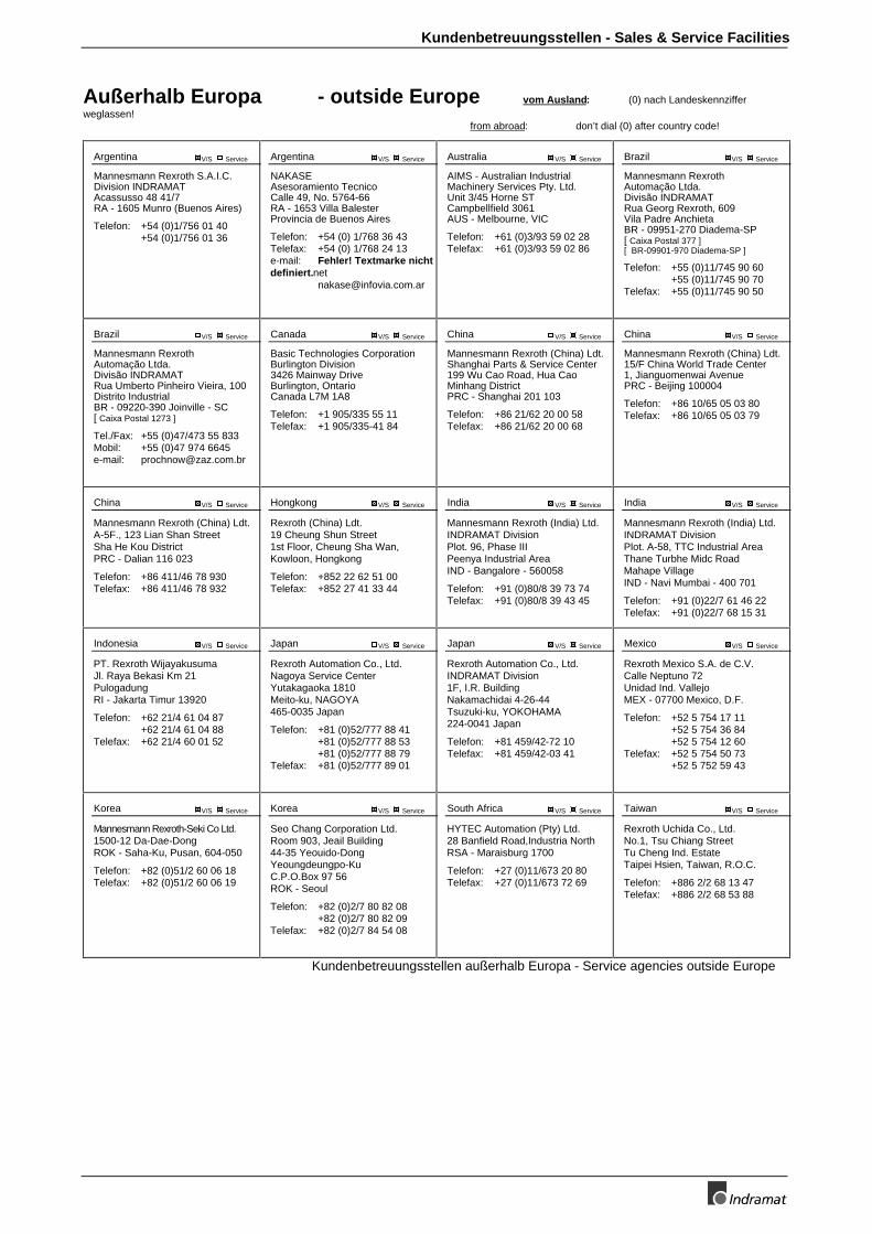
Kundenbetreuungsstellen - Sales & Service Facilities
Außerhalb Europa - outside Europe vom Ausland: (0) nach Landeskennzifferweglassen!
from abroad: don’t dial (0) after country code!
Argentina V/S Service
Mannesmann Rexroth S.A.I.C.Division INDRAMATAcassusso 48 41/7RA - 1605 Munro (Buenos Aires)
Telefon: +54 (0)1/756 01 40+54 (0)1/756 01 36
Argentina V/S Service
NAKASEAsesoramiento TecnicoCalle 49, No. 5764-66RA - 1653 Villa BalesterProvincia de Buenos Aires
Telefon: +54 (0) 1/768 36 43Telefax: +54 (0) 1/768 24 13e-mail: Fehler! Textmarke nichtdefiniert.net
Australia V/S Service
AIMS - Australian IndustrialMachinery Services Pty. Ltd.Unit 3/45 Horne STCampbellfield 3061AUS - Melbourne, VIC
Telefon: +61 (0)3/93 59 02 28Telefax: +61 (0)3/93 59 02 86
Brazil V/S Service
Mannesmann RexrothAutomação Ltda.Divisão INDRAMATRua Georg Rexroth, 609Vila Padre AnchietaBR - 09951-270 Diadema-SP[ Caixa Postal 377 ][ BR-09901-970 Diadema-SP ]
Telefon: +55 (0)11/745 90 60+55 (0)11/745 90 70
Telefax: +55 (0)11/745 90 50
Brazil V/S Service
Mannesmann RexrothAutomação Ltda.Divisão INDRAMATRua Umberto Pinheiro Vieira, 100Distrito IndustrialBR - 09220-390 Joinville - SC[ Caixa Postal 1273 ]
Tel./Fax: +55 (0)47/473 55 833Mobil: +55 (0)47 974 6645e-mail: [email protected]
Canada V/S Service
Basic Technologies CorporationBurlington Division3426 Mainway DriveBurlington, OntarioCanada L7M 1A8
Telefon: +1 905/335 55 11Telefax: +1 905/335-41 84
China V/S Service
Mannesmann Rexroth (China) Ldt.Shanghai Parts & Service Center199 Wu Cao Road, Hua CaoMinhang DistrictPRC - Shanghai 201 103
Telefon: +86 21/62 20 00 58Telefax: +86 21/62 20 00 68
China V/S Service
Mannesmann Rexroth (China) Ldt.15/F China World Trade Center1, Jianguomenwai AvenuePRC - Beijing 100004
Telefon: +86 10/65 05 03 80Telefax: +86 10/65 05 03 79
China V/S Service
Mannesmann Rexroth (China) Ldt.A-5F., 123 Lian Shan StreetSha He Kou DistrictPRC - Dalian 116 023
Telefon: +86 411/46 78 930Telefax: +86 411/46 78 932
Hongkong V/S Service
Rexroth (China) Ldt.19 Cheung Shun Street1st Floor, Cheung Sha Wan,Kowloon, Hongkong
Telefon: +852 22 62 51 00Telefax: +852 27 41 33 44
India V/S Service
Mannesmann Rexroth (India) Ltd.INDRAMAT DivisionPlot. 96, Phase IIIPeenya Industrial AreaIND - Bangalore - 560058
Telefon: +91 (0)80/8 39 73 74Telefax: +91 (0)80/8 39 43 45
India V/S Service
Mannesmann Rexroth (India) Ltd.INDRAMAT DivisionPlot. A-58, TTC Industrial AreaThane Turbhe Midc RoadMahape VillageIND - Navi Mumbai - 400 701
Telefon: +91 (0)22/7 61 46 22Telefax: +91 (0)22/7 68 15 31
Indonesia V/S Service
PT. Rexroth WijayakusumaJl. Raya Bekasi Km 21PulogadungRI - Jakarta Timur 13920
Telefon: +62 21/4 61 04 87+62 21/4 61 04 88
Telefax: +62 21/4 60 01 52
Japan V/S Service
Rexroth Automation Co., Ltd.Nagoya Service CenterYutakagaoka 1810Meito-ku, NAGOYA465-0035 Japan
Telefon: +81 (0)52/777 88 41+81 (0)52/777 88 53+81 (0)52/777 88 79
Telefax: +81 (0)52/777 89 01
Japan V/S Service
Rexroth Automation Co., Ltd.INDRAMAT Division1F, I.R. BuildingNakamachidai 4-26-44Tsuzuki-ku, YOKOHAMA224-0041 Japan
Telefon: +81 459/42-72 10Telefax: +81 459/42-03 41
Mexico V/S Service
Rexroth Mexico S.A. de C.V.Calle Neptuno 72Unidad Ind. VallejoMEX - 07700 Mexico, D.F.
Telefon: +52 5 754 17 11+52 5 754 36 84+52 5 754 12 60
Telefax: +52 5 754 50 73+52 5 752 59 43
Korea V/S Service
Mannesmann Rexroth-Seki Co Ltd.1500-12 Da-Dae-DongROK - Saha-Ku, Pusan, 604-050
Telefon: +82 (0)51/2 60 06 18Telefax: +82 (0)51/2 60 06 19
Korea V/S Service
Seo Chang Corporation Ltd.Room 903, Jeail Building44-35 Yeouido-DongYeoungdeungpo-KuC.P.O.Box 97 56ROK - Seoul
Telefon: +82 (0)2/7 80 82 08+82 (0)2/7 80 82 09
Telefax: +82 (0)2/7 84 54 08
South Africa V/S Service
HYTEC Automation (Pty) Ltd.28 Banfield Road,Industria NorthRSA - Maraisburg 1700
Telefon: +27 (0)11/673 20 80Telefax: +27 (0)11/673 72 69
Taiwan V/S Service
Rexroth Uchida Co., Ltd.No.1, Tsu Chiang StreetTu Cheng Ind. EstateTaipei Hsien, Taiwan, R.O.C.
Telefon: +886 2/2 68 13 47Telefax: +886 2/2 68 53 88
Kundenbetreuungsstellen außerhalb Europa - Service agencies outside Europe
Kundenbetreuungsstellen - Sales & Service Facilities
Außerhalb Europa / USA - outside Europe / USA
USA V/S Service
Mannesmann Rexroth CorporationINDRAMAT Division5150 Prairie Stone ParkwayUSA -Hoffman Estates, IL 60192-3707
Telefon: +1 847/6 45 36 00Telefax: +1 847/6 45 62 01
USA V/S Service
Mannesmann Rexroth CorporationINDRAMAT DivisionCentral Region Technical CenterUSA - Auburn Hills, MI 48326
Telefon: +1 248/3 93 33 30Telefax: +1 248/3 93 29 06
USA V/S Service
Mannesmann Rexroth CorporationINDRAMAT DivisionSoutheastern Technical Center3625 Swiftwater Park DriveUSA - SuwaneeGeorgia 30174
Telefon: +1 770/9 32 32 00+1 770/9 32 19 03
USA V/S Service
Mannesmann Rexroth CorporationINDRAMAT DivisionNortheastern Technical Center99 Rainbow RoadUSA - East Granby,Connecticut 06026
Telefon: +1 860/8 44 83 77+1 860/8 44 85 95
USA V/S Service
Mannesmann Rexroth CorporationINDRAMAT DivisionCharlotte Regional Sales Office14001 South Lakes DriveUSA - Charlotte,North Carolina 28273
Telefon: +1 704/5 83 97 62+1 704/5 83 14 86
Kundenbetreuungsstellen außerhalb Europa / USA Service agencies outside Europe / USA

.

Indramat