modelling the boring of curves in (very) soft soils during microtunnelling
TRANSCRIPT

Tunnelling and
www.elsevier.com/locate/tust
Tunnelling and Underground Space Technology 22 (2007) 600–609
Underground SpaceTechnologyincorporating Trenchless
Technology Research
Modelling the boring of curves in (very) soft soils duringmicrotunnelling
W. Broere a,b,*, T.F. Faassen a, G. Arends a, A.F. van Tol a,c
a Delft University of Technology, Faculty of Civil Engineering and Geosciences, P.O. Box 5048, 2600 GA Delft, The Netherlandsb A. Broere BV, Amsterdam, The Netherlands
c GeoDelft, Delft, The Netherlands
Abstract
In recent years the interest in microtunnelling has grown due to the fact that open trenching is an increasingly undesired operation.However, microtunnelling encounters restrictions in expanding into new areas. In the Netherlands, and more general in (very) soft soils,one of the main problems is the controlled boring of curves. To better understand the behaviour of the tunnel boring machine (TBM) ananalytical model has been developed, that takes translation and rotation of the TBM into account. These movements can be superim-posed to describe the complete movement of the TBM. The model has been developed in an incremental fashion by first taking only theinfluence of a limited set of parameters into account. The first model takes the subgrade reaction modulus and the influence of themachine on the stiffness of the soil into account and is subsequently improved upon by taking the dead weight and eccentric jackingforces into account. This second model is validated with a case study, the installation of the KPE-pipe under the Hartel canal in Rot-terdam, and this shows reliable results. Using the model, the required position of the steering jacks in the tunnelling machine can bedetermined, given that the required parameters are known. In addition, the ovalisation of the bored hole can be forecast. With the var-iation in angular rotations and the maximum rotation, the behaviour of the joints can be determined. In this way problematic situationscan be prevented. Although the results of the validations are good, a number of aspects do need further research.� 2007 Elsevier Ltd. All rights reserved.
Keywords: Microtunnelling; Design; Modelling; Soft soil; Saturated soil
1. Introduction
In the future the number of underground pipe systemswill continue to grow. This is true not only for the classictransport of water, gas, electricity and data, but also forthe underground transport of consumer goods, waste andfor integrated utility tunnels. Cities in the Netherlandsexpress a growing interest in possibilities to remove cartraffic from the inner cities, in order to enhance living con-ditions. Different ways of distributing freight in urbanareas are being considered, and a large number of the pro-
0886-7798/$ - see front matter � 2007 Elsevier Ltd. All rights reserved.
doi:10.1016/j.tust.2007.06.002
* Corresponding author. Address: Delft University of Technology,Faculty of Civil Engineering and Geosciences, P.O. Box 5048, 2600 GADelft, The Netherlands. Tel.: +31 15 2781545; fax: +31 15 2783328.
E-mail address: [email protected] (W. Broere).
posed ideas use the underground. These include the use ofunderground logistic systems.
Tubes are already used for underground transport ofliquids and gasses. Using underground pipelines as a trans-port medium for other goods means that the alignment ofthe pipes becomes increasingly important. The layout ofthe lines should ensure a high service level and minimisebuilding costs. Therefore, the soil conditions are an increas-ingly important factor, especially when boring techniquesare considered.
Boring techniques are considered as the traditionalmethod of open trenching causes hindrance for the sur-roundings and may require the temporary rerouting ofother (large and small) infrastructure, which considerablyincreases the costs. Trenchless technologies, although gen-erally more expensive, do not have these disadvantages and
Direction of progress
Front forcesJack forces
x Ff Ff
Ff Ff
y
Fig. 2. Forces acting on the TBM when driving straight.
W. Broere et al. / Tunnelling and Underground Space Technology 22 (2007) 600–609 601
can, therefore, become particularly cost-effective in urbanareas. As such they are an excellent option for the installa-tion of underground logistic systems.
1.1. Challenges facing microtunnelling in the netherlands
In most of the Netherlands the upper layers consist ofalluvial soil deposits, where the stiffness of the soil is low.The groundwater level is generally very high and locallyreaches the ground surface. This combination has adverseimplications for the drilling techniques used. In such poorsoil conditions, the control and steerability of the micro-tunnelling machine can become problematic (e.g. Oresteet al., 2002). One aspect, the boring of curves, is describedin more detail in this paper.
In the past several borings were executed in soft soilswithout any significant problems, or only with limitedproblems. Recently however, problems occurred on a pro-ject where a curve was introduced in the trajectory coincid-ing with the transition from very soft to stiffer soils. At thislocation the concrete pipe snapped when the tunnel boringmachine (TBM) had just entered the stiffer soils. A secondboring, with a greater curvature, was successfully com-pleted at the same location. This event raised questionsconcerning the actual behaviour of the TBM, the concretepipes and the coupling forces between the pipes. Toincrease understanding of the behaviour of the TBM in softsoils, an analytical model was formulated that describes thebehaviour of the TBM during the boring of curves in softsoils. This model has been used to explain the problemsat the aforementioned project.
2. Forces on the microtunnelling machine in curves
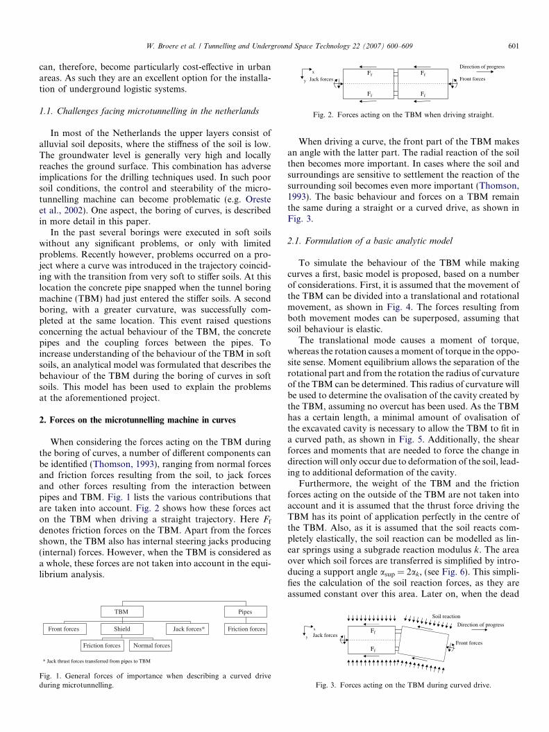
When considering the forces acting on the TBM duringthe boring of curves, a number of different components canbe identified (Thomson, 1993), ranging from normal forcesand friction forces resulting from the soil, to jack forcesand other forces resulting from the interaction betweenpipes and TBM. Fig. 1 lists the various contributions thatare taken into account. Fig. 2 shows how these forces acton the TBM when driving a straight trajectory. Here Ff
denotes friction forces on the TBM. Apart from the forcesshown, the TBM also has internal steering jacks producing(internal) forces. However, when the TBM is considered asa whole, these forces are not taken into account in the equi-librium analysis.
Front forces
PipesTBM
Jack forces*Shield Friction forces
Friction forces Normal forces
* Jack thrust forces transferred from pipes to TBM
Fig. 1. General forces of importance when describing a curved driveduring microtunnelling.
When driving a curve, the front part of the TBM makesan angle with the latter part. The radial reaction of the soilthen becomes more important. In cases where the soil andsurroundings are sensitive to settlement the reaction of thesurrounding soil becomes even more important (Thomson,1993). The basic behaviour and forces on a TBM remainthe same during a straight or a curved drive, as shown inFig. 3.
2.1. Formulation of a basic analytic model
To simulate the behaviour of the TBM while makingcurves a first, basic model is proposed, based on a numberof considerations. First, it is assumed that the movement ofthe TBM can be divided into a translational and rotationalmovement, as shown in Fig. 4. The forces resulting fromboth movement modes can be superposed, assuming thatsoil behaviour is elastic.
The translational mode causes a moment of torque,whereas the rotation causes a moment of torque in the oppo-site sense. Moment equilibrium allows the separation of therotational part and from the rotation the radius of curvatureof the TBM can be determined. This radius of curvature willbe used to determine the ovalisation of the cavity created bythe TBM, assuming no overcut has been used. As the TBMhas a certain length, a minimal amount of ovalisation ofthe excavated cavity is necessary to allow the TBM to fit ina curved path, as shown in Fig. 5. Additionally, the shearforces and moments that are needed to force the change indirection will only occur due to deformation of the soil, lead-ing to additional deformation of the cavity.
Furthermore, the weight of the TBM and the frictionforces acting on the outside of the TBM are not taken intoaccount and it is assumed that the thrust force driving theTBM has its point of application perfectly in the centre ofthe TBM. Also, as it is assumed that the soil reacts com-pletely elastically, the soil reaction can be modelled as lin-ear springs using a subgrade reaction modulus k. The areaover which soil forces are transferred is simplified by intro-ducing a support angle asup = 2ak, (see Fig. 6). This simpli-fies the calculation of the soil reaction forces, as they areassumed constant over this area. Later on, when the dead
Direction of progress
Jack forces
Front forces
x Ff
Ff
y
Soil reaction
Fig. 3. Forces acting on the TBM during curved drive.
Translation Total movement TBM
+
Rotation
=
Fig. 4. Movement of the TBM as a combination of a translational and arotational mode.
Circular Oval
Shape of the cavity the TBM makes
TBM TBM
Straight drive Curved drive
Fig. 5. Shape of the excavated cavity due to the geometry of the TBM.
Actual situationPipe surrounded by soil
Simplified situation
2α k
Fig. 6. Definition of the support angle.
Ffront
x
y
α
Fsoil,1
Fsoil,2
Fjack
A
Lback
Lfront
D
Fig. 8. Forces on the TBM during translational movement.
602 W. Broere et al. / Tunnelling and Underground Space Technology 22 (2007) 600–609
load of the TBM is introduced, this load is not equally dis-tributed over the same area and the eccentricity of the forcereduces the effective support area.
Finally, in the model a distinction is made between thesteering angle of the TBM a and the angle of movement x,as shown in Fig. 7. The difference between these two anglesis called angle b. Given these assumptions, the basic modelis constructed by firstly deriving the moments resulting fromthe translational and rotational modes independently andsecondly combining them using moment equilibrium.
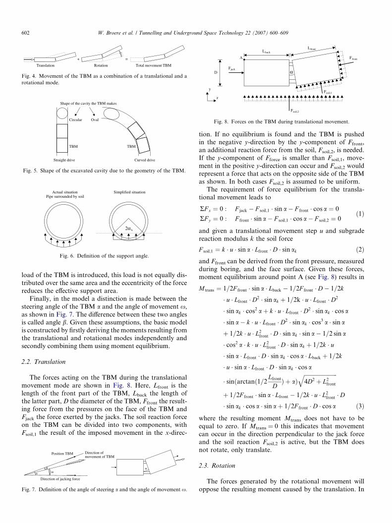
2.2. Translation
The forces acting on the TBM during the translationalmovement mode are shown in Fig. 8. Here, Lfront is thelength of the front part of the TBM, Lback the length ofthe latter part, D the diameter of the TBM, Ffront the result-ing force from the pressures on the face of the TBM andFjack the force exerted by the jacks. The soil reaction forceon the TBM can be divided into two components, withFsoil,1 the result of the imposed movement in the x-direc-
Direction ofmovement of TBM
α
Position TBM
Direction of jacking force
α
βω
Fig. 7. Definition of the angle of steering a and the angle of movement x.
tion. If no equilibrium is found and the TBM is pushedin the negative y-direction by the y-component of Ffront,an additional reaction force from the soil, Fsoil,2, is needed.If the y-component of Fforce is smaller than Fsoil,1, move-ment in the positive y-direction can occur and Fsoil,2 wouldrepresent a force that acts on the opposite side of the TBMas shown. In both cases Fsoil,2 is assumed to be uniform.
The requirement of force equilibrium for the transla-tional movement leads to
RF x ¼ 0 : F jack � F soil;1 � sin a� F front � cos a ¼ 0
RF y ¼ 0 : F front � sin a� F soil;1 � cos a� F soil;2 ¼ 0ð1Þ
and given a translational movement step u and subgradereaction modulus k the soil force
F soil;1 ¼ k � u � sin a � Lfront � D � sin ak ð2Þand Ffront can be derived from the front pressure, measuredduring boring, and the face surface. Given these forces,moment equilibrium around point A (see Fig. 8) results in
M trans ¼ 1=2F front � sin a � Lback � 1=2F front � D� 1=2k
� u � Lfront � D2 � sin ak þ 1=2k � u � Lfront � D2
� sin ak � cos2 aþ k � u � Lfront � D2 � sin ak � cos a
� sin a� k � u � Lfront � D2 � sin ak � cos3 a � sin a
þ 1=2k � u � L2front � D � sin ak � sin a� 1=2 sin a
� cos2 a � k � u � L2front � D � sin ak þ 1=2k � u
� sin a � Lfront � D � sin ak � cos a � Lback þ 1=2k
� u � sin a � Lfront � D � sin ak � cos a
� sinðarctanð1=2Lfront
DÞ þ aÞ
ffiffiffiffiffiffiffiffiffiffiffiffiffiffiffiffiffiffiffiffiffiffiffiffi4D2 þ L2
front
q
þ 1=2F front � sin a � Lfront � 1=2k � u � L2front � D
� sin ak � cos a � sin aþ 1=2F front � D � cos a ð3Þ
where the resulting moment Mtrans does not have to beequal to zero. If Mtrans = 0 this indicates that movementcan occur in the direction perpendicular to the jack forceand the soil reaction Fsoil,2 is active, but the TBM doesnot rotate, only translate.
2.3. Rotation
The forces generated by the rotational movement willoppose the resulting moment caused by the translation. In
Translation Total movement TBM+ =
Rotation
-σtrans
+
σrot -+
+
Tensile forces not possible in soil
Fig. 10. Tensile forces due to translation and rotation of the TBM.
+
σrot
Fig. 11. Admissible tensile forces due to rotation on the bottom of theTBM.
W. Broere et al. / Tunnelling and Underground Space Technology 22 (2007) 600–609 603
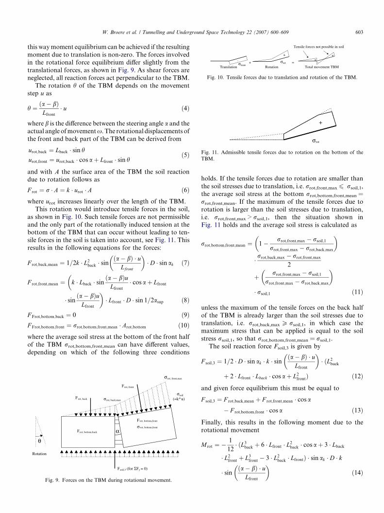
this way moment equilibrium can be achieved if the resultingmoment due to translation is non-zero. The forces involvedin the rotational force equilibrium differ slightly from thetranslational forces, as shown in Fig. 9. As shear forces areneglected, all reaction forces act perpendicular to the TBM.
The rotation h of the TBM depends on the movementstep u as
h ¼ ða� bÞLfront
� u ð4Þ
where b is the difference between the steering angle a and theactual angle of movement x. The rotational displacements ofthe front and back part of the TBM can be derived from
urot;back ¼ Lback � sin h
urot;front ¼ urot;back � cos aþ Lfront � sin hð5Þ
and with A the surface area of the TBM the soil reactiondue to rotation follows as
F rot ¼ r � A ¼ k � urot � A ð6Þwhere urot increases linearly over the length of the TBM.
This rotation would introduce tensile forces in the soil,as shown in Fig. 10. Such tensile forces are not permissibleand the only part of the rotationally induced tension at thebottom of the TBM that can occur without leading to ten-sile forces in the soil is taken into account, see Fig. 11. Thisresults in the following equations for the forces:
F rot;back;mean ¼ 1=2k � L2back � sin
ða� bÞ � uLfront
� �� D � sin ak ð7Þ
F rot;front;mean ¼ k � Lback � sinða� bÞu
Lfront
� cos aþ Lfront
�
� sinða� bÞu
Lfront
�� Lfront � D � sin 1=2asup ð8Þ
F Frot;bottom;back ¼ 0 ð9ÞF Frot;bottom;front ¼ rrot;bottom;front;mean � Arot;bottom ð10Þwhere the average soil stress at the bottom of the front halfof the TBM rrot,bottom,front,mean can have different values,depending on which of the following three conditions
σsoil
(=k* u)
α
Frot, front
F (for ΣFy = 0)soil,3
Frot, bottom,back
Frot, back
σrot, front,max
σrot, back,max
F rot, bottom,front
σ rot, bottom,front
θ
Rotation
Fig. 9. Forces on the TBM during rotational movement.
holds. If the tensile forces due to rotation are smaller thanthe soil stresses due to translation, i.e. rrot,front,max 6 rsoil,1,the average soil stress at the bottom rrot,bottom,front,mean =rrot,front,mean. If the maximum of the tensile forces due torotation is larger than the soil stresses due to translation,i.e. rrot,front,max > rsoil,1, then the situation shown inFig. 11 holds and the average soil stress is calculated as
rrot;bottom;front;mean ¼ 1� rrot;front;max � rsoil;1
rrot;front;max � rrot;back;max
� �
� rrot;back;max � rrot;front;max
2
þ rrot;front;max � rsoil;1
rrot;front;max � rrot;back;max
� �
� rsoil;1 ð11Þ
unless the maximum of the tensile forces on the back halfof the TBM is already larger than the soil stresses due totranslation, i.e. rrot,back,max P rsoil,1, in which case themaximum stress that can be applied is equal to the soilstress rsoil,1, so that rrot,bottom,front,mean = rsoil,1.
The soil reaction force Fsoil,3 is given by
F soil;3 ¼ 1=2 � D � sin ak � k � sinða� bÞ � u
Lfront
� �� ðL2
back
þ 2 � Lfront � Lback � cos aþ L2frontÞ ð12Þ
and given force equilibrium this must be equal to
F soil;3 ¼ F rot;back;mean þ F rot;front;mean � cos a
� F rot;bottom;front � cos a ð13Þ
Finally, this results in the following moment due to therotational movement
M rot ¼ �1
12� ðL3
back þ 6 � Lfront � L2back � cos aþ 3 � Lback
� L2front þ L3
front � 3 � L2back � LfrontÞ � sin ak � D � k
� sinða� bÞ � u
Lfront
� �ð14Þ

Table 1Input parameters for the standard example
Parameter Symbol Value Variations
Dimensions TBM
Length front part shield Lfront 2 m –Length back part shield Lback 3.5 m –Outside diameter shield D 2.5 m –
Steering of the TBM
Steering angle of theTBM
a 1� 0.5�, 1�, 2�
604 W. Broere et al. / Tunnelling and Underground Space Technology 22 (2007) 600–609
2.4. Influence of the subgrade reaction modulus
In the previous sections the subgrade reaction modulusk has been introduced to relate stresses in the soil to dis-placements. The subgrade reaction modulus, however, isnot a constant, but varies at different locations aroundthe TBM due to the varying interaction between TBMand soil. Three different subgrade reaction moduli are dis-tinguished, namely ktranslation in the outside bend due totranslation, krotation,outside in the outside bend due to tensileforces resulting from rotation and krotation,inside in the insidebend, in the shadow of the TBM (see also Fig. 12).
The value of ktranslation is based on the regular subgradereaction modulus of the soil. For krotation,outside the samevalue is used, disregarding a possible increase in stiffnessof the soil due to unloading–reloading behaviour. Forkrotation,inside, however, a reduction factor Ck is introducedto account for the disturbance and partial excavation ofthe soil at the shadow side of the TBM.
To determine the value of Ck based on theoretical con-siderations is difficult, as the influence of a passing TBMon the soil is largely unknown. Therefore, an estimatedvalue has been obtained based on the assumption thatin sufficiently stiff soil the angle of movement x equalsthe steering angle a. Using this assumption and realisticinput parameters, values of Ck between 0.15 and 0.35were found. Rather arbitrarily a fixed value of Ck =0.25 has been chosen for further calculations, basicallystating that the stiffness of the soil at the shadow sideof the TBM is one quarter of that of the undisturbed soil.Although this choice is based on a number of realisticparameter variations, it is recommended that furtherresearch is be done to determine with greater confidencecorrect values of Ck.
2.5. Reaction of the basic model using reference parameters
As stated above, moment equilibrium requires that
M trans þM rot ¼ 0 ð15Þwhere Mtrans and Mrot are given by (3) and (14), respec-tively. This formula requires the dimensions of the TBM,the soil parameters and the steering angle a of the TBMas input parameters and has the deviation angle b as theonly unknown. When b has been determined, the angleof movement x and rotation h follow from (4) and
x ¼ a� b ð16Þ
(Inside bend)
(Outside bend)
Excavated soil
Laterally displaced soil‘Shadow side’
Progress direction
Jack force
Fig. 12. Areas of displaced and excavated soil around the TBM.
Other measures that can be used to characterise the behav-iour of the TBM are the amount of ovalisation Ov, definedas
Ov ¼ Lfront � sin b ð17Þ
and the radius of curvature
R � ðLfront þ LbackÞ=2x ð18ÞA reference data set is used to show the influence of the dif-ferent model parameters. An overview of all input param-eters is given in Table 1. In this table, two parameters aregiven as variable, the steering angle and the subgrade reac-tion modulus, as they are varied in this and most of thesubsequent parameter studies.
This first parameter study shows the extent to which theTBM reacts to steering. This reaction depends mainly onthe subgrade reaction modulus. Fig. 13 shows that theTBM reacts better if the soil is stiffer. When the soil hasa low stiffness, the TBM shows little or no response tothe steering action. The relatively large front force Ffront,that acts perpendicular to the front of the TBM, pushesthe TBM back in line and counteracts the steering action.In extreme cases, the TBM can even rotate in the oppositedirection, but in such a case a different set of forces will acton the TBM than described by (15). Such a case is not cov-ered by the current model.
2.6. Influence of various input parameters
When varying the various input parameters of themodel, a number of conclusions can be drawn. Forinstance, if the length of the front part of the TBM Lfront
is increased, the ability to steer the TBM is improved, ascan be seen in Fig. 14. Reducing the length of the latterpart of the TBM Lback has a similar result. This behaviour
Soil parameters
Subgrade reactionmodulus
k 1000 kN/m3 0–15,000 kN/m3
Front forcea Ffront 250 kN –Support angle 2ak or asup 120� –Reduction factor for k at
the ‘shadow side’Ck 0.25 –
Model parameterMovement step u 0.1 m –
a The front force is derived from a constant front pressure. If the outsidediameter changes, the front force will change proportionally.
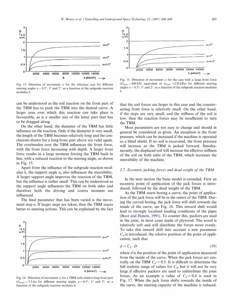
Fig. 13. Direction of movement x for the reference case for differentsteering angles a = 0.5�, 1� and 2�, as a function of the subgrade reactionmodulus k.
Fig. 15. Direction of movement x for the case with a large front force(Ffront = 600 kN, equivalent to rfront �120 kPa) for different steeringangles a = 0.5�, 1� and 2�, as a function of the subgrade reaction modulusk.
W. Broere et al. / Tunnelling and Underground Space Technology 22 (2007) 600–609 605
can be understood as the soil reaction on the front part ofthe TBM has to push the TBM into the desired curve. Alarger area over which this reaction can take place isfavourable, as is a smaller size of the latter part that hasto be dragged along.
On the other hand, the diameter of the TBM has littleinfluence on the reaction. Only if the diameter is very small,the length of the TBM becomes relatively long and the con-clusions drawn for a long front part above are valid again.The overburden over the TBM influences the front force,with the front force increasing with depth. A larger frontforce results in a large moment forcing the TBM back inline, with a reduced reaction to the steering angle, as shownin Fig. 15.
Apart from the influence of the subgrade reaction mod-ulus k, the support angle ak also influences the steerability.A larger support angle improves the reaction of the TBM,but the influence is rather small. This can be understood asthe support angle influences the TBM on both sides andtherefore both the driving and contra moment areinfluenced.
The final parameter that has been varied is the move-ment step u. If larger steps are taken, then the TBM reactsbetter to steering actions. This can be explained by the fact
Fig. 14. Direction of movement x for a TBM with relative long front part(Lfront = 3.5 m) for different steering angles a = 0.5�, 1� and 2�, as afunction of the subgrade reaction modulus k.
that the soil forces are larger in this case and the counter-acting front force is relatively small. On the other hand,if the steps are very small, and the stiffness of the soil islow, then the reaction forces may be insufficient to turnthe TBM.
Most parameters are not easy to change and should ingeneral be considered as given. An exception is the frontpressure, which can be increased if the machine is operatedas a blind shield. If no soil is excavated, the front pressurewill increase as the TBM is jacked forward. Simulta-neously, the displaced soil will increase the effective stiffnessof the soil on both sides of the TBM, which increases thesteerability of the machine.
2.7. Eccentric jacking forces and dead weight of the TBM
In the next section the basic model is extended. First aneccentric point of application of the jack forces is intro-duced, followed by the dead weight of the TBM.
As the TBM starts boring a curve, the point of applica-tion of the jack force will be in the centre of the TBM. Dur-ing the curved boring, the jack force will shift towards theinside of the curve, see Fig. 16. This inward shift wouldlead to strongly localised loading conditions of the pipes(Boot and Husein, 1991). To counter this, packers are usedin the joint, in most cases made of plywood. The wood isrelatively soft and will distribute the forces more evenly.To take this inward shift into account a new parameterCd is introduced, the relative position of the point of appli-cation, such that
d ¼ Cd � D ð19Þwhere d is the position of the point of application measuredfrom the inside of the curve. When the jack forces act cen-trally on the TBM Cd = 0.5. It is difficult to determine thefull realistic range of values for Cd, but it will not be verylarge if effective packers are used to redistribute the jointforces. As an example a value of Cd = 0.4 is used inFig. 17. When the jack force shifts towards the inside ofthe curve, the steering capacity of the machine is reduced.
Jack force acts in the centre at thestart of the curve
Point of application shifts becauseof rotation
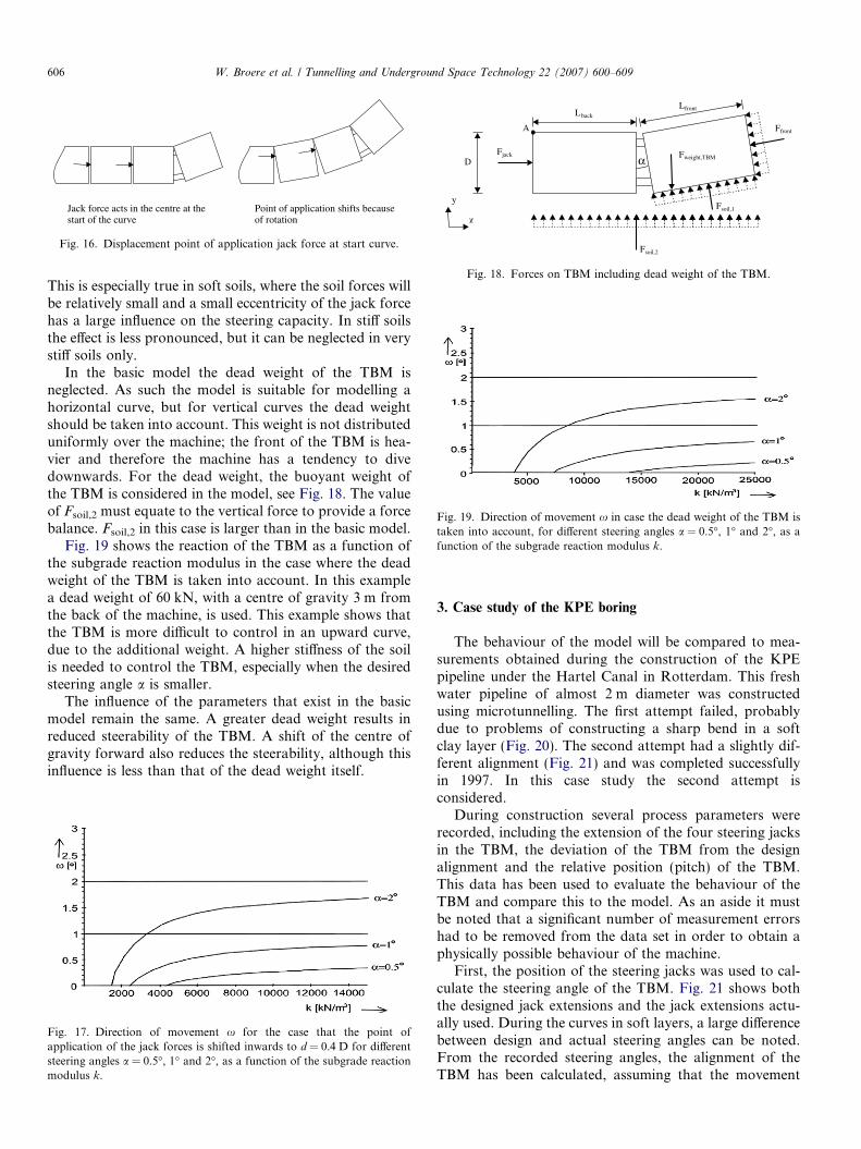
Fig. 16. Displacement point of application jack force at start curve.
Ffront
x
y
α
Fsoil,1
Fsoil,2
Fjack
A
Lback
Lfront
DFweight,TBM
Fig. 18. Forces on TBM including dead weight of the TBM.
Fig. 19. Direction of movement x in case the dead weight of the TBM istaken into account, for different steering angles a = 0.5�, 1� and 2�, as afunction of the subgrade reaction modulus k.
606 W. Broere et al. / Tunnelling and Underground Space Technology 22 (2007) 600–609
This is especially true in soft soils, where the soil forces willbe relatively small and a small eccentricity of the jack forcehas a large influence on the steering capacity. In stiff soilsthe effect is less pronounced, but it can be neglected in verystiff soils only.
In the basic model the dead weight of the TBM isneglected. As such the model is suitable for modelling ahorizontal curve, but for vertical curves the dead weightshould be taken into account. This weight is not distributeduniformly over the machine; the front of the TBM is hea-vier and therefore the machine has a tendency to divedownwards. For the dead weight, the buoyant weight ofthe TBM is considered in the model, see Fig. 18. The valueof Fsoil,2 must equate to the vertical force to provide a forcebalance. Fsoil,2 in this case is larger than in the basic model.
Fig. 19 shows the reaction of the TBM as a function ofthe subgrade reaction modulus in the case where the deadweight of the TBM is taken into account. In this examplea dead weight of 60 kN, with a centre of gravity 3 m fromthe back of the machine, is used. This example shows thatthe TBM is more difficult to control in an upward curve,due to the additional weight. A higher stiffness of the soilis needed to control the TBM, especially when the desiredsteering angle a is smaller.
The influence of the parameters that exist in the basicmodel remain the same. A greater dead weight results inreduced steerability of the TBM. A shift of the centre ofgravity forward also reduces the steerability, although thisinfluence is less than that of the dead weight itself.
Fig. 17. Direction of movement x for the case that the point ofapplication of the jack forces is shifted inwards to d = 0.4 D for differentsteering angles a = 0.5�, 1� and 2�, as a function of the subgrade reactionmodulus k.
3. Case study of the KPE boring
The behaviour of the model will be compared to mea-surements obtained during the construction of the KPEpipeline under the Hartel Canal in Rotterdam. This freshwater pipeline of almost 2 m diameter was constructedusing microtunnelling. The first attempt failed, probablydue to problems of constructing a sharp bend in a softclay layer (Fig. 20). The second attempt had a slightly dif-ferent alignment (Fig. 21) and was completed successfullyin 1997. In this case study the second attempt isconsidered.
During construction several process parameters wererecorded, including the extension of the four steering jacksin the TBM, the deviation of the TBM from the designalignment and the relative position (pitch) of the TBM.This data has been used to evaluate the behaviour of theTBM and compare this to the model. As an aside it mustbe noted that a significant number of measurement errorshad to be removed from the data set in order to obtain aphysically possible behaviour of the machine.
First, the position of the steering jacks was used to cal-culate the steering angle of the TBM. Fig. 21 shows boththe designed jack extensions and the jack extensions actu-ally used. During the curves in soft layers, a large differencebetween design and actual steering angles can be noted.From the recorded steering angles, the alignment of theTBM has been calculated, assuming that the movement
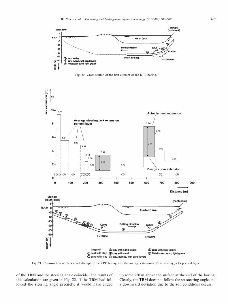
Fig. 20. Cross-section of the first attempt of the KPE boring.
Distance [m]
Jack
exte
nsio
n[m
]
12
10
8
6
4
2
00 100 200 300 400 500 600 700 800 900
9.44
5.61
4.954.37
2.482.58
1.53
3.47
2.081.70
7.76
6.69
4.09
2.66
4.85
Average steering jack extensionper soil layer
Actually used extension
Design curve extension1 2 3 4 5 6 5 57
Hartel Canal
2
Fig. 21. Cross-section of the second attempt of the KPE boring with the average extensions of the steering jacks per soil layer.
W. Broere et al. / Tunnelling and Underground Space Technology 22 (2007) 600–609 607
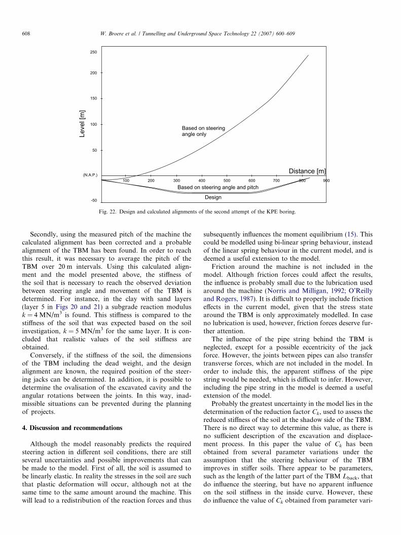
of the TBM and the steering angle coincide. The results ofthis calculation are given in Fig. 22. If the TBM had fol-lowed the steering angle precisely, it would have ended
up some 250 m above the surface at the end of the boring.Clearly, the TBM does not follow the set steering angle anda downward deviation due to the soil conditions occurs.
Leve
l [m
]
Distance [m]
Based on steeringangle only
Based on steering angle and pitch
Design
250
200
150
100
50
-50
(N.A.P.)100 200 300 400 500 600 700 800 900
Fig. 22. Design and calculated alignments of the second attempt of the KPE boring.
608 W. Broere et al. / Tunnelling and Underground Space Technology 22 (2007) 600–609
Secondly, using the measured pitch of the machine thecalculated alignment has been corrected and a probablealignment of the TBM has been found. In order to reachthis result, it was necessary to average the pitch of theTBM over 20 m intervals. Using this calculated align-ment and the model presented above, the stiffness ofthe soil that is necessary to reach the observed deviationbetween steering angle and movement of the TBM isdetermined. For instance, in the clay with sand layers(layer 5 in Figs 20 and 21) a subgrade reaction modulusk = 4 MN/m3 is found. This stiffness is compared to thestiffness of the soil that was expected based on the soilinvestigation, k = 5 MN/m3 for the same layer. It is con-cluded that realistic values of the soil stiffness areobtained.
Conversely, if the stiffness of the soil, the dimensionsof the TBM including the dead weight, and the designalignment are known, the required position of the steer-ing jacks can be determined. In addition, it is possible todetermine the ovalisation of the excavated cavity and theangular rotations between the joints. In this way, inad-missible situations can be prevented during the planningof projects.
4. Discussion and recommendations
Although the model reasonably predicts the requiredsteering action in different soil conditions, there are stillseveral uncertainties and possible improvements that canbe made to the model. First of all, the soil is assumed tobe linearly elastic. In reality the stresses in the soil are suchthat plastic deformation will occur, although not at thesame time to the same amount around the machine. Thiswill lead to a redistribution of the reaction forces and thus
subsequently influences the moment equilibrium (15). Thiscould be modelled using bi-linear spring behaviour, insteadof the linear spring behaviour in the current model, and isdeemed a useful extension to the model.
Friction around the machine is not included in themodel. Although friction forces could affect the results,the influence is probably small due to the lubrication usedaround the machine (Norris and Milligan, 1992; O’Reillyand Rogers, 1987). It is difficult to properly include frictioneffects in the current model, given that the stress statearound the TBM is only approximately modelled. In caseno lubrication is used, however, friction forces deserve fur-ther attention.
The influence of the pipe string behind the TBM isneglected, except for a possible eccentricity of the jackforce. However, the joints between pipes can also transfertransverse forces, which are not included in the model. Inorder to include this, the apparent stiffness of the pipestring would be needed, which is difficult to infer. However,including the pipe string in the model is deemed a usefulextension of the model.
Probably the greatest uncertainty in the model lies in thedetermination of the reduction factor Ck, used to assess thereduced stiffness of the soil at the shadow side of the TBM.There is no direct way to determine this value, as there isno sufficient description of the excavation and displace-ment process. In this paper the value of Ck has beenobtained from several parameter variations under theassumption that the steering behaviour of the TBMimproves in stiffer soils. There appear to be parameters,such as the length of the latter part of the TBM Lback, thatdo influence the steering, but have no apparent influenceon the soil stiffness in the inside curve. However, thesedo influence the value of Ck obtained from parameter vari-

W. Broere et al. / Tunnelling and Underground Space Technology 22 (2007) 600–609 609
ations. As the influence of Ck on the model results is signif-icant, and the certainty that the correct value has beenused in all cases is small, it is advisable to further investi-gate the soil reaction at the shadow side of the TBM whenapplying the model.
5. Conclusions
A model has been developed that describes the move-ment of a microtunnelling machine as a combination of atranslational and a rotational displacement. For bothmovement modes the soil reaction is established and theseare then superposed. If the dimensions of the TBM and thestiffness of the soil are known, the model can calculate therequired steering action needed to obtain a desired curva-ture of the boring. It is found that in soft soils a largersteering angle is needed to obtain the desired movementfrom the machine. In very soft soils it is even possible thatinsufficient soil reaction can be mobilised to steer themachine.
The model has been verified for a single case study andcan explain the behaviour observed in that case. However,
there are still a number of uncertainties in the model, suchas the influence of the excavation process on the apparentstiffness of the soil that is used as input for the model. Fur-thermore, the soil is supposed to be linearly elastic and fric-tion forces are neglected. These points warrant furtherattention before the model can be used to design allowablecurvatures in a project.
References
Boot, J.C., Husein, N.M., 1991. Vitrified clay pipes subject to jacking
forces. In: Proceedings of the First Pipe Jacking and Microtunnelling
International Conference, London, pp. 6.1–6.9.
Norris, P.M., Milligan, G.W.E., 1992. Frictional resistance of jacked pipes
at full scale. In: Proceedings of the International Conference, No-Dig
Paris, pp. 117–120.
O’Reilly, M.P., Rogers, C.D.F., 1987. Pipe jacking forces. In: Proceedings
of the International Conference On Foundations and Tunnels,
Edinburgh, 1987, pp. 201–208.
Oreste, P.P., Peila, D., Marchionni, V., Sterling, R., 2002. Analysis of the
problems connected to the sinking of micro-TBMS in difficult ground.
T.U.S.T. 16 (1), 33–45.
Thomson, J.C., 1993. Pipejacking and Microtunnelling. Blackie Academic
and Professional, Glasgow.