experience acquisition simulator for operating microtuneling boring machines
TRANSCRIPT
Automation in Construction 23 (2012) 33–46
Contents lists available at SciVerse ScienceDirect
Automation in Construction
j ourna l homepage: www.e lsev ie r .com/ locate /autcon
Experience acquisition simulator for operating microtuneling boring machines
Alberto Jardón ⁎, Juan G. Victores, Santiago Martínez, Carlos BalaguerRobotics Lab, Engineering Systems and Automation Department, Universidad Carlos III de Madrid, 28911 Leganés, Spain
⁎ Corresponding author.E-mail address: [email protected] (A. Jardón).
0926-5805/$ – see front matter. Crown Copyright © 20doi:10.1016/j.autcon.2011.12.002
a b s t r a c t
a r t i c l e i n f oArticle history:Accepted 5 December 2011Available online 8 February 2012
Keywords:Tunneling machineRobotic automationTunnel execution modelingSimulatorPipe jacking training
This paper describes an innovative modeling and training framework and an simulator application for microtunneling machines under heterogeneous gravel and sand soils. From the selective collection of skilled pilots'know-how of a pipe jacking microtunnelling machine in operation, to generate a rule-based system based ongrouped rules and states that replicates machine performance. The adjustment of these states and associatedrules allows creation, setup and analysis of a realistic functional model for tunneling machines. The systemintegrates a friendly human machine interface (HMI) that closely replicates real machine's pilot cabinetand allows natural interaction with the implemented inference engine through the simulated control panels.Additionally, the framework allows the training of tunneling machine's operators by simulation and subse-quent gathered data analysis. The virtual pilot's desk is the first implementation of a jack piping microtunnel-ing machine simulator by means of pilot's steering know-how capture methodology.
Crown Copyright © 2011 Published by Elsevier B.V. All rights reserved.
1. Introduction
The industry of underground construction is expanding; therefore,the associated technology must provide reliable solutions. The use oftunneling machines will also be affected by urban expansion that im-plies the construction of new residential zones in places where basicsupply services do not exist: electrical, water and gas supply, andwaste collectors. In the last few years, a fast development of tunnelingmachines has been experienced. The number of utility tunneling(microtunneling, pipe-jacking) and traffic tunneling (large-diametertunnel projects) is growing. Pipe-jacking microtunnel boring ma-chines (will be referred to as simply MTBM) use a powered cutter-head and steering assembly that is pushed forward by a jackingsystem from a launching pit, shown in Fig. 1. They have mainlybeen developed in Japan [3], [22], [18] and Germany [6], for sewerwork. As the machine advances, sections of permanent pipes are fedin and pushed forward behind the MTBM by the jacking unit. Theresulting tunnels are always of circular cross section (typically be-tween 0.5 m and 2.5 m diameter) due to the excavation method,which consists in rotating some form of cutterhead against the soiland rock face. Modern machines have a relatively short driven mech-anism. Such drilling assemblies tend to be long relative to their diam-eters and tend to fit tightly in the tunnel.
Most of these machines are steerable and typically use a system ofhydraulic jacks to tilt the cutterhead in the required direction. Chang-ing the direction of tunneling is then a matter of making the cutterhead cut sideways and getting the drive mechanism to follow.
11 Published by Elsevier B.V. All rig
Typically, steering angles can be 3° at most, allowing curvature radiistarting at 250 m. However, many factors can affect these values,such as pipe type, pipe size, joint type, ground condition, and tunnellength.
The first microtunneling project was completed in USA in 1984[17]. In Spain, the first microtunneling project ever assembled bya Spanish company was not until 1996, by the Eurohinca company[20]. Microtunneling machines are an excellent solution that mini-mizes urban surface disturbances and economic impact, duringthe tunnel construction. The machines operate in a variety of rela-tively soft soils, although some are provided with cutting andcrushing heads that will cope with gravel and small boulders andallow them to drill rocky terrains. Maximum tunnel lengths arecontinuously increasing, from 150 m reported at [13] up to1200 m and 3000 m [21]. Microtunneling technology is consideredhighly specialized, and inexperienced execution can severe issues.Reliability can be limited if the geology of a terrain does not fitwith ideal machine working conditions, or if the project proposaldoes not take restrictions and limitations of this technique intoconsideration.
Typically, these problems are due to undefined and unanticipatedconditions that are adverse and beyond the capabilities of the MTBMsuch as: (i) obstacles that stop the forward progress of the machine,boulders, high concentration of cobbles, (ii) rock layers and hardzones in soft rock or soil, and (iii) plastic clay with mixed ground, un-usual slits, and interfaces between materials having radical differ-ences in density and consistency. These factors can generateinadequate torque, chocking of the MTBM cutterhead, losing theguidance control and collapsing. Having to rescue the machine bymeans of digging, generating delays, cost overruns and economiclosses, and is not always possible.
hts reserved.

Fig. 1. Microtunneling machine operational schema.
34 A. Jardón et al. / Automation in Construction 23 (2012) 33–46
To recognize and solve these described previous situations and tobe able to avoid problems, an experienced crew is required to per-form the machine's control properly. Due to tunneling machine–ground interaction, some internal machine variables continuouslydrift off course and the operator's control references adjustmentsmust compensate the drift keeping the machine under control andsafe operation. The main purpose is to maintain the machine in safeconditions following the planned path. The growing demand ofmicrotunneling machines is greater than the growth of availablequalified professionals. Due to efforts in cost and learning time, nor-mally it takes from 12 to more than 18 months to achieve a certaindegree of qualification. The given training is focused on transmittingsenior pilot's knowledge to successfully solve common and unexpect-ed machine states in as many different terrains as possible, by meansof shared control of the real machine between senior and novel pilots.The senior, however, remains the ultimate responsible of themachine.
2. Training simulators in construction
Performance enhancements are a well-known advantage of simu-lator training [4]. Several training simulators for construction ma-chinery have been developed in the past by construction companies.Several examples are presented: a) “Versatile augmented reality sim-ulation for training in the safe use of construction machinery”, calledVar-trainer, is the expected result of a EU 7th Program Frame projectcoordinated by Ikerlan [29], b) Atlas Copco simulators for RocketBoomer L2C tunneling machine-drill jumbo jet simulator (updatedto a jumbo jet L2E version), and a JCB backhoe 3CX simulator [5],c) CyberMINETM immersive simulators, presented in the Bauma fair in2007 [27], that “transport” the operator in a highly realistic operatingenvironment within a 3D training world, d) Aitemin developed in2005 a mining machine simulator also used immersive environment[2].
Most of these simulators closely replicate common control cabinetinstruments and their control functions are very similar to those thatrun on real equipment. The operation of sub-systems such as engines,braking systems, hydraulics and drilling heads is mathematicallymodeled, in order to provide realistic feedback to the training opera-tor. These simulators work with a fixed implicit mathematical modelof the machine environment interaction [23], [1], but there is no in-formation about the accuracy of these models.
The proposed framework has been designed to ease the transfer-ence of high level know-how, experience, and expertise of seniorMTBM's pilots to other organization members. A discrete state virtualmachine and a rule based inference engine have been developed toimplement the machine control systems and the most influential pa-rameters. To replicate the machine performance and the terrain–machine interaction without using physics engines [9] or implicitmathematical models, a very simple initial rule engine has been
implemented, and a replica of machine control and instrumentationpanel has been programmed. This way, the model is first tuned by theexperts, and then constantly updated considering the experts' sugges-tions and typical exercise results. After some iteration the rule engineis tuned enough to respond as the real machine does, and it can beused to build a simulator or to be used as a black box model for controlalgorithms. After a detailed and progressive analysis, more precise andcomplex rules have been implemented to obtain realistic performance.Used as a training simulator, it has proved useful to focus the trainingeffort on steering problem. Other machine issues, relevant for mainte-nance or technical staff but not for pilots, have been avoided. The sys-tem has been designed to reduce training time from 12 or 18 monthsto less than a few, providing actual training quality improvements.The presented development is the first ones focused on the guidanceof tunneling jack piping machines.
3. Framework and simulator architecture
As response to proprietary complex systems' uncertainty that for-bids the analysis and modeling of internal machine subsystems andparameters in order to create practical models, the proposed frame-work assists expert systems creation. This methodology for creatinga virtual machine replicas is based on two pillars: first, the recreationof the real machine interface that is the cockpit of the pilot machine,and second, the inference engine that obtains and feeds data to thecockpit, designed from the analysis of the system form the expert'spoint of view, reliable enough for training or to be used as model indesign machine's control systems, without using physics engines orimplicit mathematical models.
The presented framework facilitates the application of the pro-posed methodology. It has been implemented by means of two com-puters linked by TCP/IP, where one of them is an industrial PC with atactile screen. The application of the methodology requires severalstages. The initial approach to analyze the problem of how to steerthe MTBM, was to analyze which are the data sources of pilots andhow they manage this data to generate the proper settings, insidethe cockpit. Efforts must focus on emulating the cockpit's data sourcesand controls as reliably as possible. After that, it's possible to applythe proposed methodology step by step. The procedure has consistedof four stages: analysis, implementation, debugging, and finally, users'validation. The analysis phase was dedicated to study the process,identify machine states for representation, report main parametersand their interrelationships, as well as designing the simulator'smain interaction schema. The second step covered the implementa-tion of the simulator architecture into a software application able tomanage all the process and machine variables, defined states anderrors. After that, expert validation of preliminary results was per-formed. The next steps were debugging the HMI and inference engineuntil they “worked like” the real system. This item was checked byexpert pilots and needed several test exercises and iterations. Afterthese processes, the simulator's responses and the real machine re-sponses were close enough to be used as a framework for modeling,training or predictive simulation.
The machine performance is heavily influenced by soil character-istics, geometric and physical properties. Most important ground orrock-mechanical parameters for machine-terrain characterizationare: the grading curve, ground water penetration, the consistencylimits, the rock/clay mineralogy, the quality of the rock, and the hard-ness of the rock. These parameters (or a subset among them) are usedto adjust machine–terrain interaction. Grain size, over break, as wellas lubrication or stoppages affect machine responses modifying pre-dictable variables ranges, which is what the pilot must understandand recognize. As Fig. 2 summarizes, the operator proceeds as hewould do at the construction site, starting the machine from the in-strument panel and loading the proper parameters to start the pipingprocess. The operator must adjust pressures of jack cylinder, cutting
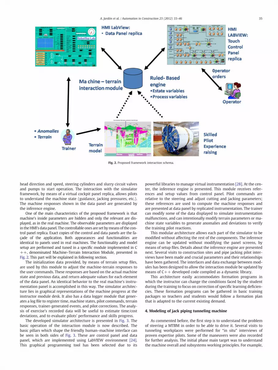
Fig. 2. Proposed framework interaction schema.
35A. Jardón et al. / Automation in Construction 23 (2012) 33–46
head direction and speed, steering cylinders and slurry circuit valvesand pumps to start operation. The interaction with the simulatorframework, by means of a virtual cockpit panel replica, allows pilotsto understand the machine state (guidance, jacking pressures, etc.).The machine responses shown in the data panel are generated bythe inference engine.
One of the main characteristics of the proposed framework is thatmachine's inside parameters are hidden and only the relevant are dis-played, as in the real machine. The observable parameters are displayedin theHMI's data panel. The controllable ones are set bymeans of the con-trol panel replica. Exact copies of the control and data panels are the fa-çade of the application. Both appearances and functionalities areidentical to panels used in real machines. The functionality and modelsetup are performed and tuned in a specific module implemented in C++, denominated Machine–Terrain Interaction Module, presented inFig. 2. This part will be explained in following section.
The initialization data provided, by means of terrain setup files,are used by this module to adjust the machine-terrain responses tothe user commands. These responses are based on the actual machinestate and previous data, and return adequate values for each elementof the data panel. An identical behavior to the real machine's instru-mentation panel is accomplished in this way. The simulator architec-ture lies in graphical representations of the machine progress at theinstructor module desk. It also has a data logger module that gener-ates a log file to register time, machine states, pilot commands, terrainresponses, trainer-generated events, and pilot corrections. The analy-sis of exercise's recorded data will be useful to estimate time/costdeviations, and to evaluate pilots' performance and skills progress.
The developed simulator architecture is presented in Fig. 3. Thebasic operation of the interaction module is now described. Thebasic pillars which shape the friendly human–machine interface canbe seen in both sides of Fig. 3. These are control panel and datapanel, which are implemented using LabVIEW environment [24].This graphical programming tool has been selected due to its
powerful libraries to manage virtual instrumentation [28]. At the cen-ter, the inference engine is presented. This module receives refer-ences and setup values from control panel. Pilot commands arerelative to the steering and adjust cutting and jacking parameters;these references are used to compute the machine responses andare presented at data panel by replicated instrumentation. The trainercan modify some of the data displayed to simulate instrumentationmalfunctions, and can intentionally modify terrain parameters or ma-chine state variables to generate anomalies and deviations to verifythe training pilot reactions.
This modular architecture allows each part of the simulator to bemodified without affecting the rest of the components. The inferenceengine can be updated without modifying the panel screens, bymeans of setup files. Details about the inference engine are presentednext. Several visits to construction sites and pipe jacking pilot inter-views have been made and crucial parameters and their relationshipshave been gathered. The interfaces and data exchange between mod-ules has been designed to allow the interaction module be updated bymeans of C++ developed code compiled as a dynamic library.
This architecture easily accommodates formation programs inwhich the instructor can change the conditions faced by the studentduring the training to focus on correction of specific learning deficien-cies. These formation programs can be gathered in basic trainingpackages so teachers and students would follow a formation planthat is adapted to the current existing demand.
4. Modeling of jack piping tunneling machine
As commented before, the first step is to understand the problemof steering a MTBM in order to be able to drive it. Several visits totunneling workplaces were performed for “in situ” interviews ofproven expertise pilots. Some of the maneuvers were also recordedfor further analysis. The initial phase main target was to understandthe machine overall and subsystems working principles. For example,
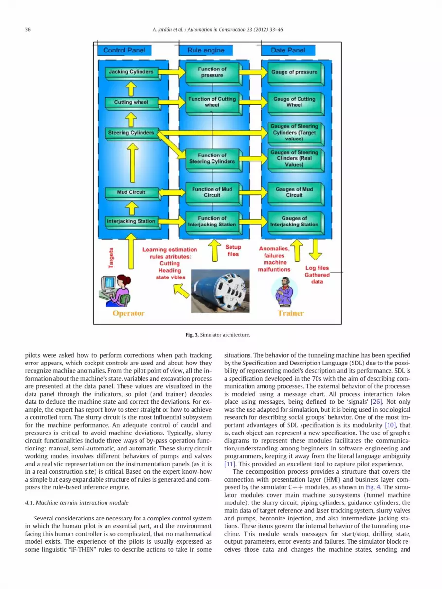
Fig. 3. Simulator architecture.
36 A. Jardón et al. / Automation in Construction 23 (2012) 33–46
pilots were asked how to perform corrections when path trackingerror appears, which cockpit controls are used and about how theyrecognize machine anomalies. From the pilot point of view, all the in-formation about the machine's state, variables and excavation processare presented at the data panel. These values are visualized in thedata panel through the indicators, so pilot (and trainer) decodesdata to deduce the machine state and correct the deviations. For ex-ample, the expert has report how to steer straight or how to achievea controlled turn. The slurry circuit is the most influential subsystemfor the machine performance. An adequate control of caudal andpressures is critical to avoid machine deviations. Typically, slurrycircuit functionalities include three ways of by-pass operation func-tioning: manual, semi-automatic, and automatic. These slurry circuitworking modes involves different behaviors of pumps and valvesand a realistic representation on the instrumentation panels (as it isin a real construction site) is critical. Based on the expert know-howa simple but easy expandable structure of rules is generated and com-poses the rule-based inference engine.
4.1. Machine terrain interaction module
Several considerations are necessary for a complex control systemin which the human pilot is an essential part, and the environmentfacing this human controller is so complicated, that no mathematicalmodel exists. The experience of the pilots is usually expressed assome linguistic “IF-THEN” rules to describe actions to take in some
situations. The behavior of the tunneling machine has been specifiedby the Specification and Description Language (SDL) due to the possi-bility of representing model's description and its performance. SDL isa specification developed in the 70s with the aim of describing com-munication among processes. The external behavior of the processesis modeled using a message chart. All process interaction takesplace using messages, being defined to be ‘signals’ [26]. Not onlywas the use adapted for simulation, but it is being used in sociologicalresearch for describing social groups' behavior. One of the most im-portant advantages of SDL specification is its modularity [10], thatis, each object can represent a new specification. The use of graphicdiagrams to represent these modules facilitates the communica-tion/understanding among beginners in software engineering andprogrammers, keeping it away from the literal language ambiguity[11]. This provided an excellent tool to capture pilot experience.
The decomposition process provides a structure that covers theconnection with presentation layer (HMI) and business layer com-posed by the simulator C++ modules, as shown in Fig. 4. The simu-lator modules cover main machine subsystems (tunnel machinemodule): the slurry circuit, piping cylinders, guidance cylinders, themain data of target reference and laser tracking system, slurry valvesand pumps, bentonite injection, and also intermediate jacking sta-tions. These items govern the internal behavior of the tunneling ma-chine. This module sends messages for start/stop, drilling state,output parameters, error events and failures. The simulator block re-ceives those data and changes the machine states, sending and
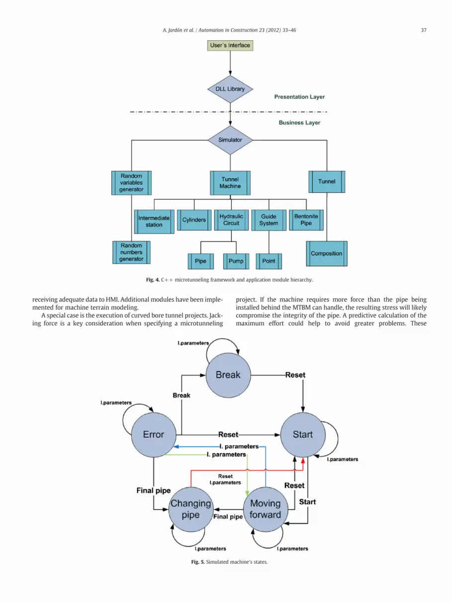
Fig. 4. C++ microtunneling framework and application module hierarchy.
37A. Jardón et al. / Automation in Construction 23 (2012) 33–46
receiving adequate data to HMI. Additional modules have been imple-mented for machine terrain modeling.
A special case is the execution of curved bore tunnel projects. Jack-ing force is a key consideration when specifying a microtunneling
Fig. 5. Simulated m
project. If the machine requires more force than the pipe beinginstalled behind the MTBM can handle, the resulting stress will likelycompromise the integrity of the pipe. A predictive calculation of themaximum effort could help to avoid greater problems. These
achine's states.

Fig. 6. A simplified interrelationship schema of guidance related variables.
38 A. Jardón et al. / Automation in Construction 23 (2012) 33–46
parameters are gathered and stored during simulation. The jackingpipe systems should limit ring stress when accommodate the neces-sary jacking force at the curve.
As previously mentioned, the terrain characteristics are also cru-cial for achieving a complete real simulation. The simplest strategyto define terrain properties is to consider it perfectly homogeneous;therefore the selected set of variables will keep its values along theentire tunnel. Anticipated conditions expected to be provided by themodel would include: average performance, ranges and the most ad-verse conditions expected. The success of the predictive simulation isconditioned by the effectiveness of geotechnical data collecting meth-od. Field and laboratory testing of samples from the tunnel envelopeor local former records must include: index properties (water con-tents, unit weight, Atterberg limits…), grain size distribution, densitytest, viscosity, hardness and strength, and obstructions. A practical
Fig. 7. Implemented rule's flowcharts o
and more realistic approach is to introduce randomness in thoseparameters, in order to simulate heterogeneous terrains. A specialset of C++ modules has been defined to model terrains and itsvariation from setup files that are loaded at initialization or anytime in the simulation exercise.
4.2. Rule-based inference engine implementation
The rule based engine has been implemented as state machine soeach state represents a real machine situation and a particular set ofrules is then applicable. The state diagram, showed at Fig. 5, has gotfive states, 1) Start: some initial setup routines and test are performedbefore starting drilling; 2) Forward: all machine subsystems mustwork within range; 3) Error: if a subsystem reports an error or areset to stop simulation; 4) Break: simulates some machine
f slurry affectation over guidance.
39A. Jardón et al. / Automation in Construction 23 (2012) 33–46
subsystem failure and must be reset or break the simulation; 5) PipeChanging: implies that pipe has been inserted successfully and a newphase must be start to continue the drilling process. These states areenough to fully characterize the machine functionality.
In Fig. 6, an example of implementation of the variable's influencesbetween machine subsystems can be seen. The rules that composeeach module of the inference engine are stored as a hierarchy of mod-ules that communicate information to each other. For example, con-sider two machine subsystems: the steering system and the slurrycircuit. The slurry circuit is also divided into two parts: pumps andvalves. Every instance of the pump module knows everything aboutthe other instance by means of each interface variables. The slurry cir-cuit uses its pumps and valves to build its behavior. At the same time,the tunnel machine gets the information from the slurry circuit andthe steering system, among others, to modify its behavior. Reciprocal-ly, the general behavior of the tunnel machine determines the behav-ior of its components.
In 'Moving forward' state, the control of head cutter pressure hasbeen implemented using SDL diagram notation as showed in Fig. 7.The left flowchart represents the activation of a rule for increasing ordecreasing cutter-head pressure in function of by-pass state. The rightflowchart shows how the rule for increasing cutter head actuates:depending on bypass state and pilot commands an upward deviationof the machine's head could be obtained. Also an alarm can will beshown to the user, and an offset shown in the guide system. This is anexample of a specific rule and the actions that are taken. Similar proce-dure has been adopted for the main subsystem of the machine.
Until now the model is used to simulate the machine–terrain in-teraction in a homogeneous soil of sands and gravels, but the modulefor interaction for rocks and clays is under development.
Fig. 8. Virtual data panel: de
5. Friendly HMI
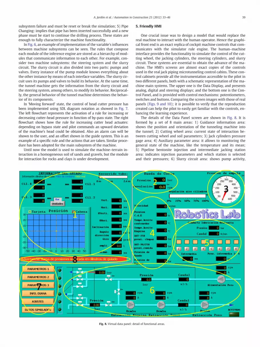
One crucial issue was to design a model that would replace thereal machine to interact with the human operator. Hence the graphi-cal front end is an exact replica of cockpit machine controls that com-municates with the simulator rule engine. The human–machineinterface provides the functionality to simulate the control of the cut-ting wheel, the jacking cylinders, the steering cylinders, and slurrycircuit. These systems are essential to obtain the advance of the ma-chine. The HMI's screens are almost exact copies of the controlsused in the real jack piping microtunneling control cabins. These con-trol cabinets provide all the instrumentation accessible to the pilot intwo different panels, both with a schematic representation of the ma-chine main systems. The upper one is the Data Display, and presentsanalog, digital and steering displays; and the bottom one is the Con-trol Panel, and is provided with control mechanisms: potentiometers,switches and buttons. Comparing the screen images with those of realpanels (Figs. 9 and 10); it is possible to verify that the reproductioncreated can help the pilot to easily get familiar with the controls, en-hancing the learning experience.
The details of the Data Panel screen are shown in Fig. 8. It isformed by a set of 8 main areas: 1) Guidance information area:shows the position and orientation of the tunneling machine intothe tunnel; 2) Cutting wheel area: current state of interaction be-tween cutting wheel and soil parameters; 3) Jack cylinders pressuregage area; 4) Auxiliary parameter area: it allows to monitoring thegeneral state of the machine, like the temperature and its mean;5) Pipeline bentonite injection and intermediate jacking stationarea: indicates injection parameters and which station is selectedand their pressures; 6) Slurry circuit area: shows pump activity,
tail of functional areas.

Fig. 9. Virtual data panel (left): comparison with real one (right).
40A.Jardón
etal./
Autom
ationin
Construction23
(2012)33
–46
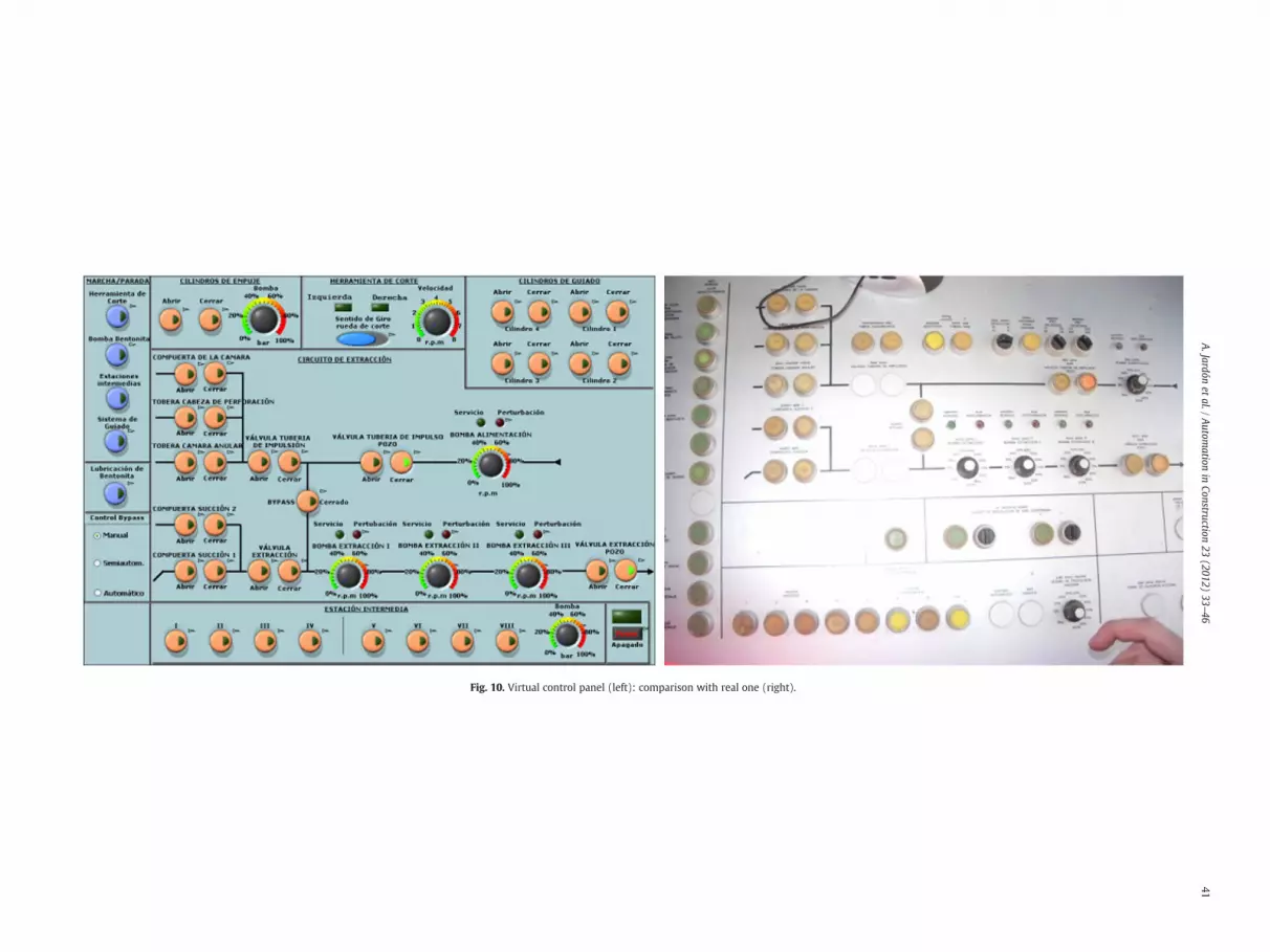
Fig. 10. Virtual control panel (left): comparison with real one (right).
41A.Jardón
etal./
Autom
ationin
Construction23
(2012)33
–46

Fig. 11. Virtual control panel: detail of functional areas.
42 A. Jardón et al. / Automation in Construction 23 (2012) 33–46
caudal, pressures and valve state; 7) Parameter buttons to setup thesimulator working conditions; 8) Message window area to displayhelp and error messages.
The details of the Control Panel screen are shown in Fig. 11. Thecontrol panel is integrated in an industrial computer with a touchscreen enabling to interact with the controls using stylus or fingers.The control screen is formed by the following control areas: 1) Start/stop area: to enable the subsystems indicated on each button; 2) Jackcylinder area: to set pressures of jacking cylinder; 3) Cutting headarea: speed set point, indicator and clockwise/counterclockwise selec-tor; 4) Steering cylinder area: push-buttons to increase or reduce
Fig. 12. Excavation param
pressure set points and actual pressure values; 5) Intermediate jackingstation area: pressure set point and activation buttons of each inter-mediate jack station; 6) Slurry circuit area: it contains all the controlsneeded to regulate the slurry circuit, extraction pumps, valves andnozzles; 7) By-pass circuit control area: where the by-pass controlmode is selected.
Inside the data screen, additional buttons allow access to addition-al windows to introduce values and ranges depending on terrain andproject specifications. One of these setup parameter screens is shownat Fig. 12. A global view of the system (real and simulation) can beseen in Fig. 13.
eters setup screens.

Fig. 13. Excavation data gathering phase and evaluation in the training place scenes.
43A. Jardón et al. / Automation in Construction 23 (2012) 33–46
6. Training process
Performance enhancements are a well-known advantage of sim-ulator training. The key to acquiring the necessary motor skills tocontrol complex systems, such as aircraft or heavy machinery, ishands-on and coached training. Researchers have shown that flightsimulators effectively improve pilot performance related to landingskills [14] and instrument and flight control abilities [25]. Trainingusing virtual environments has also been demonstrated to improveuser performance in close related developments as Aitemin's min-ing simulator [2] at Laredo Foundation, where extensive courseshave been passed or these reported by Bernold [7], [8]. They havereported that skills that were learned in a high acquisition environ-ment (e.g. extensive training in a simulator) are retained longerthan skills learned in a low acquisition environment (e.g. one-dayseminar). Therefore, when measuring skill retention, it is just as im-portant to measure skill acquisition (degree to which the skill hasbeen effectively learned), as it is to measure post-training perfor-mance [15].
Tunneling with a MTBM, the body of the machine is held in thetunnel by one or more pairs of pipe jacking cylinders, located at theback of the machine, that push the machine to advance. After eachperforation cycle, a new pipe segment is installed. Typically, steeringmethods are based on bending the cutter-head. The preferredmethodof steering consists of turning the axis from the machine by displacingthe main beam with respect to the rear jacking unit, actuating thesteering cylinders, shown in Fig. 14, with the result that the machine
pivots about the forward gripped region. To achieve a sharper turn,the pilot must hold control of the orientation of the machine. Steeringdata is obtained by observing the position of a laser beam spot cast ona target mounted on the machine, having a laser source beingmounted on a fixed support at the rear end of the tunnel. Using thisdata source, the pilot must interpret the goodness of the actual guid-ance and modify it, if necessary, using the control panel to set thetracking error lowest as possible, getting the supervision of the expertpilot that acts as a coach.
7. Experimental results
This framework and application has been implemented for fitting thetwo main objectives: for instruction, and as a predictive analysis tool. Inthis sense, to simulate the execution of the tunnel, the machine–terraininteraction has been completed with enough reliability to fit terraincharacterization based on the rule inference motor. This, therefore, isthe motor of the framework as a predictive analysis tool. Furthermore,an accelerated time scale can be applied to any of the two uses. In areal construction site, pipe jacking is a time-consuming process. Theaccelerated time scale allows reducing this time adjusting the simulationrate (×2, ×4, ×8…). Recorded data outputs can be used to check techni-cal viability, or verify or modify cost and scheduling problems.
The performance of the simulated virtual machine can be mea-sured with the same metrics as real ones. This can be defined entirelyby 3 variables: penetration, utilization rate and cutter costs. Addition-ally, for MTBM the amount of successfully inserted tubes gives a quickapproach of the performance. The average penetration rate [m/h] andother interesting parameters could be obtained, as the instantaneousrate [mm/rev]: the depth of cutter penetration/revolution, the min-ing rate [m3/h] is calculated as volume of soil excavated vs. elapsedmining time. And utilization [%] is the elapsed machine time vs. ex-cavation shift time ratio. Cutter costs [$ or €/m3] are measured re-lated to cubic meters or linear advance meter. And finally theaverage advance rate [m/day] is obtained as penetration rate multi-plied per 24 h and utilization rate, or is calculated as pipes per timeunit, normally per day.
Though some additional functionalities are still under testing,such as a new module to replicate control command previouslyrecorded to deal the virtual machine into a known state, some resultshave been obtained, as resumed in Table 1. Here, five pilots of theEurohinca company (three skilled ones, Si; and two novices, Ni)have used the simulator in accelerated time mode. The simulator al-lows them to pause the exercise and restart when they desire. Errorswere displayed with messages but operation is allowed to continue,except in case of fatal error (e.g. a pump failure due overpressure).The following acronyms are used within the table: NFE: number ofnon fatal errors; MTBF: Mean Time between Failures [h]; FE: numberof fatal errors; FP: number of jacked pipes at Full Performance; RJP:real jacked pipes; and ACCR: Accumulated equivalent time [h], tosummarize each pilot experience total time with the simulator; andthe resultant Mean Penetration in [m/h]. The presented resultsshow that after several sessions the novice pilots achieved similarscores to that senior ones. These tests are to be replicated with non-heterogeneous soils, simulated events, and anomalies, to be able torefute the goodness of the implementation.
Fig. 14 shows the 2D guidance display area and steering cylinderslocation. A partial view of results data file is shown at Fig. 15, and atthe upper left side a 3D plot generated from the recorded data of anexercise. At an industrial level, steering adjustments on the machineare currently performed manually, although some research on fuzzyassistants for steering has been published [16]. At research level, au-tomated systems are under development [18, 19]. Due to predictivecapabilities, the developed framework supposes a first approach fordesign advanced navigating system as it has set up a reliable modelof the machine at work. Automatic control would be focused on

Fig. 14. Schematic view of steering cylinders and detail of HMI panel for 2D vertical and horizontal deviations display.
44 A. Jardón et al. / Automation in Construction 23 (2012) 33–46
helping human pilots, not to remove them, and this will consequentlyincrease productivity and steering precision for tunnel execution.
Initial objectives have been fully achieved with this first version ofthe friendly framework for modeling, interfacing and training oftunneling machines in heterogeneous terrains. The right emulationof the machine performance has been reviewed by the evaluation ofexpert workmen in machine tunneling. A “stand alone” version ofthe software (usable without the development kit) has been distrib-uted to some experts and they have performed some exercises [12].They have all agreed that usual ranges of the main variables arereflected through the interfaces, and the responses to set points areclose enough to those presented in real machines.
8. Conclusions
A framework and application have been presented for modelingand creating a machine that simulates the jack piping tunneling
Table 1Preliminary trials results in heterogeneous soil.
Pilot NFE MTBF FE FP RJP ACCR MP
S1 1 48 0 6.0 5.1 48 265.6S2 2 18 1 4.5 2.8 36 192.7S3 4 13 1 6.6 4.7 53 221.9N1 6 8 3 6.0 3.7 48 192.7N2 15 3 4 6.0 4.2 48 219.6
process in heterogeneous terrains. This replica has been integratedas a simulator which is composed by a states and rules inferenceengine and an HMI that closely resembles a real cockpit cabinet.These components have been physically arranged in a PC basedtraining desktop formed by a comfortable disposition of screens.This smart composition of data panel and touch screen allows natu-ral interfacing. The result is a training tool which resembles the realworking place of pilots operating a microtunneling machine. Thesimulation framework confronts the trainee not only with scenariosfrequently encountered on real tunnel sites as drift-off on the ma-chine from the planned excavation trajectory or blocking the slurrycircuit, but also with serious incidents such those that machinecould get stuck. This avoids the common lack of realism held byother construction site simulators and will allow the most rapidand effective training for future workmen by means of the followingfeatures: a) replica of all the controls and indicators; b) machineboot sequence recreation; c) slurry circuit and by-pass controlmode recreation; d) clay and gravel behavior; e) pipe changing em-ulation; f) control system for the intermediate stations; g) imple-mentation of frequent anomalies such as slurry circuit blocking,states of unexpected deviation and blocking and draft of the ma-chine, implementation; and h) assures safety and low cost of thetraining as no real machine and excavation are needed.
Simulator training is often self-paced, allowing users to trainwhen they are ready rather than when the skilled pilot and equip-ment are available. The training effectiveness using the simulator

Fig. 15. 3D plot of a MTBM trajectory form simulator guidance area: blue and green arrows show the executed path. (For interpretation of the references to color in this figure leg-end, the reader is referred to the web version of this article.)
45A. Jardón et al. / Automation in Construction 23 (2012) 33–46
developed is still being evaluated, primarily because it is time-consuming and expensive to conduct tests on large numbers of ma-chine jacking pipe pilots. Some enterprises have started to use thisdevelopment and soon they will report with more detailed evalua-tion analysis.
The presented approach emphasizes simplicity and practicality,while limiting input data to that which is readily available from geo-logical prospects or historical records. A following paper will be fo-cused on the results of the validation study of the model developed,reporting the results of a comparison of the model's predictionswith the outcome of real tunnel execution data, which must cover awide range of project requirements, soil conditions and environmen-tal constraints.
Acknowledgment
Special thanks to the Robotics Lab team and specially to the Euro-hinca company staff, without their help it would not have been possi-ble. This work had been funded by the Spanish government under theframework of the Multidimensional City project PSE-380000-2008-5http://www.laciudadmultidimensional.es.
References
[1] O. Acaroglu, L. Ozdemir, A fuzzy logic model to predict specific energy require-ment for TBM performance prediction, Tunneling and Underground Space Tech-nology 23 (5) (2008) 600–608 Asbury. September.
[2] Aitemin, Virtual reality mining machinery simulator, project report RetrievedJune 08 from Web, http://www.aitemin.es/ei_sim_rv_maq_min_e.html 2005Last visit: June 09.
[3] T. Akiba, T. Yamada, The Enviliner Microtunneling system: NO-Dig 89, Fourth In-ternational Conference and Exhibition on Trenchless Construction for Utilities,London, ISTT, 1989, pp. 243–245.
[4] H. Anderson, L. Euhus, D. Parker, Utilizing simulators in operator training Re-trieved June 5, 2002 from Web, http://www.pacsim.com/Articles/OpTrain/art1tr.htm 2002 Last visit: Sept 08.
[5] Atlas Copco Rocket Boomer L2C Simulator, Atlas Copco internal report, http://www.atlascopco.es/ 2008 Last visit: Nov 08.
[6] T.C. Beaumont, UK experiences and developments of the Witte microtunnelingmachines: NO-Dig 89, Fourth International Conference and Exhibition on Tren-chless Construction for Utilities, ISTT, London, 1989, pp. 237–242.
[7] L.E. Bernold, J. Lloyd, M. Vouk, Equipment operator training in the age of inter-net2, 2002.
[8] L.E. Bernold, A paradigm shift in construction education is vital for the future ofour profession, Journal of Construction Engineering Management, ASCE 131 (5)(2005) 535–542 April.
[9] D.M. Bourg, Physics for game developers, O'Reilly Media, 2002 ISBN 0596000065.[10] CCITT Recommendation Z.100, Specification and description language SDL, An-
nexes A-F to Z.100, ITU, Geneva, 1988.[11] P. Fonseca, J. Casanovas, Using generic event for a simple reflexive intelligent
agent SDL specification, European Modeling & Simulation Symposium, 2006,Barcelona.
[12] Geost, Grupo Español de obras Subterráneas, Memoria general del proyecto estra-tégico de La ciudad MultidimensionalWeb, http://www.construccion2030.org 2008 Last visit: Nov 08.
[13] M. Hayashi, Y. Miyata, Okumura, Markham super mini shield tunneling method:NO-Dig 89, Fourth International Conference and Exhibition on Trenchless Con-struction for Utilities, ISTT, London, 1989, pp. 231–235.
[14] R.T.Hays, J.W. Jacobs, C. Prince, E. Salas, Requirements for future research inflight sim-ulation training: guidance based on ameta-analytic review, The International Journalof Aviation Psychology 2 (1992) 143–158 Web, http://www.trainingsystems.org.
[15] A.F. Healy, G.P. Sinclair, Long term retention of trained skills (Technical Report No94–001), Naval Air Warfare Center Training Systems Division, Orlando, FL, 1994(DTIC No. ADB187295).
[16] A.G. Herrenknecht, Universal navigation system. Technical data sheetWeb, www.herrenknecht.com 2008 Last visit: Oct 08.
[17] T. Iseley, S.B. Gokhale, Trenchless installation of conduits beneath roadways,NCHRP Synthesis 242, Transportation Research Board/National Research Council,Washington, D, 1997.

46 A. Jardón et al. / Automation in Construction 23 (2012) 33–46
[18] T. Manabe, T. Awata, A. Matsumoto, M. Sako, Automatic direction control tech-nique for pressing type small diameter tunneling machine, proceedings of NODIG International Conference and Exhibition on Trenchless Construction for Util-ities, Laussane, 1998.
[19] T. Manabe, M. Tanno, M. Matsumoto, T. Yabuta, Automatic direction control tech-nique for microtunneling machine, IEEE Industrial Electronics Society, 1999.IECON'99 Proceedings, The 25th Annual Conference of the IEEE, Vol. 3, 1999,pp. 1295–1300, San Jose, CA, USA. ISBN: 0-7803-5735-3.
[20] M. Martí, Estudio de las tuneladoras y de los sistemas de guiado, con aplicación endiversos túneles, y control dimensional de una tuneladora, Topografía y cartografía:Revista del Ilustre Colegio Oficial de Ingenieros Técnicos en Topografía 19 (112)(2002) 4–9 http://dialnet.unirioja.es/servlet/revista?tipo_busqueda=CODIGO&clave_revista=1434 ISSN 0212–9280, Last visit June 2009.
[21] M. Martí, Listado de referencia de obras completadas. Report from Web:, http://www.eurohinca.com/pdf/listado.pdf 2006 Last visit: June 09.
[22] H. Moria, A. Sawaguchi, Microtunnelling system with directional control andlong distance driving: NO-Dig 89, Fourth International Conference andExhibition on Trenchless Construction for Utilities, ISTT, London, 1989,pp. 273–282.
[23] K.S. Narendra, K. Parthasarathy, Identification and control of dynamic systemsusing neural networks, IEEE Trans, Neural Networks 1 (1991) 427.
[24] Gary W. Johnson, LabVIEW graphical programming: practical applications in in-strumentation and control (2nd ed.). McGraw-Hill School Education Group, Lab-view book, 1997 Last visit October 2009.
[25] M.G. Pfeiffer, J.D. Horey, S.K. Butrimas, Transfer of simulated instrument trainingto instrument and contact flight, The International Journal of Aviation Psychology(1991) 219–229 http://www.trainingsystems.org Last visit July 2010.
[26] SDL, ISO TC97/SC21: LOTOS, a formal description technique based on the tempo-ral ordering of observational behaviour, 1988 ISO/IS 8807.
[27] Thoroughtec, http://thoroughtec.com/products/cyberMINE/ 2008 Last visit April2011.
[28] J. Travis, J. Kring, LabVIEW for everyone: graphical programming made easy andfun, Part of the National Instruments Virtual Instrumentation Series, 3rd Edition,National Instruments Virtual Instrumentation Series Books Series, , Prentice Hall,July 27 2006 ISBN 0-13-185672.
[29] Var-trainer, Collective Research project VAR-TRAINER (Versatile augmented real-ity simulation for training in the safe use of construction machinery)Project re-port form, http://www.ikerlan.es/vartrainer/ 2007 Last visit October 2008.