synchronous machines - fer
TRANSCRIPT
SECTION 7
SYNCHRONOUS MACHINES
Omar S. Mazzoni, Ph.D., P.E.President
Systems Research International, Inc.
Marco W. Migliaro, P.E., Fellow IEEEChief Electrical and I&C Engineer
Florida Power & LightNuclear Division
Per-Unit Base Quantities . . . . . . . . . . . . . . . . . . . . . . . . . . . . . . . . 7.1
Per-Unit Direct-Axis Reactances . . . . . . . . . . . . . . . . . . . . . . . . . . . . 7.3
Per-Unit Quadrature-Axis Reactances . . . . . . . . . . . . . . . . . . . . . . . . 7.4
Per-Unit Open-Circuit Time Constants . . . . . . . . . . . . . . . . . . . . . . . . 7.4
Per-Unit Short-Circuit Time Constants . . . . . . . . . . . . . . . . . . . . . . . . 7.5
Steady-State Phasor Diagram . . . . . . . . . . . . . . . . . . . . . . . . . . . . . 7.5
Generator-Capability Curve . . . . . . . . . . . . . . . . . . . . . . . . . . . . . . . 7.6
Generator Regulation . . . . . . . . . . . . . . . . . . . . . . . . . . . . . . . . . . 7.9
Generator Short-Circuit Ratio . . . . . . . . . . . . . . . . . . . . . . . . . . . . . 7.11
Power Output and Power Factor . . . . . . . . . . . . . . . . . . . . . . . . . . . 7.11
Generator Efficiency . . . . . . . . . . . . . . . . . . . . . . . . . . . . . . . . . . . 7.13
Synchronizing Power Coefficient . . . . . . . . . . . . . . . . . . . . . . . . . . . 7.14
Generator Grounding Transformer and Resistor . . . . . . . . . . . . . . . . . . 7.14
Power-Factor Improvement . . . . . . . . . . . . . . . . . . . . . . . . . . . . . . 7.15
Bibliography . . . . . . . . . . . . . . . . . . . . . . . . . . . . . . . . . . . . . . . 7.16
PER-UNIT BASE QUANTITIES
Calculate the per-unit (p.u.) base quantities for a 150-MVA, 13.8-kV, 60-Hz, three-phase,two-pole synchronous, machine that has the following constants: d-axis mutual induc-tance between rotor and stator, Lad � 0.0056 H; d-axis mutual inductance between statorwinding a and rotor, Lafd � 0.0138 H; mutual inductance between stator winding a andd-axis amortisseur, Lakd � 0.0054 H; q-axis mutual inductance between rotor and stator,Laq � 0.0058 H; and mutual inductance between stator winding a and q-axis amortisseur,Lakq � 0.0063 H. The per-unit system used should be the reciprocal mutual per-unit sys-tem. This denotes a per-unit system where the per-unit mutual inductances between therotor and stator circuits are reciprocal. This also implies that ad � afd � akd and aq �
akq. (Note: The bar over symbol denotes a per-unit value.)LLLLL
7.1
Calculation Procedure
1. Select Base Values
Select VAbase � 150 MVA, Vbase � 13.8 kV, and fbase � 60 Hz. From these values,other base quantities may be derived.
2. Calculate rms Stator Phase Current Base, Is(base)
Is(base) � (MVAbase � 1000)/( � kVbase) � (150)(1000)/( )(13.8) � 6276 A.
3. Calculate Peak Stator Phase Current Base, is(base)
The current is is(base) � Is(base) � ( )(6276) � 8876 A.
4. Calculate Stator Base Impedance, Zs(base)
Zs(base) � kV2base /MVAbase � 13.82/150 � 1.270 �.
5. Calculate Stator Base Inductance, Ls(base)
Ls(base) � Zs(base) /�base � 1.270/377 � 3.37 � 10�3 H.
6. Calculate Field Base Current, ifd(base)
The current is ifd(base) � (Lad/Lafd)is(base) � (0.0056/0.0138) 8876 � 3602 A.
7. Calculate Field Base Impedance, Zfd(base)
Zfd(base) � (MVAbase � 106)/ � (150 � 106)/36022 � 11.56 �.
8. Calculate Field Base Inductance, Lfd(base)
Lfd(base) � Zfd(base) /�base � 11.56/377 � 30.66 � 10�3 H.
9. Calculate Field Base Voltage, efd(base)
The voltage is efd(base) � (MVAbase � 106)/ifd(base) � (150 � 106)/3602 � 41,644 V.
10. Calculate Direct-Axis Armortisseur Base Current, ikd(base)
The current is ikd(base) � (Lad /Lakd)is(base) � (0.0056/0.0054)(8876) � 9204 A.
11. Calculate Direct-Axis Amortisseur Base Impedance, Zkd(base)
Zkd(base) � (MVAbase � 106)/ � (150 � 106)/92042 � 1.77 �.
12. Calculate Direct-Axis Amortisseur Base Inductance, Lkd(base)
Lkd(base) � Zkd(base) /�base � 1.77/377 � 4.70 � 10�3 H.
13. Calculate Quadrature-Axis Amortisseur Base Current, ikq(base)
The current is ikq(base) � (Laq/Lakq)is(base) � (0.0058/0.0063)(8876) � 8172 A.
14. Calculate Quadrature-Axis Amortisseur Base Impedance, Zkq(base)
Zkq(base) � (MVAbase � 106)/ � (150 � 106)/81722 � 2.246 �.
15. Calculate Quadrature-Axis Amortisseur Base Inductance, Lkq(base)
Lkq(base) � Zkq(base) /�base � 2.246/377 � 5.96 � 10�3 H.
16. Calculate Base Mutual Inductance Between Amortisseur and Field, Lfkd(base)
Lfkd(base) � (ifd(base) /ikd(base))Lfd(base) � (3602/9204)(30.66 � 10�3) � 12 � 10�3 H.
17. Calculate Base Flux Linkage, �s(base)
�s(base) � Ls(base)is(base) � (3.37 � 10�3) 8876 � 29.9 Wb � turns.
i2kd(base)
i2kd(base)
i2fd(base)
√2√2
√3√3
7.2 HANDBOOK OF ELECTRIC POWER CALCULATIONS
18. Calculate Base Rotation Speed in r/min
The base speed is 120 fbase /P � (120)(60/2) � 3600 r/min, where P is the number ofpoles.
19. Calculate Base Torque, T(base)
Tbase � (7.04 MVAbase � 106)/r/minbase � (7.04)(150)(106)/3600 � 293 klb � ft (397.2kN � m).
PER-UNIT DIRECT-AXIS REACTANCES
Calculate the synchronous, transient, and subtransient per-unit reactances for the directaxis of the machine in the previous example for which the field resistance rfd � 0.0072�, stator resistance rs � 0.0016 �, stator leakage inductance Ll � 0.4 � 10�3 H, fieldself-inductance Lffd � 0.0535 H, d-axis amortisseur self-inductance Lkkd � 0.0087 H,d-axis amortisseur resistance rkd � 0.028 �, and the q-axis amortisseur resistance rkq �0.031 �. Assume the leakage inductances in the d- and q-axes are equal, which is gener-ally a reasonable assumption for round-rotor machines.
Calculation Procedure
1. Calculate Per-Unit Values for Lad and Ll
From the previous example, Ls(base) � 0.00337 H. Therefore, ad � Lad/Ls(base) �0.0056/0.00337 � 1.66 p.u. and l � Ll/Ls(base) � 0.0004/0.00337 � 0.12 p.u. (Note: Barover symbol designates per-unit value.)
2. Calculate Per-Unit Value of d-Axis Synchronous Inductance, d
d � ad l � 1.66 0.12 � 1.78 p.u.
3. Calculate Per-Unit Value of d-axis Synchronous Reactance, d
d � d. By choosing fbase � 60 Hz, the rated frequency of the machine is �60/fbase � 60/60 � 1. It also follows that � 1 and d � d � 1.78 p.u.
4. Calculate ffd , kkd , afd , and akd
ffd � Lffd/Lfd(base) � 0.0535/(30.66 � 10�3) � 1.74 p.u. kkd � Lkkd/Lkd(base) � 0.0087/(4.7 � 10�3) � 1.85 p.u. afd � Lafd /Ls(base)(is(base)/ifd(base)) � 0.0138/(0.00337)(8876/ 3602) � 1.66 p.u. adk � Ladk/[2/3(Lkd(base)ikd(base)/is(base))] � 0.0054/(2/3)(4.7 � 10�3)(9204/8876) � 1.66 p.u.
5. Calculate afd
fd � ffd � afd � 1.74 � 1.66 � 0.08 p.u.
6. Calculate kd
kd � kkd � akd � 1.85 � 1.66 � 0.19 p.u.
7. Calculate Per-Unit Values of d-axis Transient Inductance, d and dd � d � ad fd / ffd 1 � (1.66)(0.08)/1.74 0.12 � 0.196 p.u.LLLLXL
XL
LLL
L
LLL
L
LL
LL
LLLL
LX�fL�X
X
LLL
L
LL
SYNCHRONOUS MACHINES 7.3
8. Calculate Per-Unit Values of d-Axis Subtransient Inductance, and
� � (1/ kd 1/ ad 1/ fd) l � (1/0.19) (1/1.66) (1/0.08) 0.12 � 0.174 p.u.
PER-UNIT QUADRATURE-AXIS REACTANCES
Calculate the synchronous and subtransient per-unit reactances for the quadrature axis ofthe machine in the first example. Additional data for the machine are q-axis amortisseurself-inductance Lkkq � 0.0107 H, and the mutual inductance between stator winding a- and q-axis Lakq � 6.3 � 10�3 H.
Calculation Procedure
1. Calculate aq
From values obtained in the two previous examples, aq � Laq /Ls(base) � 0.0058/(3.37 � 10�3) � 1.72 p.u.
2. Calculate q
q � aq l � 1.72 0.12 � 1.84 p.u.
3. Calculate kkq and akq
kkq � Lkkq /Lkq(base) � 0.0107/(5.96 � 10�3) � 1.80 p.u. akq � Lakq /(Ls(base))(is(base) /ikq(base)) � (6.3 � 10�3)/(3.37 � 10�3)(8876/8172) � 1.72 p.u.
4. Calculate Per-Unit Value of q-axis Amortisseur Leakage Inductance, kq
kq � kkq � akq � 1.80 � 1.72 � 0.08 p.u.
5. Calculate Per-Unit Transient Inductance, q
q � aq kq /( aq kq) l � (1.72)(0.08)/(1.72 0.08) 0.12 � 0.196 p.u.
Related Calculations. Transient inductance q is sometimes referred to as the q-axissubtransient inductance.
PER-UNIT OPEN-CIRCUIT TIME CONSTANTS
Calculate the per-unit field and subtransient open-circuit time constants for the direct axisof the machine in the first example. Use results obtained in previous examples.
Calculation Procedure
1. Calculate fd and kd
The quantities are fd � rfd /Zfd(base) � 0.0072/11.56 � 6.23 � 10�4 p.u. and kd � rkd /Zkd(base) � 0.028/1.77 � 0.0158 p.u.
rr
rr
L
LLLLLL
L
LLL
L
LL
LL
LLL
L
L
L
LLLLX"dL"d
X"dL"d
7.4 HANDBOOK OF ELECTRIC POWER CALCULATIONS
2. Calculate Field Open-Circuit Time Constant,
� ffd / fd � 1.74/(6.23 � 10�4) � 2793 p.u.
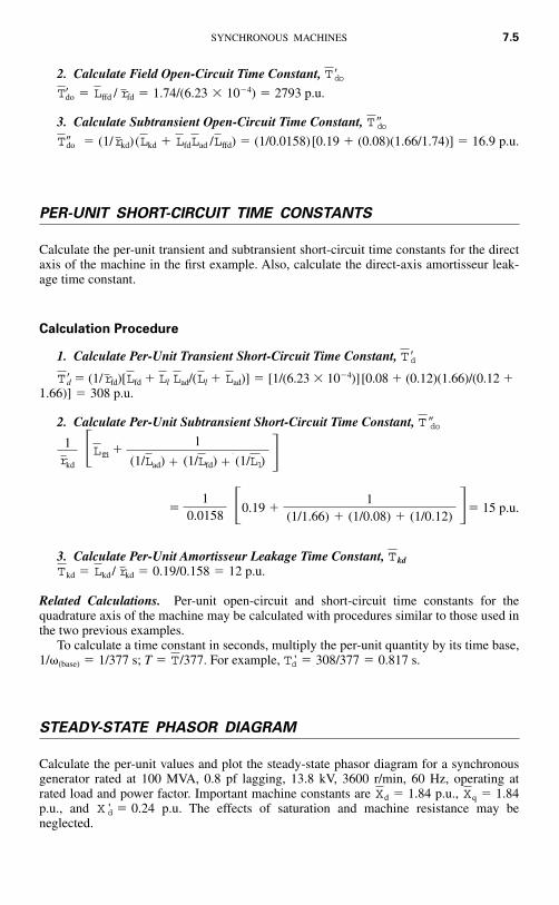
3. Calculate Subtransient Open-Circuit Time Constant,
� (1/ kd) ( kd fd ad / ffd) � (1/0.0158)[0.19 (0.08)(1.66/1.74)] � 16.9 p.u.
PER-UNIT SHORT-CIRCUIT TIME CONSTANTS
Calculate the per-unit transient and subtransient short-circuit time constants for the directaxis of the machine in the first example. Also, calculate the direct-axis amortisseur leak-age time constant.
Calculation Procedure
1. Calculate Per-Unit Transient Short-Circuit Time Constant,
d � (1/ fd)[ fd l ad/( l ad)] � [1/(6.23 � 10�4)][0.08 (0.12)(1.66)/(0.12 1.66)] � 308 p.u.
2. Calculate Per-Unit Subtransient Short-Circuit Time Constant,
� 0.19 � 15 p.u.
3. Calculate Per-Unit Amortisseur Leakage Time Constant, kd
kd � kd / kd � 0.19/0.158 � 12 p.u.
Related Calculations. Per-unit open-circuit and short-circuit time constants for thequadrature axis of the machine may be calculated with procedures similar to those used inthe two previous examples.
To calculate a time constant in seconds, multiply the per-unit quantity by its time base,1/�(base) � 1/377 s; T � /377. For example, � 308/377 � 0.817 s.
STEADY-STATE PHASOR DIAGRAM
Calculate the per-unit values and plot the steady-state phasor diagram for a synchronousgenerator rated at 100 MVA, 0.8 pf lagging, 13.8 kV, 3600 r/min, 60 Hz, operating atrated load and power factor. Important machine constants are � 1.84 p.u., � 1.84p.u., and � 0.24 p.u. The effects of saturation and machine resistance may beneglected.
X 'dXqXd
T 'dT
rLTT
�1(1/1.66) (1/0.08) (1/0.12)�1
0.0158
1
(1/Lad) (1/Lfd) (1/Ll)Lfd�1
rkd
T �do
LLLLLrT
Td
LLLLrT�do
Tdo
rLTdo
Tdo
SYNCHRONOUS MACHINES 7.5
�

Calculation Procedure
1. Determine Reference
If the VA and V base values are equal to the machine ratings, Is(base) � (MVA �1000)/ kV � (100)(1000)/( )(13.8) � 4184 A. Because the base voltage has beentaken as 13.8 kV, the per-unit rms terminal voltage is t � 1.0 p.u. From this, the per-unitpeak voltage, t � t � 1.0 p.u. Quantity t will be chosen as the reference phasor: t �1.0 p.u.
2. Locate q-AxisCalculate a fictitious voltage q � � q�/�, where � is the machine internal power angle.
q may be calculated by q � t t( j q). But t � 1.0 p.u., where � cos�1
0.8 � �36.9°. Therefore, q � 1 1.0 � j1.84 � 2.38 p.u. Powerangle � � 35°.
3. Calculate the d- and q-axis ComponentsThe d- and q-axis components may now be found by resolving t and t into compo-
nents along the d- and q-axes, respectively: q � � t� cos � � (1.0)(0.819) � 0.819 p.u. d � � t� sin � � (1.0)(0.574) � 0.574 p.u. and q � � t� cos(� � ) � 1.0 cos (35°
36.9°) � 0.311 p.u. d � � t� sin(� � ) � 0.951 p.u.
4. Calculate I
Voltage I lies on the q-axis and represents the d-axis quantity, field current. I �
ad fd � q d d d � 0.819 (1.84)(0.951) � 2.57 p.u.
5. Draw Phasor Diagram
The phasor diagram is drawn in Fig. 7.1.
GENERATOR-CAPABILITY CURVE
The generator-capability curve, supplied by the manufacturer, is used to determine theability of a generator to deliver real (MW) and reactive (Mvar) power to a network.Determine the capability curve, in per-unit values, of a generator with the following
riiXeiXEE
E
iiiiee
eeie
�35���36.9��0ºE� �iXrieEE
EE
�0eeEe
E√3√3
7.6 HANDBOOK OF ELECTRIC POWER CALCULATIONS
FIGURE 7.1 Phasor diagram for a synchronous generator.
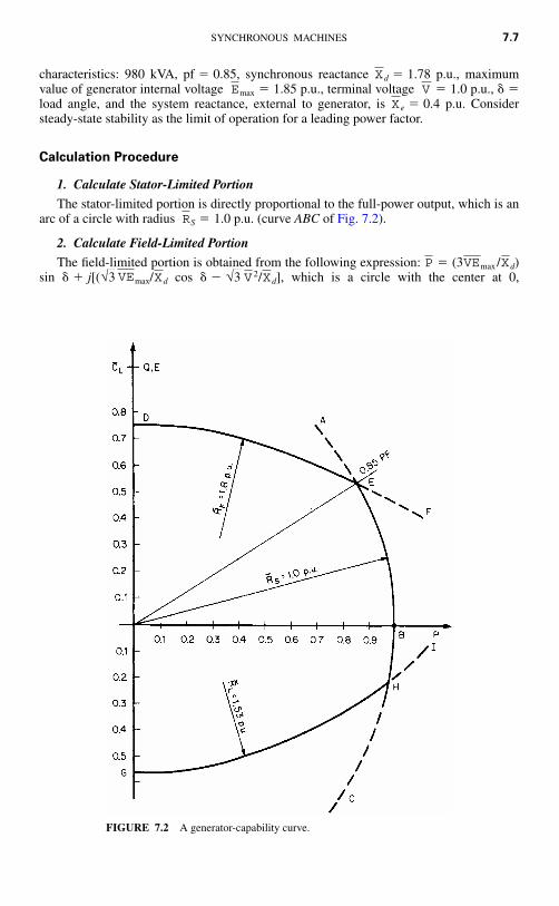
characteristics: 980 kVA, pf � 0.85, synchronous reactance d � 1.78 p.u., maximumvalue of generator internal voltage max � 1.85 p.u., terminal voltage � 1.0 p.u., � �load angle, and the system reactance, external to generator, is e � 0.4 p.u. Considersteady-state stability as the limit of operation for a leading power factor.
Calculation Procedure
1. Calculate Stator-Limited Portion
The stator-limited portion is directly proportional to the full-power output, which is anarc of a circle with radius S � 1.0 p.u. (curve ABC of Fig. 7.2).
2. Calculate Field-Limited Portion
The field-limited portion is obtained from the following expression: � (3 max / d)sin � j[( max/ d cos � � / d], which is a circle with the center at 0,X√3 V 2X√3 VE
XVEP
R
XVE
X
SYNCHRONOUS MACHINES 7.7
FIGURE 7.2 A generator-capability curve.
�j / d, and whose radius is F � max/ d � (1.0)(1.85)/1.78 � 1.8 p.u.Because � 1.0 p.u., the center is located at 0, j(�1.0 � )/1.78 � 0, �j0.97 (curveDEF, Fig. 7.2).
3. Calculate Steady-State Stability Curve
The steady-state stability curve is given by an arc of the circle defined by L �center � j /2(1/ e � 1/ d) � j/2(1/0.4 � 1/1.78) � j0.97. L � radius � /2(1/
e 1/ d) � 1/2(1/0.4 1.78) � 1.53 p.u. (curve GHI, Fig. 7.2).
Related Calculations. Synchronous machines are capable of producing and consumingmegawatts and megavars. When a generator is overexcited, it generates kilovars and de-livers them to the system. When a generator is underexcited, negative megavars flow fromthe system into the machine. When the machine operates at unity power factor, it is justself-sufficient in its excitation.
Because operation of a generator is possible at any point within the area boundedby the capability curve, operators make use of the capability curve to control machineoutput within safe limits. The stator-limited portion relates to the current-carrying ca-pacity of the stator-winding conductors. The field-limited portion relates to the area ofoperation under overexcited conditions, where field current will be higher than nor-mal. The steady-state stability portion relates to the ability of the machine to remainstable.
The curves in Fig. 7.3 are typical capability characteristics for a generator. A familyof curves corresponding to different hydrogen cooling pressures is shown. The ratedpower factor is 0.8; rated apparent power is taken as 1.0 p.u. on its own rated MVAbase. This means that the machine will deliver rated apparent power down to 0.85 lag-ging power factor. For a lower power factor, the apparent power capability is lower thanrated.
Many of the older, large steam-turbine generators in operation currently are beingevaluated for the potential of increasing their power output. The industry refers to thisas “power uprate.” In many instances, the original designs of these machines includeddesign margins that were used to account for uncertainties or were used for conser-vatism. Some machines also had generators with capabilities that exceeded the capa-bilities of the steam-turbine. With more sophisticated analysis tools available, in-creases in power output (and revenue) may potentially be obtained for a relativelysmall investment. Improved turbine blade designs and materials can also offer addi-tional power output by replacement of the original turbine rotors. An uprate normallyrequires a study to determine if auxiliary systems (e.g., cooling water, feedwater, andcondensate) can support the uprate. This study would include evaluation of systemmodifications required to support the uprate (e.g., motor horsepower increases andpump impeller replacements).
It is also possible to increase the generator power output by increased hydrogen pres-sure from the normal operating pressure to pressures as high as 75 psig. Increasing thehydrogen pressure results in increased cooling for the machine. With increased cooling,there is a greater machine rated power output available, since additional current can besafely carried by the conductors due to the increased cooling. However, a full evaluationof the generator design and its supporting systems must be conducted in order to deter-mine the acceptability of the increased generator hydrogen pressure. (This study wouldnormally involve the generator designer/manufacturer). These factors may include the ef-fect on the hydrogen coolers and seal oil system, as well as, the ability of the excitationsystem to support the desired increase in power. Additionally, once the output power ofthe machine is increased, the capability of the generator transformer and switchyardequipment (e.g., circuit breakers) must be evaluated.
XXV 2RXXV 2C
√3V√3X√3 VERX√3 V 2
7.8 HANDBOOK OF ELECTRIC POWER CALCULATIONS

GENERATOR REGULATION
Determine the regulation of a generator with the following characteristics: armature resis-tance � 0.00219 p.u.; power factor � 0.975; and open-circuit, zero power-factor andshort-circuit saturation as in Fig. 7.4.
Calculation Procedure
1. Calculate Potier Reactance, p
Use the relation E0 � E IaXp from zero power-factor conditions, where E0 �voltage at no load, Ia � armature current at full load, and E is the terminal voltage. InFig. 7.4, RD � RE DE; therefore, DE � IaXp. By definition, � IaXp / (VLL/
) � DE/ LL � DE/RE � 0.43 p.u.
2. Calculate Voltage behind Potier Reactance, p
From Fig. 7.4, � 1.175 p.u.Ep
E
V√3Xp√3
√3
X
Ra
SYNCHRONOUS MACHINES 7.9
FIGURE 7.3 Capability curves for a hydrogen inner-cooled generator rated at 983MVA, 0.85 pf, 22 kV.
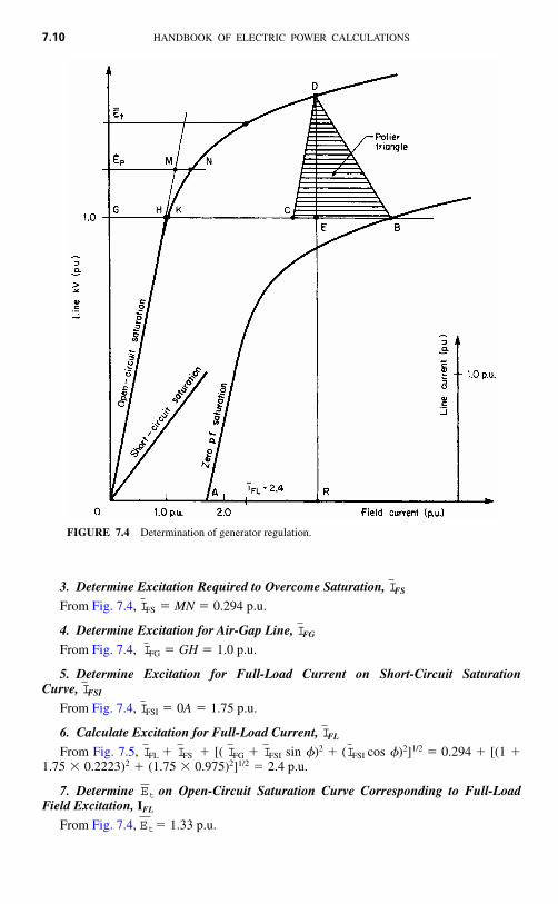
3. Determine Excitation Required to Overcome Saturation, FS
From Fig. 7.4, FS � MN � 0.294 p.u.
4. Determine Excitation for Air-Gap Line, FG
From Fig. 7.4, FG � GH � 1.0 p.u.
5. Determine Excitation for Full-Load Current on Short-Circuit Saturation Curve, FSI
From Fig. 7.4, FSI � 0A � 1.75 p.u.
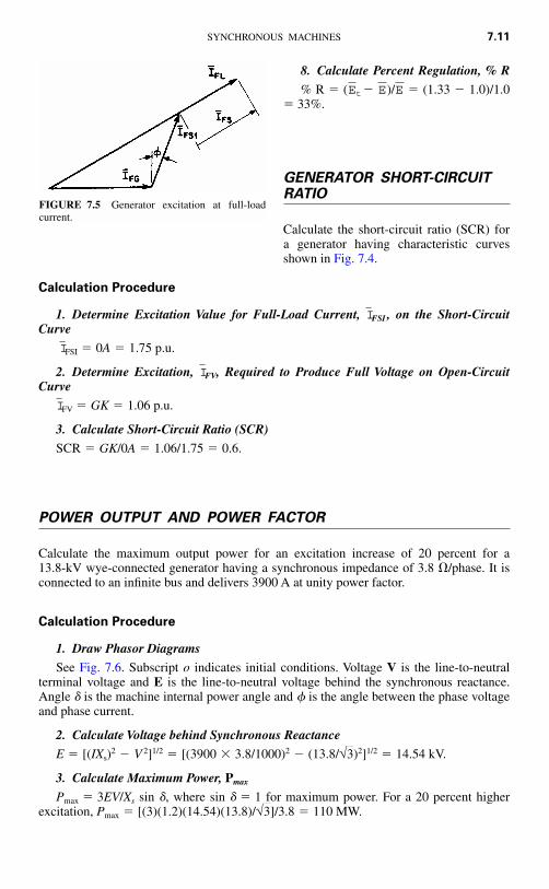
6. Calculate Excitation for Full-Load Current, FL
From Fig. 7.5, FL FS [( FG FSI sin �)2 ( FSI cos �)2]1/2 � 0.294 [(1 1.75 � 0.2223)2 (1.75 � 0.975)2]1/2 � 2.4 p.u.
7. Determine on Open-Circuit Saturation Curve Corresponding to Full-LoadField Excitation, IFL
From Fig. 7.4, � 1.33 p.u.Et
Et
IIIII
I
I
I
I
I
I
I
7.10 HANDBOOK OF ELECTRIC POWER CALCULATIONS
FIGURE 7.4 Determination of generator regulation.
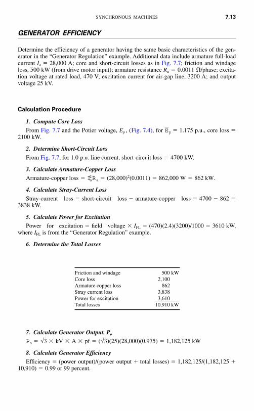
8. Calculate Percent Regulation, % R
% R � ( � )/ � (1.33 � 1.0)/1.0� 33%.
GENERATOR SHORT-CIRCUITRATIO
Calculate the short-circuit ratio (SCR) fora generator having characteristic curvesshown in Fig. 7.4.
Calculation Procedure
1. Determine Excitation Value for Full-Load Current, FSI , on the Short-CircuitCurve
FSI � 0A � 1.75 p.u.
2. Determine Excitation, FV, Required to Produce Full Voltage on Open-CircuitCurve
FV � GK � 1.06 p.u.
3. Calculate Short-Circuit Ratio (SCR)
SCR � GK/0A � 1.06/1.75 � 0.6.
POWER OUTPUT AND POWER FACTOR
Calculate the maximum output power for an excitation increase of 20 percent for a 13.8-kV wye-connected generator having a synchronous impedance of 3.8 �/phase. It isconnected to an infinite bus and delivers 3900 A at unity power factor.
Calculation Procedure
1. Draw Phasor Diagrams
See Fig. 7.6. Subscript o indicates initial conditions. Voltage V is the line-to-neutralterminal voltage and E is the line-to-neutral voltage behind the synchronous reactance.Angle � is the machine internal power angle and � is the angle between the phase voltageand phase current.
2. Calculate Voltage behind Synchronous Reactance
E � [(IXs)2 � V 2]1/2 � [(3900 � 3.8/1000)2 � (13.8/ )2]1/2 � 14.54 kV.
3. Calculate Maximum Power, Pmax
Pmax � 3EV/Xs sin �, where sin � � 1 for maximum power. For a 20 percent higherexcitation, Pmax � [(3)(1.2)(14.54)(13.8)/ ]/3.8 � 110 MW.√3
√3
I
I
I
I
EEEt
SYNCHRONOUS MACHINES 7.11
FIGURE 7.5 Generator excitation at full-loadcurrent.

4. Calculate Power Factor
The power factor is cos � � E/IXs �14.54/(3.9)(3.8) � 0.98 lagging.
High-temperature super-conducting(HTS) generators are in the process of de-velopment and promise to offer many ad-vantages over conventional generators.These advantages relate to lower losses andsmaller, more compact designs. Relatedcalculations for evaluating the performanceof HTS machines will include specific is-sues in the area of their stability assessmentand particular cooling characteristics.
7.12 HANDBOOK OF ELECTRIC POWER CALCULATIONS
FIGURE 7.6 Generator phasor diagrams: powerfactor (pf) and power output.
FIGURE 7.7 Generator loss curves.
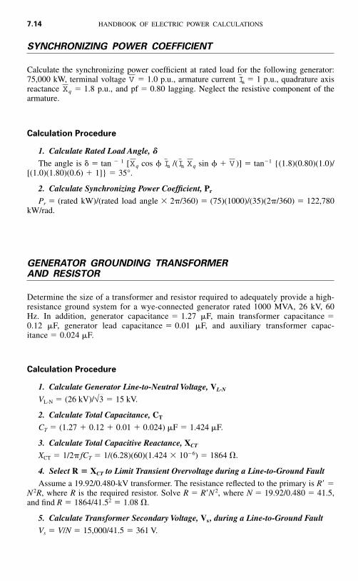
GENERATOR EFFICIENCY
Determine the efficiency of a generator having the same basic characteristics of the gen-erator in the “Generator Regulation” example. Additional data include armature full-loadcurrent Ia � 28,000 A; core and short-circuit losses as in Fig. 7.7; friction and windageloss, 500 kW (from drive motor input); armature resistance Ra � 0.0011 �/phase; excita-tion voltage at rated load, 470 V; excitation current for air-gap line, 3200 A; and outputvoltage 25 kV.
Calculation Procedure
1. Compute Core Loss
From Fig. 7.7 and the Potier voltage, Ep , (Fig. 7.4), for p.u., core loss �2100 kW.
2. Determine Short-Circuit Loss
From Fig. 7.7, for 1.0 p.u. line current, short-circuit loss � 4700 kW.
3. Calculate Armature-Copper Loss
Armature-copper loss
4. Calculate Stray-Current Loss
Stray-current loss � short-circuit loss � armature-copper loss � 4700 � 862 �3838 kW.
5. Calculate Power for Excitation
Power for excitation � field voltage � IFL � (470)(2.4)(3200)/1000 � 3610 kW,where IFL is from the “Generator Regulation” example.
6. Determine the Total Losses
7. Calculate Generator Output, Po
8. Calculate Generator Efficiency
Efficiency � (power output)/(power output total losses) � 1,182,125/(1,182,125 10,910) � 0.99 or 99 percent.
Po � √3 � kV � A � pf � (√3)(25)(28,000)(0.975) � 1,182,125 kW
� Ia2Ra � (28,000)2(0.0011) � 862,000 W � 862 kW.
Ep � 1.175
SYNCHRONOUS MACHINES 7.13
Friction and windage 500 kWCore loss 2,100Armature copper loss 862Stray current loss 3,838Power for excitationTotal losses 10,910 kW
3,610
SYNCHRONIZING POWER COEFFICIENT
Calculate the synchronizing power coefficient at rated load for the following generator:75,000 kW, terminal voltage � 1.0 p.u., armature current � 1 p.u., quadrature axisreactance q � 1.8 p.u., and pf � 0.80 lagging. Neglect the resistive component of thearmature.
Calculation Procedure
1. Calculate Rated Load Angle, �
The angle is � � tan � 1 [ q cos � /( q sin � )] � tan�1 {(1.8)(0.80)(1.0)/[(1.0)(1.80)(0.6) 1]} � 35°.
2. Calculate Synchronizing Power Coefficient, Pr
Pr � (rated kW)/(rated load angle � 2�/360) � (75)(1000)/(35)(2�/360) � 122,780kW/rad.
GENERATOR GROUNDING TRANSFORMERAND RESISTOR
Determine the size of a transformer and resistor required to adequately provide a high-resistance ground system for a wye-connected generator rated 1000 MVA, 26 kV, 60Hz. In addition, generator capacitance � 1.27 �F, main transformer capacitance �0.12 �F, generator lead capacitance � 0.01 �F, and auxiliary transformer capac-itance � 0.024 �F.
Calculation Procedure
1. Calculate Generator Line-to-Neutral Voltage, VL-N
VL-N � (26 kV)/ � 15 kV.
2. Calculate Total Capacitance, CT
CT � (1.27 0.12 0.01 0.024) �F � 1.424 �F.
3. Calculate Total Capacitive Reactance, XCT
XCT � 1/2� fCT � 1/(6.28)(60)(1.424 � 10�6) � 1864 �.
4. Select R � XCT to Limit Transient Overvoltage during a Line-to-Ground Fault
Assume a 19.92/0.480-kV transformer. The resistance reflected to the primary is R �N 2R, where R is the required resistor. Solve R � RN 2, where N � 19.92/0.480 � 41.5,and find R � 1864/41.52 � 1.08 �.
5. Calculate Transformer Secondary Voltage, Vs , during a Line-to-Ground Fault
Vs � V/N � 15,000/41.5 � 361 V.
√3
VXIaIaX
XIaV
7.14 HANDBOOK OF ELECTRIC POWER CALCULATIONS
6. Calculate Current, Is , through Grounding Resistor
Is � Vs /R � 361/1.08 � 334.3 A.
7. Calculate Required Continuous Rating in kVA of Grounding Transformer
The rating is kVA � IsVs � (334.3)(361) � 120.7 kVA.
8. Select Short-Time Rated Transformer
From ANSI standards, a 50-kVA transformer may be used if a 9-min rating is adequate.
9. Calculate Generator Line-to-Ground Fault Current, If
If � V/XCT � 15,000/1864 � 8.05 A.
POWER-FACTOR IMPROVEMENT
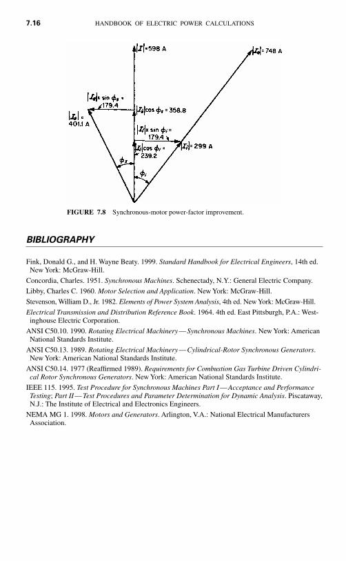
An industrial plant has a 5000-hp induction motor load at 4000 V with an average powerfactor of 0.8, lagging, and an average motor efficiency of 90 percent. A new synchronousmotor rated at 3000 hp is installed to replace an equivalent load of induction motors. Thesynchronous motor efficiency is 90 percent. Determine the synchronous motor currentand power factor for a system current of 80 percent of the original system and unitypower factor.
Calculation Procedure
1. Calculate Initial System Rating, kVAo
The rating is kVAo � (hp/�)(0.746/pf) � (5000/0.9)/(0.746/0.8) � 5181 kVA, where� is efficiency.
2. Calculate Initial System Current, Io
Io � kVA/ V � 5181 / ( )(4) � 148 A.
3. Calculate New System Current, I
I � 0.8Io � (0.8)(746) � 598 A (see Fig. 7.8).
4. Calculate New Induction-Motor Current, Ii
Ii � 0.746 hp / V �pfi � (0.746)(2000)/( )(4)(0.9)(0.8) � 299 A.
5. Calculate Synchronous-Motor Current, Is
Is � [(Ii sin �i)2 (I � Ii cos �i)2]1/2 � {[(299)(0.6)]2 [598 � (299)(0.8)]2}1/2 �(149.42 358.82 )1/2 � 401.1 A
6. Calculate Synchronous-Motor Power Factor, pfs
The power factor is pfs � 358.8/401.1 � 0.895.
Related Calculations. For verification, the synchronous motor horsepower, hps, shouldequal 3000 hp, where hps � 3VIs�pfs /0.746 � ( )(4)(401.1)(0.9)(0.895)/0.746 � 3000 hp.√3
√3√3
√3√3
SYNCHRONOUS MACHINES 7.15
BIBLIOGRAPHY
Fink, Donald G., and H. Wayne Beaty. 1999. Standard Handbook for Electrical Engineers, 14th ed.New York: McGraw-Hill.
Concordia, Charles. 1951. Synchronous Machines. Schenectady, N.Y.: General Electric Company.
Libby, Charles C. 1960. Motor Selection and Application. New York: McGraw-Hill.
Stevenson, William D., Jr. 1982. Elements of Power System Analysis, 4th ed. New York: McGraw-Hill.
Electrical Transmission and Distribution Reference Book. 1964. 4th ed. East Pittsburgh, P.A.: West-inghouse Electric Corporation.
ANSI C50.10. 1990. Rotating Electrical Machinery—Synchronous Machines. New York: AmericanNational Standards Institute.
ANSI C50.13. 1989. Rotating Electrical Machinery—Cylindrical-Rotor Synchronous Generators.New York: American National Standards Institute.
ANSI C50.14. 1977 (Reaffirmed 1989). Requirements for Combustion Gas Turbine Driven Cylindri-cal Rotor Synchronous Generators. New York: American National Standards Institute.
IEEE 115. 1995. Test Procedure for Synchronous Machines Part I—Acceptance and PerformanceTesting; Part II—Test Procedures and Parameter Determination for Dynamic Analysis. Piscataway,N.J.: The Institute of Electrical and Electronics Engineers.
NEMA MG 1. 1998. Motors and Generators. Arlington, V.A.: National Electrical ManufacturersAssociation.
7.16 HANDBOOK OF ELECTRIC POWER CALCULATIONS
FIGURE 7.8 Synchronous-motor power-factor improvement.