brush synchronous condenser systems
TRANSCRIPT
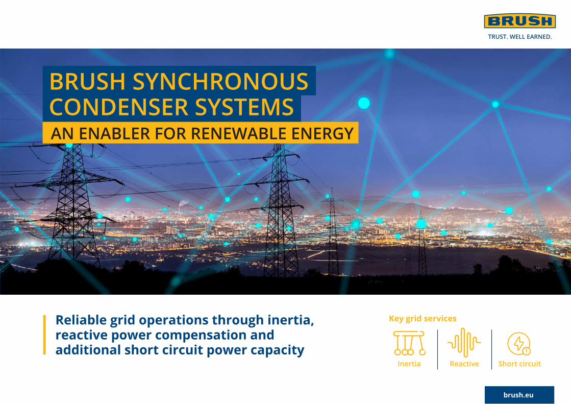
BRUSH SYNCHRONOUS CONDENSER SYSTEMSAN ENABLER FOR RENEWABLE ENERGY
Reliable grid operations through inertia, reactive power compensation and additional short circuit power capacity
Key grid services
Inertia
Reactive power
Short circuit contribution
brush.eu

Today’s Challenge: Sustainable Power Generation
As a result of the global drive for renewable energy generation, very significant capacity of solar and wind power has been added to the grid and a growing number of steam and gas turbine driven power plants are retiring well before the end of their technical life.
Renewable power generation is essential for future power supply. Unfortunately, it can adversely impact the resilience and stability of today’s grids as it misses critical components required for grid quality and reliability. A key missing element is rotational inertia, which provides a useful amount of stored energy to help keep the frequency of the power system stable. Other important factors are reactive power to load compensation, voltage support (fault ride through) and fault support.
brush.eu2
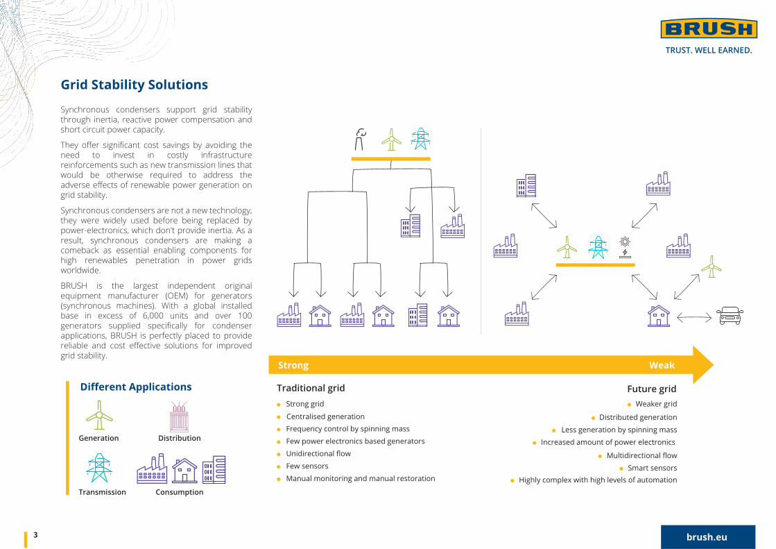
Traditional grid Strong grid
Frequency control by spinning mass
Few power electronics based generators
Unidirectional flow
Few sensors
Manual monitoring and manual restoration
Multidirectional flow
Smart sensorsHighly complex with high levels of automation
Future grid
Distributed generation
Less generation by spinning mass
Increased amount of power electronics
Weaker grid
Strong Weak
Generation
Transmission
Distribution
Consumption
Synchronous condensers support grid stability through inertia, reactive power compensation and short circuit power capacity.
They offer significant cost savings by avoiding the need to invest in costly infrastructure reinforcements such as new transmission lines that would be otherwise required to address the adverse effects of renewable power generation on grid stability.
Synchronous condensers are not a new technology, they were widely used before being replaced by power-electronics, which don't provide inertia. As a result, synchronous condensers are making a comeback as essential enabling components for high renewables penetration in power grids worldwide.
BRUSH is the largest independent original equipment manufacturer (OEM) for generators (synchronous machines). With a global installed base in excess of 6,000 units and over 100 generators supplied specifically for condenser applications, BRUSH is perfectly placed to provide reliable and cost effective solutions for improved grid stability.
Grid Stability Solutions
Different Applications
3 brush.eu
Centralised generation
111
7
7
23
3 8 9 105
46
4 brush.eu
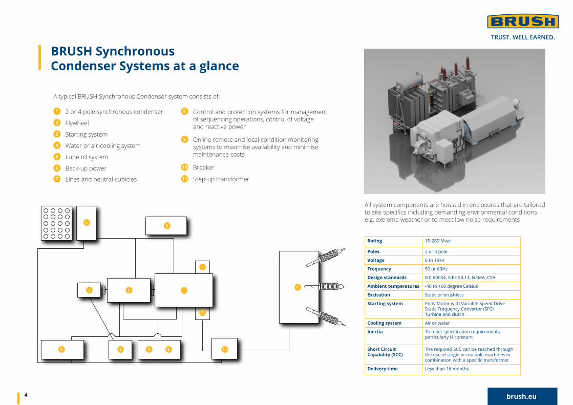
All system components are housed in enclosures that are tailored to site specifics including demanding environmental conditions e.g. extreme weather or to meet low noise requirements
BRUSH Synchronous Condenser Systems at a glance
A typical BRUSH Synchronous Condenser system consists of:
1 2 or 4 pole synchronous condenser
2 Flywheel
3 Starting system
4 Water or air-cooling system
5 Lube oil system
6 Back-up power7 Lines and neutral cubicles
10 Breaker
11 Step-up transformer
8
9 Online remote and local condition monitoring
systems to maximise availability and minimise maintenance costs
Control and protection systems for management of sequencing operations, control of voltage and reactive power
Rating 15-280 Mvar
Poles 2 or 4 pole
Voltage 6 to 19kV
Frequency 50 or 60Hz
Design standards IEC 60034, IEEE 50.13, NEMA, CSA
Ambient temperatures -40 to +60 degree Celsius
Excitation Static or brushless
Starting system Pony Motor with Variable Speed Drive Static Frequency Convertor (SFC)Turbine and clutch
Cooling system Air or water
Inertiaparticularly H constant
Short Circuit Capability (SCC)
The required SCC can be reached through the use of single or multiple machines in
Delivery time Less than 16 months
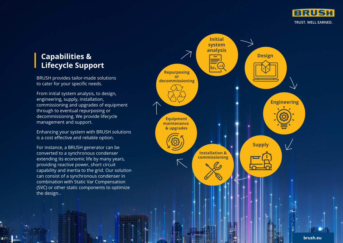
Capabilities & Lifecycle Support
Repurposing or
decommissioning
Engineering
SupplyInstallation &
commissioning
Initial system analysis
Design
Equipmentmaintenance
& upgrades
BRUSH provides tailor-made solutions to cater for your specific needs.
From initial system analysis, to design, engineering, supply, installation, commissioning and upgrades of equipment through to eventual repurposing or decommissioning. We provide lifecycle management and support.
Enhancing your system with BRUSH solutions is a cost effective and reliable option.
For instance, a BRUSH generator can be converted to a synchronous condenser extending its economic life by many years, providing reactive power, short circuit capability and inertia to the grid. Our solution can consist of a synchronous condenser in combination with Static Var Compensation (SVC) or other static components to optimize the design.
brush.eu5
111
7
7
23
3 8 9 105
46
6 brush.eu
Configuration Options –Tailor-made solutions designedto meet your exact requirements
We support customers with tailor-made solutions that are designed to resolve the prevailing grid quality challenges and site requirements, including single and multiple-unit installations based on 2-pole and 4-pole technologies.
Our system solutions can be configured with a variety of options for bringing the equipment up to synchronous speed, including pony motors, Static Frequency Converters (SFCs) or a turbine and clutch assembly. The latter is particularly beneficial where operators wish to have flexibility to generate power as well as operate as a synchronous condenser.
Typical benefits of single and multiple synchronous condensers are outlined below:
Advantages of Single Unit Applications
Advantages of Multi Unit Applications
per Mvar
Only one unit to install and commission, ensuring the quickest connection availability
Allow for quickest start up and synchronisation, rather than staggered starts (dependent on starting system)
Reduces requirements for additional ancillary equipment and/or connection points
Reduced footprint of overall site
Allow staggered delivery, ensuring grid stability at the earliest opportunity
Some units can remain online and running during maintenance, providing better continuity of grid stability
Allow grid stability to match demand – number of synchronous condensers can be matched to renewable generation
Multiple units are physically smaller than one large solution, important if site access is restricted.
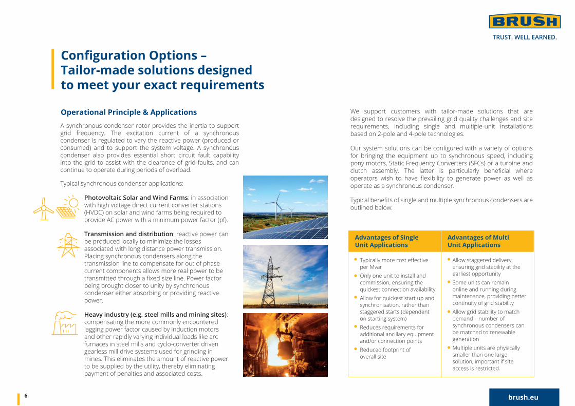
Typical synchronous condenser applications:
Photovoltaic Solar and Wind Farms: in association with high voltage direct current converter stations (HVDC) on solar and wind farms being required to provide AC power with a minimum power factor (pf).
Transmission and distribution: reactive power can be produced locally to minimize the losses associated with long distance power transmission. Placing synchronous condensers along the transmission line to compensate for out of phase current components allows more real power to be transmitted through a fixed size line. Power factor being brought closer to unity by synchronous condenser either absorbing or providing reactive power.
Heavy industry (e.g. steel mills and mining sites): compensating the more commonly encountered lagging power factor caused by induction motors and other rapidly varying individual loads like arc furnaces in steel mills and cyclo-converter driven gearless mill drive systems used for grinding in mines. This eliminates the amount of reactive power to be supplied by the utility, thereby eliminating payment of penalties and associated costs.
A synchronous condenser rotor provides the inertia to support grid frequency. The excitation current of a synchronous condenser is regulated to vary the reactive power (produced or consumed) and to support the system voltage. A synchronous condenser also provides essential short circuit fault capability into the grid to assist with the clearance of grid faults, and can continue to operate during periods of overload.
Operational Principle & Applications
1
2
3
A Synchronous Condenser (SC) has advantages over other technologies like Static VAR Compensators (SVC), consisting of Thyristor Switched Capacitors (TSC) and Thyristor Controlled Reactors (TCR) and filters. This is because a SC does not only produce vars and voltage support but also rotating inertia that supports network system stability.
Use of a synchronous condenser can also eliminate or mitigate against problems associated with power semi-conductor switching technologies such as switching transients, system electrical harmonics, excessive voltage levels and electrical resonances.
The rotating inertia of a BRUSH Synchronous Condenser (see table above) can be increased by the application of a flywheel directly coupled to the rotor of the machine. This significant inertia increase (typically by factor of 3, but can be greater if required) is achieved while still producing the same amount of Mvar, with the advantage that the inertia constant H and stored energy (MWs) is increased. Hence, a smaller machine can meet your overall requirements.
The flywheel is an integral part of the rotor drive train and runs up to synchronous speed in tandem with the synchronous condenser by the chosen starting method.
At this stage the inertia can be maintained by just supplying the losses of the system.
This continuous rotating energy provides a huge number of benefits to the grid onto which the synchronous condenser is connected, with these being:
Frequency regulation and stability in electric grids, including helping fault ride through
Reduction of load peaks in industry applications,
Elimination of power fluctuations in renewable power generation
Additional energy savings in transportation
7 brush.eu
Advantages of Synchronous Condenser Systems –Technology comparison
Higher Inertia Requirements
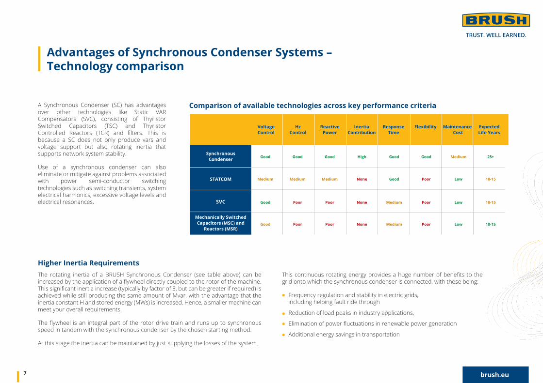
Voltage Control
Hz Control
Reactive Power
Inertia Contribution
Response Time
Flexibility Maintenance Cost
Expected Life Years
Good Good Good High Good Good Medium 25+
Medium Medium Medium None Good Poor Low 10-15
Good Poor Poor None Medium Poor Low 10-15
Good Poor Poor None Medium Poor Low 10-15
Synchronous Condenser
STATCOM
SVC
Mechanically Switched Capacitors (MSC) and
Reactors (MSR)
Comparison of available technologies across key performance criteria
The BRUSH range of control and monitoring products and solutions extends from standardised Automatic Voltage Regulators (AVRs), through specially engineered high current static excitation systems, to customised on-line monitoring and control systems.
The range includes Power Management Systems (PMS) which vary in complexity from simple single generator to very large multigenerator power systems with over 20,000 data points.
Every PMS is engineered to client and project specific requirements enabling maximum availability of electrical power for critical applications. BRUSH has successfully delivered over 300 PMS projects worldwide.
BRUSH supports customers with engineering studies and is able to provide various power system study services to ensure that the selected equipment is suitable for the application and complies with project specifications, applicable grid codes and other regulations.
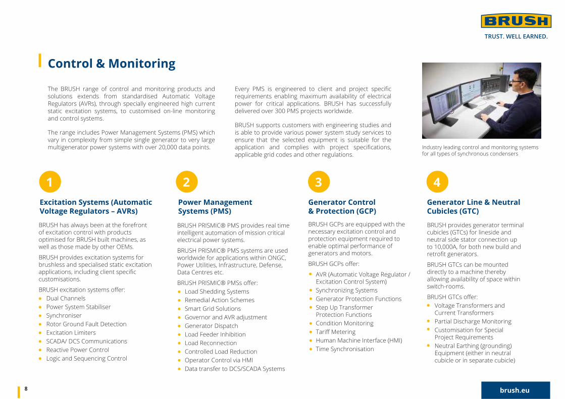
Control & Monitoring
Industry leading control and monitoring systems for all types of synchronous condensers
BRUSH has always been at the forefront of excitation control with products optimised for BRUSH built machines, as well as those made by other OEMs.
BRUSH provides excitation systems for brushless and specialised static excitation applications, including client specific customisations.
BRUSH excitation systems offer: Dual Channels Power System Stabiliser Synchroniser Rotor Ground Fault Detection Excitation Limiters SCADA/ DCS Communications Reactive Power Control Logic and Sequencing Control
Excitation Systems (AutomaticVoltage Regulators – AVRs)
1 3
BRUSH GCPs are equipped with the necessary excitation control and protection equipment required to enable optimal performance of generators and motors.
BRUSH GCPs offer:
AVR (Automatic Voltage Regulator / Excitation Control System) Synchronizing Systems Generator Protection Functions Step Up Transformer Protection Functions Condition Monitoring Tariff Metering Human Machine Interface (HMI) Time Synchronisation
Generator Control & Protection (GCP)
BRUSH provides generator terminal cubicles (GTCs) for lineside and neutral side stator connection up to 10,000A, for both new build and retrofit generators.
BRUSH GTCs can be mounted directly to a machine thereby allowing availability of space within switch-rooms.
BRUSH GTCs offer: Voltage Transformers and Current Transformers Partial Discharge Monitoring Customisation for Special Project Requirements Neutral Earthing (grounding) Equipment (either in neutral cubicle or in separate cubicle)
4Generator Line & NeutralCubicles (GTC)
2Power Management Systems (PMS)
BRUSH PRISMIC® PMS provides real time intelligent automation of mission critical electrical power systems.
BRUSH PRISMIC® PMS systems are used worldwide for applications within ONGC, Power Utilities, Infrastructure, Defense, Data Centres etc.
BRUSH PRISMIC® PMSs offer: Load Shedding Systems Remedial Action Schemes Smart Grid Solutions Governor and AVR adjustment Generator Dispatch Load Feeder Inhibition Load Reconnection Controlled Load Reduction Operator Control via HMI Data transfer to DCS/SCADA Systems
8 brush.eu
A BRUSH Condition Monitoring System (CMS) is available to provide continuous health assessment of the synchronous condenser and associated equipment. The BRUSH CMS ensures high availability even for sites which are normally unmanned or where on-site personnel numbers are very limited. The CMS ensures that maintenance costs and unplanned outages are minimised.
The CMS takes the form of an internet connected embedded computer fitted onto, or adjacent to, the condenser machine or group of machines for the purpose of marshalling data from sensors and other intelligent devices for onwards transfer to another database computer. The database computer is typically located in a purpose built remote secure data centre with access enabled for authorised BRUSH and owners’ support engineers.
Data will be transmitted using a secure protocol to ensure that data remains visible only to authorised users of the system. Additional cyber security precautions may also be included which may be discussed and agreed during the design and engineering phase to ensure that both the on-site equipment and remote systems are protected.
Data ingested into the server will be streamed into several different types of databases optimized for specific performance needs. Visualisation of the data gathered by the condition monitoring system is proposed to be available via web interfaces to several web based applications which may be optionally provided.
The database computer may be either a remote cloud server based in a data centre managed by a specialist provider or it may be provided as a local on-premises server, located at the synchronous condenser sub-station or at another location selected by the owner. As a further option both cloud server and on-premises server may be provided together with a secure link to facilitate synchronizing of data between these servers.
Security of data and protection of critical infrastructure are key considerations in the design of the CMS. With this in mind, each edge device includes a firewall and “one way data management software” to ensure that the CMS can only be used to gather condition monitoring data from the site and cannot be used to initiate unauthorised control commands.
9 brush.eu
Condition Monitoring System
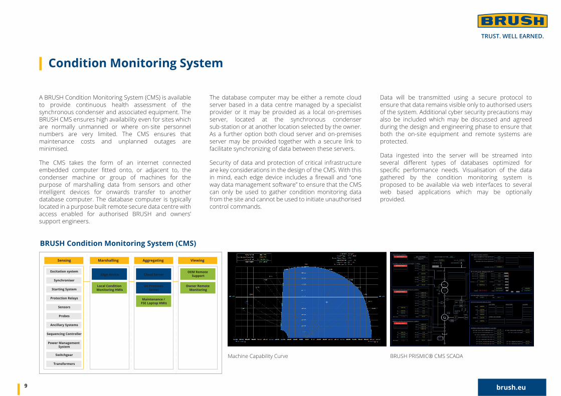
Machine Capability Curve BRUSH PRISMIC® CMS SCADA
BRUSH Condition Monitoring System (CMS)
Sensing
Excitation system
Synchroniser
Starting System
Protection Relays
Sensors
Probes
Ancillary Systems
Sequencing Controller
Power Management System
Switchgear
Transformers
Edge device
Local Condition Monitoring HMIs
OEM Remote Support
Owner Remote Monitoring
Cloud Server
On Premises Server
Maintenance / FSE Laptop HMIs
Marshalling Aggregating Viewing
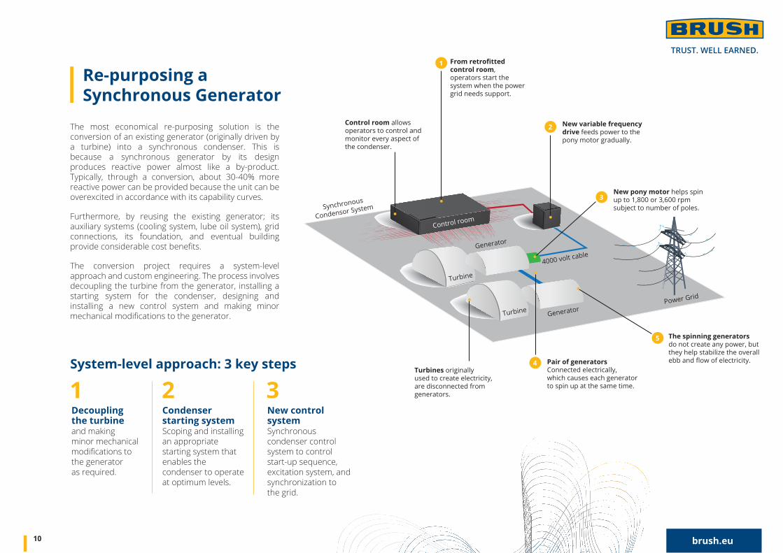
The most economical re-purposing solution is the conversion of an existing generator (originally driven by a turbine) into a synchronous condenser. This is because a synchronous generator by its design produces reactive power almost like a by-product. Typically, through a conversion, about 30-40% more reactive power can be provided because the unit can be overexcited in accordance with its capability curves.
Furthermore, by reusing the existing generator; its auxiliary systems (cooling system, lube oil system), grid connections, its foundation, and eventual building provide considerable cost benefits.
The conversion project requires a system-level approach and custom engineering. The process involves decoupling the turbine from the generator, installing a starting system for the condenser, designing and installing a new control system and making minor mechanical modifications to the generator.
10 brush.eu
Re-purposing aSynchronous Generator
4000 volt cableGenerator
Control room
Synchronous
Condensor System
GeneratorTurbine
Turbine
Power Grid
Pair of generatorsConnected electrically, which causes each generator to spin up at the same time.
Control room allows operators to control and monitor every aspect of the condenser.
Turbines originally used to create electricity, are disconnected from generators.
The spinning generatorsdo not create any power, but they help stabilize the overall ebb and flow of electricity.
New pony motor helps spin up to 1,800 or 3,600 rpm subject to number of poles.
4
5
New variable frequency drive feeds power to the pony motor gradually.
From retrofitted control room, operators start the system when the power grid needs support.
2
3
1
System-level approach: 3 key steps
1 2 3Decoupling the turbineand making minor mechanical modifications to the generator as required.
Condenser starting systemScoping and installing an appropriate starting system that enables the condenser to operate at optimum levels.
New control systemSynchronous condenser control system to control start-up sequence, excitation system, andsynchronization to the grid.
The next step is evaluating the present excitation system for its ability to reliably deliver the required excitation current needed for full reactive power generation. For maximum reactive power generation, the excitation system and generator should be capable of operation at a field current commensurate with the nameplate power factor.
Typically, a new synchronous condenser control system is designed and installed which controls the start-up sequence, the excitation system, and synchronization to the grid. The control system monitors the existing protection systems as well as the breakers, auxiliary systems, and condenser status. Optimally, the control system should be integrated with the overall plant controls to enable monitoring of the system’s status.
While converting the unit requires a system-level approach and custom engineering, the result can greatly extend the generator’s useful lifespan. For the community, a conversion to a synchronous condenser can provide electrical system voltage support resulting in a stable source of electric power.
11 brush.eu
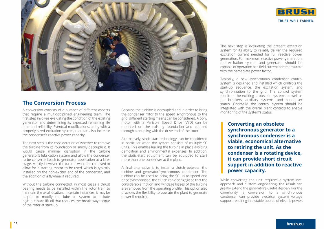
A conversion consists of a number of different aspects that require a multidisciplined engineering team. The first step involves evaluating the condition of the existing generator and determining its expected remaining life time and reliability. Eventual modifications, along with a properly sized excitation system, that can also increase the condenser’s reactive power capacity.
The next step is the consideration of whether to remove the turbine from its foundation or simply decouple it. It would cause minimal disruption in the turbine generator’s lubrication system and allow the condenser to be converted back to generator application at a later stage. Mostly, however, the turbine would be removed to allow for a starting motor to be used, which is typically installed on the non-exciter end of the condenser, and the addition of a flywheel if required.
Without the turbine connected, in most cases a thrust bearing needs to be installed within the rotor train to maintain the axial location. In certain instances, it may be helpful to modify the lube oil system to include high-pressure lift oil that reduces the breakaway torque of the rotor at start-up.
Because the turbine is decoupled and in order to bring the condenser rotor to the speed synchronous to the grid, different starting means can be considered. A pony motor with a Variable Speed Drive (VSD) can be mounted on the existing foundation and coupled through a coupling with the drive end of the rotor.
Alternatively, static-start technology, can be considered in particular when the system consists of multiple SC units. This enables leaving the turbine in place avoiding demolition and environmental expenses. In addition, the static-start equipment can be equipped to start more than one condenser at the plant.
A final alternative is to install a clutch between the turbine and generator/synchronous condenser. The turbine can be used to bring the SC up to speed and once synchronised, the clutch can disengage so that the considerable friction and windage losses of the turbine are removed from the operating profile. This option also provides the flexibility to operate the plant to generate power if required.
The Conversion Process
Converting an obsolete synchronous generator to a synchronous condenser is a viable, economical alternative to retiring the unit. As the condenser is a rotating device, it can provide short circuit support in addition to reactive power capacity.
With over 140 years of experience, a global install base of over 6,000 generators and condensers, over 300 Power Management Systems and a large, capable and enthusiastic engineering team with a “Can-Do” mentality, BRUSH is your partner of choice for enabling the transition towards a future renewable energy system that is supplying reliable power with the right quality.
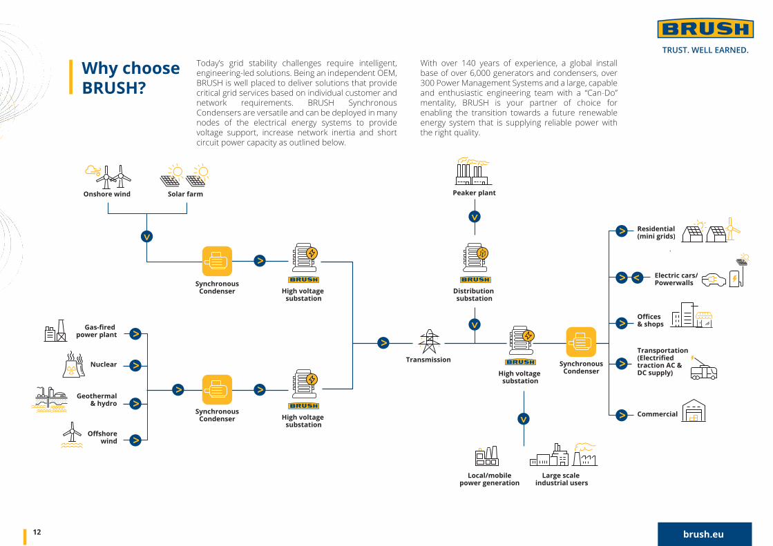
Today’s grid stability challenges require intelligent, engineering-led solutions. Being an independent OEM, BRUSH is well placed to deliver solutions that provide critical grid services based on individual customer and network requirements. BRUSH Synchronous Condensers are versatile and can be deployed in many nodes of the electrical energy systems to provide voltage support, increase network inertia and short circuit power capacity as outlined below.
12 brush.eu
Why choose BRUSH?
High voltage substation
Transmission
SynchronousCondenser
Peaker plant
power plant
Solar farmOnshore wind
Geothermal& hydro
wind
NuclearHigh voltage
substation
Distribution substation
High voltage substation
Commercial
& shops
Transportation
traction AC & DC supply)
Electric cars/Powerwalls
Residential(mini grids)
SynchronousCondenser
SynchronousCondenser
Large scale industrial users
Local/mobilepower generation

A conversion consists of a number of different aspects that require a multidisciplined engineering team. The first step involves evaluating the condition of the existing generator and determining its expected remaining life time and reliability. Eventual modifications, along with a properly sized excitation system, that can also increase the condenser’s reactive power capacity.
The next step is the consideration of whether to remove the turbine from its foundation or simply decouple it. It would cause minimal disruption in the turbine generator’s lubrication system and allow the condenser to be converted back to generator application at a later stage. Mostly, however, the turbine would be removed to allow for a starting motor to be used, which is typically installed on the non-exciter end of the condenser, and the addition of a flywheel if required.
Without the turbine connected, in most cases a thrust bearing needs to be installed within the rotor train to maintain the axial location. In certain instances, it may be helpful to modify the lube oil system to include high-pressure lift oil that reduces the breakaway torque of the rotor at start-up.
JUST CHALLENGE US! WE’RE LOOKING FORWARD TO PROVIDING INTELLIGENT GRID QUALITY SOLUTIONS YOU CAN TRUST.
13 brush.eu
Providing engineering-led, cost-effective systems for all
performance requirements and specific conditions.