handbook for testing synchronous machines as per is
TRANSCRIPT

Disclosure to Promote the Right To Information
Whereas the Parliament of India has set out to provide a practical regime of right to information for citizens to secure access to information under the control of public authorities, in order to promote transparency and accountability in the working of every public authority, and whereas the attached publication of the Bureau of Indian Standards is of particular interest to the public, particularly disadvantaged communities and those engaged in the pursuit of education and knowledge, the attached public safety standard is made available to promote the timely dissemination of this information in an accurate manner to the public.
इंटरनेट मानक
“!ान $ एक न' भारत का +नम-ण”Satyanarayan Gangaram Pitroda
“Invent a New India Using Knowledge”
“प0रा1 को छोड न' 5 तरफ”Jawaharlal Nehru
“Step Out From the Old to the New”
“जान1 का अ+धकार, जी1 का अ+धकार”Mazdoor Kisan Shakti Sangathan
“The Right to Information, The Right to Live”
“!ान एक ऐसा खजाना > जो कभी च0राया नहB जा सकता है”Bhartṛhari—Nītiśatakam
“Knowledge is such a treasure which cannot be stolen”
“Invent a New India Using Knowledge”
है”ह”ह
IS 7132 (1973): Guide for testing synchronous machines [ETD15: Rotating Machinery]


IS : 7132 - 1973
Indian Standard
GUIDE FOR TESTING SYNCHRONOUS MACHINES
( Third Reprint APRIL 1990 )
UDC 621’313’32 : 620’1
0 Copyrighl 1974
BUREAU OF INDIAN STANDARDS MANAIC BHAVAN, 9 BAHADUR SHAH ZAFAR MARG
NEW DELHI llooO2
Gr 10 August 1974

IS : 7132 - 1973
Indian Standard GUIDE FOR TESTTNG
SYNCHRONOUS MACHINES
Rotating Machinery Secticrxd Committee. ETDC 15
Chairman
SWRI J. s. ZAVERl
MWlbC?S
ReprercntinJ Bharat Bijlce Ltd, Bombay
Snn~ C. E. BH.+~KAR RAO ( Alrcma~r to Shri J. S. Zavcri )
Snar R. APPUKUTTM Fact Engineering and Design Organization, Udyogamandal
Saar G. HA~IN~~AN ( Akemnrt j ABSISTAIT DIBE~TOR ELECTRTCAI, Naval Headquarters
ENQINEERINR ( M!.TERIAL ) =A*? OPFICkR 1, X A N D E R
PROJECT ( FIZCTRICAL ) ( Alterktc ) SHRI T. V. BALAKRIWNAN Bharat Heavy Elcctricals Ltd, Hardwar
SHRIB J. Voa~.t ( dlkmafe ) .%IRI P. R. RPAT Guest, Keen, Williams Ltd, Bombay
SHRI K. R. R. IYENGAR ( Alkrnak ) SHRI G. R. B~~ATIA Directorate General of Supplies Sr Disposals
( Inspection Wing ), ILcw Delhi SHRI J. S. Pnssr ( Alfcrnaf~ )
SHRI C. S. BIJLANI SH~I B. G. DEBA:
Walchandnagar Industries Ltd, Walchandnagar Jyoti Limited, Baroda
SERI P.-L. PY.A*HAN ( A&mate ) Drmccroa (, I-I. E. D- 1 ) Cent;~,“D”~;~& Power Commission ( Power Wing ),
DEPUTY DIRECTOR ( H.E.D-I ) ( Altir~ak jr SHRI V. D. EMNDP: Hindustan Brown Bveri Ltd, Bombay
SHRI BEND~E ( A&mate ) DE S. K. GVPTA Rrycarch and Developmmt
Electrical Industry, Uho):al Grgarrization for
JOWT DIRECTOR STANDABDS Railway Board, lrTew Delhi ( ELECTRICAL )-I
DEPUTY DIRECTOW SXNDARDS ( ELECZTRICA L )-II ( Alkmak )
+IRI T. a. MOXAN Siemenr India Ltd, Bombay Sam V. L. NA~AYANAN ( Altnnok )
Q Copyighr 1974 BUREAU OF 1NDIAN SiANDARDS
ublication is protected under the Indian fZ%&right Act ( XIV of 1957 ) and Tb!sf/s repr uctlon In *:<holc or in part by any means except with written pcrmiwioa of t& publiier shall be deemed to lx an infringement of copyright under the said Act.

IS : 7132 - 1973
Stmr.~. R. MAIIA.IAN ( Afternnte ) Saw K. N. KAMAHWAMI Dircctabntr- <:encral of Trclmical Development,
New Ddhi
SIUU P. LhJ'lTA ( ~'t/t6rPlfSl~ ) Sa~r K. M. SINCLAIR Heavy I:.lu:tricalx ( India ) Lid, n110pnl
Dn A. K. CONWAMI ( Altnmtc ) Snm S. GOVINDAIIA.I ( dkmata )
&IIU M. ZAHED Arr Rharat Heavy ISlcctricals Ltd, Hydcrabad SHRI P. KONIMLA Rae ( Alternate )
-’ i%lRl i% !hINIVMAN, Dircctnr Cknkral, BIS ( Ex-oficio ‘demnbsr ;
Deputy Director ( Elcc tech )
SIIRI K. C. JAIN
Deputy Dircctoc ( Eke tcctr ), 111s
Panel for Finalization of Draft Standards on Synchronous Machines, mix 15: PI3
Ssm hi. ZAI~ED ALI
Snu T. V. BALAKRISWNAN &am 8. J. VOHRA ( Altcmat~ )
~Ihxtscroa(T.B.D.)
SHRI S. GOVIND*IWJ
Bharat Heavy Electricala Ltd. Hyderabad
Bharat Heavy Elcctricals Ltd. Hardwar +
Central Water & Power Cummisi-3n ( I’cbwer Wing ). New Delhi
Heavy Elrctricals, (, India ) Ltd, BhopPl
2

IS : 7132 - 1973
CONTENTS
0.
1.
-2.
3.
4.
5.
6.
7.
8.
9.
lC4.
11.
12.
13.
14.
15.
16.
17
18.
19.
20.
21.
22.
23.
24.
25.
26.
I! OREWORD . . . . . . . . . . . .
SCOPF . . . . . . . . . . . .
TERMINOLOGY . . . . . . . . . . . .
ELECTRKAL MEASUREMENTS . . . . . . . . .
SAFETY PRECAUTIONS . . . . . . . . .
MEAS~!REYENT OF INSULATION RESISTANGES OF WINDINGS . . .
TESTS FOR SHORT-CIRCUITED FIELD TURNS . . . . . . POLARITY TEST FOR FIELD POLES . . . . . . . . .
RESISTANCE MEASUREMENT . . . . . . . . .
HIG~I VOLTAGE TESTS . . . . . . . . .
CHECKING OF SHAFT CURRENT AND MEASUREMENT OF BEARINO INSULATION RESISTANCE . . . . . . .=.
PHASE-SEQUENCE TEST . . . . . . . . .
DETERMINATION OF IRREGUURITIES OF VOLTAGE WAVE-FORM
OVERSPEED TEST AND CI~ECKINC OF VIBRATIONS . . .
LINE-CHARGING CAPACITY . . . . . . . . .
DETERMINATION 0~ MOMENT OF INERTIA . . . . . .
MOMENTARY OVERLOAD TEST . . . . . . . . .
BREAK-AWAY STARTING CURRENT AND TORQUE FOR SYNCHRONOUS MOTORS . . . . . . . . .
SPEED TORQUE TESTS . . . . . . . . .
PULLOUT TOR_QUE ,., . . . . . . . . .
MEASUREMENT OF LOSSES BY VARIOUS METHODS AND DETERMINATION OF EFFICIENCY . . . . . . . . .
MEASUREMENT OF OPEN-CIRCUIT AND SHORT-CIRCUIT CHARACTERISTICS . . . . . . . . . . . .
ZERO POWER FACTOR CHARACTERZSTIC . . . . . .
DETERMINATION OF ‘ V ’ CURVES . . . . . . . . .
DETERMINATION 0~ ~TED EXCITATION. Am3 OTHER SYNCHRONOUS MACHINE QUANTITIES PLOY Tgms . . .
TEMPERATURE-RISE TEST . . . . . . . . .
INSTANTANEOUS SHORT-CIRCUIT WITHSTAND TIUT . . .
PAGE
4
4
5
5
5
5
6
7
5
14
16
17
20
24
25
25
27
27 29
34
35 c
35
39
39
40
40
51

IS : 7132 - 1973
Indian Standard GUIDE FOR TESTING
SYNCHRONOUS MACHINES
0. FOREWORD
6.1 This Indian Standard was adopted by the Indian Standards Institution on 23 April 1973, after the draft finalized by the Rotating Machinery Sectional Committee had been approved by the Electrotechnical Division Council.
O-2 This standarcl shall be read in conjunction with IS ; 4889-l 968* and IS : 7306?, which find reference for some tests in this standard.
0.3 In the preparation of this standard, assistance has been derived from the following standards:
IEC Pub 34-1 ( 1969 ) Rotating electrical machines, Part I Rating and performance. International Electrotechnical Commission.
IEC Pub 344 ( 1967 ) Rotating electrical machines, Part 4 Methods for determining synchronous machine quantities from tests. International Electrotechnical Commission.
CSN 350201-1960 Test code for synchronous machines. Urad pro normalizaci a mereni.
IEEE 115-1965 Test procedures for synchronous machines. Institu- tion of Electrical and Electronics Engineers, U.S.A.
0.4 For the purpose of deciding whether a particular requirement of this standard is complied with, the final value, observed or calculated, express- ing the result of a test, shall be rounded off in accordance tvith IS : 2-1960:. The number of significant places retained in the rounded off value should + be the same as that of the specified value in this standard.
1. SCOPE
1.1 This guide prescribes methods for conducting the tests on synchronous machines.
-- *Methods of determination of efficiency of rotating electrical machines. tMethods for determining synchronous machine quantities from tests $Rules for rounding off numerical values ( reuisca).
4

IS : 7132 -8 1973
2. TERMINOLOGY
2.1 For the purpose of this guide, the definitions given in IS : 4722-1968* and IS : 1885 ( Part XXXV )-1973t shall apply.
3. ELECTRICAL MEASUREMENTS
3.1 Instrument Selection - The indicating instruments used in electrical measurements shall conform to IS : 1248-1968:. Instruments with the-following accuracies shall be used:
a ) For type tests, instruments of accuracy not inferior to class 0’5 shall be used; and
b) For routine tests, instruments of accuracy class 1.0 or better shall be used.
3.2 Instrument Transformers -Where current and potential transformers are used, corrections shall be made for ratio errors in voltage and current measurements and for ratio and phase angle errors in power measurements. The instrument transformers shall have an accuracy not inferior to class 0.5 [ sek IS : 2705 ( Part II )-I9645 and IS : 3156 ( Part II )-1965/j 1.
4. SAFETY PRECAUTIONS
4.1 Before testing the machine, it should be thoroughly inspected for checking up the possible mechanical defects. The purpose of this inspec- tion is to ascertain the absence of following defects:
a ) Which may harm the machine during the tests;
b ) Which may hinder the correct assembly of the machine at the site; and
c ) Which may hinder the proper operation of the machine at the site, even if these defects may not manifest themselves while testing the machine at the manufacturer’s works.
4.2 Because of dangerous currents, voltages, and forces encountered, safety precautions shall be taken for all the tests. All tests shall be performed by qualified and experienced personnel, only.
5. MEASUREMENT OF INSULATION BESISTANCES OF WINDINGS
4
5.1 The insulation resistance shall be measured between open windings, and between windings and the frame.
*Specification for rotating electrical machines, tElectrotechnica1 vocabulary : Part XXXV Rotating machines. SSpecification for direct acting electrical indicating instruments (Jirst recision ). ispecification for current transformers: ljSpecification for voltage transformers;
Part II Measuring current transformers. Part II Measuring voltage transformers.
5

IS: 7132-1973
5.2 The recommended method for testing insulation resistance is prescribed in the ‘ Indian Standard Guide for testing insulation resistance of rotating machines ’ ( under preparation ).
5.3 Drying out shall be carried out if the insulation resistance is lower than the minimum specified values. The selection of the methods to be used for drying out a machine should be made in consultation with manufacturer.
6. TESTS FOR SHORT-CIRCUITED FIELD TURNS
6.1 The object of these tests is to detect field coils that have short- circuited turn, incorrect number of turns, or incorrect conductor size.
6.2 Method 1 : Voltage Drop Direct Current - This method can be used to detect short-circuited turns, only when connections between coils are accessible. The test is made by passing a constant direct current through the entire field winding. The drop in voltage of each coil or pair of coils is measured by means of a voltmeter. If these readings vary more than plus or minus 2 percent from the average, it is an indication that there-may be short-circuited turns in the coil, or that part of the winding is wound with the wrong number of turns or size of conductor.
6.3 Method 2 : Voltage Drop Alternating Current - A more sensitive test for short-circuited turns is made by passing constant-amplitude alter- nating current through the entire field winding. If there is access to connections between coils, the voltage across each coil or pair of coils should be measured. The voltage across a coil having short-circuited turn will be substantially less than that across a sound coil. The voltage across a sound coil adjacent te the coil with a short-circuited turn will be somewhat less than that across other sound coils because of the reduced flux in the short-circuited coils. Comparison of the measured voltages will readily locate any coils that are defective.
If the connections between coils are not accessible, the current and voltage drop ( across the entire winding ) should be measured. The impedance of one circuit winding in which one coil has short-circuited turn will be reduced to approximately ( m-1 )/m times the value across a sound winding, where m is the number of coils in the winding. This test is useful for detecting a machine which has a short-circuited turn only when running. If the speed is varied while the alternating current is applied, a discontinuity in the current or voltage readings should indicate the occurrence or removal of a short-circuit.
NOTE -The sensitivity of this method of test is much lower for cylindrical rotors in which the field winding lies in slots! and especially for solid-steel rotors. The sensitivity varies, depending on which co11 has a short-circuited turn. Factory trials in which temporary short-circuits are applied’can be made to serve as the basis for future analysis when short-circuited turns are suspected. For cylindrical-rotor machines, method 3 or 4 may be preferred.
.
6
L
IS : 7132 - 1973
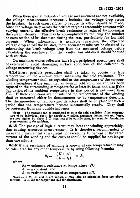
5.4 Method 3: Direct Current Resistance- In this method, a comparison is made between the field resistance and a value previously obtained by test or calculation.
After the rotor has been exposed to an ambient temperature for a sufficient period for the entire field winding to be at ambient temperature, the field resistance is measured by double bridge and the temperature of the rotor is measured by several thermometers or thermocouples located at suitable points. The resistance is then corrected to a temperature at which the resistance has previously been determined by a similar test ( or by calculation in the case of a new machine ). If the corrected value of the newly obtained resistance is significantly lower than the reference value, short-circuited turns may be present.
6.5 Method 4 : Exciting Coil, for Cylindrical Rotor Generators - This method uses a testing device having a U-shaped core capable of bridging one coil slot of a cylindrical rotor, and having an exciting coil wound on the core. The test is made by placing the device successively across a slot of every field coil and passing alternating current through the exciting coil. The voltage across the field winding or the impedance of the exciting coil should be determined for each slot. When the device spans a coil with a short-circuited turn, the voltage of the field winding or the impedance of the coil will be lower than for a slot containing a sound coil.
7. POLARITY TEST FOR FIELD POLES
7.1 The polarity of the field poles may be checked by means of a small permanent magnet mounted so that it may turn and reverse its direction freely. The field winding should be energized by 5 to 10 percent of rated current. The magnet indicates proper polarity by reversing direc- tion as it is passed from pole to pole. The magnet should be checked to insure that its magnetism has not_ been lost or its polarity reversed by the field flux.
8. RESISTANCE MEASUREMENT
8.1 General - The following two methods are commonly used for the measurement of resistance:
L
a) The drop of potential or voltmeter-ammeter method, and
b) The bridge method in which the unknown resistance is compared with the known resistance by using a suitable bridge.
8.1.1 Armature winding resistance should be measured for each phase separately. If for some reason each phase resistance can not be measured
7

18t7132-1373
directly, the measurements are made between each pair of the line terminals.of the armature winding and the resistance R of each phase is calculated as follows:
a> For star connected winding:
RI== Rtr -I- Ru - Rzr ___- 2
ohms ( rI = fLY + ru - rsa
2 per unit )
R22 + &2 - &L &e __ . -~----.. ohms ( IP =
na + TL2 - bL
2 2 per unit )
Ru -I- Rss - RIP R8= 2 ohms ( rs =
rn.+ 148 - IIS 2
per unit )
where
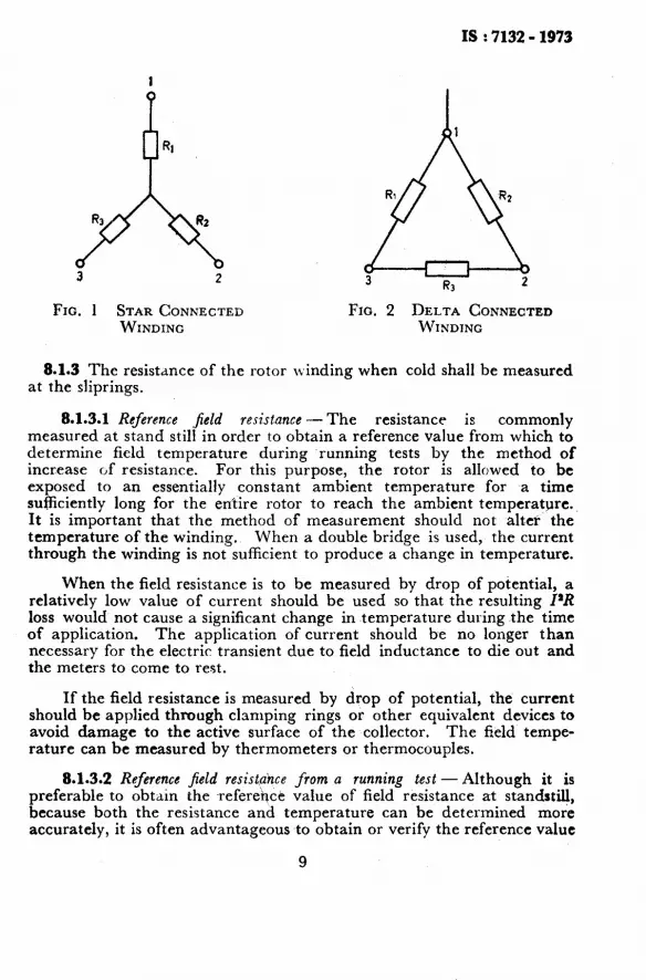
Ru, RI, and RSI ase the resistances measured between terminals t-2, 2-3, and 3-l respectively and RI, Rx and Ra are resistances of phases between terminals 1, 2 and 3 and the neutral resptc- tively (see Fig. 1 ).
b ) For delta connected winding:
RI = 2Rlr . RN R12 -I- K2a - &I -
RIB -I- Rsa - Rsl 2 ohms
i r1 =
2rrr . TP8 n2 + r26 - r21 a _.~___ ~12 + r2a - r8x 2
per unit
R2 = 2Rsa . RSL Rs 3- R~L - &a
- RYE + RII - RIP 2 ohms
(r2 = 2ro: . Ql T2a + raL - n2
--
~2s + tai - n2 2 per unit)
RI .z=- 2Ru . iZ12 Ru + &e - R2c -_- - .__-.
Rar f Ru - Rna 2 ohms
( Ya = -- 2raI . ?I2 ral + r12 - rk~
- _..__-
rti + n2 - 722 2 per unit )
where Rrr, Ru and Raz are the resistances measured between the terminals 1-2, 2-3, and 3-1 respectively and RI, Ra and R3 2 UC
resistances of phases between termin - ’ * ’ * _ _ alsYana I, I anaz, zand 3 respectively ( see Fig. 2 ).
8.1.2 The variation of resistance of the phases of armature winding to the extent of 5 percent is permissible.
8
IS : 7132 - 1973
3 2
FIG. 1 STAR CONNECTED FIG. 2 DELTA CONNECTED WINDING WINDING
8.1.3 The resistance of the rotor llinding when cold shall be measured at the sliprings.
8.1.3-l Reference jeld resistance - The resistance is commonly measured at stand still in order to obtain a reference value from which to determine field temperature during running tests by the method of increase of resistance. For this purpose, the rotor is allowed to be exposed to an essentially constant ambient temperature for ~a time sufficiently long for the entire rotor to reach the ambient temperature. It is important that the method of measurement should not alter the temperature of the winding. When a double bridge is used, the current through the winding is not sufficient to produce a change in temperature.
When the field resistance is to be measured by drop of potential, a relatively low value of current should be used so that the resulting I’R loss would not cause a significant change in temperature during the time of application. The application of current should be no longer than necessary for the electric transient due to field inductance to die out and the meters to come to rest.
If the field resistance is measured by drop of potential, the current should be applied through clamping rings or other equivalent devices to avoid damage to the active surface of the collector. The field tempe- rature can be measured by thermometers or thermocouples.
L
8.1.3.2 Reference field resistahce from a running test -Although it is preferable to obtain the reference value of field resistance at standstill, because both the resistance and temperature can be determined more accurately, it is often advantageous to obtain or verify the reference value
9

IS I 7132 - 1973
by a test made at or near normal speed, using the drop-of-potential method. For conductor cooled rotors, winding temperature may change too rapidly to make this practicable. Also the making or relieving of turn-to-turn short circuits in the field winding may cause the measured resistance of the field circuit to differ substantially from the standstill value, thus providing a possible incident21 check for short-circuited turns.
Immediately after the machine has been brought up to speed, sta.,ting with the rotor at a known uniform temperature, direct current is applied to the field, as small a value as will permit accurate current and voltage measurements. As soon as the current has become,constant, the voltage drop across the collector rings should be measured. Since the voltage drop of the normal brushes may be a substantial fraction of the impressed voltage in this test, it is essential that the brush voltage drop be eliminated from the voltage measurement, or minimized by special methods of voltage measurement or special test procedures.
8.1.3.3 Field resistance for running temperature tests - To determine the field temperature under specified or desired load conditions, the field resistance should be measured by the ‘drop-of-potential method after the machine has been operated at the required field current and as near as practicable to the required loading conditions long enough for a uniform temperature to have been reached.
Because including brush voltage drop in the measured field voltage may introduce a substantial error in the temperature determination, it is highly desirable to eliminate or minimize its effect in this test.
8.1.3.4 When measuring the resistance of the field with the machine loaded, the voltage regulator should be disconnected and a number of armature voltage, power and current readings should be taken simultan- eously with field current and voltage readings to ensure that the resistance is measured under constant conditions.
8.1.3.5 E$ect of brush voltage drop - To determine the field resistance of a running machine accurately, it is necessary to obtain the voltage drop across the field winding, without including the voltage drop of the brushes supplying the field current. This is especially important when the field current is very small, as when determining the reference resist- ance vaIue. For this purpose it is desirable to measure the voltage drop directly across the collector rings, using special brushes that are in contact with the collector rings only during voltage measurement. For this purpose, it is possible to use ( a ) special copper or bronze leaf brushes b~earing directly on the collector rings, ( b ) insulated brushes that have not developed a glazed surface, or ( c ) insulated special carbon or graphite brushes compounded with highly conducting materials to reduce their resistance. Unless a very small voltage drop occurs across these measurement brushes, a significant error may be introduced.
10
IS : 7132 - 1973
When these special methods ot voltage measurement are not available, the voltage measurement necessarily includes the voltage drop aeross the brushes. In such cases, efforts to reduce its effect should be made. Since the voltage drop across the brushes remains reasonably constant with varying current, the effective brush resistance is reduced by increasing the current density. This may be accomplished by reducing the number or cross section of brushes used during the test, particularly for low field currents. When information is available regarding the expected voltage drop across’ the brushes, more accurate r,esul+s can be obtained by subtracting the brush voltage drop from the measured voltage before calculating the resistance, but the results thus obtained should be used! with caution.
On,machines whose collectors have high peripheral speed, care shall be exercrsed to avoid damaging surface condition of the collector by voltage-measuring devices.
8.1.4 Every possible precaution shall be taken to obtain the true temperature of the winding when measuring the cold resistance. The winding temperature shall be regarded as the temperature of the surroun- ding atmosphere if the machine has been in cold condition and has been exposed to the surrounding atmosphere for at least 24 hours and also ff the fluctuation of the ambient temperature in that period is not more than 5%. If these conditions are not satisfied the temperature of the winding shall be measured either by thermometers or by temperature detectors. The thermometers, or temperature detectors .shall be in place for such a period that the temperatures become substantially steady. They shall be protected from any outside influence.
NOTE - The machine can be considered to be in the cold condition if the ternpew ture of its indixidual parts, for example, winding, armature laminationa and frame, are not higher by about 3°C than that of its outside parts, for example, foundation plate exposed to the ambient.
8.1.5 The passage of high current may heat the winding -appreciably, thus causing erroneous measurement. It is, therefore, recommended to make the measurement at a current not exceeding 10 percent of the rated current of the winding and the current should be supplied for not longer than one minute.
841.6 If the resistance of winding is known at one temperature it may be calculated for any other temperature by using following formula:
Rp= (R+fs) )( &
tx+ti
L
where RI = unknown resistance at temperature ts”C:
FL = = a constant, and
resistance measured at temperature tl“C. Nom- If RI, RI and tl are known, tr may also be calculated from the above
formula. X = 235 for copper and 225 for aluminium.
11
IS t 7132 - 1973
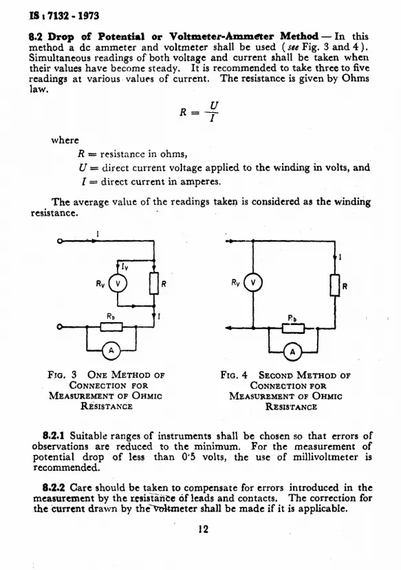
8.2 Drop of Potential or Voltmeter-Ammaer Method - In this method a dc ammeter and voltmeter shall be used (see Fig. 3 and 4). Simultaneous readings of both voltage and current shall be taken when their values have become steady. It is recommended to take three to five readings at various. values of current. The resistance is given by Ohms law.
R Y = .- where
R = resistance in ohms,
U = direct current voltage applied to the winding in volts, and
I- direct current in amperes.
The average value of the readings taken is considered as the winding resistance.
R R
Fro. 3 ONE METHOD OF Fm.4 SECOND METHOD OF CONNECTION FOR CONNECTIONFOR
MEASUREMENT OF OHMIC MEASUREMENTOF OHMIC RI~SISTANCE RESISTANCE
*-
8.2.1 Suitable ranges of instruments shall be chosen so that errors of observations are reduced to the minimum. For the measurement of potential drop of less than 0’5 volts, the use of millivoltmeter is recommended.
8.2.2 Care should be taken to compensate for errors introduced in the measurement by the r.esi&ice of leads and contacts. The correction for the current drawn by theYvoltmeter shall be made if it is applicable.
12

8.2.3 When the error caused by the internal resistance of apparatus exceeds 0’1 percent, corrections shall be carried out as follows:
For connections according to Fig. 3,
and for connections according to Fig. 4,
R=+-RI,
where
R = value in ohms of the resistance measured,
U = reading in volts of the voltmeter,
Z 5: value in amperes of the current measured by the ammeter,
Rv =-resistance of the voltmeter in ohms, and
R,, = value of shunt resistance in ohms connected for measure- ment of current.
N~TYE- The ’ ammeter referred ahove is actually a millivoltmeter calibrated directly in amperes and it measures actudly the voltage drop across the resistance &,.
8.3 Bridge Method -Resistance ahove 1 ohm may be determined with sufficient accuracy if ordinary wheatstone bridge is used. Resistance, lower than 1 ohm shall be measured by Kelvin double bridge ( also known as Kelvin-Thompson double bridge ).
It is recommended to take at least three readings each time disturbing the balance. The average value is taken for resistance.
8.3.1 Wheat&one Bridge Method - In using Wheatstone bridge, the resis- iance of the ratio arms shall be so selected that the values used correspond as closely as possible to the resistance to be measured. The use of one ohm ratio coil should be avoided. The value of the resistance thus measured includes the resistance of the connecting leads. Therefore the resistance of the connecting leads shall be subtracted from the total measured resistance, otherwise it shall be suitably compensated for.
L
8.3.2 X&in-Thomijson Double Bridge Method - The double bridge com- pensates the resistance of the leads or other connections. It also enables low resistance to be measured accurately by comparison with standard one of the same order.
13

I8 : 7132 A 1973
9. HIGH VOLTAGE TESTS
9.1 Before carrying out the high voltage test, theinsulationresistance ofthe windings shall be measured in accordance with the’ Indian Standard Guide for testing insulation resistance of rotating machines ’ ( under prcpurution). The measured insulation resistance values shall be at least equal to the minimum values ‘specified, otherwise it is necessary to dry out the windin s.
8 The high voltage test is carried out when the machine is at
rest. eneraIly,-the high voltage test is the last one in the serial order of tests carried out on the machine.
9.1.1 In case of polyphase windings, where both the terminals of each phase are not brought out, the test shall be carried out on all the phases simultaneously.
All the terminals of polyphase winding under test are joined together and connected to the high voltage terminals of the source and all terminals of other windings as well as the other terminal and the frame of the source or test equipment are connected to the machine frame which is solidly earthed.
9.1.2 In case of polyphase winding where both the terminals of each phase are brought out, _the high voltage test may be carried out on each phase separately, if desired.
The two terminals of the phase under test are joined together and connected to the high voltage terminal of the source and all the terminals of the other phases and all the other windings as well as the other terminal and the frame of the source or the test equipment are connected to the machine frame which is solidly earthed.
9.1.3 During testing of the field windings of large machines the brushes normally should be lifted so that no excessive .voltage stress will be imposed on the field winding if some part of the brush ligging or the leads fails. The brush rigging and station leads should be tested separately from the field. If it is desired to test the brush rigging of a machine at the same time the field is being tested, the exciter leads should be disconnected unless it is intended that the exciter be tested simultaneously. In any case the permanent instrumentation leads should be disconnected. They may be tested separately, if desired.
9.2 The test voltage shall be in accordance with the values specified in IS : 4722-1968* and IS : 5422-1969t.
9.3 Precautions should be taken to prevent any one from coming in contact with any part of the circuit or apparatus while the high voltage test is being conducted.
*Specification for rotating electrical maqhinea. tspecification for turbine type generators,
IS : 7132- 1973
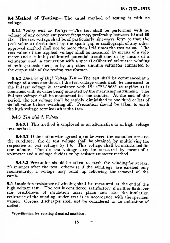
9.4 Method of Testing - The usual method of testing is with ac voltage.
9.4.1 Testing with UC Voltage -The test shall be performed with ac voltage of any convenient power frequency, preferably between 40 and 60 Hz. The test voltage shall be of particularly sine-wave form so that the peak value as determined by the spark gap or oscillograph of any other approved method shall not be more than 1’45 times the rms value. The rms value of the applied voltage shall be measured by means of a volt- meter and a suitably calibrated potential transformer or by means of a voltmeter used in connection with a special calibrated voltmeter winding of, testing transformers, or by any other suitable voltmeter connected to the output side of the testing transformer.
9.4.2 Duration of Hugh Voltage Test - The test shall be commenced at a voltage of about one-third of the test voltage which shall be increased to the full test voltage in accordance with IS : 4722-1968* as rapidly as is consistent with its value being indicated by the measuring-instrument. The full test voltage shall be maintained for one minute. ‘At the end of this period, the test voltage shall be rapidly diminished to one-third or less of its full value before switching off. Precaution should be taken to earth the high voltage terminal after the test.
9.4.3 Test with dc Voltage
9.4.3.1 This method is employed as an alternative to ac high voltage test method.
9.4.3.2 Unless otherwise agreed upon between the manufacturer and the purchaser, the dc test voltage shall be obtained by multiplying the respective ac test voltage by 1.6. This voltage shall be maintained for one minute. The dc test voltage may be measured by means of a voltmeter and a voltage divider or by resistor ammeter method.
9.4.3.3 Precaution should be taken to earth the winding for at least 30 minutes after the test, otherwise if the windings are earthed only momentarily, a voltage may build up following the removal of the earth.
c
9.5 Insulation resistance of winding shall be measured at the end of the high voltage test. The test is considered satisfactory if neither flashover nor breakdown of insulation takes place and also the insulation resistance of the winding under test is in accordance with the specified values. Corona discharges shall not be considered as an indication of defect.
*Specification for rotating electrical machines.
IS : 7132 - 1973
9.6 Supplementary High’ Voltage Test -The test made on the windings on acceptance shall as far as possible not be repeated. If, however, a second test is made at the special request of the purchaser, after further drying if considered necessary, the test voltage shall be 80 percent of the voltage as specified in IS : 4722-1968* and IS : 5422-1969-t.
10.. CHECKING OF SHAFT CURRENT AND MEASUREMENT OF BEARING INSULATION RESISTANCE
10.1 Origin of Shaft CurrentS- Irregularities in the magnetic circuit may cause a small amount of flux to link with the shaft, with the result that an electromotive force is generated between shaft ends. This electromotive force is gentrated between shaft ends. This electromotive force may cause a current to flow through the shaft, bearings, bearing supports and machine framework and back to the other end of the shaft, unless this circuit is interrupted by insulation. ( While other causes may produce a shaft voltage not involving a difference in potential from one end of the shaft to the other, no special tests are provided for the resulting effects because each of these sources would require specially adapted methods of test, essentially of a research nature. )
10.2 The shaft currents are normally prevented by insulating one or more bearing pedestals in the case of horizontal machines. Inthe case of vertical water wheel generators with a combined thrust and guide bearing at the top of the rotor and a guide bearing below the rotor, all parts likely to come into ‘contact with the stationary parts shall be insulated to prevent flow of shaft currents.
10.3 Checking of Shaft Current
10.3.1 The machine is run at rated speed on open-circuit at rated voltage. A low resistance conductor is connected between the shaft and the uninsulated bearing to short-circuit the oil film. A low range at voltmeter ( or high range ac ammeter ) is then connected between the shaft and the frame at each insulated bearing successively. Deflection of the meter indicates the presence of an electromotive force that would produce shaft currents in the absence of bearing insulations. If there is no deflection of the meter, either the insulation of bearing is defective or there is no electromotive force present. It is then necessary to check up the bearing insulation resistance.
10.4 Measurement of Bearing Insulation Resistance
10.4.1 In case of bearings insulated from the frame by a single layer of insulation and with the rotor not in the bearings the insulation resistance is measured between the bearings and frame by means of a 500-volts insulation tester. The insulation resistance measured shall be not less than one megohm.
*Specification for rotating electrical machines. tSpccification for turbine type generators.
L
16

X8:7132-1373
10.4.2 In case of machines provided with bearings insulated from the frame by two layers of insulation with a metallic separator between them, the insulation resistance between the metallic separator and the frame may be measured by means of a 500-volts insulation tester. The insulation resistance measured shall be not less than one megohm.
SO.4.3 When measuring the insulating resistance of the bearin a with rotor in position the couplings of the driving or driven units sho n! d be disengaged if not insulated.
11. PHASE-SEQUENCE TEST
1l.i The phase-sequence test is made to check the agreement of the machine with the terminal markings and phase rotation that have been speciGed, or with the relevant standards. The results are used when connecting line leads to the armature terminals to obtain correct phasing of a generator to the bus, or the correct direction of rotation for motors. The phase sequence on three-phase machines can be reversed by interchanging the line connections to any two armature terminals. The phase sequence on two-phase machines can be reversed by interchanging ihe two leads of either phase.
11.2 Method 1 : Phase-Sequence Indicators - Phase sequence is determined by running the machine as a generator in the direction of rotation for which it was designed and by connecting to the terminals a phase-sequence indicator or an induction motor, whose direction of rotation is known when a given phase sequence is applied to its terminals.
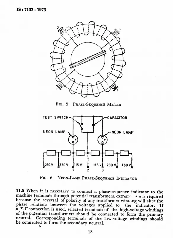
11.3 Figure 5 shows one type of phase-sequence indicator which consists of windings placed on a laminated iron core, with a steel bar mounted-in centre. The terminals of the machine under test, whether three-phase or two-phase, should be connected to the corresponding terminals of the indicator. The indicator shown in Fig. 5 will operate clockwise if the phase sequence is 1, 2, 3 and counter-clockwise if the phase sequence is 1, 3, 2.
11.4 Another type of phase-sequence indicator without moving parts is also available for three-phase machines and is shown schematically in Fig. 6. The indicator makes use of a small capacitor and two neon lamps connected in Y across the three-phase circuit to be tested. sequence 1, 2, 3 the lamp connected to terminal 1 will glow.
For phase
sequence 1, 3, 2, the lamp connected to terminal 3 will glow. For phase
To check the indicator, the switch shown in Fig. 6 should be closed. If operating correctly, both lamps will glow with equal intensity.
17
IS : 7132 - 1973
FIG. 5 PHASE-SEQUENCE METER
TEST SWITCH
NEON LAMP
b d60 V
FIG. 6
b23OV &5V
1 1lSVb 23OVh bsovb
2 3
NEON-LAMP PHASE-SEQUENCE INDICATOR
11.5 When it is necessary to connect a phase-sequence indicator to the machine terminals through potential transformers, extrem - Ire is required because the reversal of polarity of any transformer wincllng will alter the phase relations between the voltages applied to the indicator. If a T-Y connection is used, selected terminals of the high-voltage windings of the pcciential transformers should be connected to form the primary neutral. Corresponding terminals of the be connected to form the secondary neutral.
low-voltage windings should
.
18

IS : 7132 - 1973
If a delta-delta or open-delta connection is to be used, similar care is required to ensure proper phasing of the secondary.
For any of the above cases, it is important to retain the identi- fication of the proper phase sequence in the secondary network.
11.6 Method 2 : la&cation of Differential Voltage - A convenient check of the phase-sequence of a synchronous generator compared to the system to which it is to be connected can be obtained as follows:
Four potential transformers should be connected as shown in Fig. 7 for three-phase machines. Great care is necessary to maintain the correct polarity of the transformer connections. The asterisks ( * ) show the corresponding terminals of the primary and secondary windings. This connection effectively places indicating lamps across open disconnecting switches between the generator and the system. The generator should be brought up to speed and excitation applied corresponding to normal voltage. When it is near synchronous speed, lamps connected to the potential transformer secondaries will brighten or dim simultaneously if the generator has the same phase sequence as the system, whereas they will brighten or dim one after the other if the phase sequence is opposite.
DlSCONNECT SWITCH
INDICATING LAMPS
FIG. 7 -CONNECTION DIAGRAM FOR COMPARING PHASE SEQUENCE OF GENERATOR WITH THAT OP SYSTEM BY’ INDICATING
VOLTAGE ACROSS OPEN DISCONNECT WITCH
19
IS : 7132 - 1973
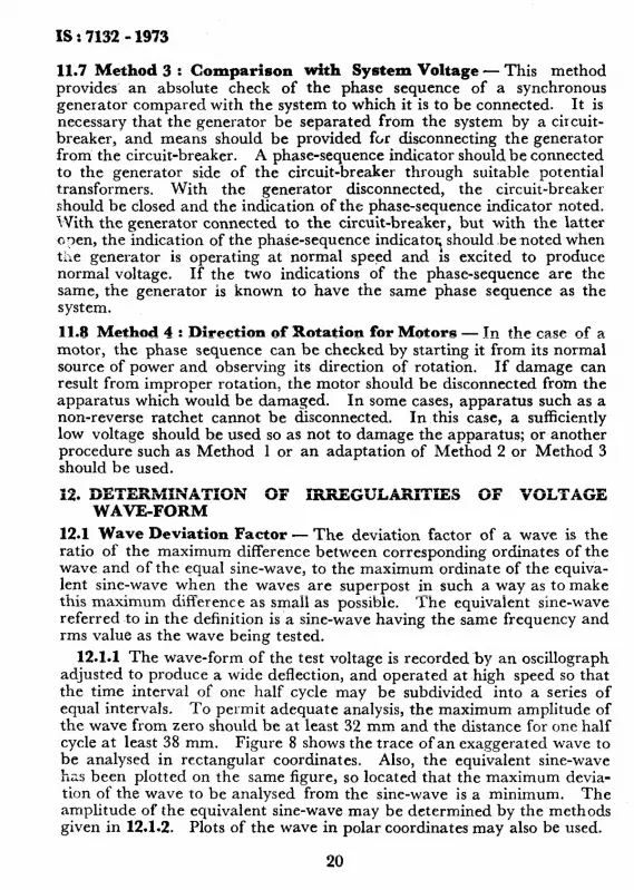
11.7 Method 3 : Comparison with System Voltage - This method provides an absolute check of the phase sequence of a synchronous generator compared with the system to which it is to be connected. It is necessary that the generator be separated from the system by a circuit- breaker, and means should be provided for disconnecting the generator from the circuit-breaker. A phase-sequence indicator should be connected to the generator side of the circuit-breaker through suitable potential transformers. With the generator disconnected, the circuit-breaker should be closed and the indication of the phase-sequence indicator noted. With the generator connected to the circuit-breaker, but with the latter o?en, the indication of the phase-sequence indicator; should benoted when the generator is operating at normal speed and is excited to produce normal voltage. If the two indications of the phase-sequence are the same, the generator is known to have the same phase sequence as the system.
11.8 Method 4 : Direction of Rotation for Motors - In the case of a motor, the phase sequence can be checked by starting it from its normal source of power and observing its direction of rotation, If damage can result from improper rotation, the motor should be disconnected from the apparatus which would be damaged. In some cases, apparatus such as a non-reverse ratchet cannot be disconnected. In this case, a sufficiently low voltage should be used so as not to damage the apparatus; or another procedure such as Method 1 or an adaptation of Method 2 or Method 3 should be used.
12. DETERMINATION OF IRREGULARITIES OF VOLTAGE WAVE-FORM
12.1 Wave Deviation Factor - The deviation factor of a wave is the ratio of the maximum difference between corresponding ordinates of the wave and of the equal sine-wave, to the maximum ordinate of the equiva- lent sine-wave when the waves are superpost in such a way as to make this maximum difference as small as possible. The equivalent sine-wave referred to in the definition is a sine-wave having the same frequency and rms value as the wave being tested.
12.1-I The wave-form of the test voltage is recorded~by an oscillograph adjusted to produce a wide deflection, and operated at high speed so that the time interval of one half cycle may be subdivided into a series of equal intervals, To permit adequate analysis, the maximum amplitude of the wave from zero should be at least 32 mm and the distance for one half cycle at least 38 mm. Figure 8 shows the trace of an exaggerated wave to be analysed in rectangular coordinates. Also, the equivalent sine-wave has been plotted on the same figure, so located that the maximum devia- tion of the wave to be analysed from the sine-wave is a minimum. The am.plitude of the equivalent sine-wave may be determined by the methods given in 12.1.2. Plots of the wave in polar coordinates may also be used.
20

IS : 7132 - 1973
0 20 LO 60 80 100 120 l&O 160 180
-ANGLE (ELEC DEGREES)
FIG. 8 PLOT OF WAVE FOR DEVIATION FACTOR
12.1.2 To obtain the amplitude of the equivalent sine-wave, the time interval of one-half cycle of the wave to be analysed is divided into j ( at least 18 ) equal intervals, beginning at a point where the trace of the Wave crosses the axis of abscissas, and a vertical line is erected at the end of each interval, crossing the trace. IT the value of the instantaneous voltage, El, is measured at each of the J points of intersection with the wave trace, the zero-to-peak amplitude of the equivalent sine-wave, E,, is given by:
Born= 23 JE (W)
J=l
where Ej is the instantaneous value of voltage wave at jth point.
In certain machines, even harmonics of. voltage may be produced, resulting in alternate half cycles differem from the negative of the intervening ones. For such an unsymmetrical wave, a complete cycle should be analysed.
As an alternate method, the rms value of the equivalent sine-wave, E, may be measured by an accurate dynamometer or thermocouple type alternating current instrument which has been calibrated against the same reference standard as the oscillograph. Since difference in calibration causes a magnified relative error in the deviation factor, a voftmeter reading should not be relied upon unless the calibrations of the oscillo- graph and the voltmeter have been carefully intercompared. The crest value of the equivalent sine-wave, E om, is the meter reading E, multiplies by 4%
21
IS t 7-132 - 1973 .
12.1.3 To adjust the equivalent sine-wave so that the deviation between the wave being analysed and the equivalent sine-wave is a minimum, it is convenient to plot the equivalent sine-wave on a transparent overlay, to the same scale as the .oscillogram, and slide the overlay over the oscillo- gram, with the axes of the abscissas coincident, until a location is found where the absolute value of the verticaldeviation between the two waves is a minimum. This location will usually occur when the zero values of voltage occur at nearly the same point in time, and often when the maximum positive deviation is the same or nearly the same as the maximum negative deviation during the half cycle ( see Fig. 8 ).
12.1.4 The maximum value of the deviation between when located as described in 12.1.2, may be designated the deviation factor Fdev is given by:
F AE dev = ___ E om
the two waves, by AE. Then
12.2 Wave Distortilon Factor - The distortion factor of a voltage wave is the ratio of the effective value of the residue after the elimination of the fundamental to the effective value of the original wave.
The distortion factor, Far, of a wave is obtained by dividing the rms harmonic content, that is, the square root of the sum of the squares of the rms values of all frequency components except the fundamental, by the rms value of the wave including the fundamental according to:
Fdi =
J-Y-&--
E rms
where
C Ean = sum of the squares of the rms values of all components of the voltage except the fundamental, and
E rms = rms value ofthe voltage.
12.2.1 The rms value of the harmonic content of the wave can b,e obtained by a filter which blocks out only the fundamental, in cqnjunction with a dynamometer type ac voltmeter calibrated with the circuit. A harmonic analyzer can also be used to measure En.
12.2.2 When a special instrument is not available, the rms value of the harmonic components of the wave can be determined by a Fourier analysis of the instantaneous values obtained in 12.1.2 according to one of the several methods available in handbooks, and other general reference books. It should be noted that th.e number of intervals into which the half cycle is to be divided is related to the order of the highest harmonic to be determined. In most cases the amplitude of the harmonic decrease6 . .
22
t.h.f. ( percent ) = 7
where U= rms value of the line-to-line terminal voltage, of the
machine; E, = rms value of nth harmonic of the line-to-line terminal
voltage; and An = The weighting factor for frequency corresponding to nth
harmonic. Numerical values of weighting factors for different frequencies are specified in Table 2 of IS : 4722-l 968*.
IS : 7132 - 1973
as the order of the harmonic increases, so that determination of the amplitudes of the first few harmonics is all that is needed to obtain a satisfactory value of the distortion factor. However, if the trace of the wave indicates by the presence of high-frequency ripples that harmonics of a relatively high frequency have significant amplitude, the number of intervals used should be sufficient to provide a determination of the amplitudes of these harmonics. When the rms values En, of the several significant harmonics have been determined, the distortion factor rnz) then be calculated by equation given above.
122.3 The rms value of the wave is obtained by using a dynamometer or thermocouple type alternating current instrument of suitable accuracy ( other types of instruments are likely to give incorrect readings because they do not respond to the rms value of distorted waves ).
12.3 Telephone Harmonic Factor
12.3.1 The telephone harmonic factor of a three phase synchronous machine is the ratio of the square rovt of the sum of the squares of the weighted rms values of the fundamental and all the series of harmonics in the line-to-line voltage to the rms value of the line-to-line terminal voltage of the machine on no load.
12.3.2 The telephone harmonic factor (‘t.h.f. ) of the line-to-line terminal voltage shall be measured when the synchronous generator is run at rated speed eon open-circuit at rated voltage. The range of the frequencies measured shall cover all harmonics from rated frequency up to 5 000 Hz.
12.3.3 The t.h.f. may be measured directly by means of a meter and associated network specially designed for the purpose.
12.3.4 By measuring each harmonic by a frequency analyser, the t.h.f. may be determined from the following formula:
E21h21 t- E22X22 -I- . . . + E2nA2n
L
*Specification for rotating electrical machines.
23

IS t 7132 - 1973
13. OVERSPEED TEST AND CHECKING OF VIBRATIONS
13.1 Before making the overspeed test, rotor should be carefully inspected making sure that all the holding-down bolts and parts are tight and in good condition. The rotor should be in as good mechanical balance as possible before starting the test. The speed should be read by means of a tachometer or other indicating device. The tachometer should be calibrated with the leads used in the test and the reading checked at normal speed before starting the test. In case of turbine type generators; the test is carried out in a special safety tunnel on the unexcited rotor to ascertain its mechanical strength.
13.2 Unless otherwise agreetl upon, rotors of all the synchronous machines other than water wheel generators shall be tested at 120 percent of the rated speed for a period of 2 minutes.
The rotors of the water wheel generators shall be tested at their runaway speed for 2 minutes at site if specially agreed between the manufacturer and the purchaser.
13.3 When making the test the rotor should be run at rated speed for a period long enough to reach approximately steady conditions and to ascertain that the rotor is running satisfactorily. The insulation resistance of the rotor winding is checked at the rated speed or at rest. The vibrations are also checked at the rated speed.
13.3.1 The rotor is then accelerated with reasonable promptness to the specified ovcrspeed. For speeds greater than 120 percent, it is desirable to pause briefly at various speeds during acceleration to check such operating conditions as vibration, runout of the rotor, and behaviour of the oil in the bearings. Following the operation at the specified overspeed for the specified period the rotor shall be brought promptly and smoothly back to rated speed and run until the bearing temperatures come to normal. Vibrations are again checked at the rated speed and the rotor is balanced if necessary. The rotor is brought to rest and the insulation resistance of rotor windings is again checked. An ac high voltage in accordance with 9 is then applied to the rotor windings for a ~ period of one minute. The rotor is then carefully inspected. L
13.3.2 The test is considered satisfactory if:
a) there are no evident deformations of the rotor, -b) the rotor winding passes the high voltage test, and c) the vibrations after the test are well within the limits specified
in IS : 472%1968*.
*Measurement and evaluation of vibration of rotating electrical machines.
24

IS : 7132 - 197?
14. LINE-CHARGING CAPACITY
14.1 The line-charging capacity of a synchronous machine is its reactive power in kilovoltamperes when operating synchronously at zero power factor, rated voltage, and with the field current reduced zero. ( This quantity has no inherent relationship to the thermal capability of the machine. )
14.2 Method 1: As Motor - The machine is operated as a synchronous motor at no load, and at rated voltage and frequency, with excitation reduced to zero. The line-charging capacity is approximately the reactive power input in kilovoltamperes. If the machine is coupled to a condensing steam turbine, it should be uncoupled to prevent overheating of the turbine.
14.3 Method 2: As Generator -The machine under test is driven at normal speed and is connected to load consisting of idle running over excited synchr81nous machines, or to a bus which may be considered as an infinite capacity voltage source with rated voltage on the generator at rated frequency and with its excitation reduced to zero. The line- charging capacity is approximately the reactive power input in kilovoltamperes.
14.4 Method 3 : As Generator - The ~machine is driven at normal speed and is connected to sections of transmission line, using sufficient sections to give rated voltage when generator excitation is reduced approximately to zero. The line-charging capacity is the reactive power input in kilovoltamperes. Because a transmission line requires at least a small synchronous source of excitation, it is not possible to make the test at zero excitation. Therefore, a series of tests with successively smaller values of excitation can be used as a basis for extrapolating the reactive power to zero excitation.
14.5 Caution - It may be noted that a limit for reduction of field current of cylindrical rotor machines at rated voltage may be set by the manufacturer to avoid local heating in the armature. If such a limit exists, the data may be taken at several greater values of field current ( at rated voltage and zero power factor ) and extrapolated
&.
to obtain a value of reactive power at zero excitation. If armature current in excess of rated current is expected, the data ti.ay ‘be taken at several values of reduced current ( and voltage ) and extrapolated to obtain a-value of reactive power at rated voltage.
15. DETERMINATION OF MOMENT OF INERTIA
15.1 Method 1 -The synchronous machine under test is driven at its rated speed with zero excitation by means of calibrated electric motor. The voltage at the machine terminals is checked and if any appreciable
25
I3 I 7132 - 1973
residual voltage appears, the field shall be demagnetised by applying field current in alternate directions with successively small magnitudes. The friction and windage loss of the synchronous machine undertest is first determined by measuring the input to the driving calibrated motor. The machine is then retarded from a speed slightly above its rated speedi and the retardation curve is obtained. GDa of the rotating parts of the machine is calculated from this curve as given below:
GD2 = 3’35 000 A p d.N ---- Jv _ dt
where GD= __ 2: moment of inertia in kg.ma, 4
Al’ = windage and friction loss in kW at rated speed, jV = rated speed in rev/min, and
dN _ = retardation per second as determined from the slope of dt the speed-time curve at the rated speed in rev/mm
15.2 Method ~2 - The synchronous machine under test is run at its rated speed as an unloaded synchronous motor. The excitation is adjusted for minimum armature current so that thp, motor runs at approximately unity power factor. The power input which includes friction and windage, core and copper loss is measured. The copper loss is subtracted from the measured input to obtain the loss which will be present at an open-circuit retardation test at the same field current.
The machine is then retarded at the same field current with the armature open-circuited and the retardation curve is obtained. The GP of rotating parts is.obtained from the equation:
GDa = 365 000 AP
Jv _JK---- dt L
where GDa
4 - moment of inertia in kg.ma,
AP = open-circuit loss at rated speed and at the test value of the field current in kW,
N = rated speed in rev/min, and
dN --- dt
= retardation per second as determined from the slope of speed-time curve at the rated speed in rev/min.
26

1s : 7132 - 1373
16. MOMENTARY OVERLOAD TEST
16.1 Momentary Excess Current Test for Synchronous Generator and Condensers
16.1~ When run as a generator, the momentary excess current test is carried out on load after having attained the thermal equilibrium~corres- pending to the rated load, the terminal voltage being maintained as near the rated value as possible, consistent with the maximum capacity of the prime mover. The exact value of the voltage is however not important. As such the test can also be carried out on short-circuit.
16.1-2 When run as a motor, the test is carried out under zero power factor condition on no-load at reduced voltage.
16.2 Momentary Excess Torque Test for Synchronous Motors - The motors shall be capable of giving momentary torque in excess of rated torque as specified in IS : 4722-1968*. The momentary excess torque is measured by loading the synchronous motor by means of a dynamometer.
17. BREAK-AWAY STARTING current T AND TORQUE FOR SYNCHRONOUS MOTORS
17.1 In the case of synchronous motors started asynchronously on damper winding, the starting torque and starting current at the agreed starting armature voltage shall be determined. During this measurement, the field winding is connected across the normal starting resistance. The value of the starting armature voltage is limited by the available source in the test room of the manufacturer.
17.2 The test shall be made as quickly as possible as the damper and stator windings get heated up very rapidly during this test.
17.3 To determine the rotor position giving the minimum torque for synchronous motors whose starting torque varies with the rotor angle within a pole pitch, it is necessary to make a series of preliminary test at a constant low voltage for each of several rotors positions.
17.4 With the rotor in the position giving minimum torque, the specified starting armature voltage is applied to the armature winding and starting torque is measured as specified in 17.5. In case the specified starting armature voltage, current and torque are not obtainable in the test room, the test is carried out as follows.
17.4.1 With the rotor in the position giving minimum starting torque tests are conducted at a series of lower starting armature voltages, starting from the highest value. The starting armature current and the starting
*Specification for rotating electrical machines.
27

ss:713!t-1973
torque for each applied armature voltage are measured as specified in 17.5. The measured values are plotted with starting current and starting torque as ordinates and armature voltage as abscissa as shown in Fig. 9. The starting current and starting torque at the specified starting armature voltage are then determined by the formula:
Ike = Ikm x
lak8 TjJs = - z2km
x l-km
where
Iks =
Ikm =
us =
break-away starting current at the terminal voltage U,, stator current corresponding to terminal voltage U,, the specified value of terminal voltage at which break-away torque and break-away starting current are to be determined,
Urk = the terminal voltage obtained by taking the intercept on the voltage axis of the line drawn from the test point on the current voltage curve at minimum voltage tangential to the current voltage curve at that point ( see Fig. 9 ),
U, = maximum voltage for the test, TkB = break-away torque at terminal voltage U#, and
?-&ii = torque corresponding to terminal voltage urn.
For determining break-away starting current and break-away torque at rated voltage following formulae are used:
u, - ulk Ik, = I&,,, x --u--
m- uLk
Iakr Tk, = Ih X Tkm
where Ikr = break-away starting current at rated terminal voltage, Ur = rated terminal voltage, and
‘Pkr = break-away torque at rated terminal voltage.
17.5 Measurement of Starting Current and Starting Torque
17.5.1 The starting current shall be measured in all the phases and shall be taken as average of all the readings, for each measurement.
17.5.2 The minimum starting torque may be directly measured by means of an electric dynamometer coupled to the motor under test. In this case, it is necessary to take into account the difference of friction at rest and during run of the electrical dynamometer.
28

I& : 7132 - 1973
I-CURVE IK /’
&
I /t TKS
T-CURVE $Ktj/- /’ I
1 /
b /0’ IUh4 I $k
Ui; ..v.
TERMINAL VOLTAGE ”
FIG. 9 STARTING CHARACTERISTICS OF SYNCHRONOUS MOTORS
17.5.3 If no means for measuring the torque are available, the starting torque is calculated from the results of the short-circuit and locked rotor tests performed on the motor.
17.5.3.1 With the rotor locked in the position giving minimum torque the specified starting armature voltage is applied to the armature winding and power input and current are measured. The short-circuit loss corres- ponding to the measured current is obtained from the short-circuit loss curve as a function of short-circuit current:
Power input to the rotor = Power input - Short-circuit loss Power input to rotor X 100
Percent of starting torque = - ___ ._~ ~.. - Rated output of motor
18. SPEED TORQUE TESTS
18.1 Any one of the following methods may be used to determine sufficient data to plot a speed-torque curve for a motor. The selection of the method will depend upon size and the speed-torque characteristic of the machine and the testing facilities. In all the four methods, sufficient test points shall be recorded to ensure that reliable curves, including irregu- larities, can be drawn in the regions of interest from the test data. It is important that the fr&ency of the power supply be maintained through- out the test at the rated value for the motor. Methods 1 and 4 require the maintenance of constant speed for each reading. Therefore, they can- not be used in regions where the torque of the machine increases with
c
29

Is t 7132 - 1973
speed more repidly than that of the loading ~device. From the results of the following tests, adjusted to specified voltage, curves of per unit torque, ~per unit armature current, and induced field current in amperes should be plotted. The adjusted values for each test point should be shown on the curves: The curves for torque should always be drawn through zero at rated speed, neglecting reluctance torque near synchronous speed.
18.2 Method 1: Measured Output - A dc generator which has had its losses previously determined, is coupled or belted to the motor being tested. The field of the motor should be closed through its normal starting resistor ( if closed-field starting is used ) , An adjustable alternat- ing voltage supply of specified frequency is connected to the motor terminals. The voltage shall be as high as can be impressed upon the motor terminals without excessive heating, at least 50 percent of rated voltage if possible. The speed of the motor for each test point is controlled by varying the load on the generator.
18.2.1 In this test, readings are taken at speeds between about one-third speed and ,the maximum speed obtamable as an induction motor. The speed should be constant at the instant the readings are taken, so that acceleration, or deceleration, power does not affect the results. At each speed setting, readings of armature voltage, current, power, speed, and induced field current aretaken for the synchronous motor, and armature voltage and current and field current for the dc generator. A record should be made of the value of the resistance connected across the field of the motor, ‘Care should be taken not to overheat the motor at the lower speeds.
18.2.1.1 The accuracy of speed measurement is particularly important at low slip. The speed measuring device shall be accurately adjusted or calibrated at synchronous speed. All points shall be read as soon as the meters have settled, without waiting for the slow creep in the indications to disappear.
18.2.2 The total power output of the motor is the sum of the output and losses of the dc generator. The air gap torque, tg at each speed is calculated using Equations 1 and 2.
me = P(-~oL$!~$~~“- + Tr, per unit on output base... ( 1 )
where P 00 = output of dc generator in kilowatts; PQ, = losses of dc generator ( including friction and windage)
kiiowatts; &XN = rated speed of motor, in revlmin; P XN = rated output of motor being tested in kilowatts;
Nt = test speed of motor in rev/min; and 7’r~~ = torque due to motor friction and windage at speed of teat
point, per unit on output base;
L
30

Isr7132-1973
The torque due to motor friction and windage, TSW is obtained using Equation 2.
Trw = -cyn$? per unit . . . . . . . . . . . . . . . . . . . . . . . . t
( 2 )
where Pm is the motor friction and windage loss at speed for test point in kilowatts.
At the speed for the test point, the torque of the motor T adjusted to the specified voltage E is obtained from Equation 6 ( see 18.6 ).
18.3 Method 2 : Acceleration - In the acceleration method the motor is started as an induction motor with no load and the value of accelera- tion is determined at various speeds. The torque at each speed is deter- mined from the acceleration and the moment of inertia of the rotating parts. Accurate measurements of speed and acceleration are an essential requirement of this method. The motor should be operated from a suitable source of rated frequency ac power with adjustable v&age. The field should be closed through its starting resistor throughout the test ( if closed field starting is used ).
18.3.1 The rate of acceleration to be used and consequently the duration of the test are determined by the type of instruments which are used to make the measurements indicated in 18.1. In any case the accelerating time should be long enough so that electric transient effects do not distort the speed-torque curve. For this a minimum time of 5 to 15 seconds, depending upon the characteristics of the motor an+the value of the field starting resistance, is usually satisfactor The accelerating time shall also be long enough to permit recording the necessary number of mechanical and electrical measurements with sufhcient accuracy for plotting the required curves ( see 18.1 ).
18.3.2 Where suitable automatic high speed recorders are available, this test can be conducted with rapid acceleration consistent with the above limits. The air gap torque at each point can be obtained by Equation 3.
18.3.3 If indicating instruments are used, the accelerating time should be increased by using a lower applied voltage to permit manual recording of the required &ta at each point. Tachometers with sign&ant time lag are not suitable for this test.
18.3.3.1 First the motor shall be started on the minimum voltage which will cause it to break-away from rest and its starting time shall be observed. If the motor requires more than about 1’5 minutes to accele- rate from 30 percent speed tc 95 percent speed, the voltage shall be increased until the acceleration is at about this rate. If the accelerating
31

IS I 7132 - 1973
time is too short at minimum starting voltage, a lower voltage should be used during :he test and starting friction should be overcome by turning the rotor by mechanical means or by applying a momentary higher voltage.’ No readings except speed and time ( at approximately 5-second intervals ) need ordinarily be taken between refl and 30 percent speed, since, in this range, the line currents and voltages are likely to be considerably unbalanced and fluctuating. However, in this range the average values of current and voltage change but little. From 30 percent speed to maximum speed, simultaneous readings should be taken at 5-second intervals of line voltage of one phase line current in one phase,~induced field current ( by ac meter , , speed and time in seconds. If method 3 (set 18.4 ) is to be used as a check, line power with a polyphase wattmeter or two single-phase wattmeters should be measured at each point and the stator winding
temperature should be taker; at the completion of each test.
18.3.3.2 Occasional confusion in recording data may be avoided if the timekeeper calls off the seconds ‘five’, ‘ten’, ‘fifteen’, etc, instead of merely ‘ read’, ‘read ‘, etc. It may sometimes be necessary to take more than one run at different voltages in order to get satisfacto1.y readings throughout the curve, especially when there are appreciable cups in the speed torque characteristic. Each test should be run at least twice at the same voltage to verify the data. Speed-time curves shou!d bc (IIXUII very carefully to a large scale. The acceleration, CL\‘/&, is me;lsurc~l at various points along the curv’e by holding a straight-edge tangent to the curve.
18.3.4 The air gap torque Tg at each speed is calculated from the acceleration using Equation 3.
+ TM per unit on output base . . . . , . , . , . . (3)
where
pvkz = moment of inertia of rotating parts in kg.m’;
.VXX = rated speed of motor in rev/min;
PMN = rated output of motor being tested in kilowatts:
aX/dt = acceleration at each speed, revolutions per minute per L
second; and
T FW = torque due to motor friction and windage at each speed ( see Equation 2, per unit on otltput base ).
At the speed for the test point, the torque of the motor T adjusted to specified voltage, E, is obtained from Equation 6 ( see 18.6 ).
18.4 Method 3 : Input - In this method the torque is determined by subtracting the losses in the machine from the input power. It is a
32

IS : 7132 - 1973
valuable check on the other methods, and is particularly useful when the machine cannot be unloaded to determine torque by acceleration. In dractice the method is approximate because the stator losses cannot,be readily determined for the actual operating conditions and shall be appro- ximated by the losses determined from open-circuit and short-circuit tests. This method is also subject to error in the case of special machines which may have substantial positive or negative harmonic torques that are not readily evaluated.
18.4.1 The air gap torque T, at each speed is determined from the input power using Equation -1.
T s = (Psr - ‘SC -“) per unit on output base .._......( 4) PM,
where
PSI = input power to stator in kilowatts, PSC = short-circuit loss inkilowatts at test current, PC = open-circuit core loss at test voltage in kilowatts, and
PMN = rated output of motor being tested in kilowatts.
Because of the use of approximate losses in this method, no temperature correction is suggested in the short-circuit loss.
At the speed for the test point, the torque of the motor T adjusted to specified voltage E is obtained from Equation 6 ( see 18.6 ).
18.5 Method 4 : -Direct Measurement-The torque may also be measured by loading the machine at various speeds with a dynamometer or prony brake. The procedures in 18.2 and 18.2.1 apply except that the dc generator is replaced by a dynamometer or prony brake, and torque readings only are taken in place of electrical data on the dc generator. The use of a prony brake is limited to tests on very small machines because of its limited capacity to dissipate heat. The torque of a prony brake is approximately constant at a given setting.
The air gap torque T, at each speed is calculated from the torque readings Tt using Equation 5.
7-g = T~/TN + TFW per unit on output base . . . . . . . . . . . . . . . . . ( 5 )
where
1-t = mechanical output torque of motor at test conditions kg.m, TN = base mechanical output torque~of motor in kg.m, and
Tm = torque due to motor friction and windage at each speed ( see Equation 2 ) per unit on output base.
At the speed for the test point, the torque of the motor T, adjusted to specified voltage E is obtained from Equation 6 ( see 18.6 ).
33

Isr7132-1973
18.6 Adjustment for Voltage - At the speed fbr each test point, the net output torque of the motor T corrected to specified voltage E is obtained from Equation 6.
TFW per unit on output base . . . . . . (6)
where
Tg = air gap torque at test conditions per unit on output base; Et = line-to-line voltage of motor at test point in volts; and
TF~ = torque due to motor friction and windage at speed for the test point ( see Equation 2), per unit on output base.
The air gap torque, which is the total torque applied to the rotor by the stator, is the torque which shall be adjusted to the specified voltage. Usually the magnitude of the torque due to friction and windage is large enough to be a significant part of the air gap toique, therefore Equations 1, 3 and 5, contain the term law. Equation 4 contains this quantity because the.friction and windage loss is not subtracted from the input power. If the torque due to friction and windage is not a significant part of the air-gap torque, it may by omitted from the calculations. .
The armature current and induced field current should be adjustedin direct proportion to the ratio of the specified voltage to the test voltage at the test point. The adjusted values of torque, armature current and induced field current are used to plot the curves described in 18.1.
19. PULLOUT TORQUE
19.1 Method 1: Direct Measurement - The motor is operated and the load is increased, keeping the voltage, frequency, and field current at specified values ( normally rated-load values ) until pullout occurs. The armature input power and current are read at various points up to the maximum stable load. The losses of the motor at this maximum load are determined and subtracted from the input to obtain the maximum output power. The maximum output power -divided by rated output in consis- tent units is the per unit pullout torque. This method *is usually not practicable for large machines.
19.2 Method 2 : Calculation From Machine Constants --For machines for which it is impracticable to employ’ Method 1, an approximate value of the pullout torque, T&J, at specified voltage and field current ( normally rated load values ) may be calculated by the following equation:
-f PO = ___..-!!-!~LEs ~ per unit 1S81. Y$ose
34

rs; : 7132 - 1973
where
Tpo = pullout torque, per unit of base mechanical output torque; IFL = specified field current in amperes or per unit; ES = specified terminal voltage per unit; IFSI = field current corresponding to base armature current an
the short-circuit saturation curve, in same units as In; cos 8 = rated power factor; and
q = efficiency at rating, per unit.
The factor K in the above equation is to allow for reluctance torque and for positive sequence PI? losses. This factor may be obtained from the machine manufacturer. It is usually in the range from 1.00 to 1’25 and may occasionally be as large as 1.5. If the positive-sequence resis- tance ( HI ) is less than-O.01 per unit ( the usual case ), the factor Fi can be calculated by determining the maximum value of right-hand side of the equation below, as a function of 6:
K = Sin 8 + _ ( ‘FS’> ( ES) ( Xd - Xq ) 2 IFL x, Xq
sin p 8
where
6 = load angle between terminal voltage and the voltage which would be generated by field current acting alone,
Xd = direct-axis synchronous reactance per unit, and Xq = quadrature-axis synchronous reactance per unit.
Losses at pullout condition are neglected in this analysis. This does not atfect appreciably the accuracy of this approximate method.
20. MEASUREMENT OF LOSSES BY VARIOUS METHODS AND DETERMINATKbN OF EFFICIENCY
20.1 The measurement of losses by various methods determination of -efficiency of synchronous machines shall be as specified in IS : 4889~-1968*
21.’ MEASUREMENT OF OPEN-CIRCUIT AND SHORT-CIRCUIT CHARACTERISTICS
21.1 No-Load Saturation Test ( Open-Circuit ) - The no-load satura- tion test is conducted:
a) by driving the machine under test as a generator by some prime mover,
b) by running the machine under test as a motor without shaft load from a source of alternating symmetrical three-phase voltage, and
c) during retardation of the machine under test.
*Mcthodr of determination of efficiency of rotating electrical machines.
35

Is t 7132 - 1973
21.1.1 Readings of no-load saturation curve ( Fig. 10) should always taken with increasing excitation. If it ever becomes necessary to decrease the field current it should be reduced to zero and then increasedcarefully to the desired value.
The machine should be allowed to run for several minutes at each voltage point to allow the speed to stabilize at the rated value so that there will be no error caused by variation in speed and excitation.
At rated voltage, readings should be taken of the terminal voltage ( line-to-line ) of all the three phases to check the phase balance. These readings should be made under constant conditions of excitation and speed, and with the same voltmeter.
21.1.2 The open-circuit saturation curve is obtained by driving the machine under test at rated speed, open-circuited and recording its armature terminal voltage and field current.
During this test, excitation current, line voltage and frequency (speed) should be measured simultaneously. Excitation changes should be made in gradual steps from zero 10 a value corresponding to at least 130 percent of the rated voltage of the machine under test with the excitation current equal to zero, the residual voltage of the machine under test is measured.
21.1.3 If the no-load saturation test is conducted when the synchronous machine is running as an unloaded motor, then in addition to the measured values mentioned in 21.1.2, it is necessary to measure armature current. At each voltage step, readings should be taken for minimum armature current which corresponds to unity power factor.
21.1.4 The no-load saturation test during retardation of the machine under test may be performed with due precision provided its retardation is not more than 4 percent of the rated speed per second.
If the machine under test has retardation above 2 percent of rated speed per second, excitation from a separate source is required in order to have more stable excitation during the test. Before disconnecting from the lint, the machine is excited to the highest required value, but not below 130 percent of the rated voltage of the machine. The excitation is lowered in c steps and at each step, readings of armature voltage and speed ( frequency) are taken simultaneously with constant excitation current. The retardaticn fest may be repeated to obtain all the steps required.
21.1.5 The no-load saturation ( open-circuit ) characteristic, that is, the relationship between the armature open-circuit winding voltage at the terminals and the excitation current at rated speed ( frequency ) is drawn from the data of the no-load test. If, due to high residual voltage, the
no-load characteristic cuts the axis above the origin, a correction shall be introduced. To determine this, the straight portion of the no-load curve,
36

Is : 7132 - 1973
which is usually called the air-gap line, is projected to the point of intersection with the abscissa. The length on the abscissa axis cut by this projected curve represents the correction value which shall be added to all the measured values of the excitation current ( scc Fig. 10 ) .
If the frequency while conducting the test differs from the rated value, all the measured voltage values shall be referred to the rated frequency.
AIR-GAP CHARACTERlSTlC
b-. ifk------+
FIG. 10 NO-LOAD SATURATION AND SUSTAINED THREE-PHASE SHORT-CIRCUIT CHARACTERISTICS
21.2 Measurement of Three-Phase Sustained Short-Circuit Characteristic
21.2.1 The sustained three-phase short-circuit test is conducted by:
a) driving the machine under test as a generator by prime mover, b) by a retardation test on the machine, and c) by running the machine under test as an unloaded synchronous
motor at a very low voltage.
37

21.2.2 The short-circuit should be made as close to the machine terminals as possible, the excitation current being applied after short- circuiting the armature winding.
The machine under test is driven at its rated sFeed and is excited to get the required armature current. The armature curl ent in each phase and the corresponding exciting current are recorded. The measurement shall be made preferably for armature currents of 125, lG0, 75, 50 and 25 percent of the rated current.
The test is carried out starting from largest value of the armature current on short-circuit so that the winding temperature is as nearly constant as possible during the run.
For each measurement the average value of all the armature currents shall be taken as the armature current on short-circuit for obtaining the short-circuit characteristics. The speed of rbtation ( or frequency of the machine ) under test may differ if required from itb rated value, but should not fall below 20 percent of its rated speed.
21.23 The sustained three-phase short-circuit test may be carried out during retardation with due precision provided the retardation of machine under test is not more than 10 percent of its rated speed per second. If the machine under test has a retardation above 4 percent of its rated speed per second, excitation from a separate source is required in order to have more stable excitation during the test.
The machine under test is driven by an electric motor at its rated speed and is excited to get the required armature current on short-circuit. The machine under test is then retarded by switching off the supply to the driving motor. The armature current in each phase and corresponding field current are recorded.
21.2.4 The relationship between the armature current on short-circuit and the corresponding excitation current is drawn from the data of the three-phase sustained short-circuit test to obtain the three-phase sustained short-circuit characteristic.
L
21.2.5 Short-circuit. characteristic may be obtained by running the machine under test as an unloaded motor and. at an input voltage just sufficient to keep the machine running stable ( about 20 percent of rated voltage ). Varying the armature current up to 150 percent for various field currents, a number of readings are taken of field current and armature current and a curve is plotted to get the overexcited part of no-load V curve. A straight line passing through origin and parallel to this part of V curve is approximately the same as short-circuit characteristic.
r 38

xs17l32-1973
22. ZERO POWER FACTOR CHARACTERISTIC
22.1 Test for zero power factor characteristic may be carried out:
a) when the machine under test operates as a generator, and b) when the machine under test operates as a motor on no-load.
22.1.1 The machine under test is run at its rated speed by a prime mover and is excited such as to operate as a generator.
It is excited and loaded by means of an inductive zero power factor load such as variable reactors or transductors in order to get rated terminal voltage and rated armature current. The excitation and the load are adjusted such as to maintain constant rated armature current but at different terminal voltages ranging from 110 percent to 25 percent of rated voltage in suitable steps. The excitation current and the terminal voltages are recorded. The speed of the machine under test shall be maintained constant at its rated value.
22.1.2 The machine under test is operated as a synchronous motor with zero shaft load by connecting it to a suitable alternating current source of variable voltage and of frequency equal to that of the machine under test. At any armature voltage the excitation is adjusted such as to get the rated armature current. The test is carried out at different armature voltages and the rated armature current is maintained by adjusting the excitation. The armature voltages and the respective excitation currents are recorded.
22.1.3 Zero power factor characteristic at the rated armature current is obtained by plotting the relationship between the armature voltage and the excitation current record+ in the above tests. When the zero power factor char,acteristic is only used to obtain Potier reactance, the point at rated armature current and rated voltage is sufficient.
23. DETERMlNATION OF ‘ Y’ CURVES
23.1 The V curves are the relation between the armature current and the excitation current at rated voltage at the terminals and at constant active power output or power output nearly equal to zero.
For the determination of Y curve, the synchronous machine under test shall be connected to an ac system or a separate ac generator and operated as a motor at its rated voltage and frequency. The synchronous machine under test shall be loaded by means of a dynamometer or a dc generator or by any other suitable method in order to obtain the desired constant active power output. The excitation is varied from underexcited region to the overexcited region. The armature current and the corres- ponding excitation current, the armature voltage and frequency, and the active power output shall be measured.
39

IS4 7132 - 1373
During the test, it is desirable to note down the minimum armature current and the corresponding excitation current, the armature current at minimum permissible excitation current ( underexcitation ) and the maximum excitation current ( overexcitation ) corresponding to rated armature current.
The armature voltage and frequency and the active power output shall be maintained constant during the test.
24. DETERMINATION OF RATED EXCITATION AND OTHER SYNCHRONOUS MACHINE QUANTITIES FROM TESTS
24.1 Determination of rated load excitation and other synchronous machine quantities from tests shall be as specified in IS:7306-1973“
25. TEMPERATURE-RISE TEST
25.0 General - This test is intended primarily to determine the tempera- ture-rise of different parts of the machine while running at rated conditions. High voltage rest is performed after the temperature-rise test in case the temperature-rise test is carried out.
The temperature-rises of different parts of the machine. are measured either by load test or by indirect methods as specified below.
Temperature readings may be taken every half an hour or less. The duration of the test is in accordance with 25.4. The final steady state tmperaturcrises are determined in accordance with 25.6. If the machine is equipped with a voltage or other regulator, it should be made inopera- tive during this test so that the field current is constant.
Zj.1 Load Test - Temperature-rise test may be carried out by loading the machine under test to the rated conditions of armature current, voltage, power and frequency.
25.2 Indirect Method of Temperature-Rise Test - The indirect methods for determination of temperature-rise of synchronous machines are as follows.
25.2.1 First Method - Steady state temperature-rise of the machine parts may be determined separately by driving the machine under test at its rated speed under the following operating conditions: L
a) Machine operating unexcited, b) Machme operating as a generator at short-circuit with its armature
current equal to the rated current, and c) Machine operating as a generator on open-circuit with its armature
voltage either equal to the rated voltage or to the voltage behind the Potier reactance at’rated load.
_ *Methods for determining synchronous machine quantities from tests. ( Under
preparation ) .
40

IS:7132-1973
25.2.1.1 In the case of armature parts the values of final steady state temperature-rise obtained under open-circuit and short-circuit conditions stated above are added and from this sum, the corresponding final steady state temperature-rise under unexcited conditions is subtracted to obtain the final steady state temperature-rise of the armature parts undes consideration at rated load.
25.2.1.2 For the field winding, final steady state temperature-rises under unexcited, open-circuit and short-circuit conditions as specified above are plotted as ordinates and the corresponding excitation currents as abscissae. The iinal steady state temperature-rise of the field winding for the rated load excitation is obtained by extrapolation from the above curve. For obtaining some more points in order to plot the above curve the temperature-rise test may be carried out under conditions (b) and (c’) of 25.2.1 but at other armature current and armature terminal voltage respectively.
25.222 Second Me&d : zero Power Factor ( Inductive) Heat Run - Temperature-rise test is carried out by driving the machine under test as a generator at rated speed and loaded inductively by means of variable reactors or transductors such as to obtain and maintain any one of the following three operating conditions:
4
b)
.c>
At rated armature current, rated excitation current and at respec- tive armature voltage lower than the rated values; At rated armature voltage, rated excitation current and at respective reduced armature current; and At rated armature voltage, rated armature current and at the respective excitation current higher than rated value, if permissible for the purpose of the test.
The temperature-rise of the armature winding or armature iron at rated load is given by the following formulae:
Tni + ( Tz - Tni ) ( pi + Paul + pa T== Plz + Poulz + p, 1
( *oul) l - ( T2 - =le ) ( 92 + PC”lZ + Ps, ) ( 2k)
where
Z- = temperature-rise ( “C ) at rated load of armature winding or armature iron over the inlet coolant temperature during the heat runs,
l- nr = temperature-rise ( “C ) on no field heat run or unexcited heat run ( 25.2.4-l ) of armature winding or ‘armature iron,
41
IS:713!2-1973
I- a = temperature-rise ( “C ) on zero power factor heat run ( 25.2.3 ) of armature winding or armature iron,
Pr = iron loss at rated load,
P cUl = armature ohmic loss at rated load at 2O”C, PS = stray load loss at rated had,
Pi, = iron loss on zero power factor heat run ( 25.2.3 ),
P cUlz = ;;-rature ohmic loss on zero power factor heat run ( 25.2.3 ),
Psz = Stray load loss on zero power factor heat run ( 25.2.3 ).
NOTE 1 -While computing the temperature-rise of armature winding or armature iron, corresponding values of Tnr and Ta should be used in the formula.
NWE 2 -The above formula is for a synchronous machine having copper armature winding. If aluminium winding is used the figure 254.5 should be replaced by 245.
The field winding temperature is corrected according to the following formula:
Z-,r (Tsh + 1-h + 234’5) + 254’5 (Z-r-, - 7’,,r) T=
where Z- = temperature-rise ( “C ) at rated load of field winding
measured over inlet coolant temperature during the heat runs,
Tr,f = temperature-rise (“C) of field winding on no field or unexcited heat run ( 25.2.4.1 ),
T& = inlet coolant temperature ( “C ) during the heat runs,
2-b = temperature-rise ( “C ) of the field winding on zero power factor heat run ( 25.2.3 ),
Ir = rated load excitation current, and a.
Znr = field current on zero power factor heat run ( 25.2.3 ).
NoTE-T~~ above formula is for synchronous machine having copper Fieid winding. If the field winding is of aluminium the fig-res 2345 and 254.5 should be replaced by 225 and 245 respectively.
25.2.3 Third Method : zero Yower Factor Heat Run ( as Synchronous Cotkfenser ) -This method consists of operating the machine under test as ‘a synchronous condenser on no-load. If the synchronous machine under test has a starting winding or has a separate starting motor, the same is used for starting the machine under test and synchronizing it with the available source of ac supply. In case the
42
IS:7132-1973
synchronous machine under test is not provided with the above starting means, it shall be started on its damper winding ( if provided and if permissible ) and synchronised with the source of ac supply or otherwise, it should be started, run to rated speed by means of a separate driving machine and then synchronised on the available source of ac supply.
Now adjusting the excitation and the applied voltage, if necessary, of synchronous machine under test which is operating as motor on no- load, the operating conditions mentioned in ( a ), ( b ), ( c ) of 25-2-1 are obtained and maintained for the purpose of the temperature-rise test. It is necessary to check up if the available ac source may supply the leading reactive power required by the machine under test for the purpose of this heat run.
The corrections ~for obtaining the final steady state temperature-rises of machine parts at rated load are applied to the measured final steady state value as in 25.2.3.
25.2.4 Fourth Method - In the case of large vertical water wheel generators in which it is not possible to run them as generators, the temperature-rise tests are carried out by running them as synchronous motors and carrying out zero power factor and unity power factor heat runs as specified below.
25.2.4.1 Heat run on the unexcited synchronous machine under test - The synchronous machine under test is driven at its rated speed without exci- tation and the temperature-rises of the armature winding, the armature iron and the field winding are measured.
NOTE - If for som? reason this heat run is not carried out the values of tempera- ture-rises of armature winding, armature iron and field winding of no field heat run may be taken as 3 to 5°C based on experience while determining the rated load tempera- ture-rises of the machine parts.
25.2.4.2 Unity power factor heat run on no-load-The synchronous machine under test is run as a motor on no-load, supplied from an ac source of frequency equal to that of the machine under test and of variable voltage that-may be increased to about 135 to 140 percent of the rated voltage of the synchronous machine under test. At a given value of applied voltage, the excitation is adjusted such as to get minimum value of armature current, that is, unity power factor operation on no-load, The applied voltage is gradually increased and the excitation is simultaneously adjusted such as to get unity power factor operation at each value of the applied voltage till the excitation at unity power factor operation on no- load is equal to the estimated rated excitation current. Heat run is now carried out. The final steady state temperature-rises of the armature core, armature winding, and field winding are measured.
43

ISt7132-1973
25.2.4.3 Low aoltage zero power factor heat run- The machine is run as a synchronous motor on no-load, applying the lowest terminal voltage at which it will hold in step ( about 25 percent ). The field current is then adjusted such as to get the rated armature current. The power factor under these conditions will be approximately zero. The field current will be half or less of that at rated load but since the rated field tempera- ture-rise has been already determined from the unity power factor no- load heat run, this is of no importance, also the effect of field copper loss on armature core and armature winding temperature-rises is quite negligible.
Under the above operating conditions, the heat run is carried out and the final steady temperature-rises of the armature winding, armature iron and the field winding are measured.
25.2.4.4 Final steady state temperature-rises at the rated load - The final steady state temperature-rises at the rated load of armature winding, armature iron and the field winding are computed as given below:
The temperature-rises at rated load of armature winding or armature iron is computed by the following formula:
‘r = temperature-rise ( “C ) at rated load of armature winding or armature iron over the inlet coolant temperature during the heat run,
Cr,t = temperature-rise ( “C ) on no-field heat run or unexcited heat run ( 25.2.4.1) of armature winding or armature iron,
Tu = temperature-rise ( “C) on unity power factor -heat run of armature winding or armature iron (25.2.4.2 ),
a.
Pi = iron loss on full load,
pna = iron loss on unity power factor heat run ( 25.2.4.2 ), 2-s = temperature-rise ( “C ) at low voltage zero power factor
heat run ( 25.2.4.3 ) of armature winding or armature iron, P oul = armature ohmic loss at rated load at 2O”C,
PB = stray load loss at rated ioad, Pool,, = armature ohmic loss on unity power factor heat run
( 25.2.4.2 ),
IS : 713!& 1373
P au = stray load loss on unity power factor heat run ( 25.2.4.3),
Ph = iron loss on low voltage zero power factor heat run ( 25.2.4.3 ) ,
P Oil12 = armature ohmic loss on low voltage zero power factor heat run ( 25.214.3 ), and
Pa = stray load loss on low voltage and power factor heat run ( 25.2.4.3 ) ,
Norm 1 --While computing the temperature-rise of armature winding or armature iron, corresponding values of Tnr and Tz should be used in the formu!a.
Noes 2 - The above formula is for a synchronoas machine having copper arma- ture winding. If aluminium winding is used, by 245.
the Fgure 254.5 should be replaced
The temperature-rise ( “C ) at rated load of field winding is computed by the following formula:
Tnl ( Tau i- I’-, + 234-S ) + 254.5 ( Z-” - Tnr) a ’ T = ’ --.__.--.I__
------7- ----- T., + T,, + 234’5 - ( TU - I!-,,? )
where
T = temperature-rise ( “C j of rotor field winding load,
Tnr = -temperature-rise ( “C ) on no field heat run or heat run ( 25.2.4.1 )‘of rotor field winding,
on rated
unexcited
?-au I= inlet coolant temperature ( “C ) on unity power factor heat run ( 25.2.4.2 ),
T-, = temperature-rise ( “C ) on unity po\\.er factor heat run ( 25.2.4.2 ),
11 = rated load excitation current, and
ZfU = field current on unity power factor heat run ( 25.2.4.2 ).
NOTE -. The above formula is for synchronous machines having copper field winding. If the field winding is of aluminium, the figures 234.5 and 2545 should be replaced by 225 and 245 respectively.
25.3 While preparing for a temperature-rise test, an open ventilated machine shall be shielded from cmrents of air coming from adjacent pulleys, belts or other machines as incorrect results may be obtained if this is not done. A very slight current of air may cause discrepancies in the results obtained. Therefore, a suitable screen or baffles shall be used to protect the machine under test, when necessary.
45

IS : 7132- 1973 /
Great GHC +a11 trr taken, hr)wever, to see that the screen doesnot interfere with tire ncrrrnal ventilation of the machine rmder test. Care shall always be taken to see that sufficient floor space is left around the machine under test to allow frcr circulation of air. Under ordinary conditions, a distarrce of 2 metres is sufficient. A check on stray-field -effects produced by the machine may be made by comparing readings of the electric devices taken immediately before and after the windings are energized or de-energized. The use of closely twisted coaxial leads for the temperature devices may minimize the effects of stray fields.
25.4 The duration of temperature-rise test is dependent on the siee of the machine.
25.4.1 For rn:rchines intended for continuous operation, the temperaturc- rise test shall be continued until the thermal equilibrium has been reached.
25.4.2 For machines intended for short time rating, the duration of the test shall correspond to the declared short time rating.
25.4.3 For machine intended for intermittent loads; the load cycle specified shall be applied and continued until the thermal equilibrium has been reached. Unless otherwise agreed, the duration of one cycle shall be 10 minutes for the purpose of this test.
25.5 Measurement of Cooling Medium Temperatures
25.5.1 fimperaturc During the Test-The value to be adopted for cooling medium during a test shall be the mean of thermometer readings taken at equal intervals of time, during the last quarter of the duration of test.
25.5.2 In order to avoid errors due to time lag between the temperature of large machines and the variations in the temperature of the cooling medium, all reasonable precautions shall be taken to reduce these varia- tions and the errors arising therefrom.
In case of open machines cooled by ambient air or gas, the tempera- ture of the ambient shall be taken as the temperature of the cooling medium. It shall he measured by means of several thermometers placed at different points around and half way up the machine at a distance of 1 or 2 metres and protected from heat radiation and draughts.
25.5.3 In case of closed machines with or without external coolers and having forced ventilation with ventilation ducts, the temperature of the cooling medium shall be taken as the measured temperature at the intake of the machine.
c

25.5.4 In case of closed machine with internal gas coolers, the tempcra- ture of the cooling medium shall be taken as the measured temperature of the cooling~medium at the outlet of the cooler. In case of water cooled coolers, the temperature of water shall be measured at the intake to the cooler.
25.6 -Dete&ination of Final Steady State Temperature-Rise of the Machine Under any SpecHied Test Conditions
25.6.1 The final steady state temperature-rise of machine parts, the temperature-rise of which may be determined while the machine under test is running under the specified test conditions, shall be obtained by extrapolation after plotting the temperature-rise as ordinate and time after the starting of the temperature-rise test as abscissa as shown in Fig. 11.
t A&AX
AeK.,- A.8, -
I = Time in minutes from the beginning of temperature-rise test. A0 = Temperature rise in “C,
A0 MUX = Final temperature-rise of the part of the machine in “C, At = Time interval in minutes, and
AfJk+I - Aeg = hCreaSe in temperature-rise in time interval At.
FIG. 11 DETERMINATION OF FINAL STEADY STATE TEMPERATURE-RISE
25.6.2 In case of machine parts, the temperature-rise of which may not be determined while the machine under test is running under specified test conditions, for example, determination of temperature of ac windings by resistance method and determination of temperature of rotating parts by thermometer method, the final steady state temperature-rise shall be determined as follows.
25.6.2.1 After the duration of temperature-rise test as specified in 25.4, the power to the machine under test or to its prime mover shall be switched off and the machine under test shall be stopped as quickly as possible. Field winding shall be simultaneously disconnected from the
47
b : 7132 - 1973
source of excitation. In case of external fan cooled machines, the external fans shall also be simultaneously stopped while in case of machines with closed circuit cooling, cooling water to the gas and/or liquid coolers shall be stopped simultaneously.
25.6.2.2 After the machine has come to rest, temperature and corres- ponding time from the instant of switching off power are recorded. The first few measurements are made as rapidly as possible. Cooling curve is then plotted with temperature-rises as ordinates on a logarithmic scale and time as abscissa on a linear scale.
25.6.2.3 If successive measurements reveal temperature-rises that in- crease first only to decrease later then the highest measured temperature- rise shall be taken as the final steady state temperature-rise of the part considered except if in the vicinity of the measuring points there are other points of the same part for which a higher temperature-rise at the measuring point is permissible.
In this latter case, the first reading of temperature shall be taken as the final steady state temperature-rise of the point of the part considered.
25.6.3 If the successive measurements of temperature-rise show conti- nuous decrease, the maximum measurable temperature at the instant of switching off power shall be determined by extrapolation of the cooling curve as shown in Fig. 12 and the temperature-rise so obtained shall be taken as the final steady state temperature-rise of the part considered. The determination of the final temperature-rise by extrapolation shall be carried out when the time from the instant of switching off power for making the first measurement exceeds the values specified below:
Rating in kVA/kW Time in Seconds After Switching off Power
0 to 50 30
Above 50 to 200 90
Above 200 120
In all the cases when time from the instant of switching off power for making the first measurement is less than or equal to the values stated above, L the first reading of temperature-rise shall be taken as the final steady state temperature-rise of the part considered.
25.7 Methods of Measurement of Temperature-Rise
25.7.1 Temperature-Rise of a Part of a Machine -The temperature- rise of a part of a machine is the difference between the temperature of that part of the machine and that of the cooling medium. The temperature of the cooling medium shall be measured as specified in 25.5.
48
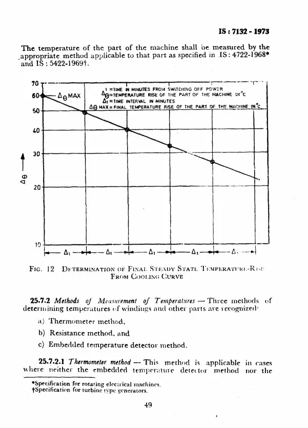
IS : 7132 - 1973
The temperature of the part of the machine shall be measured by the -appropriate method applicable to that part as specified in IS: 4722-1968* and IS : 5422-1969t.
70
60.
50
LO
t
30
2 20
19
=lEHPERATURE RISE OF THE PART Oi‘ IKE MACHINE
25.7.2 Methods oj A/ruwrement of Tem~eratnres - Three methods of deterniining temperatures of kvindilqs itn(\ other parts are rccognizetl*
a) Thermometer method,
b) Resistance method, and
c) Embedded temperature detector method.
25.7.2.1 Thermometer method - This method is applicable where wither the rmbedtkd temprr;!tllrr detec tcw method
LSprcification for rotating elrc;ricnl mnchincs. tSpecificatirm for turbine type gmerators.
49
in cases JlO1‘ thC
L

Is:7l32-1973
r&stance ~method is applicable. The use of thermometer method is also recognized in the following cases:
a) When it is not practicable to determine the temperature-rise by the resistance method, as in case of low resistance windings, especially when the resistance of joints and connections forms a considerable portion of the total resistance;
b) Single layer armature windings of machines having outputs less than 5 mVA or having core lengths less than one metre; and
c) When for reasons for manufacture in quantity, thermometer meth >d alo.~c is used, although the resistance method May be possible.
25.7.2.2 R&stance method - In this method the temperature of the windings is determined by the increase in the resistance of the winding. It is necessary to measure the resistance of the windings before the test and after the test by the method such as double bridge method described in 8.3.2. The temperature of the winding at the end of the test may be obtained by the following formula:
t2 + k R2
tl 4-k RI
where
t, = temperature ( “C ) of the windings at the end of the test,
tl = temperature ( “C ) of the winding ( cold at the moment of the initial resistance measurement ),
Rp = resistance of the winding at the end of the test,
RI = initial resistance of the winding ( cold), and
k = 234.5 for pure copper and 225 for electrical grade aluminium. L
For practical purposes, the following alternative formula may be found convenient:
t2 - fa = +$!?- ( k + t1 ) + tl - fa
where t. is the temperature ( “C ) of the cooling medium at the end of the test.
50
I8 : 71321373
This method may be used for field windings during the temperature- rise test, while for armature windings it may be used only after shut down.
For single layer armature windings of machines of outputs 5 mVA and above or core lengths 1 metre or more, this is the only recognized method.
25.7i2.3 Embedded temperature detector ( ETD ) method - Embedded temperature detectors are resistance thermometer or thermocouples or thermistors built into the machine during manufacture at points which are inaccessible after the machine is completed. Embedded temperature detectors are generally built into the machines with outputs of 5 mVA and above or having core length of 1 metre and more, between the layers of armature windings, in slot. portion and at various other points at which highest temperatures are likely to occur. In this caes unless otherwise agreed upon between the manufacturer and the purchaser the embedded temperature detector method shall be used.
25.8 Permissible Temperature-Rise on Test
25.8.1 Correction of the permissible temperature-rise on .test due PO the difference of the temperature of cooling medium at the place of testing and at the site shall be as specified in IS : 4722-1968;.
23.8.2 In the case of machine in which the absolute pressure of the cooling medium inside the machine may be maintained constant irrespec- tive of the altitude, no correction of temperature-rise on test shall be made for the difference between the altitude of the site and the altitude of the place of testing.
26. INSTANTANEOUS SHORT-CIRCUlT WlTHSTAND TEST
26.1 Sudden short-circuit tests are made to show that the mechanical design of the machine is adequate to withstand the stresses due to short- circuits and related abnormal operating conditions and also to determine certain characteristics such as rexctances and timc constants.
This test is carried out. on synchronous generators only at the express request of the purchaser made at the time of the order. The test is carried out when the machine is running at rated speed and on no-load ,with rated terminal voltage unless otherwise agreed upon but in no case the terminal voltage shall exceed 105 percent of rated -voltage. The voltage at which the instantaneous short-circuit is to be carried out
*Specification for rotating electrical machines.
51

IS : 7132 - 1973
may be reduced, by agreement between the manufacturer and the purchaser, to take into account the impedence of the transformer which may be placed between the generator and the system. The test may be carried out at site by agreement between the manufacturer and the purchaser. The short-circuit shall be maintained for a period of 3 seconds.
26.2 Before making this test the machine shall be carefully inspected to see tLat the brakings of stator end windings are satisfactory, the founda- tion is in good condition and foundation bolts are tight. The rotor shall be inspected to see that all the keys and bolts are in place and properly tightened.
26.3 Certain precautions are required in preparing the electric connections because of the abnormal conditions which attend a sudden short:circuit test. Very heavy currents how, particularly, on large machines, resulting in great forces on the test conductors. To prevent damaging by move- ment, test conductors should be securely braced.
26.3.1 The armature circuit should be solidly grounded at a single point, using a conductor of size comparable to the leads from the machine terminals. There are two choices for the location of this ground connec- tion : the neutral of a Y-connected armature winding or the point common to the three contacts of the shorting circuit breaker. If shunts are used in measuring the currents, there common point should be where the ground connection is made, to avoid hazardous voltage the oscillo- graph in case of a mishap. If current transformers are used in measuring armature current, the point common to their primaries should be where the ground connection is made, unless they are insulated to withstand full line-to-line armature voltage.
26.3.2 All protective relays which could cause the field circuit-breaker to trip should be made inoperative. A discharge resistor of sufficiently low value should be used so that if the field circuit breaker were to trip, the voltage across the field winding would not be excessively high.
26.3.3 The three phases are to be short-circuited practically simulta- neously. The phase contacts should close within 15 electrical degrees of each other. This value may be exceeded on test when the armature dc component is not of importance.
26.4 When the machine is running at rated speed and no-load and at the
52

IS : 7l32 - 1973
terminal voltage agreed upon between the manufacturer and the purchaser all the three phases are instantaneously short-circuited.
26.5 This test is considerec satisfactory if:
a) no harmful deformation of windings takes place, and
b) if the windings withstand the high voltage test performed immedi- ately after the instantaneous short-circuit withstand test.
53
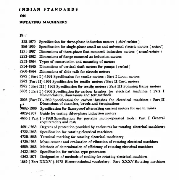
INDIAN STANDARDS
ON
ROTATING MACHINERY
IS :
325-1970 Specification for three-phase induction motors ( third ration )
936-1964 Specification for single-phase rmall ac and universal electric motors ( rroizrd ) 123i-1967 Dimensions of.three-phase foot-mounted induction motors ( sccoadrr~~fsLx~ )
2223-1962 Dimensions of flange-mounted ac induction motors
2253.1964 Types of construction and mounting of motors
2254-1965 Dimensions of vertical shaft motors for pumps ( revised j *’ 2968-1964 Dimensions of slide rails for electric motors
2972 ( Part I )-1964 Specification for textile motors : Part I Loom motors
2972 (Part II)-1964 Specification for textile motors :‘Part II Card motors
2972 ( Part III ) 1965 Specification for textile motors : Part III Spinning frame motors
3003 ( Part I )-1966 Specification for carbon brushes for electrical machinea : Part 1 Nomenclature, dimensions and teat methods
3003 (Part II)-1969 Specification for carbon brushes for electrical machines : Part II Dimensions of chamfers, bevels and terminations .,f
468L-i966
40294967
4665 ( Part
Specification for flameproof alternating current motors for use in mines
Guide for testing thlee-phase induction motors
I )-1968 Specification for- portable motor-operated tools : Part I General requirements and tests
4691-!968 Degrees of protection provided by enclosures for rotating electrical machinery 4722-1968 Specification for rotating electrical machines
4728-1968 Terminal marking for rotating electrical machinery
4729-l 968 Measurement and evaluation of vibration of rotating electrical machines
4889-1968 Methods of determination of efficiency of rotating electrical machines
5422-1969 Specification for turbine type generators
6362-1971 Designation of methods of cooling for rotating electrical machines
1885 ( Part XXXV )-I973 Electrotechnical vocabulary: Part XXXV Rotating machines
_- _ L

BUREAU OF INDIAN STANDARDS
Headquarters; Manak Bhavan, 9 Bahadur Shah Zafar Marg, NEW DELHI 110002 Telephones : 331-01 31, 331 13 75 Telegrams : Manaksanstha
( Common to all offices)
Regional Oflces: Central : Manak Bhavan, 9 Bahadur Shah Zafar Marg,
NEW DELHI-110002 *Eastern : l/14 C.I.T. Scheme VII M, V. I. P. Road,
~Maniktola, CALCUTTA 700054 Northern : SC0 445-446, Sector 35-C,
CHANDIGARH 160036
Southern : C. I. T. Campus, MADRAS 600113
twestern : Manakalaya, E9 MIDC, Marol, Andheri (East), BOMBAY 400093
Branch Offices: ‘Pushpak’ Nurmohamed Shaikh Marg, Khanpur,
AHMEDABAD 380001 SPeenya Industrial Area, 1 st Stage, Bangalore Tumkur Road
BANGALORE 560058 Gangotri Complex, 5th Floor, Bhadbhada Road, T. T. Nagar,
BHOPAL 462003 Plot No. 82/83, Lewis Road, BHUBAN~ESHWAR 751002 53/5, Ward No. 29, R. G. Barua Road, 5th Byelane,
GUWAHATI 781003 5-8-56C L. N. Gupta Marg ( Nampally Station Road ),
HYDERABAD 500001
RI4 Yudhister Marg, C Scheme, JAIPUR 302005
117/418 B Sarvodaya Nagar, KANPUR 208005
Patliputra Industrial Estate, PATNA 800013 T C. No. 14/1421, University P.O., Palayam
TRIVANDRUM 695035
lnspecfion Office (With Sale Point) : Pushpanjali, 1st Floor, 205-A West High Court Road,
Shankar Nagar Square, NAGPUR 440010 Institution of Engineers ( India ) Building, 1332 Shivaji Nagar,
PUNE 411005
Telephones
II 331 01 31 3311375
36 24 99
1 21843 31641
% ;: % I 41 2916 6329295
[ 26348 26349
[ 38 49 55 38 49 56
66716
5 36 27 3 31 77
23 1083
[ 6 3471 6 98 32
[ 21 68 76 21 82 92
62305 -L-
[ 621 04 621 17
251 71
52435
27 68 00
89 65 28
22 36 71
*Sales Offtce in Calcutta is at 5 Chowringhee Approach, P.O. Princep Street, Calcutta 700072
fsales Office in Bombay is at Novelty Chambers, Grant Road, Bombay 400007
SSales Office in Bangalore is at Unity Building, Narasimharaja Square, Bangalore 560002
Printed at Slmco Printing Press. Delhi. India