micro-to-macro: astrodynamics at extremes of length-scale
TRANSCRIPT
Strathprints Institutional Repository
McInnes, Colin and Ceriotti, Matteo and Colombo, Camilla and Sanchez Cuartielles, Joan-Pauand Bewick, Russell and Heiligers, Jeannette and Lucking, Charlotte (2011) Micro-to-Macro :astrodynamics at extremes of length-scale. Acta Futura, 4. pp. 81-97.
Strathprints is designed to allow users to access the research output of the University of Strathclyde.Copyright c© and Moral Rights for the papers on this site are retained by the individual authorsand/or other copyright owners. You may not engage in further distribution of the material for anyprofitmaking activities or any commercial gain. You may freely distribute both the url (http://strathprints.strath.ac.uk/) and the content of this paper for research or study, educational, ornot-for-profit purposes without prior permission or charge.
Any correspondence concerning this service should be sent to Strathprints administrator:mailto:[email protected]
http://strathprints.strath.ac.uk/

Micro-to-Macro: Astrodynamics at Extremes ofLength-scale
Colin R. McInnes∗, Matteo Ceriotti, Camilla Colombo, Joan-Pau SanchezRussell Bewick, Jeannette Heiligers and Charlotte Lucking
Advanced Space Concepts Laboratory, University of Strathclyde, Glasgow G1 1XJ, United Kingdom
March 18, 2011
Abstract
This paper investigates astrodynamics at ex-tremes of length-scale, ranging from swarmsof future ‘smart dust’ devices to the cap-ture and utilisation of small near Earth aster-oids. At the smallest length-scales familiesof orbits are found which balance the energygain from solar radiation pressure with energydissipation due to air drag. This results inlong orbit lifetimes for high area-to-mass ratio‘smart dust’ devices. High area-to-mass hy-brid spacecraft, using both solar sail and elec-tric propulsion, are then considered to enable‘pole-sitter’ orbits providing a polar-stationaryvantage point for Earth observation. Thesespacecraft are also considered to enable dis-placed geostationary orbits. Finally, the poten-tial material resource available from capturednear Earth asteroids is considered which canunderpin future large-scale space engineeringventures. The use of such material for geo-engineering is investigated using a cloud ofunprocessed dust in the vicinity of the Earth-Sun L1 point to fractionally reduce solar inso-
∗E-mail address: [email protected]
lation.
1 IntroductionThe growing utilisation of space as a platformfor science, telecommunications, Earth obser-vation and navigation is a direct result of theapplication of the tools of classical orbital dy-namics. Many decades of applied researchhave translated key ideas from dynamical as-tronomy to spacecraft astrodynamics to gener-ate families of orbits which now deliver essen-tial scientific and commercial products suchas high bandwidth data-links, high resolutionmulti-spectral imagery and precise global po-sitioning. While such exciting space applica-tions have transformed a range of both com-mercial and public services, the continued ex-ploitation of space will require new innova-tions both in spacecraft technologies and infundamental astrodynamics.
This paper provides an overview of an on-going programme of work which aims to de-liver radically new approaches to astrodynam-ics at extremes of length-scale to underpin newspace-derived products and services for space
1

(a) (b) (c)
Figure 1: Micro-to-macro: future space systems at extremes of length-scale (a) MICRO:swarms of ‘smart dust’ sensor nodes (b) MESO: pole-sitter orbits for gossamer spacecraft (c)MACRO: geo-engineering with captured near Earth asteroid material.
science, telecommunications and Earth obser-vation. These include vast swarms of interact-ing MEMS-scale ‘smart dust’ devices for newscience applications [9, 23], displaced polarand geostationary orbits for Earth observationand communications [6, 15] and new conceptsfor the capture and exploitation of small nearEarth asteroids [33, 3], as illustrated schemat-ically in Fig. 1.
Traditionally, astrodynamics has centred onthe classical gravitational two-body problem,with additional forces treated as small per-turbations. This approach allows the conicsection solutions to the unperturbed gravita-tional two-body problem to form the basisof an understanding of the weakly perturbedproblem (for example [18, 31]). Such an ap-proach has provided the mathematical tools toenable, for example, orbit control of geosta-tionary telecommunication satellites, the def-inition of mapping orbits for Earth observa-tion satellites and coverage patterns for satel-lite navigation constellations.
More recently, the use of modern dynamical
systems theory has led to exciting new devel-opments in the gravitational three-body prob-lem (for example [19, 13]). Work has exploredthe use of new families of trajectories connect-ing periodic orbits about the collinear librationpoints as the basis for highly efficient orbittransfer in the Earth-Moon and Earth-Sun sys-tems. These more recent developments are astrong indication that there is much work stillto be done in modern astrodynamics, and thatmany new families of useful orbits await dis-covery.
Future space systems will require a newapproach to orbital dynamics from micro-to macroscopic length-scales L. This newunderstanding will be required to underpinthe exploitation of future space systems fromswarms of interacting MEMS-scale ‘smartdust’ devices (L ∼ 10−3 m) to extremely largegossamer spacecraft (L ∼ 103 m). At theseextremes of spacecraft length-scale, perturba-tions such as atmospheric drag, solar radiationpressure and electrodynamic forces can be ofthe same order of magnitude as the central
2

two-body or three-body gravitational forces.The strongly perturbed nature of the dynamicsof such spacecraft gives rise to rich new fami-lies of orbits which can be exploited to delivernew space products and services.
Gossamer spacecraft are characterised by alarge deployable surface area, but a relativelymodest mass, yielding extremely low arealdensities. These spacecraft are strongly per-turbed by atmospheric drag and solar radiationpressure, and in the case of solar sails, utilisesolar radiation pressure directly for propul-sion. Similarly, micro-spacecraft are rapidlyshrinking in mass and volume, driven by ad-vances in integrated microelectronics. Sincespacecraft mass scales as L3, while surfacearea scales as L2, effective areal density scalesas L−1 with diminishing spacecraft size. Thisagain leads to strong atmospheric drag andsolar radiation pressure perturbations and thepossibility of electrodynamic effects due tonatural or artificial surface charging. There-fore both classes of spacecraft, while at oppos-ing ends of the length-scale spectrum, will re-quire the integrated development of new meth-ods in astrodynamics to explore such stronglyperturbed orbits. At even larger length-scales,new insights into the three-body problem canenable the capture of small near Earth aster-oids by greatly leveraging the effect of in-tervention by impulse or continuous thrust.The ability to efficiently capture such materialcould have a long-term impact on the feasi-bility and cost of future space systems at thelargest length-scales such as space solar powerand space-based geo-engineering.
Key questions to be addressed in each of thefollowing three sections include:
• MICRO: How does the orbital dynamicsof micro-spacecraft scale with rapidly di-
minishing spacecraft size and how canthe orbits of swarms of such devices becontrolled?
• MESO: Can different natural perturba-tions and low thrust propulsion technolo-gies be combined to enable new familiesof exploitable orbits for large gossamerspacecraft?
• MACRO: Can new insights from orbitaldynamics bring forward the developmentof visionary, large-scale space engineer-ing ventures by efficiently capturing nearEarth asteroid resources?
2 MICRO: Astrodynamicsfor smart dust swarms
2.1 Long-lived orbits for smartdust devices
Recent innovations in spacecraft design haveexploited advances in miniaturisation to fab-ricate small satellites with dimensions of asingle micro-chip. Low-cost manufacturingof vast numbers of micro-spacecraft can leadto their use in swarm applications, and theirsmall dimensions facilitate access-to-spacethrough deployment in orbit as piggy-back ona conventional spacecraft. The deploymentof vast numbers of ‘SpaceChips’ will enablefuture missions, such as global sensor net-works for Earth observation and communi-cation, distributed space missions for multi-point, real-time sensing for space science, in-terplanetary exploration in support of tradi-tional spacecraft, deployment in the vicinityof a spacecraft for environmental and dam-age detection, or possibly future space-based
3
geo-engineering applications. Even if limited,micro-spacecraft are also capable of long-termorbit control through the exploitation of per-turbations such as Lorentz force, solar radia-tion pressure or atmospheric drag and vicinitycontrol by means of spacecraft-to-spacecraftinteraction through Coulomb force.
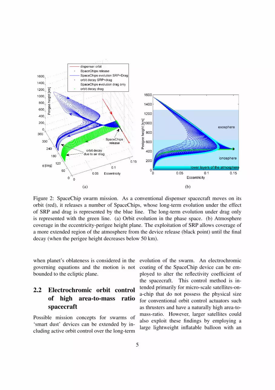
Moreover, the exploitation of orbital dy-namics at extremely small length-scales canenable novel families of exploitable non-Keplerian orbits. Due to the extremelyhigh area-to-mass ratio (A/m) of futureSpaceChips, or smaller ‘smart dust’ devices,with respect to conventional spacecraft, per-turbations such as solar radiation pressure(SRP) and aerodynamic drag, which goes asA/m, become dominant with respect to theEarth’s gravity. The study of the long-term ef-fect on the satellite’s orbit caused by those per-turbations generates equilibrium orbits wherethe total variation of semi-major axis and ec-centricity due to SPR and drag is zero, andthe effect of SRP is exploited to obtain Sun-synchronous precession of the apse-line pas-sively, without the use of active control. Inthose regions of the orbital element phasespace where solar radiation pressure and at-mospheric drag both have a non-negligible ef-fect on the spacecraft orbit, complete equilib-rium is not possible. However, the long-termorbit evolution still presents some intriguingbehaviour; if the initial conditions are in acertain region around the equilibrium solutionset, the long-term evolution is characterised bylibrational motion, progressively decaying dueto the non-conservative effect of atmosphericdrag [11, 10] (see Fig. 2). It is possible to de-fine different arcs of the orbit evolution wherethe trajectory is dominated either by drag orby solar radiation pressure.
The natural effects of solar radiation pres-
sure and atmospheric drag perturbations canbe exploited to design swarm missions, forexample, for the mapping and study of theupper regions of the Earth’s atmosphere [9].A swarm of SpaceChips is deployed on theecliptic plane from a single spacecraft, as dis-tributed nodes of a network to obtain a spatialand temporal map of the ionosphere and exo-sphere. By selecting the release conditions interms of angular displacement φ between theorbit pericentre and the direction of the Sun-Earth line, the effect of SRP is exploited toscatter the devices into a set of different orbitswhich cover an extended, but bounded, regionof the atmosphere, collecting distributed mea-surements.
Figure 2 shows the long-term evolution ofthe SpaceChip swarm after release from a con-ventional spacecraft. For the first part of theorbit evolution for φ < π the secular rate ofchange of the eccentricity is negative; as aconsequence the orbit perigee rises reachingits maximum at φ = π. Afterwards, whenφ > π, the secular variation of eccentricity isnegative, hence the perigee height decreases.
Importantly, the short lifetime of high area-to-mass spacecraft can be greatly extended(and indeed selected) through the interactionof energy gain from asymmetric solar radi-ation pressure and energy dissipation due todrag (see blue line in Fig. 6). Due to the largearea-to-mass ratio of these devices orbit life-time due to air drag alone is extremely short(see green lines in Fig. 2 and Fig. 6). In ad-dition, the effect of atmospheric drag can beexploited to obtain a fast decay of the swarmof devices in the terminal phase of the mis-sion, ensuring their end-of-life disposal andavoiding the creation of long-lived space de-bris from the swarm.
More intriguing new behaviours are found
4
(a) (b)
Figure 2: SpaceChip swarm mission. As a conventional dispenser spacecraft moves on itsorbit (red), it releases a number of SpaceChips, whose long-term evolution under the effectof SRP and drag is represented by the blue line. The long-term evolution under drag onlyis represented with the green line. (a) Orbit evolution in the phase space. (b) Atmospherecoverage in the eccentricity-perigee height plane. The exploitation of SRP allows coverage ofa more extended region of the atmosphere from the device release (black point) until the finaldecay (when the perigee height decreases below 50 km).
when planet’s oblateness is considered in thegoverning equations and the motion is notbounded to the ecliptic plane.
2.2 Electrochromic orbit controlof high area-to-mass ratiospacecraft
Possible mission concepts for swarms of‘smart dust’ devices can be extended by in-cluding active orbit control over the long-term
evolution of the swarm. An electrochromiccoating of the SpaceChip device can be em-ployed to alter the reflectivity coefficient ofthe spacecraft. This control method is in-tended primarily for micro-scale satellites-on-a-chip that do not possess the physical sizefor conventional orbit control actuators suchas thrusters and have a naturally high area-to-mass-ratio. However, larger satellites couldalso exploit these findings by employing alarge lightweight inflatable balloon with an
5

electrochromic coating. Electrochromic mate-rials are already widely used in terrestrial ap-plications such as intelligent sunshades, tint-ing windows and flexible thin film displaysand have been used in space applications,albeit not for orbit control. The recentlylaunched IKAROS solar sailing demonstra-tor uses electrochromic surfaces on the sailto adjust its attitude and electrochromic radi-ators have been developed for thermal control.Electrochromic materials (EM) change theiroptical properties when a voltage is applied,thus modulating the fraction of light which istransmitted, absorbed and reflected, thereforeeffectively changing the reflectivity coefficientcR of the spacecraft between two set values(cR min = 1 and cR max = 2). The accelera-tion any object receives from the solar radia-tion pressure is given by:
aSRP = cRpSR
c
A�
m(1)
where cR is the coefficient of reflectivity, pSR
the solar flux, c the speed of light, A� the ef-fective surface area receiving solar radiation,m the mass of the object. It can be seen thatthe value of aSRP in Eq. (1) depends on thearea-to-mass ratio of the object. Conventionalspacecraft experience SRP only as a perturb-ing force whereas the effect on micro-scalesatellites becomes dominant. Because of thediscrete nature of the reflectivity change, theorbit control has the characteristics of a on-off controller with the lower reflectivity state(cR min) of the EM thin-film defined as the off-state and the higher reflectivity state (cR max) asthe on-state. It is assumed that during each or-bit the reflectivity can be switched twice. Thetrue anomalies at which these changes takeplace are used as control parameters.
Through this control method the effect of
SRP can be modulated to stabilise the space-craft in certain sun-synchronous, elliptical or-bits and orbital manoeuvres can be performed[23]. For stabilisation, an artificial potentialfield controller has been implemented using aquadratic potential in the orbital element phasespace around the desired stabilisation point.A region in the eccentricity-φ-phase-plane hasbeen identified where spacecraft could be sta-bilised indefinitely. For orbital manoeuvres,instead, the electrochromic control method isused to balance the effect of eclipses to keepa constant semi-major axis. There are twopossible solutions achieving this, by maintain-ing the reflectivity mainly low or mainly highalong each single orbit revolution. This choicewill determine the set of flow lines the space-craft will follow in the phase space. Eachmember of the swarm can be thus navigated,depending on its current position in the phasespace with respect to the targeted final posi-tion.
The results of a case study are shown in Fig.3; eight SpaceChips starting from different ini-tial orbits are collected into the same final or-bit within one year using electrochromic or-bit control. On the left the initial and final or-bits are displayed. The right figure shows theevolution of the eccentricity and φ over time,while the semi-major axis remains constant,and the centre figure shows the evolution ofthe orbits in the phase plane. The spacecraftstart on the orbits marked by the coloured cir-cles and then progress following the flow linestowards the goal orbit marked with a black cir-cle. The dashed flow lines correspond to thehigher reflectivity control option, the dottedlines to the lower reflectivity control option.
6

Figure 3: Results of a case study simulation for the electrochromic orbit control. Initial andfinal orbital state of eight spacecraft and evolution of their orbital parameters in the e-φ-phasespace and over the time of the simulation (1 year).
2.3 Extension of the mission designthrough active control of theswarm
The mission concepts presented in Section2.1 can be extended by including active or-bit control over the long-term evolution of theSpaceChip swarm [8]. The control relies on abasic bang-bang control algorithm based on asimplified version of the electrochromic orbitcontrol introduced in Section 2.2. The space-craft follow the natural flow lines in the or-bital element phase space for the major partof their evolution accepting a change in semi-major axis due to eclipses. The change of re-flectivity coefficient takes place every time theangle between the orbit pericentre and the di-rection of the Sun-Earth line φ goes through π(see Fig. 4)
cR =
cR max, if φ < π and t ≤ Tmission max
cR min, if φ ≥ π and t ≤ Tmission max
cR max, if t > Tmission max
(2)In this way the long-term control of the orbit
can be achieved and a swarm of SpaceChipsmoving along different librational loops canbe stabilised in the phase space at φ = π, withan eccentricity within a certain range. Oncethe stabilisation region is reached, the space-craft will change its reflectivity value, once perorbit, thus keeping its orbital elements fixed ina position of the phase space which, otherwise,will not be in equilibrium. To avoid the debrishazard of the swarm existing for an indefinitetime, the duration of the mission is limited toa maximum value Tmission max, after which thecontrol algorithm is turned off and the swarmnaturally evolves towards a fast decay, due tothe effect of atmospheric drag.
Figure 5 shows the evolution of the perigee
7

Figure 4: Schematic of the control algorithmbased on the reflectivity coefficient change.
heights with time. The passive exploitationof SRP (blue lines) allows an increase of theperigee height and an extension of the life-time with respect to the drag-only scenario(green lines). The control strategy (red lines)for the reflectivity coefficient allows stabilis-ing the members of the swarm at a constantperigee for a long duration. Importantly, theeffect of SRP causes a significant increase inthe orbit lifetime with respect to the drag-onlycase, as shown in Fig. 6, as a function of theangular displacement at release. The greenline represents the orbit lifetime of the swarmin the case SRP is not considered, and the blueline corresponds to the passive evolution underdrag and SRP with a constant value or reflec-tivity cR = cR max. If the control strategy in Eq.2 is implemented, the swarm lifetime is shownwith the red line.
Figure 5: Evolution of the swarm under the ef-fect of drag-only (green lines), drag and SRPuncontrolled (blue lines), drag and SRP con-trolled (red lines).
3 MESO: Astrodynamicsfor gossamer spacecraft
The orbital dynamics of a large, high-area-to-mass ratio spacecraft is greatly influencedby natural perturbations, generating new kindsof exploitable orbits. For example, non-Keplerian orbits (NKO) are those in which asmall, but continuous acceleration is used togenerate periodic orbits that do not follow thenatural dynamics of the system [26]. Bothsolar sailing [2] and solar electric propulsion(SEP) [25] have been proposed as technolo-gies to enable this kind of missions. However,we propose to hybridise the two technologieson a gossamer spacecraft [21], and investigatethe advantages.
In the hybrid spacecraft, the sail is fixed onthe spacecraft bus and its thrust is controlledby changing the sail attitude. Solar arrays orthin film solar cells (TFSC) partially cover-
8

Figure 6: Orbit lifetime as function of the an-gular position of SpaceChips release.
ing the sail surface are used to power the SEPthruster. This is assumed to be mounted on agimbal, such that the direction of its thrust canbe controlled.
At the cost of increased spacecraft complex-ity, the two separate propulsion systems com-plement each other, cancelling their recipro-cal disadvantages and limitations. In princi-ple, a steerable SEP thruster can provide themissing acceleration component (towards theSun) that the sail cannot generate. Similarly,the hybrid spacecraft can be seen as an SEPspacecraft, in which an auxiliary solar sail pro-vides part of the acceleration, enabling savingof propellant and a lower demand on the elec-tric thruster, possibly with some intervals inwhich it could be turned off. In this sense,the hybrid spacecraft can be seen as a way togradually introduce solar sails for space appli-cations [29], and hence to reduce the advance-ment degree of difficulty (AD2) [24] in thetechnology readiness level scale.
To maximise the performance of the hybridspacecraft, the objective is to minimise the
SEP propellant consumption. When the po-sition, velocity and mass of the spacecraft areknown at a particular instant of time, the accel-eration due to gravitational forces (that need tobe counterbalanced by the hybrid propulsion)can be computed, and thus the problem is tofind the optimal solar sail cone and clock an-gles α, δ such that the SEP acceleration aT isminimised [5]:
(α∗, δ∗) = arg min (aT (α, δ)) (3)
By exploiting this method, this section in-vestigates the application and advantages ofhybrid propulsion for two types of NKO: opti-mal Earth pole-sitter orbits and displaced geo-stationary orbits.
3.1 Optimal Earth pole-sitter or-bits
A pole-sitter is a spacecraft that is constantlyabove one of the Earth’s poles, i.e. lying onthe Earth’s polar axis [12]. This type of mis-sion could provide a continuous, hemispheri-cal, real-time view of the poles, and will en-able a wide range of new applications in cli-mate science and telecommunications [20].
We consider the Sun-Earth circular re-stricted three-body problem (CR3BP). Sincethe polar axis of the Earth is almost fixed whilethe Earth rotates around the Sun, in the syn-odic reference frame, it appears to span a fullconical surface of half angle 23.5 deg everyyear. The spacecraft has to follow the samemotion during its mission, and this can there-fore be translated into constraints on the posi-tion as a function of time (see Fig. 7).
We seek optimal periodic pole-sitter orbitsthat exploit the solar sail to minimise the
9

June
September
December
March
NKO
(a)
y x
z
ω 23.5 deg tω Winter solstice
(b)
Figure 7: Apparent precession of the Earth’s polar axis due to rotation of reference frame. (a)Inertial frame. (b) Synodic frame.
SEP propellant consumption over a fixed pe-riod (one year), while maintaining the pole-sitter condition at each instant during the mis-sion. Optimal orbits are defined in termsof evolution of the states (position, velocity,mass), and controls (sail cone and clock an-gles, SEP thrust direction and magnitude) overone year. The optimal orbit design is per-formed in two steps. In the first step, after as-signing a trajectory that satisfies the pole-sitterconstraints, a locally-optimal control historyis found, through a semi-analytical procedure,solving the problem in Eq. 3. This solutionis then used for initialising the second step,which optimises the first guess through a pseu-dospectral transcription of the optimal controlproblem. Details of the design and optimisa-tion process are covered in [5].
The analysis is done for both the pure SEPspacecraft, and the hybrid spacecraft in a rangeof system lightness numbers β0, which is pro-portional to the area-to-mass ratio of the hy-brid sailcraft, and hence a measure of the sailsize for a given initial mass.
First, it is found that a consistent gain inpropellant mass fraction is obtained by adding
a small sail to a pure SEP spacecraft. As thelightness number increases towards very highvalues, the gain in propellant mass for a givenincrease of β0 becomes less. However, thisfact justifies the investigation of the hybridspacecraft, seen as a pure SEP system with asmall-lightness-number auxiliary sail.
If the distance of the spacecraft from theEarth is kept constant (an example of suchan orbit is in Fig. 8), it is found that an op-timal distance exists at which the propellantconsumption is minimised. This distance isapproximately 0.018 AU (or about 2.7 mil-lions of km), depending on the lightness num-ber, and is of the same order as that of theLagrangian point L1 of the Earth-Sun system(1.5 million km from the Earth).
Note that the distance from the Earth can bevaried: this degree of freedom can be used tofind novel families of optimal orbits, leadingto additional propellant mass saving. Differ-ent optimal orbits are found depending on thevalue of β0. Optimal orbits get closer to theEarth in winter and farther in summer, as thelightness number of the solar sail increases.The distance can even double from winter (2
10

million km) to summer (4 million km) for ahybrid spacecraft with a lightness number of0.1 (Fig. 9).
Figure 8: Sail acceleration (as), SEP acceler-ation (aT ), total gravitational acceleration (a)and sail normal (n) on a constant-distance or-bit at 0.01 AU.
By comparing optimal solutions for pureSEP and hybrid spacecraft, it is found that thelatter requires a lower propellant mass frac-tion. A substantial saving in propellant is ob-tained by adding a relatively small sail: con-sidering an initial mass of 1000 kg, an SEPspecific impulse of 3200 s and an optical sailmodel, for a 1-year orbit, the propellant massdecreases from 158 kg (for the pure SEP) to97 kg (β0 = 0.05).
However, the hybrid spacecraft is a morecomplex system, mainly due to the presenceof the solar sail and the need for a gimballedthruster. Therefore, a preliminary systems de-sign is performed, to assess the conditions atwhich the hybrid spacecraft is advantageousover the conventional SEP one, in terms of alower initial mass for carrying the same pay-load mass.
It is found that, with near- to mid-term sail
Figure 9: Minimum propellant mass hybridpole-sitter orbits, for three different values ofβ0
technology (sail loading of 7.5 g/m2), the hy-brid spacecraft has a lower initial mass thanthe SEP case if the mission duration is 7 yearsor more, with greater benefit for longer mis-sions. Assuming far-term sail technology (5g/m2), then the hybrid spacecraft outperformthe pure SEP case even for short missions [7].The comparison is performed varying the dis-tance from the Earth optimally for each typeof spacecraft.
Due to the instability of pole-sitter orbits,a feedback control is necessary to keep thespacecraft on track, counterbalancing errorsand small perturbations that are not consideredin the dynamics for the reference solution, aswell as errors in the spacecraft model (e.g. un-predictable degradation of the sail). It wasshown [6] that it is possible to keep the space-craft on-track, and counterbalance injectionserrors, only by using the SEP thruster, whilemaintaining the sail at nominal attitude. Fur-thermore, it was shown that a relatively smallvariation of the reference thrust vector is suffi-cient to respond to large injection errors (order
11

of 100,000 km), and to recover from relativelylong SEP failures (up to 35 days).
3.2 Displaced geostationary orbitsWith a period equal to the Earth’s rota-tional period, spacecraft in geostationary or-bit (GEO) are stationary with respect to theirground station, allowing for a continuousdownlink to Earth. Vital telecommunicationand Earth observation satellites are currentlyexploiting this unique property of the geosta-tionary orbit. However, due to limits imposedby east-west spacing requirements, the GEO isstarting to get congested at certain key longi-tude slots [17]. Therefore, in order to increaseits capacity, we propose the use of displacedNKOs.
By applying a continuous acceleration tocounterbalance the gravitational acceleration,the geostationary orbit can be levitated aboveor below the equatorial plane, thereby creat-ing new geostationary slots. Pure solar sailinghas already been considered to maintain suchdisplaced geostationary orbits, but a resid-ual force in the equatorial plane causes thespacecraft to move with respect to its groundstation. Furthermore, only small displace-ments, still inside the geostationary stationkeep box, appeared to be feasible, causing col-lision risk to spacecraft in the geostationaryorbit [2]. To overcome these problems, wepropose to maintain the displaced GEO usinghybrid propulsion.
We can find displaced geostationary orbits,or displaced NKOs in general, by seekingequilibrium solutions to the two- or three-bodyproblem in a rotating frame of reference. Atransformation to an inertial frame will sub-sequently show that the spacecraft executes acircular orbit displaced away from the centre
Figure 10: Definition of displaced geostation-ary orbit (GEO)
of the central body [26].The situation as it occurs in the displaced
geostationary orbit is depicted in Figure 10:the geostationary orbit is levitated over a dis-tance h while keeping both the orbital radiusand the orbital angular velocity equal to the or-bital radius and orbital angular velocity in thegeostationary orbit, rGEO and ω respectively.This case corresponds to a so-called ‘Type I’NKO for which the required thrust induced ac-celeration is at its minimum [27]. The direc-tion of the required acceleration is pure out-of-plane and, for the displaced GEO, the mag-nitude is solely a function of the displacementdistance h.
With the required acceleration known, theminimisation problem in Eq. 3 can be solvedfor a particular value for h. Analytical formu-lae for the optimal steering law are found bysetting the partial derivative of the SEP accel-eration with respect to the sail pitch and yawangles equal to zero and requiring that the sec-ond derivative is positive. As mentioned, Eq.3 can be solved at a particular instant in time,i.e. for a given value for the mass and giventime during the year. The latter is related to
12

β0 = 0 β0 = 0.05 β0 = 0.1
h = 35 km
h = 75 km
Figure 11: Mission lifetime L as a function of the specific impulse Isp and the mass fractionmf/m0, for different values of the system lightness number β0 and the displacement distanceh. The coloured surfaces include a seasonal transfer between a geostationary orbit displacedabove and below the equatorial plane. The grey surfaces exclude this transfer.
the change in the direction of the Sun-sail linedue to the tilt of the Earth’s rotational axis withrespect to the ecliptic plane. By using a dis-cretisation of the orbit into equally distributednodes, the analysis described can be extendedto find the variation of the SEP and solar sailcontrols and accelerations, SEP thrust magni-tude and spacecraft mass as a function of timeover multiple orbital periods [15].
Performing this analysis provides the resultsas shown in Figure 11, where the performanceof the hybrid spacecraft is expressed throughthe mission lifetime, L. This lifetime is depen-dent on the amount of propellant onboard thespacecraft, which is represented by the space-craft dry mass fraction, mf/m0, with m0 theinitial spacecraft mass and mf the spacecraftmass after time L. The figure shows that awide range of SEP specific impulses are con-sidered. Furthermore, considering a standardgeostationary station keeping box of 0.05o-
0.1o, equalling 36.8 - 73.6 km, two differentdisplacement distances of 35 and 75 km areinvestigated. Finally, three different values forthe system lightness number are adopted, in-cluding the case where β0 = 0, which repre-sents the use of pure SEP propulsion and isused for comparison.
Figure 11 shows that, for example, for a 35km displaced orbit, a currently feasible spe-cific impulse of 3200 s and a mass fractionof 0.5, a lifetime of 3.5 years can be achievedfor the pure SEP case, which increases to 9.7and 15 years for hybrid propulsion, depend-ing on the value chosen for β0. A slight de-crease in the performance can be observed forthe higher displaced orbit as for similar val-ues for the specific impulse and mass fraction,lifetimes of 2.9 and 4.3 years can be achieved.Note that these results assume an SEP transferbetween a geostationary orbit displaced abovethe equatorial plane and an orbit displaced be-
13

low the equatorial plane twice a year, in springand in autumn, to make full use of the annualchanging Sun-sail line direction. Solving theaccompanying optimal control problem usinga direct pseudo-spectral method shows thatthis transfer requires an almost negligible pro-pellant budget. To show the influence of thistransfer on the performance of hybrid propul-sion, Figure 11 also includes the results whenthe hybrid spacecraft is maintained above theequatorial plane throughout the year. Then, adecrease in the lifetime of a few months up toa few years can be observed, but still exceedsthe lifetimes of a pure SEP mission.
To investigate whether the mass fractionsand specific impulses of Figure 11 allow fora payload to be carried during the lifetimesshown in those figures, a preliminary space-craft mass budget is considered to express theperformance of the hybrid spacecraft in termsof payload mass capacity. For this, a maxi-mum initial mass, such that the thrust magni-tude does not exceed 0.2 N during the missionlifetime, is assumed. Further details on themass breakdown and technological assump-tions can be found in [15]. The results areshown in Figure 12. Considering a lifetimeof 10-15 years for current geostationary space-craft, Figure 12 shows that only hybrid propul-sion enables such lifetimes while still allowingfor useful payload masses of 255 to 489 kg tobe carried on board in a 35 km displaced or-bit, while reasonable lifetimes with somewhatsmaller payloads can be obtained for the largerdisplacement of 75 km.
(a)
(b)
Figure 12: Payload mass mpay as a functionof the mission lifetime L for different val-ues of the system lightness number β0 and forIsp =3200 s. (a) 35 km displacement. (b) 75km displacement.
4 MACRO: Astrodynamicsfor visionary concepts
The final research theme aims to performspeculative research from a level-headed per-spective in order to map out possible long-
14

term futures for the utilisation of space by ex-ploiting new insights into astrodynamics. Ex-amples of this speculative research are space-based geo-engineering and asteroid captureand exploitation.
The current consensus within the scientificcommunity is that global warming is currentlyhappening due to the large quantities of green-house gases such as CO2 and methane that areemitted into the atmosphere. It is clear fromthe slow movement of international agree-ments on emission restrictions that, shouldemission caps be put in place, they may be toolate to prevent the Earth from warming abovethe 1.5 − 2.5 ◦C that many fear could causeirreversible effects [16]. Hence it is prudentto investigate possible methods to mitigate theeffects of global warming by the deliberatemanipulation of the Earth’s climate. This fieldis generally referred to as geo-engineering orclimate engineering.
Many proposals have been made for possi-ble geo-engineering schemes and have beenevaluated in a study by the Royal Society in2009 [34] based on affordability, timeliness,safety and effectiveness. The report concludesthat currently too little is known about the pos-sible consequences of the these methods torecommend a single system, but also that thebest method of implementation is likely to bea mixture of different methods. Aspects ofthis research theme aims to improve the abil-ity of one of these methods, space-based geo-engineering, to mitigate the worst effects ofclimate change.
Several scenarios for space based geo-engineering platforms have already been iden-tified [1, 28, 30, 35]. All of these possiblesolutions require an enormous engineering ef-fort comparable only to the largest engineer-ing ventures on Earth (e.g., Three Gorges dam
or Panama Canal), but in a much more hostileenvironment. However, the level of the engi-neering undertaking necessary for space geo-engineering, as well as for other future spaceapplications such as space solar power satel-lites and space tourism, may be relieved tosome extent by utilising materials that are al-ready available in space [33].
4.1 Capture of near Earth asteroidmaterial
Small celestial objects, i.e., asteroids andcomets, have long been identified as possiblereservoirs of materials for utilisation in space.Some examples of this are volatiles for propel-lant, water for life support, metals for struc-tures, semiconductors for solar cells or simplyregolith for radiation shielding [22]. In par-ticular, near Earth asteroids (NEA) have re-cently risen in prominence because of two im-portant points: they are among the easiest ce-lestial bodies to reach from the Earth and theymay represent a long-term threat. A range ofmethods have also been identified as able toprovide a change in the asteroid linear mo-mentum, sufficient to deflect an asteroid on acollision trajectory with the Earth [32]. Usingthese methods, a resource-rich asteroid couldin principle be manoeuvred and captured intoa bound Earth orbit through judicious use oforbital dynamics.
The capture and transport of the entire NEAinto an Earth orbit, for posterior processing,would require more energy than the transportof processed material directly from the unper-turbed asteroid orbit. However, the miningand processing of materials in-situ would en-tail very complex and long duration missions.Both of these scenarios, in-situ processing and
15

transport or asteroid capture, imply differentmission architectures and the optimality of oneoption with respect to the other may ultimatelydepend on the technology readiness of the dif-ferent mission systems, as well as the orbit ofeach particular asteroid and resource to be ex-ploited. Nevertheless, the required ∆v, as ameasure of specific energy, is a good figureof merit that provides a qualitative estimateof the required scale of engineering necessaryfor any of the two options. The question thatarises then is how much near-Earth asteroidmaterial is there which could be captured witha modest investment of energy.
This latter question can be answered bycomparing the accessible Keplerian orbital re-gions with a NEA model able to predict thestatistical probability of the existence of an as-teroid with a given set of orbital elements anddiameters (see Fig. 13). The accessible Ke-plerian region can be delimited by defininga multi-impulsive Keplerian transfer param-eterised by the transport cost parameter ∆v.The simplest transfer can be modelled by twoimpulses: first, a change of plane in order toyield a coplanar encounter with Earth, whichensures that if the asteroid is an Earth-crossingobject, this would actually cross the Earth’s or-bital path, and second, a final insertion burnthat takes place at the periapsis passage ofthe Earth encounter. This transfer, as with aHohmann transfer analysis, provides a goodconservative estimate of the exploitable aster-oid material. A capture transfer that considersonly one single impulse during the periapsispassage of the asteroid can also be modelled.For this second transfer, one needs to com-pute the subset of asteroids with a given semi-major axis, eccentricity, inclination set {a,e,i}that have an orientation such that a serendipi-tous fly-by with the Earth is possible. Figure
13, for example, shows the accessible volumeof the {a,e,i} Keplerian subspace consideringa one-impulse capture with a ∆v threshold at2.37 km/s, the value required to escape lunargravity, used to provide a comparison of en-ergy investment [33]. The NEA density distri-bution is computed by interpolating the theo-retical distribution published by Bottke et al.[4] and can also be seen in Fig. 13.
One can then assess the availability of as-teroid material on easily accessible orbits bycomputing the median diameter of the objectthat can be found within a given ∆v limit.Figure 14 shows the median diameter of thefirst, tenth, hundredth and thousandth largestaccessible asteroid in the near Earth space,together with the 90% confidence region foreach one of these objects. While the mediandiameter indicates that there is 50% chancethat the ith-largest accessible asteroid could belarger or smaller than the median diameter, theconfidence region provides a cumulative 90%chance to find an object size within the shadedarea. Finally, the figure also shows the ex-pected median diameter of the accessible ob-jects when the maximum transfer time is setto 40 years. The information in the figure canbe read as follows: let us, for example, set the∆v threshold at 100 m/s, the largest accessibleobject has a 50% probability to be equal to orlarger than 24 meters diameter, while we cansay with 90% confidence that its size shouldbe between 72 meters and 12 meters. Theseresults are computed assuming a phase freetransfer, while if a random, but fixed initialphase is assumed, and 40 years of transfer timeare allowed, then the result of the median di-ameter decreases to 23 meters. The followingset of data in the decreasing ordinate axis is thegroup referring to the 10th largest object foundwithin the region of feasible capture given by a
16

Figure 13: Accessible region for asteroid exploitation by means of a one-impulse manoeuvrewith a 2.37 km/s ∆v (i.e., v-shaped volume) [33]. Also in the figure, Near-Earth asteroiddensity distribution represented by a set of isolines within the {a,e} and {a,i} planes andcumulative projection of the density at each side wall.
∆v threshold of 100 m/s, whose median diam-eter is at 8 meters diameter. The 100th largestobject is foreseen to have a diameter of 3 me-ters and 1000th largest of 1 meter.
The results shown in the latter figure high-light the feasibility of future asteroid resourceutilisation. One can imagine advantageousscenarios for space utilisation from the resultson the expected size of the accessible material.For example, the exploitation of the largestexpected object found within a 100 m/s bud-get, a 24-m asteroid, could supply from 107kg
to 4× 10⁷kg of asteroid material, dependingon composition and density. If this objectwas a hydrated carbonaceous asteroid, a mil-lion litres of water could possibly be extracted.However, if this object was an M-class aster-oid, of order thirty thousand tonnes of metalcould potentially be extracted and even a tonneof Platinum Group Metals (PGM). The latterresource could easily reach a value of fifty mil-lion dollars in Earth’s commodity markets. Ifthe ∆v budget is increased to 1 km/s, one 190-m diameter object should be accessible. This
17

Figure 14: Expected size of the accessible as-teroid.
corresponds to more than 300 million litres ofwater or more than 10 million tons of metaland 600 tons of PGMs valued at 30 billion dol-lars.
4.2 Geo-engineering using cap-tured near Earth asteroids
Another possible use of near Earth asteroids isto provide material for space-based geoengi-neering schemes. Space-based geoengineer-ing focuses on solar radiation management,i.e., reducing the amount of sunlight reachingthe Earth, to create a cooling effect. Thesemethods have either proposed placing largeclouds of dust around the Earth or at theL4\L5
points in the Earth-Moon system [35] or plac-ing large solar reflectors\refractors at the L1
point in the Sun-Earth system [1, 28] or also
in Earth orbit [30]. In general, the dust cloudmethods require much larger total masses dueto the dispersed nature of the material, but alsobecause the positions suggested so far meanthat for much of the time dust will not be in aposition to reflect solar photons along the Sun-Earth line.
In contrast, the reflector methods that placeobjects at the L1 point are much more massefficient as the reflectors will constantly be ina position to shade the Earth. However, thedownside to this method is that the reflectorsmust be manufactured either terrestrially andlaunched into position or manufactured in-situfrom captured NEA material. Both of thesemethods are currently unfeasible due to cur-rent launch and space manufacturing capabili-ties.
Therefore, there is a need to investigate apotentially more near-term method of space-based geoengineering. This is achieved by in-vestigating the macro-scale concept of plac-ing a large cloud of unprocessed asteroid dustat the L1 point using the micro-scale astrody-namics associated with high area-to-mass ra-tio particles discussed earlier. It is envisagedthat such a dust cloud can be created by ei-ther using a solar collector to sublimate mate-rial from the surface of a captured NEA, or bymass driver equipped landers on a NEA sur-face. The sublimation process can be used toboth capture the NEA and bound its positionin the vicinity of the L1 point.
In order to model the dynamics of such dustclouds, solar radiation pressure, parameterisedby the dust grain ‘lightness factor’, β, must beincluded in the equations of motion of the cir-cular restricted three-body problem (CR3BP).The value of β can be determined by the ra-tio of the solar radiation pressure force to the
18

solar gravitational force and is defined as:
β =|Frad||Fg|
= 570Q
ρR(4)
where Q is the coefficient of reflectance, ρ isthe grain density in kg m−3 and R is the grainradius in µm. The factorQ varies from a valueof 0 for a completely transparent material to 1for a completely absorbing material and 2 fora completely reflecting material. The inclu-sion of solar radiation pressure results in theeffective mass of the Sun being reduced in themass parameter, µ, as shown in equation (5),thus affecting the dynamics of the CR3BP.
µ =ME
(1− β)MS +ME
(5)
where ME is the mass of the Earth and MS isthe mass of the Sun. The motion of the parti-cles in the CR3BP can now be modelled for acloud of dust placed in the region of the inte-rior Lagrange point along the Sun-Earth line,a full description of which can be found in [3].Due to the instability of the L1 point, a cloudplaced in its vicinity will disperse over time.Using a model of the dynamics of the problema steady state solution can be found such thatthe average density of the cloud in the phasespace of the problem can be determined for thelifetime of the cloud. Using this understandingof the dust dynamics, along with a solar radia-tion model, also described in [3], the reductionin solar insolation experienced on the Earth’ssurface can be determined. This process hasbeen completed for several scenarios whichincorporate a varying initial cloud position andsize and dust grain size. The initial positionvaries between the classical L1 position andthe new equilibrium position found when theeffect of solar radiation pressure is taken into
account, whilst the initial dust cloud radiusvaries from 500km to 12,000km. Four initialgrain sizes have also been used, these being 32µm, 10µm, 3.2µm and 0.01µm, which corre-spond to β values of 0.005, 0.018, 0.061 and0.106 respectively [36].
Figure 15: Mass requirement of dust for thesteady state solution of clouds ejected at theL1 point for varying initial cloud radii for thefour grain sizes used.
It has been determined that a 1.7% solar in-solation reduction will offset the effects of atemperature increase of 2◦C [14], equivalentto a doubling of the atmospheric concentra-tion of CO2. The mass requirement of dustfor the cloud being released at the classicalL1 position can be seen in Figure 15 whilstthe results for the cloud being released fromthe new, displaced, equilibrium point can beseen in Figure 16. The minimum mass ofdust injected into the cloud per year necessaryto achieve the required insolation reduction is8.87×108kgyr−1, as can be seen in Figure 16.This result was achieved for a 3,000km di-ameter cloud, released at the displaced equi-librium position for a grain size of 0.01µm.This mass is considerably lower than previousdust based space-based geoengineering con-cepts and is also of the same order as the solid
19

reflector methods, assuming a mission lifetimeof 10 years, whilst reducing complexity con-siderably through the use of unprocessed dustrather than highly engineering reflectors or re-fractors. Further work is being carried out todetermine the effect that the gravitational po-tential of the captured NEA has on the stabil-ity of the cloud created from the asteroid. TheNEA can therefore help anchor the dust cloud.
Figure 16: Mass requirement of dust for thesteady state solution of clouds ejected at thenew displaced equilibrium points of the fourgrain radii used for varying initial cloud sizes.
5 Conclusions
This paper has provided an overview of anon-going programme of work which aims todeliver radically new approaches to astrody-namics at extremes of length-scale to under-pin new space-derived products and services.New developments in astrodynamics at threelength-scales, micro, meso and macro, havebeen discussed with a range of applicationsfor future space systems, from space sciencethrough to telecommunications and Earth ob-servation, and longer-term concepts such as
space-based geo-engineering. A unifying fea-ture of this work is that astrodynamics at thesmallest and largest of length-scales will leadto strongly perturbed orbits, for example withMEMS-scale ‘smart dust’ devices, or naturaldust grains, and large gossamer spacecraft. Atthese extremes of length-scale, perturbationssuch as atmospheric drag, solar radiation pres-sure and electrodynamic forces can be of thesame order of magnitude as the central two-body or three-body gravitational forces. Thestrongly perturbed nature of the dynamics ofsuch systems gives rise to rich new families oforbits which can be exploited to deliver newspace products and services. Finally, there areintriguing connections between the micro andmacro length-scales through the exploitationof an understanding of dust dynamics for bothswarms of ‘smart dust’ and large-scale space-based geo-engineering.
6 AcknowledgmentsThis work was supported by an AdvancedInvestigator Grant from the European Re-search Council through VISIONSPACE (ERCproject 227571).
20

References[1] Roger Angel. Feasibility of cooling the
Earth with a cloud of small spacecraftnear the inner lagrange point (L1). Pro-ceedings of the National Academy of Sci-ences, 103(46):17184–17189, 2006.
[2] Shahid Baig and Colin R. McInnes.Light-levitated geostationary cylindricalorbits are feasible. Journal of Guidance,Control, and Dynamics, 33(3):782–793,2010.
[3] Russell Bewick, J. Pau Sanchez, andColin R. McInnes. An L1 positioneddust cloud as an effective method ofspace-based geo-engineering. In 61stInternational Astronautical Congress(IAC 2010), number IAC-10.D1.1.7, 27September - 1 October 2010.
[4] W. F. Bottke, A. Morbidelli, R. Jedicke,J. M. Petit, H. F. Levison, P. Michel,and T. S. Metcalfe. Debiased orbital andabsolute magnitude distribution of theNear-Earth Objects. Icarus, 156(2):399–433, 2002.
[5] Matteo Ceriotti and Colin R. McInnes.An Earth pole-sitter using hybrid propul-sion. In AIAA/AAS Astrodynamics Spe-cialist Conference, number AIAA 2010-7830. AIAA, 2-5 August 2010.
[6] Matteo Ceriotti and Colin R. McInnes.Hybrid solar sail and SEP propul-sion for novel Earth observation mis-sions. In 61st International Astronauti-cal Congress (IAC 2010), number IAC-10.C4.6.8, 27 September – 1 October2010.
[7] Matteo Ceriotti and Colin R. McInnes. Anear term pole-sitter using hybrid solarsail propulsion. In Roman Kezerashvili,editor, 2nd International Symposium onSolar Sailing (ISSS 2010), pages 163–170. New York City College of Technol-ogy, 20-22 July 2010.
[8] Camilla Colombo, Charlotte M.Lucking, and Colin R. McInnes.Orbit evolution, maintenance and dis-posal of SpaceChip swarms. In 6thInternational Workshop on SatelliteConstellation and Formation Flying(IWSCFF 2010), number IWSCFF 20102-2, 1-3 November 2010.
[9] Camilla Colombo and Colin R. McInnes.Orbit design for future SpaceChip swarmmissions. In 61st International Astro-nautical Congress (IAC 2010), numberIAC-10.C1.8.2, 27 September – 1 Octo-ber 2010.
[10] Camilla Colombo and Colin R. McInnes.Orbital dynamics of Earth-orbiting‘smart dust’ spacecraft under the effectsof solar radiation pressure and aerody-namic drag. In AIAA/AAS AstrodynamicsSpecialist Conference, number AIAA2010-7656. AIAA, 2-5 August 2010.
[11] Camilla Colombo and Colin R. McInnes.Orbital dynamics of ‘smart dust’ de-vices with solar radiation pressure anddrag. Accepted for publication Jour-nal of Guidance, Control, and Dynamics,2011.
[12] Johnie M. Driver. Analysis of an arc-tic polesitter. Journal of Spacecraft andRockets, 17(3):263–269, 1980.
21

[13] G. Gomez, W. S. Koon, M. W. Lo, J. E.Marsden, J. Masdemont, and S. D. Ross.Connecting orbits and invariant mani-folds in the spatial restricted three-bodyproblem. Nonlinearity, 17(5):1571–1606, 2004.
[14] B. Govindasamy, K. Caldeira, and P. B.Duffy. Geoengineering Earth’s radiationbalance to mitigate climate change froma quadrupling of co2. Global and Plane-tary Change, 37(1-2):157–168, 2003.
[15] Jeannette Heiligers. Displaced geosta-tionary orbits using hybrid low-thrustpropulsion. In 61st International Astro-nautical Congress (IAC 2010), numberIAC-10-E2.1.2, 2010.
[16] IPCC. Contribution of working groupsi, ii and iii to the fourth assessment re-port of the intergovernmental panel onclimate change. Core Writing Team,Pachauri, R.K. and Reisinger, A. (Eds.),IPCC, Geneva, Switzerland. pp 104,2007.
[17] R. Jehn, A. Rossi, T. Flohrer, andD. Navarro-Reyes. Reorbiting of satel-lites in high altitudes. In 5th EuropeanConference on Space Debris, 2009.
[18] Desmond King-Hele. Theory of satelliteorbits in an atmosphere. Butterworths,London, 1964.
[19] Wang Sang Koon, Martin W. Lo, Jer-rold E. Marsden, and Shane D. Ross.Heteroclinic connections between peri-odic orbits and resonance transitions incelestial mechanics. Chaos, 10(2):427–469, 2000.
[20] Matthew A. Lazzara. The polar mete-orlogist’s dream machine: artificial La-grange orbit satellite applications viaarctic and antarctic composite satelliteimagery. In Roman Kezerashvili, editor,2nd International Symposium on SolarSailing (ISSS 2010), pages 49–55. NewYork City College of Technology, 20-22July 2010.
[21] M. Leipold and M. Gotz. Hybridphotonic/electric propulsion. Techni-cal Report SOL4-TR-KTH-0001, ESAcontract No. 15334/01/NL/PA, Kayser-Threde GmbH, January 2002. ESA con-tract No. 15334/01/NL/PA.
[22] J.S. Lewis. Mining the sky: untold richesfrom asteroids, comets and planets. He-lix Books/Perseus Books Reading, 1996.
[23] Charlotte M. Lucking, CamillaColombo, and Colin R. McInnes.Orbit control of high area-to-mass ratiospacecraft using electrochromic coating.In 61st International AstronauticalCongress (IAC 2010), number IAC-10.C1.2.7, 27 September – 1 October2010.
[24] Malcolm Macdonald and Colin R.McInnes. Solar sail mission applica-tions and future advancement. In Ro-man Kezerashvili, editor, 2nd Interna-tional Symposium on Solar Sailing (ISSS2010), 2010.
[25] Colin R. McInnes. The existence and sta-bility of families of displaced two-bodyorbits. Celestial Mechanics and Dynam-ical Astronomy, 67(2):167–180, 1997.
22

[26] Colin R. McInnes. Dynamics, stability,and control of displaced non-Keplerianorbits. Journal of Guidance, Control,and Dynamics, 21(5):799–805, 1998.
[27] Colin R. McInnes. Solar Sailing: Tech-nology, Dynamics and Mission Applica-tions. Springer-Praxis Books in Astro-nautical Engineering, Springer-Verlag,1999.
[28] Colin R. McInnes. Space-based geo-engineering: challenges and require-ments. Proceedings of the Institutionof Mechanical Engineers, Part C: Jour-nal of Mechanical Engineering Science,224(3):571–580, 2010.
[29] Osamu Mori, Hirotaka Sawada, Ryu Fu-nase, Tatsuya Endo, Mutsuko Morimoto,Takayuki Yamamoto, Yuichi Tsuda,Yasuhiro Kawakatsu, and Jun’ichiroKawaguchi. Development of first solarpower sail demonstrator - IKAROS. In21st International Symposium on SpaceFlight Dynamics (ISSFD 2009). CNES,2009.
[30] Jerome Pearson, John Oldson, and Eu-gene Levin. Earth rings for planetaryenvironment control. Acta Astronautica,58(1):44–57, 2006.
[31] A. E. Roy. Foundations of Astrodynam-ics. Macmillan, London, 1965.
[32] J. Pau Sanchez, Camilla Colombo, Mas-similiano Vasile, and Gianmarco Radice.Multi-criteria comparison among severalmitigation strategies for dangerous NearEarth Objects. Journal of Guidance,Control and Dynamics, 32(1):121–142,2009.
[33] J. Pau Sanchez and Colin R. McInnes.Assessment on the Feasibility of FutureSheperding of Asteroid Resources.In 61st International AstronauticalCongress (IAC 2010), number IAC-10.D3.2.7. International AstronauticalFederation, 27 September 1 October2010.
[34] J. Shepherd, K. Caldeira, P Cox, andJ. Haigh. Geoengineering the climate.Report of Royal Society working groupof geo-engineering, 2009.
[35] C. Struck. The feasibility of shading thegreenhouse with dust clouds at the sta-ble lunar Lagrange points. Journal of theBritish Interplanetary Society, 60(3):82–89, 2007.
[36] M. Wilck and I. Mann. Radiation pres-sure forces on ”typical” interplanetarydust grains. Planetary and Space Sci-ence, 44(5):493–499, 1996.
23