low-cycle fatigue behavior of inconel 718 superalloy with different concentrations of boron at room...
TRANSCRIPT

Low-Cycle Fatigue Behavior of INCONEL 718 Superalloywith Different Concentrations of Boron at Room Temperature
L. XIAO, D.L. CHEN, and M.C. CHATURVEDI
Symmetrical push-pull low-cycle fatigue (LCF) tests were performed on INCONEL 718 superalloycontaining 12, 29, 60, and 100 ppm boron (B) at room temperature (RT). The results showed thatall four of these alloys experienced a relatively short period of initial cyclic hardening, followedby a regime of softening to fracture at higher cyclic strain amplitudes (��t/2 � 0.8 pct). As thecyclic strain amplitude decreased to ��t/2 � 0.6 pct, a continuous cyclic softening occurred with-out the initial cyclic hardening, and a nearly stable cyclic stress amplitude was observed at ��t /2� 0.4 pct. At the same total cyclic strain amplitude, the cyclic saturation stress amplitude amongthe four alloys was highest in the alloy with 60 ppm B and lowest in the alloy with 29 ppm B.The fatigue lifetime of the alloy at RT was found to be enhanced by an increase in B concentra-tion from 12 to 29 ppm. However, the improvement in fatigue lifetime was moderate when the Bconcentration exceeded 29 ppm B. A linear relationship between the fatigue life and cyclic totalstrain amplitude was observed, while a “two-slope” relationship between the fatigue life andcyclic plastic strain amplitude was observed with an inflection point at about ��p /2 � 0.40 pct.The fractographic analyses suggested that fatigue cracks initiated from specimen surfaces, and trans-granular fracture, with well-developed fatigue striations, was the predominant fracture mode. Thenumber of secondary cracks was higher in the alloys with 12 and 100 ppm B than in the alloyswith 29 and 60 ppm B. Transmission electron microscopy (TEM) examination revealed that typi-cal deformation microstructures consisted of a regularly spaced array of planar deformation bandson {111} slip planes in all four alloys. Plastic deformation was observed to be concentrated inlocalized regions in the fatigued alloy with 12 ppm B. In all of the alloys, �� precipitate particleswere observed to be sheared, and continued cyclic deformation reduced their size. The observedcyclic deformation softening was associated with the reduction in the size of �� precipitate parti-cles. The effect of B concentration on the cyclic deformation mechanism and fatigue lifetime ofIN 718 was discussed.
I. INTRODUCTION
IN the late 1950s, it was realized that small additions ofboron (B) and zirconium (Zr) were extremely beneficial tothe creep-rupture properties of nickel-base superalloys. Sincethen, the addition of B in superalloys is generally consideredto be beneficial, especially for the grain boundary sensitivemechanical properties, such as creep resistance. Work byPennington[1] showed that B (up to 0.01 pct) and Zr (up to0.1 pct) improved high-temperature strength, ductility, andnotch sensitivity of several alloys, and Darmara[2] observedthat as little as 15 ppm B was sufficient to double the rup-ture life and ductility of WASPALOY* Much of the earlier
*WASPALOY is a trademark of Special Metals Corporation, Huntington,WV.
work on the effect of minor elements in superalloys has beensummarized in a review by Holt and Wallace.[3]
Cao and Kennedy[4] studied the effect of P and B onthe creep deformation of INCONEL** 718 (IN 718).* They
**INCONEL is a trademark of INCO Alloys International, Huntington,WV.
concluded that both P and B increased the resistance tocreep deformation, but the effect of a combined addition ofB and P on creep strength of IN 718 was much greater thanthe sum of the individual effects of P and B. Garosshenet al.[5] studied the effect of B, C, and Zr on the mechani-cal properties of nickel-base superalloy. They reported thatboth C and B had a strong influence on the formation ofgrain boundary precipitates, and B resulted in the forma-tion of an intergranular M3B2 boride. Both B and Zr wereobserved to be critical for improvement in the mechanicalproperties of the alloys, although B levels above the solu-bility limit resulted in no further improvement or reduc-tion in strength. Floreen and Davidson[6] studied the effectof B and Zr on the creep and fatigue crack growth behav-ior of Ni-base superalloy. They reported that additions ofB and Zr markedly improved the smooth specimen creepproperties and the threshold stress intensity values for creepcrack growth. However, they had no effect on the crackgrowth rates during creep or fatigue deformation. Nochanges in microstructure, fracture appearance, or grainboundary sliding behavior due to B and Zr additions wereobserved.
METALLURGICAL AND MATERIALS TRANSACTIONS A VOLUME 36A, OCTOBER 2005—2671
L. XIAO, Research Associate, and M.C. CHATURVEDI, DistinguishedProfessor and Canada Research Chair, are with the Department of Mechan-ical and Manufacturing Engineering, University of Manitoba, Winnipeg,MB, Canada, R3T 2N2. Contact e-mail: [email protected] D.L.CHEN, Associate Professor, is with the Department of Mechanical,Aerospace and Industrial Engineering, Ryerson University, Toronto, ON,Canada, M5B 2K3.
Manuscript submitted December 20, 2004.
2672—VOLUME 36A, OCTOBER 2005 METALLURGICAL AND MATERIALS TRANSACTIONS A
The improvement in mechanical properties of superalloysdue to the addition of B has been attributed to a variety ofmechanisms.[1–7] They include (1) decreased grain bound-ary diffusivity, (2) increased grain boundary interfacialstrength, (3) lowering of grain boundary surface energy,(4) removal of tramp elements by precipitating them as sta-ble compounds, (5) formation of denuded zones on eitherside of the grain boundaries in which the precipitation of�� was absent or was of a lower volume fraction than thatpresent in the grains, (6) slower agglomeration of grainboundary M23C6 carbide concurrently with depletion of ��from the adjacent matrix, and (7) modification in fine �� orM23C6 carbide morphologies.
A large amount of work has been done to understand theeffect of B on the grain boundary behavior of IN 718.[3,5,7,8–14]
It is generally agreed that B segregates to grain boundariesdue to its small atomic size and its low solubilities in � and��. Systematic research work has been conducted byChaturvedi and co-workers[9–14] to characterize the grainboundary segregation and precipitation in alloy 718. By sec-ondary-ion mass spectrometry (SIMS), Chaturvedi and co-workers obtained direct evidence of atomic segregation ofB at high-angle grain boundaries, and also observed B toform borides.[9–12] Most of Chaturvedi and co-workers’ inves-tigations were concerned with the role of B addition and itseffect on the grain boundary behavior during welding andnot on the mechanical properties of superalloys; however,due to the strength requirements of aircraft engine and powergeneration turbine disk alloys at high temperatures, wherethe grain boundaries play an important role in the defor-mation behavior, many significant investigations have beenconducted by other researchers. However, despite the obvi-ous importance of minor element additions, the actual mech-anism by which these elements improve mechanicalproperties remains unclear. To date, only a few studies havereported the influence of B on either the microscopic defor-mation mechanism or the low-cycle fatigue (LCF) properties
of nickel-base superalloys.[15] It was, therefore, considerednecessary to further study the effect of B on the plastic defor-mation mechanism, especially at room temperature (RT),at which the grain boundaries may not play a significant rolein plastic deformation of IN 718 and especially during LCF,which was the primary goal of this work.
II. MATERIALS AND EXPERIMENTALPROCEDURES
A. Materials and Heat Treatment
Four wrought IN 718 based alloys, which had the samebase chemical composition of (wt pct) 18.45Cr, 53.43Ni,18.83Fe, 2.91Mo, 4.86Nb, but contained 12, 29, 60, and100 ppm B, respectively, were produced via vacuum induc-tion melting vacuum arc remelting for this researchby Special Metal Corporation (Huntington, WV) (12 and29 ppm B) and by ALLVAC (Monroe, NC) (60 and100 ppm B). A split 140-kg heat was made. The first halfof the heat was poured into a 108-mm electrode with a Blevel of 60 ppm. Additional B was added into the remain-ing heat to increase the B level to 100 ppm and poured intoa 108-mm electrode. Both electrodes were vacuum arcremelted into 140-mm ingots. Ingots were homogenized at1163 °C for 16 hours and then press forged to 76 76 mmbillet at 1093 °C. The billets were further rolled to 12.7 79 mm plates at 1066 °C. A similar processing procedurewas used to produce alloys with 12 and 29 ppm B. Theactual chemical composition of these alloys is given inTable I. Cylindrical specimens, 6.25 mm in diameter and 10 mmin gage length, were machined for the LCF tests. The speci-mens were given a commercial heat treatment. This treatmentconsisted of a solution treatment at 1227 K for 1 hour andthen air cooling to RT, followed by aging at 990 K for 8 hours,cooling to 895 K at a rate of 50 K/h, and holding at 895 Kfor a total aging time of 8 hours before air cooling to RT.
Table I. Composition of the Selected IN 718 (Weight Percent Unless Designated ppm)
Alloy Mn Si Cr Ni Co Fe Mo
12 0.01 0.02 18.45 53.43 0.01 18.83 2.9129 0.07 0.08 17.97 53.92 0.71 17.61 2.9660 �0.01 �0.01 17.85 53.50 0.01 18.46 2.88
100 �0.01 �0.01 17.87 53.55 0.01 18.46 2.88
P W V Nb Ti Al B (ppm) C (ppm)
0.002 0.001 0.03 4.86 0.97 0.46 12 1200.007 0.07 0.02 5.12 0.94 0.47 29 225
�0.003 �0.01 0.02 5.33 0.99 0.54 60 40�0.003 0.01 0.02 5.33 0.99 0.54 100 40
Alloy Cu Ta Hf Ag (ppm) Pb (ppm) Bi (ppm) Ca (ppm) Mg (ppm)
12 0.001 0.004 0.004 �5 �3 �0.3 �50 3629 0.02 0.005 0.004 �5 �3 �0.3 �50 1060 0.02 �0.01 — 2 �1 �0.1 — 100
100 0.02 �0.01 — 1 �1 0.1 — 57
S (ppm) Sn (ppm) Cd (ppm) Sb (ppm) O (ppm) N (ppm) Zr
10 �20 �50 �20 3 2 0.0013 �20 �50 �20 1 65 0.0014 �5 — — �5 22 �0.01
�3 �5 — — 8 22 �0.01
METALLURGICAL AND MATERIALS TRANSACTIONS A VOLUME 36A, OCTOBER 2005—2673
B. Fatigue Tests and Microstructural Examination
The LCF tests were carried out on a computerized Instron(Canton, MA) 8502 servohydraulic testing system, which wasinterfaced with FastTrack II software. Uniaxial pull-pushLCF tests were performed under total strain control modein air, employing a symmetrical triangular strain-wave cycle.A nominal total axial strain rate of 3 10�3 s�1 was usedfor all the tests. Axial strain was measured and controlled byan extensometer of axial gage length of 10 mm. The stress-strain values were processed to determine the cyclic stressresponses and the plastic strain amplitudes as a function ofnumber of cycles.
Fractographic analysis was carried out using a JSM-5200LV scanning electron microscope (SEM). Thin foilsfor transmission electron microscopy (TEM) were preparedfrom 3-mm discs cut from regions adjacent to the fracturesurface and perpendicular to the loading axis, and twin-jetelectropolished to perforation in a 10 pct solution of per-chloric acid in methanol, at 243 K temperature and at 12 V.Fatigue deformation substructures were observed using aJEOL*-2000FX transmission electron microscope operated
*JEOL is a trademark of Japan Electron Optics Ltd., Tokyo.
at 180 kV.
III. RESULTS
A. Microstructure of the Heat-Treated Material
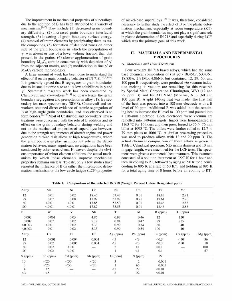
The microstructure of the heat-treated alloys, containingdifferent amounts of B, was characterized. It was found thatthe grain boundaries in all four of the alloys were exten-sively decorated with particles of various morphologies,ranging from globular to needle, and a typical SEM micro-graph of the heat-treated material containing 29 ppm B isshown in Figure 1(a). Energy-dispersive spectroscopy (EDS)revealed that these particles were (Ni3Nb) phase, as indi-cated by the arrows in Figure 1(a). Some B containing pre-cipitate particles were observed at grain boundaries, assuggested by the presence of B peaks in the correspondingEDS spectrum shown in Figure 1(b). Strong evidence ofsegregation of B at grain boundaries in B containing IN 718superalloy was observed by SIMS analysis in the earlierstudies on weldability of IN 718 superalloy.[9–12] The grainsize of all four alloys was about 6 �m; however, its distri-bution was observed to be inhomogeneous in some localregions.
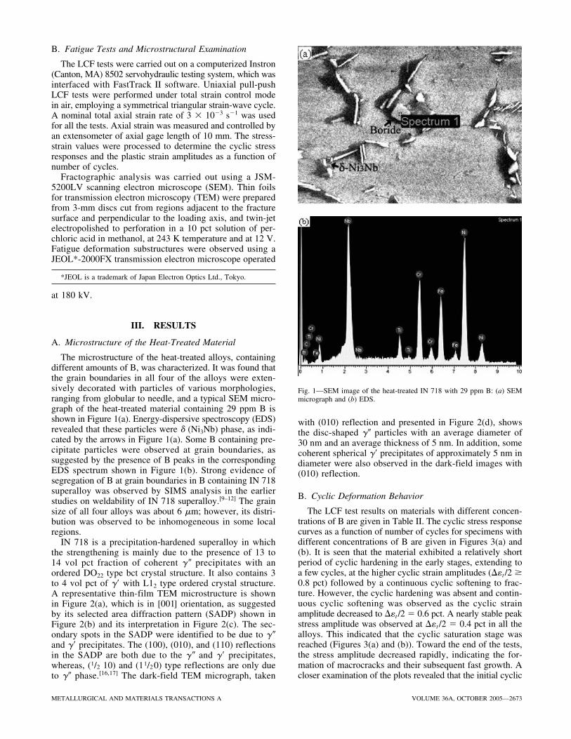
IN 718 is a precipitation-hardened superalloy in whichthe strengthening is mainly due to the presence of 13 to14 vol pct fraction of coherent �� precipitates with anordered DO22 type bct crystal structure. It also contains 3to 4 vol pct of �� with L12 type ordered crystal structure.A representative thin-film TEM microstructure is shownin Figure 2(a), which is in [001] orientation, as suggestedby its selected area diffraction pattern (SADP) shown inFigure 2(b) and its interpretation in Figure 2(c). The sec-ondary spots in the SADP were identified to be due to ��and �� precipitates. The (100), (010), and (110) reflectionsin the SADP are both due to the �� and �� precipitates,whereas, (1/2 10) and (11/2 0) type reflections are only dueto �� phase.[16,17] The dark-field TEM micrograph, taken
with (010) reflection and presented in Figure 2(d), showsthe disc-shaped �� particles with an average diameter of30 nm and an average thickness of 5 nm. In addition, somecoherent spherical �� precipitates of approximately 5 nm indiameter were also observed in the dark-field images with(010) reflection.
B. Cyclic Deformation Behavior
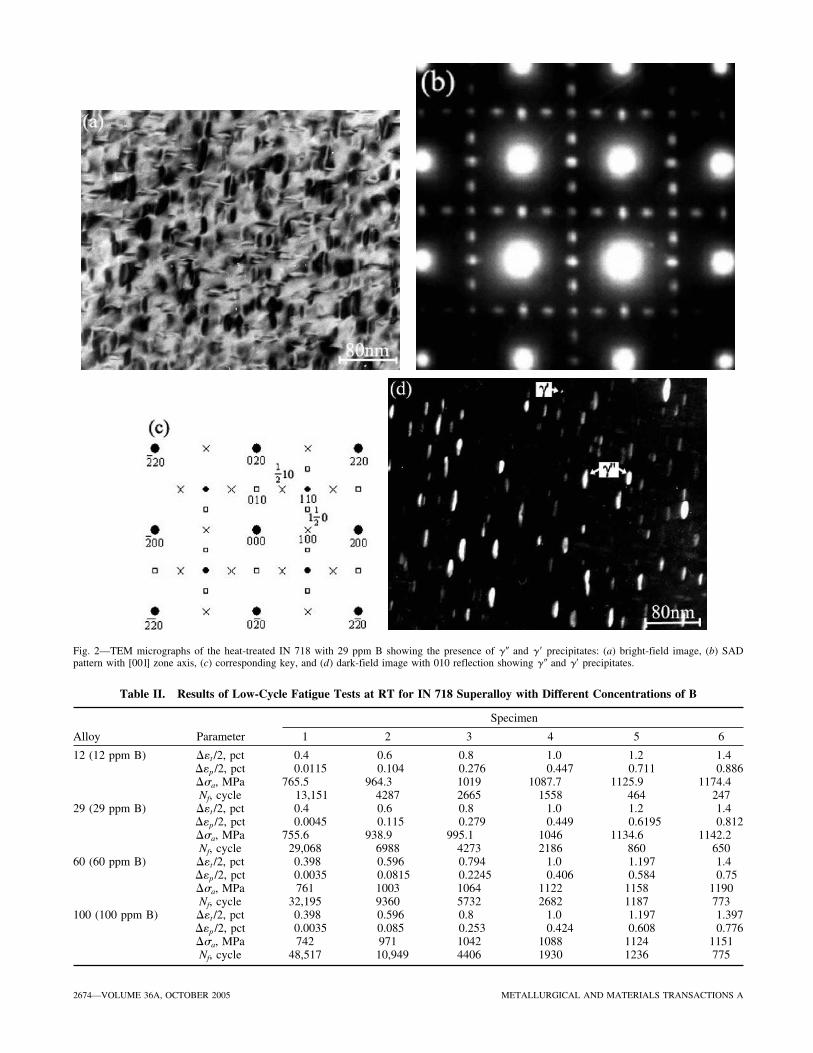
The LCF test results on materials with different concen-trations of B are given in Table II. The cyclic stress responsecurves as a function of number of cycles for specimens withdifferent concentrations of B are given in Figures 3(a) and(b). It is seen that the material exhibited a relatively shortperiod of cyclic hardening in the early stages, extending toa few cycles, at the higher cyclic strain amplitudes (��t /2 �0.8 pct) followed by a continuous cyclic softening to frac-ture. However, the cyclic hardening was absent and contin-uous cyclic softening was observed as the cyclic strainamplitude decreased to ��t /2 � 0.6 pct. A nearly stable peakstress amplitude was observed at ��t /2 � 0.4 pct in all thealloys. This indicated that the cyclic saturation stage wasreached (Figures 3(a) and (b)). Toward the end of the tests,the stress amplitude decreased rapidly, indicating the for-mation of macrocracks and their subsequent fast growth. Acloser examination of the plots revealed that the initial cyclic
Fig. 1—SEM image of the heat-treated IN 718 with 29 ppm B: (a) SEMmicrograph and (b) EDS.
2674—VOLUME 36A, OCTOBER 2005 METALLURGICAL AND MATERIALS TRANSACTIONS A
Fig. 2—TEM micrographs of the heat-treated IN 718 with 29 ppm B showing the presence of �� and �� precipitates: (a) bright-field image, (b) SADpattern with [001] zone axis, (c) corresponding key, and (d) dark-field image with 010 reflection showing �� and �� precipitates.
Table II. Results of Low-Cycle Fatigue Tests at RT for IN 718 Superalloy with Different Concentrations of B
Specimen
Alloy Parameter 1 2 3 4 5 6
12 (12 ppm B) ��t /2, pct 0.4 0.6 0.8 1.0 1.2 1.4��p /2, pct 0.0115 0.104 0.276 0.447 0.711 0.886��a, MPa 765.5 964.3 1019 1087.7 1125.9 1174.4Nf, cycle 13,151 4287 2665 1558 464 247
29 (29 ppm B) ��t /2, pct 0.4 0.6 0.8 1.0 1.2 1.4��p /2, pct 0.0045 0.115 0.279 0.449 0.6195 0.812��a, MPa 755.6 938.9 995.1 1046 1134.6 1142.2Nf, cycle 29,068 6988 4273 2186 860 650
60 (60 ppm B) ��t /2, pct 0.398 0.596 0.794 1.0 1.197 1.4��p /2, pct 0.0035 0.0815 0.2245 0.406 0.584 0.75��a, MPa 761 1003 1064 1122 1158 1190Nf, cycle 32,195 9360 5732 2682 1187 773
100 (100 ppm B) ��t /2, pct 0.398 0.596 0.8 1.0 1.197 1.397��p /2, pct 0.0035 0.085 0.253 0.424 0.608 0.776��a, MPa 742 971 1042 1088 1124 1151Nf, cycle 48,517 10,949 4406 1930 1236 775
METALLURGICAL AND MATERIALS TRANSACTIONS A VOLUME 36A, OCTOBER 2005—2675
stress response value increased as the cyclic strain ampli-tude increased, and the difference in cyclic stress amplitudesat different cyclic strain amplitudes was reduced as the cyclicdeformation progressed (Figure 3(a)). Figure 3(b) shows theeffect of B on the cyclic stress response of the materialfatigued at ��t /2 � 1.4, 0.6, and 0.4 pct, respectively. It isobserved that at the same cyclic strain amplitude, such as��t /2 � 1.4 pct, the initial cyclic hardening weakened as Bconcentration increased (Figure 3(b)). The cyclic stress ampli-tude value of the alloy with 60 ppm B was the highest amongthe four alloys fatigued at the same cyclic strain amplitude.The stress amplitude value of alloys with 12 and 29 ppm Bwas lower than that of the other two alloys.
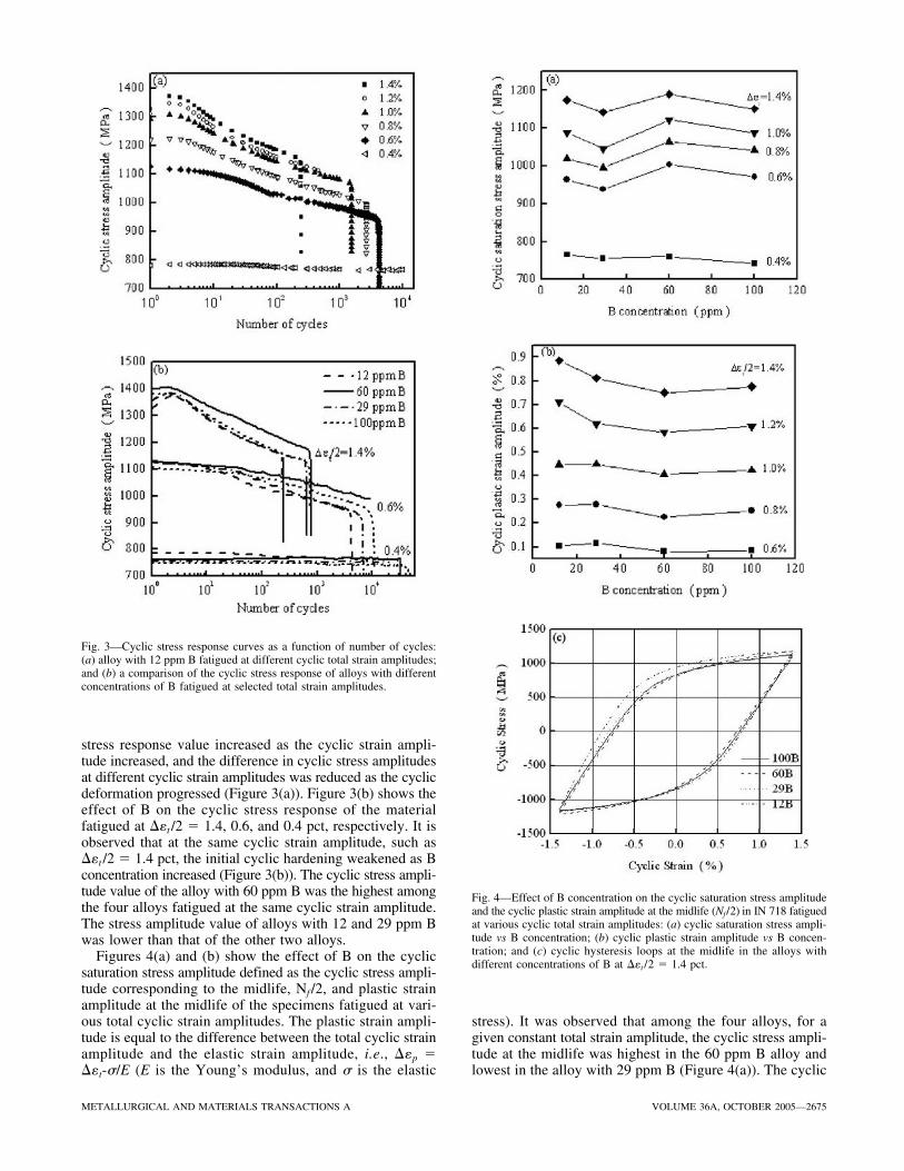
Figures 4(a) and (b) show the effect of B on the cyclicsaturation stress amplitude defined as the cyclic stress ampli-tude corresponding to the midlife, Nf /2, and plastic strainamplitude at the midlife of the specimens fatigued at vari-ous total cyclic strain amplitudes. The plastic strain ampli-tude is equal to the difference between the total cyclic strainamplitude and the elastic strain amplitude, i.e., ��p ���t-�/E (E is the Young’s modulus, and � is the elastic
stress). It was observed that among the four alloys, for agiven constant total strain amplitude, the cyclic stress ampli-tude at the midlife was highest in the 60 ppm B alloy andlowest in the alloy with 29 ppm B (Figure 4(a)). The cyclic
Fig. 3—Cyclic stress response curves as a function of number of cycles:(a) alloy with 12 ppm B fatigued at different cyclic total strain amplitudes;and (b) a comparison of the cyclic stress response of alloys with differentconcentrations of B fatigued at selected total strain amplitudes.
Fig. 4—Effect of B concentration on the cyclic saturation stress amplitudeand the cyclic plastic strain amplitude at the midlife (Nf/2) in IN 718 fatiguedat various cyclic total strain amplitudes: (a) cyclic saturation stress ampli-tude vs B concentration; (b) cyclic plastic strain amplitude vs B concen-tration; and (c) cyclic hysteresis loops at the midlife in the alloys withdifferent concentrations of B at ��t /2 � 1.4 pct.
2676—VOLUME 36A, OCTOBER 2005 METALLURGICAL AND MATERIALS TRANSACTIONS A
plastic strain amplitude corresponding to the midlife firstdecreased as the B concentration increased from 12 to60 ppm, and then increased when it increased from 60 to100 ppm, as shown in Figure 4(b). Therefore, within therange of B concentrations considered in the present inves-tigation, the variation in cyclic plastic strain amplitude withB concentration displayed a minimum value in the alloycontaining 60 ppm B. Furthermore, the cyclic stress-strainhysteresis loop of IN 718 with different concentrations ofB at the midlifetime at ��t /2 � 1.4 pct is shown in Fig-ure 4(c). As the B concentration increased from 12 to29 ppm, the slope of the elastic stress-strain curve in thestage of elastic deformation or the Young’s modulus wasobserved to decrease slightly in IN 718. This led to a slightdecrease in both the cyclic saturation stress and the cyclicplastic strain amplitude at a given total strain amplitude.When the B concentration increased from 29 to 100 ppm,no obvious change in the Young’s modulus and related hys-teresis loops was observed.
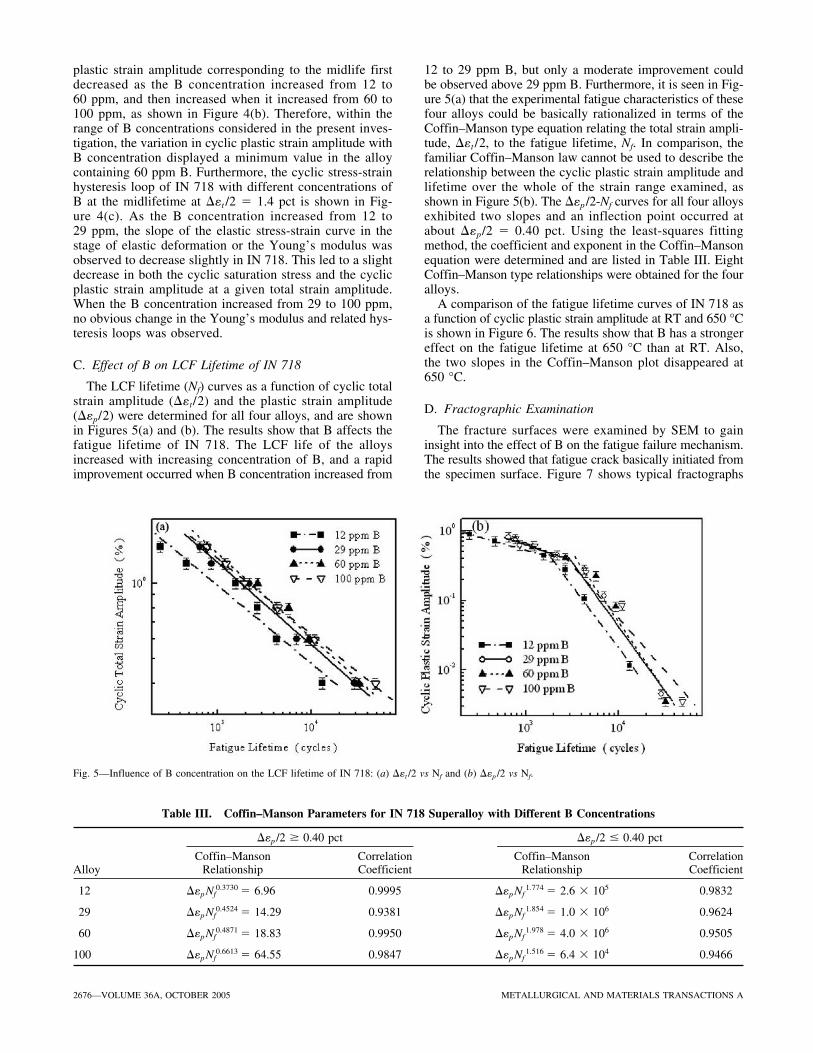
C. Effect of B on LCF Lifetime of IN 718
The LCF lifetime (Nf) curves as a function of cyclic totalstrain amplitude (��t/2) and the plastic strain amplitude(��p/2) were determined for all four alloys, and are shownin Figures 5(a) and (b). The results show that B affects thefatigue lifetime of IN 718. The LCF life of the alloysincreased with increasing concentration of B, and a rapidimprovement occurred when B concentration increased from
12 to 29 ppm B, but only a moderate improvement couldbe observed above 29 ppm B. Furthermore, it is seen in Fig-ure 5(a) that the experimental fatigue characteristics of thesefour alloys could be basically rationalized in terms of theCoffin–Manson type equation relating the total strain ampli-tude, ��t /2, to the fatigue lifetime, Nf. In comparison, thefamiliar Coffin–Manson law cannot be used to describe therelationship between the cyclic plastic strain amplitude andlifetime over the whole of the strain range examined, asshown in Figure 5(b). The ��p /2-Nf curves for all four alloysexhibited two slopes and an inflection point occurred atabout ��p/2 � 0.40 pct. Using the least-squares fittingmethod, the coefficient and exponent in the Coffin–Mansonequation were determined and are listed in Table III. EightCoffin–Manson type relationships were obtained for the fouralloys.
A comparison of the fatigue lifetime curves of IN 718 asa function of cyclic plastic strain amplitude at RT and 650 °Cis shown in Figure 6. The results show that B has a strongereffect on the fatigue lifetime at 650 °C than at RT. Also,the two slopes in the Coffin–Manson plot disappeared at650 °C.
D. Fractographic Examination
The fracture surfaces were examined by SEM to gaininsight into the effect of B on the fatigue failure mechanism.The results showed that fatigue crack basically initiated fromthe specimen surface. Figure 7 shows typical fractographs
Fig. 5—Influence of B concentration on the LCF lifetime of IN 718: (a) ��t /2 vs Nf and (b) ��p /2 vs Nf.
Table III. Coffin–Manson Parameters for IN 718 Superalloy with Different B Concentrations
��p /2 � 0.40 pct ��p /2 � 0.40 pct
Coffin–Manson Correlation Coffin–Manson Correlation Alloy Relationship Coefficient Relationship Coefficient
12 ��pNf0.3730 � 6.96 0.9995 ��pNf
1.774 � 2.6 105 0.9832
29 ��pNf0.4524 � 14.29 0.9381 ��pNf
1.854 � 1.0 106 0.9624
60 ��pNf0.4871 � 18.83 0.9950 ��pNf
1.978 � 4.0 106 0.9505
100 ��pNf0.6613 � 64.55 0.9847 ��pNf
1.516 � 6.4 104 0.9466

METALLURGICAL AND MATERIALS TRANSACTIONS A VOLUME 36A, OCTOBER 2005—2677
in the region of the fatigue crack initiation site in the alloywith 29 ppm B fatigued at different cyclic strain amplitudes.The fatigue crack initiation site can be clearly identified in
the specimens fatigued at low cyclic strain amplitude(��t /2 � 0.4 pct, Figure 7(a)). However, multiple crack ini-tiation sites could be observed in the specimens fatigued atthe high cyclic strain amplitude (��t/2 � 1.0 pct, Fig-ure 7(b)). The typical fractographs in the region of stablecrack propagation are shown in Figures 8(a) through (d).Fatigue crack propagation in all four alloys was observedto be characterized primarily by a large number of well-defined fatigue striations, which was taken as evidence oftransgranular crack growth at RT. A large number of sec-ondary cracks were observed on the fracture surfaces ofthe specimen of the alloy with the lowest (12 ppm) and thehighest (100 ppm) concentrations of B (Figures 8(a) and(d)). As the B content increased from 12 to 29 ppm, thenumber of secondary cracks decreased (Figure 8(b)). Fig-ure 8(c) depicts a typical fracture surface of the alloy with60 ppm B. Almost no secondary cracks are observed, butplastic deformation traces can be discerned on the facets ofthe fracture surface. The number of secondary cracks in thealloy with 100 ppm B (Figure 8(d)) were, however, morethan those observed in the alloy with 29 and 60 ppm B(Figures 8(b) and (c)).
Figure 9 shows other distinguishing features between thefracture surfaces of 12 and 29 ppm alloys. It is seen thatcharacteristic fatigue striations formed on the fracture sur-face of IN 718 with 29 ppm B (Figure 9(a)), but planar plas-tic deformation traces were observed on the fracture surfaceof IN 718 with 12 ppm B (Figure 9(b)). These traces wereobserved to be associated with the intersection of planar slipbands with the fracture surface or the grain boundaries.
E. Deformation Microstructures
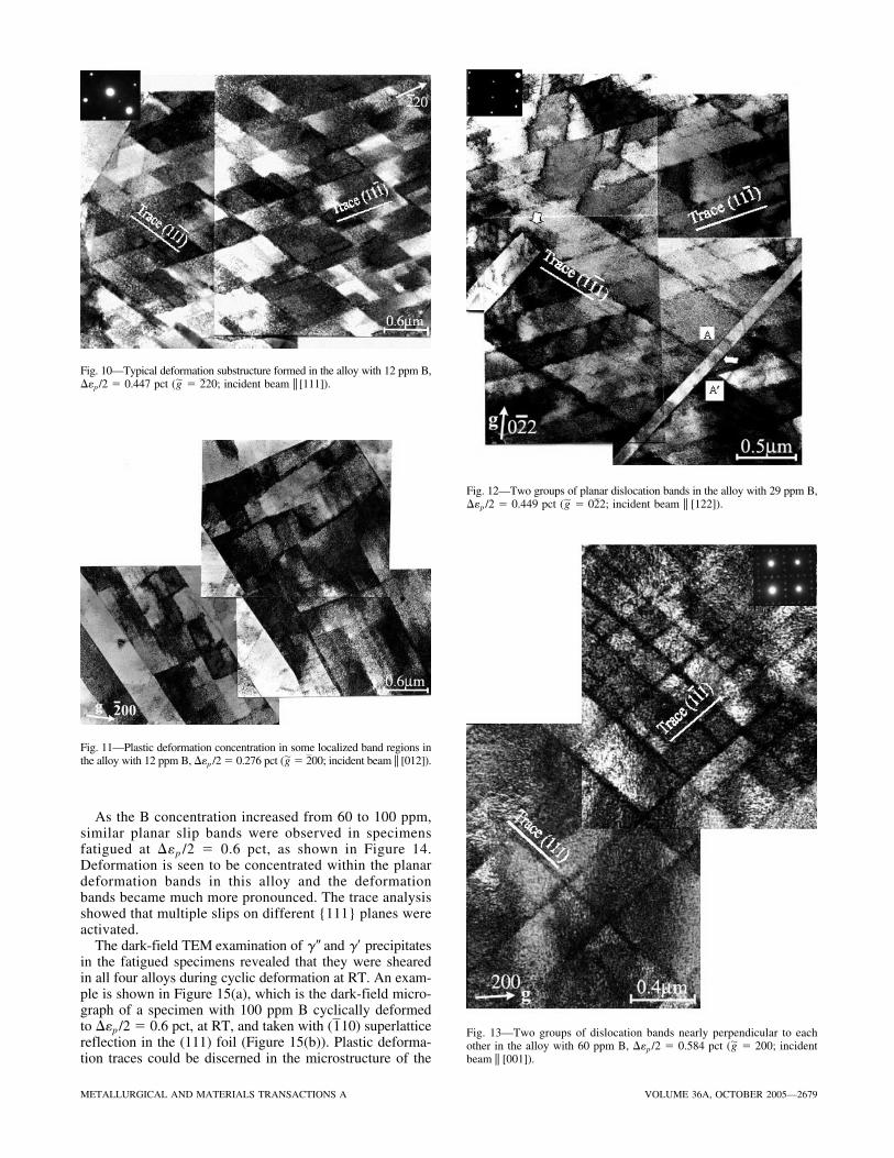
The deformation microstructures produced by LCF in thespecimens with different concentrations of B and fatiguedat similar cyclic plastic strain amplitudes (about 0.45 to0.60 pct) were examined via TEM. Regularly spaced arraysof planar deformation bands on {111} slip planes wereobserved in the fatigued specimen with 12 ppm B cyclicallydeformed at ��p /2 � 0.447 pct (Figure 10). They were char-acterized by the presence of two groups of planar deforma-tion bands lying along the traces of intersection of (11 ) and(1 ) slip planes with the (111) thin foil surface, respec-tively. Trace analysis showed that (11 ) and (1 ) slip sys-tems were activated simultaneously, giving rise to thesaturated diamond-shaped deformation structure in thefatigued specimens. In addition, some slip bands wereobserved to be concentrated in local band regions in theLCF specimen with the lower B concentration (12 ppm)(Figure 11). As a result, concentration of plastic deformationwas expected to occur in these areas.
Planar dislocation bands lying on {111} planes were alsoobserved in the specimens with 29 ppm B at ��p /2 �0.449 pct (Figure 12). The TEM examination showed thattwinning also occurred in this alloy during cyclic deforma-tion at RT. Interaction between slip bands and twinning wasobserved to occur, as indicated by the arrows in Figure 12.It was observed that the intersection of a twin with planarslip bands resulted in the formation of a staggered step onthe planar slip bands, as shown in Figure 12.
Figure 13 illustrates the typical deformation microstruc-ture that formed in the 60 ppm B alloy fatigued at ��p /2 �
11111
1
Fig. 6—A comparison of the effect of B concentration on the LCF life-time of IN 718 at RT and 650 °C.
Fig. 7—Typical fractographs showing the crack initiation sites in IN 718with 29 ppm B fatigued at different cyclic strain amplitudes: (a) ��t /2 �0.4 pct and (b) ��t/2 � 1.0 pct.

2678—VOLUME 36A, OCTOBER 2005 METALLURGICAL AND MATERIALS TRANSACTIONS A
Fig. 8—Typical fractographs in the region of stable crack propagation in IN 718 with different concentrations of B fatigued at ��t /2 � 0.4 pct: (a) 12 ppm B,(b) 29 ppm B, (c) 60 ppm B, and (d) 100 ppm B.
Fig. 9—Fracture surfaces in the region of stable crack propagation in IN 718 fatigued at ��t /2 � 0.4 pct: (a) fatigue striations in the alloy with 29 ppm Band (b) plastic traces in the alloy with 12 ppm B.
0.584 pct. Two groups of planar deformation bands, nearlyperpendicular to each other, were observed in a thin foil with[001] orientation. Trace analysis suggested them to be lyingon the (111) and (1 1) planes. Three-dimensional disloca-1
tion tangles such as cells and walls, which are the typicalfeatures in fatigued copper single crystals,[18,19] were notobserved. This suggests an absence of traditional persistentslip bands in this material with higher B content.
METALLURGICAL AND MATERIALS TRANSACTIONS A VOLUME 36A, OCTOBER 2005—2679
Fig. 10—Typical deformation substructure formed in the alloy with 12 ppm B,��p /2 � 0.447 pct ( � 20; incident beam || [111]).2�g
Fig. 11—Plastic deformation concentration in some localized band regions inthe alloy with 12 ppm B, ��p /2 � 0.276 pct ( � 00; incident beam || [012]).2�g
Fig. 12—Two groups of planar dislocation bands in the alloy with 29 ppm B,��p /2 � 0.449 pct ( � 0 2; incident beam || [122]).2�g
Fig. 13—Two groups of dislocation bands nearly perpendicular to eachother in the alloy with 60 ppm B, ��p /2 � 0.584 pct ( � 200; incidentbeam || [001]).
�g
As the B concentration increased from 60 to 100 ppm,similar planar slip bands were observed in specimensfatigued at ��p /2 � 0.6 pct, as shown in Figure 14.Deformation is seen to be concentrated within the planardeformation bands in this alloy and the deformationbands became much more pronounced. The trace analysisshowed that multiple slips on different {111} planes wereactivated.
The dark-field TEM examination of �� and �� precipitatesin the fatigued specimens revealed that they were shearedin all four alloys during cyclic deformation at RT. An exam-ple is shown in Figure 15(a), which is the dark-field micro-graph of a specimen with 100 ppm B cyclically deformedto ��p /2 � 0.6 pct, at RT, and taken with ( 10) superlatticereflection in the (111) foil (Figure 15(b)). Plastic deforma-tion traces could be discerned in the microstructure of the
1

2680—VOLUME 36A, OCTOBER 2005 METALLURGICAL AND MATERIALS TRANSACTIONS A
Fig. 14—Two groups of dislocation bands in the 100 ppm B alloy, ��p /2 �0.6 pct ( � 020; incident beam || [100]).�g
Fig. 15—Dark-field micrograph with �[ 10] reflection and the foil in [111] orientation, showing sheared precipitates in the specimen with 100 ppm Bdeformed to ��p /2 � 0.6 pct at RT: (a) dark-field image and (b) SAD pattern.
1�g
the (111) foil plane. In comparison with the nonfatiguedspecimen (Figure 2(d)), a reduction in the size of � �precipitates from 30 to 20 nm was observed after fatiguedeformation (Figure 15(a)). The reduction in the particle sizecould be attributed to the particles being sheared repeatedly,during cyclic deformation. The TEM examinations alsorevealed the presence of precipitate-free bands in the fatiguedspecimens, as shown in Figure 16, which is a dark-fieldimage of a fatigued specimen taken with the ( 10) super-lattice reflection in the (111) foil. The angle between thetraces of three groups of such bands, which coincide withthe traces of (11 ), (1 1), and (1 ) planes, with the (111)foil plane, is equal to 60 deg, as indicated by the arrows inFigure 16.
IV. DISCUSSION
A. Shearing of �� Precipitates, Formation of Planar SlipBands, and Cyclic Deformation Softening
A significant cyclic softening was observed at RT in allfour IN 718 superalloys, except when the material wasdeformed at the lowest cyclic strain amplitude, ��t /2 �0.4 pct. This may be attributed to the reduction in the sizeof � � precipitates by repeated shearing during cyclic defor-mation in the planar slip mode. The shearing mechanism of� � particles has been discussed by several authors.[16,20–25]
Sundararaman et al.[21] reported that when the size of �� par-ticles in IN 718 superalloy exceeded a critical value(�10 nm), � � precipitates were sheared by the deformationtwins, and the smaller precipitates were sheared by the move-ment of paired dislocations. Clavel and Pineau[23] showedthat the precipitates in IN 718 were sheared in the courseof cyclic straining, and plastic deformation occurred by thepropagation of planar bands, which were identified as twins.However, Oblak and co-workers[16,24] observed that shear-ing of �� particles appeared to take place by the coupled
1111
1
fatigued specimen, as indicated by arrows in Figure 15(a).The trace analysis showed the shearing traces to be paral-lel to the trace of intersection of the (1 1) slip plane with1

METALLURGICAL AND MATERIALS TRANSACTIONS A VOLUME 36A, OCTOBER 2005—2681
Fig. 16—Dark-field micrograph with � [ 10] reflection and the foil in[111] orientation, showing precipitate-free bands on three groups of {111}slip planes in a specimen with 100 ppm B deformed to ��p /2 � 0.6 pctat RT.
1�g
motion of a/2 �110� pairs in IN 718 deformed to 3 pctstrain at RT. Worthem et al.,[25] on the other hand, reportedthat shearing of � � precipitates occurred by slip only dur-ing cyclic deformation and no significant shearing of � � pre-cipitates was observed after the monotonic strains, and nodeformation twins were identified.
As an ordered phase, the �� precipitates possess anantiphase domain boundary (APB) energy representing theextra energy associated with the ordered atomic positions inthe crystal lattice versus the normal disordered or randomatomic positions. An antiphase boundary is created in both�� and �� particles in IN 718 superalloy when they are cutby a dislocation, and order is restored by the passage of asecond dislocation of the same character. The repulsiveenergy between the two dislocations traveling on the sameslip plane is balanced by the APB energy of the precipitatephase, resulting in a coupled or superdislocation. The shear-ing of �� particles during cyclic deformation is shownschematically in Figure 17(a). Since cross-slip of the cou-pled dislocations is extremely difficult, slip continues tooccur on the same slip plane during continued deformation,resulting in the formation of planar slip bands in the fatiguedIN 718 specimens, as shown schematically in Figures 17(b)and (d). It is a three-dimensional representation of all four{111} slip planes in a thin foil in [111] orientation in the[11 ]-[ 10]-[111] space, and Figure 17(c) displays projectionsof three {111} planes, i.e., ( 11), (1 1), and (11 ) planeson a (111) thin foil plane. In other words, Figure 17(c) alsorepresents schematically the projection of planar slip bandson the (111) plane. Figure 17(d) shows a similar three-dimen-sional representation of all four {111} slip planes in a thinfoil in [100] orientation in [1 0]-[110]-[001] space, andFigure 17(e) shows a projection of all four {111} planes, i.e.,on a (001) thin foil plane.
In this alloy, an additional factor that may promote pla-nar slip is a reduction in the change in configurational energy
1
11112
of short-range order in �� precipitates caused by the passageof subsequent dislocations after the passage of first-slip dis-location, as was observed by Schwander et al. regardingNi-11.2 pct Mo crystals.[26] On the basis of the short-range-ordering parameter, determined by X-ray diffuse scatteringmeasurements, and the effective pair potentials, obtained byapplying the inverse Monte Carlo technique, they calculatedthe change in configurational energy of Ni-11.2 pct Mocrystals caused by successive slip by a number of unit dis-locations on the same {111} plane. They found that a con-figurational energy change of about 25 mJ/m2 was necessaryfor the first slip, and after five slip steps, the configurationalenergy remained constant. That is, the passage of subsequentdislocations after the first five did not cause any furtherchange in configurational energy, and planar slip was favored.
Fig. 17—A schematic illustrating the shearing of �� precipitates and theformation of planar slip bands in IN 718 during cyclic deformation:(a) schematic representation of the shearing process of �� precipitates bydislocations, where cross-hatching of particles indicates the presence ofantiphase boundary; (b) three-dimensional representation of {111} slip planesin a thin foil with [111] orientation; (c) projections of {111} planes on (111)thin foil plane; (d) three-dimensional representation of {111} slip planesin a thin foil in [001] orientation; and (e) projections of {111} planes onthe (001) thin foil plane.
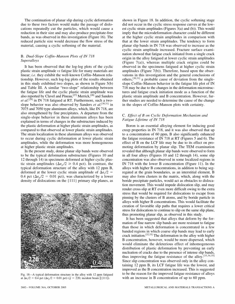
The continuation of planar slip during cyclic deformationdue to these two factors would make the passage of dislo-cations repeatedly cut the particles, which would cause areduction in their size and may also produce precipitate-freebands, as was observed in this investigation (Figure 16). Thereduced particle size would decrease the flow stress of thematerial, causing a cyclic softening of the material.
B. Dual-Slope Coffin–Manson Plots of IN 718Superalloys
It has been observed that the log-log plots of the cyclicplastic strain amplitude vs fatigue life for many materials arelinear; i.e. they exhibit the well-known Coffin–Manson rela-tionship. However, such log-log plots of the results obtainedin this study exhibited two slopes, as shown in Figure 5(b)and Table III. A similar “two-slope” relationship betweenthe fatigue life and the cyclic plastic strain amplitude wasalso reported by Clavel and Pineau,[27] Merrick,[28] and Sanderset al.[29] in IN 718 fatigued at RT. Furthermore, such a two-slope behavior was also observed by Sanders et al.[30,31] in7075 and 7050 type aluminum alloys, which, like IN 718, arealso strengthened by fine precipitates. A departure from thesingle-slope behavior in these aluminum alloys has beenexplained in terms of changes in the substructure induced bythe plastic deformation at higher plastic strain amplitudes, ascompared to that observed at lower plastic strain amplitudes.The strain localization in these aluminum alloys was observedto occur during cyclic deformation at lower plastic strainamplitudes, while the deformation was more homogeneousat higher plastic strain amplitudes.
In the present study, dense planar slip bands were observedto be the typical deformation substructure (Figures 10 and12 through 14) in specimens deformed at higher cyclic plas-tic strain amplitudes (��p /2 � 0.4 pct). In contrast, thetypical deformation structure of the alloy with 12 ppm B,deformed at the lower cyclic strain amplitude of ��t /2 �0.4 pct (��p /2 � 0.01 pct), was characterized by a lowerdensity of dislocations on the {111} primary slip planes, as
shown in Figure 18. In addition, the cyclic softening stagedid not occur in the cyclic stress response curves at the low-est cyclic strain amplitudes (Figures 3(a) and (b)). This wouldimply that the microdeformation character could be differentat the higher cyclic strain amplitudes in comparison withthat at the lower strain amplitudes. The tendency to formplanar slip bands in IN 718 was observed to increase as thecyclic strain amplitude increased. Fracture surface exami-nation showed that fatigue crack initiated from a single crackorigin in the alloy fatigued at lower cyclic strain amplitudes(Figure 7(a)), whereas multiple crack origins could beobserved in the specimens fatigued at higher cyclic strainamplitudes (Figure 7(b)). Therefore, based upon the obser-vations in this investigation and the general conclusions ofothers,[30,31] a probable cause of deviation from the single-slope Coffin–Manson behavior in the fatigue life plot of IN718 may be due to the changes in the deformation microstruc-tures and fatigue crack initiation mode as a function of theplastic strain amplitude and B concentration. However, fur-ther studies are needed to determine the cause of the changein the slopes of Coffin–Manson plots with certainty.
C. Effect of B on Cyclic Deformation Mechanism andFatigue Lifetime of IN 718
Boron is an essential alloying element for inducing goodcreep properties in IN 718, and it was also observed that upto a concentration of 60 ppm, B also significantly enhancedthe fatigue resistance of IN 718 at RT (Figures 5 and 6). Theeffect of B on the LCF life may be due to its effect on pro-moting deformation by planar slip. The TEM examinationrevealed that although planar slip bands were observed to formin all four alloys (Figures 10 and 12 through 14), some slipconcentration was also observed in some localized regions inIN 718 with the lower B concentration (Figure 11). In thealloys with higher B concentrations, in addition to being seg-regated at the grain boundaries, as an interstitial element, Bmay also form clusters in the matrix, which, along with theboride precipitate particles, would act as obstacles to disloca-tion movement. This would impede dislocation slip, and mayrender cross-slip at RT even more difficult owing to the extrastress that would be required for dislocations to escape frompinning by the clusters of B atoms, and by boride particle inalloys with higher B concentrations. This would facilitate thecreation of favorable slip paths that requires a lower criticalstress for dislocations to continue to slip on the same slip plane,thus promoting planar slip, as observed in this study.
It has been suggested that alloys that deform by the for-mation of fine narrow slip bands are more resistant to fatiguethan those in which deformation is concentrated in a fewbanded regions in which coarse slip bands may lead to earlycrack initiation.[32,33] The deformation in the alloy with higherB concentration, however, would be more dispersed, whichwould eliminate the deleterious effect of inhomogeneousdistribution of plastic deformation by preventing an earlynucleation of cracks due to the presence of intense slip bands,thus improving the fatigue resistance of the alloy.[33,34,35]
Since slip concentration was observed only in the alloy con-taining 12 ppm B, its LCF fatigue life was the lowest, andimproved as the B concentration increased. This is suggestedto be the reason for the improved fatigue resistance of alloyswith an increase in B concentration of up to 60 ppm.
2682—VOLUME 36A, OCTOBER 2005 METALLURGICAL AND MATERIALS TRANSACTIONS A
Fig. 18—A typical deformation structure in the alloy with 12 ppm fatiguedat ��t /2 � 0.4 pct (��p /2 � 0.01 pct) ( � 20; incident beam || [111]).2�g
Fractographic observations shown in Figure 8 also revealedthat the grain boundary strength was enhanced with an increasein B concentrations of up to 60 ppm, as evidenced by thedecreasing amount of secondary cracks on the fracture sur-face. This is also reflected in the beneficial effect of increas-ing the concentration of B on the fatigue lifetime, as seen inFigures 5(a) and (b). The slightly lower fatigue life of thealloy containing 100 ppm B, compared to the alloy with60 ppm B, may be related to the observed reoccurrence ofsecondary cracking in this alloy (Figure 8(d)). The relativelylower amount of B of 60 ppm compared to 100 ppm mayimprove LCF resistance by distributing the plastic deforma-tion uniformly. The excessive B addition, however, may leadto a reduction in the fracture ductility at RT due to an increasein the alloys’ dislocation slip resistance. As a result, the amountof secondary crack would increase and the LCF life woulddecrease in the alloy with 100 ppm B, as was observed.
The relationship between the microstructure and cyclicdeformation behavior is known to be complex, especially forhigh-strength commercial alloys. It is evident, however, thatany microstructural feature that causes an inhomogeneousdistribution of plastic strain will have a deleterious effect onthe fatigue life.[33,35] Microscopically, strong dislocation pile-ups and high stress concentration would lead to fatigue cracknucleation and favor crack propagation, and would therebydecrease the fatigue life of IN 718 with a lower B content.However, it is worthy of note that research on the effect ofB on LCF of IN 718 at 650 °C[15] has shown that B has astronger influence in improving the fatigue life at 650 °C incomparison with that observed at RT (Figure 6). Microstruc-tural examination showed that planar slip bands are the typ-ical cyclic deformation dislocation configuration at both RTand 650 °C. Furthermore, the width and spacing of planarslip bands observed at RT and 650 °C in foils at [100] ori-entation remained almost constant at different cyclic plasticstrain amplitudes.[20] The spacing was about 0.70 �m and thewidth 0.06 �m at both RT and 650 °C. Some plastic defor-mation concentration was observed in the alloy with 12 ppmB at 650 °C as well.[15] This indicates that the plastic defor-mation mode of IN 718 at RT remained similar to that at 650°C. However, no substantial improvement in the fatigue life-time of IN 718 was observed above 29 ppm B at RT, as com-pared to a continuous increase in fatigue lifetime observedat 650 °C from 12 ppm B to 60 ppm B. This implies thatthe effect of B is enhanced by its effect on the grain bound-ary behavior at elevated temperatures, i.e., B plays a moreimportant role in improving the high-temperature mechani-cal properties of IN 718 as compared to the RT properties.A significant improvement in the fatigue lifetime of IN 718at 650 °C due to B microadditions results from improvinggrain boundary cohesion and stabilizing grain boundary con-stituents via B segregation to grain boundaries and the pre-cipitation of boride particles on grain boundaries.[15]
V. SUMMARY AND CONCLUSIONS
1. At higher plastic strain amplitudes, all four IN 718 alloyswith different concentrations of B exhibited a relativelyshort initial cyclic hardening, with the magnitude increas-ing with increasing plastic strain amplitude, followed bya regime of continuous cyclic softening at RT (��t /2 �
0.8 pct). As the cyclic strain amplitude decreased to��t /2 � 0.6 pct, the period of cyclic hardening was absentand the material showed a continuous cyclic softeninguntil fracture. A nearly stable cyclic stress amplitude wasobserved at ��t /2 � 0.4 pct in all the alloys.
2. Among the four alloys fatigued at the same total cyclicstrain amplitude, the cyclic saturation stress amplitudevalue was the highest in the alloy with 60 ppm B, andthe lowest in the alloy with 29 ppm B.
3. Boron was observed to improve the LCF lifetime of IN718 at RT. A noticeable improvement occurred up to29 ppm B, but the improvement was moderate when con-centrations of B exceeded 29 ppm B. The positive effectof B concentration on the fatigue lifetime at RT was lessthan that observed at 650 °C. A linear relationship betweenthe fatigue life and cyclic total strain amplitude wasobserved, while a two-slope relationship between the fatiguelife and cyclic plastic strain amplitude was observed tooccur with an inflection point at about ��p /2 � 0.40 pct.
4. A fractographic examination showed that fatigue crackinitiated from specimen surfaces, and the crack propa-gation mode was predominantly transgranular with a largenumber of fatigue striations on the fracture surfaces. Thenumber of secondary cracks was observed to be higherin alloys with 12 and 100 ppm B than that present inalloys containing 29 and 60 ppm B.
5. The deformation microstructures of all four alloys werecharacterized by the presence of groups of planar defor-mation bands lying along the {111} slip plane traces, anddeformation occurred by planar slip. However, some slipwas observed to be concentrated in local band regionsin the alloy with 12 ppm B.
6. The � � precipitates in IN 718 were sheared by the slip ofdislocations during cyclic deformation. After the initial shear-ing, the trailing dislocations on the same slip plane repeat-edly sheared the � � precipitates and reduced their size tosuch an extent that they offered very little or no resistanceto the further movement of dislocations. The preferentialpaths, which had fewer precipitates and lower critical stressfor dislocation slip, were established. As a result, cyclicdeformation softening occurred and planar slip bands formed.
7. The improvement in the LCF life of IN 718 by B addi-tion is attributed to its effect on promoting cyclic defor-mation of IN 718 at RT by planar slip, which caused ahomogeneous distribution of deformation and delayedthe initiation of microcracks, thus enhancing the fatigueresistance of the material.
ACKNOWLEDGMENT
The authors thank the Natural Sciences and EngineeringResearch Council of Canada for the financial support.
REFERENCES1. W.J. Pennington: Met. Progr., 1958, vol. 73, pp. 82-86.2. F.N. Darmara, J.S. Huntington, and E.S. Machlin: J. Iron Steel Inst.,
1959, vol. 191, pp. 266-275.3. R.T. Holt and W. Wallace: Int. Met. Rev., 1976, vol. 6, Mar., pp.1-24.4. Wei-Di Cao and R.L. Kennedy: in Superalloys 718, 625, 706 and
Various Derivatives, E.A. Loria, ed., TMS, Warrendale, PA, 1997,pp. 511-20.
METALLURGICAL AND MATERIALS TRANSACTIONS A VOLUME 36A, OCTOBER 2005—2683
5. T.J. Garosshen, T.D. Tillman, and G.P. McCarthy: Metall. Trans. A,1987, vol. 18A, pp. 69-77.
6. S. Floreen and J.M. Davidson: Metall. Trans. A, 1983, vol. 14A,pp. 895-901.
7. A.K. Jena and M.C. Chaturvedi: J. Mater. Sci., 1984, vol. 19, pp. 3121-39.8. U. Franzoni, F. Marchetti, and S. Sturlese: Scripta Metall., 1985, vol. 19,
pp. 511-6.9. X. Huang, M.C. Chaturvedi, N.L. Richards, and J. Jackman: Acta
Mater., 1997, vol. 45, pp. 3095-107.10. W. Chen and M.C. Chaturvedi: Acta Mater., 1997, vol. 45, pp. 2735-46.11. W. Chen, M.C. Chaturvedi, N.L. Richards, and G. McMahom: Metall.
Mater. Trans. A, 2001, vol. 32A, pp 931-39.12. X. Huang, M.C. Chaturvedi, and N.L. Richards: Metall. Mater. Trans.
A, 1996, vol. 27A, pp. 785-90.13. W. Chen, N.L. Richards, and M.C. Chaturvedi: Metall. Mater. Trans.
A, 2001, vol. 32A, pp. 931-39.14. H. Guo, M.C. Chaturvedi, N.L. Richards, and G.S. McMahon: Scripta
Mater., 1999, vol. 40, pp. 383-8.15. L. Xiao, D.L. Chen, and M.C. Chaturvedi: Metall. Mater. Trans. A,
2004, vol. 35A, pp. 3477-87.16. J.M. Oblak, D.F. Paulonis, and D.S. Duvall: Metall. Trans., 1974,
vol. 5, pp. 143-53.17. I. Kirman and D.H. Warrington: Metall. Trans., 1970, vol. 1,
pp. 2667-75.18. C. Laird: Fatigue and Microstructure, ASM, Metals Park, OH, 1978,
pp. 149-203.19. P. Lukas, M. Klesnil, and J. Krejci: Phys. Status Solidi, 1968, vol. 27,
pp. 545-58.
20. L. Xiao, D.L. Chen, and M. C. Chaturvedi: Scripta Mater., 2005,vol. 52, pp. 603-07.
21. M. Sundararaman, P. Mukhopadhyay, and S. Banerjee: Acta Metall.,1988, vol. 36, pp. 847-64.
22. H.F. Merrick: Metall. Trans. A, 1976, vol. 7A, pp. 505-14.23. M. Clavel and A. Pineau: Metall. Trans. A, 1978, vol. 9A,
pp. 471-80.24. D.F. Paulonis, J.M. Oblak, and D.S. Duvall: Trans. ASM, 1969, vol. 62,
pp. 611-22.25. D.W. Worthem, I.M. Robertson, F.A. Leckie, D.E. Socie, and C.J.
Altstetter: Metall. Trans. A, 1990, vol. 21A, pp. 3215-20.26. P. Schwander, B. Schonfeld, and G. Kostorz: Phys. Status Solidi B,
1992, vol. 172, pp. 73-85.27. M. Clavel and A. Pineau: Mater. Sci. Eng., 1982, vol. 55, pp. 157-71.28. H.F. Merrick: Metall. Trans., 1974, vol. 5, pp. 891-97.29. T.H. Sanders, Jr., R.E. Frishmuth, and G.T. Embley: Metall. Trans. A,
1981, vol. 12A, pp. 1003-10.30. T.H. Sanders Jr. and J.T. Staley: Fatigue and Microstructure, Metals
Park, OH, 1978, pp. 467-522.31. T.H. Sanders, Jr. and E.A. Starke, Jr.: Metall. Trans. A, 1976, vol. 7A,
pp. 1407-18.32. J.C. Grosskreutz: Metall. Trans., 1972, vol. 3, pp. 1255-62.33. E.A. Starke, Jr. and G. Lutjering: Fatigue and Microstructure, Metals
Park, OH, 1978, pp. 14-15.34. A. Saxena and S.D. Antolovich: Metall. Trans. A, 1975, vol. 6A,
pp. 1809-28.35. L. Xiao, Y. Umakoshi, and J. Sun: Metall. Mater. Trans. A, 2001,
vol. 32A, pp. 2841-50.
2684—VOLUME 36A, OCTOBER 2005 METALLURGICAL AND MATERIALS TRANSACTIONS A