fluidized bed assisted abrasive jet machining (fb-ajm): precision internal finishing of inconel 718...
TRANSCRIPT
Fluidized Bed assisted Abrasive Jet Machining (FB-AJM):
Precision internal finishing of Inconel 718 components
M. Barletta*,1
, D. Ceccarelli1, S. Guarino
1, V. Tagliaferri
1
1Università degli Studi di Roma ‘Tor Vergata’, Dipartimento di Ingegneria Meccanica, Via del
Politecnico, 1 – 00133 Roma (Italy) *,1
Corresponding author e-mail: [email protected]
Abstract
The relatively new technique of Fluidized Bed assisted Abrasive Jet Machining (FB-AJM) is
applied to finishing the inner surfaces of tubular Inconel 718 components. The effects of abrasive
size, jet pressure, and machining cycle were evaluated, and the behaviour of abrasive cutting edges
acting against the surface during the process to remove material is accounted for. The finished
surface was found to be highly dependent on jet pressure as it affects the abrasive contact against
the surface as well as the finishing force acting on the abrasive, on the abrasive grain size, which
controls the depth of cut, and on machining cycle, which controls the interaction time between the
abrasives and the surface being finished. By altering these conditions, this process achieves surface
roughness (Ra) as fine as 0.1 m and imparts minimal additional residual stress on the surface. This
study also reveals the mechanisms that determine the smoothing of the inner surface of Inconel 718
tubes and to improve the form accuracy, i.e. the internal roundness of the Inconel 718 tube.
Key words: Fluidized bed assisted abrasive finishing; Internal finishing; Inconel 718; Finishing
characteristics; Surface roughness; Roundness; Residual stress.
1. INTRODUCTION
Inconel 718 is a nickel-based super alloy well suited to applications requiring high strength over
temperature ranges from cryogenic up to 750 °C. Inconel 718 also exhibits excellent tensile and
impact strength. Common applications of Inconel 718 include jet engines, gas turbine operations,
heat exchangers, cryogenic storage tanks, as well as load-bearing components in which the sliding
surfaces between inner and outer races of bearings require highly smoothed surfaces and form
accuracy to reduce wear and so extend effective life [1].
Obtaining high quality internal finishing on Inconel 718 components can be extremely
complicated [2]. In fact, conventional machining techniques used for iron based alloys can make the
Inconel 718 alloy work-harden during machining [2]. Moreover, Inconel 718 has higher strength
and "gumminess" not typical of steels. Heavy duty machining equipment and tooling should be
used to minimize chatter and work-hardening of the alloy before cutting. In turning in particular,
high-speed steel tooling with positive rake angle should be used for interrupted cuts and for smooth
finishing to close tolerance [3]. However, even if all precautions are taken during Inconel 718
machining, whenever workpieces characterized by complex shapes or a high length L to diameter D
ratio must be machined, conventional solutions are a critical and time-consuming stage of the
manufacturing process [4]. Both the machining and the finishing stage of the manufacturing
process can be compromised by severe tool vibration, large bending, and tool failure [4], therefore
the demand for alternative techniques has been increasing [5].
Several advanced machining solutions able to process complex shaped components are detailed in
the scientific literature [4-5]. Mechanisms regulating material removal and surface finishing are
modeled and energy sources, transfer media, and cutting tools used in each process have been
comprehensively described [6]. As a result, several analyses classifying the most suitable machining
technologies according to workpiece material, geometry, and end use are found in the specialized
literature [7-10]. When accurate finishing of high strength materials or of components with complex
configurations is required, several limitations affect all machining technologies, including the most
advanced. For example, etching processes are commonly used for internal finishing, but they have
drawbacks associated with the control of the surface quality and the treatment of chemical waste
[7]. It is therefore desirable to find an alternative internal finishing process to replace chemical
finishing processes. Techniques based on abrasive flows and jets such as abrasive jet machining
(AJM) [8], abrasive flow machining (AFM) [9], and abrasive magnetic flow machining (AMFM)
[10]) at best only produce reasonable results. At the same time, of all the techniques based on
abrasive flows and jets, AJM is commonly considered the most competitive as it involves shorter
start-up times as well as lower investment and running costs [4]. Even though AJM involves the
least investment and the most economical operating costs, and is not affected by any drawbacks
associated with the use of solid tools (vibrations, inflexions, or failures), and benefits from a high
degree of operational flexibility and shorter processing time, it does suffer from several limitations.
These are generally caused by the unpredictable hydrodynamic properties of the abrasive jet,
making this process unsuitable for most tubular shaped parts. Precision and repeatable machining
can be virtually impossible using AJM [11-12], and operating problems can arise including
chocking regimes, significant nozzle wear, contamination of the atmosphere from dispersed fines,
as well as continuous demand for abrasive replacement [13-14].
As an alternative to AJM, Barletta et al. tested the relatively novel hybrid technology of Fluidized
Bed assisted Abrasive Jet Machining (FB-AJM) using tubular workpieces (L/D≤20) made from
stainless steel [15] and high strength aluminum [16] alloys. This technology uses the fluidized bed
hydrodynamic to improve the abrasive feeding system, the uniformity of abrasive distribution
through the workpiece, and the recovery and self-regeneration of abrasive during machining.
Consequently, precision, uniformity, and above all, repeatable machining as well as accurate
surface finishing can be achieved even on the inner surfaces of tubular parts [15-16]. Nevertheless,
several concerns regarding the possibility of extending FB-AJM to components made from
specialized metal superalloys in order to produce fine surface finishes, improving their form
accuracy, and imparting minimal residual stresses on them, still remain unanswered.
This is the context in which the evaluation of how the progression of material removal and the
modification of surface texture during fluidized bed assisted abrasive finishing process of tubular
components made from high yield strength metal superalloys (i.e. Inconel 718 SPF) took place.
Design of experiment (DOE) techniques were used to evaluate the influence of operational
variables (i.e. abrasive mesh size, machining cycle, and jet pressure) on mass removal rate and
surface roughness. The finished surface was found to be highly dependent on three factors: firstly,
jet pressure, which affects the abrasive contact against the surface as well as the finishing force
acting on the abrasive; secondly, on the abrasive grain size, which controls the depth of cut; and
thirdly, on machining cycle, which controls the interaction time between the abrasives and the
surface being finished. The best way of choosing the operational parameters is by experimentally
analyzing these three factors to deduce them.
The macroscopic morphological modification of machined surfaces according to mesh size of
abrasive media was investigated using high resolution 3D profilometry. Therefore, tests on the
circumferential uniformity, precision, and repeatability of FB-AJM on the workpiece inner surfaces
could be carried out. In addition to this, leading process mechanisms, which concurrently determine
material removal and the establishment of a smoother finish, could be interpreted in the light of the
microscopic modification of the machined surfaces, assessed by FE-SEM analysis. Finally, the
improvements in form accuracy and the minimal occurrence of residual stresses on workpieces after
finishing were carefully checked, therefore providing definitive assessment of how suitable
fluidized bed assisted technology is for the finishing of complex shaped Inconel 718 components.
2. METHODS
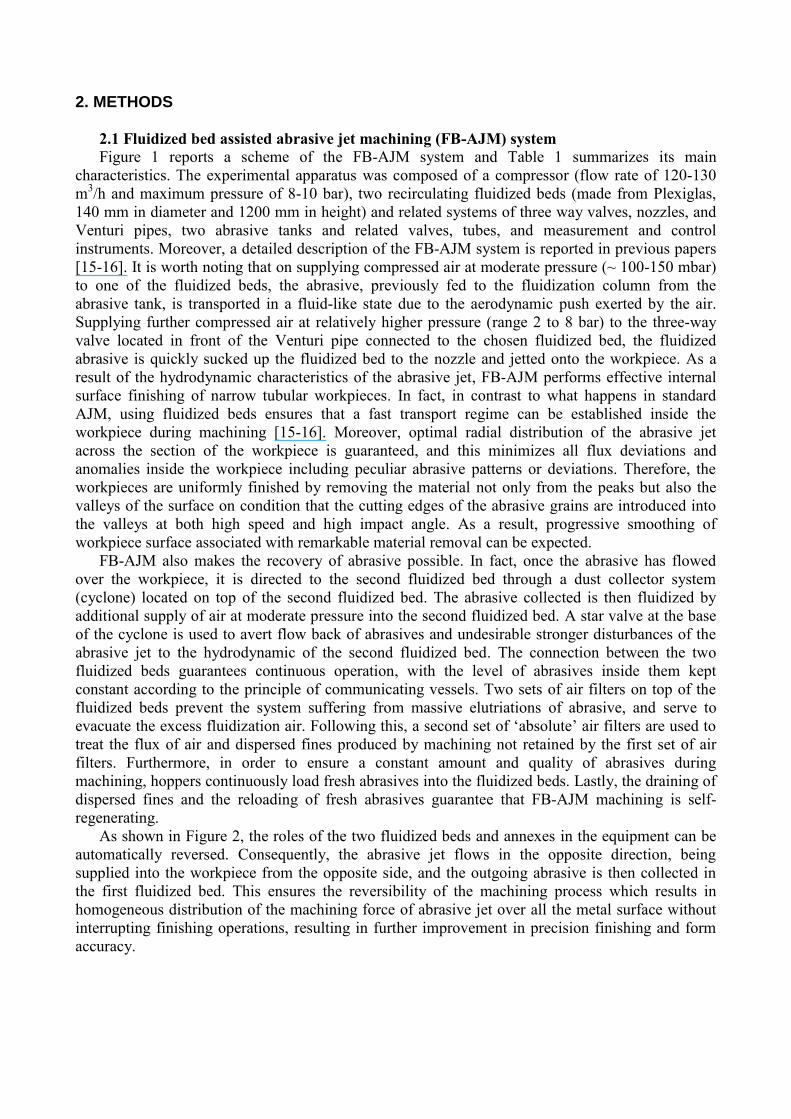
2.1 Fluidized bed assisted abrasive jet machining (FB-AJM) system
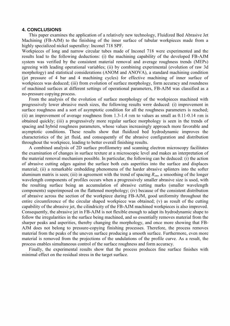
Figure 1 reports a scheme of the FB-AJM system and Table 1 summarizes its main
characteristics. The experimental apparatus was composed of a compressor (flow rate of 120-130
m3/h and maximum pressure of 8-10 bar), two recirculating fluidized beds (made from Plexiglas,
140 mm in diameter and 1200 mm in height) and related systems of three way valves, nozzles, and
Venturi pipes, two abrasive tanks and related valves, tubes, and measurement and control
instruments. Moreover, a detailed description of the FB-AJM system is reported in previous papers
[15-16]. It is worth noting that on supplying compressed air at moderate pressure (~ 100-150 mbar)
to one of the fluidized beds, the abrasive, previously fed to the fluidization column from the
abrasive tank, is transported in a fluid-like state due to the aerodynamic push exerted by the air.
Supplying further compressed air at relatively higher pressure (range 2 to 8 bar) to the three-way
valve located in front of the Venturi pipe connected to the chosen fluidized bed, the fluidized
abrasive is quickly sucked up the fluidized bed to the nozzle and jetted onto the workpiece. As a
result of the hydrodynamic characteristics of the abrasive jet, FB-AJM performs effective internal
surface finishing of narrow tubular workpieces. In fact, in contrast to what happens in standard
AJM, using fluidized beds ensures that a fast transport regime can be established inside the
workpiece during machining [15-16]. Moreover, optimal radial distribution of the abrasive jet
across the section of the workpiece is guaranteed, and this minimizes all flux deviations and
anomalies inside the workpiece including peculiar abrasive patterns or deviations. Therefore, the
workpieces are uniformly finished by removing the material not only from the peaks but also the
valleys of the surface on condition that the cutting edges of the abrasive grains are introduced into
the valleys at both high speed and high impact angle. As a result, progressive smoothing of
workpiece surface associated with remarkable material removal can be expected.
FB-AJM also makes the recovery of abrasive possible. In fact, once the abrasive has flowed
over the workpiece, it is directed to the second fluidized bed through a dust collector system
(cyclone) located on top of the second fluidized bed. The abrasive collected is then fluidized by
additional supply of air at moderate pressure into the second fluidized bed. A star valve at the base
of the cyclone is used to avert flow back of abrasives and undesirable stronger disturbances of the
abrasive jet to the hydrodynamic of the second fluidized bed. The connection between the two
fluidized beds guarantees continuous operation, with the level of abrasives inside them kept
constant according to the principle of communicating vessels. Two sets of air filters on top of the
fluidized beds prevent the system suffering from massive elutriations of abrasive, and serve to
evacuate the excess fluidization air. Following this, a second set of ‘absolute’ air filters are used to
treat the flux of air and dispersed fines produced by machining not retained by the first set of air
filters. Furthermore, in order to ensure a constant amount and quality of abrasives during
machining, hoppers continuously load fresh abrasives into the fluidized beds. Lastly, the draining of
dispersed fines and the reloading of fresh abrasives guarantee that FB-AJM machining is self-
regenerating.
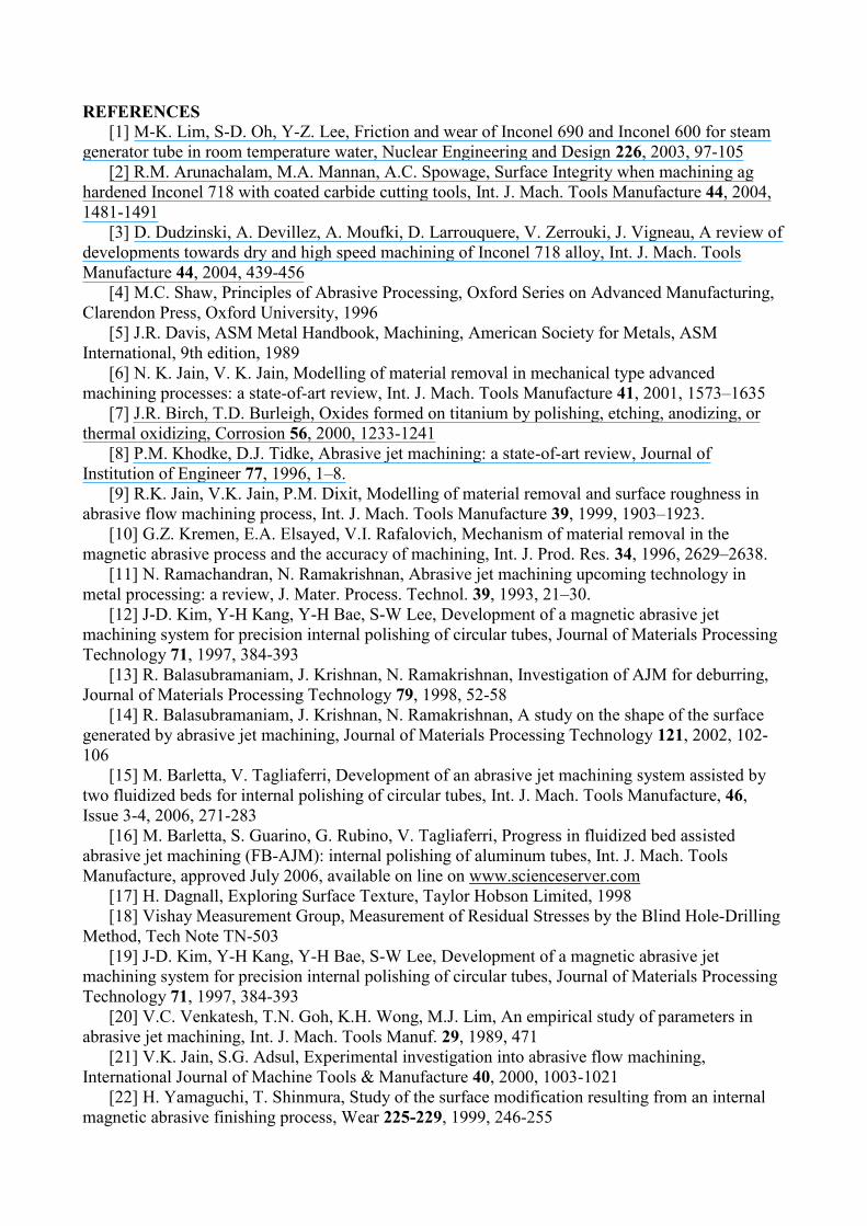
As shown in Figure 2, the roles of the two fluidized beds and annexes in the equipment can be
automatically reversed. Consequently, the abrasive jet flows in the opposite direction, being
supplied into the workpiece from the opposite side, and the outgoing abrasive is then collected in
the first fluidized bed. This ensures the reversibility of the machining process which results in
homogeneous distribution of the machining force of abrasive jet over all the metal surface without
interrupting finishing operations, resulting in further improvement in precision finishing and form
accuracy.
2.2 Materials
Tubular workpieces 100 mm long were cut from a 20 mm diameter six meter long Inconel 718
SPF rod. Following this, each workpiece was drilled, and then machined by internal longitudinal
high speed turning, with the inner diameter being opened to 10 mm.
The media used was angular pink alumina (Al2O3) with mesh size ranging from 24 to 400,
supplied as finely divided powders by Smyris Abrasivi Srl – Italy. The abrasive manufacturer states
hardness of 2300-2500 HV and factor shape of approximately 0.67.
2.3 Experimental plan
Table 2 displays the Taguchi design developed to examine the influence of operational
parameters (i.e. machining pressure, abrasive mesh size, and machining cycle) on the experimental
response ‘surface roughness’ and ‘material removal’. An L18 mixed 3-6 level design was scheduled
using the experimental factors: abrasive mesh size, abrasive jet pressure, and number of machining
cycles. Abrasive jet pressures and machining cycles ranging respectively from 2 to 8 bar and from 2
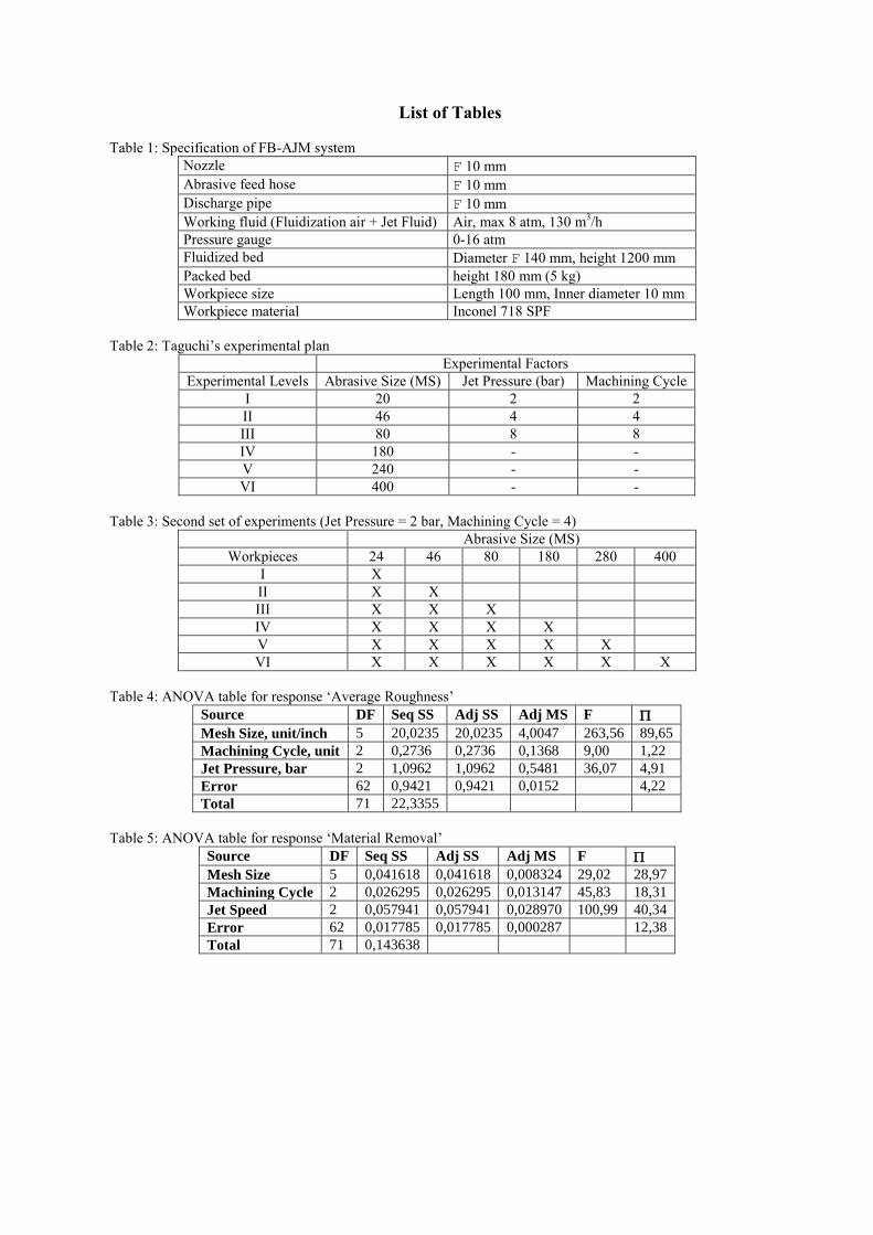
to 8 were investigated. Each machining cycle was composed of the transit of 5 kg of the chosen
abrasive over each side of the workpiece (namely side ‘d’ and ‘r’, Fig. 3). Each machining cycle
lasted from 1 to 4 min depending on the jet pressure and abrasive size choice. The amount of
abrasives passing through the workpieces was checked by measuring the rotation speed of the star
valve at the bottom of each cyclone. Each test was replicated four times to ensure the reliability and
reproduceability of the experimental results. Main Effect Plot (MEP) (that is, a plot of the means at
each level of a factor) was used to report raw response data, i.e. the means of the response variable
for each level of a factor. A main effect was considered to take place when the mean response was
found to change across the levels of a factor. Therefore, main effects plots can also be used to
compare the sizes of the various main effects as well as the relative strength of the effects across
factors.
Using the previous analysis, once the best settings of operational parameters had been defined
(four machining cycles, jet pressure 4 bar), these were then used in the second set of experiments,
where FB-AJM was repeated on workpieces step by step using progressively smaller abrasive sizes,
as reported in Table 3. The evolution of surface morphology of machined workpieces was then
followed by the estimation of material loss, roughness parameters, surface topography, form
accuracy, and residual stress profiles.
2.4 Weighing procedures
Material removal was estimated using a Sartorious Model BP 211-D weighing instrument with a
maximum resolution of 0.01 mg. To minimize any disturbance during tests caused by air currents,
workpieces were enclosed in a box. Two special stainless steel slabs were kept separately as
standard weights and used to calibrate the weighing instrument each time it was used. These
particular procedures meant the scales performed the measurements to the required level of
accuracy and with good reproduceability.
The weighing procedure followed began by taking the initial weight of the workpiece. This
involved initial accurately cleaning of the workpiece under sonification (Soltec model Sonica 2200)
using acetone, and then drying it in a convection oven (Nabertherm model B170) at moderate
temperature (< 60 °C) in a protective atmosphere in order to avoid oxidation. After this, so that the
workpiece weight before and after machining could be compared, the machined surface was cleaned
again under sonification using acetone so as to remove loose abrasives, soiling, and contaminants.
Following this, the workpiece was placed in a dryer at moderate temperature (60 °C) to evacuate
solvent and moisture. As soon as possible after this, weighing was carried out in order to avoid the
influence of any dust or oxidation. The workpiece was left on the electronic scales long enough for
the weight shown on the digital display to stabilize. Each workpiece was measured several times,
and if the difference between the two successive measurements failed to agree within 0.5 mg, the
measurements were repeated until agreement within this range was obtained in successive
determinations.
2.5 Morphological characterization of machined surfaces
To measure the macroscopic evolution of workpieces surface morphology at the different stages
of machining, 3D scanning was performed using the inductive stylus gauge of Taylor Hobson
Surface Topography System (model TalySurf CLI 2000). The first step in the 3D scanning was to
locate the samples under the gauge and view them optically using the high resolution camera built
into the Surface Topography System. This enabled the choice of the measurement area to be made
and the rough loading of the stylus to be carried out. As a result, a number of patterns (2000), each
7 mm long, were recorded for each sample so that a representative area (14 mm2) of the entire
surface structure was covered. Consequently, a lateral resolution of 1 m in both directions was
allowed for during measurement. The surface morphology was then examined using the TalyMap
Software version 3.1. The following were considered as characteristic of coating morphology:
standard amplitude, spacing and hybrid parameters for primary, waviness, and roughness profiles
(Gaussian filter).
The ‘high resolution’ local morphology of the surface was obtained using a field emission gun
scanning electron microscope (FEG-SEM Leo model Supra 35). It was used to take pictures of
workpiece surface at various levels of magnification so as to investigate the microscopic
modifications of the machined surfaces at high resolution.
2.6 Measuring form profiles of machined workpieces
A Taylor Hobson Roundness Measuring Instrument (model Talyrond 265) was used to measure the
form profiles of workpieces at the various stages of machining. For each tubular workpiece, 200
roundness profiles, 1 every ten microns, were collected in order to cover a representative area 20
mm long. Form profiles were measured using the cutoff value of 50 undulations per revolution
(upr), and the form-error of the profile, i.e. cilindricity, was calculated according to the Minimum
Zone Reference Cylinder (MZCY) method [17]. In particular, the MZCY for each sample was
defined as two concentric cylinders positioned to enclose the measured profiles so that their radial
departure is minimal. Therefore, the minimum radial separation of two cylinders coaxial with the
fitted reference axis that totally enclose the measured data was taken as the Cylindricity (CYLt).
2.7 Measuring residual stress profile of machined workpieces
The incremental hole-drilling method was used to measure the residual stress in workpieces at
the various stages of machining, with measurements being taken using a Vishay integrated system
model RS 200. It is composed of (i) a high precision centring stage provided with an optical
microscope and used to locate the holes, (ii) an ultra high-speed air turbine machine (300,000 rpm)
provided with tungsten carbide tools for precision hole-drilling, (iii) three gauges in a rosette to
measure surface strains, and of (iv) a multi-channel amplifier to monitor and store the measured
surface strains. To obtain the profile of the residual stresses, the experimental procedure was
composed of the following steps: (i) tubes cut at an angle of 45°, (ii) the drilling of the hole in steps,
(iii) measurement of the surface strains i(z) for each hole-depth z performed using the three gauges
in the rosette. Once the drilling had been completed, equations [18] were used to calculate the
values of the two principal stresses 1 and 2 by using both the values of i(z) measured and the
correlation coefficients, the latter being estimated according to calibration methods measuring
residual stresses of the Vishay Measurement Group.
3. RESULTS AND DISCUSSION
3.1 The analysis of process parameters: a statistical approach
Figure 4 reports the raw response data for the main effect plots (MEPs) of material removal and
average roughness as determined by all the operational variables. The operational variable ‘mesh
size’ was found to be the most influential factor causing the largest variations in the two
experimental responses ‘material removal’ and ‘average roughness’ across the experimental levels.
In particular, as the depth of cut is related to the main dimension of the abrasive, the greater the
increase in mean diameter of abrasive distribution, the greater the increase in material removal and
the worse the expected values of average roughness. However, both ‘machining cycle’ and ‘jet
pressure’ have a remarkable effect on the response ‘material removal’. On the other hand,
‘machining cycle’ and ‘jet speed’ exert much less significant main effects on the experimental
response ‘average roughness’. In particular, an increase in machining cycle (that is, longer
interaction time between abrasives and surface to be finished) and in jet pressure (that is, stronger
finishing forces acting on the surface to be finished) accelerates wear of the machined substrates,
with the expected values of average roughness mostly remaining unchanged. However, the
minimum for the response average roughness can be noted at jet pressure of 4 bar after 4 machining
cycles.
The results of analysis of variance (ANOVA) support previous experimental findings, and are
summarized in Tables 4 and 5. The values of degrees of freedom DF, Fisher’s factors F, and
contribution percentages are summarized for each operational variable investigated for the
experimental responses ‘material removal’ and ‘average roughness’, respectively. In the case of
average roughness (Table 4), all Fisher’s values were found to be much higher than the
corresponding tabulated Fisher’s values. Nevertheless, examining the percentage of contribution ,
only the experimental factor ‘mesh size’ was found to be a significant influence on the response
‘average roughness’ (around 90 % of contribution) in agreement with the indications provided by
MEP. On the other hand, even though large Fisher’s factors F were calculated, the other two
experimental factors (i.e. jet speed and machining cycle) definitely have a minor influence on
response ‘average roughness’ as their contribution percentages were very low. Finally, the
percentage contribution of factor ‘error’ is very low (less than 5%), confirming the reliability of
the experimental procedure. In agreement with results reported in Figure 4, all experimental factors
relating to material removal (Table 5) were found to be significant, with their Fisher’s values F a
good deal greater than their tabulated corresponding Fisher’s values F. Furthermore, the percentage
of contribution for each experimental factor was quite high, with values ranging from just under
20 to a little more than 40 %. In contrast, the percentage of contribution of factor ‘error’ is quite
low (approximately 10%), therefore showing how good the reliability of the experimental procedure
is.
Some useful indications for the best choice of operational parameters can be deduced from the
MEPs and ANOVA tables. Obtaining fine finishes on the machined surfaces of the Inconel 718
tubular components is strictly dependent on the choice of abrasive mesh size, with jet pressure and
machining cycle playing a minor roles. Nevertheless, material removal is also extremely sensitive to
the choice of jet pressure and machining cycle. In particular, too strong a jet pressure and too
lengthy a machining cycle are undesirable as too large an amount of material is removed from
substrates, which could cause severe problems of dimensional tolerance and form accuracy of the
machined workpieces. At the same time, too low a value of jet pressure and machining cycle is
undesirable as it leads to poor and uneven finishing of the machined surface. However, the
indications cannot be obtained from the proposed statistical approach alone, so it is inadequate for
manufacturers to select the best operational settings. Consequently, further indications were studied
by examining variations in the evolution of the machined workpiece surface morphology in
response to varied machining cycle and jet pressure, while keeping the abrasive mesh size constant.
3.2 The influence of machining cycle and jet pressure: visual appearance, primary profile,
and dimensional tolerances
Further to the indications provided by MEPs and ANOVA, surface morphology was studied by
using the same abrasive (Mesh Size 24), but using a different number of machining cycles (2, 4, and
8 cycles, respectively) and different abrasive jet pressures (2, 4, and 8 bar, respectively) to treat a
sample in three different conditions. The morphologies measured by 3D Profilometry are reported
in Figure 5. Panel a in Figure 5 refers to a workpiece machined at 2 bar as jet pressure for 2
machining cycles. Panel b refers to a workpiece machined at 4 bar jet pressure for 4 machining
cycles. Panel c refers to a workpiece machined at 8 bar jet pressure for 8 machining cycles. Panels
a1 to c1 and a2 to c2 respectively report the raw 3D forms of the portions of the inner surface of
tubular workpieces which were measured before and after finishing. Panels a3 to c3 and a4 to c4
respectively report the 3D morphologies of the areas of the inner surface of the tubular workpieces
which were measured before and after finishing following the form suppression [17]. The raw 3D
maps highlight the progressive improvement of the surface finishing when treated using a larger
number of machining cycles coupled with higher jet pressure.
Interpretation of the 3D maps is improved by examining the starting morphologies of the areas
measured on the tubular workpiece inner surface after the form suppression in Panels a3 to c3, and
comparing this with the same areas after the machining, shown in Panels a4 to c4. In fact, while
setting a larger number of machining cycles or stronger jet pressure does not improve the overall
surface finishing significantly (Ra of 1.80 m in Panel a4, 1.69 m in Panel b4 and 1.74 m in
Panel c4), it does continue to improve the degree of morphological uniformity. In particular, surface
waviness improves quickly until four machining cycles elapse (Wa from 4.01 m in Panel a4 to
1.78 m in Panel b4) and jet pressure is set at 4 bar (Fig. 5 - panel b4), whereupon it improves very
slowly. In fact, if all eight machining cycles are completed and jet pressure is set at its highest value
of 8 bar (Fig. 5 - Panel c4), no significant variation in surface finishing takes place and only minor
modification of surface waviness is evident (Wa of 1.19 m). These considerations explain why the
finishing mechanisms subsequently change from initial selective removal of surface asperities
(peaks) to more uniform removal of material over the entire machined surface with further slight
decreases in asperities, followed by stabilization of surface morphology. Consequently, the overall
form of the finished surface (Fig. 5 - Panels a4 to c4) is completely different from its respective
starting form (Fig.5 - Panels a3 to c3).
There is good agreement between these results and most of the data available in the literature. In
FB-AJM of stainless steel and aluminum tubes, rapid improvement in the average waviness with a
concurrent increase in material removal in the first stages of machining was followed by
stabilization of the finishing process, with progressively slower modifications in the average
waviness and the establishment of a standard amount of material removal per unit of time [15-16].
In both magnetic abrasive jet machining [19] and standard abrasive jet machining [20], surface
finishing quickly approached asymptotic values, and correlated strongly with the settings of
operational variables. Therefore, material removal was very fast in the initial stages of machining,
with this value diminishing significantly when asymptotic conditions were approached [19, 20]. In
both abrasive [21] and magnetic [22] flow machining, average roughness also approached
asymptotic values. Nevertheless, material removal tended to remain constant during all of the
finishing operations involved in flow machining processes [21-22]. This difference in material
removal trends between flow and jet machining processes can probably be ascribed to the dissimilar
finishing mechanisms involved.
In fact, in flow machining material is removed from both the peaks and valleys of the longer
wavelength component of the machined surface, leaving the overall morphology of the surface
machined substantially unchanged and guaranteeing uniform mass loss during the course of the
entire the process [21-24].
Remarkable differences in achievable finishing and shape of tubular workpieces resulting from
the influence of jet pressure and machining cycles are seen in Panels a, b, and c of Figure 5. This is
particularly evident when comparing the evolution of average roughness and material removal in
response to variation in jet pressure and machining cycles. If two machining cycles and jet pressure
of 2 bar are used (Panel a4), the material removal is 0.004273 g/cm (corresponding wear
approximately 2 m) and the arithmetic mean of the absolute departures of the primary profile from
the mean line Pa is 2.8 m. Furthermore, if four machining cycles and jet pressure of 4 bar are used
(Panel b4), a material removal of 0.055692 g/cm (corresponding wear around 20 m) and a Pa of
2.3 m are measured. Finally, if eight machining cycles and jet pressure of 8 bar are used (Panel
c4), a material removal of 0.173556 g/cm and a Pa of 2.2 m are measured. In fact, with jet pressure
set to its highest value (8 bar), too much material is removed with wear being unacceptably high at
more than 65 micron. As a result, even if a slight improvement in primary profile is detected, the
material over-removal due to aggressive strikes from the abrasives caused the machined surface to
deteriorate, and above all, influence the dimensional tolerances of the machined surfaces negatively.
There is also good agreement between these results and the data available in the literature [19,
21-24]. An optimized jet velocity value of 13 m s-1
was found in an analytical study by Kim et al.
[19] in attempting to model a magnetic abrasive jet machining system, and Barletta et al. found a
similar value to be best in FB-AJM of tubular stainless steel parts [15-16]. Jet velocities in these
studies that would have been too fast, that is, too strong a jet pressure, were carefully avoided in
order to achieve the best surface finishing without compromising the form accuracy and the
dimensional tolerances. Moreover, using a self-limiting condition imposed on the abrasive jet
pressure to set the accuracy of theoretical achievable finishing, form precision and dimensional
tolerances has not only already been stressed by one of the authors in a previous study of fluidized
bed machining of complex shaped aluminum components [25] but also in further studies of abrasive
jet machining processes [26-28].
3.3 Analysis of surface morphology
A standard machining condition for Inconel 718 tubular parts using FB-AJM can be easily
deduced by analyzing the results of the statistical approach in addition to the results previously
obtained from morphological and wear analysis. Four machining cycles and jet pressure set at 4 bar
should guarantee the best compromise between performance and accuracy of finishing process,
concurrently minimizing both wear phenomena and operational problems.
Figure 6 reports the evolution of roughness profiles according to abrasive size in standard
machining conditions, that is, 4 machining cycles and a jet pressure of 4 bar. In particular, the first
step of the machining, which is performed using abrasive mesh size 24, reset the starting
topography (from Fig. 6a to 6b) with the initial cutting marks produced by high speed turning
disappearing quickly (see SEM image in Fig. 7a). The result is a macro-scratched surface
topography (Fig. 7b), with the lateral dimension of the scratch (approximately 1 mm) being caused
by the abrasive mesh size as it is this which controls the depth of cut. Moreover, the lack of further
build up of micro-scratches on the slopes of the starting profile (see spot of Fig. 6b in Fig. 6h)
proves that the material is mainly removed from the peaks. The next step involved using abrasives
of smaller size (from 46 to 180 mesh size) that selectively machine the surface asperities and
irregularities of the workpieces, progressively reducing the scratch lateral dimension (from 1 mm to
a few hundred micron) until an almost flat finish is obtained (Figs. 7c to 7e). In addition to this, the
evolution of corresponding surface roughness profiles in Figs. 6c to 6e confirms that the cutting
edges of the abrasive tend to cut the peaks of the surface profiles. The final step involved using the
finest abrasives to make the surface topography an accumulation of micro-scratches (lateral
dimension less than 100 microns) on an almost flat topography (Figs. 7f and 7g). Figs. 6f and 6g
report the corresponding surface profiles, where the smoothed morphologies are clearly visible. It is
worth noting that the smoothest profile in Figure 6g is often interrupted by the presence of several
irregularities. These are more likely to be caused by the presence of abrasive residuals still clinging
on the surface after the machining, which become increasingly evident on such a flat topography.
However, the widespread presence of abrasive residuals standing on the surface after machining are
also seen in the corresponding SEM image reported Figure 7g.
The transformation of surface morphology demonstrated in Figures 6 and 7 can be attributed to
the features of the FB-AJM process. In fact, in agreement with the literature [16, 19, 26-28], the
abrasives in jet machining are lined along the lines of the jet fluid, effectively resulting in abrasive
chains. The abrasive chains machine the surface, removing material and performing the finishing
operation. As the abrasive chain moves through the workpiece at a very high velocity, the abrasive
chains have no time to make their shape follow and suit the shape of surface being machined. As a
result, the chain of abrasives behaves like a solid tool, largely removing and displacing material
from the peaks of the uneven surface, flattening them and generating a roughness profile composed
of shorter wavelength components superimposed on a progressively flatter surface.
Figure 8 displays the trend of a selection of roughness and waviness parameters vs. mesh size in
standard machining conditions, that is, 4 machining cycles and a jet pressure of 4 bar. The trends of
amplitude parameters (i.e. average roughness Ra and ISO 10 point height Rz) are reported in Figure
8 Panels a and b. Experimental data show that smoother finishes can be progressively achieved if
abrasives with a smaller mesh size are used. As a result, average roughness Ra decreased from 1.3-
1.4 m to 0.11-0.14 m and Iso 10 point height Rz decreased from 7-7.5 m to 1-1.5 m, with
deviations around the mean values being very small. Consequently, an ‘improvement ratio’ (i.e.
ratio between starting and final roughness) ranging from 10 to 12 results. Figure 8 also displays the
trend of spacing Rsm vs abrasive mesh size. It was observed that the continuous decrease in spacing
was detected with the use of abrasive with smaller mesh sizes. In fact, the relatively longer
wavelength components of the roughness profile induced onto the surface by high speed turning
(Fig. 6a) shortened during FB-AJM. Consequently, as the roughness profiles and SEM images
reported in Figures 6 and 7 show and the trend in slope Rq in Figure 8 confirms, the final surface is
composed of micro-scratches superimposed on a surface progressively made flat by FB-AJM. The
smaller the abrasive size employed to finish the surface of the workpiece, the smaller the dimension
of the resulting micro-scratches, therefore determining the approach to finer surface finishes.
These results are in good agreement with the data found in the scientific literature. In particular,
they agree with both the roughness trends using FB-AJM on tubular workpieces made from
hardened stainless steel and aluminum studied by Barletta et al. [15], and those found by Kim et al.
[19] using MAJM on SUS 304 circular tubes in which lowering abrasive mesh size produced a
progressive improvement in surface finishing. Average roughness values achieved in these studies
were close to 0.1 m in FB-AJM and 0.2 m in MAJM. Barletta et al. even reported data on
aluminum tubular workpieces with similar trends in roughness parameters and average roughness
values of approximately 0.6 m [16], being the softer aluminum less suited to FB-AJM than the
harder and tougher Inconel 718. On the other hand, comparison with the results obtained by Jain et
al. [21] using AFM on aluminum and brass substrates highlights that using FB-AJM results in better
overall performance. In fact, using AFM and starting from an average roughness of approximately 2
m for aluminum, 0.9 m for brass, and 0.6 for harder materials, Jain et al. obtained an average
roughness very close to 1 m, 0.4 m, and 0.2 m, respectively, with an ‘improvement ratio’ of just
2 on the two softer materials and 3 on the harder one . However, in agreement with what
happened in the experiments in the present study, AFM also always produces peculiar surface
textures (in the form of parallel stripes) after machining or finishing operations [23-24, 29].
3.4 Interaction between abrasive grains and surface
Figure 9 shows progressively higher magnification SEM photographs of machined surface
(standard condition, finest abrasive grains of 400 mesh size). As seen above, due to the high-speed
turning process preceding FB-AJM, the surface presented uneven cutting marks caused by the
aggressive removal of material (Fig. 10). From the first moment of FB-AJM, embedding
phenomena of alumina splinters were observed over the entire machined surface (Fig. 9a).
However, the finishing definitely smoothed the surface thanks to metal displacement caused by the
abrasive jet, which is visible in the cutting marks parallel to the machining direction (Fig. 9b).
The effect of material displacement and the micro-cutting action of abrasive edges is clearly
visible in Figures 9c and 9d, where the small grooves created by abrasive impact and the
consequent build up of adjacent crests can also be seen. At the same time, the micro-cutting action
can be observed (Fig. 9e), with the residual microchips still standing on the surface. Furthermore,
the embedding of abrasive splinters can be clearly seen in Figures 9f and 9g, where larger splinters
of abrasive remained trapped, with a few of them noticeably sticking out from the metal surface.
The surface rapidly reaches saturation with abrasive splinters during the machining. Nevertheless,
in employing a progressively smaller abrasive size, the average size of splinters embedded in the
surface also decreases, and consequently, the result has a more aesthetically pleasing appearance.
Similar results were found in previous studies of fluidized bed machining, which found that the
widespread embedding phenomena of harder abrasive splinters in the softer substrates is a recurring
phenomena (alumina splinters in aluminum and brass substrates [16, 25, 29], copper splinters in
polyamide 6 and 66 substrates [30]).
3.5 Machining uniformity and form accuracy
Figure 11 shows the uniformity of the roughness profile over the entire machined surface. The
trends of average roughness reveal that the surface is uniformly smoothed around the entire internal
circumference, with no significant differences in average roughness between all four locations
investigated (Fig. 3). This is in marked contrast to the experimental findings reported in the
literature for the other abrasive jet machining systems [19, 26-28], where slight deviations from
ideal running of the systems resulted in corresponding unevenness of the surface being machined.
The difference between FB-AJM and the other systems is probably that the distribution of abrasives
across the workpiece section in FB-AJM is uniform and that, as previously stated, it avoids flux
disturbance, peculiar pattern of abrasives on the workpiece, and jet fluid anomalies. This guarantees
uniformity of finishing around the entire internal circumference of the machined tubes.
Figure 12 shows the 3D morphological maps of the unfinished and finished parts for abrasive
with mesh size ranging from 24 to 400, after form suppression. In comparison to the unfinished part
it is apparent that the form profile of the finished part is more fully-rounded out. Figure 13 reports
the trend in cilindricity CYLt according to abrasive grain size. While the unfinished part has a
cilindricity CYLt of 30 m, the finished part measurements can approach cilindricity CYLt values
as low as 10 m. As mentioned above, the mass of abrasives exhibits poor flexibility in its
configuration, and so behaves like a solid tool that moves in the direction of the abrasive jet and so
is unable to follow the overall form of the surface. Since the mass of the abrasives was considerably
greater than the waviness of the profile curve, shown in Figure 12a, it could not trace the relatively
shorter wavelength components of profile curve exactly, that is the roughness profile, nor the longer
wavelength components of profile curve, that is to say, waviness profile. In terms of the relatively
longer wavelength components of the profile curve, even more material was removed from the
projections of the undulations of the profile curve, as is clearly visible in Figures 12b to 12d and
proven by the FFT analysis in Fig. 14. From this, it is apparent how the longer wavelength
components (low frequency components) induced by high speed turning on inner surface of Inconel
718 tubular workpieces (Fig. 14a) tend to disappear progressively, and above all, are reduced in
amplitude after machining by larger sized abrasives (Figs. 14b to 14d). The accumulation of this
cutting action significantly reduces the form-error of the profiles of the finished parts, thus
demonstrating the ability of the FB-AJM process to correct the form-error induced by the
manufacturing processes that precede it (high speed turning). Consequently, in addition to the jet
pressure and machining cycles, which affect the abrasive contact time and the finishing force
against the surface, the form of the finished surface is highly dependent on the abrasive grain size,
which controls the depth of cut.
On the other hand, the changes in cilindricity produced by the smaller sized abrasives used in
the finishing process were hardly significant on the form profiles (abrasive mesh size ranging from
180 to 400 in Fig.13). Finer abrasive grains are only able to produce minor rearrangements of
surface topography of the machined surfaces since they have quite small depth of cut. Therefore,
the smaller abrasives can only cause an accumulation of micro-scratches on the inner surface of
Inconel 718 tubular workpieces previously machined flat by using the larger abrasive grains,
without significantly modifying the form of the machined parts (i.e. CYLt ranging around 10 ± 2.5
m) and only acting on roughness profiles, as already reported above and seen in the corresponding
3D form maps (Figs. 12e to 12g). This result is also seen in the FFT analysis (Figs 14e to 14g),
where new shorter wavelength components (high frequency) with low amplitude are clearly visible.
It is more likely that they can be ascribed to the impact of smaller abrasive grains over the entire
machine surface and they are responsible for inducing the peculiar micro-scratched texture on the
machined surface.
As deduced from the experimental results reported in Figs. 12 to 14, the initial surface contains
a wavelength component with a very large pitch. This component diminishes with FB-AJM
processing, and a relatively shorter wavelength gradually appears. The final surface is composed of
an accumulation of the shorter wavelength micro-scratches, while the longer wavelength component
of the initial surface completely disappears. Consequently, FB-AJM can be considered to belong to
the group of no pressure-copying processes known as standard pressure-copying processes only
able, under constant pressure, to remove irregularities from longer wavelength components of a
surface while not significantly disturbing the longer wavelength features [22]. This result is also
supported macroscopically by further analysis of the changes in the out-of-roundness of tubes
finished by this process. The internal roundness of the tube changed remarkably while the surface
became smoother, hence confirming that FB-AJM is a no pressure-copying process in agreement
with the pertinent literature [31].
3.6 Residual stresses after machining
Figure 15 shows the measurements of residual stress in the unfinished and finished surfaces of
the same tubular workpieces used for the cilindricity tests. After high speed turning, the trends of
peripheral and axial residual stress distribution are quite similar in agreement on what reported in
the pertinent literature [32]. As expected, FB-AJM cycles on the inner surfaces of the Inconel 718
tubular workpieces cause a progressive reduction in stress entity, which agrees with the relevant
literature [33]. The reason for the decrease in residual stress with increase in stock removal is that
the surface is highly affected by high speed turning and once machined by FB-AJM, releases the
surface residual stress. Both the peripheral and axial residual stress distributions after the
completion of FB-AJM finishing shown in Figure 15 are within the typical range and both of them
are not significantly different. The results demonstrate that the proposed process enables control of
surface finishes and has minimal effect on the residual stress of the finished surface.
4. CONCLUSIONS This paper examines the application of a relatively new technology, Fluidized Bed Abrasive Jet
Machining (FB-AJM) to the finishing of the inner surface of tubular workpieces made from a
highly specialized nickel superalloy: Inconel 718 SPF.
Workpieces of long and narrow circular tubes made of Inconel 718 were experimented and the
results lead to the following deductions: (i) the machining capability of the developed FB-AJM
system was verified by the consistent material removal and average roughness trends (MEPs)
agreeing with leading operational variables; (ii) by combining experimental (evolution of raw 3d
morphology) and statistical considerations (ANOM and ANOVA), a standard machining condition
(jet pressure of 4 bar and 4 machining cycles) for effective machining of inner surface of
workpieces was deduced; (iii) from evolution of surface morphology, form accuracy and roundness
of machined surfaces at different settings of operational parameters, FB-AJM was classified as a
no-pressure copying process.
From the analysis of the evolution of surface morphology of the workpieces machined with
progressively lower abrasive mesh sizes, the following results were deduced: (i) improvement in
surface roughness and a sort of asymptotic condition for all the roughness parameters is reached;
(ii) an improvement of average roughness from 1.3-1.4 mm to values as small as 0.11-0.14 mm is
obtained quickly; (iii) a progressively more regular surface morphology is seen in the trends of
spacing and hybrid roughness parameters, whose values increasingly approach more favorable and
asymptotic conditions. These results show that fluidized bed hydrodynamic improves the
characteristics of the jet fluid, and consequently of the abrasive configuration and distribution
throughout the workpiece, leading to better overall finishing results.
A combined analysis of 2D surface profilometry and scanning electron microscopy facilitates
the examination of changes in surface texture at a microscopic level and makes an interpretation of
the material removal mechanism possible. In particular, the following can be deduced: (i) the action
of abrasive cutting edges against the surface both cuts asperities into the surface and displaces
material; (ii) a remarkable embedding phenomena of the harder abrasive splinters into the softer
aluminum matrix is seen; (iii) in agreement with the trend of spacing Rsm, a smoothing of the longer
wavelength components of profiles occurs when a progressively smaller abrasive size is used, with
the resulting surface being an accumulation of abrasive cutting marks (smaller wavelength
components) superimposed on the flattened morphology; (iv) because of the consistent distribution
of abrasive across the section of the workpiece during FB-AJM, good uniformity throughout the
entire circumference of the circular shaped workpiece was obtained; (v) as result of the cutting
capability of the abrasive jet, the cilindricity of the FB-AJM machined workpieces is also improved.
Consequently, the abrasive jet in FB-AJM is not flexible enough to adapt its hydrodynamic shape to
follow the irregularities in the surface being machined, and so essentially removes material from the
sharper peaks and asperities, thereby changing the morphology, and once more showing that FB-
AJM does not belong to pressure-copying finishing processes. Therefore, the process removes
material from the peaks of the uneven surface producing a smooth surface. Furthermore, even more
material is removed from the projections of the undulations of the profile curve. As a result, the
process enables simultaneous control of the surface roughness and form accuracy.
Finally, the experimental results show that the process produces fine surface finishes with
minimal effect on the residual stress in the target surface.
REFERENCES
[1] M-K. Lim, S-D. Oh, Y-Z. Lee, Friction and wear of Inconel 690 and Inconel 600 for steam
generator tube in room temperature water, Nuclear Engineering and Design 226, 2003, 97-105
[2] R.M. Arunachalam, M.A. Mannan, A.C. Spowage, Surface Integrity when machining ag
hardened Inconel 718 with coated carbide cutting tools, Int. J. Mach. Tools Manufacture 44, 2004,
1481-1491
[3] D. Dudzinski, A. Devillez, A. Moufki, D. Larrouquere, V. Zerrouki, J. Vigneau, A review of
developments towards dry and high speed machining of Inconel 718 alloy, Int. J. Mach. Tools
Manufacture 44, 2004, 439-456
[4] M.C. Shaw, Principles of Abrasive Processing, Oxford Series on Advanced Manufacturing,
Clarendon Press, Oxford University, 1996
[5] J.R. Davis, ASM Metal Handbook, Machining, American Society for Metals, ASM
International, 9th edition, 1989
[6] N. K. Jain, V. K. Jain, Modelling of material removal in mechanical type advanced
machining processes: a state-of-art review, Int. J. Mach. Tools Manufacture 41, 2001, 1573–1635
[7] J.R. Birch, T.D. Burleigh, Oxides formed on titanium by polishing, etching, anodizing, or
thermal oxidizing, Corrosion 56, 2000, 1233-1241
[8] P.M. Khodke, D.J. Tidke, Abrasive jet machining: a state-of-art review, Journal of
Institution of Engineer 77, 1996, 1–8.
[9] R.K. Jain, V.K. Jain, P.M. Dixit, Modelling of material removal and surface roughness in
abrasive flow machining process, Int. J. Mach. Tools Manufacture 39, 1999, 1903–1923.
[10] G.Z. Kremen, E.A. Elsayed, V.I. Rafalovich, Mechanism of material removal in the
magnetic abrasive process and the accuracy of machining, Int. J. Prod. Res. 34, 1996, 2629–2638.
[11] N. Ramachandran, N. Ramakrishnan, Abrasive jet machining upcoming technology in
metal processing: a review, J. Mater. Process. Technol. 39, 1993, 21–30.
[12] J-D. Kim, Y-H Kang, Y-H Bae, S-W Lee, Development of a magnetic abrasive jet
machining system for precision internal polishing of circular tubes, Journal of Materials Processing
Technology 71, 1997, 384-393
[13] R. Balasubramaniam, J. Krishnan, N. Ramakrishnan, Investigation of AJM for deburring,
Journal of Materials Processing Technology 79, 1998, 52-58
[14] R. Balasubramaniam, J. Krishnan, N. Ramakrishnan, A study on the shape of the surface
generated by abrasive jet machining, Journal of Materials Processing Technology 121, 2002, 102-
106
[15] M. Barletta, V. Tagliaferri, Development of an abrasive jet machining system assisted by
two fluidized beds for internal polishing of circular tubes, Int. J. Mach. Tools Manufacture, 46,
Issue 3-4, 2006, 271-283
[16] M. Barletta, S. Guarino, G. Rubino, V. Tagliaferri, Progress in fluidized bed assisted
abrasive jet machining (FB-AJM): internal polishing of aluminum tubes, Int. J. Mach. Tools
Manufacture, approved July 2006, available on line on www.scienceserver.com
[17] H. Dagnall, Exploring Surface Texture, Taylor Hobson Limited, 1998
[18] Vishay Measurement Group, Measurement of Residual Stresses by the Blind Hole-Drilling
Method, Tech Note TN-503
[19] J-D. Kim, Y-H Kang, Y-H Bae, S-W Lee, Development of a magnetic abrasive jet
machining system for precision internal polishing of circular tubes, Journal of Materials Processing
Technology 71, 1997, 384-393
[20] V.C. Venkatesh, T.N. Goh, K.H. Wong, M.J. Lim, An empirical study of parameters in
abrasive jet machining, Int. J. Mach. Tools Manuf. 29, 1989, 471
[21] V.K. Jain, S.G. Adsul, Experimental investigation into abrasive flow machining,
International Journal of Machine Tools & Manufacture 40, 2000, 1003-1021
[22] H. Yamaguchi, T. Shinmura, Study of the surface modification resulting from an internal
magnetic abrasive finishing process, Wear 225-229, 1999, 246-255

[23] Zhu J., Grace J.R. and Lim C.J., Tube wear in gas fluidized bed – I. Experimental findings,
Chemical Engineering Science, 45, 1990, 1003-1015
[24] Zhu J., Grace J.R. and Lim C.J., Tube wear in gas fluidized bed – II. Low velocity impact
erosion and semi-empirical model for bubbling and slugging fluidized beds, Chemical Engineering
Science 46, 1991, 1151-1156
[25] M. Barletta, A new technology in surface finishing: fluidized bed machining (FBM) of
aluminium alloys, Journal of Materials Processing Technology, approved September 2005,
available on line on www.scienceserver.com
[26] N. Ramachandran, N. Ramakrishnan, Abrasive jet machining upcoming technology in
metal processing: a review, J. Mater. Process. Technol. 39, 1993, 21–30
[27] R. Balasubramaniam, J. Krishnan, N. Ramakrishnan, Investigation of AJM for deburring,
Journal of Materials Processing Technology 79, 1998, 52-58
[28] R. Balasubramaniam, J. Krishnan, N. Ramakrishnan, A study on the shape of the surface
generated by abrasive jet machining, Journal of Materials Processing Technology 121, 2002, 102-
106
[29] M. Barletta, G. Costanza, R. Polini, Al2O3 thin coating of AA 6082 T6 components using
a fast regime fluidized bed, Thin Solid Films, approved November 2005, available on line on
www.scienceserver.com
[30] M. Barletta, A. Gisario, V. Tagliaferri, Electrostatic spray deposition (ESD) of polymeric
powders on thermoplastic (PA66) substrate, Surface and Coatings Technology, approved November
2005, available on line on www.scienceserver.com
[31] H. Yamaguchi, T. Shinmura, J. Jpn. Soc. Prec. Eng. 62 11 1996 1617–1921, in Japanese.
[32] A.B. Sadat, M.Y. Reddy, Surface Integrity of Inconel-718 Nickel-base superalloy using
controlled and natural contact length tools, Experimental Mechanics 33, 1993, 343-348
[33] H. Yamaguchi, T. Shinmura, Internal finishing process for alumina ceramic components by
a magnetic field assisted finishing process, Precision Engineering 28 (2004) 135–142
181–184.
List of Tables
Table 1: Specification of FB-AJM system
Nozzle F 10 mm
Abrasive feed hose F 10 mm
Discharge pipe F 10 mm
Working fluid (Fluidization air + Jet Fluid) Air, max 8 atm, 130 m3/h
Pressure gauge 0-16 atm
Fluidized bed Diameter F 140 mm, height 1200 mm
Packed bed height 180 mm (5 kg)
Workpiece size Length 100 mm, Inner diameter 10 mm
Workpiece material Inconel 718 SPF
Table 2: Taguchi’s experimental plan
Experimental Factors
Experimental Levels Abrasive Size (MS) Jet Pressure (bar) Machining Cycle
I 20 2 2
II 46 4 4
III 80 8 8
IV 180 - -
V 240 - -
VI 400 - -
Table 3: Second set of experiments (Jet Pressure = 2 bar, Machining Cycle = 4)
Abrasive Size (MS)
Workpieces 24 46 80 180 280 400
I X
II X X
III X X X
IV X X X X
V X X X X X
VI X X X X X X
Table 4: ANOVA table for response ‘Average Roughness’
Source DF Seq SS Adj SS Adj MS F
Mesh Size, unit/inch 5 20,0235 20,0235 4,0047 263,56 89,65
Machining Cycle, unit 2 0,2736 0,2736 0,1368 9,00 1,22
Jet Pressure, bar 2 1,0962 1,0962 0,5481 36,07 4,91
Error 62 0,9421 0,9421 0,0152 4,22
Total 71 22,3355
Table 5: ANOVA table for response ‘Material Removal’
Source DF Seq SS Adj SS Adj MS F
Mesh Size 5 0,041618 0,041618 0,008324 29,02 28,97
Machining Cycle 2 0,026295 0,026295 0,013147 45,83 18,31
Jet Speed 2 0,057941 0,057941 0,028970 100,99 40,34
Error 62 0,017785 0,017785 0,000287 12,38
Total 71 0,143638
List of Figures
Figure 1. The fluidized bed assisted abrasive jet machining (FB-AJM) system.
Figure 2. Reversibility of machining system in FB-AJM.
Figure 3. Evaluation of macroscopic 3D surface morphology.
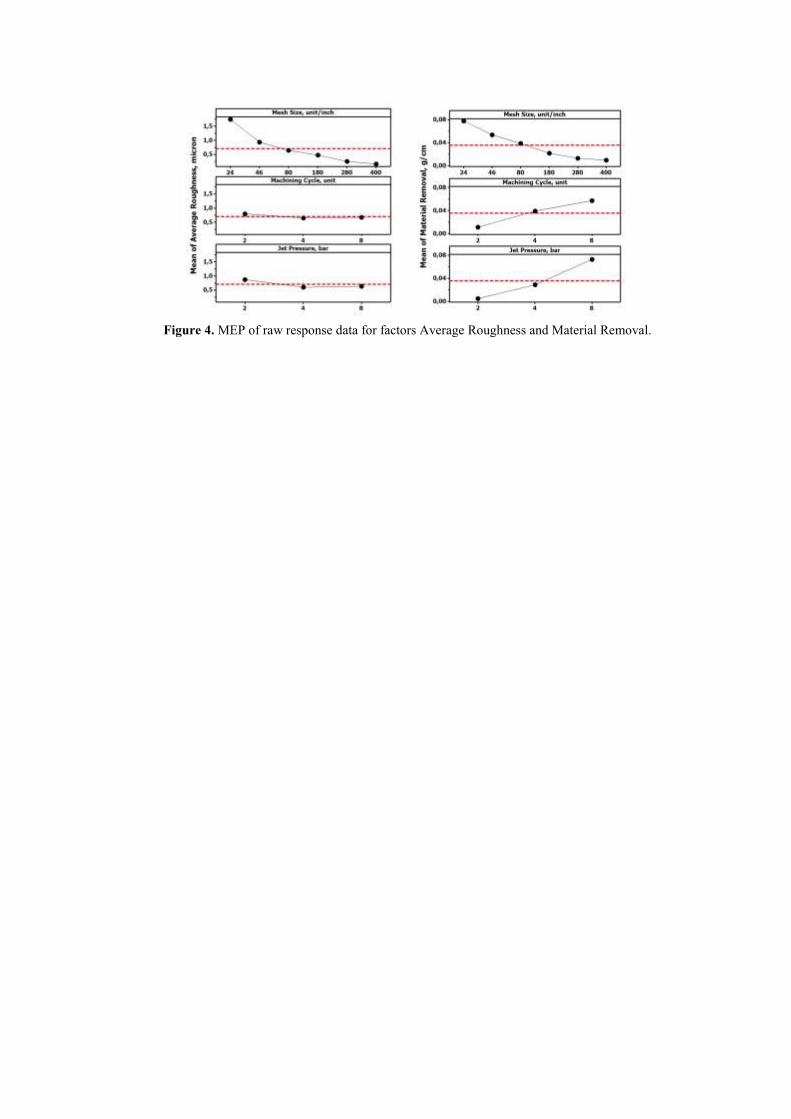
Figure 4. MEP of raw response data for factors Average Roughness and Material Removal.
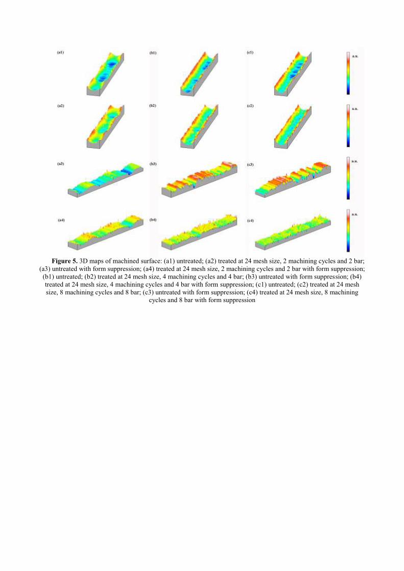
Figure 5. 3D maps of machined surface: (a1) untreated; (a2) treated at 24 mesh size, 2 machining cycles and 2 bar;
(a3) untreated with form suppression; (a4) treated at 24 mesh size, 2 machining cycles and 2 bar with form suppression;
(b1) untreated; (b2) treated at 24 mesh size, 4 machining cycles and 4 bar; (b3) untreated with form suppression; (b4)
treated at 24 mesh size, 4 machining cycles and 4 bar with form suppression; (c1) untreated; (c2) treated at 24 mesh
size, 8 machining cycles and 8 bar; (c3) untreated with form suppression; (c4) treated at 24 mesh size, 8 machining
cycles and 8 bar with form suppression
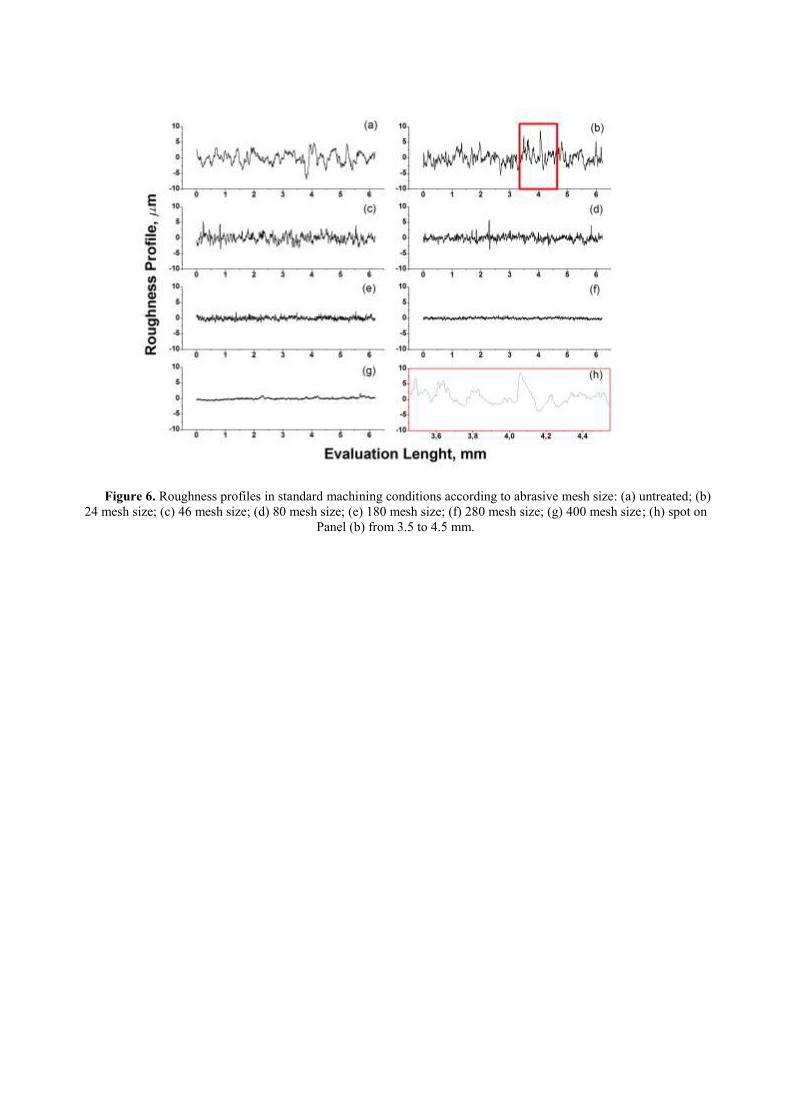
Figure 6. Roughness profiles in standard machining conditions according to abrasive mesh size: (a) untreated; (b)
24 mesh size; (c) 46 mesh size; (d) 80 mesh size; (e) 180 mesh size; (f) 280 mesh size; (g) 400 mesh size; (h) spot on
Panel (b) from 3.5 to 4.5 mm.

Figure 7. SEM images in standard machining conditions according to abrasive mesh size: (a) untreated; (b) 24
mesh size; (c) 46 mesh size; (d) 80 mesh size; (e) 180 mesh size; (f) 280 mesh size; (g) 400 mesh size
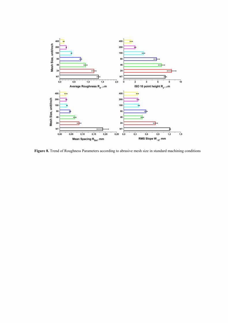
Figure 8. Trend of Roughness Parameters according to abrasive mesh size in standard machining conditions
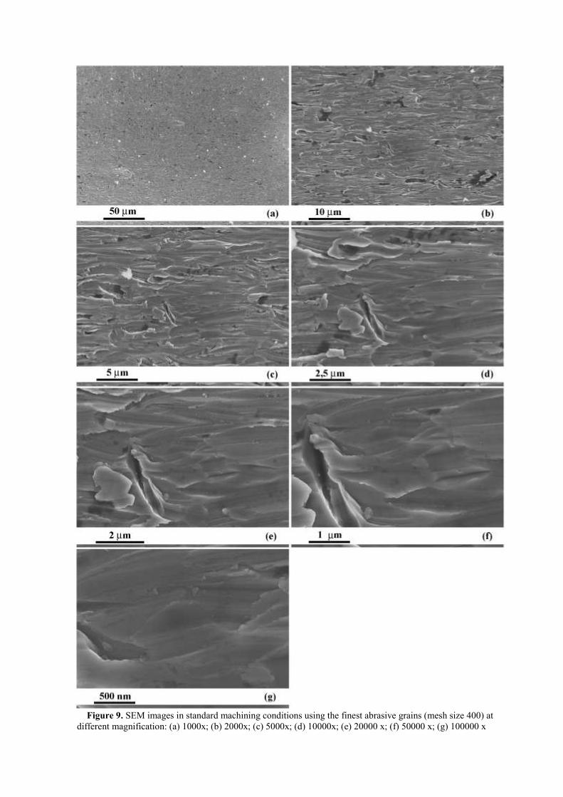
Figure 9. SEM images in standard machining conditions using the finest abrasive grains (mesh size 400) at
different magnification: (a) 1000x; (b) 2000x; (c) 5000x; (d) 10000x; (e) 20000 x; (f) 50000 x; (g) 100000 x
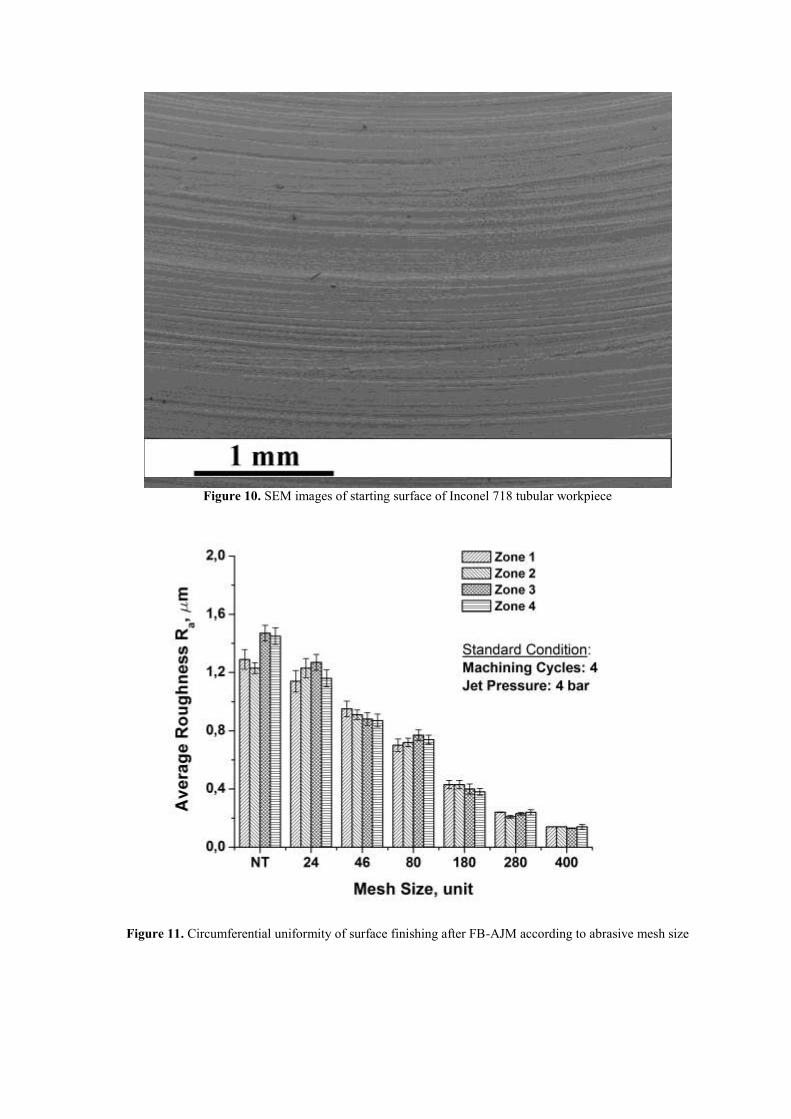
Figure 10. SEM images of starting surface of Inconel 718 tubular workpiece
Figure 11. Circumferential uniformity of surface finishing after FB-AJM according to abrasive mesh size
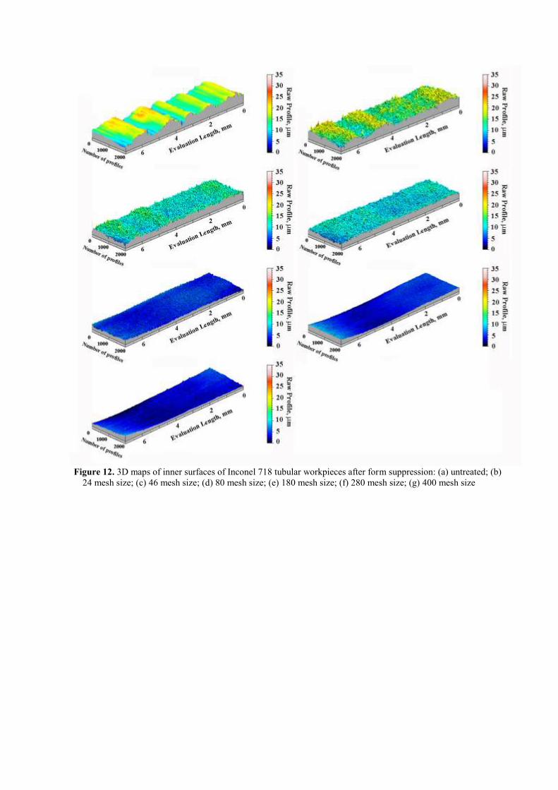
Figure 12. 3D maps of inner surfaces of Inconel 718 tubular workpieces after form suppression: (a) untreated; (b)
24 mesh size; (c) 46 mesh size; (d) 80 mesh size; (e) 180 mesh size; (f) 280 mesh size; (g) 400 mesh size
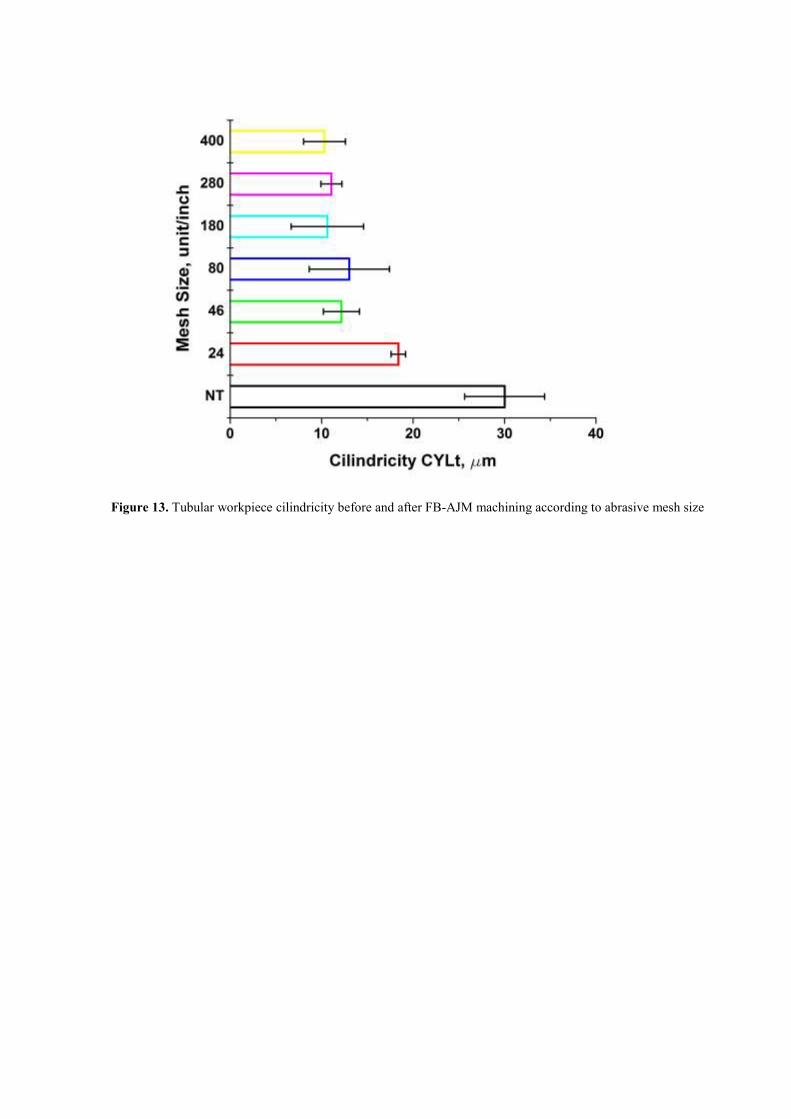
Figure 13. Tubular workpiece cilindricity before and after FB-AJM machining according to abrasive mesh size
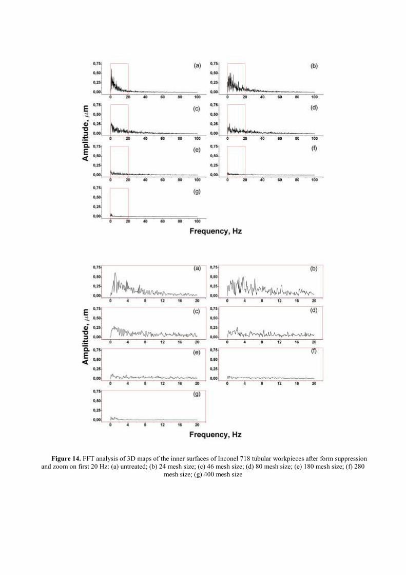
Figure 14. FFT analysis of 3D maps of the inner surfaces of Inconel 718 tubular workpieces after form suppression
and zoom on first 20 Hz: (a) untreated; (b) 24 mesh size; (c) 46 mesh size; (d) 80 mesh size; (e) 180 mesh size; (f) 280
mesh size; (g) 400 mesh size
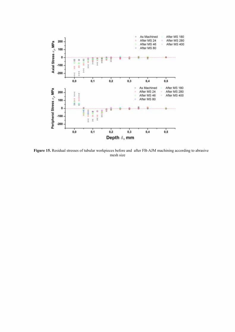
Figure 15. Residual stresses of tubular workpieces before and after FB-AJM machining according to abrasive
mesh size