cutting of aluminium alloy with abrasive water jet and cryogenic assisted abrasive water jet: a...
TRANSCRIPT

Wear 362-363 (2016) 18–32
Contents lists available at ScienceDirect
Wear
http://d0043-16
n CorrE-m
pradeep
journal homepage: www.elsevier.com/locate/wear
Cutting of aluminium alloy with abrasive water jet and cryogenicassisted abrasive water jet: A comparative study of the surfaceintegrity approach
N. Yuvaraj n, M. Pradeep KumarDepartment of Mechanical Engineering, College of Engineering Guindy, Anna University, Chennai 25, Tamilnadu, India
a r t i c l e i n f o
Article history:Received 12 February 2016Received in revised form7 May 2016Accepted 9 May 2016Available online 13 May 2016
Keywords:AWJCAAWJSurface integrityImpingement angleMesh size
x.doi.org/10.1016/j.wear.2016.05.00848/& 2016 Elsevier B.V. All rights reserved.
esponding author.ail addresses: [email protected] (N. [email protected] (M.P. Kumar).
a b s t r a c t
Cryogenic assisted machining is a recent machining technique, which is used for producing definitecomponents with a satisfactory surface condition. In the present work, surface integrity studies havebeen carried out on the abrasive water jet (AWJ), and cryogenic assisted abrasive water jet (CAAWJ)cutting of AA5083-H32 aluminium alloy by varying the jet impingement angles and abrasive mesh sizes.Micrographs, surface morphology, 3D surface topography, 2D roughness profile, XRD peak analysis,surface residual stress and micro-hardness have been characterized in the AWJ, and CAAWJ cut surfaces.Of the two cutting conditions, the CAAWJ cutting process enhances the functional performance of the cutsurfaces, leaving no traces of severe wear tracks, while obtaining a uniform roughness profile pattern,higher surface compressive residual stress and hardening. The results indicate the effect of variations inthe jet impingement angles, and the abrasive mesh sizes contributing a satisfactory surface condition,existing in CAAWJ by the Liquid Nitrogen jet.
& 2016 Elsevier B.V. All rights reserved.
1. Introduction
Surface integrity is one of the major selection criteria in anymachined product, as it determines the type of manufacturingprocess that has been applied to the target material. It is defined asa modification of the material condition after the impact of themanufacturing processes. This alteration of the material includesthe surface and subsurface alterations of the machined workmaterial. Fig. 1 shows some of the possible surface and subsurfacealterations grouped by a major mode of energy applied in themachining processes. These are drawn from Davim [1], who pro-vides a comprehensive study of the surface integrity in themachining processes. Such alterations are produced by variousforms of energy applied to the work material, such as mechanical,thermal, chemical and electrical energy. These cause alterations inthe layer of the machined surface. Such altered layers have anadverse effect on the elements of surface integrity, namely, microand macro cracks, microstructure alteration, hardness variation,residual stresses, heat affected zone, metallurgical transforma-tions, recrystallization, and intergranular attacks. They also affect
raj),
the functional performance of the machined products such asfatigue life, strength, corrosion resistance, etc.
The functional performance of the machined components canbe improved by increasing the compressive residual stress andmicro-hardness in the machined surface. These results are repor-ted by M'Saoubi et al. [2], and, later, experimental and theoreticalinvestigations by Jawahir et al. [3]. Such results have also beendemonstrated by Pusaveca et al. [4], who noted increases in thehardness, compressive residual stress, and surface quality of themachined parts through the use of cryogenics in the machining ofa nickel based alloy. Review studies on cryogenic machining-induced surface integrity have been reported by Kaynak et al. [5]later. Hence, surface integrity is the common selection criterion inthe manufacturing processes.
Aluminium–Magnesium alloys (AA 5xxx series) are widelyused in marine, automotive, and other structural applications. Ingeneral, the machining of these aluminium alloys by manu-facturing processes is quite difficult compared to other alloys, as itis a work hardened alloy, offering poor machinability and surfaceintegrity. Despite the machining done by conventional andunconventional machining processes, it leads to severe alterationsin the machined surface layer. These alterations fall within therange of surface integrity, such as the heat affected zone, forma-tion of residual stresses in the subsurface, dimensional inaccuracy,tool wear, poor surface finish, built-up edge formation, formationof cracks, and changes in strength and hardness as revealed by

Fig. 1. Causes and effects of surface and subsurface alterations.
N. Yuvaraj, M.P. Kumar / Wear 362-363 (2016) 18–32 19
Totten and Mackenzie [6]. Researchers prefer the AWJ machiningprocess, considering the superior quality of the machined surfaceobtained by this process compared to the other machining pro-cesses. Its advantages include the offer of a smaller heat affectedzone, lower stress acting on the target material, no significantchanges in the properties of the materials, etc. More detailedadvantages of the AWJ machining centre have been mentioned byFolkes [7] who has made a comprehensive study of AWJoperations.
In AWJ cutting, the material is removed by the erosion process,wherein hard abrasive particles are suspended in a high velocity ofthe water jet stream, which, in turn, increases the acceleration ofthe abrasive particles, and their kinetic energy impingementtowards the target material, causing material removal. This hasbeen reviewed by Momber and Kovacevic [8]. The erosion processfor ductile materials occurs through the cutting and deformationwear modes, as discussed by Hashish [9]. The cause and effectdiagram shows that the energy sources, such as thermal andelectrical, do not produce any adverse effect on the AWJ cuttingprocess. The AWJ machined surface is usually altered throughmechanical and chemical alterations on the target material.Alterations include the deformation effect, striation formation,abrasive contamination, intergranular attack, hardnessvariation, etc.
Some researchers have investigated surface integrity on thewater jet, and AWJ machined materials. The details are brieflypresented below. Boud et al. [10] have made studies on the surfaceintegrity of AA 7075 aluminium alloy by the impact of the plainwater jet cutting process. The results indicate improvement in thefatigue life of the aluminium alloy, caused by the generation ofcompressive residual stress induced by a plain water jet. Zhao andGuo [11] report, smooth AWJ cut surfaces being obtained on thehard materials, and the soft materials cut surfaces having severewear tracks. Sadasivam et al. [12] introduced the abrasive water jetpeening on the hard materials such as titanium and nickel. Theyfound an increase in the compressive residual stress through anincrease in the jet pressure, and the abrasive particle size. Kuna-porn et al. [13] have studied the surface integrity of the AA6061-T6aluminium alloy through the use of the various profiles of waterjet formation, such as fuzzy jet, fan jet and round jet. Theyobserved the production of a better surface integrity by a fuzzy jet,when a lower water jet pressure and a traverse rate are employed.Jegaraj and Babu [14] have studied the surface topography ofmachined AA6063 – T6 aluminium alloy by varying the ratio of theorifice to the focusing nozzle diameter in AWJ. The results indicatethe effect of increasing the orifice and the focussing nozzle dia-meter does not degrade the quality of the cut surface that much.
Akkurt et al. [15] have studied the various roughness parameterson different AWJ machined materials such as aluminium andAA6061 aluminium alloy, AISI 1030 and 304 steels, brass by adifferent traverse rate and thickness of the materials. Selvan et al.[16] have investigated the surface roughness of the AWJ machinedaluminium by varying the level of the water jet pressure, abrasivemass flow rate, traverse rate and stand-off distance. They foundthe water jet pressure and abrasive mass flow rate directly pro-portional to the surface roughness.
Kovacevic [17] has studied the surface texture in the AWJ cut-ting of AISI 304 stainless steel by scanning electron microscopeimages. The results indicate the top cutting region being char-acterized by a smooth texture and the bottom cutting region by arough texture, due to the formation of striations at the exit of thework material. Chen et al. [18] have investigated the causes ofstriation formation in the AWJ cut surfaces, and found the for-mation of striations arising out of the wavy distribution of abrasiveparticle energy and external effects. Hlavac et al. [19,20] havefound that the tilting of the cutting head from the jet impingementangle of 90° improves the quality of the kerf wall cut surfacesthrough a reduction in the jet retardation. The formation ofstriation is found to be based on the target material type and thelimit of the traverse rate used. Arola et al. [21] have studied thesurface texture and residual stresses on the plain water jet, and theAWJ surface treatment on titanium. They observed the AWJ sur-face treatment inducing high compressive residual stress and alsoproducing a rough surface over the plain water jet. The findings ofthe investigation done by Arola and Ramulu [22] indicate theinfluence of material properties on surface integrity as resultingfrom the AWJ cutting of different work materials, such as Al 7075-T6, Molybdenum, Ti-6Al-4V, Monel 400, and AISI 304 stainlesssteel. They found the occurrence of subsurface deformation on theAWJ cutting of metals. This happened due to the strain hardeningof the metals, and the jet impingement angles. The investigation ofprevious researchers on surface integrity studies of the AWJ cut-ting metals has been limited to the surface topography of the AWJcut surfaces and the compressive residual stress by the AWJpeening operations.
Recently, researchers have developed machining processeswith the assistance of liquids at very low temperatures, such ascryogenics, for the improvement of process performance andsurface integrity. Cryogenic machining processes increasemachinability, by enhancing the material properties through theuse of very low temperature cryogenic liquids. This is illustrated byRavi and Kumar [23]. Among the low temperature cryogenicliquids, liquid nitrogen (LN2) is environmentally safe for machiningoperations, as its disposal is easy with a small expansion ratio to
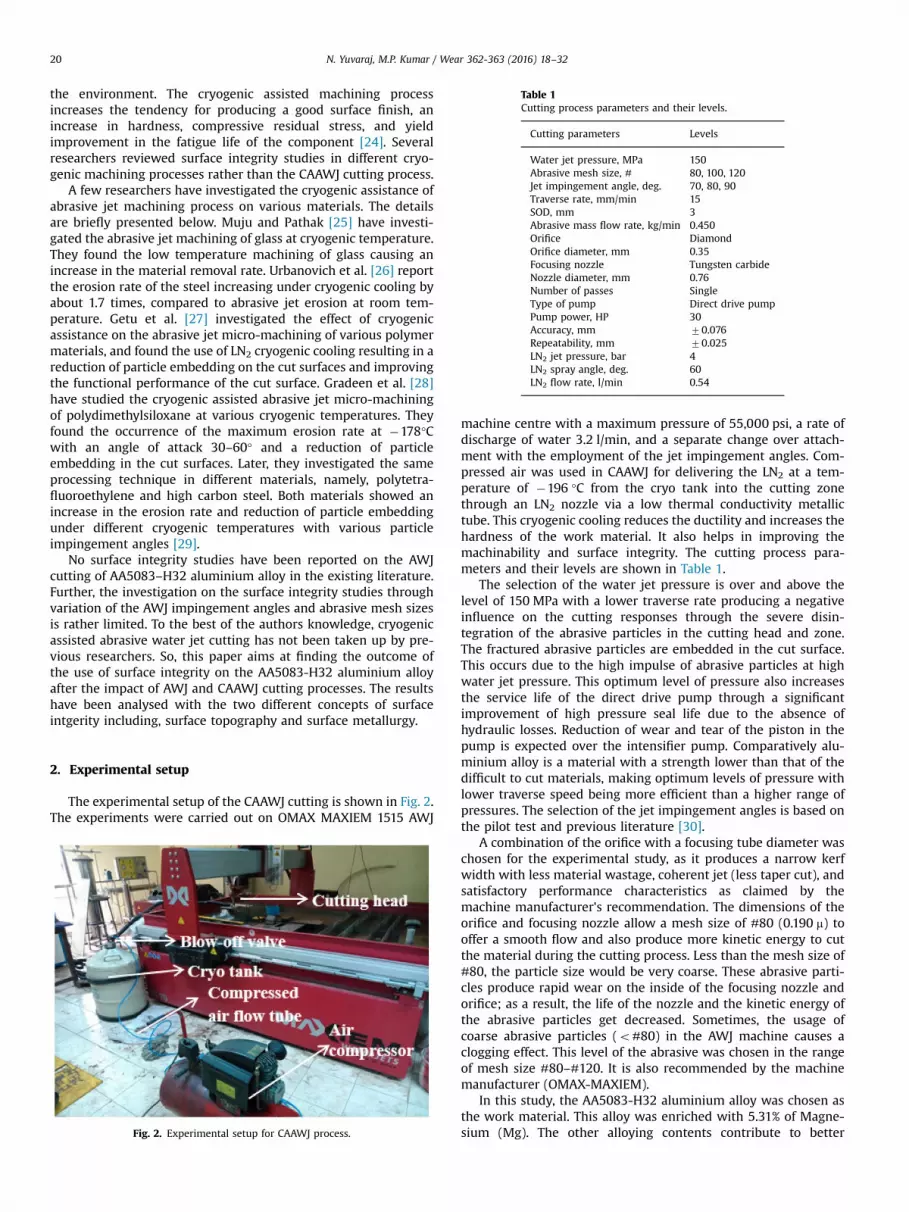
Table 1Cutting process parameters and their levels.
Cutting parameters Levels
Water jet pressure, MPa 150Abrasive mesh size, # 80, 100, 120Jet impingement angle, deg. 70, 80, 90Traverse rate, mm/min 15SOD, mm 3Abrasive mass flow rate, kg/min 0.450Orifice DiamondOrifice diameter, mm 0.35Focusing nozzle Tungsten carbideNozzle diameter, mm 0.76Number of passes SingleType of pump Direct drive pumpPump power, HP 30Accuracy, mm 70.076Repeatability, mm 70.025LN2 jet pressure, bar 4LN2 spray angle, deg. 60LN2 flow rate, l/min 0.54
N. Yuvaraj, M.P. Kumar / Wear 362-363 (2016) 18–3220
the environment. The cryogenic assisted machining processincreases the tendency for producing a good surface finish, anincrease in hardness, compressive residual stress, and yieldimprovement in the fatigue life of the component [24]. Severalresearchers reviewed surface integrity studies in different cryo-genic machining processes rather than the CAAWJ cutting process.
A few researchers have investigated the cryogenic assistance ofabrasive jet machining process on various materials. The detailsare briefly presented below. Muju and Pathak [25] have investi-gated the abrasive jet machining of glass at cryogenic temperature.They found the low temperature machining of glass causing anincrease in the material removal rate. Urbanovich et al. [26] reportthe erosion rate of the steel increasing under cryogenic cooling byabout 1.7 times, compared to abrasive jet erosion at room tem-perature. Getu et al. [27] investigated the effect of cryogenicassistance on the abrasive jet micro-machining of various polymermaterials, and found the use of LN2 cryogenic cooling resulting in areduction of particle embedding on the cut surfaces and improvingthe functional performance of the cut surface. Gradeen et al. [28]have studied the cryogenic assisted abrasive jet micro-machiningof polydimethylsiloxane at various cryogenic temperatures. Theyfound the occurrence of the maximum erosion rate at �178°Cwith an angle of attack 30–60° and a reduction of particleembedding in the cut surfaces. Later, they investigated the sameprocessing technique in different materials, namely, polytetra-fluoroethylene and high carbon steel. Both materials showed anincrease in the erosion rate and reduction of particle embeddingunder different cryogenic temperatures with various particleimpingement angles [29].
No surface integrity studies have been reported on the AWJcutting of AA5083–H32 aluminium alloy in the existing literature.Further, the investigation on the surface integrity studies throughvariation of the AWJ impingement angles and abrasive mesh sizesis rather limited. To the best of the authors knowledge, cryogenicassisted abrasive water jet cutting has not been taken up by pre-vious researchers. So, this paper aims at finding the outcome ofthe use of surface integrity on the AA5083-H32 aluminium alloyafter the impact of AWJ and CAAWJ cutting processes. The resultshave been analysed with the two different concepts of surfaceintgerity including, surface topography and surface metallurgy.
2. Experimental setup
The experimental setup of the CAAWJ cutting is shown in Fig. 2.The experiments were carried out on OMAX MAXIEM 1515 AWJ
Fig. 2. Experimental setup for CAAWJ process.
machine centre with a maximum pressure of 55,000 psi, a rate ofdischarge of water 3.2 l/min, and a separate change over attach-ment with the employment of the jet impingement angles. Com-pressed air was used in CAAWJ for delivering the LN2 at a tem-perature of �196 °C from the cryo tank into the cutting zonethrough an LN2 nozzle via a low thermal conductivity metallictube. This cryogenic cooling reduces the ductility and increases thehardness of the work material. It also helps in improving themachinability and surface integrity. The cutting process para-meters and their levels are shown in Table 1.
The selection of the water jet pressure is over and above thelevel of 150 MPa with a lower traverse rate producing a negativeinfluence on the cutting responses through the severe disin-tegration of the abrasive particles in the cutting head and zone.The fractured abrasive particles are embedded in the cut surface.This occurs due to the high impulse of abrasive particles at highwater jet pressure. This optimum level of pressure also increasesthe service life of the direct drive pump through a significantimprovement of high pressure seal life due to the absence ofhydraulic losses. Reduction of wear and tear of the piston in thepump is expected over the intensifier pump. Comparatively alu-minium alloy is a material with a strength lower than that of thedifficult to cut materials, making optimum levels of pressure withlower traverse speed being more efficient than a higher range ofpressures. The selection of the jet impingement angles is based onthe pilot test and previous literature [30].
A combination of the orifice with a focusing tube diameter waschosen for the experimental study, as it produces a narrow kerfwidth with less material wastage, coherent jet (less taper cut), andsatisfactory performance characteristics as claimed by themachine manufacturer's recommendation. The dimensions of theorifice and focusing nozzle allow a mesh size of #80 (0.190 m) tooffer a smooth flow and also produce more kinetic energy to cutthe material during the cutting process. Less than the mesh size of#80, the particle size would be very coarse. These abrasive parti-cles produce rapid wear on the inside of the focusing nozzle andorifice; as a result, the life of the nozzle and the kinetic energy ofthe abrasive particles get decreased. Sometimes, the usage ofcoarse abrasive particles (o#80) in the AWJ machine causes aclogging effect. This level of the abrasive was chosen in the rangeof mesh size #80–#120. It is also recommended by the machinemanufacturer (OMAX-MAXIEM).
In this study, the AA5083-H32 aluminium alloy was chosen asthe work material. This alloy was enriched with 5.31% of Magne-sium (Mg). The other alloying contents contribute to better

Fig. 3. SEM and EDS analysis of the base material (a) SE image (b) composition of chemical elements (c) EDS spectra.
Table 2Chemical element composition of garnet abrasives with different mesh sizes.
Element % of composition
#80 #100 #120
SiO2 35.46 36.30 34.84Al2O3 21.02 19.80 20.34Fe2O3 30.88 27.90 30.28MgO 6.34 6.80 6.65CaO 1.20 2.80 1.35TiO2 1.90 1.30 5.08
Fig. 4. Trapezoidal shaped AA5083-H32 aluminium alloy.
N. Yuvaraj, M.P. Kumar / Wear 362-363 (2016) 18–32 21
corrosion resistance and strength. A scanning electron microscope(SEM) with energy dispersive spectrometer (EDS) used for theelemental analysis of the base material, is presented in Fig. 3. Inthis study, garnet abrasive was chosen for the experimental work.The chemical elemental composition is shown in Table 2. For
geometric analysis, the work material was made into a trapezoidalshape with a maximum thickness of 64.065 mm. This modifiedshape of the work material was considered for the surface integ-rity studies in the AWJ, and the CAAWJ cut surfaces under differentcutting parameter combinations. The details are shown in Fig. 4,where θ¼angle of inclination, AB¼ Jet penetration distance, andL¼Depth of penetration. The following phases indicate the eva-luation of the surface integrity in the cut surfaces. The measure-ments were carried out on the top kerf wall cut surfaces.
2.1. Surface topography
It consists of the geometric characteristics of the external cutsurface, such as surface texture, surface roughness, surface mor-phology and visual examination. The following characterizationtechniques constitute the evaluation of the surface topography ofthe AWJ and CAAWJ cut surfaces.
2.1.1. Visual examinationThis examination helps the determination of surface defects,
such as cracks and wear tracks. It was carried out through lightmicroscopy with the magnification of 400� .
2.1.2. Surface morphologyIt reveals the qualitative evaluation of the AWJ and CAAWJ cut
surfaces. This technique provides a high spatial resolution ofimaging. The elemental composition was done by a sophisticatedmicroscope using Field emission scanning electron microscopy(FESEM) with the Energy dispersive X-ray spectroscopy (EDS)analysis. The analysis was carried out under a secondary electronmode with an acceleration voltage of 10 kV and 15 kV.
An EDS analysis was used for studying the contamination of theAWJ and CAAWJ cut surfaces through a number of Silicon (Si)particles present in the kerf wall cutting surfaces under different

N. Yuvaraj, M.P. Kumar / Wear 362-363 (2016) 18–3222
cutting conditions. “Si” is the only element not present in thecomposition of the AA5083-H32 aluminium alloy. It is used forvalidation of the particle contamination at the AWJ and CAAWJ cutsurfaces.
2.1.3. Surface textureThe surface texture measures the fine irregularities, such as
peaks and valleys, produced on the cut surface by the AWJ andCAAWJ cutting process. It was characterized through 2D and 3Dsurface profiles obtained by Tally-Surf CCI profilometry equipmentwith a magnification of 10� and a focusing area of 3250 mm.
Fig. 5. Micrographs of AWJ and CAAWJ at different cutting conditions. (a) P:150 MP(d) P:150 MPa MS: #100 IA:80°. (e) P:150 MPa MS: #100 IA:90°. (f) P:150 MPa MS: #12
2.2. Surface metallurgy
Surface metallurgy is defined as an altered zone of the cutmaterial after impact on the cut surfaces by the energy of the AWJand CAAWJ. This altered zone was produced by a mechanical andchemical action of the machining processes and evaluated by theuse of the techniques detailed below.
2.2.1. Microstructure examinationThe microstructure of the cut surfaces was obtained through
the use of an optical microscope with a magnification of 100� .
a MS: #80 IA:70°. (b) P:150 MPaMS: #80 IA:80°. (c) P:150 MPa MS: #80 IA:90°.0 IA:70°. (g) P:150 MPa MS: #120 IA:90°.
N. Yuvaraj, M.P. Kumar / Wear 362-363 (2016) 18–32 23
Prior to this, the cut surfaces were made to undergo polishing,followed by an etching operation, in which Kellers reagent wasused as an etchant. The etchant is a 1% HF solution. The cut sur-faces were immersed in the etchant for less than 2 min.
2.2.2. XRD peak analysisIt is used for the study of the metallurgical changes in the AWJ
and CAAWJ cut surfaces. Rigaku X-ray diffractometer miniflex II-Cwas used for obtaining the XRD peaks at a scanning rate of 0.02°/min, with the employment of a wavelength of 1.5406 A°.
2.2.3. Residual stress measurementIt is the most important factor among all elements in surface
integrity, as it directly affects the functional performance of the cutsurfaces. The X-ray diffraction (XRD) technique was employed forthe measurement of the residual stresses, i.e. tensile or compres-sive in the cut surface layer of the AWJ and the CAAWJ at surfacelevels. The residual stress was obtained by the graphical plot of ‘d’spacing of the crystallographic planes vs sin2ψ values. In thisanalysis, ‘d’ spacing was measured by using the Bragg's law(nλ¼2dSinθ) and 2θ was measured from the XRD peaks.
2.2.4. Microhardness testA Wolpert-micro Vickers hardness tester was used for the
analysis of the hardness of the cut surfaces with a load of 100 gand dwell time of 10 s. This micro-hardness tester consists of aright angle pyramid diamond indenter with an angle of 136°between the faces opposite to each other.
3. Results and discussion
3.1. Visual examination
Fig. 5 shows the photomicrographs of AWJ and CAAWJ cutsurfaces under different cutting conditions. In this study, completephotomicrographs were taken with the magnification of 400�using light microscopy. The images were taken at 2 mm from thetop of the AWJ and CAAWJ cut surfaces. Wear traces were iden-tified in the photomicrographs as bright and shown by thereflectivity of the light from the microscopy. Blur formation(Fig. 5b and f) could have happened somewhere in the cuttingregion. This was the configuration of the microscopy system. TheCAAWJ photomicrographs show no visible wear tracks. Also, nocracks present on the cut surfaces under all cutting conditions areshown in Fig. 5(a)–(g), occurring due to the supply of liquidnitrogen into the cutting zone, allowing material removal throughfine erosion debris (micro-cutting) rather than chip-like debris(micro-chipping). This result occurs due to a reduction in ductilityand increase in hardness of the cutting zone by LN2 jet cooling. Asmall number of wear tracks were present in the few CAAWJcutting regions due to the smaller deformation effect produced bythe combined effect of coarser abrasive grains and oblique jetimpingement angles, but they are considerably less as shown inFig. 5(b) and (d).
In the case of AWJ, deep and incomplete wear tracks werepresent on the cut surfaces, irrespective of the level of abrasivemesh sizes and jet impingement angles. The mesh size #80causing deep traces on the cut surfaces (Fig. 5b and c), was com-pared to the other mesh sizes such as #100 and #120 as shown inFig. 5(d)–(g). However, the combined result of the abrasive meshsize of #80 and jet impingement angle of 70° produces a smoothcutting region, as shown in Fig. 5(a). This happens due to thesufficient kinetic energy of the AWJ produced by cutting with ahigher positive rake angle on the abrasive particles. This was dueto an oblique position of the nozzle, its direction of motion being
behind the normal position of the jet focusing nozzle. The obliquejet impingement angles maintain the stability of the AWJ throughthe reduction of jet retardation, until it reaches the maximumpenetration depth in the target material. The deflection of the jet isminimized as a result producing a negligible ploughing effect onthe cut surfaces [20]. The results also showed wear tracks beingrandomly oriented by different sizes and shapes of the abrasiveparticles impacted with the target material. This was the con-sequence of the larger number of fractured abrasives produced bythe deformation effect at room temperature. These fractured par-ticles change the angle of wear tracks while the penetration depthincreased.
Fig. 5(d) and (e) display the production of a similar formation ofshallow wear tracks in the AWJ cut surfaces due to an abrasivemesh size of #100, irrespective of the level of the jet impingementangles. This formation happened due to a micro-ploughing effectin the cut surfaces caused by a number of spherical particles in theabrasive mesh size #100. This kind of formation was not seen inthe CAAWJ cut surfaces due to the changing of material propertiesthrough the use of the LN2 jet. The changes in the cutting zoneoffer an increase in strength and hardness, which may restrict thewear tracks produced by the angular and spherical abrasive par-ticles in the kerf wall cut surfaces. Among the various mesh sizesof abrasives, mesh size #120 produced a smooth cutting region inthe cut surfaces along with the different jet impingement angles.This is because the mesh size of #120 has finer edges with parti-cles of lesser dense size contributing to a better surface finish withless number of short shallow wear tracks as shown in Fig. 5(f) and(g). Fig. 5(f) shows a small number of wear tracks, as seen in theAWJ cut surface. This result is due to the threshold cutting energyproduced during the employment of the jet impingement angle of70° and abrasive mesh size of #120.
3.2. Surface morphology
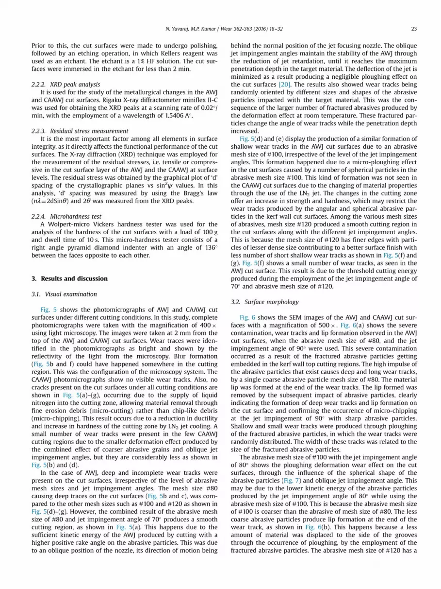
Fig. 6 shows the SEM images of the AWJ and CAAWJ cut sur-faces with a magnification of 500� . Fig. 6(a) shows the severecontamination, wear tracks and lip formation observed in the AWJcut surfaces, when the abrasive mesh size of #80, and the jetimpingement angle of 90° were used. This severe contaminationoccurred as a result of the fractured abrasive particles gettingembedded in the kerf wall top cutting regions. The high impulse ofthe abrasive particles that exist causes deep and long wear tracks,by a single coarse abrasive particle mesh size of #80. The materiallip was formed at the end of the wear tracks. The lip formed wasremoved by the subsequent impact of abrasive particles, clearlyindicating the formation of deep wear tracks and lip formation onthe cut surface and confirming the occurrence of micro-chippingat the jet impingement of 90° with sharp abrasive particles.Shallow and small wear tracks were produced through ploughingof the fractured abrasive particles, in which the wear tracks wererandomly distributed. The width of these tracks was related to thesize of the fractured abrasive particles.
The abrasive mesh size of #100 with the jet impingement angleof 80° shows the ploughing deformation wear effect on the cutsurfaces, through the influence of the spherical shape of theabrasive particles (Fig. 7) and oblique jet impingement angle. Thismay be due to the lower kinetic energy of the abrasive particlesproduced by the jet impingement angle of 80° while using theabrasive mesh size of #100. This is because the abrasive mesh sizeof #100 is coarser than the abrasive of mesh size of #80. The lesscoarse abrasive particles produce lip formation at the end of thewear track, as shown in Fig. 6(b). This happens because a lessamount of material was displaced to the side of the groovesthrough the occurrence of ploughing, by the employment of thefractured abrasive particles. The abrasive mesh size of #120 has a
P:150 MPa MS: #80 IA: 90o
P:150 MPa MS: #100 IA: 80o
P:150 MPa MS: #120 IA: 90o
Lip formation
Micro ploughing
Embedment of abrasive particles
Groove
AWJ CAAWJ
Deep and long wear tracks
Lip formation
Ploughing deformation
Micro wear tracks
Groove
Fig. 6. SEM images of AWJ and CAAWJ cut surfaces. (a) P:150 MPa MS: #80 IA: 90°. (b) P:150 MPa MS: #100 IA: 80°. (c) P:150 MPa MS: #120 IA: 90°.
N. Yuvaraj, M.P. Kumar / Wear 362-363 (2016) 18–3224
spherical shape compared to the abrasive mesh sizes of #80 and#100. This does not produce any ploughing effect on the cut sur-faces due to the effect of jet impingement angle at 90°. The jetimpingement angle of 90° produced a threshold energy while theabrasive mesh size of #120 was used. The CAAWJ cut surfaces haveno appreciable ploughing effect on the kerf wall cut surfaces(Fig. 6c), due to the supply of LN2 into the cutting zone. However, asmall number of visible wear tracks were present on the CAAWJcut surface, while the abrasive mesh size of #100 and the jetimpingement angle of 80° were employed. This is because a smallamount of deformation effect was produced, in addition to themicro-cutting at the cutting zone.
The use of LN2 in the cutting zone is more prone to increase inhardness, causing less contamination produced on the top cut
surfaces. It is under CAAWJ cutting conditions as shown in Fig. 8.The increase in the hardness of the cut surface resists theembedding of the abrasive particles, clearly indicating only asmaller number of silicon particles embedded on the CAAWJ cutsurfaces. This is shown in Table 3. This contamination has a directinfluence on the functional performance of the machined com-ponent with features like fatigue life, as claimed by Patel [31].Among the different levels of cutting conditions shown in Table 3,severe abrasive contamination occurs at the jet impingementangle of 90° and the abrasive mesh size of #80. This happens dueto the existence of the critical level of jet energy through a higherjet impingement angle (90°), and employment of coarse abrasiveparticles (#80). The other AWJ cutting conditions causing a smaller

Fig. 7. Spherical shape particles at abrasive mesh size of #100.
N. Yuvaraj, M.P. Kumar / Wear 362-363 (2016) 18–32 25
abrasive contamination were seen. This was due to the reductionin the impulse of abrasive particles at the cutting zone.
Nevertheless, abrasive contamination also occurred due to thecombined effect of the mesh size of #120 and jet impingementangle of 90°, as shown in Fig. 8(c). In contrast, there were novisible wear tracks other than a smaller abrasive contamination onthe CAAWJ cut surfaces under all cutting conditions, attributed tothe maintenance of kinetic energy of the abrasive particles duringthe cutting process, causing cutting wear and playing a pre-dominant role in the cutting region.
3.3. Surface topography
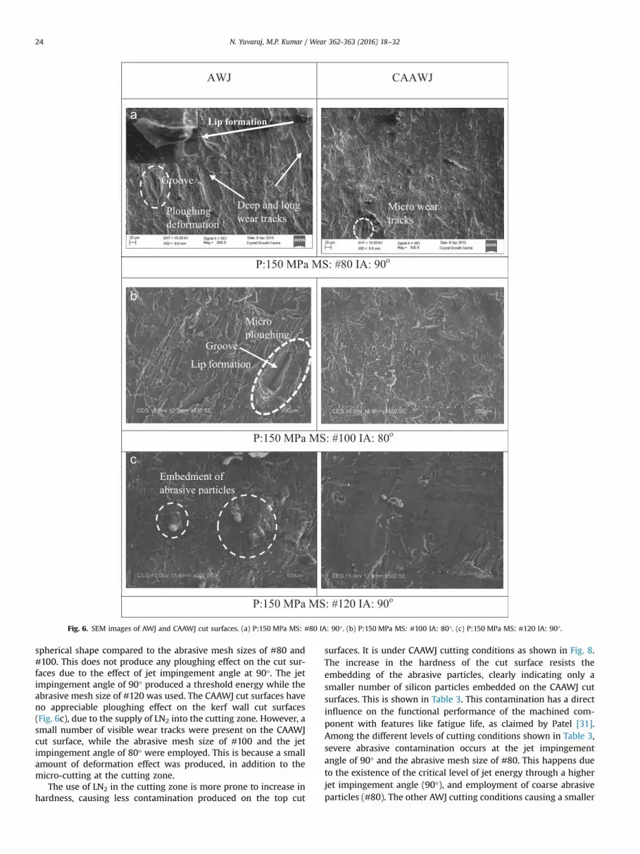
The 3D surface topography in the AWJ and CAAWJ cut surfaceswas measured under different cutting conditions, with an azimuthangle of 45° and a focused area of 3250 mm, as shown in Fig. 9. Thesurface topography images were taken 6 mm from the top of thecutting region in both the AWJ and CAAWJ cut surfaces. Peaks andvalleys were seen randomly distributed on the AWJ and CAAWJ cutsurfaces. This was due to the erosion process being carried out bythe mixing of a high velocity of water jet with a random dis-tribution of abrasive particles causing surface irregularities on themachined surfaces. This randomness of the cut surface depends onthe size and shape of the abrasive particles and fractured particlesin the jet. However, CAAWJ produces a smaller number of peaks inall the cutting conditions with valleys found on the cut surfacesand also a uniform pattern of peaks and valleys. The use of LN2 inthe cutting zone causes a reduction in deformation somewhere inthe cutting conditions. This is in addition to the increase inhardness which drastically reduces the severe impact of abrasiveparticles with kerf wall cut surfaces. This change in the cuttingzone allows material removal through the fine erosion debrisprocess. These changes in material properties are similar to theresults of a study by Strnadel et al. [32], who report an increase inmachinability due to the softening of the material. Deep traces of asmall number were found as a result also of a smooth surfacefinish produced on the cut surfaces. This clearly indicates theoccurrence of only short fluctuations on the CAAWJ cut surfaces,characterised by the use of the 2D roughness profile. This impliesthe uniform rate of material removal taking place in the CAAWJrather than the AWJ cutting process.
Fig. 9(a) shows the AWJ cut surface with a large number ofpeaks and valleys present in the corresponding 3D surface topo-graphy. It means that the kinetic energy of the AWJ produces ashearing action, along with a considerable deformation effect inthat cutting region, whereas the cutting energy of the abrasiveparticles is higher than that of the jet impingement angle of 90°.As a result, the surface roughness value is found to be higher.However, the AWJ cutting condition such as water jet pressure of150 MPa, abrasive mesh size of #80 and jet impingement angle of
90°, produce a lower roughness compared to other AWJ cuttingconditions, as shown in Fig. 9(b). The lower roughness that hap-pened by the plastic deformation may be due to the interaction ofthe energy of the coarse abrasive particles with the target material[32]. This is because the jet impingement angle of 90° with coarserabrasive particles involves a larger particle disintegration witheach disintegration of particles getting a minimum thresholdenergy to cut the material with a smooth surface finish. Theabrasive mesh size of #100 with a jet impingement angle of 80°shows a uniform distribution of peaks along the cut surfaces(Fig. 9c) rather than the jet impingement angle of 90° (Fig. 9d).This is the result of the possible particle deflection occurring at thejet impingement angle of 90°, which in turn, is due to the exis-tence of the large tangential cutting energy of the jet.
The tilting of the cutting head from the normal jet impinge-ment angle improves the quality of the kerf wall cut surfacesthrough a reduction in the jet retardation. Also, the roughnessvalue was found to be slightly higher too. The production of roughcutting regions by the oblique jet impingement angles was seen,this being due to the maintenance of a higher threshold energy inthe lower cutting region, and confirmed by the roughness values.The effect of a smaller particle disintegration caused by the use ofcoarser abrasive particles (#80) at the jet impingement angle of70° accounts for this feature. This level of energy may be critical tothe kerf wall cut surface, considering aluminium alloys have softmaterial surfaces. This is claimed by Zhao and Guo [11], whoobserved more scratches than hard materials on the 6061 alumi-nium alloy. This might be due to a lower kinetic energy obtainedwhile using the abrasive particles (#120) of a low density with theemployment of a jet impingement angle of 80°.
Despite the abrasive mesh size of #120 with a lower kineticenergy in the cutting process, the use of LN2 in the AWJ com-pensates the energy of the abrasive particles with an increase inthe penetration depth. This result is a consequence of the lowercooling temperature of LN2 allowing easier disintegration of thetarget material with a lower roughness value. This lower rough-ness value indicates a slight uniformity in peaks and valleys dis-tributed over the cut surface as seen in Fig. 9(e) and (f). For theAWJ cut surfaces (Fig. 9e and f), the roughness value was found tobe higher despite the use of the abrasive mesh size of #120 withjet impingement angles of 80° and 90°. This happens due to theinsignificant existence of the micro-chipping erosion process inthe cutting region by the use of the low density particles of theabrasive.
The 2D surface roughness profiles of the AWJ and CAAWJ cutsurfaces are shown in Fig. 10(a–f). The AWJ and CAAWJ cut sur-faces show profiles of the peaks and valleys as not repeatable andnot uniform. This is the corollary of cutting processes being ran-dom in nature, which is very similar to the grinding process [33].The roughness profiles are taken in the traverse direction of the jeton the cut surfaces rather than the cutting direction of the jet.However, the use of abrasive mesh size of #120, and jet impin-gement angles of 80° and 90° offers a smaller repeatable form ofpeaks and valleys, with the spacing being very close in the CAAWJcutting process, as shown inFig. 10(d) and (f). The presence of largepeaks and deep valleys was seen on the AWJ cut surfaces, arisingout of the effect of deformation wear through a reduction in thekinetic energy of the abrasive grains, following the decrease in thedepth of penetration. Deeper valleys also found on the AWJ cutsurfaces, as presented by an encircle in the roughness profiles, areshown in Fig. 10. This result is caused by the ploughing effectfollowing a lower kinetic energy of a single coarse abrasive grain.This is a clear indication of the maximum height of the peak to thevalley (Pt) on the 2D roughness profile values of the AWJ cutsurfaces as being higher than those of the CAAWJ cut surfaces

AWJ CAAWJ
P:150 MPa; MS: #80; IA:90o
Severe abrasive contamination
Less abrasive contamination
P:150 MPa; MS: #100; IA:80o
P:150 MPa; MS: #120; IA:90o
Severe abrasive contamination
Fig. 8. Abrasive particle contamination under different cutting conditions. (a) P:150 MPa; MS: #80; IA:90°, (b) P:150 MPa; MS: #100; IA:80°, and (c) P:150 MPa; MS: #120;IA:90°.
Table 3Abrasive particle contamination under different cutting conditions.
Cutting conditions % of particle contamination
AWJ CAAWJ
P:150 MPa; MS: #80; IA:90° 8.52 3.72P:150 MPa; MS: #100; IA:80° 4.62 3.37P:150 MPa; MS: #120; IA:90° 5.23 3.8
N. Yuvaraj, M.P. Kumar / Wear 362-363 (2016) 18–3226
(Table 4), and directly influencing the average surface roughness ofthe AWJ cut surfaces.
Table 4 summarizes the 2D roughness profiles and measures ofthe Pt values of the AWJ and CAAWJ cutting conditions. Table 4indicates the maximum value of the Pt occurring in the AWJ cut-ting process, wherein the maximum value is seen at the jet
impingement angle of 90°, and the abrasive mesh size of #100,followed by an abrasive mesh size of #120. These are reflected inFig. 10(a) and (e). Following this, the combined effect of a jetimpingement angle of 90° with different abrasive mesh sizes suchas #100 and #120 does not maintain the cutting wear in the lowercutting regions. The jet impingement angle of 90° involving alarger particle collision at the entry of the cutting process explainsthis phenomenon. Deformation wear occurs in the lower cuttingregions as a consequence. Roughness and Pt are seen as higherrather than the oblique jet impingement angles such as 70° and80°. These angles generate a smaller collision of abrasive particlesduring their interaction with the target material, following areduction in the tangential force of the AWJ. However, it has theadequate kinetic energy for processing the target material with alower Pt and roughness value. The results confirm the cuttingwear mode of the erosion process producing a surface finish better
AWJ CAAWJ
P:150 MPa MS: #80 IA: 70o
P:150 MPa MS:#80 IA:90 o
R = 2.24µm
R = 1.96µm R = 1.27µm
R = 3.07µm
P:150 MPa MS:#100 IA:80o
P:150 MPa MS:#100 IA:90o
P:150 MPa MS:#120 IA: 80o
P:150 MPa MS:#120 IA: 90o
R = 3.13µm R = 2.80µm
R = 4.82µm
R = 3.41µm
R = 1.69 µm
R = 1.48µm
R = 1.49 µm
R = 2.43µm
Fig. 9. 3D surface topography of AWJ and CAAWJ cut surfaces. (a) P:150 MPa MS: #80 IA: 70°. (b) P:150 MPa MS:#80 IA:90°. (c) P:150 MPa MS:#100 IA:80°. (d) P:150 MPaMS:#100 IA:90°. (e) P:150 MPa MS:#120 IA: 80°. (f) P:150 MPa MS:#120 IA: 90°.
N. Yuvaraj, M.P. Kumar / Wear 362-363 (2016) 18–32 27

AWJ - P:150 MS:100 IA:90
CAAWJ - P:150 MS:100 IA:90
AWJ -P:150 MS:120 IA:80
CAAWJ -P:150 MS:120 IA:80
AWJ -P:150 MS:120 IA:90
CAAWJ -P:150 MS:120 IA:90
Fig. 10. 2D roughness profiles of AWJ and CAAWJ cut surfaces. (a) AWJ -P:150 MS:100 IA:90. (b) CAAWJ - P:150 MS:100 IA:90. (c) AWJ - P:150 MS:120IA:80. (d) CAAWJ - P:150 MS:120 IA:80. (e) AWJ - P:150 MS:120 IA:90. (f) CAAWJ -P:150 MS:120 IA:90.
Table 4Pt values of different cutting conditions.
Cutting conditions Pt values, mm
AWJ CAAWJ
P:150 MPa; MS: #80; IA:70° 27.9 25.8P:150 MPa; MS: #80; IA:90° 19.7 12P:150 MPa; MS: #100; IA:80° 12.8 13.7P:150 MPa; MS: #100; IA:90° 61.1 30.1P:150 MPa; MS: #120; IA:80° 22.7 33.1P:150 MPa; MS: #120; IA:90° 45.4 32.9
Table 5Rz values of different cutting conditions.
Cutting conditions Rz values, mm
AWJ CAAWJ
P:150 MPa; MS: #80; IA:70° 19.1 15.6P:150 MPa; MS: #80; IA:90° 9.46 7.03P:150 MPa; MS: #100; IA:80° 10.2 8.97P:150 MPa; MS: #100; IA:90° 28.5 19.9P:150 MPa; MS: #120; IA:80° 15.3 11.9P:150 MPa; MS: #120; IA:90° 20.7 14.1
N. Yuvaraj, M.P. Kumar / Wear 362-363 (2016) 18–3228
than the deformation wear mode employment of the oblique jetimpingement angles. The Pt value of CAAWJ at a jet impingementangle of 80° and abrasive mesh size of #120 was found to be
higher than at the AWJ cut surface. This is attributed to the pos-sibility of the production of some measurement regions in theCAAWJ cut surface, deep traces which arise as a consequence ofinadequate cooling in the cutting zone. It also allows the cut sur-face with lower hardness, giving rise to the strong interaction ofthe abrasive particles in the cutting region.
Material removal in the top cutting region takes place throughan efficient micro-cutting through LN2 cooling. As a result, thekinetic energy of the abrasive particles is maintained with the helpof a smaller number of fractured and embedded abrasives. Thecutting wear mode of the erosion process is maintained in thelower cutting region as arising out of this factor. This happens evenwith the use of a jet impingement angle of 80° and an abrasivemesh size #120. Further, a strong impact on the cut surfaces wasseen somewhere leading to the production of a higher Pt value.Despite a maximum value of Pt which was more than the AWJ cutsurface, the mean height of the profile (Rz) value was lower in theCAAWJ cut surface and the value was found to be 11.9 mm. The Rzvalue of the AWJ cut surface was 15.3 mm, clearly indicating anextension of the maximum value of this Rz peak beyond the sur-face that may affect the static or sliding contact function of the cutsurfaces. This is due to the Rz measurement having been taken at asampling length rather than the evaluation length of the rough-ness profile (Pt). The Rz values were also found to be more sen-sitive than the Ra and Pt values. Similar results were found in thejet impingement angle of 80° and the abrasive of mesh size #100.The Rz values of the AWJ and CAAWJ cut surfaces are shown inTable 5. A higher value indicates a higher susceptibility to protrudepeaks which limits the frequency of the cut surface parts requiredto mate with the other parts.
3.4. XRD peak analysis
Fig. 11 shows the XRD peaks of the base material in the asreceived condition, and different conditions of the AWJ, and theCAAWJ cut surfaces. The AWJ and CAAWJ cut surfaces were sub-jected to XRD analysis for identification of the changes in the peakposition and their modifications on the machined surface com-pared to the base material peak profile. The cut surfaces reflectingplanes such as (111), (200), (211), (220) and, (311) Miller's indices

Fig. 11. XRD peaks under AWJ and CAAWJ cutting conditions.
Fig. 12. Coarse particles in the abrasive mesh size of #100.
N. Yuvaraj, M.P. Kumar / Wear 362-363 (2016) 18–32 29
indicate the presence of materials such as aluminium, also con-firming, the peaks of the surface reflecting planes matching to theface centred cubic (FCC) phase of aluminium, and following the X-ray diffraction standards. The base material indicated an alumi-nium (Al) rich solid solution present in the cut surface, as shown inFig. 11(a). The Mg particles were not seen and this is accounted forby the lower weight percentage of the composition of the alumi-nium alloy, but the formation of an eutectic network of β phase
(white) found in the matrix of the aluminium rich solid solution(black), is confirmed by its micro-structure.
Fig. 11(b) of the AWJ cut surface shows a water jet pressure of150 MPa, an abrasive mesh size of #80 and jet impingement angleof 90° having severe suppression of the peak intensity, more thanfrom other cutting conditions. The results, show a sharp reductionin Al peaks at planes (111), and (200). The other two planes werenot seen in the XRD profile which explains the diffusion of Mg andAl in the matrix of solid solution into grain boundaries, producinga thickened β phase arising act of coarse abrasives (#80), andimpinging with a high impulse generating a possible temperatureat the cutting zone. This was found to be 55–65 °C through the useof a non-contact type IR thermometer. This temperature wasobserved when the low traverse speed was employed in this study.This is because a low traverse speed increases the duration ofexposure to the target material. A similar result was also observedby Ohadi et al. [34], who found the peak temperature in alumi-nium by using thermocouples. The possible temperature affectsthe chemical composition of the AA5083-H32 aluminium alloy, asthis alloy operates more than 50 °C or a very long time at roomtemperature, with a continuous rich β phase formed in the grainboundaries. This resulted in the disappearance and greaterdiminution of Al peak intensity. Unlike the AWJ cutting condition,the peak intensity of the XRD planes was similar to that of the basematerial with a slight diminution of the Al plane (111). Otherplanes maintain the peaks, caused by the reduction in diffusion tothe grain boundaries by LN2 jet cooling, confirmed by a less richnetwork of β phase formed along with the grain boundaries; thedetails are shown in the microstructure.
In the AWJ cutting process, jet impingement angle of 90°, andabrasive mesh size of #100 shows the Al planes (111) and (220)becoming weak, while other planes (211), (200) maintain thepeaks compared to those of the abrasive mesh size of #80 asshown in Fig. 11(c). This is the consequence of the size and shapeof the abrasive of mesh size #100 particle size being less than thatof the abrasive of mesh size #80, which in turn, is explained bymore coarse abrasives with large size particles (#80) involvingmore heat at the cutting zone, as shown in Fig. 12. Under the samecutting conditions, CAAWJ cutting process indicates retention atthe base material of Al peaks (Fig. 11c). This is confirmed by asmaller continuous thin β phase present in the matrix of alumi-nium rich solid solution, as shown in the microstructure.
The results show all cutting conditions of the AWJ peaks gettingshifted to a higher angle. These variations in the shifting of peakshappened following the combined effect of deformation, andsurface roughness of the target material. The ductility of thematerial is high at the AWJ cutting process wherein the highimpulse of the abrasive particles (#80 and #100) induces adeformation at the jet impingement angle 90°. This peak shiftingwas confirmed by the lattice strain of increasing of “d” spacing

Table 6XRD peaks and their ‘d’ spacing values.
Cutting processparameters
Cuttingconditions
Peakangles (2θ),deg.
Peak reflectingplanes
‘d’ spacingvalue, °A
P:150 MPa,MS:80, IA: 90
AWJ 78.88 200 1.212CAAWJ 45.86 200 1.977
P:150 MPa,MS:100, IA: 90
AWJ 79.04 200 1.210CAAWJ 44.92 200 2.016
Base metal As received 37.88 111 2.236
Fig. 13. Compressive residual stress of AWJ and CAAWJ cutting conditions.
70
90
110
130
150
170
190
1 2 3
Mic
ro h
ardn
ess,
HV
Distance, mm
AWJ 150 120 80 CAAWJ 150 120 80 AWJ 150 100 90CAAWJ 150 100 90 AWJ 150 120 90 CAAWJ 150 120 90AWJ 150 100 80 CAAWJ 150 100 80 AWJ 150 80 90CAAWJ AWJ CAAWJBase metal
Fig. 14. Micro hardness of AWJ and CAAWJ cutting conditions.
N. Yuvaraj, M.P. Kumar / Wear 362-363 (2016) 18–3230
value between the crystallographic planes, triggering the occur-rence of the peak at a lower angle. With a decrease in “d” spacing,there was a change in the position of peak shifting into a higherangle. The peak values of “d” spacing are listed in Table 6. In thisstudy, cryogenic cooling reduced the shifting of peaks, whichhappened due to the increase in hardness at the cutting zone.
3.5. Residual stress analysis
Fig. 13 shows the surface compressive residual stress of the cutsurfaces under the AWJ, and the CAAWJ cutting conditions. Assuggested by Jawahir et al. [3], residual stress is more significant inthe material removal process, as the measurement of the stressdetermines the functionality of the end product, particularly whencritical structural components are machined. In the present study,all the measurements were taken at the surface of the machinedaluminium alloy cut surface, consequent on the initiation of thefatigue cracks usually at the surface of the work material ratherthan at the subsurface. In AWJ machining, the residual stresseswere developed from the erosion process by an impingement ofthe abrasive particles. For all cutting conditions of the AWJ andCAAWJ, the cut surfaces contain compressive residual stress(negative sign) rather than the tensile residual stress (positivesign), as confirmed by a sign of the residual stress values.Improvement of the fatigue life and stress corrosion crackingresistance of the work material through the formation of surfacecompressive residual stress in the AWJ and CAAWJ cut surfaces isalso confirmed.
Surface indentations in the AWJ cutting process were producedby the impingement of abrasive particles with a high velocity ofthe water jet, as demonstrated by Arola et al. [21], who claim thedevelopment of compressive residual stress through the surfaceand subsurface indentations by the high velocity of coarse abrasiveparticles. As generally known, the abrasive water jet machiningprocess offers a zone by the heat of a small degree compared to theother machining processes. Arising out of this was the completeremoval of tensile residual stress from the cut surface due to
smaller/absence of the effect of thermal load in the cutting zoneand inducing the compressive residual stress in the cut surfaces.Among the different cutting conditions, the use of LN2 in theCAAWJ cutting process produces improved surface compressiveresidual stress compared to the AWJ cutting process. It is caused byan increase in the hardness of the cutting zone due to a lowtemperature. These increments in the hardness caused additionalstress in the cut surfaces. Drastic reduction in the cutting zonetemperature was also noticed by the use of LN2. The temperaturewas found to be lower than �20°C. A high surface compressiveresidual stress was the result, explaining the reduction of ductilityin the cutting zone under CAAWJ cutting process, in which morecoarse grains of mesh size #80 produced more indentations on thekerf wall cut surface than the mesh size #100.
The high ductility of the target material under AWJ cuttingcauses coarse grains in the mesh sizes of #80 and #100, fracturingand simultaneously losing the size and shape along with theparticle energy. A smaller indentation was produced in the kerfwall cut surface, yielding a lower surface compressive residualstress. Among the cutting conditions, the jet impingement angle of90° was seen with an abrasive mesh size of #80 having lowercompressive residual stress, which was a consequence of thedevelopment of peak temperature at the cutting zone. This peaktemperature was associated with the results found by Kovacevicet al. [35], who studied the AWJ cutting of Aluminium alloy 2024,with the measurement of the peak temperature using infraredthermography. The results confirm AWJ, and the CAAWJ processesas not producing any thermal stress, which influences the for-mation of compressive residual stress instead of a tensile residualstress on the cut surfaces.
3.6. Micro hardness analysis
Fig. 14 shows the influence of AWJ and CAAWJ cutting condi-tions on micro-hardness. A comparison of the cutting conditions ofdifferent levels (Fig. 14), shows the hardness of the AWJ cut sur-faces as always lower than the CAAWJ cut surfaces. This is because,of all AWJ cutting conditions, a possible heat affected zone hap-pens following the combined effect of various abrasive particles,with the employment of jet impingement angles. Further, themaximum temperature developed at the cutting zone was seen as65 °C, measured by using a metravi digital non-contact type IRthermometer with a lower micro-hardness. The characteristicfeature of AA5083-H32 aluminium alloy was having a lowermelting point, and not operating at more than 50 °C whichexplains the matter. The work material was found to lose itsproperties and become susceptible to stress corrosion cracking atrelatively elevated temperatures ranging from 50 °C to 200 °C for a

N. Yuvaraj, M.P. Kumar / Wear 362-363 (2016) 18–32 31
constant duration, as demonstrated by Searless et al. [36] withdifferent techniques, and later on changes in the microstructure ofthe AA5083 aluminium alloy observed by Popovic et al. [37]. Theseen results confirm, the fine mesh size abrasive particles (#120)maintaining the hardness of the AWJ cut surface compared to theother abrasive mesh sizes such as #80 and #100, while the tem-perature was found in the range of 25–30 °C when an abrasive ofmesh size #120 with a jet impingement angle of 80° was used. Theuse of LN2 in the cutting zone removes the heat generated at thecutting zone with a distance of 3–6 mm from the top kerf wall cutsurface. It cools the workpiece at a lower temperature subse-quently causing a strain hardening effect which can occur throughthe grain refinement followed by improvement of the hardness ofthe cut surface.
In contrast, the jet impingement angle of 70° maintains thehardness of the cut surface under AWJ. It offers threshold energyfor cutting the material rather than a critical energy (high impulseof the abrasive particles) produced by a jet impingement angle of90°. The heat developed was smaller at the cutting zone with thehardness of the AWJ cut surface remaining unchanged. A resultingfeature of the strain hardening induced by the indentation of alarger number of less fractured coarse particles of mesh size #80 isthat it erodes the kerf wall cut surface when the jet impingementangle of 70° is employed. The impingement of the coarse abrasiveparticles (#80 and #100) on the target material under CAAWJprocess, was observed as producing more hardness compared tothe fine mesh size of the abrasive particles (#120). Coarse abrasiveparticles yielding a higher cutting force and inducing a higherindentation through an impingement of the abrasive particles bythe LN2 jet are responsible for this. The hardness of the cut surfaceincreased when this happened.
Usually, aluminium alloys have high thermal conductivity, andtherefore, suddenly conduct the heat into the uncut region duringthe cutting process, causing a decrease in hardness while simul-taneously increasing the distance from the top kerf wall cut sur-face. Therefore, LN2 jet is employed in the cutting process whilecutting AA5083-H32 aluminium alloy for the reduction of thepossible heat developed by the AWJ. A higher hardness on the cutsurface increasing the fatigue life of the finished components isthe consequence. Finally, the CAAWJ process has a longer fatiguelife, arising from higher hardness and the compressive residualstress act upon it.
4. Conclusions
Surface integrity studies in this experimental work were car-ried out on the abrasive water jet (AWJ) and cryogenic assistedabrasive water jet (CAAWJ) cutting of AA5083-H32 aluminiumalloy. For both the cutting conditions, the jet impingement angleswith different abrasive mesh sizes maintained the surface integrityof the cut surfaces. The major conclusions drawn are given below.
1. In the optical micrographs, the wear tracks seen on the CAAWJcut surfaces are insignificant. In addition, severe wear tracksoccurred in the AWJ kerf wall cut surfaces, as a result of theaction of coarse abrasive particles in the abrasive mesh size of#80 and #100 with the employment of a jet impingement angleof 90° over the oblique jet impingement angles.
2. The SEM analysis confirms the absence of ploughing and severewear tracks on the CAAWJ cut surfaces. Further, a very smallnumber of abrasive particles were embedded in the kerf wallcut surface as a necessary consequence of the increase inhardness of the cutting zone by the Liquid Nitrogen (LN2) jet.This caused a drastic reduction in the abrasive contamination inthe CAAWJ cut surfaces.
3. The 3D surface topography indicates the production of variouscutting conditions of the CAAWJ cut surfaces peaks and valleysslightly uniformly distributed causing a lower kerf wall surfaceroughness. These results are due to the fine debris erosionprocess in the cutting zone caused by the LN2 jet along with theinfluence of oblique jet impingement angles, such as 70° and80°.
4. The 2D roughness profile indicates the repeatable form of peaksand valleys with adjacent spacing in the CAAWJ cut surfacesrather than in the AWJ cut surfaces. The AWJ cut surfaces arefound to be more susceptible to the mating surfaces due to theprojection of higher peaks and deeper valleys.
5. A thick intermetallic (β) phase was observed along the grainboundaries under the AWJ cut surfaces, confirmed by the XRDpeak analysis and the microstructure. These results are due tothe peak temperature developed at the cutting zone when thejet impingement angle of 90° and coarse abrasive particles wereemployed.
6. The CAAWJ cut surfaces offer a higher compressive residualstress consequent on the indentation of less fractured coarseabrasive particles on the kerf wall cut surface through thechanging of material properties at the cutting zone by cryogeniccooling.
7. Of all the cutting conditions, the micro-hardness of the CAAWJcut surfaces was higher than that of the AWJ cut surfaces, as thestrain hardening effect was produced by the LN2 jet throughgrain refinement. Under a few AWJ cutting conditions, therewas no significant decrease in the micro-hardness as a result ofthe employment of oblique jet impingement angles.
Funding
The authors would like to express their sincere thanks to theCouncil of Scientific and Industrial Research (CSIR), Government ofIndia, New Delhi, for providing the research fund under thescheme of Senior Research Fellowship (Grant file no. 9/468(479)/2014-EMR I).
Acknowledgement
The authors acknowledge the help rendered by the Head,Department of Production Technology, Madras Institute of Tech-nology (MIT) campus, Anna University, Chennai, in providingexperimental facilities to conduct this research work.
References
[1] J.P. Davim, Surface Integrity in Machining, Springer-Verlag, London, 2010.[2] R. M'Saoubi, J.C. Outeiro, H. Chandrasekaran, O.W. Dillon Jr., I.S. Jawahir, A
review of surface integrity in machining and its impact on functional perfor-mance and life of machined products, Int. J. Sustain. Manuf. 1 (1/2) (2008)203–236.
[3] I.S. Jawahir, E. Brinksmeier, R. M’Saoubi, D.K. Aspinwall, J.C. Outeiro, D. Meyer,D. Umbrello, A.D. Jayal, Surface integrity in material removal processes: recentadvances, CIRP Ann. -Manuf. Technol. 60 (2011) 603–626.
[4] F. Pusaveca, H. Hamdib, J. Kopaca, I.S. Jawahir, Surface integrity in cryogenicmachining of nickel based alloy – inconel 718, J. Mater. Process. Technol. 211(4) (2011) 773–783.
[5] Y. Kaynak, T. Lu, I.S. Jawahir, Cryogenic machining-induced surface integrity: areview and comparison with dry, mql, and flood-cooled machining, Mach. Sci.Technol. 18 (2014) 149–198.
[6] G.E. Totten, S.D. Mackenzie, Handbook of Aluminium Physical Metallurgy andProcesses, Marcel Dekker Incorporation, New York and Basel, 2003.
[7] J. Folkes, Waterjet-An innovative tool for manufacturing, J. Mater. Process.Technol. 209 (2009) 6181–6189.
[8] A.W. Momber, R. Kovacevic, Principles of Abrasive Water Jet Machining,Springer-Verlag, London, 1998.

N. Yuvaraj, M.P. Kumar / Wear 362-363 (2016) 18–3232
[9] M. Hashish, Visualisation of the abrasive-waterjet cutting process, Exp. Mech.28 (1998) 159–168.
[10] F. Boud, L.F. Loo, P.K. Kinnell, The impact of plain waterjet machining on thesurface integrity of aluminium 7475, Procedia CIRP 13 (2014) 382–386.
[11] W. Zhao, C. Guo, Topography and microstructure of the cutting surfacemachined with abrasive waterjet, Int. J. Adv. Manuf. Technol. 73 (2014)941–947.
[12] B. Sadasivam, A. Hizal, D. Arola, Abrasive waterjet peening with elastic pres-tress: a parametric evaluation, Int. J. Mach. Tools Manuf. 49 (2009) 134–141.
[13] S. Kunaporn, A. Chillman, M. Ramulu, M. Hashish, Effect of water jet formationon surface preparation and profiling of aluminium alloy, Wear 265 (2008)176–185.
[14] R.J. Jegaraj, R.N. Babu, A strategy for efficient and quality cutting of materialswith abrasive water jets considering the variation in orifice and focusingnozzle diameter, Int. J. Mach. Tools Manuf. 45 (2005) 1443–1450.
[15] A. Akkurt, M.K. Kulekci, U. Seker, F. Ercan, Effect of feed rate on surfaceroughness in abrasive waterjet cutting applications, J. Mater. Process. Technol.147 (2004) 389–396.
[16] M.C.P. Selvan, N.M.S. Raju, H.K. Sachidananda, Effects of process parameters onsurface roughness in abrasive waterjet cutting of aluminium, Front. Mech. Eng.7 (4) (2012) 439–444.
[17] R. Kovacevic, Surface texture in abrasive water jet cutting, J. Manuf. Syst. 10(1991) 32–40.
[18] F.L. Chen, J. Wang, E. Lemmaa, E. Sioresa, Striation formation mechanisms onthe jet cutting surface, J. Mater. Process. Technol. 141 (2003) 213–218.
[19] L.M. Hlavac, Investigation of the abrasive water jet trajectory curvature insidethe Kerf, J. Mater. Process. Technol. 209 (8) (2009) 4154–4161.
[20] L.M. Hlavac, B. Strnadel, J. Kalicinsky, L. Gembalova, The model of productdistortion in AWJ cutting, Int. J. Adv. Manuf. Technol. 62 (1–4) (2012) 157–166.
[21] D. Arola, M.L. McCain, S. Kunaporn, M. Ramulu, Waterjet and abrasive waterjetsurface treatment of titanium: a comparison of surface texture and residualstress, Wear 249 (2002) 943–950.
[22] D. Arola, M. Ramulu, Material removal in abrasive waterjet machining ofmetals surface integrity and texture, Wear 210 (1–2) (1997) 50–58.
[23] S. Ravi, M. Pradeep Kumar, Experimental investigation of cryogenic cooling inmilling of AISI D3 tool steel, Mater. Manuf. Process. 27 (2012) 1017–1021.
[24] A.R. Natasha, J.A. Ghani, C.H.C. Haron, J. Syarif, The effect of cryogenic appli-cation on surface integrity in manufacturing process: a review, J. Appl. Sci. Res.8 (9) (2012) 4880–4890.
[25] M.K. Muju, A.K. Pathak, Abrasive jet machining of glass at low temperature, J.Mech. Work. Technol. 17 (1988) 325–332.
[26] L.I. Urbanovich, E.M. Kramchenkov, Y.N. Chunosov, Investigation of low tem-perature gas-abrasive erosion, J. Frict. Wear 13 (1992) 80–83.
[27] H. Getu, J.K. Spelt, M. Papini, Cryogenically assisted abrasive jet micro-machining of polymers, J. Micromech. Microeng. 18 (2008) 1–8.
[28] A.G. Gardeen, J.K. Spelt, M. Papini, Cryogenic abrasive jet machining of poly-dimethylsiloxane at different temperatures, Wear 274–275 (2012) 335–344.
[29] A.G. Gradeen, M. Papini, J.K. Spelt, The effect of temperature on the cryogenicabrasive jet micro-machining of polytetrafluoroethylene, high carbon steeland polydimethylsiloxane, Wear 317 (2014) 170–178.
[30] J. Wang, T. Kuriyagawa, C.Z. Huang, An experimental study to enhance thecutting performance in abrasive waterjet machining, Mach. Sci. Technol. 7 (2)(2003) 191–207.
[31] K.J. Patel, Quantitative evaluation of abrasive contamination in ductile mate-rial during abrasive water jet machining and minimizing with a nozzle headoscillation technique, Int. J. Mach. Tools Manuf. 44 (2004) 1125–1132.
[32] B. Strnadel, L.M. Hlaváč, L. Gembalová, Effect of steel structure on the decli-nation angle in AWJ cutting, Int. J. Mach. Tools Manuf. 64 (2013) 12–19.
[33] R.A. Waikar, Y.B. Guo, A comprehensive characterization of 3D surface topo-graphy induced by hard turning versus grinding, J. Mater. Process. Technol.197 (2008) 189–199.
[34] M.M. Ohadi, A.I. Ansari, M. Hashish, Thermal distributions in the workpieceduring cutting with an abrasive waterjet, J. Manuf. Sci. Eng. 114 (1) (1992)67–73.
[35] R. Kovacevic, R. Mohan, H.E. Beardsley, Monitoring of thermal energy dis-tribution in abrasive waterjet cutting using infrared thermography, J. Manuf.Sci. Eng. 118 (1996) 555–563.
[36] J.L. Searless, P.I. Gouma, R.G. Buchheit, Stress corrosion cracking of sensitizedAA5083 (Al–4.5Mg–1.0Mn), Mater. Sci. Forum 396–402 (2002) 1437–1442.
[37] M. Popovic, E. Romhanji, Characterization of microstructural changes in anAl6.8 wt%Mg alloy by electrical resistivity measurements, Mater. Sci. Eng. A492 (2008) 460–467.