vols 1 & 2 of "qualification of inconel 82 temperbead weld
TRANSCRIPT
- _ _ _ _ _ _ _ _ _ _ ._______ _ __-__. _.._ _ - _ _ ______ __ _ _ _ _ . _ _ _ _ --_ ___ __ _ __ _ _ _ _ _ _ _ _ _ _ _ _ _ - _ _ _ _ _ _ _ _ _ _
..
,--'. -
_.-
-- %N*.
! Report No.: SIR 90-063f '; .% 'i , .'
+-.,
'
~'/ ' Revision: 0(]V i . . -T i ~ ~ -
Project No.: NYPA 260November 1991
r
I
,
Qualification of Inconel 82 TemperbeadWeld Overlay Repair With Reduced Preheat ,
and No Post Weld Heating - ;.
Prepared by: ,
Structural Integrity Associates, Inc.
<Q San Jose, CA\S
I
Prepared for:
New York Power AuthoriyWhite Plains, NY
1
//!> bklPrepared by: D Date:_
A.(f Giannuzzi'
Reviewed by: fm Date: /l 26 / .
G. J. Licina ) '
.. c-; u
N!.24,!T/Approved by: M / te:A. e.' Olannuzzi / ' ""'
>
nQ.):
' ss''
gu _9N)J070162 911227 M{,DR - ADOCK Ot.oo 3 ASSOCIATEE
._
y - - er --p ,_-- - -r .-g.*;e p 3 - ,.wwtM a- r 9- i-ir-g -y --.-,y- i,e- ,yw--Tw y--ww-t w, vei-t- 1 -pv------ - - - - - , -+r w-
_ _._._ _ _ _ . . _ _ . _ _ - - . _-_ _ _ . _ _ _ _ . . _
1
Table of Contents |
Section bgt
'
1.0 P U R POS E AN D O BJ ECTI VE . . . . . . . . . . . . . . . . . . . . . . . . . . . . . . . . . . . 1
1.1 Ba ckgro u n d . . . . . . . . . . . . . . . . . . . . . . . . . . . . . . . . . . . . . . . . . . . . . 3 j
2.0 TECHNI CAL APPROACH . . . . . . . . . . . . . . . . . . . . . . . . . . . . . . . . . . . . . . 7-
2.1 New York Power Authority Temperbead Qualification Program . . . . . .'
2.2 Industry Developed Temperbead Qualification Programs . . . . . . . . . . 10
3.0 TEST RES U LTS . . . . . . . . . . . . . . . . . . . . . . . . . . . . . . . . . . . . . . . . . . . . . 13
3.1 New York Power Authority Temperbead Qualification Program . . . . . 13*
3.2 Industry Developed Temperbead Qualification Programs . . . . . . . . . . 15,
-4.0 DISCUSSION OF RESULTS . . . . . . . . . . . . . . . . . . . . . . . . . . . . . . . . . . . 31
- 4.1 Additional Issues . . . . . . . . . . . . . . . . . . . . . . . . . . . . . . . . . . . . . . . . 334.2 Re sid ual S tress . . . . . . . . . . . . . . . . . . . . . . . . . . . . . . . . . . . . . . . . . 34
i'
5.0 SUMMARY AND CONCLUSIONS . . . . . . . . . . . . . . . . . . . . . . . . . . . . . . 40
6.0 R EFER EN CES . . . . . . . . . . . . . . . . . . . . . . . . . . . . . . . . . . . . . . . . . . . . . . 43
'
Appendix 1 Certified Material Test Reports
Appendix 2 Weld Procedure Specification and Procedure Qualification Records -WPS: NZ Overlay and PORs: 395,745,746 ,
Appendit 3 Nutech Temperbead Out.lification Program for Discharge Nm21e at theOyster Creek Nuclear Power Station (EPRI Advisory Committee forTemperbead Welding, November 2 3,1989, Charlotte, tF') -
Appendix 4 CB&l Reactor Nozzle to Safe-end Temperbead Str uctura10verlayTest,
Program .- (EPRI Advisory Committee for Temperbead Welding,,
November 2-3,1989, Charlotte, NC)-
- Appendix 5 Mechanical Properties Test Reports in Support of PORs 395,745,746 ;
Appendix 6 Metallurgical Test Reports in Support of PORs 395,_745, 746
.
. . i
SIR 90-063, Rev. O ii !
- -: ,u,
I t' ; 4 '
ERREINC..
-+vr-- -=ami-==,-ew-cam -= eue- E mew--m u nawe-*'enevn ewwwwv. n--w-7,Tw, swwe - T ve w a v - . r-ev erv ww,-vr,,,-v. rw.-,,--- eiw,*wy m-wy ye v -v - y -tw my- ,,,-yww-wr----r,y
Table of Contents(Concluded)
OSetlica EBEC
Appendix 7 Diffusible Hydrofp Produced as a Result of Welding onSA 508 Cl. 2 Low edloy Steel with 150*F and 300*F Preheatand No Post Heat Treatment (Presented at Second TernperbeadAdvisory Committee Meeting, October 30,1990, Charlotte, NC)
.
h
v
|
A SIR-90 063, Rev, 0 iii%d
7NlDITEGRITY
/ ASSOCIATEINC
._ _ _ _ _ _ _ _ . _ . _ . _ _ _ _ - - . _ _ _ _ _ _ _ _ _ _ . _
i
:List of Tables
Tabk Eage
1 Base Metal and Heat Affected Zone (HAZ) Charpy impact Results forEPRI Qualification Samples [3] . . . . . . . . . . . . . . . . . . . . . . . . . . . . . . . . . . 19
2 Base Metal and Heat Affected Zone (HAZ) Charpy Impact Results forNYPA Qualification '.2mples Procedure 746 (300'F Preheat 500'FP os t H e a t) . . . . . . . . . . . . . . . . . . . . . . . . . . . . . . . . . . . . . . . . . . . . . . . . . . 20
3 Base Metal and Heat Affected kne (HAZ) Charpy Impact Results for -
NYPA Qualification Samples - Procedure 745 (200'F Preheat - 500*FPos t H e a t ) . . . . . . . . . . . . . . . . . . . . . . . . . . . . . . . . . . . . . . . . . . . . . . . . . . 21
4- Base Metal and Heat Affected Zone (HAZ) Charpy impact Results for *
NYPA Oualification Samples Procedure 395 (Nonle Mockup 300*FPre heat, 5 00' F Post Heat) . . . . . . . . . . . . . . . . . . . . . . . . . . . . . . . . . . . . . . 22
5 Comparison of Average Charpy Impact Test Results Among the EPRI andNYPA Inconel 82 Temperbead Weld Overlay Procedures . . . . . . . . . . . . . . . 23
6 EPRI Test Results Microhardness Measurements in the P-3 Heat Affected
0,. Zone of the Groove Weld (Reference 3) . . . . . . . . . . . . . . . . . . . . . . . . . . . 24
'7 Microhardness Traverse on SA-508 Cl. 2 Heat Affected Zones in Groove''
Welds from the EPRI Program (Reference 2) and the AuthorityTemperbead Qualification (PORs 745 & 746)........_................ 25
8 Microhardness Traverse on SA.5L8 Cl. 2 Heat Affected Zones in GrooveWelds from the EPRI Program (Reference 2) and the NYPA TemperbeadQualification (PQRs 74 5 & 74 6) . . . . . . . . . . . . . . . . . . . . . . . . . . . . . . . . . . 26
9 Nutech/ Oyster Creek Mockup Nonle Charpy Comparisons . . . . 27........
p10- 'CB&I Mockup Nonle Charpy Comparisons (Procedure 7673 - 300'F ,
Pre heat, 5 00* F Post Heat) . . . . . . . . . . . . . . . . . . . . . . . . . . . . . . . . . . . . . . 28
11 ; CB&I Mockup Non.le Charpy Comparisons (Procedure 7718 -_
Wa t e r i n Nonle ) . . . . . . . . . . . . . . . . . . . . . . . . . . . . . . . . . . . . . . . . . . . . . 29
N PR.90-063, Rev. O iv("fu
-STRUCTURALDiTEGRITYASSOCIATESINC
-- - - . . . - - . - . - - - , . - - - - - - - - . - - -. - . .
List of Tables(Concluded)
Iabh Put
12 CB&I Mockup Nozzle Charpy Comparison (Proc: dure 7717 -Nozzle D.y - No Preheat or Post Heat) . . . . . . . . . . . . . . . . . . . . . . . . . . . . 30
13 Measured Diffusible Hydrogen Content (ml/100 g) in SamplesPrepared by EPRI (Appendix 7) . . . . . . . . . . . . . . . . . . . . . . . . . . . . . . . . . 37
.
O_
..
Q SIR-90-063, Rev. O v
r-b N
isscx u u sz c
_ _ _ . . _
List of Figures
OFigure higt
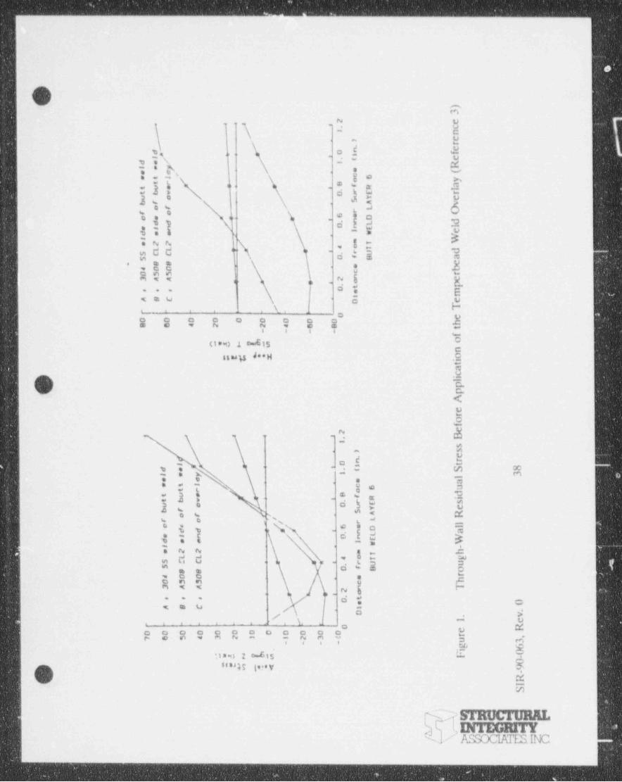
1 Through Wall Residual Stress Before Application of the TemperbeadWeld Ove rlay (Re fe re nce 3) . . . . . . . . . . . . . . . . . . . . . . . . . . . . . . . . . . . . 38
2 Through-Wall Residual Stress After Application of the TemperbeadWeld Ove rlay (Re fe re nce 3) . . . . . . . . . . . . . . . . . . . . . . . . . . . . . . . . . . . . 39
.
Q
<
$
'
O S'" 9 - 63 "*"- '
~ smxxuan3 INTEGRITY- assccuussue
_ _ _ _ _

_ _ _ . _ _ . _ _ _ . _ . _ . _ . _ _ _ . _ _ _.. _ .___ _.__ _ _
|
,
EXECUTIVE SUMMARY
'
The New York Power Authority has developed an alternative Inconel 82 temperbead weld
overlay welding approach which simplifies welding on reactor pressure vessel components.
1 his approach extends the temperbead welding concepts developed in a prior EPRI prograrn
so that reduced preheat can be applied to the low alloy steel component being repair
welded. This approach may allow for repair welding on these components without the.
necessity of dropping the water level in the vessel. The following items highlight the
Authority's qualification program.
* No deleterious change in mechanical properties or metallurgical structure
were observed when comparing the Authority's temperbead qualification
program to the industry and ASME Code accepted EPRI qualification
program.
* Other industry studies examining the use of no or reduced preheat or water.
O backins for the inco nei te m Perbeed w eid overiar su P r ort the A uthoriir -
welding approach that reduced preheat can produce a quality, weld cverlay
repair meeting the requirements of the ASME Code. *
e Potenthi adverse effects of reduced preheat welding on low alloy steel,
notably hydrogen embrittlement, have been investigated by others and have,
been determined to be of nc concern.'
* This subject remains a prominent research topic for EPRI and the utility
- industry as testing and evaluation continue to qualify and obtain ASME Code
acceptance for a reduced preheat temperbead welding process for low alloy
steel vessel and nozzle materials.
,
SIR-90-063, Rev. O vii
ersucromu,DITEGRITYASSOCIAIT. SINC
- . . - - - - . _ . - - __. . . - . - . - - . - _ _. .-_
_ _ _ - _ . _ - . _ _ . _ . _ - _ _ _ _ _ _ _ _ _ _ _ _ _ _ _ _ . . _
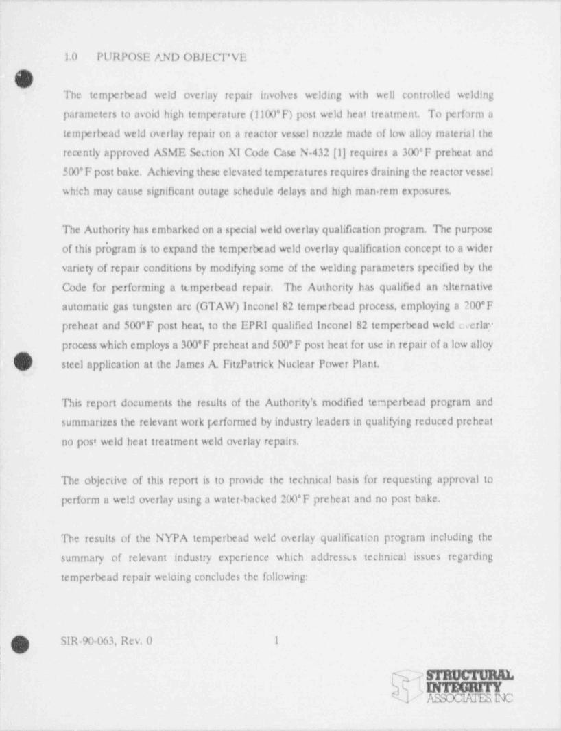
l.0 PURPOSE AND OBJECT'VE
O'The temperbead weld overlay repair involves welding with well controlled welding-
parameters to avoid high temperature (1100*F) post weld heat treatment. To perform a
temperbead weld overlay repair on a reactor vessel nozzle made of low alloy material the ;
recently approved ASME Section XI Code Case N432 [1] requires a 300'F preheat and
500'F post bake. Achieving these elevated temperatures requires draining the reactor vessel
which may cause significant outage schedule delays and high man rem exposures.
The Authority has embarked on a special weld overlay qualification program. The purpose
of this pr'ogram is to expand the temperbead weld overlay qualification concept to a wider
variety of repair conditions by modifying some of the welding parameters specified by the
Code for performing a temperbead repair. The Authority has qualified an alternative,
automatie gas tungsten arc (GTAW) Inconel 82 temperbead process, employing a 200*F
preheat and 500*F post heat, to the EPRI qualified Inconel 82 temperbead weld overlay
process which employs a 300*F preheat and 500'F post heat for use in repair of a low alloy
O stcei erguce a n atthe 3ames & Fitzre e k secieer e - er rient.
This report documents the results of the Authority's modified ter,perbead program and
summarizes the relevant work performed by industry leaders in qualifying reduced preheat
no post weld heat treatment weld overlay repairs.
The objective of this report is to provide the technical basis for requesting approval to
perform a weld overlay using a water backed 200*F preheat and no post bake.
The results of the NYPA temperbead weld overlay qualification program including the"
summary of relevant industry experience which addresscs technical issues regarding
temperbead repair weloing concludes the following:
Q SIR-90-063, Rev. 0 1
, ~ moenmaDfTEGRHT
- ASSOCWESINC
-_ _ _ - _ . _ . _ _ _ _ __ _ _.. ~ _ , _ _ .._._
. _ _ _ - _ _ _ _ _ _ _ .
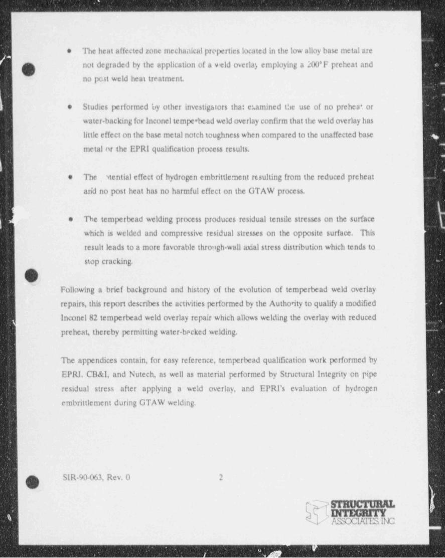
The heat affected zone mechanical prciperties located in the low alloy base metal are*
not degraded by the application of a v eld overla', employing a 200*F preheat and
no post weld heat treatment.
Studies performed by other investigators that examined the use of no prehea'. or*
water backing for Inconel temperbead weld overlay confirm that the weld overlay has
little effect on the base metal notch toughness when compared to the unaffected base
metal nr the EPRI qualification process results.
The ytential effect of hydrogen embrittlement resulting from the reduced preheat*
arid no post heat has no harmful effect on the GTAW process.
The temperbead welding process produces residual tensile stresses on the surface*
which is welded and compressive residual stresses on the opposite surface. This
result leads to a more favorable through wall axial stress distribution which tends to
stop cracking.AV
~
Following a brief background and history of the evolution of temperbead weld overlay
repairs, this report describes the activities performed by the Authority to qualify a modified
Inconel 82 temperbead weld overlay repair which allows welding the overlay with reduced
preheat, thereby permitting water-backed welding.
The appendices contain, for easy reference, temperbead qualification work performed by
EPRI, CB&I, and Nutech, as well as material performed by Structural Integrity on pipe
residual stress after applying a weld overlay, and EPRI's evaluation of hydrogen
embrittlement during GTAW welding.
O SIR-90-063, Rev. 0 2
U
& .STRtJCTIJRAL ,
INTEGRITY/ ASSOClKfESINC
- - - _ _ _ _ _ _ _ _ _ - _ _ _ _ _ _ - _ - _ _ _ - - _ _ _ - _ _ _ _ _ - _ - _ _ _ _ - - _ _ - _ -

1.1 Background
r(
De use of the weld overlay for austenitic stainless steel piping as an intergranular stress
corrosion cracking (IGSCC) repair is widespread in the BWR industry. Originally the weld
overlay was designed as an interim measure, but extensive laboratory testing, analysis, and
field performance have demonstrated its suitability as a long term repair for stainless steel
piping. As a result of the extensive activity qualifying the overlay as a long term repair, the
Nuclear Regulatory Commission approved its use in NUREG 0313, Revision 2, [2]. In
addition, a Code Case has been introduced to Section X1 of the ASME Pressure Vessel
Code which would allow the overlay to be applied to stainless steel components without the
need for tase by case NRC review and approval as is presently required. This Code Case
has received a favorable endorsement by the utility industry and the jurisdictional and
regulatory personnel involved and is expected to be cdopted in the near future.
During the past several years, IGSCL has also been observed in Inconel 182 weld metal
associated with nonle cladding and noale butter, recirculation inlet and outlet nonles and
(l incore spray safe-end to nonle welds. IGSCCin inconel 182 weld metal has been reportedv
in domestic and foreign BWRs. The IGSCC associated with Inconel 182 in the nonle butter
at some plants also involved reported stress corrosion cracking which may have progressed
into the low alloy steel nonle material.
Recognizing the Incor,el 182 butter susceptibility to IGSCC in BWRs, an effort was
undertaken in 1985 to develop and qualify an inconel 82 weld overlay repair which could
be used to mitigate the consequences ofIGSCC in components containing Inconel 182 butter
or cladding. The project team for that program included the Georgia Power Company
(GPCo), the Electric Power Research Institute (EPRI), General Electric Company (GE) and,
1
Structural Integrity Associates (SI). The team performed the analysis, welding, metallurgical1
examinations, fracture mechanics, mockup evaluations, Code and licensing activities
1
SIR-90-063, Rev. 0 3'
v
' INTEGRITY/ /LssoctATESINC
_. _ _. _ _ _ _ _ _ _ . _ ._. _
+#vesny * tuali econel we.ld overlay repair to the low alloy steel to safe-end pressure
p ;ar, iomt ic. L jicalBWR[3)., -wy,
)y
i m recirculatio' inlet nozzle (N-2) joint for that -tudy because it-
ai- which has t.ff .. , the largest incidence of IGSCC .i Inconel 182 in
- "/ . . #R N-2 c ou to safe-end was modeled as the joint to be qualified
tb weling and post weld heat treatment parameters selected were based9
' nce provided by Section 111 and Section XI of the ASME Code and upor. the-op a.
a
pri eurk y t'ormed by the Babcod & Wilcox Company (B&W) under contract to EPRI
[1]..
.
The B&W cffort invt.- -d development of a temperbvad welding procedure for welding on
low alloy steel nonle materials using automatic GTAW technology. In that study, various
wtMing ap zoaches were evaluated ir an at - 1pt to develop an alte'. native welding
techniquc m3 che Code appror.-4 '' half-bead" shielded metal arc welding (SMAW) technique
which was the only ASME Cede approved repair technique at ine time for low alloy steel
h components which did not require a full post weld heat treatment.
The successful completion of the B&W program and the RI sponsored Inconel 82 weld
overlay program led directly to the incorporation of Code Case N-132 into the ASME Code
'[1]. Code Case N-432 allows one to perform a gas tungste> . gerbead repair to a
carbon or low alloy steel component (P-1 or P-3 material) wanout a full post weld heat
treatment provided the requirements in the Code Case are met. This Code Case has (provided the basis for all temperbead Inconel 82 repairs which have been performed in
operating BWRs and has also been u;ed for Inconel 82 temperbead weld build-ups in
P%Rs.
g SIR-90-063, ~Rev. 0 4
o(mucrunnINTEGRITY/ ASSCCIATESINC
_ _ _ _ _ _ _ _ _ _ _ _ _ _ _ _ . _ _ _ _ _ _ _ _
One of the shortcomings of the EPRI temperbead study is that the required 300*F preheat
g and 500*F post bake result in the need to perform the repair with water removed from the
sicinity of the joint. This need can create scheduling and refueling problems. EPRI
recognized this short-coming and assembled a Temperbead Advisory Committee to
determine the technical feasibility of reducing the preheat and post bake to temperatures
which would allow the temperbead weld overlay to be applied with water in the pipe. The
Authority and Structural Integrity Associates, as well as the NRC are represented on this
EPRI Temperbead Advisory Committee.
In addition to the EPRI sponsored activities, other experimental studies have been
performed examining the effect of a reduced preheat or no preheat temperbead repair to
low alloy steel nozzle materials. The results of two of these studies are presented in this
report.
As presented in Section LO of this repcrt, the objective of the current New York Power
Authority study is to expand the temperbead weld overlay concept to a widet variety of
h repair conditions by modifying some of the welding parameters which were qualified in the
original temperbead weld overlay qualification program [3]. The parameters which were
ndjusted in this study are the preheat and the post weld heat treatment. As noted in the
preceding paragraphs, the original temperbead weld overlay qualiScation required a 300*F
preheat and a 500 F post bake. In this study, an Inconel 82 temperbead weld overlay was
qualific witt,1200*F preheat and no post weld bake. The incorporation of the 200'F
preheat w' ..o post heat treatment will allow the utilities a peiform the temperbead weld
overlay repair without draining any of the piping systems of water, thereby providing a
potentially significant reduction in outage schedule. Additionally, the presence of water in
the pipe can reduce the man-rem exposure associated with the repair and may provide
additional benefits to the repair, such as improving the inside surface residual stress
distribution when comp; red to a full post weld eat tretted safe-end to nozzle joint. Issues
SIR-90-063, Rev. 0 5gm srauerunn.h9 INTEGRITYAssoc m Esy c~
- _ _ - _ __- _ _ _ _ _ _ _ _ - _ __ __________ - ________ _ ___ _ ___ _ ___
-- . ..- .. - .- .-. ... . - -- - -. .
such as unfavorable residual stress distributions, incomplete tempering of the low alloy steel- weld heat affected zone and hydrogen embrittlement effects were evaluated.
The following sections of this report describe the welding activities performed by the New
York Power Authority in qualifying a modified Inconel 82 temperbead weld overlay repair
which allows welding the overlay with reduced preheat, thereby permitting water backed
welding.
.
O
SIR-90-063, Rev. 0 6
mucmu.. INTEGRITY
ASSOCIATESIIC
. -
_ _ _ . __ _ _ . _ _ . _ _ _ _ . _ _ __ _. ._ . _ _ _ _
2.0 TECHNICAL APPROACH
O'2.1 New York Power Authority Temperbead Qualification Program
As described in Section 1 of this report, the objective of the Authority's program was to
qualify an alternative automatic gas tungsten arc (GTAW) Inconel 82 temperbead process,
employing a 200'F preheat and no post heat by comparing the results to the EPRI qualified
Inconel 82 temperbead weld overlay process, which employs a 300'F preheat and a 500'F
post heat, for use in repair of a low alloy steel nozzle application at the James A. FitzPatrick
Nuclear Power Plant. The approach used in this program was to procure two SA 508 Cl. 2
ring forg*ngs from the same heat of material in a size consistent with the recirculation inlet
nozzle (N 2 nozzle) at the FitzPatrich plant, perform the required post weld heat treatments
to simulate the heat treatment condition of the existing nozzles at the plant, and perform
the Inconel 82 temperbead overlay welding procedure on the ring forgings and machine
qualification test samples. The' certified material test reports for the ring forgings used in
this test program are presented in Appendix 1 of this report.
TNkj'
Three procedure qualification tests (PORs) were performed in accordance with Authority
weld proced. ire specification (WPS) NZ-Overlay. Two of the qualification tests were
performed to compare tiie lower preheat, no post bake temperbead approach to the EPRI
approach. -The third procedure qualification was of an actua' weld overlay using the EPRI
preheat and post bake parameters. WPS NZ-Overlay and the supporting PQRs (POR 395,
745 and 746) used to perform these qualifications are appended to this report as Appendix
2. One of the PORs, POR.746, was ud to deposit an Inconel 82 temperbead groove weld
in the ring forging (see figure in POR 746, Appendix 2). This temperbead groove weld,
deposited using a 300'F preheat and 500*F post bake in accordance with the EPRI
temperbead Inconel 82 qualification program [3], used welding parameters which_
approximated those used in the Reference 3 project. The principal difference between the
welding parameters in the EPRI welding procedures and in the Authority WPS NZ-Overlay
,
f SIR-90-063, Rev. 0 7%yLSTRUCTOBAL
, INTEGRITYASSOCIATESlbC
_ _-
. ~ . _ _ _ _ _ . - . _. _ m. ._ _
involved the arc voltage which was reduced by approximately 10% for the temperbead weld
overlay qualified in the program. This reduced are voltage, applied consistently as in the
Authority program, has no effect on the temperbead results.
The second POR, POR 745, was used to deposit an Inconel 82 temperbead groove weld in
the ring forging (see figure in POR 745, Appendix 2) with a 200*F preheat and no post'
bake using the same welding parameters as in POR 746 (WPS NZ-Overlay). This
temperbead weld represents the Authority alternative to the EPRI temperbead Inconel 82
weld overlay process.
The final weld, the demonstration Inconel 82 weld overlay weld, involving fabrication of a
simulated nozzle to safe-end mockup by welding a section of a ring forging to a Type 304
stainless steel simulated safe-end in accordance with Authority welding procedures employing
both automatic and manual welding techniques (GTAW and SMAW). A GTAW
temperbead Inconel 82 weld overlay was then applied to the simulated nozzle to safe-end
joint. The nozzle to safe-end mockup temperbead Inconel 82 weld overlay was welded in
'I accordance with WPS NZ-Overlay employing a 300*F preheat and 500*F post heat in.
accordance with the EPRI' qualification program [3]. Following welding, the weld was
sectioned and destructively examined as illustrated in the Physical Test Report for mockup
395 (Appendix 2), and the metallurgical and mechanical properties of the low alloy steel
weld ' heat affected zone were compared to the base metal properties for this nozzle to
safe-end joint.
The purpose of these tests on welded components is to determine whether the component
properties were degraded by welding. Section XI requires that repairs to components be
performed which result in the base metal being left in a state equal to or better than the
original as installed condition. Proper selection of weld metal can generally ensure that the
weld metal properties will meet or exceed those of the base metal which it is replacing.
However, tne weld fusion zone and the base metal heat affected zone can be adversely
SIR-90-063, Rev. 0 8
STRUCTURALINTEGRITYASSOCIATESINC
, - ._ ._ . - _
.- -- - - . . - . _ . - - - -- _
i
affected unless careful selection is made of welding materials and welding parameters and )high quality welding is performed. The ASME Boiler and Pressure Code requires that, for
- heat treatable steels, of which low alloy vessel and nozzle steels are examples, appropriate
post weld heat treatment must be performed to ensure that mechanical properties of the
component are not degraded by the welding process.
The GTAW temperbead process simulates the post weld heat treatment metallurgical ]condition in the weld heat affected zone of a carbon or low alloy steel component by
judicious selection of welding heat input for each of the layers of the temperbead weld. The
EPRI/B&W program illustrates that using controlled welding parameters can produce a
suitably tempered low alloy steel metallurgical structure without post weld heat treatment
(4]. The EPRI Inconel temperbead study demonstrates that this automatic GTAW process
could be extended to an Inconel 82 weld overlay on a low alloy steel nozzle using an
automatic orbital welding technique [3].
WPS NZ-Overlay (Appendix 2) illustrates how the temperbead welding paremeters have
Q been selected to provide the metallurgical tempering and grain refinement normally obtainedV'
by a post weld heat treatment at typical temperatures of 1100 to 1300*F. One observes
from WPS NZ-Overlay that the welding heat input is quite low for the initial weld layer,
increasing in the secord layer and again in the third layer to allow the second and third
layers to temper and grain refine the low alloy steel heat affected zone beneath the first
weld overlay layer. The demonstration of this tempering effect on the low alloy steel heat
affected zone is obtained by ASME Code mandated mechanical property testing. The Code
| tests required for these heat treatable steels are tensile tests, bend tests, and Charpy V-notch
L impact tests. The tensile and bend tests evaluate the soundness of the weld metal and the
welding process. The impact tests examine the weld metal and the weld heat affected zone
comparing the results to the unaffected base metal. In subsequent test programs, EPRI has
demonstrated that increasing heat input with each temperbead layer not required. Rather,
! well controlled heat input will produce the required tempering effect.
SIR-90-063, Ilev. 0 9
mocronar.DiTEGR17YASSOCIATESINC
. . - - -
- ._ _ _ _ _ _ _ _ _ _ _ . _ _ - . _ . _ _ . _ _ . _ _ _ _ . _ _
2.2 Ir.dustry Developed Temperbead Qualification Prograrns
In addition to the EPRI qualification program (3) which the Authority used to develop--
parameters for its temperbead qualification program, other temperbead qualifications have
been performed by engineering organizations supporting the nuclear power industry. Among
the performed programs, two are particularly notable since preheat and post heat var 6d.
from the EPRI qualification program,in a manner similar to that performed in the Authority
program. These qualification programs were performed by Nutech, Inc. and by _CB&I )Services,Inc., and were reported at the EPRI Advisory Committee Meeting for Temperbead |
Welding held in Charlotte, NC, on November 2 and 3,1989. :
.
Sections 2.2.1 and 2.2.2 summarize the qualifications performed by these two organizations.
Detailed descriptions of these activities are presented in Appendices 3 and 4 of this report.
2.2.1 Nutech Temperbead Qualification Program for Discharge Nozzle at the Oyster Creek
Nuclear Power St '
- OGenera! Public Utilities contracted Nutech, Inc. to develop a contingency plan for providing
an Inconel 82 temperbead weld overlay repair to a 26 inch diameter recirculation system
discharge nozzle at the Oyster Creek Nuclear Power Station. The temperbead repair was
identified as trie preferred approach compared to a full post weld heat treatment, since the
geometry of the nozzle end the physical space .:onstraint resulted in difficulty in'
accommodating preheat and post weld heat treatment equipment. Consequently, Nutech
developed procedures and performed qualification welds for both the temperbead weld
overlay approach developed in the EPRI program [3] and a modified temperbead approach -
in which no preheat or post heat were applied to the joint.
.
A
SIR-90-063, Rev. 0 10
mmemm.
b NissoC-sana -
.. . __ . . _ _ - . _ _ . _
.. . . - -- - ._ = . - _ - - . . _ . - . .- - ~ _ _ - . - . --
A 14-inch diameter nozzle was heat treated to simulate the post weld heat treatment
, condition of the discharge nozzle, buttered with inconel 182, and stress relieved at
1100-1150*F for one heur.
Following the stress relief heat treatment, a Type 304 stainless steel safe-end was welded to
the buttered nozzle using Inconel 182 manual welding techniques. Following the welding of
the safe-end to the nozzle, two additional grooves were machined into the nozzle for
temperbead welding in order to provide procedure qualification test samples. The
configuration of the nozzle to safe-end including the grooves for the procedure qualification
samples is presented in Figure 3 in Appendix 3. The procedure qualification temperbead
welding 6 performed by welding other temperbead welds including a weld overlay using
the EPRI 300'F preheat,500'F post heat technique (5 layers), then removing the preheat
and performing the water backed other one-half of the temperbead welds (5 layers) without
any preheat or post heat. The average temperature for the water backed welds was
70-75'F. Following the welding of the three temperbead welds as illustrated in Figure 3,
Appendix 3, the Code required mechanical tests and supplemental metallurgical tests wereOQ. performed. Results of these tests are presented in Appendix 3 of this report and are
discussed in Section 3.2.1 of this report.
2.2.2 CB&I Reactor Nozzle to Safe-end Temperbead Structural Overlay Test Program
The test program developed by CB&I Services, Inc., presents an ahernative to the EPRI
temperbead qualification [3] and affords utilities increased flexibility in performing a
temperbead repair to a low alloy steel nozzle to safe-end joint buttered with Inconel 182
weld metal. This test program, presented in Appendix 4, investigated the use of a non-water
backed, non-preheated, non-post heated condition and a water backed non post heated
condition as alternatives to the EPRI temperbead qualification [3].|
O SIR-90-063, Rev. 0 11
Q:STRUCTURALINTEGRITYASSOCIATESINC.
.._ - .- - . -
. -- . . - -- .- .- -- - -. - -- .. - - ._ - -
The CB&I program used an SA 508 Cl. 2 low alloy steel nozzle forging to perfonn the -
appropriate post weld heat treatment to simalate the vessel heat treatment, and to weld a
Type 304 stainless steel safe-end to the nozzle. Subsequent to the welding of the safe-end
to nozzle, a one inch deep groove was machined in the nozzle remote from the rozzle to
safe-end weld as illustrated in Appendix 4 and a six layer Inconel 82 temperbead weld was
deposited to fill the groove using a 300*F preheat and 500'F post heat to simulate the
EPRI temperbead process [3].
In addition to the temperbead groove weld, an Inconel 82 temperbead weld overlay was
applied to the nozzle to safe-end weld as a wet / dry overlay, using a partial thermal sleeve
(see Appendix 4 for details). With this configuration, one half of the nozzle at the safe-end
would be filled with water while the other half remained dry. This configuration allowed the
welding to be affected by a severe quench and a moderate quench. Neither preheat nor
post heat was applied to this joint. Following welding, Code required mechanical tests and
supplemental metallurgical tests were performed on the temperbead groove weld and the-
modified temperbead weld overlay. The results of these tests are presented in the Appendix
0 4 renort =#a re disc #ssee ia secti " 3.2.2 of this report.
t
..
i
i
|
i-
q SIR 90-06.5, Rev 0 12
u-
! TEGRITYb W'SOCIATESINCK-
t
--, .- --_______ _ . _ - - - _ _ _ _ _ _ _ _ _
. _ . . _ _ _ _ _ _ _._ . __ _ _ _ _ _ . _ _ . . . _ _ _
3.0 TEST RESULTS
3.1 New York Power Authority Temperbead Qualification Program
This section of the report presents the mechanical and metallurgical tests performed to
qualify the 200*F preheat, no post heat Authority Inconel 82 temperbead weld overlay for
low alloy steel nozzle to austenitic stainless steel safe-end welds (POR 745). The results of i
these tests are compared to the Inconel 82 te.mperbead weld overlay test results from the
EPRI por.sored program [3] and the results from the Authority simulation of the EPRI
qualification (POR 746) Finally, a simulued nozzle to safe-end Inconel 82 weld overlay
mockup was fabricated using the same welding parameters as POR 746, and the test results
for this mnckup are presented (POR 395) and compared to the EPRI qualification results.
3.1.1 Mechanical Property Tests
Professional Service Industries,Inc. performed all of the tensile and bend qualification tests
and for the metallurgical tests. The Charpy V-notch impact tests were performed by Lucius'
Pitkin, Inc. All physical property tests were performed in accordance with the ASME Code
requirements of Sections IX and XI and Code Case N-432. The physical test reports for
PORs 395,745, and 746 are included as Appendix 5 of this report, and the metallurgical
reports for the temperbead samples removed for the qualification welds are provided in
. Appendix 6. Tensile and bend test presented in Appendix 5 illustrate that acceptable results
were achieved for all samples tested. No defects were observed in any of the bend tests, and
the tensile specimens all failed in the weld at a stress level near the certified material test
report base metal tensile strength.
.Charpy V-notch impact tw were performed on weld metal, heat affected one and base
metal samples for each of the test conditions and were compared to the EPRI test results.
1 he heat affected zone Charpy samples for PORs 745 and 746 were oriented normal to the
SIR-90-063, Rev. 0 13
_
INTEGRITYASSOCIATESINC
_ _ _ .
_ ._. . ._ ~ _ _ . . _ _ . . _ _ _ .. _. . __ .
weid so that the entire sample failure was in the heat affected zone. The base metal sample
was oriented the same way so as to make a direct comparison between HAZ and base metal
L/ . for these two PORs. Figure 1 in the Lucius Pitkin report for these two PQRs in Appendix
5 presents the orientation for these samples.
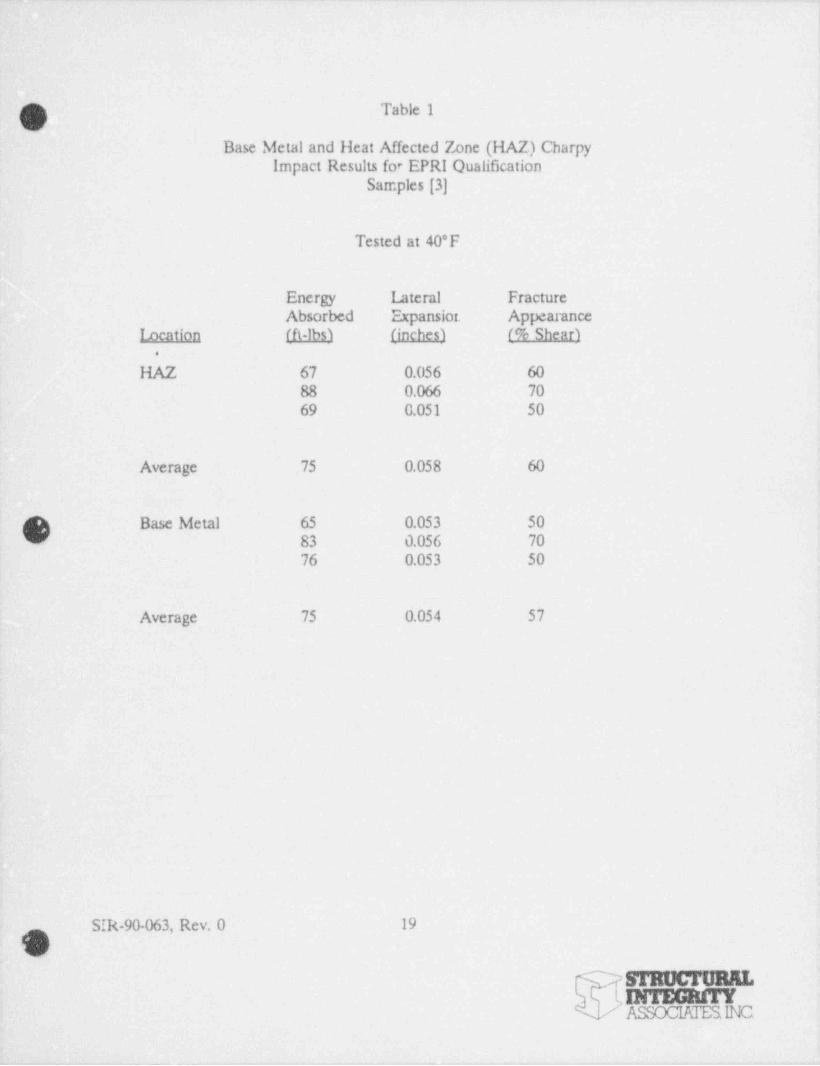
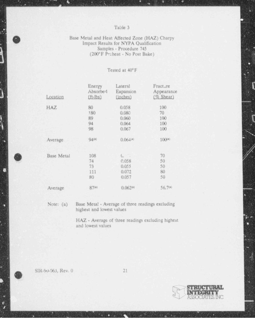
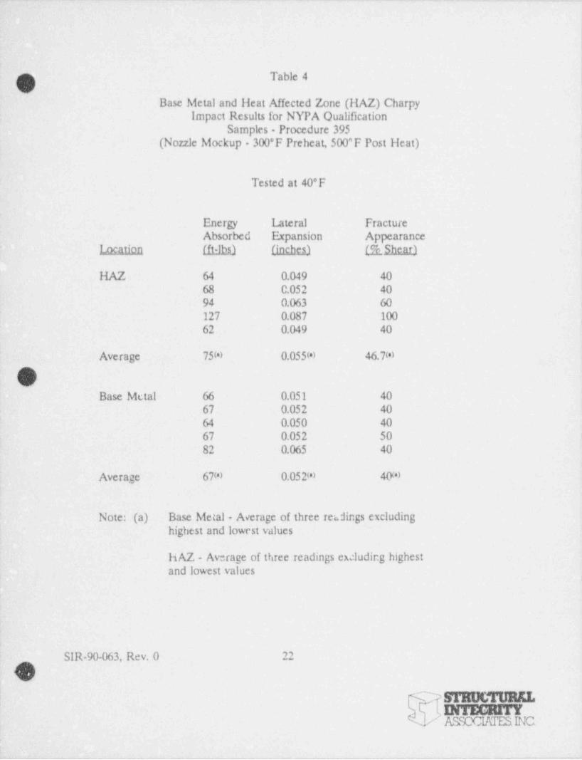
Tables 1 through 4 present the results of the Charpy V-notch impact tests for the three
procedures qualified in the Authority's program, comparing the results to the EPRI test
results for the HAZ and base metals at 40*F, the test temperature for the EPRI tests [3].
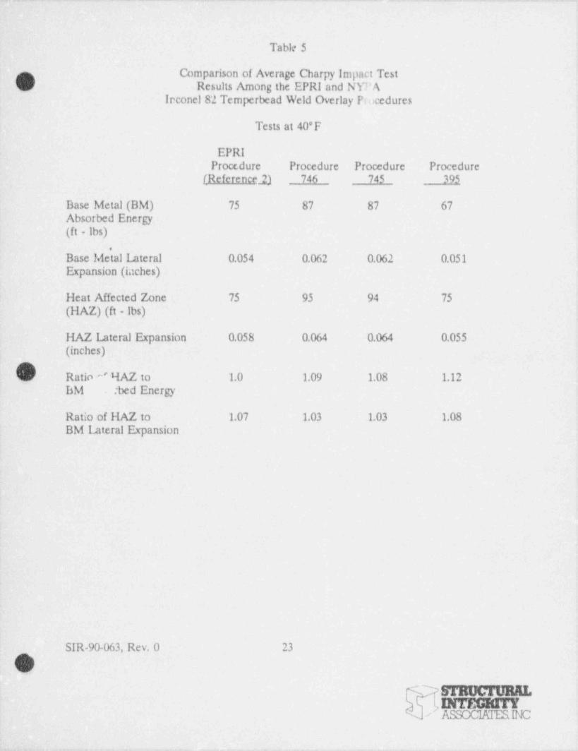
Table 5 is a summary of the average Charpy impact results for the three Authority
temperbead weld procedures and the EPRI procedure. All of the samples meet the 50 ft lbs
absorbed energy and the 35 mils lateral expansion required by ASME Section XI and Code
Case N-432. In all cases, the energy absorbed in the weld heat affected zones is greater than
the base metal absorbed energy. This result meets the mechanical property requirements
of the Code and of Code Case N-432 for the process to be qualified. No degradation of
physical property resulted from the 200'F preheat, no post heat treatment used in the POR
745 qualifiuition.
-
'"3.1.2 Metallurgical Tests
Metallurgical tests were performed to provide a direct comparison between the results of
these tests and the prior EPRI study [3]. The metallurgical tests involved microhardness
te.sts and metallographic examination of the weld heat affected zones for each of the
procedures qualified in this prsgram.
L The metallurgical tests were performed by Professional Service Industries, Inc. and are gD appended to this report as Appendix 6. Examination of the metallography for the 1
Authority's PQRs 395,745 and 746 revealed that the anticipated grain refinement occurred
| in the low alloy- steel weld heat affected zones for each of the procedures. The-
microstructural results are quite similar to those presented in Figures 3-8 and 3-9 of the
SIR-90-063, Rev. L 14
*
sTaocrunn.DITEGRITY,
ASSOCIAIESINC'
.
,-
~ Reference 2 report. The base metal structure for these specimens appears to be a tempe ud
bainite or tempered martensite structure, the anticipated structure in this steel following' - quenching and tempering.
:
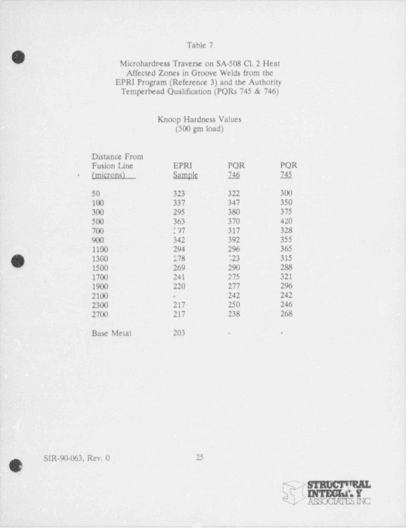
In order to confirm the tempering effect of the temperbead welding in the low alloy steel
heat affected zove, microhardness measurements were performed on the groove weld
samples in the Authority's qualification program (POR 745 and 746), and compared to the
EPRI groove weld qualification results using a 500 yam Knoop indentor traversing the weld
heat affected zone as was done in the EPRI study. The results of the traverses for the EPRI
groove weld sample [3] are presented in Table 6 and are compared to the Authority's POR
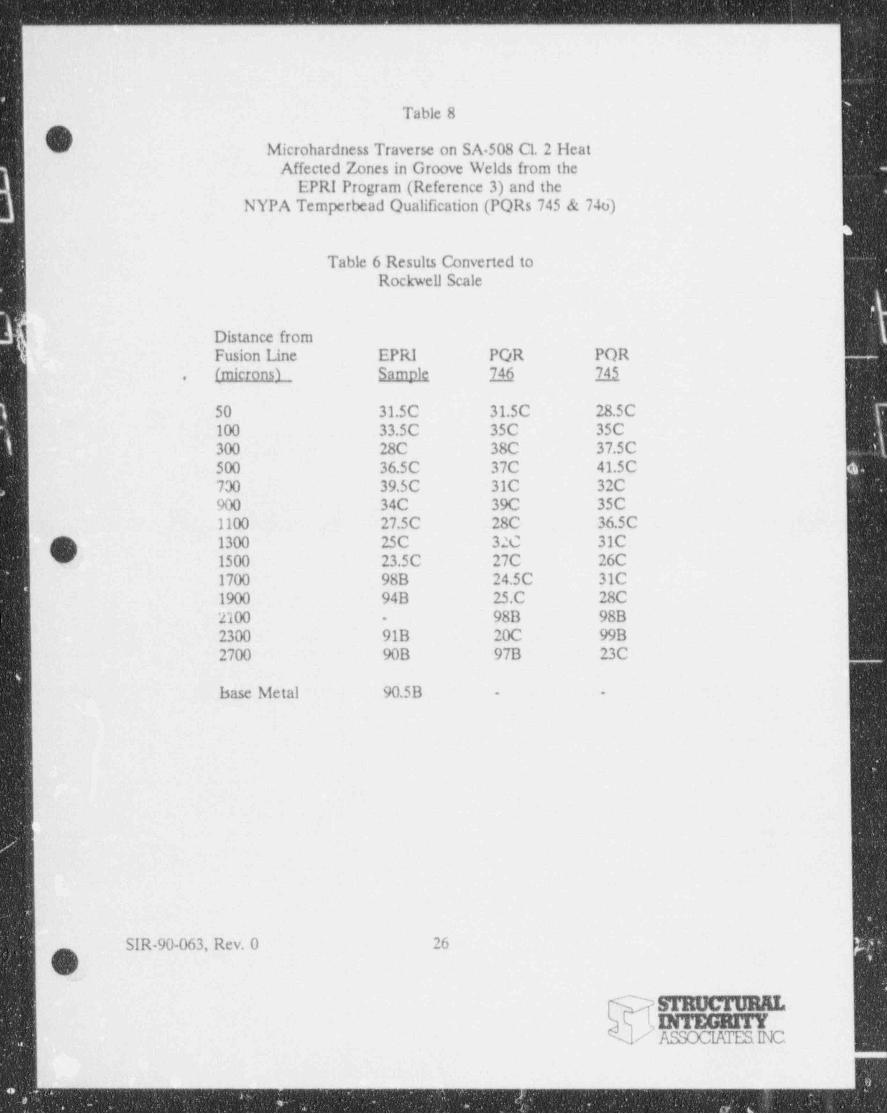
746 groove weld sample and the POR 745 groove weld sample in Tabler 7 and 8. Table 7
presents the actual Knoop data for the three traverses and Table 8 presents these data
converted to the Rockwell hardness scale. Examination of the Table 8 results reveals that
the hardnesses for the three procedures are quite comparable, within anticipated data
scatter, to a distance of approximately 1000 micr<ms (0.04 inches) from the weld fusion line.-
Beyond that point, the hardness in the EPRI sampb is significantly lower than for the two
] Authority samples, reflecting the fact that the base metel hardness of the EPRI nozzle was''
markedly lower than for the Authority ring forging. However, it is within the initial 1000
microns in the low alloy heat affected zone where high hardness due to improper tempering
may create a low toughness or embrittled joint. No such concern is observed from these
microhardness results.
3.2 Industry Developed Temperbead Qualification Programs
This section of the report summarizes the significant mechanical and metallurgical tests
performed in the Nutech and CB&l programs to qualify alternatives to the EPRI qualified
temperbead welding program (3]. These two alternative p:ograms qualified a water backed
temperbead procedure without preheat or post heat and a dry temperbead procedure again
without preheat or post heat treatment. In each case the results are compared to the EPRI
ol'
|p SIR-90-063, Rev. 0 15
srmxmmm.INTEGRITYASSOCIATESINC'
,
w * w va. w~ - r --- e
- .. - . . -. - - . - . . . ..
!:
- qualification program results [3]. Detailed descriptions of the Nutech and CD&I programs |
are enclosed as Appendices 3 and 4 to this report.
3.2.1 Nutech Temperbead Qualification Program for Discharge Nozzle at the Oyster Creek
Nuclear Power Station
As described in Section 2 of this report, the Nutech qualification program compared an
Inconel temperbead weld overlay using the EPRI qualification program parameters [3] to
a temperbead weld overlay using water-bacxing and employing no preheat nor post heat
treatment. In addition to fabricating a weld overlay on a nozzle to safe-end mockup, two
groove welds were also fabricated to provide procedure qualificat.icn test samples comparing
the EPRI temperbead parameters to the water backed temperbead parameters. One of the
groove samples was welded in a part of the nozzle containing a 1/2 inch remaining wall
thickness beneath the groove (the 1/2 inch groove), and the other procedure qualification
test specimen was welded in a part of the nozzle with a 1-1/4 incil remaining thickness
beneath the groove. The two different thicknesses were examined to evaluate the effects
of location. Details of these tests are presented in Appendix 3 to this report and are~
summarized below.
Results of the tensile and bend tes.s for the procedure qualification welds illustrate no
unusual failures for any of the samples tested. No defects were observed in any of the bend
tests, and the tensile specimens all failed in the base metal remote from the weld heat
affected zone indicating that the temperbead welding had no deleterious effect on the tensile
results and bend test results.
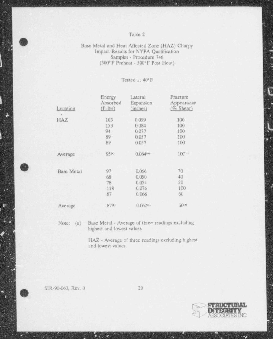
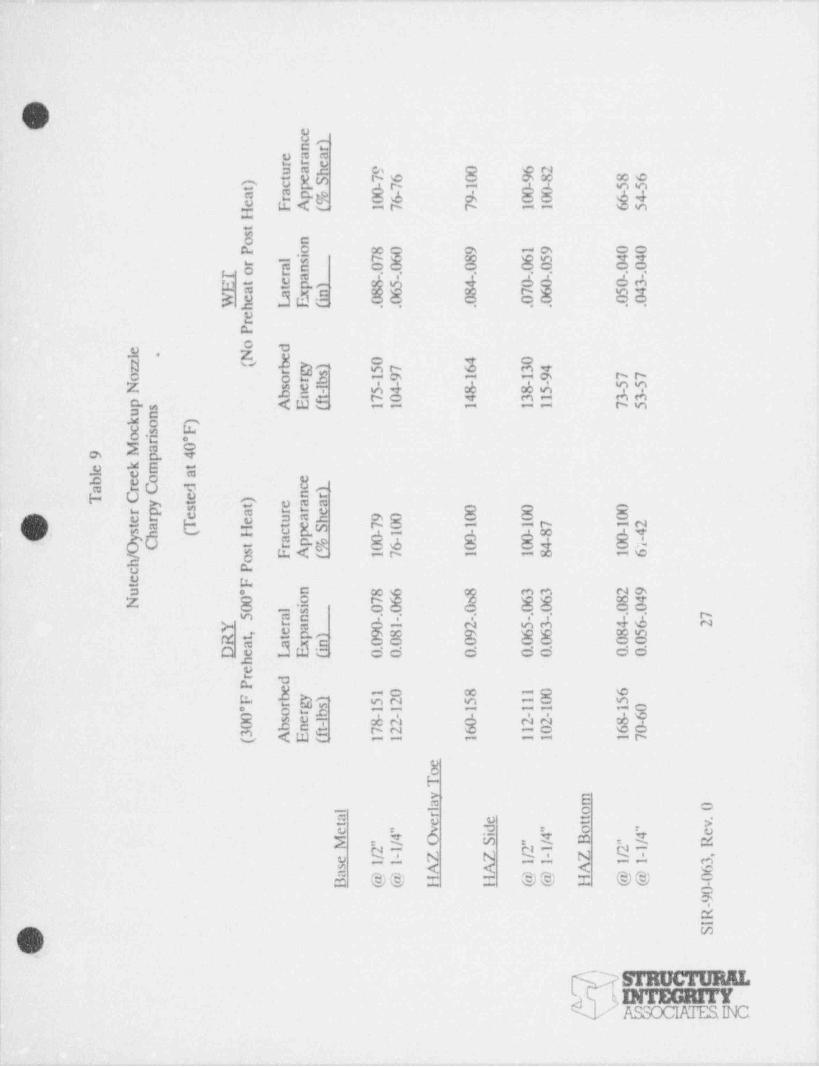
Charpy V notch impact tests -were performed on the two procedure qualification weld
samples for the base metal and heat affected zones. Table 9 presents the results for both
the water backed (wet) and the " dry" 300*F preheat,500*F post heat temperbead groove
weld at the 1/2 inch and the 1-1/4 inch nozzle locations. Also included in Table 9 are the
SIR-90-063, Rev. 0 16gO
sTaucreanLINTEGRITY
r ASSOCIATESINC
_.

Charpy V-notch results for the base metal on the ". vet" and " dry" halves of the nozzle.
q These test results show that the absorbed energy and lateral expansion mee: the Codeb requirements of 50 ft-lb energy absorbed and 0.035 inches lateral expansion in all cases. The
impact energy absorbed and lateral expansion for the " wet" temperbead process are
generall lawer than that for the " dry" process. However, in the case of the heat affectedi
side samples, the " wet" properties are somewhat better than the " dry" results. One other
noteworthy result is that there is significant variability in properties in a nozzle forging. The
differences between the " wet" and the " dry" results at a specific location in the nozzle are
generally less than the differ nces in properties when comparing thinner and thicker
locations in the same no72.ie.
.
Table 9 also presents Charpy V-notch impact results for the weld overlay, using the EPRI
parameters (dry) for one half of the overlay and the water backed " wet" temperbead
parameters for the other half of the overlay. The weld overlay toe Charpy results in Table
9 illustrate that these results approximate the best base metal results in absorbed energy and
lateral expansion. Further, these results are essentially the same whether the welding was
O performed " wet," without preheat and post heat or " dry," with a 300* F preheat and a 500* FG
post heat treatment. The variability :n properties within the forging Lppears to dominate
the result obtained with the material notch toughness properties being far superior at the
outside surfax than within the forging. The implication of these results will be explored
further in Section 4 of this report.
3.2.2 CB&I Reactor Nozzle to Safe-end Tempe: bead Structural Overlay Test Program
The CB&l test program for the nozzle to safe-end is similar to the Nutech program. A
water backed " wet" overlay was qualified and compared to an overlay using the EPRI
qualification parameters [3]. However, the CB&l program contains an additional
qualification in which a " dry" temperhead weld overlay is applied to 1/2 of the nozzle to
SIR-90-063, Rev. 0 17q%J
-
INTEGRITYk ASSOCIATESINC l
__ -_
. . - . - . . -- - - .- . - - . - - -. - --. _
safe-end joint without preheat or post heat. The results of this overlay qualification program
are presented below.'
Results of the tensile and bend tests for the procedure qualification welds show no unusual
failures for any of the samples tested. No defects were observed in any of the bend tests,
and the tensile specimens removed frorn the groove weld failed in the base metal remote
from the weld heat affected zone. Only all weld metal tensile specimens were evaluated for
the weld overlay specimens. The *. ensile and bend test results indicate that the temperbead
-welding has no deleterious effect on the mechanical properties for these temperbead
qualifiention welds, as illustrated in Appendix 4.
The Charpy V-notch impact results for the temperbe.ad groove weld welded using the EPRI
. qualification pararneters [3] are presented in Tab:e 10. These results illustrate that the heat
affected zone absorbed energy and lateral expansion are superior to the base metal results.
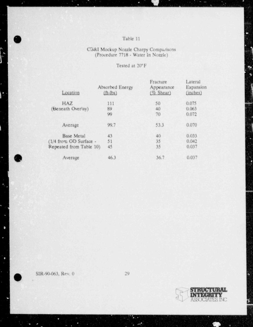
The Charpy V-notch impact results for the water backed temperbead weld overlay and the
dry temperbead weld overlay employing i o preheat or post heat treatment are presented
h in Tables 11 and 12. Also included in these tables are the corresponding base metal impact~
I test results repeated from Table 10. One observes from Tables 11 and 12 that the heat
affected zone notch toughness for both ginalification tests are superior to the base metal
properties in absorbed energy as well as in lateral expansion. No impact tests were
performed at the weld averlay toe regions for the water backed or dry qualification tests.
However, hardness te vs illustrate.J that full structural temperbead weld overlays covering
the nozzle to safe-end weld can be temperbead welded at the toe tie in points without the
use of filler- to obtain similar hardness and impact strength levels to that of the EPRI
; qualification (3).
:
-
SIR-90-063, Rev. 0 18'
n.y-
b assoc 1' URALSTRUCN sm
e--v
, __ _ ._. _ _ . ,.
i
|
(~} Table 1|
_V i
Base Metal and Heat Affected Zone (HAZ) Charpy i
Impact Results for EPRI QualificationSamples [3]
Tested at 40'F
,
Energy Lateral FractureAbsorbed Expansior. Appearance
Location (ft-lbs) (inchesi (% Sheari.
HAZ 67 0.056 6088 0.066 7069 0.051 50
Average 75 0.058 60
Base Metal 65 0.053 50yv' 83 0.056 70
76 0.053 50
Average 75 0.054 57
SIR-90-063, Rev. 0 19
IOv
DITEGRfTYASSOCIATESINC
- - _. .. -
- - _ _ _ _ _ _ _ _ _ _ _ _ _ _ _
Table 2
Base Metal and Heat Affected Zone (HAZ) CharpyImpact Results for NYPA Qualification
Samples - Procedure 746(300'F Preheat - 500*F Post Heat)
Tested c 40*F
Energy Lateral FractureAbsorbed Expansion Appearance
Location (ft-lbs1 (inches) (% Sheari.
HAZ 103 0.059 100153 0.084 10094 0.077 10089 0.057 10089 0.057 100
Average 95N 0.064N 100"
Base Metal 97 0.066 7068 0.050 4078 0.054 50118 0.076 10087 0.066 60
Average 87N 0.062N 60N -
Note: (a) Base Metal _- Average of three readings excludinghighest and lowest values
HAZ - Average of three readings excluding highestand lowest values
SIR-90-063, Rev, 0 20
_
' lINTEGRITY/ ASSOCIATESINC
_ _ _ _ - - _ _ - _ _ _ ____ _ - _ _-_ _ - _ _ _ - - _ _ _ _ - _ - - _ _ _ - _ _ _ _ _ - - - - _ _ - _ _ _
. . - _ _ _ _ _ _ _ _ _ _ _ _ _ - _ _
Table 3
/]Base Metal and Heat Affected Zone (HAZ) Charpy
Impact Results for NYPA OualificationSamples - Procedure 745
(200*F Pr: heat - No Post Bake)
Tested at 40*F
Energy Lateral FractureAbsorbert Expansion Appearance
Location (ft-lbs) finches) (f% Shearl
HAZ 80 0.058 100180 0.080 7089 0.060 10094 0.064 10098 0.067 100
Average 94N 0.064N 100N
O- Base Metal 108 0. ' . 7074 0.058 5073 0.055 50111 0.072 8080 0.057 50
Average 87N 0.062W 56.7N -
Note: (a) Base Metal- Average of three readings excludinghighest and lowest values
a
HAZ - Average of three readings excluding highestand lowest values
SIR-90-063, Rev. 0 21
-
DITEGRITYASSOCIATESINC
_ _ __ _ __ - -__________ -__________________________ __________ _ _ _ _ _ _ _ _ _ _ _ _ _ _ _ _ _ _ _ _ _ _ _ _ _ _ _ _ _ _ _ _ _ _ _ _ _ _ - _ _ _ _
_ _ _ _ _ . _ . . _ _. _ ._ . _ _ ._
Table 4|
Base Metal and Heat Affected Zone (HAZ) CharpyImpact Results for NYPA Qualification
Samples - Procedure 395(Nozzle Mockup 300*F Preheat,500*F Post Heat)
Tested at 40*F
Energy Lateral FractureAbsorbed Expansion Appearance
I;> cation (f1:]h) (inches) (% Shearl
HAZ 64 0.049 4068 0.052 4094 0.063 60127 0.087 10062 0.049 40
Average 75M 0.055m 46.7M
(G_/Base Metal 66 0.051 40-
67 0.052 4064 0.050 4067 0.052 5082 0.065 40
Average 67N 0.052m 40M
Note: (a) Base Metal- Average of three res: lings excludinghighest and lowest values
HAZ - Average of three readings excluding highestand lowest values
-. SIR-90-063, Rev. 0 22
Ov,
| 7STRUC'I'URKL/sINTEGRITY
'
ASSCCIATESINC
,._y-
- . _. - - - . . - - - -- -- - . . . , . . .
Table 5
eg Comparison of Average Charpy impact TestC/ Results Among the EPRI and NYPA
loconel 82 Temperbead Weld Overlay Procedures
Tests at 40*F
EPRI-Procedure Procedure Procedure Procedure
(Reference.2) 746 745 395
Base Metal (BM) 75 87 87 67Absorbed Energy
(ft - Ibs)
Base Metal Lateral 0.054 0.062 0.062 0.051Expansion (iaches)
Heat Affected Zone 75 95 94 75
(HAZ) (ft - lbs)_
HAZ Lateral Expansion 0.058 0.064 0.064 0.055
(inches)
Ratio e' MAZ to 1.0 1.09 1.08 1.12. BM - : bed Energy
Ratio of HAZ to 1.07 1.03 1.03 1.08BM Lateral Expansion
_
.
SIR-90-063, Rev. 0 23.
'a
INTEGRITY- ASSCCIATESINC,
. . --

_--_ - - - . - - - . . .- . - . . . ..
Table 6-
EPRI Test Results'-
Microhardness Measurements in theP-3 Heat Affected Zone of the Groove Weld
(Reference 3)
Distance From Knoop Haroness ConvertedFusion Line Values Rockwell(Microns) (500 cram loadi Hardness Values
(Peak) (Valley) (Peak) (Valley)
50 380 323 38C 31.5C*
100 387 337 38.5C 33.5C
300 421 295 41.5C 28C
500 408 363 40.5C 36.5C
700 340 397 33.5C 39.5C
900 348 342 34.5C 34C
110C 343 294 34C 27.5C
1300 300 278 28.5C 25C
1500 277 269 25C 23.5C
-Q 1700 268 241 23.5C 98Bv 1900 252 220 20C 94B
2300 207 217 91B 93B
2700 201 217 90B 93B
Base Metal 204 203 90.5B 90.5B
SIR-90-063, 'Rev. 0 24
STRUCTURALDITEGRITYASSOCIATESINC
- ._. ._._ __ . . . . - . -. . . _ _ _ . _ . _ _ . . _ _ _ _ . _ _ ._ _
l
Table 7
O Microhardness Traverse on SA-508 Cl. 2 HeatAffected Zones in Groove Welds from the
EPRI Program (Reference 3) and the AuthorityTemperbead Qualification (PORs 745 & 746) l
|
Knoop Hardness Values(500 gm load)
Distance FromFusion Line EPRI POR POR(microns) Sample 746 745.
50' 323 322 300100 337 347 350300 295 380 375
500 363 370 420700 177 317 328900 342 392 355
.. 1100 294 2% 365
-O 1300 2.78 323 315' <' 1500 269 290 288
1700 241 275 321
1900 220 277 296242 2422100 -
~2300 217 250 246
2700 217- 238 268
Base Metal- 203 - -
h,...
SIR-90-063, Itev. 0 25
| MINTEGE#ifASSOCIATESINC
,
!
. - - . - . . , , . - . . , - - - . - . . , - . .,,- .
. _ _ _ _ _ _ _ _ _ _ _ - _ - _ _ _ _ - - _ _ .
Table 8
Microhardness Traverse on SA 508 C1. 2 HeatAffected Zones in Groove Welds from the
EPRI Program (Reference 3) and theNYPA Temperbead Qualification (PORs 745 & 746)
Table 6 Results Converted toRockwell Scale
l Distance fromFusion Line EPRI POR POR(microns)_ Sample 746 745,
50 31.5C 31.5C 28.5C100 33.5C 35C 35C300 28C 38C 37.5C500 36.5C 37C 41.5C730 39.5C 31C 32C900 34C 39C 35C1100 27.5C 28C 36.5C1300 25C 32C 31C
O~ 1500 23.5C 27C 26C1700 98B 24.5C 31C1900 94B 25.C 28C2100 98B 98B-
2300 91B 20C 99B2700 908 97B 23C
base Metal 90.5B - -
SIR-90-063, Rev. 0 26
_
/, INTEGRITYASSOCIATESINC
- _ _ _ _ _ _ _ _ _ _ _ _ _ _ - _ _ _ - _ _ _ _ _ _ _ - - _ _ _ - _ - _ _ _ _ _ _ _
' , ' ! , i: ; ' I' : |
ecn )reaar r euah 9 0 62eS 76 0 98 86t
-) c p - 7 1 - - 55t 0 - - 00 - -a p% 06 9 00 64a re FA( 651 7 7 1 1Htso nP o 80 9 1 9 00
l s 76 8 65 44i
r an 00 0 00 00To r a - - - - - - -et p) 85 4 00 03E t
a ax n 86 8 76 54We lEf 00 0 00 00i
herPo d -e N el .
0 4 0z ( b y) 57 6 34z r gs1 9 1 1 9 77o orb - - - - - 55N -s eI 54 8 85 - --b nt 70 4 31 33ps AE( f1 1 1 1 1 75u n
k o )c s Foi r *
Ma 09 p 4e k m t
e al
b e o ea rC d c)T C e nr) eaay t tr p e a r r e 0 0 0s
t a T e uah 90 0 0 0ereS 70 1 1 7 1 2tH c p - 1 - - 8 - 4- s (yh 0 -0 - 0 0 -a p%-
. O C r 06 0 04 01- t
FA(s 1 7 1 1 8 1 6/ oh Pce Ft
u * n 86 8 33 29N 0 o 76 o 66 84
0 00 0 00 00il s 75 an - - - - - - -
Y a 01 2 53 46 2re p) 98 9 66 85,
R t t
a 2x n 00 0 00 00D e E( 00 0 00 00i
1her dP e 1 0 8 1 0 6F b yg )s 52 5 1 0 5r
1 1 1 1 1 1 0* orb - - - - - - 60 s el 82 0 22 8- -0 b nt 72 6 1 0 603 A E (f 1 1 1 1 1 1 7(
eoTv ma o 0ll
_ra t
t . e e t
v d " o "4 .ee "4 O S " /
4 Bi_ M " /" /-
_ 21 21 21Z7 Z / - ./-/-. e 1 1 >_ 1 1 1 1
_ A A A 6- s_
a. B @@ H H @@ H @@ 0__ 0_
_ 9_
__
..
.
._.
_
-
- ga8-
_
_
-_
1 i '

. .. .- . . _ . - .- . -.
Table 10
CB&I Mocxup Nozzle Charpy Comparisons(Procedure 7673 - 300*F Preheat,500'F Post Heat)
Tested at 20*F
Fracture LateralAbsorbed Energy Appearance Expansion
Location (ft-lbs) (% Shear) (inches)
iia 2 70 45 0.037
(uaom of Groove) 62 40 0.04484 50 0.063.
98 70 0.05991 65 0.05593 70 0.056
Average 83 56.7 0.052
Base Metal 43 40 0.036
(1/4T from OD Surface) 48 50 0.045
|A 60 50 0.040V 43 40 0.033
! 51 35 0.042L 45 35 0.037
Average 48.3 41.7 0.039
F
SIR-90-063, Rev. 0 28 x
0 -
INTEGRITY -ASSOCIATESINC
,, -
,
Asv4> (0v$>sa 9
o i.
T[^59 k,*If IMAGE EVALUATION / #b,fd (g'( $ TEST TARGET (MT-3)\/
/ Q 'g3 f~4gej
N%v'459
4sr<<(e4-
V
i.o y me a l p= n3g =
1.1 t m # "22e"~
j| i.gz
a . _.
1.25 l.4 i 1.6'
!== =
* 150mm >..
4 6" *
af>4D 4+ '>*
s;fy 5,,jf3 = ,
4 ) f.e. ,. (4se -
3,
oy,tt
5bx. .:, , . . . , MA *_
.v _
__ _ __ -- . ____ -______- - _ _ - _ _ _ _ _ _ _ - _ _ -. .
.
3
t
. } Table 11gs .. . . ,
C3&l Mockup Nozzle Charpy Compuisons(Procedure 7718. Water In Nozzle)
Tested at 20'F-.,
;
Fracture Lateral-Absorbed Energy Appearance Expansion
Location (ft-lbs) (% Shear) (inches)
HAZ 111 50 0.075 -
,.'
(Beneath Overlay) 89 40 0.06399- 70 0.072
Average 99.7 53.3 0.070
-Base Metal 43 40 0.033
(1/4 from OD Surface - 51 35 0.042Repeated from Table 10) 45 35 0.037
.
. Average 46.3 36.7 0.037
L
_
11
i
W - SIR-90 063, Rev. 0 29
k|c .,
sTauctuum'
-
. INTEGRITT. ASSOCIATESINC
. . . . .

. . . .
,
,
.
Table 12
CB&I Mockup Nor21e .Charpy Comparison(Procedure 7717 - Nor21e Dry No Pt '. eat or Fost Heat)
Tested at 20*F
Fracture LateralAbsorbed Energy Appearance Expansion,
Locatiqa (ft-lbs) (% Shear) (inches)
HAZ 95 50 0.060.
(Beneath Overlay) 76 40 0.05795 55 0.065
<
Average 88.7 48.3 0.061
Base Metal 43 40 0.036(1/4 from OD Surface - 48 50 0.045
.
Repeated from Table 10) 60 50 0.010
Average 50.3 46.7 0.010
'
, .
-
I .
L+
L
() . SIR-90-063, Rev. 0 30%
.c
INTEGRITY'
ASSOCIATESINC
_ _ - _ _ _ _ - . _ _ _ _ _
4.0 DISCUSSION OF RESULTS
O ,
'
The results of the mechanical and metallurgical tests described in the prior section i
of this report illustrate that much research has been performed in developing and
qualifying alternative procedures to the EPRI qualified 300*F preheat,500*F post
- heat temperbead procedure for producing a weld overlay repair to a low alloy steel
nozzle to austenitic safe-end joint [3]. The Authority's process examined the effect
of a reduced preheat (200'F) and no post heat inconel 82 temperbead weld overlay .
repair process on mechanical and metallurgical properties of a low alloy steel nozzle
material..
The two groove weld procedure qualification tests performed in the Authority's
program, comparing the reduced preheat process (POR 745) to the EPRI process
(POR 746), demonstrated that little or no difference in mechanical or metallurgical
properties is to be expected when the preheat is reduced and no post heat is
performed. The slight differences in absorbed energy and lateral expansion between
the two processes fall well within the expected within lmat data scatter for impact
tests in this class of material.
This observation is confirmed by the Nutech and CB&l results in which a water
backed temperbead weld overlay is compared to the EPRI qualification results [3].,
In the CB&I case, Charpy V-notch absorbed energy and lateral expansion results for
the no preheat, no post heat procedure are superior to 'he unaffected base metal
results indicating that no deleterious effect would result from such a temperbead
overlay repair whether water backed or dry. The Nutech test results indicate that
both the wet and the dry temperbead groove welds produce heat affected zone
absorbed energy and lateral expansion which are reduced from the base metal results.
However, the actual temperbead weld overlay fabricated over the nozzle to safe-end-
weld produces absorbed energy which approximates that for the unaffected base
SIR-90-063, Rev. 0 31
m u c m m I.TINTEGRITY
6 asoc mEstwa_ _ - _ _ - - _ - -
_ . . __ _ _ _ - - _ _ . _ _ _ _ _ . _
.
metal and the lateral expansion exceeds that for the base metal for both the . vet and
.O; the drx weid everier with ee nrcheet er nest heet treatment.
When comparing the water backed temperbead welding process to the dry
temperbcad welding process on the same heat of material using the same welding
parameters, the dry temperbead profess produce: somewhat improved toughness
results. However, this effect is less sig.tificant than the within heat variability in notch.
toughness which appears in each of :Se tests described in this program.
Th,e toughness of the as-fabricated and heat treated forging 's quite variable due ta
the metallurgy associated with this heat treatable material. Although this alloy is
designed for improved through-thickness hardenability, there remains a significant
variability in properties from the surface to the interior. The Nutech and CB&l base
metalimpact values illustra.e the through thickness variability in the notch toughness
of this class of steel. The outside suiface of the nozzle (or ring forging) always has
the best properties, since it is most rapidly quenched during component fabrication.
The fully quenched ma-tenait structure will always be tougher than a bainitic-
structure when properly tempered following the quenching. Therefore, this surface
-and the near surface region should have the highest notch toughness within the
component. Consequently, a temperbead weld overlay repair over this surface can
readily produce a significantly tougher structure than that of the base metalinterior.
This feature of a quenched and tempered low alloy steel provides added assurance
that the overall nozzle properties will not be degraded by a well controlled
temperbead weld repair. Of greatest importance, however, is that the base metal
- properties always met or exceeded the Code required 50 ft-lbs and 35 mils lateral
expansion at temperatures of 40*F or greater in the tcst programs described in this
report.
1
g S
mocm.INTEGRITY
. / ASSOCIATESINC
- - - - - - - . - - - - - . - - - . . - - . - -- . - - -
, - _ . - .. _ - - - . - . . ... . . - . . - - - - - . . - . - . . . . -
The previous discussions have illustrated that the use of reduced or no preheat, with
or without water-backing, can indeed produce an inconel 82 temperbead weld overlay'
repair on an SA 508 Cl. 2 low alloy steel forging which meets the Code requirements
for not'h toughness provided the welding is well controlled.
4,1 Additional Issues|
Additional issues were addressed providing further confidence that such a repair will
have no deleterious effect on the low alloy steel torging material. The issues are
hydrogen produced during welding, and the high residual stress due to the welding
of>eration. Both the hydrogen effect and the residual stress effect result from the
lack cf a post weld heat treatment.
4.1.1 Hydrogen
EPRI recently initiated a program to address the issue of hydrogen in SA 508 Cl. 2
( low alloy steel. The prograni involved preheating two sections of this material to
150*F and 300*F. Once the preheat was established, welding was initiated under
conditions of 95% humidity and a 120* F laboratory working temperature. Following
welding, the samples were prepared in accordance with the AWS Standard A4.3-86,
" Standard Methods for Determination of the Diffusable Hydrogen Content of a
Martensitic, Bainitic, and Ferritic Weld Metal Produced by Arc Welding." The results
of these tests are presented in Table 13.
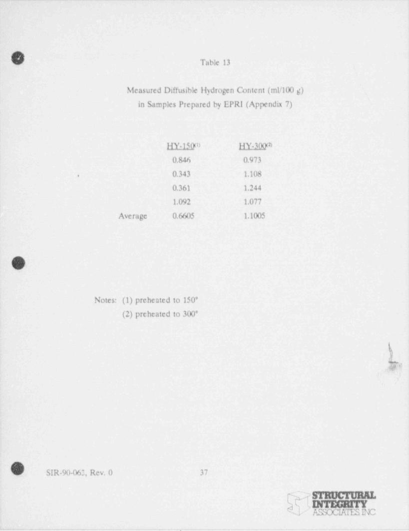
The amount of diffusable hydrogen in t're sample preheated to 150*F was somewhat
lower than that produced during the 300* F preheat. Both diffusable hydrogen results
are at least one order of magnitude lower than the maximum allowed by the
Interr.ationalInstitute of Welding for acceptance as a hydrogen controlled weld when
welding mild and low alloy steels [5]. The results of this test program were presented
SIR-90-063, Rev. 0 33
c mmcromaF INTEGRITY
ASSOCIKIESINC
- . . . - --

- - .- - . . - - - - - . - - _ - . - - . . - . - . - -
V
.
at the_ Temperbead Advisory Committee Meeting on October 30, 1990 and are
. included as Appendix 7 to this report. These results demonstrate that neither the_
150'F nor the_300'F preheat GTAW temperbead welding process will produce
-diffusable hydrogen in quantities which would produce a hydrogen embrittlement'
conceru in this alloy.
'
-This result is expected, since the bare wire GTAW process contains no obvious
source of hydrogen. There is no flux or coating which can be a source or hideout'
i
location for hydrogen as could be the case for the shielded electrode welding
processes.
I -
Residual Stress-
'
| 4.2'
| The issue of high tensile residual stress resulting from the welding operation is'
important to low alloy steel components. The ASME Code contains specific post
weld heat treatment requirements to address the residual stress issue and provides
e.:emptions depending on material hardenability and the restraint imposed by-
material thickness. The use of a well controlled welding process may reduce the size
of a heat affected zone thereby-limiting the extent of the residual stress field.
However, it is difficult to reduce or eliminate the peak residual stress caused by
melting of the base metal and resulting solidification shrinkage.,
In the case of a weld overlay, however,it is possible to use the residual stress effect,
|
|to an advantage. Since the weld overlay is applied to the outside surface of the
| component, opposite the surfa:.e which sees the aggressive coolant, one can use the
added heat sink effect associated with low or no preheat for residual stress'
redistribution. In the EPRI Inconel 82 temperbead weld overlay qualification 5
program, residual stress analyses were performed using finite element modeling to
| evaluate the effect of a temperbead weld overlay o- e state of ID stress in tne!-
ISIR-90-063, Rev. O ; 34
L - ocru m,(INTEGRITY.
V ASSOCUMMC. -. - - . , ,.
. . _ _ _ _ _. _ _ _ _ _ _ _ _ _ . . _-
nozzle and safe end in the vicinity of the butt weld [3]. In that study, a temperature
_h model was used to develop the transient temperature history due to welding. A
stress model using the temperature history as input, provided the residual stresses and
strains due to the temperbead welding, comparing the residual stresses of the butt
weld with those 4 the temperbead weld overlay..
The residual stress distribution due to the butt weld before the application of the
overlay is illustrated in Figure 1, taken from Reference 3. This figure shows that, as
a result of the relaively thick pipe wall modeled in this study, the inner surface of the
pipe and nozzle are under compressive axial and hoop stresses and the outer surface
of the pipe and nozzle are under tensile stress in the butt weld region. Residual
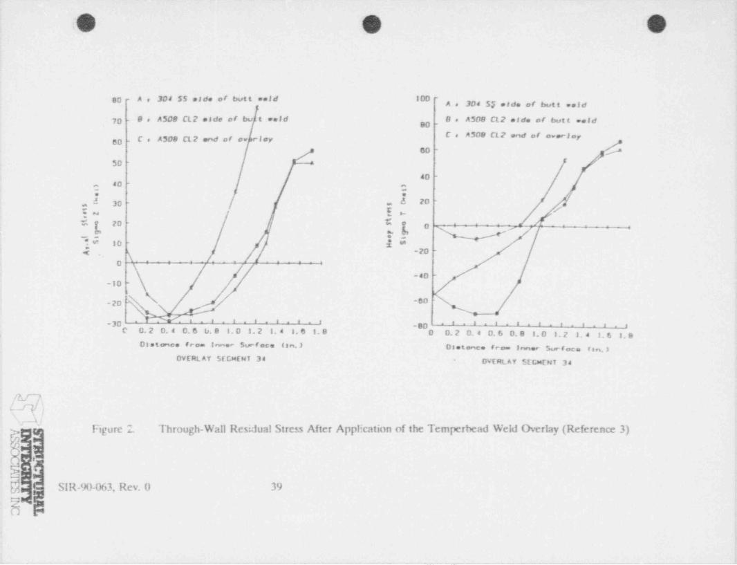
stress distributions after the application of the overlay are 3e 4mted in Figure 2 [3]
for the axial and hoop stresses. The weld overlay extends the compressive region for
axial residual stresses to almost the entire thickn-ss of the original pipe wall under
the overlay. The stresses at the ID surface are slightly less compressive following the
overlay compared to the residual stresses prior to the overlay application. However,
.. - the temperbead weld overlay significan:ly improves the through thickness residual'
stress state compared to the butt weld residual stress distribution. A lower preheat
would have little effect on the weld overlay distributions presented in Figures 1 and
2, because any reduction in preheat would be expected to produce an even more
favorable ID and through the pipe wall residual stiess distribution. Any increase in
the through wall temperature gradient would produce a more favorable ID residual
stress state, much as is observed-with heat sink welding and with the induction
heating stress improvement process.
The favorable residual stress improvement due to a weld overlay application stands
in marked contrast to a temperbead repair which is performed on the same surface
as is exposed to the aggressive coolant. In that case, the temperbead repair produces|
| ten;ile residual stresses in a location susceptible to stress corrosion cracking. In the
QL SIR-90-063, Rev. 0 35
l NINTEGRITYL .
/ ASSOCIATESINCL
.- , . . - - . _ _ .
. _ .
1
. _ _
temperbead weld overlay application, the tensile residual stresses occur in the surface-
.
. opposite to that exposed 'to the aggressive coolant, thereby having no deleterious
effect on the exposed surface,i
1
|e
|
.- -
-
SIR-90-063, Rev. 0 36
srmx n mar.INTEGRITY
/ ASSOCIATESINC
_ _ _ _ _ . _ . . . _ . . _ . _ . - - _ .. - . _ _ _ , _._ . _ _ - , ._.
. _ . _ __ _ -. _ . _ - . _. . . _ _ . . . - _ . . . _ . _ _ . . _ _ _ _ _ _ _ . . _ - _ . _
Table 13
Measured Diffusible Hydrogen Content (ml/100 g)
in Samples Prepared by EPRI (Appendix.7)
HY-150m HY-300m
0.846 0.973
0.343 1.108.
0.361 1.244
1.092 1.077
i Average 0,6605 1.1005
O
Notes: (1) preheated to 150'
(2) preheated to 300*
_/
.;>
s
.
SIR-90-063, Rev. 0 37 |-
- mocrann. ,
/> DrFEGRHYi
ASSOCIATESINC j- - - - . - .- . ._ . - . . . . . - . ..|
.|' , !|||I |'
o )3
2 e
s j' *
. cf n
e- J r.
l| '0 n ed f
_ s. ( e
d * 1 Rl * |- e (e e, ^
c 6m * l a y* e at * e - '8 f R l. r E rt b v 0 u Y eo
u'f S A vb * Lr Of o 6 e Do * _' '.* d n dL0 n E l
ne *W eI
d *e~ ^ Wi
m T
[e I ?4 o TL L _' r U d*S E C .
c f B a.S * 0 ee4 * 0 b^
c0 5 5 rn2 a e3 ^ A ^ -" ' pt0me * e s
:A * C 0 e
[ T" ~ ' - -
0 e0 0 O 0 0 0 D 0 h9 6 " 2 2 6 9 t- , - - f
o0 H gn
f oit
aco il
ppAerof -
' 2eB.
1
s) s
e.
n r0 tl s
S 8.
'd e (l w y
--
1 3le e e a^e t l c 6 ut - ar dt u e
'9 f Rt b v .
i
r E su o 0 u Y eb f S A Ro f f -
Lf o ,
r~ lo + 6 e O l
d d n a-
e l n'
. n EL0 Wd e e I Wi ^ -e 2 2 m T h
5'
4 oL L T g5 '. C r U u^
c. f B o0 8 r4 0 0 e h'
0 3 3 c3 A A n T2 a'
.e e e t0 0sA 8 C l
.O v.
1 e- - - - - - - --
0 Re0 0 0 0 0 0 0 O 0 0 0 r*1 6 S 4 3 2 1 1 3 4 ,u 3- - - g 6
i
C N ; F 0-0
_ " - 9
O -
RI
S
z|
| _/ @I
l(
O O O 1
!
80 - Ae 304 SS eide or butt ** 1 d . 100 --
,, 3g4 $g ,,g, ,,y,,, ,,gg'
'70 - Be A508 CL2 eide of bu t veld . Oe A508 CL2 eide of butt weld'* # U* " I **# *' **"I*!
BD - Ce A508 CL2 end of 'ov riey
SD -
}i. 50 -
40 -|
40 -
-. a..
;I
,,
6 20 -
30 - .~ay. /'
{w y*~ 4 zo
-
/ "
7a; 7, p-s
|*" 10 -
Z;-20 -
((~
*: .
o
-40 -,
-10 -
i
\ -80-20
' ^ ' ' ' ' " ' ' ' ^' ' ' ' ' ' ' ' ' ' " ' '-30 -80'
{. C 0.20.4 0.66.8 f. 0 1. 2 1. 4 1. 6 f. B D 0.20.4 0.60.0 1. 0 1. 2 1. 4 1. 6 3. 9 ;i
Di s tece from Inner Surfoce (sn.) Oletence from Inner Surface fan.)DVERt. AY SECHENT 34 -
DVERt.AY SECMENT 34
.
>
\ !
\Figure 2. Through-Wall Residual Stress After Application of the Temperbead Weld Overlay (Reference 3) ;
jSIR-90-063, Rev. 0 39
b
-
,,e a - - _ _ _ - _ - - - - - - - - - - - . _ _ _ _ - _ _ - - _ _ _ _ _ _ . _ - _ - . . - _ - . . _ _ _ . _ _ _ - _ - . - _ _ _
. .. - - - - .- .- . .. _ . - - - - -
5.0 SUMMARY AND CONCLUSIONS
QThe New York Power Authority has developed u. alternative Inconel 82 temperbead
weld overlay repair method for low alloy steel components at the James A.
FitzPatrick Nuclear Power Plant. This temperbead welding approach provides an
alternative to the EPRI and the Code Case N 432 temperbead qualificationi
approach. In the Authority's qualification, a 200'F preheat, no post heat treatment j
temperbead welding approach is compared to the EPRI and Code Case N-432 |~
temperbead approach in which a 300'F preheat,500*F post heat treat weld was !
qualified. The results of the Authority qualification are summarized below,
The Authority's Inunel 82 temperbead wela overlay qualificatione
program demonstrated that the tensile, bend, and Charpy V-notch
impact properties of the SA 508 Cl. 2 low alloy steel heat affected zone -
are not degraded by the application of the temperbead weld overlay
employing a 200'F preheat with no post heat treatment. No
O. metallographic changes were noted in the Authority samp'n welded
with the lower preheat as compared to the Authority sample welded
in accordance with the EPRI temperbead parameters.
Studies performed by other investigators examining the use of no*
preheat or water-backing for the inconel temperbead weld overlay
support the Authority's observation that the lower preheat has little
effect on the notch toughness of these materials when compared to the
unaffected base metal or the EPRI qualification process results. In
some cases, the "no preheat" case produces superior notch toughness
as compared to the EPRI and Code Case N-432 parameters. In other
cases, the "no preheat" case produces somewhat lower notch toughness.
Although the notch toughness may be reduced slightly when using
sir-90-063, Rev. 0 40
-
sTaucrunstINTEGRrrY
h ASSOCIATESINC
.. _ - - - .- . . -- - .-
-(.. . . . ..
,
water backing or no preheat during the temperbead welding, the within- heat variability in notch toughness properties in this class cf materials
is ' more significant than the lack of preheat during welding in
determining the Charpy V notch impact properties of these weldments
fabricated from SA 508 Cl. 2 low alloy steel. '
Reduction of the preheat from 300'F to 200'F and climination ofe
500*F post weld bake permit repairs to be made without dewatering
the pipe.. Significant reductions in outage schedule and decreased
radiation exposure to craft are potential advantages of the revised,
procedure.
The potential effect of hydrogen embrittlement resulting from thee
reduced preheat and no post heat has been investigated. For the
GTAW process, no deleterious effects of the reduced preheat are
noted. The amount of diffusable hydrogen within the low alloy ste:1'
following low temperature GTAW welding on SA 508 Cl. 2 is at least
one- order of magnitude less than that required for a hydragen
embrittlement concern.
The temperbead welding process on a low alloy steel component*
produces tensile residual stresses on the surface which is welded and
compressive residual stresses on the opposite surface. This result leads
to a more favorable through-wall axial residual stress distribution for
the temperbead weld overlay in which the cracking is initiated on the
surface opposite to that surface which is weld repaired. For weld
repairs to surfaces exposed to the aggressive environment, the tensile
residual stresses resulting from the temperbead repair must be
accounted for in the repair program.
. SIR-90-063, Rev. 0 - 41
~. m. INTEGRITY
/ ASSOCIATESINC. _ _ _ _ - _ - _ _ _ -

_ _ - _ _ _ - _ _ _ - _ - _ _ _ _ _ _ - _ - _ - _ _ _ _ _ _ _ _ _ _ _ _ _ - _
1
In summary, the Authority, Nutech and CB&l qualification programs demonstrate
that an inconel 82 temperbead weld overlay repair can be applied to a low alloy steel=
nozzle with no or reduced preheat and no post heat treatment, without deterioration
of notch toughness of the SA 508 Cl. 2 steel properties. Any changes observed in
notch toughness are smaller than the within heat variability which exists in a typical
nozzle. Since the overlay is applied to the outside surface of the nozzle, opposite the
surface exposed to the aggressive coolant, no residual stress concerns or hydrogen
embrittlement concerns have been observed or are anticipated.<
0
x
.
*
SIR-90-063, Rev. 0 42
g _TEGUTYMeN- ASSOCIATESINC
}_ _ _ _ - - - - - - - - - - - _ -
__ . _ _.._._ _ _ _ _. _ _ .- _ _ . _ _ _.__ __ _ . _ . . _ . _ _
- 6.0 REFERENCES
1. " Repair Welding Using Automatic or Machine Gas Tungsten Arc Welding'(GTAW) Temperbead Technique, Section XI, Division 1," Code Case N-432,ASME Boiler and Pressure Vessel Code, February 20,1986.
2. ' Technical Report on Material Selection and Processing Guidelines for BWRCoolant Pressure Boundary Piping," NUREG-0313, Revision 2, U.S. NuclearRegulatory Commission, January,1988.
3. P. Norris, et al., " Development of Incone; Weld Overlay Repair for Low AlloySteel Nozzle to Safe-end Joint," EPRI Research Project RPT3031, Structural
, Integrity Associates Report SIR-86-015, June,1988.
4. " Repair Welding of Heavy Section Steel Components in LWRs," EPRI NP-3614,Volumes 1 & 2, July,1984.
5. " Weld Metal Hydrogen Levels and the Definition of Hydrogen ControlledElectrodes," International Institute of Welding, Document IIS/IIW-452-74,Provided by D. Gandy, EPRI NDE Center,1990.
10
)
SIR-90-063, Rev. 0 43'
m sinuorumI.INTEGRITYASSONINC
_ . - _.
. . - . . - ._ - - .. - - - --. _ - - - _. .-... .- ... - - - _. _ - .- - - - . - - . -
Report No.: SIR.90-063Resision: 0Project No.: NTTA 260November 1991
O.
|
1
>
;,
|VOLUME 2 - APPENDICES
|
Qualification of inconel 82 Temperbead |
Weld Overlay Repair With Reduced Preheat ;
and No Post Weld Heatmg l!
i
!
l
|
Prepared by: |
StructuralIntegrity Associates, Inc. ;
San Jose, CA
OPrepared for:
New York Power AuthorityWhite Plains, NY
.
;i
W[ 5arrowTY: .O . / ASSOCATESK
,
l'
s
. . . . . _ . _ . . . _ . . . _ _ _ . . _. !
_ _ = - __ _ _ __ ._ _ _. _ _ _ _ . _ . _ . . . . . , _ _ , , , _ . . . . . . . _ . , , - . . , . . , _ . _ _ . . . . , . _ _ , _ . , , _ . . . . _ . . . . . . . . . . . , , . , . . _ - . ,-
O
i
Appendix 1
Certified Matenal Test Reports -
O
_
SIR-90-063, Rev. 0
1
'
_---___--.___-------_|_'" ___--
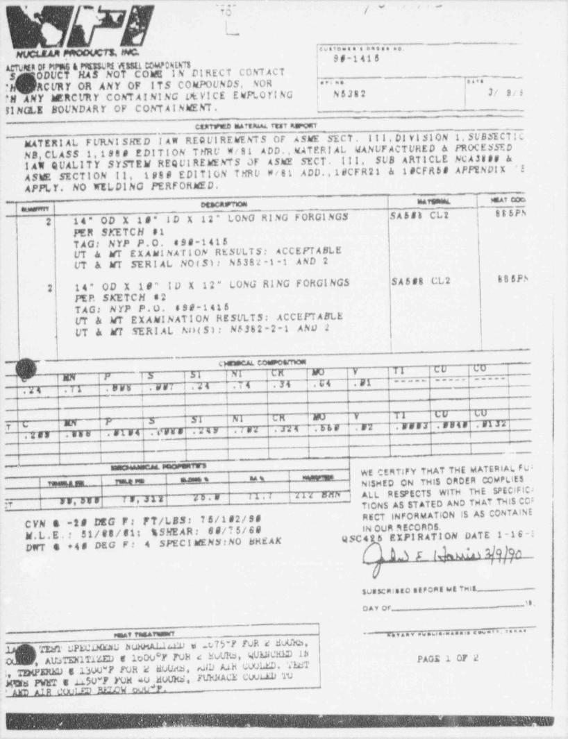
.. . - _ . .- . . - - _ - --
*i (v ,, -
--
<ueva..,==e.....NUct. san pnooUCTx, NO.
0I'1410ACTUMR OF PtFUEi & PM350Ri'ASSit COM70Nih78.S ODUCT HAS NOT COW I N DI RECT CONT ACTT ACURY OR ANY OF ITS COMPOUNDS. NOR a r i a' .
..,.
' PN ANY ERCURY COhT AI NI NG t*VICE EWPLO YING N5Js2 3r sf3
!!NGLE SOUNDARY OF CONT A I NMEh7. _.
_
CtKTfuED MArtAAAL ft*7 43racisti~
MATER 1 AL FURNI SHED I AM REQ UI REWEhTS OF ASWE SECT . I I I , Dj Yi S1ON 1 SUBSECT1 C'
lfANUF ACTURED & PROCESSEDNB, CL ASS 1,198 8 EDI T I ON THRU W/ 81 ADD., MATERIAL i
1 AO QUALITY SYSTEM REQUIREMENTS OF ASME SECT. Ill, SUB ARTICLE NCA38## &ASE SECTION 11, 198 9 EDITION THRU W/ 81 ADD. 18CFR21 & 1 #CFR5 8 APPENDIX '!
APPLY. NO WELDING PERFORMED.mrennt mt cometsca m meuanme
2 14" OD X 18" 1D X 12" LONG RING FORGINGS SA5f8 CL2 885Ph,
PER SKETCH 51TAG: NYP P.O. s90-1415UT k MT EX AML NAT 1ON RESULTS: ACCEPTABLEUT & WT SERIAL NOIS): N5382-1-1 AND 2
2 14" OD X 18" ID X 12" LONG RING FORGINGS SA588 CL2 6 8 5P.A
PEP. SKETCH s2TAG: N YP P . O . 899-1416UT & MT EXAMINATION RESULTS: ACCEPTABLE I
UT & W SERI AL N H S ) : N6362-2-1 AND 2I.
,
_~ cg+m conspeamosi
I XM l' |3 |bl Ni CM NU Y TI CU UU t
-----j|Y ----- -----
j.44 .IA .swu i . ws7 4 24 .i t .34 .U4 .y1i
i i(I -
! t
ma l' 3 31 jhl LM NU V T1 UU UU
}.zss .555 1 8184 . crus .zsy 1.tsz .Jzi .bbf .NZ .KsNJ .5547 51J2:y | L
i~
1 1 Il - - -
i -
_l - ,WE CERTIFY THAT THE MATERIAL FU3
_ ,,
! ,,,,ga m ,,me ,e sunesi s na s -NISHED ON THIS ORDER COMPLIES
'
y as,ase i s, .1 x 4o.# t1.I g41x ana i ALL RESPECTS WITH THE SPECIFIC >TiONS AS ST ATED AND TH AT THIS CO:RECT INFORMATION IS AS CONTAINEC YN a -2 8 DEG F : FT/LSS: 75/182/98
N.L.E.: 51/88/61i % SHEAR: 69/75/69 IN Oun nEcOROS.
DNT 4 +48 DEG F: 4 SPECIMENN NO BREAKQSC4 5 EXPI R ATION DATE 1 -16-!
a05l U?A YQ]Qn~ l 'l I
SUBSCR15EO stFont set TMit.--
'8DAY Or
" " " " " - " ' " " - " " " -PGAT79 TEAT W -
Tzst uPEe1xau huHaA1.1,cu e 23-r ruR a avUx3,, AlbTEN1T1'4ED E lo00*Y TOH 4: WURd, QUL!iCHED 1h PAGE 1 OF 2
T2HPERED 513OU*F EOR 2 WUdS, ,dlD A.1h CUOLED. NT:,i 30|W1 PWET s .LLSU*F YOM au .MUUES, FUE! DACE CUut.11) TU: ' AYD JLIR L'OUY 83 #370W coo *P.
.-
. .
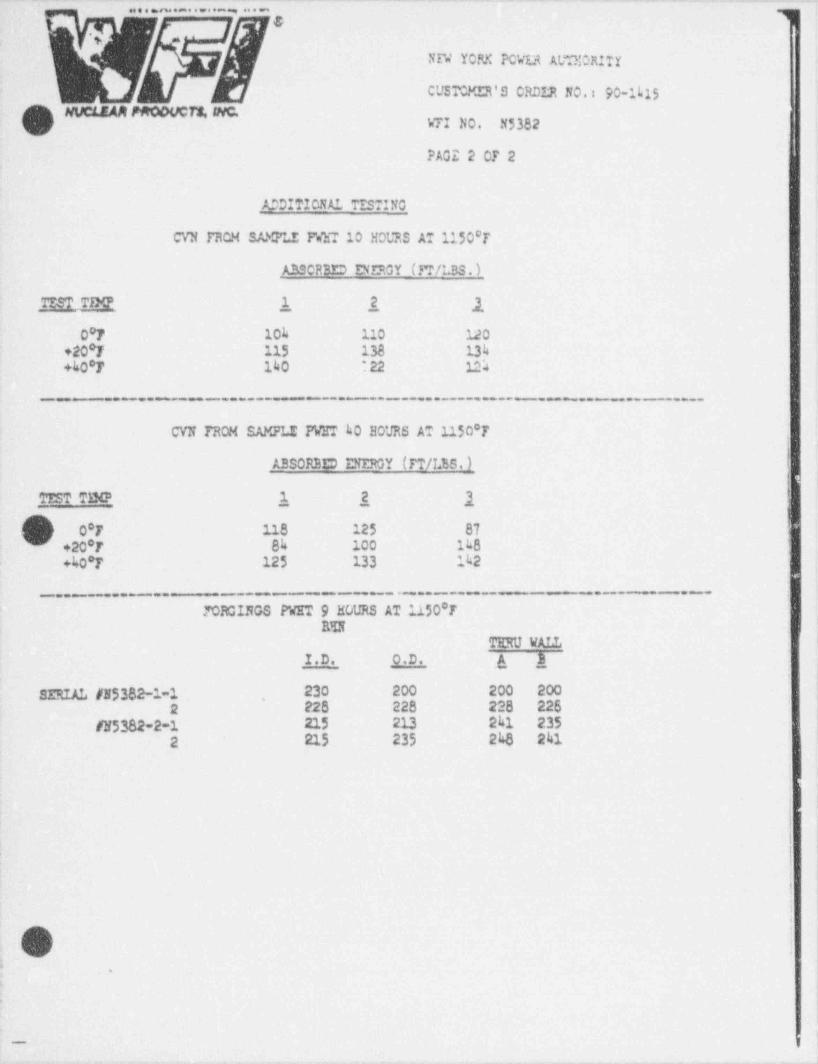
~' ~~ ~~ ^ -~^ ' -
~^ ~ ~'l~~
. . . . . . . . . . . . , . . . .
&.
NW YOFX PCVLt At.TOIORItr
CUSTCMER'S CRDIR NO.: 90 1L15
O NUCLEAM PMODUCTS, WC. VTI NO. N5382
PAGE 2 0F 2
_ADDITIONA1 TT. STING
CVN TRCH SA).?LE PVhT 10 HOURS AT 1150'r
_A3SCRBED DERGY (M/LBS. )
TT.S? TD@ ,1_ 2, 10'F lok 110 120
+20*F 115 138 13k+kO'F 140 : 22 1S
_ _ - .._ _. _-- - - . _ _. __...____. - ..__. .. _ . ..
CVN FROM SAMPLE PWT ho E0VRS AT 1150*T
ARSORBED D'FKY (TT/I25. ) !
!iTEST TINP 1_ 2, 1'0*r 118 125 87
- +20 7 8k 100 1LS0
+ko'r 125 133 1h2
.._ . . _ . . . - - ___. - _ - . _ _ . . _ _ - - _ _ - . - = - - ._
JORGINGS P'GT 9 HOURS AT 1150'TRU
TERU VALL i
I.D. O.D. A }
SIRIAL #N5382-1-1 230 200 200 200. ,
2 22 8 228 228 225
#N5382-2-1 215 213 241 2352 215 235 2kB 241 !
,
'
i
I
i |
| |
i
!
O :;
.
I.
-
_ .,m,
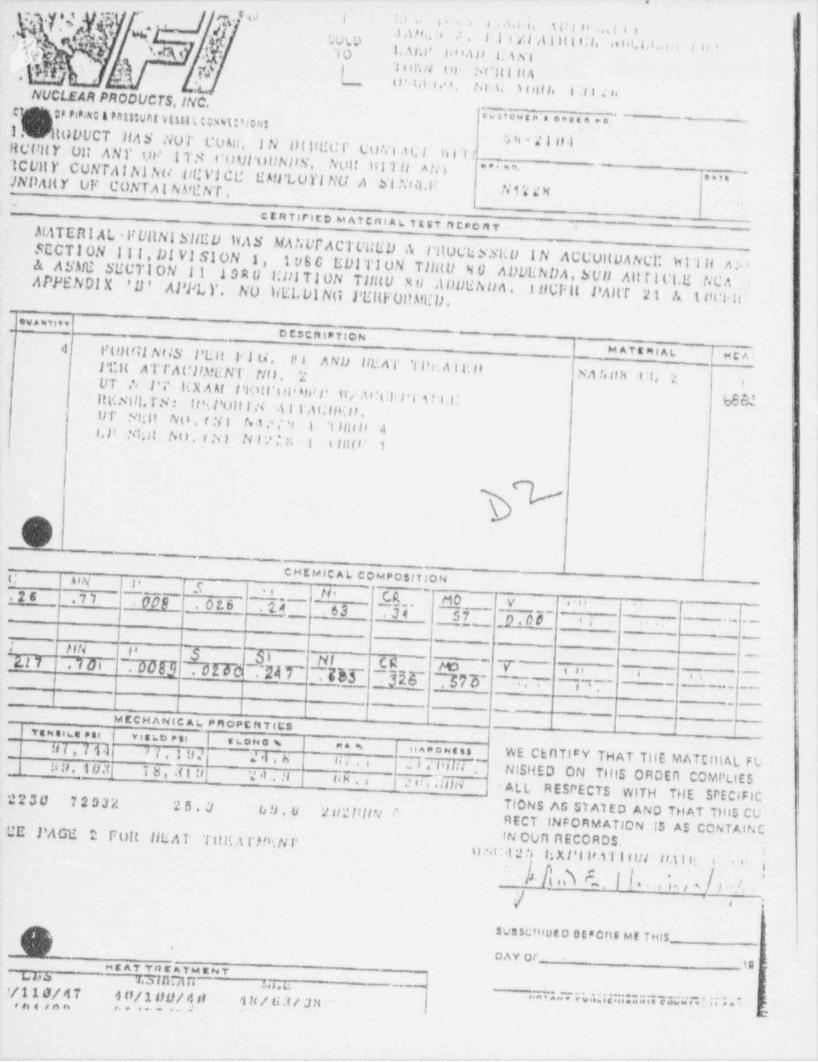
. , . . . "** V
.
Mc i f.i e l' . 24 8 e d.4 h T U I 8' :..! I i'-
O' a-
. *
EM)'.'I i,47. . .
. .I ,m.. :.' ,1.- L.O W F 1 i /.l A I H t i:1, a t,s. t.t..o ; tiv.
- 1.asm no.m p Nibras IO..
,- i)'
; 'l u r,N t it- Ft 'l(I f t A.e L o ui . .o. t. . u , oi, ,, i . , i < ..NUCLEAR PRODUCTS, INC.
.
.cpop r4p.sc a Pntstunt vtun. tout: 5tous cwo~s"'*e"oc***-
I Ut0 DUCT llAS liUT CU An.I N U(It!!C I' Cotifj q , j j g .
!!UIfit Y Oli ANY UI' Act re l 'I tI TS COUl'ul)NDN.
'tCUlt Y CUNTAINI AU DE VI CU EMl'LUYING ANolt tvi'l || A ti )" ' ' " - _ . _
""7NDAlt Y OF CONTA I NA' LINT . FI Niii.1 Ni'i n
- .
C E R T1 PIE D M A T C fll A L. T E ST ft C PC f1 T'_
MATEtt! AL VUl!NE SilEU \tAS MAriUFACTUUEU A l'ituuliSSuu IN ACCunUSECTION iiI, DIVISION 1, A N C Y. H 1'l li A :ALORU HllTlUN TIIHU Ntt198 6 Eul TION TilHU N O ADDENDA,500 Altfl Ut.E t/C A& ASME SECTlUN i IAPPENDI X
A UUtih n A . 11tEFlt PAHT 21 A t tici h ''ll' APPL Y. NU liELDIN(i PEl(F0llAftD.tva ssis te '
D CS C ft t P TIO N'
il FLittfil NfiS l' Ult Fl u.I! ! A Nll Illi. AT Tlh*. A ll(D
M ATE MI AL I MCU
}' Cit ATTA(.'llMENT Ntt. 2 NA li f th O (, 2
UT ', l'i' H X A nf l'Kitl'ul' ari l' 1*l/ .u 'UI. Ft T ! i .i:i
l
ltl#. Nill, TS * gjlt'i l'UIi i N 41l'.U.'lll(18lil' Ftilt NO,r3) ret .' ,' ': I 'l lfit t s .I !
l.l' N1'li Atl. f N) N l'.'I N t t flHt' 1.
.
\O
CHEMIC Al. COMPO$1 TIONh |AIN l' % \ .*a tt Ctl 14 0 V ''s?2s _.si 009 _ . 0 2. 6 ,u .s3 34 57 _p.00 ei
*
*
.[ }_[-
-
. ~ ftN t* ^$ }\ ~N|~
CC~ ~
_~
~~D T~_
2.17 .70i ~~F#U . of Fb .~24 F Tb3~ 7318~ 57 5- 77 ~~1VI t s' e. s.
~ -"; l'M CCH ANIC A L. PftOPC ft TICS
| veness.: ese.
|
t
visto esiH I , 7 01 >7.Iu?
~Lous w i na w nanowans
~~"I .' li t in ." WE CERTI'Y THAT Tile MATEntAL FL2l.6 14 4 . i3 0. t uit, I b , .i I U '.: al . H f* s | 2 on.HlHALL RESPECTS WITH THE SPECIFIC !
NISHED ON THIS ORDErl COMPLIES2230 7203'/. 2 5 . |,1 te !> . ti 2 sf 2 filln.' o T10NS AS STA1ED AND THAT Tilts CU
RECT INFORMATION IS AS CONTAINC- CE PAGE 2 Fult IlliAT Tl!Ra l'H'(NI' IN OUR AECORDS,
LI NC 12 fi I;X Pi l'S T l 884 Ud l f'-;
I ' ' 'n
- t n\ $ . h * . , . t '.I I,
.I.,
SUSSCf110tD DEPOftf ME THIS-_.
D AY or_.19nr A7 Ynt A the at TL. b b W. 5fIlUIIC 4 4.c.
|/110/ A T a n/1 ny/ A st 4 tt / u;ti;su ..... ,,........ ,ea. ..c.. .. E
*
, , , , , , , , , ........e , *

-- -. . . ..- . . . . - . . - - - . - . . ..
* 'd '
\.4,s'
NUCLEAR fMODUCTSi INC.
''
-
NEW YORK POWER AUTHOR!TY'
JAMES A. FITZPATRICK NUCLEAR-POWER PLANT' LAKE ROAD F.AST
.
Town OF SCRIBAOSWEGO,' NEW YORX 13126 '
4
.
REF: WF1 WN4228,
HEAT TREATMENT ATTACHMENT
7%TERIAL SA508 CLASS 2HEAT CODE 6BBBN11
PAGE 2
MATERIAL AND TEST PIECE % 1, 2, s 3-
NORPALIZE AT 1675' F + 2501
AIR COOL; AUSTENITIZE AT 1600' F i 250F, 2 HOURS HEAT VP TIME, 2 1/4 HOURS AT TEMP, AtOF, 2 HOURS HEAT UP TIPE, 2 1/4 HOUR 5AT TEMPERATURE AND WATER QUENCH;
TEMPER AT 1250' F: -
2 1/4 HOURS AT TEMPERATURE AND AIR COOLED.f. 25 0 F, 2 HOURS HEAT UP Tile,t
N 45T PIECE # 2,
!
POST WELO HEAT TREAT AT 1150' F + 250'
TO 150' F. HEAT UP AND C00E DowN RATE ABOVE 600F FOR 20 ICURS !!J ADDITION TO IIEAT TREAT roRI,TEST PIECE d 1.F. CONTROLLED TO 1000 F i
'
TEST PIECE # 3
POST WELD HEAT TREAT AT 11500 F g 250 F FOR 40 HOURS IN ADDITION TO HEAT,!
.
ITREAT FOR TEST PIECE 9 1,TC 100'#F TO 150' F. HEAT UP AND COOL DOWN RATE ABOVE 500* F CONTROLLED'
.O
e
$,
v
h/18O ''
.
6
.
'
.
/'
.-,,----r-. . - , , -
_ _ _ _ _ _ _ _ _ _ _ _ _ _ - _ - _ _ - _ __
O
Appendix 2
i
Weld Procedure Specification and |
Procedure Qualification Records I
.
WPS: NZ Overlay andPQRt 395, 745, 746
i
O -
,
-
%
SIR-9043, Rev. O
O
i
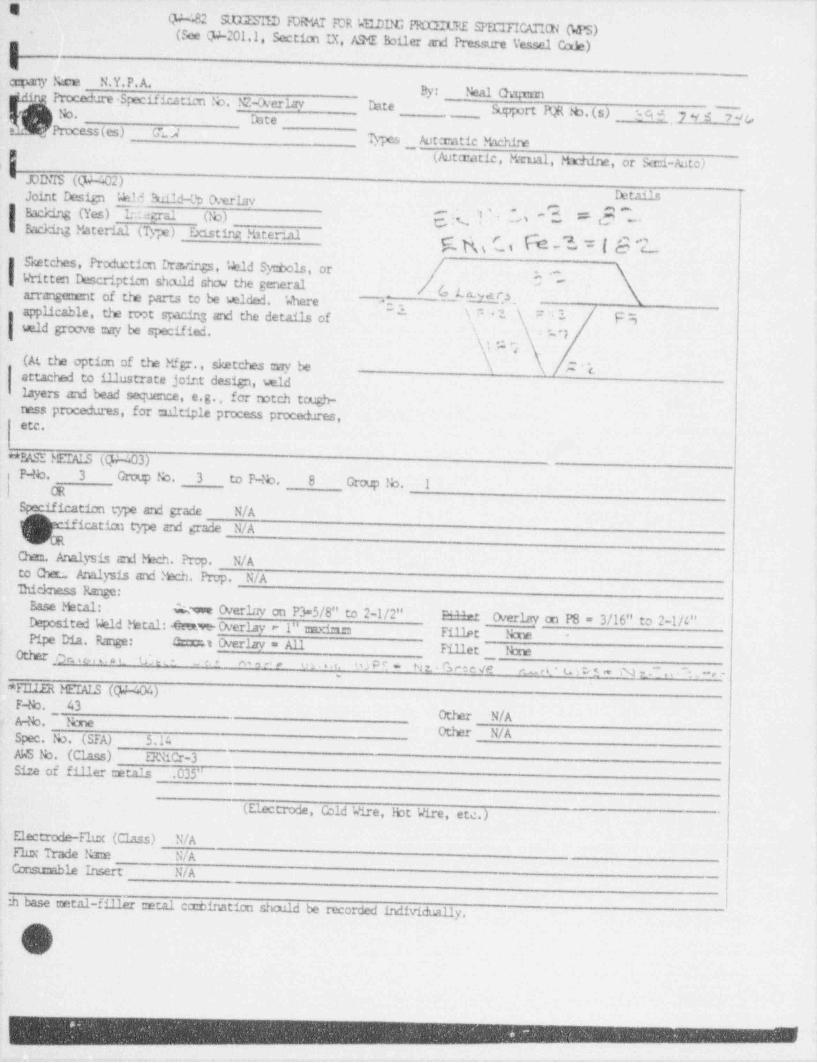
I(F '.82 SLUISn:D FDMT FOR 'aHIDG PFLGLTI SPECITICAn0[(MS)(Sce (P-201.1, Section IX, ASG lbiler and Pressure Ve"el Ccaje)
.
E4-cgpany Neu N.Y.P.A.
By: Neal On;runProcedure Specificatien No. NZ-Oterlav Date!b. Support PQR fb.(s) _ -A9Prtcess(es) G"u;
' 7 *y 4 7 ac.Ibte.
.
Types ._ Autcratic Nchine(Autcratic, Mrml, natine, or Sani-Auto) __
' JOINIS (ty-402)Joint Design Wid Build-lb CVerlav Detaile
-Eacking (Yes) L.imal (!b) c, N , . 'A p-, , . _
,U ~~
= Backing Material (Ty;e) _ Dcisting Material c g r , {~e '3, r { g 1
- Sketches, Production Draring;s, Wld Sy6cis, or /. Written Description shculd show the general [G gg ,,'
arrangement of tre parts to be wided. 'nhere 5, _
_
-
' '; -applicable, the toot sW and the detai1= of -. . . -~' F_
weld grocwe cay be specified. ' j ''I ,
' ' '' , .. ,.. s
(At th2 option of the Mfgr., sketches eny be A ' i-ettached to illustrate joint design, widlayers and bead seqJence, e.g., for rotch tough-ness procedures, for tultiple process procedures,6tc.
**FASE MEIAIS @ -.03)P b. 3 Croup No. 3 to P4b. 8 Croup !b. IonSp~ iffr ae4m type and grade N/A
ication type and grade N/A
Om. Analysis armi Nch. P: p. N/A-to Qa_ Analysis and Mech. Ewy, N/A'Ihickness Range:
Base Metal: Awe Overlav on P3=5/8" to 2-1/2" F-WeDepcsited Wld Metal:-Ome Overlay - 1" unxi,r, Overlav on P8 = 3/16" to 2-1/4"
Fillet NcuePipe Dia. Range: Lt Overlav = All-
Fillet _ tbneOther on + ,.... u '.w - - m,', . . . . . <; W2 P P - Nt Gree ve u t_ * m s .= N ~ . , ~ . * * -
'EnIR MEIALS ((p-404)F b. , _ 43 Other N/A' A46. None |
Other N/ASpec, tb. (SFA) 5.14 !
AWS 15. (Cla ") EWiCr-3Si:e of filler tern 1s .035" l
1
(Flw-trode, Cold Wire, )bt Wire, etc.)i
Electrode-Flux (Class) N/AFlux Trade Name N/AConstcable Insert N/A -
:h haca untal-fille metal c:rbinatico shau.ld be recorded individually.
IDV
:!
.
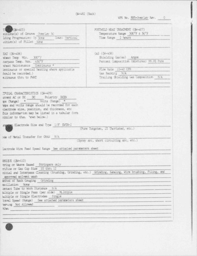
i
Q4 482 (Back) I*
kTS No, M R-a vrlav,Fa . O i
"1
(F-405) POS1VE1D HEAT IREAIMLNr (Q4-407)
sitax.s(s) of Crrove O.vtlav M Tcqerature Range 500'F 2 50'F1 ding Pr g m ion: Up 'bne rwn: Vertical Ti::e P,rge 2 harssition(s) of Tillet Nme
T.AT (CF-'.06) GNS (Q4-408)eheat Te:p Min. 300*F Shieldire Cas(es) Arcan
iterpass Ta p. Max. 450*F Percent Ca::positico (mixtures) 99.9% Puretheat M11ntenance Contiruns *kmtinu:us or special heatire dere applicable F1w Bate 104 chi:h:uld be recorded.) Gas Backirg N/A
r.*m thru to FMtr Trailing Shielding Gas Ccc: position N/A
'.'ICICAL GARACIERISTICS (QA409)Irrent AC or DC DC Polarity DCEN
Volts (Pangt):ps (Range) **
kps and volts range sh.uld be recorded for each ,
slectrode size, position, and thickness, etcIhis infomation cay be listed in a tabular for:nsi-ilar to that 'rNn belw.)
:i
'Electrode Size and Type 1/8'' E'DI-2,(Pure Tungsten, 2% 1horiated, etc.)
:de of Metal Transfer for Q W N/A(Spray arc, short circuiting are, etc.) ;
lectrede Wire Feed Speed Range See attached para:eters sheet
. HNIQUE (Q4-410)tring or Weave Based Strirgers onlyrifice or Cas Cup Size 10 thru 12nitial ard Interpass Cleaning (Brushing Orindi.q, etc.) Grittiing Sa:ning, Wire brushirg, F111rg, a:xiacoreved solvent wish
tched of Back Gouging Gri:xiing
w 411mH nn Ncre' ttact Tube to 'vbrk Distance N/Aabitiplo or Single Pass (per side) Itltiple
bitiple or Single Electrodes Sirs,letavel Speed (Range) See attached paraceters sheet i
'ecrur:g Not Allowed !
ther
.
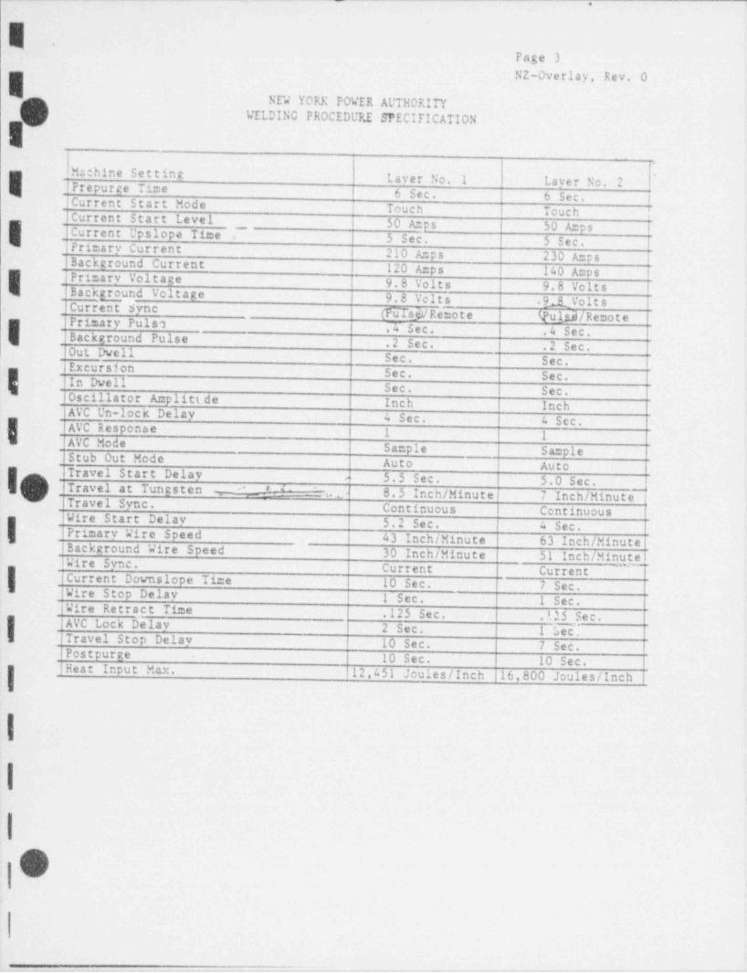
_ .
E'Page 3NZ-Overlay, Rev. O
NEW YORK POWER AUTHORITYVELDING PROCEDURE SPECIFICATION
Mschine Settine Laver No.IPrepurge Time '1 Laver No. 2
b Sec. b Sec. !ICurrent Start Mode Touch Touch |i
Current Start Levelcurrent Upslope Time _
i 50 Amps j 50 AmpsI
. Primary Current5 Sec. i 5 Sec..
210 A=ps 230 A=ps iBackground Current 120 Amps 140 Amps |I , Primary Voltagei 9.8 Volts 9.8 Volts IBackground Voltage i 9.8 Velt_s .9 1 VoltsCurrent Sync (F6TsjV Remo t e Q'ul 3/ RemotefPrimary PulsoI 4 Sec. .4 Sec.' Background Pulse .2 Sec. .2 Sec.'Out Dwell Sec. Sec.Excursion Sec. Sec.In Dwell Sec. Sec.
Oscillator Amplitt de Inch InchAVC Un-lock Delay 4 Sec. 4 Sec.I AVC Response1 1
AVC Mode Sample SampleiStub Out Mode Auto AutoIiravel Start DelayI(g 4 5.5 Sec. 5.0 Sec.ITravel at Tungsten 8.5 Inch / Minute 7 Inch / Minute' ' -m t. .N Travel Sync. Continuous Centinuous
; Wire Start Delav 5.2 Sec. 4 Sec.IPrimary Wire Speed 43 Inch / Minute 63 Inch / Minute(Background Wire Speed 30 Inch / Minute 51 Inch /MinutiWire Sync. Current CurrentI Current Downslope Tice 10 Sec. 7 Sec.Wire Stop Delay 1 Sec. 1 Sec.
:
Wire Retract Time .125 Sec. .!.15 Sec.|
I AVC Lock Delay 2 Sec. 1 Sec.Travel Stop Delay 10 Sec. 7 Sec.iPostpurge - 10 Sec. 10 Sec.| Heat Input Max. 12.451 Joules / Inch 16,800 Joules / Inch|
|
I
I-
G

.
!
Page 4-
NZ-Overlay, Rev. O
NEW YORK POWER AUTHORITY
[~'} VElDING PROCEDURE SPECIFICATION
%_)
Layer No. 4,
Machine Settine Layer No. 3 and Ewa=xte.Prepurge Time 6 Sec. 6 Sec. 1
Current Start Mode i Touch Touch |
ICurrent Start Level I 50 Amps 50 AmpsICurrent Upslope Time 5 Sec. 5 Sec.iPri=ary Current 240 Amps 230 AmpsjBackground Current i 140 Amps 140 AmprPrimary Voltage i 9.8 Volts 9.8 Volts
Background Voltage i 9_._d i'ol t s 9.8 Volts q.
Current S ync I fuls e.J Remo t e Pulse / Remote 't
Primary Pulse .4 Sec. 4 Sec.
Background Pulse .2 Sec. .2 Sec.
Out Dwell Sec. Sec.Excursion Sec. Sec.In Dwell Sec. Sec.Oscillator Amplitude Inch inch
AVC Un-lock Delay I 4 Sec. 4 Sec.
AVC Response i 1 1
AVC Mode Sample SampleStub Out Mode Auto Auto
Travel Start Delay 5 Sec. 5 Sec. |
| Travel at Tungsten 6 Inch / Minute 7 Inch / Minute| , ITravel Sync. Continuous Continuous
Wire Start Delay | 4 Sec. 4 Sec.'
Primary Wire Speed i 69 inch / Minute 63 Inch / MinuteBackground Wire Speed i 56 Inch / Minute 51 Inch / MinuteWire Syne. Current Current
Current Downslope Time 10 Sec. 7 Sec.Wire Stop Delay 1 Sec. 1 Sec.
Wire Retract Time .125 Sec. .125 Sec.| AVC Lock Delay 1 Sec. 1 Sec.
ITravel Stop Delay 7 Sec. 7 Sec.- Postpurge 10 Sec. 10 Sec.Heat Input Max. {20,247 Joules / Inch 16,800 Joules / Inch I
l
! Layer 7 and subsequent layers if required may use any of the parameter setsj listed.
|
|
|||
v)t
_ . _ . _ 'N

SUGGESTED FORMAT FOR PROCEDURE QUALIFICATION ALCQfio (PQMIun 4eJ
(5ee QW 201.2.Sectisn IX. ASME 8 iler and Pressure VesselCatelRecord Actuel Conditices Us:d to Wold Test Csustn. pan, ) of g
m.: =-
Companv Nam, New York Power AuthorttyProcoowre Osallftcet on Recore No EU ogie{' h _ N2 Clad-
r
- U 4 Procniin)- SMAW -
Typn tVam et. Autometic, temi Aato.) - Manua1v
sotNTS (CW 402) ~
This PQR is comprised of 3separata stages.1) ID Cladding of SA508
E 3 0 %- 2) Buttering 6 PWHT of SA50$'
-
3) Groove Weld',9)T~g~e,-bfM OWALA Y
E30BL -l y s
y,- . . . . . _
i
Groove Cetion of Test Cowoon(For combination cwelitiestions, the concolted weic raetst tnamers snell be recoretc for es:n filler metet or crocess wsec.)
SA8E METALS (CW403)ceteriet se c.- SA508 PQ1 MELD HEAT TREATMENT (CW407
Type et Qrece - C1 ass !I_ 7,,n ,,,,, ,, See subsecusnt PQR
y ,n, oaea 2 e f _4,
p.No. I NAto P.No. ein,, W P $ # N Z -IM. (buT.E.Q~ Thickness of Test Coucon I I/0"D cf Test Cowcon-- IW _
,--
C A8 (CW 408)_ Type of Gas or Gue:-- NONE
Composition of Gas Misture -
O th ee--
- _ _
FILLEA METALS (CW4041_
Weld Meist Analysia A No. S
Sus of Pittet Meut I/II" & I/0"ELECTRICAL Cl*AA ACTERISTICS (CW 409)FIDer Metal F.No. 5Cwerent 01reet
SFA soecifteetion 5k P oiarity - - Reverse OCEP _
Aws cusification E309L FIest Layee Amos, y o,,,otn,r _. EIO8L Ba1anee _ , ,
Tunssten Electroa. siae NA
Otrer-_
PCSITION (QW405)TEONNIQUE (CW450)
Position af Orcove IOTrevet Scoed
W;td Progression (Vont11, Dowanlit) Uoh111 sinn,or w ,,g,,, strineerother #1oe Re1Ied
_o,cist tion
Multicats or Sietie Pass (per tical MUl?ID4sSSiegte or Mwit sie Electroon EIn;Ie
PREH EAT IQW4061 OtherPr Temp. 3TY
Te, . enn*r
.n.efo _ t.... >,m.. .... . _ .m . .r.. o.es...us.34. ...>. .<,n.. e,. coit: 1, , , ,
I
.. .
_ _ _ _ _ _ _ _ _
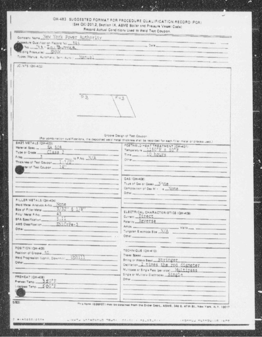
_ _ _ _ _ _ - _ . ______-_ _ _ _--_
s
QW 483 $UGGESTED FORMAT FOR PROCEDURE QUALIFICATION REcortD (POR)(See CW 201.2e Sectlen IX, A8ME B;tter and Pressure Vauel Codel
Mecord Actual Conditi:n Used to Wele Test couptn.
Com enyName ev York Powr Authorityfwre Owesificet on Ae:o a No,_ TC;
No. d 1,*.In- Bu w AR. ' t e ., ..
car's ProctWes) . NWTvPee (Venwe . Awtor=at1c, $ew Aatt) _.Dt01_1
_
JC;NTS 104402)
.
PQ F43
I
Groove Des'en of Test Cowoon
(For comb >nstion owsilf.cetions. tne concohed weid metal telckness s*sli be reto doo for seen fit'or mew or crocen wees )SA35 METALS (QW403)-
.
w ierd spec._ SA 50R PO47 WELD ME AT TME ATMENT gCW 407)Tempores .e 1150*F 50 F'
Type ce Grece CIRES 2Time 10 heurs
P.No. 3 to P.No.3/A Qt e,
Thiciness of Test Couoon-- l''/0"
(Ger of Test CoweenI4"
_
V)._ CAS (OW40el
_ Two of Ces or Qases jn?_ Comoesttien of Qas MT re _ NOM
__
_ omer -
PILLEIt METALS 10W 404)Wold Mete 4 Anolysis A.No. None
-
saa of mer umi 3/32" 6 1/8" iFHIS* Wtal P her 43
._ stacTaicAi.cwAmacTcaistics tow cos)Cwerent - DiTOCI '
:P A toecmcation SellPoi e,i,, Reverse
Aws oomme. tion cNitrFe-3 Amos. _Oats voii,_
_ Tungsten E.ect ode S'as M_
Over..
._
__
POSITION (QW 405),.
TECHNIQUE (QW410)fosition of Croove ZTrevel Scese
weid Progreuien tunnue, cow,nin! Uchillsteine or weeve need Stringeroe:r
_. owmetion 2 tines the md dinneterMetteoen or sine e Pai, toer sidei WitipassSieg e or Mattip's Clectroce Sif1E elFREHEAT (CW4061 og ,,
Pieneet Temp. 3 50'Ft.m;pa Temo. f 00*F
_
~ Ss4 ..
This form (E00607) mov ce ootained from the Order Oest , A3Mt. 343 g,47 in 33., No. yera, g,y,1go37 .
l.c waocceelcen* . i ni.v* s V A ' W eninUS *CWSe en.nl e me 67 n t e - tota"VJ ^Wta:W*10 I ll* P -
. . .
- _ _ _ _ _ _ _ _ _ _ _
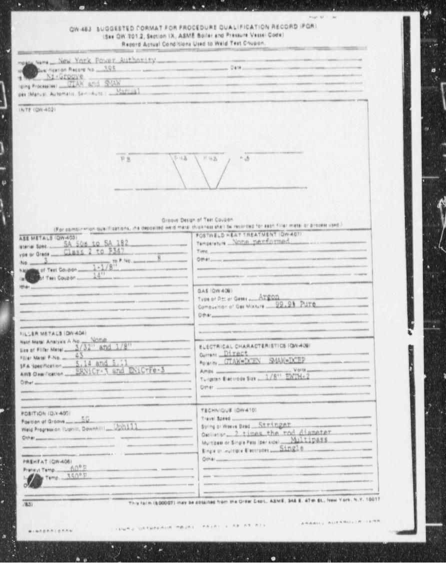
--- _ - - - - _ ''
4~ . , =
QW.48J SUGGESTED 00RMAT Foa PROCEDU;t QUMIFICATION Af CORD |PQM)
(See CW.101.2,secti:n IX, A8Mt Boilee e e Pressute VesielCode)Reeced Actest Canciti2ni V :d to Weld Test C%psa.
_
-
,
,
~ . - . : , . .. . -. _ _.-.
n
e.,,,e j ev Yr"4 h er_AM*% *4 ty ,
,
3 htet'on 8'HD't %e 395 O s te .K
't _, h' * GTML _ .___
i:ing Pexeestsei f.[Sh._N11 YAW ._
M m 11pee tMem.ei. Atomat.c. 5.~ A.ie i__
_
thir (CW 4026
Pg \f4A t* u y, 63
.
- .n_ ___
Croo t Dettaa of Test Co. pen
(F or comb.e * ion ove.tfiestreme. <* e coposited we.c * eta! i4c taeni ans t be ruo cos 'o' esta toe' reets- or proce.: woe.)
Att MtTiaL8 4QW403) ~ POSTYv t LO m L AT T Ftt AN#ENT LOW 8071_Nnee we*(n pr.AM W tQ,,hdU y mpe,e,w,, _ ,_,,,
Ctenal Spee.-Cin n 2 to F347 7,,nc
ype er o: ee3 to P.No, B oeer_
.No. 1 1/8" --
b of Test ca pon314" -_
} ita # Twi cowson- _ _ _
meeG AL (CW4061)Type of 0:. . Geeee : Argen
_co-a.. mea e' coi eit.re - 99 9% hte
.
overs
81L* 63 etTALS (OW404)Seis vient Aneiveis A Ao._ Nnno
3/32" and 1/0" E LECTRIC AL CHAR ACTIRi& TIC 510W40011.se ef FlJer Metet _ D4 rectsii:e, uetei 7.No. 45 curreat
IPMoesitiestica l.d4 and 5,*.1.._ _
og er,,, __ C' TAW ="M\' SMyi'.1Y p _
EANitr 3 rmd ENicefe 3 gyne _ _ voi,Awa en ncetion
Tseinn sei,oo. sisi 1/8" Nm.2 ,
oucia er .
T8 CHNIQvi (CW410)PottThoN (0.140MT'evet $0eed
PDe'llon $f Orooveweis Propeu on wonm, sowantil_ Uphill svy or Wo... stea _ Rtr4 nger
m
ote met e ? ti~ne the mA A4 nmntercteer _
uwit esis or sian'e reis toer nice) Withus8:ag e o' cwitip's e actroces _ D Elf _
.
_.
,, ,
othe,PEN F AT (CW406)
-60'UPrpht Temp.MO E -.
Temp.
/831-This f e1*i (6000071 me, be otta nee troen lee 0,per Leet., Aswt,344 3 et en gg , New y are. %.V.10017
' * * * * " ' " " ' " " ' ' * *s a%= s na * uetiave' *e sa n ****' * ^* ^' "''
...nennee=n____
- - - - _ _ _ _ _ - _ _ - -
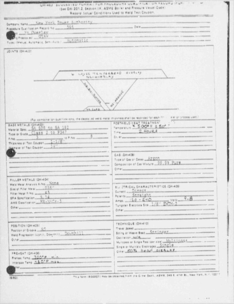
bV uut > a s e/ Punma a e vn e nvwa ss n a wwrdi> Na e gre e t svp ; trigsI e~
- . , ]tJn CeJ($ee CW 201.2, $tttien lx, A$ hat Bolet and Presswee Venett Cs ct) g
'
|Record ?.stsel Condition Wed te Weld Test Cowpem.. = - - - - - -
__-
=
_- : :
New _YoQ 0%!* * Ae+kard?yComesee ieme _.s
fPre'cebre c.ewest ea mese o Ac 19? 7,,,
i
9e .,, E* har.1 Ayi r,ee.. .e.i ._SIM '"~
SUto*alis , __ _Teter iMea..i. Avis *s t t. Sem . Awe, t
__
-
JCl%TS 10* 402)
.
g., n m,y (4 t t. n. # s A en g * C C V e 4 6 * 1r \,
NL. s.v sr tam,y \
i
t ,(
m .. x# v#
,
I#14 or9'ettesvoet.11
IFoi compiest'ea cytiit.esuces, the roots;.et ett metti thienaets sas:t t:s 'ete'deo ter eeth 't".* **lPCSTWl'.D > t AT T R E AT Y E N*
S A5E ME Tan $ 10W403)useere 1,,,, SA 509 to S A 1E2 to.,o,,,,,,, * S OO* e t co* ~ ,,
2 Meivg,5 ._
Type er c,ee _ Class 2 :o F347 T ,-p
3 8 - - - co e,_ ._
p. No. . i, P No
1*1/6" .
Twesi et test ce. net34" _sie, of ie i covo a -
_.
CAS(CW40tlTvee of o., o. oeie, Arten
C9. 9 % PJr*Composition et Ces Mlatste a
Ctaer- _
.
PILLIm WITALS terW4047Wete Vete Answ sie A No._ N^* *
--
;r
DM" E',t ;Tmic AL CH AR ACTimittics (CW4Cgi51ee ef *mer Meie! _ D I ' '' '' 'Filter Metal F No. ., _ . AI Csreent _
;_1a P ..,,,y ,_ St;Aight.9*b$F A 58 t lleetloa _ '10*2NO Vo'ts __
l ._
AWS Clessif+estica28'D I' * 5 A'e D t. -
I/E" E' 7Other_
-- Tvesiten flettreme Site :Other
_
m ___
e.,__
TECHNIQUE LOW 410)P;5aTION (QW 405)
Poshlom et Groove _. C Tehst heed _S' " d " t' e '' f-D%'di 11 - Strimt er Weeve IsadWeig Progresoon (vomii, Dgan;ti) '
ose net or u/> i ;0 0.87.. . ... e ., o. .. , e , e . 4 0.. . ;o e, uo.e,o _
- bME1P-
$.el' or Mwit:s|e (tecteoget _
cirser_ c o Y. ha arj Mehm eP0 tdt AT (CW.406)Premset Temo. a s e ,, y4 |
tetersais Te.r, M E d' F' m s , ti-
ner_
- e u-
n i v.. isooocn me, no eemnee ..m e. e<e- oeot,4:ue. ses e, ste si, .. ve a, e..v ic:oe ,
ta/331
.. . . ..
.-. - _ . . - _
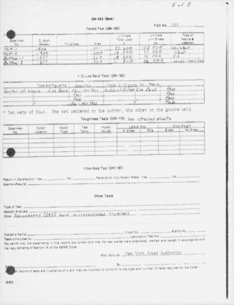
-- . . - . _. . - - ~__ .-.,. _ _ _ _ _ , - - - _
5,/ 3 =
OW443 (Sees)
'' ^[Tenells toet (OR.160)
-9 vi.-.ie v w.ie i tv.. .f !
| | t et.i te.a va.i si,e s e en.,,e a ;stoca.en aika . 1>
'
Arts 5D rs' _ (ccat or.mI Tm etmeteNo aa i
_n_|A H EQ CtCD _.8L 0O |LA b t,LQ._ . ..Tb P - / i 1.SQ +
5?.$ _$ .1.t ;X) 14_ S22. ..,_ ? */_6 C O 'A'L t.h _ ..7~cP-3 *
*** _ ._ J.t$r .t o O__{' 10 ' Liat t:Are t 049
fEt%Dr - / *1C9 MA, || >D0 ft' 000*
L% % . 2 St? .? tot '
* h.,'ed4end Tetts (CW.160)-
I 'twe 6 rieure Sa_ n un_
T ee one %re No I th em + c et
A nk W 2[t$1}Lb - 55 -- -& n +* t e 5 L ruta /L_. . ... {L Lhl& .[f t L .* Ye tfitR' A'
,_ " t Fats _ f M ..
( As,LL li n? . rn . 4 nn V Hn
)
TkV set $ of four. One set centered on the butter, the other en the groove k' eld. {*
Toughness Tests (QW 170) See 2,S2.642 gM3 )
Specimen Notch hotch Test impett lateraltwo | Daeo Weicht i
No loc atiem Type t,,n p ye,y,g g g w,,, J u n, ! g.,,, so g ,,,
_ _
-
-__..
_
_._
-
rittet Weld Test (QW.iB0)
Cesult - 8 atisf actory: Yes _. No Pometretion into Perent Metsi Yes No
_._MacWesAs
Othe Tests
-- --
Type of TestDeposit AnalysieOther .EALAAMfgy (!LT) wd__ n , n h olun H.ngw 1 ,_ _
...... . . .... .
., . . ... .
..... ..., ...
Clock No .,-- $ts or p N o. . - .
WelfereName teDoratory Test No. ._
Tests conducted byWe c3rttN tht.4 the staternents in this recortl are cortest and test the test welcs we's peopterne, we'ese sna toeted in accorconce withthe requirements of Section IX of the ASME Cece.
hW T_Od_EECJ._Authqti1Y ._ -_ _v amu eetw,er
.._ .._ - . -- -
er _m(v;f record of teste are IHwstrative only enr aney to mocif ed to toMorm to the type and nwerber of tests reQWred by the Coos i
.
16131 '
. ..- _ .- . . - . - - .

_. __
--
net 7 Yo;K Pot */ER AUTHORITY gJAMES A.FITZPATRICK NUCLEAR POWER PLANT tae 2 tg "' ''* * ''" * ' " * ' ' ' ' "
CALCULATION SHEET *w*A vo. to. ost_
w , .L ., .7.-
_ c c .,,_.mimi.
| ) PQR. 5% T WT S A. m P t. % (~ 1.n.. s...
e..m., m.i. .......c.i. v. i. o
K,t . P.y 414 sa *4>
1 1 .....,. . 1 .,.... ..... ...... ....... ..... . .... .... . . . .
...... ..
? ..s.! ' . . ..-
... . . ......... .., .... .... . ...... .....
3 g. 4 |... .Misw 6vww p aa n ...... '
+.... .
...... ..... . . .'.,.....
. ..i. ........ . . . . . . . . '. . .f&m.C t :h . d .w. t4. . . ; . . .4 . .' ...... ..
:,,,,,,,;,,,,,;, ,,,,,,,,Wem m . ., i ~ d,.,, , , , , , , ,s,4, ,gg , ,
; i5 ,,,,,(,,; ;,,;,,, / ~h,,,,,i ,,,, ,, ,
-
;i......n6 ...... ..=
.
. .......
....$.. ',.. ...iN' ,........ ,...... . . ........ .......< ... . . ,i
8 , i,4, 3, _ t,..
,
, ,, , , ,
:
/~..|./. !.
>
/ //.l ./. ./ / /_/ / / ,
9 . . . . ...+ ,
.. y.,. .... . .
.1..... V. 7 f s I/_l/ '
6'10l
"%* .._. q'i' ' '. ,' i- n" '*~ \
,, d,4 , , p, ,;,,L ,,j. h.L.._.' 3/-. m',g.j......
<
11 l ...... . , . . . ... ..,.... ,
. 4. 4... \ ;..... .. 7 .T u uodp. ....... f . . . J ,,* v- i |
12 4w . ... .. .....i
t3-
i i13 ;.- ...... ...
...y ,
. ..p..)...... . ). . . . . ... .j . . , . 2.p
,.. ,
3.............i............, !,....... - . . .,
... . ..... .. ....., ..... .. .... ' s t i
i............ ..... , .4.... ,i..y..,..,,. L - , gy.,,
. .p'15 i + .....
'
16-
..,..... .,....... ./.... .... ....... . ..
..v...h..,..a...........t......,/,.......... ./ W. .m. g,y4 k.aa' ........
....'...4 edp h . 6 .,c M .2,....r % ..... u M % 4 ..s.... ...i..i .,.. h a.'# v.o. < .'... b.. M .p m. .. i
.s.t *
4 ih17 . . . . . . . ,
4m.k.'...i.....
I
. 1..i .'.....s. .../...'.. m .;..!..'I ........ ........ .E.H w h .L' > '..... .... ..
. i...t..'. i,..i....., .,....... . . . . . . . ; . ,i . . . . . < . , . . . . . .u. s. d. 3, , . . . . . .e >
20 ........ ......
J ,, j ,,;,, g gyms , g,g,o,,;,,,, q , ,,,,,,,,, ,,, .,, ,: ! .;,,; , ,,,; ,.,.
21
,,;,turgas,.,
.,;
,,p;g,, . ,,,,,, , , ,,(,w,p;, j,,3 oo , ,w ,,(,,,,,,: , , pgi,.,, -
22,, ,,,,,, , ,,,, ,,,,
. y,;wl ,,;;.6 ...
...s .... ..
.D...... ....h.L/ b ,:. G M n = .........gc..t'R|.gvg........... ' .%.423
, , , ,k, ,|, , ,,|. . . . . Ti I i ~ ;,
24 L.ms ' i . .+
8 ..{.mco I. i j ,, g } ..Ta i **...e5M..Id. iMac.St .
'i I
,,3 ,,L,,49,_;.
i ' '25 .1_
...'...t. u n e ;.. w . a ...a .i..:.g '
< 2 -,4
I i L ..T .....'T 9 A N P.lt', n . M' ..(,'I !27
..o SODD !l!' ''--
.,
i! i '.,.4..|.3.......-
> .- .i i ' i i ias . 4. . , mo ..........s..g.... ..,
...,.....;.3i, ' i i
. %oi i {' '
i', ,,
29 ...i.
:. .........., ,,.. . ....
:
| . . .'
i. . ,. . , ,
30 .... go. oi I. ! I i -i'........ > . , . . . . . . . . . . . . . ..
. . ' . . .' '
! i ; ; ; - ''.| ;31 ..'.- % o
' .. 1. 4,.
. ...........,
i4,i i , . . . . . . ' . . . ,
, '.. f . .. 'jh@. i
8, .i i . .....g..,...... .... . . ,
I .,,.., . ' . ,.,
' ,i i i- - -... .....i
s 15 00: ...-
i ..*..i.........'.. ' . . . . .| i.'ii! i :34 noo ;i , .....3'
. t. . . '. . . 'ti..i ' ' ' .i,635 i geho, ,. . , .
i . '.........'. ....L..}.. .. .. '..-.6' '' '
36 . . . . _ ti bo 1- I il1 ''
-
i -| ! |' iI t ; . . ; . . ), . . . . . . .
* ,'37 . |. noo-, ....p.....s.., . .
|, ,
1, . . . . . . . 1. . . r' '* ' i i* | ; , . . , . . . '..g,i 7,.10o ;
,.
.4..'..g............... . . k . . . q. . 6..%' ..J..... . .. .
. . . 4.. .2.. ... ....... . . . . . . . . <i i , 4
..i. 4............'... ..t..l..:.. ..s................v..'...!.4 .
i. g * e q..; . ...... ...t..................p.;...
1. * '.g . . . . . l . . ; . . . . . . . . . . . . . . . . >. . / ;, . . . . . i .. , . . . . . -
'. ,41 i* , i l i..,... .
. .... ..., .
. 6..t ,..... m .......... i ; ;+
..'.i....u ....'. 4..t .........t..;..:.4............: ; . .t. '' ;-
42. .i. . . .
'- , . . -
} .,...... ..... 4< ' .
*.,........,'......$6 +
. . } . . ; . . . . . . . . . . t. . ., . . ,i . . ! . . . . . . . . . . . . . . l . ....l..,. ,t,..:..;..... ,........ r ..|...;.....t. 6........ .. *,
. , .i43 . ' ..''
; -
|i ' . . .; ; ;A4 . e ; ,
,$
-
. .. ,
' '' ' '' _ _-_ . _ _ _ _ . _ _ _ _ . _ _ _ _'
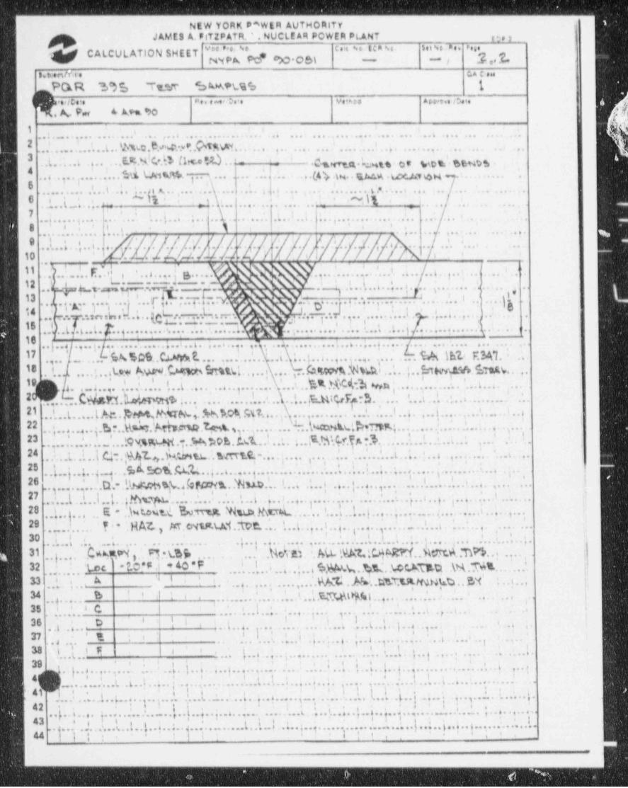
NEW YORK p"WER AUTHORITY ,
!JAMES A. FITZPATil. ' . NUCLE AR POWER PLANT g,2g'# '"*** '"'"#'' " ' '
""*Pk W C')O Ob\CALCULATION SHEET ~p .]. ,, f'
m ~
menm. c,. c .
PO.R ~5 % 'Tumr c:MM.% 1~
( F.oc. . n . . . - e. . . v. m a w.. . u. , - g
.. A N ' Arm to
1., , . ,
, ,.... ...... ........ ... .... ... m....... .. .. ... ... ... .... ... ... ..-. .,.. ... .
2.............t.. m . w. s..p q..ii i i ,
. .. .. .,. .. .... ... . . ...1
... ... .... .....
3 .( . . . . . , q . . , . .g. .,,.L.3, g g . . _
i,
. %,g. .m . p m . %m .,
=.3
.
. J. L . . . . . .(4 4 .y. . as,cp . wem . . .. 3. 3......... M u n % . 3 .. ) ... ....
6........ .i...t . .i
.,. . . .. .........4... .... .......hix.........
... ... .. ... .. .. .. ....
.~ g , _ ,: , .-O i~ -
< .i,, ,t.. .....s w. .... .... .... ... . . _ s .. .. . ....
7 ;-
i ,.. . ,,
...i... .,.. . . . . . .. ... .,
... ....... 3.... ....,........ ..... . . .... .. .... ..'i i8 ...'..8. . . . . ' .i,
,i
. ... . ... e...... .,.. . . ,..
~. . .,/ /. ;/ : i9 1. . . ....i,..i.,....../. . . . . /.
- * ~, . ,
. . . , ...... ...... . . .. . . , . .
... ,.s /. _s /6 i10. ,
.. , , ..
. -
N ...i. .... ..i. ,..c' i - i - i11 ........y...,,,L- ......., a..... \
, m.............. . ... .
h . 7.q q g . g . ,, - . 5 ....i... .. j. ,. 3....- .
: i .-
12 i-
... ... ..
- -
,
......q.. .A. .J. . . . . . . . , . . . . . . . . . . . . . . I....'.........t .>..i..,. j.:
...r.. ,Ts..y . . .,. . . . . . .d. .l '. m i ...t.. . . .6-...p}..L.(..i.f.q...,...k,'.'..,,.....
. . ~
:". 7 --- .. .. a . . . . ..... ....q .............. .. . .
.
., 1! ''
16 i ,i<... .
,. .... 3........... .
. }..7
16 , , ,. ..,.t..............,..i. 5. ........ ,. . .... .........,..$...,.q .....s. .. ... ....
. i. . . . . , .
. , . . ' ..,..'.l '%. W. . C.t.wpt 2. . . . . .. .' . . .'. . ' . . t' . ' . . i . . . . , . 3@. . , . . . . . . .. . CA. WL, F. ML17 . ... .
. ' . . ....!.4L9.* A%W.$.a49ed argg[ , , ,,,, ,,,, ,,,Q sggpg , gg,'i ,;, ;,,99gatg37g , ,,,N C
g gAc4 3 % . . . . . ,' . . . . . .!. . '. . a . . .' ' \1 *i.'i '
.
....... % n,. ......... .. a .... .... 3........p 4. . 2.. . ..
,,i ,t ,,, p y,,p 4 4;... .... .....L .',..\...... ....t...s. u tq n g - b . ...*...t..t .'............ . ' ..Wwo2.
,,;,,,,,,,, g e ,, A j, % .r g , ,,,: ',,%,,,,;9 e a ,t g y ,;,,,,,,,,j,,; j,,,. ,w.og m , ,3 ,,,,,,,, ,,,, ;,,3 ,a , ,,,i ,,. . .i. ,, ,,,21 ,
,, '
22 . ,,.. ,,
, ,, , ;, , ,., , ,, ,j,, ,g y g< , ,,s.%,3, fa , , , ,,, , , ,,,s,w,47,p ,3, , , , |, ,,t , ;. ,3 ,, , , !,,
2a , i. ,,,
,
, , .,,, ; , , ;, , g' , ,p,4, g i,,:, m,,c, _ , ,, , , , , ,, ,, , , ;, , ; , ,', , ,i, ,: ,,; ,i ,,; c g, , , 3 , , ; , . . , , , , , , , ;,24 .
,,, ,,*
g, 3o3g, gg , , ; ,,,,,,,, ;,,,,, ,,, ;,,;, , ,t,,,; , ,( , ,;,,; , , ;,,, , ,, , , :2s :, , , , , , ,,,,,,,,
26 . . .i.J.Q. .'.lM hW.Mi. IS J._i o . . p m . . _ '. . .I . . . ' . -'..o /.. !
27 ,j,,,L ,L ,1,,;,,; w,g : p @g,,; ,;,,,: ,;,, t.,,; 1 ,,.,,,,,,,,,',,,,,, ,;, j,,,', ,;,,,,g ,p...
,,, - i a
28 . . s .. e.o u .a. S . m g. g a. y ,L .... i...'6..i...}.....,.........,... .....;.....,.....i.. ...29 . ..'. . .)3. . . .
* '- y.. g Ay,, , gy.eygga,g ..tp e,.'.. i..t..,..i.q..g.. .
3,.....'...i...i .... . .
' ' ...., . . .. . .
.... ...'..................... . i30 ..; ..i #* .. , ,,
31 ,,,,,,, f. gum ,, . E.ggi, M,cd,. gt igt.g,;pgyy,,y . . . . . , . . . . .. . ..,. ..... ,..,... ...i.......,.. .. ... ....
'.
w y,,A n M ,,, ,,,, ,
.. . . . .. . . .d . . , . . e.p,g . 4%. .w c,jpg . .y. . .r.Viu.' b.; i ;- '
32 . . . . . to c -2.o 's .i * 40 " P'
, .. ....
'
23 .. ' ' . 3. .... ....,.. . m .. w . a w t w o .. a t :.. ..,'.L : .. A <.
* *
............' .'.. i..i g. m,. l..,.. . ' . . . ' . ....i... .. ..34 b_ t i .I i i'
, ..q.....i *8 C. -| '..'. i...(...*. . ...'......t .,..t..> . . .!.
'35 i
i..e.I... s... ..........I i .' 1 I i . . .'t ...a....-}.4..,... .. ,36 <D i i
i ;..l. 4 .i ,. 3..t ....
- i ...3...
....'
37 E ; i.
. . . . . . ' . ' . .; . . 't .*' i i , . '
,q. .. 6. ,..n .3........ 3
......4 ....
' ' i i i38 i. . A ..i E i i i..a-.,..;.........- i..g .,... ....,-
, .....6-.......... .. 6 g. . . . t
'..i5 . . | . . j . . . . . . . . . . .' . . . . . . q:'39 i' ; i
,.. ..t,..'...._,..t.....,.... ....i..i-i i ,,
t ,.q}l . . } . 4 . . , . 3 . . .-. $....
i 'i,,, , i i . . >-
4! L.. . . .i .. . . . . .L a . . , . . . . . ; . . . . ......;............. ,.... s......'..a ....t.....'....,
..... .
.........i..,,.....I,......i!..............- '
! |( 41 s. ,.. ...._,. q ....3.... . . ' . . . ......|.....'t,...
' '
:i;; : .i ,. . . ... . .
3............ .
.. . . ,
I ;!: ! ;42 . . , ,' - .
.. . .....t.....,,.. ..f.. ..,..... ....... ,.........,.,)......I.............,..L..,,..,,.4.....- ........L
. l . . . . . .,. . .' . . . s . . l . . [ . . , . . : . q . .- - .- i i43 '
. . .. . . . . . t . . ! .. J . . ; . . . . . . . . ~ . . . . . .'. . . . . J. . . } . J . . ,i . d . q . . . . . .'. . . . . . '..i i
!= ..
1 ! i . . ;,._ i
' ' * '44 1 ; ; i;* ' i -
, ,
_
._ a
- - . . ..
. _ . . . . . _
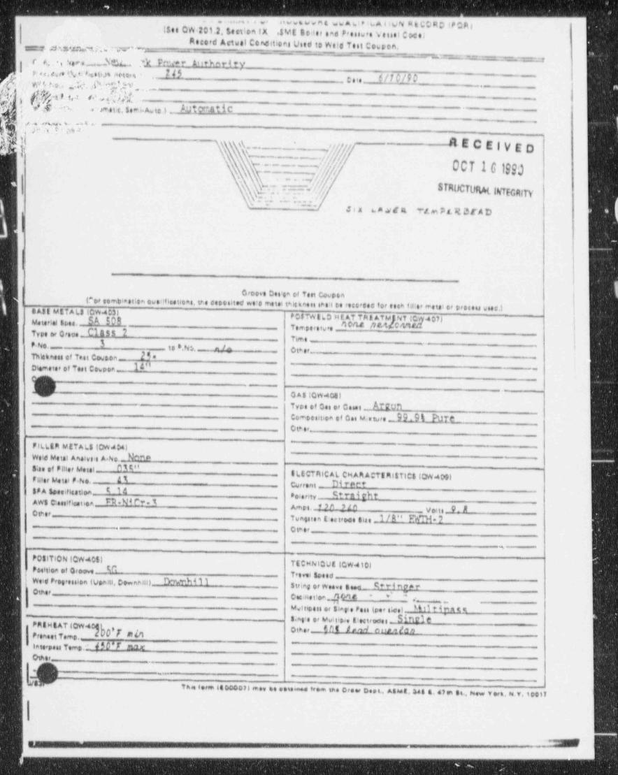
_._ ___ _ _ _ _ _ _ - - - - - - - - - - - , - , . , , , , , , , , ,, , m , u g,,u iwy q cggeip;p,!$es QW 201.2. Section IX 8'.*E Bo>ler sad Pressw e Vessel Cxele
Accord Actual CoMitices Used to Weld Test Co6pon,m.z.wx. w ~_.
Ic. s , s .._. Nm 'k Fmar A"thnrJ tv
-- . -- - ,
e -
r...e... w ..o.n * m - 2M:sie - ur 0/4.-% ~ wn t,o., 2 f. ''':.%v ._
f P9!hfrgs9.t,a ||h[ .hs -.d.t c. s e-i. A. , 3 Aut r.atic .y ;q . . _-( j} r e a o .
3-
k :j $ C" ._b q f,[,,f---
RECEIVED,
007 161990.. -___ _ _.
\ . s ; ~. ' ] i/y.ySTRUCTUM ingmyy.
Qi...Y: .- . . '''
l'
' - ' _ _ ~ _ Jix 6. A .vsf E Y t. m P L R,3 E A D "
I
croove ces'e* et ten cocoontror some,i.ecen owennuneas. ire eeposite<r were mim mene. .*e i ce reco,see for enn tii:e, mem or e,neu wienj
jt cAtt METALS 60W403) i
PC$7WILO HEAT Tat ATMINT to Iwterini si,se, SA SOB vem,,,e,,,, _ nou MticN5t24 07)Type or orece Class 2 |7,,e _
jP. N3. _ 3 t o *.N:,. - -4 Ce et_Thhkmess of Test Cowson- 25*Diameter of Teet Cowpoe- IA" _
.,
p>.,
V Q A5 (CW408)_
-
Tree of ces or ce.e, . ArronComecouen of coi u,.we 99.9 % Pur.e_Ctmer
FILLER METALS (OWJ*AlWeld Wtal Anelve>s A.No.--. N^ae ~
8;te of Pilier Waal W"ELECTRICAL CHAAAOTE RI$ TIC $ (QW409|Filter Wtal F.ho, a1
$$ A Samfkstion I IA__ Corrent- Di T P f* t
.
Po6erity StMi ehtAWS C e:Cfication Ml N4l'?-1 ~
Ames. ' M - S In _ voiti 9_ AOther Tungsten E ntroce siae 1/ A" N 7
- Otmer
w
P081T10N ICW4C51TECHNicut (cwatos
Poittion of G#oove- M Tre si speed -Weid Prog,ession (Venett, Downhill) hTM 1 IOther
_ stria 0 or Weeve BW S * '" i M * "* ''
Cecinetton 40't e ._.-
Mvf ocais or Slap <e Pass (per s'cel M 11 tim t t~ .
8 ng+e or Mutsio4e EtHtrodel- NMIO 3
fat H EAT (QwaFrenseiTeme..
O,T 2 other_ { M /,n_4 e un ga n
laterpose Teme.1 4 S O ' T m 't'Osher -
-
J.-_.
,, i.e. . .o e , m ee oe . .,e .r.m . e o r. ., .. ... . .. .e . o .2, . o ... e,s . ,< ,. , co ,,
_= mar 1__-
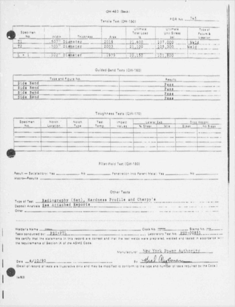
. . . _.
3
.
QW 44 3 (bxA )
PCRho' 7'STemelle Te n (CM.1!.0) -
- _
{ vitimsie Vitim e t e T ,4. ,,i$peonaen tetal(cas Unit Stress p.,m a
Ne ! Wiet> ?>ichaes __ aree__ <e __
ps L x, , ...,_
T1 j . 50]" D14t's t e r 2019 1 71.600 .10 7 , Q20 ,_.,_. }{ tig .,,, ,, , , , , ,,.
T2 ! .305_" Dieeter 2003 21.10p..-..- 1 0).i.3,Q0 ... L'ej d--
.
L= 1 ! . 502" Disene t e r .19B i 20,150'
T6l'T66~ " ' " ' - - - ~ ~ ~ "
.
Gulded. Band Tests (OW.160)i
Tvoe saa resee No. e ,wi3s
Side Bend p.,,~~ ' ~' ~ ~ ' ~
~~
p',Side Bend~ ~ ~ ~ ~ ~ * * * ~ *Side Bund p ,
-~~Side Bend pg.,
Toughness Tests (QW.170)'
Specimen Notch' * Notch Test lmpstt (tief el ( s e Deer We chtNo. Leest;on Tvoe Teme Velvet % 5heer _I Mits t'est i _ No B'est
= - - . - .
l._ __
__ . . . _ ._ _ _.
Fillet Weld Tett (CW 180)
Re wit - $stistsetery: Yes - No Penetratien into Pareet Meist: Yes Ne
M 4 c rt>--A e wit: _ . . _
Other Tests
Radiography (Sat), Hardness Profile and Charpy'sType of TestCaposit Anahrsis E.es At tached Report s- _. - . . ~ . . . . .... . . . . . . . . . . . . . . .
,Other - . - _ . . . . - - . . . . . . . . . - . . -
......................................................................... ........................ .................o'."oo
Clock No. :""." ~ S t a m p h e. .~ . LWelders Name ----
Tests concustee by: PSI PTp__,,, (spo,etory Y :: No ,23% 00_01.1. ......- 4, , , , , , , , , , , , , , , , , , , , , , , ,
We certify inat the statements in this recore are correct sna test tr.e test welcs we.e proprsrec. welces and testes in accorcente wn* !ine teauirements et section m of tu AsMt cose. .
Memwlatter:P O N
hhCatt U.l.QlI.0 py u__ _ ... _ .
loissa or',e.o . .iiesi, s,e niw.t,.u.. oniv sna may es moose to convorm io ine iy.. ano no b oiinsi. ,siase or in ceenm
OOq im
||
|
_ _ .
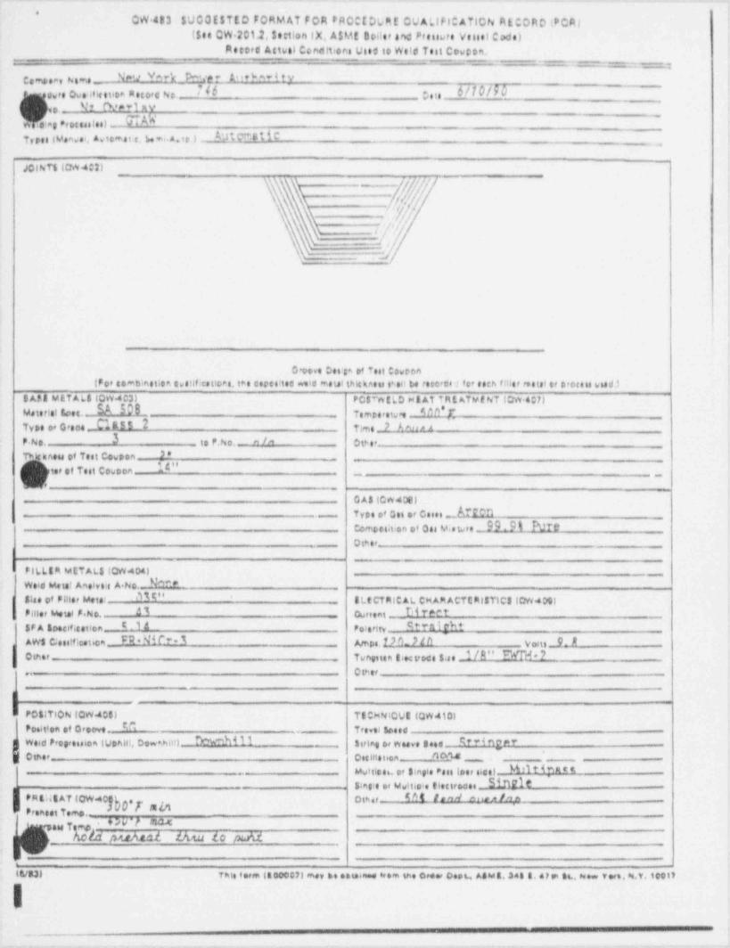
._ __ _ _ - _ _ -
*
CW.483 $U00tsTto FotiMAT FoA PR00t0LRt OUALIF10Afl0N AE00RD (PCR)($st CW 201.2, Settlen IX. A$ME Doiler aM Preuvre Vessel Ccide)
Retof d Attbtl Conditi$es Use# 10 Weld Test C#wCon.-- - _ ;
como:avhems N"U "* ?k P''" 1. h t %- 4 tvN6 6/1b790v2,e ove ivIcisioa seco,e No ;e t,
Nr N*-luv,o
;eg Procenles) - NTypes (Vanwei, Av to*st c. be ** A.te 1 DI F8IiC
4
JO t hTl (DW402)1 1
__
. . . .
\\ 5
. -|/'[f/\\ ' /
\\ r/
s .
omo eCo ino,toico. con|Po# co*bination tus14f testloes, t*e espes!tes wold moul thlehness shell t.e reectos 'l for eeth filler rettal er D'ocess w64dj
BAS A METALS (QW4C31 PC$mtLD HEAT TRE ATMf NT IOW.4C7)Meterial foes.- _.SA 50B _TypegtOrsee J JL55 2
_
Tom,e,ety,, _ s on' rTime 7AN"A
P No. 3 _ to P.No. m /^ Otb et__
TP'kness of Test Cowpen . 3*-
[ )i ter of Test Cowoon l'"__ .
L . - _ _ _
G AS (CW40s)
Tree of on or ce .. Amn-
comossation of on M., pre _ 09,9% PureO th er-
____
__ _
PILLI A METAL 810W404) _
t*!*Id Mete! Anelve e A No.- N^* P
814e cf Pillet Meter W" I L t CT RIC A L CH AM ACTE RISTIC310W4091Piller Metet P.No. Al Cureent __N ?*Ft
h$F A Specification _ E 1A Peterity StYalf tAW$ C;esiffication _ M * MM?-I Amps. D h_7 t h y,1, = 9 AO(nor Tuneiten Iwtroce 1.4e _1/E" M* ?.. Other
! P381 TION (QW408) TECHNtQgg (QW410)
Posit'en of Oroove C Trevei gases..
-smwe.. ,< ,re..oniuen,,. oo. _ ,_ , ,,, , o, , se .e , .e . x,,%..'
Other - Oss stisi.on /10 4
..~+mI
M.,t:e e o. , ,,e .. .. oe. ,,.e ,. . -
om,,s....,,,0,e,....,o.a_ s u eI;re:e==*'w r a o~ * ' ' - ' - -
, .w,-~
pu)\.tal. thru lo puW,
m.., .n,s. .n ,. .,1 ~ . ,e.. _ . .e- .e .... ..o ~ ... ..... ..... . .e. . ..~... ,,,,,
I_
r,m. ~-, , - - - -
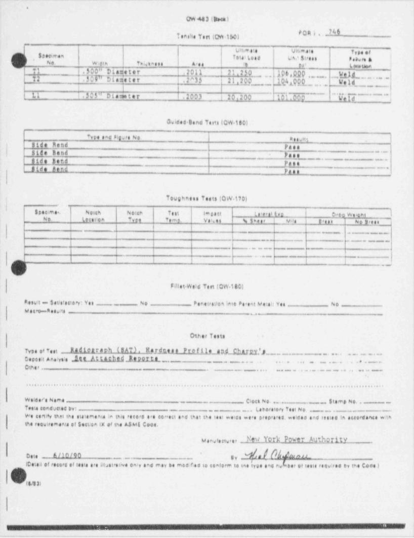
_ _ _ . _ _ _ _ . _ _ _ _ - _ __ _. -_ _ _ _ _ . __ _ . _. _ _ _ _ _ __ __ _ _
.
OW443 (Dech)
QR i .. M4Tenstie Tert (on.1!,0)
r, eme,
vine.ie vium.ie 1,,s . ,s T.i.it... uv si,... , w ,, i 1
,
*No. Wieth T>ietasse Ares 't __ tr' L ,as tne e '
'l T1 .500" Diameter .2011 21.250 196,92Q ,_ . _ y.fj1,, _, _ , . ., . ,,,l
| 72 .$09" Diatieter .2^35 21,200.
_.
,,,},,0,4 Q QQ,_, . . Weld i1I
--. 5 05 " D i a rse t e r .2003 ! 20,200 101.000 WeldI I
I L1 . _. _ ...... . ..,
___
|
Gwides Bend Tsite (QW.ito)
tue .no n u,e u. I s e s vi,3e
Bide Mend PassSide Band Paes.
Side Eer.d PaenSide Llend Pass
* ~''
Toughnete Tests (QW.170)
| S pe cimer. Noich Notch Test impact ts' erst be Deco We.ckt lL No. we. con Tee te-e vessi s s e., ,n e e,e.. ~. v,e..
_
I__
. - _-
_ . - .._
- ._
. . . . -
-
Fillet. Weld Test (QW.180)
Result a.- $stisisstory: Ye s No Penet,etica lete Potent Metal: Yes Nowesto stesAs n.
Other Tests .
Typs of Test Rediottaph (BAT). Hardnt.ge Profi1e_And Chatr.,y.'),._ . , , , . . . . . . . . _ _ . .
Oepeeit Anafyste .ite At ta ehg,4 Bigort a ,,,... , . - , . . , , . . , . . . . . . . , . . . . . . , . _ . -
Othe, . - - -
. . . . . . . . _ . - . . . . . . . . . -.
...........,..................................................................................... ...............................
Wolser's Nema Clock No. ... - . _. Stemp No. . - -
Tests conductec Dyt-__ . La tio,etory Te st No. _ .
--
- ___
We certl*y that the statememe in thle ,eto,e era cortest and that the test weics were proces,es, welde. and testeg in setordance withthe ,eewi,emania of Sect;cn IX of the ASME Coot.
M a ng fe ggy,e, New York Power Authority
M,/ hmeste mmo '
iv._ ._ __.
teet.a .< ,e..,. .r i.si. .,e msires. .,iv .n. ,eer .e mous. io e.ei ,,, i. ies iv.e e,. Je.e, . iesi. ,e.vi,e. .y tne cuor:\
. .
---w- 9 --. _3 = 9 -w, -c-,
.,
O
i
Appendix 3
Nutech Temperbead Quabfication Programfor Discharge No7zle at the
Oys:er Creek Nuclear Power Station
(EPRI Advisory Committee for Temperhead Welding,November 2 3,1989, Charlotte, NC)
O
|
ii
!
I
V SIR 90-063, Rev. 0
|- ~ -- - - _ - - .

_ - . . - . . _ . ..__ . .-...- --.. _.-- --.- . ---
|4|t.
4 :
| .
O aozz a 2oa att t"o wtto ovta'ar !|UNDEILWAIEfLBACKED_COND1110NS
,iI
'
;
i
[,DBJECTIVE
i]; !e'
DEVELOP A WATER BACKED WELD OVERLAY PROCEDURE FOR N0ZZLE TO f'''
i
SAFE END WELDS.
;i
'IDEVELOPED AS A CONTINGENCY PLAN FOR OYSTER CREEK NUCLEAR- i
;
PLANT.P
'
-GEOMETRY.0F THE N0ZZLE AND LACK OF PHYSICAL SPACE TO-
ACCOMMODATE PREHEAT AND PWHT EQUIPMENT.[;
O :!
APPLICATION OF NUTECH'S PROCEDURE WITH PREHEAT AND POST i-
BAKE (N-432) WAs DzrrrCutt.!
:
.
J
..
,
>
O;
i
nutech i-1-BC-3- I :
,
.
f
,.-,.y,,, ,. n.,. ....,,,,,,,_.n.. ,.,......_,..-,,.,n,__-_-. , , . , . - . , + . , , , . _ ,
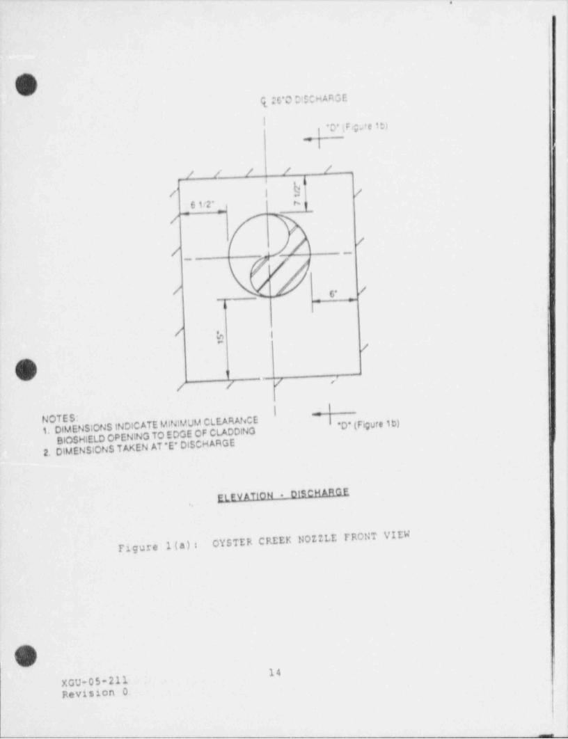
._. -__._.
,
i'
Oq 00*O D:ECHARGE
I *D* (Fgre it)i
,
/ / / / /b
h/ | /[61/2" | q._
y---/,
//
|f6* /
= =I,
b I
'
O ,,
/ / / <'
t| "
NOTES:1. DIMENSIONS INDICATE MINIMUM CLEARANCE'D* (Figure ib)
BCSHIELD OPENING TO EDGE OF CLADDING2. DIMENSIONS TAKEN AT *E' DISCHARGE
ELEV ATION . OlSCH ARGE,
OYSTER CREEK NDZZLE FRONT VIEWFigure 1(a):
d<
14XGU-05-211Revision 0
4 |
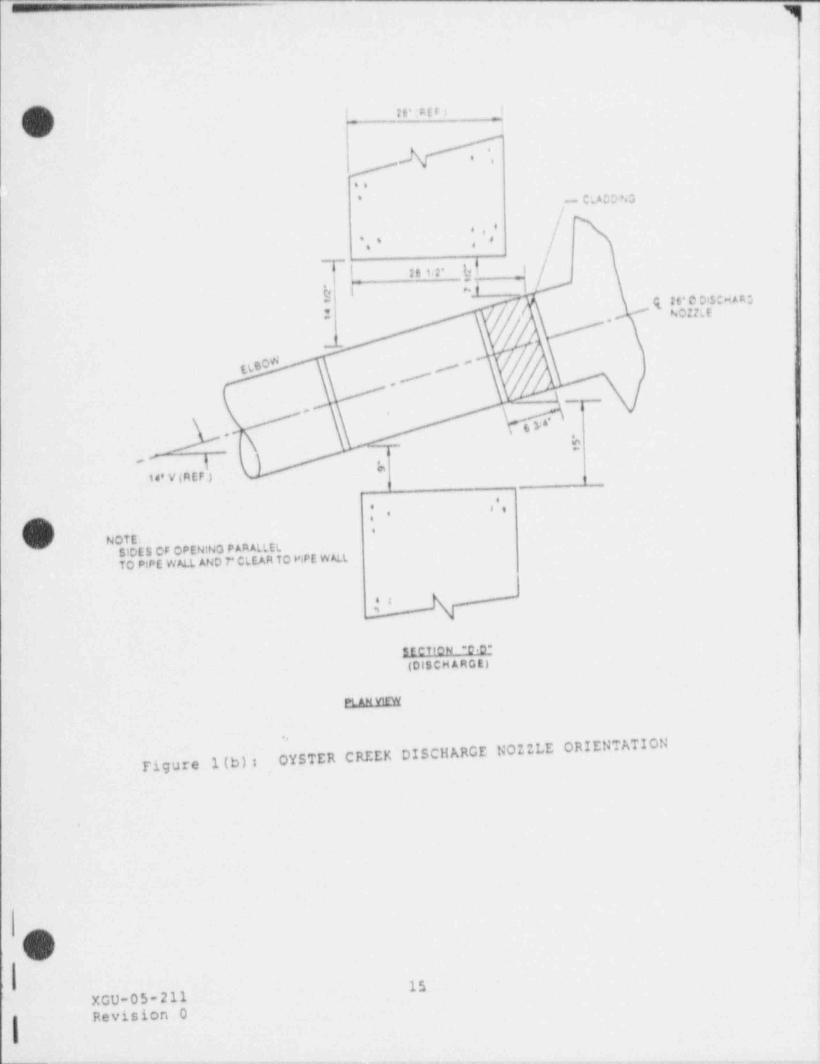
_-_ --._
g __
I
1' 28'sntti -
#*.
~ C.ADDiN3.
|.-,e ,
., ' ,
s o i
'"l'
hf26 tit'*. $ I
( #6'O Of 5ONAAa,j N0!!LE,
* .
__
dn60 #,/
\
5_* ,
re ,,
- ,- *- ,
-k
14' V (REF-)
e,. 4 ee,
O 4
NOTE:SIDES OF OPENING PARALLELTO PlPE WALL AND 7* CLEAR TO PIPE WALL
nectiew r.n-
(DISCH ARCE)
PLANVEW
=<
OYSTER' CREEK DISCHARGE NOZZLE ORIENTATIONFigure 1(b):
e ?
b
1 4
-'__
-
'
' 15 .' ,
XGU-05-211Revision 0
. l- @
_...-...--_.,__._._._.-.._-..._,._..__.,.._,_.._.,_.......,..,..~.-,,,_.._._.--,...___,-.,_._._-,._m_,._.,...-,,._,- - -
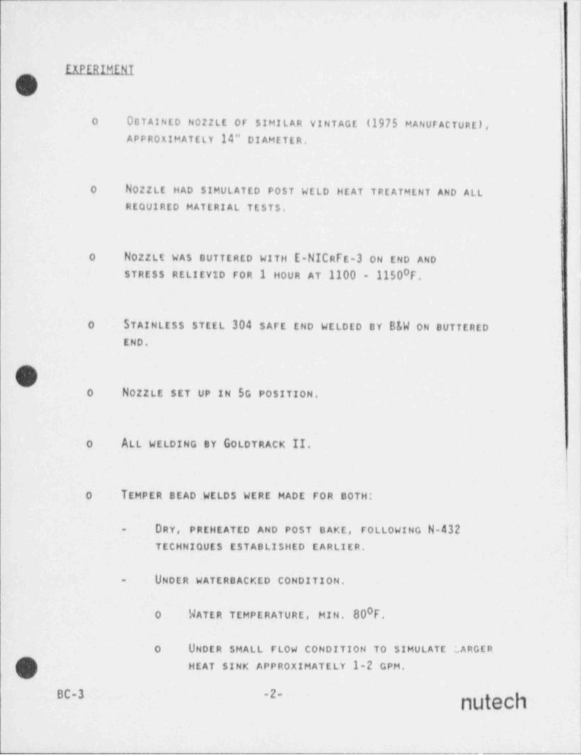
... _ _ - .. __ _ _ _ - _ _ _ . . _ _ _ ~ -
)
i
'EXPERIMENT
-
o OBTAINED N0ZZLE OF SIMILAR VINTAGE (1975 MANUFACTURE),
APPROXIMATELY 14" DIAMETER.
O No22LE HAD SIMULATED POST WELD HEAT TREATMENT AND ALLREQUIRED MATERIAL TESTS.
o NOZZLE WAS BUTTERED WITH E-NICRFE-3 oN END AND'
0STRESS RELIEVID FOR 1 HOUR AT 1100 - 1150 F.
s
0 STAINLESS STEEL 304 SAFE END WELDED BY B&W ON BUTTERED'
END.
Oo NOZZLE SET UP IN SG POSITION.
o ALL WELDING BY GOLDTRACK II.
o TEMPER BEAD. WELDS WERE MADE FOR BOTH:
DRY, PREHEATED AND POST HAKE, FOLLOWING N-432-
iTECHNIQUES ESTABLISHED EARLIER. >
UNDER WATERBACKED CONDITION.-
.
0O WATER TEMPERATURE, HIN. 80 F,
o UNDER SMALL FLOW CONDITION TO SIMULATE LARGER
(]) HEAT SINK APPROXIMATELY 1-2 GPM.
BC-3 -2- nutech!
)
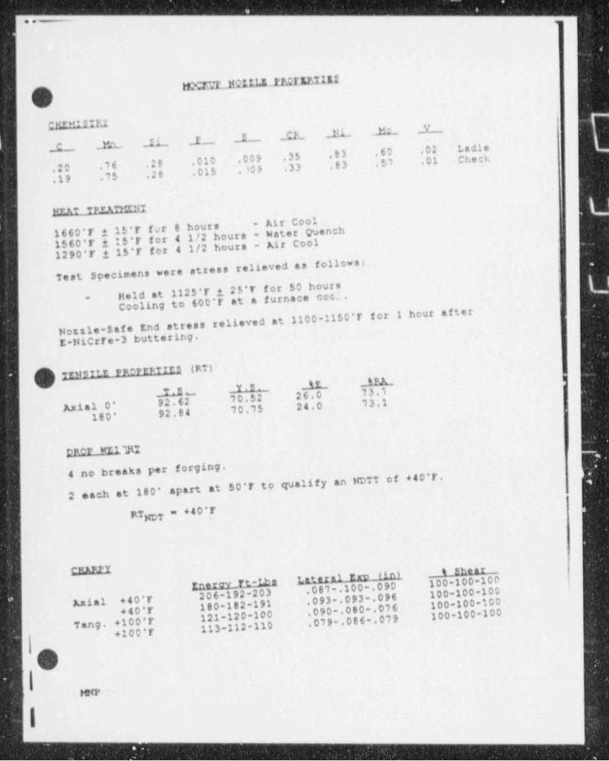
3--_--__-____ _ _ _ _ _ _ - - - - - _ _ _
mern_na u.z_ m uarumQLJ
,
[REMISTPJ
C EL fi._ P- ._E._._ ._CE 111._ 112._ V
.20 76 .28 .010 .009 .35 .83 .60 .02 Ladle
.19 .75 .28 .015 10 9 .33 .83 .57 .01 Chech
MrftT TPIATPIt{I- Air Cool
1660'T i 15*F for B hours 1560*F i 15'T for 4 1/2 hours - Water Quench1290'F i 15'T for 4 1/2 hours - Air Cool
follows:Test Specimens were stress relieved as
1125*F i 25'E for 50 hoursHeld atCooling to 600'F at a furnace coc!..-
1100-1150'T for 1 hour afterHottle-Safe End stress relieved atE-HiCrFe-3 buttering.
TENSILE PROPERTIES (P.T)tE SRA_
M .u __ Y S . _
Axial O' 92.62 70.52 26.0 73.1
180' 92.84 70.75 24.0 73.1
DROP WEl M _
4 no breaks per forging. $
at 50*F to qualify an NDTT of +40'F.2 each at 180* apart
RTNDT = +40'Te
pMAP_PY f ini_ __ t shear _Enerav_Tt-Lbs Lateral Ern 100-100-100.087 .100 .090 100-100-100206-192-203 .093 .093 .096 100-100-100Axial +40*F 180-182-191 .090 .080 .076 100-100-100+40*F 121-120-100 .079 .086 .079T ang . +10 0 * F 113-112-110+100*F
{ HNP '
I|
_
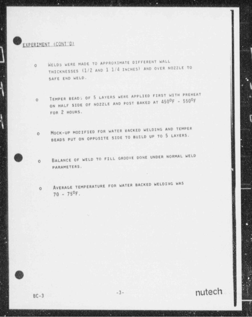
- - - _ _ - - - - - _ _ - _ _ _ _ _ _ - _
O EXPERIMENT (CONT'D1
WELDS WERE MADE TO APPROXIMATE DIFFERENT WALLO(1/2 AND 1 1/4 INCHES) AND OVER N0ZZLE TOTHICKNESSES
SAFE END WELD.
TEMPER BEADS OF 5 LAYERS WERE APPLIED FIRST WITH PREHEAT0 0O
ON HALF SIDE OF N0ZZLE AND POST DAKED AT 450 F - 550 FFOR 2 HOURS.
HOCK-UP MODIFIED FOR WATER BACKED WELDING AND TEMPERO
DEADS PUT ON OPPOSITE SIDE TO BUILD UP TO 5 LAYERS. P
FILL GROOVE DONE UNDER HORMAL WELDo BALANCE OF WELD TO
PARAMETERS..
AVERAGE TEMPERATURE FOR WATER BACKED WELDING WASO070 - 75 F.
O-3- nuteC1 .;
Bc-3 )
|-- - ___ .___
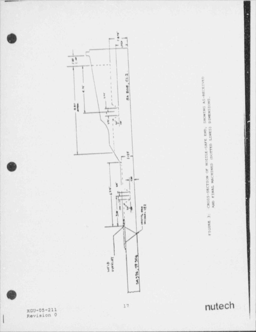
_. - - - _ . - _ - - - _ _ _ . _ - . _ _ - - - _ - - . - _ - _. _.
!
ii
!
k
'- : 3nt- t *- - -
! F'
_ - -e ,
--, . . . . ,
A' a|
I i .
tT.
i 6 e>. .
l+ i & M
',
I: : i , t.i vi nn
'
:: t.| <E, e. ?_;, x,
T?,i i!,3 i aa
; i aW'
*Ei .
i., a .
I d Q; ;
' ' t "!| r :- :: - '
n, 2 o,,
85'
i =7 v
i ''4'-i ap-
y 9s; .,4 s,; - v- mm
mdsI a.$
.
,, uE i 3-b ge,
| t s a
il.""
' i: s
3J u s,
/I A 5,
:!
1
=-1 8
21 F2
-
te$
O -
r
nutech'
1,
XGO-05-211 ;
gevision 0 i

__ _ _ - . . _ _ _ _ _ - _ _ _ _ _ _ _ _ ___ __ __ _ _ _ . ._ . __
f
O o O-
,
t
yxmC<: c i, ye !
moww TENSILE-L !0 8i' nu FWOF- 1 -e
oe ,
MICRO- 1-5 |
f ';!.
SIDEBDiD-1 '
,
1 "' !| SIDEBEND- \
|! - 35 !
OVERLAY SIDEBEND-1 ts -.
| C11ARPY-1 . , '-
- ray |4
OVERLAY SIDEBEND-2'
CilARPY-3-
|
[a
\3 pqy. CilARPY-2- ;{ p f3,,g ;
** * U "'- i--
-,gCHARPY-4 - | I ,4_=- :u ye
;
IElrseer ?
f
i
$ A>
,
1
-I
OVERI).Y SIDEBUID-3 n- t,
!
|OVERLAY SIDF">END-4 / /
/I
SIDEBSND-V ,
D'
SIDEBEND-4 *180'
t
OVERLAY MICRO-1 - ]tTMOF-2 - ,
/TENSILE-2'
| l
LAYOt,7 PLAN FOR REMOVING SAMPLE BLANKS1/2" THICKNESS GROOVEFigure 7:
FOR OVERLAY ANDi
!
i !
N >
:|
3
- . _ - - - - --_ - - -- - - - - _ - _ _
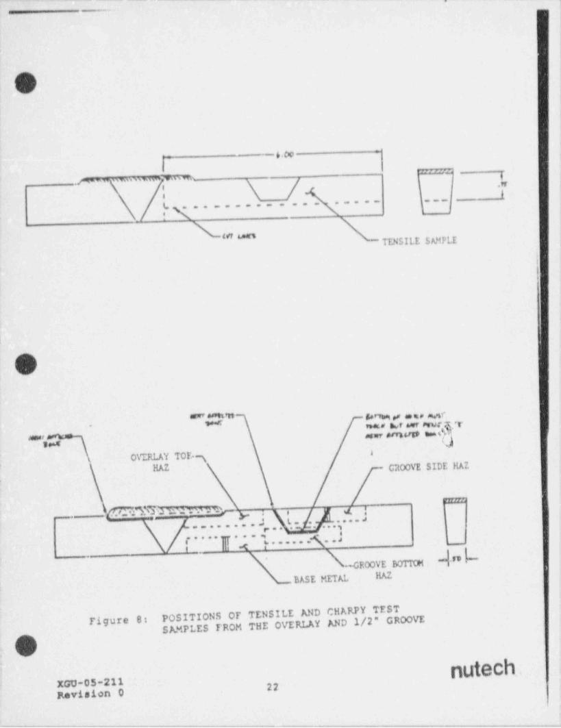
. . -.. - - _. _... _ ,
.
I
|
O lP
I
i
-6.co-
1.m w wowm hs
: \ /4 { I.... . ... . , , , ,
f .. -....-
ut sanTENSILE SMfPLE ,
i
I
|
O
-.- 4% ,, = = a erW nw* Ar wrever .T~
-,,mo ,
d**' y I-
,
,
. O\T.RLAY TOE.SHAZ CitOOVE SIDE HAZ
'
mMME rd r.vn, . .
- . .L. . . ..
... .... ,-..... - ....r- R ..,J| 4 y......
" ''-GROOVE BOTITH
BASE METAL HAZ
POSITIONS OF TENSILE AND CHARPY TESTSAMPLES FROM THE OVERLAY AND 1/2" GROOVE
Tigure 8:
V>
nutechXGU.05 211 22 ,
Revision 0
. . ~ . . - ,_,.....-_..,,_........_w , , . _ , . . , _ . , , , . , ~......-~_m.-,..-...-_,.....y,_,.,,. ,.__,._,._-..--...-m.. . - , _ ~ _ .-
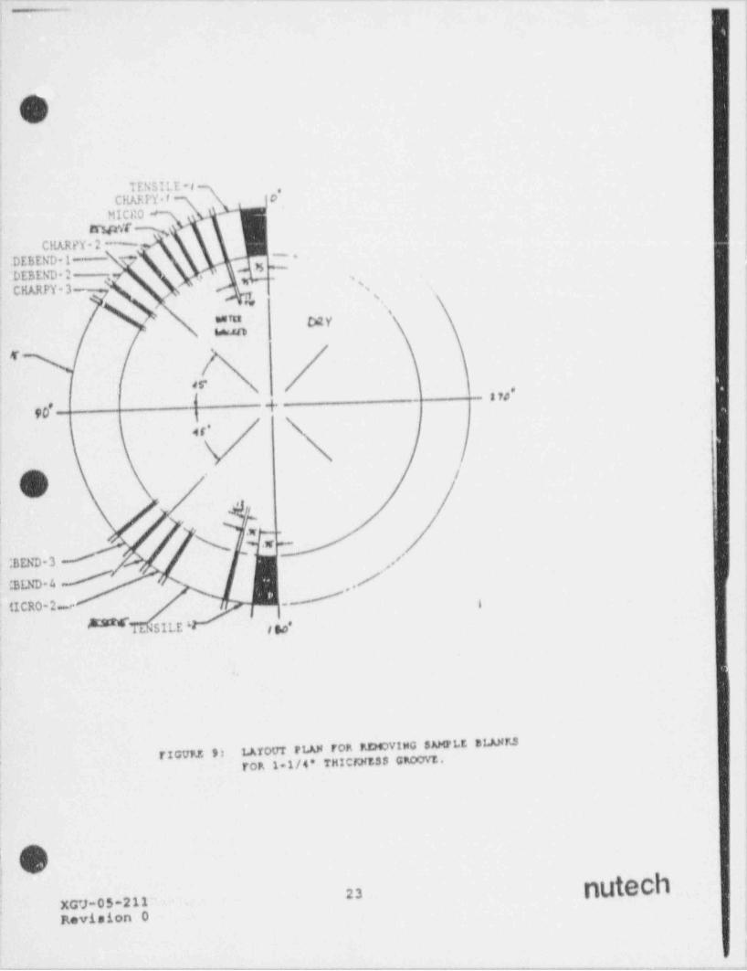
-
,
.i
s
;
,
0>I
4
TENSILE -#CHAh!'Y t o'
MICR0trs{tof .
CHARPY-2 % |.
.DEBEND 1- 7M ;--
,
DEBEND-2 y ', .s -,- *
CHARPY-3'
,
'sc ' 6
N% *wem D2V
es*
-{-- tW'
90
/
'+ '
% * .a L-
| BEND-3 ''
CBLND-4 /-,y'(ICRO-2_-
tr. SILE ' gg,
,
i
LAYOUT PLAN FOR P.DOVING $ AMPLE BLANTJf TICUFJ. 9:
TOR 1 1/4" THICTEES$ GRCovt.;
; O.
nutech23xa;-os-212Revision 0.
,
b
f
- , _ . , . . . _ - . , _ . _ . . - ~ - , , , , - . , - _ _ . - , _ . - . . _ , - . _ . _ . - . . , , . - _ - - , . . - _ - - _ . . , , , - . . . . _ _ _ . - _ . . . - _ - - - - - , - - - . . - - - - , - . - - - - - - . --
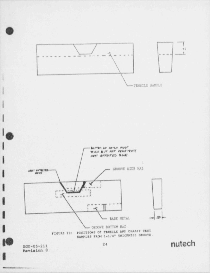
1
|
m
\ / ),. t |.. .
:'
TENSILE SAMPLE
|
1 o}.\
I nertw or wrw mv>rTs M ser Her PratettartHnr nrrterco ino#
I
GROOVE SIDE HAIpr
'*--;,~
_
m.. .._... ,
,p-.......! i t- _
+ .SDBASE METAL+-
GROOVE BOTTOM HAZ
rIcvP2 los POSITIONS Of TEN 3!LE ED CHARPY TESTSAMPLES FFCH 1 1/4' THICFMESS GP.OOVE.
gg24XGU-05-211Revision 0-
E_
-.

.. _. _ ._. ._ . _ - _ _ _ _ _ _ . . . _ _ _ . _ . _ , _ _ _ __
a r
Oauuus
DPMJ1EliEALED_AND POST BAKED _EROCEDDRE
MLTIMATE T ENHLL_$T RENGT11191.1, 88.0 (P ARENT MET AL)
AT 1/2 INCH GROOVE
84.9, 88.5 (PARENT METAL) i
AT 1 1/4 INCH GROOVE
SIot Britan
SAMPLES SATISrACTORY AT EACH OF THE 1/2ALL rouR (4)INCH AND 1 1/4 INCH GROOVE LOCATIONS.
OWATER _DACKED PROCEDURE_
ULTIMATE TENSILE STRENGTH 1(PARENT METAL)91.0, 91.3 KSI
AT 1/2 INCH GROOVE
(PARENT METAI.)88.8, 86.5 KSIAT 1 1/4 INCH GROOVE $ 'if,i
g"T
'ySwE BENos-
SAMPLES SATISrACTORY AT EACH OF THE 1/2ALL rouR (4)INCH AND 1 1/4 INCH GROOVE LOCATIONS.
|
1 0:1 ded5--
|BC-3| \
- - - . - . ._ . . -- __-.- _.
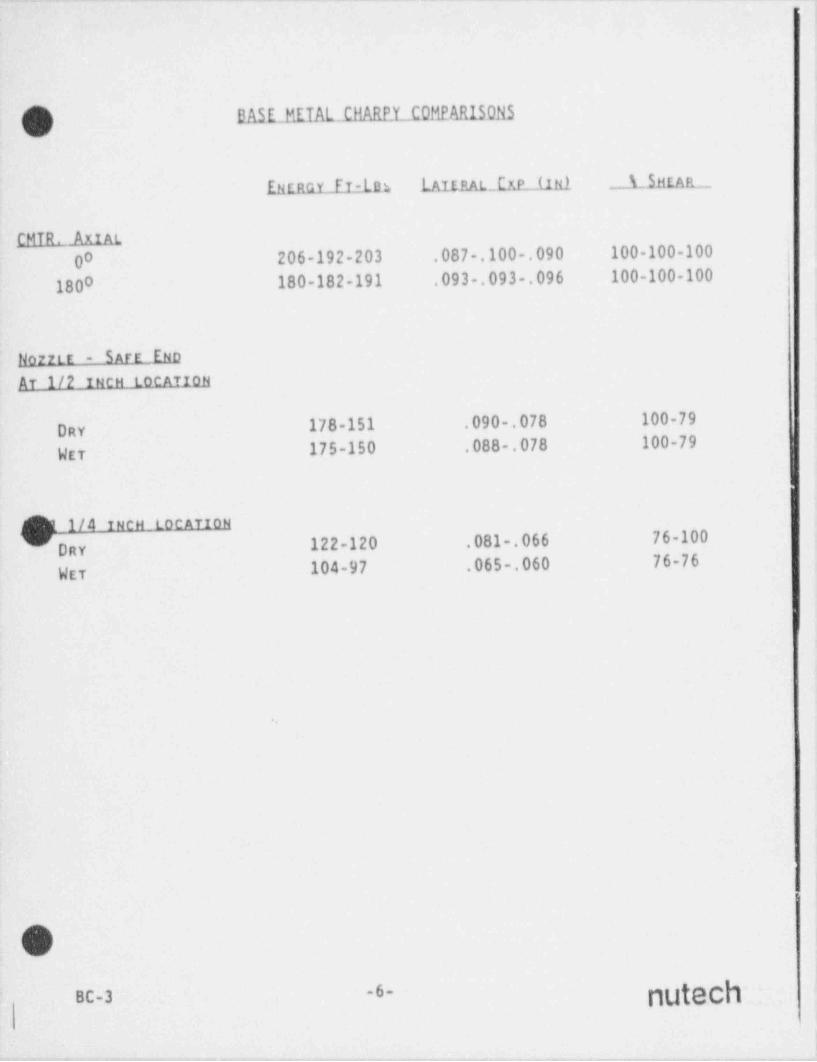
. -. - - _ _ _ .-. .- --. - - - -
) DASE_tiEIAL CHARPY C0!iEARISONS('J%
EtiffGY fT-ldh [AHEAL_D.P__(llf1 ,,_.kbliEAfL_
CMTR. AXIAL00 206-192-203 .087 .100 .090 100-100-100
1800 180-182-191 .093 .093 .096 100-100-100
Nozztr - SArt ENDAT 1/2 INCH LOCATION
DRY 178-151 .090 .078 100-79
WET 175-150 .088 .078 100-79
QCATION
DRY 122-120 .081 .066 76-100
WET 104-97 .065 .060 76-76
,
bJNteCh8C-3- -6-
!
" _
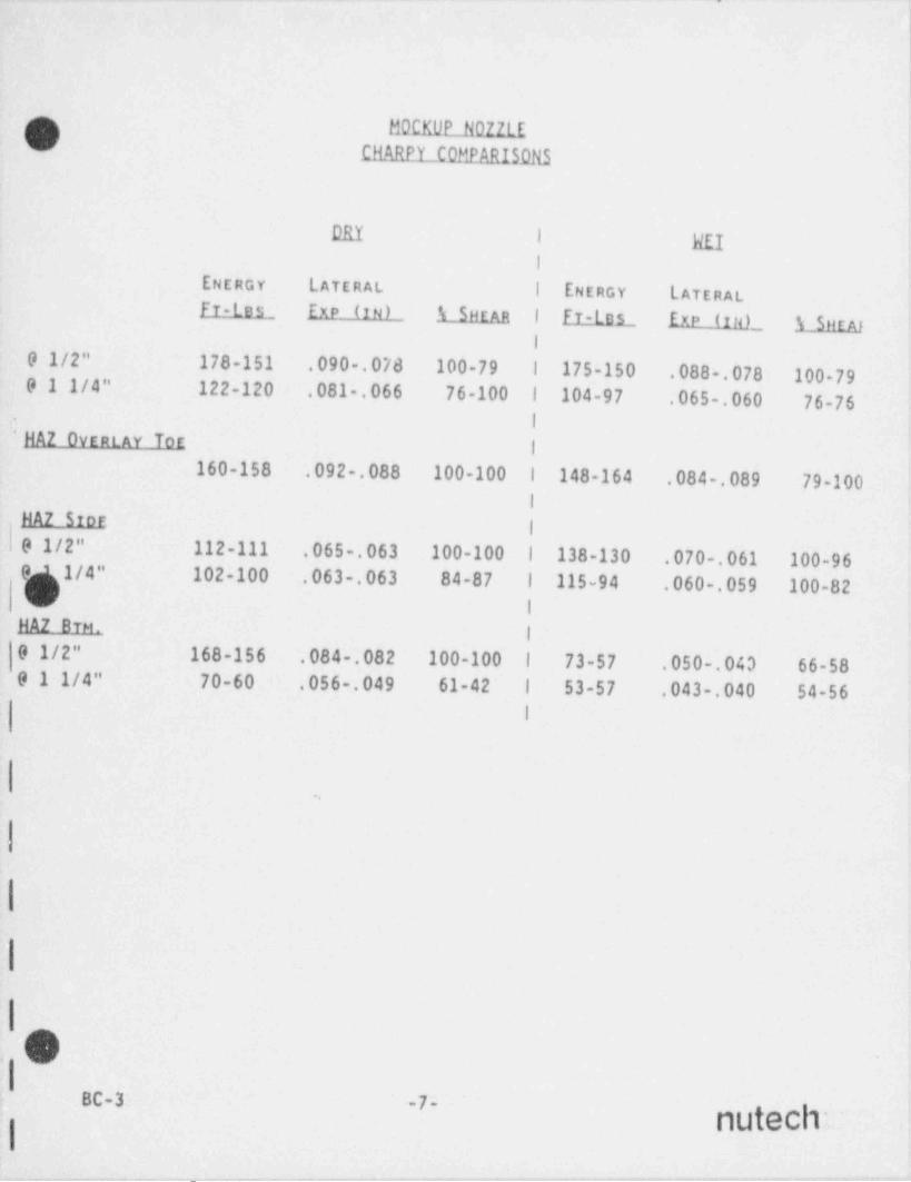
- . - - .- .__ - ._- __ __. - - - _..
. - . . - . - . .- . --
|
f BOCKUP N0ZZLE
CHARPY COMPARISDNS:
i
DRY I REII
,
ENERGY LATERAL i ENERGY LATERAL,
FT-Les_ EXP (IN) A SHEAR I FT-Los Exp (in) 1 SHEAF'
I
9 1/2" 178-151 .090 .078 100-79 | 175-150 .088 .078 100-79;
9 1 1/4" 122-120 .081 .066 76-100 1 104-97 .065 .060 76-76 .
I*
'HAZ OVERLAY toe ,
I,
160-158 .092 .088 100-100 1 148-164 .084 .089 79-100i
HAZ Srori
9 1/2" 112-111 .065 063 100-100 1 138-130 .070 .061 100-960> 1/4" 102-100 .063 .063 84-87 | 115-94 .060 .059 100-82i
NA2 BTM.I
9 1/2" 168-156 .084 .082 100-100 l 73-57 .050 .043 66-58 I
9 1 1/4" 70-60 .056 .049 61-42 1 53-57 .043 .040 54-56I
.
..
|
|
|
|O -
.I-
( BC-31 -7- mMch '
:I.
;
.- . . - _ - . .. -. --- - --- .- .
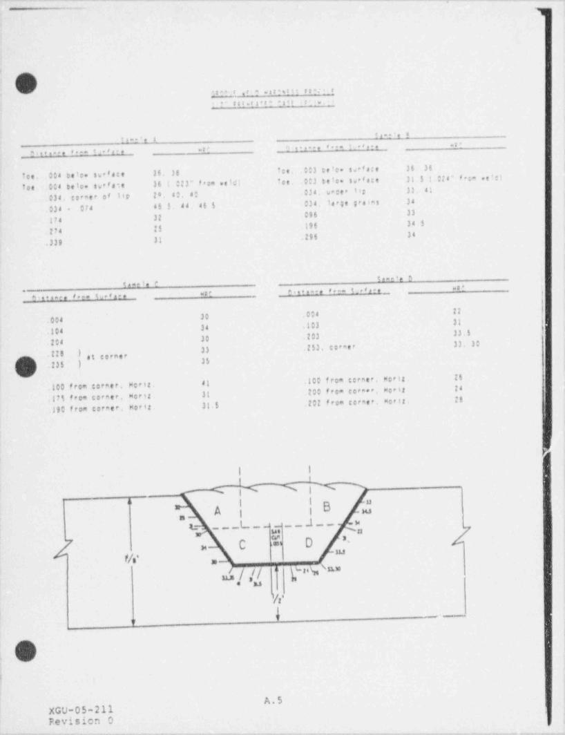
. . . _ _ _ _ _ - . . _ _ _ . . . . _ . . _ . . _ . . _ _ . _ . _ _ _ _ _ _ _ _ . _ _ . . . . _ _ _ . . _ _ . . . _ . . . . . _ . . - . _ . _ _ . _ m_.-____. _.m
: O *taa f ,t.9 ws!*gtt+ p g a. 5 r
i res.rs r* :: .r;. .a ,
e...'. ei,-r', s
.<,.. .c.e... *
ate,c. 8.-- c3.'_r. .rc r ,...r,
fee. 004 belo surface 36. 36 fee, ,003 eele. sprece 36. 36
foe. 004 telo. su fste 36 1. 0:3" f rom ne bJ: Tee. 003 eetc. swerece 31.5 t Ots" frem . ele;r
034 c;*eer of Itr 28 80. 40 034 vacer leg 33. 41
074 46 5, 44, 46 5 034, large greens 34.034 *
174 32 .096 33
.274 25 196 34 5
.339 31 .296 34
in-e*, $t , e i, e us" :
wp* ^***.ar, *e-- 12.'s.,,th,*tsac, **e- tu.'ar, ,
30 .004 !!
.004 3134 .303
.104 33.530 .203
.204 33. 3033 .253. corner
.!!O ) ,g ,,,,,,.235 ) 35
.100 f rom corne r. Her tz . 41 .100 from cerete. Norts. 25
.17% from corner. Hert 31 .200 feca corner. Mort 24
.190 from career. Morts. 31.5 .202 from ceraer. Morts. 28
I I
hwx" | I "
BA i i,
t ___t_____ a__ ,
/5 D^*
C}~
u mf/' =
\3th l1M// ' d' L
. u'
4 -n
O.
.
A.5XGU-05-211Fevision 0
__ . _ . . _ . . . _. _. _ _ _ _ _ _ - . . . _ . ___ . _ _ _ _ _ . _ . , _.-
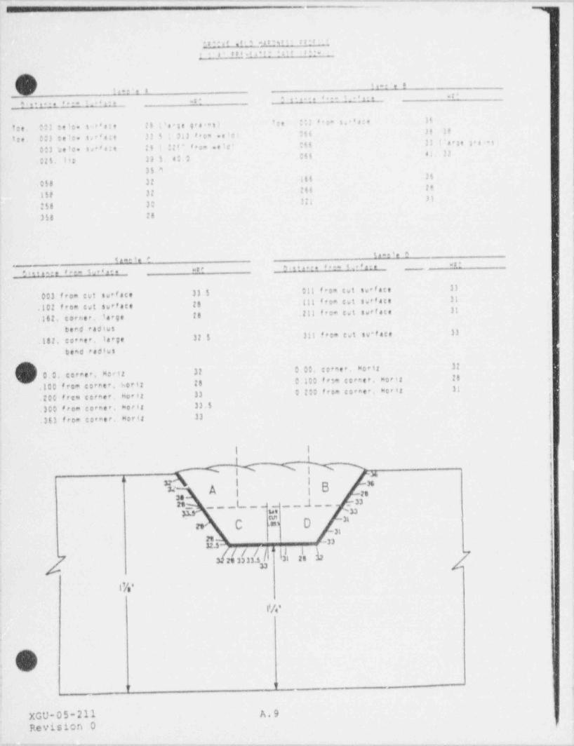
. _- . . . . - - - , . ~ - . - _ . . _ . _ . _ . - . . ~ . - . - - _ . - - . _ - . . . . - - - - _ - - - -
..-
****<!..! S wit?$ti r**r: L
* s" se_v.rt*r; is:t st?..
1,-t'e !*.- ', a.c*
n....... a... . .s... .ca ; r...r, 8.t. _.8 11_
tee, 003 teic. so's:e 25 i'a*;e gesias: ':e *;) '':- $ *'s:e H
tee, 003 te t:. s.*'s:e 33 $ 013 f r e. .e te: Ot6 38 H
003 'ae'o. ss**e:e ;5 0:t* fea+ .e'c' 066 33 '' erne ; s'as',
02%. Its 3) 5 a 0 Of6 a; JJa
|35 9 I
058 32 166 36|
15e 32 266 ff
$8 303;; 31,
.358 26
\t
in-e'e Sin-e e e_ 't
***we* S..*,a*. ' e- 1. + ' n e
g g , e.. sa,s|
nee
su face 33 5 .011 from twt swrface 33.003 from cut r
.jc2 from twt surface !$ ,111 from cut surface 31
.16 2. c o r rie r . Iarge 28 .211 from twt surface 31
berd raciws.182. corner. large 32 5 311 from est sv-face 33
bend radius
0.0, corner, Mertz 32 0 00, cerner. Morir 3! .
.100 from coreer. hert: 26 0 100 fr-m corner, worir 26
200 free corner. Nort 33 D 200 from coraee. woria 31
|.300 fecm corner, korit 33.5
!
.363 from corner. Mort 33 1
|I i ;
-
- .,a , i '' I-
BA A i i to ,sere_ ___L_ ___.1__ _n ;
s.e ~nCU1
h~
gge ( .351
- 31rt -3332.3- ..// / . I i -
23 sa ss.s /| 6 |2th,
233
i%'.
iw
'W
d -
XGU-05-211 A,9
Revision 0. .._ _- __ _ _ _ _ _ . . _ _ _ _ . _ _ _ , _ . . , ._ ._ _ . _ _ _ _ _ _ ,
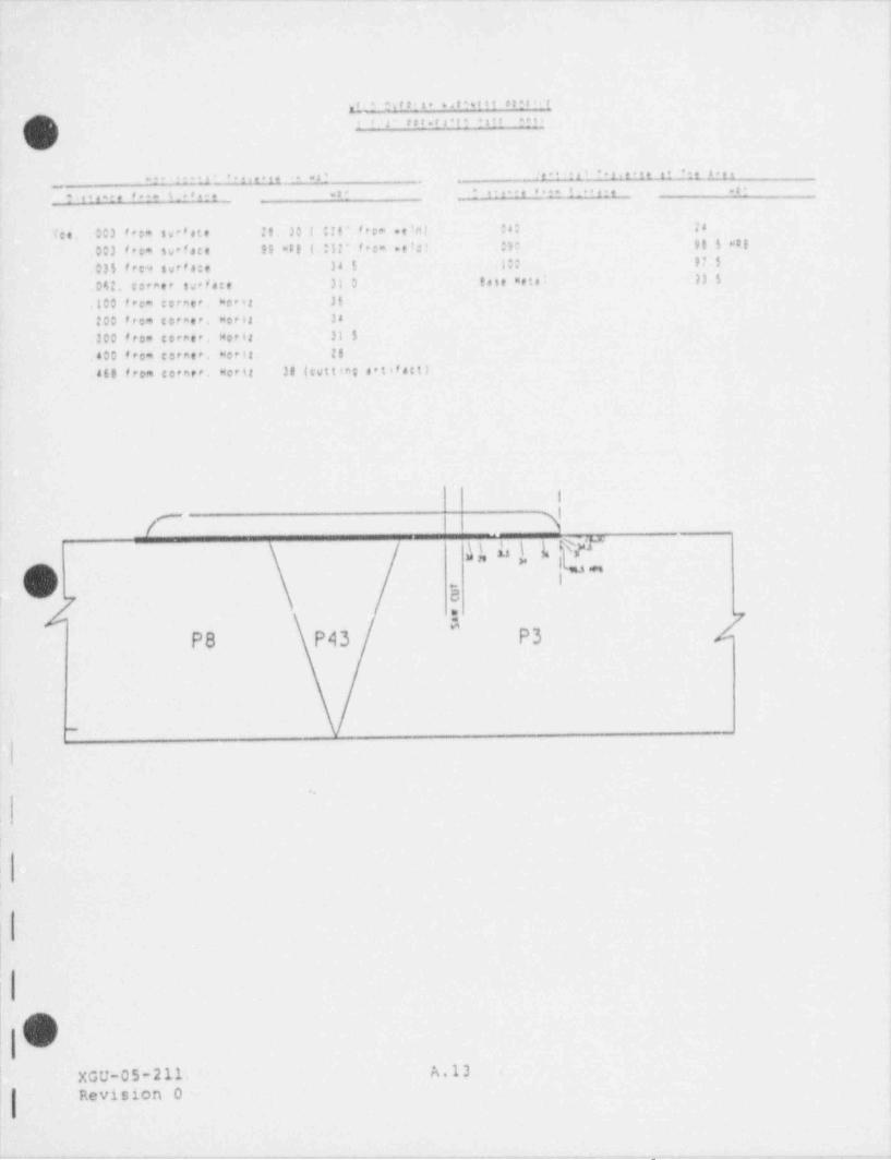
. - - _ ~ - - ~ , . - . , - - . a ~ ~ .. - . a _ - , - ~ - _ ~ . . . - ~ . . _ , . . - _ . _ - = . - , _ ..
f '_ * $\f t '_ t o 649'titt # 9 ? t i i_ fe
! J' f f f . f 3 * t' * fiff '*?ti*
'c
.-- - t1' ' r,. 1,,... 32 f,.. -1, . 3,,.1, .. .., s.,3,
a.its -, f*-- t_+<.-. .- ? ,t..., 4 .n t _ . u , . , , , -_
Tee. .003 from swefste it. 30 ( |tt" fec= .eirtl 04; 24
Sv face 99 weg ( .052" f ee= .e le t . ); gg 5 *eg*
.003 from e
.0)$ fec* svefa:e 34 $ ,100 9? 5
062, cocaer su' face 31 0 tese mete' )).5.100 fece coraee, merit. 36
200 frem cocaer, morts. 34
.300 from cereer. Moria. 31 $,400 frem coenee, worts. !$
.468 from corner. Hoett. 38 (tuttie; artif act)
|
|u u *t t yr""
IG ,,,
I
.
O ~
B,
2 y"
P8 P43 P3 4
t
.
|
I
Ii
P
1
XGU-05-211. A.13. '. ,
Revision 0
. . . - . - - . - - _ .- - . -. .
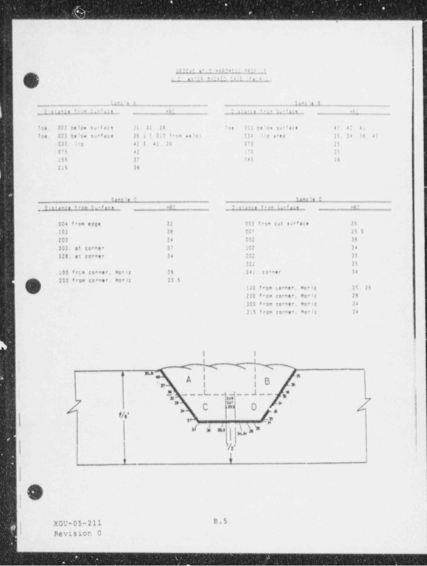
. _ _
.. . . . . . . . . . . U
**?"vr .r + 5 * a 9: i _ e g gg.
) i* .sers ar*i t?*: tr,' .,
\ /w'
t_.- 'e a 11**'e *
y ?nare '*r= !_8 1r L *t* S-sts re **r= 1_ 81L ***
toe. 003 eelo. sw* face 31. 31. 38 toe. :*3 teie. tweface 40 a* 4;
toe. 003 beto surface Jl i ( 0:0 '+om .eici '34 14e area ll. 34 36, di
.030. 11e 42.5. 43. 39 0?O 35
075 42 170 35
155 37 .?45 36
.!!5 36
e -ei, e ta=et, en
, Steta-ee 8+e= 12*rnae wt* ,$'sta=*, 8 s= Su r e '#*a
.004 from edge 32 003 frca cut surface 36
.103 38 .007 35 5
.203 38 052 36
.303, at corner 37 .102 34
.320, at corner 34 70 35
30t 35
.100 frts corner. Nort 36 .341. co*aer 38
(m .200 from corner, Hect: 35.5c.100 from torner, Nort 31, 35
200 from corner Norts 28
.300 from coreer. Moria 34
315 fece corner, Mort 34
4I I
! % |h 3._
- -A I I '"
B.. n i i =___L_____J__
|-= =
mm u.
: / ;J c ="
\ . o ,?,,,,.
3. .
-
it' s J. -
w.k's.
'[2'
h'
o,
,(L . ,
XGU-05-211 B. S.0
Revision 0,
..
.
.
. -___..
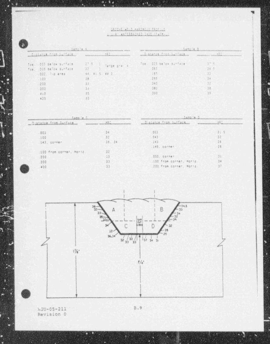
I gg
toravt .ri? -st**r** te?t__t ,
Ii .s" iservaater$ int er.... i
< -w
(-
*.. *. s e...s. n'
. . . . , - . 8 . r f gh- . -t* a...n . 8.-- $_.s.r..
Tee. 003 bele sse'4:e 2' 5 ) fee. :;5 he ic. s w'* 4:e 3' i9,p,,, .,
Tee. .00$ tele. sseface 3 ) 055 34 503;. l.c dres 44 41 5. 44 ? 165 33
.100 38 .!!! 34
.200 33 .340 32
300 JJ .383 38
4k0 35 390 39
435 33s.
t~e',* to--'e n
8--- tua*=ce wDE D strace 8 e- Su*'are wt*_ m.s+ -?,
.003 34 .003 31 5
.100 32 .043 32
.143. corner 36. 34 143 IB.149, corner 28
.100 frem cormer. Horir, 32
.200 33 000, corner 31
.300 33 .100 from corner. Morir. 34
400 33 700 from corner. Norts. 37
I I
I I
M N thI " I I su3.' = A i 1 B =
.33 34
I ! 32n= __L_. u. _ _ .L _ 33
em
C D =*
g 262 *'
36.34 g jn /=# j.h gu; 34/
f ! jmu 33
1%'
W.
\) n u
XGU-05-211~ B.9
Revision 0i
..
_ _ _ - _ - _
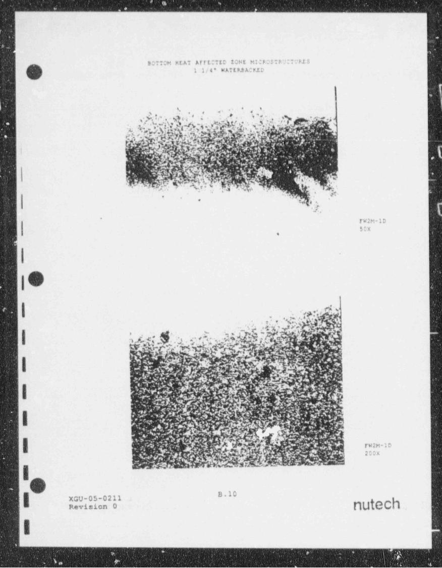
- - - _ _ _ _ _ _ _
BOTTOM HEAT ATTECTED EONE MICPOSTP.U;TUPIS
O 1 1/4* HATLP3 ACRID
F
'
. .s, ,,
i
....
eTW2M-1D50X
,
5
I
IO| m..,
.
' . r,k y ''s5*''',.,_ ', .o ;g y 4 yr
_
.:'s. , |h:\ b *. ,,' '- -
I
. I
IrW2M-1D200X
1O B.10XGU-05-0211
- Revision'O g
i 1
,.
. . .. . . . . .
._ ._
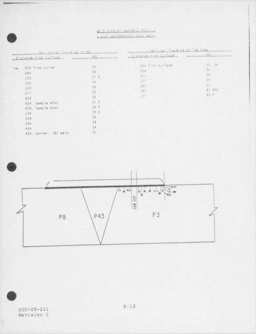
_ _ _ ._ _ . _ . . _ . _ _ . . . _ _ . . _ . __
.awIs'.st'
v' t a O v r t ._ a . a.t !M t t tetr'_rm
1 1:n" .s'rten.st? . set rgts?
........,..._c ...... . ........ .. ... ...... .,.
we. t....... .... < .. .. .e.e....-,e '... t_.r e.
_.
Tee. .000 from :ormee 34 004 from surface 33, 34
.044 36 006 34
. 130 37.5 01% Ja
- 230 34 037 35
.J30 36 062 21
.J77 30 091 97 wie
430 35 .137 95.5
.004, 5 ample WO43 31.5
.079, Sample v043 35.5
.104 35.5
.204 36
.304 36
404 34|
.504 corner. 162 wela 31 1
1
!
I
DUl
T'[m. 4,6pg%,;cas
_
5 l.
1 a [P8 P43 F3
..
B 13-XGU-05-211Revision 0
.
,-
__ -_ _ _ __ ______ _ _ _ -__ _ __ __- __ _ _ __ - -__ __ _ _ _ _ _ - _ _ _
O
Appendix 4
CB&l Reactor Nozzle to Safe-end Temperbead -
Structural Overlay Test Program'
'
(EPRI Advisory Committ:e for TemperbeadWelding, November 2-3, 1989, Charlotte, NC)
O
-
1
ISIR-90-063, Rev. O
I,
---
1
li
1
l
1 :
I
O|
Reactor Nozzle To Safe-EndStructural Overlay
Test Program
O
:,
.1
5
Jo
!
'
'
.O-i
|
_ _ . . _ _ _ . _ . . . _ _ . _ _ _ _ _ _ _ . _ . . _ - _ _ _ _ _ _ _ _ . _ _ . _ _ _ . _ _ ~ _ . _ _ _ . _ . . _ _ _ _ _ _ _
i
AESTRACT
Program
Reactor No :le to safe-End Structural Overlay Test|
lding
This report details the SA568 C1. 2 no::le mock-up, wei ions and
instructions and the results of non-destructive exam natet Code;
mechanical testing to qualify an overlay procedure to meAdditionally, an actual overlay done conventionally, without preheat or post heat was performed to compare data toTne overlay was done inCase N-432.
that of the Code Case qualification. condition and a non-water backedboth a water backed (teat sink)condition. dure'
The results of the test program yielded welding proceresults fori l t
qualifications meeting Code Case N-432 and equ va enan in-situ no::le to safe-end overlay using convent onsink and non-water backedi al (non-
Additionally, a random occurring weldability problemtechniques it. the heatCode case)
f e quality,
was observed and traced to filler material sur acconditions.
( pviding additional infcrmation to prevent weld defects.i ,
'
t
i
f
i
!
|
|* -
;
I
.
'
.o-1
|I|
- - - . - . - .- - . - -
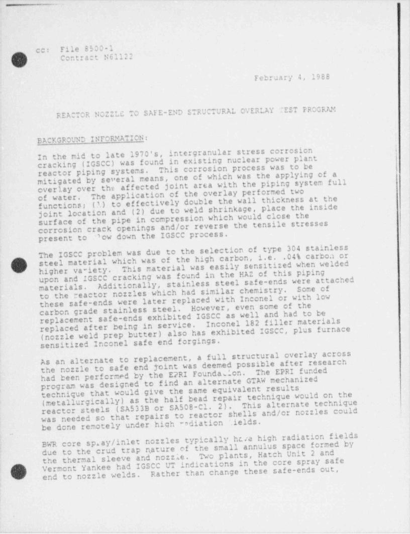
,- _ - _ _ - _ ._. _ - _ _ _ __ _ _ . . _ . -___ . _ _
'- -
|
!
-( )._ ce - File 8500-1Contract N61122
February 4, 1988-
,
'
REACTOR NOZZLC TO SAFE-END STRUCTURAL OVERLAY CEST PROGRAM_
.
,
BACKGROUND INFORMATION: ,
In the mid:to late 1970's, intergranular stress corrosioncracking (IGSCC) was found in existing nuclear power plant .This corrosion process was to be ,
reactor. piping' systems.'
1 mitigated by several means, one of which was the applying of aoverlay over the affected-joint area with the piping system full
The application-of.the overlay performed two-of water. (A)-to effectively double the wall thickness at the +-
functions;joint location and (2) due to weld shrinkage, place-the inside3
surface of the pipe in compression which would close thecorrosion _ crack openings and/or reverse the tensile stressespresent to "ow down the IGSCC process.~
The-IGSCCoproblem was-due to the selection of type 304 stainless.04% carboa or_ steel material which was of the high carbon, i.e._This material was easily sensitized when welded
"
g' higher va-lety.upon and IGSCC cracking was=found in_the HAZ of this pipingAdditionally, stainless steel safe-ends were attached .
materials. Some ofto the? reactor nozzles which had similar chemistry.these safe-ends'were later replaced-with Inconel or with lowF
-
However, even some of the ,
carbon grade stainlessEsteel.replacement safe-ends exhibited IGSCC as well'and had to be.Inconel 182 filler materials: replaced after..being in service.(nozzle weld prep _ butter)'also has exhibited IGSCC, plus. furnace 1
sensitized-Inconel safe end forgings.-
'
As anLalternate to replacement,.a full structural overlay across~
the nozzle to safe end foint was deemed possible-after researchThe=EPRI fundedhad'.been performed 1by the EPRI'Foundasion.program was designed to_ find an alternate 1GTAW-mechanized
=
; technique'that would give_the same equivalent results-(metallurgically)Jas the half bead repair technique would on the-
This alternate techniquereactor steels.(SA533B.or SA508-C1. 2).was needed so that-repairs to reactor shells and/or nozzles could-*
be done remotely under-high -ndiation '.ields,
BWR core spray / inlet _ nozzles typically hcva high radiation fieldsh i
due to the crud trap nature of the small annulus space formed by.Two. plants, Hatch Unit 2 and-the~ thermal sleeve and nozzle., h -Vermont Yankee had IGSCC~UT indications in the core spray safe
'
'
v -end to nozzle welds. 'Rather than change these safe-ends out,<
s
-_
h
v up g -, ~ -v ,mn~-- - - . , . , -- ,-. < - - -

- - - -
')y
February 4, 1968
Page 2
hethe Utilities opted to go with a structural overlay utilizing tin order to do so, Code Case N432alternate half bead technique.was passed by the ASME Code to allow this alternate mechanizedGTAW technique.
CBIanother method to fix the IGSCC problem,As this was just necessary to have this method qualified andServices deemed itavailabic for future repair alternates to offer utilities withPresently, only two companies have qualified thethis problem.procedure, one being GE and the other being CBI. '
This report deals exclusively with the actual Code Case N-432qualifications and a proposed alternate method which will giveCode Casethe Utilities more flexibility in performing this fix.N-432 requires both preheat and post heat during the weldingsix layers deposited. The alternatesprocess for the first ;
' investigated in this report are a non water backed, nonnon post heated condition and a water backed non postheated condition to compare with the Code Case qualification.s_,rcheated,The water backed qualification allows the Utility the greatestflexibility in that the reactor annulus and recirculation pipingsystem could remain full and/or flowing which allows in vesseloperations to be performed simultaneously with the remote overlay
It also eliminates the need for the attachment ofing and
thermocouples and preheating devices or for the preheatEliminating the need to preheat / post heatoperation. p
would minimize outage time required to perform the structuralpost heating cycles.overlay.
THE TEST PROGRAM
The test program was designed to qualify welding procedures ini
the SG position utilizing existing SA506 C1. 2 no::le forg ngAs-
material which had been procured from a scrapped reactor.this material had been procured to nuclear specifications,it was
assumed to be typical of what would be found in existingthe Code Case requirements of minimum posttime applied to the no::le prior to the repair,reactors. To meet
T at
the reactor no::le was given an additional 24 hours of PWH(This particular no::le was cut out of an existing 10 hours of DWHT at 1150 Fweld heat treatj
1150 r. is assumed that at least Thed during the original fabrication cycle.)reactor. It
jno::le chosen also had been utilized for an Induction Heatingshad been applie
This induction heating was( (IHSI) mockup.'' Stress Improvement
I

y. s._ .._
./
i 1
February 5, 195E
Page 3 i
l11
concentrated in the stainless steel safe-end area rather than inthe no::le forging. This induction heat treatment is thougnt tohave no effect on the actual no::le properties in the regionstested. Please refer to the work orders in Appendix IV whichshow test specimen location.
The purpose of the test was threefold:
1. Produce a welding procedure qualification meeting the ASMECode Case N-432 which would establish base line materialproperties.
2. Produce a non-water backed and a water backed overlay which,when tested, the material properties could be comparea tothe base line established in the Code Case qualification. :
( ) 3. Provide sufficient technical data to allow in-servicen
repairs on no::le to safe-end welds by overlaying with and''
without water in the affected no::le/ safe-end.To do the comparison, a Code Case groove weld was made in oneregion of the no::le forging and a full thickness structuraloverlay was built-up across the no::le to safe-end joint. Theoverlay was blended smoothly into the 45 slope region of theno::le forging. Please refer to Appendix II for the no :leassembly drawings for details. As the Code Case requires the
procedure qualification to be done utilizing the equipmentplanned for the repair, the use of fiberoptic video monitoringwas used to produce both the groove and overlay welds.
Code Case N-432 Groove Weld.;
A 1" deep, 60 , with a .25" root opening groove was machined 360in the nozzle forging after trimming excess material from theno :le forging and PWHT for 24 hours at 1150 F plus or minus 25F. Once machined, the forging was nondestructively tested andpositioned for welding. Preheaters were installed inside thebore of the no :le, and thermocouples attached outside in the"3T" band of the groove. After preheating of the no::le to the,
required 300 F, it was allowed to " soak" for one hour prior toI , ~3 start of welding. Welding was performed per the instructions in
) W.O. H5173 (Appendix IV). Using ERNiCr-3 (Inconel) filler.(G
I
I

- _ _ . _
[Udebruary 5, 1988page 4
It was interesting to note that during the first six layersdeposited, no real prcblems were encountered. It was feared thatthe sidewalls of the groove could not be easily welded(especially using remote video). Because the torch wasmotori:cd, it could be easily positioned to have the arc impingeon the sidewall. Additionally, positioning of the filler wasalso easily done with it being motorized as well. These featuresare necessary for ease of operation in a high radiation field.With these featares, the six layers required by Code case N-432were deposited easily and the 60 groove shape was r.aintainedallowing conventional split weave beading to complete the joint.(See photos 5 thru 7, Appendix III).
During the welding of the groove, some difficulty was incurred onpasses 53 and 54 at the 90 location. The passes exhibited poorwatting into the side walls and heavy oxides were produced. Thelocation was ground and liquid penetrant examined. Noindications were found. As the spool of wire being used for
another filler spool was used for theI'_ filler was almost empty,'2xt passes without incident. Upon UT examination after groove:
(_lompletion, this location exhibited indications of non-fusion.This location was marked for further examination by sectioningand microscopic examination. This exam revealed inclusionsbetween beads and internally within the beads. This defect wascaused by an intermittent filler material quality problem. (Seeweld overlay for additional details and photos 25 and 26 AppendixIII).
Upon completion of welding, the no::le was post heated at 500 Ffor 2 hours minimum prior to cooling to ambient. After coolingto ambient for 48 hours * minimum, the groove weld was liquidpenetrant and ultrasonic inspected. With the exception of the UTindications at 90 , no defects were found.
Weld overlay
In order to do a wet / dry overlay, the nozzle was re-configured tohave a partial thermosleeve detail. (See No::le Mock-up DrawingAppendix II). With this configuration, one half (0 -90 -180 )would be filled with water (both stagnate and flowing at +40 F)and the other half (0 -270 -180 ) dry. This configuration wouldallow the welding to be affected by a severe (water backed)quench rate and a moderate quench rate (steel mass effect -
both conditions without the('_ increasing interpass temperature),'2nefits of preheat or post heat.\_/
/m! )"V
iFebruary 5, 1955
Fage 5
The no::le assembly was instrumented with thermocouples at the 90and 270 center lines at the I.D. surface of the no::le bore.surface thermocouple was placed en the 45Additionally, an O.D.slope of the no::le and both the flowing water and stagnate waterwere monitored. (see photos 10 thru 17 for plumbing andthermocouple installation.)To do the overlay welding, passes were alternated from clockwiseto counter-clockwise to eliminate the variable of pass directionso impact specimens could be taken from the highest heat input(vertical up) locations - wet or dry.
H5224.Welding was performed per the instructions of W.O.Temperatures were monitored to determine peak temperature perpass and location. It became evident that the stagnate water
could not
/~] (which was to represent water in the reactor annulus)(_- be maintained at +40 F due to its small volume.
Therefore, tap
to flow at the minimum rate which would allowdwater was allowere contacting the I.D. surface of the noctlethe water temperCold water (+40 F) was circulated in thereach equilibrium.
thermal sleeve to cool the annulus water to the equilibriumThe actual water temperature contacting the steel rangedpoint.from +45 F to 65 F, for the majority of the overlay welding.
During the first two beads being deposited en the first layer,As theheavy oxides were formed and wetability was very poor.beads were being deposited on the stainless steel safe-end,A review of the weldwetability should have been very good.parameters, equipment se'-up, Argon supply, etc. was made priorAt this point, it was noticed that the spool ofto proceeding.filler material had seams or laps present on the exposed wraps.The spool of wire was replaced with another which did not exhibitthis condition. Welding resumed using the same parameters, etc.with excellent results.
,
\_s)
.
I
_
m
February 5, 1955
Page 6
layer, a liquid penetrant exam wasUpon completion of the firstbeads exhibited several indications.performed. The first tw7These indications were ground into and additional ones found.The entire volume represented by these two beads were then ground
(See photo 19, Appendix III) and replaced with goodout,material.Now that the weldability (poor wetting - heavy oxide) problem hadbeen traced to wire surface quality, a stepped up visualinspection of wire surface quality was instituted to preventThis inspection noted several spools of theadditional repairs.same heat / lot to have this surface problem where as the majority
The surface problem was very intermittent without anydid not. An entire spool might be defective or only a few
a few wraps be defective and those inches or wraps wouldpattern.cross sections of good and badinches,
be found any where on the spool,wire (same heat / lou) were cut, mounted and polished for(See photos
7 71croscopic examination which confirmed the problem.S and 26, Appendix III).QIn order to produce a smcoth transition from the no:tle shape to
=
the safe-end, it was necessary to " step" each layer into theexisting radius joining the 45 sloped no::le reinforcement and
,
'
This transition is necessary so thethe weld prep extension.overlay will not induce piping reactions into the radiused regionThis meant that the last layer ;.
of the nozzle causing fatigue.would have to have a temper bead technique which could soften the
Temper beads were deposited 1/32 to 1/16" fromtoe tie in area.
,
the use of filler and decreasing heatthe toe tie in withoutThis technique is the same as " Flame Softening" except i
(See W.O. H5224, !input.thru the use of the mechanized GTAW process. '
Appendix IV for details).Upon overlay completion and grinding for ISI UT inspection, theNooverlay was ultrasonic and liquid penetrant inspected.defects were found.
Test Results:
Code Case Groove Weld: PQR 7673 (Appendix V) lists allmechanical results including hardness, nil ductility temperature,The results meet the requirementstensile strength levels, etc.A 1" deep 'or less) weld repair could be
(~Nof Code Case N-432.hade utilizing a welding procedure which incorporates these('' techniques.
73
February 5, 1985
page 7
Weld overlay: pcR 7718 (Appendix V) list all mechanical resultspOR 7719 lists the results forfor the non-water backed overlay.Both FQR's exhibit good notchthe water-backed overlay. This tou7 ness level is similar tohtoughness levels in the HAZ. strength of the code case Groove.that of the HAZ impactThe non-water backed overlay exhibited lower hardness levels inthe toe tie region than either the Code Case groove or waterbacked overlay, which exhibited hardness of 380 to 410 Hv-10.The non-water backed overlay also c :hibited a hard zone in thefrom the toe tie. In generalHAZ at a location slightly removed This area became suspect whenthis region was 400 to 435 Hv-10. As the welds were madeetched for determining the HAZ region. orbital and no similar condition was found on the water360 it is thought that the interpassbacked hardness samples,temperature may have allowed a greater portion of the HAZ totransform into a harder microstructure.
As the Code Case groove had also exhibited hardness in excess ofa small sample was " temper beaded" to see the effects.
7s
(< ')A supplement to W.O. H5173 was prepared to400 Hv-10,
After temper beading, the !of this technique.perform this technique and testing. 10. |
toe of the groove hardness dropped approximately 30 to 50 Hv-A suspect region further away from the no::le surface however,;
(See W.O. 5173increased in hardness by the same amount.Appendix IV).In reviewing all hardness data, it appears the HAZ will rangeThese hardness ranges are probably typical of the SA508-C1.from 375 to 400 Hv-10 with some locations reaching 435 Hv-10.2
Forgings, especially inmaterial when welded in this manner. Specimenare noted for non-uniform properties.location may account f or some of the scatter seen in the hardnessremains that the hardest location is not atthis shape,
results, but the fact fbut at a depth of
-the toe of the weld within imm of the sur ace.
.3/16 to 1/4" within 1 to 2mm of the fusion line.~
l-,
, s'
I-J
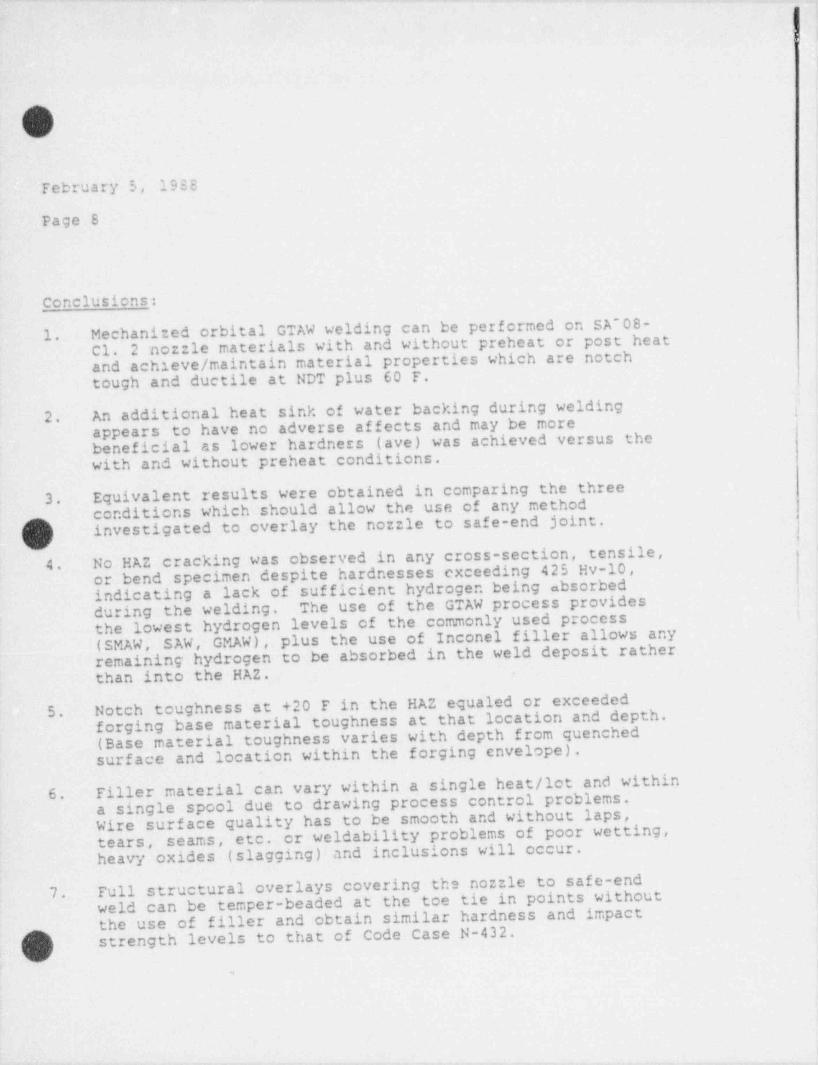
1
h
r
\'
~.
February 5, 1933
page 8
conclusions:
Mechanized orbital GTAW welding can be performed on SA'08-1. C1. 2 nozzle materials with and without preheat or post heatand achieve / maintain material properties which are notchtough and ductile at NDT plus 60 F.An additional heat sink of water backing during welding2. '
appears to have no adverse af f ects and may be morewas achieved versus thebeneficial as lower hardness (ave)with and without preheat conditions.
Equivalent results were obtained in comparing the three3. conditions which should allow the use of any methodinvestigated to overlay the no::le to safe-end joint.
|z~s'
);/
No HAZ cracking was observed in any cross-section, tensile, i4. or bend specimen despite hardnesses exceeding 425 Hv-10,
indicating a lack of sufficient hydrogen being absorbed ,
during the welding. The use of the GTAW process provides '
the lowest hydrogen levels of the commonly used process(SMAW, SAW, GMAW), plus the use of Inconel filler allows anyremaining hydrogen to be absorbed in the weld deposit ratherthan into the HAZ.
5. Notch toughness at +20 F in the HAZ equaled or exceededthat location and depth.forging base material toughness at
(Base material toughness varies with depth from quenchedsurface and location within the forging cnvelope).
Filler material can vary within a single heat / lot and within6. a single spool due to drawing process control problems.laps,Wire surface quality has to be smooth and withoutor weldability problems of poor wetting,tears, seams, etc.
heavy oxides (slagging) and inclusions will occur.Full structural overlays covering the no :le to safe-end I
j
7. weld can be temper-beaded at the toe tie in points without|the use of filler and obtain similar hardness and impact
( j') strength levels to that of Code Case N-432.-s
w
|
I
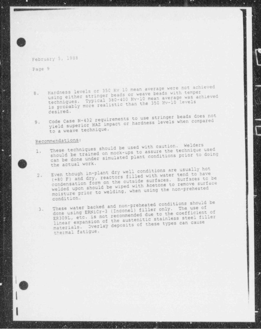
1
- __-_-____-_-_ _ _ _ _ _ -- -
r^NN.
February 5, 1988
page 9
achievedHardness levels or 350 Hv 10 mean average were notusing either stringer beads or weave beads with temper 380-400 Hv-10 mean average was achieved
8.
techniques. Typicalis probably more realistic than the 350 Hv-10 levelsdesired.Code Case N-432 requirements to use stringer beads does notyield superior HAZ impact or hardness levels when compared9.
to a weave technique.
gecommendations:Welders
These techniques should be used with caution.should be trained on mock-ups to assure the technique used1.can be done under simulated plant conditions prior to doing
'
~N/(,,) the actual work.
Even though in-plant dry well conditions are usually hotreactors filled with water tend to have2. (+80 F) and dry, Surfaces to be
condensation form on the outside surfaces.welded upon should be wiped with Acetone to remove surfacemoisture prior to welding, when using the non-preheated
1condition.These water backed and non-preheated conditions should be
filler only. The use of3.done using ERNiCr-3 (Inconel)etc. is not recommended due to the coefficientof
linear expansion of the austenitic stainless steel fillerER309L,
Overlay deposits of these types can causematerials.thermal fatigue.
/O()>
i
I- -
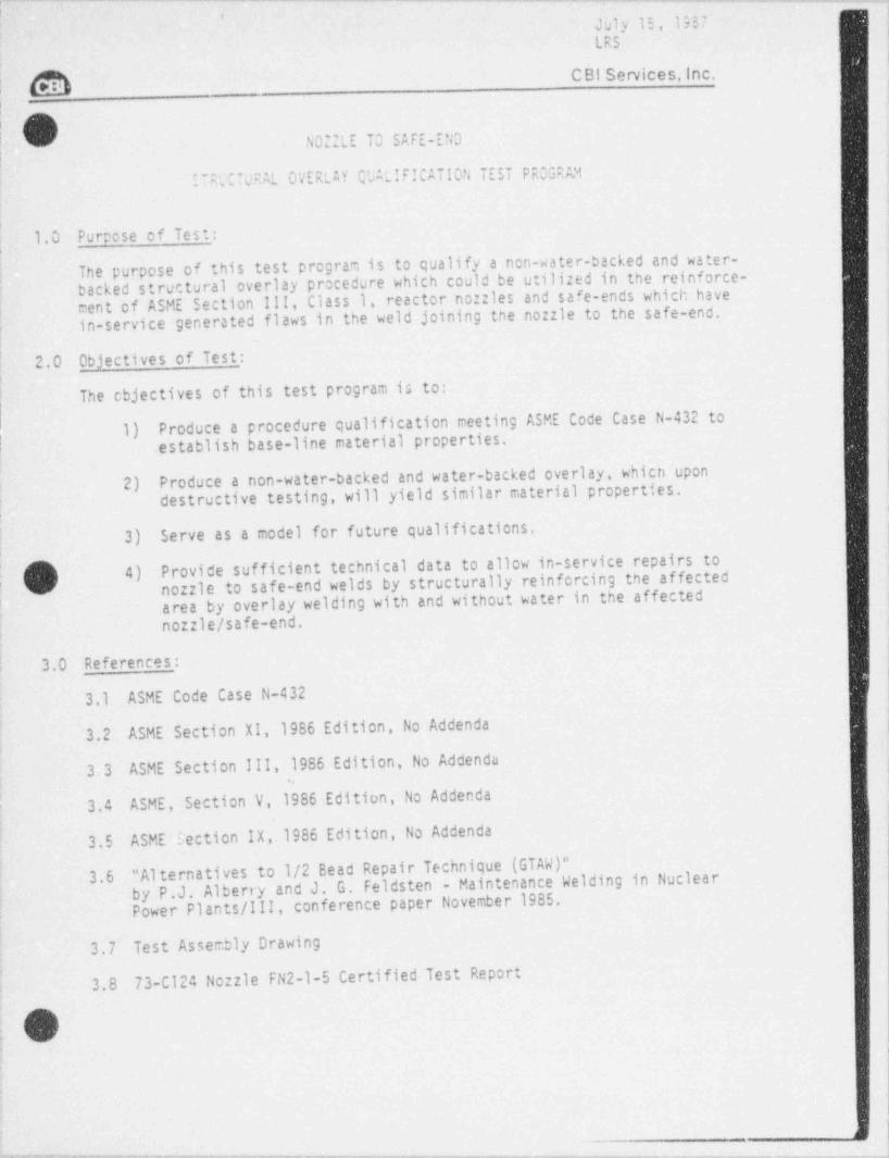
___ _ __-__- . -- -. . _. .-
I
July 15, 1957I
LRS
C BI Services. Inc.,M|
O'
NO:ZLE TO SAFE-END;.
^TRUCTURAL OVERLAY QUALIFICATION TEST PROGRAM
1.0 Purpose of Test::
The purpose of this test program is to qualify a non-water-backed and water-| backed strue.tural overlay procedure which could be utilized in the reinforce-1
ment of ASME Section III, Class 1, reactor nozzles and safe-ends which have| in-service generated flaws in the weld joining the nozzle to the safe-end..
.
2.0 Objectives of Test _:il
| The cbjectives of this test program is to:i
f 1) Produce a procedure qualification meeting ASME Code Case N-432 toestablish base-line material properties.|
Produce a non-water-backed and water-backed overlay, which upon |-2) destructive testing, will yield similar material properties.|
| 3) Serve as a model for future qualifications.
Provide sufficient technical data to allow in-service repairs to| 4)' nozzle to safe-end welds by structurally reinforcing the affected
area by overlay welding with and without water in the affectedno::le/ safe-end.
,
j .
3.0 Reference s_:|
3.1 ASME Code Case N-432 i
3.2 ASME Section XI,1986 Edition, No Addenda
3.3 ASME Section III,1986 Edition, No Addenda ;
.. '
3.4 ASME, Section V,1986 Edition, No Addenda'
,
3.5 ASME 5ection IX,1986 Edition, No Addenda |I
" Alternatives to 1/2 Bead Repair Technique (GTAW)"3.6by P.J. Alberry and J. G. Feldsten - Maintenance Welding in NuclearPower Plants /III, conference paper November 1985.
I
|3.7 Test Assembly Drawing ,
3.8 73-Cl24 Nozzle FN2-1-5 Certified Test Report
iO:
. -
,
:
|
_
p*r*-e g etw-wc.7-ygari y.q-u-g. g r m y n,s.m1irw-.gv are-g q,-ta ger,y g-.y yyw.,wwa4* '--*mes w= rw- 'we=Nw-reww - m - wwe-+wwwe- a-* -- ar y e+-m+ - +4 w-*-- -- '=- -WP'--*--w-*"w *r 7- =d* ---
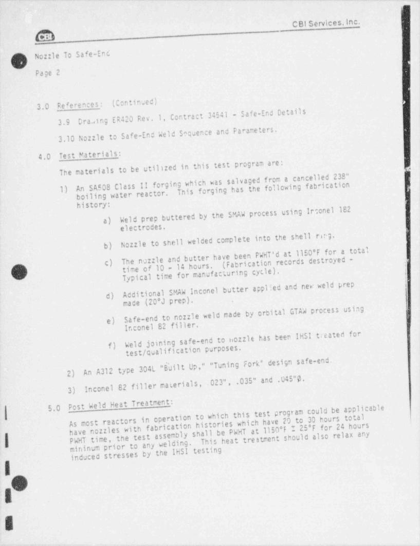
CBI Services, Inc.
ONozzle To Safe-Enc
Page 2
3.0 Re fe rence s_: (Centinued)
Dra..ing ER420 Rev.1, Contract 34541 - Safe-End Details3.9
3.10 Nozzle to Safe-End Weld Sequence and Parameters.
4.0 Test Materials:The materials to be utilized in this test program are: l
An SA508 Class 11 forging which was salvaged from a cancelled 238"This forging has the following fabrication;
1) boiling water reactor.history:
Weld prep buttered by the SMAW process using Irconel 182a)
electrodes.
Nozzle to shell welded complete into the shell reg.b)
The nozzle and butter have been PWHT'd at il50*F for a total(Fabrication records destroyed -c)time of 10 - 14 hours.QTypical time for manufacturing cycle).
;
V-
Additional SMAW Inconel butter applied and new weld prepd) made (20*J prep).
Safe-end to nozzle weld made by orbital GTAW process usinge)
Ir.conel 82 filler.Weld joining safe-end to nozzle has been IHSI treated forf) test / qualification purposes.
An A312 type 304L "B'uilt Up," " Tuning Fork" design safe-end.2)
Inconel 82 filler materials, .023", .035" and .045"03)
Post Weld Heat Treatment _: l5.0As most reactors in operation to which this test program could be applicab etl
have nozzles with fabrication histories which have 20 to 30 hours to aPWHT time, the test assembly shall be PWHT at il50*F ! 25*F for 24 hoursThis heat treatment should also relax anyI mininum prior to any welding.induced stresses by the IHSI testing.
OIE ;
)
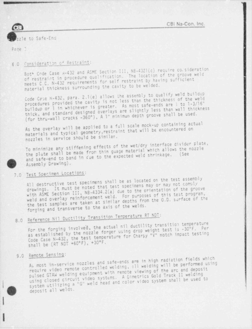
_ _
.
CBI Na Con. Inc.O--zzle to Safe-End
Pace ?
6,0 Consideration o' Restraint:
Code Case d-432 and ASME Section III, NS-4321(c) require co.: siderationBoth The location of the groove weldof restraint in procedure qualification.meets C.C. N-432 requirements for self restraint by having sufficientmaterial thickness surrounding the cavity to be welded.
Code Cese N-432, para. 2.1(e) allows the assembly to qualify weld buildupprocedures provided the cavity is not less than the thickness of the weldAs most safe-ends are i to 1-3/16"buildup or 1 in whichever is greater.thick, and standard designed overlays are slightly less than wall thickness(for thru-wall cracks -360'), A 1" minimum depth groove shall be used.
As the overlay will be applied to a full scale mock-up containing actualmaterials and typical geometry, restraint that will be encountered onnozzles in service should be similar.To minimize any stiffening effects of the wet / dry interface divider plate,the plate shall be made from thin guage material which allows the nozzle(Seeand safe-end to band in cue to the expected weld shrinkage,,G
() Assembly Drawing).
7.0 Test Specimen Locations:
All destructive test specimens shall be as located on the test assemblyIt must be noted that test specimens may or may not comoly
with ASME Section III, NS-4334.2(a) due to the orientation of the groovedrawings.
For purposes of this test program,weld and overlay reinforcement weld.the test samples are taken at similar depths from the 0 D. surface of theforging and transverse to the axis of the welds.
!
Reference Nil Ductility Transition Temperature RT NOT: |8.0 i
For the forging involve'd, the actual nil ductility transitica temperature :Per
as established by the nozzle forger using drop weight test is -30*F. Code Case N-432, the test temperature for Charpy "V"notch impact testing
shall be (RT NOT +60'F), +30*F.
9.0 Remote Sensing:
As most in-service nozzles and safe-ends are in high radiation fields whichrequire video remote controlled welding, all welding will be performed usingpulsed GTAW welding equipment with remote viewing of the arc and depositA Dimetrics Gold Track 11 welding
using closed circuit video systems. system utilizing a"G" weld head and color video system shall be used top deposit all welds.Q
I
- - - - - - - ___ _ _ _
C BI Services, Inc.Mim( ) No::le to Safe-Endv
Page 4
10.0 Test Program Operation Sequence:
10.1 Test assembly preparation for Welding:
10.1.1 Burn excess shell material from forging.
Machine excess forging material to required dimensions.10.1.2
Machine Code Case cavity in forging hub to required dimensions.10.1.3
FWHT assembly for 24 hours minimum at il50'F ! 25'F.10.1.4
Clean all surfaces of scale, rust, etc. by wire brushing or10.1.5 Care must be taken to protect the Inconel weldsandblasting.and stainless safe-end from iron contaminatad brushes or sand-blast effects. Use only stainless steel brushes on the safe-end and weld.
Layout reference lines for specimen removal and dimensional10.1.6n) checks.I
'w/10.1.7 Take as-builts of test assembly prior to welding.
|10.1.8 Install wet / dry divider plate and thermocouples.
!
10.2 Code Case N-432 Welding- l
|The groove shall be welded with stringer bead welding with |10.2.1 heat inputs ranging from 20 to 40 K Joules /in of deposit..
:Additionally, the wire feed speeds shall be controlled toallow deposits to be made within the 1.25 to 2.0 megajoule-
~range.
The groove shall be filled with the required layer sequence of10.2.2 C.C. N-432, Fig.1, using parameters meeting the Kilo Joule /'
Mega Joule heat input limitations.
As more than 6 layers may be required for actual overlay, a10.2.3 minimum of 8 layers shall be deposited in the groove,
I
}. o)L. .
I
.__
C BI Service s, Inc.
b+ le to safe-Fnd
Page 5
10.2 Code Case N 432 Welding: (Continued)
Preheat and post heat requirements shall be met usingelectrical heaters and recording instruments to monitor10.2.4
Thermo-
preheat, interpass and post heat temperatures. couples shall be attached by the thermal discharge method.
10.3 Non-Water-Backed And Water-Backed Overlay Welding:Af ter completion of the post heat operations, the assemblyshall be filled with water internally and cooled to +40 F10.3.1
+ 5'F by circulating the water and/or adding ice.
Once the assembly has been cooled to +40*F, water in theannulus space between the themal sleeve and nozzle wall10.3.2shall be allowed to become stagnent, water may be flowed
maintain +40* *. 5'F for the water backed portion onlythrough the themal sleeve and safe-end as necessary toduring welding.
using a weave
Overlay welding shall be accomplishedtechnique and heat inputs ranging from 20 to 40 KJoules/in.A 10.3.3V Additionally, wire feed speeds shall be controlled to makeWeld beadsdeposits within a 1.25 to 2.0 Megajoule range. Clockwise, counter clockwise
shall be alternately deposited.360', to allow impact specimens to be taken from the verticalposition.
Cere shall be taken to deposit the overlay in such a mannerto produce a smooth transition in the crotch section of the10.3.4
forging.
Temperature monitoring of forging shall be done during all10.3.5welding.
Required Non-Destructive Examinations _*11.0* All nondestructive examinations snall be perfomed to meet ASME Section
V,1986 Edition, No Addenda Techniques.
11.1 Code Case Groove Weld:
11.1.1 Magnetic Particle:MT inspect the groove surfaces and l" either side of the,
groove prior to welding.m
.
I
-. . _. ... - . - -
7
C BI Services, Inc.MNozzle to Safe-End
fage 6
11.1 Code Case Groove Weld: (Continued).
11.1.1 Magnetic Particle:
MT inspect the groove surfaces and 1" either side of thegroove prior to welding,
11.1.2 Licuid Penetrant:
a) PT inspect the groove surfaces plus 1" either side ofthe groove prior to welding,
b) PT first layer deposited in groove.
c) PT final surf ace of completed weld prior to destructivesemple removal.
11.1.3 Ul trasonic:UT inspect the groove and machined hub area to a deptha) of 2" from the machined surface using focused longitudinal
-.: inspection techniques.
b) UT inspect the final weld.
Non-Water-Backed And Water-Backed Overlay Weld:11.2
11.2.1 Magnetic Particle: |
MT surface of SA508 Cl 11 forging wnich is to be overlayedplus 1".
,
11.2.2 Licuid Penetrant: ;
PT en' tire sur. ace of forging and safe-end to be overlayeda)plus 1" prior to overlaying. i
b) PT first layer deposited plus 1" additional.', |
c) PT final surface deposited plus 1" additional. l ,
,
!
11.2.3 Ultrasonic:
a) UT inspect the volume to be overlayed using focusedf
'
longitudinal inspection techniques.,
||
,
f
b) UT inspect the final deposit.|
.
J
Surfaces to be inspected may be ground, cleaned, buffed as necessary|
|
11.3to obtain meaningful; examinations. 1
|.. . -
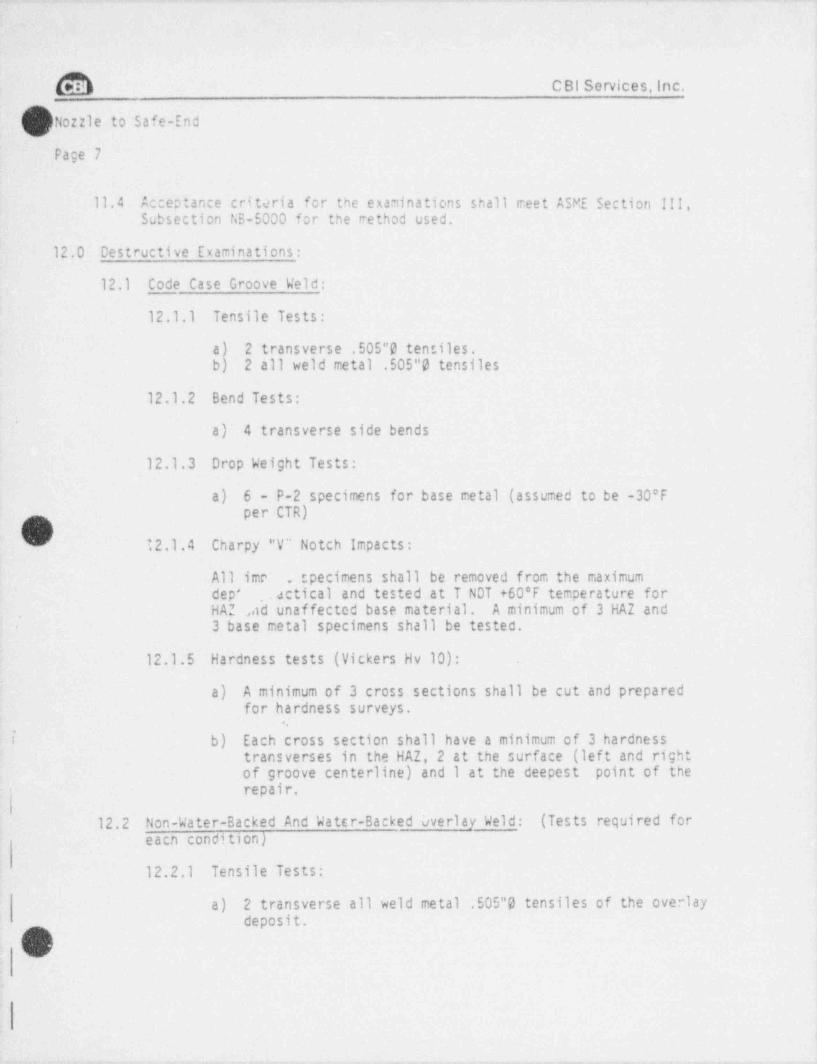
@ C BI Services, Inc.,
( | Nozzle to Safe-Endv
Page 7
11.4 Acceptance critaria for the examinations shall meet ASME section III,Subsection NS-5000 for the rethod used.
12.0 Destructive Examinations:
12.1 Code Case Groove Weld:
12.1.1 Tensile Tests:
a 2 transverse .505"0 tensiles,
b 2 all weld metal .505"O tensiles
12.1.2 Bend Tests:
a) 4 transverse side bends
12.1.3 Drop Weight Tests:
a) 6 - P-2 specimens for base metal (assumed to be -30'Fper CTR)
73);
' 12.1.4 Charpy "V" Notch Impacts:
All ime- . specimens shall be removed from the maximumdep' . actical and tested at T NOT +60*F temperature for,
HAZ ad unaffected base material. A minimum of 3 HAZ and,
3 base metal specimens shall be tested.
12.1.5 Hardness tests (Vickers Hv 10):
a) A minimum of 3 cross sections shall be cut and preparedfor hardness surveys.
i b) Each cross section shall have a minimum of 3 hardnesstransverses in the HAZ, 2 at the surface (lef t and rightof groove centerline) and I at the deepest point of therepair.-
'|12.2 Non-Water-Backed And Water-Backed Overlay Weld: (Tests required for
eacn condition)
12.2.1 Tensile Tests:
a) 2 transverse all weld metal .505"O tensiles of the overlaydeposit.
v
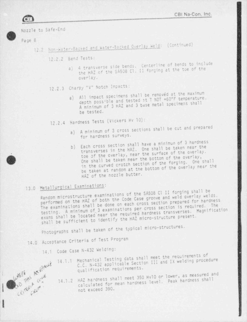
_- ..- - -. -- .
CBI Na-Con, Inc.
Nozzle to Safe-End
O Page 8
Non-Water-Backed and Water-Backed Overlav Weld:(Continued)
12.2
12.2.2 Bend Tests:
4 transverse side bends. Centerline of bends to includea) the HAZ of the SA508 Cl. II forging at the toe of the
overlay.
12.2.3 Charpy "V" Notch Impacts:
All impact specimens shall be removed at the maximuma) depth possible and tested at T NDT +60 F temperature.A minimum of 3 HAZ and 3 base metal specimens shallbe tested.
Hardness Tests (Vickers Hv 10):12.2.4A minimum of 3 cross sections shall be cut and prepared |a) for hardness surveys.
Each cross section shall have a minimum of 3 hardnessb) One shall be taken near thetransverses in the HAZ.toe of the overlay, near the surface of the overlay.I
[ One shall be taken near the bottom of the overlay,One shallin the curved crotch section of the forging.| be taken at random at the bottom of the overlay near the|
HAZ of the nozzle butter.
13.0 Metallurcical Examinations: I
Random microstructure examinations of the SA508 Cl 11 forging shall beperformed on the HAZ of both the Code Case groove and weld overlay welds.The examinations shall be done on each cross section prepared for hardness
i
The i
testing. A minimum of. i tions per cross section is required. >
Magnificationexams shall be located,3 exam nanear the required hardness transverses.shall be sufficient to identify the HAZ micro-structure present.
Photographs shall be taken of the typical micro-structures. I
Acceptance Criteria of Test Program14.0
14.1 Code Case N-432 Welding:
Mechanical Testing data shall meet the requirements of|
|g 14.1.1 C.C. N-432 applicable Section III and IX welding procedure[p qualification requirements.
.I .El
HAZ hardness shall meet 350 Hv10 or lower, as measured andPeak hardness shallN 14.1.2calculated for mean hardness level.gg> not exceed 390.tu p.
,
j
' - - - - - . . _ _ _ _ _ _ _
~ - - - - - - . . _ _ _ . . _ _ . _ _ _ _ _ , _ , , , " '"*"AM__m2., A
C BI Services, Inc.
M,
' Nozzle to Safe-End
Page 9
P
Non-Water-Backed and Water-Backed Overlay Welding14.2'
Mechanical test data shall meet the requirements of 14.1.1.14.2.1
HAZ hardness shall meet the requirements of 14.1.2.14.2.2
O \. . 1
.
. M !
-
',i
i'" [.
!,
:,
;
:
I
IO:F *
: I. . - . . . _ .
_ _ _ _ _ _ _ _ _ _ _ _ - _ - _ _ -.
O.
Appendix II
List Of Drawings
Recirculation Inlet Nozzle Mock-up1. code Case N-432 & Weld overlay Qualification Assembly
2. N2 No :le Asse:nbly Contract 73-6124
3. N2 Safe-End Details Dwg. ER420 Contract 34541
O
m
*6
3
ig '
h-c
,
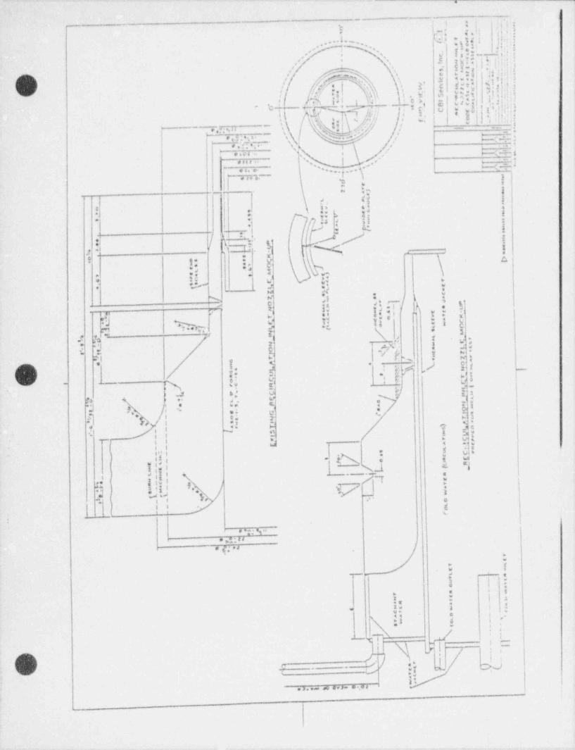
'U 1
_
f i ,< m
'b 2,I; d. L .i.e d I"
.-4. 3..I n . !. !'
k;':'I-, M.. .'
'
s'
: ---- o :Y, y,/' .
e'.__ '
sb# ' . ,;
/.e . 'N \ ,', L, _c gg < y<.i ;
N -
,/ f
. b-! $ .. i, 3- @ }! e[ $ EM!. II;f.d. )'
c o i. 3- .,
. E,'I yw$
U 3 l ', ' i . 4 , *
r ,(k&|%w}/}/| - _; :
*
M /!Uli>{{\ S 's }
.-
\~ 3.n , a :pp;- s\u/
,, ,
%+:,i,4., I.
. .... .-H =.- i. sa . q , ,s ;
. . . .. s,
.' - It -}..-. . , .
H =, - ;, '
i ,-* , , . . . ~ !|| ? !.
be 1~
~ i.t <! !,
s
.i .!.
,.,
..e ,1-
.* .. . ..
0 h.i u s - i..
i;.1 $
5 f f)a- ' ' Nt,'' "/
~
|- i X !..
e
i ,. c,.y....s ,
.$ N aw.
'J ' . - | % t.i,
* W* - d
Ni .s ' .15 a si <*
ss '', ."i - y t.- e *a . .
si- r 2. i o' : : [i i
y:g t'sed %r .. q7" b. 2:
-\ s
<::a b'
sO r *
.
ml -4 f Js
:a.i F 5 % *
. r. Q.=ys' .-
c.r:>*s f,A yp v e..
pi [*. < * c, gr, ,)2;
/.Jf|; e, 3
me" .') ; 3
,>
t, *:N. y ew/ - ,
.1 -5
-- pv <J t :., ; e * t -
t.>.J,
.s . e .
[ I, e),,
f] p**f> / t "E N ..
2 *-..'-s
.; *
t,N
<. y e+ Jc.
- , N o,
.! 3w*_ g t -tsi-
1 I w . . .I g u' se,"E ,
e + s- .
5,
w ,s g i ,. A 9. u) . .
I ' ,. i I ._N. _l3.
LI1 *,,l, 'i
i \ M.. i
Yf "ks 9.I Y/ |i n4 i
. . . C
i , ,, ,
t
e >;; 9..
* ;;rd
n q; a.
- .- - - . <> *3
O ;* t*
'! e I | :* ,
Es l t .w uw '*
p t | e-<< a.. ,
*
' T. -
,
: ,n - . g
is., ,+ |f / t " Nn./
. .s M
,:I'.>.,- a e,>- e.au.
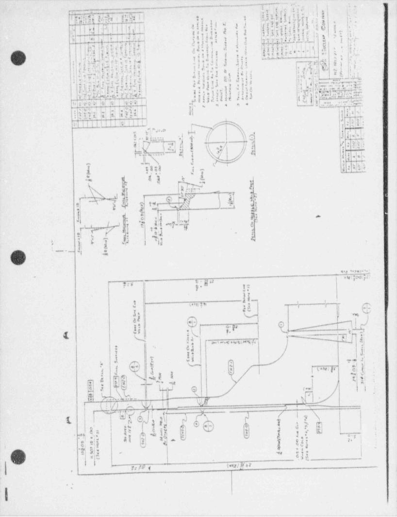
..
... ''.,,
. hi[E,14 i2$ i ;I*jfi$5 Wi ! C$ l I q[.+-e4j,"f J rt ' :'9 9 < . . .11 r I pi o
=, .' -
- < % T C -
m||.d|+m';|| |t V -| | aft - } f 6. . ,-| i s *uo>
- .
,,igou ..:s.J so,
,) l 3*N I :! l i' I i ( f )! .' ' 34{jgt j II)j3|3 { hT,[ . f y' J , 3 ; I;.
; e y ;. i.~e .. . : -,
d*!if* i j d k-5??-IIIUEl'
$ ' } . 'h, ,
>
h] h. il,Mi1 l{u rr, i,t.e .l l..i t, i;-'
al t,i:-
i W'
* I,
6 57,f' I t
3- i ,- ,O' a:. -ae. M L;~ ' ' ', .m' e-n . r & .b ..a h
* "' : .'-1;6. g :; . .
< .g ;:: di s}'h, i.
s' : ,1 N g,t:N n !< , ~1'S2 i 3 sl' '
% N G *i l'7 ", le. |>f.
7 'f ; e, !] : :, j pj.! L*;
.ai:%' il 't" :,e ! .',. ,.8:ft ';'.N ilb
1. a, _| . . +-> ; .I . r. * '.' 2 e . I J!1sa- e- ** --
' .: -# - cu J;.- 15'',:',..---,--li 2, |4.
i.'w f r';g s . .I *. ,, f..
= {;3f;.t.1. g ,! . ! :: 1 - - . . . , , . * -:- 9
. "I . - - ~ - ?' *.tt .-
. : e s,:g -') - .
I *. *.],*
{hf'f )l3.t u .1 ; *
,$ f 3 j *". y*25 }db 5[(![kE's .):t_e -HL*.v,p ; : : W t',w
... ,. M. e*
If *YO b !h[ I0 f 407 i M | , , ,v ., .m , m *I. ' -
-l {.4 :.y, . E{t.I i
J ~h( .~ m i.i, )3-o+ ~
,
i ~ t,
: tL| Ti 2 :. E
.
O I'. I L, lf-| - *
.. - -' hb
-
Illi1||!ICill|I| :18 ( i -, u',P.a.O*
*'| i
'.|J T. ,
4.,[[ ;
*,
ic 1 j i. A .,e. * > .:.~. 2 - 1-
-. v,M|:
. , , *,.
e. -- .., o 'I ,8 *-
O *I, --,* q .
;3 jrr - . . . - , .
ll 2 . . s.
*- -, e k 4 ? ha!+r
'
f g 8 "2'$, jg.4
> - s.,-
g,.~ .a . ,
e -a a.,t
"N.. , . , 'D. k? " s, e;0
v.t !ga j 7
\) '[:~, 5@ W
e., b jT''
J-"Y(%
,,.; %nn
d.
tf 6"].
Sh D
g
.O.I
t ? m 7a.,.,._**ii e Lt 0..i a r -
3)'
[l' r* s
yh 29 .!.i
%' s..
-4 E T 5h }
.-
...I
.8e
t _ - p'Ji
/"'N) .I %!
V,,3*>.2.*._-
e 4;'N]:.
f:6 5 - y 627' 1:
.
d !--- , ,
2 (. o p, pg'* 'Idis V ,"'%.'.<'E
&. &t; 7 !ai v.
( (i. nj.*-1-.c .4e%[4 ,.
-
e'f;I'o. '
'
8. ,..,.
,* d..
-$ j h. Ib 2 ?? f{
$ ufm =
.Q,3 r ~ r<O:c N-Q,_ j e . ,
~s ; .
e . L.J g * ia i. h%. .x . . .. , I lF s 7,- -
( ! V) A W. I 11. W eWl-.
*n,.
7,_ .g. ,. . (N.
.--
e 7e a 15 , .r M..-
l a |, .a e* * gI y ww 3 9 - 10 .
-~. . . .
3, v;: os|v se*s e{ 2*I
. , -
. d, f, _I m -ig m 1m a.
t'
'7,'k,x=/' - . "Se ;;
C! 3m-
t \ssy) f 61y1 {0 fe ,
f6 9
.
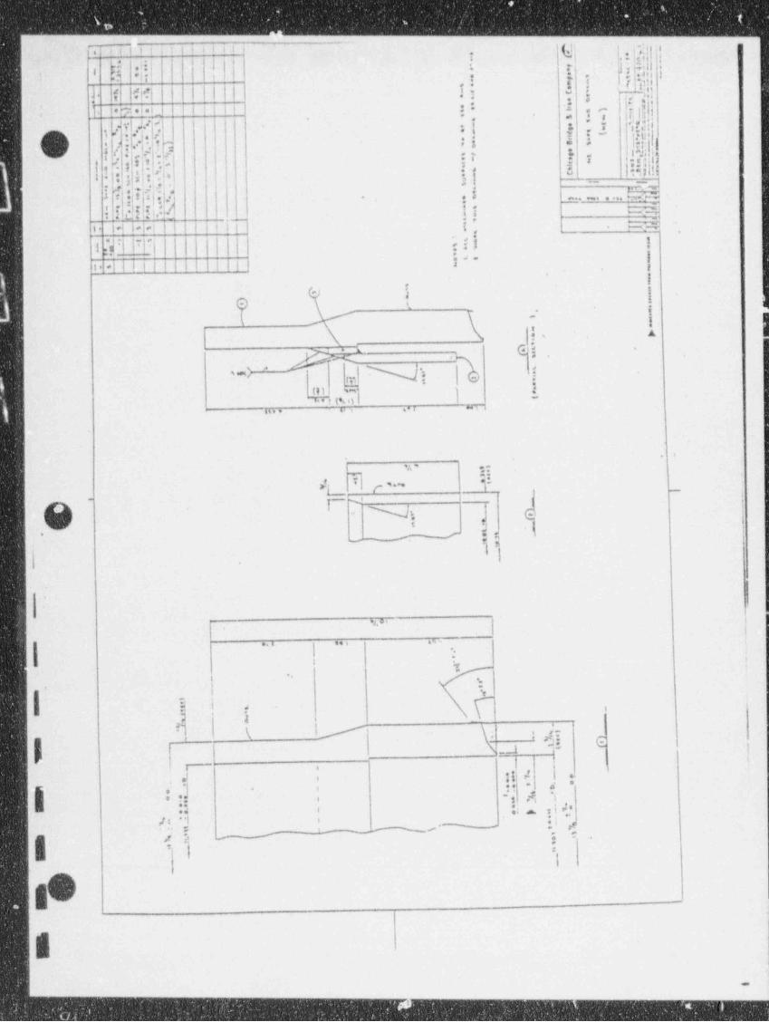
-------_____ _ __ - - - __
.4 it ii;i4, ;9;g
_.
kI! -:4f ::'
. * |' e,i. h,4?|*
ha,! elif | I . . .. .
! I tivi i} ,!$ f
i53 'li, i ;
l
(II@~!If l&! || { 1! -
T}|*!b ! * &. . i . t ii i, i* i*
i.< s^ .s'. *r,
- <
,- I"dr) p ; :I : di*n,
, iggi :ite.fj !! ;j7
e '*-/
('-) f '',>4 , ,r' . / ' .l aJ;j ,h l' , ,:, *-
,- * ,
: 8 * - lN'e g!!I I *,N| 1- I .r*
OI . ** ;. *' . el,. hf -
!#i..-
f Liii f !f***'
.: s m. .. . . .. %%%-
; i .s ,, &Qm* * .a.~
[J -
W4!l*! l*lal i Iitj[l '
t'
f-
'. j I[. | ill.
;
, sl
'' '!l!!I i o ;; I~~,
,I k
-J
- ' i" =
N I ,-*
i*
, ,pN a | '.
-
.
,1(p.' j ,
:0) G i
V (*s .) l ) *
,,755 * * . , . . . ,
..
'4 * ..t:
1-< * g%. $
- *L- w_
I;
Nd..
u - * .
' t.N . d.'
'g,
"I )-
.
.,,a..
**i .s, >*'
l +.;.
.
1% t<
-
| '.,.
Ir1, 't
~-E i s I
'
s i- .; , s-
b.
I. I 1t
|, ' )
Iil if1 e ; .*.
- , :! 4,j -
|>*
, 't $s 't.';: <
a.;
st***f ei a ,,
$1 y./ : 1 i; m/%.. m ~ *;' w ;
1' E
' .r,
;I
_
_ _ _ _ _ . _ _ _ .
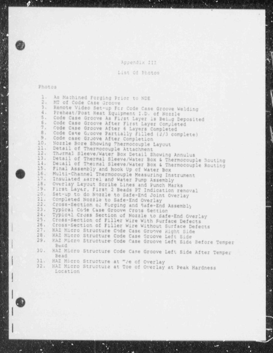
<"
.{
i /-'
(
(
.tppendix III
List Of Photos|
Photos
1. As Ma:hined Tcrging Prior to NDE2. MT of Code Case Groove3. Remote Video Set-up Fct Code Case Groove Welding4. Preheat / Post Heat Equipment I.D. of Netzle5. Code case Groeve As First Layer is Being Deposited6. Code Case Groove After First Layer Completed7. Code Case Groove After 6 Layers Completed8. Code Case Groove Partially filled (2/3 complete)9. Code case Graove After completion
10. Mozzle Bore Showing Thermocouple Layout.
11. Detail of Thermocouple Attachment12. Thermal Sleeve / Water Box Detail Showing Annulus13. Detail of Thermal Sleeve / Water Box & Thermocouple Routing14. Detail of Thermal Sleeve / Water Box & Thermocouple Routing15. Final Assembly and hook Up cf Water Box
O- 16. Multi-Channel Thermocouple Measuring Instrument !17. Insulated Larrel and Water Pump Assembly18. Overlay Layout Scribe Lines and Punch Marks19. First Lay 6r, First 2 Beads PT Indication removal20. Set-up to do Nozzle to Safe-End Joint overlay21. Completed Nozzla to safe-End overlay22. Cross-Section of Forging and Safe-End Assembly
,
23. Typical Code Chse Groove Cross Section24. Typical Crcss Section of Nozzle to Safe-End Overlay25. Cross-Section of Filler Wire With Surface Defects26. Cross-Section of Tiller Wire Without Surface Defects27. HAZ Micro Structure Code Case Groove Right Side28. HAZ Micro Structure Code Case Groove Left Side29. HAZ Micro Structure Code Case Groove Lef t Side Bef ore Temper
Becd30. HAZ Micro Structure Code Case Groove Left Side After Temper
Bead,
31. HAZ Micro Structure at *ce of Overlay32. HAZ Micro Structure at Toe of overlay at Peak Hardness
Location
(v
_ _ _ _ _ _
- - - - - - . - - _ _ _ _ . . _ _ _ _ _ _ . _ _ _ _ . _ _ _ _ _ _ _ _ _ _ _ _ _ _ _ _ _ _ _ - -_
s+- *4 .
h,\.; .f. .
""1*,+ ,. ,,..*p ':*1f,
.,
3, , , , . . .- 2
7~s-at e u-,
f y % ! f g *g .:; ,B y + Q [ ..;.
--
O cQ,( -..
. .. .,_< ''.. .,
- .S'. Ph;to i'-
\ .
* - ,
' ' - . ,,.
.,
., .._.,
- \ .#'
'
s.' . ,, _'
''
_. '"~%-QQ3. . . , -
^ *
-
..
,. ,.- ~ * mx- 4. ,''
s .
, '
,' .
s-
s s,
9 . $'. g. .... _
' F ..- ,,
"\,
I *.<...-..,s,! l ,,
'
.%, %,,Yql e -
o ...
<'
.-
s.
o V > 1./J u. .
~,"-- -
. ,..q i
.
,
k dg ~ ;
' *. . ..f -,L ,.
'
y .,) ' , _
'*_- . . ~ . . . . .
^ 9 . -
__,
., .. .. . s. . . . . .
u9s
g 9's
' '
|dh'|I|'ha - r ,
..
|_ 2g
* r * n
.
4"I- -
. , ..
I w eg ..
_ .
E-I i = ~1"_
..
. ,. . .
, ,,-,, n. '
:={,[i.g.,3 43
O .
1 %\..,
--
- ..~ .
. | . ' .
|~ * 9
|. - ,.
| , \
'
. ; .. . . ,
-. .
-.
- _ - _ _ _ - _ _ _ _ _ _
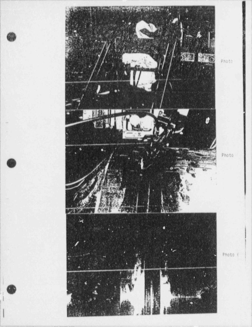
| [i|.".t-.* ,7 , , ,, pwg _ g , ,
' ,,.
-
,.r
...c. . . . .. J. ..
I =. . ,
w -' ,i i
,
... . .
.
< ;' -,
''
' ' > - \
, . f .. _ ,
,., . . , .i 'E } ?. . y ),, ' ,
PhDt0'
,
- .
| 4 l}yfg |.
-|.
, %' ..
|.
|# /
'
N W *~ _
~
'
134 8
.---.
.
....-
.. , -- ..
h. pg." - *i.T (y
i
.. ;d .-
y .J .t . a. ..O , :
I7 c ' ,.e '*
\ L...- ~
.
. wg .
..
t'.,:.* I ,;.*
,
Lj/s
t ,
. ; )j,.
; 1'
,
,,/t . ;./j [ *. d, k |
'
#~ 'I
!.- '
i
i,....',
. " . ' .gh- I'.
's, '%s .: :' . 1 2n*,j ; [ ,
,
i
I:
' *, .
!'
ji '
I
I f4 '< ' ,-
.|
.
''- " -
-
; . Photo f_.
- . . . '!
n.
[I *
*
I
I._ _ __. _ _ _ . _ _ _ _ _ _ . _ _ _ _ _ _ . . - - _ . . _ _ _ _ _~

-p
i
|
Is..
( . . - ,*; , , es* : * . ..-
> ',| '
4> *
,, } e -A
f ,"i -: $ ,
. , |
!, '.. b%b g ,
.- 8 '
i~
9
' N. 4 j
.<
. .,
'-,
ote
< < . .
!.
. .-/
, .-
. g .., -,
.
, .
6 ,i '( p,, , . ~ ~; ~ V *,'
{ g '.. , . g, - . 4 .
. . . .
;. i ,.g . . ,4, t -g 9$, y " i
.
t,, 6.., t $ $ ,q a . . g*
o.y . , .
. |.
M.W*. .i '. 4 <
,,
t
, %, **/
| .%'' *
43 d
. l ' '. 43
, - . e >
(-
.
-
.
. , ,h_
9, , ~,, ,- --
,.
? '..
, .. '.- %
' 1
i Photo 7 |-
| || -
<
i I. . . )
#.
'.-
,
as
%4
*.II
,
%f %... _,
'
,
- M .
i.
.
.
>' ' w^ .
j
' fh.p l.#hi hyad.
, , ,
-
, _. .' . - .u
'
' Il I,
p, .. 3, ,.c ,
, 9 ,* b
g,.: ; - -,
,. .
*~ '. e '
; ...e.. .,
-y . - " .:$.'46
'
. , ,;,, ,
T) . . ,. $ s./. 8'
.
-
j
. s!
,-. .
' * #p+.h ,f h . :|| t', j:. .
y ''. ...,,
i -,, ,,
e r. e.. . 4 j ..n r....e[ ''[I-'
g ' <,w,* i, , , e,,, .
._.
*e q ,,
-v .. r 1. vy u
..
,
.
. , ,..-. ,
$ . *i - |, h,a, QI , e
% 9 l * ** 'g *
W .g
rnoto 9_ *e, : --
_ _ _ _ _ _ . _ _ _ _ _ _ _ - . ___ . _.-_._..___ _. _ _ _ _ _ _ _ _ _ _ . - . , . - - . . . _ . . - _ _ . . . _ _ .
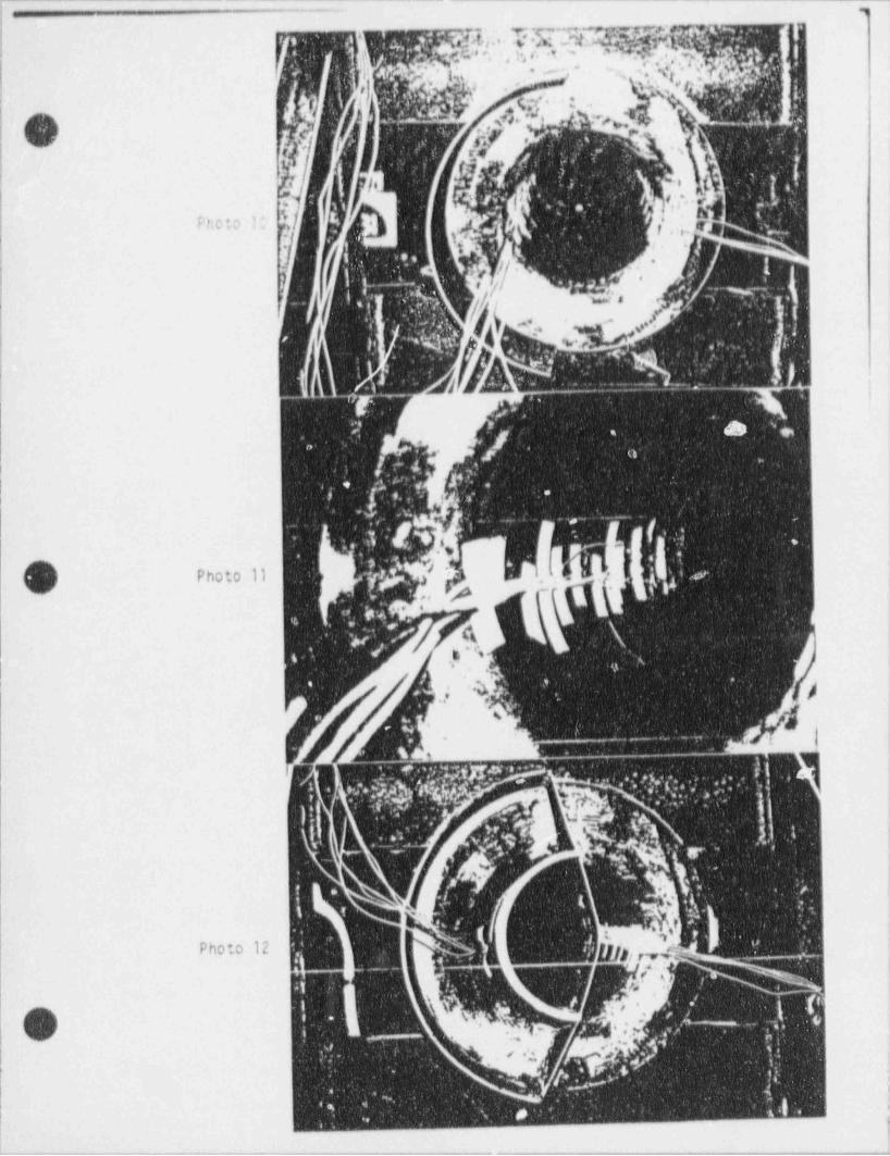
_- - - _ _- _ _ _ _ _ . . - - - _ _ _ _ _ _ _ _ _ _ - . - - - - - - -_
c ,1," ', h hff.i'
'
u . .- 9
'
-
Ft:oto 1;
.
I;
.
!
~
O ;.~1e n -
rs1
.i '4 )4
,
'
,,
.
|
!
Photo 12
(.-'
'
.~O -
:
;., ..s.
i
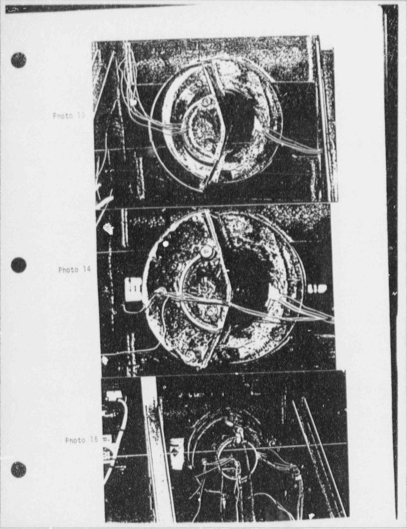
-a_.-saa. - em m. am.m m m wam m e.m m. - - - - -
- _ - - - - -- - - =---aa .m a
im
r
|' .,td ,
""
_.
'
' .
-
P=to n
j- s . |.
i..
%-,
, .
\ <} ,)5 .,;
' ' ' 5 ~,
,
f '..
- .- < ..
; yJ l,
|
f .. . y..:, v; f (,\. t..i . , \
.s . g R
y.._qpp-.-
y,, . . .
| .. . .q; v;
: ~,?'. e s
i y ,: g-
e-. ,
, , , .tO
',,
Photo 14.
, , ,, '; . ,, /S ' ~ ) -
, .,. -s
f, b, -
k_bf , ,, j ' _
yy;j* ..*|,
N!{!
(,[d[.if|h~-!.
f .,< .
Og ,,
bW ''('
I,
.
., ~..
,.k' . . - -
f..,.. '
3 \ i. - g' /,'/ W :f
-
g4| A. 7.' ,73x i ,y,; .yi Photo 15 :. , 3, ; .;
| g. > -' * . . . _ .y
-:. r r
-
}i . I ( ",;_>, .y\,
,
,
|*
i, \.
\ ,fl 1 y ',A ,% ~
_-
*
3in' U'
(
p. |I , '
; i - ~ ~ _ " ^ ~1'gwg _ _
;. . ,
- - - -- _
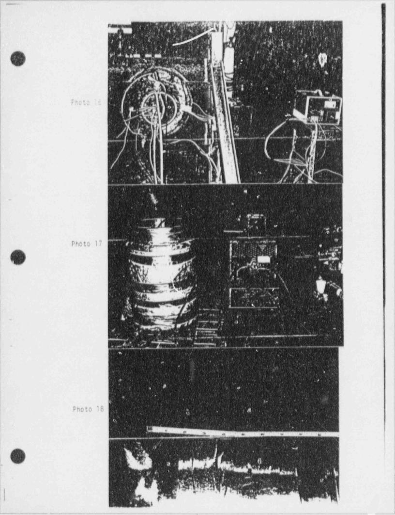
. _ _ _ _ _ _ _
. ,'',*er"J'Tu'3I" ", t- .,'
"'i*r . :.M 4- - s i 41>
'h,,.
!' M 2 /; ).,' .
'
;.
-
O rasss ,;,
t'-
,_
.
. < s.)a , .
.- 4' s
.. .-
.,, <= : e ,-
.-p)g
-,.
- g. .\ . .-
>- "e t g.
'' 8 '.
, . .,,
Enee H . 8 .l' . :. .
'*
,- - .,, .
,gy |%.
. , ' s ,*.y . . ,, ,
.
_1, f' \ .*: .. >I:'
1 .~
~ ~ ~.
r .. .-_ . ..
,-
' *-. y - )'
; ,. .. t-
,
6 / y*
. .
*: ..
'
. . . ...
. s
.
~'
.
; T**, a :.'' ,, .
; . < -_
- . . .-
.
*
Photo 17 << -. m '~ -*
j _ .:.-Y
O d.h . ;;.si 4 . -
i. ,i.( :....*
,. .e? ,
'
Na.
f ",. , *# p- ''
.
.
x-
: .fa *gs *
, . i''
s. ', gf^
- . - . ,
' ,-. , , _ . . . . ...
.
- : -- .- - -.
.
..
S , , ,'# a
"
'~
>
a
a
e g3
.
Photo 18 ;. .,
,
8, _,85 em en w ' en- a j
o 4.s.,-.
| 6f |: v* '
...
,':. ',41
. , p -. it ' I
~< 1r. :" '- ,
L. L * , # g,',.,.,,** <
' ' " ' ' ' ,'., ,
p.g .,
i
.- - ,._,-.-,.... .~ ._m m - ...-....,_ _-_ _ _.. _ m ___.-_.I
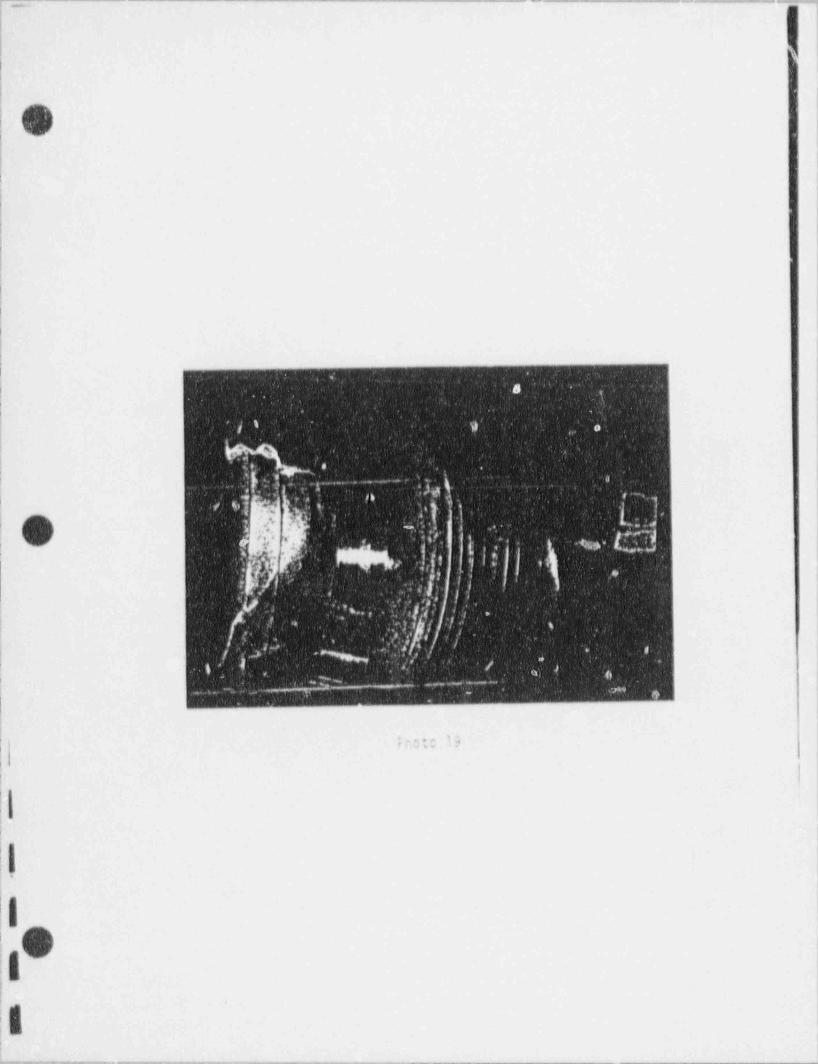
W*
1'i
.
f' '
!
|O |
!
!
|4
ir
||
|r
1
I
i
1
I-,
(|
* *
,
I
I d g
.
*I g
'e ' ')
s; - '' ; ,- ,|
h,f.
,'
.-
*- ''g
< , ,
| ,. .s-
|,
,# . ' ' '%, j p . h r i ji ~"'
,
. . ,*
ff. ' ; , -
-
.. ..
j'' :.
, .- - n [_, ,
. ,
..
; .
. 6, / ,
n g,
_i
: ,L_. _ _ --
*|s11
If r,c t: 19
iI
i ,'
|,
'
i
,'
i}|
|*/
|
||;
il.
i 1
--~~~-m.-..._-.-...--~.-...--~.---------__ . _ - - - - _ _ _ - - - - - - - - --I
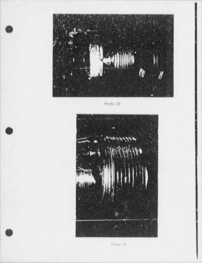
i i
f!
.
f: . . _c - '; .
-- -
.
.
_
|' ' ~
.. - -
.. . , .
.. ,
|O 12,'.
;
- -
s.
.
i~ , s, ... .
,
.
| 9| ., -
;
- -
';
..
l
Photo 20 '
)|
.. ..,.
. . |~
..
O.
1~
'
'.
g , ,~ s e., 9,
. ... h k \ k ff .\,f. h''
~
, .
..,
.,
"'
fe.,
| :
|'
!
liI
.
, -- _ - J - . -.,
..-
,
O,
il
Photo 21,
1-. -. _ _ _ _ _ . . . _ - . . . - - _ _ _ - . . - - - . , . - - - - . - - . . .

mm img
--
O
s' 5
+6
l4
~
.
b
} >
$
e
4
3 (5,4;*, , s: .-
,.
k ,h*l" d}e- Ig;g ''
p,a..
0
ed
e.'
2' eO VHO N'1 " a*
O TD *ae
.,' @ e=4 *fu **
O e0 ,%4
O e.rs 2e *I
(6w.
C y-3 m g.s.
aed
eY es-
|L4**
44-
4*W
%A
Nt
Nw
tt
).as r3
,6*. %$
J
,'d4
e
e
-_ I
.
i -m__-_-_-__:_.._.- _ _ _ _ _ _ _
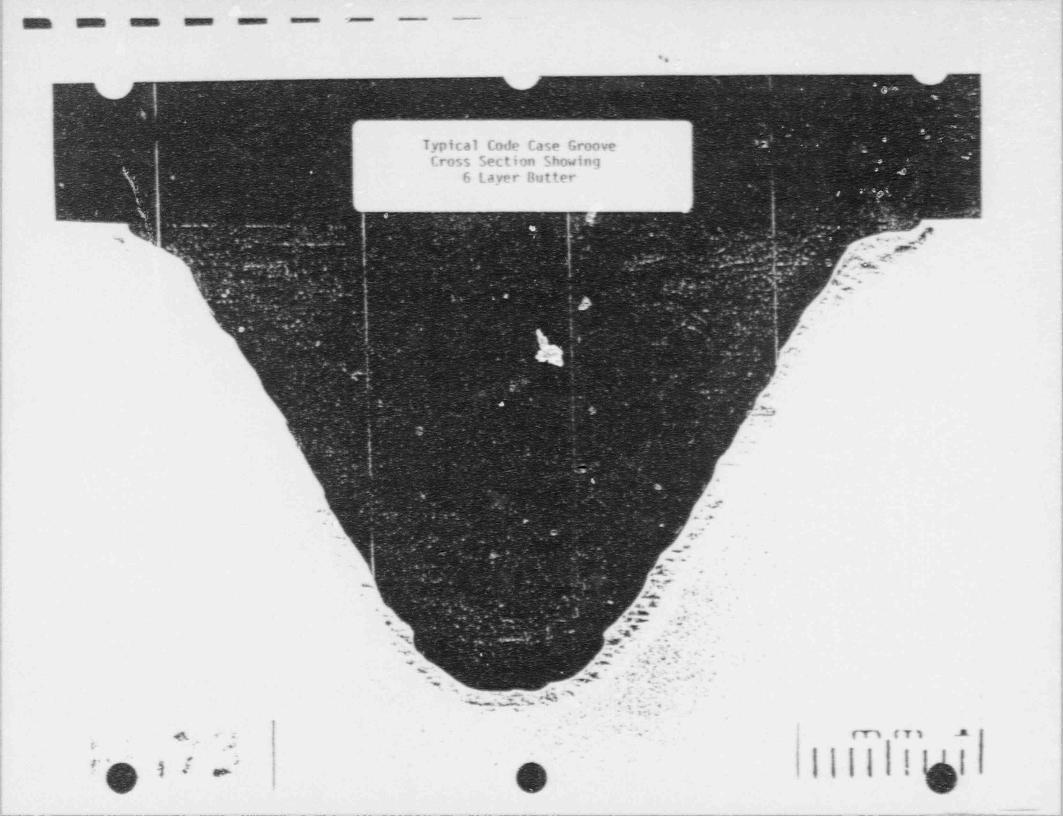
. _ _ _ _ _ _ _ _ _._-______ _ ._ _..__ __ _._.._____________ -. _ _ . _ . _ _ _ _ _ _ _ _ _ _ . . _ . _ _ _ _ _ _ . _ . . . _ . . . _ . . - ___ _ _._ _ _._ ___ _ _ _ _ ,-
_
,
m m sums umme summa ==== -<
.
!
l
{Typical Code Case Groove |
i
|Cross Section Showing
|!
6 Layer Butter|
!;
|
. ~. f. ,j'. . . ~ ,
a rc* - !
e A |o,,...|4 -m >
.
_. n. |,.
1t
,.- j
b& 7- ,
1
.
.s. |.
,
$
: - |ii.._1
- . .
.
.
' ' ' ".- ,
-. ~ ~~ ;, '
g .~.~
~ . ' " .~
,
_- .
* .Vi - J" N- .
!. g _h,g *
.. A- - -
<
=,. n . x: ,
,M :.|,^, - .*~~
'.% .
..'.'<.4.'j., ,
*4< . . . . .. _
--s
.
e.... -g. *w.,r..... .. .,
. . . o ... y > .
... .. ,G % _
* 3'
' MW. . . . , .w .- .,*;,.''.,|3w'- a
-. . - >: 7 . .
!-
i. +. ;- -
~ mm .-
..
* I
C' ) [-
- - - - - - - - - -- - - - --- -- -
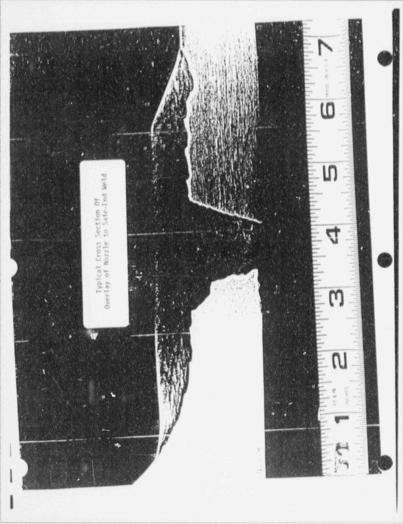
( ~ - - _ _ ___ ~ ----- _ _ _ . . _ _ - - - - - - - - _ _,
|,
i . .
. z- r' , . ' ' ,'
. , * , .. + , ;. .< , , . , , .I - - ~; ',,' ,
i .
.'
, .
- , . h i * % *4 I t .;;6
Is 4 . * '*
(I y , .' ,e-
8 r- - -
>. /Q .; * l,, j,[ !
1.
) Q,.1 t e .j j ' I .,, -
4.i, n . .i ' ' '-l *
^ -t -
], :. -5ego.
,V ,e }I;
c .y/ M |,i. r e 2.
r l -jt a ---
f .1 f* 'J,{', ' ' , .
V,! 3. %|p!
''
5d :. 3--
p in .'4g,. -- ;;
' -.
3 g>
.,,.9 _ _.
g,- y - -.' i
y3.,
,. . q:,: '
':-
|_ ,jg
t' '; . ,..
: q_*
J,. a _.. . .
. '
. . .l h :' . . ', ,' =atm., -g,, .
V.i-
i. . ' . g -
.I -
7,t ' k '-| a 1,.
,
|*
a i,g ;
',.. ,, [
:.,y. [$.Q, (, . .
, '
|s. .;_
.
: '' . f . "'
- :
, , - | . . l . ' i . , '!*
,. ~.74
1{4h,,'g(;'I'.I' ' [~~:t
j|
| # - e1
. '$ ;g " %; m-' ' - ',.' . , . 3
| .
i ' .| Ii ;.O*s , ' ' ., '
~3i
.-
,'q *
; I4 's. *~., ,
e
+j ,
_. _ - . _ ., , ***:
. .]-
f,
- vE .:'
, *.--E.
,
-. | .3; ,-
:.2| .
.
j - ~ _' v 5, 4. . ) <,<0 , ,
m, ']' > -
,- . . *
* **' . , > f'
i -
,. .* ' * ' . ,e ,
|$.-- .
'a'
,g e> ,,'
e'k.
j * = .
i.< * 4 ~
| .
f. .
|,
|,
I .' - m_=_.* . n
.- =
44.. - .s
...j\IR | :k''.-
{!!1 ' ' > d -~~sj
' L) , .2s -
~hI
; , w,;
--s,,
%.:.e- --s' .,
*
,,
, --
'
'. ( oom w
4, . . -.# ~'
~
,..,
:_.. ' -
~ ~j _% .
'I' ~ . ',
. ,c -
,.
T7 |<M_. .. i.
'
'
*{ - -; . ,, e
_
!-.
.q
-,
; I,
!- - . . . ==ew%_, '-- ww+w-% " "'-'--..,r-.- , _ _ _ ,
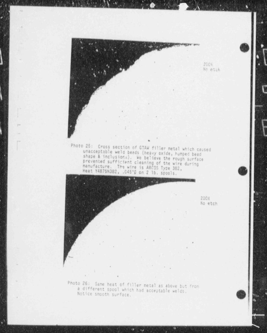
mi
-s
|..
v'n
' OM.
No etch..
,-
.
We
.. .,
.
r' - *7 , ,
; ..
. ..
. ,.
P:
._. .
,
* Sm
i~ Photo 25:I Cross section of GTAW filler metal which caused
unacceptable wela beads (heavy oxide, bumped beadshape & inclusions). We believe the rough surfaceprevented sufficient cleaning of the wire duringmanufacture. The wire is ARCOS Type 382,Heat Y4875N382, .045"O on 2 lb. spools.
3*
'
200X ,
No etch
. .
.
'
.
* *
-.
.' ,
-.
,.
.
.~.
.
. *. <
.
.
. . .
-
Photo 26: Same heat of filler metal as above but froma different spool which had acceptable welds.Notice smooth surface. '
1.
h<
t
- _ _ _ x

_ _ _ _ _ _ _ . . _ _ _ _ _ _ _ _ . _ _ . _ . _ . _ _ _ _ _ _ . _ _ _ _ _ _ . _ _ . . _ _ _ _ _ _ _ _ _ _ _ _
.
I
4
&',
' Nital EtchC 400X
N
46.
W/0 H5173
Spcciren Aq
e,
I
s
Photo 27: Typical HAZ microstructure near the surface'
of the code case repair groove weld (Identified as"right side" in hardness report). Weld /Fusionline isin upper right corner. The vickers hardness numberof the impression in the photo is 408 HV 10kg.
f f+ . |Wk it.f-
. .
-
NY[ .$'1q.%Nayj ,! ,.'
-
. [ 6 , & .c Vis.,;. -4. wy Nital Etch.. .
% g. :.~~ ' f . . . .,. j,g ,y Q '- 7 400x-t '- f ,n
y''hi '' , . . w|h|.
| z Jh.'' :||Q a
'*
:. a $. .'
. % .sF ' , A.. , 4>
$ 1. ', . : 'h' V ,'u'. W/0 H5173,
!- Tii, ? '/ .; [f; ;?.*.i , bj/ < Mad ? s)4j,A ' -' *''
U.' ' "
-[ .d J' ' . , ,
''5 -
w ;3'. q. , ,, . ,.m -?. u , ; :..
.m .v. '~[ ,. . '. -
s ..
}.f. :e ...,
.,iz.k'* $ } s G ' ' ' ' [u f.:' y ,f'
.,
' F- 's . >
. =. . r'g . . . 5--
r , , p, s :'.ig' 'srN4 s;pf;-
[ ,Y['.' # I '#.
~ 5[ . f .
4p$^', hM . J ..['I ) .
"E $$ ' ~
| 4~,.
Photo 28: Same as above but on the other side of thegroove (ID as " left side" in hardness report).
| The vickers hardness number of the impression inthe photo is 356 HV 10kg.
1,
- _ _ _-_ - - _ _ - _ _ - - -
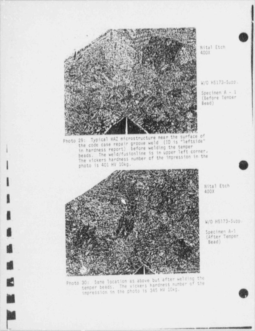
_ . . . _ _ _ _ _ _ _ _ _ _ _ . _ _ _ _ _ _ _ _ _ - - _ _ _ _ _ _ _ _ _ - _ _ _ _ _ . _ . _ _ _ _ .
i
:
l, ,
'
|' :
: !'
, 'i
*.
|_
Nital Etch ,
,',
1 400X| '
'
i
:
I.. W/0 H5173-Supp.;
I'
Specimen A - 1(Before Temper
I
Bead)i
,
-
4 |
,
Typical HAZ microstructure near the surface ofPhoto 29: (!D is *leftside"the code case repair groove weldin hardness report) before welding the temper1
i
The weld /fusionline is in upper left corner,: beads,The vickers hardness number of the impression in the
,
photo is 401 HV 10kg. 9 :,
g' g :: 7,., . k ,, Y .4a k'' ' . L.'''y;W,?f f ~ ..!I,', ,
* '
I |}.
,
' Hital Etch'
i 7 4 .- - . . . r iw 400x.:. , e, % ; w . .
gt- %4 || * ; ; ' . : . 5:, 4 , '- '.' :
M/M')q...<[^$p$L| Ms h Mi<, ; p ' tf
;
,
-' a- ., ?, g p ,,,, .f g[-; h .,a fr-f f f W/0 H5173-Supp.t.s e q N [
e. 4,
k'
F.,,,-
. h' . !,[ ..f, ,','.
. ,k i'y ,' . i g J'. ;3.N,. ' .f
h Specimen A-1
M f f (I'}).!
'4 [ . ' . 4f .
.(AfterTemper'
;( ' s / ?;1,,%c $..
y' : .k- - %yJ Bead)'
e ..
; 1. :;-pr , n' r y.
-
'
^ - 2'
g~ - ,, , .,
{ f 'r & g % ,-' ^
, y ~ h, , k. 5 9 & . ~ % e'-y AS'v |~ ,'
'
'h h%'$y* g<
,~(g 4' .
i '.
Same location as above but af ter welding the,
Photo 30: The vickers hardness number of the'
temper beads,impression in the photo is 345 HV 10kg. Oi
M;
: m|
,
- . , . - - - _ _ _ _ . _ _ _ - . - _ - . - _ - . - - - . - - - - - - - .]'
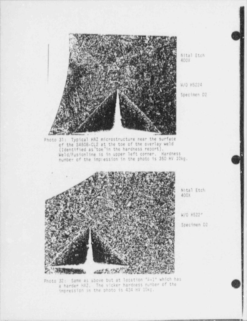
. _ . _ _ _ _ _ _ _ _ _ _ _ _ _ _ - - _ . _ _ . _ _ _ _ _ . . _ _ _ _ _ . _ _ _ - _ _ _ _ _ _
. |'
2
'
|*
: '
i
f* r - |
i , . I- ' ).;-.
b ',8,,,er',h. .f,-.[i O,
,q j? d*''|
, &'f V,/ ''
.E',',$d- Nital Etch <
kf . 7 .,' 4. ". N S ,','a,'f ~, ' 4 00 X'y-
y'. Wf I,..
A . W; a t .'/ g-
k:,g.; <
,,. :' ' , .6 .z 4
- 4,i
jr] j.if4
- ff +' ' ~ . f, -) ,' . ''
)3 ,
''
.g. f Ar, i3e.- . W/0 H5224 i, . . -
''E'J'jt/"
g4 ' M /4 '
6'tr' ,
Specimen D2 |'J '. .' | 'l. j' .,4 . i ' 4'y (on i t .
hk$, .? .'7 .Y , * :''h
3)fQm '- [ .
%,'
,
vt-. . _ . .
Photo 31: Typical HA2 microstructure near the surface:
of the SA508-CL2 at the toe of the overlay weld(Identified as" toe"in the hardness report),' <
Weld /Fusionline is in upper left corner. Hardness.; Inumber of the irrp;ession in the photo is 350 HV 10kg.'
|i
.
A
s
-
Nital Etch'
'
400X
.c ,4
W/0 H522'i .
,,
| |
|Specimen 02 |
..
'
;*(p .
['
(h d hi ..nj
| Photo 32: Same as 6bove but at lo;ttion "i-1" which has)
a harder HA2. The vicker hardness nur.ber of theimpression in the photo is 434 HV 10ke.
,
{ \\
t
__ _ __ _ _ _ _ . _ _ _ _ _ _ _ . . _ m
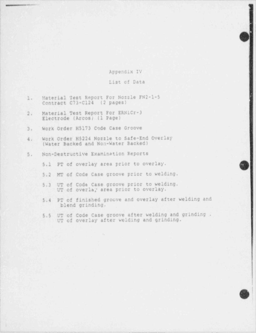
_ . . _ . . . _ . . _ _ _ _ _ _ _ _ _ _ _ _ _ _ _ _ __ _ _ _ _ _ _ , _ , , _ _ ,_
.|~
|1
>
J
;
|
|Appendix IV i
I
List of Data |
j,
1. Material 'Iest Report For No::le FN2-1-5 )|
Contract C73-Cl24 (2 pages) ;
I
2. Material Test Report For ERNicr-3Electrode (Arcos) (1 Page)
3. Work Order H5173 Code Case Groove
4. Work Order H5224 Norrie to Safe-End Overlay(Water Backed and Non-Water Backed)
4 5. Non-Destructive Examination Reports
5.1 PT of overlay area prior to overlay.'
5.2 MT of Code case groove prior to welding.
5.3 UT of Code case groove prior to welding.UT of overlai' area prior to overlay.
5.4 PT of finished groove and overlay after welding andblend grinding.
5.5 UT of Code Case groove after welding and grinding .
UT of overlay after welding and grinding.
9
!
|.
I'
l
; 6 i
!
. . |1
_ . . . - , . _ . _ . _ . _ . . _ _ _ _ . _ . - . _ . _ _ _ . . _ . _ . _ _ _ _ _ _ _ _ _ _ _ . _ _ _ _ _ _ . _ _ _ _ _ . _ - - _ _ . -
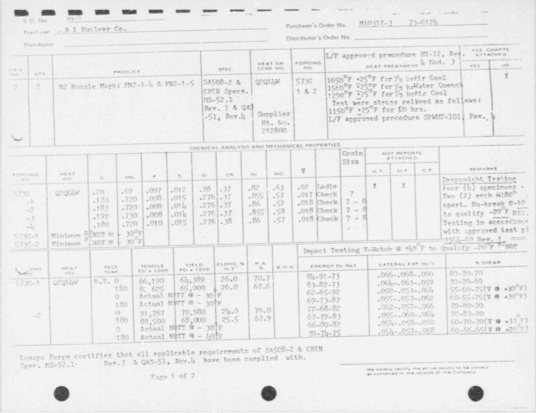
_ _ _ _ _
_ ___ _ _
M M M M m umme usan . - - _
' .. ._ ._~ -
.us "10. raoPurchaser's ord.r tio. M10 312- 3 73-012h
B I Huclear Co.re,e n,,
-Distramio, s Order tio.*
o w,,tmt or
L/F approved precedure IIT-12, Req. 'l',11*c'O,"$' --utar on c oncino In!bd- 3 ! ,,, ,,,
...., secc. ceot no. * o. tarvntavutor. raoo;ct
un ov v.
? 2 H2 !!onzle Mat-k: M12-1-h & R12-1-$ SA508-2 & Q2QIlN $73C 3650 F +25*F for7 brAir CoolI
w ter Quenct,1560 F ~25,F for7b hr aCPIN Specs. 1&2
12")0 F ~425 F for7h brAir CoolMS-$2.1. '' Test were stress rel hed as fo11ovs:
-
Rev. 7 & Qr 1150 F +25 F for 60 hrs.-$1, Rev.12 Supplier L/F appro red proceduro SPWirf-101 Fev., is,
tit. la.
212000V
_ Cl4CMIC At. AN A4.Y$15 AMD *AT CH ANIC AL PROPE f17tESGrain nor nseoats
""*C"'Sito
Y u. v. u, r. o e. a v v .a.s
."$$ * c un e s si ca ni uo""
I" ' 'I"U
973C Q2QIliW .20 .69 .007 .012 .28 37 82 .63 .02 Ladle I I Fcer (h) specinen: -
-1 .1 33 .720 .008 .015 .276 37 855 57 .017 check 7 T* C21 '"th ''100 -
-2 .183 .720 .008 .01 h .276 37 .86 57 .01 8 Check 70 -
0-10_cprt.No-brea)t,g:c2,-3 .192 .730 .008 .01 h .276 37 .855' 58 .018 Check 7E to quality -20-b .180 .720 01 0 .01 5 .276 3B .86 57 .018 Check 7-O Testing in acecrd:n*:e
G73C-1 Minkmn R INDT 6 - 30 F "Ilh OPETUV*d 188D FI*
f NIJr @ - 30 F 19% O') Rev. 1,*
_}inim,473C-2 Irpact Testing V-Notch @ *!to F to Qualify -20"F "'UDT
\*d O No. TEut, PSI a 9000 PSI . 1000 la 2'* % e. 64_ N. E N E RGY t't . tt>s I L att H AL E PP. f ra ") %sutsa
% ' t NG HFAT Tf07 T C NSit. E YtE LO Eloff G. % n. A.
,
573C-1 Q2QI):V - H.T. 0 86,190 6h,389 26.0 70.7 Bh-91-73 .066 .068 .060 80-70-70
180 82.625 65,000 26.0 67.6 83 82-73 .06h .063 .059 70-70 6062-65-92 .050 .053 .06h 55-60-75(v 0 +30'F)e
0 Actual UnTT @ - 30 F69-73-87 .055 .057 .062 60-55-75(v a +30'F)
180 Actual TWrT a - 30er0 91,767 70,980 2h.0 70.0 72-68 82 .c62 .057 .or/, 70-co-90
68 0 25.5 67.9 67-79 83 .0$$ .060 .0/4 7c-80-90-2
0 Acl.ual in 30"F 66-80-S? .0$h .053 .050 60-70-70(v 9 .)[r)180 88,$00rrr 4 00
*80 Actual ID;TT 0 - h0 |F 70-7h-75 .05h .057 .058 60 6< 65(V H *?,0*F 1
1.cnare Forr,e certifics that, all ripp11coble requirerents of SA5C8-2 & CEINSpec. MS-52.1- nev.7 4 QAs-51, Rev.h have bcen complied with.
w . ....,,.,...... ,~. . .. ... .. ..,. - ..... . . . . . ~ . .a .+.. . .. .. . c - .....
Paco 1 o f ,,c
# 9 e-
. _.

. _ _ _ _ _ _ _ _ _ _ _ _ _____ _ _______ -________________ - -_- _ _ _ _ ___
.
' ,'
*
' , . g..
i E"* A DIV. OF Hd5K1!:S VJG. CO.
P.O. DR AWIR 308 ' M1 C ARMil. P A '78 51p ,e Ortete+ 23, }964
CERTIFICATION OF TESTSnp 533.;6
43701DCustomer's order NoIf313A'tes 5. O No. ._
Ort:ter 23, 19P4Lnicago bridge & Iton Shipping Dete/c/o Copper 1uelear Station A!!Z CECITICATE CSC-4 4 6
2 tiiles South of Erovnville Expiration dete: Octeter 2:/s1*
E r ownv ille . Ne t:r a sk a $6321' TIM 10. 1 .
/ A k- M 352 /% f e r _ Grade _sige 64% v Y4675N3F2 / ~
La No./ Alloy No. 430tlbs 3No. Pieces ~~~"
ASr1 SFA 5.14 Clar.s EF.N1Ct-3e'
*/AttE Section II, Part C 1551 MM15 _
ASF2 B 6 PVC Section III, /^ ".02/ 10E3 Editien, Suysectfen ~~
2.0 /srbon .NB2400 and 10CTR21 erplies. ,
mengenese V WS-4N (43700) Eev. 0.15 /. '
.00c /-
$;t;cen / OAS-311 Rev.15 .00 /,lphur_1b'' /r. .tesphorus74 3 /
Chromium*04 /
.cLet'3I /elybdenum
Titonium ____ 2.3 ,,
*
*Ta _ , _
31.mbium._
Al .n _.07 /
1.7 /r epper ,
.003n
.01icntelumCobelt
n .(
,
*094 /
. onodium._.Zine . , _
ec onium _ Total Others 4.50 /__
,rrite '
As w.tn.d 8. . 1, . . . . dX Roy -H. . , t . . . d ,,A s w.14.dserpy5:
s g . .i a,,,___
v..id 5.n.a. g;. g.
f nsile s: v..id 1. a.in. ti ag.
s Welded: __ .
',ectTiect: _ . , . _
_
__
:rdnesst,
inds:__
'
f
'e hereby certdy thet the cbove meteriel hos been tested in occordonce with *he 1bied tre:d.cotion end is in con orme-<ei'
// F/ g#335with equirements,
,
b, |P 1g
'Ihn,1 a
. *
, 4 w,4 L 4 A. C) J?'
.
ce,, a/ ,oi senic n |n nt.
|
- - - _ _ - _ _ _ __ -
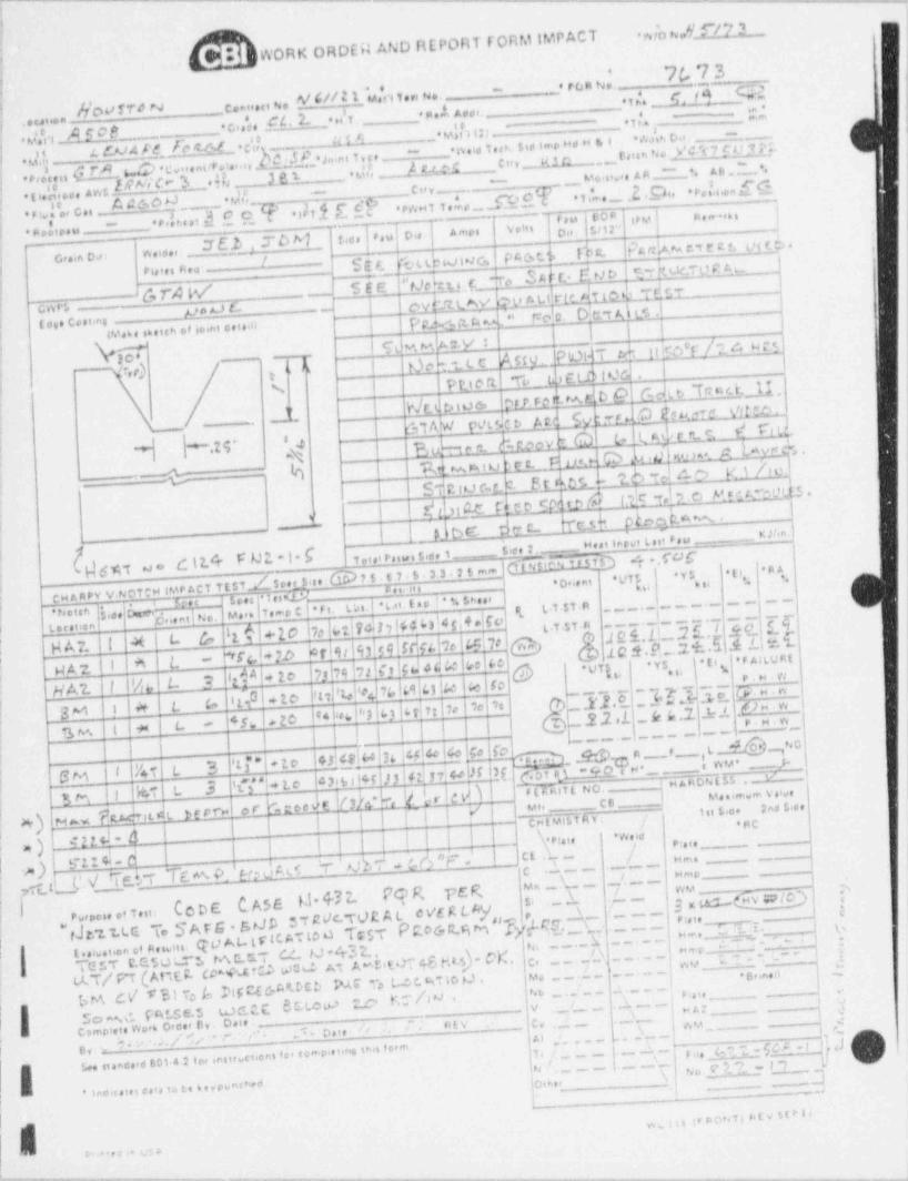
___ _ __ _. _ _ _ _ - - . - - - - - - - . _ . . . . _ _
,
$ .v,/o n,,[f/7 3WORK ORDER AND REPORT FORM IMPACT
|
;
. ec. %( Q _3 (-_cn...oN, p /2 ('u,'n3,,u,, _ .i s'. ,_,gg 9 QR
!f
_
f ..u. . M' W N + c,j, a 2. .n'T, y , . A 4 ,, . _~ *1|s . --
,'|_- vU s w ~ - v.h o,. .. ,8n __ A F C' 8 __ _. < --
| WLEAMELb wDcU nes 5,,s sie %, o, n a iJ U d ._ 008h b d ' D 9 ',2[ h
.,,4 ,,, U_ 1 w c ...nieri...n .h._ _ _ > ~ i1,,,_ -< r).I,
-h!! -iNb kS M k___,.CUV *, s e . D.
f._. v o s, o a n _ -'N _._ M 3 _ '+ t ,,M, ... AW S W'
MW dn .
* T i,..s .d Mi, ' P e s!i,on[6- _-_ cur . - ' i'---
t
f * m eo'epass ___*Pd tsst d ( Q [ *tE1,f ,(
* PW H T 1,ke ._C 8* s ife, cn
J E.b , T b M r.,,, f r.u| o., { 4 m,.~ 5,E,]" Q"..i ,,y ) n,,,.,,,,.
-"- ,
l. c. n n b rrect. mr;>.| f
,
nuov. .: oc,.in o.,: < - ,D Tb ubo wc, P4cs t.% i
{ ~ SM M S6E Mrbupjro .S d t.J u ra J t ; kuerp r' t.y -; ,,,,,,e.. --~
,w m,6,E ._ s ,. _1,#
r i._ L-* '
j
,
| go, y4- "m- D n r Qg. ]cn e1 -_'p- FoAc . . . c. . . .
-
P t.<a ce w; 69.6. 6.icn .e,..n,e.i m iI.| I \
I %k MA ' POWT etuto'r / ; e, mj p| -Q q'' -
I OnMc Any _RFLOl*R) I
;
t
r>rr rdwe b phtb Tresuu['TL! \ ! Plu e rt
I h/ts k,nm Q wgt|JL ._ Md Q -r w
P t'.c t>J-
l CM AW F' %t- it4 r rt. n'
;
'N I E d-w e. M eovi 6Jy |-.-zy e4dudd h num A hvy'*.,.1
,
7
|;_. +
- h | T2d % u _c.tb 26 3 c.o y i N|
3 e c._
__
Sho e,ui M e ct,*;2g.$ .m
N th1 C._A"t@c d IN id 2 c)0I
_ _ _| 0bW d er c-
TC.sb t$eqW.C
, , , ,, y , ,, , ,;, { , ,, , , , __
g,,qI
{Wpt di2/r Fg*1f ,,,,,,,,,,,3,,,L m T O 'r .f'O C lJ OTee t
. g ,,.uo .n,
| cwaney vwonw ive Act its7.Z ster s.6D1 s . t 7. s . 3 3 2 t m ;J.v7s ,ys
. *.. o, ,, n, *u * sis i. aie
seu r 1 mG.tv _ .
i """ - - -| _ _ _ _f _. _v.<=l1,-o e *ri. n i.| m i.tso 1 s sw u,(,,g .uno,. nd No.
;.N itn
lC+20 pad?dhMM4%!ro| .. .
@@M M M.b'6 d, L4-
t.t.st n _ - . _ ..f c i,1L.2 E , I Sc1t u.i .a i|
__H A 7. !I l x I t- GbrMih). 59 M 54.bol4c!7e g *2 'l '
- I''f c. l + 2h? !8 iAl+ 2e '7 !79 bz itIGd ed4o ;I,el&c'
W A 2. l i ! ^ L ,
'' " S2 9.H.n
47)' lob #f74|69|4!so|4ff0,
H A'2. I|% 4 t
d,l~ }~91~,,],Q'~RU. . w]'
| =e 2 O 4
3M )f# L (, 11I'de<,P'JI43|6FI7:heiOc|lo_ .2 2 1 k A .2 ' ' h" ,w45. L20 fpy p
| T } } | | | l - {~~~~**'~]~*"~~"'"~~"")I!. r4 i +8 L.* -~
<
j ii -
43kS!64|76 |4!4eI40|so fcil~
e,
: -, _ '
| -
3 13 *ED~~1"~~
# g
| SM |I keT L,
.3 't$ b 2.0 f43|6iI4 )J|4 J 744g,
DM 55 ,
M ff"HIor" b:'ord_E,h h b h rb|dh)If (6H$[ NO.
1 M
%M $) |ST LC O ---) M' ' ** * Y O *'
*' - .___ 1st Sice 2nd $<ee
f f I | J | f I I } !| _ CNEMibT Av : # *RCM w NUM*lL 83 L'
4 21d * d ! I | ,\ . p ig , j.w,
ah e v . ___ __. _)| c c ._ _ ,/A) j b'11 t W ge', W l
/ Hm" -
,
gfy tT&TTcwohJe-
. - -i !C .-
' ' m -
! un
. j Ceoc c Asa M 4nPe g vcc a
'-k 1- [j g;;,,,,gy geq 15' -e .. .. .. .. v . ,e We r LM/
* Jr/ .t.t.G. T. S A r g . sup 5? We. TOR A LP c.o G ra m '$","u:r.--s-- *
I n,,,_1 J, 9 9
c ...a e a..ai.. qv At-tr cc to o TcsT
p c g , h[ - ~ y/ t n,,
- ~ . . ;-'~1
/y, [[[,' [[ ~[[f wv, i T ' ' *" " ]i [TE TT C.G.5O L.T"L M C.tr.T C./ M 432 ,,g
fLAT/ P'T (AnEE. (Mtro wM m A .gitr cg,e a,~o
fdf/ C D PAG" *'s L 0 0 M to p ,.
i?!f C(G
IpM CY T 31 To /nsc e m m .s u c c c e c u :.c. e A u-y p v A ,'
% _.a__ , s ausf '
}j
,2l C omteiets Wora 0,o.er By . Date ~ , # / / ' $ { \'n , _ _ L , ,\ ,_ _ f ^ *d . - ~
,.
I gy , ?+ . ,. / //*. -+ ,.* * () g t ,' lAl ,
c , ~ ~ ~ ~T f os M 2 -(M - f ],d,
1 e.
nstru tions fo, comp etitie tNs f orm h,/% 1 '' 2- I.2._._ _.f.
En standsed 801-4 2 f cer e |qI nchea Io,se, )* lesdic ates cata to te 6 e,pu ___
.
| |, -. _ -
_ . , _- , -
-,-....------,.--,.n-----.-,- - . - . - - . - ~ - - , - - _ - - - - - - ~ . . - , - - - - - - - - - - - - , - - ,
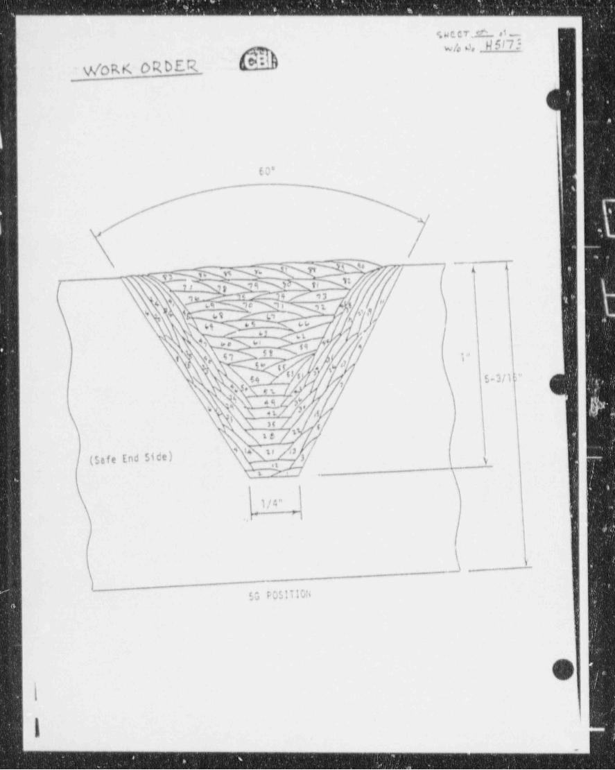
- - - - - - - - - - - - - - - - - - _ - - - - - - _ _ - _ _ _ _ _ _ - _ _ ___
*i 4 C C 7 ; ^ ,1_
w/o o, H5/73e= : )v/oRK ORDE.R .
_
E0*
//
-'
| ~ i. 1.
. . .
'
- k ,.
/ ,//\ n/ ,
\te /2 /
' is s, 6 /
/(SafeEndSide) $ .
' i> -
-
,_
\ 1/4"*
.H i
J
r.__
M POSIT 10ti
O
1~ ~ - - -- -
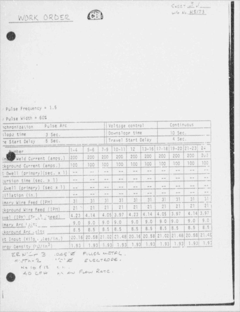
Cc1T YfI
o
M ## "'- "I! h/ORK OR D92.i
i|
!i i:
3
I
\
i| .
|
|
|
| .
i
. Pulse Frequency = 1.5
i Pulse Width = 60"
ichronization Pulse Arc | Volt:ge control Continuous
11opa time 3 Sec. | 0cwnslope time 10 sec..-
e Start Delay 5 Sec. | Travel Start Celay 4 Sec.
2(1-4 5-6 7-9 10-11 12 13-16 17-18 19-20 21-23p yber
imt ) Weld Current (ames.) 200 200 200 200 200 200 200 200 200 2W '
|
:kground Current (amos.) 100 100 100 100 100 100 100 100 100 100 1-
_
@ ell (primary)(sec. x 1) *,-- -- -- -- -- -- -- -- -- '
-- -- -- -- -- -- -- -- -- --
:ursion time (sec. x 1)Onell (primary) (sec x 1) -- -- -- -- -- -- -- -- -- --
-- -- -- -- -- -- -- -- -- --
:111ation (in.)51]
~
imary Wire feed (IPM) 31 31 31 31 31 31 31 31 31_
:koround Wire Feed ilPfi) 2I " 21 2I| 2I 2I 2I 2I 2I I 2I 2I !
ivel (IPMMTesfijgeed) 4.23 4.14 4.05 3.97 4.23 _4.14 4.05 3.97 4.14 3.97
9.0 9.0 9.0 9.0 9.0 9.0 9,0 9.0 9.0 9.0imarv Arc 1g1t. .
8.5 8.5 8.5 8.5 8.5 8.5 8.5 |8.5 8.5 S.5 |:koround Arc solts
Qout (Kilo.. sl es /i n. ) {20.16 20.58 21.02 21.48 20.16 20.58 21.02 21.48 20.58'21.%
gy Oensity (7tJ/in ) |1.93 | 1.93 1.93 1.93l1.93 1.93 1.93 1.93 ,1.93 1.93!3,
E 2. (J ? (- r- 3 046'M Ft LL cI:. r%TA (,,,
-
.
t'M c uc c r o.c oc .*w;M k- 2.-
:Me I c> [ l'L ( is . -
F w R c-i c .40 C.F H- m ou4
.-
- -- .
---,,-,.y.--,-,y,,,v,--=,w-y---y-m ,ww=,,ww---9 --msei. ,s,pq-,w-u-y-w+g----w ----r-, , - e ew ,. ,+.--.--,-,w.,..,r.,, , - , . , , , ,,.,,.,,eem,,..ww..wr- ,c_. _ ._,-w.g. w
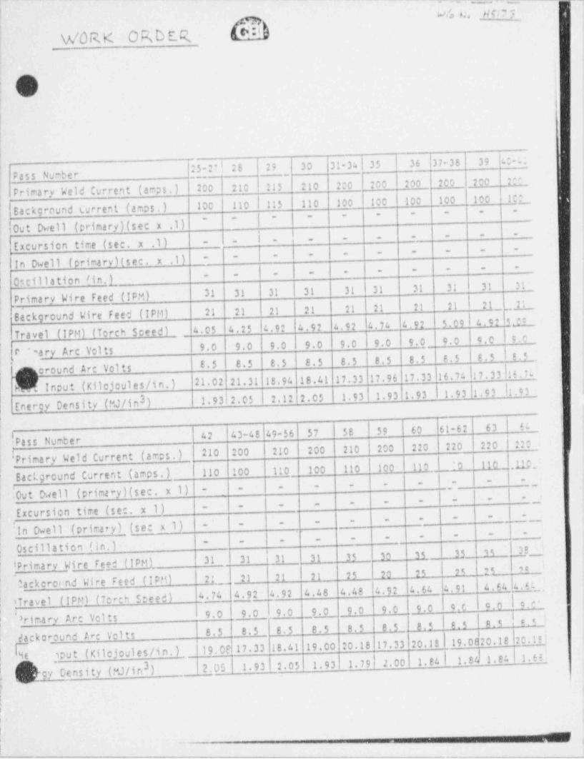
-- -- __.__-_ _ _ _ _ - - ~ _ . , _ ,, _ , _
j 4% Nci? :'
QI V/O R,K ORDE.R bddi
,
i-
I1
;, l
li
25-2'!2S 29 30 31-34|35 36 37-36 39 :. 2 . [Pass Number '
215 210 200 200 200_ 200 200 2rPrimary Weld Current (amps.) 200|210
'! Background Current (amps.) 100 110 | 115 110 100 100 100 100 100 1 C ;__,
,
IOut Dwell (primary)(sec x .1) |~- - ~ ~ ~ - -
~ ~
<
i- ' - --_-- - -
Excursion time (sec. x .1) - -
- - - - - - - - -
'. | In Dwell (primary)(sec. x .1) _-|-- -
-_-- - - - -
f Oscillation l i n . l_ 31 3131 31 31 31 31 31 31 3! '
i Primary Wire Feed (IPM)| 2.L_L 21
Background Vire feed (IPM) 21 21 21 |21 21 | 21 21 21
5.09I4.92 54.I_I4.74 - 4.92Travel (IPM) (Torch Sceed) 4.05 4.25 |4.92 I 4.92 4.92'
9.0|9.0 | 9.0 9.0 9.0 9.0 9.0 9.0 9.0 |9.0, ' ' ary Arc Vol ts | !.5f *
8.5 8.5 8.5 8.5 8.5 8.5 8.5 8.5 8.5Acround Arc Volts 16.74 fl 7. 3 3 16. 7(.,
Input (Kilojoules/in.) 21.02 21.31 18.94 18.41 17.33 17.96 17.33
Energy Density (MJ/in ) 1,93|2.05 2.12 2.05 1.93 1.93 1.93 i1.93 1.93 |l 9.1._.t
u3
! Pass Number42 43-48 49-56 57 58 59 60 61-62 63 6a
210 200 210 200 210 200 220 220 220 |220IPrimary Weld Current (amps,) || :0 110 .np _Background Current (amps.) 110 100 110 100 110 |100 110
|- ..
--- - -
|0ut Dwell (primary)(sec. x 1) I-' -- - _,
|--- -
- - __-
Excursion time (sec. x 1) b__- -
I-. -- -
-- -
in Owell (primary) (se: x 1)# - -
- |- I
- -
Oscillation (in.) t '
; iPrimary Wire Feed (IPM) 31 31 | 31 31 35 _ 30 35 35 15 38;
'
2 !. 21 21 21 25 20 25 L_ 2.5_ _2.5 '!
jackcroondWireFeed(IPM) '
4.48 4.48 |4.92 4.64 4.91 4.64|4.544.74 4.92__4.92
| iTravel (IPM) (Torch speed) !c.C'9.0 9.0_> 9.0 _9.0 9.0 9.0 9.0 i 9.C t o.0
! E.'|rima ry Arc Vol ts | 8.5 8.5
2
8.5 8.5 8.5 8.5 8.5 8.5 8.5Jackaround Arc Volts 19.0620.18ho.!!j
19.0? 17.33 18.41 19.00 20.18 17.33 20.184e ,out (Kilojoules/in.) _
1.93!2.05 1.93 1.79 2.00 1.84| 1.Sh 1.84 1.63!I
,
3 2.05}gy Density (PJ/in ) _
*
I
!
|
|
|_ .
!
+ - - * < - ~ . _ . _ . , . . , _ _ _ , _ , '''**#" '''-vyrvw ,.y, _
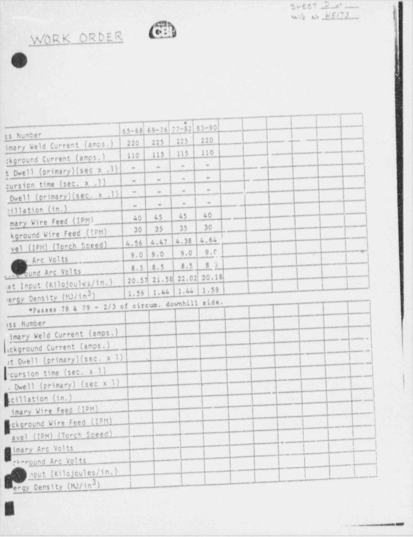
":.W E C T 2., o* ,
w'!c rh H i t ? t _ ,,, ;
A[*NWbR K OR DE R
,9,i i'J
77h2 83-90_
ss Number j65-68 69-76
imary Weld Current (amps.) 220 225 225 220 _
_
'
110 115|115 110_
:kground Current (amps.)'
- -
t Dwell (primary)(sec x .1) - -
-
cursion time (sec. x .1)---
-
Dwell (primary)(sec . x .1)- ,- -
| ---
:illation (in.)_-
40 45 45 40___
mary Wire feed (IPM)__30 35 35 30
kground Wire feed (IPM) j
4.56 4.47 4.38 4.64yel (IPM) (Torch Soeed) I
9.0 9.0 9.0 , 9.0
Art Volts |
er'
8.5 8.5 8.5 8.3'
und Arc Volts |'
20.57 21.58 22.02 20.18. . _ .
:at Input (Kilojoules/in.) |3 1.39 | 1,44 | 1,44 1,59
tergy Density (FU/in ) _
78 & 79 - 2/3 of circum. downhill side.* Passes
iss Numberimary Weld Current (amps.) '
ackground Current (amps.) _!,
t Dwell (primary)(sec. x 1) |-
f[cursion time (sec. x 1).
'
i
. Dwell (primary) (sec x 1) f>
__ _
!
_heillation(in.)_
- - - -
imary Wire Feed (IPM)
ekcround Wire Feed (IPM)-
- - . _ _ _ _ |_ _ _._ .
avel (IPM) (Torch Speed) _ I.
__ _
1iimary Arc Volts _
_ _ ,
i i
W round Arc Volts f_.____
aput (Kilojoules/in.)__
, ,__,,_,
ergy Censity (MJ/in ) |3
. _
+ -

_ _ _ _ _ _ . _ _ _ _ . _ -,
,
, - .-
e a**
we., I,. /~ t . . . n . . r, ... ..,i n.
i. . . . . . . .,
1/ N dw/"
GN~ L ~~/ L'm;.. ,.'
O, , , , , , ,
.
'r .- ,.n......,.Qf $ .
'
o. nt.n..:s,
'
\ ( y s.ut.ns.tn|-
e f
bu1 .t e a m e - /P' ' SECTION A.A I; ., n =ff f V
\ -""2"'"f (W/0 H5173) {
l . , a'
1 n, .- i -- 1 m
d. < s
3 1.stkd ./hitre I
.,'
it \ O ,*. .. 1/ 3
/ -
s
I \ / .
h ,
f \ s'# i
s i . .. ._/ s s si.. i.., '
-s ~ . -
I4ellig. Atm f( bf.etl)..Tegaseert e ||
, ,.
I " ' ' I'* "' #I .* t o e s t le.sas .4
L"".a '--
"- " ,tQ\m 'j-i... ..)
N f........ .
,f\ fx t- - - -
. . . . . .as .pze s,e,
O /> #[\ , !
y
i, g . . .. ...,
| sEcTIota e-a :: s(W/0 H5224) n.;;Q pA-t ;;- i,
, ,
q J'
p. wa
_L, _"a
i , , . __ , . .. . , _.
'N 1 t.,.S.( . 6 / 3 -
,/; a..<.
UU ' % 5i . ..
\ x. s..'
. i . ,"a '$
, . . . ,
gi. 3,,i .#....
' ' " "" #'
L ,..i
'
1. . .. . . . . ._ .,, . . . . . . . _ . ,
. y|,,. .iin ._\r .. .- - > , _ _ . . . . . . . . , , .
U.. .n.e,.t ..
. . . .,=
..-Is 3 .it allt.
I .M \
| P V;. .: N-c . . .. . .. . ,,,
,O 4-r|_,
.c 4/ 3
N0ZZLE ASSEMBLY-L0tlGITUDillAL SECTION ,
.
e
M___
-
- - - - - - . . --._-.m.. . . _ . - , - , - . - - , - - - _ . . + - - , . . . . - - , - - - . . _ - - . . - - . . - - - , -- -
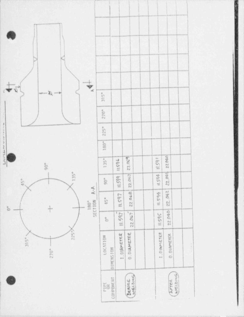
ii i i i ! ; t ' ;
'
| || :
I I, ._
_
.
'>
ii
cv t > <~ ---+ ( .
m-O
OON' N
l_ -
*_
eo m) N
N).
o2 e
~
4c .
r- -. am c-0 r1 C* b'i ca> ,
O N. ~
i @ D Mk CM # 4 W De ( O, % dO
m.:r \C' a N : N
rJ
N 4 -
N '.< c3 ef--
D 8,4 ro C o
c Z m V * go0 - ; .y
. eJ= s -
.
m-t
,e-- >--p
U OLW I N' f* h qO e d l, e oO $ - @ d
= N = sN
o\
N ce WC % B w W "W
e eWo
m e a e u-
n h $ E< L
0 = x 4 6 5,O * E C,
~ Caa -g ; a - a~w -
o| -
O2 2~
= G~ d-. w w eo oc._ :t = g >
L O\". D O y&c> -.
j N -
v | ._.-
. - - - - - . .. . . - . . .. . _ - - . - - - - .. _ _ . - . _ . .. ._

whmee aum 4 ha,ns.'mm-Waa..s a.J ' da Ads. nim # Aahh @ ms(=G =4 h h -a w ha v4 +.M.6pe m 46 " ee fs Ma M eM .m*4 W h ham--- Am-.WNhM A asumdwau. Naps.m'.mrsh=&'Nem .iinu"''nea._iq m ae. ,mwii.-w.m smsruv.s.-wi- _m--rwme-.hesi
$$NI
t
, ,
1
w=:.,
[
.m _
||
'
..
sj>,
: n i
I~i bI ;
f 1 h /s +
ei !
II
ou,
a s.a j ,
<1
4 , ag
.. , _ . ,,d O -- b4 e M J %
%A V m o) -
J Is "m o - D. .Os s a o a
4 e
s b d 9 %W 3 o eJ +2 s
'' O Q 4 4, MI J o o 4N
sI '
U "m N NL_ N 4, y
c.g
~ o. O. oN a o d %s
4 . c' 4 m o2 o ~ ~a a Q Qo c) O, o ," e e .- a ;@
|O3 s - ; ... ~a_z_
.-. m q q O, O,e -
| [: J a 4 o, m; ,
! m PJ
o O b b Ds wM4
o.e -
om o -
th O O.er | d| d G d ON ii
dd,
O 4b ~ ~e
c. O O O,-e z m
a a J , ;OO M;3 ;-
-..-ej -- -.o u
4Wm *1A %
g(,,o w
~ OO O. O- O,
O so'
+b .,$
$ $ YW~ r a ~e 3e 9e ; 1-
h 3 5n 5e e- o o vR "a $
a a e a~
h W ef ( W b. 2 ,
= p a e wo-
.
g= d,
L.1 te.s
N5 b 9e
|1 --
D D |! a e F 2 *
afO .
.I .
I
n
- . . - . - . , . , , _ _ _ _ _ _ . . . , _ . . , ....._,..-_..-_,.._....~_._._-._......,_._,..,...,,__,.._.__,.m._,, . ,_.,,. - . - . , - . . _ . . ,

W/ s_- H 51 ~/ 3..
CONTOUR GAGE TRACING
LOCATION k FT E.c. L L A>' E c.5 [ Teien. Te WrlbdyG .
O a.
n. Jr +-'
m' yf %-
[ h' t x -
.
0- gyg. 4
) '--m v ~- j
| no- 4--
9,
..N d1'
,,
|l'
| '4s' /..- /
a /7[ ,-
! . .
\.'O",, gg.- .
\ . oc3.
\ b( .
-'
,
7,,,eg,u o'- swo*| m --
M Ac.moe d Ge.onve. ,
160*i-
;---- .. .
,,
.. y
| \'
225* ; q| ,
-/ s ;
\/ s
270' _' 'N-.
! I,O / \\
f31 5' w '
jI~
- ...
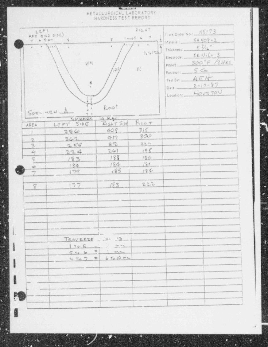
. _ _ _ ,_ -____ -_____ - _ . .
METALLURGICAL LAECR ATORYHARDHE55 TEST REPORT
;
L C.F Tp,, g g 7
b' b '
C N b 5'C') 'y\. xk Order No.:AFC
5 +- 3 y b 4 50I* 2. _jIwf 6 7p 6
Material:'
... . . q. 6 k'L"
. . . . . . .,
,' Thickness-, ,,g .
E 'b"'3 --
. ~
Electrode;
PWHT: ,
$b {' Position:'
AE |Test By:g
E~I7' 7* Date:
NWS TOd ILocation:-
4!
A [- E.ooI$p e c : .A C. O
,
y,
*<irmt c( ta Kv~ ~ ~ "
AREA Lc r 7' $tD C Tic.$-r $rtd R c,c. r i |I
'
1 2 9 (o 407 Flf|eI? 9CO
2. 3 a -2. rI
'
3 -2. W I 3 I2. u. ,
|4 '2 -2. 4 7.GI ,9 f
'!
T /93 /TT 190
IE4 1% I?rO e '
Cl 7 179 /75 | /t6 | |i
i'-
7 n7 /fs | 2. t. t i
i } I |
| \
1,l
-
j j li !
__.- | i,
,|-
_
S AY CEEE 9 jgd ,d_|
|t,o q .. i 2 ,~
l+
(=- ic c. o _ .
| !to "To *~1 ': L, T~e 10 - *-
I
|.
esas
eu.Nur
,, .:
a- - _ - _ _ _ _ _

MET ALLURGlC AL LABOR ATORYHARDNESS TEST REPORT
Ric.HT('lC CVD SibC) H Sl7 3Ert wo,k Order No.:\
e I -- c s , t's-SA EDOM, u se e~ y Material;, . . . /.'
. .,. . . .g . 5 Vev'. .
t.r.LasJ in.cx nesi: --
E R UICT- - 9Electrode:WO WAT TL* EW F / 2 M G .pwgT :
Position: [6KEN) Test By:
2-i ,- 8 7o ,i,
NoostouLocation:[.s.
C '' RwTSpe.c iut e.rJ _
-
n.
Vec.tre_s 16 k - .~ ' '
AREA LerT(Targ:onof 'Rie,n - Roe -_ _ _
. __.!_ I 9 79 .304 ;91
_ _.
2 39b 2 9 2. :t 9 e_ . .
9 191 2"% | 249 __
+ 241 ?.06 los|
14 4 M7 l?q
I _j(e . _ ,. _ _ f ~7 9 t "7 ') 17A
'
7 17 9 | ( 74- t77
I ~/4 l72 ~2. I 3 _
_.kis,j...,_.,
f'
I'
.
i ._
w ma sm ,,, 3 i<
g .s- n. __
.E f e bt I mm
I 6 . ~7 - G r.10 0,
d-
..
-
_.
- - . -
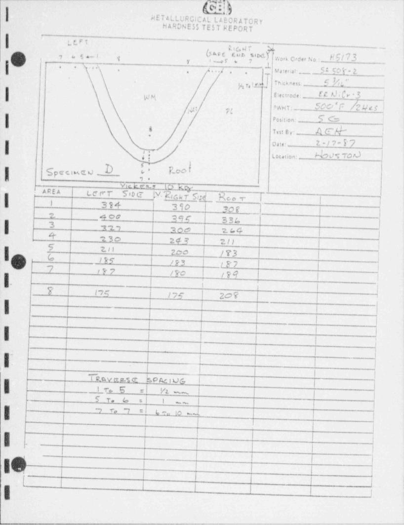
Ift...._,c7
MET ALLURGICAL L AEORATORYHARDNESS TE5 T REPORT
| LLFT ~'
, 7 g --,
($ M C 5.8t<,J ' vim Order No.: - Nb/73Cud, ,7 s| j
3
' . . .;1
'y 1 -- c f 6 ,
,. .
^[ M a terial- b 5 $C'5' * 14, . . ./,|, , ,
j Twe ,m 5 A'g, ,y
I Electrede: EE db '3 i
,,, PWHT: 50D |~ /2IIC$ l,,.. ,..
Fesit;on: $b !
in: B y: 4 E'Y !s '
/.'
o,i,: 2 - / 7 - P '7 ||4 :; - toc.uon: Wove ror) i,
$p C C. t M C d .._- vie. E te n r 10 k
|- AREA Lce r: T Tio g (V, 'g, g g g-r Sc>d'M 7- | | |
'
1 3s+ 390 soe !
--
z 4 0a ase 33c| 3 n7 700 ?_ (. 4 | |+ 23o 243 1 ?. / > | |5 2. i l zoo I /73 | JI(~') G _ / R <r /p3 I tg7
| jv' 7 iP7 i /Fo | /pq | | ||. I || |7 | 175 /75 | 2O? t |
'
I L | | i< i , ,i| 1 I l I !
\ |
{. -
j-I
'
| | |, jTRavncig s' P Ac i UG ||-
1nE :| V2. | 1 |. ~ ~
5 T. o =I i ii
__
g o 7 = c ,, to7 r
! i| . II
i ii 4m
,'
.;t| 1 ; ;| | | |l-
i

-- - . .-
* pee, ...g:g w'o Na Hil7 3E2C0 BWORK ORDER AND REPORT FORM NONIMPACT rupp cus.or
''1 * -
h cusTo a . C oei...o. . s16# 2 7.M,t i T,n N. . reg uo.-
{ h A SOT c, .'o e _ :- HtT .'Re A Aeo, _ . t |. yN g,. e. n -
Fo .c. E . C',f, . moi m T' CnNga La m oe ~
' Process M k Dm A,. 'Cwr e e nt ,P o la,.t , M @ _'.loint Tyge _ A*w,ld Tech $id lenp Ho H & 4 *W,sn 0,r.
* E t,'cfrode AW$ b ''"*3 * N. [E * M'N AILCO ! Cuv (L5 A Sasen No ,V C.q 'p"pf g-
""'"" Ctry -" Mo4stwee A A ~_% A B ,,,, t,so10 4 CO _ Mit _
'Pr heat Q ~].C L *iPT,} O_ q .PWHY Te p _ _''~_- * T ,',n e ,,T _ H , . p , ,$ , ,o n f,,,,,,'
'Fiws e* Cas*~~
' R oo t pe ns
S.d e Pau Ca Ampi Volts , :PM R,ma,h g
Ce.in Der: W e toe,4 I
ath46 '-sO 4 f O VC. R T I C. AL b c Lu d .- O rPt.tes Rea
---
| |yi
coes.
pq y 7 Jgg Th njg.,,., g ,.t5 gEdge coating
(M4he sketch of so,nt det.11-
9g dD Gm A FLA- Tg r,chX Cwr. |"OPF6*E
'h Li u LEPTO a r) FEO m. Omk "A '
y 'I'h F- k A rt B OkM h tW rr_rt N "J HAtibGST' % .% gD TN 5FE E EW 'J .8.. h AR 15T
% / if..g
E r f*' A M o r 9 f ft X d c_T Ir e) 5 h r -Pr 4 m. F.
h"ir ~p E.c . .. d i__d d %I9ce nasa er< u rtr mg r
s| NrA h9.s i
s % %!. d b /\ | YT A t''T E A f Ofitbj .G'g /
'
5kI r o.., e.ne. s.de i ._ s.de 2 _
He.i i pwi t.n e.u - u .a.\s ss
\ % 4 I TENSION TESTS.~ '_ \\ ) % t 'Oeient 'UTS, 'YS *Et> RAe
I g .! hu hs . t.%./ s
g wg 8L L T ST R ___m _ _ - _. _ _
s)NL.T.ST.R _ _ -.. _ . - _
w m. - _ - . _ ._ .-
h, [ A'Z. W Ut-9- 'vs . ' * El ' 'F AILURL,
Ji, * u Tg ', ""cr/q c>" , , . ,
P.H.W~~ ~ ~
#4dd N(bNd..- n._. -
p,g,w
#'"'*- - . _ -.,
R OK NC7 '
,F ,L._ P7 s t $* q
NOTR* sH . c WM* c
F E RRITE NO. WE.,
IMfs CB / Ma nimum V.twe
CH EMIS T R Y . I ts S.d e 2nd Side'nc
Piete weidPlateCE .
1 .--- - - Hmm..C
h ~.p2.ft 3 u Dy eja Mg3 dHmp
Mn ..
Purrese of Test: U ALVATF ^" -- -Si -- -
D b"# * I 3"MINC- LEFT OVLt. TCST tdE.L5 * 'Pi.i. A~rf a c. W co - bai ge.iu.i.n of Re wiis:
--- --
s . _ . _ . _ .
"So wt~ SosTo3J% AT f v E.f' A(.'.E,. At-TER --w g7%g" ' ~ ~ ~ ~ ~ ~ ' * ~ * *
Cr- WM Ar@t_7, f
. ._
M o .,, _ , ,, , , , , , , , , , , __
C.aA.pCR. SE AD5. ""'"t " * ~ ' - ~
3' I b:' ' I 7~ ~ ~ ~ ~
pi'$[ ""- -Complete Woth Order By: ate ; - - - ' ' sOm O_.C o.ie: ?- 12-17 Rev o
WMAl- /5 e stand 4ed 8014.2 for instrucisons f or completirsg this f orm.
,,
Ti' * ~ " ~ " .
"" ~~ ~' p;ie,,
-- . _ .* tad. cates cata to be keyputursee. @4
IhI: ..e.._,,._.,,_.-.-. -
- - - - , . ., _ _ _,

g 0.SI WORK ORbER nectaJ_W/o u M/73
(') %> e e c e m
'wJ
k3 T'tspcc.3 cab 5[t)-+ *
MSArc cub)
II ,
i
- Synchroni za tion 7vac. Aw . Voltage control SAM PLG D_
Upslope time 3 s cc. Downslope time 10 nc .__
re Start Delay Travel Start Delay 4 sec,--
Pass Number I 2- |' I-- -- - - ~ ~
-..
IPrimary Weld Current (amos.) /to 12 o
Background Current (amos.) 90 /, o
Out Dwell (primary)(sec. x 1)I - -.
Excursion time (sec. x 1) - -
In Dwell (primary) (sec x 1)~
- -
C.-.11.;. .. s'i. .' LPN t,0 (,o-
,, . ; ;; g , . ,, s gyp ,, y ,,9< _ . _
~~
Backoround Wire Feed (IPti) --
Travel (IPM) (Torch Speed) 7.4 24,_Primary Arc Velts 4o 9.0 $Backcround Arc Volts 95 f. 6
Heat input (Kilojoules/in.) 31.4- 20.933Energy Density (PJ/in ) ;_ _
_
Oe
I
. -
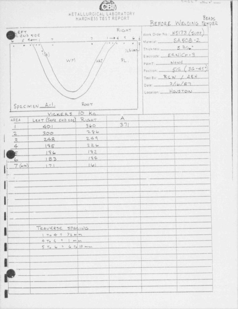
-- + snu_, - ,3
k5)METALLURGICAL LABOR ATORY
HARDNESS TEST REPORT ypg3EFQR_E net.0IMQytpER,
-_
Ric.sv(~'u r y N503 TOPEC dub SibC Work Order No.:( jc c4-: , 7 : --> < v c. 1 S A FC8 -2_M,terw:
, . . . . . ,7
, , , . . . ,
5 M s. 'T hick ness:gr tme
E R d iCr- - 9,
Ele: trode:WM wt n' 900dPWHT:
Position: [M N'~4i
Test B y: ICW ,/ A E RUtts|R1Dste:
NA'S To tJLocation:
A I. R=vSpac wieuVic t c p s 10 ke.
AREA LtFT (Sc4 Eud ud h ur A |
l l' 4o1 3bo 3 71 |_
'I
|2 20o 196
9 14R 249 | |
| | |4 19E 2. 2. 6
7 19(. l % 2. | | |^
l1
-6 iss is+I r o,i
.
.7 (~4 iit
l
l.. ...
i. ._.
Ia
l l
i . i
| $Te.wcts c sedi oc, i l i
l .
Pt Jm | |i r. + :| |4 T. 6 5 t m m
| c r.J io -5 r, r s
i
i8, 1:
, ,
g
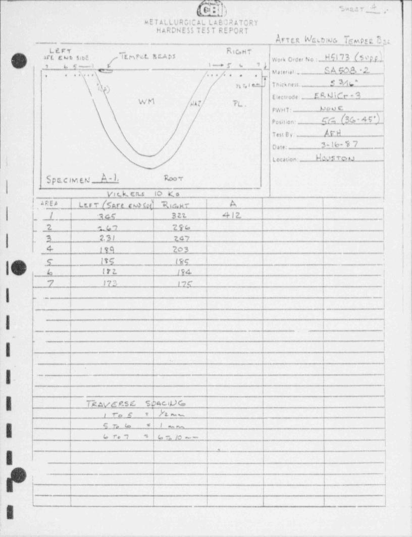
9 ac r i ,.MET ALLURGIC AL L ABOR ATORY
HARDNESS TEST REPORThf T E R NC LD NG f(mpEt C1:
'- s'L6FT R it,H T g!
N b I D {5 '' P.f_4.'~
<) art. c ub sies I t h N t. E CA 05 Work Order No :) n t, <-1 \ ~~* T s. 9[ |Mil"'*': -- bA Nbl'. h. . . D . . . /. . ,
'
. . ,
f f 3A L'T hic k ne u.,, y, , a em'') |
/ Elec tr ode: E R W C~t- * 9 I
WN b' A 7 TL.PW H T - M c' ') C
Position- $430'' M --ITe,i u uw
3-16- % 7 _)o ,1,;
Location: N& 'S To t 1,
i
$ pc.cim es A-L hv
V c_ k, crus to Ko
| AREA Ler T [ son N fn) "Risy - | A |
_, _f., _ _ 1cc 3 22. 4 l 2, I |_
I |_,2 1G7 29G3 zsi zcy I I
'
4- 194 203 I I I f.
e les twe I I _: i
bn) |6 ir2. 1?4 | |_,
7 17 3 17c
_ . - ;
_-
, , ,
!-
i i i I i
I I I !-
|~
l | I I
i i
|. -
| |i i , i
| nuacsc s e;c,c.,0 c, I Ih -- 1 Ii ,r,y =
s r, s < 1 1 II = l u , n, --
~-
a r. ,
'
| | |,
i ,
, , , , i,
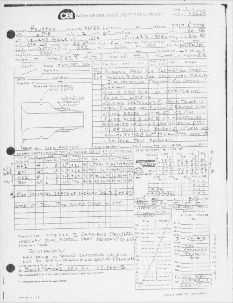
--- -- ,.
.
I cipee,
k(BWORK ORDER AND REPORT FORM IMPACTm'o w H52.21
Not> 5 To 4 c,,y, No All2 g_'u|n ten no. . Pen Noi 7 7I 7 [ 17/d_-
u'fn A 50 8 .c,4 e _ 'L __ ,. d t. 4 T R e ,L od , . . _ T ,'. l. 2 ce <WQ, m,oni.on
.u'f, __Lt v A. r4 e ac.L c'J, LL5 4 uifi m ) '5> ''L - 30 41L T|6 i. z c3 Rwk o. . -
eP, Aes, GT A .4 co,,e-cr a,,,e.!Lc !SP uini T,n __t.L _ we'd Tec, sid ino#H s i caw Noyg7s n> 3g_,.E,e';,ose Aas Et Dm r -3 n n 2- _ dri M?rn can v: Ao
mo. .e A A = % A 6 m_ *.e no ,' 'o, c ,, Asmo u d,3 - ci,y -
e.heatf-lo_.T_dr_~.~_c ew s t T e L _. _ _ . 's T .',ie ._ ._w, . Po !,,,on S (=*
nob.o -
' ' '. 7 o M 7 E 3 , A gil 5.ce Pau o .a . Amps Volis ,
IPM R e ma,6 s
c..in o.- weide,:
" " ' " " ' * M fat eub c, D r.,a Ert3c kth uscoIstd %.,jttrei san rb !srecidex ovouwe- r Aw .
-
| g geg, ,, y pg s,4 Q,coes-
E do. coa tino|iMa6e 6 eien of ,o.nt dei.m k^- W9W/0 H 5|7i ~
dd _Lc Asv host A r Il 50Y/24 u c.sw/o H5114 Pd ic> tt re t3eL.bNb, f
-
[d $ NdLbuJ em Pf.kFofleeb/C bold T~tAcKlls*v Pow 6 ,w susTr& %ew yue( v m
WsAve e e>os w % 4f K r Au.s
f, Luce Fto n c 1.trTf2.6 me.Anootes..k 0- N @. D tU b hill [t- Od f" ACit D A$$.
[ OF % od "Joiuk IJ,6 LcL4n c) ro' ore mr"M ydoWMc>sh F M che.Tr.:. ro ,ot Tg.
u6c. pu. wr mk u m .Ii
M8JT 40. O l14 Y M 7 - h* $ Total passes Side 1 Sece 2 Hut innt Last Pau KJhn.
CH ARPY V. NOTCH IMP ACT TESTI5cer tine h. 7.5 6.7 5 3.3 2.5 mmTE NSION TESTS: *t 15 'S ' I j
RA#
-.
Onent UTS *YS . Ej%ht' b li ..
Side hurt* N otch
9s 7c '15Le 15@sise4d5s ' ca.Ak[_y-{Q$ $ [Ft. Lbs.| 'L.u. E sp. i ' % SheerD,ient | No. Ma,k Tomo C.
L ocation
HA7- I d t 3 'z/ 4 te43 47'o|3c|4.bre|44 fo 50 J,J.{,,, JJ, / c, e, c. Cep ld 4to
g JM | NLT L 3 I
l|99 fo|75|bi 71|fo40.7e|Hu'5''JfE l -b 2* b d b'E t-- 58 B,,
I,
N A*Z.I I N L 3 MD Y 2.e l f ''# " "'
_ . _ _ . _ _ _ " _ . __ ' ' ' . _*N' k si %
N BM' i kT L .3 'Id *lo 43 Gl 45 33I4A 37I4o|J5 35' ~ P.H.W
; ; ; ,, '
ZZ_ M 's~ T.._~h..__*
'"*
d h niemcat Me w or ededte (3i% d op evl. ,4fer-j j j i 7-
h.' "~~&nh fLbre: EV Th r 7&p spum i uh ._V_ddF
~F ERMf E NO.
k n...
! ! 6AADNESQ ~~~''
! C8 " Manimum Valve| | |
M', -
| | f |
- CHE MIST R Y : 1st $ide 2ndSide*RC
' - * Pla te * WeldPiaie
-
! | | | | | C E , __ _f .._ __ __ . _ _ __
s,-c
To SAF E: E.*JD STr.0cTUR|Ma ----- -*
Purpose of Tut: N 07 7 L E fOVC.R.LY 90%I EICAT500 b"T ('RO GN.A *\" $y [P3 p$' ' ~ ~'~
2~ ~ ~ ~ ~' ' ' ~ ~ ~ ' ~ py g,Evaluation of Results: $
- - - -- H m s __ S f* 6~N' A mM b Dh *1($ S c,70(l.Y. Hmpd c,~~~~~ V~ ~ " ~ ' ~
WM RgJcyp~ela.J P #- 0 C4 M D E T C.C TW'C- VJ Eth i r/L y,~~~
b r.nen rJHAD .,C a.4, C ~~~*
5 Ab w ( G E Mec4 wAs 254043 ( 2 Nc t.b CDui, y 1. Doc To atai,
/ Complete Wo,k 0,dre By; Date :y
C)/ ey; 3 WN .b. Me-muus ,. A e !t one: it 2.P'eaEv s c ._ _. ,4sAz__
WMAlLee standa,d 8014 2 to, inst,uctions fo, completing this fo,m. __ _ __ mTe ~ ~~ ' ~ ' ~ ' ' F sie (o2.7 506*I fj 4
tyb 3 3 * *#dd L- | ** 1pdicain casa to tie keypunched, No
~'~
)Oth ,12 t -I 7-/-
.
wL ilt (F ROfwT) HEV SEp 510 intec m t,)S A
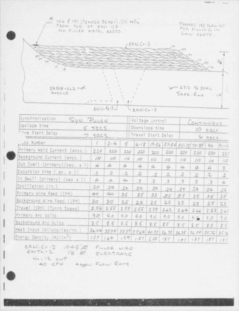
_ . _ . _ . . _ _ __ _ _ _ . _ _ . _ _ _ _ _ _ _ _._-___ _ _ _ _ _ _ _ _ - _ _ _ . - _ _.
. ._:
!,
f |4 f. {' f''t'/ [TE efEl SE. AB h 'hI 4* Y'*FAm r pt rsea ar'
i
C RD *. . To C cF PMt 12 5 701 riLLlu G IMN c. F'Itt,t t M t,TA L AbbCb.i Lo w spor g ,'
jr E E M'b'3 ,, u
', 55 -> };.--) } f.'} ;Q};[_Ngh- n 5 0g'
g- 'M?q- y DW---7 -&- y Q' -
>S ' s i, ,
i \ J%/
.
'\
/\ s
'' 'i' / r A 312. Tp 304 LSA508.C.L2. M ''
y,u g ( ( $s;rr:..E'we t b,i
1-s .i ,----- f i f ,i' ,
E 0id, Fe t ( c.r 0;c 3,
Synchronization q q o *Ri ts e Vol tage control ['owri v o o u s''Upsicpe time .-- ge c.s , Downslope time 10 s u.s .
] '" ire Start Delay y_g,g , | Travel Start Delay (o m3.ss Number |/ 2- 4 | 6 42-/ f /9 M 37-54 55 72 73 Ff 40 9/-/C
! Primary Weld Current (amps.) ZZo 110 | 22o 2Z0 22 o 220 l 22c 2to | 220 | 220.
;,
Background Current (amos.) //0 //0 ! //4 /M //o //o //0 | //0 //d | //C|
Out D.vell (primary)(sec. x 1) 4 4 4- 4 4 |$ G G A .7Excursion time (;ec. x 1) . 3 2 .2 .2. 2 .? .2 .2- .? I .2
IIn Dwell (primary) (sec x 1) | 4 4 9- .3 .3 .3 3 .3 .3 4Oscillation (in.) |.20 .24 . 24- .2 4- 24 .24 . 2 9- .24- . 24- .2C5imaryNireFeeL(IPM)'
90 40 l35 35 33 .35 '35 I35 35 | 35Backcround Wire Feed (IPM) 20 |30 | 2.s i 2.5 2.5 2.5 2.5 25 2.7 | 2.5-Travel (IPM) (Torch Soeed) 2.C6 I 2.fi 256 25C 23T 2.42. 2. /. 4 . 2. /,4 2.G ? 2.65Primarv Arc Vol ts 90 9.0 9.0 9.0 9.C | 9.0 9. 0 9.) 9.0 30
,
i
Backaround Arc Volts ?.C | O f ' ?. C ?.E ?.s U PC ?. C | F. 5 T$~
Heat Input (K110 joules /in. ) 36.04 37?9 3739 ? ?%4- 40.33 % 7d 3:38 36. 0 V K7C|3574|
evergy oensity (Ma in3) w7 >. s + in i.e, z.m i.e , i. e > i.t ? irr i. e ;
e.. 2 .xswn_ _<| cwTh - 2 Va ' sa$ etec mx
I Ljo . 12. rvP+O c. F' N Awe Fi_o u) ME
|I.
f
'e
i
e
v- - - - - . - - . . --..,,,,-,%_ , . . . - _ _ . - . - . - - . , _ _ - - - - - - - - - - . - - . - . - - . . - . - - , - . . - - . - . - - - - , . - - - - - - - - . . . ,.
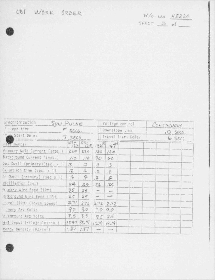
CSI M/0R K ORbER. w/c) ao #52245 HEC T - 3 of_
_'
; I I
sa' j
l_
,ynchronizatien Syp),_Ptjtsg Vol tage con'.rol COU N OOdsI5cpetime_
' __ { 5,gcs. IDownslope ime ; O SCC 5._.
' in s Start Delev.. . . . - -- ? g g 5. | Travel stert Delay ( Sa.s .
',--
< --
IN ~ l .__ R_I4 *7 +_,
. . .-_- . . . .- --m1-gh /Humber - <
(4Q l%_ _. . I 3-_
P tmary Weld Current (arps.) 710 Eto /Fo /2 d- - - . -
!
Bickground Current lamps.) No //O 90 Gd6Out Owell (primary)(sec. x 1) 3 | 3 , 13 3
f xi.ursion time (sec. x 1) .2 .7- .2 _7 [
_ ,
_ _ - _ - . .. .
Ir Owell (primary) (sec x 1) .@ 7 ,9- .4 .@
.....
>sjilla tion (in. )_
., 24,, .24 .24 .23 _ _ _
_,
,
fr. mary Wire Fee _d (IPM) {f.__ 36 -.
, _ _ - - , l,,
| ~~~__ ___ _ ,,
1[ Loround Wire Feed (IPtQ, 26 25"k "
ravel (IPMl_(T_ orch Speed) 2.7/ 2.7,2_ ;,2 3 2 2,73'
. mary Arc Vol ts 9f___94 [9h 90,
taekorcur.d Arc Vol ts 7E 36 ,76 f.6 |_
l 3EO 36./(2?.79 /9./9y t inout (Kilojoules/in.)3rergy Density (MJ/in ) |/,37 477
./~'N ,'
L. )'
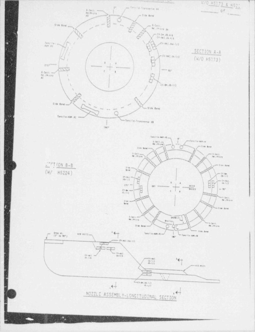
_ _ _ . . - - - _ _ _ _ _ _ ---- - =- '-_
||/o 95173 g, u ,- O|
__
- ,
c- t . e . . n . .. .. . . . u t
w ,u. % 's I / oro s. t/ ~
5~dN[ si.. ...
"d I
'
8\f id",,, ,.t
s i .. . . , ,.~ ~
-
/ \ ,M'g((s s= it.4,e i
vh Q ul.u tig'
/ / \1. iii.. N r t Mi,pa,4.In ''*" , 1
-
I,/ -
_SECTION A-A |/ / ' " ' " ' ' "%, / .
,1 (W/0 H5173),
f O am- s g-
3s.5,ci. / # ' .
N,f MlCPO 5 '-
ot , in'
\ tt Sn.f|.in/i
: \
s / !
v's |m' 8 * d ' ' |s : i,. ...,s -
!% .. -
_ ... n . ... ,e,
g i.. n . . r , . . . . . . . ,, ,
, 1tw!
u....... ,.
i.., n.. m ..
. i.. .Q- - ,- ., , , , , ,
, , , , , , , ,
tw.a ] bNJN' ' ' ' ' " 'i
7 . u. . . ;\ gN ~-
2 ,7[0N 8-8 [ Q4 ,-i....
(W/.H5224) \,,/] ,,,,,:s/n.~. \ \ "c ."..". . i
fn tn
, , n.sa s
- : - ;' j< ,v. - .o --I
.c. . _,
c .non y i%,,,, i
A mm ./n e.se::\ i . .-
, ;
. ~ '
--3,... s. . , ,
-- A' Aq u ... .W
,e
.
wj . .. , ,, \ .l.T m_i.... . . . - . . . . . . . . _
\ p cv- auwin_l W
J w,. r.'(p . ga g d..4/.#41/6
*g
g
/ ~- e n I,,, n,\
w -
*, s , %
4,. .. . inI
.
n,n*
.N;
_ N0ZZLE ASSEMBL Y-LONGITUDINAL- SECTIO 1t
.
\
..
.
,, ,.,.,v,.v--- - - " - ' ' - " ' ' - - ' ' ' ~ " " e -n-
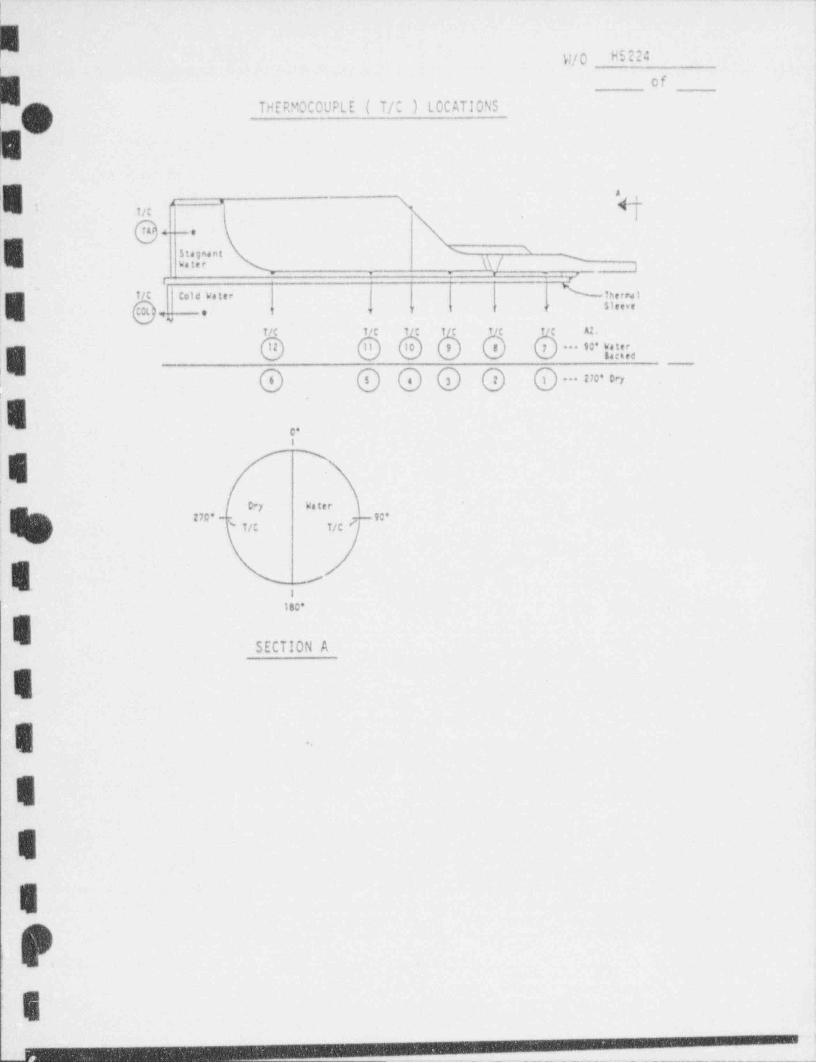
1
-.. --._.-.---._ _ ----.-.-.-.-..- - - --..- -._ . - - - - - - . . - - . - - - . _ . . - . . - -
W/0 H5 224
of
THERMOCOUPLE ( T/C ) LOCATIONS |oes. y. -
,,,
e.._,E w' y' 7
'
. . .
,
1/C Cold Water thers t
'E es """''-
f/C t/C t/C t/C A2, i
e e 8TC 61CG O " =. |g|
*** 210' Dry
i s .
C*'
i
!D*y Water
j2M' -
( T/C T/C
e riso-
ISECTION A 1
E -
E
.E
E
Ps
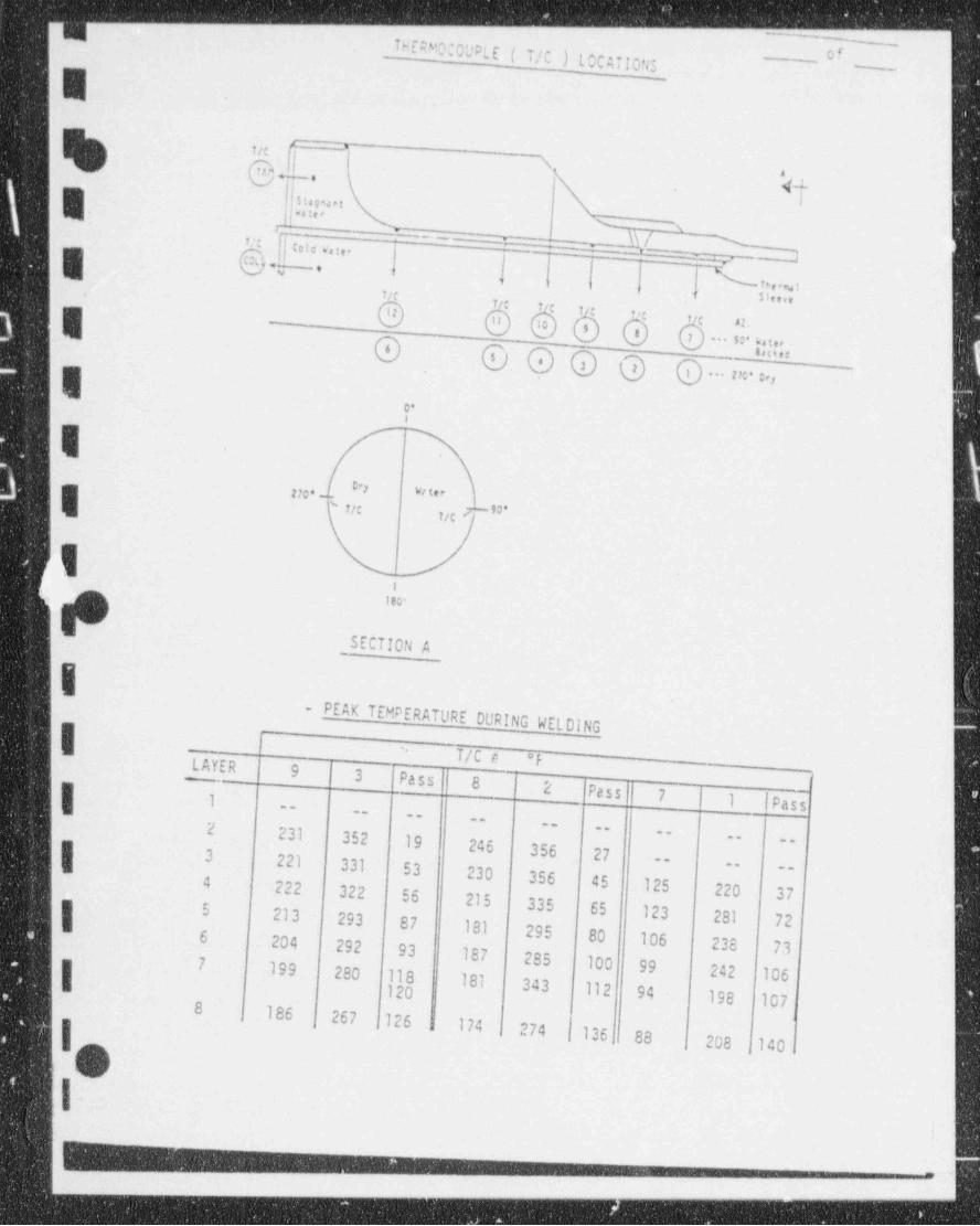
g- ..
THERMO;0UPLE ( T/C ) LOCAi!OgR
% @gx,,,,
|. t,..., . ,I_.
X"" m ,
Jm -} \\J-
.
t<:
e e,,w.:n | | |g \( ,,, ,, ,, 1,
1,
E 5< ,,....
555o o'o o$
@ h:a;,_
o o ..& >, -
Er
5 -
>> ~, , , . _' itt n c < _ ,,.
11
180*
SECTION A
i
- PEAK TEMPERATURE DURING WELDING. I _
T/C e *F[ LAYER-
9 3 Pass 8 l 2 Pass 7 1 | Pas
7
g 1 s---- --
--
2 231 352 19 246 356 27
-- '----
.. --
3 221 331 53 230 356 45 125 220 37
---. --
4 222 322 56 215 335 65 123 281 7215 213 293 87 181 295 80 106 238 736 204 292 93 187 285 100 99 242 1067 199 280 118 181 343 112 94 198 107
| 1208
| 186 267 jl26 174 , 274i 136u 88
, 208 140iI,
O 3
13--
_. 1
_ _ _ _ _ _ _ - _ - _ .
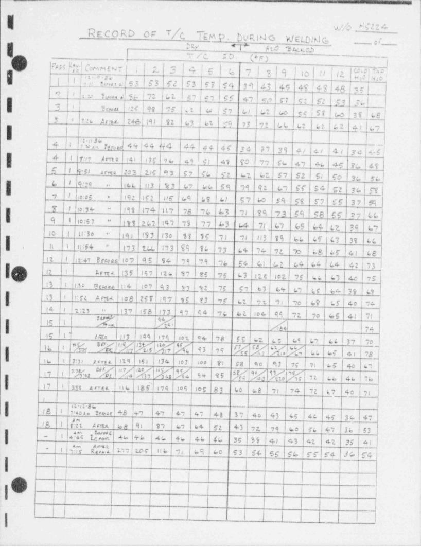
-__
Y.//D _ $2 2 ARecord OF T/c. tem p . DUR UJ G VJELDUJ G _ :(I tv <i" s.o we ,
T /C. ID. (*F) ~ ~ ~|N5E,T}CcumsNrI 1 ;L 3 4|5|6 7|2 9 to 11 (2. |$[f[['
, .. ,
| !I I,.....,.r,,,,, c i s 3 i 5 3 52 53 F 3 ,' 54 39 4-3 49 47 49)48 35 Cy
'? I* Tua. | % 7 G 2. 59197 | 65 +, w c: gz , F? Sq 3,\rw
u h 57^3 6 ~?veu ?:C 99 ,5 w; G, G2. Go gg Si c.o 3s3 . ,:: c w zw ,8 , n u, uz co ,3 ,2 Gu u ut a2 g f e.,
{w' ,,.v., in e 4+ .4 a 14 n ,, ., ., a, s.
1
+ ,
zi? I 1:n Ama ' tan oss vu e gt as 70 7, Su 41 au +5 ga 67s , ,,, - , , , z,, ,, c, a 8z - a e, F2 s, cc ,a s.G I 9:39| tra ur3 1%3 u, u.u ss 99 9z c, SC 54 cz sc. ST
..
? I to:os 192 162 88 6 49 LS L1 57 bo s9 59 5'7 CF 37 9*
7 I to:3 4- 19% 17 4 117 76 76 b3 71 79 73 69 58 66 37 bb"
Cl I i lo:5 7 I?T 2 (,2 i 14'l 75 ~7 7 63 L4 7/ 67 65 64 Lt 39 67"
to i 11:30 eq 15'3 13e Si 16 ;; il ll3 29 66 45 ' 4f 3% 6C''
ti i it:54 " t73 UL I13 T9 10 73 L4 ~/ 4 72 >c. L S, af 41 68,
,z , _, - ,., es s4 ,, ,, ,, s. c, m s4 c. c. .m >312 1 Arra. 13 5 15 7 i t s i 17 rs ;g 43 i n g . 102 15 L: L'3 Ac I 75
,
Ini*i3 i to e e- oc ' ro7 93 tz 75 57 63 cs. c, cs sc. 3 s. t3lost 2 ,ee zerl,s, ,s r3 ,r u: 21 ,, ,e us. cr to ,cJ n ,
In, ira 1e4 , uzs .. 03 97 44 ,c et io+ 99 n 7e u.s 4, 7m 11 % % daI i 74,
!!3 ,'I " Ii7sIC { l T e g.t not 9+ ,8 Fs 62. cs c9 L7 && 37 7oNNb | 43 79 k k NM LL hi |4 , 7S16 i
| iu , r, , , ,,s ' it e isi I ,3+ | 3 ,o. s., sa so u 2r 7i us o 4,
% "M "% %I% 'E s+ es M M elmn ,
| isil i,sn ca 4e ve
n i m , ,, y nu nos ios 83 co se ,, 7+ 2e t7 4o 17,i,
,
|IL st $s tt8 i| : 4ea s u.,ar +3 47 I47 47 47 49 37 4o 43 45 44 45 S t.- 47
IA i [Et A nr.2 68 91 97 67 64 52 43 72. 79 Le ic 4-7 36 53-|1- 'Tc *d /|, 7 4 4 % 46 |% 4b (c. 35 39 4.i +3 ct 41 35 41| i | , ry C1 t, , tor I n a
'-
,, as so s s , s4 sg sc rr s+ Jc 54
II li
I i
| #nv I |
; ) I i I! ,
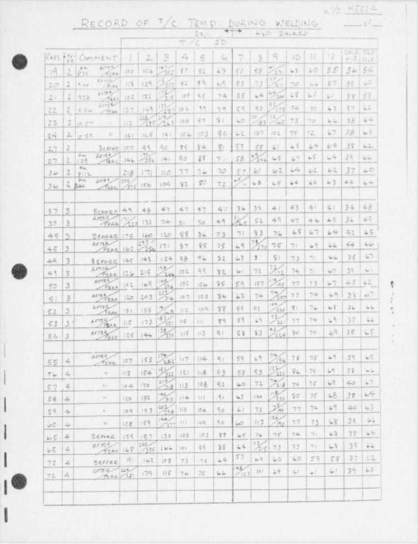
g ',h N h'. [ di
Recono or 7/c. Tam p nuniae v;ctonac, ;_454
e 'L)' _ _ _ , . | 10 3 A r.OW 4*
T /C. I D. ; ;
[]| IA55 D f Cc m M E N T'| | ;'_, 3 4f5|G 7|3 9 to|11 | (; 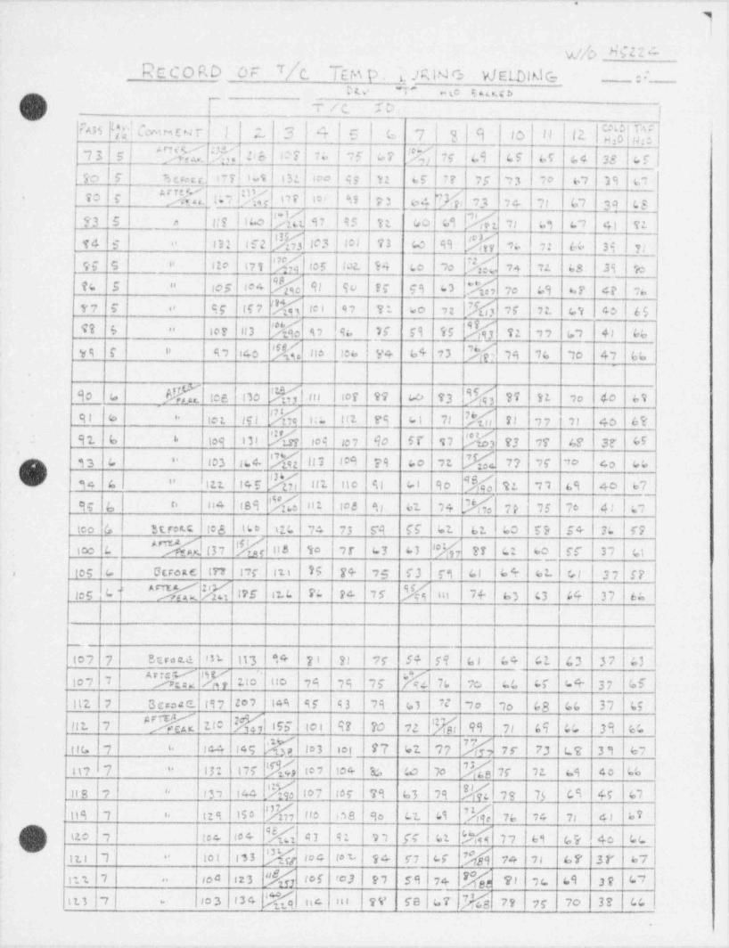
^
4
!
vj/o HC22 4Record or 7/c. T m p . p u e: WaDWe ::
w ~r -s s.m(3 -
T / c. :D.wJ j
r"AM f,*[ Om m t y r j |* afg|6 7 | 3 | q | Jo | || |2 | [ f f7
u gj xW.1 u~
er :s l ,d or % vt :cs cs i cr .4 3s cris - J cyl,_s a:l-l o f uso r sr n :s ,3 w e, 39 c,
"E r.,1% or l m j u 2 u %u20 e.
>c w c, 39 csuslico % s2 95 n. 50 69 rge3 s o ,, as c, 4, v:
,c2 % m3 wi 72 co es %e4 s m ,a :: a 3s u-
i2, I% es I m s to ,, % u u cs 2s 1.nu s o no
ws1 ms % 9, 9u es ss aL% ce|,as c. s a u us e
77 5' o 9r if 2 'M le 1 97 70. [b ,f 72. IV 40 | 65'o 7 ;'w
rr n3 % u ka 26 rs v5 %n 5- " v: ,, s, 4, ce
% no l me i v+ e+ 43 M ,e w. ,o e u.vs e i, s, ,co
!C %| ,n s3 % ss st ,o 40 s,so a we es uowe ao~
M ,;;. 2,1734 r, ,, ,, 40 6esi s io t ,y, itz es mi..
91 6 6 ies o, % ,e9 743 e3 2r ce 3r c5,07 so sr s2
M 77 25 'o 4o , 46ios n.c '.'M ui ,e9 79 Go ,1q 33 e -
L> ht:. i m s % nt ne si ci so %| u.3 c| " ,, ss 40 57
,4 lies % n: ma e, a w % 2, as 7e 4 l a,_se 4, o
LZL | ,4too (, ' St.rea.Clies 73 | r9 ff 62. 62. 60 59 54 7; r7iLo
to ,r | 47h tisico c YN< | l37 I
'.*M7 ?? G: 60 r5' 37 4143
u u+ 2wg u auoa m ,,c a, vs z+ ',e r3 | r, ai n sr,
ms . c - "'Eg %i n, a s3 o a n aies n. t. r: 1 >rl l l I
L m.ul,n. nyl w v ' n I ,r s+ 19 c, .. u a n a7
^" C M uo l uo ,e ,a hr MI 76 20 cc cr u+ 37 Isfm, 7
nz1 2 ao a n2 zov i m sr a 1,3 a|u :,o ,o c3 cu n c;
bl IFF tot 97 70 72 |% 99 71 64 c; 39 6cI:2. 7 $ INi
m i4s K to mi n 62 v 'W; 2,- 73 ut 3, ev ;ou , i.
n, I v - |_gl,ri3: i>r El ie,'
- io+ 1c, so 2 ,t ss to es
%n s I, o7 ,or 23 u3 I ,3 SJ,4 ,3 73 cs e.y 5,1~ o, u
% ie ,38 so :_ tics 'Mns , .. us, ise 7s 24 7, 4, uv
(] rc I c: M n e, c3 o uc,e+ [M u u 9, !tzo , ie.'~~
to t 133 %[ ioc ' to t , 94 57 | cf . 'rgi7j 74 al 67 3r 67itt 7 "
c |123 M tof 'o3 P, 59 | 74 % 91 ;c sq 3p ,L7 |n1 ,| I" ,o
o bl Im3 oc b% nc- ,o ev re l ur j ag 7, yy 20 3r cct
.

.-_ - - - _. - .- ._. - - . , _ . _ _ . . . . - _ _ _ _ _ . _ . _ _ _ _ _ _ - _ _ _ _ _ _ _ _ _ _ _ _ _ _ _ _ _ _
'
_ RECORD OF T[C, TEM p . bvR14 C, yJ E WI M G., . . -~, s,
m a~
t |i T /c. ID .
n l a g;g {g,
| .-'
ass elcm - r i z 3 41s s 713 9 ,o
O x.e><> x. .4 >s >< -ima4 cx. "z "= e et " n ,
.
7%lal %asI ,, ,, u .3s aos ou u n a1. ,e:
M 93 75 70 33 c,ete i te7 |n3 M l>+ #c) 44 59 ,s"
%w3|ns !!d n ,c v 3r c,on no ni n <,| ar s -
as ,! sucw u \rs as su e - 3+ n s8 a, so si 30 g,
% s, s3 <s n | <vi:.s s ""X u. | ,7 X;'ut uo si a u :.
pf;ino M w r7 r, 37 r3 ;n n sc e wa.9 S - so,
97 15 5 !%1% n 62 49 u % u#, ci a 3, ys ,: nu 9 -
(3) S Actra qc sy u4 t o. ?| c/ 5i 77 74 69 45 f7 3r c, ,
Ist t Beroa.c 14o 140 11 0 94 91 So 57 63 65 LV (4 49 44 6t'
8+) 9f 13 So cr '$$ to t. &P G7 40 3r cris t. S 94( ie3 M
as ne s, vs ,, rr ur es c, c7 cc n ci! ,e S 6. l ,,o
2f-Ma% n, 9, so us c> cr .39 c y.,zs t so a. 2
. __. ___ ___.____
,,h, 1 E r33 3trott (2.7 13 s IS+ 100 97 "l b f6 45 Li 74 ci ci f/ (,3
|h' 7t -fo 6; (/ c7hp Ae_ b3 N lif IE fo (o b 97 79 56 cf
!O |'
> |
| | 1 I |. _. j
l
I l
II
'
g'
I !
i
|| .
I iI l
I!
| | | |
r i-
1
' |
10 I i1
4
|i| ' . -
l_
- .. . .. . .. . . _ _ _ _ . .. - _ . . - - . . - -
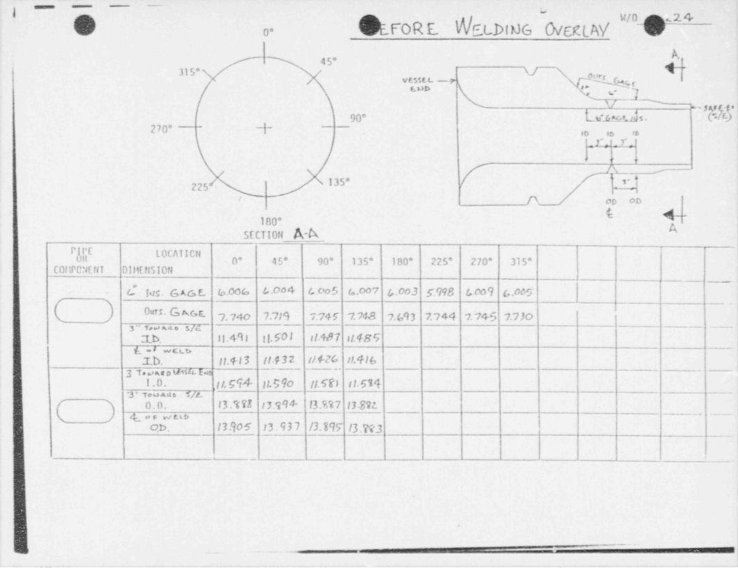
- - -
/' W/0 < % '2.4b 0* v1FOR E. NELDIMG Ch/gLAV b
45" i~~315* \/ \gQ4vesset -rNE.ob q U_ g~\*
'
,dh. :90 l_M_ureds. (.270 Y ,o ,, ,,
= Y: _f.
135"225D. op ob
180*'
SECTI0ft A-A
PfPE t.0 CAT I CflR 0* 45' 90* 135* 180* 225* 270* 315*
C0!!P0:iErfT Dil1E tlS10t1
d las. G A G E. lo D % b ** L*5 != ** ' 60*3 5 998 f* '* 9 6 05
( ).
Ours. G Ac,s. 7,74o 7,7;9 7,74y 7,74s 7,gq3 7,744 7.745 7.73o3 " Ts e.s m,6t o 5/d
1 b. \ \ .+9 | Il.50 I stab 7 s t.48'iL'~~
.T.b. II.+I 3 !!.432 R&26 H.41b3 T *=> " o " 4''' Eet
1.0. ,1t.G94 Il.590 11.5fn I!.5143* Tou Ano T/E
0.D. 13.% 7E 13.994* 13 ?>%7 13 89LC
y(( o p W ELb ____ . _ _
o.b . 13.90 5 13.937 /3.399 /3.W3
- .
. . , - . - - <
m m _ _... _ _ _ _ _ _ _ _ _ _ _ . - _ - - . - _ _ _ _ _ _ _ . _ - _ _ . _ . . _ _ _ _ _ _ _ _ - _ _ _ _ _ _ - . _ _ _ _ _ _ - - - _ _

- - -- . __
-~'-') M M M M M M e e neg.sasegus transc et ar==
i gChFTER h etbrue OveruAy "O "
(0 /0-
45* A+-315 Vogq g u o
3N/ *
'rc4
,.- se,A90* k'us Gs.} '
(
270*~
d- --_
.m zb sb
W Xd;
vn <
'=
## \ I35
, /
225 - y p,
: 1 ,pf--ou c o. co.
100 ASECT 10ti A- A
P il'E LOCAT10tiUR 0* 45" 90* 135* 180* 225* 270* 315*
C0llP0tlEf1T DIMEll510tl
(l Iis.6xst 5.9 U Eqs0 5.937 5.993 5.q 77 5.97(o 5A73 g.974
Disc. C,AG E, 7,cos 7,c gg 7,627 769g 7. 62'E 7.642. 7.64A 7.668 i
} * T~e. s.> a n D 5 / E_.- . ~ .
t l.4 l8 II 9-19 II.413 11.4 10g_|
-
- t ,e ovetop_ II. 3 7I 11.383 II. 379 |1.360
3 rowan o ven t t.- -
l.0, a vn. II. 5BG 11.672. II. 570 lj.G75"
~
s rus.ss a s,y0.D. 1351 13T33 '393' 83 334
( - - - -
s or ue.uoO.D I4 9 3l" I4 903 |4.469 It.196
s u > n a o ve w --
c
o.D . 14.944 19.91/ 14.195 14.9Hc"6
"*1 mne ' w p m m e - ,.. -.
.
d,emanaammansummuWa hA Ja'~n.'. ~
._
xm- --"
n &
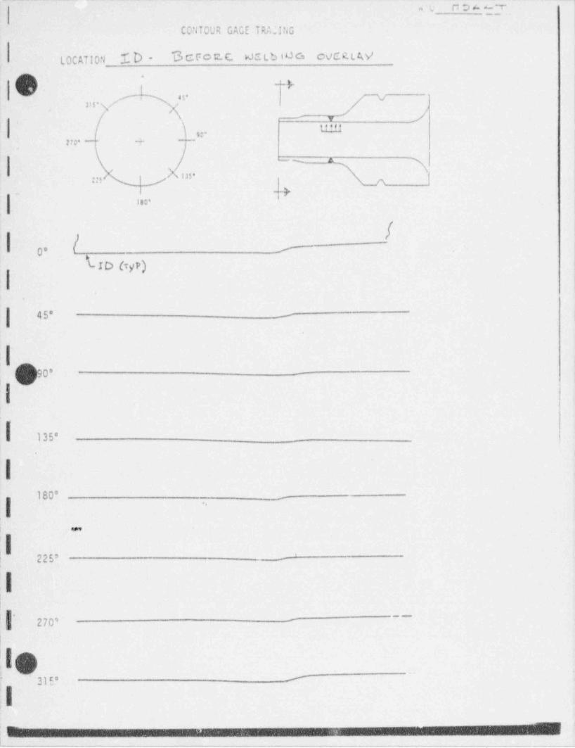
.. - .. . - . . . . . . . . - . . . . - ... ~ . - . - . - . - . - - . - - .. -. - -. ~
s'y n D A 3_T_
CONTOUR GAGE TRA.'ING
LOCATION ZD- S c Fo t C. Ws tb iOG oVCR L W
* *r,
,, v ;- p 1-
j, - ,. ) ,, um
m. + -
|-- A
:g' h us' jj
|__+ ,
ise !
I| I0 -
ID h/P|
.
#
.
I90*
I
f us..
I180* _
,
1
|| .
22s..
I:
1
* ~~>-
270' ~
|
LIO'
31 E" '
;l: .
| -. , . . . - . - . .. . .. - . . . , _ . . . _ . . . . . , . - . - . - . - - . . . . . . - . . . - . . . . . . - . . . . ~ . . _ . . . - . . . .
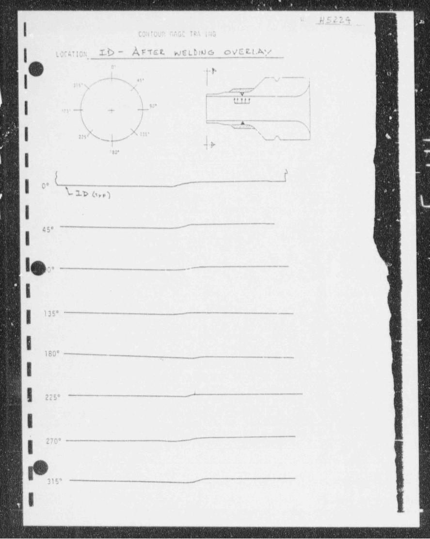
-- ______ -_______- --_ _________--______ _ __-__- _ _ _ _ _ _ _ _ __ _
UE.00. ..'"
|,
C0:1 TOUT > r. AGE TRA iris
LOC AT ICn. Ib - Anct w e a ,o e o v e.t tAy
0 *'. . . p.
,
I mvm ;" ,f ~ ;8 - , .-
/ b. =| . , , . .
,- s 3| -o u.
or
,', 3 ~+
|t
-
| 0" l -woI
'45'
lo0 -
,
|135' --
|180*
_
i'
-225* -
I270' -
IO315' --
t
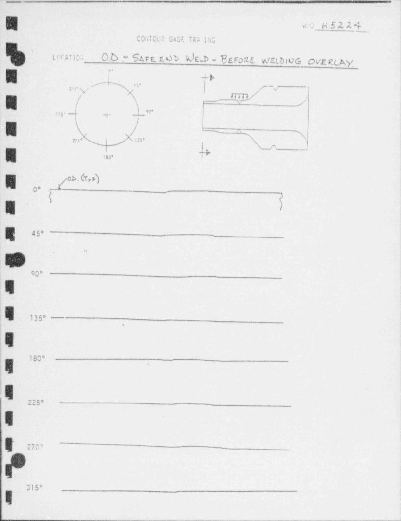
~_.
'
W/0_ H 52 2 4CO: HOUR GAGF. TRA 1713
'
LorATICa 0. 6 - S u t. r. o b k) ELD - 73EFoTLE v/ELDIOG OVE P4Ay,
a r- ,Jtia e
i
-
y r --- j
E'no - 3
2'5< 25',
g *,...
E / "' *")o._
E I
e <s-
.,.
! 90'
,
1
I135'
-
;
I'
180*4
j
1 1
225'
Ii
|' 270'-
?315*
I. _ _ _ _ _ _ _ - -
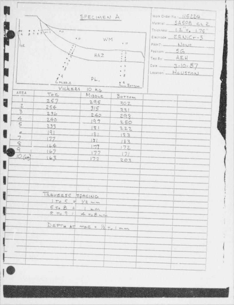
- - .. - - - - -- ~ ~ ~ ~ ' ~ ~ ~ ~ ~ ~ ~ ~ ~ ~ ~ ~ ~ ~
|I ~
I SPEC.IntO k #' ""i,.
~
M in;,n S A 508, c_ t. P_ l
1mme,,: t . 2. 1. i.w* ' ' * ' ' ''{( , 5 !-
Electrode- ESU5C"~3>
\ %f Me so
. to PWHT: Uow.- Tot |:
Pos tion * bMf h4RA2 7,3 3 y:1-
,
.[3-ID-87,, osie:
*ttom,on; >J w sro u. v
! ,4 . s
__ [miw e.PL,
,qu s.m
V'tr k.tr_t.s 10 k.c-,AREA ,
toc Minue t ;
Ee r s, % ! I
,
I | 247 29c l ac tiE Z. I 254- 3If agi|3 274 240 299 I)| 4 240 i 19 7 150 l1 ~5 2.33 171 2. 2. t |
. l 191 l #91 | 19 9 I| 7 | 17 7 ! lYf 193E '|
9 | - i t c. IM 1 7 2. l I4
,
9 1 167 177 | (7/ | ji' rlO /.d' ,I i G ,% I t77 t zos I | L;g
| | jE I I I I I I
,
||||'
i l-
l 1I 1-
|1 'l
Il l |
.
:IITiavec.se boncioc, I !
I|'
i i ro s =l v: - 1I i .)I l S r. a d
I lj |l- 1 -I e to 9 :I A vm e - ~. 1 1.,
i ;,
b E.WM A To C. /k;
To | m% (| |
| | l|
,
'
lI i
-
j | i-
-
1 ; .
|, I b I |' ' 'O1
::
f.
_ - . _ _ _ _ -_ - _ _
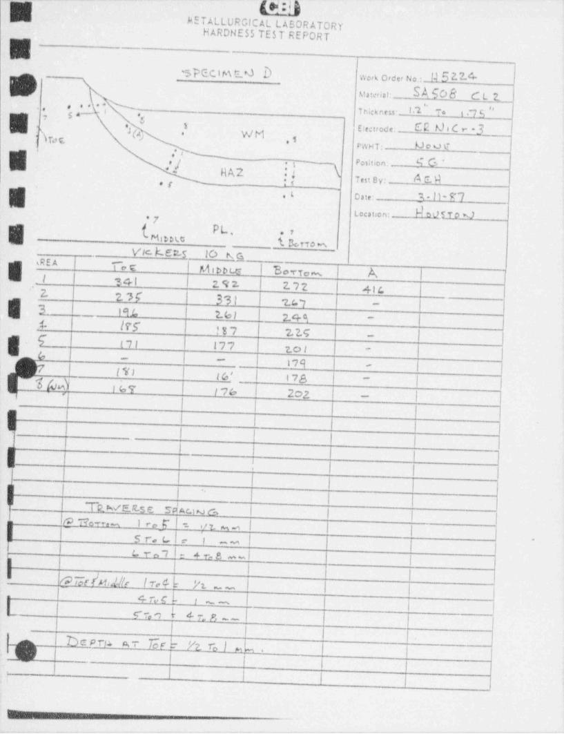
_ ----
{"'jMETALLURGICAL LABORATORY
HARDHESS TEST REPORTq-
j,
I3 p Q C,1 M E d h
C \ work Order No.: 1-152.2A-i'") Materist: 54608 cuz,..(, ,
asThickness:- l7 T* I75r' ; 5#~ *5 __
Electrode: U N 8 C " ~3-~_s \
A)*
1PWHT: U O O l'*
*8Position: $b'
ff \*
HA2-
7,,i s y: ACH*f'
3-h-K7,t o,i,:
Loca tiorn B Qi T O d7
(Mitne PL, .7
_ t Bc.rTo wVic h E ns 10 k G
(REA *{~,q !,
pd t bb W 30TTom k |__ f 341 I 19% 172 4 t t. |'l 23f 331 1M| 3-
__ ML 2.61 2M |
|-
_ -
A. 175' 'E7 2. 2.5 I
E_.f-
t7l 177 tol6 |-
- -
179 |-7 (7) I tv i 176 |i E' T (ed
-
i ro v 176 | 202 I'l 'l i I
-
ia | I Iq l I l | |
t I
J 1i i l | || 1 ! I l |T
I I li 1 1 '-
| 1 IY T a v s .s e s e c. ~ c , I I I I!; /D *ITo-tr,% ) r c. E t e/ t % e | | |S r|L 1 e- i '|
|.
! c. r m , 6 4 r- a - I$ I
| I|smbs,2b t r& h Vt 1
| 1~ ~.
E c. n. c L.
i ~. _! Cre q b4 L P, - f
1 i
n B c p ris Sr TJr L- h to J4|! )
,
l_
_-i !{
i
m_
e==+ 4

~ ~ ~ ^ ~ ~ ~ _ _ - - - - - - - - - - - - - ~ - - = . ~ = - - ~ ~ ~ ^ ' - - ~ " ~ ^ ~ ^ " ' ' - ^ ^ ^ ^ " ~ ~ ~ ^ ^ ~ ~ ' ^ ^ ~ ^
HARDNESS TEST REPORT
- .__
S P E.c1 M.E d 31 I work order rio.: N 5 2. U- )"
Material: SA508 0.t E. . . . Thickness: 5'E D !'
'T 4 Electrode: M di d"~ 31 *7 N
,7 PWHT: "O #I
_ Position: b_C' 4
N A'7. Test By: Rcu)I '
,g~'
3 *ID -Date: -
N105 W ILocation:*w
*Ogacott '
t B vr ~bcFERS 10 KG
AREA~
- Tp f ,_ N ID E C. hm^-
t 38_7 3/J, 300 I,
7 2 56, 273 3/4 I
3 pp c., 227 274 I
r .(90 203 234~
/82 /84- /86(72 I?4 /77,
16 4 \ i95 203|p(")
.
' I_
i I.
.
: - 1 I
I __ t
I
|^ 'Tinv c.g.s el SP A c.10c'-i
1 - c, ei- d V7 - - |
I4. n C -- -*
5 Tc 6 r 4% 8MM| !
i
be.9TR Ai Toc =__b _Te i-
.
I7) | ':~ <s
4
'_. .._,,.,,. , . . ' i !
'- , . . - . _ _ . _ _ . . _ .
_ _ _ , _ , , , _ _ . _ _ , . _ _ _ _ _ _ _ _ _ _ _ _ .
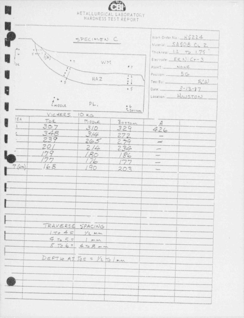
__
W
METALLURGICAL LABORATOGYHARDNESS TEST REPORT
I
$?CC l % E d b v.ork Order No.:d6 2 E du,ie ;,i; SA508 Ct E
. s... y$).. n ,, ,,, i . 2. - n i. 75 ..''j" #
t( \{ Elecrode: E R h)i d "" 3":w ,, r.v,m -c
.'|~
Position: 5CHA2 \ 7,,, s y; WA,
5 cate: 13-DLocation: NM 5 to *J.
E[m. EL-oca. 6
% r.~ 'Vic KE E S 10 KG
!EA !
It'
To t Po e ea L y re m ,4 |307 J/o 329 426 II 348 3/4 t 272 l ||t
-
1 239 26,5 l 2 79-
|-
20/ I 2 /4 1 234|
-
/79 I /Ro | /% i
*
'-
/7'7 I / 7/, /77'
I-
7M !.b_8 l 190 l Rom I I-
I 't I
-
ii !
I
I|
i L.| 1 il I l l |I I
I l I_
l l
~
,
! i'
'| TR AVE RS$ SPActAG l |
/v , 4 cl vt e- l I i4 r, s el 1 -- 1 I
.
I rc6=l sroni \| | |
be p r u A l i~ c = P't k i -'
1 I I '
il I l
n I |( )
_
lI
l I i

_ _ . _ _ _ _ _ . _ . . _ . _ _ _ _ - _ _ _ _ _ _ _ _ _ _ _ . _ _ _ _ _ _ - _ _ _ _ _ _ . _ _ _ . _ _ - _ - _ _ _ _ _ _ . _
Wb '
I METALLURGICAL LABORATORY fHARDh'E55 TES T REPORT ', ' aj -
i -E
i _,
work Order No.: N5E2 4[k> '* ~
m31.,m: SA508 Et 7_/.KA Thick ness: h 2- T~2 I 76 "4 .
| I I '. ' * 4 Electrode: ER 0;de- 3W
e7 PWHT: N o d'
| .' _ Fosition: bC7i
Nk2 Test By: MO MNf
5 Date: 3*l3'
!| Location; A tM TO d| g *
L [+*e ou. EL- *6L 9,r.~
Vjc KEC.5 10 KGAREA | yt | Plinetc 7,orro_ 8_
gt 360 1 30 B 264 434252- 30 7 ?*:d- 4r,q._ 1
a 3 L93 P &. 7 24 R 3/6 i
E+ 189 2 24- z33 2-70-'
'IS R I183 l96 25b~
[G /y,j_. l /R/ I /72 / F F_'
SfM /63 ! /90 / 9 '7 I I-
''l IaE I
_ l I
|E I I- .
| t i
a IE I
_ | I
| | | L I-
1 I i .
'E hv e we spacms Iu | iy, 4 1 yt__ |2
_ | e r, 6 : I 1 l I'
- - ~
,E g To 6 - 2 re s _ I I I I
i 4
|m , ,
!F i l i I:- i i i
.
i ,
"
:- - .. - -. . - - - - . _ _ - _ . - . - . - - - - - . . - _ _ . . _ . - - - . . . . . _ . . . . _ . - . - - - . - . - . - .
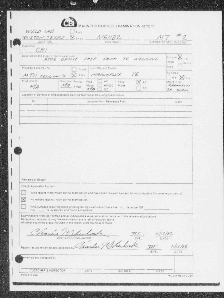
I--__-___-_______-____-_____-_---_- _ _ --- - - -
.is'N
I|M AGNETIC PARTICLE EXAMINATION REPORT
wsw ms D re,d
VOL'S@V WX/91 'Ssnap 'Wh$ 0 $ $,. g
|[(7^Vj L OC ATION CONTRACT REPORT OR SEQUENCE NO.
Customer
IDescript on and stage of items enam.ned
Outside kl))fC 6 G}f00VZ Nff AC'C8 W WSMWh C1 -snside L ) stems
Procedure and Rev No Prods U"d M'E ''d M C''
. N 0 | sffV).C/p W Y Y***?e 0,y
Prod Unit ID Prod Unit Raung Prod AC Yoke @ AC Mfg & Color
|Mod O HWDO Mode M A M 4 W u,X* Amps
DC/1 O DC IA DMLocation of Defects or Unacceptable Cavities Not Repaired During Enamination.
ID Location From Reference Point Date
_
l._
I|e(q
.
R marks cr Sketch '
--
Check Applicable Bestes):
Weld repairs were made during esamination and have been re examrned and found acceptable lancludes repair cavity).
No welded repairs made during examinati rt
Final surf aces requiring blend gnnding during uamination have bee , co . 3ieted per GRRev,. . re examined and found acceptable.
Examinations were performed and ailindications evaluated in accordance with the referenced procedure.Ostects not repaired during the ex amination are listed ey location above.All other examiner areas included in this repori were found acceetao|e.
b 3 av __W ?-- |O bOPE RATdRIEVALU ATOR '
LEVEL DATE
'R2 port results reviewed and accepted by-LEVEL DATE
,[\iview.ed and accepted by -' NY
ICUSTOMER'S INSPECTOR DATE AN6 OH At DATEe
Pneted m USA WL 244 REV AUG 81
- - - _ - -
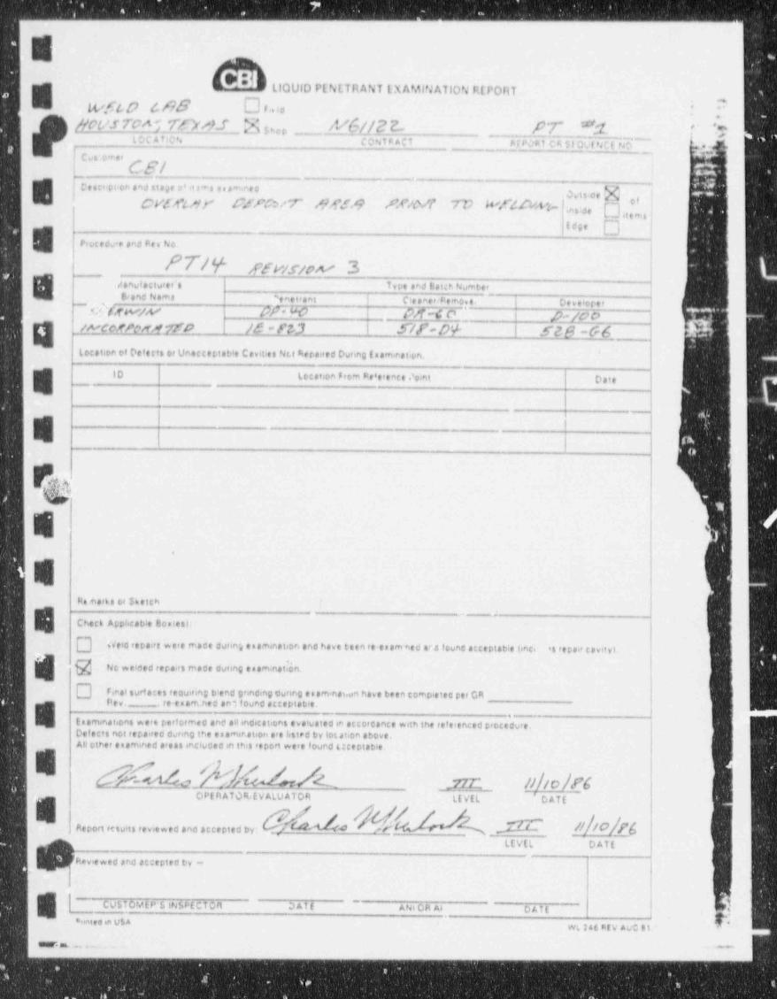
_ ___ _ . _________________ -__ _ . . . ,
:.E Ll0VID PENETRANT LX AMINATION R[F' ORT
*-
tyfw u?B Dr.ia i;
9 gwncM 7EydJpf uc, M 6//22- __ _[7* Y.1 'c e**
t Oc A sic >. cc w ac, negy, cw ou,a GB-c e .,
C S. I ._ i
,
E |,.
-
e,.ci.roonanditaaeo io - e.s ~ eae
ai . , g 'cv.m sr c.mcur Ma.9 AnM v v n e u ust 'i de- c
stems -
Prot tdu'e and Fe v No.
UN ffw.wk 3E
.
san iaciu,e,.. T,re and cauh Numbe,ue,andunma , et,a ,i t eiesee,a,e.no,e.
-
o,,e, ope,~
5|Yaf W/W CFR a2-c c> ^ ,6-soo' wcwungro M -r0 5/f'- D'+ S28-GS ___Location of Defects or Unsecettable Cavities Nc.t Siepaired Dunng iseminat.pn.
E ID Location F#0m Pe't'ence .'oint Date
I_
.
P@II
u.
Ramarks ce $~ etchn
8 --
Check Applicable Bostes):
] Weid repairs were enace curing es smanation and have teen re ea am''.ed er a founc acceptable (inci , *: repair cavityL
h No welded rerairs made during esaminatIon-,
Fieel surf aces requiring blend grinding dunng es aminas.un have been completed rer GRPev. - re esam.ned ani found acceptable.
E. Enem. nations wera performed and allindications eva'vated in accorcance with the referenced procedure.Defects not repaired during the esamir.ation are listed by location above,All other easmined areas snclucec in this report were found uceptable.
N |C h49_ - aOPE R AT Q4t V ALU ATOR LEVEL 'DATE
Report retufts reviewed and accepted by. ' 4
LEVEL DATE
IR* viewed and accepted by -
| ~ CutTOvtP's iN5PECTOR~
DAf f ANi OR At DAit ,
*rraita in U$AWL 2a6 PEV AUC 51
euer at . - . ~,
_ _ _ _ _ _ . _ _ _ _ _ _ . _ . . _

ULTRASONIC EXAMINATION REPORT
I uwez 6e d'U'7u "1
O ~[~CONTHACT F ei,10 Nhve''(e ho
~
VO'b Id {j 62 f E M CT kf P,4rtiag Het 1.e.eIJ E to'
''' '~Cocomer (, Q- - -
-_ ,,
*** ' m| I-- _
Description and stapt of itemt en ama.ed I I I j
I /) CVf/ftRy (2fPr5/ 7' Mf9 /W/#tt ~7c w/alw'h IC i f f| j ;
r) nroe circeav r.r.co s.nex -rc wruv.m s|1 i | ! !! !'
i l i l i1 . I' * |'
|Procedure and Re, No Coupf ant EWL
Iran 6dwcer I ! .|: * -
| !i.,,
' ! J 1 <Mfo g.afee ,,
Sae . 5 * X / * 1
t n s t r u m e n t M f g ,,pp, y,,,,,A,,,) ,y,o, gno;, 3 7_
I |_
Model # l$l*)& Stesal N 2)UOW h ; | | ) | * |* J b 'r.
Location of Unacceptable Indication 6 or other indications Atovired by the Procedure to be Recorced |
| Depth from I
f10 Location From Reference Point Defect Sier Outside O oai,
Length | Depth inside O .|I
,-
-
: I | |
| i I | |. . - - .
| I I.- . . . . - - _ _ .
"
.O Remarks or $ ketch
1
I
I..
I Enaminations were performed and evaluated per the referenced procedure.Unacceptable Indications found Yes O No 3
,
Unacceptable and other indications fecuired to be recorded are hsted with tneir location above.
I All other esamined areas included in this report were found acceptable.
' M d --- 0 |b / 9/ $$ || /bCPE R AT OR Liv (L DAfC (V ALVATOR L(y[L Dayg
( beviewed and accepted by~
k.
(vgl oset R'S st[YCf0R DATL Art s b an A4 DaTE
I. _ ... .. _ ..
1. ___. , - - . _ , __ _ _ _ _ , - -, _ . . _ '
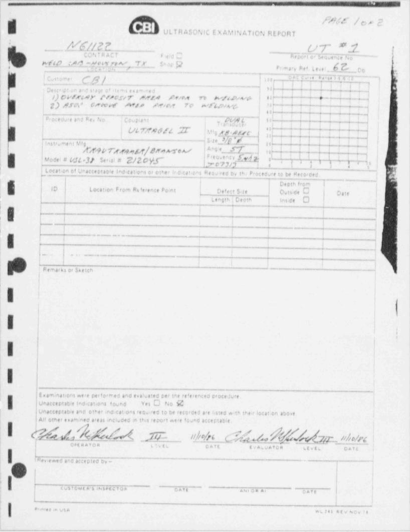
.--__-.. -.~- ----- - --
i
| <WS / O r 2ULTR ASONIC E X AMifJATIOPJ REPORT ik' I
2'dal?I'e00't c' Iew_e|n6 e No1I i2T; CONTRACT f (!c C
|, Ff98 61 ~dCjl(%f. 7# IN' }2"
-' Primary Aef L e et b te . i
!c= o u c .. . . . . ,. 3 i s a q ' '
CS/- "';
| i i j i !'
', , i i* ,
te' Delc'>Cla n an0 atJif o' 'It" l e t ave d1
| I I I l i I I i }| }) CVffM" N/C.5"/ T bY/A $ Y/f* t O W*NEW$* 8 ~
i k\ s } \ | 1 !& jdfC*, * CWWW N/P Miraf ?C' We"$O/Wi'- 8 h;6 g | ;
| 1 l f | | | | !Pect edste and Fev fm | Courtant -br 'i j i } j i ; ji }{ Tr
l./L 7n M G /4 % '{IL!'|| S a c_'f */
!. t i ii' it."g sp*Srsc2
i I i iii|n|L iInstru ment Yf 9 |
| | t ;1st*,ppp7'ggg4&Le ?A.s*cA./ #"9 '- U.-n
_ _ . . n{ { ; 3-- |-fModel # M[[ *M ber al ** hdMf[ fA | ja' 0
!
$ locat+on Cf Un4CceDiable Indicatton$ or other 1r cbcat.cel HeQuired by th, Proctdure to be Recordtd.| V
i
DtOthfrom hID location From At erence Po:nt Defect Sire Outste C Date
f
Ilength f Cepth innde O
|| | h | | | | |! E I I ! t i
..
|
| i l I | j|| 1 | |_. .. _ _ . . . _
i
i Remarkt or Sketch ~
l,
i I1 i
6
!Ii
E,
r
Enaminations were perf ormed and evaluated per the referenced procedure.'
Unacceptable Indications found Yet O rao EUnacceptable and other indications re sired to be recorded are listed with their locat:en aboveAll other examined areas included in this report were found acceptable.
(Yd.a &h$N< )U~ //|tcAG &;{a% hk7(2- nbc/pg_
C8'f A A T O R tiveL CATL (/ALyATOR ggygg pagg g )
Neviewed and accepted by-
!| C V 5 f C,vt. V b #N but C T O b OAT 8 ANi OR A6 cafe*
j
.!| ... i. . i, us A we e., or no, ,,
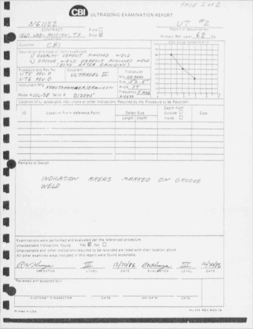
, , ,Qf .$ t'f $['
ULTRASONIC LXAMINATION REPORT
I| WGUC3 UT "2'
.o
i| CONTRACT F eld C ~7 e por t cdE e nt e N o ~
p,, mpy p , f L ,, e t ,__f_, pg,[[49 (d y 'i N bh0p N-
i- o m. . . . ., . . 4 a ,
Cuttemer (g/ j j j j | j ; )3"
q
f Despipt pn sad stage e-f ,te" e n aw e d i i I f i i ~i~~"
<
}} eV?fs&Y' ('f f N / T //A' mfd Wil O $t j R| | | | - | || :-) Gircov: wrip prreur n.w.two wtw "* T iN i i7] i
QCfM M/Tf4 GoTa4%?/WJ .) O '
Frocedure and Rev No Couplant H~ j -- ~] ;; j |,
'
**"' I'?----%|!=-
L |
-
|i ()'T* " A'fn 0 bit ys,.qggt fS se
u yg ggy, o h"e ne'-"!?! n - ! ! iSite .f"X . 5', I ! I
I 5'O'U**' ,k'fgpfxyg,efggggt,y,e,vf ps,,o Angie_ 3 7'"_
I !| Freovency.S~q], , ,
|Model # v.56,"4f' Senat # $/?pydf' j3 j' j j /
a ' 8,ygg ,,
i location of U-acceptab!c rnai,uions or other indications Reavited by ths Procedure to te Recordetn
j Depth from ;
| ID Lout.en Fra n deference Point Defect $ ire Outside O cat, !j Length Depth innide D i
4 - ._ _ . .
4
__ __. 1
l | | | $
.h l !____
! I I I
Remarks or Sketch
j M'DM7MY M4595 ^M74'4'50 OA' Gn'ao yg :
| Wft.D l
,
! !
j !
!s |-
Esaminations were performed and evaluated per the teferenced procedure.Unacceptable Indications found Yes @ No O
! Unacceptable and other indications required to be recorded are listed with their location above.All other examined areas included in this report were found acceptable, !
| 6 $ _$ Y&'b 24 ''
J;
c<...e. om e.1c e m a,on mm e.,,
ii et..tw.d .n amep,ed ,_-
_ _ . _ _ _ , ,c .
;
e. .r . . ._ a . -.:_,a,
1. k
*
J
+r--eerwg,- -m..,*-,-rw.-v+r,,--+y.---..,__ ._m.,,.-----,--,,-e.---,.e. . . - - - , . . __
,-===--=-*==-~n - - . - - -
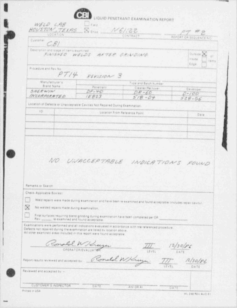
. . _ _ _ _ _ _ _ _ _ . _ _ _ _ _ _ . - _ -- _ _ . _ _ _ . . _ _ _ , __
Ll0UlD PENETRANT EX AMINATION REPORT''
,
g was MS O ou'
anysrc% z;om k,, /vD|2 ej LOC AT ACN
_ 17 * e ,CONTRACT Pf eOni C N floulidi ho
Customer
CS/ l|Descr rt on ene stage of items eaawee
' nV/SN!O M44,05 o f W <1' f & ' U O'' Y f o,,,,g, yf
!C0 ',i
C ,i, r..il'' $ ic e
.i
o ..jfue,
Vrocedu*e and hev No,
EfV/sww 3 |
Man f actu er's Ts re and Fetch N;mseru r
i B'and Name Fe ne trant i Cleaner /Re.nover Oesetope,
|I .5NE,f W/W Dh W | f)N =50 [)#/00 )&VCDRPMMfD /E823 | S/B-DY SCB-GSLocation of Defects et UnacceptaVe Cavities Not Aeraired During f aamination..
ID tocation From Aeference Point I Date>
I'
|.
!
4 .
/VO (AV/?CCSP 78866 /A4/C# T/GWS /GtwDi
nemeni or neien
Check Apphcable Boalesi:
] Weld repairs were made during e aamination and have been te esamined and found acceptable bncludes repair cavityLNo welded repairs mace during e aamination.
] Rev. Final surf aces recumng blend gnnd,ng during e remination have been completed per GRre-eaamined and found acCtDiabie.
(samination$ were performed and allindication$ evaluatedin accordance with the referenced procedure.Detects not repaired during the esaminat6en are b$ted by location ebove.Allothee taa%ned arealIncluded in thiS report were found acceptable.
,
Y p ? [OPE R A T OR/E V ALU A T t il LEVIL DATE
5
Report results reviewed and accepted by: *
# LEVEL DATEl
Reviewed and accepted by -,
e
{ CUSTOVtR 5 6NLPECTOR DATE ANI OH Al DATE~
,
PsmteQ m V$A| WL 246 R(V AUG 01\
===
.~.._-.-____.-.-.,_,__,___,.-_..,_-.._._,,_.-_...,_..-r-_- _ . , . . .m . .,,..r,. . . _ _ _ , . , _ . . . , _ - , , - - .
, - - - _ . . __- _ _ _ . _ . _ _ _ _ _ _
- -.l
3
h,-
*,
!W Appendix v
,'~ Procedure Qualifications
,6J
' '' "P '1. Code case N-432 Groove - PQR 7673 ,5,
?. Water Backed Noz 10 to Safe-End overlay EQR-7717-
' W 3. Non-Water Backed Norne to Safe-End overlay-POR 7718s
J,.
'
L.
N
. r.,
1.
M*4
.
;|e'
, N!
P ..<
N
| ~l
!
||
5. -
|
Ei
. . . . .. - . - - - _ _ . - - . . . - - . . . . .- ._ --- .. - -.- . - - - . . - . _ .- . ,1
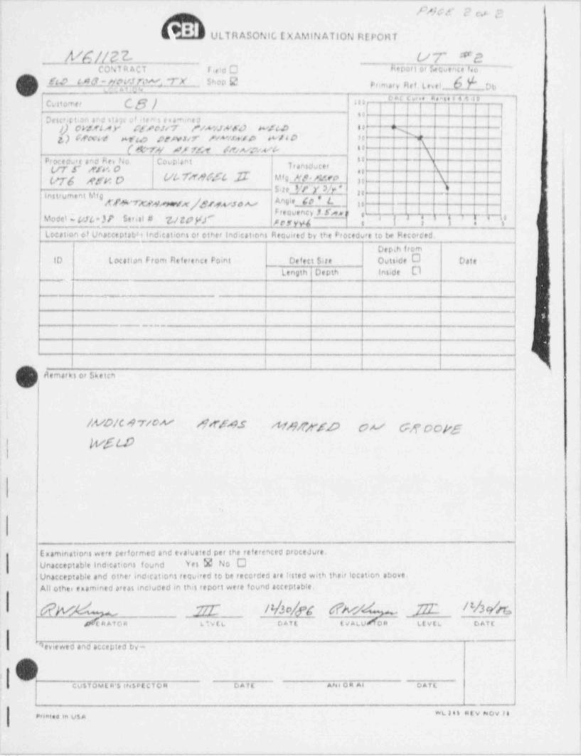
_ . _ _. _ _ _ _ _ _ _ _ . _ . _ _ _ _ _ _ _ _ _ . _ _ _ _ _ _ _ _ _ . . _ _ _ . _ _ _ _ _ _ _ _ _ _ _ . . _ __
h/5/' c? cv &'dE ULTRASONIC EXAMINATION REPORT
A%jn3 ur "eCONT 4ACT r eia O EE R 6 Ncue M o -~
Prtmary Ref Lese Y__Duft? t AG_ f'qt'JfsW'TX Shop CJt
|
Customet C8/ | "{""" '"8";
,
"Driced ton va uay v itera eommes | | j y
|} CbML A)" ff/CJW /VMJA'fd WitD Ct Y ;|g) f#xt / Ws.o Crn14 H"u a e i+14O 't
| Q |[ey n r.cr /,w.~.wp a
; jx ;Prxedure and Rev No. Coup: ant U
\. I |Transduce' I''g y ,yy, p y
[g ggy Q U b Yr W | $ $ $ Mf g N/T* /LWO | \ IyS tel'r._.y W \ >,,
Instrument Mf9d'$&*TKfA Mx|$/4<sse As Angle _ Co L_ _
.|et ne
Freovency S S'n e s-
Modd w VJL *)? St[el # '&/ w ff" p g, y yf ,e
{ jk \'] *|J
Lccation of Unateeptab81 Indications or other Indications Required by the Procedure to te Hecorc'ed.
Depih from10 Location From Reference Point DefectSire Outside O osie
Length Depth inside 0,.
, , _ - __
|
|
I I
I I-
: .
g
riemarks or $ketc*i
||<W|C 'i 7/W OSA.S A fs y/j y' f p pA/ gg 9pj,gt
WSt.D
,
Enaminations were performed and evaluated per the referenced procedure.Unacceptable Indications found Yes 2 No OUnacceptable and other indications teauired to be recorded are hsted with their location above.All other enemined areas incluced en this report were found acceptable.
Ghv 2 nb/n c1 w L =D C !%k*ERATOR LIVEL Daft (VALU OR LEVEL DATC
J9eviewed and accepted t>y-
4
4
CUSTOMLR*h INSPECTOR DATE ANs 04 Al DATL
"I # 'IPrinted in US A
_ _ . . _ . . ._ , . . . . . _ _ , . . . _ _ . . . _ _ - . . . _ _ _ .. ._, .- . - - - . _ . . , . _ . , _ . _ , . _ . . ~ , . . _ _ _ . . . . _ . . . - . _ . _ , - . , . - , _ - -_

u
r,pC or ti s ci
FROCf DURE QU AliflC ATION RtCORD
lo A S M E Se: tion ix
FART !!! WI LDING V ARIABLLS
f0*~~,- - -
;,p
'Ii
"xv:iNWwNIN, - ,
7= -
t,,3,s,c ;< >,
'' t 's , j"
n .s .. , ;s ,,
*) . ;N o , - 61*
f g ; _ $ IN 9
J. I"
1.1 j/s /' 5-3/10"*-
r 07)F y/' ''
,Vn/
#\ te /*(Safe End Side) 'ssf /'
d_ s,
. /4" .1.
k'
r
SG P051 TION
OvaHUcation No. 7673_
hm I u/x~Alan E. Hudson2/18/87 gyDate. _
/
's -
- . . . , , , . . . . . . . . .
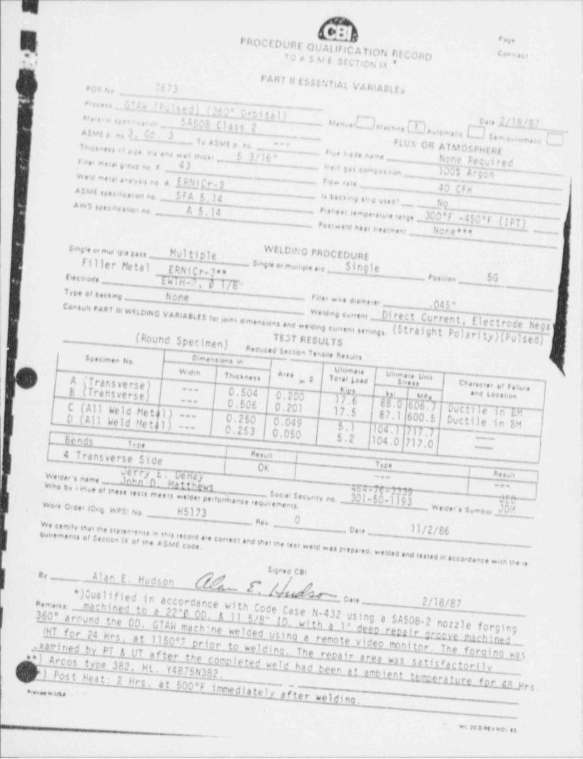
_..__ _ _ _ _ _ _ _ _ _ _ _ _ _ __
g. . , .
FROCCDUHF OUAllTICATION RICORDComrect.Y, to A 5 M !. ItCTicN n *
PART U L SSENTIAL VAmADLisr a n u _._ _
u.n .EG l * dLW ? Ort i t a l i_ _ _ _ _ __ _ _ _ _ _ _n
v.,,, ,, u , ,e., r fA!O3 CI355 2AIMER ec 3* C' 3 .
v.i[]>.*,em . [R,e,.au []raie ILIM 7u.nt. .m.m.a []
To A5vt r nce __Z_ FLUN OR AlMOSFHt Ht'18 aren u p 3 e e . ,ne.n ts.cu f 3 / I6 "_
i< ace na ,f6None Ee:;ui reds.n , r.i.i s,e r no r 43
.e
.. r . i p i o,.u u r IUU'' #'90"
e
w . o m e i,i ,,.., ,-.
ERNicr-3 . ti r. A 4.,.i.......
. _ 40 CFHA sMt u-umor en no. 5TA 5.14_
i.t.o m ,u,, e No_
Aws u n s.o n.n no. A 5.14.
p , , r , , , ,, ,on , , ,,, , , r g , 300'T-450'T(!PQ.
.
_ r im.ie n.n i,,n+,ni . ,. No n e * "e
c.nsie ,m r:e o a _ Multio1e WELDING PROCEDURE
. I
I e v
! filler Metal ERNitr-?**_ s m,,, ,, m n y, ,,, 51ngieo
!g ,, n ,,,, _ EWiH-2, 0 1/P _ ,,,,,g,, 5G
,
ktyn et tuung _ None _ na,, ,;,, ,,, ,,,,, _ .045"Coaswa PART in w*LoiNo VAntAett5 fo, somt o me
nsions enc .e'eing curreni uninst_ w,ie,ng,y,,,n, _Di re c t Curren t , El ec t rode Negi.
.
i ~ (Pound Specimen) TEST RESULTS (5tratght Polarity) Fulsed)p.evue z,o.en T,no, n! 5 " i"' ' " "'' L ca.n .on. inI ovni5 i~I ] un m.i.w,ois 1 Ts.on n l ^'" I"'' '"' { vn m.i. unoI
A 'TrarsverseI 2 '"'"! I in en,,n,, e t r.ao,. I
B kTransverse)) (|| 0.504 |0.200 ; 17.6 . E B .O EL_L k
un .!6 M* .no too oon--
! | 0.506 | 0.201---
C ( All We ld Me t A l ) ---7 Ductile in c,M17.5
~ D ( All Weld Me t(1) -- 0.250 | 0.049 ( 87.1 600.5 Ductile in EM5.1 T04.1 TFTT~ {_
0.253|0.0503 nds ' 1re. ( 5.2 (104.0 717.0-
-
I puun | (1
I 4 Transverse Side\ | OK
| ! r4 nun 1T.c.
Jerry tJnkn n... Uehayw,1ce, . n.m. _ -
Matth_eys W Cr3779 |w se dy sino. . in ---
n in a m..ii w iee, reform.nu ..._un ,e,,i s,,,,,,y no. _301 -50- 1 19 3so JP
Week 0,0,,(0,,gs WPfl No. _ _ w,3,,, , s y,n eo, Mv .nii.
_ Rev, _ _
Qvietmenit of stCi4on tx of he AsME codw. c.ns, in.nn. nven. nu :n in . ,eeo,e ... we.o ene in.nn_ oa t e ,,,_
t
eini ..ie w n c.. n..o. ..io.o .no u.i.ein .cce.
o,e.nu ..in is. ...s,gn.e cese,
_ Alan E. Hudson.
~ ( / dee,m.a.:._Ilshhgito a ?2"O 00. $ 11 5/6" 10*) Qualified in accordance with Code Cas
o,,. _ 2/18/87
e N-432 using a SA508-2 nozzle forging _360' arr'und the OD. GTAW rnachine welded u i, with a 1" det2 rmit 4;rmtmr110tL.lHT for 24 Hrs, at 1150*7 prior tos no a remote video monitor. The forcin* * }_ Arcos type 382. Ht ..xamiteed by Pi & UT af ter the completed wald had bwelding. The repair aret was satis faclorilm*,
.
v
)*)PostHeat: Y4875N382.2 Hrs at 500*F immediately after weldinoeen a t emhient . t'Frer.Lture for anJrs_ _ _ _
.
9e.ee n UU. _
'
_
'
Wt200D(VWOiil
-9--W-'# pT&'.H# yeve*- ^ .me "# ,,,dTE"*''
_ _ . , _ - - - - - -

. . - -..- ._ - .. _ _ _ - . . - - _ _ - _ _ _ _ . _ _ _ _. .-
E ir ;,ei
Centeon
PROCEDURE QUAllFICATlON RECORD
To A.S.ML Sectien IX ),
'
i*PART (11 WELDING VARIADL ESll
*
)ss Number 25-27 28 29 30 31-34 35 36 37-38 39 !40 41'imary Weld Current (amps. ) 200 210 215 210 200 200 200 200 _200 200
3'
ekground Current'(amps.) 100 110 | 115_ 110 100 100 -100 100 300 300!
. t Dwell (primary)(sec x .1) ' ' ' - - - '
-]-' -
!gpursion time (sec. x .1)
!- - - - - - -
u Owell (primarv)(sec. x .1).
|-. .
- -
_- - - -
I- -
illation (in.) -
- - - - - - - - - -
mary Wire feed (IPM) 31 31 31 31 31 31 31 31 31 31 1kground Wire Teed (IPM) 21 21 21 21_ 21 21 3L__ ll_ I 21 . lL|'ej (IPM) (Torch Speed) 4.05 4.25 4.92 4.92 4.92_ 4.74 4.92 s.09 4.923dLo_.
; ary Arc Volts 9.0 9.0 9.0 I 9.0 9.0 ' 9. 0 9.0 9.0 9.0 9.0 Ig, y round Arc Volts 8.5 8.5 8.5 8.5 8.5 8.5 8.5 8.5 _8.5 | 8.5' Heat Input (Xilojoules/in.) 21.02 21.31 18.94 18.41 17.33 17.96117.33 16. 74 H. 33 |16. 74L
| Energy Den:;ity (MJ/in3) 1.93I2.05l2.12 2.05 1.93 1.93 1.93 1.93|1.93 |1.93,J
Pass Number 42 43-48 49-56 57 58 59 60 61-62 63 64'
'rimary Weld Current (amps.) 210 200 210 200 210 200 220 220 220 220 <iBackground Current (amps.) 110 100 110 100 110 100 110 I 110 110 .np, ;'lut Dwell (primary)(sec. x 1) - -1 - - - - -
-
. ;xcursion time (sec. x 1) l l
-
,_
;!nDwell(primary)(secx1) _ _ _ _ .- - - - - - - - -
{_scillation(in.) - __-
!-- - - '- - - -
' rimary Wire Feed (IPM) 31 31 31__ _31 35 30 35 ' 35 1s 38
_
_
iackground Wire Feed (IPM) 21 21 21 21 25 1 20 25 29 ?s 2R|-avel (IPM) (Torch Speed) 4.74 4.92 4.92 4.48 4.48 4.92 4.64 _4.91 4.64 4.64! *imary Arc Volts _
9.0 9.0 _9.0 9. 0 9.0 9.0 9.0 9.0 9.0 ; 9.0'****1round Art Volts 8.5 8.5 __ 8 . 5 8.5 8 ._1 8.5 8.5 8.5 l 8.5]85 |ut (V.ilojoules/in.) 19.0P 17.33 18.41 19.00 20.18 17.33 20.18 19.0N20.183 20.18. ergy Density (MJ/in ) 2.05 1.93 2.05 1.93 1.79 2.00, 1.84| 1.84'l.84 1.68!
( ,,,,, QUALIFICATION NO. 7673DATE 7-1A-A7 av , , , n ,g ,,, n
- - -.---
. _ . .
g- . - - - - .__ - - - - . . - _ _ _ _ _ _ _
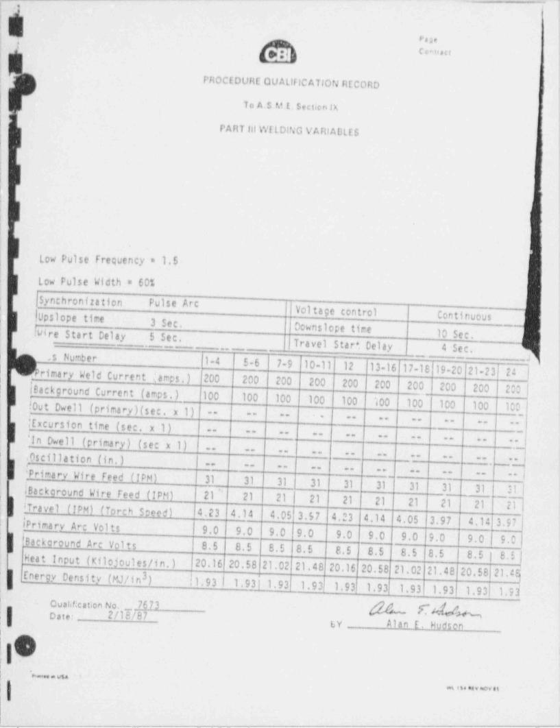
._ __ _ _ _ _ _ _ _ _ _ _ _ _ _ - - - - - - - -----
! ..,
j Page
cc-vectt
!;
PROCEDURE QUAllflCATlON RECORD'
'
!
To A.S M E. Sectien lX;
I
|,
PART 111 Wf LDING VARIADLES !
! ;
\
!!
i
!
;
i
|
\
o-
Low Pulse Frequency * 1.5
! i
Low Pulse Width = 60%
jSynchronization Pulse Arc | Voltage control} IUpslopetime Continuous
3 Sec. Downslope time! @ ire Start Delay 5 Sec. 10 see.Travel Star +. Delay 4 Sec.. __- -
. . _ _ _ - -
i s Number 1-4 5-6 7-9 '10-1 1 12 13-16 17-18 19-20 21-23 24 |. __ J_-
Ierimary Weld Current | amps.) 200 200 200 200 200 200 200 200 200 200 |
m,
[BackroundCurrent(amps.)9 100 100 100 100 100 100 100 ' 100 100 100j !0ut Owell (primary)(sec. x 1) -- -- --
!- --
{ Excursion time (sec. x 1)-- -- -- -- --
-- -- -- ~-- - -- -- --
'In Dwell (primary) (sec x 1) -- --
-- -- -- -- -- -- -- --| . Oscillation (in.) < -- -, _-
-- -- -- --_ _ _ -_ -- |Primary Wire feed (IPM) 31 31 31 31 31 31 31 31 31 31 |
-- -- --
) |Backaround Wire feed (IPM) 21 ' 21 21 1 21 21 21 21 21 21 21! Travel (IPM) (Torch Soeed) 4.23 4.14 4.05 3.57 4.23 4.14 4.05 3.97 4.14 3.97
,
[ Primary Arc Volts'
9.0 9.0 9.0 9.0 9.0 9.0 9.0 9.0 9.0 | 9.0Backaround Arc Volts 8.5 8.5 8.5 8.5 8.5 8.5 8.5 8.5 8.5 | 8.5 |Heat input (Kilojoules/in.) (20.16 20.58 21.02 21.48 20.16 20.58 21.02 21.48 20.5821.cdeEnergy Density (MJ/in ) |1.93l1.9311.933
'
1.93 1.93 1.93 1.93 1.93[ 1.93, 1. 9.i'
ovahl: cation No, _ 76 73Date: 2/18/87 ( A MN| Ly Alan E. Hudsen
!i O|
( *"8 * N
wg 1 $4 hf v seOV f t
11. - . - - _ _ _ _ __ - -.-_ - __---__ - ..-...-_- --- ___

_ . . _ _ - - _ _ - -- _ _ _ _ _ _ .___. _ ___- ___. _ ___ _ _ __ ___. _ _ .
mVQH140. J L''
!A1 W.o. tso. H5173
.
! . .' 3T ra ve rs e
] PHOCEDURE QUAUFICATIOfJ RECORD __ Spacing1-5 = 1/2nn4
VICKERS HARDNESS TE57 5-6 = 1m; 6-7 = 6 to 10m; ; 10 KG LOAD1W'
(Safe-end side) tin star-
7 s i e i s s pl/2 to 1 n,
k ,
i . . .... .. .... . . . - -
N- n ur a
n ..
.
g~ ...'
;g SPECIMEN A art,. I
'1..
' !.
(Safe-End Side)LOCATION LEFT SIDE RIGHT SIDE ROOT
-
'.I 386 408 315
f 2 362 417 300 ;
| ! 3 255 312 227
4 224 261 1981
j 5 183 188 180'
|, 6 184 184 181
7 179 185 184'
8 177 183 222'I.
,10 " " c &eom 2'>8'87 -
, :
;
U5a
. - _ . - - . _ . . . - . . . . _ _ _ _ _ _ . _ _ . _ _ . _ , . _ - _ . _ _ . , _ , _ - . . _ . _ _ . . . , _ , _ . . . _ _ . _ - _ - , . . , - ~ , . , , _ _ _ , _ . . . . _ , , , _ _ . - , _ _ , , _ , , _ _ . - - _ . - , - , _ __
-_
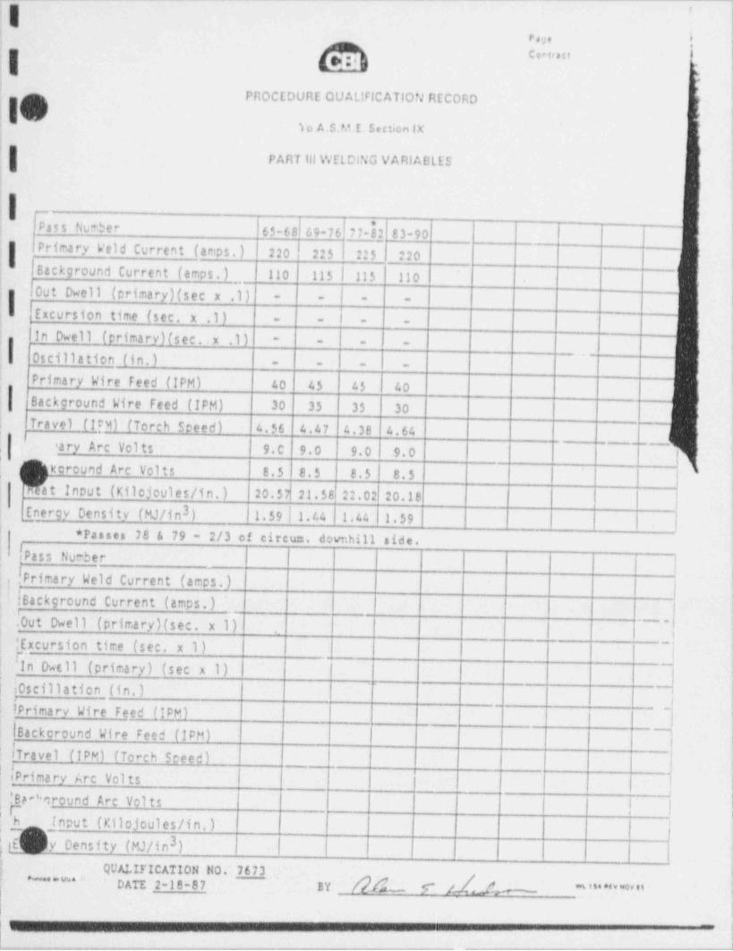
- . - - - . - - - - - . . - - - - --____.- -.
;Ir. . i ;
ccetrut !
15,
-'
PROCEDURE QUALIFICATION RECORD|i
i10 'c S o A.S.M E. Section IX-| ,
t
PART til WELDING VARIABLES(
,
4
i fi Pass Number 65-68 69-76 77-82 83-90
Primary Weld Current (amps. ) 220 225 225 | 220I
I Background Current (amos _. ) 110 115 | 115 110; -..
#0ut Dwell (primary)(sec x .1) ''
- - - -
,M '- - - -
j In Dwell (primary)(sec..x .1) - - - i -! 'i Oscillation (in.) _
|- - - -
'. Primary Wire Feed (IPM) 40 45 45 40Background Wire feed (IPM) 30 35 35 30
i
| Travel (I[M) (Torch Sceed) 4.56 4.47 4.38 4.64_
'ary Arc Vol ts 9.C 9.0 9.01 9.0 i
_,,_,
,
i
koround Arc Volts 8.5 8.5 8.5 8.5hdt Input (Kilojoules/in.) ;
20.57 21.58 22.02 20.18,
3: Energy Density (MJ/in ) 1.59|1.44 1.44 1.59 | |,
)_ * Passes 78 & 79 - 2/3 of circum, dovnhill side.! ass NumberP
|.
(PrimaryWeldCurrent(amps.)| | !,; fBackground Current (amps.)!
!
.Out Dwell (primary)(sec. x 1) - _,
J[ Excursion time (sec. x 1) ;'>
_I'In D4 11 (primary) (sec x 1)
(i0scillation(in.)>
--
! Primary Wire Feed (IPM)'
l
|BackcroundWireFeed(IPM)I
fTravel (TPM) (Torch Speed)_
tPrima ry Arc Vol ts '
'
!Be '*around Arc Volts;I !h (nput (r.ilojoules/in.) i
{3,t _ y Density (MJ/in )
,
QUALIFICATION NO. 7673'
[2A_ 5" /1Ae" * * * ' DATE 2-18-87 BY " ' " ' " " " * * "1 !,
'1
.,
. - - - - - , - - - - - .r,w-,--m,e,,-v m%,.~.w,-- w.--,,.w_.y. , , , , . --..% ,-,.-,w- . . , _ , - . - , - ._
_m,--- - . - - . -

-
POR 80. 7673
W.O. NO. h6l 73
PROCEOURE QUALIFICATION RECORD TraverseI _ Spacing
VICKERS HARDNESS TEST ," )h*I
-
10 KG LOA 0 6-7 = 6-10m
un(Safe-End Side)erst'
I3 7 s s i a i 5 6,
f-- 1/2 to im,
\....,
, . . . .... ,- ,
|- in ,n et
I s.
I s.:*
,
SPECIMEN O *,.
1.
IS(Safe-End Side)
LOCATION LEFT SIDE RIGHT SIDE ROOT
I; 1 384 390 308
2 400 395 336
3 327 300 264
4 230 243 211
5 211 200 183''
6 185 183 187
| 7 187 180 189
8 175 175 208
[ A-Alan E. Hudson
DATE 2/IO/07..
i
.. usa_ __
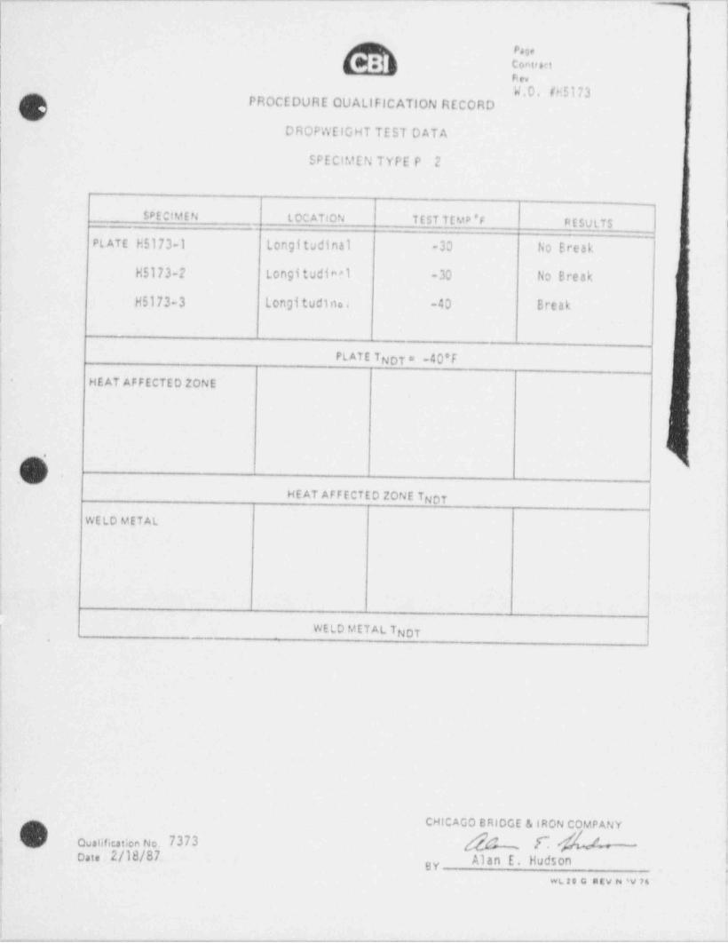
__ ___ ___ .- - - - - -- -
~=m~ ~)!
i
l!C rect
|nev
W.0. (H5173| PROCEDURE OUAllFICATION RECORD:
DROPWElGHT TEST DATA I,
:
SPECIMEN TYPE P 2
SPECIMEN LOCATION TEST TEMD 'F RESULTS I,
! PLATE H5173-1 Longitudinal -30 No Break,
) H5173-2 Longitudine1 -30 No BreakI
,
'
H5173-3 Longi tudi no , -40 Breaki
.| .
PLATE TNor = -40'F|- HEAT AFFECTED ZONE
i
|
|0 |
;
HEAT AFFECTED ZONE TNOT
WELD METAL !
|
;
WELD METAL T.
NOT
i
,
.|
<
1
iCHICAGO BRIDGE & |RON COMPANY
Qualification No. 7373 M f~ 4- ;; o,i 2/18/87.. Alan E. Hudsongy ;
WL,2 0 G R EV N SV 76
_ . . . , ,- - . _ _ _ . , . . . _ , ._
. _ - - . . . . _ _ . - - . . , . , , . . _ _ _ _ _ _ _ _ _ _ _ - - _ - - . . . _ ~ . - ~ , - - . . - _ . . _ -, .-
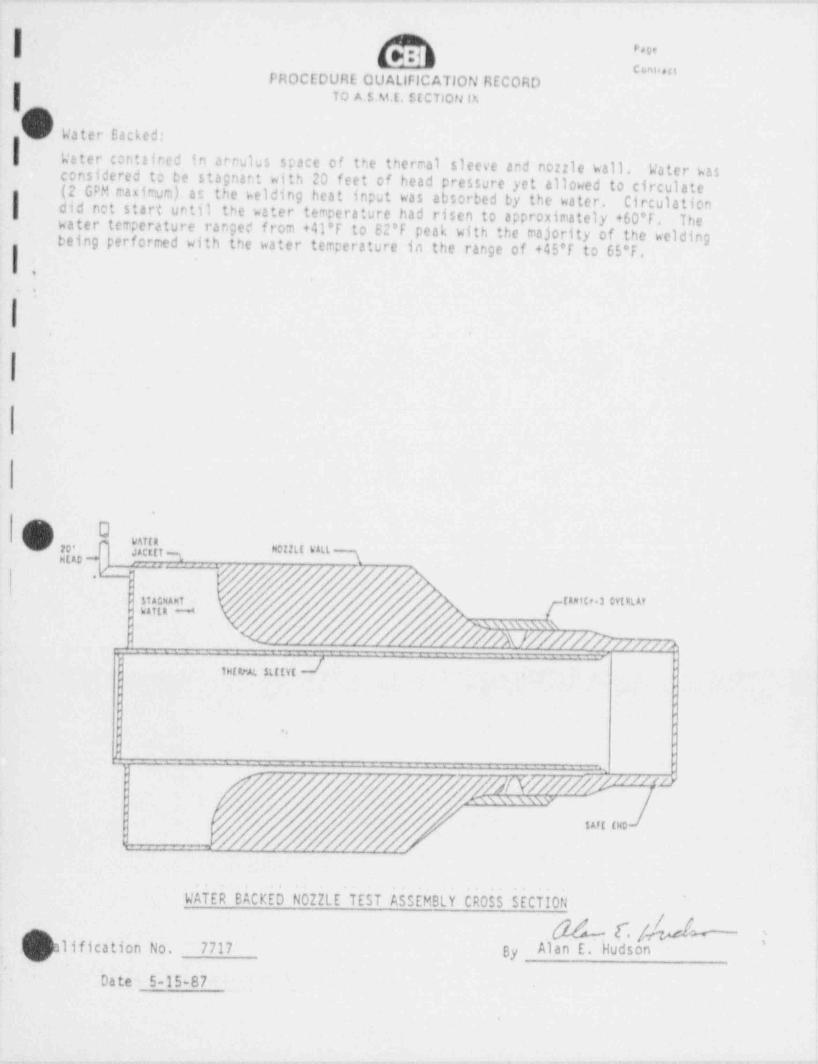
onn.ci
PHOCEDURE QUAllFICATION RECORDTO A.SME. SECTIOtJ P.
V Water Sacked:
Weter contained in arrulus space of the thermal sleeve and nozzle wall. Water wasconsidered to be stagnant with 20 feet of head pressure yet allowed to circulate(2 GPM maximum) at the welding heat input was absorbed by the water. Circulation| did not start until the water temperature had risen to approximately +60'f. Thewater temperature ranged from +41'T to 62*f peak with the majority of the weldingbeing performed with the water temperature in the range of +45'T to 65*f.
.
I
'
(~') I0
-- N IISI kAll ]A i3'
- , ,-
'
$tA*NAnt (Anttr.3 CytRLAYhAf tR W*
| ' . N AX \\ 4:Wh
f..=
/O/A}Y/////YJ////w>'
-..
,
dterarAt strtvt
|'
: -..
, -
A
r - j yjp p yj,i,/,j/j ////td: , y/ mxwwww
" ' ".
WATER BACKED N0ZZLE TEST ASSEMBLY CROSS SECTION
!'% l./ "i ,311fication No. 7717 By Alan E. Hudson
.
Date 5-15-87
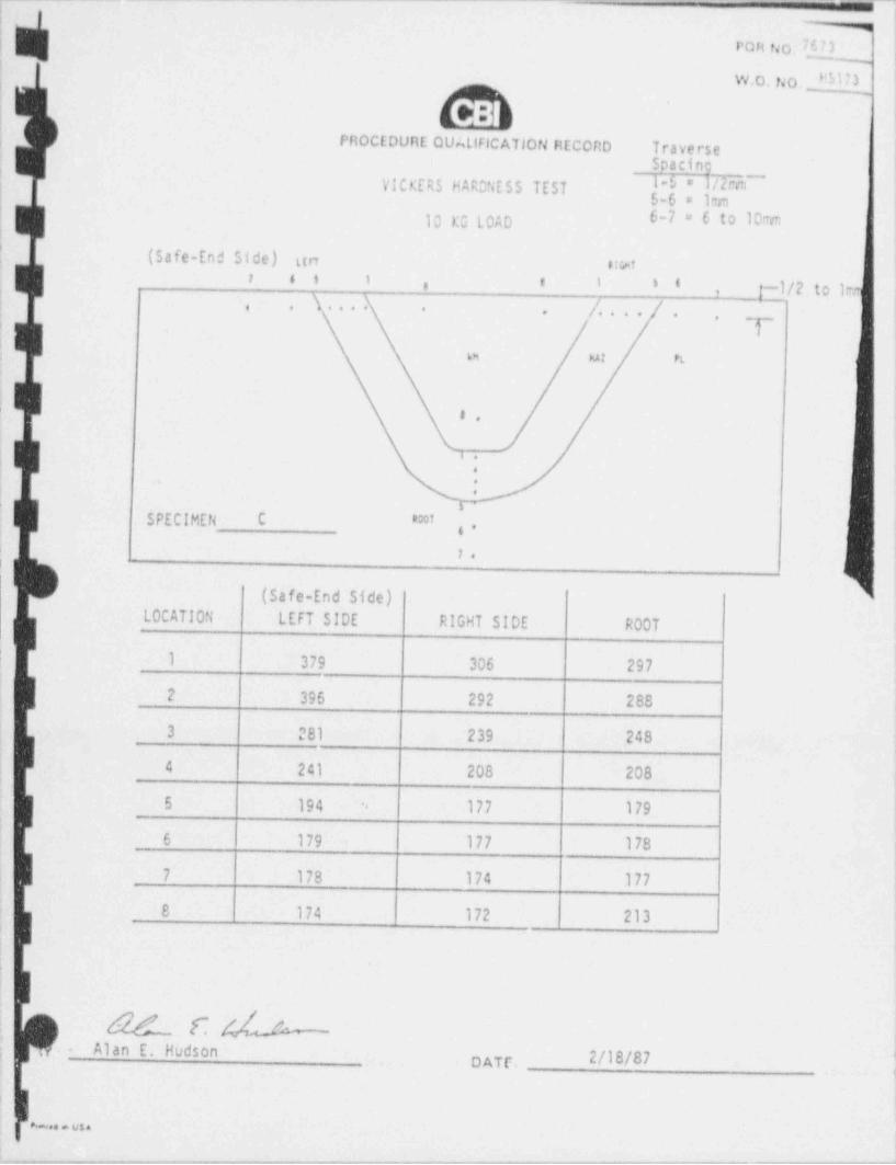
! !
| POR fio. { ,
'
W.O. No, __W U |
!<
;PROCEDURE QUALIFICA710N REcono Traverse
\
9 acingVICKERS HACNESS TEST f,~f," |
'
10 KG LOAD 6-7 = 6 to 10m'
(Safe-End Side) u rt wt!
7 5 5 1 * 1 5 ' j-1/2toImr i.
,s.... /. . . .; . . . .. . _r ,'
; a ut et
|
|s.
'. ;
} .'1
SPECIMEN C *,.
1.t
(Safe-End Side) '
LOCATION LEFT SIDE RIGHT SIDE ROOT
! l 379 306 297
2 396 292 288
3 281 239 248
) 4 241 208 208|
5 194 177 179-
-
I6 179 177 178
7 178 174 177
8 174 172 213|
I
,
- Alan E. Hudson_
DATE.- 2/IO/07
,
......
,.,--..,-..,y-~., ....--..y..._wmm-, - . , - . - - . . . , . ~ . . . . . , . _ _ . . . - _ . . . . . _ _ - . . . . - - . - - - . - - - , . , ~ , - . - - - . - - , , _ . ~ ~ ~ .

PROCEDURE QUAL!f! CATION RECORDTo ASME Section IX
PART Ill Welding Variables
b'i .
1
III
chronization Syn Pulse Voltage control Continuouslope time 5 Secs. Downslope time 10 Secs.
.e Start Delry 7 Secs. Travel Start Delay 6 Sees._ _
.ss Number N23 5 146 147'
Primary Weld Current (ar.:os.) 220 220 180 120
Background O' rent (amps.) 110 110 90 60
Out Owell 5, eimary)(sec. x 1) .3 .3 .3 .3I Excursion time (sec. x 1_) .2 .2 .2 .2In Owell (primary) (sec x 1) .4 .4 .4 .4
Oscillation (in.) .24 .24 .24 .24
Primary Wire Feed (IPM) 35 35 -- --
Backcround Wire Feed (IPM) 25 25 --| --
Travel (IPM) (Torch Speed) 2.71 2.72 2.72 2.72
Primary Arc Volts 9.0 9.0 9.0 9.0
Backaround Arc Volts 8.5 8.5 8.5 8.5Heat Input (Kilojoules/in.) 35.47 35.19 28,79 19.19
3Energy Density (MJ/in ) 1,g7 1,87 .. _.
| , ualification No. 7717Q g g/Date May 15, 1987 By Alan E. hudson
.
I-1
_ - -
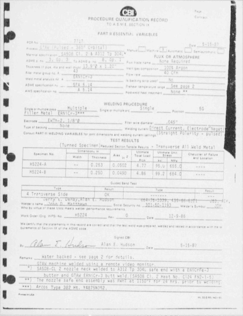
_ _ _ _ _ _ - -- - ~
n]tes j
* c r o.oPROCEDURE QUAllflCATIOf.' RECORD || TO A s 8.1 (. $(C TjQN is
|i
\jPART 11 ESSENTIAL v' A Rit.Bils
, ;
U17 ,
ocn t.orue _5 - 15 - E |Ftecess ci " (F;ite*" *L'0" trbit3I)'
I rT~ r- !Manw ays; M, * ne J A vt:<r at.g*
Se mi,9,e,mp t g gl iev., c are:n o.e, S A603 CI + 2 E A312 IP E4l*1
FLUX OR ATMOSPHERE fI 3, G;. 3 E' UN I t.cre Requiredesuse ,, b 4tur s no s u t,ne n.- e _in.cinen u 4 e. <: . .me o.1 mu 13 9 "0 X 1 2C" ine ,i s s -,.u s.t 4., _ 100t Ar, cone -
43) Finer reetal g> csp to f , 40 CFH,Jtiir-a _ ficev f oie
4 tr . _ _,
Weld metal analvs s nc A . . . . Is t sc 6 ng si,ip vs#0' - M.ALMt srec,#, cat.on na
. SIA 5.14irieneet iemrero.,re ange 500 Pace 2
____
AWS srecif, cat on noFest a eld be st t'est'r ent N000 ***.
,
l 1
WELDING PROCEDUREs,n e o,ensit#epass Multiple Single SG
| Filrler Metal ERNiCr-3"*3,,, ,, ,, m y m g , , ,, , ,,n _
tiectroce EWTh-2. 1/8"O!
r ,ne, * ,,e ci.m. e , .045"! NoneType of tecong w,,,,ng ,,,,,s, Di rec t Curre nt , E l ec t rode"Nega t i '
iCon:vri PART !!! WELDtNG VARIABLES for io,nt c,mensions and nocing cur <ent settegs.
|'
!TEST RESULTS
!, (Turned Specimen)n,oucea reci.on t,ns,:, p, suns - Transverse All Weld Metal,
:'
o ensiont in|to<aiLoen
vu m.te vn mue ua''Srn*en No Arn 5""' cnerocie, et reau,ew ,, , , y,,, ,,,, g , .ne toe t;,,
_ __.n,s sii uce
H5224-A _.,
0.253 0.0502 4.77 | c5.0 655.C--
| |'----
H5224-B 0.250 0.0490 4.86 |99.2 684,q--
----
'
ov.ees tend Tesi,
; , - . ..s, ,-. , .es, ,
4 Transverse Side OKi
| |-------
!~ ~
Verry t. vehay,M an i, nus:,an 64 7pt3M7-4996 5H1 ,20 , 4!H.---
We#cer's name M ''i h MntihPwt socro security no. 30l * 50-1193 woeec s,mou &sWho ty vince of tnese tests meets welcer pertorrr.ance reov,itmeats1
Work Orcer torig WPSI No H5224 O 12-9-86g,. e.,,
We certif y that t*-e statements in this reco<d are conect and that tre test wcld was p<ecared, weiced and testec in erecreance witn the re-overements of section tx of t*>e AsME cece
/ s>gnea CBI
M _ [~ / 4 j h- _. _. Alan E. HudsonE 5-15-87 j,y ,,,e- ._ _ . _
n,m ,,, _ Water backed - see page 2 forf teils.,
GTAW n ehine weided usir.a a remote video monitor._) SA508-CL 2 nozzle neck welded to A312 Tp 204L safe end with a ENiCrFe-3*
butter and GTAW ERNitr-3 bett weld. (SA508 C1. 2 Heat No. C124 FN2-1-5)**) The nozzle safe ena assembly was FWHI a t 1150 4 t o r 'ia h r s . p r icF t o we i d i n g .! ***) Arcos Type 382 Ht. Y4875N382.
e.,, vs.m so o .t. ac n.
_. _ _
. - - . . . - _ . - - - - . . , . - . - - . _ _ . - -.-- - . _ _ ~ _ . - - - - . . - . . _ _ - - _ _ - - _ _ . . - - - - ~ . - -- - . -
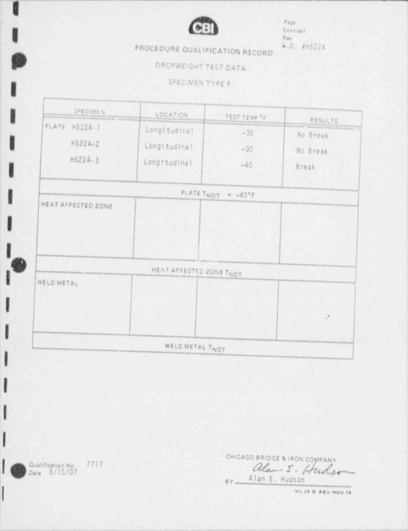
I#!h 1.,
I N tv
W.0. th5224PROCEDURE QUAltFICATION RECORD
DROPWEIGHT TEST DATAt
SPECIMEN TYPE P
iISP E CIM C- NI aL OC A TION TEST TEMP 'F PESULTS |PLATE H5224 I longitudinal -30 tio Break
H5224-2 Longitudinal -30 fio BreakH5224-3 Longitudinal -40 BreakI '
PL ATE TNOT * -40*f'=
HE AT AFFECTED ZONE
I
i t._OI
~ ~ m e " " ~v,._1 <
|..
. . . - . - -
WELD METAL TNOT-
.,
I.
il 9
ICHICAGO BRIDGE & IRON CO iPANY
.I Quahfication No 77I7o,i, 5/10/07 ' E'
'
Alan f. Hudson. BY-
wt se a atv Nov M i
l_ - . - - .- - - - - .. . _ - _ . - - _ . .
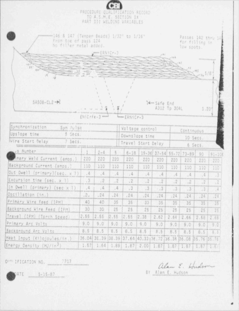
.
. . - - - _ _ . -
FRO'EDWE C #Lif!CAi!O'4 FEC: ?TO A.S.M.E. SECTION lt
FMT 111 'nELNN5 V RI AELES |t,
)
/ 1461 147 (Taper f ead:.) 1/32" tt 1/10" Passes 142 thru RFrc- t:c cf pass 124 fcr fillirg in |u ':11er retal ad cd. I N spots.N
L- EFNiCr 1% . >IN &d M ,.k- D7&&,. %---<- ,o 4__
I
/ NSY$$fENN.[fMN.-M* ,. -NM l [r. ->ENM-;d.~tsp N,v.,._% : g,.. .-:us - r -mu, ,,. ~ -r%;jf.-# 0 ,- . C --- - ". # c- 9 % ',9 I-
M t?.&' |;7G G ? = X M S ~; - M = 2 & % f ' e i
.. rjgn >
,s .
N- -
,s,
i kl (i
i / I i, ,.
i, ,t /e
S A!OS-CL2 -H \ ', N- Safe End..~
';
\ '; ' f ,' A312 Tp 304L 1.20'$
__4......- i ,l,i p
[NICrf t: 3 J LERNiCr-3 ~
,
Synchronization Syn Pulse Vol tage control ContinuousUpslope time 5 Stc5e Downslope time 10 Secs.
. Wire Start Delay 7 Secs. Travel Start Delay 6 Sees.1
.s Number [J 24 5 6-18 19-3f|37-54 55-72|73-89 90 | 91-1CE1 1
'_,,
I| f mary Weld Current (amos ) !220 220 220 220 220 220 220 220 220|220y
Back round Current (amps.j_,M10 110 | 110 110 110 110 110 | 110 110 | 110 ]i 9
Out Dwell (primary)(sec. x 1) .4 .4 .4 .4 4 .4 4| .4 ( .4 .3 |Excursion time (sec. x 1) - . | ,. 3 .2 i .2 .2 | .2 .2 .2 .2 | .2 .2 { l,
,
in Owell (primary) (sec x J L|_.4 .4 .4 .3 | .3 .3 .3 .3 .3 ; 4 !
Oscillation (in.) .2v .24 .24 .24 .24 .24 .24 | .24 .24 .24Primary Wire Feed (IPM) 40 40 35 35 -33 35 35 | 35 35 | 35jBackcround Wire Feed (If 30 30 | 25 | 25 25 25 25 25 25 | 2E|Travel (!PM) / Torch Stet.g |2.55 2.55 |2.55 |2.55 2.38 2.62 2.64 | 2.66 2.68 2.6S |iPrimary Arc Vol ts J 9.0 9.0 l 9.0 9.0 9.0 9.0 9.0 | 9.0 9.0 . 9.0 |
s
I. .J, - '
Backcround Arc Volts S.5 8.5 8.5 8.5 8.5 8.5 8.5 | 8.5 ! 8.5 | 8.5 | -1
',
- - - - . _ _ . _ . . -
Heat Input (Xilojeules/in.)_ - |36.04 3C.39 38.39 37.64 40.33 36.72 36.38 36.08 35. 76 |35. 76 |'Ener9y Density (MJ/in3) 1.57 1.64 1.89|1.67|2.00. 1.87 1.87 1.87 1.57 1.Dl
_
,
, O''" IFICATION NO. 7717
| N [. Yu!wEY Alan E. Hudson1 ATE 5-15-87
:e
|
|
| 8 I
, .-_ , , - ,._. _ _ _ _ _ _ _ - . _ _ , , . . _ _ _ _ . _ . _ . . _ _ _ . . - _ . . _ _ _. _ . _ _ _ . . . - _ _ _ _ , - _ . _ . .
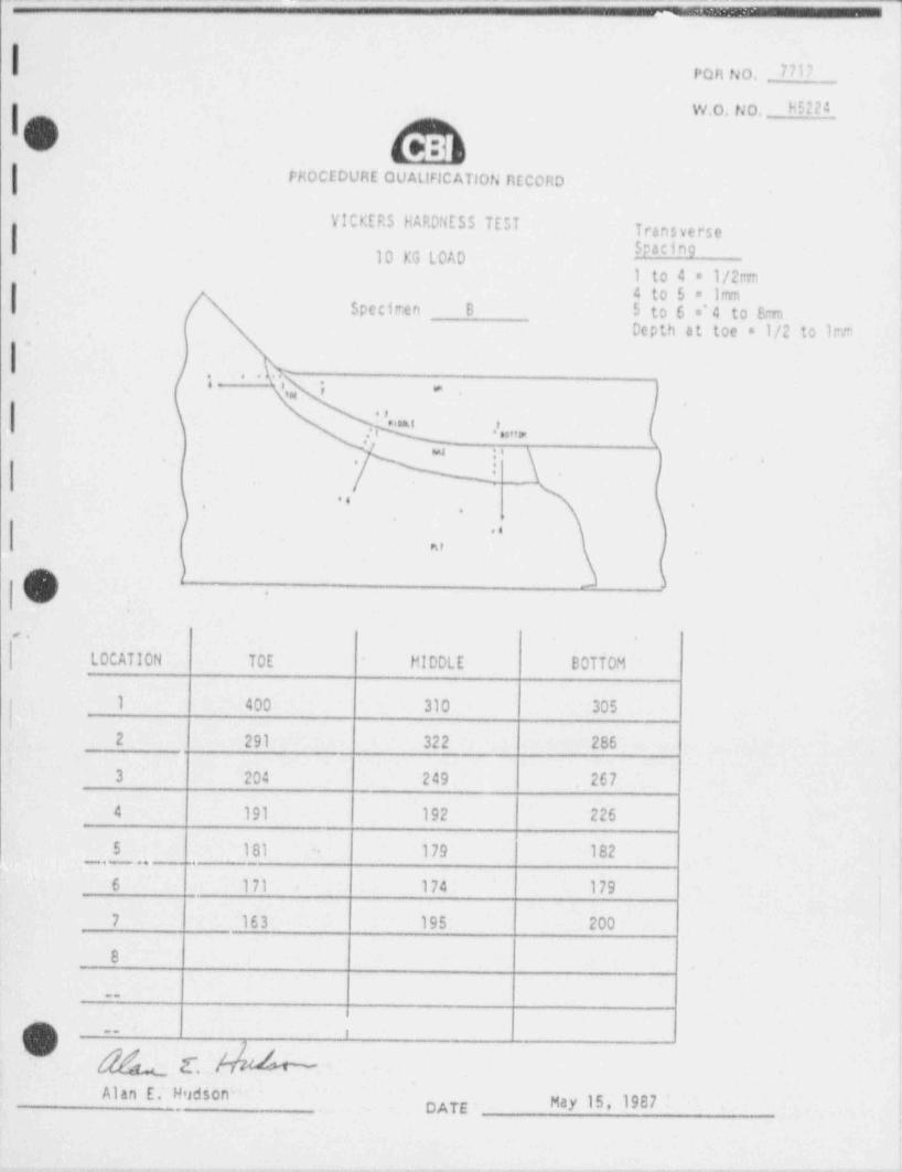
,.:....
| Pon 140. _ 7717
W.O. tJo. _ h5224
FHOCEDURE QUALIFICATIOfi RECORD
i
YlCKERS HARDNESS TEST Transverse" "910 KG LOAD |
1 to 4 = 1/2m,. '
I 4 to 5 = 1rnm| Specimen B 5 to 6 =' 4 to 8m i
i Depth at toe = 1/2 to Iren
; ' ",_. .
ji., t ,
-
,
.,
,.-Q '+ .. n .
* :* \ | .*: \ 4
'
l.
\-.
..,
..
hf,
)r
.
,.
LOCATION TOE HIDDLE BOTTOM
1 400 310 305
2 291 322 286i
3 204 249 267
4 191 192 226
5 181 179 182.
'6 171 174 179
)7 163 195 200
8
..
r5 ..
~ $g [. .Alan E. Hudson-
DATE . May 15, 1987
- - . - ,, - . . _ .
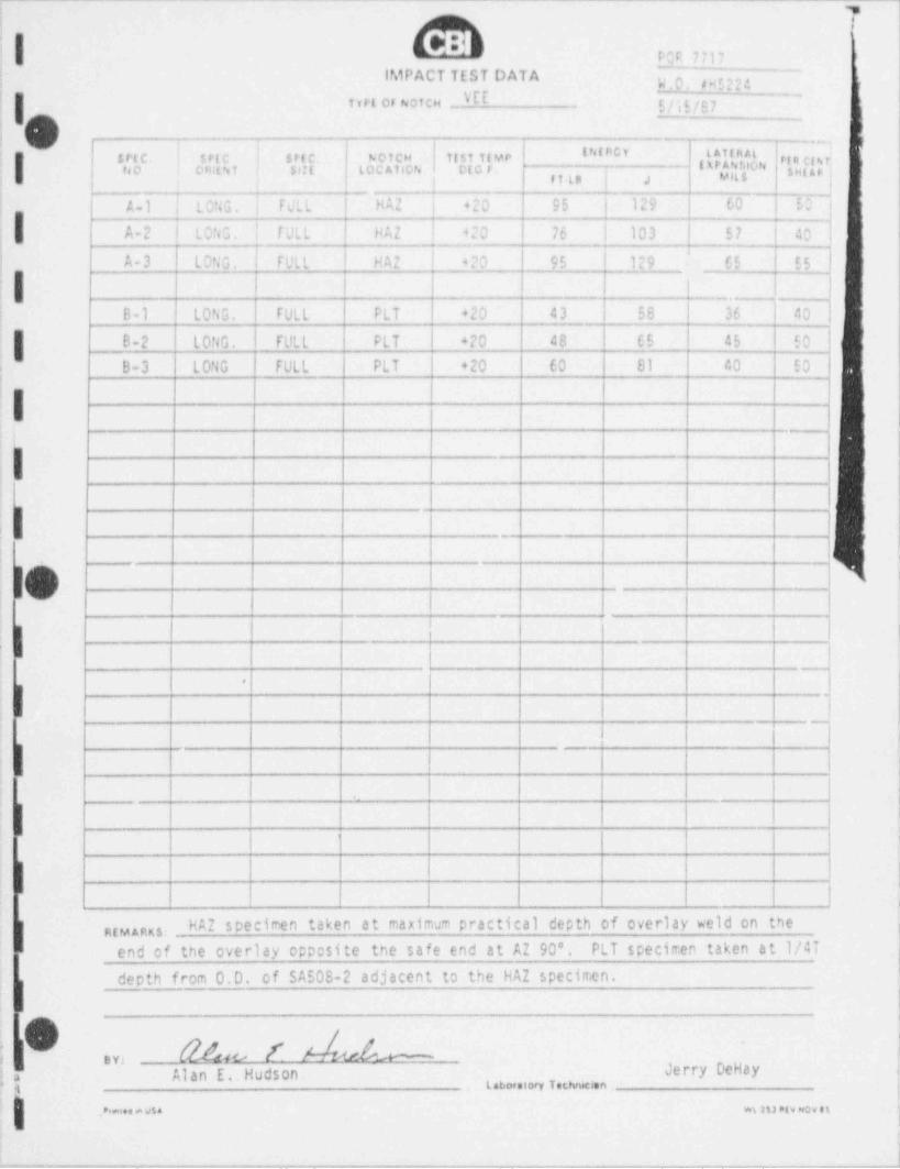
. - . - _ -- - - _ _ ___ -_ . __.
5 PCR 7717
] IMPACT TEST DATA ] g.,4VEE
{ tvrt orNotes gj g g7
i O , .,
srt e. | r.rt e i strc wotcw inst teve W RCY latinal ''ri ,
f( * rgt;'o rdsat tocAucN cto rno caut s t 4 sui; ,
! A-1 | LONG. i FULL HAZ { +20 95 | 129 | 60 | 504
-
. ,
A-2 LONG. | FULL HAZ | 420 76 | 103 57 40j
A-3 LONG. ) FULL HAZ | 4?O 95 l?9 65 55 |
|!! I ! ..
! B-1 LONG. | FULL PLT +20 43 | 58 36 40
B-2 LONG. | FULL PLT | 420 48 65 45 50'|B-3 LONG FULL PLT +20 60 81 40 E0;
;l'
|
|1.I |
l,
;10 '
! |! i
i l'
.
.l i i 1i'
11
| | ;
I| | | |
| |'
| | | !
|! I ;
HAZ specimen taken at maximum practical depth of overlay weld on thein gyang r,
end of the overlay opposite the safe end at AZ 90', PLT specimen taken at 1/41 i
!depth from 0.D. of SA508-2 adjacent to the HAZ specimen.
l !,
| eY: fD M M
!. i Alan E. Hudson Jerry DeHay i
*1 Laboratory Technecian
f.me a usa wt 2%)9(y NQW $$
,. . - . . .- - _ . - . - - _ _ - - - - _ . - . - . . . . . _ - - _ - - .--_.-._--:
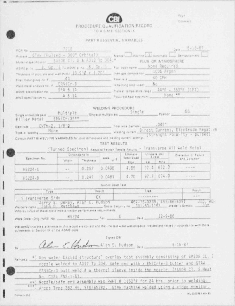
._.
fby9
- - c oeu sa
PROCEDURE QUAllflCATION RECORD
[3 10 A 5 M [, $[CTION lx
PART 11 CSSENTIAL VARIABLES
E-15-87'71E e ,,r;n se
GTu' (rulsed - 360 Crbita1) v,,,,J lu , m , W , m ..,,,, [~ ] 3,,,, ,,,,,,,, Op,cc,s s _SAEDE C1. 2 & A312 Tp 324L* FLUX OR ATMOSPHEREj unte,.ai n ec,# c ai.on
hone RecuiredAsut e no 3. Or.1 to Asvg e no 8. GP. I ry, i,aet name-
100!, ArgonTh.cknesi u v.c, o.a and wau ih.co _lLCL 1. 20" ine.t s es c ompos.i.,, _
40 CFH43 rie ,ai,r n , ,,,etai g.oup no. s .e
ERNitr-3 ,,ty6,,,,,,, ,,,,, No- weid ,netal ana4ys,s no A,
Asur spec.f. cat.on no. p,,s,,,,,,ng,,,,,,,,,n,, acer - 350*F (IPT)SFA 5.14None **A 5.14 resi,,eid he ,,t,,,i,t.n,AWs necificanon no.
WELDING PROCEDUREb Pf nde %
single or mult*ple pass 5.ngie or mutt.ple arc p , , , t ,, n
Filler Metal ERNiCr-3*".045"
(12ctrode EWTh-2. 1/8"O r ,ne, .,, d,am,,,, _
None Direct Current, Electrode Negat.vetype of decking w,,d,ng ,y,,, n,
"
Consuit P ART lil WEL'.HNG VARIABLts to, joint dimensions and welding current settings-.
TEST RESULTSTransverse All Weld MetalQ (Turned Scecimen) neduced e,et,on 7ensae neso,ts -
C Dimensions in Ultima t e Ulumste Umi gg,,,,,,, ,,y ,,g,,
I '*' L 'd and Location'" '
Width Th ckne ss in 2kies b il ! MPs )
0.252 0.0498 4.85 97.4 672.$|----
H5224-C --
0.247 0.0481 4.70 97.7 674.h ----
H5224-D - ,,
Gweed Bend Test
Type Re s u't Type Resutr
1 Transverse Side OK------------
I Jerryi..DeHa{p,wtAlan E. Hudson 464-76-3339 455 66-6391 JED, AEH
Weicer's name John D. Mate social secunty no. 301 60 11 3 Weider's symbot 10"
Who by virtue of these tests meets weider performance tesvi,ements.
H5224 O 12-9-86n,, c.,,Work Orcer lovig WPs) No.
We certify that tre statements in this record are correct and that the test weld was prepared. welded and testedin accordance with the re-guirements of section IX of the AsMt coce
s.gned CBI
[[ . Alan E. Hudson 5-15-87| g n,1,3,
*) Non water backed structural overlay test assembly consisting of SA508 CL. 2n,,,,,,,.
nozzle welded to A312 Tp 304L safe end with a ENiCrFe-3 butter and GTAW
I(m) FRNiCr-3 butt weld 1 a thermal sleeve inside the nonie. (5a509 C1. 2 Heft
No. C194 FN9 1 M .''
**) Nozzle / safe end assembly was PWHT ra 1150*F for 24 hrs. _ prior to welding.-
"*) Arcos Tvoe 382 Ht. Ya875N192. GTAW rnachine welded usino a video monitor. ,
woo o eiv ov s.e..... v5
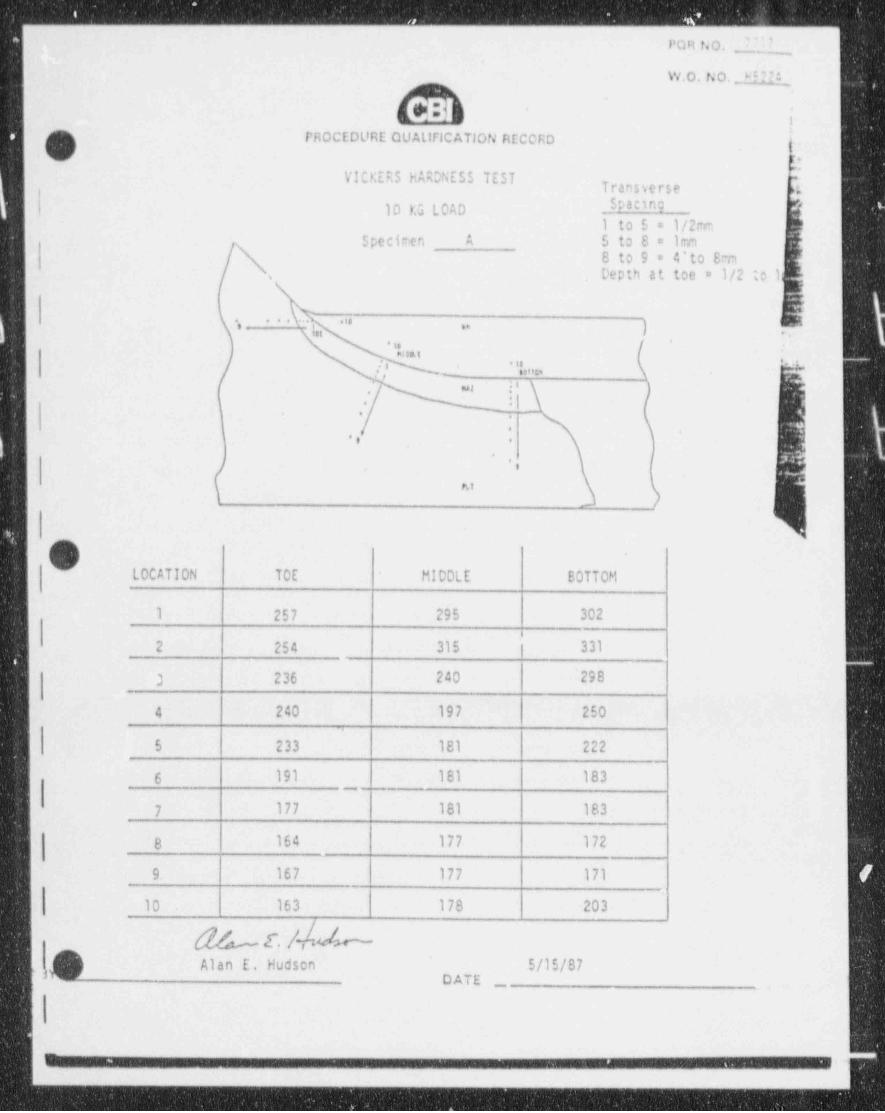
POR f40. 7 'l 7_
W,0. N O. HI?"
'
PROCEDURE QUAllFICATION RECORD g
VICKERS HARDNESS TESTTransverse L
10 LG LOAD spacmg
1 to 5 = 1/2mSpeciren A 5 to 8 = 1m
8 to 9 = 4'to SmDepth at toe = 1/2 to 1.
'''***' , , ).- ; ..
,,*
< ns .' ' * * . ., . , . , ,
*. t >t 1C',, .w_
i .M!il-
.
i*
., .,
-
.,h1
OLOCATION TOE M100LE BOTTOM
1 257 295 302
2 254 315 h 331.
3 236 240 '298
4 240 197 250
5 233 181 222__
6 191 181 183-
7 177 181 183
8 164 177 172
9. 167 177 171
10 163 178 -203
d 4 E. /- | 6. Alan E. Hudson 5/15/87,)
DATE ,
.
_. . . . . .
.
l
. .
. _ - - -
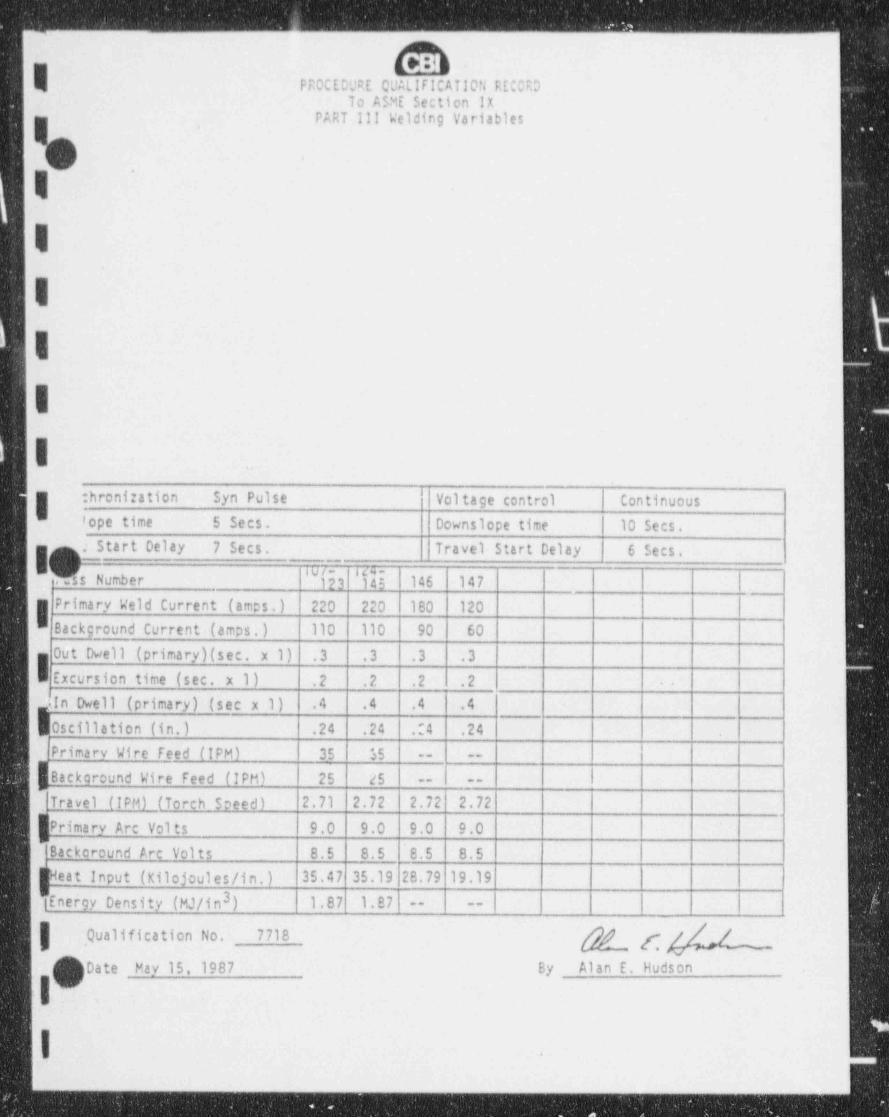
~ _ .
PP,0CEDURE QUAllFICATION RECORDTo ASME Section IX
PART Ill Welding Variables
-
IIIIII
- :hronization Syn Pulse Voltage control Continuous' ope time 5 Secs. Downslope time 10 Secs.
I . Start Delay 7 Secs. Travel Start Delay 6 Sees.IU/- 14 *+ -
.Tss Number 123 145 146 147 |Primary Weld Current (amos.) 220 220 180 120
Background Current (amps.) 110 110 90 60
0ut Dwell (primary)(sec. x 1) .3 .3' .3 .31
_
Excursion time (sec. x 1) .2 .2 .2 .2 .
g In Dwell (primary) (see x 1) .4 .4 .4 .4 -
|0scillation(in.) .24 .24 .:4 .24fPrimaryWireFeed(IPM) 35 $5 -- --
|BackaroundWireFeed(IPM) 25 25 -- --
| Travel (IPM) (Torch Speed) 2'.71 2.72 2.72 2.72| Primary Arc Vol ts 9.0 9.0 9.0 9.0w|Backorcund Arc Volts 8.5 8.5 8.5 8.5
heat Input (Kilojoules/in. ) 35.47 35.19 28.79 19.19
$EnergyDensity(MJ/in) 1.87 1.873 -- --
| , ualification No. 7718Q g g[)Date May 15, 1987 By Alan E. Hudsonv
.
|.. .
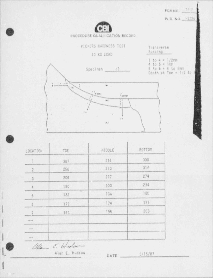
~
|
POR tJo. 71j
W.O.14 0. _ J.Qi
l PROCEDURE QUAlfilCATIOtJ HECORD
1 VICKERS HARONE55 TEST Transverse"9
10 KG LOAD
1 to 4 = 1/2nn4 to 5 = 1m
i Specimen 62 5 ' o 6 = 4 to 8mmDepth at Toe = 1/2 to 1|
I
| t c.,,, ; .
|a19Al f
; ; none
. p \ i
:] ) I-
!
1\..
. .
;..
At .
| );
'
O -.
LOCATION TOE MIDDLE BOTTOM ;
i 1 387 216 300 '
-
| 2 256 273 31^
3 206 227 '274,
4 190 203 234
| 5 182 134 180;
| 6 172 174 177|
. . -
'
7 164 195 203
|i __
,
|~~
.--
;,
!
b [/,,
Alan E. Hudson 5/15/87'
y DATE ,
;
' ,.....,,---.------,--..--._~,.-.,....,_-._-n._,._-.---,,,.._.n,---r,.,-n,,,,,,-._wn, - . . _ . . _ _
, , , -. . - -
-
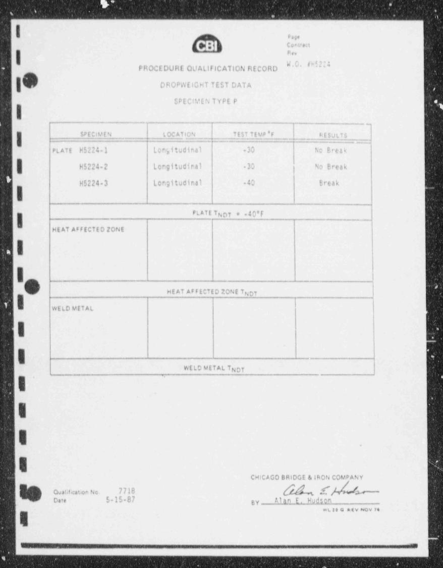
_ . _ _ _ _ _ _ _ _ _ _ _ _ _ _ _ _ _ _ _ _ _ - _ _ _ _ - _ _ _ _-
Ig?\ L
nn
PROCEDURE QUALIFICATION RECORD' ' '
DROPWElGHT TEST DATA
SPECIMEN TYPE P
-
SPECIMEN L OC A1,10N TEST TEMP'F RESULTS
PLATE H5224-1 Longitudinal -30 No Break
| H5224-2 Longitudinal 30 No Break
H5224-3 Longitudinal -40 Break
HEAT AFFECTED ZONE
II _
HEAT AFFECTED ZONE Tnoy
WELD METAL,
II '
WELD METAL TNOT-
. .
I
E .
ICHICAGO BRIDGE & |RON COMPANY
Qualification No. 7738 [ ecate 5-15-87 Alan E. Hudsongy
wue o acv nov n
1
_ . _ . . _ _ . . . .-

- - _ - ___ _ __ _
_
||
FROCEDURE CUALIFICATION RECORD !lTO A.S.M.E. SECTION IXf
7 PART 111 WELDING VARIA5LES
s
13 & 147 (Temper Beads) 1/32" to 1/15" Passer 142 thru 1
I 7 From toe of pass 124 for filling in
No filler metal added. Iow spots.,
ERNiCr-3 ,, u
I 270&WWQWM%_ .
,c "" ~-
I QQ:>9 30 ynw% 36ctsq '-
[ k'8b M k s i s h k N N h h .5/8",,,"
"'
/
- [', j| ', \ t i
t1 ,
/4 i
f 57,50S-CL 2 -H ', Safe End .'
's
# A312 Tp 304L->l 1.20''
,,_ _ .2 4 , , ,
yo ,\. 9-
JENicrFe-3 L--ERNiCr-3
Synchronizacion Syn Pulse Voltage control | Continuous
Upslope time 5 Secs. Downslepe time 10 Secs.ire Start Delay 7 Secs. Travel Start Delay | 6 Secs.
,s Nunber 1 2-4 |5 6-18 19-36 37-54 55-72|73-89 90 |91-1C ~Primary Weld Current (amps.) 220 220 | 220 220 220 220 220 220 220 | 220Background Current (amps.) 110 110 | 110 110 110 110 110 | 110 | 110 | 110 |Out Owell (primary)(sec. x 1)' .4 .4 .4 .4 .4 .4 4 .4 | .4 | .3 |
| Excursion time (sec. y 1) .J .2 | .2 .2 .2 .2 .2 .2 .2 | .2
la Owell (primary) (sec x 1) .4 .4 | .4 .3 .3 ,3 .3 .3 .3 4
Oscillation (in.) | .20 .24 |.24 .24 7 24 .24 .24 .24 | .24 .24 |
Primary Wire Feed (IPM) 40 40 | 35 35 33 35 35 | 35 35 | 35
Backcround Wire F :d ('Ptd 3'O 30 | 25 25 25 25 25 | 25 25 | 25
Travel (IPM) (Torch Soeed) 2.55 2.55 |2.55 |2.55 2.38 2.62 2.64 | 2.66 2.68|2.6Sj,
Primary Arc Volts 9.0 9.0 | 9.0 9.0 9.0 9.u j 9.0 | 9.0 9.0| 9.0ji |8.5 8.5 ~8.5 8.5 8.5 8.5 8.5 | 8.5 | 8.5 j 6.5|Backcroond Arc Volts
Heat Input (Kilojoules/in.) 36.04 38.39 38.39 37.64 40.33 35.72 36.3836.0835.76|35.76Energy Density (MJ/in ) |1.57 1.64|1.89 1.87|2.00 1.87 1.87 1.87|1.87 1.87|3
" 1FICATION N3. 7718 g" *" I
DATE. 5-15-87~
|.
_ - __ _ _
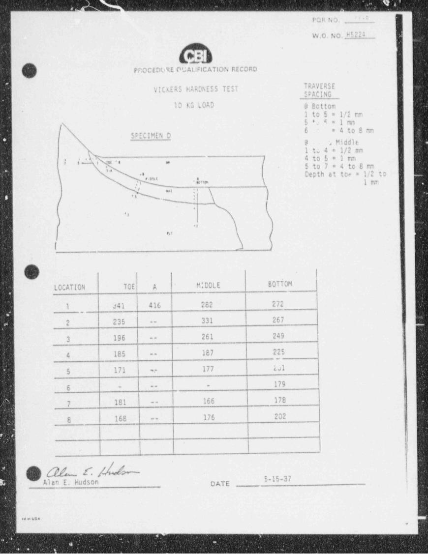
_ _ _ _ _ _ _ _ _ _ _ _ _ _
''dPQR NO.
:W,0. No, HS?? *
,O( ) PROCEDME OUALIFICATION RECORD
VICKERS HARDNESS TEST TRAVERSESPACING
10 KG LOAD 9 Bottom,
1 to 5 = 1/2 r:n5 +o 6 = 1 m\f 6 = 4 to 8 cm
! SPECIMEN D9 2 Middit.-
I tc 4 = 1/2 mm/ 4 to 5 = 1 rm*
i s' i uo .5 to 7 = 4 to 8 cmi ..
'',mi Depth at toe = 1/2 to, \ 1,ww
j's. p
d ei .
( m _
*i
- ,,
^' ,
,
I_
cOV
LOCATION T0E A M:00LE BOTTOM
i 341 416 282 272
331 267.2 235 --
261 249 t
3 196 -
187 2254 185 --
i~
'al ;i1775 171 .-;
'
1796
-- --
166 1787 181 --
176 2028 168 --
a
4
. [V) 0$n [/ - 5-37'
Alan E. Hudson DATE4
e4 - usaa
-- - _ - _ _ _ _ _ _ _ _ _ _ _ _ _ _ . _ _
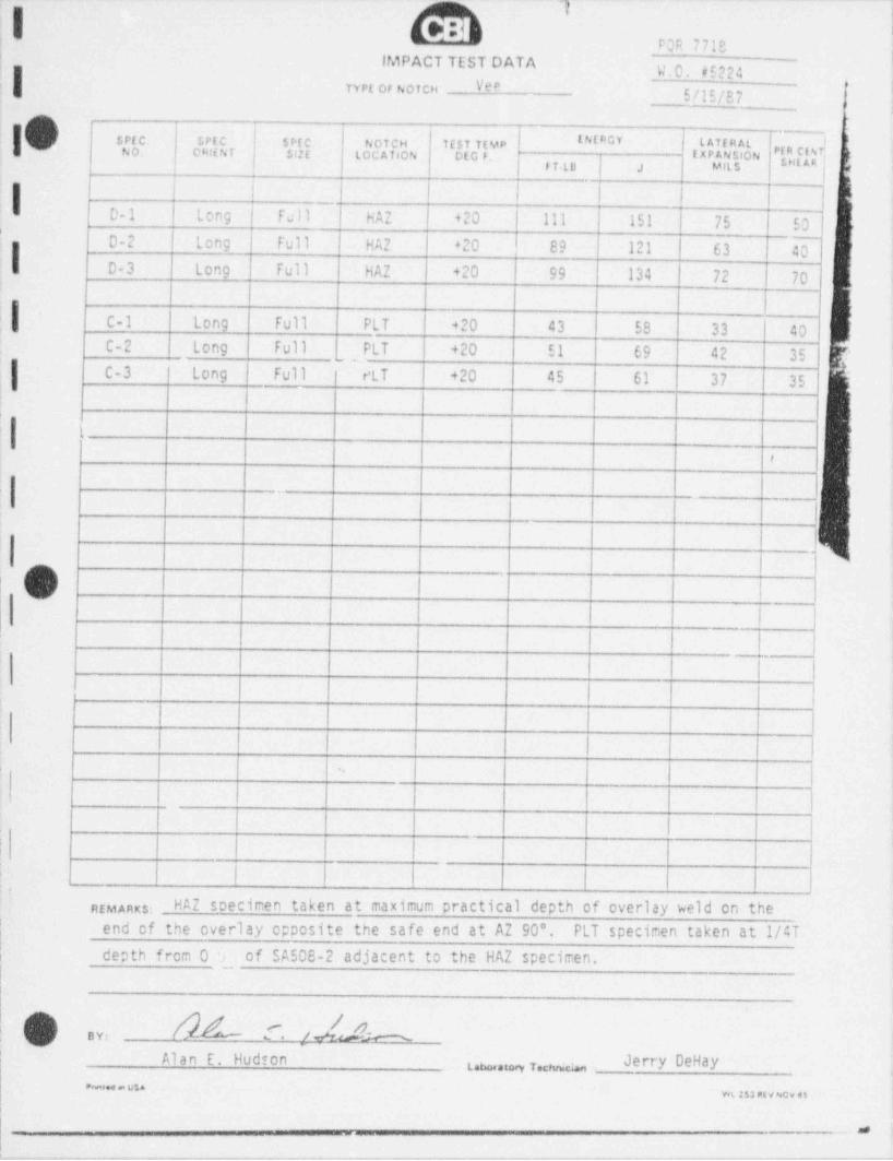
--- -----..----_. - --.-- . - - - . . . - _ - - - - - - - - - - - - -
POR 7718 |
| IMPACT TEST DATA }.0.45224nrt or Noicn Vee
5/15/87 !'
sof c. setc srtc.'
IAIRGY LAffRAL lNoicH 7tsiitupNo. cmiNr set LOCATION Of G F. iXPANSloN I" E
| .i Mats gggri to
| | l,
0-1 | Long i Full HAZ +20 111 151 75 l 50'
I D-2 l Long full HA2 +20 89 121 63 [1
g5 D-3 Long Full HAZ +20 99 134 72 70
'
i
f C-1 Long Full PLT +20 43 58 33 40C-2 Long Full PLT +20 51 69 42 35
|,
C-3 Long Full ! eLT 420 45 61 37 35'
'| 1
9
I{
.
O i
'
-
|
||
1
! !
| !
l |~
1 I l |I
|
|f a
REMARKS: HAZ specimen taken at maximum practical depth of overlay weld on the; end of the overlay opposite the safe end at AZ 90". PLT specimen taken at 1/4Ti
| depth from 0 - of SA508-2 adjacent to the HAZ specimen.i
__
|
|,
{. / hBY: -
Alan E. Hudion Jerry DeHayt,%,,, 7,
*WA213REWNCvel
_ -. . 30
- - , , , . . . - . - . - - , - - - - . . , - . - - - , . . _ , - - ., . . - . - - - - , , - - - - - --

_ . _ _ . . - . . . . - . - .-. . -.- -- - - - - . - . - . . . - . - .
|
|'
ii
O(l
||
Reactor No::le To Safe-End Structural Overlay Test Programt
i
Index
i Section
1. Abstract
2. Report
3. Appendix
I Test program Instructions,
'
II No::le Assembly Drawings
l| III Photographs
IV Work Orders Instructions and Data-1
| V Welding Procedure Qualifications'
'
L[..
_
t-
iI,
.
-
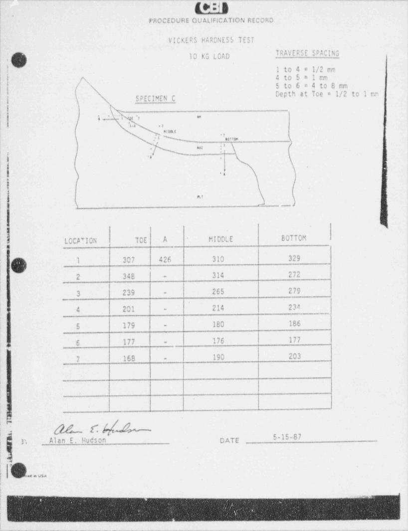
-. - _ _ - _ - . _ - - _ _ _ - _ _ . _ _ - - - _ _ - - ---
Id:JR.
PROCEDURE QUALIFICATION RECORD
VICKERS HARDNESS TEST
TRAVERSE SPACING10 KG LOAD,>'' I to 4 = 1/2 cm!
a to 5 = 1 emS to 6 = 4 to 8 mm
!-
Depth at Toe = 1/2 to 1 cm'| SPECIMEN C
: 1' 's ~ c 's - ;1
,., .,
nlaa t1
l'' N "..nr (| us ic \.
,-,
. . .,, .
*
1
.
..;'
.
i
|,nr
<
ii s - _ ,
l'
<.4
i8 LOCATION TOE A MIDDLE BOTTOM
| 1 307 426 310 329
2 348 314 272 :-
265 2793 239 -
4 201 214 234 |' -<
5 179 - 180 186
j .: 6 177 - 176 177
7 168 190 203 |-
||
|
;
I
f
b5-15-87 |n Alan E. Hudson DATE
|n . usa i
v
I
-- - - - -
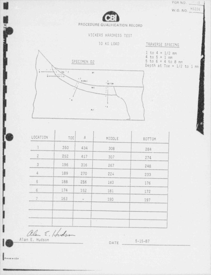
. _ . _ . _ . . _ . _ . . _ _ . _ _ . . _ _ _ _ _ . _ _ . . _ _ _ _ _ - . _ . . _ _ _ _ _ _ . _ _ _ _ _ _ _ _ _ - _ _ _ __ .
YoHNO. L kW.o. No. H5224
.
FROCEDURE QUAL!flCATION RECORD
VICKERS HARONESS TEST
10 KG LOAD TRAVERSE SPACING
1 to 4 = 1/2 mm.
/ 4 to 5 = 1 m eI
SPECIMEN D2 5 to 6 = 4 to 8 mm''
| |Depth at Toe = 1/2 to 1 mm
\. . . ,f, ' ' f,*
/ :'- '
r_ i._
1 4\ /m .,
-
. - g' .
- sm, f
E
| 1
liLOCATION TOE A MIDDLE BOTTOM
-
1 350 434 308 2841
l 2 252 417 307 274
3 196 316 267 248
| 4 189 270 224 233
5 188 256 183 176
6 174 .182 181 172
|1 7 163 190 197-
||
|
I #1c./A -
Alan E. HudsonDATE
!
e-.4 usa
_
v v-$-w w y-iv- & .-- N- N ew e----'- e- - - - - - - e g----mw-m-e www--aw-ew---e-eew7 w- m e- w arr we's- D-wFF'7-=uaw'v-
. _ _ . _ . - _ - _ _ _ . . . . _ - . _ . _ _ _ _ _ _ _ _ . _ _ _ _ _ _ _ . . . _ . _ _ _ _ . _ . _ _ . _ . _ _ _ _ _ . _ _ _ _ . .-
I
I
,
i-
1Appendix 5
Mechanical Properties Test Reports inSupport of PORs 395,745,746
I.
I
hIIIE
g
4
4SIR-90-063, Rev. 0
3g ,
-_ ,
_ .
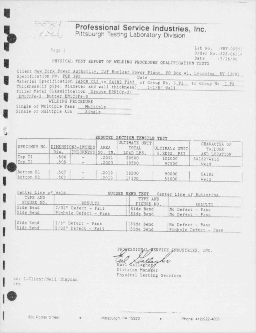
..
E':. .= == v
O7 Professional Service Industries, Inc. ---'
. [ .t 2-d.l_j Pittsburgh Testing Laboratory Division
Lab No. :PHY-00851E330 I Order No.:828-06214Date 5/16/90
FIIISICAL TEST REPORT OP WELDING PROCEDURE QUALIFICATION TESTS
Client New York Power Authority. JAF Nuclear Power Plant. PO Bgx 41. Lycomint. NY 13993Specification No. POR 395 Date
E Material Specification SA508 Cid_to SA182 F347 of Group No. 3 P3 to Group No. 1 PBThickness (if pipe, diameter and vall thickness) 1-1/8" WgliTiller Metal Classification Groove ERRICr-3/
I ENiCrTe-3 Butter ENiCrFe-3WELDING PROCEDURE
Single or Multiple Pass Multiole
ESingle or Multiple Arc Single
&
REDUCED SECTION TENSILE TESTULTIMATE UNIT CHARACTER 05' |I SPECIMEN NO. DIMENSIONS-INCHES AREA TOTAL ULTIMA 72 UNIT PAILURE
Dia. THICDTESS 50. IN. LOAD LBS. S'; RES S . PS I AND LOCATIONTop T1 .506 .2011 20600 102000 SA182/ Weld-
I1 Too T2 .505
9- .2003 19500 97500 Weld |
Dottom B1 .507 .2019 18200 90000 SA182-
.Bottom B2 .507 - .2010 17300 56000 Weld
Center Lin _gf,3f d GUIDED BFND TEST Center Line of Butteringi
i TYPE AND TYPE ANDFIGURE NO, RESULTS FIGURE NO. RESULTS
Side Bend 7/32" Defect - Pail Side Bend No Defect - PassSide Bend Pinhole Defect - Pass Side Bend No Defect - Pass
Side Bend 1/8" Defect - Pass Side Bend No Defect - PassSide Bend 5/32" Defect - Fail Side Bend Pinhole Defect - PassI
PR SSIOf ERVICE NDUSTRIES, INC.
-| gear s-allagheg
I Division ManaYerPhysical Testing Services
1-Client /Neil ChapmanI
cc:etn
,
|O| 850 gociar street %sm pu5m. meumm m..
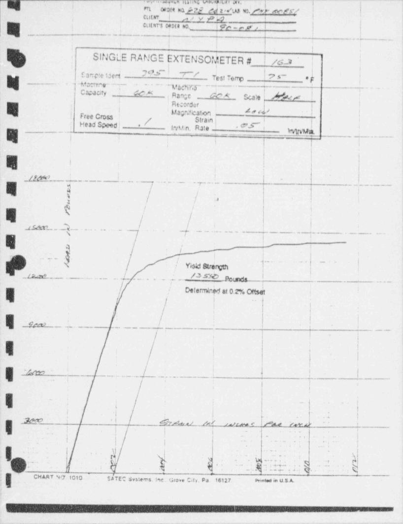
. .sv..c, p a m as w,. ['---~--~~~~~~~-~~~'a- n,
- m C23(11 m f 2 2 M AB N3 f @ e / 5'/L
cutur I ,, ., v p ap i, ,
] j Cutwrs 0;tDtt No i pc y ,cr,- 1
y .. - - -.
. _L1 I i >
1 i I j i.
SINGLE RANGE EXTENSO! HETER #I /c_2 |',
Camp!c iderd M#' Yest Temp/ /f
7 5'~ *- ~ Mar - - -- ~yacgy- q .
,
~
;'
, . . . .Capacity (cA: ! Range _ de'* Scale Me# | !,
! ' Re: order !-,
| Free Cross ! ' Magnification 4" M |'
| Head Speed |*p Strain j
,6 6
g yg| fIrvM.n. Rate # i
E i :i i.
,,
. . ,//M' ' ' ''. . - - . . . . . - .
. . , - - - .
$.--
r .
. . ,3
. ,
j
. .
k j' ; ,
is.m . _} . .. .. .. 4 -- -. . . . . - - - -
.'
,
|'
s, i
Pw '| ; ._ . . _ . __
|N i Yisk! Strerpi
_....._...._...; /3 3~O/ NtMs . -
,/ .! Determined at 0.2% i.
..
4
#re . . _ - _ _ .- .
[ --
*
,
,
. i
.
: / ! 1.- _.
.
Em . ,-
.
:
..
i i
~.i j -- -,
.t . .
.
| __W .' $'7 4 s) /Y
- . 4 |
Y.e.+ |nJm < P A.4.. ..'L'; ;
. . . ,.
+
,
.. - . . . e
,
, 9 **' *
- I, e . . . . . 9-
M - .-k..-i49, ,
, . . . . . ,
'
r,, -t f*'4 N. - - . .6- . - tf..3 , <*a*y4 4-* *-. e
; g cant w ioio - sim s..:,,m. i.ie.. u,o., cw,. pt is m m.,en, u s.A
. ._. . . - . .-
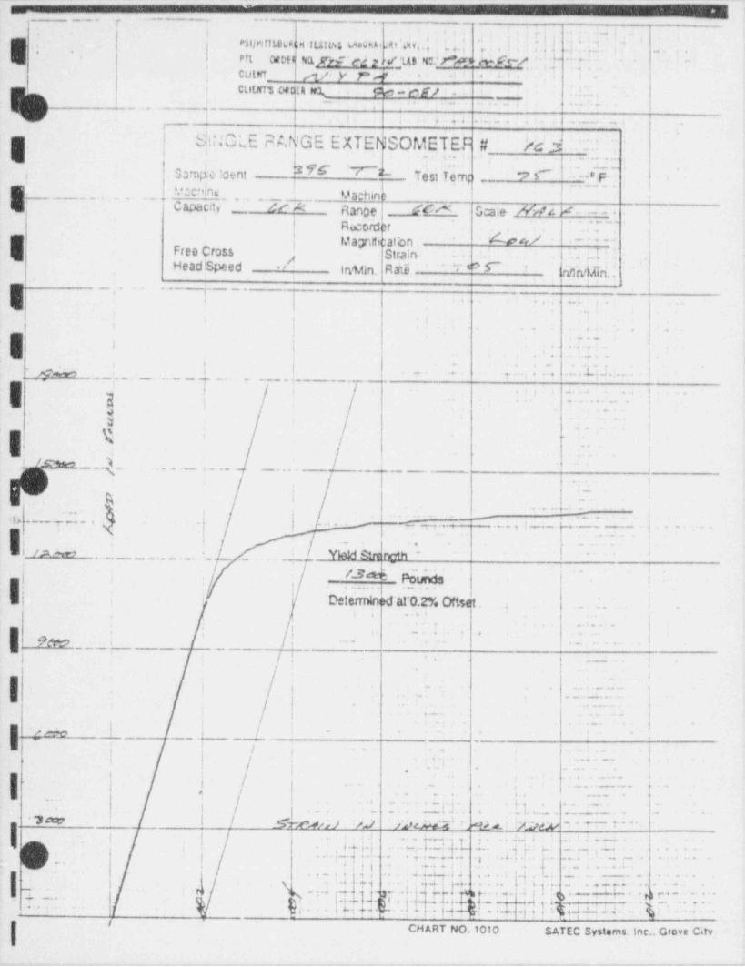
_.
_ ___. _
, ._- .... . - _ _ - -.
' r;, q +. !i* ,
,. , -.. .
E ', *. | PhljMT]!,$gh,H |L${pg (Apguid t @ yj,, , 3, 4,, | ,,{ ,[;j ,'_ ) ,,,,} , g [' g,"
*,,
\ nt cnts nyr;'ed Mys wine NCW f - ' . * ^ - --
, ,.
; CutnT_ ,,,t/. y P 4'.
e cs/ .' '. .>' - * a.' . *
! cutm aan n . : :. ,. .
| _1,
4.-,--
. - . . . -, .,
i : , . . . . . _ . . . . . . - . . ., . .,
IMNGLE FA GE EkTENSOMETEF #. Mi$ . ..J ..
~
2, .s., _ .
.' .
j Samde laent .T' T.est Te.mp ?I ":- . F. .i
' tecning '
Vachin )., ,
..
. . - , C apaC4 -_. '"r K> ',
?.
Range, -.fM Scale- /WN. V - . _ ...
, . ,
Recorder+
a-.
Mayttication . D, ew'' .
E ' ~ ' - ' '":'
Free Cross Strain. . . .,H'4Head! Speed /' IrMn. Raib '-'T # 6~ ' ' sqh4,Kni.
- - _ , . . ...-y.__.
E i | .. L.,
t ,
> i.
| . . . .
,
| v-,
|i.
,- i, .. . i .. . . .
_h ___.....__,4 | .-. -. , . ., , . , .. . . . . ,
. . . . . . .i : .: . . . .g._...-,.y__
I_
,
| t . -..4 . -.
} ) . . . . . . _ . '
, .. .
y ..
|g , c.-
,
Ii -. - - i
. .
. . t.t- /_pga , - - . .-
. . _ . . . . _ . . . . _ _ . _ . I. -
,
, .. I
i r |e . -~ : -
--,..,._w.- -
, , , ,
G . ' .. ~y ., - ~. . . , y ,.,. .,Z.-- - .- , . ..
| . . . . _ .
, . . , ,,
,.
! / - gi ,
i- . |
.. .
| /*....,_ .. _ . . L .!. _ . Ybid honc_th -
- t
|
|I. . .N k._thbs |
~
i, ,
. .
.~ t
OflhK! al'O.2% Oftset . . _ . . t .-t
; '... i,
.a.. .
I 9e,
, . - - . &, , s
, , -- .. .. ..- _ . . _
j..
,/ ! j. _.
A
I. . . . . . _ _
i4
- - . .,. . .....
. . _ . . . . . . _ .
,
l.(,.5
.
,i ; . . - .. . .
, , ,. . -. .- N
* * * ' *. ,. . ) .
..
| ! j i. .. , a.
; j ; q.,.. ..
...e...
e .; . , .
,.
,
l.. . _ . .
! l ._
. ,. . . . . _ . . ..'4 . .. i.,
'-__ .
.-
.|a - . ... , ,.
i .i . . _l. . _ . .
I.. - . ..
^
! SMsWJ %/ ' yleip,f g ,_: iApp
I ]h .{
a99 r '-; . ! .i -
...44 . .. t z . - .... , Ts . l .:. . s . . , . , . -, e .i.; - . w _,j... . , . ,. .y [ .. ... . . . ., .. -. . . . -
! .._7 ;, .. ..
/ ;. , | .... g- .
. . .,- . . ,,,-.,i . .. 4_w . J
. . . . . . ...,%
c .1 . . .: .;. .
. . . .- - , , . . . . .
- ..} y.a i q L .. . .. ' ' ; l' . . . ;. et ..4....J H |.
-
. . . .: _ ; . ..s%, . . .,r
- - . . ,-
yT'.. a y :g r.* . , . --' M :
;m.4-.q . n. .,.
- - - -. 3 . ; a,. .jp i m! & . s ., , , ap ; u_. a . y._.. .
, .s .
;...; . a .~4 .
y w .. 7.. g ,
< c_. - smc s, ,_ .. e_ c.
. .
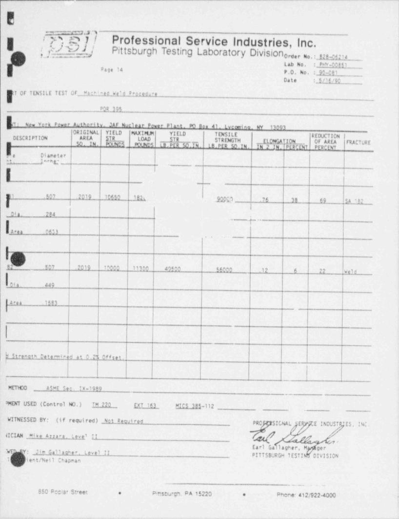
E
Ir P . .o ds. Professional Service Industries, Inc.
.
.
g./ 9 J ' Pittsburgh Testing Laboratory Division 0ser No. 82,_ce21,g
Lab No. : PW-00!Q_Page 14 P.O. No. :_90-081 jDate . 5/10/90 '
T OF TENSILE TEST OF *ar*4aed Weld Precedu er
POR ?95
P New verk Pewer Authoritv. JAF Nuclear Pewer Plant. PO Ben 41. Lveomino. W 13093~
ORIGINAL YIELD P%XIMM YIELD TENSILE REDUCTIONDESCRIPTION AREA STR _ LOAD STR STRENGTH ELOW.W ION OF AREA FRACTUREm $0. IN. POLNDS DOUN05 LB.PER SO.IN. LB.PER SO.IN. IN 2 IN. PERCENT PEPCENT
_
.a Diametert. lacht-
E1 .507 .2019 10650 1 B h ;_ JQpg.S .76 3B 69 SA 1er|Dia. .2P4
L ,,,
Lea!
,m. -
I
Ig92 .507 .2019 10000 11100 40500 56000 .12 6 22 Weld
Dia. 449
Area .1593
hStren0th Dete -4 red at 0.2% offset.I
i
HETH00 ASWE See. IX-1999
' MENT USED (Control NO.) TM 220 EXT 163 MICS 385-112
WITNESSED BY: (if required) Not DeoviredPRO SICRAL 'EP .E IND ES, INC,
(!CIAN Mike Arrara. Leve' IIEarl Ga lagher, M ger
t. ;- Jim Gallacher. Level IIPITTSBURGH TESTI o DIVISION
1 lent /Neil Chapman
S50 P00 tar St eet P ttsuurgn. PA 15220 'e * Phone 2/922 000 -
.
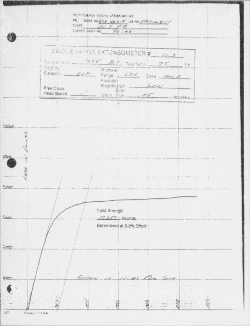
, - - . - _ _ - - . _ _ _ - . _ . - . . - . -
.. g- _ __
I ! I*
P31/PIIT50.i4GH ftsilNG LA80(t,40Ry M.^
lO d fR fv0 j 7 5 d u k. # LA$ 60. N .oMPTL; *
,
CLfth7 | * %> y ,ry *
| CLl[NT'S DaMa No 9g_ag< ir^g , -
tL.- '> .. . _ .
U i : | |
' . _,
-
'
i ;_ .__....__.
SINGLE idi Nf.35 EXTdN!sOMETER '# i !'
et,,
, C?.*rfe .2ern ~ . _N W S_
e3;7 *-'r. 7 I~ 'F-. __ .
6..,-.
. -_. -,73, - . . . - - p,
Capac:p Gek pange _ Cox <., ;, sc,, , , =
ROCorded'
ia
Magt.!!ication -- he w - <!
'~
Free Cross IS: rain :
' Head Speed - /'
in ujn fj 3, n , , , elr'" , ,g,.,A,.,, . _ . _ ._
,
I I
; p |i i
4!
t,s .
|'
FSM ...___._.._.__..q..__. _ . _ _ . .i . __._.a.._.____.,. ..
<
. w-
w ;
6.g ,
'. . _s,! . _ . . _ . . . _ .
%. ._ .. _ . . . . _ ~ . . ..
|
- - . . _ _ _
i
. . _ ,/ j . _ . ... . . , . _ . . .1 j
.
.[ ! _.-W :. . . __. l 4
. _ . . . _ _ .
/ !-
, .
: ; i _
,
ti
i i
,, Yield Strenph .
'
. ,
h - _ . . . . _ . . _ _ - - eN N unds- -.' . - .-'
i
i Determtnec at 0.2% Offset i. '
, i .i
!.. |
'.
i'
t
oT.
,_ .-.
1 e
, ,
|'
|4 /
4
: iI .
|i'
i j i '
!
.
'i,
! {t i
w I ! / K-4w_a in +< 6x /sey.
. t _. .'
. | -
. _ .'
_ . . _
i - .
';- .
_ki : . . ' . . . . .
._ f.
/. .
y.
;q . . :.,.
,-.F N%g 4
,... _ y _ _ __2_. .t....
127 PImics n U.S. A.' '
__ _ - .- -
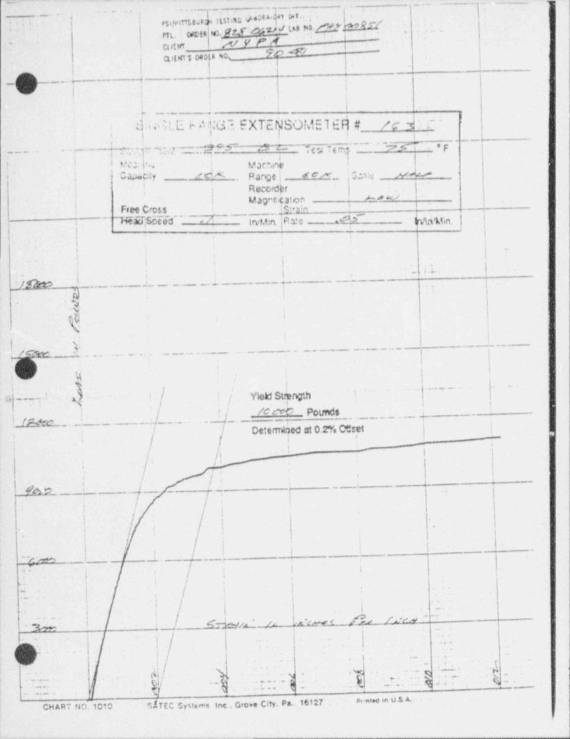
_ -
. ..q._esy,.imen usan Mad" i" . '. . _ . . .
. ,
!-* i t ^,
rit. 0@tR PW).' .NI IOI' NO M' * ..
'' ' '
AsyFM -
'
cutta FC ## -
at!Kr$ ND R N0' i ,
I g.
l I, ,>q,__..g -- , . --
v' | | ||._
.
|.
it. . - _ _ _
!d., MW i- /.n:Gr- EXTE SOMEl EFI # /c h c -Ii
,
,-
i-' --
' ~~GT: y i~;7 . .-2?S~ 5a -y y y ,7., yy ,p'
i [, - -I
'
i p'*.. ,
; M ac*,mei .' ='* ge ,_j
_,_- Cap. cay e e x. pmj,
,,'
| Recordhri
| Marcitatbn Arw/, Free Cross is.,nm
,
~7aKSBcoc ,/ g,y.qpig , ,,
j | T i8
|> .
-'
|i .,
: ,.
i' i i
|h - t-.
}<_7_m_| -' __._ ___ _. -
,
, ,
|_.._ _ , ;
!
., )%
!'
i
I
| 871r.N .__L._- .
Y I i;_! !J %
;>
.\ /s__s yI
H " '~~~ ~
/ ,[ M St !-p' '.
/ i '
l r M-c_,- _.. _./.___. .. I/, N WO Potmds.
,
!
1 Determided at 0.2% Otret i i..
Ili-;
.
/ o/i- -
q ;: -'
f.;.
. i
1 |.
!. ._'
#A22 _ . ___ _
t
!I I .''|
! | II i .
' I' I -
. .|
~~(M L. ,___y_.__
1 I ,+'' ' a
! i isf
|'
I
,- ,,
i. *
i i
I,;
,
i . . .
~'
(x ~cm < fl?rd ~.
Chp _ ' o! i _ _.
h.| h"
!
-8
_
| .
. , , -
t }//
.
l-i - I
. . 'S .. ,d
-
u. j
.'_i\ y . ,
L
0 ,,/.1 . . .
.g ,. . . .
. .. ,
.%;..~ ,.. . . _ . .
/.. . . .
. . .
_. . _ - . . . t {f .
.
,
,,
~ Prated in u.s A.CHART rJO.1010 SdTEC Systems Inc., Grove City. Pa.16127
-- - --- --- __ _ _
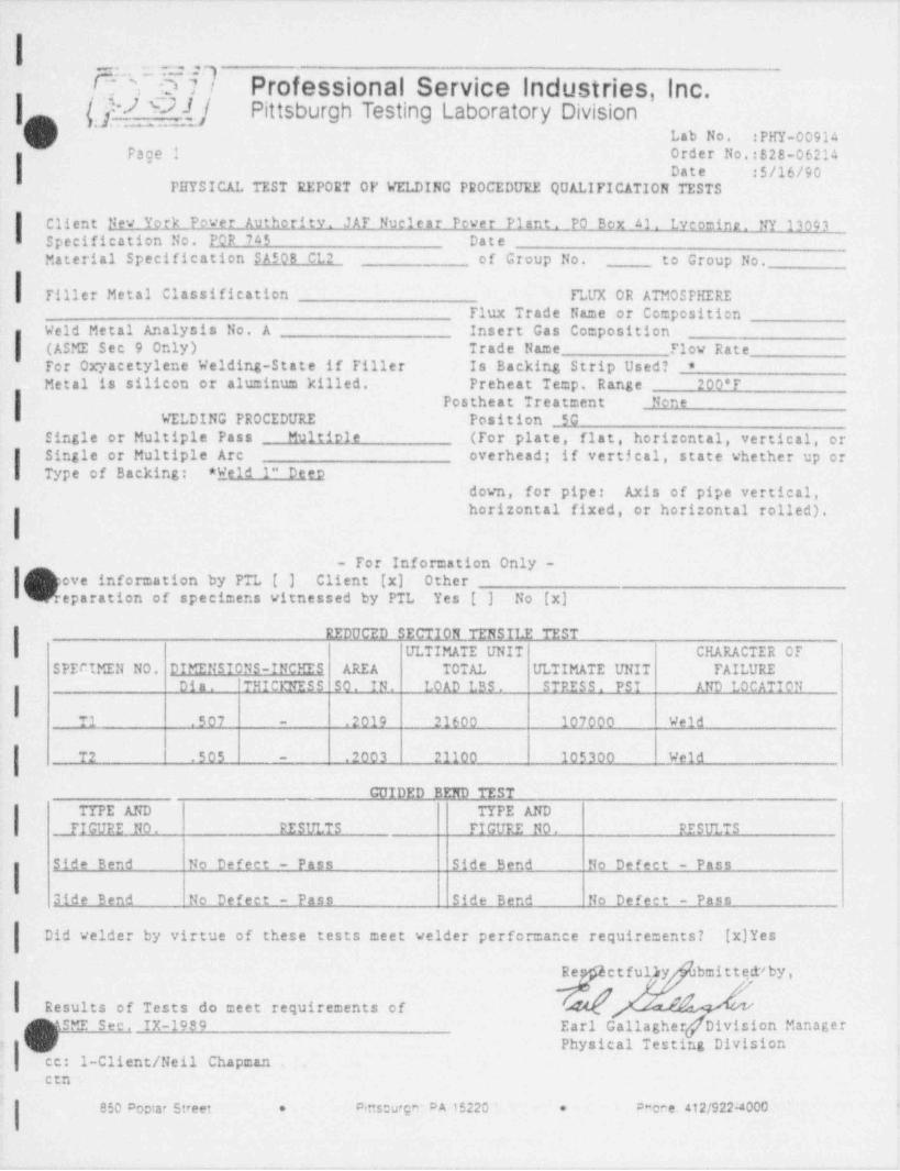
. - - - . -- - - - . - - - -- -
I. .. - , q
/~ ; o n Professional Service Industries, Inc.|-- Q) 9]/ Pittsburgh Testing Laboratory Division
Lab No. :PHY-00914'
Page 1 Order No.:828-062141 Date :$/16/90
PHYSICAL TEST REPORT OF VELDING PROCEDURE QUALIFICATION TESTS
IClientNewYorkPowerAuthority. JAF Nuclear Pever Plant. PO Box 41. Lveomine. NY 13093Specification No. POR 745 DateMaterial Specification $_A508 CL2 of Group No. to Group No.
Tiller Metal Classification__
FLUX OR ATMOSPHEREFlux Trade Name or Composition
eld Metal Analysis No. A Insert Gas CompositionIW(ASMESec9Only) Trade Name Flow Rate
For Oxyacetylene Welding-State if Filler Is Backing Strip Used? *
lMetalissilicon-oraluminumkilled.Preheat Temp. Range 200'F
Postheat Treatment NoneWELDING PROCEDURE Position SG
Single or Multiple Pass Multiole (For plate, flat, horizontal, vertical, or
.| Single or Multiple Arc overhead; if vertical, state whether up orI Type of Backing: * Weld 1" Det2
down, for pipe: Axis of pipe vertical,horizontal fixed, or horizontal rolled).
I- For Information Only -
bpoveinformationbyPTL[] Client (x) Othereparation of specimens vitnessed by PTL Yes [ ] No [x]
IREDUCED SECTION TENSII2 TEST
ULTIMATE UNIT CHARACTER OFSPECIMEN NO. DIMENSIONS-INCHES AREA TOTAL ULTIMATE UNIT FAILURE
Dia. THICENESS SO. IN. LOAD LBS . STRESS. PSI AND LOCATION
T1 .507 - .2019 21600 107000 Weld
T2 .505 .2003 21100 1053_00 Weld-
GUIDED BEND TEST
ITYPE AND TYPE AND
FIGURE NO. RESULTS FIGURE NO. RESULTS
Side Bend No Defect - Pass Side Bend No Defect - Pass
Side Bend No Defect - Pass Side Bend No Defect - Pass
Did welder by virtue of these tests meet velder performance requirements? [x)Yes
Re etful y bmittedvby,/
~Results of Tests do meet requirements of
/ ^ \SE Sec. IX-1989 EarlGallagher[DivisionManager- |V Physical Testing Division i
| cc: 1-Client /Neil Chapman _
cen -\
Prone. 412/922:4000-850 Poetar Street - Amseurgn: DA 15220 : -. .
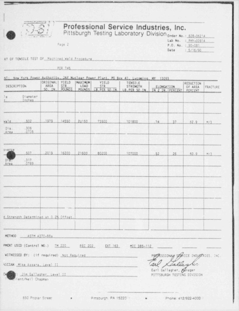
_
5:r)-
< n :D 7 ' Professional Service industries, Inc.' >V 1(3 ( 4 / Pittsburgh Testing Laboratory Division g,, u,.. ers-ur,4
-
o''
Lab No. : PW-00914Page 2 P.O. No. : 90-091,
Date : $/16/90
RT OF TENSILE TEST OF Machined Weld Precedure_ _ _
PO# 745
gT. New York Pever Authori tv. JAF Noelcar Power Plaat. PO Ben 41. tycomina. WY 13093ORIGINAL YIELD MAXIMJM YIELD TENSILE REDUCTION
DESCRIPTION AREA SIR LOAD STR STRENGTH ELONGATION OF AREA FRACTURE50. IN. POUNDS POLNDS LB . PER SO. IN . L B . PE9 50. IN . IN 2 IN. IPERCENT PEPCENT
1e Diametert. Intbes
we1d .502 .1979 14550 20150 73500 101800 .74 37 62.9 w /3
Dia, .306Area .0735
svene.507 .2019 16200 21600 80200 107000 52 26 60.9 w/3
Dir .317Area 0799
- . .
d Stremoth Determined at 0.2% of f set.
METHOD ASTM A370-82a
PMENT USED (Control NO.) TM 220 REC 202 EXT 163 MIC 385-112
t'ITNESSED BY: (if required) Not Decui red P - SSIC e ICE IND' IES, INC.
41CIAN Mike Arrara. Level II -'
Earl Ga11agter, nager,,sEt" J:,,)imGallacher. Level II PITTSBURGH TESTING DIVISIONl\~ dient/Neil Chapman
_
850 Peptar Street * Pmscurgn, PA 15220 * * Phone: 412/922-4000 -
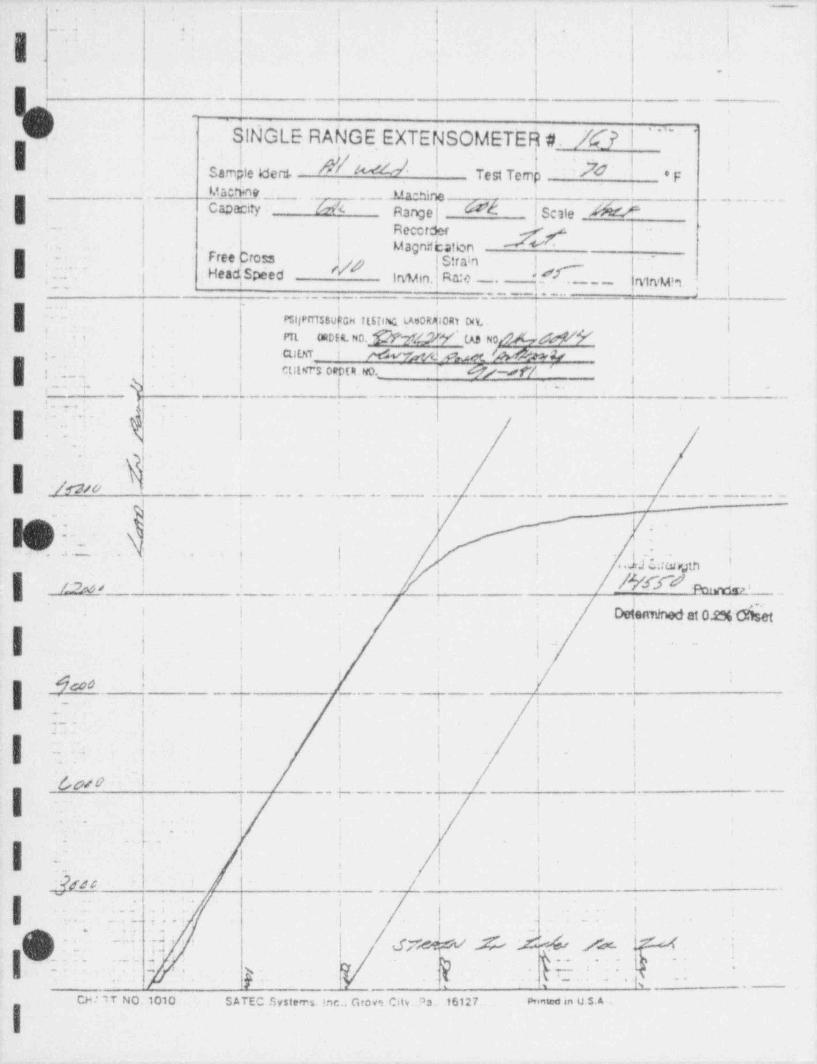
sir
i
'
- . ' . | -
{-
I '
! !
t. .
i
- | I1
~
t :>
_I | 1 I i
-'
SINGLE RANGE EXTENSOMETER #. Xf I '" '!. .
,
samh, e eerthd 2 73 !'
Test Teme e,,M50M9 . _ __ . U n -Nne'
- Ck;)$ity - .[efk Range | | Sc3te M. - . Recctder gf,
..
Magnnhation-. .
Free Cros:s I Strain j.
;..' - : Head Speed t/O-
Irs %n. Ra:c . ".s f. _ _ _i
__ |. :n1ryu!.1_
_ __ _ _ : . . . -
: i.. - .
t,
|I ..-P$ljPITI$$VfGH Il${l% 1.Ae0R 10Rt Dit. j j
i .
! PTL ORDE4.NO. b l V ' (,AS ND [ W i,
CU DiT_. ! W d #M 'M44i.
I , ,. ..
tutMrs Dept 4.NO._ f 8/W/ ': i
. -
-
..,rs.Vs 9
. . . _ _
8..
- . .
, ,
| .... ,- ) |,,
e
..
j i-
,
| fan. ; . '.
~
-
I
_. .. .. . . . . . . . . - . . - - . - - - - - - - - - - - - -
?|.
-
! ! ;, 'i ,
i . ..in.en. . , - - .
,.
I y ; We ' _
.
.i . . .
. i i Detenn. miat 0.2%disetY'|
' I.
, , _ . _+
'
'__I .]gd6 '
__
,.
i i i.
. - . j , ,4 !
,'n
i :! '
I -* .' , .
! ' '
f. !
i,i f j
,
a
<
h&/ 0k
y . _ . .. . * ~ ~ * ~
. . . k. ,i i
.
*
i. l' '
.- ,
AC ',
~~
| _ . ..i
..
. .. ,
| _ _ ,|
, , _ ,
. - .. ... .;
(~) . - -:.. . .; , , gm p 44, y ? ;
,/'. . L .. .- T* *
':, _ _ . , .
. -
1% -, , .s
CH I iT NO .1010.. SATEC Systerrs Inc.. Grove City. '3a 16127 . enntoo in u.s. A .
I
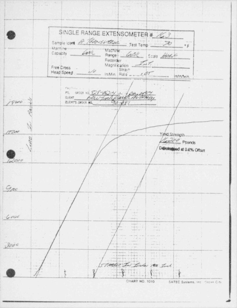
|. . . _
. . . ._ |. .. .. ._ . .
- t -
|,.
_ . _ . ___._
.-.i... .6 . . . ..p,
/m. | S' INGLE RANGE:EXTENSOMETERW6J,
.
|
.'O \ sm\ieieen p g g , , r J.;:; .a.; .
,r - - - @; _.,i
--- ugnf.ye3nemr .g,,
.. - -useneCapah:ty df'( .
,
Aangef --b[- nato 2?M- | | Recot&r - "
- '
. Free. Cross - | Magnif' atbnI cStrai."- <
S r- i -
HeapI peed. In%n; ,Raic -- /M_ _ _ _ _ 41ft%n. ," " ~ ' - -
-, .
. .-. ,, - , . - i.
,
e v s.; ,=. . . . . * . .,
,
CJCtRNY W~$&/V % AAG MNPTL- -
k CLttfiT. h & 'f-r d W WWOAf.jp[.' . CUiffr's.CratA % ,. ' * ' 94f -df'/ I 'j . |
-
! --/- . . ._. |-
/..- '
iI.
'| | t
y} j L. -
'
i |/gd -
Yi RSann'h'
k/M_ _ _ . _
'
,
r ._ . r ..gg;
\.; Desengmas er o.eg or 3c,.,q _- N. , 7 .,
_., .- - .. , ,,,
/ ! | i,
, .. K2wo i I. _ .
.
t
i i -
t-,.
i t
!
1 ; ,. - - . jg i
_
. _. ..-'
. ..
|_ . -; . .
_ .-,
,. .
, ,. = , - .
| |,
, i -' ~
2 ;-
. ' :--- ..r' .-
i| 1
|. i
- |'.fpyg | | .g . _ . . . a.3 4. j
.
>
'. ; i i ./ . . , _ . . , .;. .ii ...
g .. { -.g . .j . R ,
.
{ ! _ ./ - 'L
q .. ..
.g._ . ... -. .
.._4_ ;.-
. j .- . -- : 7r.J.pgf 6 ,.
|. . .. _ _ . . . . . ;
._- : . A. . . . . . . 1_ . . ,. . I
.lb. , ;4.;|a_.*. ~ .
'
- - ,
. i .L; .
. g; .. . . -,; .- L - .4 J J. i { 4, . . . , ..
.f[ @rh, - ^ ~ _h!M . f.. ~.. '. '-.-. , '' g~
.i.
, ,.p ->..
, A. - . . . . .....- s ,
, ,. -
.p - - ; p -i.p!/ j - F
.
*j 'g ., .,i ,) [ :- r- -- .''r4-, f "* a " '' ~~
CHART NO,1010 SATEC Systems. Ine C.rova C.t3.
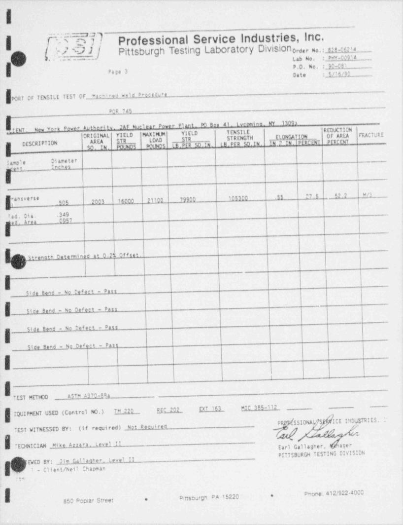
-
|
| N:= ~O d. Professional Service Industries, Inc.a-
('s [/r{_3f] Pittsburgh Testing Laboratory Division 0ro,r u .. sa_0ns,, " ' " ' ' * ~ " ' '
l'J-
P,0, No, ; 93-0B1Page 3
Date :_i/jfLCO
FORT OF TENSILE TEST OF wachined wald Drecefu*e
VOR 745-
I rvf . New Yerk Pever Authority. 3AF Nuclear Power Plant. 43 Ber 41. Lycomine. W 13093ORIGIMAL YIELD t%XIHJM YIELD T ENSIL E REDUCTION
STR STRENGTH _ E10NGATION _ 0F AREA FRACTURE
AREA STR LO/,D_
SO. IN. MYJNDS POUN05 LB.PER 50.IN. tB.PER 50.IN. IM.? IN.!PFDCENT PERCCNT
IDESCRIPTION
em
3 ample Diameter* ent. Inches
.505 .2003 16000 21100 79220 105300 .E5 27.5 52.2 MO
*ad Dia, .349mied. t.rea 0957
5treneth Determined at 0.2% of fset.^^
-
E
S4de Bend - No Defect Pass
Side Bend - No Defect - Pass
Side Bend - No DM eet - Pass
Side Bend - No Defect - Past
it
iTEST METHOD ASTM 4370-89a
EQUIPMENT USED (Control NO.)TH 220 _ MC 202 EXT 163 MIC 325-112
PPENSSIONAL S) ICE INDySTRIES, l'TEST VITNESSED BY: (if required) Not Pecuired Y 4/8 "
w
TECHNICIAN Mike Arrara. Level _ II Earl Gallagher, .ager
PITTSBURGH TESTING DIVISION
89EWED BY:Jim Gallaeer. Level II
1 - Client /Neil Chapmann
EPhone; 412/922 4000
Pittscurg'1 PA 15220 *850 Poplar Street *
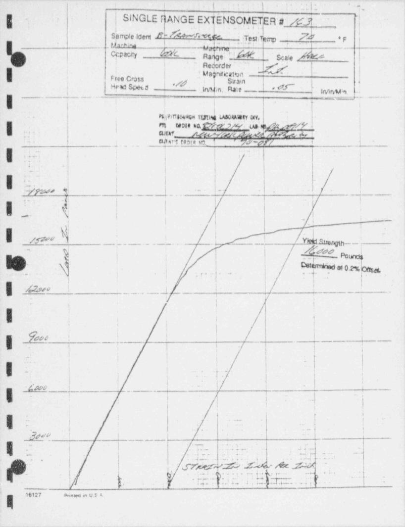
,i i ,i {. .. . i . . . , .
..... ,;
g. .
SINGLE RANGE EXT 5NSO,yETER;#i/#j.'~
"
_
Sample Ident B - M"N"fC -Test |Teg 74 *F;4 . 'r __ - 1- r - j-. t)n.-wns i-
. _ _ _ _
Qpamy (dt RaYhb'M Scale MW |t i ~ Recorder 7
~'
, fj-I |g 4 Mahndicatha-
Free Cross Strain 4- .*
|hem Spet.d ^
.hMn, Rate "#fing,y q _;
,
i i4
i. PijlPmmaGH flyttg LA604A13ty (W,
mNota nCfrSD5 wY: /d2M/V
II Rhw McWwu,Lv /Vv/ 4 i ~;-
_l-ases ema e_1 ' y.7-my i-- i
| , .' ,:: ; | '. 1
'
',
o . : 1
!
I.~ ,
4-
| | .
. i
Wo" *(J l" ~ -
' i..
4_ . . _ _ _.
/- - !
I3-
h ! -/j ;
I ,, 9 i i 4%_! -
-
:
om. .
| _gao II-
Poure; I' t.s, ,
! Cmem*i.e ai o,2x a,3,Ly .
-| 1. r '' - --.. . . ' -t t.-
.'
| |i ,
| M2uo I i ! I i ._ . ,,
| / ;. >i
-
i i ! I*
, :I-
.,
;1 i i 1,
. > i, F ..,
fece ! _L !I . !
,__
i
i !-
i i
:-' i i i -
| _. -. '.,
. . ; -
.
. gu.o - -,
*
! ...
~
; ,'
! .,,
I; i
I. 1 -. .|
... . . .-
: . _ i
8dtw 1 |^^
'
. .,., j . ,,. - . -
. I . .: J,'. ,1-~- - .
t , ,i . ._i , . ,. | . 1,p '-., _.._ . .q .. . . .,,.. '. . .--+.., ,
g .., . . .:. Z, f. g . A t f EA~
-
f7k' . .:w. .f<J. j p 3-..-. .-6- - --..
g,..
. p . .. J , Pf c t. 2*"j.. ; .+ .-. .4 - . +, "9 -,- i3. 4 -,e-. t
16127 peinted in US A
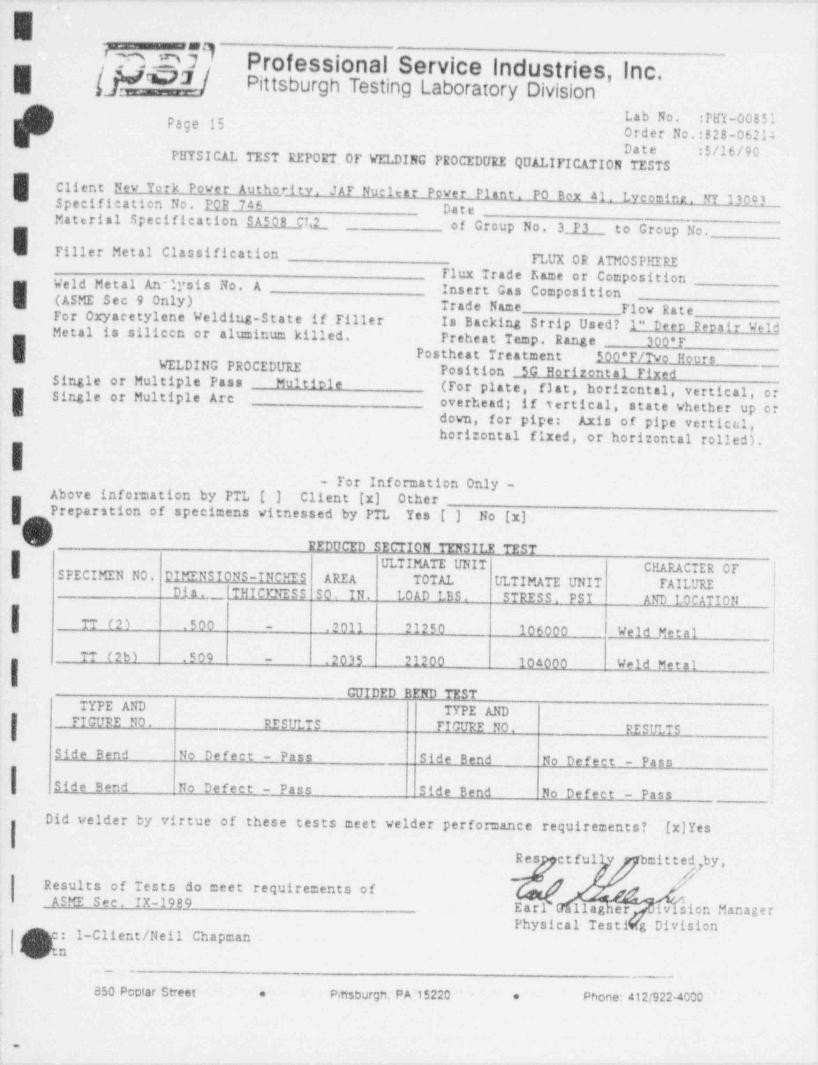
~ -
.
E
g' n.r dL Profossional Sorvice industries, Inc.-
?7 / Pittsburgh Testing Laboratory DivisionLab No. :PHY-00851Page 15Order No.:828-06214Date :$/16/90
PHYSICAL TEST REPORT OF VELDING PROCEDURE QUALIFICATION TESTS
Client New York Power Authority. JAP Nucitar Power Plant. PO Box 41. Lycemine. NY 13,p03Specification No. POR 746 DateMaterial Specification SA508 C Q_ of Group No. 3 P3 . to Group No.Tiller Metal Classification
TLUX OR ATMOSPHEREFlux Trade Kame or Composition
I W(ASME Sec 9 Only) Insert Gas Compositioneld Metal An-lysis No. A
Trade Name Flow RateFor Oxyacetylene Welding-State if Filler Is Backing Strip Used? 1" Deco Reoatt VeldMetal is silicen or aluminum killed. Preheat Temp Range 300*PI Postheat Treatment 500*P/Tvo HoursWELDING PROCEDURE Position 5G Horizontal Fixed
,,__
Single or Multiple Pass Multiole (For plate, f3at, horizontal, vertical, orI Single or Multiple Arc overhead; if vertical, state whether up ordown, for pipe: Axis of pipe vertical,horizontal fixed, or horizontal rolled),
I- For Information Only -
Above information by PTL [ ] Client [x] OtherPreparstion of specimens vitnessed by PTL Yes [ ] No [x]hV REDUCED SECTION TENSILE TEST
'
I ULTIMATE UNIT CHARACTER OFSPECIMEN NO. DIMENSIONS-INCHES AREA TOTAL ULTIMATE UNIT FAILUREDih THICKNESS SO, IN. LOAD LBS. STRESS. PSI AND LOCATION
TT (2) .500 - .2011 21250 106000 Weld Metal
TT (2b) .509
i- .2035 21200 104000 Weld Metal
GUIDED BEND TESTTYPE AND TYPE AND
FIGURE NO. RESULTS PICURE NO. RESULTS
Side Bend No Defect - Pass Side Bend No Defect - Pass i
Side Bend No Defect - Pass Side Bend No Defect - Pass
Did velder by virtue of these tests meet velder performance requirements? [x]Yes
Res etfull bmitted,by,4,,,,
Results of Tests do meet requirements of #ASME Sec. IX-1989 Ear llag er ivbienManager
Physical Testi g Division
Q]tnf' : 1-Client /Neil Chapman
. . -
850 Pootar Street e Pittsburgh,' PA 15220 e Phone: 412/922-4000.
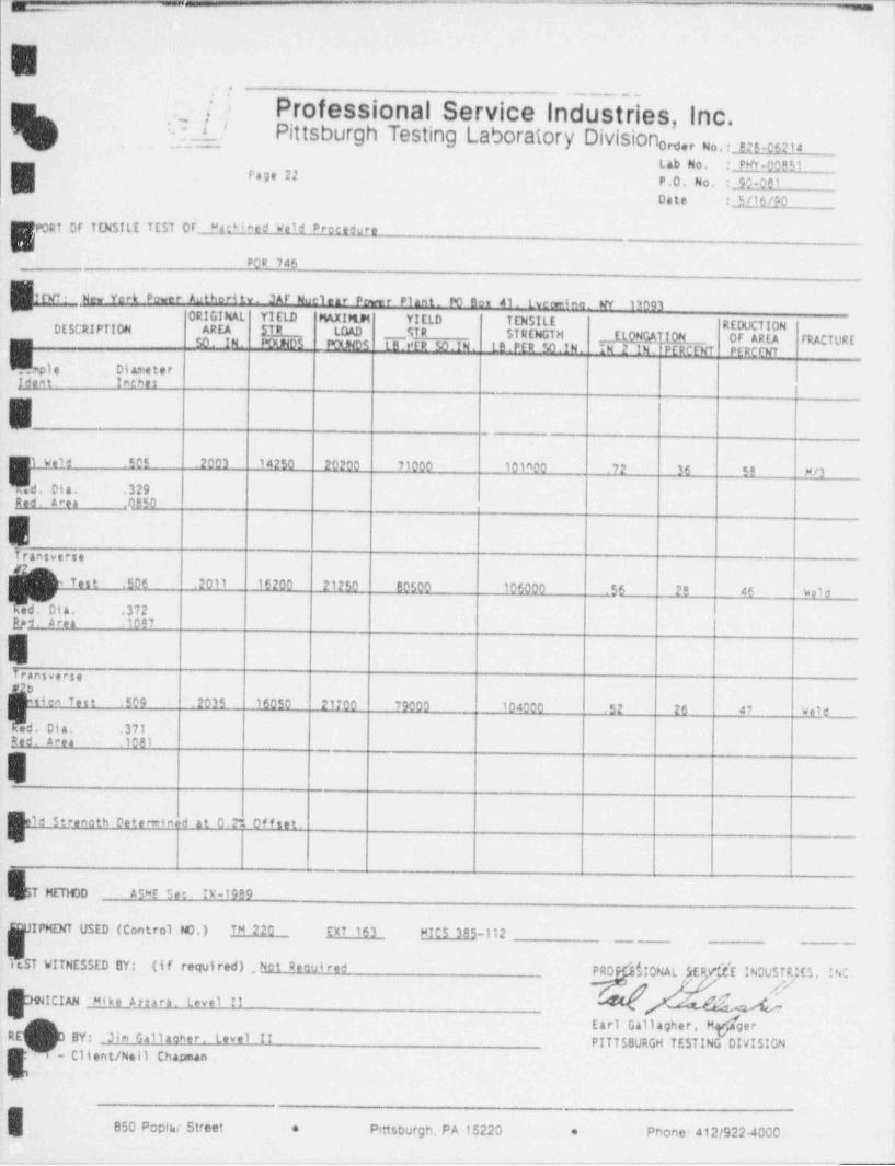
, a -
- -
E--
,
Q_ / ';---
. Professional Service Industries Inc.Pittsburgh Testing Laboratory Division ,e, No.. ,2,.0s2,4om
Lab No. : PW 00B51
~ 5Page 22
P.O. No. :JQ QB1Date : 5/16/90
PORT OF TENSILE TEST OF MacM eed Weld Procedure
POP 746
.Nw York power Authori ty. JAF Noelear Powr Plant. PO Bev 41. tverino. NY 13093ORIGIMAL YIELD MAXIMM YIELD TENSILE REDUCTIONDESCRIPTION AREA STR .
POLNDS 1B PER 50.1N. LB.PER 50.IN. IN 2 IN.! PERCENT PEPCCNT
LOAD _ qR STRENGTH ELON@ TION OF AREA FRACTURE50. IN. POUNDS
v.;.np1 e Diameter |Ident. Isthet
Eweld .505 .2003 14250 20200 71000 101600 . 7.L 36 59 M/3
s.d. Dia. .329Red area .0850
5Iransverse '
iQ6 .2011 16200 21250 80500 106000 56 29 45 w lde
Dyd. a rea .1097
ET rans ve rse
tiem Test .509 .2035 16050 21700 79000 104000 .52 26 47 w lde
d. Dia. .371Ped. area 1081
E
Eid Streneth Deteminod at 0.2* Of f set.E
T MET 100 a5=E See. D' 1999
IPMENT USED (Control NO.) TM 220 EXT 163 MICS 385-112_
stST t!ITNESSED BY: (if required) . Not Deaui red PRO $10NAL JER,/dE INDUSTRjES. INC
ICIAN . Mike Arrara. Level Ils
. RE&. - Client /Neil ChapmanEarl Gallagher, M ger
BY: . lim Gallacher. Level II PITTSBURGH TESTING DIVISION '
850 Poptw Street * Pittsburgh, PA 15220 * Phone: 412/922 4000
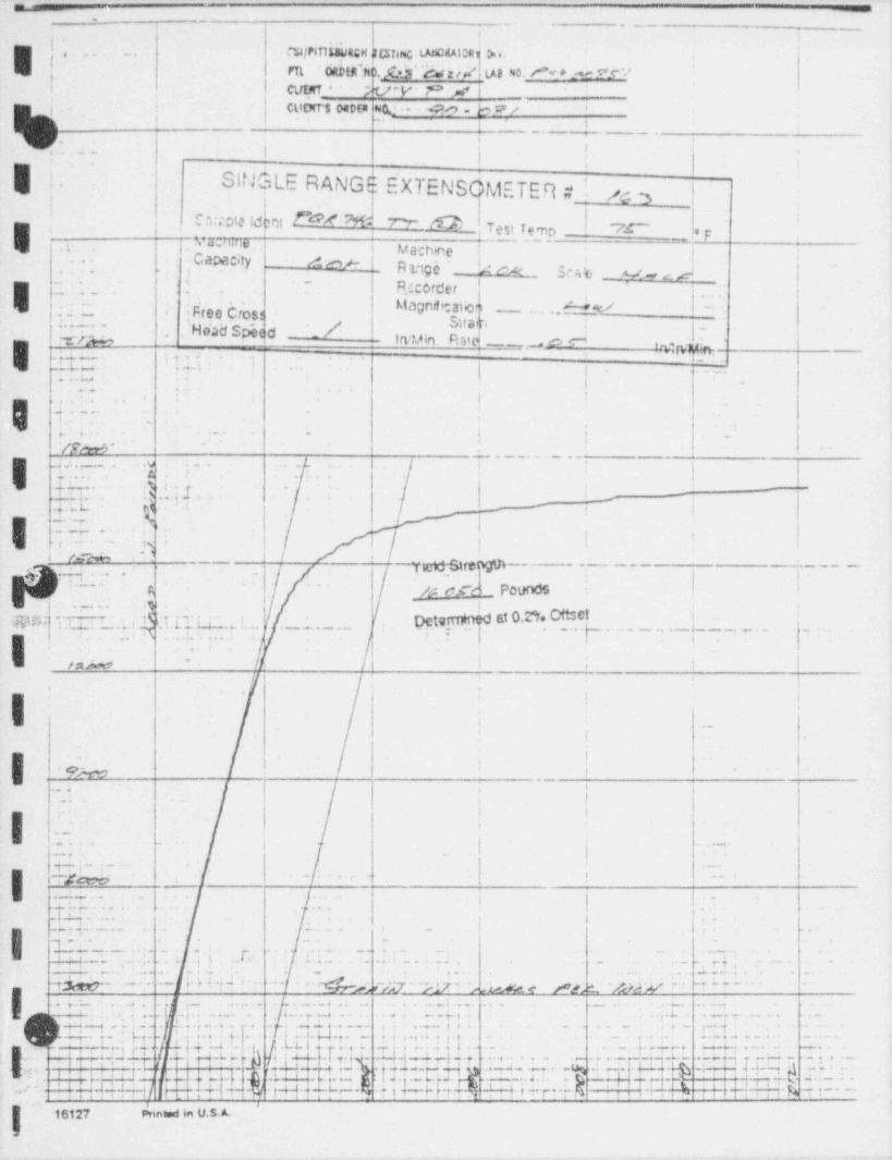
=
-.. .- .
_
_
8 i. . . . . ,
E,-.... 3/ PIT 15aWRGH JCST4NG. LatCdAIDR1N.Fil [email protected] y h gja' lag aio. A e p ?W
.
k CLit.MT_ '. '- tPV 'o -ac* |t
| . ! CLlDtT'S 04Dta N(L. ." . .. @ . b y p,
i
! ~*| t
. ; i....;_ | '1 ! i
-
i
|' SINGLE RAMGE EXTENSdMETER # 43 |. .
G-. i. si im | v.f_.--
._.
C3 icle ld mt N# */fB 7''r-'
I
E,...| Capac;ty
,
?,*Lhine ' e, . .-A ,.,
I Mach *r'e a '-
.. - AM~ R M0h " !m ' ' '
mb M , c .el |'--
: . 2 -.
n . '. .' -
R.! corder I
I -
'NiecCr's! Magnifcat'ioi..
/dv --. n,. .: 4 o --- "
!ggay spec d /L..---.-
gg;4|-'
*-U frtvin R ue_ . ,p,
I y. _M,;
,. ;t ., 3 i_.
. r .. .
| . - . . .
...m . -.,r .. t- *
.,
9.. . .
. . . .
,! --
..
. . . _ - i , _-
Vp w , |' '
-
. - . - . . . - . - -
I.I iai.-. .W : . . ' .. : .';... A . 4
3 i_-H 7. . .- 4 .. ;; y j i
1-
-
.y. ; L. t - i,
|-r
~. .:.e - , , | .
|2 .. [,
j'
s i- w
'' '
(-r-*- -/ i>
..- wre. nom---,
. - - - - - - - - - -
.. , ) - - - - -_
.~~-- -
A: < .m PoundsA 5
,1 6
DetytTed.d d W. N,. _ . . .
1. d, . . , z:W: F i , -.. . _ . . _ . . .pj!!E. .. ...
;
I .
, ,. . . . . , ...
. |. ....L._..._.,,__ _ . _ . . , _ . .
| .
.,, ,
.. . ..
r:n &O
>
e |1 1
* '/'
c
i i
|'
I. | ;
'.
f ..
'i.
!I N._
i.'
i-, ,
''
I. . . . ,
<. ; {- | |
-_ .
1. ..- .
I. . . , .
|. _ ,
_ I ..r.gg| 7- . j
. . . .:! .. . , . . .
,
.y. i .. .
| .. . . . , . ..
. . . .; ; .. . . , . . . - . ,
,.
.
I. q_...-.- . . . . . . . ., .. ....,. ,
. . , . -
.$.- ._.
. . . . . .. . . . , __ ,y, _ _ _ . .g-- - , , . . .....
}.4 : .p .=.; i . . . ,. 4 g.._y.. g .. g g _, _. :. . . .. .
. .: , , , . . . - .. _ . . . . . ._. _ . . . . ..
Ig.9Q ... ..y., -
,,
.._;... .. . _ .
, . 7. L . .p... .. , > _; , . .a, .- . . , . . ..-4 , . . . .. .
'. . ,. .....f , j . , ._..
i . ,~ .
. ._7a . . ,. ;. , . .
y| 9. . 7 ; .>
. ' .,_.
.
: .,,
, _. 4, . . . .7. . . , . . 6 . ,,...i, .
,.. ,[ ,e.+.
..J. j 4 7 7. . :,.
,
,_ - . .j .. . , . 4 |. .
I.;'L,,h,.9,,.i..,.6..s ,, . . . , . . ..
4. a , . I . . . .L. .;. W . _; -
p..'. . v.g. e- r Jj j. '4 -;- 3 .L L .
# T,. . . . p .u p ;..;.4g.7._
'
_,.
_ H, ,, .. . .r +- H, Q.r.. r :. g.4+.g _1. '-H.... - - r + g 2.;S
-. . . . . . . . . ._ - -*-. . . _ . . _ _
aa- d%7 L..- n. - rt.-H,. - - :Iw.g L:.J. - --t w,,; .nr --7- . . -:.g
.yT/
..
. , + w[-- +H W..- + 3 -h r H n+k | N .t r| W :: AH---. p .
'
- .- - . .r .
. W..- '+ & M+ F--,
i <
lh}N NinW M U.S. A.

_ _ - _ _ _ _ _ _ _ _ _ _ _ _ _ _
,_ . I i i 1i
nyPfm3dt,qu.ShNg, usMi P| Di.i
, ?. .~
im own tc'AW cc ete m n /W EsY I,- icuiNT_ h y _P ,,,f i
,
-
| 'cistwts o#D(# NO, R9-SP/ I -
|
(< .
3 _- ~ ._. _ _ . . ._ . .. -
I(q.
SIN $, LE RANGE EXTENSOMETER #
..,. . ,
- - ! &2'
,.
4 ,8
'
i. . Sample Idpnt N# 7 W W C3 est Temp MT.'F _.
'
' L'ndhjne { { ..yg4 y _,
*
.
;_ _ --_ Mrd,
: QapacW i Sc * ' Ratt;c 6er scaleI
_ t,_. _ . . _ < ._
! Recorder". '-,
Magnsheation 2 MNu' - |'
n _ ',- 1
<
i
-
.t F.r.'ec.Cr.osb -- - * e:- 2. t . _ . i.7k'
Irvin> Min. I,-- ... w _.
hWin. Ratd M. . . . .
: Head Spee.d..t. ..
- - --um. ... '
----
,,
,. , ;} .
. . . . ,;. ,,
,
.,7. 7 ;. . . . . . . . . . _ .
i . ; ..,_ j .}._ s . . _ . . . , ._
- __.. , ,
. ..
. _ . _ . . . , ,. . . . _ . . .
- :. . ;
..
.. . _ . ,
-
;.. ., __ . _. ,
_ N~v :t .. . . . . . - .. I. .a_._...._.-
- . - _ . . . - .. i i_
i._L .. g . .. )
-
1
-
_s. ;- |
-.. .. _.. s4 . .
;,
e e. dup
I'
j ;. . . . . .a'
w'~~r -d .
- TfMStrifrgin' i. :N :. .,
t,e_-.<s,. . . . .
,
IQ'
. _ _ , . - .
M Pounds,
-
_ _
'.. ._ u
w3 r. .., Ti r.. a. . ' - . Determined at 0.2%Ottset. . . _ . - .
*
.w-:-H_ r..e- q - -- r. - r--
i t. n- ,
.. .. . -
., .
k .,g. . . +. . .
| . - | _ . . .
. 8/s* M '
1.. ~I ,
|.
.
i
. .
I-
.
. ... , , i
. , -ti
i.
.. I,e
'
_
- _.-.. .i.-,
!>
u. . ,
. _ _. . ;
. ..
|. . -. .. .
,_;. .
. !
I{
.Lt .. . . , .
lg __ .J.; . . . j ; ,
. .. _ .. .. .. ; I
I_. J . . . . ,.e a .
., ... .
f
' '---!... ..
I .. . . . - H .'. _, , . .
. +. .:._,! ,; 3 . ,, , ..
.. -.... ,
of .'4.M. '. ' , J _ . 1.
..L, g. ..,i.,,..'9., , , . . .. , . . . , , , . , ,
. ._.. . . , . ..a , .-7
. . . i.6 . J . f L.'' ._ % .
. ,,
.-.
a .j 3 ' 2. . ,; 4'
..v. , t, , . J .. g.i ,-
, ~ . . - ;-,,-,.. gww a w s,u< ! / :;rg w.. w- --
. . - .
I .7. -. O k 3-t,.'' '_ . t 9 b. y
. ' | i,,.. . * _,.41
'-l* -} . .W .; . t , w--4. .-4
~ t
.'. t q ;..i . ' , .
,
i- .j I- -- -*- , -+ - - | a '-- '4
'
J . 4 .L.t- N- - I--MTt, i ,' . - - 4 -
',. . . . . . ; g , .-. s** *
1- 4- -. i
' ' I ... .i . ..1.4.1, .+F-4 i -. i , e.~,. f-em ; ,i r+ r- t 4 i . t .- ~~?''
,, - -
.i*
, 7 .. ..; .4 - . - -
;J -'Tj( /- i, pyt- -7- ,,
p . ,g6 h. [, f[, t--- --*-t-: M H~- -t + : -
,
i i 1--
tt-- v r- ----'
d. .r-(, It.f, ! ' -'.*.:', ,
y pj ..p ,g g . g . .-- F t * .p.y 1 -g.- - , t- -t-t1 - - - * -,
t 9w- .ii,i, 1p. , ,
.. .. ~,
- -q , g t-j ei
-+..~~ q m, ,
, ,, p ; y t- -- --- ,
4 ,,, ii rri i H i-
r-f t tm t . * l'r" ' it, ., . .i ; i f t--1 7 .
1~-'. . - . .
i ' CH ART NO.1010 - SATEC Systems. Inc , Grove Cit'
|
_ _ _ _ - _ . - - _ _ _ _ _ . _ _ _ _ _ _ _ . _ _ _ _ _ _ _
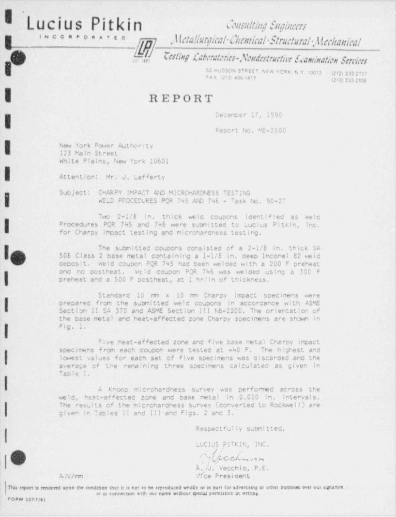
I 'Lucius Pitkin ensultingenginursy ,Alctallurgicalflicutical Structural.Alaltanical
<ueon>oe>,ca
, f Ccsting Laboratories-Scudestnetix Ecamination Scn'ixs
$0 HUDSON STAECT. NE W YORK. N Y.10013 I?12) 233 7737FAA (212)406-1417 (2121233 75tB
| REPORTDecember 17, 1990
Report No. ME-2500
I New York Power Authority123 Main StreetWhite Plains, New York 10601
Attention: Mr. J. Lafferty
Sub.J ect : CHARPY IMPACT Ato MICRDMARDNE55 TESTING
I WELD PP.OCEDURES PQR 745 AND 746 - Task No. 90-27
Two 2-1/8 in, thick weld coupons identified as WeldProcedures PQR 745 and 746 were sutrnitted to Lucius Pitkin, Inc.for Charpy impact testing and microhardness testing.
I(V) 508 Class 2 base metal containing a 1-1/8 in, deep Inconel 82 weldThe submitted coupons consisted of a 2-1/8 in. thick SA
deposit. Weld coupon PQR 745 had been welded with a 200 F preheatand no postheat. Weld coupon PQR 746 was welded using a 300 F
I preheat and a 500 F postheat, at I hr/in of thickness.
Standard 10 nm x 10 mm Charpy impact specimens were
Iprepared from the submitted weld coupons in accordance with ASMESection Il SA 370 and ASME Section Ill NS-2200. The orientation ofthe base metal and heat-affected ::one Charpy specimens are shown inFig. 1.
Five heat-affected cone and five base metal Charpy impactspecirmns f rcm each coupon were tested at +40 F. The highest and
I Icwest values for each set of five specimens was discarded and theaverage of the remaining three specimens calculated as given in
A Knoop microhardness survey was performed across theweld, heat-affected cone and base metal in 0.010 in. intervals.The results of the microhardness survey (converted to Rockwell) are
I given in Tables !! and III and Figs. 2 and 3.
Respectful 1y sutml tted,
LUCIUSf!TKIN, INC.,a . ,
Ebb '/1 hx. J. Vecchio, P.E.
AJV/rrm e President.
This report is rendered upon the condation that it is not to be reproduced wholly or in part for advertising or other purposes ovet our signature ;or ut connect 2on v1th our narne without specul perrnission an writing.
FOKM 107+7/41
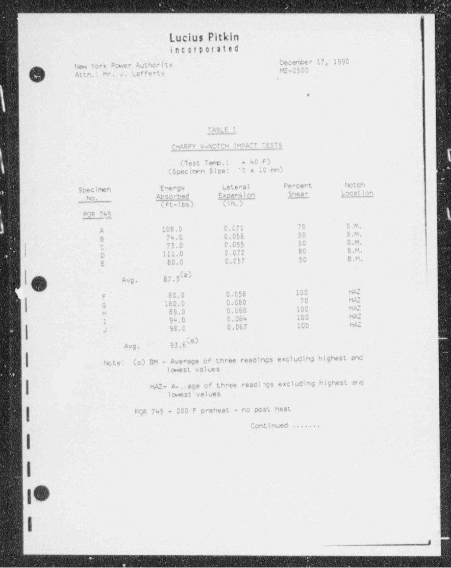
- - - -- - -
.
o
Lucius Pitkin i
inC Of p0f 3IedDecember 17, 1990New York P;wer Authority
(v]/,e MF-2500Attn.: Mr. J. Lafferty
,
e
TABLE I
CHARPY V-NOTCH IMPACT TESTS
(Test Teno. : + 40 F)(Specirmn Size: ' O x 10 ran) >
Specimen Energy Lateral Percent Notch
No. Absorbed Expans1on Shear Location
(ft-lbs) (in.)
POR 745
A 108.0 0.C71 70 B.M.
B 74.0 0.058 50 B.M.
C 73.0 0.055 50 B.M.
D 111.0 0.072 80 B.M.
E 80.0 0.057 50 e.M.
87.3(a)e~sI i Avg.
? RJ' F 80.0 0.058 100 H;c
G 180.0 0.080 70 HAZ
H 89.0 0.060 100 H/C
I 94.0 0.064 100 HAZ
J 98.0 0.067 100 HAZ
93.6(#}-
Avg.
(c) BM - Average of three readings excluding highest andtcto:lowest values
HAZ- Av... age of three readligs excluding highest aridlowest values
PQR 745 - 200 F preheat - no post heat
Continued .......
I
Im'
/
I,
I ,|
.- _ __
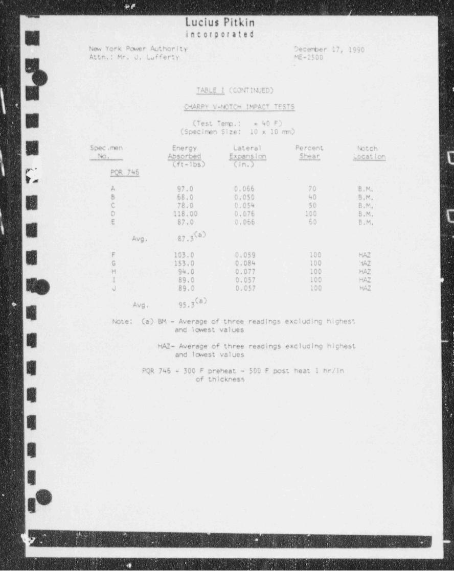
"Lucius Pitkin
'
".
incorporated
New York Pcwer Authority Deceche r 17, 1990Attn.: Mr. J. Lafferty ME-2500
TABLE ! (COtJTit/JED)
CMARPY V-NOTCH IMPACT TESTS-
' (Test Temp.: + 40 F)Q(Specirmn SI:e: 10 x 10 ran)
Spec .rmn Energy Lateral Percent lbtchW No. Absorbed Expansion Shear :.ocation
(f t -lbs) (in.)
{.* POR 746vs
A 97.0 0.066 70 B.M.B 68.0 0.050 40 B,M.
E C 78.0 0.054 50 B.M.D 118.00 0.076 100 B,M.E 87.0 0.066 60 B.M.
Avg. 87.3(a)
E F 103.0 0.059 100 HA2G 153.0 0.084 100 :%2H 94.0 0.077 100 HA2
! 89.0 0.057 100 HA2 :4 J 89.0 0.057 100 HA2
Avg. 95.3 *)E Note: (a) BM - Average of three readings excluding highest -
and Icwest values
HAZ- Average of three readings excluding highest'
and lowest values
PQR 746 - 300 F preheat - 500 F post heat I hr/inof thickness
E
E
E
E
Og
_ _ - - _ . . . . .
!- _ - _ _ _ _ _ - _ _ _ _ - _ _ _ _ _

. .. . - _ .
,o y <w. . . . , ,
JUCIUS 3D'JD,InC. ug, , , ,I
I-- O d/ / bh */ *ho, g,gpgg
--
p e. 7 # s M p o o W + tw,,
fts 00Cyn'te,it is the property of and il to be used only in the perto,fea' ice of wo.m for Luc |un pitkin, I,it. ?
re.... w .o o,.n,om.,po,.ot.,.fo,.....n.
| | l i i ! | i | | | ! I il i I | | | | !| || !' '
! l ! I | ! ! ! '! ! ! ! l l l I i !'
| |' i
' ' ! | | || 1 | | i i ! ! |t
-
...! i |
|i -| L | i i' -
.i
rI !. .
. . .
! ; |.
' i ! ! ; ii ' i
| ; j|1 i i ; # i ; . ' , .> .
; ; ii ! , 1 - , ,
I. i ._ _ . , . . . _ _ , _ . . - . . . . . . . .. .. _ . . . . _ .
. . . . . _ . . . . . . _ , _ . _ . . . . _ . - - _ - _ . . . - . - - . - - , . ..
i i 4 .. !
.
. - . . . _ - _ . - . _ - . _ _ -- _ - - - - . -
,
,,4 __..-a.. . . + . i**.e_ e.: ..eu._ ,
| .__.E.M o^/Et 62.. __ _ . _ _ . _ . . . , _ . . _ _ _~ _ . _ . . .
6.2DDVC WELD- | 7 _ . . _
. g .. . . ... . _. .. ./ . _ . _ ._
_
j N <
. - _ - . . . - - . . _
. | .. _ . _, __ _ _ . ._ . _ __ g _ _ _ _ _. _ ___ . ___ . _ . S_A. 5. _0. 8.. CL A 5S ?
*._
s
-
. y ,/6- ...
*< .. ./ b# -. .. -.. ..
| Q *. .s.
_. . - _ - _ - _ . . , . . _ . . . _ _. . . . . , . - - . . . - - _.
; ___
, ,,
__ .7. - . . . . - . . - . .._ . . . . . _ , , , _ . . - -
.- - _ ..
-__ _.-- ._ -
r._ _ _ _ . . . . . _o _ . - .
. .
. . . . . _ , . . . . _ _ . _ - / __
. . . ,,
' !! I
' I.- f I I' I ; | | ! ! ! ! | | |
' ''
. .,
. , ,
f | \ !i ! l * i i ii'
~ . _ . _ _ -... _ _ -.
- . . , ~ . . . . , . . . _ . . . . ,.
i i <oh A,m,o e mv_r,Ams -
-! ! I i
. [!'
. . ..
' &ditss Me rsi.._CsdeAy2peciyew.S'
'
- |- : ! ! i i i: !'
. ,,
. , , i i i i !: i : t i ., .
> i F/rf, f. I I i I | l' ! l I.<
3 i i
! l!I ii ! i ! I i' - -
|n!! 1
! i I ! Il i I I | | |k'. I ; ; i'
r : 1 1l iI i
i i l i i ! i i i l i | !i i {j i .I i g i ; ,iI I
i
( i ! 'I i i i t i I
1 i'
1 ! l ! .' ,,
l | k i ! ! | | | I | | ! | 1'
4$
i i i i i i , i i i i i i i i i i i i i iial : : i ,. .
- .
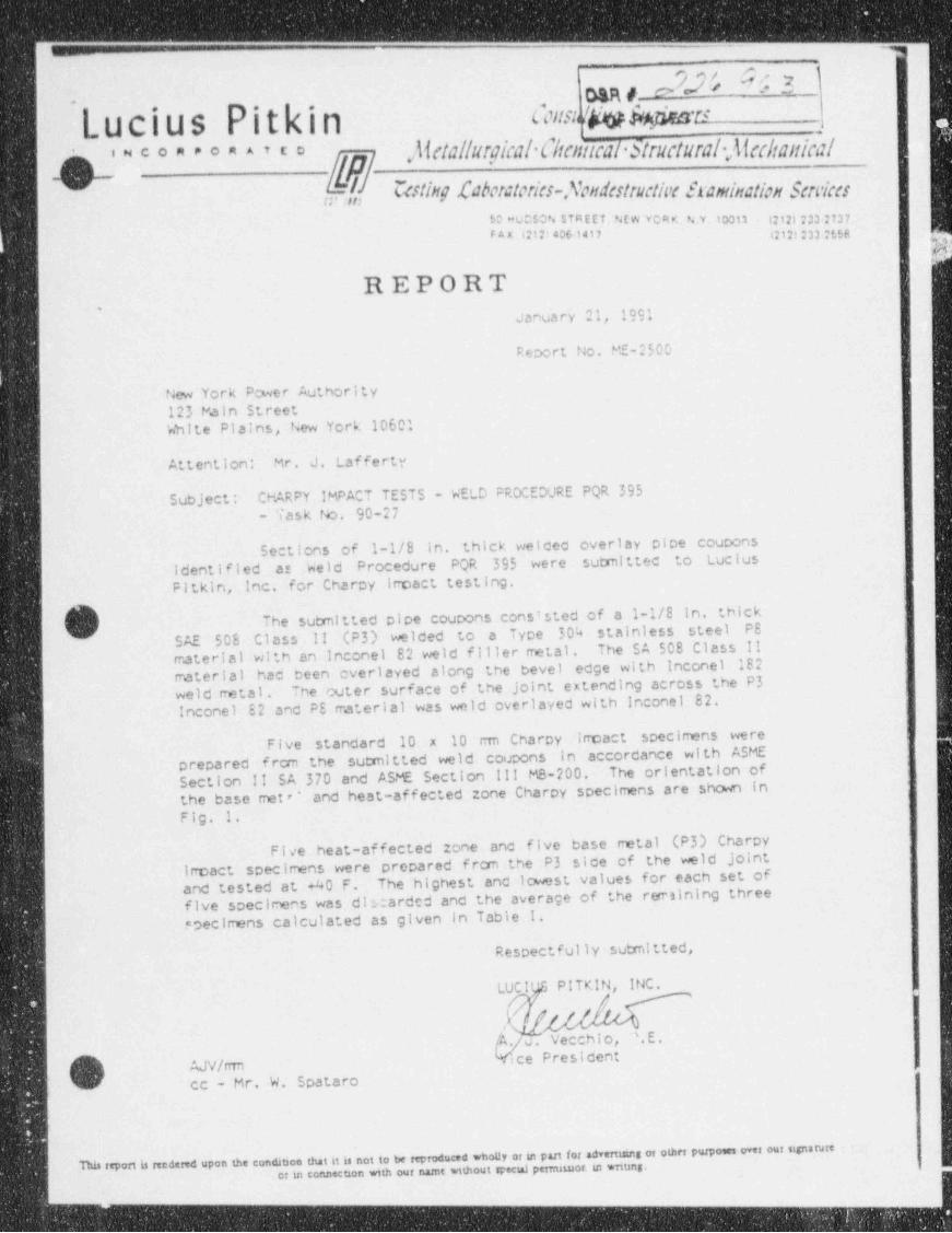
c-- __
s _
onw e 7b/ O :, 1,s.
-
(_ U Cl u s Pit a, n Gua w tw*su,
, ,
}iciallurgical C/ttntical Structural-)lcc/tattical'"***'***''*
a f Cating Laboratoria-Mondatructia framination Savica$D MUCSON $TR E ET. NEw VCRK. NN.10013 Q121233 2737FAX C1214061417 gm m g
12"
REPORT. January 21, 1991
Report No, ME-2500
New York Power Authority123 Fain StreetWhite Plains, New York 10601
Attention: Mr. J. Lafferty
Subject: CHARPY IMPACT TESTS - WELD PROCEDURE PQR 395- Task tb. 90-27
Sections of 1-1/8 in, thick welceo overlay pipe couponsidentified at Weld Procedure PQR 395 were submittec to LuciusPitkin, Inc. for Charpy irpact testing,
(q The sutmitted pipe coupons cons'sted of a 1-1/8 in, thick) SAE 508 Class !! (P3) welded to a Type 304 stainless steel PS
traterial with an inconel 82 weld filler metal . The SA 508 Class !!rrateri al had been overlayed along the bevel edge with inconel 182weld metal. The outer surface of the Joint extending across the P3Inconel E2 and PE rraterial was weld overlayed with Inconel 82.
Five standard 10 x 10 rmi Charcy impact specimens wereprepared f rcm the sutmitted weld coupons in accordance with ASMESection II SA 370 and ASME Section !!! MS-200. The orientation ofthe base met '' and heat-affected zone Charpy specimens are shown inFig. 1.
Five heat-affected Zone and five base metal (P3) Charpyspecimens were prepared frcm the P3 side of the weld jointirroact
and tested at 40 F. The highest and icmst values for each set offive specimens was dlicarded and the average of the rerrsining threespecimens calculated as given in Table I.
Respectfully sutmitted,
LUCI PITKIN, INC./
[k / v . Vecchio, '.E.
'*/ ice Presi den:i AJV/rrm[d ec - Mr. W. Spataro'
t
This report is rendered upon the condicon that it is not to be reproduced whony or ist part for advertmns of other purposes over our signaturec in connecuan with our namt without special petrnnuor. in wnung.
- - - - _ _ _ ___
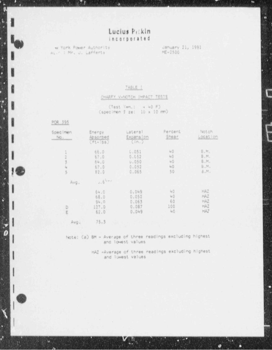
i
ILucius Pitkini fl C O f 9 0 f a t t d
w Yor b. Pcwe r Author i t y January 21, }99)4. : Mr. J. Lafferty ME-2500
ITADLE I
CHARRY V *CTCH IMDACT TE$TS
40 F)(Test % .: 4
(spectren ! re: 10 x 10 re)
| POR 395
Specirten Energy Lateral Percent fetch
| ID. Osorbed Eroansion Shear Location
(ft-!bs) (, i n . )
1 66.0 0.051 40 B.M.
I 2 67.0 0.052 40 B.M.3 64.0 0.050 40 B.M.4 67.0 0.052 40 B.M.
f 5 B2.0 0.065 50 6.M.
Avg. .> . 6 ' ' '3
64.0 0.049 40 KA2
68.0 0.052 40 W94.0 0.063 60 MA:
l D 127.0 0.087 100 PME 62.0 0.049 40 FN
Avg. 75.37
)tete: (a) BM - Average of three readings excluding highest
I and l wef.t values
HA2 -Average of three readings excluding highestI and lowest values
O
- -
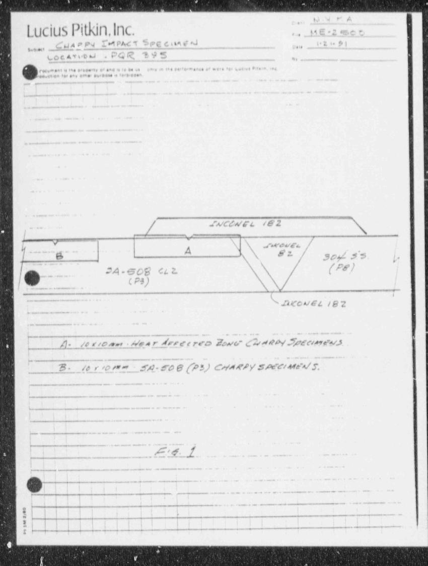
- - - - -__ - - - _ - - _ _ _ _ _ - -__
UNKA' ~ '''
UCi~) ,
\ y 6 -: sc y* ...- -
dd AgP4 M PA< T 6F C C. n M F 'J ie ,, p 1e.i. '--wmi
L o c. A v s,0 6J . PQIR 19 5 8b y
h cw ..at is i ,. ,, .i, e' eae . i. H 6. oa., .a o . o.. . .. .ai v. . .. . ... uoe e n. ia , .m
x j m o..a e.,ea, e m , ...p ....e <>..e.a.. _ . . . _ _ _ . . _ _ _ . . .. . _ . _ . . _
._._
i i!
L_j- - _ - . _ _ . _ .. _ ._ _
..
- . . _ . . . . _ . . . . _ _ _ . _ . _ _ _ _ _
I ); i..
. . - - . . - . ..
..
. . _ _ . - . . . - . .
. . _ _ .. _ __
- _ _ . _ . . . . . . . _ . . . _ _-
. .. .. . .
.
. . .
-..
. .- - .__.._ E-_
.fA/CdsTL /82. ..
I_ _ . _ .
..jy .f*VC4/4*t. f
g ~., S o d,.. .
- -- -- g - - S "> .,_
.
m_ . . M - 509 ct 2. (M)... .
J _. c Ps).,
.... .
.22/cc A/E4 / g 2e
;- . .... . . . . . .
. . _ . -.
,. . . . . . . . . . - . . . - - . . . -
/1 ' /e ito,*wr h/e4 r Aprcc reo IwG' (k ft?p '.7pd'c/p rp y.,5_ry
,.. _.. .. . ..u . _ ._. _._.
O* _ /e r /O_/.n y' ,q,g. g p g p (,,f,4,gpyt 3,gq: c ,44g x/ 3,I 'm.
'
_
,,
,
,
6 .
i i i. .. .. .t
'
._ - _ _ .
| I t'
_ . _ . . . . . . . ..
i I
'I ..
_ . . . . _ _ _ . _ . . - . . . . . .
Mq . ... .\" _ .- ___. . . . . . . . . _ . _ . .
- . _ . _ . . .. .. . . - .
,-\
. .
_.- .. . _ . . . . . . . . . . . . -. .. ..
. -.y, .
_ . . . _ . - . . . . - -
,
' , ; .. . . . . _ . ..
_ . . . . . _ _ _ . _,
I .,
| I i i | i li : i | I I i ! ! |'
'
: ;-
:'
; ;' j'
r ; -,
1
|-----------~_ _ _ _ . _ _ _ _ _ _ _ . _ _ _ _ _ _ _ _ _ . _ _ _ _
. _ . - _ _ _ . _ . _ . _ . _ _ . _ . _ . - _ . - . _ _ _ - . _ _ _ . . _ _ _ _ _ _ . . _ . _ _ _ _ _ _ _ _ _ _ _ _ _ . . . _ _ _
l ;
,I '
O'
I
I.
I
I
)g Appendix 6
; Metallurgical Test Reports;
| In Support of PORs 395,745,746 '
,
:I.
1. .
IOI
!II
I
I. '
iSIR 90-063, Rev. O
h
'I i
- _ - - -._ - --- _ _ - - - . _.
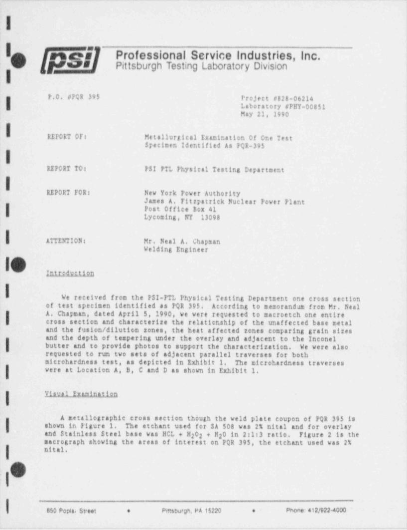
-. . -. _ _ _ .
|
|n .esams Professional Service Industries, Inc.O yes Pittsburgh Testing Laboratory Division
iP.O. #PQR 395 Project #828-06214
I Laboratory #PHY-00851May 21, 1990
i RITORT OP: Metallurgical Examination Of One Test >
Specimen Identified As PQR-395
iREPORT 70: PSI PTL Physical Testing Department
iREPORT TOR: New York Power Authority
James A. Titzpatrick Nuclear Power Plant
i Post Office Box 41Lycoming, NY 13098
ATTENTION: Mr. Neal A. ChapmanWelding Engineer
|f~Introduction
I We received from the PSI-PTL Physical Testing Department one cross sectionof test specimen identified as PQR 395. According to memorandum from Mr. Neal
l_A. Chapman, dated April 5, 1990, we were requested to macroetch one entirecross section and characterize the relationship of the unaffected base metaland the fusion / dilution zones, the heat affected zones comparing grain sizesand the depth of tempering under the overlay and adjacent to the Inconel
I butter and to provide photos to support the characterization. We were nisorequested to run two sets of adjacent parallel traverses for bothmicrohardness test, as depicted in Exhibit 1. The microhardness traverseswere at Location A, B, C and D as shown in Exhibit 1.
Visual Examination
A mettilographic cross section though the veld plate coupon of PQR 395 isshown in Figure 1. The etchant used for SA 508 was 2% nital and for overlayand Stainless Steel base was HCL + H 02 2 + H O in 2:1:3 ratio. Figure 2 is the2macrograph showing the areas of interest on PQR 395, the etchant used was 2%nital.
O:
| e~e-meBs0 e.a, s,.e, . e,e~ ,.easm -.
-
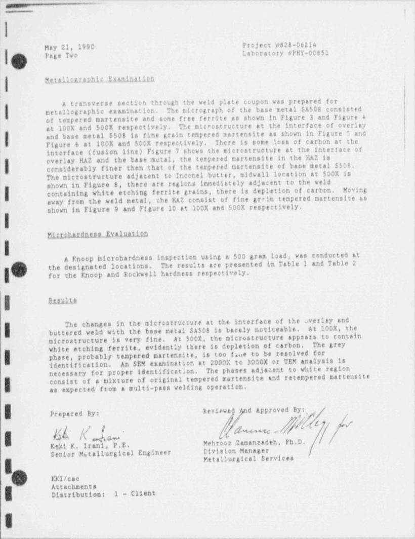
._
|
May 21, 1990 Project #828-06214Page TVo Laboratory #FHY-00851
vtitta11rtrJrhiLIxmina11rn
A transverse section through the veld plate coupon was prepared for
1 metallographic examination. The micrograph of the base metal SA508 consistedof tempered martensite and some free ferrite as shown in Figure 3 and Figure 4at 100X and 500X respectively. The microstructure at the interface of overlay
Iand base metal S508 is fine grain tempered martensite as shovn in Figure 5 andTigure 6 at 100X and 500X respectively. There is some loss of carbon at theinterface (fusion line) Figure 7 shews the microstructure at the interf ace ofoverlay llAZ and the base metal, the tempered martensite in the llAZ is
I considerably finer then that of the tempered martensite of base metal $508.The microstructure adjacent to Inconel butter, midvall location at 500X isshown in Figure 8, there are regions immediately adjacent to the veldcontaining white etching ferrite grains, there is depletion of carbon. Movingaway from the veld metal, the llAZ consist of fine grtin tempered martensite asshown in Figure 9 and Figure 10 at 100X and 500X respectively.
Microhardness Evaluation
1 A Knoop microbardness inspection using a 500 gram load, was conducted atO the designated locations. The results are presented in Table 1 and Table 2O for the Knoop and Rockvell hardness respectively.
| aunta
The changes in the microstructure at the interface of the overlay andI buttered veld with the base metal SA508 is barely noticeable. At 200X, the
microstructure is very fine. At 500X, the microstructure appears to containwhite etching ferrite, evidently there is depletion of carbon. The grey
I phase, probably tempered martensite, is too inne to be resolved foridentification. An SEM examination at 2000X to 3000X or TEM analysis isnecessary for proper identification. The phases adjacent to white regionconsist of a mixture of original tempered martensite and retempered martensiteI as expected from a multi-pass velding operation.
Reviewed / d Approved By:Prepared By:
g g w- & J/W GKeki K. Irani, P.E. Mehtooz Zamanzadeh, Ph.D.Senior Metallurgical Engineer Division Manager
Metallurgical Services
III/cac, Attachments
Distributions. 1 - Cliene .
I-- .

.... ..... . . . , ... .v .. . _
J AMES A. FITZP AT RICK NUCLEAA POWEA PLANTg,.
,
' ' ' ' ' ' ' ' ' " " ' " " ' ' ' ' ' '" *" . .E' ' " '
cat.CULATION SHECT ""PA. PO . 9 0 03t 1e -'- f'HM' . ~- c a c....
' L.,,nn . .
pctg 3% T 95T WPt G.4 {j . .. . ,0,,,w.ia.p , ..e m e r c.i.e,, u. . ,ip.i .
%A.Pn 4WM g
1
*2 _ _ . ... .
,
3 Ws o Sve vt Cit.M4 te H te '6 ( T. a @6 su L>ettAs - g*, ~E~ l 't ~
;-'
6 g#gg ;a7 wmn8 f
...
,; Wey/ ////M%%W#fM%W/h- .
11 !. $ l.. 1Y - \-*--_I
12 [.t4en I b #.
... {. ''
---- -
6- L'- - ' ----cj ,
15 %. l__. 77- \- -- F
, - - - ,o,_
M*1 cd. 506 C.uen* 7. IRCDHD N""
MmEM' - - '
hd*M16 6 Aw % % . Y W.CtFa 4 . ...1, .
u,.u;ce s J. ... ..
.
E *M* 3'
20
21 5tm g,g BA.RouEn V A1 V.Y.h . .. - -
( 2 009 / 500g kcND) . M** *..
.I 22 m I- TOP % # "'*$23 v~" eg ._
24 65 /A B C- .D Two tu v.4w-.
.,
E' T' '" 50'#1 TD ***''.I2F 60 / NM"' 5 * ' TTEE 26 gon
TRw"55 0P 27 3m>
,_
28 soo29 '160
,,
30 goo'
31 ,,,J,1,QO
32 moo33 , Isre34 _\" loo
--
36 \*>ao.
36 egco,
37 _EMDu 38 ggo
['.'AMD =
41
4243 D'HIBIT 144| ,,
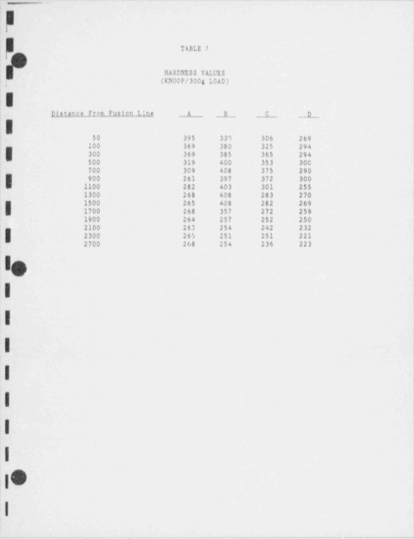
_ _ _ _ _ . _ _ _ _ _ _ _ . _ _ _ . _ . _ _ _ _ _ _ _ _ _ _ _ _ _ _ _ _ _ _ _ _ . _ . _ _ . . . _ _ _ . ._ _ _. . _
i TABLE )
HARDNESS VALUES,
(13400P/300g LOAD)'
|
IDistance Trnrn Fution Line A B C D
50 395 3 3') 306 269100 369 380 325 294300 369 385 365 294
,
500 319 400 353 30C700 309 408 375 290
I 900 261 397 372 3001100 282 403 301 2551300 268 408 283 2701500 265 408 282 269
1 1700 268 357 272 2591900 264 257 252 2502100 265 254 242 232'
2300 26's 251 251 2212700 268 254 236 223
I
I
I
I
I
I
I
IO .
I
-_ . . __ _ .. .. . _ _ - _ - . . . . .

~ - - . - _ _ . - . _ - - -_ _ __ _ - . _ - - . - - - _ _ . . - - _ - . __ _ _ .. _
m
ii
iTABLE 2
Al'FROXIMATE HRB AND HRC! (
';
! H! i
E111Antt.ltem rusien Line A _. h C D
'
N.
'
50 39 C 32.5 C 29 C 23.5 C100,
37 C 38 C 32 C 28 C). 300 37 C 38 C 36.5 C 28 C I!m 500 31 C 40 C 35 C 28.5 C !'
, ,
, 7C0i 30 C 41 C 37.5 C 27 C900 22 C 40 C 37 C 28.5 C1100 25 C 40 C 28.5 C 21 C'
1300 23 0 41 C 26 C 24 C'
i'1500 23 C 41 C 26 C 24 C| 1700 23 C 36 C 24 C 22 CE 1900 23 C 21 C 20 C 20 C2200 23 C 21 C 98 B 96 B
,
2300 23 C 20 C 20 C 94 B {E2700 23 C 21 C 97 B 94.5 B
s i.
' I,tt
i
1|
;IJ
!O4
l
_ _ _ _ _ . _ . ... _ . ._._.._._.- _ ._ _ __ _ _ _ _ _ _ . . . _ . _ _ _ _ _ _ _ _ _ _ . _ . . _ _ _ _ _ _ . . . _ _ _ . _ _ _ _ . _ . _ _ _ _ _ . _ _ _ _

- - - . - _ . - - - - - _ - - - - - - .
. . - - -. __ ___ _ . - - - . - - - - -
-
i
\%,
i
i
| s m :*-,
j
I . . . .
i
i i' -
r g rp , g . . ..;.. . ., . .;. ,. ,. .;.3. . . ., .. ,. ..y ... ,. ._ , _ , , , , , , , , , , , , , , , , , , ,
03,
I M'
i
j Figure 1 - Macrograph showing full cross section of PQR 395.
i
c. --
||.
. . . _ - __ _ . . _ __
; l ,,
! '
I ,,
'
.
e, s I
i,
s! N
' 'e
!
. .
7'
, t,
! ,
|Er .
:
; si tiill|Illi lill|Illi lill|Illi lill|Illi lilljilli lililllli till|Illi I;i 5, 6 7 8 9 10 1 1 1,
|II
f Figure 2 - Macrograph showing the areas of interest on PQR 395.Project #828-06214, Laboratory #FHY-00851
;i
:- - . . . - _ . - - . _ _ _ _ _ _ ^----F'@"w-PerN'y-_
_y w . , ,
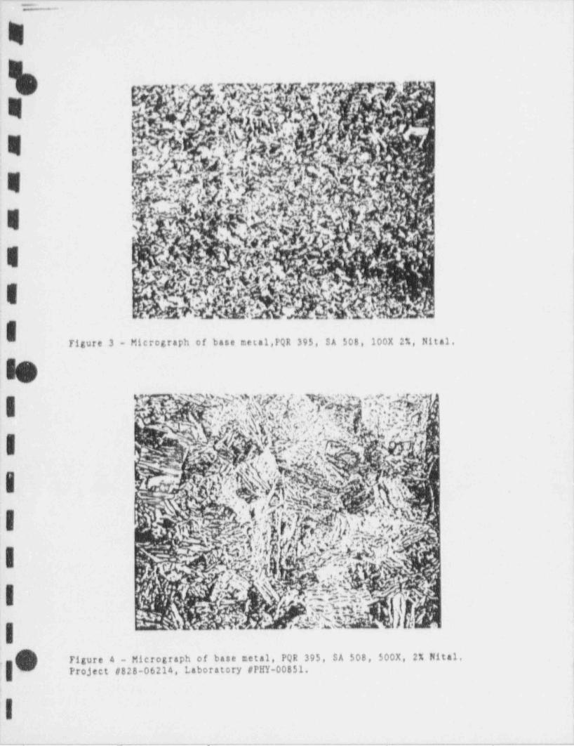
_ _ _ _ _ . _ _ _ _ . . _ . . _ _ _ _ _ ____ ._ _ _ _ .._ _ _ _ _ _ __ _ _ _ _ _ _ _ . _ ____ _ . _ _ _
\
%
| h->_3-
h |
%
;
e ;
e .
4
Figure 3 - Micrograph of base metal,PQR 395, SA 508, 100X 2%, Nital,
le
i 1 :. ..
= a w-.e: .. . ,.< : . ..
.;,*' ,#,
, ,, W -$, , ,
I ~
'
~
rt
I .T "fj
A,.
| |f .
'
A Aik. |i mjg - . .
--\
| |
.|On .r. . . m e,cor.,s o, ba.. ..t.1 Po, 3,,, si soe, ,00x, 2x m .1. iProject #828-0621., Laboratory #P!IY-00851. ,
'l._ - -____- __ - -- _ _- -
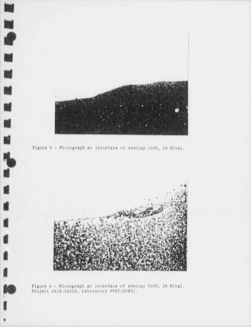
- - -
N ,
; "
!"
,
: ~
!
l,
a
|~ .
I ;
I" || w
.Tigure 5 - Micrograph at interface of overlay 200X, 2% Nital,i
s ,I
Ii o4'
. , .. 4 ;idf
"
.*' : x~ p
'
f. .. . . . .. . g,M f ea ,.sV .. ' #(t
e , ,
.. m_V |
g'
|I~
$Figure 6 - Micrograph at interface of overlay 500X, 2% Nital,
,
! Project t/828-06214, Laboratory #PHY-00851.!
|||..
|=,
- _ _ - _ _ - _ _ _ _ _ _ . _ _
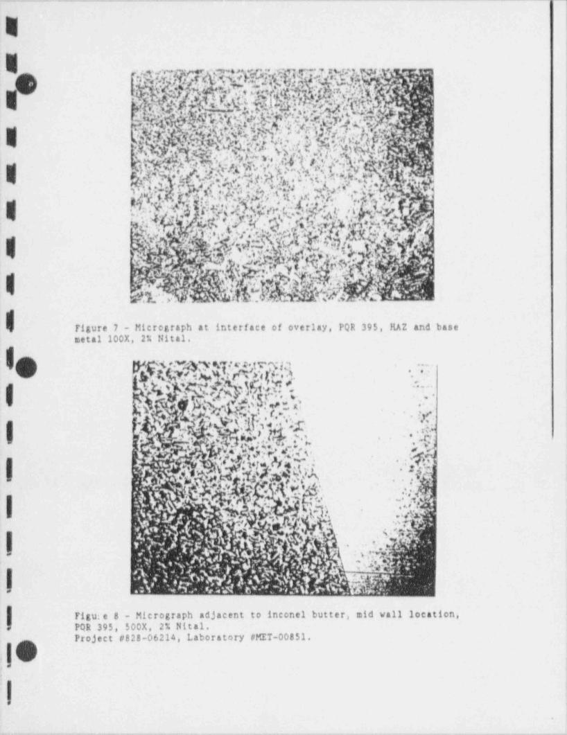
. - _ . . - . - -. .= - . . . = _ - - . _ . . _ _ - - - - . _ - - . . - - _ . - _ -_ _ ____
Ea w~.f amma!
yyr.
'ft && W. I h9 '
;.
, i,
'
, . /: 4.' .'.tc 4,,",.%f d/j pA -
s.t. pq.,. !, h ' he;' .e<m a % d'i p'" &' m.,i'''
.
= s c
h<],)/;f1 .T([r g'sg . . *+e, .
.m * d. . i' . %. . : . w '
i
R -c t*
%"t.y
%?/.;ts'*2 * Ur>? ,ty-.
'<
1 ' ,- . ib t.< er;,. 1
5 **,f $ , kl.' *$g. b,/gb='* Yqh&-.
Y*<<
Ifigure 7 - Micrograph at interface of overlay, PQR 395, HAZ and basemetal 100X, 2% Nital.
m% *-Q*5 {o.c h}m'C'yQ,. . . - --
s
.....
I q 4.M C' "
s- ..--.,
. $?h.Yl.b} k",dNd ** '2% ..i;,.'
.
4,L 'h*
I 5 ', P$g6!,J$.?(;~.-*C ~. A
.,'
.nh%5
. .
" ~ ~ \,? ,RQ;?IV' ;
.
*; !
|^ '
* j%..g': ,
. .;; h:- . .
"},
. :,; 4 ~* jt,,
..g., ..
' . . gn| . n ..,- -,
-
.
~7'.'f. s
.
Figure 8 - Micrograph adjacent to inconel butter, mid vall location,PQR 395, $00X, 2% Nital.*
Project #828-06214, Laboratory # MET-00851.!
4
:. .
.
I :.
.o.,, , - . , . . _ - , , _ . _ . _ .,___,# .em. -, - . - . -, _ , ,,,_-,,--..,.# -,,.-w......
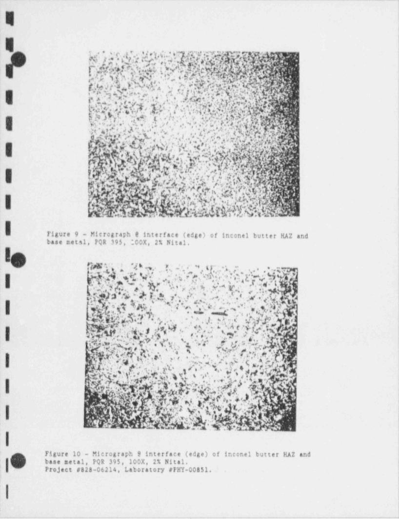
. . . . - - .. . _. .-. - --
E'
E
'i!t.M/k'ig''* ''' ' ',iM'<**'' f' h3''tCA'rV>*.!NYNk'kIhhh'k~iIN.hh*
'f 'MM
3.. }g0%st4@M}M. \,'>.'yGg.u=
:: % . .% LM $03d M M,,d N.);g. w!Ij$% '-
|
yp. . >%.,.. . .1n . .sa. . .~.,ffil.
. M.e-4 u:i.r t q M,..,.
g;.o.i ' s 'j..,'.8;. e , v.w..>,.g
.
.
. ' :.. , , . . . ..
w .*
[ *N.kf$$OK,f.,fe, p~ ,N:.k : g. 9.,$,..
9. ,e% f % ;..:. *-.
.
$'),S,%ji,?,gh.
G*'o- i
|-
,
',G. .$r.;*tC <'*' .%:, |Y'v,,:. .
'.s'
* "T@'k. .! ?!)T,.f >'Y;g;-i
*
~ f$b N'*
..
i? b 1(**i 'i
N7,Q. f '{|.~<.:::h ,1. *h| }-
E%2|bb$ns o
Tigure 9 - Microgr.aph 9 interface (edge) of inconel butter HAZ andbase metal, PQR 395, ;00X, 2% Nital.
IO nw ;.1 n..th<d;tip(hY;;Q.:f Vi ;. .:.. .:oW* # 4,a'J.o:.ww.a.
.
5u:. :.g $ .i?:q ; t r.. . ,. . ..
.% .;
,.r.c. * 0,y-| .
.; .
L- 5j.s*'.~v'2f.';.(. tN ]1' '*, . *? f.h. ' * '..
. c ., . . .... .-
:. p.. m y&. . . . ar . . c : -. ; ,. .s y . g-
. ---c. . . ,.; N. x '.'p c .n. .y+)a.c;Wth.%,,f.;43..p,.
a .
. .6.J;.g. .i,ffi:.5 9 W,;. s sg ",^
v. <e ..
^
| 4~~# .y, q|* '1'.
s {'{i, . <. -.,,
.
"b|C1h --.
..... 4. %, '' ~w.1,$?H A,';4. . c . a. y .| , . . . e , . % 7 '.. .'. ;.c : . . .y .1 u,). .t *. h\
S 1 '.I _ Y.-+,
.,
) ' .: . < ~ f. - h''. ' .
'
.iN..h,#4'S,..ii.<),i.F 2* -' '
f- -.
_
. ,., . [ -(5Y,hg<'s.-.
.: '
.
'
-
%-Q.. I.,.,s= .A.. . . __
lFigure 10 - Micrograph 9 interface (edge) of inconel butter HAZ and
|' base metal, PQR 395, 200X, 2% Hital.'
,
I Project #828-06214, Laboratory #FHY-00851.
i
| ||
. - - . _ . _ ._. _ _ _ -. _ _ . _ . _ . .- -. , . _ - _
. - --
E.
es Profossisnal Scrvico industrios, Inc.E POs Pittsburgh Testing Laboratory Division
I PQR 745 and 746 Project #828-06214Laboratory #PHY-00851May 21, 1990
RIPORT OT: Metallurgical Examination of Tvo TestSpecimens Identified As PQR 745 And 746
REPORT TO: PSI-PIL Physical Testing Depart Lent
REPORT POR: New York Power AuthorityI James A. Fitzpatrick Nuclear Power PlantPost Office Box 41Lycoming, in 13093
ATTENTION: Mr. Heal A. ChapmanWelding Engineer
O Introduction
We received from the PSI-PTL Physical Testing Department two cross sectionof tect specimens identified as PQR 745 and 746. According to memorandum fromMr. Neal A. Chapman, dated April 6, 1990, we were requested to macroetch oneentire cross section and determine and characterize the relationship of theunaffected base metal and the fusion zone, the heat affected zone comparinggrain sizes and depth of tempering under the veld and to provide photos toI support the characterization. We were also requested to provide two sets ofadjacent parallel traverses for the micro-hardness test. One traverse shallbe initiated in the base of the veld bead denoted " valley" and the other
I traverse initiating between veld beads denoted " peeks". The microhardnesstraverse location is shown in Exhibit 1.
I Visual Examination
A metallographic cross section through the veld plate coupon of PQR 745I and PQR 746 is shown in Figures 1 and 2 respectively. The etchant used for SA2 2 + H O in 2:1:3 ratio.508 was 2% nital and for the veld metal was HCL + H 0 2
ItGPhone:. 412/922-4000Pittsburgh, PA 15220 *850 Poptar Street - e
i*
g- - . _ . _
l
M
May 21, 1990 Project #828-06214jy} Page Two Laboratory #PHY-00851w
tic 1All2ALaghitLuainallsa
A transverse section through the two veld plate coupons of PQR 745 and PQF* 746 vas prepared for metallographic examination. The micrographs of the base
metal 5508 are shown in Figure 3 and 4 at 100X and 500X for PQR 745 andh Pigures 4 and 5 at 100X and 500X for PQR 746. The microstructures in both theW cases are unhomogeneous, consisting of a mixture of parallel dark and white
bands. The dark band contains carbon rich tempered martensite and the Whiteband microstructure is also tempered martensite which has a greatar amount offerrite. Figures 7 and 8 are micrographe 6t interface of fusion line, at 100)and 500X of PQR 745, the location is at center of flat portion of weld.Tigures 9 and 10 are the corresponding microataphs of PQR 746. At the fusionline, microstructure for PQR 745 consist of fine white etchit.g grains offerrite depleted of tempered martensite. There is similar less of carbon forPQR 746 at the interface of fusion line. The microstructure at the edge of
h HAZ and base aetal is fine tempered martensite as shown in Figures 13 and 14m at 100X and 500X for PQR 745 respectively and the corresponding one in Pigure
15 and 16 for PQR 746,
tMicrehardness Evaluation
A Knoop microhardness inspection, using a 500 gram load was conducted atthe designated locations. The results are presented in Tables 3 and 4 for PQR745, Pnoop Hardness and Rockwell Hardness respectively and in Tables 5 and 6for PQR 746, Knoop Hardness and Rockwell Hardness respectively.
Results
The microstructure of the base metal SA 508 for PQR 745 and PQR 746was similar and exhibited a banded tempered martensite structure. The fintgrain microstructure at interface of fusion line of the veld and base metal SA ~
w 508 for both PQR 745 and PQR 746 at 500X revealed white etching ferritedispersed with a grey phase, however the pattern of the microstructure at the '
I interface was different. The grey phase was too fine to be resolved, prnbab'llit is tempered martensite. There was a loss of carbon for both PQR 745 and- yPQR 746 at the interface. 'I
Prepared By: Reviewed An Approved By:
5 KL KL in /U ~
Keki K. Irani, P.E. Mehrooz Za.manzadeh, Ph.D.Senior Metallurgical Engineer Division Manager
Metallurgical Services
KKI/cac-
Attachments.I Distribution ' 1:- Client'
I- -- .
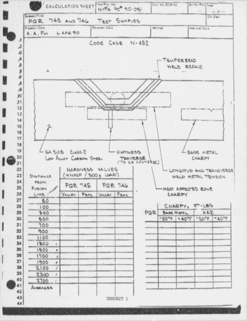
"h'{"'=g, l' ' ' ' ' ' ' ' ' ' " * " ' ' ' ' ''"C ALCUt. ATION SHE ET
3 . . . _ . . . . . c. _.Pdt R., 7 4 5 A u t 7 4(.e l~t.tT 60APb?.S
,..,,,,,o.. a... u o. . wtw we. ie.i. i,
F . A. N 4 APS.90 |,
'
CcCE. C W E. N * 432.| 2 |
-
a \
/ Ts.wPExetAD| ,8 wate Rt.PMR
y - .. .. -. . _ .
I-.-. . , . .--
.
_12 ) ,.= = w .- f.--- - *
. -..y.,
3 13|
3, i _ . . _ . . . . _ -,
f) hI 15 . _
16 j I
17 ' !
'| 18
19 SA e.20 b Co.% ?. J- R ERtmt.*./o EA% AETAL20 (,, by (fato.4 6nn. TRAVER.tE. C M PY
\ 21 (TO %E C'"" C) -
22 RAtbuY% %LVE6 LoH(atTub Awu TuAusvtt.5123 D mTAuc.t ( M009/*009 #I WreLb thETC.L TVntc4
d]g POR16 PGR % gg,g a gg,g ,
|,
26 b u Y. ( Ve Part Wu.u Puv. tAAst.W27 50 -
*~
23 goo C.MW g f*LES29 100 PQR ba.*t. Rm i % W.30 *s00 -E0'F t40'r ''lD*F 'AO'F
l31 100 -
' , _
32 *> 00'- 33 1100 >
| 34 1%00 e
35 1500 s
38 t100 s
37 1900 < ..
38 '2.100 /
39 2300 s
40 2700 t
'
0 41 g gg42C3 DGIIBIT 144
,,
_ _ _ _ . . _ _ _ _ _ .__ _. _ . , ._. - _ _-
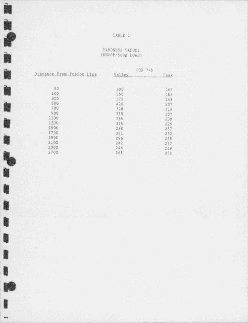
[~ -
i
L~ ,,
t
TABLE 1
HARDNESS VALUES f(KN00P/500g LOAD),
|PQR 745
j pistance From Tusion Ling y311ev Peatt
50 300 265|
,
100 350 283300 375 243!
500 420 207,
700 328 214;'
900 355 2071100 365 208
b 1300 315 2251500 288 2571700 321 252
R 1900 296 2552100 242 2574
i
2300 246 269'
l 2700 268 252
rl
i
4'
R
I !,.
.
I
.I* ',
.
_
- . . . - _ . _ - _ - _ . - - . --.. _ - . - . . . - - _ . . . . . . . - - . . . . _ - - - . . . . - , , . - . - . - - ,
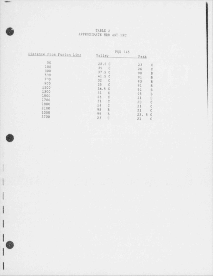
-__ _ . _ -. .. . _ _ _ _ _ _ . _ _ - . _ _ - _ _ . . _ _ _ _ .
ATABLE 2
APPR0XIMATE liRB AND IIRC
PQR 745DittAnce Frb"LfREiAILL1ng E411c_y. Peat50 28.5 C 23 C100 35 C 26 C300 37.5 C 98 B500 41.5 C 91 B700 32 C 93 B900 35 C 91 B1100 36.5 C 91 B1300 31 C 95 B1500 26 C 21 C1700 31 C 20 C1900 28 C 21 C2100 98 8 21 C2300 99 B 23, 5 C
2700 23 C 21 C
O
|,
1
I
I |
|O|
I.. ._ .
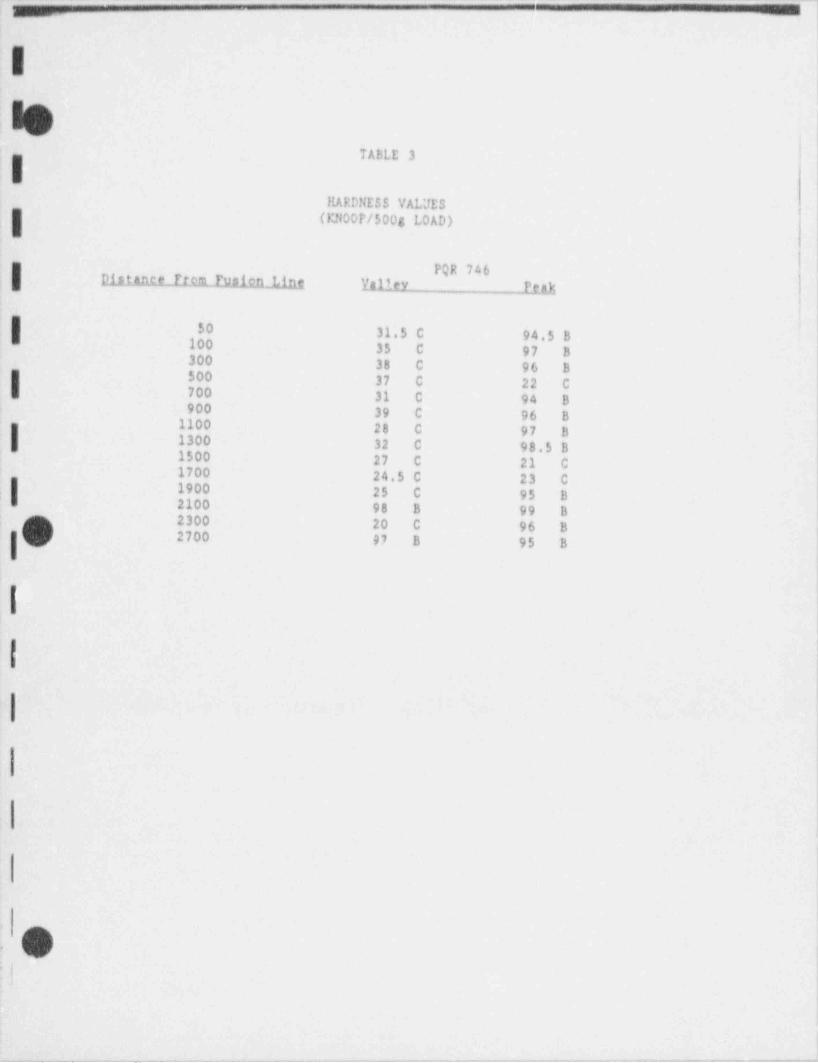
, _ _ _ _ _ - . - - - "-' ' ~ ~_ .
_ _ _ . --
TABLE 3
IRARDNESS VALUES
I (13100P/500g LOAD)
p h a2ce Frem Pulitn h YJttley Peak
i'
I 50 31.5 C 94.5 B100 35 C 97 B300 38 C 96 B
I $00 37 C 22 C700 31 C 94 B900 39 C 96 B
1100 28 C 97 Bi 1300 32 C 98.5 B1500 27 C 21 C1700 24.5 C 23 C
i
I 1900 25 C 95 B2100 98 B 99 B2300 20 C 96 BO 2700 97 8 95 B
1.
|
|
.
j
: Oo.
-.....-m_ _-.. .__m_ o - - . , . , - , , - . . . _ . . .,m _. _ , ._,,,.,_-,,.,r-. , _ .- _ , , _ ,- _ , . . . - - , . . . - _ _ ,
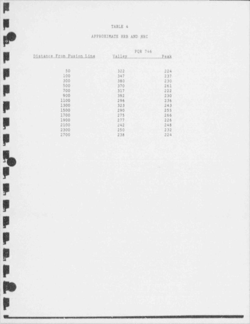
, ___ .___ _ - - - - - -
TABLE 4
APPE0XIMATE !!RB AND }!RC
D.ialaRC.C ILC2 l'Hif1LLint Valley P e 3),
a
' 50 322 22g
100 347 237300 330 23o$00 370 261
|- 700 317 222900 392 230 ]
1100 296 2361300 323 2431500 290 255 i
1700 275 266 !
1900 277 226 || 2100 242 248 '
2300 250 232;
2700 238 224,
,
'F
F
F
F
F
> ,
p .
-
,--,-.,.,..-..m,,_,..,,,cmr.,,,,-...,,,.,-e.,, ._._.m._... . _ , .m . ,,..,__,_.m,__ _ _ . . , , _ , , , . _ . . . _ , . . . , . . . , _ , , . . , .--
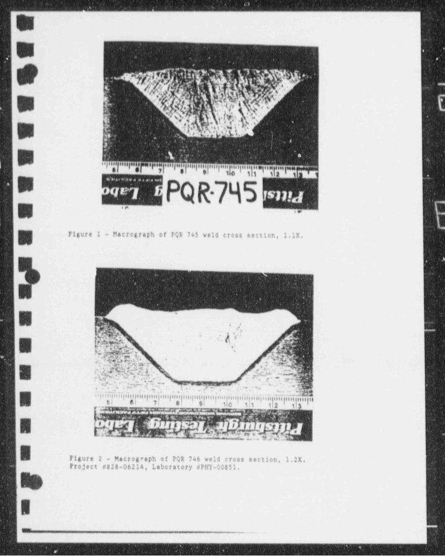
~
W-.
! ,
W
'
.
g .*=
~
|;
.
[b].4
. cu.
.'-
.'
u i u .'**,
t :.- v ri
4 ., . 3v~
..,..a....,. . . . . . , . . n . . . ., , , , . . . . , . .. , . . ., , , , m.. ,, .
-
6FiPQR-795-.6
-
..w
~Tigure 1 - Macrograph of PQR 745 veld cross section, 1.1X.
w
- -
,. ,
u%- A d'e'
_
5 p4t
-
..m -
...arsp. -- -
'4 b P % '
' W$$@%. Mz. . ..|%:?? y 9 6 ? ?p,,,p. 7;; z r v,,p.:g:.,^p.,=,..p ',g.:. : : ,
-%;
g ..
. . , , .g . , ,, p ,g .. , p ,;,ig,,i p i; ,, .,p,g.p.,,= -
. . . ... .
E :, r a, 2_. .
_. r'- - _ _. 1 1 ofp e--
B Tigure 2 - Macrograph of PQR 746 veld cross section, 1.2X.Project #828-06214, Laboratory #PHY-00851.
t
s_
_ _ _ - _ _ _ _ _ _ _ _ _ _ _ _ _ - . - - . - - - - - - - - - - - - - -
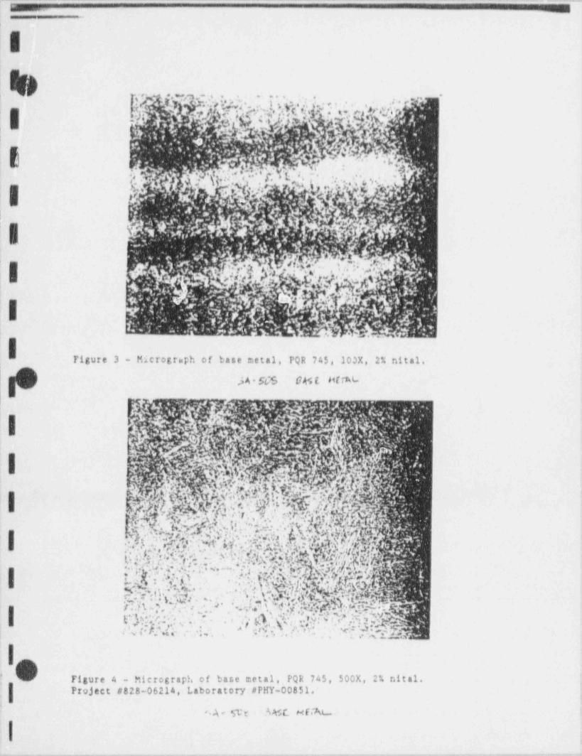
- .. . - . . . . . . - - _ . . . - . - . . .-
Ir, . .
, ,, #- '. ,ife,''#U:J |- ,'sp,p[''. , . . .. ...
#. .
3 :
<
: .
f b...,
{','d.F*,*'fL'L.f...?>g.,.g?Io
,g.., , . . < ;, .
.
.-
E !|
Ii el'!; .?f. .g.. .
. . 4, .;4 &g,|,' '
" ': , ,,
.
'
?-
: g ,
.
:, . .
Figure 3 - Micrograph of base metal, PQR 745, 100X, 2% nital.
JA SCS GASl ht %
i.
.
,
1
| 1 -
'
tite %,W.y y,. -'''1 ,,,'| 1 ; s. .
' '' '
,
. ' 5 ? .- . ,$ ' ' Y(*b ,.| 'i.e.&.' a''; , j' |c iY *,;s n '.~
.
* c A& *L- f*, .*
W,''ff.Off.y2b*
'
< r ,.g;; ,f.Up e ',L; .:'
...$1)|':.V ; G |.|| [: %"..
, ~ , ~.d* - S*,C''
| , , , .l *;. .
.*- a " ').
, ;*m t
g,g.;,=,.t..-
..
.| ..
g' ,j %- . . ; .; ... .
' ' 4 .* . ~
'_ , _ , ., . 4 (,,. ,j
Nd,55_IN ,'".!,'. .' A M:.',,:D.'OF''khy}?a* '
s,
. .
'|| Figure 4 - Micrograph of base metal, PQR 745, 500X, 2% nital. .
Project #828-06214,- Laboratory #PHY-00851. ;-
n - n
I .
_ _ _ _ _ - - _ .. . . - -- _ - _

. - . . _ . . . . - - - - . _ - . - . . _ - - - _ . . . - _ . . - - - - - - . - - - . - - . - - . - - _ - - _ - . . . -_
&E
2
-
u .aww.we.r.+ ww =
. ' O' N f,h[rb,, h .pg*,, . . , . g,2,g.',
-
,
' " .v .4.bi
~.s
*p, t ; . . ga . r
(g* . ,yA *.', .y') 'i , * .*,s Q ' #; *, {- ? ,* ', ,.<c w-
. u, ,.' + 4,n ,. *
, . -*
'eg. . , . . ; pg, r . , ..;'. '
. .--- - - _ -.--- . - . _ . - - _ - . _ - - - - - . ..
|
h .
|
|
'1
i
~
\j\ - /~
'
'
!N
Ie
)
rigure 7 - Micrograph 0 interface of fusion line PQR 745, 100X, 2%'
| nital.
I-. -
,
i
|
$- Y % * *h. h.* ," .;.t' ,.' ,' '; *, , ,7, y. '. , . ,, . '.,;. ,',,1| ' . ;, * ;,%,'
L%$.g. -
, ,. ..
** \' % ,y ' . . */. L', ,~b'y ., *7
I , . . # ,', . , , ' . .k. - */a., .f :
.Y.,,&,'O,'.' E, ,' ?!* *$.',. . -* a 6 ..:gy.k.'g.s.N,7,\'';Yn ?~kh,h |& 1..%p
> . y ,,.e<*-- ..v
. . . ,
.. . V *h..
'' *
| g .
' e
.nts.i j,'(. 'A'C$>'.*,j , . .. 't s - c f).. .
'
y, Vi:<. . .,.-
,~. . a. j'3
'
rI
_ _ _ . .
'
|Ps
: .
Figure 8 - Micrograph 8 interface of fusion line, PQR 745, 500X, 2% ,
nital. ;tiProj e ct'. #828-06214,7 Laboratory # PITY 00851.
,
,
- _ _ _ _ _ _ _
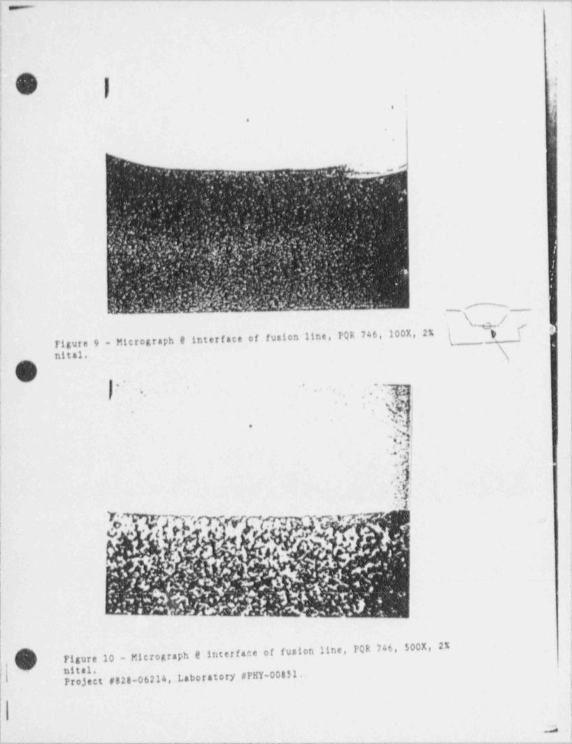
. _ - - --__
W|;
'
Ii.
| i
|$ '
f |
|*
,
.
i|;, .*
1 -t .
'
.
<i*- e ,
'. ...s. . *'g; -
, .,y.
,- -**, ~. . . -- n , v . . . . . T, ., ..,, . . . i
., - ' - ,- . .' . .*- '- , .,,
s
.
7 .,
.'*
~ .. .' '.,' - *
... . _ . ,. ..
'
J _: ..; ,*n_ . s,'. ' ', ' - [s , ':: ';. . s, ,%j. .
_
:~' *
..rpt>[.,c...{ ._ . ' . *. .
- , , .*
;. .s'' ' ---
,_
| |4 .|' . * . . ~. ._ f ' / > . . c '. .J.? , _,
' ''
,,
_
. . < ,-,. ..
'
.
. , . ,.
'.:.a.. . ' - '-. . . ..< : v'a ; : . . . . a . . : , ,-
,. . ._;*
, d dbO*'' Y8,E';EI GW*S *Exub?'* '' ^'. . , . . -.. - , . , , , .,
'
&
i \m,- /'
- s- ,
746, 100x, 2% ( ) )a-
Figure 9 - Micrograph e interface of fusion line, PQR\I nital.
.,
..'. .. -. ., . ,.- ..
,* . . ,
$! |-
j ..
ci,
.. .47J*
s,O+
| ,!** 't [j .,. 4;
.t!i,
i ;"3 1V!..3.R! '
| i-t. 'T* y
n.,
. [-r 'e--er*'
h4,
| l( | |
1
1' .
I__
mr.L=suininTt !'
i
||
M8 UTigure 10 - Micrograph e itsterface of fusion line, N M e
! ro ect #828-06214, Laboratory #PHY-00851.| ,
!
.J..__ ___._.... _ _ ___ _ _ ____________ _ ___ _______ _ ___._______________--._ _ ._ ..__ .,.. _ .,.__- -. -. . -- _ .--.-..-..- _ , -
_ _ _

_ _ _ _ _ _ _ . _ _ _ _ _ - . _ _ _ _ _ _ _ _ _ _ _ _ _ . _ . _ . _ _ _ . _
,
v, .f'
:!
'. |<' '~ ' ,
I .
. u. c . y m %'|" ; Y{ ..'' ~ '.- ,
.
'; ,i| '.tQR|Qid^
? ' ,
f .|.,A' '
,
h]/*y' . -|N Wh|1,.
~~ h, | y4' '' '
, .,- '
(g. -, - . . g.-
,
. t .'''
.''
'
s.. ,V :L *
'. : ' e !~., .
. . .' c -e m ,e -.
,.
w, ,s. . .
,e
q~ k,,,,',' %'
., ,
* , ': f 1 s''3 g; ' **-.,,]
h'.> '/. h .a N <,. ark &.;- O g''s..%-.
;.
y; ' |. - %r M| ,,
k X [6 N ' .' ~*. ,
|,
Figure 11 - Micrograph 9 edge sf IlAZ and base metal, PQR 745, 100X,2% nital.
?rY $4!,' Y,$:y . t.--
.
,' n.- c .9
: r |$' ?."., % .1 fg #'S ..i'I ,,
jk?p |
||' T jh: y'Q WY . . -
,
. N .. ,. O k.T . . h,, '
'. ..
|I' 'Tj.E2S*OtsEt'} ,
,v.c t. ,6%.; .
- a- 3gi 8w,| '')
i :
s
!
I- M %. .
-
1Figure 12 - Micrograph 0 edge of HA2 and base metal, PQR 745, 500X,
,|. 2% Nital.5 Project #828-06214,. Laboratory #PHY-00851.
I
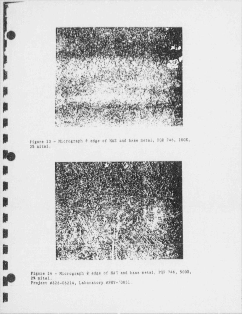
__ _ _._. - _ _ _ _ _ ..._. _ _. - . . _ _ . . . _ _ _ _ _ . _ _ _ _ _ _ _ _ _ _ - _ . _ _ _ _ _ _ . . _ _- -
.
._ .
,
F
1
p,
)' [? b''} *ejl .* f:. ?.. . .%*
k* 8' 1,Y'h.*j'E *-
y ;.O$a' .G 4,. 'h'
|, J ,p3..s. ..J(
1'' -
, c e . ,,,
, .
.. %,'g; p - t * '. * , ' * * ' ~ ~*|.
*4' p ., v . , .
~Y? ' '? y';, 2m:' ''
,,
g. >'..V*','' . ,,'.j'?f,;-
i w. .. .
h .:?$k ' ~.Y.'.5=."v.. . :Y|1 Ybi)
}igure 13 - Micrograph @ edge of HAZ and base metal, PQR 746, 100X,2% nital.
s
B
B .
'E &,
... O|
' , - -
p , g,lNo%;;'
-
..' ?: . 3.~..
:a '
Figure 14 - Micrograph e edge of HA t and base metal, PQR 746, 500%,2% nital.Project #828-06214, Laboratory #PHY-10851-.
;
.
,
. . _ u
_ _ . _ _ _ _ . _ _ _ . . . . _ _ _ . . _ _ . _ . . _ . . _ _ _ _ _ . _ - _ , . _ . . _ _ _ _ _ _ . _ .
A--
.~
1
,
v
U'
-
'WAppendix 7
,
Diffusible Hydrogen Produced as a Result ofWelding on SA 508 Cl. 2 Low Alloy Stee:
.M with 150'F and 300'F Preheat andNo Post Heat Treatment-
(Presented at Second Temperbead AdvisoryCornmittee Meeting, October 30,1990,
Charlotte, NC)i
|
|
sd.
d,
,
,8:I
~
L SIR-90-063, Rev, Og.:
|1
~
-. -_._______-_ _ - _
- - - - - - - - - - - - - - -- -
,
I
i
O1
_
REPAIR WELDING OF LOW,
,'
ALLOY STEEL UTILIZING THEAUTOMATIC GAS-TUNGSTEN
l ARC WELDING PROCESSl
l October 30,1990|
Presented by:
EPRI NCE Center,
Materials and Repair Application Division_
Principal Investigators:David W. Gandy and Shane J. Findian
Prepared for:
'
Temperbead Advisory Committee. , --
..
8-hW Materials and Repair Applicationf *30C Harris Boulevard; Charlottei NC'28262
,
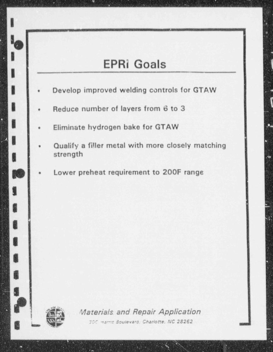
. _ _ _ _ _ _ _____ ___
l
hI
EPRi Goals|| Develop improved welding controls for GTAW.
| Reduce number of layers from 6 to 3.
Eliminate hydrogen bake for GTAW.
Qualify a filler metal with more closely matching.
.g strength
g Lower preheat requirement to 200F range.
I
I =
I'
I
E
I
E
| {$b. Materials:and. Repair Application,
f 30C -sarn Boulevara Charlotte; NC 28262. ,. -
__
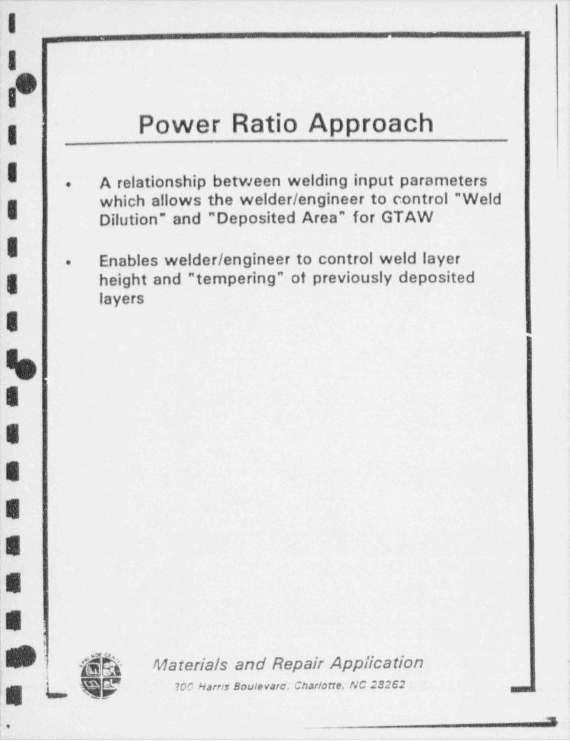
- .-. . -. - . . - -. . - - .
I ,
.
I0
1
Power Ratio Approach'
g
I A relationship between welding input parameters.
which allows the welder / engineer to control " Weldg Dilution" and " Deposited Area" for GTAW
I Enables welder / engineer to control weld layer.
g height and " tempering" of previously depositedlayers
I
%'sE
E
E
|E
|E'8
9 g Materials and Repair Application
, t ,gt,
:_ , _ , _ _ _ _ _ _
: *' .-
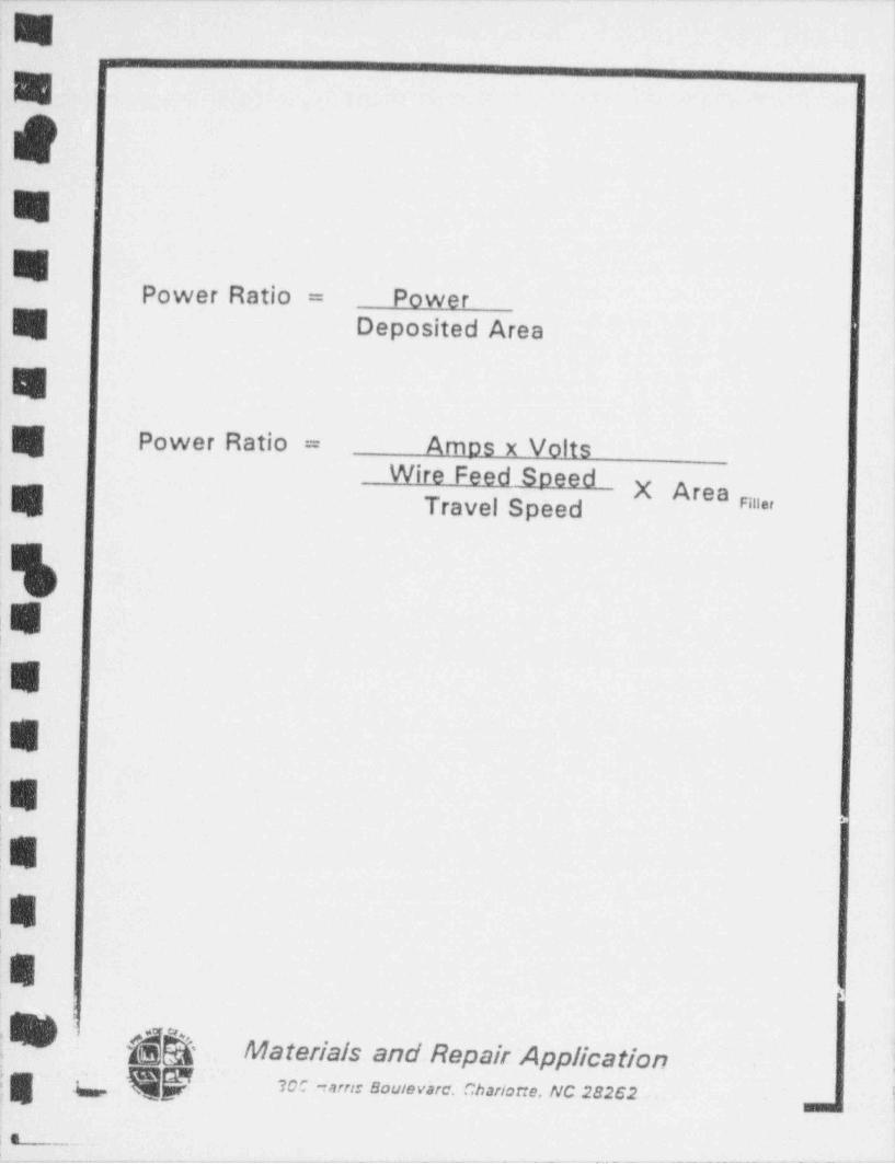
_ _ _ _ _ _ . _ ._. __ .. _ _ _ _ _ _ _ . .._. _ _. _ _ _ _ _ _ _ _ _ _ _ _ _ _ _ _
&. i
k |i
f''~ i
% !-
F..
k
<
D_.Power Ratio = Power t~
Deposited Area'
\Pk
[ Power Ratio = Amps x VoltsWire Feed Soeed
X Area ""*''
Travel Speed~
-
rk,-
"N
'
,LJt
: L
E,
i hh Materials and Repair Application ;;, c gp m ,- e- .m.,, . uc me2 ;,,,
,-. - . - - _ _ . _ _ _ _ _ _ _ _ _ _ _ _ _ __
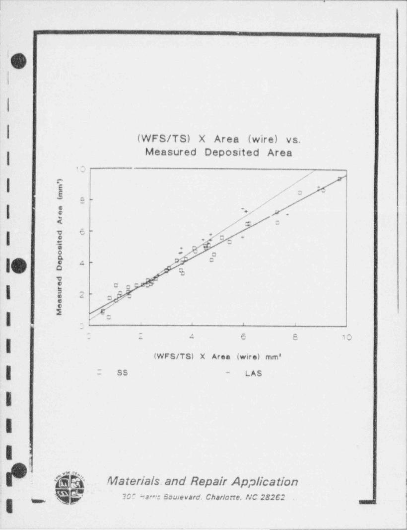
I"
_._._.
,|!
u
(WFS/TS) X Area (wire) vs.Measured Deposited Area
I10
I^a
6 .
o5_= .
| @~
'+.
E = 0
t 6 -
|+
3 U '* c
5 +o - oG C
10 a " -
ef c e-
| #2 -
a -
/, , 1
'; 2 4 6 5 10
I(WFS/TS) X Area (wire) mm'
| 2 SS LAS-
III
..m
@ @ea .Materials.and Repair Application 1.
w Qf ~ sac nare= souievard. chariorre. nc 2s2s2 ',

._ _ _ . ._-. _ - . . - . - - -- -- --- -
,_
I-,
j. . . . - _ . . _
! I
I,
III
, s!
.
IO;I
DILUTION = AREA BELOW WELD SURFACEg TOTAL AREA OF WELD BEAD
I
||
:I,
;I'
l
:,
i|
|| i
!Ii4
i| hh' Materiais and Repair Applicatibn,Q w e-: souievare. charione. ivc 2e2e2
,
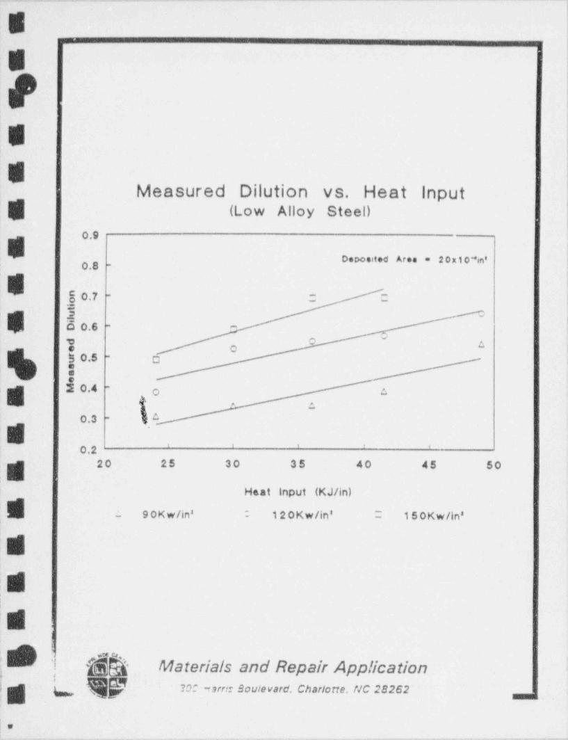
- . - _ - - _ - _ - . - - - _ - - - _ - - - _ _ _ _ _ _ _ _ _ _ _ _ _
E
E1
S1
511
EMeasured Dilution vs. Heat input
i
'| (Low Alloy Steel)
O.8 -Deposited Area - 20xtoain'
;'
|
80.7 C C |-
=
0.6 - -
E Oo !
o 0.5 0 |-
20.4' -
a{' o
,
, ;o0.3 -
,f.
~
U ' ' ' ' '0.220 25 30 35 40 45 50-
,UHeat input (KJ/in)
fL - 9 0Kw/in' ; 12 0 Kw/in' ; 15 0Kw/in'
~
! r~L -
!
& Materials and Repair Application^
fs- ?OC nstre Soulevard. Charlotte. NC 28262' ,..
Ia. . . . - _ . . . . . _ . . . . - . . . . . - - . -
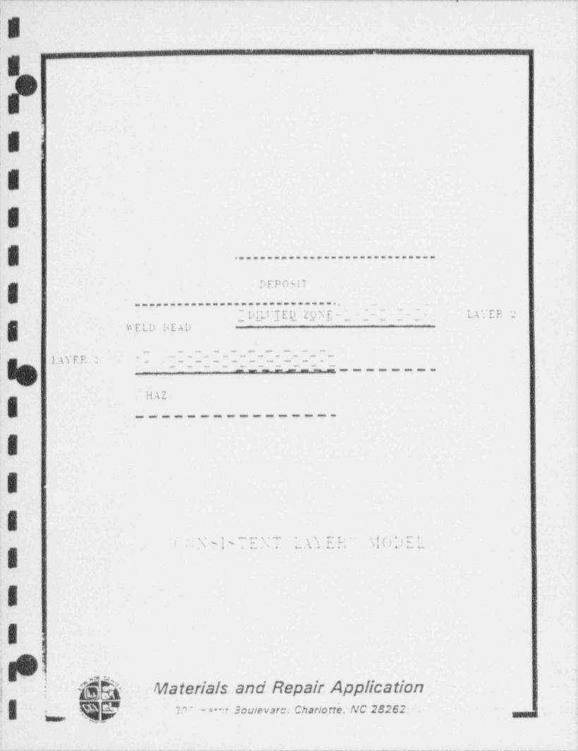
- - . - . . . - - - .. ... . - . - . _ --_ . . _ - - _ ~ __
.- - .. . .
:
,.
;,
I ,i,
E
E
......--.....................
DEPovlT
. . . . . . . . . . . . . . . . . . . . . . . . . . . . . . ._ _
' WELD liEAD~~ DILt'TED ZON E - ~
- ~~ ~
LA Y E P, 2-- - -
~ ~ ~ ~ ~ ~ ~ ~~~
_- _- - _. - _ . _ . _ --; , ..g. 7. p. ,. - _ _ - _ _ _ _ _ _ _ _ __- - - - - .
- -. - - ---________.
HAZ
III
.xx p _ . T ' .\ V. E R. . \l01 'r ':. -
y u
I 1
I1;
t,
i
I, - . .m s* ,
; | gQ Materials and Repair Application| ~ - -- souievar=. chariocre: nc 282e2 - .
.- . ,
. ._.
i
|
-- __ - _ ____ ____ . _ _ _ _ - _ _ _ . . _ _ _ _ - _ _ _ -. ____ _-. - .1
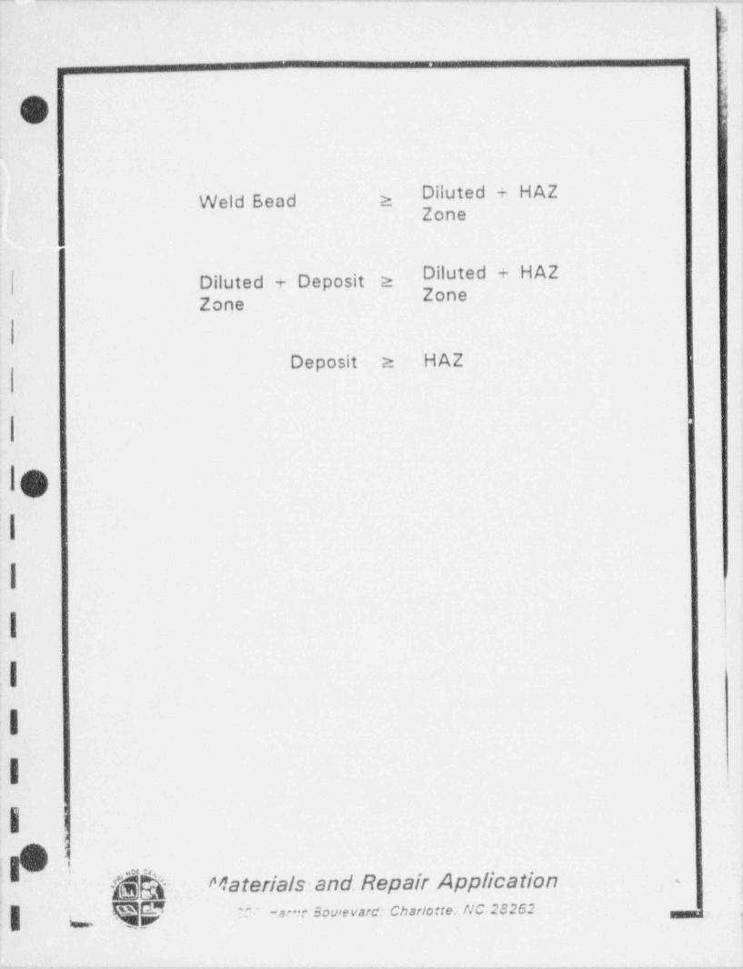
.. . _ _ . - _ . . . . . - _ _ _ _ . _ _ . _ _ _ _ . _ . _ _ _ . _ _ _ . _ . _
a
.
.
Diluted + HAZWeld Bead 2Zone'
Diluted + HAZDiluted + Deposit 2ZoneZone
Deposit a HAZ
O.I
I
I .
I
I
I
i;
-hh Materials:and. Repair Application ~,
| Qy =.v. -a. - sourevare: chariorie. nc,2e2e2 _. .
. - . ._. -.______-

. ,-_.-. - .. - .- - _- _ _ _ . - . . _ ._ ._ - - .
I_ _ . . . . . _ . . . . . ,
!h, _ _ _
|
I
I
I As-Welded vs. 112 5F PWHT--Microhardness vs. Distance from WFL (mm)
400 39.9, eli
E.
360 K 35.8 !!!.- -
g s =, --~~,, x -
| N %'
's s\* 320 31.3 o- -
se s:r's e
>
'280 -- - - 25.4
| $ N \iF |
s ss
g 240 's 's-
(17.3 ) g |-
8 's :x s .' '' ' '200 (6.3)o.o o.5 1.0 1.5 2.0 2.5 3.0 3.5
Distance From Weld Fusion Line (mm)
AW PWHT - - - -
1
g- |
||
'|4'
l:| ]$$ Materials 'and. Repair Application ~ !
.-
\Q f 3D: -a -*- Sautevard. Charlotte, NC 28262 '
},
_ _ _ __ _ _. _ - _ _
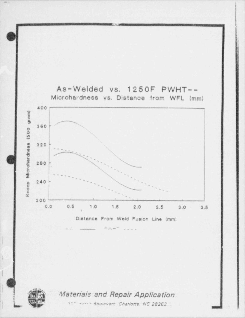
_ _ _ . ._. . _ _ . . . ._._ . _ _ . _ _ - - - . - - - - - _ _ _ _ _ _ _ _
>
c e
L..
.
I :
1i As-Welded vs. 12 5 0F PWHT--| Microhardness vs. Distance from WFL (mm)|
400$e5 A
360 NO '
o N$ 'Ng 320 -
s. -
..
'G .- - <
e 280 's-,
o ,,
0 's,m
j -
,, ,
'
a 240 -' '
), .
o, . ;
'
o , . . jc .
X '
.' ' ' '' ' '00O.0 0.5 1.0 1.5 2.0 2.5 3.0 3.5
i
|
Distance From Weld Fusion Line (mm)= vy ~
i. ....
I
i
|.| i
t'l (
~& ' Materials:'and. Repair Application:;
*^ W'
""* souleva?c Charlorie:NC 28262 . 1-p-~
mm. ~ Y m|
, , - . . . . . . , . . . . , . , - . - - - . , , . . . . . , . . . - . - . - - . . - . _ . - _ . , . , - - . . , . . . . . . . . . . . - . - - . - . . . . - . . . . . . _ . . . - . , - . ,
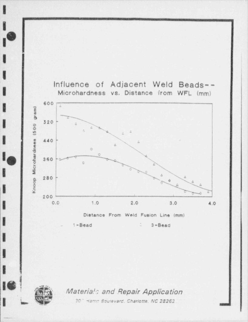
-- - - -. . - - . - - . --_. - - - .- _-. ~
I_.
IoVI
II
influence of Adjacent Weld Beads--| Microhardness vs. Distance from WFL (mm)
600 .
EeEi DN
| .
:520 -
.g . .
| g 440 - 'e.
,
E o2
I.O .E 360 -- #o g
-
8 o c.o o
a 280 *-
o
I I N J-. .
200. 0.0 1.0 2.0 3.0 4.0
Distance From Weld Fusion Line (mm)
- 1-Bead : 3-Beadi
|| |
I
.|-
r
gU ;I $$'. Materia!c and Repair Applicationn
|| , L R? ' 20 -tam.- sovievare. chariarre. ac 282s2._-
. . _ . - .-. . - . - . . . - . . . . . - - .
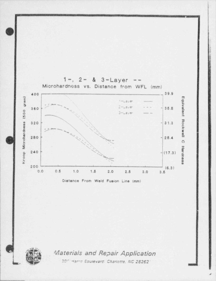
-- - . .. - - _. . - - - - - - - - - - - - - - -
s4
,
O.
1 l
1, 2- & 3 -Layer --
Microhardness vs. Distance from WFL (mm)goo _ 39.9,
3, ' ' aa yer e,
'
:~- a ve' ~~~ ~360 . %' 35.8s, a ye- -- g
'O,N-
\ x320 s,' 'N 313- ~
e 9NN N g|
280 - \' ~
25.4y -
,,
\'h' hE
,
5 \ I'
; 'a 240 -- (17.3 )
E's
oO 5, .mx
' ' ' ' '200 - (6.3 )0.0 0.5 1.0 1.5 2.0 2.5 3.0 3.5
Distance From Weld Fusion Line (mm)
|
g~&-Q, Materials and Repair Application
c
-
Qf 2ar -iar-: sovievare:chariotte, uc-2e2e2-,, , , ,
,
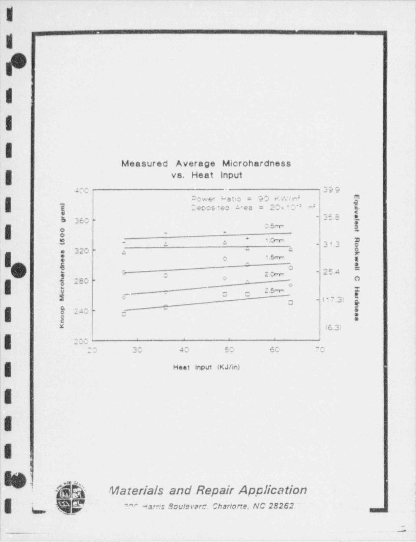
. - - - -- .. .- -. . - .. - .- . - _ _ _ . - - - . . .
~
l
!
|
Oi
'
I.I.
Measured Average Microhardness
g vs. Heat Input
age . 399jOower Latic = 90 KWhniI E Cecositeo 1"ea = 20x 10'' n E.8
$ 360 - 36'S~
0.5mI . +, g,
S 4 a . 33,3 @* 'h
f|" At a 320 a S
-
g o 1.5crrn g^ ^
*f o -
. (, 4 G- 2.Ow. 25A-
oe 280 - 0 - O
I o -m oU 2.5m_ {a a2 0 (17.3) g-
_ aS 240 - c-
-I *
g :-
x (6.3)' ' ' '
200| 20 30 40 50 60 70l
jg Heat -Input (KJ/in)
II
Ii.
I h
$$ Materials and Repair Applicationg a qy ,, ,. ,,,, soc,. ,,,c. =,.,,o,,.. nc 2s2 a2. _ .
.
_. ..Mi-
_ _ _ - - _ _ _ _ _ _ _ _ . . _ .. .. ._
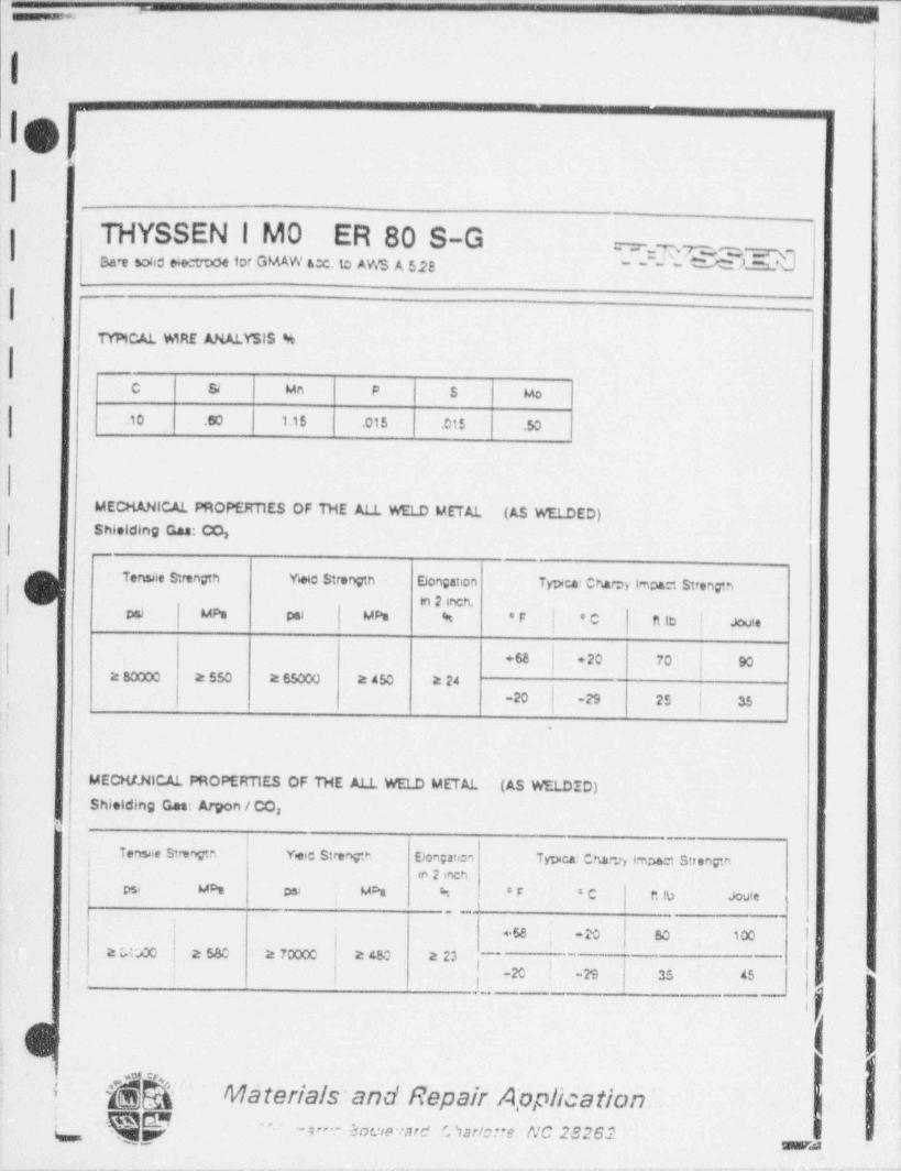
=.- .
!<
1
10.
I
THYSSENIM0 ER 80 S-G = = _ ,n r~ _~.Sa'e Sohd eie troce for GMAW acc. to AWS A $28
_~~~~ #**
.
TYPICAL WIRE ANALYSIS %
C $ Mn P S Mo
.10 .60 1.15 .015 .015 .50
MECMANICAL PROPERTIES OF THE ALL WELD METAL (AS WELDED)Shielding Gas: CO,_
G Tensile Strengtn Wie Strength Elongation Tpeai Charpy impa~, Strengthin 2 inch,
psi MPs pal MPs % 'F 'C ft le | Joule
+ 68 +20 70 902 80000 2550 2 65000 2 450 2 24
: .
MECHl.NICAL PROPERTIES OF THE ALL WELD METAL (AS WELDID)Shielding Ges: Amon / CO,
Tensae Strong n Y+c Strengin Elongation Tpca! Char.r, imm Strengtn'in 2 inch.
'
psi M% psr M% % *F *C f* 10 Joute,
_
b
i._ 2. 2- 2 ..
i c -
,
-20 -n 35 <s, , .
, :
Ie ;:
^ $Q Materials and Repair Application.,
w gg ~., ,_ c u- -s-_
-__ - _ - --
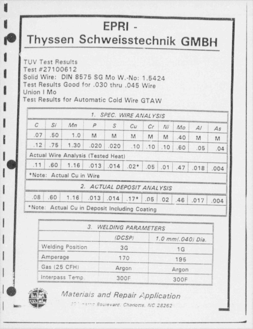
-. . - .
II EPRI-19 Thyssen Schweisstechnik GMBH| <
TUV Test ResultsTest #27100612
| Solid Wire: DIN 8575 SG Mo W.-No: 1.5424Test Results Good for .030 thru .045 Wire
| Union i MoTest Results for Automatic Cold Wire GTAW
I1. SPEC. WIRE ANAL YSIS
| C Si Mn P S Cu Cr Ni Mo Al As.07 .50 1.0 M M M M M .40 M M,12 .75 1.30 .020 .020 .10 .10 .10 .60 .05 .04
| Actual Wire Analysis (Tested Heat)
|$.11 .60 1.16 .013 .014 .02' .05 .01 .47 .018 .004
' Note: Actual Cu in Wire
I. 2. ACTUAL DEPOSIT ANAL YSIS
| .08 .60 1.16 .013 .014 .17 ' .05 .02 .46 .017 .004| + Note: Actual Cu in Deposit including Coating
| '
3. WELDING PARAMETERS
(DCSP) 1.0 mm(.040) Dia.Welding Position 3G 1G
-| Amperage 170 195Gas (25 CFH) Argon Argon
! | Interpass Temp. 300F 300F'
, &> & Materials and Repair Application. qp = ,..n.w-,s. cu,ian.. uc unt.
_
_
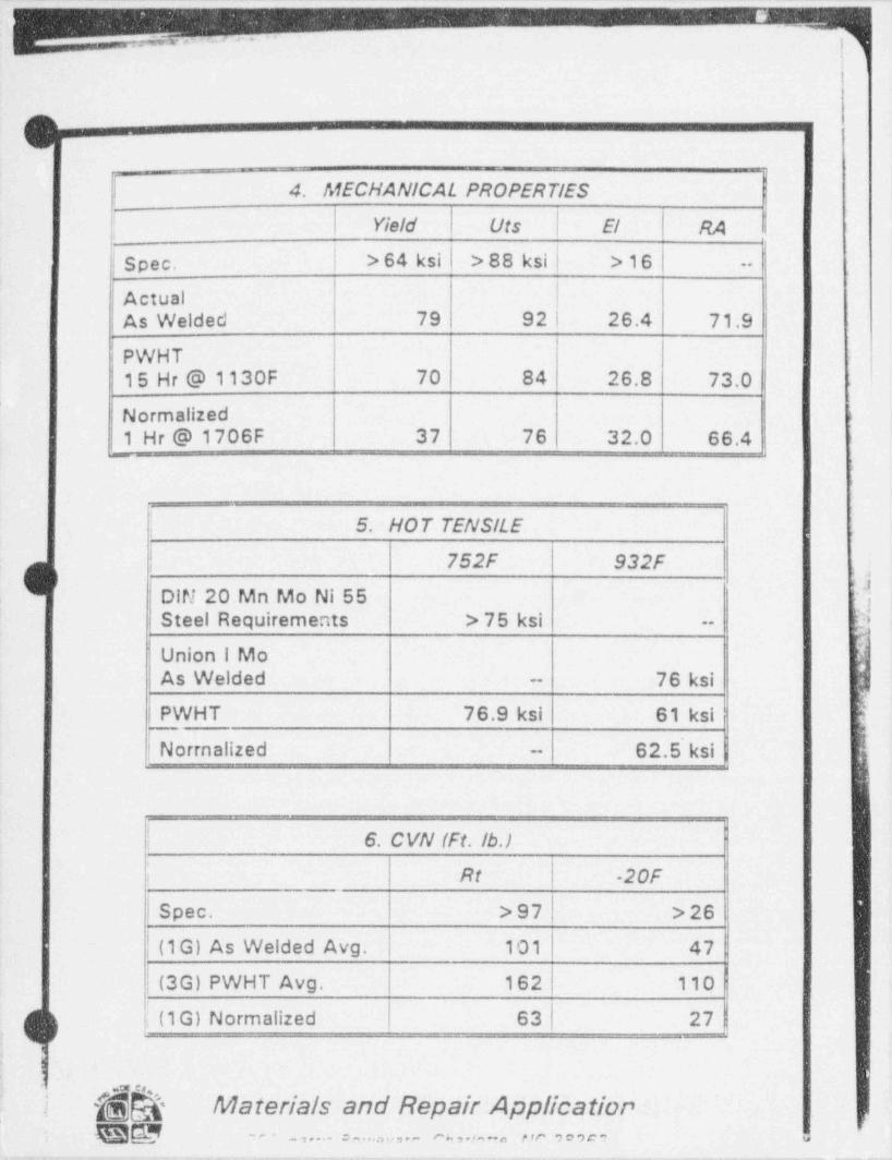
- -- . . .- -- __ __.
-mumie um
gI 4. MECHANICAL PROPERTIES; Yield Uts El RA
Spec. | > 64 ksi > 88 ksi >16 --
ActualAs Welded 79 92 26.4 71.9
PWHT15 Hr @ 1130F 70 84 26.8 73.0
Normalized -
1 Hr @ 1706F 37 76 32.0 66.4_
5. HOT TENSILE
| 752F 932Fji ?j
,
DIN 20 Mn Mo Ni 55 EiSteel Requirements > 75 ksi Dj '--
Union i MoAs Welded 76 ksi--
|PWHT 76.9 ksi 61 ksi
| | Norrnalized 62.5' ksi-
I 6. CVN (Ft. Ib.) .
1 ; Rt -20F
| Spec. > 97 > 26
| (1G) As Welded Avg. 101 47
| (3G) PWHT Avg. 162 110
, (1G) Normalized 63 27g
:
'
-gh Materials and Repair Application.M
; EB@ _,....o.,....,1,.- r s , . , ., - . ,,c ,,,c-~-
.- - - . . . . _- _ - . - - _
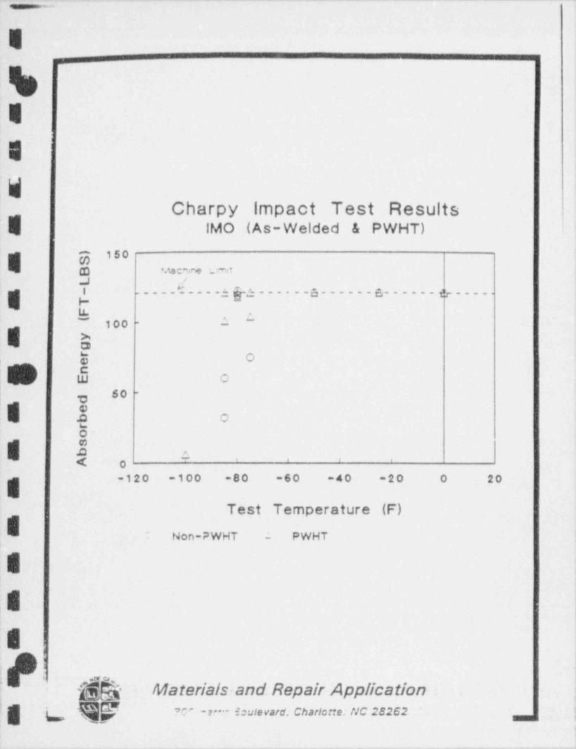
. -. . - - - - - - - . _ _ - - - _
E
E
E
WCharpy impact Test Results
E IMO (As-Welded & PWHT)
E-g 150
-(D Macnine '_mt.,J /
_____E____3 g3___.__3._____s______ g ____.
LL ,.~
00 - 1 ~
1
E- Xoy O
h is oso -
| ,e.c ouoe
I .O A-4 ,
. , , ,
-120 -100 -80 -60 -40 -20 0 20
Test Temperature (F)
: Non-PWHT - PWHT
E- |
,8|
E,,
1'
,
r .a u
; g Q. Materials and Repair Application|
'| L QQ w e :- e=uievard. chariotte. nc 2s2e2 - |,
1.-- . - . . . - . . - 1-
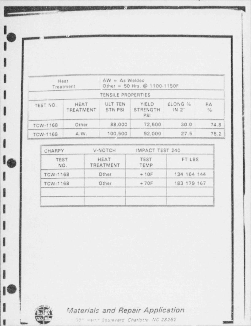
-= - - .. . . . - - _ - . _ - - . _ . - - . - . _ . , . - . . . . . . . ...--
. - - . . - - - .,
'O -----------------1
I
Heat AW = As Welded| Treatment Other = 50 Hrs. @ 11001150F
| [ TENSILE PROPERTIES
TEST NO. HEAT ULT TEN YlELD ELONG % RA.
| TREATMENT STR PSI STRENGTH IN 2* % '
PSI ..
h
! TCW 1168 Other | 88,000 72,500 30.0 | 74.8 r
i TCW 1168 A.W. 100,500 | 92.000 | 27.5 75.2 ;
I !
CHARPY V NOTCH IMPACT TEST 240 |
| TEST HEAT TEST FT LBSNO. TREATMENT TEMP
| TCW 1168 Other + 10F 134 164 144
TCW 1168 Other +70F 183 179 167
I
I
I
I
-|
|
10;t
.
-$$ Materials and Repair Application'
-
K_ K V -. =-" ~ ' ' " ~ " " ' " ' ' " ' ' " " ' " ' " ' * '
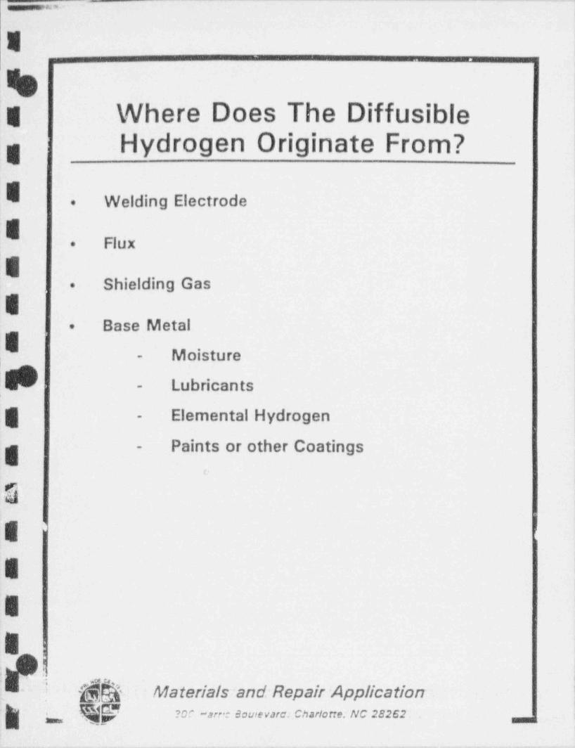
. - _ _ - . _- _ - - _ -_ - - .
E '
%;g Where Does The Diffusible '
,g Hydrogen Originate From?
E Welding Electrode.
E Flux.>
EShielding Gas. '
EBase Metal.
|E Moisture-
Lubricants-
;g Elemental Hydrogen-
Paints or other Coatings-
e
Q)E
;E
E
i: :. .
:i ~$& Materials:and Repair Application.
Qty roc -.are.: ecutevard. Charlotte: NC 28262 m, ,
.
__ .,. . - . . . , . .
__
- q-
American Welding SocietyStandard A4.3-86
f
Standard Methods for Determinationof the Diffusible Hydrogen Content of
Martensitic, Bainitic, and Ferritic Weld Metal --
Produced by Arc Welding
,
Ik !.
I
I
I
I
II.
"& -hk Materials and Repair Applicationm ,- s _ ..,m c.,,,,_ .,,c2 m z !g c qp
- - _ _ . - _ - - - . _ _ . - . _ . _ _ _ _ . _ _ _ _ _ . _
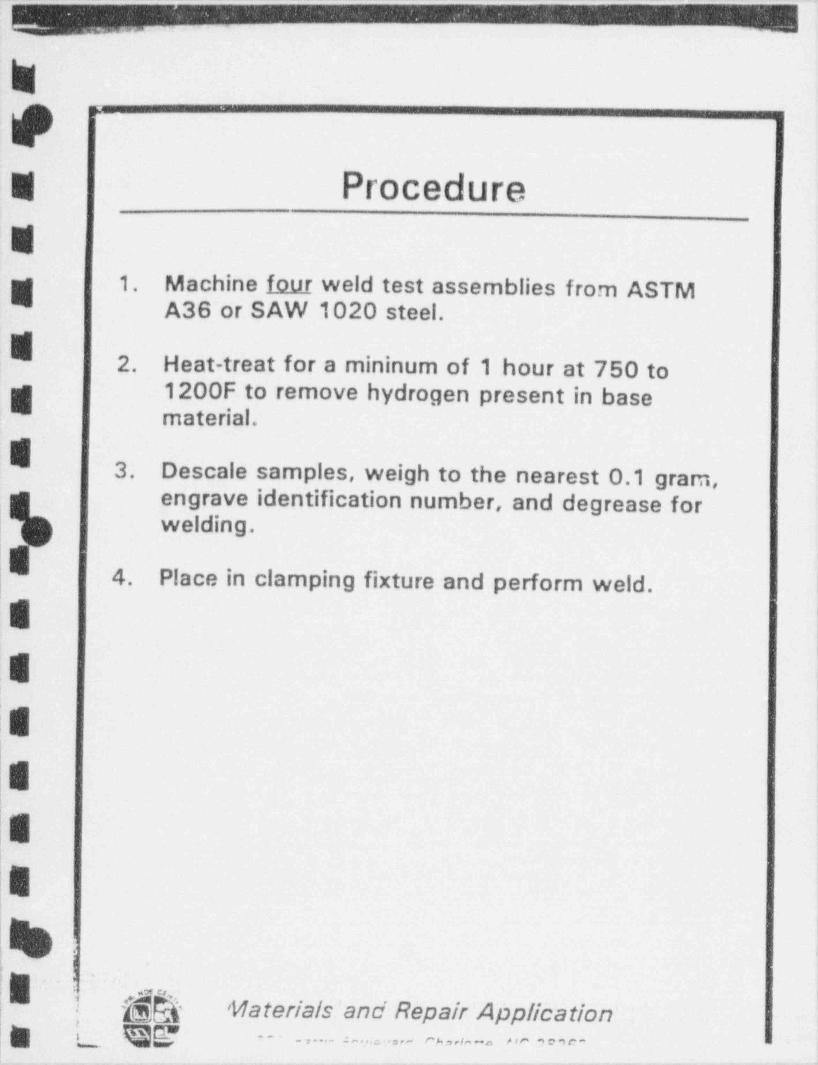
_ _ _ _ _ . _ _ - . ._ . . . .. . . . .
.=
,@g ProcedureW
1. Machine four weld test assemblies from ASTMW A36 or SAW 1020 steel.
E2. . Heat-treat for a mininum of 1 hour at 750 to
g. 1200F to remove hydrogen present in basematenal.
E 3. Descale samples, weigh to the nearest 0.1 gram,engrave identification number, and degrease forwelding.
|4. Place in clamping fixture and perform weld. .!
E
.E i
|E
E
E\|
4<, ,
.
E y{&- . . - - - -
'Vlaterials/and Repair Applibationa .. ..... _ .- - ~ _ - ,., .
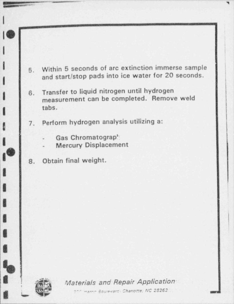
-- - - _ _ - - - - -
,, . . ,
| .
:- ,
IO i
| |:1
5. Within 5 seconds of arc extinction immerse sample I'
and start /stop pads into ice water for 20 seconds.['
6. Transfer to liquid nitrogen until hydrogeng measurement can be completed. Remove weld
tabs.g
7. Perform hydrogen analysis utilizing a:g
Gas Chromatographg
-
Mercury Displacement-
01 8. Obtain final weight.
III ,
IE
I
kt, ]|<
QW ' Materials and' Repair; Application-_
i
g g 9gy v ,,,- e _ ,+ c u ,, u.. n c 2s2 e r .
. __ __ _ - _ - - _ . __
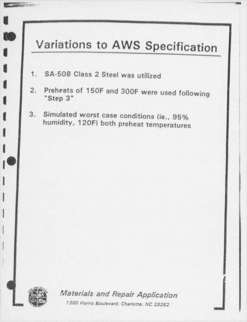
-- - - - - - - - - - - . -__ _-
y,, ,, -_
;
g-
!-
GVariations to AWS Specification
I.
1. SA-508 Class 2 Steel was utilizedI
2. Preheats of 150F and 300F were used followingg " Step 3"
g 3. Simulated worst case conditions (ie., 95%humidity,120F) both preheat temperatures
1
I
I O
I
I :
.
I $ . Materials and Repair.~ Applicationf f 1300 Harris Boulevard, Charlane, NC 28262 *, '
,
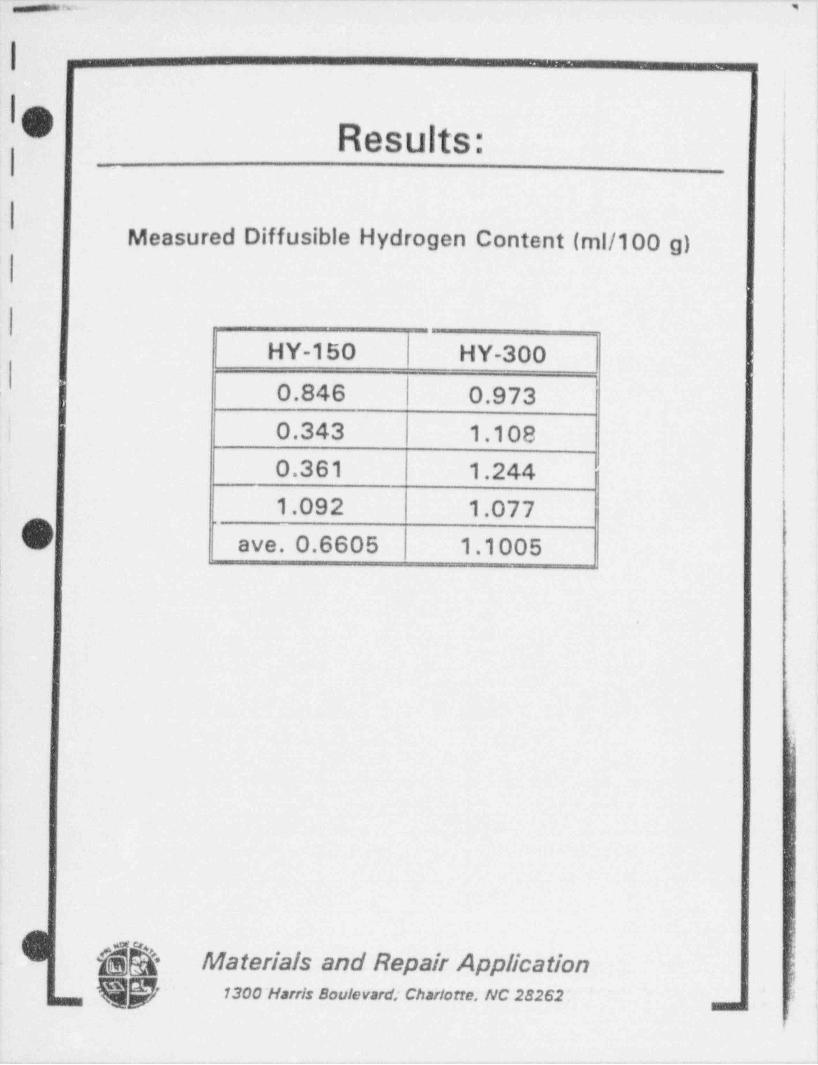
.. . _ _ . _ _. __ __ _._. ._ _ - - __.
p rw w - ,
'
i
| !! ;
O '
Results:
Measured Diffusible Hydrogen Content (ml/100 g)
HY-150 HY-300i0.846 0.973
| 0.343 1.1080.361 1.2441.092 1.077
C ave. 0.6605 1.1005
.
s
$ $$ Materials and Repair Application i-
f' ~ 1300 ' Harris Boulevard; Charlotte; NC 28262 : |*
, ,
.

. . . . . ,
Pd W TELEDYNEMcKAYtic G9N'i.r* AX
<
M BOX W9
v0M PA 17e%N
F 7) C4424 M
TELEX 640428-
nu arm,aV
MX f442365
iFt
October 3,1990.m
(f< 2
Mr. David GandyJ. A. Jones Applied Researth1300 Harris Boulevard
'
Char. lone, NC 28262
Dear Dasid:
We have ectopleted your request of diffusible hydrogen values for your test identificationnumbers HY-150 and HY-300 in accordance w,th AWS A4.3-86. Enclosed are the datasheets frotn our tests. The results are:
Avera;;c Diffusible Hydrogen Standard Deviation of AserageTest Number (ml/100g) (ml/1COe)
''
HY-150 .6605 .3702HY-300 1.1005 .I117-
, I would recommend weighing the sample on your scales to compare the " weight after ~~
welding" to our values. Also, note inat the variation of HY-150 is much higher than that ofH Y-300.
Please call me if you have any questions or comments.
Sincerelv
i[. 5N
.uj Jon E. Snyder 1
saf
JES/90/025
8Il#u
.
. _ _ _ _ _ _ _ _ _ _ _ _ _ _

# f'%)/t
HYDROQf N ANALYStB DATm {'y/~
_
O.t. of.n.ly.i.
N. NG'kfr 7 ele /v r e ff % vT.st ic.ntific.iion numb ,
An.:,see eautomenu so ,.io,
s ,.ci n .io,... u m. o.im . io.a.n ,.n.i a e. .. ,.iu.
-?!>o'F sp.,,m.nio.. ,,.n .ino p ,,oo.g>sp .ns.n.im. .i.. ,.io,.
#//tT.mp.r.iu,. ou m.<cory aorms io.a n,
AC T ur.
h<s 4 % d m. Empe, IHyd. Og.n .volypon um.
-
. mo. ., .n., r.,.w; . . ,,, ,, .,. ., um. o, .n.,,.i. 7sw < - 9 / 4..n, .. ..i.. . .. . o . n. ,,,,. w c_ |.
( 7 7 573. ,n , ~,, ,
d'M d d7 d./4 4. d f| H,e,oo.n .osum. ii.ci.e. me
* W M MH..d of m.rcu,y in tute. mm O# * i
T.mper.tur. of g. 'CM * 9 O
Hyd,og.n cor,.ct.d to STP. mivai ea ew zu :
6''I73 / /0 7 /.2W A077 |-o .. .n ,
| ois,u. x,. nya, .n. w , . , '
A Ax 5 si.n..,. ..... .on o, . .. . ... . , , ,A......~,.....n..,
lo (uFig. 5 -Hydrogen analysis data sheet
I -
..
.
.
g .
-
8
8 .
|8 .
'|
:
: :
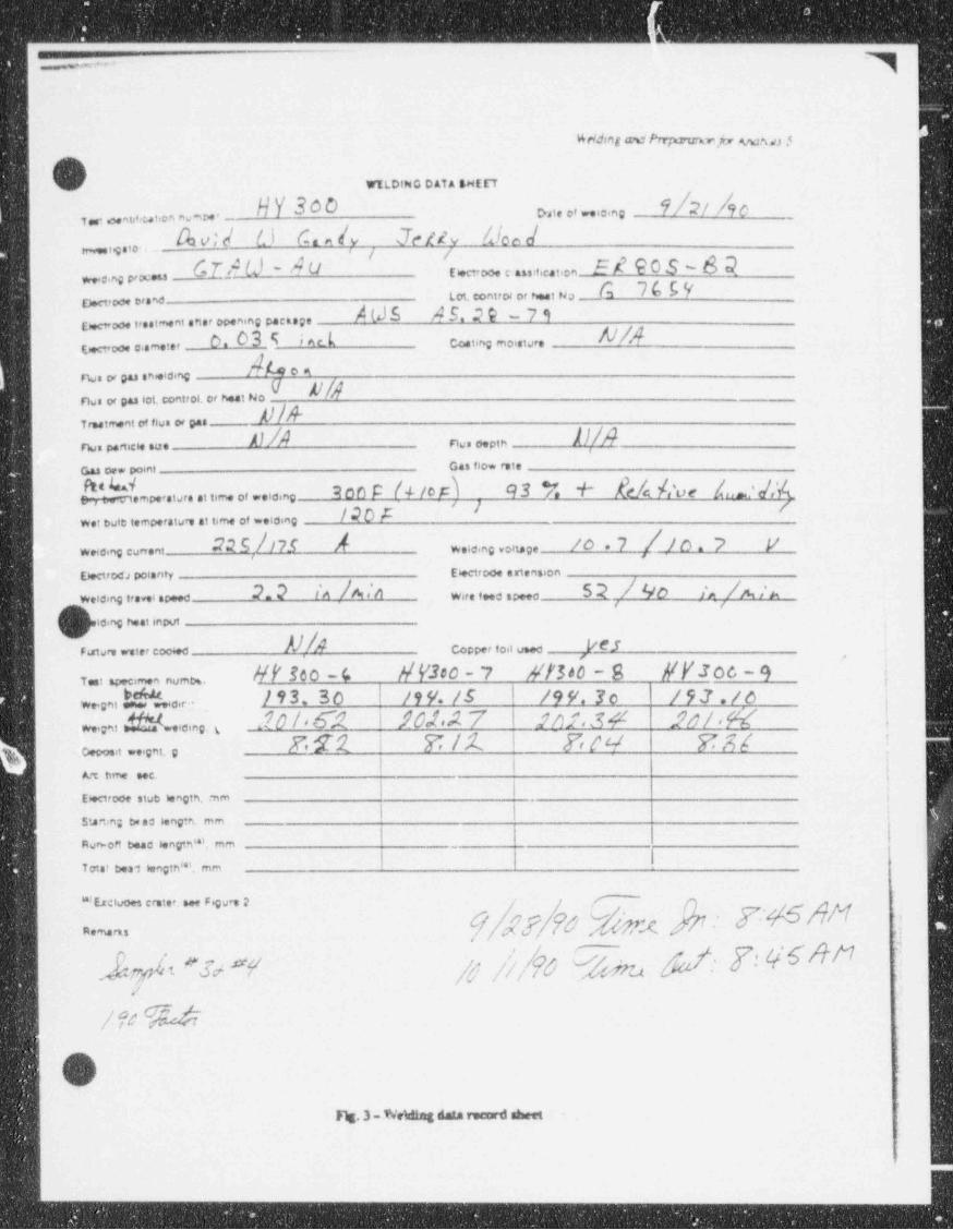
_ _ _ _ _ _ _ _ _ _ _ _ __ _ _______
4%dd#ng esi Prr;s2vrefr %24,r3 y
WELDING D ATA SHEET
NY 300 9/2/ 4o>,i . .. .. n gT , ,u,,w.., no-~ .
Sw el O C. e /y Jezev /Jon /_ , , , , . . .
C-TA U - A U Imoo, e.a, ,,,c.i,on_5 # 9 0 S - 6 Q..ng p, -
b 7bbILot. control or heat NoE)ectroce br.M N A b. 2 @ - 7 iEwoo. I'.eiment .ft.r poening pact.p.
On 5 i Ar kEcooe c..m.ter Costing moisture
b0"Na or pas sheiding
Na or gas lot, control, or heat NodTre.tment of fius or pas
A /Na p.rincie .u. . N a o.pth
Gas oe. po nl Gas flow rot.
son p /4 tor) / 9s v. + f,y ,o, 4,_,j;(a.u-. .n-.i u,. .n , m. .< .. .. g
//70Aw. bein i.mper.ium .i tim. ov ..ia.e,
22 5 /nf / jo , 7 ,/ j n , j y, , , , , , , , , , , , , ,wee.no cun.ni
tem poi.ney ceroo. .in.n. on
22 /^ /A .'A 52 / Oo /, /m /uw,, a . awve,no ir. i . o' "
he.no n..onpui ,.
Al|A Vescooper saa u a.v n , i.ee w .e'
5 BOO ~Y Y A00 ~ I $b "b YYS00 ~ O |T t specamen num%, 'w,g,,L%. 193.50 19 4. /5 /99.30 193./oa,m ,w,v, dbb.,,e,ng. , a?O /* 6? \-10f*A 7 9 /) f . 3 4 128/ %( ,
! '[ ek['. Ceco.it ..ignt, g
Art time e.
iEwrooe stub i.ngth, mm j
Staa.ing be.d kngte., mm
Rumoff bead I.ngtn'*i, mm ,
Tot.f b.a1 6engtn'''. mm
' '''Esciuoes crat.r, e F.gure 2 g
[[ f[ hQ [nemars:
J 6 esn ,e , % % sat: 7 6 M '7im vs
.
.
Oris.3 Wema dam record eine
i
|
_ _ . _ - _ _ _ _ _ _ - - _ _ _ _ _ _ _ - - _ _ _ _
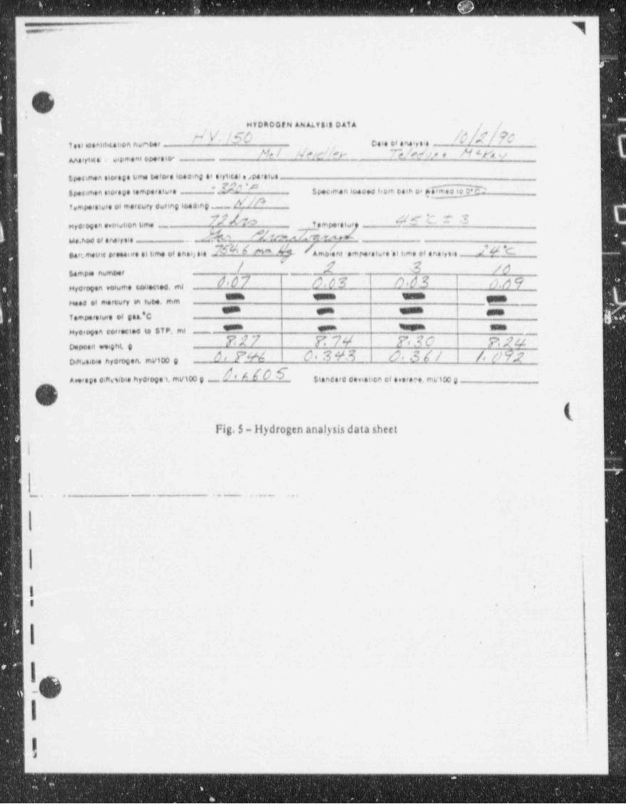
]--
9
b0.
Hf DR00f N AN ALT 818 DATA f f ,
" V InD /d4e/.?,C,
,
/4/c4 __ e. .. ., . ., . ,.n/n . M mt .. .ei,i .o., nom ,
^4/,,,..,m........,.
in...,s.n.i.,. . u m. i ..,.io...ne .. .,,,,w . , ,.io.'
_f#e'e s ,, ,~ n , m ,, ,, . ,o , , , ,, ,, , s, . ,, ,e5,...,,.n.i....i.,ne.,.io,. . , -
r. .io,. . , .,. ,,..,in ,io...ne .__ _ p / / p-,.
?/ho .& 'c r s1. ,n,.. . n ..... e u~ ._.4o h & n.,. 2io,~u..,,...n..,...
.754 / - 44. 4,,4n, . ..,,,,. .,. , ,,,, ,, . n. ,,,,, ./ a e,. ,o. u .. ., . .. . . i ii m. . . . , . . . .
"/ ,f 3 as.,o, nomo.,
d'0 7 8.? S O.63 o.g 9'
Hraro,. n, ore, w ,.e,,a. ms= === ===
n... . ,n.,-r in iot . mm""" * === ans iv.. ,.i . . .. *c
8''" P W ium.H,o, g.n .o,,.cto. to $T P, ml ^~
727 P': 7y 7,30 7>, yao. .,i .ent eo , F4M d, S 9' S O, .3 / / /,(19.go.,io..... n,or.s m mviDo e
'4[Ave,.p. .ieivsibt. hyd, g.1. myt00 g Si.nc.rc c.n. tion . ...r.e., mV100 g
s
k,.
Fig. 5 -liydrogen analysis data sheet
I
_
,
-. . .- .. . . - ...
,.
e i
i*
I .
,e
6
I-O..
I .
,
,
_ _ _ _ _ _
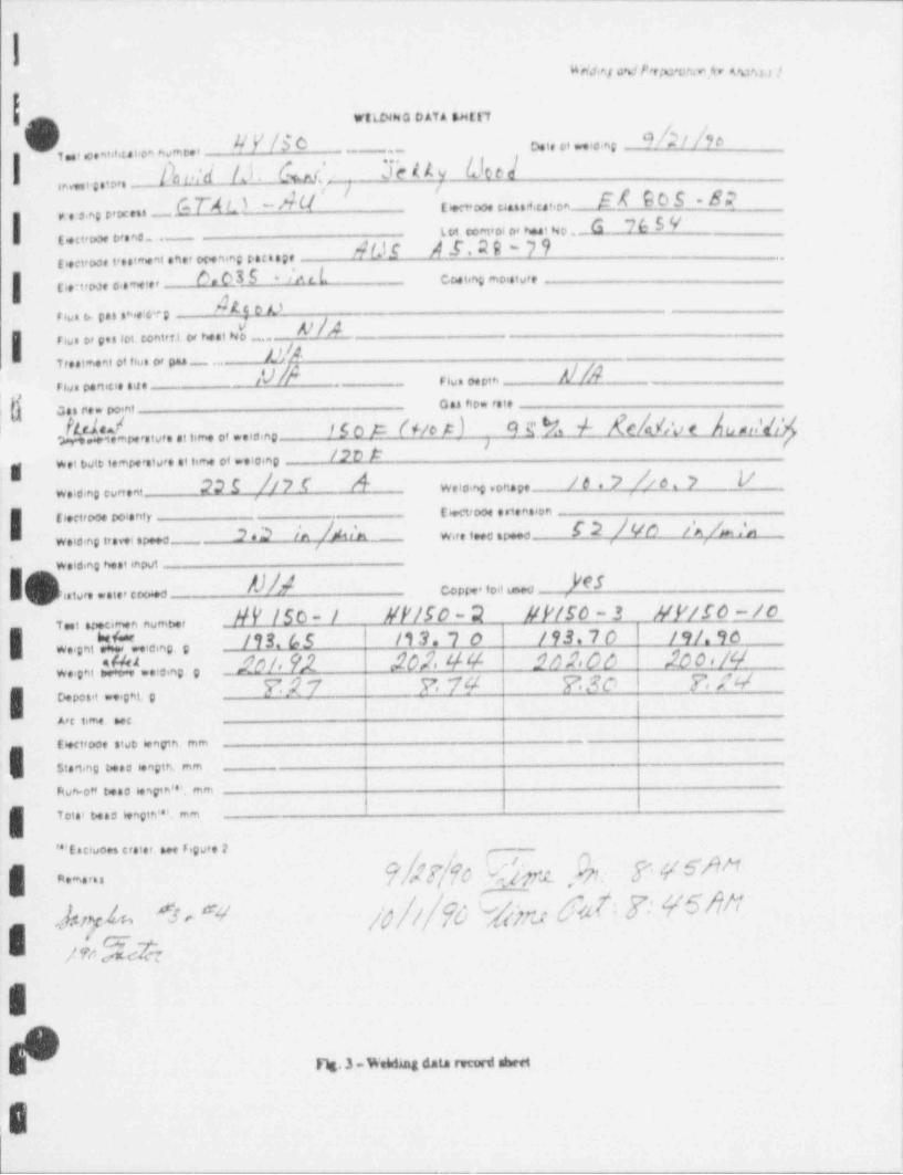
ao,v sr.,,mm.o w u
WtLINNO D AT A EN[[7f
9/;/ /pW'/5o o. ,, o, , .,,''
, , ,, ,, . .u i .o, n ., e., -_ __o
1%:d Id. Gus' .3b Uy Oce}
,.,,,,o._
! ,co,n,.,,,,,e.. c- r w - A u ' '
' et sas -s:t -, - u... ,u,.on
w to,.i, i ,,, * i w o ._6 76 5 Y,.no . ._
4DI A f.2 9 - 7 9ren,w. .... ni.n.,c.p.n, , ,u.... *
8. 63 5 /.u L e, ,,,,, mo,,,v,,| c ,,,w, . wi. ,
4t.$ e e, , . . c . . .n ,6. ,
i ///Fau, o, ..s lot. C.ont,fl or ti..I N -
..
n1,:,,,,i o ie o, ._ . .
<U/A ///Ar io, ,,,,rio, p.n v. 4
{},,
o .,e .. c.i.a. c.- no,ntt
-/d'd.?dn..tv,..n,o,..ia.no /so A fuer) ; 9g 3 4 ge/,14;,c 4 ,,,i/,,'
/20 #w.i osie i,-r4,to.. .n,m. ei .. ..nog 22I // 7 f <4 / g , p /, o , y yw ,,,,,,,.ons,,
w.io no eon.nit es,w .nen ,on
I tien,oo.coi.nir -_
C 2 )'t,/n s 's,A., ,%h,/Ju%2.3 w,,,,,.aiv aw:,e,no s,.w .v a ,
w.io.n, e ., .nout
/'CSO/M copp., ,o.i u:, oato,. ..ie, cco.,o
AV /So- 1 Ul'/50 - 2 NP/50 ~ 3 HP/So-/o, , u,.e,m.n numt,.,
| w2,,ni M ie,ng. , /93. 65 /13. 7 0 /93.70 /9/.9o
w,,,,, :.tt!....,,, , soi n sos,44 sns.co so_o ,nE#7 F 79 F.30 J, N
g o....., ....ei. ._
A,g .im. .eg
[6.Ctroot . tub 6tngth mm _
I St., ting d..e 6.neth, mm
Fiv,* oM to.0 6.ngtm'''. m,n
T ot.' t4 0 l.mgth''', ,em
'' e. n o c,.i.,. ,,,u,. 2 . ,._
| c~ . ?bT/fo % u .Dr. 7VSW1,9 / ,@ j;.m dht 7' 45Nf/ G
E nA% "+'hi
~aE
Fw. 3.w. Wha data rward shec
!
~ ~
3h .- [. . e4 . ., : . . - 1. . , .. .
. .
1
)*
!O $$,3s !~
\ e ,% /o-
b /.
/
Whf g
pi' 3+> 4i.e
'\}P ^ : ', f,'
.o sNa'
-,,A 00.
,. ,
$q
n 05Q ), j - .
0 00-
10y[(-
0 00
sC)-[
fyr - ool
@h !
,
O |.
.
8
. . _ _ . . . . - - .-.
_ _ _ _ _ _ _ - _ _ _ - _ _ - _ - _ _ _ _ _ _ - _ _ _ _ - _ - _ _ -
IO ' ^.,:>. . , * .
f .p # "U
'
f
'W ,
-
%
- 07gg | - co-
~.
p;G g os~00
-
A p- .ov-. 00-
%
W p q - .on <
<00
m sk-:pE
,._.,MW
0-
D', l'E ,L M
e
+
g / Ne/ - :"g 2..:
A-,
-
,/ ,-
' '
o fr' n , '
* /' /
- g p .or ..
.
i-i
_ _ _ . _ _ _ . _ _