sure-weld®/sure-flex™ - carlisle syntec
TRANSCRIPT
Sure-Weld/Sure-Flex™ Mechanically Fastened and Adhered Roofing Systems
TABLE OF CONTENTS January 2022
Part I – General 1.01 Description....................................................................................................................................................................................... 3 1.02 General Design Considerations ........................................................................................................................................................ 4 1.03 Quality Assurance .............................................................................................................................................................................. 6 1.04 Submittals .......................................................................................................................................................................................... 6 1.05 Warranty ............................................................................................................................................................................................ 7 TABLE I – Warranty Options and Minimum Membrane Thickness ..................................................................................................................... 9 TABLE II – Mechanically Fastened TPO – Membrane Fastening – Steel/Concrete Decks ............................................................................... 10 TABLE III – Mechanically Fastened PVC / KEE HP PVC – Membrane Fastening – Steel/Concrete Decks ...................................................... 11 TABLE IV – Mechanically Fastened TPO – Membrane Fastening – Wood Decks ............................................................................................ 12 TABLE V – Mechanically Fastened PVC / KEE HP PVC – Membrane Fastening – Wood Decks ..................................................................... 12 TABLE VI – Mechanically Fastened TPO – Membrane Fastening – Lightweight/Gypsum/Wood Fiber Decks .................................................. 13 TABLE VII – Mechanically Fastened PVC / KEE HP PVC – Membrane Fastening – Lightweight/Gypsum/Wood Fiber Decks ......................... 14 TABLE VIII – Adhered TPO – Underlayment/Fastening – Up to 20 Yr Warranties ........................................................................................... 15 TABLE IX – Adhered TPO SAT – Underlayment/Fastening – Up to 20 Yr Warranties ...................................................................................... 17 TABLE X – Adhered TPO – Underlayment/Fastening – 25/30 Yr Warranties ................................................................................................... 19 TABLE XI – Adhered TPO SAT – Underlayment/Fastening – 25/30 Yr Warranties .......................................................................................... 20 TABLE XII – Adhered PVC / KEE HP PVC – Underlayment/Fastening – Up to 20 Yr Warranties .................................................................... 21 TABLE XIII – Adhered PVC / KEE HP PVC – Underlayment/Fastening – 25/30 Yr Warranties ........................................................................ 23 1.06 Job Conditions ................................................................................................................................................................................. 24 1.07 Product Delivery Storage and Handling ........................................................................................................................................... 26
Part II – Product 2.01 General ............................................................................................................................................................................................ 26 2.02 Membranes...................................................................................................................................................................................... 26 2.03 Insulations/Underlayments ............................................................................................................................................................... 32 2.04 Related Materials ............................................................................................................................................................................. 38 2.05 Fastening Components .................................................................................................................................................................... 43 2.06 Insulation Securement Adhesive ...................................................................................................................................................... 45 2.07 Vapor/ Air Barrier ............................................................................................................................................................................. 45 2.08 Edgings/Terminations ...................................................................................................................................................................... 46 2.09 Roof Walkways ................................................................................................................................................................................ 47 2.10 Other Carlisle Accessories ............................................................................................................................................................... 48
Part III – Execution 3.01 General ............................................................................................................................................................................................ 48 3.02 Roof Deck/Substrate Criteria ........................................................................................................................................................... 48 3.03 Insulation/Underlayment .................................................................................................................................................................. 50 3.04 Insulation Attachment ...................................................................................................................................................................... 51 3.05 Membrane Placement and Securement Criteria ............................................................................................................................... 53 3.06 Heat Welding Procedures ................................................................................................................................................................ 58 3.07 Welding Problems/Repairs............................................................................................................................................................... 60 3.08 Flashings ......................................................................................................................................................................................... 60 3.09 Roof Walkways ................................................................................................................................................................................ 63 3.10 Daily Seal ........................................................................................................................................................................................ 63
ATTACHMENTS Attachment I – Induction Welding Attachment Method 64 Attachment II – TPO Flashing Procedures utilizing Sure-White EPDM Flashing Products 73 Installation Details 91
Note: In addition to information listed in this section Specifiers and Authorized applicators should reference Spec Supplement and Design

Thermoplastics 1/2022 2
Reference Sections for other pertinent information.

Thermoplastics 1/2022 3
Sure Weld/Sure-Flex™
Mechanically Fastened and Adhered Roofing Systems
January 2022 The information contained in this generic specification represents a part of Carlisle’s requirements for obtaining a roofing system warranty. Construction materials and practices, building siting and operation, climatic conditions, and other site-specific factors will have an impact on the performance of the roofing system. Carlisle recommends that the building owner retain a design professional to determine appropriate design measures to be taken in order to address these factors. This section is to serve as criteria for Specifiers and Authorized Applicators regarding the design and installation of Carlisle's Adhered and Mechanically Fastened Thermoplastic Membrane Roofing Systems. Additional information essential for the design and installation of the roof system mentioned herein are also included in the Design Reference Section and also listed in the form of a Specification Supplement at the end of the Technical Manual. Specifiers and Authorized Applicators are advised to reference all applicable sections. Various Warranty Tables have been included in Paragraph 1.05 citing various requirements by which specific warranty coverage can be obtained. Appropriate Warranty Table should be referenced to ensure proper warranty coverage. Part I – GENERAL 1.01 Description
A. Mechanically Fastened Systems (Sure-Weld / Sure-Flex) 1. The Sure-Weld Mechanically Fastened Roofing System incorporates 12', 10' or 8' wide, white, tan or gray
in 45, 60 or 80-mil thick scrim-reinforced, Sure-Weld Thermoplastic Polyolefin (TPO) membrane field sheets (also available in special colors in 60-mil thick, maximum 10’ wide sheets). The Spectro-Weld™ Mechanically Fastened Roofing System incorporates 10’ or 6’ wide, white, 60 or 80-mil thick scrim-reinforced Thermoplastic Polyolefin (TPO) membrane field sheets. Insulation is mechanically fastened to an acceptable roof deck. Sure-Weld perimeter sheets (6' used with 10' and 12' wide field sheets; 4' used with 8' wide field sheets) are installed along building edges and field membrane sheets are mechanically fastened to the roof deck with the appropriate Carlisle fasteners and fastening plates. Adjoining sheets of Sure-Weld membrane are overlapped and joined together with a minimum 1-1/2" wide heat weld. Membrane fastening requirements are outlined in Warranty Tables in Paragraph 1.05 of this Specification.
2. The Sure-Flex Mechanically Fastened Roofing System incorporates 50, 60 or 80-mil Polyester Reinforced Sure-Flex Polyvinyl Chloride (PVC) membrane (white, gray, light gray, slate gray and tan) or Polyester Reinforced Sure-Flex KEE HP Polyvinyl Chloride (PVC) Membrane (white, gray, light gray or tan). Either membrane is available in 10’ wide field sheets and 5’ perimeter sheets. Standard Polyester Reinforced membrane is also available in 81” wide field sheets and 40.5" perimeter sheets. Sure-Flex sheets are available in rolls in 75’ or 100’ rolls. All sheets are mechanically fastened over an approved insulation/underlayment to an acceptable roof deck with the appropriate Carlisle Fasteners and Fastening Plates. Adjoining sheets of Sure-Flex membrane are overlapped and joined together with a minimum 1-1/2" wide heat weld. Membrane fastening requirements are outlined in Warranty Tables in Paragraph 1.05 of this Specification.
NOTE: Either Roofing System may be specified using over an existing standing seam, flat seam or corrugated metal roof (mechanically fastened systems incorporate membrane securement into the structural purlins). Refer to the Metal Retrofit Roofing System Specification, published separately, for applicable requirements.
Thermoplastics 1/2022 4
NOTE: Either Roofing System may be specified over an existing standing seam, flat seam or corrugated metal roof (mechanically fastened systems incorporate membrane securement into the structural purlins). Refer to the Metal Retrofit Roofing System Specification, published separately, for applicable requirements.
B. Adhered Roofing Systems (Sure-Weld / Sure-Weld SAT™ / Sure-Flex) 1. The Sure-Weld Adhered Roofing System incorporates maximum 12' wide white, gray or tan 45, 60 or 80-mil
thick scrim-reinforced Sure-Weld Thermoplastic Polyolefin (TPO) membrane (also available in special colors in 60-mil thick, maximum 10’ wide sheets). The Spectro-Weld™ Adhered Roofing System incorporates 10’ wide, white, 60 or 80-mil thick scrim-reinforced Thermoplastic Polyolefin (TPO) membrane field sheets. Carlisle Insulation is mechanically fastened to the roof deck or secured with Flexible FAST™ Adhesive, OlyBond 500 BA, or OlyBond Spot Shot Adhesive and the membrane is fully adhered to the insulation with the appropriate Sure-Weld Bonding Adhesive. Adjoining sheets of membrane are overlapped approximately 2" and joined together with a minimum 1-1/2" wide heat weld.
2. The Sure-Weld SAT™ (Self Adhering Technology) membrane is a heat-weldable single-ply thermoplastic
polyolefin (TPO) sheet available in 10’ wide, (white, tan or gray) 60 or 80-mil thick reinforced TPO membrane laminated to an elastomeric pressure-sensitive adhesive.
3. The Sure-Flex Adhered Roofing System incorporates maximum 10’ wide, 50-mil, 60-mil or 80-mil thick
Polyester or Fiberglass reinforced Sure-Flex Polyvinyl Chloride (PVC) membrane (white, gray, light gray, slate gray and tan). Carlisle Insulation is mechanically fastened to the roof deck or secured with an approved adhesive and the membrane is fully adhered to the substrate with Sure-Flex Low-VOC Bonding Adhesive or HydroBond Water-Based Adhesive. Adjoining sheets of membrane are overlapped and joined together with a minimum 1-1/2" wide heat weld.
A KEE HP enhanced (white, gray, light gray, and tan) Sure-Flex PVC membrane with Polyester Reinforcement is available in 5’ and 10’ width. Polyester Reinforced membrane is available in widths of 40.5”, 5’, 81” and 10’ wide (white, gray, light gray, slate gray and tan). Fiberglass Reinforced membrane is available in widths of 10’ (white, gray, light gray and tan).
1.02 General Design Considerations
Various Warranty Tables have been included in Paragraph 1.05 citing various requirements by which specific warranty coverage can be obtained. Appropriate Warranty Table should be referenced to ensure proper warranty coverage.
A. The maximum roof slope for Mechanically Fastened Roofing Systems is 18" in one horizontal foot. There are no
maximum slope restrictions for the application of the Adhered Roofing System. B. The mechanically fastened roofing system is not acceptable for installations on steel decks lighter than 22 gauge
unless the steel deck is used in conjunction with lightweight concrete and a minimum of 360 pounds pullout per fastener is achieved with HP-X Fasteners into the steel deck below. An Adhered Roofing System may be specified or refer to the Metal Retrofit Roofing System Specification, published separately for other roofing options.
C. Certain petroleum based products, chemicals, and waste products may not be compatible with this roofing system.
Contact Carlisle for verification of compatibility and recommendations concerning an acceptable roofing assembly. D. Metal-Edge Systems and Copings should be designed in compliance with Section 1504.5 of the International Building
Code and shall be tested in accordance with ANSI/SPRI ES-1. E. Concentrated loads from rooftop equipment may cause deformation of insulation/underlayment and possible damage
to the membrane if proper protection is not provided. A protection course or sleepers must be specified. F. It is the responsibility of the specifier to review local, state and regional codes to determine their impact on the
specified Carlisle Roofing System.
G. It is the responsibility of the building owner or his/her designated representative to verify structural load limitation. In addition, a core cut may be taken to verify weight of existing components when the roofing system is to be specified on an existing facility.

Thermoplastics 1/2022 5
H. For information regarding CRRC (Cool Roof Rating Council) and LEED™, refer to the applicable Product Data
Sheets and Design Reference DR 07-20 “CRRC/LEED Information”.
I. Construction Generated Moisture / Vapor Drive
1. On new construction projects, especially in cold climate regions, moisture generated due to the construction process could adversely impact various components within the roofing assembly if not addressed. Refer to Design Reference DR-01-21 ”Construction Generated Moisture” included in the Carlisle Technical Manual.
2. On structural concrete decks, when a vapor retarder is not used, gaps in the deck along the perimeter and
around penetrations must be sealed along with vertical joints between tilt-up panels, if present, to prevent infiltration of hot humid air and possible moisture contamination resulting from condensation. This is specifically important when adhesive is used to attach the roof insulation.
NOTE: If left unaddressed, collected moisture could weaken insulation boards and facers resulting in a blow-off or increase the probability of mold growth.
J. Drainage
1. Drainage must be evaluated by the specifier in accordance with all applicable codes. Slopes may be provided
by tapering the structure or through the use of tapered insulation; a sufficient number of roof drains should also be specified and properly located to allow for positive drainage. Significant ponding that could remain after 48 hours should be eliminated with the addition of auxiliary drains in low areas where ponding is anticipated.
Carlisle specifically disclaims responsibility for the design and selection of an adequate drainage system and drain accessories. Selection must be made by the building owner or the owner's design professional.
2. Small incidental areas of ponded water will not impact the performance of this roofing system; however, in
accordance with industry standards, the roofing assembly should be designed to prevent ponding of water on the roof for prolonged periods (longer than 48 hours). Good roofing practice dictates proper drainage to prevent possible excessive live load and, in the event of a roof leak, to minimize potential interior damage to the roofing assembly and to the interior of the building.
3. Tapered edge strips, crickets or saddles are recommended where periodic ponding of water may occur.
When the slope of the taper exceeds 2 inches to one horizontal foot, additional membrane securement at the base of the tapered edge strip will be required.
4. Subject to code requirement, it is recommended that a minimum roof slope of 1/8" per horizontal foot be
provided to serve long-term aesthetics. On New Construction projects, roof drains should be positioned in areas where maximum deflection is anticipated. Slopes greater than 1/8” per foot should be considered due to possible roof deflection.
K. Retrofit - Recover Projects (when the existing roofing material is left in place)
1. The removal of existing wet insulation and membrane must be specified. The specifier shall select an
appropriate and compatible material as filler for voids created by removal of old insulation or membrane.
2. Entrapment of water between old and new membrane can damage and deteriorate new insulation/underlayment between the two membranes. If a vapor retarder or air barrier is not specified, Carlisle recommends existing membrane be perforated to avoid potential moisture accumulation to allow for detection of moisture to enable the building owner to take corrective action. This can be accomplished by drilling approximately 3/4" diameter holes every 100 square feet in the existing built-up roof or single-ply membrane (excluding non-reinforced PVC membrane).
3. If total removal of existing non-reinforced PVC membrane is not specified, existing membrane may be cut into maximum 10' x 10' sections, when the new insulation or membrane underlayment is to be mechanically fastened.
4. Regardless of the type of membrane or assembly selected, any loose flashings at the perimeter, roof drains
and roof penetrations must be removed.
Thermoplastics 1/2022 6
1.03 Quality Assurance
Building codes are above and beyond the intended purpose of this specification. The building owner, owner’s representative or Specifier should verify local codes for applicable requirements and limitations. It is the responsibility of the specifier to review local, state and regional codes to determine their impact on the specified Carlisle Roofing System.
NOTE: For code approvals achieved with the Carlisle Roofing Systems, refer to the Carlisle Code Approval Guide, DORA (Directory of Roof Assemblies), Factory Mutual (FM) Approval Guide or Underwriters Laboratories (UL) Fire Resistance or Roofing Materials and Systems Directories.
A. When recovering or retrofitting an existing roof system, the addition of new insulation (type and thickness) may alter the fire performance characteristics of the assembly. Building owners or their designated representatives shall consult the local code enforcement agency to avoid potential code violation.
B. Carlisle recommends the use of Carlisle supplied products for use with Sure-Weld/Sure-Flex Roofing Systems. The performance or integrity of products by others, when selected by the specifier and accepted as compatible by Carlisle, is not the responsibility of Carlisle and is expressly disclaimed by the Carlisle warranty.
C. This roofing system must be installed by a Carlisle Authorized Roofing Applicator in compliance with drawings and
specifications as approved by Carlisle SynTec.
D. There must be no deviations made from Carlisle's specifications or Carlisle's approved shop drawings without the PRIOR WRITTEN APPROVAL of Carlisle SynTec.
E. After completion of the installation, upon request, an inspection shall be conducted by a Field Service
Representative (FSR) of Carlisle SynTec to ascertain that the membrane roofing system has been installed according to Carlisle's published specifications and details applicable at the time of bid. This inspection is to determine whether a warranty shall be issued. It is not intended as a final inspection for the benefit of the owner.
F. Coordination between various trades is essential to avoid unnecessary rooftop traffic over completed sections of the roof and to prevent subsequent damage to the membrane roofing system.
G. The solar reflectance of this roofing product may decrease over time due to environmental defacement such as dirt,
biological growth, ponded water, etc. The roof should be monitored at regular intervals and maintained or cleaned when necessary to assure the maximum solar reflectance.
H. Refer to the Design Reference DR-07-20 “CRRC/LEED Information” for information. (i.e. solar emittance, solar
reflectance and recycled content.)
1.04 Submittals
A. To ensure compliance with Carlisle's minimum warranty requirements, the following projects should be forwarded to Carlisle for review prior to installation, preferably prior to bid:
1. Air pressurized buildings, canopies and buildings with large openings where the total wall openings exceed
10% of the total wall area on which the openings are located (such as airport hangars, warehouses and large maintenance facilities).
2. Cold storage buildings and freezer facilities.
3. Adhered Roofing System over 250' in height for projects with warranties up to 15 years.
4. Adhered Roofing System over 100' in height for projects with warranties greater than 15 years.
5. Mechanically Fastened Roofing System projects over 100’ in height regardless of warranty duration.
6. Projects where the Sure-Weld or Sure-Flex membrane is expected to come in direct contact with petroleum-
based products or other chemicals.

Thermoplastics 1/2022 7
7. Mechanically Fastened systems specified with a fastener length exceeding 12 inches.
B. Along with the project submittals (shop drawings and Request for Warranty), the roofing contractor must include pullout tests when results are below the requirements identified in this specification.
C. Shop drawings must be submitted to Carlisle by the Carlisle Authorized Roofing Applicator along with a completely
executed Notice of Award (Page 1 of Carlisle's Request For Warranty form) for approval. Approved shop drawings are required for inspection of the roof and on projects where on-site technical assistance is requested.
Shop drawings must include: 1. Outline of roof and size 2. Deck type (for multiple deck types) 3. Location and type of all penetrations 4. Perimeter and penetration details 5. Key plan (for multiple roof areas) with roof heights indicated 6. Sheet width and number of perimeter sheets for Mechanically Fastened systems 7. Fastener type, length and maximum spacing (for membrane securement) for Reinforced Mechanically
Fastened systems. Along with the project submittals (shop drawing and Request for Warranty), the roofing contractor must
include pullout test results when the results are below the requirements identified in, Table included in Design Reference DR-06-19 “Withdrawal Resistance Criteria”.
When field conditions necessitate modifications to originally approved shop drawings, a copy of the shop drawing outlining all modifications must be submitted to Carlisle for revision and approval prior to inspection and warranty issuance.
D. As-Built Projects (roofing systems installed prior to project approval by Carlisle)
The Carlisle Authorized Applicator may supply Carlisle with an As-Built drawing for a project completed prior to Carlisle's approval. The As-Built drawings:
1. Must conform to Carlisle's most current published specifications and details applicable at the time of bid. 2. Must be submitted along with a completely executed Notice of Completion. 3. Must include the items identified in Paragraph 1.04.C.
NOTE: As-Built projects are not recommended for those projects referenced in Paragraph 1.04A in order to ensure
Carlisle warranty requirements have been met.
E. Notice of Completion (Page 2 of the Carlisle Request for Warranty form)
After project completion, a Notice of Completion must be submitted to Carlisle to schedule the necessary inspection of the project prior to issuance of the Carlisle Warranty.
1.05 Warranty
A. A Total System Warranty is available for roofing systems on commercial buildings within the United States and applies only to products manufactured or marketed by Carlisle SynTec. The total system is defined as membrane, flashings, adhesives, sealants and other Carlisle brand products utilized in the installation. For a complete description of these products, refer to the Part II “Products” Section in this Specification and Spec Supplement “Related Products” P-01-20.
See Tables Below for information regarding Warranted Systems and Design Criteria: TABLE I – Minimum Membrane Thickness for Various Warranty Options Identifies minimum membrane thickness for
Reinforced membranes used in adhered or mechanically fastened roofing systems. TABLE II - Mechanically Fastened Roofing Systems – TPO Membrane Fastening Criteria - Steel/Concrete Decks
Identifies fastening density, field membrane width and number perimeter sheets required for the various wind zones. The assemblies are categorized based on various building height and specific wind speed warranty coverage.
Thermoplastics 1/2022 8
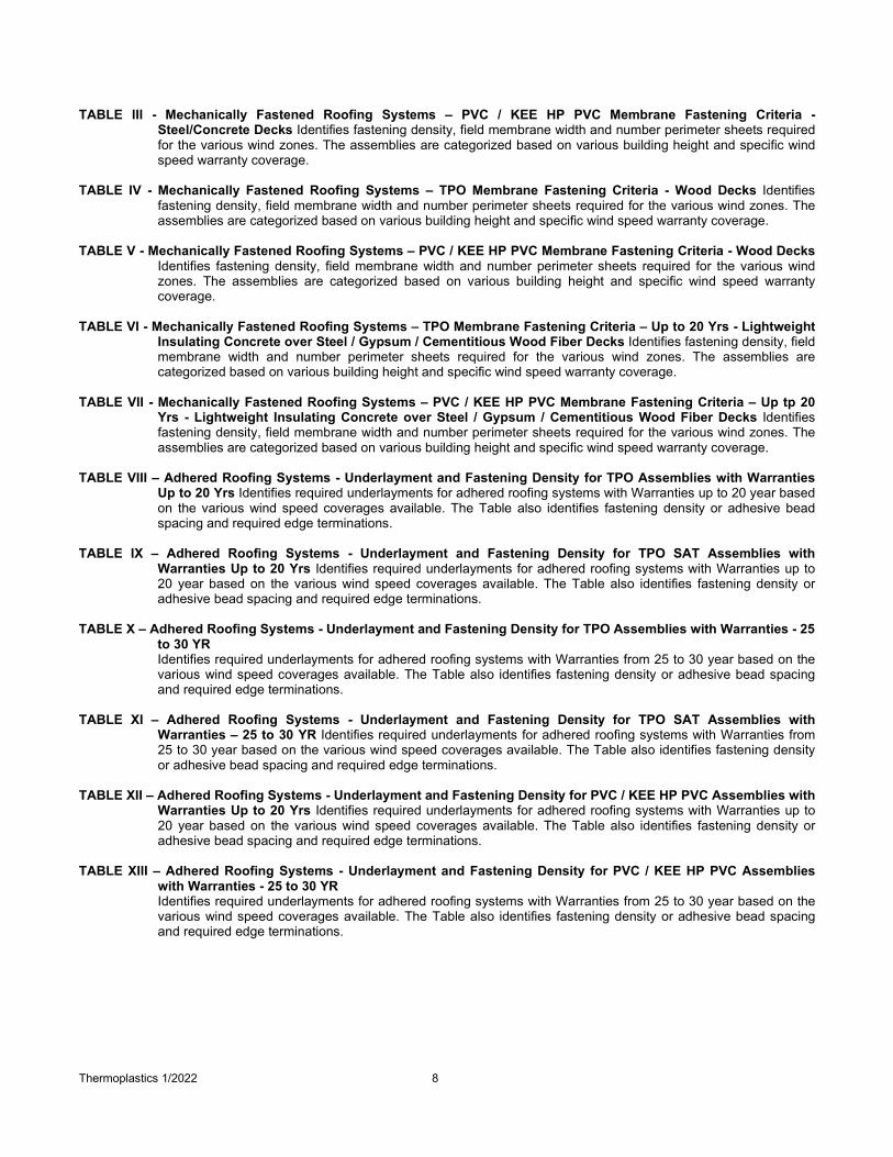
TABLE III - Mechanically Fastened Roofing Systems – PVC / KEE HP PVC Membrane Fastening Criteria -
Steel/Concrete Decks Identifies fastening density, field membrane width and number perimeter sheets required for the various wind zones. The assemblies are categorized based on various building height and specific wind speed warranty coverage.
TABLE IV - Mechanically Fastened Roofing Systems – TPO Membrane Fastening Criteria - Wood Decks Identifies
fastening density, field membrane width and number perimeter sheets required for the various wind zones. The assemblies are categorized based on various building height and specific wind speed warranty coverage.
TABLE V - Mechanically Fastened Roofing Systems – PVC / KEE HP PVC Membrane Fastening Criteria - Wood Decks
Identifies fastening density, field membrane width and number perimeter sheets required for the various wind zones. The assemblies are categorized based on various building height and specific wind speed warranty coverage.
TABLE VI - Mechanically Fastened Roofing Systems – TPO Membrane Fastening Criteria – Up to 20 Yrs - Lightweight
Insulating Concrete over Steel / Gypsum / Cementitious Wood Fiber Decks Identifies fastening density, field membrane width and number perimeter sheets required for the various wind zones. The assemblies are categorized based on various building height and specific wind speed warranty coverage.
TABLE VII - Mechanically Fastened Roofing Systems – PVC / KEE HP PVC Membrane Fastening Criteria – Up tp 20
Yrs - Lightweight Insulating Concrete over Steel / Gypsum / Cementitious Wood Fiber Decks Identifies fastening density, field membrane width and number perimeter sheets required for the various wind zones. The assemblies are categorized based on various building height and specific wind speed warranty coverage.
TABLE VIII – Adhered Roofing Systems - Underlayment and Fastening Density for TPO Assemblies with Warranties
Up to 20 Yrs Identifies required underlayments for adhered roofing systems with Warranties up to 20 year based on the various wind speed coverages available. The Table also identifies fastening density or adhesive bead spacing and required edge terminations.
TABLE IX – Adhered Roofing Systems - Underlayment and Fastening Density for TPO SAT Assemblies with
Warranties Up to 20 Yrs Identifies required underlayments for adhered roofing systems with Warranties up to 20 year based on the various wind speed coverages available. The Table also identifies fastening density or adhesive bead spacing and required edge terminations.
TABLE X – Adhered Roofing Systems - Underlayment and Fastening Density for TPO Assemblies with Warranties - 25
to 30 YR Identifies required underlayments for adhered roofing systems with Warranties from 25 to 30 year based on the
various wind speed coverages available. The Table also identifies fastening density or adhesive bead spacing and required edge terminations.
TABLE XI – Adhered Roofing Systems - Underlayment and Fastening Density for TPO SAT Assemblies with
Warranties – 25 to 30 YR Identifies required underlayments for adhered roofing systems with Warranties from 25 to 30 year based on the various wind speed coverages available. The Table also identifies fastening density or adhesive bead spacing and required edge terminations.
TABLE XII – Adhered Roofing Systems - Underlayment and Fastening Density for PVC / KEE HP PVC Assemblies with
Warranties Up to 20 Yrs Identifies required underlayments for adhered roofing systems with Warranties up to 20 year based on the various wind speed coverages available. The Table also identifies fastening density or adhesive bead spacing and required edge terminations.
TABLE XIII – Adhered Roofing Systems - Underlayment and Fastening Density for PVC / KEE HP PVC Assemblies
with Warranties - 25 to 30 YR Identifies required underlayments for adhered roofing systems with Warranties from 25 to 30 year based on the
various wind speed coverages available. The Table also identifies fastening density or adhesive bead spacing and required edge terminations.

Thermoplastics 1/2022 9
Sure-Weld TPO Membrane Hail
- 1” Dia. Hail Coverage requires a minimum of 60-mil TPO Adhered to cover board. - 2” Dia. Hail Coverage requires 80-mil TPO Adhered to cover board.
Additional Design Requirement: - Cover board (SecurShield HD, SecurShield HD Plus, SecurShield HD or StormBase Composite, DensDeck Prime, DensDeck StormX Prime or Securock – Adhered Only).
Puncture - Minimum 80-mil TPO Adhered or Mechanically Fastened.
Sure-Flex PVC and KEE HP PVC Membrane Hail
- 1” Dia. Hail Coverage requires a minimum of 60-mil PVC or KEE HP PVC Adhered to cover board. - 2” Dia. Hail Coverage requires 80-mil PVC or KEE HP PVC Adhered to cover board.
Additional Design Requirement: - Cover board (SecurShield HD, SecurShield HD Plus, SecurShield HD or StormBase Composite, DensDeck Prime, Dens Deck StormX Prime or Securock – Adhered Only).
Puncture - Minimum 60-mil PVC with Polyester Reinforcement.
Table I Mechanically Fastened or Adhered Membrane Systems Warranty Options (9)
Warranty Duration
Thermoplastic Membranes (Sure-Weld TPO / Sure-Flex PVC or KEE HP PVC)
Warranty Wind Speed Coverage
Minimum Membrane Thickness (2)
Additional Membrane Coverage
55, 72, 80 or 90 mph 100 mph 110 to 120 mph
Adhered Mech. Fastened Adhered Mech.
Fastened Adhered Mech. Fastened
Additional Puncture Hail
5,10, or 15 year √ √ √ N/A(1) √ N/A Sure-Weld 45-mil OR
Sure-Flex 50-mil (6) See Below See Below
20 year √(3) √ √ N/A √ N/A Sure-Weld 60-mil (4) OR Sure-Flex 60 mil (6)(7) See Below See Below
25 year (9) √ √ √ N/A N/A N/A
Sure-Weld 80-mil (5) OR Sure-Flex 80-mil
(6)(8)(10) See Below See Below
30 year (9) √ √ √ N/A N/A N/A
Sure-Weld 80-mil (5) OR Sure-Flex KEE HP PVC
80-mil (10) See Below See Below
Notes: N/A = Not Acceptable √= Acceptable (1) Contact Carlisle for specific requirements. (2) All “T-Joints” must be overlaid with appropriate flashing material when using 60- or 80-mil TPO or 80-mil PVC/KEE HP membrane. (3) Aqua Base 120 adhesive may be used for projects with 20 year maximum warranty and wind speed coverage up to 72 mph. HydroBond Adhesive (PVC Only) may be used for projects with 20 year maximum warranty and wind speed coverage up to 90 mph. (4) Spectro-Weld OR Sure-Weld SAT TPO 60-mil membranes may be used in lieu of Sure-Weld 60-mil membrane. (5) Spectro-Weld 80-mil membrane OR Sure-Weld SAT TPO 80-mil membrane can be used in lieu of Sure-Weld 80-mil membrane. Sure-Weld 80-mil TPO in Special Colors are limited to Warranties Up to 20 Year. (6) Sure-Flex FRS membrane can be used in lieu of Sure-Flex Polyester reinforced membrane for Adhered Roofing Systems Only. (7) Sure-Flex KEE HP PVC 50-mil membrane can be used in lieu of Sure-Flex 60-mil membrane for Warranties Up to 20 Year. (8) Sure-Flex KEE HP PVC 60-mil membrane can be used in lieu of Sure-Flex 80-mil membrane for Warranties Up to 25 Year. (9) Enhancements may be required for certain flashing details. Published details must be referenced for applicable requirements. (10) Sure-Flex PVC 60- or 80-mil membranes in Slate Gray are limited to Warranties Up to 20 Year.

Thermoplastics 1/2022 10
Table II TPO Membrane Fastening Criteria (All Warranties) for Mechanically Fastening Roofing Systems
22 GA. Steel Deck or Structural Concrete Only
Caution: Projects with 25 or 30 year warranties an additional perimeter sheet is required beyond those listed in the table below. Projects with 25 or 30 year warranties the use of 12’ wide sheets is NOT
PERMITTED
Peak Gust Wind Speed
Warranty
Max. Building Height
Min. Number of Perimeter Sheets
Field* Membrane
Width
Perimeter* Sheet Width
Fastening Density* (Field & Perimeter Sheets) Building Distance from Coastline
Greater than 7 miles
3 to 7 miles
Less than 3 miles
55 MPH
Up to 60' 1 2 3 12' or 10’ 6' 12" O.C.
8' 4' 12" O.C.
61' to 100' 2 2 3 10' 6' ** See Note
8' 4' 12" O.C.
72 MPH
Up to 60' 2 2 3 12' or 10’ 6' 12" O.C.
8' 4' 12" O.C.
61' to 100' 3 4 4 10' 6' ** See Note
8' 4' 12" O.C.
80 MPH
Up to 60' 3 3 4 10' 6' ** See Note
8' 4' 12" O.C.
61' to 100' 3 4 4 10' 6' ** See Note
8' 4' 12" O.C.
90 MPH
Up to 60' 3 4 4 10' 6' ** See Note
8' 4' 12" O.C.
61' to 100' 4 5 5 10' 6' ** See Note
8' 4' 12" O.C.
*Using HP-X™ Fasteners for steel decks and HD 14-10 or CD-10 for structural concrete decks. ** Structural Concrete Decks use 12” O.C. spacing utilizing HD 14-10 or CD-10. Steel Decks use 6” O.C. utilizing HP-X Fasteners. Steel Decks use 12” O.C. spacing utilizing HP-Xtra Fasteners.

Thermoplastics 1/2022 11
Table III
PVC / KEE HP PVC Membrane Fastening Criteria (All Warranties) for Mechanically Fastening Roofing Systems
22 GA. Steel Deck or Structural Concrete Only Caution: Projects with 25 or 30 year warranties an additional perimeter sheet
is required beyond those listed in the table below.
Peak Gust Wind Speed
Warranty
Max. Building Height
Min. Number of Perimeter Sheets Field*
Membrane Width
Perimeter* Sheet Width
Fastening Density* (Field &
Perimeter Sheets)
Building Distance from Coastline Greater than 7 miles
3 to 7 miles
Less than 3 miles
55 MPH
Up to 60' 1 2 3 10' 5' 12" O.C.
81" 40.5" 12" O.C.
61' to 100' 2 2 3 10' 5' ** See Note
81" 40.5" 12" O.C.
72 MPH
Up to 60' 2 2 3 10' 5' 12" O.C.
81" 40.5" 12" O.C.
61' to 100' 3 4 4 10' 5' ** See Note
81" 40.5" 12" O.C.
80 MPH
Up to 60' 3 3 4 10' 5' 12" O.C.
81" 40.5" 12" O.C.
61' to 100' 3 4 4 10' 5' ** See Note
81" 40.5" 12" O.C.
90 MPH
Up to 60' 3 4 4 10' 5' 6" O.C.
81" 40.5" 12" O.C.
61' to 100' 4 5 5 10' 5' ** See Note
81" 40.5" 12" O.C.
*Using HP-X Fasteners for steel decks and HD 14-10 or CD-10 for structural concrete decks. ** Structural Concrete Decks use 12” O.C. spacing utilizing HD 14-10 or CD-10. Steel Decks use 6” O.C. utilizing HP-X Fasteners. Steel Decks use 12” O.C. spacing utilizing HP-Xtra Fasteners.

Thermoplastics 1/2022 12
Table IV TPO Membrane Fastening Criteria (Up to 20 year Warranty)
for Mechanically Fastening Roofing Systems Wood Decks
Peak Gust Wind
Speed Warranty
Deck Type Projected Pull-Out Values
Min. Number of Perimeter Sheets
Field Membrane
Width
Perimeter Sheet Width
Fastening Density (Field &
Perimeter Sheets)
Building Distance from Coastline
Greater than 7 miles
Less than or equal to 7 miles
55 MPH
7/16" OSB* 210 lbs 2 3 10' 6' 9" O.C.
2 3 8' 4' 12" O.C.
15/32" 3-Ply Plywood 240 lbs 2 3 8' 4' 12" O.C.
15/32" 5-Ply Plywood 530 lbs 1 1 10' 6' 12" O.C.
5/8" OSB* 310 lbs 2 3 10' 6' 12" O.C.
2 3 8' 4' 12" O.C.
72 MPH
15/32" 3-Ply Plywood 240 lbs 2 3 8' 4' 12" O.C.
15/32" 5-Ply Plywood 530 lbs 1 1 10' 6' 12" O.C.
5/8" OSB* 310 lbs 2 3 10' 6' 12" O.C.
2 3 8' 4' 12" O.C.
*Maximum duration for OSB NOT to exceed 20 Years.
Table V PVC / KEE HP PVC Membrane Fastening Criteria (Up to 20 year Warranty)
for Mechanically Fastening Roofing Systems Wood Decks
Peak Gust Wind
Speed Warranty
Deck Type Projected Pull-Out Values
Min. Number of Perimeter Sheets
Field Membrane
Width
Perimeter Sheet Width
Fastening Density (Field &
Perimeter Sheets)
Building Distance from Coastline
Greater than 7 miles
Less than or equal to 7 miles
55 MPH
7/16" OSB* 210 lbs 2 3 10' 5' 9" O.C.
2 3 81" 40.5" 12" O.C.
15/32" 3-Ply Plywood 240 lbs 2 3 81" 40.5" 12" O.C.
15/32" 5-Ply Plywood 530 lbs 1 1 10' 5' 12" O.C.
5/8" OSB* 310 lbs 2 3 10' 5' 12" O.C.
2 3 81" 40.5" 12" O.C.
72 MPH
15/32" 3-Ply Plywood 240 lbs 2 3 81" 40.5" 12" O.C.
15/32" 5-Ply Plywood 530 lbs 1 1 10' 5' 12" O.C.
5/8" OSB* 310 lbs 2 3 10' 5' 12" O.C.
2 3 81" 40.5" 12" O.C.
*Maximum duration for OSB NOT to exceed 20 Years.

Thermoplastics 1/2022 13
Table VI TPO Membrane Fastening Criteria
Up to 20 Yr Warranty for Mechanically Fastening Roofing Systems Lightweight Insulating Concrete over Steel / Gypsum / Cementitious Wood Fiber
Peak Gust Wind
Speed Warranty
Building Height 50’ Max.
Min. Number of Perimeter Sheets
Field Membrane
Width
Perimeter Sheet Width
Fastening Density (Field
& Perimeter Sheets)
Building Distance from Coastline
Deck Type Greater than 7 miles
3 to 7 miles
Less than 3 miles
55 MPH
Lightweight Concrete over Steel Deck
2 3 (1) N/A 12’ 6’ 12" O.C.
1 2 4 10' 6’ 12" O.C.(2)
1 2 3 8’ 4’ 12" O.C.(3)
Gypsum Deck or Cementitious Wood Fiber
2 (3) 3 N/A 10’ 6’ 9" O.C.
2 (3) 3 4 (4) 8’ 4’ 12" O.C.
N/A is Not Acceptable (1) Fastening Density must be secured 6” O.C. (2) For Buildings 51’ to 75’ with 10’ field sheets – Fastening Density must be increased to 9” O.C. (3) Acceptable for Buildings up to 75’ in height. (4) Fastening Density must be increased to 9” O.C.
Additional Design Considerations (Up to 20 YR Warranty)
1-Membrane configuration and fastening density in Table above is based on HP-X Fasteners penetrating metal pan below Lightweight Insulating Concrete and for Polymer Gyptec Fasteners engaging into Gypsum and Cementitious Fiber Decks. 2-See Design Reference DR-06-19 “Withdrawal Resistance Criteria” for more information.

Thermoplastics 1/2022 14
Table VII PVC / KEE HP PVC Membrane Fastening Criteria
Up to 20 Warranty for Mechanically Fastening Roofing Systems Lightweight Insulating Concrete over Steel / Gypsum / Cementitious Wood Fiber
Peak Gust Wind
Speed Warranty
Building Height 50’ Max.
Min. Number of Perimeter Sheets
Field Membrane
Width Perimeter
Sheet Width
Fastening Density (Field
& Perimeter Sheets)
Local Wind Speed
Deck Type Greater than 7 miles
3 to 7 miles
Less than 3 miles
55 MPH
Lightweight Concrete over Steel Deck
1 2 4 10’ 5’ 12" O.C.(1)
2 3 4 81” (3) 40.5” 12" O.C.(2)
Gypsum Deck or Cementitious Wood Fiber
2 3 N/A 10’ 5’ or 6’ 9" O.C.
2 3 4 81” 4’ 12" O.C.
N/A is Not Acceptable (1) For Buildings 51’ to 75’ with 10’ field sheets – Fastening Density must be increased to 9” O.C. for field and
perimeter sheets. (2) Fasteners may be spaced at 18” O.C. in the field for buildings Up to 50’ in height. (3) Building Height may be Up to 75’ in height.
Additional Design Considerations (Up to 20 YR Warranty)
1- Membrane configuration and fastening density in Table above is based on HP-X Fasteners penetrating metal pan below Lightweight Insulating Concrete and for Polymer Gyptec Fasteners engaging into Gypsum and Cementitious Fiber Decks. 2-See Design Reference DR-06-19 “Withdrawal Resistance Criteria” for more information.

Thermoplastics 1/2022 15
Table VIII
Underlayment/Insulation & Required Attachment Assemblies Up to 20 YR Warranty for TPO Adhered Roofing Systems
Other Requirements are Listed in Additional Design Considerations following this Table All Carlisle Products listed for higher wind speed coverage can also be used for Warranties for a lower speed coverage. (i.e. 72 MPH underlayment may be used for 55 MPH underlayment)
Peak Gust Wind
Speed Warranty
Minimum Membrane Underlayment*
Underlayment/Insulation Attachment
Metal Edging # of
Fasteners per 4' x 8'
board size (1)
Adhesive Ribbon Spacing for 4' x 4'
size board
Field Perimeter
55 or 72 MPH
1” (20 psi) Polyisocyanurate 16 (11)
12" (6)(7) 6" (6) Carlisle Drip Edge, SecurEdge™ 200
1-1/2" (20 psi) Polyisocyanurate 10 2" (20 psi) Polyisocyanurate 8
1/2" SecurShield HD (3) 12 1/4" DensDeck Prime or 1/4” Securock (2) 12
80 MPH
1/2" SecurShield HD Plus (3) 8
12" (6)(7)(8) 6" (6)(8)
Carlisle Drip Edge, SecurEdge 200
(12)
1/2” HP Recovery Board (2) 16
2” SecurShield HD Composite 6
1/2" DensDeck Prime or 1/2” Securock (2) 8
1-1/2" (25-psi) Polyisocyanurate 10
2" (25 -psi) Polyisocyanurate 8
90 MPH
1/2" DensDeck Prime or 1/2” Securock (2) 12
6"(10) 6"(8)(9)
Carlisle Drip Edge (4), SecurEdge
200 (4)(5) or SecurEdge 2000 or
3000.
1/2" SecurShield HD (3) or 1-1/2" (20-psi) SecurShield Polyiso 16
1/2" SecurShield HD Plus (3) 12 2" (20-psi) SecurShield Polyiso or 2” SecurShield HD
Composite 8
1-1/2” StormBase (OSB/Polyiso Composite) or 1/2” EcoStorm VSH (2) 8
1-1/2” Insulfoam HD Composite 16
100 MPH 2" (25-psi) SecurShield Polyiso (1) 16 FS FS
Carlisle Drip Edge (4), SecurEdge
200 (4)(5) or SecurEdge 2000 or
3000.
110 MPH 1-1/2” StormBase (OSB/Polyiso Composite) or 1/2”
EcoStorm VSH (2) 16 FS FS SecurEdge 2000 or 3000
1/2” SecurShield HD Plus (3)
120 MPH
5/8" DensDeck Prime or 5/8” Dens Deck StormX Prime or 5/8” Securock (2) 16
FS FS SecurEdge 2000 or 3000
1-1/2” StormBase (OSB/Polyiso Composite) (1) or 1/2” EcoStorm VSH (3) 17
1/2" SecurShield HD Plus (3) 24
2” SecurShield HD Composite 16
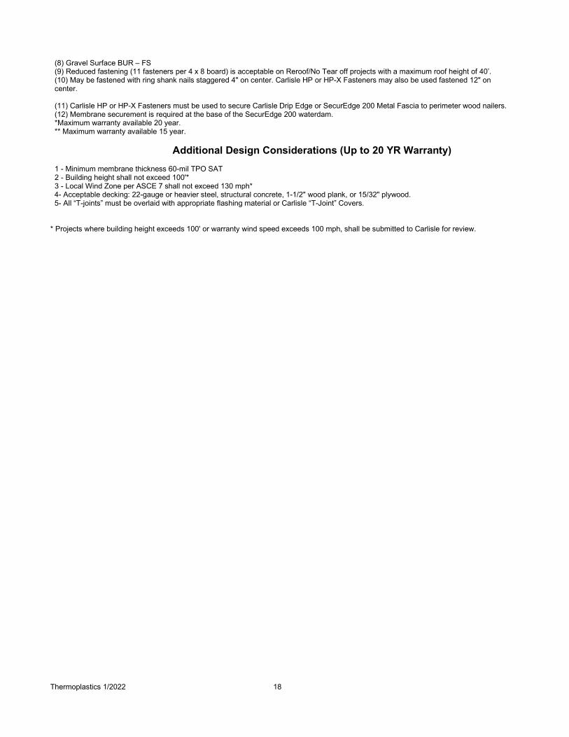
FS = Full Spray or Ribbons @ 4" O.C. *For Direct Application over Wood Decks and Lightweight Cellular Concrete, Refer to Roof Deck & Substrate Criteria Table. (1) For Building heights between 51-100', enhance 12'-wide perimeter with 50% more fasteners and plates. (2) Cover boards must be installed over a min. 1" thick approved Carlisle Insulation. (3) 1/2" SecurShield HD limited to 90 mph. 1/2” SecurShield HD Plus limited to 120 mph. (4) Carlisle HP or HP-X Fasteners must be used to secure Carlisle Drip Edge or SecurEdge 200 Metal Fascia to perimeter wood nailers. (5) Membrane securement is required at the base of the SecurEdge 200 waterdam. (6) Gravel Surface BUR - Field @ 6" O.C. / Perimeter @ 4" O.C. (7) Steel Decks - Field & Perimeter @ 6" O.C.

Thermoplastics 1/2022 16
(8) Cementitious Wood Fiber - Field @ 6" O.C. / Perimeter @ 4" O.C. (9) Smooth BUR - Field @ 6" O.C. / Perimeter @ 4" O.C. (10) Gravel Surface BUR – FS (11) Reduced fastening (11 fasteners per 4 x 8 board) is acceptable on Reroof/No Tear off projects with a maximum roof height of 40’. (12) May be fastened with ring shank nails staggered 4" on center. Carlisle HP or HP-X Fasteners may also be used fastened 12" on center.
Additional Design Considerations (Up to 20 YR Warranty)
1 – Refer to Table I paragraph 1.05 for warranty options available with various membrane thickness. 2 - Building height shall not exceed 100'* 3 - Local Wind Zone per ASCE 7 shall not exceed 130 mph* 4 - Acceptable decking: 22-gauge or heavier steel, structural concrete, 1-1/2" wood plank, or 15/32" plywood.
* Projects where building height exceeds 100', shall be submitted to Carlisle for review.

Thermoplastics 1/2022 17
Table IX Underlayment/Insulation & Required Attachment Assemblies Up to 20 YR Warranty for TPO SAT Adhered Roofing Systems
Other Requirements are Listed in Additional Design Considerations following this Table All Carlisle Products listed for higher wind speed coverage can also be used for Warranties for a lower speed coverage. (i.e. 72 MPH underlayment may be used for 55 MPH underlayment)
Peak Gust Wind Speed
Warranty Minimum Membrane Underlayment
Insulation Attachment
Metal Edging # of
Fasteners per 4' x 8'
board size (1)
Adhesive Ribbon Spacing for 4' x 4' size
board
Field Perimeter
55 or 72 MPH
1” (20 psi) Polyisocyanurate 16 (9)
12" (4)(5) 6" (4) Carlisle Drip
Edge, SecurEdge 200
1-1/2" (20 psi) Polyisocyanurate 10
2"(20 psi) Polyisocyanurate 8
1/2” SecurShield HD (3)
12 1/4” DensDeck Prime or 1/4” Securock (2)
2” (1.25 lb/density) Insulfoam SP*
80 MPH
1/2" DensDeck Prime or 1/2” Securock (2) 8
12" (4)(5)(6) 6' (4)(7) Carlisle Drip
Edge, SecurEdge (10)
1/2” SecurShield HD (3) 16 1/2” SecurShield HD Plus (3) 8 2" SecurShield HD Composite 6
1-1/2" (25-psi) Polyisocyanurate 10
2" (25 -psi) Polyisocyanurate 8
2” (1.25 lb/density) Insulfoam SP** 16 6" (4)(5)(6) 6" (4)(6)
1-1/2” Insulfoam HD Composite* 12 12” (8) 6” (6)(7)
90 MPH
1/2” DensDeck Prime or 1/2” Securock (2) 12
6” (8) 6” (6)(7)
Carlisle Drip Edge (11),
SecurEdge 200 (11)(12) or
SecurEdge 2000 or 3000.
1/2” SecurShield HD (3) or 1-1/2” (20-psi) SecurShield Polyiso 16
1/2” SecurShield HD Plus (3) 12 1-1/2” StormBase (OSB/Polyiso Composite) or 1/2”
EcoStorm VSH 8
2” (20-psi) SecurShield Polyiso or 2” SecurShield HD Composite 8
1-1/2” Insulfoam HD Composite 16
100 MPH
5/8" DensDeck Prime or 5/8” DensDeck StormX Prime or 5/8” Securock (2)
16 FS FS
Carlisle Drip Edge (11),
SecurEdge 200 (11)(12) or
SecurEdge 2000 or 3000.
1/2" SecurShield HD Plus (3) 1-1/2” StormBase (OSB/Polyiso Composite) or 1/2”
EcoStorm VSH 2" (25-psi) SecurShield Polyiso (1)
2” SecurShield HD Composite
FS = Full Spray or Ribbons @ 4" O.C. (1) For Building heights between 51-100', enhance 12'-wide perimeter with 50% more fasteners and plates. (2) Cover boards must be installed over a min. 1" thick approved Carlisle Insulation. (3) 1/2" SecurShield HD limited to 90 mph. 1/2” SecurShield HD Plus limited to 120 mph. (4) Gravel Surface BUR - Field @ 6" O.C. / Perimeter @ 4" O.C. (5) Steel Decks - Field & Perimeter @ 6" O.C. (6) Cementitious Wood Fiber - Field @ 6" O.C. / Perimeter @ 4" O.C. (7) Smooth BUR - Field @ 6" O.C. / Perimeter @ 4" O.C.
Thermoplastics 1/2022 18
(8) Gravel Surface BUR – FS (9) Reduced fastening (11 fasteners per 4 x 8 board) is acceptable on Reroof/No Tear off projects with a maximum roof height of 40’. (10) May be fastened with ring shank nails staggered 4" on center. Carlisle HP or HP-X Fasteners may also be used fastened 12" on center. (11) Carlisle HP or HP-X Fasteners must be used to secure Carlisle Drip Edge or SecurEdge 200 Metal Fascia to perimeter wood nailers. (12) Membrane securement is required at the base of the SecurEdge 200 waterdam. *Maximum warranty available 20 year. ** Maximum warranty available 15 year.
Additional Design Considerations (Up to 20 YR Warranty)
1 - Minimum membrane thickness 60-mil TPO SAT 2 - Building height shall not exceed 100'* 3 - Local Wind Zone per ASCE 7 shall not exceed 130 mph* 4- Acceptable decking: 22-gauge or heavier steel, structural concrete, 1-1/2" wood plank, or 15/32" plywood. 5- All “T-joints” must be overlaid with appropriate flashing material or Carlisle “T-Joint” Covers.
* Projects where building height exceeds 100' or warranty wind speed exceeds 100 mph, shall be submitted to Carlisle for review.

Thermoplastics 1/2022 19
Table X Underlayment/Insulation & Required Attachment Assemblies 25 YR or 30 YR Warranty for Adhered TPO Roofing Systems
Other Requirements are Listed in Additional Design Considerations following this Table All Carlisle Products listed for higher wind speed coverage can also be used for Warranties for a lower speed coverage. (i.e. 72 MPH underlayment may be used for 55 MPH underlayment)
Peak Gust Wind
Speed Warranty
Minimum Membrane Underlayment
Insulation Attachment
Metal Edging # of
Fasteners per 4' x 8'
board size (1)
Adhesive Ribbon Spacing for 4' x 4'
size board
Field Perimeter
55 or 72 MPH
1" to 2" (25 psi) Polyisocyanurate
16 6" (3)(5) 6" (5) Carlisle Drip
Edge, SecurEdge 200
1/2” HP Recovery Board (1)(9)
1/4” DensDeck Prime or 1/4” Securock (2)
1/2” SecurShield HD (2)
80 MPH
1-1/2" to 2" (25-psi) SecurShield Polyisocyanurate 20
6" (4)(5)(6) 6" (5)(6)
Carlisle Drip Edge (7),
SecurEdge 200 (7)(8) or
SecurEdge 2000 or 3000
1/2" DensDeck Prime or 1/2” Securock (2) 16
1/2" SecurShield HD Plus (2)
1/2" SecurShield HD (2) 20
90 MPH
1/2” SecurShield HD (2) 24
FS FS SecurEdge 2000 or 3000 1/2” SecurShield HD Plus (2)
20 1/2” DensDeck Prime or 1/2” Securock (2)
100 MPH
5/8" DensDeck Prime or 5/8” DensDeck StormX Prime or 5/8” Securock (2)
16 FS FS SecurEdge 2000
or 3000 1-1/2” StormBase (OSB/Polyiso Composite) or 1/2” EcoStorm VSH (2)
2” SecurShield HD Composite (2)
1/2” SecurShield HD Plus (2) 24
FS = Full Spray or Ribbons @ 4" O.C. (1) For Building heights between 51-100', enhance 12'-wide perimeter with 50% more fasteners and plates. (2) Hail coverage offered with substrate. (3) Structural Concrete - Field @ 12" O.C. / Perimeter @ 6" O.C. (4) 80-mph over structural concrete - Field & Perimeter @ 6" O.C. (5) Cementitious Wood Fiber & Wood - FS (6) 80-mph warranty wind speed coverage over Gypsum Decks – Adhesive Ribbon spacing shall be at 4” O.C. (7) Carlisle HP or HP-X Fasteners must be used to secure Carlisle SecurEdge200 Metal Fascia to perimeter wood nailers. (8) Membrane securement is required at the base of the SecurEdge 200 waterdam. (9) 1/2” Recovery Board limited to 55 mph.
Additional Design Considerations (25 YR or 30 YR Warranty)
1 - Minimum membrane thickness 80-mil TPO 2 - Building height shall not exceed 100'* 3 - Local Wind Zone per ASCE 7 shall not exceed 130 mph* 4- Acceptable decking: 22-gauge or heavier steel, structural concrete, 1-1/2" wood plank, or 15/32" plywood. 5– All “T-Joints” must be overlaid with appropriate flashing material or Carlisle “T-Joint” Covers. 6 – New construction or complete tear-off of existing roofing material.
*Projects where building height exceeds 100' or warranty wind speed exceeds 100 mph, shall be submitted to Carlisle for review.

Thermoplastics 1/2022 20
Table XI Underlayment/Insulation & Required Attachment Assemblies
25 YR or 30 YR Warranty for TPO SAT Adhered Roofing Systems Other Requirements are Listed in Additional Design Considerations following this Table All Carlisle Products listed for higher wind speed coverage can also be used for Warranties for a lower speed coverage. (i.e. 72 MPH underlayment may be used for 55 MPH underlayment)
Peak Gust Wind
Speed Warranty
Minimum Membrane Underlayment
Insulation Attachment
Metal Edging # of
Fasteners per 4' x 8'
board size (1)
Adhesive Ribbon Spacing for 4' x 4' size
board
Field Perimeter
55 or 72 MPH
1" to 2" (25 psi) Polyisocyanurate
16 6" (3)(5) 6" (5) Carlisle Drip Edge, SecurEdge 200 1/4" DensDeck Prime or 1/4” Securock (2)
1/2" SecurShield HD (2)
1-1/2" to 2" (25-psi) SecurShield Polyisocyanurate 20
6" (4)(5)(6) 6" (5)(6)
Carlisle Drip Edge (7), SecurEdge 200 (7)(8) or SecurEdge 2000 or
3000 80 MPH 1/2" DensDeck Prime or 1/2” Securock (2) 16
1/2" SecurShield HD Plus (2) 1/2" SecurShield HD (2) 20
90 MPH
1/2" SecurShield HD (2) 24
FS FS
Carlisle Drip Edge (7), SecurEdge 200 (7)(8) or SecurEdge 2000 or
3000
1/2" SecurShield HD Plus (2) 20
1/2" DensDeck Prime or 1/2” Securock (2)
100 MPH
5/8” DensDeck Prime or 5/8” DensDeck StormX Prime or 5/8” Securock (2)
16 FS FS SecurEdge 2000 or
3000 1-1/2” StormBase (OSB/Polyiso Composite) or 1/2”
EcoStorm VSH (2) 2” SecurShield HD Composite (2)
1/2” SecurShield HD Plus (2) 24 FS = Full Spray or Ribbons @ 4" O.C. (1) For Building heights between 51-100', enhance 12'-wide perimeter with 50% more fasteners and plates. (2) Hail coverage offered with substrate. (3) Structural Concrete - Field @ 12" O.C. / Perimeter @ 6" O.C. (4) 80-mph over structural concrete - Field & Perimeter @ 6" O.C. (5) Cementitious Wood Fiber & Wood - FS (6) 80-mph warranty wind speed coverage over Gypsum Decks – Adhesive Ribbon spacing shall be at 4” O.C. (7) Carlisle HP or HP-X Fasteners must be used to secure Carlisle SecurEdge200 Metal Fascia to perimeter wood nailers. (8) Membrane securement is required at the base of the SecurEdge 200 waterdam.
Additional Design Considerations (25 YR or 30 YR Warranty)
1 - Minimum membrane thickness 80-mil TPO SAT 2 - Building height shall not exceed 100'* 3 - Local Wind Zone per ASCE 7 shall not exceed 130 mph* 4- Acceptable decking: 22-gauge or heavier steel, structural concrete, 1-1/2" wood plank, or 15/32" plywood. 5– All “T-Joints” must be overlaid with appropriate flashing material or Carlisle “T-Joint” Covers. 6 – New construction or complete tear-off of existing roofing material.
* Projects where building height exceeds 100' or warranty wind speed exceeds 100 mph, shall be submitted to Carlisle for review.

Thermoplastics 1/2022 21
Table XII Underlayment/Insulation & Required Attachment Assemblies Up to 20 YR Warranty for Adhered PVC / KEE HP PVC Roofing
Other Requirements are Listed in Additional Design Considerations following this Table All Carlisle Products listed for higher wind speed coverage can also be used for Warranties for a lower speed coverage. (i.e. 72 MPH underlayment may be used for 55 MPH underlayment)
Peak Gust Wind
Speed Warranty
Minimum Membrane Underlayment*
Insulation Attachment
Metal Edging # of
Fasteners per 4' x 8' board size
(1)
Adhesive Ribbon Spacing for 4' x 4' size
board
Field Perimeter
55 or 72 MPH
1” (20 psi) Polyisocyanurate 16 (11)
12"(6)(7) 6"(6) Carlisle Drip
Edge, SecurEdge 200
1-1/2" (20 psi) Polyisocyanurate 10
2"(20 psi) Polyisocyanurate 8
1/2” SecurShield HD (3) 12
1/4” DensDeck Prime or 1/4” Securock (2) 12
80 MPH
1/2” SecurShield HD Plus (3) 8
12"(6)(7)(8) 6"(6)(8)
Carlisle Drip Edge,
SecurEdge 200 (12)
1/2” HP Recovery Board (2) 16
2” SecurShield HD Composite 6
1/2" DensDeck Prime or 1/2” Securock (2) 8
1-1/2" (25 psi) Polyisocyanurate 10
2" (25 psi) Polyisocyanurate 8
90 MPH
1/2" DensDeck Prime or 1/2” Securock (2) 12
6"(10) 6"(8)(9)
Carlisle Drip Edge (4),
SecurEdge 200 (4)(5) or
SecurEdge 2000 or 3000.
1/2” SecurShield HD (3) or 1-1/2" (20 psi) SecurShield Polyiso 16
1/2” SecurShield HD Plus 12 2" (20 psi) SecurShield Polyiso or 2” SecurShield HD
Composite 8
1-1/2” StormBase (OSB/Polyiso Composite) or 1/2” EcoStorm VSH (2) 8
1-1/2” Insulfoam HD Composite 16
100 MPH 2” (25-psi) SecurShield Polyiso (1) 16 FS FS
Carlisle Drip Edge (4),
SecurEdge 200 (4)(5) or
SecurEdge 2000 or 3000.
110 MPH 1-1/2” StormBase (OSB/Polyiso Composite) or 1/2”
EcoStorm VSH (2) 16 FS FS SecurEdge 2000 or 3000 1/2” SecurShield HD Plus (3)
120 MPH
5/8" DensDeck Prime or 5/8” DensDeck StormX Prime or 5/8” Securock (2) 16
FS FS SecurEdge 2000 or 3000
1-1/2” StormBase (OSB/Polyiso Composite) (1) or 1/2” EcoStorm VSH (2) 17
1/2” SecurShield HD Plus (3) 24
2” SecurShield HD Composite 16

Thermoplastics 1/2022 22
FS = Full Spray or Ribbons @ 4" O.C. *For Direct Application over Wood Decks and Lightweight Cellular Concrete, Refer to Roof Deck & Substrate Criteria Table. (1) For Building heights between 51-100', enhance 12'-wide perimeter with 50% more fasteners and plates. (2) Cover boards must be installed over a min. 1" thick approved Carlisle Insulation. (3) 1/2” SecurShield HD limited to 90 mph. 1/2” SecurShield HD Plus limited to 120 mph. (4) Carlisle HP or HP-X Fasteners must be used to secure Carlisle Drip Edge or SecurEdge 200 Metal Fascia to perimeter wood nailers. (5) Membrane securement is required at the base of the SecurEdge 200 waterdam. (6) Gravel Surface BUR - Field @ 6" O.C. / Perimeter @ 4" O.C. (7) Steel Decks - Field & Perimeter @ 6" O.C. (8) Cementitious Wood Fiber - Field @ 6" O.C. / Perimeter @ 4" O.C. (9) Smooth BUR - Field @ 6" O.C. / Perimeter @ 4" O.C. (10) Gravel Surface BUR – FS (11) Reduced fastening (11 fasteners per 4 x 8 board) is acceptable on Reroof/No Tear off projects with a maximum roof height of 40’. (12) May be fastened with ring shank nails staggered 4" on center. Carlisle HP or HP-X Fasteners may also be used fastened 12" on center.
Additional Design Considerations (Up to 20 YR Warranty)
1 - Minimum membrane thickness 60-mil PVC or 50-mil KEE HP PVC 2 - Building height shall not exceed 100'* 3 - Local Wind Zone per ASCE 7 shall not exceed 130 mph* 4 - Acceptable decking: 22-gauge or heavier steel, structural concrete, 1-1/2" wood plank, or 15/32" plywood. 5 - All “T-Joints” must be overlaid with Carlisle “T-Joint” Covers.
* Projects where building height exceeds 100', shall be submitted to Carlisle for review.

Thermoplastics 1/2022 23
Table XIII Underlayment/Insulation & Required Attachment Assemblies
25 YR or 30 YR Warranty for Adhered PVC / KEE HP PVC Roofing Systems Other Requirements are Listed in Additional Design Considerations following this Table All Carlisle Products listed for higher wind speed coverage can also be used for Warranties for a lower speed coverage. (i.e. 72 MPH underlayment may be used for 55 MPH underlayment)
Peak Gust Wind
Speed Warranty
Minimum Membrane Underlayment
Insulation Attachment
Metal Edging # of
Fasteners per 4' x 8' board size
(1)
Adhesive Ribbon Spacing for 4' x 4' size
board
Field Perimeter
55 or 72 MPH
1" to 2" (25 psi) Polyisocyanurate
16 6" (3)(5) 6" (5) Carlisle Drip
Edge, SecurEdge 200
1/2" HP Recovery Board (1) (9)
1/4" DensDeck Prime or 1/4” Securock (2)
1/2" SecurShield HD (2)
80 MPH
1-1/2" to 2" (25-psi) SecurShield Polyisocyanurate 20
6" (4)(5)(6) 6" (5)(6)
Carlisle Drip Edge (7),
SecurEdge 200 (7) (8) or
SecurEdge 2000 or 3000
1/2" DensDeck Prime or 1/2” Securock (2) 16
1/2” SecurShield HD Plus (2)
1/2" SecurShield HD (2) 20
90 MPH
1/2” SecurShield HD (2) 24
FS FS SecurEdge 2000 or 3000 1/2” SecurShield HD Plus (2)
20 1/2” DensDeck Prime or 1/2” Securock (2)
100 MPH
5/8" DensDeck Prime or 5/8” Dens Deck StormX Prime or 5/8” Securock (2)
16 FS FS SecurEdge 2000
or 3000
1-1/2” StormBase (OSB/Polyiso Composite) or 1/2” EcoStorm VSH (2)
2” SecurShield HD Composite (2)
1/2” SecurShield HD Plus (2) 24
FS = Full Spray or Ribbons @ 4" O.C. (1) For Building heights between 51-100', enhance 12'-wide perimeter with 50% more fasteners and plates. (2) Hail coverage offered with substrate. (3) Structural Concrete - Field @ 12" O.C. / Perimeter @ 6" O.C. (4) 80 mph over Structural Concrete - Field & Perimeter @ 6" O.C. (5) Cementitious Wood Fiber & Wood – FS (6) 80-mph warranty wind speed coverage over Gypsum Decks – Adhesive Ribbon spacing shall be at 4” O.C. (7) Carlisle HP or HP-X Fasteners must be used to secure Carlisle Drip Edge or SecurEdge200 Metal Fascia to perimeter wood nailers. (8) Membrane securement is required at the base of the SecurEdge 200 waterdam. (9) 1/2” Recovery Board limited to 55 mph.
Additional Design Considerations (25 YR or 30 YR Warranty)
1 - Minimum membrane thickness 80-mil PVC or KEE HP PVC 2 - Building height shall not exceed 100'* 3 - Local Wind Zone per ASCE 7 shall not exceed 130 mph* 4 - Acceptable decking: 22-gauge or heavier steel, structural concrete, 1-1/2" wood plank, or 15/32" plywood. 5 - All "T-joints" must be overlaid with Carlisle “T-Joint” Covers. 6 – New construction or complete tear-off of existing roofing material.
* Projects where building height exceeds 100' or warranty wind speed exceeds 100 mph, shall be submitted to Carlisle for review.
Thermoplastics 1/2022 24
B. Access for warranty service
It shall be the owner's responsibility to expose the membrane in the event that warranty service is required when access is impaired. Such impairment includes, but is not necessarily limited to:
1. Design features, such as window washer systems, which require the installation of traffic surface units in
excess of 100 pounds per unit.
2. Any equipment, ornamentation, building service units and other top surfacing materials which are not defined as part of this specification.
3. Photovoltaic and Mounting systems or other Rooftop equipment that does not provide Carlisle with reasonable
access to the membrane system for purposes of warranty investigation and related repairs.
4. Severely ponded conditions.
CAUTION: APPLICATIONS SUCH AS WALKING DECKS, TERRACES, PATIOS OR AREAS SUBJECTED TO CONDITIONS NOT TYPICALLY FOUND ON ROOFING SYSTEMS WILL NOT BE ELIGIBLE FOR A MEMBRANE SYSTEM WARRANTY.
C. The formation or presence of mold or fungi in a building is dependent upon a broad range of factors including, but
not limited to, the presence of spores and nutrient sources, moisture, temperatures, climatic conditions, relative humidity, and heating/ventilating systems and their maintenance and operating capabilities. These factors are beyond the control of Carlisle and Carlisle shall not be responsible for any claims, repairs, restoration or damages relating to the presence of any irritants, contaminants, vapors, fumes, molds, fungi, bacteria, spores, mycotoxins, or the like in any building or in the air, land, or water serving the building.
1.06 Job Conditions
A. On phased roofing, temporary closures should be provided to prevent moisture infiltration. When a temporary roof is specified, Carlisle 725-TR in conjunction with CCW-702 or CAV-GRIP III Low-VOC Adhesive/Primer may be used. Refer to Product Section Part II for additional product information and Specification Supplement G-08-20.
B. When possible on multiple level roofs, begin the installation on the highest level to avoid or minimize construction
traffic on completed roof sections. C. On projects at high altitudes (6,000' and above) rapid flash-off (drying) of Adhesives will occur due to low
atmospheric pressure.
D. When roof slopes exceed 5 inches per horizontal foot, use of an Automatic Heat Welder may be more difficult. A Hand Held Hot Air Welder should be specified.
E. Vapor Retarders
1. Carlisle does not require a vapor retarder for the protection of the membrane; however, the following criteria should be considered by the specifier:
a. Use of a vapor retarder to protect insulation and reduce moisture accumulation within an insulated roofing
assembly, should be investigated. Consult latest publications by ASHRAE (American Society of Heating, Refrigerating and Air-Conditioning Engineers, Inc.) and NRCA (National Roofing Contractors Association) for specific information.
b. In the generally temperate climate of the United States, during the winter months, water vapor flows upward from a heated, more humid interior toward a colder, drier exterior. Vapor retarders are more commonly required in northern climates than in southern regions, where downward vapor pressure may be expected and the roofing membrane itself becomes the vapor retarder.
c. On cold storage/freezer facilities, the perimeter and penetration details must be selected to provide an air
seal and prevent outside air from infiltrating and condensing within the roofing assembly.

Thermoplastics 1/2022 25
2. When a vapor retarder is specified, Carlisle 725TR Air and Vapor Barrier may be used. Refer to Part II “Products” for necessary information and Spec Supplement G-08-20 “Application Procedures for 725TR Air and Vapor Barrier” for product Installation.
F. Wood nailers are required for the securement of metal edgings, scuppers, and insulated pipes. Wood Nailer shall
be secured per specifier recommendation or in accordance with Factory Mutual’s property Loss Prevention Data Sheet 1-49. Refer to Design Reference DR-08-11 “Wood Nailers Securement Criteria” in Carlisle Technical Manual shall be referenced.
G. When any of the Roofing Systems are specified on a portion of a roof, tie-ins to existing roofing membranes will be
required. Depending on the type of the existing roofing system, the tie-in method will vary. Total isolation between two roofing systems or weep holes may be required to address moisture migration from one roofing system to the other. Prior to the selection of any tie-in detail, ensure the selected detail will not restrict drainage.
H. On new construction projects, located in colder climates, special consideration should be given to construction
practices and the possible migration of hot, humid air and moisture generated during construction. Refer to Paragraph 1.02 I and Design Reference DR-01-21 “Construction Generated Moisture”.
1.07 Product, Delivery, Storage and Handling
A. Deliver materials to the job site in the original, unopened containers.
B. When loading materials onto the roof, the Carlisle Authorized Roofing Applicator must comply with the requirements of the specifier/owner to prevent overloading and possible disturbance to the building structure.
C. Job site storage temperatures in excess of 90° F (32° C) may affect shelf life of curable materials (i.e., adhesives
and sealants).
D. When the temperature is expected to fall below 40° F (4° C), outside storage boxes should be provided on the roof for temporary storage of liquid adhesives and sealants. Adhesive and sealant containers should be rotated to maintain their temperature above 40° F (4° C). Refer to Product Data Sheets for individual products for temperature restrictions.
E. Do not store adhesive or cleaner containers with opened lids due to the loss of solvent that will occur from flash-off.
F. Store Carlisle membrane on provided pallets in the original undisturbed plastic wrap in a cool, shaded area and
cover with light-colored, breathable tarpaulins.
G. Insulation/underlayment must be stored so that it is kept dry and is protected from the elements. Store insulation on a skid and completely cover with a breathable material such as tarp or canvas. If the insulation is lightweight, it should be weighted to prevent possible wind damage.
Part II – PRODUCTS 2.01 General
The components of this roofing system are to be products of Carlisle or accepted by Carlisle as compatible. The installation, performance or integrity of products by others, when selected by the specifier and accepted by Carlisle, is not the responsibility of Carlisle and is expressly disclaimed by the Carlisle warranty.
2.02 Membranes
A. Sure-Weld Membranes 1. General
a. Sure-Weld TPO Membrane meets or exceeds the requirements of ASTM D6878-17, standard specification
for Thermoplastic Polyolefin Based Sheet Roofing. In addition to the physical properties listed below, refer to the Sure-Weld Membrane Product Data Sheets for Cool Roof Rating Council (CRRC), ENERGY STAR and LEED™ radiative properties as well as U.S.E.P.A. Toxic Leachate Testing and dynamic puncture
Thermoplastics 1/2022 26
resistance.
b. The Sure-Weld TPO membrane (white and tan) meets the ENERGYSTAR requirement for reflectance and emittance. When tested in accordance with ASTM C1549, the material has an initial reflectance of 0.79 (white) and 0.71(tan) and a 3-year aged reflectance of 0.70 (white) and 0.64 (tan). The material has also been tested for emittance in accordance with ASTM C1371. An initial emittance of 0.90 (white) and 0.86 (tan) and a 3-year aged emittance of 0.86 (white) and 0.87 (tan) were achieved.
c. The Spectro-Weld TPO membrane (white) meets the ENERGY STAR requirement for reflectance and
emittance. When tested in accordance with ASTM C1549, the material has an initial reflectance of 0.88 and a 3-year aged reflectance of 0.75. The material has also been tested for emittance in accordance with ASTM C1371. An initial emittance of 0.89 and a 3-year aged emittance of 0.90 were achieved.
d. The Sure-Weld TPO membrane (white) meets the emittance requirements set forth by the USGBC (US Green Building Council) for their LEED (Leadership in Energy and Environmental Designs) Program. When tested in accordance with ASTM E408, an emittance of 0.90 was achieved and an SRI (solar reflectance index) of 99 was calculated using ASTM E1980.
e. The Spectro-Weld TPO membrane (white) meets the emittance requirements set forth by the USGBC (US
Green Building Council) for their LEED (Leadership in Energy and Environmental Designs) Program. When tested in accordance with ASTM E408, an emittance of 0.89 was achieved and an SRI (solar reflectance index) of 111 was calculated using ASTM E1980.
2. Sure-Weld 45 or 60-mil thick Reinforced Thermoplastic Polyolefin (TPO) membrane, Sure-Weld SAT (Self-Adhering Technology) 60 or 80-mil thick Reinforced Thermoplastic Polyolefin (TPO) membrane and Sure-Weld 80-mil thick Reinforced EXTRA™ Thermoplastic Polyolefin (TPO) conforms to the following physical properties. Sure-Weld SAT (white, tan or gray) membrane is available in 10’ wide by 50’ or 100’ long rolls and Sure-Weld Standard / HS membrane available in field sheets in rolls 12', 10' or 8' wide by 100' long. Perimeter membrane sheets are available in widths of 6' (used with 12' and 10' wide field sheets) or 4' (used with 8' wide field sheets) by 100' long. Sure-Weld Membrane is available in white, gray or tan. Special Color TPO membrane is available in 5 colors (Medium Bronze, Rock Brown, Terra Cotta, Slate Gray and Patina Green) in 60-mil field sheets in rolls 5’ or 10’ wide by 100’ long and 80-mil field sheets in 10’ wide by 100’ long. Special Color TPO is a special order product and may require a lead time. OPTION: 60- or 80-mil Sure-Weld TPO (white, tan or gray) reinforced membrane is available with an optional APEEL Protective Film. APEEL Protective Film can be left in place for up to 90 days without affecting the integrity of the film, guarding the TPO membrane’s surface from scuffs and dirt accumulation during installation. Durable and easy to remove, APEEL Protective Film improves aesthetics and long-term reflectivity. Available 4’, 6’, 8’, 10’ and 12’ widths by 100’ long rolls. Some sizes and colors of Sure-Weld SAT with APEEL require a minimum order of 200 squares and 2-3 week lead time. Also available, APEEL 6” Cover Tape, allowing 100% coverage of the TPO surface. APEEL Cover Tape rolls are 1,640 feet long.
Note: Sure-Weld HS and Special Color TPO Membrane is specially formulated with higher fire retardancy to accommodate steep slope roof conditions.

Thermoplastics 1/2022 27
PHYSICAL PROPERTY ASTM D6878 Requirement
45-mil Std & HS
60-mil Std & HS
60-mil SAT or Spectro-
Weld
80-mil EXTRA or Spectro-
Weld Tolerance on nominal thickness, %
ASTM D751 test method +15, -10 ± 10 ± 10 ± 10 ± 10
Thickness over scrim, in. (mm) ASTM D6878 optical method, average
of 3 areas
0.012 min. (0.305)
0.018 typical (0.457)
0.024 typical (0.610)
0.024 typical (0.610)
0.034 typical (0.864)
Breaking strength, lbf (kN) ASTM D751 grab method
220 (976 N) min.
225 (1.0) min. 320 (1.4) typ.
250 (1.1) min. 360 (1.6) typ.
250 (1.1) min. 360 (1.6) typ.
350 (1.6) min. 425 (1.9) typ.
Elongation break of reinforcement, % ASTM D751 grab method 15 min. 15 min. 25
typ. 15 min. 25
typ. 15 min. 25
typ. 15 min. 25
typ. Tearing strength, lbf (N) ASTM
D751 proc. B 8 by 8 in. 55 (245) min. 55 (245) min. 130 (578) typ.
55 (245) min. 130 (578) typ.
55 (245) min. 130 (578) typ.
55 (245) min. 130 (578) typ.
Brittleness point, °F (°C) ASTM D2137 -40 (-40) max. -40 (-40) max. -50 (-46) typ.
-40 (-40) max. -50 (-46) typ.
-40 (-40) max. -50 (-
46) typ.
-40 (-40) max. -50 (-
46) typ. Linear dimensional change, % ASTM
D1204, 6 hours at 158 °F ± 1 max. ± 1 max. -0.2 typ.
± 1 max. -0.2 typ.
± 0.5 max. -0.2 typ.
± 1 max. -0.2 typ.
Ozone resistance, no cracks 7X ASTM D1149, 100 pphm, 168 hrs Pass Pass Pass Pass Pass
Water absorption resistance, mass % ASTM D471 top surface only 166
hours at 158 °F water ± 3.0 max. 3.0 max.
2.0 typ. 3.0 max. 2.0 typ.
4.0 max. 2.0 typ.
3.0 max. 2.0 typ.
Factory seam strength, lbf /in. (kN/m) ASTM D751 grab method 66 (290) min. 66 (290) min. 66 (290) min. 66 (290) min. 66 (290) min.
Field seam strength, lbf /in. (kN/m) ASTM D1876 tested in peel
No requirement
25 (4.4) min. 50 (8.8) typ.
25 (4.4) min. 60 (10.5) typ.
25 (4.4) min. 60 (10.5) typ.
40 (7.0) min. 70 (12.3) typ.
Water vapor permeance, Perms ASTM E96 proc. B
No requirement
0.10 max. 0.05 typ.
0.10 max. 0.05 typ.
0.10 max. 0.05 typ.
0.10 max. 0.05 typ.
Puncture resistance, lbf (kN) FTM 101C, method 2031 (see
supplemental section)
No requirement
250 (1.1) min. 325 (1.4) typ.
300 (1.3) min. 350 (1.6) typ.
300 (1.3) min. 350 (1.6) typ.
400 (1.8) min. 450 (2.0) typ.
Properties after heat aging ASTM D573, 670 hrs at 240 °F
Breaking strength, % retained
Elongation reinf., % retained Tearing strength, % retained
Weight change, %
90 min. 90 min. 60 min.
± 1.0 max.
90 min. 90 min. 60 min.
± 1.0 max.
90 min. 90 min. 60 min.
± 1.0 max.
90 min. 90 min. 60 min.
± 1.0 max.
90 min. 90 min. 60 min.
± 1.0 max.

Thermoplastics 1/2022 28
B. Sure-Flex Membranes 1. General
a. The Sure-Flex PVC membrane (white) meets the ENERGY STAR requirement for reflectance and
emittance. When tested in accordance with ASTM C1549, the material has an initial reflectance of 0.86 and a 3-year aged reflectance of 0.63. The material has also been tested for emittance in accordance with ASTM C1371. An initial emittance of 0.89 and a 3-year aged emittance of 0.87 were achieved.
b. The Sure-Flex KEE HP PVC membrane (white) meets the ENERGY STAR requirement for reflectance and emittance. When tested in accordance with ASTM C1549, the material has an initial reflectance of 0.82 and a 3-year aged reflectance of 0.71. The material has also been tested for emittance in accordance with ASTM C1371. An initial emittance of 0.89 and a 3-year aged emittance of 0.84 were achieved.
c. The Sure-Flex PVC membrane (white) meets the emittance requirements set forth by the USGBC (US
Green Building Council) for their LEED (Leadership in Energy and Environmental Designs) Program. When tested in accordance with ASTM E408, an emittance of 0.89 was achieved and an SRI (solar reflectance index) of 108 was calculated using ASTM E1980.
d. The Sure-Flex KEE HP PVC membrane (white) meets the emittance requirements set forth by the
USGBC (US Green Building Council) for their LEED (Leadership in Energy and Environmental Designs) Program. When tested in accordance with ASTM E408, an emittance of 0.89 was achieved and an SRI (solar reflectance index) of 103 was calculated using ASTM E1980.

Thermoplastics 1/2022 29
2. Sure-Flex 50-mil, 60-mil or 80-mil thick Polyester Reinforced PVC (Polyvinyl Chloride) Membrane conforms to the following physical properties
a. Physical properties of the membrane are enhanced by a strong, polyester fabric that is encapsulated
between the PVC based top and bottom plies. The combination of the fabric and PVC plies provide Sure-Flex Reinforced PVC membranes with high breaking strength, tearing strength, and puncture resistance.
b. Field membrane sheets are packaged in rolls 81" or 120” wide. Perimeter membrane sheets are
available in a width of 40.5" or 60” wide. 50-mil thick membrane is available in lengths of 100', 60-mil is available in 100' lengths and 80-mil is available in 75' lengths. Sure-Flex PVC Membrane is available in white, gray, light gray, slate gray and tan. Sure-Flex PVC KEE HP Membrane is available in white, gray, light gray, and tan.
OPTION: 60-mil Sure-Flex PVC or 60-mil Sure-Flex KEE HP (white color only) reinforced membrane is available with an optional APEEL Protective Film. APEEL Protective Film can be left in place for up to 90 days without affecting the integrity of the film, guarding the PVC/KEE HP membrane’s surface from scuffs and dirt accumulation during installation. Durable and easy to remove, APEEL Protective Film improves aesthetics and long-term reflectivity. Available 5’ and 10’ widths by 100’ long rolls. Also available, APEEL 6” Cover Tape, allowing 100% coverage of the PVC surface.
Sure-Flex Polyester Reinforced PVC Membrane
Physical Property ASTM D4434 Requirement 50-mil Min. 60-mil Min. 80-mil Min.
Thickness Over Scrim, in. (mm) ASTM D4434 optical method average of 3 areas 0.016 min. (0.40) 0.022 (0.559) 0.028 (0.711) 0.038 (0.965)
Weight, lbs/ft2 (kg/m2) No requirement 0.33 (1.61) 0.40 (1.95) 0.55 (2.68) Breaking Strength (MD X CD), lbf/in (kN/m) ASTM D751 grab method 275 min. (48) 320 x 300
(56 x 53) 330 x 300 (58 x 55)
360 x 330 (63 x 58)
Elongation break of reinforcement (MD x CD), % ASTM D751 grab method 25 min. 30 x 30 30 x 30 30 x 30
Seam Strength, min. ASTMD751 grab method (% of breaking strength) >75 PASS PASS PASS
Tearing Strength (MD x CD), lbf (N) ASTM D751 proc. B, 8 in. x 8 in. 90 min. (400) 100 x 120
(445 x 534) 100 x 130
(445 x 578) 100 x 132
(445 x 587) Low Temperature Bend, ASTM D2135, no cracks 5x at -40oC PASS PASS (-40oC) PASS (-40oC) PASS (-40oC)
Linear Dimensional Change, % ASTM D1204, 6 hours at 176oF +/- 0.5 max. 0.4 0.4 0.4
Ozone Resistance, no cracks 7x ASTM D1149, 100pphm, 168 hrs PASS PASS PASS PASS
Water Absorption Resistance, mass % ASTM D570, 166 hours at 158oF +/- 3.0 max. 2.0 2.0 2.0
Field Seam Strength, lbf/in. (kN/m) ASTM D1876 tested in peel No Requirement 25 (4.4) min.
60 (10.5) max. 25 (4.4) min.
60 (10.5) max. 25 (4.4) min.
60 (10.5) max. Water Vapor Permeance, Perms, ASTM E96 proc. B No Requirement 0.10 max.
0.05 typ. 0.10 max. 0.05 typ.
0.10 max. 0.05 typ.
Puncture Resistance – Federal, lbf (kN) FTM 101C, method 2031 No Requirement 280 320 380
Puncture Resistance – Dynamic, J (ft-lbf) ASTM D5635 20 (14.7) PASS PASS PASS
Puncture Resistance – Static, lbf (N) ASTM D5602 33 (145) PASS PASS PASS
Xenon-Arc Resistance, no cracks/crazing 10x, ASTM G155 0.35 W/m2 at 340-nm, 63oC B.P.T. 12,600 kJ/m2 total radiant exposure 10,000 hours
PASS PASS PASS PASS
Properties After Heat Aging, ASTM D3045, 56 days at 176oF Breaking Strength, % retained Elongation reinf., % retained
90 min. 90 min.
90 min. 90 min.
90 min. 90 min.
90 min. 90 min.
B.P.T. is black panel temperature
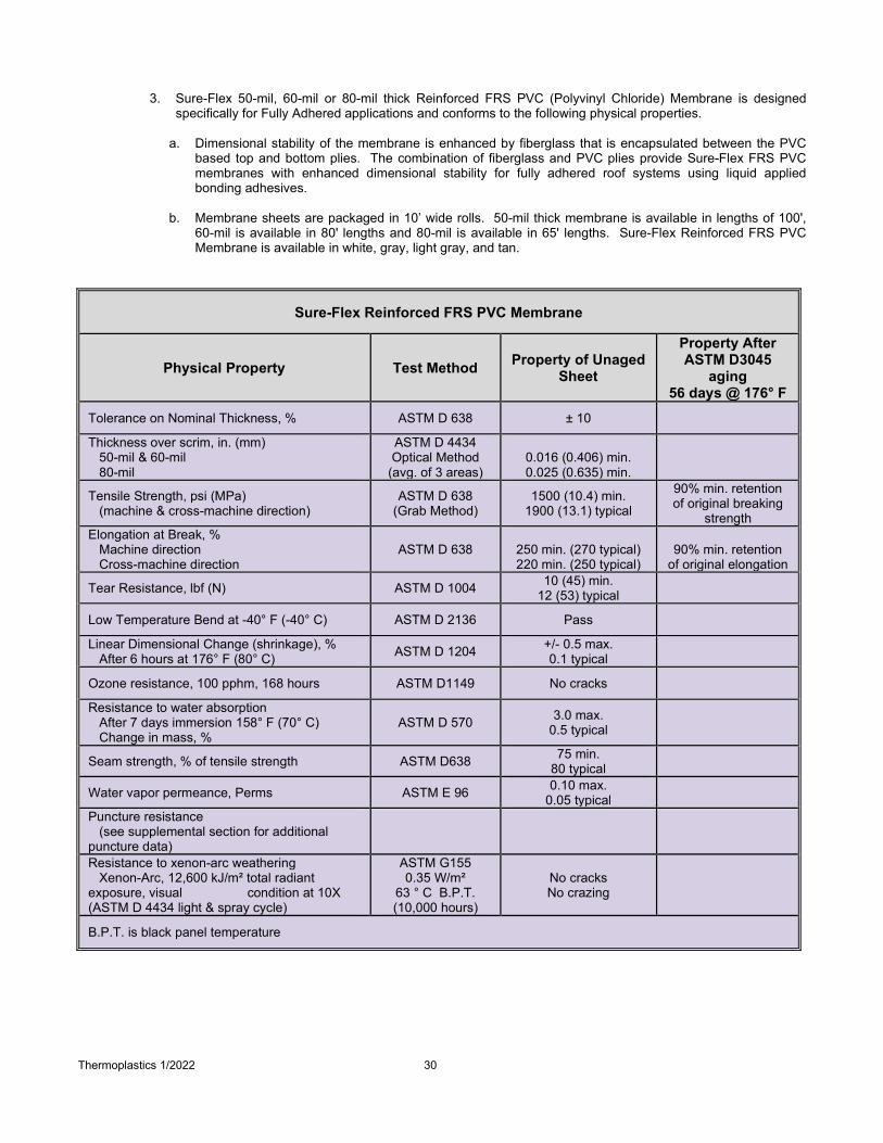
Thermoplastics 1/2022 30
3. Sure-Flex 50-mil, 60-mil or 80-mil thick Reinforced FRS PVC (Polyvinyl Chloride) Membrane is designed specifically for Fully Adhered applications and conforms to the following physical properties.
a. Dimensional stability of the membrane is enhanced by fiberglass that is encapsulated between the PVC
based top and bottom plies. The combination of fiberglass and PVC plies provide Sure-Flex FRS PVC membranes with enhanced dimensional stability for fully adhered roof systems using liquid applied bonding adhesives.
b. Membrane sheets are packaged in 10’ wide rolls. 50-mil thick membrane is available in lengths of 100',
60-mil is available in 80' lengths and 80-mil is available in 65' lengths. Sure-Flex Reinforced FRS PVC Membrane is available in white, gray, light gray, and tan.
Sure-Flex Reinforced FRS PVC Membrane
Physical Property Test Method Property of Unaged Sheet
Property After ASTM D3045
aging 56 days @ 176° F
Tolerance on Nominal Thickness, % ASTM D 638 ± 10
Thickness over scrim, in. (mm) 50-mil & 60-mil 80-mil
ASTM D 4434 Optical Method
(avg. of 3 areas)
0.016 (0.406) min. 0.025 (0.635) min.
Tensile Strength, psi (MPa) (machine & cross-machine direction)
ASTM D 638 (Grab Method)
1500 (10.4) min. 1900 (13.1) typical
90% min. retention of original breaking
strength Elongation at Break, % Machine direction Cross-machine direction
ASTM D 638
250 min. (270 typical) 220 min. (250 typical)
90% min. retention
of original elongation
Tear Resistance, lbf (N) ASTM D 1004 10 (45) min. 12 (53) typical
Low Temperature Bend at -40° F (-40° C) ASTM D 2136 Pass
Linear Dimensional Change (shrinkage), % After 6 hours at 176° F (80° C) ASTM D 1204 +/- 0.5 max.
0.1 typical
Ozone resistance, 100 pphm, 168 hours ASTM D1149 No cracks
Resistance to water absorption After 7 days immersion 158° F (70° C) Change in mass, %
ASTM D 570 3.0 max. 0.5 typical
Seam strength, % of tensile strength ASTM D638 75 min. 80 typical
Water vapor permeance, Perms ASTM E 96 0.10 max. 0.05 typical
Puncture resistance (see supplemental section for additional puncture data)
Resistance to xenon-arc weathering Xenon-Arc, 12,600 kJ/m² total radiant exposure, visual condition at 10X (ASTM D 4434 light & spray cycle)
ASTM G155 0.35 W/m²
63 ° C B.P.T. (10,000 hours)
No cracks No crazing
B.P.T. is black panel temperature

Thermoplastics 1/2022 31
4. Sure-Flex 50-mil, 60-mil or 80-mil thick KEE HP PVC Polyester Reinforced Membrane is designed for Fully Adhered or Mechanically Fastened applications and conforms to the following physical properties. a. Physical properties of the membrane are enhanced by a strong, polyester fabric that is encapsulated
between the KEE HP based top and bottom plies. The combination of the fabric and KEE HP plies provide Sure-Flex KEE HP Polyester Reinforced membranes with high breaking strength, tearing strength, and puncture resistance.
b. Field membrane sheets are packaged in 5’ and 10’ wide rolls. 50-mil thick membrane is available in
lengths of 100', 60-mil is available in 100' lengths and 80-mil is available in 75' lengths. Sure-Flex KEE HP Membrane is available in white, gray, light gray, slate gray and tan.
Sure-Flex KEE HP Polyester Reinforced Membrane
PHYSICAL PROPERTY ASTM D4434 Requirement 50-mil 60-mil 80-mil
Thickness Over Scrim, in. (mm) ASTM D4434 optical method average of 3 areas
0.016 min. (0.40) 0.024 (0.61) 0.029 (0.74) 0.036 (0.91)
Weight, lbs/ft2 (kg/m2) No requirement 0.33 (1.61) 0.40 (1.95) 0.55 (2.68)
Breaking Strength (MD X CD), lbf/in (kN/m) ASTM D751 grab method 275 min. (48) 290 x 290
(51 x 51) 320 x 300 (56 x 52)
330 x 320 (58 x 56)
Elongation break of reinforcement (MD x CD), % ASTM D751 grab method 25 min. 30 x 30 30 x 30 30 x 30
Tearing Strength (MD x CD), lbf (N) ASTM D751 proc. B, 8 in. x 8 in. 90 min. (400) 120 x 125
(534 x 556) 120 x 125
(534 x 556) 140 x 150
(623 x 667)
Low Temperature Bend, ASTM D2135, no cracks 5x at -40oC PASS PASS (-46oC) PASS (-46oC) PASS (-46oC)
Linear Dimensional Change, % ASTM D1204, 6 hours at 176oF +/- 0.5 max. 0.4 typ. 0.4 typ. 0.4 typ.
Ozone Resistance, no cracks 7x ASTM D1149, 100pphm, 168 hrs PASS PASS PASS PASS
Water Absorption Resistance, mass % ASTM D570, 166 hours at 158oF +/- 3.0 max. 1.25 0.87 0.89
Puncture Resistance – Dynamic, J (ft-lbf) ASTM D5635 20 (14.7) PASS PASS PASS
Puncture Resistance – Static, lbf (N) ASTM D5602 33 (145) PASS PASS PASS
Xenon-Arc Resistance, no cracks/crazing 10x, ASTM G155 0.35 W/m2 at 340-nm, 63oC B.P.T. 12,600 kJ/m2 total radiant exposure 10,000 hours
PASS PASS PASS PASS
Properties After Heat Aging, ASTM D3045, 56 days at 176oF Breaking Strength, % retained Elongation reinf., % retained
90 min. 90 min.
90 min. 90 min.
90 min. 90 min.
90 min. 90 min.
B.P.T. is black panel temperature
2.03 Insulations/Underlayments A. General

Thermoplastics 1/2022 32
1. Roof insulation thickness must be determined by the thermal value required for each project and may be
subject to code approval limitations. On projects where a vapor retarder is used, the specifier must calculate insulation thickness to ensure the temperature at the vapor retarder will not fall below the calculated dew point.
2. Multiple layers of insulation are recommended with all joints staggered between layers.
3. For minimum recommended R-Values, previously published by American Society of Heating and Air-Conditioning Engineers (ASHRAE), consult local building code official for applicable requirements.
4. For Insulation fastening pattern and densities refer to Carlisle Applicable Details and Design Reference DR-05-
19 “Insulation Fastening Patterns”.
5. When new insulation or cover boards are specified, the use of Carlisle Insulation and Carlisle marketed cover board is required. Any of the Carlisle Insulation/Underlayment may be specified subject to design restrictions included with each of the following tables.
B. Carlisle Polyisocyanurate
Table B1 Polyisocyanurate (See below for product descriptions)
Insulations / Underlayment Minimum Thickness ASTM
Roofing System Acceptability
Adhered Mechanically Fastened
Carlisle InsulBase Polyisocyanurate *1.5" C1289, Type II, Class 1, Grade 2 or 3 √ √
Carlisle SecurShield Polyisocyanurate *1.5" C1289, Type II, Class 2, Grade 2 or 3 √ √
Carlisle SecurShield HD Composite (SS HD) 2" C1289, Type IV, Grade 2 or 3 √ √
Carlisle StormBase Composite (OSB) 1.5" C1289, Type V, Grade 2 or 3 √ √ Design Restrictions
-Extended Warranty, those with longer duration, higher wind speed, or puncture coverage, may require the use of a cover board over Polyiso Insulation, refer to Warranty Tables in Paragraph 1.04 for applicable requirements.
-Maximum Flute Spanability shall be limited to 2-5/8” when 1” Minimum Polyiso Insulation is to be used. -Minimum thickness of insulation board may be restricted by wind speed coverage and warranty duration, refer to Tables V and VI in Paragraph 1.05.
*1.5” minimum for adhered systems. 1” minimum for mechanically fastened systems or as a base layer for adhered.
Notes: N/A = Not Acceptable √ = Acceptable

Thermoplastics 1/2022 33
Note: SecurShield HD is listed in Paragraph F below.
1. Carlisle InsulBase Polyisocyanurate – A foam core insulation board covered on both sides with a medium weight fiber-reinforced felt facer meeting ASTM C 1289, Type II, Class 1, Grade 2 (20 psi) or Grade 3 (25 psi). The product is available in 4’ x 8’ standard size with a thickness from 1 to 4 inches. 4’ x 4’ tapered panels are also available.
2. Carlisle SecurShield Polyisocyanurate– A foam core insulation board covered on both sides with a coasted glass fiber mat facer meeting ASTM C 1289, Type II, Class 2, Grade 2 (20 psi) or Grade 3 (25 psi). The product is available in 4’ x 8’ standard size with a thickness from 1 to 4 inches. 4’ x 4’ tapered panels are also available. These flat board products feature a dark-colored coated-glass facer (CGF) on one side of the insulation board and a light-colored CGF on the other, labeled Ready Flash. Ready Flash Technology allows applicators to manage adhesive flash-off times by choosing between two different-colored facers on every board.
3. Carlisle SecurShield HD Composite – Composite insulation panel comprised of 1/2-inch high-density
(109 psi max) Polyiso cover board laminated during the manufacturing process to SecurShield rigid Polyiso roof insulation meeting ASTM C1289 Type IV, Grade 2 (20 psi) or Grade 3 (25 psi). Available in 4’ x 8’ boards with thickness from 2” to 4.5”. 4’ x 4’ panels are also available.
4. Carlisle StormBase Polyiso Composite (OSB) – Polyiso insulation bonded on the bottom side with a
medium weight fiber-reinforced felt face and laminated with a top surface of 7/16” or 5/8” thick Oriented Strand Board (OSB) meeting ASTM C1289, Type V, Grade 2 (20 psi) or Grade 3 (25 psi). Available in 4’ x 8’ boards with thickness from 1-1/2” to 4”.
C. EPS : Expanded Polystyrene
Table C1 EPS : Expanded Polystyrene (See below for product descriptions)
Insulations / Underlayment Minimum Thickness ASTM
Roofing System Acceptability
Adhered Mechanically Fastened
InsulFoam I 1” C578 Type I N/A √ (1)(3) InsulFoam VIII .75” C578 Type VIII N/A √ (1) InsulFoam II .75" C578 Type II N/A √ (1) InsulFoam IX .75" C578 Type IX N/A √ (1)
InsulFoam HD Composite (SecurShield HD) 1.5” C578 Type (I, VIII, II, or IX) √ √
InsulLam (Various Cover Boards) 1.5" C578 Type (I, VIII, II. or IX) √ N/A InsulFoam SP 1" C578 Type VIII N/A √ InsulFoam SP 2" C578 Type VIII (2) √
Design Restrictions -Local Codes must be consulted regarding the acceptance of expanded insulation directly over steel decks. When specified, minimum thickness shall be designated by the manufacturer.
-Expanded polystyrene roof insulations cannot be installed directly over coal-tar pitch roof surfaces or existing PVC membranes. A separation layer of minimum 1/2” SecurShield HD, HP Recovery Board or Polyiso Insulation shall be used.
(1) Sure-Flex PVC and KEE HP PVC Membrane is not acceptable for this application. (2) May be used as a substrate for Sure-Weld TPO SAT membrane Only. (3) Minimum 1.25 lbs/cubic ft (pcf) density required for Sure-Weld TPO Membrane (White Membrane Only)
Notes: N/A = Not Acceptable √ = Acceptable
Note: R-Tech Fanfold Recover Board is listed in Paragraph F below. Note: Insulation boards listed in a through d, may be specified beneath SecurShield HD, Sure-Seal HP Recovery Board, DensDeck Prime, Dens Deck StormX Prime or Securock.
1. InsulFoam I – A closed-cell lightweight expanded polystyrene (EPS) that meets ASTM C578, Type I.
Thermoplastics 1/2022 34
Nominal density of 1.0 lbs/cubic ft (pcf) available in 4’ x 4’ or 4’ x 8’ sizes with thickness from 1/4” to 40”. Custom lengths, widths and tapered boards are available.
2. InsulFoam VIII – A closed-cell lightweight expanded polystyrene (EPS) that meets ASTM C578, Type VIII.
Nominal density of 1.25 lbs/cubic ft (pcf) available in 4’ x 4’ or 4’ x 8’ sizes with thickness from ¼” to 40”. Custom lengths, widths and tapered boards are available.
3. InsulFoam II – A closed-cell lightweight expanded polystyrene (EPS) that meets ASTM C578, Type II.
Nominal density of 1.5 lbs/cubic ft (pcf) available in 4’ x 4’ or 4’ x 8’ sizes with thickness from 1/4” to 40”. Custom lengths, widths and tapered boards are available.
4. InsulFoam IX – A closed-cell lightweight expanded polystyrene (EPS) that meets ASTM C578, Type IX.
Nominal density of 2.0 lbs/cubic ft (pcf) available in 4’ x 4’ or 4’ x 8’ sizes with thickness from 1/4” to 40”. Custom lengths, widths and tapered boards are available.
5. InsulFoam HD Composite – InsulFoam expanded polystyrene (EPS) insulation laminated with a top
surface of 1/2” thick SecurShield HD. Available in 4’ x 8’ boards with thickness from 1-1/2” to 7”.
6. InsulLam – InsulFoam expanded polystyrene (EPS) insulation laminated with a top surface of 7/16” or 5/8” thick Oriented Strand Board (OSB),1/2” DensDeck Prime, 1/2” Securock, or 1/2" HP Recovery Board. Available in 4’ x 8’ boards with thickness from 1-1/2” to 7”.
7. InsulFoam SP – A closed-cell lightweight expanded polystyrene (EPS) with a factory-laminated fiber glass
facer. Nominal density of 1.25 lbs/cubic ft (pcf), available in 4’ x 8’ size, and meets ASTM C578, Type VIII. Designed for low-sloped roof applications that employ mechanically fastened or Self Adhered, Sure-Weld TPO SAT membranes.
D. XPS: Extruded Polystyrene – Available through Carlisle is dimensionally stable with high thermal and low
water absorption performance capability. XPS is available in varying compressive strengths thicknesses and sizes. Refer to specific product data sheets for physical properties and additional technical information.
Table D1 XPS: Extruded Polystyrene (See below for product descriptions)
Insulations / Underlayment
Minimum Thickness ASTM
Roofing System Acceptability
Adhered Mechanically Fastened
Thermapink 18 .75" Refer to Product Data Sheet N/A √ (1)
Thermapink 25 1" Refer to Product Data Sheet N/A √ (1)
Foamular 400 1" Refer to Product Data Sheet N/A √ (1)
Dow Styrofoam Deckmate Plus 1" Refer to Product Data Sheet N/A √ (1)
Design Restrictions -Local Codes must be consulted regarding the acceptance of expanded insulation directly over steel decks. When specified, minimum thickness shall be designated by the manufacturer.
-Extruded polystyrene roof insulations cannot be installed directly over coal-tar pitch roof surfaces or existing PVC membranes. A separation layer of minimum 1/2” SecurShield HD, HP Recovery Board or Polyiso Insulation shall be used.
-Refer to related products listed in Spec Supplement P-01-20 “Related Products” for other products which may be suitable for use. Carlisle must be contacted for specific requirements.
(1) Sure-Flex PVC and KEE HP PVC Membrane is not acceptable for this application. Notes: N/A = Not Acceptable √ = Acceptable
1. Thermapink 18 or 25 Extruded Polystyrene
2. Foamular 400 Extruded Polystyrene

Thermoplastics 1/2022 35
3. Dow Styrofoam Deckmate Plus Extruded Polystyrene
E. Carlisle Vacuum Insulated Panel (VIP)
Table E1 Vacuum Insulated Panel (VIP) (See below for product descriptions)
Insulations / Underlayment Minimum Thickness ASTM
Roofing System Acceptability
Adhered Mechanically Fastened
Carlisle Optim-R VIP *1.6" C1484 √ N/A
Design Restrictions *2.6” minimum for total installed system including an additional 2 layers of 1/2” SecurShield HD panels; 1 layer on top and 1 layer on bottom of Optim-R. For adhered systems only. Note: Optim-R VIP cannot be cut or punctured.
Notes: N/A = Not Acceptable √ = Acceptable
1. Optim-R Vacuum Insulated Panel (VIP) – a high R-Value vacuum insulated panel (VIP) used to provide a low-profile solution when height restrictions exist, such as windows, doors, equipment curbs, etc. Provides an R-38 insulating value in a 2.6” system thickness with up to 35% infill (non-VIP material). Available in 23.6” x 23.6” and 23.6” x 47.2” board sizes.
Thermoplastics 1/2022 36
F. Cover Boards / Slip Sheets
Table F1 Cover Boards / Slip Sheets (see below for product descriptions)
Insulations / Underlayment Minimum Thickness ASTM
Roofing System Acceptability
Adhered Mechanically Fastened
SecurShield HD .5" C1289, Type II, Class 4 (109 psi max) √ √
SecurShield HD Plus .5” C1289, Type II, Class 4 (109 psi max) √ √
InsulBase HD .5” C1289, Type II, Class 1, Grade 3 N/A √
EcoStorm VSH .5” Refer to Product Data Sheet √ √
Securock Cover Board .25" Refer to Product Data Sheet √ √
HP Recovery Board .5" C208 Grade 2 √ √ DensDeck StormX Prime .625" C1177 √ √ (1)
DensDeck Prime .25" C1177 √ √ (1) DensDeck .25" C1177 N/A √ (1)
R-Tech Fanfold Recovery Board .5" C578 Type (I, VIII, II. or IX) N/A √ (2)
HP Protection Mat 6 oz Refer to Product Data Sheets N/A √
Design Restrictions -HP Recovery Board and R-Tech Fanfold not recommended for direct use over Type B and F steel decks. -Securock Cover Board, HP Recovery Board, DensDeck Prime, DensDeck StormX Prime or DensDeck may not be used directly over New or Existing Lightweight Insulating Concrete Decks existing or Structural Concrete.
-Due to some warranty restrictions, DensDeck, DensDeck Prime and DensDeck StormX Prime not recommended for use directly over existing roofing membrane without prior written approval from Carlisle. Contact Carlisle for specific requirements.
-R-Tech Fanfold primarily for use in existing roof re-covers applications or directly over structural or lightweight insulating concrete.
(1) Permitted for use on combustible decks with slopes greater than 2” per foot for compliance with external fire codes, refer to UL listings or contact Carlisle.
(2) Install Polymeric Side Up when installing Sure-Flex PVC and KEE HP PVC membrane.
Notes: N/A = Not Acceptable √ = Acceptable
1. SecurShield HD – a rigid insulation panel composed of a high-density (109 psi max), closed-cell polyisocyanurate foam core laminated to coated-glass fiber-mat facer for use as a cover board or recover board. Available 1/2” thick 4’ x 8’ panel weight 11 lbs with an R-value of 2.5. These flat board products feature a dark-colored coated-glass facer (CGF) on one side of the insulation board and a light-colored CGF on the other, labeled Ready Flash. Ready Flash Technology allows applicators to manage adhesive flash-off times by choosing between two different-colored facers on every board.
2. SecurShield HD Plus - a rigid insulation panel composed of a high-density (109 psi max), closed-cell polyisocyanurate foam core laminated to premium-performance coated-glass fiber-mat facer for use as a cover board or recover board. Available 1/2” thick 4’ x 8’ panel weight 11 lbs with an R-value of 2.5. Meets an FM 1-90 using only 8 fasteners per 4’ x 8’ board.
3. Insulbase HD – a closed-cell polyisocyanurate foam core insulation board covered on both sides with glass-reinforced felt (GRF) facer meeting ASTM C 1289, Type II, Class 1, Grade 3. The product is available in 4’ x 4’ and 4’ x 8’ standard sizes with a thickness of one half inch.
4. Securock Cover Board – A uniform composition of fiber-reinforced gypsum, without a facer, for use as a cover
board or a thermal barrier. Available in 1/4” to 5/8” thick and 4’ x 4’ or 4’ x 8’ size boards. Long uninterrupted runs (>200’) may require slight gapping due to thermal expansion.
5. EcoStorm VSH Cover Board – an engineered composite building material made from a proprietary blend of plastic and cellulose fiber sourced from post-industrial and post-consumer waste streams. EcoStorm VSH is a
Thermoplastics 1/2022 37
durable, extremely moisture and mold resistant building material with a core that does not disintegrate or delaminate in the presence of water. Available in 1/2” thick and 4’ x 8’ size board.
6. Sure-Seal HP Recovery Board - A 1/2” or 1” thick high-density wood fiberboard with an asphalt coated facer for
use as a cover board or recover board. Available 1/2” or 1” thick and 4’ x 4’ or 4’ x 8’ size boards.
7. DensDeck StormX Prime – a reinforced gypsum cover board with an enhanced, moisture-resistant core and coated glass mat facers on the top and bottom side. The top surface is pre-primed and provides excellent bond strength for adhered membrane for use as a cover board. DensDeck StormX Prime is extremely durable and is approved for use in assemblies meeting FM’s Very Severe Hail (VSH) Classification. Available in 5/8” thickness and 4’ x 4’ or 4’ x 8’ size boards.
8. DensDeck Prime –gypsum core that incorporates glass-mat facings on the top and bottom side. The top
surface is pre-primed and provides excellent bond strength for adhered membrane for use as a cover board. Available in 1/4” to 5/8” and 4’ x 4’ or 4’ x 8’ size boards.
9. DensDeck Cover Board –gypsum core that incorporates glass-mat facings on the top and bottom side for use
as a cover board. Available in 1/4” to 5/8” and 4’ x 4’ or 4’ x 8’ size boards.
10. R-Tech FanFold Recover Board – Closed-cell lightweight expanded polystyrene (EPS) with polymeric laminated faces which meets ASTM C 578 for use as a recover board. Polymeric facer compatible with PVC and KEE HP PVC membrane, while metallic side used with EPDM. Available in thicknesses of 3/8” to 3/4” with coverage 4’ x 50’ (2 squares). 4’ x 8’ units are also available.
11. HP Protection Mat – A nominal 6-oz per square yard UV resistant polypropylene needle punched fabric used
either above the membrane as a slip-sheet for ballast or as an underlayment to the membrane. Available 15’ x 300’ roll (4500 square foot) weighing 0.06 lbs per square foot.
2.04 RELATED MATERIALS
A. Sure-Weld Flashing (for use with Sure-Weld Adhered, Mechanically Fastened and Self Adhered Membrane Assemblies) 1. Sure-Weld Flashing: Sure-Weld non-reinforced flashing is available in rolls 12" and 24" wide by 50'
long. Flashing is used for inside/outside corners and field fabricated pipe flashings when the use of pre-molded or pre-fabricated accessories is not feasible. In addition, 45-mil by 6" wide by 100' long, 60-mil by 6" wide by 100' long, 9” wide by 50’ long and 80-mil by 9” wide by 50’ long Sure-Weld reinforced membrane is available for overlaying fasteners and fastening plates.
2. Sure-Weld Pressure-Sensitive Cover Strip: A nominal 40-mil thick non-reinforced TPO membrane laminated to nominal 35-mil thick cured synthetic rubber pressure-sensitive adhesive used in conjunction with TPO Primer or Low-VOC TPO Primer to strip in flat metal flanges (i.e., drip edges). Available in rolls 6" wide by 100' long in colors of white, gray or tan. Not for use on 25—year or 30-year Warranty projects.
3. Sure-Weld TPO Reinforced Overlayment Strip: A heat-weldable, reinforced thermoplastic polyolefin membrane. It is available in 45-mil 6" x 100' and 60-mil 6" x 100' and 9" x 50' rolls in colors of white, gray or tan. It can be used to cover end laps on FleeceBACK and SAT TPO systems and to strip in flat metal flanges on details such as TPO coated drip edges, gravel stops, and scuppers.
4. APEEL Cover Tape: A 6"-wide, 1,640' long roll of APEEL Protective Film used to protect areas of Sure-Weld TPO or Sure-Flex PVC/KEE HP membranes where APEEL Protective Film has been removed (around details) or was not factory applied (seams). APEEL Cover Tape allows contractors to keep 100 percent of the TPO or PVC/KEE HP surface clean during installation and is applied using the APEEL Cover Tape Applicator.
5. Sure-Weld TPO Pressure-Sensitive RUSS: A nominal 6" and 10" wide, 45-mil thick reinforced TPO
membrane with nominal 3" wide 35-mil thick cured synthetic rubber pressure-sensitive tape adhesive laminated along one edge on 6" wide RUSS and along both edges on 10" wide RUSS. Used in conjunction with TPO Primer or Low-VOC TPO Primer. 6" wide RUSS is used as a base membrane securement along walls, curbs, etc.; 10" wide RUSS is used to form perimeter sheets on Mechanically Fastened Systems.
6. Sure-Weld TPO T-Joint Covers: A 60-mil thick injection molded TPO flashing formed into a 4.5" diameter

Thermoplastics 1/2022 38
circle used to seal step-offs at splice intersections. Installation is mandatory on all 60, 72, and 80-mil TPO systems and on 45-mil systems where step-offs have not been properly sealed. Packaged in boxes of 100. Available in white, tan or gray.
7. Yellow Pressure-Sensitive (PS) Warning Strip: A nominal 30-mil-thick non-reinforced TPO flashing
laminated to a nominal 30-mil-thick, fully cured synthetic rubber Pressure-Sensitive adhesive and is available in 6" wide by 100' long rolls. Yellow Pressure-Sensitive Warning Strip can be applied to EPDM, TPO or Hypalon roofing systems to provide a visual warning of an impending hazard (i.e. roof edge, deep drain sump, skylight).
8. Sure-Weld TPO Contour Rib Profile: Used to obtain the appearance of standing seam metal roofing with the performance of a TPO single-ply membrane. The Contour Rib Profile measures 1-1/4” tall and 1-3/4” wide, including the welding flanges, while the vertical profile is a substantial 3/8” thick. The profile has a continuous 1/8” diameter alignment hole, for use with fiberglass connecting pins, as well as a 1/8” fiberglass reinforcing cord for added strength. The Contour Rib Profile is available in white, gray and tan, as well as Special Colors (Medium Bronze, Rock Brown, Terra Cotta, Slate Gray and Patina Green) in 10’ lengths and packaged 20 per carton.
9. Pre-Molded Accessories:
a. Inside Corners: A pre-molded corner flashing for inside corners. Available in white, gray or tan; 60-mil
thick.
b. Outside Corners: A one-piece injection molded corner flashing used for flashing outside corners. Available in white, gray or tan; 60-mil thick.
c. TPO Curb Wrap Corners: Fabricated flashings are made of 60-mil thick reinforced Sure-Weld Detail
membrane designed to reduce installation time to flash a curb when compared to conventional methods. Each corner is fabricated with a 6" wide base flange and a 12" overall height. Four sizes are available to fit curbs up to 6' by 6' in size. One curb requires 4 corners for a complete installation. TPO Curb Corners are packaged in boxes containing twelve corners. Custom sizes are available as a special order product requiring lead time.
d. TPO Universal Corners: a pre-molded flashing for use in a variety of corner details, including inside
and outside corners. Available in white, gray and tan and are 60-mil thick.
e. Pipe Flashings: A pre-molded white, gray or tan pipe flashing used for pipe penetrations. Available for 3/4” –8” diameter pipes with clamping rings included.
f. Split Pipe Seals: A prefabricated flashing consisting of 60-mil thick reinforced Sure-Weld Detail
Membrane for pipes 1" – 6" in diameter. A split (cut) and overlapped tab are incorporated to allow the pipe seal to be opened and wrapped around the pipe when it is not possible to pull a standard pipe flashing over a round penetration. Custom sizes are available as a special order product requiring lead time.
g. TPO Square Tubing Wraps: Fabricated flashings made of 60-mil thick reinforced Sure-Weld Detail
membrane for square tubing. A split (cut) and overlap tab are incorporated into these parts to allow the seals to be opened and wrapped around a square penetration. Available for 3", 4", 5" and 6" square tubing.
h. Molded TPO Sealant Pocket: A pre-fabricated, interlocking, 2-piece, injection molded, flexible pocket
with a rigid polypropylene vertical wall and pre-formed deck flanges. Pockets can be adjusted from 11.5” to 7.5” in length by 6” in width by following the cutting lines molded into the pocket. Used in conjunction with White One-Part Pourable Sealer for waterproofing pipe clusters or other odd shaped penetrations. Available in white, gray or tan.
i. Pre-fabricated Sealant Pocket: A two-piece, pre-fabricated sealant pocket that utilizes reinforced 60-
mil TPO membrane and coated metal to form a rigid, oversized sealant pocket with a weldable horizontal deck flange. Available in 12" (total volume of 1.87 gallons). Packaged 2 per carton and available in white only. Refer to the applicable Technical Data Bulletin for dimensions and installation instructions. Custom sizes are available as special order product.
j. Sealant Pocket Extension Legs: Designed for use with the TPO Molded Sealant Pocket and the Pre-

Thermoplastics 1/2022 39
Fabricated Sealant Pocket to extend the length in increments of 10". Fabricated from 60-mil thick reinforced TPO membrane and TPO coated metal. Can be used full length, cut to size for customized lengths or welded to each other for extra long applications. Packaged 10 legs per carton and available in white only.
B. Sure-Flex Flashing (for use with Sure-Flex PVC Polyester Reinforced, FRS, and KEE HP Membrane
Assemblies) 1. Sure-Flex PVC non-reinforced Flashing is 60-mil thick (white, gray, light gray, slate gray and tan) and
available in rolls 12" and 24" wide by 50' long. Flashing is used for inside/outside corners and field fabricated pipe flashings when use of pre-molded accessories is not feasible.
2. Sure-Flex PVC Reinforced Cover Strip: A 8” wide, nominal 80-mil thick, polyester reinforced PVC
membrane. Used for stripping in rows of fasteners and plates and covering the butt joints of Sure-Flex PVC membranes. Available in rolls 8" wide by 75' long in colors of white, gray or tan.
3. Sure-Flex KEE HP Reinforced Cover Strip: A 8” wide, nominal 80-mil thick, polyester reinforced KEE HP PVC membrane. Used for stripping in rows of fasteners and plates and covering the butt joints of Sure-Flex KEE HP PVC membranes. Available in rolls 8" wide by 75' long in colors of white, gray or tan, also available in 60-mil in rolls of 8” wide by 100’ long in white only.
4. Sure-Flex PVC Pressure-Sensitive Cover Strip: A 6” wide, nominal 35-mil thick non-reinforced KEE HP
flashing laminated to a nominal 35-mil, fully cured, pressure-sensitive, synthetic rubber adhesive. Used for stripping in flat metal edgings (i.e. drip edge) of Sure-Flex PVC and KEE HP PVC membranes. Available in rolls 6" wide by 100' long in colors of white, gray or tan. Used in conjunction with PVC Step 1 Activator and PVC Step 2 Primer.
5. Sure-Flex PVC Overlayment Strip: An 80-mil non-reinforced thermoplastic polyvinyl chloride-based
membrane used for stripping in PVC Coated Metal roof edging. Sure-Flex PVC Overlayment Strip is available in 6” x 100’ rolls with a white top side and gray or tan bottom side to match white and gray Sure-Flex PVC membranes.
6. Sure-Flex PVC “T” Joint Cover: A 4-1/2" diameter, 60-mil thick (white) or 40-mil (gray or tan), pre-cut non-
reinforced PVC flashing used to overlay “T” joints at field splices when 60-mil or 80-mil Sure-Flex PVC membrane is used.
7. APEEL Cover Tape: A 6"-wide, 1,640' long roll of APEEL Protective Film used to protect areas of Sure-Weld
TPO or Sure-Flex PVC/KEE HP membranes where APEEL Protective Film has been removed (around details) or was not factory applied (seams). APEEL Cover Tape allows contractors to keep 100 percent of the TPO or PVC/KEE HP surface clean during installation and is applied using the APEEL Cover Tape Applicator.
8. Sure-Flex PVC Yellow Pressure-Sensitive Warning Strip: a nominal 30-mil-thick, non-reinforced membrane flashing laminated to a nominal 30-mil-thick, fully cured, synthetic rubber, pressure-sensitive adhesive and is available in 6"-wide by 100'-long rolls. Pressure-Sensitive Warning Strip can be applied to Sure-Flex PVC or KEE HP systems to provide a visual warning of an impending hazard (e.g., roof edge, deep drain sump, skylight, etc.).
9. Sure-Flex PVC Contour Rib Profile: Used to obtain the appearance of standing seam metal roofing with the
performance of a PVC single-ply membrane. The Contour Rib Profile measures 1-1/4” tall and 2-1/8” wide, including the welding flanges, while the vertical profile is a substantial 3/8” thick. The profile has a continuous 1/8” diameter alignment hole, for use with fiberglass connecting pins, as well as a 1/8” fiberglass reinforcing cord for added strength. The Contour Rib Profile is available in white, gray, light gray, slate gray and tan, 10’ lengths and packaged 20 per carton.
10. Pre-Molded Accessories:
a. Sure-Flex PVC Inside Corners: A pre-molded flashing for inside corners. Available in white, gray or
tan; 60-mil thick.
b. Sure-Flex PVC Outside Corners: A pre-molded flashing for outside corners. Available in white, gray or tan; 60-mil thick.

Thermoplastics 1/2022 40
c. Sure-Flex PVC Curb Wrap Corners: Fabricated flashings are made of 60-mil thick reinforced Sure-Flex KEE HP PVC Detail membrane designed to reduce installation time to flash a curb when compared to conventional methods. Each corner is fabricated with a 6" wide base flange and a 12" overall height. Three sizes are available to fit curbs up to 3' by 3' in size. One curb requires 4 corners for a complete installation. PVC Curb Wrap Corners are packaged in boxes containing twelve corners. Custom sizes are available as a special order product requiring lead time.
d. PVC Universal Corners: a pre-molded flashing for use in a variety of corner details, including inside and
outside corners. Available in white and are 60-mil thick.
e. Sure-Flex PVC Pipe Flashings: A pre-molded (white, gray or tan) pipe flashing used for pipe penetrations. Available for 3/4" – 8" diameter pipes with clamping rings included.
f. Sure-Flex PVC Split Pipe Seals: A prefabricated flashing consisting of 60-mil thick reinforced Sure-Flex
Membrane for pipes 1" – 6" in diameter. A split (cut) and overlapped tab are incorporated to allow the pipe seal to be opened and wrapped around the pipe when it is not possible to pull a standard pipe flashing over a round penetration. Available in white, gray or tan.
g. Sure-Flex PVC Square Tubing Wraps: Fabricated flashings made of 60-mil thick reinforced Sure-Flex
membrane for square tubing. A split (cut) and overlap tab are incorporated into these parts to allow the seals to be opened and wrapped around a square penetration. Available for 3", 4" and 6" diameter square tubing. Available in white and gray.
h. Sure-Flex PVC Molded Sealant Pockets: A pre-fabricated, interlocking, 2-piece, injection molded,
flexible pocket with a rigid PVC vertical wall and pre-formed deck flanges. Used in conjunction with White One-Part Pourable Sealer for waterproofing pipe clusters or other odd shaped penetrations. Pockets can be adjusted from 11.5” to 7.5” in length by 6” in width by following the cutting lines molded in the pocket. Available in white only.
C. PRIMERS, ADHESIVES, SEALANTS AND CLEANERS
Refer to Product Data Sheets for material coverage rates and proper usage. Prior to the use of any of the products listed below, consult the Safety Data Sheets for applicable cautions and warnings.
1. Sure-Weld Products
a. Sure-Weld Bonding Adhesive: A high-strength, synthetic rubber adhesive used for bonding Sure-Weld
membrane to various surfaces. The adhesive is applied to both the membrane and the substrate at a coverage rate of approximately 60 square feet per gallon per finished surface (includes coverage on both surfaces).
b. Low-VOC Bonding Adhesive for TPO: This product meets the <250 gpl VOC (volatile organic compound)
content requirements of the OTC Model Rule for Single-Ply Roofing Adhesives. A high strength, solvent-based contact adhesive that allows bonding of TPO membrane to various porous and non-porous substrates. Apply at a rate of 60 ft2 per gallon finished surface. Available in 5 gallon pails. This product does not comply with certain counties in the State of California which have additional restrictions on solvents.
c. Low-VOC Bonding Adhesive 1168: This product meets the <250 gpl VOC (volatile organic compound)
content requirements of the OTC Model Rule for Single Ply Roofing Adhesives. A high strength, solvent-based contact adhesive that allows bonding of TPO membrane to various porous and non-porous substrates. Apply at a rate of 60 ft2 per gallon finished surface. Available in 5-gallon cans. This product complies with all counties in the State of California which have additional restrictions on solvents.
d. Aqua Base 120 Bonding Adhesive: A semi pressure-sensitive, water based adhesive used as a two-sided
contact adhesive. Coverage rate is 120 square feet per gallon finished surface (applied to membrane and substrate). Refer to Spec Supplement G-10-18 “Aqua Base 120 Bonding Adhesive” for Warranty limitations and other considerations.
e. CAV-GRIP III Low-VOC Aerosol Contact Adhesive/Primer: a low-VOC, methylene chloride-free adhesive
that can be used for a variety of applications including: priming unexposed asphalt prior to applying Flexible FAST Adhesive, adhering Sure-Weld TPO membrane, horizontally, for the field of the roof, and for adhering

Thermoplastics 1/2022 41
Sure-Weld/Sure-Flex FleeceBACK and Sure-Weld TPO membrane to vertical walls. Coverage rate is approximately 2,000-2,500 sq. ft. per #40 cylinder and 4,000-5,000 sq. ft. per #85 cylinder as a primer, in a single-sided application; 750 sq. ft. per #40 cylinder and 1,500 sq. ft. per #85 cylinder as an adhesive for vertical walls, in a double-sided application; 1,000 sq. ft. per #40 cylinder and 2,000 sq. ft. per #85 cylinder as an adhesive, horizontally, for the field of the roof, in a double-sided application.
f. Cut-Edge Sealant: A clear colored sealant used to seal cut edges of reinforced Sure-Weld membrane. A
coverage rate of approximately 225 - 275 linear feet per squeeze bottle can be achieved when a 1/8" diameter bead is applied.
g. Water Cut-Off Mastic: Used as a mastic to prevent moisture migration at drains, compression terminations
and beneath conventional metal edging (at a coverage rate of approximately 10' per tube or 100' per gallon).
h. Universal Single-Ply Sealant: A 100% solids, solvent free, voc free, one part polyether sealant that provides a weather tight seal to a variety of building materials. It is white in color and is used for general caulking such as above termination bars and metal counter flashings and at scuppers.
i. White One-Part Pourable Sealer: A one-part, moisture curing, elastomeric polyether sealant used to fill
Molded Pourable Sealant Pockets. Packaged in 4, 2-liter foil pouches inside a reusable plastic bucket. 1 pouch will fill 122 cubic inches of volume within a sealant pocket.
j. Weathered Membrane Cleaner: Used to prepare membrane for heat welding that has been exposed to the
elements or to remove general construction dirt at an approximate coverage rate of 400 square feet per gallon (one surface).
k. TPO Primer: A solvent-based primer used to prepare the surface of Sure-Weld Membrane prior to
application of Pressure-Sensitive Coverstrip and TPO Pressure-Sensitive RUSS.
l. TPO Low-VOC Primer: A solvent-based, low solids primer used to prepare the surface of Sure-Weld Membrane prior to application of Pressure-Sensitive Coverstrip and TPO Pressure-Sensitive RUSS. This Low-VOC product is ideal for use in states where environmental issues are a concern.
2. Sure-Flex Products
a. Low-VOC PVC Bonding Adhesive: A high-strength solvent based adhesive that allows bonding of PVC and KEE-enhanced PVC membrane to various porous and non-porous substrates. The adhesive is applied to both the membrane and the substrate at a coverage rate of approximately 60 square feet per gallon per finished surface (includes coverage on both surfaces).
b. Hydrobond Water-Based Adhesive: A wet lay-in, one-sided dispersion adhesive. Compatible with only
Sure-Flex PVC smooth-backed and FleeceBACK membranes, this product is ideal for bonding only PVC membranes to various porous and non-porous substrates (cannot be used with any KEE or KEE HP PVC bareback membranes). Coverage rates vary between 100-133 square foot per gallon using roller or spray applications.
c. CAV-GRIP PVC Aerosol Contact Adhesive: a low-VOC, methylene chloride-free adhesive that can be
used for a variety of applications including: adhering PVC bareback membranes to a variety of horizontal substrates and vertical walls (cannot be used with any KEE or KEE HP bareback membranes), as well as adhering FleeceBACK membranes to vertical walls. Coverage rate is approximately 400 sq. ft. per #40 cylinder and 800 sq. ft. per #85 cylinder as an adhesive for vertical walls, in a double-sided application; 750 sq. ft. per #40 cylinder and 1,500 sq. ft. per #85 cylinder as an adhesive, horizontally, for the field of the roof, in a double-sided applications.
d. Sure-Flex PVC Cut-Edge Sealant: A clear-colored sealant used to seal cut edges of reinforced Sure-Flex membrane. A coverage rate of approximately 225 - 275 linear feet per squeeze bottle can be achieved when a 1/8" diameter bead is applied. Use of Cut-Edge Sealant to seal cut edges of PVC or KEE HP PVC Membranes is not required.
e. Water Cut-Off Mastic: Used as mastic to prevent moisture migration at drains, compression terminations
and beneath conventional metal edging (at a coverage rate of approximately 10' per tube or 100' per gallon).

Thermoplastics 1/2022 42
f. Universal Single-Ply Sealant: A 100% solids, solvent free, one-part, polyether sealant that provides a weather tight seal to a variety of building substrates. Can be used as a termination bar sealant or for use in counterflashing, coping, and scupper details.
g. White One-Part Pourable Sealer: A one-part, moisture curing, elastomeric polyether sealant used to fill
Molded Sealant Pockets. Packaged in four 1/2 gallon pouches per plastic bucket. One pouch will fill 122 cubic inches of volume within a molded sealant pocket.
h. PVC and KEE HP Membrane Cleaner: Used to prepare PVC and KEE HP PVC membranes that have
been exposed to the elements for approximately 7 days prior to heat welding or to remove general construction dirt. Approximate coverage rate of 400 square feet per gallon (one surface).
i. Sure-Flex Low-VOC PVC Step 1 Activator: A high-strength, solvent-based activator that allows PVC
Pressure-Sensitive (PS) Cover Strip to be bonded to Sure-Flex PVC or KEE HP membranes. Low-VOC PVC Step 1 Activator meets the < 250 gpl VOC content requirements of the OTC Model Rule. It is specially formulated using a blend of VOC-exempt and non-exempt solvents and follows the state of California Clean Air Act of 1988 (updated in 1997) as further regulated by California’s Air Quality Control Districts listing VOC limitations.
j. Sure-Flex Low-VOC PVC Step 2 Primer: A high-solids-content, polymer based splice primer. This product
is applied to KEE HP and PVC membranes to improve the adhesion of PVC Pressure-Sensitive Cover Strip. Low-VOC PVC Step 2 Primer meets the < 250 gpl VOC content requirements of the OTC Model Rule.
k. Sure-Flex PVC Step 2 Primer: A high-solids-content, clear (translucent color), polymer-based splice
primer used to prepare KEE HP and PVC membranes to be bonded to PVC Pressure-Sensitive Cover Strip.
2.05 Fastening Components
A. Securement Strips (RUSS)
1. Sure-Weld Pressure-Sensitive RUSS (Reinforced Universal Securement Strip): A 6" or 10" wide, nominal 45-mil thick reinforced TPO membrane STRIP with a nominal 35-mil thick cured TPO splice tape adhesive laminated along one or both edges. (3" wide Factory-Applied TAPE laminated along one edge for the 6" wide RUSS and along both edges for the 10" wide RUSS.)
a. 6" wide Pressure-Sensitive RUSS is used horizontally or vertically at the base of walls, curbs, etc., in
conjunction with Seam Fastening Plates below the Sure-Weld TPO deck membrane for additional membrane securement. Available in rolls 100’ long, 2 per carton.
b. 10" wide Pressure-Sensitive RUSS is utilized for perimeter membrane securement along the center of field
sheets to form perimeter membranes. Available in rolls 100' long, 1 per carton

Thermoplastics 1/2022 43
B. Fasteners
The following Table illustrates criteria for fastening of Carlisle Insulation with the referenced roof deck and includes minimum penetration requirements and pilot hole criteria.
Insulation Fastening Criteria Deck Type Carlisle
Fasteners (1) Min.
Penetration Pilot Hole
Depth Pilot Hole Diameter
Steel or Lightweight Insulating Concrete over Steel
ASAP or InsulFast™ 3/4" N/A N/A
Structural Concrete, rated 3,000 psi or greater
CD-10 1" Note (2) 7/32" HD 14-10 1" Note (2) 3/16"
Wood Plank, min. 15/32" thick Plywood or min. 7/16" OSB
HP, ASAP or InsulFast Min. 1" (3) N/A N/A
Cementitious Wood Fiber Polymer Gyptec 1-1/2" Note (4) N/A
Gypsum Polymer Gyptec 1-1/2" Note (2) 7/16", 1/2" or 9/16" (5)
Notes: N/A = Not Applicable (1) For Adhered Systems, only 3" diameter insulation fastening plates can be used for insulation attachment. (2) The pilot hole must be predrilled to a sufficient depth to prevent contact between the fastener point and any accumulated dust in the predrilled hole. This will help prevent bottoming out of the fastener during installation. (3) For wood planks only, fastener penetration shall not exceed 1-1/2". (4) Most cementious wood fiber decks do not require pre-drilling; however, Carlisle should be contacted prior to installation for verification of specific types that may require a pilot hole to be predrilled. (5) Pilot hole size may be varied to maximize pullout resistance.
All Fasteners listed below can be used with Sure-Weld or Sure-Flex Roofing Systems. Refer to the applicable specification for specific requirements.
1. HP-X Fastener: A heavy duty #15 threaded fastener with a #3 Phillips drive used with Carlisle’s Piranha™ Fastening Plate to secure Mechanically Fastened Roofing Systems. It is used on minimum 22 gauge steel decks or minimum 15/32" CDX plywood decks. It is also designed to offer an optimum combination of driving performance, back-out and corrosion resistance with excellent pullout performance.
2. HP-Xtra Fastener: An oversized diameter #22 (.315") steel, threaded fastener used in conjunction with Piranha
Xtra Plates for membrane securement into minimum 22 gauge steel or wood decks on Mechanically Fastened Roofing Systems.
3. HP Fastener: A threaded E-coat square head fastener for insulation attachment only. Used into steel, wood
plank, minimum 15/32" thick plywood or minimum 7/16" thick oriented strand board (OSB).
4. Pre-Assembled ASAP Fastener: Carlisle’s InsulFAST Fastener pre-assembled with a 3" diameter plastic plate used for insulation attachment only on Adhered and Mechanically Fastened Roofing Systems. Installed using OMG Roofing Products Fastening Tool.
5. InsulFast Fastener: A threaded Phillips drive fastener used with Carlisle Insulation Plates for insulation
attachment to steel or wood decks.
6. CD-10 Fastener: A hammer-driven, non-threaded E-Coat fastener for use with structural concrete decks rated 3,000 psi or greater.
7. HD 14-10 Concrete Fastener: A #14 threaded fastener with a #3 Phillips drive used for minimum 3,000 psi
concrete decks.
8. Polymer Gyptec Fastener: A glass-filled nylon auger fastener designed for securing insulation and/or membrane to specialty decks such as cement wood fiber or gypsum.
C. Fastening Plates

Thermoplastics 1/2022 44
1. Piranha Plate: A 2-3/8" diameter metal barbed fastening plate used with Carlisle HP-X, CD-10 or HD 14-10
Fasteners for membrane or insulation securement. This plate can be used for membrane or insulation securement on Mechanically Fastened Roofing Systems.
2. Piranha Xtra Plate: A 2-3/8" diameter metal barbed fastening plate with an oversized hole for use with Carlisle
HP-Xtra Fasteners for membrane securement on Mechanically Fastened Roofing Systems.
3. Seam Fastening Plate: A 2" diameter metal plate used for insulation attachment on Mechanically Fastened Systems or membrane securement at angle changes on Adhered Systems in conjunction with the appropriate Carlisle Fastener.
4. Insulation Fastening Plate: A nominal 3-inch metal plate used for insulation attachment in conjunction with the
appropriate Carlisle Fastener.
5. SecurFast Insulation Fastening Plates: A nominal 2-7/8” hexagon metal plate used for insulation attachment in conjunction with the appropriate Carlisle Fastener.
6. Accutrac Insulation Plates: A nominal 3” square, recessed or flat bottomed, metal plate used for insulation
attachment in conjunction with the appropriate Carlisle Fastener. Flat bottom plate is used with manufactured Philips Head fasteners only.
7. Sure-Flex PVC Oval Barbed Plate: A 2-3/4” x 1-1/2” oval metal barbed fastening plate for use with Carlisle HP-X
fasteners for securement of 10’ wide PVC and KEE HP PVC membranes on Mechanically Fastened Roofing Systems.
2.06 Insulation Securement Adhesive
A. Flexible FAST Adhesive: A spray (full coverage) or bead-applied, two-component polyurethane, construction grade, low-rise expanding foam adhesive used for attaching approved insulations to compatible roof decks or existing smooth or gravel surfaced BUR, modified bitumen or cap sheets.
B. Flexible FAST Dual Tank: A two component (Part A and B), extrusion applied, low rise adhesive for bonding insulation to various surfaces. FAST Dual Tanks utilize an HFO blowing agent. HFO (hydrofluoroolefin) blowing agents are widely recognized as the next-generation environmentally friendly blowing agent, replacing their HFC (hydrofluorocarbon) predecessor. When extruded at 12” on center the coverage rate is 3,500 to 3,700 sq.ft. per set of Dual Tanks.
C. Flexible FAST Dual Cartridge and 5-gallon Jug Adhesive: A two component (Part A and B), extrusion applied,
low rise adhesive for bonding insulation to various surfaces. When extruded at 12” on center the coverage rate is 400-600 sq.ft. per carton of Dual Cartridges or 2,000-2,500 sq.ft. per set of 5-gallon Jug Adhesive.
D. OlyBond 500 Bag in a Box – A two-component, polyurethane, low-rise expanding adhesive used to bond
insulation to various substrates. Packaged in 5-gallon boxes of Part A and Part B formulations that are applied using a mechanical dispenser system. Applied in 1/2" to 3/4" beads or ribbons at the rate of 1 gallon per 150-250 square feet for 12" o.c. bead spacing. Perimeter bead spacing patterns and acceptable insulation and deck types are listed in the applicable Product Data Sheet.
E. OlyBond 500 BA Spot Shot - A two-component, polyurethane construction grade, low-rising expanding
adhesive designed for bonding insulation to various substrates. Applied in 1/2" to 3/4" beads or ribbons using a portable 1:1 applicator (oversized, dual-cartridge caulking gun). Refer to the Product Data Sheet for bead spacing with reference to building height.
2.07 Vapor/Air Barrier
A. General
If insulation is to be adhered to the vapor retarder with Flexible FAST Adhesive, the vapor retarder must be compatible and shall be fully adhered to the substrate. Available products include Carlisle’s VapAir Seal 725TR Air and Vapor Barrier, VapAir Seal MD Air and Vapor Barrier and spray or roller applied butyl coatings. Installation requirements for Carlisle’s VapAir Seal 725TR Air and Vapor Barrier are identified in Spec Supplement G-08-20 “Application Procedures for Carlisle’s VapAir Seal 725TR Air and Vapor Barrier/Temporary Roof” and Carlisle’s VapAir Seal MD Air and Vapor Barrier are identified in Spec Supplement G-12-19 “Application Procedures for
Thermoplastics 1/2022 45
Carlisle’s VapAir Seal MD Air and Vapor Barrier” in the Carlisle Technical Manual.
B. Carlisle VapAir Seal 725TR Air and Vapor Barrier - A 40-mil thick composite consisting of 35-mil self-adhering rubberized asphalt membrane laminated to an 5-mil UV resistant poly film with an anti-skid surface which is fully compatible with Flexible FAST Adhesive. 725TR can also function as a temporary roof for up to 120 days. Available in rolls 39" wide by 100' long (325 square feet).
B. Carlisle VapAir Seal MD Air and Vapor Barrier – a reinforced composite aluminum foil with self-adhesive SBS
backing and removable poly release film. Used for direct application over metal decks. Available in rolls 42.5" wide by 131.23’ long (460 square feet).
C. Carlisle CAV-GRIP III Low-VOC Aerosol Contact Adhesive/Primer: a low-VOC, methylene chloride-free adhesive that can be used for a variety of applications including: enhancing the bond between Carlisle’s VapAir Seal 725TR and various substrates. Coverage rate is approximately 2,000-2,500 sq. ft. per 40 lb cylinder and 4,000-5,000 sq. ft. per 85 lb cylinder as a primer, in a single-sided application.
D. CCW-702 Primer and 702LV Primer (Low-VOC) - A single component, solvent based, high-tack primer used to
provide maximum adhesion between Carlisle 725TR Air and Vapor Barrier and an approved substrate. Applied by spray or long nap roller with a coverage rating ranging from approximately 300 to 350 square feet per gallon on smooth finishes (i.e., concrete) to 75 square feet per gallon on porous surfaces (i.e., DensDeck Prime gypsum board). Available in 5-gallon containers. CCW-702LV Primer contains less than 250g/L VOCs and meets South Coast Air Quality Management District (SCAQMD) and Leadership in Energy and Environmental Design (LEED) Requirements for Volatile Organic Compounds.
E. CCW-702WB – a high-tack, water-based contact adhesive for promoting adhesion of Carlisle air/vapor barrier
membranes and an approved substrate (i.e., concrete, DensDeck Prime and Securock). Applied by roller, brush or spray with an application rate of approximately 200 sq. ft. per gallon. Available in 5-gallon containers. CCW-702WB Primer contains 57g/L VOCs and meets South Coast Air Quality Management District (SCAQMD) and Leadership in Energy and Environmental Design (LEED) Requirements for Volatile Organic Compounds.
2.08 Metal Accessories, Edgings, Coping, And Terminations
A. General Products listed below can be used with any of the available Carlisle Roofing Systems. Refer to the applicable Carlisle details and installation instruction manuals for specific installation criteria.
B. Products
a. Sure-Weld Coated Metal: A 24 gauge, galvanized steel sheet coated with a layer of 40-mil non-reinforced
Sure-Weld Flashing. The sheet is cut to the appropriate width and used to fabricate metal drip edges or other roof perimeter edging profiles. Sure-Weld Membrane may be heat welded directly to the coated metal. Coated metal is available in sheets 4' x 10' and comes packaged 25 sheets per pallet (also available packaged 10 sheets per pallet on a direct ship basis). Available in white, gray or tan. Also available in TPO Special Colors (Medium Bronze, Rock Brown, Terra Cotta, Slate Gray and Patina Green) and comes packaged 5 sheets per pallet on a direct ship basis.
b. Sure-Flex PVC Coated Metal: A 24 gauge, galvanized steel sheet coated with a layer of non-reinforced Sure-Flex Flashing. The sheet is cut to the appropriate width and used to fabricate metal drip edges or other roof perimeter edging profiles. Sure-Flex Membrane may be heat welded directly to the coated metal. Coated metal is available in sheets 4' x 10' and comes packaged 10 sheets per pallet. Available in white, gray, light gray, slate gray and tan.
c. SecurWeld 200/300 Drip Edge: Pre-fabricated with TPO or PVC-coated metal edging. Heat-weld
membrane directly to edge. Available in sizes up to 8” fascia height and in colors: white, gray or tan.
4. SecurEdge 200 Fascia: A snap-on edge system consisting of a 24 gauge galvanized metal water dam and 40, 50 or 63-mil thick aluminum Kynar 500, clear and colored anodized finish or 22 or 24 gauge steel, Kynar 500 finish. The fascia is available in a variety of colors and heights varying from 5" to 12-1/2". Custom fascias and colors are available upon request. ANSI/SPRI ES-1 certified.
5. SecurEdge 2000 Standard Fascia: An anchor bar roof edge fascia system consisting of heavy .100" thick extruded aluminum bar, corrosion resistant stainless steel fasteners and snap-on fascia cover used with

Thermoplastics 1/2022 46
Adhered, Mechanically Fastened assemblies. Refer to installation instructions for various sizes, colors and accessories ANSI/SPRI ES-1 certified. Also available in SecurEdge 2000 Extended Fascia (Up to 13” Face Height) and Securedge 2000 Canted Fascia.
6. SecurEdge 3000 Roof Edge System: A metal anchor bar fascia system consisting of a 20 gauge steel
retainer bar, corrosion resistant fasteners and a 32, 40, 50 or 63-mil thick aluminum or 24 gauge steel snap-on fascia cover. It is for use in Fully Adhered and Mechanically Fastened Roofing Systems. ANSI/SPRI ES-1 certified. Also available in SecurEdge 3000XT Roof Edge System (Up to 13” Face Height).
7. SecurEdge 4000: A two-piece assembly that includes a continuous cleat and a decorative fascia cover.
Available in pre-painted Kynar 500-coated 0.40” formed aluminum and 24-gauge Galvalume steel, this product features 22-gauge pre-punched cleats with fasteners spaced at 12” on center. ANSI/SPRI ES-1 certified.
8. Termination Bar: A 1" wide and 98-mil thick extruded aluminum bar pre-punched 6" on center which
incorporates a sealant ledge to support Lap Sealant and provide increased stability for membrane terminations.
9. SecurEdge Term Bar Fascia: A 1.75” wide formed aluminum termination bar with pre-slotted fastening holes
for ease of locating and installing. The decorative cover is available in 0.040” aluminum or 24-gauge galvanized steel. SecurEdge Term Bar Fascia is manufactured in 12’ lengths for fewer joints/seams, fewer sections to handle and faster installation.
10. Refer to Spec Supplement P-01-20 “Related Products” for other edgings and coping materials. 2.09 Roof Walkways
Walkways are to be specified at all traffic concentration points (i.e., roof hatches, access doors, rooftop ladders, etc.), and if regular maintenance, once a month or more, is necessary to service rooftop equipment.
1. Walkway Types
a. Sure-Weld Heat Weldable Walkway Rolls: Designed to protect Sure-Weld membrane in those areas
exposed to repetitive foot traffic or other hazards. Walkway material may be heat welded to Sure-Weld membrane using an automated heat welder or hand held heat welder. The diamond plate tread pattern offers superior slip resistance. The walk edges are trimmed in safety yellow to better define the designated traffic flow. Walkway Rolls are 34” wide by 50' long and are overall a nominal 180 mils thick. Available in white, tan or gray with safety yellow welding tabs along both edges. NOTE: As an option, walkway rolls may be adhered to the membrane surface with SecurTAPE™/TPO Primer
b. Sure-Flex PVC Heat Weldable Walkway Rolls: Manufactured from specially compounded PVC, offering superior tear, puncture and weather resistance. Designed to protect Sure-Flex (PVC/KEE HP) membrane in those areas exposed to repetitive foot traffic or other hazards. Walkway material may be heat welded to Sure-Flex (PVC/KEE HP) membranes using an automated heat welder or hand held heat welder. Walkway Rolls are 36" wide by 60' long and are nominal 110-mils thick. Available in gray only.
c. Sure-Weld TPO Crossgrip Walkway Rolls: Manufactured from TPO and may be used in lieu of standard Sure-Weld TPO Walkway Rolls when a walkway is to be loose-laid and not secured to the membrane. Loose-laid Crossgrip TPO Walkway Rolls are effective for winds up to 55 mph. Rolls are 36” wide by 33’ long, available in white, gray and yellow.
d. Sure-Flex PVC Crossgrip Walkway Rolls: Manufactured from PVC and may be used in lieu of standard
Sure-Flex PVC Walkway Rolls when a walkway is to be loose-laid and not secured to the membrane. Loose-laid Crossgrip PVC Walkway Rolls are effective for winds up to 55 mph. Rolls are 36” wide by 33’ long, available in white, gray and yellow.
e. Carlisle’s InterlockingTM Rubber Pavers: 24" X 24" X 2" thick rubber paver weighing approximately 24
pounds per unit, 6 pounds per square foot manufactured from recycled rubber, which provides a resilient, shock absorbing, weather resistant surface. Designed primarily for use as a walkway or on terrace areas offering a unique, environmentally sound advantage over concrete pavers. Features include freeze/thaw stability, bi-directional drainage and no breakage concerns. Available in black and terra cotta.

Thermoplastics 1/2022 47
f. Hanover Ballast and Lightweight Ballast Pavers: The standard, 24” x 24” x 1-13/16” thick, Ballast Paver
comes in a natural color and a non-slip Diamond finish and weighs 22 lbs/sq. ft. The Lightweight, 23-1/2” x 23-1/2” x 1-1/4” thick, Ballast Paver comes in a natural color and a non-slip diamond finish and weighs 15 lbs/sq. ft. Both pavers can be used as ballast or walkways.
2.10 OTHER CARLISLE ACCESSORIES
Refer to Spec Supplement P-01-20 “Related Products” for additional accessories.
Part III – EXECUTION Prior to commencing with the installation of any of the Thermoplastic Membrane Systems refer to Paragraph 1.05 “Warranty Tables” for applicable components and proper securement method suitable for the appropriate warranty coverage. Requirements listed in this specification are considered minimum and are intended for the sole purpose of obtaining a Carlisle Warranty. Additional requirements dictated by Regulatory Agencies, Building Insurance or Specifiers must be complied with and are considered to be beyond the scope of this specification. 3.01 General
A. Safety Data Sheets (SDS) must be on location at all times during transportation, storage and application of materials. The applicator shall follow all safety regulations as recommended by OSHA and other agencies having jurisdiction.
B. Subject to project conditions, it is recommended to begin the application of this roofing system at the highest point
of the project area and work to the lowest point to prevent water infiltration. This will include completion of all flashings, terminations and daily seals.
C. A proper substrate shall be provided by the building owner. The structure shall be sufficient to withstand normal
construction loads and live loads. 3.02 Roof Deck/Substrate Criteria
A. Proper decking shall be provided by the building owner. The building owner or its designated representative must ensure that the building structure is investigated by a registered engineer to assure its ability to withstand the total weight of the specified roofing system, as well as construction loads and live loads, in accordance with all applicable codes. The specifier must also designate the maximum allowable weight and location for material loading and storage on the roof.
B. Withdrawal resistance tests are strongly suggested to determine the suitability of a roof deck. Refer to Design
Reference DR-06-19 “Withdrawal Resistance Criteria” in the Carlisle Technical Manual proper procedures for conducting pullout tests.
C. Defects in the substrate must be reported and documented to the specifier, general contractor and building owner
for assessment. The Carlisle Authorized Applicator shall not proceed with installation unless defects are corrected
D. On structural concrete decks, when a vapor retarder is not used, gaps in the deck along the perimeter and around penetrations must be sealed along with vertical joints between tilt-up panels, if present, to prevent infiltration of hot humid air and possible moisture contamination resulting from condensation. This is specifically important when adhesive is used to attach the roof insulation. (Migrating warm air through gaps left unsealed can result in condensation and weakening of the insulation bottom facer leading to possible board dislodgement.)
E. For all projects (new or retrofit), the substrate must be relatively even without noticeable high spots or depressions.
Accumulated water, ice or snow must be removed to prevent the absorption of moisture in the new roofing components and roofing system.
F. Prior to the placement of membrane underlayment, clear the substrate of debris and foreign material that may be
harmful to the roofing system. Gaps greater than 1/4" must be filled with an appropriate material. G. For direct application over an acceptable roof deck/substrate or when HP Protective Mat is specified and approved

Thermoplastics 1/2022 48
by Carlisle as the membrane underlayment in accordance with the Roof Deck and Substrate Criteria Table, the substrate must be smooth, steel trowel finished (structural concrete), free of debris, protrusions, sharp edges and loose and foreign material. Cracks or voids in the substrate, greater than 1/4", must be filled with an appropriate material.
H. The following chart identifies the acceptable roof decks/substrates and the minimum underlayment requirements,
Tables in Paragraph 1.05 for specific acceptable underlayment types, based on warranty duration:
Roof Deck & Substrate Criteria TPO Membrane Acceptable Roof
Deck/Substrate PVC / KEE HP PVC Membrane
Adhered Mechanically Fastened NEW CONSTRUCTION Mechanically
Fastened Adhered
Insulation Insulation Steel (min. 22 gauge)(1)(2), Wood Plank (3/4" min.), or
Fibrous Cement Insulation Insulation
Direct Application Insulation Structural Concrete (min. 3000 psi ) or Gypsum Insulation Direct Application
Direct Application(5)
Direct Application(5)
Plywood (min. 15/32" thick) or Oriented Strand Board (min.
7/16" thick)
Direct Application(5)
Direct Application(5)
Direct Application (5)(10)
Direct Application(5) Lightweight Insulating Concrete Insulation Direct
Application(5)(10)
Adhered Mechanically Fastened RETROFIT / NO TEAR-OFF Mechanically
Fastened Adhered
Direct Application (9) (11)
Direct Application (9) (11)
Existing Smooth Surface BUR (3)(8) or Mineral Surface Cap
Sheet Insulation Insulation
Insulation Insulation Gravel Surfaced BUR (3)(4) or Coal Tar Pitch (3)(4)(12) Insulation Insulation
Direct Application (7)(9)
Direct Application (7)(9) Modified Bitumen (11) Insulation Insulation
Insulation Direct Application (6) Existing Single-Ply (11)
Direct Application
(6) Insulation
Complete Tear-off Required
Complete Tear-off Required Sprayed-in-place Urethane
Complete Tear-off Required
Complete Tear-off Required
Adhered Mechanically Fastened RETROFIT / TEAR-OFF Mechanically
Fastened Adhered
Insulation Insulation Existing roof material removed (regardless of deck type) Insulation Insulation
Notes: (1) Local codes must be consulted regarding thermal barrier requirements. (2) Mechanically Fastened Systems cannot be specified on steel decks less than 22 gauge or for corrugated steel decks, regardless of gauge. Refer to the Metal Retrofit Roofing System Specification, published separately, for installation options. (3) Loose gravel must be removed to avoid entrapment of moisture. (4) Existing coal tar could drip back into the building, especially when new insulation does not provide sufficient thermal value to prevent the surface of the coal tar from softening. (5) Maximum Warranty Duration of 15 Years. (6) An approved underlayment is required over existing ballasted (ballast removed) single-ply systems and PVC roofing systems of any type. (7) Direct application permitted over smooth surfaced modified bitumen. To reduce the probability of cold welds, membrane shall be positioned with length of sheets parallel to modified bitumen field seams. At end laps or other locations where splices intersect modified bitumen field seams, 6" wide Sure-Weld or Sure-Flex Flashing must be heat welded over intersections. (8) Existing Type III or IV smooth asphalt BUR Only. (9) Possible staining/discoloration of the membrane may result when installing this system directly over existing smooth surfaced BUR or modified bitumen. If aesthetics are critical, an approved insulation should be specified beneath the membrane. (10) New approved cellular lightweight insulating concrete must have a minimum compressive strength of 200 psi. Except when the lightweight concrete is poured over slotted steel decks, pressure relief vents must be installed every 2,000 square feet. Direct application is not permitted where lightweight concrete is poured over an existing roofing material. Equilibrium moisture content after hydration/curing shall not exceed 12%. (11) Maximum warranty available 20 YR with 55 MPH peak gust wind speed coverage. Carlisle may be contacted for

Thermoplastics 1/2022 49
other warranty options. (12) If insulation is specified to be secured to an existing coal tar pitch roof with Carlisle Flexible FAST Adhesive or hot asphalt, minimum 1.5” thick Polyisocyanurate is the required minimum thickness when white membrane is specified.
I. On retrofit - recover projects, cut and remove wet insulation, as identified by the specifier, and fill all voids with
new insulation of type specified so it is relatively flush (+/- 1/4") with the existing surface.
1. Entrapment of water between the old and new membrane can damage and deteriorate new insulation/underlayment between the two membranes. If a vapor retarder or air barrier is not specified, Carlisle recommends the existing membrane be perforated to avoid potential moisture accumulation and to allow the detection of moisture to enable the building owner to take corrective action. This can be accomplished by drilling approximately 3/4" diameter holes every 100 square feet in the existing built-up roof or single-ply membrane (excluding non-reinforced PVC membrane).
2. If total removal of existing PVC membrane is not specified, existing non-reinforced membrane may be cut into
maximum 10' x 10' sections, when the new insulation or membrane underlayment is to be mechanically fastened.
3. Regardless of the type of membrane or assembly selected, any loose flashings at the perimeter, roof drains
and roof penetrations must be removed.
8. When installing this roofing system over an existing gravel surfaced built-up roof, loose gravel must be removed. Power brooming is recommended by Carlisle to remove the loose gravel, which may trap moisture. Any uneven areas of the substrate must be leveled to prevent insulation from bridging.
9. On retrofit projects, all existing phenolic insulation must be removed. 10. Refer to table above for other Recover/Retro-fit considerations.
J. Vapor Retarder Installation
For Carlisle’s Vapor Retarder refer to Spec Supplement G-08-20 “Application Procedures for 725TR Air and Vapor Barrier”. Follow the respective vapor retarder manufacturer's recommended installation procedures and the specifier's instructions for the installation of the product specified. When insulation is to be set in adhesive, verify compatibility with Carlisle when Vapor Retarder by others is specified.
K. Wood Nailers a. Install wood nailers in locations that have been designated by the specifier and as approved by Carlisle. Refer
to Design Reference DR-08-11 “Wood Nailers and Securement Criteria” for Wood Nailer Criteria. b. Wood nailers are not covered by the Carlisle Warranty.
3.03 Insulation/Underlayment
A. General
1. Roof insulation thickness must be determined by the thermal value required for each project and may be subject to code approval limitations. On projects where a vapor retarder is used, the specifier must calculate insulation thickness to ensure the temperature at the vapor retarder will not fall below the dew point.
2. For new construction projects in cold climate regions, the use of vapor retarders or air barriers is strongly
recommended to protect insulation from moisture generated during construction.
3. Multiple layers of insulation are recommended with all joints staggered between layers.
4. Do not install more insulation/underlayment than can be covered by membrane in the same day.
5. All insulation boards must be butted together with no gaps greater than 1/4". Gaps greater than 1/4" are not acceptable.
Thermoplastics 1/2022 50
6. Restrictions:
a. Carlisle Roofing Systems cannot be specified in conjunction with Phenolic Insulation.
b. Fiberglass insulation cannot be specified even if overlaid with additional insulation or membrane
underlayment.
c. For all Thermoplastic Roofing Assemblies, the use of insulation by others is not acceptable when a Carlisle Membrane System Warranty is specified. Carlisle insulation must be used.
d. The direct application of Sure-Flex Membrane over expanded or extruded polystyrene insulation is not
permitted. 3.04 Insulation Attachment
A. General
1. Prior to proceeding with insulation securement refer to Warranty Tables, Paragraph 1.05, for attachment method and appropriate fastening density required for the specific Carlisle Warranty.
B. Adhered Roofing Systems
1. Mechanical Attachment, insulation fastening density will vary based on insulation type, thickness, and required
warranty. Warranty Tables in Paragraph 1.05 should be referenced for fastening density and the appropriate Carlisle detail may be consulted to identify acceptable fastening pattern.
a. For code compliance, increased fastening density may be required depending upon project wind speed and
wind uplift requirement. Refer to Design Reference DR-05-19 “Insulation Fastening Patterns” for fastening pattern reference.
b. When insulation securement is to comply with Factory Mutual (FM) approvals, follow the requirements of the
specifier concerning additional securement at the roof perimeter and corners. Also refer to Design Reference DR-05-19 “Insulation Fastening Patterns” for various fastening patterns.
c. On Reroof/No Tear off projects with a maximum roof height of 40', any Carlisle Insulation (i.e., 1/2”
SecurShield HD, HP Recovery Board, Polyisocyanurate less than 1-1/2" thick) may be secured at the minimum rate of 11 Fasteners per 4' x 8' board (5 Fasteners per 4' x 4' board).
d. When Oriented strand board (OSB) is specified for membrane underlayment, utilize Stormbase OSB/Polyiso
Composite, mechanically fastened to the deck at the rate 17 fasteners for 4 x 8 board in accordance with Carlisle Details. When positioning OSB, butt edges and stagger joints of adjacent panels.
2. Adhesive attachment, Carlisle Urethane Adhesive Full Spray (Flexible FAST) or Bead (Flexible FAST or
Olybond) may be used. When bead adhesive is specified bead spacing will vary based on Warranty coverage, refer to Warranty Tables, Paragraph 1.05 and appropriate Carlisle Details. CAUTION: Apply adhesive bead so that the distance from the edge of the board does not exceed half the bead spacing (i.e. within 6” of bead spacing of 12” O.C.).
a. CAUTION: Do not apply urethane adhesives directly to un-weathered asphalt, (new or residual).
b. CAUTION: Especially in cold regions on tear-off projects or new construction gaps between horizontal
and vertical surfaces of the roof area as well as gaps around penetrations must be sealed to prevent interior warm air from infiltrating and condensing within the roofing assembly. Condensing moisture could weaken bottom insulation facer and eventually result in dislodgement or loose boards when adhesive is used.
c. On FM Global insured projects, consult FM Global’s local representative concerning the use of adhesive to
attach insulation to steel decks.
d. Check to ensure the substrate is clean, free of debris, other contaminants, and dry. Adhesive cannot be applied to a wet or a damp surface.

Thermoplastics 1/2022 51
e. Apply Adhesive over the dry substrate area at the coverage rates indicated in Spec Supplement G-03-20 “Insulation Attachment with Flexible FAST Adhesive”.
f. Allow the adhesive to rise up approximately 1/8" and develop strings prior to setting insulation boards into
adhesive.
Note: String-time is measured by touching the adhesive with a splice wipe and looking for development of “strings” of adhesive as you pull the splice wipe out of the adhesive. With Flexible FAST Adhesive, string time is generally around 1-1/2 – 2 minutes after application at room temperature.
g. Walk the boards into the adhesive and roll using the 30" wide, 150 pound segmented steel roller to
ensure full embedment. Optimal set up time should be approximately 5 to 7 minutes.
CAUTION: Walking on the boards immediately after placement in adhesive can cause slippage/movement until the adhesive has started to set up.
On roofs with a slope greater than 1/2" in 12", begin adhering insulation at the low point and work upward to
avoid slippage. A person should be designated to walk/roll-in all boards and trim/slit or apply weight as needed to
ensure adequate securement.
h. Refer to Spec Supplement G-02-20 “Flexible FAST Adhesive Equipment and Set-Up Requirements” and G-03-20 “Insulation Attachment with Flexible FAST Adhesive” for application procedures and coverage rates.
3. Alternate attachment method, the specifier may select an alternate insulation attachment that incorporates a
solid mopping of the insulation with hot asphalt (ASTM D312, Type III or IV). If the attachment method is to be covered by the Carlisle Warranty, Carlisle must be contacted for specific requirements. Upon review and acceptance by Carlisle, the maximum warranty coverage available is limited to 15 Year with maximum Peak Gust Wind Speed Coverage of 55 mph, for other warranties contact Carlisle.
a. Extruded or Expanded Polystyrene insulation are not acceptable when this alternate attachment method is
specified.
b. The existing gravel surfaced built-up roof must be scraped to remove all loose gravel. Large blisters that may prevent continuous embedment of insulation must be repaired. The surface of the substrate must also be dry and clear of foreign material.
c. On coal tar pitch, when deemed compatible by the specifier, minimum 1.5" Polyisocyanurate is the required
membrane underlayment when using darker heat weldable membranes (tan or gray). If Sure-Weld / Sure-Flex white membrane is used, minimum 1" thick Polyisocyanurate is required.
d. For successful attachment, proper asphalt temperatures must be maintained and the specifier's requirements
concerning the installation of a base sheet (where required) and quantity of hot asphalt must be followed. e. The maximum insulation board size shall not exceed 4' X 4'. Trim insulation boards around crickets and
saddles to ensure continuous embedment. f. Care must be exercised to prevent contamination of the top surface of the insulation. Asphalt oozing through
insulation joints must be wiped from the surface. Contact with fresh asphalt can result in discoloration of the Sure-Weld / Sure-Flex membrane.
g. A grid shall be installed subdividing the roof in individual sections of 2400 square feet. Required for
warranties up to 10 year with wind speed coverage up to 55mph.
h. The wood nailers are installed relatively flush with the insulation surface and the membrane is to be fastened with seam fastening plates and Carlisle HP or HP-X fasteners on 12” o.c. For wood nailer installation, refer to Design Reference DR-08-11 “Wood Nailers and Securement Criteria”.
C. Mechanically Fastened Roofing Systems
1. Carlisle Fasteners and Fastening Plates are required for insulation securement. Refer to Insulation

Thermoplastics 1/2022 52
Fastening Criteria Table in Paragraph 2.05, for appropriate fastener and deck penetration. The fastener can be used with either a 2” diameter Seam Fastening Plate or 2-3/8" diameter Pirahna/Pirahna Extra Plates OR 3" diameter Insulation Fastening plate.
2. Any Carlisle approved insulation or cover board shall be mechanically fastened to the roof deck at the
minimum rate of 1 fastener and plate per every 8 square feet (4 fasteners in a 4 x 8 board) for warranties up to 15 year. Projects with 20 year or greater warranties require the use of 6 fasteners and plates in a 4’ x 8’ board (1 per 5.333 square feet).
CAUTION: Carlisle Polyisocyanurate Insulation with a thickness less than 1.5" installed over an existing
roofing membrane without a tear-off must be mechanically fastened to the roof deck with a minimum of 1 fastener and plate for every 4 square feet or less of insulation.
3. Use of DensDeck, DensDeck Prime and Dens Deck StormX Prime should be limited to assemblies with slopes
greater than 2” per foot to ensure compliance with external fire codes. 3.05 Membrane Placement and Securement
A. General
1. Ensure that water does not flow beneath any completed sections of the membrane system by completing all flashings, terminations and daily seals by the end of each workday.
2. Sweep all loose debris from the substrate.
3. If aesthetics are of concern, protection should be specified to avoid discoloration of the white membrane surface resulting from adhesive residue or excess foot traffic.
4. In addition to the primary membrane securement (Bonding for Adhered and Fastening for Mechanically
Fastened Assemblies), additional membrane securement is required at the perimeter of each roof level, roof section, curb, skylight, interior wall, penthouse, etc., at any inside angle change where slope or combined slopes exceed 2" in one horizontal foot, and at other penetrations in accordance with the applicable Carlisle details. Refer to Paragraph F for additional membrane securement.
B. Membrane Placement
Maximum 12’ wide Sure-Weld or maximum 10’ wide Sure-Flex Membrane is fully adhered or mechanically fastened to an approved insulation or substrate.
1. Position Sure-Weld or Sure-Flex membrane over the acceptable substrate. For a mechanically fastened
assembly, ensure proper number of perimeter sheets are positioned along the perimeter of the roof as outlined in Paragraph 1.05 “Warranty Tables”.
2. Position field sheets perpendicular to the steel deck flutes in Mechanically Fastened Applications.
3. Place adjoining membrane sheets in the same manner, overlapping edges appropriately to provide for the minimum overlap width. It is recommended all overlaps be shingled to avoid bucking of water.
C. Membrane Securement / Bonding - Adhered Roofing System
1. Adhere Sure-Weld or Sure-Flex membrane to an acceptable substrate with Carlisle Bonding Adhesive. CAV-
GRIP III low-VOC aerosol adhesive may be utilized with Sure-Weld TPO membranes. CAV-GRIP PVC aerosol adhesive may be utilized with Sure-Flex PVC membranes (cannot be used with any KEE or KEE HP bareback membranes). Comply with Labels, Safety Data Sheet (SDS) and Product Data Sheets for installation procedures and use. Adhesive must be applied to both the membrane and the surface to which it is being bonded.
2. On projects at high altitudes (6,000' and above), rapid flash-off (drying) of Bonding Adhesive and Primers will
occur due to low atmospheric pressure.
3. Fold membrane sheet back so half the underside is exposed. Sheet fold should be smooth without wrinkles or buckles.

Thermoplastics 1/2022 53
4. Stir Bonding Adhesive thoroughly scraping the sides and the bottom of the can (minimum 5 minutes stirring is recommended). Bonding surfaces must be dry and clean.
5. Apply Bonding Adhesive to the exposed underside of the membrane and the corresponding substrate area.
Do not apply Bonding Adhesive along the splice edge of the membrane to be heat welded over adjoining sheet.
When using Sure-Weld Bonding Adhesive or Sure-Flex Low-VOC Bonding Adhesive, a coverage rate of approximately 120 square feet per gallon per one surface (membrane or substrate) or approximately 60 square feet per gallon per finished surface (includes coverage on both membrane and substrate) shall be achieved. Apply adhesive evenly, without globs or puddles with a plastic core, medium nap paint roller to achieve continuous coating of both surfaces. A 9-inch roller will easily fit into the 5-gallon containers.
A mechanical roller dispenser can be used to apply Bonding Adhesive when the continuous coating and coverage rate noted above are maintained. Backrolling is required.
CAUTION: Due to solvent flash-off, condensation may form on freshly applied Bonding Adhesive when the
ambient temperature is near the dew point. If condensation develops, possible surface contamination may occur and the application of Bonding Adhesive must be discontinued. Allow the surface to dry and apply a thin freshener coat at the coverage rate which is approximately half the coverage rate stated above to the previously coated surface when conditions allow for continuing.
NOTE: When Aqua Base 120 is specified refer to Spec Supplement G-10-18 “Aqua Base 120 Bonding
Adhesive” for application methods and warranty requirements.
6. Allow adhesive to flash-off until it does not string but remains tacky to a dry finger touch.
CAUTION: Care must be exercised to ensure proper drying. Avoid thin areas of adhesive because over drying can occur and proper adhesion may not be achieved.
7. Roll the coated membrane into the coated substrate while avoiding wrinkles.
8. Brush down the bonded section of the membrane sheet immediately after rolling the membrane into the
adhesive with a soft bristle push broom to achieve maximum contact.
9. Fold back the unbonded half of the sheet and repeat the bonding procedures. Apply Bonding Adhesive to the remaining exposed underside of membrane and adjacent substrate and complete this section as described above.
10. Install adjoining membrane sheets in the same manner, overlapping edges a minimum of 2 inches to provide
for a minimum 1-1/2 inch heat weld. It is recommended that all splices be shingled to avoid bucking of water.
CAUTION: If aesthetics are of concern, protect completed sections of the roof so Bonding Adhesive will not discolor the membrane surface. Do not place Bonding Adhesive containers or their lids directly on the surface of the Sure-Weld/Sure-Flex membrane, to avoid rust stains.

Thermoplastics 1/2022 54
D. Membrane Securement / Fastening - Mechanically Fastened Roofing Systems
1. Thermoplastic membranes shall be mechanically attached to the structural deck with specified Carlisle Fasteners and designated Plates, for fastening densities and numbers of perimeter sheets refer to Warranty Tables, Paragraph 1.05.
2. Membrane Fastening Selection Table:
Membrane Fastener Selection Deck Type Carlisle
Fasteners* Carlisle Plate Min. Penetration
Steel or Lightweight Insulating Concrete over Steel**
HP-X Piranha Plates 3/4" HP-Xtra Piranha-Xtra Plates Structural Concrete, rated 3,000
psi or greater CD-10 Piranha Plates 1" HD 14-10 Piranha Plates
Wood Plank, min. 15/32" thick Plywood or min. 7/16" OSB**
HP-X Piranha Plates Min. 1" HP-Xtra Piranha-Xtra Plates Cementitious Wood Fiber Polymer Gyptec Gyptec Plates – 2” Dia. 1-1/2"
Gypsum Polymer Gyptec Gyptec Plates – 2” Dia. 1-1/2" Refer to Warranty Tables in Paragraph 1.05 for fastening densities and number of perimeter sheets. *Determine proper fastener length for deck penetration, refer to Table 2.05B. ** For Mechanically Fastened PVC and KEE HP PVC Assemblies, 2-3/4” x 1-1/2” Oval Metal Barbed Fastening Plates can be used in conjunction with HP-X Fasteners for membrane securement. (Not recommended for Insulation Securement)
3. On steel decks, membrane shall be positioned with seams perpendicular to the steel deck flutes. This allows
the external forces on the roof assembly to be distributed between multiple steel deck panels. Refer to Design Reference DR-06-19 “Withdrawal Resistance Criteria” in the Carlisle Technical Manual.
4. Perimeter Sheets
The number of perimeter sheets and fastener spacing is dependent on the building height, wind zone location and warranty duration as outlined in Warranty Tables in Paragraph 1.05.
The roof perimeter is defined as all edges of each roof section (i.e., parapets, building expansion joints at adjoining walls, penthouse walls, etc.). When multi-level roofs meet at a common wall, the adjacent edge of the upper roof is treated as a roof perimeter if the difference in height is greater than 10'. Perimeter sheets are not required at the base of the wall at the lower level.
Note: Expansion joints, control joints and fire walls in the field of the roof or roof ridges with slopes less than 3" to the horizontal foot are not considered as part of the roof perimeter.
For Sure-Weld membranes, perimeter sheets can be formed by using individual 4’ to 6’ wide sheets or by sub-dividing 8’ or 10’ wide field sheet using 10” wide Pressure-Sensitive RUSS strip or row of seam fastening plates as described below. For Sure-Flex membranes, perimeter sheets can be formed by using individual 40.5” or 5’-0” wide sheets.
a. Individual perimeter sheets (TPO – 4’, 5’ or 6’ wide)(PVC - 40.5” or 5’ wide)(KEE HP PVC – 5’ wide)
Position membrane along the perimeter of the roof over the acceptable insulation/underlayment. The perimeter membrane width from line of securement to line of securement should be approximately 3’-6” to 4’-0” wide.
b. RUSS - Reinforced Universal Securement Strip Method (Sure-Weld Membrane Only)
1) When field sheets are positioned parallel to a roof perimeter, 10" wide Sure-Weld Pressure-Sensitive RUSS (with 3” wide tape each side) shall be placed approximately down the center of the 8’-0”, 10'-0” or 12'-0” wide Sure-Weld TPO field membrane sheets. When a RUSS divides a field sheet in half, two perimeter sheets are created.
2) When field membrane sheets extend perpendicular to the edge of the roof, position the 10" wide Sure-Weld Pressure-Sensitive RUSS beneath the membrane along the center of each field sheet extending a distance equal to 0.4 times the building height to create perimeter sheets.

Thermoplastics 1/2022 55
CAUTION: 6" wide Sure-Weld Pressure-Sensitive RUSS is only available with 3” wide SecurTAPE on one side and therefore cannot be used to form perimeter sheets.
c. Fastening Plates Method
In lieu of the RUSS securement method, position a row of seam fastening plates in the locations identified in Paragraph 4.b.1 and 4.b.2, secure plates with appropriate fastener and overlay plates with 6” wide Pressure-Sensitive Sure-Weld Cover Strip (TPO Only) overlay the plates as follows: 1) Sure-Weld Installation – Warranties Up to 20 Years - 6” wide Pressure Sensitive Sure-Weld Cover
Strip or 6” wide Sure-Weld membrane centered over the plates and heat welded to the field membrane. Seal cut edges of TPO overlay with TPO Cut-Edge Sealant to seal any exposed scrim, cut edge sealant is not required for PVC or KEE HP PVC.
2) Projects with Warranties greater than 20 Years OR Sure-Flex projects regardless of warranty duration center 6” wide section of TPO/PVC/KEE HP PVC membrane (equal thickness to the deck membrane) over the plates and heat weld the field sheets. All cut edges of TPO overlay must be sealed with TPO Cut-Edge Sealant to seal any exposed scrim, cut edge sealant is not required for PVC or KEE HP PVC.
Note: Perimeter sheets can also be formed by positioning Rhinobond plates placed along the center of a field membrane (if heat induction welder is available on job-site). Refer to “Attachment I” for additional information
d. Building with Special Conditions:
Air pressurized buildings, canopies and buildings with large openings where the total wall openings exceed 10% of the total wall area on which the openings are located (such as airport hangars, warehouses and large maintenance facilities) will typically require additional perimeter membrane securement, an increased fastening density or other enhancement.
e. Buildings with large openings
When any wall contains major openings with a combined area which exceeds 10% of the total wall area on which the openings are located, four (4) perimeter sheets (centered over the opening) must be specified as shown.
As an option to the above perimeter securement, an adhered membrane section may be used in lieu of the mechanically fastened membrane at large openings in accordance with the Carlisle Specification for the Sure-Weld/Sure-Flex Adhered Roofing System.
NOTE: Depth of perimeter area, noted above, shall not be less than 2.5 times the width of the opening.
Thermoplastics 1/2022 56
f. Buildings with overhangs
The membrane must be specified with perimeter sheets installed over the entire overhang area extending onto the main roof deck when at the same level.
As an option, an adhered membrane section may be used in lieu of the mechanically fastened membrane at building overhangs in accordance with the Carlisle Specification for the Sure-Weld/Sure-Flex Adhered Roofing System.
5. Field Membrane
a. Position adjoining field membrane sheets to allow an approximate overlap of 5-1/2" at those locations where Fastening Plates are located (along the length of the membrane); at the same time overlap end roll sections (the width of the membrane) a minimum of 2".
b. Secure the membrane at the approved fastening density with the required Carlisle Fastener and
Fastening Plates.
c. For installation of membrane with fullness, tighten the sheet between fasteners as follows:
1) Unroll sheets and position.
2) Place a fastener and plate in one end of the sheet on the appropriate fastener mark. Go to the opposite end of the sheet, pull it tight and place a fastener and plate at the appropriate mark. Place the remaining fasteners into the sheet.
3) Proceed to weld the sheet in place and continue across the roof.
6. Prevention of membrane distortion during windy conditions:
a. Unroll sheet approximately 5' and position edge of membrane with overlap line on adjacent sheet.
b. Install fasteners along the 5' exposed edge.
c. While the 5' of exposed membrane is being fastened, begin welding the overlapped edge using the
Automatic Heat Welder.
d. As sheet is being welded and fastened concurrently, unroll membrane. Unroll only enough membrane to stay a few feet ahead of welding and fastening process. This reduces amount of unsecured membrane to be distorted by wind.
e. Continue this process for each adjoining sheet.
E. SAT (Self-Adhering Technology) – Self-Adhered Roofing System (membrane bonding)
10’ wide Sure-Weld SAT is fully adhered to an approved insulation or substrate with Factory Applied Pressure-Sensitive Adhesive.
1. Position Sure-Weld SAT membrane over the acceptable substrate.
2. Fold membrane sheet back so half the underside is exposed.

Thermoplastics 1/2022 57
3. Remove the release liner on one half of the sheet starting from the split in the liner at the middle of the sheet. The liner should be removed at an angle to reduce risk of splitting or tearing.
4. Roll the membrane onto the substrate while avoiding wrinkles. To achieve the best adhesion, the membrane
should be rolled onto the substrate at an angle with 30” wide, 150 lb weighted segmented steel roller. When applying the Carlisle Sure-Weld SAT TPO membrane it is recommended to maintain a large curve on the leading edge of the membrane. This will help eliminate creases and bubbles that cannot be removed after the sheet is in place.
5. Fold back the remaining half of the sheet and repeat the above process.
F. Additional Membrane Securement
1. Securement must be provided at the perimeter of each roof level, roof section, expansion joint, curb, skylight, interior wall, penthouse, etc., at any inside angle change where slope exceeds 2 inches to one horizontal foot, and at all penetrations as identified on the Carlisle details.
2. Securement may be achieved as follows:
a. On Mechanically Fastened Roofing Systems, Carlisle’s Piranha Fastening Plates are used to secure the membrane with the appropriate Carlisle Fastener at the base of walls and penetrations and flashed as shown on the applicable Carlisle detail (excluding OSB, cementitious wood fiber and gypsum decks where the required Carlisle Fastener is installed with the associated 2" diameter plate). On Adhered Roofing Systems, Carlisle standard 2" diameter Seam Fastening Plates may be used in lieu of Piranha Plates.
b. Securement of the membrane shall be a maximum of 12 inches on center. Fasteners shall be positioned 6
inches minimum to 9 inches maximum from the inside or outside corner.
c. On Mechanically Fastened assemblies, additional membrane securement is required around pipes and sealant pockets as shown on the applicable detail. The plates must be positioned a maximum of 12" away from the penetration, spaced a maximum of 12" on center and flashed in accordance with the applicable Carlisle Detail.
d. After securing the membrane, flash in accordance with the appropriate detail.
3.06 Heat Welding Procedures
A. General
1. APEEL Protective Film should be removed from within areas that are to be heat-welded together. In areas that do not require heat welding, the APEEL Protective Film can be left in place for up to 90 days.
2. Heat weld the Sure-Weld or Sure-Flex membrane sheets using the Automatic Heat Welder or Hot Air Hand Welder and silicone roller.
3. When roof slope exceeds 5" per horizontal foot, use of the Automatic Heat Welding Machine may become
more difficult; use of the Hand Held Hot Air Welder is recommended.
4. Check the surfaces of the membrane to be heat welded to ensure they are properly prepared.
The surfaces to be heat welded must be clean. Membrane overlaps that become contaminated with field dirt must be cleaned with Weathered or PVC and KEE HP Membrane Cleaner (Weathered Membrane Cleaner should not be used to clean Sure-Flex PVC or KEE HP). Weathered or PVC and KEE HP Membrane Cleaner should be wiped dry with a clean HP Splice Wipe prior to welding. No residual dirt or contaminants should be evident.
B. Automatic and/or Hand Held Heat Welder Equipment
1. Refer to Supplemental Document T-01-18 “Heat Welding Equipment” for:
a. Temperature Settings. b. Equipment Set-up.
Thermoplastics 1/2022 58
c. Additional Information.
C. Membrane Welding
1. Prepare the Automatic Heat Welder and allow it to warm for approximately 5 to 10 minutes to reach operating temperature.
2. Position the Automatic Heat Welder properly prior to seaming with the guide handle pointing in the same
direction the machine will move along the seam.
3. Lift the overlapping membrane sheet and insert the blower nozzle of the Automatic Heat Welder between the overlap. Machine will begin moving along the seam immediately.
4. Weight plates provided on Automatic Welders must be utilized.
5. Proceed along the seam ensuring that the small guide wheel in front of the machine aligns with the edge of
the top membrane sheet. Guide the machine from the front only.
CAUTION: Ensure the power cord has plenty of slack to prevent dragging the machine off course (which could result from a tightly stretched cord).
6. At all splice intersections, roll the seam with a silicone roller to ensure a continuous heat welded seam (the
membrane should be creased into any membrane step-off with the edge of the silicone roller). A false weld may result due to surface irregularities created by multiple thicknesses of Sure-Weld/Sure-Flex membrane sheets.
When using 60-mil or 80-mil Sure-Weld or 80-mil Sure-Flex Membrane, a TPO/PVC “T”-Joint Cover must be applied over all “T” joint splice intersections.
7. To remove the Automatic Heat Welder from the finished splice, disengage and pull the nozzle from the seam
area, the machine will stop automatically.
8. Mark the end of the heat welded seam with a water-soluble marker for easy identification. A Hand Held Welder will be necessary to complete the weld in the area between where the Automatic Heat Welder is stopped and restarted.
9. Perform a test weld, at least, at the start of work each morning and afternoon. Test welds should be made if
any changes in substrate or weather conditions occur.
D. Preventing Membrane Creeping During Welding
1. The operator of automatic welding equipment must apply foot pressure to the membrane, keeping the membrane tight under the welder. Refer to Supplemental Document T-01-18 “Heat Welding Equipment” for additional information.
E. Test Cuts
1. Perform a test weld at least at the start of work each morning and afternoon. Refer to Supplemental
Document T-01-18 “Heat Welding Equipment” for additional information.
F. Seam Probing
1. A cotter pin puller (blunt or dull for PVC or KEE HP PVC Membranes) or Carlisle TPO Seam Probe is recommended to probe all heat-welded seams. Probing seams must be done once heat welds have thoroughly cooled. Refer to Supplemental Document T-01-18 “Heat Welding Equipment” for additional information.
G. Seam Sealing
1. Apply Cut-edge Sealant on all cut edges of the reinforced Sure-Weld membrane (where the scrim
reinforcement is exposed) after seam probing is completed. When a 1/8" diameter bead of TPO Cut-Edge Sealant is applied, approximately 225 – 275 linear feet of coverage per squeeze bottle can be achieved.

Thermoplastics 1/2022 59
a) Cut-Edge Sealant is not required on cut edges of Sure-Flex membrane (Horizontal or Vertical).
b) Cut-Edge Sealant is not required on vertical Sure-Weld splices. 3.07 Welding Problems/Repairs
A. A Hand Held Hot Air Welder and a 2" wide silicone roller must be used when repairing the Sure-Weld/Sure-Flex membrane. When the entire heat welded seam is to be overlaid, an Automatic Heat Welder may be used.
B. Prior to proceeding with any repair procedure, the area to be repaired must be cleaned with Weathered or PVC and
KEE HP Membrane Cleaner (Weathered Membrane Cleaner should not be used to clean Sure-Flex PVC or KEE HP PVC Membrane). The membrane can typically be repaired with standard cleaning methods. In cases where the standard cleaning method is not sufficient, the following procedures must be used.
1. Scrub the area to be welded with a “Scotch Brite” Pad and Weathered or PVC and KEE HP Membrane
Cleaner.
2. Clean all residue from the area to be welded with a Splice Wipe or a clean natural fiber (cotton) rag.
3. Weld the new membrane to the cleaned area using standard welding procedures.
C. Clean all residue from the area to be welded with a Splice Wipe or clean natural fiber (cotton) rag.
D. Weld the new membrane to the cleaned area using standard welding procedures.
E. Voids in welded seams can be repaired using a Hand Held Hot Air Welder and a silicone roller. Depending on conditions, a splice overlay may be required.
F. Position the hand held welder facing into void so hot air is forced between overlapping membranes. Roll the top
membrane surface using positive pressure toward the outer edge until the heated membrane surfaces are fused.
G. Exposed scrim-reinforcement (resulting from scorching surface of membrane) and test weld areas must be repaired by overlaying the damaged area with a separate piece of Sure-Weld/Sure-Flex reinforced membrane with rounded corners. The overlay must extend a minimum of 2 inches past the area to be repaired.
H. Probe all edges of the overlay once cooled to ensure a proper weld has been achieved.
I. Seal all cut edges of Sure-Weld Reinforced membrane with TPO Cut-Edge Sealant. Cut-Edge Sealant is not
required on cut edges of Sure-Flex Membranes.
Note: The same overlay repair procedures may be used for punctures in the Sure-Weld/Sure-Flex membrane. 3.08 Flashings
For other requirements which must be complied with in order for Carlisle warranty to be issued, refer to Spec Supplement G-05-20 “Flashing Considerations / Metal Work”.
A. General Considerations
1. The height of new wall flashing must extend above the anticipated water level or slush line.
2. On 15 or 20-year Warranty projects, Carlisle’s Termination Bar, in conjunction with Water Cut-Off Mastic, must
be specified under all metal counterflashings and surface mounted reglets.
3. To comply with various warranty options, flashing material must equal the required minimum membrane thickness but shall not be less than 60-mils thick. For projects with 20 year or greater warranties Carlisle Pre-Fabricated accessories must be used unless prohibited by a specific field condition.
4. On retrofit projects
Bitumen-based roof cement and asphaltic-based flashing material, if allowed to remain in contact with the membrane, will cause severe membrane discoloration and for PVC and KEE HP PVC membranes, promote premature plasticizer migration. Existing wall and curb flashing must be removed or concealed with a new
Thermoplastics 1/2022 60
acceptable substrate.
a. The specifier must examine structural supports for rooftop equipment to determine if reasonable access to the membrane beneath the equipment is provided. Carlisle should be consulted for clarification when access to the membrane system will be restricted.
b. When hot pipes or other similar penetrations exceed 140° F (60° C) (PVC/KEE HP PVC) or 160° F (71°
C) (TPO), they must be designed to incorporate an insulated metal collar and rain hood designed to maintain a surface temperature less than 140° F (60° C) (PVC/KEE HP PVC) or 160° F (71° C) (TPO).
5. Flashing of parapets, curbs, expansion joints and other parts of the roof must be performed using Sure-
Weld/Sure-Flex reinforced membrane. Sure-Weld/Sure-Flex non-reinforced membrane can be used for flashing pipe penetrations, Sealant Pockets and scuppers as well as inside and outside corners when the use of pre-molded accessories is not feasible.
6. When possible, all reinforced membrane splices are heat welded with the Automatic Heat Welder. The Hand
Held Hot Air Welder should be utilized in hard to reach areas, smaller curbs, vertical splices and when using non-reinforced membrane.
a. The new Sure-Weld/Sure-Flex membrane flashing must not conceal weep holes or cover existing
throughwall flashing.
b. Install surface mounted reglets and compression bar terminations directly to the wall surface.
7. In areas where metal counterflashing or surface mounted reglets are used as vertical terminations, the counterflashing must be sealed with a rubber grade caulking to prevent moisture migration behind the new wall flashing.
B. Application of Bonding Adhesive
1. Membrane shall be adhered to vertical surfaces with Sure-Weld/Sure-Flex Bonding Adhesive. CAV-GRIP III
low-VOC aerosol adhesive may be utilized with Sure-Weld TPO membranes. CAV-GRIP PVC aerosol adhesive may be utilized with Sure-Flex PVC membranes (cannot be used with any KEE or KEE HP bareback membranes). Bonding Adhesive shall be applied continuously, without globs or puddles.
2. Allow adhesive to flash-off until it is tacky but will not string or transfer to a dry finger touch.
3. Roll the membrane into the adhesive.
4. Care must be taken when setting the flashing to avoid bridging greater than 3/4 inch at angle changes (i.e.,
where a parapet or roof penetration meets the roof deck). This can be accomplished by creasing the membrane into the angle change.
5. Terminate the edges of the installed membrane in accordance with Carlisle's applicable details.
6. When using TPO membrane flashing only, bonding adhesive is not required when the flashing height is 12” or
less. When Carlisle termination bar is used beneath the counter-flashing, bonding adhesive can be eliminated when the flashing height is 18” or less.
C. Walls, Parapets, Curbs, Skylights, etc.
The flashing height must be calculated so that the Sure-Flex membrane flashing includes a minimum 1-1/2 inch heat weld beyond the Fastening Plates.
1. Fasten at angle change as identified in Paragraph 3.05, Additional Membrane Securement, with the required
Carlisle Fastener and plate.
2. Flash the fasteners/plates with a separate piece of Sure-Weld/Sure-Flex reinforced membrane; apply heat and crease the flashing into the angle change before attaching it to the vertical surface.
D. Metal Edge Terminations
Factory-fabricated metal edge systems must be secured to the wood nailer as specified by the manufacturer.

Thermoplastics 1/2022 61
Shop-fabricated edging must be installed in compliance with appropriate Carlisle Detail using Carlisle TPO/PVC Coated Metal in order to achieve ES-1 Compliance. Refer to the appropriate Universal Details for other flashing options and requirements.
E. Roof Drains
1. Sure-Weld/Sure-Flex membrane may extend into the drain sump when the slope of the sump is less than 3" to
one horizontal foot.
When the drain sump is greater than 3" to one horizontal foot, additional membrane securement must be installed.
2. Only drain strainers that have been approved by the specifier in accordance with applicable codes may be
used.
F. Sure-Weld/Sure-Flex Contour Rib Profiles 1. The Contour Rib Profile is recommended for use with FleeceBACK® TPO and PVC adhered roofing systems.
2. The Sure-Weld/Sure-Flex Contour Rib Profiles should be positioned parallel to the laps of the installed
TPO/PVC roofing system and parallel with the roof slope where possible.
3. Ensure that all welding surfaces are clean and dry. Inspect all seam areas for proper weld prior to installing Sure-Weld/Sure Flex Contour Rib Profile.
4. Contour Rib Profile spacing can be individually determined to achieve the desired appearance.
5. Connecting multiple ribs is achieved by using fiberglass pins. Insert a pin half-way into the end of one profile.
Connect the adjoining rib by inserting the exposed end of the pin into the alignment hole. Repeat previous steps for additional TPO/PVC Contour Rib profiles.
6. Consult the Sure-Weld or Sure Flex Contour Rib Profile installation guides for instructions on proper
installation techniques.
G. Other Penetrations
On Mechanically Fastened assemblies, additional membrane securement is required around pipes and sealant pockets as shown on the applicable detail. The plates must be positioned a maximum of 12" away from the penetration, spaced a maximum of 12" on center and flashed in accordance with the applicable Carlisle Detail.
1. Pipes, Round Supports, etc.
a. Flash pipes with Molded Pipe Flashings or Split Pipe Seals where their installation is possible. Molded pipe
flashings cannot be cut and patched; deck flanges cannot be overlapped or installed over angle changes.
b. Where Molded Pipe Flashings or Split Pipe Seals cannot be installed, APPLY FIELD FABRICATED PIPE FLASHING using Sure-Weld/Sure-Flex non-reinforced membrane.
2. Flexible Penetrations (braided cables, conduits, wires, etc.) must be enclosed in a stable “goose neck.”
Apply a Split Pipe Seal or field fabricated pipe flashing to flash the goose neck.
3. Hot pipes that exceed 140° F (60° C) (PVC/KEE HP PVC) and 160° F (71° C) (TPO), must utilize an insulated metal collar and rain hood, flashed with a field fabricated pipe flashing.
4. For pipe clusters or unusually shaped penetrations, a Molded Sealant Pocket and White One Part Sealant
must be utilized.
5. Existing Roof Tie-Ins for PVC or KEE HP PVC or TPO membranes refer to applicable Carlisle details for tie-ins.
6. Flashing of Difficult Penetrations, refer to Spec Supplement G-13-20 for “LIQUISEAL Liquid Flashing” for
additional information and specific requirements.

Thermoplastics 1/2022 62
H. APEEL Protective Film (Optional) When the optional APEEL Protective Film is utilized on TPO or PVC/KEE HP, remove and discard the APEEL Protective Film after the installation of the entire TPO or PVC/KEE HP Roofing System is complete.
3.09 Roof Walkways
Walkways are to be specified at all traffic concentration points (i.e., roof hatches, access doors, rooftop ladders, etc.), and if regular maintenance (once a month or more) is necessary to service rooftop equipment. Refer to Spec Supplement G-06-19 “Roof Walkway Installation”.
3.10 Daily Seal
On phased roofing, when the completion of flashings and terminations is not possible by the end of each workday, provisions must be taken to temporarily close the membrane to prevent water infiltration. Refer to Spec Supplement G-07-20 “Daily Seal & Clean Up”.
Copyright 2022 Carlisle Construction Materials Incorporated APEEL, Carlisle, CAV-GRIP, Elastoform Flashing, Flexible FAST Adhesive, FAT and Factory Applied Tape, FleeceBACK, HPX
Fasteners, HydroBond, InsulBase, InsulFast, LIQUISEAL, Piranha Plate, SAT/Self Adhering Technology, SecurEdge, Securfast, SecurShield, SecurTAPE, SecurWeld, Spectro-Weld, StormBase, Sure-Flex, Sure-Seal, Sure-Weld, Sure-White, VapAir Seal and X-Tenda Coat are
Trademarks of Carlisle Construction Materials Incoporated
Insulfoam, InsulLam and R-Tech are Trademarks of Insulfoam Thermapink, Foamular and Durapink are Trademarks of Owens Corning
DensDeck, Dens Deck Prime and DensDeck StormX Prime are Trademarks of Georgia-Pacific Corporation Securock is a Trademark of USG
Styrofoam is Trademark of the DOW Chemical Company Olybond is a Trademark of OMG, Inc.
This specification represents the applicable information available at the time of its publication. Owners, specifiers and Carlisle Authorized
Roofing Applicators should consult Carlisle or their Carlisle Manufacturer's Representative for any information, which has subsequently been made available.
Review the appropriate Carlisle warranty for specific warranty coverage, terms, conditions and limitations.
Thermoplastics 1/2022 63
Thermoplastic Mechanically Fastened Roofing Systems Induction Welding (RhinoBond / Isoweld) Attachment Method
“Attachment I”
January 2022
This is an alternate method for securing the Carlisle’s Sure-Weld (TPO) or Sure-Flex (PVC/KEE HP PVC) membrane and is intended to be used in conjunction with the Carlisle’s Thermoplastic Mechanically Fastened Specification and Details. A. Description The Induction Welding (RhinoBond/Isoweld) Attachment Method incorporates 3" diameter corrosion-resistant plates with a hot melt TPO or PVC coating. The RhinoBond or Isoweld Plates are installed with HP-X Fasteners to secure an acceptable insulation to minimum 22 gauge steel deck or minimum 15/32" thick plywood. Carlisle’s Polyester Reinforced Thermoplastic membrane is positioned over the secured RhinoBond or Isoweld plates and welded to the top surface of the plate with the RhinoBond or Isoweld Induction Welding Tool. Induction Welding (Rhinobond/Isoweld) Attachment Method Limited to 20 Year Maximum Warranty and Wind Speed Coverage Up to 90 mph. Perimeter enhancements will be required on systems greater than 72 mph and/or projects over 50’ in height. Contact Carlisle for requirements for enhancements.
(1) All “T-Joints” must be overlaid with appropriate flashing material when using 60- or 80-mil TPO or 80-mil PVC/KEE HP membrane. (2) Perimeter enhancements required for wind speed coverage greater than 72mph and/or projects over 50’ in height. Contact Carlisle for requirements. B. Products/Heat Welding Equipment Products listed in "Part II” of the Carlisle Thermoplastic Mechanically Fastened Roofing System Specification can be used as part of this alternate securement method in conjunction with the RhinoBond or Isoweld Welding Plates.
Table I
Induction Welded - Membrane Systems Warranty Options
Years
Thermoplastic Membranes (Sure-Weld TPO/Sure-Flex PVC)
Warranty Wind Speed Minimum Membrane Thickness (1) Additional Puncture Coverage
55, 72, 80 or 90 mph
5,10, or 15 year √ (2) Sure-Weld 45-mil or Sure-Flex 50-mil Not Available
20 year √ (2) Sure-Weld 60-mil or Sure-Flex 60-mil Not Available
Notes: √= Acceptable
Thermoplastics 1/2022 64
1. RhinoBond or Isoweld TPO or PVC Welding Plate: A 3" diameter, 0.028" thick, corrosion-resistant steel plate with hot melt coating on the top surface. The plate is used in conjunction with Carlisle's HP-X Fasteners to attach the roofing assembly and is activated using the RhinoBond or Isoweld Induction Welding Tool.
2. RhinoBond or Isoweld Induction Welding Tool: An induction heating tool is used to emit the magnetic field that
activates the hot melt coating on the top surface of the RhinoBond or Isoweld Welding Plate to fuse with the roofing membrane. Refer to RhinoBond or Isoweld Owner’s Manual for additional information.
3. Magnet: A stand-up device that allows the weld to cool as it holds the membrane to the heated plate. Refer to
RhinoBond or Isoweld Owner’s Manual for additional information. C. RhinoBond Induction Tool Calibration Prior to proceeding with membrane attachment to the plate, the RhinoBond Induction Welding Tool must be calibrated with samples of the project specified insulation thickness and type and project specified membrane thickness. Refer to RhinoBond Owner’s Manual for additional information.
1. Loose lay five RhinoBond Plates in a row about 12-24” apart on the specified membrane substrate.
2. Place membrane over the RhinoBond Plates.
3. Centering over the RhinoBond Plate under the membrane, place the Induction Welding Tool and use the device’s default setting. Weld the membrane to the first plate, and when ready, completely remove Welding Tool. Immediately place the Magnet on the membrane over the plate and leave in place for 60 seconds.
4. Place Induction Welding Tool on the next plate as previously done and increasing induction energy one level by
depressing the “up” button once. After welding, immediately place the Magnet.
5. Repeat above procedure for the remainder of the plates, increasing induction energy one level for each plate.
6. After allowing the membrane and plates to cool to ambient temperature, remove Cooling Clamp and use a pliers by apply force to peel RhinoBond Plate from underside of membrane to determine bonding strength. Desired result is welded ply of membrane stays fused to RhinoBond Plate.
7. Repeat trial process, if needed, adjusting energy level up or down until desired results are achieved.
Note: Recalibrate induction tool settings is necessary when ambient temperature changes more than +/- 15°F or
power to device has been interrupted.
D. Isoweld Induction Tool Calibration Calibrate the Isoweld induction welding tool using the process outlined in the Owner’s Manual. E. Installation
Caution: To avoid false welds and ensure adequate membrane attachment to the plates, induction tool calibration and test welds (along with the proper positioning of the induction welder over the plate and placement of the magnet) must be performed prior to the start of work each day. All test welds must be completed using the exact components of the assembly to be installed.
1. After placement of insulation on substrate, secure the insulation at a rate of six HP-X Fasteners and RhinoBond or
Isowled Plates per 4’ x 8’ board in the designated field and eight HP-X Fasteners and RhinoBond or Isoweld Plates around the perimeter. Refer to appropriate Carlisle detail for patterns and depth of perimeter area.
Note: Avoiding fastener overdrive to prevent plate from deforming.
2. Place Sure-Weld or Sure-Flex membrane over the appropriate RhinoBond or Isoweld Plates and allow membrane to relax.
3. Place RhinoBond Induction Tool over the RhinoBond TPO or PVC Welding Plate, under the roofing membrane OR Place
the Isowled Induction Tool over the Isoweld TPO or PVC Welding Plate, until the acoustic search mode signals the inductor is properly positioned.

Thermoplastics 1/2022 65
4. Activate induction welding tool and leave in place until heating cycle is complete.
5. Immediately place Magnet on the membrane over the plate and leave in place for at least 60 seconds.
6. Resume process ensuring membrane is attached to all plates.
F. Membrane Hot Air Welding Procedures & Additional Securement
1. Adjoin membrane sheets by overlapping and heat welding the seam following standard Hot Air Welding Procedures asoutlined in the “Part III” of the Thermoplastic Mechanically Fastened Roofing System Specification.
2. Base wall securement and securement around roof penetrations as well as flashings of walls and penetrations mustcomply with Carlisle requirements for the Thermoplastic Mechanically Fastened Roofing System.
G. Associated Installation Details
RhinoBond Attachment Method – Number of Fasteners and Location ........................................................................... RB-1 Angle Change Securement Method with RhinoBond Plates ........................................................................................... RB-2 Induction Welded Wall Attachment ................................................................................................................................. RB-3 Isoweld Attachment Method – Number of Fasteners and Location ................................................................................. IW-1 Angle Change Securement Method with Isoweld Plates ................................................................................................. IW-2 Induction Welded Wall Attachment ................................................................................................................................. IW-3 Induction Welding Attachment Method – Fastening Patterns/Enhancements ................................................................. FP-1 Induction Welding Attachment Method – Fastening Patterns/Enhancements ................................................................. FP-2
End of Section

Thermoplastics 1/2022 66


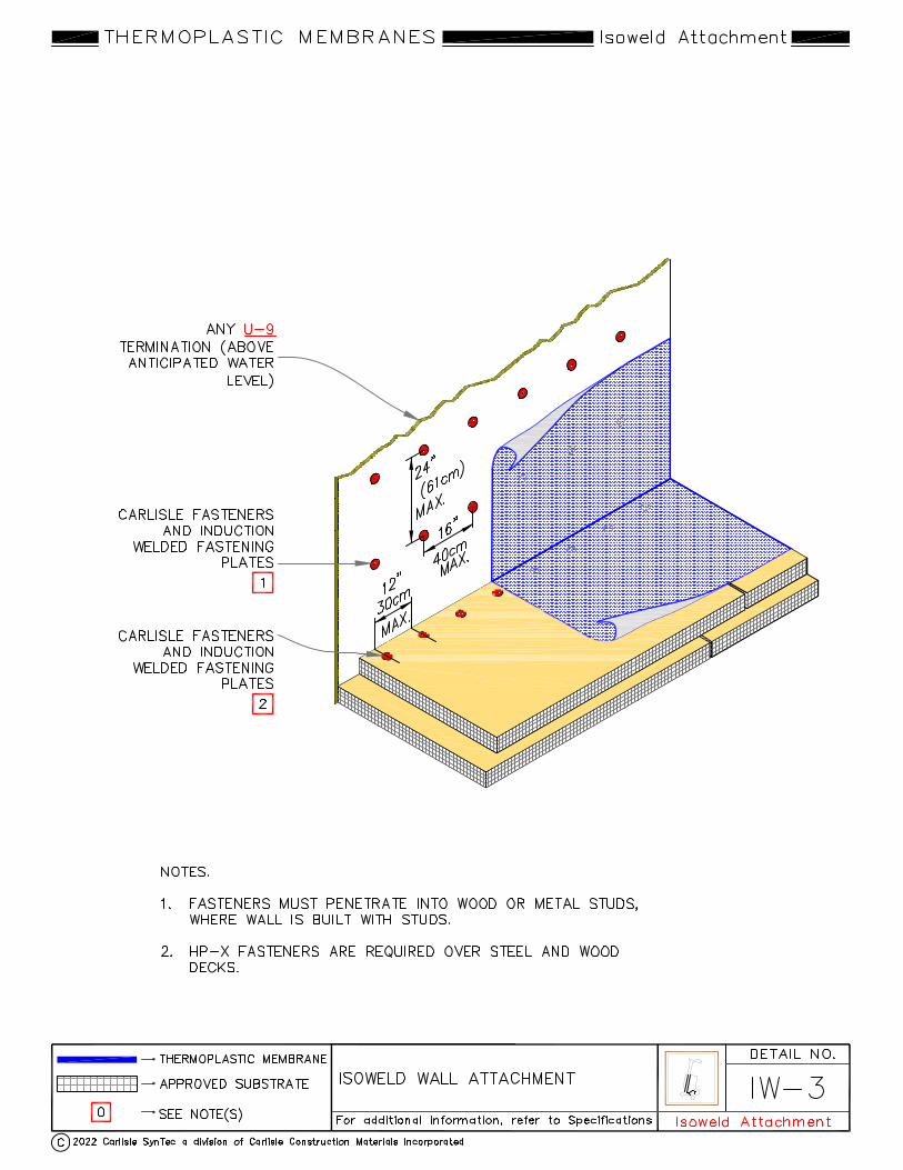


Thermoplastics 1/2022 75
TPO Flashing Procedures utilizing Sure-White EPDM Flashing Products
“Attachment II”
January 2022
This is an alternate method for flashing Carlisle’s Sure-Weld (TPO) membrane ONLY and is intended to be used in conjunction with the Carlisle Thermoplastic Specification and Details. A. Description Thermoplastic flashing procedures utilizing Carlisle Sure-White EPDM flashing products incorporates Pressure-Sensitive Elastoform Flashing, Pressure-Sensitive Inside/Outside Corners, Pressure Sensitive ‘T’-Joint Covers, Pressure-Sensitive Pipe Seals, and Pressure-Sensitive Pourable Sealer Pockets. These Pressure-Sensitive products are used as an option and in lieu of welding TPO Flashing products for a maximum warranty duration of 20 years. Carlisle’s Sure-White EPDM Pressure-Sensitive products are comprised of uncured or cured White EPDM membrane laminated to fully cured Pressure-Sensitive adhesive. B. Products Products listed below can be used as part of this alternate flashing method in conjunction with TPO Primer.
1. Sure-White Pressure-Sensitive Elastoform Flashing: A 6” X 100’ and 9" or 12" wide by 50' long, 60-mil thick Sure-White uncured EPDM Flashing laminated to a 30-mil Pressure-Sensitive TAPE used in conjunction with TPO Primer. Sure-White uncured Pressure-Sensitive Elastoform Flashing is used to flash inside and outside corners, pipes, scuppers and field fabricated pourable sealer pockets when the use of Carlisle pre-fabricated flashing accessories is not feasible.
2. Sure-White Pressure-Sensitive Corner/T-Joint Cover: A 7" x 9" precut 60-mil thick (white) Elastoform Flashing with
a 30-mil Pressure-Sensitive TAPE; used for inside and outside corners, to overlay field splice intersections, and to cover field splices at angle changes.
3. Sure-White Pressure-Sensitive Cured Cover Strip: A 6" or 9" wide and 100’ long and 12" wide by 50' long Sure-
White 60-mil cured EPDM membrane laminated to a nominal 30-mil cured Pressure-Sensitive TAPE. The Cured Cover Strip is for flashing Carlisle Seam Fastening Plates.
4. Sure-White Pressure-Sensitive Pipe Seals with Pressure-Sensitive TAPE on the deck flange. Pipe Seals are
available in one size: 1” to 6”.
5. Sure-White 20” Pressure-Sensitive Cured Flashing - A 20" wide by 50' long Sure-White cured 60-mil thick EPDM membrane, with Pressure-Sensitive TAPE the full width already applied, used to flash curbs/skylights, etc.
6. Sure-White Pourable Sealer Pocket: A pre-fabricated Pourable Sealer Pocket which consists of a 2" wide plastic
support strip with Pressure-Sensitive, adhesive backed uncured Elastoform Flashing; available in 6” diameter.
7. Sure-White SecurTAPE: A 3" or 6" wide by 100' long splice tape used to bond Sure-White EPDM or Sure-Weld TPO membrane to Sure-Weld TPO membrane when flashing a curb or a wall with a separate section of membrane.

Thermoplastics 1/2022 76
8. Low-VOC EPDM and TPO Primer - A Low-VOC (volatile organic compound) primer (less than 250 grams/liter) for priming of EPDM or TPO surfaces prior to application of FAT, Cover strip, SecurTAPE and all other pressure-sensitive products. Available in 1 gallon pails.
C. Sure-White EPDM Flashing Installation Criteria General
1. When using Sure-White Pressure-Sensitive EPDM products on TPO membrane, TPO primer should be used to
prepare the TPO membrane surface.
2. Sure-White Pressure-Sensitive Seam Tape is not to be used for field membrane seaming.
3. Pressure-Sensitive Uncured Elastoform Flashing must be limited to the overlayment of vertical seams (as required at angle changes), or to flash inside/outside corners, vent pipes, scuppers and other unusually shaped penetrations where the use of Pre-molded Pipe Seals is not practical.
Note: Even when working in warmer temperatures, in most cases a heat gun will be required to elevate the temperature of Pressure-Sensitive Uncured Flashing between 105°F and 110°F (40°C and 43°C) to permit proper forming of the uncured flashing.
4. Inside/Outside Corners and ‘T’-Joint Covers a. Pressure-Sensitive Inside/Outside Corners and ‘T’-Joint Covers are installed on both inside and outside corners in
conjunction with TPO Primer.
b. T-Joint Covers are installed at field splice intersections or at horizontal to vertical transitions of field splices in conjunction with TPO Primer.
5. Other Penetrations
a. Flash pipes and round supports with Pressure-Sensitive Pipe Seals, when feasible, in accordance with the
applicable detail.
b. Form Field Fabricated Pipe Seals using Pressure-Sensitive Uncured Elastoform Flashing around pipes, round supports and structural steel tubing with corner radius greater than 1/4".
c. When flashing seamless metal posts, maximum 4" by 4", with a corner radius less than 1/4", apply a field
fabricated pipe flashing with a double vertical wrapping.
d. For pipe clusters or unusually shaped penetrations, a pourable sealer pocket must be utilized.
D. Associated Installation Details
Securseal Drip Edge fascia with Sure-White EPDM ..................................................................................................... U-1AT Curb/Wall with Sure-White EPDM and Sure-White SecurTAPE ................................................................................... U-5AT Curb with 20” wide Sure-White EPDM Pressure-Sensitive Cured Flashing .................................................................. U-5BT Pipe: Pre-Molded Pressure-Sensitive Sure-White EPDM Pipe Seal ............................................................................. U-8AT Field-Fabricated Pipe Seal ......................................................................................................................................... MF-8BT Hot Stack: Field Fabricated Flashing with Sure-White Pressure-Sensitive Elastoform ................................................ U-8DT Parapet/Curb with Sure-White EPDM and Sure-White SecurTAPE ............................................................................ U-12AT Sure-White Pressure-Sensitive Inside Corner with Continuous TPO Wall Flashing................................................... U-15CT Outside Corner with Pre-Cut Pressure-Sensitive Flashing (Option 1) ......................................................................... U-15ET Outside Corner with Pressure-Sensitive EPDM Flashing (Option 2) .......................................................................... U-15GT Pressure-Sensitive Pourable Sealer Pocket ............................................................................................................... U-16BT Scupper at Deck with Pressure Sensitive Elastoform ................................................................................................. U-18BT
End of Section

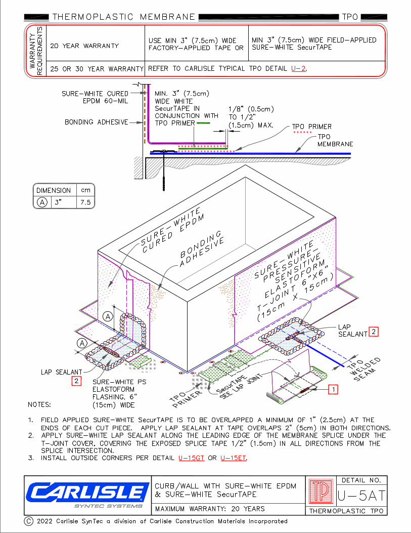
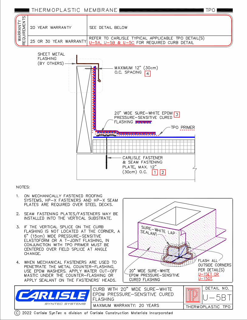


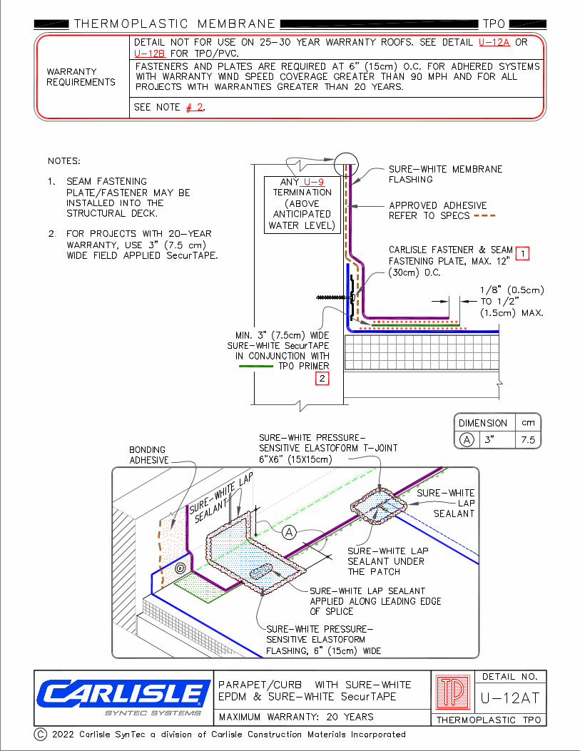


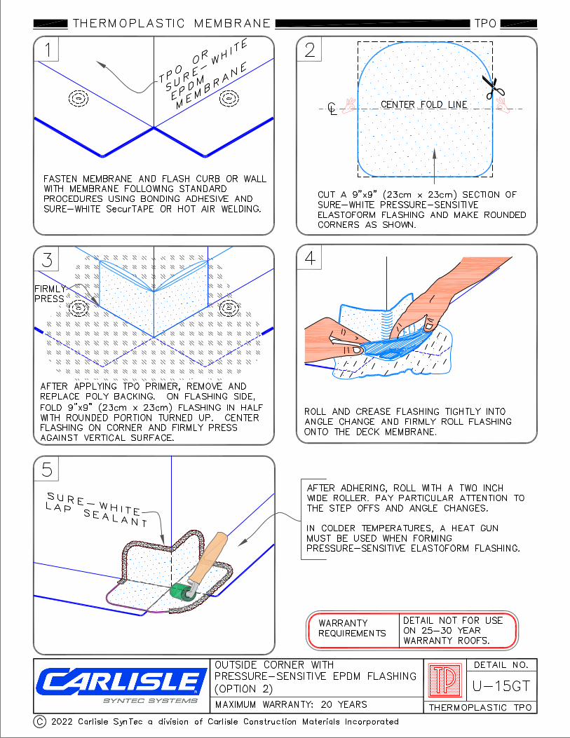


Thermoplastics 1/2022 90
Sure-Weld/Sure-Flex™
Mechanically Fastened and Adhered Roofing Systems
Installation Details
TABLE OF CONTENTS January 2022
Mechanically Fastened Detail Membrane Securement .......................................................................................................................................................... MF-2 TPO Membrane Securement with Pressure-Sensitive RUSS ............................................................................................. MF-2.1 Mechanically Fastened Membrane Splice ........................................................................................................................... MF-2A Fastener and Plate Placement ............................................................................................................................................ MF-2B Ridge Member Attachment ................................................................................................................................................... MF-22 Metal Edges and Gravel Stops SecurSeal Drip Edge Fascia .................................................................................................................................................. U-1A SecurWeld Coated Drip Edge Fascia ..................................................................................................................................... U-1B Metal Bar Edge Termination ................................................................................................................................................... U-1C Carlisle SecurEdge 200 .......................................................................................................................................................... U-1D Carlisle SecurEdge 300 .......................................................................................................................................................... U-1E Carlisle SecurEdge 2000 & 3000 ........................................................................................................................................... U-1F Pressure-Sensitive PVC/KEE HP Cover Strip ....................................................................................................................... U-1G Membrane Splices Membrane Splice ................................................................................................................................................................... U-2A Thermoplastic SAT Membrane Splice .................................................................................................................................... U-2B Expansion Joints Deck-to-Deck Expansion Detail .............................................................................................................................................. U-3A Deck-to-Wall Expansion Detail ............................................................................................................................................... U-3B Curb Flashing Curb Flashing with TPO or PVC Membrane ........................................................................................................................... U-5A Curb Flashing with TPO or PVC Coated Metal ...................................................................................................................... U-5B Curb Flashing with CFA TPO or PVC Curb Wrap Corners ..................................................................................................... U-5C Self-Flashing Curb with CFA TPO or PVC Curb Wrap Corners ............................................................................................. U-5D Drains Roof Drain (Drain Sump Up to 3 inches to 1 Horizontal Foot) ................................................................................................ U-6A Roof Drain (Drain Sump Greater than 3 inches to 1 Horizontal Foot) Option 1 ...................................................................... U-6B Roof Drain (Drain Sump Greater than 3 inches to 1 Horizontal Foot) Option 2, Page 1 of 2.................................................. U-6C Roof Drain (Drain Sump Greater than 3 inches to 1 Horizontal Foot) Option 2, Page 2 of 2............................................... U-6C.1 Add-On Drain ......................................................................................................................................................................... U-6D Pipe Flashing Pre-molded Flashing .............................................................................................................................................................. U-8A Field Fabricated Pipe Flashing ............................................................................................................................................... U-8B CFA Certified Pre-Fabricated Square Tube Wrap .................................................................................................................. U-8C Field Fabricated Square Tube Flashing ................................................................................................................................ U-8D CFA Certified Pre-Fabricated Split Pipe Seal ......................................................................................................................... U-8E CFA Certified Hot Pipe Flashing ............................................................................................................................................ U-8F
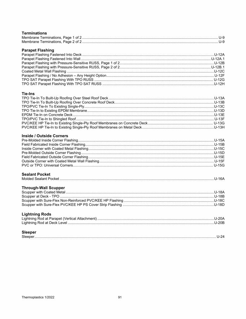
Thermoplastics 1/2022 91
Terminations Membrane Terminations, Page 1 of 2 ...................................................................................................................................... U-9 Membrane Terminations, Page 2 of 2 ...................................................................................................................................... U-9 Parapet Flashing Parapet Flashing Fastened Into Deck .................................................................................................................................. U-12A Parapet Flashing Fastened Into Wall ................................................................................................................................ U-12A.1 Parapet Flashing with Pressure-Sensitive RUSS, Page 1 of 2 ............................................................................................. U-12B Parapet Flashing with Pressure-Sensitive RUSS, Page 2 of 2 .......................................................................................... U-12B.1 Coated Metal Wall Flashing ................................................................................................................................................. U-12C Parapet Flashing / No Adhesion – Any Height Option .......................................................................................................... U-12F TPO SAT Parapet Flashing With TPO RUSS ..................................................................................................................... U-12G TPO SAT Parapet Flashing With TPO SAT RUSS .............................................................................................................. U-12H Tie-Ins TPO Tie-In To Built-Up Roofing Over Steel Roof Deck ........................................................................................................ U-13A TPO Tie-In To Built-Up Roofing Over Concrete Roof Deck .................................................................................................. U-13B TPO/PVC Tie-In To Existing Single-Ply ................................................................................................................................ U-13C TPO Tie-In to Existing EPDM Membrane ............................................................................................................................. U-13D EPDM Tie-In on Concrete Deck ........................................................................................................................................... U-13E TPO/PVC Tie-In to Shingled Roof ........................................................................................................................................ U-13F PVC/KEE HP Tie-In to Existing Single-Ply Roof Membranes on Concrete Deck ................................................................ U-13G PVC/KEE HP Tie-In to Existing Single-Ply Roof Membranes on Metal Deck ....................................................................... U-13H Inside / Outside Corners Pre-Molded Inside Corner Flashing ...................................................................................................................................... U-15A Field Fabricated Inside Corner Flashing ............................................................................................................................... U-15B Inside Corner with Coated Metal Flashing ............................................................................................................................ U-15C Pre-Molded Outside Corner Flashing ................................................................................................................................... U-15D Field Fabricated Outside Corner Flashing ............................................................................................................................ U-15E Outside Corner with Coated Metal Wall Flashing ................................................................................................................. U-15F PVC or TPO: Universal Corners .......................................................................................................................................... U-15G Sealant Pocket Molded Sealant Pocket ........................................................................................................................................................ U-16A Through-Wall Scupper Scupper with Coated Metal .................................................................................................................................................. U-18A Scupper at Deck - TPO ........................................................................................................................................................ U-18B Scupper with Sure-Flex Non-Reinforced PVC/KEE HP Flashing ......................................................................................... U-18C Scupper with Sure-Flex PVC/KEE HP PS Cover Strip Flashing .......................................................................................... U-18D Lightning Rods Lightning Rod at Parapet (Vertical Attachment) ................................................................................................................... U-20A Lightning Rod at Deck Level ................................................................................................................................................ U-20B
Sleeper Sleeper ................................................................................................................................................................................... U-24