the flex engine - scholarworks
TRANSCRIPT
Capstone Project – Written Report 04/14/15 Instructor: Michael Strange
ME 494 – PROJECT DESIGN II
The Flex Engine
Spring 2015
Team Members: Tyler Smith, Zachary Hayman, Eduardo Castaneda, Cameron Kiani, Scott Gibes
Faculty Advisor: Professor Tony Snell
The Flex Engine Team: Spring 2015 Report Page 1
Legal Disclaimer The technology we are developing is part of a suite of patents, both issued and pending, for one
of Murray Tech Law’s clients. In order to protect the client’s intellectual property rights, it is
important that elements of the projects are not publicly disclosed accidentally or ahead of
schedule. Therefore, while the students and faculty are free to exchange information regarding
the project as academically necessary, Murray Tech Law asks that they refrain from discussing
the technology with anyone outside of Cal Maritime. Murray Tech Law is aware that the
project will eventually be publicized, both in the form of a final report and presentation. If
there is any necessary publication of project material before the final report and presentation,
Murray Tech Law requests that they are informed of the expected date of first publication as
soon as possible.
The Flex Engine Team: Spring 2015 Report Page 2
Abstract Since the first internal combustion engine was built the design has required a rotating camshaft
to mechanically actuate the valve timing. The problem with actuating the valves on an engine
with a camshaft is there are many added losses. Turning the camshaft consumes energy from
the crankshaft which takes away from the overall power output; also the springs used to close
the valves create a large amount of parasitic losses which take away from the engine
performance. Some types of camshafts use a rocker arm assembly that requires many extra
parts and adds a considerable amount of weight to the engine. Clearly, mechanical valve timing
that uses a rotating camshaft has serious flaws; a new design that gets rid of the camshaft and
its accessories could revolutionize the internal combustion engine.
There are many companies competing to invent camless valve timing for engines, and all of
which are at the basic R&D and prototyping stage. There are no camless four stroke engines
being produced and sold on the market today. The objective of this project is to enter the
camless actuation race and create a camless valve actuator that is driven by the forces from a
piezoelectric crystal. Piezoelectric crystals expand when high voltage is applied to them. The
expansion displacement is minimal, but the forces produced are impressive, making it
undoubtedly possible to actuate the valves of an engine.
Designing a new valve actuator that does not use a camshaft is greatly beneficial for many
reasons. By eliminating the camshaft and the associated components, the engine design will be
less complex, the overall timing components on the engine will weigh less, and the removed
spring will reduce parasitic loss. Utilizing piezoelectric crystals and an electronic controller to
actuate the valves and control the timing has the potential to increase the engine efficiency up
to 20%, increase the potential horsepower up to 20%, and reduce exhaust emissions up to 50%.
This technology has the potential to change the industry, and this project summarizes how the
Cal Maritime senior capstone Flex Engine team is attempting to break into the camless internal
combustion engine market.
The Flex Engine Team: Spring 2015 Report Page 3
Photos of Project
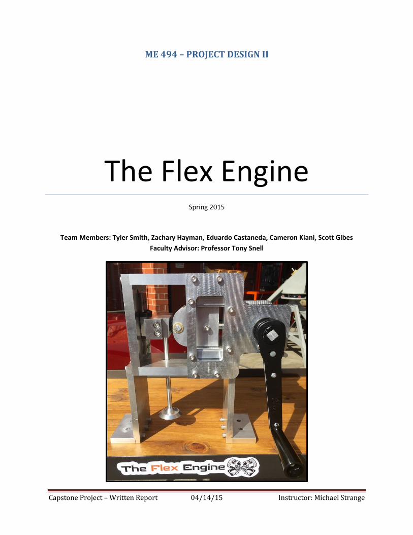
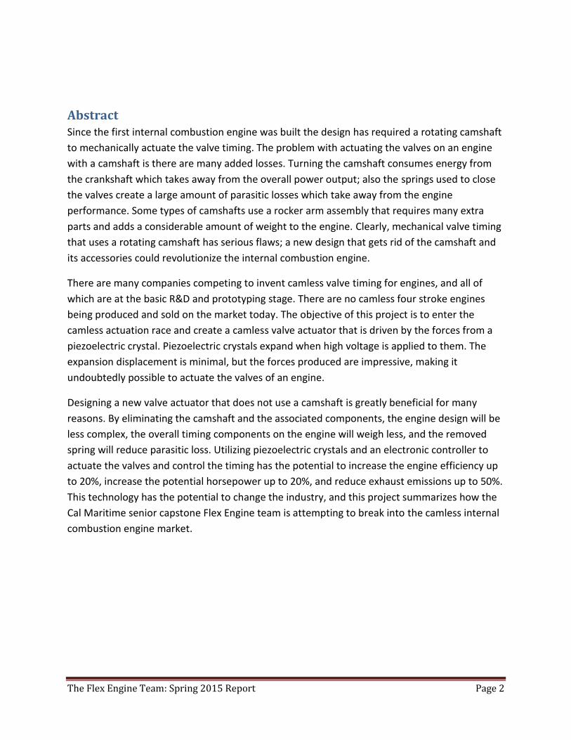
This picture displays the main
components of the Flex Engine
project. Depicted is hand crank,
valve, legs, compression blocks,
wedge angles and main housing for
project.
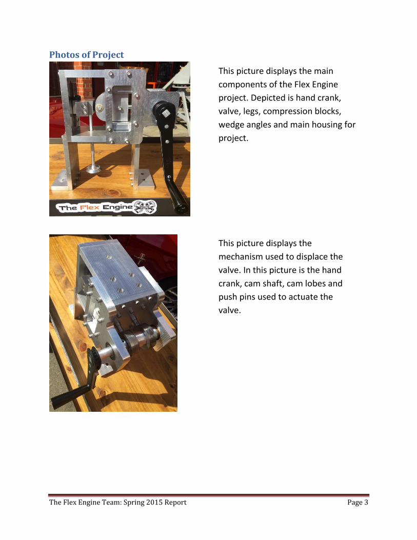
This picture displays the
mechanism used to displace the
valve. In this picture is the hand
crank, cam shaft, cam lobes and
push pins used to actuate the
valve.
The Flex Engine Team: Spring 2015 Report Page 4
Gratitude and Acknowledgements A special thank you for all of the support to Ken Murray, David Smith, and Murry Tech Law for
the privilege to of being able to work on a revolutionary concept and all of the support along
the way. We would also like to thank our project faculty advisor, Anthony Snell, for all of his
guidance, knowledge and support with educational concepts needed for our project. Lastly,
we’d like to thank DSM (Dynamic Structure and Materials) for loaning the piezo crystals and
supplying the amplifier used for collecting and analyzing data on piezo crystals and their
performances.
The Flex Engine Team: Spring 2015 Report Page 5
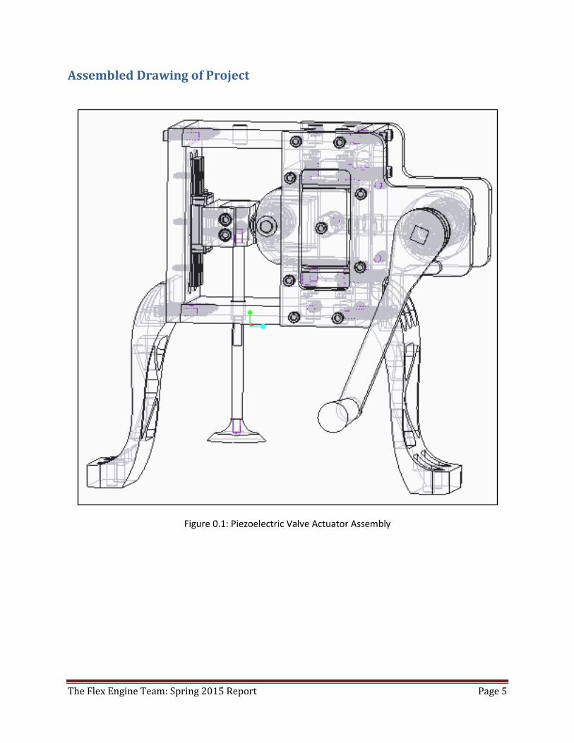
Assembled Drawing of Project
Figure 0.1: Piezoelectric Valve Actuator Assembly
The Flex Engine Team: Spring 2015 Report Page 6
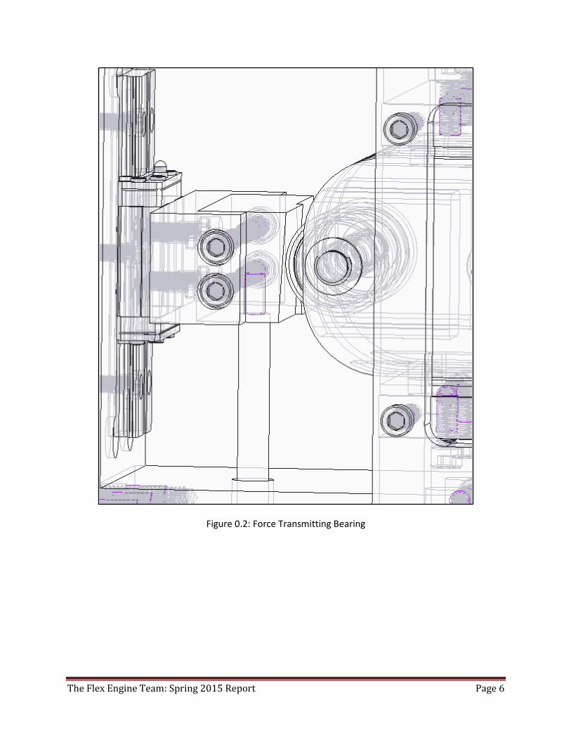
Figure 0.2: Force Transmitting Bearing
The Flex Engine Team: Spring 2015 Report Page 7
Contents Legal Disclaimer ............................................................................................................................................ 1
Abstract ......................................................................................................................................................... 2
Photos of Project ........................................................................................................................................... 3
Gratitude and Acknowledgements ............................................................................................................... 4
Assembled Drawing of Project ...................................................................................................................... 5
Contents ........................................................................................................................................................ 7
Table of Tables .............................................................................................................................................. 9
Table of Figures ........................................................................................................................................... 10
1.0 Introduction .......................................................................................................................................... 11
2.0 Literature Survey/Benchmarking .......................................................................................................... 11
3.0 Schedule ................................................................................................................................................ 13
4.0 Problem Definition Phase ..................................................................................................................... 14
4.1 Establishing User Requirements/ Clarifying Design Objectives ........................................................ 14
4.2 Identifying the Constraints................................................................................................................ 14
4.3 Identifying Functions ......................................................................................................................... 16
4.4 Establishing Design Specification ...................................................................................................... 17
5.0 Conceptual Design Phase ...................................................................................................................... 19
5.1 Generating Designs ........................................................................................................................... 19
5.2 Wedge Evolution ............................................................................................................................... 24
6.0 Preliminary Design Phase ...................................................................................................................... 26
6.1 Product Architecture ......................................................................................................................... 26
6.2 Material Selection ............................................................................................................................. 27
7.0 Final Design Phase................................................................................................................................. 29
7.1 Product Architecture ......................................................................................................................... 29
7.2 Material Selection ............................................................................................................................. 30
8.0 Engineering Design & Analysis .............................................................................................................. 31
8.1 Valve Wedge Transformation ........................................................................................................... 31
8.2 Dynamic Modeling ............................................................................................................................ 33
9.0 Fabrication Process ............................................................................................................................... 38
9.1 Design for Reliability ......................................................................................................................... 38
9.2 Design for Manufacturing ................................................................................................................. 38
The Flex Engine Team: Spring 2015 Report Page 8
9.3 Design for Assembly .......................................................................................................................... 39
10.0 Prototype Testing ................................................................................................................................ 39
11.0 Final Design Testing ............................................................................................................................ 40
12.0 Preliminary Summary .......................................................................................................................... 41
13.0 Preliminary Conclusion ....................................................................................................................... 41
14.0 Preliminary Recommendations ........................................................................................................... 42
15.0 Final Modeling, Simulation, Analysis and Testing Results .................................................................. 42
16.0 Discussion of the Final Results ............................................................................................................ 44
Piezo Design ............................................................................................................................................ 44
Valve Design ............................................................................................................................................ 45
17.0 Conclusions and Recommendations about the Project ...................................................................... 47
Piezo Design ............................................................................................................................................ 47
Valve Design ............................................................................................................................................ 47
18.0 Appendices .......................................................................................................................................... 50
18.1 Detailed Drawings ........................................................................................................................... 50
18.1.1 Overall Assembly Drawing ..................................................................................................... 50
18.1.2 Sub Assembly Drawings ........................................................................................................... 51
18.1.3 Detailed Drawings .................................................................................................................... 52
18.1.4 Bill of Materials ........................................................................................................................ 76
18.2 Computer Programs ........................................................................................................................ 79
18.5 Supporting Background Information .............................................................................................. 82
18.6 Other Relevant Information ............................................................................................................ 84
18.7 Cost Analysis ................................................................................................................................... 85
18.8 Final Project Virtual Realizations .................................................................................................... 86
18.9: Final Project Detailed Photos ......................................................................................................... 91
The Flex Engine Team: Spring 2015 Report Page 9
Tables Table 6.2.1: Possible Materials of Construction 23
Table 7.2.1: Material Selection 30
Table 15.1: Test 1 42
Table 15.2: Test 2 43
Table 15.3: Test 3 43
The Flex Engine Team: Spring 2015 Report Page 10
Figures Figure 0.1: Piezoelectric Valve Actuator Assembly 3
Figure 0.2: Force Transmitting Bearing 4
Figure 3.0.1: Gantt Chart 11
Figure 4.3.1: Black Box 14
Figure 4.3.2: Function Chart 14
Figure 4.4.1: Quality Function Diagram 15
Figure 5.1.1: Shower Head Valve 16
Figure 5.1.2: Slider Valve 17
Figure 5.1.3: Slider Valve Implemented into Manifold 18
Figure 5.1.4: Slider Valve Implemented into Manifold 18
Figure 5.1.5: Rotating Slider Valve 19
Figure 5.1.6: Modified Standard Annular Valve 20
Figure 5.2.1: First Wedge Design 21
Figure 5.2.2: Current Wedge Design 22
Figure 6.1.1: Wedge Actuator Dimensions 23
Figure 7.1.1: Wedge Concept FBD 25
Figure 7.1.2: Wedge FBD 27
Figure 7.1.3: 0.4in Vertical Valve Maximum Displacement 27
Figure 7.2.1: Intake Valve Lift vs. Camshaft Angle 30
Figure 7.2.3: 480 RPM Dynamic Model Force Requirement of Piezo 30
Figure 7.2.4: 6000 RPM (60HZ) Pure Cosine 31
Figure 7.2.5: 6000 RPM (60HZ) Pure Cosine 32
Figure 13.1.1: Roller Bearing used in CAD model 35
The Flex Engine Team: Spring 2015 Report Page 11
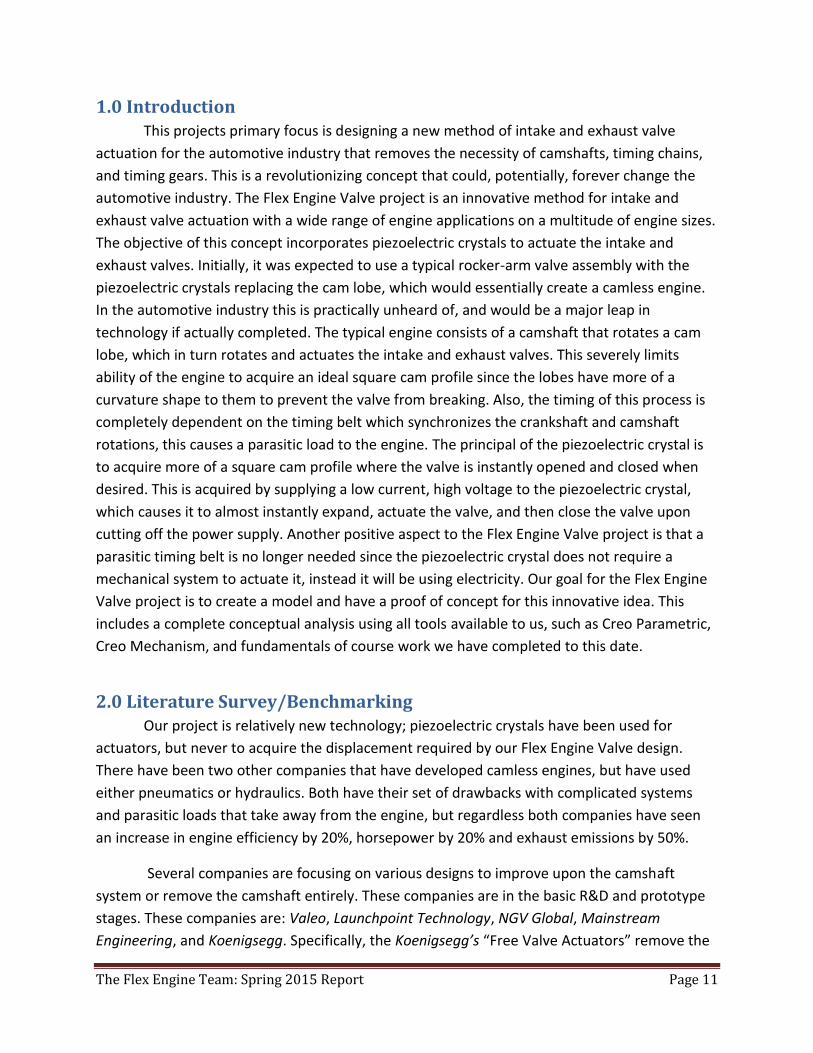
1.0 Introduction This projects primary focus is designing a new method of intake and exhaust valve
actuation for the automotive industry that removes the necessity of camshafts, timing chains,
and timing gears. This is a revolutionizing concept that could, potentially, forever change the
automotive industry. The Flex Engine Valve project is an innovative method for intake and
exhaust valve actuation with a wide range of engine applications on a multitude of engine sizes.
The objective of this concept incorporates piezoelectric crystals to actuate the intake and
exhaust valves. Initially, it was expected to use a typical rocker-arm valve assembly with the
piezoelectric crystals replacing the cam lobe, which would essentially create a camless engine.
In the automotive industry this is practically unheard of, and would be a major leap in
technology if actually completed. The typical engine consists of a camshaft that rotates a cam
lobe, which in turn rotates and actuates the intake and exhaust valves. This severely limits
ability of the engine to acquire an ideal square cam profile since the lobes have more of a
curvature shape to them to prevent the valve from breaking. Also, the timing of this process is
completely dependent on the timing belt which synchronizes the crankshaft and camshaft
rotations, this causes a parasitic load to the engine. The principal of the piezoelectric crystal is
to acquire more of a square cam profile where the valve is instantly opened and closed when
desired. This is acquired by supplying a low current, high voltage to the piezoelectric crystal,
which causes it to almost instantly expand, actuate the valve, and then close the valve upon
cutting off the power supply. Another positive aspect to the Flex Engine Valve project is that a
parasitic timing belt is no longer needed since the piezoelectric crystal does not require a
mechanical system to actuate it, instead it will be using electricity. Our goal for the Flex Engine
Valve project is to create a model and have a proof of concept for this innovative idea. This
includes a complete conceptual analysis using all tools available to us, such as Creo Parametric,
Creo Mechanism, and fundamentals of course work we have completed to this date.
2.0 Literature Survey/Benchmarking Our project is relatively new technology; piezoelectric crystals have been used for
actuators, but never to acquire the displacement required by our Flex Engine Valve design.
There have been two other companies that have developed camless engines, but have used
either pneumatics or hydraulics. Both have their set of drawbacks with complicated systems
and parasitic loads that take away from the engine, but regardless both companies have seen
an increase in engine efficiency by 20%, horsepower by 20% and exhaust emissions by 50%.
Several companies are focusing on various designs to improve upon the camshaft
system or remove the camshaft entirely. These companies are in the basic R&D and prototype
stages. These companies are: Valeo, Launchpoint Technology, NGV Global, Mainstream
Engineering, and Koenigsegg. Specifically, the Koenigsegg’s “Free Valve Actuators” remove the
The Flex Engine Team: Spring 2015 Report Page 12
camshaft and the timing belt, and control the valves electronically via pneumatic actuators.
Koenigsegg has already demonstrated improvements in engine efficiency, horsepower, and
exhaust emissions. All of these systems have serious drawbacks or fall short of the industry
target. The designs are highly complex yet provide only minimal control improvement. The
valves are still all operated synchronously, with no ability to change a single valve profile
independent of the others. The valve profiles are hard-coded into the engine design, usually
optimized for only one of a wide range of operating conditions. Finally, each camless
configuration cannot optimize the engine profile to take a specific fuel type. For example, the
valves cannot change to optimally accommodate higher octane or richer fuels, ethanol
mixtures, natural gas, etc.
Another competitor is Sturman Industries, a company based out of Woodland Park,
Colorado. They have taken an alternative approach to camless engine design and developed an
innovative design involving electro-hydraulic valve timing. Their design system is fast, precise,
electronically controlled and can be used on reciprocating piston engines or gas compressors. It
can also be used for engine operation for any fuel (gas, diesel, ethanol, propane, natural gas,
etc.) This electro-hydraulic valve also closely acquired the desired square profile.
Capstone Project – Written Report 04/14/14 Instructor: Michael Strange
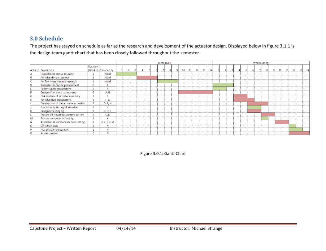
3.0 Schedule The project has stayed on schedule as far as the research and development of the actuator design. Displayed below in figure 3.1.1 is
the design team gantt chart that has been closely followed throughout the semester.
Figure 3.0.1: Gantt Chart
Capstone Project – Written Report 04/14/14 Instructor: Michael Strange
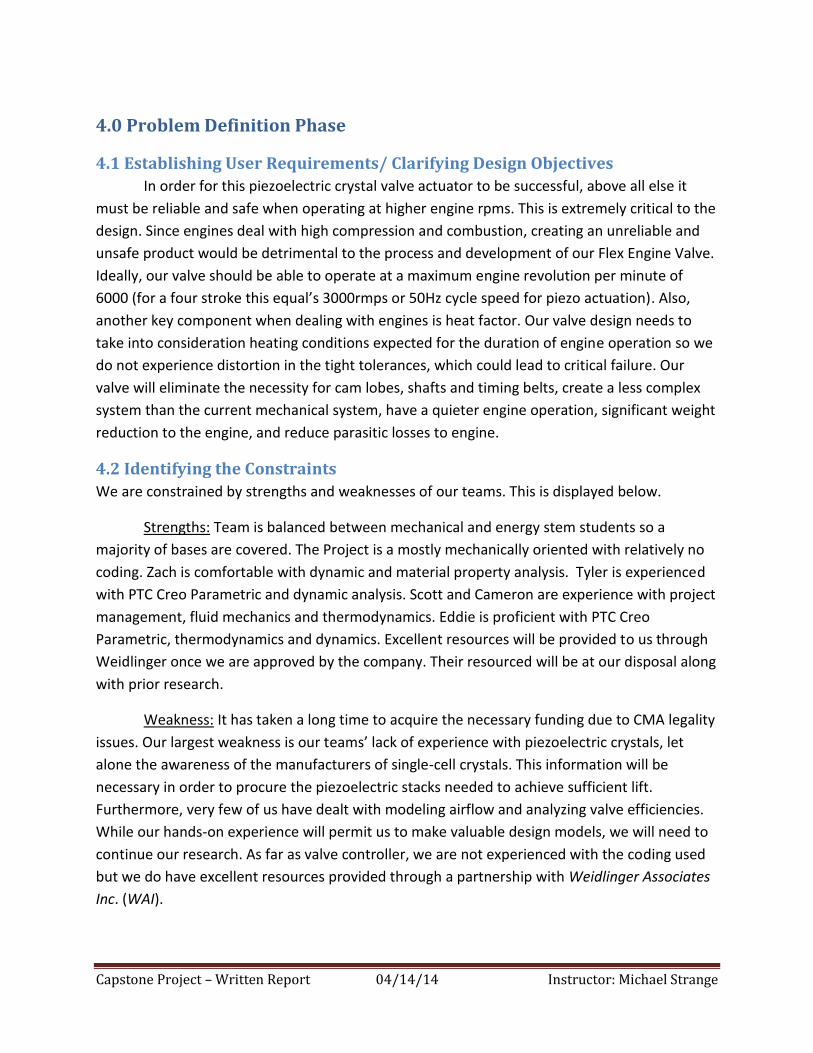
4.0 Problem Definition Phase
4.1 Establishing User Requirements/ Clarifying Design Objectives
In order for this piezoelectric crystal valve actuator to be successful, above all else it
must be reliable and safe when operating at higher engine rpms. This is extremely critical to the
design. Since engines deal with high compression and combustion, creating an unreliable and
unsafe product would be detrimental to the process and development of our Flex Engine Valve.
Ideally, our valve should be able to operate at a maximum engine revolution per minute of
6000 (for a four stroke this equal’s 3000rmps or 50Hz cycle speed for piezo actuation). Also,
another key component when dealing with engines is heat factor. Our valve design needs to
take into consideration heating conditions expected for the duration of engine operation so we
do not experience distortion in the tight tolerances, which could lead to critical failure. Our
valve will eliminate the necessity for cam lobes, shafts and timing belts, create a less complex
system than the current mechanical system, have a quieter engine operation, significant weight
reduction to the engine, and reduce parasitic losses to engine.
4.2 Identifying the Constraints
We are constrained by strengths and weaknesses of our teams. This is displayed below.
Strengths: Team is balanced between mechanical and energy stem students so a
majority of bases are covered. The Project is a mostly mechanically oriented with relatively no
coding. Zach is comfortable with dynamic and material property analysis. Tyler is experienced
with PTC Creo Parametric and dynamic analysis. Scott and Cameron are experience with project
management, fluid mechanics and thermodynamics. Eddie is proficient with PTC Creo
Parametric, thermodynamics and dynamics. Excellent resources will be provided to us through
Weidlinger once we are approved by the company. Their resourced will be at our disposal along
with prior research.
Weakness: It has taken a long time to acquire the necessary funding due to CMA legality
issues. Our largest weakness is our teams’ lack of experience with piezoelectric crystals, let
alone the awareness of the manufacturers of single-cell crystals. This information will be
necessary in order to procure the piezoelectric stacks needed to achieve sufficient lift.
Furthermore, very few of us have dealt with modeling airflow and analyzing valve efficiencies.
While our hands-on experience will permit us to make valuable design models, we will need to
continue our research. As far as valve controller, we are not experienced with the coding used
but we do have excellent resources provided through a partnership with Weidlinger Associates
Inc. (WAI).
The Flex Engine Team: Fall 2014 Report Page 15
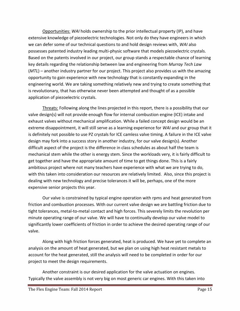
Opportunities: WAI holds ownership to the prior intellectual property (IP), and have
extensive knowledge of piezoelectric technologies. Not only do they have engineers in which
we can defer some of our technical questions to and hold design reviews with, WAI also
possesses patented industry leading multi-physic software that models piezoelectric crystals.
Based on the patents involved in our project, our group stands a respectable chance of learning
key details regarding the relationship between law and engineering from Murray Tech Law
(MTL) – another industry partner for our project. This project also provides us with the amazing
opportunity to gain experience with new technology that is constantly expanding in the
engineering world. We are taking something relatively new and trying to create something that
is revolutionary, that has otherwise never been attempted and thought of as a possible
application of piezoelectric crystals.
Threats: Following along the lines projected in this report, there is a possibility that our
valve design(s) will not provide enough flow for internal combustion engine (ICE) intake and
exhaust valves without mechanical amplification. While a failed concept design would be an
extreme disappointment, it will still serve as a learning experience for WAI and our group that it
is definitely not possible to use PZ crystals for ICE camless valve timing. A failure in the ICE valve
design may fork into a success story in another industry, for our valve design(s). Another
difficult aspect of the project is the difference in class schedules as about half the team is
mechanical stem while the other is energy stem. Since the workloads very, it is fairly difficult to
get together and have the appropriate amount of time to get things done. This is a fairly
ambitious project where not many teachers have experience with what we are trying to do,
with this taken into consideration our resources are relatively limited. Also, since this project is
dealing with new technology and precise tolerances it will be, perhaps, one of the more
expensive senior projects this year.
Our valve is constrained by typical engine operation with rpms and heat generated from
friction and combustion processes. With our current valve design we are battling friction due to
tight tolerances, metal-to-metal contact and high forces. This severely limits the revolution per
minute operating range of our valve. We will have to continually develop our valve model to
significantly lower coefficients of friction in order to achieve the desired operating range of our
valve.
Along with high friction forces generated, heat is produced. We have yet to complete an
analysis on the amount of heat generated, but we plan on using high heat resistant metals to
account for the heat generated, still the analysis will need to be completed in order for our
project to meet the design requirements.
Another constraint is our desired application for the valve actuation on engines.
Typically the valve assembly is not very big on most generic car engines. With this taken into
The Flex Engine Team: Fall 2014 Report Page 16
consideration, we have to keep the size down for our Flex Engine Valve and ideally want the
valve to be no more than 6 inches tall off of the engine block with a width of 4 inches. With
these design specifications achieved, the project will be considered a success and be applicable
for real world engine modifications. Along with these ideal design constraints we also have to
deal with tolerance. Since we are relatively inexperienced with this, it is a possibility to over
constrain the design. We must be cautions when designing the valve actuation method.
Once we acquire some piezoelectric crystals, we can begin to gain experience with their
functionalities prior to the application in our valve design. We will need to become familiar with
how much voltage and current are required by the piezoelectric actuator, and how to safely
operate them. Some tests will need to be completed to see approximately how much expansion
can be expected from them, and if they will function with our valve design.
4.3 Identifying Functions
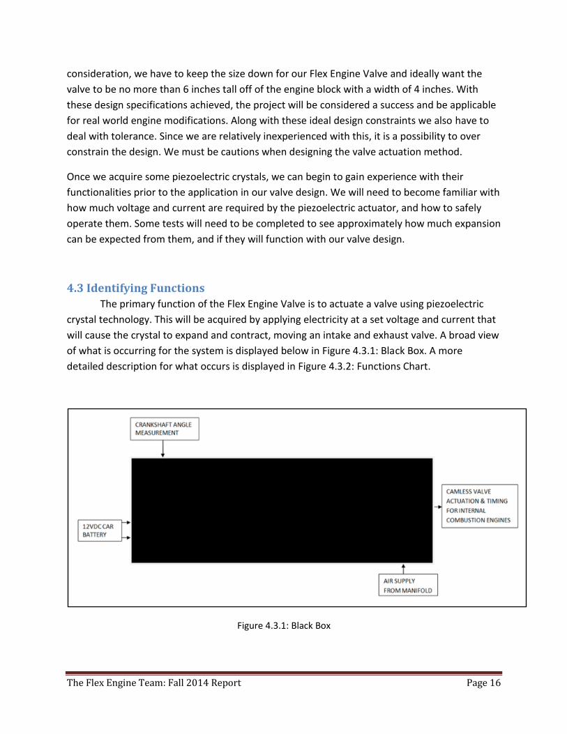
The primary function of the Flex Engine Valve is to actuate a valve using piezoelectric
crystal technology. This will be acquired by applying electricity at a set voltage and current that
will cause the crystal to expand and contract, moving an intake and exhaust valve. A broad view
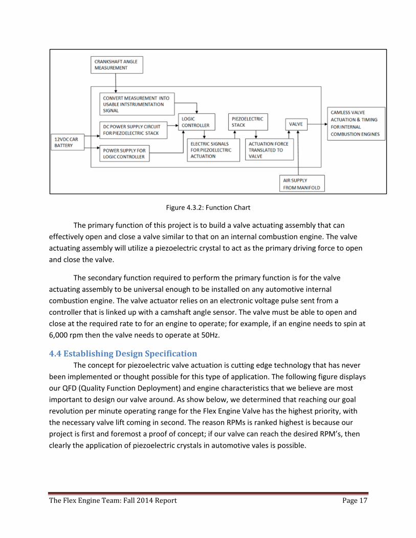
of what is occurring for the system is displayed below in Figure 4.3.1: Black Box. A more
detailed description for what occurs is displayed in Figure 4.3.2: Functions Chart.
Figure 4.3.1: Black Box
The Flex Engine Team: Fall 2014 Report Page 17
Figure 4.3.2: Function Chart
The primary function of this project is to build a valve actuating assembly that can
effectively open and close a valve similar to that on an internal combustion engine. The valve
actuating assembly will utilize a piezoelectric crystal to act as the primary driving force to open
and close the valve.
The secondary function required to perform the primary function is for the valve
actuating assembly to be universal enough to be installed on any automotive internal
combustion engine. The valve actuator relies on an electronic voltage pulse sent from a
controller that is linked up with a camshaft angle sensor. The valve must be able to open and
close at the required rate to for an engine to operate; for example, if an engine needs to spin at
6,000 rpm then the valve needs to operate at 50Hz.
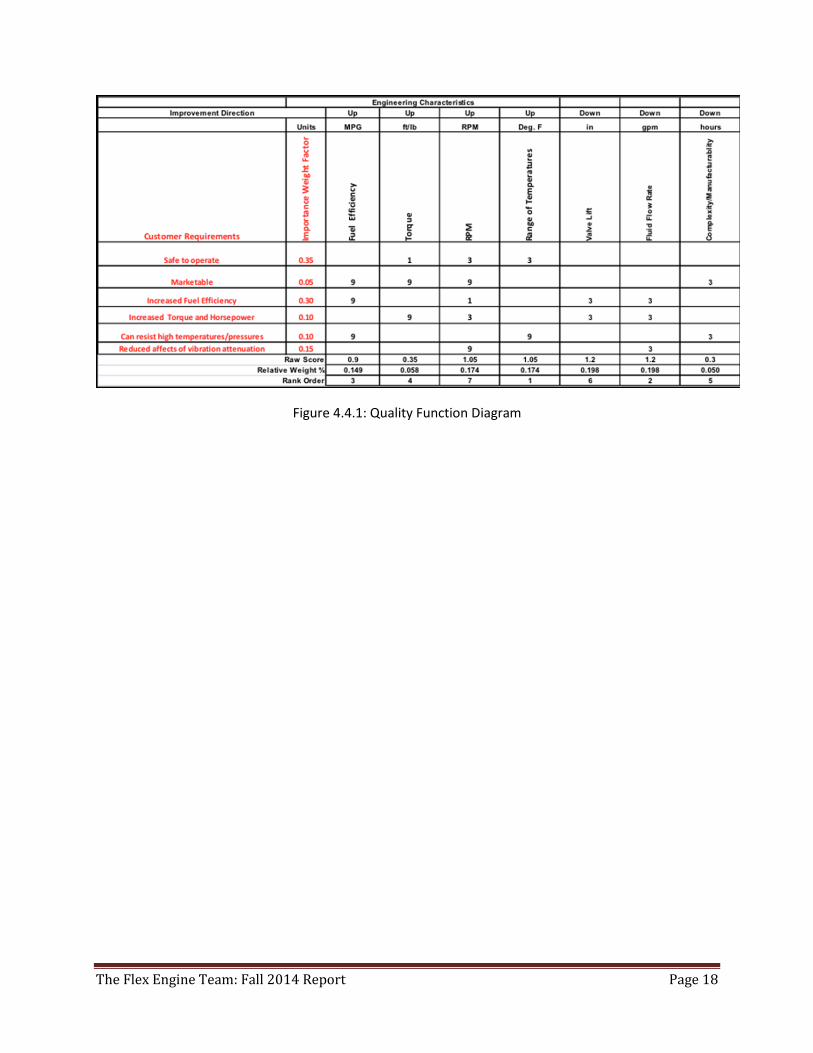
4.4 Establishing Design Specification
The concept for piezoelectric valve actuation is cutting edge technology that has never
been implemented or thought possible for this type of application. The following figure displays
our QFD (Quality Function Deployment) and engine characteristics that we believe are most
important to design our valve around. As show below, we determined that reaching our goal
revolution per minute operating range for the Flex Engine Valve has the highest priority, with
the necessary valve lift coming in second. The reason RPMs is ranked highest is because our
project is first and foremost a proof of concept; if our valve can reach the desired RPM’s, then
clearly the application of piezoelectric crystals in automotive vales is possible.
The Flex Engine Team: Fall 2014 Report Page 18
Figure 4.4.1: Quality Function Diagram
The Flex Engine Team: Fall 2014 Report Page 19
5.0 Conceptual Design Phase Certain constraint criteria had to be met in order to accomplish the goals that the team had
previously set. In order to remove parasitic loads involved with the cam assembly, as well as
achieving variable valve timing, many designs were formulated using piezoelectric crystals as
actuator means. Early on in the design phase, designs were oriented around changing the valve
to obtain the required flow with no mechanical amplification; in other words, the piezo
displacement would be the same as the displacement of the valve during actuation. Along these
lines, many design iterations were made resulting in plausible designs. Eventually designs
utilizing mechanical amplification were a better deign alternative for this project. Displayed
below are the different designs as they evolved.
5.1 Generating Designs
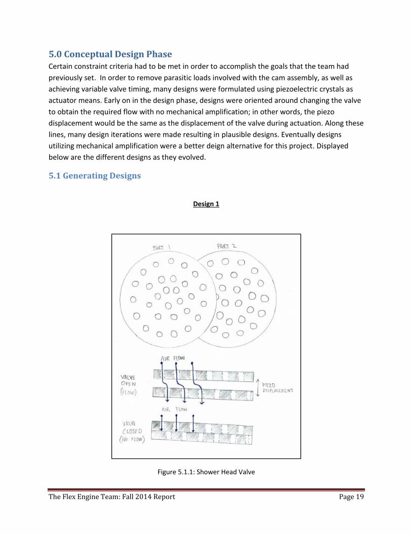
Design 1
Figure 5.1.1: Shower Head Valve
The Flex Engine Team: Fall 2014 Report Page 20
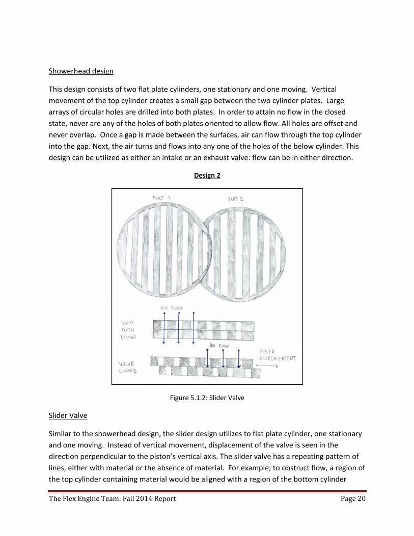
Showerhead design
This design consists of two flat plate cylinders, one stationary and one moving. Vertical
movement of the top cylinder creates a small gap between the two cylinder plates. Large
arrays of circular holes are drilled into both plates. In order to attain no flow in the closed
state, never are any of the holes of both plates oriented to allow flow. All holes are offset and
never overlap. Once a gap is made between the surfaces, air can flow through the top cylinder
into the gap. Next, the air turns and flows into any one of the holes of the below cylinder. This
design can be utilized as either an intake or an exhaust valve: flow can be in either direction.
Design 2
Figure 5.1.2: Slider Valve
Slider Valve
Similar to the showerhead design, the slider design utilizes to flat plate cylinder, one stationary
and one moving. Instead of vertical movement, displacement of the valve is seen in the
direction perpendicular to the piston’s vertical axis. The slider valve has a repeating pattern of
lines, either with material or the absence of material. For example; to obstruct flow, a region of
the top cylinder containing material would be aligned with a region of the bottom cylinder
The Flex Engine Team: Fall 2014 Report Page 21
containing no material. The small spacing is used to satisfy the small displacements seen by
piezoelectric crystals. Conceptually, but not practically, this type of design could see 50% flow
area of the swept area of the valve. Although it reduces spacing between gaps, a simplified
design was formulated to use a single piezoelectric stack as means of opening and closing both
the intake and exhaust valves. This can be done by having a neutral position about the
displacement of the piezoelectric stack. For example; assuming steady state, 0%, 50%, and
100% valve displacement would translate to [1 0],[0 0], and [0 1], respectively ([intake valve;
exhaust valve], 0=closed, 1=open).
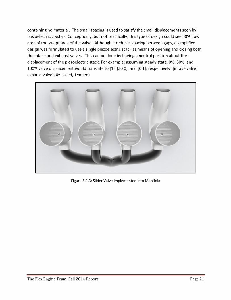
Figure 5.1.3: Slider Valve Implemented into Manifold
The Flex Engine Team: Fall 2014 Report Page 22
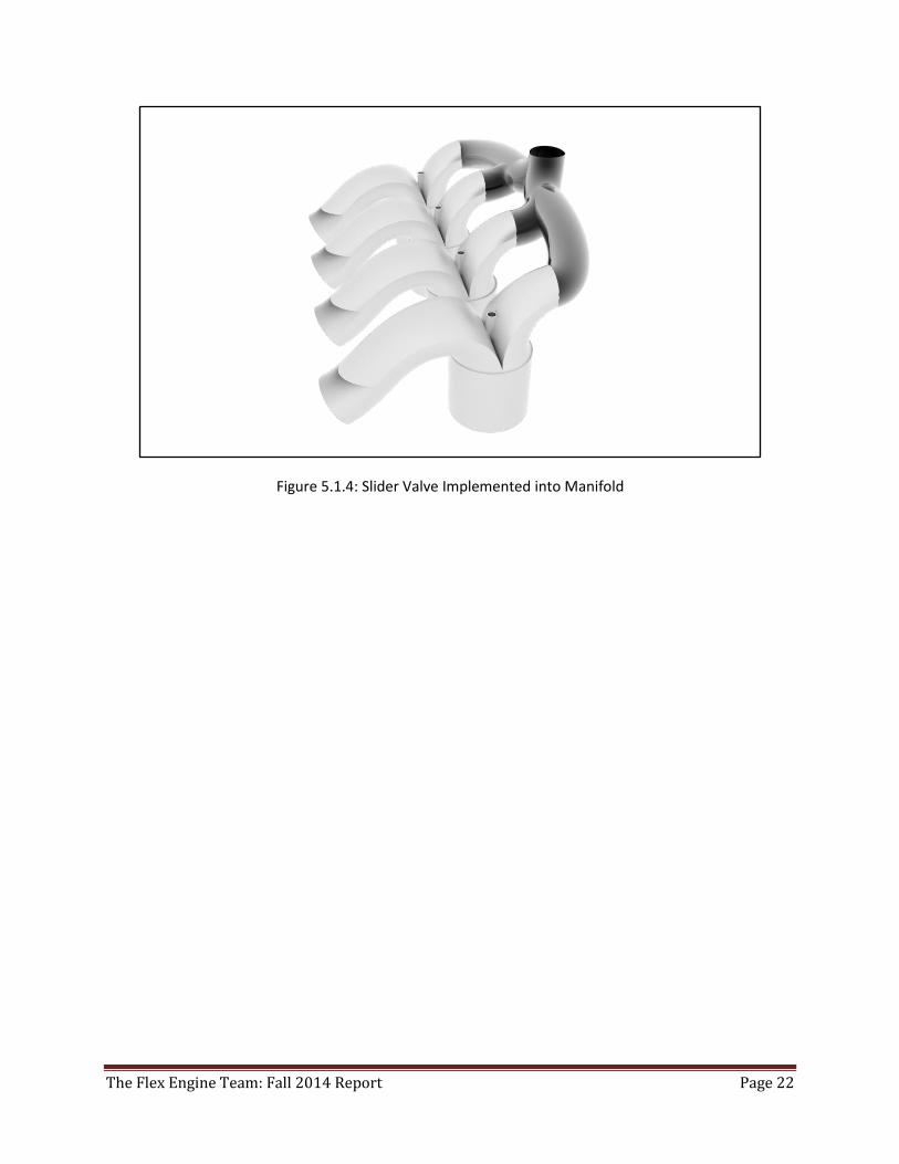
Figure 5.1.4: Slider Valve Implemented into Manifold
The Flex Engine Team: Fall 2014 Report Page 23
Design 3
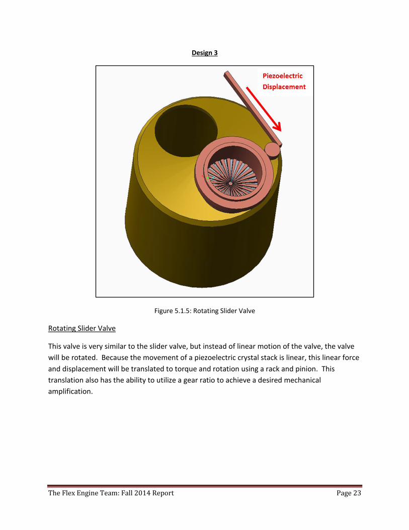
Figure 5.1.5: Rotating Slider Valve
Rotating Slider Valve
This valve is very similar to the slider valve, but instead of linear motion of the valve, the valve
will be rotated. Because the movement of a piezoelectric crystal stack is linear, this linear force
and displacement will be translated to torque and rotation using a rack and pinion. This
translation also has the ability to utilize a gear ratio to achieve a desired mechanical
amplification.
The Flex Engine Team: Fall 2014 Report Page 24
Design 4
Figure 5.1.6: Modified Standard Annular Valve
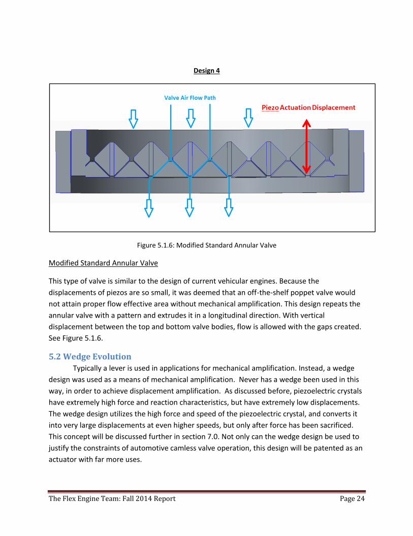
Modified Standard Annular Valve
This type of valve is similar to the design of current vehicular engines. Because the
displacements of piezos are so small, it was deemed that an off-the-shelf poppet valve would
not attain proper flow effective area without mechanical amplification. This design repeats the
annular valve with a pattern and extrudes it in a longitudinal direction. With vertical
displacement between the top and bottom valve bodies, flow is allowed with the gaps created.
See Figure 5.1.6.
5.2 Wedge Evolution
Typically a lever is used in applications for mechanical amplification. Instead, a wedge
design was used as a means of mechanical amplification. Never has a wedge been used in this
way, in order to achieve displacement amplification. As discussed before, piezoelectric crystals
have extremely high force and reaction characteristics, but have extremely low displacements.
The wedge design utilizes the high force and speed of the piezoelectric crystal, and converts it
into very large displacements at even higher speeds, but only after force has been sacrificed.
This concept will be discussed further in section 7.0. Not only can the wedge design be used to
justify the constraints of automotive camless valve operation, this design will be patented as an
actuator with far more uses.
The Flex Engine Team: Fall 2014 Report Page 25
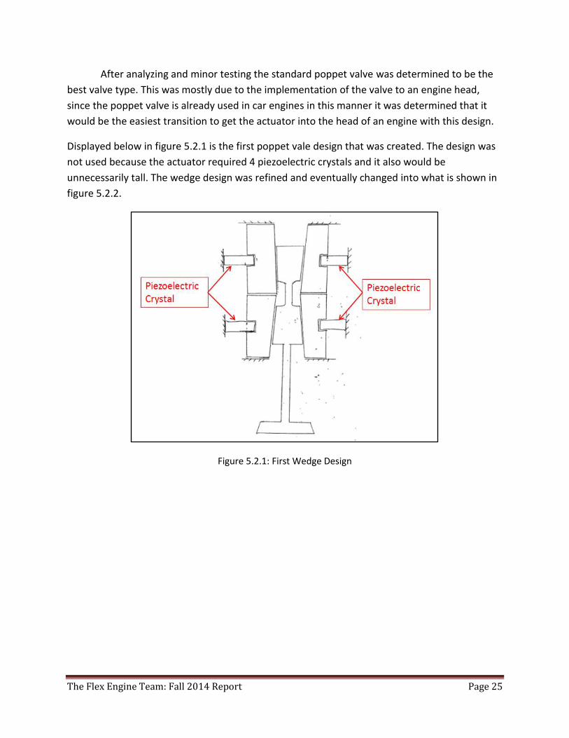
After analyzing and minor testing the standard poppet valve was determined to be the
best valve type. This was mostly due to the implementation of the valve to an engine head,
since the poppet valve is already used in car engines in this manner it was determined that it
would be the easiest transition to get the actuator into the head of an engine with this design.
Displayed below in figure 5.2.1 is the first poppet vale design that was created. The design was
not used because the actuator required 4 piezoelectric crystals and it also would be
unnecessarily tall. The wedge design was refined and eventually changed into what is shown in
figure 5.2.2.
Figure 5.2.1: First Wedge Design
The Flex Engine Team: Fall 2014 Report Page 26
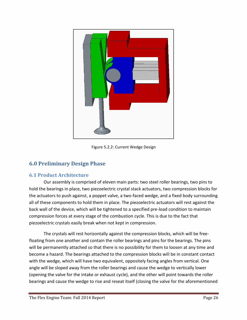
Figure 5.2.2: Current Wedge Design
6.0 Preliminary Design Phase
6.1 Product Architecture
Our assembly is comprised of eleven main parts: two steel roller bearings, two pins to
hold the bearings in place, two piezoelectric crystal stack actuators, two compression blocks for
the actuators to push against, a poppet valve, a two-faced wedge, and a fixed body surrounding
all of these components to hold them in place. The piezoelectric actuators will rest against the
back wall of the device, which will be tightened to a specified pre-load condition to maintain
compression forces at every stage of the combustion cycle. This is due to the fact that
piezoelectric crystals easily break when not kept in compression.
The crystals will rest horizontally against the compression blocks, which will be free-
floating from one another and contain the roller bearings and pins for the bearings. The pins
will be permanently attached so that there is no possibility for them to loosen at any time and
become a hazard. The bearings attached to the compression blocks will be in constant contact
with the wedge, which will have two equivalent, oppositely facing angles from vertical. One
angle will be sloped away from the roller bearings and cause the wedge to vertically lower
(opening the valve for the intake or exhaust cycle), and the other will point towards the roller
bearings and cause the wedge to rise and reseat itself (closing the valve for the aforementioned
The Flex Engine Team: Fall 2014 Report Page 27
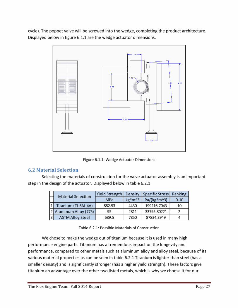
cycle). The poppet valve will be screwed into the wedge, completing the product architecture.
Displayed below in figure 6.1.1 are the wedge actuator dimensions.
Figure 6.1.1: Wedge Actuator Dimensions
6.2 Material Selection
Selecting the materials of construction for the valve actuator assembly is an important
step in the design of the actuator. Displayed below in table 6.2.1
Table 6.2.1: Possible Materials of Construction
We chose to make the wedge out of titanium because it is used in many high
performance engine parts. Titanium has a tremendous impact on the longevity and
performance, compared to other metals such as aluminum alloy and alloy steel, because of its
various material properties as can be seen in table 6.2.1 Titanium is lighter than steel (has a
smaller density) and is significantly stronger (has a higher yield strength). These factors give
titanium an advantage over the other two listed metals, which is why we choose it for our
Yield Strength Density Specific Stress Ranking
MPa kg*m^3 Pa/(kg*m^3) 0-10
1 Titanium (TI-6AI-4V) 882.53 4430 199216.7043 10
2 Aluminum Alloy (775) 95 2811 33795.80221 2
3 ASTM Alloy Steel 689.5 7850 87834.3949 4
Material Selection
The Flex Engine Team: Fall 2014 Report Page 28
material. For instance, if our valve were composed of titanium it would have a smoother
acceleration, which will allow better control over the valve train. The down side to titanium is
its higher cost; however, you get what you pay for: a better quality material.
Capstone Project – Written Report 04/14/14 Instructor: Michael Strange
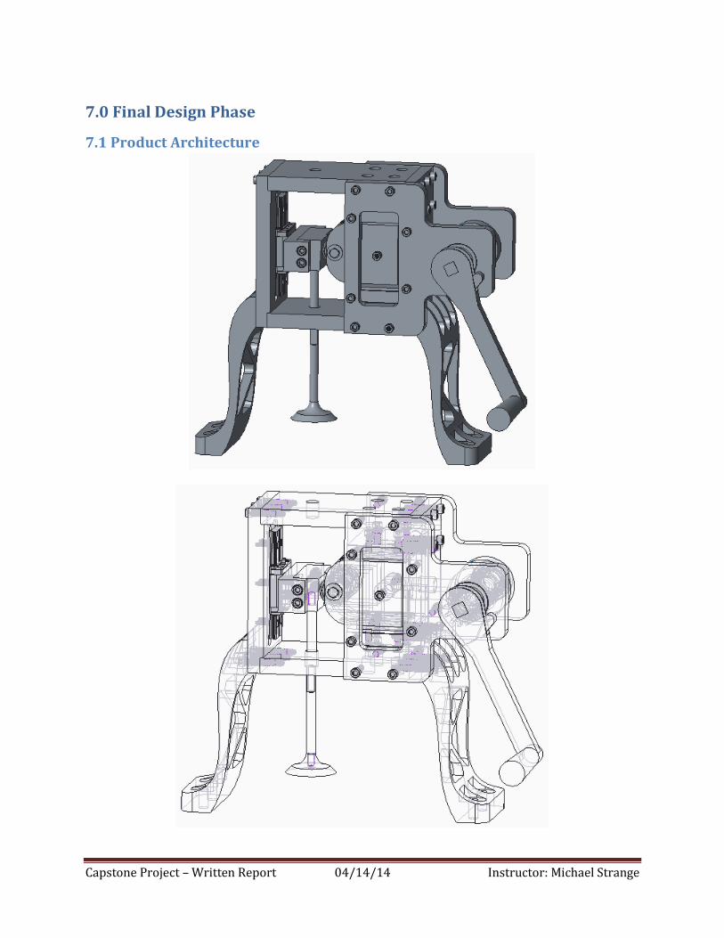
7.0 Final Design Phase
7.1 Product Architecture
The Flex Engine Team: Fall 2014 Report Page 30
Our final assembly is comprised of the following main parts: top housing part, bottom
housing part, wall slider rear wall part, two wall compression block parts, two compression
blocks, two push pin shafts, two side wall cam holders, cam shaft, cams, poppet valve, linear
bearing, crank handle and two-faced wedge fixture. We designed this wedge valve actuator to
operate off of cams to actuate the valve and display the ingenuity behind the concept. The
project was designed to allow for removal of the camshaft and substituting piezo crystals for
the two push pin shafts that displace the two compression blocks and actuate the valve using
the wedge principal design.
By comparing the preliminary design product with the final design product, it should be
noted the significant design improvements and alterations. Nearly everything was changed in
the overall end product. Only the original wedge actuation concept from the Preliminary Design
phase was kept as observed by looking at the final design above.
The final design still operates on the same principles as the initial design. The crank
handle is rotated, which causes the cams to come in contact with the push pins. From here the
pushpins come into contact with the compression blocks and move them forward. The
compression block bearing applies a force on the wedges and either pushes the poppet valve
up or down. Another key component that allows the valve to move is the linear bearing located
on the back wall of the housing. This provides smooth, near frictionless linear track movement
for the valve to follow along. As previously stated, if the push pins were replaced with piezo
crystals then the design principles would still function based on the concept would still operate
the same.
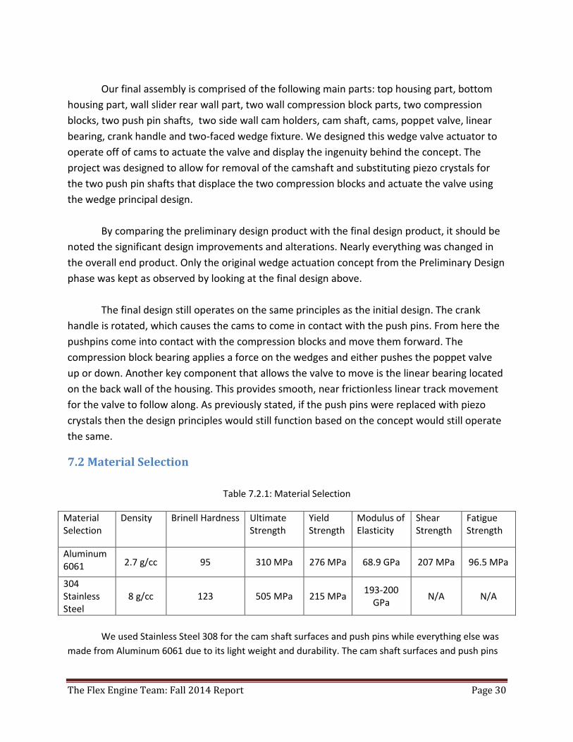
7.2 Material Selection
Table 7.2.1: Material Selection
Material Selection
Density Brinell Hardness Ultimate Strength
Yield Strength
Modulus of Elasticity
Shear Strength
Fatigue Strength
Aluminum 6061 2.7 g/cc 95 310 MPa 276 MPa 68.9 GPa 207 MPa 96.5 MPa
304 Stainless Steel
8 g/cc 123 505 MPa 215 MPa 193-200
GPa N/A N/A
We used Stainless Steel 308 for the cam shaft surfaces and push pins while everything else was
made from Aluminum 6061 due to its light weight and durability. The cam shaft surfaces and push pins
The Flex Engine Team: Fall 2014 Report Page 31
were made from stainless steel 308 because we did not want any gouging effects to occur since the cam
surfaces are critical elements to the function of the final design.
8.0 Engineering Design & Analysis
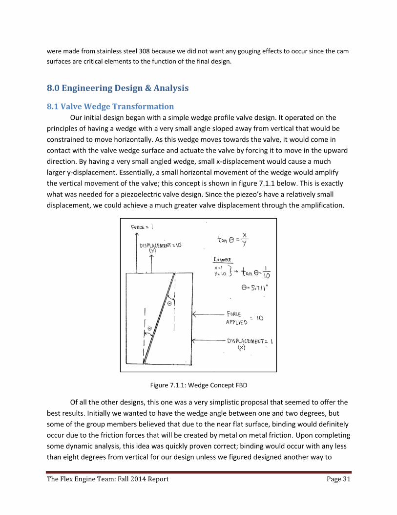
8.1 Valve Wedge Transformation
Our initial design began with a simple wedge profile valve design. It operated on the
principles of having a wedge with a very small angle sloped away from vertical that would be
constrained to move horizontally. As this wedge moves towards the valve, it would come in
contact with the valve wedge surface and actuate the valve by forcing it to move in the upward
direction. By having a very small angled wedge, small x-displacement would cause a much
larger y-displacement. Essentially, a small horizontal movement of the wedge would amplify
the vertical movement of the valve; this concept is shown in figure 7.1.1 below. This is exactly
what was needed for a piezoelectric valve design. Since the piezeo’s have a relatively small
displacement, we could achieve a much greater valve displacement through the amplification.
Figure 7.1.1: Wedge Concept FBD
Of all the other designs, this one was a very simplistic proposal that seemed to offer the
best results. Initially we wanted to have the wedge angle between one and two degrees, but
some of the group members believed that due to the near flat surface, binding would definitely
occur due to the friction forces that will be created by metal on metal friction. Upon completing
some dynamic analysis, this idea was quickly proven correct; binding would occur with any less
than eight degrees from vertical for our design unless we figured designed another way to
The Flex Engine Team: Fall 2014 Report Page 32
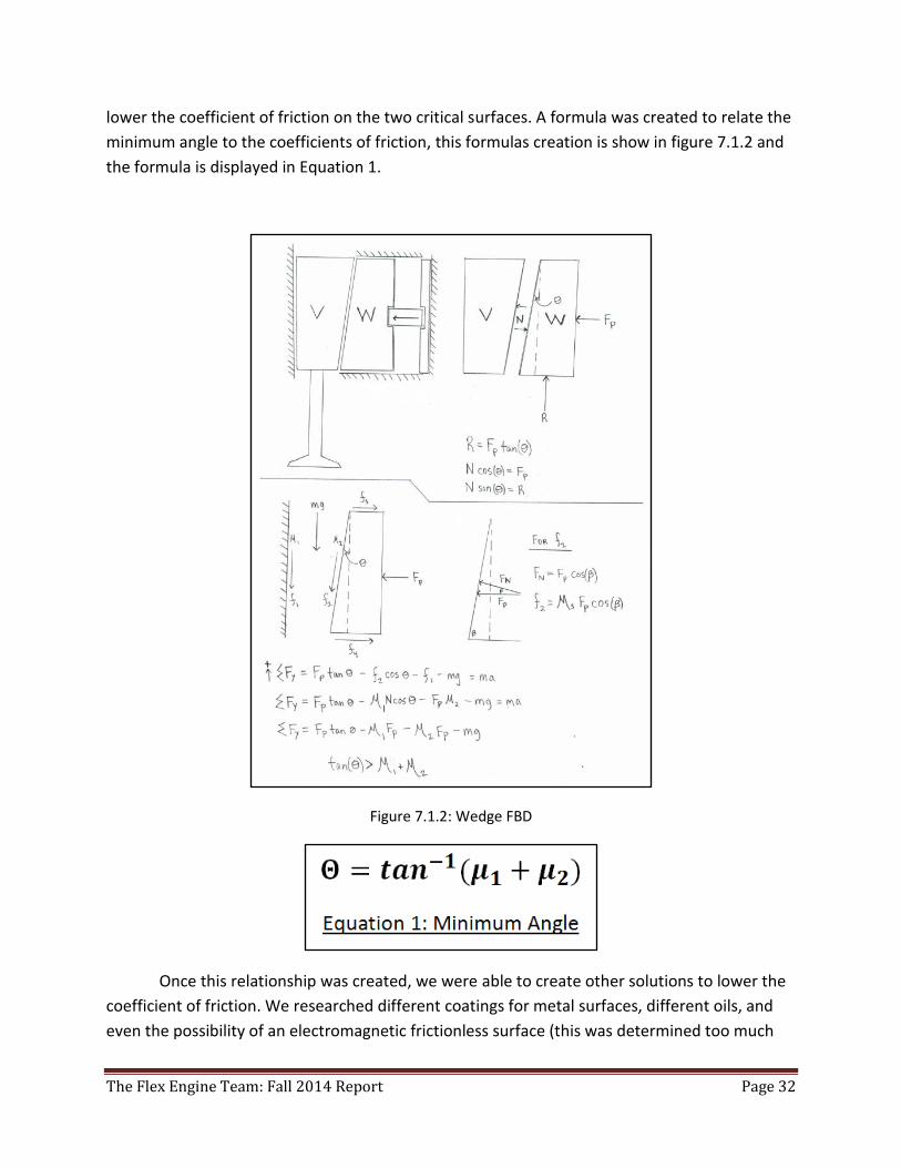
lower the coefficient of friction on the two critical surfaces. A formula was created to relate the
minimum angle to the coefficients of friction, this formulas creation is show in figure 7.1.2 and
the formula is displayed in Equation 1.
Figure 7.1.2: Wedge FBD
Once this relationship was created, we were able to create other solutions to lower the
coefficient of friction. We researched different coatings for metal surfaces, different oils, and
even the possibility of an electromagnetic frictionless surface (this was determined too much
The Flex Engine Team: Fall 2014 Report Page 33
work though). Lastly we went back to basic physical modifications and came up with an
addition of roller bearings, which have a very low coefficient of friction compared to our initial
design of metal-on-metal surfaces. We plugged in the necessary coefficients of friction
expected from the valve design into Equation 1 and determined that the minimal angle
dropped down to 2.92 degrees with a static coefficient of friction for metal-metal surfaces (with
lube) at 0.05 and roller static friction at 0.001. This is much more desirable for our project,
which still produces the necessary amplification of the valve displacement required to actuate
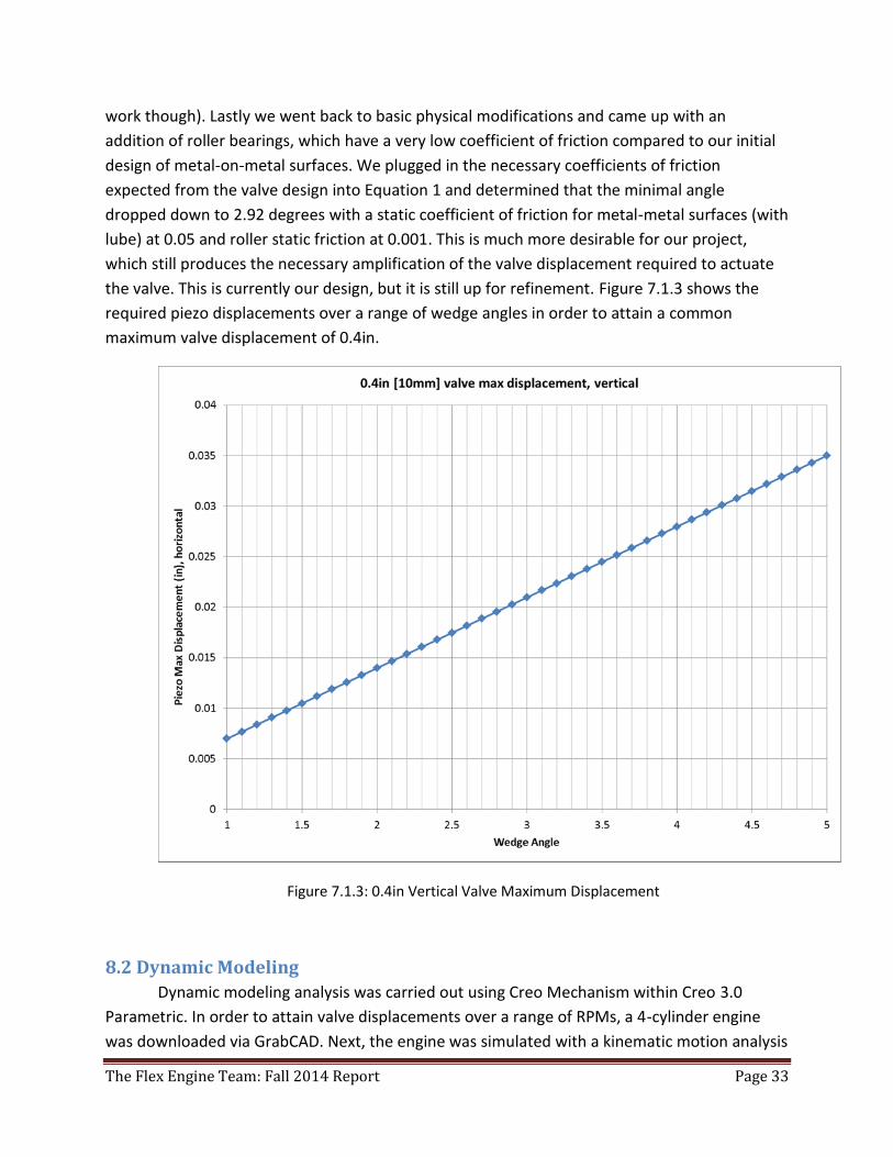
the valve. This is currently our design, but it is still up for refinement. Figure 7.1.3 shows the
required piezo displacements over a range of wedge angles in order to attain a common
maximum valve displacement of 0.4in.
Figure 7.1.3: 0.4in Vertical Valve Maximum Displacement
8.2 Dynamic Modeling
Dynamic modeling analysis was carried out using Creo Mechanism within Creo 3.0
Parametric. In order to attain valve displacements over a range of RPMs, a 4-cylinder engine
was downloaded via GrabCAD. Next, the engine was simulated with a kinematic motion analysis
The Flex Engine Team: Fall 2014 Report Page 34
in Autodesk. Valve displacements relative to the crankshaft’s rotation were found at the
completion of the simulation. In order to attain the timing for the opening and closing of valves,
current engines utilize a mechanically bound link between the crankshaft and the camshaft.
Because the goal of this project is to attain camless valve actuation, there will be no
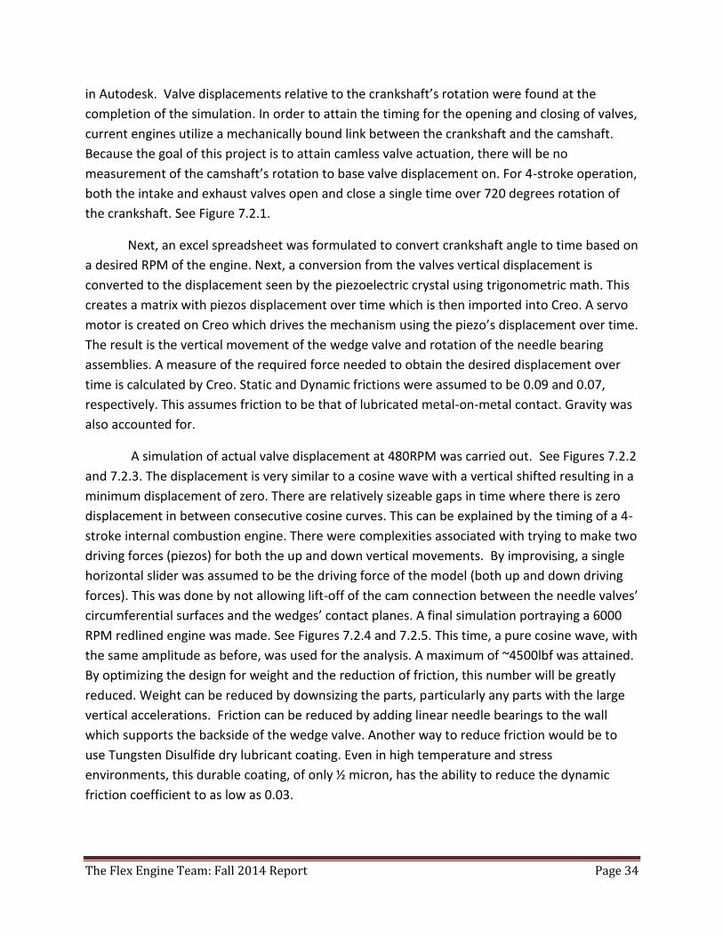
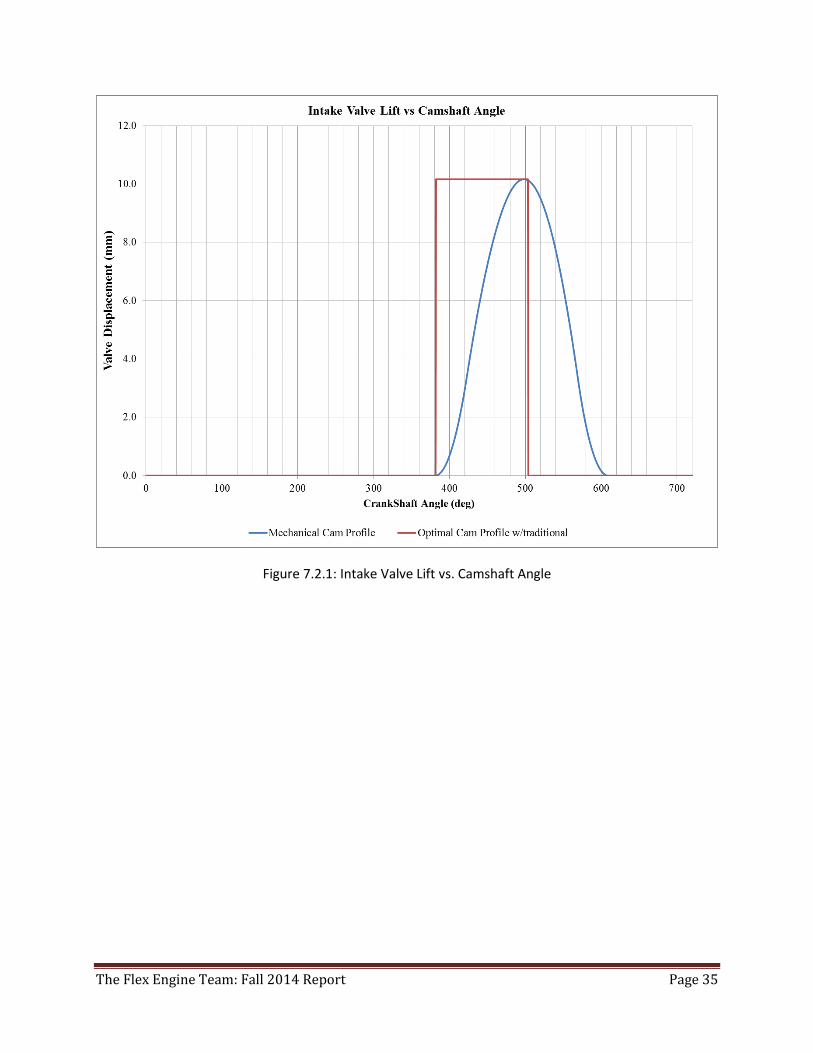
measurement of the camshaft’s rotation to base valve displacement on. For 4-stroke operation,
both the intake and exhaust valves open and close a single time over 720 degrees rotation of
the crankshaft. See Figure 7.2.1.
Next, an excel spreadsheet was formulated to convert crankshaft angle to time based on
a desired RPM of the engine. Next, a conversion from the valves vertical displacement is
converted to the displacement seen by the piezoelectric crystal using trigonometric math. This
creates a matrix with piezos displacement over time which is then imported into Creo. A servo
motor is created on Creo which drives the mechanism using the piezo’s displacement over time.
The result is the vertical movement of the wedge valve and rotation of the needle bearing
assemblies. A measure of the required force needed to obtain the desired displacement over
time is calculated by Creo. Static and Dynamic frictions were assumed to be 0.09 and 0.07,
respectively. This assumes friction to be that of lubricated metal-on-metal contact. Gravity was
also accounted for.
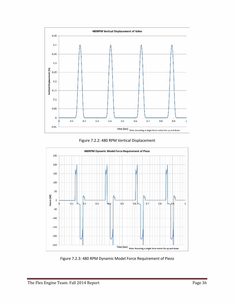
A simulation of actual valve displacement at 480RPM was carried out. See Figures 7.2.2
and 7.2.3. The displacement is very similar to a cosine wave with a vertical shifted resulting in a
minimum displacement of zero. There are relatively sizeable gaps in time where there is zero
displacement in between consecutive cosine curves. This can be explained by the timing of a 4-
stroke internal combustion engine. There were complexities associated with trying to make two
driving forces (piezos) for both the up and down vertical movements. By improvising, a single
horizontal slider was assumed to be the driving force of the model (both up and down driving
forces). This was done by not allowing lift-off of the cam connection between the needle valves’
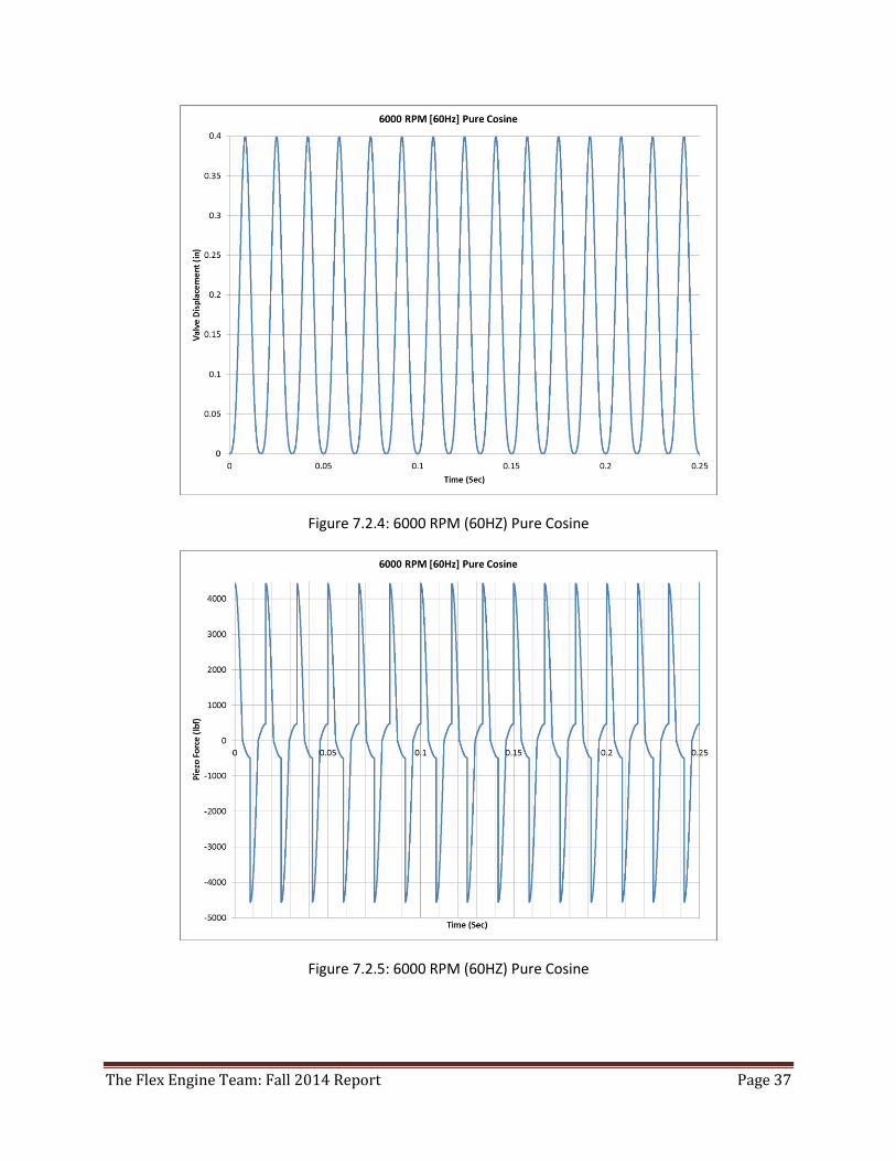
circumferential surfaces and the wedges’ contact planes. A final simulation portraying a 6000
RPM redlined engine was made. See Figures 7.2.4 and 7.2.5. This time, a pure cosine wave, with
the same amplitude as before, was used for the analysis. A maximum of ~4500lbf was attained.
By optimizing the design for weight and the reduction of friction, this number will be greatly
reduced. Weight can be reduced by downsizing the parts, particularly any parts with the large
vertical accelerations. Friction can be reduced by adding linear needle bearings to the wall
which supports the backside of the wedge valve. Another way to reduce friction would be to
use Tungsten Disulfide dry lubricant coating. Even in high temperature and stress
environments, this durable coating, of only ½ micron, has the ability to reduce the dynamic
friction coefficient to as low as 0.03.
The Flex Engine Team: Fall 2014 Report Page 35
Figure 7.2.1: Intake Valve Lift vs. Camshaft Angle
The Flex Engine Team: Fall 2014 Report Page 36
Figure 7.2.2: 480 RPM Vertical Displacement
Figure 7.2.3: 480 RPM Dynamic Model Force Requirement of Piezo
The Flex Engine Team: Fall 2014 Report Page 37
Figure 7.2.4: 6000 RPM (60HZ) Pure Cosine
Figure 7.2.5: 6000 RPM (60HZ) Pure Cosine
The Flex Engine Team: Fall 2014 Report Page 38
9.0 Fabrication Process Taking into account manufacturing, assembly, and reliability aspects during the design
process is critical for a successful final product. Due to the fact that medium-scale piezoelectric
valves have not been created before, we had to start our design from scratch and were more
focused on trying to simply create a working design. After settling on the wedge-shape for the
mechanical advantage, we considered the following ways to: strengthen components to
lengthen product life, simplify the design to decrease manufacturing time, and modify element
relations to increase ease of assembly.
9.1 Design for Reliability
Design for Reliability (DFR) is incredibly important because warranty costs and customer
satisfaction with final designs can make or break a company. Both reliability and quality must
be taken into consideration when determining reliability of design. Typical quality control will
guarantee that our valve will work as intended after manufacturing and assembly, whereas
reliability deals specifically with average lifecycle of each device.
By keeping the total number of parts to a minimum, quality control can be more easily
carried out. Making any changes to the design to prevent potential failures will therefore be
significantly easier due to the simplicity of the component shapes; whether it be changing
material selection, component geometry, or manipulating the dimensions. All of these changes
could be made to reduce stresses that might be found to cause critical failures. Besides this, we
increased the strength of our device by choosing very robust parts. Piezoelectric crystals have
an extremely long life cycle when they are only used in compression, and should outlast the
other components of the engine. Other than that, selecting sturdy metals such as lightweight
titanium for the wedge and steel for the needle bearings will keep fatigue failures to a
minimum for the longest amount of time possible.
The major downfall to the piezoelectric stacks is that a flaw such as an edge crack from a
bad actuator could lead to a high chance of brittle fracture; a stress failure that occurs without
warning due to a lack of plastic deformation. To prevent this, we will simply have to purchase
our piezoelectric stacks from the most reliable manufacturer possible.
9.2 Design for Manufacturing
The goal for both Design for Manufacturing (DFM) and Design for Assembly (DFA) of our
model is to create a valve that is easily and economically produced. Reducing the number of
parts not only helps with simplifying adjustments to increase reliability and lessen the time for
quality control checks, but it also is a major step towards reducing the manufacturing costs.
Unfortunately, almost none of the components involved are standard parts commonly found,
but the dual wedge setup allows the main part of our assembly to be multi-use – opening and
closing the valve, which further decreases the number of parts. Because almost all of the
The Flex Engine Team: Fall 2014 Report Page 39
components can be fabricated using two-dimensional cuts, the only difficulty from fabrication
will be the tight tolerance of the wedge angles.
9.3 Design for Assembly
Three main aspects were considered when dealing with DFA: minimizing assembly
directions, maximizing compliance, and minimizing handling. Because of the rectangular shape
of the valve assembly, it is easy to describe the instructions for constructing it from one
direction. The rigid exterior surrounding the moving components also helps with keeping errors
during insertion phases to a minimum, which may otherwise cause damage to the finished
surfaces. Additionally, the dual piezoelectric actuators equally preload each other, so individual
torques for each does not have to be applied. During assembly, the housing will engage both
actuators simultaneously to a predetermined amount. Lastly, creating a round top to the
horizontally moving block that exaggerates asymmetry will help assemblers quickly orient and
insert the component.
10.0 Prototype Testing We are currently lacking a sufficient prototype, but we have modeled our design using
PTC Creo. Our plan for creating the prototype is to send the three-dimensional model to a
machine shop in San Leandro called Machine Logics, which would be able to create it within the
tight specifications required. Originally, we planned on creating a model using a 3-D printer due
to the fast prototyping speed possible, but a continued lack of funding from hang-ups within
the CSU system made the purchase of one impossible. We did not know this would occur, so we
researched and selected the most affordable and advanced printer within our budget. By the
time November came around, we became much more aware that obtaining the printer was not
possible, and we likely would not need it because we had already chosen a final design to
proceed with. With further research in piezoelectric manufacturers, we were able to find a local
distributor called Kinetic Ceramics, Inc. that is located in Hayward, California. We plan on
purchasing two piezoelectric stack actuators from them to use in our prototype assembly.
Upon procuring all of the components, we will construct the valve assembly and create
a MatLab code to control the charges applied to the piezoelectric actuator stacks. We will begin
testing with extremely low cycling rates until we are confident that our design and setup can
overcome the friction between components and withstand the forces applied to each. Once we
are confident with the tests at low cycling rates, we will gradually increase it and see how the
components withstand continuous actuation over longer periods of time.
The Flex Engine Team: Fall 2014 Report Page 40
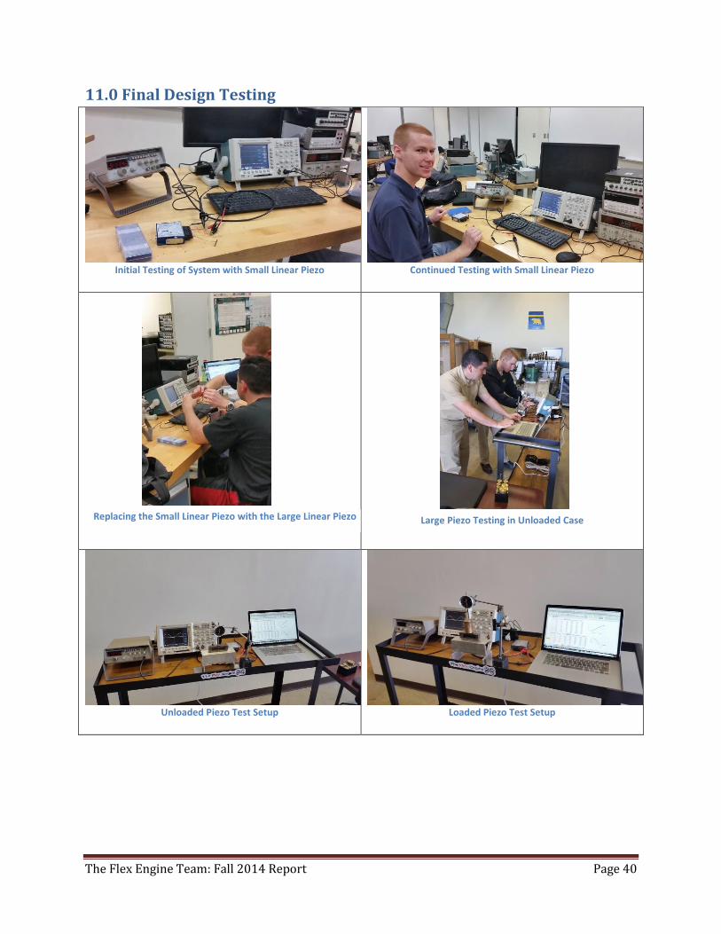
11.0 Final Design Testing
Initial Testing of System with Small Linear Piezo
Continued Testing with Small Linear Piezo
Unloaded Piezo Test Setup
Loaded Piezo Test Setup
Replacing the Small Linear Piezo with the Large Linear Piezo Large Piezo Testing in Unloaded Case
The Flex Engine Team: Fall 2014 Report Page 41
12.0 Preliminary Summary During the beginning of the semester, the idea of what our final project would be was a
cam-less engine. This entailed a fully running 1 or 2 piston engine with no cam shaft, with the
valves controlled by an actuator. With this being the first piezoelectric-controlled valve, it was
necessary for us to design the actuator from scratch. The initial actuator designs were similar to
rocker arms, but we would incorporate piezoelectric crystals as the device exerting force on the
air intake and exhaust valves. After a few meetings and delegations, we trimmed down our idea
to an actuated valve assembly that we could quickly and easily mount on a redesigned engine
block. We would acquire a 3-D printer in order to duplicate various valve models and have two
prints of each design to test in case we broke or destroyed a model during testing. These valves
would replace the typical poppet-valve with horizontally sliding cylinders with varying inlet
shapes that would require less movement from the piezoelectric stack. The models would be
tested to see which had optimal airflow.
Unfortunately, we had tremendous delays due to issues with funding, which halted any
progress with acquiring a 3-D printer and eventually led to the decision not to purchase one at
all. Due to this, we were unable to create the new valve designs for testing, and agreed that it
would be best to keep the standard poppet found in almost every car engine. Some sort of
mechanical advantage was still required to greatly increase the displacement obtained from the
piezoelectric stack actuators. Various initial designs were taken into consideration, with the
team concluding on a wedge design which would actuate the valve up and down without the
use of any springs. From dynamic modeling calculations and a 3-D CAD model simulation, we
determined that friction between many of the surfaces would lead to force requirements
impossible to obtain with any piezoelectric actuator on the market. Therefore, we added a steel
roller bearing that could handle the large pressures from the piezoelectric crystals to decrease
the amount of area contributing to friction forces.
13.0 Preliminary Conclusion Based on where we stand at this halfway point in our senior project we have had to
reevaluate our end goals. Initially we were hoping to achieve installing a piezo valve actuator
and have one running by the end of spring 2015, but the 3D model still needs improvements
before we are able to actually start manufacturing it. Another issue that we have run into is
funding for the actual piezos to be used in the valve design. It was discovered that the piezo
required would cost around $10,000 to be created and we need two. This cost greatly exceeds
our budget for the senior project and thus this route is no longer possible. Instead we have
concluded to finalize the valve design and incorporate cams to actuate the design as a proof of
concept. As far as the piezo crystals go, we plan on purchasing the piezos and setting up a
display with some analysis to demonstrate the capabilities they are capable of achieving. With
The Flex Engine Team: Fall 2014 Report Page 42
these two goals met we can successfully conclude that by replacing the cams inside of the
wedge valve design with piezos the design should still function as intended.
14.0 Preliminary Recommendations In order to improve manufacturability, simplification of the valve assembly is critical in
the spring semester. With simpler parts, the cost of manufacturing at a local machine shop will
be drastically reduced, along with the production time. With limited time before project
presentations, meeting with representatives that Murray Tech knows of from a machine shop
in Stockton is essential. Researching cheaper piezoelectric crystals will also be required in order
to keep the team’s budget more reasonable. We concluded on a few companies that might
offer actuators at a reduced rate compared to that of the local manufacturer. These companies
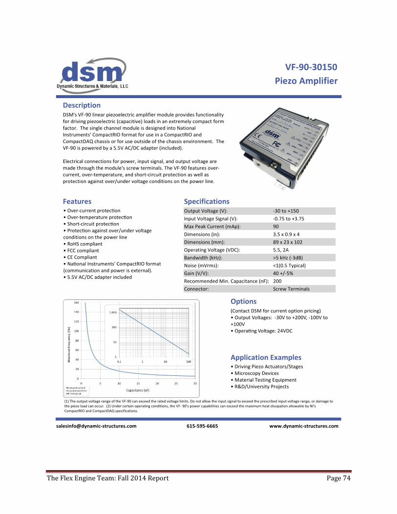
include APC and Dynamic Structures and Materials (DSM). More importantly, the actuators that
the new companies sell are stock parts which could quickly be shipped upon payment. In order
to further reduce the price of these expensive devices, we plan on requesting the actuator on
loan so that we could complete tests and have it during our presentation for a physical model
but return it immediately following graduation.
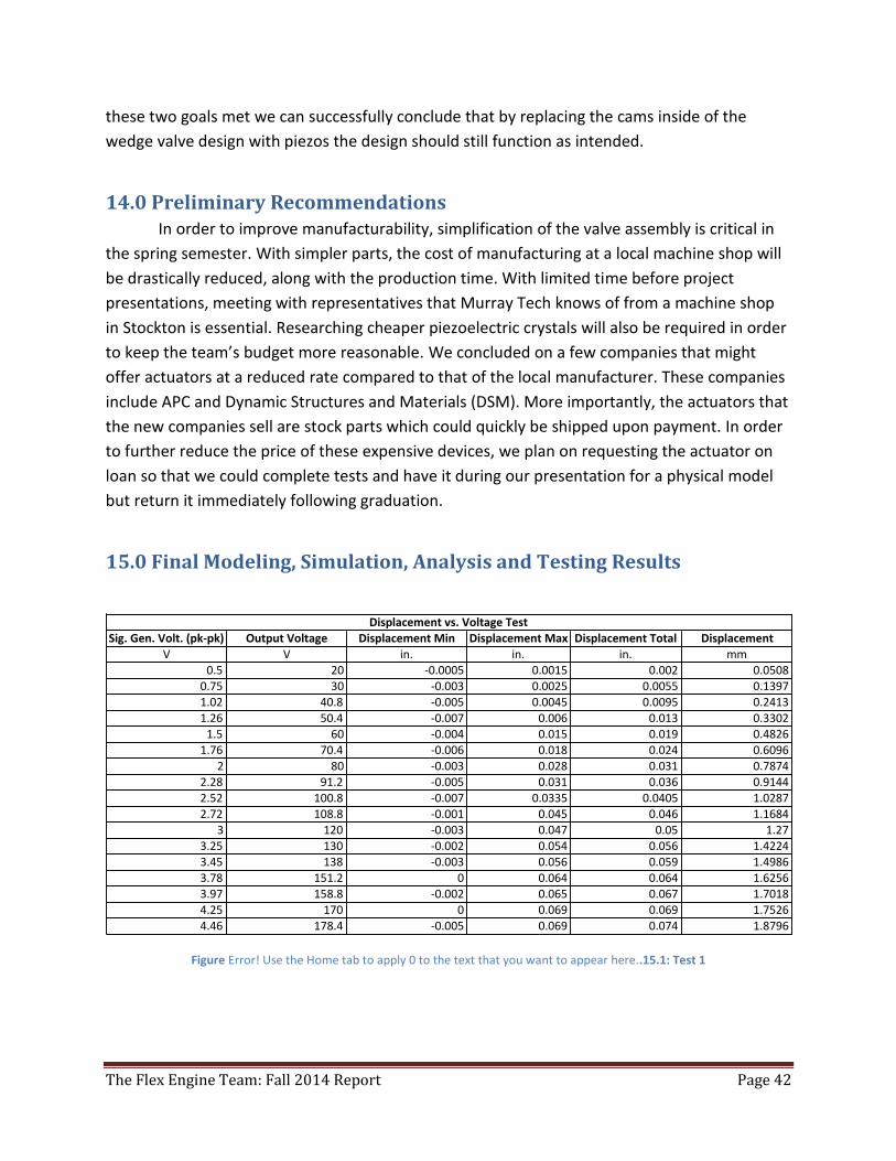
15.0 Final Modeling, Simulation, Analysis and Testing Results
Figure Error! Use the Home tab to apply 0 to the text that you want to appear here..15.1: Test 1
Sig.Gen.Volt.(pk-pk) OutputVoltage DisplacementMin DisplacementMax DisplacementTotal Displacement
V V in. in. in. mm0.5 20 -0.0005 0.0015 0.002 0.05080.75 30 -0.003 0.0025 0.0055 0.13971.02 40.8 -0.005 0.0045 0.0095 0.2413
1.26 50.4 -0.007 0.006 0.013 0.33021.5 60 -0.004 0.015 0.019 0.48261.76 70.4 -0.006 0.018 0.024 0.6096
2 80 -0.003 0.028 0.031 0.7874
2.28 91.2 -0.005 0.031 0.036 0.91442.52 100.8 -0.007 0.0335 0.0405 1.02872.72 108.8 -0.001 0.045 0.046 1.1684
3 120 -0.003 0.047 0.05 1.273.25 130 -0.002 0.054 0.056 1.42243.45 138 -0.003 0.056 0.059 1.49863.78 151.2 0 0.064 0.064 1.62563.97 158.8 -0.002 0.065 0.067 1.70184.25 170 0 0.069 0.069 1.75264.46 178.4 -0.005 0.069 0.074 1.8796
Displacementvs.VoltageTest
The Flex Engine Team: Fall 2014 Report Page 43
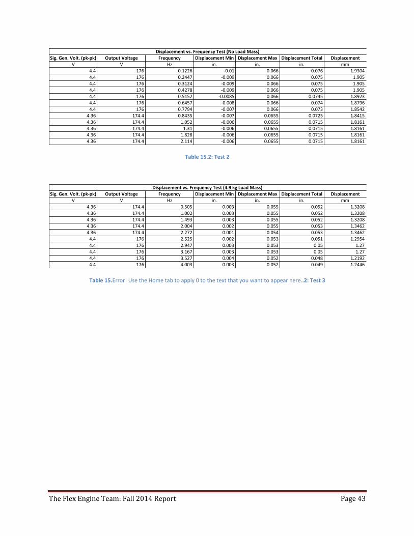
Table 15.2: Test 2
Table 15.Error! Use the Home tab to apply 0 to the text that you want to appear here..2: Test 3
Sig.Gen.Volt.(pk-pk) OutputVoltage Frequency DisplacementMin DisplacementMax DisplacementTotal DisplacementV V Hz in. in. in. mm
4.4 176 0.1226 -0.01 0.066 0.076 1.9304
4.4 176 0.2447 -0.009 0.066 0.075 1.905
4.4 176 0.3124 -0.009 0.066 0.075 1.9054.4 176 0.4278 -0.009 0.066 0.075 1.9054.4 176 0.5152 -0.0085 0.066 0.0745 1.8923
4.4 176 0.6457 -0.008 0.066 0.074 1.87964.4 176 0.7794 -0.007 0.066 0.073 1.85424.36 174.4 0.8435 -0.007 0.0655 0.0725 1.8415
4.36 174.4 1.052 -0.006 0.0655 0.0715 1.81614.36 174.4 1.31 -0.006 0.0655 0.0715 1.81614.36 174.4 1.828 -0.006 0.0655 0.0715 1.81614.36 174.4 2.114 -0.006 0.0655 0.0715 1.8161
Displacementvs.FrequencyTest(NoLoadMass)
Sig.Gen.Volt.(pk-pk) OutputVoltage Frequency DisplacementMin DisplacementMax DisplacementTotal Displacement
V V Hz in. in. in. mm
4.36 174.4 0.505 0.003 0.055 0.052 1.3208
4.36 174.4 1.002 0.003 0.055 0.052 1.3208
4.36 174.4 1.493 0.003 0.055 0.052 1.32084.36 174.4 2.004 0.002 0.055 0.053 1.3462
4.36 174.4 2.272 0.001 0.054 0.053 1.3462
4.4 176 2.525 0.002 0.053 0.051 1.2954
4.4 176 2.947 0.003 0.053 0.05 1.274.4 176 3.167 0.003 0.053 0.05 1.27
4.4 176 3.527 0.004 0.052 0.048 1.2192
4.4 176 4.003 0.003 0.052 0.049 1.2446
Displacementvs.FrequencyTest(4.9kgLoadMass)
The Flex Engine Team: Fall 2014 Report Page 44
16.0 Discussion of the Final Results
Piezo Design
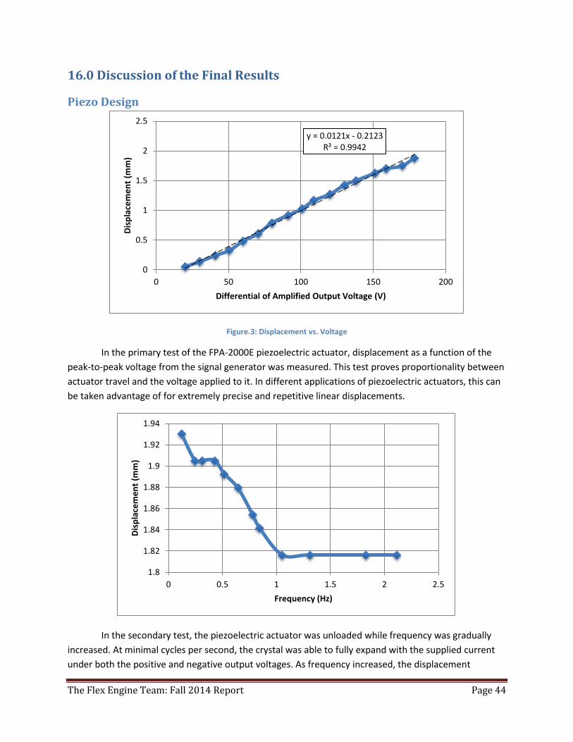
Figure.3: Displacement vs. Voltage
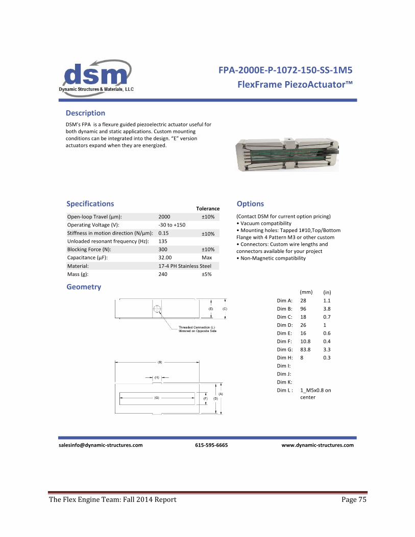
In the primary test of the FPA-2000E piezoelectric actuator, displacement as a function of the
peak-to-peak voltage from the signal generator was measured. This test proves proportionality between
actuator travel and the voltage applied to it. In different applications of piezoelectric actuators, this can
be taken advantage of for extremely precise and repetitive linear displacements.
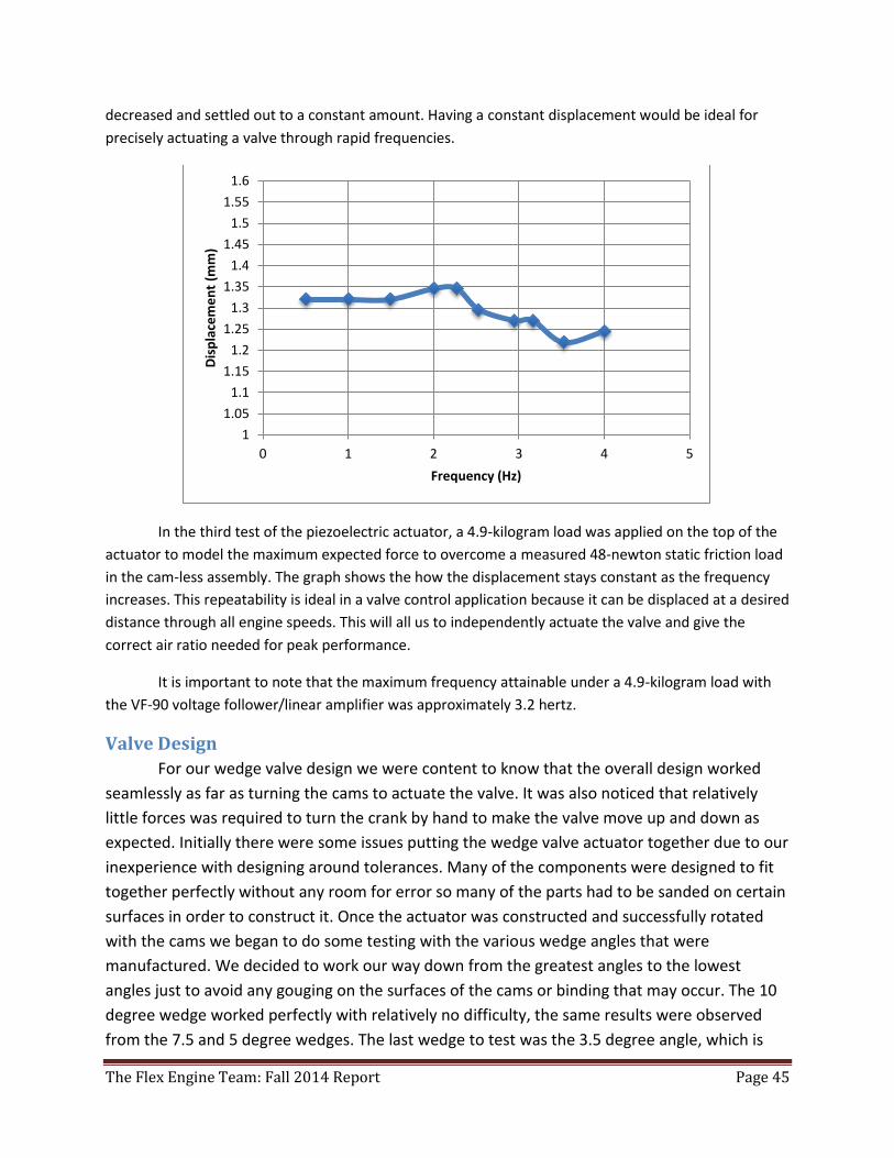
In the secondary test, the piezoelectric actuator was unloaded while frequency was gradually
increased. At minimal cycles per second, the crystal was able to fully expand with the supplied current
under both the positive and negative output voltages. As frequency increased, the displacement
y = 0.0121x - 0.2123 R² = 0.9942
0
0.5
1
1.5
2
2.5
0 50 100 150 200
Dis
pla
cem
en
t (m
m)
Differential of Amplified Output Voltage (V)
1.8
1.82
1.84
1.86
1.88
1.9
1.92
1.94
0 0.5 1 1.5 2 2.5
Dis
pla
cem
en
t (m
m)
Frequency (Hz)
The Flex Engine Team: Fall 2014 Report Page 45
decreased and settled out to a constant amount. Having a constant displacement would be ideal for
precisely actuating a valve through rapid frequencies.
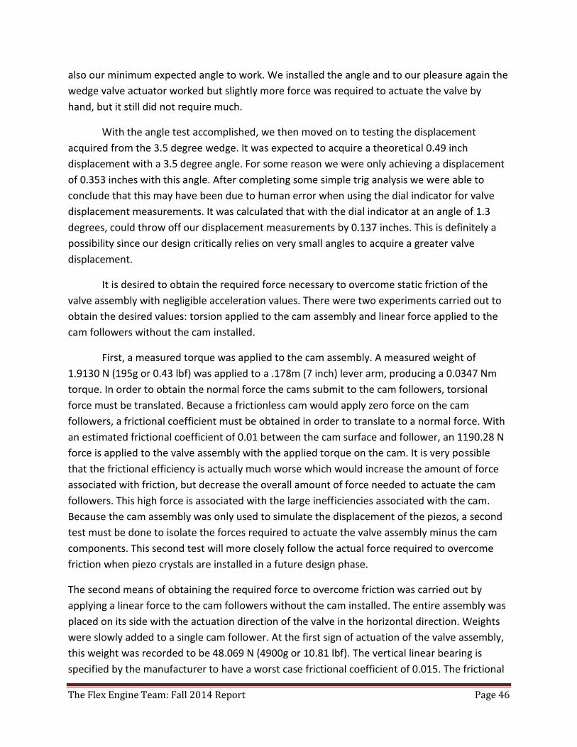
In the third test of the piezoelectric actuator, a 4.9-kilogram load was applied on the top of the
actuator to model the maximum expected force to overcome a measured 48-newton static friction load
in the cam-less assembly. The graph shows the how the displacement stays constant as the frequency
increases. This repeatability is ideal in a valve control application because it can be displaced at a desired
distance through all engine speeds. This will all us to independently actuate the valve and give the
correct air ratio needed for peak performance.
It is important to note that the maximum frequency attainable under a 4.9-kilogram load with
the VF-90 voltage follower/linear amplifier was approximately 3.2 hertz.
Valve Design
For our wedge valve design we were content to know that the overall design worked
seamlessly as far as turning the cams to actuate the valve. It was also noticed that relatively
little forces was required to turn the crank by hand to make the valve move up and down as
expected. Initially there were some issues putting the wedge valve actuator together due to our
inexperience with designing around tolerances. Many of the components were designed to fit
together perfectly without any room for error so many of the parts had to be sanded on certain
surfaces in order to construct it. Once the actuator was constructed and successfully rotated
with the cams we began to do some testing with the various wedge angles that were
manufactured. We decided to work our way down from the greatest angles to the lowest
angles just to avoid any gouging on the surfaces of the cams or binding that may occur. The 10
degree wedge worked perfectly with relatively no difficulty, the same results were observed
from the 7.5 and 5 degree wedges. The last wedge to test was the 3.5 degree angle, which is
1
1.05
1.1
1.15
1.2
1.25
1.3
1.35
1.4
1.45
1.5
1.55
1.6
0 1 2 3 4 5
Dis
pla
cem
en
t (m
m)
Frequency (Hz)
The Flex Engine Team: Fall 2014 Report Page 46
also our minimum expected angle to work. We installed the angle and to our pleasure again the
wedge valve actuator worked but slightly more force was required to actuate the valve by
hand, but it still did not require much.
With the angle test accomplished, we then moved on to testing the displacement
acquired from the 3.5 degree wedge. It was expected to acquire a theoretical 0.49 inch
displacement with a 3.5 degree angle. For some reason we were only achieving a displacement
of 0.353 inches with this angle. After completing some simple trig analysis we were able to
conclude that this may have been due to human error when using the dial indicator for valve
displacement measurements. It was calculated that with the dial indicator at an angle of 1.3
degrees, could throw off our displacement measurements by 0.137 inches. This is definitely a
possibility since our design critically relies on very small angles to acquire a greater valve
displacement.
It is desired to obtain the required force necessary to overcome static friction of the
valve assembly with negligible acceleration values. There were two experiments carried out to
obtain the desired values: torsion applied to the cam assembly and linear force applied to the
cam followers without the cam installed.
First, a measured torque was applied to the cam assembly. A measured weight of
1.9130 N (195g or 0.43 lbf) was applied to a .178m (7 inch) lever arm, producing a 0.0347 Nm
torque. In order to obtain the normal force the cams submit to the cam followers, torsional
force must be translated. Because a frictionless cam would apply zero force on the cam
followers, a frictional coefficient must be obtained in order to translate to a normal force. With
an estimated frictional coefficient of 0.01 between the cam surface and follower, an 1190.28 N
force is applied to the valve assembly with the applied torque on the cam. It is very possible
that the frictional efficiency is actually much worse which would increase the amount of force
associated with friction, but decrease the overall amount of force needed to actuate the cam
followers. This high force is associated with the large inefficiencies associated with the cam.
Because the cam assembly was only used to simulate the displacement of the piezos, a second
test must be done to isolate the forces required to actuate the valve assembly minus the cam
components. This second test will more closely follow the actual force required to overcome
friction when piezo crystals are installed in a future design phase.
The second means of obtaining the required force to overcome friction was carried out by
applying a linear force to the cam followers without the cam installed. The entire assembly was
placed on its side with the actuation direction of the valve in the horizontal direction. Weights
were slowly added to a single cam follower. At the first sign of actuation of the valve assembly,
this weight was recorded to be 48.069 N (4900g or 10.81 lbf). The vertical linear bearing is
specified by the manufacturer to have a worst case frictional coefficient of 0.015. The frictional
The Flex Engine Team: Fall 2014 Report Page 47
coefficient of a steel roller bearing applied to an aluminum surface is defined to be 0.001. The
static sliding friction between a well lubricated steel and aluminum surface is 0.01 (linear
horizontal slider bearings). With the applied mass of 4.9kg, a 0.4kg slider assembly, and a
0.04kg cam follower, 52.38 N is applied to the wedge assembly at the circular roller bearing.
The weight of the wedge/valve assembly is 56.87 N. A 3.2 N horizontal force is resisted at the
3.5 degree wedge surface. An approximate combined coefficient of friction of the entire system
is 0.05865. A numerical solution for the actual coefficient of rolling friction on the wedge
surface is 0.00101, as well as a 0.05541 coefficient of friction on the vertical bearing supporting
the wedge. The numerical solutions provide a means of estimating the bind angle of the
system, or the angle at which no amount of force will cause the assembly to actuate. During the
fall semester, it was calculated the estimated binding force would be 2.92 with an estimated
0.05 coefficient of friction between a well lubricated metal on metal surface and a rolling
coefficient of friction of 0.001. It was then agreed that a 3.5 degree wedge would satisfy the
amplification needs as well as actuate at a non-binding angle. With the frictional coefficient
obtained in this term, the actual estimated binding angle would be 3.23 degrees. In conclusion,
the results obtained were very similar to the estimations made before the physical construction
and experimentation of the project.
17.0 Conclusions and Recommendations about the Project
Piezo Design Although the maximum frequency obtained before reaching attenuation cannot be applied to
high-performance engines, the technology could be applied to slow speed diesel engines. With a
frequency of 4 hertz, or 480 RPM, the actuator was easily able to displace approximately 1.25
millimeters (nearly 0.050 in.) with the 90-milliamp voltage amplifier. In order to apply this to a high
performance engine, we would need to use an amplifier with a higher operating current in order to fully
displace the piezoelectric crystal at higher frequencies. This would be an easy part in the system to
upgrade during further design development.
To achieve better results, a DAQ should be used with a LabVIEW program to generate precise
voltages (-0.75 V to 3.75 V), and the DAQ could also be set up with a more precise displacement
measurement tool. This improved setup would guarantee maximum (-30 V to 150 V) output to the
actuator, and the electronic displacement device would measure the true displacement during high
performance testing.
Valve Design
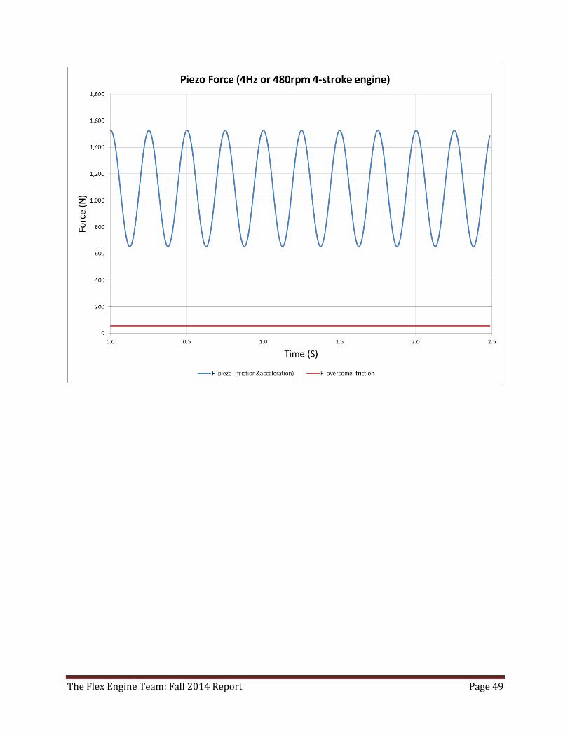
Lastly, a dynamic force model was carried out on Microsoft Excel. Accounting for the force of
acceleration created by the moving masses, as well as the frictional forces from above, required
force over time was calculated for at 4 Hz or a 480 RPM operating 4-stroke engine. Although
this is a relatively low RPM, it was never expected that the piezo amplifier purchased for this
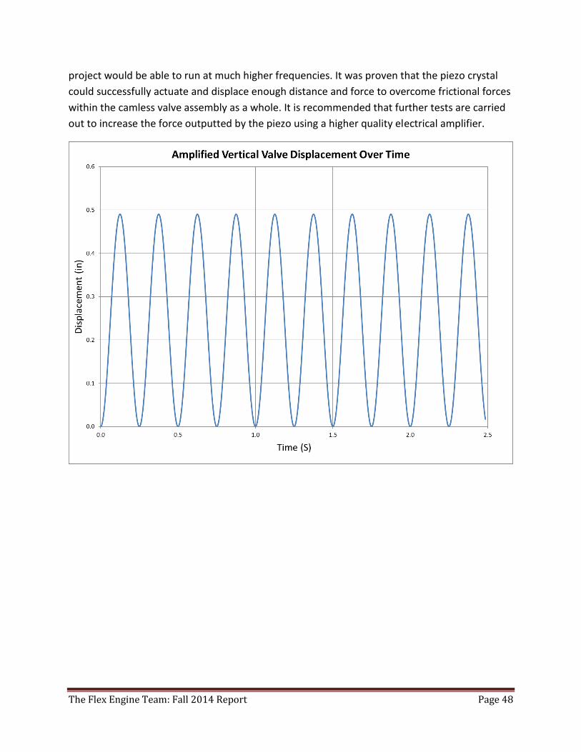
The Flex Engine Team: Fall 2014 Report Page 48
project would be able to run at much higher frequencies. It was proven that the piezo crystal
could successfully actuate and displace enough distance and force to overcome frictional forces
within the camless valve assembly as a whole. It is recommended that further tests are carried
out to increase the force outputted by the piezo using a higher quality electrical amplifier.
The Flex Engine Team: Fall 2014 Report Page 49
The Flex Engine Team: Fall 2014 Report Page 50
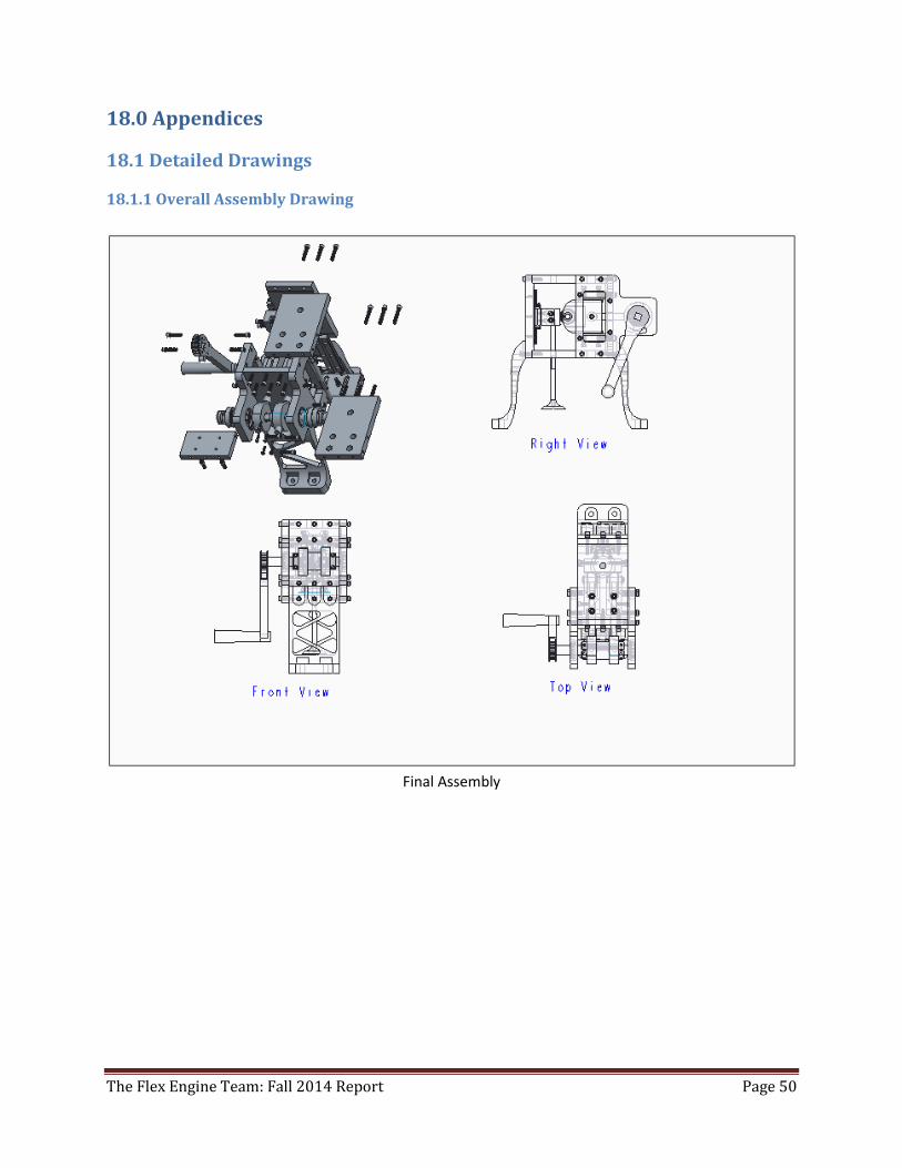
18.0 Appendices
18.1 Detailed Drawings
18.1.1 Overall Assembly Drawing
Final Assembly
The Flex Engine Team: Fall 2014 Report Page 51
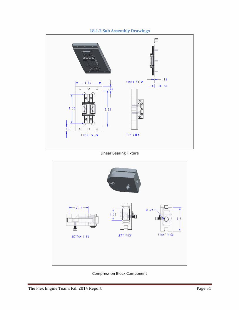
18.1.2 Sub Assembly Drawings
Linear Bearing Fixture
Compression Block Component
The Flex Engine Team: Fall 2014 Report Page 52
Wedge Fixture
18.1.3 Detailed Drawings
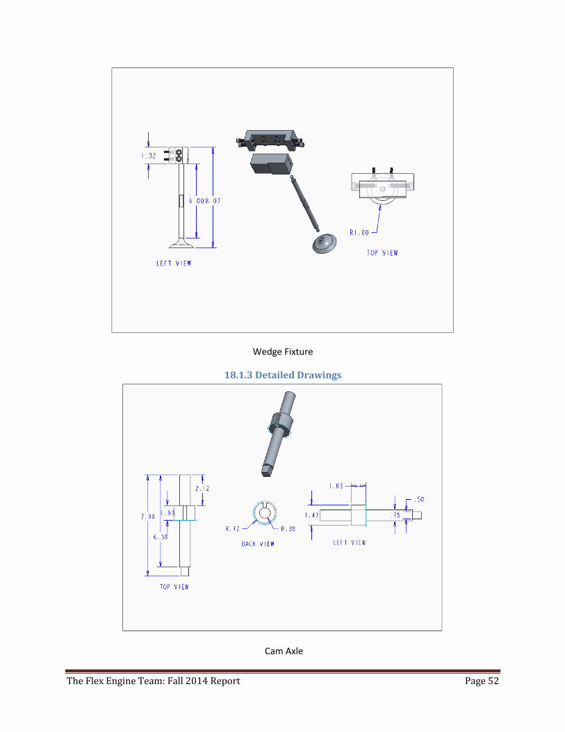
Cam Axle
The Flex Engine Team: Fall 2014 Report Page 53
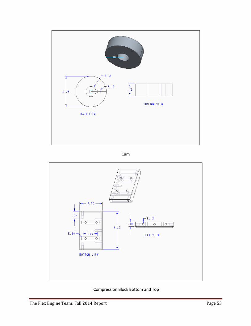
Cam
Compression Block Bottom and Top
The Flex Engine Team: Fall 2014 Report Page 54
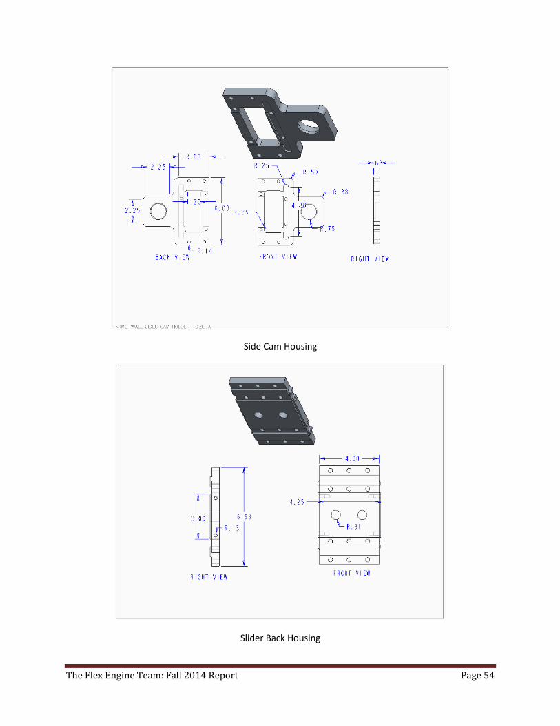
Side Cam Housing
Slider Back Housing
The Flex Engine Team: Fall 2014 Report Page 55
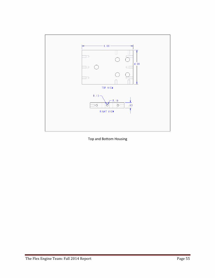
Top and Bottom Housing
The Flex Engine Team: Fall 2014 Report Page 56
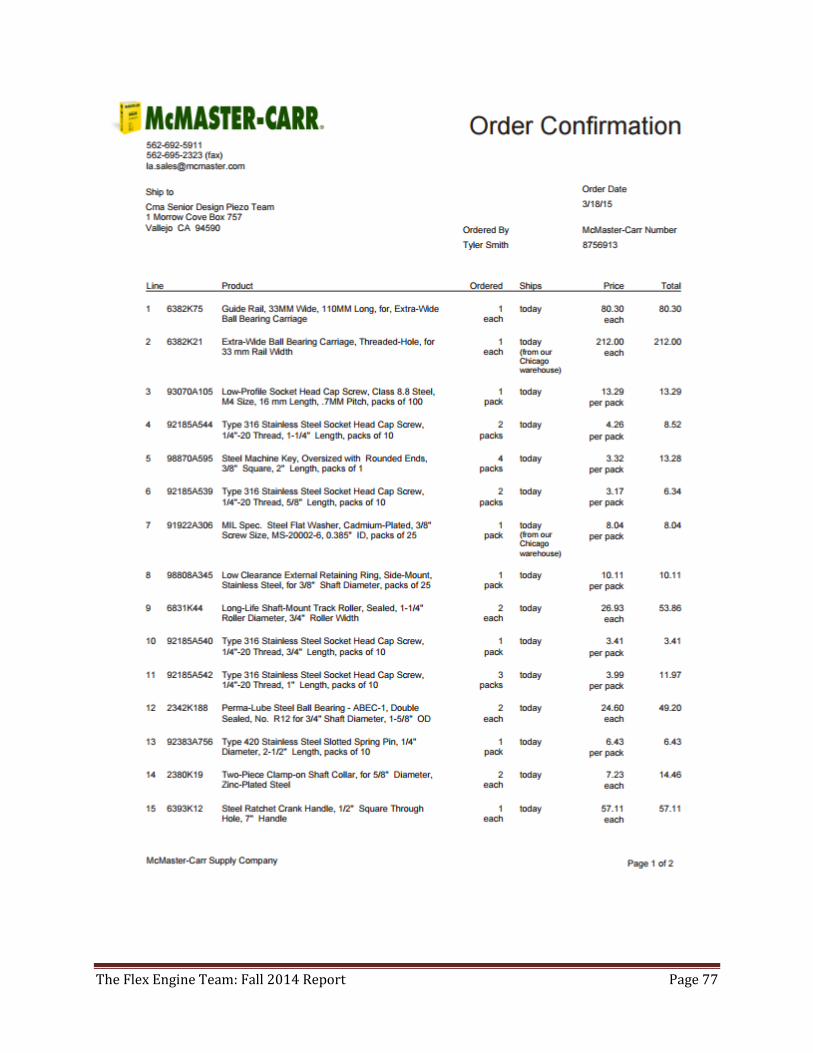
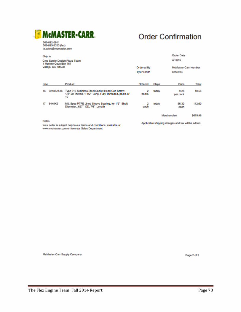
McMaster-Carr Parts
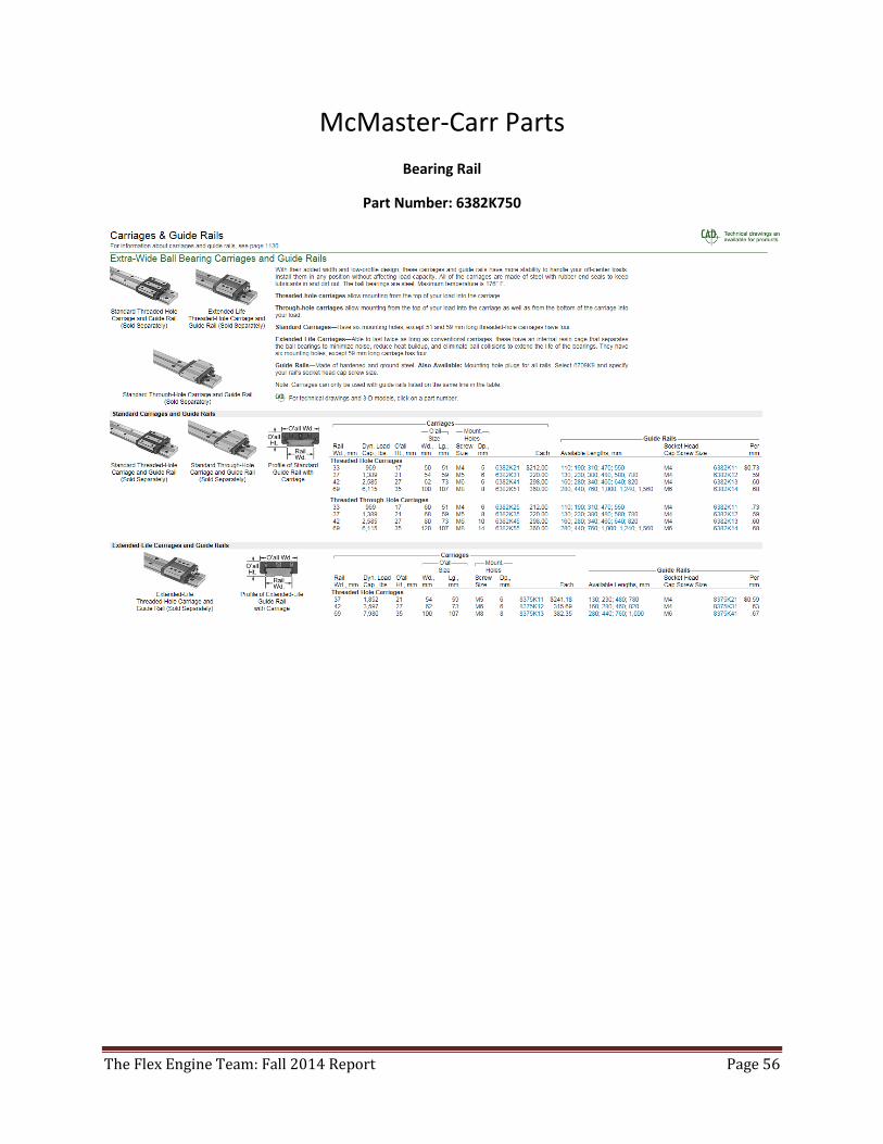
Bearing Rail
Part Number: 6382K750
The Flex Engine Team: Fall 2014 Report Page 57
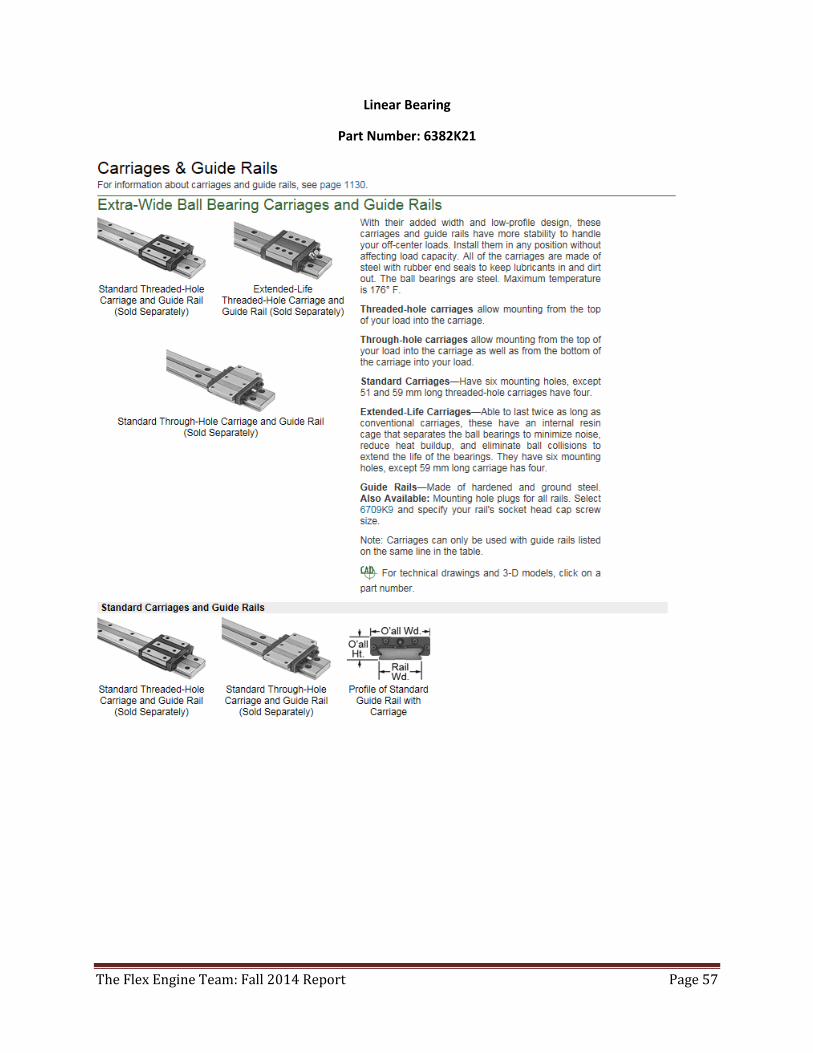
Linear Bearing
Part Number: 6382K21
The Flex Engine Team: Fall 2014 Report Page 58
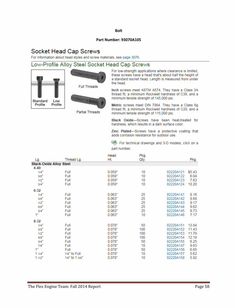
Bolt
Part Number: 93070A105
The Flex Engine Team: Fall 2014 Report Page 59
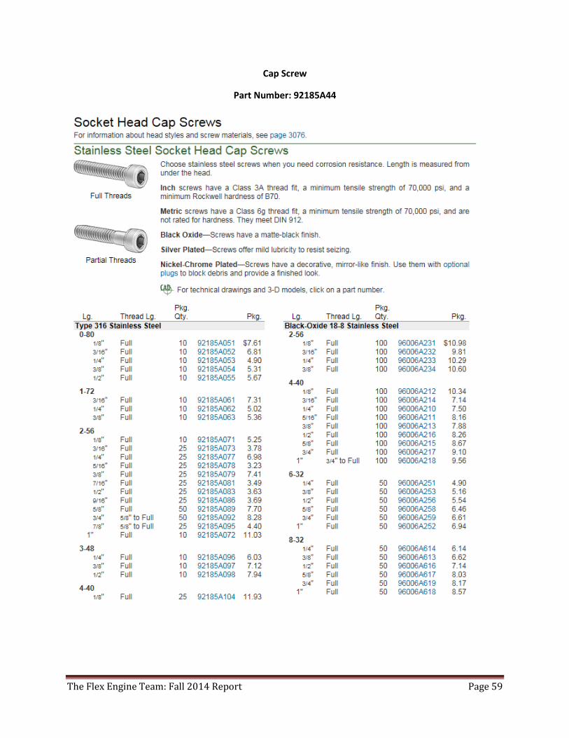
Cap Screw
Part Number: 92185A44
The Flex Engine Team: Fall 2014 Report Page 60
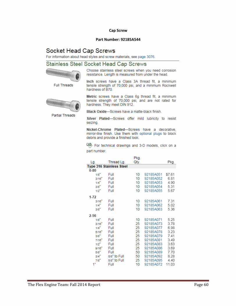
Cap Screw
Part Number: 92185A544
The Flex Engine Team: Fall 2014 Report Page 61
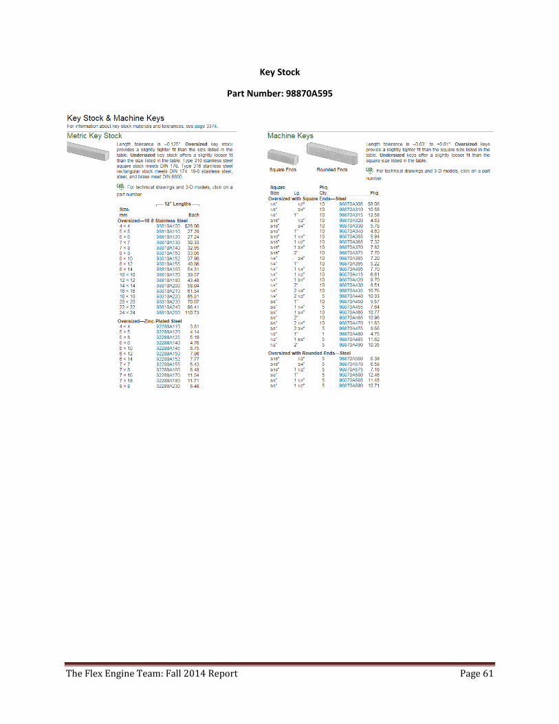
Key Stock
Part Number: 98870A595
The Flex Engine Team: Fall 2014 Report Page 62
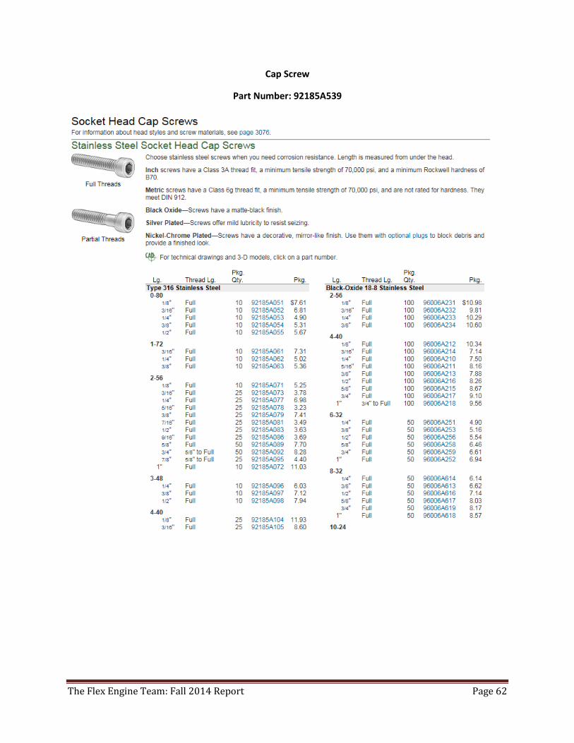
Cap Screw
Part Number: 92185A539
The Flex Engine Team: Fall 2014 Report Page 63
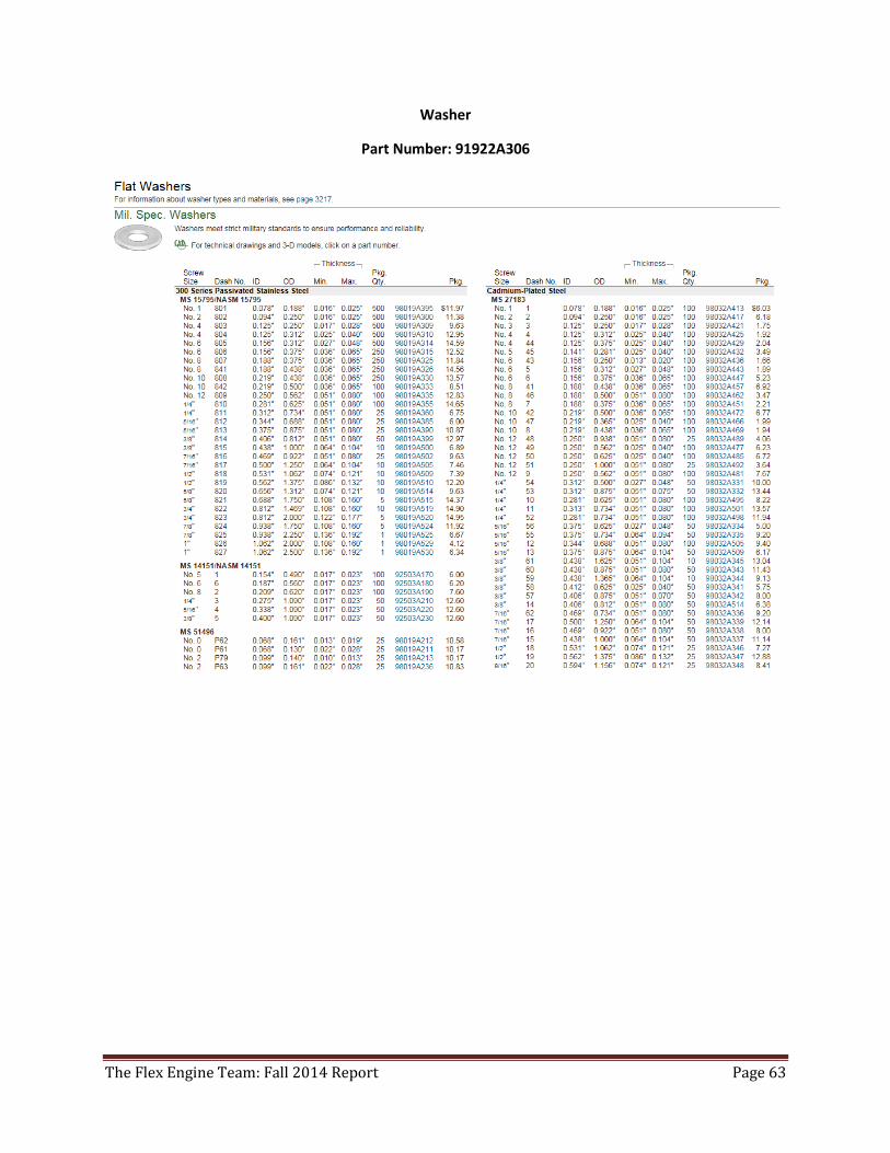
Washer
Part Number: 91922A306
The Flex Engine Team: Fall 2014 Report Page 64
C Clip
Part Number: 98808A345
The Flex Engine Team: Fall 2014 Report Page 65
Cam Follower
Part Number: 6831K140
The Flex Engine Team: Fall 2014 Report Page 66
Washer
Part Number: 91922A306
The Flex Engine Team: Fall 2014 Report Page 67
Cap Screw
Part Number: 92185A540
The Flex Engine Team: Fall 2014 Report Page 68
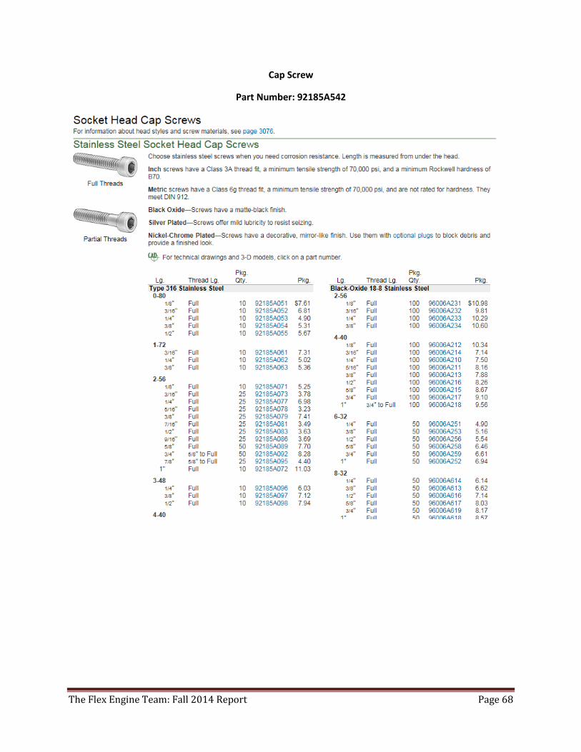
Cap Screw
Part Number: 92185A542
The Flex Engine Team: Fall 2014 Report Page 69
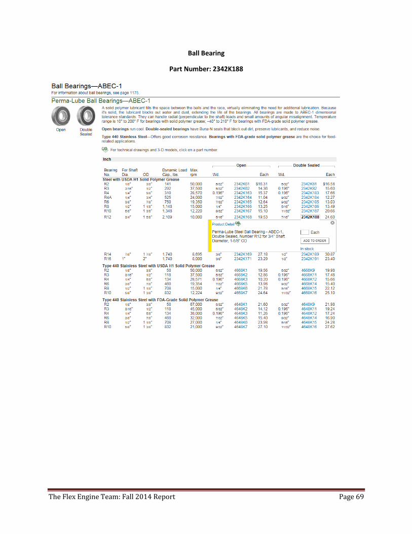
Ball Bearing
Part Number: 2342K188
The Flex Engine Team: Fall 2014 Report Page 70
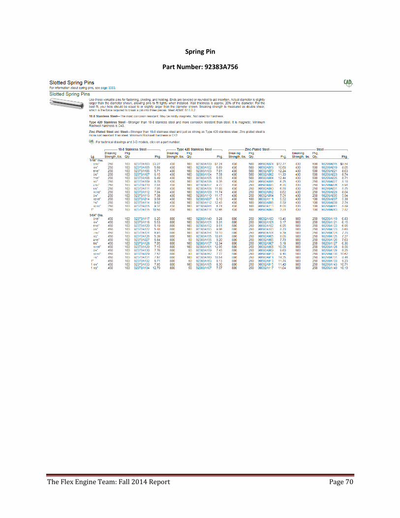
Spring Pin
Part Number: 92383A756
The Flex Engine Team: Fall 2014 Report Page 71
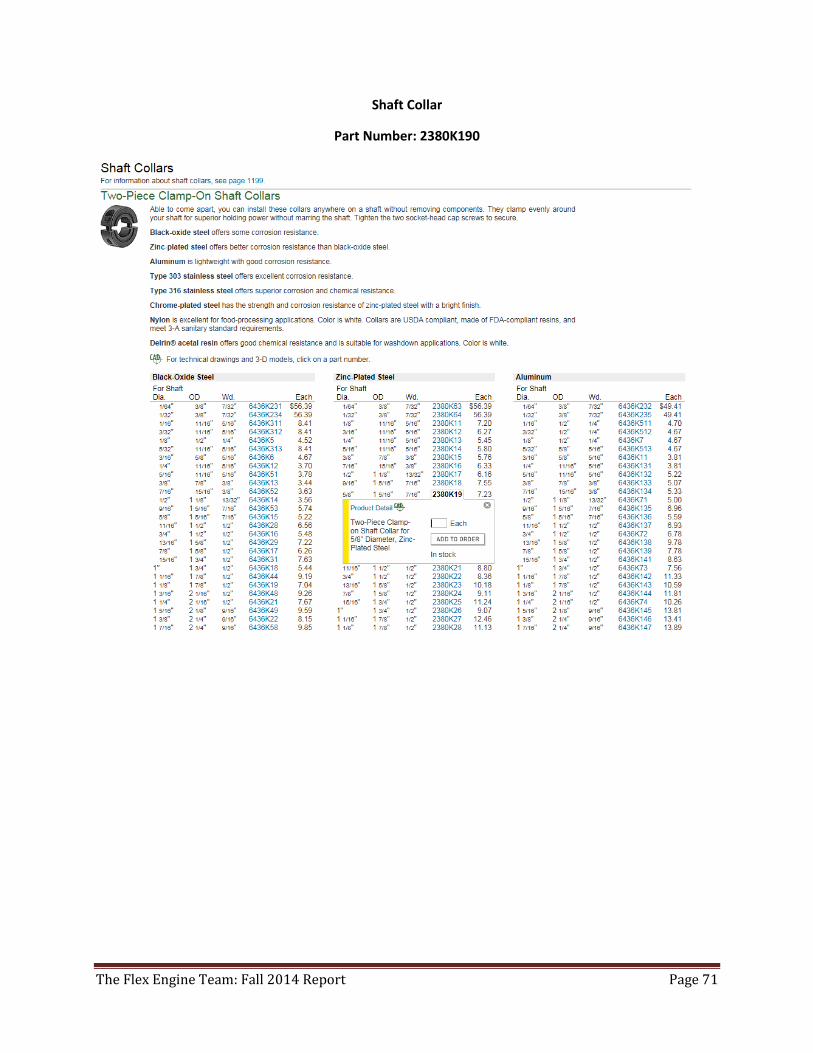
Shaft Collar
Part Number: 2380K190
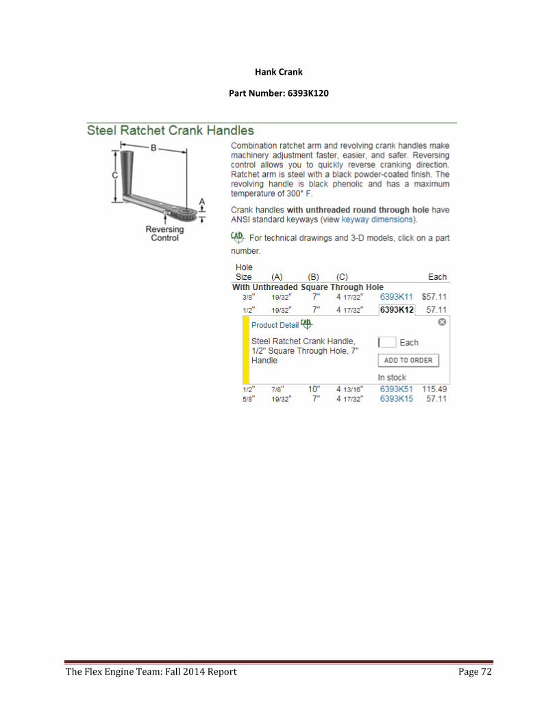
The Flex Engine Team: Fall 2014 Report Page 72
Hank Crank
Part Number: 6393K120
The Flex Engine Team: Fall 2014 Report Page 73
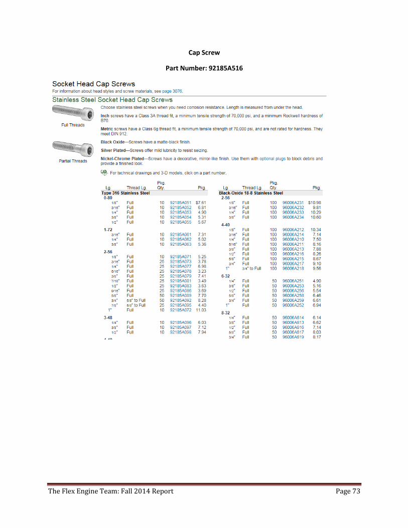
Cap Screw
Part Number: 92185A516
The Flex Engine Team: Fall 2014 Report Page 74
The Flex Engine Team: Fall 2014 Report Page 75
The Flex Engine Team: Fall 2014 Report Page 76
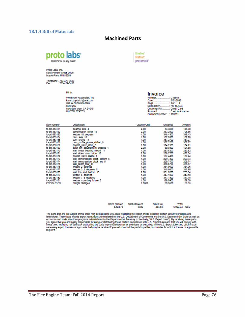
18.1.4 Bill of Materials
Machined Parts
The Flex Engine Team: Fall 2014 Report Page 77
The Flex Engine Team: Fall 2014 Report Page 78
The Flex Engine Team: Fall 2014 Report Page 79
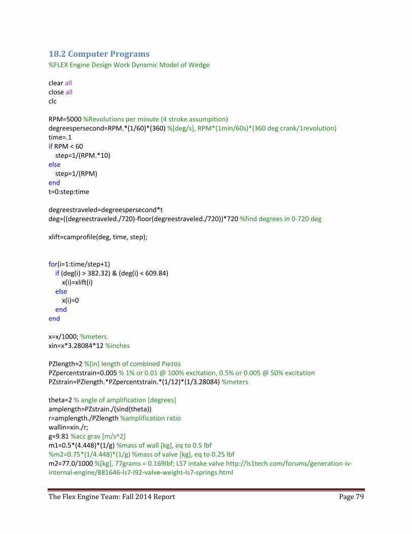
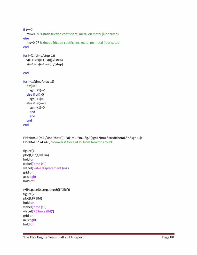
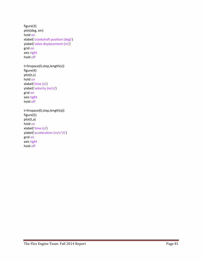
18.2 Computer Programs %FLEX Engine Design Work Dynamic Model of Wedge clear all close all clc RPM=5000 %Revolutions per minute (4 stroke assumpition) degreespersecond=RPM.*(1/60)*(360) %[deg/s], RPM*(1min/60s)*(360 deg crank/1revolution) time=.1 if RPM < 60 step=1/(RPM.*10) else step=1/(RPM) end t=0:step:time degreestraveled=degreespersecond*t deg=((degreestraveled./720)-floor(degreestraveled./720))*720 %find degrees in 0-720 deg xlift=camprofile(deg, time, step); for(i=1:time/step+1) if (deg(i) > 382.32) & (deg(i) < 609.84) x(i)=xlift(i) else x(i)=0 end end x=x/1000; %meters xin=x*3.28084*12 %inches PZlength=2 %[in] length of combined Piezos PZpercentstrain=0.005 % 1% or 0.01 @ 100% excitation, 0.5% or 0.005 @ 50% excitation PZstrain=PZlength.*PZpercentstrain.*(1/12)*(1/3.28084) %meters theta=2 % angle of amplification [degrees] amplength=PZstrain./(sind(theta)) r=amplength./PZlength %amplification ratio wallin=xin./r; g=9.81 %acc grav [m/s^2] m1=0.5*(4.448)*(1/g) %mass of wall [kg], eq to 0.5 lbf %m2=0.75*(1/4.448)*(1/g) %mass of valve [kg], eq to 0.25 lbf m2=77.0/1000 %[kg], 77grams = 0.169lbf; LS7 intake valve http://ls1tech.com/forums/generation-iv-internal-engine/881646-ls7-l92-valve-weight-ls7-springs.html
The Flex Engine Team: Fall 2014 Report Page 80
if t==0 mu=0.09 %static friction coefficient, metal on metal (lubricated) else mu=0.07 %kinetic friction coefficient, metal on metal (lubricated) end for i=(1:(time/step-1)) v(i+1)=(x(i+1)-x(i))./(step) a(i+1)=(v(i+1)-v(i))./(step) end for(i=1:(time/step-1)) if v(i)<0 sgn(i+1)=-1 else if v(i)>0 sgn(i+1)=1 else if v(i)==0 sgn(i+1)=0 end end end end FPZ=((m1+(m2./sind(theta))).*a)+mu.*m1.*g.*(sgn)./(mu.*cosd(theta).*r.*sgn+1); FPZlbf=FPZ./4.448; %converst force of PZ from Newtons to lbF figure(1) plot(t,xin,t,wallin) hold on xlabel('time (s)') ylabel('valve displacement (in)') grid on axis tight hold off t=linspace(0,step,length(FPZlbf)) figure(2) plot(t,FPZlbf) hold on xlabel('time (s)') ylabel('PZ force (lbf)') grid on axis tight hold off
The Flex Engine Team: Fall 2014 Report Page 81
figure(3) plot(deg, xin) hold on xlabel('crankshaft position (deg)') ylabel('valve displacement (in)') grid on axis tight hold off t=linspace(0,step,length(v)) figure(4) plot(t,v) hold on xlabel('time (s)') ylabel('velocity (m/s)') grid on axis tight hold off t=linspace(0,step,length(a)) figure(5) plot(t,a) hold on xlabel('time (s)') ylabel('acceleration (m/s^2)') grid on axis tight hold off
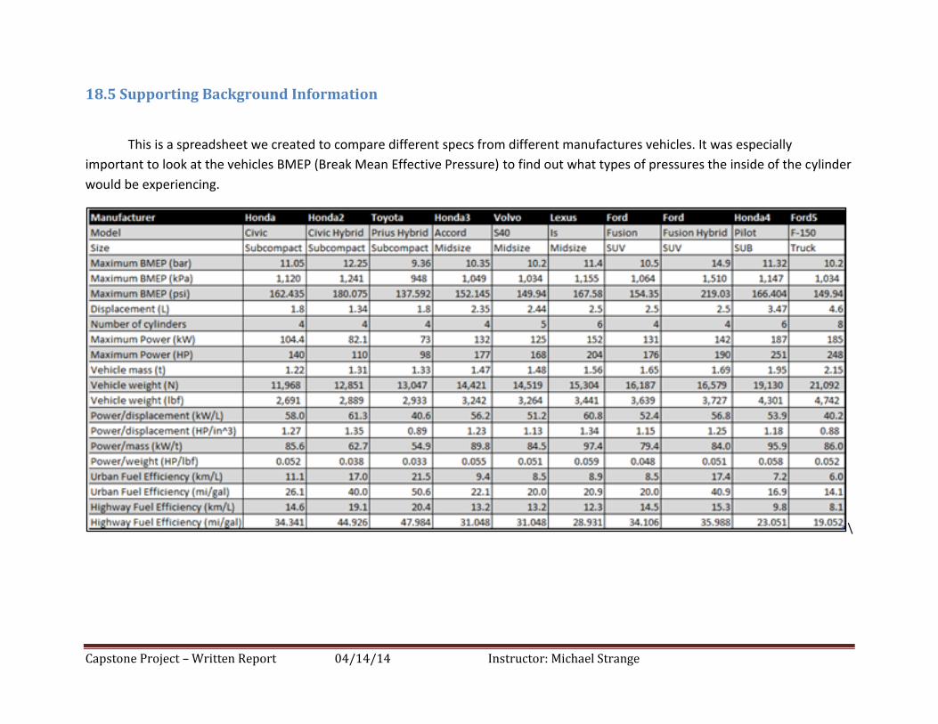
Capstone Project – Written Report 04/14/14 Instructor: Michael Strange
18.5 Supporting Background Information
This is a spreadsheet we created to compare different specs from different manufactures vehicles. It was especially
important to look at the vehicles BMEP (Break Mean Effective Pressure) to find out what types of pressures the inside of the cylinder
would be experiencing.
\
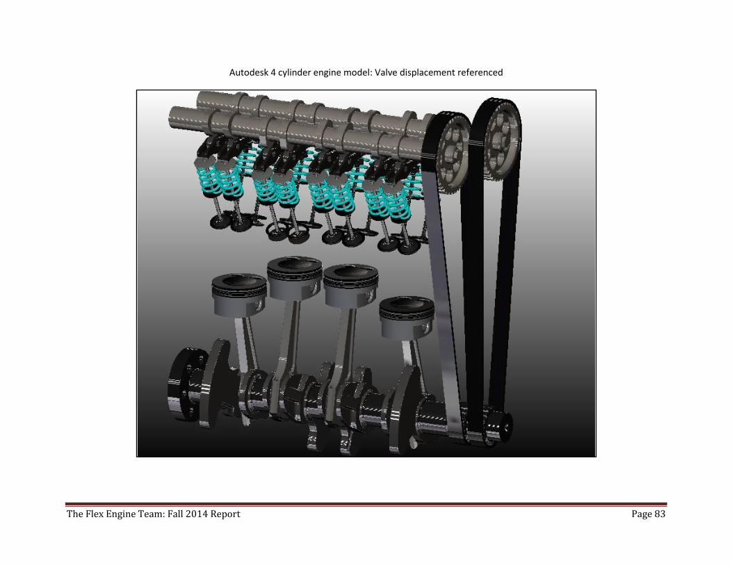
The Flex Engine Team: Fall 2014 Report Page 83
Autodesk 4 cylinder engine model: Valve displacement referenced
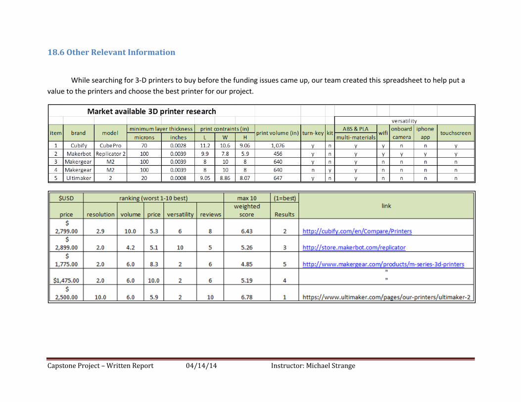
Capstone Project – Written Report 04/14/14 Instructor: Michael Strange
18.6 Other Relevant Information
While searching for 3-D printers to buy before the funding issues came up, our team created this spreadsheet to help put a
value to the printers and choose the best printer for our project.
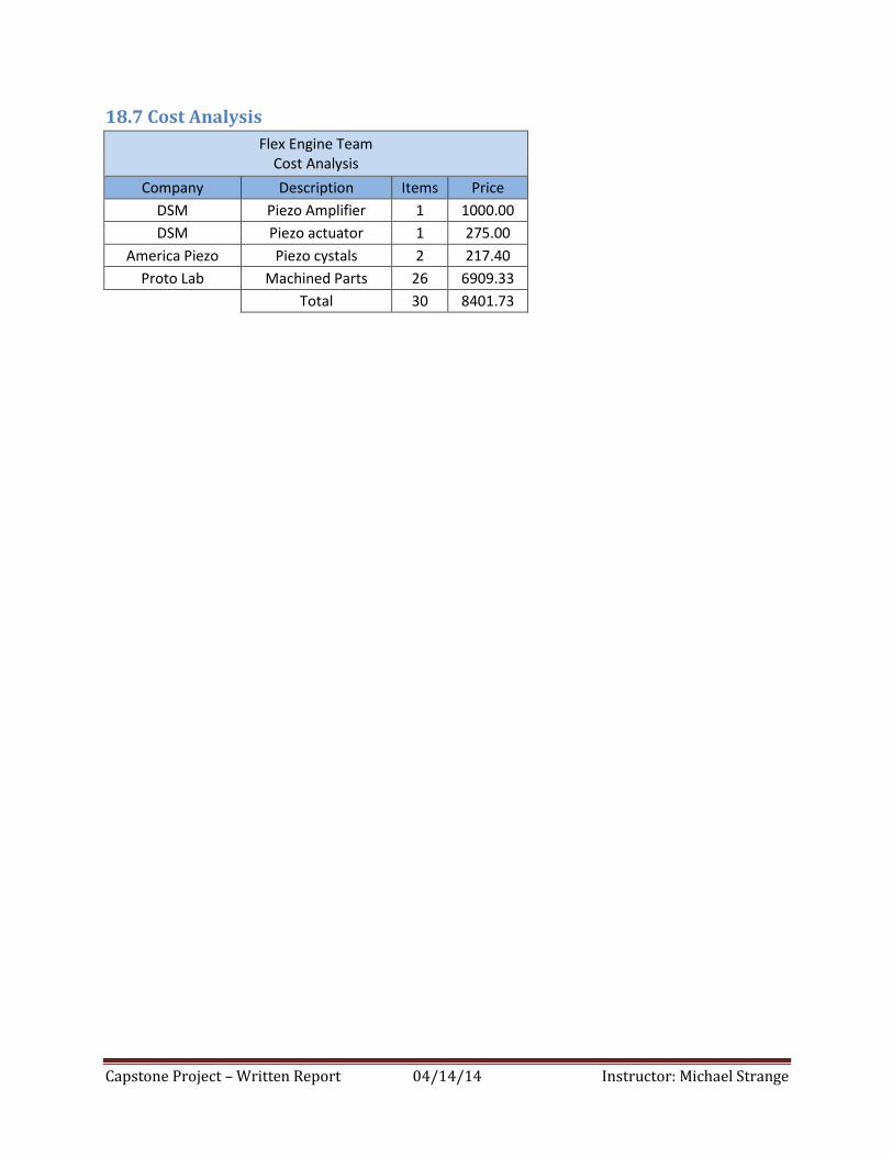
Capstone Project – Written Report 04/14/14 Instructor: Michael Strange
18.7 Cost Analysis
Flex Engine Team Cost Analysis
Company Description Items Price
DSM Piezo Amplifier 1 1000.00
DSM Piezo actuator 1 275.00
America Piezo Piezo cystals 2 217.40
Proto Lab Machined Parts 26 6909.33
Total 30 8401.73
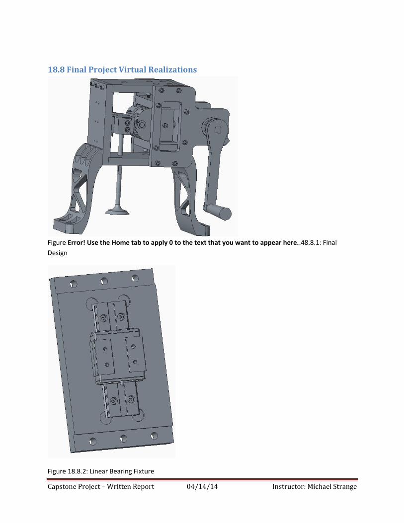
Capstone Project – Written Report 04/14/14 Instructor: Michael Strange
18.8 Final Project Virtual Realizations
Figure Error! Use the Home tab to apply 0 to the text that you want to appear here..48.8.1: Final
Design
Figure 18.8.2: Linear Bearing Fixture
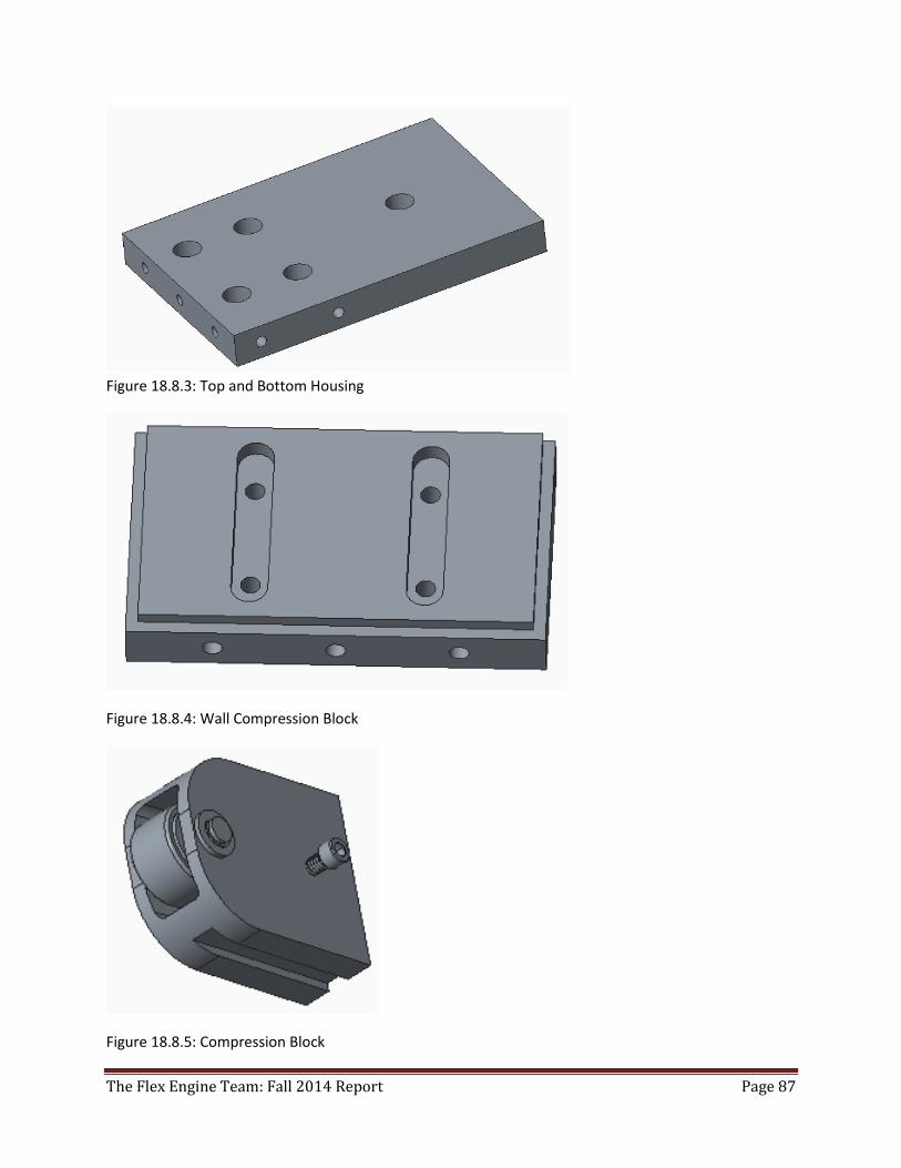
The Flex Engine Team: Fall 2014 Report Page 87
Figure 18.8.3: Top and Bottom Housing
Figure 18.8.4: Wall Compression Block
Figure 18.8.5: Compression Block
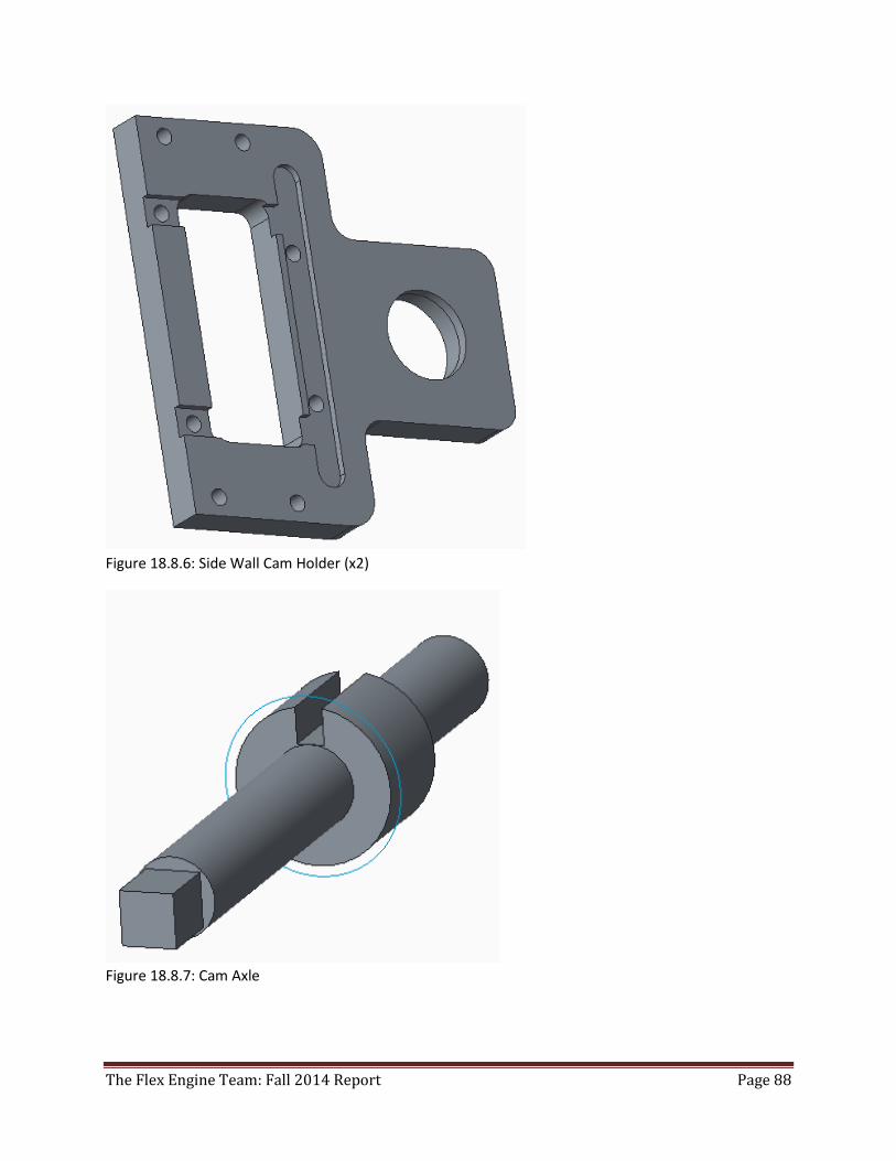
The Flex Engine Team: Fall 2014 Report Page 88
Figure 18.8.6: Side Wall Cam Holder (x2)
Figure 18.8.7: Cam Axle
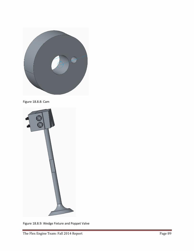
The Flex Engine Team: Fall 2014 Report Page 89
Figure 18.8.8: Cam
Figure 18.8.9: Wedge Fixture and Poppet Valve
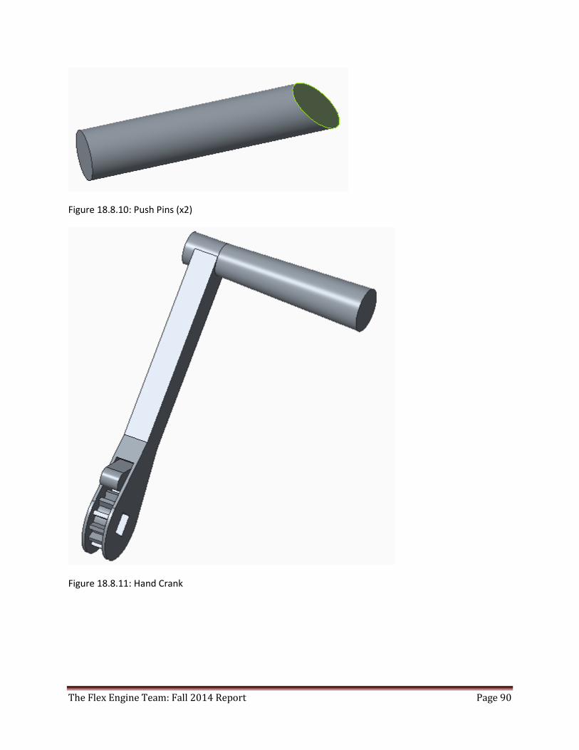
The Flex Engine Team: Fall 2014 Report Page 90
Figure 18.8.10: Push Pins (x2)
Figure 18.8.11: Hand Crank
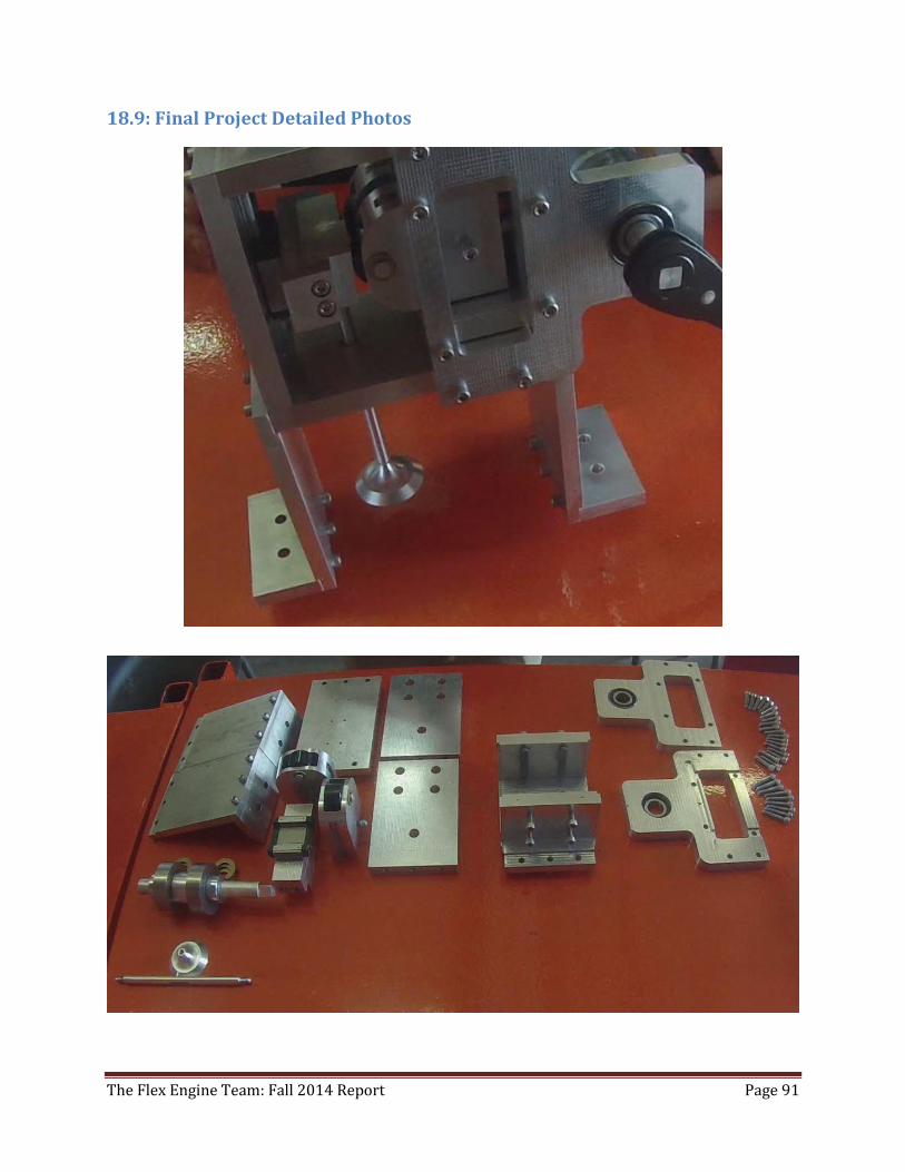
The Flex Engine Team: Fall 2014 Report Page 91
18.9: Final Project Detailed Photos
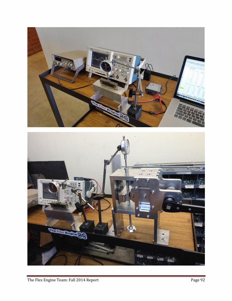
The Flex Engine Team: Fall 2014 Report Page 92