diaphragm pump dx200 - carlisle fluid technologies
TRANSCRIPT
EN
Service Manual
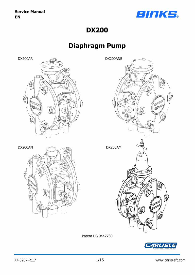
Diaphragm Pump
DX200
DX200ANB
DX200AM
DX200AR
DX200AN
Patent US 9447780
77-3207-R1.7 1/16 www.carlisleft.com
EN
D Smith Director of Sales (EMEA)
Machinery Directive 2006/42/EC
ATEX Directive 2014/34/EU
by complying with the following statutory documents and harmonized standards:
EN ISO 12100:2010 Safety of Machinery - General Principles for Design
EN 12621:+A1:2010 Machinery for the supply and circulation of coating materials under pressure - Safety
requirements
EN 1127-1:2011 Explosive atmospheres - Explosion prevention - Basic concepts
EN 13463-1:2009 Non electrical equipment for use in potentially explosive atmospheres - Basic methods and
requirements
EN 13463-5:2011 Non electrical equipment for use in potentially explosive atmospheres - Protection by
constructional safety "c"
Providing all conditions of safe use / installation stated within the product manuals have been
complied with and also installed in accordance with any applicable local codes of practice.
Signed for and on behalf of Carlisle Fluid
Technologies UK Ltd: 3/5/17 Bournemouth,BH11 9LH,UK
The object of the declaration described above is in conformity with the relevant Union
harmonisation legislation:
Product Description / Object of Declaration: Diaphragm Pumps - DX70, DX200, DX200-3 Bare pump and
packages
This Product is designed for use with: Solvent and Water based materials
Zone 1
Protection Level: II 2 G c X IIB T4
Notified body details and role: Element Materials Technology (0891)
Lodging of Technical file
This Declaration of conformity / incorporation
is issued under the sole responsibility of the
manufacturer:
Carlisle Fluid Technologies UK Ltd,
Ringwood Road,
Bournemouth, BH11 9LH. UK
Suitable for use in hazardous area:
EU Declaration of Conformity
77-3207-R1.7 2/16 www.carlisleft.com
EN
NEVER MODIFY THE EQUIPMENT. Do
not modify the equipment unless the
manufacturer provides written
approval.
KNOW WHERE AND HOW TO SHUT
OFF THE EQUIPMENT IN CASE OF AN
EMERGENCY.
INSPECT THE EQUIPMENT DAILY. Inspect the equipment for worn or
broken parts on a daily basis. Do not operate the equipment if you
are uncertain about its condition.
EQUIPMENT MISUSE HAZARD. Equipment misuse can cause the
equipment to rupture, malfunction or start unexpectedly and result in
serious injury.
NOISE LEVELS. The A-weighted sound level of pumping and spray
equipment may exceed 85 dB(A) depending on equipment settings.
Actual noise levels are available on request. It is recommended that
ear protection is worn at all times while equipment is in use.
PROJECTILE HAZARD. You may be
injured by venting liquids or gases that
are released under pressure, or flying
debris.
HIGH PRESSURE CONSIDERATION. High pressure can cause serious
injury. Relieve all pressure before servicing. Spray from the gun,
hose leaks or ruptured components can inject fluid into your body
and cause extremely serious injury.
NOTE
READ THE MANUAL. Before operating finishing equipment, read and
understand all safety, operation and maintenance information
provided in the operation manual.
AUTOMATIC EQUIPMENT. Automatic
equipment may start suddenly without
warning.
WEAR SAFETY GLASSES. Failure to wear safety glasses with side
shields could result in serious eye injury or blindness.
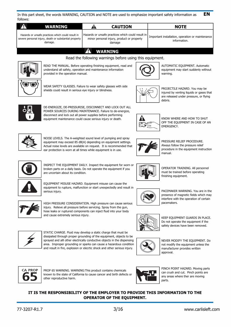
In this part sheet, the words WARNING, CAUTION and NOTE are used to emphasize important safety information as
follows:
WARNING
IT IS THE RESPONSIBILITY OF THE EMPLOYER TO PROVIDE THIS INFORMATION TO THE
OPERATOR OF THE EQUIPMENT.
PRESSURE RELIEF PROCEDURE.
Always follow the pressure relief
procedure in the equipment instruction
manual.
OPERATOR TRAINING. All personnel
must be trained before operating
finishing equipment.
PACEMAKER WARNING. You are in the
presence of magnetic fields which may
interfere with the operation of certain
pacemakers.
KEEP EQUIPMENT GUARDS IN PLACE.
Do not operate the equipment if the
safety devices have been removed.
PROP 65 WARNING. WARNING:This product contains chemicals
known to the state of California to cause cancer and birth defects or
other reproductive harm.
PINCH POINT HAZARD. Moving parts
can crush and cut. Pinch points are
any areas where ther are moving
parts.
DE-ENERGIZE, DE-PRESSURISE, DISCONNECT AND LOCK OUT ALL
POWER SOURCES DURING MAINTENANCE. Failure to de-energize,
disconnect and lock out all power supplies before performing
equipment maintenance could cause serious injury or death.
STATIC CHARGE. Fluid may develop a static charge that must be
dissipated through proper grounding of the equipment, objects to be
sprayed and alll other electrically conductive objects in the dispensing
area. Improper grounding or sparks can cause a hazardous condition
and result in fire, explosion or elecrtic shock and other serious injury.
CAUTION
Hazards or unsafe practices which could result in
severe personal injury, death or substantial property
damage.
Read the following warnings before using this equipment.
WARNING
Hazards or unsafe practices which could result in
minor personal injury, product or property
damage
Important installation, operation or maintenance
information.
77-3207-R1.7 3/16 www.carlisleft.com
EN
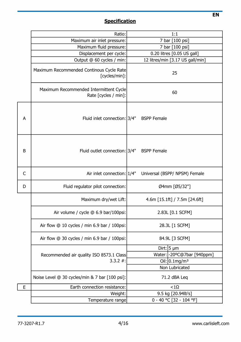
E
BSPP Female3/4"
3/4" BSPP Female
Universal (BSPP/ NPSM) Female1/4"
Oil:
B Fluid outlet connection:
0 - 40 °C [32 - 104 °F]
D
Dirt:
Earth connection resistance:
Noise Level @ 30 cycles/min & 7 bar [100 psi]:
4.6m [15.1ft] / 7.5m [24.6ft]
1:1
28.3L [1 SCFM]
0.1mg/m³
Water: -20ºC@7bar [940ppm]
71.2 dBA Leq
5 µm
Output @ 60 cycles / min: 12 litres/min [3.17 US gall/min]
2.83L [0.1 SCFM]
Air inlet connection:
Specification
7 bar [100 psi]
7 bar [100 psi]
A Fluid inlet connection:
Air volume / cycle @ 6.9 bar/100psi:
Displacement per cycle:
9.5 kg [20.94lb's]
Temperature range
Weight:
Recommended air quality ISO 8573.1 Class
3.3.2 #:
Non Lubricated
Air flow @ 30 cycles / min 6.9 bar / 100psi: 84.9L [3 SCFM]
Maximum fluid pressure:
0.20 litres [0.05 US gall]
Ratio:
Maximum air inlet pressure:
<1Ω
Air flow @ 10 cycles / min 6.9 bar / 100psi:
Maximum dry/wet Lift:
Maximum Recommended Continous Cycle Rate
[cycles/min]:25
Maximum Recommended Intermittent Cycle
Rate [cycles / min]:60
Ø4mm [Ø5/32"]
C
Fluid regulator pilot connection:
77-3207-R1.7 4/16 www.carlisleft.com
EN
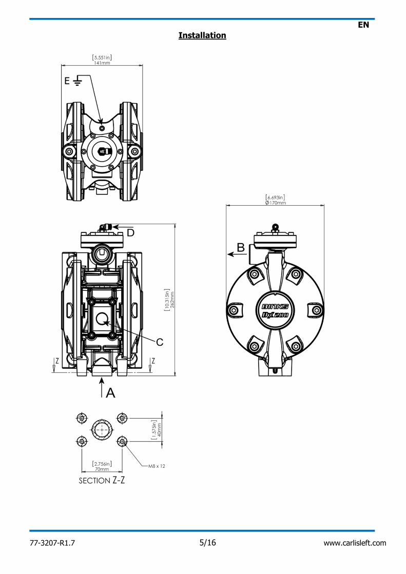
Installation
77-3207-R1.7 5/16 www.carlisleft.com
EN
The pump inlet pressure should nominally be 1 bar [15 psi] higher.
ATEX special conditions for safe use:
Earth connection, Binks Part No. 0114-011798
Attach flexible hoses to all connections. Connect a regulated air supply to the air connection.
Mount the pump securely and position the pump at a convenient height to allow for maintenance.
Set the air regulator pressure to give the desired fluid flow.
The pump must be earthed at all times. A resistance <1Ω when measuring with an ohm-meter at the
earth point
Pump Earthing
Fluid Regulator Air Pilot
Set the pump speed to a slow cycle rate and prime the pump to remove any air before increasing
pressure.
Prior To Use
This product should be flushed with a suitable compatible solvent prior to use.
77-3207-R1.7 6/16 www.carlisleft.com
EN
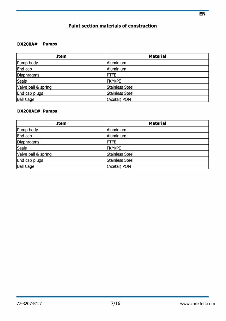
Pumps
Pumps
DX200A#
DX200AE#
Stainless Steel
Diaphragms PTFE
Seals FKM/PE
Valve ball & spring
End cap plugs
Stainless Steel
Ball Cage (Acetal) POM
Ball Cage
Aluminium
Pump body
End cap
Item Material
FKM/PE
Valve ball & spring Stainless Steel
Stainless Steel
Item Material
End cap plugs
Paint section materials of construction
Seals
Diaphragms PTFE
Aluminium
Pump body Aluminium
End cap
Aluminium
(Acetal) POM
77-3207-R1.7 7/16 www.carlisleft.com
EN
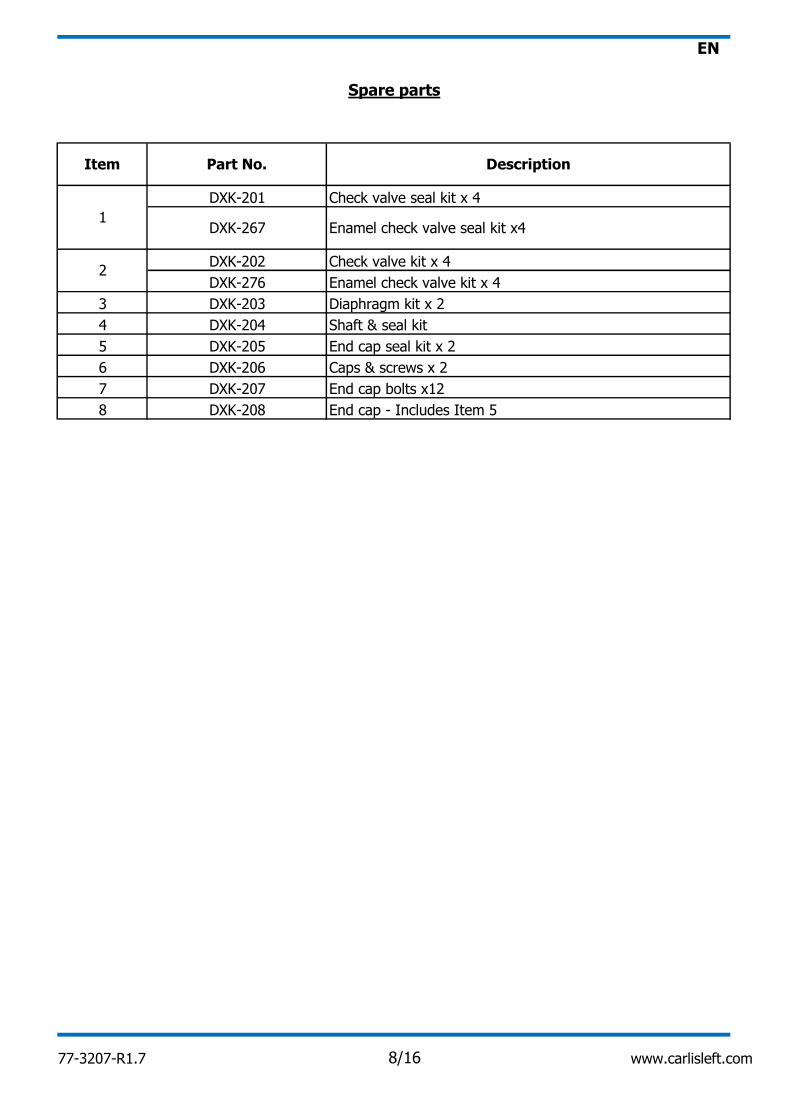
Item Part No. Description
Shaft & seal kit
8 DXK-208
Check valve kit x 4
3
DXK-201 Check valve seal kit x 4
DXK-203
1
2DXK-276 Enamel check valve kit x 4
DXK-204
Diaphragm kit x 2
DXK-202
Spare parts
4
End cap - Includes Item 5
End cap seal kit x 2
DXK-207
6 DXK-206 Caps & screws x 2
End cap bolts x12
5 DXK-205
7
Enamel check valve seal kit x4DXK-267
77-3207-R1.7 8/16 www.carlisleft.com
EN
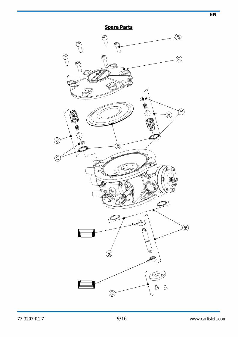
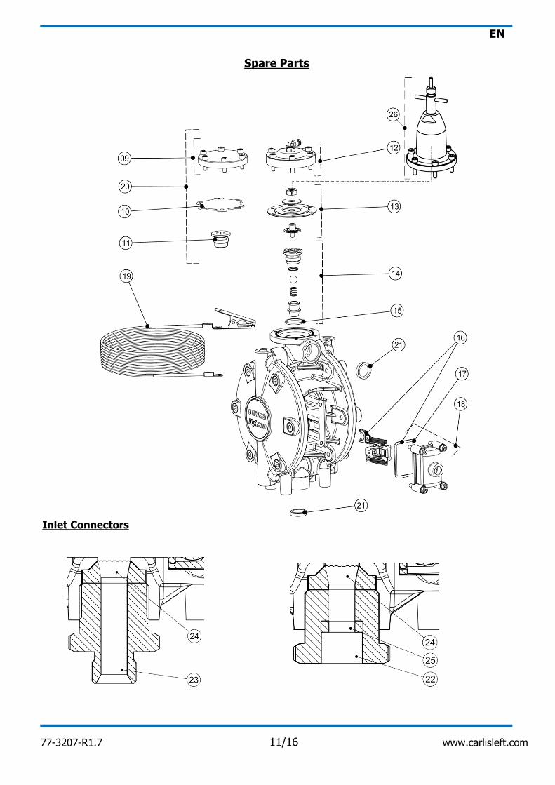
Spare Parts
77-3207-R1.7 9/16 www.carlisleft.com
EN
‡ =
22
Parts for non-fluid regulator model
26 DXK-247
Spare Parts
Diaphragm assembly
10 DXK-210
12 DXK-212 Regulator cap & screws
15
14
DXK-21923
24 DXK-220 Seal x 4
18 DXK-18 Cover, seal & screws
0114-011798
3/4" BSP(M) - 3/8" BSP(F) Connector with sealsDXK-218
Description
Blanking gasket x 4 ‡
DXK-209
Seal x 425
DXK-25 Gasket x 4
Air valve kit
17
16 DXK-216
DXK-215
Manual regulator control
Blanking plate & screws ‡
11 DXK-211 Insert ‡
Grounding cable 4m
20 DXK-217 Non-Regulated Conversion Kit
13
DXK-214
3/4" BSP(M) - 3/8" BSP(M) Connector with seals
Item Part No.
Regulator Insert
Gasket x 4
DXK-213
9
19
DXK-19
21 DXK-221 Seal x 4
77-3207-R1.7 10/16 www.carlisleft.com
EN
Spare Parts
Inlet Connectors
77-3207-R1.7 11/16 www.carlisleft.com
EN
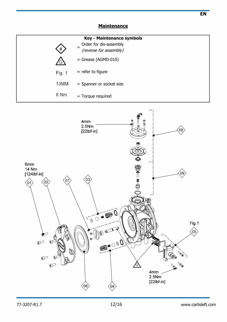
=Order for dis-assembly
(reverse for assembly)
=
=
=
refer to figure
Spanner or socket size
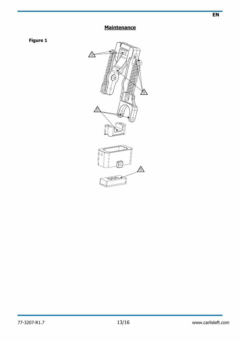
Maintenance
Torque required
Grease (AGMD-010)
=
Key - Maintenance symbols
77-3207-R1.7 12/16 www.carlisleft.com
EN
Figure 1
Maintenance
77-3207-R1.7 13/16 www.carlisleft.com
EN
-
-
-
-
-
-
a. a.
b. b.
a. a.
b.
b.
a. a.
b. b.
c. c.
d. d.
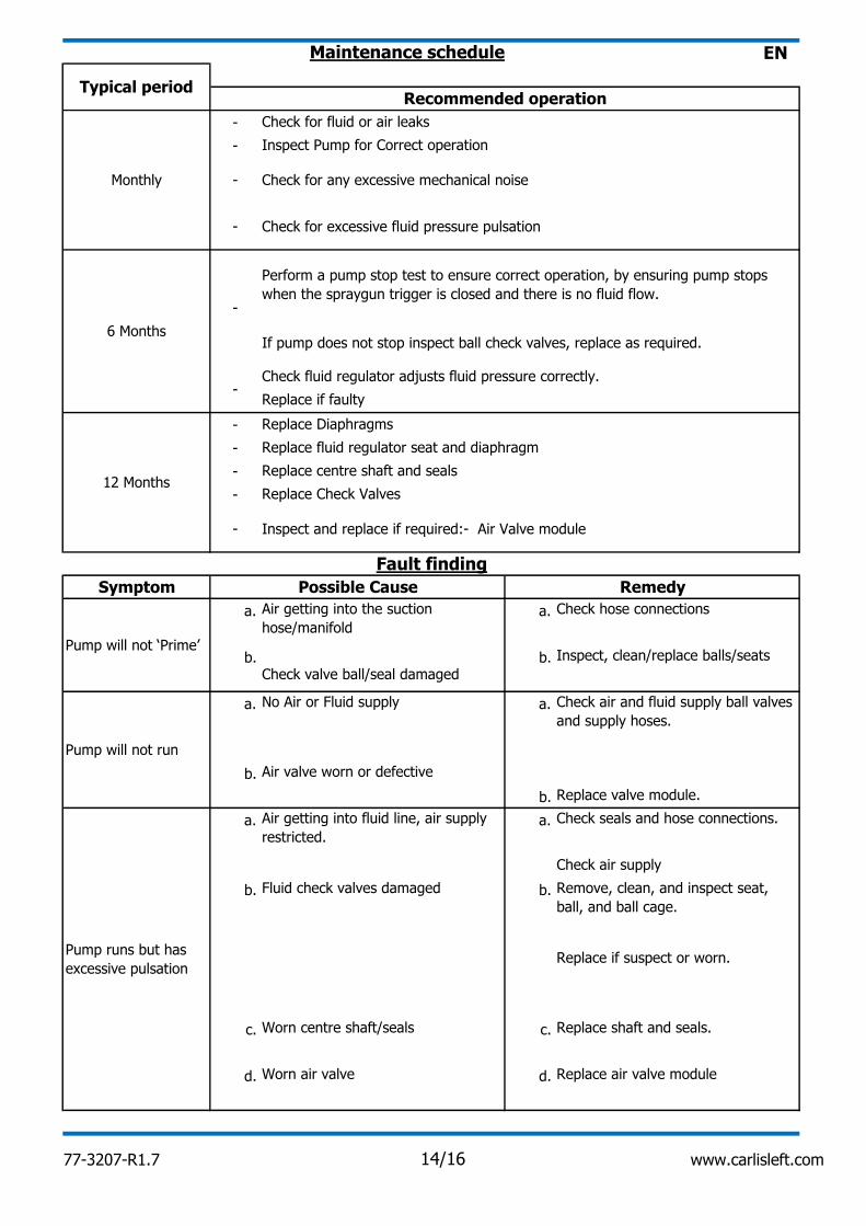
Maintenance schedule
6 Months
Fault finding
Recommended operation
Monthly
Check for fluid or air leaks
Inspect Pump for Correct operation
- Check for any excessive mechanical noise
- Check for excessive fluid pressure pulsation
-
Perform a pump stop test to ensure correct operation, by ensuring pump stops
when the spraygun trigger is closed and there is no fluid flow.
If pump does not stop inspect ball check valves, replace as required.
Typical period
-Check fluid regulator adjusts fluid pressure correctly.
Replace if faulty
12 Months
Replace Diaphragms
Replace fluid regulator seat and diaphragm
Replace centre shaft and seals
Replace Check Valves
- Inspect and replace if required:- Air Valve module
Symptom Possible Cause Remedy
Pump will not ‘Prime’
Air getting into the suction
hose/manifold
Check hose connections
Check valve ball/seal damaged
Inspect, clean/replace balls/seats
Pump will not run
No Air or Fluid supply Check air and fluid supply ball valves
and supply hoses.
Air valve worn or defective
Replace valve module.
Pump runs but has
excessive pulsation
Air getting into fluid line, air supply
restricted.
Check seals and hose connections.
Check air supply
Fluid check valves damaged Remove, clean, and inspect seat,
ball, and ball cage.
Replace if suspect or worn.
Worn centre shaft/seals Replace shaft and seals.
Worn air valve Replace air valve module
77-3207-R1.7 14/16 www.carlisleft.com
EN
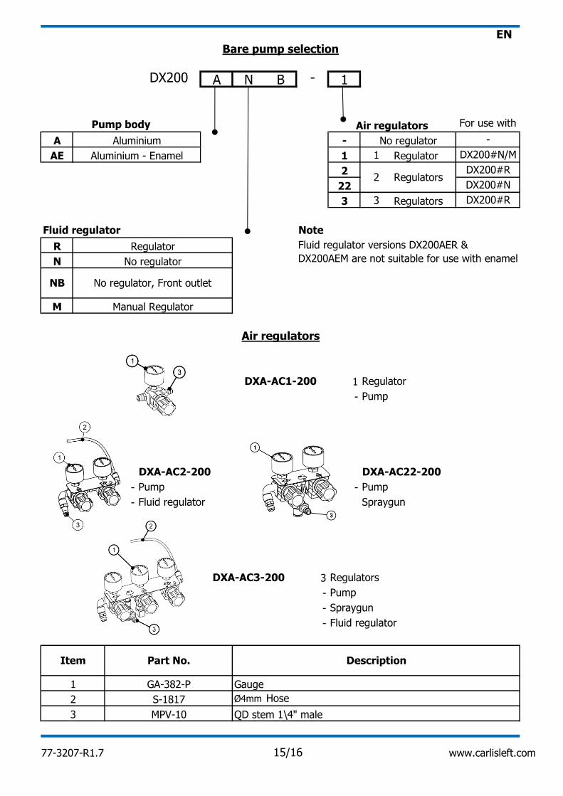
A N B - 1
A -
AE 1 1
2
22
3 3
R
N
M
1
-
- -
-
3
-
-
-
Ø4mm
Pump
Spraygun
Note
Fluid regulator versions DX200AER &
DX200AEM are not suitable for use with enamel
Bare pump selection
For use withAir regulatorsPump body
DX200
No regulator
DXA-AC2-200
No regulator
DX200#N/M
Aluminium
Aluminium - Enamel
DXA-AC1-200
Air regulators
Manual Regulator
-
DX200#R
DX200#N
Fluid regulator
NB No regulator, Front outlet
Fluid regulator
DXA-AC22-200
Pump
Spraygun
DX200#R
Gauge
Pump
3 MPV-10 QD stem 1\4" male
2 S-1817
Regulator
1 GA-382-P
Fluid regulator
Regulators
Hose
Regulators
Regulators
Regulator
2
Regulator
Pump
DXA-AC3-200
Item Part No. Description
77-3207-R1.7 15/16 www.carlisleft.com
EN
www.carlisleft.com.cn
Tel: +8621-3373 0108
Fax: +8621-3373 0308
www.ransburg.co.jp
Tel: 081 45 785 6421
Fax: 081 45 785 6517
www.carlisleft.com.au
Tel: +61 (0) 2 8525 7555
Fax: +61 (0) 2 8525 7575
Carlisle Fluid Technologies reserves the right to modify equipment specifications without prior notice.
DeVilbiss®, Ransburg®, MS®, BGK® and Binks® are registered trademarks of Carlisle Fluid
Technologies, Inc.
© 2017 Carlisle Fluid Technologies, Inc.
China Japan Australia
Binks is part of Carlisle Fluid Technologies, a global leader in innovative finishing technologies. For
technical assistance or to locate an authorized distributer, contact one of our international sales and
customer support locations below.
Mexico
www.carlisleft.com.mx
Tel: 011 52 55 5321 2300
Fax: 011 52 55 5310 4790
Brazil
www.devilbiss.com.br
Tel: +55 11 5641 2776
Fax: +55 11 5641 1256
Binks products are covered by Carlisle Fluid Technologies one year materials and workmanship
limited warranty. The use of any parts or accessories, from a source other than Carlisle Fluid
Technologies, will void all warranties. For specific warranty information please contact the
closest Carlisle Fluid Technologies location listed below.
WARRANTY POLICY
USA/Canada
All rights reserved.
www.binks.com
Toll Free Tel: 1-888-992-4657
Toll Free Fax: 1-888-246-5732
United Kingdom France Germany
www.carlisleft.eu
Tel: +44 (0)1202 571 111
Fax: +44 (0)1202 573 488
www.carlisleft.eu
Tel: +33(0)475 75 27 00
Fax: +33(0)475 75 27 59
www.carlisleft.eu
Tel: +49 (0) 6074 403 1
Fax: +49 (0) 6074 403 281
77-3207-R1.7 16/16 www.carlisleft.com