effect of boron on fatigue crack growth behavior in superalloy in 718 at rt and 650 °c
TRANSCRIPT
Materials Science and Engineering A 428 (2006) 1–11
Effect of boron on fatigue crack growth behavior insuperalloy IN 718 at RT and 650 ◦C
L. Xiao a, D.L. Chen b, M.C. Chaturvedi a,∗a Department of Mechanical and Manufacturing Engineering, University of Manitoba, Winnipeg, Man., Canada R3T 2N2
b Department of Mechanical and Industrial Engineering, Ryerson University, 350 Victoria Street, Toronto, Ont., Canada M5B 2K3
Received 27 April 2005; accepted 30 August 2005
Abstract
The effect of boron on the fatigue crack growth rate (FCGR) in Inconel 718 (IN 718) was studied at room temperature (RT) and 650 ◦C. Theresults showed that the addition of B improved the fatigue crack propagation resistance of IN 718. The higher the B concentration, higher wasthe fatigue threshold at 650 ◦C. While the FCGRs increased as the test temperature increased from RT to 650 ◦C in the Paris regime, a rapid dropin the FCGRs in the near-threshold regime and a higher fatigue threshold at 650◦ were observed due to the oxide-induced crack closure. Thefracture surfaces were observed to exhibit transgranular cracking with fatigue striations in specimens tested at RT, and a mixture of transgranularamaTmat©
K
1
waeaiaIaccrai
0d
nd intergranular cracking at 650 ◦C. The fracture mode changed from intergranular cracking to transgranular cracking and plastic deformationarks increased with increasing B concentration at 650 ◦C. The micromechanism of improvement in the fatigue crack growth resistance due to B
ddition was further studied via observations of crack growth path, fractography and TEM examination of the plastic zone ahead of the crack tip.he plastic deformation mode within the crack tip plastic zone was planar slip, along with twinning, on {1 1 1} planes. A crystallographic crackingodel was, thus, proposed on the basis of restricted slip or twinning. The improvement in the fatigue crack growth resistance in IN 718 due to B
ddition was mainly attributed to the increase in the grain boundary cohesion via minimizing the deteriorative effect of oxygen and the increase inhe resistance to the dislocation movement at the crack tip.
2006 Elsevier B.V. All rights reserved.
eywords: Inconel 718 superalloy; Fatigue crack growth rate; Fatigue threshold; Slip; Twin
. Introduction
Due to its superior mechanical properties and acceptableeldability, Inconel 718 (IN 718) is being extensively used
s a structural material in the aerospace industry for a vari-ty of applications, such as, gas turbine engine disks, bladesnd shafts, where the resistance to fatigue crack growth is anmportant design consideration [1,2]. Therefore, a considerablettention has been paid to the fatigue crack growth behavior ofN 718 superalloys [1–9]. These studies have demonstrated thatvariation in test temperature, composition and microstructure
an produce an order of magnitude of differences in the fatiguerack growth rates (FCGRs) in this alloy. Clavel and Pineau [3,4]eported that an increase in test temperature from 25 to 650 ◦C ordecrease in the test frequency at 550 ◦C produced a significant
ncrease in the FCGR, especially in the near-threshold regime. In
∗ Corresponding author. Tel.: +1 204 474 6675; fax: +1 204 261 6735.E-mail address: [email protected] (M.C. Chaturvedi).
addition, they examined the microstructure at the tip of fatiguecracks using transmission electron microscopy and showed thatIN 718 exhibits very inhomogeneous deformation within theplastic zone ahead of the crack tip. Microtwinning played animportant role in maintaining the plastic deformation within theplastic zone corresponding to the near-threshold FCGR regime[4]. Yuen and Roy [5] reported that the near-threshold FCGRdecreased and fatigue threshold value, �Kth, increased withincreasing grain size from 22 to 91 �m due to an increase inthe roughness-induced closure [5]. However, Osinkolu et al. [7]suggested that the FCGR in IN 718 is insensitive to the grainsize in air at 650 ◦C. James and Mills [1,8,9] studied the FCGRin weldments of IN 718 and reported that FCGRs in weldedspecimens were higher than those observed in wrought speci-mens due to the presence of residual stresses in the as-weldedcondition.
Although the FCGR in IN 718 has been extensively stud-ied, relatively little is known about the effect of boron on thefatigue crack growth behavior. The presence of boron in super-alloys and weld metal can have a significant effect on their
921-5093/$ – see front matter © 2006 Elsevier B.V. All rights reserved.
oi:10.1016/j.msea.2005.08.206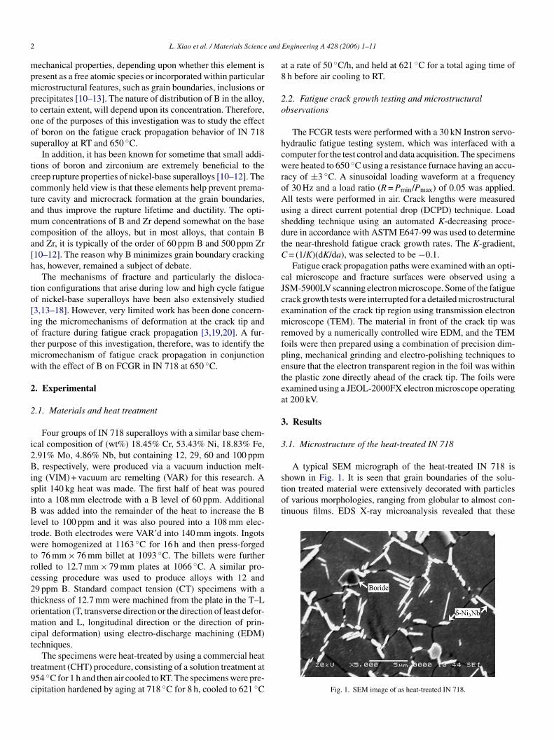
2 L. Xiao et al. / Materials Science and Engineering A 428 (2006) 1–11
mechanical properties, depending upon whether this element ispresent as a free atomic species or incorporated within particularmicrostructural features, such as grain boundaries, inclusions orprecipitates [10–13]. The nature of distribution of B in the alloy,to certain extent, will depend upon its concentration. Therefore,one of the purposes of this investigation was to study the effectof boron on the fatigue crack propagation behavior of IN 718superalloy at RT and 650 ◦C.
In addition, it has been known for sometime that small addi-tions of boron and zirconium are extremely beneficial to thecreep rupture properties of nickel-base superalloys [10–12]. Thecommonly held view is that these elements help prevent prema-ture cavity and microcrack formation at the grain boundaries,and thus improve the rupture lifetime and ductility. The opti-mum concentrations of B and Zr depend somewhat on the basecomposition of the alloys, but in most alloys, that contain Band Zr, it is typically of the order of 60 ppm B and 500 ppm Zr[10–12]. The reason why B minimizes grain boundary crackinghas, however, remained a subject of debate.
The mechanisms of fracture and particularly the disloca-tion configurations that arise during low and high cycle fatigueof nickel-base superalloys have been also extensively studied[3,13–18]. However, very limited work has been done concern-ing the micromechanisms of deformation at the crack tip andof fracture during fatigue crack propagation [3,19,20]. A fur-ther purpose of this investigation, therefore, was to identify themw
2
2
i2BisiBltwtrc2tomct
t9c
at a rate of 50 ◦C/h, and held at 621 ◦C for a total aging time of8 h before air cooling to RT.
2.2. Fatigue crack growth testing and microstructuralobservations
The FCGR tests were performed with a 30 kN Instron servo-hydraulic fatigue testing system, which was interfaced with acomputer for the test control and data acquisition. The specimenswere heated to 650 ◦C using a resistance furnace having an accu-racy of ±3 ◦C. A sinusoidal loading waveform at a frequencyof 30 Hz and a load ratio (R = Pmin/Pmax) of 0.05 was applied.All tests were performed in air. Crack lengths were measuredusing a direct current potential drop (DCPD) technique. Loadshedding technique using an automated K-decreasing proce-dure in accordance with ASTM E647-99 was used to determinethe near-threshold fatigue crack growth rates. The K-gradient,C = (1/K)(dK/da), was selected to be −0.1.
Fatigue crack propagation paths were examined with an opti-cal microscope and fracture surfaces were observed using aJSM-5900LV scanning electron microscope. Some of the fatiguecrack growth tests were interrupted for a detailed microstructuralexamination of the crack tip region using transmission electronmicroscope (TEM). The material in front of the crack tip wasremoved by a numerically controlled wire EDM, and the TEMfoils were then prepared using a combination of precision dim-petea
3
3
stot
icromechanism of fatigue crack propagation in conjunctionith the effect of B on FCGR in IN 718 at 650 ◦C.
. Experimental
.1. Materials and heat treatment
Four groups of IN 718 superalloys with a similar base chem-cal composition of (wt%) 18.45% Cr, 53.43% Ni, 18.83% Fe,.91% Mo, 4.86% Nb, but containing 12, 29, 60 and 100 ppm, respectively, were produced via a vacuum induction melt-
ng (VIM) + vacuum arc remelting (VAR) for this research. Aplit 140 kg heat was made. The first half of heat was pourednto a 108 mm electrode with a B level of 60 ppm. Additional
was added into the remainder of the heat to increase the Bevel to 100 ppm and it was also poured into a 108 mm elec-rode. Both electrodes were VAR’d into 140 mm ingots. Ingotsere homogenized at 1163 ◦C for 16 h and then press-forged
o 76 mm × 76 mm billet at 1093 ◦C. The billets were furtherolled to 12.7 mm × 79 mm plates at 1066 ◦C. A similar pro-essing procedure was used to produce alloys with 12 and9 ppm B. Standard compact tension (CT) specimens with ahickness of 12.7 mm were machined from the plate in the T–Lrientation (T, transverse direction or the direction of least defor-ation and L, longitudinal direction or the direction of prin-
ipal deformation) using electro-discharge machining (EDM)echniques.
The specimens were heat-treated by using a commercial heatreatment (CHT) procedure, consisting of a solution treatment at54 ◦C for 1 h and then air cooled to RT. The specimens were pre-ipitation hardened by aging at 718 ◦C for 8 h, cooled to 621 ◦C
ling, mechanical grinding and electro-polishing techniques tonsure that the electron transparent region in the foil was withinhe plastic zone directly ahead of the crack tip. The foils werexamined using a JEOL-2000FX electron microscope operatingt 200 kV.
. Results
.1. Microstructure of the heat-treated IN 718
A typical SEM micrograph of the heat-treated IN 718 ishown in Fig. 1. It is seen that grain boundaries of the solu-ion treated material were extensively decorated with particlesf various morphologies, ranging from globular to almost con-inuous films. EDS X-ray microanalysis revealed that these
Fig. 1. SEM image of as heat-treated IN 718.
L. Xiao et al. / Materials Science and Engineering A 428 (2006) 1–11 3
Fig. 2. TEM dark field image of heat-treated IN 718 in [1 0 0] orientation takenwith [1 1 0] reflection, showing the presence of �′′ and �′ precipitates.
particles were � (Ni3Nb) phase. Some boron containing precipi-tate particles were observed at grain boundaries, as indicatedby an arrow in Fig. 1, and an evidence of segregation of Bon grain boundaries of IN 718 superalloy was observed byone of the authors by SIMS analysis in an earlier studies onthe weldability of IN 718 [21,22]. TEM examination showedthat the aged IN 718 is precipitation strengthened primarilyby �′′ precipitates, which has a Ni3Nb based DO22 orderedbody-centered tetragonal structure. A typical dark field TEMmicrograph taken with (1 1 0) �′′ reflection is presented in Fig. 2.It shows the presence of disc-shaped �′′ particles with a sizeof about 30 nm in diameter and 5 nm in thickness, which havethe following cube–cube relationship with the parent fcc �matrix: [0 0 1]�′′ ||〈0 0 1〉� and {1 0 0}�′′ ||{1 0 0}�, as has beenalso observed by others [23–27]. In addition, some spherical-shaped �′ precipitates of approximately 5 nm in diameter werealso observed in the dark field images obtained with (1 1 0)reflection.
3.2. Effect of boron on the fatigue crack growth rate at RTand 650 ◦C
The FCGRs, da/dN, obtained at RT, as a function of the stressintensity factor range, �K, are shown in Fig. 3 for the four IN718 alloys with different concentrations of B. It is seen that theattrta�
w�
Ftctf
Fig. 3. Influence of boron concentration on the fatigue crack growth behaviorof IN 718 at RT.
tested at RT, as indicated by a continuous decrease in �K valueswith decreasing FCGR (Fig. 3).
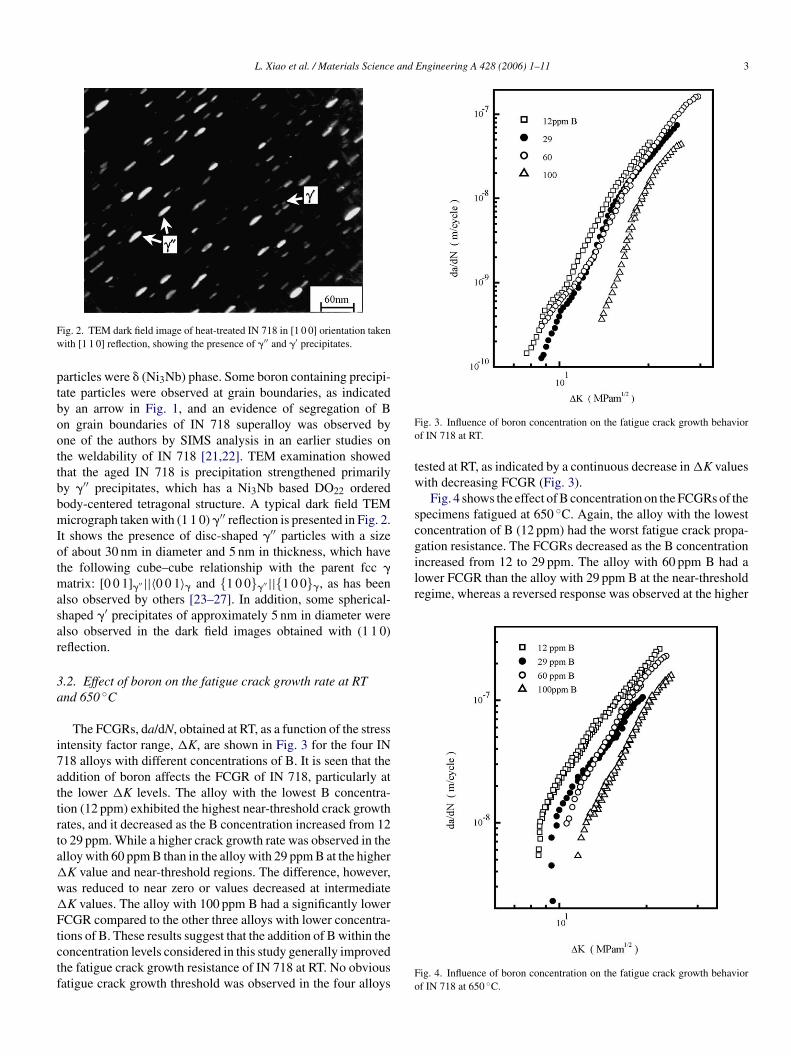
Fig. 4 shows the effect of B concentration on the FCGRs of thespecimens fatigued at 650 ◦C. Again, the alloy with the lowestconcentration of B (12 ppm) had the worst fatigue crack propa-gation resistance. The FCGRs decreased as the B concentrationincreased from 12 to 29 ppm. The alloy with 60 ppm B had alower FCGR than the alloy with 29 ppm B at the near-thresholdregime, whereas a reversed response was observed at the higher
Fo
ddition of boron affects the FCGR of IN 718, particularly athe lower �K levels. The alloy with the lowest B concentra-ion (12 ppm) exhibited the highest near-threshold crack growthates, and it decreased as the B concentration increased from 12o 29 ppm. While a higher crack growth rate was observed in thelloy with 60 ppm B than in the alloy with 29 ppm B at the higherK value and near-threshold regions. The difference, however,as reduced to near zero or values decreased at intermediateK values. The alloy with 100 ppm B had a significantly lowerCGR compared to the other three alloys with lower concentra-
ions of B. These results suggest that the addition of B within theoncentration levels considered in this study generally improvedhe fatigue crack growth resistance of IN 718 at RT. No obviousatigue crack growth threshold was observed in the four alloys
ig. 4. Influence of boron concentration on the fatigue crack growth behaviorf IN 718 at 650 ◦C.
4 L. Xiao et al. / Materials Science and Engineering A 428 (2006) 1–11
Table 1Paris parameters of IN 718 with different concentrations of B at RT and 650 ◦C
Alloys B concentration(ppm)
Paris law
RT 650 ◦C
12 12 da/dN = 5 × 10⁻¹⁶
�K6.18da/dN = 1 × 10⁻¹¹
�K3.27
29 29 da/dN = 2 × 10⁻¹⁶
�K6.27da/dN = 9 × 10⁻¹²
�K3.17
60 60 da/dN = 1 × 10⁻¹⁵
�K5.62da/dN = 1 × 10⁻¹²
�K3.99
100 100 da/dN = 2 × 10⁻¹⁹
�K8.20da/dN = 1 × 10⁻¹³
�K4.48
�K values, thus causing a cross-over of FCGR curves betweenthe alloys with 29 and 60 ppm B. The best fatigue crack growthresistance was again observed in the alloy with 100 ppm B. Itis evident that the B addition significantly enhanced the fatiguecrack growth resistance of IN 718 tested at 650 ◦C as well. Inaddition, a rapid drop in the FCGRs in the near-threshold regimewas observed in all the four alloys tested, as shown in Fig. 4,indicating the presence of a fatigue crack growth threshold.
The relationship between the da/dN and �K in the interme-diate crack propagation regime for the specimen fatigued at RTand 650 ◦C may be expressed by the Paris law, as illustratedin Table 1. A list of fatigue crack propagation threshold valuesobtained with different B concentrations and test temperaturesis given in Table 2. Since the FCGR decreased continuouslywith decreasing �K value at RT (Fig. 3), the fatigue crack prop-agation threshold was defined as the �K value correspondingto a growth rate of ∼10−10 m/cycle. The fatigue threshold at650 ◦C was well defined as the �K value corresponding to thesharp decrease in the FCGR (Fig. 4). As seen from Table 2, thehigher the B concentration the higher was the fatigue thresholdat 650 ◦C. The fatigue threshold was observed to be higher at650 ◦C than at RT.
3.3. Effect of test temperature on the fatigue crack growthrate
aFtbtr
TFR
A
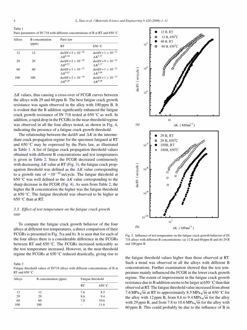
Fig. 5. Influence of test temperature on the fatigue crack growth behavior of IN718 alloys with different B concentrations: (a) 12 B and 60 ppm B and (b) 29 Band 100 ppm B.
the fatigue threshold values higher than those observed at RT.Such a trend was observed in all the alloys with different Bconcentrations. Further examination showed that the test tem-perature mainly influenced the FCGR in the lower crack growthregime. The extent of improvement in the fatigue crack growthresistance due to B addition seems to be larger at 650 ◦C than thatobserved at RT. The fatigue threshold value increased from about7.6 MPa
√m at RT to approximately 8.5 MPa
√m at 650 ◦C for
the alloy with 12 ppm B, from 8.6 to 9.4 MPa√
m for the alloywith 29 ppm B, and from 7.8 to 10.6 MPa
√m for the alloy with
60 ppm B. This could probably be due to the influence of B in
To compare the fatigue crack growth behavior of the fourlloys at different test temperatures, a direct comparison of theirCGRs is presented in Fig. 5(a and b). It is seen that for each of
he four alloys there is a considerable difference in the FCGRsetween RT and 650 ◦C. The FCGRs increased noticeably ashe test temperature increased. However, in the near-thresholdegime the FCGRs at 650 ◦C reduced drastically, giving rise to
able 2atigue threshold values of IN718 alloys with different concentrations of B atT and 650 ◦C
lloys B concentration (ppm) Fatigue threshold
RT 650 ◦C
12 12 7.6 8.529 29 8.6 9.460 60 7.8 10.6
100 100 – 11.6
L. Xiao et al. / Materials Science and Engineering A 428 (2006) 1–11 5
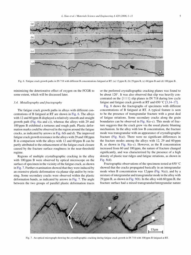
Fig. 6. Fatigue crack growth paths in IN 718 with different B concentrations fatigued at RT: (a) 12 ppm B, (b) 29 ppm B, (c) 60 ppm B and (d) 100 ppm B.
minimizing the deteriorative effect of oxygen on the FCGR tosome extent, which will be discussed later.
3.4. Metallography and fractography
The fatigue crack growth paths in alloys with different con-centrations of B fatigued at RT are shown in Fig. 6. The alloyswith 12 and 60 ppm B displayed a relatively smooth and straightgrowth path (Fig. 6(a and c)), whereas the alloys with 29 and100 ppm B exhibited a tortuous and rough path. Plastic defor-mation marks could be observed in the region around the fatiguecracks, as indicated by arrows in Fig. 6(b and d). The improvedfatigue crack growth resistance in the alloys with 29 and 100 ppmB in comparison with the alloys with 12 and 60 ppm B can bepartly attributed to the enhancement of the fatigue crack closurecaused by the fracture surface roughness in the near-thresholdregime.
Regions of multiple crystallographic cracking in the alloywith 100 ppm B were observed by optical microscope on thesurface of specimen in the vicinity of the fatigue crack, as shownin Fig. 7. Further examination showed that they were induced byan extensive plastic deformation via planar slip and/or by twin-ning. Some secondary cracks were observed within the plasticdeformation bands, as indicated by arrows in Fig. 7. The anglebetween the two groups of parallel plastic deformation traces
or the preferred crystallographic cracking planes was found tobe about 120◦. It was also observed that slip was heavily con-centrated on the {1 1 1} slip planes in IN 718 during low cyclefatigue and fatigue crack growth at RT and 650 ◦C [3,14–17].
Fig. 8 shows the fractographs of specimens with differentconcentrations of B fatigued at RT. A typical feature is seento be the presence of transgranular fracture with a great dealof fatigue striations. Some secondary cracks along the grainboundaries can be observed in Fig. 8(a–c). This mode of frac-ture suggests that the crack grew via the usual plastic bluntingmechanism. In the alloy with low B concentration, the fracturemode was transgranular with an appearance of crystallographicfracture (Fig. 8(a)). There were no significant differences inthe fracture modes among the alloys with 12, 29 and 60 ppmB, as shown in Fig. 8(a–c). However, as the B concentrationincreased from 60 and 100 ppm, the nature of fracture changedsignificantly, and was characterized by the presence of a highdensity of plastic tear ridges and fatigue striations, as shown inFig. 8(d).
Fractographic observations of the specimens tested at 650 ◦Cshowed that the cracks propagated basically in an intergranularmode when B concentration was 12 ppm (Fig. 9(a)), and by amixture of intergranular and transgranular mode in the alloy with29 ppm B, as shown in Fig. 9(b). In the alloy with 60 ppm B, thefracture surface had a mixed transgranular/intergranular nature
g dur
Fig. 7. An optical micrograph showing the crystallographic crackin ing fatigue crack growth in IN 718 with 100 ppm B fatigued at RT.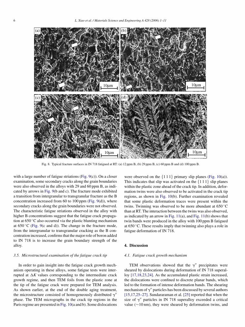
6 L. Xiao et al. / Materials Science and Engineering A 428 (2006) 1–11
Fig. 8. Typical fracture surfaces in IN 718 fatigued at RT: (a) 12 ppm B, (b) 29 ppm B, (c) 60 ppm B and (d) 100 ppm B.
with a large number of fatigue striations (Fig. 9(c)). On a closerexamination, some secondary cracks along the grain boundarieswere also observed in the alloys with 29 and 60 ppm B, as indi-cated by arrows in Fig. 9(b and c). The fracture mode exhibiteda transition from intergranular to transgranular fracture as the Bconcentration increased from 60 to 100 ppm (Fig. 9(d)), wheresecondary cracks along the grain boundaries were not observed.The characteristic fatigue striations observed in the alloy withhigher B concentrations suggest that the fatigue crack propaga-tion at 650 ◦C also occurred via the plastic blunting mechanismat 650 ◦C (Fig. 9(c and d)). The change in the fracture mode,from the intergranular to transgranular cracking as the B con-centration increased, confirms that the major role of boron addedto IN 718 is to increase the grain boundary strength of thealloy.
3.5. Microstructural examination of the fatigue crack tip
In order to gain insight into the fatigue crack growth mech-anism operating in these alloys, some fatigue tests were inter-rupted at �K values corresponding to the intermediate crackgrowth regime, and then TEM foils from the plastic zone atthe tip of the fatigue crack were prepared for TEM analysis.As shown earlier, at the end of the double aging treatment,the microstructure consisted of homogeneously distributed �′′phase. The TEM micrographs in the crack tip regions in theP
were observed on the {1 1 1} primary slip planes (Fig. 10(a)).This indicates that slip was activated on the {1 1 1} slip planeswithin the plastic zone ahead of the crack tip. In addition, defor-mation twins were also observed to be activated in the crack tipregions, as shown in Fig. 10(b). Further examination revealedthat some plastic deformation traces were present within thetwins. Twinning was observed to be more abundant at 650 ◦Cthan at RT. The interaction between the twins was also observed,as indicated by an arrow in Fig. 11(a), and Fig. 11(b) shows thattwin bands were produced in the alloy with 100 ppm B fatiguedat 650 ◦C. These results imply that twinning also plays a role infatigue deformation of IN 718.
4. Discussion
4.1. Fatigue crack growth mechanism
TEM observations showed that the �′′ precipitates weresheared by dislocations during deformation of IN 718 superal-loy [17,18,23,24]. As the accumulated plastic strain increased,the dislocations were confined to discrete planar bands, whichled to the formation of intense deformation bands. The shearingmechanism of �′′ particles has been discussed by several authors[15,17,25–27]. Sundararaman et al. [25] reported that when thesize of �′′ particles in IN 718 superalloy exceeded a criticalv
aris regime are presented in Fig. 10(a and b). Some dislocations alue (∼10 nm), they were sheared by deformation twins, and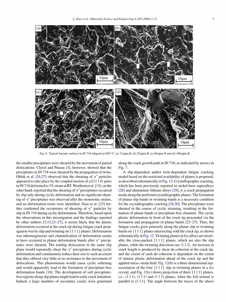
L. Xiao et al. / Materials Science and Engineering A 428 (2006) 1–11 7
Fig. 9. Typical fracture surfaces in IN 718 fatigued at 650 ◦C: (a) 12 ppm B, (b) 29 ppm B, (c) 60 ppm B and (d) 100 ppm B.
the smaller precipitates were sheared by the movement of paireddislocations. Clavel and Pineau [3], however, showed that theprecipitates in IN 718 were sheared by the propagation of twins.Oblak et al. [26,27] observed that the shearing of �′′ particlesappeared to take place by the coupled motion of a/2〈1 1 0〉 pairsin IN 718 deformed to 3% strain at RT. Worthem et al. [15], on theother hand, reported that the shearing of �′′ precipitates occurredby slip only during cyclic deformation and no significant shear-ing of �′′ precipitates was observed after the monotonic strains,and no deformation twins were identified. Xiao et al. [23] fur-ther confirmed the occurrence of shearing of �′′ particles byslip in IN 718 during cyclic deformation. Therefore, based uponthe observations in this investigation and the findings reportedby other authors [3,15,23–27], it seems likely that the plasticdeformation occurred at the crack tip during fatigue crack prop-agation was by slip and twinning on {1 1 1} planes. Deformationwas inhomogeneous and channelization of deformation seemsto have occurred in planar deformation bands after �′′ precip-itates were sheared. The trailing dislocation in the same slipplane would repeatedly shear the �′′ precipitates during cyclicdeformation and continuously reduce their size to such an extentthat they offered very little or no resistance to the movement ofdislocations. This phenomenon would cause cyclic softeningand would apparently lead to the formation of precipitate-freedeformation bands [18]. The development of soft precipitate-free regions along slip planes might lead to early crack initiation.I
along the crack growth path in IN 718, as indicated by arrows inFig. 7.
A slip-dependent and/or twin-dependent fatigue crackingmodel based on the restricted availability of planes is proposed,as described schematically in Fig. 12. Crystallographic cracking,which has been previously reported in nickel-base superalloys[28] and aluminium–lithium alloys [29], is a crack propagationmode along the preferred crystallographic planes. The formationof planar slip bands or twinning bands is a necessary conditionfor the crystallographic cracking [28,30]. The precipitates weresheared in the course of cyclic straining, resulting in the for-mation of planar bands or precipitate-free channels. The cyclicplastic deformation in front of the crack tip proceeded via theformation and propagation of planar bands [23–27]. Thus, thefatigue cracks grew primarily along the planar slip or twinningbands on {1 1 1} planes intersecting with the crack tip, as shownschematically in Fig. 12. Twinning planes in fcc alloys are invari-ably the close-packed {1 1 1} planes, which are also the slipplanes, while the twinning directions are 〈1 1 2〉. An increase incrack length is produced by shear de-cohesion at the crack tip,and the extent of such de-cohesion is dependent on the extentof intense plastic deformation ahead of the crack tip and theapplied stress–strain field. Fig. 12(b) is a three-dimensional rep-resentation of the four {1 1 1} slip or twinning planes in a fcccrystal, and Fig. 12(c) shows projection of three {1 1 1} planes,i.e., (1 1 1), (1 1 1) and (1 1 1) planes, when the foil normal isp
ndeed, a large numbers of secondary cracks were generated arallel to [1 1 1]. The angle between the traces of the above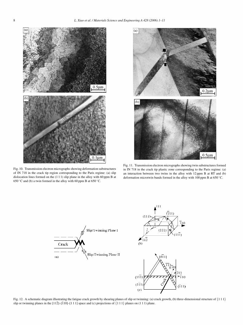
8 L. Xiao et al. / Materials Science and Engineering A 428 (2006) 1–11
Fig. 10. Transmission electron micrographs showing deformation substructuresof IN 718 in the crack tip region corresponding to the Paris regime: (a) slipdislocation lines formed on the (1 1 1) slip plane in the alloy with 60 ppm B at650 ◦C and (b) a twin formed in the alloy with 60 ppm B at 650 ◦C.
Fig. 11. Transmission electron micrographs showing twin substructures formedin IN 718 in the crack tip plastic zone corresponding to the Paris regime: (a)an interaction between two twins in the alloy with 12 ppm B at RT and (b)deformation microtwin bands formed in the alloy with 100 ppm B at 650 ◦C.
Fig. 12. A schematic diagram illustrating the fatigue crack growth by shearing planes of slip or twinning: (a) crack growth, (b) three-dimensional structure of {1 1 1}slip or twinning planes in the [112̄]–[1̄10]–[1 1 1] space and (c) projections of {1 1 1} planes on (1 1 1) plane.
L. Xiao et al. / Materials Science and Engineering A 428 (2006) 1–11 9
three {1 1 1} planes with the (1 1 1) plane is either 60 or 120◦,and is in good agreement with the experimental observationsillustrated in Fig. 7.
4.2. Effect of boron on plastic deformation at the tip offatigue crack
As shown in the previous section, the addition of B leads toa lower value of FCGR and a higher fatigue threshold value inIN 718 at RT and 650 ◦C. The mechanism responsible for theimprovement in the fatigue crack growth resistance of IN 718due to the addition of B is discussed next.
Slip reversibility, crack branching and resistance to activeenvironments can be critical factors influencing the fatigue crackpropagation resistance of metals and alloys. It seems likely thatthe mechanism of fatigue crack propagation of IN 718 in theParis regime is associated with the crystallographic fracture inthe favored crystallographic directions, induced by the separa-tion of atomic bonds directly ahead of the crack tip (Fig. 7).Accommodation of the plastic strain in front of the crack tipappears to occur via fracturing or shearing of �′′-Ni3Nb precipi-tates, which may occur as a result of high local stresses, or somelimited amount of dislocation motion or micro-twinning activity(Fig. 11). These plastic deformation features were observed tobe localized, and very fine (Figs. 10 and 11).
One mechanism for the observed improvement in the fatiguectrSoabeioobawufowp
viBwiIiTpim
stress above the critical stress for the preferential slip wouldbe required for dislocations to escape the pinning by B atomswithin the cross-slip plane. As a result, B addition can influencethe slip distribution and the relevant mode of cracking in thesealloys. In the alloy with higher B concentration these defor-mation bands disperse before a crack could be initiated. It hasbeen shown that, at a lower B concentration, however, plas-tic deformation was concentrated in the local regions due tocross-slip being easily activated, and it led to the crack initiationwithin the bands [16]. Microscopically, strong slip concentra-tion within the persistent slip bands would lead to fatigue cracknucleation and favor crack propagation, thereby would decreasethe fatigue crack growth resistance of IN 718 with lower B con-centration. The planar slip characteristics in the higher B alloyhas been attributed to crack branching and mixed mode I andII crack propagation [31]. The zig-zag crack paths thus pro-duced, as shown in Fig. 7, would promote roughness-inducedcrack closure which in turn would reduce the effective stressintensity factor range �Keff—the driving force for fatigue crackpropagation. By contrast, the alloy with lower B concentrationshowed relatively straight fracture paths, resulting in smallercrack closure. A combination of changes in the slip character inthe plastic zone ahead of the crack tip and the closure contribu-tion behind the crack tip could account for the increased fatiguecrack growth resistance of the material with increasing B con-centration. The flatter surface in the alloy with 60 ppm B shownialgisr
4
brbctbstaebcuacaiat1
rack propagation resistance due to B addition could be relatedo the increased grain boundary cohesion arising from B seg-egation, which has been demonstrated to occur in IN 718 byIMS analysis [21,22]. This would lead to a reduced tendencyf cracking along grain boundaries in the higher B alloy. Stressnd strain concentrations at the grain boundary regions, inducedy a lack of sufficient number of slip systems, can be released byither intergranular cracking or transgranular cracking, depend-ng on the cohesion strength of the boundary relative to thatf the bulk material. Metallographic and SEM examinationsf the specimens revealed a much higher incidence of grainoundary cracking in the lower B alloys at RT and 650 ◦C,s shown in Figs. 8 and 9. This indicates that the boundariesith a higher B concentration are more resistant to intergran-lar cracking. In general, intergranular cracking occurs at aaster rate than transgranular cracking. Therefore, the absencef intergranular cracking in alloys with higher B concentrationould partly account for their superior fatigue crack growthroperties.
Another possible mechanism for the improvement could beia direct elastic interaction between dislocations and B atomsn solution, and by boride particles. As an interstitial element,
atoms may form clusters which, along with boride particles,ould act as obstacles to the dislocation movement by imped-
ng the dislocation slip, and thus enhance the FCG resistance.t was observed that planar deformation bands were generatedn the fatigued IN 718 with the higher B concentration [16,17].his was suggested to be due to the formation of preferentialaths for the dislocation movement, resulting in a lower crit-cal stress for the slip of subsequent dislocations. This would
ake cross-slip relatively more difficult, since an additional
n Fig. 6(c) corresponds to a lower fatigue threshold (Table 2)nd/or faster near-threshold crack growth rate (Fig. 3) due to theower crack closure level. However, the reason why the crackrowth path in the alloy with 60 ppm B, shown in Fig. 6(c),s a little flatter than that observed in the alloy with 29 ppm Bhown in Fig. 6(b), is not understood and further studies areequired.
.3. Effect of boron on fracture mode of IN 718
The difference in the fatigue crack growth rates of IN 718etween RT and 650 ◦C may be explained in terms of slipeversibility and oxide penetration when deformation occursy the shearing of precipitates. Temperature influences fatiguerack growth behavior via its effect on both the localized strain athe crack tip and the kinetics of environmental interactions. It haseen long recognized that air, or more specifically oxygen, canignificantly degrade the fatigue properties of superalloys [6],hus leading to a significant increase in the fatigue crack prop-gation rate at 650 ◦C, as shown in Fig. 5. The most commonxplanation for this effect is that oxygen diffuses into the grainoundaries and makes them more susceptible to intergranularracking [6]. The change in the fracture mode from transgran-lar cracking at RT to intergranular cracking at 650 ◦C in thelloy with lower B concentration, as shown in Figs. 8(a) and 9(a),orroborates that the role of oxygen is to reduce the grain bound-ry energy in such a way that the crack growth path becomesntergranular. On the other hand, it is the environmental inter-ctions at 650 ◦C that give rise to a rapid reduction or a halt inhe fatigue crack growth when it is smaller than approximately0−8 m/cycle, leading to a higher fatigue threshold as compared
10 L. Xiao et al. / Materials Science and Engineering A 428 (2006) 1–11
to the RT tests (Fig. 5). In this situation, an oxide layer wouldbe expected to form on the freshly cracked surface in the wakeof the crack tip, causing the oxide-induced crack closure, whichis especially significant in the near-threshold regime [32].
The fractographic examination indicated that an increase in Bconcentration reduced the tendency to intergranular separationin IN 718 fatigued at 650 ◦C, as shown in Fig. 9. The intergran-ular cracking was basically eliminated in alloys with higher Bconcentrations, and entirely transgranular fracture was observedin the alloy with 100 ppm B (Fig. 9(d)). This implies that Bdrastically suppressed the occurrence of intergranular cracking,which is most likely controlled by the grain boundary cohesion.The major effect of B addition appeared, therefore, to increasethe grain boundary cohesion and to minimize the deleteriouseffect of oxygen in the air environment. Furthermore, the segre-gation of B at grain boundaries may tie up vacancies and reducegrain-boundary diffusion reactions, and thus prevent a prematureformation of cavities and microcracks at the grain boundaries.That is, the beneficial role of B is to counteract the acceleratingeffect of oxygen on the nucleation and growth of cavities, oract as a getter of detrimental impurity elements, thus mitigatetheir negative effects [11]. Accordingly, at 650 ◦C the fracturemode changed from intergranular cracking in the alloys withlower B concentration to transgranular cracking in the alloyswith higher B concentration, giving rise to an increased fatiguecrack growth resistance with increasing B concentration, as seeni
5
1
2
3
4
transgranular cracking, indicating that the beneficial role ofB was to an increase in the grain boundary cohesion.
5. TEM examination of the material in the crack tip regionsshowed that the mode of plastic deformation was mainly slip,but twinning also played a role.
6. During fatigue of IN 718 plastic deformation occurred viaplanar slip or twinning in the vicinity of the crack in theParis regime. A crystallographic cracking mechanism wasproposed on the basis of planar slip or twinning plane.
7. Fatigue crack growth occurred primarily along the planar slipbands or twinning bands on {1 1 1} planes intersecting withthe crack tip.
8. Addition of B increased the resistance to dislocation move-ment due to the interaction between B atoms and dislocations,thus giving rise to an increased FCG resistance. At 650 ◦Cboron suppressed the occurrence of intergranular fracturewhich was basically controlled by the grain boundary cohe-sion. The major effect of B addition appeared, therefore, toincrease the grain boundary cohesion and to minimize thedeleterious effect of oxygen in the air environment at ele-vated temperatures.
Acknowledgement
The authors would like to thank the Natural Sciences andEs
R
[[
[
[[
[
[[[
[
[
n Fig. 4.
. Summary and conclusions
. Addition of boron improved the fatigue crack growth resis-tance of IN 718 alloy at room temperature (RT) and at 650 ◦C,particularly in the near-threshold regime. The alloy withlower B concentration exhibited faster fatigue crack growthrates (FCGRs) than the alloy with higher B concentration.The higher the B concentration was, the higher was thefatigue threshold at 650 ◦C. The intermediate stable crackpropagation behavior could be expressed via the Paris equa-tion.
. The FCGRs of IN 718 increased noticeably as the test temper-ature increased from RT to 650 ◦C due to the slip reversibilityand environmental interaction. The extent of improvement infatigue crack propagation resistance due to B addition wasfound to be larger at 650 ◦C than at RT.
. In spite of the presence of a well-defined fatigue crack growththreshold at 650 ◦C, no obvious fatigue threshold region wasobserved for the alloys fatigued at RT. The rapid drop in theFCGRs in the near-threshold regime and the higher fatiguethreshold value at 650◦, compared to those obtained at RT,was due to the oxide-induced crack closure.
. The typical fracture surface obtained at RT was characterizedby the transgranular fracture together with fatigue striationsfor the alloys with different concentrations of B. However, thefracture mode changed from the predominantly transgranularcracking at RT to intergranular cracking at 650 ◦C in the alloywith lower B concentration. With increasing B concentration,the fracture mode changed from intergranular cracking to
ngineering Research Council of Canada for the financialupport.
eferences
[1] L.A. James, ASME J. Eng. Mater. Technol. 103 (1981) 234.[2] T. Connolley, P.A.S. Reed, M.J. Starink, Mater. Sci. Eng. A 340 (2003)
139.[3] M. Clavel, A. Pineau, Metall. Trans. 9A (1978) 471.[4] M. Clavel, A. Pineau, Mater. Sci. Eng. 55 (1982) 157.[5] J.L. Yuen, P. Roy, Scripta Metall. 19 (1985) 17.[6] J.L. Yuen, P. Roy, W.D. Nix, Metall. Trans. 15A (1984) 1769.[7] G.A. Osinkolu, G. Onofrio, M. Marchionni, Mater. Sci. Eng. A 356
(2003) 425.[8] L.A. James, W.J. Mills, ASME J. Eng. Mater. Technol. 107 (1985) 34.[9] W.J. Mills, L.A. James, ASME J. Eng. Mater. Technol. 107 (1985) 41.10] S. Floreen, J.M. Davidson, Metall. Trans. 14A (1983) 895.11] T.J. Garosshen, T.D. Tillman, G.P. McCarthy, Metall. Trans. 18A (1987)
69.12] W.D. Cao, R.L. Kennedy, in: E.A. Loria (Ed.), Superalloys 718, 625,
706 and Various Derivatives, The Minerals, Metals & Materials Society,1997, p. 511.
13] H.F. Merrick, Metall. Trans. 5 (1974) 891.14] T.H. Sanders Jr., R.E. Frishmuth, G.T. Embley, Metall. Trans. 12A
(1981) 1003.15] D.W. Worthem, I.M. Robertson, F.A. Leckie, D.F. Socie, C.J. Altstetter,
Metall. Trans. 21A (1990) 3215.16] L. Xiao, D.L. Chen, M.C. Chaturvedi, Metall. Trans. 35A (2004) 3477.17] L. Xiao, D.L. Chen, M.C. Chaturvedi, Metall. Trans. 36A, in press.18] S. Kalluri, K.B.S. Rao, G.R. Halford, M.A. McGaw, in: E.A. Loria
(Ed.), Superalloys 718, 625, 706 and Various Derivatives, The Minerals,Metals & Materials Society, 1994, p. 593.
19] C. Mercer, W.O. Soboyejo, in: E.A. Loria (Ed.), Superalloys 718, 625,706 and Various Derivatives, The Minerals, Metals & Materials Society,1997, p. 577.
20] C. Mercer, A.B.O. Soboyejo, W.O. Soboyejo, Mater. Sci. Eng. A 270(1999) 308.
L. Xiao et al. / Materials Science and Engineering A 428 (2006) 1–11 11
[21] X. Huang, M.C. Chaturvedi, N.L. Richards, J. Jackman, Acta Mater. 45(1997) 3095.
[22] W. Chen, M.C. Chaturvedi, Acta Mater. 45 (1997) 2735.[23] L. Xiao, D.L. Chen, M.C. Chaturvedi, Scripta Mater. 52 (2004) 603.[24] D. Fournier, A. Pineau, Metall. Trans. 8A (1977) 1095.[25] M. Sundararaman, P. Mukhopadhyay, S. Banerjee, Acta Metall. 36
(1988) 847.[26] D.F. Paulonis, J.M. Oblak, D.S. Duvall, Trans. ASM 62 (1969) 611.[27] J.M. Oblak, D.F. Paulonis, D.S. Duvall, Metall. Trans. 5A (1974) 143.
[28] R.B. Scarlin, Metall. Trans. 7A (1976) 1535.[29] D.L. Chen, M.C. Chaturvedi, Metall. Mater. Trans. 31A (2000)
1531.[30] S.P. Lynch, Fatigue Mechanisms A Symp. Sponsored by ASTM Com-
mittee E-9 on Fatigue National Bureau of Standards National ScienceFoundation Kansas City, Mo., 22–24, 1978, p. 174.
[31] C.J. Beevers, R.L. Carlson, in: R.A. Smith (Ed.), Fatigue Crack Growth30 Years of Progress, Pergamon Press, 1984, p. 89.
[32] D.L. Chen, B. Weiss, R. Stickler, Eng. Fract. Mech. 53 (1996) 493.