leveraging lean in construction: a case study of a bim-based hvac manufacturing process
TRANSCRIPT
SDAR* Journal of Sustainable Design & AppliedResearch
Volume 2Issue 1 SDAR December 2014 Article 2
2014-12-09
Leveraging Lean in construction: A case study of aBIM-based HVAC manufacturing processColin j. ConwayDublin Institute of Technology, [email protected]
Colin Keane MrMercury Engineering, [email protected]
McCarthy McCarthy MrMercury Engineering, [email protected]
Ciara AhernDIT, Dublin Energy Lab, [email protected]
Avril BehanDublin Institute of Technology, [email protected]
Follow this and additional works at: http://arrow.dit.ie/sdar
Creative Commons LicenseThis work is licensed under a Creative Commons Attribution-Noncommercial-Share Alike 3.0 License
Recommended CitationConway, Colin j.; Keane, Colin Mr; McCarthy, McCarthy Mr; Ahern, Ciara; and Behan, Avril (2014) "Leveraging Lean inconstruction: A case study of a BIM-based HVAC manufacturing process," SDAR* Journal of Sustainable Design & Applied Research:Vol. 2: Iss. 1, Article 2.Available at: http://arrow.dit.ie/sdar/vol2/iss1/2

Leveraging Lean inconstruction: A case studyof a BIM-based HVACmanufacturing process
BuildingBuildingServicesServicesnews
School ofMultidisciplinaryTechnologies
Colin ConwaySCHOOL OF ELECTRICAL AND ELECTRONIC ENGINEERING, [email protected]
Colin KeaneMERCURY ENGINEERING
Sean McCarthyMERCURY ENGINEERING
Ciara AhernSCHOOL OF MECHANICAL AND DESIGN ENGINEERING, DIT
Avril BehanSCHOOL OF MULTIDISCIPLINARY TECHNOLOGIES, DIT
Ciara SDAR paper:Layout 1 13/11/2014 12:03 Page 235
1
Conway et al.: Leveraging Lean in construction: A case study of a BIM-based HVAC manufacturing process
Published by ARROW@DIT, 2014
Abstract
The impetus towards efficiency in the AECO
(Architecture, Engineering, Construction &
Operations) sector is driving the implementation of
Lean practices. BIM technologies and BIM processes
provide methods by which this can be achieved.
Major clients of building services contractors have
begun to mandate the use of BIM and some are using
BIM preparedness/experience as pre-tender
qualification criteria. In this case study, an initial
review has been conducted of the achievements of a
major Irish M&E contractor in implementing BIM. The
firm purpose-built a facility for the off-site
manufacture of building services components. The
operations of the plant are efficient and quality-
assured through the use of an appropriately skilled
workforce at all stages of manufacture, and tracking
software that has developed as the knowledge of the
contractor grew. Standardised processes have been
developed which have resulted in greater efficiencies
and lower costs for the contractor as a result of fewer
requirements for onsite modifications (such as those
caused by clashes), less waste, and greater flexibility.
Despite some initial objections, the employees of the
company are now more satisfied with their working
conditions and are, as a result, more productive.
Through investment in BIM-based, Lean processes, the
contractor can now better compete when tenerding
for large-scale projects in Ireland and worldwide,
including the rapidly-increasing number where BIM
experience and preparedness is mandated.
Glossary
AECO: Architecture, Engineering, Construction and
Operations
Autodesk Navisworks: project review software that
enables AEC professionals to “holistically review
integrated models and data with stakeholders to gain
better control over project outcomes. Integration,
analysis, and communication tools help teams
coordinate disciplines, resolve conflicts, and plan
projects before construction or renovation begins.”
(Autodesk, 2014)
BIM: Building Information Modelling/Management
BIM4M2: BIM for Manufacturers and Manufacturing
BOM: Bill of Materials
CITA: Construction IT Alliance
Eida: Tracking software used to record and document
the progress of spools from time of issue to
installation
IFC: Issued for Construction (process specific) or
Industry Foundation Classes
Tool: a set of connected components carrying out the
function of routing a particular service through an
area of a building
SAP: Systems, Applications & Products in Data
Processing software for data warehousing
Spools: the subdivisions of service lines in manageable
lengths varying from a single component to a 6m
pipe-run
WBS: Work Breakdown Structure
SDAR Journal 2014
24
Ciara SDAR paper:Layout 1 13/11/2014 12:03 Page 236
2
SDAR* Journal of Sustainable Design & Applied Research, Vol. 2, Iss. 1 [2014], Art. 2
http://arrow.dit.ie/sdar/vol2/iss1/2

Leveraging Lean in construction: A case study of a BIM-based HVAC manufacturing process
1. IntroductionLarge scale manufacturing facilities, due to the nature of operationsand the processes undertaken, frequently require additional buildingservices that might include ammonia, acid waste, solvent waste,helium and argon (Gulledge et al., 2014). Design, fabrication,installation and management of these services are complexoperations. While the design of such systems has long been carriedout digitally using CAD-based software, due to inconsistencies and uncertainties in the process (Eastman et al., 2011), onsitefabrication of services prior to installation is still necessitated. Thisis, by its nature, inefficient due to, inter alia, the influence of remotestock locations, clashes with other trades, weather, etc.
Building information modelling (BIM) is a relatively new process andset of software tools that has the potential to improve the currentsituation. BIM is a shared knowledge resource for information that can be defined as “a digital representation of physical andfunctional characteristics of a facility” (National BIM Standard,2014). The advent of BIM-based design and build processes enablesthe use of off-site fabrication through the “creation of a singlesource of truth” for all parties (Saxon, 2013) where potentialclashes between services are identified and resolved in the virtualmodel and not onsite where their occurrence is much more costly.This enables more efficient work practices that leverage BIM for speed, economy, quality control, and health and safetyimprovements (Saxon, 2013).
While perhaps best-known as assisting at the design stage of aproject, the 2014 McGraw Hill Business Value of BIM report(McGraw Hill Construction, 2014) found that between 59% (UK)and 97% (Japan, Germany, France) of contractors who had
adopted BIM practices reported a positive return on investment(ROI). The variation in success was dependent on the levels ofoverall adoption of BIM in individual markets. The report alsorecommends that throughout the developed world, for contractorsto remain competitive, they must “embrace emerging uses forleveraging model data” among which are “simulation and analysisto optimise logistical planning and decision-making”. Enablingcontractors to benefit from BIM adoption is being facilitated bygroups such as BIM for Manufacturers and Manufacturing UK(BIM4M2 Task Group, 2014), who focus on the standardisation of interfaces between BIM and existing systems and processes and, in Ireland, by the Construction Information TechnologyAlliance’s Construction Technology Series, BIM-2-Win, and SmartCollaboration Challenge events (CITA, 2014).
Much of the pressure to adopt BIM processes is being applied by building owners because the improvements in operationalprocesses and the associated costs achievable through BIM havethe greatest potential for financial benefit (Azhar, 2011; Carmonaand Irwin, 2007). In America, contractors who do not use BIM toolsare no longer able to compete in tendering processes on even low-value contracts (AGC, 2010). This has changed from the situationin the mid-2000s when the use of BIM was recommended, ratherthan required, but with contractors who were not BIM-enabledhaving to add their services last during fit-out (AGC, 2006).
Thus, many owners and operators, for example Irish Water and theGrangegorman Development Agency, are requiring that the designand build of new and retrofitted facilities be implemented thoughBIM. The developers are required, as part of the final handover, todeliver a virtual building that is compatible with the PAS 1192-3
Figure 1: The Bew and Richards BIM Maturity Levels Model (Bew and Richards, 2008)
Drawings, lines, arcs, text etc. Models, objects, collabora�on Integrated, interoperable data
Level 0
Level 1
Level 2
Level 3
CAD ISO BIM
BIMs
2D 3D CPIC Avan� BS 1192:2007 User guides:CPIC, Avan�, BSI
AIM
SI
M
FIM
BS
IM
BrIM
iBIM Data management
Process management
Standards for interoperability: IFC, IFD, IDM
Asse
t life
cyc
le m
anag
emen
t
Key IFC Industry Founda�on Classes IFD Interna�onal Framework Dic�onary IDM Informa�on Delivery Manual iBIM Integrated BIM CPIC Construc�on Project Informa�on
Commi�ee AIM Architectural Informa�on Model SIM Structural Informa�on Model FIM Facili�es Informa�on Model BSIM Building services Informa�on Model BrIM Bridge Informa�on Model
Moving up through the levels of technology use leads to seamless working and effec�ve data and process management
Source: Bew and Richards, 2008
25
Ciara SDAR paper:Layout 1 13/11/2014 12:03 Page 237
3
Conway et al.: Leveraging Lean in construction: A case study of a BIM-based HVAC manufacturing process
Published by ARROW@DIT, 2014
Standard for Information Modelling for the Operational Phase ofAssets (British Standards Institute, 2014). BIM for asset and facilitiesmanagement is sometimes called 6D or 7D BIM and PAS 1192-3 isfacilitating a move towards the “integrated interoperable data”and “asset life cycle management” defined by Bew & Richards(2008) as Level 3 BIM Maturity. Major component fabricationplants are among the types of facility seeking operational BIMcompatibility upon completion of building and retrofit works.
Thus an Irish-based mechanical and electrical contracting firm hasdeveloped an off-site HVAC manufacturing facility to support theimplementation of BIM-based processes. This paper describes themanufacturing facility, its associated work practices, and the initialimpacts of implementing this new method. The optimisation andstreamlining of the processes resulting from lessons learned on twomajor building servicing campaigns are detailed in Section 2.Section 3 examines the impact of BIM-based practices on the staffand the necessity of staff “buy-in” to enable the realisation of newwork processes from the ground up. Section 3 also evaluates theassociated business benefits and Section 4 discusses the potentialof BIM-enabled off-site manufacture for the mechanical andelectrical building services sector.
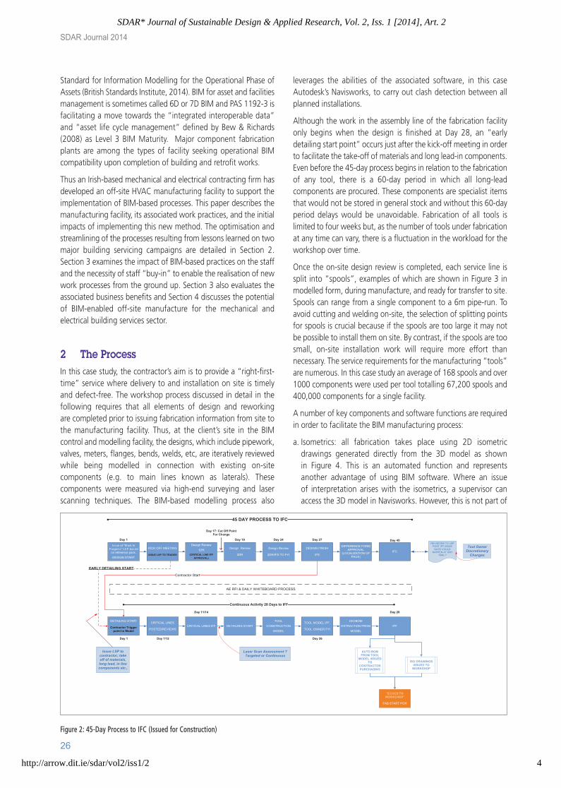
2 The ProcessIn this case study, the contractor’s aim is to provide a “right-first-time” service where delivery to and installation on site is timely and defect-free. The workshop process discussed in detail in thefollowing requires that all elements of design and reworking are completed prior to issuing fabrication information from site tothe manufacturing facility. Thus, at the client’s site in the BIMcontrol and modelling facility, the designs, which include pipework,valves, meters, flanges, bends, welds, etc, are iteratively reviewedwhile being modelled in connection with existing on-sitecomponents (e.g. to main lines known as laterals). Thesecomponents were measured via high-end surveying and laserscanning techniques. The BIM-based modelling process also
leverages the abilities of the associated software, in this caseAutodesk’s Navisworks, to carry out clash detection between allplanned installations.
Although the work in the assembly line of the fabrication facilityonly begins when the design is finished at Day 28, an “earlydetailing start point” occurs just after the kick-off meeting in orderto facilitate the take-off of materials and long lead-in components.Even before the 45-day process begins in relation to the fabricationof any tool, there is a 60-day period in which all long-leadcomponents are procured. These components are specialist itemsthat would not be stored in general stock and without this 60-dayperiod delays would be unavoidable. Fabrication of all tools islimited to four weeks but, as the number of tools under fabricationat any time can vary, there is a fluctuation in the workload for theworkshop over time.
Once the on-site design review is completed, each service line issplit into “spools”, examples of which are shown in Figure 3 inmodelled form, during manufacture, and ready for transfer to site.Spools can range from a single component to a 6m pipe-run. Toavoid cutting and welding on-site, the selection of splitting pointsfor spools is crucial because if the spools are too large it may notbe possible to install them on site. By contrast, if the spools are toosmall, on-site installation work will require more effort thannecessary. The service requirements for the manufacturing “tools”are numerous. In this case study an average of 168 spools and over1000 components were used per tool totalling 67,200 spools and400,000 components for a single facility.
A number of key components and software functions are requiredin order to facilitate the BIM manufacturing process:
a. Isometrics: all fabrication takes place using 2D isometricdrawings generated directly from the 3D model as shown in Figure 4. This is an automated function and represents another advantage of using BIM software. Where an issue of interpretation arises with the isometrics, a supervisor canaccess the 3D model in Navisworks. However, this is not part of
SDAR Journal 2014
26
Figure 2: 45-Day Process to IFC (Issued for Construction)
Issue of “Work In P rogress” LS P based
on reference pack.
DESIGN START
KICK OFF MEETING
ISSUE LSP TO TRADES
Design Review
1DR
(CRITICAL LINE IFFAPPROVAL)
Design Review
2DR
Design Review
2DR/IFS TO FYI
DESIGN FINISH
IFS
DIFFERENCE FORMAPPROVAL
(LOCALIZATION OFPACK)
IFC
REVISIONS TO LSPPOST IFF ISSUE
DATE COULDHAPPEN AT ANY
TIME ?
Tool OwnerDiscretionaryChanges
Day 45Day 27Day 24Day 19Day 1
Day 17: Cut Off PointFor Change
DETAILING START
Contractor Triggerpoint to Model
CRITICAL LINES
POSTED/REVIEWSCRITICAL LINES IFF DETAILING START
TOOL
CONSTRUCTION
MODEL
TOOL MODEL IFF,
TOOL OWNER FYI
ISO/BOM
EXTRACTION FROM
MODEL
IFF
Day 28
Day 26Day 1 Day 7/12
Day 11/14
AUTO BOMFROM TOOL
MODEL ISSUEDTO
CONTRACTORPURCHASING
ISO DRAWINGSISSUED TO
WORKSHOP
“IS S UE D T O WOR K S HOP ”
FAB START POR
Continuous Activity 28 Days to IFF
45 DAY PROCESS TO IFC
AE RFI & DAILY WHITEBOARD PROCESS
Contractor Start
EARLY DETAILING START
Issue LSP tocontractor; takeoff of materials,long lead, in linecomponents etc.,
Laser Scan Assessment ?Targeted or Continuous
Ciara SDAR paper:Layout 1 13/11/2014 12:03 Page 231
4
SDAR* Journal of Sustainable Design & Applied Research, Vol. 2, Iss. 1 [2014], Art. 2
http://arrow.dit.ie/sdar/vol2/iss1/2

27
the standard process and most staff are not trained in the use ofthe software;
b. SAP software: used for stock management to ensure that allrequired components are available prior to the beginning of themanufacturing process;
c. Eida software: used for tracking the manufacturing progress ofall spools.
Figure 4 illustrates an isometric drawing of a spool manufacturedfrom 2” PVC and designed to carry acid waste water. Isometricdrawings, including all of the annotations, can be extractedautomatically from the 3D model provided that the model has beendeveloped at a sufficient level of detail. No separate redrawing isrequired. Under the cutting list section, the lengths of the sevenpipe sections are shown in millimetres. This allows cutting tocommence immediately as part of the processing steps set outbelow. This is a direct improvement on site work where the lengthof each pipe must be determined on the basis of installationconditions before being cut. The isometric also includes thefollowing information:
• Bill of materials (BOM) providing information on each componentsuch as 90o and 45o elbows, reducers and tees;
• Unique identifying and traceable scan code (QR code), tracked bythe staff using iPad minis which send live updates to the Eidatracking software;
• Date and time of receipt;
• Rework Indicator, completed on-site in case of failure.
The QA, recording and actions that form part of the workshopprocess are detailed in Figure 5 which follows on from Day 28 ofthe 45-day process presented in Figure 2.
1. Isometric drawings of all spools and a bill of materials (BOM)are issued to the workshop;
2. The BOM is cross-referenced with the previous list of long-leaditems as a QA procedure before the tool is recorded into the
Leveraging Lean in construction: A case study of a BIM-based HVAC manufacturing process
Figure 3: Various components in modelled form (a), during manufacture (b)and ready for transfer to site (c).
Figure 4: An example isometric drawing showing a single spool, its associatedBill of Materials, the QR code used for scanning and populating Eida, and theRework Indicator, in case of errors at point of installation. Figure 5: Numbered workshop process at manufacturing facility
“IS S UE D T O WOR K S HOP ”
FAB START POR
BOM REVIEW BY
ENGINEER
TOOL LOADED
ONTO EIDA SYSTEM
BOM
RESERVED
AGAINST TOOL
WBS
DATA ENTERED ON
EIDA
LINE ISSUED TOPROGRAMME FOR
FABRICATION
QR SCAN TO EIDA
‘L ine A vailable’
LINE PICKED &BAGGED FORFABRICATION
QR SCAN TO EIDA
‘L ine P ic ked’
LINE FABRICATEDQR SCAN TO EIDA
‘F ab S tart’
LINE QA CHECKSQR SCAN TO EIDA
‘F ab & QA C omplete’
FAB FINISH POR
LINE STORED
LINE SPOOL
DISPATCHED TO
SITE & SIGNED FOR
QR SCAN TO EIDA
‘Dis patc h’
DATE/DOC #
ENTERED INTO EIDA
SITE SUP REQUESTS
LINE SPOOL VIA
EIDA
9
8
7
6
5
4
3
2
1
Send to Site for Install 10
a
b
c
Ciara SDAR paper:Layout 1 13/11/2014 12:03 Page 232
5
Conway et al.: Leveraging Lean in construction: A case study of a BIM-based HVAC manufacturing process
Published by ARROW@DIT, 2014

stock management software. The requirements for the tool arecompared to what is already in stock and what has already beenordered. The software then lists the required elements forcompletion of the tool. The goal is to finish fabrication with aslittle left-over stock as possible, thus creating a lean process.
The information for every spool is sent to Eida, which produces .pdffiles containing a unique QR (Quick Response) code for eachspool. This QR code is used to track the progress of the spoolduring fabrication, delivery, and installation;
3. The BOM is then reserved against the tool's WBS (WorkBreakdown Structure code) and the date is entered onto Eidaunder the "material reserved" column. As shown in Figure 6,components that are in stock become reserved specifically foran individual tool facilitating the tracking of costs;
4. The next step is another QA procedure. All isometric drawingsare reviewed by engineers to check for constructability,corruptions, omissions, etc. Once the isometric is approved bythe engineer, the QR code is scanned and the "Line Available"column in Figure 6 is populated. At this point some spools maybe identified and prioritised as more urgent than others;
5. A general operative (GO) collects and bags all items for a spool.This part of the process means that skilled tradespeople do notwaste valuable time collecting items for fabrication. Anengineering technician or experienced GO checks the bag beforeit is scanned to make sure all items are correct. Once the baghas been scanned, the "Line Picked" column in Figure 6 ispopulated and the bag is placed on a shelf ready for fabrication;
6. An engineering craftsperson selects a bag from the shelf andscans it, thus populating the "Fab Start" column. Fabricationtakes place at a workstation where all tools are readily availableand where each worker has plenty of workspace (Figure 3(b)).Once the spool is complete and the event scanned, it is passedto another table where all spools are QA checked;
7. At this point the spools are checked for accuracy of length,angles, joints, welds, etc. If any problems are identified the spoolis returned to the technician. If the spool passes QA, the QR codeis scanned and the "Fab & QA Complete" column in Figure 6 ispopulated;
8. The completed spool is “bagged and tagged” and placed in
storage for up to a month, depending on when it is needed onsite;
9. The foremen on site can order spools to be delivered once the“Fab & QA Complete” step (8) has finished. They can log intoEida and select the spools which they require and enter thedesired delivery date. This step fills in the “Load Plan Request”column in Figure 6. Due to the in-house logistics involved inloading trolleys with spools for delivery, a 48-hour turnaroundbetween order and delivery is the norm, except for urgentrequirements. The foreman decides the order in which the spoolsshould be installed and how many he wants delivered each day.The goal on site is to install spools on the day they arrive, therebyreducing the storage requirements by the contractor on theclient’s site;
10.The spools are scanned when they are dispatched and againwhen delivered on site as proof of delivery;
Each isometric drawing has a Rework Indicator checklist which ispopulated during installation on the rare occasions when a spoolis incorrect. This step provides feedback as to the source of theproblem. Issues can result from fabrication, tools not meetingwith specification, or bracket issues. Using traditional processesclashes with other new or existing services frequently but theability to carry out clash detection in the virtual world of the BIMsoftware practically eliminates that problem. Issues of this natureonly occur if the As-Built model used during design is different tothe As-Built conditions at the time of delivery.
Using the Rework Indicator checklist the source of any problemcan be identified and operational improvement can be promptlyachieved; thus enhancing the leanness of the process.
3 The Impact of New ProcessesThe significant changes in the day-to-day operations of the M&Econtractor achieved through BIM-based, Lean processes hasresulted in improvements in relation to financial returns andemployee satisfaction. However, there was a steep learning curvefor all concerned and this caused more problems for someemployees than others. This impact will now be evaluated fromboth a business point-of-view and in relation to the human andbehavioural aspects.
SDAR Journal 2014
28
Figure 6: Progress of the fabrication of individual spools from reservation of materials (Material Reserved) to delivery to site based on Isometric Number via Eidasoftware.
Ciara SDAR paper:Layout 1 13/11/2014 12:03 Page 233
6
SDAR* Journal of Sustainable Design & Applied Research, Vol. 2, Iss. 1 [2014], Art. 2
http://arrow.dit.ie/sdar/vol2/iss1/2

3.1 Business Appraisal
The Eida tracking system that is central to the fabrication processprovides a level of traceability previously impossible for thecontractor. When first used the software did not have all of thefunctions currently available but the M&E contractor’s engineers, inconjunction with the developer of the software, customised anddeveloped it to optimise the solution and to ensure that itsupported rather than hindered the workflow.
Among other items, the software records who fabricated and QAchecked each spool, and how many spools each employeefabricated daily. If a problem arises on site in relation to a faultyelement, the system can reveal the identity of the fabricator and thechecker. This acts as an incentive to improve the quality of eachindividual’s work. It also ensures that staff maintain comparablelevels of productivity and enables management to identify areas inthe pipeline where problems may be occurring and/or personnelchanges (including increases and decreases in numbers carrying outparticular tasks) may be required. The data recorded on a perpetualbasis facilitates the continuous improvement of the fabricationworkflow and associated inputs and outputs. It also supports moreaccurate cost estimation, thus impacting on operational costs.
Although there are still some occurrences of failures that requirereworking, as indicated by the fields on the Isometrics (Figure 4),the amount is significantly lower than would have occurred usingtraditional practices. During one month this year, 1311 spools weredispatched with only 26 spools needing to be remade. However, 24of these spools were required only because they were lost on sitewhile the other two had been incorrectly fabricated. Therefore, lessthan 0.2% of spools required reworking as a result of failures in thefabrication process. It should also be noted that, despite protocolsthat discourage the practice, minor issues related to fabricationmay have been fixed on site because installation engineers choseto carry out necessary works rather than return the spools to theworkshop. No statistics on these occurrences are available.
Some additional costs have been incurred by the contractor, forexample, parts are now stored in 40-foot containers external to themain building. Most containers hold a specific pipe type: highpurity, low purity, PVC etc. while a quarantine store is used toprevent parts that do not belong in any other store causing mixups. Despite this additional requirement, materials in these storesare now retained for shorter periods as a result of the just-in-timeprocess meaning that overall efficiency has improved.
3.2 Human and Behavioural Aspects
The new process has had a profound impact on the work practicesof individuals and the contractor’s workforce as a collective. Prior toimplementation of BIM-based Lean processes, tradespeople wereinvolved in many trivial tasks in relation to the acquisition andmaintenance of components and tools. Skilled workers can nowfocus solely on fabrication because they work at secure, well-equipped benches in a purpose-built facility where the componentsrequired for each fabrication task are delivered in a Quality Assuredstate.
The workshop environment is very different to the traditional onsiteconditions known to most tradespeople. Those fabricating thespools simply select a bag containing all the required parts andimmediately work on it at a bench where all tools and power areavailable. When stopping for breaks, tools and equipment can beleft unattended without fear of theft. Canteens and toilets are ofa standard expected in offices. Workshop conditions are quieterand more comfortable. Hard hats are replaced with bump capswhich are lightweight and comfortable.
Upskilling is also encouraged where staff rotate between functionsto learn new skills. This has the dual benefit of motivating staff andallowing management to re-allocate staff as necessary, dependingon requirements at different times during a project.
The tracking aspect of the process, which is considered a majorpositive from the business perspective, was initially considered to bevery invasive by some of the workers. Some fabricators thoughtthat the new processes undervalued their skills by requiring somuch QA and adherence to stringent practices. However, after ashort period these methods became embedded and accepted.
During the early stages of implementation of the process, a pointof failure was identified in the ordering of spools by the siteforemen over the phone. Each spool has a unique code but thesewere often miscommunicated via this process resulting in thewrong spools being delivered to site. This created delays on siteuntil the correct spool arrived, necessitated extra delivery runs, andserved to undermine the entire operation by reducing confidencein the system, particularly among the onsite installers. Managementresponded quickly by implementing an online spool selectionmechanism which the site foremen can access from anywhere andthis has significantly reduced these errors and resulted in acorresponding increase in confidence in the system.
Anecdotal evidence suggests that tradespeople at the fabricationfacility preferred the new conditions over site work. This favourableresponse has allowed the contractor to attract and retain the mostskilled tradespeople available on the market.
The contractor reports a significant increase in efficiency throughthe use of Lean processes when compared with a traditionalinstallation. Metrics on the value of this increase will be evaluatedin the future. The current evidence enables the firm to tender morecompetitively for new work thus providing increased stability ofemployment for its workforce.
4. Conclusions and Future DevelopmentsThe case study presented here demonstrates the results of applyingBIM on a large scale in the M&E manufacturing context for the firsttime in Ireland. It has shown that innovation and streamlining ofthe process can be achieved, particularly through working closelywith software developers and valuing your workforce.
The introduction of a BIM-based process has enabled this M&Econtractor to apply and benefit from the principles of LeanConstruction including:
• Elimination of waste;
Leveraging Lean in construction: A case study of a BIM-based HVAC manufacturing process
29
Ciara SDAR paper:Layout 1 13/11/2014 12:03 Page 234
7
Conway et al.: Leveraging Lean in construction: A case study of a BIM-based HVAC manufacturing process
Published by ARROW@DIT, 2014

• Clear identification of the elements of operation that deliverwhat the customer values, i.e. the value stream, and eliminatesall non-value-adding steps;
• Not making anything before it is needed and then making itquickly;
• Striving to achieve perfection by continuously monitoring andimproving performance (Lean Sigma 60, 2014).
The Eida tracking system that has been developed andimplemented in support of the process agrees with the Associationof General Contractors of America’s assertion that “any well-planned and well-executed BIM project should necessarily includeprocedures and protocols for creating a detailed audit trail” (AGC,2006, p. 38).
Continually reviewing operations and processes with a view toachieving improvement has become embedded within the firm’spsyche. At present, for example, the laser scanning and BIMmodelling portions of the workflow are under examination as partof a Construction IT Alliance (CITA) technology challenge.
As a result of this project, the firm has built a uniquely-skilled team,experienced in the production and installation of components usingthe Lean BIM process that was developed and improved by thecompany. It is envisaged that these factors will enable thecontractor to be successful in tendering for, and engaging in futurelarge-scale projects within and outside Ireland, both where BIMcompetence is a criterion for pre-qualification to tender (SECGROUP, 2012) and where BIM-based Lean processes provide anadvantage over competitors who have not engaged in similarupskilling. This may also result in a significant shift in operationalmethods for a large number of other contractors who will need toadopt leaner processes in order to compete in the new BIM-focussed market.
ReferencesAGC (2006) The Contractors’ Guide to Building InformationModeling, Association of General Contractors of America, Arlington,VA. Available.
AGC (2010) The Contractors’ Guide to Building InformationModeling. Available.
Autodesk (2014) Navisworks Overview [Online]. Available:http://www.autodesk.com/products/navisworks/overview [AccessedNovember]
Azhar, S (2011) Building Information Modeling (Bim): Trends,Benefits, Risks, and Challenges for the Aec Industry. Leadership andManagement in Engineering, 11(3), 241-52.
Bew, M and Richards, M. (2008). Bim Maturity Diagram Model:BuildingSmart,Construction Product Information Committee (CPIC),.
BIM4M2 Task Group (2014) Bim for Manufacturers andManufacturing [Online]. Available: http://www.bim4m2.co.uk/[Accessed November]
British Standards Institute. (2014). Pas 1192-3 Specification forInformation Management for the Operational Phase of Assets UsingBuilding Information Modelling (Bim): British Standards Institute,.
Carmona, J and Irwin, K. (2007). Bim: Who, What, How and Why:Facilitiesnet.com.
CITA (2014) Bim Events [Online]. Available:http://www.cita.ie/events.asp [Accessed November]
Eastman, C M, Teicholz, P, Sacks, R and Liston, K (2011) BimHandbook: A Guide to Building Information Modeling for Owners,Managers, Designers, Engineers and Contractors, 2nd ed, Wiley,Hoboken, N.J.
Gulledge, C E, Conyers, R S, Poe, B M and Kibby, C M (2014) DesignBuild Manufacturing Plant. ASHRAE Journal, 56, 32-9.
Lean Sigma 60 (2014) Lean Construction [Online]. Available:http://www.leansigma.ie/education-items/lean-construction[Accessed November]
McGraw Hill Construction (2014) The Business Value of Bim forConstruction in Global Markets: How Contractors around the WorldAre Driving Innovation with Building Information Modeling, McGrawHill Construction, Bedford, MA. Available.
National BIM Standard (2014) What Is Bim? [Online]. Available:http://www.nationalbimstandard.org/faq.php#faq1 [AccessedNovember]
Saxon, R G (2013) Growth through Bim, Construction IndustryCouncil, London. Available.
SEC GROUP (2012) First Steps to Bim Competence: A Guide forSpecialist Contractors BIM Academy Ltd. . Available
SDAR Journal 2014
30
Ciara SDAR paper:Layout 1 13/11/2014 12:03 Page 235
8
SDAR* Journal of Sustainable Design & Applied Research, Vol. 2, Iss. 1 [2014], Art. 2
http://arrow.dit.ie/sdar/vol2/iss1/2