turbochill™ tcw - systemy hvac
TRANSCRIPT

EMS52086FM00542
TurboChill™ TCW
Technical Manual
Water Cooled Compact Chiller
150-375kW
R134a
R1234ze
TurboChill™ Chillers
2 TurboChill Water Cooled Technical Manual 9216326 V1.1.0 04_2016
Customer Services
Warranty, Commissioning & Maintenance
As standard, Airedale guarantees all non consumable parts only for a period of 12 months, variations tailored to suit
product and application are also available; please contact Airedale for full terms and details.
To further protect your investment in Airedale products, Airedale can provide full commissioning services,
comprehensive maintenance packages and service cover 24 hours a day, 365 days a year (UK mainland).
For a free quotation contact Airedale or your local Sales Engineer.
All Airedale products are designed in accordance with EU Directives regarding prevention of build up of water,
associated with the risk of contaminants such as legionella.
For effective prevention of such risk it is necessary that the equipment is maintained in accordance with Airedale
recommendations.
In addition to commissioning, a 24 hour, 7 days a week on-call service is available throughout the year to UK mainland
sites. This service will enable customers to contact a duty engineer outside normal working hours and receive
assistance over the telephone. The duty engineer can, if necessary, attend site, usually within 24 hours or less.
Full details will be forwarded on acceptance of the maintenance agreement.
Warranty cover is not a substitute for maintenance. Warranty cover is conditional to maintenance
being carried out in accordance with the recommendations provided during the warranty period.
Failure to have the maintenance procedures carried out will invalidate the warranty and any
liabilities by Airedale International Air Conditioning Ltd.
Spares
A spares list for 1, 3 and 5 years will be supplied with every unit and is also available from our Spares department on
request.
Training
As well as our comprehensive range of products, Airedale offers a modular range of Refrigeration and Air Conditioning
Training courses, for further information please contact Airedale.
Customer Services
For further assistance, please e-mail: [email protected] or telephone:
UK Sales Enquiries + 44 (0) 113 239 1000 [email protected]
International Enquiries + 44 (0) 113 239 1000 [email protected]
Spares Hot Line + 44 (0) 113 238 7878 [email protected]
Airedale Service + 44 (0) 113 239 1000 [email protected]
Technical Support + 44 (0) 113 239 1000 [email protected]
Training Enquiries + 44 (0) 113 239 1000 [email protected]
For information, visit us at our web site: www.airedale.com
Airedale Ltd endeavours to ensure that the information in this document is correct and fairly stated, but none of the
statements are to be relied upon as a statement or representation of fact. Airedale Ltd does not accept liability for any
error or omission, or for any reliance placed on the information contained in this document. The development of Airedale
products and services is continuous and the information in this document may not be up to date. It is important to check
the current position with Airedale Ltd at the address stated. This document is not part of a contract or licence unless
expressly agreed. No part of this document may be reproduced or transmitted in any form or by any means, electronic
or mechanical, including photocopying, recording, or information storage and retrieval systems, for any purpose other
than the purchaser’s personal use, without the express written permission of Airedale Ltd.
©2016 Airedale International Air Conditioning Limited. All rights reserved. Printed in the UK.
CAUTION
ChillerGuard™
TurboChill™Chillers
3TurboChill Water Cooled Technical Manual 9216326 V1.1.0 04_2016
Some operations when servicing or maintaining the unit may require additional assistance with
regard to manual handling. This requirement is down to the discretion of the engineer. Remember
do not perform a lift that exceeds your ability.
Occupancy Note - Plant Rooms
In line with EN378-1 2008+A2:2012 section 4.2 the typical application of a TCW will be in plant rooms which can
be determined as Class III location. The plant/machinery room can also be classed as an occupancy category B
(supervised occupancy).
The refrigerant charge restriction is classed as A2 for R134a and A2L for R1234ze both as per EN378-1 annex E which
2L respectively and therefore still has no charge restrictions.
IMPORTANT
Environmental Considerations
Units with supply water temperatures below +5°C
• Glycol is recommended when a supply water temperature of +5°C or below is required or when static water can
be exposed to freezing temperatures.
Units subject to ambient temperatures lower than 0°C
• Glycol of an appropriate concentration (1) must be used within the system to ensure adequate freeze protection.
Please ensure that the concentration is capable of protection to at least 3°C lower than ambient.
• Water / glycol solution should be constantly circulated through all waterside pipework and coils to avoid static
water from freezing.
• Ensure that pumps are started and running even during shut down periods, when the ambient is within 3°C of the
solution freeze point (1) (i.e. if the solution freezes at 0°C, the pump must be operating at 3°C ambient).
• Additional trace heating is provided for interconnecting pipework.
(1) Refer to your glycol supplier for details.
Environmental Policy
It is our policy to:
• Take a proactive approach to resolve environmental issues and ensure compliance with regulatory requirements.
• Train personnel in sound environmental practices.
• Pursue opportunities to conserve resources, prevent pollution and eliminate waste.
• Manufacture products in a responsible manner with minimum impact on the environment.
• Reduce our use of chemicals and minimise their release to the environment.
• Measure, control and verify environmental performance through internal and external audits.
• Continually improve our environmental performance.
CE Directive
Airedale certify that the equipment detailed in this manual conforms with the following EC Directives:
Electromagnetic Compatibility Directive (EMC) 2014/30/EU
Low Voltage Directive (LVD) 2014/35/EU
Machinery Directive (MD) 89/392/EEC version 2006/42/EC
Pressure Equipment Directive (PED) 97/23/EC
Article 13 of 2014/68/EU
To comply with these directives appropriate national & harmonised standards have been applied. These are listed on the
Declaration of Conformity, supplied with each product.

TurboChill™ Chillers
4 TurboChill Water Cooled Technical Manual 9216326 V1.1.0 04_2016
Health and Safety
IMPORTANT
The information contained in this manual is critical to the correct operation and maintenance of the unit and should be
read by all persons responsible for the installation, commissioning and maintenance of this Airedale unit.
Safety
The equipment has been designed and manufactured to meet international safety standards but, like any mechanical /
electrical equipment, care must be taken if you are to obtain the best results.
When working with any air conditioning units ensure that the electrical isolator is switched off prior
to servicing or repair work and that there is no power to any part of the equipment. Also ensure
heater permanent supplies etc.
Electrical installation commissioning and maintenance work on this equipment should be undertaken by competent and
trained personnel in accordance with local relevant standards and codes of practice.
Refrigerant Warning
These Airedale chillers use R134a or R1234ze refrigerant which requires careful attention to proper storage and
42°C. All service personnel must have hydrocarbon refrigerant handling training.
Use only manifold gauge sets designed for use with refrigerants. Use only refrigerant recovery units and cylinders
designed for the pressure category of the refrigerants.
Refrigerants must only be charged in the liquid state.
The refrigerant must be stored in a clean, dry area away from sunlight. The refrigerant must never be stored above
50°C.
Global Warming Potential
R134a = 1300
Global Warming Potential
R1234ze = <1
EN378-1 :2012 (100 year life)
EN378-1 :2012 (100 year life)
Maximum and Minimum Operation Temperature (TS) and Pressure (PS)
Low Side 10.3 Barg
Maximum and Minimum Operation Temperature (TS) and Pressure (PS)
Low Side 10.3 Barg
CAUTION
TurboChill™Chillers
5TurboChill Water Cooled Technical Manual 9216326 V1.1.0 04_2016
temperatures may exist during unit operation.
The refrigerant has a boiling point of -19°C.
Protective Personal Equipment
Airedale recommends that personal protective equipment is used whilst installing, maintaining and commissioning
equipment.
Safe Operating Limits
The TurboChill R1234ze (E) chiller has operating limits set to ensure that the refrigerant does not become unstable.
Certain aspects of the installation and design must be considered.
The installation of the unit is subject to various design aspects, see below.
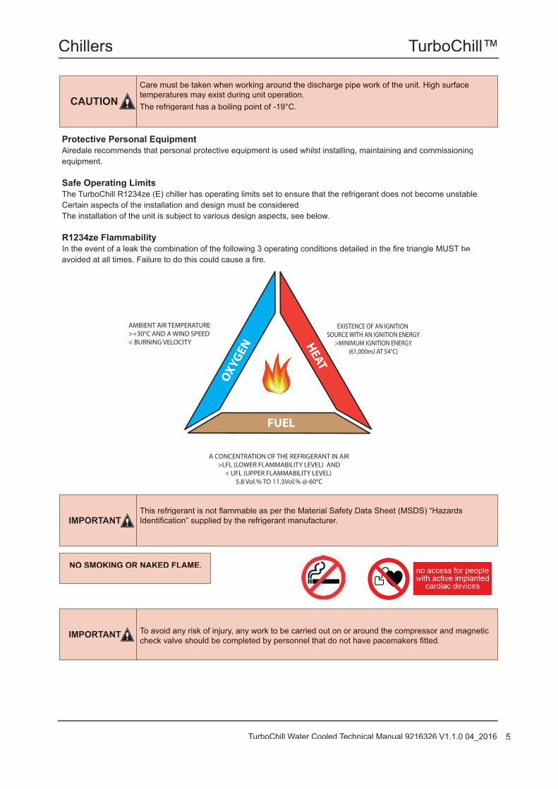
R1234ze Flammability
NO SMOKING OR NAKED FLAME.
To avoid any risk of injury, any work to be carried out on or around the compressor and magnetic
OXYGEN H
EAT
FUEL
A CONCENTRATION OF THE REFRIGERANT IN AIR>LFL (LOWER FLAMMABILITY LEVEL) AND
< UFL (UPPER FLAMMABILITY LEVEL) 5.8 Vol.% TO 11.3Vol.% @ 60°C
EXISTENCE OF AN IGNITION SOURCE WITH AN IGNITION ENERGY
>MINIMUM IGNITION ENERGY(61,000mJ AT 54°C)
AMBIENT AIR TEMPERATURE>+30°C AND A WIND SPEED< BURNING VELOCITY
CAUTION
IMPORTANT
IMPORTANT
TurboChill™ Chillers
TurboChill Water Cooled Technical Manual 9216326 V1.1.0 04_2016
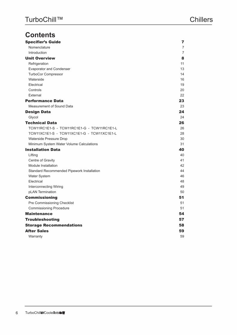
Contents
Nomenclature 7
Introduction 7
Refrigeration 11
Evaporator and Condenser 13
TurboCor Compressor 14
Electrical 19
Controls 20
External 22
Glycol 24
TCW11XC1E1-S - TCW11XC1E1-G - TCW11XC1E1-L 28
Minimum System Water Volume Calculations 31
Lifting 40
Centre of Gravity 41
Module Installation 42
Standard Recommended Pipework Installation 44
Electrical 48
Interconnecting Wiring 49
pLAN Termination 50
Pre Commissioning Checklist 51
Commissioning Procedure 51
Warranty 59

TurboChill™Chillers
7TurboChill Water Cooled Technical Manual 9216326 V1.1.0 04_2016
Example: TCW 1 1 R C1 E1 - S - 0
TurboChill Watercooled
Number of Circuits
Number of Compressors
Noise Variant (Regular R or Extra X Quiet)
Condenser Code (C1)
Evaporator Code (E1)
Compressor Code (S,G,L)
400V 3PH 50Hz Power Supply
The Airedale TurboChill Water Cooled chiller uses the technologically superior centrifugal TurboCor compressors.
Designed for a cooling capacity of 150kW to 1488kW*, the nominal operating conditions are based on EN14511 rating
conditions for water cooled chillers which are 12/7°C Evaporator and 30/35°C Condenser water temperatures.
The range has been designed and optimised for operation with ozone benign R134a refrigerant or R1234ze refrigerant.
The base shall be fabricated from galvanised steel to ensure a rigid, durable, weatherproof construction.
Unit panels shall be manufactured from galvanised sheet steel coated with epoxy baked powder paint to provide a
Standard unit colour shall be Light Grey (RAL 7035).
The Compressor, Evaporator and Condenser shall be mounted on a rigid galvanised heavy-duty sub frame.
Electrical panels shall be situated at one side of the unit.**
*Capacity data based on minimum capacity of one module to maximum capacity of four modules.
**Only low noise (X) models will be supplied with enclosed panels.
Intro
ductio
n
TurboChill™ Chillers
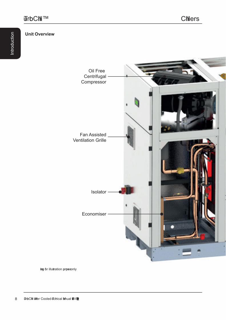
8 TurboChill Water Cooled Technical Manual 9216326 V1.1.0 04_2016
Oil Free
Centrifugal
Compressor
Fan Assisted
Ventilation Grille
Isolator
Economiser
Image for illustration purposes only
Intr
oduction

TurboChill™Chillers
9TurboChill Water Cooled Technical Manual 9216326 V1.1.0 04_2016
Evaporator
Condenser
Intro
ductio
n

TurboChill™ Chillers
10 TurboChill Water Cooled Technical Manual 9216326 V1.1.0 04_2016
The TurboChill Water Cooled Chiller shall be supplied complete with:
• TurboCor Oil Free Compressor
• Microprocessor Control
• Compact Evaporator
• Compact Condenser
• Single Refrigeration Circuit
• Liquid Level Transmitters and Liquid Level Control Valves
• Maintainable Dual Pressure Relief Valves
• Electronic Expansion Valve
• Grooved Water Connections & Counter Pipe Assembly
• Differential Pressure Sensors across the evaporator and condenser offer the same protection as a Water Flow
Switch.
The refrigeration circuit is supplied with the following:
• Full operating charge of R134a or R1234ze refrigerant
•
• Discharge Line Shut Off Valves
• Liquid Line Shut Off Valves
• Filter Driers with Replaceable Core
• Evaporator and Liquid Line Sight Glass
• Low Pressure Switch with Auto Reset
• 2 High Pressure Switches with Manual Reset per compressor
• Liquid Pressure Transducer
• Discharge Check (non return) Valve
Each water glycol circuit shall be supplied with the following:
• Differential Pressure Sensor across the evaporator and condenser offer the same protection as Flow Switches
• Strategically placed Drain Valves
Intr
oduction
TurboChill™Chillers
11TurboChill Water Cooled Technical Manual 9216326 V1.1.0 04_2016
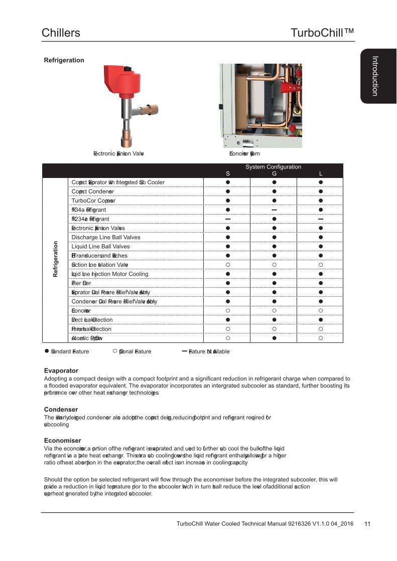
S G L
Compact Evaporator with Integrated Sub Cooler
Compact Condenser
TurboCor Compressor
R134a Refrigerant –R1234ze Refrigerant – –Electronic Expansion Valves
HP/LP Transducers and Switches
Suction Line Isolation Valve
Liquid Line Injection Motor Cooling
Filter Drier
Evaporator Dual Pressure Relief Valve Assembly
Condenser Dual Pressure Relief Valve Assembly
Economiser
Direct Leak Detection
Premium Leak Detection
Automatic Pump Down
Standard Feature Optional Feature – Feature Not Available
Electronic Expansion Valve Economiser System
performance over other heat exchanger technologies.
The similarly designed condenser also adopts the compact design, reducing footprint and refrigerant required for
subcooling.
Via the economiser, a portion of the refrigerant is evaporated and used to further sub cool the bulk of the liquid
refrigerant via a plate heat exchanger. This extra sub cooling lowers the liquid refrigerant enthalpy allowing for a higher
ratio of heat absorption in the evaporator; the overall effect is an increase in cooling capacity.
provide a reduction in liquid temperature prior to the subcooler which in turn shall reduce the level of additional suction
superheat generated by the integrated subcooler.
Intro
ductio
n

TurboChill™ Chillers
12 TurboChill Water Cooled Technical Manual 9216326 V1.1.0 04_2016
Electronic expansion valves differ to the normal thermostatic expansion valves in their ability to maintain control of
loading and low ambient temperatures. EEV step position, superheat setpoint, head pressure set point and other
features can be viewed and adjusted via the microprocessor display.
Whilst offering versatile control at the full design duty of the unit, Thermostatic Expansion Valves (TEV) do not
automatically optimise themselves to all operating conditions. Therefore, if the refrigeration system is operating at 40%
or 50% of full load, especially at a lower ambient temperature than that for which the valve was sized, the conventional
condensing pressure is normal in conventional systems.
Using an EEV allows for good refrigeration control whilst operating at part load and lower ambient conditions with a
superheat at reduced head pressures. The turn-down rate of a typical EEV is superior to that of it’s thermostatic
equivalent, such that a reduced optimum condensing pressure can be maintained at low compressor load.
An EEV can operate effectively between 10-100% of its rated capacity.
any unwanted moisture in the system. This can be serviced with changeable inner cores.
High pressure switches
are manual reset for R134a units and automatic reset for R1234ze units.
will be positioned close to the compressor section.
A premium package is available that monitors refrigeration parameters and determines if loss of refrigerant is occurring.
This can detect which circuit is leaking from these parameters making an intelligent decision of potential shut-down of
the unit.
Intr
oduction
TurboChill™Chillers
13TurboChill Water Cooled Technical Manual 9216326 V1.1.0 04_2016
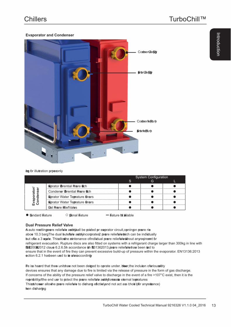
S G L
Evaporator Differential Pressure Switch
Condenser Differential Pressure Switch
Evaporator Water Temperature Sensors
Evaporator Water Temperature Sensors
Dual Pressure Relief Valves
Standard Feature Optional Feature – Feature Not Available
Condenser Inlet (Return)
Condenser Outlet (Supply)
Evaporator Outlet (Supply)
Evaporator Inlet (Return)
Image for illustration purposes only
An auto resetting pressure relief valve assembly shall be provided per evaporator circuit, opening on pressure rise
above 10.3 barg. The dual shut-off valve assembly incorporates 2 pressure relief valves which can be individually
shut off via a 3 way valve. This allows the maintenance of individual pressure relief valves without any requirement for
EN 378-2:2008+A2:2012 clause 6.2.6.5. In accordance with EN13136:2013, pressure relief valves have been sized to
section 6.2.1 has been used to size valves accordingly.
Fire is a hazard that these units have not been designed to operate under. However, the inclusion of various safety
responsibility of the end user to protect the pressure relief valve assembly from excessive external temperatures.
This must however allow the pressure relief valve to discharge effectively and not act as a ‘choke’ (offer any resistance)
when discharging.
Intro
ductio
n

TurboChill™ Chillers
14 TurboChill Water Cooled Technical Manual 9216326 V1.1.0 04_2016
TurboCor Compressor - R134a Refrigerant
S G L
Vibration Isolating Rubber Mounts
Suction Strainer
Discharge Shut Off Valves
Suction Shut Off Valves
Line Reactor
EMI/EMC Filter
Standard Feature Optional Feature – Feature Not Available
Ensure single phase power supply is connected permanently to ensure that the system will isolate
refrigerant and ventilate the compressor housing in the event of a leak being detected. A UPS
permanent supply is required.
TurboCor Compressor - R1234ze Refrigerant
TurboCor centrifugal compressor supplied with as standard:
• Suction and discharge shut off valves
• Discharge non-return valve
• Line reactor (for removing additional impedance harmonics and voltage spikes in the ac waveform)
•
o DC capacitors
o Motor/bearing management system and incorporated surge protection
o Soft start module
o Magnetic bearing system
o Compressors are mounted on Turbocor specially designed vibration reducing isolating rubber mounts
o Linear capacity modulation is provided by a variable frequency drive
IMPORTANT
Intr
oduction
TurboChill™Chillers
15TurboChill Water Cooled Technical Manual 9216326 V1.1.0 04_2016
• Oil Free Operation
• No oil entrainment issues – pipe work can be optimised for performance not oil return
• Variable speed operation offering exact capacity match and optimum part load performance
• Magnetic bearing system constantly optimises shaft / impeller position
• Small and light, only 132kg
• No mechanical contact, very quiet operation
• Very low start current, only 2A
speed control
• Turbocor compressor shaft and impellers levitate on a magnetic cushion eliminating friction and vibration
resulting in the compressor running at a smooth and reduced sound spectrum
o Uses substantially less power at part load and gives accurate set-point control and exact
capacity match
o The inbuilt electronic soft start produces a very low starting current of just 2A and eradicates the need
to oversize electrical supply components on site
Intro
ductio
n
TurboChill™ Chillers
16 TurboChill Water Cooled Technical Manual 9216326 V1.1.0 04_2016
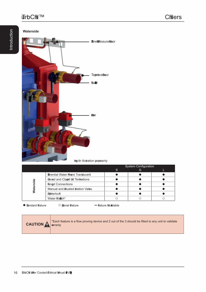
Shut Off Valve
Differential Pressure Sensor
Actuator
Temperature Sensor
S G L
Differential Water Pressure Transducers*
Grooved and Clamped Unit Terminations
Flanged Connections
Manual and Actuated Isolation Valves
Pump Interlock*
Water Flow Switch*
Standard Feature Optional Feature – Feature Not Available
warranty.
Image for illustration purposes only
CAUTION
Intr
oduction
TurboChill™Chillers
17TurboChill Water Cooled Technical Manual 9216326 V1.1.0 04_2016
Provision for a pump interlock is available within the control panel.
warranty.CAUTION
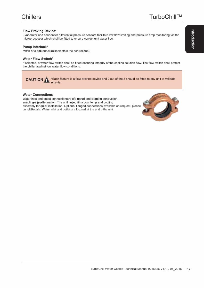
Water inlet and outlet connections are of a grooved and clamped type construction,
enabling easy pipework termination. The unit is supplied with a counter pipe and coupling
consult Airedale. Water inlet and outlet are located at the end of the unit.
Intro
ductio
n
TurboChill™ Chillers
18 TurboChill Water Cooled Technical Manual 9216326 V1.1.0 04_2016
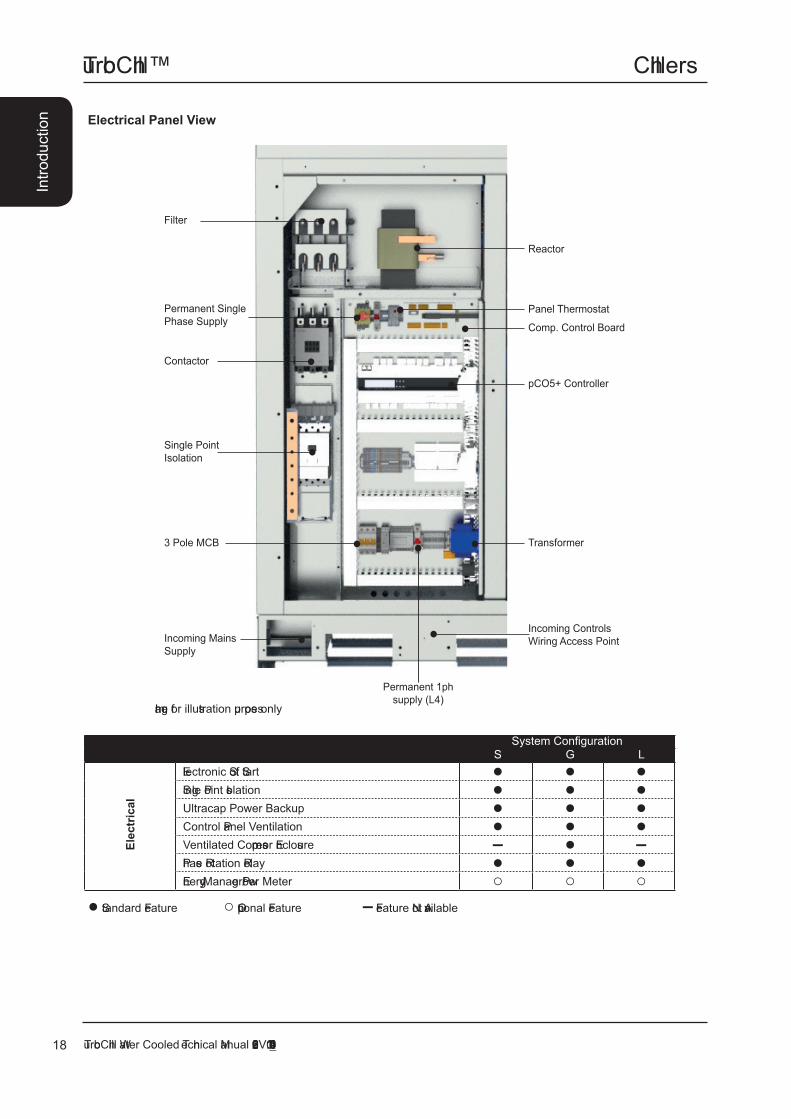
Filter
Reactor
pCO5+ Controller
Contactor
Single Point
Isolation
Permanent 1ph
supply (L4)
Transformer3 Pole MCB
Panel Thermostat
Comp. Control Board
Permanent Single
Phase Supply
Incoming Mains
Supply
Incoming Controls
Wiring Access Point
S G L
Electronic Soft Start
Single Point Isolation
Control Panel Ventilation
Ventilated Compressor Enclosure – –Phase Rotation Relay
Energy Manager/Power Meter
Standard Feature Optional Feature – Feature Not Available
Image for illustration purposes only
Intr
oduction
TurboChill™Chillers
19TurboChill Water Cooled Technical Manual 9216326 V1.1.0 04_2016
An electrical power and controls panel is situated at the front of the unit and contains:
• Individual mains power isolator for the compressor
• Emergency interlock isolator handle
• Fully accessible controls compartment, allowing adjustment of control set points whilst the unit is operational
• Circuit breakers for protection of all major unit components
•
The electrical power and control panel is wired to the latest European standards and codes of practice. Mains supply is
3 phase, a neutral is only required for permanent supply (L4). Separate 230V permanent supply (L4) is required for the
controls and safety features.
TurboChill units are designed for indoor use only and must not be installed outside.
The feature is however available to be removed upon request, subject to your own 3
phase unit mains isolator.
Unit controls are maintained by an Ultracap. The Ultracap module is an external backup
device for the controller. The module guarantees temporary power to the controller in the
event of power failures and allows for enough time to keep the controller running with
time to change power supplies.
The Ultra Capacitors are used to maintain the controller’s main functions, to close the
electronic valves in the event of mains power failures. Power will be maintained until
mains power is reinstated for a maximum period of 10 minutes.
The module is made using Ultracap storage capacitors (EDLC = Electric Double Layer
Capacitor), which are recharged independently by the module.
These ensure reliability in terms of much longer component life than a module made with
lead batteries: the life of the Ultracap module is at least 10 years.
prevent possible damage by running the compressor in the wrong direction.
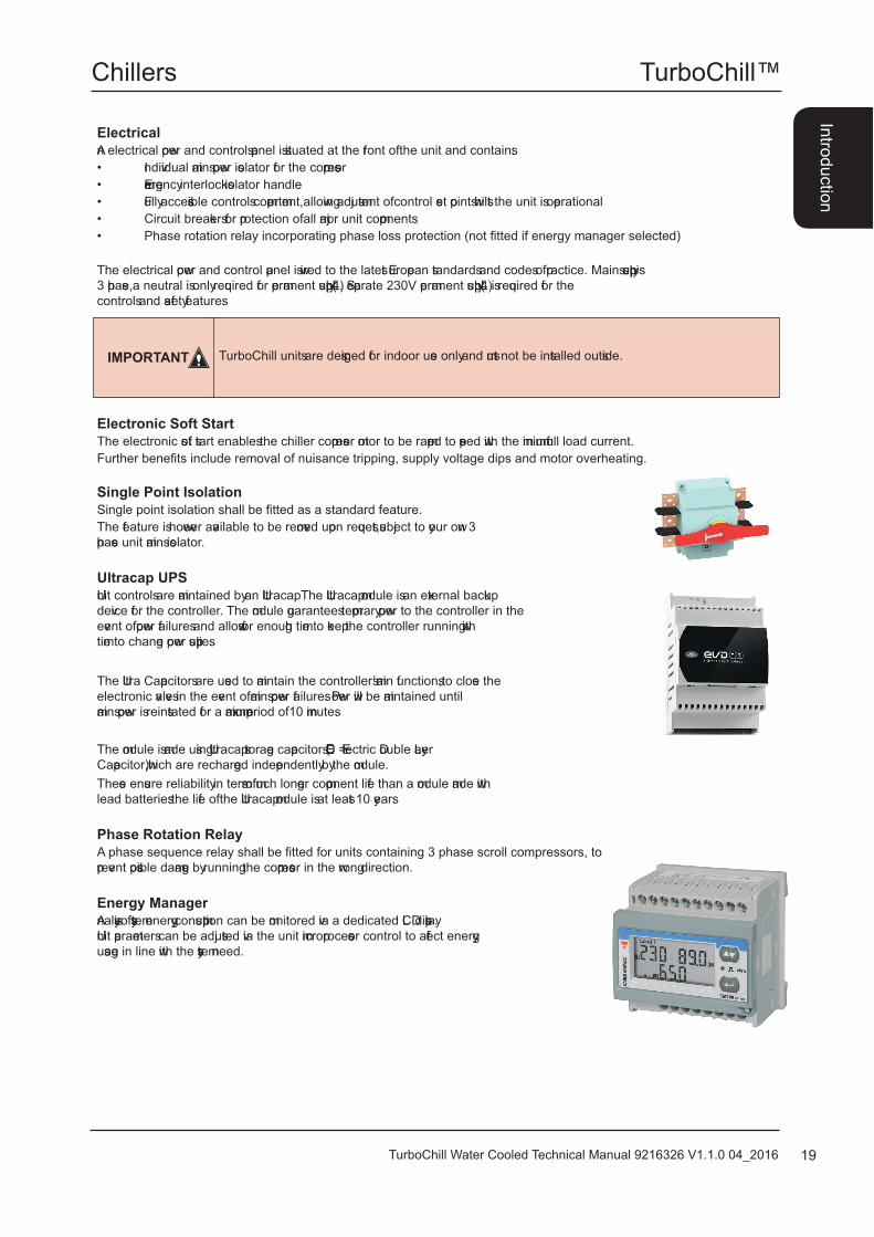
Analysis of system energy consumption can be monitored via a dedicated LCD display.
Unit parameters can be adjusted via the unit microprocessor control to affect energy
usage in line with the system need.
IMPORTANT
The electronic soft start enables the chiller compressor motor to be ramped to speed with the minimum full load current.
Intro
ductio
n
TurboChill™ Chillers
20 TurboChill Water Cooled Technical Manual 9216326 V1.1.0 04_2016
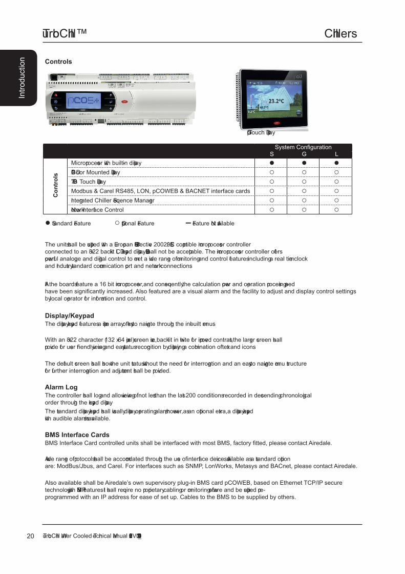
pGD Touch Display
S G L
Microprocessor with built-in display
PGD1 Door Mounted Display
7” PGDT Touch Display
Integrated Chiller Sequence Manager
Network Interface Control
Standard Feature Optional Feature – Feature Not Available
The units shall be supplied with a European ROHS Directive 2002/95/EC compatible microprocessor controller
connected to an 8 x 22 back-lit LCD keypad display. LEDs shall not be acceptable. The microprocessor controller offers
powerful analogue and digital control to meet a wide range of monitoring and control features including a real time clock
and Industry standard communication port and network connections.
All the boards feature a 16 bit microprocessor, and consequently the calculation power and operation processing speed
by local operator for information and control.
The display keypad features a simple array of keys to navigate through the in-built menus.
With an 8 x 22 character (132 x 64 pixel) screen size, back lit in white for improved contrast, the larger screen shall
provide for user friendly viewing and easy status recognition by displaying a combination of text and icons.
The default screen shall show the unit status without the need for interrogation and an easy to navigate menu structure
for further interrogation and adjustment shall be provided.
The controller shall log and allow viewing of not less than the last 200 conditions recorded in descending chronological
order through the keypad display.
The standard display keypad shall visually display operating alarms, however, as an optional extra, a display keypad
with audible alarms is available.
A wide range of protocols shall be accommodated through the use of interface devices. Available as a standard option
technology with SNMP features. It shall require no proprietary cabling or monitoring software and be supplied pre-
Intr
oduction

TurboChill™Chillers
21TurboChill Water Cooled Technical Manual 9216326 V1.1.0 04_2016
A sequence light control algorithm has been integrated into the unit strategy which will allow operation of up to 4
modules (circa 1.5MW). The loading sequence has also been optimised to maximise system EER for a given load,
where multiple TCW modules will share the load evenly when possible.
As a single module ramps up to 60% demand, the second module becomes active and ramps up to 30% (minimum).
8 modules. Once all modules are active they will load up equally as the system load increases. This loading strategy
minimum possible demand (for each module), and then as one module is switched off the remaining modules ramp up
to make up the difference to maintain a smooth reduction in cooling capacity. This strategy is continued until the system
is at its minimum cooling capacity represented by one module at its minimum demand.
TurboChill optimised loading sequence
Intro
ductio
n
TurboChill™ Chillers
22 TurboChill Water Cooled Technical Manual 9216326 V1.1.0 04_2016
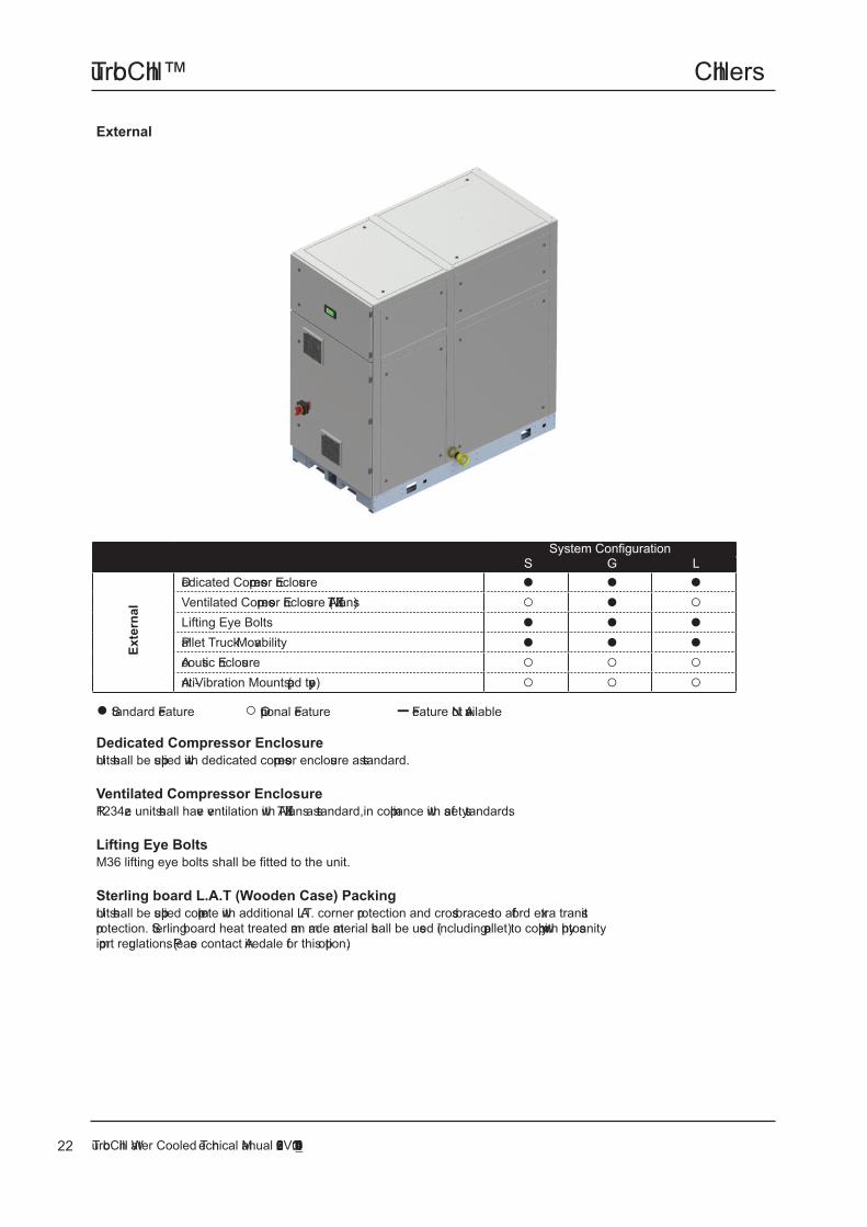
S G L
Dedicated Compressor Enclosure
Ventilated Compressor Enclosure (ATEX fans)
Pallet Truck Movability
Acoustic Enclosure
Anti-Vibration Mounts (pad type)
Standard Feature Optional Feature – Feature Not Available
Units shall be supplied with dedicated compressor enclosure as standard.
R1234ze units shall have ventilation with ATEX fans as standard, in compliance with safety standards.
Units shall be supplied complete with additional L.A.T. corner protection and cross braces to afford extra transit
protection. Sterling board heat treated man made material shall be used (including pallet) to comply with phytosanity
import regulations. (Please contact Airedale for this option).

TurboChill™Chillers
23TurboChill Water Cooled Technical Manual 9216326 V1.1.0 04_2016
All sound data quoted has been measured in the third-octave band limited values, using a Real Time Analyser calibrated
emitted in the horizontal plane in all directions.
Sound Pressure Levels are calculated from sound power using the expanded parallelepiped method according to
The global sound measurements quoted in the following tables do not incorporate any directivity or denote any sound level
heard at any given position surrounding the unit, rather they represent the total sound level radiating from the unit in all
directions in the horizontal plane from source.
Control Panel side Evaporator & Condenser side
-10-10
-3
-3
Technica
l

TurboChill™ Chillers
24 TurboChill Water Cooled Technical Manual 9216326 V1.1.0 04_2016
Design Data
Glycol
Glycol is recommended when a supply water temperature of +5°C or below is required or when static water can be
section at the front of this document.
Glycol Percentage / Freezing Point
Temperature °C 0% / 0°C 20% / -7.8°C 25% / -10.7°C 30% / -14.1°C 35% / -17.9°C 40% / -22.3°C
0 4.21 3.77 3.68 3.59 3.50 3.40
5 4.20 3.78 3.69 3.60 3.51 3.42
10 4.19 3.79 3.71 3.62 3.53 3.44
15 4.19 3.80 3.72 3.63 3.54 3.45
20 4.18 3.82 3.73 3.65 3.56 3.47
25 4.18 3.83 3.74 3.66 3.57 3.49
30 4.18 3.84 3.76 3.67 3.59 3.50
35 4.18 3.85 3.77 3.69 3.60 3.52
40 4.18 3.86 3.78 3.70 3.62 3.54
45 4.18 3.87 3.79 3.72 3.63 3.55
Glycol Percentage / Freezing Point
Temperature °C 0% / 0°C 20% / -7.8°C 25% / -10.7°C 30% / -14.1°C 35% / -17.9°C 40% / -22.3°C
0 999.8 1035.7 1043.7 1051.8 1059.3 1066.8
5 999.9 1034.4 1042.4 1050.3 1057.8 1065.2
10 999.7 1032.9 1040.9 1048.8 1056.1 1063.5
15 999.0 1031.4 1039.2 1047.1 1054.4 1061.7
20 998.2 1029.7 1037.5 1045.3 1052.5 1059.7
25 997.0 1027.9 1035.6 1043.3 1050.5 1057.6
30 995.6 1026.0 1033.6 1041.3 1048.3 1055.4
35 994.0 1024.0 1031.5 1039.1 1046.1 1053.1
40 992.2 1021.8 1029.3 1036.8 1043.7 1050.6
45 990.2 1019.6 1027.0 1034.4 1041.2 1048.1
Ethylene Glycol Density
Q =ρ x m x Cp x ∆t
Where
Q = Cooling Performance (kW)ρ = Density of cooling medium (kg/m³)m = mass flow of cooling media (kg/s)Cp = Specific heat Capacity (kj/kg K)∆t = Temperature difference between Inlet and Outlet (K)
.
.
Glycol in System / Freezing Point ºC
10% / -3.2°C 20% / -7.8°C 30% / -14.1°C 40% / -22.3°C
Cooling Duty
Catalogue
Data x by:
0.98 0.97 0.95 0.93
Input Power 0.99 0.98 0.96 0.95
Water Flow 0.99 1.02 1.04 1.07
Pressure Drop 1.05 1.20 1.38 1.57
Correction Factors
Technic
al

TurboChill™Chillers
25TurboChill Water Cooled Technical Manual 9216326 V1.1.0 04_2016
Glycol is recommended when a supply water temperature of +5°C or below is required or when static water can be
section at the front of this document.
Glycol Percentage / Freezing Point
Temperature °C 0% / 0°C 20% / -7.1°C 25% / -9.6°C 30% / -12.7°C 35% / -16.4°C 40% / -21.1°C
0 4.21 3.93 3.86 3.79 3.72 3.64
5 4.20 3.94 3.87 3.81 3.73 3.65
10 4.19 3.95 3.89 3.82 3.75 3.67
15 4.19 3.96 3.90 3.83 3.76 3.69
20 4.18 3.97 3.91 3.85 3.78 3.70
25 4.18 3.98 3.92 3.86 3.79 3.72
30 4.18 3.99 3.94 3.88 3.81 3.74
35 4.18 4.01 3.95 3.89 3.82 3.75
40 4.18 4.02 3.96 3.90 3.84 3.77
45 4.18 4.03 3.97 3.92 3.85 3.78
Glycol Percentage / Freezing Point
Temperature °C 0% / 0°C 20% / -7.1°C 25% / -9.6°C 30% / -12.7°C 35% / -16.4°C 40% / -21.1°C
0 999.8 1025.8 1031.0 1036.2 1040.7 1045.1
5 999.9 1024.3 1029.4 1034.5 1038.8 1043.1
10 999.7 1022.7 1027.6 1032.6 1036.8 1040.9
15 999.0 1020.9 1025.7 1030.5 1034.6 1038.7
20 998.2 1019.0 1023.7 1028.4 1032.3 1036.2
25 997.0 1017.0 1021.5 1026.1 1029.9 1033.7
30 995.6 1014.8 1019.2 1023.6 1027.3 1031.0
35 994.0 1012.6 1016.8 1021.1 1024.7 1028.2
40 992.2 1010.2 1014.3 1018.4 1021.9 1025.3
45 990.2 1007.6 1011.6 1015.6 1018.9 1022.2
Propylene Glycol Density
Glycol
Design Data
Q =ρ x m x Cp x ∆t
Where
Q = Cooling Performance (kW)ρ = Density of cooling medium (kg/m³)m = mass flow of cooling media (kg/s)Cp = Specific heat Capacity (kj/kg K)∆t = Temperature difference between Inlet and Outlet (K)
.
.
Glycol in System / Freezing Point ºC
10% / -3.3°C 20% / -7.1°C 30% / -12.7°C 40% / -21.1°C
Cooling Duty
Catalogue
Data x by:
0.97 0.95 0.91 0.88
Input Power 0.99 0.98 0.96 0.95
Water Flow 0.98 0.97 0.95 0.95
Pressure Drop 1.08 1.17 1.31 1.45
Correction Factors
Technica
l
TurboChill™ Chillers
26 TurboChill Water Cooled Technical Manual 9216326 V1.1.0 04_2016
Technic
al
(2) EER = Cooling duty/compressor input power
(4) Nominal dimensions does not include waterside isolation valves external to unit
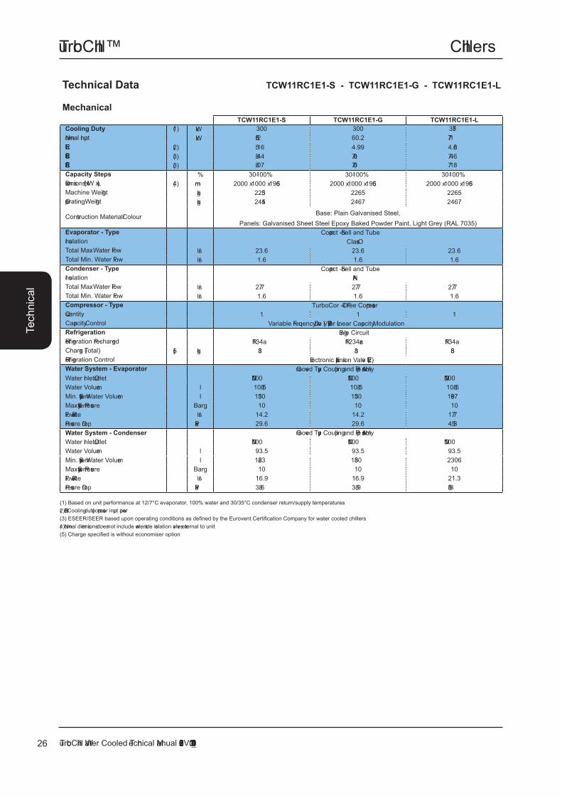
TCW11RC1E1-S
(1) kW 300 300 375
Nominal Input kW 58.2 60.2 77.1
EER (2) 5.16 4.99 4.86
ESEER (3) 8.44 7.80 7.46
SEER (3) 8.07 7.50 7.18
% 30-100% 30-100% 30-100%
Dimensions (H x W x L) (4) mm 2000 x 1000 x 1956 2000 x 1000 x 1956 2000 x 1000 x 1956
Machine Weight kg 2253 2265 2265
Operating Weight kg 2454 2467 2467
Construction Material/Colour
Compact - Shell and Tube
Insulation Class O
Total Max. Water Flow l/s 23.6 23.6 23.6
Total Min. Water Flow l/s 1.6 1.6 1.6
Compact - Shell and Tube
Insulation N/A
Total Max. Water Flow l/s 27.7 27.7 27.7
Total Min. Water Flow l/s 1.6 1.6 1.6
TurboCor - Oil Free Compressor
Quantity 1 1 1
Capacity Control Variable Frequency Drive (VFD) for Linear Capacity Modulation
Single Circuit
Refrigeration Pre-charged R134a R1234ze R134a
Charge (Total) (5) kg 83 83 85
Refrigeration Control Electronic Expansion Valve (EEV)
Grooved Type Coupling and Pipe Assembly
Water Inlet/Outlet DN100 DN100 DN100
Water Volume l 108.5 108.5 108.5
Min. System Water Volume l 1530 1530 1897
Max. System Pressure 10 10 10
Flow Rate l/s 14.2 14.2 17.7
Pressure Drop kPa 29.6 29.6 45.8
Grooved Type Coupling and Pipe Assembly
Water Inlet/Outlet DN100 DN100 DN100
Water Volume l 93.5 93.5 93.5
Min. System Water Volume l 1823 1830 2306
Max. System Pressure 10 10 10
Flow Rate l/s 16.9 16.9 21.3
Pressure Drop kPa 38.6 38.9 58.8
TurboChill™Chillers
27TurboChill Water Cooled Technical Manual 9216326 V1.1.0 04_2016
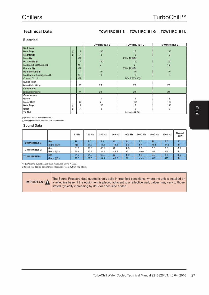
(2) Starting amps refers to the direct on line connections.
TCW11RC1E1-S
Nominal Run Amps (1) A 135 150 210
Maximum Start Amps (2) A 2 2 2
Mains Supply VAC 400V (±10%) 3PH 50Hz
Rec Mains Fuse Size A 160 160 250
Max Mains Incoming Cable Size mm² 70 70 185
Permanent Supply VAC 230V (±10%) 1PH 50Hz
Rec Permanent Fuse Size A 16 16 16
Max Permanent Incoming Cable Size mm² 6 6 6
Control Circuit VAC 24V & 230V (±10%)
Immersion Heater Rating W 270 270 270
Immersion Heater Rating W 270 270 270
Quantity 1 1 1
Motor Rating kW 87 92 130
Nominal Run Amps (1) A 135 150 210
Start Amps (2) A 2 2 2
Type Of Start Electronic Soft Start
Technica
l
TCW11RC1E1-SPower 77.5 73.0 73.3 76.1 85.4 83.2 78.2 76.6 88.7
Pressure @ 10m 45.8 41.3 41.6 44.3 53.6 51.4 46.5 44.8 57.0
Power 61.3 61.3 66.2 78.0 86.9 81.6 80.0 79.3 89.5
Pressure @ 10m 29.5 29.5 34.4 46.2 55.2 49.9 48.3 47.5 57.8
Power 61.3 61.3 66.2 78.0 86.9 81.6 80.0 79.3 89.5
Pressure @ 10m 29.5 29.5 34.4 46.2 55.2 49.9 48.3 47.5 57.8
2) All sound data measured at nominal conditions: Water in/out 12/7°C at 30°C ambient.
IMPORTANT

TurboChill™ Chillers
28 TurboChill Water Cooled Technical Manual 9216326 V1.1.0 04_2016
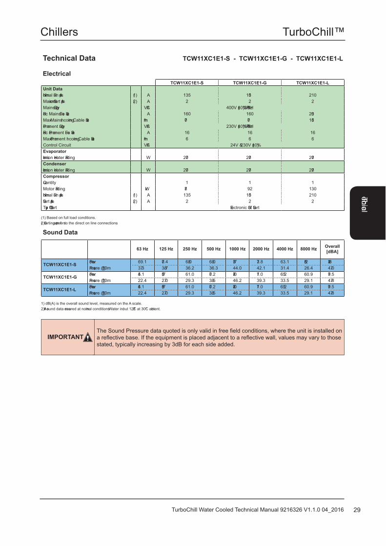
TCW11XC1E1-S
(1) kW 300 300 375
Nominal Input kW 58.2 60.2 77.1
EER (2) 5.16 4.99 4.86
ESEER (3) 8.44 7.8 7.46
SEER (3) 8.07 7.50 7.18
% 30-100% 30-100% 30-100%
Dimensions (H x W x L) (4) mm 2000 x 1000 x 1956 2000 x 1000 x 1956 2000 x 1000 x 1956
Machine Weight kg 2358 2370 2370
Operating Weight kg 2559 2572 2572
Construction Material/Colour
Compact - Shell and Tube
Insulation Class O
Total Max. Water Flow l/s 23.6 23.6 23.6
Total Min. Water Flow l/s 1.6 1.6 1.6
Compact - Shell and Tube
Insulation N/A
Total Max. Water Flow l/s 27.7 27.7 27.7
Total Min. Water Flow l/s 1.6 1.6 1.6
TurboCor - Oil Free Compressor
Quantity 1 1 1
Capacity Control Variable Frequency Drive (VFD) for Linear Capacity Modulation
Single Circuit
Refrigeration Pre-charged R134a R1234ze R134a
Charge (Total) (5) kg 83 83 85
Refrigeration Control Electronic Expansion Valve (EEV)
Grooved Type Coupling and Pipe Assembly
Water Inlet/Outlet DN100 DN100 DN100
Water Volume l 108.5 108.5 108.5
Min. System Water Volume l 1530 1530 1897
Max. System Pressure 10 10 10
Flow Rate l/s 14.2 14.2 17.7
Pressure Drop kPa 29.6 29.6 45.8
Grooved Type Coupling and Pipe Assembly
Water Inlet/Outlet DN100 DN100 DN100
Water Volume l 93.5 93.5 93.5
Min. System Water Volume l 1823 1830 2306
Max. System Pressure 10 10 10
Flow Rate l/s 16.9 16.9 21.3
Pressure Drop kPa 38.6 38.9 58.8
Technic
al
(2) EER = Cooling duty/compressor input power
(4) Nominal dimensions does not include waterside isolation valves external to unit
TurboChill™Chillers
29TurboChill Water Cooled Technical Manual 9216326 V1.1.0 04_2016
(2) Starting amps refers to the direct on line connections.
Technica
l
TCW11XC1E1-S
Nominal Run Amps (1) A 135 150 210
Maximum Start Amps (2) A 2 2 2
Mains Supply VAC 400V (±10%) 3PH 50Hz
Rec Mains Fuse Size A 160 160 250
Max Mains Incoming Cable Size mm² 70 70 185
Permanent Supply VAC 230V (±10%) 1PH 50Hz
Rec Permanent Fuse Size A 16 16 16
Max Permanent Incoming Cable Size mm² 6 6 6
Control Circuit VAC 24V & 230V (±10%)
Immersion Heater Rating W 270 270 270
Immersion Heater Rating W 270 270 270
Quantity 1 1 1
Motor Rating kW 87 92 130
Nominal Run Amps (1) A 135 150 210
Start Amps (2) A 2 2 2
Type Of Start Electronic Soft Start
TCW11XC1E1-SPower 69.1 70.4 68.0 68.0 75.7 73.8 63.1 58.2 78.8
Pressure @ 10m 37.3 38.7 36.2 36.3 44.0 42.1 31.4 26.4 47.0
Power 54.1 58.7 61.0 70.2 78.0 71.0 65.2 60.9 79.5
Pressure @ 10m 22.4 27.0 29.3 38.5 46.2 39.3 33.5 29.1 47.8
Power 54.1 58.7 61.0 70.2 78.0 71.0 65.2 60.9 79.5
Pressure @ 10m 22.4 27.0 29.3 38.5 46.2 39.3 33.5 29.1 47.8
2) All sound data measured at nominal conditions: Water in/out 12/7°C at 30°C ambient.
IMPORTANT

TurboChill™ Chillers
30 TurboChill Water Cooled Technical Manual 9216326 V1.1.0 04_2016
Technic
al
0
20
40
60
80
100
120
0 5 10 15 20 25 30
Pre
ss
ure
Dro
pk
Pa
Flowrate l/s
0
20
40
60
80
100
120
0 5 10 15 20 25 30
Pre
ss
ure
Dro
pk
Pa
Flowrate l/s
Graphs represent performance at 100% water.
TurboChill™Chillers
31TurboChill Water Cooled Technical Manual 9216326 V1.1.0 04_2016
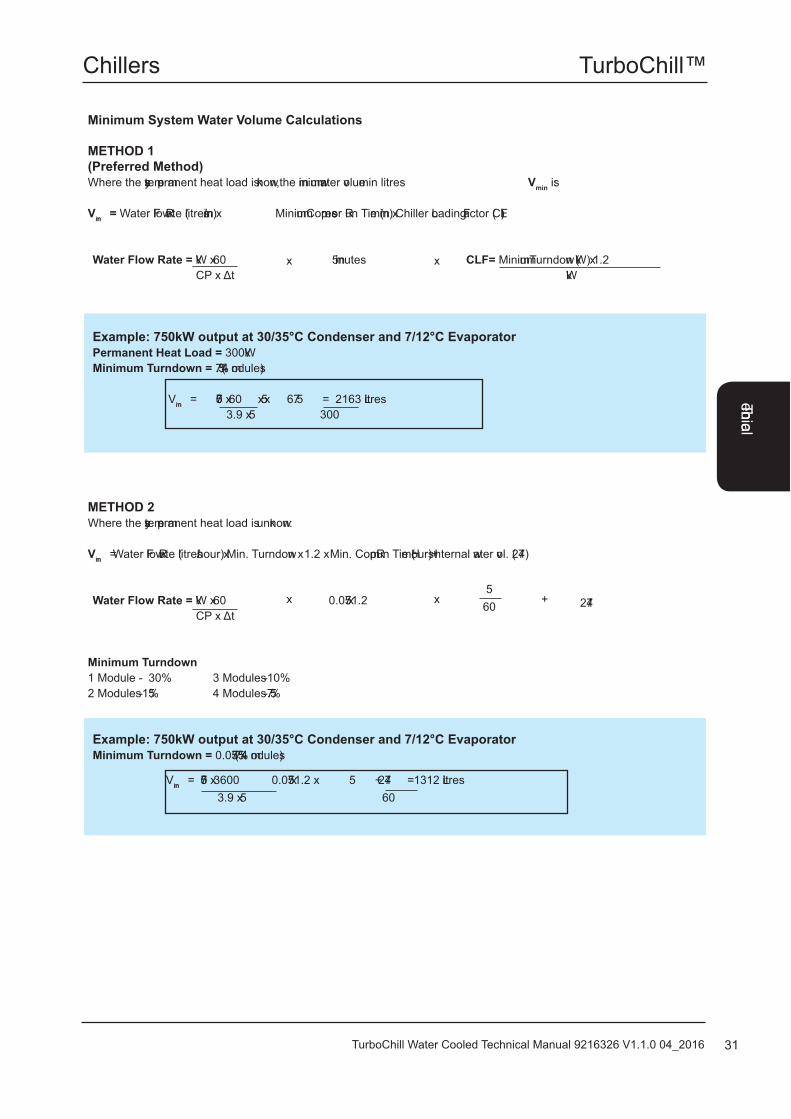
Where the system permanent heat load is known, the minimum water volume in litres min
is:
minWater Flow Rate (litres/min) x Minimum Compressor Run Time (min) xChiller Loading Factor (CLF)
300kW
7.5% (4 modules)
Vmin
= 750 x 60 x 5 x 67.5 = 2163 Litres
3.9 x 5 300
kW x 60 5 minutes Minimum Turndown (kW) x 1.2
kW
x x
Where the system permanent heat load is unknown:
min = Water Flow Rate (litres/hour) x Min. Turndown x 1.2 x Min. Comp. Run Time (Hours) + Internal water vol. (274)
0.075 (7.5% 4 modules)
Vmin
= 750 x 3600 0.075 x 1.2 x 5 + 274 = 1312 Litres
3.9 x 5 60
kW x 60 x x
1 Module - 30%
2 Modules - 15%
3 Modules - 10%
4 Modules - 7.5%
0.075 x 1.25
60+ 274
Technica
l
TurboChill™ Chillers
40 TurboChill Water Cooled Technical Manual 9216326 V1.1.0 04_2016
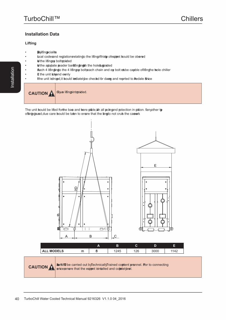
• Employ lifting specialists
• Local codes and regulations relating to the lifting of this type of equipment should be observed
• Use the lifting eye bolts provided
• Use the appropriate spreader bars/lifting slings with the holes/lugs provided
• Attach 4 lifting slings to the 4 lifting eye bolts, each chain and eye bolt must be capable of lifting the whole chiller
• Lift the unit slowly and evenly
• If the unit is dropped, it should immediately be checked for damage and reported to Airedale Service
Only use lifting points provided.CAUTION
ALL work MUST be carried out by Technically Trained competent personnel. Prior to connecting
services, ensure that the equipment is installed and completely level.CAUTION
Insta
llation
Installation Data
Lifting
The unit should be lifted from the base and where possible, with all packing and protection in position. If any other type
of slinging is used, due care should be taken to ensure that the slings do not crush the casework.
A B C D E
ALL MODELS mm 550 1245 126 3000 1142
1141.9
B C
E
A

TurboChill™Chillers
41TurboChill Water Cooled Technical Manual 9216326V1.1.0 04_2016TurboChill Water Cooled Technical Manual 9216326TurboChill Water Cooled Technical Manual 9216326
Insta
llatio
n
Installation Data
Centre of Gravity
L2L1
R1 R2
Lifting
Mass
Operating
MassL1 L2 R1 R2 CoG 1 CoG 2 Lifting CoG
kg kg P1 P2 P3 P4 mm mm x y
TCW11RC1E1-S 2253 2465 405 815 410 830 505 1225 500 1220
TCW11RC1E1-G 2265 2477 410 820 420 830 505 1220 500 1220
TCW11RC1E1-L 2265 2477 410 820 420 830 505 1220 500 1220
TCW11XC1E1-S 2358 2570 435 840 440 855 505 1215 500 1220
TCW11XC1E1-G 2370 2582 440 845 445 855 505 1215 500 1220
TCW11XC1E1-L 2370 2582 440 845 445 855 505 1215 500 1220
TurboChill™ Chillers
42 TurboChill Water Cooled Technical Manual 9216326 V1.1.0 04_2016
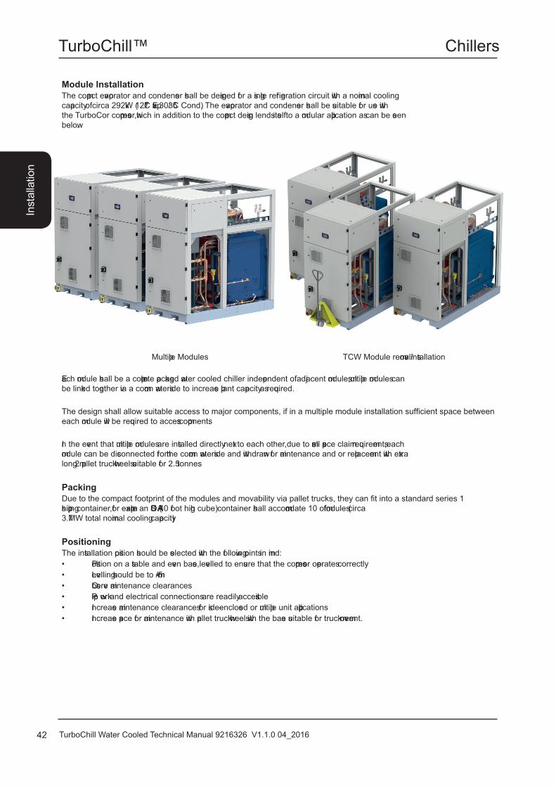
Module Installation
The compact evaporator and condenser shall be designed for a single refrigeration circuit with a nominal cooling
capacity of circa 292kW (12/7°C Evap 30/35°C Cond). The evaporator and condenser shall be suitable for use with
the TurboCor compressor, which in addition to the compact design lends itself to a modular application as can be seen
below.
Each module shall be a complete packaged water cooled chiller independent of adjacent modules; multiple modules can
be linked together via a common waterside to increase plant capacity as required.
each module will be required to access components.
In the event that multiple modules are installed directly next to each other, due to small space claim requirements, each
module can be disconnected from the common waterside and withdrawn for maintenance and or replacement with extra
long 2m pallet truck wheels suitable for 2.5 tonnes.
Packing
shipping container, for example an ISO 1AAA (40 foot high cube) container shall accommodate 10 off modules (circa
3.7MW total nominal cooling capacity)
Positioning
The installation position should be selected with the following points in mind:
• Position on a stable and even base, levelled to ensure that the compressor operates correctly
• Levelling should be to +/- 5mm
• Observe maintenance clearances
• Pipe work and electrical connections are readily accessible
• Increase maintenance clearances for side-enclosed or multiple unit applications
• Increase space for maintenance with pallet truck wheels with the base suitable for truck movement.
Multiple Modules TCW Module removal/installation
Insta
llation
TurboChill™Chillers
43TurboChill Water Cooled Technical Manual 9216326V1.1.0 04_2016TurboChill Water Cooled Technical Manual 9216326TurboChill Water Cooled Technical Manual 9216326
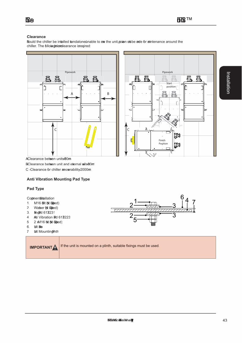
Pad Type
Components/Installation
1. M16 Bolt (Not Supplied)
2. Washer (Not Supplied)
3. Fixing Pad 6173231
4. Anti Vibration Pad 6173223
5. 2 x M16 Nut (Not Supplied)
6. Unit Base
7. Unit Mounting Plinth
12 3
25
4
3
67
Anti Vibration Mounting Pad Type
Clearance
Should the chiller be installed standalone/unable to move the unit, provison must be made for maintenance around the
chiller. The following minimum clearance is required:
A B
C
Pipework
A - Clearance between units - 800mm
B - Clearance between unit and external walls - 800mm
C - Clearance for chiller manoverability - 2000mm
C
Pipework
Startposition
Finish Position
IMPORTANT
Insta
llatio
n
TurboChill™ Chillers
44 TurboChill Water Cooled Technical Manual 9216326 V1.1.0 04_2016
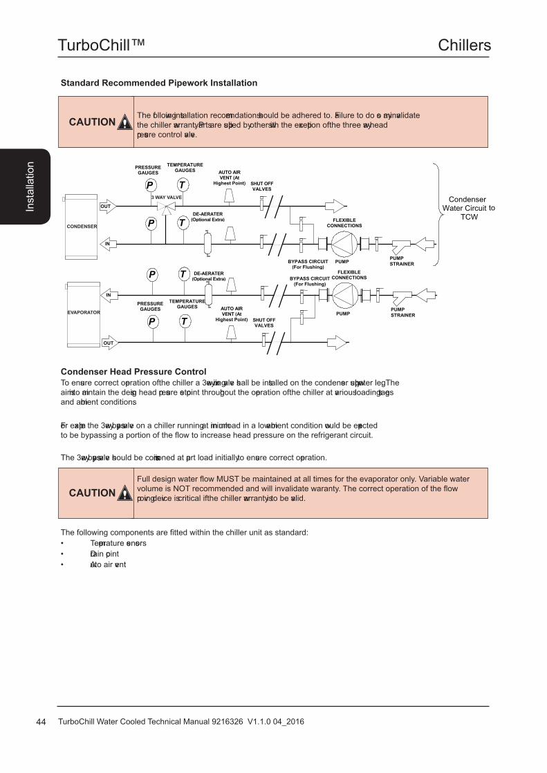
Standard Recommended Pipework Installation
Condenser Head Pressure Control
To ensure correct operation of the chiller a 3-way mixing valve shall be installed on the condenser supply water leg. The
aim is to maintain the design head pressure setpoint throughout the operation of the chiller at various loading stages
and ambient conditions.
For example the 3-way bypass valve on a chiller running at minimum load in a low ambient condition would be expected
The 3-way bypass valve should be commissioned at part load initially to ensure correct operation.
P T
BYPASS CIRCUIT(For Flushing)
SHUT OFFVALVES
TEMPERATUREGAUGES
PRESSUREGAUGES
FLEXIBLECONNECTIONS
AUTO AIRVENT (At
Highest Point)
PUMPPUMP
STRAINER
TP
OUT
IN
DE-AERATER(Optional Extra)
P T SHUT OFFVALVES
TEMPERATUREGAUGES
PRESSUREGAUGES
FLEXIBLECONNECTIONS
AUTO AIRVENT (At
Highest Point)
OUT
BYPASS CIRCUIT(For Flushing)
PUMPPUMP
STRAINER
TP
IN
DE-AERATER(Optional Extra)
CondenserWater Circuit to
TCW
3 WAY VALVE
CONDENSER
EVAPORATOR
Insta
llation
The following installation recommendations should be adhered to. Failure to do so may invalidate
the chiller warranty. Parts are supplied by others with the exception of the three way head
pressure control valve.
proving device is critical if the chiller warranty is to be valid.
• Temperature sensors
• Drain point
• Auto air vent
CAUTION
CAUTION
TurboChill™Chillers
45TurboChill Water Cooled Technical Manual 9216326V1.1.0 04_2016
Insta
llatio
n
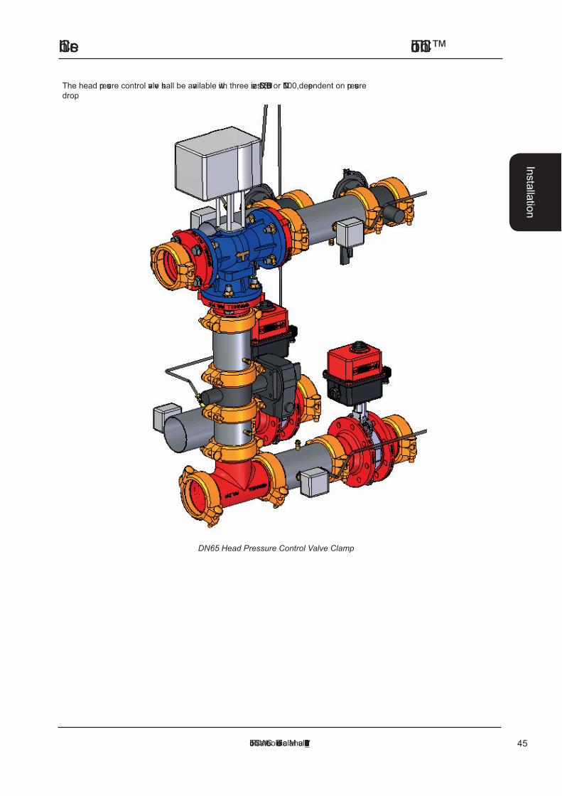
The head pressure control valve shall be available with three sizes: DN65, DN80 or DN100, dependent on pressure
drop.
DN65 Head Pressure Control Valve Clamp

TurboChill™ Chillers
46 TurboChill Water Cooled Technical Manual 9216326 V1.1.0 04_2016
Insta
llation
Water System
Component Recommended Requirements
The recommended requirements to allow commissioning to be carried out correctly are:
•
readings
•
•
•
• In multiple chiller installations, 1 commissioning valve set is required per chiller
• Isolating valves should be installed adjacent to all major items of equipment for ease of maintenance
• Balancing valves can be installed if required to aid correct system balancing
• All chilled water pipework must be insulated and vapour sealed to avoid condensation
• If several units are installed in parallel adjacent to each other, reverse return should be applied to avoid
unnecessary balancing valves
Chilled water pipework and ancillary components must be installed in accordance with:
• National and local water supply company standards
•
• The system liquid is treated to prevent corrosion and algae forming
• In ambients of 0°C and below, where static water can be expected, or when water supply temperatures of +5°C
or below is required, the necessary concentration of Glycol or use of an electrical trace heater must be included
• The schematic is referred to as a guide to ancillary recommendations
The unit water connections are NOT designed to support external pipework, pipework MUST
be supported separately. Pipes are fully isolated from supports helping to prevent electrolytic
corrosion. Units may be moved periodically for maintenance requirements.
Grooved & Clamped Type Connection
Rubber gasket
Shouldered bolts
CLAMP ASSEMBLY
Split between two
clamp halves
1
CUTAWAY SIDE-VIEW
2
3
CLOSE-UP OF JOINT
AND RUBBER GASKET
Split between two
pipe halves
CAUTION
TurboChill™Chillers
47TurboChill Water Cooled Technical Manual 9216326V1.1.0 04_2016
Failure to install safety devices will invalidate the chiller warranty. CAUTION
Insta
llatio
n
Pump Statement
When installing circulating water pumps or equipment containing them, the following rules should be applied:
•
this is required because the pumped liquid cools the pump bearings and mechanical seal faces
• To avoid cavitation the NPSH (Net Positive Suction Head) incorporating a safety margin of 0.5Barg must be
available at the pump inlet during operation
Interlocks & Protection
reasons.
Maximum System Operating Pressure
The system can safely operate at a maximum of 10bar.
Filling
•
• Once the system has been completely vented all vents should be closed
•
pipework
•
• Considerations must be made for glycol of the correct concentration to ensure the cooling medium is not diluted
Although a pressure of 1.5 x working pressure is adequate for testing purposes, most local water
authorities require 2 x working pressure. CAUTION
CAUTION
TurboChill™ Chillers
48 TurboChill Water Cooled Technical Manual 9216326 V1.1.0 04_2016
Insta
llation
Electrical
As standard the equipment is designed for 400V, 3 phase, 3 wire 50Hz and a separate permanent 230V, 1 phase, 50Hz
supply, to all relevant IEE regulations, British standards and IEC requirements.
The control voltage to the interlocks is 24V, always size the low voltage interlock and protection cabling for a maximum
voltage drop of 2 volts.
A fused and isolated electrical supply of the appropriate phase, frequency and voltage should be installed.
Wires should be capable of carrying the maximum load current under non-fault conditions at the stipulated voltage.
Ensure correct phase rotation.
• Please refer to the electrical wiring diagrams provided for installation
• ALL work MUST be carried out by technically trained competent personnel
• The equipment contains live electrical and moving parts, ISOLATE prior to maintenance
or repair work
• The unit isolators DO NOT isolate the incoming mains supply, but isolate the individual
electrical circuits. Isolate REMOTELY the mains incoming supply prior to
maintenance or repair work
• Ensure electrical lock off procedures are conducted
A separately fused, locally isolated, permanent single phase and neutral supply is required for the
evaporator trace heating and control circuit.CAUTION
IMPORTANT
TurboChill™Chillers
49TurboChill Water Cooled Technical Manual 9216326V1.1.0 04_2016
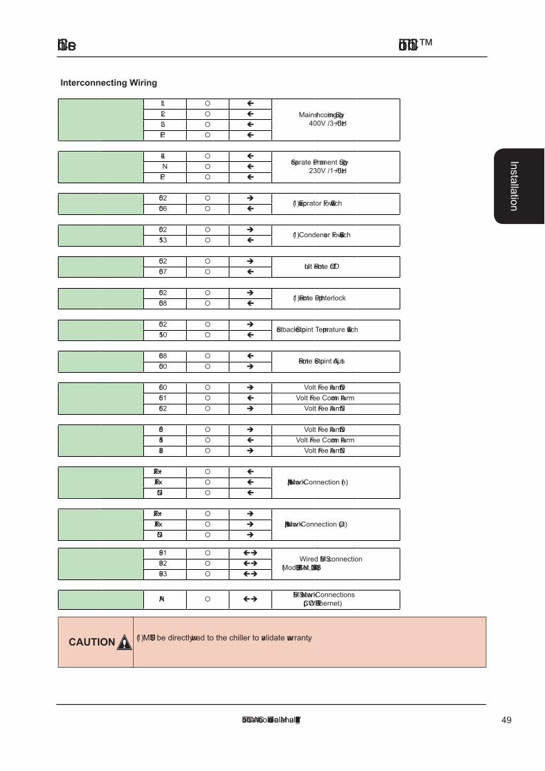
Interconnecting Wiring
L1
Mains Incoming Supply
400V / 3~ / 50Hz
L2
L3
PE
L4Separate Permanent Supply
230V / 1~ / 50HzN
PE
502(1) Evaporator Flow Switch
506
502(1) Condenser Flow Switch
513
502Unit Remote On/Off
507
502(1) Remote Pump Interlock
508
502Setback Setpoint Temperature Switch
510
808Remote Setpoint Adjust
500
560 Volt Free Alarm N/O
561 Volt Free Common Alarm
562 Volt Free Alarm N/C
580 Volt Free Alarm N/O
581 Volt Free Common Alarm
582 Volt Free Alarm N/C
Rx/Tx+
pLAN Network Connection (In)Rx/Tx-
GND
Rx/Tx+
pLAN Network Connection (Out)Rx/Tx-
GND
891Wired BMS connection
(ModBUS, BACNet, LON, RS485)892
893
N/ABMS Network Connections
(pCOWEB Ethernet)
(1) MUST be directly wired to the chiller to validate warranty.
Insta
llatio
n
CAUTION

TurboChill™ Chillers
50 TurboChill Water Cooled Technical Manual 9216326 V1.1.0 04_2016
RxTx -
RxTx +
GNDRxTx -
RxTx +
GND
Panel Side
Customer Side
pLAN Termination
The plugged termination ensures that the connections are made simultaneously. Failure to attach the cables this way
may cause damage to the controller.
pLAN Termination
Insta
llation

TurboChill™Chillers
51TurboChill Water Cooled Technical Manual 9216326V1.1.0 04_2016
Com
mis
sio
nin
g
Commissioning
To be read in conjunction with the commissioning sheets provided.
Pre Commissioning Checklist
The equipment contains live electrical and moving parts, ISOLATE prior to maintenance or repair work.
The door interlocking MCCB should be in the OFF position and the auxiliary alarm contact from the MCCB should be
linked out.
Check all pipework is complete and insulated where necessary.
Refrigerant Standing Pressure
The refrigerant charge is to be checked to ensure correct charge. This is done by measuring the liquid line standing
pressure and temperature. This can then be compared to refrigerant data tables or Refrigerant Comparator.
Standing pressures can only be measured in the liquid state.
Commissioning Procedure
Water Flow Rate
Waterside Pressure Drop
Glycol Strength
Check and record the glycol type and strength. Low levels of glycol can cause freeze up problems when operating at low
temperatures or during the unit off state during cold ambient conditions.
Glycol concentration is measured by use of a Refractometer.
ALL work MUST be carried out by technically trained competent personnel.
Check phase rotation of electrical supply prior to running compressor as compressor is direction
sensitive.
Please ensure all documents have been completed correctly and return to Airedale Technical
Support immediately to validate warranty.
CAUTION
CAUTION
IMPORTANT

TurboChill™ Chillers
52 TurboChill Water Cooled Technical Manual 9216326 V1.1.0 04_2016
Com
mis
sio
nin
g
Differential Pressure Sensor
Ensure that the differential pressure sensor operates satisfactorily; the best way to do this is to:
•
• From pressure curves determine the design Flowrate/ pressure drop
•
•
•
alarm is activated
• Ensure that the tubes connected to the sensor are insulated
Low Supply Water Trip
To check operation of the low temperature trip the following procedure can be carried out:
• With the unit running increase the low temperature limit to the actual supply water temperature - this will trip the
unit in a safe manner without risk of freezing the evaporator
• Return the low temperature limit to correct value after test (this will allow the unit to operate correctly)
Pump Interlock
Controls
Controller
Record on the commissioning sheet the controller serial numbers details.
• Controller type
• Address
• Serial number
• Bios
• Boot
Also record any expansion valve driver serial numbers.
Controller Settings
The following controller settings are to be recorded on the commissioning sheet.
• Head pressure differential (Barg)
• Minimum suction pressure (Barg)
• Supply water set point (summer/day) (°C)
• Supply water set point (winter/night) (°C)
• Minimum supply water temperature (°C)
TurboChill™Chillers
53TurboChill Water Cooled Technical Manual 9216326V1.1.0 04_2016
Com
mis
sio
nin
g
Refrigeration
Compressor
Record on the commissioning sheet compressor details
• Type
• Serial numbers
• Overload settings
Operating Conditions
Record the following operating conditions of the unit at stable conditions:
• Suction pressure (Bar)
• Liquid pressure (Bar)
• Discharge pressure (Bar)
• Suction temperature (°C)
• Liquid temperature (°C)
• Discharge temperature (°C)
• Superheat (K)
• Sub cooling (K)
• Evaporator water return temperature (°C)
• Evaporator water supply temperature (°C)
• Condenser water return temperature (°C)
• Condenser water supply temperature (°C)
The supply and return water temperatures should be taken and recorded in both full and part load conditions
approximately 1m away from the unit.
Liquid Line Sight Glass
Record the status of the liquid line sight glass
•
• Wet/dry (yellow or green)
HP/LP Trips
Check operating of HP/LP cut-out, settings
LP cut-out – (Auto reset for 3 times when the low pressure is detected for 6 minutes)
Low pressure cut-out – 0.5 bar (7 psig )
Differential 2.0bar (29 psig)
HP switch – (manual reset): High pressure switch – 14.6 bar (212 psig)
Differential 2.0 bar (29 psig)
HP limiting function 13.6 bar
TurboChill™ Chillers
54 TurboChill Water Cooled Technical Manual 9216326 V1.1.0 04_2016
Mainte
nance
Maintenance
The equipment contains live electrical and moving parts, ISOLATE prior to maintenance or
repair work. ALL work MUST be carried out by technically trained competent personnel. Ensure
electrical lock off procedures are conducted.
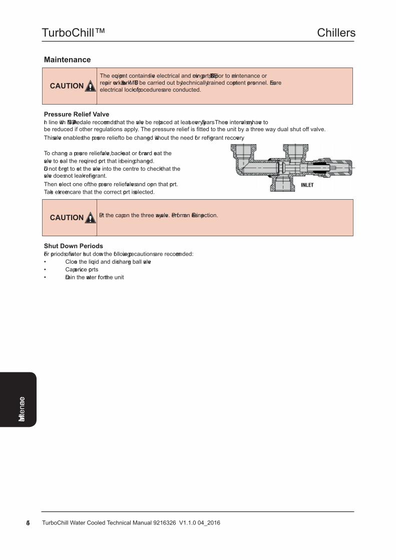
Pressure Relief Valve
In line with EN 378, Airedale recommends that the valve be replaced at least every 5 years. These intervals may have to
This valve enables the pressure relief to be changed without the need for refrigerant recovery.
To change a pressure relief valve, back seat or forward seat the
valve to seal the required port that is being changed.
Do not forget to set the valve into the centre to check that the
valve does not leak refrigerant.
Then select one of the pressure relief valves and open that port.
Take extreme care that the correct port is selected.
Put the cap on the three way valve. Perform an F-Gas inspection.
Shut Down Periods
For periods of winter shut down the following precautions are recommended:
• Close the liquid and discharge ball valve
• Cap service ports
• Drain the water from the unit
CAUTION
CAUTION

TurboChill™Chillers
55TurboChill Water Cooled Technical Manual 9216326V1.1.0 04_2016
Syste
m
Task
Frequency
3 months 12 months 60 months
Check the following against commissioning records:
Alarm log for unusual occurrences
Chilled water control maintains design termperatures
Check pressure drop of evaporator/condenser. Clean where
appropriate.
Check glycol concentration if appropriate. Adjust as necessary.
Clean evaporator water strainer.
Leak test all refrigerant joints and visually inspect pipe and
pipework insulation.
Inspect all water connections for any leaks.
Pipe work clamps are secure.
Refr
igera
tio
n
System pressure readings, suction, liquid and discharge
System temperature readings, suction, liquid and discharge
Head pressure control is maintained
Liquid level control
Check each circuit sight glass for dryness and bubbles for
indication of leaks
Pressure relief valves
F-Gas inspection
Mainte
nance
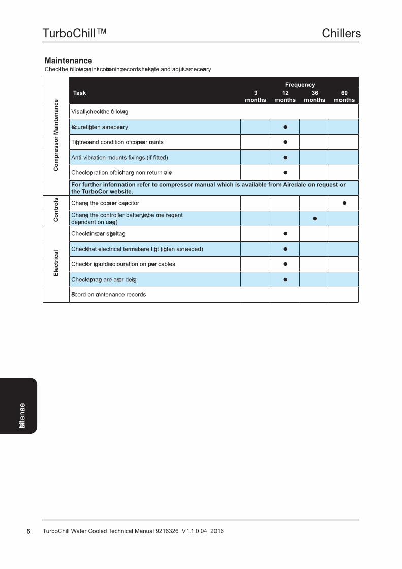
MaintenanceCheck the following against commissioning records. Investigate and adjust as necessary.
TurboChill™ Chillers
56 TurboChill Water Cooled Technical Manual 9216326 V1.1.0 04_2016
Co
mp
resso
r M
ain
ten
an
ce
Task
Frequency
3
months
12
months
36
months
60
months
Visually check the following:
Secure/tighten as necessary
Tightness and condition of compressor mounts
Check operation of discharge non return valve
For further information refer to compressor manual which is available from Airedale on request or
the TurboCor website.
Co
ntr
ols Change the compressor capacitor
Change the controller battery (may be more frequent
dependant on usage)
Ele
ctr
ical
Check mains power supply voltage
Check that electrical terminals are tight (tighten as needed)
Check for signs of discolouration on power cables
Check amperage are as per design
Record on maintenance records.
MaintenanceCheck the following against commissioning records. Investigate and adjust as necessary.
Mainte
nance

TurboChill™Chillers
57TurboChill Water Cooled Technical Manual 9216326V1.1.0 04_2016
Troubleshooting
FAULT POSSIBLE CAUSE REMEDY/ACTION
Unit will not start
No power. Check power supply to the controller.
Wired incorrectly.Check wire connections in accordance with wiring
diagram.
Loose wires. Check all wires, connections, terminals etc.
Remote on/off. Check that the remote on/off is at the on position.
Compressor not
operating
No power to compressor.Check isolator, fuses, MCBs, contactor and control circuit
wiring.
Low pressure cut-out operated
(large or complete loss of refrigerant
charge).
Recover refrigerant, repair, pressure test, evacuate and
recharge system.
Compressor showing fault on
controller.
Determine fault, refer to alarm codes for further
information.
Head Pressure too
high/HP cut-out
operated
Condenser clogged or dirty. Clean condenser.Overcharge of refrigerant. Normally
troublesome in warm weather.
Remove excess refrigerant from system using correct
refrigerant handling techniques.Air or other non-condensable gas in
system.Evacuate system and re-charge with new refrigerant.
Head pressure controller faulty. Check EC fan control module - if faulty - replace.
Head pressure too
lowWater temperature too low. Check condenser temperature setpoint
Suction Pressure too
low
Flash gas (bubbles in sight glass) at
liquid line.
Investigate for refrigerant leaks, repair, pressure test,
evacuate and re-charge system.
temperature drop across it).Replace drier cores.
Strainer blocked. Clean strainer
Unit not operating
due to water pressure
sensor low limit
alarm.
If too high the unit may have nuisance trips.
Low temp limit alarm
Partial blockage in evaporator
is reduced however the differential
pressure switch still remains healthy
as the pressure would increase.
Water/Glycol freezing
up (crystallizes)concentration for operating
temperatures.
Check glycol concentration and add accordingly.
Tro
uble
shootin
g

TurboChill™ Chillers
58 TurboChill Water Cooled Technical Manual 9216326 V1.1.0 04_2016
Tro
uble
shootn
g
Storage RecommendationsAiredale recommends that equipment should be stored in an ambient protected warehouse facility. The unit should be
stored within a heated warehouse ensuring that the temperature does not fall below 0°C. All water should be drained
from the evaporator and condenser. Ensure refrigerant line shut off valves are closed.
Before turning the unit on after extended periods of storage the following checks/procedures must be carried out over
and above any commissioning checks:
Any low temperature protection devices must be turned on for a minimum of 8 hour.
These include:
• Panel heaters
• Electric trace heating
Checks must be carried out for the operation of unit components
Waterside
• Check 3 way valve operates correctly
•
• Check that differential pressure sensor operates
Electrical
• Check electrical seals and glands are satisfactory and have not cracked
• Check all electrical terminal boxes are free from moisture
• Check all cable insulation is satisfactory and does not have any signs of damage
Refrigeration
• Ensure all valves are open
• Carry out an F-gas inspection ensuring no refrigerant leaks

TurboChill™Chillers
59TurboChill Water Cooled Technical Manual 9216326V1.1.0 04_2016
Tro
uble
shootin
g
After Sales
Warranty
All Airedale products or parts (non consumable) supplied for installation within the UK mainland and commissioned by
an Airedale engineer, carry a full Parts & Labour warranty for a period of 12 months from the date of commissioning or
18 months from the date of despatch, whichever is the sooner.
Parts or Equipment supplied by Airedale for installation within the UK or for Export that are properly commissioned in
warranty on non consumable Parts only from the date of commissioning or 18 months from the date of despatch,
whichever is the sooner.
warranty.
Warranty is only valid in the event that
In the period between delivery and commissioning the equipment:
• is properly protected & serviced as per the Airedale installation & maintenance manual provided
• where applicable the glycol content is maintained to the correct level.
operating conditions, the Company will provide the appropriate warranty coverage (as detailed above) attributable to the
that must be ordered by the customer).
Any spare part supplied by Airedale under warranty shall be warranted for the unexpired period of the warranty or 3
months from delivery, whichever period is the longer. To be read in conjunction with the Airedale Conditions of Sale -
Warranty and Warranty Procedure, available upon request.
Procedure
When a component part fails, a replacement part should be obtained through our Spares department. If the part is
considered to be under warranty, the following details are required to process this requirement. Full description of part
required, including Airedale’s part number, if known. The original equipment serial number. An appropriate purchase
order number.
A spares order will be raised under our warranty system and the replacement part will be despatched, usually within 24
hours should they be in stock. When replaced, the faulty part must be returned to Airedale with a suitably completed and
securely attached “Faulty Component Return” (FCR) tag. FCR tags are available from Airedale and supplied with each
Warranty order.
or not.
the release of this complete report may be delayed as component manufacturers become involved in the investigation.
When warranty is allowed, a credit against the Warranty invoice will be raised. Should warranty be refused the Warranty
invoice becomes payable on normal terms.
Exclusions
Warranty may be refused for the following reasons.
• Misapplication of product or component
• Incorrect site installation
• Incomplete commissioning documentation
• Inadequate site installation
• Inadequate site maintenance
• Damage caused by mishandling
• Replaced part being returned damaged without explanation
• Unnecessary delays incurred in return of defective component
Returns analysis
All faulty components returned under warranty are analysed on a monthly basis as a means of verifying component and
product reliability as well as supplier performance. It is important that all component failures are reported correctly.
Airedale International Air Conditioning Ltd
Leeds Road
Rawdon
Leeds LS19 6JY
Tel: +44 (0) 113 2391000
Fax:+44 (0) 113 2507219