design checks for hvac
TRANSCRIPT
A BSRIA Guide www.bsria.co.uk
BG 4/2007
Design Checks for HVAC
A quality control framework (Second edition)
Revised by Kevin Pennycook
Supported by
Design considerations Design data Calculations Systems and equipment
DESIGN CHECKS FOR HVAC © BSRIA BG 4/2007
PREFACE
This publication provides practical, easy to follow HVAC design guidance. It is presented in a format that can be readily incorporated into company Quality Assurance (QA) systems and become part of the daily routine of design. It can be used to demonstrate compliance with the relevant requirements of ISO 9001 and BS 7000 Part 4. There are two major elements of the guidance. The design guidance sheets provide information and guidance on design inputs, outputs and practical watchpoints for 62 key building services design topics, to aid the design process and reduce errors. The design check sheets provide checks that can be used as part of the project quality assurance process to record and demonstrate control of design inputs and outputs. The guidance and check sheets are detailed and relevant to many design applications, although they cannot be fully comprehensive or exclusive or cover every possible design scenario. Every design project is different and has differing needs. It is the responsibility of the design engineer to consider fully all design requirements. In particular, the design watchpoints are not an exhaustive list of all factors to be considered, so designers should exercise professional judgement to decide which factors are relevant. Diagrams are included for illustrative purposes only and do not necessarily include all required components. Designers must be aware of their contractual obligations and ensure that these are met. Adherence to this guidance does not preclude or imply compliance with those obligations. Similarly, it is the duty of the designer to ensure compliance with all relevant legislation and regulations. This publication is also relevant to those responsible for the installation, commissioning, operation and maintenance of building services. This second edition of Design Checks for HVAC is up to date with the requirements of the latest building legislation, standards and codes of practice current in January 2007. The guide also contains new design checks for whole life costing and health and safety. Where possible, design topics have been cross-referenced to the relevant Common Arrangement of Work Sections (CAWS). It is hoped that design practices and individual designers will be encouraged to further share knowledge and experience by extending and adding to the design watchpoints and disseminating this within their organisations. BSRIA would be pleased to receive any such contributions for incorporation into any future revisions of this publication.
Design considerations Design data Calculations Systems and equipment
DESIGN CHECKS FOR HVAC
© BSRIA BG 4/2007
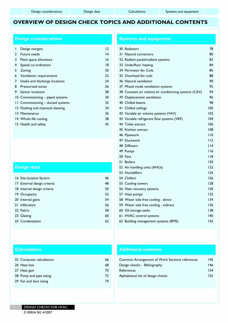
OVERVIEW OF DESIGN CHECK TOPICS AND ADDITIONAL CONTENTS
Design considerations 1 Design margins 12 2 Future needs 14 3 Plant space allowance 16 4 Spatial co-ordination 18 5 Zoning 20 6 Ventilation requirements 22 7 Intake and discharge locations 24 8 Pressurised zones 26 9 Sensor locations 28 10 Commissioning – piped systems 30 11 Commissioning – ducted systems 32 12 Flushing and chemical cleaning 34 13 Maintenance 36 14 Whole life costing 38 15 Health and safety 42
Design data 16 Site location factors 46 17 External design criteria 48 18 Internal design criteria 50 19 Occupancy 52 20 Internal gains 54 21 Infiltration 56 22 Fabric 58 23 Glazing 60 24 Condensation 62
Calculations 25 Computer calculations 66 26 Heat loss 68 27 Heat gain 70 28 Pump and pipe sizing 72 29 Fan and duct sizing 74
Systems and equipment 30 Radiators 78 31 Natural convectors 80 32 Radiant panels/radiant systems 82 33 Underfloor heating 84 34 Perimeter fan Coils 86 35 Overhead fan coils 88 36 Natural ventilation 90 37 Mixed mode ventilation systems 92 38 Constant air volume air conditioning systems (CAV) 94 39 Displacement ventilation 96 40 Chilled beams 98 41 Chilled ceilings 100 42 Variable air volume systems (VAV) 102 43 Variable refrigerant flow systems (VRF) 104 44 Toilet extract 106 45 Kitchen extract 108 46 Pipework 110 47 Ductwork 112 48 Diffusers 114 49 Pumps 116 50 Fans 118 51 Boilers 120 52 Air handling units (AHUs) 122 53 Humidifiers 124 54 Chillers 126 55 Cooling towers 128 56 Heat recovery systems 130 57 Heat pumps 132 58 Water side free cooling - direct 134 59 Water side free cooling - indirect 136 60 Oil storage tanks 138 61 HVAC control systems 140 62 Building management systems (BMS) 142
Additional contents Common Arrangement of Work Sections references 145 Design checks – Bibliography 146 References 154 Alphabetical list of design checks 155
Design considerations Design data Calculations Systems and equipment
DESIGN CHECKS FOR HVAC 1 © BSRIA BG 4/2007
INTRODUCTION
Aim The aim of Design Checks for HVAC is to improve the quality control and performance of the technical design process within the building services industry by identifying best practice. This should reduce the risk of design errors and omissions, improve the overall efficiency of the design process, and provide HVAC services that better meet the needs of the client. A comprehensive review of current building services design practice and procedures was carried out in consultation with the industry to identify best practice and current problems and explore relevant design tools. The result includes: • A map of the HVAC building services design process • Design guidance sheets giving information and guidance
on design inputs, outputs and practical watchpoints for 62 key design topics, to aid the design process and reduce errors
• Design check sheets that can be included in project quality assurance procedures.
These provide a formal framework to record and review design inputs and encourage designers to consider the requirements for installation, commissioning, operation and control and subsequent maintenance of their selected systems at the design stage. This should lead to improvements in both the design process and in the subsequent implementation of that design, and reduce the risk of problems occurring during installation, commissioning or system operation. This practical easy to follow guidance can be incorporated into company quality assurance systems to become part of the daily routine of design and can be used to demonstrate compliance with the relevant requirements of ISO 9001:20001 and BS 7000 Part 4:19962. The guidance incorporates practical design watchpoints based on feedback from many practising engineers and others experienced in design. These vary from avoidance of possible errors or misunderstandings that could be made by inexperienced, junior engineers to very practical tips based on experience of installation, commissioning, maintenance and facilities management over many years. Use of the design checks will allow these lessons to be passed on to other engineers, particularly junior engineers, and future projects. This can help improve design quality, reduce risk and increase client confidence.
Intended users This guidance is intended for practising HVAC design engineers. Clients, PII providers and others involved in the design process and its outcomes are also potential users as they may request compliance with this guidance or ask to see evidence that reasonable design quality assurance procedures are being followed. The guidance complements the CIBSE Guide B, Heating, Ventilating, Air-conditioning and Refrigeration, and the CIBSE Concise Guide. The check sheets and design inputs and outputs guidance are intended for use by all design engineers, whether to gather information and complete the sheets or to check or sign off as completed. While the more detailed guidance in the design watchpoints is obviously directly useful for junior engineers, experienced engineers will also find it useful when designing a less-familiar system. Companies may also use the guidance to support formal design quality assurance procedures while the check sheets may be photocopied, they are also available, for purchase in electronic format, thus enabling them to be customised for particular projects and kept on specific project files. For further information visit www.bsria.co.uk/bookshop. Note that the design of HVAC systems involves working in a design team with other disciplines. This involves interactive efforts, co-ordination and project programming.

DESIGN CONSIDERATIONS
Design considerations Design data Calculations Systems and equipment
12 DESIGN CHECKS FOR HVAC
© BSRIA BG 4/2007
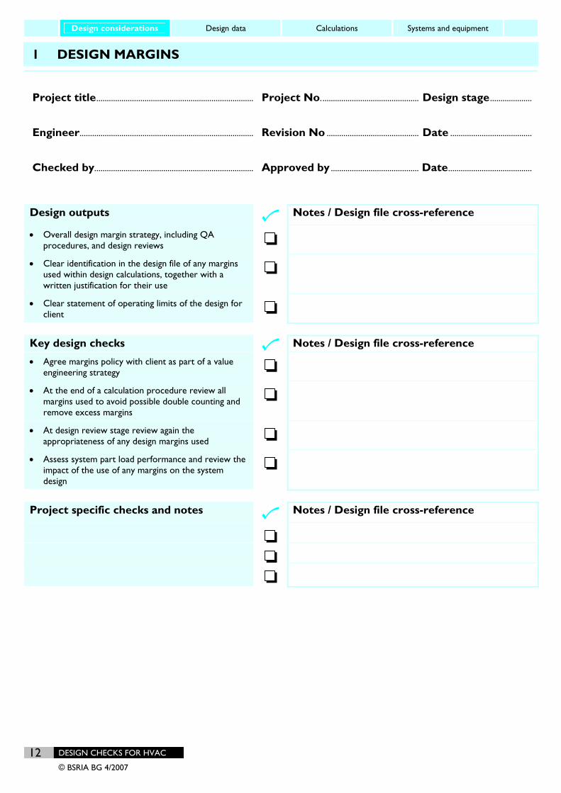
1 DESIGN MARGINS
Project title........................................................................... Project No............................................... Design stage ....................
Engineer................................................................................... Revision No ............................................ Date .......................................
Checked by............................................................................ Approved by .......................................... Date........................................
Design outputs
Notes / Design file cross-reference
• Overall design margin strategy, including QA procedures, and design reviews
• Clear identification in the design file of any margins used within design calculations, together with a written justification for their use
• Clear statement of operating limits of the design for client
Key design checks
Notes / Design file cross-reference
• Agree margins policy with client as part of a value engineering strategy
• At the end of a calculation procedure review all margins used to avoid possible double counting and remove excess margins
• At design review stage review again the appropriateness of any design margins used
• Assess system part load performance and review the impact of the use of any margins on the system design
Project specific checks and notes
Notes / Design file cross-reference
Design considerations Design data Calculations Systems and equipment
DESIGN CHECKS FOR HVAC 13 © BSRIA BG 4/2007
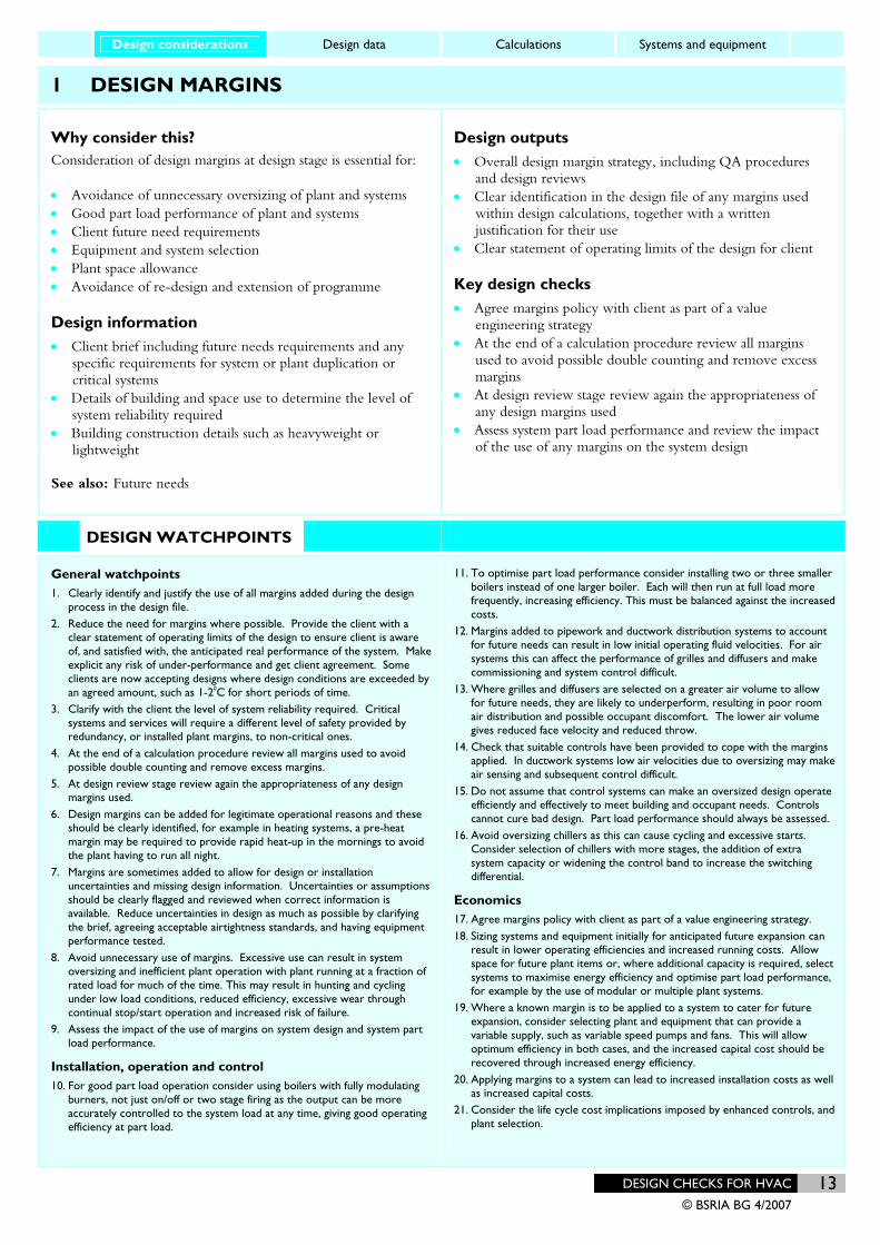
1 DESIGN MARGINS
Why consider this? Consideration of design margins at design stage is essential for: • Avoidance of unnecessary oversizing of plant and systems • Good part load performance of plant and systems • Client future need requirements • Equipment and system selection • Plant space allowance • Avoidance of re-design and extension of programme
Design information
• Client brief including future needs requirements and any specific requirements for system or plant duplication or critical systems
• Details of building and space use to determine the level of system reliability required
• Building construction details such as heavyweight or lightweight
See also: Future needs
Design outputs • Overall design margin strategy, including QA procedures
and design reviews • Clear identification in the design file of any margins used
within design calculations, together with a written justification for their use
• Clear statement of operating limits of the design for client
Key design checks • Agree margins policy with client as part of a value
engineering strategy • At the end of a calculation procedure review all margins
used to avoid possible double counting and remove excess margins
• At design review stage review again the appropriateness of any design margins used
• Assess system part load performance and review the impact of the use of any margins on the system design
DESIGN WATCHPOINTS
General watchpoints 1. Clearly identify and justify the use of all margins added during the design
process in the design file. 2. Reduce the need for margins where possible. Provide the client with a
clear statement of operating limits of the design to ensure client is aware of, and satisfied with, the anticipated real performance of the system. Make explicit any risk of under-performance and get client agreement. Some clients are now accepting designs where design conditions are exceeded by an agreed amount, such as 1-20C for short periods of time.
3. Clarify with the client the level of system reliability required. Critical systems and services will require a different level of safety provided by redundancy, or installed plant margins, to non-critical ones.
4. At the end of a calculation procedure review all margins used to avoid possible double counting and remove excess margins.
5. At design review stage review again the appropriateness of any design margins used.
6. Design margins can be added for legitimate operational reasons and these should be clearly identified, for example in heating systems, a pre-heat margin may be required to provide rapid heat-up in the mornings to avoid the plant having to run all night.
7. Margins are sometimes added to allow for design or installation uncertainties and missing design information. Uncertainties or assumptions should be clearly flagged and reviewed when correct information is available. Reduce uncertainties in design as much as possible by clarifying the brief, agreeing acceptable airtightness standards, and having equipment performance tested.
8. Avoid unnecessary use of margins. Excessive use can result in system oversizing and inefficient plant operation with plant running at a fraction of rated load for much of the time. This may result in hunting and cycling under low load conditions, reduced efficiency, excessive wear through continual stop/start operation and increased risk of failure.
9. Assess the impact of the use of margins on system design and system part load performance.
Installation, operation and control 10. For good part load operation consider using boilers with fully modulating
burners, not just on/off or two stage firing as the output can be more accurately controlled to the system load at any time, giving good operating efficiency at part load.
11. To optimise part load performance consider installing two or three smaller boilers instead of one larger boiler. Each will then run at full load more frequently, increasing efficiency. This must be balanced against the increased costs.
12. Margins added to pipework and ductwork distribution systems to account for future needs can result in low initial operating fluid velocities. For air systems this can affect the performance of grilles and diffusers and make commissioning and system control difficult.
13. Where grilles and diffusers are selected on a greater air volume to allow for future needs, they are likely to underperform, resulting in poor room air distribution and possible occupant discomfort. The lower air volume gives reduced face velocity and reduced throw.
14. Check that suitable controls have been provided to cope with the margins applied. In ductwork systems low air velocities due to oversizing may make air sensing and subsequent control difficult.
15. Do not assume that control systems can make an oversized design operate efficiently and effectively to meet building and occupant needs. Controls cannot cure bad design. Part load performance should always be assessed.
16. Avoid oversizing chillers as this can cause cycling and excessive starts. Consider selection of chillers with more stages, the addition of extra system capacity or widening the control band to increase the switching differential.
Economics 17. Agree margins policy with client as part of a value engineering strategy. 18. Sizing systems and equipment initially for anticipated future expansion can
result in lower operating efficiencies and increased running costs. Allow space for future plant items or, where additional capacity is required, select systems to maximise energy efficiency and optimise part load performance, for example by the use of modular or multiple plant systems.
19. Where a known margin is to be applied to a system to cater for future expansion, consider selecting plant and equipment that can provide a variable supply, such as variable speed pumps and fans. This will allow optimum efficiency in both cases, and the increased capital cost should be recovered through increased energy efficiency.
20. Applying margins to a system can lead to increased installation costs as well as increased capital costs.
21. Consider the life cycle cost implications imposed by enhanced controls, and plant selection.

A guide to
Second edition
HVAC Building Services
Calculations
BSRIA Guide 30/2007Supported by the DTI
BG 30-2007coverfnt.p65 01/06/2007, 11:121
Heating loads Cooling loads Water flow Air flow Acoustics
GUIDE TO HVAC BUILDING SERVICES CALCULATIONS © BSRIA BG 30/2007
ACKNOWLEDGEMENTS
The first edition of this publication was produced by BSRIA as part of a contract placed by the Department of Trade & Industry and funded by the DTI, BSRIA membership and industry partners. BSRIA would like to thank the following sponsors for their contributions to the first edition Guide:
Department of Trade and Industry CIBSE (Chartered Institution of Building Services Engineers) ACE (Association of Consulting Engineers) ESTTL (Engineering Services Training Trust Limited) HVCA (Heating and Ventilating Contractors Association) Bovis Crown House Engineering FaberMaunsell Hoare Lea N G Bailey South Bank University Troup Bywaters & Anders W S Atkins
The research project was undertaken under the guidance of a project steering group drawn from industry representatives and BSRIA staff. The steering group contributors were:
Fulcrum Consulting Andrew Ford, representing DTI Independent chair Bryan Franklin CIBSE Hywel Davies ACE Jeremy Croxson Bovis Jean-Louis Auguste Crown House Engineering Susan Hone-Brookes ESTTL Tony Barton FaberMaunsell Quinten Babcock
Ant Wilson Hoare Lea Graham Cossons
Les Mackenzie Terry Wyatt
HVCA Derrick Newson Bob Towse
N G Bailey Ken Sargeant Roland Edkins
South Bank University Martin Ratcliffe Troup Bywaters & Anders David Arnold (representing CIBSE) W S Atkins Adrian Defalco
Steve Platt The first edition of this guide was authored by Gay Lawrence Race and Sally Mitchell. This second edition of the Guide to HVAC Building Services Calculations has been extensively revised and added to by Kevin Pennycook, David Churcher and David Bleicher from BSRIA. The authors have sought to incorporate the views of the steering group, but final editorial control of this document rested with BSRIA.
©BSRIA 70186 June 2007 ISBN 978-0-86022-657-4 Printed by ImageData Group
All rights reserved. No part of this publication may be reproduced, stored in a retrieval system, or transmitted in any form or by any means electronic or mechanical including photocopying, recording or otherwise without prior written permission of the publisher.

Heating loads Cooling loads Water flow Air flow Acoustics
GUIDE TO HVAC BUILDING SERVICES CALCULATIONS
© BSRIA BG 30/2007
PREFACE
This publication provides practical, easy to follow methodologies for a range of calculations used in the design of heating ventilating and air conditioning building services systems. The calculation sheets are presented in five sections covering: • Heating loads and plant • Cooling loads and plant • Water flow distribution systems • Air flow distribution systems • Acoustics for building services The calculation sheets provide practical guidance including design watchpoints, design tips and rules of thumb, and are intended to aid the design process and reduce errors. The guidance is based primarily on data and procedures contained within the CIBSE Guides, together with other sources such as Building Regulations, with clear cross-referencing provided to data sources. This publication is intended primarily to help junior design engineers, working within a structured and supervised training framework, by providing assistance in completing the basic calculations needed to define operating conditions for systems, size distribution systems and to specify required duties for plant and equipment. It is not the purpose of this guide to identify the most appropriate system for a particular application. Such decisions require knowledge, experience and analysis of the application. This guidance is also not intended to be exhaustive or definitive. It will be necessary for users to exercise their own professional judgement, or obtain further advice from senior engineers within their organisation when deciding whether to abide by or depart from the guide. The calculation sheets are relevant to many design applications, but cannot be fully comprehensive or cover every possible design scenario. Every design project is different and has differing needs, and it is the professional duty of the responsible design engineer to consider fully all design requirements. Designers should exercise professional judgement to decide relevant factors and establish the most appropriate data sources and methodologies to use for a particular application. Designers must be aware of their contractual obligations and ensure that these are met. Following this guidance - or any other guidance - does not preclude or imply compliance with those obligations. Similarly, it is the duty of the designer to ensure compliance with all relevant legislation and regulations. It is hoped that design practices and individual designers will be encouraged to share knowledge and experience by extending and adding to the design watchpoints and design tips, and disseminating this work within their organisations. BSRIA would be pleased to receive any such contributions for incorporation into any future revisions of this publication to provide wider industry sharing of such knowledge.
Heating loads Cooling loads Water flow Air flow Acoustics
GUIDE TO HVAC BUILDING SERVICES CALCULATIONS 1 © BSRIA BG 30/2007
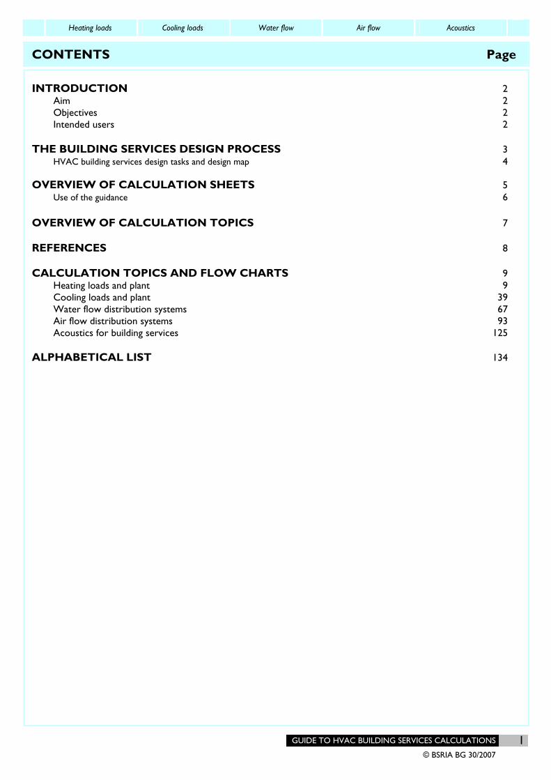
CONTENTS Page INTRODUCTION 2
Aim 2 Objectives 2 Intended users 2
THE BUILDING SERVICES DESIGN PROCESS 3 HVAC building services design tasks and design map 4
OVERVIEW OF CALCULATION SHEETS 5
Use of the guidance 6 OVERVIEW OF CALCULATION TOPICS 7 REFERENCES 8 CALCULATION TOPICS AND FLOW CHARTS 9
Heating loads and plant 9 Cooling loads and plant 39 Water flow distribution systems 67 Air flow distribution systems 93 Acoustics for building services 125
ALPHABETICAL LIST 134
Heating loads Cooling loads Water flow Air flow Acoustics
2 GUIDE TO HVAC BUILDING SERVICES CALCULATIONS
© BSRIA BG 30/2007
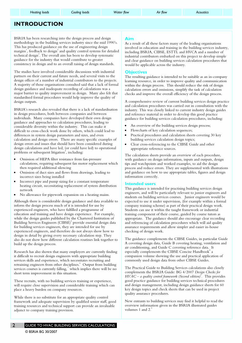
INTRODUCTION
BSRIA has been researching into the design process and design methodology in the building services industry since the mid 1990’s. This has produced guidance on the use of engineering design margins1, feedback to design2 and quality control systems for detailed technical design3. The overall aim has been to develop systematic guidance for the industry that would contribute to greater consistency in design and to an overall raising of design standards. The studies have involved considerable discussions with industrial partners on their current and future needs, and several visits to the design offices of a number of industrial contributors to the projects. A majority of those organisations consulted said that a lack of formal design guidance and inadequate recording of calculations was a major barrier to quality improvement in design. Many also felt that standardised formal procedures would help improve the quality of design outputs. BSRIA’s research also revealed that there is a lack of standardisation in design procedures, both between companies and between individuals. Many companies have developed their own design guidance and approaches to calculation procedures, leading to considerable diversity within the industry. This can make it difficult to cross-check work done by others, which could lead to differences in system design parameters and sizes, and even calculation and design errors. There are many specific examples of design errors and issues that should have been considered during design calculations and have led, (or could have led) to operational problems or subsequent litigation4, including: • Omission of HEPA filter resistance from fan-pressure
calculations, requiring subsequent fan motor replacement which then required additional silencing
• Omission of duct sizes and flows from drawings, leading to incorrect sizes being installed
• Incorrect pipe and pump sizing for a constant temperature heating circuit, necessitating replacement of system distribution network
• No allowance for pipework expansion on a heating mains. Although there is considerable design guidance and data available to inform the design process much of it is intended for use by experienced engineers, who have fulfilled a programme of education and training and have design experience. For example, while the design guides published by the Chartered Institution of Building Services Engineers (CIBSE)5 provide essential design data for building services engineers, they are intended for use by experienced engineers, and therefore do not always show how to design in detail by giving every necessary calculation step. They also do not show how different calculation routines link together to build up the design process. Research has also shown that many employers are currently finding it difficult to recruit design engineers with appropriate building services skills and experience, which necessitates recruiting and retraining engineers from other disciplines.6 Output from building services courses is currently falling, 7 which implies there will be no short term improvement in this situation. These recruits, with no building services training or experience, will require close supervision and considerable training which can place a heavy burden on company resources. While there is no substitute for an appropriate quality control framework and adequate supervision by qualified senior staff, good training resources and technical support can provide an invaluable adjunct to company training provision.
Aim As a result of all these factors many of the leading organisations involved in education and training in the building services industry, including BSRIA, CIBSE, ESTTL and HVCA and a number of industrial contributors embarked on this project to develop simple and clear guidance on building services calculation procedures that would be applicable across the industry.
Objectives The resulting guidance is intended to be suitable as an in-company learning resource, in order to improve quality and communication within the design process. This should reduce the risk of design calculation errors and omissions, simplify the task of calculation checks and improve the overall efficiency of the design process. A comprehensive review of current building services design practice and calculation procedures was carried out in consultation with the industry. This was closely linked to current industry design guides and reference material in order to develop this good practice guidance for building services calculation procedures, including: • An overview of the building services design process; • Flowcharts of key calculation sequences; • Practical procedures and calculation sheets covering 30 key
building services calculation design topics; • Clear cross-referencing to the CIBSE Guide and other
appropriate reference sources. The calculation sheets provide an overview of each procedure, with guidance on design information, inputs and outputs, design tips and watchpoints and worked examples, to aid the design process and reduce errors. They are supplemented with illustrations and guidance on how to use appropriate tables, figures and design information correctly.
Intended users This guidance is intended for practising building services design engineers, and will be particularly relevant to junior engineers and students on building services courses. Junior engineers would be expected to use it under supervision, (for example within a formal company training scheme) as part of their practical design work. Students can use it within the taught framework or industrial training component of their course, guided by course tutors as appropriate. The guidance should also encourage clear recording and referencing of calculation procedures which will aid quality assurance requirements and allow simpler and easier in-house checking of design work. The guidance complements the CIBSE Guides, in particular Guide A covering design data, Guide B covering heating, ventilation and air conditioning, and Guide C covering reference data. It especially complements the CIBSE Concise Handbook8 a companion volume showing the use and practical application of commonly used design data from other CIBSE Guides. The Practical Guide to Building Services calculations also closely complements the BSRIA Guide: BG 4/2007 Design Checks for HVAC – a quality control framework (Second edition)3. This provides good practice guidance for building services technical procedures and design management, including design guidance sheets for 60 key design topics and check sheets that can be used in project quality assurance procedures. New entrants to building services may find it helpful to read the overview information given in the BSRIA illustrated guides volumes 1 and 2.9
Heating loads Cooling loads Water flow Air flow Acoustics
GUIDE TO HVAC BUILDING SERVICES CALCULATIONS 3 © BSRIA BG 30/2007
THE BUILDING SERVICES DESIGN PROCESS
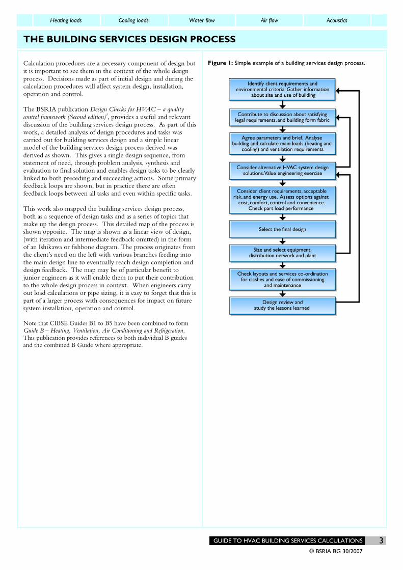
Calculation procedures are a necessary component of design but it is important to see them in the context of the whole design process. Decisions made as part of initial design and during the calculation procedures will affect system design, installation, operation and control. The BSRIA publication Design Checks for HVAC – a quality control framework (Second edition)3, provides a useful and relevant discussion of the building services design process. As part of this work, a detailed analysis of design procedures and tasks was carried out for building services design and a simple linear model of the building services design process derived was derived as shown. This gives a single design sequence, from statement of need, through problem analysis, synthesis and evaluation to final solution and enables design tasks to be clearly linked to both preceding and succeeding actions. Some primary feedback loops are shown, but in practice there are often feedback loops between all tasks and even within specific tasks. This work also mapped the building services design process, both as a sequence of design tasks and as a series of topics that make up the design process. This detailed map of the process is shown opposite. The map is shown as a linear view of design, (with iteration and intermediate feedback omitted) in the form of an Ishikawa or fishbone diagram. The process originates from the client’s need on the left with various branches feeding into the main design line to eventually reach design completion and design feedback. The map may be of particular benefit to junior engineers as it will enable them to put their contribution to the whole design process in context. When engineers carry out load calculations or pipe sizing, it is easy to forget that this is part of a larger process with consequences for impact on future system installation, operation and control. Note that CIBSE Guides B1 to B5 have been combined to form Guide B – Heating, Ventilation, Air Conditioning and Refrigeration. This publication provides references to both individual B guides and the combined B Guide where appropriate.
Figure 1: Simple example of a building services design process.

Heating loads Cooling loads Water flow Air flow Acoustics
4 GUIDE TO HVAC BUILDING SERVICES CALCULATIONS
© BSRIA BG 30/2007
THE BUILDING SERVICES DESIGN PROCESS
Heating loads Cooling loads Water flow Air flow Acoustics
GUIDE TO HVAC BUILDING SERVICES CALCULATIONS 5 © BSRIA BG 30/2007
OVERVIEW OF CALCULATION SHEETS
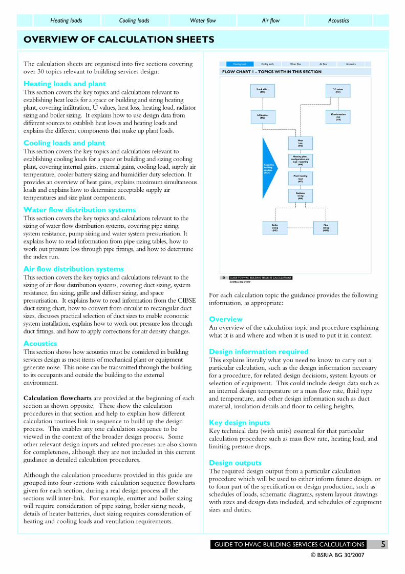
The calculation sheets are organised into five sections covering over 30 topics relevant to building services design:
Heating loads and plant This section covers the key topics and calculations relevant to establishing heat loads for a space or building and sizing heating plant, covering infiltration, U values, heat loss, heating load, radiator sizing and boiler sizing. It explains how to use design data from different sources to establish heat losses and heating loads and explains the different components that make up plant loads.
Cooling loads and plant This section covers the key topics and calculations relevant to establishing cooling loads for a space or building and sizing cooling plant, covering internal gains, external gains, cooling load, supply air temperature, cooler battery sizing and humidifier duty selection. It provides an overview of heat gains, explains maximum simultaneous loads and explains how to determine acceptable supply air temperatures and size plant components.
Water flow distribution systems This section covers the key topics and calculations relevant to the sizing of water flow distribution systems, covering pipe sizing, system resistance, pump sizing and water system pressurisation. It explains how to read information from pipe sizing tables, how to work out pressure loss through pipe fittings, and how to determine the index run.
Air flow distribution systems This section covers the key topics and calculations relevant to the sizing of air flow distribution systems, covering duct sizing, system resistance, fan sizing, grille and diffuser sizing, and space pressurisation. It explains how to read information from the CIBSE duct sizing chart, how to convert from circular to rectangular duct sizes, discusses practical selection of duct sizes to enable economic system installation, explains how to work out pressure loss through duct fittings, and how to apply corrections for air density changes.
Acoustics This section shows how acoustics must be considered in building services design as most items of mechanical plant or equipment generate noise. This noise can be transmitted through the building to its occupants and outside the building to the external environment. Calculation flowcharts are provided at the beginning of each section as shown opposite. These show the calculation procedures in that section and help to explain how different calculation routines link in sequence to build up the design process. This enables any one calculation sequence to be viewed in the context of the broader design process. Some other relevant design inputs and related processes are also shown for completeness, although they are not included in this current guidance as detailed calculation procedures. Although the calculation procedures provided in this guide are grouped into four sections with calculation sequence flowcharts given for each section, during a real design process all the sections will inter-link. For example, emitter and boiler sizing will require consideration of pipe sizing, boiler sizing needs, details of heater batteries, duct sizing requires consideration of heating and cooling loads and ventilation requirements.
For each calculation topic the guidance provides the following information, as appropriate:
Overview An overview of the calculation topic and procedure explaining what it is and where and when it is used to put it in context.
Design information required This explains literally what you need to know to carry out a particular calculation, such as the design information necessary for a procedure, for related design decisions, system layouts or selection of equipment. This could include design data such as an internal design temperature or a mass flow rate, fluid type and temperature, and other design information such as duct material, insulation details and floor to ceiling heights.
Key design inputs Key technical data (with units) essential for that particular calculation procedure such as mass flow rate, heating load, and limiting pressure drops.
Design outputs The required design output from a particular calculation procedure which will be used to either inform future design, or to form part of the specification or design production, such as schedules of loads, schematic diagrams, system layout drawings with sizes and design data included, and schedules of equipment sizes and duties.
Heating loads Cooling loads Water flow Air flow Acoustics
GUIDE TO HVAC BUILDING SERVICES CALCULATIONS 7 © BSRIA BG 30/2007
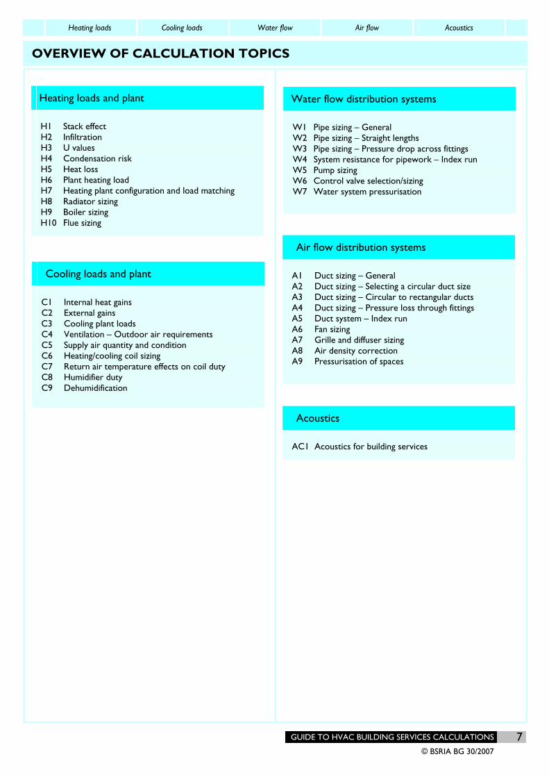
OVERVIEW OF CALCULATION TOPICS
Heating loads and plant
H1 Stack effect H2 Infiltration H3 U values H4 Condensation risk H5 Heat loss H6 Plant heating load H7 Heating plant configuration and load matching H8 Radiator sizing H9 Boiler sizing H10 Flue sizing
Cooling loads and plant
C1 Internal heat gains C2 External gains C3 Cooling plant loads C4 Ventilation – Outdoor air requirements C5 Supply air quantity and condition C6 Heating/cooling coil sizing C7 Return air temperature effects on coil duty C8 Humidifier duty C9 Dehumidification
Water flow distribution systems
W1 Pipe sizing – General W2 Pipe sizing – Straight lengths W3 Pipe sizing – Pressure drop across fittings W4 System resistance for pipework – Index run W5 Pump sizing W6 Control valve selection/sizing W7 Water system pressurisation
Air flow distribution systems
A1 Duct sizing – General A2 Duct sizing – Selecting a circular duct size A3 Duct sizing – Circular to rectangular ducts A4 Duct sizing – Pressure loss through fittings A5 Duct system – Index run A6 Fan sizing A7 Grille and diffuser sizing A8 Air density correction A9 Pressurisation of spaces
Acoustics
AC1 Acoustics for building services
Heating loads Cooling loads Water flow Air flow Acoustics
8 GUIDE TO HVAC BUILDING SERVICES CALCULATIONS
© BSRIA BG 30/2007
REFERENCES
1 Lawrence Race G, BSRIA, Parand F, BRE, Engineering Design Margins, CIBSE Research Report RR04 1997. Available free to CIBSE members at www.cibse.org.
2 Lawrence Race G, Pearson C & De Saulles T, Feedback for Better Building Services Design, AG 21/98, BSRIA 1998 ISBN 0 86022 520 8
3 Lawrence Race G, Design Checks for HVAC – A Quality Control Framework (Second edition), BSRIA BG 4/2007. ISBN 978-0-86022-669-7
4 From information gathered for the publication Design Checks for HVAC – A Quality Control Framework (Second edition), BSRIA BG 4/2007
5 CIBSE Design Guides, including Volumes: A Environmental Design, 2006, ISBN 1 903287 66 9; B Heating, Ventilating, Air Conditioning and Refrigeration., ISBN 1 903287 58 8, C Reference Data 2007, ISBN 9 781903287 80 4
6 H Connor, S Dench, P Bates, An Assessment of Skill Needs in Engineering. DfEE Skills Dialogues SD2, February 2001.
7 Professor D Gann & Dr A Salter, Interdisciplinary Skills for the Built Environment Professional, Arup Foundation 1999.
8 CIBSE, Concise Handbook, 2003, ISBN 1 903287 44 8
9 De Saulles, T, Illustrated Guide to Building Services, 27/99, BSRIA 1999, ISBN 0 86022 543 3, and Illustrated Guide to Electrical Building Services AG 14/2001, BSRIA 2001, ISBN 0 86022 586 0
Heating loads Cooling loads Water flow Air flow Acoustics
134 GUIDE TO HVAC BUILDING SERVICES CALCULATIONS
© BSRIA BG 30/2007
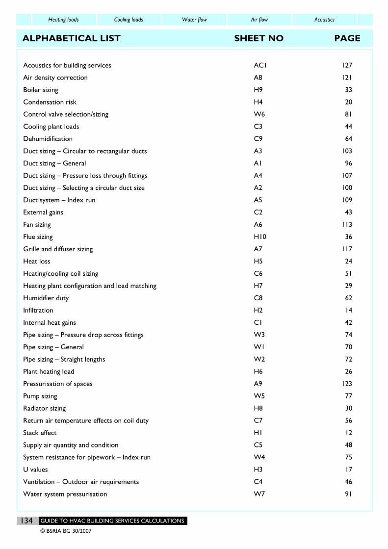
ALPHABETICAL LIST SHEET NO PAGE
Acoustics for building services AC1 127
Air density correction A8 121
Boiler sizing H9 33
Condensation risk H4 20
Control valve selection/sizing W6 81
Cooling plant loads C3 44
Dehumidification C9 64
Duct sizing – Circular to rectangular ducts A3 103
Duct sizing – General A1 96
Duct sizing – Pressure loss through fittings A4 107
Duct sizing – Selecting a circular duct size A2 100
Duct system – Index run A5 109
External gains C2 43
Fan sizing A6 113
Flue sizing H10 36
Grille and diffuser sizing A7 117
Heat loss H5 24
Heating/cooling coil sizing C6 51
Heating plant configuration and load matching H7 29
Humidifier duty C8 62
Infiltration H2 14
Internal heat gains C1 42
Pipe sizing – Pressure drop across fittings W3 74
Pipe sizing – General W1 70
Pipe sizing – Straight lengths W2 72
Plant heating load H6 26
Pressurisation of spaces A9 123
Pump sizing W5 77
Radiator sizing H8 30
Return air temperature effects on coil duty C7 56
Stack effect H1 12
Supply air quantity and condition C5 48
System resistance for pipework – Index run W4 75
U values H3 17
Ventilation – Outdoor air requirements C4 46
Water system pressurisation W7 91
A BSRIA Guide www.bsria.co.uk
Choosing building services
A practical guide to system selection
By John Langmaid
BG 9/2004
CHOOSING BUILDING SERVICES © BSRIA BG 9/2004
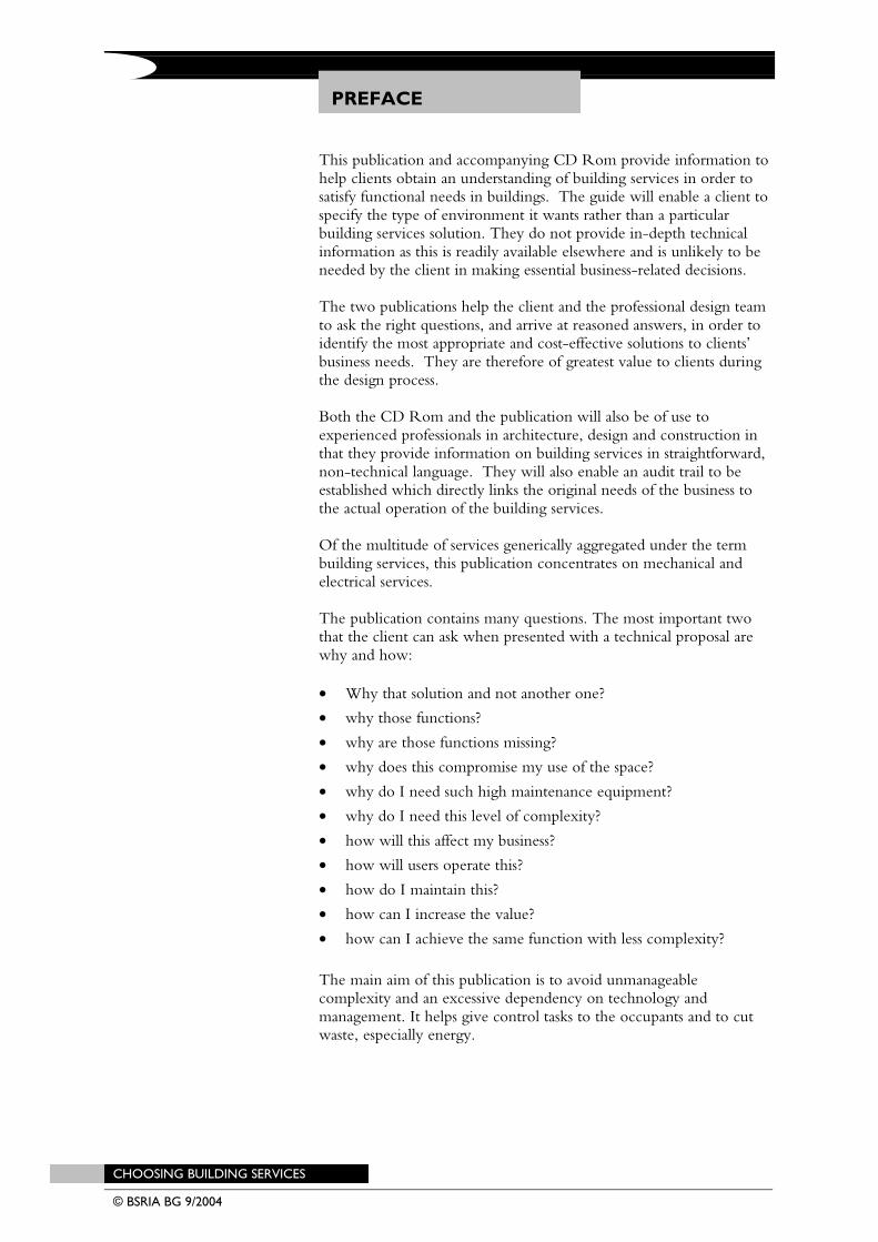
PREFACE
This publication and accompanying CD Rom provide information to help clients obtain an understanding of building services in order to satisfy functional needs in buildings. The guide will enable a client to specify the type of environment it wants rather than a particular building services solution. They do not provide in-depth technical information as this is readily available elsewhere and is unlikely to be needed by the client in making essential business-related decisions. The two publications help the client and the professional design team to ask the right questions, and arrive at reasoned answers, in order to identify the most appropriate and cost-effective solutions to clients’ business needs. They are therefore of greatest value to clients during the design process. Both the CD Rom and the publication will also be of use to experienced professionals in architecture, design and construction in that they provide information on building services in straightforward, non-technical language. They will also enable an audit trail to be established which directly links the original needs of the business to the actual operation of the building services. Of the multitude of services generically aggregated under the term building services, this publication concentrates on mechanical and electrical services. The publication contains many questions. The most important two that the client can ask when presented with a technical proposal are why and how:
• Why that solution and not another one?
• why those functions?
• why are those functions missing?
• why does this compromise my use of the space?
• why do I need such high maintenance equipment?
• why do I need this level of complexity?
• how will this affect my business?
• how will users operate this?
• how do I maintain this?
• how can I increase the value?
• how can I achieve the same function with less complexity?
The main aim of this publication is to avoid unmanageable complexity and an excessive dependency on technology and management. It helps give control tasks to the occupants and to cut waste, especially energy.
CHOOSING BUILDING SERVICES © BSRIA BG 9/2004 25/08/04 CHOOSING BUILDING Services
CONTENTS
1 BACKGROUND 1
2 USING THE DOCUMENT 3
3 BEING A CLIENT 7
4 FUNCTIONAL SPACE 9 4.1 The concept 9 4.2 Descriptions 9
5 BUILDING SERVICES 11
6 PROCUREMENT, DESIGN AND HANDOVER 13 6.1 Health and safety 13 6.2 Comfortable environment 13 6.3 Power requirements 16 6.4 Domestic hot water 18 6.5 Fundamentals of energy and resource efficient design 19 6.6 Access and risers 21 6.7 Plant rooms 22 6.8 Spatial co-ordination 22 6.9 Commissioning 23 6.10 Lease agreements 24
7 OPERATING THE BUILDING 26 7.1 Environment 26 7.2 Flexibility and adaptability 28 7.3 Operation 31
8 MAINTAINING THE BUILDING 34 8.1 Equipment life 34 8.2 Maintenance 37
9 REFURBISHMENT AND DECOMMISSIONING 43 9.1 Refurbishment 43 9.2 Decommissioning 44 9.3 Legislation 44
REFERENCES 47
CHOOSING BUILDING SERVICES © BSRIA BG 9/2004
TABLES
FIGURES
Table 1: Functional spaces 10 Table 2: Office power requirements 16 Table 3: Conference room power requirements 17 Table 4: Power outlet requirements 17 Table 5: Expected economic life of various types of mechanical
and electrical services 36
FIGURES
Figure 1: The introductory page of the decision tool 4 Figure 2: Example of a functional space table in the decision tool 4 Figure 3: A filled in example from part of the decision table 5 Figure 4: The professional response form 6 Figure 5: Relation to well-known process maps 8 Figure 6: Comparison of calculated internal gains to composite
guidance values 20 Figure 7: Building life-cycle flow 26 Figure 8: Achievable level of operational savings 32 Figure 9: Achievable levels of carbon emissions 32 Figure 10: A maintenance logic tree 39
BACKGROUND
CHOOSING BUILDING SERVICES 1 © BSRIA BG 9/2004
1
1 BACKGROUND
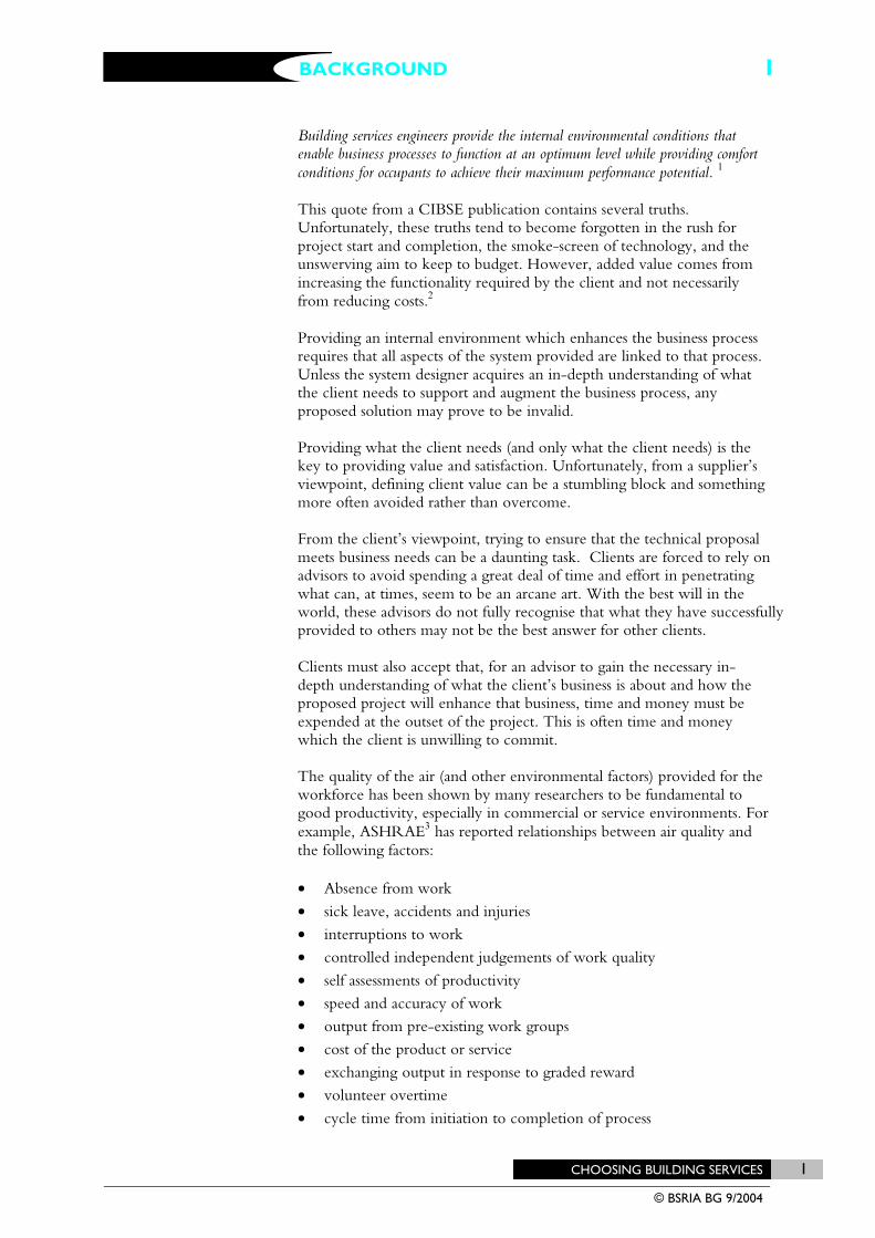
Building services engineers provide the internal environmental conditions that enable business processes to function at an optimum level while providing comfort conditions for occupants to achieve their maximum performance potential. 1 This quote from a CIBSE publication contains several truths. Unfortunately, these truths tend to become forgotten in the rush for project start and completion, the smoke-screen of technology, and the unswerving aim to keep to budget. However, added value comes from increasing the functionality required by the client and not necessarily from reducing costs.2 Providing an internal environment which enhances the business process requires that all aspects of the system provided are linked to that process. Unless the system designer acquires an in-depth understanding of what the client needs to support and augment the business process, any proposed solution may prove to be invalid. Providing what the client needs (and only what the client needs) is the key to providing value and satisfaction. Unfortunately, from a supplier’s viewpoint, defining client value can be a stumbling block and something more often avoided rather than overcome. From the client’s viewpoint, trying to ensure that the technical proposal meets business needs can be a daunting task. Clients are forced to rely on advisors to avoid spending a great deal of time and effort in penetrating what can, at times, seem to be an arcane art. With the best will in the world, these advisors do not fully recognise that what they have successfully provided to others may not be the best answer for other clients. Clients must also accept that, for an advisor to gain the necessary in-depth understanding of what the client’s business is about and how the proposed project will enhance that business, time and money must be expended at the outset of the project. This is often time and money which the client is unwilling to commit. The quality of the air (and other environmental factors) provided for the workforce has been shown by many researchers to be fundamental to good productivity, especially in commercial or service environments. For example, ASHRAE3 has reported relationships between air quality and the following factors: • Absence from work
• sick leave, accidents and injuries
• interruptions to work
• controlled independent judgements of work quality
• self assessments of productivity
• speed and accuracy of work
• output from pre-existing work groups
• cost of the product or service
• exchanging output in response to graded reward
• volunteer overtime
• cycle time from initiation to completion of process
BACKGROUND 1

BACKGROUND
2 CHOOSING BUILDING SERVICES © BSRIA BG 9/2004
1
• multiple measures at all organisational levels
• visual measures of performance, health and well-being at work
• development of measures and patterns of change over time.
The ASHRAE Journal4 also quotes that operational productivity may be influenced by up to 17% by addressing factors such as noise, temperature fluctuation, lighting and glare, comfort, relocation frequency, layout and the users’ perception and level of control. A study by Dorgan and Dorgan5 concluded that the American economy could be improved by US$55 bn per annum for a one-time investment of US$120 bn to improve poor air quality in all buildings. This benefit is achieved because people work better (and therefore more productively) as a direct result of good air quality. This does not mean that all buildings require full air-conditioning. They do not. What it does emphasise very strongly is that, given the 1:5:200 ratio6 (where 1 represents the cost of construction of a facility, 5 the cost of operating and maintaining that facility, and 200 the cost of the business process being undertaken in the facility) there is a convincing argument that the money needed to fully and properly define and plan the M&E services in a facility is easily recoverable within a short period of occupation. CRISP Report 00/047 states that 87% of survey responders (representing companies who commission building projects) said that they received what they expected – but this was not necessarily what they wanted. It should not be surprising, then, to find that no facilities managers were involved in the development of the client statement of requirements (often called the client brief). In an attempt to ensure client satisfaction without understanding what that client’s adjudication will be based upon, it would seem, that architects, designers, and development surveyors specify the highest level of implementation achievable within the budget that can be forced from the client, irrespective of whether the functionality thus provided is required or not. If this is the case, the level of unwanted function and therefore unnecessary cost, must be considered excessively high. The primary objective of the rules of thumb contained in this publication is not to provide prescriptive or quantative answers. Rather, they are designed to assist the client and the clients advisors towards asking – and getting answers to – the questions that are fundamental to understanding the business needs and thus the available generic solutions. The identification and definition of business needs, which are the drivers in most construction projects, are two important factors in achieving a high client perception of value for money.
USING THE DOCUMENT
CHOOSING BUILDING SERVICES 3 © BSRIA BG 9/2004
2
2 USING THE DOCUMENT
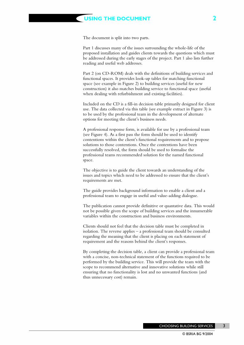
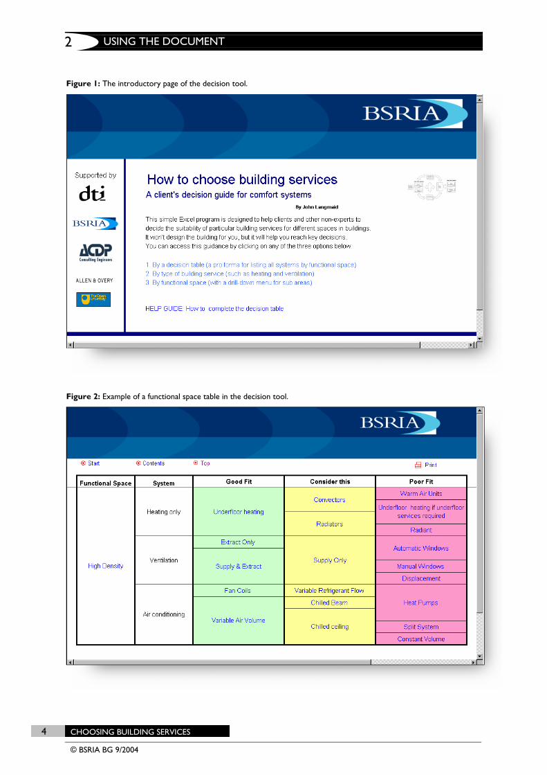
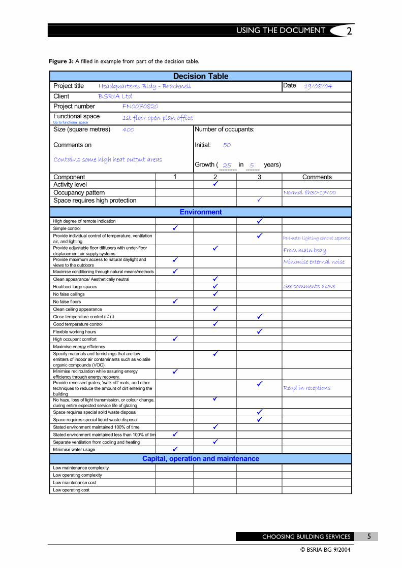
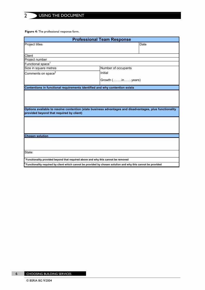
The document is split into two parts. Part 1 discusses many of the issues surrounding the whole-life of the proposed installation and guides clients towards the questions which must be addressed during the early stages of the project. Part 1 also lists further reading and useful web addresses. Part 2 (on CD-ROM) deals with the definitions of building services and functional spaces. It provides look-up tables for matching functional space (see example in Figure 2) to building services (useful for new construction) it also matches building service to functional space (useful when dealing with refurbishment and existing facilities). Included on the CD is a fill-in decision table primarily designed for client use. The data collected via this table (see example extract in Figure 3) is to be used by the professional team in the development of alternate options for meeting the client’s business needs. A professional response form, is available for use by a professional team (see Figure 4). As a first pass the form should be used to identify contentions within the client’s functional requirements and to propose solutions to those contentions. Once the contentions have been successfully resolved, the form should be used to formalise the professional teams recommended solution for the named functional space. The objective is to guide the client towards an understanding of the issues and topics which need to be addressed to ensure that the client’s requirements are met. The guide provides background information to enable a client and a professional team to engage in useful and value-adding dialogue. The publication cannot provide definitive or quantative data. This would not be possible given the scope of building services and the innumerable variables within the construction and business environments. Clients should not feel that the decision table must be completed in isolation. The reverse applies – a professional team should be consulted regarding the meaning that the client is placing on each statement of requirement and the reasons behind the client’s responses. By completing the decision table, a client can provide a professional team with a concise, non-technical statement of the functions required to be performed by the building service. This will provide the team with the scope to recommend alternative and innovative solutions while still ensuring that no functionality is lost and no unwanted functions (and thus unnecessary cost) remain.
USING THE DOCUMENT 2
USING THE DOCUMENT
4 CHOOSING BUILDING SERVICES © BSRIA BG 9/2004
2
Figure 1: The introductory page of the decision tool.
Figure 2: Example of a functional space table in the decision tool.
USING THE DOCUMENT
CHOOSING BUILDING SERVICES 5 © BSRIA BG 9/2004
2
Figure 3: A filled in example from part of the decision table.
Date
Initial:
Growth ( 25 in 5 years)
Project number FN0070820
50
Number of occupants:
Comments on
Size (square metres) 400
Contains some high heat output areas
19/08/04Project titleClient
Functional space
Headquarteres Bldg - BracknellBSRIA Ltd
1st floor open plan office
Decision Table
Go to functional space
Component 1 2 3 CommentsActivity levelOccupancy pattern Normal 8h30-17h00
EnvironmentHigh degree of remote indication
Space requires high protection
Provide individual control of temperature, ventilation air, and lighting
Perimeter lighting control separate
Simple control
From main bodyProvide maximum access to natural daylight and views to the outdoors
Minimise external noise
Provide adjustable floor diffusers with under-floor displacement air supply systems
Clean appearance/ Aesthetically neutralMaximise conditioning through natural means/methods
See comments aboveNo false ceilingsHeat/cool large spaces
Clean ceiling appearanceNo false floors
Good temperature controlClose temperature control (
High occupant comfortFlexible working hours
Specify materials and furnishings that are low emitters of indoor air contaminants such as volatile organic compounds (VOC).
Maximise energy efficiency
Provide recessed grates, 'walk off' mats, and other techniques to reduce the amount of dirt entering the building
Reqd in receptions
Minimise recirculation while assuring energy efficiency through energy recovery.
Space requires special solid waste disposal
No haze, loss of light transmission, or colour change, during entire expected service life of glazing
Stated environment maintained 100% of timeSpace requires special liquid waste disposal
Separate ventilation from cooling and heatingStated environment maintained less than 100% of tim
Capital, operation and maintenanceLow maintenance complexity
Minimise water usage
Low maintenance costLow operating complexity
Low operating cost
)2C°±
USING THE DOCUMENT
6 CHOOSING BUILDING SERVICES © BSRIA BG 9/2004
2
Figure 4: The professional response form.
State:
1 Functionality provided beyond that required above and why this cannot be removed2 Functionality required by client which cannot be provided by chosen solution and why this cannot be provided
Options available to resolve contention (state business advantages and disadvantages, plus functionality provided beyond that required by client)
Chosen solution
Comments on space2 Initial
Growth (……..in…….years)
Contentions in functional requirements identified and why contention exists
ClientProject numberFunctional space1
Number of occupantsSize in square metres
Professional Team ResponseProject titles Date