lg hvac solution - lgair
TRANSCRIPT
LG HVAC SOLUTION
LG ElectronicsAE Company, Commercial Air Conditioning20 Yeouido-dong, Yeongdeungpo-gu, Yeouido P.O.Box 335 Seoul, 150-721, Korea.www.lg.com www.lgeaircon.com
Copyright © 2013 LG Electronics. All rights reserved.
Distributed by

13
LG Air Conditioning and Energy Solution (AE) company’s
primary goal is to ‘vitalizing every environment’ around the
globe – from private residences to commercial buildings and
shared communal spaces. To make this a reality, the company
has developed a comprehensive range of innovative heating,
ventilation and air conditioning (HVAC) products as well as
state-of-the-art energy solutions. One such product is the
advanced MULTI V IV variable refrigerant flow (VRF), which
delivers incredible performance and energy efficiency through
a number of proprietary LG technologies.
VRF solutions are widely considered to be among the most
versatile and powerful system air conditioners available.
Providing exceptional comfort, energy efficiency and reliability,
they are highly regarded by building managers, business
operators and HVAC engineers. The latest model VRF solutions
boast a number of other tangible benefits too, including cost
effectiveness and easier installation.
Thanks to significant advancements in HVAC technology,
VRF systems are now able to offer unmatched performance
capabilities along with reduced energy consumption.
Nevertheless, LG continues to focus on removing all causes of
‘hidden loss,’ thereby further improving operational efficiency
and passing on considerable energy savings to the consumer.
Through close observation, testing, analysis and extensive
R&D, LG has been able to drastically cut energy loss. The
results of this endeavor can clearly be seen in the company’s
finest achievement to date, new MULTI V IV. Going ‘Beyond
Your Standard,’ the groundbreaking HVAC system possesses
all of the strengths and none of the weaknesses in a VRF
system.
One of LG’s firmly held beliefs is that in order to be the very
best, one must offer the very best. Equipped with world-first
technologies and offering unrivalled performance, MULTI V IV
can rightly be called ‘the very best’ VRF system the market.
The Rule of 20 In 2008, the EU announced its triple goal related to energy efficiency under the ‘20-20-20 Policy’. With a
wide range of far-reaching policies, the EU aims to cut its dependence on primary energy sources by 20%, reduce CO2 emissions by
20%, and also increase renewable energy production by 20% before 2020. To help lower electricity consumption by raising consumer
awareness, all appliances released in the European market must display a label, which indicates the energy efficiency rating, annual
energy consumption, and other energy-related information. In addition to helping consumers choose more efficient products, the
labeling system encourages manufacturers to develop technologies, which require less energy to operate.
20% 20% 20%Primary Energy
Consumption
Greenhouse Gas
Emissions 2020By the year
Sharing of
Renewable Energy
MULTI V IV Development Philosophy
32
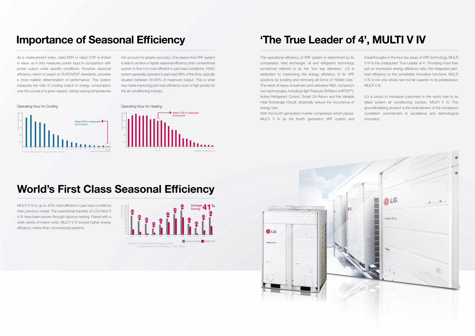
‘The True Leader of 4’, MULTI V IV
The operational efficiency of VRF system is determined by its
compressor, heat exchanger, oil and refrigerant technology
sometimes referred to as the ‘four key elements.’ LG is
dedicated to maximizing the energy efficiency of its VRF
solutions by locating and removing all forms of ‘hidden loss.’
The result of heavy investment and extensive R&D, company’s
own technologies, including High Pressure Oil Return (HiPORTM),
Active Refrigerant Control, Smart Oil Return and the Variable
Heat Exchanger Circuit, drastically reduce the occurrence of
energy loss.
With the fourth generation inverter compressor which places
MULTI V IV as the fourth generation VRF system and
breakthroughs in the four key areas of VRF technology, MULTI
V IV is the undisputed ‘True Leader of 4’. Providing more than
just an impressive energy efficiency ratio, the integrated part-
load efficiency or the completely innovative functions, MULTI
V IV is not only whole new but far superior to its predecessor,
MULTI V III.
LG is proud to introduce customers in the world over to its
latest system air conditioning solution, MULTI V IV. This
groundbreaking product is the embodiment of the company’s
consistent commitment to excellence and technological
innovation.
World’s First Class Seasonal Efficiency
MULTI V IV is up to 40% more efficient in part load conditions
than previous model. The operational benefits of LG’s MULTI
V IV have been proven through rigorous testing. Paired with a
wide variety of indoor units, MULTI V IV scored higher energy
efficiency marks than conventional systems.
1400
1600
1800
2000
2200
2400
2600
1000
1200
600
800
200
400
MULTI V IVPrevious ModelSource: LG Energy Estimate Program (LEEP) simulation data-5th floor building in Paris, France
Po
wer
inp
ut
(kW
h)
Jan
65%
Feb
68%
Mar
66%
Apr
46%
May
17%
Jun
16%
Jul
19%
Aug
23%
Sep
11%
Oct
35%
Nov
70%
Dec
67%
41%AverageSaving
Importance of Seasonal Efficiency
Operating Hour for Heating
Outdoor Air Temperature (Cº)
400
500
Yearly
occurr
ence (ho
urs
)
300
200
100
15 214 110 -36 -712 -18 -5413 09 -45 -811 -27 -630
Rated COP is measured at this point
400
500
300
200
100
Operating Hour for Cooling
Outdoor Air Temperature (Cº)
17 18 19 20 21 22 23 24 25 26 27 28 29 30 31 32 33 34 350
Rated EER is measured at this point
Yearly
occurr
ence (ho
urs
)
Source: Meteonom-1 year in Paris, France
As a measurement index, rated EER or rated COP is limited
in value, as it only measures power input in comparison with
power output under specific conditions. However, seasonal
efficiency, which is based on EUROVENT standards, provides
a more realistic determination of performance. This system
measures the ratio of cooling output to energy consumption
over the course of a given season, taking varying temperatures
into account for greater accuracy. One reason that VRF system
is able to achieve a higher seasonal efficiency than conventional
system is that it is more efficient in part load conditions. HVAC
system generally operates in part load 98% of the time, typically
situated between 40-80% of maximum output. This is what
has made improving part load efficiency such a high priority for
the air conditioning industry.
54
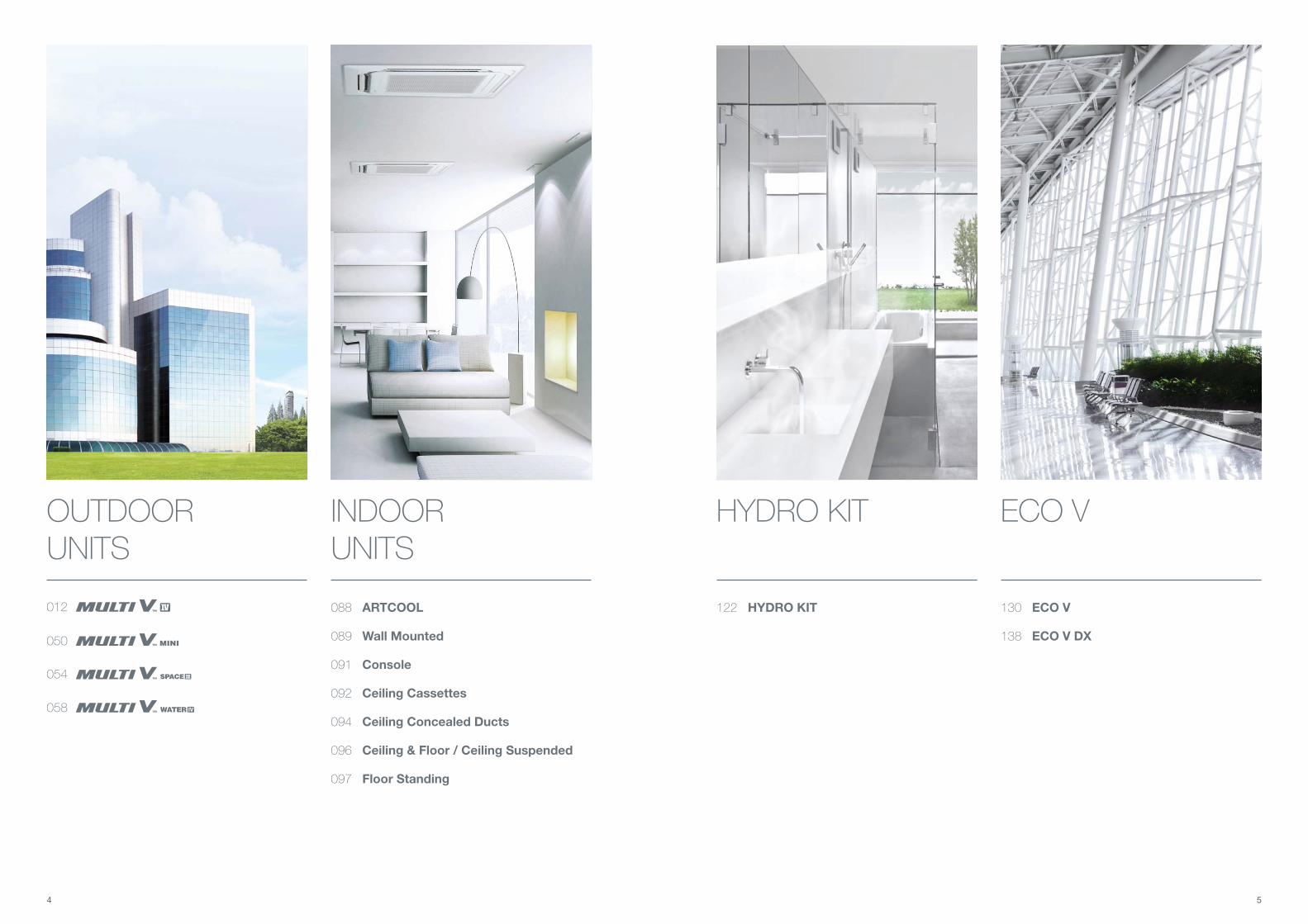
088 ARTCOOL
089 Wall Mounted
091 Console
092 Ceiling Cassettes
094 Ceiling Concealed Ducts
096 Ceiling & Floor / Ceiling Suspended
097 Floor Standing
122 HYDRO KIT 130 ECO V
138 ECO V DX050
012
054
058
OUTDOOR UNITS
INDOOR UNITS
HYDRO KIT ECO V
76
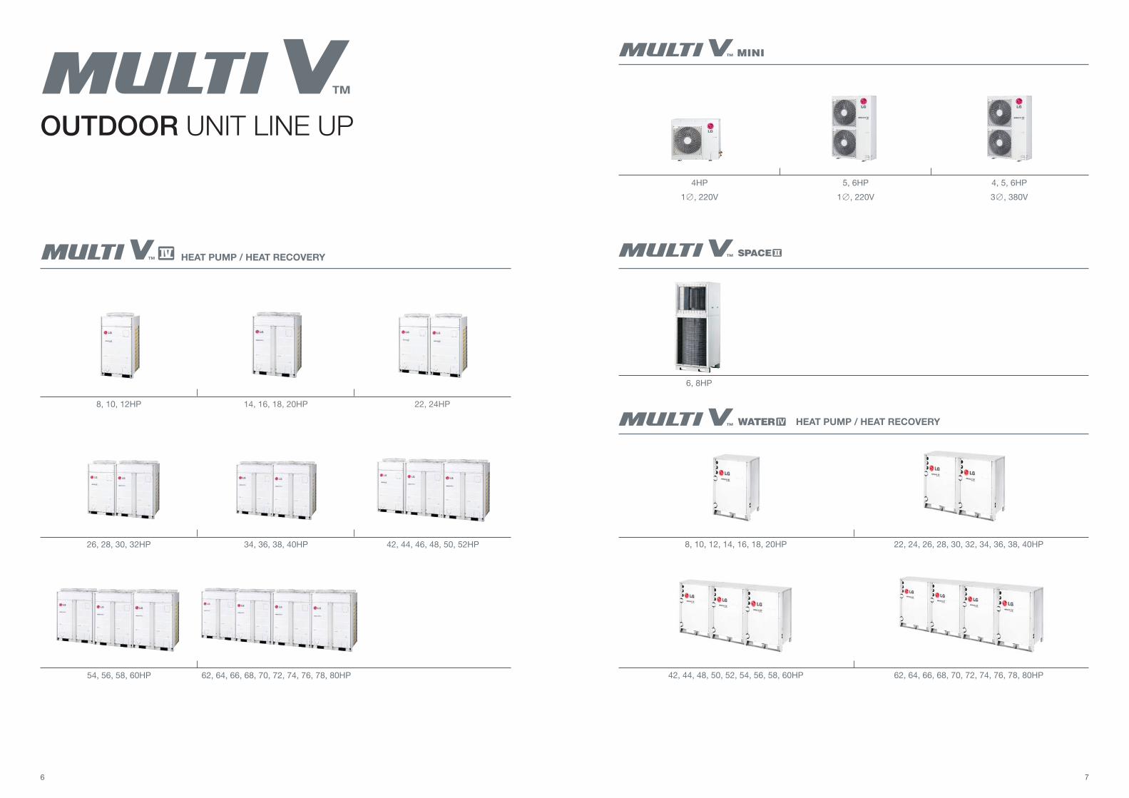
OUTDOOR UNIT LINE UP
HEAT PUMP / HEAT RECOVERY
8, 10, 12HP 14, 16, 18, 20HP 22, 24HP
26, 28, 30, 32HP 34, 36, 38, 40HP 42, 44, 46, 48, 50, 52HP
54, 56, 58, 60HP 62, 64, 66, 68, 70, 72, 74, 76, 78, 80HP 4
HEAT PUMP / HEAT RECOVERY
6, 8HP 1 2
4HP 5, 6HP 4, 5, 6HP
1 , 220V 1 , 220V 3 , 380V
8, 10, 12, 14, 16, 18, 20HP 22, 24, 26, 28, 30, 32, 34, 36, 38, 40HP
42, 44, 48, 50, 52, 54, 56, 58, 60HP 62, 64, 66, 68, 70, 72, 74, 76, 78, 80HP
98
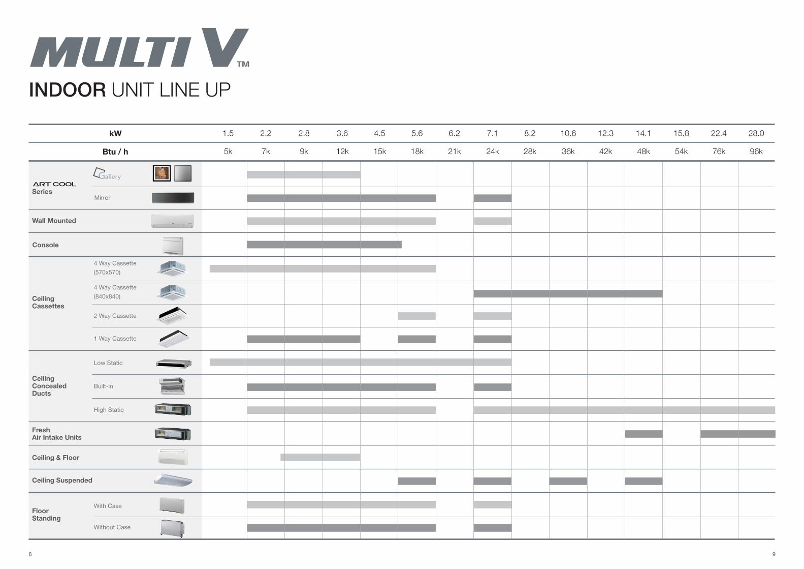
Console
2 Way Cassette
1 Way Cassette
Low Static
Built-in
High Static
With Case
Without Case
(840x840)
4 Way Cassette
(570x570)
4 Way Cassette
Mirror
Ceiling Cassettes
Ceiling Concealed Ducts
FreshAir Intake Units
Floor Standing
Ceiling & Floor
Ceiling Suspended
Series
Wall Mounted
INDOOR UNIT LINE UP
kW
Btu / h 5k
1.5
7k 9k 12k 15k 18k
2.2 2.8 3.6 4.5 5.6
24k21k 28k 36k 42k 48k 54k 76k 96k
7.16.2 8.2 10.6 12.3 14.1 15.8 22.4 28.0
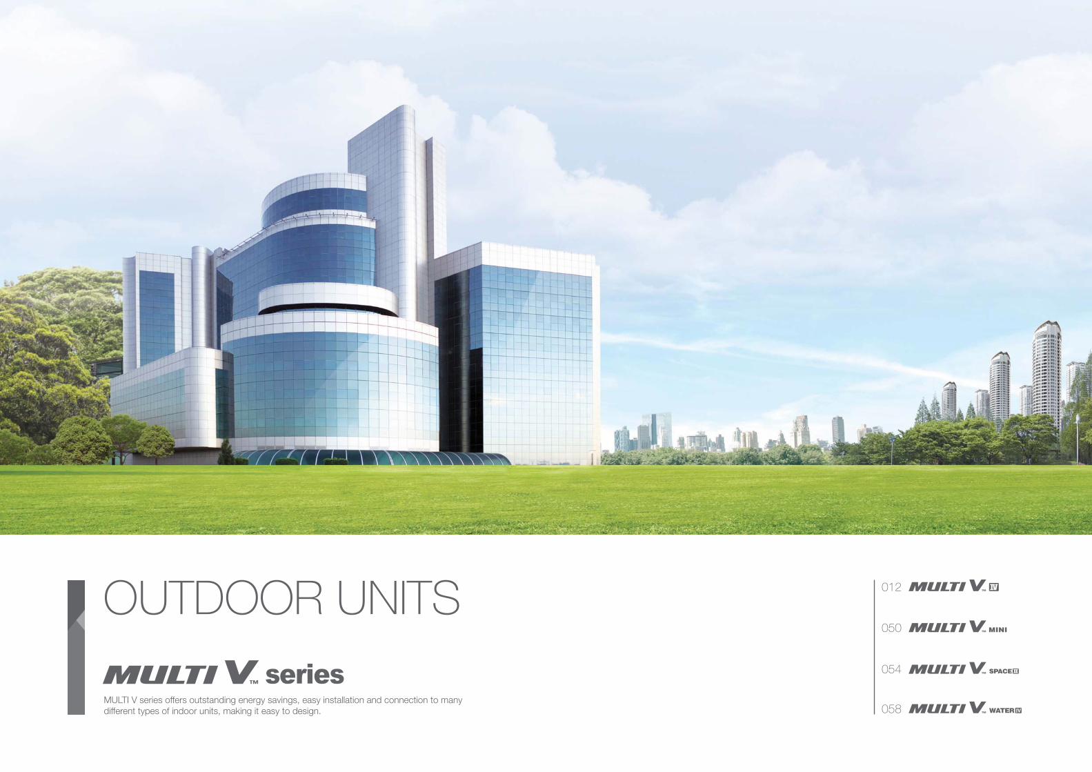
MULTI V series offers outstanding energy savings, easy installation and connection to many
different types of indoor units, making it easy to design.
OUTDOOR UNITS012
050
054
058
1312 1312
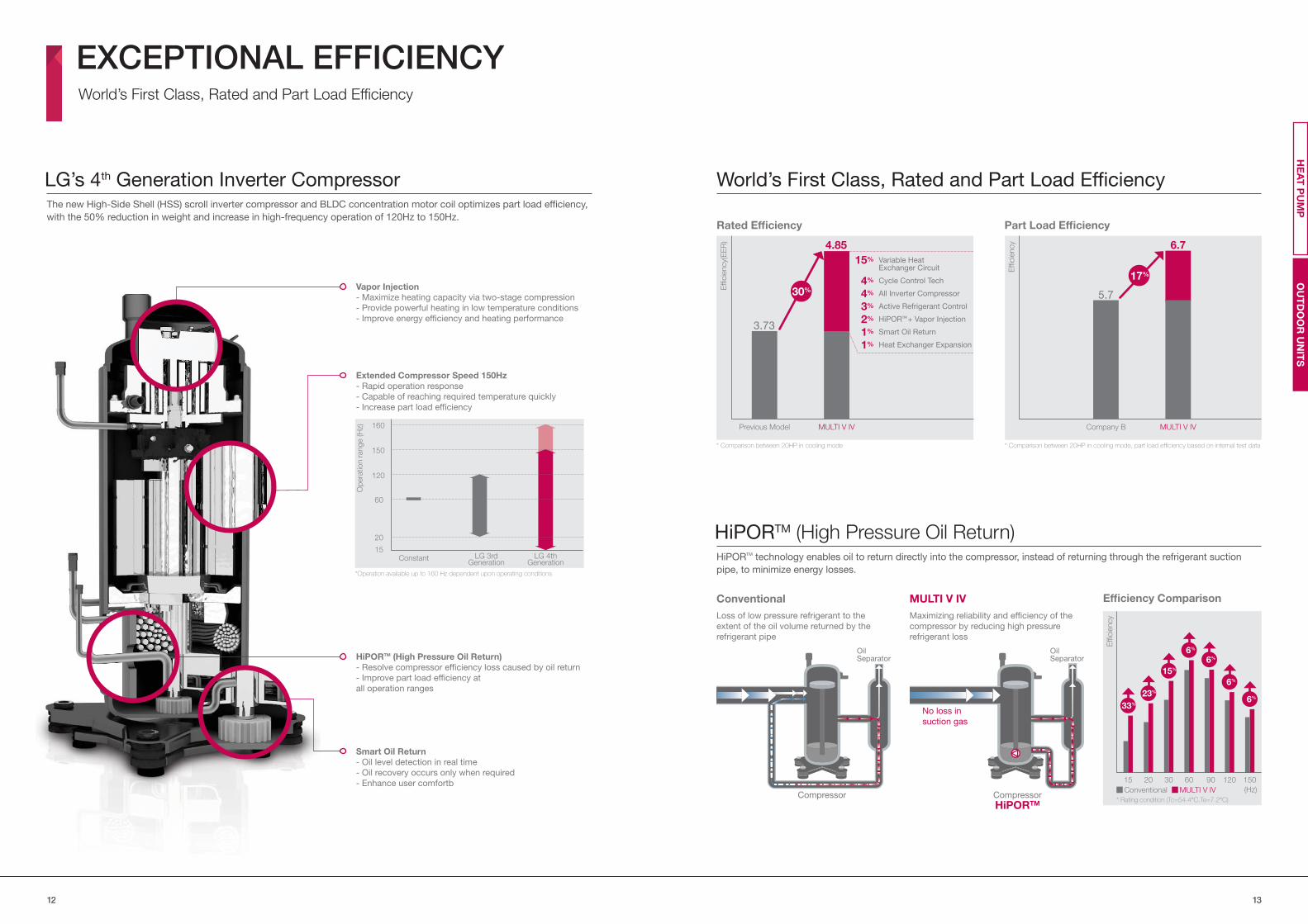
The new High-Side Shell (HSS) scroll inverter compressor and BLDC concentration motor coil optimizes part load efficiency,
with the 50% reduction in weight and increase in high-frequency operation of 120Hz to 150Hz.
LG’s 4th Generation Inverter Compressor
*Operation available up to 160 Hz dependent upon operating conditions
Vapor Injection
- Maximize heating capacity via two-stage compression
- Provide powerful heating in low temperature conditions
- Improve energy efficiency and heating performance
Extended Compressor Speed 150Hz
- Rapid operation response
- Capable of reaching required temperature quickly
- Increase part load efficiency
HiPORTM (High Pressure Oil Return)
- Resolve compressor efficiency loss caused by oil return
- Improve part load efficiency at
all operation ranges
Smart Oil Return
- Oil level detection in real time
- Oil recovery occurs only when required
- Enhance user comfortb
EXCEPTIONAL EFFICIENCYWorld’s First Class, Rated and Part Load Efficiency
World’s First Class, Rated and Part Load Efficiency
* Comparison between 20HP in cooling mode * Comparison between 20HP in cooling mode, part load efficiency based on internal test data
Rated Efficiency Part Load Efficiency
Effi
cie
ncy(
EE
R)
Effi
cie
ncy4.85
15%
4%
4%
3%
2%
1%
1%
3.73
MULTI V IVPrevious Model
30%
Cycle Control Tech
Variable Heat Exchanger Circuit
Active Refrigerant Control
All Inverter Compressor
HiPORTM + Vapor Injection
Smart Oil Return
Heat Exchanger Expansion
6.7
5.7
MULTI V IVCompany B
17%
HiPORTM technology enables oil to return directly into the compressor, instead of returning through the refrigerant suction
pipe, to minimize energy losses.
HiPORTM (High Pressure Oil Return)
Conventional
Loss of low pressure refrigerant to the
extent of the oil volume returned by the
refrigerant pipe
MULTI V IV
Maximizing reliability and efficiency of the
compressor by reducing high pressure
refrigerant loss
No loss in
suction gas
Oil Separator
Oil Separator
Compressor Compressor
HiPORTM
Efficiency Comparison
MULTI V IVConventional (Hz)
* Rating condition (Tc=54.4°C,Te=7.2°C)
15
33%
20
23%
30
15%
60
6%
90
6%
120
6%
150
6%
Effi
cie
ncy
OU
TD
OO
R U
NIT
SH
EA
T P
UM
P
Constant LG 3rdGeneration
LG 4thGeneration
Op
era
tion r
ange (H
z)
15
20
60
120
150
160
1514
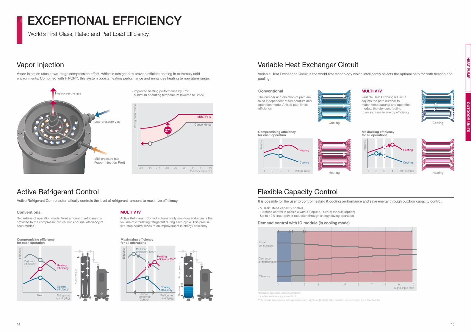
Vapor Injection uses a two-stage compression effect, which is designed to provide efficient heating in extremely cold
environments. Combined with HiPORTM, this system boosts heating performance and enhances heating temperature range.
Vapor Injection
- Improved heating performance by 27%
- Minimum operating temperature lowered to -25°C
Outdoor temp.(°C)-25 -20 -15 -10 -5 0 7 11 15
Heating
perf
orm
ance
Low-pressure gas
Mid-pressure gas
(Vapor Injection Port)
High-pressure gas
Conventional
MULTI V IV
Variable Heat Exchanger CircuitVariable Heat Exchanger Circuit is the world first technology which intelligently selects the optimal path for both heating and
cooling.
Conventional
The number and direction of path are
fixed independent of temperature and
operation mode. A fixed path limits
efficiency.
MULTI V IV
Variable Heat Exchanger Circuit
adjusts the path number to
match temperatures and operation
modes, thereby contributing
to an increase in energy efficiency
Cooling Cooling
Heating Heating
Compromising efficiencyfor each operation
Maximizing efficiencyfor all operations
Effi
cie
ncy
1 2 3 4
Cooling
Path number
Heating Effi
cie
ncy
1 2 3 4
Cooling
Path number
Heating
Active Refrigerant ControlActive Refrigerant Control automatically controls the level of refrigerant amount to maximize efficiency.
Heating efficiency
Cooling efficiency
Cooling efficiency
Conventional
Regardless of operation mode, fixed amount of refrigerant is
provided to the compressor, which limits optimal efficiency of
each modes
MULTI V IV
Active Refrigerant Control automatically monitors and adjusts the
volume of circulating refrigerant during each cycle. This precise,
five-step control leads to an improvement in energy efficiency
Effi
cie
ncy
Effi
cie
ncy
Fixed Refrigerant quantity(kg)
Refrigerant quantity(kg)
Part load efficiency
Heating efficiency 3%
Part load efficiency 10%
Compromising efficiencyfor each operation
Maximizing efficiencyfor all operations
Active Refrigerant
Control
Accum
ula
tor
Receiv
er
Accum
ula
tor
Flexible Capacity ControlIt is possible for the user to control heating & cooling performance and save energy through outdoor capacity control.
- 5 Basic steps capacity control
- 10 steps control is possible with IO(Input & Output) module (option)
- Up to 40% input power reduction through energy saving operation
Demand control with IO module (In cooling mode)
* Reduction rate varies upon site conditions
** It will be available at the end of 2013
*** IO module also provides silent operation during night time, IDU/ODU alarm operation, error alarm and low ambient control
Power
consumption
Discharge
air temperature
Efficiency
Signal input step
0 1 2 3 4 5 6 7 8 9 10
EXCEPTIONAL EFFICIENCYWorld’s First Class, Rated and Part Load Efficiency
OU
TD
OO
R U
NIT
SH
EA
T P
UM
P
27%
1716
OUTSTANDING PERFORMANCEAlways Ahead of the Competition and on the Leading Edge of Innovation
with Powerful Heating and Unsurpassed Cooling Performance
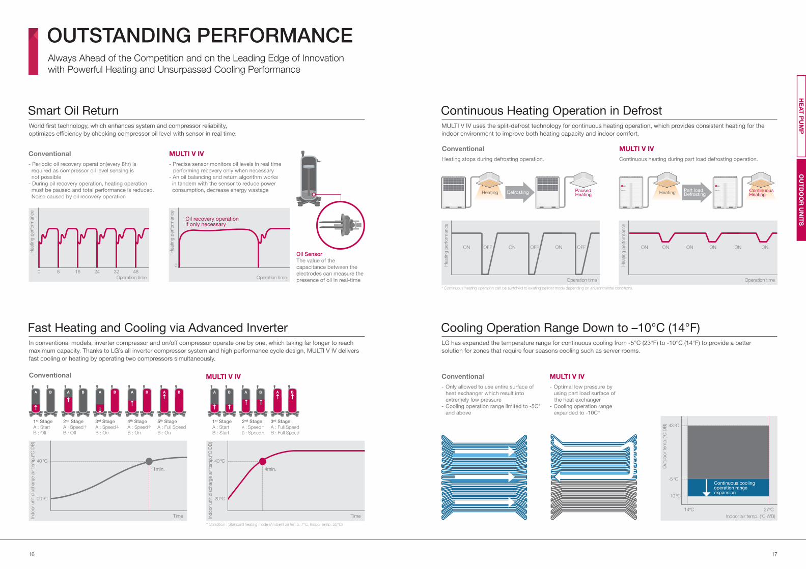
Smart Oil ReturnWorld first technology, which enhances system and compressor reliability,
optimizes efficiency by checking compressor oil level with sensor in real time.
Conventional
- Periodic oil recovery operation(every 8hr) is
required as compressor oil level sensing is
not possible
- During oil recovery operation, heating operation
must be paused and total performance is reduced.
Noise caused by oil recovery operation
MULTI V IV
- Precise sensor monitors oil levels in real time
performing recovery only when necessary
- An oil balancing and return algorithm works
in tandem with the sensor to reduce power
consumption, decrease energy wastage
Oil Sensor
The value of the
capacitance between the
electrodes can measure the
presence of oil in real-time
Oil recovery operation if only necessary
16 24 32 48
Operation time
Heating p
erf
orm
ance
Heating p
erf
orm
ance
Operation time
80
0
Conventional
In conventional models, inverter compressor and on/off compressor operate one by one, which taking far longer to reach
maximum capacity. Thanks to LG’s all inverter compressor system and high performance cycle design, MULTI V IV delivers
fast cooling or heating by operating two compressors simultaneously.
Fast Heating and Cooling via Advanced Inverter
1st Stage
A : Start
B : Start
2nd Stage
A : Speed
B : Speed
3rd Stage
A : Full Speed
B : Full Speed
1st Stage
A : Start
B : Off
2nd Stage
A : Speed
B : Off
3rd Stage
A : Speed
B : On
4th Stage
A : Speed
B : On
5th Stage
A : Full Speed
B : On
MULTI V IV
Time TimeInd
oor
unit d
ischarg
e a
ir t
em
p.(ºC
DB
)
Ind
oor
unit d
ischarg
e a
ir t
em
p.(ºC
DB
)
40 ºC 40 ºC
20 ºC 20 ºC
11min. 4min.
* Condition : Standard heating mode (Ambient air temp. 7°C, Indoor temp. 20°C)
Cooling Operation Range Down to –10°C (14°F)LG has expanded the temperature range for continuous cooling from -5°C (23°F) to -10°C (14°F) to provide a better
solution for zones that require four seasons cooling such as server rooms.
Conventional
- Only allowed to use entire surface of
heat exchanger which result into
extremely low pressure
- Cooling operation range limited to -5C°
and above
MULTI V IV
- Optimal low pressure by
using part load surface of
the heat exchanger
- Cooling operation range
expanded to -10C°
Outd
oor
tem
p.(ºC
DB
)
Indoor air temp. (ºC WB)
43 ºC
-5 ºC
-10 ºC
14ºC 27ºC
Continuous coolingoperation rangeexpansion
Conventional
Heating stops during defrosting operation.
Continuous Heating Operation in DefrostMULTI V IV uses the split-defrost technology for continuous heating operation, which provides consistent heating for the
indoor environment to improve both heating capacity and indoor comfort.
Heating ContinuousHeating
PausedHeatingHeating
MULTI V IV
Continuous heating during part load defrosting operation.
* Continuous heating operation can be switched to existing defrost mode depending on environmental conditions.
Operation time
Heating p
erf
orm
ance
Operation time
Heating p
erf
orm
ance
OFF ONON ONON ON ONON ONOFF OFF ON
HeaHeatintinggg ConContintinuouuoussHeaHeatintinggDefrosting Part load
Defrosting HeaHeatintinggg
OU
TD
OO
R U
NIT
SH
EA
T P
UM
P
1918
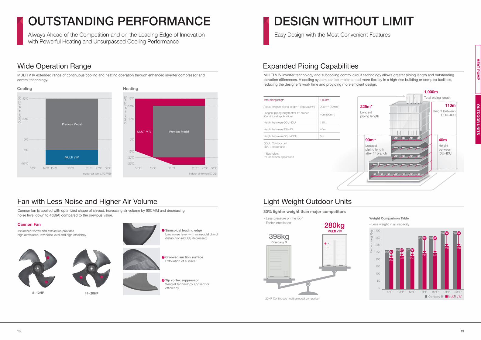
Wide Operation RangeMULTI V IV extended range of continuous cooling and heating operation through enhanced inverter compressor and
control technology.
Outd
oo
r te
mp
. (º
C D
B)
Outd
oo
r te
mp
. (º
C W
B)
-10 ºC -25ºC
-15ºC
-20ºC
0ºC 0ºC
20ºC 10ºC
43ºC 18ºC
15.5ºC
Indoor air temp.(ºC WB) Indoor air temp.(ºC DB)
10 ºC 14 ºC 15 ºC 20 ºC 25 ºC 27 ºC 30 ºC 10 ºC 15 ºC 20 ºC 25 ºC 27 ºC 30 ºC
HeatingCooling
Fan with Less Noise and Higher Air VolumeCannon fan is applied with optimized shape of shroud, increasing air volume by 50CMM and decreasing
noise level down to 4dB(A) compared to the previous value.
8~12HP 14~20HP
1
1 Sinusoidal leading edge
Low noise level with sinusoidal chord
distribution (4dB(A) decreased)
2
2
2 Grooved suction surface
Exfoliation of surface
3
Tip vortex suppressor
Winglet technology applied for
efficiency
3
Minimized vortex and exfoliation provides
high air volume, low noise level and high efficiency
Cannon Fan
OUTSTANDING PERFORMANCEAlways Ahead of the Competition and on the Leading Edge of Innovation
with Powerful Heating and Unsurpassed Cooling Performance
DESIGN WITHOUT LIMITEasy Design with the Most Convenient Features
Light Weight Outdoor Units
30% lighter weight than major competitors
- Less pressure on the roof
- Easier installation - Less weight in all capacity
Weight Comparison Table
* 20HP Continuous heating model comparison
Outd
oor
weig
ht(kg)
8HP 10HP 12HP 14HP 16HP 18HP 20HP
0
50
100
150
200
250
300
350
400
261
202
268
208
268
208
364
245
364
245
398
280
398
280
23%22% 22%
33% 33%
30% 30%
MULTI V IVCompany B
280kgMULTI V IV
398kgCompany B
Expanded Piping CapabilitiesMULTI V IV inverter technology and subcooling control circuit technology allows greater piping length and outstanding
elevation differences. A cooling system can be implemented more flexibly in a high-rise building or complex facilities,
reducing the designer’s work time and providing more efficient design.
225m*
Longest
piping length
1,000m
Total piping length
110m
Height between
ODU~IDU
40m
Height
between
IDU~IDU
90m**
Longest
piping length
after 1st branch
Total piping length 1,000m
Actual longest piping length** (Equivalent*) 200m** (225m*)
Longest piping length after 1st branch
(Conditional application)40m (90m**)
Height between ODU~IDU 110m
Height between IDU~IDU 40m
Height between ODU~ODU 5m
ODU : Outdoor unit
I D U : Indoor unit
* Equivalent
** Conditional application
OU
TD
OO
R U
NIT
SH
EA
T P
UM
P
-5ºC
Previous Model
MULTI V IV
Previous ModelMULTI V IV
2120
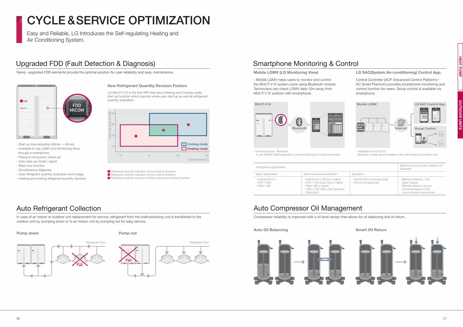
CYCLE & SERVICE OPTIMIZATIONEasy and Reliable, LG Introduces the Self-regulating Heating and
Air Conditioning System.
OU
TD
OO
R U
NIT
SH
EA
T P
UM
P
* Connection type : Bluetooth
To use Mobile LGMV application, exclusive Bluetooth module is required.
Central Controller (ACP (Advanced Control Platform) /
AC Smart Premium) provides smartphone monitoring and
control function for users. Group control is available via
smartphone.
Mobile LGMV (LG Monitoring View)
- Mobile LGMV helps users to monitor and control
the MULTI V IV system cycle using Bluetooth module.
Technicians can check LGMV data 10m away from
MULTI V IV outdoor with smartphone.
Smartphone Monitoring & ControlLG SAC(System Air-conditioning) Control App.
Smartphone specificationEffective communication distance of
Bluetooth
Basic specification Recommended specification Exception
- Android OS 2.2
- CPU 1 GHz
- RAM 1 GB
- Android OS 4.0(ICS) or higher
- CPU 1 GHz Dual Core or higher
- RAM 1GB or higher
- 1280 x 720, 800 x 480 resolution
(Optimized)
- Android OS 3.x (Honeycomb)
- iPhone not supported
- Effective distance : 10m
(Open Space)
- Effective distance can be
shortened based on the
communication environment.
Auto Compressor Oil ManagementCompressor reliability is improved with a oil level sensor that allows for oil balancing and oil return.
Auto Oil Balancing Smart Oil Return
Upgraded FDD (Fault Detection & Diagnosis)Newly upgraded FDD elements provide the optimal solution for user reliability and easy maintenance.
LG MULTI V IV is the first VRF that has a Heating and Cooling mode
start up function which permits whole year start up as well as refrigerant
quantity evaluation
- Start up time reduction (60min 45min)
- Available to use LGMV (LG Monitoring View)
through a smartphone
- Piping & wiring error check-up
- Auto start-up mode / report
- Black box function
- Simultaneous diagnosis
- Auto refrigerant quantity evaluation and charge
- Heating and cooling refrigerant quantity decision
New Refrigerant Quantity Decision Feature
Pump down Pump out
Refrigerant quantity evaluation during heating Operation
Refrigerant quantity evaluation during cooling Operation
Refrigerant quantity evaluation during cooling and heating Operation
12
3
-10 0 24 43
Ind
oor
air t
em
p.(ºC
DB
)
Outdoor temp.(ºC)
18
27
33
10Heating mode
Cooling mode
FDDMICOM
Auto Refrigerant CollectionIn case of an indoor or outdoor unit replacement for service, refrigerant from the malfunctioning unit is transferred to the
outdoor unit by pumping down or to an indoor unit by pumping out for easy service.
Refrigerant Flow Refrigerant Flow
Fail
Fail
Mobile LGMV MULTI V IV
BluetoothACP / AC
Smart
Premium Internet
LG SAC Control App.
Group Control
Manager
1
3
2
* Available from Oct 2013
Bluetooth module can be installed on the main board of the outdoor unit.
2322
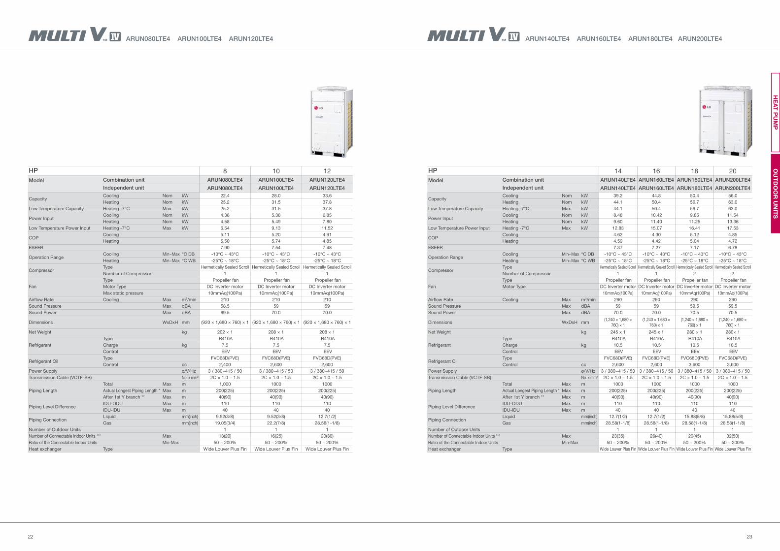
ARUN140LTE4 ARUN160LTE4 ARUN180LTE4 ARUN200LTE4
HP 14 16 18 20
Model Combination unit ARUN140LTE4 ARUN160LTE4 ARUN180LTE4 ARUN200LTE4
Independent unit ARUN140LTE4 ARUN160LTE4 ARUN180LTE4 ARUN200LTE4
Capacity Cooling Nom kW 39.2 44.8 50.4 56.0
Heating Nom kW 44.1 50.4 56.7 63.0
Low Temperature Capacity Heating -7°C Max kW 44.1 50.4 56.7 63.0
Power Input Cooling Nom kW 8.48 10.42 9.85 11.54
Heating Nom kW 9.60 11.40 11.25 13.36
Low Temperature Power Input Heating -7°C Max kW 12.83 15.07 16.41 17.53
COP Cooling 4.62 4.30 5.12 4.85
Heating 4.59 4.42 5.04 4.72
ESEER 7.37 7.27 7.17 6.78
Operation RangeCooling Min~Max °C DB -10°C ~ 43°C -10°C ~ 43°C -10°C ~ 43°C -10°C ~ 43°C
Heating Min~Max °C WB -25°C ~ 18°C -25°C ~ 18°C -25°C ~ 18°C -25°C ~ 18°C
Compressor Type Hermetically Sealed Scroll Hermetically Sealed Scroll Hermetically Sealed Scroll Hermetically Sealed Scroll
Number of Compressor 1 1 2 2
Fan
Type Propeller fan Propeller fan Propeller fan Propeller fan
Motor Type DC Inverter motor DC Inverter motor DC Inverter motor DC Inverter motor
10mmAq(100Pa) 10mmAq(100Pa) 10mmAq(100Pa) 10mmAq(100Pa)
Airflow Rate Cooling Max m3/min 290 290 290 290
Sound Pressure Max dBA 59 59 59.5 59.5
Sound Power Max dBA 70.0 70.0 70.5 70.5
Dimensions WxDxH mm(1,240 × 1,680 ×
760) × 1
(1,240 × 1,680 ×
760) × 1
(1,240 × 1,680 ×
760) × 1
(1,240 × 1,680 ×
760) × 1
Net Weight kg 245 x 1 245 x 1 280 × 1 280× 1
Refrigerant
Type R410A R410A R410A R410A
Charge kg 10.5 10.5 10.5 10.5
Control EEV EEV EEV EEV
Refrigerant OilType FVC68D(PVE) FVC68D(PVE) FVC68D(PVE) FVC68D(PVE)
Control cc 2,600 2,600 3,600 3,600
Power Supply ø/V/Hz 3 / 380~415 / 50 3 / 380~415 / 50 3 / 380~415 / 50 3 / 380~415 / 50
Transmission Cable (VCTF-SB) No. x mm² 2C × 1.0 ~ 1.5 2C × 1.0 ~ 1.5 2C × 1.0 ~ 1.5 2C × 1.0 ~ 1.5
Piping Length
Total Max m 1000 1000 1000 1000
Actual Longest Piping Length * Max m 200(225) 200(225) 200(225) 200(225)
After 1st Y branch ** Max m 40(90) 40(90) 40(90) 40(90)
Piping Level DifferenceIDU-ODU Max m 110 110 110 110
IDU-IDU Max m 40 40 40 40
Piping ConnectionLiquid mm(inch) 12.7(1/2) 12.7(1/2) 15.88(5/8) 15.88(5/8)
Gas mm(inch) 28.58(1-1/8) 28.58(1-1/8) 28.58(1-1/8) 28.58(1-1/8)
Number of Outdoor Units 1 1 1 1
Number of Connectable Indoor Units *** Max 23(35) 26(40) 29(45) 32(50)
Ratio of the Connectable Indoor Units Min-Max 50 ~ 200% 50 ~ 200% 50 ~ 200% 50 ~ 200%
Heat exchanger Type Wide Louver Plus Fin Wide Louver Plus Fin Wide Louver Plus Fin Wide Louver Plus Fin
ARUN080LTE4 ARUN100LTE4 ARUN120LTE4
HP 8 10 12
Model Combination unit ARUN080LTE4 ARUN100LTE4 ARUN120LTE4
Independent unit ARUN080LTE4 ARUN100LTE4 ARUN120LTE4
Capacity Cooling Nom kW 22.4 28.0 33.6
Heating Nom kW 25.2 31.5 37.8
Low Temperature Capacity Heating -7°C Max kW 25.2 31.5 37.8
Power Input Cooling Nom kW 4.38 5.38 6.85
Heating Nom kW 4.58 5.49 7.80
Low Temperature Power Input Heating -7°C Max kW 6.54 9.13 11.52
COP Cooling 5.11 5.20 4.91
Heating 5.50 5.74 4.85
ESEER 7.90 7.54 7.48
Operation RangeCooling Min~Max °C DB -10°C ~ 43°C -10°C ~ 43°C -10°C ~ 43°C
Heating Min~Max °C WB -25°C ~ 18°C -25°C ~ 18°C -25°C ~ 18°C
Compressor Type Hermetically Sealed Scroll Hermetically Sealed Scroll Hermetically Sealed Scroll
Number of Compressor 1 1 1
Fan
Type Propeller fan Propeller fan Propeller fan
Motor Type DC Inverter motor DC Inverter motor DC Inverter motor
Max static pressure 10mmAq(100Pa) 10mmAq(100Pa) 10mmAq(100Pa)
Airflow Rate Cooling Max m3/min 210 210 210
Sound Pressure Max dBA 58.5 59 59
Sound Power Max dBA 69.5 70.0 70.0
Dimensions WxDxH mm (920 × 1,680 × 760) × 1 (920 × 1,680 × 760) × 1 (920 × 1,680 × 760) × 1
Net Weight kg 202 × 1 208 × 1 208 × 1
Refrigerant
Type R410A R410A R410A
Charge kg 7.5 7.5 7.5
Control EEV EEV EEV
Refrigerant OilType FVC68D(PVE) FVC68D(PVE) FVC68D(PVE)
Control cc 2,400 2,600 2,600
Power Supply ø/V/Hz 3 / 380~415 / 50 3 / 380~415 / 50 3 / 380~415 / 50
Transmission Cable (VCTF-SB) No. x mm² 2C × 1.0 ~ 1.5 2C × 1.0 ~ 1.5 2C × 1.0 ~ 1.5
Piping Length
Total Max m 1,000 1000 1000
Actual Longest Piping Length * Max m 200(225) 200(225) 200(225)
After 1st Y branch ** Max m 40(90) 40(90) 40(90)
Piping Level DifferenceIDU-ODU Max m 110 110 110
IDU-IDU Max m 40 40 40
Piping ConnectionLiquid mm(inch) 9.52(3/8) 9.52(3/8) 12.7(1/2)
Gas mm(inch) 19.05(3/4) 22.2(7/8) 28.58(1-1/8)
Number of Outdoor Units 1 1 1
Number of Connectable Indoor Units *** Max 13(20) 16(25) 20(30)
Ratio of the Connectable Indoor Units Min-Max 50 ~ 200% 50 ~ 200% 50 ~ 200%
Heat exchanger Type Wide Louver Plus Fin Wide Louver Plus Fin Wide Louver Plus Fin
OU
TD
OO
R U
NIT
SH
EA
T P
UM
P
2524
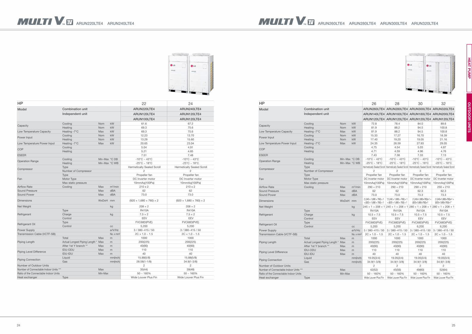
ARUN260LTE4 ARUN280LTE4 ARUN300LTE4 ARUN320LTE4
HP 26 28 30 32
Model Combination unit ARUN260LTE4 ARUN280LTE4 ARUN300LTE4 ARUN320LTE4
Independent unit ARUN140LTE4 ARUN160LTE4 ARUN180LTE4 ARUN200LTE4
ARUN120LTE4 ARUN120LTE4 ARUN120LTE4 ARUN120LTE4
Capacity Cooling Nom kW 72.8 78.4 84.0 89.6
Heating Nom kW 81.9 88.2 94.5 100.8
Low Temperature Capacity Heating -7°C Max kW 81.9 88.2 94.5 100.8
Power Input Cooling Nom kW 15.33 17.27 16.70 18.39
Heating Nom kW 17.40 19.20 19.05 21.16
Low Temperature Power Input Heating -7°C Max kW 24.35 26.59 27.93 29.05
COP Cooling 4.75 4.54 5.03 4.87
Heating 4.71 4.59 4.96 4.76
ESEER 7.43 7.38 7.33 7.13
Operation RangeCooling Min~Max °C DB -10°C ~ 43°C -10°C ~ 43°C -10°C ~ 43°C -10°C ~ 43°C
Heating Min~Max °C WB -25°C ~ 18°C -25°C ~ 18°C -25°C ~ 18°C -25°C ~ 18°C
Compressor Type Hermetically Sealed Scroll Hermetically Sealed Scroll Hermetically Sealed Scroll Hermetically Sealed Scroll
Number of Compressor 2 2 3 3
Fan
Type Propeller fan Propeller fan Propeller fan Propeller fan
Motor Type DC Inverter motor DC Inverter motor DC Inverter motor DC Inverter motor
Max static pressure 10mmAq(100Pa) 10mmAq(100Pa) 10mmAq(100Pa) 10mmAq(100Pa)
Airflow Rate Cooling Max m3/min 290 + 210 290 + 210 290 + 210 250 + 210
Sound Pressure Max dBA 62 62 62.3 62.3
Sound Power Max dBA 73.0 73.0 73.3 73.3
Dimensions WxDxH mm(1,240 × 1,680 × 760) × 1
+ (920 × 1,680 × 760) × 1
"(1,240 × 1,680 × 760) × 1
+ (920 × 1,680 × 760) × 1
(1,240×1,680×760)×1 +
(920×1,680×760)×1
(1,240×1,680×760)×1 +
(920×1,680×760)×1"
Net Weight kg 245 × 1 + 208 × 1 245 × 1 + 208 × 1 280 × 1 + 208 × 1 280 × 1 + 208 × 1
Refrigerant
Type R410A R410A R410A R410A
Charge kg 10.5 + 7.5 10.5 + 7.5 10.5 + 7.5 10.5 + 7.5
Control EEV EEV EEV EEV
Refrigerant OilType FVC68D(PVE) FVC68D(PVE) FVC68D(PVE) FVC68D(PVE)
Control cc 5,200 5,200 6,200 6,200
Power Supply ø/V/Hz 3 / 380~415 / 50 3 / 380~415 / 50 3 / 380~415 / 50 3 / 380~415 / 50
Transmission Cable (VCTF-SB) No. x mm² 2C × 1.0 ~ 1.5 2C × 1.0 ~ 1.5 2C × 1.0 ~ 1.5 2C × 1.0 ~ 1.5
Piping Length
Total Max m 1000 1000 1000 1000
Actual Longest Piping Length * Max m 200(225) 200(225) 200(225) 200(225)
After 1st Y branch ** Max m 40(90) 40(90) 40(90) 40(90)
Piping Level DifferenceIDU-ODU Max m 110 110 110 110
IDU-IDU Max m 40 40 40 40
Piping ConnectionLiquid mm(inch) 19.05(3/4) 19.05(3/4) 19.05(3/4) 19.05(3/4)
Gas mm(inch) 34.9(1-3/8) 34.9(1-3/8) 34.9(1-3/8) 34.9(1-3/8)
Number of Outdoor Units 2 2 2 2
Number of Connectable Indoor Units *** Max 42(52) 45(56) 49(60) 52(64)
Ratio of the Connectable Indoor Units Min-Max 50 ~ 160% 50 ~ 160% 50 ~ 160% 50 ~ 160%
Heat exchanger Type Wide Louver Plus Fin Wide Louver Plus Fin Wide Louver Plus Fin Wide Louver Plus Fin
ARUN220LTE4 ARUN240LTE4
HP 22 24
Model Combination unit ARUN220LTE4 ARUN240LTE4
Independent unit ARUN120LTE4 ARUN120LTE4
ARUN100LTE4 ARUN120LTE4
Capacity Cooling Nom kW 61.6 67.2
Heating Nom kW 69.3 75.6
Low Temperature Capacity Heating -7°C Max kW 69.3 75.6
Power Input Cooling Nom kW 12.23 13.70
Heating Nom kW 13.29 15.60
Low Temperature Power Input Heating -7°C Max kW 20.65 23.04
COP Cooling 5.04 4.91
Heating 5.21 4.85
ESEER 7.51 7.48
Operation RangeCooling Min~Max °C DB -10°C ~ 43°C -10°C ~ 43°C
Heating Min~Max °C WB -25°C ~ 18°C -25°C ~ 18°C
Compressor Type Hermetically Sealed Scroll Hermetically Sealed Scroll
Number of Compressor 2 2
Fan
Type Propeller fan Propeller fan
Motor Type DC Inverter motor DC Inverter motor
Max static pressure 10mmAq(100Pa) 10mmAq(100Pa)
Airflow Rate Cooling Max m3/min 210 x 2 210 x 2
Sound Pressure Max dBA 62 62
Sound Power Max dBA 73.0 73.0
Dimensions WxDxH mm (920 × 1,680 × 760) × 2 (920 × 1,680 × 760) × 2
Net Weight kg 208 × 2 208 × 2
Refrigerant
Type R410A R410A
Charge kg 7.5 × 2 7.5 × 2
Control EEV EEV
Refrigerant OilType FVC68D(PVE) FVC68D(PVE)
Control cc 5,200 5,200
Power Supply ø/V/Hz 3 / 380~415 / 50 3 / 380~415 / 50
Transmission Cable (VCTF-SB) No. x mm² 2C × 1.0 ~ 1.5 2C × 1.0 ~ 1.5
Piping Length
Total Max m 1000 1000
Actual Longest Piping Length * Max m 200(225) 200(225)
After 1st Y branch ** Max m 40(90) 40(90)
Piping Level DifferenceIDU-ODU Max m 110 110
IDU-IDU Max m 40 40
Piping ConnectionLiquid mm(inch) 15.88(5/8) 15.88(5/8)
Gas mm(inch) 28.58(1-1/8) 34.9(1-3/8)
Number of Outdoor Units 2 2
Number of Connectable Indoor Units *** Max 35(44) 39(48)
Ratio of the Connectable Indoor Units Min-Max 50 ~ 160% 50 ~ 160%
Heat exchanger Type Wide Louver Plus Fin Wide Louver Plus Fin
OU
TD
OO
R U
NIT
SH
EA
T P
UM
P

2726
ARUN380LTE4 ARUN400LTE4
HP 38 40
Model Combination unit ARUN380LTE4 ARUN400LTE4
Independent unit ARUN200LTE4 ARUN200LTE4
ARUN180LTE4 ARUN200LTE4
Capacity Cooling Nom kW 106.4 112.0
Heating Nom kW 119.7 126.0
Low Temperature Capacity Heating -7°C Max kW 119.7 126.0
Power Input Cooling Nom kW 21.39 23.08
Heating Nom kW 24.61 26.72
Low Temperature Power Input Heating -7°C Max kW 33.94 35.06
COP Cooling 4.97 4.85
Heating 4.86 4.72
ESEER 6.98 6.78
Operation RangeCooling Min~Max °C DB -10°C ~ 43°C -10°C ~ 43°C
Heating Min~Max °C WB -25°C ~ 18°C -25°C ~ 18°C
Compressor Type Hermetically Sealed Scroll Hermetically Sealed Scroll
Number of Compressor 4 4
Fan
Type Propeller fan Propeller fan
Motor Type DC Inverter motor DC Inverter motor
Max static pressure 10mmAq(100Pa) 10mmAq(100Pa)
Airflow Rate Cooling Max m3/min 290 x 2 290 x 2
Sound Pressure Max dBA 62.5 62.5
Sound Power Max dBA 73.5 73.5
Dimensions WxDxH mm (1,240 × 1,680 × 760) × 2 (1,240 × 1,680 × 760) × 2
Net Weight kg 280 × 2 280 × 2
Refrigerant
Type R410A R410A
Charge kg 10.5 × 2 10.5 × 2
Control EEV EEV
Refrigerant OilType FVC68D(PVE) FVC68D(PVE)
Control cc 7,200 7,200
Power Supply ø/V/Hz 3 / 380~415 / 50 3 / 380~415 / 50
Transmission Cable (VCTF-SB) No. x mm² 2C × 1.0 ~ 1.5 2C × 1.0 ~ 1.5
Piping Length
Total Max m 1000 1000
Actual Longest Piping Length * Max m 200(225) 200(225)
After 1st Y branch ** Max m 40(90) 40(90)
Piping Level DifferenceIDU-ODU Max m 110 110
IDU-IDU Max m 40 40
Piping ConnectionLiquid mm(inch) 19.05(3/4) 19.05(3/4)
Gas mm(inch) 41.3(1-5/8) 41.3(1-5/8)
Number of Outdoor Units 2 2
Number of Connectable Indoor Units *** Max 61(64) 64
Ratio of the Connectable Indoor Units Min-Max 50 ~ 160% 50 ~ 160%
Heat exchanger Type Wide Louver Plus Fin Wide Louver Plus Fin
ARUN340LTE4 ARUN360LTE4
HP 34 36
Model Combination unit ARUN340LTE4 ARUN360LTE4
Independent unit ARUN200LTE4 ARUN200LTE4
ARUN140LTE4 ARUN160LTE4
Capacity Cooling Nom kW 95.2 100.8
Heating Nom kW 107.1 113.4
Low Temperature Capacity Heating -7°C Max kW 107.1 113.4
Power Input Cooling Nom kW 20.02 21.96
Heating Nom kW 22.96 24.76
Low Temperature Power Input Heating -7°C Max kW 30.36 32.60
COP Cooling 4.76 4.59
Heating 4.66 4.58
ESEER 7.08 7.03
Operation RangeCooling Min~Max °C DB -10°C ~ 43°C -10°C ~ 43°C
Heating Min~Max °C WB -25°C ~ 18°C -25°C ~ 18°C
Compressor Type Hermetically Sealed Scroll Hermetically Sealed Scroll
Number of Compressor 3 3
Fan
Type Propeller fan Propeller fan
Motor Type DC Inverter motor DC Inverter motor
Max static pressure 10mmAq(100Pa) 10mmAq(100Pa)
Airflow Rate Cooling Max m3/min 290 x 2 290 x 2
Sound Pressure Max dBA 62.3 62.3
Sound Power Max dBA 73.3 73.3
Dimensions WxDxH mm (1,240×1,680×760)×2 (1,240 × 1,680 × 760) × 2
Net Weight kg 280 × 1 + 245 × 1 280 × 1 + 245 × 1
Refrigerant
Type R410A R410A
Charge kg 10.5 × 2 10.5 × 2
Control EEV EEV
Refrigerant OilType FVC68D(PVE) FVC68D(PVE)
Control cc 6,200 6,200
Power Supply ø/V/Hz 3 / 380~415 / 50 3 / 380~415 / 50
Transmission Cable (VCTF-SB) No. x mm² 2C × 1.0 ~ 1.5 2C × 1.0 ~ 1.5
Piping Length
Total Max m 1000 1000
Actual Longest Piping Length * Max m 200(225) 200(225)
After 1st Y branch ** Max m 40(90) 40(90)
Piping Level DifferenceIDU-ODU Max m 110 110
IDU-IDU Max m 40 40
Piping ConnectionLiquid mm(inch) 19.05(3/4) 19.05(3/4)
Gas mm(inch) 34.9(1-3/8) 41.3(1-5/8)
Number of Outdoor Units 2 2
Number of Connectable Indoor Units *** Max 55(64) 58(64)
Ratio of the Connectable Indoor Units Min-Max 50 ~ 160% 50 ~ 160%
Heat exchanger Type Wide Louver Plus Fin Wide Louver Plus Fin
OU
TD
OO
R U
NIT
HE
AT
PU
MP
2928
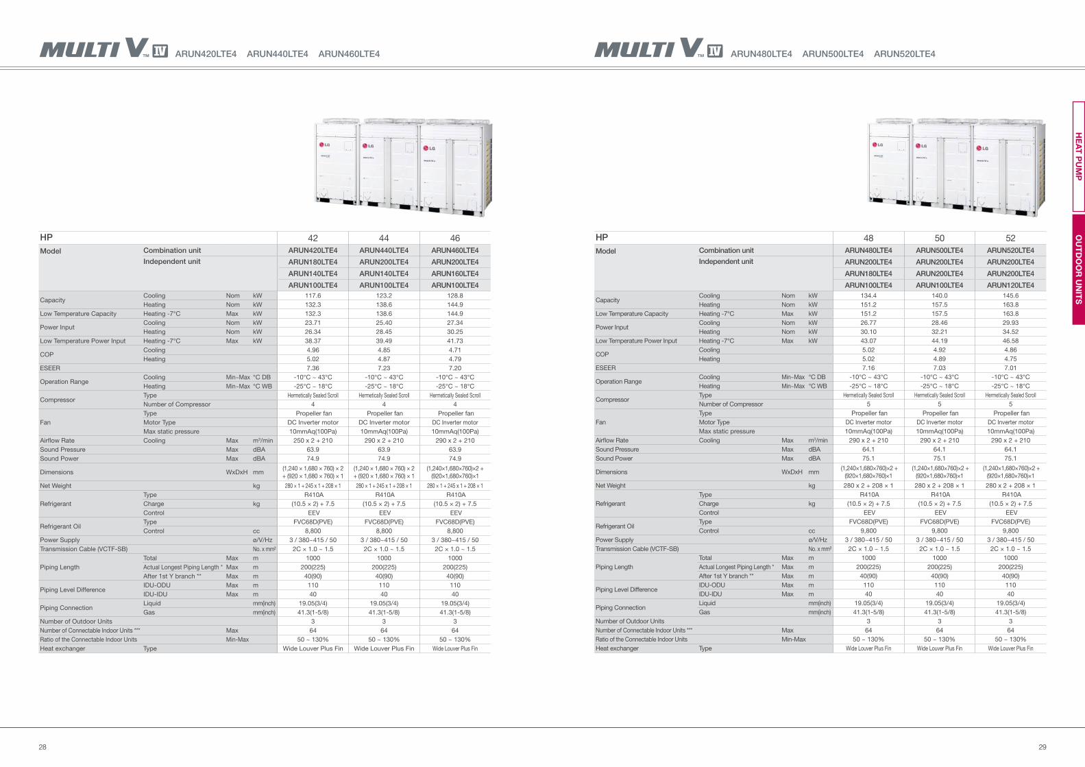
ARUN480LTE4 ARUN500LTE4 ARUN520LTE4
HP 48 50 52
Model Combination unit ARUN480LTE4 ARUN500LTE4 ARUN520LTE4
Independent unit ARUN200LTE4 ARUN200LTE4 ARUN200LTE4
ARUN180LTE4 ARUN200LTE4 ARUN200LTE4
ARUN100LTE4 ARUN100LTE4 ARUN120LTE4
Capacity Cooling Nom kW 134.4 140.0 145.6
Heating Nom kW 151.2 157.5 163.8
Low Temperature Capacity Heating -7°C Max kW 151.2 157.5 163.8
Power Input Cooling Nom kW 26.77 28.46 29.93
Heating Nom kW 30.10 32.21 34.52
Low Temperature Power Input Heating -7°C Max kW 43.07 44.19 46.58
COP Cooling 5.02 4.92 4.86
Heating 5.02 4.89 4.75
ESEER 7.16 7.03 7.01
Operation RangeCooling Min~Max °C DB -10°C ~ 43°C -10°C ~ 43°C -10°C ~ 43°C
Heating Min~Max °C WB -25°C ~ 18°C -25°C ~ 18°C -25°C ~ 18°C
Compressor Type Hermetically Sealed Scroll Hermetically Sealed Scroll Hermetically Sealed Scroll
Number of Compressor 5 5 5
Fan
Type Propeller fan Propeller fan Propeller fan
Motor Type DC Inverter motor DC Inverter motor DC Inverter motor
Max static pressure 10mmAq(100Pa) 10mmAq(100Pa) 10mmAq(100Pa)
Airflow Rate Cooling Max m3/min 290 x 2 + 210 290 x 2 + 210 290 x 2 + 210
Sound Pressure Max dBA 64.1 64.1 64.1
Sound Power Max dBA 75.1 75.1 75.1
Dimensions WxDxH mm (1,240×1,680×760)×2 +
(920×1,680×760)×1
(1,240×1,680×760)×2 +
(920×1,680×760)×1
(1,240×1,680×760)×2 +
(920×1,680×760)×1
Net Weight kg 280 x 2 + 208 × 1 280 x 2 + 208 × 1 280 x 2 + 208 × 1
Refrigerant
Type R410A R410A R410A
Charge kg (10.5 × 2) + 7.5 (10.5 × 2) + 7.5 (10.5 × 2) + 7.5
Control EEV EEV EEV
Refrigerant OilType FVC68D(PVE) FVC68D(PVE) FVC68D(PVE)
Control cc 9,800 9,800 9,800
Power Supply ø/V/Hz 3 / 380~415 / 50 3 / 380~415 / 50 3 / 380~415 / 50
Transmission Cable (VCTF-SB) No. x mm² 2C × 1.0 ~ 1.5 2C × 1.0 ~ 1.5 2C × 1.0 ~ 1.5
Piping Length
Total Max m 1000 1000 1000
Actual Longest Piping Length * Max m 200(225) 200(225) 200(225)
After 1st Y branch ** Max m 40(90) 40(90) 40(90)
Piping Level DifferenceIDU-ODU Max m 110 110 110
IDU-IDU Max m 40 40 40
Piping ConnectionLiquid mm(inch) 19.05(3/4) 19.05(3/4) 19.05(3/4)
Gas mm(inch) 41.3(1-5/8) 41.3(1-5/8) 41.3(1-5/8)
Number of Outdoor Units 3 3 3
Number of Connectable Indoor Units *** Max 64 64 64
Ratio of the Connectable Indoor Units Min-Max 50 ~ 130% 50 ~ 130% 50 ~ 130%
Heat exchanger Type Wide Louver Plus Fin Wide Louver Plus Fin Wide Louver Plus Fin
ARUN420LTE4 ARUN440LTE4 ARUN460LTE4
HP 42 44 46
Model Combination unit ARUN420LTE4 ARUN440LTE4 ARUN460LTE4
Independent unit ARUN180LTE4 ARUN200LTE4 ARUN200LTE4
ARUN140LTE4 ARUN140LTE4 ARUN160LTE4
ARUN100LTE4 ARUN100LTE4 ARUN100LTE4
Capacity Cooling Nom kW 117.6 123.2 128.8
Heating Nom kW 132.3 138.6 144.9
Low Temperature Capacity Heating -7°C Max kW 132.3 138.6 144.9
Power Input Cooling Nom kW 23.71 25.40 27.34
Heating Nom kW 26.34 28.45 30.25
Low Temperature Power Input Heating -7°C Max kW 38.37 39.49 41.73
COP Cooling 4.96 4.85 4.71
Heating 5.02 4.87 4.79
ESEER 7.36 7.23 7.20
Operation RangeCooling Min~Max °C DB -10°C ~ 43°C -10°C ~ 43°C -10°C ~ 43°C
Heating Min~Max °C WB -25°C ~ 18°C -25°C ~ 18°C -25°C ~ 18°C
Compressor Type Hermetically Sealed Scroll Hermetically Sealed Scroll Hermetically Sealed Scroll
Number of Compressor 4 4 4
Fan
Type Propeller fan Propeller fan Propeller fan
Motor Type DC Inverter motor DC Inverter motor DC Inverter motor
Max static pressure 10mmAq(100Pa) 10mmAq(100Pa) 10mmAq(100Pa)
Airflow Rate Cooling Max m3/min 250 x 2 + 210 290 x 2 + 210 290 x 2 + 210
Sound Pressure Max dBA 63.9 63.9 63.9
Sound Power Max dBA 74.9 74.9 74.9
Dimensions WxDxH mm(1,240 × 1,680 × 760) × 2
+ (920 × 1,680 × 760) × 1
(1,240 × 1,680 × 760) × 2
+ (920 × 1,680 × 760) × 1
(1,240×1,680×760)×2 +
(920×1,680×760)×1
Net Weight kg 280 × 1 + 245 x 1 + 208 × 1 280 × 1 + 245 x 1 + 208 × 1 280 × 1 + 245 x 1 + 208 × 1
Refrigerant
Type R410A R410A R410A
Charge kg (10.5 × 2) + 7.5 (10.5 × 2) + 7.5 (10.5 × 2) + 7.5
Control EEV EEV EEV
Refrigerant OilType FVC68D(PVE) FVC68D(PVE) FVC68D(PVE)
Control cc 8,800 8,800 8,800
Power Supply ø/V/Hz 3 / 380~415 / 50 3 / 380~415 / 50 3 / 380~415 / 50
Transmission Cable (VCTF-SB) No. x mm² 2C × 1.0 ~ 1.5 2C × 1.0 ~ 1.5 2C × 1.0 ~ 1.5
Piping Length
Total Max m 1000 1000 1000
Actual Longest Piping Length * Max m 200(225) 200(225) 200(225)
After 1st Y branch ** Max m 40(90) 40(90) 40(90)
Piping Level DifferenceIDU-ODU Max m 110 110 110
IDU-IDU Max m 40 40 40
Piping ConnectionLiquid mm(inch) 19.05(3/4) 19.05(3/4) 19.05(3/4)
Gas mm(inch) 41.3(1-5/8) 41.3(1-5/8) 41.3(1-5/8)
Number of Outdoor Units 3 3 3
Number of Connectable Indoor Units *** Max 64 64 64
Ratio of the Connectable Indoor Units Min-Max 50 ~ 130% 50 ~ 130% 50 ~ 130%
Heat exchanger Type Wide Louver Plus Fin Wide Louver Plus Fin Wide Louver Plus Fin
OU
TD
OO
R U
NIT
SH
EA
T P
UM
P
3130
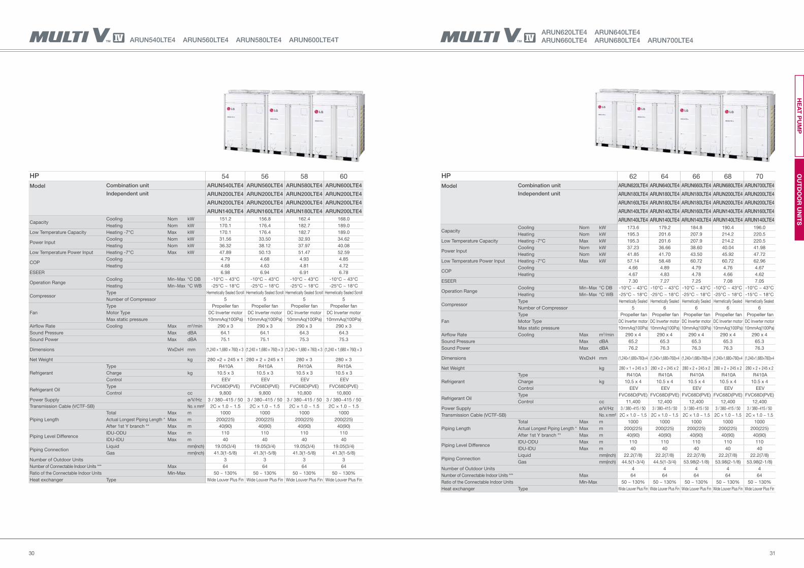
ARUN620LTE4 ARUN640LTE4
ARUN660LTE4 ARUN680LTE4 ARUN700LTE4
HP 62 64 66 68 70
Model Combination unit ARUN620LTE4 ARUN640LTE4 ARUN660LTE4 ARUN680LTE4 ARUN700LTE4
Independent unit ARUN180LTE4 ARUN180LTE4 ARUN180LTE4 ARUN200LTE4 ARUN200LTE4
ARUN160LTE4 ARUN180LTE4 ARUN180LTE4 ARUN200LTE4 ARUN200LTE4
ARUN140LTE4 ARUN140LTE4 ARUN160LTE4 ARUN140LTE4 ARUN160LTE4
ARUN140LTE4 ARUN140LTE4 ARUN140LTE4 ARUN140LTE4 ARUN140LTE4
Capacity Cooling Nom kW 173.6 179.2 184.8 190.4 196.0
Heating Nom kW 195.3 201.6 207.9 214.2 220.5
Low Temperature Capacity Heating -7°C Max kW 195.3 201.6 207.9 214.2 220.5
Power Input Cooling Nom kW 37.23 36.66 38.60 40.04 41.98
Heating Nom kW 41.85 41.70 43.50 45.92 47.72
Low Temperature Power Input Heating -7°C Max kW 57.14 58.48 60.72 60.72 62.96
COP Cooling 4.66 4.89 4.79 4.76 4.67
Heating 4.67 4.83 4.78 4.66 4.62
ESEER 7.30 7.27 7.25 7.08 7.05
Operation RangeCooling Min~Max °C DB -10°C ~ 43°C -10°C ~ 43°C -10°C ~ 43°C -10°C ~ 43°C -10°C ~ 43°C
Heating Min~Max °C WB -25°C ~ 18°C -25°C ~ 18°C -25°C ~ 18°C -25°C ~ 18°C -15°C ~ 18°C
Compressor Type Hermetically Sealed Hermetically Sealed Hermetically Sealed Hermetically Sealed Hermetically Sealed
Number of Compressor 5 6 6 6 6
Fan
Type Propeller fan Propeller fan Propeller fan Propeller fan Propeller fan
Motor Type DC Inverter motor DC Inverter motor DC Inverter motor DC Inverter motor DC Inverter motor
Max static pressure 10mmAq(100Pa) 10mmAq(100Pa) 10mmAq(100Pa) 10mmAq(100Pa) 10mmAq(100Pa)
Airflow Rate Cooling Max m3/min 290 x 4 290 x 4 290 x 4 290 x 4 290 x 4
Sound Pressure Max dBA 65.2 65.3 65.3 65.3 65.3
Sound Power Max dBA 76.2 76.3 76.3 76.3 76.3
Dimensions WxDxH mm (1,240×1,680×760)×4 (1,240×1,680×760)×4 (1,240×1,680×760)×4 (1,240×1,680×760)×4 (1,240×1,680×760)×4
Net Weight kg 280 × 1 + 245 x 3 280 × 2 + 245 x 2 280 × 2 + 245 x 2 280 × 2 + 245 x 2 280 × 2 + 245 x 2
Refrigerant
Type R410A R410A R410A R410A R410A
Charge kg 10.5 x 4 10.5 x 4 10.5 x 4 10.5 x 4 10.5 x 4
Control EEV EEV EEV EEV EEV
Refrigerant OilType FVC68D(PVE) FVC68D(PVE) FVC68D(PVE) FVC68D(PVE) FVC68D(PVE)
Control cc 11,400 12,400 12,400 12,400 12,400
Power Supply ø/V/Hz 3 / 380~415 / 50 3 / 380~415 / 50 3 / 380~415 / 50 3 / 380~415 / 50 3 / 380~415 / 50
Transmission Cable (VCTF-SB) No. x mm² 2C × 1.0 ~ 1.5 2C × 1.0 ~ 1.5 2C × 1.0 ~ 1.5 2C × 1.0 ~ 1.5 2C × 1.0 ~ 1.5
Piping Length
Total Max m 1000 1000 1000 1000 1000
Actual Longest Piping Length * Max m 200(225) 200(225) 200(225) 200(225) 200(225)
After 1st Y branch ** Max m 40(90) 40(90) 40(90) 40(90) 40(90)
Piping Level DifferenceIDU-ODU Max m 110 110 110 110 110
IDU-IDU Max m 40 40 40 40 40
Piping ConnectionLiquid mm(inch) 22.2(7/8) 22.2(7/8) 22.2(7/8) 22.2(7/8) 22.2(7/8)
Gas mm(inch) 44.5(1-3/4) 44.5(1-3/4) 53.98(2-1/8) 53.98(2-1/8) 53.98(2-1/8)
Number of Outdoor Units 4 4 4 4 4
Number of Connectable Indoor Units *** Max 64 64 64 64 64
Ratio of the Connectable Indoor Units Min-Max 50 ~ 130% 50 ~ 130% 50 ~ 130% 50 ~ 130% 50 ~ 130%
Heat exchanger Type Wide Louver Plus Fin Wide Louver Plus Fin Wide Louver Plus Fin Wide Louver Plus Fin Wide Louver Plus Fin
ARUN540LTE4 ARUN560LTE4 ARUN580LTE4 ARUN600LTE4T
HP 54 56 58 60
Model Combination unit ARUN540LTE4 ARUN560LTE4 ARUN580LTE4 ARUN600LTE4
Independent unit ARUN200LTE4 ARUN200LTE4 ARUN200LTE4 ARUN200LTE4
ARUN200LTE4 ARUN200LTE4 ARUN200LTE4 ARUN200LTE4
ARUN140LTE4 ARUN160LTE4 ARUN180LTE4 ARUN200LTE4
Capacity Cooling Nom kW 151.2 156.8 162.4 168.0
Heating Nom kW 170.1 176.4 182.7 189.0
Low Temperature Capacity Heating -7°C Max kW 170.1 176.4 182.7 189.0
Power Input Cooling Nom kW 31.56 33.50 32.93 34.62
Heating Nom kW 36.32 38.12 37.97 40.08
Low Temperature Power Input Heating -7°C Max kW 47.89 50.13 51.47 52.59
COP Cooling 4.79 4.68 4.93 4.85
Heating 4.68 4.63 4.81 4.72
ESEER 6.98 6.94 6.91 6.78
Operation RangeCooling Min~Max °C DB -10°C ~ 43°C -10°C ~ 43°C -10°C ~ 43°C -10°C ~ 43°C
Heating Min~Max °C WB -25°C ~ 18°C -25°C ~ 18°C -25°C ~ 18°C -25°C ~ 18°C
Compressor Type Hermetically Sealed Scroll Hermetically Sealed Scroll Hermetically Sealed Scroll Hermetically Sealed Scroll
Number of Compressor 5 5 5 5
Fan
Type Propeller fan Propeller fan Propeller fan Propeller fan
Motor Type DC Inverter motor DC Inverter motor DC Inverter motor DC Inverter motor
Max static pressure 10mmAq(100Pa) 10mmAq(100Pa) 10mmAq(100Pa) 10mmAq(100Pa)
Airflow Rate Cooling Max m3/min 290 x 3 290 x 3 290 x 3 290 x 3
Sound Pressure Max dBA 64.1 64.1 64.3 64.3
Sound Power Max dBA 75.1 75.1 75.3 75.3
Dimensions WxDxH mm (1,240 × 1,680 × 760) × 3 (1,240 × 1,680 × 760) × 3 (1,240 × 1,680 × 760) × 3 (1,240 × 1,680 × 760) × 3
Net Weight kg 280 ×2 + 245 x 1 280 × 2 + 245 x 1 280 × 3 280 × 3
Refrigerant
Type R410A R410A R410A R410A
Charge kg 10.5 x 3 10.5 x 3 10.5 x 3 10.5 x 3
Control EEV EEV EEV EEV
Refrigerant OilType FVC68D(PVE) FVC68D(PVE) FVC68D(PVE) FVC68D(PVE)
Control cc 9,800 9,800 10,800 10,800
Power Supply ø/V/Hz 3 / 380~415 / 50 3 / 380~415 / 50 3 / 380~415 / 50 3 / 380~415 / 50
Transmission Cable (VCTF-SB) No. x mm² 2C × 1.0 ~ 1.5 2C × 1.0 ~ 1.5 2C × 1.0 ~ 1.5 2C × 1.0 ~ 1.5
Piping Length
Total Max m 1000 1000 1000 1000
Actual Longest Piping Length * Max m 200(225) 200(225) 200(225) 200(225)
After 1st Y branch ** Max m 40(90) 40(90) 40(90) 40(90)
Piping Level DifferenceIDU-ODU Max m 110 110 110 110
IDU-IDU Max m 40 40 40 40
Piping ConnectionLiquid mm(inch) 19.05(3/4) 19.05(3/4) 19.05(3/4) 19.05(3/4)
Gas mm(inch) 41.3(1-5/8) 41.3(1-5/8) 41.3(1-5/8) 41.3(1-5/8)
Number of Outdoor Units 3 3 3 3
Number of Connectable Indoor Units *** Max 64 64 64 64
Ratio of the Connectable Indoor Units Min-Max 50 ~ 130% 50 ~ 130% 50 ~ 130% 50 ~ 130%
Heat exchanger Type Wide Louver Plus Fin Wide Louver Plus Fin Wide Louver Plus Fin Wide Louver Plus Fin
OU
TD
OO
R U
NIT
SH
EA
T P
UM
P
3332
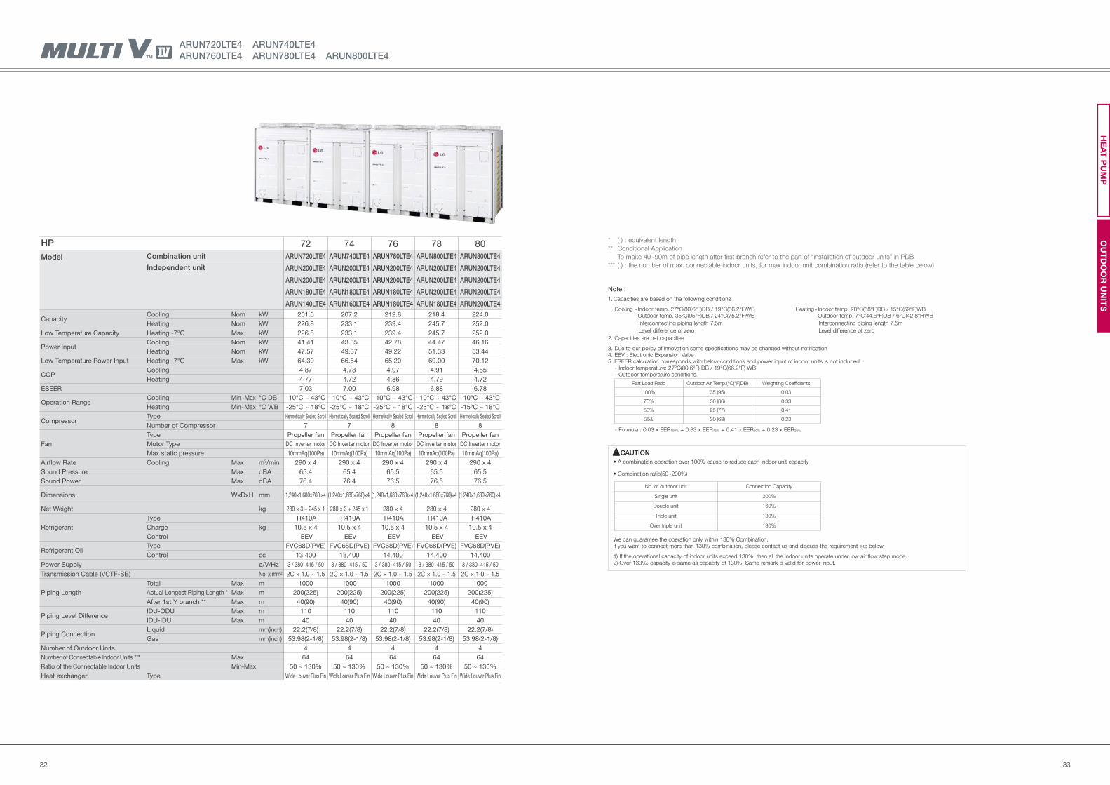
HP 72 74 76 78 80
Model Combination unit ARUN720LTE4 ARUN740LTE4 ARUN760LTE4 ARUN800LTE4 ARUN800LTE4
Independent unit ARUN200LTE4 ARUN200LTE4 ARUN200LTE4 ARUN200LTE4 ARUN200LTE4
ARUN200LTE4 ARUN200LTE4 ARUN200LTE4 ARUN200LTE4 ARUN200LTE4
ARUN180LTE4 ARUN180LTE4 ARUN180LTE4 ARUN200LTE4 ARUN200LTE4
ARUN140LTE4 ARUN160LTE4 ARUN180LTE4 ARUN180LTE4 ARUN200LTE4
Capacity Cooling Nom kW 201.6 207.2 212.8 218.4 224.0
Heating Nom kW 226.8 233.1 239.4 245.7 252.0
Low Temperature Capacity Heating -7°C Max kW 226.8 233.1 239.4 245.7 252.0
Power Input Cooling Nom kW 41.41 43.35 42.78 44.47 46.16
Heating Nom kW 47.57 49.37 49.22 51.33 53.44
Low Temperature Power Input Heating -7°C Max kW 64.30 66.54 65.20 69.00 70.12
COP Cooling 4.87 4.78 4.97 4.91 4.85
Heating 4.77 4.72 4.86 4.79 4.72
ESEER 7.03 7.00 6.98 6.88 6.78
Operation RangeCooling Min~Max °C DB -10°C ~ 43°C -10°C ~ 43°C -10°C ~ 43°C -10°C ~ 43°C -10°C ~ 43°C
Heating Min~Max °C WB -25°C ~ 18°C -25°C ~ 18°C -25°C ~ 18°C -25°C ~ 18°C -15°C ~ 18°C
Compressor Type Hermetically Sealed Scroll Hermetically Sealed Scroll Hermetically Sealed Scroll Hermetically Sealed Scroll Hermetically Sealed Scroll
Number of Compressor 7 7 8 8 8
Fan
Type Propeller fan Propeller fan Propeller fan Propeller fan Propeller fan
Motor Type DC Inverter motor DC Inverter motor DC Inverter motor DC Inverter motor DC Inverter motor
Max static pressure 10mmAq(100Pa) 10mmAq(100Pa) 10mmAq(100Pa) 10mmAq(100Pa) 10mmAq(100Pa)
Airflow Rate Cooling Max m3/min 290 x 4 290 x 4 290 x 4 290 x 4 290 x 4
Sound Pressure Max dBA 65.4 65.4 65.5 65.5 65.5
Sound Power Max dBA 76.4 76.4 76.5 76.5 76.5
Dimensions WxDxH mm (1,240×1,680×760)×4 (1,240×1,680×760)×4 (1,240×1,680×760)×4 (1,240×1,680×760)×4 (1,240×1,680×760)×4
Net Weight kg 280 × 3 + 245 x 1 280 × 3 + 245 x 1 280 × 4 280 × 4 280 × 4
Refrigerant
Type R410A R410A R410A R410A R410A
Charge kg 10.5 x 4 10.5 x 4 10.5 x 4 10.5 x 4 10.5 x 4
Control EEV EEV EEV EEV EEV
Refrigerant OilType FVC68D(PVE) FVC68D(PVE) FVC68D(PVE) FVC68D(PVE) FVC68D(PVE)
Control cc 13,400 13,400 14,400 14,400 14,400
Power Supply ø/V/Hz 3 / 380~415 / 50 3 / 380~415 / 50 3 / 380~415 / 50 3 / 380~415 / 50 3 / 380~415 / 50
Transmission Cable (VCTF-SB) No. x mm² 2C × 1.0 ~ 1.5 2C × 1.0 ~ 1.5 2C × 1.0 ~ 1.5 2C × 1.0 ~ 1.5 2C × 1.0 ~ 1.5
Piping Length
Total Max m 1000 1000 1000 1000 1000
Actual Longest Piping Length * Max m 200(225) 200(225) 200(225) 200(225) 200(225)
After 1st Y branch ** Max m 40(90) 40(90) 40(90) 40(90) 40(90)
Piping Level DifferenceIDU-ODU Max m 110 110 110 110 110
IDU-IDU Max m 40 40 40 40 40
Piping ConnectionLiquid mm(inch) 22.2(7/8) 22.2(7/8) 22.2(7/8) 22.2(7/8) 22.2(7/8)
Gas mm(inch) 53.98(2-1/8) 53.98(2-1/8) 53.98(2-1/8) 53.98(2-1/8) 53.98(2-1/8)
Number of Outdoor Units 4 4 4 4 4
Number of Connectable Indoor Units *** Max 64 64 64 64 64
Ratio of the Connectable Indoor Units Min-Max 50 ~ 130% 50 ~ 130% 50 ~ 130% 50 ~ 130% 50 ~ 130%
Heat exchanger Type Wide Louver Plus Fin Wide Louver Plus Fin Wide Louver Plus Fin Wide Louver Plus Fin Wide Louver Plus Fin
ARUN720LTE4 ARUN740LTE4
ARUN760LTE4 ARUN780LTE4 ARUN800LTE4
OU
TD
OO
R U
NIT
SH
EA
T P
UM
P
Note :
1. Capacities are based on the following conditions
Cooling - Indoor temp. 27°C(80.6°F)DB / 19°C(66.2°F)WB Heating - Indoor temp. 20°C(68°F)DB / 15°C(59°F)WB Outdoor temp. 35°C(95°F)DB / 24°C(75.2°F)WB Outdoor temp. 7°C(44.6°F)DB / 6°C(42.8°F)WB
Interconnecting piping length 7.5m Interconnecting piping length 7.5m
Level difference of zero Level difference of zero
2. Capacities are net capacities
3. Due to our policy of innovation some specifications may be changed without notification4. EEV : Electronic Expansion Valve5. ESEER calculation corresponds with below conditions and power input of indoor units is not included. - Indoor temperature: 27°C(80.6°F) DB / 19°C(66.2°F) WB - Outdoor temperature conditions.
- Formula : 0.03 x EER100% + 0.33 x EER75% + 0.41 x EER50% + 0.23 x EER25%
CAUTION
We can guarantee the operation only within 130% Combination.If you want to connect more than 130% combination, please contact us and discuss the requirement like below.
1) If the operational capacity of indoor units exceed 130%, then all the indoor units operate under low air flow step mode.2) Over 130%, capacity is same as capacity of 130%, Same remark is valid for power input.
( ) : equivalent length
Conditional Application
To make 40~90m of pipe length after first branch refer to the part of “installation of outdoor units” in PDB
( ) : the number of max. connectable indoor units, for max indoor unit combination ratio (refer to the table below)
*
**
***
Part Load Ratio Outdoor Air Temp.(°C(°F)DB) Weighting Coefficients
100% 35 (95) 0.03
75% 30 (86) 0.33
50% 25 (77) 0.41
25& 20 (68) 0.23
No. of outdoor unit Connection Capacity
Single unit 200%
Double unit 160%
Triple unit 130%
Over triple unit 130%
3534
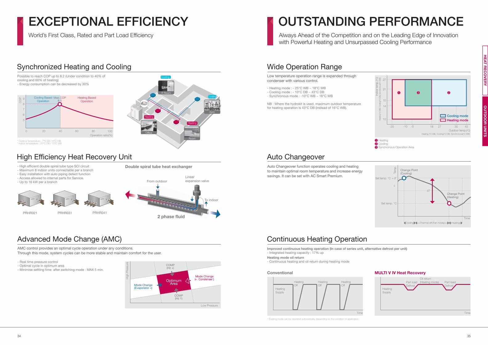
Possible to reach COP up to 8.2 (Under condition to 40% of
cooling and 60% of heating)
- Energy consumption can be decreased by 30%
Synchronized Heating and Cooling
Cooling
Gym
Heating
Office
Heating
Room
Cooling
IT Room
* Outdoor temperature : 7°C DB / 6°C WB* Indoor temperature : 20°C DB / 15°C WB
100
Operation ratio(%)
0
CO
P
20 40 60 80
9
8
7
6
5
Heating Based
Operation
Cooling Based
OperationMax.COP
8.5
AMC control provides an optimal cycle operation under any conditions.
Through this mode, system cycles can be more stable and maintain comfort for the user.
- Real time pressure control
- Optimal cycle in optimum area
- Minimise settling time after switching mode : MAX 5 min.
Advanced Mode Change (AMC)
Hig
h P
ressure
Low Pressure
OptimumArea
COMP(Hz )
COMP(Hz )
Mode Change( Condenser)
Mode Change(Evaporator )
High Efficiency Heat Recovery Unit- High efficient double spiral tube type SCI circuit
- Maximum 8 indoor units connectable per a branch
- Easy installation with auto piping detect function
- Access allowed to internal parts for Service.
- Up to 16 kW per a branch
PRHR031 PRHR041PRHR021
From outdoor
To indoor
2 phase fluid
Linear
expansion valve
Double spiral tube heat exchanger
Continuous Heating Operation
Conventional MULTI V IV Heat Recovery
Improved continuous heating operation (In case of series unit, alternative defrost per unit)
- Integrated heating capacity : 17% up
Heating mode oil return
- Continuous heating and oil return during heating mode
* Existing mode can be operated automatically, depending on the condition of application.
Time
Heating
Supply
Part load
Defrost
Part load
Defrost
Oil return
(Heating mode)
Time
Heating
Supply
Heating
Off
Wide Operation Range
- Heating mode : - 25°C WB ~ 18°C WB
- Cooling mode : - 10°C DB ~ 43°C DB
- Synchronous mode : -10°C WB ~ 16°C WB
NB : Where the hydrokit is used, maximum outdoor temperature
for heating operation is 43°C DB (instead of 16°C WB).
Low temperature operation range is expanded through
condenser with various control.
Auto ChangeoverAuto Changeover function operates cooling and heating
to maintain optimal room temperature and increase energy
savings. It can be set with AC Smart Premium.
Tem
p.
Time
Change Point(Cooling)
Set temp. °C
Change Point(Heating)
Set temp. °C + T
Heating
Cooling
Synchronous Operation Area
12
3
-25 -5-10 27 3518 43
Indoor te
mp. (
°C)
Heating (°C DB), Cooling(°C DB), Synchronous(°C WB)
Hea
ting (°
C D
B),
Coolin
g(°C
DB
), S
ynch
ronous(
°C W
B)
Outdoor temp.(°C)
15
14
21
27
10
Heating
Off
Heating
Off
OUTSTANDING PERFORMANCEAlways Ahead of the Competition and on the Leading Edge of Innovation
with Powerful Heating and Unsurpassed Cooling Performance
EXCEPTIONAL EFFICIENCYWorld’s First Class, Rated and Part Load Efficiency
Heating mode
Cooling mode
1 3 2
OU
TD
OO
R U
NIT
SH
EA
T R
EC
OV
ER
Y
Thermal off (Fan mode)Cooling Heating
T
3736
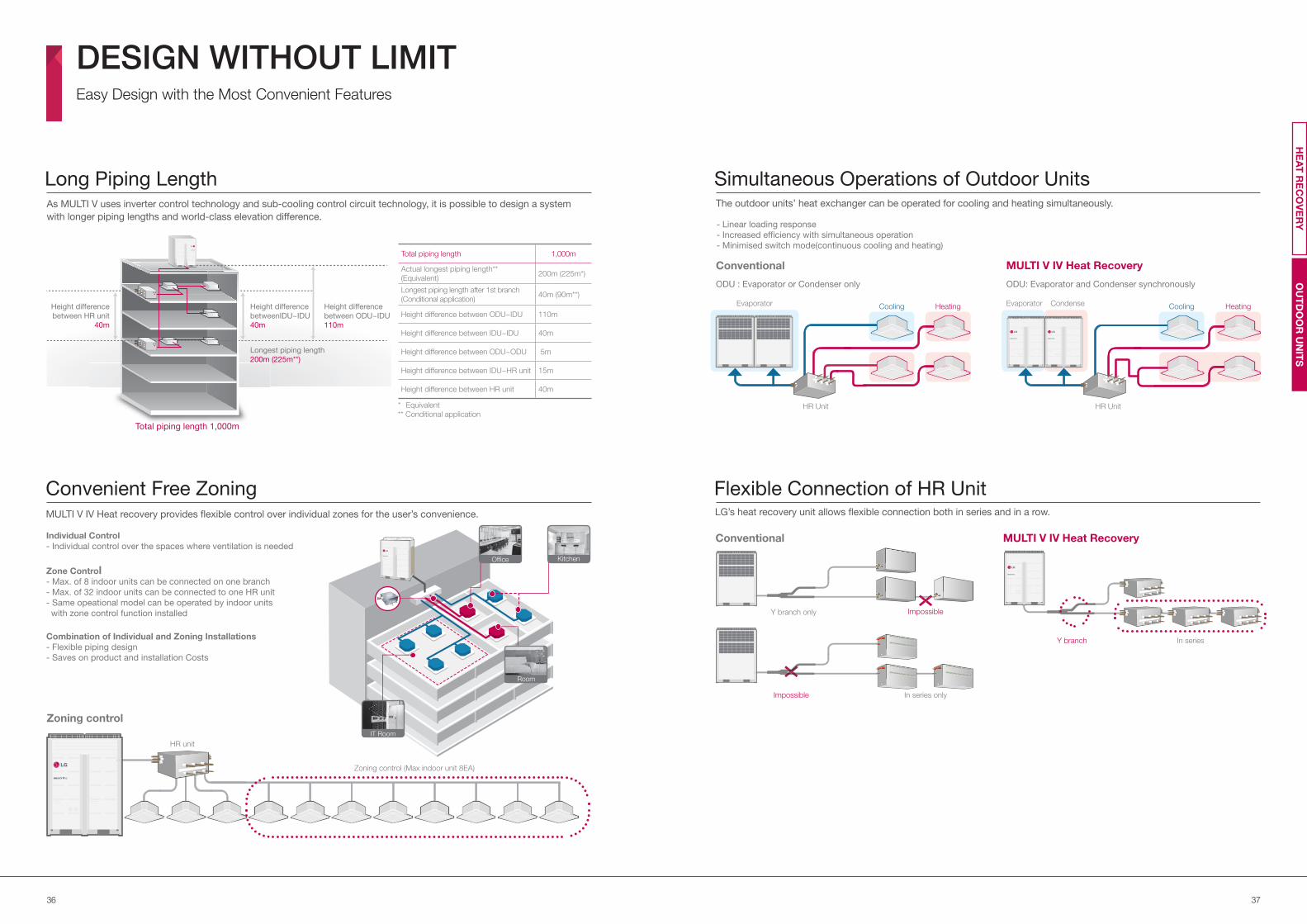
Flexible Connection of HR UnitLG’s heat recovery unit allows flexible connection both in series and in a row.
Conventional MULTI V IV Heat Recovery
In series onlyImpossible
Impossible
Y branch
Y branch only
In series
Long Piping LengthAs MULTI V uses inverter control technology and sub-cooling control circuit technology, it is possible to design a system
with longer piping lengths and world-class elevation difference.
Total piping length 1,000m
Actual longest piping length**
(Equivalent)200m (225m*)
Longest piping length after 1st branch
(Conditional application)40m (90m**)
Height difference between ODU~IDU 110m
Height difference between IDU~IDU 40m
Height difference between ODU~ODU 5m
Height difference between IDU~HR unit 15m
Height difference between HR unit 40m
Convenient Free ZoningMULTI V IV Heat recovery provides flexible control over individual zones for the user’s convenience.
Zoning control
HR unit
Zoning control (Max indoor unit 8EA)
Individual Control
- Individual control over the spaces where ventilation is needed
Zone Control- Max. of 8 indoor units can be connected on one branch
- Max. of 32 indoor units can be connected to one HR unit
- Same opeational model can be operated by indoor units
with zone control function installed
Combination of Individual and Zoning Installations
- Flexible piping design
- Saves on product and installation Costs
Total piping length 1,000m
Height difference
between ODU~IDU
110m
Height difference
betweenIDU~IDU
40m
Longest piping length
200m (225m**)
Height difference
between HR unit
40m
* Equivalent
** Conditional application
The outdoor units’ heat exchanger can be operated for cooling and heating simultaneously.
Conventional MULTI V IV Heat Recovery
Simultaneous Operations of Outdoor Units
- Linear loading response
- Increased efficiency with simultaneous operation
- Minimised switch mode(continuous cooling and heating)
ODU: Evaporator and Condenser synchronously ODU : Evaporator or Condenser only
HR UnitHR Unit
Evaporator Evaporator CondenseCooling CoolingHeating Heating
KitchenOffice
IT Room
Room
DESIGN WITHOUT LIMITEasy Design with the Most Convenient Features
OU
TD
OO
R U
NIT
SH
EA
T R
EC
OV
ER
Y
3938
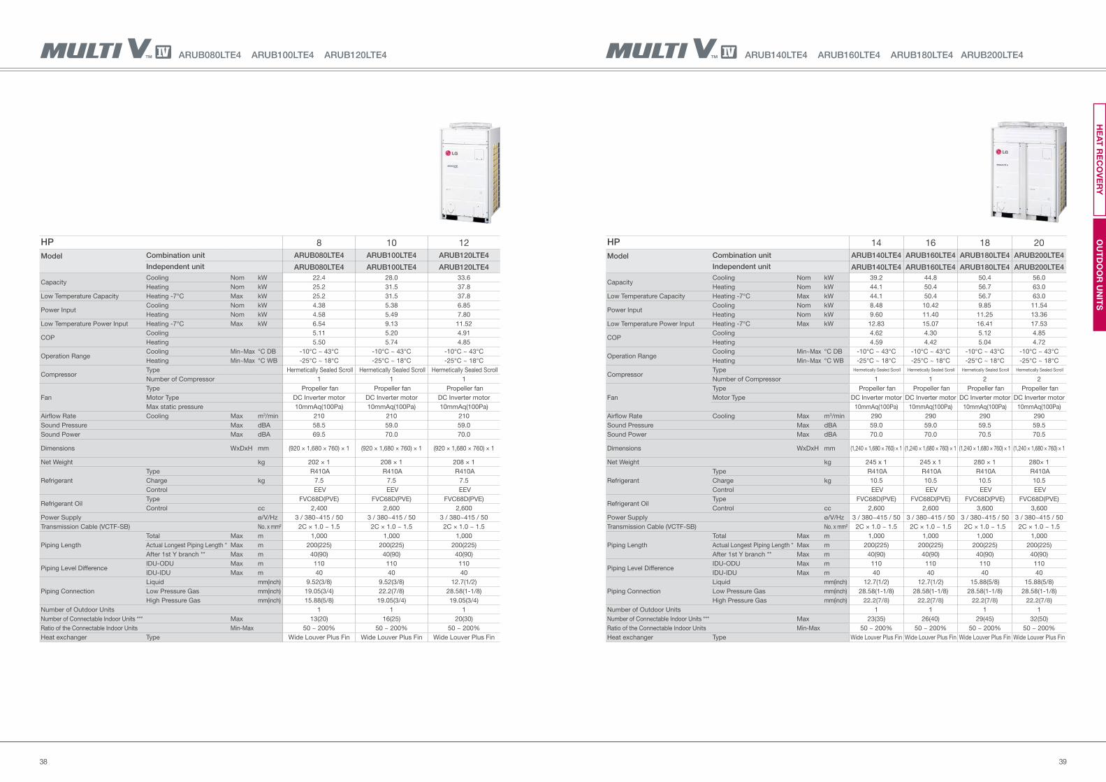
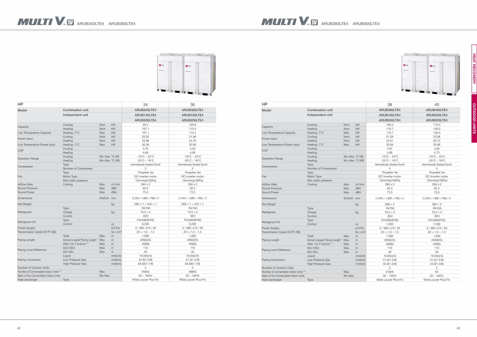
ARUB140LTE4 ARUB160LTE4 ARUB180LTE4 ARUB200LTE4
HP 14 16 18 20
Model Combination unit ARUB140LTE4 ARUB160LTE4 ARUB180LTE4 ARUB200LTE4
Independent unit ARUB140LTE4 ARUB160LTE4 ARUB180LTE4 ARUB200LTE4
Capacity Cooling Nom kW 39.2 44.8 50.4 56.0
Heating Nom kW 44.1 50.4 56.7 63.0
Low Temperature Capacity Heating -7°C Max kW 44.1 50.4 56.7 63.0
Power Input Cooling Nom kW 8.48 10.42 9.85 11.54
Heating Nom kW 9.60 11.40 11.25 13.36
Low Temperature Power Input Heating -7°C Max kW 12.83 15.07 16.41 17.53
COP Cooling 4.62 4.30 5.12 4.85
Heating 4.59 4.42 5.04 4.72
Operation RangeCooling Min~Max °C DB -10°C ~ 43°C -10°C ~ 43°C -10°C ~ 43°C -10°C ~ 43°C
Heating Min~Max °C WB -25°C ~ 18°C -25°C ~ 18°C -25°C ~ 18°C -25°C ~ 18°C
Compressor Type Hermetically Sealed Scroll Hermetically Sealed Scroll Hermetically Sealed Scroll Hermetically Sealed Scroll
Number of Compressor 1 1 2 2
Fan
Type Propeller fan Propeller fan Propeller fan Propeller fan
Motor Type DC Inverter motor DC Inverter motor DC Inverter motor DC Inverter motor
10mmAq(100Pa) 10mmAq(100Pa) 10mmAq(100Pa) 10mmAq(100Pa)
Airflow Rate Cooling Max m3/min 290 290 290 290
Sound Pressure Max dBA 59.0 59.0 59.5 59.5
Sound Power Max dBA 70.0 70.0 70.5 70.5
Dimensions WxDxH mm (1,240 × 1,680 × 760) × 1 (1,240 × 1,680 × 760) × 1 (1,240 × 1,680 × 760) × 1 (1,240 × 1,680 × 760) × 1
Net Weight kg 245 x 1 245 x 1 280 × 1 280× 1
Refrigerant
Type R410A R410A R410A R410A
Charge kg 10.5 10.5 10.5 10.5
Control EEV EEV EEV EEV
Refrigerant OilType FVC68D(PVE) FVC68D(PVE) FVC68D(PVE) FVC68D(PVE)
Control cc 2,600 2,600 3,600 3,600
Power Supply ø/V/Hz 3 / 380~415 / 50 3 / 380~415 / 50 3 / 380~415 / 50 3 / 380~415 / 50
Transmission Cable (VCTF-SB) No. x mm² 2C × 1.0 ~ 1.5 2C × 1.0 ~ 1.5 2C × 1.0 ~ 1.5 2C × 1.0 ~ 1.5
Piping Length
Total Max m 1,000 1,000 1,000 1,000
Actual Longest Piping Length * Max m 200(225) 200(225) 200(225) 200(225)
After 1st Y branch ** Max m 40(90) 40(90) 40(90) 40(90)
Piping Level DifferenceIDU-ODU Max m 110 110 110 110
IDU-IDU Max m 40 40 40 40
Piping Connection
Liquid mm(inch) 12.7(1/2) 12.7(1/2) 15.88(5/8) 15.88(5/8)
Low Pressure Gas mm(inch) 28.58(1-1/8) 28.58(1-1/8) 28.58(1-1/8) 28.58(1-1/8)
High Pressure Gas mm(inch) 22.2(7/8) 22.2(7/8) 22.2(7/8) 22.2(7/8)
Number of Outdoor Units 1 1 1 1
Number of Connectable Indoor Units *** Max 23(35) 26(40) 29(45) 32(50)
Ratio of the Connectable Indoor Units Min-Max 50 ~ 200% 50 ~ 200% 50 ~ 200% 50 ~ 200%
Heat exchanger Type Wide Louver Plus Fin Wide Louver Plus Fin Wide Louver Plus Fin Wide Louver Plus Fin
ARUB080LTE4 ARUB100LTE4 ARUB120LTE4
HP 8 10 12
Model Combination unit ARUB080LTE4 ARUB100LTE4 ARUB120LTE4
Independent unit ARUB080LTE4 ARUB100LTE4 ARUB120LTE4
Capacity Cooling Nom kW 22.4 28.0 33.6
Heating Nom kW 25.2 31.5 37.8
Low Temperature Capacity Heating -7°C Max kW 25.2 31.5 37.8
Power Input Cooling Nom kW 4.38 5.38 6.85
Heating Nom kW 4.58 5.49 7.80
Low Temperature Power Input Heating -7°C Max kW 6.54 9.13 11.52
COP Cooling 5.11 5.20 4.91
Heating 5.50 5.74 4.85
Operation RangeCooling Min~Max °C DB -10°C ~ 43°C -10°C ~ 43°C -10°C ~ 43°C
Heating Min~Max °C WB -25°C ~ 18°C -25°C ~ 18°C -25°C ~ 18°C
Compressor Type Hermetically Sealed Scroll Hermetically Sealed Scroll Hermetically Sealed Scroll
Number of Compressor 1 1 1
Fan
Type Propeller fan Propeller fan Propeller fan
Motor Type DC Inverter motor DC Inverter motor DC Inverter motor
Max static pressure 10mmAq(100Pa) 10mmAq(100Pa) 10mmAq(100Pa)
Airflow Rate Cooling Max m3/min 210 210 210
Sound Pressure Max dBA 58.5 59.0 59.0
Sound Power Max dBA 69.5 70.0 70.0
Dimensions WxDxH mm (920 × 1,680 × 760) × 1 (920 × 1,680 × 760) × 1 (920 × 1,680 × 760) × 1
Net Weight kg 202 × 1 208 × 1 208 × 1
Refrigerant
Type R410A R410A R410A
Charge kg 7.5 7.5 7.5
Control EEV EEV EEV
Refrigerant OilType FVC68D(PVE) FVC68D(PVE) FVC68D(PVE)
Control cc 2,400 2,600 2,600
Power Supply ø/V/Hz 3 / 380~415 / 50 3 / 380~415 / 50 3 / 380~415 / 50
Transmission Cable (VCTF-SB) No. x mm² 2C × 1.0 ~ 1.5 2C × 1.0 ~ 1.5 2C × 1.0 ~ 1.5
Piping Length
Total Max m 1,000 1,000 1,000
Actual Longest Piping Length * Max m 200(225) 200(225) 200(225)
After 1st Y branch ** Max m 40(90) 40(90) 40(90)
Piping Level DifferenceIDU-ODU Max m 110 110 110
IDU-IDU Max m 40 40 40
Piping Connection
Liquid mm(inch) 9.52(3/8) 9.52(3/8) 12.7(1/2)
Low Pressure Gas mm(inch) 19.05(3/4) 22.2(7/8) 28.58(1-1/8)
High Pressure Gas mm(inch) 15.88(5/8) 19.05(3/4) 19.05(3/4)
Number of Outdoor Units 1 1 1
Number of Connectable Indoor Units *** Max 13(20) 16(25) 20(30)
Ratio of the Connectable Indoor Units Min-Max 50 ~ 200% 50 ~ 200% 50 ~ 200%
Heat exchanger Type Wide Louver Plus Fin Wide Louver Plus Fin Wide Louver Plus Fin
OU
TD
OO
R U
NIT
SH
EA
T R
EC
OV
ER
Y
4140
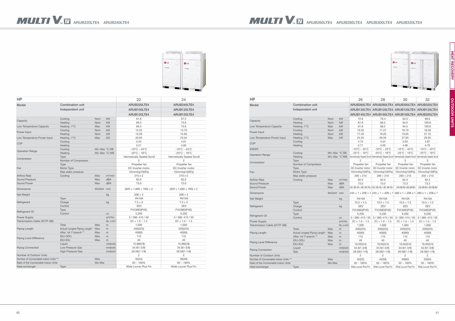
ARUB260LTE4 ARUB280LTE4 ARUB300LTE4 ARUB320LTE4ARUB220LTE4 ARUB240LTE4
HP 22 24
Model Combination unit ARUB220LTE4 ARUB240LTE4
Independent unit ARUB100LTE4 ARUB120LTE4
ARUB120LTE4 ARUB120LTE4
Capacity Cooling Nom kW 61.6 67.2
Heating Nom kW 69.3 75.6
Low Temperature Capacity Heating -7°C Max kW 69.3 75.6
Power Input Cooling Nom kW 12.23 13.70
Heating Nom kW 13.29 15.60
Low Temperature Power Input Heating -7°C Max kW 20.65 23.04
COP Cooling 5.04 4.91
Heating 5.21 4.85
Operation RangeCooling Min~Max °C DB -10°C ~ 43°C -10°C ~ 43°C
Heating Min~Max °C WB -25°C ~ 18°C -25°C ~ 18°C
Compressor Type Hermetically Sealed Scroll Hermetically Sealed Scroll
Number of Compressor 2 2
Fan
Type Propeller fan Propeller fan
Motor Type DC Inverter motor DC Inverter motor
Max static pressure 10mmAq(100Pa) 10mmAq(100Pa)
Airflow Rate Cooling Max m3/min 210 x 2 210 x 2
Sound Pressure Max dBA 62.0 62.0
Sound Power Max dBA 73.0 73.0
Dimensions WxDxH mm (920 × 1,680 × 760) × 2 (920 × 1,680 × 760) × 2
Net Weight kg 208 × 2 208 × 2
Refrigerant
Type R410A R410A
Charge kg 7.5 × 2 7.5 × 2
Control EEV EEV
Refrigerant OilType FVC68D(PVE) FVC68D(PVE)
Control cc 5,200 5,200
Power Supply ø/V/Hz 3 / 380~415 / 50 3 / 380~415 / 50
Transmission Cable (VCTF-SB) No. x mm² 2C × 1.0 ~ 1.5 2C × 1.0 ~ 1.5
Piping Length
Total Max m 1,000 1,000
Actual Longest Piping Length * Max m 200(225) 200(225)
After 1st Y branch ** Max m 40(90) 40(90)
Piping Level DifferenceIDU-ODU Max m 110 110
IDU-IDU Max m 40 40
Piping Connection
Liquid mm(inch) 15.88(5/8) 15.88(5/8)
Low Pressure Gas mm(inch) 34.9(1-3/8) 34.9(1-3/8)
High Pressure Gas mm(inch) 28.58(1-1/8) 28.58(1-1/8)
Number of Outdoor Units 2 2
Number of Connectable Indoor Units *** Max 35(44) 39(48)
Ratio of the Connectable Indoor Units Min-Max 50 ~ 160% 50 ~ 160%
Heat exchanger Type Wide Louver Plus Fin Wide Louver Plus Fin
OU
TD
OO
R U
NIT
SH
EA
T R
EC
OV
ER
Y
HP 26 28 30 32
Model Combination unit ARUB260LTE4 ARUB280LTE4 ARUB300LTE4 ARUB320LTE4
Independent unit ARUB120LTE4 ARUB120LTE4 ARUB120LTE4 ARUB120LTE4
ARUB140LTE4 ARUB160LTE4 ARUB180LTE4 ARUB200LTE4
Capacity Cooling Nom kW 72.8 78.4 84.0 89.6
Heating Nom kW 81.9 88.2 94.5 100.8
Low Temperature Capacity Heating -7°C Max kW 81.9 88.2 94.5 100.8
Power Input Cooling Nom kW 15.33 17.27 16.70 18.39
Heating Nom kW 17.40 19.20 19.05 21.16
Low Temperature Power Input Heating -7°C Max kW 24.35 26.59 27.93 29.05
COP Cooling 4.75 4.54 5.03 4.87
Heating 4.71 4.59 4.96 4.76
ESEER -10°C ~ 43°C -10°C ~ 43°C -10°C ~ 43°C -10°C ~ 43°C
Operation RangeCooling Min~Max °C DB -25°C ~ 18°C -25°C ~ 18°C -25°C ~ 18°C -25°C ~ 18°C
Heating Min~Max °C WB Hermetically Sealed Scroll Hermetically Sealed Scroll Hermetically Sealed Scroll Hermetically Sealed Scroll
Compressor Type 2 2 3 3
Number of Compressor Propeller fan Propeller fan Propeller fan Propeller fan
Fan
Type DC Inverter motor DC Inverter motor DC Inverter motor DC Inverter motor
Motor Type 10mmAq(100Pa) 10mmAq(100Pa) 10mmAq(100Pa) 10mmAq(100Pa)
Max static pressure 290 + 210 290 + 210 290 + 210 250 + 210
Airflow Rate Cooling Max m3/min 62.0 62.0 62.3 62.3
Sound Pressure Max dBA 73.0 73.0 73.3 73.3
Sound Power Max dBA (1,240 × 1,680 × 760) × 1 + (920 × 1,680 × 760) × 1 (1,240 × 1,680 × 760) × 1 + (920 × 1,680 × 760) × 1 (1,240×1,680×760)×1 + (920×1,680×760)×1 (1,240×1,680×760)×1 + (920×1,680×760)×1
Dimensions WxDxH mm 245 × 1 + 208 × 1 245 × 1 + 208 × 1 280 x 1 + 208 x 1 280 x 1 + 208 x 1
Net Weight kg R410A R410A R410A R410A
Refrigerant
Type 10.5 + 7.5 10.5 + 7.5 10.5 + 7.5 10.5 + 7.5
Charge kg EEV EEV EEV EEV
Control FVC68D(PVE) FVC68D(PVE) FVC68D(PVE) FVC68D(PVE)
Refrigerant OilType 5,200 5,200 6,200 6,200
Control cc 3 / 380~415 / 50 3 / 380~415 / 50 3 / 380~415 / 50 3 / 380~415 / 50
Power Supply ø/V/Hz 2C × 1.0 ~ 1.5 2C × 1.0 ~ 1.5 2C × 1.0 ~ 1.5 2C × 1.0 ~ 1.5
Transmission Cable (VCTF-SB) No. x mm² 1,000 1,000 1,000 1,000
Piping Length
Total Max m 200(225) 200(225) 200(225) 200(225)
Actual Longest Piping Length * Max m 40(90) 40(90) 40(90) 40(90)
After 1st Y branch ** Max m 110 110 110 110
Piping Level DifferenceIDU-ODU Max m 40 40 40 40
IDU-IDU Max m 19.05(3/4) 19.05(3/4) 19.05(3/4) 19.05(3/4)
Piping ConnectionLiquid mm(inch) 34.9(1-3/8) 34.9(1-3/8) 34.9(1-3/8) 34.9(1-3/8)
Gas mm(inch) 28.58(1-1/8) 28.58(1-1/8) 28.58(1-1/8) 28.58(1-1/8)
Number of Outdoor Units 2 2 2 2
Number of Connectable Indoor Units *** Max 42(52) 45(56) 49(60) 52(64)
Ratio of the Connectable Indoor Units Min-Max 50 ~ 160% 50 ~ 160% 50 ~ 160% 50 ~ 160%
Heat exchanger Type Wide Louver Plus Fin Wide Louver Plus Fin Wide Louver Plus Fin Wide Louver Plus Fin
4342
ARUB380LTE4 ARUB400LTE4
HP 38 40
Model Combination unit ARUB380LTE4 ARUB400LTE4
Independent unit ARUB180LTE4 ARUB200LTE4
ARUB200LTE4 ARUB200LTE4
Capacity Cooling Nom kW 106.4 112.0
Heating Nom kW 119.7 126.0
Low Temperature Capacity Heating -7°C Max kW 119.7 126.0
Power Input Cooling Nom kW 21.39 23.08
Heating Nom kW 24.61 26.72
Low Temperature Power Input Heating -7°C Max kW 33.94 35.06
COP Cooling 4.97 4.85
Heating 4.86 4.72
Operation RangeCooling Min~Max °C DB -10°C ~ 43°C -10°C ~ 43°C
Heating Min~Max °C WB -25°C ~ 18°C -25°C ~ 18°C
Compressor Type Hermetically Sealed Scroll Hermetically Sealed Scroll
Number of Compressor 4 4
Fan
Type Propeller fan Propeller fan
Motor Type DC Inverter motor DC Inverter motor
Max static pressure 10mmAq(100Pa) 10mmAq(100Pa)
Airflow Rate Cooling Max m3/min 290 x 2 290 x 2
Sound Pressure Max dBA 62.5 62.5
Sound Power Max dBA 73.5 73.5
Dimensions WxDxH mm (1,240 × 1,680 × 760) × 2 (1,240 × 1,680 × 760) × 2
Net Weight kg 280 × 2 280 × 2
Refrigerant
Type R410A R410A
Charge kg 10.5 × 2 10.5 × 2
Control EEV EEV
Refrigerant OilType FVC68D(PVE) FVC68D(PVE)
Control cc 7,200 7,200
Power Supply ø/V/Hz 3 / 380~415 / 50 3 / 380~415 / 50
Transmission Cable (VCTF-SB) No. x mm² 2C × 1.0 ~ 1.5 2C × 1.0 ~ 1.5
Piping Length
Total Max m 1,000 1,000
Actual Longest Piping Length * Max m 200(225) 200(225)
After 1st Y branch ** Max m 40(90) 40(90)
Piping Level DifferenceIDU-ODU Max m 110 110
IDU-IDU Max m 40 40
Piping Connection
Liquid mm(inch) 19.05(3/4) 19.05(3/4)
Low Pressure Gas mm(inch) 41.3(1-5/8) 41.3(1-5/8)
High Pressure Gas mm(inch) 34.9(1-3/8) 34.9(1-3/8)
Number of Outdoor Units 2 2
Number of Connectable Indoor Units *** Max 61(64) 64
Ratio of the Connectable Indoor Units Min-Max 50 ~ 160% 50 ~ 160%
Heat exchanger Type Wide Louver Plus Fin Wide Louver Plus Fin
ARUB340LTE4 ARUB360LTE4
HP 34 36
Model Combination unit ARUB340LTE4 ARUB360LTE4
Independent unit ARUB140LTE4 ARUB160LTE4
ARUB200LTE4 ARUB200LTE4
Capacity Cooling Nom kW 95.2 100.8
Heating Nom kW 107.1 113.4
Low Temperature Capacity Heating -7°C Max kW 107.1 113.4
Power Input Cooling Nom kW 20.02 21.96
Heating Nom kW 22.96 24.76
Low Temperature Power Input Heating -7°C Max kW 30.36 32.60
COP Cooling 4.76 4.59
Heating 4.66 4.58
Operation RangeCooling Min~Max °C DB -10°C ~ 43°C -10°C ~ 43°C
Heating Min~Max °C WB -25°C ~ 18°C -25°C ~ 18°C
Compressor Type Hermetically Sealed Scroll Hermetically Sealed Scroll
Number of Compressor 3 3
Fan
Type Propeller fan Propeller fan
Motor Type DC Inverter motor DC Inverter motor
Max static pressure 10mmAq(100Pa) 10mmAq(100Pa)
Airflow Rate Cooling Max m3/min 290 x 2 290 x 2
Sound Pressure Max dBA 62.3 62.3
Sound Power Max dBA 73.3 73.3
Dimensions WxDxH mm (1,240 × 1,680 × 760) × 2 (1,240 × 1,680 × 760) × 2
Net Weight kg 280 × 1 + 245 × 1 280 × 1 + 245 × 1
Refrigerant
Type R410A R410A
Charge kg 10.5 × 2 10.5 × 2
Control EEV EEV
Refrigerant OilType FVC68D(PVE) FVC68D(PVE)
Control cc 6,200 6,200
Power Supply ø/V/Hz 3 / 380~415 / 50 3 / 380~415 / 50
Transmission Cable (VCTF-SB) No. x mm² 2C × 1.0 ~ 1.5 2C × 1.0 ~ 1.5
Piping Length
Total Max m 1,000 1,000
Actual Longest Piping Length * Max m 200(225) 200(225)
After 1st Y branch ** Max m 40(90) 40(90)
Piping Level DifferenceIDU-ODU Max m 110 110
IDU-IDU Max m 40 40
Piping Connection
Liquid mm(inch) 19.05(3/4) 19.05(3/4)
Low Pressure Gas mm(inch) 34.9(1-3/8) 41.3(1-5/8)
High Pressure Gas mm(inch) 28.58(1-1/8) 28.58(1-1/8)
Number of Outdoor Units 2 2
Number of Connectable Indoor Units *** Max 55(64) 58(64)
Ratio of the Connectable Indoor Units Min-Max 50 ~ 160% 50 ~ 160%
Heat exchanger Type Wide Louver Plus Fin Wide Louver Plus Fin
OU
TD
OO
R U
NIT
SH
EA
T R
EC
OV
ER
Y
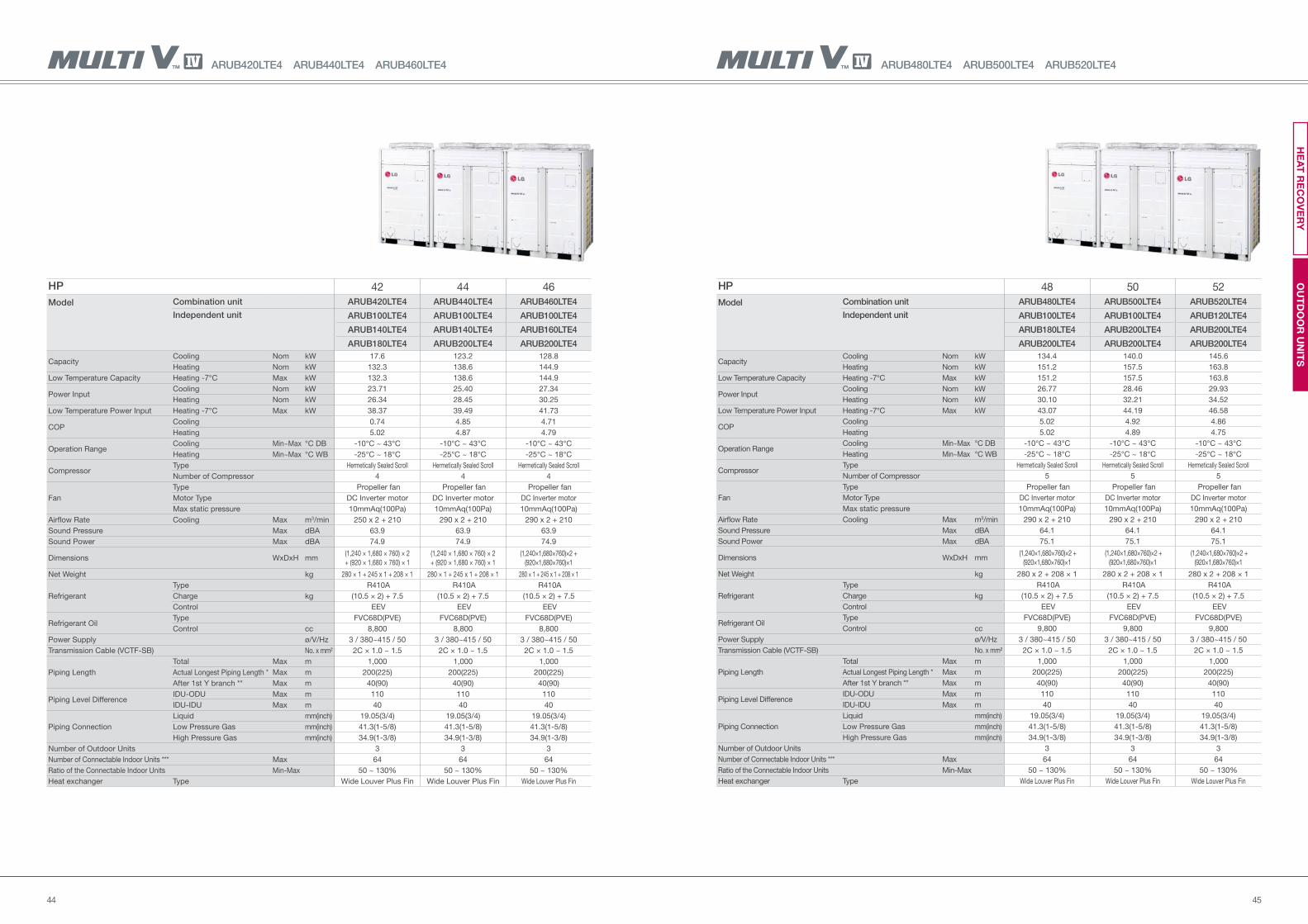
4544
ARUB480LTE4 ARUB500LTE4 ARUB520LTE4
HP 48 50 52
Model Combination unit ARUB480LTE4 ARUB500LTE4 ARUB520LTE4
Independent unit ARUB100LTE4 ARUB100LTE4 ARUB120LTE4
ARUB180LTE4 ARUB200LTE4 ARUB200LTE4
ARUB200LTE4 ARUB200LTE4 ARUB200LTE4
Capacity Cooling Nom kW 134.4 140.0 145.6
Heating Nom kW 151.2 157.5 163.8
Low Temperature Capacity Heating -7°C Max kW 151.2 157.5 163.8
Power Input Cooling Nom kW 26.77 28.46 29.93
Heating Nom kW 30.10 32.21 34.52
Low Temperature Power Input Heating -7°C Max kW 43.07 44.19 46.58
COP Cooling 5.02 4.92 4.86
Heating 5.02 4.89 4.75
Operation RangeCooling Min~Max °C DB -10°C ~ 43°C -10°C ~ 43°C -10°C ~ 43°C
Heating Min~Max °C WB -25°C ~ 18°C -25°C ~ 18°C -25°C ~ 18°C
Compressor Type Hermetically Sealed Scroll Hermetically Sealed Scroll Hermetically Sealed Scroll
Number of Compressor 5 5 5
Fan
Type Propeller fan Propeller fan Propeller fan
Motor Type DC Inverter motor DC Inverter motor DC Inverter motor
Max static pressure 10mmAq(100Pa) 10mmAq(100Pa) 10mmAq(100Pa)
Airflow Rate Cooling Max m3/min 290 x 2 + 210 290 x 2 + 210 290 x 2 + 210
Sound Pressure Max dBA 64.1 64.1 64.1
Sound Power Max dBA 75.1 75.1 75.1
Dimensions WxDxH mm (1,240×1,680×760)×2 +
(920×1,680×760)×1
(1,240×1,680×760)×2 +
(920×1,680×760)×1
(1,240×1,680×760)×2 +
(920×1,680×760)×1
Net Weight kg 280 x 2 + 208 × 1 280 x 2 + 208 × 1 280 x 2 + 208 × 1
Refrigerant
Type R410A R410A R410A
Charge kg (10.5 × 2) + 7.5 (10.5 × 2) + 7.5 (10.5 × 2) + 7.5
Control EEV EEV EEV
Refrigerant OilType FVC68D(PVE) FVC68D(PVE) FVC68D(PVE)
Control cc 9,800 9,800 9,800
Power Supply ø/V/Hz 3 / 380~415 / 50 3 / 380~415 / 50 3 / 380~415 / 50
Transmission Cable (VCTF-SB) No. x mm² 2C × 1.0 ~ 1.5 2C × 1.0 ~ 1.5 2C × 1.0 ~ 1.5
Piping Length
Total Max m 1,000 1,000 1,000
Actual Longest Piping Length * Max m 200(225) 200(225) 200(225)
After 1st Y branch ** Max m 40(90) 40(90) 40(90)
Piping Level DifferenceIDU-ODU Max m 110 110 110
IDU-IDU Max m 40 40 40
Piping Connection
Liquid mm(inch) 19.05(3/4) 19.05(3/4) 19.05(3/4)
Low Pressure Gas mm(inch) 41.3(1-5/8) 41.3(1-5/8) 41.3(1-5/8)
High Pressure Gas mm(inch) 34.9(1-3/8) 34.9(1-3/8) 34.9(1-3/8)
Number of Outdoor Units 3 3 3
Number of Connectable Indoor Units *** Max 64 64 64
Ratio of the Connectable Indoor Units Min-Max 50 ~ 130% 50 ~ 130% 50 ~ 130%
Heat exchanger Type Wide Louver Plus Fin Wide Louver Plus Fin Wide Louver Plus Fin
ARUB420LTE4 ARUB440LTE4 ARUB460LTE4
HP 42 44 46
Model Combination unit ARUB420LTE4 ARUB440LTE4 ARUB460LTE4
Independent unit ARUB100LTE4 ARUB100LTE4 ARUB100LTE4
ARUB140LTE4 ARUB140LTE4 ARUB160LTE4
ARUB180LTE4 ARUB200LTE4 ARUB200LTE4
Capacity Cooling Nom kW 17.6 123.2 128.8
Heating Nom kW 132.3 138.6 144.9
Low Temperature Capacity Heating -7°C Max kW 132.3 138.6 144.9
Power Input Cooling Nom kW 23.71 25.40 27.34
Heating Nom kW 26.34 28.45 30.25
Low Temperature Power Input Heating -7°C Max kW 38.37 39.49 41.73
COP Cooling 0.74 4.85 4.71
Heating 5.02 4.87 4.79
Operation RangeCooling Min~Max °C DB -10°C ~ 43°C -10°C ~ 43°C -10°C ~ 43°C
Heating Min~Max °C WB -25°C ~ 18°C -25°C ~ 18°C -25°C ~ 18°C
Compressor Type Hermetically Sealed Scroll Hermetically Sealed Scroll Hermetically Sealed Scroll
Number of Compressor 4 4 4
Fan
Type Propeller fan Propeller fan Propeller fan
Motor Type DC Inverter motor DC Inverter motor DC Inverter motor
Max static pressure 10mmAq(100Pa) 10mmAq(100Pa) 10mmAq(100Pa)
Airflow Rate Cooling Max m3/min 250 x 2 + 210 290 x 2 + 210 290 x 2 + 210
Sound Pressure Max dBA 63.9 63.9 63.9
Sound Power Max dBA 74.9 74.9 74.9
Dimensions WxDxH mm(1,240 × 1,680 × 760) × 2
+ (920 × 1,680 × 760) × 1
(1,240 × 1,680 × 760) × 2
+ (920 × 1,680 × 760) × 1
(1,240×1,680×760)×2 +
(920×1,680×760)×1
Net Weight kg 280 × 1 + 245 x 1 + 208 × 1 280 × 1 + 245 x 1 + 208 × 1 280 × 1 + 245 x 1 + 208 × 1
Refrigerant
Type R410A R410A R410A
Charge kg (10.5 × 2) + 7.5 (10.5 × 2) + 7.5 (10.5 × 2) + 7.5
Control EEV EEV EEV
Refrigerant OilType FVC68D(PVE) FVC68D(PVE) FVC68D(PVE)
Control cc 8,800 8,800 8,800
Power Supply ø/V/Hz 3 / 380~415 / 50 3 / 380~415 / 50 3 / 380~415 / 50
Transmission Cable (VCTF-SB) No. x mm² 2C × 1.0 ~ 1.5 2C × 1.0 ~ 1.5 2C × 1.0 ~ 1.5
Piping Length
Total Max m 1,000 1,000 1,000
Actual Longest Piping Length * Max m 200(225) 200(225) 200(225)
After 1st Y branch ** Max m 40(90) 40(90) 40(90)
Piping Level DifferenceIDU-ODU Max m 110 110 110
IDU-IDU Max m 40 40 40
Piping Connection
Liquid mm(inch) 19.05(3/4) 19.05(3/4) 19.05(3/4)
Low Pressure Gas mm(inch) 41.3(1-5/8) 41.3(1-5/8) 41.3(1-5/8)
High Pressure Gas mm(inch) 34.9(1-3/8) 34.9(1-3/8) 34.9(1-3/8)
Number of Outdoor Units 3 3 3
Number of Connectable Indoor Units *** Max 64 64 64
Ratio of the Connectable Indoor Units Min-Max 50 ~ 130% 50 ~ 130% 50 ~ 130%
Heat exchanger Type Wide Louver Plus Fin Wide Louver Plus Fin Wide Louver Plus Fin
OU
TD
OO
R U
NIT
SH
EA
T R
EC
OV
ER
Y
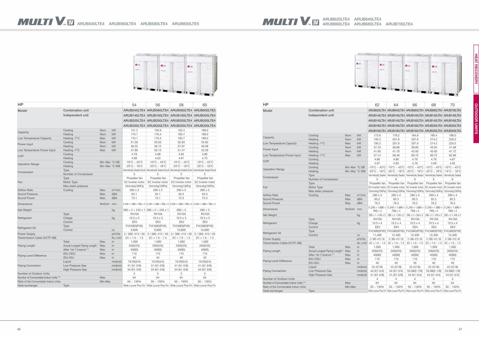
4746
ARUB620LTE4 ARUB640LTE4
ARUB660LTE4 ARUB680LTE4 ARUB700LTE4
HP 62 64 66 68 70
Model Combination unit ARUB620LTE4 ARUB640LTE4 ARUB660LTE4 ARUB680LTE4 ARUB700LTE4
Independent unit ARUB140LTE4 ARUB140LTE4 ARUB140LTE4 ARUB140LTE4 ARUB140LTE4
ARUB140LTE4 ARUB140LTE4 ARUB160LTE4 ARUB140LTE4 ARUB160LTE4
ARUB160LTE4 ARUB180LTE4 ARUB180LTE4 ARUB200LTE4 ARUB200LTE4
ARUB180LTE4 ARUB180LTE4 ARUB180LTE4 ARUB200LTE4 ARUB200LTE4
Capacity Cooling Nom kW 173.6 179.2 184.8 190.4 196.0
Heating Nom kW 195.3 201.6 207.9 214.2 220.5
Low Temperature Capacity Heating -7°C Max kW 195.3 201.6 207.9 214.2 220.5
Power Input Cooling Nom kW 37.23 36.66 38.60 40.04 41.98
Heating Nom kW 41.85 41.70 43.50 45.92 47.72
Low Temperature Power Input Heating -7°C Max kW 57.14 58.48 60.72 60.72 62.96
COP Cooling 4.66 4.89 4.79 4.76 4.67
Heating 4.67 4.83 4.78 4.66 4.62
Operation RangeCooling Min~Max °C DB -10°C ~ 43°C -10°C ~ 43°C -10°C ~ 43°C -10°C ~ 43°C -10°C ~ 43°C
Heating Min~Max °C WB -25°C ~ 18°C -25°C ~ 18°C -25°C ~ 18°C -25°C ~ 18°C -15°C ~ 18°C
Compressor Type Hermetically Sealed Hermetically Sealed Hermetically Sealed Hermetically Sealed Hermetically Sealed
Number of Compressor 5 6 6 6 6
Fan
Type Propeller fan Propeller fan Propeller fan Propeller fan Propeller fan
Motor Type DC Inverter motor DC Inverter motor DC Inverter motor DC Inverter motor DC Inverter motor
Max static pressure 10mmAq(100Pa) 10mmAq(100Pa) 10mmAq(100Pa) 10mmAq(100Pa) 10mmAq(100Pa)
Airflow Rate Cooling Max m3/min 290 x 4 290 x 4 290 x 4 290 x 4 290 x 4
Sound Pressure Max dBA 65.2 65.3 65.3 65.3 65.3
Sound Power Max dBA 76.2 76.3 76.3 76.3 76.3
Dimensions WxDxH mm(1,240 × 1,680 ×
760) × 4
(1,240 × 1,680 ×
760) × 4
(1,240 × 1,680 ×
760) × 4
(1,240 × 1,680 ×
760) × 4
(1,240 × 1,680 ×
760) × 4
Net Weight kg 280 × 1 + 245 x 3 280 × 2 + 245 x 2 280 × 2 + 245 x 2 280 × 2 + 245 x 2 280 × 2 + 245 x 2
Refrigerant
Type R410A R410A R410A R410A R410A
Charge kg 10.5 x 4 10.5 x 4 10.5 x 4 10.5 x 4 10.5 x 4
Control EEV EEV EEV EEV EEV
Refrigerant OilType FVC68D(PVE) FVC68D(PVE) FVC68D(PVE) FVC68D(PVE) FVC68D(PVE)
Control cc 11,400 12,400 12,400 12,400 12,400
Power Supply ø/V/Hz 3 / 380~415 / 50 3 / 380~415 / 50 3 / 380~415 / 50 3 / 380~415 / 50 3 / 380~415 / 50
Transmission Cable (VCTF-SB) No. x mm² 2C × 1.0 ~ 1.5 2C × 1.0 ~ 1.5 2C × 1.0 ~ 1.5 2C × 1.0 ~ 1.5 2C × 1.0 ~ 1.5
Piping Length
Total Max m 1,000 1,000 1,000 1,000 1,000
Actual Longest Piping Length * Max m 200(225) 200(225) 200(225) 200(225) 200(225)
After 1st Y branch ** Max m 40(90) 40(90) 40(90) 40(90) 40(90)
Piping Level DifferenceIDU-ODU Max m 110 110 110 110 110
IDU-IDU Max m 40 40 40 40 40
Piping Connection
Liquid mm(inch) 22.2(7/8) 22.2(7/8) 22.2(7/8) 22.2(7/8) 22.2(7/8)
Low Pressure Gas mm(inch) 44.5(1-3/4) 44.5(1-3/4) 53.98(2-1/8) 53.98(2-1/8) 53.98(2-1/8)
High Pressure Gas mm(inch) 41.3(1-5/8) 41.3(1-5/8) 44.5(1-3/4) 44.5(1-3/4) 44.5(1-3/4)
Number of Outdoor Units 4 4 4 4 4
Number of Connectable Indoor Units *** Max 64 64 64 64 64
Ratio of the Connectable Indoor Units Min-Max 50 ~ 130% 50 ~ 130% 50 ~ 130% 50 ~ 130% 50 ~ 130%
Heat exchanger Type Wide Louver Plus Fin Wide Louver Plus Fin Wide Louver Plus Fin Wide Louver Plus Fin Wide Louver Plus Fin
ARUB540LTE4 ARUB560LTE4 ARUB580LTE4 ARUB600LTE5
HP 54 56 58 60
Model Combination unit ARUB540LTE4 ARUB560LTE4 ARUB580LTE4 ARUB600LTE5
Independent unit ARUB140LTE4 ARUB160LTE4 ARUB180LTE4 ARUB200LTE4
ARUB200LTE4 ARUB200LTE4 ARUB200LTE4 ARUB200LTE4
ARUB200LTE4 ARUB200LTE4 ARUB200LTE4 ARUB200LTE4
Capacity Cooling Nom kW 151.2 156.8 162.4 168.0
Heating Nom kW 170.1 176.4 182.7 189.0
Low Temperature Capacity Heating -7°C Max kW 170.1 176.4 182.7 189.0
Power Input Cooling Nom kW 31.56 33.50 32.93 34.62
Heating Nom kW 36.32 38.12 37.97 40.08
Low Temperature Power Input Heating -7°C Max kW 47.89 50.13 51.47 52.59
COP Cooling 4.79 4.68 4.93 4.85
Heating 4.68 4.63 4.81 4.72
Operation RangeCooling Min~Max °C DB -10°C ~ 43°C -10°C ~ 43°C -10°C ~ 43°C -10°C ~ 43°C
Heating Min~Max °C WB -25°C ~ 18°C -25°C ~ 18°C -25°C ~ 18°C -25°C ~ 18°C
Compressor Type Hermetically Sealed Scroll Hermetically Sealed Scroll Hermetically Sealed Scroll Hermetically Sealed Scroll
Number of Compressor 5 5 5 5
Fan
Type Propeller fan Propeller fan Propeller fan Propeller fan
Motor Type DC Inverter motor DC Inverter motor DC Inverter motor DC Inverter motor
Max static pressure 10mmAq(100Pa) 10mmAq(100Pa) 10mmAq(100Pa) 10mmAq(100Pa)
Airflow Rate Cooling Max m3/min 290 x 3 290 x 3 290 x 3 290 x 3
Sound Pressure Max dBA 64.1 64.1 64.3 64.3
Sound Power Max dBA 75.1 75.1 75.3 75.3
Dimensions WxDxH mm (1,240 × 1,680 × 760) × 3 (1,240 × 1,680 × 760) × 3 (1,240 × 1,680 × 760) × 3 (1,240 × 1,680 × 760) × 3
Net Weight kg 280 × 2 + 245 x 1 280 × 2 + 245 x 1 280 × 3 280 × 3
Refrigerant
Type R410A R410A R410A R410A
Charge kg 10.5 x 3 10.5 x 3 10.5 x 3 10.5 x 3
Control EEV EEV EEV EEV
Refrigerant OilType FVC68D(PVE) FVC68D(PVE) FVC68D(PVE) FVC68D(PVE)
Control cc 9,800 9,800 10,800 10,800
Power Supply ø/V/Hz 3 / 380~415 / 50 3 / 380~415 / 50 3 / 380~415 / 50 3 / 380~415 / 50
Transmission Cable (VCTF-SB) No. x mm² 2C × 1.0 ~ 1.5 2C × 1.0 ~ 1.5 2C × 1.0 ~ 1.5 2C × 1.0 ~ 1.5
Piping Length
Total Max m 1,000 1,000 1,000 1,000
Actual Longest Piping Length * Max m 200(225) 200(225) 200(225) 200(225)
After 1st Y branch ** Max m 40(90) 40(90) 40(90) 40(90)
Piping Level DifferenceIDU-ODU Max m 110 110 110 110
IDU-IDU Max m 40 40 40 40
Piping Connection
Liquid mm(inch) 19.05(3/4) 19.05(3/4) 19.05(3/4) 19.05(3/4)
Low Pressure Gas mm(inch) 41.3(1-5/8) 41.3(1-5/8) 41.3(1-5/8) 41.3(1-5/8)
High Pressure Gas mm(inch) 34.9(1-3/8) 34.9(1-3/8) 34.9(1-3/8) 34.9(1-3/8)
Number of Outdoor Units 3 3 3 3
Number of Connectable Indoor Units *** Max 64 64 64 64
Ratio of the Connectable Indoor Units Min-Max 50 ~ 130% 50 ~ 130% 50 ~ 130% 50 ~ 130%
Heat exchanger Type Wide Louver Plus Fin Wide Louver Plus Fin Wide Louver Plus Fin Wide Louver Plus Fin
OU
TD
OO
R U
NIT
SH
EA
T R
EC
OV
ER
Y
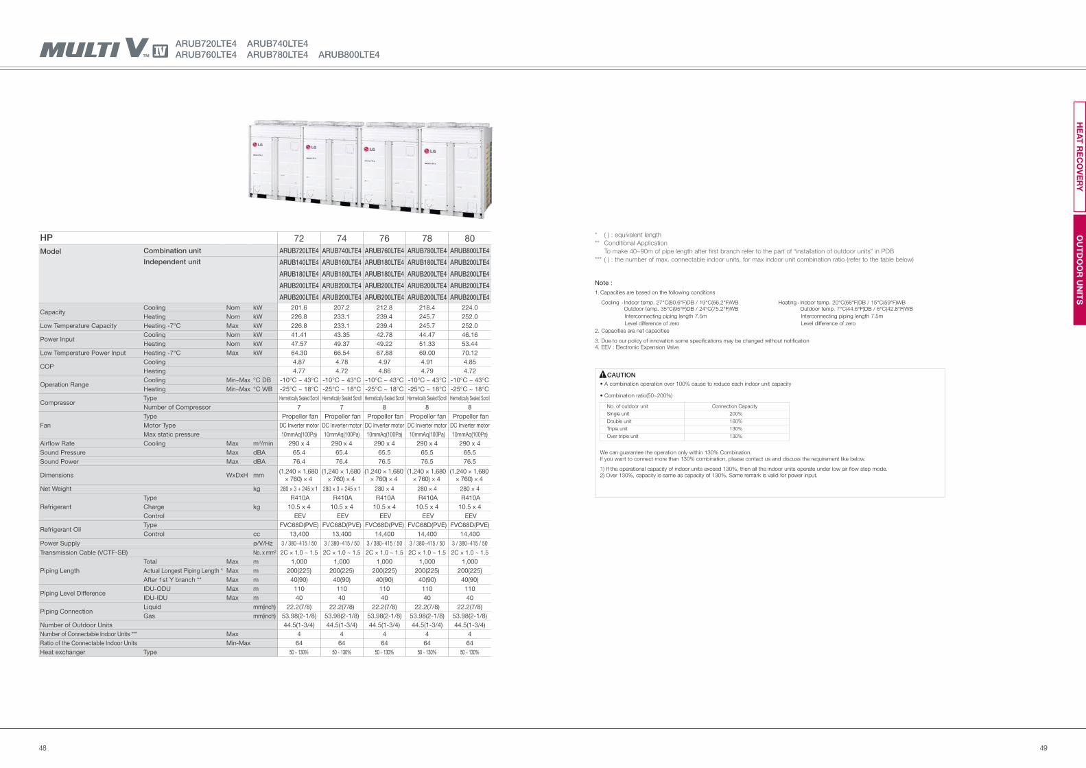
4948
Note :
1. Capacities are based on the following conditions
Cooling - Indoor temp. 27°C(80.6°F)DB / 19°C(66.2°F)WB Heating - Indoor temp. 20°C(68°F)DB / 15°C(59°F)WB Outdoor temp. 35°C(95°F)DB / 24°C(75.2°F)WB Outdoor temp. 7°C(44.6°F)DB / 6°C(42.8°F)WB
Interconnecting piping length 7.5m Interconnecting piping length 7.5m
Level difference of zero Level difference of zero
2. Capacities are net capacities
3. Due to our policy of innovation some specifications may be changed without notification4. EEV : Electronic Expansion Valve
No. of outdoor unit Connection Capacity
Single unit 200%
Double unit 160%
Triple unit 130%
Over triple unit 130%
CAUTION
We can guarantee the operation only within 130% Combination.If you want to connect more than 130% combination, please contact us and discuss the requirement like below.
1) If the operational capacity of indoor units exceed 130%, then all the indoor units operate under low air flow step mode.2) Over 130%, capacity is same as capacity of 130%, Same remark is valid for power input.
( ) : equivalent length
Conditional Application
To make 40~90m of pipe length after first branch refer to the part of “installation of outdoor units” in PDB
( ) : the number of max. connectable indoor units, for max indoor unit combination ratio (refer to the table below)
*
**
***
HP 72 74 76 78 80
Model Combination unit ARUB720LTE4 ARUB740LTE4 ARUB760LTE4 ARUB780LTE4 ARUB800LTE4
Independent unit ARUB140LTE4 ARUB160LTE4 ARUB180LTE4 ARUB180LTE4 ARUB200LTE4
ARUB180LTE4 ARUB180LTE4 ARUB180LTE4 ARUB200LTE4 ARUB200LTE4
ARUB200LTE4 ARUB200LTE4 ARUB200LTE4 ARUB200LTE4 ARUB200LTE4
ARUB200LTE4 ARUB200LTE4 ARUB200LTE4 ARUB200LTE4 ARUB200LTE4
Capacity Cooling Nom kW 201.6 207.2 212.8 218.4 224.0
Heating Nom kW 226.8 233.1 239.4 245.7 252.0
Low Temperature Capacity Heating -7°C Max kW 226.8 233.1 239.4 245.7 252.0
Power Input Cooling Nom kW 41.41 43.35 42.78 44.47 46.16
Heating Nom kW 47.57 49.37 49.22 51.33 53.44
Low Temperature Power Input Heating -7°C Max kW 64.30 66.54 67.88 69.00 70.12
COP Cooling 4.87 4.78 4.97 4.91 4.85
Heating 4.77 4.72 4.86 4.79 4.72
Operation RangeCooling Min~Max °C DB -10°C ~ 43°C -10°C ~ 43°C -10°C ~ 43°C -10°C ~ 43°C -10°C ~ 43°C
Heating Min~Max °C WB -25°C ~ 18°C -25°C ~ 18°C -25°C ~ 18°C -25°C ~ 18°C -25°C ~ 18°C
Compressor Type Hermetically Sealed Scroll Hermetically Sealed Scroll Hermetically Sealed Scroll Hermetically Sealed Scroll Hermetically Sealed Scroll
Number of Compressor 7 7 8 8 8
Fan
Type Propeller fan Propeller fan Propeller fan Propeller fan Propeller fan
Motor Type DC Inverter motor DC Inverter motor DC Inverter motor DC Inverter motor DC Inverter motor
Max static pressure 10mmAq(100Pa) 10mmAq(100Pa) 10mmAq(100Pa) 10mmAq(100Pa) 10mmAq(100Pa)
Airflow Rate Cooling Max m3/min 290 x 4 290 x 4 290 x 4 290 x 4 290 x 4
Sound Pressure Max dBA 65.4 65.4 65.5 65.5 65.5
Sound Power Max dBA 76.4 76.4 76.5 76.5 76.5
Dimensions WxDxH mm(1,240 × 1,680
× 760) × 4
(1,240 × 1,680
× 760) × 4
(1,240 × 1,680
× 760) × 4
(1,240 × 1,680
× 760) × 4
(1,240 × 1,680
× 760) × 4
Net Weight kg 280 × 3 + 245 x 1 280 × 3 + 245 x 1 280 × 4 280 × 4 280 × 4
Refrigerant
Type R410A R410A R410A R410A R410A
Charge kg 10.5 x 4 10.5 x 4 10.5 x 4 10.5 x 4 10.5 x 4
Control EEV EEV EEV EEV EEV
Refrigerant OilType FVC68D(PVE) FVC68D(PVE) FVC68D(PVE) FVC68D(PVE) FVC68D(PVE)
Control cc 13,400 13,400 14,400 14,400 14,400
Power Supply ø/V/Hz 3 / 380~415 / 50 3 / 380~415 / 50 3 / 380~415 / 50 3 / 380~415 / 50 3 / 380~415 / 50
Transmission Cable (VCTF-SB) No. x mm² 2C × 1.0 ~ 1.5 2C × 1.0 ~ 1.5 2C × 1.0 ~ 1.5 2C × 1.0 ~ 1.5 2C × 1.0 ~ 1.5
Piping Length
Total Max m 1,000 1,000 1,000 1,000 1,000
Actual Longest Piping Length * Max m 200(225) 200(225) 200(225) 200(225) 200(225)
After 1st Y branch ** Max m 40(90) 40(90) 40(90) 40(90) 40(90)
Piping Level DifferenceIDU-ODU Max m 110 110 110 110 110
IDU-IDU Max m 40 40 40 40 40
Piping ConnectionLiquid mm(inch) 22.2(7/8) 22.2(7/8) 22.2(7/8) 22.2(7/8) 22.2(7/8)
Gas mm(inch) 53.98(2-1/8) 53.98(2-1/8) 53.98(2-1/8) 53.98(2-1/8) 53.98(2-1/8)
Number of Outdoor Units 44.5(1-3/4) 44.5(1-3/4) 44.5(1-3/4) 44.5(1-3/4) 44.5(1-3/4)
Number of Connectable Indoor Units *** Max 4 4 4 4 4
Ratio of the Connectable Indoor Units Min-Max 64 64 64 64 64
Heat exchanger Type 50 ~ 130% 50 ~ 130% 50 ~ 130% 50 ~ 130% 50 ~ 130%
ARUB720LTE4 ARUB740LTE4
ARUB760LTE4 ARUB780LTE4 ARUB800LTE4
OU
TD
OO
R U
NIT
SH
EA
T R
EC
OV
ER
Y
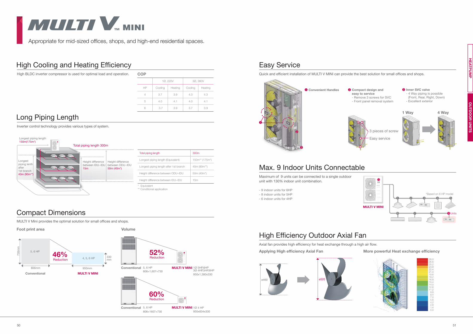
5150
High BLDC inverter compressor is used for optimal load and operation.
Inverter control technology provides various types of system.
MULTI V Mini provides the optimal solution for small offices and shops.
High Cooling and Heating Efficiency
Long Piping Length
Compact Dimensions
1Ø 4 HP
Foot print area
46%Reduction
806mm
730m
m
330mm
950mm
5, 6 HP
Volume
52%Reduction
806×1607×730
806×1,607×730
5, 6 HP
5, 6 HP
950x1,380x330
1Ø 5HP,6HP 3Ø 4HP,5HP,6HP
Quick and efficient installation of MULTI V MINI can provide the best solution for small offices and shops.
Maximum of 9 units can be connected to a single outdoor
unit with 130% indoor unit combination.
- 9 indoor units for 6HP
- 8 indoor units for 5HP
- 6 indoor units for 4HP
Easy Service
Max. 9 Indoor Units Connectable
Axial fan provides high efficiency for heat exchange through a high air flow.
High Efficiency Outdoor Axial Fan
Applying High efficiency Axial Fan More powerful Heat exchange efficiency
28.026.625.223.822.421.019.618.216.815.414.012.611.2
9.88.47.05.64.22.81.40.0
Appropriate for mid-sized offices, shops, and high-end residential spaces.
COP
1Ø, 220V 3Ø, 380V
HP Cooling Heating Cooling Heating
4 3.7 3.9 4.3 4.3
5 4.0 4.1 4.0 4.1
6 3.7 3.9 3.7 3.9
Inner SVC valve
- 4 Way piping is possible
(Front, Rear, Right, Down)
- Excellent exterior
3
3
2
1 Convenient Handles
Total piping length 300m
Height difference
between ODU~IDU
50m (40m*)
Height difference
between IDU~IDU
15m
Longest piping length
150m(175m*)
Longest
piping lenth
after
1st branch
40m (90m**)
Total piping length 300m
Longest piping length (Equivalent) 150m** (175m*)
Longest piping length after 1st branch 40m (90m**)
Height difference between ODU~IDU 50m (40m*)
Height difference between IDU~IDU 15m
60%Reduction
1 Way 4 Way
Easy service
3 pieces of screw
*Based on 6 HP model
Units
1 2
6
3
7
4
8
5
9
ø460 ø520
Conventional
Conventional MULTI V MINI
MULTI V MINI
MULTI V MINIConventional950x834x330
4, 5, 6 HP
1
Compact design and
easy to service
- Remove 3 screws for SVC
- Front panel removal system
2
OU
TD
OO
R U
NIT
SH
EA
TP
UM
P
MULTI V MINI
* Equivalent
** Conditional application
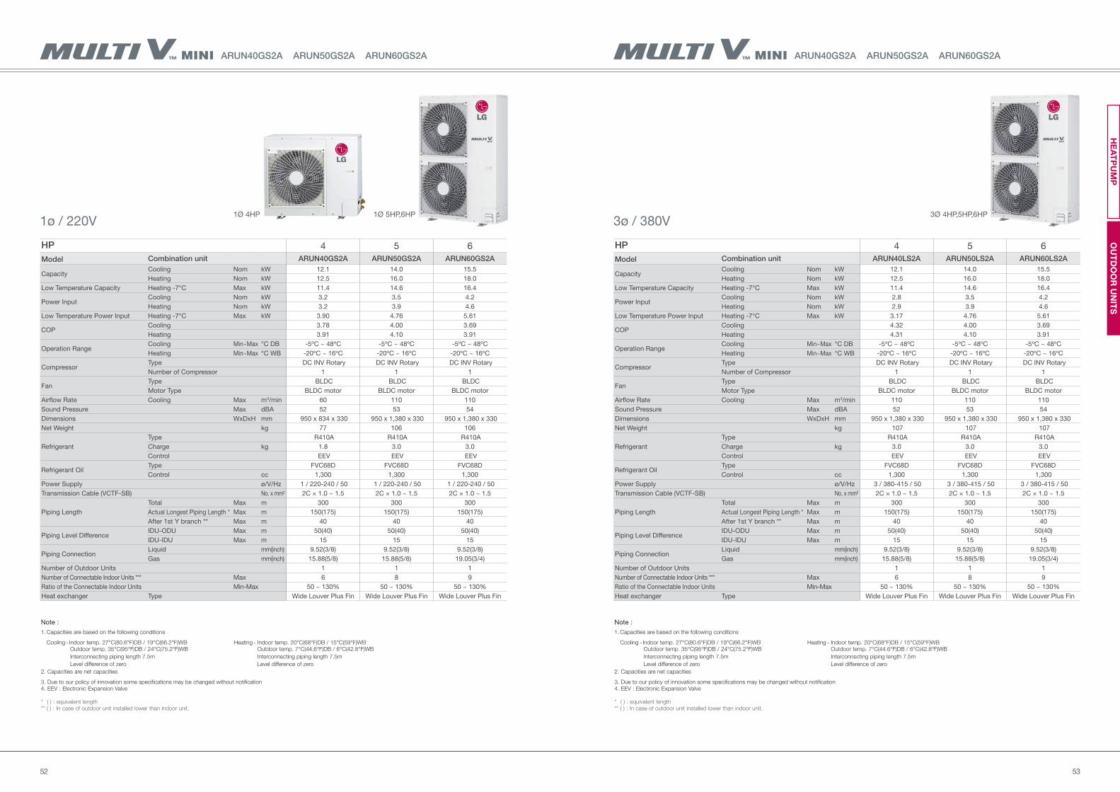
5352
ARUN40GS2A ARUN50GS2A ARUN60GS2A ARUN40GS2A ARUN50GS2A ARUN60GS2A
HP 4 5 6
Model Combination unit ARUN40GS2A ARUN50GS2A ARUN60GS2A
Capacity Cooling Nom kW 12.1 14.0 15.5
Heating Nom kW 12.5 16.0 18.0
Low Temperature Capacity Heating -7°C Max kW 11.4 14.6 16.4
Power Input Cooling Nom kW 3.2 3.5 4.2
Heating Nom kW 3.2 3.9 4.6
Low Temperature Power Input Heating -7°C Max kW 3.90 4.76 5.61
COP Cooling 3.78 4.00 3.69
Heating 3.91 4.10 3.91
Operation RangeCooling Min~Max °C DB -5ºC ~ 48ºC -5ºC ~ 48ºC -5ºC ~ 48ºC
Heating Min~Max °C WB -20ºC ~ 16ºC -20ºC ~ 16ºC -20ºC ~ 16ºC
Compressor Type DC INV Rotary DC INV Rotary DC INV Rotary
Number of Compressor 1 1 1
FanType BLDC BLDC BLDC
Motor Type BLDC motor BLDC motor BLDC motor
Airflow Rate Cooling Max m3/min 60 110 110
Sound Pressure Max dBA 52 53 54
Dimensions WxDxH mm 950 x 834 x 330 950 x 1,380 x 330 950 x 1,380 x 330
Net Weight kg 77 106 106
Refrigerant
Type R410A R410A R410A
Charge kg 1.8 3.0 3.0
Control EEV EEV EEV
Refrigerant OilType FVC68D FVC68D FVC68D
Control cc 1,300 1,300 1,300
Power Supply ø/V/Hz 1 / 220-240 / 50 1 / 220-240 / 50 1 / 220-240 / 50
Transmission Cable (VCTF-SB) No. x mm² 2C × 1.0 ~ 1.5 2C × 1.0 ~ 1.5 2C × 1.0 ~ 1.5
Piping Length
Total Max m 300 300 300
Actual Longest Piping Length * Max m 150(175) 150(175) 150(175)
After 1st Y branch ** Max m 40 40 40
Piping Level DifferenceIDU-ODU Max m 50(40) 50(40) 50(40)
IDU-IDU Max m 15 15 15
Piping ConnectionLiquid mm(inch) 9.52(3/8) 9.52(3/8) 9.52(3/8)
Gas mm(inch) 15.88(5/8) 15.88(5/8) 19.05(3/4)
Number of Outdoor Units 1 1 1
Number of Connectable Indoor Units *** Max 6 8 9
Ratio of the Connectable Indoor Units Min-Max 50 ~ 130% 50 ~ 130% 50 ~ 130%
Heat exchanger Type Wide Louver Plus Fin Wide Louver Plus Fin Wide Louver Plus Fin
HP 4 5 6
Model Combination unit ARUN40LS2A ARUN50LS2A ARUN60LS2A
Capacity Cooling Nom kW 12.1 14.0 15.5
Heating Nom kW 12.5 16.0 18.0
Low Temperature Capacity Heating -7°C Max kW 11.4 14.6 16.4
Power Input Cooling Nom kW 2.8 3.5 4.2
Heating Nom kW 2.9 3.9 4.6
Low Temperature Power Input Heating -7°C Max kW 3.17 4.76 5.61
COP Cooling 4.32 4.00 3.69
Heating 4.31 4.10 3.91
Operation RangeCooling Min~Max °C DB -5ºC ~ 48ºC -5ºC ~ 48ºC -5ºC ~ 48ºC
Heating Min~Max °C WB -20ºC ~ 16ºC -20ºC ~ 16ºC -20ºC ~ 16ºC
Compressor Type DC INV Rotary DC INV Rotary DC INV Rotary
Number of Compressor 1 1 1
FanType BLDC BLDC BLDC
Motor Type BLDC motor BLDC motor BLDC motor
Airflow Rate Cooling Max m3/min 110 110 110
Sound Pressure Max dBA 52 53 54
Dimensions WxDxH mm 950 x 1,380 x 330 950 x 1,380 x 330 950 x 1,380 x 330
Net Weight kg 107 107 107
Refrigerant
Type R410A R410A R410A
Charge kg 3.0 3.0 3.0
Control EEV EEV EEV
Refrigerant OilType FVC68D FVC68D FVC68D
Control cc 1,300 1,300 1,300
Power Supply ø/V/Hz 3 / 380-415 / 50 3 / 380-415 / 50 3 / 380-415 / 50
Transmission Cable (VCTF-SB) No. x mm² 2C × 1.0 ~ 1.5 2C × 1.0 ~ 1.5 2C × 1.0 ~ 1.5
Piping Length
Total Max m 300 300 300
Actual Longest Piping Length * Max m 150(175) 150(175) 150(175)
After 1st Y branch ** Max m 40 40 40
Piping Level DifferenceIDU-ODU Max m 50(40) 50(40) 50(40)
IDU-IDU Max m 15 15 15
Piping ConnectionLiquid mm(inch) 9.52(3/8) 9.52(3/8) 9.52(3/8)
Gas mm(inch) 15.88(5/8) 15.88(5/8) 19.05(3/4)
Number of Outdoor Units 1 1 1
Number of Connectable Indoor Units *** Max 6 8 9
Ratio of the Connectable Indoor Units Min-Max 50 ~ 130% 50 ~ 130% 50 ~ 130%
Heat exchanger Type Wide Louver Plus Fin Wide Louver Plus Fin Wide Louver Plus Fin
1ø / 220V 3ø / 380V1Ø 4HP 1Ø 5HP,6HP 3Ø 4HP,5HP,6HP
Note :
1. Capacities are based on the following conditions
Cooling - Indoor temp. 27°C(80.6°F)DB / 19°C(66.2°F)WB Heating - Indoor temp. 20°C(68°F)DB / 15°C(59°F)WB Outdoor temp. 35°C(95°F)DB / 24°C(75.2°F)WB Outdoor temp. 7°C(44.6°F)DB / 6°C(42.8°F)WB
Interconnecting piping length 7.5m Interconnecting piping length 7.5m
Level difference of zero Level difference of zero
2. Capacities are net capacities
3. Due to our policy of innovation some specifications may be changed without notification4. EEV : Electronic Expansion Valve
* ( ) : equivalent length** ( ) : In case of outdoor unit installed lower than indoor unit.
OU
TD
OO
R U
NIT
SH
EA
TP
UM
P
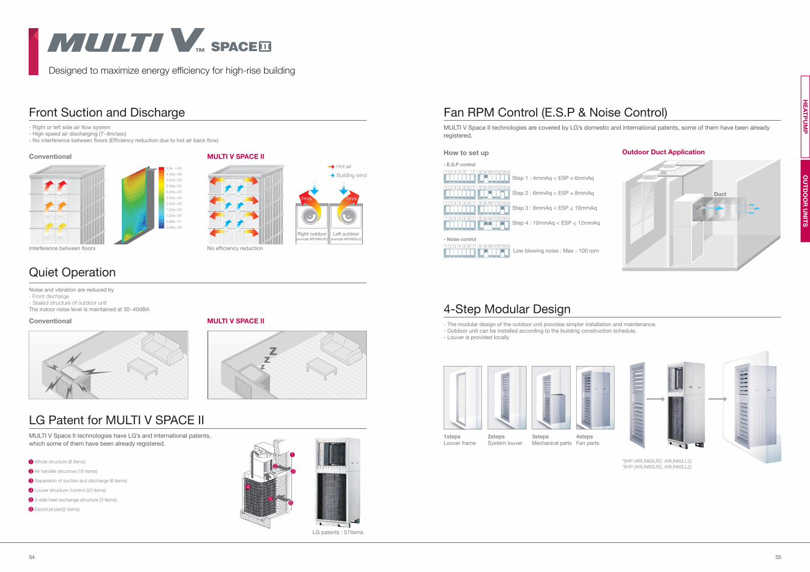
5554
- Right or left side air flow system
- High speed air discharging (7~8m/sec)
- No interference between floors (Efficiency reduction due to hot air back flow)
Noise and vibration are reduced by
- Front discharge
- Sealed structure of outdoor unit
The indoor noise level is maintained at 30~40dBA
Front Suction and Discharge
Quiet Operation
LG Patent for MULTI V SPACE II
LG patents : 57items
Interference between floors
Hot air
Building wind
Right outdoor (example ARUN80LR2)
Left outdoor (example ARUN80LL2)
7m/s7m/s
No efficiency reduction
MULTI V Space II technologies are covered by LG’s domestic and international patents, some of them have been already
registered.
- The modular design of the outdoor unit provides simpler installation and maintenance.
- Outdoor unit can be installed according to the building construction schedule.
- Louver is provided locally
Fan RPM Control (E.S.P & Noise Control)
4-Step Modular Design
Low blowing noise : Max - 100 rpm
Step 1 : 4mmAq < ESP < 6mmAq
Step 2 : 6mmAq < ESP < 8mmAq
Step 3 : 8mmAq < ESP < 10mmAq
Step 4 : 10mmAq < ESP < 12mmAq
How to set up
1 2 3 4 5 7 8 9 10 11 12 13 14
- E.S.P control
- Noise control
1
1
1
1
2
2
2
2
3
3
3
3
4
4
4
4
5
5
5
5
6
6
6
6
7
7
7
7
8
8
8
8
9
9
9
9
10
10
10
10
11
11
11
11
12
12
12
12
13
13
13
13
14
14
14
14
*6HP (ARUN60LR2, ARUN60LL2)
*8HP (ARUN80LR2, ARUN80LL2)
1
23
4
5
Whole structure (8 items)
Air handler structrue (18 items)
Separation of suction and discharge (6 items)
Louver structure /control (20 items)
3-side heat exchange structure (3 items)
Electrical part(2 items)
1
2
3
4
5
6
6
MULTI V SPACE IIOutdoor Duct Application
MULTI V SPACE II
Conventional
Conventional
1steps
Louver frame
4steps
Fan parts
3steps
Mechanical parts
2steps
System louver
5.0e + 00
4.58e + 00
4.07e + 00
3.56e + 00
3.05e + 00
2.54e + 00
2.03e + 00
1.53e + 00
1.02e + 00
5.08e - 01
0.00e + 00
zz
z
Duct
Designed to maximize energy efficiency for high-rise building
MULTI V Space II technologies have LG’s and international patents,
which some of them have been already registered.
OU
TD
OO
R U
NIT
SH
EA
TP
UM
P
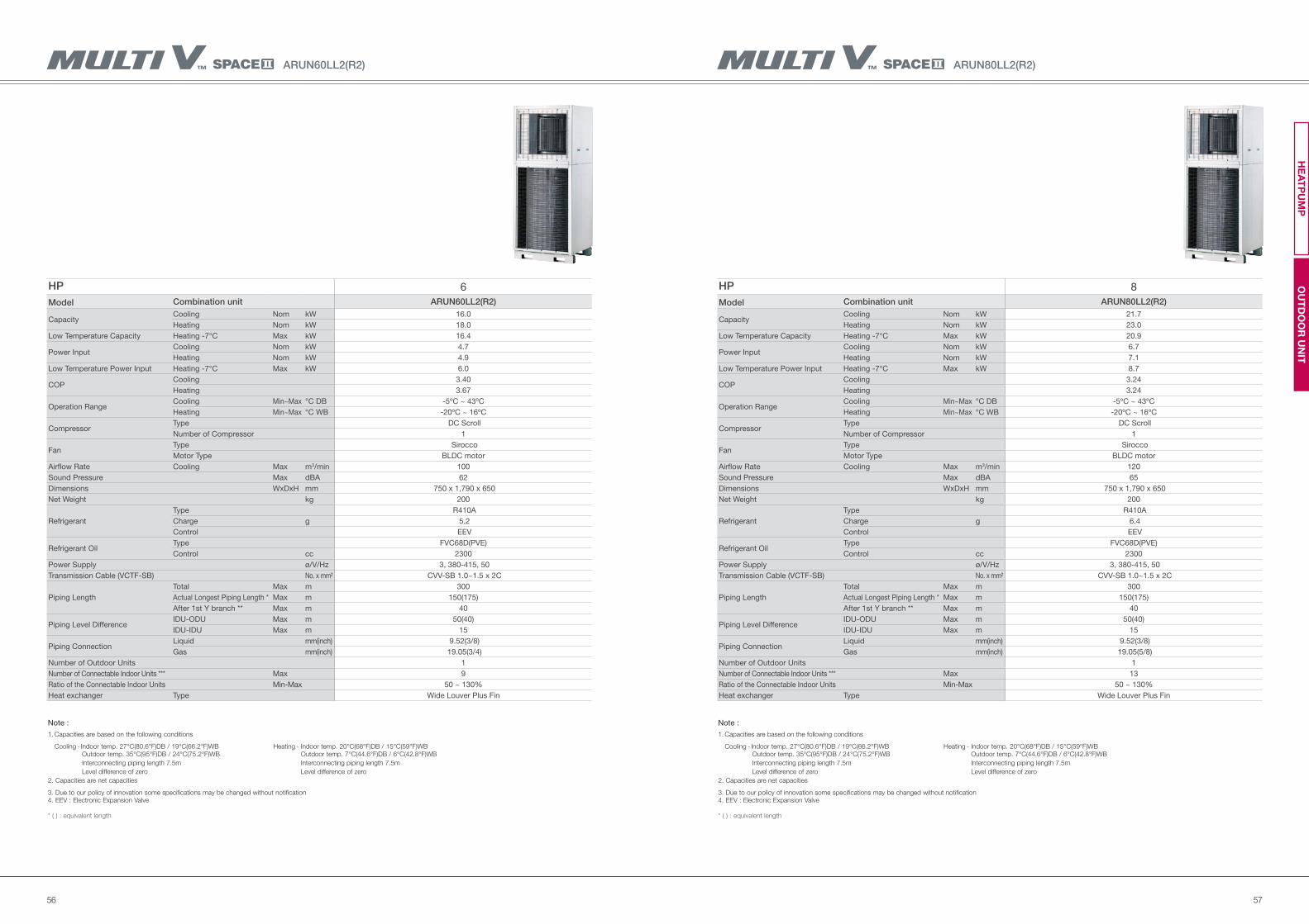
5756
HP 8
Model Combination unit ARUN80LL2(R2)
Capacity Cooling Nom kW 21.7
Heating Nom kW 23.0
Low Temperature Capacity Heating -7°C Max kW 20.9
Power Input Cooling Nom kW 6.7
Heating Nom kW 7.1
Low Temperature Power Input Heating -7°C Max kW 8.7
COP Cooling 3.24
Heating 3.24
Operation RangeCooling Min~Max °C DB -5ºC ~ 43ºC
Heating Min~Max °C WB -20ºC ~ 16ºC
Compressor Type DC Scroll
Number of Compressor 1
FanType Sirocco
Motor Type BLDC motor
Airflow Rate Cooling Max m3/min 120
Sound Pressure Max dBA 65
Dimensions WxDxH mm 750 x 1,790 x 650
Net Weight kg 200
Refrigerant
Type R410A
Charge g 6.4
Control EEV
Refrigerant OilType FVC68D(PVE)
Control cc 2300
Power Supply ø/V/Hz 3, 380-415, 50
Transmission Cable (VCTF-SB) No. x mm² CVV-SB 1.0~1.5 x 2C
Piping Length
Total Max m 300
Actual Longest Piping Length * Max m 150(175)
After 1st Y branch ** Max m 40
Piping Level DifferenceIDU-ODU Max m 50(40)
IDU-IDU Max m 15
Piping ConnectionLiquid mm(inch) 9.52(3/8)
Gas mm(inch) 19.05(5/8)
Number of Outdoor Units 1
Number of Connectable Indoor Units *** Max 13
Ratio of the Connectable Indoor Units Min-Max 50 ~ 130%
Heat exchanger Type Wide Louver Plus Fin
Note :
1. Capacities are based on the following conditions
Cooling - Indoor temp. 27°C(80.6°F)DB / 19°C(66.2°F)WB Heating - Indoor temp. 20°C(68°F)DB / 15°C(59°F)WB Outdoor temp. 35°C(95°F)DB / 24°C(75.2°F)WB Outdoor temp. 7°C(44.6°F)DB / 6°C(42.8°F)WB
Interconnecting piping length 7.5m Interconnecting piping length 7.5m
Level difference of zero Level difference of zero
2. Capacities are net capacities
3. Due to our policy of innovation some specifications may be changed without notification4. EEV : Electronic Expansion Valve
* ( ) : equivalent length
ARUN80LL2(R2)
HP 6
Model Combination unit ARUN60LL2(R2)
Capacity Cooling Nom kW 16.0
Heating Nom kW 18.0
Low Temperature Capacity Heating -7°C Max kW 16.4
Power Input Cooling Nom kW 4.7
Heating Nom kW 4.9
Low Temperature Power Input Heating -7°C Max kW 6.0
COP Cooling 3.40
Heating 3.67
Operation RangeCooling Min~Max °C DB -5ºC ~ 43ºC
Heating Min~Max °C WB -20ºC ~ 16ºC
Compressor Type DC Scroll
Number of Compressor 1
FanType Sirocco
Motor Type BLDC motor
Airflow Rate Cooling Max m3/min 100
Sound Pressure Max dBA 62
Dimensions WxDxH mm 750 x 1,790 x 650
Net Weight kg 200
Refrigerant
Type R410A
Charge g 5.2
Control EEV
Refrigerant OilType FVC68D(PVE)
Control cc 2300
Power Supply ø/V/Hz 3, 380-415, 50
Transmission Cable (VCTF-SB) No. x mm² CVV-SB 1.0~1.5 x 2C
Piping Length
Total Max m 300
Actual Longest Piping Length * Max m 150(175)
After 1st Y branch ** Max m 40
Piping Level DifferenceIDU-ODU Max m 50(40)
IDU-IDU Max m 15
Piping ConnectionLiquid mm(inch) 9.52(3/8)
Gas mm(inch) 19.05(3/4)
Number of Outdoor Units 1
Number of Connectable Indoor Units *** Max 9
Ratio of the Connectable Indoor Units Min-Max 50 ~ 130%
Heat exchanger Type Wide Louver Plus Fin
Note :
1. Capacities are based on the following conditions
Cooling - Indoor temp. 27°C(80.6°F)DB / 19°C(66.2°F)WB Heating - Indoor temp. 20°C(68°F)DB / 15°C(59°F)WB Outdoor temp. 35°C(95°F)DB / 24°C(75.2°F)WB Outdoor temp. 7°C(44.6°F)DB / 6°C(42.8°F)WB
Interconnecting piping length 7.5m Interconnecting piping length 7.5m
Level difference of zero Level difference of zero
2. Capacities are net capacities
3. Due to our policy of innovation some specifications may be changed without notification4. EEV : Electronic Expansion Valve
* ( ) : equivalent length
ARUN60LL2(R2)
OU
TD
OO
R U
NIT
HE
AT
PU
MP
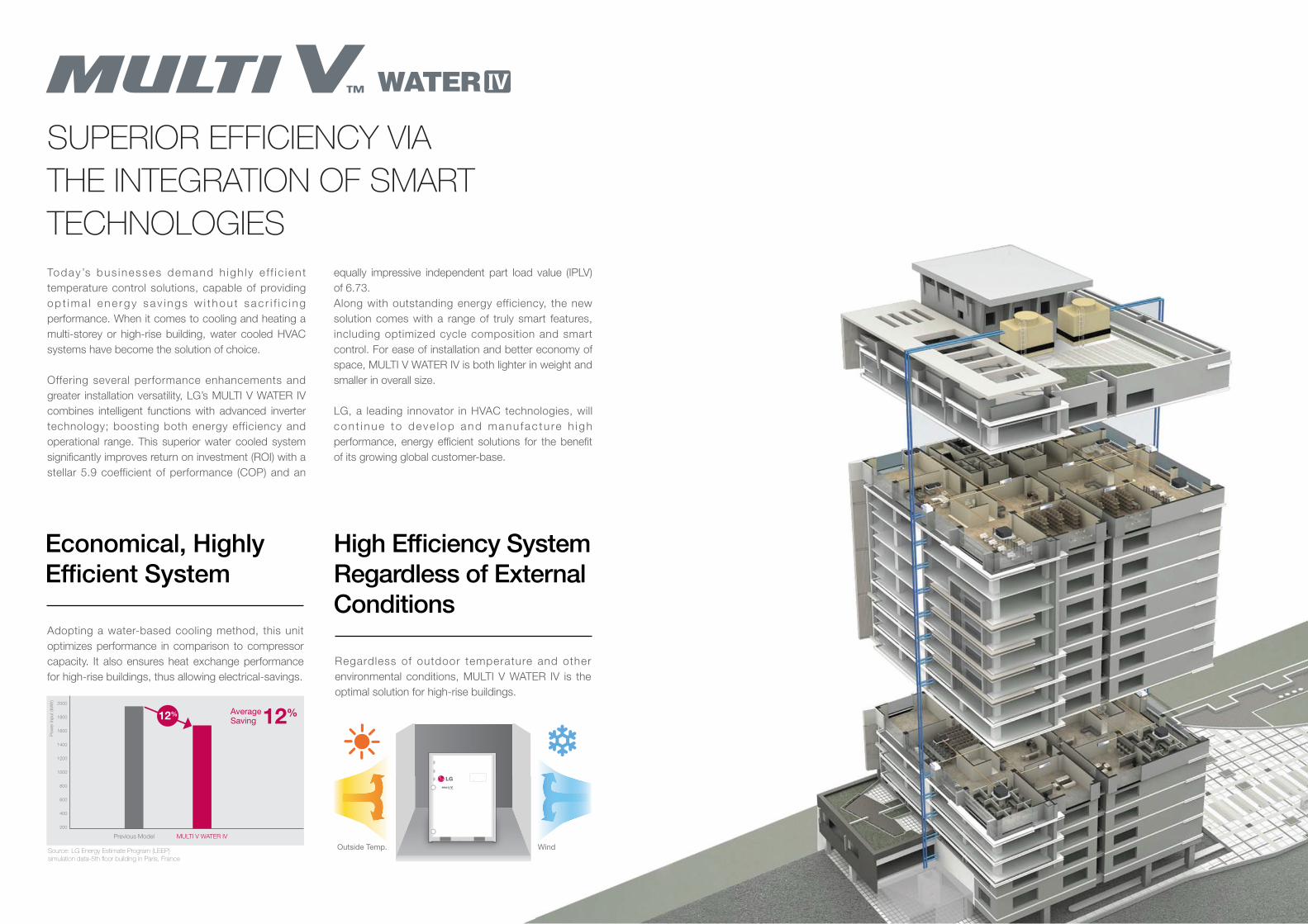
5958
SUPERIOR EFFICIENCY VIA
THE INTEGRATION OF SMART
TECHNOLOGIES
Today ’s bus inesses demand h igh ly e f f i c ien t
temperature control solutions, capable of providing
op t ima l ene rgy sav i ngs w i t hou t sac r i f i c i ng
performance. When it comes to cooling and heating a
multi-storey or high-rise building, water cooled HVAC
systems have become the solution of choice.
Offering several performance enhancements and
greater installation versatility, LG’s MULTI V WATER IV
combines intelligent functions with advanced inverter
technology; boosting both energy efficiency and
operational range. This superior water cooled system
significantly improves return on investment (ROI) with a
stellar 5.9 coefficient of performance (COP) and an
equally impressive independent part load value (IPLV)
of 6.73.
Along with outstanding energy efficiency, the new
solution comes with a range of truly smart features,
including optimized cycle composition and smart
control. For ease of installation and better economy of
space, MULTI V WATER IV is both lighter in weight and
smaller in overall size.
LG, a leading innovator in HVAC technologies, will
con t i nue to deve lop and manu fac tu re h igh
performance, energy efficient solutions for the benefit
of its growing global customer-base.
Adopting a water-based cooling method, this unit
optimizes performance in comparison to compressor
capacity. It also ensures heat exchange performance
for high-rise buildings, thus allowing electrical-savings.
Regardless of outdoor temperature and other
environmental conditions, MULTI V WATER IV is the
optimal solution for high-rise buildings.
Economical, Highly
Efficient System
High Efficiency System
Regardless of External
Conditions
12%
WATER
WindOutside Temp.
1400
1600
1800
2000
1000
1200
600
800
200
400
MULTI V WATER IVPrevious Model
Source: LG Energy Estimate Program (LEEP)simulation data-5th floor building in Paris, France
Po
wer
inp
ut
(kW
h)
12%AverageSaving
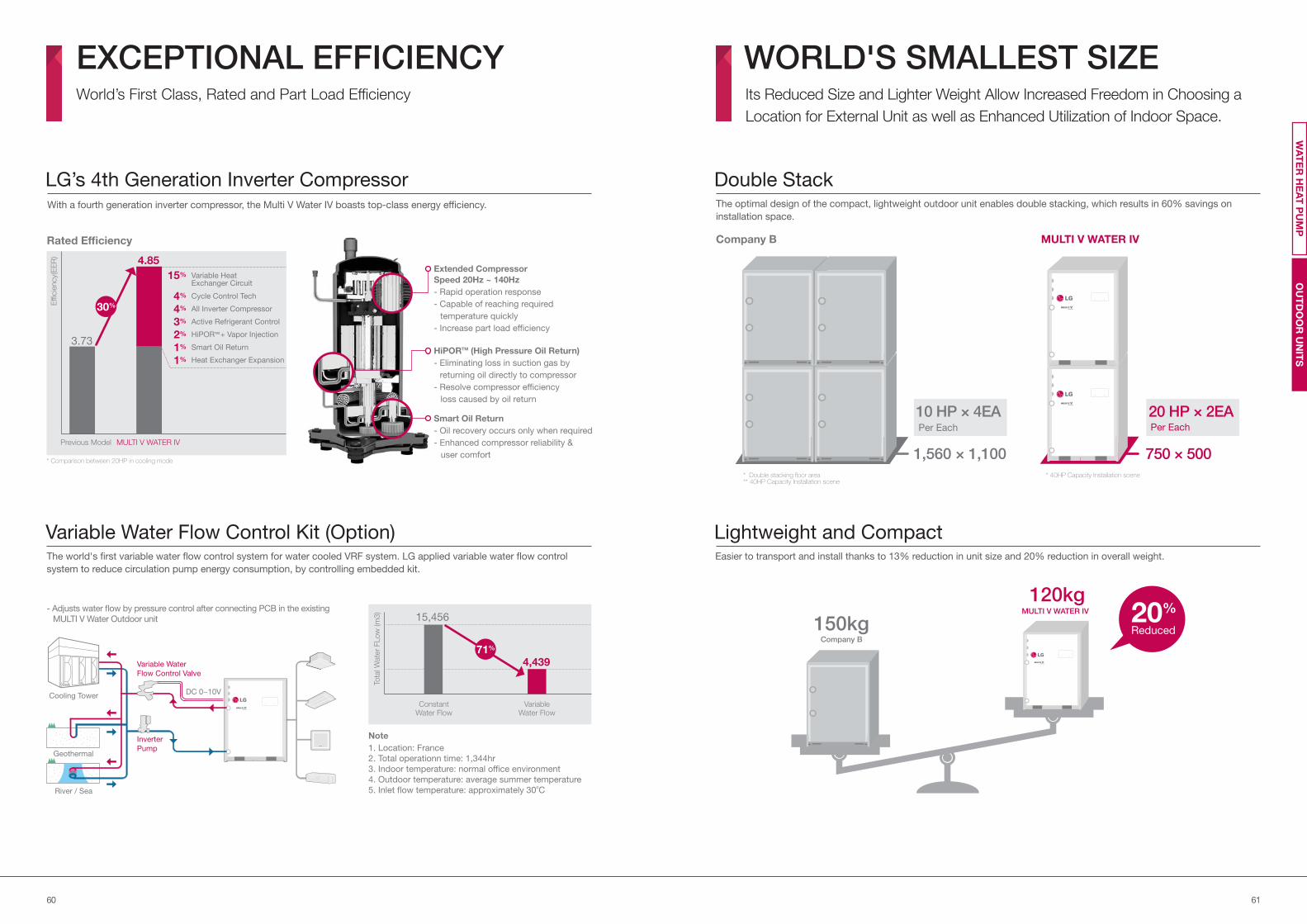
6160
With a fourth generation inverter compressor, the Multi V Water IV boasts top-class energy efficiency.
LG’s 4th Generation Inverter Compressor
EXCEPTIONAL EFFICIENCYWorld’s First Class, Rated and Part Load Efficiency
OU
TD
OO
R U
NIT
SW
AT
ER
HE
AT
PU
MP
Extended Compressor
Speed 20Hz ~ 140Hz
- Rapid operation response
- Capable of reaching required
temperature quickly
- Increase part load efficiency
HiPORTM (High Pressure Oil Return)
- Eliminating loss in suction gas by
returning oil directly to compressor
- Resolve compressor efficiency
loss caused by oil return
Smart Oil Return
- Oil recovery occurs only when required
- Enhanced compressor reliability &
user comfort
WORLD'S SMALLEST SIZEIts Reduced Size and Lighter Weight Allow Increased Freedom in Choosing a
Location for External Unit as well as Enhanced Utilization of Indoor Space.
Easier to transport and install thanks to 13% reduction in unit size and 20% reduction in overall weight.
WATER
WATER
The optimal design of the compact, lightweight outdoor unit enables double stacking, which results in 60% savings on
installation space.
Double Stack
Lightweight and Compact
MULTI V WATER IVCompany B
750 × 5001,560 × 1,100
10 HP × 4EAPer Each
20 HP × 2EAPer Each
* Double stacking floor area** 40HP Capacity Installation scene
* 40HP Capacity Installation scene
150kgCompany B
20%
Reduced
120kgMULTI V WATER IV
WATER
The world's first variable water flow control system for water cooled VRF system. LG applied variable water flow control
system to reduce circulation pump energy consumption, by controlling embedded kit.
Variable Water Flow Control Kit (Option)
WATER
Inverter
Pump
Variable Water
Flow Control Valve
Cooling Tower DC 0~10V
River / Sea
15,456
ConstantWater Flow
Tota
l Wate
r FLo
w (m
3)
VariableWater Flow
4,43971%
Geothermal1. Location: France
2. Total operationn time: 1,344hr
3. Indoor temperature: normal office environment
4. Outdoor temperature: average summer temperature
5. Inlet flow temperature: approximately 30oC
Note
- Adjusts water flow by pressure control after connecting PCB in the existing
MULTI V Water Outdoor unit
* Comparison between 20HP in cooling mode
Rated Efficiency
Effi
cie
ncy(
EE
R)
4.85
15%
4%
4%
3%
2%
1%
1%
3.73
MULTI V WATER IVPrevious Model
30%
Cycle Control Tech
Variable Heat Exchanger Circuit
Active Refrigerant Control
All Inverter Compressor
HiPORTM + Vapor Injection
Smart Oil Return
Heat Exchanger Expansion

6362
WATER
OUTSTANDING PERFORMANCEStable Performance and Long Life are Ensured Irrespective of Environmental
Changes, in addition to High-Speed Cooling and Heating.
Front-side connectable refrigerant and water pipe makes easier installation. Uses underground heat sources such as soil, ground water, lake, river, etc. as renewable energy for cooling and Heating of
a building. Water or antifreeze solution is circulated through the closed loop HDPE(High Density Poly-Ethylene) pipes buried
beneath the earth's surface. It is a highly efficient and eco-friendly MULTI V system.
Easy InstallationMULTI V WATER IV System for Geothermal Applications
MULTI V WATER IV
-The Circulating water temperature range is between -5°C~45°C
- Antifreeze should be applied depending on the application.
* Please contact local LG office for application availability.
Water piping
Water piping
Refrigerant piping
Liquid
Gas
Out
In
Under ground
HEX
Machine RoomMULTI V
WATER IV
Pump
OU
TD
OO
R U
NIT
SW
AT
ER
HE
AT
PU
MP
Company B
Water piping Refrigerant piping
Outdoor
units
DESIGN WITHOUT LIMITEasy Design with the Most Convenient Features
Provide flexible installation up to 300m of total piping length. As water pipes are not connected to indoor units, users are free
from leakage problems.
Longest Piping Length
Longest piping length after 1st branch
WATER
Height difference 50m
Height
between
IDU
Total piping length 300m
Actual longest piping
length (Equivalent)150m (175m*)
Longest piping length
after 1st branch40m (90m**)
Height difference
between ODU~IDU50m
Height difference
between IDU~IDU40m
Providing 8~20 HP with single unit, and up to the world's largest capacity 80HP by combination.
World’s Largest Capacity
Line up
(HP)8 10 12 14 16 18 20 22 24 26 28 30 32 34 36 38 40 42~60 62~80
LG
B
Company
C
Company
WATER WATER WATER
WATER WATER WATER WATER
WATER WATERWATER
1 Unit
- -
-
- - - - - - -
- - - -
1 Unit
1 Unit
2 Units
2 Units
2 Units
3 Units
3 Units
3 Units
4 Units
-* Equivalent
** Conditional application
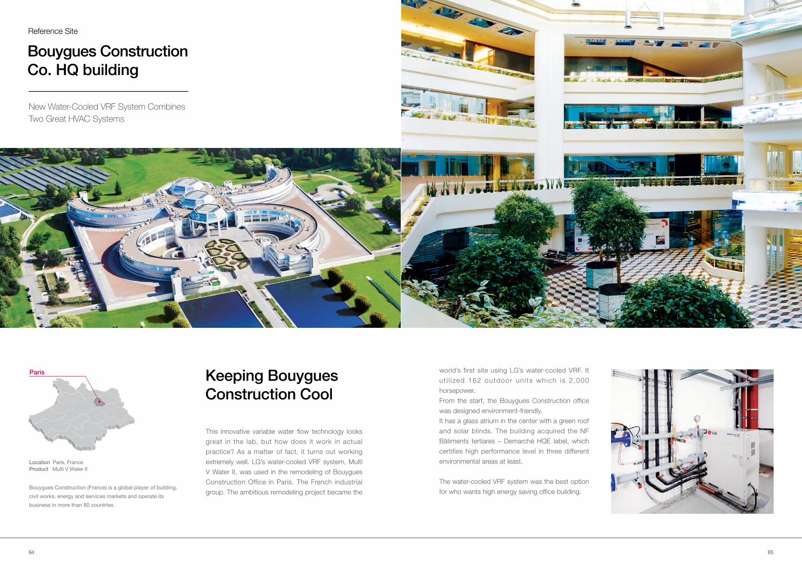
6564
Reference Site
This innovative variable water flow technology looks
great in the lab, but how does it work in actual
practice? As a matter of fact, it turns out working
extremely well. LG’s water-cooled VRF system, Multi
V Water II, was used in the remodeling of Bouygues
Construction Office in Paris. The French industrial
group. The ambitious remodeling project became the Bouygues Construction (France) is a global player of building,
civil works, energy and services markets and operate its
business in more than 80 countries.
Keeping Bouygues
Construction Cool
Paris
Location Paris, France
Product Multi V Water II
Bouygues Construction
Co. HQ building
New Water-Cooled VRF System Combines
Two Great HVAC Systems
world’s first site using LG’s water-cooled VRF. It
u t i l i zed 162 outdoor un i ts wh ich is 2 ,000
horsepower.
From the start, the Bouygues Construction office
was designed environment-friendly.
It has a glass atrium in the center with a green roof
and solar blinds. The building acquired the NF
Bâtiments tertiares – Demarché HQE label, which
certifies high performance level in three different
environmental areas at least.
The water-cooled VRF system was the best option
for who wants high energy saving office building.
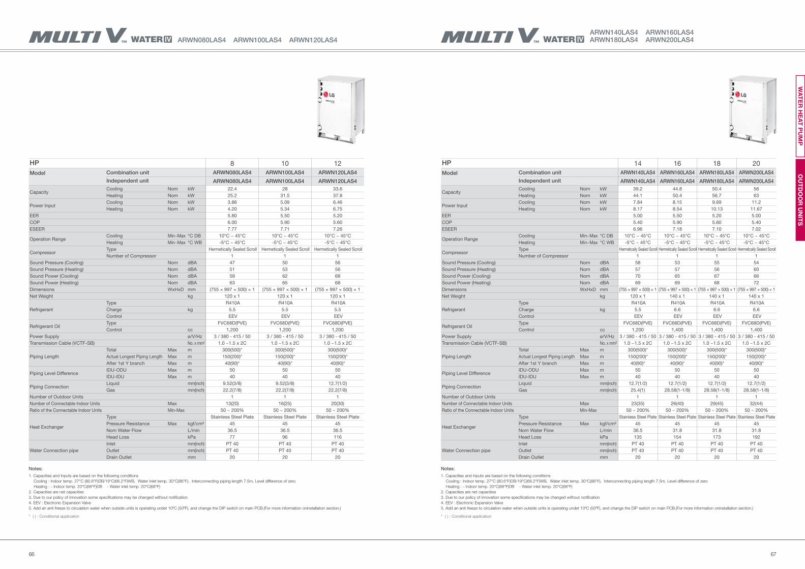
6766
HP 8 10 12
Model Combination unit ARWN080LAS4 ARWN100LAS4 ARWN120LAS4
Independent unit ARWN080LAS4 ARWN100LAS4 ARWN120LAS4
Capacity Cooling Nom kW 22.4 28 33.6
Heating Nom kW 25.2 31.5 37.8
Power Input Cooling Nom kW 3.86 5.09 6.46
Heating Nom kW 4.20 5.34 6.75
EER 5.80 5.50 5.20
COP 6.00 5.90 5.60
ESEER 7.77 7.71 7.26
Operation RangeCooling Min~Max °C DB 10°C ~ 45°C 10°C ~ 45°C 10°C ~ 45°C
Heating Min~Max °C WB -5°C ~ 45°C -5°C ~ 45°C -5°C ~ 45°C
Compressor Type Hermetically Sealed Scroll Hermetically Sealed Scroll Hermetically Sealed Scroll
Number of Compressor 1 1 1
Sound Pressure (Cooling) Nom dBA 47 50 56
Sound Pressure (Heating) Nom dBA 51 53 56
Sound Power (Cooling) Nom dBA 59 62 68
Sound Power (Heating) Nom dBA 63 65 68
Dimensions WxHxD mm (755 × 997 × 500) × 1 (755 × 997 × 500) × 1 (755 × 997 × 500) × 1
Net Weight kg 120 x 1 120 x 1 120 x 1
Refrigerant
Type R410A R410A R410A
Charge kg 5.5 5.5 5.5
Control EEV EEV EEV
Refrigerant OilType FVC68D(PVE) FVC68D(PVE) FVC68D(PVE)
Control cc 1,200 1,200 1,200
Power Supply ø/V/Hz 3 / 380 - 415 / 50 3 / 380 - 415 / 50 3 / 380 - 415 / 50
Transmission Cable (VCTF-SB) No. x mm² 1.0 ~1.5 x 2C 1.0 ~1.5 x 2C 1.0 ~1.5 x 2C
Piping Length
Total Max m 300(500)* 300(500)* 300(500)*
Actual Longest Piping Length Max m 150(200)* 150(200)* 150(200)*
After 1st Y branch Max m 40(90)* 40(90)* 40(90)*
Piping Level DifferenceIDU-ODU Max m 50 50 50
IDU-IDU Max m 40 40 40
Piping ConnectionLiquid mm(inch) 9.52(3/8) 9.52(3/8) 12.7(1/2)
Gas mm(inch) 22.2(7/8) 22.2(7/8) 22.2(7/8)
Number of Outdoor Units 1 1 1
Number of Connectable Indoor Units Max 13(20) 16(25) 20(30)
Ratio of the Connectable Indoor Units Min-Max 50 ~ 200% 50 ~ 200% 50 ~ 200%
Heat Exchanger
Type Stainless Steel Plate Stainless Steel Plate Stainless Steel Plate
Pressure Resistance Max kgf/cm² 45 45 45
Nom Water Flow L/min 36.5 36.5 36.5
Head Loss kPa 77 96 116
Water Connection pipe
Inlet mm(inch) PT 40 PT 40 PT 40
Outlet mm(inch) PT 40 PT 40 PT 40
Drain Outlet mm 20 20 20
HP 14 16 18 20
Model Combination unit ARWN140LAS4 ARWN160LAS4 ARWN180LAS4 ARWN200LAS4
Independent unit ARWN140LAS4 ARWN160LAS4 ARWN180LAS4 ARWN200LAS4
Capacity Cooling Nom kW 39.2 44.8 50.4 56
Heating Nom kW 44.1 50.4 56.7 63
Power Input Cooling Nom kW 7.84 8.15 9.69 11.2
Heating Nom kW 8.17 8.54 10.13 11.67
EER 5.00 5.50 5.20 5.00
COP 5.40 5.90 5.60 5.40
ESEER 6.96 7.18 7.10 7.02
Operation RangeCooling Min~Max °C DB 10°C ~ 45°C 10°C ~ 45°C 10°C ~ 45°C 10°C ~ 45°C
Heating Min~Max °C WB -5°C ~ 45°C -5°C ~ 45°C -5°C ~ 45°C -5°C ~ 45°C
Compressor Type Hermetically Sealed Scroll Hermetically Sealed Scroll Hermetically Sealed Scroll Hermetically Sealed Scroll
Number of Compressor 1 1 1 1
Sound Pressure (Cooling) Nom dBA 58 53 55 54
Sound Pressure (Heating) Nom dBA 57 57 56 60
Sound Power (Cooling) Nom dBA 70 65 67 66
Sound Power (Heating) Nom dBA 69 69 68 72
Dimensions WxHxD mm (755 × 997 × 500) × 1 (755 × 997 × 500) × 1 (755 × 997 × 500) × 1 (755 × 997 × 500) × 1
Net Weight kg 120 x 1 140 x 1 140 x 1 140 x 1
Refrigerant
Type R410A R410A R410A R410A
Charge kg 5.5 6.6 6.6 6.6
Control EEV EEV EEV EEV
Refrigerant OilType FVC68D(PVE) FVC68D(PVE) FVC68D(PVE) FVC68D(PVE)
Control cc 1,200 1,400 1,400 1,400
Power Supply ø/V/Hz 3 / 380 - 415 / 50 3 / 380 - 415 / 50 3 / 380 - 415 / 50 3 / 380 - 415 / 50
Transmission Cable (VCTF-SB) No. x mm² 1.0 ~1.5 x 2C 1.0 ~1.5 x 2C 1.0 ~1.5 x 2C 1.0 ~1.5 x 2C
Piping Length
Total Max m 300(500)* 300(500)* 300(500)* 300(500)*
Actual Longest Piping Length Max m 150(200)* 150(200)* 150(200)* 150(200)*
After 1st Y branch Max m 40(90)* 40(90)* 40(90)* 40(90)*
Piping Level DifferenceIDU-ODU Max m 50 50 50 50
IDU-IDU Max m 40 40 40 40
Piping ConnectionLiquid mm(inch) 12.7(1/2) 12.7(1/2) 12.7(1/2) 12.7(1/2)
Gas mm(inch) 25.4(1) 28.58(1-1/8) 28.58(1-1/8) 28.58(1-1/8)
Number of Outdoor Units 1 1 1 1
Number of Connectable Indoor Units Max 23(35) 26(40) 29(45) 32(44)
Ratio of the Connectable Indoor Units Min-Max 50 ~ 200% 50 ~ 200% 50 ~ 200% 50 ~ 200%
Heat Exchanger
Type Stainless Steel Plate Stainless Steel Plate Stainless Steel Plate Stainless Steel Plate
Pressure Resistance Max kgf/cm² 45 45 45 45
Nom Water Flow L/min 36.5 31.8 31.8 31.8
Head Loss kPa 135 154 173 192
Water Connection pipe
Inlet mm(inch) PT 40 PT 40 PT 40 PT 40
Outlet mm(inch) PT 40 PT 40 PT 40 PT 40
Drain Outlet mm 20 20 20 20
Notes:
1. Capacities and Inputs are based on the following conditions
Cooling : Indoor temp. 27°C (80.6°F)DB/19°C(66.2°F)WB, Water inlet temp. 30°C(86°F), Interconnecting piping length 7.5m, Level difference of zero
Heating : - Indoor temp. 20°C(68°F)DB - Water inlet temp. 20°C(68°F)
2. Capacities are net capacities
3. Due to our policy of innovation some specifications may be changed without notification
4. EEV : Electronic Expansion Valve
5. Add an anti freeze to circulation water when outside units is operating undet 10ºC (50ºF), and change the DIP switch on main PCB.(For more information oninstallation section.)
* ( ) : Conditional application
ARWN140LAS4 ARWN160LAS4 ARWN180LAS4 ARWN200LAS4ARWN080LAS4 ARWN100LAS4 ARWN120LAS4
Notes:
1. Capacities and Inputs are based on the following conditions
Cooling : Indoor temp. 27°C (80.6°F)DB/19°C(66.2°F)WB, Water inlet temp. 30°C(86°F), Interconnecting piping length 7.5m, Level difference of zero
Heating : - Indoor temp. 20°C(68°F)DB - Water inlet temp. 20°C(68°F)
2. Capacities are net capacities
3. Due to our policy of innovation some specifications may be changed without notification
4. EEV : Electronic Expansion Valve
5. Add an anti freeze to circulation water when outside units is operating undet 10ºC (50ºF), and change the DIP switch on main PCB.(For more information oninstallation section.)
* ( ) : Conditional application
OU
TD
OO
R U
NIT
SW
AT
ER
HE
AT
PU
MP
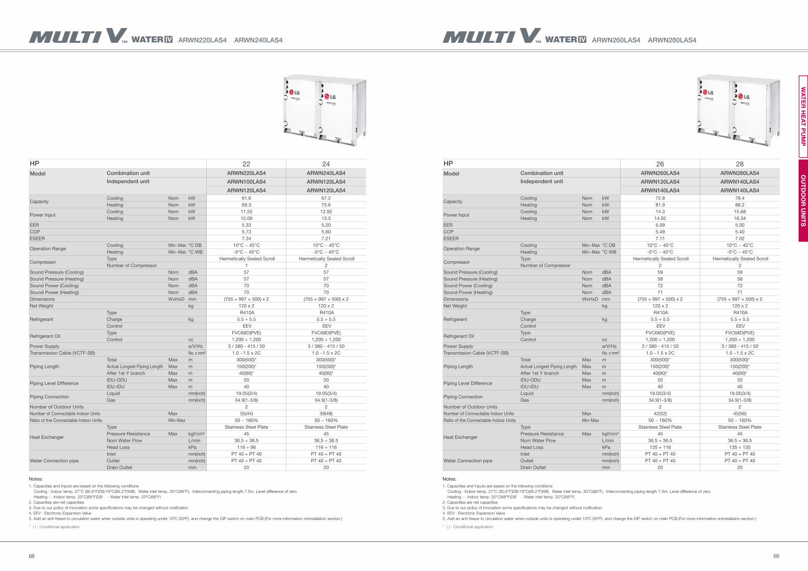
6968
HP 26 28
Model Combination unit ARWN260LAS4 ARWN280LAS4
Independent unit ARWN120LAS4 ARWN140LAS4
ARWN140LAS4 ARWN140LAS4
Capacity Cooling Nom kW 72.8 78.4
Heating Nom kW 81.9 88.2
Power Input Cooling Nom kW 14.3 15.68
Heating Nom kW 14.92 16.34
EER 5.09 5.00
COP 5.49 5.40
ESEER 7.11 7.02
Operation RangeCooling Min~Max °C DB 10°C ~ 45°C 10°C ~ 45°C
Heating Min~Max °C WB -5°C ~ 45°C -5°C ~ 45°C
Compressor Type Hermetically Sealed Scroll Hermetically Sealed Scroll
Number of Compressor 2 2
Sound Pressure (Cooling) Nom dBA 59 59
Sound Pressure (Heating) Nom dBA 58 58
Sound Power (Cooling) Nom dBA 72 72
Sound Power (Heating) Nom dBA 71 71
Dimensions WxHxD mm (755 × 997 × 500) x 2 (755 × 997 × 500) x 2
Net Weight kg 120 x 2 120 x 2
Refrigerant
Type R410A R410A
Charge kg 5.5 + 5.5 5.5 + 5.5
Control EEV EEV
Refrigerant OilType FVC68D(PVE) FVC68D(PVE)
Control cc 1,200 + 1,200 1,200 + 1,200
Power Supply ø/V/Hz 3 / 380 - 415 / 50 3 / 380 - 415 / 50
Transmission Cable (VCTF-SB) No. x mm² 1.0 ~1.5 x 2C 1.0 ~1.5 x 2C
Piping Length
Total Max m 300(500)* 300(500)*
Actual Longest Piping Length Max m 150(200)* 150(200)*
After 1st Y branch Max m 40(90)* 40(90)*
Piping Level DifferenceIDU-ODU Max m 50 50
IDU-IDU Max m 40 40
Piping ConnectionLiquid mm(inch) 19.05(3/4) 19.05(3/4)
Gas mm(inch) 34.9(1-3/8) 34.9(1-3/8)
Number of Outdoor Units 2 2
Number of Connectable Indoor Units Max 42(52) 45(56)
Ratio of the Connectable Indoor Units Min-Max 50 ~ 160% 50 ~ 160%
Heat Exchanger
Type Stainless Steel Plate Stainless Steel Plate
Pressure Resistance Max kgf/cm² 45 45
Nom Water Flow L/min 36.5 + 36.5 36.5 + 36.5
Head Loss kPa 135 + 116 135 + 135
Water Connection pipe
Inlet mm(inch) PT 40 + PT 40 PT 40 + PT 40
Outlet mm(inch) PT 40 + PT 40 PT 40 + PT 40
Drain Outlet mm 20 20
ARWN260LAS4 ARWN280LAS4ARWN220LAS4 ARWN240LAS4
HP 22 24
Model Combination unit ARWN220LAS4 ARWN240LAS4
Independent unit ARWN100LAS4 ARWN120LAS4
ARWN120LAS4 ARWN120LAS4
Capacity Cooling Nom kW 61.6 67.2
Heating Nom kW 69.3 75.6
Power Input Cooling Nom kW 11.55 12.92
Heating Nom kW 12.09 13.5
EER 5.33 5.20
COP 5.73 5.60
ESEER 7.34 7.21
Operation RangeCooling Min~Max °C DB 10°C ~ 45°C 10°C ~ 45°C
Heating Min~Max °C WB -5°C ~ 45°C -5°C ~ 45°C
Compressor Type Hermetically Sealed Scroll Hermetically Sealed Scroll
Number of Compressor 1 2
Sound Pressure (Cooling) Nom dBA 57 57
Sound Pressure (Heating) Nom dBA 57 57
Sound Power (Cooling) Nom dBA 70 70
Sound Power (Heating) Nom dBA 70 70
Dimensions WxHxD mm (755 × 997 × 500) x 2 (755 × 997 × 500) x 2
Net Weight kg 120 x 2 120 x 2
Refrigerant
Type R410A R410A
Charge kg 5.5 + 5.5 5.5 + 5.5
Control EEV EEV
Refrigerant OilType FVC68D(PVE) FVC68D(PVE)
Control cc 1,200 + 1,200 1,200 + 1,200
Power Supply ø/V/Hz 3 / 380 - 415 / 50 3 / 380 - 415 / 50
Transmission Cable (VCTF-SB) No. x mm² 1.0 ~1.5 x 2C 1.0 ~1.5 x 2C
Piping Length
Total Max m 300(500)* 300(500)*
Actual Longest Piping Length Max m 150(200)* 150(200)*
After 1st Y branch Max m 40(90)* 40(90)*
Piping Level DifferenceIDU-ODU Max m 50 50
IDU-IDU Max m 40 40
Piping ConnectionLiquid mm(inch) 19.05(3/4) 19.05(3/4)
Gas mm(inch) 34.9(1-3/8) 34.9(1-3/8)
Number of Outdoor Units 2 2
Number of Connectable Indoor Units Max 35(44) 39(48)
Ratio of the Connectable Indoor Units Min-Max 50 ~ 160% 50 ~ 160%
Heat Exchanger
Type Stainless Steel Plate Stainless Steel Plate
Pressure Resistance Max kgf/cm² 45 45
Nom Water Flow L/min 36.5 + 36.5 36.5 + 36.5
Head Loss kPa 116 + 96 116 + 116
Water Connection pipe
Inlet mm(inch) PT 40 + PT 40 PT 40 + PT 40
Outlet mm(inch) PT 40 + PT 40 PT 40 + PT 40
Drain Outlet mm 20 20
Notes:
1. Capacities and Inputs are based on the following conditions
Cooling : Indoor temp. 27°C (80.6°F)DB/19°C(66.2°F)WB, Water inlet temp. 30°C(86°F), Interconnecting piping length 7.5m, Level difference of zero
Heating : - Indoor temp. 20°C(68°F)DB - Water inlet temp. 20°C(68°F)
2. Capacities are net capacities
3. Due to our policy of innovation some specifications may be changed without notification
4. EEV : Electronic Expansion Valve
5. Add an anti freeze to circulation water when outside units is operating undet 10ºC (50ºF), and change the DIP switch on main PCB.(For more information oninstallation section.)
* ( ) : Conditional application
OU
TD
OO
R U
NIT
SW
AT
ER
HE
AT
PU
MP
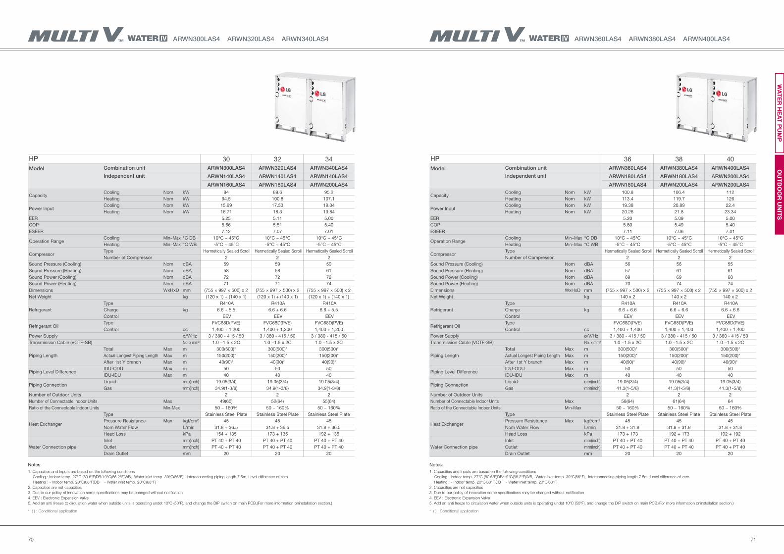
7170
HP 36 38 40
Model Combination unit ARWN360LAS4 ARWN380LAS4 ARWN400LAS4
Independent unit ARWN180LAS4 ARWN180LAS4 ARWN200LAS4
ARWN180LAS4 ARWN200LAS4 ARWN200LAS4
Capacity Cooling Nom kW 100.8 106.4 112
Heating Nom kW 113.4 119.7 126
Power Input Cooling Nom kW 19.38 20.89 22.4
Heating Nom kW 20.26 21.8 23.34
EER 5.20 5.09 5.00
COP 5.60 5.49 5.40
ESEER 7.11 7.06 7.01
Operation RangeCooling Min~Max °C DB 10°C ~ 45°C 10°C ~ 45°C 10°C ~ 45°C
Heating Min~Max °C WB -5°C ~ 45°C -5°C ~ 45°C -5°C ~ 45°C
Compressor Type Hermetically Sealed Scroll Hermetically Sealed Scroll Hermetically Sealed Scroll
Number of Compressor 2 2 2
Sound Pressure (Cooling) Nom dBA 56 56 55
Sound Pressure (Heating) Nom dBA 57 61 61
Sound Power (Cooling) Nom dBA 69 69 68
Sound Power (Heating) Nom dBA 70 74 74
Dimensions WxHxD mm (755 × 997 × 500) x 2 (755 × 997 × 500) x 2 (755 × 997 × 500) x 2
Net Weight kg 140 x 2 140 x 2 140 x 2
Refrigerant
Type R410A R410A R410A
Charge kg 6.6 + 6.6 6.6 + 6.6 6.6 + 6.6
Control EEV EEV EEV
Refrigerant OilType FVC68D(PVE) FVC68D(PVE) FVC68D(PVE)
Control cc 1,400 + 1,400 1,400 + 1,400 1,400 + 1,400
Power Supply ø/V/Hz 3 / 380 - 415 / 50 3 / 380 - 415 / 50 3 / 380 - 415 / 50
Transmission Cable (VCTF-SB) No. x mm² 1.0 ~1.5 x 2C 1.0 ~1.5 x 2C 1.0 ~1.5 x 2C
Piping Length
Total Max m 300(500)* 300(500)* 300(500)*
Actual Longest Piping Length Max m 150(200)* 150(200)* 150(200)*
After 1st Y branch Max m 40(90)* 40(90)* 40(90)*
Piping Level DifferenceIDU-ODU Max m 50 50 50
IDU-IDU Max m 40 40 40
Piping ConnectionLiquid mm(inch) 19.05(3/4) 19.05(3/4) 19.05(3/4)
Gas mm(inch) 41.3(1-5/8) 41.3(1-5/8) 41.3(1-5/8)
Number of Outdoor Units 2 2 2
Number of Connectable Indoor Units Max 58(64) 61(64) 64
Ratio of the Connectable Indoor Units Min-Max 50 ~ 160% 50 ~ 160% 50 ~ 160%
Heat Exchanger
Type Stainless Steel Plate Stainless Steel Plate Stainless Steel Plate
Pressure Resistance Max kgf/cm² 45 45 45
Nom Water Flow L/min 31.8 + 31.8 31.8 + 31.8 31.8 + 31.8
Head Loss kPa 173 + 173 192 + 173 192 + 192
Water Connection pipe
Inlet mm(inch) PT 40 + PT 40 PT 40 + PT 40 PT 40 + PT 40
Outlet mm(inch) PT 40 + PT 40 PT 40 + PT 40 PT 40 + PT 40
Drain Outlet mm 20 20 20
ARWN360LAS4 ARWN380LAS4 ARWN400LAS4ARWN300LAS4 ARWN320LAS4 ARWN340LAS4
HP 30 32 34
Model Combination unit ARWN300LAS4 ARWN320LAS4 ARWN340LAS4
Independent unit ARWN140LAS4 ARWN140LAS4 ARWN140LAS4
ARWN160LAS4 ARWN180LAS4 ARWN200LAS4
Capacity Cooling Nom kW 84 89.6 95.2
Heating Nom kW 94.5 100.8 107.1
Power Input Cooling Nom kW 15.99 17.53 19.04
Heating Nom kW 16.71 18.3 19.84
EER 5.25 5.11 5.00
COP 5.66 5.51 5.40
ESEER 7.12 7.07 7.01
Operation RangeCooling Min~Max °C DB 10°C ~ 45°C 10°C ~ 45°C 10°C ~ 45°C
Heating Min~Max °C WB -5°C ~ 45°C -5°C ~ 45°C -5°C ~ 45°C
Compressor Type Hermetically Sealed Scroll Hermetically Sealed Scroll Hermetically Sealed Scroll
Number of Compressor 2 2 2
Sound Pressure (Cooling) Nom dBA 59 59 59
Sound Pressure (Heating) Nom dBA 58 58 61
Sound Power (Cooling) Nom dBA 72 72 72
Sound Power (Heating) Nom dBA 71 71 74
Dimensions WxHxD mm (755 × 997 × 500) x 2 (755 × 997 × 500) x 2 (755 × 997 × 500) x 2
Net Weight kg (120 x 1) + (140 x 1) (120 x 1) + (140 x 1) (120 x 1) + (140 x 1)
Refrigerant
Type R410A R410A R410A
Charge kg 6.6 + 5.5 6.6 + 6.6 6.6 + 5.5
Control EEV EEV EEV
Refrigerant OilType FVC68D(PVE) FVC68D(PVE) FVC68D(PVE)
Control cc 1,400 + 1,200 1,400 + 1,200 1,400 + 1,200
Power Supply ø/V/Hz 3 / 380 - 415 / 50 3 / 380 - 415 / 50 3 / 380 - 415 / 50
Transmission Cable (VCTF-SB) No. x mm² 1.0 ~1.5 x 2C 1.0 ~1.5 x 2C 1.0 ~1.5 x 2C
Piping Length
Total Max m 300(500)* 300(500)* 300(500)*
Actual Longest Piping Length Max m 150(200)* 150(200)* 150(200)*
After 1st Y branch Max m 40(90)* 40(90)* 40(90)*
Piping Level DifferenceIDU-ODU Max m 50 50 50
IDU-IDU Max m 40 40 40
Piping ConnectionLiquid mm(inch) 19.05(3/4) 19.05(3/4) 19.05(3/4)
Gas mm(inch) 34.9(1-3/8) 34.9(1-3/8) 34.9(1-3/8)
Number of Outdoor Units 2 2 2
Number of Connectable Indoor Units Max 49(60) 52(64) 55(64)
Ratio of the Connectable Indoor Units Min-Max 50 ~ 160% 50 ~ 160% 50 ~ 160%
Heat Exchanger
Type Stainless Steel Plate Stainless Steel Plate Stainless Steel Plate
Pressure Resistance Max kgf/cm² 45 45 45
Nom Water Flow L/min 31.8 + 36.5 31.8 + 36.5 31.8 + 36.5
Head Loss kPa 154 + 135 173 + 135 192 + 135
Water Connection pipe
Inlet mm(inch) PT 40 + PT 40 PT 40 + PT 40 PT 40 + PT 40
Outlet mm(inch) PT 40 + PT 40 PT 40 + PT 40 PT 40 + PT 40
Drain Outlet mm 20 20 20
Notes:
1. Capacities and Inputs are based on the following conditions
Cooling : Indoor temp. 27°C (80.6°F)DB/19°C(66.2°F)WB, Water inlet temp. 30°C(86°F), Interconnecting piping length 7.5m, Level difference of zero
Heating : - Indoor temp. 20°C(68°F)DB - Water inlet temp. 20°C(68°F)
2. Capacities are net capacities
3. Due to our policy of innovation some specifications may be changed without notification
4. EEV : Electronic Expansion Valve
5. Add an anti freeze to circulation water when outside units is operating undet 10ºC (50ºF), and change the DIP switch on main PCB.(For more information oninstallation section.)
* ( ) : Conditional application
OU
TD
OO
R U
NIT
SW
AT
ER
HE
AT
PU
MP
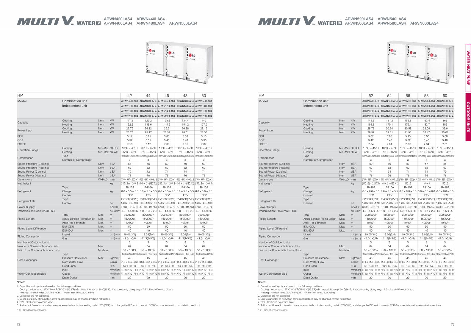
7372
HP 52 54 56 58 60
Model Combination unit ARWN520LAS4 ARWN540LAS4 ARWN560LAS4 ARWN580LAS4 ARWN600LAS4
Independent unit ARWN140LAS4 ARWN140LAS4 ARWN180LAS4 ARWN180LAS4 ARWN200LAS4
ARWN180LAS4 ARWN200LAS4 ARWN180LAS4 ARWN200LAS4 ARWN200LAS4
ARWN200LAS4 ARWN200LAS4 ARWN200LAS4 ARWN200LAS4 ARWN200LAS4
Capacity Cooling Nom kW 145.6 151.2 156.8 162.4 168
Heating Nom kW 163.8 170.1 176.4 182.7 189
Power Input Cooling Nom kW 28.73 30.24 30.58 32.09 33.6
Heating Nom kW 29.97 31.51 31.93 33.47 35.01
EER 5.07 5.00 5.13 5.06 5.00
COP 5.47 5.40 5.52 5.46 5.40
ESEER 7.04 7.01 7.07 7.04 7.01
Operation RangeCooling Min~Max °C DB 10°C ~ 45°C 10°C ~ 45°C 10°C ~ 45°C 10°C ~ 45°C 10°C ~ 45°C
Heating Min~Max °C WB -5°C ~ 45°C -5°C ~ 45°C -5°C ~ 45°C -5°C ~ 45°C -5°C ~ 45°C
Compressor Type Hermetically Sealed Scroll Hermetically Sealed Scroll Hermetically Sealed Scroll Hermetically Sealed Scroll Hermetically Sealed Scroll
Number of Compressor 3 3 3 3 3
Sound Pressure (Cooling) Nom dBA 60 60 57 57 56
Sound Pressure (Heating) Nom dBA 62 62 62 62 62
Sound Power (Cooling) Nom dBA 74 74 71 71 70
Sound Power (Heating) Nom dBA 76 76 76 76 76
Dimensions WxHxD mm (755 × 997 × 500) x 3 (755 × 997 × 500) x 3 (755 × 997 × 500) x 3 (755 × 997 × 500) x 3 (755 × 997 × 500) x 3
Net Weight kg (140 x 2) + (120 X 1) (140 x 2) + (120 X 1) 140 x 3 140 x 3 140 x 3
Refrigerant
Type R410A R410A R410A R410A R410A
Charge kg 6.6 + 6.6 + 5.5 6.6 + 6.6 + 5.5 6.6 + 6.6 + 6.6 6.6 + 6.6 + 6.6 6.6 + 6.6 + 6.6
Control EEV EEV EEV EEV EEV
Refrigerant OilType FVC68D(PVE) FVC68D(PVE) FVC68D(PVE) FVC68D(PVE) FVC68D(PVE)
Control cc 1,400 + 1,400 + 1,200 1,400 + 1,400 + 1,200 1,400 + 1,400 + 1,400 1,400 + 1,400 + 1,400 1,400 + 1,400 + 1,400
Power Supply ø/V/Hz 3 / 380 - 415 / 50 3 / 380 - 415 / 50 3 / 380 - 415 / 50 3 / 380 - 415 / 50 3 / 380 - 415 / 50
Transmission Cable (VCTF-SB) No. x mm² 1.0 ~1.5 x 2C 1.0 ~1.5 x 2C 1.0 ~1.5 x 2C 1.0 ~1.5 x 2C 1.0 ~1.5 x 2C
Piping Length
Total Max m 300(500)* 300(500)* 300(500)* 300(500)* 300(500)*
Actual Longest Piping Length Max m 150(200)* 150(200)* 150(200)* 150(200)* 150(200)*
After 1st Y branch Max m 40(90)* 40(90)* 40(90)* 40(90)* 40(90)*
Piping Level DifferenceIDU-ODU Max m 50 50 50 50 50
IDU-IDU Max m 40 40 40 40 40
Piping ConnectionLiquid mm(inch) 19.05(3/4) 19.05(3/4) 19.05(3/4) 19.05(3/4) 19.05(3/4)
Gas mm(inch) 41.3(1-5/8) 41.3(1-5/8) 41.3(1-5/8) 41.3(1-5/8) 41.3(1-5/8)
Number of Outdoor Units 3 3 3 3 3
Number of Connectable Indoor Units Max 64 64 64 64 64
Ratio of the Connectable Indoor Units Min-Max 50 ~ 130% 50 ~ 130% 50 ~ 130% 50 ~ 130% 50 ~ 130%
Heat Exchanger
Type Stainless Steel Plate Stainless Steel Plate Stainless Steel Plate Stainless Steel Plate Stainless Steel Plate
Pressure Resistance Max kgf/cm² 45 45 45 45 45
Nom Water Flow L/min 31.8 + 31.8 + 36.5 31.8 + 31.8 + 36.5 31.8 + 31.8 + 31.8 31.8 + 31.8 + 31.8 31.8 + 31.8 + 31.8
Head Loss kPa 192 + 173 + 135 192 + 192 + 135 192 + 173 + 173 192 + 192+ 173 192 + 192+ 192
Water Connection pipe
Inlet mm(inch) PT 40 + PT 40 + PT 40 PT 40 + PT 40 + PT 40 PT 40 + PT 40 + PT 40 PT 40 + PT 40 + PT 40 PT 40 + PT 40 + PT 40
Outlet mm(inch) PT 40 + PT 40 + PT 40 PT 40 + PT 40 + PT 40 PT 40 + PT 40 + PT 40 PT 40 + PT 40 + PT 40 PT 40 + PT 40 + PT 40
Drain Outlet mm 20 20 20 20 20
ARWN520LAS4 ARWN540LAS4 ARWN560LAS4 ARWN580LAS4 ARWN600LAS4
ARWN420LAS4 ARWN440LAS4 ARWN460LAS4 ARWN480LAS4 ARWN500LAS4
HP 42 44 46 48 50
Model Combination unit ARWN420LAS4 ARWN440LAS4 ARWN460LAS4 ARWN480LAS4 ARWN500LAS4
Independent unit ARWN100LAS4 ARWN120LAS4 ARWN120LAS4 ARWN140LAS4 ARWN140LAS4
ARWN120LAS4 ARWN120LAS4 ARWN140LAS4 ARWN140LAS4 ARWN160LAS4
ARWN200LAS4 ARWN200LAS4 ARWN200LAS4 ARWN200LAS4 ARWN200LAS4
Capacity Cooling Nom kW 117.6 123.2 128.8 134.4 140
Heating Nom kW 132.3 138.6 144.9 151.2 157.5
Power Input Cooling Nom kW 22.75 24.12 25.5 26.88 27.19
Heating Nom kW 23.76 25.17 26.59 28.01 28.38
EER 5.17 5.11 5.05 5.00 5.15
COP 5.57 5.51 5.45 5.40 5.55
ESEER 7.18 7.12 7.06 7.01 7.07
Operation RangeCooling Min~Max °C DB 10°C ~ 45°C 10°C ~ 45°C 10°C ~ 45°C 10°C ~ 45°C 10°C ~ 45°C
Heating Min~Max °C WB -5°C ~ 45°C -5°C ~ 45°C -5°C ~ 45°C -5°C ~ 45°C -5°C ~ 45°C
Compressor Type Hermetically Sealed Scroll Hermetically Sealed Scroll Hermetically Sealed Scroll Hermetically Sealed Scroll Hermetically Sealed Scroll
Number of Compressor 3 3 3 3 3
Sound Pressure (Cooling) Nom dBA 58 58 60 60 60
Sound Pressure (Heating) Nom dBA 62 62 62 62 62
Sound Power (Cooling) Nom dBA 72 72 74 74 74
Sound Power (Heating) Nom dBA 76 76 76 76 76
Dimensions WxHxD mm (755 × 997 × 500) x 3 (755 × 997 × 500) x 3 (755 × 997 × 500) x 3 (755 × 997 × 500) x 3 (755 × 997 × 500) x 3
Net Weight kg (140 x 1) + (120 X 2) (140 x 1) + (120 X 2) (140 x 1) + (120 X 2) (140 x 1) + (120 X 2) (140 x 2) + (120 X 1)
Refrigerant
Type R410A R410A R410A R410A R410A
Charge kg 6.6 + 5.5 + 5.5 6.6 + 5.5 + 5.5 6.6 + 5.5 + 5.5 6.6 + 5.5 + 5.5 6.6 + 6.6 + 5.5
Control EEV EEV EEV EEV EEV
Refrigerant OilType FVC68D(PVE) FVC68D(PVE) FVC68D(PVE) FVC68D(PVE) FVC68D(PVE)
Control cc 1,400 + 1,200 + 1,200 1,400 + 1,200 + 1,200 1,400 + 1,200 + 1,200 1,400 + 1,200 + 1,200 1,400 + 1,400 + 1,200
Power Supply ø/V/Hz 3 / 380 - 415 / 50 3 / 380 - 415 / 50 3 / 380 - 415 / 50 3 / 380 - 415 / 50 3 / 380 - 415 / 50
Transmission Cable (VCTF-SB) No. x mm² 1.0 ~1.5 x 2C 1.0 ~1.5 x 2C 1.0 ~1.5 x 2C 1.0 ~1.5 x 2C 1.0 ~1.5 x 2C
Piping Length
Total Max m 300(500)* 300(500)* 300(500)* 300(500)* 300(500)*
Actual Longest Piping Length Max m 150(200)* 150(200)* 150(200)* 150(200)* 150(200)*
After 1st Y branch Max m 40(90)* 40(90)* 40(90)* 40(90)* 40(90)*
Piping Level DifferenceIDU-ODU Max m 50 50 50 50 50
IDU-IDU Max m 40 40 40 40 40
Piping ConnectionLiquid mm(inch) 19.05(3/4) 19.05(3/4) 19.05(3/4) 19.05(3/4) 19.05(3/4)
Gas mm(inch) 41.3(1-5/8) 41.3(1-5/8) 41.3(1-5/8) 41.3(1-5/8) 41.3(1-5/8)
Number of Outdoor Units 3 3 3 3 3
Number of Connectable Indoor Units Max 64 64 64 64 64
Ratio of the Connectable Indoor Units Min-Max 50 ~ 130% 50 ~ 130% 50 ~ 130% 50 ~ 130% 50 ~ 130%
Heat Exchanger
Type Stainless Steel Plate Stainless Steel Plate Stainless Steel Plate Stainless Steel Plate Stainless Steel Plate
Pressure Resistance Max kgf/cm² 45 45 45 45 45
Nom Water Flow L/min 31.8 + 36.5 + 36.5 31.8 + 36.5 + 36.5 31.8 + 36.5 + 36.5 31.8 + 36.5 + 36.5 31.8 + 31.8 + 36.5
Head Loss kPa 192 + 116 + 96 192 + 116 + 116 192 + 135 + 116 192 + 135 + 135 192 + 154 + 135
Water Connection pipe
Inlet mm(inch) PT 40 + PT 40 + PT 40 PT 40 + PT 40 + PT 40 PT 40 + PT 40 + PT 40 PT 40 + PT 40 + PT 40 PT 40 + PT 40 + PT 40
Outlet mm(inch) PT 40 + PT 40 + PT 40 PT 40 + PT 40 + PT 40 PT 40 + PT 40 + PT 40 PT 40 + PT 40 + PT 40 PT 40 + PT 40 + PT 40
Drain Outlet mm 20 20 20 20 20
Notes:
1. Capacities and Inputs are based on the following conditions
Cooling : Indoor temp. 27°C (80.6°F)DB/19°C(66.2°F)WB, Water inlet temp. 30°C(86°F), Interconnecting piping length 7.5m, Level difference of zero
Heating : - Indoor temp. 20°C(68°F)DB - Water inlet temp. 20°C(68°F)
2. Capacities are net capacities
3. Due to our policy of innovation some specifications may be changed without notification
4. EEV : Electronic Expansion Valve
5. Add an anti freeze to circulation water when outside units is operating undet 10ºC (50ºF), and change the DIP switch on main PCB.(For more information oninstallation section.)
* ( ) : Conditional application
OU
TD
OO
R U
NIT
SW
AT
ER
HE
AT
PU
MP
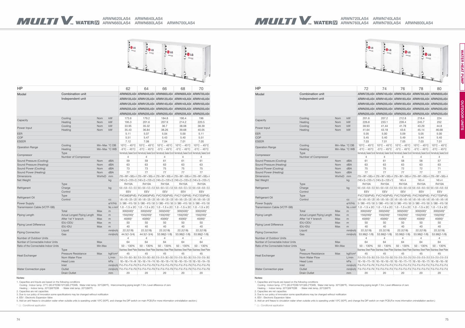
7574
ARWN720LAS4 ARWN740LAS4 ARWN760LAS4 ARWN780LAS4 ARWN800LAS4
ARWN620LAS4 ARWN640LAS4 ARWN660LAS4 ARWN680LAS4 ARWN700LAS4
HP 72 74 76 78 80
Model Combination unit ARWN720LAS4 ARWN740LAS4 ARWN760LAS4 ARWN780LAS4 ARWN800LAS4
Independent unit ARWN140LAS4 ARWN140LAS4 ARWN180LAS4 ARWN180LAS4 ARWN200LAS4
ARWN180LAS4 ARWN200LAS4 ARWN180LAS4 ARWN200LAS4 ARWN200LAS4
ARWN200LAS4 ARWN200LAS4 ARWN200LAS4 ARWN200LAS4 ARWN200LAS4
ARWN200LAS4 ARWN200LAS4 ARWN200LAS4 ARWN200LAS4 ARWN200LAS4
Capacity Cooling Nom kW 201.6 207.2 212.8 218.4 224
Heating Nom kW 226.8 233.1 239.4 245.7 252
Power Input Cooling Nom kW 39.93 41.44 41.78 43.29 44.8
Heating Nom kW 41.64 43.18 43.6 45.14 46.68
EER 5.05 5.00 5.09 5.05 5.00
COP 5.45 5.40 5.49 5.44 5.40
ESEER 7.03 7.01 7.05 7.03 7.01
Operation RangeCooling Min~Max °C DB 10°C ~ 45°C 10°C ~ 45°C 10°C ~ 45°C 10°C ~ 45°C 10°C ~ 45°C
Heating Min~Max °C WB -5°C ~ 45°C -5°C ~ 45°C -5°C ~ 45°C -5°C ~ 45°C -5°C ~ 45°C
Compressor Type Hermetically Sealed Scroll Hermetically Sealed Scroll Hermetically Sealed Scroll Hermetically Sealed Scroll Hermetically Sealed Scroll
Number of Compressor 4 4 4 4 4
Sound Pressure (Cooling) Nom dBA 61 61 58 58 57
Sound Pressure (Heating) Nom dBA 63 63 63 63 63
Sound Power (Cooling) Nom dBA 75 75 72 72 71
Sound Power (Heating) Nom dBA 77 77 77 77 77
Dimensions WxHxD mm (755 × 997 × 500) x 4 (755 × 997 × 500) x 4 (755 × 997 × 500) x 4 (755 × 997 × 500) x 4 (755 × 997 × 500) x 4
Net Weight kg (140 x 3) + (120 x 1) (140 x 3) + (120 x 1) 140 x 4 140 x 4 140 x 4
Refrigerant
Type R410A R410A R410A R410A R410A
Charge kg 6.6 + 6.6 + 6.6 + 5.5 6.6 + 6.6 + 6.6 + 5.5 6.6 + 6.6 + 6.6 + 6.6 6.6 + 6.6 + 6.6 + 6.6 6.6 + 6.6 + 6.6 + 6.6
Control EEV EEV EEV EEV EEV
Refrigerant OilType FVC73D(PVE) FVC74D(PVE) FVC75D(PVE) FVC76D(PVE) FVC77D(PVE)
Control cc 1,400 + 1,400 + 1,400 + 1,200 1,400 + 1,400 + 1,400 + 1,200 1,400 + 1,400 + 1,400 + 1,400 1,400 + 1,400 + 1,400 + 1,400 1,400 + 1,400 + 1,400 + 1,400
Power Supply ø/V/Hz 3 / 380 - 415 / 50 3 / 380 - 415 / 50 3 / 380 - 415 / 50 3 / 380 - 415 / 50 3 / 380 - 415 / 50
Transmission Cable (VCTF-SB) No. x mm² 1.0 ~1.5 x 2C 1.0 ~1.5 x 2C 1.0 ~1.5 x 2C 1.0 ~1.5 x 2C 1.0 ~1.5 x 2C
Piping Length
Total Max m 300(500)* 300(500)* 300(500)* 300(500)* 300(500)*
Actual Longest Piping Length Max m 150(200)* 150(200)* 150(200)* 150(200)* 150(200)*
After 1st Y branch Max m 40(90)* 40(90)* 40(90)* 40(90)* 40(90)*
Piping Level DifferenceIDU-ODU Max m 50 50 50 50 50
IDU-IDU Max m 40 40 40 40 40
Piping ConnectionLiquid mm(inch) 22.2(7/8) 22.2(7/8) 22.2(7/8) 22.2(7/8) 22.2(7/8)
Gas mm(inch) 53.98(2-1/8) 53.98(2-1/8) 53.98(2-1/8) 53.98(2-1/8) 53.98(2-1/8)
Number of Outdoor Units 4 4 4 4 4
Number of Connectable Indoor Units Max 64 64 64 64 64
Ratio of the Connectable Indoor Units Min-Max 50 ~ 130% 50 ~ 130% 50 ~ 130% 50 ~ 130% 50 ~ 130%
Heat Exchanger
Type Stainless Steel Plate Stainless Steel Plate Stainless Steel Plate Stainless Steel Plate Stainless Steel Plate
Pressure Resistance Max kgf/cm² 45 45 45 45 45
Nom Water Flow L/min 31.8 + 31.8 + 31.8 + 36.5 31.8 + 31.8 + 31.8 + 36.5 31.8 + 31.8 + 31.8 + 31.8 31.8 + 31.8 + 31.8 + 31.8 31.8 + 31.8 + 31.8 + 31.8
Head Loss kPa 192 + 192 + 173 + 135 192 + 192 + 192 + 135 192 + 192 + 173 + 173 192 + 192 + 192 + 173 192 + 192 + 192 + 192
Water Connection pipe
Inlet mm(inch) PT 40 + PT 40 + PT 40 + PT40 PT 40 + PT 40 + PT 40 + PT 40 PT 40 + PT 40 + PT 40 + PT 40 PT 40 + PT 40 + PT 40 + PT 40 PT 40 + PT 40 + PT 40 + PT 40
Outlet mm(inch) PT 40 + PT 40 + PT 40 + PT40 PT 40 + PT 40 + PT 40 + PT 40 PT 40 + PT 40 + PT 40 + PT 40 PT 40 + PT 40 + PT 40 + PT 40 PT 40 + PT 40 + PT 40 + PT 40
Drain Outlet mm 20 20 20 20 20
HP 62 64 66 68 70
Model Combination unit ARWN620LAS4 ARWN640LAS4 ARWN660LAS4 ARWN680LAS4 ARWN700LAS4
Independent unit ARWN100LAS4 ARWN120LAS4 ARWN120LAS4 ARWN140LAS4 ARWN140LAS4
ARWN120LAS4 ARWN120LAS4 ARWN140LAS4 ARWN140LAS4 ARWN160LAS4
ARWN200LAS4 ARWN200LAS4 ARWN200LAS4 ARWN200LAS4 ARWN200LAS4
ARWN200LAS4 ARWN200LAS4 ARWN200LAS4 ARWN200LAS4 ARWN200LAS4
Capacity Cooling Nom kW 173.6 179.2 184.8 190.4 196
Heating Nom kW 195.3 201.6 207.9 214.2 220.5
Power Input Cooling Nom kW 33.95 35.32 36.7 38.08 38.39
Heating Nom kW 35.43 36.84 38.26 39.68 40.05
EER 5.11 5.07 5.04 5.00 5.11
COP 5.51 5.47 5.43 5.40 5.51
ESEER 7.12 7.08 7.04 7.01 7.05
Operation RangeCooling Min~Max °C DB 10°C ~ 45°C 10°C ~ 45°C 10°C ~ 45°C 10°C ~ 45°C 10°C ~ 45°C
Heating Min~Max °C WB -5°C ~ 45°C -5°C ~ 45°C -5°C ~ 45°C -5°C ~ 45°C -5°C ~ 45°C
Compressor Type Hermetically Sealed Scroll Hermetically Sealed Scroll Hermetically Sealed Scroll Hermetically Sealed Scroll Hermetically Sealed Scroll
Number of Compressor 4 4 4 4 4
Sound Pressure (Cooling) Nom dBA 59 59 61 61 61
Sound Pressure (Heating) Nom dBA 63 63 63 63 63
Sound Power (Cooling) Nom dBA 73 73 75 75 75
Sound Power (Heating) Nom dBA 77 77 77 77 77
Dimensions WxHxD mm (755 × 997 × 500) x 4 (755 × 997 × 500) x 4 (755 × 997 × 500) x 4 (755 × 997 × 500) x 4 (755 × 997 × 500) x 4
Net Weight kg (140 x 2) + (120 x 2) (140 x 2) + (120 x 2) (140 x 2) + (120 x 2) (140 x 2) + (120 x 2) (140 x 3) + (120 x 1)
Refrigerant
Type R410A R410A R410A R410A R410A
Charge kg 6.6 + 6.6 + 5.5 + 5.5 6.6 + 6.6 + 5.5 + 5.5 6.6 + 6.6 + 5.5 + 5.5 6.6 + 6.6 + 5.5 + 5.5 6.6 + 6.6 + 6.6 + 5.5
Control EEV EEV EEV EEV EEV
Refrigerant OilType FVC68D(PVE) FVC69D(PVE) FVC70D(PVE) FVC71D(PVE) FVC72D(PVE)
Control cc 1,400 + 1,400 + 1,200 + 1,200 1,400 + 1,400 + 1,200 + 1,200 1,400 + 1,400 + 1,200 + 1,200 1,400 + 1,400 + 1,200 + 1,200 1,400 + 1,400 + 1,400 + 1,200
Power Supply ø/V/Hz 3 / 380 - 415 / 50 3 / 380 - 415 / 50 3 / 380 - 415 / 50 3 / 380 - 415 / 50 3 / 380 - 415 / 50
Transmission Cable (VCTF-SB) No. x mm² 1.0 ~1.5 x 2C 1.0 ~1.5 x 2C 1.0 ~1.5 x 2C 1.0 ~1.5 x 2C 1.0 ~1.5 x 2C
Piping Length
Total Max m 300(500)* 300(500)* 300(500)* 300(500)* 300(500)*
Actual Longest Piping Length Max m 150(200)* 150(200)* 150(200)* 150(200)* 150(200)*
After 1st Y branch Max m 40(90)* 40(90)* 40(90)* 40(90)* 40(90)*
Piping Level DifferenceIDU-ODU Max m 50 50 50 50 50
IDU-IDU Max m 40 40 40 40 40
Piping ConnectionLiquid mm(inch) 22.2(7/8) 22.2(7/8) 22.2(7/8) 22.2(7/8) 22.2(7/8)
Gas mm(inch) 44.5(1-3/4) 44.5(1-3/4) 53.98(2-1/8) 53.98(2-1/8) 53.98(2-1/8)
Number of Outdoor Units 4 4 4 4 4
Number of Connectable Indoor Units Max 64 64 64 64 64
Ratio of the Connectable Indoor Units Min-Max 50 ~ 130% 50 ~ 130% 50 ~ 130% 50 ~ 130% 50 ~ 130%
Heat Exchanger
Type Stainless Steel Plate Stainless Steel Plate Stainless Steel Plate Stainless Steel Plate Stainless Steel Plate
Pressure Resistance Max kgf/cm² 45 45 45 45 45
Nom Water Flow L/min 31.8 + 31.8 + 36.5 + 36.5 31.8 + 31.8 + 36.5 + 36.5 31.8 + 31.8 + 36.5 + 36.5 31.8 + 31.8 + 36.5 + 36.5 31.8 + 31.8 + 31.8 + 36.5
Head Loss kPa 192 + 192 + 116 + 96 192 + 192 + 116 + 116 192 + 192 + 135 + 116 192 + 192 + 135 + 135 192 + 192 + 154 + 135
Water Connection pipe
Inlet mm(inch) PT 40 + PT 40 + PT 40 + PT40 PT 40 + PT 40 + PT 40 + PT40 PT 40 + PT 40 + PT 40 + PT40 PT 40 + PT 40 + PT 40 + PT40 PT 40 + PT 40 + PT 40 + PT40
Outlet mm(inch) PT 40 + PT 40 + PT 40 + PT40 PT 40 + PT 40 + PT 40 + PT40 PT 40 + PT 40 + PT 40 + PT40 PT 40 + PT 40 + PT 40 + PT40 PT 40 + PT 40 + PT 40 + PT40
Drain Outlet mm 20 20 20 20 20
Notes:
1. Capacities and Inputs are based on the following conditions
Cooling : Indoor temp. 27°C (80.6°F)DB/19°C(66.2°F)WB, Water inlet temp. 30°C(86°F), Interconnecting piping length 7.5m, Level difference of zero
Heating : - Indoor temp. 20°C(68°F)DB - Water inlet temp. 20°C(68°F)
2. Capacities are net capacities
3. Due to our policy of innovation some specifications may be changed without notification
4. EEV : Electronic Expansion Valve
5. Add an anti freeze to circulation water when outside units is operating undet 10ºC (50ºF), and change the DIP switch on main PCB.(For more information oninstallation section.)
* ( ) : Conditional application
OU
TD
OO
R U
NIT
SW
AT
ER
HE
AT
PU
MP
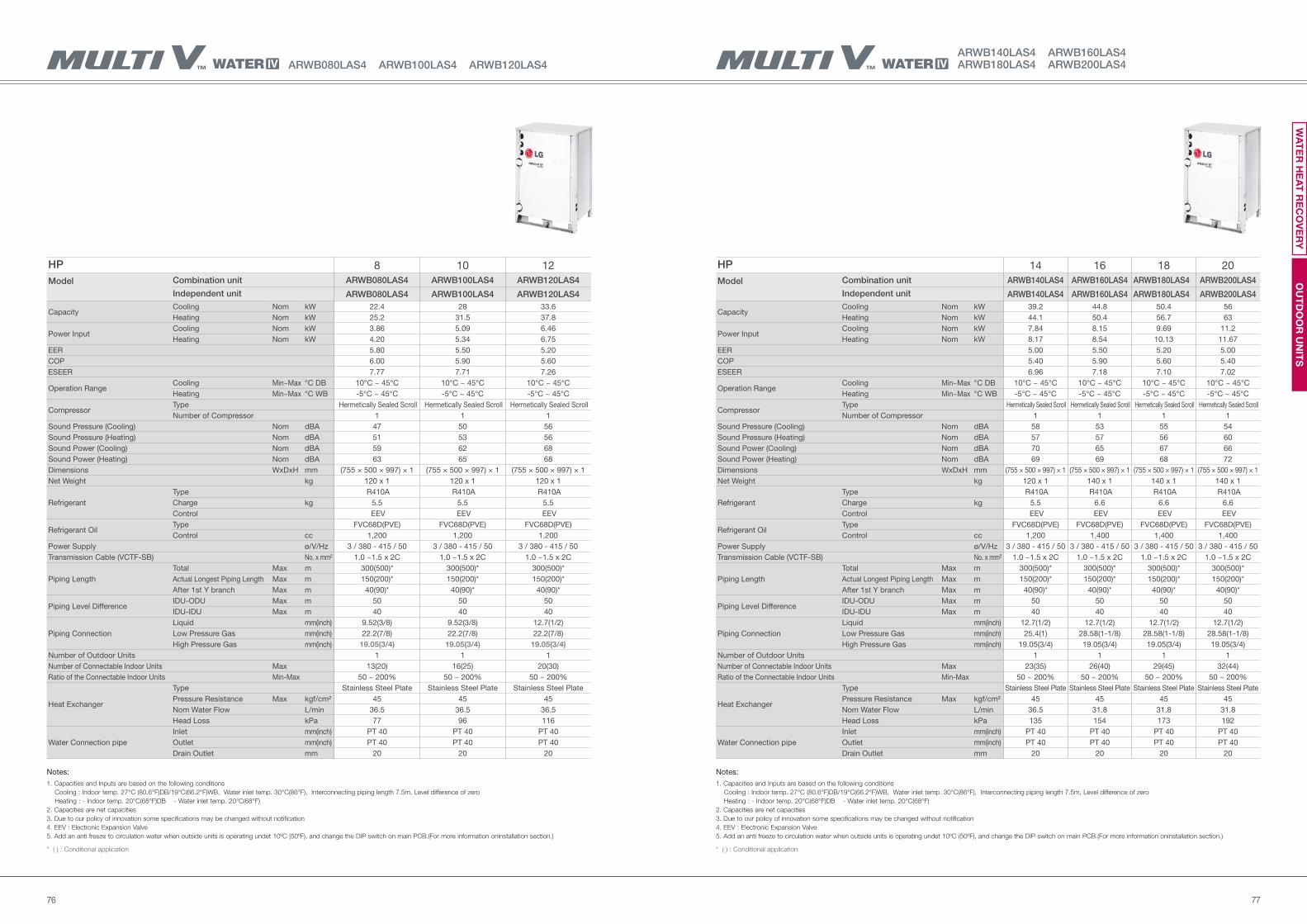
7776
ARWB140LAS4 ARWB160LAS4ARWB180LAS4 ARWB200LAS4
HP 8 10 12
Model Combination unit ARWB080LAS4 ARWB100LAS4 ARWB120LAS4
Independent unit ARWB080LAS4 ARWB100LAS4 ARWB120LAS4
Capacity Cooling Nom kW 22.4 28 33.6
Heating Nom kW 25.2 31.5 37.8
Power Input Cooling Nom kW 3.86 5.09 6.46
Heating Nom kW 4.20 5.34 6.75
EER 5.80 5.50 5.20
COP 6.00 5.90 5.60
ESEER 7.77 7.71 7.26
Operation RangeCooling Min~Max °C DB 10°C ~ 45°C 10°C ~ 45°C 10°C ~ 45°C
Heating Min~Max °C WB -5°C ~ 45°C -5°C ~ 45°C -5°C ~ 45°C
Compressor Type Hermetically Sealed Scroll Hermetically Sealed Scroll Hermetically Sealed Scroll
Number of Compressor 1 1 1
Sound Pressure (Cooling) Nom dBA 47 50 56
Sound Pressure (Heating) Nom dBA 51 53 56
Sound Power (Cooling) Nom dBA 59 62 68
Sound Power (Heating) Nom dBA 63 65 68
Dimensions WxDxH mm (755 × 500 × 997) × 1 (755 × 500 × 997) × 1 (755 × 500 × 997) × 1
Net Weight kg 120 x 1 120 x 1 120 x 1
Refrigerant
Type R410A R410A R410A
Charge kg 5.5 5.5 5.5
Control EEV EEV EEV
Refrigerant OilType FVC68D(PVE) FVC68D(PVE) FVC68D(PVE)
Control cc 1,200 1,200 1,200
Power Supply ø/V/Hz 3 / 380 - 415 / 50 3 / 380 - 415 / 50 3 / 380 - 415 / 50
Transmission Cable (VCTF-SB) No. x mm² 1.0 ~1.5 x 2C 1.0 ~1.5 x 2C 1.0 ~1.5 x 2C
Piping Length
Total Max m 300(500)* 300(500)* 300(500)*
Actual Longest Piping Length Max m 150(200)* 150(200)* 150(200)*
After 1st Y branch Max m 40(90)* 40(90)* 40(90)*
Piping Level DifferenceIDU-ODU Max m 50 50 50
IDU-IDU Max m 40 40 40
Piping Connection
Liquid mm(inch) 9.52(3/8) 9.52(3/8) 12.7(1/2)
Low Pressure Gas mm(inch) 22.2(7/8) 22.2(7/8) 22.2(7/8)
High Pressure Gas mm(inch) 19.05(3/4) 19.05(3/4) 19.05(3/4)
Number of Outdoor Units 1 1 1
Number of Connectable Indoor Units Max 13(20) 16(25) 20(30)
Ratio of the Connectable Indoor Units Min-Max 50 ~ 200% 50 ~ 200% 50 ~ 200%
Heat Exchanger
Type Stainless Steel Plate Stainless Steel Plate Stainless Steel Plate
Pressure Resistance Max kgf/cm² 45 45 45
Nom Water Flow L/min 36.5 36.5 36.5
Head Loss kPa 77 96 116
Water Connection pipe
Inlet mm(inch) PT 40 PT 40 PT 40
Outlet mm(inch) PT 40 PT 40 PT 40
Drain Outlet mm 20 20 20
HP 14 16 18 20
Model Combination unit ARWB140LAS4 ARWB160LAS4 ARWB180LAS4 ARWB200LAS4
Independent unit ARWB140LAS4 ARWB160LAS4 ARWB180LAS4 ARWB200LAS4
Capacity Cooling Nom kW 39.2 44.8 50.4 56
Heating Nom kW 44.1 50.4 56.7 63
Power Input Cooling Nom kW 7.84 8.15 9.69 11.2
Heating Nom kW 8.17 8.54 10.13 11.67
EER 5.00 5.50 5.20 5.00
COP 5.40 5.90 5.60 5.40
ESEER 6.96 7.18 7.10 7.02
Operation RangeCooling Min~Max °C DB 10°C ~ 45°C 10°C ~ 45°C 10°C ~ 45°C 10°C ~ 45°C
Heating Min~Max °C WB -5°C ~ 45°C -5°C ~ 45°C -5°C ~ 45°C -5°C ~ 45°C
Compressor Type Hermetically Sealed Scroll Hermetically Sealed Scroll Hermetically Sealed Scroll Hermetically Sealed Scroll
Number of Compressor 1 1 1 1
Sound Pressure (Cooling) Nom dBA 58 53 55 54
Sound Pressure (Heating) Nom dBA 57 57 56 60
Sound Power (Cooling) Nom dBA 70 65 67 66
Sound Power (Heating) Nom dBA 69 69 68 72
Dimensions WxDxH mm (755 × 500 × 997) × 1 (755 × 500 × 997) × 1 (755 × 500 × 997) × 1 (755 × 500 × 997) × 1
Net Weight kg 120 x 1 140 x 1 140 x 1 140 x 1
Refrigerant
Type R410A R410A R410A R410A
Charge kg 5.5 6.6 6.6 6.6
Control EEV EEV EEV EEV
Refrigerant OilType FVC68D(PVE) FVC68D(PVE) FVC68D(PVE) FVC68D(PVE)
Control cc 1,200 1,400 1,400 1,400
Power Supply ø/V/Hz 3 / 380 - 415 / 50 3 / 380 - 415 / 50 3 / 380 - 415 / 50 3 / 380 - 415 / 50
Transmission Cable (VCTF-SB) No. x mm² 1.0 ~1.5 x 2C 1.0 ~1.5 x 2C 1.0 ~1.5 x 2C 1.0 ~1.5 x 2C
Piping Length
Total Max m 300(500)* 300(500)* 300(500)* 300(500)*
Actual Longest Piping Length Max m 150(200)* 150(200)* 150(200)* 150(200)*
After 1st Y branch Max m 40(90)* 40(90)* 40(90)* 40(90)*
Piping Level DifferenceIDU-ODU Max m 50 50 50 50
IDU-IDU Max m 40 40 40 40
Piping Connection
Liquid mm(inch) 12.7(1/2) 12.7(1/2) 12.7(1/2) 12.7(1/2)
Low Pressure Gas mm(inch) 25.4(1) 28.58(1-1/8) 28.58(1-1/8) 28.58(1-1/8)
High Pressure Gas mm(inch) 19.05(3/4) 19.05(3/4) 19.05(3/4) 19.05(3/4)
Number of Outdoor Units 1 1 1 1
Number of Connectable Indoor Units Max 23(35) 26(40) 29(45) 32(44)
Ratio of the Connectable Indoor Units Min-Max 50 ~ 200% 50 ~ 200% 50 ~ 200% 50 ~ 200%
Heat Exchanger
Type Stainless Steel Plate Stainless Steel Plate Stainless Steel Plate Stainless Steel Plate
Pressure Resistance Max kgf/cm² 45 45 45 45
Nom Water Flow L/min 36.5 31.8 31.8 31.8
Head Loss kPa 135 154 173 192
Water Connection pipe
Inlet mm(inch) PT 40 PT 40 PT 40 PT 40
Outlet mm(inch) PT 40 PT 40 PT 40 PT 40
Drain Outlet mm 20 20 20 20
Notes:
1. Capacities and Inputs are based on the following conditions
Cooling : Indoor temp. 27°C (80.6°F)DB/19°C(66.2°F)WB, Water inlet temp. 30°C(86°F), Interconnecting piping length 7.5m, Level difference of zero
Heating : - Indoor temp. 20°C(68°F)DB - Water inlet temp. 20°C(68°F)
2. Capacities are net capacities
3. Due to our policy of innovation some specifications may be changed without notification
4. EEV : Electronic Expansion Valve
5. Add an anti freeze to circulation water when outside units is operating undet 10ºC (50ºF), and change the DIP switch on main PCB.(For more information oninstallation section.)
* ( ) : Conditional application
OU
TD
OO
R U
NIT
SW
AT
ER
HE
AT
RE
CO
VE
RY
ARWB080LAS4 ARWB100LAS4 ARWB120LAS4
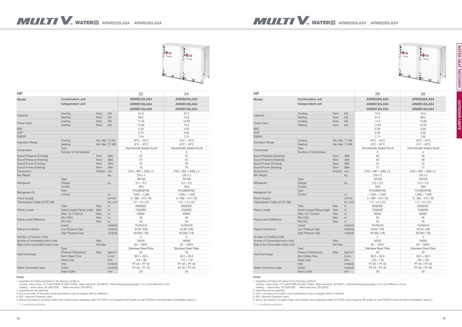
7978
ARWB260LAS4 ARWB280LAS4
HP 26 28
Model Combination unit ARWB260LAS4 ARWB280LAS4
Independent unit ARWB120LAS4 ARWB140LAS4
ARWB140LAS4 ARWB140LAS4
Capacity Cooling Nom kW 72.8 78.4
Heating Nom kW 81.9 88.2
Power Input Cooling Nom kW 14.3 15.68
Heating Nom kW 14.92 16.34
EER 5.09 5.00
COP 5.49 5.40
ESEER 7.11 7.02
Operation RangeCooling Min~Max °C DB 10°C ~ 45°C 10°C ~ 45°C
Heating Min~Max °C WB -5°C ~ 45°C -5°C ~ 45°C
Compressor Type Hermetically Sealed Scroll Hermetically Sealed Scroll
Number of Compressor 2 2
Sound Pressure (Cooling) Nom dBA 59 59
Sound Pressure (Heating) Nom dBA 58 58
Sound Power (Cooling) Nom dBA 72 72
Sound Power (Heating) Nom dBA 71 71
Dimensions WxDxH mm (755 × 997 × 500) x 2 (755 × 997 × 500) x 2
Net Weight kg 120 x 2 120 x 2
Refrigerant
Type R410A R410A
Charge kg 5.5 + 5.5 5.5 + 5.5
Control EEV EEV
Refrigerant OilType FVC68D(PVE) FVC68D(PVE)
Control cc 1,200 + 1,200 1,200 + 1,200
Power Supply ø/V/Hz 3 / 380 - 415 / 50 3 / 380 - 415 / 50
Transmission Cable (VCTF-SB) No. x mm² 1.0 ~1.5 x 2C 1.0 ~1.5 x 2C
Piping Length
Total Max m 300(500)* 300(500)*
Actual Longest Piping Length Max m 150(200)* 150(200)*
After 1st Y branch Max m 40(90)* 40(90)*
Piping Level DifferenceIDU-ODU Max m 50 50
IDU-IDU Max m 40 40
Piping Connection
Liquid mm(inch) 19.05(3/4) 19.05(3/4)
Low Pressure Gas mm(inch) 34.9(1-3/8) 34.9(1-3/8)
High Pressure Gas mm(inch) 28.58(1-1/8) 28.58(1-1/8)
Number of Outdoor Units 2 2
Number of Connectable Indoor Units Max 42(52) 45(56)
Ratio of the Connectable Indoor Units Min-Max 50 ~ 160% 50 ~ 160%
Heat Exchanger
Type Stainless Steel Plate Stainless Steel Plate
Pressure Resistance Max kgf/cm² 45 45
Nom Water Flow L/min 36.5 + 36.5 36.5 + 36.5
Head Loss kPa 135 + 116 135 + 135
Water Connection pipe
Inlet mm(inch) PT 40 + PT 40 PT 40 + PT 40
Outlet mm(inch) PT 40 + PT 40 PT 40 + PT 40
Drain Outlet mm 20 20
HP 22 24
Model Combination unit ARWB220LAS4 ARWB240LAS4
Independent unit ARWB100LAS4 ARWB120LAS4
ARWB120LAS4 ARWB120LAS4
Capacity Cooling Nom kW 61.6 67.2
Heating Nom kW 69.3 75.6
Power Input Cooling Nom kW 11.55 12.92
Heating Nom kW 12.09 13.5
EER 5.33 5.20
COP 5.73 5.60
ESEER 7.34 7.21
Operation RangeCooling Min~Max °C DB 10°C ~ 45°C 10°C ~ 45°C
Heating Min~Max °C WB -5°C ~ 45°C -5°C ~ 45°C
Compressor Type Hermetically Sealed Scroll Hermetically Sealed Scroll
Number of Compressor 1 2
Sound Pressure (Cooling) Nom dBA 57 57
Sound Pressure (Heating) Nom dBA 57 57
Sound Power (Cooling) Nom dBA 70 70
Sound Power (Heating) Nom dBA 70 70
Dimensions WxDxH mm (755 × 997 × 500) x 2 (755 × 997 × 500) x 2
Net Weight kg 120 x 2 120 x 2
Refrigerant
Type R410A R410A
Charge kg 5.5 + 5.5 5.5 + 5.5
Control EEV EEV
Refrigerant OilType FVC68D(PVE) FVC68D(PVE)
Control cc 1,200 + 1,200 1,200 + 1,200
Power Supply ø/V/Hz 3 / 380 - 415 / 50 3 / 380 - 415 / 50
Transmission Cable (VCTF-SB) No. x mm² 1.0 ~1.5 x 2C 1.0 ~1.5 x 2C
Piping Length
Total Max m 300(500)* 300(500)*
Actual Longest Piping Length Max m 150(200)* 150(200)*
After 1st Y branch Max m 40(90)* 40(90)*
Piping Level DifferenceIDU-ODU Max m 50 50
IDU-IDU Max m 40 40
Piping Connection
Liquid mm(inch) 19.05(3/4) 19.05(3/4)
Low Pressure Gas mm(inch) 34.9(1-3/8) 34.9(1-3/8)
High Pressure Gas mm(inch) 28.58(1-1/8) 28.58(1-1/8)
Number of Outdoor Units 2 2
Number of Connectable Indoor Units Max 35(44) 39(48)
Ratio of the Connectable Indoor Units Min-Max 50 ~ 160% 50 ~ 160%
Heat Exchanger
Type Stainless Steel Plate Stainless Steel Plate
Pressure Resistance Max kgf/cm² 45 45
Nom Water Flow L/min 36.5 + 36.5 36.5 + 36.5
Head Loss kPa 116 + 96 116 + 116
Water Connection pipe
Inlet mm(inch) PT 40 + PT 40 PT 40 + PT 40
Outlet mm(inch) PT 40 + PT 40 PT 40 + PT 40
Drain Outlet mm 20 20
Notes:
1. Capacities and Inputs are based on the following conditions
Cooling : Indoor temp. 27°C (80.6°F)DB/19°C(66.2°F)WB, Water inlet temp. 30°C(86°F), Interconnecting piping length 7.5m, Level difference of zero
Heating : - Indoor temp. 20°C(68°F)DB - Water inlet temp. 20°C(68°F)
2. Capacities are net capacities
3. Due to our policy of innovation some specifications may be changed without notification
4. EEV : Electronic Expansion Valve
5. Add an anti freeze to circulation water when outside units is operating undet 10ºC (50ºF), and change the DIP switch on main PCB.(For more information oninstallation section.)
* ( ) : Conditional application
Notes:
1. Capacities and Inputs are based on the following conditions
Cooling : Indoor temp. 27°C (80.6°F)DB/19°C(66.2°F)WB, Water inlet temp. 30°C(86°F), Interconnecting piping length 7.5m, Level difference of zero
Heating : - Indoor temp. 20°C(68°F)DB - Water inlet temp. 20°C(68°F)
2. Capacities are net capacities
3. Due to our policy of innovation some specifications may be changed without notification
4. EEV : Electronic Expansion Valve
5. Add an anti freeze to circulation water when outside units is operating undet 10ºC (50ºF), and change the DIP switch on main PCB.(For more information oninstallation section.)
* ( ) : Conditional application
OU
TD
OO
R U
NIT
SW
AT
ER
HE
AT
RE
CO
VE
RY
ARWB220LAS4 ARWB240LAS4
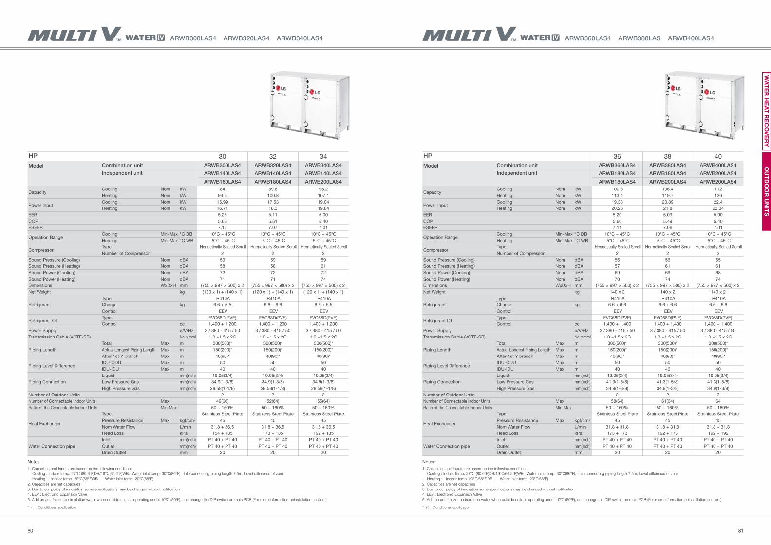
8180
ARWB360LAS4 ARWB380LAS ARWB400LAS4ARWB300LAS4 ARWB320LAS4 ARWB340LAS4
HP 36 38 40
Model Combination unit ARWB360LAS4 ARWB380LAS4 ARWB400LAS4
Independent unit ARWB180LAS4 ARWB180LAS4 ARWB200LAS4
ARWB180LAS4 ARWB200LAS4 ARWB200LAS4
Capacity Cooling Nom kW 100.8 106.4 112
Heating Nom kW 113.4 119.7 126
Power Input Cooling Nom kW 19.38 20.89 22.4
Heating Nom kW 20.26 21.8 23.34
EER 5.20 5.09 5.00
COP 5.60 5.49 5.40
ESEER 7.11 7.06 7.01
Operation RangeCooling Min~Max °C DB 10°C ~ 45°C 10°C ~ 45°C 10°C ~ 45°C
Heating Min~Max °C WB -5°C ~ 45°C -5°C ~ 45°C -5°C ~ 45°C
Compressor Type Hermetically Sealed Scroll Hermetically Sealed Scroll Hermetically Sealed Scroll
Number of Compressor 2 2 2
Sound Pressure (Cooling) Nom dBA 56 56 55
Sound Pressure (Heating) Nom dBA 57 61 61
Sound Power (Cooling) Nom dBA 69 69 68
Sound Power (Heating) Nom dBA 70 74 74
Dimensions WxDxH mm (755 × 997 × 500) x 2 (755 × 997 × 500) x 2 (755 × 997 × 500) x 2
Net Weight kg 140 x 2 140 x 2 140 x 2
Refrigerant
Type R410A R410A R410A
Charge kg 6.6 + 6.6 6.6 + 6.6 6.6 + 6.6
Control EEV EEV EEV
Refrigerant OilType FVC68D(PVE) FVC68D(PVE) FVC68D(PVE)
Control cc 1,400 + 1,400 1,400 + 1,400 1,400 + 1,400
Power Supply ø/V/Hz 3 / 380 - 415 / 50 3 / 380 - 415 / 50 3 / 380 - 415 / 50
Transmission Cable (VCTF-SB) No. x mm² 1.0 ~1.5 x 2C 1.0 ~1.5 x 2C 1.0 ~1.5 x 2C
Piping Length
Total Max m 300(500)* 300(500)* 300(500)*
Actual Longest Piping Length Max m 150(200)* 150(200)* 150(200)*
After 1st Y branch Max m 40(90)* 40(90)* 40(90)*
Piping Level DifferenceIDU-ODU Max m 50 50 50
IDU-IDU Max m 40 40 40
Piping Connection
Liquid mm(inch) 19.05(3/4) 19.05(3/4) 19.05(3/4)
Low Pressure Gas mm(inch) 41.3(1-5/8) 41.3(1-5/8) 41.3(1-5/8)
High Pressure Gas mm(inch) 34.9(1-3/8) 34.9(1-3/8) 34.9(1-3/8)
Number of Outdoor Units 2 2 2
Number of Connectable Indoor Units Max 58(64) 61(64) 64
Ratio of the Connectable Indoor Units Min-Max 50 ~ 160% 50 ~ 160% 50 ~ 160%
Heat Exchanger
Type Stainless Steel Plate Stainless Steel Plate Stainless Steel Plate
Pressure Resistance Max kgf/cm² 45 45 45
Nom Water Flow L/min 31.8 + 31.8 31.8 + 31.8 31.8 + 31.8
Head Loss kPa 173 + 173 192 + 173 192 + 192
Water Connection pipe
Inlet mm(inch) PT 40 + PT 40 PT 40 + PT 40 PT 40 + PT 40
Outlet mm(inch) PT 40 + PT 40 PT 40 + PT 40 PT 40 + PT 40
Drain Outlet mm 20 20 20
HP 30 32 34
Model Combination unit ARWB300LAS4 ARWB320LAS4 ARWB340LAS4
Independent unit ARWB140LAS4 ARWB140LAS4 ARWB140LAS4
ARWB160LAS4 ARWB180LAS4 ARWB200LAS4
Capacity Cooling Nom kW 84 89.6 95.2
Heating Nom kW 94.5 100.8 107.1
Power Input Cooling Nom kW 15.99 17.53 19.04
Heating Nom kW 16.71 18.3 19.84
EER 5.25 5.11 5.00
COP 5.66 5.51 5.40
ESEER 7.12 7.07 7.01
Operation RangeCooling Min~Max °C DB 10°C ~ 45°C 10°C ~ 45°C 10°C ~ 45°C
Heating Min~Max °C WB -5°C ~ 45°C -5°C ~ 45°C -5°C ~ 45°C
Compressor Type Hermetically Sealed Scroll Hermetically Sealed Scroll Hermetically Sealed Scroll
Number of Compressor 2 2 2
Sound Pressure (Cooling) Nom dBA 59 59 59
Sound Pressure (Heating) Nom dBA 58 58 61
Sound Power (Cooling) Nom dBA 72 72 72
Sound Power (Heating) Nom dBA 71 71 74
Dimensions WxDxH mm (755 × 997 × 500) x 2 (755 × 997 × 500) x 2 (755 × 997 × 500) x 2
Net Weight kg (120 x 1) + (140 x 1) (120 x 1) + (140 x 1) (120 x 1) + (140 x 1)
Refrigerant
Type R410A R410A R410A
Charge kg 6.6 + 5.5 6.6 + 6.6 6.6 + 5.5
Control EEV EEV EEV
Refrigerant OilType FVC68D(PVE) FVC68D(PVE) FVC68D(PVE)
Control cc 1,400 + 1,200 1,400 + 1,200 1,400 + 1,200
Power Supply ø/V/Hz 3 / 380 - 415 / 50 3 / 380 - 415 / 50 3 / 380 - 415 / 50
Transmission Cable (VCTF-SB) No. x mm² 1.0 ~1.5 x 2C 1.0 ~1.5 x 2C 1.0 ~1.5 x 2C
Piping Length
Total Max m 300(500)* 300(500)* 300(500)*
Actual Longest Piping Length Max m 150(200)* 150(200)* 150(200)*
After 1st Y branch Max m 40(90)* 40(90)* 40(90)*
Piping Level DifferenceIDU-ODU Max m 50 50 50
IDU-IDU Max m 40 40 40
Piping Connection
Liquid mm(inch) 19.05(3/4) 19.05(3/4) 19.05(3/4)
Low Pressure Gas mm(inch) 34.9(1-3/8) 34.9(1-3/8) 34.9(1-3/8)
High Pressure Gas mm(inch) 28.58(1-1/8) 28.58(1-1/8) 28.58(1-1/8)
Number of Outdoor Units 2 2 2
Number of Connectable Indoor Units Max 49(60) 52(64) 55(64)
Ratio of the Connectable Indoor Units Min-Max 50 ~ 160% 50 ~ 160% 50 ~ 160%
Heat Exchanger
Type Stainless Steel Plate Stainless Steel Plate Stainless Steel Plate
Pressure Resistance Max kgf/cm² 45 45 45
Nom Water Flow L/min 31.8 + 36.5 31.8 + 36.5 31.8 + 36.5
Head Loss kPa 154 + 135 173 + 135 192 + 135
Water Connection pipe
Inlet mm(inch) PT 40 + PT 40 PT 40 + PT 40 PT 40 + PT 40
Outlet mm(inch) PT 40 + PT 40 PT 40 + PT 40 PT 40 + PT 40
Drain Outlet mm 20 20 20
Notes:
1. Capacities and Inputs are based on the following conditions
Cooling : Indoor temp. 27°C (80.6°F)DB/19°C(66.2°F)WB, Water inlet temp. 30°C(86°F), Interconnecting piping length 7.5m, Level difference of zero
Heating : - Indoor temp. 20°C(68°F)DB - Water inlet temp. 20°C(68°F)
2. Capacities are net capacities
3. Due to our policy of innovation some specifications may be changed without notification
4. EEV : Electronic Expansion Valve
5. Add an anti freeze to circulation water when outside units is operating undet 10ºC (50ºF), and change the DIP switch on main PCB.(For more information oninstallation section.)
* ( ) : Conditional application
Notes:
1. Capacities and Inputs are based on the following conditions
Cooling : Indoor temp. 27°C (80.6°F)DB/19°C(66.2°F)WB, Water inlet temp. 30°C(86°F), Interconnecting piping length 7.5m, Level difference of zero
Heating : - Indoor temp. 20°C(68°F)DB - Water inlet temp. 20°C(68°F)
2. Capacities are net capacities
3. Due to our policy of innovation some specifications may be changed without notification
4. EEV : Electronic Expansion Valve
5. Add an anti freeze to circulation water when outside units is operating undet 10ºC (50ºF), and change the DIP switch on main PCB.(For more information oninstallation section.)
* ( ) : Conditional application
OU
TD
OO
R U
NIT
SW
AT
ER
HE
AT
RE
CO
VE
RY
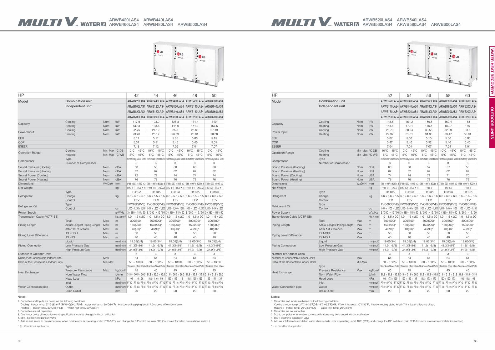
8382
ARWB520LAS4 ARWB540LAS4ARWB560LAS4 ARWB580LAS4 ARWB600LAS4
ARWB420LAS4 ARWB440LAS4ARWB460LAS4 ARWB480LAS4 ARWB500LAS4
HP 52 54 56 58 60
Model Combination unit ARWB520LAS4 ARWB540LAS4 ARWB560LAS4 ARWB580LAS4 ARWB600LAS4
Independent unit ARWB140LAS4 ARWB140LAS4 ARWB180LAS4 ARWB180LAS4 ARWB200LAS4
ARWB180LAS4 ARWB200LAS4 ARWB180LAS4 ARWB200LAS4 ARWB200LAS4
ARWB200LAS4 ARWB200LAS4 ARWB200LAS4 ARWB200LAS4 ARWB200LAS4
Capacity Cooling Nom kW 145.6 151.2 156.8 162.4 168
Heating Nom kW 163.8 170.1 176.4 182.7 189
Power Input Cooling Nom kW 28.73 30.24 30.58 32.09 33.6
Heating Nom kW 29.97 31.51 31.93 33.47 35.01
EER 5.07 5.00 5.13 5.06 5.00
COP 5.47 5.40 5.52 5.46 5.40
ESEER 7.04 7.01 7.07 7.04 7.01
Operation RangeCooling Min~Max °C DB 10°C ~ 45°C 10°C ~ 45°C 10°C ~ 45°C 10°C ~ 45°C 10°C ~ 45°C
Heating Min~Max °C WB -5°C ~ 45°C -5°C ~ 45°C -5°C ~ 45°C -5°C ~ 45°C -5°C ~ 45°C
Compressor Type Hermetically Sealed Scroll Hermetically Sealed Scroll Hermetically Sealed Scroll Hermetically Sealed Scroll Hermetically Sealed Scroll
Number of Compressor 3 3 3 3 3
Sound Pressure (Cooling) Nom dBA 60 60 57 57 56
Sound Pressure (Heating) Nom dBA 62 62 62 62 62
Sound Power (Cooling) Nom dBA 74 74 71 71 70
Sound Power (Heating) Nom dBA 76 76 76 76 76
Dimensions WxDxH mm (755 × 997 × 500) x 3 (755 × 997 × 500) x 3 (755 × 997 × 500) x 3 (755 × 997 × 500) x 3 (755 × 997 × 500) x 3
Net Weight kg (140 x 2) + (120 X 1) (140 x 2) + (120 X 1) 140 x 3 140 x 3 140 x 3
Refrigerant
Type R410A R410A R410A R410A R410A
Charge kg 6.6 + 6.6 + 5.5 6.6 + 6.6 + 5.5 6.6 + 6.6 + 6.6 6.6 + 6.6 + 6.6 6.6 + 6.6 + 6.6
Control EEV EEV EEV EEV EEV
Refrigerant OilType FVC68D(PVE) FVC68D(PVE) FVC68D(PVE) FVC68D(PVE) FVC68D(PVE)
Control cc 1,400 + 1,400 + 1,200 1,400 + 1,400 + 1,200 1,400 + 1,400 + 1,400 1,400 + 1,400 + 1,400 1,400 + 1,400 + 1,400
Power Supply ø/V/Hz 3 / 380 - 415 / 50 3 / 380 - 415 / 50 3 / 380 - 415 / 50 3 / 380 - 415 / 50 3 / 380 - 415 / 50
Transmission Cable (VCTF-SB) No. x mm² 1.0 ~1.5 x 2C 1.0 ~1.5 x 2C 1.0 ~1.5 x 2C 1.0 ~1.5 x 2C 1.0 ~1.5 x 2C
Piping Length
Total Max m 300(500)* 300(500)* 300(500)* 300(500)* 300(500)*
Actual Longest Piping Length Max m 150(200)* 150(200)* 150(200)* 150(200)* 150(200)*
After 1st Y branch Max m 40(90)* 40(90)* 40(90)* 40(90)* 40(90)*
Piping Level DifferenceIDU-ODU Max m 50 50 50 50 50
IDU-IDU Max m 40 40 40 40 40
Piping Connection
Liquid mm(inch) 19.05(3/4) 19.05(3/4) 19.05(3/4) 19.05(3/4) 19.05(3/4)
Low Pressure Gas mm(inch) 41.3(1-5/8) 41.3(1-5/8) 41.3(1-5/8) 41.3(1-5/8) 41.3(1-5/8)
High Pressure Gas mm(inch) 34.9(1-3/8) 34.9(1-3/8) 34.9(1-3/8) 34.9(1-3/8) 34.9(1-3/8)
Number of Outdoor Units 3 3 3 3 3
Number of Connectable Indoor Units Max 64 64 64 64 64
Ratio of the Connectable Indoor Units Min-Max 50 ~ 130% 50 ~ 130% 50 ~ 130% 50 ~ 130% 50 ~ 130%
Heat Exchanger
Type Stainless Steel Plate Stainless Steel Plate Stainless Steel Plate Stainless Steel Plate Stainless Steel Plate
Pressure Resistance Max kgf/cm² 45 45 45 45 45
Nom Water Flow L/min 31.8 + 31.8 + 36.5 31.8 + 31.8 + 36.5 31.8 + 31.8 + 31.8 31.8 + 31.8 + 31.8 31.8 + 31.8 + 31.8
Head Loss kPa 192 + 173 + 135 192 + 192 + 135 192 + 173 + 173 192 + 192+ 173 192 + 192+ 192
Water Connection pipe
Inlet mm(inch) PT 40 + PT 40 + PT 40 PT 40 + PT 40 + PT 40 PT 40 + PT 40 + PT 40 PT 40 + PT 40 + PT 40 PT 40 + PT 40 + PT 40
Outlet mm(inch) PT 40 + PT 40 + PT 40 PT 40 + PT 40 + PT 40 PT 40 + PT 40 + PT 40 PT 40 + PT 40 + PT 40 PT 40 + PT 40 + PT 40
Drain Outlet mm 20 20 20 20 20
HP 42 44 46 48 50
Model Combination unit ARWB420LAS4 ARWB440LAS4 ARWB460LAS4 ARWB480LAS4 ARWB500LAS4
Independent unit ARWB100LAS4 ARWB120LAS4 ARWB120LAS4 ARWB140LAS4 ARWB140LAS4
ARWB120LAS4 ARWB120LAS4 ARWB140LAS4 ARWB140LAS4 ARWB160LAS4
ARWB200LAS4 ARWB200LAS4 ARWB200LAS4 ARWB200LAS4 ARWB200LAS4
Capacity Cooling Nom kW 117.6 123.2 128.8 134.4 140
Heating Nom kW 132.3 138.6 144.9 151.2 157.5
Power Input Cooling Nom kW 22.75 24.12 25.5 26.88 27.19
Heating Nom kW 23.76 25.17 26.59 28.01 28.38
EER 5.17 5.11 5.05 5.00 5.15
COP 5.57 5.51 5.45 5.40 5.55
ESEER 7.18 7.12 7.06 7.01 7.07
Operation RangeCooling Min~Max °C DB 10°C ~ 45°C 10°C ~ 45°C 10°C ~ 45°C 10°C ~ 45°C 10°C ~ 45°C
Heating Min~Max °C WB -5°C ~ 45°C -5°C ~ 45°C -5°C ~ 45°C -5°C ~ 45°C -5°C ~ 45°C
Compressor Type Hermetically Sealed Scroll Hermetically Sealed Scroll Hermetically Sealed Scroll Hermetically Sealed Scroll Hermetically Sealed Scroll
Number of Compressor 3 3 3 3 3
Sound Pressure (Cooling) Nom dBA 58 58 60 60 60
Sound Pressure (Heating) Nom dBA 62 62 62 62 62
Sound Power (Cooling) Nom dBA 72 72 74 74 74
Sound Power (Heating) Nom dBA 76 76 76 76 76
Dimensions WxDxH mm (755 × 997 × 500) x 3 (755 × 997 × 500) x 3 (755 × 997 × 500) x 3 (755 × 997 × 500) x 3 (755 × 997 × 500) x 3
Net Weight kg (140 x 1) + (120 X 2) (140 x 1) + (120 X 2) (140 x 1) + (120 X 2) (140 x 1) + (120 X 2) (140 x 2) + (120 X 1)
Refrigerant
Type R410A R410A R410A R410A R410A
Charge kg 6.6 + 5.5 + 5.5 6.6 + 5.5 + 5.5 6.6 + 5.5 + 5.5 6.6 + 5.5 + 5.5 6.6 + 6.6 + 5.5
Control EEV EEV EEV EEV EEV
Refrigerant OilType FVC68D(PVE) FVC68D(PVE) FVC68D(PVE) FVC68D(PVE) FVC68D(PVE)
Control cc 1,400 + 1,200 + 1,200 1,400 + 1,200 + 1,200 1,400 + 1,200 + 1,200 1,400 + 1,200 + 1,200 1,400 + 1,400 + 1,200
Power Supply ø/V/Hz 3 / 380 - 415 / 50 3 / 380 - 415 / 50 3 / 380 - 415 / 50 3 / 380 - 415 / 50 3 / 380 - 415 / 50
Transmission Cable (VCTF-SB) No. x mm² 1.0 ~1.5 x 2C 1.0 ~1.5 x 2C 1.0 ~1.5 x 2C 1.0 ~1.5 x 2C 1.0 ~1.5 x 2C
Piping Length
Total Max m 300(500)* 300(500)* 300(500)* 300(500)* 300(500)*
Actual Longest Piping Length Max m 150(200)* 150(200)* 150(200)* 150(200)* 150(200)*
After 1st Y branch Max m 40(90)* 40(90)* 40(90)* 40(90)* 40(90)*
Piping Level DifferenceIDU-ODU Max m 50 50 50 50 50
IDU-IDU Max m 40 40 40 40 40
Piping Connection
Liquid mm(inch) 19.05(3/4) 19.05(3/4) 19.05(3/4) 19.05(3/4) 19.05(3/4)
Low Pressure Gas mm(inch) 41.3(1-5/8) 41.3(1-5/8) 41.3(1-5/8) 41.3(1-5/8) 41.3(1-5/8)
High Pressure Gas mm(inch) 34.9(1-3/8) 34.9(1-3/8) 34.9(1-3/8) 34.9(1-3/8) 34.9(1-3/8)
Number of Outdoor Units 3 3 3 3 3
Number of Connectable Indoor Units Max 64 64 64 64 64
Ratio of the Connectable Indoor Units Min-Max 50 ~ 130% 50 ~ 130% 50 ~ 130% 50 ~ 130% 50 ~ 130%
Heat Exchanger
Type Stainless Steel Plate Stainless Steel Plate Stainless Steel Plate Stainless Steel Plate Stainless Steel Plate
Pressure Resistance Max kgf/cm² 45 45 45 45 45
Nom Water Flow L/min 31.8 + 36.5 + 36.5 31.8 + 36.5 + 36.5 31.8 + 36.5 + 36.5 31.8 + 36.5 + 36.5 31.8 + 31.8 + 36.5
Head Loss kPa 192 + 116 + 96 192 + 116 + 116 192 + 135 + 116 192 + 135 + 135 192 + 154 + 135
Water Connection pipe
Inlet mm(inch) PT 40 + PT 40 + PT 40 PT 40 + PT 40 + PT 40 PT 40 + PT 40 + PT 40 PT 40 + PT 40 + PT 40 PT 40 + PT 40 + PT 40
Outlet mm(inch) PT 40 + PT 40 + PT 40 PT 40 + PT 40 + PT 40 PT 40 + PT 40 + PT 40 PT 40 + PT 40 + PT 40 PT 40 + PT 40 + PT 40
Drain Outlet mm 20 20 20 20 20
Notes:
1. Capacities and Inputs are based on the following conditions
Cooling : Indoor temp. 27°C (80.6°F)DB/19°C(66.2°F)WB, Water inlet temp. 30°C(86°F), Interconnecting piping length 7.5m, Level difference of zero
Heating : - Indoor temp. 20°C(68°F)DB - Water inlet temp. 20°C(68°F)
2. Capacities are net capacities
3. Due to our policy of innovation some specifications may be changed without notification
4. EEV : Electronic Expansion Valve
5. Add an anti freeze to circulation water when outside units is operating undet 10ºC (50ºF), and change the DIP switch on main PCB.(For more information oninstallation section.)
* ( ) : Conditional application
Notes:
1. Capacities and Inputs are based on the following conditions
Cooling : Indoor temp. 27°C (80.6°F)DB/19°C(66.2°F)WB, Water inlet temp. 30°C(86°F), Interconnecting piping length 7.5m, Level difference of zero
Heating : - Indoor temp. 20°C(68°F)DB - Water inlet temp. 20°C(68°F)
2. Capacities are net capacities
3. Due to our policy of innovation some specifications may be changed without notification
4. EEV : Electronic Expansion Valve
5. Add an anti freeze to circulation water when outside units is operating undet 10ºC (50ºF), and change the DIP switch on main PCB.(For more information oninstallation section.)
* ( ) : Conditional application
OU
TD
OO
R U
NIT
SW
AT
ER
HE
AT
RE
CO
VE
RY
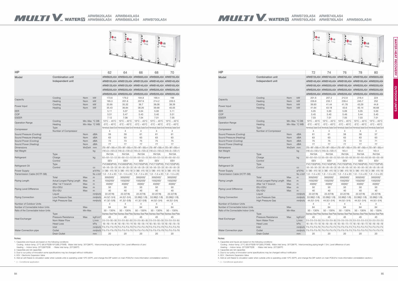
8584
ARWB620LAS4 ARWB640LAS4ARWB660LAS4 ARWB680LAS4 ARWB700LAS4
HP 72 74 76 78 80
Model Combination unit ARWB720LAS4 ARWB740LAS4 ARWB760LAS4 ARWB780LAS4 ARWB800LAS4
Independent unit ARWB140LAS4 ARWB140LAS4 ARWB180LAS4 ARWB180LAS4 ARWB200LAS4
ARWB180LAS4 ARWB200LAS4 ARWB180LAS4 ARWB200LAS4 ARWB200LAS4
ARWB200LAS4 ARWB200LAS4 ARWB200LAS4 ARWB200LAS4 ARWB200LAS4
ARWB200LAS4 ARWB200LAS4 ARWB200LAS4 ARWB200LAS4 ARWB200LAS4
Capacity Cooling Nom kW 201.6 207.2 212.8 218.4 224
Heating Nom kW 226.8 233.1 239.4 245.7 252
Power Input Cooling Nom kW 39.93 41.44 41.78 43.29 44.8
Heating Nom kW 41.64 43.18 43.6 45.14 46.68
EER 5.05 5.00 5.09 5.05 5.00
COP 5.45 5.40 5.49 5.44 5.40
ESEER 7.03 7.01 7.05 7.03 7.01
Operation RangeCooling Min~Max °C DB 10°C ~ 45°C 10°C ~ 45°C 10°C ~ 45°C 10°C ~ 45°C 10°C ~ 45°C
Heating Min~Max °C WB -5°C ~ 45°C -5°C ~ 45°C -5°C ~ 45°C -5°C ~ 45°C -5°C ~ 45°C
Compressor Type Hermetically Sealed Scroll Hermetically Sealed Scroll Hermetically Sealed Scroll Hermetically Sealed Scroll Hermetically Sealed Scroll
Number of Compressor 4 4 4 4 4
Sound Pressure (Cooling) Nom dBA 61 61 58 58 57
Sound Pressure (Heating) Nom dBA 63 63 63 63 63
Sound Power (Cooling) Nom dBA 75 75 72 72 71
Sound Power (Heating) Nom dBA 77 77 77 77 77
Dimensions WxDxH mm (755 × 997 × 500) x 4 (755 × 997 × 500) x 4 (755 × 997 × 500) x 4 (755 × 997 × 500) x 4 (755 × 997 × 500) x 4
Net Weight kg (140 x 3) + (120 x 1) (140 x 3) + (120 x 1) 140 x 4 140 x 4 140 x 4
Refrigerant
Type R410A R410A R410A R410A R410A
Charge kg 6.6 + 6.6 + 6.6 + 5.5 6.6 + 6.6 + 6.6 + 5.5 6.6 + 6.6 + 6.6 + 6.6 6.6 + 6.6 + 6.6 + 6.6 6.6 + 6.6 + 6.6 + 6.6
Control EEV EEV EEV EEV EEV
Refrigerant OilType FVC73D(PVE) FVC74D(PVE) FVC75D(PVE) FVC76D(PVE) FVC77D(PVE)
Control cc 1,400 + 1,400 + 1,400 + 1,200 1,400 + 1,400 + 1,400 + 1,200 1,400 + 1,400 + 1,400 + 1,400 1,400 + 1,400 + 1,400 + 1,400 1,400 + 1,400 + 1,400 + 1,400
Power Supply ø/V/Hz 3 / 380 - 415 / 50 3 / 380 - 415 / 50 3 / 380 - 415 / 50 3 / 380 - 415 / 50 3 / 380 - 415 / 50
Transmission Cable (VCTF-SB) No. x mm² 1.0 ~1.5 x 2C 1.0 ~1.5 x 2C 1.0 ~1.5 x 2C 1.0 ~1.5 x 2C 1.0 ~1.5 x 2C
Piping Length
Total Max m 300(500)* 300(500)* 300(500)* 300(500)* 300(500)*
Actual Longest Piping Length Max m 150(200)* 150(200)* 150(200)* 150(200)* 150(200)*
After 1st Y branch Max m 40(90)* 40(90)* 40(90)* 40(90)* 40(90)*
Piping Level DifferenceIDU-ODU Max m 50 50 50 50 50
IDU-IDU Max m 40 40 40 40 40
Piping Connection
Liquid mm(inch) 22.2(7/8) 22.2(7/8) 22.2(7/8) 22.2(7/8) 22.2(7/8)
Low Pressure Gas mm(inch) 53.98(2-1/8) 53.98(2-1/8) 53.98(2-1/8) 53.98(2-1/8) 53.98(2-1/8)
High Pressure Gas mm(inch) 44.5(1-3/4) 44.5(1-3/4) 44.5(1-3/4) 44.5(1-3/4) 44.5(1-3/4)
Number of Outdoor Units 4 4 4 4 4
Number of Connectable Indoor Units Max 64 64 64 64 64
Ratio of the Connectable Indoor Units Min-Max 50 ~ 130% 50 ~ 130% 50 ~ 130% 50 ~ 130% 50 ~ 130%
Heat Exchanger
Type Stainless Steel Plate Stainless Steel Plate Stainless Steel Plate Stainless Steel Plate Stainless Steel Plate
Pressure Resistance Max kgf/cm² 45 45 45 45 45
Nom Water Flow L/min 31.8 + 31.8 + 31.8 + 36.5 31.8 + 31.8 + 31.8 + 36.5 31.8 + 31.8 + 31.8 + 31.8 31.8 + 31.8 + 31.8 + 31.8 31.8 + 31.8 + 31.8 + 31.8
Head Loss kPa 192 + 192 + 173 + 135 192 + 192 + 192 + 135 192 + 192 + 173 + 173 192 + 192 + 192 + 173 192 + 192 + 192 + 192
Water Connection pipe
Inlet mm(inch) PT 40 + PT 40 + PT 40 + PT40 PT 40 + PT 40 + PT 40 + PT 40 PT 40 + PT 40 + PT 40 + PT 40 PT 40 + PT 40 + PT 40 + PT 40 PT 40 + PT 40 + PT 40 + PT 40
Outlet mm(inch) PT 40 + PT 40 + PT 40 + PT40 PT 40 + PT 40 + PT 40 + PT 40 PT 40 + PT 40 + PT 40 + PT 40 PT 40 + PT 40 + PT 40 + PT 40 PT 40 + PT 40 + PT 40 + PT 40
Drain Outlet mm 20 20 20 20 20
HP 62 64 66 68 70
Model Combination unit ARWB620LAS4 ARWB640LAS4 ARWB660LAS4 ARWB680LAS4 ARWB700LAS4
Independent unit ARWB100LAS4 ARWB120LAS4 ARWB120LAS4 ARWB140LAS4 ARWB140LAS4
ARWB120LAS4 ARWB120LAS4 ARWB140LAS4 ARWB140LAS4 ARWB160LAS4
ARWB200LAS4 ARWB200LAS4 ARWB200LAS4 ARWB200LAS4 ARWB200LAS4
ARWB200LAS4 ARWB200LAS4 ARWB200LAS4 ARWB200LAS4 ARWB200LAS4
Capacity Cooling Nom kW 173.6 179.2 184.8 190.4 196
Heating Nom kW 195.3 201.6 207.9 214.2 220.5
Power Input Cooling Nom kW 33.95 35.32 36.7 38.08 38.39
Heating Nom kW 35.43 36.84 38.26 39.68 40.05
EER 5.11 5.07 5.04 5.00 5.11
COP 5.51 5.47 5.43 5.40 5.51
ESEER 7.12 7.08 7.04 7.01 7.05
Operation RangeCooling Min~Max °C DB 10°C ~ 45°C 10°C ~ 45°C 10°C ~ 45°C 10°C ~ 45°C 10°C ~ 45°C
Heating Min~Max °C WB -5°C ~ 45°C -5°C ~ 45°C -5°C ~ 45°C -5°C ~ 45°C -5°C ~ 45°C
Compressor Type Hermetically Sealed Scroll Hermetically Sealed Scroll Hermetically Sealed Scroll Hermetically Sealed Scroll Hermetically Sealed Scroll
Number of Compressor 4 4 4 4 4
Sound Pressure (Cooling) Nom dBA 59 59 61 61 61
Sound Pressure (Heating) Nom dBA 63 63 63 63 63
Sound Power (Cooling) Nom dBA 73 73 75 75 75
Sound Power (Heating) Nom dBA 77 77 77 77 77
Dimensions WxDxH mm (755 × 997 × 500) x 4 (755 × 997 × 500) x 4 (755 × 997 × 500) x 4 (755 × 997 × 500) x 4 (755 × 997 × 500) x 4
Net Weight kg (140 x 2) + (120 x 2) (140 x 2) + (120 x 2) (140 x 2) + (120 x 2) (140 x 2) + (120 x 2) (140 x 3) + (120 x 1)
Refrigerant
Type R410A R410A R410A R410A R410A
Charge kg 6.6 + 6.6 + 5.5 + 5.5 6.6 + 6.6 + 5.5 + 5.5 6.6 + 6.6 + 5.5 + 5.5 6.6 + 6.6 + 5.5 + 5.5 6.6 + 6.6 + 6.6 + 5.5
Control EEV EEV EEV EEV EEV
Refrigerant OilType FVC68D(PVE) FVC69D(PVE) FVC70D(PVE) FVC71D(PVE) FVC72D(PVE)
Control cc 1,400 + 1,400 + 1,200 + 1,200 1,400 + 1,400 + 1,200 + 1,200 1,400 + 1,400 + 1,200 + 1,200 1,400 + 1,400 + 1,200 + 1,200 1,400 + 1,400 + 1,400 + 1,200
Power Supply ø/V/Hz 3 / 380 - 415 / 50 3 / 380 - 415 / 50 3 / 380 - 415 / 50 3 / 380 - 415 / 50 3 / 380 - 415 / 50
Transmission Cable (VCTF-SB) No. x mm² 1.0 ~1.5 x 2C 1.0 ~1.5 x 2C 1.0 ~1.5 x 2C 1.0 ~1.5 x 2C 1.0 ~1.5 x 2C
Piping Length
Total Max m 300(500)* 300(500)* 300(500)* 300(500)* 300(500)*
Actual Longest Piping Length Max m 150(200)* 150(200)* 150(200)* 150(200)* 150(200)*
After 1st Y branch Max m 40(90)* 40(90)* 40(90)* 40(90)* 40(90)*
Piping Level DifferenceIDU-ODU Max m 50 50 50 50 50
IDU-IDU Max m 40 40 40 40 40
Piping Connection
Liquid mm(inch) 22.2(7/8) 22.2(7/8) 22.2(7/8) 22.2(7/8) 22.2(7/8)
Low Pressure Gas mm(inch) 44.5(1-3/4) 44.5(1-3/4) 53.98(2-1/8) 53.98(2-1/8) 53.98(2-1/8)
High Pressure Gas mm(inch) 41.3(1-5/8) 41.3(1-5/8) 41.3(1-5/8) 44.5(1-3/4) 44.5(1-3/4)
Number of Outdoor Units 4 4 4 4 4
Number of Connectable Indoor Units Max 64 64 64 64 64
Ratio of the Connectable Indoor Units Min-Max 50 ~ 130% 50 ~ 130% 50 ~ 130% 50 ~ 130% 50 ~ 130%
Heat Exchanger
Type Stainless Steel Plate Stainless Steel Plate Stainless Steel Plate Stainless Steel Plate Stainless Steel Plate
Pressure Resistance Max kgf/cm² 45 45 45 45 45
Nom Water Flow L/min 31.8 + 31.8 + 36.5 + 36.5 31.8 + 31.8 + 36.5 + 36.5 31.8 + 31.8 + 36.5 + 36.5 31.8 + 31.8 + 36.5 + 36.5 31.8 + 31.8 + 31.8 + 36.5
Head Loss kPa 192 + 192 + 116 + 96 192 + 192 + 116 + 116 192 + 192 + 135 + 116 192 + 192 + 135 + 135 192 + 192 + 154 + 135
Water Connection pipe
Inlet mm(inch) PT 40 + PT 40 + PT 40 + PT40 PT 40 + PT 40 + PT 40 + PT40 PT 40 + PT 40 + PT 40 + PT40 PT 40 + PT 40 + PT 40 + PT40 PT 40 + PT 40 + PT 40 + PT40
Outlet mm(inch) PT 40 + PT 40 + PT 40 + PT40 PT 40 + PT 40 + PT 40 + PT40 PT 40 + PT 40 + PT 40 + PT40 PT 40 + PT 40 + PT 40 + PT40 PT 40 + PT 40 + PT 40 + PT40
Drain Outlet mm 20 20 20 20 20
Notes:
1. Capacities and Inputs are based on the following conditions
Cooling : Indoor temp. 27°C (80.6°F)DB/19°C(66.2°F)WB, Water inlet temp. 30°C(86°F), Interconnecting piping length 7.5m, Level difference of zero
Heating : - Indoor temp. 20°C(68°F)DB - Water inlet temp. 20°C(68°F)
2. Capacities are net capacities
3. Due to our policy of innovation some specifications may be changed without notification
4. EEV : Electronic Expansion Valve
5. Add an anti freeze to circulation water when outside units is operating undet 10ºC (50ºF), and change the DIP switch on main PCB.(For more information oninstallation section.)
* ( ) : Conditional application
Notes:
1. Capacities and Inputs are based on the following conditions
Cooling : Indoor temp. 27°C (80.6°F)DB/19°C(66.2°F)WB, Water inlet temp. 30°C(86°F), Interconnecting piping length 7.5m, Level difference of zero
Heating : - Indoor temp. 20°C(68°F)DB - Water inlet temp. 20°C(68°F)
2. Capacities are net capacities
3. Due to our policy of innovation some specifications may be changed without notification
4. EEV : Electronic Expansion Valve
5. Add an anti freeze to circulation water when outside units is operating undet 10ºC (50ºF), and change the DIP switch on main PCB.(For more information oninstallation section.)
* ( ) : Conditional application
OU
TD
OO
R U
NIT
SW
AT
ER
HE
AT
RE
CO
VE
RY
ARWB720LAS4 ARWB740LAS4ARWB760LAS4 ARWB780LAS4 ARWB800LAS4t
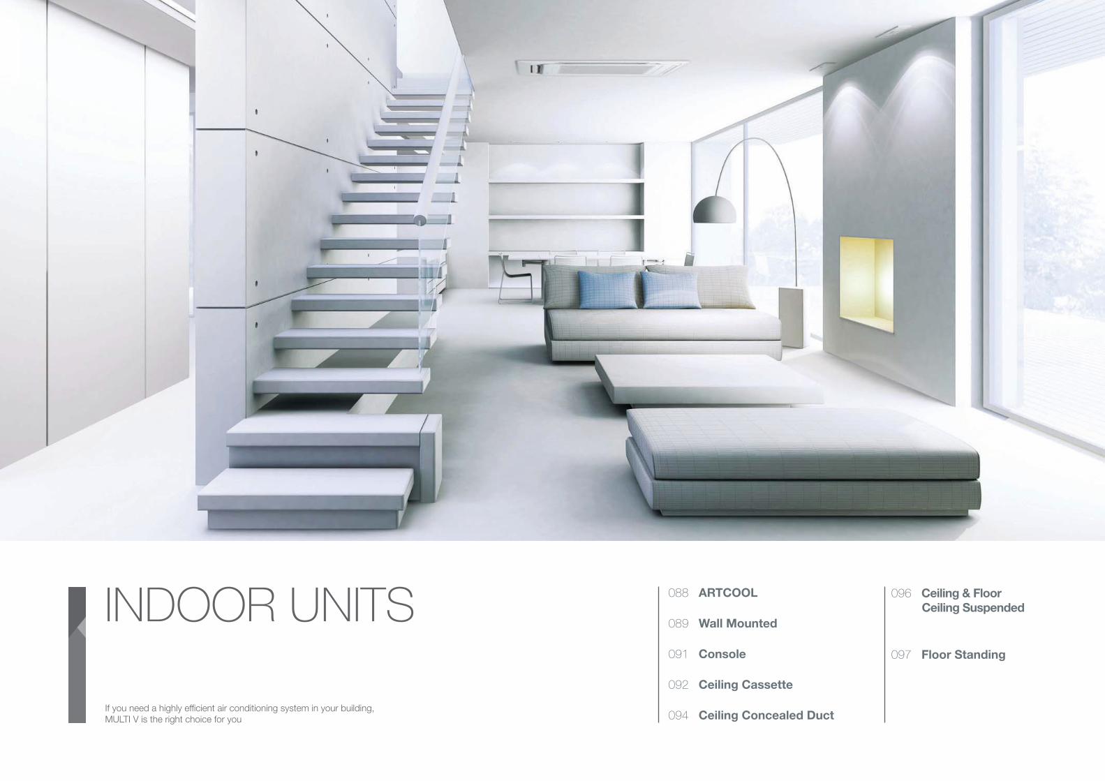
IND
OO
R U
NIT
S
INDOOR UNITS088 ARTCOOL
089 Wall Mounted
091 Console
092 Ceiling Cassette
094 Ceiling Concealed Duct
096 Ceiling & Floor
Ceiling Suspended
097 Floor Standing
If you need a highly efficient air conditioning system in your building,
MULTI V is the right choice for you
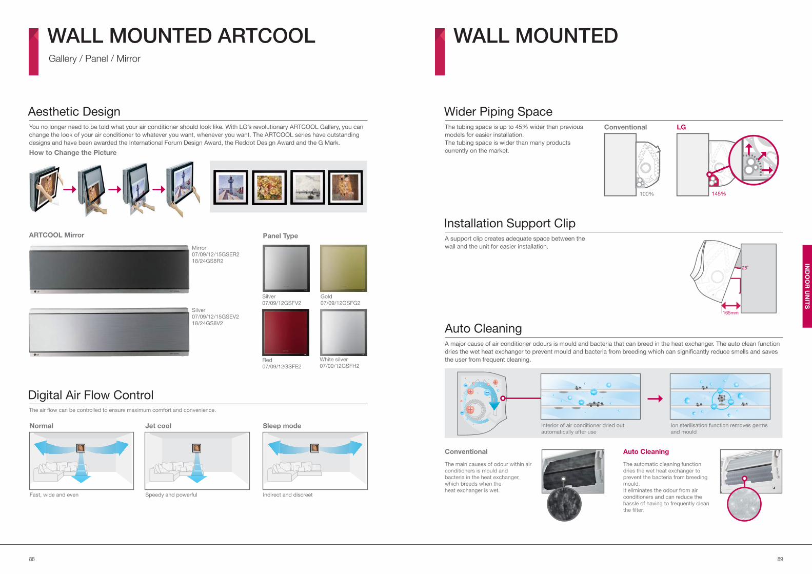
8988
IND
OO
R U
NIT
S
The main causes of odour within air
conditioners is mould and
bacteria in the heat exchanger,
which breeds when the
heat exchanger is wet.
You no longer need to be told what your air conditioner should look like. With LG’s revolutionary ARTCOOL Gallery, you can
change the look of your air conditioner to whatever you want, whenever you want. The ARTCOOL series have outstanding
designs and have been awarded the International Forum Design Award, the Reddot Design Award and the G Mark.
The air flow can be controlled to ensure maximum comfort and convenience.
Aesthetic Design
Digital Air Flow Control
How to Change the Picture
ARTCOOL Mirror
Auto CleaningA major cause of air conditioner odours is mould and bacteria that can breed in the heat exchanger. The auto clean function
dries the wet heat exchanger to prevent mould and bacteria from breeding which can significantly reduce smells and saves
the user from frequent cleaning.
Wider Piping Space
Installation Support Clip
The tubing space is up to 45% wider than previous
models for easier installation.
The tubing space is wider than many products
currently on the market.
A support clip creates adequate space between the
wall and the unit for easier installation.
WALL MOUNTED ARTCOOL Gallery / Panel / Mirror
WALL MOUNTED
Panel Type
Silver
07/09/12GSFV2
Gold
07/09/12GSFG2
Red
07/09/12GSFE2
White silver
07/09/12GSFH2
Silver
07/09/12/15GSEV2
18/24GS8V2
Mirror
07/09/12/15GSER2
18/24GS8R2
Normal
Fast, wide and even
Jet cool
Speedy and powerful
Sleep mode
Indirect and discreet
165mm
25˚
145%
LG
100%
Conventional
Conventional Auto Cleaning
The automatic cleaning function
dries the wet heat exchanger to
prevent the bacteria from breeding
mould.
It eliminates the odour from air
conditioners and can reduce the
hassle of having to frequently clean
the filter.
Interior of air conditioner dried out
automatically after use
Ion sterilisation function removes germs
and mould
*
*
*
*
*
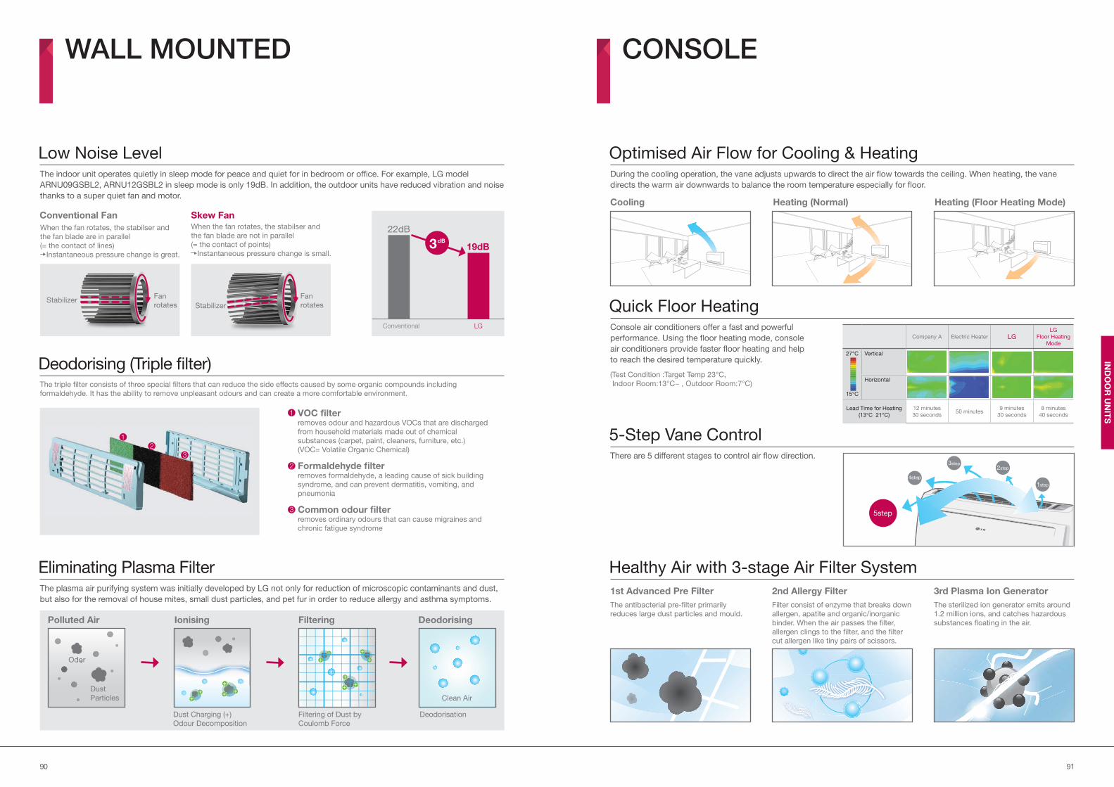
9190
IND
OO
R U
NIT
S
The indoor unit operates quietly in sleep mode for peace and quiet for in bedroom or office. For example, LG model
ARNU09GSBL2, ARNU12GSBL2 in sleep mode is only 19dB. In addition, the outdoor units have reduced vibration and noise
thanks to a super quiet fan and motor.
The triple filter consists of three special filters that can reduce the side effects caused by some organic compounds including
formaldehyde. It has the ability to remove unpleasant odours and can create a more comfortable environment.
Low Noise Level
Deodorising (Triple filter)
Optimised Air Flow for Cooling & Heating
Quick Floor Heating
5-Step Vane Control
During the cooling operation, the vane adjusts upwards to direct the air flow towards the ceiling. When heating, the vane
directs the warm air downwards to balance the room temperature especially for floor.
Console air conditioners offer a fast and powerful
performance. Using the floor heating mode, console
air conditioners provide faster floor heating and help
to reach the desired temperature quickly.
There are 5 different stages to control air flow direction.
WALL MOUNTED CONSOLE
VOC filter
removes odour and hazardous VOCs that are discharged
from household materials made out of chemical
substances (carpet, paint, cleaners, furniture, etc.)
(VOC= Volatile Organic Chemical)
Formaldehyde filter
removes formaldehyde, a leading cause of sick building
syndrome, and can prevent dermatitis, vomiting, and
pneumonia
Common odour filter
removes ordinary odours that can cause migraines and
chronic fatigue syndrome
1
2
3
The plasma air purifying system was initially developed by LG not only for reduction of microscopic contaminants and dust,
but also for the removal of house mites, small dust particles, and pet fur in order to reduce allergy and asthma symptoms.
Eliminating Plasma Filter
Ionising
Dust Charging (+)
Odour Decomposition
Deodorisation
Deodorising
Clean Air
Polluted Air
Odor
Dust
Particles
Filtering of Dust by
Coulomb Force
Filtering
When the fan rotates, the stabilser and
the fan blade are in parallel
(= the contact of lines)
Instantaneous pressure change is great.
When the fan rotates, the stabilser and
the fan blade are not in parallel
(= the contact of points)
Instantaneous pressure change is small.
LGConventional
19dB
22dB
3dB
Conventional Fan Skew Fan
Fan
rotatesStabilizer
Fan
rotatesStabilizer
Cooling
Healthy Air with 3-stage Air Filter System
1st Advanced Pre Filter 2nd Allergy Filter 3rd Plasma Ion Generator
The antibacterial pre-filter primarily
reduces large dust particles and mould.
Filter consist of enzyme that breaks down
allergen, apatite and organic/inorganic
binder. When the air passes the filter,
allergen clings to the filter, and the filter
cut allergen like tiny pairs of scissors.
The sterilized ion generator emits around
1.2 million ions, and catches hazardous
substances floating in the air.
(Test Condition :Target Temp 23°C,
Indoor Room:13°C~ , Outdoor Room:7°C)
Company A Electric Heater LGLG
Floor Heating
Mode
27°C
15°C
Vertical
Horizontal
Lead Time for Heating
(13°C 21°C)
12 minutes
30 seconds50 minutes
9 minutes
30 seconds
8 minutes
40 seconds
Heating (Normal) Heating (Floor Heating Mode)
1
2
3
4step
3step2step
1step
5step
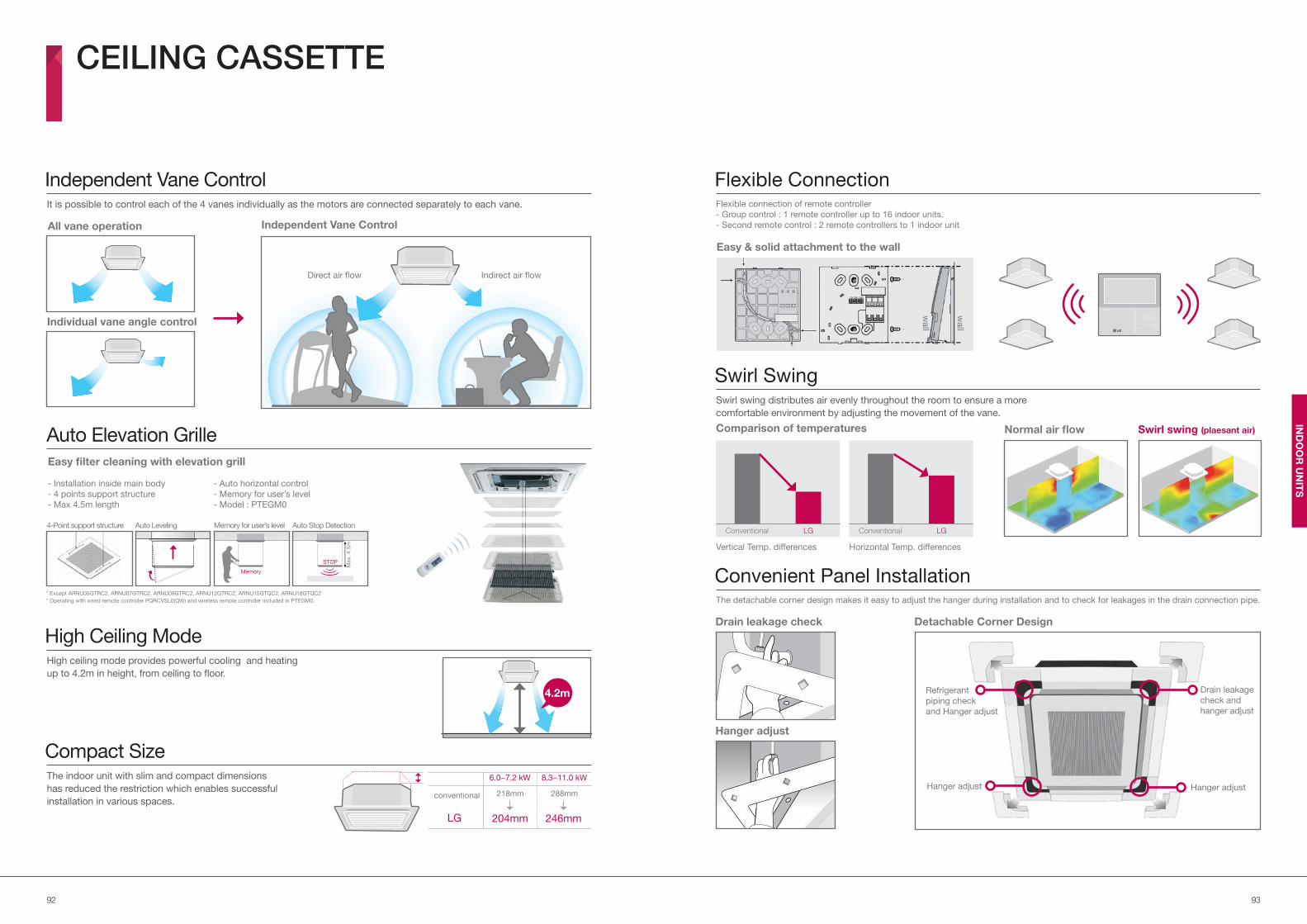
9392
IND
OO
R U
NIT
S
It is possible to control each of the 4 vanes individually as the motors are connected separately to each vane.
High ceiling mode provides powerful cooling and heating
up to 4.2m in height, from ceiling to floor.
The indoor unit with slim and compact dimensions
has reduced the restriction which enables successful
installation in various spaces.
Independent Vane Control
Auto Elevation Grille
High Ceiling Mode
Compact Size
Flexible Connection
Swirl Swing
Convenient Panel Installation
Flexible connection of remote controller
- Group control : 1 remote controller up to 16 indoor units.
- Second remote control : 2 remote controllers to 1 indoor unit
Swirl swing distributes air evenly throughout the room to ensure a more
comfortable environment by adjusting the movement of the vane.
The detachable corner design makes it easy to adjust the hanger during installation and to check for leakages in the drain connection pipe.
CEILING CASSETTE
Independent Vane ControlAll vane operation
Individual vane angle control
Indirect air flowDirect air flow
Easy filter cleaning with elevation grill
- Installation inside main body - Auto horizontal control
- 4 points support structure - Memory for user’s level
- Max 4.5m length - Model : PTEGM0
4-Point support structure Auto Leveling
STOP
Auto Stop Detection
Max.
4.5
m
Memory
Memory for user’s level
* Operating with wired remote controller PQRCVSL0(QW) and wireless remote controller included in PTEGM0.
* Except ARNU05GTRC2, ARNU07GTRC2, ARNU09GTRC2, ARNU12GTRC2, ARNU15GTQC2, ARNU18GTQC2
LG
conventional
204mm
218mm
246mm
288mm
6.0~7.2 kW 8.3~11.0 kW
4.2m
wall
wall
Easy & solid attachment to the wall
Swirl swing (plaesant air)Normal air flow
LGConventional LGConventional
Comparison of temperatures
Vertical Temp. differences Horizontal Temp. differences
Hanger adjust
Drain leakage check Detachable Corner Design
Refrigerant
piping check
and Hanger adjust
Drain leakage
check and
hanger adjust
Hanger adjust Hanger adjust
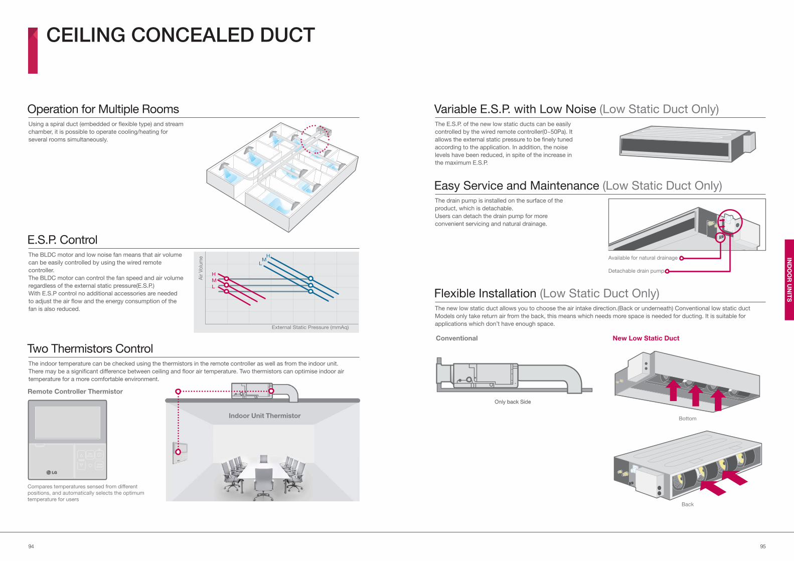
9594
IND
OO
R U
NIT
S
Using a spiral duct (embedded or flexible type) and stream
chamber, it is possible to operate cooling/heating for
several rooms simultaneously.
The BLDC motor and low noise fan means that air volume
can be easily controlled by using the wired remote
controller.
The BLDC motor can control the fan speed and air volume
regardless of the external static pressure(E.S.P.)
With E.S.P control no additional accessories are needed
to adjust the air flow and the energy consumption of the
fan is also reduced.
The indoor temperature can be checked using the thermistors in the remote controller as well as from the indoor unit.
There may be a significant difference between ceiling and floor air temperature. Two thermistors can optimise indoor air
temperature for a more comfortable environment.
Operation for Multiple Rooms
E.S.P. Control
Two Thermistors Control
Variable E.S.P. with Low Noise (Low Static Duct Only)
Easy Service and Maintenance (Low Static Duct Only)
Flexible Installation (Low Static Duct Only)
The E.S.P. of the new low static ducts can be easily
controlled by the wired remote controller(0~50Pa). It
allows the external static pressure to be finely tuned
according to the application. In addition, the noise
levels have been reduced, in spite of the increase in
the maximum E.S.P.
The drain pump is installed on the surface of the
product, which is detachable.
Users can detach the drain pump for more
convenient servicing and natural drainage.
The new low static duct allows you to choose the air intake direction.(Back or underneath) Conventional low static duct
Models only take return air from the back, this means which needs more space is needed for ducting. It is suitable for
applications which don’t have enough space.
CEILING CONCEALED DUCT
Compares temperatures sensed from different
positions, and automatically selects the optimum
temperature for users
Remote Controller Thermistor
Indoor Unit Thermistor
Air V
olu
me
H
M
L
H M L
External Static Pressure (mmAq)
Conventional
Only back SideOnly back Side
Bottom
Back
New Low Static Duct
Available for natural drainage
Detachable drain pump
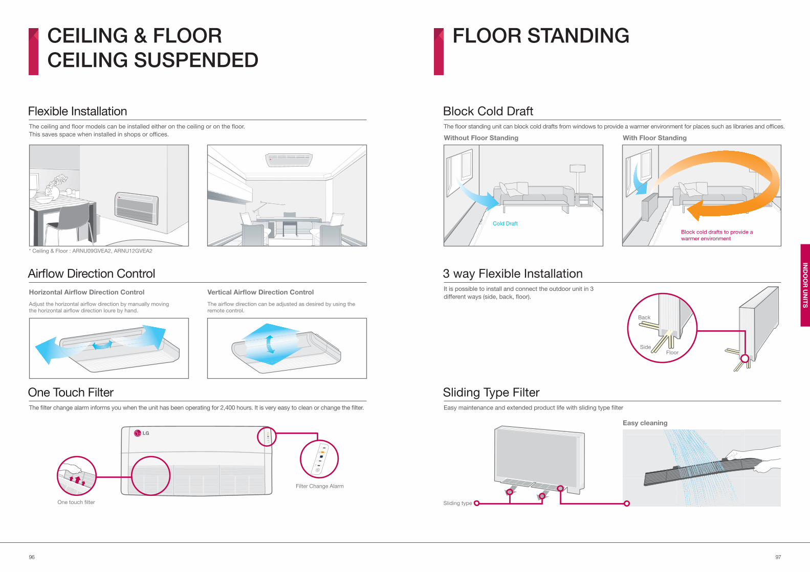
9796
IND
OO
R U
NIT
S
Back
SideFloor
The ceiling and floor models can be installed either on the ceiling or on the floor.
This saves space when installed in shops or offices.
The filter change alarm informs you when the unit has been operating for 2,400 hours. It is very easy to clean or change the filter.
Flexible Installation
One Touch Filter
Block Cold DraftThe floor standing unit can block cold drafts from windows to provide a warmer environment for places such as libraries and offices.
Sliding Type FilterEasy maintenance and extended product life with sliding type filter
CEILING & FLOOR
CEILING SUSPENDED
FLOOR STANDING
* Ceiling & Floor : ARNU09GVEA2, ARNU12GVEA2
Airflow Direction Control
Horizontal Airflow Direction Control
Adjust the horizontal airflow direction by manually moving
the horizontal airflow direction loure by hand.
Vertical Airflow Direction Control
The airflow direction can be adjusted as desired by using the
remote control.
One touch filter
Filter Change Alarm
Without Floor Standing With Floor Standing
Cold Draft
Block cold drafts to provide a
warmer environment
3 way Flexible InstallationIt is possible to install and connect the outdoor unit in 3
different ways (side, back, floor).
Easy cleaning
Sliding type
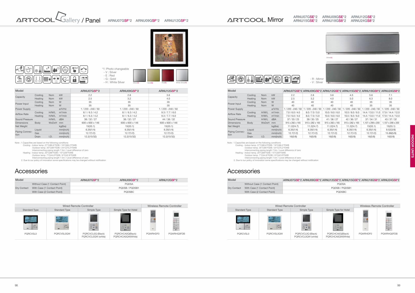
9998
IND
OO
R U
NIT
S
Model ARNU07GSE*2 ARNU09GSE*2 ARNU12GSE*2 ARNU15GSE*2 ARNU18GS8*2 ARNU24GS8*2
Dry Contact
Without Case (1 Contact Point) PQDSA
With Case (1 Contact Point) PQDSB / PQDSB1
With Case (2 Contact Point) PQDSBC
Wired Remote Controller Wireless Remote Controller
Standard Type Standard Type Simple Type Simple Type for Hotel
ARNU07GSE*2 ARNU09GSE*2 ARNU12GSE*2 ARNU15GSE*2 ARNU18GS8*2 ARNU24GS8*2Mirror
Model ARNU07GSE*2 ARNU09GSE*2 ARNU12GSE*2 ARNU15GSE*2 ARNU18GS8*2 ARNU24GS8*2
Capacity Cooling Nom kW 2.2 2.8 3.6 4.5 5.6 7.1
Heating Nom kW 2.5 3.2 4.0 5.0 6.3 8.0
Power Input Cooling Nom W 40 40 40 40 35 35
Heating Nom W 40 40 40 40 35 35
Power Supply ø/V/Hz 1 / 220 ~240 / 50 1 / 220 ~240 / 50 1 / 220 ~240 / 50 1 / 220 ~240 / 50 1 / 220 ~240 / 50 1 / 220 ~240 / 50
Airflow RateCooling H/M/L m3/min 7.0 / 6.0 / 4.0 8.0 / 7.0 / 5.0 10.0 / 8.0 / 6.0 10.5 / 8.0 / 6.0 14.4 / 13.0 / 11.0 17.9 / 14.4 / 12.0
Heating H/M/L m3/min 7.0 / 6.0 / 4.0 8.0 / 7.0 / 5.0 10.0 / 8.0 / 6.0 10.5 / 8.0 / 6.0 14.4 / 13.0 / 11.0 17.9 / 14.4 / 12.0
Sound Pressure H/M/L dBA 37 / 33 / 23 39 / 35 / 25 41 / 36 / 27 42 / 36 / 27 37 / 34 / 31 43 / 37 / 32
Dimensions Body WxDxH mm 915 x 282 x 165 915 x 282 x 165 915 x 282 x 165 915 x 282 x 165 1,107 x 299 x 200 1,107 x 299 x 200
Net Weight kg(lbs) 11.2(24.7) 11.2(24.7) 11.2(24.7) 11.2(24.7) 15(33.1) 15(33.1)
Piping Connec-
tion
Liquid mm(inch) 6.35(1/4) 6.35(1/4) 6.35(1/4) 6.35(1/4) 6.35(1/4) 9.52(3/8)
Gas mm(inch) 12.7(1/2) 12.7(1/2) 12.7(1/2) 12.7(1/2) 12.7(1/2) 15.88(5/8)
Drain I.D. mm(inch) 16(5/8) 16(5/8) 16(5/8) 16(5/8) 16(5/8) 16(5/8)
Note : 1.Capacities are based on the following conditions
Cooling - Indoor temp. 27°C(80.6°F)DB / 19°C(66.2°F)WB
Outdoor temp. 35°C(95°F)DB / 24°C(75.2°F)WB
Interconnecting piping length 7.5m / Level difference of zero
Heating - Indoor temp. 20°C(68°F)DB / 15°C(59°F)WB
Outdoor temp. 7°C(44.6°F)DB / 6°C(42.8°F)WB
Interconnecting piping length 7.5m / Level difference of zero
2. Due to our policy of innovation some specifications may be changed without notification
Accessories
PQRCVSL0QW PQRCHCA0Q(Black)
PQRCHCA0QW(White)
PQWRHDF0 PQWRHQ0FDBPQRCVSL0 PQRCVCL0Q (Black)
PQRCVCL0QW (white)
Silver(V)
- R : Mirror
- V : Silver
Wired Remote Controller Wireless Remote Controller
Standard Type Standard Type Simple Type Simple Type for Hotel
ARNU07GSF*2 ARNU09GSF*2 ARNU12GSF*2/ Panel
*1: Photo changeable
- V : Silver
- E : Red
- G : Gold
- H : White Silver Silver(V) Gold(G) Red(E) White Silver(H)
Model ARNU07GSF*2 ARNU09GSF*2 ARNU12GSF*2
Capacity Cooling Nom kW 2.2 2.8 3.6
Heating Nom kW 2.5 3.2 4.0
Power Input Cooling Nom W 35 35 35
Heating Nom W 35 35 35
Power Supply ø/V/Hz 1 / 220 ~240 / 50 1 / 220 ~240 / 50 1 / 220 ~240 / 50
Airflow RateCooling H/M/L m3/min 8.1 / 6.3 / 4.2 8.1 / 6.3 / 4.2 9.3 / 7.7 / 6.0
Heating H/M/L m3/min 8.1 / 6.3 / 4.2 8.1 / 6.3 / 4.2 9.3 / 7.7 / 6.0
Sound Pressure H/M/L dBA 38 / 32 / 27 38 / 32 / 27 44 / 38 / 32
Dimensions Body WxDxH mm 600 x 600 x 146 600 x 600 x 146 600 x 600 x 146
Net Weight kg(lbs) 15(33.1) 15(33.1) 15(33.1)
Piping Connec-
tion
Liquid mm(inch) 6.35(1/4) 6.35(1/4) 6.35(1/4)
Gas mm(inch) 12.7(1/2) 12.7(1/2) 12.7(1/2)
Drain I.D. mm(inch) 12.2(15/32) 12.2(15/32) 12.2(15/32)
Note : 1.Capacities are based on the following conditions
Cooling - Indoor temp. 27°C(80.6°F)DB / 19°C(66.2°F)WB
Outdoor temp. 35°C(95°F)DB / 24°C(75.2°F)WB
Interconnecting piping length 7.5m / Level difference of zero
Heating - Indoor temp. 20°C(68°F)DB / 15°C(59°F)WB
Outdoor temp. 7°C(44.6°F)DB / 6°C(42.8°F)WB
Interconnecting piping length 7.5m / Level difference of zero
2. Due to our policy of innovation some specifications may be changed without notification
Accessories
Model ARNU07GSF*2 ARNU09GSF*2 ARNU12GSF*2
Dry Contact
Without Case (1 Contact Point) PQDSA
With Case (1 Contact Point) PQDSB / PQDSB1
With Case (2 Contact Point) PQDSBC
PQRCVSL0QW PQRCHCA0Q(Black)
PQRCHCA0QW(White)
PQWRHDF0 PQWRHQ0FDBPQRCVSL0 PQRCVCL0Q (Black)
PQRCVCL0QW (white)
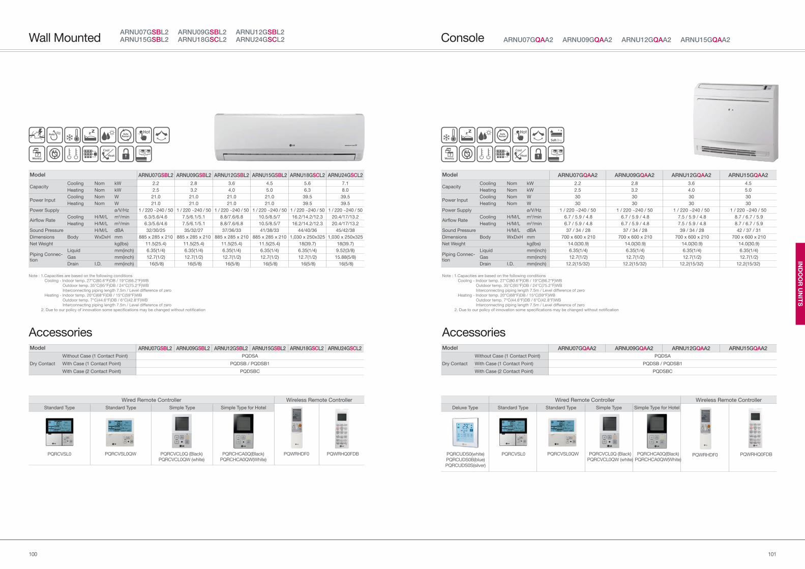
101100
IND
OO
R U
NIT
S
Wired Remote Controller Wireless Remote Controller
Deluxe Type Standard Type Standard Type Simple Type Simple Type for Hotel
ARNU07GQAA2 ARNU09GQAA2 ARNU12GQAA2 ARNU15GQAA2Console
Note : 1.Capacities are based on the following conditions
Cooling - Indoor temp. 27°C(80.6°F)DB / 19°C(66.2°F)WB
Outdoor temp. 35°C(95°F)DB / 24°C(75.2°F)WB
Interconnecting piping length 7.5m / Level difference of zero
Heating - Indoor temp. 20°C(68°F)DB / 15°C(59°F)WB
Outdoor temp. 7°C(44.6°F)DB / 6°C(42.8°F)WB
Interconnecting piping length 7.5m / Level difference of zero
2. Due to our policy of innovation some specifications may be changed without notification
Accessories
PQRCVSL0QW PQRCHCA0Q(Black)
PQRCHCA0QW(White)PQWRHDF0 PQWRHQ0FDBPQRCVSL0 PQRCVCL0Q (Black)
PQRCVCL0QW (white)
Model ARNU07GQAA2 ARNU09GQAA2 ARNU12GQAA2 ARNU15GQAA2
Dry Contact
Without Case (1 Contact Point) PQDSA
With Case (1 Contact Point) PQDSB / PQDSB1
With Case (2 Contact Point) PQDSBC
Model ARNU07GQAA2 ARNU09GQAA2 ARNU12GQAA2 ARNU15GQAA2
Capacity Cooling Nom kW 2.2 2.8 3.6 4.5
Heating Nom kW 2.5 3.2 4.0 5.0
Power Input Cooling Nom W 30 30 30 30
Heating Nom W 30 30 30 30
Power Supply ø/V/Hz 1 / 220 ~240 / 50 1 / 220 ~240 / 50 1 / 220 ~240 / 50 1 / 220 ~240 / 50
Airflow RateCooling H/M/L m3/min 6.7 / 5.9 / 4.8 6.7 / 5.9 / 4.8 7.5 / 5.9 / 4.8 8.7 / 6.7 / 5.9
Heating H/M/L m3/min 6.7 / 5.9 / 4.8 6.7 / 5.9 / 4.8 7.5 / 5.9 / 4.8 8.7 / 6.7 / 5.9
Sound Pressure H/M/L dBA 37 / 34 / 28 37 / 34 / 28 39 / 34 / 28 42 / 37 / 31
Dimensions Body WxDxH mm 700 x 600 x 210 700 x 600 x 210 700 x 600 x 210 700 x 600 x 210
Net Weight kg(lbs) 14.0(30.9) 14.0(30.9) 14.0(30.9) 14.0(30.9)
Piping Connec-
tion
Liquid mm(inch) 6.35(1/4) 6.35(1/4) 6.35(1/4) 6.35(1/4)
Gas mm(inch) 12.7(1/2) 12.7(1/2) 12.7(1/2) 12.7(1/2)
Drain I.D. mm(inch) 12.2(15/32) 12.2(15/32) 12.2(15/32) 12.2(15/32)
PQRCUDS0(white)
PQRCUDS0B(blue)
PQRCUDS0S(silver)
Wired Remote Controller Wireless Remote Controller
Standard Type Standard Type Simple Type Simple Type for Hotel
ARNU07GSBL2 ARNU09GSBL2 ARNU12GSBL2 ARNU15GSBL2 ARNU18GSCL2 ARNU24GSCL2Wall Mounted
Note : 1.Capacities are based on the following conditions
Cooling - Indoor temp. 27°C(80.6°F)DB / 19°C(66.2°F)WB
Outdoor temp. 35°C(95°F)DB / 24°C(75.2°F)WB
Interconnecting piping length 7.5m / Level difference of zero
Heating - Indoor temp. 20°C(68°F)DB / 15°C(59°F)WB
Outdoor temp. 7°C(44.6°F)DB / 6°C(42.8°F)WB
Interconnecting piping length 7.5m / Level difference of zero
2. Due to our policy of innovation some specifications may be changed without notification
Accessories
PQRCVSL0QW PQRCHCA0Q(Black)
PQRCHCA0QW(White)
PQWRHDF0 PQWRHQ0FDBPQRCVSL0 PQRCVCL0Q (Black)
PQRCVCL0QW (white)
Model ARNU07GSBL2 ARNU09GSBL2 ARNU12GSBL2 ARNU15GSBL2 ARNU18GSCL2 ARNU24GSCL2
Dry Contact
Without Case (1 Contact Point) PQDSA
With Case (1 Contact Point) PQDSB / PQDSB1
With Case (2 Contact Point) PQDSBC
Model ARNU07GSBL2 ARNU09GSBL2 ARNU12GSBL2 ARNU15GSBL2 ARNU18GSCL2 ARNU24GSCL2
Capacity Cooling Nom kW 2.2 2.8 3.6 4.5 5.6 7.1
Heating Nom kW 2.5 3.2 4.0 5.0 6.3 8.0
Power Input Cooling Nom W 21.0 21.0 21.0 21.0 39.5 39.5
Heating Nom W 21.0 21.0 21.0 21.0 39.5 39.5
Power Supply ø/V/Hz 1 / 220 ~240 / 50 1 / 220 ~240 / 50 1 / 220 ~240 / 50 1 / 220 ~240 / 50 1 / 220 ~240 / 50 1 / 220 ~240 / 50
Airflow RateCooling H/M/L m3/min 6.3/5.6/4.6 7.5/6.1/5.1 8.8/7.6/6.8 10.5/8.5/7 16.2/14.2/12.3 20.4/17/13.2
Heating H/M/L m3/min 6.3/5.6/4.6 7.5/6.1/5.1 8.8/7.6/6.8 10.5/8.5/7 16.2/14.2/12.3 20.4/17/13.2
Sound Pressure H/M/L dBA 32/30/25 35/32/27 37/36/33 41/38/33 44/40/36 45/42/38
Dimensions Body WxDxH mm 885 x 285 x 210 885 x 285 x 210 885 x 285 x 210 885 x 285 x 210 1,030 x 250x325 1,030 x 250x325
Net Weight kg(lbs) 11.5(25.4) 11.5(25.4) 11.5(25.4) 11.5(25.4) 18(39.7) 18(39.7)
Piping Connec-
tion
Liquid mm(inch) 6.35(1/4) 6.35(1/4) 6.35(1/4) 6.35(1/4) 6.35(1/4) 9.52(3/8)
Gas mm(inch) 12.7(1/2) 12.7(1/2) 12.7(1/2) 12.7(1/2) 12.7(1/2) 15.88(5/8)
Drain I.D. mm(inch) 16(5/8) 16(5/8) 16(5/8) 16(5/8) 16(5/8) 16(5/8)
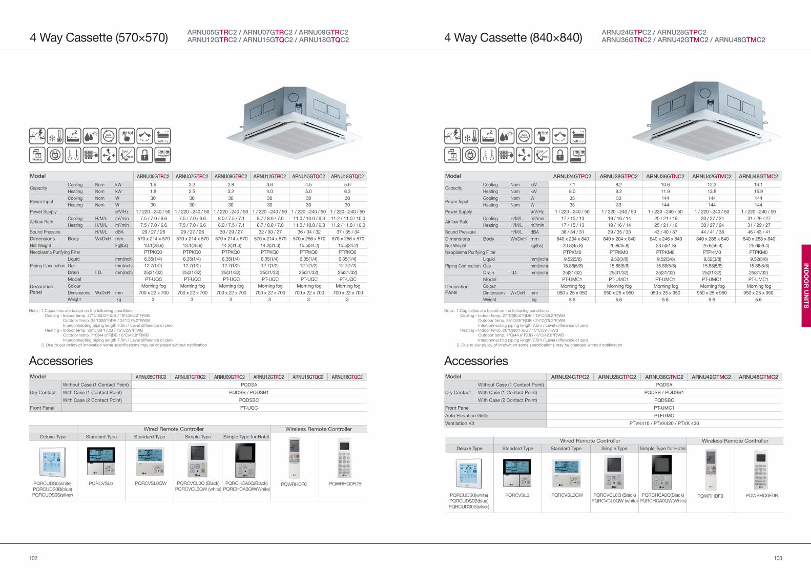
103102
IND
OO
R U
NIT
S
Note : 1.Capacities are based on the following conditions
Cooling - Indoor temp. 27°C(80.6°F)DB / 19°C(66.2°F)WB
Outdoor temp. 35°C(95°F)DB / 24°C(75.2°F)WB
Interconnecting piping length 7.5m / Level difference of zero
Heating - Indoor temp. 20°C(68°F)DB / 15°C(59°F)WB
Outdoor temp. 7°C(44.6°F)DB / 6°C(42.8°F)WB
Interconnecting piping length 7.5m / Level difference of zero
2. Due to our policy of innovation some specifications may be changed without notification
Accessories
Wired Remote Controller Wireless Remote Controller
Deluxe Type Standard Type Standard Type Simple Type Simple Type for Hotel
PQRCVSL0QW PQRCHCA0Q(Black)
PQRCHCA0QW(White)PQWRHDF0 PQWRHQ0FDBPQRCVSL0 PQRCVCL0Q (Black)
PQRCVCL0QW (white)PQRCUDS0(white)
PQRCUDS0B(blue)
PQRCUDS0S(silver)
4 Way Cassette (840×840)ARNU24GTPC2 / ARNU28GTPC2ARNU36GTNC2 / ARNU42GTMC2 / ARNU48GTMC2
Model ARNU24GTPC2 ARNU28GTPC2 ARNU36GTNC2 ARNU42GTMC2 ARNU48GTMC2
Capacity Cooling Nom kW 7.1 8.2 10.6 12.3 14.1
Heating Nom kW 8.0 9.2 11.9 13.8 15.9
Power Input Cooling Nom W 33 33 144 144 144
Heating Nom W 33 33 144 144 144
Power Supply ø/V/Hz 1 / 220 ~240 / 50 1 / 220 ~240 / 50 1 / 220 ~240 / 50 1 / 220 ~240 / 50 1 / 220 ~240 / 50
Airflow RateCooling H/M/L m3/min 17 / 15 / 13 19 / 16 / 14 25 / 21 / 19 30 / 27 / 24 31 / 29 / 27
Heating H/M/L m3/min 17 / 15 / 13 19 / 16 / 14 25 / 21 / 19 30 / 27 / 24 31 / 29 / 27
Sound Pressure H/M/L dBA 36 / 34 / 31 39 / 35 / 33 43 / 40 / 37 44 / 41 / 38 46 / 43 / 41
Dimensions Body WxDxH mm 840 x 204 x 840 840 x 204 x 840 840 x 246 x 840 840 x 288 x 840 840 x 288 x 840
Net Weight kg(lbs) 20.8(45.8) 20.8(45.8) 23.5(51.8) 25.6(56.4) 25.6(56.4)
Neoplasma Purifying Filter PTPKM0 PTPKM0 PTPKM0 PTPKM0 PTPKM0
Piping Connection
Liquid mm(inch) 9.52(3/8) 9.52(3/8) 9.52(3/8) 9.52(3/8) 9.52(3/8)
Gas mm(inch) 15.88(5/8) 15.88(5/8) 15.88(5/8) 15.88(5/8) 15.88(5/8)
Drain I.D. mm(inch) 25(31/32) 25(31/32) 25(31/32) 25(31/32) 25(31/32)
Decoration
Panel
Model PT-UMC1 PT-UMC1 PT-UMC1 PT-UMC1 PT-UMC1
Colour Morning fog Morning fog Morning fog Morning fog Morning fog
Dimensions WxDxH mm 950 x 25 x 950 950 x 25 x 950 950 x 25 x 950 950 x 25 x 950 950 x 25 x 950
Weight kg 5.6 5.6 5.6 5.6 5.6
Model ARNU24GTPC2 ARNU28GTPC2 ARNU36GTNC2 ARNU42GTMC2 ARNU48GTMC2
Dry Contact
Without Case (1 Contact Point) PQDSA
With Case (1 Contact Point) PQDSB / PQDSB1
With Case (2 Contact Point) PQDSBC
Front Panel PT-UMC1
Auto Elevation Grille PTEGMO
Ventilation Kit PTVK410 / PTVK420 / PTVK 430
ARNU05GTRC2 / ARNU07GTRC2 / ARNU09GTRC2 ARNU12GTRC2 / ARNU15GTQC2 / ARNU18GTQC24 Way Cassette (570×570)
Note : 1.Capacities are based on the following conditions
Cooling - Indoor temp. 27°C(80.6°F)DB / 19°C(66.2°F)WB
Outdoor temp. 35°C(95°F)DB / 24°C(75.2°F)WB
Interconnecting piping length 7.5m / Level difference of zero
Heating - Indoor temp. 20°C(68°F)DB / 15°C(59°F)WB
Outdoor temp. 7°C(44.6°F)DB / 6°C(42.8°F)WB
Interconnecting piping length 7.5m / Level difference of zero
2. Due to our policy of innovation some specifications may be changed without notification
Accessories
Wired Remote Controller Wireless Remote Controller
Deluxe Type Standard Type Standard Type Simple Type Simple Type for Hotel
PQRCVSL0QW PQRCHCA0Q(Black)
PQRCHCA0QW(White)PQWRHDF0 PQWRHQ0FDBPQRCVSL0 PQRCVCL0Q (Black)
PQRCVCL0QW (white)PQRCUDS0(white)
PQRCUDS0B(blue)
PQRCUDS0S(silver)
Model ARNU05GTRC2 ARNU07GTRC2 ARNU09GTRC2 ARNU12GTRC2 ARNU15GTQC2 ARNU18GTQC2
Capacity Cooling Nom kW 1.6 2.2 2.8 3.6 4.5 5.6
Heating Nom kW 1.8 2.5 3.2 4.0 5.0 6.3
Power Input Cooling Nom W 30 30 30 30 30 30
Heating Nom W 30 30 30 30 30 30
Power Supply ø/V/Hz 1 / 220 ~240 / 50 1 / 220 ~240 / 50 1 / 220 ~240 / 50 1 / 220 ~240 / 50 1 / 220 ~240 / 50 1 / 220 ~240 / 50
Airflow RateCooling H/M/L m3/min 7.5 / 7.0 / 6.6 7.5 / 7.0 / 6.6 8.0 / 7.5 / 7.1 8.7 / 8.0 / 7.0 11.0 / 10.0 / 9.3 11.2 / 11.0 / 10.0
Heating H/M/L m3/min 7.5 / 7.0 / 6.6 7.5 / 7.0 / 6.6 8.0 / 7.5 / 7.1 8.7 / 8.0 / 7.0 11.0 / 10.0 / 9.3 11.2 / 11.0 / 10.0
Sound Pressure H/M/L dBA 29 / 27 / 26 29 / 27 / 26 30 / 29 / 27 32 / 30 / 27 36 / 34 / 32 37 / 35 / 34
Dimensions Body WxDxH mm 570 x 214 x 570 570 x 214 x 570 570 x 214 x 570 570 x 214 x 570 570 x 256 x 570 570 x 256 x 570
Net Weight kg(lbs) 13.1(28.9) 13.1(28.9) 14.2(31.3) 14.2(31.3) 15.5(34.2) 15.5(34.2)
Neoplasma Purifying Filter PTPKQ0 PTPKQ0 PTPKQ0 PTPKQ0 PTPKQ0 PTPKQ0
Piping Connection
Liquid mm(inch) 6.35(1/4) 6.35(1/4) 6.35(1/4) 6.35(1/4) 6.35(1/4) 6.35(1/4)
Gas mm(inch) 12.7(1/2) 12.7(1/2) 12.7(1/2) 12.7(1/2) 12.7(1/2) 12.7(1/2)
Drain I.D. mm(inch) 25(31/32) 25(31/32) 25(31/32) 25(31/32) 25(31/32) 25(31/32)
Decoration
Panel
Model PT-UQC PT-UQC PT-UQC PT-UQC PT-UQC PT-UQC
Colour Morning fog Morning fog Morning fog Morning fog Morning fog Morning fog
Dimensions WxDxH mm 700 x 22 x 700 700 x 22 x 700 700 x 22 x 700 700 x 22 x 700 700 x 22 x 700 700 x 22 x 700
Weight kg 3 3 3 3 3 3
Model ARNU05GTRC2 ARNU07GTRC2 ARNU09GTRC2 ARNU12GTRC2 ARNU15GTQC2 ARNU18GTQC2
Dry Contact
Without Case (1 Contact Point) PQDSA
With Case (1 Contact Point) PQDSB / PQDSB1
With Case (2 Contact Point) PQDSBC
Front Panel PT-UQC
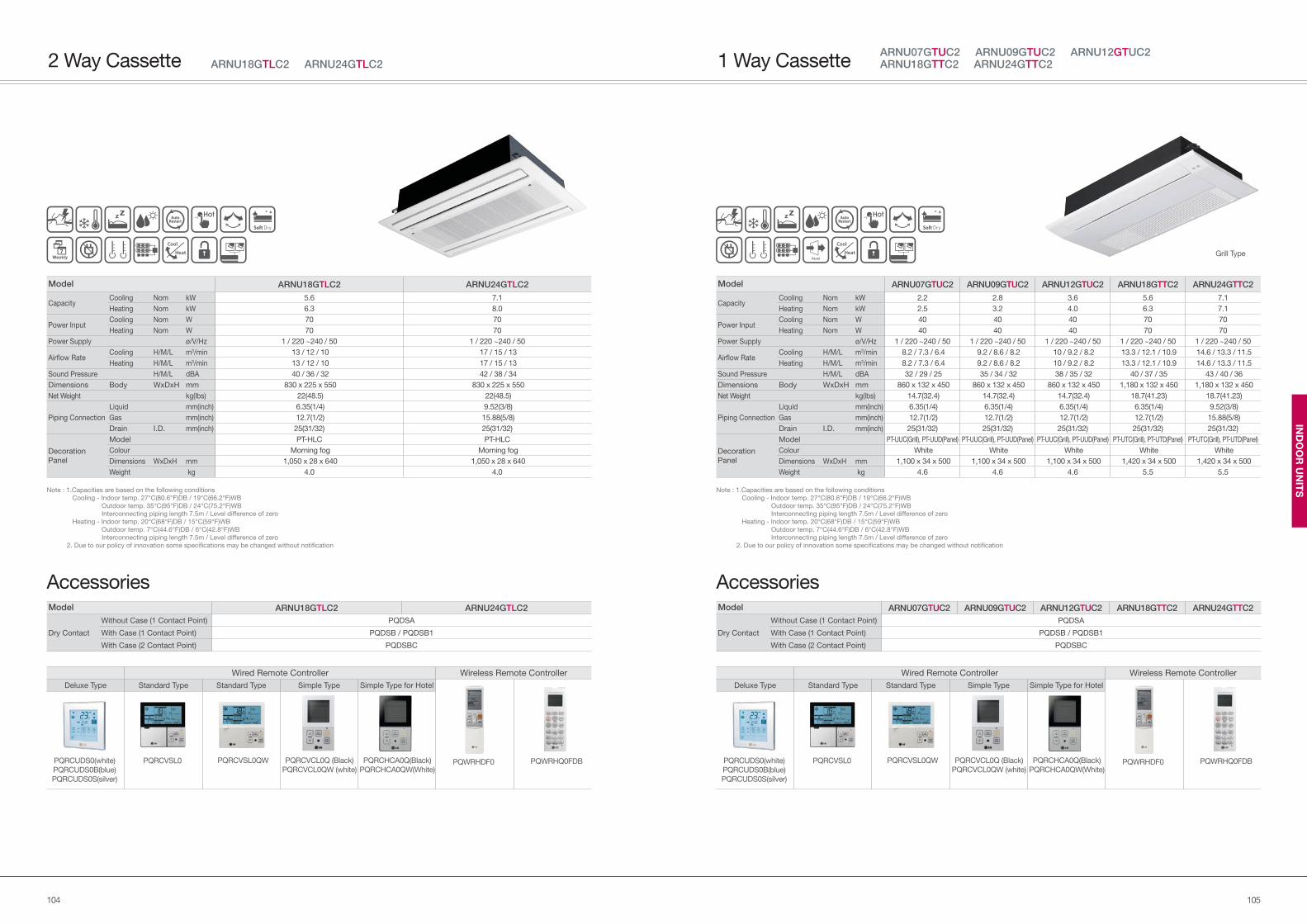
105104
IND
OO
R U
NIT
S
ARNU07GTUC2 ARNU09GTUC2 ARNU12GTUC2 ARNU18GTTC2 ARNU24GTTC21 Way Cassette
Note : 1.Capacities are based on the following conditions
Cooling - Indoor temp. 27°C(80.6°F)DB / 19°C(66.2°F)WB
Outdoor temp. 35°C(95°F)DB / 24°C(75.2°F)WB
Interconnecting piping length 7.5m / Level difference of zero
Heating - Indoor temp. 20°C(68°F)DB / 15°C(59°F)WB
Outdoor temp. 7°C(44.6°F)DB / 6°C(42.8°F)WB
Interconnecting piping length 7.5m / Level difference of zero
2. Due to our policy of innovation some specifications may be changed without notification
Accessories
Wired Remote Controller Wireless Remote Controller
Deluxe Type Standard Type Standard Type Simple Type Simple Type for Hotel
PQRCVSL0QW PQRCHCA0Q(Black)
PQRCHCA0QW(White)PQWRHDF0 PQWRHQ0FDBPQRCVSL0 PQRCVCL0Q (Black)
PQRCVCL0QW (white)PQRCUDS0(white)
PQRCUDS0B(blue)
PQRCUDS0S(silver)
Model ARNU07GTUC2 ARNU09GTUC2 ARNU12GTUC2 ARNU18GTTC2 ARNU24GTTC2
Dry Contact
Without Case (1 Contact Point) PQDSA
With Case (1 Contact Point) PQDSB / PQDSB1
With Case (2 Contact Point) PQDSBC
Model ARNU07GTUC2 ARNU09GTUC2 ARNU12GTUC2 ARNU18GTTC2 ARNU24GTTC2
Capacity Cooling Nom kW 2.2 2.8 3.6 5.6 7.1
Heating Nom kW 2.5 3.2 4.0 6.3 7.1
Power Input Cooling Nom W 40 40 40 70 70
Heating Nom W 40 40 40 70 70
Power Supply ø/V/Hz 1 / 220 ~240 / 50 1 / 220 ~240 / 50 1 / 220 ~240 / 50 1 / 220 ~240 / 50 1 / 220 ~240 / 50
Airflow RateCooling H/M/L m3/min 8.2 / 7.3 / 6.4 9.2 / 8.6 / 8.2 10 / 9.2 / 8.2 13.3 / 12.1 / 10.9 14.6 / 13.3 / 11.5
Heating H/M/L m3/min 8.2 / 7.3 / 6.4 9.2 / 8.6 / 8.2 10 / 9.2 / 8.2 13.3 / 12.1 / 10.9 14.6 / 13.3 / 11.5
Sound Pressure H/M/L dBA 32 / 29 / 25 35 / 34 / 32 38 / 35 / 32 40 / 37 / 35 43 / 40 / 36
Dimensions Body WxDxH mm 860 x 132 x 450 860 x 132 x 450 860 x 132 x 450 1,180 x 132 x 450 1,180 x 132 x 450
Net Weight kg(lbs) 14.7(32.4) 14.7(32.4) 14.7(32.4) 18.7(41.23) 18.7(41.23)
Piping Connection
Liquid mm(inch) 6.35(1/4) 6.35(1/4) 6.35(1/4) 6.35(1/4) 9.52(3/8)
Gas mm(inch) 12.7(1/2) 12.7(1/2) 12.7(1/2) 12.7(1/2) 15.88(5/8)
Drain I.D. mm(inch) 25(31/32) 25(31/32) 25(31/32) 25(31/32) 25(31/32)
Decoration
Panel
Model PT-UUC(Grill), PT-UUD(Panel) PT-UUC(Grill), PT-UUD(Panel) PT-UUC(Grill), PT-UUD(Panel) PT-UTC(Grill), PT-UTD(Panel) PT-UTC(Grill), PT-UTD(Panel)
Colour White White White White White
Dimensions WxDxH mm 1,100 x 34 x 500 1,100 x 34 x 500 1,100 x 34 x 500 1,420 x 34 x 500 1,420 x 34 x 500
Weight kg 4.6 4.6 4.6 5.5 5.5
Grill Type
ARNU18GTLC2 ARNU24GTLC22 Way Cassette
Note : 1.Capacities are based on the following conditions
Cooling - Indoor temp. 27°C(80.6°F)DB / 19°C(66.2°F)WB
Outdoor temp. 35°C(95°F)DB / 24°C(75.2°F)WB
Interconnecting piping length 7.5m / Level difference of zero
Heating - Indoor temp. 20°C(68°F)DB / 15°C(59°F)WB
Outdoor temp. 7°C(44.6°F)DB / 6°C(42.8°F)WB
Interconnecting piping length 7.5m / Level difference of zero
2. Due to our policy of innovation some specifications may be changed without notification
Accessories
Wired Remote Controller Wireless Remote Controller
Deluxe Type Standard Type Standard Type Simple Type Simple Type for Hotel
PQRCVSL0QW PQRCHCA0Q(Black)
PQRCHCA0QW(White)PQWRHDF0 PQWRHQ0FDBPQRCVSL0 PQRCVCL0Q (Black)
PQRCVCL0QW (white)PQRCUDS0(white)
PQRCUDS0B(blue)
PQRCUDS0S(silver)
Model ARNU18GTLC2 ARNU24GTLC2
Dry Contact
Without Case (1 Contact Point) PQDSA
With Case (1 Contact Point) PQDSB / PQDSB1
With Case (2 Contact Point) PQDSBC
Model ARNU18GTLC2 ARNU24GTLC2
Capacity Cooling Nom kW 5.6 7.1
Heating Nom kW 6.3 8.0
Power Input Cooling Nom W 70 70
Heating Nom W 70 70
Power Supply ø/V/Hz 1 / 220 ~240 / 50 1 / 220 ~240 / 50
Airflow RateCooling H/M/L m3/min 13 / 12 / 10 17 / 15 / 13
Heating H/M/L m3/min 13 / 12 / 10 17 / 15 / 13
Sound Pressure H/M/L dBA 40 / 36 / 32 42 / 38 / 34
Dimensions Body WxDxH mm 830 x 225 x 550 830 x 225 x 550
Net Weight kg(lbs) 22(48.5) 22(48.5)
Piping Connection
Liquid mm(inch) 6.35(1/4) 9.52(3/8)
Gas mm(inch) 12.7(1/2) 15.88(5/8)
Drain I.D. mm(inch) 25(31/32) 25(31/32)
Decoration
Panel
Model PT-HLC PT-HLC
Colour Morning fog Morning fog
Dimensions WxDxH mm 1,050 x 28 x 640 1,050 x 28 x 640
Weight kg 4.0 4.0
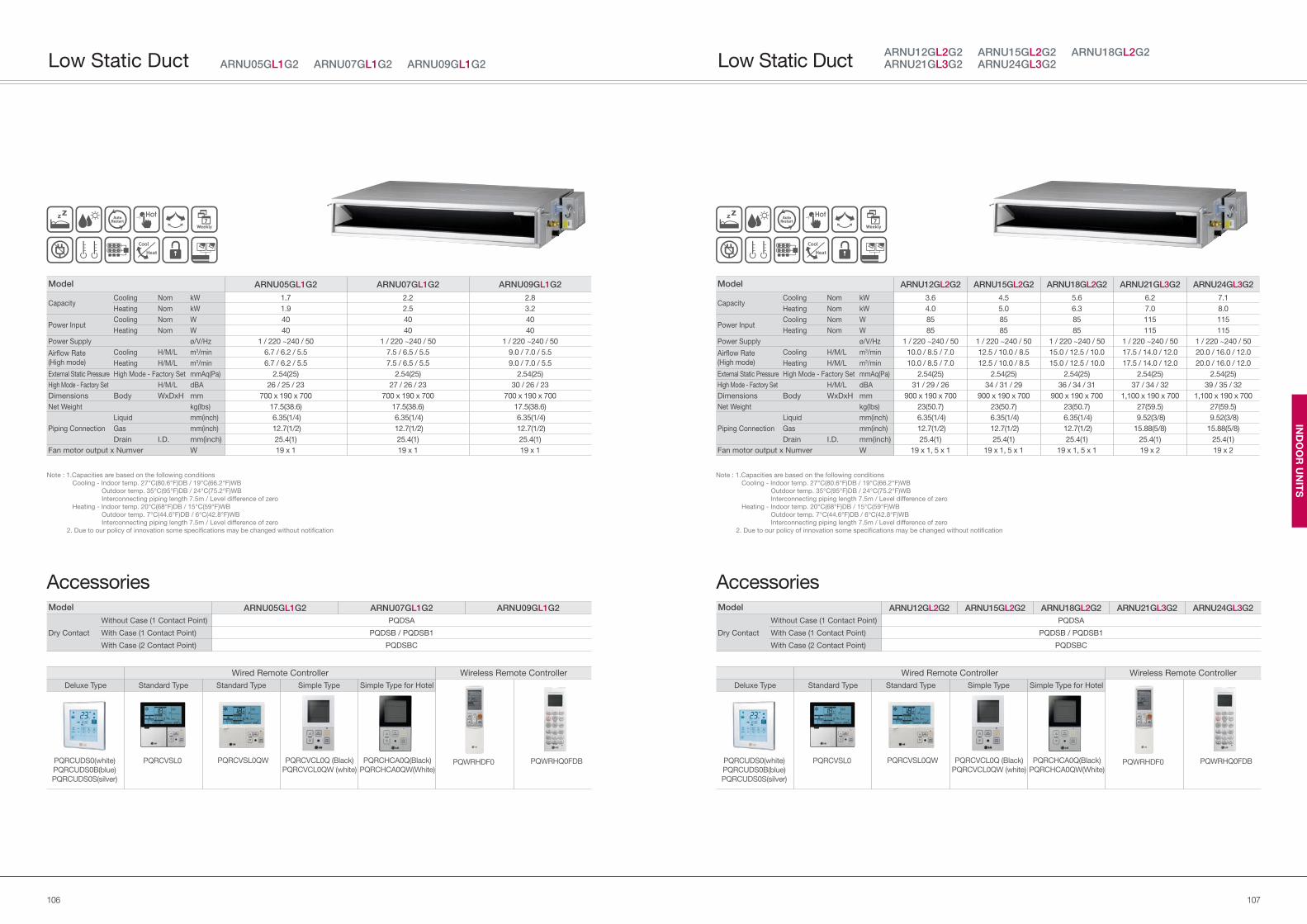
107106
IND
OO
R U
NIT
S
Note : 1.Capacities are based on the following conditions
Cooling - Indoor temp. 27°C(80.6°F)DB / 19°C(66.2°F)WB
Outdoor temp. 35°C(95°F)DB / 24°C(75.2°F)WB
Interconnecting piping length 7.5m / Level difference of zero
Heating - Indoor temp. 20°C(68°F)DB / 15°C(59°F)WB
Outdoor temp. 7°C(44.6°F)DB / 6°C(42.8°F)WB
Interconnecting piping length 7.5m / Level difference of zero
2. Due to our policy of innovation some specifications may be changed without notification
ARNU12GL2G2 ARNU15GL2G2 ARNU18GL2G2 ARNU21GL3G2 ARNU24GL3G2Low Static Duct
Accessories
Wired Remote Controller Wireless Remote Controller
Deluxe Type Standard Type Standard Type Simple Type Simple Type for Hotel
PQRCVSL0QW PQRCHCA0Q(Black)
PQRCHCA0QW(White)PQWRHDF0 PQWRHQ0FDBPQRCVSL0 PQRCVCL0Q (Black)
PQRCVCL0QW (white)PQRCUDS0(white)
PQRCUDS0B(blue)
PQRCUDS0S(silver)
Model ARNU12GL2G2 ARNU15GL2G2 ARNU18GL2G2 ARNU21GL3G2 ARNU24GL3G2
Dry Contact
Without Case (1 Contact Point) PQDSA
With Case (1 Contact Point) PQDSB / PQDSB1
With Case (2 Contact Point) PQDSBC
Model ARNU12GL2G2 ARNU15GL2G2 ARNU18GL2G2 ARNU21GL3G2 ARNU24GL3G2
Capacity Cooling Nom kW 3.6 4.5 5.6 6.2 7.1
Heating Nom kW 4.0 5.0 6.3 7.0 8.0
Power Input Cooling Nom W 85 85 85 115 115
Heating Nom W 85 85 85 115 115
Power Supply ø/V/Hz 1 / 220 ~240 / 50 1 / 220 ~240 / 50 1 / 220 ~240 / 50 1 / 220 ~240 / 50 1 / 220 ~240 / 50
Airflow Rate
(High mode)
Cooling H/M/L m3/min 10.0 / 8.5 / 7.0 12.5 / 10.0 / 8.5 15.0 / 12.5 / 10.0 17.5 / 14.0 / 12.0 20.0 / 16.0 / 12.0
Heating H/M/L m3/min 10.0 / 8.5 / 7.0 12.5 / 10.0 / 8.5 15.0 / 12.5 / 10.0 17.5 / 14.0 / 12.0 20.0 / 16.0 / 12.0
External Static Pressure High Mode - Factory Set mmAq(Pa) 2.54(25) 2.54(25) 2.54(25) 2.54(25) 2.54(25)
High Mode - Factory Set H/M/L dBA 31 / 29 / 26 34 / 31 / 29 36 / 34 / 31 37 / 34 / 32 39 / 35 / 32
Dimensions Body WxDxH mm 900 x 190 x 700 900 x 190 x 700 900 x 190 x 700 1,100 x 190 x 700 1,100 x 190 x 700
Net Weight kg(lbs) 23(50.7) 23(50.7) 23(50.7) 27(59.5) 27(59.5)
Piping Connection
Liquid mm(inch) 6.35(1/4) 6.35(1/4) 6.35(1/4) 9.52(3/8) 9.52(3/8)
Gas mm(inch) 12.7(1/2) 12.7(1/2) 12.7(1/2) 15.88(5/8) 15.88(5/8)
Drain I.D. mm(inch) 25.4(1) 25.4(1) 25.4(1) 25.4(1) 25.4(1)
Fan motor output x Numver W 19 x 1, 5 x 1 19 x 1, 5 x 1 19 x 1, 5 x 1 19 x 2 19 x 2
ARNU05GL1G2 ARNU07GL1G2 ARNU09GL1G2Low Static Duct
Note : 1.Capacities are based on the following conditions
Cooling - Indoor temp. 27°C(80.6°F)DB / 19°C(66.2°F)WB
Outdoor temp. 35°C(95°F)DB / 24°C(75.2°F)WB
Interconnecting piping length 7.5m / Level difference of zero
Heating - Indoor temp. 20°C(68°F)DB / 15°C(59°F)WB
Outdoor temp. 7°C(44.6°F)DB / 6°C(42.8°F)WB
Interconnecting piping length 7.5m / Level difference of zero
2. Due to our policy of innovation some specifications may be changed without notification
Accessories
Wired Remote Controller Wireless Remote Controller
Deluxe Type Standard Type Standard Type Simple Type Simple Type for Hotel
PQRCVSL0QW PQRCHCA0Q(Black)
PQRCHCA0QW(White)PQWRHDF0 PQWRHQ0FDBPQRCVSL0 PQRCVCL0Q (Black)
PQRCVCL0QW (white)PQRCUDS0(white)
PQRCUDS0B(blue)
PQRCUDS0S(silver)
Model ARNU05GL1G2 ARNU07GL1G2 ARNU09GL1G2
Dry Contact
Without Case (1 Contact Point) PQDSA
With Case (1 Contact Point) PQDSB / PQDSB1
With Case (2 Contact Point) PQDSBC
Model ARNU05GL1G2 ARNU07GL1G2 ARNU09GL1G2
Capacity Cooling Nom kW 1.7 2.2 2.8
Heating Nom kW 1.9 2.5 3.2
Power Input Cooling Nom W 40 40 40
Heating Nom W 40 40 40
Power Supply ø/V/Hz 1 / 220 ~240 / 50 1 / 220 ~240 / 50 1 / 220 ~240 / 50
Airflow Rate
(High mode)
Cooling H/M/L m3/min 6.7 / 6.2 / 5.5 7.5 / 6.5 / 5.5 9.0 / 7.0 / 5.5
Heating H/M/L m3/min 6.7 / 6.2 / 5.5 7.5 / 6.5 / 5.5 9.0 / 7.0 / 5.5
External Static Pressure High Mode - Factory Set mmAq(Pa) 2.54(25) 2.54(25) 2.54(25)
High Mode - Factory Set H/M/L dBA 26 / 25 / 23 27 / 26 / 23 30 / 26 / 23
Dimensions Body WxDxH mm 700 x 190 x 700 700 x 190 x 700 700 x 190 x 700
Net Weight kg(lbs) 17.5(38.6) 17.5(38.6) 17.5(38.6)
Piping Connection
Liquid mm(inch) 6.35(1/4) 6.35(1/4) 6.35(1/4)
Gas mm(inch) 12.7(1/2) 12.7(1/2) 12.7(1/2)
Drain I.D. mm(inch) 25.4(1) 25.4(1) 25.4(1)
Fan motor output x Numver W 19 x 1 19 x 1 19 x 1
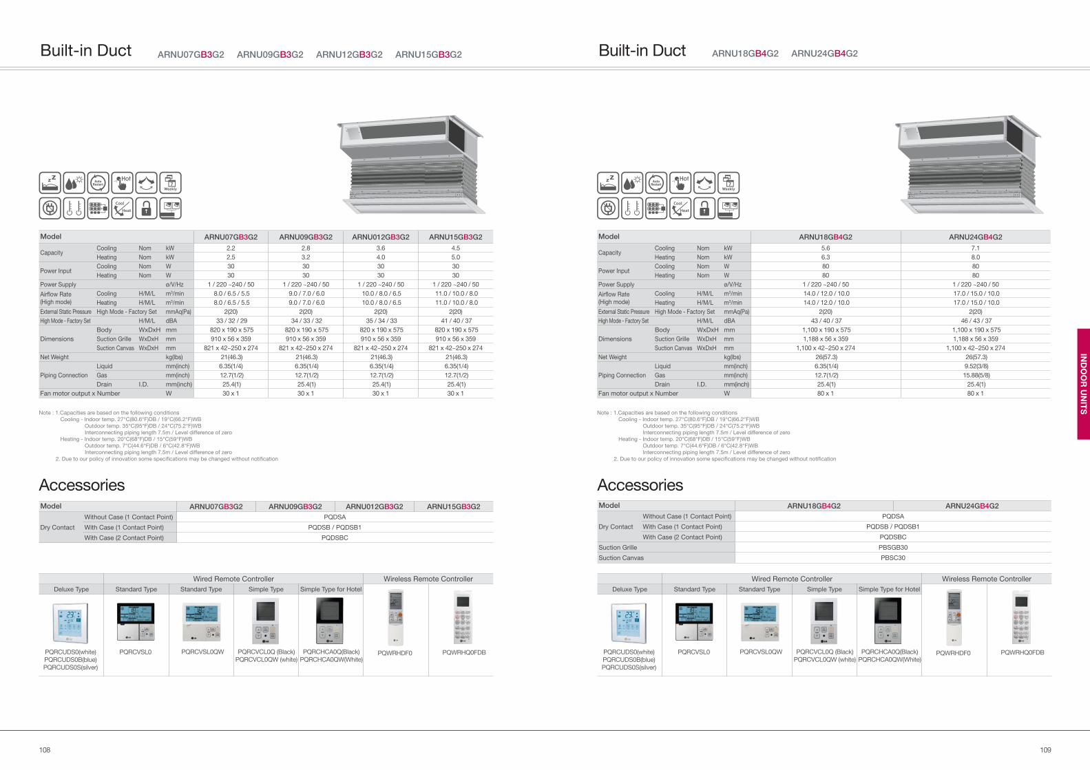
109108
IND
OO
R U
NIT
S
Model ARNU18GB4G2 ARNU24GB4G2
Dry Contact
Without Case (1 Contact Point) PQDSA
With Case (1 Contact Point) PQDSB / PQDSB1
With Case (2 Contact Point) PQDSBC
Suction Grille PBSGB30
Suction Canvas PBSC30
Model ARNU18GB4G2 ARNU24GB4G2
Capacity Cooling Nom kW 5.6 7.1
Heating Nom kW 6.3 8.0
Power Input Cooling Nom W 80 80
Heating Nom W 80 80
Power Supply ø/V/Hz 1 / 220 ~240 / 50 1 / 220 ~240 / 50
Airflow Rate
(High mode)
Cooling H/M/L m3/min 14.0 / 12.0 / 10.0 17.0 / 15.0 / 10.0
Heating H/M/L m3/min 14.0 / 12.0 / 10.0 17.0 / 15.0 / 10.0
External Static Pressure High Mode - Factory Set mmAq(Pa) 2(20) 2(20)
High Mode - Factory Set H/M/L dBA 43 / 40 / 37 46 / 43 / 37
Dimensions
Body WxDxH mm 1,100 x 190 x 575 1,100 x 190 x 575
Suction Grille WxDxH mm 1,188 x 56 x 359 1,188 x 56 x 359
Suction Canvas WxDxH mm 1,100 x 42~250 x 274 1,100 x 42~250 x 274
Net Weight kg(lbs) 26(57.3) 26(57.3)
Piping Connection
Liquid mm(inch) 6.35(1/4) 9.52(3/8)
Gas mm(inch) 12.7(1/2) 15.88(5/8)
Drain I.D. mm(inch) 25.4(1) 25.4(1)
Fan motor output x Number W 80 x 1 80 x 1
Note : 1.Capacities are based on the following conditions
Cooling - Indoor temp. 27°C(80.6°F)DB / 19°C(66.2°F)WB
Outdoor temp. 35°C(95°F)DB / 24°C(75.2°F)WB
Interconnecting piping length 7.5m / Level difference of zero
Heating - Indoor temp. 20°C(68°F)DB / 15°C(59°F)WB
Outdoor temp. 7°C(44.6°F)DB / 6°C(42.8°F)WB
Interconnecting piping length 7.5m / Level difference of zero
2. Due to our policy of innovation some specifications may be changed without notification
ARNU18GB4G2 ARNU24GB4G2Built-in Duct
Accessories
Wired Remote Controller Wireless Remote Controller
Deluxe Type Standard Type Standard Type Simple Type Simple Type for Hotel
PQRCVSL0QW PQRCHCA0Q(Black)
PQRCHCA0QW(White)PQWRHDF0 PQWRHQ0FDBPQRCVSL0 PQRCVCL0Q (Black)
PQRCVCL0QW (white)PQRCUDS0(white)
PQRCUDS0B(blue)
PQRCUDS0S(silver)
Model ARNU07GB3G2 ARNU09GB3G2 ARNU012GB3G2 ARNU15GB3G2
Capacity Cooling Nom kW 2.2 2.8 3.6 4.5
Heating Nom kW 2.5 3.2 4.0 5.0
Power Input Cooling Nom W 30 30 30 30
Heating Nom W 30 30 30 30
Power Supply ø/V/Hz 1 / 220 ~240 / 50 1 / 220 ~240 / 50 1 / 220 ~240 / 50 1 / 220 ~240 / 50
Airflow Rate
(High mode)
Cooling H/M/L m3/min 8.0 / 6.5 / 5.5 9.0 / 7.0 / 6.0 10.0 / 8.0 / 6.5 11.0 / 10.0 / 8.0
Heating H/M/L m3/min 8.0 / 6.5 / 5.5 9.0 / 7.0 / 6.0 10.0 / 8.0 / 6.5 11.0 / 10.0 / 8.0
External Static Pressure High Mode - Factory Set mmAq(Pa) 2(20) 2(20) 2(20) 2(20)
High Mode - Factory Set H/M/L dBA 33 / 32 / 29 34 / 33 / 32 35 / 34 / 33 41 / 40 / 37
Dimensions
Body WxDxH mm 820 x 190 x 575 820 x 190 x 575 820 x 190 x 575 820 x 190 x 575
Suction Grille WxDxH mm 910 x 56 x 359 910 x 56 x 359 910 x 56 x 359 910 x 56 x 359
Suction Canvas WxDxH mm 821 x 42~250 x 274 821 x 42~250 x 274 821 x 42~250 x 274 821 x 42~250 x 274
Net Weight kg(lbs) 21(46.3) 21(46.3) 21(46.3) 21(46.3)
Piping Connection
Liquid mm(inch) 6.35(1/4) 6.35(1/4) 6.35(1/4) 6.35(1/4)
Gas mm(inch) 12.7(1/2) 12.7(1/2) 12.7(1/2) 12.7(1/2)
Drain I.D. mm(inch) 25.4(1) 25.4(1) 25.4(1) 25.4(1)
Fan motor output x Number W 30 x 1 30 x 1 30 x 1 30 x 1
ARNU07GB3G2 ARNU09GB3G2 ARNU12GB3G2 ARNU15GB3G2Built-in Duct
Note : 1.Capacities are based on the following conditions
Cooling - Indoor temp. 27°C(80.6°F)DB / 19°C(66.2°F)WB
Outdoor temp. 35°C(95°F)DB / 24°C(75.2°F)WB
Interconnecting piping length 7.5m / Level difference of zero
Heating - Indoor temp. 20°C(68°F)DB / 15°C(59°F)WB
Outdoor temp. 7°C(44.6°F)DB / 6°C(42.8°F)WB
Interconnecting piping length 7.5m / Level difference of zero
2. Due to our policy of innovation some specifications may be changed without notification
Wired Remote Controller Wireless Remote Controller
Deluxe Type Standard Type Standard Type Simple Type Simple Type for Hotel
PQRCVSL0QW PQRCHCA0Q(Black)
PQRCHCA0QW(White)PQWRHDF0 PQWRHQ0FDBPQRCVSL0 PQRCVCL0Q (Black)
PQRCVCL0QW (white)PQRCUDS0(white)
PQRCUDS0B(blue)
PQRCUDS0S(silver)
AccessoriesModel ARNU07GB3G2 ARNU09GB3G2 ARNU012GB3G2 ARNU15GB3G2
Dry Contact
Without Case (1 Contact Point) PQDSA
With Case (1 Contact Point) PQDSB / PQDSB1
With Case (2 Contact Point) PQDSBC
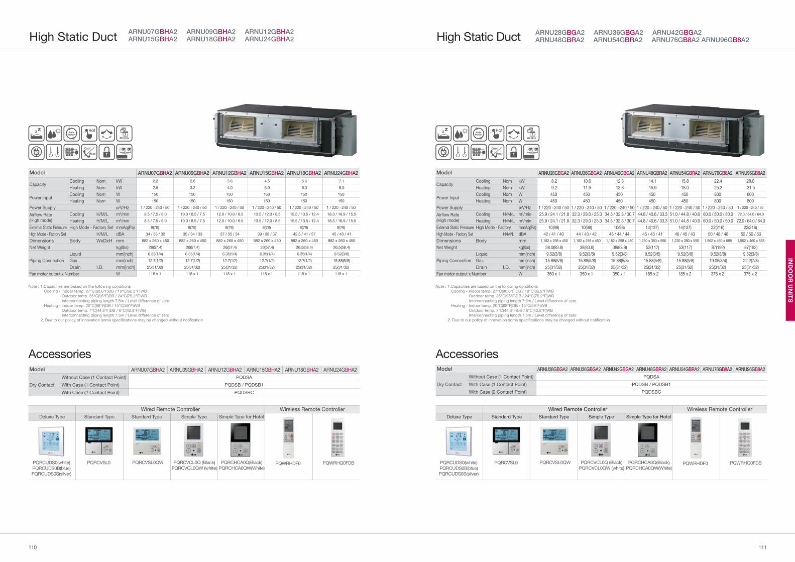
111110
IND
OO
R U
NIT
S
Model ARNU28GBGA2 ARNU36GBGA2 ARNU42GBGA2 ARNU48GBRA2 ARNU54GBRA2 ARNU76GB8A2 ARNU96GB8A2
Capacity Cooling Nom kW 8.2 10.6 12.3 14.1 15.8 22.4 28.0
Heating Nom kW 9.2 11.9 13.8 15.9 18.0 25.2 31.5
Power Input Cooling Nom W 450 450 450 450 450 800 800
Heating Nom W 450 450 450 450 450 800 800
Power Supply ø/V/Hz 1 / 220 ~240 / 50 1 / 220 ~240 / 50 1 / 220 ~240 / 50 1 / 220 ~240 / 50 1 / 220 ~240 / 50 1 / 220 ~240 / 50 1 / 220 ~240 / 50
Airflow Rate
(High mode)
Cooling H/M/L m3/min 25.9 / 24.1 / 21.8 32.3 / 29.0 / 25.3 34.5 / 32.3 / 30.7 44.8 / 40.6 / 33.3 51.0 / 44.8 / 40.6 60.0 / 50.0 / 50.0 72.0 / 64.0 / 64.0
Heating H/M/L m3/min 25.9 / 24.1 / 21.8 32.3 / 29.0 / 25.3 34.5 / 32.3 / 30.7 44.8 / 40.6 / 33.3 51.0 / 44.8 / 40.6 60.0 / 50.0 / 50.0 72.0 / 64.0 / 64.0
External Static Pressure High Mode - Factory mmAq(Pa) 10(98) 10(98) 10(98) 14(137) 14(137) 22(216) 22(216)
High Mode - Factory Set H/M/L dBA 42 / 41 / 40 44 / 43 / 42 45 / 44 / 44 45 / 43 / 41 46 / 45 / 43 50 / 48 / 48 52 / 50 / 50
Dimensions Body mm 1,182 x 298 x 450 1,182 x 298 x 450 1,182 x 298 x 450 1,230 x 380 x 590 1,230 x 380 x 590 1,562 x 460 x 688 1,562 x 460 x 688
Net Weight kg(lbs) 38.0(83.8) 38(83.8) 38(83.8) 53(117) 53(117) 87(192) 87(192)
Piping Connection
Liquid mm(inch) 9.52(3/8) 9.52(3/8) 9.52(3/8) 9.52(3/8) 9.52(3/8) 9.52(3/8) 9.52(3/8)
Gas mm(inch) 15.88(5/8) 15.88(5/8) 15.88(5/8) 15.88(5/8) 15.88(5/8) 19.05(3/4) 22.2(7/8)
Drain I.D. mm(inch) 25(31/32) 25(31/32) 25(31/32) 25(31/32) 25(31/32) 25(31/32) 25(31/32)
Fan motor output x Number W 350 x 1 350 x 1 350 x 1 185 x 2 185 x 2 375 x 2 375 x 2
Note : 1.Capacities are based on the following conditions
Cooling - Indoor temp. 27°C(80.6°F)DB / 19°C(66.2°F)WB
Outdoor temp. 35°C(95°F)DB / 24°C(75.2°F)WB
Interconnecting piping length 7.5m / Level difference of zero
Heating - Indoor temp. 20°C(68°F)DB / 15°C(59°F)WB
Outdoor temp. 7°C(44.6°F)DB / 6°C(42.8°F)WB
Interconnecting piping length 7.5m / Level difference of zero
2. Due to our policy of innovation some specifications may be changed without notification
ARNU28GBGA2 ARNU36GBGA2 ARNU42GBGA2ARNU48GBRA2 ARNU54GBRA2 ARNU76GB8A2 ARNU96GB8A2High Static Duct
Accessories
Wired Remote Controller Wireless Remote Controller
Deluxe Type Standard Type Standard Type Simple Type Simple Type for Hotel
PQRCVSL0QW PQRCHCA0Q(Black)
PQRCHCA0QW(White)PQWRHDF0 PQWRHQ0FDBPQRCVSL0 PQRCVCL0Q (Black)
PQRCVCL0QW (white)PQRCUDS0(white)
PQRCUDS0B(blue)
PQRCUDS0S(silver)
Model ARNU28GBGA2 ARNU36GBGA2 ARNU42GBGA2 ARNU48GBRA2 ARNU54GBRA2 ARNU76GB8A2 ARNU96GB8A2
Dry Contact
Without Case (1 Contact Point) PQDSA
With Case (1 Contact Point) PQDSB / PQDSB1
With Case (2 Contact Point) PQDSBC
Model ARNU07GBHA2 ARNU09GBHA2 ARNU12GBHA2 ARNU15GBHA2 ARNU18GBHA2 ARNU24GBHA2
Dry Contact
Without Case (1 Contact Point) PQDSA
With Case (1 Contact Point) PQDSB / PQDSB1
With Case (2 Contact Point) PQDSBC
Model ARNU07GBHA2 ARNU09GBHA2 ARNU12GBHA2 ARNU15GBHA2 ARNU18GBHA2 ARNU24GBHA2
Capacity Cooling Nom kW 2.2 2.8 3.6 4.5 5.6 7.1
Heating Nom kW 2.5 3.2 4.0 5.0 6.3 8.0
Power Input Cooling Nom W 150 150 150 150 150 150
Heating Nom W 150 150 150 150 150 150
Power Supply ø/V/Hz 1 / 220 ~240 / 50 1 / 220 ~240 / 50 1 / 220 ~240 / 50 1 / 220 ~240 / 50 1 / 220 ~240 / 50 1 / 220 ~240 / 50
Airflow Rate
(High mode)
Cooling H/M/L m3/min 8.5 / 7.5 / 6.0 10.0 / 8.5 / 7.5 12.0 / 10.0 / 8.5 13.5 / 12.0 / 8.5 15.5 / 13.5 / 12.4 18.3 / 16.9 / 15.5
Heating H/M/L m3/min 8.5 / 7.5 / 6.0 10.0 / 8.5 / 7.5 12.0 / 10.0 / 8.5 13.5 / 12.0 / 8.5 15.5 / 13.5 / 12.4 18.3 / 16.9 / 15.5
External Static Pressure High Mode - Factory Set mmAq(Pa) 8(78) 8(78) 8(78) 8(78) 8(78) 8(78)
High Mode - Factory Set H/M/L dBA 34 / 33 / 32 35 / 34 / 33 37 / 35 / 34 39 / 38 / 37 42.5 / 41 / 37 45 / 43 / 41
Dimensions Body WxDxH mm 882 x 260 x 450 882 x 260 x 450 882 x 260 x 450 882 x 260 x 450 882 x 260 x 450 882 x 260 x 450
Net Weight kg(lbs) 26(57.4) 26(57.4) 26(57.4) 26(57.4) 26.5(58.4) 26.5(58.4)
Piping Connection
Liquid mm(inch) 6.35(1/4) 6.35(1/4) 6.35(1/4) 6.35(1/4) 6.35(1/4) 9.52(3/8)
Gas mm(inch) 12.7(1/2) 12.7(1/2) 12.7(1/2) 12.7(1/2) 12.7(1/2) 15.88(5/8)
Drain I.D. mm(inch) 25(31/32) 25(31/32) 25(31/32) 25(31/32) 25(31/32) 25(31/32)
Fan motor output x Number W 118 x 1 118 x 1 118 x 1 118 x 1 118 x 1 118 x 1
ARNU07GBHA2 ARNU09GBHA2 ARNU12GBHA2 ARNU15GBHA2 ARNU18GBHA2 ARNU24GBHA2High Static Duct
Accessories
Wired Remote Controller Wireless Remote Controller
Deluxe Type Standard Type Standard Type Simple Type Simple Type for Hotel
PQRCVSL0QW PQRCHCA0Q(Black)
PQRCHCA0QW(White)PQWRHDF0 PQWRHQ0FDBPQRCVSL0 PQRCVCL0Q (Black)
PQRCVCL0QW (white)PQRCUDS0(white)
PQRCUDS0B(blue)
PQRCUDS0S(silver)
Note : 1.Capacities are based on the following conditions
Cooling - Indoor temp. 27°C(80.6°F)DB / 19°C(66.2°F)WB
Outdoor temp. 35°C(95°F)DB / 24°C(75.2°F)WB
Interconnecting piping length 7.5m / Level difference of zero
Heating - Indoor temp. 20°C(68°F)DB / 15°C(59°F)WB
Outdoor temp. 7°C(44.6°F)DB / 6°C(42.8°F)WB
Interconnecting piping length 7.5m / Level difference of zero
2. Due to our policy of innovation some specifications may be changed without notification
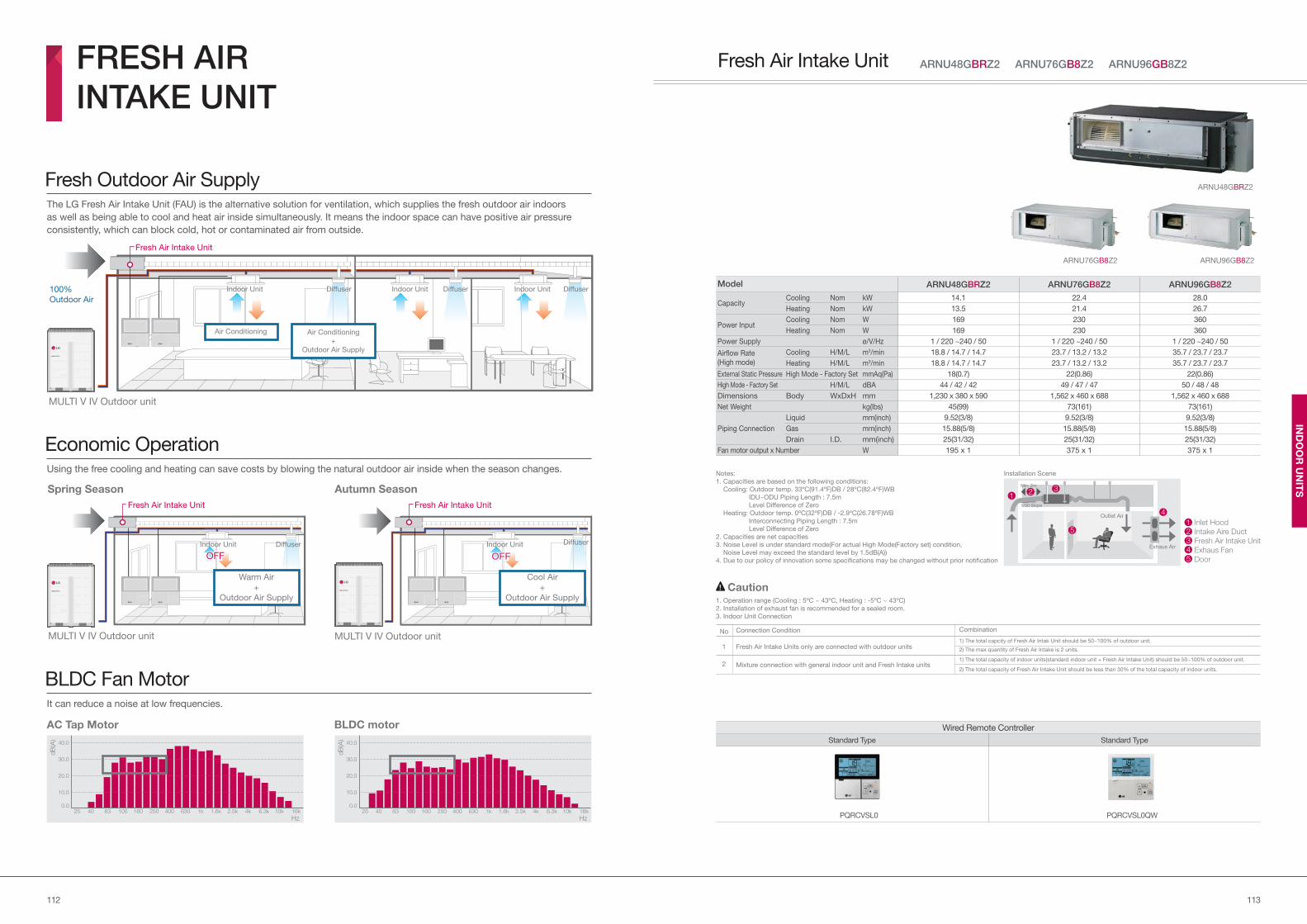
113112
IND
OO
R U
NIT
S
Model ARNU48GBRZ2 ARNU76GB8Z2 ARNU96GB8Z2
Capacity Cooling Nom kW 14.1 22.4 28.0
Heating Nom kW 13.5 21.4 26.7
Power Input Cooling Nom W 169 230 360
Heating Nom W 169 230 360
Power Supply ø/V/Hz 1 / 220 ~240 / 50 1 / 220 ~240 / 50 1 / 220 ~240 / 50
Airflow Rate
(High mode)
Cooling H/M/L m3/min 18.8 / 14.7 / 14.7 23.7 / 13.2 / 13.2 35.7 / 23.7 / 23.7
Heating H/M/L m3/min 18.8 / 14.7 / 14.7 23.7 / 13.2 / 13.2 35.7 / 23.7 / 23.7
External Static Pressure High Mode - Factory Set mmAq(Pa) 18(0.7) 22(0.86) 22(0.86)
High Mode - Factory Set H/M/L dBA 44 / 42 / 42 49 / 47 / 47 50 / 48 / 48
Dimensions Body WxDxH mm 1,230 x 380 x 590 1,562 x 460 x 688 1,562 x 460 x 688
Net Weight kg(lbs) 45(99) 73(161) 73(161)
Piping Connection
Liquid mm(inch) 9.52(3/8) 9.52(3/8) 9.52(3/8)
Gas mm(inch) 15.88(5/8) 15.88(5/8) 15.88(5/8)
Drain I.D. mm(inch) 25(31/32) 25(31/32) 25(31/32)
Fan motor output x Number W 195 x 1 375 x 1 375 x 1
Notes:
1. Capacities are based on the following conditions:
Cooling: Outdoor temp. 33ºC(91.4ºF)DB / 28ºC(82.4ºF)WB
IDU~ODU Piping Length : 7.5m
Level Difference of Zero
Heating: Outdoor temp. 0ºC(32ºF)DB / -2.9ºC(26.78ºF)WB
Interconnecting Piping Length : 7.5m
Level Difference of Zero
2. Capacities are net capacities
3. Noise Level is under standard mode(For actual High Mode(Factory set) condition,
Noise Level may exceed the standard level by 1.5dB(A))
4. Due to our policy of innovation some specifications may be changed without prior notification
ARNU48GBRZ2
ARNU76GB8Z2 ARNU96GB8Z2
Installation Scene
1. Operation range (Cooling : 5ºC ~ 43ºC, Heating : -5ºC ~ 43ºC)
2. Installation of exhaust fan is recommended for a sealed room.
3. Indoor Unit Connection
Caution
Wired Remote Controller
Standard Type Standard Type
PQRCVSL0 PQRCVSL0QW
Fresh Air Intake Units only are connected with outdoor units
Mixture connection with general indoor unit and Fresh Intake units
No
1
2
Connection Condition
1) The total capcity of Fresh Air Intak Unit should be 50~100% of outdoor unit.
2) The max quantity of Fresh Air Intake is 2 units.
1) The total capacity of indoor units(standard indoor unit + Fresh Air Intake Unit) should be 50~100% of outdoor unit.
2) The total capacity of Fresh Air Intake Unit should be less than 30% of the total capacity of indoor units.
Combination
ARNU48GBRZ2 ARNU76GB8Z2 ARNU96GB8Z2Fresh Air Intake Unit
The LG Fresh Air Intake Unit (FAU) is the alternative solution for ventilation, which supplies the fresh outdoor air indoors
as well as being able to cool and heat air inside simultaneously. It means the indoor space can have positive air pressure
consistently, which can block cold, hot or contaminated air from outside.
Using the free cooling and heating can save costs by blowing the natural outdoor air inside when the season changes.
It can reduce a noise at low frequencies.
Fresh Outdoor Air Supply
Economic Operation
BLDC Fan Motor
FRESH AIR
INTAKE UNIT
MULTI V IV Outdoor unit
100%
Outdoor Air
Indoor Unit Indoor Unit Indoor UnitDiffuser Diffuser Diffuser
Air Conditioning Air Conditioning
+
Outdoor Air Supply
Fresh Air Intake Unit
AC Tap Motor
MULTI V IV Outdoor unit
Indoor Unit Diffuser
OFF
Cool Air
+
Outdoor Air Supply
MULTI V IV Outdoor unit
Indoor Unit
OFF
Warm Air
+
Outdoor Air Supply
Diffuser
Spring Season Autumn Season
BLDC motor
250.0
10.0
20.0
30.0
40.0
dB
(A)
Hz40 63 100 160 250 400 630 1k 1.6k 2.5k 4k 6.3k 10k 16k25
0.0
10.0
20.0
30.0
40.0
dB
(A)
Hz40 63 100 160 250 400 630 1k 1.6k 2.5k 4k 6.3k 10k 16k
Min. 2m
1/30 Slope
Outlet Air
Exhaus Air
3
4
5Inlet Hood
Intake Aire Duct
Fresh Air Intake Unit
Exhaus Fan
Door
12345
12
Fresh Air Intake Unit Fresh Air Intake Unit
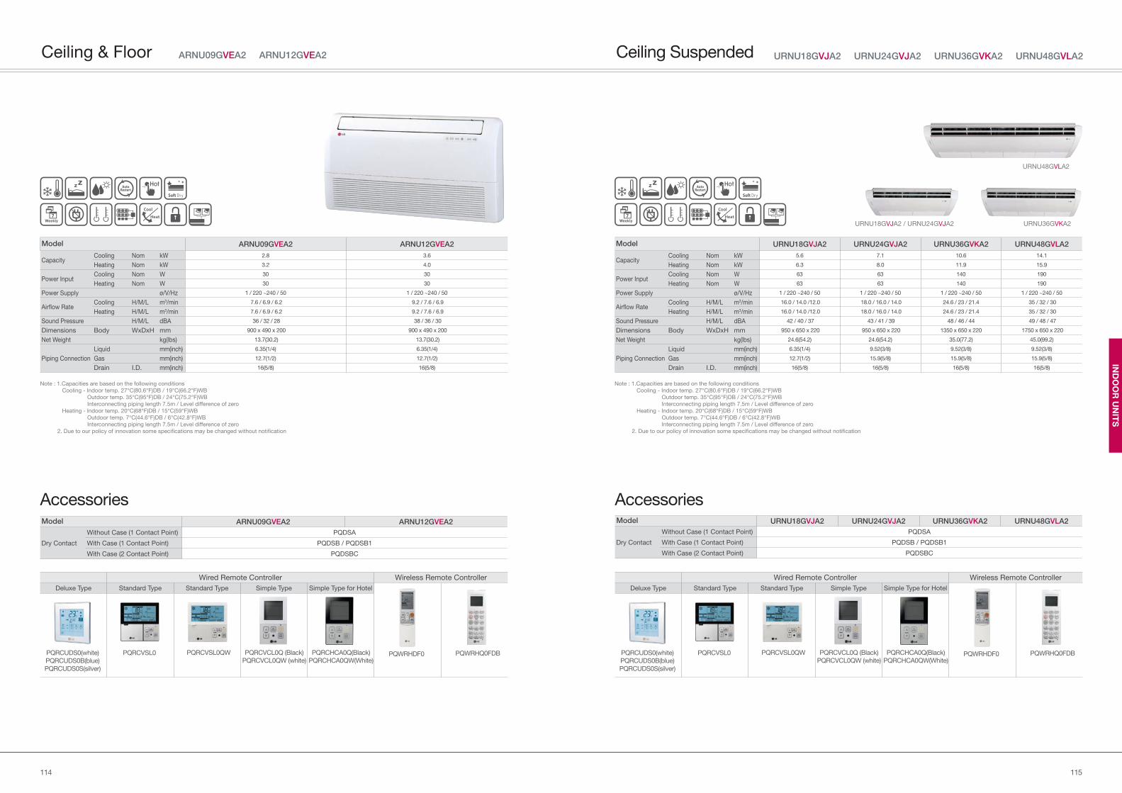
115114
IND
OO
R U
NIT
S
Model URNU18GVJA2 URNU24GVJA2 URNU36GVKA2 URNU48GVLA2
Dry Contact
Without Case (1 Contact Point) PQDSA
With Case (1 Contact Point) PQDSB / PQDSB1
With Case (2 Contact Point) PQDSBC
Model URNU18GVJA2 URNU24GVJA2 URNU36GVKA2 URNU48GVLA2
Capacity Cooling Nom kW 5.6 7.1 10.6 14.1
Heating Nom kW 6.3 8.0 11.9 15.9
Power Input Cooling Nom W 63 63 140 190
Heating Nom W 63 63 140 190
Power Supply ø/V/Hz 1 / 220 ~240 / 50 1 / 220 ~240 / 50 1 / 220 ~240 / 50 1 / 220 ~240 / 50
Airflow RateCooling H/M/L m3/min 16.0 / 14.0 /12.0 18.0 / 16.0 / 14.0 24.6 / 23 / 21.4 35 / 32 / 30
Heating H/M/L m3/min 16.0 / 14.0 /12.0 18.0 / 16.0 / 14.0 24.6 / 23 / 21.4 35 / 32 / 30
Sound Pressure H/M/L dBA 42 / 40 / 37 43 / 41 / 39 48 / 46 / 44 49 / 48 / 47
Dimensions Body WxDxH mm 950 x 650 x 220 950 x 650 x 220 1350 x 650 x 220 1750 x 650 x 220
Net Weight kg(lbs) 24.6(54.2) 24.6(54.2) 35.0(77.2) 45.0(99.2)
Piping Connection
Liquid mm(inch) 6.35(1/4) 9.52(3/8) 9.52(3/8) 9.52(3/8)
Gas mm(inch) 12.7(1/2) 15.9(5/8) 15.9(5/8) 15.9(5/8)
Drain I.D. mm(inch) 16(5/8) 16(5/8) 16(5/8) 16(5/8)
Note : 1.Capacities are based on the following conditions
Cooling - Indoor temp. 27°C(80.6°F)DB / 19°C(66.2°F)WB
Outdoor temp. 35°C(95°F)DB / 24°C(75.2°F)WB
Interconnecting piping length 7.5m / Level difference of zero
Heating - Indoor temp. 20°C(68°F)DB / 15°C(59°F)WB
Outdoor temp. 7°C(44.6°F)DB / 6°C(42.8°F)WB
Interconnecting piping length 7.5m / Level difference of zero
2. Due to our policy of innovation some specifications may be changed without notification
URNU18GVJA2 URNU24GVJA2 URNU36GVKA2 URNU48GVLA2Ceiling Suspended
Accessories
Wired Remote Controller Wireless Remote Controller
Deluxe Type Standard Type Standard Type Simple Type Simple Type for Hotel
PQRCVSL0QW PQRCHCA0Q(Black)
PQRCHCA0QW(White)PQWRHDF0 PQWRHQ0FDBPQRCVSL0 PQRCVCL0Q (Black)
PQRCVCL0QW (white)PQRCUDS0(white)
PQRCUDS0B(blue)
PQRCUDS0S(silver)
URNU18GVJA2 / URNU24GVJA2 URNU36GVKA2
URNU48GVLA2
Model ARNU09GVEA2 ARNU12GVEA2
Dry Contact
Without Case (1 Contact Point) PQDSA
With Case (1 Contact Point) PQDSB / PQDSB1
With Case (2 Contact Point) PQDSBC
Model ARNU09GVEA2 ARNU12GVEA2
Capacity Cooling Nom kW 2.8 3.6
Heating Nom kW 3.2 4.0
Power Input Cooling Nom W 30 30
Heating Nom W 30 30
Power Supply ø/V/Hz 1 / 220 ~240 / 50 1 / 220 ~240 / 50
Airflow RateCooling H/M/L m3/min 7.6 / 6.9 / 6.2 9.2 / 7.6 / 6.9
Heating H/M/L m3/min 7.6 / 6.9 / 6.2 9.2 / 7.6 / 6.9
Sound Pressure H/M/L dBA 36 / 32 / 28 38 / 36 / 30
Dimensions Body WxDxH mm 900 x 490 x 200 900 x 490 x 200
Net Weight kg(lbs) 13.7(30.2) 13.7(30.2)
Piping Connection
Liquid mm(inch) 6.35(1/4) 6.35(1/4)
Gas mm(inch) 12.7(1/2) 12.7(1/2)
Drain I.D. mm(inch) 16(5/8) 16(5/8)
ARNU09GVEA2 ARNU12GVEA2Ceiling & Floor
Note : 1.Capacities are based on the following conditions
Cooling - Indoor temp. 27°C(80.6°F)DB / 19°C(66.2°F)WB
Outdoor temp. 35°C(95°F)DB / 24°C(75.2°F)WB
Interconnecting piping length 7.5m / Level difference of zero
Heating - Indoor temp. 20°C(68°F)DB / 15°C(59°F)WB
Outdoor temp. 7°C(44.6°F)DB / 6°C(42.8°F)WB
Interconnecting piping length 7.5m / Level difference of zero
2. Due to our policy of innovation some specifications may be changed without notification
Accessories
Wired Remote Controller Wireless Remote Controller
Deluxe Type Standard Type Standard Type Simple Type Simple Type for Hotel
PQRCVSL0QW PQRCHCA0Q(Black)
PQRCHCA0QW(White)PQWRHDF0 PQWRHQ0FDBPQRCVSL0 PQRCVCL0Q (Black)
PQRCVCL0QW (white)PQRCUDS0(white)
PQRCUDS0B(blue)
PQRCUDS0S(silver)
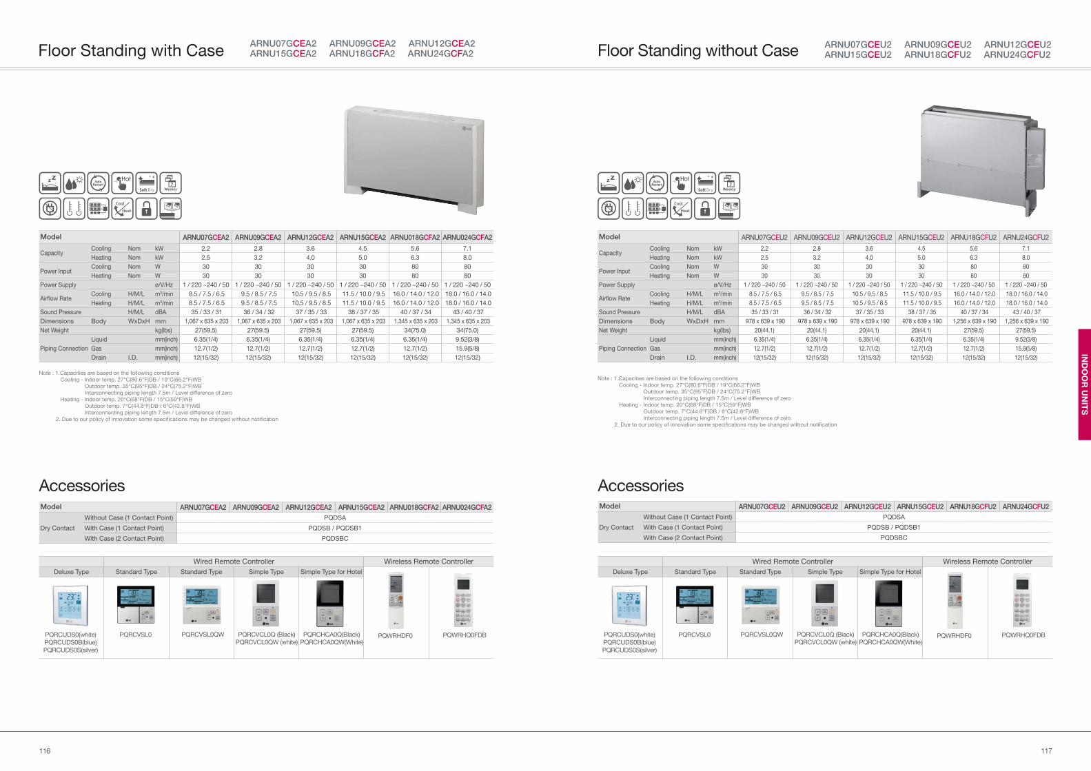
117116
IND
OO
R U
NIT
S
Model ARNU07GCEU2 ARNU09GCEU2 ARNU12GCEU2 ARNU15GCEU2 ARNU18GCFU2 ARNU24GCFU2
Dry Contact
Without Case (1 Contact Point) PQDSA
With Case (1 Contact Point) PQDSB / PQDSB1
With Case (2 Contact Point) PQDSBC
Model ARNU07GCEU2 ARNU09GCEU2 ARNU12GCEU2 ARNU15GCEU2 ARNU18GCFU2 ARNU24GCFU2
Capacity Cooling Nom kW 2.2 2.8 3.6 4.5 5.6 7.1
Heating Nom kW 2.5 3.2 4.0 5.0 6.3 8.0
Power Input Cooling Nom W 30 30 30 30 80 80
Heating Nom W 30 30 30 30 80 80
Power Supply ø/V/Hz 1 / 220 ~240 / 50 1 / 220 ~240 / 50 1 / 220 ~240 / 50 1 / 220 ~240 / 50 1 / 220 ~240 / 50 1 / 220 ~240 / 50
Airflow RateCooling H/M/L m3/min 8.5 / 7.5 / 6.5 9.5 / 8.5 / 7.5 10.5 / 9.5 / 8.5 11.5 / 10.0 / 9.5 16.0 / 14.0 / 12.0 18.0 / 16.0 / 14.0
Heating H/M/L m3/min 8.5 / 7.5 / 6.5 9.5 / 8.5 / 7.5 10.5 / 9.5 / 8.5 11.5 / 10.0 / 9.5 16.0 / 14.0 / 12.0 18.0 / 16.0 / 14.0
Sound Pressure H/M/L dBA 35 / 33 / 31 36 / 34 / 32 37 / 35 / 33 38 / 37 / 35 40 / 37 / 34 43 / 40 / 37
Dimensions Body WxDxH mm 978 x 639 x 190 978 x 639 x 190 978 x 639 x 190 978 x 639 x 190 1,256 x 639 x 190 1,256 x 639 x 190
Net Weight kg(lbs) 20(44.1) 20(44.1) 20(44.1) 20(44.1) 27(59.5) 27(59.5)
Piping Connection
Liquid mm(inch) 6.35(1/4) 6.35(1/4) 6.35(1/4) 6.35(1/4) 6.35(1/4) 9.52(3/8)
Gas mm(inch) 12.7(1/2) 12.7(1/2) 12.7(1/2) 12.7(1/2) 12.7(1/2) 15.9(5/8)
Drain I.D. mm(inch) 12(15/32) 12(15/32) 12(15/32) 12(15/32) 12(15/32) 12(15/32)
Note : 1.Capacities are based on the following conditions
Cooling - Indoor temp. 27°C(80.6°F)DB / 19°C(66.2°F)WB
Outdoor temp. 35°C(95°F)DB / 24°C(75.2°F)WB
Interconnecting piping length 7.5m / Level difference of zero
Heating - Indoor temp. 20°C(68°F)DB / 15°C(59°F)WB
Outdoor temp. 7°C(44.6°F)DB / 6°C(42.8°F)WB
Interconnecting piping length 7.5m / Level difference of zero
2. Due to our policy of innovation some specifications may be changed without notification
ARNU07GCEU2 ARNU09GCEU2 ARNU12GCEU2ARNU15GCEU2 ARNU18GCFU2 ARNU24GCFU2Floor Standing without Case
Accessories
Wired Remote Controller Wireless Remote Controller
Deluxe Type Standard Type Standard Type Simple Type Simple Type for Hotel
PQRCVSL0QW PQRCHCA0Q(Black)
PQRCHCA0QW(White)PQWRHDF0 PQWRHQ0FDBPQRCVSL0 PQRCVCL0Q (Black)
PQRCVCL0QW (white)PQRCUDS0(white)
PQRCUDS0B(blue)
PQRCUDS0S(silver)
Model ARNU07GCEA2 ARNU09GCEA2 ARNU12GCEA2 ARNU15GCEA2 ARNU018GCFA2 ARNU024GCFA2
Dry Contact
Without Case (1 Contact Point) PQDSA
With Case (1 Contact Point) PQDSB / PQDSB1
With Case (2 Contact Point) PQDSBC
Model ARNU07GCEA2 ARNU09GCEA2 ARNU12GCEA2 ARNU15GCEA2 ARNU018GCFA2 ARNU024GCFA2
Capacity Cooling Nom kW 2.2 2.8 3.6 4.5 5.6 7.1
Heating Nom kW 2.5 3.2 4.0 5.0 6.3 8.0
Power Input Cooling Nom W 30 30 30 30 80 80
Heating Nom W 30 30 30 30 80 80
Power Supply ø/V/Hz 1 / 220 ~240 / 50 1 / 220 ~240 / 50 1 / 220 ~240 / 50 1 / 220 ~240 / 50 1 / 220 ~240 / 50 1 / 220 ~240 / 50
Airflow RateCooling H/M/L m3/min 8.5 / 7.5 / 6.5 9.5 / 8.5 / 7.5 10.5 / 9.5 / 8.5 11.5 / 10.0 / 9.5 16.0 / 14.0 / 12.0 18.0 / 16.0 / 14.0
Heating H/M/L m3/min 8.5 / 7.5 / 6.5 9.5 / 8.5 / 7.5 10.5 / 9.5 / 8.5 11.5 / 10.0 / 9.5 16.0 / 14.0 / 12.0 18.0 / 16.0 / 14.0
Sound Pressure H/M/L dBA 35 / 33 / 31 36 / 34 / 32 37 / 35 / 33 38 / 37 / 35 40 / 37 / 34 43 / 40 / 37
Dimensions Body WxDxH mm 1,067 x 635 x 203 1,067 x 635 x 203 1,067 x 635 x 203 1,067 x 635 x 203 1,345 x 635 x 203 1,345 x 635 x 203
Net Weight kg(lbs) 27(59.5) 27(59.5) 27(59.5) 27(59.5) 34(75.0) 34(75.0)
Piping Connection
Liquid mm(inch) 6.35(1/4) 6.35(1/4) 6.35(1/4) 6.35(1/4) 6.35(1/4) 9.52(3/8)
Gas mm(inch) 12.7(1/2) 12.7(1/2) 12.7(1/2) 12.7(1/2) 12.7(1/2) 15.9(5/8)
Drain I.D. mm(inch) 12(15/32) 12(15/32) 12(15/32) 12(15/32) 12(15/32) 12(15/32)
ARNU07GCEA2 ARNU09GCEA2 ARNU12GCEA2 ARNU15GCEA2 ARNU18GCFA2 ARNU24GCFA2Floor Standing with Case
Note : 1.Capacities are based on the following conditions
Cooling - Indoor temp. 27°C(80.6°F)DB / 19°C(66.2°F)WB
Outdoor temp. 35°C(95°F)DB / 24°C(75.2°F)WB
Interconnecting piping length 7.5m / Level difference of zero
Heating - Indoor temp. 20°C(68°F)DB / 15°C(59°F)WB
Outdoor temp. 7°C(44.6°F)DB / 6°C(42.8°F)WB
Interconnecting piping length 7.5m / Level difference of zero
2. Due to our policy of innovation some specifications may be changed without notification
Accessories
Wired Remote Controller Wireless Remote Controller
Deluxe Type Standard Type Standard Type Simple Type Simple Type for Hotel
PQRCVSL0QW PQRCHCA0Q(Black)
PQRCHCA0QW(White)PQWRHDF0 PQWRHQ0FDBPQRCVSL0 PQRCVCL0Q (Black)
PQRCVCL0QW (white)PQRCUDS0(white)
PQRCUDS0B(blue)
PQRCUDS0S(silver)
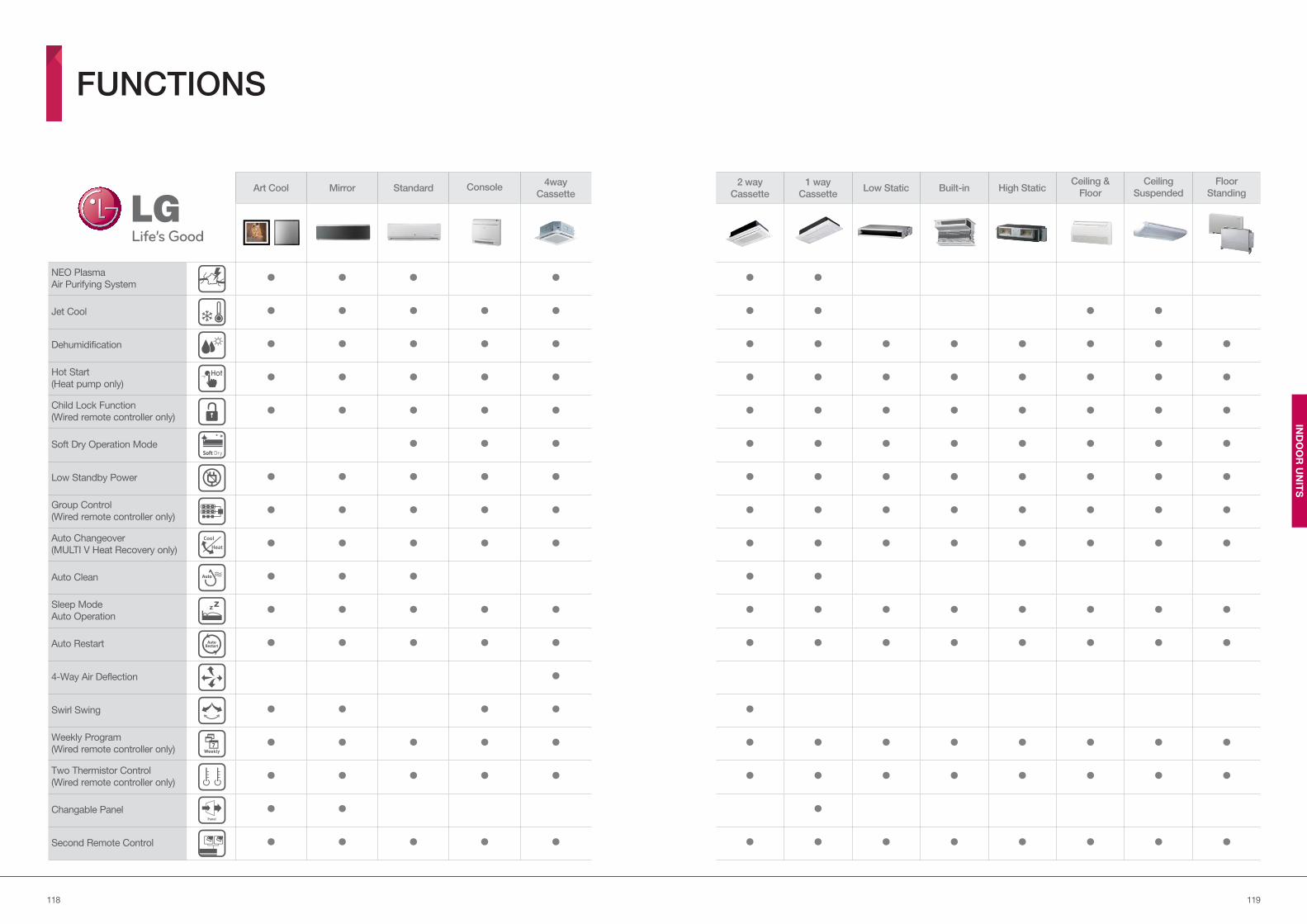
119118
IND
OO
R U
NIT
S
FUNCTIONS
Art Cool Mirror Standard Console4way
Cassette
2 way
Cassette
1 way
CassetteLow Static Built-in High Static
Ceiling &
Floor
Ceiling
Suspended
Floor
Standing
NEO Plasma
Air Purifying System
Jet Cool
Dehumidification
Hot Start
(Heat pump only)
Child Lock Function
(Wired remote controller only)
Soft Dry Operation Mode
Low Standby Power
Group Control
(Wired remote controller only)
Auto Changeover
(MULTI V Heat Recovery only)
Auto Clean
Sleep Mode
Auto Operation
Auto Restart
4-Way Air Deflection
Swirl Swing
Weekly Program
(Wired remote controller only)
Two Thermistor Control
(Wired remote controller only)
Changable Panel
Second Remote Control
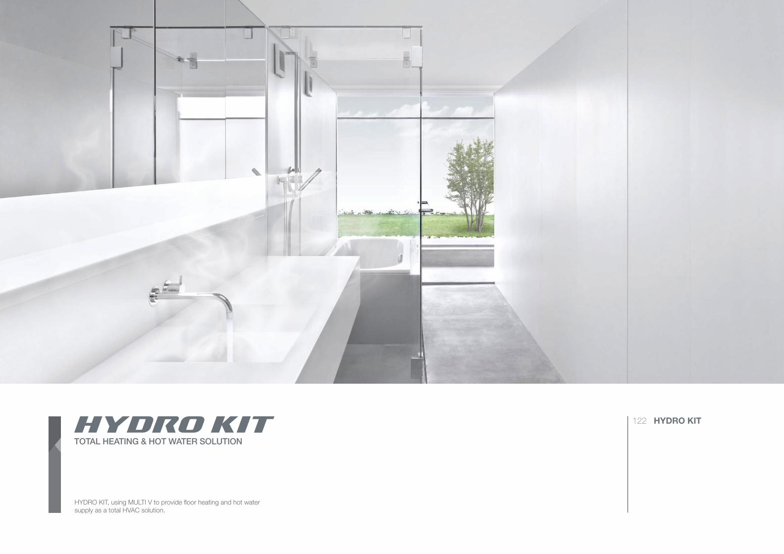
IND
OO
R U
NIT
S
HYDRO KIT, using MULTI V to provide floor heating and hot water
supply as a total HVAC solution.
122 HYDRO KIT
TOTAL HEATING & HOT WATER SOLUTION
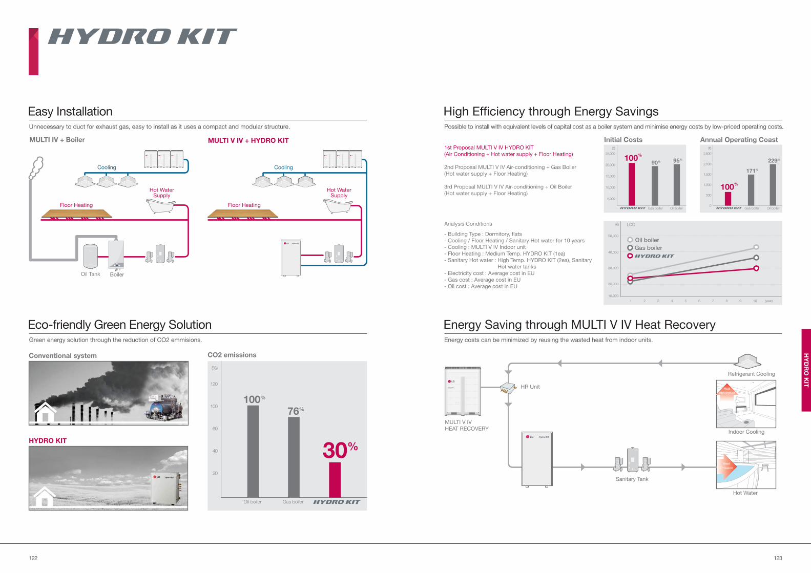
123122
HY
DR
O K
IT
Unnecessary to duct for exhaust gas, easy to install as it uses a compact and modular structure.
Easy Installation High Efficiency through Energy SavingsPossible to install with equivalent levels of capital cost as a boiler system and minimise energy costs by low-priced operating costs.
Energy Saving through MULTI V IV Heat RecoveryEnergy costs can be minimized by reusing the wasted heat from indoor units. Green energy solution through the reduction of CO2 emmisions.
Eco-friendly Green Energy Solution
Conventional system
HYDRO KIT
CO2 emissions
20
40
60
100
120
(%)
Oil boiler Gas boiler
100%
76%
30%
MULTI IV + Boiler MULTI V IV + HYDRO KIT
Hot WaterSupply
Cooling
Oil Tank
Floor Heating
Boiler
Floor Heating
Cooling
1st Proposal MULTI V IV HYDRO KIT
(Air Conditioning + Hot water supply + Floor Heating)
2nd Proposal MULTI V IV Air-conditioning + Gas Boiler
(Hot water supply + Floor Heating)
3rd Proposal MULTI V IV Air-conditioning + Oil Boiler
(Hot water supply + Floor Heating)
Analysis Conditions
- Building Type : Dormitory, flats
- Cooling / Floor Heating / Sanitary Hot water for 10 years
- Cooling : MULTI V IV Indoor unit
- Floor Heating : Medium Temp. HYDRO KIT (1ea)
- Sanitary Hot water : High Temp. HYDRO KIT (2ea), Sanitary
Hot water tanks
- Electricity cost : Average cost in EU
- Gas cost : Average cost in EU
- Oil cost : Average cost in EU
(year)1
10,000
20,000
30,000
40,000
50,000
LCC
2 3 4 5 6 7 8 9 10
Oil boiler
Gas boiler
(€)
Annual Operating CoastInitial Costs
5,000
10,000
15,000
20,000
25,000
(€)
Oil boilerGas boiler
95%
90%100
%
500
0
1,000
1,500
2,000
2,500
(€)
229%
171%
Oil boilerGas boiler
100%
HR Unit
Indoor Cooling
Heat
Absorption
Sanitary Tank
MULTI V IV
HEAT RECOVERY
Hot Water
Heat
Emission
Refrigerant Cooling
Hot WaterSupply
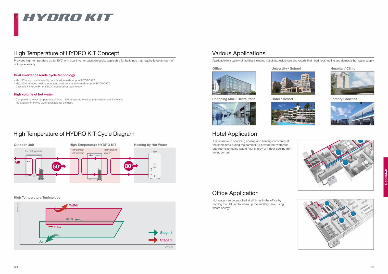
125124
HY
DR
O K
IT
Provides high temperature up to 80ºC with dual inverter cascade cycle, applicable for buildings that require large amount of
hot water supply.
High Temperature of HYDRO KIT Concept Various ApplicationsApplicable to a variety of facilities including hospitals, residences and resorts that need floor heating and domestic hot water supply.
Hotel ApplicationIt is possible to operating cooling and heating constantly at
the same time during the summer, to provide hot water for
bathrooms by using waste heat energy of indoor cooling from
an indoor unit.
Office ApplicationHot water can be supplied at all times in the office by
cooling the HR unit to warm up the sanitary tank, using
waste energy.
- Max 55% improved capacity compared to mid-temp. of HYDRO KIT
- Max 20% reduced heating operating cost compared to mid-temp. of HYDRO KIT
- Cascade R410A to R134a BLDC compressor technology
Dual inverter cascade cycle technology
- Compared to lower temperature, storing high temperature water in a sanitary tank increases
the quantity of mixed water available for the user.
High volume of hot water
High Temperature of HYDRO KIT Cycle Diagram
AIR
Outdoor Unit
Air-Refrigerant Refrigerant -
Water
Refrigerant -
Refrigerant
High Temperature HYDRO KIT Heating by Hot Water
High Temperature Technology
Pre
ssure
Enthalpy
Stage 2
Stage 1
Water
Air
R410A
R134A
80ºC
50ºC
Office
Shopping Mall / Restaurant
University / School
Hotel / Resort
Hospital / Clinic
Factory Facilities
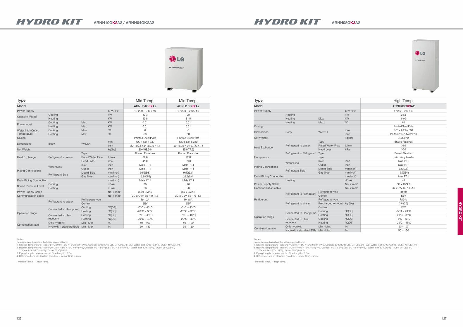
127126
HY
DR
O K
IT
ARNH08GK3A2
Type High Temp.
Model ARNH08GK3A2
Power Supply ø/ V / Hz 1 / 220 ~ 240 / 50
Heating kW 25.2
Heating Max kW 5.00
Heating Max ºC 80
Casing Painted Steel Plate
Dimensions Body WxDxHmm 520 x 1,080 x 330
inch 20-15/32 x 42-17/32 x 13
Net Weight kg(lbs) 94.0(207.2)
Heat ExchangerRefrigerant to Water
Type Brazed Plate Hex
Rated Water Flow L/min 36.0
Head Loss kPa 30.0
Refrigerant to Refrigerant Type Brazed Plate Hex
Compressor Type Twin Rotary Inverter
Piping Connections
Water SideInlet inch Male PT 1
Outlet inch Male PT 1
Refrigerant SideLiquid Side mm(inch) 9.52(3/8)
Gas Side mm(inch) 19.05(3/4)
Drain Piping Connectiion mm(inch) Male PT 1
Heating dB(A) 43
Power Supply Cable No. x mm2 3C x CV4.0
Communication cable No. x mm2 2C x CVV-SB 1.0~1.5
Refrigerant
Refrigerant to RefrigerantRefrigerant type R410a
Control EEV
Refrigerant to Water
Refrigerant type R134a
Precharged Amount kg (lbs) 3.0 (6.6)
Control EEV
Operation range
Connected to Heat pumpCooling °C(DB) -5°C ~ 43°C
Heating °C(DB) -20°C ~ 35°C
Connected to Heat
recovery
Cooling °C(DB) -5°C ~ 43°C
Heating °C(DB) -20°C ~ 43°C
Combination ratioOnly hydrokit Min ~Max % 50 ~ 100
Hydrokit + standard IDUs Min ~Max % 50 ~ 130
*Notes
Capacities are based on the following conditions:
1. Cooling Temperature : Indoor 27°C(80.6°F) DB / 19°C(66.2°F) WB, Outdoor 35°C(95°F) DB / 24°C(75.2°F) WB, Water Inlet 23°C(73.4°F) / Outlet 18°C(64.4°F)
2. Heating Temperature : Indoor 20°C(68°F) DB / 15°C(59°F) WB, Outdoor 7°C(44.6°F) DB / 6°C(42.8°F) WB, * Water Inlet 30°C(86°F) / Outlet 35°C(95°F),
** Water Inlet 55°C(131°F) / Outlet 65°C(149°F)
3. Piping Length : Interconnected Pipe Length = 7.5m
4. Difference Limit of Elevation (Outdoor ~ Indoor Unit) is Zero.
* Medium Temp. ** High Temp.
ARNH10GK2A2 / ARNH04GK2A2
Type Mid Temp. Mid Temp.
Model ARNH04GK2A2 ARNH10GK2A2
Power Supply ø/ V / Hz 1 / 220 ~ 240 / 50 1 / 220 ~ 240 / 50
Capacity (Rated)Cooling kW 12.3 28
Heating kW 13.8 31.5
Power Input Cooling Max kW 0.01 0.01
Heating Max kW 0.01 0.01
Water Inlet/Outlet
Temperature
Cooling M in ºC 6 6
Heating Max ºC 50 50
Casing Painted Steel Plate Painted Steel Plate
Dimensions Body WxDxHmm 520 x 631 x 330 520 x 631 x 330
inch 20-15/32 x 24-27/32 x 13 20-15/32 x 24-27/32 x 13
Net Weight kg(lbs) 30.4(68.34) 35.0(77.2)
Heat Exchanger Refrigerant to Water
Type Brazed Plate Hex Brazed Plate Hex
Rated Water Flow L/min 39.6 92.0
Head Loss kPa 41.0 69.0
Piping Connections
Water SideInlet inch Male PT 1 Male PT 1
Outlet inch Male PT 1 Male PT 1
Refrigerant SideLiquid Side mm(inch) 9.52(3/8) 9.52(3/8)
Gas Side mm(inch) 15.88(5/8) 22.2(7/8)
Drain Piping Connectiion mm(inch) Male PT 1 Male PT 1
Sound Pressure LevelCooling dB(A) 26 26
Heating dB(A) 26 26
Power Supply Cable No. x mm2 3C x CV2.5 3C x CV2.5
Communication cable No. x mm2 2C x CVV-SB 1.0~1.5 2C x CVV-SB 1.0~1.5
Refrigerant to WaterRefrigerant type R410A R410A
Control EEV EEV
Operation range
Connected to Heat pumpCooling °C(DB) -5°C ~ 43°C -5°C ~ 43°C
Heating °C(DB) -20°C ~ 35°C -20°C ~ 35°C
Connected to Heat
recovery
Cooling °C(DB) -5°C ~ 43°C -5°C ~ 43°C
Heating °C(DB) -20°C ~ 43°C -20°C ~ 43°C
Combination ratioOnly hydrokit Min ~Max % 50 ~ 100 50 ~ 100
Hydrokit + standard IDUs Min ~Max % 50 ~ 130 50 ~ 130
*Notes
Capacities are based on the following conditions:
1. Cooling Temperature : Indoor 27°C(80.6°F) DB / 19°C(66.2°F) WB, Outdoor 35°C(95°F) DB / 24°C(75.2°F) WB, Water Inlet 23°C(73.4°F) / Outlet 18°C(64.4°F)
2. Heating Temperature : Indoor 20°C(68°F) DB / 15°C(59°F) WB, Outdoor 7°C(44.6°F) DB / 6°C(42.8°F) WB, * Water Inlet 30°C(86°F) / Outlet 35°C(95°F),
** Water Inlet 55°C(131°F) / Outlet 65°C(149°F)
3. Piping Length : Interconnected Pipe Length = 7.5m
4. Difference Limit of Elevation (Outdoor ~ Indoor Unit) is Zero.
* Medium Temp. ** High Temp.
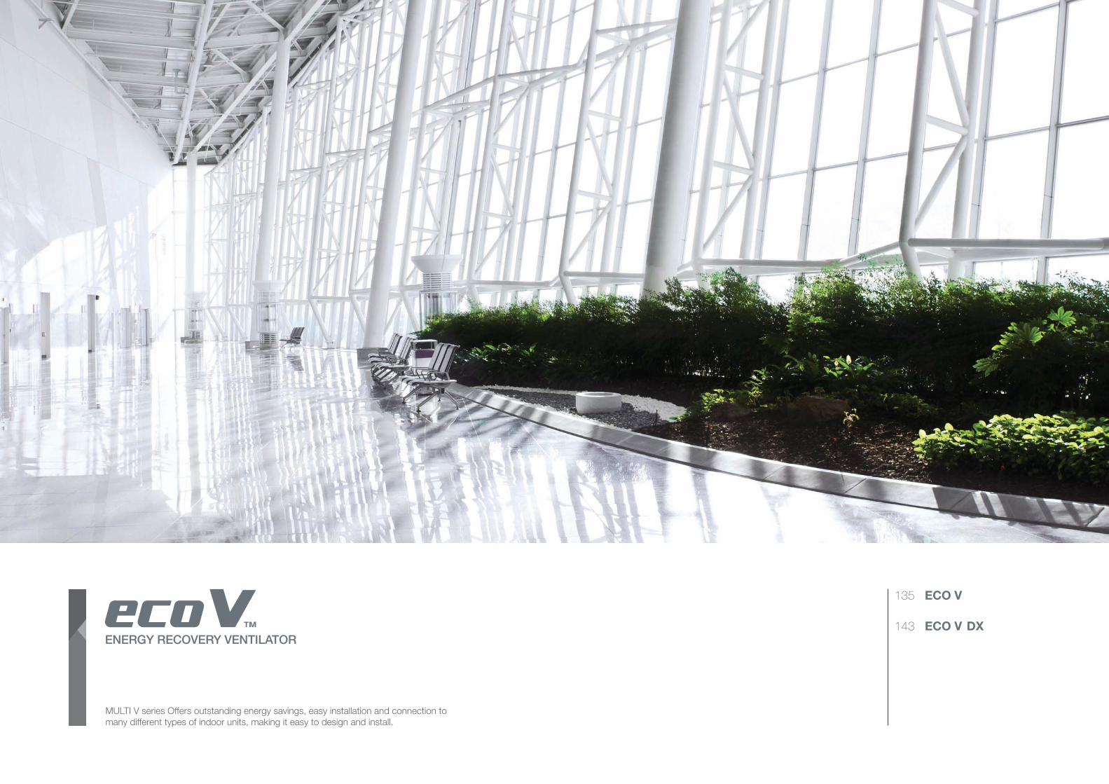
MULTI V series Offers outstanding energy savings, easy installation and connection to
many different types of indoor units, making it easy to design and install.
ENERGY RECOVERY VENTILATOR
135 ECO V
143 ECO V DX
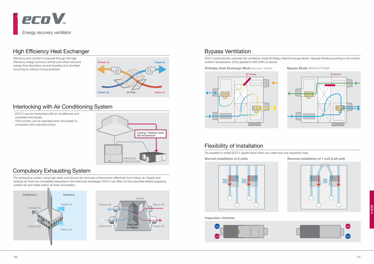
131130
EC
O V
Efficiency and comfort is ensured through the high-
efficiency energy recovery central core which recovers
energy from the indoor air and transfers it to the fresh
incoming air without mixing airstream.
- ECO V can be interlocked with air conditioners and
controlled individually.
- This function can be operated when the system is
connected with a remote control.
The exhausting system using high static and sirocco fan removes contaminants effectively from indoor air. Supply and
exhaust air flows are completely separated in the total heat exchanger, ECO V can filter out the impurities before supplying
outdoor air and make indoor air fresh and healthy.
High Efficiency Heat Exchanger
Interlocking with Air Conditioning System
Compulsory Exhausting System
Bypass VentilationECO V automatically switches the ventilation mode (Enthalpy Heat Exchange Mode / Bypass Mode) according to the indoor/
outdoor temperature. (Only applied to 500 CMH or above)Exhaust air
Outdoor air
Supply air
Air Filter Indoor air
Outdoors Indoors
Supply Air
Outdoor Air
Exhaust Air
Damper
Return Air
Supply AirOutdoor Air
Exhaust Air
Return Air
Total Heat
Exchanger
PQRCVSL0
PQRCVSL0QW
Energy recovery ventilator
Damper Damper
(Summer / Winter) (Seasonal Change)Enthalpy Heat Exchange Mode Bypass Mode
Flexibility of InstallationIt’s possible to install ECO V upside down when you need only one inspection hole.
Top
Low
Low
Top
Inspection chamber
Reverse installation of 1 unit (Left unit)Normal installation of 2 units
Cooling / Heating modeSet temperature
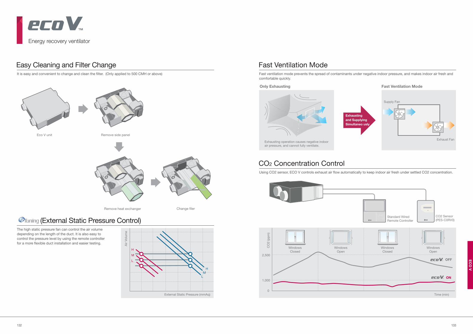
133132
EC
O V
It is easy and convenient to change and clean the filter. (Only applied to 500 CMH or above)
The high static pressure fan can control the air volume
depending on the length of the duct. It is also easy to
control the pressure level by using the remote controller
for a more flexible duct installation and easier testing.
Easy Cleaning and Filter Change
(External Static Pressure Control)
Fast Ventilation Mode
CO2 Concentration Control
Fast ventilation mode prevents the spread of contaminants under negative indoor pressure, and makes indoor air fresh and
comfortable quickly.
Using CO2 sensor, ECO V controls exhaust air flow automatically to keep indoor air fresh under settled CO2 concentration.
Air V
olu
me
H
M
L
H
M
L
External Static Pressure (mmAq)
Exhausting operation causes negative indoor
air pressure, and cannot fully ventilate.
Exhausting
and Supplying
Simultaneo usly
Only Exhausting
Supply Fan
Exhaust Fan
Fast Ventilation Mode
Standard Wired
Remote Controller
CO2 Sensor
(PES-C0RV0)
CO
2 (p
pm
)
Time (min)
1,000
0
2,500
Windows
Closed
Windows
Closed
Windows
Open
Windows
Open
OFF
ON
Energy recovery ventilator
Eco V unit Remove side panel
Remove heat exchanger Change filer
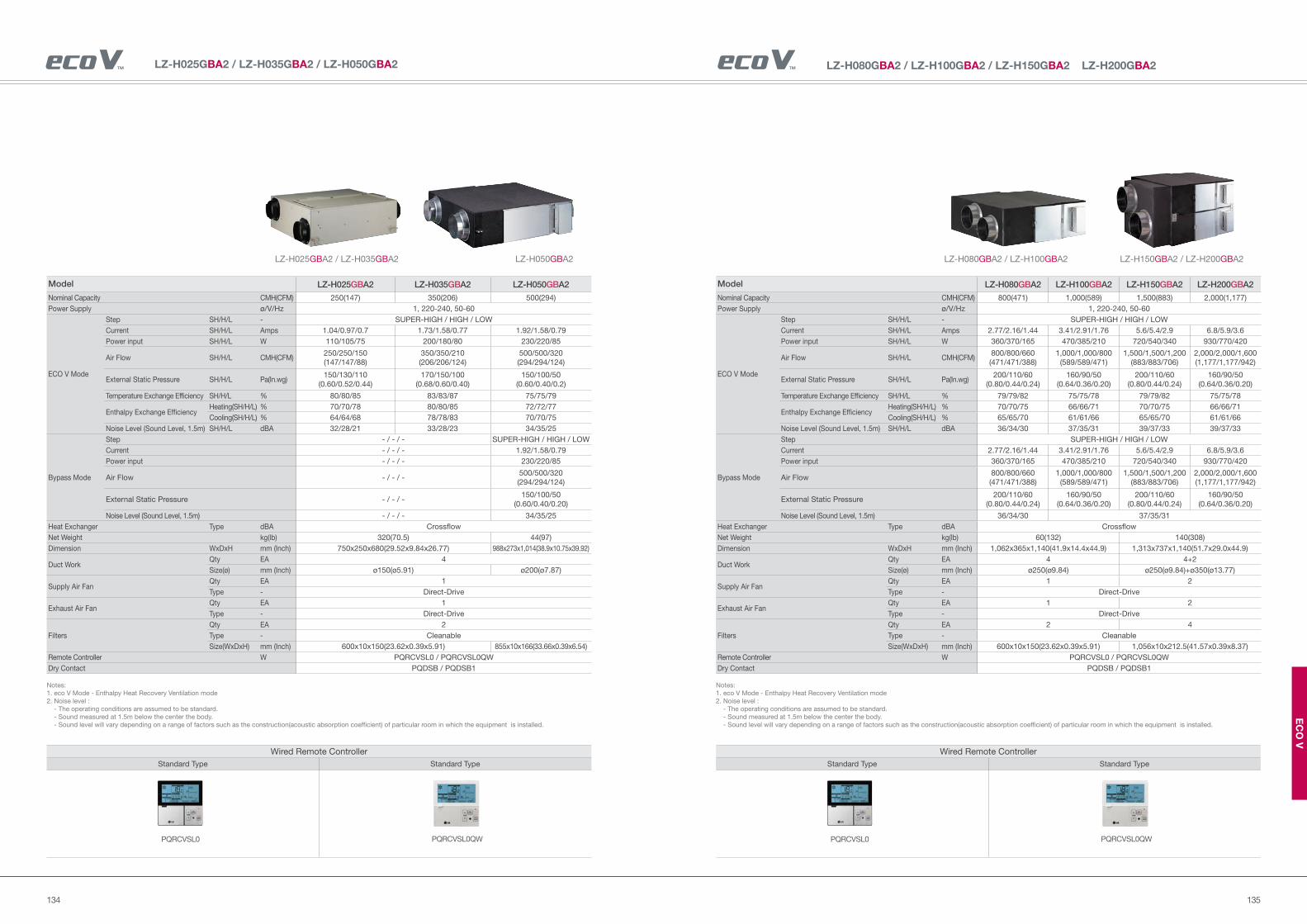
135134
EC
O V
LZ-H080GBA2 / LZ-H100GBA2 / LZ-H150GBA2 LZ-H200GBA2
Wired Remote Controller
Standard Type Standard Type
PQRCVSL0QWPQRCVSL0
LZ-H080GBA2 / LZ-H100GBA2 LZ-H150GBA2 / LZ-H200GBA2
Notes:
1. eco V Mode - Enthalpy Heat Recovery Ventilation mode
2. Noise level :
- The operating conditions are assumed to be standard.
- Sound measured at 1.5m below the center the body.
- Sound level will vary depending on a range of factors such as the construction(acoustic absorption coefficient) of particular room in which the equipment is installed.
Model LZ-H080GBA2 LZ-H100GBA2 LZ-H150GBA2 LZ-H200GBA2
Nominal Capacity CMH(CFM) 800(471) 1,000(589) 1,500(883) 2,000(1,177)
Power Supply ø/V/Hz 1, 220-240, 50-60
ECO V Mode
Step SH/H/L - SUPER-HIGH / HIGH / LOW
Current SH/H/L Amps 2.77/2.16/1.44 3.41/2.91/1.76 5.6/5.4/2.9 6.8/5.9/3.6
Power input SH/H/L W 360/370/165 470/385/210 720/540/340 930/770/420
Air Flow SH/H/L CMH(CFM)800/800/660
(471/471/388)
1,000/1,000/800
(589/589/471)
1,500/1,500/1,200
(883/883/706)
2,000/2,000/1,600
(1,177/1,177/942)
External Static Pressure SH/H/L Pa(In.wg)200/110/60
(0.80/0.44/0.24)
160/90/50
(0.64/0.36/0.20)
200/110/60
(0.80/0.44/0.24)
160/90/50
(0.64/0.36/0.20)
Temperature Exchange Efficiency SH/H/L % 79/79/82 75/75/78 79/79/82 75/75/78
Enthalpy Exchange EfficiencyHeating(SH/H/L) % 70/70/75 66/66/71 70/70/75 66/66/71
Cooling(SH/H/L) % 65/65/70 61/61/66 65/65/70 61/61/66
Noise Level (Sound Level, 1.5m) SH/H/L dBA 36/34/30 37/35/31 39/37/33 39/37/33
Bypass Mode
Step SUPER-HIGH / HIGH / LOW
Current 2.77/2.16/1.44 3.41/2.91/1.76 5.6/5.4/2.9 6.8/5.9/3.6
Power input 360/370/165 470/385/210 720/540/340 930/770/420
Air Flow800/800/660
(471/471/388)
1,000/1,000/800
(589/589/471)
1,500/1,500/1,200
(883/883/706)
2,000/2,000/1,600
(1,177/1,177/942)
External Static Pressure200/110/60
(0.80/0.44/0.24)
160/90/50
(0.64/0.36/0.20)
200/110/60
(0.80/0.44/0.24)
160/90/50
(0.64/0.36/0.20)
Noise Level (Sound Level, 1.5m) 36/34/30 37/35/31
Heat Exchanger Type dBA Crossflow
Net Weight kg(lb) 60(132) 140(308)
Dimension WxDxH mm (Inch) 1,062x365x1,140(41.9x14.4x44.9) 1,313x737x1,140(51.7x29.0x44.9)
Duct WorkQty EA 4 4+2
Size(ø) mm (Inch) ø250(ø9.84) ø250(ø9.84)+ø350(ø13.77)
Supply Air FanQty EA 1 2
Type - Direct-Drive
Exhaust Air FanQty EA 1 2
Type - Direct-Drive
Filters
Qty EA 2 4
Type - Cleanable
Size(WxDxH) mm (Inch) 600x10x150(23.62x0.39x5.91) 1,056x10x212.5(41.57x0.39x8.37)
Remote Controller W PQRCVSL0 / PQRCVSL0QW
Dry Contact PQDSB / PQDSB1
LZ-H025GBA2 / LZ-H035GBA2 / LZ-H050GBA2
Wired Remote Controller
Standard Type Standard Type
PQRCVSL0QWPQRCVSL0
LZ-H025GBA2 / LZ-H035GBA2 LZ-H050GBA2
Notes:
1. eco V Mode - Enthalpy Heat Recovery Ventilation mode
2. Noise level :
- The operating conditions are assumed to be standard.
- Sound measured at 1.5m below the center the body.
- Sound level will vary depending on a range of factors such as the construction(acoustic absorption coefficient) of particular room in which the equipment is installed.
Model LZ-H025GBA2 LZ-H035GBA2 LZ-H050GBA2
Nominal Capacity CMH(CFM) 250(147) 350(206) 500(294)
Power Supply ø/V/Hz 1, 220-240, 50-60
ECO V Mode
Step SH/H/L - SUPER-HIGH / HIGH / LOW
Current SH/H/L Amps 1.04/0.97/0.7 1.73/1.58/0.77 1.92/1.58/0.79
Power input SH/H/L W 110/105/75 200/180/80 230/220/85
Air Flow SH/H/L CMH(CFM)250/250/150
(147/147/88)
350/350/210
(206/206/124)
500/500/320
(294/294/124)
External Static Pressure SH/H/L Pa(In.wg)150/130/110
(0.60/0.52/0.44)
170/150/100
(0.68/0.60/0.40)
150/100/50
(0.60/0.40/0.2)
Temperature Exchange Efficiency SH/H/L % 80/80/85 83/83/87 75/75/79
Enthalpy Exchange EfficiencyHeating(SH/H/L) % 70/70/78 80/80/85 72/72/77
Cooling(SH/H/L) % 64/64/68 78/78/83 70/70/75
Noise Level (Sound Level, 1.5m) SH/H/L dBA 32/28/21 33/28/23 34/35/25
Bypass Mode
Step - / - / - SUPER-HIGH / HIGH / LOW
Current - / - / - 1.92/1.58/0.79
Power input - / - / - 230/220/85
Air Flow - / - / -500/500/320
(294/294/124)
External Static Pressure - / - / -150/100/50
(0.60/0.40/0.20)
Noise Level (Sound Level, 1.5m) - / - / - 34/35/25
Heat Exchanger Type dBA Crossflow
Net Weight kg(lb) 320(70.5) 44(97)
Dimension WxDxH mm (Inch) 750x250x680(29.52x9.84x26.77) 988x273x1,014(38.9x10.75x39.92)
Duct WorkQty EA 4
Size(ø) mm (Inch) ø150(ø5.91) ø200(ø7.87)
Supply Air FanQty EA 1
Type - Direct-Drive
Exhaust Air FanQty EA 1
Type - Direct-Drive
Filters
Qty EA 2
Type - Cleanable
Size(WxDxH) mm (Inch) 600x10x150(23.62x0.39x5.91) 855x10x166(33.66x0.39x6.54)
Remote Controller W PQRCVSL0 / PQRCVSL0QW
Dry Contact PQDSB / PQDSB1
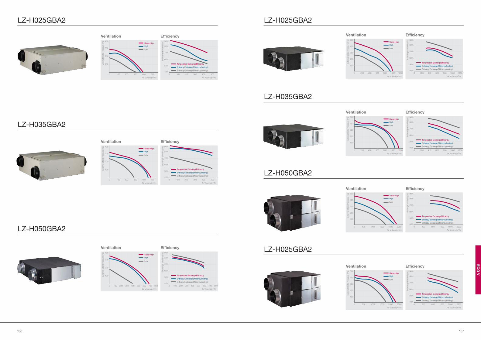
137136
EC
O V
100
40%
50%
60%
70%
80%
90%
0 200 300 400 500
Air Volume(m3/h)
Efficiency
Enthalpy Exchange Efficiency(heating)
Enthalpy Exchange Efficiency(cooling)
Temperature Exchange Efficiency
Exchang
e E
fficie
ncy(
%)
Exchange E
fficie
ncy(
%)
40%
50%
60%
70%
80%
90%
Air Volume(m3/h)
Efficiency
Enthalpy Exchange Efficiency(heating)
Enthalpy Exchange Efficiency(cooling)
Temperature Exchange Efficiency
200 3001000 400 500 600 700 800
LZ-H025GBA2 LZ-H025GBA2
LZ-H035GBA2
LZ-H050GBA2
LZ-H025GBA2
LZ-H035GBA2
LZ-H050GBA2
Exte
rnal S
tatic P
ressure
(P
a)
100
100
0 200
200
300
300
400
400
500
Air Volume(m3/h)
Ventilation
High
Low
Super-High
Exte
rnal S
tatic P
ressure
(P
a)
100
100
0 200
200
300
300
400
400
500
Air Volume(m3/h)
Ventilation
High
Low
Super-High
Exchange E
fficie
ncy(
%)
100
40%
50%
60%
70%
80%
90%
0 200 300 400 500
Air Volume(m3/h)
Efficiency
Enthalpy Exchange Efficiency(heating)
Enthalpy Exchange Efficiency(cooling)
Temperature Exchange Efficiency
Ventilation
Exte
rnal S
tatic P
ressure
(P
a)
200 300100
100
0 400 500
200
600 700
300
800
400
Air Volume(m3/h)
High
Low
Super-High
Ventilation
Exte
rnal S
tatic P
ressure
(P
a)
400 600200
100
0 800 1000
200
1200
300
400
500
Air Volume(m3/h)
High
Low
Super-High
Exchang
e E
fficie
ncy(
%)
40%
50%
60%
70%
80%
90%
Air Volume(m3/h)
Efficiency
400 6002000 800 1000 1200
Enthalpy Exchange Efficiency(heating)
Enthalpy Exchange Efficiency(cooling)
Temperature Exchange Efficiency
Ventilation
Exte
rnal S
tatic P
ressure
(P
a)
800 1200400
100
0 1600
200
2000
300
400
500
Air Volume(m3/h)
High
Low
Super-High
Exchange E
fficie
ncy(
%)
40%
50%
60%
70%
80%
90%
Air Volume(m3/h)
Efficiency
Enthalpy Exchange Efficiency(heating)
Enthalpy Exchange Efficiency(cooling)
Temperature Exchange Efficiency
800 12004000 1600 2000
Exchange E
fficie
ncy(
%)
40%
50%
60%
70%
80%
90%
Air Volume(m3/h)
Efficiency
Enthalpy Exchange Efficiency(heating)
Enthalpy Exchange Efficiency(cooling)
Temperature Exchange Efficiency
1000 15005000 2000 2500
Ventilation
Exte
rnal S
tatic P
ressure
(P
a)
1000 1500500
100
0 2000
200
2500
300
400
500
Air Volume(m3/h)
High
Low
Super-High
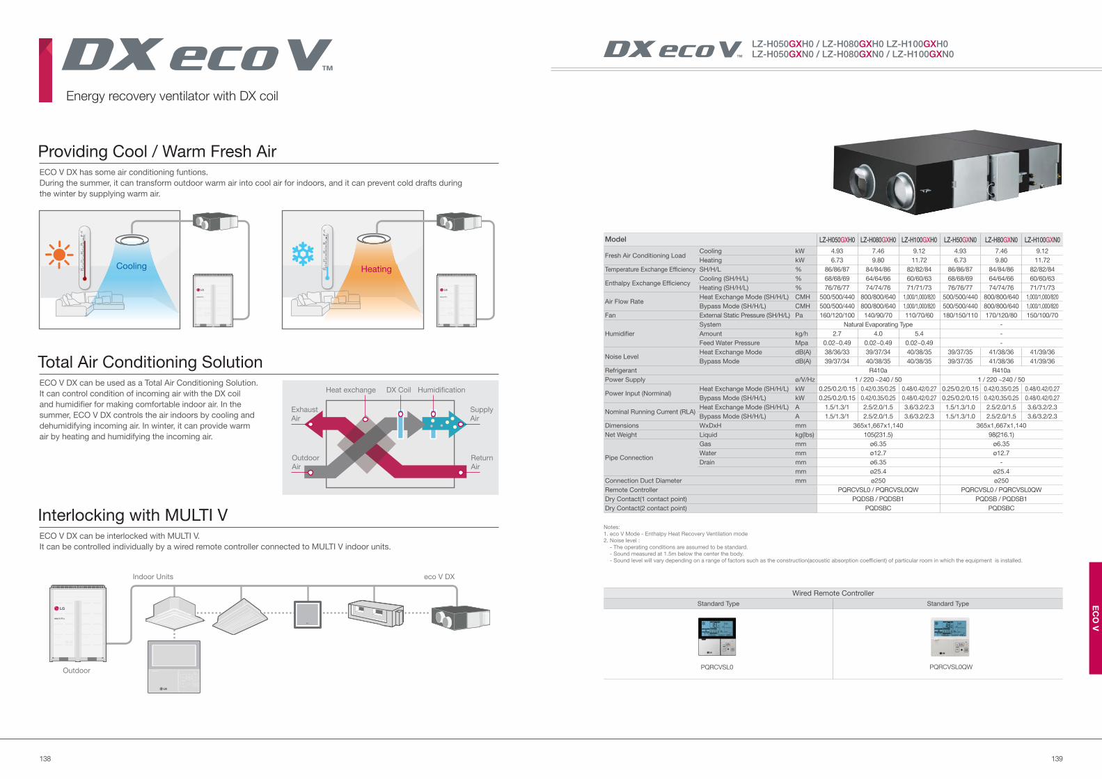
139138
EC
O V
ECO V DX has some air conditioning funtions.
During the summer, it can transform outdoor warm air into cool air for indoors, and it can prevent cold drafts during
the winter by supplying warm air.
ECO V DX can be used as a Total Air Conditioning Solution.
It can control condition of incoming air with the DX coil
and humidifier for making comfortable indoor air. In the
summer, ECO V DX controls the air indoors by cooling and
dehumidifying incoming air. In winter, it can provide warm
air by heating and humidifying the incoming air.
ECO V DX can be interlocked with MULTI V.
It can be controlled individually by a wired remote controller connected to MULTI V indoor units.
Providing Cool / Warm Fresh Air
Total Air Conditioning Solution
Interlocking with MULTI V
HeatingCooling
Heat exchange DX Coil Humidification
Exhaust
Air
Outdoor
Air
Supply
Air
Return
Air
Outdoor
Indoor Units eco V DX
Energy recovery ventilator with DX coil
LZ-H050GXH0 / LZ-H080GXH0 LZ-H100GXH0 LZ-H050GXN0 / LZ-H080GXN0 / LZ-H100GXN0
Wired Remote Controller
Standard Type Standard Type
PQRCVSL0QWPQRCVSL0
Notes:
1. eco V Mode - Enthalpy Heat Recovery Ventilation mode
2. Noise level :
- The operating conditions are assumed to be standard.
- Sound measured at 1.5m below the center the body.
- Sound level will vary depending on a range of factors such as the construction(acoustic absorption coefficient) of particular room in which the equipment is installed.
Model LZ-H050GXH0 LZ-H080GXH0 LZ-H100GXH0 LZ-H50GXN0 LZ-H80GXN0 LZ-H100GXN0
Fresh Air Conditioning LoadCooling kW 4.93 7.46 9.12 4.93 7.46 9.12
Heating kW 6.73 9.80 11.72 6.73 9.80 11.72
Temperature Exchange Efficiency SH/H/L % 86/86/87 84/84/86 82/82/84 86/86/87 84/84/86 82/82/84
Enthalpy Exchange EfficiencyCooling (SH/H/L) % 68/68/69 64/64/66 60/60/63 68/68/69 64/64/66 60/60/63
Heating (SH/H/L) % 76/76/77 74/74/76 71/71/73 76/76/77 74/74/76 71/71/73
Air Flow RateHeat Exchange Mode (SH/H/L) CMH 500/500/440 800/800/640 1,000/1,000/820 500/500/440 800/800/640 1,000/1,000/820
Bypass Mode (SH/H/L) CMH 500/500/440 800/800/640 1,000/1,000/820 500/500/440 800/800/640 1,000/1,000/820
Fan External Static Pressure (SH/H/L) Pa 160/120/100 140/90/70 110/70/60 180/150/110 170/120/80 150/100/70
Humidifier
System Natural Evaporating Type -
Amount kg/h 2.7 4.0 5.4 -
Feed Water Pressure Mpa 0.02~0.49 0.02~0.49 0.02~0.49 -
Noise LevelHeat Exchange Mode dB(A) 38/36/33 39/37/34 40/38/35 39/37/35 41/38/36 41/39/36
Bypass Mode dB(A) 39/37/34 40/38/35 40/38/35 39/37/35 41/38/36 41/39/36
Refrigerant R410a R410a
Power Supply ø/V/Hz 1 / 220 ~240 / 50 1 / 220 ~240 / 50
Power Input (Norminal)Heat Exchange Mode (SH/H/L) kW 0.25/0.2/0.15 0.42/0.35/0.25 0.48/0.42/0.27 0.25/0.2/0.15 0.42/0.35/0.25 0.48/0.42/0.27
Bypass Mode (SH/H/L) kW 0.25/0.2/0.15 0.42/0.35/0.25 0.48/0.42/0.27 0.25/0.2/0.15 0.42/0.35/0.25 0.48/0.42/0.27
Nominal Running Current (RLA)Heat Exchange Mode (SH/H/L) A 1.5/1.3/1 2.5/2.0/1.5 3.6/3.2/2.3 1.5/1.3/1.0 2.5/2.0/1.5 3.6/3.2/2.3
Bypass Mode (SH/H/L) A 1.5/1.3/1 2.5/2.0/1.5 3.6/3.2/2.3 1.5/1.3/1.0 2.5/2.0/1.5 3.6/3.2/2.3
Dimensions WxDxH mm 365x1,667x1,140 365x1,667x1,140
Net Weight Liquid kg(lbs) 105(231.5) 98(216.1)
Pipe Connection
Gas mm ø6.35 ø6.35
Water mm ø12.7 ø12.7
Drain mm ø6.35 -
mm ø25.4 ø25.4
Connection Duct Diameter mm ø250 ø250
Remote Controller PQRCVSL0 / PQRCVSL0QW PQRCVSL0 / PQRCVSL0QW
Dry Contact(1 contact point) PQDSB / PQDSB1 PQDSB / PQDSB1
Dry Contact(2 contact point) PQDSBC PQDSBC
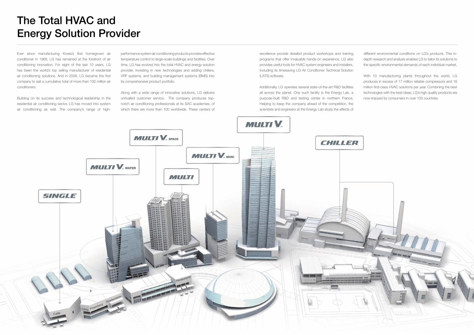
141140 141140
Ever since manufacturing Korea’s first homegrown air
conditioner in 1968, LG has remained at the forefront of air
conditioning innovation. For eight of the last 10 years, LG
has been the world’s top selling manufacturer of residential
air conditioning solutions. And in 2008, LG became the first
company to sell a cumulative total of more than 100 million air
conditioners.
Building on its success and technological leadership in the
residential air conditioning sector, LG has moved into system
air conditioning as well. The company’s range of high-
performance system air conditioning products provides effective
temperature control to large-scale buildings and facilities. Over
time, LG has evolved into the total HVAC and energy solution
provider, investing in new technologies and adding chillers,
VRF systems, and building management systems (BMS) into
its comprehensive product portfolio.
Along with a wide range of innovative solutions, LG delivers
unrivalled customer service. The company produces top-
notch air conditioning professionals at its SAC academies, of
which there are more than 100 worldwide. These centers of
The Total HVAC and
Energy Solution Provider
excellence provide detailed product workshops and training
programs that offer invaluable hands-on experience. LG also
provides useful tools for HVAC system engineers and installers,
including its timesaving LG Air Conditioner Technical Solution
(LATS) software.
Additionally, LG operates several state-of-the-art R&D facilities
all across the planet. One such facility is the Energy Lab, a
purpose-built R&D and testing center in northern France.
Helping to keep the company ahead of the competition, the
scientists and engineers at the Energy Lab study the effects of
different environmental conditions on LG’s products. This in-
depth research and analysis enables LG to tailor its solutions to
the specific environmental demands of each individual market.
With 10 manufacturing plants throughout the world, LG
produces in excess of 17 million reliable compressors and 16
million first-class HVAC solutions per year. Combining the best
technologies with the best ideas, LG’s high quality products are
now enjoyed by consumers in over 100 countries.