vlt® hvac basic drive design guide - danfoss
TRANSCRIPT
MAKING MODERN LIVING POSSIBLE
Design GuideVLT® HVAC Basic Drive FC 101

Contents
1 How to Read this Design Guide 1-1
1.1.1 Legal Information 1-1
1.1.2 Available Literature for VLT® HVAC Basic Drive 1-1
1.1.3 Symbols 1-2
1.1.4 Abbreviations 1-2
1.1.5 Definitions 1-3
1.1.6 Power Factor 1-5
2 Introduction to VLT® HVAC Basic Drive 2-1
2.1 Safety 2-1
2.1.2 Safety 2-1
2.2 CE Labeling 2-2
2.3 Air humidity 2-3
2.4 Aggressive Environments 2-4
2.5 Vibration and Shock 2-4
2.6 Advantages 2-4
2.7 Control Structures 2-17
2.8 General Aspects of EMC 2-24
2.9 Galvanic Isolation (PELV) 2-29
2.10 Ground Leakage Current 2-30
2.11 Extreme Running Conditions 2-30
3 VLT® HVAC Basic Drive Selection 3-1
3.1 Options and Accessories 3-1
3.1.1 Local Control Panel (LCP) 3-1
3.1.2 Mounting of LCP in Panel Front 3-1
3.1.3 IP21/TYPE 1 Enclosure Kit 3-2
3.1.4 Decoupling Plate 3-3
4 How to Order 4-1
5 How to Install 5-1
5.1.1 Dimensions 5-1
5.1.2 Shipping Dimensions 5-4
5.1.3 Side-by-Side Installation 5-5
5.2 Electrical Data 5-6
5.2.1 Electrical Overview 5-6
5.2.2 Electrical Installation in General 5-7
Contents VLT® HVAC Basic Drive Design Guide
MG18C422 - VLT® is a registered Danfoss trademark
5.2.3 Connecting to Line Power and Motor 5-8
5.2.4 Fuses 5-15
5.2.5 EMC-compatible Electrical Installation 5-17
5.2.6 Control Terminals 5-19
6 How to Program 6-1
6.1 Programming with MCT 10 Setup Software 6-1
6.2 Local Control Panel (LCP) 6-1
6.3 Menus 6-2
6.3.1 Status 6-2
6.3.2 Quick Menu 6-2
6.3.3 Start-up Wizard for Open-loop Applications 6-3
6.3.4 Main Menu 6-11
6.4 Quick Transfer of Parameter Settings between Multiple Adjustable FrequencyDrives 6-12
6.5 Read-out and Programming of Indexed Parameters 6-12
6.6 Initialize the Adjustable Frequency Drive to Default Settings in Two Ways 6-12
7 RS-485 Installation and Set-up 7-1
7.1.1 Overview 7-1
7.2 Adjustable Frequency Protocol Overview 7-2
7.3 Network Configuration 7-3
7.4 FC Protocol Message Framing Structure 7-3
7.4.1 Content of a Character (byte) 7-3
7.4.2 Message Structure 7-3
7.4.3 Message Length (LGE) 7-3
7.4.6 The Data Field 7-4
7.4.13 Process Words (PCD) 7-6
7.5 Examples 7-6
7.6 Modbus RTU Overview 7-7
7.6.1 Assumptions 7-7
7.6.2 What the User Should Already Know 7-7
7.6.3 Modbus RTU Overview 7-7
7.6.4 Adjustable Frequency Drive with Modbus RTU 7-8
7.7 Network Configuration 7-8
7.8 Modbus RTU Message Framing Structure 7-8
7.8.1 Adjustable Frequency Drive with Modbus RTU 7-8
7.8.2 Modbus RTU Message Structure 7-8
7.8.3 Start/Stop Field 7-9
Contents VLT® HVAC Basic Drive Design Guide
MG18C422 - VLT® is a registered Danfoss trademark
7.8.4 Address Field 7-9
7.8.5 Function Field 7-9
7.8.6 Data Field 7-9
7.8.7 CRC Check Field 7-9
7.8.9 How to Control the Adjustable Frequency Drive 7-11
7.8.10 Function Codes Supported by Modbus RTU 7-11
7.8.11 Modbus Exception Codes 7-12
7.9 How to Access Parameters 7-12
7.9.1 Parameter Handling 7-12
7.9.2 Storage of Data 7-12
7.9.3 IND 7-12
7.9.4 Text Blocks 7-12
7.9.5 Conversion Factor 7-12
7.9.6 Parameter Values 7-12
7.10 Examples 7-13
7.10.2 Force/Write Single Coil (05 HEX) 7-13
7.10.3 Force/Write Multiple Coils (0F HEX) 7-14
7.10.5 Preset Single Register (06 HEX) 7-14
7.11 Danfoss FC Control Profile 7-15
7.11.1 Control Word According to FC Profile (8-10 Protocol = FC profile) 7-15
8 General Specifications and Troubleshooting 8-1
8.1 Line Power Supply Tables 8-2
8.1.1 Line Power Supply 3x200–240 V AC 8-2
8.1.2 Line Power Supply 3x380–480 V AC 8-3
8.1.3 Line Power Supply 3x380–480 V AC 8-5
8.1.4 Line Power Supply 3x525–600 V AC 8-7
8.2 General Specifications 8-8
8.3 Acoustic Noise 8-10
8.4 dU/Dt 8-11
8.5 Derating according to Ambient Temperature and Switching Frequency 8-13
9 Index 9-1
Contents VLT® HVAC Basic Drive Design Guide
MG18C422 - VLT® is a registered Danfoss trademark
Contents VLT® HVAC Basic Drive Design Guide
MG18C422 - VLT® is a registered Danfoss trademark
1 How to Read this Design Guide
VLT® HVAC DriveFC 100 Series
Table 1.1
This guide can be used with all VLTHVAC Basic Drive adjustable
frequency drives with softwareversion 2.0X.
The actual software versionnumber can be read from
15-43 Software Version.Table 1.2
1.1.1 Legal Information
This publication contains information proprietary toDanfoss. By accepting and using this manual, the useragrees that the information contained herein will be usedsolely for operating equipment from Danfoss or equipmentfrom other vendors provided that such equipment isintended for communication with Danfoss equipment overa serial communication link. This publication is protectedunder the copyright laws of Denmark and most othercountries.
Danfoss does not warrant that a software programproduced according to the guidelines provided in thismanual will function properly in every physical, hardwareor software environment.
Although Danfoss has tested and reviewed the documen-tation within this manual, Danfoss makes no warranty orrepresentation, neither expressed nor implied, with respectto this documentation, including its quality, performance,or fitness for a particular purpose.
In no event shall Danfoss be liable for direct, indirect,special, incidental, or consequential damages arising out ofthe use, or the inability to use information contained in
this manual, even if advised of the possibility of suchdamages. In particular, Danfoss is not responsible for anycosts, including but not limited to those incurred as aresult of lost profits or revenue, loss or damage ofequipment, loss of computer programs, loss of data, thecosts to substitute these, or any claims by third parties.
Danfoss reserves the right to revise this publication at anytime and to make changes to its contents without priornotice or any obligation to notify former or present usersof such revisions or changes.
1.1.2 Available Literature for VLT® HVACBasic Drive
- Quick Guide, MG18A
- Programming Guide, MG18B provides informationon how to program and includes completeparameter descriptions.
- Design Guide, MG18C provides all technicalinformation about the adjustable frequency driveand customer design and applications.
- PC-based Configuration Tool MCT 10, MG10Renables the user to configure the adjustablefrequency drive from a Windows™-based PCenvironment.
- Danfoss VLT® Energy Box software atwww.danfoss.com/BusinessAreas/DrivesSolutionsthen choose PC Software DownloadVLT® Energy Box Software allows energyconsumption comparisons of HVAC fans andpumps driven by Danfoss drives and alternativemethods of flow control. This tool may be usedto project, as accurately as possible, the costs,savings, and payback of using Danfoss adjustablefrequency drives on HVAC fans and pumps.
Danfoss technical literature is available in print from yourlocal Danfoss Sales Office or at:www.danfoss.com/BusinessAreas/DrivesSolutions/Documen-tations/Technical+Documentation.htm
How to Read this Design Gui... VLT® HVAC Basic Drive Design Guide
MG18C422 - VLT® is a registered Danfoss trademark 1-1
1 1
1.1.3 Symbols
The following symbols are used in this manual.
WARNINGIndicates a potentially hazardous situation which, if notavoided, could result in death or serious injury.
CAUTIONIndicates a potentially hazardous situation which, if notavoided, may result in minor or moderate injury. It mayalso be used to alert against unsafe practices.
CAUTIONIndicates a situation that may result in equipment orproperty-damage only accidents.
NOTE!Indicates highlighted information that should be regardedwith attention to avoid making mistakes or operatingequipment at less than optimal performance.
1.1.4 Abbreviations
Alternating current AC
American wire gauge AWG
Ampere/AMP A
Automatic Motor Adaptation AMA
Current limit ILIM
Degrees Celsius °CDirect current DC
Electro Magnetic Compatibility EMC
Electronic Thermal Relay ETR
Adjustable Frequency Drive FC
Gram g
Hertz Hz
Kilohertz kHz
Local Control Panel LCP
Meter m
Millihenry Inductance mH
Milliampere mA
Millisecond ms
Minute min
Motion Control Tool MCT
Nanofarad nF
Newton Meters Nm
Nominal motor current IM,N
Nominal motor frequency fM,N
Nominal motor power PM,N
Nominal motor voltage UM,N
Protective Extra Low Voltage PELV
Printed Circuit Board PCB
Rated Inverter Output Current IINV
Revolutions Per Minute RPM
Regenerative terminals Regen
Second s
Synchronous Motor Speed ns
Torque limit TLIM
Volts V
The maximum output current IVLT,MAX
The rated output current supplied by theadjustable frequency drive
IVLT,N
Table 1.3
How to Read this Design Gui... VLT® HVAC Basic Drive Design Guide
1-2 MG18C422 - VLT® is a registered Danfoss trademark
11
1.1.5 Definitions
Adjustable Frequency Drive
IVLT,MAX
The maximum output current.
IVLT,N
The rated output current supplied by the adjustablefrequency drive.
UVLT, MAX
The maximum output voltage.
Input
Control commandThe connected motor canstart and stop with LCP andthe digital inputs.Functions are divided intotwo groups.Functions in group 1 havehigher priority thanfunctions in group 2.
Group1
Reset, Coasting stop,Reset and Coasting stop,Quick Stop, DC braking,Stop and the [Off] key.
Group2
Start, Pulse start,Reversing, Start reversing,Jog and Freeze output
Table 1.4
Motor
fJOG
The motor frequency when the jog function is activated(via digital terminals).
fM
The motor frequency.
fMAX
The maximum motor frequency.
fMIN
The minimum motor frequency.
fM,N
The rated motor frequency (nameplate data).
IM
The motor current.
IM,N
The rated motor current (nameplate data).
nM,N
The rated motor speed (nameplate data).
PM,N
The rated motor power (nameplate data).
UM
The instantaneous motor voltage.
UM,N
The rated motor voltage (nameplate data).
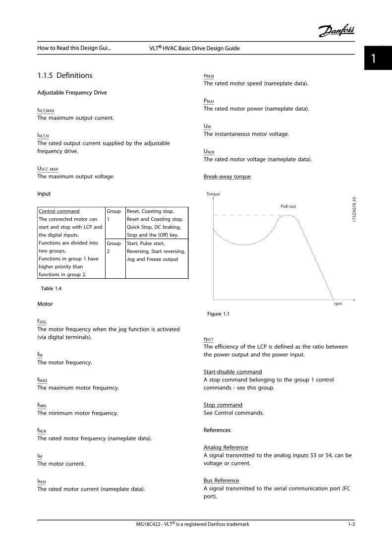
Break-away torque
175Z
A07
8.10
Pull-out
rpm
Torque
Figure 1.1
ηVLT
The efficiency of the LCP is defined as the ratio betweenthe power output and the power input.
Start-disable commandA stop command belonging to the group 1 controlcommands - see this group.
Stop commandSee Control commands.
References
Analog ReferenceA signal transmitted to the analog inputs 53 or 54, can bevoltage or current.
Bus ReferenceA signal transmitted to the serial communication port (FCport).
How to Read this Design Gui... VLT® HVAC Basic Drive Design Guide
MG18C422 - VLT® is a registered Danfoss trademark 1-3
1 1
Preset ReferenceA defined preset reference to be set from -100% to +100%of the reference range. Selection of eight preset referencesvia the digital terminals.
RefMAXDetermines the relationship between the reference inputat 100% full scale value (typically 10 V, 20 mA) and theresulting reference. The maximum reference value set in3-03 Maximum Reference.
RefMINDetermines the relationship between the reference inputat 0% value (typically 0 V, 0 mA, 4 mA) and the resultingreference. The minimum reference value set in3-02 Minimum Reference
MiscellaneousAnalog InputsThe analog inputs are used for controlling variousfunctions of the adjustable frequency drive.There are two types of analog inputs:Current input, 0–20 mA and 4–20 mAVoltage input, 0–10 V DC.
Analog OutputsThe analog outputs can supply a signal of 0–20 mA, 4–20mA, or a digital signal.
Automatic Motor Adaptation, AMAAMA algorithm determines the electrical parameters forthe connected motor at standstill.
Digital InputsThe digital inputs can be used for controlling variousfunctions of the adjustable frequency drive.
Digital OutputsThe adjustable frequency drive features two solid stateoutputs that can supply a 24 V DC (max. 40 mA) signal.
Relay OutputsThe adjustable frequency drive features two programmablerelay outputs.
ETRElectronic Thermal Relay is a thermal load calculationbased on present load and time. Its purpose is to estimatethe motor temperature.
InitializingIf initialization is carried out (14-22 Operation Mode), theprogrammable parameters of the adjustable frequencydrive return to their default settings.Initializing; 14-22 Operation Mode will not initializecommunication parameters.
Intermittent Duty CycleAn intermittent duty rating refers to a sequence of dutycycles. Each cycle consists of an on-load and an off-loadperiod. The operation can be either periodic duty or non-periodic duty.
LCP The Local Control Panel (LCP) makes up a completeinterface for control and programming of the adjustablefrequency drive. The control panel is detachable and canbe installed up to 10 ft [3 m] from the adjustablefrequency drive, i.e. in a front panel by means of the instal-lation kit option.
lsbLeast significant bit.
MCMShort for Mille (thousand) Circular Mils, an Americanmeasuring unit for cable cross-section. 1 MCM ≡ 0.5067mm2.
msbMost significant bit.
Online/Offline ParametersChanges to online parameters are activated immediatelyafter the data value is changed. Press [OK] to activate off-line parameters.
PI ControllerThe PI controller maintains the desired speed, pressure,temperature, etc. by adjusting the output frequency tomatch the varying load.
RCDResidual Current Device.
Set-upParameter settings in two set-ups can be saved. Changebetween the two parameter set-ups and edit one set-up,while another set-up is active.
Slip CompensationThe adjustable frequency drive compensates for the motorslip by giving the frequency a supplement that follows themeasured motor load, keeping the motor speed almostconstant.
Smart Logic Control (SLC)The SLC is a sequence of user-defined actions executedwhen the associated user-defined events are evaluated astrue by the SLC.
How to Read this Design Gui... VLT® HVAC Basic Drive Design Guide
1-4 MG18C422 - VLT® is a registered Danfoss trademark
11
ThermistorA temperature-dependent resistor placed where thetemperature is to be monitored (adjustable frequency driveor motor).
TripA state entered in fault situations, e.g., if the adjustablefrequency drive is subject to an overtemperature or whenthe adjustable frequency drive is protecting the motor,process or mechanism. Restart is prevented until the causeof the fault has disappeared and the trip state is canceledby activating reset or, in some cases, by beingprogrammed to reset automatically. Trip may not be usedfor personal safety.
Trip LockedA state entered in fault situations when the adjustablefrequency drive is protecting itself and requiring physicalintervention, for example, if the adjustable frequency driveis subject to a short circuit on the output. A locked tripcan only be canceled by cutting off line power, removingthe cause of the fault, and reconnecting the adjustablefrequency drive. Restart is prevented until the trip state iscanceled by activating reset or, in some cases, by beingprogrammed to reset automatically. The trip-lock functionmay not be used as a personal safety measure.
VT CharacteristicsVariable torque characteristics used for pumps and fans.
VVC plus
If compared with standard voltage/frequency ratio control,Voltage Vector Control (VVCplus) improves the dynamicsand the stability, both when the speed reference ischanged and in relation to the load torque.
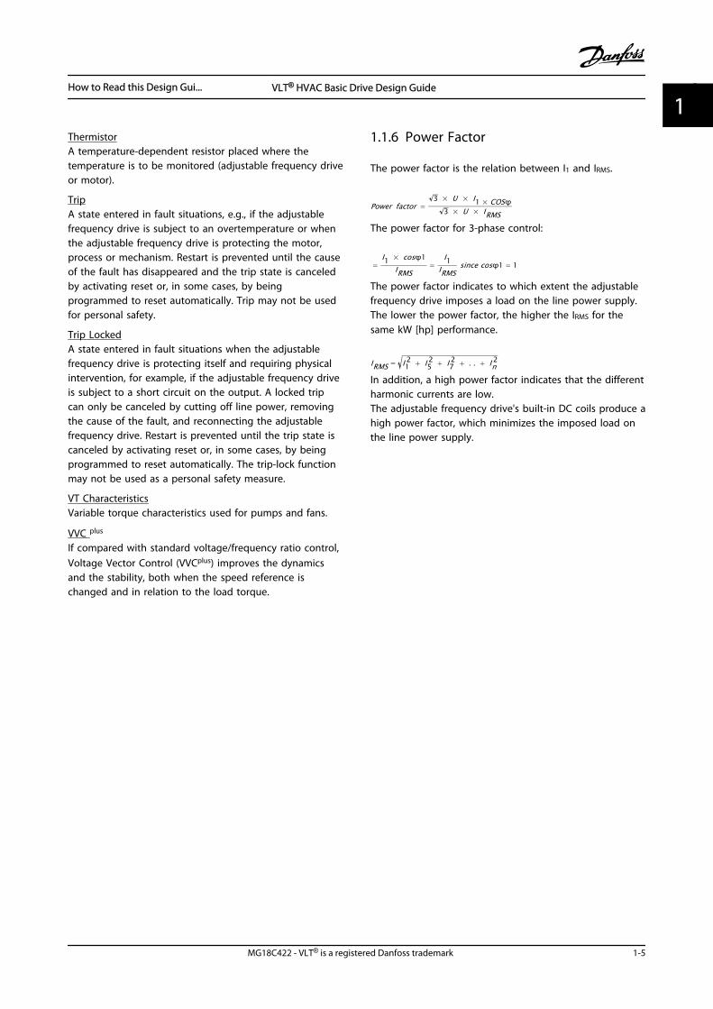
1.1.6 Power Factor
The power factor is the relation between I1 and IRMS.
Power factor =3 × U × I1 × COSϕ
3 × U × IRMSThe power factor for 3-phase control:
=I1 × cosϕ1
IRMS=
I1IRMS
since cosϕ1 = 1
The power factor indicates to which extent the adjustablefrequency drive imposes a load on the line power supply.The lower the power factor, the higher the IRMS for thesame kW [hp] performance.
IRMS = I12 + I5
2 + I72 + . . + In
2
In addition, a high power factor indicates that the differentharmonic currents are low.The adjustable frequency drive's built-in DC coils produce ahigh power factor, which minimizes the imposed load onthe line power supply.
How to Read this Design Gui... VLT® HVAC Basic Drive Design Guide
MG18C422 - VLT® is a registered Danfoss trademark 1-5
1 1
How to Read this Design Gui... VLT® HVAC Basic Drive Design Guide
1-6 MG18C422 - VLT® is a registered Danfoss trademark
11
2 Introduction to VLT® HVAC Basic Drive
2.1 Safety
2.1.1 Safety Note
WARNINGDANGEROUS VOLTAGEThe voltage of the adjustable frequency drive is dangerouswhenever connected to line power. Incorrect installation ofthe motor, adjustable frequency drive or serial communi-cation bus may cause death, serious personal injury ordamage to the equipment. Consequently, the instructionsin this manual, as well as national and local rules andsafety regulations, must be complied with.
Safety Regulations1. The adjustable frequency drive must be discon-
nected from line power if repair work is to becarried out. Make sure that the line power supplyhas been disconnected and that the necessarytime has passed before removing motor and linepower plugs.
2. The [Off/Reset] key on the LCP does notdisconnect the equipment from line power and istherefore not to be used as a safety switch.
3. Correct protective grounding of the equipmentmust be established, the user must be protectedagainst supply voltage, and the motor must beprotected against overload in accordance withapplicable national and local regulations.
4. The ground leakage currents are higher than 3.5mA.
5. Protection against motor overload is set by1-90 Motor Thermal Protection. If this function isdesired, set 1-90 Motor Thermal Protection to datavalue [ETR trip] (default value) or data value [ETRwarning]. Note: The function is initialized at 1.16x rated motor current and rated motor frequency.For the North American market: the ETR functionsprovide class 20 motor overload protection inaccordance with NEC.
6. Do not remove the plugs for the motor and linepower supply while the adjustable frequencydrive is connected to line power. Make sure thatthe line power supply has been disconnected andthat the necessary time has passed beforeremoving motor and line power plugs.
7. Make sure that all voltage inputs have beendisconnected and that the necessary time haspassed before commencing repair work.
Installation at high altitudes
CAUTIONAt altitudes above 6,600 ft [2 km], contact Danfossregarding PELV.
WARNINGUNINTENDED START
1. The motor can be brought to a stop with digitalcommands, bus commands, references or a localstop, while the adjustable frequency drive isconnected to line power. If personal safetyconsiderations make it necessary to ensure thatno unintended start occurs, these stop functionsare not sufficient.
2. While parameters are being changed, the motormay start. Consequently, the stop key [Off/Reset]must always be activated; after which data can bemodified.
3. A motor that has been stopped may start if faultsoccur in the electronics of the adjustablefrequency drive, or if a temporary overload or afault in the line power or the motor connectionceases.
2.1.2 Safety
WARNINGHIGH VOLTAGE!Adjustable frequency drives contain high voltage whenconnected to AC line power. Installation, start-up, andmaintenance should be performed by qualified personnelonly. Failure to perform installation, start-up, andmaintenance by qualified personnel could result in deathor serious injury.
High VoltageAdjustable frequency drives are connected to hazardousAC line voltage. Extreme care should be taken to protectagainst shock. Only trained personnel familiar withelectronic equipment should install, start, or maintain thisequipment.
Introduction to VLT® HVAC B... VLT® HVAC Basic Drive Design Guide
MG18C422 - VLT® is a registered Danfoss trademark 2-1
2 2
WARNINGUNINTENDED START!When the adjustable frequency drive is connected to ACline power, the motor may start at any time. Theadjustable frequency drive, motor, and any drivenequipment must be in operational readiness. Failure to bein operational readiness when the adjustable frequencydrive is connected to AC line power could result in death,serious injury, equipment, or property damage.
Unintended StartWhen the adjustable frequency drive is connected to ACline power, the motor may be started with an externalswitch, a serial bus command, an input reference signal, ora cleared fault condition. Use appropriate caution to guardagainst an unintended start.
WARNINGDISCHARGE TIME!Adjustable frequency drives contain DC link capacitors thatcan remain charged even when the adjustable frequencydrive is not powered. To avoid electrical hazards,disconnect AC line power, any permanent magnet typemotors, and any remote DC link power supplies, includingbattery backups, UPS and DC link connections to otheradjustable frequency drives. Wait for the capacitors to fullydischarge before performing any service or repair work.The wait time required is listed in the Discharge Time table.Failure to wait for the specified period of time after powerhas been removed to do service or repair could result indeath or serious injury.
Voltage [V] Power range hp [kW] Minimum waiting time[min]
3x200 0.34–5 [0.25–3.7] 4
3x200 7.5–60 [5.5–45] 15
3x400 0.5–10 [0.37–7.5] 4
3x400 15–125 [11–90] 15
3x600 3–10 [2.2–7.5] 4
3x600 15–125 [11–90] 15
Table 2.1 Discharge Time
2.1.3 Disposal Instructions
Equipment containing electricalcomponents may not be disposed oftogether with domestic waste.It must be separately collected withelectrical and electronic waste accordingto local and currently valid legislation.
Table 2.2
2.2 CE Labeling
2.2.1 CE Conformity and Labeling
What is CE Conformity and Labeling?The purpose of CE labeling is to avoid technical tradeobstacles within EFTA and the EU. The EU has introducedthe CE label as a simple way of showing whether aproduct complies with the relevant EU directives. The CElabel says nothing about the specifications or quality ofthe product. Adjustable frequency drives are regulated bythree EU directives:The machinery directive (98/37/EEC)All machines with critical moving parts are covered by themachinery directive of January 1, 1995. Since an adjustablefrequency drive is largely electrical, it does not fall underthe Machinery Directive. However, if an adjustablefrequency drive is supplied for use in a machine, Danfossprovides information on safety aspects relating to theadjustable frequency drive. Danfoss do this by means of amanufacturer's declaration.The low-voltage directive (73/23/EEC)Adjustable frequency drives must be CE-labeled inaccordance with the Low-voltage Directive of January 1,1997. The directive applies to all electrical equipment andappliances used in the 50–1,000 V AC and the 75–1,500 VDC voltage ranges. Danfoss CE-labels in accordance withthe directive and issues a declaration of conformity uponrequest.The EMC directive (89/336/EEC)EMC is short for electromagnetic compatibility. Thepresence of electromagnetic compatibility means that themutual interference between different components/appliances does not affect the way the appliances work.The EMC directive came into effect January 1, 1996.Danfoss CE-labels in accordance with the directive andissues a declaration of conformity upon request. To carryout EMC-compatible installation, see the instructions in thisDesign Guide. In addition, Danfossspecifies whichstandards our products comply with. Danfossoffers thefilters presented in the specifications and provides othertypes of assistance to ensure the optimum EMC result.
Introduction to VLT® HVAC B... VLT® HVAC Basic Drive Design Guide
2-2 MG18C422 - VLT® is a registered Danfoss trademark
22
The adjustable frequency drive is most often used byprofessionals of the trade as a complex componentforming part of a larger appliance, system or installation. Itmust be noted that the responsibility for the final EMCproperties of the appliance, system or installation restswith the installer.
2.2.2 What is Covered
The "Guidelines on the Application of Council Directive89/336/EEC" issued by the EU outline three typicalsituations for using an adjustable frequency drive. See2.2.3 Danfoss Adjustable Frequency Drive and CE Labeling forEMC coverage and CE labeling.
1. The adjustable frequency drive is sold directly tothe end-consumer. For example, it may be sold toa DIY market. The end-consumer is a layman. Heinstalls the adjustable frequency drive himself foruse with a hobby machine, a kitchen appliance,etc. For such applications, the adjustablefrequency drive must be CE labeled inaccordance with the EMC directive.
2. The adjustable frequency drive is sold for instal-lation in a plant. The plant is assembled byprofessionals of the trade. It could be aproduction plant or a heating/ventilation plantdesigned and installed by professionals of thetrade. Neither the adjustable frequency drive northe finished plant has to be CE labeled under theEMC directive. However, the unit must complywith the basic EMC requirements of the directive.This is ensured by using components, appliances,and systems that are CE labeled under the EMCdirective.
3. The adjustable frequency drive is sold as part of acomplete system. The system is being marketedas complete and could, for example, be an air-conditioning system. The complete system mustbe CE labeled in accordance with the EMCdirective. The manufacturer can ensure CElabeling under the EMC directive either by usingCE labeled components or by testing the EMC ofthe system. If only CE-labeled components arechosen, the entire system does not have to betested.
2.2.3 Danfoss Adjustable Frequency Driveand CE Labeling
CE labeling is a positive feature when used for its originalpurpose, that is, to facilitate trade within the EU and EFTA.
However, CE labeling may cover many different specifi-cations. Check what a given CE label specifically covers.
The covered specifications can be very different and a CElabel may therefore give the installer a false feeling ofsecurity when using an adjustable frequency drive as acomponent in a system or an appliance.
Danfoss CE labels the adjustable frequency drives inaccordance with the low-voltage directive. This means thatif the adjustable frequency drive is installed correctly,Danfoss guarantees compliance with the low-voltagedirective. Danfoss issues a declaration of conformity thatconfirms our CE labeling in accordance with the low-voltage directive.
The CE label also applies to the EMC directive providedthat the instructions for EMC-compatible installation andfiltering are followed. On this basis, a declaration ofconformity in accordance with the EMC directive is issued.
The Design Guide provides detailed instructions for instal-lation to ensure EMC-compatible installation. Furthermore,Danfoss specifies which of our different products are incompliance.
Danfoss provides other types of assistance that can help toobtain the best EMC result.
2.2.4 Compliance with EMC Directive89/336/EEC
As mentioned, the adjustable frequency drive is mostlyused by professionals of the trade as a complexcomponent forming part of a larger appliance, system orinstallation. It must be noted that the responsibility for thefinal EMC properties of the appliance, system or installationrests with the installer. As an aid to the installer, Danfosshas prepared EMC installation guidelines for the PowerDrive system. The standards and test levels stated forPower Drive systems are complied with if the EMC-compatible instructions for installation are followed.
2.3 Air humidity
The adjustable frequency drive has been designed to meetthe IEC/EN 60068-2-3 standard, EN 50178 9.4.2.2 at 122 °F[50 °C].
Introduction to VLT® HVAC B... VLT® HVAC Basic Drive Design Guide
MG18C422 - VLT® is a registered Danfoss trademark 2-3
2 2
2.4 Aggressive Environments
An adjustable frequency drive contains many mechanicaland electronic components. All are to some extentvulnerable to environmental effects.
CAUTIONThe adjustable frequency drive should not be installed inenvironments with airborne liquids, particles or gasescapable of affecting and damaging the electroniccomponents. Failure to take the necessary protectivemeasures increases the risk of stoppages, thus reducingthe life of the adjustable frequency drive.
Liquids can be carried through the air and condense in theadjustable frequency drive and may cause corrosion ofcomponents and metal parts. Steam, oil, and salt watermay cause corrosion of components and metal parts. Insuch environments, use equipment with enclosure ratingIP54. As an extra protection, coated printed circuit boardscan be ordered as an option. (Standard on some powersizes.)
Airborne particles such as dust may cause mechanical,electrical or thermal failure in the adjustable frequencydrive. A typical indicator of excessive levels of airborneparticles is the presence of dust particles around theadjustable frequency drive fan. In dusty environments, useequipment with enclosure rating IP54 or a cabinet forIP20/TYPE 1 equipment.
In environments with high temperatures and humidity,corrosive gases such as sulphur, nitrogen, and chlorinecompounds causes chemical processes on the adjustablefrequency drive components.
Such chemical reactions rapidly affect and damage theelectronic components. In such environments, mount theequipment in a cabinet with fresh air ventilation, keepingaggressive gases away from the adjustable frequency drive.An extra protection in such areas is a coating of theprinted circuit boards, which can be ordered as an option.
NOTE!Mounting adjustable frequency drives in aggressiveenvironments increases the risk of stoppages and consid-erably reduces the life of the adjustable frequency drive.
Before installing the adjustable frequency drive, check theambient air for liquids, particles and gases. This is done by
observing existing installations in this environment. Typicalindicators of harmful airborne liquids are water or oil onmetal parts, or corrosion of metal parts.
Excessive dust particle levels are often found on instal-lation cabinets and existing electrical installations. Oneindicator of aggressive airborne gases is the blackening ofcopper rails and cable ends on existing installations.
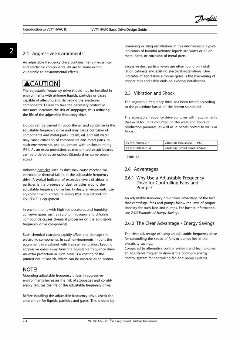
2.5 Vibration and Shock
The adjustable frequency drive has been tested accordingto the procedure based on the shown standards:
The adjustable frequency drive complies with requirementsthat exist for units mounted on the walls and floors ofproduction premises, as well as in panels bolted to walls orfloors.
IEC/EN 60068-2-6 Vibration (sinusoidal) - 1970
IEC/EN 60068-2-64 Vibration, broad-band random
Table 2.3
2.6 Advantages
2.6.1 Why Use a Adjustable FrequencyDrive for Controlling Fans andPumps?
An adjustable frequency drive takes advantage of the factthat centrifugal fans and pumps follow the laws of propor-tionality for such fans and pumps. For further information,see 2.6.3 Example of Energy Savings.
2.6.2 The Clear Advantage - Energy Savings
The clear advantage of using an adjustable frequency drivefor controlling the speed of fans or pumps lies in theelectricity savings.Compared to alternative control systems and technologies,an adjustable frequency drive is the optimum energycontrol system for controlling fan and pump systems.
Introduction to VLT® HVAC B... VLT® HVAC Basic Drive Design Guide
2-4 MG18C422 - VLT® is a registered Danfoss trademark
22
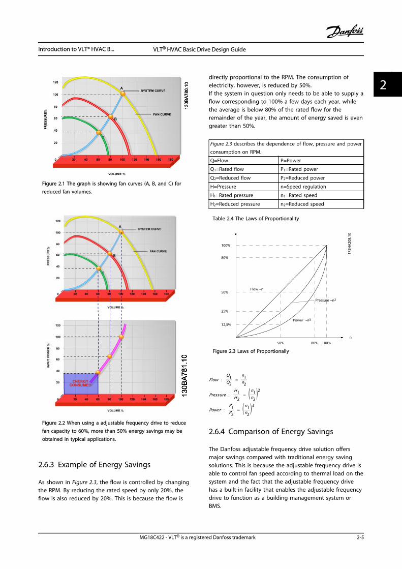
Figure 2.1 The graph is showing fan curves (A, B, and C) forreduced fan volumes.
Figure 2.2 When using a adjustable frequency drive to reducefan capacity to 60%, more than 50% energy savings may beobtained in typical applications.
2.6.3 Example of Energy Savings
As shown in Figure 2.3, the flow is controlled by changingthe RPM. By reducing the rated speed by only 20%, theflow is also reduced by 20%. This is because the flow is
directly proportional to the RPM. The consumption ofelectricity, however, is reduced by 50%.If the system in question only needs to be able to supply aflow corresponding to 100% a few days each year, whilethe average is below 80% of the rated flow for theremainder of the year, the amount of energy saved is evengreater than 50%.
Figure 2.3 describes the dependence of flow, pressure and powerconsumption on RPM.
Q=Flow P=Power
Q1=Rated flow P1=Rated power
Q2=Reduced flow P2=Reduced power
H=Pressure n=Speed regulation
H1=Rated pressure n1=Rated speed
H2=Reduced pressure n2=Reduced speed
Table 2.4 The Laws of Proportionality
n
100%
50%
25%
12,5%
50% 100%
80%
80%17
5HA
208.
10
Power ~n 3
Pressure ~n 2
Flow ~n
Figure 2.3 Laws of Proportionally
Flow :Q1Q2
= n1n2
Pressure :H1H2
= ( n1n2 )2
Power :P1P2
= ( n1n2 )3
2.6.4 Comparison of Energy Savings
The Danfoss adjustable frequency drive solution offersmajor savings compared with traditional energy savingsolutions. This is because the adjustable frequency drive isable to control fan speed according to thermal load on thesystem and the fact that the adjustable frequency drivehas a built-in facility that enables the adjustable frequencydrive to function as a building management system orBMS.
Introduction to VLT® HVAC B... VLT® HVAC Basic Drive Design Guide
MG18C422 - VLT® is a registered Danfoss trademark 2-5
2 2
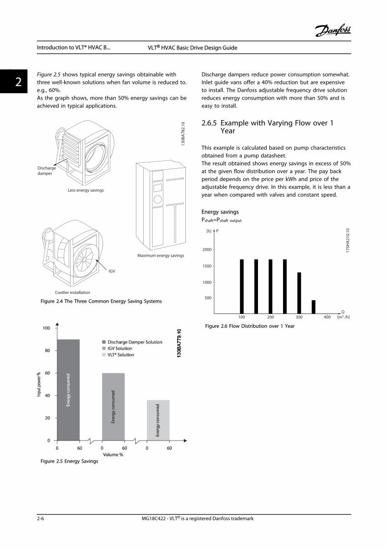
Figure 2.5 shows typical energy savings obtainable withthree well-known solutions when fan volume is reduced to.e.g., 60%.As the graph shows, more than 50% energy savings can beachieved in typical applications.
130B
A78
2.10
Dischargedamper
Less energy savings
IGV
Costlier installation
Maximum energy savings
Figure 2.4 The Three Common Energy Saving Systems
Figure 2.5 Energy Savings
Discharge dampers reduce power consumption somewhat.Inlet guide vans offer a 40% reduction but are expensiveto install. The Danfoss adjustable frequency drive solutionreduces energy consumption with more than 50% and iseasy to install.
2.6.5 Example with Varying Flow over 1Year
This example is calculated based on pump characteristicsobtained from a pump datasheet.The result obtained shows energy savings in excess of 50%at the given flow distribution over a year. The pay backperiod depends on the price per kWh and price of theadjustable frequency drive. In this example, it is less than ayear when compared with valves and constant speed.
Energy savingsPshaft=Pshaft output
500
[h] P
1000
1500
2000
200100 300 [m3 /h]400Q
175H
A21
0.10
Figure 2.6 Flow Distribution over 1 Year
Introduction to VLT® HVAC B... VLT® HVAC Basic Drive Design Guide
2-6 MG18C422 - VLT® is a registered Danfoss trademark
22
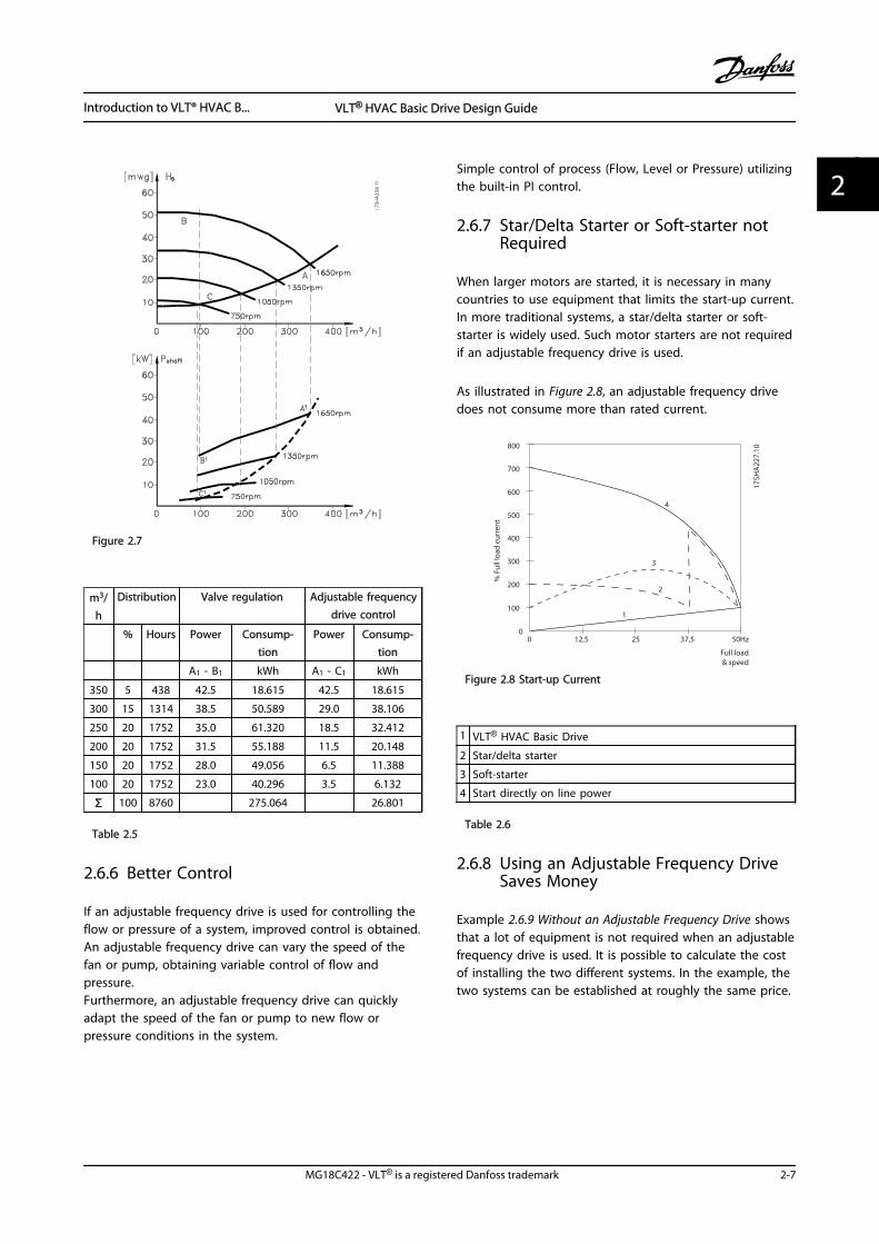
Figure 2.7
m3/h
Distribution Valve regulation Adjustable frequencydrive control
% Hours Power Consump-tion
Power Consump-tion
A1 - B1 kWh A1 - C1 kWh
350 5 438 42.5 18.615 42.5 18.615
300 15 1314 38.5 50.589 29.0 38.106
250 20 1752 35.0 61.320 18.5 32.412
200 20 1752 31.5 55.188 11.5 20.148
150 20 1752 28.0 49.056 6.5 11.388
100 20 1752 23.0 40.296 3.5 6.132
Σ 100 8760 275.064 26.801
Table 2.5
2.6.6 Better Control
If an adjustable frequency drive is used for controlling theflow or pressure of a system, improved control is obtained.An adjustable frequency drive can vary the speed of thefan or pump, obtaining variable control of flow andpressure.Furthermore, an adjustable frequency drive can quicklyadapt the speed of the fan or pump to new flow orpressure conditions in the system.
Simple control of process (Flow, Level or Pressure) utilizingthe built-in PI control.
2.6.7 Star/Delta Starter or Soft-starter notRequired
When larger motors are started, it is necessary in manycountries to use equipment that limits the start-up current.In more traditional systems, a star/delta starter or soft-starter is widely used. Such motor starters are not requiredif an adjustable frequency drive is used.
As illustrated in Figure 2.8, an adjustable frequency drivedoes not consume more than rated current.
Full load
% F
ull l
oad
curr
ent
& speed
500
100
00 12,5 25 37,5 50Hz
200
300
400
600
700
800
4
3
2
1
175H
A22
7.10
Figure 2.8 Start-up Current
1 VLT® HVAC Basic Drive
2 Star/delta starter
3 Soft-starter
4 Start directly on line power
Table 2.6
2.6.8 Using an Adjustable Frequency DriveSaves Money
Example 2.6.9 Without an Adjustable Frequency Drive showsthat a lot of equipment is not required when an adjustablefrequency drive is used. It is possible to calculate the costof installing the two different systems. In the example, thetwo systems can be established at roughly the same price.
Introduction to VLT® HVAC B... VLT® HVAC Basic Drive Design Guide
MG18C422 - VLT® is a registered Danfoss trademark 2-7
2 2
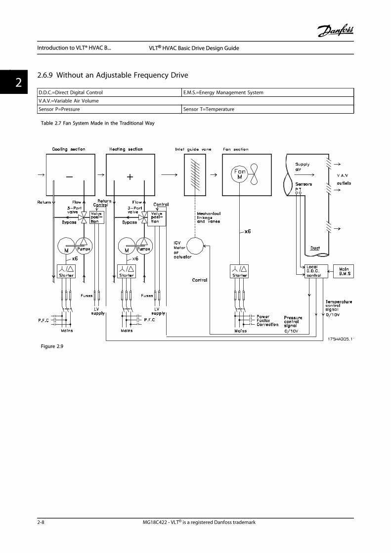
2.6.9 Without an Adjustable Frequency Drive
D.D.C.=Direct Digital Control E.M.S.=Energy Management System
V.A.V.=Variable Air Volume
Sensor P=Pressure Sensor T=Temperature
Table 2.7 Fan System Made in the Traditional Way
Figure 2.9
Introduction to VLT® HVAC B... VLT® HVAC Basic Drive Design Guide
2-8 MG18C422 - VLT® is a registered Danfoss trademark
22
2.6.10 With a
175H
A20
6.11
Pump
FlowReturn
Supplyair
V.A.Voutlets
Duct
Mains
Pump
Return Flow
Mains
Fan
MainB.M.S
LocalD.D.C.control
Sensors
Mains
Cooling section Heating section Fan section
Pressurecontrol0-10Vor0/4-20mA
Controltemperature0-10Vor0/4-20mA
Controltemperature0-10Vor0/4-20mA
VLT
M
- +
VLT
M
MPT
VLT
x3 x3
x3
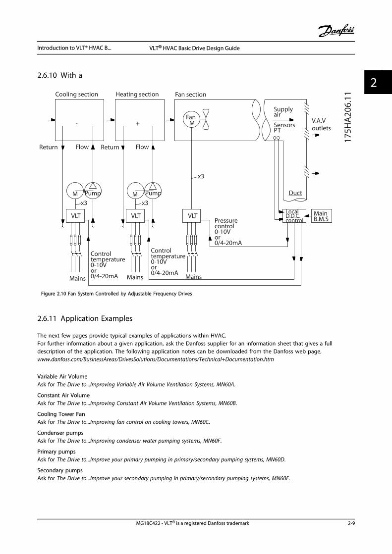
Figure 2.10 Fan System Controlled by Adjustable Frequency Drives
2.6.11 Application Examples
The next few pages provide typical examples of applications within HVAC.For further information about a given application, ask the Danfoss supplier for an information sheet that gives a fulldescription of the application. The following application notes can be downloaded from the Danfoss web page,www.danfoss.com/BusinessAreas/DrivesSolutions/Documentations/Technical+Documentation.htm
Variable Air VolumeAsk for The Drive to...Improving Variable Air Volume Ventilation Systems, MN60A.
Constant Air VolumeAsk for The Drive to...Improving Constant Air Volume Ventilation Systems, MN60B.
Cooling Tower FanAsk for The Drive to...Improving fan control on cooling towers, MN60C.
Condenser pumpsAsk for The Drive to...Improving condenser water pumping systems, MN60F.
Primary pumpsAsk for The Drive to...Improve your primary pumping in primary/secondary pumping systems, MN60D.
Secondary pumpsAsk for The Drive to...Improve your secondary pumping in primary/secondary pumping systems, MN60E.
Introduction to VLT® HVAC B... VLT® HVAC Basic Drive Design Guide
MG18C422 - VLT® is a registered Danfoss trademark 2-9
2 2
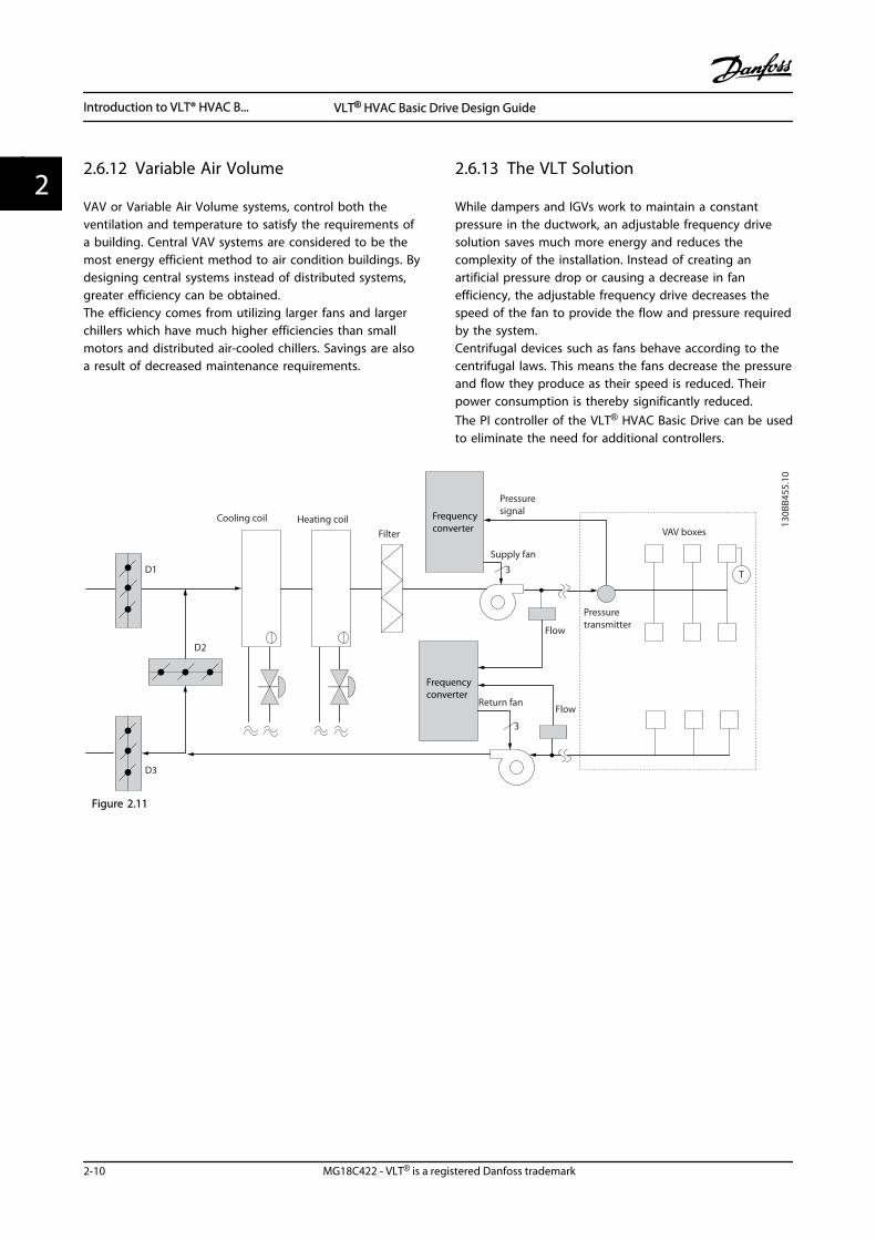
2.6.12 Variable Air Volume
VAV or Variable Air Volume systems, control both theventilation and temperature to satisfy the requirements ofa building. Central VAV systems are considered to be themost energy efficient method to air condition buildings. Bydesigning central systems instead of distributed systems,greater efficiency can be obtained.The efficiency comes from utilizing larger fans and largerchillers which have much higher efficiencies than smallmotors and distributed air-cooled chillers. Savings are alsoa result of decreased maintenance requirements.
2.6.13 The VLT Solution
While dampers and IGVs work to maintain a constantpressure in the ductwork, an adjustable frequency drivesolution saves much more energy and reduces thecomplexity of the installation. Instead of creating anartificial pressure drop or causing a decrease in fanefficiency, the adjustable frequency drive decreases thespeed of the fan to provide the flow and pressure requiredby the system.Centrifugal devices such as fans behave according to thecentrifugal laws. This means the fans decrease the pressureand flow they produce as their speed is reduced. Theirpower consumption is thereby significantly reduced.The PI controller of the VLT® HVAC Basic Drive can be usedto eliminate the need for additional controllers.
Frequency converter
Frequency converter
D1
D2
D3
Cooling coil Heating coil
Filter
Pressuresignal
Supply fan
VAV boxes
Flow
Flow
Pressuretransmitter
Return fan
3
3 T
130B
B455
.10
Figure 2.11
Introduction to VLT® HVAC B... VLT® HVAC Basic Drive Design Guide
2-10 MG18C422 - VLT® is a registered Danfoss trademark
22
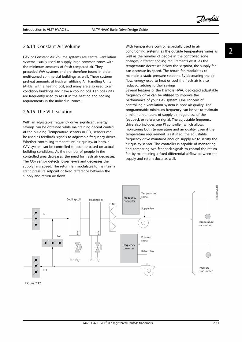
2.6.14 Constant Air Volume
CAV or Constant Air Volume systems are central ventilationsystems usually used to supply large common zones withthe minimum amounts of fresh tempered air. Theypreceded VAV systems and are therefore found in oldermulti-zoned commercial buildings as well. These systemspreheat amounts of fresh air utilizing Air Handling Units(AHUs) with a heating coil, and many are also used to aircondition buildings and have a cooling coil. Fan coil unitsare frequently used to assist in the heating and coolingrequirements in the individual zones.
2.6.15 The VLT Solution
With an adjustable frequency drive, significant energysavings can be obtained while maintaining decent controlof the building. Temperature sensors or CO2 sensors canbe used as feedback signals to adjustable frequency drives.Whether controlling temperature, air quality, or both, aCAV system can be controlled to operate based on actualbuilding conditions. As the number of people in thecontrolled area decreases, the need for fresh air decreases.The CO2 sensor detects lower levels and decreases thesupply fans speed. The return fan modulates to maintain astatic pressure setpoint or fixed difference between thesupply and return air flows.
With temperature control, especially used in airconditioning systems, as the outside temperature varies aswell as the number of people in the controlled zonechanges, different cooling requirements exist. As thetemperature decreases below the setpoint, the supply fancan decrease its speed. The return fan modulates tomaintain a static pressure setpoint. By decreasing the airflow, energy used to heat or cool the fresh air is alsoreduced, adding further savings.Several features of the Danfoss HVAC dedicated adjustablefrequency drive can be utilized to improve theperformance of your CAV system. One concern ofcontrolling a ventilation system is poor air quality. Theprogrammable minimum frequency can be set to maintaina minimum amount of supply air, regardless of thefeedback or reference signal. The adjustable frequencydrive also includes one PI controller, which allowsmonitoring both temperature and air quality. Even if thetemperature requirement is satisfied, the adjustablefrequency drive maintains enough supply air to satisfy theair quality sensor. The controller is capable of monitoringand comparing two feedback signals to control the returnfan by maintaining a fixed differential airflow between thesupply and return ducts as well.
Frequency converter
Frequency converter
Pressuresignal
Cooling coil Heating coil
D1
D2
D3
Filter
Pressuretransmitter
Supply fan
Return fan
Temperaturesignal
Temperaturetransmitter
130B
B451
.10
Figure 2.12
Introduction to VLT® HVAC B... VLT® HVAC Basic Drive Design Guide
MG18C422 - VLT® is a registered Danfoss trademark 2-11
2 2
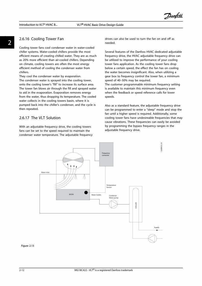
2.6.16 Cooling Tower Fan
Cooling tower fans cool condenser water in water-cooledchiller systems. Water-cooled chillers provide the mostefficient means of creating chilled water. They are as muchas 20% more efficient than air-cooled chillers. Dependingon climate, cooling towers are often the most energyefficient method of cooling the condenser water fromchillers.They cool the condenser water by evaporation.The condenser water is sprayed into the cooling tower,onto the cooling tower's “fill” to increase its surface area.The tower fan blows air through the fill and sprayed waterto aid in the evaporation. Evaporation removes energyfrom the water, thus dropping its temperature. The cooledwater collects in the cooling towers basin, where it ispumped back into the chiller's condenser, and the cycle isthen repeated.
2.6.17 The VLT Solution
With an adjustable frequency drive, the cooling towersfans can be set to the speed required to maintain thecondenser water temperature. The adjustable frequency
drives can also be used to turn the fan on and off asneeded.
Several features of the Danfoss HVAC dedicated adjustablefrequency drive, the HVAC adjustable frequency drive canbe utilized to improve the performance of your coolingtower fans application. As the cooling tower fans dropbelow a certain speed, the effect the fan has on coolingthe water becomes insignificant. Also, when utilizing agear box to frequency control the tower fan, a minimumspeed of 40–50% may be required.The customer programmable minimum frequency settingis available to maintain this minimum frequency evenwhen the feedback or speed reference calls for lowerspeeds.
Also as a standard feature, the adjustable frequency drivecan be programmed to enter a “sleep” mode and stop thefan until a higher speed is required. Additionally, somecooling tower fans have undesireable frequencies that maycause vibrations. These frequencies can easily be avoidedby programming the bypass frequency ranges in theadjustable frequency drive.
Frequency converter
Water Inlet
Water Outlet
CH
ILLE
R
TemperatureSensor
BASINConderserWater pump
Supply
130B
B453
.10
Figure 2.13
Introduction to VLT® HVAC B... VLT® HVAC Basic Drive Design Guide
2-12 MG18C422 - VLT® is a registered Danfoss trademark
22
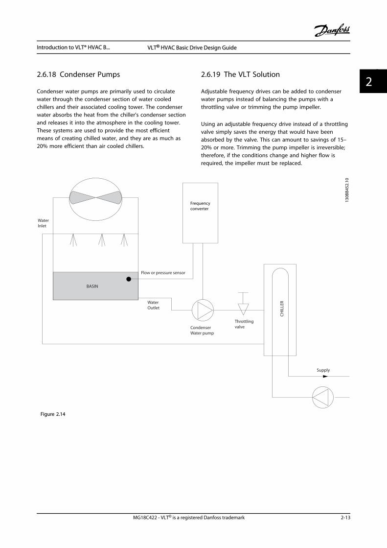
2.6.18 Condenser Pumps
Condenser water pumps are primarily used to circulatewater through the condenser section of water cooledchillers and their associated cooling tower. The condenserwater absorbs the heat from the chiller's condenser sectionand releases it into the atmosphere in the cooling tower.These systems are used to provide the most efficientmeans of creating chilled water, and they are as much as20% more efficient than air cooled chillers.
2.6.19 The VLT Solution
Adjustable frequency drives can be added to condenserwater pumps instead of balancing the pumps with athrottling valve or trimming the pump impeller.
Using an adjustable frequency drive instead of a throttlingvalve simply saves the energy that would have beenabsorbed by the valve. This can amount to savings of 15–20% or more. Trimming the pump impeller is irreversible;therefore, if the conditions change and higher flow isrequired, the impeller must be replaced.
Frequency converter
WaterInlet
WaterOutlet
BASIN
Flow or pressure sensor
CondenserWater pump
Throttlingvalve
Supply
CH
ILLE
R
130B
B452
.10
Figure 2.14
Introduction to VLT® HVAC B... VLT® HVAC Basic Drive Design Guide
MG18C422 - VLT® is a registered Danfoss trademark 2-13
2 2
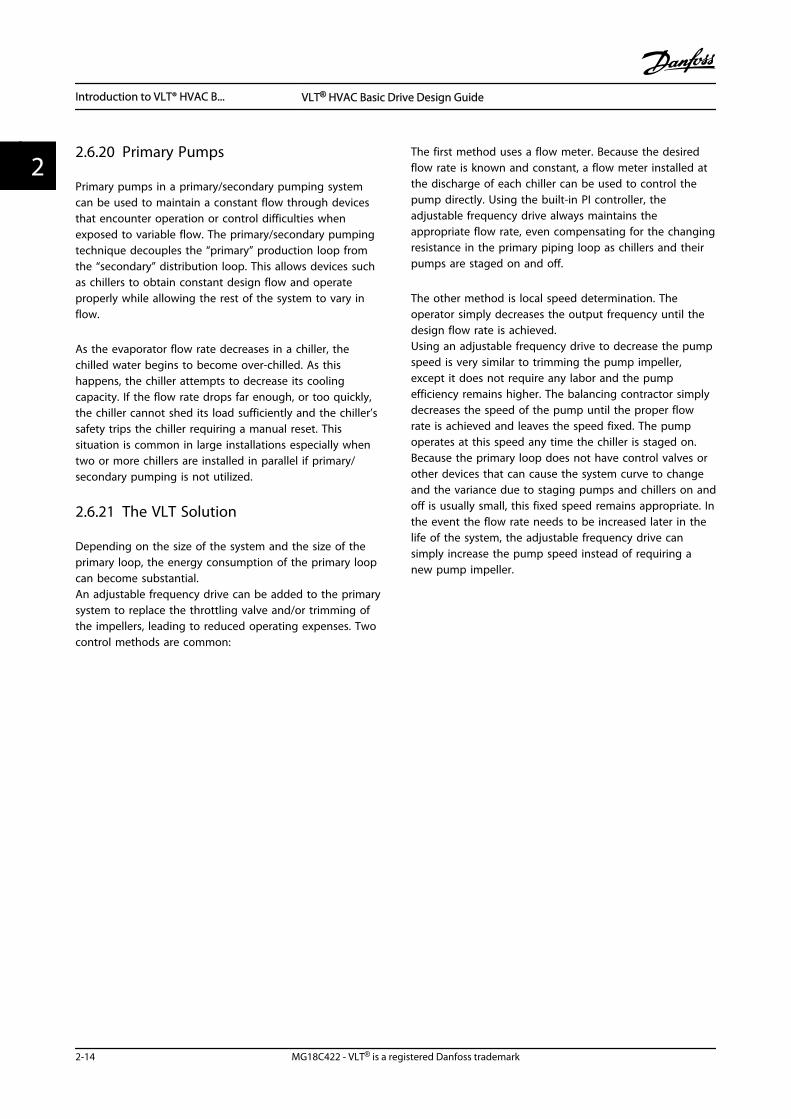
2.6.20 Primary Pumps
Primary pumps in a primary/secondary pumping systemcan be used to maintain a constant flow through devicesthat encounter operation or control difficulties whenexposed to variable flow. The primary/secondary pumpingtechnique decouples the “primary” production loop fromthe “secondary” distribution loop. This allows devices suchas chillers to obtain constant design flow and operateproperly while allowing the rest of the system to vary inflow.
As the evaporator flow rate decreases in a chiller, thechilled water begins to become over-chilled. As thishappens, the chiller attempts to decrease its coolingcapacity. If the flow rate drops far enough, or too quickly,the chiller cannot shed its load sufficiently and the chiller’ssafety trips the chiller requiring a manual reset. Thissituation is common in large installations especially whentwo or more chillers are installed in parallel if primary/secondary pumping is not utilized.
2.6.21 The VLT Solution
Depending on the size of the system and the size of theprimary loop, the energy consumption of the primary loopcan become substantial.An adjustable frequency drive can be added to the primarysystem to replace the throttling valve and/or trimming ofthe impellers, leading to reduced operating expenses. Twocontrol methods are common:
The first method uses a flow meter. Because the desiredflow rate is known and constant, a flow meter installed atthe discharge of each chiller can be used to control thepump directly. Using the built-in PI controller, theadjustable frequency drive always maintains theappropriate flow rate, even compensating for the changingresistance in the primary piping loop as chillers and theirpumps are staged on and off.
The other method is local speed determination. Theoperator simply decreases the output frequency until thedesign flow rate is achieved.Using an adjustable frequency drive to decrease the pumpspeed is very similar to trimming the pump impeller,except it does not require any labor and the pumpefficiency remains higher. The balancing contractor simplydecreases the speed of the pump until the proper flowrate is achieved and leaves the speed fixed. The pumpoperates at this speed any time the chiller is staged on.Because the primary loop does not have control valves orother devices that can cause the system curve to changeand the variance due to staging pumps and chillers on andoff is usually small, this fixed speed remains appropriate. Inthe event the flow rate needs to be increased later in thelife of the system, the adjustable frequency drive cansimply increase the pump speed instead of requiring anew pump impeller.
Introduction to VLT® HVAC B... VLT® HVAC Basic Drive Design Guide
2-14 MG18C422 - VLT® is a registered Danfoss trademark
22
Frequency converterFrequency
converter
CH
ILLE
R
CH
ILLE
R
Flowmeter Flowmeter
F F
130B
B456
.10
Figure 2.15
Introduction to VLT® HVAC B... VLT® HVAC Basic Drive Design Guide
MG18C422 - VLT® is a registered Danfoss trademark 2-15
2 2
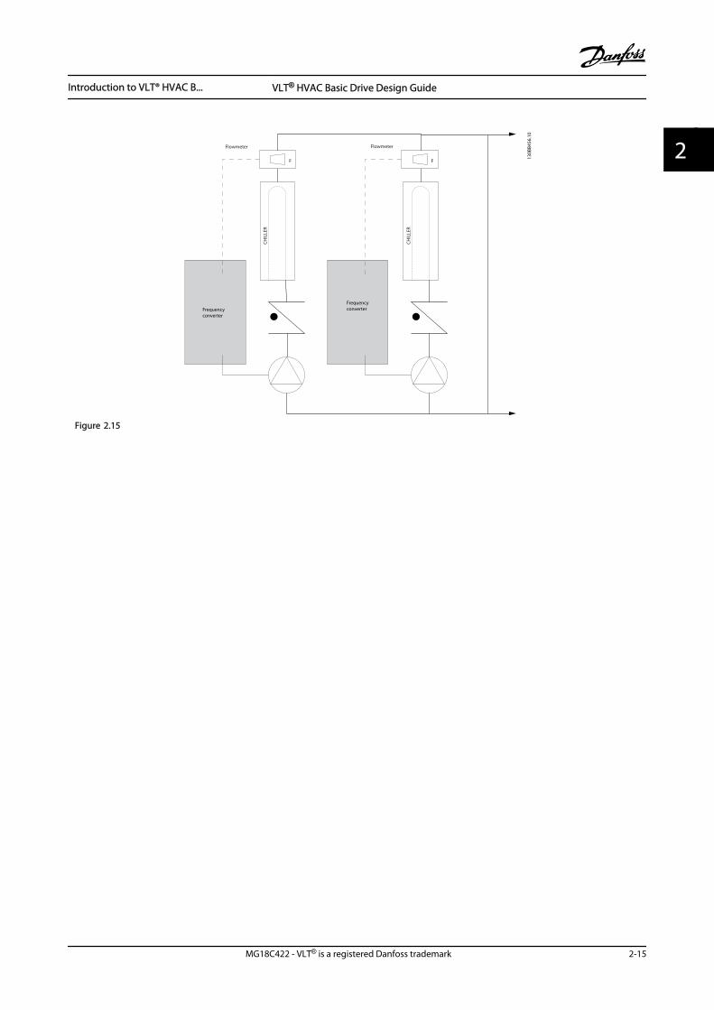
2.6.22 Secondary Pumps
Secondary pumps in a primary/secondary chilled waterpumping system distribute the chilled water to the loadsfrom the primary production loop. The primary/secondarypumping system is used to hydronically de-couple onepiping loop from another. In this case, the primary pump isused to maintain a constant flow through the chillers whileallowing the secondary pumps to vary in flow, increasecontrol and save energy.If the primary/secondary design concept is not used and avariable volume system is designed, the chiller cannotshed its load properly when the flow rate drops farenough or too quickly. The chiller’s low evaporatortemperature safety then trips the chiller, requiring amanual reset. This situation is common in large instal-lations, especially when two or more chillers are installedin parallel.
2.6.23 The VLT Solution
While the primary-secondary system with two-way valvesimproves energy savings and eases system controlproblems, the true energy savings and control potential isrealized by adding adjustable frequency drives.
With the proper sensor location, the addition of adjustablefrequency drives allows the pumps to vary their speed tofollow the system curve instead of the pump curve.This results in the elimination of wasted energy andeliminates most of the over-pressurization to which two-way valves can be subjected.As the monitored loads are reached, the two-way valvesclose down. This increases the differential pressuremeasured across the load and two-way valve. As thisdifferential pressure starts to rise, the pump is slowed tomaintain the control head also called setpoint value. Thissetpoint value is calculated by summing the pressure dropof the load and two-way valve together under designconditions.
NOTE!When running multiple pumps in parallel, they must run atthe same speed to maximize energy savings, either withindividual dedicated drives or one adjustable frequencydrive running multiple pumps in parallel.
Frequency converter
Frequency converter
CH
ILLE
R
CH
ILLE
R
3
3
P
130B
B454
.10
Figure 2.16
Introduction to VLT® HVAC B... VLT® HVAC Basic Drive Design Guide
2-16 MG18C422 - VLT® is a registered Danfoss trademark
22
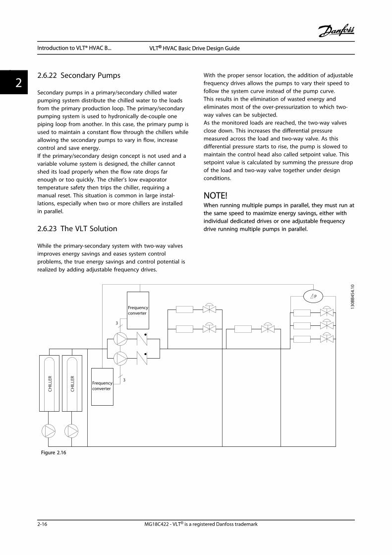
2.7 Control Structures
1-00 Configuration Mode can be selected if open-loop or closed-loop is to be used.
2.7.1 Control Structure Open-loop
130B
B892
.10
100%
0%
-100%
100%Localreferencescaled toHz
Auto mode
Hand mode
LCP Hand on,off and autoon keys
Local
Remote
ReferenceRamp
P 4-10Motor speeddirection
To motorcontrol
ReferencehandlingRemotereference
P 4-14Motor speedhigh limit [Hz]
P 4-12Motor speedlow limit [Hz]
P 3-4* Ramp 1P 3-5* Ramp 2
Figure 2.17 Open-loop Structure
In the configuration shown in Figure 2.17, 1-00 Configuration Mode is set to [0] Open-loop. The resulting reference from thereference handling system or the local reference is received and fed through the ramp limitation and speed limitationbefore being sent to the motor control. The output from the motor control is then limited by the maximum frequency limit.
2.7.2 PM/EC+ Motor Control
The Danfoss EC+ concept provides the possibility for using high efficient PM motors in IEC standard frame size operated byDanfoss adjustable frequency drives.The commissioning procedure is comparable to the existing one for asynchronous (induction) motors by utilizing theDanfoss VVCplus PM control strategy.
Customer advantages:
• Free choice of motor technology (permanentmagnet or induction motor)
• Installation and operation as known on inductionmotors
• Manufacturer independent when choosing systemcomponents (e.g., motors)
• Best system efficiency by choosing bestcomponents
• Possible retrofit of existing installations
• Power range: 0.5–125 hp [0.37–90 kW] (400 V) forinduction motors and 0.5–30 hp [0.37–22 kW](400 V) for PM motors.
Current limitations:
• Currently only supported up to 30 hp [22 kW]
• Currently limited to non-salient type PM motors
• LC filters not supported together with PM motors
• Over Voltage Control algorithm is not supportedwith PM motors
• Kinetic backup algorithm is not supported withPM motors
• Support reduced AMA of the stator resistance Rsin the system only
• No stall detection
• No ETR function
Introduction to VLT® HVAC B... VLT® HVAC Basic Drive Design Guide
MG18C422 - VLT® is a registered Danfoss trademark 2-17
2 2
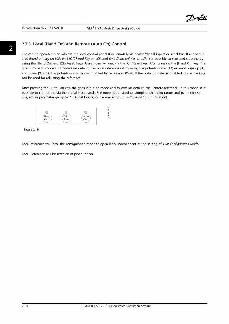
2.7.3 Local (Hand On) and Remote (Auto On) Control
The can be operated manually via the local control panel () or remotely via analog/digital inputs or serial bus. If allowed in0-40 [Hand on] Key on LCP, 0-44 [Off/Reset] Key on LCP, and 0-42 [Auto on] Key on LCP, it is possible to start and stop the by using the [Hand On] and [Off/Reset] keys. Alarms can be reset via the [Off/Reset] key. After pressing the [Hand On] key, the goes into hand mode and follows (as default) the Local reference set by using the potentiometer (12) or arrow keys up []and down [] (11). The potentiometer can be disabled by parameter P6-80. If the potentiometer is disabled, the arrow keyscan be used for adjusting the reference.
After pressing the [Auto On] key, the goes into auto mode and follows (as default) the Remote reference. In this mode, it ispossible to control the via the digital inputs and . See more about starting, stopping, changing ramps and parameter set-ups, etc. in parameter group 5-1* (Digital Inputs) or parameter group 8-5* (Serial Communication).
HandOn
OffReset
AutoOn 13
0BB8
93.10
Figure 2.18
Local reference will force the configuration mode to open loop, independent of the setting of 1-00 Configuration Mode.
Local Reference will be restored at power-down.
Introduction to VLT® HVAC B... VLT® HVAC Basic Drive Design Guide
2-18 MG18C422 - VLT® is a registered Danfoss trademark
22
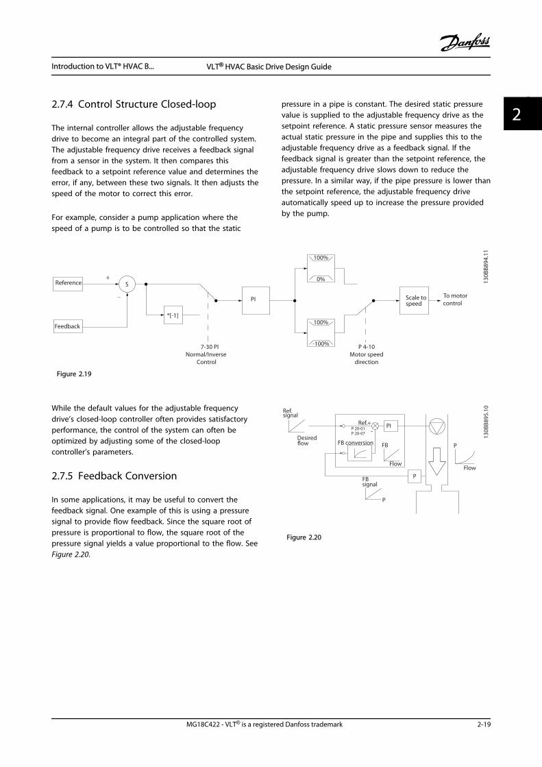
2.7.4 Control Structure Closed-loop
The internal controller allows the adjustable frequencydrive to become an integral part of the controlled system.The adjustable frequency drive receives a feedback signalfrom a sensor in the system. It then compares thisfeedback to a setpoint reference value and determines theerror, if any, between these two signals. It then adjusts thespeed of the motor to correct this error.
For example, consider a pump application where thespeed of a pump is to be controlled so that the static
pressure in a pipe is constant. The desired static pressurevalue is supplied to the adjustable frequency drive as thesetpoint reference. A static pressure sensor measures theactual static pressure in the pipe and supplies this to theadjustable frequency drive as a feedback signal. If thefeedback signal is greater than the setpoint reference, theadjustable frequency drive slows down to reduce thepressure. In a similar way, if the pipe pressure is lower thanthe setpoint reference, the adjustable frequency driveautomatically speed up to increase the pressure providedby the pump.
7-30 PI Normal/Inverse
Control
PI
Reference
Feedback
Scale tospeed
P 4-10Motor speed
direction
To motorcontrol
130B
B894
.11
S
100%
0%
-100%
100%*[-1]
_
+
Figure 2.19
While the default values for the adjustable frequencydrive’s closed-loop controller often provides satisfactoryperformance, the control of the system can often beoptimized by adjusting some of the closed-loopcontroller’s parameters.
2.7.5 Feedback Conversion
In some applications, it may be useful to convert thefeedback signal. One example of this is using a pressuresignal to provide flow feedback. Since the square root ofpressure is proportional to flow, the square root of thepressure signal yields a value proportional to the flow. SeeFigure 2.20.
+-
PI
P
P
P
130B
B895
.10
Ref.signal
Desiredflow
P 20-07
FB conversion
Ref.
FB
Flow
FBsignal
Flow
P 20-01
Figure 2.20
Introduction to VLT® HVAC B... VLT® HVAC Basic Drive Design Guide
MG18C422 - VLT® is a registered Danfoss trademark 2-19
2 2
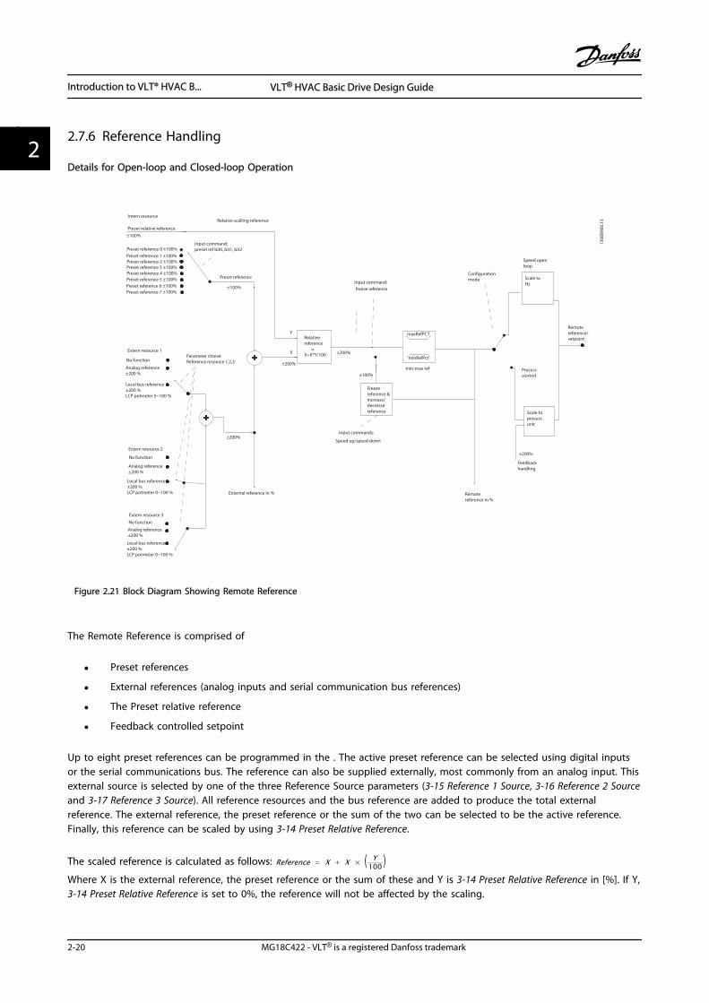
2.7.6 Reference Handling
Details for Open-loop and Closed-loop Operation
Speed open loop
Configuration mode
Input command:freeze reference
Processcontrol
Scale toHz
Scale toprocessunit
Remotereference/setpoint
±200%
Feedbackhandling
Remote reference in %
maxRefPCT
minRefPct
min-max ref
Freezereference &increase/decreasereference
±100%
Input commands:
Speed up/speed down
±200%
Relativereference =X+X*Y/100
±200%
External reference in %
±200%
Parameter choise:Reference resource 1,2,3
±100%
Preset reference
Input command:preset ref bit0, bit1, bit2
+
+
Relative scalling referenceIntern resource
Preset relative reference
±100%
Preset reference 0 ±100%
Preset reference 1 ±100%Preset reference 2 ±100%Preset reference 3 ±100%Preset reference 4 ±100%Preset reference 5 ±100%Preset reference 6 ±100%Preset reference 7 ±100%
Extern resource 1
No function
Analog reference ±200 %
Local bus reference ±200 %LCP potmeter 0~100 %
Extern resource 2
No function
Analog reference ±200 %
Local bus reference ±200 %LCP potmeter 0~100 %
Extern resource 3
No function
Analog reference ±200 %
Local bus reference ±200 %LCP potmeter 0~100 %
Y
X
130B
B900
.13
Figure 2.21 Block Diagram Showing Remote Reference
The Remote Reference is comprised of
• Preset references
• External references (analog inputs and serial communication bus references)
• The Preset relative reference
• Feedback controlled setpoint
Up to eight preset references can be programmed in the . The active preset reference can be selected using digital inputsor the serial communications bus. The reference can also be supplied externally, most commonly from an analog input. Thisexternal source is selected by one of the three Reference Source parameters (3-15 Reference 1 Source, 3-16 Reference 2 Sourceand 3-17 Reference 3 Source). All reference resources and the bus reference are added to produce the total externalreference. The external reference, the preset reference or the sum of the two can be selected to be the active reference.Finally, this reference can be scaled by using 3-14 Preset Relative Reference.
The scaled reference is calculated as follows: Reference = X + X × ( Y100 )
Where X is the external reference, the preset reference or the sum of these and Y is 3-14 Preset Relative Reference in [%]. If Y,3-14 Preset Relative Reference is set to 0%, the reference will not be affected by the scaling.
Introduction to VLT® HVAC B... VLT® HVAC Basic Drive Design Guide
2-20 MG18C422 - VLT® is a registered Danfoss trademark
22
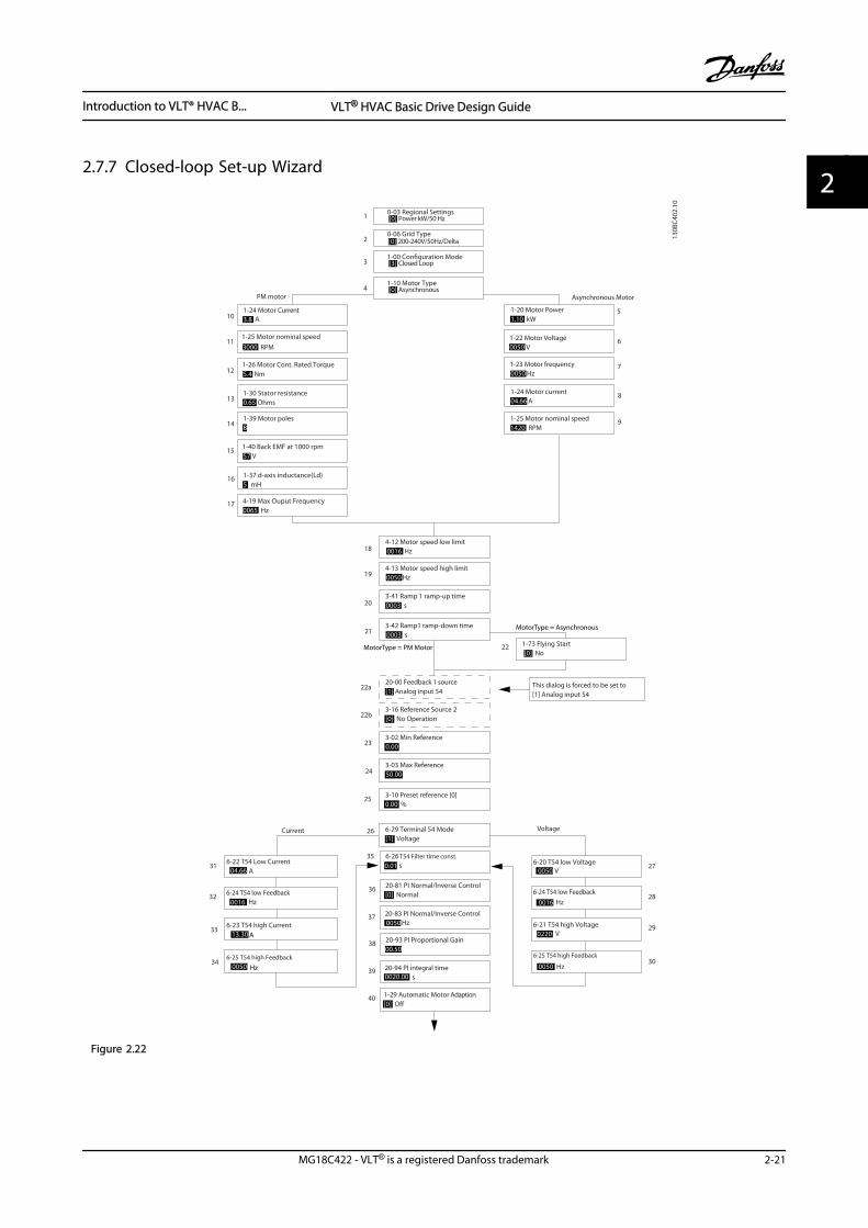
2.7.7 Closed-loop Set-up Wizard
6-29 Terminal 54 Mode[1] Voltage
6-25 T54 high Feedback
0050 Hz20-94 PI integral time0020.00 s
Current Voltage
This dialog is forced to be set to [1] Analog input 54
27
28
29
30
31
32
33
34
20-00 Feedback 1 source[1] Analog input 54
3-10 Preset reference [0]0.00
3-03 Max Reference50.00
3-02 Min Reference0.00
Asynchronous Motor
1-73 Flying Start [0] No
1-22 Motor Voltage0050 V
1-24 Motor current04.66 A
1-25 Motor nominal speed1420 RPM
3-41 Ramp 1 ramp-up time0003 s
3-42 Ramp1 ramp-down time0003 s
5
6
7
8
9
18
19
20
21
22
22a
23
24
25
26
35
36
37
38
39
40
0-06 Grid Type
4-12 Motor speed low limit0016 Hz
4-13 Motor speed high limit0050 Hz
130B
C402
.10
1-20 Motor Power1.10 kW
1-23 Motor frequency0050 Hz
6-22 T54 Low Current A
6-24 T54 low Feedback0016 Hz
6-23 T54 high Current13.30 A
6-25 T54 high Feedback0050
0.01 s
20-81 PI Normal/Inverse Control[0] Normal
20-83 PI Normal/Inverse Control0050 Hz
20-93 PI Proportional Gain00.50
1-29 Automatic Motor Adaption[0] O
6-20 T54 low Voltage0050 V
6-24 T54 low Feedback0016 Hz
6-21 T54 high Voltage0220 V
6-26 T54 Filter time const.
1-00 Conguration Mode[3] Closed Loop3
0-03 Regional Settings[0] Power kW/50 Hz1
3-16 Reference Source 2[0] No Operation22b
1-10 Motor Type[0] Asynchronous4
2 [0] 200-240V/50Hz/Delta
1-30 Stator resistance0.65 Ohms
1-25 Motor nominal speed3000 RPM
1-24 Motor Current3.8 A
1-26 Motor Cont. Rated Torque5.4 Nm
1-37 d-axis inductance(Ld)5 mH
4-19 Max Ouput Frequency0065 Hz
1-40 Back EMF at 1000 rpm57 V
10
11
12
13
14
15
16
17
PM motor
1-39 Motor poles8
%
04.66
Hz
MotorType = Asynchronous
MotorType = PM Motor
Figure 2.22
Introduction to VLT® HVAC B... VLT® HVAC Basic Drive Design Guide
MG18C422 - VLT® is a registered Danfoss trademark 2-21
2 2
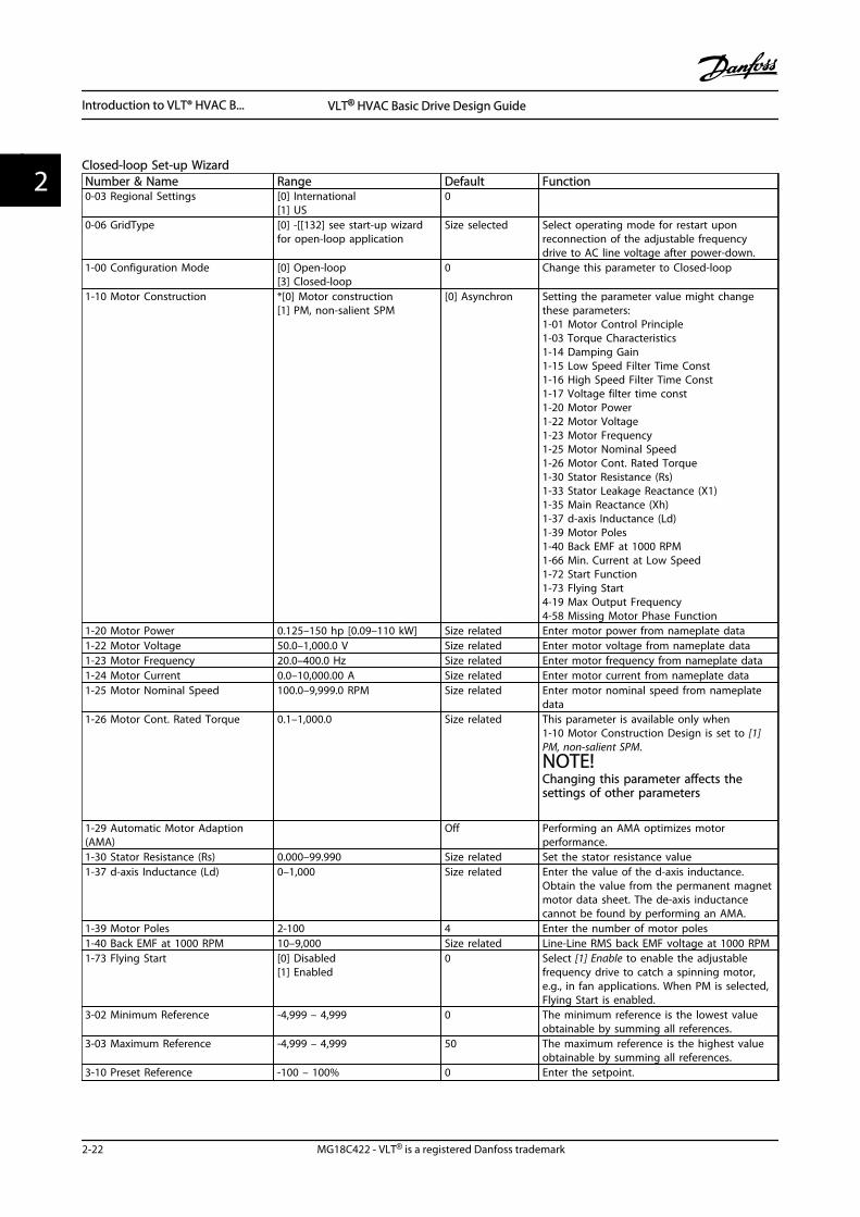
Closed-loop Set-up WizardNumber & Name Range Default Function0-03 Regional Settings [0] International
[1] US0
0-06 GridType [0] -[[132] see start-up wizardfor open-loop application
Size selected Select operating mode for restart uponreconnection of the adjustable frequencydrive to AC line voltage after power-down.
1-00 Configuration Mode [0] Open-loop[3] Closed-loop
0 Change this parameter to Closed-loop
1-10 Motor Construction *[0] Motor construction[1] PM, non-salient SPM
[0] Asynchron Setting the parameter value might changethese parameters:1-01 Motor Control Principle1-03 Torque Characteristics1-14 Damping Gain1-15 Low Speed Filter Time Const1-16 High Speed Filter Time Const1-17 Voltage filter time const1-20 Motor Power1-22 Motor Voltage1-23 Motor Frequency1-25 Motor Nominal Speed1-26 Motor Cont. Rated Torque1-30 Stator Resistance (Rs)1-33 Stator Leakage Reactance (X1)1-35 Main Reactance (Xh)1-37 d-axis Inductance (Ld)1-39 Motor Poles1-40 Back EMF at 1000 RPM1-66 Min. Current at Low Speed1-72 Start Function1-73 Flying Start4-19 Max Output Frequency4-58 Missing Motor Phase Function
1-20 Motor Power 0.125–150 hp [0.09–110 kW] Size related Enter motor power from nameplate data1-22 Motor Voltage 50.0–1,000.0 V Size related Enter motor voltage from nameplate data1-23 Motor Frequency 20.0–400.0 Hz Size related Enter motor frequency from nameplate data1-24 Motor Current 0.0–10,000.00 A Size related Enter motor current from nameplate data1-25 Motor Nominal Speed 100.0–9,999.0 RPM Size related Enter motor nominal speed from nameplate
data1-26 Motor Cont. Rated Torque 0.1–1,000.0 Size related This parameter is available only when
1-10 Motor Construction Design is set to [1]PM, non-salient SPM.NOTE!Changing this parameter affects thesettings of other parameters
1-29 Automatic Motor Adaption(AMA)
Off Performing an AMA optimizes motorperformance.
1-30 Stator Resistance (Rs) 0.000–99.990 Size related Set the stator resistance value1-37 d-axis Inductance (Ld) 0–1,000 Size related Enter the value of the d-axis inductance.
Obtain the value from the permanent magnetmotor data sheet. The de-axis inductancecannot be found by performing an AMA.
1-39 Motor Poles 2-100 4 Enter the number of motor poles1-40 Back EMF at 1000 RPM 10–9,000 Size related Line-Line RMS back EMF voltage at 1000 RPM1-73 Flying Start [0] Disabled
[1] Enabled0 Select [1] Enable to enable the adjustable
frequency drive to catch a spinning motor,e.g., in fan applications. When PM is selected,Flying Start is enabled.
3-02 Minimum Reference -4,999 – 4,999 0 The minimum reference is the lowest valueobtainable by summing all references.
3-03 Maximum Reference -4,999 – 4,999 50 The maximum reference is the highest valueobtainable by summing all references.
3-10 Preset Reference -100 – 100% 0 Enter the setpoint.
Introduction to VLT® HVAC B... VLT® HVAC Basic Drive Design Guide
2-22 MG18C422 - VLT® is a registered Danfoss trademark
22
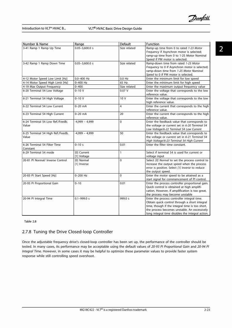
Number & Name Range Default Function3-41 Ramp 1 Ramp Up Time 0.05–3,600.0 s Size related Ramp-up time from 0 to rated 1-23 Motor
Frequency if Asynchron motor is selected;ramp-up time from 0 to 1-25 Motor NominalSpeed if PM motor is selected.
3-42 Ramp 1 Ramp Down Time 0.05–3,600.0 s Size related Ramp-down time from rated 1-23 MotorFrequency to 0 if Asynchron motor is selected;ramp-down time from 1-25 Motor NominalSpeed to 0 if PM motor is selected.
4-12 Motor Speed Low Limit [Hz] 0.0–400 Hz 0.0 Hz Enter the minimum limit for low speed4-14 Motor Speed High Limit [Hz] 0–400 Hz 65 Hz Enter the minimum limit for high speed4-19 Max Output Frequency 0–400 Size related Enter the maximum output frequency value6-20 Terminal 54 Low Voltage 0–10 V 0.07 V Enter the voltage that corresponds to the low
reference value.6-21 Terminal 54 High Voltage 0–10 V 10 V Enter the voltage that corresponds to the low
high reference value.6-22 Terminal 54 Low Current 0–20 mA 4 Enter the current that corresponds to the high
reference value.6-23 Terminal 54 High Current 0–20 mA 20 Enter the current that corresponds to the high
reference value.6-24 Terminal 54 Low Ref./Feedb.Value
-4,999 – 4,999 0 Enter the feedback value that corresponds tothe voltage or current set in 6-20 Terminal 54Low Voltage/6-22 Terminal 54 Low Current
6-25 Terminal 54 High Ref./Feedb.Value
-4,999 – 4,999 50 Enter the feedback value that corresponds tothe voltage or current set in 6-21 Terminal 54High Voltage/6-23 Terminal 54 High Current
6-26 Terminal 54 Filter TimeConstant
0–10 s 0.01 Enter the filter time constant.
6-29 Terminal 54 mode [0] Current[1] Voltage
1 Select if terminal 54 is used for current orvoltage input
20-81 PI Normal/ Inverse Control [0] Normal[1] Inverse
0 Select [0] Normal to set the process control toincrease the output speed when the processerror is positive. Select [1] Inverse to reducethe output speed.
20-83 PI Start Speed [Hz] 0–200 Hz 0 Enter the motor speed to be attained as astart signal for commencement of PI control.
20-93 PI Proportional Gain 0–10 0.01 Enter the process controller proportional gain.Quick control is obtained at high amplifi-cation. However, if amplification is too great,the process may become unstable
20-94 PI Integral Time 0.1–999.0 s 999.0 s Enter the process controller integral time.Obtain quick control through a short integraltime, though if the integral time is too short,the process becomes unstable. An excessivelylong integral time disables the integral action.
Table 2.8
2.7.8 Tuning the Drive Closed-loop Controller
Once the adjustable frequency drive's closed-loop controller has been set up, the performance of the controller should betested. In many cases, its performance may be acceptable using the default values of 20-93 PI Proportional Gain and 20-94 PIIntegral Time. However, in some cases it may be helpful to optimize these parameter values to provide faster systemresponse while still controlling speed overshoot.
Introduction to VLT® HVAC B... VLT® HVAC Basic Drive Design Guide
MG18C422 - VLT® is a registered Danfoss trademark 2-23
2 2
2.7.9 Manual PI Adjustment
1. Start the motor.
2. Set 20-93 PI Proportional Gain to 0.3 and increase it until the feedback signal begins to oscillate. If necessary, startand stop the adjustable frequency drive or make step changes in the setpoint reference to attempt to causeoscillation. Next reduce the PI proportional gain until the feedback signal stabilizes. Then reduce the proportionalgain by 40–60%.
3. Set 20-94 PI Integral Time to 20 s and reduce it until the feedback signal begins to oscillate. If necessary, start andstop the adjustable frequency drive or make step changes in the setpoint reference to attempt to cause oscillation.Next, increase the PI integral time until the feedback signal stabilizes. Then increase of the integral time by 15–50%.
2.8 General Aspects of EMC
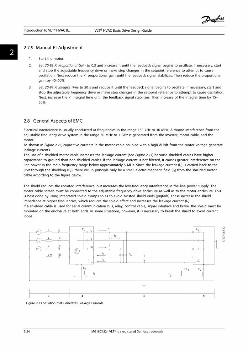
Electrical interference is usually conducted at frequencies in the range 150 kHz to 30 MHz. Airborne interference from theadjustable frequency drive system in the range 30 MHz to 1 GHz is generated from the inverter, motor cable, and themotor.As shown in Figure 2.23, capacitive currents in the motor cable coupled with a high dU/dt from the motor voltage generateleakage currents.The use of a shielded motor cable increases the leakage current (see Figure 2.23) because shielded cables have highercapacitance to ground than non-shielded cables. If the leakage current is not filtered, it causes greater interference on theline power in the radio frequency range below approximately 5 MHz. Since the leakage current (I1) is carried back to theunit through the shielding (I 3), there will in principle only be a small electro-magnetic field (I4) from the shielded motorcable according to the figure below.
The shield reduces the radiated interference, but increases the low-frequency interference in the line power supply. Themotor cable screen must be connected to the adjustable frequency drive enclosure as well as to the motor enclosure. Thisis best done by using integrated shield clamps so as to avoid twisted shield ends (pigtails) These increase the shieldimpedance at higher frequencies, which reduces the shield effect and increases the leakage current (I4).If a shielded cable is used for serial communication bus, relay, control cable, signal interface and brake, the shield must bemounted on the enclosure at both ends. In some situations, however, it is necessary to break the shield to avoid currentloops.
1
2
z
z
z
L1
L2
L3
PE
U
V
W
CS
I2
I1
I3
I4
CS CS CS
CS
I4
CSz PE
3 4 5 6
175Z
A06
2.12
Figure 2.23 Situation that Generates Leakage Currents
Introduction to VLT® HVAC B... VLT® HVAC Basic Drive Design Guide
2-24 MG18C422 - VLT® is a registered Danfoss trademark
22
If the shield is to be placed on a mounting plate for the adjustable frequency drive, the mounting plate must be made ofmetal, because the shield currents have to be conveyed back to the unit. Moreover, ensure good electrical contact from themounting plate through the mounting screws to the adjustable frequency driver chassis.
When non-shielded cables are used, some emission requirements are not complied with, although the immunityrequirements are observed.
In order to reduce the interference level from the entire system (unit+installation), make motor and brake cables as short aspossible. Avoid placing cables with a sensitive signal level alongside motor and brake cables. Radio interference higher than50 MHz (airborne) is especially generated by the control electronics. See 5.2.5 EMC-compatible Electrical Installation for moreinformation on EMC.
2.8.1 Emission Requirements
According to the EMC product standard for adjustable frequency drives EN/IEC 61800-3:2004 the EMC requirements dependon the intended use of the . Four categories are defined in the EMC product standard. The definitions of the four categoriestogether with the requirements for line power supply voltage conducted emissions are given in Table 2.9.
Category DefinitionConducted emission requirement
according to the limits given in EN55011
C1 Adjustable frequency drives installed in the first environment (home and office) witha supply voltage less than 1000 V.
Class B
C2 Adjustable frequency drives installed in the first environment (home and office) witha supply voltage less than 1000 V, which are neither plug-in nor movable and areintended to be installed and commissioned by a professional.
Class A Group 1
C3 Adjustable frequency drives installed in the second environment (industrial) with asupply voltage lower than 1000 V.
Class A Group 2
C4 Adjustable frequency drives installed in the second environment with a supplyvoltage equal to or above 1000 V or rated current equal to or above 400 A orintended for use in complex systems.
No limit line.An EMC plan should be made.
Table 2.9 Emission Requirements
When the generic emission standards are used the adjustable frequency drives are required to comply with the followinglimits:
Environment Generic standardConducted emission requirement
according to the limits given in EN 55011
First environment(home and office)
EN/IEC 61000-6-3 Emission standard for residential, commercialand light industrial environments.
Class B
Second environment(industrial environment)
EN/IEC 61000-6-4 Emission standard for industrial environments. Class A Group 1
Table 2.10
Introduction to VLT® HVAC B... VLT® HVAC Basic Drive Design Guide
MG18C422 - VLT® is a registered Danfoss trademark 2-25
2 2
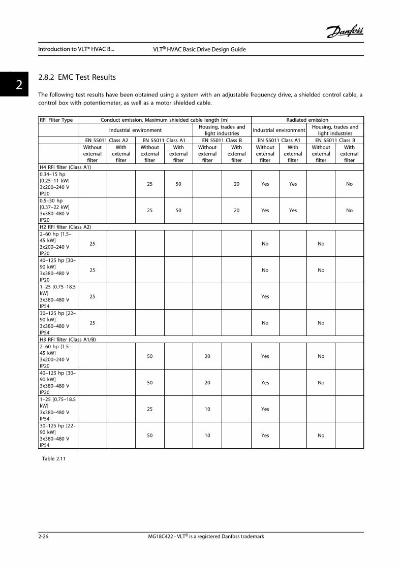
2.8.2 EMC Test Results
The following test results have been obtained using a system with an adjustable frequency drive, a shielded control cable, acontrol box with potentiometer, as well as a motor shielded cable.
RFI Filter Type Conduct emission. Maximum shielded cable length [m] Radiated emission
Industrial environment Housing, trades andlight industries Industrial environment Housing, trades and
light industries EN 55011 Class A2 EN 55011 Class A1 EN 55011 Class B EN 55011 Class A1 EN 55011 Class B
Withoutexternal
filter
Withexternal
filter
Withoutexternal
filter
Withexternal
filter
Withoutexternal
filter
Withexternal
filter
Withoutexternal
filter
Withexternal
filter
Withoutexternal
filter
Withexternal
filterH4 RFI filter (Class A1)0.34–15 hp[0.25–11 kW]3x200–240 VIP20
25 50 20 Yes Yes No
0.5–30 hp[0.37–22 kW]3x380–480 VIP20
25 50 20 Yes Yes No
H2 RFI filter (Class A2)2–60 hp [1.5–45 kW]3x200–240 VIP20
25 No No
40–125 hp [30–90 kW]3x380–480 VIP20
25 No No
1–25 [0.75–18.5kW]3x380–480 VIP54
25 Yes
30–125 hp [22–90 kW]3x380–480 VIP54
25 No No
H3 RFI filter (Class A1/B)2–60 hp [1.5–45 kW]3x200–240 VIP20
50 20 Yes No
40–125 hp [30–90 kW]3x380–480 VIP20
50 20 Yes No
1–25 [0.75–18.5kW]3x380–480 VIP54
25 10 Yes
30–125 hp [22–90 kW]3x380–480 VIP54
50 10 Yes No
Table 2.11
Introduction to VLT® HVAC B... VLT® HVAC Basic Drive Design Guide
2-26 MG18C422 - VLT® is a registered Danfoss trademark
22
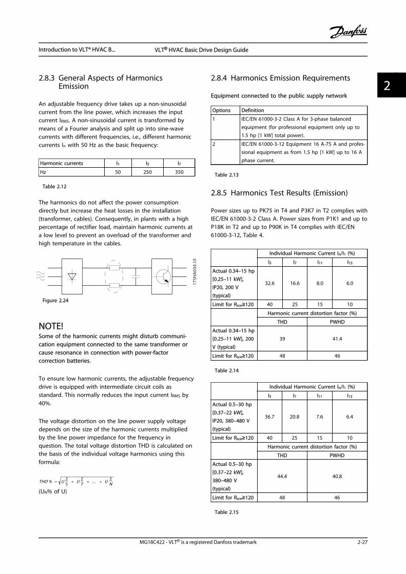
2.8.3 General Aspects of HarmonicsEmission
An adjustable frequency drive takes up a non-sinusoidalcurrent from the line power, which increases the inputcurrent IRMS. A non-sinusoidal current is transformed bymeans of a Fourier analysis and split up into sine-wavecurrents with different frequencies, i.e., different harmoniccurrents In with 50 Hz as the basic frequency:
Harmonic currents I1 I5 I7
Hz 50 250 350
Table 2.12
The harmonics do not affect the power consumptiondirectly but increase the heat losses in the installation(transformer, cables). Consequently, in plants with a highpercentage of rectifier load, maintain harmonic currents ata low level to prevent an overload of the transformer andhigh temperature in the cables.
175H
A03
4.10
Figure 2.24
NOTE!Some of the harmonic currents might disturb communi-cation equipment connected to the same transformer orcause resonance in connection with power-factorcorrection batteries.
To ensure low harmonic currents, the adjustable frequencydrive is equipped with intermediate circuit coils asstandard. This normally reduces the input current IRMS by40%.
The voltage distortion on the line power supply voltagedepends on the size of the harmonic currents multipliedby the line power impedance for the frequency inquestion. The total voltage distortion THD is calculated onthe basis of the individual voltage harmonics using thisformula:
THD % = U 25 + U 2
7 + ... + U 2N
(UN% of U)
2.8.4 Harmonics Emission Requirements
Equipment connected to the public supply network
Options Definition
1 IEC/EN 61000-3-2 Class A for 3-phase balancedequipment (for professional equipment only up to1.5 hp [1 kW] total power).
2 IEC/EN 61000-3-12 Equipment 16 A-75 A and profes-sional equipment as from 1.5 hp [1 kW] up to 16 Aphase current.
Table 2.13
2.8.5 Harmonics Test Results (Emission)
Power sizes up to PK75 in T4 and P3K7 in T2 complies withIEC/EN 61000-3-2 Class A. Power sizes from P1K1 and up toP18K in T2 and up to P90K in T4 complies with IEC/EN61000-3-12, Table 4.
Individual Harmonic Current In/I1 (%)
I5 I7 I11 I13
Actual 0.34–15 hp[0.25–11 kW],IP20, 200 V(typical)
32.6 16.6 8.0 6.0
Limit for Rsce≥120 40 25 15 10
Harmonic current distortion factor (%)
THD PWHD
Actual 0.34–15 hp[0.25–11 kW], 200V (typical)
39 41.4
Limit for Rsce≥120 48 46
Table 2.14
Individual Harmonic Current In/I1 (%)
I5 I7 I11 I13
Actual 0.5–30 hp[0.37–22 kW],IP20, 380–480 V(typical)
36.7 20.8 7.6 6.4
Limit for Rsce≥120 40 25 15 10
Harmonic current distortion factor (%)
THD PWHD
Actual 0.5–30 hp[0.37–22 kW],380–480 V(typical)
44.4 40.8
Limit for Rsce≥120 48 46
Table 2.15
Introduction to VLT® HVAC B... VLT® HVAC Basic Drive Design Guide
MG18C422 - VLT® is a registered Danfoss trademark 2-27
2 2
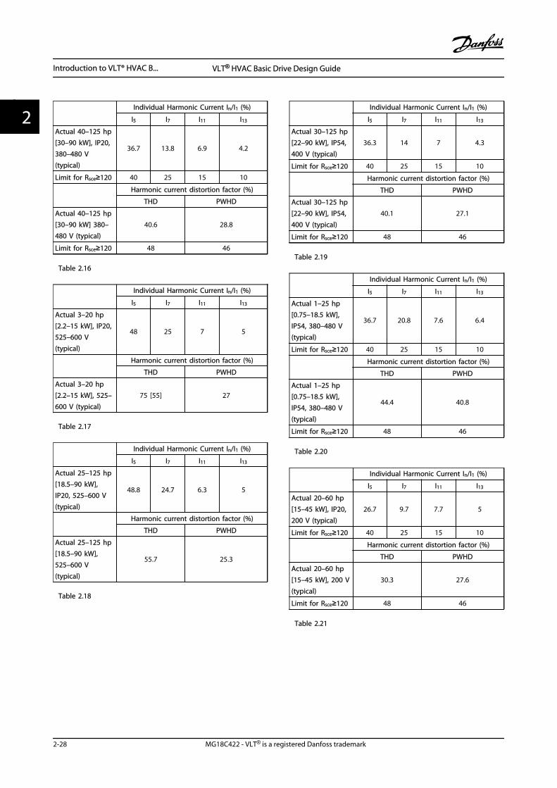
Individual Harmonic Current In/I1 (%)
I5 I7 I11 I13
Actual 40–125 hp[30–90 kW], IP20,380–480 V(typical)
36.7 13.8 6.9 4.2
Limit for Rsce≥120 40 25 15 10
Harmonic current distortion factor (%)
THD PWHD
Actual 40–125 hp[30–90 kW] 380–480 V (typical)
40.6 28.8
Limit for Rsce≥120 48 46
Table 2.16
Individual Harmonic Current In/I1 (%)
I5 I7 I11 I13
Actual 3–20 hp[2.2–15 kW], IP20,525–600 V(typical)
48 25 7 5
Harmonic current distortion factor (%)
THD PWHD
Actual 3–20 hp[2.2–15 kW], 525–600 V (typical)
75 [55] 27
Table 2.17
Individual Harmonic Current In/I1 (%)
I5 I7 I11 I13
Actual 25–125 hp[18.5–90 kW],IP20, 525–600 V(typical)
48.8 24.7 6.3 5
Harmonic current distortion factor (%)
THD PWHD
Actual 25–125 hp[18.5–90 kW],525–600 V(typical)
55.7 25.3
Table 2.18
Individual Harmonic Current In/I1 (%)
I5 I7 I11 I13
Actual 30–125 hp[22–90 kW], IP54,400 V (typical)
36.3 14 7 4.3
Limit for Rsce≥120 40 25 15 10
Harmonic current distortion factor (%)
THD PWHD
Actual 30–125 hp[22–90 kW], IP54,400 V (typical)
40.1 27.1
Limit for Rsce≥120 48 46
Table 2.19
Individual Harmonic Current In/I1 (%)
I5 I7 I11 I13
Actual 1–25 hp[0.75–18.5 kW],IP54, 380–480 V(typical)
36.7 20.8 7.6 6.4
Limit for Rsce≥120 40 25 15 10
Harmonic current distortion factor (%)
THD PWHD
Actual 1–25 hp[0.75–18.5 kW],IP54, 380–480 V(typical)
44.4 40.8
Limit for Rsce≥120 48 46
Table 2.20
Individual Harmonic Current In/I1 (%)
I5 I7 I11 I13
Actual 20–60 hp[15–45 kW], IP20,200 V (typical)
26.7 9.7 7.7 5
Limit for Rsce≥120 40 25 15 10
Harmonic current distortion factor (%)
THD PWHD
Actual 20–60 hp[15–45 kW], 200 V(typical)
30.3 27.6
Limit for Rsce≥120 48 46
Table 2.21
Introduction to VLT® HVAC B... VLT® HVAC Basic Drive Design Guide
2-28 MG18C422 - VLT® is a registered Danfoss trademark
22
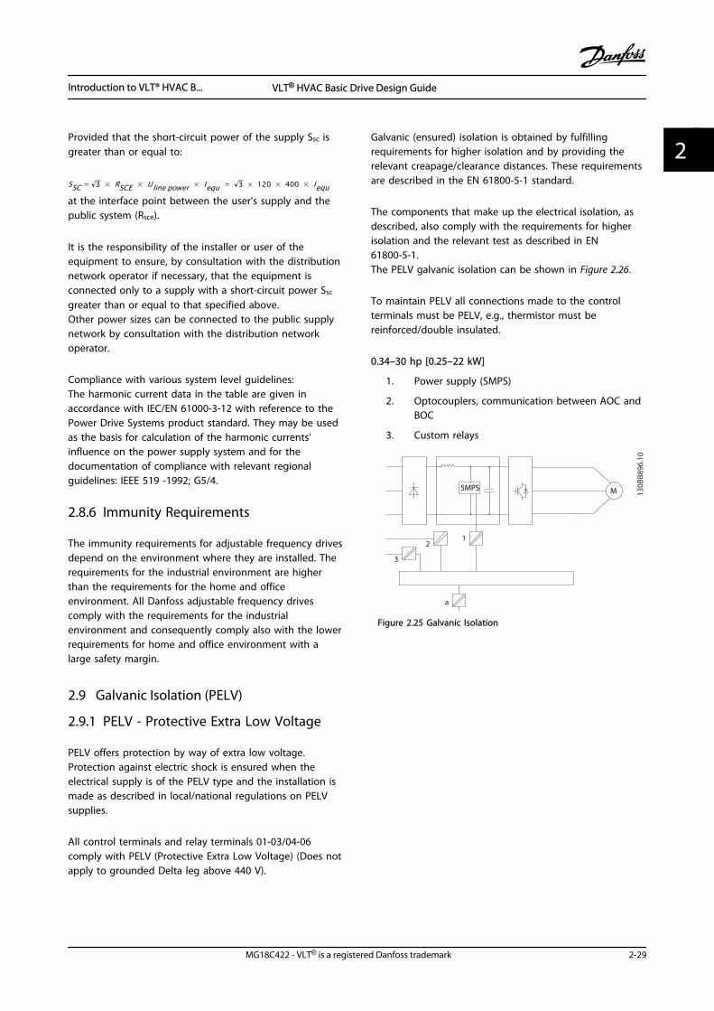
Provided that the short-circuit power of the supply Ssc isgreater than or equal to:
SSC = 3 × RSCE × Uline power × Iequ = 3 × 120 × 400 × Iequat the interface point between the user’s supply and thepublic system (Rsce).
It is the responsibility of the installer or user of theequipment to ensure, by consultation with the distributionnetwork operator if necessary, that the equipment isconnected only to a supply with a short-circuit power Ssc
greater than or equal to that specified above.Other power sizes can be connected to the public supplynetwork by consultation with the distribution networkoperator.
Compliance with various system level guidelines:The harmonic current data in the table are given inaccordance with IEC/EN 61000-3-12 with reference to thePower Drive Systems product standard. They may be usedas the basis for calculation of the harmonic currents'influence on the power supply system and for thedocumentation of compliance with relevant regionalguidelines: IEEE 519 -1992; G5/4.
2.8.6 Immunity Requirements
The immunity requirements for adjustable frequency drivesdepend on the environment where they are installed. Therequirements for the industrial environment are higherthan the requirements for the home and officeenvironment. All Danfoss adjustable frequency drivescomply with the requirements for the industrialenvironment and consequently comply also with the lowerrequirements for home and office environment with alarge safety margin.
2.9 Galvanic Isolation (PELV)
2.9.1 PELV - Protective Extra Low Voltage
PELV offers protection by way of extra low voltage.Protection against electric shock is ensured when theelectrical supply is of the PELV type and the installation ismade as described in local/national regulations on PELVsupplies.
All control terminals and relay terminals 01-03/04-06comply with PELV (Protective Extra Low Voltage) (Does notapply to grounded Delta leg above 440 V).
Galvanic (ensured) isolation is obtained by fulfillingrequirements for higher isolation and by providing therelevant creapage/clearance distances. These requirementsare described in the EN 61800-5-1 standard.
The components that make up the electrical isolation, asdescribed, also comply with the requirements for higherisolation and the relevant test as described in EN61800-5-1.The PELV galvanic isolation can be shown in Figure 2.26.
To maintain PELV all connections made to the controlterminals must be PELV, e.g., thermistor must bereinforced/double insulated.
0.34–30 hp [0.25–22 kW]
1. Power supply (SMPS)
2. Optocouplers, communication between AOC andBOC
3. Custom relays
SMPS
130B
B896
.10
12
3
a
M
Figure 2.25 Galvanic Isolation
Introduction to VLT® HVAC B... VLT® HVAC Basic Drive Design Guide
MG18C422 - VLT® is a registered Danfoss trademark 2-29
2 2
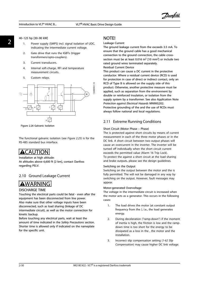
40–125 hp [30–90 kW]
1. Power supply (SMPS) incl. signal isolation of UDC,indicating the intermediate current voltage.
2. Gate drive that runs the IGBTs (triggertransformers/opto-couplers).
3. Current transducers.
4. Internal soft-charge, RFI and temperaturemeasurement circuits.
5. Custom relays.
130B
B901
.10
1
3
245
a
M
Figure 2.26 Galvanic Isolation
The functional galvanic isolation (see Figure 2.25) is for theRS-485 standard bus interface.
CAUTIONInstallation at high altitude:At altitudes above 6,600 ft [2 km], contact Danfossregarding PELV.
2.10 Ground Leakage Current
WARNINGDISCHARGE TIMETouching the electrical parts could be fatal - even after theequipment has been disconnected from line power.Also make sure that other voltage inputs have beendisconnected, such as load sharing (linkage of DCintermediate circuit), as well as the motor connection forkinetic backup.Before touching any electrical parts, wait at least theamount of time indicated in the Safety Precautions section.Shorter time is allowed only if indicated on the nameplatefor the specific unit.
NOTE!Leakage CurrentThe ground leakage current from the exceeds 3.5 mA. Toensure that the ground cable has a good mechanicalconnection to the ground connection, the cable cross-section must be at least 0.016 in2 [10 mm2] or include tworated ground wires terminated separately.Residual Current DeviceThis product can cause a DC current in the protectiveconductor. Where a residual current device (RCD) is usedfor protection in case of direct or indirect contact, only anRCD of Type B is allowed on the supply side of thisproduct. Otherwise, another protective measure must beapplied, such as separation from the environment bydouble or reinforced insulation, or isolation from thesupply system by a transformer. See also Application NoteProtection against Electrical Hazards MN90G202.Protective grounding of the and the use of RCDs mustalways follow national and local regulations.
2.11 Extreme Running Conditions
Short Circuit (Motor Phase – Phase)The is protected against short circuits by means of currentmeasurement in each of the three motor phases or in theDC link. A short circuit between two output phases willcause an overcurrent in the inverter. The inverter will beturned off individually when the short circuit currentexceeds the permitted value (Alarm 16 Trip Lock).To protect the against a short circuit at the load sharingand brake outputs, please see the design guidelines.
Switching on the OutputSwitching on the output between the motor and the isfully permitted. The will not be damaged in any way byswitching on the output. However, fault messages mayappear.
Motor-generated OvervoltageThe voltage in the intermediate circuit is increased whenthe motor acts as a generator. This occurs in the followingcases:
1. The load drives the motor (at constant outputfrequency from the ), i.e., the load generatesenergy.
2. During deceleration ("ramp-down") if the momentof inertia is high, the friction is low and the ramp-down time is too short for the energy to bedissipated as a loss in the , the motor and theinstallation.
3. Incorrect slip compensation setting (1-62 SlipCompensation) may cause higher DC link voltage.
Introduction to VLT® HVAC B... VLT® HVAC Basic Drive Design Guide
2-30 MG18C422 - VLT® is a registered Danfoss trademark
22
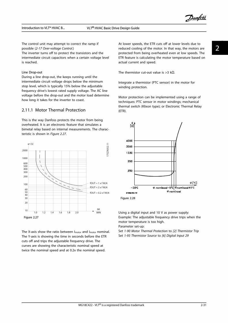
The control unit may attempt to correct the ramp ifpossible (2-17 Over-voltage Control.)The inverter turns off to protect the transistors and theintermediate circuit capacitors when a certain voltage levelis reached.
Line Drop-outDuring a line drop-out, the keeps running until theintermediate circuit voltage drops below the minimumstop level, which is typically 15% below the adjustablefrequency drive's lowest rated supply voltage. The AC linevoltage before the drop-out and the motor load determinehow long it takes for the inverter to coast.
2.11.1 Motor Thermal Protection
This is the way Danfoss protects the motor from beingoverheated. It is an electronic feature that simulates abimetal relay based on internal measurements. The charac-teristic is shown in Figure 2.27.
1.21.0 1.4
30
10
20
100
60
4050
1.81.6 2.0
2000
500
200
400300
1000
600
t [s]
175Z
A05
2.11
fOUT = 0.2 x f M,N
fOUT = 2 x f M,N
fOUT = 1 x f M,N
IMNIM
Figure 2.27
The X-axis show the ratio between Imotor and Imotor nominal.The Y-axis is showing the time in seconds before the ETRcuts off and trips the adjustable frequency drive. Thecurves are showing the characteristic nominal speed attwice the nominal speed and at 0.2x the nominal speed.
At lower speeds, the ETR cuts off at lower levels due toreduced cooling of the motor. In that way, the motors areprotected from being overheated even at low speeds. TheETR feature is calculating the motor temperature based onactual current and speed.
The thermistor cut-out value is >3 kΩ.
Integrate a thermistor (PTC sensor) in the motor forwinding protection.
Motor protection can be implemented using a range oftechniques: PTC sensor in motor windings; mechanicalthermal switch (Klixon type); or Electronic Thermal Relay(ETR).
Figure 2.28
Using a digital input and 10 V as power supply:Example: The adjustable frequency drive trips when themotor temperature is too high.Parameter set-up:Set 1-90 Motor Thermal Protection to [2] Thermistor TripSet 1-93 Thermistor Source to [6] Digital Input 29
Introduction to VLT® HVAC B... VLT® HVAC Basic Drive Design Guide
MG18C422 - VLT® is a registered Danfoss trademark 2-31
2 2
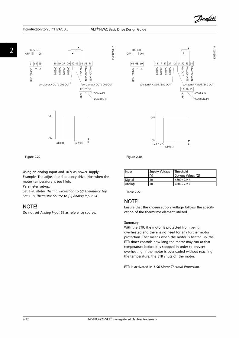
R
OFF
ON
<800 Ω >2.9 kΩ
18 19
12 20 55
27 29 42 45 50 53 54
DIG
I IN
DIG
I IN
DIG
I IN
DIG
I IN
61 68 69
NPCOM
M. G
ND
+24V
0/4-20mA A OUT / DIG OUT 0/4-20mA A OUT / DIG OUT
COM A IN
COM DIG IN
10V/20mA
IN
10V/20mA
IN
10V OU
T
BUS TER.OFF ON
130B
B898
.10
Figure 2.29
Using an analog input and 10 V as power supply:Example: The adjustable frequency drive trips when themotor temperature is too high.Parameter set-up:Set 1-90 Motor Thermal Protection to [2] Thermistor TripSet 1-93 Thermistor Source to [2] Analog Input 54
NOTE!Do not set Analog Input 54 as reference source.
18 19
12 20 55
27 29 42 45 50 53 54
DIG
I IN
DIG
I IN
DIG
I IN
DIG
I IN
61 68 69
NPCOM
M. G
ND
+24V
0/4-20mA A OUT / DIG OUT 0/4-20mA A OUT / DIG OUT
COM A IN
COM DIG IN
10V/20mA
IN
10V/20mA
IN
10V OU
T
BUS TER.OFF ON
130B
B897
.10
R<3.0 k Ω>2.9k Ω
OFF
ON
Figure 2.30
Input Supply Voltage[V]
ThresholdCut-out Values [Ω]
Digital 10 <800⇒2.9 kAnalog 10 <800⇒2.9 k
Table 2.22
NOTE!Ensure that the chosen supply voltage follows the specifi-cation of the thermistor element utilized.
SummaryWith the ETR, the motor is protected from beingoverheated and there is no need for any further motorprotection. That means when the motor is heated up, theETR timer controls how long the motor may run at thattemperature before it is stopped in order to preventoverheating. If the motor is overloaded without reachingthe temperature, the ETR shuts off the motor.
ETR is activated in 1-90 Motor Thermal Protection.
Introduction to VLT® HVAC B... VLT® HVAC Basic Drive Design Guide
2-32 MG18C422 - VLT® is a registered Danfoss trademark
22
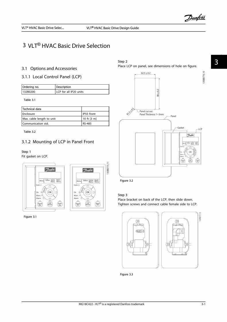
3 VLT® HVAC Basic Drive Selection
3.1 Options and Accessories
3.1.1 Local Control Panel (LCP)
Ordering no. Description
132B0200 LCP for all IP20 units
Table 3.1
Technical data
Enclosure IP55 front
Max. cable length to unit 10 ft [3 m]
Communication std. RS-485
Table 3.2
3.1.2 Mounting of LCP in Panel Front
Step 1Fit gasket on LCP.
130B
B775
.11
Status MainMenu
QuickMenuMenu
Back
Com.
Status MainMenu
QuickMenu
HandOn
OK
Menu
OReset
AutoOn
AlarmWarn.
On
Com.
AlarmWarn.
On
Back
Hand
OK
OReset
AutoOn On
Figure 3.1
Step 2Place LCP on panel, see dimensions of hole on figure.
Gasket
R1.5 +_ 0.5
62.5 +_ 0.2
Panel cut outPanel Thickness: 1~3mm
86 +_
0.2
LCP
Panel
130B
B776
.10
Status MainMenu
QuickMenuMenu
Com
Alarm
Warn
On
Back
HandOn
OK
OffReset
AutoOn
Figure 3.2
Step 3Place bracket on back of the LCP, then slide down.Tighten screws and connect cable female side to LCP.
130B
B777
.10
Figure 3.3
VLT® HVAC Basic Drive Selec... VLT® HVAC Basic Drive Design Guide
MG18C422 - VLT® is a registered Danfoss trademark 3-1
3 3
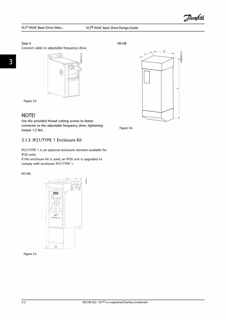
Step 4Connect cable to adjustable frequency drive.
130B
B778
.10
Figure 3.4
NOTE!Use the provided thread cutting screws to fastenconnector to the adjustable frequency drive, tighteningtorque 1.3 Nm.
3.1.3 IP21/TYPE 1 Enclosure Kit
IP21/TYPE 1 is an optional enclosure element available forIP20 units.If the enclosure kit is used, an IP20 unit is upgraded tocomply with enclosure IP21/TYPE 1.
H1-H5
130B
B902
.11
VLTHVAC Basic Drive
A
BC
OK
Alarm
Warn.
On
Back
HandOn
OReset Auto
On
Status QuickMenu
MainMenu
R
Figure 3.5
H6-H8
130B
B903
.10
Figure 3.6
VLT® HVAC Basic Drive Selec... VLT® HVAC Basic Drive Design Guide
3-2 MG18C422 - VLT® is a registered Danfoss trademark
33
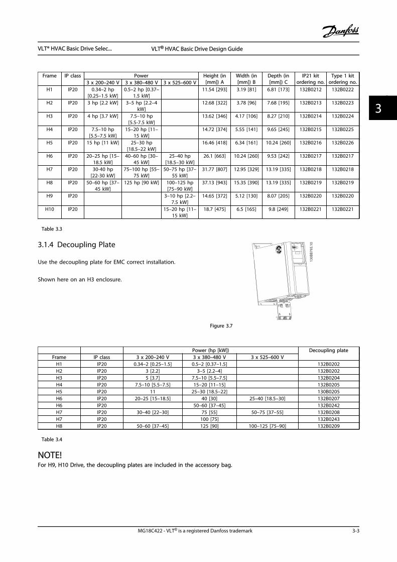
Frame IP class Power Height (in[mm]) A
Width (in[mm]) B
Depth (in[mm]) C
IP21 kitordering no.
Type 1 kitordering no.3 x 200–240 V 3 x 380–480 V 3 x 525–600 V
H1 IP20 0.34–2 hp[0.25–1.5 kW]
0.5–2 hp [0.37–1.5 kW]
11.54 [293] 3.19 [81] 6.81 [173] 132B0212 132B0222
H2 IP20 3 hp [2.2 kW] 3–5 hp [2.2–4kW]
12.68 [322] 3.78 [96] 7.68 [195] 132B0213 132B0223
H3 IP20 4 hp [3.7 kW] 7.5–10 hp[5.5-7.5 kW]
13.62 [346] 4.17 [106] 8.27 [210] 132B0214 132B0224
H4 IP20 7.5–10 hp[5.5–7.5 kW]
15–20 hp [11–15 kW]
14.72 [374] 5.55 [141] 9.65 [245] 132B0215 132B0225
H5 IP20 15 hp [11 kW] 25–30 hp[18.5–22 kW]
16.46 [418] 6.34 [161] 10.24 [260] 132B0216 132B0226
H6 IP20 20–25 hp [15–18.5 kW]
40–60 hp [30–45 kW]
25–40 hp[18.5–30 kW]
26.1 [663] 10.24 [260] 9.53 [242] 132B0217 132B0217
H7 IP20 30-40 hp[22-30 kW]
75–100 hp [55–75 kW]
50–75 hp [37–55 kW]
31.77 [807] 12.95 [329] 13.19 [335] 132B0218 132B0218
H8 IP20 50–60 hp [37–45 kW]
125 hp [90 kW] 100–125 hp[75–90 kW]
37.13 [943] 15.35 [390] 13.19 [335] 132B0219 132B0219
H9 IP20 3–10 hp [2.2–7.5 kW]
14.65 [372] 5.12 [130] 8.07 [205] 132B0220 132B0220
H10 IP20 15–20 hp [11–15 kW]
18.7 [475] 6.5 [165] 9.8 [249] 132B0221 132B0221
Table 3.3
3.1.4 Decoupling Plate
Use the decoupling plate for EMC correct installation.
Shown here on an H3 enclosure.
130B
B793
.10
99 99
Figure 3.7
Power (hp [kW]) Decoupling plateFrame IP class 3 x 200–240 V 3 x 380–480 V 3 x 525–600 V
H1 IP20 0.34–2 [0.25–1.5] 0.5–2 [0.37–1.5] 132B0202H2 IP20 3 [2.2] 3–5 [2.2–4] 132B0202H3 IP20 5 [3.7] 7.5–10 [5.5–7.5] 132B0204H4 IP20 7.5–10 [5.5–7.5] 15–20 [11–15] 132B0205H5 IP20 11 25–30 [18.5–22] 130B0205H6 IP20 20–25 [15–18.5] 40 [30] 25–40 [18.5–30] 132B0207H6 IP20 50–60 [37–45] 132B0242H7 IP20 30–40 [22–30] 75 [55] 50–75 [37–55] 132B0208H7 IP20 100 [75] 132B0243H8 IP20 50–60 [37–45] 125 [90] 100–125 [75–90] 132B0209
Table 3.4
NOTE!For H9, H10 Drive, the decoupling plates are included in the accessory bag.
VLT® HVAC Basic Drive Selec... VLT® HVAC Basic Drive Design Guide
MG18C422 - VLT® is a registered Danfoss trademark 3-3
3 3
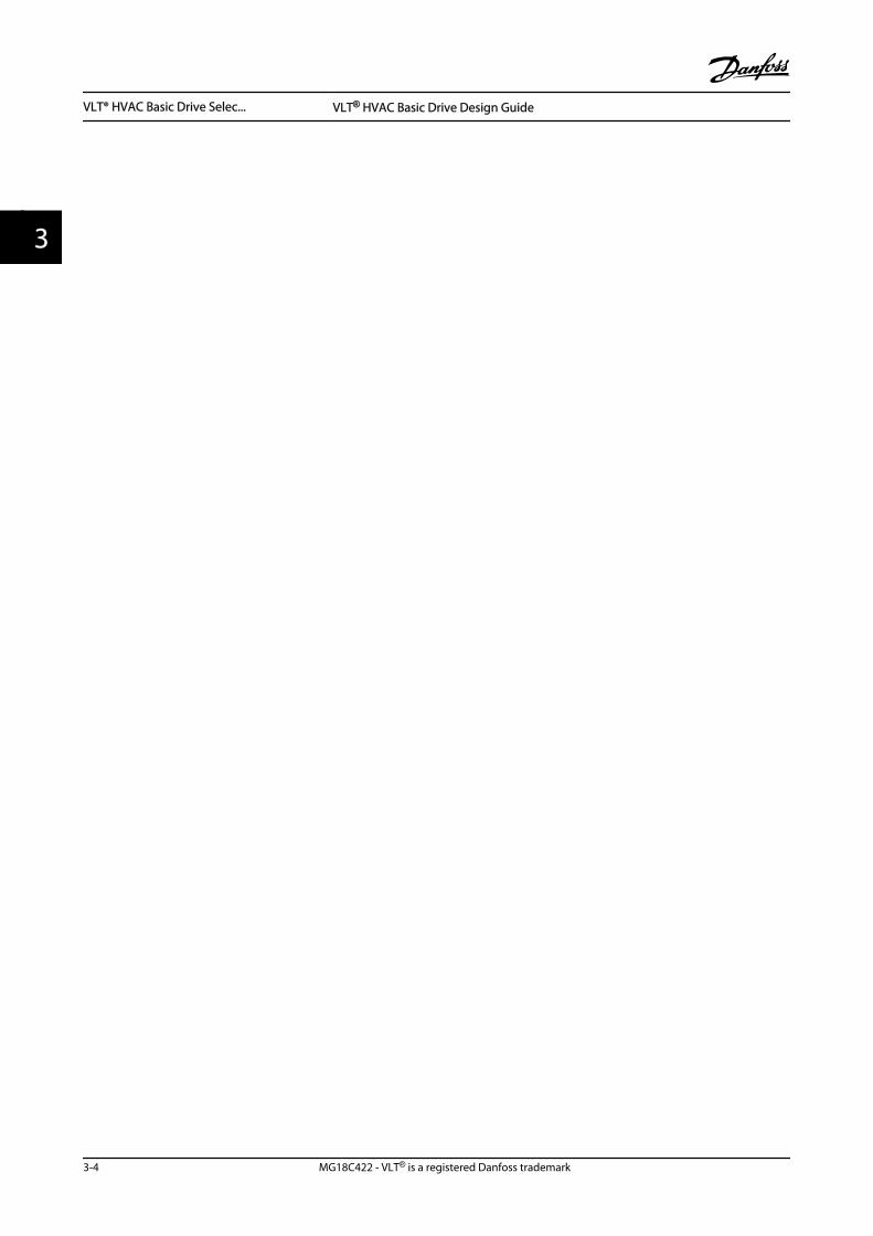
VLT® HVAC Basic Drive Selec... VLT® HVAC Basic Drive Design Guide
3-4 MG18C422 - VLT® is a registered Danfoss trademark
33
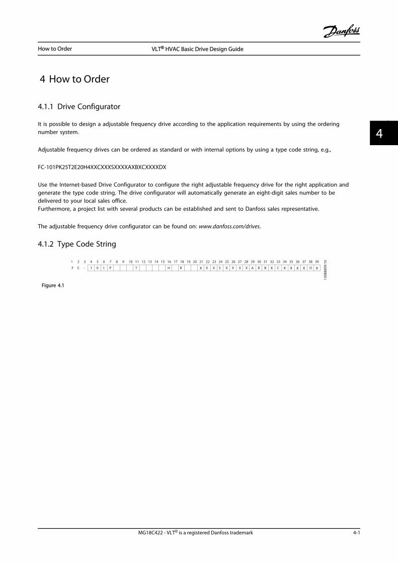
4 How to Order
4.1.1 Drive Configurator
It is possible to design a adjustable frequency drive according to the application requirements by using the orderingnumber system.
Adjustable frequency drives can be ordered as standard or with internal options by using a type code string, e.g.,
FC-101PK25T2E20H4XXCXXXSXXXXAXBXCXXXXDX
Use the Internet-based Drive Configurator to configure the right adjustable frequency drive for the right application andgenerate the type code string. The drive configurator will automatically generate an eight-digit sales number to bedelivered to your local sales office.Furthermore, a project list with several products can be established and sent to Danfoss sales representative.
The adjustable frequency drive configurator can be found on: www.danfoss.com/drives.
4.1.2 Type Code String
F C - P T H
130B
B899
.10
X S A B CX X X X
1 2 3 4 5 6 7 8 9 10 11 12 13 14 15 16 17 18 19 20 302221 23 272524 26 28 29 31 373635343332 38 39
X0 D1 1 X X X X X X X X X
Figure 4.1
How to Order VLT® HVAC Basic Drive Design Guide
MG18C422 - VLT® is a registered Danfoss trademark 4-1
4 4
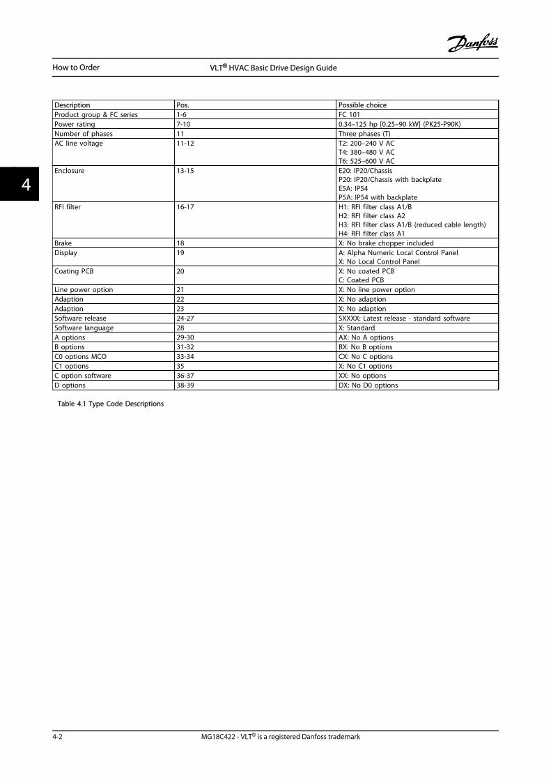
Description Pos. Possible choiceProduct group & FC series 1-6 FC 101Power rating 7-10 0.34–125 hp [0.25–90 kW] (PK25-P90K)Number of phases 11 Three phases (T)AC line voltage 11-12 T2: 200–240 V AC
T4: 380–480 V ACT6: 525–600 V AC
Enclosure 13-15 E20: IP20/ChassisP20: IP20/Chassis with backplateE5A: IP54P5A: IP54 with backplate
RFI filter 16-17 H1: RFI filter class A1/BH2: RFI filter class A2H3: RFI filter class A1/B (reduced cable length)H4: RFI filter class A1
Brake 18 X: No brake chopper includedDisplay 19 A: Alpha Numeric Local Control Panel
X: No Local Control PanelCoating PCB 20 X: No coated PCB
C: Coated PCBLine power option 21 X: No line power optionAdaption 22 X: No adaptionAdaption 23 X: No adaptionSoftware release 24-27 SXXXX: Latest release - standard softwareSoftware language 28 X: StandardA options 29-30 AX: No A optionsB options 31-32 BX: No B optionsC0 options MCO 33-34 CX: No C optionsC1 options 35 X: No C1 optionsC option software 36-37 XX: No optionsD options 38-39 DX: No D0 options
Table 4.1 Type Code Descriptions
How to Order VLT® HVAC Basic Drive Design Guide
4-2 MG18C422 - VLT® is a registered Danfoss trademark
44
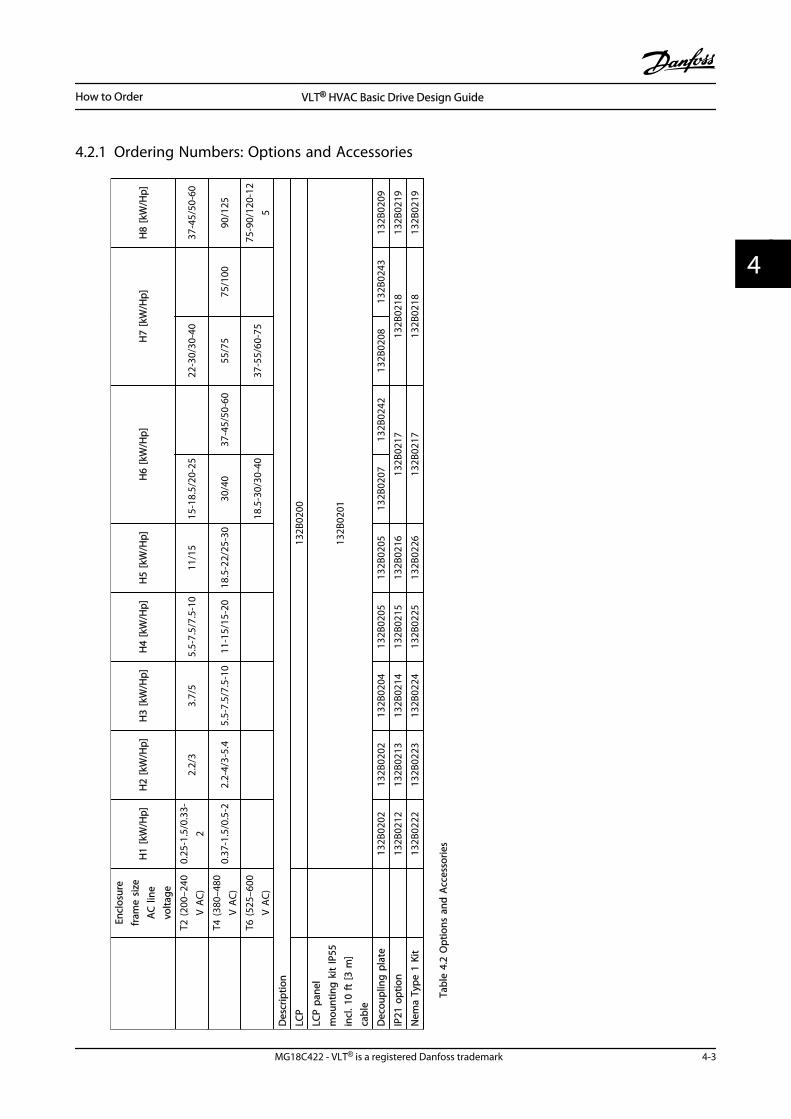
4.2.1 Ordering Numbers: Options and Accessories
Encl
osur
efr
ame
size
AC
line
volta
ge
H1
[kW
/Hp]
H2
[kW
/Hp]
H3
[kW
/Hp]
H4
[kW
/Hp]
H5
[kW
/Hp]
H6
[kW
/Hp]
H7
[kW
/Hp]
H8
[kW
/Hp]
T2 (2
00–2
40V
AC)
0.25
-1.5
/0.3
3-2
2.2/
33.
7/5
5.5-
7.5/
7.5-
1011
/15
15-1
8.5/
20-2
522
-30/
30-4
037
-45/
50-6
0
T4
(380
–480
V A
C)0.
37-1
.5/0
.5-2
2.2-
4/3-
5.4
5.5-
7.5/
7.5-
1011
-15/
15-2
018
.5-2
2/25
-30
30/4
037
-45/
50-6
055
/75
75/1
0090
/125
T6 (5
25–6
00V
AC)
18.5
-30/
30-4
037
-55/
60-7
575
-90/
120-
125
Des
crip
tion
LCP
13
2B02
00
LCP
pane
lm
ount
ing
kit
IP55
incl
. 10
ft [3
m]
cabl
e
132B
0201
Dec
oupl
ing
pla
te
132B
0202
132B
0202
132B
0204
132B
0205
132B
0205
132B
0207
132B
0242
132B
0208
132B
0243
132B
0209
IP21
opt
ion
132B
0212
132B
0213
132B
0214
132B
0215
132B
0216
132B
0217
132B
0218
132B
0219
Nem
a Ty
pe 1
Kit
13
2B02
2213
2B02
2313
2B02
2413
2B02
2513
2B02
2613
2B02
1713
2B02
1813
2B02
19
Tabl
e 4.
2 O
ptio
ns a
nd A
cces
sorie
s
How to Order VLT® HVAC Basic Drive Design Guide
MG18C422 - VLT® is a registered Danfoss trademark 4-3
4 4
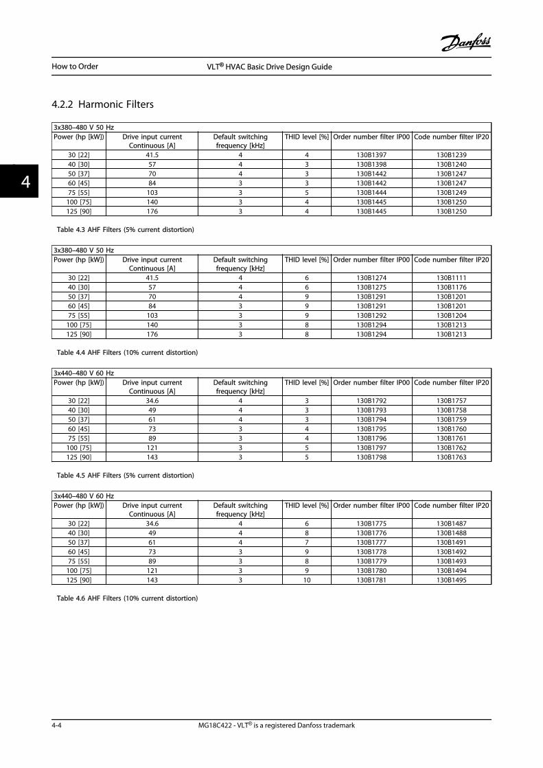
4.2.2 Harmonic Filters
3x380–480 V 50 HzPower (hp [kW]) Drive input current
Continuous [A]Default switchingfrequency [kHz]
THID level [%] Order number filter IP00 Code number filter IP20
30 [22] 41.5 4 4 130B1397 130B123940 [30] 57 4 3 130B1398 130B124050 [37] 70 4 3 130B1442 130B124760 [45] 84 3 3 130B1442 130B124775 [55] 103 3 5 130B1444 130B1249
100 [75] 140 3 4 130B1445 130B1250125 [90] 176 3 4 130B1445 130B1250
Table 4.3 AHF Filters (5% current distortion)
3x380–480 V 50 HzPower (hp [kW]) Drive input current
Continuous [A]Default switchingfrequency [kHz]
THID level [%] Order number filter IP00 Code number filter IP20
30 [22] 41.5 4 6 130B1274 130B111140 [30] 57 4 6 130B1275 130B117650 [37] 70 4 9 130B1291 130B120160 [45] 84 3 9 130B1291 130B120175 [55] 103 3 9 130B1292 130B1204
100 [75] 140 3 8 130B1294 130B1213125 [90] 176 3 8 130B1294 130B1213
Table 4.4 AHF Filters (10% current distortion)
3x440–480 V 60 HzPower (hp [kW]) Drive input current
Continuous [A]Default switchingfrequency [kHz]
THID level [%] Order number filter IP00 Code number filter IP20
30 [22] 34.6 4 3 130B1792 130B175740 [30] 49 4 3 130B1793 130B175850 [37] 61 4 3 130B1794 130B175960 [45] 73 3 4 130B1795 130B176075 [55] 89 3 4 130B1796 130B1761
100 [75] 121 3 5 130B1797 130B1762125 [90] 143 3 5 130B1798 130B1763
Table 4.5 AHF Filters (5% current distortion)
3x440–480 V 60 HzPower (hp [kW]) Drive input current
Continuous [A]Default switchingfrequency [kHz]
THID level [%] Order number filter IP00 Code number filter IP20
30 [22] 34.6 4 6 130B1775 130B148740 [30] 49 4 8 130B1776 130B148850 [37] 61 4 7 130B1777 130B149160 [45] 73 3 9 130B1778 130B149275 [55] 89 3 8 130B1779 130B1493
100 [75] 121 3 9 130B1780 130B1494125 [90] 143 3 10 130B1781 130B1495
Table 4.6 AHF Filters (10% current distortion)
How to Order VLT® HVAC Basic Drive Design Guide
4-4 MG18C422 - VLT® is a registered Danfoss trademark
44
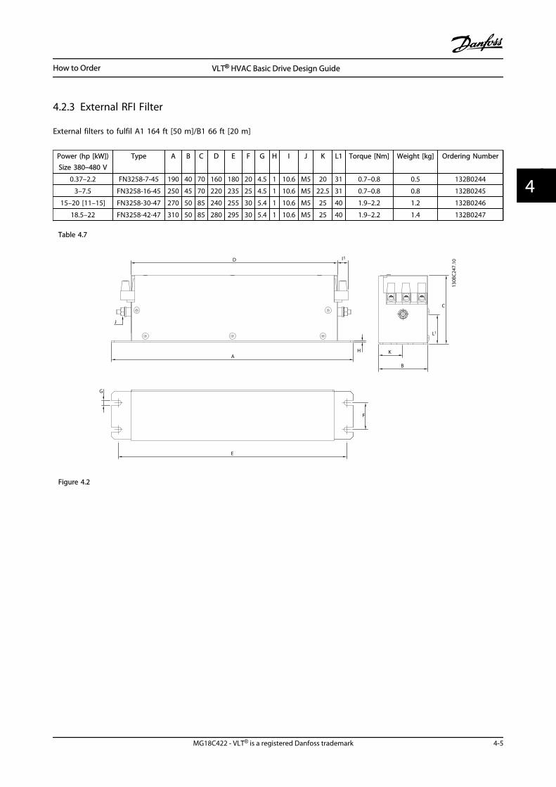
4.2.3 External RFI Filter
External filters to fulfil A1 164 ft [50 m]/B1 66 ft [20 m]
Power (hp [kW])Size 380–480 V
Type A B C D E F G H I J K L1 Torque [Nm] Weight [kg] Ordering Number
0.37–2.2 FN3258-7-45 190 40 70 160 180 20 4.5 1 10.6 M5 20 31 0.7–0.8 0.5 132B0244
3–7.5 FN3258-16-45 250 45 70 220 235 25 4.5 1 10.6 M5 22.5 31 0.7–0.8 0.8 132B0245
15–20 [11–15] FN3258-30-47 270 50 85 240 255 30 5.4 1 10.6 M5 25 40 1.9–2.2 1.2 132B0246
18.5–22 FN3258-42-47 310 50 85 280 295 30 5.4 1 10.6 M5 25 40 1.9–2.2 1.4 132B0247
Table 4.7
H
B
K
C
A
D
J
G
E
F
l1
L1
130B
C247
.10
Figure 4.2
How to Order VLT® HVAC Basic Drive Design Guide
MG18C422 - VLT® is a registered Danfoss trademark 4-5
4 4
How to Order VLT® HVAC Basic Drive Design Guide
4-6 MG18C422 - VLT® is a registered Danfoss trademark
44
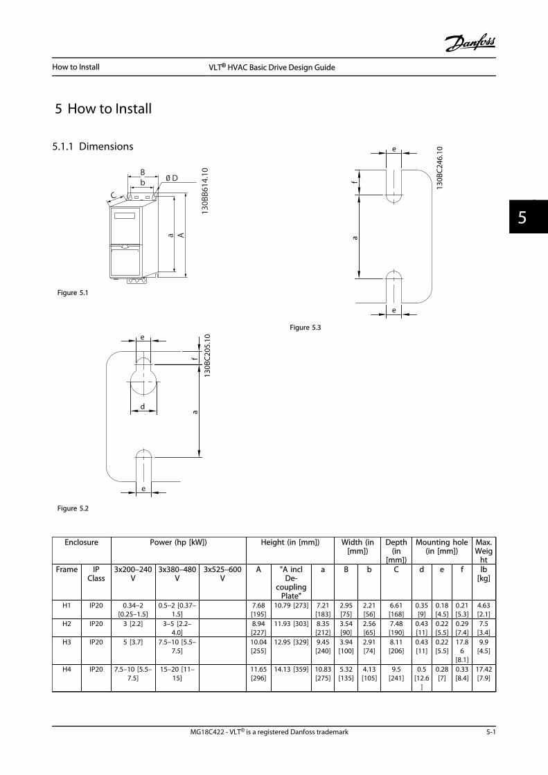
5 How to Install
5.1.1 Dimensions
Aa
bB
C
0 D
130B
B614
.10
Figure 5.1
e
fa
d
e
130B
C205
.10
Figure 5.2
e
fa
e
130B
C246
.10
Figure 5.3
Enclosure Power (hp [kW]) Height (in [mm]) Width (in[mm])
Depth(in
[mm])
Mounting hole(in [mm])
Max.Weig
htFrame IP
Class3x200–240
V3x380–480
V3x525–600
VA "A incl
De-coupling
Plate"
a B b C d e f lb[kg]
H1 IP20 0.34–2[0.25–1.5]
0.5–2 [0.37–1.5]
7.68[195]
10.79 [273] 7.21[183]
2.95[75]
2.21[56]
6.61[168]
0.35[9]
0.18[4.5]
0.21[5.3]
4.63[2.1]
H2 IP20 3 [2.2] 3–5 [2.2–4.0]
8.94[227]
11.93 [303] 8.35[212]
3.54[90]
2.56[65]
7.48[190]
0.43[11]
0.22[5.5]
0.29[7.4]
7.5[3.4]
H3 IP20 5 [3.7] 7.5–10 [5.5–7.5]
10.04[255]
12.95 [329] 9.45[240]
3.94[100]
2.91[74]
8.11[206]
0.43[11]
0.22[5.5]
17.86
[8.1]
9.9[4.5]
H4 IP20 7.5–10 [5.5–7.5]
15–20 [11–15]
11.65[296]
14.13 [359] 10.83[275]
5.32[135]
4.13[105]
9.5[241]
0.5[12.6
]
0.28[7]
0.33[8.4]
17.42[7.9]
How to Install VLT® HVAC Basic Drive Design Guide
MG18C422 - VLT® is a registered Danfoss trademark 5-1
5 5
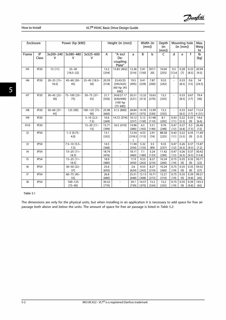
Enclosure Power (hp [kW]) Height (in [mm]) Width (in[mm])
Depth(in
[mm])
Mounting hole(in [mm])
Max.Weig
htFrame IP
Class3x200–240
V3x380–480
V3x525–600
VA "A incl
De-coupling
Plate"
a B b C d e f lb[kg]
H5 IP20 15 [11] 25–30[18.5–22]
13.2[334]
15.83 [402] 12.36[314]
5.91[150]
[97/120]
10.04[255]
0.5[12.6
]
0.28[7]
0.33[8.5]
20.94[9.5]
H6 IP20 20–25 [15–18.5]
45–60 [30–45]
25–45 [18.5–30]
20.39[518]
23.43/25[595/635]
(60 hp [45kW])
19.5[495]
9.41[239]
7.87[200]
9.53[242]
- 0.33[8.5]
0.6[15]
54[24.5]
H7 IP20 30–45 [22–30]
75–100 [55–75]
50–75 [37–55]
21.7[550]
24.8/27.17[630/690](100 hp[75 kW])
20.51[521]
12.32[313]
10.63[270]
13.2[335]
- 0.33[8.5]
0.67[17]
79.4[36]
H8 IP20 50–60 [37–45]
125 [90] 100–125 [75–90]
25.98[660]
31.5 [800] 28.84[631]
14.76[375]
12.99[330]
13.2[335]
- 0.33[8.5]
0.67[17]
112.44 [51]
H9 IP20 3–10 [2.2–7.5]
10.6[269]
14.72 [374] 10.12[257]
5.12[130]
0.148[110]
8.1[205]
0.43[11]
0.22[5.5]
0.35[9]
14.6[6.6]
H10 IP20 15–20 [11–15]
15.71[399]
16.5 [419] 14.96[380]
6.5[165]
5.51[140]
9.76[248]
0.47[12]
0.27[6.8]
0.3[7.5]
26.46[12]
I2 IP54 1–5 [0.75–4.0]
13.1[332]
- 12.54[318.5
]
4.53[115]
2.91[74]
88.58[225]
0.43[11]
0.22[5.5]
0.35[9]
11.69[5.3]
I3 IP54 7.5–10 [5.5–7.5]
14.5[368]
- 11.94[354]
5.32[135]
3.5[89]
9.33[237]
0.47[12]
0.26[6.5]
0.37[9.5]
15.87[7.2]
I4 IP54 15–25 [11–18.5]
18.74[476]
- 18.11[460]
7.1[180]
5.24[133]
11.42[290]
0.47[12]
0.26[6.5]
0.37[9.5]
30.42[13.8]
I5 IP54 15–25 [11–18.5]
18.9[480]
- 17.9[454]
9.53[242]
8.27[210]
10.24[260]
0.75[19]
0.35[9]
0.35[9]
50.71[23]
I6 IP54 30–50 [22–37]
25.6[650]
- 2.6[624]
9.53[242]
8.27[210]
10.24[260]
0.75[19]
0.35[9]
0.35[9]
59.52[27]
I7 IP54 60–75 [45–55]
26.8[680]
- 25.51[648]
12.13[308]
10.71[272]
12.21[310]
0.75[19]
0.35[9]
0.39[9.8]
99.21[45]
I8 IP54 100–125[75–90]
30.32[770]
- 29.1[739]
14.57[370]
13.2[334]
13.2[335]
0.75[19]
0.35[9]
0.39[9.8]
143.3[65]
Table 5.1
The dimensions are only for the physical units, but when installing in an application it is necessary to add space for free airpassage both above and below the units. The amount of space for free air passage is listed in Table 5.2:
How to Install VLT® HVAC Basic Drive Design Guide
5-2 MG18C422 - VLT® is a registered Danfoss trademark
55
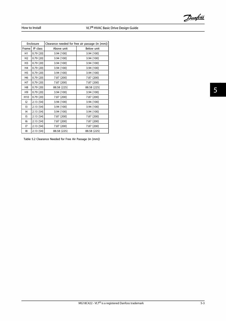
Enclosure Clearance needed for free air passage (in [mm])
Frame IP class Above unit Below unit
H1 0.79 [20] 3.94 [100] 3.94 [100]
H2 0.79 [20] 3.94 [100] 3.94 [100]
H3 0.79 [20] 3.94 [100] 3.94 [100]
H4 0.79 [20] 3.94 [100] 3.94 [100]
H5 0.79 [20] 3.94 [100] 3.94 [100]
H6 0.79 [20] 7.87 [200] 7.87 [200]
H7 0.79 [20] 7.87 [200] 7.87 [200]
H8 0.79 [20] 88.58 [225] 88.58 [225]
H9 0.79 [20] 3.94 [100] 3.94 [100]
H10 0.79 [20] 7.87 [200] 7.87 [200]
I2 2.13 [54] 3.94 [100] 3.94 [100]
I3 2.13 [54] 3.94 [100] 3.94 [100]
I4 2.13 [54] 3.94 [100] 3.94 [100]
I5 2.13 [54] 7.87 [200] 7.87 [200]
I6 2.13 [54] 7.87 [200] 7.87 [200]
I7 2.13 [54] 7.87 [200] 7.87 [200]
I8 2.13 [54] 88.58 [225] 88.58 [225]
Table 5.2 Clearance Needed for Free Air Passage (in [mm])
How to Install VLT® HVAC Basic Drive Design Guide
MG18C422 - VLT® is a registered Danfoss trademark 5-3
5 5
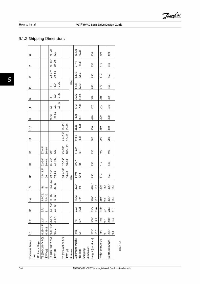
5.1.2 Shipping Dimensions
Encl
osur
e fr
ame
size
AC
line
vol
tage
H1
H2
H3
H4
H5
H6
H7
H8
H9
H10
I2I3
I4I5
I6I7
I8
T2 (2
00–2
40 V
AC)
[kW
/Hp]
0.25
–1.5
/0.
33–2
2.2/
33.
7/5
5.5–
7.5/
7.5–
1011
/15
15–1
8.5/
2022
–30/
30–4
037
–45/
50–6
0
T4 (3
80–4
80 V
AC)
[kW
/Hp]
0.37
–1.5
/0.
5–2
2.2–
4/3–
5.4
5.5–
7.5/
7.5–
1011
–15/
15–2
018
.5–2
2/25
–30
30–4
5/40
–60
55–7
5/73
–100
90/
125
0.75
/1.
0–5.
05.
5–7.
5/7.
5–10
11–
18.5
/15
–25
11–
18.5
/15
–25
22–3
7/30
–50
45–5
5/60
–70
75–9
0/12
5
T6 (5
25–6
00 V
AC)
[kW
/Hp]
18
.5–3
0/30
–40
37–5
5/60
–70
75–9
0/10
0–12
52.
2–7.
5/3.
0–10
11–1
5/15
–20
IP fr
ame
IP20
IP54
Max
imum
wei
ght
(lbs
[kg]
)4.
63[2
.1]
7.5
[3.4
]9.
92[4
.5]
17.4
2[7
.9]
20.9
4[9
.5]
54.0
1[2
4.5]
79.3
7[3
6]11
2.44
[51]
14.5
5[6
.6]
25.3
5[1
1.5]
13.4
5[6
.1]
17.2
[7.8
]30
.42
[13.
8]51
.37
[23.
3]62
.39
[28.
3]91
.49
[41.
5]13
3.38
[60.
5]
Ship
ping
dim
ensi
ons
Hei
ght
[mm
/inch
]25
5/10
.030
0/11
.833
0/13
.038
0/15
.042
0 /
16.5
850
850
850
380
500
440
470
588
850
850
850
950
Wid
th [m
m/in
ch]
154/
6.1
170/
6.7
188/
7.4
250/
9.8
290/
11.4
370
410
490
290
330
200
240
285
370
370
410
490
Dep
th [m
m/in
ch]
235/
9.3
260/
10.2
282/
11.1
375/
14.8
375/
14.8
460
540
490
200
350
300
330
385
460
460
540
490
Tabl
e 5.
3
How to Install VLT® HVAC Basic Drive Design Guide
5-4 MG18C422 - VLT® is a registered Danfoss trademark
55
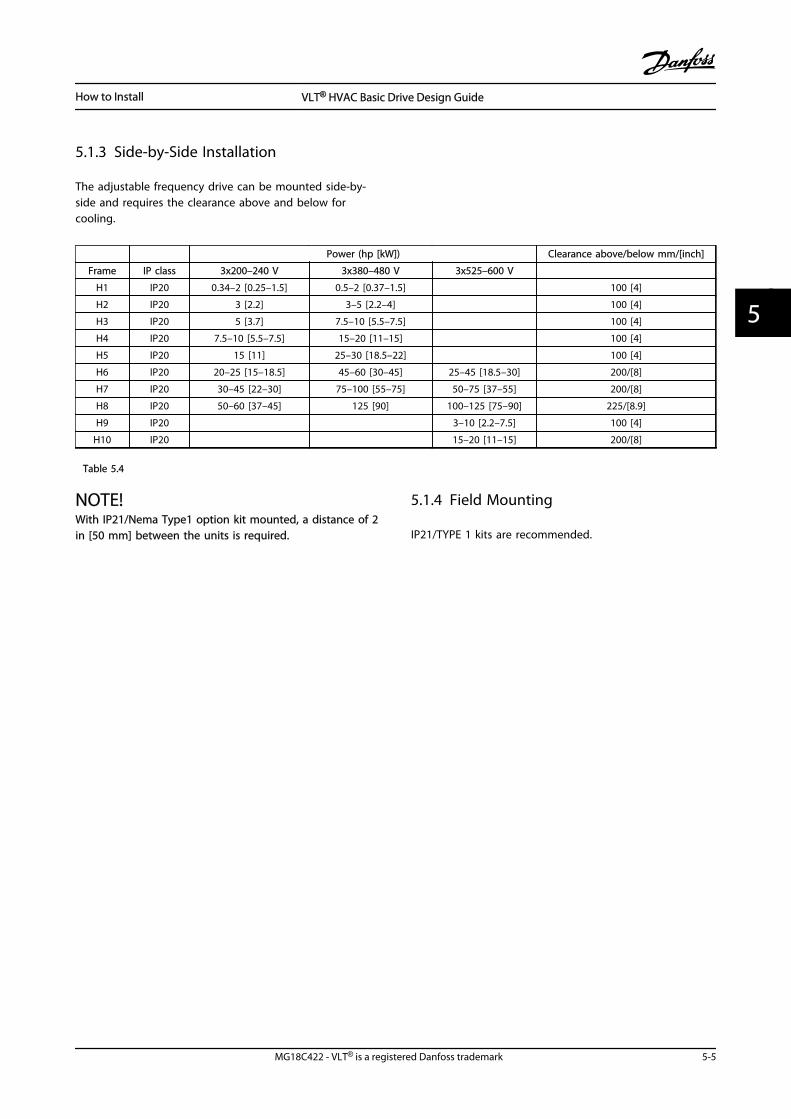
5.1.3 Side-by-Side Installation
The adjustable frequency drive can be mounted side-by-side and requires the clearance above and below forcooling.
Power (hp [kW]) Clearance above/below mm/[inch]
Frame IP class 3x200–240 V 3x380–480 V 3x525–600 V
H1 IP20 0.34–2 [0.25–1.5] 0.5–2 [0.37–1.5] 100 [4]
H2 IP20 3 [2.2] 3–5 [2.2–4] 100 [4]
H3 IP20 5 [3.7] 7.5–10 [5.5–7.5] 100 [4]
H4 IP20 7.5–10 [5.5–7.5] 15–20 [11–15] 100 [4]
H5 IP20 15 [11] 25–30 [18.5–22] 100 [4]
H6 IP20 20–25 [15–18.5] 45–60 [30–45] 25–45 [18.5–30] 200/[8]
H7 IP20 30–45 [22–30] 75–100 [55–75] 50–75 [37–55] 200/[8]
H8 IP20 50–60 [37–45] 125 [90] 100–125 [75–90] 225/[8.9]
H9 IP20 3–10 [2.2–7.5] 100 [4]
H10 IP20 15–20 [11–15] 200/[8]
Table 5.4
NOTE!With IP21/Nema Type1 option kit mounted, a distance of 2in [50 mm] between the units is required.
5.1.4 Field Mounting
IP21/TYPE 1 kits are recommended.
How to Install VLT® HVAC Basic Drive Design Guide
MG18C422 - VLT® is a registered Danfoss trademark 5-5
5 5
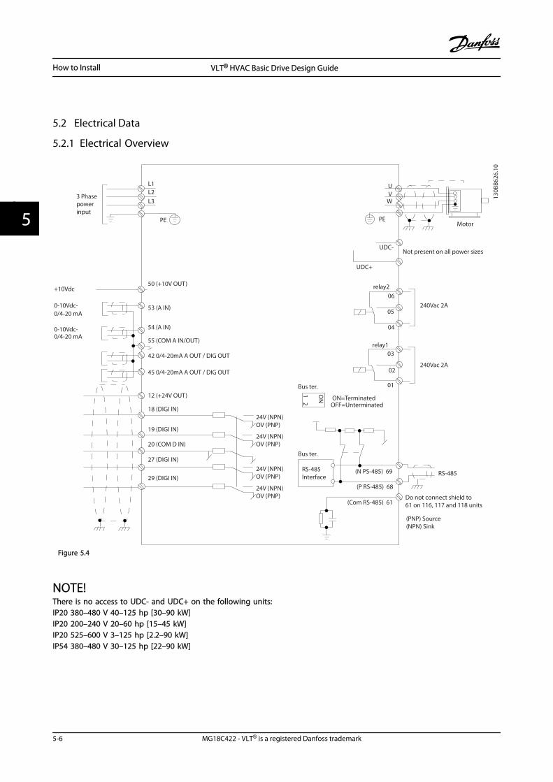
5.2 Electrical Data
5.2.1 Electrical Overview
L1L2L3
3 Phasepowerinput
PE PE
+10Vdc
0-10Vdc-
0-10Vdc-
50 (+10V OUT)
54 (A IN)
53 (A IN)
55 (COM A IN/OUT)
0/4-20 mA
0/4-20 mA
42 0/4-20mA A OUT / DIG OUT
45 0/4-20mA A OUT / DIG OUT
18 (DIGI IN)
19 (DIGI IN)
27 (DIGI IN)
29 (DIGI IN)
12 (+24V OUT)
24V (NPN)
20 (COM D IN)
OV (PNP)
24V (NPN)OV (PNP)
24V (NPN)OV (PNP)
24V (NPN)OV (PNP)
Bus ter.
Bus ter.
RS-485Interface RS-485(N PS-485) 69
(P RS-485) 68
(Com RS-485) 61
(PNP) Source(NPN) Sink
ON=TerminatedOFF=Unterminated
ON
12
240Vac 2A
Not present on all power sizes
Do not connect shield to 61 on 116, 117 and 118 units
01
02
03relay1
relay2
UDC+
UDC-
Motor
UV
W
130B
B626
.10
06
05
04
240Vac 2A
Figure 5.4
NOTE!There is no access to UDC- and UDC+ on the following units:IP20 380–480 V 40–125 hp [30–90 kW]IP20 200–240 V 20–60 hp [15–45 kW]IP20 525–600 V 3–125 hp [2.2–90 kW]IP54 380–480 V 30–125 hp [22–90 kW]
How to Install VLT® HVAC Basic Drive Design Guide
5-6 MG18C422 - VLT® is a registered Danfoss trademark
55
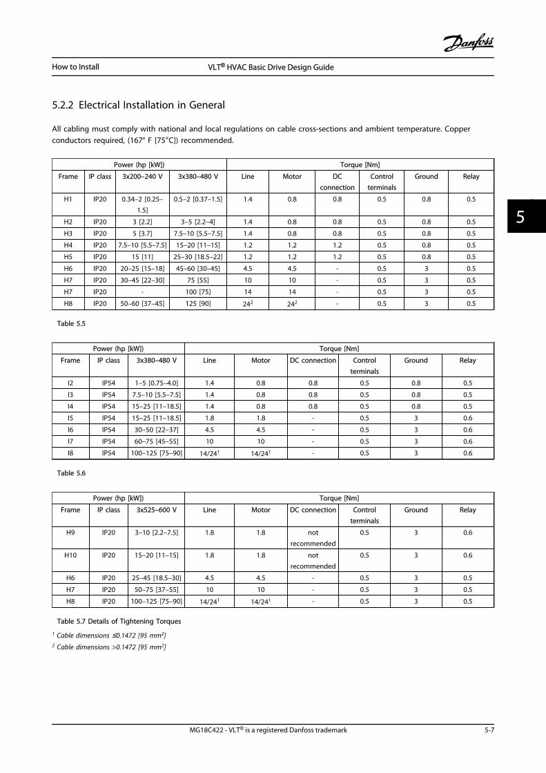
5.2.2 Electrical Installation in General
All cabling must comply with national and local regulations on cable cross-sections and ambient temperature. Copperconductors required, (167° F [75°C]) recommended.
Power (hp [kW]) Torque [Nm]
Frame IP class 3x200–240 V 3x380–480 V Line Motor DCconnection
Controlterminals
Ground Relay
H1 IP20 0.34–2 [0.25–1.5]
0.5–2 [0.37–1.5] 1.4 0.8 0.8 0.5 0.8 0.5
H2 IP20 3 [2.2] 3–5 [2.2–4] 1.4 0.8 0.8 0.5 0.8 0.5
H3 IP20 5 [3.7] 7.5–10 [5.5–7.5] 1.4 0.8 0.8 0.5 0.8 0.5
H4 IP20 7.5–10 [5.5–7.5] 15–20 [11–15] 1.2 1.2 1.2 0.5 0.8 0.5
H5 IP20 15 [11] 25–30 [18.5–22] 1.2 1.2 1.2 0.5 0.8 0.5
H6 IP20 20–25 [15–18] 45–60 [30–45] 4.5 4.5 - 0.5 3 0.5
H7 IP20 30–45 [22–30] 75 [55] 10 10 - 0.5 3 0.5
H7 IP20 - 100 [75] 14 14 - 0.5 3 0.5
H8 IP20 50–60 [37–45] 125 [90] 242 242 - 0.5 3 0.5
Table 5.5
Power (hp [kW]) Torque [Nm]
Frame IP class 3x380–480 V Line Motor DC connection Controlterminals
Ground Relay
I2 IP54 1–5 [0.75–4.0] 1.4 0.8 0.8 0.5 0.8 0.5
I3 IP54 7.5–10 [5.5–7.5] 1.4 0.8 0.8 0.5 0.8 0.5
I4 IP54 15–25 [11–18.5] 1.4 0.8 0.8 0.5 0.8 0.5
I5 IP54 15–25 [11–18.5] 1.8 1.8 - 0.5 3 0.6
I6 IP54 30–50 [22–37] 4.5 4.5 - 0.5 3 0.6
I7 IP54 60–75 [45–55] 10 10 - 0.5 3 0.6
I8 IP54 100–125 [75–90] 14/241 14/241 - 0.5 3 0.6
Table 5.6
Power (hp [kW]) Torque [Nm]
Frame IP class 3x525–600 V Line Motor DC connection Controlterminals
Ground Relay
H9 IP20 3–10 [2.2–7.5] 1.8 1.8 notrecommended
0.5 3 0.6
H10 IP20 15–20 [11–15] 1.8 1.8 notrecommended
0.5 3 0.6
H6 IP20 25–45 [18.5–30] 4.5 4.5 - 0.5 3 0.5
H7 IP20 50–75 [37–55] 10 10 - 0.5 3 0.5
H8 IP20 100–125 [75–90] 14/241 14/241 - 0.5 3 0.5
Table 5.7 Details of Tightening Torques
1 Cable dimensions ≤0.1472 [95 mm2]2 Cable dimensions >0.1472 [95 mm2]
How to Install VLT® HVAC Basic Drive Design Guide
MG18C422 - VLT® is a registered Danfoss trademark 5-7
5 5
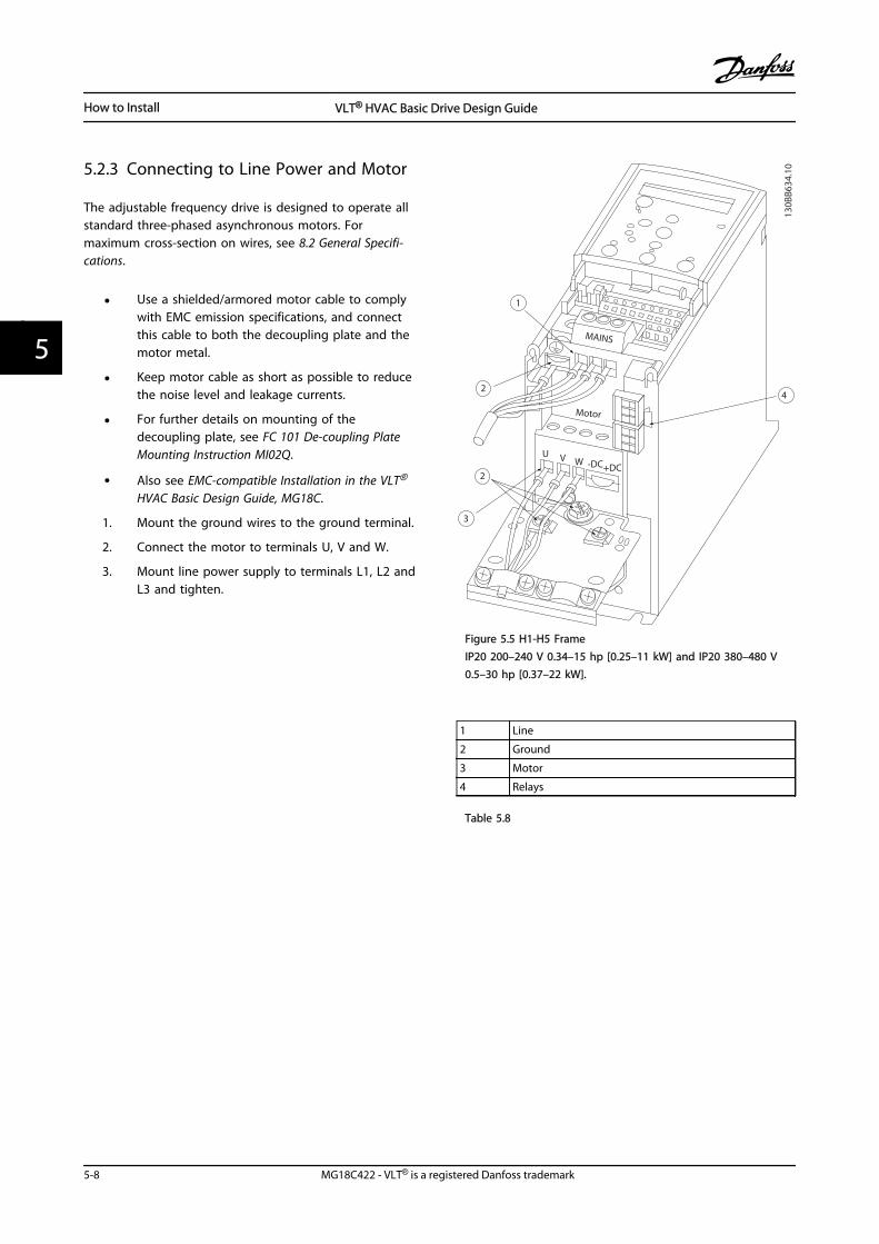
5.2.3 Connecting to Line Power and Motor
The adjustable frequency drive is designed to operate allstandard three-phased asynchronous motors. Formaximum cross-section on wires, see 8.2 General Specifi-cations.
• Use a shielded/armored motor cable to complywith EMC emission specifications, and connectthis cable to both the decoupling plate and themotor metal.
• Keep motor cable as short as possible to reducethe noise level and leakage currents.
• For further details on mounting of thedecoupling plate, see FC 101 De-coupling PlateMounting Instruction MI02Q.
• Also see EMC-compatible Installation in the VLT®
HVAC Basic Design Guide, MG18C.
1. Mount the ground wires to the ground terminal.
2. Connect the motor to terminals U, V and W.
3. Mount line power supply to terminals L1, L2 andL3 and tighten.
130B
B634
.10
1
2
2
3
4
Motor
U V W -DC+DC
MAINS
Figure 5.5 H1-H5 FrameIP20 200–240 V 0.34–15 hp [0.25–11 kW] and IP20 380–480 V0.5–30 hp [0.37–22 kW].
1 Line
2 Ground
3 Motor
4 Relays
Table 5.8
How to Install VLT® HVAC Basic Drive Design Guide
5-8 MG18C422 - VLT® is a registered Danfoss trademark
55
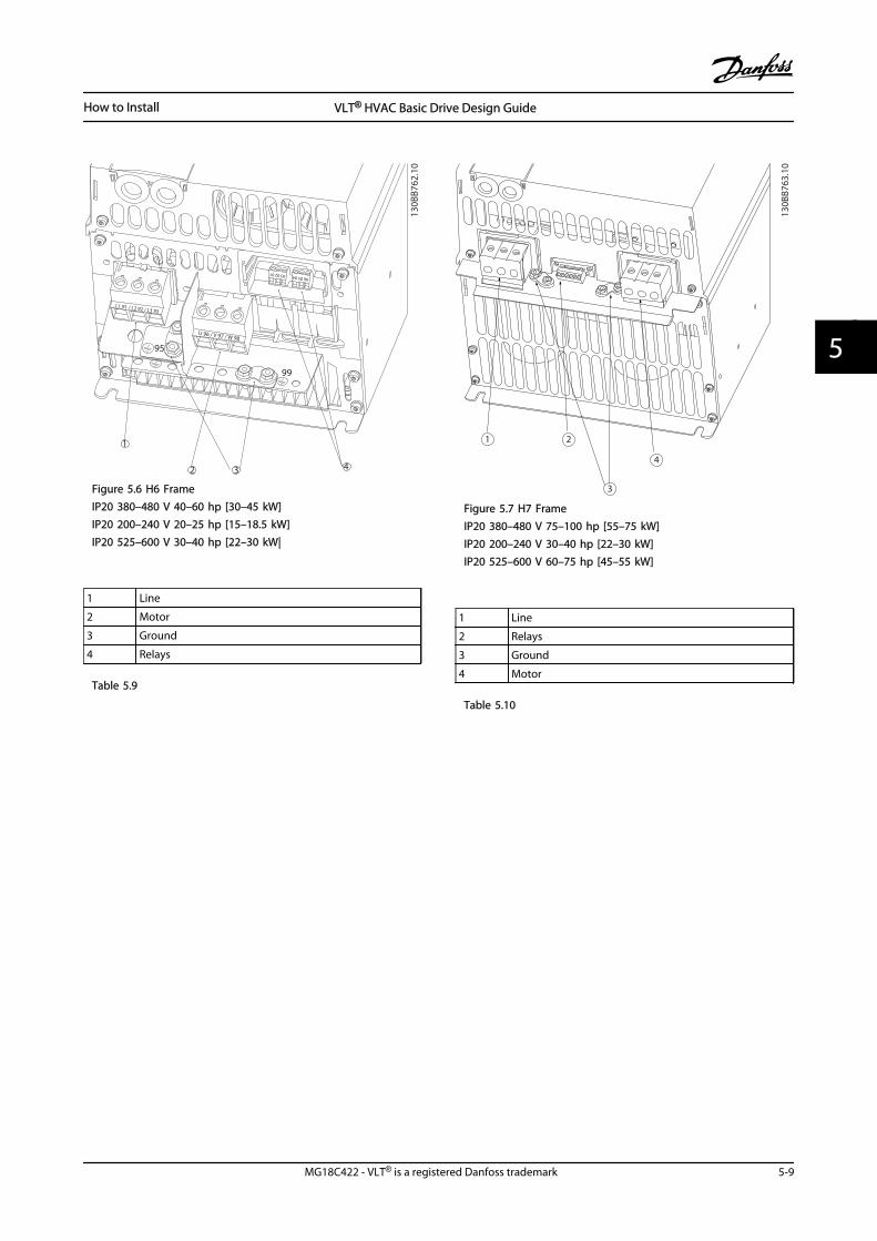
1
95
99
L1 91 / L2 92 / L3 93
U 96 / V 97 / W 98
03 02 0106 05 04
2 3 4
130B
B762
.10
Figure 5.6 H6 FrameIP20 380–480 V 40–60 hp [30–45 kW]IP20 200–240 V 20–25 hp [15–18.5 kW]IP20 525–600 V 30–40 hp [22–30 kW|
1 Line
2 Motor
3 Ground
4 Relays
Table 5.9
1 2
3
4
130B
B763
.10
Figure 5.7 H7 FrameIP20 380–480 V 75–100 hp [55–75 kW]IP20 200–240 V 30–40 hp [22–30 kW]IP20 525–600 V 60–75 hp [45–55 kW]
1 Line
2 Relays
3 Ground
4 Motor
Table 5.10
How to Install VLT® HVAC Basic Drive Design Guide
MG18C422 - VLT® is a registered Danfoss trademark 5-9
5 5
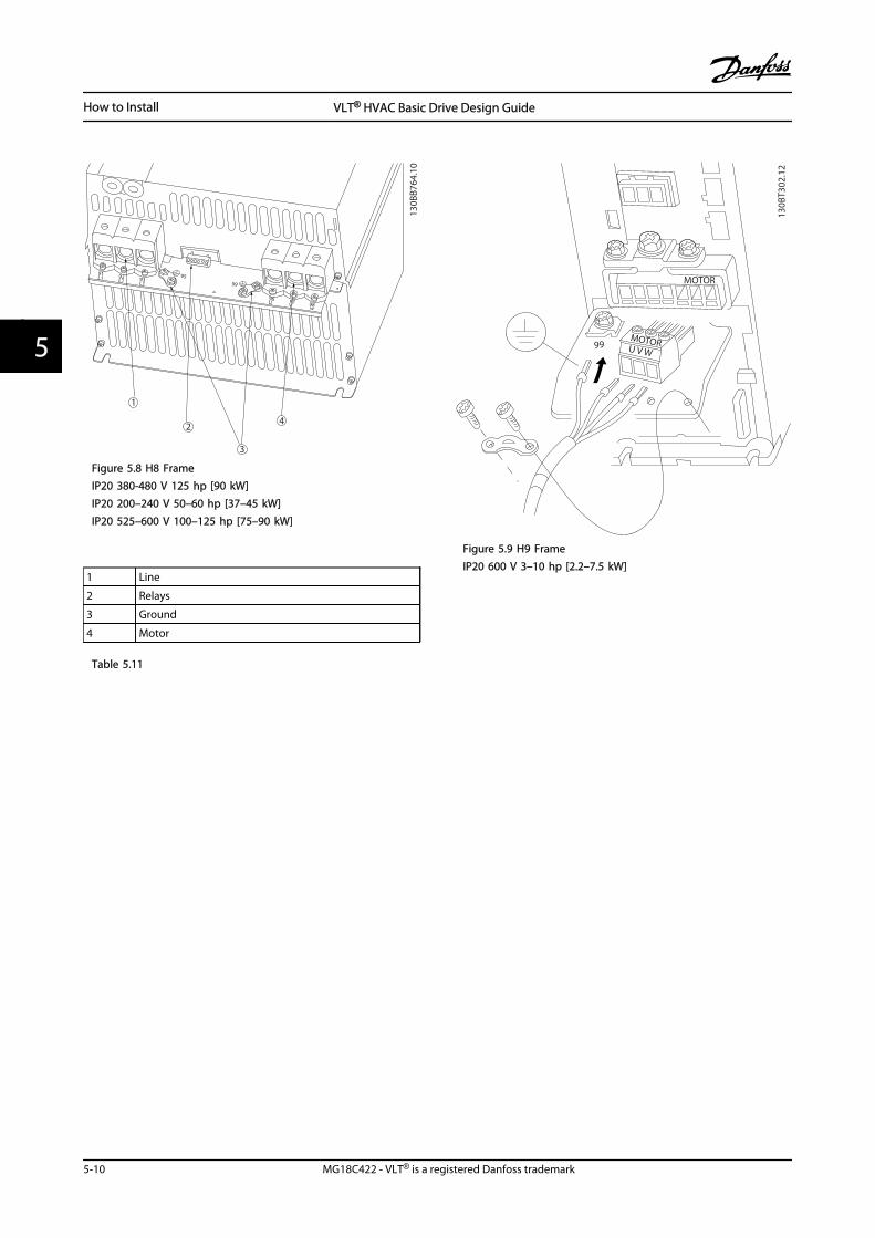
130B
B764
.10
1
2
3
4
989796
99
95939291
L1 L1 L1
U V w
Figure 5.8 H8 FrameIP20 380-480 V 125 hp [90 kW]IP20 200–240 V 50–60 hp [37–45 kW]IP20 525–600 V 100–125 hp [75–90 kW]
1 Line
2 Relays
3 Ground
4 Motor
Table 5.11
MOTOR
MOTORU V W
99
130B
T302
.12
Figure 5.9 H9 FrameIP20 600 V 3–10 hp [2.2–7.5 kW]
How to Install VLT® HVAC Basic Drive Design Guide
5-10 MG18C422 - VLT® is a registered Danfoss trademark
55
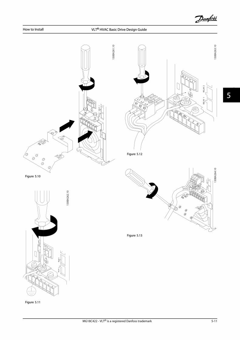
-DC+DC BR- BR+ U V W
99
M A I N S
95
RELA
Y 1
REL
AY 2
- LC
+
130B
A26
1.10
Figure 5.10
130B
A26
2.10
M
I N S
+DCBR-
BR+U
V
W
RELA
Y 1
RELA
Y 295
Figure 5.11
130B
A26
3.10
95
MA
I NS
+DC BR- BR+U
VW
91 92 93
L1L2 L3 RE
LAY
1
REL
AY 2
Figure 5.12
+DC BR- BR+U
VW
MA
I NS
L1 L2 L391 92 93
RELA
Y 1
R
ELAY
2
99
- LC
-
130B
A26
4.10
Figure 5.13
How to Install VLT® HVAC Basic Drive Design Guide
MG18C422 - VLT® is a registered Danfoss trademark 5-11
5 5
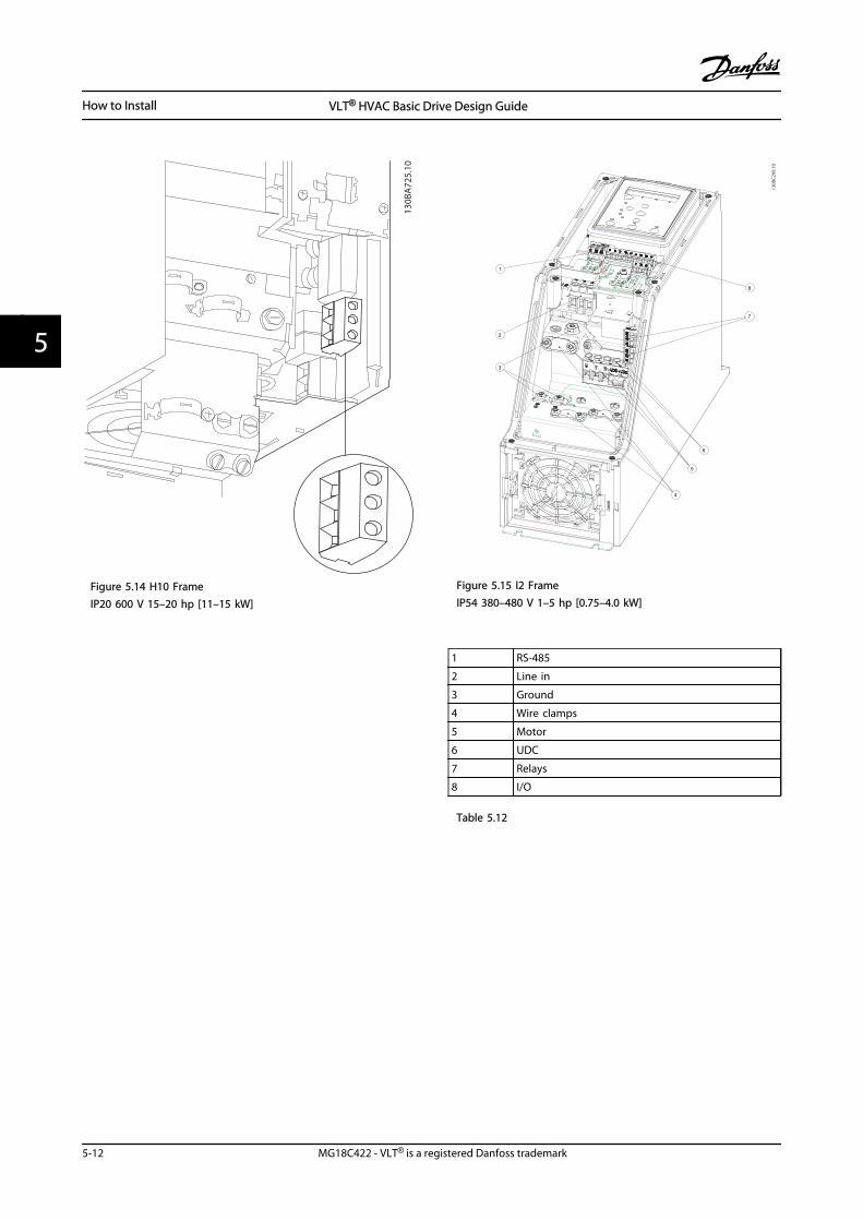
130B
A72
5.10
Figure 5.14 H10 FrameIP20 600 V 15–20 hp [11–15 kW]
130B
C29
9.10
7
3
2
5
1
8
4
6
Figure 5.15 I2 FrameIP54 380–480 V 1–5 hp [0.75–4.0 kW]
1 RS-485
2 Line in
3 Ground
4 Wire clamps
5 Motor
6 UDC
7 Relays
8 I/O
Table 5.12
How to Install VLT® HVAC Basic Drive Design Guide
5-12 MG18C422 - VLT® is a registered Danfoss trademark
55
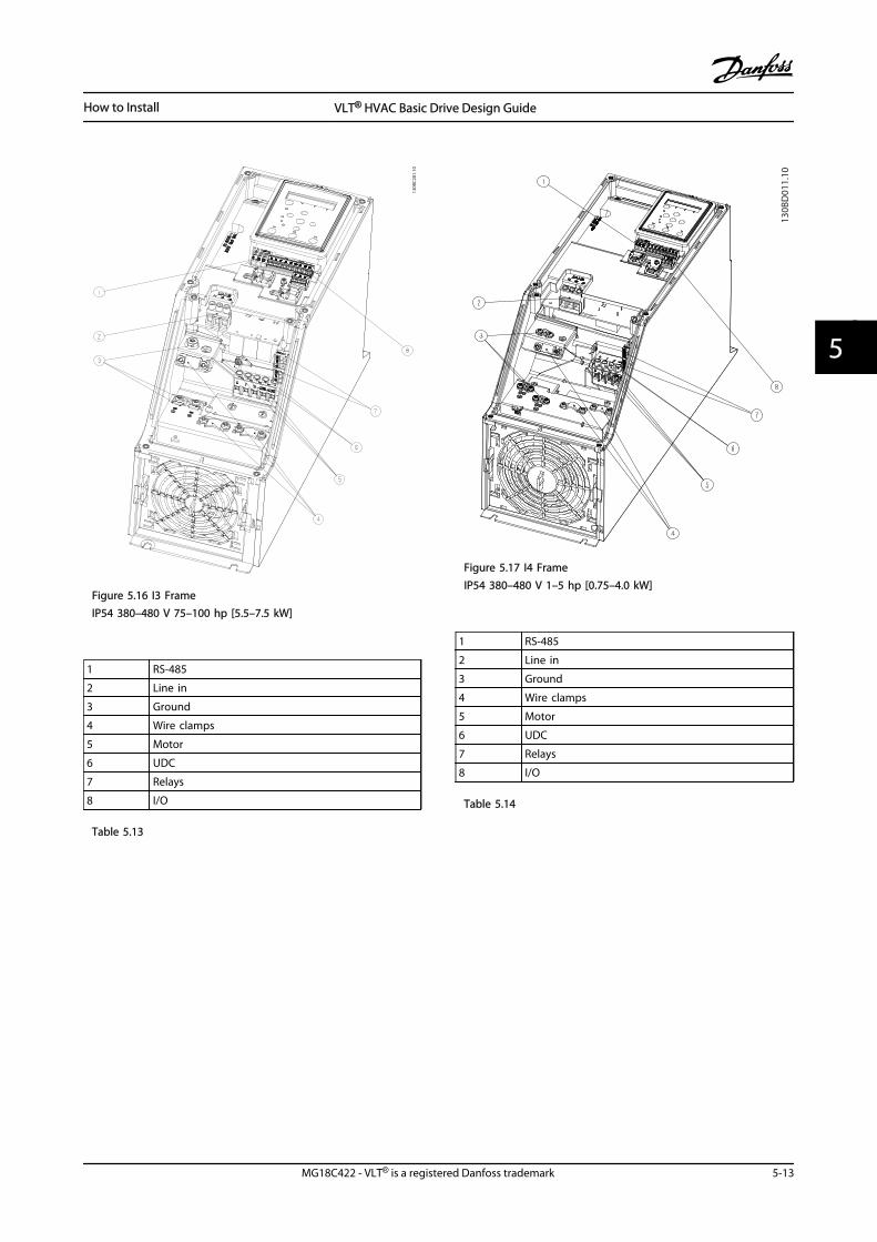
130B
C20
1.10
Figure 5.16 I3 FrameIP54 380–480 V 75–100 hp [5.5–7.5 kW]
1 RS-485
2 Line in
3 Ground
4 Wire clamps
5 Motor
6 UDC
7 Relays
8 I/O
Table 5.13
130B
D01
1.10
Figure 5.17 I4 FrameIP54 380–480 V 1–5 hp [0.75–4.0 kW]
1 RS-485
2 Line in
3 Ground
4 Wire clamps
5 Motor
6 UDC
7 Relays
8 I/O
Table 5.14
How to Install VLT® HVAC Basic Drive Design Guide
MG18C422 - VLT® is a registered Danfoss trademark 5-13
5 5
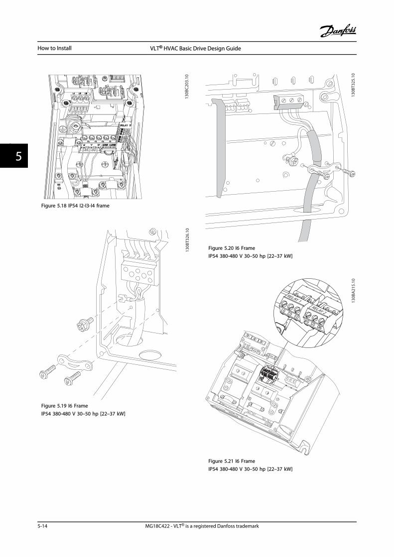
130B
C203
.10
Figure 5.18 IP54 I2-I3-I4 frame
130B
T326
.10
Figure 5.19 I6 FrameIP54 380-480 V 30–50 hp [22–37 kW]
130B
T325
.10
Figure 5.20 I6 FrameIP54 380-480 V 30–50 hp [22–37 kW]
311
130B
A21
5.10
RELAY 1RELAY 2
9
9
6
03 02 01
90 05 04
Figure 5.21 I6 FrameIP54 380-480 V 30–50 hp [22–37 kW]
How to Install VLT® HVAC Basic Drive Design Guide
5-14 MG18C422 - VLT® is a registered Danfoss trademark
55
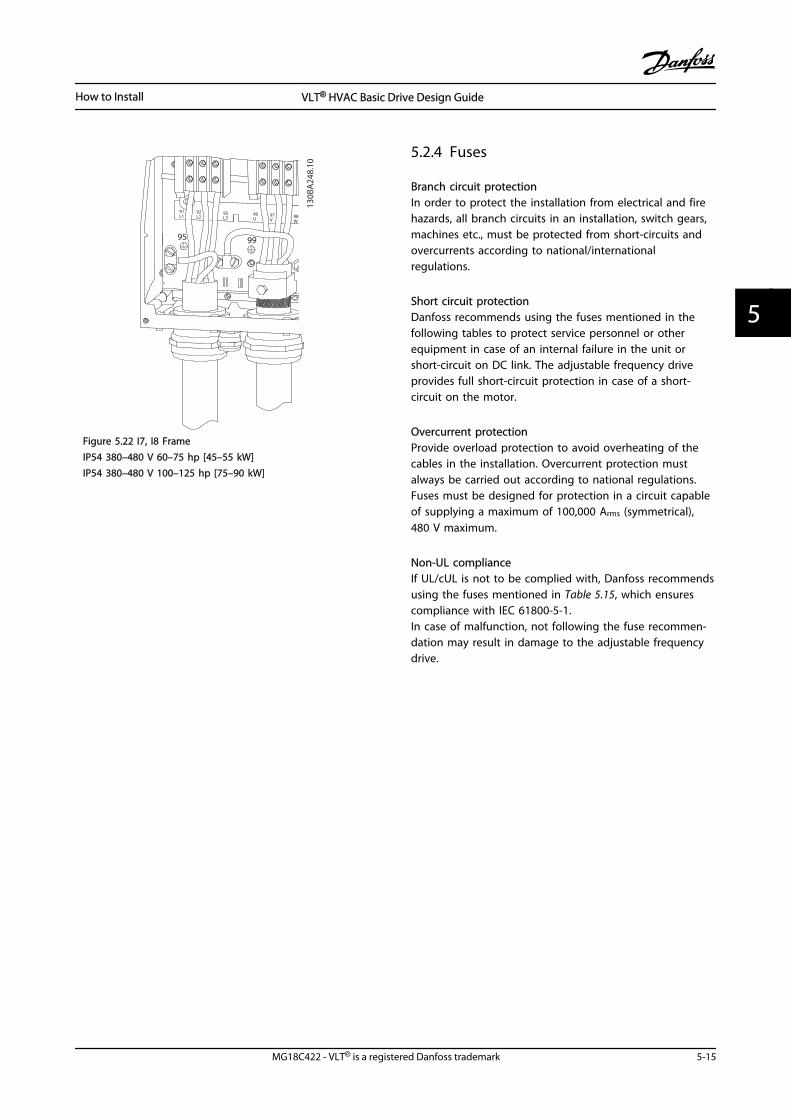
91L1
92L2
93L3
96U
97V
98W
88DC-
89DC+
81R-
8R+
9995
130B
A24
8.10
Figure 5.22 I7, I8 FrameIP54 380–480 V 60–75 hp [45–55 kW]IP54 380–480 V 100–125 hp [75–90 kW]
5.2.4 Fuses
Branch circuit protectionIn order to protect the installation from electrical and firehazards, all branch circuits in an installation, switch gears,machines etc., must be protected from short-circuits andovercurrents according to national/internationalregulations.
Short circuit protectionDanfoss recommends using the fuses mentioned in thefollowing tables to protect service personnel or otherequipment in case of an internal failure in the unit orshort-circuit on DC link. The adjustable frequency driveprovides full short-circuit protection in case of a short-circuit on the motor.
Overcurrent protectionProvide overload protection to avoid overheating of thecables in the installation. Overcurrent protection mustalways be carried out according to national regulations.Fuses must be designed for protection in a circuit capableof supplying a maximum of 100,000 Arms (symmetrical),480 V maximum.
Non-UL complianceIf UL/cUL is not to be complied with, Danfoss recommendsusing the fuses mentioned in Table 5.15, which ensurescompliance with IEC 61800-5-1.In case of malfunction, not following the fuse recommen-dation may result in damage to the adjustable frequencydrive.
How to Install VLT® HVAC Basic Drive Design Guide
MG18C422 - VLT® is a registered Danfoss trademark 5-15
5 5
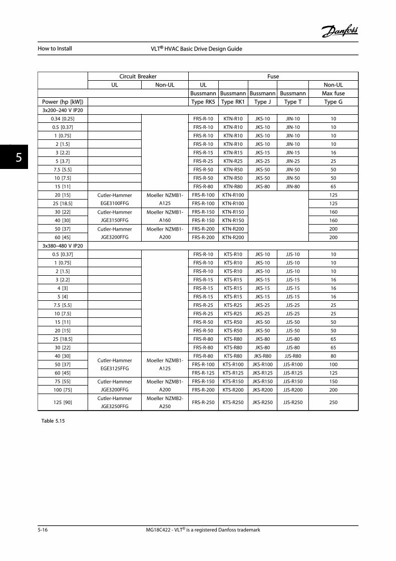
Circuit Breaker Fuse
UL Non-UL UL Non-UL Bussmann Bussmann Bussmann Bussmann Max fuse
Power (hp [kW]) Type RK5 Type RK1 Type J Type T Type G3x200–240 V IP20
0.34 [0.25]
FRS-R-10 KTN-R10 JKS-10 JIN-10 10
0.5 [0.37] FRS-R-10 KTN-R10 JKS-10 JIN-10 10
1 [0.75] FRS-R-10 KTN-R10 JKS-10 JIN-10 10
2 [1.5] FRS-R-10 KTN-R10 JKS-10 JIN-10 10
3 [2.2] FRS-R-15 KTN-R15 JKS-15 JIN-15 16
5 [3.7] FRS-R-25 KTN-R25 JKS-25 JIN-25 25
7.5 [5.5] FRS-R-50 KTN-R50 JKS-50 JIN-50 50
10 [7.5] FRS-R-50 KTN-R50 JKS-50 JIN-50 50
15 [11] FRS-R-80 KTN-R80 JKS-80 JIN-80 65
20 [15] Cutler-HammerEGE3100FFG
Moeller NZMB1-A125
FRS-R-100 KTN-R100
125
25 [18.5] FRS-R-100 KTN-R100 125
30 [22] Cutler-HammerJGE3150FFG
Moeller NZMB1-A160
FRS-R-150 KTN-R150 160
40 [30] FRS-R-150 KTN-R150 160
50 [37] Cutler-HammerJGE3200FFG
Moeller NZMB1-A200
FRS-R-200 KTN-R200 200
60 [45] FRS-R-200 KTN-R200 200
3x380–480 V IP20
0.5 [0.37]
FRS-R-10 KTS-R10 JKS-10 JJS-10 10
1 [0.75] FRS-R-10 KTS-R10 JKS-10 JJS-10 10
2 [1.5] FRS-R-10 KTS-R10 JKS-10 JJS-10 10
3 [2.2] FRS-R-15 KTS-R15 JKS-15 JJS-15 16
4 [3] FRS-R-15 KTS-R15 JKS-15 JJS-15 16
5 [4] FRS-R-15 KTS-R15 JKS-15 JJS-15 16
7.5 [5.5] FRS-R-25 KTS-R25 JKS-25 JJS-25 25
10 [7.5] FRS-R-25 KTS-R25 JKS-25 JJS-25 25
15 [11] FRS-R-50 KTS-R50 JKS-50 JJS-50 50
20 [15] FRS-R-50 KTS-R50 JKS-50 JJS-50 50
25 [18.5] FRS-R-80 KTS-R80 JKS-80 JJS-80 65
30 [22] FRS-R-80 KTS-R80 JKS-80 JJS-80 65
40 [30]Cutler-Hammer
EGE3125FFGMoeller NZMB1-
A125
FRS-R-80 KTS-R80 JKS-R80 JJS-R80 80
50 [37] FRS-R-100 KTS-R100 JKS-R100 JJS-R100 100
60 [45] FRS-R-125 KTS-R125 JKS-R125 JJS-R125 125
75 [55] Cutler-HammerJGE3200FFG
Moeller NZMB1-A200
FRS-R-150 KTS-R150 JKS-R150 JJS-R150 150
100 [75] FRS-R-200 KTS-R200 JKS-R200 JJS-R200 200
125 [90]Cutler-Hammer
JGE3250FFGMoeller NZMB2-
A250FRS-R-250 KTS-R250 JKS-R250 JJS-R250 250
Table 5.15
How to Install VLT® HVAC Basic Drive Design Guide
5-16 MG18C422 - VLT® is a registered Danfoss trademark
55
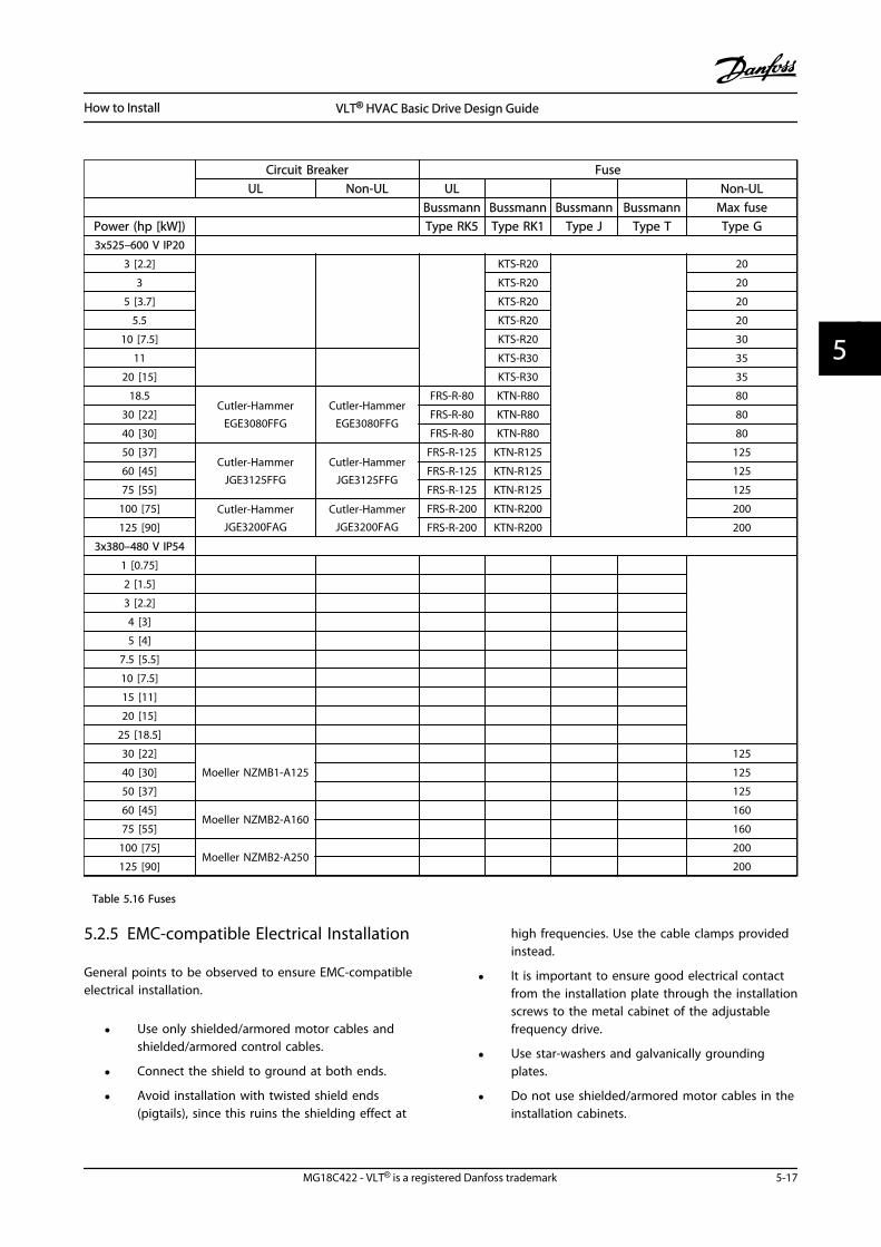
Circuit Breaker Fuse
UL Non-UL UL Non-UL Bussmann Bussmann Bussmann Bussmann Max fuse
Power (hp [kW]) Type RK5 Type RK1 Type J Type T Type G3x525–600 V IP20
3 [2.2]
KTS-R20
20
3 KTS-R20 20
5 [3.7] KTS-R20 20
5.5 KTS-R20 20
10 [7.5] KTS-R20 30
11
KTS-R30 35
20 [15] KTS-R30 35
18.5Cutler-Hammer
EGE3080FFGCutler-Hammer
EGE3080FFG
FRS-R-80 KTN-R80 80
30 [22] FRS-R-80 KTN-R80 80
40 [30] FRS-R-80 KTN-R80 80
50 [37]Cutler-Hammer
JGE3125FFGCutler-Hammer
JGE3125FFG
FRS-R-125 KTN-R125 125
60 [45] FRS-R-125 KTN-R125 125
75 [55] FRS-R-125 KTN-R125 125
100 [75] Cutler-HammerJGE3200FAG
Cutler-HammerJGE3200FAG
FRS-R-200 KTN-R200 200
125 [90] FRS-R-200 KTN-R200 200
3x380–480 V IP54
1 [0.75]
2 [1.5]
3 [2.2]
4 [3]
5 [4]
7.5 [5.5]
10 [7.5]
15 [11]
20 [15]
25 [18.5]
30 [22]
Moeller NZMB1-A125
125
40 [30] 125
50 [37] 125
60 [45]Moeller NZMB2-A160
160
75 [55] 160
100 [75]Moeller NZMB2-A250
200
125 [90] 200
Table 5.16 Fuses
5.2.5 EMC-compatible Electrical Installation
General points to be observed to ensure EMC-compatibleelectrical installation.
• Use only shielded/armored motor cables andshielded/armored control cables.
• Connect the shield to ground at both ends.
• Avoid installation with twisted shield ends(pigtails), since this ruins the shielding effect at
high frequencies. Use the cable clamps providedinstead.
• It is important to ensure good electrical contactfrom the installation plate through the installationscrews to the metal cabinet of the adjustablefrequency drive.
• Use star-washers and galvanically groundingplates.
• Do not use shielded/armored motor cables in theinstallation cabinets.
How to Install VLT® HVAC Basic Drive Design Guide
MG18C422 - VLT® is a registered Danfoss trademark 5-17
5 5
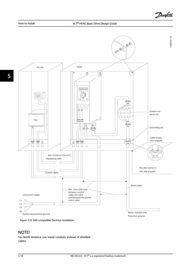
L1
L2L3
PE
Min. 0.0248 in2 [16 mm2]
Equalizing cable
Control cables
All cable entries in
one side of panel
Grounding rail
Cable insula-tion stripped
Output con-tactor, etc.
Motor cable
Motor, 3 phases and
PLC etc. Panel
Line power supply
Min. 7.9 in [200 mm]between control cable, line cable and between line power motor cable
PLC
Protective groundReinforced protective ground
130B
B761
.10
Figure 5.23 EMC-compatible Electrical Installation
NOTE!For North America, use metal conduits instead of shieldedcables.
How to Install VLT® HVAC Basic Drive Design Guide
5-18 MG18C422 - VLT® is a registered Danfoss trademark
55
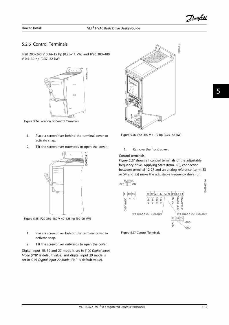
5.2.6 Control Terminals
IP20 200–240 V 0.34–15 hp [0.25–11 kW] and IP20 380–480V 0.5–30 hp [0.37–22 kW]:
130B
B622
.10
Figure 5.24 Location of Control Terminals
1. Place a screwdriver behind the terminal cover toactivate snap.
2. Tilt the screwdriver outwards to open the cover.
130B
B624
.10
Figure 5.25 IP20 380–480 V 40–125 hp [30–90 kW]
1. Place a screwdriver behind the terminal cover toactivate snap.
2. Tilt the screwdriver outwards to open the cover.
Digital input 18, 19 and 27 mode is set in 5-00 Digital InputMode (PNP is default value) and digital input 29 mode isset in 5-03 Digital Input 29 Mode (PNP is default value).
130B
C24
9.10
Figure 5.26 IP54 400 V 1–10 hp [0.75–7.5 kW]
1. Remove the front cover.
Control terminalsFigure 5.27 shows all control terminals of the adjustablefrequency drive. Applying Start (term. 18), connectionbetween terminal 12-27 and an analog reference (term. 53or 54 and 55) make the adjustable frequency drive run.
18 19
12 20 55
27 29 42 45 50 53 54
DIG
I IN
DIG
I IN
DIG
I IN
DIG
I IN
61 68 69
NPCOM
M. G
ND
+24V
0/4-20mA A OUT / DIG OUT 0/4-20mA A OUT / DIG OUT
GND
GND
10V/20mA
IN
10V/20mA
IN
10V OU
T
130B
B625
.10BUS TER.
OFF ON
Figure 5.27 Control Terminals
How to Install VLT® HVAC Basic Drive Design Guide
MG18C422 - VLT® is a registered Danfoss trademark 5-19
5 5
How to Install VLT® HVAC Basic Drive Design Guide
5-20 MG18C422 - VLT® is a registered Danfoss trademark
55
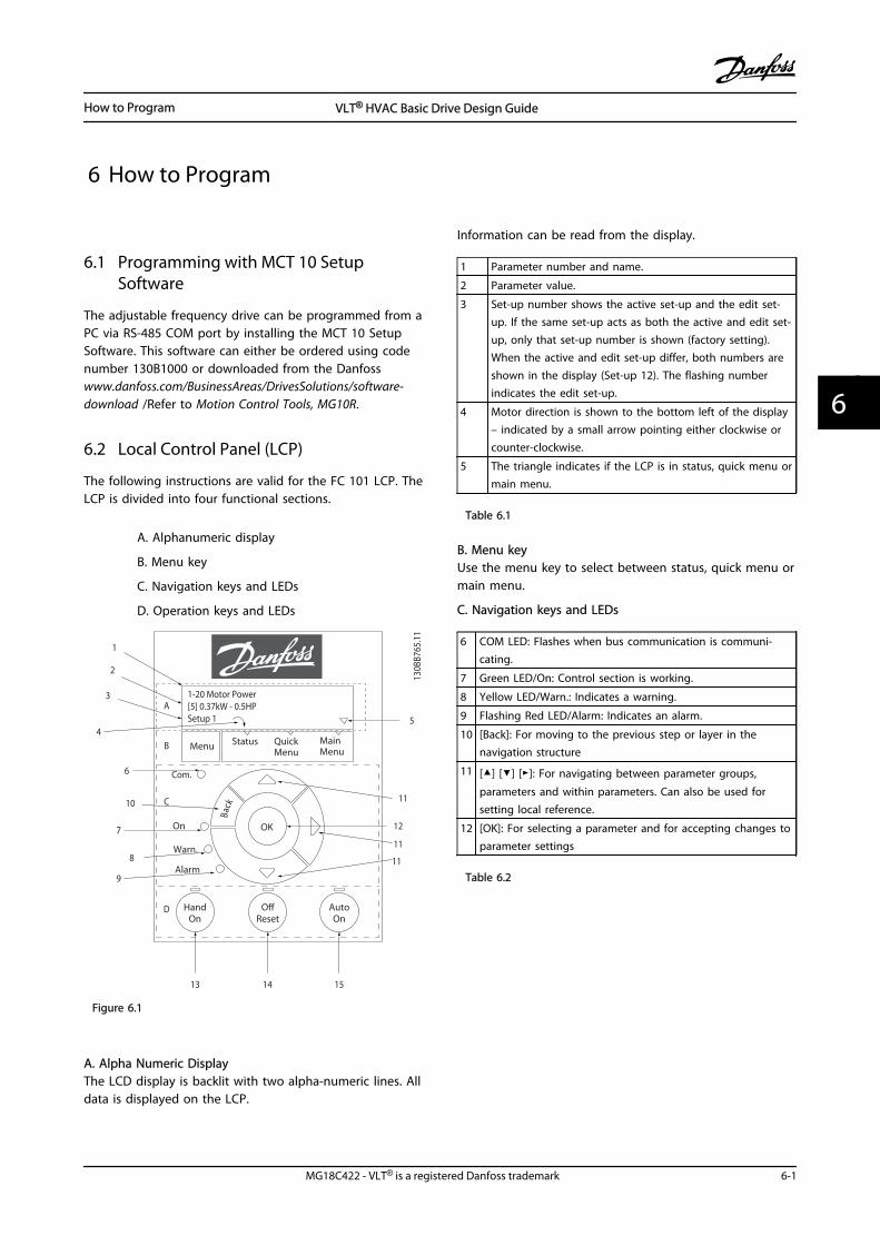
6 How to Program
6.1 Programming with MCT 10 SetupSoftware
The adjustable frequency drive can be programmed from aPC via RS-485 COM port by installing the MCT 10 SetupSoftware. This software can either be ordered using codenumber 130B1000 or downloaded from the Danfosswww.danfoss.com/BusinessAreas/DrivesSolutions/software-download /Refer to Motion Control Tools, MG10R.
6.2 Local Control Panel (LCP)
The following instructions are valid for the FC 101 LCP. TheLCP is divided into four functional sections.
A. Alphanumeric display
B. Menu key
C. Navigation keys and LEDs
D. Operation keys and LEDs
130B
B765
.11
Back
Com.
1-20 Motor Power[5] 0.37kW - 0.5HPSetup 1
A
B
1
12
13 14 15
11
11
10
9
8
7
6
54
3
2
C
D
Status MainMenu
QuickMenu
HandOn
OK
Menu
OReset
AutoOn
Alarm
Warn.
On
11
Figure 6.1
A. Alpha Numeric DisplayThe LCD display is backlit with two alpha-numeric lines. Alldata is displayed on the LCP.
Information can be read from the display.
1 Parameter number and name.
2 Parameter value.
3 Set-up number shows the active set-up and the edit set-up. If the same set-up acts as both the active and edit set-up, only that set-up number is shown (factory setting).When the active and edit set-up differ, both numbers areshown in the display (Set-up 12). The flashing numberindicates the edit set-up.
4 Motor direction is shown to the bottom left of the display– indicated by a small arrow pointing either clockwise orcounter-clockwise.
5 The triangle indicates if the LCP is in status, quick menu ormain menu.
Table 6.1
B. Menu keyUse the menu key to select between status, quick menu ormain menu.
C. Navigation keys and LEDs
6 COM LED: Flashes when bus communication is communi-cating.
7 Green LED/On: Control section is working.
8 Yellow LED/Warn.: Indicates a warning.
9 Flashing Red LED/Alarm: Indicates an alarm.
10 [Back]: For moving to the previous step or layer in thenavigation structure
11 [] [] []: For navigating between parameter groups,
parameters and within parameters. Can also be used forsetting local reference.
12 [OK]: For selecting a parameter and for accepting changes toparameter settings
Table 6.2
How to Program VLT® HVAC Basic Drive Design Guide
MG18C422 - VLT® is a registered Danfoss trademark 6-1
6 6
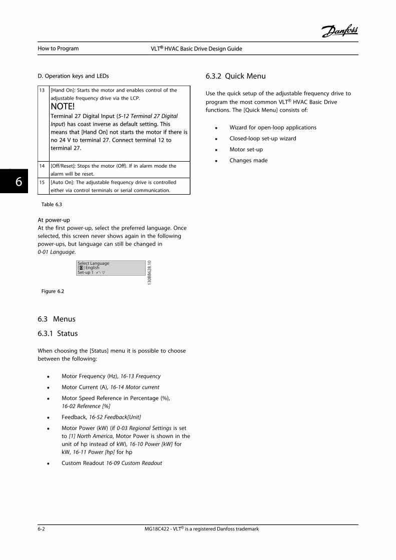
D. Operation keys and LEDs
13 [Hand On]: Starts the motor and enables control of theadjustable frequency drive via the LCP.
NOTE!Terminal 27 Digital Input (5-12 Terminal 27 DigitalInput) has coast inverse as default setting. Thismeans that [Hand On] not starts the motor if there isno 24 V to terminal 27. Connect terminal 12 toterminal 27.
14 [Off/Reset]: Stops the motor (Off). If in alarm mode thealarm will be reset.
15 [Auto On]: The adjustable frequency drive is controlledeither via control terminals or serial communication.
Table 6.3
At power-upAt the first power-up, select the preferred language. Onceselected, this screen never shows again in the followingpower-ups, but language can still be changed in0-01 Language.
130B
B628
.10Select Language
[ 0 ] EnglishSet-up 1
Figure 6.2
6.3 Menus
6.3.1 Status
When choosing the [Status] menu it is possible to choosebetween the following:
• Motor Frequency (Hz), 16-13 Frequency
• Motor Current (A), 16-14 Motor current
• Motor Speed Reference in Percentage (%),16-02 Reference [%]
• Feedback, 16-52 Feedback[Unit]
• Motor Power (kW) (if 0-03 Regional Settings is setto [1] North America, Motor Power is shown in theunit of hp instead of kW), 16-10 Power [kW] forkW, 16-11 Power [hp] for hp
• Custom Readout 16-09 Custom Readout
6.3.2 Quick Menu
Use the quick setup of the adjustable frequency drive toprogram the most common VLT® HVAC Basic Drivefunctions. The [Quick Menu] consists of:
• Wizard for open-loop applications
• Closed-loop set-up wizard
• Motor set-up
• Changes made
How to Program VLT® HVAC Basic Drive Design Guide
6-2 MG18C422 - VLT® is a registered Danfoss trademark
66
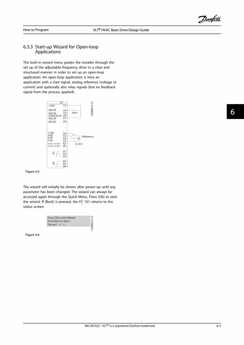
6.3.3 Start-up Wizard for Open-loopApplications
The built-in wizard menu guides the installer through theset up of the adjustable frequency drive in a clear andstructured manner in order to set up an open-loopapplication. An open-loop application is here anapplication with a start signal, analog reference (voltage orcurrent) and optionally also relay signals (but no feedbacksignal from the process applied).
FC+24V
DIG INDIG IN
DIG INDIG IN
COM DIG IN
A OUT / D OUTA OUT / D OUT
1819
2729
4255
505354
20
12
010203
040506
R2R1
0-10 V
Reference
Start
+10VA INA INCOM
130B
B674
.10
45
+
-
Figure 6.3
The wizard will initially be shown after power-up until anyparameter has been changed. The wizard can always beaccessed again through the Quick Menu. Press [Ok] to startthe wizard. If [Back] is pressed, the FC 101 returns to thestatus screen.
130B
B629
.10Press OK to start Wizard
Push Back to skip itSet-up 1
Figure 6.4
How to Program VLT® HVAC Basic Drive Design Guide
MG18C422 - VLT® is a registered Danfoss trademark 6-3
6 6
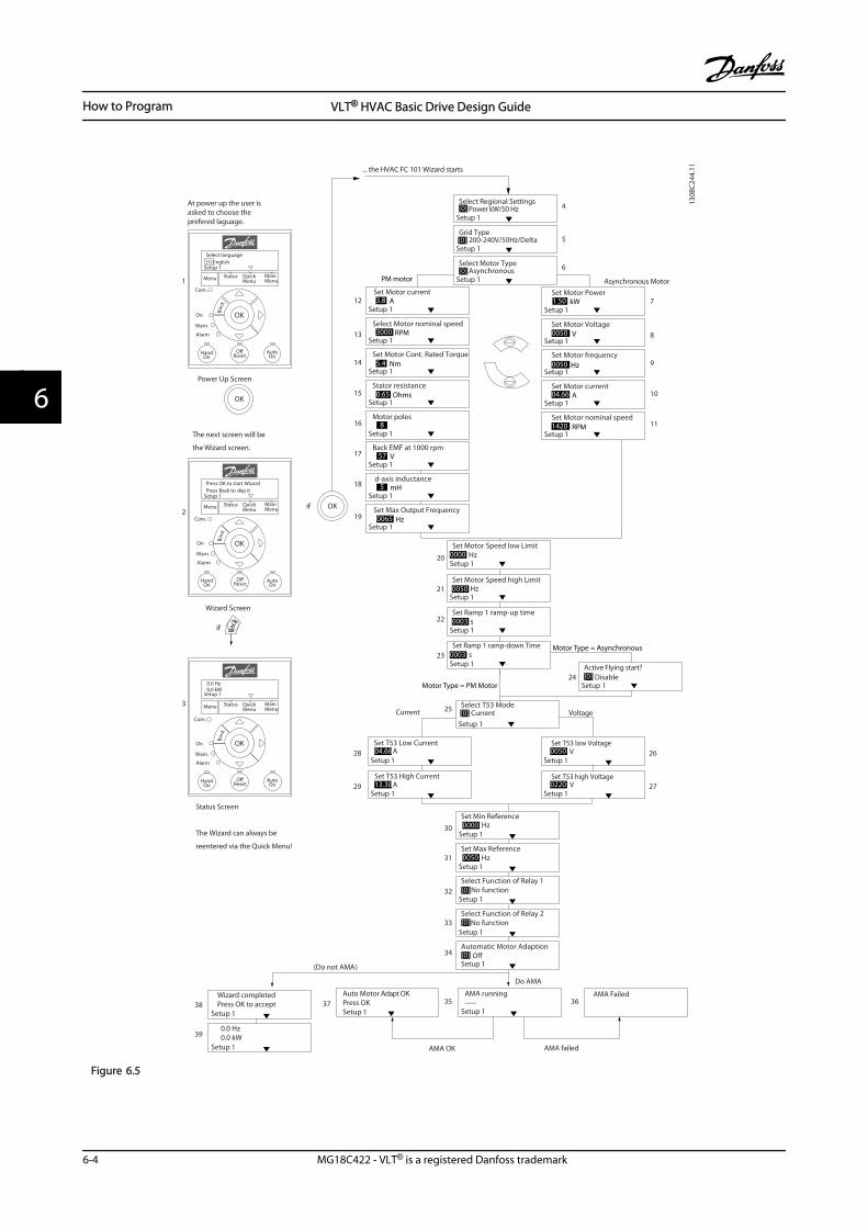
Setup 1Power kW/50 Hz
Setup 1
Set Motor Speed low LimitHz
Setup 1
Set Motor Speed high Limit Hz
Setup 1
Set Ramp 1 ramp-up time s
Setup 1
Set Ramp 1 ramp-down Times
Setup 1
Active Flying start? Disable
OK
5
Setup 1
Set Motor Power7
Setup 1
Set Motor Voltage8
Setup 1
Set Motor frequency9
Setup 1
Set Motor current10
Setup 1
Set Motor nominal speed 11
if
17
20
21
22
Select Regional Settings
... the HVAC FC 101 Wizard starts
Setup 1200-240V/50Hz/Delta
Grid Type
4
Asynchronous MotorSetup 1Asynchronous
Select Motor Type 6
Setup 1
Set Motor current12
Setup 1
Select Motor nominal speed13
Setup 1
Set Motor Cont. Rated Torque14
Setup 1
Stator resistance15
Setup 1
Motor poles16
Setup 1
Back EMF at 1000 rpm
18
Setup 1
d-axis inductance
19Setup 1
Set Max Output Frequency
23
24
Setup 1
Setup 1Setup 1
Setup 1
Set T53 low VoltageV
Set T53 high VoltageV
Set T53 Low CurrentA
Set T53 High CurrentA
Current Voltage
28
29
26
27
Setup 1
Setup 1 Setup 1 Setup 1
Setup 1
Setup 1
Setup 1
Setup 1
Setup 1
AMA Failed
0.0 Hz0.0 kW
Wizard completedPress OK to accept
Automatic Motor Adaption O
Auto Motor Adapt OKPress OK
Select Function of Relay 2 No function
Select Function of Relay 1[0] No function
Set Max ReferenceHz
Set Min ReferenceHz
AMA running-----
AMA failed
Do AMA
(Do not AMA)
AMA OK
30
31
32
33
34
3738
39
35 36
[0]
[0]
[0]
Setup 1
Select T53 ModeCurrent 25
[0]
[0]
3.8 A
3000 RPM
5.4 Nm
0.65 Ohms
8
57 V
5 mH
0065 Hz
1.50 kW
0050 V
0050 Hz
04.66 A
1420 RPM
[0]
PM motor
Motor Type = Asynchronous
Motor Type = PM Motor
0000
0050
0003
0003
[0]
[0]
04.66
13.30
0050
0220
0000
0050
OK
Back
Status MainMenu
QuickMenu
HandOn
OK
Menu
OReset
AutoOn
Alarm
Warn.
On
Status Screen
The Wizard can always be
reentered via the Quick Menu!
Power Up Screen
At power up the user isasked to choose theprefered laguage.
Select language[1] English
0.0 Hz0.0 kW
Setup 1
Setup 1
Status MainMenu
QuickMenu
HandOn
OK
Menu
OReset Auto
On
Alarm
Warn.
On
Press OK to start WizardPress Back to skip it
Setup 1
Status MainMenu
QuickMenu
HandOn
OK
Menu
OReset
AutoOn
Alarm
Warn.
On
The next screen will be
the Wizard screen.
Wizard Screen
1
2
if
3
Back
Back
Back
Com.
Com.
Com.
130B
C244
.11
Figure 6.5
How to Program VLT® HVAC Basic Drive Design Guide
6-4 MG18C422 - VLT® is a registered Danfoss trademark
66
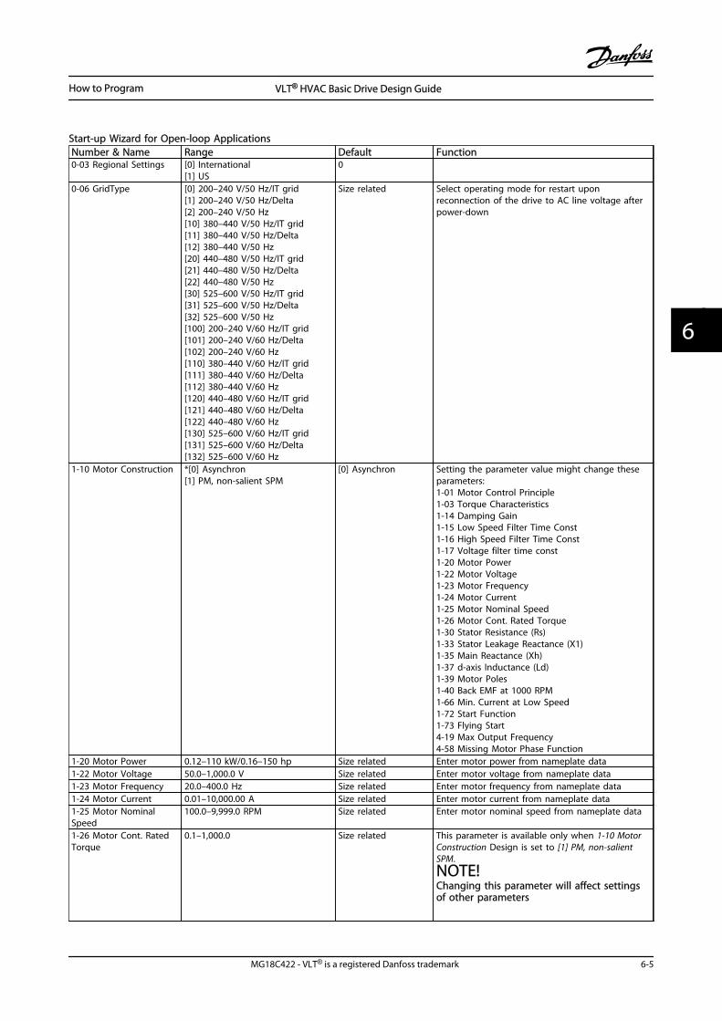
Start-up Wizard for Open-loop ApplicationsNumber & Name Range Default Function0-03 Regional Settings [0] International
[1] US0
0-06 GridType [0] 200–240 V/50 Hz/IT grid[1] 200–240 V/50 Hz/Delta[2] 200–240 V/50 Hz[10] 380–440 V/50 Hz/IT grid[11] 380–440 V/50 Hz/Delta[12] 380–440 V/50 Hz[20] 440–480 V/50 Hz/IT grid[21] 440–480 V/50 Hz/Delta[22] 440–480 V/50 Hz[30] 525–600 V/50 Hz/IT grid[31] 525–600 V/50 Hz/Delta[32] 525–600 V/50 Hz[100] 200–240 V/60 Hz/IT grid[101] 200–240 V/60 Hz/Delta[102] 200–240 V/60 Hz[110] 380–440 V/60 Hz/IT grid[111] 380–440 V/60 Hz/Delta[112] 380–440 V/60 Hz[120] 440–480 V/60 Hz/IT grid[121] 440–480 V/60 Hz/Delta[122] 440–480 V/60 Hz[130] 525–600 V/60 Hz/IT grid[131] 525–600 V/60 Hz/Delta[132] 525–600 V/60 Hz
Size related Select operating mode for restart uponreconnection of the drive to AC line voltage afterpower-down
1-10 Motor Construction *[0] Asynchron[1] PM, non-salient SPM
[0] Asynchron Setting the parameter value might change theseparameters:1-01 Motor Control Principle1-03 Torque Characteristics1-14 Damping Gain1-15 Low Speed Filter Time Const1-16 High Speed Filter Time Const1-17 Voltage filter time const1-20 Motor Power1-22 Motor Voltage1-23 Motor Frequency1-24 Motor Current1-25 Motor Nominal Speed1-26 Motor Cont. Rated Torque1-30 Stator Resistance (Rs)1-33 Stator Leakage Reactance (X1)1-35 Main Reactance (Xh)1-37 d-axis Inductance (Ld)1-39 Motor Poles1-40 Back EMF at 1000 RPM1-66 Min. Current at Low Speed1-72 Start Function1-73 Flying Start4-19 Max Output Frequency4-58 Missing Motor Phase Function
1-20 Motor Power 0.12–110 kW/0.16–150 hp Size related Enter motor power from nameplate data1-22 Motor Voltage 50.0–1,000.0 V Size related Enter motor voltage from nameplate data1-23 Motor Frequency 20.0–400.0 Hz Size related Enter motor frequency from nameplate data1-24 Motor Current 0.01–10,000.00 A Size related Enter motor current from nameplate data1-25 Motor NominalSpeed
100.0–9,999.0 RPM Size related Enter motor nominal speed from nameplate data
1-26 Motor Cont. RatedTorque
0.1–1,000.0 Size related This parameter is available only when 1-10 MotorConstruction Design is set to [1] PM, non-salientSPM.NOTE!Changing this parameter will affect settingsof other parameters
How to Program VLT® HVAC Basic Drive Design Guide
MG18C422 - VLT® is a registered Danfoss trademark 6-5
6 6
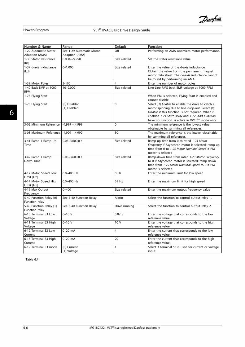
Number & Name Range Default Function1-29 Automatic MotorAdaption (AMA)
See 1-29 Automatic MotorAdaption (AMA)
Off Performing an AMA optimizes motor performance.
1-30 Stator Resistance(Rs)
0.000–99.990 Size related Set the stator resistance value
1-37 d-axis Inductance(Ld)
0–1,000 Size related Enter the value of the d-axis inductance.Obtain the value from the permanent magnetmotor data sheet. The de-axis inductance cannotbe found by performing an AMA.
1-39 Motor Poles 2-100 4 Enter the number of motor poles1-40 Back EMF at 1000RPM
10–9,000 Size related Line-Line RMS back EMF voltage at 1000 RPM
1-73 Flying Start When PM is selected, Flying Start is enabled andcannot disable
1-73 Flying Start [0] Disabled[1] Enabled
0 Select [1] Enable to enable the drive to catch amotor spinning due to line drop-out. Select [0]Disable if this function is not required. When isenabled 1-71 Start Delay and 1-72 Start Functionhave no function. is active in VVCplus mode only
3-02 Minimum Reference -4,999 – 4,999 0 The minimum reference is the lowest valueobtainable by summing all references.
3-03 Maximum Reference -4,999 – 4,999 50 The maximum reference is the lowest obtainableby summing all references.
3-41 Ramp 1 Ramp UpTime
0.05–3,600.0 s Size related Ramp-up time from 0 to rated 1-23 MotorFrequency if Asynchron motor is selected; ramp-uptime from 0 to 1-25 Motor Nominal Speed if PMmotor is selected
3-42 Ramp 1 RampDown Time
0.05–3,600.0 s Size related Ramp-down time from rated 1-23 Motor Frequencyto 0 if Asynchron motor is selected; ramp-downtime from 1-25 Motor Nominal Speed to 0 if PMmotor is selected.
4-12 Motor Speed LowLimit [Hz]
0.0–400 Hz 0 Hz Enter the minimum limit for low speed
4-14 Motor Speed HighLimit [Hz]
0.0–400 Hz 65 Hz Enter the maximum limit for high speed
4-19 Max OutputFrequency
0–400 Size related Enter the maximum output frequency value
5-40 Function Relay [0]Function relay
See 5-40 Function Relay Alarm Select the function to control output relay 1.
5-40 Function Relay [1]Function relay
See 5-40 Function Relay Drive running Select the function to control output relay 2.
6-10 Terminal 53 LowVoltage
0–10 V 0.07 V Enter the voltage that corresponds to the lowreference value.
6-11 Terminal 53 HighVoltage
0–10 V 10 V Enter the voltage that corresponds to the highreference value.
6-12 Terminal 53 LowCurrent
0–20 mA 4 Enter the current that corresponds to the lowreference value.
6-13 Terminal 53 HighCurrent
0–20 mA 20 Enter the current that corresponds to the highreference value.
6-19 Terminal 53 mode [0] Current[1] Voltage
1 Select if terminal 53 is used for current or voltageinput.
Table 6.4
How to Program VLT® HVAC Basic Drive Design Guide
6-6 MG18C422 - VLT® is a registered Danfoss trademark
66
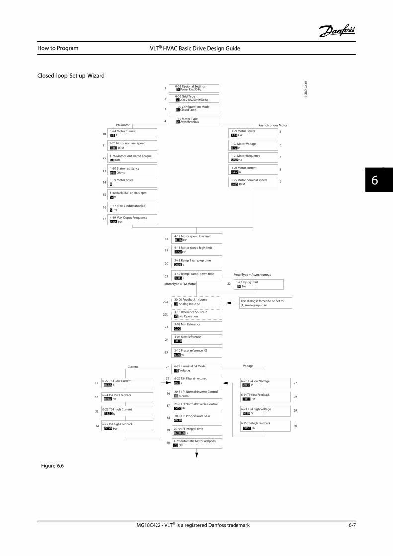
Closed-loop Set-up Wizard
6-29 Terminal 54 Mode[1] Voltage
6-25 T54 high Feedback
0050 Hz20-94 PI integral time0020.00 s
Current Voltage
This dialog is forced to be set to [1] Analog input 54
27
28
29
30
31
32
33
34
20-00 Feedback 1 source[1] Analog input 54
3-10 Preset reference [0]0.00
3-03 Max Reference50.00
3-02 Min Reference0.00
Asynchronous Motor
1-73 Flying Start [0] No
1-22 Motor Voltage0050 V
1-24 Motor current04.66 A
1-25 Motor nominal speed1420 RPM
3-41 Ramp 1 ramp-up time0003 s
3-42 Ramp1 ramp-down time0003 s
5
6
7
8
9
18
19
20
21
22
22a
23
24
25
26
35
36
37
38
39
40
0-06 Grid Type
4-12 Motor speed low limit0016 Hz
4-13 Motor speed high limit0050 Hz
130B
C402
.10
1-20 Motor Power1.10 kW
1-23 Motor frequency0050 Hz
6-22 T54 Low Current A
6-24 T54 low Feedback0016 Hz
6-23 T54 high Current13.30 A
6-25 T54 high Feedback0050
0.01 s
20-81 PI Normal/Inverse Control[0] Normal
20-83 PI Normal/Inverse Control0050 Hz
20-93 PI Proportional Gain00.50
1-29 Automatic Motor Adaption[0] O
6-20 T54 low Voltage0050 V
6-24 T54 low Feedback0016 Hz
6-21 T54 high Voltage0220 V
6-26 T54 Filter time const.
1-00 Conguration Mode[3] Closed Loop3
0-03 Regional Settings[0] Power kW/50 Hz1
3-16 Reference Source 2[0] No Operation22b
1-10 Motor Type[0] Asynchronous4
2 [0] 200-240V/50Hz/Delta
1-30 Stator resistance0.65 Ohms
1-25 Motor nominal speed3000 RPM
1-24 Motor Current3.8 A
1-26 Motor Cont. Rated Torque5.4 Nm
1-37 d-axis inductance(Ld)5 mH
4-19 Max Ouput Frequency0065 Hz
1-40 Back EMF at 1000 rpm57 V
10
11
12
13
14
15
16
17
PM motor
1-39 Motor poles8
%
04.66
Hz
MotorType = Asynchronous
MotorType = PM Motor
Figure 6.6
How to Program VLT® HVAC Basic Drive Design Guide
MG18C422 - VLT® is a registered Danfoss trademark 6-7
6 6

Closed-loop Set-up WizardNumber & Name Range Default Function0-03 Regional Settings [0] International
[1] US0
0-06 GridType [0] -[[132] see start-up wizardfor open-loop application
Size selected Select operating mode for restart uponreconnection of the adjustable frequencydrive to AC line voltage after power-down.
1-00 Configuration Mode [0] Open-loop[3] Closed-loop
0 Change this parameter to Closed-loop
1-10 Motor Construction *[0] Motor construction[1] PM, non-salient SPM
[0] Asynchron Setting the parameter value might changethese parameters:1-01 Motor Control Principle1-03 Torque Characteristics1-14 Damping Gain1-15 Low Speed Filter Time Const1-16 High Speed Filter Time Const1-17 Voltage filter time const1-20 Motor Power1-22 Motor Voltage1-23 Motor Frequency1-25 Motor Nominal Speed1-26 Motor Cont. Rated Torque1-30 Stator Resistance (Rs)1-33 Stator Leakage Reactance (X1)1-35 Main Reactance (Xh)1-37 d-axis Inductance (Ld)1-39 Motor Poles1-40 Back EMF at 1000 RPM1-66 Min. Current at Low Speed1-72 Start Function1-73 Flying Start4-19 Max Output Frequency4-58 Missing Motor Phase Function
1-20 Motor Power 0.125–150 hp [0.09–110 kW] Size related Enter motor power from nameplate data
1-22 Motor Voltage 50.0–1,000.0 V Size related Enter motor voltage from nameplate data
1-23 Motor Frequency 20.0–400.0 Hz Size related Enter motor frequency from nameplate data
1-24 Motor Current 0.0–10,000.00 A Size related Enter motor current from nameplate data
1-25 Motor Nominal Speed 100.0–9,999.0 RPM Size related Enter motor nominal speed from nameplatedata
1-26 Motor Cont. Rated Torque 0.1–1,000.0 Size related This parameter is available only when1-10 Motor Construction Design is set to [1]PM, non-salient SPM.
NOTE!Changing this parameter affects thesettings of other parameters
1-29 Automatic Motor Adaption(AMA)
Off Performing an AMA optimizes motorperformance.
1-30 Stator Resistance (Rs) 0.000–99.990 Size related Set the stator resistance value
1-37 d-axis Inductance (Ld) 0–1,000 Size related Enter the value of the d-axis inductance.Obtain the value from the permanent magnetmotor data sheet. The de-axis inductancecannot be found by performing an AMA.
How to Program VLT® HVAC Basic Drive Design Guide
6-8 MG18C422 - VLT® is a registered Danfoss trademark
66
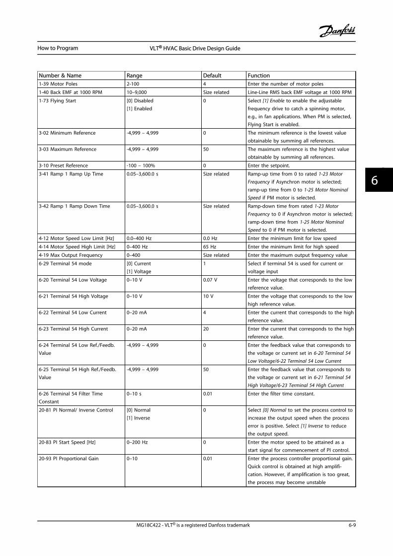
Number & Name Range Default Function1-39 Motor Poles 2-100 4 Enter the number of motor poles
1-40 Back EMF at 1000 RPM 10–9,000 Size related Line-Line RMS back EMF voltage at 1000 RPM
1-73 Flying Start [0] Disabled[1] Enabled
0 Select [1] Enable to enable the adjustablefrequency drive to catch a spinning motor,e.g., in fan applications. When PM is selected,Flying Start is enabled.
3-02 Minimum Reference -4,999 – 4,999 0 The minimum reference is the lowest valueobtainable by summing all references.
3-03 Maximum Reference -4,999 – 4,999 50 The maximum reference is the highest valueobtainable by summing all references.
3-10 Preset Reference -100 – 100% 0 Enter the setpoint.
3-41 Ramp 1 Ramp Up Time 0.05–3,600.0 s Size related Ramp-up time from 0 to rated 1-23 MotorFrequency if Asynchron motor is selected;ramp-up time from 0 to 1-25 Motor NominalSpeed if PM motor is selected.
3-42 Ramp 1 Ramp Down Time 0.05–3,600.0 s Size related Ramp-down time from rated 1-23 MotorFrequency to 0 if Asynchron motor is selected;ramp-down time from 1-25 Motor NominalSpeed to 0 if PM motor is selected.
4-12 Motor Speed Low Limit [Hz] 0.0–400 Hz 0.0 Hz Enter the minimum limit for low speed
4-14 Motor Speed High Limit [Hz] 0–400 Hz 65 Hz Enter the minimum limit for high speed
4-19 Max Output Frequency 0–400 Size related Enter the maximum output frequency value
6-29 Terminal 54 mode [0] Current[1] Voltage
1 Select if terminal 54 is used for current orvoltage input
6-20 Terminal 54 Low Voltage 0–10 V 0.07 V Enter the voltage that corresponds to the lowreference value.
6-21 Terminal 54 High Voltage 0–10 V 10 V Enter the voltage that corresponds to the lowhigh reference value.
6-22 Terminal 54 Low Current 0–20 mA 4 Enter the current that corresponds to the highreference value.
6-23 Terminal 54 High Current 0–20 mA 20 Enter the current that corresponds to the highreference value.
6-24 Terminal 54 Low Ref./Feedb.Value
-4,999 – 4,999 0 Enter the feedback value that corresponds tothe voltage or current set in 6-20 Terminal 54Low Voltage/6-22 Terminal 54 Low Current
6-25 Terminal 54 High Ref./Feedb.Value
-4,999 – 4,999 50 Enter the feedback value that corresponds tothe voltage or current set in 6-21 Terminal 54High Voltage/6-23 Terminal 54 High Current
6-26 Terminal 54 Filter TimeConstant
0–10 s 0.01 Enter the filter time constant.
20-81 PI Normal/ Inverse Control [0] Normal[1] Inverse
0 Select [0] Normal to set the process control toincrease the output speed when the processerror is positive. Select [1] Inverse to reducethe output speed.
20-83 PI Start Speed [Hz] 0–200 Hz 0 Enter the motor speed to be attained as astart signal for commencement of PI control.
20-93 PI Proportional Gain 0–10 0.01 Enter the process controller proportional gain.Quick control is obtained at high amplifi-cation. However, if amplification is too great,the process may become unstable
How to Program VLT® HVAC Basic Drive Design Guide
MG18C422 - VLT® is a registered Danfoss trademark 6-9
6 6
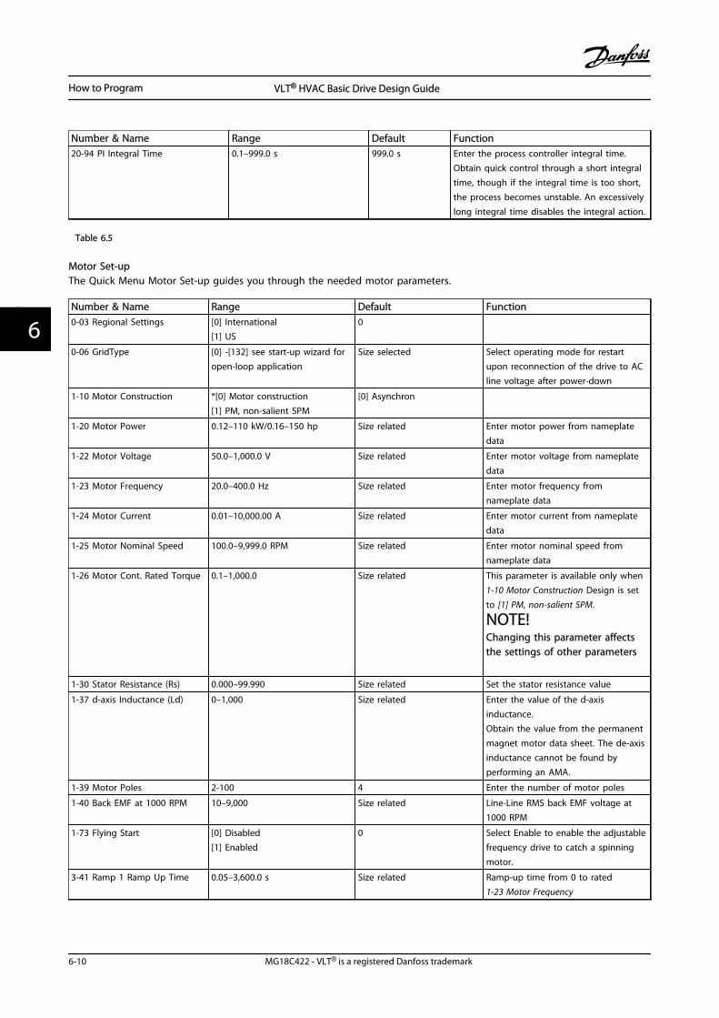
Number & Name Range Default Function20-94 PI Integral Time 0.1–999.0 s 999.0 s Enter the process controller integral time.
Obtain quick control through a short integraltime, though if the integral time is too short,the process becomes unstable. An excessivelylong integral time disables the integral action.
Table 6.5
Motor Set-upThe Quick Menu Motor Set-up guides you through the needed motor parameters.
Number & Name Range Default Function0-03 Regional Settings [0] International
[1] US0
0-06 GridType [0] -[132] see start-up wizard foropen-loop application
Size selected Select operating mode for restartupon reconnection of the drive to ACline voltage after power-down
1-10 Motor Construction *[0] Motor construction[1] PM, non-salient SPM
[0] Asynchron
1-20 Motor Power 0.12–110 kW/0.16–150 hp Size related Enter motor power from nameplatedata
1-22 Motor Voltage 50.0–1,000.0 V Size related Enter motor voltage from nameplatedata
1-23 Motor Frequency 20.0–400.0 Hz Size related Enter motor frequency fromnameplate data
1-24 Motor Current 0.01–10,000.00 A Size related Enter motor current from nameplatedata
1-25 Motor Nominal Speed 100.0–9,999.0 RPM Size related Enter motor nominal speed fromnameplate data
1-26 Motor Cont. Rated Torque 0.1–1,000.0 Size related This parameter is available only when1-10 Motor Construction Design is setto [1] PM, non-salient SPM.
NOTE!Changing this parameter affectsthe settings of other parameters
1-30 Stator Resistance (Rs) 0.000–99.990 Size related Set the stator resistance value
1-37 d-axis Inductance (Ld) 0–1,000 Size related Enter the value of the d-axisinductance.Obtain the value from the permanentmagnet motor data sheet. The de-axisinductance cannot be found byperforming an AMA.
1-39 Motor Poles 2-100 4 Enter the number of motor poles
1-40 Back EMF at 1000 RPM 10–9,000 Size related Line-Line RMS back EMF voltage at1000 RPM
1-73 Flying Start [0] Disabled[1] Enabled
0 Select Enable to enable the adjustablefrequency drive to catch a spinningmotor.
3-41 Ramp 1 Ramp Up Time 0.05–3,600.0 s Size related Ramp-up time from 0 to rated1-23 Motor Frequency
How to Program VLT® HVAC Basic Drive Design Guide
6-10 MG18C422 - VLT® is a registered Danfoss trademark
66
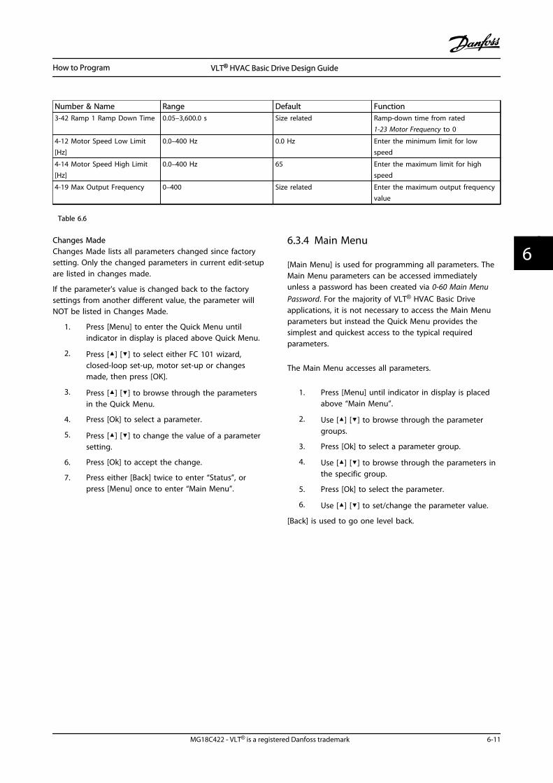
Number & Name Range Default Function3-42 Ramp 1 Ramp Down Time 0.05–3,600.0 s Size related Ramp-down time from rated
1-23 Motor Frequency to 0
4-12 Motor Speed Low Limit[Hz]
0.0–400 Hz 0.0 Hz Enter the minimum limit for lowspeed
4-14 Motor Speed High Limit[Hz]
0.0–400 Hz 65 Enter the maximum limit for highspeed
4-19 Max Output Frequency 0–400 Size related Enter the maximum output frequencyvalue
Table 6.6
Changes MadeChanges Made lists all parameters changed since factorysetting. Only the changed parameters in current edit-setupare listed in changes made.
If the parameter's value is changed back to the factorysettings from another different value, the parameter willNOT be listed in Changes Made.
1. Press [Menu] to enter the Quick Menu untilindicator in display is placed above Quick Menu.
2. Press [] [] to select either FC 101 wizard,closed-loop set-up, motor set-up or changesmade, then press [OK].
3. Press [] [] to browse through the parametersin the Quick Menu.
4. Press [Ok] to select a parameter.
5. Press [] [] to change the value of a parametersetting.
6. Press [Ok] to accept the change.
7. Press either [Back] twice to enter “Status”, orpress [Menu] once to enter “Main Menu”.
6.3.4 Main Menu
[Main Menu] is used for programming all parameters. TheMain Menu parameters can be accessed immediatelyunless a password has been created via 0-60 Main MenuPassword. For the majority of VLT® HVAC Basic Driveapplications, it is not necessary to access the Main Menuparameters but instead the Quick Menu provides thesimplest and quickest access to the typical requiredparameters.
The Main Menu accesses all parameters.
1. Press [Menu] until indicator in display is placedabove “Main Menu”.
2. Use [] [] to browse through the parametergroups.
3. Press [Ok] to select a parameter group.
4. Use [] [] to browse through the parameters inthe specific group.
5. Press [Ok] to select the parameter.
6. Use [] [] to set/change the parameter value.
[Back] is used to go one level back.
How to Program VLT® HVAC Basic Drive Design Guide
MG18C422 - VLT® is a registered Danfoss trademark 6-11
6 6
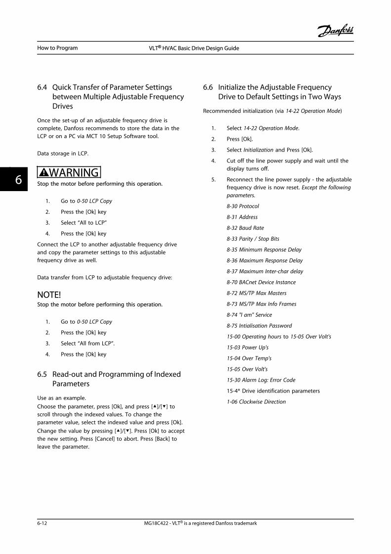
6.4 Quick Transfer of Parameter Settingsbetween Multiple Adjustable FrequencyDrives
Once the set-up of an adjustable frequency drive iscomplete, Danfoss recommends to store the data in theLCP or on a PC via MCT 10 Setup Software tool.
Data storage in LCP.
WARNINGStop the motor before performing this operation.
1. Go to 0-50 LCP Copy
2. Press the [Ok] key
3. Select “All to LCP”
4. Press the [Ok] key
Connect the LCP to another adjustable frequency driveand copy the parameter settings to this adjustablefrequency drive as well.
Data transfer from LCP to adjustable frequency drive:
NOTE!Stop the motor before performing this operation.
1. Go to 0-50 LCP Copy
2. Press the [Ok] key
3. Select “All from LCP”.
4. Press the [Ok] key
6.5 Read-out and Programming of IndexedParameters
Use as an example.Choose the parameter, press [Ok], and press []/[] toscroll through the indexed values. To change theparameter value, select the indexed value and press [Ok].Change the value by pressing []/[]. Press [Ok] to acceptthe new setting. Press [Cancel] to abort. Press [Back] toleave the parameter.
6.6 Initialize the Adjustable FrequencyDrive to Default Settings in Two Ways
Recommended initialization (via 14-22 Operation Mode)
1. Select 14-22 Operation Mode.
2. Press [Ok].
3. Select Initialization and Press [Ok].
4. Cut off the line power supply and wait until thedisplay turns off.
5. Reconnect the line power supply - the adjustablefrequency drive is now reset. Except the followingparameters.
8-30 Protocol
8-31 Address
8-32 Baud Rate
8-33 Parity / Stop Bits
8-35 Minimum Response Delay
8-36 Maximum Response Delay
8-37 Maximum Inter-char delay
8-70 BACnet Device Instance
8-72 MS/TP Max Masters
8-73 MS/TP Max Info Frames
8-74 "I am" Service
8-75 Intialisation Password
15-00 Operating hours to 15-05 Over Volt's
15-03 Power Up's
15-04 Over Temp's
15-05 Over Volt's
15-30 Alarm Log: Error Code
15-4* Drive identification parameters
1-06 Clockwise Direction
How to Program VLT® HVAC Basic Drive Design Guide
6-12 MG18C422 - VLT® is a registered Danfoss trademark
66
Two-finger initialization:1. Power off the adjustable frequency drive.
2. Press [Ok] and [Menu].
3. Power up the adjustable frequency drive whilestill pressing the keys above for 10 s.
4. The adjustable frequency drive is now reset,except the following parameters:
15-00 Operating hours
15-03 Power Up's
15-04 Over Temp's
15-05 Over Volt's
15-4* Drive identification parameters
Initialization of parameters is confirmed by AL80 in thedisplay after the power cycle.
How to Program VLT® HVAC Basic Drive Design Guide
MG18C422 - VLT® is a registered Danfoss trademark 6-13
6 6
How to Program VLT® HVAC Basic Drive Design Guide
6-14 MG18C422 - VLT® is a registered Danfoss trademark
66
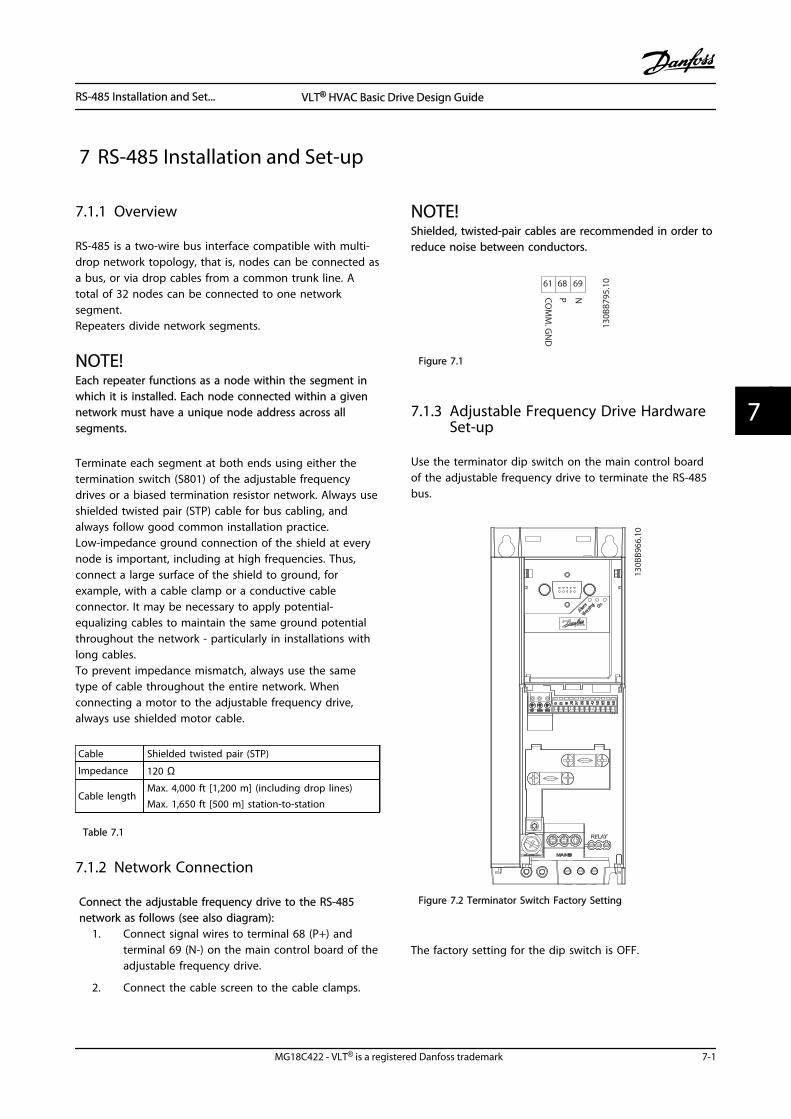
7 RS-485 Installation and Set-up
7.1.1 Overview
RS-485 is a two-wire bus interface compatible with multi-drop network topology, that is, nodes can be connected asa bus, or via drop cables from a common trunk line. Atotal of 32 nodes can be connected to one networksegment.Repeaters divide network segments.
NOTE!Each repeater functions as a node within the segment inwhich it is installed. Each node connected within a givennetwork must have a unique node address across allsegments.
Terminate each segment at both ends using either thetermination switch (S801) of the adjustable frequencydrives or a biased termination resistor network. Always useshielded twisted pair (STP) cable for bus cabling, andalways follow good common installation practice.Low-impedance ground connection of the shield at everynode is important, including at high frequencies. Thus,connect a large surface of the shield to ground, forexample, with a cable clamp or a conductive cableconnector. It may be necessary to apply potential-equalizing cables to maintain the same ground potentialthroughout the network - particularly in installations withlong cables.To prevent impedance mismatch, always use the sametype of cable throughout the entire network. Whenconnecting a motor to the adjustable frequency drive,always use shielded motor cable.
Cable Shielded twisted pair (STP)
Impedance 120 Ω
Cable lengthMax. 4,000 ft [1,200 m] (including drop lines)Max. 1,650 ft [500 m] station-to-station
Table 7.1
7.1.2 Network Connection
Connect the adjustable frequency drive to the RS-485network as follows (see also diagram):
1. Connect signal wires to terminal 68 (P+) andterminal 69 (N-) on the main control board of theadjustable frequency drive.
2. Connect the cable screen to the cable clamps.
NOTE!Shielded, twisted-pair cables are recommended in order toreduce noise between conductors.
61 68 69
NPCOM
M. G
ND
130B
B795
.10
Figure 7.1
7.1.3 Adjustable Frequency Drive HardwareSet-up
Use the terminator dip switch on the main control boardof the adjustable frequency drive to terminate the RS-485bus.
130B
B966
.10
Figure 7.2 Terminator Switch Factory Setting
The factory setting for the dip switch is OFF.
RS-485 Installation and Set... VLT® HVAC Basic Drive Design Guide
MG18C422 - VLT® is a registered Danfoss trademark 7-1
7 7
7.1.4 Adjustable Frequency DriveParameter Settings for ModbusCommunication
The following parameters apply to the RS-485 interface (FCport):
Parameter Function
8-30 Protocol Select the application protocol to run onthe RS-485 interface
8-31 Address Set the node address.
NOTE!The address range depends on theprotocol selected in 8-30 Protocol
8-32 Baud Rate Set the baud rate.
NOTE!The default baud rate depends on theprotocol selected in 8-30 Protocol
8-33 Parity / StopBits
Set the parity and number of stop bits.
NOTE!The default selection depends on theprotocol selected in 8-30 Protocol
8-35 MinimumResponse Delay
Specify a minimum delay time betweenreceiving a request and transmitting aresponse. This function is for overcomingmodem turnaround delays.
8-36 MaximumResponse Delay
Specify a maximum delay time betweentransmitting a request and receiving aresponse.
8-37 MaximumInter-char delay
If transmission is interrupted, specify amaximum delay time between two receivedbytes to ensure timeout.
Table 7.2
7.1.5 EMC Precautions
To achieve interference-free operation of the RS-485network, Danfoss recommends the following EMCprecautions.
Relevant national and local regulations, for exampleregarding protective ground connection, must beobserved. To avoid coupling of high frequency noisebetween the cables, the RS-485 communication cable mustbe kept away from motor and brake resistor cables.Normally a distance of 8 in [200 mm] is sufficient, butDanfoss recommends keeping the greatest possibledistance between the cables. Especially where cables run
in parallel over long distances. When crossing isunavoidable, the RS-485 cable must cross motor and brakeresistor cables at an angle of 90°.
7.2 Adjustable Frequency ProtocolOverview
The FC protocol, also referred to as FC bus or Standardbus, is the Danfoss standard serial communication bus. Itdefines an access technique according to the master-slaveprinciple for communications via a serial bus.One master and a maximum of 126 slaves can beconnected to the bus. The master selects the individualslaves via an address character in the message. A slaveitself can never transmit without first being requested todo so, and direct message transfer between the individualslaves is not possible. Communications occur in the half-duplex mode.The master function cannot be transferred to another node(single-master system).
The physical layer is RS-485, thus utilizing the RS-485 portbuilt into the adjustable frequency drive. The FC protocolsupports different message formats:
• A short format of 8 bytes for process data.
• A long format of 16 bytes that also includes aparameter channel.
• A format used for texts.
7.2.1 FC with Modbus RTU
The FC protocol provides access to the control word andbus reference of the adjustable frequency drive.
The Control Word allows the Modbus master to controlseveral important functions of the adjustable frequencydrive.
• Start
• Stopping the adjustable frequency drive invarious ways:
• Coast stop
• Quick stop
• DC Brake stop
• Normal (ramp) stop
• Reset after a fault trip
• Run at various preset speeds
• Run in reverse
RS-485 Installation and Set... VLT® HVAC Basic Drive Design Guide
7-2 MG18C422 - VLT® is a registered Danfoss trademark
77
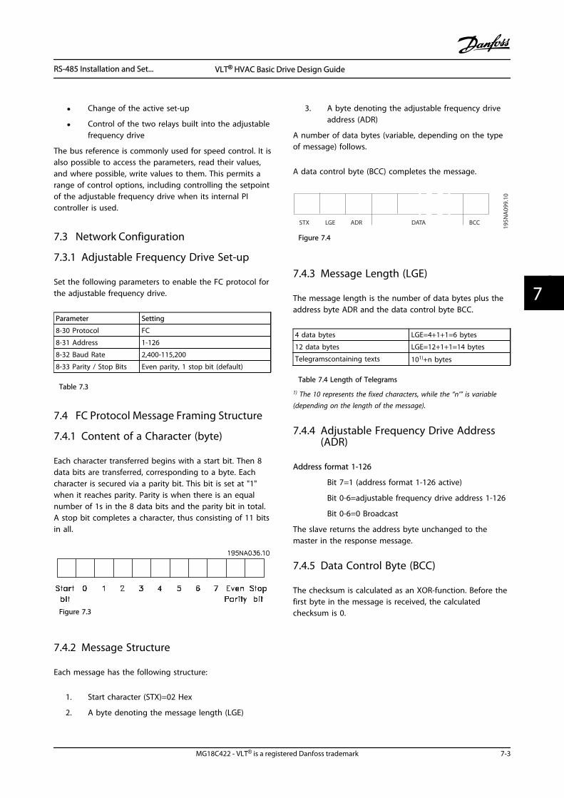
• Change of the active set-up
• Control of the two relays built into the adjustablefrequency drive
The bus reference is commonly used for speed control. It isalso possible to access the parameters, read their values,and where possible, write values to them. This permits arange of control options, including controlling the setpointof the adjustable frequency drive when its internal PIcontroller is used.
7.3 Network Configuration
7.3.1 Adjustable Frequency Drive Set-up
Set the following parameters to enable the FC protocol forthe adjustable frequency drive.
Parameter Setting
8-30 Protocol FC
8-31 Address 1-126
8-32 Baud Rate 2,400-115,200
8-33 Parity / Stop Bits Even parity, 1 stop bit (default)
Table 7.3
7.4 FC Protocol Message Framing Structure
7.4.1 Content of a Character (byte)
Each character transferred begins with a start bit. Then 8data bits are transferred, corresponding to a byte. Eachcharacter is secured via a parity bit. This bit is set at "1"when it reaches parity. Parity is when there is an equalnumber of 1s in the 8 data bits and the parity bit in total.A stop bit completes a character, thus consisting of 11 bitsin all.
Figure 7.3
7.4.2 Message Structure
Each message has the following structure:
1. Start character (STX)=02 Hex
2. A byte denoting the message length (LGE)
3. A byte denoting the adjustable frequency driveaddress (ADR)
A number of data bytes (variable, depending on the typeof message) follows.
A data control byte (BCC) completes the message.
STX LGE ADR DATA BCC
195N
A09
9.10
Figure 7.4
7.4.3 Message Length (LGE)
The message length is the number of data bytes plus theaddress byte ADR and the data control byte BCC.
4 data bytes LGE=4+1+1=6 bytes
12 data bytes LGE=12+1+1=14 bytes
Telegramscontaining texts 101)+n bytes
Table 7.4 Length of Telegrams
1) The 10 represents the fixed characters, while the “n’” is variable(depending on the length of the message).
7.4.4 Adjustable Frequency Drive Address(ADR)
Address format 1-126
Bit 7=1 (address format 1-126 active)
Bit 0-6=adjustable frequency drive address 1-126
Bit 0-6=0 Broadcast
The slave returns the address byte unchanged to themaster in the response message.
7.4.5 Data Control Byte (BCC)
The checksum is calculated as an XOR-function. Before thefirst byte in the message is received, the calculatedchecksum is 0.
RS-485 Installation and Set... VLT® HVAC Basic Drive Design Guide
MG18C422 - VLT® is a registered Danfoss trademark 7-3
7 7
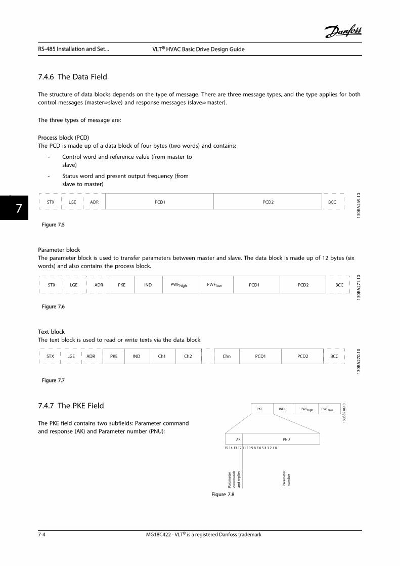
7.4.6 The Data Field
The structure of data blocks depends on the type of message. There are three message types, and the type applies for bothcontrol messages (master⇒slave) and response messages (slave⇒master).
The three types of message are:
Process block (PCD)The PCD is made up of a data block of four bytes (two words) and contains:
- Control word and reference value (from master toslave)
- Status word and present output frequency (fromslave to master)
ADRLGESTX PCD1 PCD2 BCC
130B
A26
9.10
Figure 7.5
Parameter blockThe parameter block is used to transfer parameters between master and slave. The data block is made up of 12 bytes (sixwords) and also contains the process block.
PKE INDADRLGESTX PCD1 PCD2 BCC
130B
A27
1.10
PWEhigh PWElow
Figure 7.6
Text blockThe text block is used to read or write texts via the data block.
PKE IND13
0BA27
0.10
ADRLGESTX PCD1 PCD2 BCCCh1 Ch2 Chn
Figure 7.7
7.4.7 The PKE Field
The PKE field contains two subfields: Parameter commandand response (AK) and Parameter number (PNU):
15 14 13 12 11 10 9 8 7 6 5 4 3 2 1 0
130B
B918
.10
PKE IND PWEhigh PWElow
AK PNU
Para
met
er
com
man
ds
and
rep
lies
Para
met
ernu
mb
er
Figure 7.8
RS-485 Installation and Set... VLT® HVAC Basic Drive Design Guide
7-4 MG18C422 - VLT® is a registered Danfoss trademark
77
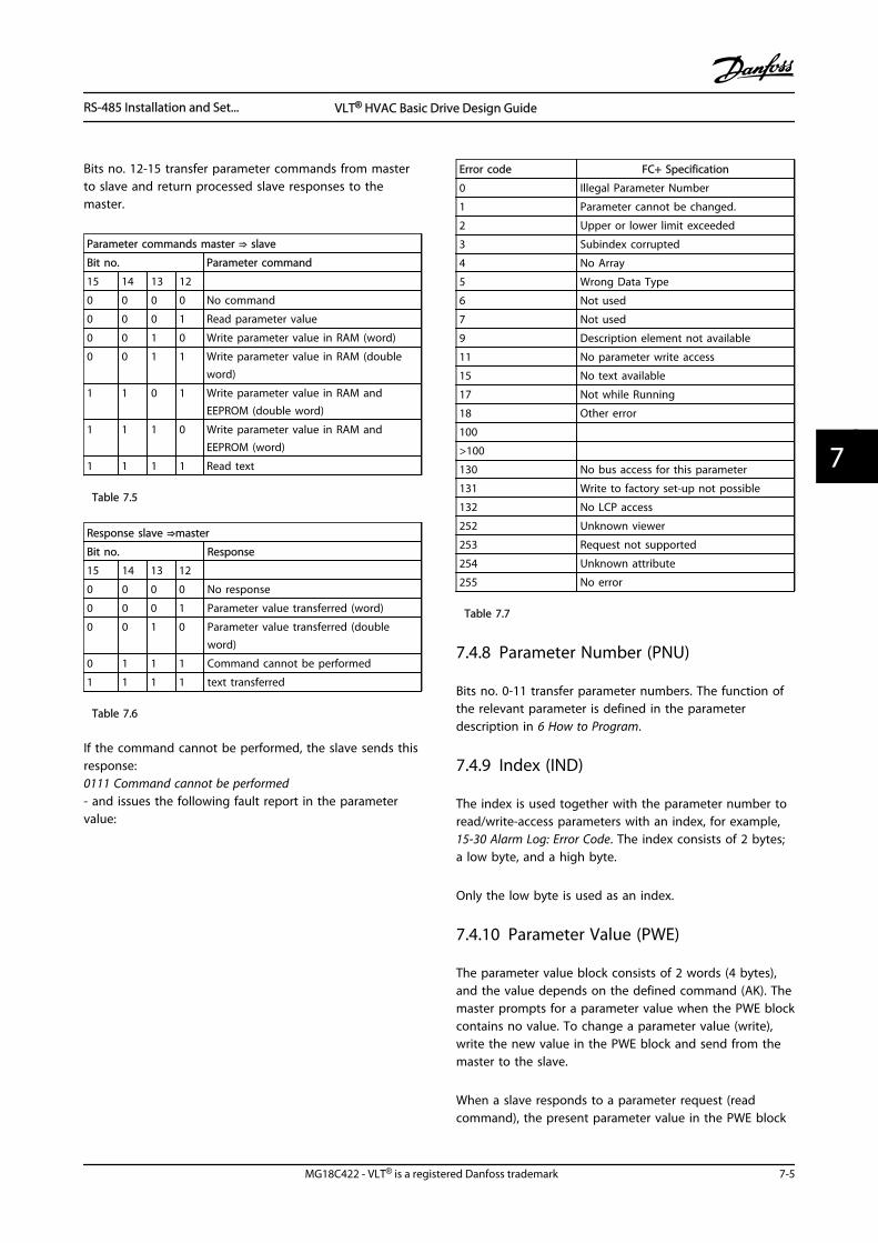
Bits no. 12-15 transfer parameter commands from masterto slave and return processed slave responses to themaster.
Parameter commands master ⇒ slave
Bit no. Parameter command
15 14 13 12
0 0 0 0 No command
0 0 0 1 Read parameter value
0 0 1 0 Write parameter value in RAM (word)
0 0 1 1 Write parameter value in RAM (doubleword)
1 1 0 1 Write parameter value in RAM andEEPROM (double word)
1 1 1 0 Write parameter value in RAM andEEPROM (word)
1 1 1 1 Read text
Table 7.5
Response slave ⇒master
Bit no. Response
15 14 13 12
0 0 0 0 No response
0 0 0 1 Parameter value transferred (word)
0 0 1 0 Parameter value transferred (doubleword)
0 1 1 1 Command cannot be performed
1 1 1 1 text transferred
Table 7.6
If the command cannot be performed, the slave sends thisresponse:0111 Command cannot be performed- and issues the following fault report in the parametervalue:
Error code FC+ Specification
0 Illegal Parameter Number
1 Parameter cannot be changed.
2 Upper or lower limit exceeded
3 Subindex corrupted
4 No Array
5 Wrong Data Type
6 Not used
7 Not used
9 Description element not available
11 No parameter write access
15 No text available
17 Not while Running
18 Other error
100
>100
130 No bus access for this parameter
131 Write to factory set-up not possible
132 No LCP access
252 Unknown viewer
253 Request not supported
254 Unknown attribute
255 No error
Table 7.7
7.4.8 Parameter Number (PNU)
Bits no. 0-11 transfer parameter numbers. The function ofthe relevant parameter is defined in the parameterdescription in 6 How to Program.
7.4.9 Index (IND)
The index is used together with the parameter number toread/write-access parameters with an index, for example,15-30 Alarm Log: Error Code. The index consists of 2 bytes;a low byte, and a high byte.
Only the low byte is used as an index.
7.4.10 Parameter Value (PWE)
The parameter value block consists of 2 words (4 bytes),and the value depends on the defined command (AK). Themaster prompts for a parameter value when the PWE blockcontains no value. To change a parameter value (write),write the new value in the PWE block and send from themaster to the slave.
When a slave responds to a parameter request (readcommand), the present parameter value in the PWE block
RS-485 Installation and Set... VLT® HVAC Basic Drive Design Guide
MG18C422 - VLT® is a registered Danfoss trademark 7-5
7 7
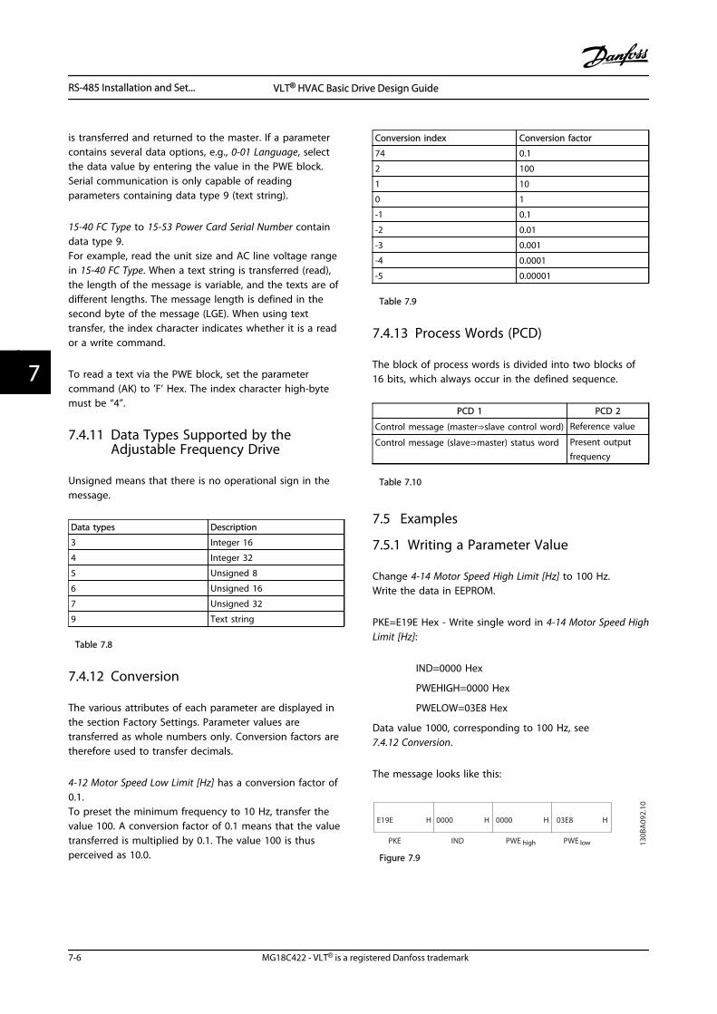
is transferred and returned to the master. If a parametercontains several data options, e.g., 0-01 Language, selectthe data value by entering the value in the PWE block.Serial communication is only capable of readingparameters containing data type 9 (text string).
15-40 FC Type to 15-53 Power Card Serial Number containdata type 9.For example, read the unit size and AC line voltage rangein 15-40 FC Type. When a text string is transferred (read),the length of the message is variable, and the texts are ofdifferent lengths. The message length is defined in thesecond byte of the message (LGE). When using texttransfer, the index character indicates whether it is a reador a write command.
To read a text via the PWE block, set the parametercommand (AK) to ’F’ Hex. The index character high-bytemust be “4”.
7.4.11 Data Types Supported by theAdjustable Frequency Drive
Unsigned means that there is no operational sign in themessage.
Data types Description
3 Integer 16
4 Integer 32
5 Unsigned 8
6 Unsigned 16
7 Unsigned 32
9 Text string
Table 7.8
7.4.12 Conversion
The various attributes of each parameter are displayed inthe section Factory Settings. Parameter values aretransferred as whole numbers only. Conversion factors aretherefore used to transfer decimals.
4-12 Motor Speed Low Limit [Hz] has a conversion factor of0.1.To preset the minimum frequency to 10 Hz, transfer thevalue 100. A conversion factor of 0.1 means that the valuetransferred is multiplied by 0.1. The value 100 is thusperceived as 10.0.
Conversion index Conversion factor
74 0.1
2 100
1 10
0 1
-1 0.1
-2 0.01
-3 0.001
-4 0.0001
-5 0.00001
Table 7.9
7.4.13 Process Words (PCD)
The block of process words is divided into two blocks of16 bits, which always occur in the defined sequence.
PCD 1 PCD 2
Control message (master⇒slave control word) Reference value
Control message (slave⇒master) status word Present outputfrequency
Table 7.10
7.5 Examples
7.5.1 Writing a Parameter Value
Change 4-14 Motor Speed High Limit [Hz] to 100 Hz.Write the data in EEPROM.
PKE=E19E Hex - Write single word in 4-14 Motor Speed HighLimit [Hz]:
IND=0000 Hex
PWEHIGH=0000 Hex
PWELOW=03E8 Hex
Data value 1000, corresponding to 100 Hz, see7.4.12 Conversion.
The message looks like this:
E19E H
PKE IND PWE high PWE low
0000 H 0000 H 03E8 H
130B
A09
2.10
Figure 7.9
RS-485 Installation and Set... VLT® HVAC Basic Drive Design Guide
7-6 MG18C422 - VLT® is a registered Danfoss trademark
77
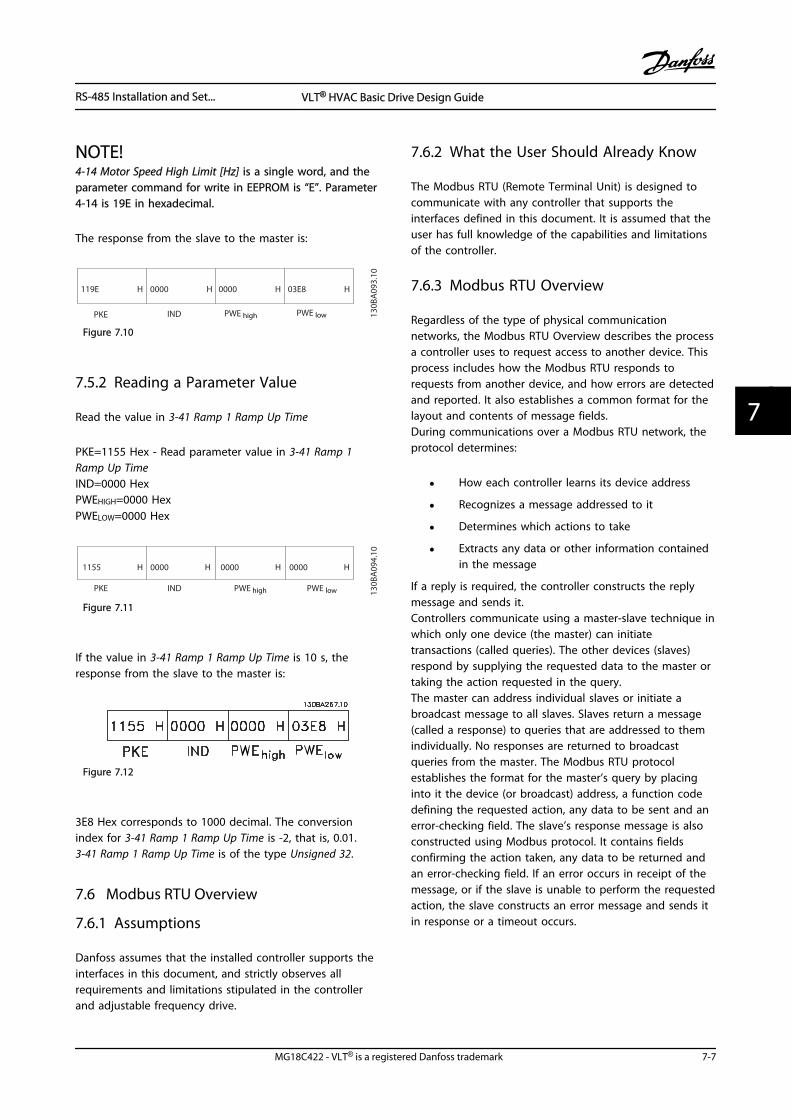
NOTE!4-14 Motor Speed High Limit [Hz] is a single word, and theparameter command for write in EEPROM is “E”. Parameter4-14 is 19E in hexadecimal.
The response from the slave to the master is:
119E H
PKE IND PWE high PWE low
0000 H 0000 H 03E8 H
130B
A09
3.10
Figure 7.10
7.5.2 Reading a Parameter Value
Read the value in 3-41 Ramp 1 Ramp Up Time
PKE=1155 Hex - Read parameter value in 3-41 Ramp 1Ramp Up TimeIND=0000 HexPWEHIGH=0000 HexPWELOW=0000 Hex
1155 H
PKE IND PWE high PWE low
0000 H 0000 H 0000 H
130B
A09
4.10
Figure 7.11
If the value in 3-41 Ramp 1 Ramp Up Time is 10 s, theresponse from the slave to the master is:
Figure 7.12
3E8 Hex corresponds to 1000 decimal. The conversionindex for 3-41 Ramp 1 Ramp Up Time is -2, that is, 0.01.3-41 Ramp 1 Ramp Up Time is of the type Unsigned 32.
7.6 Modbus RTU Overview
7.6.1 Assumptions
Danfoss assumes that the installed controller supports theinterfaces in this document, and strictly observes allrequirements and limitations stipulated in the controllerand adjustable frequency drive.
7.6.2 What the User Should Already Know
The Modbus RTU (Remote Terminal Unit) is designed tocommunicate with any controller that supports theinterfaces defined in this document. It is assumed that theuser has full knowledge of the capabilities and limitationsof the controller.
7.6.3 Modbus RTU Overview
Regardless of the type of physical communicationnetworks, the Modbus RTU Overview describes the processa controller uses to request access to another device. Thisprocess includes how the Modbus RTU responds torequests from another device, and how errors are detectedand reported. It also establishes a common format for thelayout and contents of message fields.During communications over a Modbus RTU network, theprotocol determines:
• How each controller learns its device address
• Recognizes a message addressed to it
• Determines which actions to take
• Extracts any data or other information containedin the message
If a reply is required, the controller constructs the replymessage and sends it.Controllers communicate using a master-slave technique inwhich only one device (the master) can initiatetransactions (called queries). The other devices (slaves)respond by supplying the requested data to the master ortaking the action requested in the query.The master can address individual slaves or initiate abroadcast message to all slaves. Slaves return a message(called a response) to queries that are addressed to themindividually. No responses are returned to broadcastqueries from the master. The Modbus RTU protocolestablishes the format for the master’s query by placinginto it the device (or broadcast) address, a function codedefining the requested action, any data to be sent and anerror-checking field. The slave’s response message is alsoconstructed using Modbus protocol. It contains fieldsconfirming the action taken, any data to be returned andan error-checking field. If an error occurs in receipt of themessage, or if the slave is unable to perform the requestedaction, the slave constructs an error message and sends itin response or a timeout occurs.
RS-485 Installation and Set... VLT® HVAC Basic Drive Design Guide
MG18C422 - VLT® is a registered Danfoss trademark 7-7
7 7
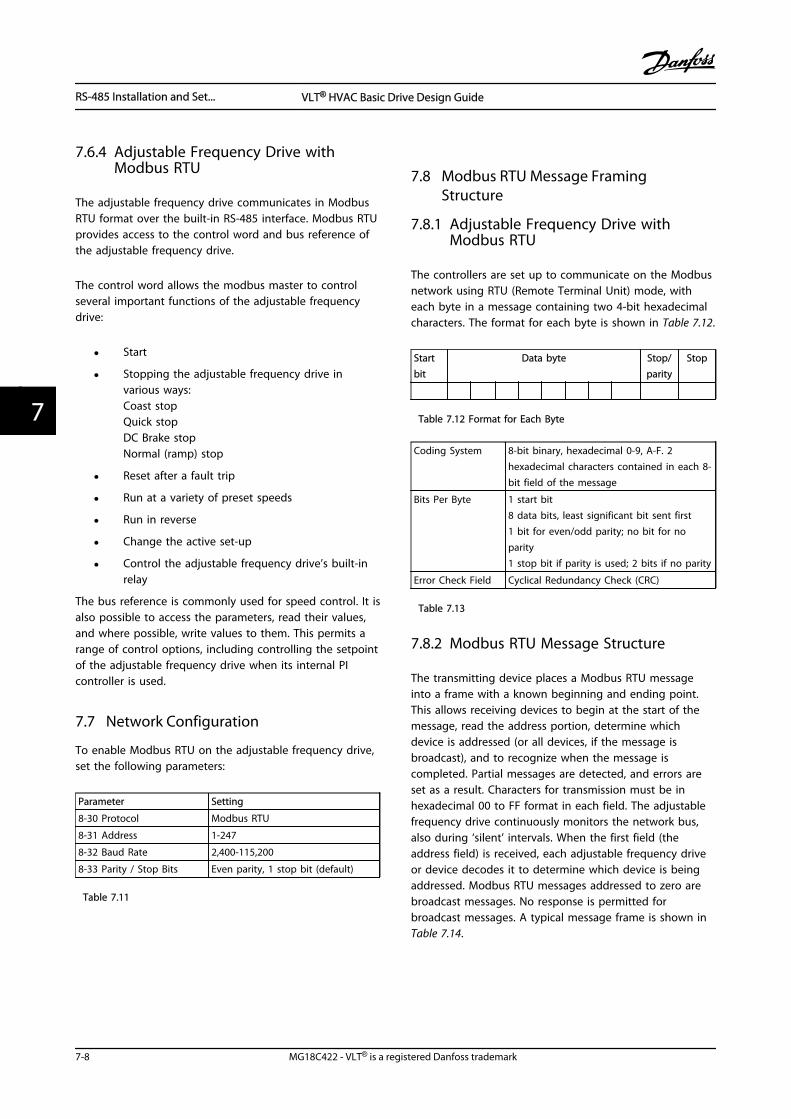
7.6.4 Adjustable Frequency Drive withModbus RTU
The adjustable frequency drive communicates in ModbusRTU format over the built-in RS-485 interface. Modbus RTUprovides access to the control word and bus reference ofthe adjustable frequency drive.
The control word allows the modbus master to controlseveral important functions of the adjustable frequencydrive:
• Start
• Stopping the adjustable frequency drive invarious ways:Coast stopQuick stopDC Brake stopNormal (ramp) stop
• Reset after a fault trip
• Run at a variety of preset speeds
• Run in reverse
• Change the active set-up
• Control the adjustable frequency drive’s built-inrelay
The bus reference is commonly used for speed control. It isalso possible to access the parameters, read their values,and where possible, write values to them. This permits arange of control options, including controlling the setpointof the adjustable frequency drive when its internal PIcontroller is used.
7.7 Network Configuration
To enable Modbus RTU on the adjustable frequency drive,set the following parameters:
Parameter Setting
8-30 Protocol Modbus RTU
8-31 Address 1-247
8-32 Baud Rate 2,400-115,200
8-33 Parity / Stop Bits Even parity, 1 stop bit (default)
Table 7.11
7.8 Modbus RTU Message FramingStructure
7.8.1 Adjustable Frequency Drive withModbus RTU
The controllers are set up to communicate on the Modbusnetwork using RTU (Remote Terminal Unit) mode, witheach byte in a message containing two 4-bit hexadecimalcharacters. The format for each byte is shown in Table 7.12.
Startbit
Data byte Stop/parity
Stop
Table 7.12 Format for Each Byte
Coding System 8-bit binary, hexadecimal 0-9, A-F. 2hexadecimal characters contained in each 8-bit field of the message
Bits Per Byte 1 start bit8 data bits, least significant bit sent first1 bit for even/odd parity; no bit for noparity1 stop bit if parity is used; 2 bits if no parity
Error Check Field Cyclical Redundancy Check (CRC)
Table 7.13
7.8.2 Modbus RTU Message Structure
The transmitting device places a Modbus RTU messageinto a frame with a known beginning and ending point.This allows receiving devices to begin at the start of themessage, read the address portion, determine whichdevice is addressed (or all devices, if the message isbroadcast), and to recognize when the message iscompleted. Partial messages are detected, and errors areset as a result. Characters for transmission must be inhexadecimal 00 to FF format in each field. The adjustablefrequency drive continuously monitors the network bus,also during ‘silent’ intervals. When the first field (theaddress field) is received, each adjustable frequency driveor device decodes it to determine which device is beingaddressed. Modbus RTU messages addressed to zero arebroadcast messages. No response is permitted forbroadcast messages. A typical message frame is shown inTable 7.14.
RS-485 Installation and Set... VLT® HVAC Basic Drive Design Guide
7-8 MG18C422 - VLT® is a registered Danfoss trademark
77
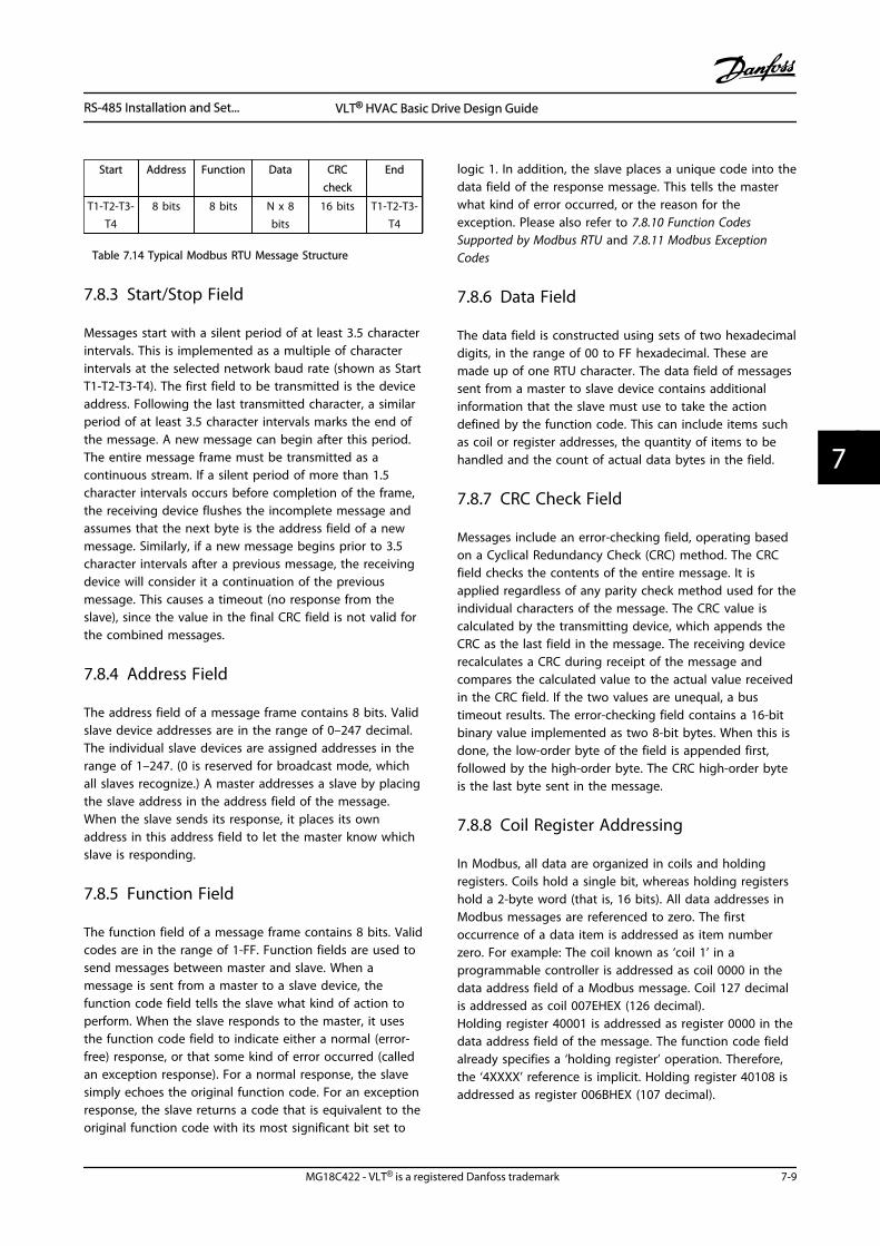
Start Address Function Data CRCcheck
End
T1-T2-T3-T4
8 bits 8 bits N x 8bits
16 bits T1-T2-T3-T4
Table 7.14 Typical Modbus RTU Message Structure
7.8.3 Start/Stop Field
Messages start with a silent period of at least 3.5 characterintervals. This is implemented as a multiple of characterintervals at the selected network baud rate (shown as StartT1-T2-T3-T4). The first field to be transmitted is the deviceaddress. Following the last transmitted character, a similarperiod of at least 3.5 character intervals marks the end ofthe message. A new message can begin after this period.The entire message frame must be transmitted as acontinuous stream. If a silent period of more than 1.5character intervals occurs before completion of the frame,the receiving device flushes the incomplete message andassumes that the next byte is the address field of a newmessage. Similarly, if a new message begins prior to 3.5character intervals after a previous message, the receivingdevice will consider it a continuation of the previousmessage. This causes a timeout (no response from theslave), since the value in the final CRC field is not valid forthe combined messages.
7.8.4 Address Field
The address field of a message frame contains 8 bits. Validslave device addresses are in the range of 0–247 decimal.The individual slave devices are assigned addresses in therange of 1–247. (0 is reserved for broadcast mode, whichall slaves recognize.) A master addresses a slave by placingthe slave address in the address field of the message.When the slave sends its response, it places its ownaddress in this address field to let the master know whichslave is responding.
7.8.5 Function Field
The function field of a message frame contains 8 bits. Validcodes are in the range of 1-FF. Function fields are used tosend messages between master and slave. When amessage is sent from a master to a slave device, thefunction code field tells the slave what kind of action toperform. When the slave responds to the master, it usesthe function code field to indicate either a normal (error-free) response, or that some kind of error occurred (calledan exception response). For a normal response, the slavesimply echoes the original function code. For an exceptionresponse, the slave returns a code that is equivalent to theoriginal function code with its most significant bit set to
logic 1. In addition, the slave places a unique code into thedata field of the response message. This tells the masterwhat kind of error occurred, or the reason for theexception. Please also refer to 7.8.10 Function CodesSupported by Modbus RTU and 7.8.11 Modbus ExceptionCodes
7.8.6 Data Field
The data field is constructed using sets of two hexadecimaldigits, in the range of 00 to FF hexadecimal. These aremade up of one RTU character. The data field of messagessent from a master to slave device contains additionalinformation that the slave must use to take the actiondefined by the function code. This can include items suchas coil or register addresses, the quantity of items to behandled and the count of actual data bytes in the field.
7.8.7 CRC Check Field
Messages include an error-checking field, operating basedon a Cyclical Redundancy Check (CRC) method. The CRCfield checks the contents of the entire message. It isapplied regardless of any parity check method used for theindividual characters of the message. The CRC value iscalculated by the transmitting device, which appends theCRC as the last field in the message. The receiving devicerecalculates a CRC during receipt of the message andcompares the calculated value to the actual value receivedin the CRC field. If the two values are unequal, a bustimeout results. The error-checking field contains a 16-bitbinary value implemented as two 8-bit bytes. When this isdone, the low-order byte of the field is appended first,followed by the high-order byte. The CRC high-order byteis the last byte sent in the message.
7.8.8 Coil Register Addressing
In Modbus, all data are organized in coils and holdingregisters. Coils hold a single bit, whereas holding registershold a 2-byte word (that is, 16 bits). All data addresses inModbus messages are referenced to zero. The firstoccurrence of a data item is addressed as item numberzero. For example: The coil known as ‘coil 1’ in aprogrammable controller is addressed as coil 0000 in thedata address field of a Modbus message. Coil 127 decimalis addressed as coil 007EHEX (126 decimal).Holding register 40001 is addressed as register 0000 in thedata address field of the message. The function code fieldalready specifies a ‘holding register’ operation. Therefore,the ‘4XXXX’ reference is implicit. Holding register 40108 isaddressed as register 006BHEX (107 decimal).
RS-485 Installation and Set... VLT® HVAC Basic Drive Design Guide
MG18C422 - VLT® is a registered Danfoss trademark 7-9
7 7
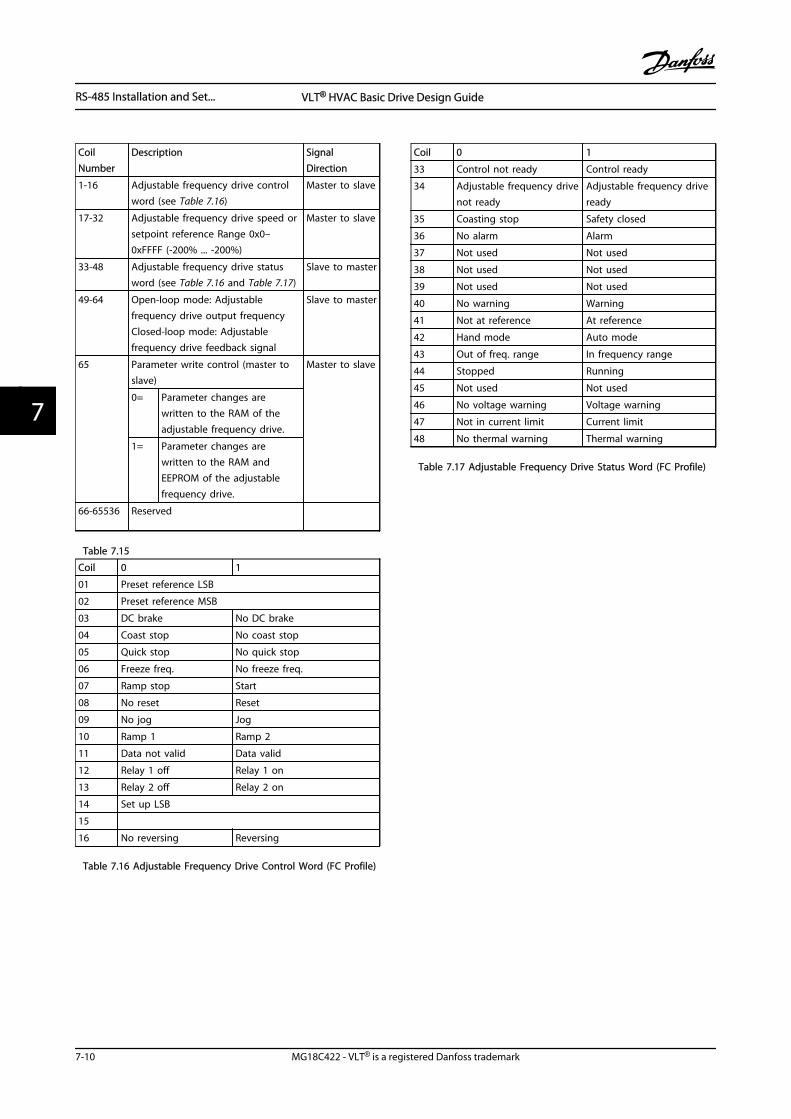
CoilNumber
Description SignalDirection
1-16 Adjustable frequency drive controlword (see Table 7.16)
Master to slave
17-32 Adjustable frequency drive speed orsetpoint reference Range 0x0–0xFFFF (-200% ... -200%)
Master to slave
33-48 Adjustable frequency drive statusword (see Table 7.16 and Table 7.17)
Slave to master
49-64 Open-loop mode: Adjustablefrequency drive output frequencyClosed-loop mode: Adjustablefrequency drive feedback signal
Slave to master
65 Parameter write control (master toslave)
Master to slave
0= Parameter changes arewritten to the RAM of theadjustable frequency drive.
1= Parameter changes arewritten to the RAM andEEPROM of the adjustablefrequency drive.
66-65536 Reserved
Table 7.15
Coil 0 1
01 Preset reference LSB
02 Preset reference MSB
03 DC brake No DC brake
04 Coast stop No coast stop
05 Quick stop No quick stop
06 Freeze freq. No freeze freq.
07 Ramp stop Start
08 No reset Reset
09 No jog Jog
10 Ramp 1 Ramp 2
11 Data not valid Data valid
12 Relay 1 off Relay 1 on
13 Relay 2 off Relay 2 on
14 Set up LSB
15
16 No reversing Reversing
Table 7.16 Adjustable Frequency Drive Control Word (FC Profile)
Coil 0 1
33 Control not ready Control ready
34 Adjustable frequency drivenot ready
Adjustable frequency driveready
35 Coasting stop Safety closed
36 No alarm Alarm
37 Not used Not used
38 Not used Not used
39 Not used Not used
40 No warning Warning
41 Not at reference At reference
42 Hand mode Auto mode
43 Out of freq. range In frequency range
44 Stopped Running
45 Not used Not used
46 No voltage warning Voltage warning
47 Not in current limit Current limit
48 No thermal warning Thermal warning
Table 7.17 Adjustable Frequency Drive Status Word (FC Profile)
RS-485 Installation and Set... VLT® HVAC Basic Drive Design Guide
7-10 MG18C422 - VLT® is a registered Danfoss trademark
77
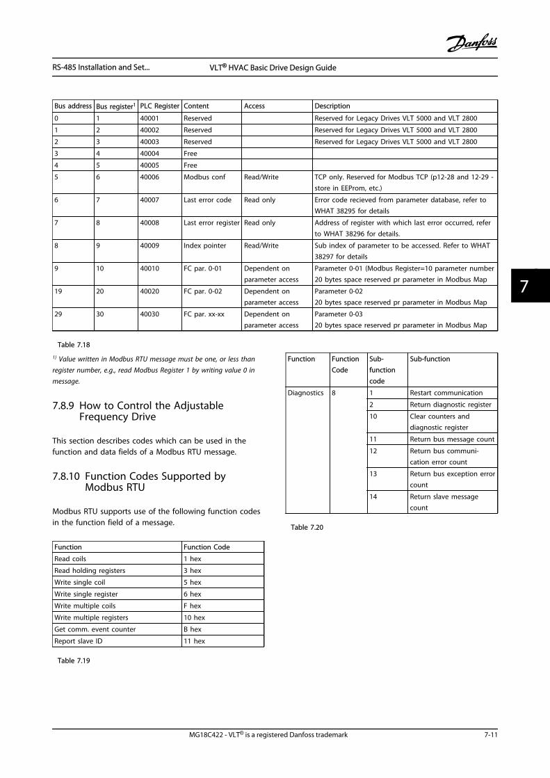
Bus address Bus register1 PLC Register Content Access Description
0 1 40001 Reserved Reserved for Legacy Drives VLT 5000 and VLT 2800
1 2 40002 Reserved Reserved for Legacy Drives VLT 5000 and VLT 2800
2 3 40003 Reserved Reserved for Legacy Drives VLT 5000 and VLT 2800
3 4 40004 Free
4 5 40005 Free
5 6 40006 Modbus conf Read/Write TCP only. Reserved for Modbus TCP (p12-28 and 12-29 -store in EEProm, etc.)
6 7 40007 Last error code Read only Error code recieved from parameter database, refer toWHAT 38295 for details
7 8 40008 Last error register Read only Address of register with which last error occurred, referto WHAT 38296 for details.
8 9 40009 Index pointer Read/Write Sub index of parameter to be accessed. Refer to WHAT38297 for details
9 10 40010 FC par. 0-01 Dependent onparameter access
Parameter 0-01 (Modbus Register=10 parameter number20 bytes space reserved pr parameter in Modbus Map
19 20 40020 FC par. 0-02 Dependent onparameter access
Parameter 0-0220 bytes space reserved pr parameter in Modbus Map
29 30 40030 FC par. xx-xx Dependent onparameter access
Parameter 0-0320 bytes space reserved pr parameter in Modbus Map
Table 7.18
1) Value written in Modbus RTU message must be one, or less thanregister number, e.g., read Modbus Register 1 by writing value 0 inmessage.
7.8.9 How to Control the AdjustableFrequency Drive
This section describes codes which can be used in thefunction and data fields of a Modbus RTU message.
7.8.10 Function Codes Supported byModbus RTU
Modbus RTU supports use of the following function codesin the function field of a message.
Function Function Code
Read coils 1 hex
Read holding registers 3 hex
Write single coil 5 hex
Write single register 6 hex
Write multiple coils F hex
Write multiple registers 10 hex
Get comm. event counter B hex
Report slave ID 11 hex
Table 7.19
Function FunctionCode
Sub-functioncode
Sub-function
Diagnostics 8 1 Restart communication
2 Return diagnostic register
10 Clear counters anddiagnostic register
11 Return bus message count
12 Return bus communi-cation error count
13 Return bus exception errorcount
14 Return slave messagecount
Table 7.20
RS-485 Installation and Set... VLT® HVAC Basic Drive Design Guide
MG18C422 - VLT® is a registered Danfoss trademark 7-11
7 7
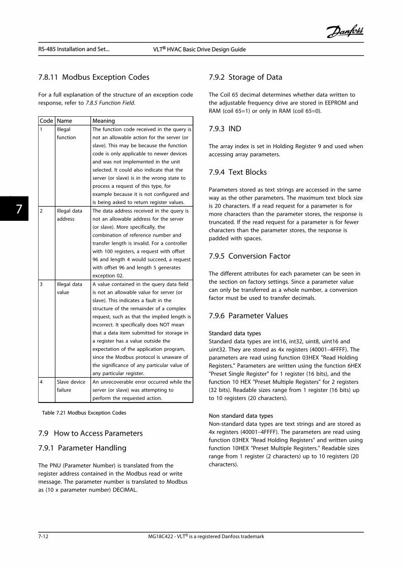
7.8.11 Modbus Exception Codes
For a full explanation of the structure of an exception coderesponse, refer to 7.8.5 Function Field.
Code Name Meaning1 Illegal
functionThe function code received in the query isnot an allowable action for the server (orslave). This may be because the functioncode is only applicable to newer devicesand was not implemented in the unitselected. It could also indicate that theserver (or slave) is in the wrong state toprocess a request of this type, forexample because it is not configured andis being asked to return register values.
2 Illegal dataaddress
The data address received in the query isnot an allowable address for the server(or slave). More specifically, thecombination of reference number andtransfer length is invalid. For a controllerwith 100 registers, a request with offset96 and length 4 would succeed, a requestwith offset 96 and length 5 generatesexception 02.
3 Illegal datavalue
A value contained in the query data fieldis not an allowable value for server (orslave). This indicates a fault in thestructure of the remainder of a complexrequest, such as that the implied length isincorrect. It specifically does NOT meanthat a data item submitted for storage ina register has a value outside theexpectation of the application program,since the Modbus protocol is unaware ofthe significance of any particular value ofany particular register.
4 Slave devicefailure
An unrecoverable error occurred while theserver (or slave) was attempting toperform the requested action.
Table 7.21 Modbus Exception Codes
7.9 How to Access Parameters
7.9.1 Parameter Handling
The PNU (Parameter Number) is translated from theregister address contained in the Modbus read or writemessage. The parameter number is translated to Modbusas (10 x parameter number) DECIMAL.
7.9.2 Storage of Data
The Coil 65 decimal determines whether data written tothe adjustable frequency drive are stored in EEPROM andRAM (coil 65=1) or only in RAM (coil 65=0).
7.9.3 IND
The array index is set in Holding Register 9 and used whenaccessing array parameters.
7.9.4 Text Blocks
Parameters stored as text strings are accessed in the sameway as the other parameters. The maximum text block sizeis 20 characters. If a read request for a parameter is formore characters than the parameter stores, the response istruncated. If the read request for a parameter is for fewercharacters than the parameter stores, the response ispadded with spaces.
7.9.5 Conversion Factor
The different attributes for each parameter can be seen inthe section on factory settings. Since a parameter valuecan only be transferred as a whole number, a conversionfactor must be used to transfer decimals.
7.9.6 Parameter Values
Standard data typesStandard data types are int16, int32, uint8, uint16 anduint32. They are stored as 4x registers (40001–4FFFF). Theparameters are read using function 03HEX "Read HoldingRegisters." Parameters are written using the function 6HEX"Preset Single Register" for 1 register (16 bits), and thefunction 10 HEX "Preset Multiple Registers" for 2 registers(32 bits). Readable sizes range from 1 register (16 bits) upto 10 registers (20 characters).
Non standard data typesNon-standard data types are text strings and are stored as4x registers (40001–4FFFF). The parameters are read usingfunction 03HEX "Read Holding Registers" and written usingfunction 10HEX "Preset Multiple Registers." Readable sizesrange from 1 register (2 characters) up to 10 registers (20characters).
RS-485 Installation and Set... VLT® HVAC Basic Drive Design Guide
7-12 MG18C422 - VLT® is a registered Danfoss trademark
77
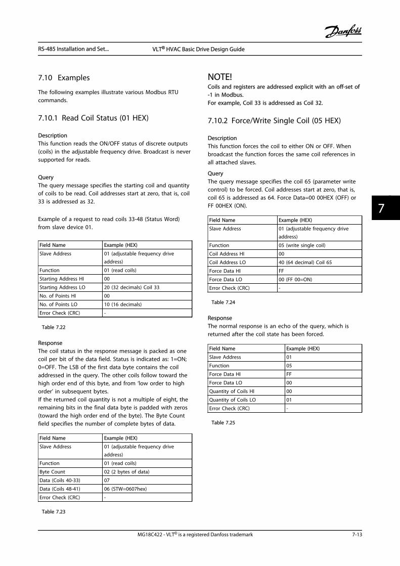
7.10 Examples
The following examples illustrate various Modbus RTUcommands.
7.10.1 Read Coil Status (01 HEX)
DescriptionThis function reads the ON/OFF status of discrete outputs(coils) in the adjustable frequency drive. Broadcast is neversupported for reads.
QueryThe query message specifies the starting coil and quantityof coils to be read. Coil addresses start at zero, that is, coil33 is addressed as 32.
Example of a request to read coils 33-48 (Status Word)from slave device 01.
Field Name Example (HEX)
Slave Address 01 (adjustable frequency driveaddress)
Function 01 (read coils)
Starting Address HI 00
Starting Address LO 20 (32 decimals) Coil 33
No. of Points HI 00
No. of Points LO 10 (16 decimals)
Error Check (CRC) -
Table 7.22
ResponseThe coil status in the response message is packed as onecoil per bit of the data field. Status is indicated as: 1=ON;0=OFF. The LSB of the first data byte contains the coiladdressed in the query. The other coils follow toward thehigh order end of this byte, and from ‘low order to highorder’ in subsequent bytes.If the returned coil quantity is not a multiple of eight, theremaining bits in the final data byte is padded with zeros(toward the high order end of the byte). The Byte Countfield specifies the number of complete bytes of data.
Field Name Example (HEX)
Slave Address 01 (adjustable frequency driveaddress)
Function 01 (read coils)
Byte Count 02 (2 bytes of data)
Data (Coils 40-33) 07
Data (Coils 48-41) 06 (STW=0607hex)
Error Check (CRC) -
Table 7.23
NOTE!Coils and registers are addressed explicit with an off-set of-1 in Modbus.For example, Coil 33 is addressed as Coil 32.
7.10.2 Force/Write Single Coil (05 HEX)
DescriptionThis function forces the coil to either ON or OFF. Whenbroadcast the function forces the same coil references inall attached slaves.
QueryThe query message specifies the coil 65 (parameter writecontrol) to be forced. Coil addresses start at zero, that is,coil 65 is addressed as 64. Force Data=00 00HEX (OFF) orFF 00HEX (ON).
Field Name Example (HEX)
Slave Address 01 (adjustable frequency driveaddress)
Function 05 (write single coil)
Coil Address HI 00
Coil Address LO 40 (64 decimal) Coil 65
Force Data HI FF
Force Data LO 00 (FF 00=ON)
Error Check (CRC) -
Table 7.24
ResponseThe normal response is an echo of the query, which isreturned after the coil state has been forced.
Field Name Example (HEX)
Slave Address 01
Function 05
Force Data HI FF
Force Data LO 00
Quantity of Coils HI 00
Quantity of Coils LO 01
Error Check (CRC) -
Table 7.25
RS-485 Installation and Set... VLT® HVAC Basic Drive Design Guide
MG18C422 - VLT® is a registered Danfoss trademark 7-13
7 7
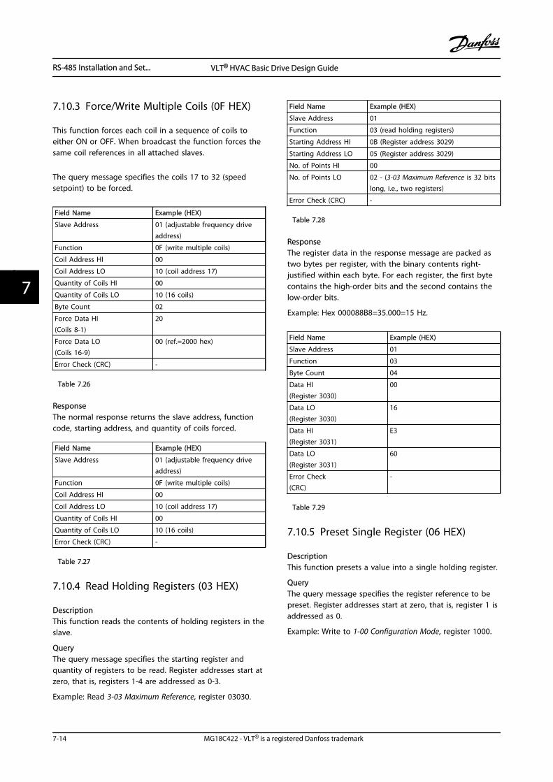
7.10.3 Force/Write Multiple Coils (0F HEX)
This function forces each coil in a sequence of coils toeither ON or OFF. When broadcast the function forces thesame coil references in all attached slaves.
The query message specifies the coils 17 to 32 (speedsetpoint) to be forced.
Field Name Example (HEX)
Slave Address 01 (adjustable frequency driveaddress)
Function 0F (write multiple coils)
Coil Address HI 00
Coil Address LO 10 (coil address 17)
Quantity of Coils HI 00
Quantity of Coils LO 10 (16 coils)
Byte Count 02
Force Data HI(Coils 8-1)
20
Force Data LO(Coils 16-9)
00 (ref.=2000 hex)
Error Check (CRC) -
Table 7.26
ResponseThe normal response returns the slave address, functioncode, starting address, and quantity of coils forced.
Field Name Example (HEX)
Slave Address 01 (adjustable frequency driveaddress)
Function 0F (write multiple coils)
Coil Address HI 00
Coil Address LO 10 (coil address 17)
Quantity of Coils HI 00
Quantity of Coils LO 10 (16 coils)
Error Check (CRC) -
Table 7.27
7.10.4 Read Holding Registers (03 HEX)
DescriptionThis function reads the contents of holding registers in theslave.
QueryThe query message specifies the starting register andquantity of registers to be read. Register addresses start atzero, that is, registers 1-4 are addressed as 0-3.
Example: Read 3-03 Maximum Reference, register 03030.
Field Name Example (HEX)
Slave Address 01
Function 03 (read holding registers)
Starting Address HI 0B (Register address 3029)
Starting Address LO 05 (Register address 3029)
No. of Points HI 00
No. of Points LO 02 - (3-03 Maximum Reference is 32 bitslong, i.e., two registers)
Error Check (CRC) -
Table 7.28
ResponseThe register data in the response message are packed astwo bytes per register, with the binary contents right-justified within each byte. For each register, the first bytecontains the high-order bits and the second contains thelow-order bits.
Example: Hex 000088B8=35.000=15 Hz.
Field Name Example (HEX)
Slave Address 01
Function 03
Byte Count 04
Data HI(Register 3030)
00
Data LO(Register 3030)
16
Data HI(Register 3031)
E3
Data LO(Register 3031)
60
Error Check(CRC)
-
Table 7.29
7.10.5 Preset Single Register (06 HEX)
DescriptionThis function presets a value into a single holding register.
QueryThe query message specifies the register reference to bepreset. Register addresses start at zero, that is, register 1 isaddressed as 0.
Example: Write to 1-00 Configuration Mode, register 1000.
RS-485 Installation and Set... VLT® HVAC Basic Drive Design Guide
7-14 MG18C422 - VLT® is a registered Danfoss trademark
77
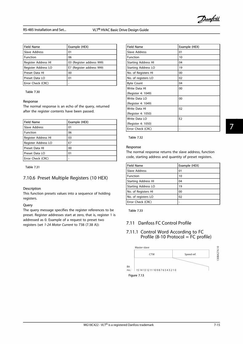
Field Name Example (HEX)
Slave Address 01
Function 06
Register Address HI 03 (Register address 999)
Register Address LO E7 (Register address 999)
Preset Data HI 00
Preset Data LO 01
Error Check (CRC) -
Table 7.30
ResponseThe normal response is an echo of the query, returnedafter the register contents have been passed.
Field Name Example (HEX)
Slave Address 01
Function 06
Register Address HI 03
Register Address LO E7
Preset Data HI 00
Preset Data LO 01
Error Check (CRC) -
Table 7.31
7.10.6 Preset Multiple Registers (10 HEX)
DescriptionThis function presets values into a sequence of holdingregisters.
QueryThe query message specifies the register references to bepreset. Register addresses start at zero, that is, register 1 isaddressed as 0. Example of a request to preset tworegisters (set 1-24 Motor Current to 738 (7.38 A)):
Field Name Example (HEX)
Slave Address 01
Function 10
Starting Address HI 04
Starting Address LO 19
No. of Registers HI 00
No. of registers LO 02
Byte Count 04
Write Data HI(Register 4: 1049)
00
Write Data LO(Register 4: 1049)
00
Write Data HI(Register 4: 1050)
02
Write Data LO(Register 4: 1050)
E2
Error Check (CRC) -
Table 7.32
ResponseThe normal response returns the slave address, functioncode, starting address and quantity of preset registers.
Field Name Example (HEX)
Slave Address 01
Function 10
Starting Address HI 04
Starting Address LO 19
No. of Registers HI 00
No. of registers LO 02
Error Check (CRC) -
Table 7.33
7.11 Danfoss FC Control Profile
7.11.1 Control Word According to FCProfile (8-10 Protocol = FC profile)
Speed ref.CTW
Master-slave
130B
A27
4.10
15 14 13 12 11 10 9 8 7 6 5 4 3 2 1 0Bitno.:
Figure 7.13
RS-485 Installation and Set... VLT® HVAC Basic Drive Design Guide
MG18C422 - VLT® is a registered Danfoss trademark 7-15
7 7
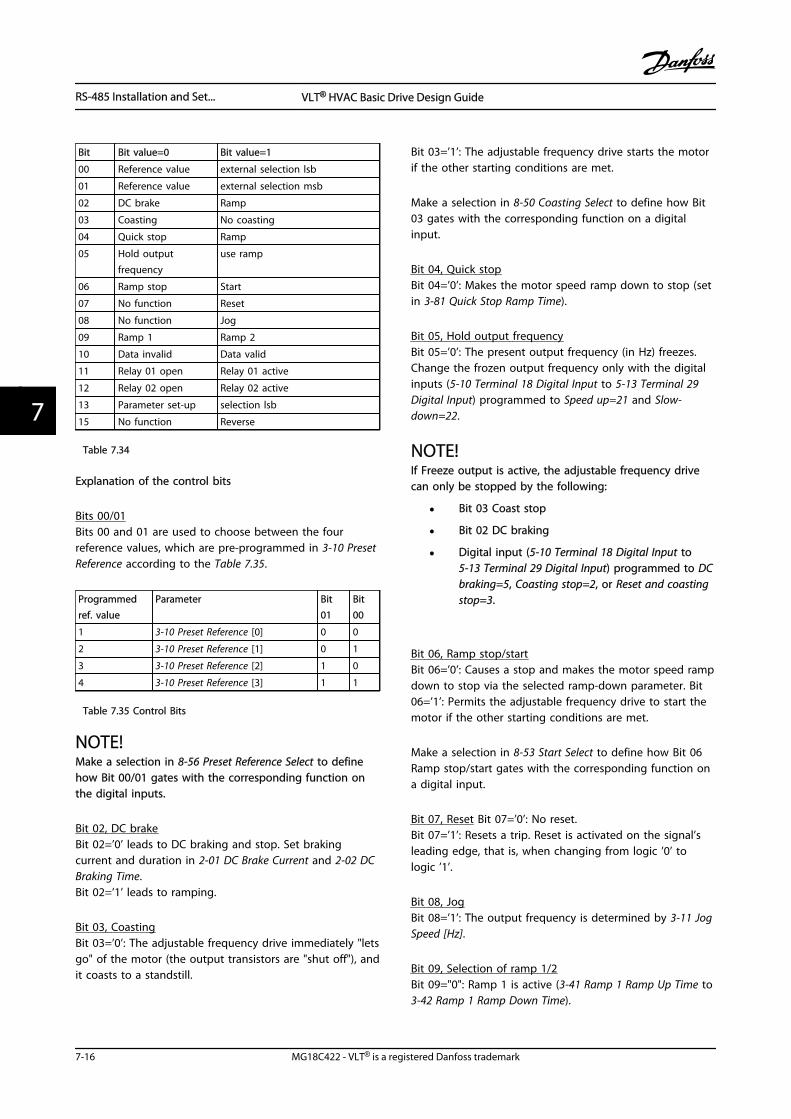
Bit Bit value=0 Bit value=1
00 Reference value external selection lsb
01 Reference value external selection msb
02 DC brake Ramp
03 Coasting No coasting
04 Quick stop Ramp
05 Hold outputfrequency
use ramp
06 Ramp stop Start
07 No function Reset
08 No function Jog
09 Ramp 1 Ramp 2
10 Data invalid Data valid
11 Relay 01 open Relay 01 active
12 Relay 02 open Relay 02 active
13 Parameter set-up selection lsb
15 No function Reverse
Table 7.34
Explanation of the control bits
Bits 00/01Bits 00 and 01 are used to choose between the fourreference values, which are pre-programmed in 3-10 PresetReference according to the Table 7.35.
Programmedref. value
Parameter Bit01
Bit00
1 3-10 Preset Reference [0] 0 0
2 3-10 Preset Reference [1] 0 1
3 3-10 Preset Reference [2] 1 0
4 3-10 Preset Reference [3] 1 1
Table 7.35 Control Bits
NOTE!Make a selection in 8-56 Preset Reference Select to definehow Bit 00/01 gates with the corresponding function onthe digital inputs.
Bit 02, DC brakeBit 02=’0’ leads to DC braking and stop. Set brakingcurrent and duration in 2-01 DC Brake Current and 2-02 DCBraking Time.Bit 02=’1’ leads to ramping.
Bit 03, CoastingBit 03=’0’: The adjustable frequency drive immediately "letsgo" of the motor (the output transistors are "shut off"), andit coasts to a standstill.
Bit 03=’1’: The adjustable frequency drive starts the motorif the other starting conditions are met.
Make a selection in 8-50 Coasting Select to define how Bit03 gates with the corresponding function on a digitalinput.
Bit 04, Quick stopBit 04=’0’: Makes the motor speed ramp down to stop (setin 3-81 Quick Stop Ramp Time).
Bit 05, Hold output frequencyBit 05=’0’: The present output frequency (in Hz) freezes.Change the frozen output frequency only with the digitalinputs (5-10 Terminal 18 Digital Input to 5-13 Terminal 29Digital Input) programmed to Speed up=21 and Slow-down=22.
NOTE!If Freeze output is active, the adjustable frequency drivecan only be stopped by the following:
• Bit 03 Coast stop
• Bit 02 DC braking
• Digital input (5-10 Terminal 18 Digital Input to5-13 Terminal 29 Digital Input) programmed to DCbraking=5, Coasting stop=2, or Reset and coastingstop=3.
Bit 06, Ramp stop/startBit 06=’0’: Causes a stop and makes the motor speed rampdown to stop via the selected ramp-down parameter. Bit06=’1’: Permits the adjustable frequency drive to start themotor if the other starting conditions are met.
Make a selection in 8-53 Start Select to define how Bit 06Ramp stop/start gates with the corresponding function ona digital input.
Bit 07, Reset Bit 07=’0’: No reset.Bit 07=’1’: Resets a trip. Reset is activated on the signal’sleading edge, that is, when changing from logic ’0’ tologic ’1’.
Bit 08, JogBit 08=’1’: The output frequency is determined by 3-11 JogSpeed [Hz].
Bit 09, Selection of ramp 1/2Bit 09="0": Ramp 1 is active (3-41 Ramp 1 Ramp Up Time to3-42 Ramp 1 Ramp Down Time).
RS-485 Installation and Set... VLT® HVAC Basic Drive Design Guide
7-16 MG18C422 - VLT® is a registered Danfoss trademark
77
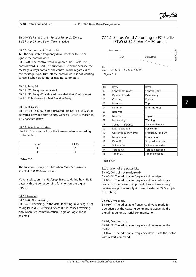
Bit 09="1": Ramp 2 (3-51 Ramp 2 Ramp Up Time to3-52 Ramp 2 Ramp Down Time) is active.
Bit 10, Data not valid/Data validTell the adjustable frequency drive whether to use orignore the control word.Bit 10=’0’: The control word is ignored. Bit 10=’1’: Thecontrol word is used. This function is relevant because themessage always contains the control word, regardless ofthe message type. Turn off the control word if not wantingto use it when updating or reading parameters.
Bit 11, Relay 01Bit 11="0": Relay not activated.Bit 11="1": Relay 01 activated provided that Control wordbit 11=36 is chosen in 5-40 Function Relay.
Bit 12, Relay 02Bit 12="0": Relay 02 is not activated. Bit 12="1": Relay 02 isactivated provided that Control word bit 12=37 is chosen in5-40 Function Relay.
Bit 13, Selection of set-upUse bit 13 to choose from the 2 menu set-ups accordingto the table.
Set-up Bit 13
1 0
2 1
Table 7.36
The function is only possible when Multi Set-ups=9 isselected in 0-10 Active Set-up.
Make a selection in 8-55 Set-up Select to define how Bit 13gates with the corresponding function on the digitalinputs.
Bit 15 ReverseBit 15=’0’: No reversing.Bit 15=’1’: Reversing. In the default setting, reversing is setto digital in 8-54 Reversing Select. Bit 15 causes reversingonly when Ser. communication, Logic or Logic and isselected.
7.11.2 Status Word According to FC Profile(STW) (8-30 Protocol = FC profile)
Output freq.STW
Bitno.:
Slave-master
15 14 13 12 11 10 9 8 7 6 5 4 3 2 1 0
130B
A27
3.10
Figure 7.14
Bit Bit=0 Bit=1
00 Control not ready Control ready
01 Drive not ready Drive ready
02 Coasting Enable
03 No error Trip
04 No error Error (no trip)
05 Reserved -
06 No error Triplock
07 No warning Warning
08 Speed ≠ reference Speed=reference
09 Local operation Bus control
10 Out of frequency limit Frequency limit OK
11 No operation In operation
12 Drive OK Stopped, auto start
13 Voltage OK Voltage exceeded
14 Torque OK Torque exceeded
15 Timer OK Timer exceeded
Table 7.37
Explanation of the status bitsBit 00, Control not ready/readyBit 00=’0’: The adjustable frequency drive trips.Bit 00=’1’: The adjustable frequency drive controls areready, but the power component does not necessarilyreceive any power supply (in case of external 24 V supplyto controls).
Bit 01, Drive readyBit 01=’1’: The adjustable frequency drive is ready foroperation but the coasting command is active via thedigital inputs or via serial communication.
Bit 02, Coasting stopBit 02=’0’: The adjustable frequency drive releases themotor.Bit 02=’1’: The adjustable frequency drive starts the motorwith a start command.
RS-485 Installation and Set... VLT® HVAC Basic Drive Design Guide
MG18C422 - VLT® is a registered Danfoss trademark 7-17
7 7
Bit 03, No error/tripBit 03=’0’: The adjustable frequency drive is not in faultmode. Bit 03=’1’: The adjustable frequency drive trips. Tore-establish operation, press [Reset].
Bit 04, No error/error (no trip)Bit 04=’0’: The adjustable frequency drive is not in faultmode. Bit 04=“1”: The adjustable frequency drive shows anerror but does not trip.
Bit 05, Not usedBit 05 is not used in the status word.
Bit 06, No error / triplockBit 06=’0’: The adjustable frequency drive is not in faultmode. Bit 06=“1”: The adjustable frequency drive is trippedand locked.
Bit 07, No warning/warningBit 07=’0’: There are no warnings.Bit 07=’1’: A warning has occurred.
Bit 08, Speed≠ reference/speed=referenceBit 08=’0’: The motor is running but the present speed isdifferent from the preset speed reference. It might, forexample, be the case when the speed ramps up/downduring start/stop.Bit 08=’1’: The motor speed matches the preset speedreference.
Bit 09, Local operation/bus controlBit 09=’0’: [Off/Reset] is activated on the control unit orLocal control in F-02 Operation Method is selected. It is notpossible to control the adjustable frequency drive via serialcommunication.Bit 09=’1’ It is possible to control the adjustable frequencydrive via the serial communication bus/serial communi-cation.
Bit 10, Out of frequency limitBit 10=’0’: The output frequency has reached the value in4-12 Motor Speed Low Limit [Hz] or 4-14 Motor Speed HighLimit [Hz].Bit 10="1": The output frequency is within the definedlimits.
Bit 11, No operation/in operationBit 11=’0’: The motor is not running.Bit 11=’1’: The coasting has a start signal or the outputfrequency is greater than 0 Hz.
Bit 12, Drive OK/stopped, autostart:Bit 12='0’: There is no temporary over temperature on theinverter.Bit 12=’1’: The inverter stops because of overtemperaturebut the unit does not trip and resumes operation once theovertemperature stops.
Bit 13, Voltage OK/limit exceededBit 13=’0’: There are no voltage warnings.Bit 13=’1’: The DC voltage in the intermediate circuit of theadjustable frequency drive is too low or too high.
Bit 14, Torque OK/limit exceededBit 14=’0’: The motor current is lower than the torque limitselected in 4-18 Current Limit.Bit 14=’1’: The torque limit in 4-18 Current Limit isexceeded.
Bit 15, Timer OK/limit exceededBit 15=’0’: The timers for motor thermal protection andthermal protection are not exceeded 100%.Bit 15=’1’: One of the timers exceeds 100%.
RS-485 Installation and Set... VLT® HVAC Basic Drive Design Guide
7-18 MG18C422 - VLT® is a registered Danfoss trademark
77
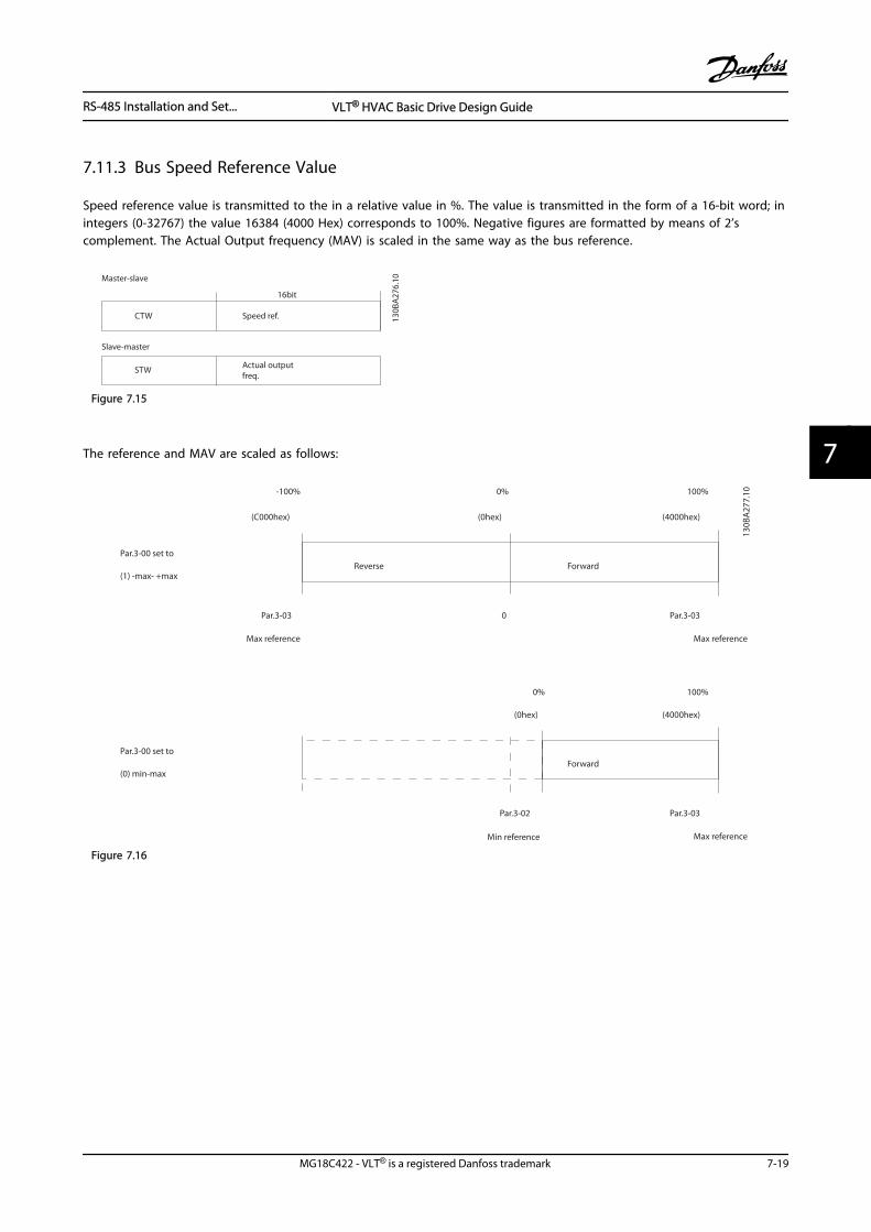
7.11.3 Bus Speed Reference Value
Speed reference value is transmitted to the in a relative value in %. The value is transmitted in the form of a 16-bit word; inintegers (0-32767) the value 16384 (4000 Hex) corresponds to 100%. Negative figures are formatted by means of 2’scomplement. The Actual Output frequency (MAV) is scaled in the same way as the bus reference.
Actual outputfreq.
STW
Slave-master
Speed ref.CTW
Master-slave
16bit
130B
A27
6.10
Figure 7.15
The reference and MAV are scaled as follows:
Reverse ForwardPar.3-00 set to
(1) -max- +max
Max reference Max reference
Par.3-00 set to
(0) min-max
Max reference
Forward
Min reference
100%
(4000hex)
-100%
(C000hex)
0%
(0hex)
Par.3-03 0 Par.3-03
Par.3-03
(4000hex)(0hex)
0% 100%
Par.3-02
130B
A27
7.10
Figure 7.16
RS-485 Installation and Set... VLT® HVAC Basic Drive Design Guide
MG18C422 - VLT® is a registered Danfoss trademark 7-19
7 7
RS-485 Installation and Set... VLT® HVAC Basic Drive Design Guide
7-20 MG18C422 - VLT® is a registered Danfoss trademark
77
8 General Specifications and Troubleshooting
General Specifications and ... VLT® HVAC Basic Drive Design Guide
MG18C422 - VLT® is a registered Danfoss trademark 8-1
8 8
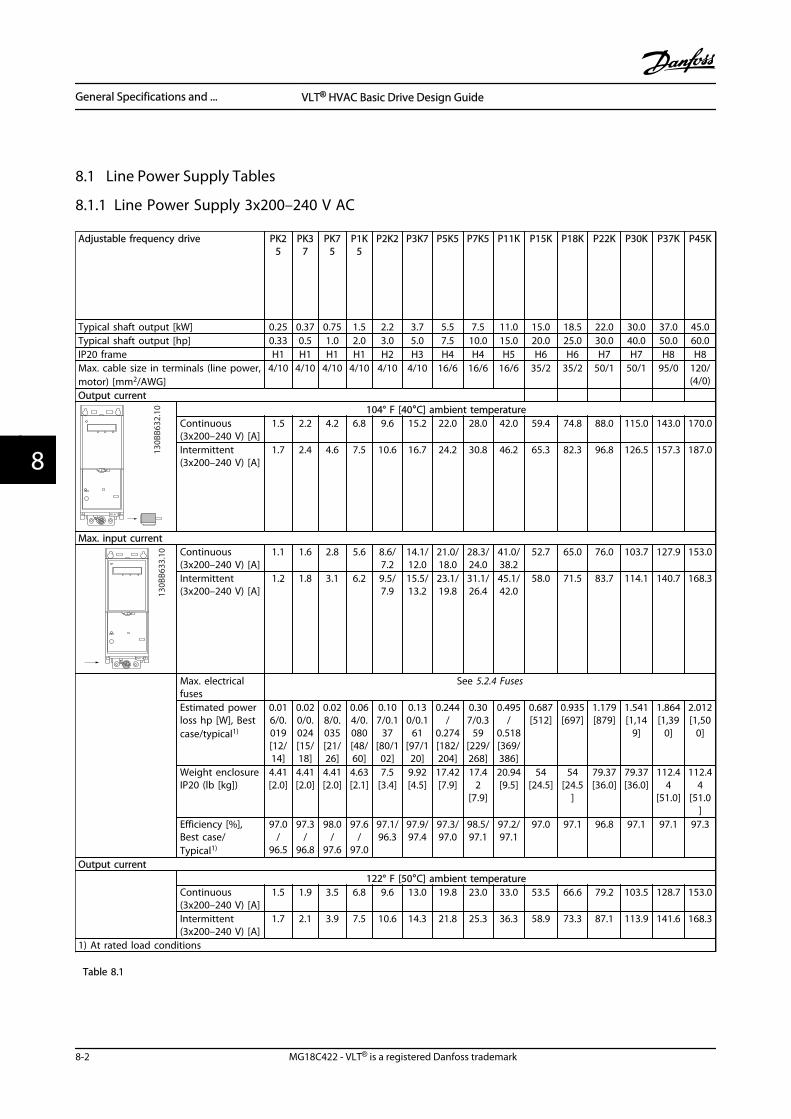
8.1 Line Power Supply Tables
8.1.1 Line Power Supply 3x200–240 V AC
Adjustable frequency drive PK25
PK37
PK75
P1K5
P2K2 P3K7 P5K5 P7K5 P11K P15K P18K P22K P30K P37K P45K
Typical shaft output [kW] 0.25 0.37 0.75 1.5 2.2 3.7 5.5 7.5 11.0 15.0 18.5 22.0 30.0 37.0 45.0Typical shaft output [hp] 0.33 0.5 1.0 2.0 3.0 5.0 7.5 10.0 15.0 20.0 25.0 30.0 40.0 50.0 60.0IP20 frame H1 H1 H1 H1 H2 H3 H4 H4 H5 H6 H6 H7 H7 H8 H8Max. cable size in terminals (line power,motor) [mm2/AWG]
4/10 4/10 4/10 4/10 4/10 4/10 16/6 16/6 16/6 35/2 35/2 50/1 50/1 95/0 120/(4/0)
Output current
RELAY 2
130B
B632
.10 104° F [40°C] ambient temperature
Continuous(3x200–240 V) [A]
1.5 2.2 4.2 6.8 9.6 15.2 22.0 28.0 42.0 59.4 74.8 88.0 115.0 143.0 170.0
Intermittent(3x200–240 V) [A]
1.7 2.4 4.6 7.5 10.6 16.7 24.2 30.8 46.2 65.3 82.3 96.8 126.5 157.3 187.0
Max. input current
RELAY 2
130B
B633
.10 Continuous
(3x200–240 V) [A]1.1 1.6 2.8 5.6 8.6/
7.214.1/12.0
21.0/18.0
28.3/24.0
41.0/38.2
52.7 65.0 76.0 103.7 127.9 153.0
Intermittent(3x200–240 V) [A]
1.2 1.8 3.1 6.2 9.5/7.9
15.5/13.2
23.1/19.8
31.1/26.4
45.1/42.0
58.0 71.5 83.7 114.1 140.7 168.3
Max. electricalfuses
See 5.2.4 Fuses
Estimated powerloss hp [W], Bestcase/typical1)
0.016/0.019[12/14]
0.020/0.024[15/18]
0.028/0.035[21/26]
0.064/0.080[48/60]
0.107/0.1
37[80/1
02]
0.130/0.1
61[97/1
20]
0.244/
0.274[182/204]
0.307/0.3
59[229/268]
0.495/
0.518[369/386]
0.687[512]
0.935[697]
1.179[879]
1.541[1,14
9]
1.864[1,39
0]
2.012[1,50
0]
Weight enclosureIP20 (lb [kg])
4.41[2.0]
4.41[2.0]
4.41[2.0]
4.63[2.1]
7.5[3.4]
9.92[4.5]
17.42[7.9]
17.42
[7.9]
20.94[9.5]
54[24.5]
54[24.5
]
79.37[36.0]
79.37[36.0]
112.44
[51.0]
112.44
[51.0]
Efficiency [%],Best case/Typical1)
97.0/
96.5
97.3/
96.8
98.0/
97.6
97.6/
97.0
97.1/96.3
97.9/97.4
97.3/97.0
98.5/97.1
97.2/97.1
97.0 97.1 96.8 97.1 97.1 97.3
Output current 122° F [50°C] ambient temperature
Continuous(3x200–240 V) [A]
1.5 1.9 3.5 6.8 9.6 13.0 19.8 23.0 33.0 53.5 66.6 79.2 103.5 128.7 153.0
Intermittent(3x200–240 V) [A]
1.7 2.1 3.9 7.5 10.6 14.3 21.8 25.3 36.3 58.9 73.3 87.1 113.9 141.6 168.3
1) At rated load conditions
Table 8.1
General Specifications and ... VLT® HVAC Basic Drive Design Guide
8-2 MG18C422 - VLT® is a registered Danfoss trademark
88
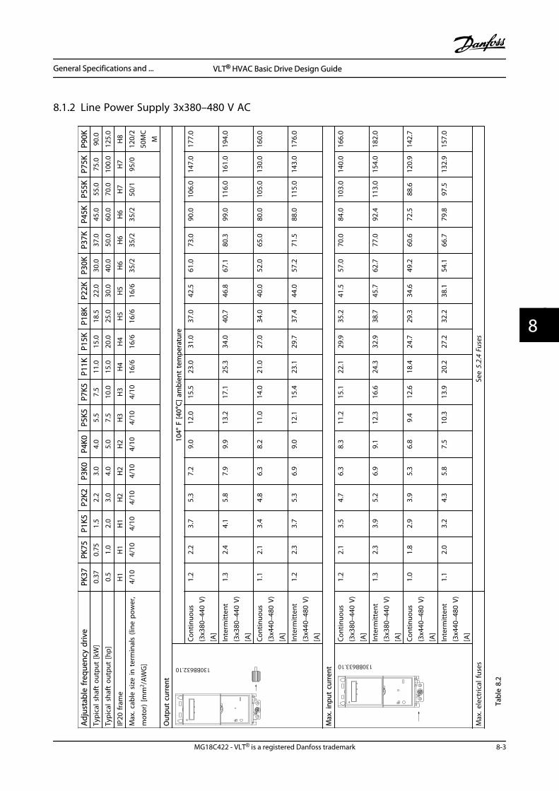
8.1.2 Line Power Supply 3x380–480 V AC
Adj
usta
ble
freq
uenc
y dr
ive
PK37
PK75
P1K5
P2K2
P3K0
P4K0
P5K5
P7K5
P11K
P15K
P18K
P22K
P30K
P37K
P45K
P55K
P75K
P90K
Typi
cal s
haft
out
put
[kW
]0.
370.
751.
52.
23.
04.
05.
57.
511
.015
.018
.522
.030
.037
.045
.055
.075
.090
.0
Typi
cal s
haft
out
put
[hp]
0.5
1.0
2.0
3.0
4.0
5.0
7.5
10.0
15.0
20.0
25.0
30.0
40.0
50.0
60.0
70.0
100.
012
5.0
IP20
fram
eH
1H
1H
1H
2H
2H
2H
3H
3H
4H
4H
5H
5H
6H
6H
6H
7H
7H
8
Max
. cab
le s
ize
in t
erm
inal
s (li
ne p
ower
,
mot
or)
[mm
2 /AW
G]
4/10
4/10
4/10
4/10
4/10
4/10
4/10
4/10
16/6
16/6
16/6
16/6
35/2
35/2
35/2
50/1
95/0
120/
250
MC
M
Out
put
curr
ent
RELA
Y 2
130BB632.10
104°
F [4
0°C]
am
bien
t te
mpe
ratu
re
Cont
inuo
us(3
x380
–440
V)
[A]
1.2
2.2
3.7
5.3
7.2
9.0
12.0
15.5
23.0
31.0
37.0
42.5
61.0
73.0
90.0
106.
014
7.0
177.
0
Inte
rmitt
ent
(3x3
80–4
40 V
)[A
]
1.3
2.4
4.1
5.8
7.9
9.9
13.2
17.1
25.3
34.0
40.7
46.8
67.1
80.3
99.0
116.
016
1.0
194.
0
Cont
inuo
us(3
x440
–480
V)
[A]
1.1
2.1
3.4
4.8
6.3
8.2
11.0
14.0
21.0
27.0
34.0
40.0
52.0
65.0
80.0
105.
013
0.0
160.
0
Inte
rmitt
ent
(3x4
40–4
80 V
)[A
]
1.2
2.3
3.7
5.3
6.9
9.0
12.1
15.4
23.1
29.7
37.4
44.0
57.2
71.5
88.0
115.
014
3.0
176.
0
Max
. inp
ut c
urre
nt
RELA
Y 2
130BB633.10
Cont
inuo
us(3
x380
–440
V)
[A]
1.2
2.1
3.5
4.7
6.3
8.3
11.2
15.1
22.1
29.9
35.2
41.5
57.0
70.0
84.0
103.
014
0.0
166.
0
Inte
rmitt
ent
(3x3
80–4
40 V
)[A
]
1.3
2.3
3.9
5.2
6.9
9.1
12.3
16.6
24.3
32.9
38.7
45.7
62.7
77.0
92.4
113.
015
4.0
182.
0
Cont
inuo
us(3
x440
–480
V)
[A]
1.0
1.8
2.9
3.9
5.3
6.8
9.4
12.6
18.4
24.7
29.3
34.6
49.2
60.6
72.5
88.6
120.
914
2.7
Inte
rmitt
ent
(3x4
40–4
80 V
)[A
]
1.1
2.0
3.2
4.3
5.8
7.5
10.3
13.9
20.2
27.2
32.2
38.1
54.1
66.7
79.8
97.5
132.
915
7.0
Max
. ele
ctric
al fu
ses
See
5.2.
4 Fu
ses
Tabl
e 8.
2
General Specifications and ... VLT® HVAC Basic Drive Design Guide
MG18C422 - VLT® is a registered Danfoss trademark 8-3
8 8
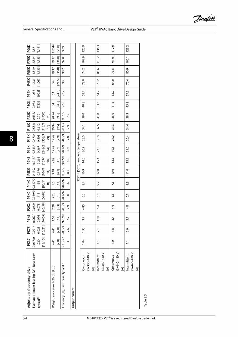
Adj
usta
ble
freq
uenc
y dr
ive
PK37
PK75
P1K5
P2K2
P3K0
P4K0
P5K5
P7K5
P11K
P15K
P18K
P22K
P30K
P37K
P45K
P55K
P75K
P90K
Estim
ated
pow
er lo
ss h
p [W
], Be
st c
ase/
typi
cal1)
0.01
7/0
.020
[13/
15]
0.02
1/0.
028
[16/
21]
0.06
2/0.
076
[46/
57]
0.06
2/0.
078
[46/
58]
0.08
9/0
.111
[66/
83]
0.12
7/0
.158
[95/
118]
0.13
9/0.
176
[104
/131
]
0.21
3/0.
266
[159
/198
]
0.33
3/0.
367
[248
/274
]
0.47
3/0.
508
[353
/379
]
0.55
2/0.
612
[412
/456
]
0.63
7/0.
701
[475
/523
]
0.98
3[7
33]
1.23
6[9
22]
1.43
1[1
,067
]1.
519
[1,1
33]
2.32
4[1
,733
]2.
871
[2,1
41]
Wei
ght
encl
osur
e IP
20 (l
b [k
g])
4.41
[2.0
]4.
41[2
.0]
4.63
[2.1
]7.
28[3
.3]
7.28
[3.3
]7.
5[3
.4]
9.48
[4.3
]9.
92[4
.5]
17.4
2[7
.9]
17.4
2[7
.9]
20.9
4[9
.5]
20.9
4[9
.5]
54[2
4.5]
54[2
4.5]
54[2
4.5]
79.3
7[3
6.0]
79.3
7[3
6.0]
112.
44[5
1.0]
Effic
ienc
y [%
], Be
st c
ase/
Typi
cal 1
97.8
/97
.398
.0/9
7.6
97.7
/97.
298
.3/9
7.9
98.2
/97
.898
.0/9
7.6
98.4
/98.
098
.2/9
7.8
98.1
/97.
998
.0/9
7.8
98.1
/97.
998
.1/9
7.9
97.8
97.7
9898
.297
.897
.9
Out
put
curr
ent
12
2° F
[50°
C] a
mbi
ent
tem
pera
ture
Cont
inuo
us(3
x380
–440
V)
[A]
1.04
1.93
3.7
4.85
6.3
8.4
10.9
14.0
20.9
28.0
34.1
38.0
48.8
58.4
72.0
74.2
102.
912
3.9
Inte
rmitt
ent
(3x3
80–4
40 V
)[A
]
1.1
2.1
4.07
5.4
6.9
9.2
12.0
15.4
23.0
30.8
37.5
41.8
53.7
64.2
79.2
81.6
113.
213
6.3
Cont
inuo
us(3
x440
–480
V)
[A]
1.0
1.8
3.4
4.4
5.5
7.5
10.0
12.6
19.1
24.0
31.3
35.0
41.6
52.0
64.0
73.5
91.0
112.
0
Inte
rmitt
ent
(3x4
40–4
80 V
)[A
]
1.1
2.0
3.7
4.8
6.1
8.3
11.0
13.9
21.0
26.4
34.4
38.5
45.8
57.2
70.4
80.9
100.
112
3.2
Tabl
e 8.
3
General Specifications and ... VLT® HVAC Basic Drive Design Guide
8-4 MG18C422 - VLT® is a registered Danfoss trademark
88
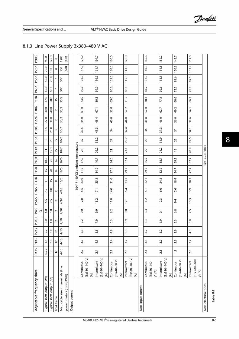
8.1.3 Line Power Supply 3x380–480 V AC
Adj
usta
ble
freq
uenc
y dr
ive
PK75
P1K5
P2K2
P3K0
P4K O
P5K5
P7K5
P11K
P15K
P18K
P11K
P15K
P18K
P22K
P30K
P37K
P45K
P55K
P75K
P90K
Typi
cal s
haft
out
put
[kW
]0.
751.
52.
23.
04.
05.
57.
511
1518
.511
1518
.522
.030
.037
.045
.055
.075
.090
.0
Typi
cal s
haft
out
put
[hp]
1.0
2.0
3.0
4.0
5.0
7.5
10.0
1520
2515
.020
25.0
30.0
40.0
50.0
60.0
70.0
100.
012
5.0
IP54
fram
eI2
I2I2
I2I2
I3I3
I4I4
I4I5
I5I5
I6I6
I6I7
I7I8
I8
Max
. cab
le s
ize
in t
erm
inal
s (li
ne
pow
er, m
otor
) [m
m2 /A
WG
]
4/10
4/10
4/10
4/10
4/10
4/10
4/10
16/6
16/6
16/6
10/7
10/7
10/7
35/2
35/2
35/2
50/1
50/1
95/
(3/0
)12
0/(4
/0)
Out
put
curr
ent
10
4° F
[40°
C] a
mbi
ent
tem
pera
ture
Cont
inuo
us(3
x380
–440
V)
[A]
2.2
3.7
5.3
7.2
9.0
12.0
15.5
23.0
31.0
37.0
2432
37.5
44.0
61.0
73.0
90.0
106.
014
7.0
177.
0
Inte
rmitt
ent
(3x3
80–4
40 V
)[A
]
2.4
4.1
5.8
7.9
9.9
13.2
17.1
25.3
34.0
40.7
26.2
35.2
41.3
48.4
67.1
80.3
99.0
116.
616
1.7
194.
7
Cont
inuo
us(3
x440
–80
V)[A
]
2.1
3.4
4.8
6.3
8.2
11.0
14.0
21.0
27.0
34.0
2127
3440
.052
.065
.080
.010
5.0
130.
016
0.0
Inte
rmitt
ent
(3x4
40–4
80 V
)[A
]
2.3
3.7
5.3
6.9
9.0
12.1
15.4
23.1
29.7
37.4
23.1
29.7
37.4
44.0
57.2
71.5
88.0
115.
514
3.0
176.
0
Max
. inp
ut c
urre
nt
Co
ntin
uous
(3x3
80–4
40V
)[A
]
2.1
3.5
4.7
6.3
8.3
11.2
15.1
22.1
29.9
35.2
2229
3441
.857
.070
.384
.210
2.9
140.
316
5.6
Inte
rmitt
ent
(3x3
80–4
40 V
)[A
]
2.3
3.9
5.2
6.9
9.1
12.3
16.6
24.3
32.9
38.7
24.2
31.9
37.3
46.0
62.7
77.4
92.6
113.
115
4.3
182.
2
Cont
inuo
us(3
x440
–80
V)[A
]
1.8
2.9
3.9
5.3
6.8
9.4
12.6
18.4
24.7
29.3
1925
3136
.049
.260
.672
.588
.612
0.9
142.
7
Inte
rmitt
ent
(3 x
440
–480
V) [A
]
2.0
3.2
4.3
5.8
7.5
10.3
13.9
20.2
27.2
32.2
20.9
27.5
34.1
39.6
54.1
66.7
79.8
97.5
132.
915
7.0
Max
. ele
ctric
al fu
ses
See
5.2.
4 Fu
ses
Tabl
e 8.
4
General Specifications and ... VLT® HVAC Basic Drive Design Guide
MG18C422 - VLT® is a registered Danfoss trademark 8-5
8 8
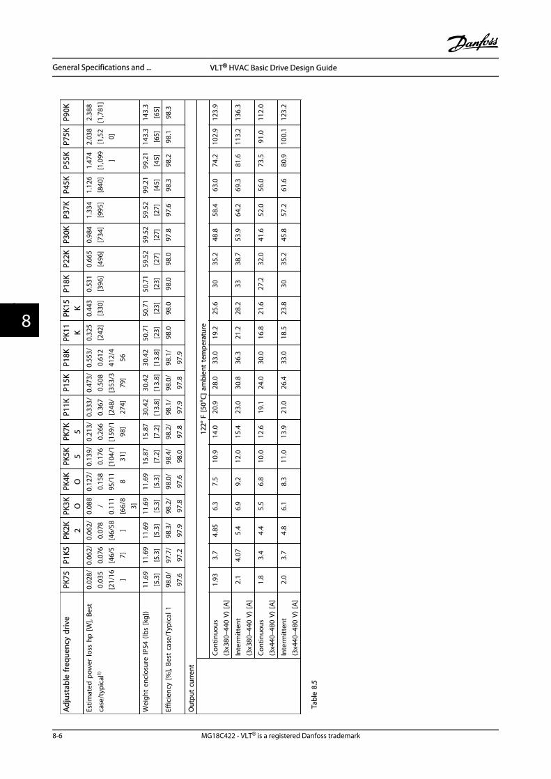
Adj
usta
ble
freq
uenc
y dr
ive
PK75
P1K5
PK2K 2
PK3K O
PK4K O
PK5K 5
PK7K 5
P11K
P15K
P18K
PK11 K
PK15 K
P18K
P22K
P30K
P37K
P45K
P55K
P75K
P90K
Estim
ated
pow
er lo
ss h
p [W
], Be
st
case
/typ
ical
1)
0.02
8/0.
035
[21/
16 ]
0.06
2/0.
076
[46/
57]
0.06
2/0.
078
[46/
58 ]
0.08
8/
0.11
1[6
6/8
3]
0.12
7/0.
158
95/1
18
0.13
9/0.
176
[104
/131
]
0.21
3/0.
266
[159
/198
]
0.33
3/0.
367
[248
/27
4]
0.47
3/0.
508
[353
/379
]
0.55
3/0.
612
412/
456
0.32
5[2
42]
0.44
3[3
30]
0.53
1[3
96]
0.66
5[4
96]
0.98
4[7
34]
1.33
4[9
95]
1.12
6[8
40]
1.47
4[1
,099 ]
2.03
8[1
,52
0]
2.38
8[1
,781
]
Wei
ght
encl
osur
e IP
54 (l
bs [k
g])
11.6
9[5
.3]
11.6
9[5
.3]
11.6
9[5
.3]
11.6
9[5
.3]
11.6
9[5
.3]
15.8
7[7
.2]
15.8
7[7
.2]
30.4
2[1
3.8]
30.4
2[1
3.8]
30.4
2[1
3.8]
50.7
1[2
3]50
.71
[23]
50.7
1[2
3]59
.52
[27]
59.5
2[2
7]59
.52
[27]
99.2
1[4
5]99
.21
[45]
143.
3[6
5]14
3.3
[65]
Effic
ienc
y [%
], Be
st c
ase/
Typi
cal 1
98.0
/97
.697
.7/
97.2
98.3
/97
.998
.2/
97.8
98.0
/97
.698
.4/
98.0
98.2
/97
.898
.1/
97.9
98.0
/97
.898
.1/
97.9
98.0
98.0
98.0
98.0
97.8
97.6
98.3
98.2
98.1
98.3
Out
put
curr
ent
12
2° F
[50°
C] a
mbi
ent
tem
pera
ture
Cont
inuo
us(3
x380
–440
V)
[A]
1.93
3.7
4.85
6.3
7.5
10.9
14.0
20.9
28.0
33.0
19.2
25.6
3035
.248
.858
.463
.074
.210
2.9
123.
9
Inte
rmitt
ent
(3x3
80–4
40 V
) [A
]2.
14.
075.
46.
99.
212
.015
.423
.030
.836
.321
.228
.233
38.7
53.9
64.2
69.3
81.6
113.
213
6.3
Cont
inuo
us(3
x440
–480
V)
[A]
1.8
3.4
4.4
5.5
6.8
10.0
12.6
19.1
24.0
30.0
16.8
21.6
27.2
32.0
41.6
52.0
56.0
73.5
91.0
112.
0
Inte
rmitt
ent
(3x4
40–4
80 V
) [A
]2.
03.
74.
86.
18.
311
.013
.921
.026
.433
.018
.523
.830
35.2
45.8
57.2
61.6
80.9
100.
112
3.2
Tabl
e 8.
5
General Specifications and ... VLT® HVAC Basic Drive Design Guide
8-6 MG18C422 - VLT® is a registered Danfoss trademark
88
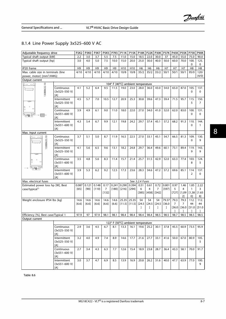
8.1.4 Line Power Supply 3x525–600 V AC
Adjustable frequency drive P2K2 P3K0 P3K7 P5K5 P7K5 P11K P15K P18K P22K P30K P37K P45K P55K P75K P90KTypical shaft output [kW] 2.2 3.0 3.7 5.5 7.5 11.0 15.0 18.5 22.0 30.0 37 45.0 55.0 75.0 90.0Typical shaft output [hp] 3.0 4.0 5.0 7.5 10.0 15.0 20.0 25.0 30.0 40.0 50.0 60.0 70.0 100.
0125.
0IP20 frame H9 H9 H9 H9 H9 H10 H10 H6 H6 H6 H7 H7 H7 H8 H8Max. cable size in terminals (linepower, motor) [mm2/AWG]
4/10 4/10 4/10 4/10 4/10 10/8 10/8 35/2 35/2 35/2 50/1 50/1 50/1 95/0 120/(4/0)
Output current
RELAY 2
130B
B632
.10 104° F [40°C] ambient temperature
Continuous(3x525–550 V)[A]
4.1 5.2 6.4 9.5 11.5 19.0 23.0 28.0 36.0 43.0 54.0 65.0 87.0 105.0
137.0
Intermittent(3x525–550 V)[A]
4.5 5.7 7.0 10.5 12.7 20.9 25.3 30.8 39.6 47.3 59.4 71.5 95.7 115.5
150.7
Continuous(3x551–600 V)[A]
3.9 4.9 6.1 9.0 11.0 18.0 22.0 27.0 34.0 41.0 52.0 62.0 83.0 100.0
131.0
Intermittent(3x551–600 V)[A]
4.3 5.4 6.7 9.9 12.1 19.8 24.2 29.7 37.4 45.1 57.2 68.2 91.3 110.0
144.1
Max. input current
RELAY 2
130B
B633
.10 Continuous
(3x525–550 V)[A]
3.7 5.1 5.0 8.7 11.9 16.5 22.5 27.0 33.1 45.1 54.7 66.5 81.3 109.0
130.9
Intermittent(3x525–550 V)[A]
4.1 5.6 6.5 9.6 13.1 18.2 24.8 29.7 36.4 49.6 60.1 73.1 89.4 119.9
143.9
Continuous(3x551–600 V)[A]
3.5 4.8 5.6 8.3 11.4 15.7 21.4 25.7 31.5 42.9 52.0 63.3 77.4 103.8
124.5
Intermittent(3x551–600 V)[A]
3.9 5.3 6.2 9.2 12.5 17.3 23.6 28.3 34.6 47.2 57.2 69.6 85.1 114.2
137.0
Max. electrical fuses See 5.2.4 FusesEstimated power loss hp [W], Bestcase/typical1)
0.087[65]
0.121[90]
0.148[110]
0.177
[132]
0.241[180]
0.290[216]
0.394[294]
0.516
[385]
0.614
[458]
0.727
[542]
0.801[597]
0.975
[727]
1.464
[1,092]
1.851
[1,380]
2.223
[1.658]
Weight enclosure IP54 lbs [kg] 14.6[6.6]
14.6[6.6]
14.6[6.6]
14.6[6.6]
14.6[6.6]
25.35[11.5]
25.35[11.5]
54[24.5
]
54[24.5
]
54[24.5
]
79.37[36.0
]
79.37
[36.0]
79.37
[36.0]
112.44
[51.0]
112.44
[51.0]
Efficiency [%], Best case/Typical 1 97.9 97 97.9 98.1 98.1 98.4 98.4 98.4 98.4 98.5 98.5 98.7 98.5 98.5 98.5Output current 122° F [50°C] ambient temperature
Continuous(3x525–550 V)[A]
2.9 3.6 4.5 6.7 8.1 13.3 16.1 19.6 25.2 30.1 37.8 45.5 60.9 73.5 95.9
Intermittent(3x525–550 V)[A]
3.2 4.0 4.9 7.4 8.9 14.6 17.7 21.6 27.7 33.1 41.6 50.0 67.0 80.9 105.5
Continuous(3x551–600 V)[A]
2.7 3.4 4.3 6.3 7.7 12.6 15.4 18.9 23.8 28.7 36.4 43.3 58.1 70.0 91.7
Intermittent(3x551–600 V)[A]
3.0 3.7 4.7 6.9 8.5 13.9 16.9 20.8 26.2 31.6 40.0 47.7 63.9 77.0 100.9
Table 8.6
General Specifications and ... VLT® HVAC Basic Drive Design Guide
MG18C422 - VLT® is a registered Danfoss trademark 8-7
8 8
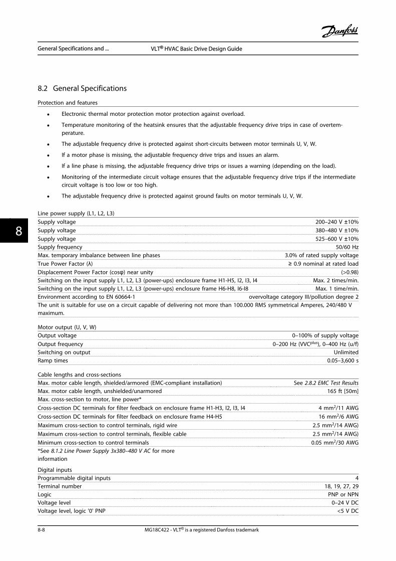
8.2 General Specifications
Protection and features
• Electronic thermal motor protection motor protection against overload.
• Temperature monitoring of the heatsink ensures that the adjustable frequency drive trips in case of overtem-perature.
• The adjustable frequency drive is protected against short-circuits between motor terminals U, V, W.
• If a motor phase is missing, the adjustable frequency drive trips and issues an alarm.
• If a line phase is missing, the adjustable frequency drive trips or issues a warning (depending on the load).
• Monitoring of the intermediate circuit voltage ensures that the adjustable frequency drive trips if the intermediatecircuit voltage is too low or too high.
• The adjustable frequency drive is protected against ground faults on motor terminals U, V, W.
Line power supply (L1, L2, L3)Supply voltage 200–240 V ±10%Supply voltage 380–480 V ±10%Supply voltage 525–600 V ±10%Supply frequency 50/60 HzMax. temporary imbalance between line phases 3.0% of rated supply voltageTrue Power Factor (λ) ≥ 0.9 nominal at rated loadDisplacement Power Factor (cosφ) near unity (>0.98)Switching on the input supply L1, L2, L3 (power-ups) enclosure frame H1-H5, I2, I3, I4 Max. 2 times/min.Switching on the input supply L1, L2, L3 (power-ups) enclosure frame H6-H8, I6-I8 Max. 1 time/min.Environment according to EN 60664-1 overvoltage category III/pollution degree 2The unit is suitable for use on a circuit capable of delivering not more than 100.000 RMS symmetrical Amperes, 240/480 Vmaximum.
Motor output (U, V, W)Output voltage 0–100% of supply voltageOutput frequency 0–200 Hz (VVCplus), 0–400 Hz (u/f)Switching on output UnlimitedRamp times 0.05–3,600 s
Cable lengths and cross-sectionsMax. motor cable length, shielded/armored (EMC-compliant installation) See 2.8.2 EMC Test ResultsMax. motor cable length, unshielded/unarmored 165 ft [50m]Max. cross-section to motor, line power*Cross-section DC terminals for filter feedback on enclosure frame H1-H3, I2, I3, I4 4 mm2/11 AWGCross-section DC terminals for filter feedback on enclosure frame H4-H5 16 mm2/6 AWGMaximum cross-section to control terminals, rigid wire 2.5 mm2/14 AWG)Maximum cross-section to control terminals, flexible cable 2.5 mm2/14 AWG)Minimum cross-section to control terminals 0.05 mm2/30 AWG*See 8.1.2 Line Power Supply 3x380–480 V AC for moreinformation
Digital inputsProgrammable digital inputs 4Terminal number 18, 19, 27, 29Logic PNP or NPNVoltage level 0–24 V DCVoltage level, logic '0' PNP <5 V DC
General Specifications and ... VLT® HVAC Basic Drive Design Guide
8-8 MG18C422 - VLT® is a registered Danfoss trademark
88
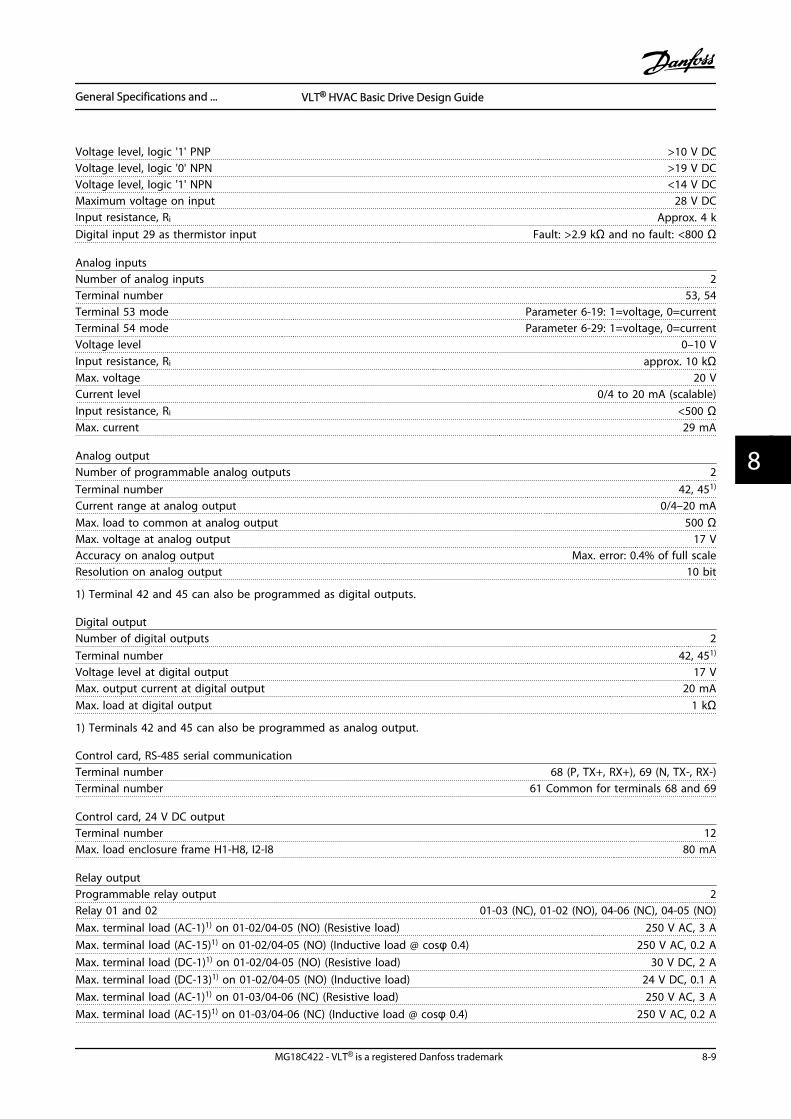
Voltage level, logic '1' PNP >10 V DCVoltage level, logic '0' NPN >19 V DCVoltage level, logic '1' NPN <14 V DCMaximum voltage on input 28 V DCInput resistance, Ri Approx. 4 kDigital input 29 as thermistor input Fault: >2.9 kΩ and no fault: <800 Ω
Analog inputsNumber of analog inputs 2Terminal number 53, 54Terminal 53 mode Parameter 6-19: 1=voltage, 0=currentTerminal 54 mode Parameter 6-29: 1=voltage, 0=currentVoltage level 0–10 VInput resistance, Ri approx. 10 kΩMax. voltage 20 VCurrent level 0/4 to 20 mA (scalable)Input resistance, Ri <500 ΩMax. current 29 mA
Analog outputNumber of programmable analog outputs 2Terminal number 42, 451)
Current range at analog output 0/4–20 mAMax. load to common at analog output 500 ΩMax. voltage at analog output 17 VAccuracy on analog output Max. error: 0.4% of full scaleResolution on analog output 10 bit
1) Terminal 42 and 45 can also be programmed as digital outputs.
Digital outputNumber of digital outputs 2Terminal number 42, 451)
Voltage level at digital output 17 VMax. output current at digital output 20 mAMax. load at digital output 1 kΩ
1) Terminals 42 and 45 can also be programmed as analog output.
Control card, RS-485 serial communicationTerminal number 68 (P, TX+, RX+), 69 (N, TX-, RX-)Terminal number 61 Common for terminals 68 and 69
Control card, 24 V DC outputTerminal number 12Max. load enclosure frame H1-H8, I2-I8 80 mA
Relay outputProgrammable relay output 2Relay 01 and 02 01-03 (NC), 01-02 (NO), 04-06 (NC), 04-05 (NO)Max. terminal load (AC-1)1) on 01-02/04-05 (NO) (Resistive load) 250 V AC, 3 AMax. terminal load (AC-15)1) on 01-02/04-05 (NO) (Inductive load @ cosφ 0.4) 250 V AC, 0.2 AMax. terminal load (DC-1)1) on 01-02/04-05 (NO) (Resistive load) 30 V DC, 2 AMax. terminal load (DC-13)1) on 01-02/04-05 (NO) (Inductive load) 24 V DC, 0.1 AMax. terminal load (AC-1)1) on 01-03/04-06 (NC) (Resistive load) 250 V AC, 3 AMax. terminal load (AC-15)1) on 01-03/04-06 (NC) (Inductive load @ cosφ 0.4) 250 V AC, 0.2 A
General Specifications and ... VLT® HVAC Basic Drive Design Guide
MG18C422 - VLT® is a registered Danfoss trademark 8-9
8 8
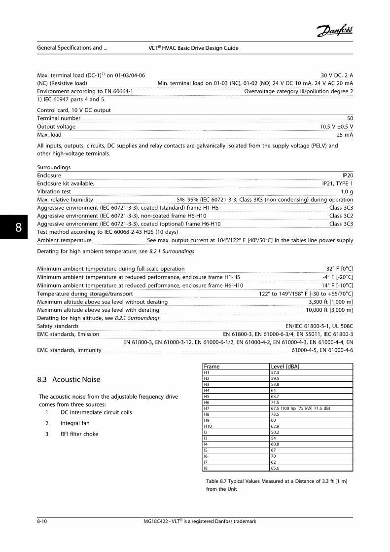
Max. terminal load (DC-1)1) on 01-03/04-06(NC) (Resistive load)
30 V DC, 2 AMin. terminal load on 01-03 (NC), 01-02 (NO) 24 V DC 10 mA, 24 V AC 20 mA
Environment according to EN 60664-1 Overvoltage category III/pollution degree 21) IEC 60947 parts 4 and 5.
Control card, 10 V DC outputTerminal number 50Output voltage 10.5 V ±0.5 VMax. load 25 mA
All inputs, outputs, circuits, DC supplies and relay contacts are galvanically isolated from the supply voltage (PELV) andother high-voltage terminals.
SurroundingsEnclosure IP20Enclosure kit available. IP21, TYPE 1Vibration test 1.0 gMax. relative humidity 5%–95% (IEC 60721-3-3; Class 3K3 (non-condensing) during operationAggressive environment (IEC 60721-3-3), coated (standard) frame H1-H5 Class 3C3Aggressive environment (IEC 60721-3-3), non-coated frame H6-H10 Class 3C2Aggressive environment (IEC 60721-3-3), coated (optional) frame H6-H10 Class 3C3Test method according to IEC 60068-2-43 H2S (10 days)Ambient temperature See max. output current at 104°/122° F [40°/50°C] in the tables line power supply
Derating for high ambient temperature, see 8.2.1 Surroundings
Minimum ambient temperature during full-scale operation 32° F [0°C]Minimum ambient temperature at reduced performance, enclosure frame H1-H5 -4° F [-20°C]Minimum ambient temperature at reduced performance, enclosure frame H6-H10 14° F [-10°C]Temperature during storage/transport 122° to 149°/158° F [-30 to +65/70°C]Maximum altitude above sea level without derating 3,300 ft [1,000 m]Maximum altitude above sea level with derating 10,000 ft [3,000 m]Derating for high altitude, see 8.2.1 SurroundingsSafety standards EN/IEC 61800-5-1, UL 508CEMC standards, Emission EN 61800-3, EN 61000-6-3/4, EN 55011, IEC 61800-3
EMC standards, ImmunityEN 61800-3, EN 61000-3-12, EN 61000-6-1/2, EN 61000-4-2, EN 61000-4-3, EN 61000-4-4, EN
61000-4-5, EN 61000-4-6
8.3 Acoustic Noise
The acoustic noise from the adjustable frequency drivecomes from three sources:
1. DC intermediate circuit coils
2. Integral fan
3. RFI filter choke
Frame Level [dBA]H1 57.3H2 59.5H3 53.8H4 64H5 63.7H6 71.5H7 67.5 (100 hp [75 kW] 71.5 dB)H8 73.5H9 60H10 62.9I2 50.2I3 54I4 60.8I5 67I6 70I7 62I8 65.6
Table 8.7 Typical Values Measured at a Distance of 3.3 ft [1 m]from the Unit
General Specifications and ... VLT® HVAC Basic Drive Design Guide
8-10 MG18C422 - VLT® is a registered Danfoss trademark
88
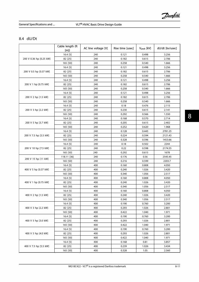
8.4 dU/Dt
Cable length (ft
[m])AC line voltage [V] Rise time [usec] Vpeak [kV] dU/dt [kv/usec]
200 V 0.36 hp [0.25 kW]
16.4 [5] 240 0.121 0.498 3.256
82 [25] 240 0.182 0.615 2.706
165 [50] 240 0.258 0.540 1.666
200 V 0.5 hp [0.37 kW]
16.4 [5] 240 0.121 0.498 3.256
82 [25] 240 0.182 0.615 2.706
165 [50] 240 0.258 0.540 1.666
200 V 1 hp [0.75 kW]
16.4 [5] 240 0.121 0.498 3.256
82 [25] 240 0.182 0.615 2.706
165 [50] 240 0.258 0.540 1.666
200 V 2 hp [1.5 kW]
16.4 [5] 240 0.121 0.498 3.256
82 [25] 240 0.182 0.615 2.706
165 [50] 240 0.258 0.540 1.666
200 V 3 hp [2.2 kW]
16.4 [5] 240 0.18 0.476 2.115
82 [25] 240 0.230 0.615 2.141
165 [50] 240 0.292 0.566 1.550
200 V 5 hp [3.7 kW]
16.4 [5] 240 0.168 0.570 2.714
82 [25] 240 0.205 0.615 2.402
165 [50] 240 0.252 0.620 1.968
200 V 7.5 hp [5.5 kW]
16.4 [5] 240 0.128 0.445 2781.25
82 [25] 240 0.224 0.594 2121.43
165 [50] 240 0.328 0.596 1453.66
200 V 10 hp [7.5 kW]
16.4 [5] 240 0.18 0.502 2244
82 [25] 240 0.22 0.598 2174.55
165 [50] 240 0.292 0.615 1678
200 V 15 hp [11 kW]118.11 [36] 240 0.176 0.56 2545.45
165 [50] 240 0.216 0.599 2203.7
400 V 5 hp [0.37 kW]
16.4 [5] 400 0.160 0.808 4.050
82 [25] 400 0.240 1.026 3.420
165 [50] 400 0.340 1.056 2.517
400 V 1 hp [0.75 kW]
16.4 [5] 400 0.160 0.808 4.050
82 [25] 400 0.240 1.026 3.420
165 [50] 400 0.340 1.056 2.517
400 V 2 hp [1.5 kW]
16.4 [5] 400 0.160 0.808 4.050
82 [25] 400 0.240 1.026 3.420
165 [50] 400 0.340 1.056 2.517
400 V 3 hp [2.2 kW]
16.4 [5] 400 0.190 0.760 3.200
82 [25] 400 0.293 1.026 2.801
165 [50] 400 0.422 1.040 1.971
400 V 5 hp [3.0 kW]
16.4 [5] 400 0.190 0.760 3.200
82 [25] 400 0.293 1.026 2.801
165 [50] 400 0.422 1.040 1.971
400 V 5 hp [4.0 kW]
16.4 [5] 400 0.190 0.760 3.200
82 [25] 400 0.293 1.026 2.801
165 [50] 400 0.422 1.040 1.971
400 V 7.5 hp [5.5 kW]
16.4 [5] 400 0.168 0.81 3.857
82 [25] 400 0.239 1.026 3.434
165 [50] 400 0.328 1.05 2.560
General Specifications and ... VLT® HVAC Basic Drive Design Guide
MG18C422 - VLT® is a registered Danfoss trademark 8-11
8 8
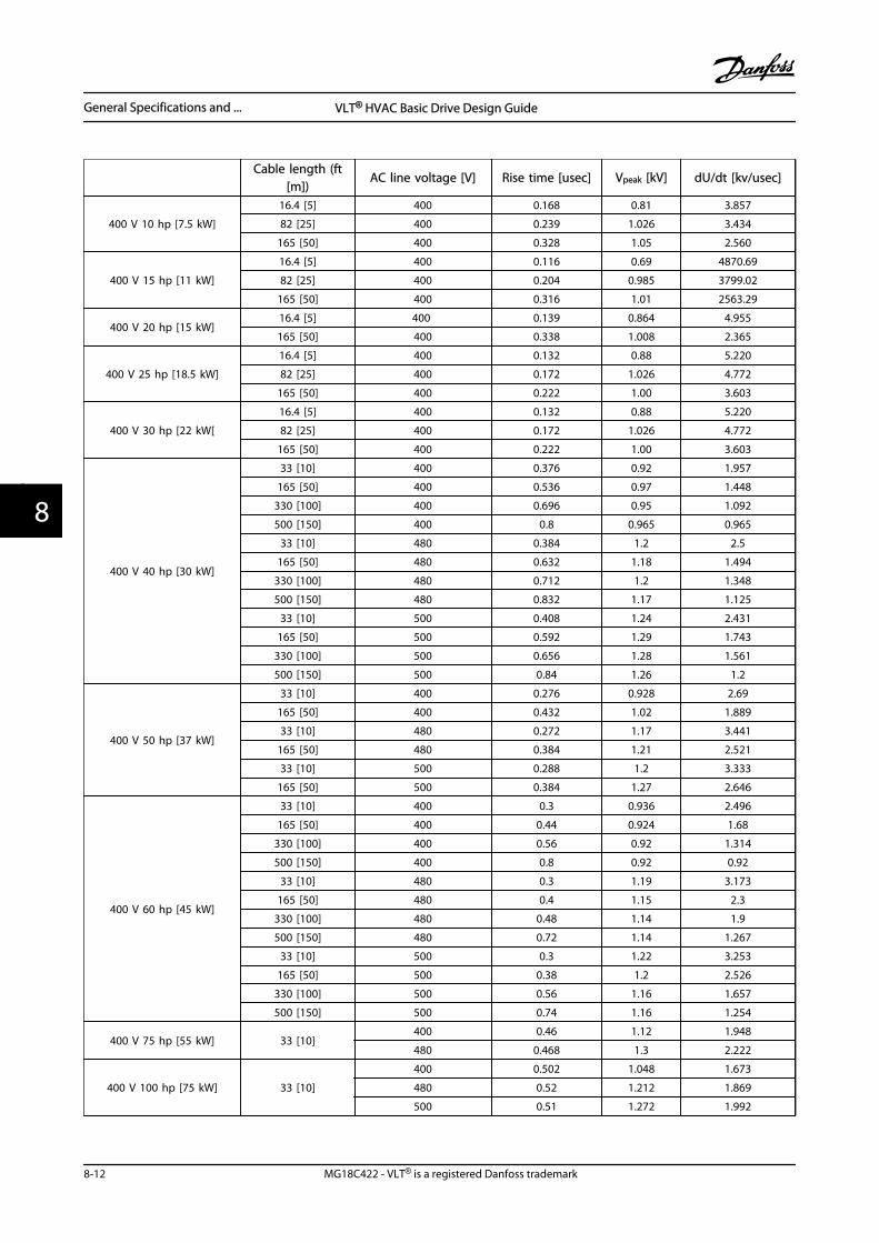
Cable length (ft
[m])AC line voltage [V] Rise time [usec] Vpeak [kV] dU/dt [kv/usec]
400 V 10 hp [7.5 kW]
16.4 [5] 400 0.168 0.81 3.857
82 [25] 400 0.239 1.026 3.434
165 [50] 400 0.328 1.05 2.560
400 V 15 hp [11 kW]
16.4 [5] 400 0.116 0.69 4870.69
82 [25] 400 0.204 0.985 3799.02
165 [50] 400 0.316 1.01 2563.29
400 V 20 hp [15 kW]16.4 [5] 400 0.139 0.864 4.955
165 [50] 400 0.338 1.008 2.365
400 V 25 hp [18.5 kW]
16.4 [5] 400 0.132 0.88 5.220
82 [25] 400 0.172 1.026 4.772
165 [50] 400 0.222 1.00 3.603
400 V 30 hp [22 kW[
16.4 [5] 400 0.132 0.88 5.220
82 [25] 400 0.172 1.026 4.772
165 [50] 400 0.222 1.00 3.603
400 V 40 hp [30 kW]
33 [10] 400 0.376 0.92 1.957
165 [50] 400 0.536 0.97 1.448
330 [100] 400 0.696 0.95 1.092
500 [150] 400 0.8 0.965 0.965
33 [10] 480 0.384 1.2 2.5
165 [50] 480 0.632 1.18 1.494
330 [100] 480 0.712 1.2 1.348
500 [150] 480 0.832 1.17 1.125
33 [10] 500 0.408 1.24 2.431
165 [50] 500 0.592 1.29 1.743
330 [100] 500 0.656 1.28 1.561
500 [150] 500 0.84 1.26 1.2
400 V 50 hp [37 kW]
33 [10] 400 0.276 0.928 2.69
165 [50] 400 0.432 1.02 1.889
33 [10] 480 0.272 1.17 3.441
165 [50] 480 0.384 1.21 2.521
33 [10] 500 0.288 1.2 3.333
165 [50] 500 0.384 1.27 2.646
400 V 60 hp [45 kW]
33 [10] 400 0.3 0.936 2.496
165 [50] 400 0.44 0.924 1.68
330 [100] 400 0.56 0.92 1.314
500 [150] 400 0.8 0.92 0.92
33 [10] 480 0.3 1.19 3.173
165 [50] 480 0.4 1.15 2.3
330 [100] 480 0.48 1.14 1.9
500 [150] 480 0.72 1.14 1.267
33 [10] 500 0.3 1.22 3.253
165 [50] 500 0.38 1.2 2.526
330 [100] 500 0.56 1.16 1.657
500 [150] 500 0.74 1.16 1.254
400 V 75 hp [55 kW] 33 [10]400 0.46 1.12 1.948
480 0.468 1.3 2.222
400 V 100 hp [75 kW] 33 [10]
400 0.502 1.048 1.673
480 0.52 1.212 1.869
500 0.51 1.272 1.992
General Specifications and ... VLT® HVAC Basic Drive Design Guide
8-12 MG18C422 - VLT® is a registered Danfoss trademark
88
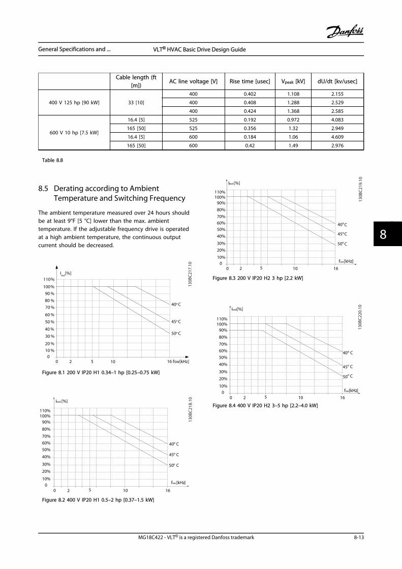
Cable length (ft
[m])AC line voltage [V] Rise time [usec] Vpeak [kV] dU/dt [kv/usec]
400 V 125 hp [90 kW] 33 [10]
400 0.402 1.108 2.155
400 0.408 1.288 2.529
400 0.424 1.368 2.585
600 V 10 hp [7.5 kW]
16.4 [5] 525 0.192 0.972 4.083
165 [50] 525 0.356 1.32 2.949
16.4 [5] 600 0.184 1.06 4.609
165 [50] 600 0.42 1.49 2.976
Table 8.8
8.5 Derating according to AmbientTemperature and Switching Frequency
The ambient temperature measured over 24 hours shouldbe at least 9°F [5 °C] lower than the max. ambienttemperature. If the adjustable frequency drive is operatedat a high ambient temperature, the continuous outputcurrent should be decreased.
110%
100%
90 %
80 %
70 %
60 %
50 %
40 %
30 %
20 %
10 % 0
Iout
[%]
0 2 5 10 16
40o C
50o C
45o C
fsw[kHz]
130B
C21
7.10
Figure 8.1 200 V IP20 H1 0.34–1 hp [0.25–0.75 kW]
fsw[kHz]
20 100
10%
20%
30%
40%
50%60%70%
80%
90%100%110%
Iout [%]
16
40
45
50
5
o C
o C
o C
130B
C218
.10
Figure 8.2 400 V IP20 H1 0.5–2 hp [0.37–1.5 kW]
fsw[kHz]
20 100
10%
20%30%
40%50%60%70%80%90%
100%110%
Iout[%]
16
40
45
50
5
oC
oC
oC
130B
C219
.10
Figure 8.3 200 V IP20 H2 3 hp [2.2 kW]
fsw[kHz]
20 100
10%
20%
30%
40%
50%60%70%
80%
90%100%110%
Iout[%]
16
40
45
50
5
o C
o C
o C
130B
C220
.10
Figure 8.4 400 V IP20 H2 3–5 hp [2.2–4.0 kW]
General Specifications and ... VLT® HVAC Basic Drive Design Guide
MG18C422 - VLT® is a registered Danfoss trademark 8-13
8 8
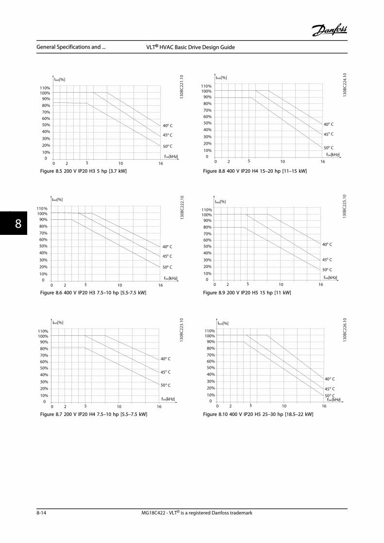
fsw[kHz]
20 100
10%
20%
30%
40%
50%60%70%
80%
90%100%110%
Iout[%]
16
40
45
50
5
o C
o C
o C
130B
C221
.10
Figure 8.5 200 V IP20 H3 5 hp [3.7 kW]
fsw[kHz]
20 100
10%
20%
30%
40%
50%60%70%
80%
90%100%110%
Iout[%]
16
40
45
50
5
o C
o C
o C
130B
C222
.10
Figure 8.6 400 V IP20 H3 7.5–10 hp [5.5-7.5 kW]
fsw[kHz]
20 100
10%
20%
30%
40%
50%60%70%
80%
90%100%110%
Iout[%]
16
40
45
50
5
o C
o C
o C
130B
C223
.10
Figure 8.7 200 V IP20 H4 7.5–10 hp [5.5–7.5 kW]
fsw[kHz]
20 100
10%
20%
30%
40%
50%60%70%
80%
90%100%110%
Iout[%]
16
40
45
50
5
o C
o C
o C
130B
C224
.10
Figure 8.8 400 V IP20 H4 15–20 hp [11–15 kW]
fsw[kHz]
20 100
10%
20%
30%
40%
50%60%70%
80%
90%100%110%
Iout[%]
16
40
45
50
5
o C
o C
o C
130B
C225
.10
Figure 8.9 200 V IP20 H5 15 hp [11 kW]
fsw[kHz]20 10
010%
20%
30%
40%
50%60%70%
80%
90%100%110%
Iout[%]
16
40
45
50
5
o C
o Co C
130B
C226
.10
Figure 8.10 400 V IP20 H5 25–30 hp [18.5–22 kW]
General Specifications and ... VLT® HVAC Basic Drive Design Guide
8-14 MG18C422 - VLT® is a registered Danfoss trademark
88
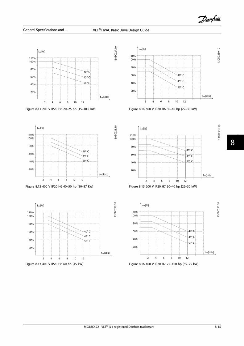
Iout [%]
fsw [kHz]
20%
2 4 6 8 10 12
40%
60%
80%40o C
45o C
50o C
100%110%
130B
C227
.10
Figure 8.11 200 V IP20 H6 20–25 hp [15–18.5 kW]
Iout [%]
fsw [kHz]
20%
2 4 6 8 10 12
40%
60%
80%
40o C
45o C
50o C
100%110%
130B
C228
.10
Figure 8.12 400 V IP20 H6 40–50 hp [30–37 kW]
Iout [%]
fsw [kHz]
20%
2 4 6 8 10 12
40%
60%
80%
40o C
45o C
50o C
100%110%
130B
C229
.10
Figure 8.13 400 V IP20 H6 60 hp [45 kW]
Iout [%]
fsw [kHz]
20%
2 4 6 8 10 12
40%
60%
80%
40o C
45o C
50o C
100%110%
130B
C230
.10
Figure 8.14 600 V IP20 H6 30–40 hp [22–30 kW]
Iout [%]
fsw [kHz]
20%
2 4 6 8 10 12
40%
60%
80%40o C
45o C
50o C
100%110%
130B
C231
.10
Figure 8.15 200 V IP20 H7 30–40 hp [22–30 kW]
Iout [%]
fsw [kHz]
20%
2 4 6 8 10 12
40%
60%
80%
40o C
45o C
50o C
100%110%
130B
C232
.10
Figure 8.16 400 V IP20 H7 75–100 hp [55–75 kW]
General Specifications and ... VLT® HVAC Basic Drive Design Guide
MG18C422 - VLT® is a registered Danfoss trademark 8-15
8 8
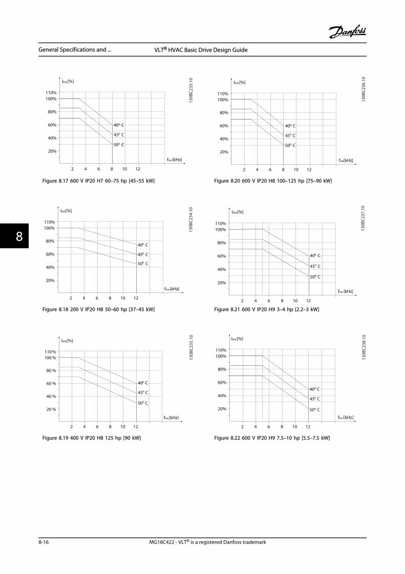
Iout [%]
fsw [kHz]
20%
2 4 6 8 10 12
40%
60%
80%
40o C
45o C
50o C
100%110%
130B
C233
.10
Figure 8.17 600 V IP20 H7 60–75 hp [45–55 kW]
Iout [%]
fsw [kHz]
20%
2 4 6 8 10 12
40%
60%
80%40o C
45o C
50o C
100%110%
130B
C234
.10
Figure 8.18 200 V IP20 H8 50–60 hp [37–45 kW]
Iout [%]
fsw [kHz]
20 %
2 4 6 8 10 12
40 %
60 %
80 %
40o C
45o C
50o C
100 %110 %
130B
C235
.10
Figure 8.19 400 V IP20 H8 125 hp [90 kW]
Iout [%]
fsw [kHz]
20%
2 4 6 8 10 12
40%
60%
80%
40o C
45o C
50o C
100%110%
130B
C236
.10
Figure 8.20 600 V IP20 H8 100–125 hp [75–90 kW]
Iout [%]
fsw [kHz]
20%
2 4 6 8 10 12
40%
60%
80%
40o C
45o C
50o C
100%110%
130B
C237
.10
Figure 8.21 600 V IP20 H9 3–4 hp [2.2–3 kW]
Iout [%]
fsw [kHz]
20%
2 4 6 8 10 12
40%
60%
80%
40o C
45o C
50o C
100%110%
130B
C238
.10
Figure 8.22 600 V IP20 H9 7.5–10 hp [5.5–7.5 kW]
General Specifications and ... VLT® HVAC Basic Drive Design Guide
8-16 MG18C422 - VLT® is a registered Danfoss trademark
88
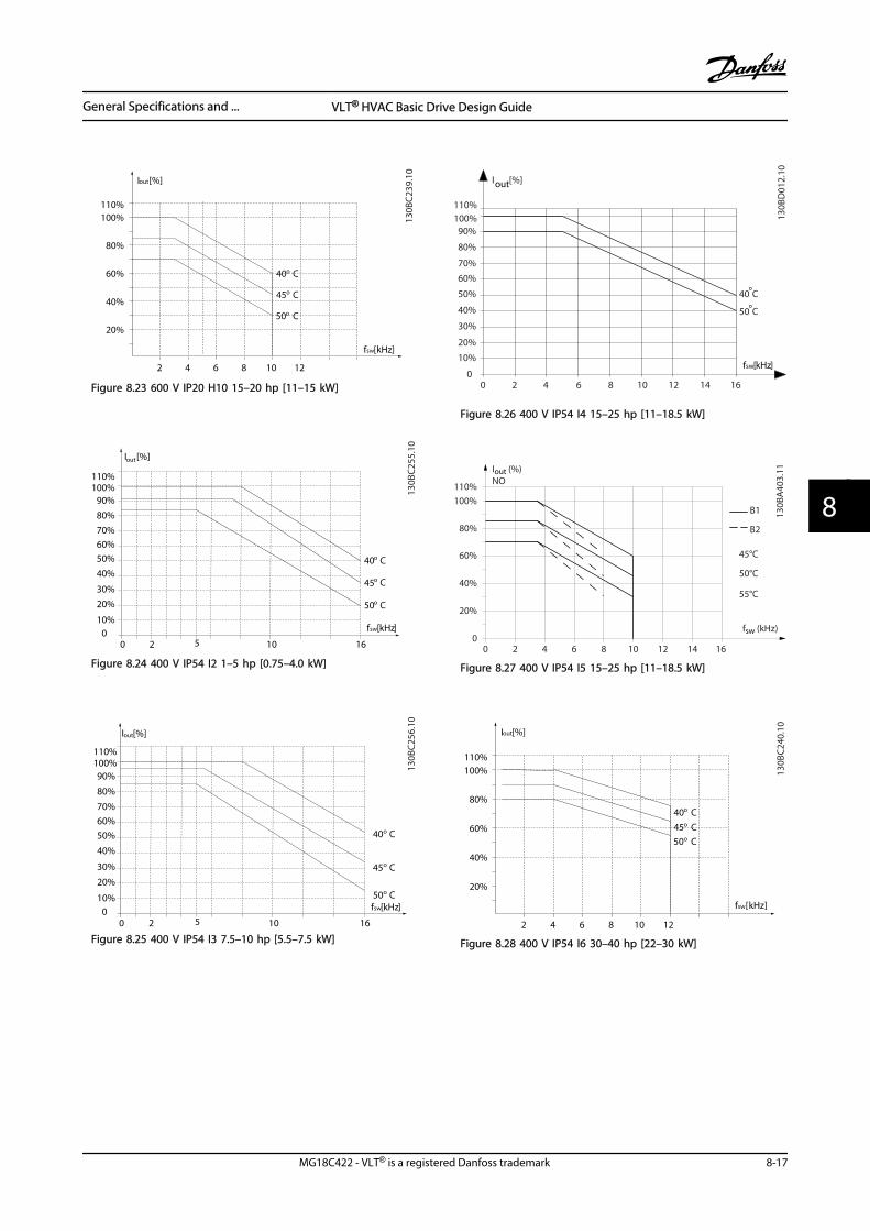
Iout [%]
fsw [kHz]
20%
2 4 6 8 10 12
40%
60%
80%
40o C
45o C
50o C
100%110%
130B
C239
.10
Figure 8.23 600 V IP20 H10 15–20 hp [11–15 kW]
fsw[kHz]
20 100
10%
20%
30%
40%
50%
60%
70%
80%
90%100%110%
Iout[%]
16
40
45
50
5
o C
o C
o C
130B
C25
5.10
Figure 8.24 400 V IP54 I2 1–5 hp [0.75–4.0 kW]
fsw[kHz]
20 10010%
20%
30%
40%
50%
60%
70%
80%
90%100%110%
Iout[%]
16
40
45
50
5
o C
o C
o C
130B
C25
6.10
Figure 8.25 400 V IP54 I3 7.5–10 hp [5.5–7.5 kW]
130B
D01
2.10
o
70%
80%
90%
0
I [%]out
60%
100%110%
2 84 106
50 C
50%
40%
30%
20%
10%
0
o40 C
12 14 16
fsw[kHz]
Figure 8.26 400 V IP54 I4 15–25 hp [11–18.5 kW]
2
20%
4 6 8 10 12 14 16
40%
60%
80%
100%110%
fsw (kHz)
45°C
50°C
55°C
00
Iout (%)NO
130B
A40
3.11
B1
B2
Figure 8.27 400 V IP54 I5 15–25 hp [11–18.5 kW]
Iout [%]
fsw [kHz]
20%
2 4 6 8 10 12
40%
60%
80%40o C45o C50o C
100%110%
130B
C240
.10
Figure 8.28 400 V IP54 I6 30–40 hp [22–30 kW]
General Specifications and ... VLT® HVAC Basic Drive Design Guide
MG18C422 - VLT® is a registered Danfoss trademark 8-17
8 8
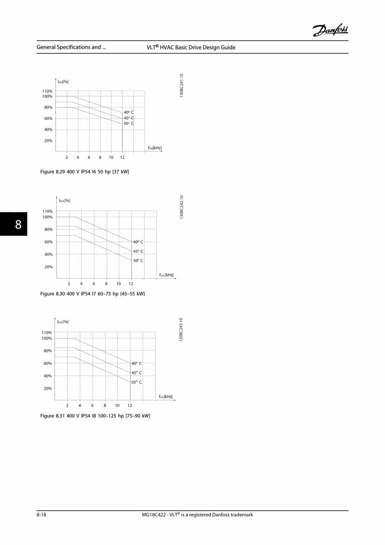
Iout [%]
fsw [kHz]
20%
2 4 6 8 10 12
40%
60%
80%40o C45o C50o C
100%110%
130B
C241
.10
Figure 8.29 400 V IP54 I6 50 hp [37 kW]
Iout [%]
fsw [kHz]
20%
2 4 6 8 10 12
40%
60%
80%
40o C
45o C
50o C
100%110%
130B
C242
.10
Figure 8.30 400 V IP54 I7 60–75 hp [45–55 kW]
Iout [%]
fsw [kHz]
20%
2 4 6 8 10 12
40%
60%
80%
40o C
45o C
50o C
100%110%
130B
C243
.10
Figure 8.31 400 V IP54 I8 100–125 hp [75–90 kW]
General Specifications and ... VLT® HVAC Basic Drive Design Guide
8-18 MG18C422 - VLT® is a registered Danfoss trademark
88
Index
AAbbreviations....................................................................................... 0-2
Acoustic Noise................................................................................... 7-10
AdjustableFrequency Drive Hardware Set-up........................................... 6-1Frequency Drive Set-up............................................................... 6-3Frequency Drive With Modbus RTU........................................ 6-8
Advanced Vecter Control................................................................. 0-3
Aggressive Environments................................................................ 1-4
Air Humidity.......................................................................................... 1-3
Alpha Numeric Display..................................................................... 5-1
AnalogInputs................................................................................. 0-3, 7-9, 0-3Output................................................................................................ 7-9
Application Examples........................................................................ 1-9
BBalancing Contractor...................................................................... 1-14
Better Control....................................................................................... 1-7
Break-away Torque............................................................................. 0-3
Building Management System, BMS............................................ 1-5
Bypass Frequency Ranges............................................................. 1-12
CCable Lengths And Cross-sections............................................... 7-8
CAV System......................................................................................... 1-11
CE Conformity And Labeling.......................................................... 1-2
Central VAV Systems....................................................................... 1-10
Changes Made.......................................................................... 5-2, 5-11
Closed-loop Set-up Wizard.......................................... 5-2, 1-21, 5-3
CO2 Sensor.......................................................................................... 1-11
Coasting............................................................................ 6-17, 0-3, 6-16
Comparison Of Energy Savings..................................................... 1-5
Condenser Pumps............................................................................ 1-13
Connecting To Line Power And Motor........................................ 4-8
Constant Air Volume....................................................................... 1-11
ControlCard, 10 V DC Output................................................................. 7-10Card, 24 V DC Output.................................................................... 7-9Card, RS-485 Serial Communication........................................ 7-9Potential.......................................................................................... 1-16Structure Closed-loop................................................................ 1-19Structure Open-loop................................................................... 1-17Terminals......................................................................................... 4-19Word.................................................................................................... 6-3
Controlling Fans And Pumps.......................................................... 1-4
Cooling Tower Fan........................................................................... 1-12
DDampers............................................................................................... 1-10
DANGEROUS VOLTAGE..................................................................... 1-1
Data Types Supported By The Adjustable Frequency Drive.......6-6
DC Brake............................................................................................... 6-16
Decoupling Plate................................................................................. 2-3
Definitions............................................................................................. 0-3
Differential Pressure........................................................................ 1-16
DigitalInputs.................................................................................................. 7-8Output................................................................................................ 7-9
Discharge Time.................................................................................... 1-2
Disposal Instructions......................................................................... 1-2
Drive Configurator.............................................................................. 3-1
EElectrical
Installation In General................................................................... 4-7Overview............................................................................................ 4-6
EMCDirective 89/336/EEC.................................................................... 1-3Precautions....................................................................................... 6-2
EMC-compatible Electrical Installation..................................... 4-17
Emission Requirements.................................................................. 1-25
Energy Savings............................................................................ 1-6, 1-4
Evaporator Flow Rate...................................................................... 1-14
Example Of Energy Savings............................................................. 1-5
Extreme Running Conditions....................................................... 1-30
FFC
Profile.................................................................................................. 6-3With Modbus RTU.......................................................................... 6-2
Feedback Conversion...................................................................... 1-19
Field Mounting.................................................................................... 4-5
Flow Meter.......................................................................................... 1-14
Freeze Output...................................................................................... 0-3
Function Codes Supported By Modbus RTU.......................... 6-11
Fuses...................................................................................................... 4-15
GGalvanic Isolation............................................................................. 1-29
Index VLT® HVAC Basic Drive Design Guide
MG18C422 - VLT® is a registered Danfoss trademark 9-1
GeneralAspects Of EMC Emissions........................................................ 1-24Aspects Of Harmonics Emission............................................. 1-27Specifications................................................................................... 7-8
Ground Leakage Current............................................................... 1-30
HHarmonics
Emission Requirements............................................................. 1-27Test Results (Emission)............................................................... 1-27
Hold Output Frequency................................................................. 6-16
HowTo Control The Adjustable Frequency Drive...................... 6-11To Order............................................................................................. 3-1To Program....................................................................................... 5-1
IIGVs........................................................................................................ 1-10
Immunity Requirements................................................................ 1-29
Index (IND)............................................................................................. 6-5
Initialize The Adjustable Frequency Drive............................... 5-12
Installation At High Altitudes......................................................... 1-1
Intermediate Circuit.............................................................. 1-30, 7-10
IP21/TYPE 1 Enclosure Kit................................................................ 2-2
JJog................................................................................................. 0-3, 6-16
LLaws Of Proportionality.................................................................... 1-5
LCPLCP............................................................................................... 0-3, 0-4Copy.................................................................................................. 5-12
Leakage Current................................................................................ 1-30
Legal Information............................................................................... 0-1
LineDrop-out.......................................................................................... 1-31Power Supply................................................................................... 0-5Power Supply (L1, L2, L3)............................................................. 7-8Power Supply 3x200–240 V AC................................................. 7-2Power Supply 3x380–480 V AC......................................... 7-3, 7-5Power Supply 3x525–600 V AC................................................. 7-7
Literature................................................................................................ 0-1
Local(Hand On) And Remote (Auto On) Control......................... 1-18Control Panel (LCP)........................................................................ 5-1Speed Determination................................................................. 1-14
Low Evaporator Temperature...................................................... 1-14
MMain Menu.......................................................................................... 5-11
Manual PI Adjustment.................................................................... 1-24
Menu Key............................................................................................... 5-1
Menus...................................................................................................... 5-2
Message Length (LGE)....................................................................... 6-3
ModbusCommunication.............................................................................. 6-2Exception Codes........................................................................... 6-12RTU Overview.................................................................................. 6-7
Moment Of Inertia............................................................................ 1-30
MotorOutput (U, V, W).............................................................................. 7-8Phases.............................................................................................. 1-30Protection.......................................................................................... 7-8Set-up................................................................................................. 5-2Thermal Protection........................................................... 6-18, 1-31
Motor-generated Overvoltage.................................................... 1-30
Multiple Pumps................................................................................. 1-16
NNavigation Keys And Indicator Lights (LEDs)............................ 5-1
NetworkConfiguration................................................................................... 6-8Connection....................................................................................... 6-1
OOperation Keys And Indicator Lights (LEDs)............................. 5-1
Options And Accessories......................................................... 2-1, 3-3
Overcurrent Protection.................................................................. 4-15
PParameter
Number (PNU)................................................................................. 6-5Values............................................................................................... 6-12
Payback Period.................................................................................... 1-6
PELV - Protective Extra Low Voltage.......................................... 1-29
Power Factor......................................................................................... 0-5
Primary Pumps.................................................................................. 1-14
Programmable Minimum Frequency Setting........................ 1-12
Programming With MCT 10 Setup Software............................. 5-1
ProtectionProtection......................................................... 1-4, 1-29, 1-30, 4-15And Features.................................................................................... 7-8
Protocol Overview.............................................................................. 6-2
Public Supply Network................................................................... 1-27
Pump Impeller................................................................................... 1-13
Index VLT® HVAC Basic Drive Design Guide
9-2 MG18C422 - VLT® is a registered Danfoss trademark
QQuick
Menu................................................................................................... 5-2Transfer Of Parameter Settings Between Multiple Adjusta-
ble Frequency Drives...... 5-12
RRated Motor Speed............................................................................ 0-3
RCD................................................................................................ 0-3, 1-30
Read Holding Registers (03 HEX)................................................ 6-14
Readout And Programming Of Indexed Parameters.......... 5-12
Recommended Initialization........................................................ 5-12
ReferenceReference........................................................................................... 1-2Handling.......................................................................................... 1-20
Relay Output......................................................................................... 7-9
Residual Current Device................................................................. 1-30
RS-485RS-485................................................................................................. 6-1Installation And Set-up................................................................. 6-1
SSafety
Note..................................................................................................... 1-1Regulations....................................................................................... 1-1
Secondary Pumps............................................................................. 1-16
Serial Communication Port............................................................. 0-3
Short Circuit (Motor Phase – Phase).......................................... 1-30
Side-by-Side Installation................................................................... 4-5
Soft-starter............................................................................................. 1-7
Software Version................................................................................. 0-1
Star/Delta Starter................................................................................. 1-7
Start-up Wizard For Open-loop Applications........................... 5-3
StatusStatus.................................................................................................. 5-2Word................................................................................................. 6-17
Surroundings..................................................................................... 7-10
SwitchingOn The Input Supply..................................................................... 7-8On The Output.............................................................................. 1-30
Symbols.................................................................................................. 0-2
TThe
EMC Directive (89/336/EEC)........................................................ 1-2Low-voltage Directive (73/23/EEC).......................................... 1-2Machinery Directive (98/37/EEC).............................................. 1-2
Thermistor............................................................................................. 0-3
Throttling Valve................................................................................. 1-13
Tuning The Drive Closed-loop Controller................................ 1-23
Two-finger Initialization................................................................. 5-13
Type Code String................................................................................. 3-1
UUL Compliance.................................................................................. 4-15
UNINTENDED START.......................................................................... 1-1
Using An Adjustable Frequency Drive Saves Money............. 1-7
VVariable
Air Volume...................................................................................... 1-10Control Of Flow And Pressure.................................................... 1-7
Varying Flow Over 1 Year................................................................. 1-6
VAV........................................................................................................ 1-10
Vibration And Shock.......................................................................... 1-4
Vibrations............................................................................................ 1-12
VVC........................................................................................................... 0-5
WWhat Is Covered................................................................................... 1-3
Wizard For Open-loop Applications............................................. 5-2
Index VLT® HVAC Basic Drive Design Guide
MG18C422 - VLT® is a registered Danfoss trademark 9-3
www.danfoss.com/drives
*MG18C422*130R0222 MG18C422 Rev. 2013-03-18