vacon nx liquid-cooled drives user manual - danfoss
TRANSCRIPT

vacon nxac drives
liquid-cooled drivesuser manual
®


vacon • 3
Local contacts: https://www.danfoss.com/en/contact-us/contacts-list/
TABLE OF CONTENTS Document: DPD00887I
Release date : 14/12/20
1. Safety ..................................................................................................................... 91.1 Safety symbols used in the manual .......................................................................................... 91.2 Danger..................................................................................................................................... 101.3 Warnings ................................................................................................................................. 101.4 Grounding and earth fault protection ..................................................................................... 111.5 Running the motor .................................................................................................................. 13
2. EU directive.......................................................................................................... 142.1 CE marking.............................................................................................................................. 142.2 EMC directive .......................................................................................................................... 142.2.1 General .................................................................................................................................... 142.2.2 Technical criteria .................................................................................................................... 142.2.3 VACON® AC drive EMC classification .................................................................................... 142.2.4 Explanations of voltage classes.............................................................................................. 15
3. Receipt of delivery ............................................................................................... 163.1 Type designation code............................................................................................................. 163.2 Storage and shipping .............................................................................................................. 173.3 Maintenance............................................................................................................................ 173.4 Warranty.................................................................................................................................. 20
4. Technical data ...................................................................................................... 214.1 Introduction............................................................................................................................. 214.2 Power ratings.......................................................................................................................... 244.2.1 AC drives ................................................................................................................................. 244.2.2 Inverter units........................................................................................................................... 304.3 Technical data ......................................................................................................................... 33
5. Installation........................................................................................................... 385.1 Mounting.................................................................................................................................. 385.1.1 Lifting the drive ....................................................................................................................... 385.1.2 VACON® NX Liquid-Cooled dimensions ................................................................................ 405.2 Cooling..................................................................................................................................... 555.2.1 Condensation .......................................................................................................................... 625.2.2 Cooling system connections ................................................................................................... 635.3 Drive derating.......................................................................................................................... 695.4 Input chokes............................................................................................................................ 715.4.1 Grounding of input chokes...................................................................................................... 715.4.2 Liquid-cooled input chokes..................................................................................................... 725.4.3 Air-cooled input chokes .......................................................................................................... 735.4.4 Installation of the input chokes .............................................................................................. 75
6. Electrical cabling and connections....................................................................... 796.1 Power unit ............................................................................................................................... 796.1.1 Power connections.................................................................................................................. 796.1.2 Drive protection – Fuses ......................................................................................................... 866.1.3 Fuse sizes................................................................................................................................ 866.1.4 Cable installation instructions................................................................................................ 926.1.5 Supply busbars for inverter units ........................................................................................... 956.1.6 Installation space .................................................................................................................... 966.1.7 Grounding of power unit ......................................................................................................... 966.1.8 Installation of ferrite rings (option) on the motor cable......................................................... 976.1.9 Cable installation and the UL standards ................................................................................ 976.1.10 Cable and motor insulation checks ........................................................................................ 98

vacon • 4
Local contacts: https://www.danfoss.com/en/contact-us/contacts-list/
6.2 Control unit ............................................................................................................................. 996.2.1 Control board power-up ....................................................................................................... 1016.2.2 Control connections .............................................................................................................. 1016.2.3 Control terminal signals ....................................................................................................... 1036.2.4 Control unit mounting box .................................................................................................... 1086.3 Internal connections ............................................................................................................. 1116.3.1 Connections between Power Unit ASIC and Driver Boards ................................................. 1116.3.2 Connections between power unit ASIC and the control unit................................................ 1146.3.3 Connections between mains device and inverter power module ........................................ 118
7. Control keypad....................................................................................................1217.1 Indications on the Keypad display ........................................................................................ 1217.1.1 Drive status indications ........................................................................................................ 1217.1.2 Control place indications ...................................................................................................... 1227.1.3 Status LEDs (green – green – red) ....................................................................................... 1227.1.4 Text lines .............................................................................................................................. 1227.2 Keypad push-buttons ............................................................................................................ 1237.2.1 Button descriptions............................................................................................................... 1237.3 Navigation on the control keypad ......................................................................................... 1247.3.1 Monitoring menu (M1)........................................................................................................... 1257.3.2 Parameter menu (M2)........................................................................................................... 1277.3.3 Keypad control menu (M3) .................................................................................................... 1287.3.4 Active faults menu (M4) ........................................................................................................ 1307.3.5 Fault history menu (M5)........................................................................................................ 1327.3.6 System menu (M6) ................................................................................................................ 1337.3.7 Expander board menu (M7)................................................................................................... 1467.4 Further keypad functions...................................................................................................... 147
8. Commissioning ...................................................................................................1488.1 Safety..................................................................................................................................... 1488.2 Commissioning of the AC drive............................................................................................. 149
9. Fault tracing........................................................................................................1519.1 Fault codes............................................................................................................................ 1519.2 Load test with motor ............................................................................................................. 1579.3 DC link test (without motor).................................................................................................. 158
10. Active front end (NXA).........................................................................................15910.1 Introduction........................................................................................................................... 15910.2 Diagrams............................................................................................................................... 15910.2.1 Active Front End block diagram............................................................................................ 15910.3 Type designation code........................................................................................................... 16010.4 Active Front End unit technical data..................................................................................... 16110.5 Power ratings........................................................................................................................ 16510.6 Liquid-Cooled RLC filters ..................................................................................................... 16710.6.1 Introduction........................................................................................................................... 16710.6.2 Wiring diagrams.................................................................................................................... 16710.6.3 Power rating and dimensions............................................................................................... 16810.6.4 Technical data ....................................................................................................................... 17010.6.5 Removing discharging resistors........................................................................................... 17010.6.6 Removing HF capacitors ....................................................................................................... 17110.7 Active front end - fuse selection........................................................................................... 17310.7.1 Fuse sizes, Active Front End units (AC supply) .................................................................... 17310.8 Pre-charging circuit.............................................................................................................. 17510.9 Paralleling............................................................................................................................. 17710.10 Common pre-charging circuit .............................................................................................. 17810.11 Each Active Front End unit has the pre-charging circuit ..................................................... 179

vacon • 5
Local contacts: https://www.danfoss.com/en/contact-us/contacts-list/
11. Non-regenerative front end ................................................................................18011.1 Introduction........................................................................................................................... 18011.2 Diagrams............................................................................................................................... 18011.2.1 Non-regenerative Front End Unit wiring diagrams ............................................................. 18011.3 Installation of the NFE control cables .................................................................................. 18311.4 Type designation codes......................................................................................................... 18411.5 Power ratings........................................................................................................................ 18511.6 Non-regenerative Front End unit technical data ................................................................. 18611.7 Dimensions............................................................................................................................ 18811.8 Chokes................................................................................................................................... 18911.9 Non-regenerative front end - fuse selection........................................................................ 19011.9.1 Fuse sizes, Non-regenerative Front End units .................................................................... 19111.9.2 Circuit breaker settings, Non-regenerative Front End units............................................... 19111.10 Settings ................................................................................................................................. 19111.10.1Phase monitor settings........................................................................................................ 19111.10.2Option board settings........................................................................................................... 19211.11 DC pre-charging circuit ........................................................................................................ 19311.12 Paralleling............................................................................................................................. 19411.13 Parameters ........................................................................................................................... 19511.14 CH60 Liquid-cooled NFE protections ................................................................................... 20011.15 Fault codes............................................................................................................................ 201
12. Brake chopper unit (NXB) ...................................................................................20412.1 Introduction........................................................................................................................... 20412.2 Type designation code........................................................................................................... 20412.3 Diagrams............................................................................................................................... 20412.3.1 NXB Brake Chopper Unit block diagram.............................................................................. 20412.3.2 VACON® NXB topologies and connection ............................................................................ 20512.4 Brake chopper unit technical data ....................................................................................... 20612.5 BCU power ratings................................................................................................................ 20912.5.1 VACON® NXB; DC voltage 460–800 V................................................................................... 20912.5.2 VACON® NXB; DC voltage 640–1100 V................................................................................. 21012.6 VACON® brake resistors and brake chopper dimensioning ............................................... 21112.6.1 Braking energy and losses ................................................................................................... 21112.6.2 Braking power and resistance, mains voltage 380–500 V AC/600–800 V DC ...................... 21212.6.3 Braking power and resistance, mains voltage 525–690 V AC/840–1100 V DC..................... 21412.7 Brake chopper unit – Fuse selection.................................................................................... 216
13. Grid converter/Utility interactive inverter ..........................................................21813.1 Safety..................................................................................................................................... 21813.2 Used symbols and markings ................................................................................................ 21813.3 Conditions of acceptability .................................................................................................... 21913.3.1 Conditions of acceptability and engineering considerations for UL1741 ............................ 21913.4 Required tools ....................................................................................................................... 21913.5 Mounting................................................................................................................................ 21913.5.1 Dimensions - Drive unit ........................................................................................................ 21913.5.2 Dimensions - RLC filter ........................................................................................................ 21913.6 Cooling................................................................................................................................... 21913.7 Power cabling........................................................................................................................ 22013.7.1 Cable installation and the UL standards .............................................................................. 22013.7.2 Cable sizes - UL1741............................................................................................................. 22013.7.3 Terminal sizes....................................................................................................................... 22113.7.4 Bolt sizes and tightening torques ......................................................................................... 22113.8 Grounding.............................................................................................................................. 22113.8.1 Grounding terminal............................................................................................................... 22113.9 Protections ............................................................................................................................ 222

vacon • 6
Local contacts: https://www.danfoss.com/en/contact-us/contacts-list/
13.9.1 Overcurrent protection ......................................................................................................... 22213.9.2 Voltage/frequency trip limits ................................................................................................ 22913.10 Control cabling...................................................................................................................... 22913.11 RLC filter ............................................................................................................................... 22913.12 Specifications ........................................................................................................................ 23013.12.1Technical data ...................................................................................................................... 23013.12.2Current and power ratings .................................................................................................. 23113.12.3Configuration circuit diagrams............................................................................................ 234
14. Appendices..........................................................................................................23614.1 Appendix 1 - Circuit diagrams .............................................................................................. 23614.2 Appendix 2 - OETL, OFAX and charging circuit .................................................................... 24814.3 Appendix 3 - Fuse sizes ........................................................................................................ 25114.4 Appendix 4 - Power conversion equipment.......................................................................... 25814.4.1 Technical data ....................................................................................................................... 25814.4.2 Power ratings........................................................................................................................ 259

vacon • 7
Local contacts: https://www.danfoss.com/en/contact-us/contacts-list/
AT LEAST THE FOLLOWING STEPS OF THE START-UP QUICK GUIDE MUST BE PERFORMED DURING THE INSTALLATION AND COMMISSIONING.
IF ANY PROBLEMS OCCUR, CONTACT YOUR LOCAL DISTRIBUTOR.
Start-up Quick Guide
1. Check that the delivery corresponds to your order, see Chapter 3.2. Before taking any commissioning actions read carefully the safety instructions in
Chapter 1.3. Check the size of the motor cable, mains cable, mains fuses and check the cable
connections, read Chapter 6.1.1.1 – Chapter 6.1.2.4. Follow the installation instructions.5. Control connections are explained in Chapter 6.2.2.6. Ensure the adequate pressure and flow of the cooling agent you are using. See
Chapter 5.2.7. If the Start-Up wizard is active, select the language of the keypad and the application you
want to use and confirm by pressing the Enter button. If the Start-Up wizard is not active, follow the instructions 7a and 7b.
7a. Select the language of the keypad from the Menu M6, S6.1. Instructions on using the keypad are given in Chapter 7.
7b. Select the application you want to use from the Menu M6, S6.2. Instructions on using the keypad are given in Chapter 7.
8. All parameters have factory default values. In order to ensure proper operation, check the rating plate data for the values below and the corresponding parameters of parameter group G2.1.
• nominal voltage of the motor
• nominal frequency of the motor
• nominal speed of the motor
• nominal current of the motor
• motor cosϕ
All parameters are explained in VACON® NX All in One Application Manual.
9. Follow the commissioning instructions, see Chapter 8.
10. The VACON® NX Liquid-Cooled AC drive is now ready for use.
Vacon Ltd is not responsible for the use of its products against instructions.

vacon • 8
Local contacts: https://www.danfoss.com/en/contact-us/contacts-list/
ABOUT THE VACON® NX LIQUID-COOLED AC DRIVES USER MANUAL
Congratulations for choosing the Smooth Control provided by VACON® NX Liquid-Cooled drives!
This manual will provide you with the necessary information about the installation, commissioning and operation of VACON® NX Liquid-Cooled drives. We recommend that you carefully study these instructions before powering up the AC drive for the first time.
This manual is available in both paper and electronic editions. We recommend you to use the electronic version if possible. If you have the electronic version at your disposal you will be able to benefit from the following features:
The manual contains several links and cross-references to other locations in the manual which makes it easier for the reader to move around in the manual, to check and find things faster.
The manual also contains hyperlinks to web pages. To visit these web pages through the links you must have an internet browser installed on your computer.
The manual is subject to change without prior notice.
Safety vacon • 9
Local contacts: https://www.danfoss.com/en/contact-us/contacts-list/
1. SAFETY
ONLY A COMPETENT ELECTRICIAN MAY CARRY OUT THE ELECTRICAL INSTALLATION!
1.1 Safety symbols used in the manual
This manual contains warnings and cautions, which are identified with safety symbols. The warnings and cautions give important information on how to prevent injury and damage to the equipment or your system.
Read the warnings and cautions carefully and obey their instructions.
= DANGEROUS VOLTAGE!
= GENERAL WARNING!
IMPORTANT SAFETY INSTRUCTIONSSAVE THESE INSTRUCTIONSYou can download the English and French product manuals with applicable safety, warning and caution information from https://www.danfoss.com/en/service-and-support/.
INSTRUCTIONS IMPORTANTES CONCERNANT LA SÉCURITÉCONSERVER CES INSTRUCTIONSVous pouvez télécharger les versions anglaise et française des manuels produit contenant l’ensemble des informations de sécurité, avertissements et mises en garde applicables sur le site https://www.danfoss.com/en/service-and-support/.
9000.emf
9000.emf
13006.emf

vacon • 10 Safety
Local contacts: https://www.danfoss.com/en/contact-us/contacts-list/
1.2 Danger
1.3 Warnings
Do not touch the components of the power unit when the drive is connected to mains. The components are live when the drive is connected to mains. A contact with this voltage is very dangerous.
Do not touch the motor cable terminals U, V, W, the brake resistor terminals or the DC terminals when the drive is connected to mains. These terminals are live when the drive is connected to mains, also when the motor does not operate.
Do not touch the control terminals. They can have a dangerous voltage also when the drive is disconnected from mains.
Before you do electrical work on the drive, disconnect the drive from the mains and make sure that the motor has stopped. Lock out and tag out the power source to the drive. Make sure that no external source generates unintended voltage during work. Note that also the load side of the drive can generate voltage.
Wait 5 minutes before you open the cabinet door. Use a measuring device to make sure that there is no voltage. The terminal connections and the components of the drive can be live 5 minutes after it is disconnected from the mains and the motor has stopped.
Before you connect the AC drive to mains, make sure that the coolant circulation functions properly, and check the circulation for possible leaks.
Before you connect the drive to mains, make sure that the front cover and the cable cover of the drive are closed. The connections of the AC drive are live when the drive is connected to mains.
Before connecting the drive to mains make sure that the enclosure door is closed.
Disconnect the motor from the drive if an accidental start can be dangerous. When there is a power-up, a power break or a fault reset, the motor starts immediately if the start signal is active, unless the pulse control for Start/Stop logic is selected. If the parameters, the applications or the software change, the I/O functions (including the start inputs) can change.
Wear protective gloves when you do mounting, cabling or maintenance operations. There can be sharp edges in the AC drive that can cause cuts.
Do not move the AC drive. Use a fixed installation to prevent damage to the drive.
9000.emf
9000.emf
9000.emf
9000.emf
9000.emf
9000.emf
9000.emf
9000.emf
9000.emf

Safety vacon • 11
Local contacts: https://www.danfoss.com/en/contact-us/contacts-list/
1.4 Grounding and earth fault protection
The touch current of the drive is more than 3.5 mA AC. The standard EN 61800-5-1 tells that 1 or more of these conditions for the protective circuit must be true.
The connection must be fixed.
Do not make measurements when the AC drive is connected to mains. It can causedamage to the drive.
Make sure that there is reinforced protective ground connection. It is mandatory,
because the touch current of the AC drives is more than 3.5 mA AC (refer to EN61800-5-1). See Chapter 1.4.
Do not use spare parts that are not from the manufacturer. Using other spare partscan cause damage to the drive.
Before you make measurements on the motor or the motor cable, disconnect the motor cable from the AC drive.
Do not lift the AC drive from the plastic handles with an elevating device, such as jib crane or hoist.
Do not touch the components on the circuit boards. Static voltage can causedamage to these components.
Make sure that the EMC level of the AC drive is correct for your mains. Contact your local distributor for instructions. An incorrect EMC level can cause damage to thedrive.
Prevent radio interference. The AC drive can cause radio interference in a domesticenvironment.
NOTE!If you activate the autoreset function, the motor starts automatically after anautomatic fault reset. See the Application Manual.
NOTE!If you use the AC drive as a part of a machine, the machine manufacturer mustsupply a mains disconnection device (refer to EN 60204-1).
The AC drive must always be grounded with a grounding conductor that is connected
to the grounding terminal that is identified with the symbol . Not using a ground-ing conductor can cause damage to the drive.

vacon • 12 Safety
Local contacts: https://www.danfoss.com/en/contact-us/contacts-list/
a) The protective grounding conductor must have a cross-sectional area of minimum 10 mm2 Cu or 16 mm2 Al. OR
b) There must be an automatic disconnection of the mains, if the protective grounding conductor breaks. See Chapter 6. OR
c) There must be a terminal for a second protective grounding conductor in the same cross-sectional area as the first protective grounding conductor.
The values of the table are valid only if the protective grounding conductor is made of the same metal as the phase conductors. If this is not so, the cross-sectional area of the protective grounding conductor must be determined in a manner that produces a conductance equivalent to that which results from the application of this table.
The cross-sectional area of each protective grounding conductor that is not a part of the mains cable or the cable enclosure, must be a minimum of:
• 2.5 mm2 if there is mechanical protection, and
• 4 mm2 if there is not mechanical protection. If you have cord-connected equipment, make sure that the protective grounding conductor in the cord is the last conductor to be interrupted, if the strain-relief mechanism breaks.
Obey the local regulations on the minimum size of the protective grounding conductor.
Table 1. Protective grounding conductor cross-section
Cross-sectional area of the phase conductors (S) [mm2]
The minimum cross-sectional area of the protective grounding conductor in
question [mm2]
S ≤ 16 S
16 < S ≤ 35 16
35 < S S/2
NOTE!Because there are high capacitive currents in the AC drive, it is possible that thefault current protective switches do not operate correctly.
If you use a fault protection relay, it must be of at least type B, preferably B+ (accord-ing to EN 50178), with a trip level of 300 mA. This is for fire protection, not for touch protection in grounded systems.
The earth fault protection inside the AC drive protects only the AC drive itself against earth faults in the motor or the motor cable. It is not intended for personal safety.
Do not do voltage withstand tests on the AC drive. The manufacturer has alreadydone the tests. Doing voltage withstand tests can cause damage to the drive.
13006.emf

Safety vacon • 13
Local contacts: https://www.danfoss.com/en/contact-us/contacts-list/
1.5 Running the motor
Motor run check list
Before you start the motor, check that it is mounted properly and make sure that the machine connected to the motor allows the motor to be started.
Set the maximum motor speed (frequency) on the AC drive according to the motor and the machine connected to it.
Before reversing the motor make sure that this can be done safely.
Make sure that no power correction capacitors are connected to the motor cable.
Make sure that the motor terminals are not connected to mains potential.
Before you use the VACON® NX Liquid-Cooled AC drive to control the motor, make sure that liquid-cooling system functions properly.

vacon • 14 EU directive
Local contacts: https://www.danfoss.com/en/contact-us/contacts-list/
2. EU DIRECTIVE
2.1 CE marking
The CE marking on the product guarantees the free movement of the product within the EEA (European Economic Area).
VACON® NX AC drives carry the CE label as a proof of compliance with the Low Voltage Directive and the Electro Magnetic Compatibility Directive (EMC). The company SGS FIMKO has acted as the Competent Body.
2.2 EMC directive
2.2.1 General
The EMC Directive provides that the electrical apparatus must not excessively disturb the environment it is used in, and, on the other hand, it must have an adequate level of immunity toward other disturbances from the same environment.
The compliance of VACON® NX Liquid-Cooled AC drives with the EMC directive is verified with Technical Construction Files (TCF) checked and approved by SGS FIMKO, which is a Competent Body. The Technical Construction Files are used to authenticate the conformity of VACON® AC drives with the Directive because such a large-sized product family is impossible to be tested in a laboratory environment and because the combinations of installation vary greatly.
2.2.2 Technical criteria
Our basic idea was to develop a range of AC drives offering the best possible usability and cost-efficiency. EMC compliance was a major consideration from the outset of the design.
VACON® NX Liquid-Cooled AC drives are marketed throughout the world, a fact which makes the EMC requirements of customers different. As far as the immunity is concerned, all VACON® NX Liquid-Cooled AC drives are designed to fulfil even the strictest requirements.
2.2.3 VACON® AC drive EMC classification
VACON® NX Liquid-Cooled AC drive and inverter modules delivered from factory fulfil all EMC immunity requirements (standard EN 61800-3).
The basic liquid cooled modules do not have any inherent emission filtering. If filtering is needed and a certain EMC emission level is required, external RFI filters must be used.
Class N: The VACON® NX Liquid-Cooled drives of this class do not provide EMC emission protection. This kind of drives are mounted in enclosures. External EMC filtering is usually required to fulfil the EMC emission requirements.
Class T:The T-class AC drives have a smaller earth leakage current and are intended to be used with IT supplies only. If they are used with other supplies no EMC requirements are complied with.
Warning: This is a product of the restricted sales distribution class according to IEC 61800-3. In a domestic environment this product may cause radio interference in which case the user may be required to take adequate measures.

EU directive vacon • 15
Local contacts: https://www.danfoss.com/en/contact-us/contacts-list/
2.2.4 Explanations of voltage classes
NX_5 = 380 - 500 VAC drives -> DC link voltage = 465 - 800 VDC
NX_6 = 525 - 690 VAC drives -> DC link voltage = 640 - 1100 VDC
NX_8 = 525 - 690 VAC drives -> DC link voltage = 640 - 1200 VDC
2.2.4.1 IT networks
The grounding of input capacitors made by default with the grounding screw at terminal X41 of the bus board in all drives is imperative in all variations of TN/TT networks. Should a drive originally purchased for TN/TT networks be used in an IT network, the screw at X41 must be removed. It is strongly recommended that this be done by Danfoss personnel. Ask you local distributor for more information.

vacon • 16 Receipt of delivery
Local contacts: https://www.danfoss.com/en/contact-us/contacts-list/
3. RECEIPT OF DELIVERY
The standard delivery of VACON® NX Liquid-Cooled AC drives includes all or part of the following components:
VACON® NX Liquid-Cooled AC drives have undergone scrupulous tests and quality checks at the factory before they are delivered to the customer. However, after unpacking the product, check that no signs of transport damages are to be found on the product and that the delivery is complete (compare the type designation of the product to the code).
Should the drive have been damaged during the shipping, contact primarily the cargo insurance company or the carrier.
If the delivery does not correspond to your order, contact the supplier immediately.
3.1 Type designation code
The type designation code for the VACON® NX Liquid-Cooled drives is presented below.
*) Note, the control unit of NX_8 (voltage class 8) drives need to be supplied with a external 24 V DC power source.
• Power unit• Control unit• Main line connecting hoses and
conduits (1.5 m) + aluminium adapters for CH5-CH74
• Tema 1300 series fast connectors for CH3-CH4
• Choke (not DC-fed inverters, type code I)• Control unit mounting kit• Optic fibre & cable set (1.5 m) for control
unit; Optic sets in different lengths also available
• Optic fibre cable set for 2*CH64/CH74: 1.8 m/11 fibres (Power module 1) and 3.8 m/8 fibres (Power module 2)
NXP 0000 A 0 N 1 YWV A1A20000C35
Option boards; each slot is represented by two characters where:A = basic I/O board, B = expander I/O board,C = fieldbus board, D = special board
Hardware modifications; Supply - Mounting - BoardsF = Fiber connection/standard (from CH61)G = Fiber connection/varnished (from CH61)S = Direct connection/standardV = Direct connection/varnished
W = Liquid-cooled module with aluminium heatsinkP = Liquid cooled module with nickel-coated aluminium heatsink
I = Inverter unit; DC-supplyS = Standard supply; 6-pulse connection with air-cooled chokesY = Standard supply; 6-pulse connection with liquid-cooled chokesN = Standard supply; 6-pulse connection without chokesT = 12-pulse connection (with air-cooled chokes)W = 12-pulse connection (with liquid-cooled chokes)U = 12-pulse connection (without chokes)2 = Active front end unit8 = Brake chopper unit
Brake chopper0 = no brake chopper1 = internal brake chopper (CH3, CH72 (6-pulse) & Ch74 only)
EMC emission level:N = No EMC emission protection; to be installed in enclosures.T = Fulfils standard 61800-3 for IT networks.
Control keypad:A = standard (alpha-numeric)B = neutral (no local control keypad)F = dummy panelG = graphic display
Nominal mains voltage (3-phase):5 = 380–500 V ac, 6 = 525–690 V ac (640–1100 Vdc), 8 = 525–690 Vac (640–1200 Vdc). (CH6X only). *)
Nominal current (low overload)0007 = 7 A, 0022 = 22 A, 0205 = 205 A etc.
Product range: NXP = high-performance, NXB = brake chopper unit, NXA = Active front end unit, NXN = Non-regenerative front end unit
Enclosure class:0 = IP00 (UL open type)
3035E_uk

Receipt of delivery vacon • 17
Local contacts: https://www.danfoss.com/en/contact-us/contacts-list/
3.2 Storage and shipping
If the AC drive is to be kept in store before use make sure that the ambient conditions are acceptable:
Storing temperature –40…+70°C (no cooling liquid inside cooling element allowed below 0ºC
Relative humidity <96%, no condensation
If the storage time exceeds 12 months the electrolytic DC capacitors need to be charged with caution. Therefore, such a long storage time is not recommended. See Chapter 9.3 and the VACON® NX Liquid-Cooled Drives Service Manual for instructions on charging. See also Chapter 3.3.
Warning: Always remove all cooling agent from the cooling element(s) before shipping to avoid damage caused by freezing.
3.3 Maintenance
In case the AC drive is used in conditions with temperatures below the freezing point and the liquid used for cooling is likely to freeze, be sure to empty the cooling element if the AC drive must be moved or if it is taken out of use for a longer time. See also Chapter 3.2.
It may also be necessary to clean up the coolant ducts in the cooling element. Contact the factory for more information.
The instructions for the cooling system provided by its manufacturer must be followed.
NOTE! The content of the maintenance and intervals may vary depending on ambient conditions, assembly and application.
Table 2. VACON® NX Liquid-Cooled AC drive maintenance program, general
Inspection target
Inspection intervals
Service schedule Proactive maintenance actions
Conditions of installation
environment1 year 1 year
Check that installation and environ-ment conditions are within manufac-turer’s specification, in respect, for example, heat, dust, moisture, vibra-tion. Take corrective actions based on findings.
Cleaning 1 year 1 yearIf needed, clean the product with an antistatic vacuum cleaner.
Cleanliness of cooling tunnel
1 year 1 yearCheck/evaluate the cleanliness of the cooling tunnel for air cooled drives. Cleaning if necessary.
Air filters 3 months
• 3 months in demanding environment
• 1 year in typical environment
NOTE! VACON® NX Liquid-Cooled AC drives do not include air filter. They may be included in the enclosure solution. The inspection and replace-ment intervals of filters depend on the environment. Replace at least once a year.
Sealings 1 year Based on inspection
Check the sealings for IP21 or IP54 AC drives. Check visually the cable bushing. Take corrective actions based on findings.

vacon • 18 Receipt of delivery
Local contacts: https://www.danfoss.com/en/contact-us/contacts-list/
Main DC cooling fans and and
internal cooling fans for elec-
tronics
1 year 5 yearReplace parts according to service schedule or based on maintenance report recommendation.
DC-link capaci-tors
1 year
• 8 years in demanding environment or heavy load
• 12 years in typical environment or normal load
The expected life time of the capaci-tor is determined based on load and the temperature of the environment. Replace parts according to service schedule.
Product upgrades
1 year 1 yearManufacturer offers product upgrades.
Printed circuit boards
1 year12 years in typical
environment
The printed circuit boards to be checked for contamination and possi-ble corrosion. In case of contamina-tion or corrosion printed circuit boards to be changed.
Recommended reforming inter-val for electro-
lytic DC-link capacitors (spare parts and prod-ucts in storage)
1 year 1 year
Reforming must be done once a year for products and spare part capaci-tors in storage. Ask instructions from your local distributor.
Table 3. VACON® Liquid-Cooled AC drive maintenance program, liquid cooling system
Inspection target
Inspection intervals
Service schedule Proactive maintenance actions
Coolant inhibitor 1 year 2 yearsAdd inhibitor according to instruc-tions or analyze the coolant and add inhibitor based on result.
Coolant 2 years 6 yearsCheck and change coolant according to service schedule.
VACON® NX Liq-uid-Cooled drive
coolant flow
1 year Based on inspection
Check pressure, flow and tempera-ture of the system. Compare to previ-ous measurement. Temperature alarm or trip indicates that AC drive warms up and the flow is to low. Cleaning of heatsink if necessary, Ask instructions from your local distribu-tor.
Table 2. VACON® NX Liquid-Cooled AC drive maintenance program, general
Inspection target
Inspection intervals
Service schedule Proactive maintenance actions

Receipt of delivery vacon • 19
Local contacts: https://www.danfoss.com/en/contact-us/contacts-list/
Coolant leakage 3 months Based on inspection
Open the cubicle doors and check that there are no visible leaks on cooling unit or coolant manifold con-nections. If you find a leak, shut down the unit and repair the leak.
Table 4. VACON® Liquid-Cooled AC drive maintenance program, cabinet, cabling and connections
Inspection target
Inspection intervals
Service schedule Proactive maintenance actions
Cabinet, auxil-iary devices (contactors,
switches, relays, push buttons,
indicators, etc.)
1 yearAccording to manufac-
turer information
Replace parts according to service schedule or based on maintenance
report recommendation.
Sealings 1 year Based on inspectionCheck cabinet and drive sealings.
Check visually cable bushing. Correc-tive actions based on findings.
Visual inspec-tion of cablings
1 year 1 year
Visual inspection for possible dam-ages and so on, due to, for example, vibration. Actions based on inspec-
tion.
Tightness of connections
1 year 1 yearCheck and tighten the cable and wire
connections.
Radiator cool-ing fans and control com-
partment fans
1 year 5 years
Check the operation of the fans and measure the radiator fan capacitor
every 2 years. Replace parts accord-ing to service schedule or based on maintenance report recommenda-
tion.
Table 3. VACON® Liquid-Cooled AC drive maintenance program, liquid cooling system
Inspection target
Inspection intervals
Service schedule Proactive maintenance actions

vacon • 20 Receipt of delivery
Local contacts: https://www.danfoss.com/en/contact-us/contacts-list/
3.4 Warranty
Only manufacturing defects are covered by the warranty. The manufacturer assumes no responsibility for damages caused during or resulting from transport, receipt of the delivery, installation, commissioning or use.
The manufacturer shall in no event and under no circumstances be held responsible for damages and failures resulting from misuse, wrong installation, unacceptable ambient temperature, running motor with lower coolant flow than minimum flow, condensation, dust, corrosive substances or operation outside the rated specifications.
Neither can the manufacturer be held responsible for consequential damages.
NOTE! VACON® NX Liquid-Cooled drives must not be run with the liquid cooling system disconnected. Furthermore, the requirements of the liquid cooling specifications, e.g. minimum flow rate (see Chapter 5.2 and Table 15) must be satisfied. Ignoring this will render the warranty null and void.
NOTE! VACON® Liquid-Cooled NX_8 inverter unit must be equipped with a du/dt- or sine-filter. The warranty is void in case filter are not used with these units.
The Manufacturer's time of warranty, if not otherwise agreed, is 18 months from the delivery or 12 months from the commissioning whichever expires first.
The local distributor may grant a warranty time different from the above. This warranty time shall be specified in the distributor's sales and warranty terms. Vacon Ltd assumes no responsibility for any other warranties than that granted by Vacon itself.
In all matters concerning the warranty, contact first your distributor.

Technical data vacon • 21
Local contacts: https://www.danfoss.com/en/contact-us/contacts-list/
4. TECHNICAL DATA
4.1 Introduction
The VACON® NX Liquid-Cooled product range consists of active front ends, inverters, brake choppers and AC drives. Figure 1 & Figure 2 presents the block diagram of the VACON® NX Liquid-Cooled inverter and AC drive. Mechanically, the product consists of two units, the Power Unit and the Control Unit. The power unit can contain one to six modules (cooling plates), depending on the drive size. Instead of air, VACON® NX Liquid-Cooled inverters and AC drives use liquid for cooling. A charging circuit is embodied in the AC drives but not in active front ends, inverters or brake choppers.
An external three-phase AC-choke (1) at the mains input together with the DC-link capacitor (2) form an LC-filter. In AC drives, the LC-filter together with the diode bridge produce the DC-voltage supply to the IGBT Inverter Bridge (3) block. The AC-choke also functions as a filter against High Frequency disturbances from the mains as well as against those caused by the AC drive to the mains. In addition, it enhances the waveform of the input current to the AC drive. In chasses with multiple parallel line-rectifiers (CH74) AC-chokes are required to balance the line current between the rectifiers.
The power drawn by the AC drive from the mains is mostly active power.
The IGBT Inverter Bridge produces a symmetrical, 3-phase Pulse Width Modulated AC-voltage to the motor.
The Motor and Application Control Block is based on microprocessor software. The microprocessor controls the motor basing on the information it receives through measurements, parameter settings, control I/O and control keypad. The motor and application control block controls the motor control ASIC which, in turn, calculates the IGBT positions. Gate drivers amplify these signals for driving the IGBT inverter bridge.
The control keypad constitutes a link between the user and the AC drive. The control keypad is used for parameter setting, reading status data and giving control commands. It is detachable and can be operated externally and connected via a cable to the AC drive. Instead of the control keypad, a PC can also be used to control the AC drive if connected through a similar cable (±12 V).
You can have your AC drive equipped with a control I/O board which is either isolated (OPT-A8) or not isolated (OPT-A1) from the frame. Optional I/O expander boards that increase the number of inputs and outputs to be used are also available. For closer information, contact the Manufacturer or your nearest distributor.
The basic control interface and the parameters (the Basic Application) are easy to use. If a more versatile interface or parameters are required, a more suitable application can be chosen from the "All in One" Application Package. See VACON® NX All in One Application Manual for more information on the different applications.
An internal brake chopper is available as standard for chassis CH3. For Ch72 (only 6-pulse) and Ch74, it is available as internal option while in all other sizes the brake chopper is available as option and installed externally. The standard product does not include a brake resistor. It should be acquired separately.

vacon • 22 Technical data
Local contacts: https://www.danfoss.com/en/contact-us/contacts-list/
Figure 1. VACON® NX Liquid-Cooled AC drive principal block diagram
=
=L1
L2
L3
PE
U/T1
V/T2
W/T3
3~
3~
RS 232
3065_uk
Mains
Motor
Measure-ments
Gate Drivers
Motor Control ASIC
Motor and ApplicationControl
Control Keypad
CurrentSensors
Rectifier(frequency
converters only)IGBT Inverter
PowerSupply
Control I/O
Control I/O
Control I/O
Control I/O
Control I/O
1)
2)
3)External
choke
*Brake resistor is available for all sizes (CH3 to CH7). An internal brake chopper belongs to standard equipment in sizes CH3. For CH72 (only 6-pulse) and CH74, it is available as internal option while in all other sizes it is optional but installed externally.
Controlmodule
Powermodule
Charg.res.
BrakeChopper*
Brake resistor*

Technical data vacon • 23
Local contacts: https://www.danfoss.com/en/contact-us/contacts-list/
Figure 2. VACON® NX Liquid-Cooled inverter principal block diagram
=
PE
U/T1
V/T2
W/T33~
RS 232
+
-
DC supply
Motor
Measure-ments
GateDrivers
MotorControlASIC
Motor andApplicationControl
ControlKeypad
CurrentSensors
IGBTInverter
PowerSupply
Control I/O
Control I/O
Control I/O
Control I/O
Control I/O
2)
3)
*Brake resistor is available for all sizes (CH3 to CH7).An internal brake chopper belongs to standard equipment in sizes CH3 only, while in all other sizes it is optional but installed externally.
Controlmodule
Powermodule
BrakeChopper*
Brake resistor*
3066_uk

vacon • 24 Technical data
Local contacts: https://www.danfoss.com/en/contact-us/contacts-list/
4.2 Power ratings
VACON® Liquid-Cooled product range consists of both AC drives (AC input, AC output) and inverter units (DC input, AC output). The following tables present the drive output values for both and an indication of motor shaft power at Ith and IL at different mains voltages as well as the drive losses and mechanical sizes. The power achieved is given as per the supply voltage.
4.2.1 AC drives
4.2.1.1 VACON® NX Liquid-Cooled AC drive – Mains voltage 400—500 VAC
Table 5. Power ratings of VACON® NX Liquid-Cooled AC drive (6-pulse), supply voltage 400-500 VAC
Mains voltage 400-500 VAC, 50/60 Hz, 3~, 6-pulse drives
AC drive type
Drive output
Power loss
c/a/T*)
[kW]Chassis
Current Motor output power
Thermal Ith[A]
Rated cont. IL[A]
Rated contin. IH [A]
Optimum motor at Ith(400 V) [kW]
Optimum motor at Ith(500 V) [kW]
0016_5 16 15 11 7.5 11 0.4/0.2/0.6 CH3
0022_5 22 20 15 11 15 0.5/0.2/0.7 CH3
0031_5 31 28 21 15 18.5 0.7/0.2/0.9 CH3
0038_5 38 35 25 18.5 22 0.8/0.2/1.0 CH3
0045_5 45 41 30 22 30 1.0/0.3/1.3 CH3
0061_5 61 55 41 30 37 1.3/0.3/1.5 CH3
0072_5 72 65 48 37 45 1.2/0.3/1.5 CH4
0087_5 87 79 58 45 55 1.5/0.3/1.8 CH4
0105_5 105 95 70 55 75 1.8/0.3/2.1 CH4
0140_5 140 127 93 75 90 2.3/0.3/2.6 CH4
0168_5 168 153 112 90 110 4.0/0.4/4.4 CH5
0205_5 205 186 137 110 132 5.0/0.5/5.5 CH5
0261_5 261 237 174 132 160 6.0/0.5/6.5 CH5
0300_5 300 273 200 160 200 4.5/0.5/5.0 CH61
0385_5 385 350 257 200 250 6.0/0.5/6.5 CH61
0460_5 460 418 307 250 315 6.5/0.5/7.0 CH72
0520_5 520 473 347 250 355 7.5/0.6/8.1 CH72
0590_5 590 536 393 315 400 9.0/0.7/9.7 CH72
0650_5 650 591 433 355 450 10.0/0.7/10.7 CH72
0730_5 730 664 487 400 500 12.0/0.8/12.8 CH72
0820_5 820 745 547 450 560 12.5/0.8/13.3 CH63
0920_5 920 836 613 500 600 14.4/0.9/15.3 CH63
1030_5 1030 936 687 560 700 16.5/1.0/17.5 CH63
1150_5 1150 1045 766 600 750 18.5/1.2/19.7 CH63
1370_5 1370 1245 913 700 900 19.0/1.2/20.2 CH74
1640_5 1640 1491 1093 900 1100 24.0/1.4/25.4 CH74
2060_5 2060 1873 1373 1100 1400 32.5/1.8/34.3 CH74
2300_5 2300 2091 1533 1250 1500 36.3/2.0/38.3 CH74

Technical data vacon • 25
Local contacts: https://www.danfoss.com/en/contact-us/contacts-list/
Ith = Thermal maximum continuous RMS current. Dimensioning can be done according to this current if the process does not require any overloadability or the process does not include any load variation or margin for overloadability.IL = Low overloadability current. Allows +10% load variation. 10% exceeding can be continuous.
IH = High overloadability current. Allows +50% load variation. 50% exceeding can be continuous.
All values with cosϕ = 0.83 and efficiency = 97%.
*) c = power loss into coolant; a = power loss into air; T = total power loss; power losses of input chokes not included. All power losses obtained using max. supply voltage, Ith and switching frequency of 3.6 kHz and Closed Loop control mode. All power losses are worst case losses.
If some other mains voltage is used, apply the formula P = x Un x In x cosϕ x eff% to calculate the VACON® NX Liquid-Cooled drive output power.
The enclosure class for all VACON® NX Liquid-Cooled AC drives is IP00 (UL open type).
If the motor is continuously (besides start and stop ramps) run at frequencies below 5 Hz, pay attention to the drive dimensioning for low frequencies, i.e. maximum IH = 0.66*Ith or choose drive according to IH. It is recommended to check the rating with your nearest distributor.
Drive overrating may also be necessary if the process requires high starting torque.
2470_5 2470 2245 1647 1300 1600 38.8/2.2/41.0 2*CH74
2950_5 2950 2681 1967 1550 1950 46.3/2.6/48.9 2*CH74
3710_5 3710 3372 2473 1950 2450 58.2/3.0/61.2 2*CH74
4140_5 4140 3763 2760 2150 2700 65.0/3.6/68.6 2*CH74
Table 6. Power ratings of VACON® NX Liquid-Cooled AC drive (12-pulse), supply voltage 400-500 VAC
Mains voltage 400-500 VAC, 50/60 Hz, 3~, 12-pulse drives
AC drive type
Drive output
Power loss
c/a/T*)
[kW]Chassis
Current Motor output power
Thermal Ith[A]
Rated cont. IL[A]
Rated contin. IH
[A]
Optimum motor at Ith(400 V) [kW]
Optimum motor at Ith(500 V) [kW]
0460_5 460 418 307 250 315 6.5/0.5/7.0 CH72
0520_5 520 473 347 250 355 7.5/0.6/8.1 CH72
0590_5 590 536 393 315 400 9.0/0.7/9.7 CH72
0650_5 650 591 433 355 400 10.0/0.7/10.7 CH72
0730_5 730 664 487 400 450 12.0/0.8/12.8 CH72
1370_5 1370 1245 913 700 900 19.0/1.2/20.2 CH74
1640_5 1640 1491 1093 850 1050 24.0/1.4/25.4 CH74
2060_5 2060 1873 1373 1050 1350 32.5/1.8/34.3 CH74
2470_5 2470 2245 1647 1300 1600 38.8/2.2/41.0 2*CH74
2950_5 2950 2681 1967 1550 1950 46.3/2.6/48.9 2*CH74
3710_5 3710 3372 2473 1950 2450 58.2/3.0/61.2 2*CH74
4140_5 4140 3763 2760 2150 2700 65.0/3.6/68.6 2*CH74
Table 5. Power ratings of VACON® NX Liquid-Cooled AC drive (6-pulse), supply voltage 400-500 VAC
Mains voltage 400-500 VAC, 50/60 Hz, 3~, 6-pulse drives
3

vacon • 26 Technical data
Local contacts: https://www.danfoss.com/en/contact-us/contacts-list/
NOTE! Braking power: Pbrake = Ubrake^2 / Rbrake
NOTE! Braking DC current: Iin_max = Pbrake_max / Ubrake1) Only 6 pulse drives
The internal brake chopper can also be used in motor application where 2…4 x Ch7x drives are used for a single motor, but in this case the DC connections of the power modules must be connected together. The break choppers are working independently of each other and because of this the DC connections must be connected together otherwise there can be unbalance between the power modules.
Table 7. Internal brake chopper unit (BCU) ratings, braking voltage 640—800 VDC
Internal brake chopper ratings, braking voltage 640-800 Vdc
AC drive type
Loadability Braking capacity at 600 Vdc Braking capacity at 800 Vdc
ChassisRated min resistance
[Ω]
Rated cont. braking power
[kW]
BCU rated cont. braking current,
Ibr
[A]
Rated cont. brak-ing power
R at 800VDC[kW]
BCU rated cont. braking current, Ibr
[A]
NX_460 5 1) 1.3 276 461 492 615 CH72
NX_520 5 1) 1.3 276 461 492 615 CH72
NX_590 5 1) 1.3 276 461 492 615 CH72
NX_650 5 1) 1.3 276 461 492 615 CH72
NX_730 51) 1.3 276 461 492 615 CH72
NX_1370 5 1.3 276 461 492 615 CH74
NX_1640 5 1.3 276 461 492 615 CH74
NX_2060 5 1.3 276 461 492 615 CH74
NX_2300 5 1.3 276 461 492 615 CH74
Technical data vacon • 27
Local contacts: https://www.danfoss.com/en/contact-us/contacts-list/
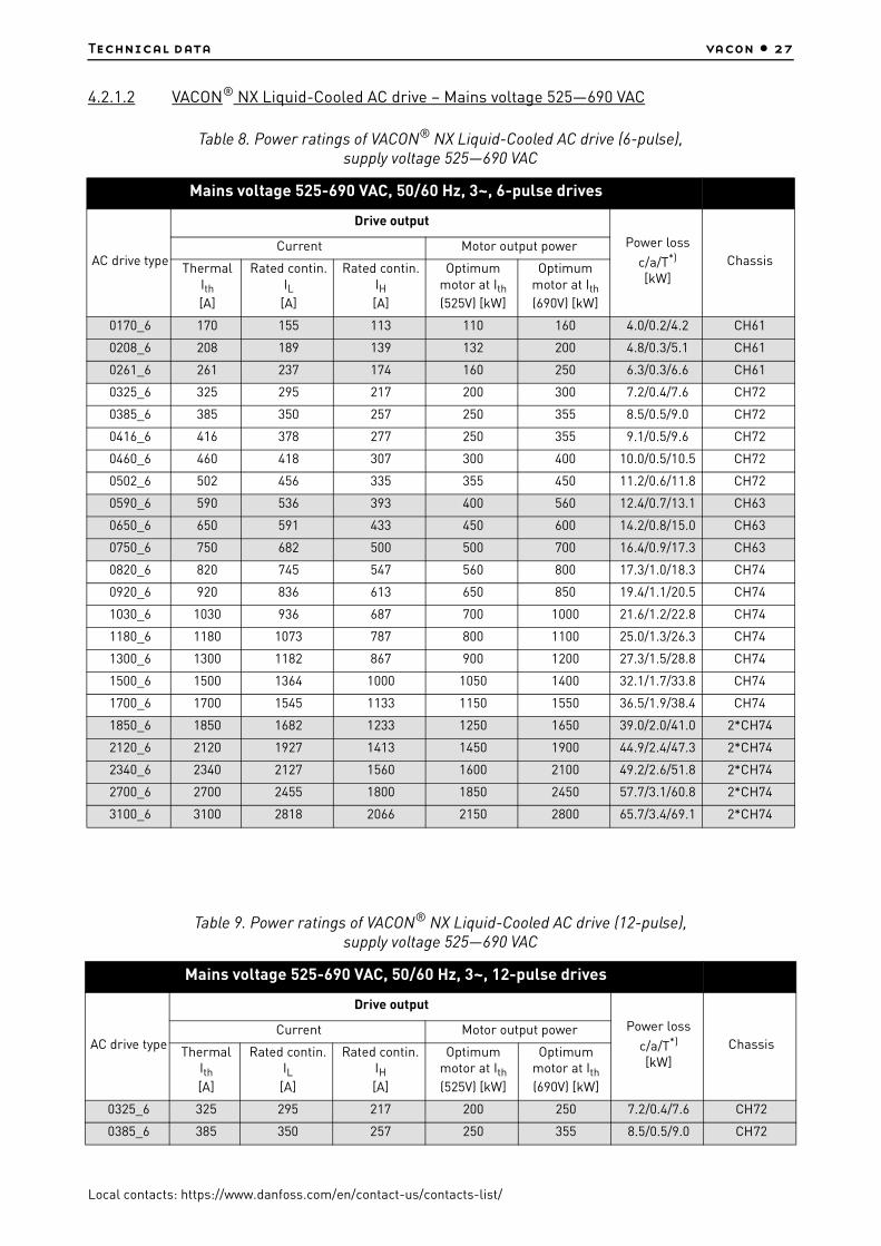
4.2.1.2 VACON® NX Liquid-Cooled AC drive – Mains voltage 525—690 VAC
Table 8. Power ratings of VACON® NX Liquid-Cooled AC drive (6-pulse), supply voltage 525—690 VAC
Mains voltage 525-690 VAC, 50/60 Hz, 3~, 6-pulse drives
AC drive type
Drive output
Power loss
c/a/T*)
[kW]Chassis
Current Motor output power
Thermal Ith[A]
Rated contin. IL
[A]
Rated contin. IH[A]
Optimum motor at Ith(525V) [kW]
Optimum motor at Ith(690V) [kW]
0170_6 170 155 113 110 160 4.0/0.2/4.2 CH61
0208_6 208 189 139 132 200 4.8/0.3/5.1 CH61
0261_6 261 237 174 160 250 6.3/0.3/6.6 CH61
0325_6 325 295 217 200 300 7.2/0.4/7.6 CH72
0385_6 385 350 257 250 355 8.5/0.5/9.0 CH72
0416_6 416 378 277 250 355 9.1/0.5/9.6 CH72
0460_6 460 418 307 300 400 10.0/0.5/10.5 CH72
0502_6 502 456 335 355 450 11.2/0.6/11.8 CH72
0590_6 590 536 393 400 560 12.4/0.7/13.1 CH63
0650_6 650 591 433 450 600 14.2/0.8/15.0 CH63
0750_6 750 682 500 500 700 16.4/0.9/17.3 CH63
0820_6 820 745 547 560 800 17.3/1.0/18.3 CH74
0920_6 920 836 613 650 850 19.4/1.1/20.5 CH74
1030_6 1030 936 687 700 1000 21.6/1.2/22.8 CH74
1180_6 1180 1073 787 800 1100 25.0/1.3/26.3 CH74
1300_6 1300 1182 867 900 1200 27.3/1.5/28.8 CH74
1500_6 1500 1364 1000 1050 1400 32.1/1.7/33.8 CH74
1700_6 1700 1545 1133 1150 1550 36.5/1.9/38.4 CH74
1850_6 1850 1682 1233 1250 1650 39.0/2.0/41.0 2*CH74
2120_6 2120 1927 1413 1450 1900 44.9/2.4/47.3 2*CH74
2340_6 2340 2127 1560 1600 2100 49.2/2.6/51.8 2*CH74
2700_6 2700 2455 1800 1850 2450 57.7/3.1/60.8 2*CH74
3100_6 3100 2818 2066 2150 2800 65.7/3.4/69.1 2*CH74
Table 9. Power ratings of VACON® NX Liquid-Cooled AC drive (12-pulse), supply voltage 525—690 VAC
Mains voltage 525-690 VAC, 50/60 Hz, 3~, 12-pulse drives
AC drive type
Drive output
Power loss
c/a/T*)
[kW]Chassis
Current Motor output power
Thermal Ith[A]
Rated contin. IL
[A]
Rated contin. IH[A]
Optimum motor at Ith(525V) [kW]
Optimum motor at Ith(690V) [kW]
0325_6 325 295 217 200 250 7.2/0.4/7.6 CH72
0385_6 385 350 257 250 355 8.5/0.5/9.0 CH72

vacon • 28 Technical data
Local contacts: https://www.danfoss.com/en/contact-us/contacts-list/
Ith = Thermal maximum continuous RMS current. Dimensioning can be done according to this current if the process does not require any overloadability or the process does not include any load variation.
IL = Low overloadability current. Allows +10% load variation. 10% exceeding can be continuous.
IH = High overloadability current. Allows +50% load variation. 50% exceeding can be continuous.
All values with cosϕ = 0.83 and efficiency = 97%.
*) c = power loss into coolant; a = power loss into air; T = total power loss; power losses of input chokes not included. All power losses obtained using max. supply voltage, Ith and switching frequency of 3.6 kHz and Closed Loop control mode. All power losses are worst case losses.
If some other mains voltage is used, apply the formula P = x Un x In x cosϕ x eff% to calculate the VACON® NX Liquid-Cooled drive output power.
The enclosure class for all VACON® NX Liquid-Cooled AC drives is IP00 (UL open type).
If the motor is continuously (besides start and stop ramps) run at frequencies below 5 Hz, pay attention to the drive dimensioning for low frequencies, i.e. maximum IH = 0.66*Ith or choose drive according to IH. It is recommended to check the rating with your nearest distributor.
Drive overrating may also be necessary if the process requires high starting torque.
0416_6 416 378 277 250 355 9.1/0.5/9.6 CH72
0460_6 460 418 307 315 400 10.0/0.5/10.5 CH72
0502_6 502 456 335 355 450 11.2/0.6/11.8 CH72
0820_6 820 745 547 600 750 17.3/1.0/18.3 CH74
0920_6 920 836 613 650 850 19.4/1.1/20.5 CH74
1030_6 1030 936 687 750 950 21.6/1.2/22.8 CH74
1180_6 1180 1073 787 800 1100 25.0/1.3/26.3 CH74
1300_6 1300 1182 867 950 1200 27.3/1.5/28.8 CH74
1500_6 1500 1364 1000 1050 1400 32.1/1.7/33.8 CH74
1700_6 1700 1545 1133 1150 1550 36.5/1.9/38.4 Ch74
1850_6 1850 1682 1233 1250 1650 39.0/2.0/41.0 2*CH74
2120_6 2120 1927 1413 1450 1900 44.9/2.4/47.3 2*CH74
2340_6 2340 2127 1560 1600 2100 49.2/2.6/51.8 2*CH74
2700_6 2700 2455 1800 1850 2450 57.7/3.1/60.8 2*CH74
3100_6 3100 2818 2067 2150 2800 65.7/3.4/69.1 2*CH74
Table 10. Internal brake chopper unit (BCU) ratings, braking voltage 840—1100 VDC
Internal brake chopper ratings, braking voltage 840-1100 Vdc
AC drive Type
Loadability Braking capacity at 840 Vdc Braking capacity at 1100 Vdc
ChassisRated min resistance
[Ω]
Rated cont. brak-ing power
[kW]
BCU rated cont. braking current,
Ibr
[A]
Rated cont. brak-ing power
[kW]
BCU rated cont. braking current,
Ibr
[A]
NX_325 6 1) 2.8 252 300 432 392 Ch72
NX_385 6 1) 2.8 252 300 432 392 Ch72
NX_416 6 1) 2.8 252 300 432 392 Ch72
Table 9. Power ratings of VACON® NX Liquid-Cooled AC drive (12-pulse), supply voltage 525—690 VAC
Mains voltage 525-690 VAC, 50/60 Hz, 3~, 12-pulse drives
3

Technical data vacon • 29
Local contacts: https://www.danfoss.com/en/contact-us/contacts-list/
NOTE! Braking power: Pbrake = Ubrake^2 / Rbrake
NOTE! Braking DC current: Iin_max = Pbrake_max / Ubrake
1) Only 6 pulse drives
The internal brake chopper can also be used in motor application where 2…4 x Ch7x drives are used for a single motor, but in this case the DC connections of the power modules must be connected together. The break choppers are working independently of each other and because of this the DC connections must be connected together otherwise there can be unbalance between the power modules.
NX_460 6 1) 2.8 252 300 432 392 Ch72
NX_502 6 1) 2.8 252 300 432 392 Ch72
NX_820 6 2.8 252 300 432 392 Ch74
NX_920 6 2.8 252 300 432 392 Ch74
NX_1030 6 2.8 252 300 432 392 Ch74
NX_1180 6 2.8 252 300 432 392 Ch74
NX_1300 6 2.8 252 300 432 392 Ch74
NX_1500 6 2.8 252 300 432 392 Ch74
NX_1700 6 2.8 252 300 432 392 Ch74
Table 10. Internal brake chopper unit (BCU) ratings, braking voltage 840—1100 VDC
Internal brake chopper ratings, braking voltage 840-1100 Vdc

vacon • 30 Technical data
Local contacts: https://www.danfoss.com/en/contact-us/contacts-list/
4.2.2 Inverter units
4.2.2.1 VACON® NX Liquid-Cooled Inverter Unit – Mains voltage 465—800 VDC
Ith = Thermal maximum continuous RMS current. Dimensioning can be done according to this current if the process does not require any overloadability or the process does not include any load variation.
Table 11. Power ratings of VACON® NX Liquid-Cooled inverter unit, supply voltage 540—675 VDC
Mains voltage 465-800 VDC
AC drive type
Drive output
Power loss
c/a/T*)
[kW]Chassis
Current Motor output power
Thermal Ith[A]
Rated cont. IL
[A]
Rated cont. IH
[A]
Optimum motor at Ith
(540 VDC) [kW]
Optimum motor at Ith
(675 VDC) [kW]
0016_5 16 15 11 7.5 11 0.4/0.2/0.6 CH3
0022_5 22 20 15 11 15 0.5/0.2/0.7 CH3
0031_5 31 28 21 15 18.5 0.7/0.2/0.9 CH3
0038_5 38 35 25 18.5 22 0.8/0.2/1.0 CH3
0045_5 45 41 30 22 30 1.0/0.3/1.3 CH3
0061_5 61 55 41 30 37 1.3/0.3/1.5 CH3
0072_5 72 65 48 37 45 1.2/0.3/1.5 CH4
0087_5 87 79 58 45 55 1.5/0.3/1.8 CH4
0105_5 105 95 70 55 75 1.8/0.3/2.1 CH4
0140_5 140 127 93 75 90 2.3/0.3/2.6 CH4
0168_5 168 153 112 90 110 2.5/0.3/2.8 CH5
0205_5 205 186 137 110 132 3.0/0.4/3.4 CH5
0261_5 261 237 174 132 160 4.0/0.4/4.4 CH5
0300_5 300 273 200 160 200 4.5/0.4/4.9 CH61
0385_5 385 350 257 200 250 5.5/0.5/6.0 CH61
0460_5 460 418 307 250 315 5.5/0.5/6.0 CH62
0520_5 520 473 347 250 355 6.5/0.5/7.0 CH62
0590_5 590 536 393 315 400 7.5/0.6/8.1 CH62
0650_5 650 591 433 355 450 8.5/0.6/9.1 CH62
0730_5 730 664 487 400 500 10.0/0.7/10.7 CH62
0820_5 820 745 547 450 560 12.5/0.8/13.3 CH63
0920_5 920 836 613 500 600 14.4/0.9/15.3 CH63
1030_5 1030 936 687 560 700 16.5/1.0/17.5 CH63
1150_5 1150 1045 766 600 750 18.4/1.1/19.5 CH63
1370_5 1370 1245 913 700 900 15.5/1.0/16.5 CH64
1640_5 1640 1491 1093 900 1100 19.5/1.2/20.7 CH64
2060_5 2060 1873 1373 1100 1400 26.5/1.5/28.0 CH64
2300_5 2300 2091 1533 1250 1500 29.6/1.7/31.3 CH64
2470_5 2470 2245 1647 1300 1600 36.0/2.0/38.0 2*CH64
2950_5 2950 2681 1967 1550 1950 39.0/2.4/41.4 2*CH64
3710_5 3710 3372 2473 1950 2450 48.0/2.7/50.7 2*CH64
4140_5 4140 3763 2760 2150 2700 53.0/3.0/56.0 2*CH64

Technical data vacon • 31
Local contacts: https://www.danfoss.com/en/contact-us/contacts-list/
IL = Low overloadability current. Allows +10% load variation. 10% exceeding can be continuous.
IH = High overloadability current. Allows +50% load variation. 50% exceeding can be continuous.
All values with cosϕ = 0.83 and efficiency = 97%.
*) c = power loss into coolant; a = power loss into air; T = total power loss.
All power losses obtained using max. supply voltage, Ith and switching frequency of 3.6 kHz and Closed Loop control mode. All power losses are worst case losses.
If some other mains voltage is used, apply the formula DC P = (UDC/1.35)* *In*cosϕ*eff% to calculate the VACON® NX Liquid-Cooled drive electrical output power.
If the motor is continuously (besides start and stop ramps) run at frequencies below 5 Hz, pay attention to the drive dimensioning for low frequencies, i.e. maximum IH = 0.66*Ith or choose drive according to IH. It is recommended to check the rating with your nearest distributor.
Drive overrating may also be necessary if the process requires high starting torque.
The voltage classes for the inverter units used in the tables above have been defined as follows:
Input 540 VDC = Rectified 400 VAC supply
Input 675 VDC = Rectified 500 VAC supply
The enclosure class of all inverter units is IP00 (UL open type).
4.2.2.2 VACON® NX Liquid-Cooled Inverter Unit – Mains voltage 640—1100 VDC
Table 12. Power ratings of VACON® NX Liquid-Cooled inverter unit, supply voltage 710—930 VDC
Mains voltage 640-1100 VDC*)
Invertertype
Drive output
Power loss
c/a/T*)
[kW]Chassis
Current Motor output power
Thermal Ith[A]
Rated cont. IL
[A]
Rated cont. IH
[A]
Optimum motor at Ith
(710VDC) [kW]
Optimum motor at Ith
(930VDC) [kW]
0170_6 170 155 113 110 160 3.6/0.2/3.8 CH61
0208_6 208 189 139 132 200 4.3/0.3/4.6 CH61
0261_6 261 237 174 160 250 5.4/0.3/5.7 CH61
0325_6 325 295 217 200 300 6.5/0.3/6.8 CH62
0385_6 385 350 257 250 355 7.5/0.4/7.9 CH62
0416_6 416 378 277 250 355 8.0/0.4/8.4 CH62
0460_6 460 418 307 300 400 8.7/0.4/9.1 CH62
0502_6 502 456 335 355 450 9.8/0.5/10.3 CH62
0590_6 590 536 393 400 560 10.9/0.6/11.5 CH63
0650_6 650 591 433 450 600 12.4/0.7/13.1 CH63
0750_6 750 682 500 500 700 14.4/0.8/15.2 CH63
0820_6 820 745 547 560 800 15.4/0.8/16.2 CH64
0920_6 920 836 613 650 850 17.2/0.9/18.1 CH64
1030_6 1030 936 687 700 1000 19.0/1.0/20.0 CH64
1180_6 1180 1073 787 800 1100 21.0/1.1/22.1 CH64
1300_6 1300 1182 867 900 1200 24.0/1.3/25.3 CH64
1500_6 1500 1364 1000 1050 1400 28.0/1.5/29.5 CH64
1700_6 1700 1545 1133 1150 1550 32.1/1.7/33.8 CH64
1850_6 1850 1682 1233 1250 1650 34.2/1.8/36.0 2*CH64
3

vacon • 32 Technical data
Local contacts: https://www.danfoss.com/en/contact-us/contacts-list/
*) Mains voltage 640-1200 VDC for NX_8 inverter units
Ith = Thermal maximum continuous RMS current. Dimensioning can be done according to this current if the process does not require any overloadability or the process does not include any load variation.
IL = Low overloadability current. Allows +10% load variation. 10% exceeding can be continuous.
IH = High overloadability current. Allows +50% load variation. 50% exceeding can be continuous.
All values with cosϕ = 0.83 and efficiency = 97%.
*) c = power loss into coolant; a = power loss into air; T = total power loss.
All power losses obtained using max. supply voltage, Ith and switching frequency of 3.6 kHz and Closed Loop control mode. All power losses are worst case losses.
If some other mains voltage is used, apply the formula DC P = (UDC/1.35)* *In*cosϕ*eff% to calculate the VACON® NX Liquid-Cooled drive output power.
The voltage classes for the inverter units used in the tables above have been defined as follows:
Input 710 VDC = Rectified 525 VAC supply
Input 930 VDC = Rectified 690 VAC supply
The enclosure class of all inverter units is IP00 (UL open type).
If the motor is continuously (besides start and stop ramps) run at frequencies below 5 Hz, pay attention to the drive dimensioning for low frequencies, i.e. maximum IH = 0.66*Ith or choose drive according to IH. It is recommended to check the rating with your nearest distributor.
Drive overrating may also be necessary if the process requires high starting torque.
2120_6 2120 1927 1413 1450 1900 37.8/2.0/39.8 2*CH64
2340_6 2340 2127 1560 1600 2100 43.2/2.3/45.5 2*CH64
2700_6 2700 2455 1800 1850 2450 50.4/2.7/53.1 2*CH64
3100_6 3100 2818 2066 2150 2800 57.7/3.1/60.8 2*CH64
Table 12. Power ratings of VACON® NX Liquid-Cooled inverter unit, supply voltage 710—930 VDC
Mains voltage 640-1100 VDC*)
3

Technical data vacon • 33
Local contacts: https://www.danfoss.com/en/contact-us/contacts-list/
4.3 Technical data
*) NX_8 AC drives only available as Ch6x AFE/BCU/INU units.* Note: System software version
Table 13. Technical data
Mains connection
Input voltage Uin
NX_5: 400…500 VAC (–10%…+10%); 465…800 V DC (–0%…+0%)NX_6: 525…690 VAC (–10%…+10%); 640…1100 V DC(–0%…+0%)NX_8: 525…690 VAC (–10%…+10%); 640…1200 V DC
(–0%…+0%)*)
Input frequency 45…66 Hz
Connection to mains Once per minute or less
DC bank capacitance
Voltage class 500 V:
Voltage class 690 V:
Ch3 (16-31A units): 410 µFCh3 (38-61A units): 600 µFCH4: 2400 µFCH5: 7200 µFCH61: 10800 µFCH62/CH72: 10800 µFCH63: 21600 µFCH64/CH74: 32400 µF2*CH64/2*CH74: 64800 µF
CH61: 4800 µFCH62/CH72: 4800 µFCH63: 9600 µFCH64/CH74: 14400 µF2*CH64/2*CH74: 28800 µF
Supply networkNetworks TN, TT, IT
Short circuit current Maximum short circuit current has to be < 100 kA.
Motor connection
Output voltage 0—Uin
Continuous output currentRated current at nominal inflow cooling water temperature according to dimensioning charts.
Output frequency 0…320 Hz (standard); 7200 Hz (Special software)
Frequency resolution Application dependent
Output filter VACON® Liquid-Cooled NX_8 unit must be equipped with a dU/dt- or sine-filter.

vacon • 34 Technical data
Local contacts: https://www.danfoss.com/en/contact-us/contacts-list/
Control characteristics
Control methodFrequency control U/fOpen Loop Sensorless Vector ControlClosed Loop Vector Control
Switching frequency
NX_5:
NX_6/NX_8:
Up to and including NX_0061:1…16 kHz; Factory default 10 kHzFrom NX_0072:1…12 kHz; Factory default 3.6 kHz
1…6 kHz; Factory default 1.5 kHz
NOTE!
NOTE!
Derating required if higher switching frequency than the default is used!
DriveSynch paralleling concept:Recommended minimum switching frequency for open loop control 1.7 kHz and closed loop control 2.5 kHz. Maximum switching frequency 3.6 kHz.
Frequency referenceAnalogue inputPanel reference
Resolution 0.1% (10-bit), accuracy ±1% Resolution 0.01 Hz
Field weakening point 8…320 Hz
Acceleration time 0.1…3000 s
Deceleration time 0.1…3000 s
Braking torque DC brake: 30% * TN (without brake option)
Table 13. Technical data

Technical data vacon • 35
Local contacts: https://www.danfoss.com/en/contact-us/contacts-list/
Ambient conditions
Ambient operating temperature
–10°C (no frost)…+50°C (at Ith)
The VACON® NX Liquid-Cooled drives must be used in an heated indoor controlled environment.
Installation temperature
0...+70°C
Storage temperature –40°C…+70°C; No liquid in heatsink under 0ºC
Relative humidity 5 to 96% RH, non-condensing, no dripping water
Air quality:• chemical vapours• mechanical
particles
IEC 60721-3-3, unit in operation, class 3C2IEC 60721-3-3, unit in operation, class 3S2 (no conductive dust allowed)No corrosive gases
Altitude
NX_5: (380...500 V): max. 3000 m (in case network is not corner grounded)NX_6/NX_8: max. 2000 m. For further requirements, contact factory 100-% load capacity (no derating) up to 1,000 m; above 1,000 m derating of maximum ambient operating temperature by 0.5 °C per each 100 m is required.
VibrationEN 50178/EN 60068-2-6
5…150 HzDisplacement amplitude 0.25 mm (peak) at 3…31 HzMax. acceleration amplitude 1 G at 31…150 Hz
ShockEN 50178, EN 60068-2-27
UPS Drop Test (for applicable UPS weights)Storage and shipping: max 15 G, 11 ms (in package)
Enclosure classIP00 (UL open type) / Open Frame standard in entire kW / HP range
Pollution degree PD2
EMC
ImmunityFulfils IEC/EN 61800-3 EMC immunity requirements
EmissionsEMC level N for TN/TT networksEMC level T for IT networks
Safety
IEC/EN 61800-5-1 (2007), CE, UL, cUL, GOST R,(see unit nameplate for more detailed approvals)IEC 60664-1 and UL840 in overvoltage category III.
Safe Torque Off (STO) board
The drive is equipped with VACON® OPTAF board for prevention of torque on motor shaft. Standards: prEN ISO 13849-1 (2004), EN ISO 13849-2 (2003), EN 60079-14 (1997), EN 954-1 (1996), cat. 3 (hardware disable); IEC 61508-3(2001), prEN 50495 (2006).
See VACON® NX OPTAF STO Board User Manual for detailed information.
Table 13. Technical data

vacon • 36 Technical data
Local contacts: https://www.danfoss.com/en/contact-us/contacts-list/
Control connections
(apply to boards OPT-A1, OPT-A2
and OPT-A3)
Analogue input voltage0…+10 V, Ri = 200 kΩ, (–10 V…+10 V joystick control)Resolution 0.1%, accuracy ±1%
Analogue input current 0(4)…20 mA, Ri = 250 W differential
Digital inputs (6) Positive or negative logic; 18…24 VDC
Auxiliary voltage
+24 V, ±10%, max volt. ripple < 100 mVrms; max. 250 mADimensioning: max. 1000 mA/control box1A external fuse required (no internal short-circuit protection on the control board)
Output reference voltage +10 V, +3%, max. load 10 mA
Analogue output0(4)…20 mA; RL max. 500 Ω; Resolution 10 bit; Accuracy ±2%
Digital outputs Open collector output, 50 mA/48 V
Relay outputs
2 programmable change-over relay outputsSwitching capacity: 24 V DC/8 A, 250 VAC/8 A, 125 V DC/0.4 AMin. switching load: 5 V/10 mA
Protections
Overvoltage trip limit
NX_5: 911 V DC NX_6: (CH61, CH62, CH63 & CH64): 1258 V DC NX_6: (CH72 & CH74): 1200 V DC NX_8: (CH61, CH62, CH63 & CH64): 1300 V DC
Undervoltage trip limit NX_5: 333 VDC; NX_6: 461 VDC; NX_8: 461 VDC
Earth fault protectionIn case of earth fault in motor or motor cable, only the AC drive is protected.
Mains supervisionTrips if any of the input phases is missing (AC drives only).
Motor phase supervision Trips if any of the output phases is missing.
Unit overtemperature protection
Alarm limit: 65 ºC (heatsink); 75 ºC (circuit boards).Trip limit: 70 ºC (heatsink); 85 ºC (circuit boards).
Overcurrent protection Yes
Motor overload protectionYes *Motor overload protection provided at 110% of full motor load current.
Motor stall protection Yes
Motor underload protection
Yes
Short-circuit protection of +24 V and +10 V reference voltages
Yes
Table 13. Technical data
*) NXP00002V186 (or newer) must be used for the motor thermal memory and memory retention functionality to conform to UL 508C requirements. If an older system software version is used, motor overtemperature protection is required at installation to comply with UL requirements.
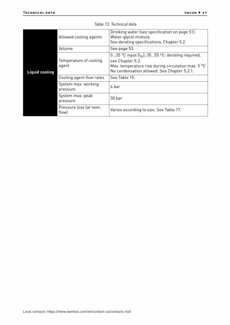
Technical data vacon • 37
Local contacts: https://www.danfoss.com/en/contact-us/contacts-list/
Liquid cooling
Allowed cooling agentsDrinking water (see specification on page 51).Water-glycol mixture.See derating specifications, Chapter 5.2.
Volume See page 53.
Temperature of cooling agent
0…35 °C input (Ith); 35…55 ºC: derating required,
see Chapter 5.3.Max. temperature rise during circulation max. 5 °CNo condensation allowed. See Chapter 5.2.1.
Cooling agent flow rates See Table 15.
System max. working pressure
6 bar
System max. peak pressure
30 bar
Pressure loss (at nom. flow)
Varies according to size. See Table 17.
Table 13. Technical data

vacon • 38 Installation
Local contacts: https://www.danfoss.com/en/contact-us/contacts-list/
5. INSTALLATION
5.1 Mounting
VACON® NX Liquid-Cooled Drive modules must be installed into an enclosure. The drives consisting of one module will be mounted on the mounting plate. The drives that include two or three modules are mounted inside a mounting bracket (see table below) which will then be installed in the enclosure.
NOTE! If any other than vertical installation position is required, contact your distributor!
NOTE! The allowed installation temperature is 0...+70°C.
In Chapter 5.1.2 you will find the dimensions of VACON® NX Liquid-Cooled drives installed on mounting bases (plates and brackets).
5.1.1 Lifting the drive
We recommend you to always use a jib crane or similar elevating device to lift the AC drive/ inverter unit. See figures below for correct lifting points.
For units with no mounting bracket (see Chapter 5.1.2.1), the best place for hoisting is the hole(s) in the middle of the mounting plate (Lifting point 1). VACON® NX Liquid-Cooled drives consisting of several modules can the most safely and easily be lifted by the holes in the mounting bracket (Lifting point 2) using a screw pin shackle. Pay also attention to the recommended dimensions of the hoisting belt and the beam. See Figure 3.
Figure 3. Lifting points for drives consisting of one module (left) and several modules
In cabinet installation, the hoisting procedure described above right may, however, become difficult or even impossible if the cabinet width does not allow the use of the screw pin shackle in Lifting point 2 (see above).
nxw7.fh8
Lifting point 1Ø13mm
Hoisting Belt35 x 1000mm
Beam
1/2" Screw Pin ShackleLifting point 2
n88,9 x 5mm
11311_uk

Installation vacon • 39
Local contacts: https://www.danfoss.com/en/contact-us/contacts-list/
In such case, follow the lifting procedure described in Figure 4. The mounting becomes easier and safer if the drive can be laid on a supporting girder fixed on the cabinet frame. We also recommend to use an aligning stud to guarantee an easy and safe mounting.
Figure 4. Lifting of drive into a narrow mounting space
To additionally stabilize the cabinet with the drive, we recommend to mount a fixing rail on the back of the cabinet, to which the top of the drive can be fastened with 5 or 6 M5 screws. The cut-out is compatible with Rittal or Veda cabinets. Also secure the drive with M8 nuts and studs to the supporting girder. See Figure 4 and Figure 5.
The VACON® NX Liquid-Cooled drives are equipped with plastic handles and these handles can be used to move and lift drives consisting of one power module (CH61, CH62, & CH72) by hand.
NOTE! Never lift a drive from the plastic handle or handles with an elevating device, such as jib crane or hoist. Recommended lifting procedure for these units are as described in Figure 3 and Figure 4.
Hoisting Belt 35 x 1000mm
Beam n 88,9 x 5mm
Fixing Rail
Supporting grider
Aligning stud
Hex nut M12
Washer DIN 7989 - B 14
Protect hoisting beltfrom sharp edges
Washer ISO 7091ST 12 - 100 HV
Hexagon Fit ScrewDIN 7968M12 x 75 10.9
11312_uk

vacon • 40 Installation
Local contacts: https://www.danfoss.com/en/contact-us/contacts-list/
Figure 5. Securing the drive to the cabinet frame
5.1.2 VACON® NX Liquid-Cooled dimensions
5.1.2.1 Drives consisting of one module
Table 14. One-module drive dimensions (mounting base included)
Chassis Width Height Depth Weight*
*. AC choke excluded.
CH3 160 431 246 15
CH4 193 493 257 22
CH5 246 553 264 40
CH61/62 246 658 372 55
CH72 246 1076 372 90
2pcs M8
2pcs M8 PEM
5-6pcs M5
Fixing rail
11313_uk
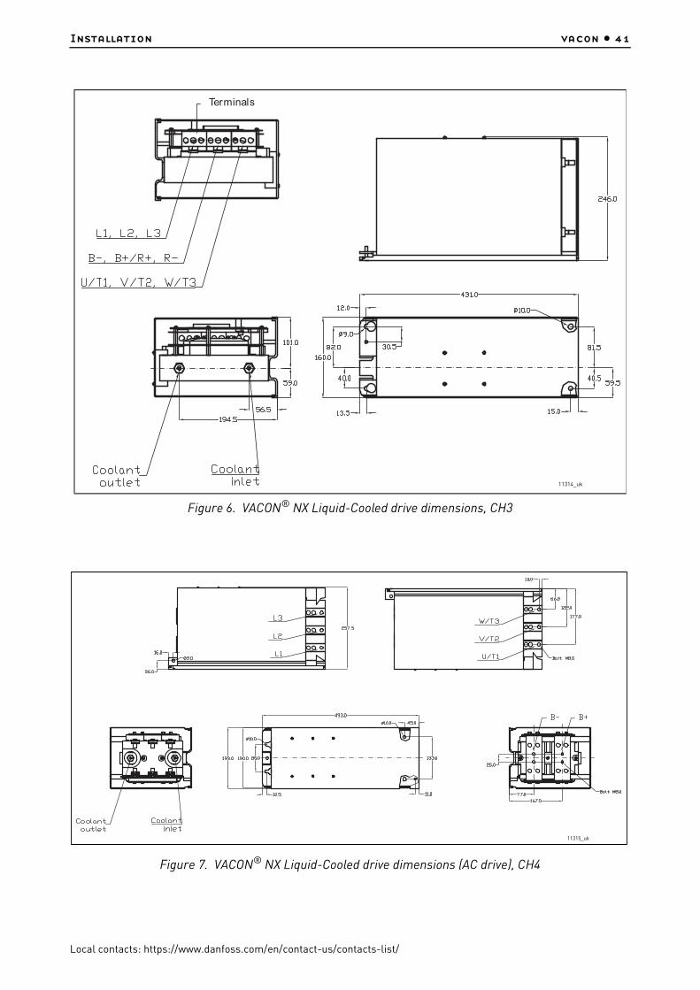
Installation vacon • 41
Local contacts: https://www.danfoss.com/en/contact-us/contacts-list/
Figure 6. VACON® NX Liquid-Cooled drive dimensions, CH3
Figure 7. VACON® NX Liquid-Cooled drive dimensions (AC drive), CH4
Terminals
11314_uk
11315_uk

vacon • 42 Installation
Local contacts: https://www.danfoss.com/en/contact-us/contacts-list/
Figure 8. VACON® NX Liquid-Cooled drive dimensions (inverter), CH4
Figure 9. VACON® NX Liquid-Cooled dimensions, CH5 AC drive
11316_uk
11317_uk

Installation vacon • 43
Local contacts: https://www.danfoss.com/en/contact-us/contacts-list/
Figure 10. VACON® NX Liquid-Cooled dimensions, CH5 inverter
Figure 11. VACON® Liquid-Cooled AC drive, CH61
11318_uk
11319_uk

vacon • 44 Installation
Local contacts: https://www.danfoss.com/en/contact-us/contacts-list/
Figure 12. VACON® Liquid-Cooled inverter, CH61
11320_uk

Installation vacon • 45
Local contacts: https://www.danfoss.com/en/contact-us/contacts-list/
Figure 13. VACON® Liquid-Cooled inverter, CH62
11321_uk

vacon • 46 Installation
Local contacts: https://www.danfoss.com/en/contact-us/contacts-list/
Figure 14. VACON® Liquid-Cooled AC drive (6-pulse), CH72
Figure 15. VACON® Liquid-Cooled AC drive (6-pulse) with internal brake chopper
11322_uk
11323_uk

Installation vacon • 47
Local contacts: https://www.danfoss.com/en/contact-us/contacts-list/
Figure 16. VACON® Liquid-Cooled AC drive (12-pulse), CH72
5.1.2.2 Drives consisting of several modules
VACON® NX Liquid-Cooled drives consisting of several modules are mounted in a mounting bracket as presented in Figure 17.
11324_uk
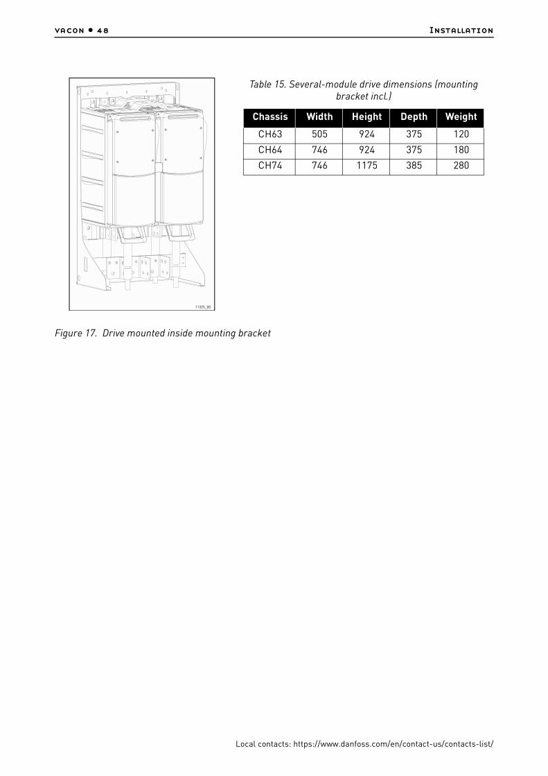
vacon • 48 Installation
Local contacts: https://www.danfoss.com/en/contact-us/contacts-list/
Figure 17. Drive mounted inside mounting bracket
11325_00
Table 15. Several-module drive dimensions (mounting bracket incl.)
Chassis Width Height Depth Weight
CH63 505 924 375 120
CH64 746 924 375 180
CH74 746 1175 385 280

Installation vacon • 49
Local contacts: https://www.danfoss.com/en/contact-us/contacts-list/
Figure 18. VACON® Liquid-Cooled AC drive with mounting bracket, CH63
11326_uk
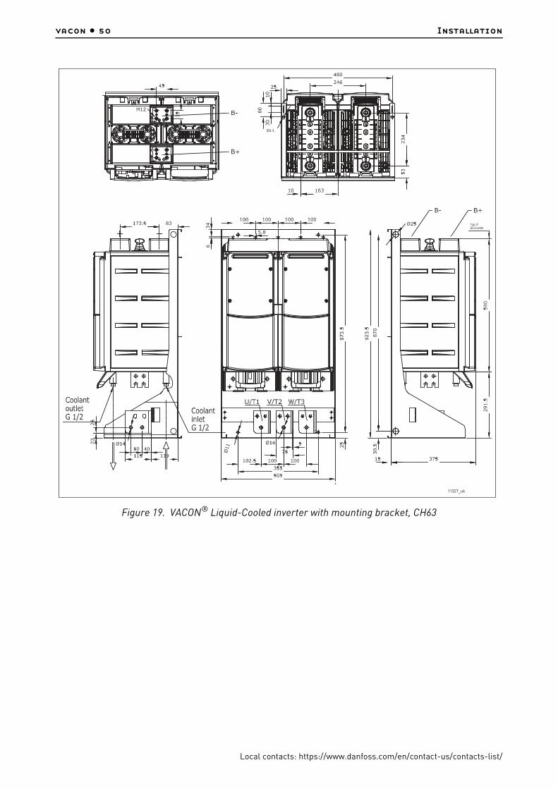
vacon • 50 Installation
Local contacts: https://www.danfoss.com/en/contact-us/contacts-list/
Figure 19. VACON® Liquid-Cooled inverter with mounting bracket, CH63
11327_uk

Installation vacon • 51
Local contacts: https://www.danfoss.com/en/contact-us/contacts-list/
Figure 20. VACON® NX Liquid-Cooled inverter dimensions, CH64, IP00 (UL open type)
11328_uk

vacon • 52 Installation
Local contacts: https://www.danfoss.com/en/contact-us/contacts-list/
Figure 21. VACON® NX Liquid-Cooled AC drive (6-pulse) dimensions, CH74, IP00 (UL open type)
11329_uk

Installation vacon • 53
Local contacts: https://www.danfoss.com/en/contact-us/contacts-list/
Figure 22. VACON® NX Liquid-Cooled AC drive (6-pulse) with internal brake chopper dimensions, CH74, IP00 (UL open type)
11330_uk

vacon • 54 Installation
Local contacts: https://www.danfoss.com/en/contact-us/contacts-list/
Figure 23. VACON® NX Liquid-Cooled AC drive (12-pulse) with internal brake chopper dimensions, CH74, IP00 (UL open type)
11331_uk

Installation vacon • 55
Local contacts: https://www.danfoss.com/en/contact-us/contacts-list/
5.2 Cooling
Instead of using air for cooling, VACON® NX Liquid-Cooled drives are cooled with liquid. The liquid circulation of the drive is usually connected to a heat-exchanger (liquid-liquid/liquid-air) which cools down the liquid circulating in the cooling elements of the drive. Because the cooling elements are made of aluminium, the cooling agents allowed to be used are drinking water, demineralized water or a mixture of water and glycol.
There are two types of circulation system: open systems and closed systems.
An open system has no pressure, and allows free contact with air.
In a closed system, the piping is completely air-tight and there is pressure inside the pipes. The pipes must be made of metal, or specific plastic or rubber that includes an oxygen barrier. Preventing of oxygen diffusion in the coolant diminishes the risk of electrochemical corrosion of the metal parts, and generation of rust deposits. Always use a closed system with VACON® NX Liquid-Cooled drives.
In case there is no other option than using an open system, you must take several precautions.
1. Use glycol and inhibitor in the coolant.2. Examine the water quality regularly, and add inhibitor accordingly. 3. Yearly check that the properties of the cooling liquid are in accordance with the
specification in this manual.
In a closed circulation system, the following figures are recommended reference values. To avoid electrochemical corrosion, it is necessary to add an inhibitor (e.g. Cortec VpCI-649) in the cooling agent.
Add inhibitor to the cooling agent every 2 years and change the cooling agent every 6 years.
The addition of each 0.05% of VpCI-649 into the cooling agent increases the electrical conductivity with 75-100 µS. The maximum value depends on the added dosage rate.
The heat-exchanger delivered by VACON® (HX) consists of stainless steel materials. The good corrosion performance of stainless steel in district water systems is utilized and no disadvantage of divergent metal filler is included. Nevertheless, some precautions must be taken to reduce the corrosion risk on the stainless steel in high chloride waters, see Table 18. We recommend to use a VACON® HX heat exchanger whenever possible.
NOTE! If no heat-exchanger is used, actions must be taken to avoid electrochemical corrosion. Specifically no brass or copper elements may be used in the liquid circulation of the drive.
Copper and brass may be used in the liquid circulation in case the liquid-cooled drive is equipped with a nickel coated aluminum heatsink.
Specification: Drinking water
The attached table gives the chemical requirements for drinking water provided for by the Finnish Ministry of Social Affairs and Health. These values are indicative.
Table 16. Drinking water chemical specification
Quality Unit Value
Acrylamide µg/l 0.10
Antimony µg/l 5.0
Arsenic µg/l 10
Benzene µg/l 1.0

vacon • 56 Installation
Local contacts: https://www.danfoss.com/en/contact-us/contacts-list/
Benzopyrene µg/l 0.010
Boron mg/l 1.0
Bromate µg/l 10
Cadmium µg/l 5.0
Chromium µg/l 50
Copper mg/l 2.0
Cyanides µg/l 50
1,2-Dichloroethane µg/l 3.0
Epichlorohydrin µg/l 0.10
Fluoride mg/l 1.5
Lead µg/l 10
Mercury µg/l 1.0
Nickel µg/l 20
Nitrate (NO3 -) mg/l 50
Nitrate-Nitrogen (NO3-N) mg/l 11.0
Nitrite (NO2 -) mg/l 0.5
Nitrite-Nitrogen (NO2-N) mg/l 0.15
Bactericides µg/l 0.10
Bactericides, total µg/l 0.50
Polynuclear aromatic hydrocarbons µg/l 0.10
Selenium µg/l 10
Tetrachloroethylene and trichloroethylene tot. µg/l 10
Trihalomethanes tot. µg/l 100
Vinyl chloride µg/l 0.50
Chlorophenols total µg/l 10
Table 16. Drinking water chemical specification
Quality Unit Value

Installation vacon • 57
Local contacts: https://www.danfoss.com/en/contact-us/contacts-list/
Notes:
1) No aggressive water allowed.
2) To avoid corrosion of piping, the sulphate content must not exceed 150 mg/l.
The cleanness of the heat exchanger, and therefore the heat exchanging capacity, depend on the purity of the process water. The more impure the water, the more frequently the heat exchanger needs cleaning. The following figures are reference values required of cooling circuit process water:
Table 17. Drinking water quality recommendations
Quality Unit Max. value
Aluminium µg/l 200
Ammonium (NH4 +) mg/l 0.50
Ammonium (NH4-N) mg/l 0.40
Chloride1] mg/l <100
Manganese µg/l 50
Iron µg/l <0.5
Sulphate 1] 2] mg/l 250
Sodium mg/l 200
Oxidizability (CODMn-O2) mg/l 5.0
Quality Unit Desired value
Clostridium perfringens(including spores)
pmy/100 ml 0
Coliform bacteria pmy/100 ml 0
Bacterial count (22 °C) No unusual changes
pH1] pH 6…8
Electrical conductivity1] µS/cm <100
TurbidityTo be approved by user and
no unusual changes
Colour No unusual changes
Smell and taste No unusual changes
Total organic carbon (TOC) No unusual changes
Tritium beq/l 100
Indicative total dose mSv/year 0.10
Water hardness °dH 3...10
Max. particle size in coolant µm 300

vacon • 58 Installation
Local contacts: https://www.danfoss.com/en/contact-us/contacts-list/
Specification: Process water
The design temperature of the cooling agent entering the drive module(s) is 35 °C. While circulating inside the cooling element, the liquid transfers the heat produced by the power semiconductors (and the capacitors). The design temperature rise of the cooling agent during the circulation is less than 5 °C. Typically, 95% of the power losses is dissipated in the liquid. We advise you to equip the cooling agent circulation with temperature supervision.
The heat exchanging equipment can be located outside the electrical room in which the AC drives are. The connections between these two are made on site. In order to minimize the pressure drops, the pipings must be made as straight as possible. We further recommend that a regulating valve equipped with a measurement point is mounted. This makes the measurement and regulation of liquid circulation possible in the commissioning phase.
In order to prevent dirt particles from accumulating in the connections and thus gradually weakening the cooling effect, installation of filters is also recommended.
The highest point of the piping must be equipped with either an automatic or a manual venting device. The material of the piping must comply with at least AISI 304 (AISI 316 is recommended).
Prior to the actual connection of the pipes, the bores must be cleaned thoroughly. If cleaning with water is not possible, although recommended, pressured air must be used to remove all loose particles and dust.
To facilitate the cleaning and venting of the coolant circulation, we recommend you to install a bypass valve in the main line and valves at each AC drive inlet. Open the bypass valve and shut the valves to the AC drive when cleaning and airing the system. On commissioning the system, the bypass valve must be closed and the valves to the AC drives opened.
Below you will find a simplified example of the cooling system as well as an example of the connections between the AC drives and the cooling system.
Table 18. Process water specification
Quality Unit Value
pH 6…9
Water hardness °dH <20
Electrical conductivity µS/cm <100
Chlorides (Cl) *
*. The allowed concentration of chloride ions (Cl–): <1000 ppm at 20°C, < 300 ppm at 50°C and < 100 ppm at 80°C; the values are given as guidance to reduce the corrosion risk on stainless steel. The values are valid for pH=7. Lower pH value increases the risk.
mg/l <100
Iron (Fe) mg/l <0.5

Installation vacon • 59
Local contacts: https://www.danfoss.com/en/contact-us/contacts-list/
Figure 24. Example of cooling system
We recommend to equip the cooling system with pressure and flow supervision (FE). The flow supervision can be connected to digital input function External fault. If the coolant flow is found too low, the AC drive will be stopped.
The flow supervision and other actuators, e.g. a constant flow valve, are available as options. The options must be mounted at the junction of the main line and the branching line to the element, indicated with an asterisk (*) in the figure above.
Figure 25. Example: PI-diagram of the cooling system and the connections
≈=
=
≈
=
≈
=
≈
18.0ºC
26.1ºC
30.0ºC
34.5ºC
FE FE FE
* * **
* * * *
TE
11332_uk
Cooling water inlet
Frequency converters
Cooling water outlet
11333_uk
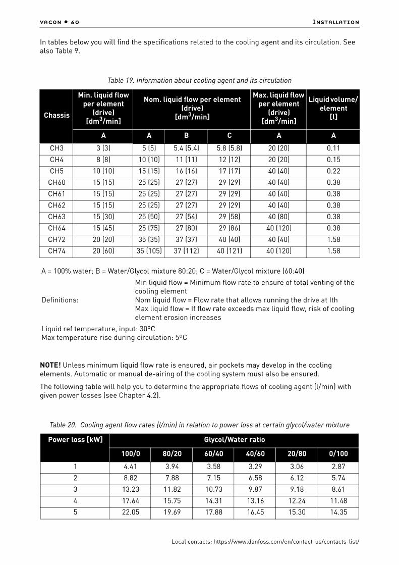
vacon • 60 Installation
Local contacts: https://www.danfoss.com/en/contact-us/contacts-list/
In tables below you will find the specifications related to the cooling agent and its circulation. See also Table 9.
NOTE! Unless minimum liquid flow rate is ensured, air pockets may develop in the cooling elements. Automatic or manual de-airing of the cooling system must also be ensured.
The following table will help you to determine the appropriate flows of cooling agent (l/min) with given power losses (see Chapter 4.2).
Table 19. Information about cooling agent and its circulation
Chassis
Min. liquid flow per element
(drive)[dm3/min]
Nom. liquid flow per element (drive)
[dm3/min]
Max. liquid flow per element
(drive)[dm3/min]
Liquid volume/ element
[l]
A A B C A A
CH3 3 (3) 5 (5) 5.4 (5.4) 5.8 (5.8) 20 (20) 0.11
CH4 8 (8) 10 (10) 11 (11) 12 (12) 20 (20) 0.15
CH5 10 (10) 15 (15) 16 (16) 17 (17) 40 (40) 0.22
CH60 15 (15) 25 (25) 27 (27) 29 (29) 40 (40) 0.38
CH61 15 (15) 25 (25) 27 (27) 29 (29) 40 (40) 0.38
CH62 15 (15) 25 (25) 27 (27) 29 (29) 40 (40) 0.38
CH63 15 (30) 25 (50) 27 (54) 29 (58) 40 (80) 0.38
CH64 15 (45) 25 (75) 27 (80) 29 (86) 40 (120) 0.38
CH72 20 (20) 35 (35) 37 (37) 40 (40) 40 (40) 1.58
CH74 20 (60) 35 (105) 37 (112) 40 (121) 40 (120) 1.58
A = 100% water; B = Water/Glycol mixture 80:20; C = Water/Glycol mixture (60:40)
Definitions:
Min liquid flow = Minimum flow rate to ensure of total venting of the cooling elementNom liquid flow = Flow rate that allows running the drive at IthMax liquid flow = If flow rate exceeds max liquid flow, risk of cooling element erosion increases
Liquid ref temperature, input: 30ºCMax temperature rise during circulation: 5ºC
Table 20. Cooling agent flow rates (l/min) in relation to power loss at certain glycol/water mixture
Power loss [kW] Glycol/Water ratio
100/0 80/20 60/40 40/60 20/80 0/100
1 4.41 3.94 3.58 3.29 3.06 2.87
2 8.82 7.88 7.15 6.58 6.12 5.74
3 13.23 11.82 10.73 9.87 9.18 8.61
4 17.64 15.75 14.31 13.16 12.24 11.48
5 22.05 19.69 17.88 16.45 15.30 14.35
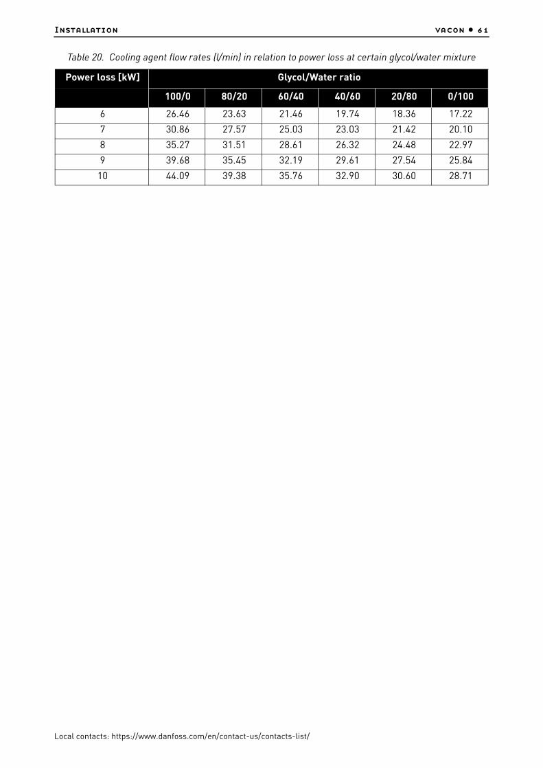
Installation vacon • 61
Local contacts: https://www.danfoss.com/en/contact-us/contacts-list/
6 26.46 23.63 21.46 19.74 18.36 17.22
7 30.86 27.57 25.03 23.03 21.42 20.10
8 35.27 31.51 28.61 26.32 24.48 22.97
9 39.68 35.45 32.19 29.61 27.54 25.84
10 44.09 39.38 35.76 32.90 30.60 28.71
Table 20. Cooling agent flow rates (l/min) in relation to power loss at certain glycol/water mixture
Power loss [kW] Glycol/Water ratio
100/0 80/20 60/40 40/60 20/80 0/100

vacon • 62 Installation
Local contacts: https://www.danfoss.com/en/contact-us/contacts-list/
5.2.1 Condensation
Condensation on the cooling plate of the VACON® NX Liquid-Cooled drive must be avoided. Therefore, the temperature of the cooling liquid must be kept higher than the temperature of the electrical room. Use the graph below to determine if the drive operating conditions (combination of room temperature, humidity and cooling liquid temperature) are safe, or, to choose the allowed temperature for the cooling liquid.
The conditions are safe when the point is below the respective curve. If not, take adequate precautions by decreasing the room temperature and/or the relative humidity or increase the cooling liquid temperature. Note that increasing the temperature of the cooling liquid above figures in loadability charts decreases the nominal output current of the drive. The below curves are valid at sea level altitude (1013 mbar).
Figure 26. Safe operating conditions in relation to condensation
Example:
If the temperature of the electric room is 30 °C, the relative humidity is 40% and the temperature of the cooling liquid is 20 °C (the lowest curve in Figure 26), then the drive operating conditions are safe.
However, if the room temperature were to rise to 35 °C and the relative humidity to 60%, then the operating conditions of the drive would no longer be safe. In this case, to reach safe operating conditions, the air temperature should be cooled to 28 °C or lower. If it is not possible to lower the room temperature, then the temperature of the cooling liquid should be raised to at least 25 °C.
0
10
20
30
40
50
60
0102030405060708090100
Am
bie
n t
em
p °
C
Electric room rela!ve humidity %
Condensation - Safe operating area
45
40
38
35
30
25
20
Coolant temp °C
11334_uk
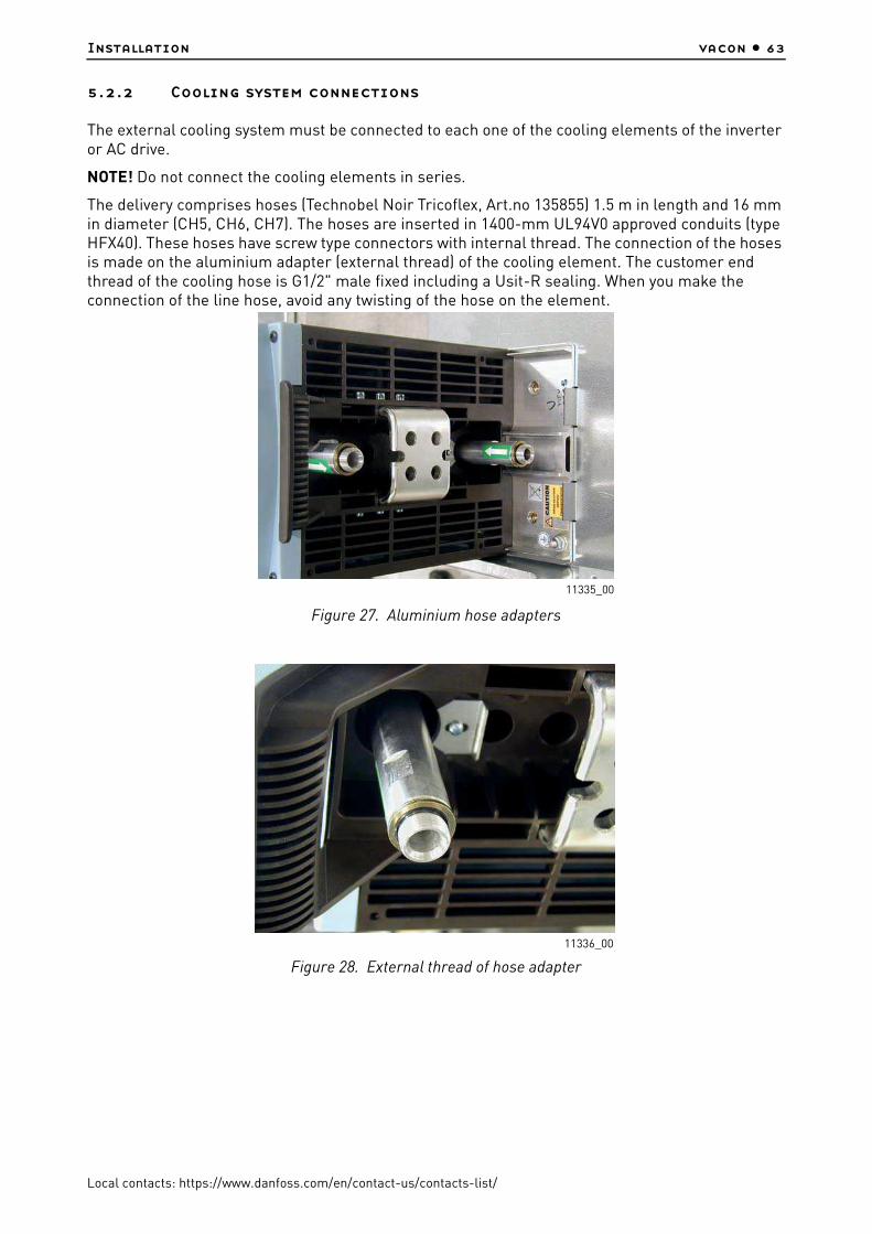
Installation vacon • 63
Local contacts: https://www.danfoss.com/en/contact-us/contacts-list/
5.2.2 Cooling system connections
The external cooling system must be connected to each one of the cooling elements of the inverter or AC drive.
NOTE! Do not connect the cooling elements in series.
The delivery comprises hoses (Technobel Noir Tricoflex, Art.no 135855) 1.5 m in length and 16 mm in diameter (CH5, CH6, CH7). The hoses are inserted in 1400-mm UL94V0 approved conduits (type HFX40). These hoses have screw type connectors with internal thread. The connection of the hoses is made on the aluminium adapter (external thread) of the cooling element. The customer end thread of the cooling hose is G1/2" male fixed including a Usit-R sealing. When you make the connection of the line hose, avoid any twisting of the hose on the element.
Figure 27. Aluminium hose adapters
Figure 28. External thread of hose adapter
11335_00
11336_00

vacon • 64 Installation
Local contacts: https://www.danfoss.com/en/contact-us/contacts-list/
For all other chasses (CH3, CH4), the standard delivery includes fast connectors of type 'Tema', series 1300 or 1900. The fast connectors are available as option also for CH5, CH6, CH7.
Table 21. Liquid connector types (all pressure values at nominal flow)
Chassis
Thread on element
(internal)BSPP *.)
*. ) Use sealing (e.g. Usit-R Metal washer-rubber sealing) for this type of connection according to ISO standard 228-1
Connector type or hose type
Thread(cust.)
BSPP **.)
**. ) Use sealant or sealing tape for this type of connection
Max. pressure
(entire system)
Pressure loss,(fast
connector + element)
Pressure loss,
(hoses + element)
CH3 G3/8" 1300NE2 1/4" 6 bar 0.25 bar
CH4 G3/8" 1300NE2 1/4" 6 bar 0.25 bar
CH5 G3/4" Technobel 16*23.5 G1/2" 6 bar 0.2 bar
CH6 G3/4" Technobel 16*23.5 G1/2" 6 barSee table
belowSee table
below
CH7 G3/4" Technobel 16*23.5 G1/2" 6 barSee table
belowSee table
below

Installation vacon • 65
Local contacts: https://www.danfoss.com/en/contact-us/contacts-list/
5.2.2.1 Pressure losses
Figure 29. Pressure loss, CH6x
Table 22. Pressure losses; CH6x
CH6x with standard 1.5m hoses and optional fast connectors TEMA
Volume flow rate
(l/min)
Pressure loss;
Tema, inflow (bar)
Pressure loss; inflow hose (bar)
Pressure loss;
element (bar)
Pressure loss;
outflow hose: (bar)
Pressure loss; Tema,
outflow (bar)
Pressure loss total
(inflow hose,
element and
outflow hose) (bar)
Pressure loss total
(Tema, inflow and
outflow hoses and element)
(bar)
40.0 0.59 0.30 0.28 0.29 0.51 0.87 1.96
30.0 0.30 0.17 0.16 0.16 0.25 0.49 1.04
20.0 0.10 0.09 0.08 0.07 0.09 0.24 0.43
17.0 0.06 0.07 0.06 0.03 0.07 0.16 0.29
CH6; Pressure loss
10,0
15,0
20,0
25,0
30,0
35,0
40,0
45,0
0,00 0,50 1,00 1,50 2,00 2,50
Pressure loss, bar
Vo
lum
e f
low
rate
, l/
min
Pressure loss; Tema, inflow(SET-SEL) (bar)
Pressure loss; inflow hose (SEL-SEE) (bar)
Pressure loss; element (SEE-PEJ)
Pressure loss; outflow hose:(PEJ-PLJ) (bar)
Pressure loss; Tema, outflow(PLJ-PTJ)(bar)
Pressure loss total (inflow hose,ele-ment and outflow hose)
Pressure loss total (Tema, inflowand outflow hoses and element)
11337_uk

vacon • 66 Installation
Local contacts: https://www.danfoss.com/en/contact-us/contacts-list/
Figure 30. Pressure loss, CH7x
The liquid carrying hoses from the network to the cooling elements of the drive must not be electrically conductive. Risk of electrical shock and device damage! To avoid electrochemical corrosion, it is necessary to add an inhibitor (e.g. Cortec VpCI-649l in the cooling liquid.
The following main line hose materials are allowed for a liquid cooled drive including an aluminum heatsink:
The following main line hose materials are allowed for a liquid cooled drive including a nickel coated aluminum heatsink:
Table 23. Pressure losses; CH7x
CH7x (16) with standard 1.5m hoses and optional fast connectors TEMA
Volume flow
rate (l/min)
Pressure loss;
Tema, inflow (bar)
Pressure loss;
inflow hose (bar)
Pressure loss;
element (bar)
Pressure loss;
outflow hose: (bar)
Pressure loss; Tema,
outflow (bar)
Pressure loss total
(inflow hose,
element and outflow hose) (bar)
Pressure loss total
(Tema, inflow and
outflow hoses and element)
(bar)
40.0 0.61 0.30 0.28 0.28 0.50 0.87 1.97
30.0 0.31 0.17 0.17 0.16 0.26 0.50 1.07
20.0 0.11 0.09 0.08 0.07 0.10 0.24 0.44
• plastic (PVC) • aluminium
• rubber (EPDM & NBR only) • other stainless and acid-proof materials
• plastic (PVC) • aluminium
• rubber (EPDM & NBR only) • brass
• copper • other stainless and acid-proof material
CH7, pressure loss
10,0
15,0
20,0
25,0
30,0
35,0
40,0
45,0
0,00 0,50 1,00 1,50 2,00 2,50
Pressure loss, bar
Vo
lum
e f
low
rate
Pressure loss; element (SEE-PEJ)
Pressure loss; outflow hose;(PEJ-PLJ)
Pressure loss; inflow hose (SEL-SEE)
Pressure loss; Tema, inflow(SET-SEL)
Pressure loss; Tema, outflow(PLJ-PTJ)
Pressure loss total (inflow hose,element and outflow hose)
Pressure loss total (Tema, inflowand outflow hoses, element)
11338_uk

Installation vacon • 67
Local contacts: https://www.danfoss.com/en/contact-us/contacts-list/
The hoses must tolerate a peak pressure of 30 bar.
Connect the line hose to its counterpart (screw connector or fast connector) on the cooling element of the AC drive/inverter. The coolant inlet connector is the one closer to the mounting plate and the outlet connector the one closer to the face of the drive, see Figure 32. Due to high pressure in the line hose, it is recommended to equip the liquid line with a shut-off valve, which makes the connection easier. In order to prevent water from spraying in the installation room we also recommend to wrap e.g. linters around the connection on installing.
We also recommend to equip the pipe branches to the cooling elements with valves.
5.2.2.2 Installation of flow switch
As stated on page 59, we recommend the installation of flow supervision in the liquid cooling system. You can order the flow switch as an option. The specification of the flow switch as well as notes as concerns its installation are given below.
About the installation
We recommend to mount the flow switch on the inflow side of the system (see Figure 24). Pay attention to the direction of flow. The switch reaches the highest accuracy when it is mounted in horizontal position. If mounted vertically, the mechanical sensor is affected by the Earth’s gravity which reduces the accuracy according to the data given in Table 24.
Figure 31. Flow switch: Hose connection, fast connector (electrical), fast connector lock screw, cable seal and clamp
Table 24. Flow switch data
Hose connection G1/2” female, internal thread ISO228-1
Closing The switch closes if the flow exceeds 20 l/min.
Switching accuracy:Horizontal installation
Vertical installation
–5…+15% (19…23 l/min)±5% (19…21 l/min)
11339_00

vacon • 68 Installation
Local contacts: https://www.danfoss.com/en/contact-us/contacts-list/
Figure 32. Direction of coolant circulation
Coolant inletCoolant outlet
11340_uk

Installation vacon • 69
Local contacts: https://www.danfoss.com/en/contact-us/contacts-list/
5.3 Drive derating
The tables below state the maximum coolant temperatures for VACON® Liquid-Cooled drives at given switching frequencies. Drive derating is required if the maximum temperatures are exceeded.
NOTE! If the heatsink is nickel-coated you must allow for a 2-degree C derating of values in the tables below.1) (Temperatures given in parenthesis). This applies only to the two biggest drive sizes of each chassis!
Table 25. Max temperatures of coolant at switching frequency of 3.6 kHz
Supply voltage 400-500 VAC, switching frequency 3.6 kHz
Chassis TypeMax coolant temperature [°C]
Supply voltage 400 VMax coolant temperature [°C]
Supply voltage 500 V
CH61 NXP0385_5 47 (45) 1) 43 (41) 1)
CH62 NXP0730_5 40 (38) 1) 37 (35) 1)
CH63 NXP1150_5 38 (36) 1) 36 (34) 1)
CH64 NXP2060_5 44 (42) 1) 42 (40) 1)
CH64 NXP2300_5 42 (40) 1) 40 (38) 1)
CH72 NXP0730_5 42 (40) 1) 40 (38) 1)
CH74 NXP2060_5 37 (35) 1) 34 (32) 1)
CH74 NXP2300_5 37 (35) 1) 34 (32) 1)
Table 26. Max temperatures of coolant at switching frequency of 1.5 kHz
Supply voltage 400-500 VAC, switching frequency 1.5 kHz
Chassis TypeMax coolant temperature [°C]
Supply voltage 400 VMax coolant temperature [°C]
Supply voltage 500 V
CH61 NXP0385_5 52 (50) 1) 49 (47) 1)
CH62 NXP0730_5 47 (45) 1) 45 (43) 1)
CH63 NXP1150_5 44 (42) 1) 42 (40) 1)
CH64 NXP2060_5 49 (47) 1) 47 (45) 1)
CH64 NXP2300_5 44 (42) 1) 42 (40) 1)
CH72 NXP0730_5 45 (43) 1) 43 (41) 1)
CH74 NXP2060_5 49 (47) 1) 47 (45) 1)
CH74 NXP2300_5 44 (42) 1) 43 (41) 1)

vacon • 70 Installation
Local contacts: https://www.danfoss.com/en/contact-us/contacts-list/
Table 27. Max temperatures of coolant at switching frequency of 3.6 kHz
Supply voltage 525-690 VAC, switching frequency 3.6 kHz
Chassis TypeMax coolant temperature [°C]
Supply voltage 525 VMax coolant temperature [°C]
Supply voltage 690 V
CH61 NXP0261_6 45 (43) 1) 39 (37) 1)
CH62 NXP0502_6 41 (39) 1) 33 (31) 1)
CH63 NXP0750_6 42 (40) 1) 36 (34) 1)
CH64 NXP1500_6 41 (39) 1) 34 (32) 1)
CH72 NXP0502_6 38 (36) 1) 32 (30) 1)
CH74 NXP1500_6 41 (39) 1) 34 (32) 1)
Table 28. Max temperatures of coolant at switching frequency of 1.5 kHz
Supply voltage 525-690 VAC, switching frequency 1.5 kHz
Chassis TypeMax coolant temperature [°C]
Supply voltage 525 VMax coolant temperature [°C]
Supply voltage 690 V
CH61 NXP0261_6 54 (52) 1) 51 (49) 1)
CH62 NXP0502_6 52 (50) 1) 47 (45) 1)
CH63 NXP0750_6 53 (51) 1) 50 (48) 1)
CH64 NXP1500_6 52 (50) 1) 47 (45) 1)
CH72 NXP0502_6 51 (49) 1) 46 (44) 1)
CH74 NXP1500_6 52 (50) 1) 48 (46) 1)
Table 29. Max temperatures of coolant
Supply voltage 400-690 VAC
Chassis TypeMax coolant temperature [°C]
Supply voltage 400 VMax coolant temperature [°C]
Supply voltage 690 V
CH 60 NXN2000_6 43 43

Installation vacon • 71
Local contacts: https://www.danfoss.com/en/contact-us/contacts-list/
5.4 Input chokes
The input choke has several functions in the VACON® NX Liquid-Cooled AC drive. Connection of the input choke is necessary except if you have a component in your system that performs the same tasks (e.g. a transformer). The input choke is needed as an essential component for motor control, to protect the input and DC-link components against abrupt changes of current and voltage as well as to function as a protection against harmonics. In chasses with multiple parallel line rectifiers (CH74) AC-chokes are required to balance the line current between the rectifiers.
The input chokes are included in the standard delivery of VACON® Liquid-Cooled AC drives (not inverters). However, you can also order your AC drive without the choke.
The VACON® input chokes listed in the following chapters are meant for supply voltages of 400-500 V and 525-690 V.
The use of liquid-cooled input chokes increases the proportion of the system’s total power losses directed to coolant. Therefore the manufacturer recommends the use of liquid-cooled input chokes.
The specified minimum/maximum flow rate for liquid-cooled input chokes is 4–12 l/min.
5.4.1 Grounding of input chokes
The grounding of the input chokes can be made optionally from top or bottom. See Figure 33. It is recommended to use M12 bolt with tightening torque 70 Nm.
Figure 33. The grounding points for input chokes
A. Grounding points from the topB. Grounding points from the lower bracket
A B
12016_00

vacon • 72 Installation
Local contacts: https://www.danfoss.com/en/contact-us/contacts-list/
5.4.2 Liquid-cooled input chokes
Table 30. Liquid-cooled input choke dimensioning, 6-pulse supply
Table 31. Liquid-cooled input choke dimensioning, 12-pulse supply
AC drive types(400—500
V AC)
Chokes per
drive
AC drive types
(690 V AC)
Chokes per
driveChoke type
Thermal current
[A]
Nominal inductance [uH] A/B*
Power lossc/a/T**[W] ***
0168…0261 1 0170…0261 1CHK-0261-6-
DL261 139/187 527/323/850
0300…0385 10325…03850820...11801850...2340
136
CHK-0400-6-DL
400 90/126616/484/
1100
0460…05201370 (CH74)
13
0416…05021300...15002700...3100
136
CHK-0520-6-DL
520 65/95826/574/
1400
0590…06501640
13
0590…06501700
13
CHK-0650-6-DL
650 51/71732/468/
1200
07302060
13
0750 1CHK-0750-6-
DL750 45/61
884/816/1700
08202300
13
- -CHK-0820-6-
DL820 39/53
969/731/1700
0920…1030 1 - -CHK-1030-6-
DL1030 30/41
1073/777/1850
1150 1 - -CHK-1150-6-
DL1150 26/36
1218/882/2100
2470...2950 6 - -CHK-0520-6-
DL520 65/95
826/574/1400
3710 6 - -CHK-0650-6-
DL650 51/71
732/468/1200
4140 6 - -CHK-0750-6-
DL750 45/61
884/816/1700
*Inductances for different supply voltages; A = 400…480 V AC, B = 500…690 V AC. See page 77.**C = power loss into coolant, A = power loss into air, T = total power loss.***Losses for one input choke.
AC drive types(400—500
V AC)
AC drive types(690 V AC)
Choke type(2 chokes needed)
Thermal current
[A]
Nominal inductance [uH]
A/B*
Power lossc/a/T**[W]***
0460…0520 0325…0502 CHK-0261-6-DL 261 139/187 527/323/850
0590…0730 0590…0750 CHK-0400-6-DL 400 90/120 616/484/1100
0820…10300820…1030
1850CHK-0520-6-DL 520 65/95 826/574/1400
115023002470
1180…13002120…2340
CHK-0650-6-DL 650 51/71 732/468/1200

Installation vacon • 73
Local contacts: https://www.danfoss.com/en/contact-us/contacts-list/
5.4.3 Air-cooled input chokes
13702950
13702700
CHK-0750-6-DL 750 45/61 884/816/1700
164015003100
CHK-0820-6-DL 820 39/53 969/731/1700
20603710
1700 CHK-1030-6-DL 1030 30/41 1073/777/1850
4140 - CHK-1150-6-DL 1150 26/36 1218/882/2100
AC drive types written in bold require two (2) chokes of the designated kind per unit (totally 4).*Inductances for different supply voltages; A = 400…480 V AC, B = 500…690 V AC. See page 77.**C = power loss into coolant, A = power loss into air, T = total power loss.***Losses for one input choke.
Table 32. Air-cooled input choke dimensioning, 6-pulse supply
AC drive types(400—500
V AC)
Chokes per
drive
AC drive types
(690 V AC)
Chokes per
driveChoke type
Thermal current
[A]
Nominal inductance [uH] A/B*
Calculated loss [W]**
0016…0022 1 - 1 CHK0023N6A0 23 1900 145
0031…0038 1 - 1 CHK0038N6A0 38 1100 170
0045…0061 1 - 1 CHK0062N6A0 62 700 210
0072…0087 1 - 1 CHK0087N6A0 87 480 250
0105…0140 1 - 1 CHK0145N6A0 145 290 380
0168…0261 1 0170…0261 1 CHK0261N6A0 261 139/187 750
0300…0385 10325…03850820…11801850…2340
136
CHK0400N6A0 400 90/126 1060
0460…05201370 (CH74)
13
0416…05021300...15002700...3100
136
CHK0520N6A0 520 65/95 1230
0590…06501640
13
0590…06501700
13
CHK0650N6A0 650 51/71 1260
07302060
13
0750 1 CHK0750N6A0 750 45/61 1510
08202300
13
- - CHK0820N6A0 820 39/53 1580
0920...1030 1 - - CHK1030N6A0 1030 30/41 1840
1150 1 - - CHK1150N6A0 1150 26/36 2200
2470...2950 6 - - CHK0520N6A0 520 65/95 810
3710 6 - - CHK0650N6A0 650 51/71 890
4140 6 - - CHK0750N6A0 750 45/61 970
*Inductances for different supply voltages; A = 400…480 V AC, B = 500…690 V AC. See page 77.**Losses for one input choke.
AC drive types(400—500
V AC)
AC drive types(690 V AC)
Choke type(2 chokes needed)
Thermal current
[A]
Nominal inductance [uH]
A/B*
Power lossc/a/T**[W]***
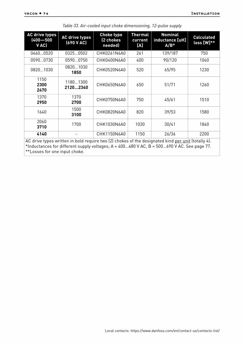
vacon • 74 Installation
Local contacts: https://www.danfoss.com/en/contact-us/contacts-list/
Table 33. Air-cooled input choke dimensioning, 12-pulse supply
AC drive types(400—500
V AC)
AC drive types(690 V AC)
Choke type(2 chokes needed)
Thermal current
[A]
Nominal inductance [uH]
A/B*
Calculated loss [W]**
0460…0520 0325…0502 CHK0261N6A0 261 139/187 750
0590…0730 0590…0750 CHK0400N6A0 400 90/120 1060
0820…10300820…1030
1850CHK0520N6A0 520 65/95 1230
115023002470
1180…13002120…2340
CHK0650N6A0 650 51/71 1260
13702950
13702700
CHK0750N6A0 750 45/61 1510
164015003100
CHK0820N6A0 820 39/53 1580
20603710
1700 CHK1030N6A0 1030 30/41 1840
4140 - CHK1150N6A0 1150 26/36 2200
AC drive types written in bold require two (2) chokes of the designated kind per unit (totally 4).*Inductances for different supply voltages; A = 400…480 V AC, B = 500…690 V AC. See page 77.**Losses for one input choke.

Installation vacon • 75
Local contacts: https://www.danfoss.com/en/contact-us/contacts-list/
5.4.4 Installation of the input chokes
There are two types of input choke connection in VACON® NX Liquid-Cooled drives. The two smallest sizes (CH31, CH32; up to 61 A) have terminal block connection whereas the bigger sizes use busbar connection. Examples of connections and the input choke dimensions below.
5.4.4.1 Connection examples and dimensions for liquid-cooled input chokes
Always connect the supply cables to the choke terminals marked with #1 (see Figure Figure 34). Choose the AC drive side connection according the following table.
The limb in the middle has two sensors for overtemperature protection. The contacts are normally closed (NC switches). A warning is issued when the temperature exceeds 140ºC and a fault when the temperature exceeds 150ºC.
Figure 34. Example of liquid-cooled input chokes for VACON® NX Liquid-Cooled. Sizes 261 A…1150 A
12020_00
A
S2
S2
A. Terminal number
Table 34.
Supply voltage
AC drive connection
(terminal no.)
400-480 Vac 2
500 Vac 3
525-690 Vac 3

vacon • 76 Installation
Local contacts: https://www.danfoss.com/en/contact-us/contacts-list/
Table 35. Liquid-cooled input choke dimensions; Sizes 261 A...1150 A
5.4.4.2 Connection examples and dimensions for air-cooled input chokes
Figure 35. Example of air-cooled input chokes for VACON® NX Liquid-Cooled. Sizes up to 62 A
Choke type
H1 [mm]
W1 [mm]
W2 [mm]
W3 [mm]
W4 [mm]
W5 [mm]
D1 [mm]
D2 [mm]
D3 [mm]
D4 [mm]
S1 [mm]
S2 [mm]
Weight [kg]
261 500 308 305 150 50 100 270 62 91 217 13 11x15 70
400 497 308 305 150 50 100 276 62 97 217 13 11x15 75
520 502 390 380 250 150 115 276 64 97 217 13 11x15 104
650 505 450 430 300 200 140 284 64 105 217 13 11x15 121
750 557 450 430 300 200 140 284 64 105 217 13 11x15 135
820 506 450 430 300 200 140 282 64 102 217 13 11x15 118
1030 642 450 430 300 200 140 274 76 130 185 13 13x18 124
1150 647 450 430 300 200 140 308 76 130 217 13 13x18 162
W1
W2
H1 H2
D1
D2
S1
Z W Y V X U
23a.fh8
11341_00

Installation vacon • 77
Local contacts: https://www.danfoss.com/en/contact-us/contacts-list/
Figure 36. Example of air-cooled input chokes for VACON® NX Liquid-Cooled. Sizes 87 A…145 A and 590A
Always connect the supply cables to the choke terminals marked with #1 (see Figure 37). Choose the AC drive connection according to the following table.
Figure 37. Example of air-cooled input chokes for VACON® NX Liquid-Cooled. Sizes 261 A…1150 A
Table 36. Air-cooled input choke dimensions; Sizes 23 A…145 A and 590 A
Choke typeH1
[mm]H2
[mm]W1
[mm]W2
[mm]D1
[mm]D2
[mm]S1
[mm]S2
[mm]Weight
[kg]
CHK0023N6A0 178 140 230 210 121 82 9*14 (4pcs) 10
CHK0038N6A0 209 163 270 250 NA NA 9*14 (6pcs) 15
CHK0062N6A0 213 155 300 280 NA NA 9*14 (4pcs) 20
CHK0087N6A0 232 174 300 280 170 9*14 (4pcs) Ø9 (6 pcs) 26
CHK0145N6A0 292 234 300 280 185 9*14 (4pcs) Ø9 (6 pcs) 37
CHK0590N6A0 519 394 316 272 165 10*35 (4pcs) Ø11 (6 pcs) 125
W1
H1
W2
D1
D2
S2
S1
220a.fh8
H2
Mains
Converter
11342_uk
1 1 1
3 3 3
2 2 2
W1
H1 H2
W2W3
W4 W4
D1
D2
D3
S1
S2
nxw12.fh11
Terminal numbers
11343_uk
Table 37.
Supply voltageAC drive
connection(terminal no.)
400-480 Vac 2
500 Vac 3
525-690 Vac 3

vacon • 78 Installation
Local contacts: https://www.danfoss.com/en/contact-us/contacts-list/
5.4.4.3 Instructions for installation of the input chokes
If you have ordered the input chokes for VACON® NX Liquid-Cooled separately pay attention to the following instructions:
1. Protect the chokes from dripping water. You may even need to use plexiglass for protection because jets of water may occur when working with the connections.
2. Connection of cables:Types CHK0023N6A0, CHK0038N6A0, CHK0062N6A0 (chokes with terminal blocks)The terminals are marked with letters U,V, W and X,Y and Z in such an order, however, that terminals U and X, V and Y as well as W and Z form pairs of which one is an input and the other an output. Furthermore, terminals U,V and W must all be used as either input or output. The same applies to terminals X, Y and Z. See Figure 35.
Example: If you connect the mains cable of one phase to terminal X, the other two phases must be connected to Y and Z. Accordingly, the choke output cables are connected to their corresponding input pairs: phase 1 à U, phase 2 à V and phase 3 à W.
Other types (chokes with busbar connection) Connect the mains cables to the upper busbar connectors (see Figure 36 and Figure 37) with bolts. The cables to the AC drive are bolted to the lower connectors. See Table 36 and Table 38 for bolt sizes.
Table 38. Air-cooled input choke dimensions; Sizes 261 A…1150 A
Choke typeH1
[mm]H2
[mm]W1
[mm]W2
[mm]W3
[mm]W4
[mm]D1
[mm]D2
[mm]D3
[mm]S1
S2Ø
Weight[kg]
CHK0261N6A0 319 357 354 150 275 120 230 206 1089*14
(8 pcs)9*14
(9 pcs)53
CHK0400N6A0 383 421 350 150 275 120 262 238 1409*14
(8 pcs)11*15 (9 pcs)
84
CHK0520N6A0 399 446 497 200 400 165 244 204 145Ø13
(8 pcs)11*15 (9 pcs)
115
CHK0650N6A0 449 496 497 200 400 165 244 206 145Ø13
(8 pcs)11*15 (9 pcs)
130
CHK0750N6A0 489 527 497 200 400 165 273 231 170Ø13
(8 pcs)13*18 (9 pcs)
170
CHK0820N6A0 491 529 497 200 400 165 273 231 170Ø13
(8 pcs)13*18 (9 pcs)
170
CHK1030N6A0 630 677 497 200 400 165 307 241 170Ø13
(8 pcs)13*18
(36 pcs)213
CHK1150N6A0 630 677 497 200 400 165 307 241 170Ø13
(8 pcs)13*18
(36 pcs)213

Electrical cabling and connections vacon • 79
Local contacts: https://www.danfoss.com/en/contact-us/contacts-list/
6. ELECTRICAL CABLING AND CONNECTIONS
6.1 Power unit
How the power connections of VACON® NX Liquid-Cooled units are implemented depends on the size of the unit. The smallest VACON® NX Liquid-Cooled unit (CH3) has terminal blocks for the connections. In all other units, the connection is established using cables and cable clips or bolting the busbars together.
The main circuit diagrams of each VACON® NX Liquid-Cooled drive chassis you will find in Appendix 2 on page 248.
6.1.1 Power connections
Use cables with heat resistance of at least +90 °C. The cables and the fuses must be sized according to the drive nominal OUTPUT current that you can find on the rating plate. Sizing according to the output current is recommended because the drive input current never significantly exceeds the output current. Installation of cables according to UL regulations is presented in Chapter 6.1.6.
In chassis CH5 and greater, the field cables (both motor and mains) must be connected to a specific cable connection block (optional equipment). However, inside a switchgear, the cable connection can be made directly to the drive.
VACON® Liquid-Cooled NX_8 inverter units must be equipped with a dU/dt- or sine-filter.
Table 45 shows the minimum sizes of the Cu-cables and the corresponding aR fuse sizes.
If the motor temperature protection of the drive (see VACON® NX All in One Application Manual) is used as an overload protection, the cable must be chosen accordingly. If three or more cables are used in parallel each cable requires a separate overload protection.
These instructions apply only to cases with one motor and one cable connection from the AC drive or inverter to the motor. In any other case, ask the factory for more information.
6.1.1.1 Mains cable
The mains cables of the size CH31 are connected to terminal blocks [see Figure 6] whereas busbar connection is used for greater sizes, see drawings in Chapter 5.1.2.2. Mains cable type for EMC level N in Table 39.
6.1.1.2 Motor cable
In order to avoid current sharing disbalance it is imperative to use symmetrical motor cables. We also recommends to always use shielded cable whenever possible.
The motor cables of the size CH31 are connected to terminal blocks (see Figure 6) whereas busbar connection is used for greater sizes, see drawings on on Chapter 5.1.2.2. Motor cable type for EMC level N in Table 39. Ask factory for more information on the use of ferrite cores with the motor cable in order to protect the motor bearings against motor bearing currents.
For information on control cables see Chapter 6.2.2.1 and Table 39.

vacon • 80 Electrical cabling and connections
Local contacts: https://www.danfoss.com/en/contact-us/contacts-list/
6.1.1.3 Motor cable data
Table 39. Cable types required to meet standards
Cable type Level N/T
Mains cable 1
Motor cable 1
Control cable 4
1 = Power cable intended for fixed installation and the specificmains voltage. Symmetrical shielded cable recommended.(NKCABLES/MCMK or similar recommended)
4 = Screened cable equipped with compact low-impedanceshield (NKCABLES /JAMAK, SAB/ÖZCuY-O or similar).
Table 40. Motor cable sizes, 400—500 V
Chassis Type IthMotor cable
Cu [mm2]
Terminal cable sizeMax. number of
cables/Bolt size
Main terminal
[mm2], max.
Earth terminal[mm2]
CH3 0016_5 16 3*2.5+2.5 50 1—10 (Terminal block)
CH3 0022_5 22 3*4+4 50 1—10 (Terminal block)
CH3 0031 31 3*6+6 50 1—10 (Terminal block)
CH30038_50045_5
38—45 3*10+1050 Cu50 Al
6—35 (Terminal block)
CH3 0061_5 61 3*16+1650 Cu50 Al
6—35 (Terminal block)
CH4 0072_5 72 3*25+1650 Cu50 Al
6—70 1/M8
CH4 0087_5 87 3*35+1650 Cu50 Al
6—70 1/M8
CH4 0105_5 105 3*50+2550 Cu50 Al
6—70 1/M8
CH4 0140_5 140 3*70+35 95 Cu/Al 25—95 1/M8
CH5 0168_5 168 3*95+50 185 Cu/Al 25—95 2/M10
CH5 0205_5 205 3*150+70 185 Cu/Al 25—95 2/M10
CH5 0261_5 261 3*185+95 185 Cu/Al 25—95 2/M10
CH61 0300_5 300 2*(3*120+70) * 25—185 2/M12
CH61 0385_5 385 2*(3*120+70) * 25—185 2/M12
CH62/72 0460_5 460 2*(3*150+70) ** 25—185 4/M12
CH62/72 0520_5 520 2*(3*185+95) ** 25—185 4/M12
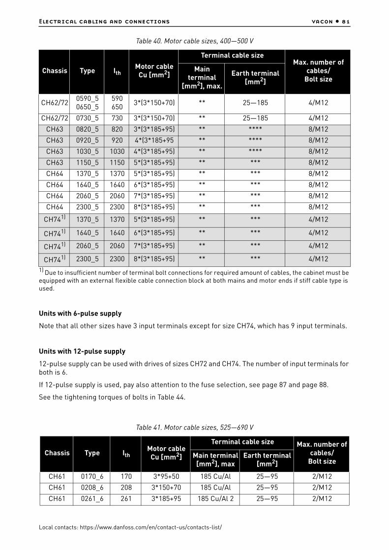
Electrical cabling and connections vacon • 81
Local contacts: https://www.danfoss.com/en/contact-us/contacts-list/
1) Due to insufficient number of terminal bolt connections for required amount of cables, the cabinet must be equipped with an external flexible cable connection block at both mains and motor ends if stiff cable type is used.
Units with 6-pulse supply
Note that all other sizes have 3 input terminals except for size CH74, which has 9 input terminals.
Units with 12-pulse supply
12-pulse supply can be used with drives of sizes CH72 and CH74. The number of input terminals for both is 6.
If 12-pulse supply is used, pay also attention to the fuse selection, see page 87 and page 88.
See the tightening torques of bolts in Table 44.
CH62/720590_50650_5
590650
3*(3*150+70) ** 25—185 4/M12
CH62/72 0730_5 730 3*(3*150+70) ** 25—185 4/M12
CH63 0820_5 820 3*(3*185+95) ** **** 8/M12
CH63 0920_5 920 4*(3*185+95 ** **** 8/M12
CH63 1030_5 1030 4*(3*185+95) ** **** 8/M12
CH63 1150_5 1150 5*(3*185+95) ** *** 8/M12
CH64 1370_5 1370 5*(3*185+95) ** *** 8/M12
CH64 1640_5 1640 6*(3*185+95) ** *** 8/M12
CH64 2060_5 2060 7*(3*185+95) ** *** 8/M12
CH64 2300_5 2300 8*(3*185+95) ** *** 8/M12
CH741) 1370_5 1370 5*(3*185+95) ** *** 4/M12
CH741) 1640_5 1640 6*(3*185+95) ** *** 4/M12
CH741) 2060_5 2060 7*(3*185+95) ** *** 4/M12
CH741) 2300_5 2300 8*(3*185+95) ** *** 4/M12
Table 41. Motor cable sizes, 525—690 V
Chassis Type IthMotor cable
Cu [mm2]
Terminal cable size Max. number of cables/
Bolt sizeMain terminal
[mm2], maxEarth terminal
[mm2]
CH61 0170_6 170 3*95+50 185 Cu/Al 25—95 2/M12
CH61 0208_6 208 3*150+70 185 Cu/Al 25—95 2/M12
CH61 0261_6 261 3*185+95 185 Cu/Al 2 25—95 2/M12
Table 40. Motor cable sizes, 400—500 V
Chassis Type IthMotor cable
Cu [mm2]
Terminal cable sizeMax. number of
cables/Bolt size
Main terminal
[mm2], max.
Earth terminal[mm2]

vacon • 82 Electrical cabling and connections
Local contacts: https://www.danfoss.com/en/contact-us/contacts-list/
1)Due to insufficient number of terminal bolt connections for required amount of cables, the cabinet must be equipped with an external flexible cable connection block at both mains and motor ends if stiff cable type is used.
* = Number of bolt connections 2
** = Number of bolt connections 4
*** = Three grounding terminals per mounting plate, see Chapter 6.1.7.
**** = Two grounding terminals per mounting plate, see Chapter 6.1.7.
See the tightening torques of bolts in Table 44.
CH62/72 0325_6 325 2*(3*95+50) ** 25—185 4/M12
CH62/72 0385_6 385 2*(3*120+70) ** 25—185 4/M12
CH62/72 0416_6 416 2*(3*150+70) ** 25—185 4/M12
CH62/72 0460_6 460 2*(3*185+95) ** 25—185 4/M12
CH62/72 0502_6 502 2*(3*185+95) ** 25—185 4/M12
CH63 0590_6 590 3*(3*150+70) ** *** 8/M12
CH63 0650_6 650 3*(3*150+70) ** *** 8/M12
CH63 0750_6 750 3*(3*185+95) ** *** 8/M12
CH741) 0820_6 820 4*(3*150+70) ** *** 4/M12
CH741) 0920_6 920 4*(3*185+95) ** *** 4/M12
CH741) 1030_6 1030 4*(3*185+95) ** *** 4/M12
CH741) 1180_6 1180 5*(3*185+95) ** *** 4/M12
CH741) 1300_6 1300 5*(3*185+95) ** *** 4/M12
CH741) 1500_6 1500 6*(3*185+95) ** *** 4/M12
CH741) 1700_6 1700 6*(3*240+120) ** *** 4/M12
Table 41. Motor cable sizes, 525—690 V
Chassis Type IthMotor cable
Cu [mm2]
Terminal cable size Max. number of cables/
Bolt sizeMain terminal
[mm2], maxEarth terminal
[mm2]

Electrical cabling and connections vacon • 83
Local contacts: https://www.danfoss.com/en/contact-us/contacts-list/
6.1.1.4 Mains cable data for AC drives
Table 42. Mains cable sizes for AC drives, 400—500 V
Chassis Type Ith Mains cableCu [mm2]
Terminal cable sizeMax. number
of cables/Bolt size
Main terminal[mm2], max
Earth terminal[mm2]
CH3 0016_5 16 3*2.5+2.5 50 1—10(Terminal
block)
CH3 0022_5 22 3*4+4 50 1—10(Terminal
block)
CH3 0031 31 3*6+6 50 1—10(Terminal
block)
CH30038_50045_5
38—45 3*10+1050 Cu50 Al
6—35(Terminal
block)
CH3 0061_5 61 3*16+1650 Cu50 Al
6—35(Terminal
block)
CH4 0072_5 72 3*25+1650 Cu50 Al
6—701/M8
CH4 0087_5 87 3*35+1650 Cu50 Al
6—701/M8
CH4 0105_5 105 3*50+2550 Cu50 Al
6—70 1/M8
CH4 0140_5 140 3*70+35 95 Cu/Al 25—95 1/M8
CH5 0168_5 168 3*95+50 185 Cu/Al 25—95 2/M10
CH5 0205_5 205 3*150+70 185 Cu/Al 25—95 2/M10
CH5 0261_5 261 3*185+95 185 Cu/Al 25—95 2/M10
CH61 0300_5 300 2*(3*120+70) 300 Cu/Al 25—185 2/M12
CH61 0385_5 385 2*(3*120+70) 300 Cu/Al 25—185 2/M12
CH72/CH72 0460_5 460 2*(3*150+70) 300 Cu/Al 25—185 2 (or 4)/M12
CH72/CH72 0520_5 520 2*(3*185+95) 300 Cu/Al 25—185 2 (or 4)/M12
CH720590_50650_5
590650
2*(3*240+120) 300 Cu/Al 25—185 2/M12
CH720590_50650_50730_5
590650730
4*(3*95+50)300 Cu/Al 25—185 4/M12
CH721) 0730_5 7303*(3*150+70)
300 Cu/Al 25—185 2/M12
CH631) 0820_5 8203*(3*185+95)
300 Cu/Al *** 2/M12
CH631) 0920_51030_5
9201030
4*(3*185+95) 300 Cu/Al *** 2/M12
CH631) 1150_5 1150 4*(3*240+120) 300 Cu/Al *** 2/M12
CH74/ CH741) 1370_5 1370 6*(3*150+70) 300 Cu/Al *** 6 (or 4)/M12
CH74/ CH741) 1640_5 1640 6*(3*185+95) 300 Cu/Al *** 6 (or 4)/M12
CH741) 2060_5 2060 9*(3*150+70) 300 Cu/Al *** 6/M12

vacon • 84 Electrical cabling and connections
Local contacts: https://www.danfoss.com/en/contact-us/contacts-list/
1)Due to insufficient number of terminal bolt connections for required amount of cables, the cabinet must be equipped with an external flexible cable connection block at both mains and motor ends if stiff cable type is used.
Data in Italic refer to drives with 12-pulse supply.
Units with 6-pulse supply
Note that all other sizes have 3 input terminals except for size CH74, which has 9 input terminals. CH74 cables must be connected symmetrically between 3 parallel connected rectifiers in each phase.
Units with 12-pulse supply
12-pulse supply can be used with drives of sizes CH72 and CH74. The number of input terminals for both is 6.
If 12-pulse supply is used, pay also attention to the fuse selection, see page 87 and page 88.
See the tightening torques of bolts in Table 44.
CH741) 2060_5 2060 8*(3*185+95) 300 Cu/Al *** 4/M12
CH741) 2300_5 2300 9*(3*185+95) 300 Cu/Al *** 6/M12
Table 43. Mains cable sizes, 525—690 V
Chassis Type IthMains cable
Cu [mm2]
Terminal cable size Max. number of cables/Bolt size
Main terminal[mm2], max.
Earth terminal[mm2]
CH61 0170_6 170 3*95+50 185 Cu/Al 25—95 2/M12
CH61 0208_6 208 3*150+70 185 Cu/Al 25—95 2/M12
CH61 0261_6 261 3*185+95 185 Cu/Al 2 25—95 2/M12
CH72/CH72 0325_6 325 2*(3*95+50) 300 Cu/Al 25—185 2 (or 4)/M12
CH72/CH72 0385_6 385 2*(3*120+70) 300 Cu/Al 25—185 2 (or 4)/M12
CH72/CH72 0416_6 416 2*(3*150+70) 300 Cu/Al 25—185 2 (or 4)/M12
CH72/CH72 0460_6 460 2*(3*185+95) 300 Cu/Al 25—185 2 (or 4)/M12
CH72/CH72 0502_6 502 2*(3*185+95) 300 Cu/Al 25—185 2 (or 4)/M12
CH630590_60650_6
590650
2*(3*240+120) 300 Cu/Al **** 2/M12
CH631) 0750_6 750 3*(3*185+95) 300 Cu/Al **** 2/M12
CH74 0820_6 820 3*(3*185+95) 300 Cu/Al *** 6/M12
CH74 0820_6 820 4*(3*150+70) 300 Cu/Al *** 4/M12
CH74 0920_6 920 3*(3*240+120) 300 Cu/Al *** 6/M12
CH74 0920_6 920 4*(3*185+95) 300 Cu/Al *** 4/M12
CH74 1030_6 1030 6*(3*95+50) 300 Cu/Al *** 6/M12
Table 42. Mains cable sizes for AC drives, 400—500 V
Chassis Type Ith Mains cableCu [mm2]
Terminal cable sizeMax. number
of cables/Bolt size
Main terminal[mm2], max
Earth terminal[mm2]

Electrical cabling and connections vacon • 85
Local contacts: https://www.danfoss.com/en/contact-us/contacts-list/
1)Due to insufficient number of terminal bolt connections for required amount of cables, the cabinet must be equipped with an external flexible cable connection block at both mains and motor ends if stiff cable type is used.
Data in Italic refer to drives with 12-pulse supply.
Units with 6-pulse supply
Note that all other sizes have 3 input terminals except for size CH74, which has 9 input terminals.
Units with 12-pulse supply
12-pulse supply can be used with drives of sizes CH72 and CH74. The number of input terminals for both is 6.
If 12-pulse supply is used, pay also attention to the fuse selection, see page 87 and page 88.
See the tightening torques of bolts in Table 44.
We recommend a low-impedance grounding of the motor cable shield for better performance.
Because of several possible cable installations and environmental conditions, it is very important to consider local regulations and the IEC/EN standards.
CH74 1030_6 1030 4*(3*185+95) 300 Cu/Al *** 4/M12
CH74 1180_6 1180 6*(3*120+95) 300 Cu/Al *** 6/M12
CH741180_61300_6
11801300
4*(3*240+120) 300 Cu/Al *** 4/M12
CH74 1300_6 1300 6*(3*150+95) 300 Cu/Al *** 6/M12
CH74 1500_6 1500 6*(3*185+95) 300 Cu/Al *** 6/M12
CH741) 1500_6 1500 6*(3*185+95) 300 Cu/Al *** 4/M12
CH74 1700_6 1700 6*(3*240+120) 300 Cu/Al *** 6/M12
CH741) 1700_6 1700 6*(3*240+120) 300 Cu/Al *** 4/M12
Table 44. Tightening torques of bolts
BoltTightening torque
[Nm]Max. inward thread length
[mm]
M8 20 10
M10 40 22
M12 70 22
Grounding bolt (see page 96)
13.5 -
Table 43. Mains cable sizes, 525—690 V
Chassis Type IthMains cable
Cu [mm2]
Terminal cable size Max. number of cables/Bolt size
Main terminal[mm2], max.
Earth terminal[mm2]

vacon • 86 Electrical cabling and connections
Local contacts: https://www.danfoss.com/en/contact-us/contacts-list/
6.1.1.5 Cable selection and unit installation in accordance with the UL standards
To meet the UL (Underwriters Laboratories) regulations, use a UL-approved copper cable with a
minimum heat-resistance of +90 °C to meet the requirements.
Use Class 1 wire only.
The units are suitable for use on a circuit capable of delivering not more than 100,000 rms
symmetrical amperes, 600 V maximum, when protected by J, L or T Class fuses.
Integral solid state short circuit protection does not provide branch circuit protection. Branch circuit protection must be provided in accordance with the National Electric Code and any additional local codes. Branch circuit protection provided by fuses only.
6.1.2 Drive protection – Fuses
In order to protect the drive from short-circuits and excessive loads, input line fuses must be used. The warranty becomes void if the drive is not equipped with approriate fuses.
Depending on the drive configuration, the following types of fuse protection are recommended:
AC drive with AC supply:
Always protect the drive with fast-acting input line fuses for short-circuit protection. Also pay attention to protection of cables!
Common DC bus:
• Inverter units: Choose fuse protection according to Table 47 and Table 48.• Active Front End (AFE) units: Choose DC fuses according to Table 47 and Table 48;
Appropriate fuses for the AC supply are listed in Table 67 and Table 68, see Chapter 10.• Inverter units connected to AFE units: Choose fuses for AC supply according to Table 67 and
Table 68; NOTE! Protect each inverter unit with fuses according to Table 47 and Table 48.
DC links interconnected (e.g. 2*CH74)
In case interconnection of DC links is required, contact the manufacturer.
Brake chopper unit
See Chapter 11.
6.1.3 Fuse sizes
The fuse sizing in the tables below is based on Ferraz aR fuses. We primarily recommend you to use these fuses or corresponding Bussman aR fuses (see Appendix 3 on page 251). Sufficient protection against short-circuit cannot be guaranteed if other fuse types are used. Furthermore, equation of the fuse values given in the tables below with those of other fuse manufacturers is not allowed. In case you wish to use fuses of other fuse manufacturers, contact your nearest distributor.

Electrical cabling and connections vacon • 87
Local contacts: https://www.danfoss.com/en/contact-us/contacts-list/
6.1.3.1 AC drives
1 Fuse current (In) 50A for TTF aR fuse. 2 Data in Italic refer to drives with 12-pulse supply
Table 45. Fuse sizes for VACON® NX Liquid-Cooled (500 V) AC drives
Chassis
TypeIth[A]
Fuse size
DIN43620 DIN43653 TTFFuse
Un[V]
FuseIn
[A]
Qty. of fuses per
drive3~/6~
aR fuse catalog nr.
aR fuse catalog nr.
aR fuse catalog nr.
CH3 0016 16 DIN000 NH000UD69V40PV DN00UB69V40L PC30UD69V50TF 690 40/501 3
CH3 0022 22 DIN000 NH000UD69V40PV DN00UB69V40L PC30UD69V50TF 690 40/501 3
CH3 0031 31 DIN000 NH000UD69V63PV DN00UB69V63L PC30UD69V63TF 690 63 3
CH3 0038 38 DIN000 NH000UD69V100PV DN00UB69V100L PC30UD69V100TF 690 63 3
CH3 0045 45 DIN000 NH000UD69V100PV DN00UB69V100L PC30UD69V100TF 690 100 3
CH3 0061 61 DIN00 NH00UD69V125PV DN00UB69V125L PC30UD69V125TF 690 100 3
CH4 0072 72 DIN00 NH00UD69V200PV DN00UB69V200L PC30UD69V200TF 690 200 3
CH4 0087 87 DIN00 NH00UD69V200PV DN00UB69V200L PC30UD69V200TF 690 200 3
CH4 0105 105 DIN00 NH00UD69V200PV DN00UB69V200L PC30UD69V200TF 690 200 3
CH4 0140 140 DIN1 NH1UD69V315PV PC30UD69V315A PC30UD69V315TF 690 200 3
CH5 0168 168 DIN1 NH1UD69V315PV PC30UD69V315A PC30UD69V315TF 690 400 3
CH5 0205 205 DIN1 NH1UD69V400PV PC30UD69V400A PC30UD69V400TF 690 400 3
CH5 0261 261 DIN2 NH2UD69V500PV PC31UD69V500A PC31UD69V500TF 690 400 3
CH61 0300 300 DIN2 NH2UD69V700PV PC31UD69V700A PC31UD69V700TF 690 700 3
CH61 0385 385 DIN2 NH2UD69V700PV PC31UD69V700A PC31UD69V700TF 690 700 3
CH72 0460 460 DIN3 NH3UD69V1000PV PC33UD69V1000A PC33UD69V1000TF 690 1000 3
CH722 0460 460 DIN2 NH2UD69V500PV PC31UD69V500A PC31UD69V500TF 690 700 6
CH72 0520 520 DIN3 NH3UD69V1000PV PC33UD69V1000A PC33UD69V1000TF 690 1000 3
CH722 0520 520 DIN2 NH2UD69V500PV PC31UD69V500A PC31UD69V500TF 690 700 6
CH72 0590 590 DIN3 PC73UB69V1100PA PC33UD69V1100A PC33UD69V1100TF 690 1000 3
CH722 0590 590 DIN2 NH2UD69V700PV PC31UD69V700A PC31UD69V700TF 690 700 6
CH72 0650 650 DIN3 PC73UB69V1250PA PC33UD69V1250A PC33UD69V1250TF 690 1250 3
CH722 0650 650 DIN2 NH2UD69V700PV PC31UD69V700A PC31UD69V700TF 690 700 6
CH72 0730 730 DIN3 PC73UB69V1250PA PC33UD69V1250A PC33UD69V1250TF 690 1250 3
CH722 0730 730 DIN2 NH2UD69V700PV PC31UD69V700A PC31UD69V700TF 690 700 6
CH63 0820 820 DIN3 NH3UD69V800PV PC32UD69V800A PC32UD69V800TF 690 800 6
CH63 0920 920 DIN3 NH3UD69V1000PV PC33UD69V1000A PC33UD69V1000TF 690 800 6
CH63 1030 1030 DIN3 NH3UD69V1000PV PC33UD69V1000A PC33UD69V1000TF 690 1000 6
CH63 1150 1150 DIN3 PC73UB69V1100PA PC33UD69V1100A PC33UD69V1100TF 690 1000 6
CH74 1370 1370 DIN3 NH3UD69V1000PV PC33UD69V1000A PC33UD69V1000TF 690 1000 9
CH742 1370 1370 DIN3 PC73UB69V1250PA PC33UD69V1250A PC73UB69V13CTF 690 800 6
CH74 1640 1640 DIN3 NH3UD69V1000PV PC33UD69V1000A PC33UD69V1000TF 690 1000 9
CH742 1640 1640 DIN3 NH3UD69V800PV PC32UD69V800A PC32UD69V800TF 690 800 12
CH74 2060 2060 DIN3 PC73UB69V1250PA PC33UD69V1250A PC33UD69V1250TF 690 1250 9
CH742 2060 2060 DIN3 NH3UD69V1000PV PC33UD69V1000A PC33UD69V1000TF 690 1000 12
CH74 2300 2300 DIN3 PC73UB69V1250PA PC33UD69V1250A PC33UD69V1250TF 690 1250 9
CH742 2300 2300 DIN3 PC73UB69V1100PA PC33UD69V1100A PC33UD69V1100TF 690 1000 12

vacon • 88 Electrical cabling and connections
Local contacts: https://www.danfoss.com/en/contact-us/contacts-list/
1 Data in Italic refer to drives with 12-pulse supply
Table 46. Fuse sizes for VACON® NX Liquid-Cooled (690 V) AC drives
Chassis TypeIth[A]
Fuse size
DIN43620 DIN43653 TTFFuse
Un[V]
FuseIn
[A]
Qty. of fuses per
drive3~/6~
aR fuse part nr.
aR fuse part nr.
aR fuse part nr.
CH61 0170 170 DIN1 NH1UD69V315PV PC30UD69V315A PC30UD69V315TF 690 315 3
CH61 0208 208 DIN1 NH1UD69V400PV PC30UD69V400A PC30UD69V400TF 690 400 3
CH61 0261 261 DIN2 NH2UD69V500PV PC31UD69V500A PC31UD69V500TF 690 500 3
CH72 0325 325 DIN2 NH2UD69V700PV PC31UD69V700A PC31UD69V700TF 690 700 3
CH721 0325 325 DIN1 NH1UD69V315PV PC30UD69V315A PC30UD69V315TF 690 315 6
CH72 0385 385 DIN2 NH2UD69V700PV PC31UD69V700A PC31UD69V700TF 690 700 3
CH721 0385 385 DIN1 NH1UD69V400PV PC30UD69V400A PC30UD69V400TF 690 400 6
CH72 0416 416 DIN3 NH3UD69V800PV PC32UD69V800A PC32UD69V800TF 690 800 3
CH721 0416 416 DIN1 NH1UD69V400PV PC30UD69V400A PC30UD69V400TF 690 400 6
CH72 0460 460 DIN3 NH3UD69V1000PV PC33UD69V1000A PC33UD69V1000TF 690 1000 3
CH721 0460 460 DIN1 NH1UD69V400PV PC30UD69V400A PC30UD69V400TF 690 400 6
CH72 0502 502 DIN3 NH3UD69V1000PV PC33UD69V1000A PC33UD69V1000TF 690 1000 3
CH721 0502 502 DIN2 NH2UD69V500PV PC31UD69V500A PC31UD69V500TF 690 500 6
CH63 0590 590 DIN3 PC73UB69V1100PA PC33UD69V1100A PC33UD69V1100TF 690 1100 3
CH63 0650 650 DIN3 PC73UB69V1250PA PC33UD69V1250A PC33UD69V1250TF 690 1250 3
CH63 0750 750 DIN3 PC73UB69V1250PA PC33UD69V1250A PC33UD69V1250TF 690 1250 3
CH74 0820 820 DIN2 NH2UD69V500PV PC31UD69V500A PC31UD69V500TF 690 500 9
CH741 0820 820 DIN3 NH3UD69V800PV PC32UD69V800A PC32UD69V800TF 690 800 6
CH74 0920 920 DIN2 NH2UD69V700PV PC31UD69V700A PC31UD69V700TF 690 700 9
CH741 0920 920 DIN3 NH3UD69V800PV PC32UD69V800A PC32UD69V800TF 690 800 6
CH74 1030 1030 DIN2 NH2UD69V700PV PC31UD69V700A PC31UD69V700TF 690 700 9
CH741 1030 1030 DIN3 NH3UD69V1000PV PC33UD69V1000A PC33UD69V1000TF 690 1000 6
CH74 1180 1180 DIN3 NH3UD69V800PV PC32UD69V800A PC32UD69V800TF 690 800 9
CH741 1180 1180 DIN3 PC73UB69V1100PA PC33UD69V1100A PC33UD69V1100TF 690 1100 6
CH74 1300 1300 DIN3 NH3UD69V800PV PC32UD69V800A PC32UD69V800TF 690 800 9
CH741 1300 1300 DIN3 PC73UB69V1250PA PC33UD69V1250A PC33UD69V1250TF 690 1250 6
CH74 1500 1500 DIN3 NH3UD69V1000PV PC33UD69V1000A PC33UD69V1000TF 690 1000 9
CH741 1500 1500 DIN3 PC73UB69V1250PA PC33UD69V1250A PC33UD69V1250TF 690 1250 6
CH74 1700 1700 DIN3 NH3UD69V1000PV PC33UD69V1000A PC33UD69V1000TF 690 1000 9
CH741 1700 1700 DIN3 NH3UD69V800PV PC32UD69V800A PC32UD69V800TF 690 800 12

Electrical cabling and connections vacon • 89
Local contacts: https://www.danfoss.com/en/contact-us/contacts-list/
Fuse information
The values in tables are based on max ambient temperature of +50ºC.
Fuse sizes can differ in the same chassis. Make sure that the Isc of the supply transformer is high enough to burn fuses fast enough.
Check the current rating of the fuse bases according to the input current of the drive.
The physical size of the fuse is chosen on the basis of the fuse current: Current > 400 amps (size 2 fuse or smaller), current < 400 amps (size 3 fuse). The aR fuses are thermally rated into switch fuse in 50 degrees ambient temperature.

vacon • 90 Electrical cabling and connections
Local contacts: https://www.danfoss.com/en/contact-us/contacts-list/
6.1.3.2 Fuse sizes, inverters
Each DC supply line must be equipped with an aR fuse according to the tables below.
Table 47. Fuse sizes for VACON® NX Liquid-Cooled (450—800 V) inverters
Chassis
TypeIth[A]
DIN43620
"TTF" threaded end "7X"
or size 83 with end contacts
"TTQF" threaded end size84 or "PLAF" 2x84
with end contacts Fuse
In [A]
Fuse size
aR fuse part nr.
Fuses needed
per drive
aR fuse part nr.
Fuses needed
per drive
aR fuse part nr.
Fuses needed
per drive
CH3 0016 16 DIN0 PC70UD13C50PA 2 PC70UD13C50TF 2 - - 50
CH3 0022 22 DIN0 PC70UD13C50PA 2 PC70UD13C50TF 2 - - 50
CH3 0031 31 DIN0 PC70UD13C80PA 2 PC70UD13C63TF 2 - - 80/63
CH3 0038 38 DIN0 PC70UD13C80PA 2 PC70UD13C80TF 2 - - 125
CH3 0045 45 DIN0 PC70UD13C125PA 2 PC70UD13C125TF 2 - - 125
CH3 0061 61 DIN0 PC70UD13C125PA 2 PC70UD13C125TF 2 - - 125
CH4 72 72 DIN0 PC70UD13C200PA 2 PC70UD13C200TF 2 - - 200
CH4 0087 87 DIN0 PC70UD13C200PA 2 PC70UD13C200TF 2 - - 200
CH4 0105 105 DIN0 PC70UD13C200PA 2 PC70UD13C200TF 2 - - 200
CH4 0140 140 DIN1 PC71UD13C315PA 2 PC71UD13C315TF 2 - - 315
CH5 0168 168 DIN1 PC71UD13C315PA 2 PC71UD13C315TF 2 - - 315
CH5 0205 205 DIN1 PC71UD13C400PA 2 PC71UD13C400TF 2 - - 400
CH5 0261 261 DIN3 PC73UD13C500PA 2 PC73UD13C500TF 2 - - 500
CH61 0300 300 DIN3 PC73UD13C630PA 2 PC73UD13C630TF 2 - - 630
CH61 0385 385 DIN3 PC73UD11C800PA 2 PC73UD13C800TF 2 - - 800
CH62 460 460 DIN3 PC73UD90V11CPA 2 PC73UD95V11CTF 2 - - 1100
CH62 520 520 DIN3 PC73UD90V11CPA 2 PC73UD95V11CTF 2 - - 1100
CH62 590 590 DIN3 PC73UD13C630PA 4 PC73UD95V11CTF 2 - -630/1100
CH62 650 650 DIN3 PC73UD13C630PA 4 PC83UD11C13CTF 2 - -630/1300
CH62 730 730 DIN3 PC73UD11C800PA 4 PC83UD11C13CTF 2 - -800/1300
CH63 0820 820 DIN3 PC73UD11C800PA 4 PC73UD13C800TF 4PC84UD13
C15CTQ2
800/1500
CH63 0920 920 DIN3 PC73UD90V11CPA 4 PC73UD95V11CTF 4PC84UD12
C18CTQ2
1100/1800
CH63 1030 1030 DIN3 PC73UD90V11CPA 4 PC73UD13C800TF 4PC84UD11
C20CTQ2
1100/800/2000
CH63 1150 1150 - - - PC83UD11C13CTF 4PC84UD11
C22CTQ2
1300/2200
CH64 1370 1370 - - - PC83UD11C14CTF 4PC84UD10
C27CTQ2
1400/2700

Electrical cabling and connections vacon • 91
Local contacts: https://www.danfoss.com/en/contact-us/contacts-list/
CH64 1640 1640 - - - PC73UD13C800TF 8PC87UD12C30CP50
2800/3000
CH64 2060 2060 - - - PC73UD95V11CTF 8PC87UD11C38CP50
21100/3800
CH64 2300 2300 - - - PC73UD95V11CTF 8PC87UD10C44CP50
21100/4400
Table 48. Fuse sizes for VACON® NX Liquid-Cooled (640—1100 V) inverters
Chassis
TypeIth[A]
DIN43620
"TTF" threaded end "7X"
or size 83 with end contacts
"TTQF" threaded end size84 or
"PLAF" 2x84 with end contacts Fuse
In[A]
Fuse size
aR fuse part nr.
Fuses needed
per drive
aR fuse part nr.
Fuses needed
per drive
aR fuse part nr.
Fuses needed
per drive
CH61 0170 170 DIN1 PC71UD13C400PA 2 PC71UD13C400TF 2 - - 400
CH61 0208 208 DIN1 PC71UD13C400PA 2 PC71UD13C400TF 2 - - 400
CH61 0261 261 DIN1 PC73UD13C500PA 2 PC73UD13C500TF 2 - - 500
CH62 0325 325 DIN3 PC73UD13C630PA 2 PC73UD13C630TF 2 - - 630
CH62 0385 385 DIN3 PC73UD11C800PA 2 PC73UD13C800TF 2 - - 800
CH62 0416 416 DIN3 PC73UD11C800PA 2 PC73UD13C800TF 2 - - 800
CH62 0460 460 DIN3 PC73UD10C900PA 2 PC73UD12C900TF 2 - - 900
CH62 0502 502 DIN3 PC73UD10C900PA 2 PC73UD12C900TF 2 - - 900
CH63 0590 590 DIN3 PC73UD13C630PA 4 PC83UD12C11CTF 2 - -630/1100
CH63 0650 650 DIN3 PC73UD13C630PA 4 PC83UD11C13CTF 2 - -630/1300
CH63 0750 750 DIN3 PC73UD11C800PA 4 PC83UD11C14CTF 2 - -800/1400
CH64 0820 820 DIN3 PC73UD11C800PA 4 PC73UD13C800TF 4PC84UD13
C15CTQ2
800/1500
CH64 0920 920 DIN3 PC73UD10C900PA 4 PC73UD12C900TF 4PC84UD12
C18CTQ2
900/1800
CH64 1030 1030 - - - PC83UD12C11CTF 4PC84UD11
C20CTQ2
1100/2000
Table 47. Fuse sizes for VACON® NX Liquid-Cooled (450—800 V) inverters
Chassis
TypeIth[A]
DIN43620
"TTF" threaded end "7X"
or size 83 with end contacts
"TTQF" threaded end size84 or "PLAF" 2x84
with end contacts Fuse
In [A]
Fuse size
aR fuse part nr.
Fuses needed
per drive
aR fuse part nr.
Fuses needed
per drive
aR fuse part nr.
Fuses needed
per drive

vacon • 92 Electrical cabling and connections
Local contacts: https://www.danfoss.com/en/contact-us/contacts-list/
Fuse information
The values in tables are based on max ambient temperature of +50ºC.
Fuse sizes can differ in the same chassis. Fuses can be chosen according to the biggest current rating of the chassis to minimize fuse variants. Make sure that the Isc of the supply transformer is high enough to burn fuses fast enough.
Check the current rating of the fuse bases according to the input current of the drive.
The physical size of the fuse is chosen on the basis of the fuse current: Current < 250 amps (size 1 fuse), current > 250 amps (size 3 fuse).
The aR fuses are thermally rated into switch fuse in 50 degree ambient temperature.
6.1.4 Cable installation instructions
CH64 1180 1180 - - - PC83UD12C11CTF 4PC84UD11
C22CTQ2
1100/2200
CH64 1300 1300 - - - PC83UD11C13CTF 4PC84UD11
C24CTQ2
1300/2400
CH64 1500 1500 - - - PC83UD11C14CTF 4PC87UD12C30CP50
21400/3000
CH64 1700 1700 - - - PC73UD12C900TF 8PC87UD11C34CP50
2900/3400
CH64 1900 1900 - - - PC73UD12C900TF 8PC87UD11C34CP50
2900/3400
1 Before starting the installation, check that none of the components of the AC drive is live.
2VACON® NX Liquid-Cooled drive must always be installed in an enclosure, a separate cubicle or an electrical room.Always use a jib crane or similar lifting device to lift the drive. For safe and appropriate lifting, see Chapter 5.1.1.
Table 48. Fuse sizes for VACON® NX Liquid-Cooled (640—1100 V) inverters
Chassis
TypeIth[A]
DIN43620
"TTF" threaded end "7X"
or size 83 with end contacts
"TTQF" threaded end size84 or
"PLAF" 2x84 with end contacts Fuse
In[A]
Fuse size
aR fuse part nr.
Fuses needed
per drive
aR fuse part nr.
Fuses needed
per drive
aR fuse part nr.
Fuses needed
per drive

Electrical cabling and connections vacon • 93
Local contacts: https://www.danfoss.com/en/contact-us/contacts-list/
3
Place the motor cables far enough from other cables:• Avoid placing the motor cables in long parallel lines with other cables• If the motor cables run in parallel with other cables, note the minimum distances
between the motor cables and other cables given in table below.• The given distances also apply between the motor cables and signal cables of
other systems.
• The maximum length of the motor cables is 300 m.• The motor cables should cross other cables at an angle of 90 degrees.
4 If cable insulation checks are needed, see Chapter 6.1.10.
5
Connect the cables/busbars:• For chassis CH5 and greater, an external flexible cable connection block must be
used at both mains and motor ends if stiff cable type (EMCMK, MCMK) is used. See Chapter 6.1.1.
• Strip the cables at a sufficient distance if needed.• Connect the mains, motor and control cables to their respective terminals (see
Chapter 5.1.2). If busbar connection is used, bolt the bars and the terminals together. See bolt sizes in Table 13.
• Take the maximum terminal stresses shown in Figure 39 into account.• For information on cable installation according to UL regulations see
Chapter 6.1.9.• Make sure that the control cable wires do not come in contact with the electronic
components of the unit.• If an external brake resistor (option) is used, connect its cable to the appropriate
terminal.• Check the connection of the earth cable to the motor and the AC driveterminals
marked with .• Connect the separate shield of the power cable to the earth terminals of the AC
drive, motor and the supply centre.
6 Clamp the motor cables to the cabinet frame as instructed in Figure 38.
7
Liquid cooling connection:
The standard delivery of the VACON® NX Liquid-Cooled drive includes hoses on the cooling element 1.5 m in length and 15 mm in diameter. The hoses are inserted in 1400-mm UL94V0 approved conduits. Connect the line hose branch to
its counterpart (screw or fast connector) on the VACON® Liquid-Cooled drive. Due to high pressure in the line hose, it is recommended to equip the liquid line with a shut-off valve, which makes the connection easier. In order to prevent water from spraying in the installation room we also recommend to wrap e.g. linters around the connection on installing. For more information on the liquid connection, see Chapter 5.2.2.When the installation in the enclosure is completed the liquid pump can be started. See Commissioning of the AC drive on page 149.
NOTE! Do not switch on the power before ensuring the proper functioning of the liquid cooling system.
Distance betweenparallelly running
cables [m]Shielded cable [m]
0.3 ≤ 50
1.0 ≤ 200

vacon • 94 Electrical cabling and connections
Local contacts: https://www.danfoss.com/en/contact-us/contacts-list/
Figure 38. Clamping the motor cables to cabinet frame
Figure 39. Maximum terminal stresses
Cable clamp
Armouring
Cable clamp forEMC grounding
11344_uk
2,3 kN
2,3 kN
2,3 kN
2,3 kN
1 kN
2,3 kN
1 kN
2,3 kN
2,3 kN
2,3 kN
nxw11.fh8
AC drivesMaximum terminal stress
11345_uk

Electrical cabling and connections vacon • 95
Local contacts: https://www.danfoss.com/en/contact-us/contacts-list/
6.1.5 Supply busbars for inverter units
In order to avoid excessive terminal stresses on busbar terminals on inverter units with DC-supply on top (CH61…CH64), use flexible busbar connection. See figure below. The maximum terminal stresses are shown in Figure 39.
Figure 40. Mounting of flexible busbar
Flexible busbar
11346_uk

vacon • 96 Electrical cabling and connections
Local contacts: https://www.danfoss.com/en/contact-us/contacts-list/
6.1.6 Installation space
Enough free space must be left above and below the AC drive/inverter to ensure practical and appropriate electrical and cooling connections. The minimum dimensions are given in the table below. The space left and right to the drive may be 0 mm.
6.1.7 Grounding of power unit
The mains cables are connected to the protective earth of the switchgear enclosure.
We recommend to connect the motor cables to the common PE of the cabinet/cabinet system.
For grounding of the drive itself, use the grounding terminal on the drive mounting plate (see Figure 41) and tighten the grounding bolt to 13.5 Nm.
Figure 41. Grounding terminal on mounting plate
Table 49. Installation space
ChassisA
[mm]B
[mm]
CH3 100 150
CH4 100 200
CH5 100 200
CH61 100 300
CH62 100 400*
CH63 200 400*
CH64 200 500*
CH72 200 400*
CH74 200 500*
*Distance to the cable connection block. Additional space must be reserved for possibly used ferrite rings. See Chapter 6.1.1.2.
A
B 11347_00
11348_00

Electrical cabling and connections vacon • 97
Local contacts: https://www.danfoss.com/en/contact-us/contacts-list/
6.1.8 Installation of ferrite rings (option) on the motor cable
Slip only the phase conductors through the window; leave the cable screen below and outside the rings, see Figure 42. Separate the PE conductor. In case of parallel motor cables, reserve an equal amount of ferrite rings for each cable and feed all the phase conductors of one cable through one set of rings. The delivery includes fixed sets of ferrite rings.
When ferrite rings are used to attenuate the risk of bearing damages, the number of ferrites has to be 6…10 for a single motor cable and 10 per cable when the motor is supplied with parallel cables.
NOTE! The ferrite rings are only additional protection. The basic protection against bearing currents is an insulated bearing.
Figure 42. Installation of ferrite rings
6.1.9 Cable installation and the UL standards
To meet the UL (Underwriters Laboratories) regulations, a UL-approved copper cable with a minimum heat-resistance of 90°C must be used.
Use Class 1 wire only.
The units are suitable for use on a circuit capable of delivering not more than 100,000 rms symmetrical amperes, 600 V maximum.
The tightening torques of the terminals are given in Table 44.
11349_uk
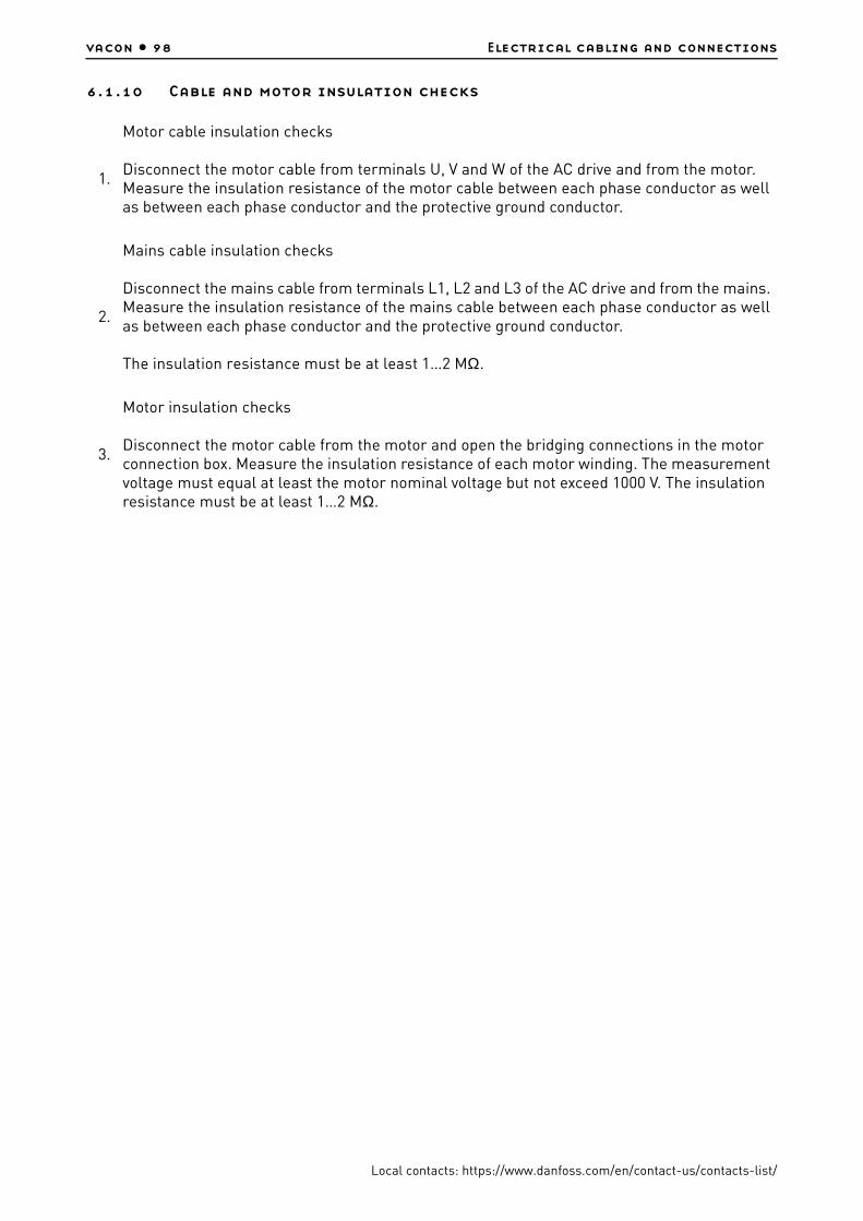
vacon • 98 Electrical cabling and connections
Local contacts: https://www.danfoss.com/en/contact-us/contacts-list/
6.1.10 Cable and motor insulation checks
1.
Motor cable insulation checks
Disconnect the motor cable from terminals U, V and W of the AC drive and from the motor. Measure the insulation resistance of the motor cable between each phase conductor as well as between each phase conductor and the protective ground conductor.
2.
Mains cable insulation checks
Disconnect the mains cable from terminals L1, L2 and L3 of the AC drive and from the mains. Measure the insulation resistance of the mains cable between each phase conductor as well as between each phase conductor and the protective ground conductor.
The insulation resistance must be at least 1…2 MΩ.
3.
Motor insulation checks
Disconnect the motor cable from the motor and open the bridging connections in the motor connection box. Measure the insulation resistance of each motor winding. The measurement voltage must equal at least the motor nominal voltage but not exceed 1000 V. The insulation resistance must be at least 1…2 MΩ.

Electrical cabling and connections vacon • 99
Local contacts: https://www.danfoss.com/en/contact-us/contacts-list/
6.2 Control unit
The control unit of VACON® NX Liquid-Cooled AC drive/inverter is installed into a mounting box. It contains the control board and additional boards (see Figure 43 and Figure 44) connected to the five slot connectors (A to E) of the control board. The control unit and the ASIC of the power unit are connected through cables (and an adapter board). For more information, see page 113.
The mounting box with the control unit is mounted inside an enclosure. See the mounting instructions on page 108.
Figure 43. VACON® NX control board
Figure 44. Basic and option board connections on the control board
11350_00
AB
CD
E
11351_00

vacon • 100 Electrical cabling and connections
Local contacts: https://www.danfoss.com/en/contact-us/contacts-list/
Usually, when the AC drive is delivered from the factory, the control unit includes at least the standard compilation of two basic boards (I/O board and relay board) which are normally installed in slots A and B. On the next pages you will find the arrangement of the control I/O and the relay terminals of the two basic boards, the general wiring diagram and the control signal descriptions. The I/O boards mounted at the factory are indicated in the type code.
The control board can be powered externally (+24 VDC, ±10%) by connecting the external power source to the control unit. This voltage is sufficient for parameter setting and for keeping the fieldbus active.
NOTE! The control board of NX_8 (voltage class 8) AFE, INU or BCU units must always be powered externally with a +24 VDC ±10% power source.
The preferred solution is to connect the external +24 VDC power supply to the fiber adapter board terminals X3:1 (24 VDC) & X3:2 (GND) or star coupler board terminals X4:25 (24VDC)& X4:26 (GND), see pictures below.
The control board can also be powered externally (+24 V, ±10%) by connecting the external power source to either of the bidirectional terminal #6 or #12, see page 103.
NOTE! If the 24 V inputs of several AC drives are parallelly connected we recommend to use a diode in terminal #6 (or #12) in order to avoid the current to flow in opposite direction. This might damage the control board. See picture below.
3067_00
+ -#6 #7
+ -#6 #7
+ -#6 #7
+ -#6 #7
External+24V
11352_uk
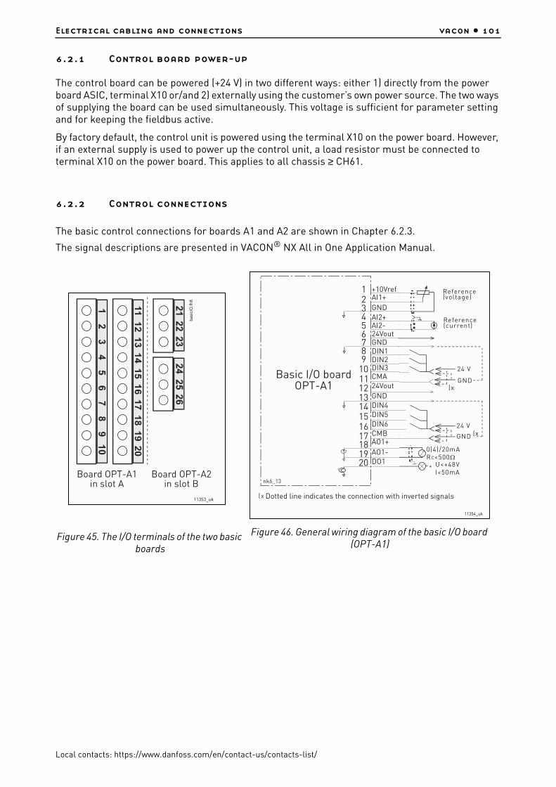
Electrical cabling and connections vacon • 101
Local contacts: https://www.danfoss.com/en/contact-us/contacts-list/
6.2.1 Control board power-up
The control board can be powered (+24 V) in two different ways: either 1) directly from the power board ASIC, terminal X10 or/and 2) externally using the customer’s own power source. The two ways of supplying the board can be used simultaneously. This voltage is sufficient for parameter setting and for keeping the fieldbus active.
By factory default, the control unit is powered using the terminal X10 on the power board. However, if an external supply is used to power up the control unit, a load resistor must be connected to terminal X10 on the power board. This applies to all chassis ≥ CH61.
6.2.2 Control connections
The basic control connections for boards A1 and A2 are shown in Chapter 6.2.3.
The signal descriptions are presented in VACON® NX All in One Application Manual.
Figure 45. The I/O terminals of the two basic boards
Board OPT-A1in slot A
Board OPT-A2in slot B
11353_uk
Figure 46. General wiring diagram of the basic I/O board (OPT-A1)
+10VrefAI1+
GNDAI2+AI2-24VoutGNDDIN1DIN2DIN3CMA24Vout
GNDDIN4DIN5DIN6CMBAO1+
AO1-DO1
123456789
1011121314151617181920
24 V
GND
24 V
GND
U<+48VI<50mA
+
0(4)/20mARC<500Ω
nk6_13
Basic I/O boardOPT-A1
Reference(voltage)
Reference(current)
Dotted line indicates the connection with inverted signals
11354_uk

vacon • 102 Electrical cabling and connections
Local contacts: https://www.danfoss.com/en/contact-us/contacts-list/
Figure 47. General wiring diagram of the basic relay board (OPT-A2)
6.2.2.1 Control cables
The control cables must be a minimum of 0.5 mm2 (20 AWG) screened multicore cables. The terminal wires must be a maximum of 2.5 mm2 (14 AWG) for the terminals of the relay board and 1.5 mm2 (16 AWG) for other terminals.
6.2.2.2 Galvanic isolation barriers
The control connections are isolated from the mains potential and the GND terminals are
permanently connected to ground. See Figure 48.
The digital inputs are galvanically isolated from the I/O ground. The relay outputs are additionally
double-isolated from each other at 300 VAC (EN-50178).
Table 50. The tightening torques of the control cables
The terminalThe terminal
screw
The tightening torque
Nm lb-in.
Relay and thermistor terminals M3 0.5 4.5
Other terminals M2.6 0.2 1.8
RO1/11/2
RO1/3
RO2/12/2
RO2/3
ac/dc
212223
242526
NX6_6.fh8
Switching:<8A/24Vdc,<0.4A/125Vdc,<2kVA/250VacContinuously:<2Arms
Basic relay boardOPT-A2
11355_uk

Electrical cabling and connections vacon • 103
Local contacts: https://www.danfoss.com/en/contact-us/contacts-list/
Figure 48. Galvanic isolation barriers
6.2.3 Control terminal signals
Table 51. Control I/O terminal signals
Terminal Signal Technical information
OPT-A1
1 +10 Vref Reference voltage Maximum current 10 mA
2 AI1+Analogue input, voltage or current
Selection V or mA with jumper block X1 (see page 107):Default:0– +10 V (Ri = 200 kΩ)(-10 V…..+10 V Joy-stick control, selected with a jumper)0– 20 mA (Ri = 250 Ω)
3 GND/AI1–Analogue input common
Differential input if not connected to ground; Allows ±20 V differential mode voltage to GND
4 AI2+Analogue input, voltage or current
Selection V or mA with jumper block X2 (see page 107):Default:0– 20 mA (Ri = 250 Ω)0– +10 V (Ri = 200 kΩ)(-10 V…..+10 V Joy-stick control, selected with a jumper)
L1 L2 L3
U V W
RO1/1
RO1/2RO1/3
RO2/3RO2/2RO2/1
10VrefGND
GND+24V
AI1
AI2+AI2 -
DIN1...DIN3CMADIN4...DIN6CMB
AO1+AO2 -
DO1
TI1+
TI1-
Control I/Oground
Digital inputgroup A
Digital inputgroup B
AnalogueoutputDigitaloutput
Controlboard
Controlpanel
Gate drivers
Powerboard
3064_uk

vacon • 104 Electrical cabling and connections
Local contacts: https://www.danfoss.com/en/contact-us/contacts-list/
5 GND/AI2–Analogue input common
Differential input if not connected to ground; Allows ±20 V differential mode voltage to GND
624 Vout
(bidirectional)24 V auxiliary voltage
±15%, maximum current 250 mACan also be used as external power backup for the control unit (and fieldbus)
7 GND I/O ground Ground for reference and controls
8 DIN1 Digital input 1Ri = min. 5 kΩ18...30 V = "1"
9 DIN2 Digital input 2
10 DIN3 Digital input 3
11 CMADigital input common A for DIN1, DIN2 and DIN3.
Must be connected to GND or 24 V of I/O terminal or to external 24 V or GNDSelection with jumper block X3 (see page 107):
1224 Vout
(bidirectional) 24 V auxiliary voltage Same as terminal #6
13 GND I/O ground Same as terminal #7
14 DIB4 Digital input 4
Ri = min. 5 kΩ15 DIB5 Digital input 5
16 DIB6 Digital input 6
17 CMBDigital input common B for DIB4, DIB5 and DIB6
Must be connected to GND or 24V of I/O terminal or to external 24 V or GNDSelection with jumper block X3 (see page 107):
18 AO1+Analogue signal (+out-put)
Output signal range:Current 0(4)–20 mA, RL max 500 Ω orVoltage 0—10 V, RL >1 kΩSelection with jumper block X6 (see page 107):
19 AO1–Analogue output common
20 DO1 Open collector outputMaximum Uin = 48 VDCMaximum current = 50 mA
OPT-A2
21 RO1/1
Relay output 1
Max. switching voltage 250 VAC, 125 VDC
22 RO1/2 Max. switching current8 A/24 VDC, 0.4 A/250 VDC
23 RO1/3 Min. switching load 5 V/10 mA
24 RO2/1
Relay output 2
Max. switching voltage 250 VAC, 125 VDC
25 RO2/2
RO2/3
Max. switching current8 A/24 VDC, 0.4 A/250 VDC
26 Min. switching load 5 V/10 mA
Table 51. Control I/O terminal signals
Terminal Signal Technical information

Electrical cabling and connections vacon • 105
Local contacts: https://www.danfoss.com/en/contact-us/contacts-list/
6.2.3.1 Digital input signal inversions
The active signal level depends on which potential the common inputs CMA and CMB (terminals 11 and 17) are connected to. The alternatives are either +24 V or ground (0 V). See Figure 49.
The 24-volt control voltage and the ground for the digital inputs and the common inputs (CMA, CMB) can be either internal or external.
Figure 49. Positive/Negative logic
6.2.3.2 Jumper selections on the OPT-A1 basic board
The user is able to customise the functions of the AC drive to better suit his needs by selecting certain positions for the jumpers on the OPT-A1 board. The positions of the jumpers determine the signal type of analogue and digital inputs.
On the A1 basic board, there are four jumper blocks X1, X2, X3 and X6 each containing eight pins and two jumpers. The selectable positions of the jumpers are shown in Figure 51.
+24V
+24V
DIN1
DIN2
DIN3
CMA
DIN1
DIN2
DIN3
CMAnk6_16
Ground
Ground
Positive logic (+24V is the active signal) =the input is active when the switch is closed
Negative logic (0V is the active signal) =the input is active when the switch is closed.Requires setting of jumper X3 to position‘CMA/CMB isolated from ground’
11356_uk

vacon • 106 Electrical cabling and connections
Local contacts: https://www.danfoss.com/en/contact-us/contacts-list/
Figure 50. Jumper blocks on OPT-A1
11357_00

Electrical cabling and connections vacon • 107
Local contacts: https://www.danfoss.com/en/contact-us/contacts-list/
Figure 51. Jumper selection for OPT-A1
A B C D
A B C D
A B C D
A B C D
A B C D
A B C D
A B C D
A B C D
A B C D
A B C D
Jumper block X1 :AI1 mode
AI1 mode: Voltage input; 0...10V
AI1 mode: Voltage input; 0...10V (differential)
AI1 mode: Voltage input; -10...10V
Jumper block X2 :AI2 mode
AI2 mode: 0...20mA; Current input
AI2 mode: Voltage input; 0...10V
AI2 mode: Voltage input; 0...10V (differential)
AI2 mode: Voltage input; -10...10V
Jumper block X3 :CM A and CM B grounding
CMB connected to GNDCMA connected to GND
CMB isolated from GNDCMA isolated from GND
CMB and CMAinternally connected together,isolated from GND
= Factory default
Jumper block X6 :AO1 mode
AO1 mode: 0...20mA; Current output
AO1 mode: Voltage output; 0...10V
AI1 mode: 0...20mA; Current input
11358_uk

vacon • 108 Electrical cabling and connections
Local contacts: https://www.danfoss.com/en/contact-us/contacts-list/
6.2.4 Control unit mounting box
Figure 52. Control unit mounting box dimensions
6.2.4.1 Installing the control unit mounting box
The control unit of VACON® NX Liquid-Cooled drive is mounted into a metal box which then can be placed inside the enclosure. VACON® alpha-numeric or graphical keypad can be used to control the
If you change the AI/AO signal content also remember to change the corresponding board parameter in menu M7.
13006.emf
329
R5
144
5945
(top)
11359_00

Electrical cabling and connections vacon • 109
Local contacts: https://www.danfoss.com/en/contact-us/contacts-list/
drive. The keypad is connected to the control unit with an RS232 cable and mounted on the enclosure door. Pay special attention to the grounding of the cable, see instructions below.
Figure 53. Control unit installed into the mounting box; Left: front; Right: back
1. If the keypad sits in its place on the control unit, remove the keypad.
2. Connect the male end of the keypad cable to the D-connector of the control unit. Use VACON® RS232 cable included in the delivery. Figure 1.
3. Run the cable over the top of the box and secure with plastic band on the backside. Figure 2.
4.Grounding of keypad cable: Earth the keypad cable in the mounting box frame by fixing the branch cable with a screw underneath the control unit. See Figures 3 and 4.
5.
Mount the control unit mounting box in the front-left corner of the enclosure using two screws as shown in Figure 5. NOTE! Do not install the mounting box floating (with e.g. plastic screws). To ensure a proper grounding of the control unit box assembly, we recommend that an additional grounding cable be drawn from the mounting box and connected to the cabinet frame. Use a braided copper cable designed for high-frequency signals. Remember to remove the paint from the enclosure grounding point to ensure proper connection for the grounding cable.
6.Connect the optical cables (or the flat cable) to the power unit. See Chapter 6.3.2 and Figures 6 and 7.
7.Connect the female end of the keypad cable to keypad on the enclosure door, Figure 8. Use a cable channel for the cable run, Figure 9.
Figure. 1 Figure. 2 Figure. 3
11360_00
11361_0011362_00 11363_00

vacon • 110 Electrical cabling and connections
Local contacts: https://www.danfoss.com/en/contact-us/contacts-list/
Figure. 4 Figure. 5 Figure. 6
Figure. 7 Figure. 8 Figure. 9
11363_0011364_00
11365_00
VANXPLC_1061_INS_uk11366_00
11367_00
11368_00
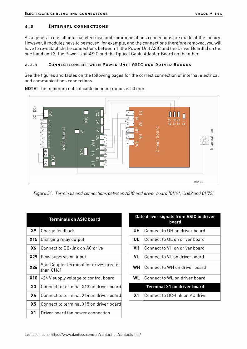
Electrical cabling and connections vacon • 111
Local contacts: https://www.danfoss.com/en/contact-us/contacts-list/
6.3 Internal connections
As a general rule, all internal electrical and communications connections are made at the factory. However, if modules have to be moved, for example, and the connections therefore removed, you will have to re-establish the connections between 1) the Power Unit ASIC and the Driver Board(s) on the one hand and 2) the Power Unit ASIC and the Optical Cable Adapter Board on the other.
6.3.1 Connections between Power Unit ASIC and Driver Boards
See the figures and tables on the following pages for the correct connection of internal electrical and communications connections.
NOTE! The minimum optical cable bending radius is 50 mm.
Figure 54. Terminals and connections between ASIC and driver board (CH61, CH62 and CH72)
Terminals on ASIC boardGate driver signals from ASIC to driver
board
X9 Charge feedback UH Connect to UH on driver board
X15 Charging relay output UL Connect to UL on driver board
X6 Connect to DC-link on AC drive VH Connect to VH on driver board
X29 Flow supervision input VL Connect to VL on driver board
X26Star Coupler terminal for drives greater than CH61
WH Connect to WH on driver board
X10 +24 V supply voltage to control board WL Connect to WL on driver board
X3 Connect to terminal X13 on driver board Terminal X1 on driver board
X4 Connect to terminal X14 on driver board X1 Connect to DC-link on AC drive
X5 Connect to terminal X15 on driver board
X1 Driver board fan power connection
11369_uk

vacon • 112 Electrical cabling and connections
Local contacts: https://www.danfoss.com/en/contact-us/contacts-list/
NOTE! Terminals X9 and X15 are connected by default. The cable can be removed if the signal is receved from other source.
Figure 55. Terminals and connections between ASIC and driver boards (CH63)
Terminals on ASIC boardGate driver signals from ASIC to driver
board
X9 Charge feedback UH Connect to UH on Phase U driver board
X15 Charging relay output UL Connect to UL on Phase U driver board
X6 Connect to DC-link on AC drive VH Connect to VH on Phase V/W driver board
X29 Flow supervision input VL Connect to VL on Phase V/W driver board
X26Star Coupler terminal for drives greater than CH61
WH Connect to WH on Phase V/W driver board
X10 +24 V supply voltage to control board WL Connect to WL on Phase V/W driver board
X3Connect to terminal X6 on phase U driver board
Terminal X2 on Phase U driver board
X4Connect to terminal X2 on phase V/W driver board
X2 Internal fan power connection for Mod. 1
X10
UHUL
VHVL
WHWL
ASIC board
DC- DC+
X6
X3 X4 X5
X29
X9 X15
X26
H1H2H3H4H5H6H7
Driver board,phase U
Driver board,phases V&W
UH UL VL WH WL
X6 X6X2
X2
VH
Module 1 Module 2
X1
Internal fan Internal fan 11370_uk

Electrical cabling and connections vacon • 113
Local contacts: https://www.danfoss.com/en/contact-us/contacts-list/
NOTE! Terminals X9 and X15 are connected by default. The cable can be removed if the signal is receved from other source.
Figure 56. Terminals and connections between ASIC and driver boards (CH64 and CH74)
X5Connect to terminal X6 on phase V/W driver board
X1 Internal fan power connection for Mod. 2
Terminals on ASIC boardGate driver signals from ASIC to driver
board
X9 Charge feedback UH Connect to UH on Phase U driver board
X15 Charging relay output UL Connect to UL on Phase U driver board
X6 Connect to DC-link on AC drive VH Connect to VH on Phase V driver board
X29 Flow supervision input VL Connect to VL on Phase V driver board
X26Star Coupler terminal for drives greater than CH61
WH Connect to WH on Phase W driver board
Terminals on ASIC boardGate driver signals from ASIC to driver
board
X10
UHUL
VHVL
WHWL
ASIC board
DC- DC+
X6
X3 X4 X5
X29
X9 X15
X26
H1H2H3H4H5H6H7
UH UL VH VL WH WL
X1 X1 X1
Module 3
Driver board,phase U
Driver board,phase V
Driver board,phase W
Module 1 Module 2
X2 X2 X2
Internal fan Internal fan Internal fan
11371_uk

vacon • 114 Electrical cabling and connections
Local contacts: https://www.danfoss.com/en/contact-us/contacts-list/
NOTE! Terminals X9 and X15 are connected by default. The cable can be removed if the signal is receved from other source.
6.3.2 Connections between power unit ASIC and the control unit
The communication connections between the VACON® NX Liquid-Cooled drive power unit and the control unit (see Chapter 6.2) can be established using either the conventional round cable (standard in chassis CH3, CH4 and CH5) or optical cable (all chassis). Note that for chassis CH61 and greater, only optical cables can be used.
6.3.2.1 Connections with round cable (Chassis CH3, CH4 and CH5)
The communication connection between the drive power unit and the control unit in chassis CH3, CH4 and CH5 are primarily made with conventional round cable and D-connectors at both ends.
Remove the protective cover to reveal the D-connector on the power unit. Connect the one end of the communication cable to the D-connector of the power unit and the other end to the control unit. If the Optical Cable Adapter Board (see below) sits on the D-connector of the control unit you have to remove it first. See Figure 57 below.
Figure 57.
X10 +24 V supply voltage to control board WL Connect to WL on Phase W driver board
X3Connect to terminal X1 on phase U driver board
Terminal X2 on Phase driver board
X4Connect to terminal X1 on phase V driver board
X2 Internal fan power connection
X5Connect to terminal X1 on phase W driver board
Terminals on ASIC boardGate driver signals from ASIC to driver
board
D-connector
Opticalterminals
11372_uk
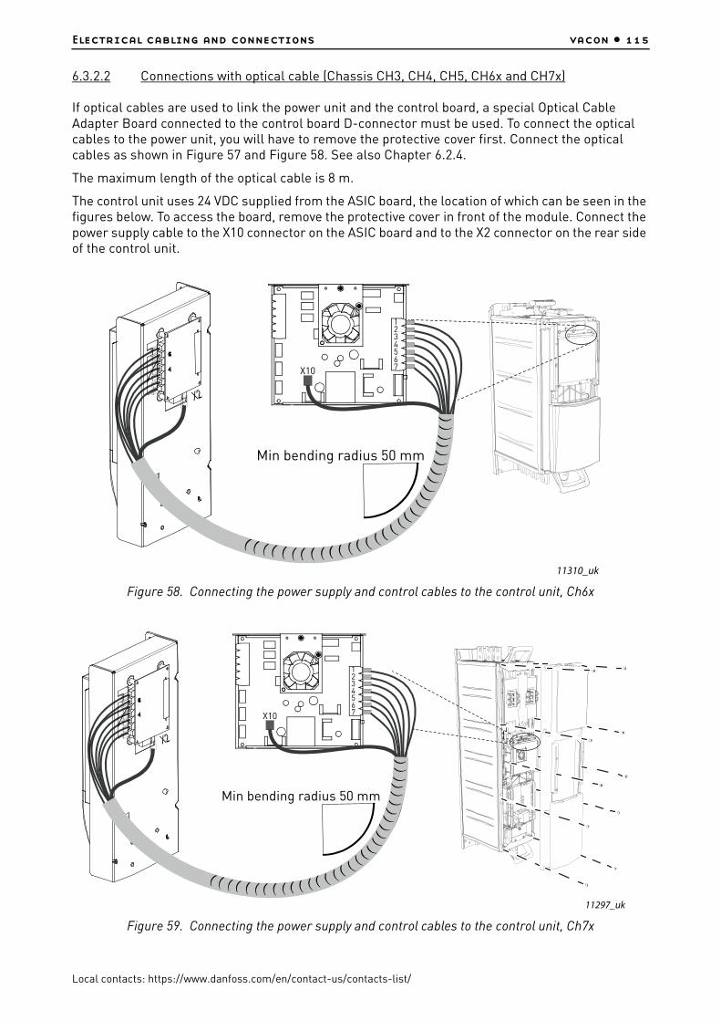
Electrical cabling and connections vacon • 115
Local contacts: https://www.danfoss.com/en/contact-us/contacts-list/
6.3.2.2 Connections with optical cable (Chassis CH3, CH4, CH5, CH6x and CH7x)
If optical cables are used to link the power unit and the control board, a special Optical Cable Adapter Board connected to the control board D-connector must be used. To connect the optical cables to the power unit, you will have to remove the protective cover first. Connect the optical cables as shown in Figure 57 and Figure 58. See also Chapter 6.2.4.
The maximum length of the optical cable is 8 m.
The control unit uses 24 VDC supplied from the ASIC board, the location of which can be seen in the figures below. To access the board, remove the protective cover in front of the module. Connect the power supply cable to the X10 connector on the ASIC board and to the X2 connector on the rear side of the control unit.
Figure 58. Connecting the power supply and control cables to the control unit, Ch6x
Figure 59. Connecting the power supply and control cables to the control unit, Ch7x
Min bending radius 50 mm
X10
1234567
11310_uk
Min bending radius 50 mm
X10
1234567
11297_uk

vacon • 116 Electrical cabling and connections
Local contacts: https://www.danfoss.com/en/contact-us/contacts-list/
Each fibre optic cable has a number 1...7 marked on the cable shield at both cable ends. Connect each cable to the connectors marked with the same number 1...7 on the ASIC board and on the rear side of the control unit.
Optical terminals on Optical cable adapter board:
Other terminals on adapter board:
NOTE! The minimum optical cable bending radius is 50 mm.
NOTE! Terminals X2 and X3 can be in use simultaneously. However, if the +24 V supply from the control I/O terminals (e.g. from board OPT-A1) is used, this terminal must be protected with a diode.
Fix the cable bundle at two or more points, at least one at each end, to prevent damages to the
cables.
H1 Gate control enable
H2 Phase U control
H3 Phase V control
H4 Phase W control
H5 ADC synchronization
H6 VaconBus data from control board to ASIC
H7 VaconBus data from ASIC to control board
X1 Control board connection
X2 Supply voltage 24Vin (from power unit ASIC)
X3
Supply voltage 24Vin (customer);
- Max. current 1A
- Terminal #1: +
- Terminal #2: –
CAUTION! Be careful when connecting the fibre optic cables! Connecting the wires incorrectly
may damage power electronic components.13006.emf

Electrical cabling and connections vacon • 117
Local contacts: https://www.danfoss.com/en/contact-us/contacts-list/
Fasten the removed cover(s) on the inverter module when the work is finished.
6.3.2.3 Connections with optical cable (Chassis 2xCH64 and 2xCH74)
If optical cables are used to link the power unit and the control board, a special Optical Cable Adapter Board connected to the control board D-connector must be used. To connect the optical cables to the power unit, you will have to remove the protective cover first. Connect the optical cables as shown in Figure 61 and Figure 61. See also Chapter 6.2.4.
The maximum length of the optical cable is 8 m.
The control unit uses 24 VDC supplied from the ASIC board, which is located on the left side of the power unit 1. To access the board, remove the protective cover in front of the power module. Connect the power supply cable to the X10 connector on the ASIC board and to the X2 connector on the rear side of the control unit.
Figure 60. Connecting the power supply and control cables to the control unit, 2xCh64 and 2xCH74
Each fibre optic cable has a number 1...8 and 11…18 marked on the cable shield at both cable ends. Connect each cable to the connectors marked with the same number on the ASIC board and on the rear side of the control unit. Additionally, you may have to connect the 4 fibre cables from the feedback board to the star coupler board. The list of the optic signals can be found in Figure 61.
X10
Power module 1ASIC-board
Power module 2ASIC-board
FB board
X2
Min bending radius 50 mm
Star coupler board
11298_uk

vacon • 118 Electrical cabling and connections
Local contacts: https://www.danfoss.com/en/contact-us/contacts-list/
Figure 61. Terminals and connections between the star-coupler board, ASIC boards and feedback boards (CH64 and CH74)
NOTE! The minimum optical cable bending radius is 50 mm.
NOTE! Terminals X2 and X3 can be in use simultaneously. However, if the +24 V supply from the control I/O terminals (e.g. from board OPT-A1) is used, this terminal must be protected with a diode.
Fix the cable bundle at two or more points, at least one at each end, to prevent damages to the
cables.
Fasten the removed cover(s) on the inverter module when the work is finished.
6.3.3 Connections between mains device and inverter power module
The dimensions in the table below must be taken into account if some kind of mains device (e.g. fuse, switch fuse, contactor) is used in the input line between the mains and the VACON® Liquid-Cooled inverter.
Be careful when connecting the fibre optic cables! Connecting the wiresincorrectly may damage power electronic components.
nxw13.fh11
Star coupler board on control unit
H18 Trip signal from power module 2
H17 VaconBus data from ASIC 2 to control board
H16 VaconBus data from control board to ASIC 2
H15 ADC synchronization, power module 2
H14 Phase W control, power module 2
H13 Phase V control, power module 2
H12 Phase U control, power module 2
H11 Gate control enable, power module 2
H23 Feedback phase W
H22 Feedback phase VH21 Feedback phase U
Terminals on ASIC board of power module 1
H1 Gate control enable
H2 Phase U control
H3 Phase V control
H4 Phase W control
H5 ADC synchronization
H6 VaconBus data from control board to ASIC
H7 VaconBus data from ASIC to control board
Terminals on ASIC board of power module 2
H8 Trip signal from power module 1
H7 VaconBus data from ASIC 1 to control board
H6 VaconBus data from control board to ASIC 1
H5 ADC synchronization, power module 1
H4 Phase W control, power module 1
H3 Phase V control, power module 1
H2 Phase U control, power module 1
H1 Gate control enable, power module 1
H10 Trip signal
Terminals on FB board of power module 2
H1 Gate control enable
H2 Phase U control
H3 Phase V control
H4 Phase W control
H5 ADC synchronization
H6 VaconBus data from control board to ASIC
H7 VaconBus data from ASIC to control board
H10 Trip signal
H11 Feedback phase U
H12 Feedback phase V
H13 Feedback phase W
Terminals on FB board of power module 1
H12
H13
H14
H15
H16
H17
H18
H11
H23
H22
H21
H2
H3
H4
H5
H6
H7
H8
H1
H10 FB PM1
H7 ASIC PM1
H6 ASIC PM1
H5 ASIC PM1
H2 ASIC PM1
H3 ASIC PM1
H4 ASIC PM1
H1 ASIC PM1
H10 FB PM2
H7 ASIC PM2
H6 ASIC PM2
H5 ASIC PM2
H4 ASIC PM2
H3 ASIC PM2
H2 ASIC PM2
H1 ASIC PM2
H13 FB PM1
H12 FB PM1
H11 FB PM1
Explanations of abbreviations:
ASIC = ASIC boardFB = Feedback boardPM1 = Power Module 1PM2 = Power Module 2
11373_uk
13006.emf

Electrical cabling and connections vacon • 119
Local contacts: https://www.danfoss.com/en/contact-us/contacts-list/
Table 52. Connections from mains device to drive
Chassis Type
Connection
Conductor cross section [mm2]
Busbar size (flexible connection)
Busbar size (bare Cu)
CH3
0016_5
60022_5
0031_5
CH3
0038_5
100045_5
0061_5
CH4
0072_5
250087_5
0105_5
CH4 0140_5 50
CH5 0168_5 70
2*24*1CH5 0205_5 95
CH5 0261_5 120
1*50*5
CH61 0300_52*70
5*32*1
CH61 0385_5
CH72 0460_5 2*95
CH72 0520_5 2*120
CH72 0590_5 2*150
1*80*5CH72 0650_5
2*(6*40*1)
CH72 0730_5
CH63 0820_5
1*100*5CH63 0920_5
CH63 1030_5
CH63 1150_5
CH74 1370_52*100*5
CH74 1640_5
CH74 2060_53*100*5
CH74 2300_5
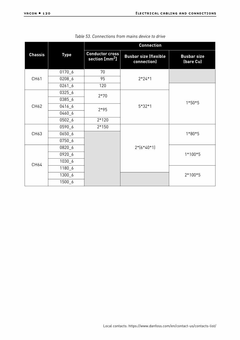
vacon • 120 Electrical cabling and connections
Local contacts: https://www.danfoss.com/en/contact-us/contacts-list/
Table 53. Connections from mains device to drive
Chassis Type
Connection
Conductor cross section [mm2]
Busbar size (flexible connection)
Busbar size (bare Cu)
CH61
0170_6 70
2*24*10208_6 95
0261_6 120
1*50*5CH62
0325_62*70
5*32*1
0385_6
0416_62*95
0460_6
0502_6 2*120
CH63
0590_6 2*150
2*(6*40*1)
1*80*50650_6
0750_6
CH64
0820_6
1*100*50920_6
1030_6
1180_6
2*100*51300_6
1500_6

Control keypad vacon • 121
Local contacts: https://www.danfoss.com/en/contact-us/contacts-list/
7. CONTROL KEYPAD
The control keypad is the link between the VACON® AC drive and the user. The VACON® NX control keypad features an alphanumeric display with seven indicators for the Run status (RUN, , READY, STOP, ALARM, FAULT) and three indicators for the control place (I/O term/ Keypad/BusComm). There are also three Status Indicator LEDs (green - green - red), see below.
The control information, i.e. the number of menu, description of menu or the displayed value and the numeric information are presented on three text lines.
The AC drive is operable through the nine push-buttons of the control keypad. Furthermore, the buttons serve the purposes of parameter setting and value monitoring.
The keypad is detachable and isolated from the input line potential.
7.1 Indications on the Keypad display
Figure 62. VACON® control keypad and drive status indications
7.1.1 Drive status indications
The drive status indications tell the user what the status of the motor and the drive is and whether the motor control software has detected irregularities in motor or AC drive functions.
RUN =Motor is running; Blinks when the stop command has been given but the frequency is still ramping down.
= Indicates the direction of motor rotation.
STOP = Indicates that the drive is not running.
READY = Lights when AC power is on. In case of a trip, the symbol will not light up.
ALARM =Indicates that the drive is running outside a certain limit and a warning is given.
FAULT =Indicates that unsafe operating conditions were encountered due to which the drive was stopped.
READY FAULTSTOPRUN
Bus/CommKeypadI/O term
ALARM
runready fault
1 2 3 4 5 6
a b
I II I I
• •• •••
c
3062_00
enter
reset
select
I
1
2
3
4
5
6

vacon • 122 Control keypad
Local contacts: https://www.danfoss.com/en/contact-us/contacts-list/
7.1.2 Control place indications
The symbols I/O term, Keypad and Bus/Comm (see Figure 62) indicate the choice of control place made in the Keypad Control Menu (see Chapter 7.3.3).
7.1.3 Status LEDs (green – green – red)
The status LEDs light up in connection with the READY, RUN and FAULT drive status indicators.
7.1.4 Text lines
The three text lines (•, ••, •••) provide the user with information on his present location in the keypad menu structure as well as with information related to the operation of the drive.
I/O term =I/O terminals are the selected control place; i.e. START/STOP commands or reference values etc. are given through the I/O terminals.
Keypad =Control keypad is the selected control place; i.e. the motor can be started or stopped, or its reference values etc. altered from the keypad.
Bus/Comm
= The AC drive is controlled through a fieldbus.
=Illuminates with the AC power connected to the drive and no faults are active. Simultaneously, the drive status indicator READY is lit up.
=Illuminates when the drive is running. Blinks when the STOP button has been pushed and the drive is ramping down.
=
Blinks when unsafe operating conditions were encountered due to which the drive was stopped (Fault Trip). Simultaneously, the drive status indicator FAULT blinks on the display and the fault description can be seen, see Chapter 7.3.4, Active Faults.
• =Location indication; displays the symbol and number of menu, parameter etc.Example: M2 = Menu 2 (Parameters); P2.1.3 = Acceleration time
•• = Description line; Displays the description of menu, value or fault.
••• =Value line; Displays the numerical and textual values of references, parameters etc. and the number of submenus available in each menu.
a
b
c
I
II
III

Control keypad vacon • 123
Local contacts: https://www.danfoss.com/en/contact-us/contacts-list/
7.2 Keypad push-buttons
The VACON® alphanumeric control keypad features 9 push-buttons that are used for the control of the AC drive (and motor), parameter setting and value monitoring.
Figure 63. Keypad push-buttons
7.2.1 Button descriptions
= This button is used to reset active faults (see Chapter 7.3.4).
=This button is used to switch between two latest displays. May be useful when you want to see how the changed new value influences some other value.
=The Enter button serves for: 1) confirmation of selections2) fault history reset (2…3 seconds)
=Browser button upBrowse the main menu and the pages of different submenus.Edit values.
=Browser button downBrowse the main menu and the pages of different submenus.Edit values.
=
Menu button leftMove backward in menu.Move cursor left (in parameter menu).Exit edit mode.Swap between keypad control and another control as active control place (see Chapter 7.2.1.1)
=
Menu button rightMove forward in menu.Move cursor right (in parameter menu).Enter edit mode.
3063_00
reset
select
enter
+
-
3
4

vacon • 124 Control keypad
Local contacts: https://www.danfoss.com/en/contact-us/contacts-list/
7.2.1.1 Swap between keypad control and another control as active control place
With the I/O terminals or fieldbus selected as the active control place, it is also possible to change the control to the local keypad and back to the original control place.
Irrespective of your location in the menu structure, keep the button pushed down for 5 seconds. This will activate the Start & Stop keypad control. The display will jump to the editing mode of R3.2
Keypad Reference and you will be able to enter the desired frequency on the keypad. Push the start button to start the drive.
Pushing the button again for 5 seconds returns the control to the original control place (active control place, P3.1) and its reference. NOTE: The motor starts if the start command of the active control place is ON and run at the formerly set reference. The keypad display will show monitoring value V1.1 Output Frequency.
If any of the parameter values in menu M3 is changed in between the swapping the keypad reference will be reset to 0.00 Hz.
7.3 Navigation on the control keypad
The data on the control keypad are arranged in menus and submenus. The menus are used for example for the display and editing of measurement and control signals, parameter settings (Chapter 7.3.2), reference values and fault displays (Chapter 7.3.4). Through the menus, you can also adjust the contrast of the display (page 142).
The first menu level consists of menus M1 to M7 and is called the Main menu. The user can navigate in the main menu using the Browser buttons up and down. The desired submenu can be entered from the main menu using the Menu buttons. When there still are pages to enter under the currently displayed menu or page, you can see an arrow ( ) in the lower right corner of the display and by pressing the Menu button right, you can reach the next menu level.
The control keypad navigation chart is shown on the next page. Note that the menu M1 is located in the lower left corner. From there you will be able to navigate your way up to the desired menu using the menu and browser buttons.
More detailed descriptions of the menus you will find later in this Chapter.
=Start buttonPressing this button starts the motor if the keypad is the active control place. See Chapter 7.3.3.
=Stop button. Pressing this button stops the motor (unless disabled by parameter R3.4/R3.6). See Chapter 7.3.3.
3
3
V1 V14
READY
Local
RUN
MonitorLocation
Description
Number of itemsavailable; Item value 11374_uk

Control keypad vacon • 125
Local contacts: https://www.danfoss.com/en/contact-us/contacts-list/
Figure 64. Keypad navigation chart
7.3.1 Monitoring menu (M1)
You can enter the Monitoring menu from the Main menu by pushing the Menu button right when the location indication M1 is visible on the first line of the display. How to browse through the monitored values is presented in Figure 65.
The monitored signals carry the indication V#.# and they are listed in Table 54. The values are updated once every 0.3 seconds.
This menu is meant only for signal checking. The values cannot be altered here. For changing values of parameters see Chapter 7.3.2.
F T1 T7
STOP FAULT
I/Oterm
STOP
I/Oterm
FAULT
H1 H3
READY
I/Oterm
T1 T7
I/Oterm
READY
I/Oterm
READY
S1 S9
STOP READY
I/Oterm
STOP READY
I/Otermenter
G1 G5
READY
I/Oterm
A:NXOPTA1
READY
I/Oterm
G1 G1
READY
I/Oterm
V1 V15
READY
I/Oterm
RUN
13.95 Hz
READY
I/Oterm
RUN
G1 G9
READY
I/Oterm
P1 P15
READY
I/Oterm
13.95 Hz
READY
Loc al
P1 P3
READY
I/Oterm
STOP READY
I/Oterm
STOP
enter
enter
F0
STOP FAULT
I/Oterm
Parameters Basic parameters Min Frequency
11 Output phase Operation days
17
Fault history 11 Output phase Operation days
System Menu Language
Changevalue
Browse
Expander boards ParametersP1 P3
Monitor Output frequency No editing!
Keypad control Control Place
I/O Terminal
Changevalue
Changevalue
Browse
Browse
Active faults
17
English
or:
VANXPLC_1073_INS_uk
F T1 T7
STOP FAULT
I/Oterm
STOP
I/Oterm
FAULT
H1 H3
READY
I/Oterm
T1 T7
I/Oterm
READY
I/Oterm
READY
S1 S9
STOP READY
I/Oterm
STOP READY
I/Otermenter
G1 G5
READY
I/Oterm
A:NXOPTA1
READY
I/Oterm
G1 G1
READY
I/Oterm
V1 V15
READY
I/Oterm
RUN
13.95 Hz
READY
I/Oterm
RUN
G1 G9
READY
I/Oterm
P1 P15
READY
I/Oterm
13.95 Hz
READY
Loc al
P1 P3
READY
I/Oterm
STOP READY
I/Oterm
STOP
enter
enter
F0
STOP FAULT
I/Oterm
Parameters Basic parameters Min Frequency
11 Output phase Operation days
17
Fault history 11 Output phase Operation days
System Menu Language
Changevalue
Browse
Expander boards ParametersP1 P3
Monitor Output frequency No editing!
Keypad control Control Place
I/O Terminal
Changevalue
Changevalue
Browse
Browse
Active faults
17
English
or:
11375_uk

vacon • 126 Control keypad
Local contacts: https://www.danfoss.com/en/contact-us/contacts-list/
Figure 65. Monitoring menu
NOTE! The All in One applications embody more monitoring values.
Table 54. Monitored signals
Code Signal name Unit Description
V1.1 Output frequency Hz Frequency to the motor
V1.2 Frequency reference Hz
V1.3 Motor speed rpm Calculated motor speed
V1.4 Motor current A Measured motor current
V1.5 Motor torque % Calculated motor shaft torque
V1.6 Motor power % Calculated motor shaft power
V1.7 Motor voltage V Calculated motor voltage
V1.8 DC-link voltage V Measured DC-link voltage
V1.9 Unit temperature ºC Heat sink temperature
V1.10 Motor temperature % Calculated motor temperature. See VACON®NX All in One applica-tion manual.
V1.11 Voltage input V AI1
V1.12 Current input mA AI2
V1.13 DIN1, DIN2, DIN3 Digital input statuses
V1.14 DIN4, DIN5, DIN6 Digital input statuses
V1.15 DO1, RO1, RO2 Digital and relay output statuses
V1.16 Analogue output current mA AO1
V1.17 Multimonitoring items Displays three selectable monitoring values. See Chapter 7.3.6.5.
V1 V14
READY
Local
13.95 Hz
READY
Local
13.95 Hz
READY
Loca l
RUN RUN
RUN
Monitor Output frequency
FreqReference
11376_uk

Control keypad vacon • 127
Local contacts: https://www.danfoss.com/en/contact-us/contacts-list/
7.3.2 Parameter menu (M2)
Parameters are the way of conveying the commands of the user to the AC drive. The parameter values can be edited by entering the Parameter Menu from the Main Menu when the location indication M2 is visible on the first line of the display. The value editing procedure is presented in Figure 66.
Push the Menu button right once to move into the Parameter Group Menu (G#). Locate the parameter group desired by using the Browser buttons and push the Menu button right again to enter the group and its parameters. Use again the Browser buttons to find the parameter (P#) you want to edit. From here you can proceed in two different ways: Pushing the Menu button right takes you to the edit mode. As a sign of this, the parameter value starts to blink. You can now change the value in two different manners:
1. Just set the new desired value with the Browser buttons and confirm the change with the Enter button. Consequently, the blinking stops and the new value is visible in the value field.
2. Push the Menu button right once again. Now you will be able to edit the value digit by digit. This editing manner may come in handy, when a relatively greater or smaller value than that on the display is desired. Confirm the change with the Enter button.
The value will not change unless the Enter button is pushed. Pressing the Menu button left takes you back to the previous menu.
Several parameters are locked, i.e. uneditable, when the drive is in RUN status. If you try to change the value of such a parameter the text *Locked* will appear on the display. The AC drive must be stopped in order to edit these parameters.
The parameters values can also be locked using the function in menu M6 (see Chapter Parameter lock (P6.5.2)).
You can return to the Main menu anytime by pressing the Menu button left for 3 seconds.
The basic application package "All in One+" includes seven applications with different sets of parameters.
Once in the last parameter of a parameter group, you can move directly to the first parameter of that group by pushing the Browser button up.
See the diagram for parameter value change procedure on page 128.

vacon • 128 Control keypad
Local contacts: https://www.danfoss.com/en/contact-us/contacts-list/
Figure 66. Parameter value change procedure
7.3.3 Keypad control menu (M3)
In the Keypad Controls Menu, you can choose the control place, edit the frequency reference and change the direction of the motor. Enter the submenu level with the Menu button right.
7.3.3.1 Selection of control place
There are three different places (sources) which the AC drive can be controlled from. For each control place, a different symbol will appear on the alphanumeric display:
Table 55. Keypad control parameters, M3
Code Parameter Min Max Unit Default Cust ID Note
P3.1 Control place 1 3 1 1251 = I/O terminal2 = Keypad3 = Fieldbus
R3.2 Keypad reference Par. 2.1.1Par. 2.1.2
Hz
P3.3 Direction (on keypad) 0 1 0 1230 = Forward1 = Reverse
R3.4 Stop button 0 1 1 1140 = Limited function of Stop button1 = Stop button always enabled
Control place symbol
I/O terminals
Keypad (panel)
Fieldbus
G1 G8
READY
Keypad
P1 P18
READY
Keypad
13.95 Hz
READY
Keypad
G1 G8
Keypad
READY
Keypad
13.95 Hz enter
READY
Keypad
14.45 Hz
Parameters Basic parameters Min Frequency
Input signals
Min Frequency Min Frequency
11377_uk
I/O term
Keypad
Bus/Comm
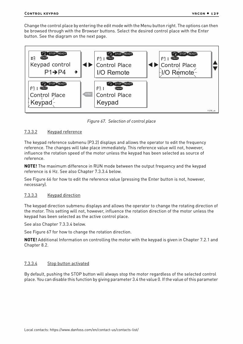
Control keypad vacon • 129
Local contacts: https://www.danfoss.com/en/contact-us/contacts-list/
Change the control place by entering the edit mode with the Menu button right. The options can then be browsed through with the Browser buttons. Select the desired control place with the Enter button. See the diagram on the next page.
Figure 67. Selection of control place
7.3.3.2 Keypad reference
The keypad reference submenu (P3.2) displays and allows the operator to edit the frequency reference. The changes will take place immediately. This reference value will not, however, influence the rotation speed of the motor unless the keypad has been selected as source of reference.
NOTE! The maximum difference in RUN mode between the output frequency and the keypad reference is 6 Hz. See also Chapter 7.3.3.4 below.
See Figure 66 for how to edit the reference value (pressing the Enter button is not, however, necessary).
7.3.3.3 Keypad direction
The keypad direction submenu displays and allows the operator to change the rotating direction of the motor. This setting will not, however, influence the rotation direction of the motor unless the keypad has been selected as the active control place.
See also Chapter 7.3.3.4 below.
See Figure 67 for how to change the rotation direction.
NOTE! Additional Information on controlling the motor with the keypad is given in Chapter 7.2.1 and Chapter 8.2.
7.3.3.4 Stop button activated
By default, pushing the STOP button will always stop the motor regardless of the selected control place. You can disable this function by giving parameter 3.4 the value 0. If the value of this parameter
P1 P4
READY
I /Oterm
READY
I/Oterm
READY
I/Oterm
READY
I/Oterm
enter
READY
Keypad
STOP STOP STOP
STOPSTOP
Keypad control Control Place
I/O RemoteControl Place
I/O Remote
Control Place
KeypadControl Place
Keypad11378_uk
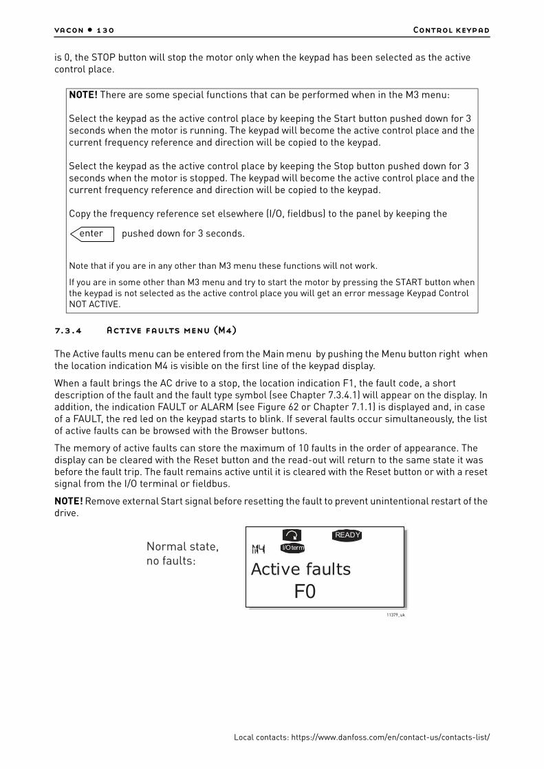
vacon • 130 Control keypad
Local contacts: https://www.danfoss.com/en/contact-us/contacts-list/
is 0, the STOP button will stop the motor only when the keypad has been selected as the active control place.
7.3.4 Active faults menu (M4)
The Active faults menu can be entered from the Main menu by pushing the Menu button right when the location indication M4 is visible on the first line of the keypad display.
When a fault brings the AC drive to a stop, the location indication F1, the fault code, a short description of the fault and the fault type symbol (see Chapter 7.3.4.1) will appear on the display. In addition, the indication FAULT or ALARM (see Figure 62 or Chapter 7.1.1) is displayed and, in case of a FAULT, the red led on the keypad starts to blink. If several faults occur simultaneously, the list of active faults can be browsed with the Browser buttons.
The memory of active faults can store the maximum of 10 faults in the order of appearance. The display can be cleared with the Reset button and the read-out will return to the same state it was before the fault trip. The fault remains active until it is cleared with the Reset button or with a reset signal from the I/O terminal or fieldbus.
NOTE! Remove external Start signal before resetting the fault to prevent unintentional restart of the drive.
NOTE! There are some special functions that can be performed when in the M3 menu:
Select the keypad as the active control place by keeping the Start button pushed down for 3 seconds when the motor is running. The keypad will become the active control place and the current frequency reference and direction will be copied to the keypad.
Select the keypad as the active control place by keeping the Stop button pushed down for 3 seconds when the motor is stopped. The keypad will become the active control place and the current frequency reference and direction will be copied to the keypad.
Copy the frequency reference set elsewhere (I/O, fieldbus) to the panel by keeping the
pushed down for 3 seconds.
Note that if you are in any other than M3 menu these functions will not work.
If you are in some other than M3 menu and try to start the motor by pressing the START button when the keypad is not selected as the active control place you will get an error message Keypad Control NOT ACTIVE.
enter
Normal state, no faults:
F0
READY
I/Oterm
Active faults
11379_uk

Control keypad vacon • 131
Local contacts: https://www.danfoss.com/en/contact-us/contacts-list/
7.3.4.1 Fault types
In the VACON® NX AC drive, there are four different types of faults. These types differ from each other on the basis of the subsequent behaviour of the drive. See Table 56.
Figure 68. Fault display
7.3.4.2 Fault codes
The fault codes, their causes and correcting actions are presented in Table 65. The shadowed faults are A faults only. The items written in white on black background present faults for which you can program different responses in the application. See parameter group Protections.
NOTE! When contacting distributor or factory because of a fault condition, always write down all texts and codes on the keypad display.
Table 56. Fault types
Fault type symbol
Meaning
A(Alarm)
This type of fault is a sign of an unusual operating condition. It does not cause the drive to stop, nor does it require any special actions. The 'A fault' remains in the display for about 30 seconds.
F(Fault)
An 'F fault' is a kind of fault that makes the drive stop. Actions need to be taken in order to restart the drive.
AR(Fault Autoreset)
If an 'AR fault' occurs the drive will also stop immediately. The fault is reset automatically and the drive tries to restart the motor. Finally, if the restart is not successful, a fault trip (FT, see below) occurs.
FT(Fault Trip)
If the drive is unable to restart the motor after an AR fault an FT fault occurs. The effect of the 'FT fault' is basically the same as that of the F fault: the drive is stopped.
F T1 T13
STOP FAULT
I /Oterm
STOP
I /Oterm
FAULT
34:21:05
I/Oterm
17 11 Output phase Operations days
Operation hours
Fault type symbol
11380_uk

vacon • 132 Control keypad
Local contacts: https://www.danfoss.com/en/contact-us/contacts-list/
7.3.4.3 Fault time data record
When a fault occurs the information described above in is displayed. By pushing the Menu button right here you will enter the Fault time data record menu indicated by T.1àT.13. In this menu, some selected important data valid at the time of the fault are recorded. This feature is intended to help the user or the service person to determine the cause of fault.
The data available are:
Real time record
If real time is set to run on the AC drive the data items T1 and T2 will appear as follows:
7.3.5 Fault history menu (M5)
The Fault history menu can be entered from the Main menu by pushing the Menu button right when the location indication M5 is visible on the first line of the keypad display. Find the fault codes in Table 65.
All faults are stored in the Fault history menu in which you can browse through them using the Browser buttons. Additionally, the Fault time data record pages are accessible at each fault. You can return to the previous menu anytime by pushing the Menu button left.
The memory of the AC drive can store a maximum of 30 faults in the order of appearance. The number of faults currently in the fault history is shown on the value line of the main page (H1àH#).
Table 57. Fault time recorded data
T.1Counted operation days
(Fault 43: Additional code)d
T.2Counted operation hours
(Fault 43: Counted operation days)hh:mm:ss
(d)
T.3Output frequency
(Fault 43: Counted operation hours)Hz
(hh:mm:ss)
T.4 Motor current A
T.5 Motor voltage V
T.6 Motor power %
T.7 Motor torque %
T.8 DC voltage V
T.9 Unit temperature °C
T.10 Run status
T.11 Direction
T.12 Warnings
T.13 0-speed*
* Tells the user if the drive was at zero speed (< 0.01 Hz) when the fault occurred
T.1 Counted operation days yyyy-mm-dd
T.2 Counted operation hours hh:mm:ss,sss
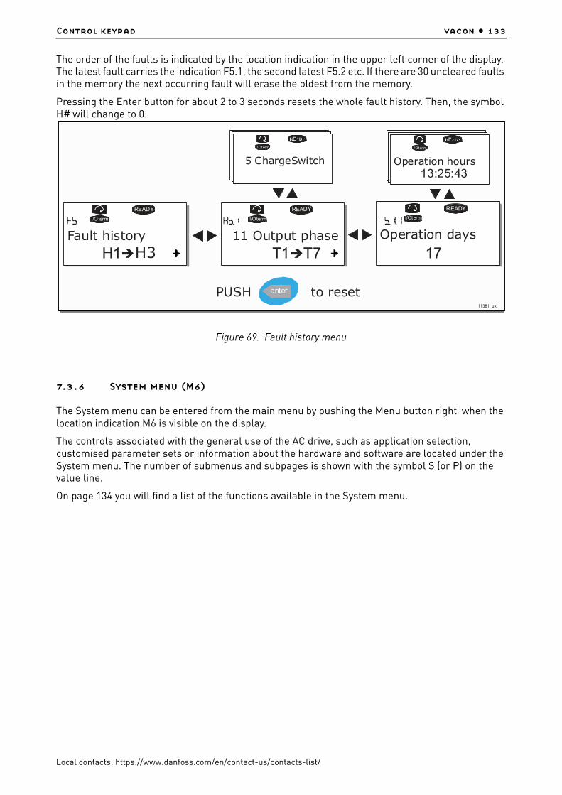
Control keypad vacon • 133
Local contacts: https://www.danfoss.com/en/contact-us/contacts-list/
The order of the faults is indicated by the location indication in the upper left corner of the display. The latest fault carries the indication F5.1, the second latest F5.2 etc. If there are 30 uncleared faults in the memory the next occurring fault will erase the oldest from the memory.
Pressing the Enter button for about 2 to 3 seconds resets the whole fault history. Then, the symbol H# will change to 0.
Figure 69. Fault history menu
7.3.6 System menu (M6)
The System menu can be entered from the main menu by pushing the Menu button right when the location indication M6 is visible on the display.
The controls associated with the general use of the AC drive, such as application selection, customised parameter sets or information about the hardware and software are located under the System menu. The number of submenus and subpages is shown with the symbol S (or P) on the value line.
On page 134 you will find a list of the functions available in the System menu.
H1 H3
READY
I/Oterm
T1 T7
I/Oterm
READY
I/Oterm
I/Oterm
READY
13:25:43
I/Oter m
enter
17Fault history 11 Output phase
5 ChargeSwitch
Operation days
Operation hours
PUSH to reset11381_uk

vacon • 134 Control keypad
Local contacts: https://www.danfoss.com/en/contact-us/contacts-list/
Functions in the System menu
Table 58. System menu functions
Code Function Min Max Unit Default Cust Selections
S6.1 Language selection EnglishAvailable selections depend on the language package.
S6.2 Application selectionBasic
Applica-tion
Basic ApplicationStandard ApplicationLocal/Remote control Appl.Multi-Step ApplicationPID Control ApplicationMulti-Purpose Control Appl.Pump and Fan Control Appl.
S6.3 Copy parameters
S6.3.1 Parameter sets
Store set 1Load set 1Store set 2Load set 2Load factory defaults
S6.3.2 Load up to keypad All parameters
S6.3.3 Load down from keypadAll parametersAll but motor parametersApplication parameters
P6.3.4 Parameter backup YesYesNo
S6.4 Compare parameters
S6.4.1 Set1 Not used
S6.4.2 Set2 Not used
S6.4.3 Factory settings
S6.4.4 Keypad set
S6.5 Security
S6.5.1 Password Not used 0 = Not used
P6.5.2 Parameter lockChange Enabled
Change EnabledChange Disabled
S6.5.3 Start-up wizardNoYes
S6.5.4 Multimonitoring itemsChange EnabledChange Disabled
S6.6 Keypad settings
P6.6.1 Default page
P6.6.2Default page/
Operating menu
P6.6.3 Timeout time 0 65535 s 30
P6.6.4 Contrast 0 31 18
P6.6.5 Backlight time Always 65535 min 10
S6.7 Hardware settings
P6.7.3 HMI acknowledg. timeout 200 5000
P6.7.4 HMI number of retries 1 10
S6.8 System information

Control keypad vacon • 135
Local contacts: https://www.danfoss.com/en/contact-us/contacts-list/
7.3.6.1 Language selection
The VACON® control keypad offers you the possibility to control the AC drive through the keypad in the language of your choice.
Locate the language selection page under the System menu. Its location indication is S6.1. Press the Menu button right once to enter the edit mode. As the name of the language starts to blink you are able to choose another language for the keypad texts. Confirm the selection by pushing the Enter button. The blinking stops and all textual information on the keypad is presented in the language you chose.
You can return to the previous menu anytime by pushing the Menu button left.
S6.8.1 Total counters
C6.8.1.1 MWh counter
C6.8.1.2 Power On day counter
C6.8.1.3 Power On hours counter
S6.8.2 Trip counters
T6.8.2.1 MWh counter kWh
T6.8.2.2Clear
MWh trip counter
T6.8.2.3Operating days
trip counter
T6.8.2.4Operating hours
trip counterhh:mm:ss
T6.8.2.5Clear operating time
counter
S6.8.3 Software info
S6.8.3.1 Software package
S6.8.3.2 System software version
S6.8.3.3 Firmware interface
S6.8.3.4 System load
S6.8.4 Applications
S6.8.4.# Name of application
D6.8.4.#.1 Application ID
D6.8.4.#.2Applications:
Version
D6.8.4.#.3Applications:
Firmware interface
S6.8.5 Hardware
I6.8.5.1Info: Power unit type
code
I6.8.5.2 Info: Unit voltage V
I6.8.5.3 Info: Brake chopper
I6.8.5.4 Info: Brake resistor
S6.8.6 Expander boards
S6.8.7 Debug menuFor Application programming only. Contact factory for more details.
Table 58. System menu functions
Code Function Min Max Unit Default Cust Selections

vacon • 136 Control keypad
Local contacts: https://www.danfoss.com/en/contact-us/contacts-list/
Figure 70. Selection of language
7.3.6.2 Application selection
The user can select the application desired by entering the Application selection page (S6.2). This is done by pushing the Menu button right when on the first page of the System menu. Change then the application by pushing the Menu button right once again. The name of the application starts to blink. Now you can browse through the applications with the Browser buttons and select another application with the Enter button.
Changing application will reset all parameters. After application change, you will be asked if you want the parameters of the new application to be uploaded to the keypad. If you wish this to happen push the Enter button Pushing any other button leaves the parameters of the previously used application saved in the keypad. For more information, see Chapter 7.3.6.3.
For more information about the Application Package, see VACON® NX All-in-One Application Manual.
Figure 71. Change of application
System Menu
S1 S11
READY
I/Oterm
Language
English
READY
I/Oterm
Language
English
READY
I/Oterm
enter
READY
I/Oterm
FrancaisLangue
11382_uk
S1 S11
STOP READY
I/Oterm
STOP READY
I/Oterm
STOP READY
I/Oterm
enter
STOP READY
I/Oterm
System Menu Application
Standard
Application
StandardApplication
Multi-step
11383_uk

Control keypad vacon • 137
Local contacts: https://www.danfoss.com/en/contact-us/contacts-list/
7.3.6.3 Copy parameters
The parameter copy function is used when the operator wants to copy one or all parameter groups from one drive to another or to store parameter sets in the internal memory of the AC drive. All the parameter groups are first uploaded to the keypad, then the keypad is connected to another drive and then the parameter groups are downloaded to it (or possibly back to the same drive).
Before any parameters can successfully be copied from one drive to another the drive has to be stopped when the parameters are downloaded to it:
The parameter copy menu (S6.3) embodies four functions:
Parameter sets (S6.3.1)
The VACON® NX AC drive features a possibility for the user to load back the factory default parameter values and to store and load two customised parameter sets (all parameters included in the application).
On Parameter sets page (S6.3.1), push the Menu button right to enter the Edit menu. The text LoadFactDef begins to blink and you can confirm the loading of factory defaults by pushing the Enter button. The drive resets automatically.
Alternatively you can choose any other of the storing or loading functions with the Browser buttons. Confirm with the Enter button. Wait until 'OK' appears on the display.
Figure 72. Storing and loading of parameter sets
Upload parameters to keypad (To keypad, S6.3.2)
This function uploads all existing parameter groups to the keypad provided that the drive is stopped.
Enter the To keypad page (S6.3.2) from the Parameter copy menu. Push the Menu button right to enter the edit mode. Use the Browser buttons to select the option All parameters and press the Enter button. Wait until 'OK' appears on the display.
READY READYenter
READY READY
OK
Parameter sets
SelectParameter sets
CANCEL
CONFIRM
Parameter sets
Wait...Parameter sets
LoadFactDef
11384_uk

vacon • 138 Control keypad
Local contacts: https://www.danfoss.com/en/contact-us/contacts-list/
Figure 73. Parameter copy to keypad
Download parameters to drive (From keypad, S6.3.3)
This function downloads one or all parameter groups uploaded to the keypad to a drive provided that the drive is in STOP status.
Enter the From keypad page (S6.3.3) from the Parameter copy menu. Push the Menu button right to enter the edit mode. Use the Browser buttons to select either the option All parameters or Application parameters and press the Enter button. Wait until 'OK' appears on the display.
The procedure to download the parameters from keypad to drive is similar to that of from drive to keypad. See above.
Automatic parameter backup (P6.3.4)
On this page you can activate or inactivate the parameter backup function. Enter the edit mode by pressing the Menu button right. Choose Yes or No with the Browser buttons.
When the Parameter backup function is activated VACON® NX control keypad makes a copy of the parameters of the presently used application. Every time a parameter is changed the keypad backup is automatically updated.
When applications are changed, you will be asked if you wish the parameters of the new application to be uploaded to the keypad. For this to happen, push the Enter button. If you wish to keep the copy of the parameters of the previously used application saved in the keypad push any other button. Now you will be able to download these parameters to the drive following the instructions given in Chapter 7.3.6.3.
If you want the parameters of the new application to be automatically uploaded to the keypad you have to do this for the parameters of the new application once on page 6.3.2 as instructed. Otherwise the panel will always ask for the permission to upload the parameters.
NOTE! Parameters saved in the parameter settings on page S6.3.1 will be deleted when applications are changed. If you want to transfer the parameters from one application to another you have to upload them first to the keypad.
7.3.6.4 Parameter comparison
In the Parameter comparison submenu (S6.4), you can compare the actual parameter values to the values of your customised parameter sets and those loaded to the control keypad.
The comparison is performed by pushing the Menu button right when in the Compare parameters submenu. The actual parameter values are first compared to those of the customised parameter Set1. If no differences are detected a '0' is displayed on the lowermost line. But if any of the parameter values differ from those of the Set1 the number of the deviations is displayed together
P1 P4
READY READY READY
enter
READY READY
Copy Parameters Up to keypad Up to keypad
Select CANCEL
CONFIRM
Up to keypad
Wait...Up to keypad
OK
All param.CHANGE VALUE
11385_uk

Control keypad vacon • 139
Local contacts: https://www.danfoss.com/en/contact-us/contacts-list/
with symbol P (e.g. P1àP5 = five deviating values). By pressing the Menu button right once again you can still enter the pages where you can see both the actual value and the value it was compared to. In this display, the value on the Description line (in the middle) is the default value and the one on the value line (lowermost) is the edited value. Furthermore, you can also edit the actual value with the Browser buttons in the edit mode that you can reach by pushing the Menu button right once again.
In the same way, you can perform the comparison of the actual values to Set2, Factory Settings and Keypad Set.
Figure 74. Parameter comparison
7.3.6.5 Security
NOTE! The Security submenu is protected with a password. Store the password in a safe place!
Password (S6.5.1)
The application selection can be protected against unauthorised changes with the Password function (S6.5.1).
By default, the password function is not in use. If you want to activate the function, enter the edit mode by pushing the Menu button right. A blinking zero appears in the display and now you can set a password with the Browser buttons. The password can be any number between 1 and 65535.
NOTE! that you can also set the password by digits. In the edit mode, push the Menu button right once again and another zero appears on the display. Now set first the units. Then push the Menu button left and you can set the tens etc. Finally, confirm the password setting with the Enter button. After this, you have to wait until the Timeout time (P6.6.3) (see page 142) has expired before the password function is activated.
If you now try to change applications or the password itself you will be prompted for the current password. The password will be entered with the Browser buttons.
C1 C3
READY READY
READY
0
enter
P1 P6P2.1.2= 50.0
READY
20.0 Hz
P2.1.2= 50.0
READY
20.0 Hz
ParamComparison Set1
Set1
CONFIRM CHANGE
EDIT VALUE
OR
11386_uk

vacon • 140 Control keypad
Local contacts: https://www.danfoss.com/en/contact-us/contacts-list/
Deactivate the password function by entering the value 0.
Figure 75. Password setting
NOTE! Store the password in a secure location! No changes can be made unless a valid password
is entered!
Parameter lock (P6.5.2)
This function allows the user to prohibit changes to the parameters.
If the parameter lock is activated the text *locked* will appear on the display if you try to edit a parameter value.
NOTE! This function does not prevent unauthorised editing of parameter values.
Enter the edit mode by pushing the Menu button right. Use the Browser buttons to change the parameter lock status. Accept the change with the Enter button or return to the previous level with the Menu button left.
Figure 76. Parameter locking
Start-up Wizard (P6.5.3)
The Start-up Wizard is a feature on the control keypad to facilitate the commissioning of the AC drive. If selected active (default), the Start-up Wizard prompts the operator for the language and application of his/her choice plus for the values for a set of parameters common to all applications as well as for a set of application-dependent parameters.
Always accept the value with the Enter button, scroll options or change values with the Browser buttons (up and down arrows).
Set the Start-up Wizard active in the following way: In the System Menu, find page P6.5.3. Press the Menu button right once to reach the edit mode. Use the Browser buttons to set value Yes and confirm the selection with the Enter button. If you want to deactivate the function follow the same procedure and give the parameter value No.
READY
I/Oterm
0
READY
I/Oterm enter
00
READY
I/Oterm enter
Password
Not in usePassword PasswordOR:
11387_uk
S1 S9
READY
I/Oterm
READY
I/Oterm
READY
I/Oterm
enter
READY
I/Oterm
READY
I/Oterm
P1 P4System Menu Security
Parameter Lock
ChangeEnable
Parameter Lock
ChangeDisabl
Parameter Lock
ChangeEnable11388_uk

Control keypad vacon • 141
Local contacts: https://www.danfoss.com/en/contact-us/contacts-list/
Figure 77. Activation of Start-up wizard
Multimonitoring items (P6.5.4)
VACON® alpha-numeric keypad features a display where you can monitor even three actual values at the same time (see Chapter 7.3.1 and Chapter Monitoring values in the manual of the application you are using). On page P6.5.4 of the System Menu you can define if it is possible for the operator to replace the values monitored with other values. See below.
Figure 78. Enabling the change of multimonitoring items
7.3.6.6 Keypad settings
In the Keypad settings submenu under the System menu you can further customise your AC drive operator interface.
Locate the Keypad settings submenu (S6.6). Under the submenu, there are four pages (P#) associated with the keypad operation:
Figure 79. Keypad settings submenu
Default page (P6.6.1)
Here you can set the location (page) to which the display automatically moves as the Timeout time (see below) has expired or as the power is switched on to the keypad.
If the Default Page value is 0 the function is not activated, i.e. the last displayed page remains on the keypad display. Press the Menu button right once to enter the edit mode. Change the number of the Main menu with the Browser buttons. Pressing the Menu button right once again makes you able to edit the number of the submenu/page. If the page you want to move to by default is at the third level
READY
I/Oterm
READY
I/Oterm
READY
I/Otermenter
Startup wizard Startup wizard
No NoStartup wizard
YesCANCEL
CONFIRM
11389_uk
READY
I/Oterm
READY
I/Oterm
enter
READY
I/Oterm
Multimon. items
ChangeEnableMultimon. items Multimon. items
ChangeEnable ChangeDisable
11390_uk
P1 P5
READY
I/Oterm
0.
READY
I/Oterm
Keypad settings Default page
11391_uk

vacon • 142 Control keypad
Local contacts: https://www.danfoss.com/en/contact-us/contacts-list/
repeat the procedure. Confirm the new default page value with the Enter button. You can return to the previous step anytime by pushing the Menu button left.
Figure 80. Default page function
Default page in the operating menu (P6.6.2)
Here you can set the location (page) in the Operating menu (in special applications only) to which the display automatically moves as the set Timeout time (see below) has expired or as the power is switched on to the keypad. See setting of Default page above.
Timeout time (P6.6.3)
The Timeout time setting defines the time after which the keypad display returns to the Default page (P6.6.1) see above.
Move to the Edit menu by pressing the Menu button right. Set the timeout time you want and confirm the change with the Enter button. You can return to the previous step anytime by pushing the Menu button left.
Figure 81. Timeout time setting
NOTE! If the Default page value is 0 the Timeout time setting has no effect.
Contrast adjustment (P6.6.4)
In case the display is unclear you can adjust its contrast through the same procedure as that for the timeout time setting (see above).
Backlight time (P6.6.5)
Giving a value for the Backlight time, you can determine how long the backlight stays on before going out. You can select here any time between 1 and 65535 minutes or 'Forever'. For the value setting procedure see Timeout time (P6.6.3).
7.3.6.7 Hardware settings
NOTE! The Hardware settings submenu is protected with a password (see Chapter Password (S6.5.1)). Store the password in a safe place!
In the Hardware settings submenu (S6.7) under the System menu you can further control some functions of the hardware in your AC drive. The functions available in this menu are HMI acknowledge timeout and HMI retry.
0.
READY
I/Oterm
READY
I/Oterm
READY
I/Oterm
0. 1.
enter
Default page REPEAT TO SETDEFAULT SUBMENU/PAGE
CANCEL
Default pageDefault page
CONFIRM CHANGE
11392_uk
90 s
READY READY READY
90 s.
enter
60 s.Timeout time Timeout time Timeout time
CANCEL
CONFIRM CHANGE
11393_uk
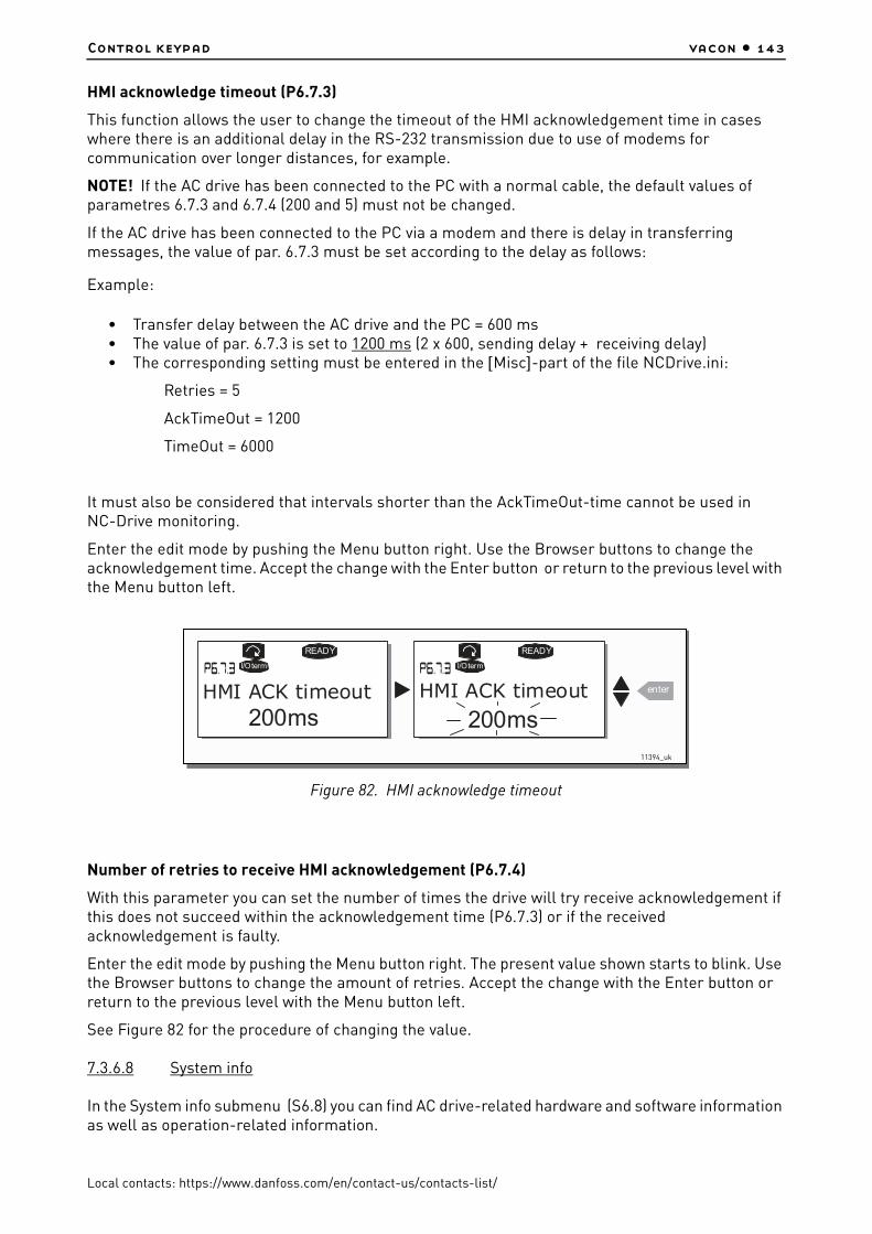
Control keypad vacon • 143
Local contacts: https://www.danfoss.com/en/contact-us/contacts-list/
HMI acknowledge timeout (P6.7.3)
This function allows the user to change the timeout of the HMI acknowledgement time in cases where there is an additional delay in the RS-232 transmission due to use of modems for communication over longer distances, for example.
NOTE! If the AC drive has been connected to the PC with a normal cable, the default values of parametres 6.7.3 and 6.7.4 (200 and 5) must not be changed.
If the AC drive has been connected to the PC via a modem and there is delay in transferring messages, the value of par. 6.7.3 must be set according to the delay as follows:
Example:
• Transfer delay between the AC drive and the PC = 600 ms• The value of par. 6.7.3 is set to 1200 ms (2 x 600, sending delay + receiving delay)• The corresponding setting must be entered in the [Misc]-part of the file NCDrive.ini:
Retries = 5
AckTimeOut = 1200
TimeOut = 6000
It must also be considered that intervals shorter than the AckTimeOut-time cannot be used in NC-Drive monitoring.
Enter the edit mode by pushing the Menu button right. Use the Browser buttons to change the acknowledgement time. Accept the change with the Enter button or return to the previous level with the Menu button left.
Figure 82. HMI acknowledge timeout
Number of retries to receive HMI acknowledgement (P6.7.4)
With this parameter you can set the number of times the drive will try receive acknowledgement if this does not succeed within the acknowledgement time (P6.7.3) or if the received acknowledgement is faulty.
Enter the edit mode by pushing the Menu button right. The present value shown starts to blink. Use the Browser buttons to change the amount of retries. Accept the change with the Enter button or return to the previous level with the Menu button left.
See Figure 82 for the procedure of changing the value.
7.3.6.8 System info
In the System info submenu (S6.8) you can find AC drive-related hardware and software information as well as operation-related information.
READY
I/Oterm
200ms
READY
I/Oterm
enter
200msHMI ACK timeout HMI ACK timeout
11394_uk

vacon • 144 Control keypad
Local contacts: https://www.danfoss.com/en/contact-us/contacts-list/
Total counters (S6.8.1)
In the Total counters page (S6.8.1) you can find information related to the AC drive operation times, i.e. the total numbers of MWh, operation days and operation hours passed so far. Unlike the counters in the Trip counters, these counters cannot be reset.
NOTE! The Power On time counter (days and hours) runs always, when the power is on.
Trip counters (S6.8.)
Trip counters (menu S6.8.2) are counters the values of which can be reset i.e. restored to zero. You have the following resettable counters at your disposal. See Table 59 for examples.
NOTE! The trip counters run only when the motor is running.
The counters can be reset on pages 6.8.2.2 (Clear MWh counter) and 6.8.2.5 (Clear Operation time counter).
Example: When you want to reset the operation counters you should do the following:
Figure 83. Counter reset
Table 59. Counter pages
Page Counter Example
C6.8.1.1. MWh counter
C6.8.1.2. Power On day counterValue on display is 1.013. The drive has operated for 1 year and 13 days.
C6.8.1.3. Power On hour counterValue on display is 7:05:16. The drive has operated for 7 hours 5 minutes and 16 seconds.
Table 60. Resettable counters
Page Counter
T6.8.2.1 MWh counter
T6.8.2.3 Operation day counter
T6.8.2.4 Operation hour counter
T1 T5
READY READY READY
enter
READY READY
STOP STOP
STOP STOP READYSTOP
Trip counters Clr Optime cntr Clr Optime cntr
Not reset Not reset
Clr Optime cntr
ResetClr Optime cntr
ResetClr Optime cntr
Not reset
11395_uk

Control keypad vacon • 145
Local contacts: https://www.danfoss.com/en/contact-us/contacts-list/
Software (S6.8.3)
The Software information page includes information on the following AC drive software related topics:
Applications (S6.8.4)
At location S6.8.4 you can find the Applications submenu containing information about not only the application currently in use but also all other applications loaded into the AC drive. The information available is:
Figure 84. Applications info page
In the Applications information page, push the Menu button right to enter the Application pages of which there are as many as there are applications loaded into the AC drive. Locate the application you want information about with the Browser buttons and then enter the Information pages with the Menu button right. Use again the Browser buttons to see the different pages.
Table 61. Software information pages
Page Content
6.8.3.1 Software package
6.8.3.2 System software version
6.8.3.3 Firmware interface
6.8.3.4 System load
Table 62. Applications information pages
Page Content
6.8.4.# Name of application
6.8.4.#.1 Application ID
6.8.4.#.2 Version
6.8.4.#.3 Firmware interface
A1 A7
I/Oterm I/Oterm
D1 D3
I/Oterm
READY READY
D1 D3
I/Oterm
READY
NXFIFF01
2.01
I/Oterm
Applications Basic
Standard
Application id
Version
11396_uk

vacon • 146 Control keypad
Local contacts: https://www.danfoss.com/en/contact-us/contacts-list/
Hardware (S6.8.5)
The Hardware information page provides information on the following hardware-related topics:
Expander boards (S6.8.6)
In the Expander boards pages you find information about the basic and option boards connected to the control board (see Chapter 6.1.2).
You can check the status of each board slot by entering the Expander boards page with the Menu button right and using the Browser buttons to choose the board whose status you wish to check. Push the Menu button right again to display the status of the board. The keypad will also display the program version of the respective board when you push either one of the Browser buttons.
If no board is connected to the slot the text 'no board' will be shown. If a board is connected to a slot but the connection is somehow lost the text 'no conn.' is displayed. See Chapter 6.2 and Figure 43 and Figure 52 for more information.
For more information on the expander board-related parameters, see Chapter 7.3.7.
Figure 85. Expander board information menus
Debug menu (S6.8.7)
This menu is meant for advanced users and application designers. Contact factory for any assistance needed.
7.3.7 Expander board menu (M7)
The Expander board menu makes it possible for the user 1) to see what expander boards are connected to the control board and 2) to reach and edit the parameters associated with the expander board.
Table 63. Hardware information pages
Page Content
6.8.5.1 Power unit type code
6.8.5.2 Nominal voltage of the unit
6.8.5.3 Brake chopper
6.8.5.4 Brake resistor
E1 E5
READY
I/Oterm
A:NXOPTA1
I/Oterm
READY
B:NXOPTA2
I/Oterm
E1 E2
I/Oterm
READY
I/Oterm
E1 E2 10001.0
Expander boards
Software version
State
Run
11397_uk

Control keypad vacon • 147
Local contacts: https://www.danfoss.com/en/contact-us/contacts-list/
Enter the following menu level (G#) with the Menu button right. At this level, you can browse through slots (see page 87) A to E with the Browser buttons to see what expander boards are connected. On the lowermost line of the display you also see the number of parameters associated with the board. You can view and edit the parameter values in the same way as described in Chapter 7.3.2. See Table 64 and Figure 86.
Expander board parameters
Figure 86. Expander board information menu
7.4 Further keypad functions
The VACON® NX control keypad embodies additional application-related functions. See VACON® NX Application Package for more information.
Table 64. Expander board parameters (board OPT-A1)
Code Parameter Min Max Default Cust Selections
P7.1.1.1 AI1 mode 1 5 3
1 = 0…20 mA2 = 4…20 mA3 = 0…10 V4 = 2…10 V5 = –10…+10 V
P7.1.1.2 AI2 mode 1 5 1 See P7.1.1.1
P7.1.1.3 AO1 mode 1 4 1
1 = 0…20 mA2 = 4…20 mA3 = 0…10 V4 = 2…10 V
G1 G5
READY READY
G1 G2
READY
READY
enter
P1 P4
REA DY
I/Oterm
G1 G2
REA DY
I/Oterm
V1 V2
READY
REA DY
I/Oterm
D:NXOPTC2
C:NXOPTC1Expander boards Parameters
Slave address
126Slave address
126
Baud rate
Auto
Monitor
CHANGE VALUE
CONFIRM CHANGE
11398_uk
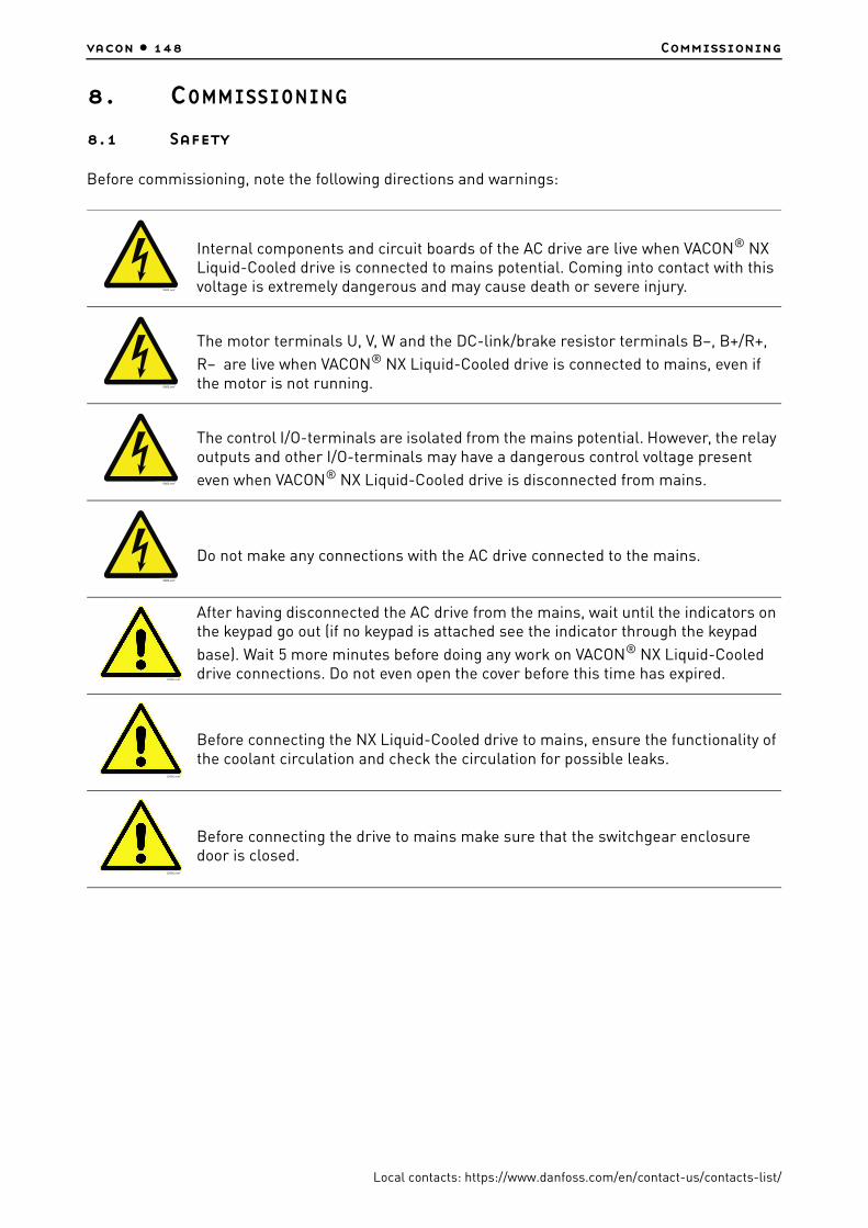
vacon • 148 Commissioning
Local contacts: https://www.danfoss.com/en/contact-us/contacts-list/
8. COMMISSIONING
8.1 Safety
Before commissioning, note the following directions and warnings:
Internal components and circuit boards of the AC drive are live when VACON® NX Liquid-Cooled drive is connected to mains potential. Coming into contact with this voltage is extremely dangerous and may cause death or severe injury.
The motor terminals U, V, W and the DC-link/brake resistor terminals B–, B+/R+,
R– are live when VACON® NX Liquid-Cooled drive is connected to mains, even if the motor is not running.
The control I/O-terminals are isolated from the mains potential. However, the relay outputs and other I/O-terminals may have a dangerous control voltage present
even when VACON® NX Liquid-Cooled drive is disconnected from mains.
Do not make any connections with the AC drive connected to the mains.
After having disconnected the AC drive from the mains, wait until the indicators on the keypad go out (if no keypad is attached see the indicator through the keypad
base). Wait 5 more minutes before doing any work on VACON® NX Liquid-Cooled drive connections. Do not even open the cover before this time has expired.
Before connecting the NX Liquid-Cooled drive to mains, ensure the functionality of the coolant circulation and check the circulation for possible leaks.
Before connecting the drive to mains make sure that the switchgear enclosure door is closed.
9000.emf
9000.emf
9000.emf
9000.emf
13006.emf
13006.emf
13006.emf

Commissioning vacon • 149
Local contacts: https://www.danfoss.com/en/contact-us/contacts-list/
8.2 Commissioning of the AC drive
1. Read carefully the safety instructions in Chapter 1 and follow them.
2. After the installation, pay attention:
- that both the AC drive and the motor are grounded.- that the mains and motor cables comply with the requirements given in Chapter 6.1.1.- that the control cables are located as far as possible from the power cables and that the
shields of the shielded cables are connected to protective earth . The wires may not touch the electrical components of the AC drive.
- that the common inputs of digital input groups are connected to +24 V or ground of the I/O terminal or the external supply.
3. Check liquid cooling connections and system operation.- open the shut-off valves- check the quality and quantity of the cooling liquid (Chapter 5.2)- ensure the proper operation of liquid circulation system
4. Perform the cable and motor insulation checks, see Chapter 6.1.10.
5. Check the AC drive for condensation.
6. Check that all Start/Stop switches connected to the I/O terminals are in Stop-position.
7. Connect the AC drive to mains.
8. Set the parameters of group 1 (See VACON® All in One Application Manual) according to the requirements of your application. At least the following parameters should be set:
- motor nominal voltage- motor nominal frequency- motor nominal speed- motor nominal current
You will find the values needed for the parameters on the motor rating plate.
9. Perform run test without motor
Perform either Test A or Test B:
A Controls from the I/O terminals:
a) Turn the Start/Stop switch to ON position.b) Change the frequency reference (potentiometer).c) Check in the Monitoring menu (M1) that the value of Output frequency changes according
to the change of frequency reference.d) Turn the Start/Stop switch to OFF position.
B Control from the control keypad:
a) Change the control from the I/O terminals to the keypad as advised in Chapter 7.3.3.1.

vacon • 150 Commissioning
Local contacts: https://www.danfoss.com/en/contact-us/contacts-list/
b) Push the Start button on the keypad.c) Move over to the Keypad control menu (M3) and Keypad Reference submenu
(Chapter 7.3.3.2) and change the frequency reference using the Browser buttons
d) Check in the Monitoring menu (M1) that the value of Output frequency changes according to the change of frequency reference.
e) Push the Stop button on the keypad.
10. Run the start-up tests without the motor being connected to the process, if possible. If this is not possible, secure the safety of each test prior to running it. Inform your co-workers of the tests.
a) Switch off the supply voltage and wait up until the drive has stopped as advised at Chapter 8.1, step 5.
b) Connect the motor cable to the motor and to the motor cable terminals of the AC drive.c) See to that all Start/Stop switches are in Stop positions.d) Switch the mains ONe) Repeat test 9A or 9B.
11. Connect the motor to the process (if the startup test was run without the motor being con nected).
a) Before running the tests, make sure that this can be done safely.b) Inform your co-workers of the tests.c) Repeat test 9A or 9B.
+
-
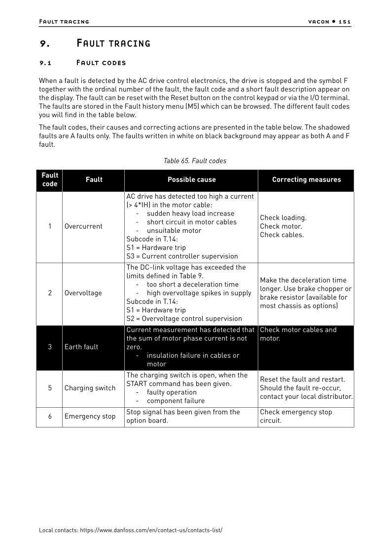
Fault tracing vacon • 151
Local contacts: https://www.danfoss.com/en/contact-us/contacts-list/
9. FAULT TRACING
9.1 Fault codes
When a fault is detected by the AC drive control electronics, the drive is stopped and the symbol F together with the ordinal number of the fault, the fault code and a short fault description appear on the display. The fault can be reset with the Reset button on the control keypad or via the I/O terminal. The faults are stored in the Fault history menu (M5) which can be browsed. The different fault codes you will find in the table below.
The fault codes, their causes and correcting actions are presented in the table below. The shadowed faults are A faults only. The faults written in white on black background may appear as both A and F fault.
Table 65. Fault codes
Fault code
Fault Possible cause Correcting measures
1 Overcurrent
AC drive has detected too high a current (> 4*IH) in the motor cable:
- sudden heavy load increase- short circuit in motor cables- unsuitable motor
Subcode in T.14:S1 = Hardware tripS3 = Current controller supervision
Check loading.Check motor.Check cables.
2 Overvoltage
The DC-link voltage has exceeded the limits defined in Table 9.
- too short a deceleration time- high overvoltage spikes in supply
Subcode in T.14:S1 = Hardware tripS2 = Overvoltage control supervision
Make the deceleration time longer. Use brake chopper or brake resistor (available for most chassis as options)
3 Earth fault
Current measurement has detected that the sum of motor phase current is not zero.
- insulation failure in cables or motor
Check motor cables and motor.
5 Charging switch
The charging switch is open, when the START command has been given.
- faulty operation- component failure
Reset the fault and restart.Should the fault re-occur, contact your local distributor.
6 Emergency stopStop signal has been given from the option board.
Check emergency stop circuit.

vacon • 152 Fault tracing
Local contacts: https://www.danfoss.com/en/contact-us/contacts-list/
7 Saturation trip
Various causes:- defective component- brake resistor short-circuit or
overload
Cannot be reset from the keypad. Switch off power.DO NOT RE-CONNECT POWER!Contact your local distributor.If this fault appears simultaneously with Fault 1, check motor cables and motor.
8 System fault
- component failure- faulty operation
Note exceptional fault data record.Subcode in T.14:S1 = Feedback of motor voltageS2 = ReservedS3 = ReservedS4 = ASIC tripS5 = Disturbance in VaconBusS6 = Feedback of charging switchS7 = Charging switchS8 = No power to driver cardS9 = Power unit communication (TX)S10 = Power unit communication (Trip)S11 = Power unit comm. (Measurement)S12 = Expander board (slot D or E)S30-S48 = OPT-AF board (slot B)
Reset the fault and restart.Should the fault re-occur, contact your local distributor.
9 Undervoltage
DC-link voltage is under the voltage limits defined in Table 9.
- most probable cause: too low a supply voltage
- AC drive internal faultSubcode in T.14:S1 = DC-link too low during runS2 = No data from power unitS3 = Undervoltage control supervision
In case of temporary supply voltage break reset the fault and restart the AC drive. Check the supply voltage. If it is adequate, an internal fail-ure has occurred.Contact your local distributor.
10
Input line supervision
Input line phase is missing.Subcode in T.14:S1 = Phase supervision diode supplyS2 = Phase supervision active front end
Check supply voltage, fuses and cable.
12Brake chopper supervision
- no brake resistor installed- brake resistor is broken- brake chopper failure
Check brake resistor and cabling.If ok, the chopper is faulty. Contact your local distribu-tor.
13Frequency converter undertemperature
Heatsink temperature is under –10°C.
Table 65. Fault codes
Fault code
Fault Possible cause Correcting measures

Fault tracing vacon • 153
Local contacts: https://www.danfoss.com/en/contact-us/contacts-list/
14
Frequency converter overtemperature
3) Heatsink temperature is over 70°C. Overtemperature warning is issued when the heatsink temperature exceeds 65°C.4) Circuit board temperature is over 85ºC. Overtemperature warning is issued when the board temperature exceeds 75ºC.Subcodes:S1 = Overtemperature warning in unit, board or phasesS2 = Overtemperature in power boardS3 = Liquid flowS4 = Overtemperature on ASIC board or driver boards
Cause 1):Check that values for Ith (Chapter 4.2) are not exceeded.Check the correct coolant flow and temperature. Also check the circulation for possible leaks.Check the ambient temperature.Make sure that the switching frequency is not too high in relation to ambient temperature and motor load.Cause 2):Circulation of air in the drive is blocked.The cooling fans are defect.
15 Motor stalled Motor stall protection has tripped. Check motor and load.
16
Motor overtemperature
Motor overheating has been detected by AC drive motor temperature model. Motor is overloaded.
Decrease the motor load.If no motor overload exists, check the temperature model parameters.
17 Motor underload Motor underload protection has tripped. Check load.
18Unbalance (Warning only)
Unbalance between power modules in paralleled units.Subcode in T.14:S1 = Current unbalanceS2 = DC-Voltage unbalance
Should the fault re-occur, contact your local distributor.
22EEPROM checksum fault
Subcodes:S1 = Firmware interface power down variable checksum error.S2 = Firmware interface variable check sum error.S3 = System power down variable check sum errorS4 = System parameter checksum errorS5 = Application-defined powerdown, variable checksum error.S6 = Application-defined powerdown, variable checksum.S10 = System parameter checksum error (fault history entries, device valid, system menu parameters).
Should the fault re-occur, contact your local distributor.
24 Counter faultValues displayed on counters are incorrect.
Take a critical attitude towards values shown on counters.
Table 65. Fault codes
Fault code
Fault Possible cause Correcting measures

vacon • 154 Fault tracing
Local contacts: https://www.danfoss.com/en/contact-us/contacts-list/
25Microprocessor watchdog fault
- faulty operation- component failure
Subcodes:S1 = CPU watchdog timerS2 = ASIC reset
Reset the fault and restart.Should the fault re-occur, contact your distributor.
26 Startup prevented
Start-up of the drive has been prevented.Subcodes:S1 = Prevention of accidental start-up.S2 = Appears if START command is ON, when returning to READY STATE after Safe Disable has been active.S30 = Appears if START command is ON after system software has been downloaded, after application has been downloaded or application has been changed.
Cancel prevention of start-up if this can be done safely.
29
Thermistor fault The thermistor input of option board has detected increase of the motor tempera-ture.Subcodes:S1 =Thermistor input activated on OPT-AF boardS2 = Special application
Check motor cooling and loading.Check thermistor connection(If thermistor input of the option board is not in use it has to be short circuited).
30Safe Disable warning
Safe disable inputs SD1 and SD2 are acti-vated through the option board OPT-AF.
Contact your distributor.
31IGBT temperature(hardware)
IGBT Inverter Bridge overtemperature protection has detected too high a short-term overload current.
Check loading.Check motor size.
34CAN bus communication
Sent message not acknowledged.Ensure that there is another device on the bus with the same configuration.
35 Application Problem in application software.
Contact your distributor. If you are application programmer check the application program.
36 Control unitVACON® NXS Control Unit can not con-
trol VACON® NXP Power Unit and vice versa.
Change control unit.
37Device changed(same type)
Option board or power unit changed.New device of same type and rating.Subcodes:S1 = Control boardS2 = Control unitS3 = Power boardS4 = Power unitS5 = Adapter board and slot
Reset. Device is ready for use.Old parameter settings will be used.
Table 65. Fault codes
Fault code
Fault Possible cause Correcting measures

Fault tracing vacon • 155
Local contacts: https://www.danfoss.com/en/contact-us/contacts-list/
38Device added(same type)
Option board added.Subcodes:S1 = Control boardS4 = Control unitS5 = Adapter board and slot
Reset. Device is ready for use. Old board settings will be used.
39 Device removed Option board removed.Reset. Device no longer available.
40Device unknownUnknown option board or drive.
Subcode in T.14:S1 = Unknown deviceS2 = Power1 not same type as Power2S3 = NXS or NXP1 and star couplerS4 = Software and ctrl unit incompatibleS5 = Old control board version
Contact your local distribu-tor.
41 IGBT temperatureIGBT Inverter Bridge overtemperature protection has detected too high a short term overload current
Check loading.Check motor size.
42
Brake resistor overtemperature
Subcodes:S1 = Internal brake chopper overtemp.S2 = Brake resistance too high (BCU)S3 = Brake resistance too low (BCU)S4 = Brake resistance not detected (BCU)S5 = Brake resistance leakage (earth fault) (BCU)
Reset unit.Set the deceleration time longer and restart.Dimensioning of the brake chopper is not correct.Use external brake resistor.
43 Encoder fault
Problem detected in encoder signals.Sub code in T.14:S1 = Encoder 1 channel A is missingS2 = Encoder 1 channel B is missingS3 = Both enc. 1 channels are missingS4 = Encoder reversedS5 = Encoder board missingS6 = Serial communication faultS7 = Channel A/Channel B mismatchS8 = Resolver/Motor pole pair mismatchS9 = Missed start angle
Check encoder channel connections.Check the encoder board.
44Device changed(different type)
Option board or power unit changed.New device of different type or different rating than the previous one.Subcodes:S1 = Control boardS2 = Control unitS3 = Power boardS4 = Power unitS5 = Adapter board and slot
ResetSet the option board parameters again if option bard changed. Set AC drive parameters again if power unit changed.
Table 65. Fault codes
Fault code
Fault Possible cause Correcting measures

vacon • 156 Fault tracing
Local contacts: https://www.danfoss.com/en/contact-us/contacts-list/
45Device added(different type)
Option board of different type added.Subcodes:S1 = Control boardS2 = Control unitS3 = Power boardS4 = Power unitS5 = Adapter board and slot
ResetSet the option board parameters again.
49Div by zero in application
A division by zero has occurred in the application program.
Contact your distributor. If you are application programmer check the application program.
50
Analogue input Iin < 4mA (sel. signal range 4 to 20 mA)
Current at the analogue input is < 4mA.- control cable is broken or loose- signal source has failed
Check the current loop circuitry.
51 External fault Digital input fault.
52Keypad communication fault
Keypad communication faultThe connection between the control key-pad and the AC drive is broken.
Check keypad connection and possible keypad cable.
53 Fieldbus faultThe data connection between the field-bus Master and the fieldbus board is bro-ken.
Check installation.If installation is correct contact the nearest distributor.
54 Slot fault Defective option board or slot.Check board and slot.Contact the nearest distribu-tor.
55Actual value supervision
56PT100 boardtemp. fault
Temperature limit values set for the PT100 board parameters have been exceeded.
Find the cause of temperature rise.
57 Identification Identification run has failed.
Run command was removed before completion of identification run.Motor is not connected to AC drive.There is load on motor shaft.
58 BrakeActual status of the brake is different from the control signal.
Check mechanical brake state and connections.
59Follower communication
SystemBus or CAN communication is broken between Master and Follower.
Check option board parameters.Check optical fibre cable or CAN cable.
60 CoolingCoolant circulation on liquid-cooled drive has failed.
Check reason for the failure on external system.
Table 65. Fault codes
Fault code
Fault Possible cause Correcting measures

Fault tracing vacon • 157
Local contacts: https://www.danfoss.com/en/contact-us/contacts-list/
9.2 Load test with motor
1. Connect the motor cables and check the right phase order. Also check that the motor rotates freely.
2. Check liquid cooling system operation.3. Turn on the supply voltage and ensure that all input phases are connected to the unit.4. Check DC link voltage by measuring with multimeter and compare the value to the one
on monitoring page V1.8.5. Select the application of your choice and set the needed parameters (see Start-up Quick
Guide, step 8 on page 7.6. Start the operation with lower Current Limit value and long Acceleration/Deceleration
times.7. If Closed Loop control mode is used, check direction of encoder and make necessary
Closed Loop parameter settings. Check the correct operation of the encoder by running the system in open loop and check the signals in the expander board menu.
8. Run the motor without load between minimum and maximum frequencies and check the unit output current with a current clamp. Compare the value to the one on monitoring page V1.4.
9. Load the motor to nominal value if possible and repeat the current measurement. Follow the Unit Temperature value on page V1.9.
61 Speed error Motor speed is unequal to reference.Check encoder connection.PMS motor has exceeded the pull out torque.
62 Run disable Run enable signal is low.Check reason for Run enable signal.
63 Emergency stopCommand for emergency stop received from digital input or fieldbus.
New run command is accepted after reset.
64 Input switch open Drive input switch is open.Check the main power switch of the drive.
Table 65. Fault codes
Fault code
Fault Possible cause Correcting measures

vacon • 158 Fault tracing
Local contacts: https://www.danfoss.com/en/contact-us/contacts-list/
9.3 DC link test (without motor)
NOTE! There will be dangerous voltages present during this test!
1. Read carefully the safety instructions in Chapter 1 and follow them.2. Connect a variable DC power supply to DC+ and DC– terminals. Make sure that all
polarities are correct.3. Slowly charge up the DC link to nominal voltage. Allow the system to remain at this level
for at least one minute and check current.4. If possible, continue increasing the DC link voltage up to the trip limit. Fault F2 (see
Chapter 9) should occur at 911 VDC (NX_5, 400…500-volt units), at 1200 VDC (NX_6, 525…690-volt units) and 1300 VDC (NX_8, 525...690-volt units). Do not increase the voltage over the trip limit.
5. Bring the power supply voltage back to zero. Allow sufficient time for the capacitors to discharge.
6. Check the DC bus voltage with a multimeter. When you read zero volts disconnect the power supply and reconnect all wires to the phase module.
7. If the phase module has been de-energized for an extended period of time (six months or longer) allow this voltage to remain for a minimum of 30 minutes – even 4 hours if time permits.
Through the above test procedure, two things are achieved: 1) It allows the caps to partially reform due to storage and shipping; 2) It allows any device failures to evidence themselves with a low power failure.

Active front end (NXA) vacon • 159
Local contacts: https://www.danfoss.com/en/contact-us/contacts-list/
10. ACTIVE FRONT END (NXA)
10.1 Introduction
The VACON® NX Active Front End is used to transfer power between the AC input and intermediate DC circuit. The VACON® NX Active Front End has a two-way function. This means that when power is transferred from the AC input to the intermediate DC circuit, the VACON® NX Active Front End rectifies the alternating current and voltage. When power is transferred from the intermediate DC circuit to the AC input, the VACON® NX Active Front End inverts the direct current and voltage.
The Active Front End configurations consist of the unit itself, LCL filter, pre-charging circuit, control unit, AC fuses, main contactor / circuit breaker and DC fuses which you need to take into account when planning the switchgear configuration, see Figure 87.
10.2 Diagrams
10.2.1 Active Front End block diagram
Figure 87. Active front end configuration
3073_uk

vacon • 160 Active front end (NXA)
Local contacts: https://www.danfoss.com/en/contact-us/contacts-list/
10.3 Type designation code
In Vacon type designation code, the Active Front End is characterized by the characters NXA and number 2, for example:
Figure 88. Active front end block diagram
NXA 0300 5 A 0 T 0 2WF A1A2000000
POWER MODULE
CONTROL MODULE
B+
B-
Powersupply
Fan
Measure-ments
Driver
ASIC
IGBTbridge
U/T1
V/T2W/T3
Control
I/Oslot A
I/Oslot B
I/Oslot C
I/Oslot D
I/Oslot E
RS-232
KEYPAD
11399_uk

Active front end (NXA) vacon • 161
Local contacts: https://www.danfoss.com/en/contact-us/contacts-list/
10.4 Active Front End unit technical data
The technical data for the active front end unit, see table below.
*) NX_8 AC drives only available as Ch6x AFE/BCU/INU units.
Table 66. Technical data
Mains connection
Input voltage Uin
NX_5: 400…500 VAC (–10%…+10%); 465…800 VDC (–0%…+0%)NX_6: 525…690 VAC (–10%…+10%); 640…1100 VDC(–0%…+0%)NX_8: 525…690 VAC (–10%…+10%); 640…1200 VDC
(–0%…+0%)*)
Input frequency 45…66 Hz
Connection to mains Once per minute or less
DC bank capacitance
Voltage class 500 V:
Voltage class 690 V:
Ch3 (16-31A units): 410 µFCh3 (38-61A units): 600 µFCH4: 2400 µFCH5: 7200 µFCH61: 10800 µFCH62/CH72: 10800 µFCH63: 21600 µFCH64/CH74: 32400 µF2*CH64/2*CH74: 64800 µF
CH61: 4800 µFCH62/CH72: 4800 µFCH63: 9600 µFCH64/CH74: 14400 µF2*CH64/2*CH74: 28800 µF
Supply network
Networks TN, TT, IT
Short circuit current Maximum short circuit current has to be < 100 kA.
Rated apparent power
The rated apparent power of the supply network including generators and/or transformers should be greater than 50% of the total rated apparent power of the Active Front End units which are connected to the network.
DC output connection
Voltage1.35 x Uin x 1.1 (default DC link voltage boosting is 110%)
Continuous output cur-rent
Rated current at nominal inflow cooling water temperature according to dimensioning charts.
Control characteristics
Control method Open Loop Vector Control
Switching frequency NXA: Factory setting 3.6 kHz

vacon • 162 Active front end (NXA)
Local contacts: https://www.danfoss.com/en/contact-us/contacts-list/
Ambient conditions
Ambient operating temperature
–10°C (no frost)…+50°C (at Ith)
The VACON® NX Liquid-Cooled drives must be used in an heated indoor controlled environment.
Installation temperature
0...+70°C
Storage temperature –40°C…+70°C; No liquid in heatsink under 0ºC
Relative humidity 5 to 96% RH, non-condensing, no dripping water
Air quality:• chemical
vapours• mechanical
particles
IEC 60721-3-3, unit in operation, class 3C2IEC 60721-3-3, unit in operation, class 3S2 (no conductive dust allowed)No corrosive gases
Altitude
NX_5: (380...500 V): max. 3000 m (in case network is not corner grounded)NX_6/NX_8: max. 2000 m. For further requirements, contact factory 100-% load capacity (no derating) up to 1,000 m; above 1,000 m derating of maximum ambient operating temperature by 0.5 °C per each 100 m is required.
VibrationEN 50178/EN 60068-2-6
5…150 HzDisplacement amplitude 0.25 mm (peak) at 3…31 HzMax acceleration amplitude 1 G at 31…150 Hz
ShockEN 50178, EN 60068-2-27
UPS Drop Test (for applicable UPS weights)Storage and shipping: max 15 G, 11 ms (in package)
Enclosure classIP00 (UL open type) / Open Frame standard in entire kW / HP range
Pollution degree PD2
EMC
Immunity Fulfils IEC/EN 61800-3 EMC immunity requirements.
EmissionsEMC level N for TN/TT networksEMC level T for IT networks
Safety
IEC/EN 61800-5-1 (2007), CE, UL, cUL, GOST R,(see unit nameplate for more detailed approvals)IEC 60664-1 and UL840 in overvoltage category III.
Safe Torque Off (STO) board
The drive is equipped with VACON® OPTAF board for prevention of torque on motor shaft . Standards: prEN ISO 13849-1 (2004), EN ISO 13849-2 (2003), EN 60079-14 (1997), EN 954-1 (1996), cat. 3 (hardware disable); IEC 61508-3(2001), prEN 50495 (2006).
See VACON® NX OPTAF STO Board User Manual for detailed information.
Table 66. Technical data

Active front end (NXA) vacon • 163
Local contacts: https://www.danfoss.com/en/contact-us/contacts-list/
Control connections
(apply to boards OPT-A1, OPT-A2
and OPT-A3)
Analogue input voltage0…+10 V, Ri = 200 kΩ, (–10 V…+10 V joystick control)Resolution 0.1%, accuracy ±1%
Analogue input current 0(4)…20 mA, Ri = 250 W differential
Digital inputs (6) Positive or negative logic; 18…24 VDC
Auxiliary voltage
+24 V, ±10%, max volt. ripple < 100 mVrms; max. 250 mADimensioning: max. 1000 mA/control box1A external fuse required (no internal short-circuit protection on the control board)
Output reference voltage
+10 V, +3%, max. load 10 mA
Analogue output0(4)…20 mA; RL max. 500 Ω; Resolution 10 bit; Accuracy ±2%
Digital outputs Open collector output, 50 mA/48 V
Relay outputs
2 programmable change-over relay outputsSwitching capacity: 24 VDC/8 A, 250 VAC/8 A, 125 VDC/0.4 AMin. switching load: 5 V/10 mA
Protections
Overvoltage trip limit
NX_5: 911 VDC NX_6: (CH61, CH62, CH63 & CH64): 1258 VDC NX_8: 1300 VDC
Undervoltage trip limit NX_5: 333 VDC; NX_6: 461 VDC; NX_8: 461 V (all VDC)
Earth fault protectionIn case of earth fault in motor or motor cable, only the AC drive is protected.
Mains supervisionTrips if any of the input phases is missing (AC drives only).
Input phase monitoring Trips if any of the output phases is missing.
Unit overtemperature protection
Alarm limit: 65ºC (heatsink); 75ºC (circuit boards).Trip limit: 70ºC (heatsink); 85ºC (circuit boards).
Overcurrent protection Yes
Unit overheat protection
Yes
Short-circuit protection of +24 V and +10 V reference voltages
Yes
Table 66. Technical data

vacon • 164 Active front end (NXA)
Local contacts: https://www.danfoss.com/en/contact-us/contacts-list/
Liquid cooling
Allowed cooling agentsDrinking water (see specification on page 51)Water-glycol mixtureSee derating specifications, Chapter 5.3.
Volume See Table 19.
Temperature of cooling agent
0…35°C input (Ith); 35…55ºC: derating required, see
Chapter 5.3.Max. temperature rise during circulation max. 5°CNo condensation allowed. See Chapter 5.1.1.
Cooling agent flow rates
See Table 15.
System max. working pressure
6 bar
System max. peak pressure
30 bar
Pressure loss (at nom. flow)
Varies according to size. See Table 17.
Table 66. Technical data

Active front end (NXA) vacon • 165
Local contacts: https://www.danfoss.com/en/contact-us/contacts-list/
10.5 Power ratings
*) C = power loss into coolant, A = power loss into air, T = total power loss.
The enclosure class for all VACON® NX Liquid-Cooled AC drives is IP00 (UL open type).
Ith = Thermal maximum continuous RMS current. Dimensioning can be done according to this current if the process does not require any overloadability or the process does not include any load variation.
IL = Low overloadability current. Allows +10% load variation. 10% exceeding can be continuous.
IH = High overloadability current. Allows +50% load variation. 50% exceeding can be continuous.
All values with cosϕ = 0.99 and efficiency = 97.5%.
*) c = power loss into coolant; a = power loss into air; T = total power loss.
All power losses obtained using max. supply voltage, Ith and switching frequency of 3.6 kHz. All power losses are worst case losses.
Table 67. Power ratings of VACON® NX Liquid-Cooled AFE unit, supply voltage 400-500 V AC
VACON® NX Liquid-Cooled Front End; DC Bus voltage 465–800 V DC
AFE type
AC Current DC power Power loss
c/a/T*) [kW]
Enclo-sure size
Thermal
Ith[A]
Rated
IL[A]
Rated
IH[A]
400 V AC mains
Ith[kW]
500 V AC mains
Ith[kW]
400 V AC mains
IL[kW]
500 V AC mains
IL[kW]
0168_5 168 153 112 113 142 103 129 2.5/0.3/2.8 CH5
0205_5 205 186 137 138 173 125 157 3.0/0.4/3.4 CH5
0261_5 261 237 174 176 220 160 200 4.0/0.4/4.4 CH5
0300_5 300 273 200 202 253 184 230 4.5/0.4/4.9 CH61
0385_5 385 350 257 259 324 236 295 5.5/0.5/6.0 CH61
0460_5 460 418 307 310 388 282 352 5.5/0.5/6.0 CH62
0520_5 520 473 347 350 438 319 398 6.5/0.5/7.0 CH62
0590_5 590 536 393 398 497 361 452 7.5/0.6/8.1 CH62
0650_5 650 591 433 438 548 398 498 8.5/0.6/9.1 CH62
0730_5 730 664 487 492 615 448 559 10.0/0.7/10.7 CH62
0820_5 820 745 547 553 691 502 628 10.0/0.7/10.7 CH63
0920_5 920 836 613 620 775 563 704 12.4/0.8/12.4 CH63
1030_5 1030 936 687 694 868 631 789 13.5/0.9/14.4 CH63
1150_5 1150 1045 767 775 969 704 880 16.0/1.0/17.0 CH63
1370_5 1370 1245 913 923 1154 839 1049 15.5/1.0/16.5 CH64
1640_5 1640 1491 1093 1105 1382 1005 1256 19.5/1.2/20.7 CH64
2060_5 2060 1873 1373 1388 1736 1262 1578 26.5/1.5/28.0 CH64
2300_5 2300 2091 1533 1550 1938 1409 1762 29.6/1.7/31.3 CH64

vacon • 166 Active front end (NXA)
Local contacts: https://www.danfoss.com/en/contact-us/contacts-list/
*) C = power loss into coolant, A = power loss into air, T = total power loss.
The enclosure class for all VACON® NX Liquid-Cooled AC drives is IP00 (UL open type).
***) Mains voltage 640-1200 VDC for NX_8 inverter units.
Ith = Thermal maximum continuous RMS current. Dimensioning can be done according to this current if the process does not require any overloadability or the process does not include any load variation.
IL = Low overloadability current. Allows +10% load variation. 10% exceeding can be continuous.
IH = High overloadability current. Allows +50% load variation. 50% exceeding can be continuous.
All values with cosϕ = 0.99 and efficiency = 97.5%.
*) c = power loss into coolant; a = power loss into air; T = total power loss.
All power losses obtained using max. supply voltage, Ith and switching frequency of 3.6 kHz. All power losses are worst case losses.
Table 68. Power ratings of VACON® NX Liquid-Cooled AFE unit, supply voltage 525-690 VAC
VACON® NX Liquid-Cooled Front End; DC Bus voltage 640–1100 VDC ***)
Active front-
end type
AC Current DC power Power loss
c/a/T*) [kW]
ChassisThermal
Ith[A]
Rated
IL[A]
Rated
IH[A]
525 VAC mains
Ith[kW]
690 VAC mains
Ith[kW]
525 VAC mains
IL[kW]
690 VAC mains
IL[kW]
0170_6 170 155 113 150 198 137 180 3.6/0.2/3.8 CH61
0208_6 208 189 139 184 242 167 220 4.3/0.3/4.6 CH61
0261_6 261 237 174 231 303 210 276 5.4/0.3/5.7 CH61
0325_6 325 295 217 287 378 261 343 6.5/0.3/6.8 CH62
0385_6 385 350 257 341 448 310 407 7.5/0.4/7.9 CH62
0416_6 416 378 277 368 484 334 439 8.0/0.4/8.4 CH62
0460_6 460 418 307 407 535 370 486 8.7/0.4/9.1 CH62
0502_6 502 456 335 444 584 403 530 9.8/0.5/10.3 CH62
0590_6 590 536 393 522 686 474 623 10.9/0.6/11.5 CH63
0650_6 650 591 433 575 756 523 687 12.4/0.7/13.1 CH63
0750_6 750 682 500 663 872 603 793 14.4/0.8/15.2 CH63
0820_6 820 745 547 725 953 659 866 15.4/0.8/16.2 CH64
0920_6 920 836 613 814 1070 740 972 17.2/0.9/18.1 CH64
1030_6 1030 936 687 911 1197 828 1088 19.0/1.0/20.0 CH64
1180_6 1180 1073 787 1044 1372 949 1247 21.0/1.1/22.1 CH64
1300_6 1300 1182 867 1150 1511 1046 1374 24.0/1.3/25.3 CH64
1500_6 1500 1364 1000 1327 1744 1207 1586 28.0/1.5/29.5 CH64
1700_6 1700 1545 1133 1504 1976 1367 1796 32.1/1.7/33.8 CH64

Active front end (NXA) vacon • 167
Local contacts: https://www.danfoss.com/en/contact-us/contacts-list/
10.6 Liquid-Cooled RLC filters
10.6.1 Introduction
VACON® Liquid-Cooled AFE units can be used with either Liquid Cooled or Air Cooled LCL filters. The standard Liquid Cooled LCL filters are named RLC filter. The RLC filter type codes can be seen from Table 67. The RLC filters are not included in the standard delivery of the AFE units and therefore they need to be ordered reparately. More information about Air Cooled LCL filters can be found from UD01190B, VACON® NX Active Front End User‘s Manual, FI9-13.
10.6.2 Wiring diagrams
The RLC filter contains a 3-phase chokes (Lnet)on the mains side, capacitors bank (Cbank) and 3 pcs of 1-phase choke (Ldrive) on the AFE side, Figure 89. The RLC also includes capacitors connected against ground potential. There are resistors connected across the capacitors for discharging them when the LCL filter is disconnected from the input power. The discharging resistors are 10 MΩ, 500 V and 0.5 W.
Figure 89. VACON® RLC filter wiring diagram
3071_uk
Active front end unit
U
V
W
Ld
rive
Ln
et
Cbank
B-
B+L
out /L
inL
in /L
outL1
in /L1
outL1
Crf
CrfC
rf
Crf C
rf
Crf
Crf
Crf
Crf
Crf
Crf
Crf
RRRRRR
L3
L2 L2in
/L2out
L3in
/L3out
L1out
/L1in
L2out
/L2in
L3out
/L3in
Lin
/Lout
Lin
/Lout
Lout
/Lin
Lout
/Lin
L3L3
L2
L2
L1L1

vacon • 168 Active front end (NXA)
Local contacts: https://www.danfoss.com/en/contact-us/contacts-list/
10.6.3 Power rating and dimensions
Figure 90. Example of Lnet choke of a VACON® RLC filter
Table 69. VACON® RLC ratings, drive suitability and dimensions
VACON® NX Liquid-Cooled regenerative line filters - IP00 (UL open type)
RCL filter type
Thermal currentIth [A]
Power loss
c/a/T*) [kW]
Suitability[Drive/voltage:
current]
Dimensions Lnet, 1 pc
WxHxD [mm]
Dimensions Ldrive, 1 pc(total 3 pcs),
WxHxD[mm]
Dimensions Cbank, 1 pc
WxHxD [mm]
Total weight
[kg]
RLC-0385-6-0
3852.6/0.8/
3.4CH62/690 V AC: 325 A & 385 A
580 x 450 x 385 410 x 415 x 385 360 x 265 x 150 458
RLC-0520-6-0
5202.65/0.65/
3.3CH62/500-690 V AC
580 x 450 x 385 410 x 415 x 385 360 x 265 x 150 481
RLC-0750-6-0
750 3.7/1/4.7CH62/500 V AC, CH63/690 V AC
580 x 450 x 385 410 x 450 x 385 360 x 275 x 335 508
RLC-0920-6-0
9204.5/1.4/
5.9CH63/500 V AC, CH64/690 V AC
580 x 500 x 390 410 x 500 x 400 360 x 275 x 335 577
RLC-1180-6-0
11806.35/1.95/
8.3CH63/500 V AC, CH64/690 V AC
585 x 545 x 385 410 x 545 x 385 350 x 290 x 460 625
RLC-1640-6-0
1640 8.2/2.8/11CH64/500-690 V AC
585 x 645 x 385 420 x 645 x 385 350 x 290 x 460 736
RLC-2300-5-0
23009.5/2.9/
12.4CH64/500 V AC: 2060 A & 2300 A
585 x 820 x 370 410 x 820 x 380 580 x 290 x 405 896
Lifting points
25
L3in/L3
out
10 15L2in/L2
outL1
in/L1
out
L1out
/L1in
L1out2
/L1in2
L2out
/L2in
L2out2
/L2in2
L3out
/L3in
H
W
D
L3out2
/L3in2
3069A_uk
CONNECTION:
In/Out (Always
connected)
400-500V In/Out
(L_in/L_out)
525-690V In/Out
(L_in2/L_out2)

Active front end (NXA) vacon • 169
Local contacts: https://www.danfoss.com/en/contact-us/contacts-list/
Figure 91. Example of Lafe choke of a VACON® RLC filter
Figure 92. Example of capacitor bank (Cbank) of a VACON® RLC filter
Lifting points25
H
W
D
Lin/L
out
Lout1
/Lin1
Lout2
/Lin2
3070A_uk
CONNECTION:
In/Out (Always
connected)
400-500V In/Out
(L_in/L_out)
525-690V In/Out
(L_in2/L_out2)
3072_00

vacon • 170 Active front end (NXA)
Local contacts: https://www.danfoss.com/en/contact-us/contacts-list/
10.6.4 Technical data
10.6.5 Removing discharging resistors
If the filter is used in a network fitted with an earth fault protection relay, the discharging resistors should be removed. If the discharging resistors are not removed, the earth fault monitoring device might indicate a very low leakage resistance. The resistors must be connected so that the capacitors are discharged when disconnecting from the input power. The wiring diagram of an alternative discharging circuit can be seen in Figure 93. The discharging resistors should be 10 kΩ, 500 V and 2 W. Failure to ensure the discharging of capacitors take a very long time to discharge.
Figure 94 and Figure 95 have a blue marking on the lead that has to be removed from each capacitors if the discharge resistor is not to be used.
WARNING! If you do not allow a total discharge of the system before starting the modification, it is likely that you will get an electricshock in spite of the fact the system is disconnected from the power supply.
Table 70. VACON® RLC technical data
AC connections Voltage Uin Same as the NXA unit.
Frequency fin 50 or 60 Hz + 2%.
Continuous output cur-rent
See current rating of filter.
Switching frequency 3.6 kHz
Ambient conditionsAmbient temperature during operation
-10...+50°C
Installation temperature 0...+70°C
Storage temperature -40...+70°C, no liquid in filter under 0°C.
Relative humidity Same as the NXA unit.
Enclosure class IP00 (UL open type)
Liquid cooling Allowed cooling agentsDrinking water, demineralized water or a mixture of water and glycol. (To avoid electromechanical corrosion it is necessary to add an inhibitor.)
Temperature of cooling agent
0...+60°C
Cooling agent flow rate8l/min for one choke, total 32 l/min (for 1pcs Lnet choke and 3pcs Ldrive chokes).
System max working pressure
6 bar
Coolant connection G3/8" female thread x 2 pcs. (1pcs inlet / 1pcs outlet)
ProtectionOver-temperature monitoring
Thermal relay at each winding of the chokes. Thermal relays connected in series between terminals 10 and 15. Relay contact type: normally closed. Switching temperature: 150°C.

Active front end (NXA) vacon • 171
Local contacts: https://www.danfoss.com/en/contact-us/contacts-list/
Figure 93. Wiring diagram of the alternative discharging circuit configuration
10.6.6 Removing HF capacitors
If a PWM modulated rectifier from another manufacturer is connected to the same input transformer, the capacitors must be removed! Otherwise the capacitors must not be removed.
Figure 94 and Figure 95 have a red marking on the lead that has to be removed from each capacitor if the interference suppression capacitors are not to be used. Removing the lead disconnects the capacitors from ground potential.
3074_uk
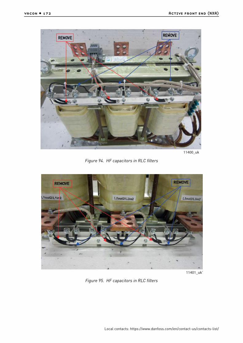
vacon • 172 Active front end (NXA)
Local contacts: https://www.danfoss.com/en/contact-us/contacts-list/
Figure 94. HF capacitors in RLC filters
Figure 95. HF capacitors in RLC filters
11400_uk
11401_uk

Active front end (NXA) vacon • 173
Local contacts: https://www.danfoss.com/en/contact-us/contacts-list/
10.7 Active front end - fuse selection
AC fuses are used to protect the input network in case the Active Front End unit or the LCL filter is faulty. DC fuses are used to protect the Active Front End unit and the LCL filter in case there is a short circuit in the DC buses. If DC fuses are not used, short-circuit in the DC buses will cause a loading of the Active Front End unit. Vacon Ltd will not assume any responsibility for damages caused by insufficient protection. The warranty becomes void if the drive is not equipped with appropriate fuses.
Fuse information
The values in tables are based on max ambient temperature of +50ºC.
Fuse sizes can differ in the same chassis. Make sure that the Isc of the supply transformer is high enough to burn fuses fast enough.
Check the current rating of the fuse bases according to the input current of the drive.
The physical size of the fuse is chosen on the basis of the fuse current: Current < 250 amps (size 1 fuse), current > 250 amps (size 3 fuse).
The aR fuses are thermally rated into switch fuse in 50 degree ambient temperature.
The required AC fuse selection for the active front end unit can be found fromTable 71 and Table 72. The required DC fuse selection for the active front end unit can be found from Table 42 and Table 43.
10.7.1 Fuse sizes, Active Front End units (AC supply)
Table 71. Fuse sizes for VACON® NX AFE units (380—500V)
Chassis TypeIth[A]
Fuse size
DIN43620‘TTF’ threaded
end‘TTF’ threaded
endQty. of fuses /
drive 3~aR fuse part nr. aR fuse part nr. aR fuse part nr.
CH3 0016 16 DIN000 NH000UD69V40PV PC30UD69V50TF - 3
CH3 0022 22 DIN000 NH000UD69V40PV PC30UD69V50TF - 3
CH3 0031 31 DIN000 NH000UD69V63PV PC30UD69V63TF - 3
CH3 0038 38 DIN000 NH000UD69V100PV PC30UD69V100TF - 3
CH3 0045 45 DIN000 NH000UD69V100PV PC30UD69V100TF - 3
CH3 0061 61 DIN00 NH00UD69V125PV PC30UD69V125TF - 3
CH4 0072 72 DIN00 NH00UD69V200PV PC30UD69V200TF - 3
CH4 0087 87 DIN00 NH00UD69V200PV PC30UD69V200TF - 3
CH4 0105 105 DIN00 NH00UD69V200PV PC30UD69V200TF - 3
CH4 0140 140 DIN1 NH1UD69V315PV PC30UD69V315TF - 3
CH5 0168 168 DIN1 NH1UD69V315PV PC30UD69V315TF - 3
CH5 0205 205 DIN1 NH1UD69V400PV PC30UD69V400TF - 3
CH5 0261 261 DIN2 NH2UD69V500PV PC31UD69V500TF - 3
CH61 0300 300 DIN3 NH3UD69V630PV PC32UD69V630TF - 3
CH61 0385 385 DIN3 NH3UD69V630PV PC32UD69V630TF - 3
CH62 0460 460 DIN3 NH3UD69V1000PV PC33UD69V1000TF - 3
CH62 0520 520 DIN3 NH3UD69V1000PV PC33UD69V1000TF - 3
CH62 0590 590 DIN3 PC73UB69V1100PA PC33UD69V1100TF - 3

vacon • 174 Active front end (NXA)
Local contacts: https://www.danfoss.com/en/contact-us/contacts-list/
For DC fuse selection use table for liquid cooled inverters (page 80).
_____________________________1 Quantity of fuses needed of TTF types PC4************ and PC8***********.
CH62 0650 650 DIN3 PC73UB69V1250PA PC33UD69V1250TF - 3
CH62 0730 730 DIN3 PC73UB69V1250PA PC33UD69V1250TF - 3
CH63 0820 820 DIN3 NH3UD69V800PV PC32UD69V800TF PC44UD75V16CTQ 6 (3)
CH63 0920 920 DIN3 NH3UD69V1000PV PC33UD69V1000TF PC44UD75V16CTQ 6 (3)
CH63 1030 1030 DIN3 NH3UD69V1000PV PC33UD69V1000TF PC44UD75V18CTQ 6 (3)
CH63 1150 1150 DIN3 PC73UB69V1100PA PC33UD69V1100TF PC44UD75V20CTQ 6 (3)
CH64 1370 1370 DIN3 NH3UD69V1000PV PC33UD69V1000TF PC44UD75V24CTQ 9 (31)
CH64 1640 1640 DIN3 NH3UD69V1000PV PC33UD69V1000TF PC44UD70V27CTQ 9 (31)
CH64 2060 2060 DIN3 PC73UB69V1250PA PC33UD69V1250TF PC44UD69V34CTQB 9 (31)
CH64 2300 2300 DIN3 PC73UB69V1250PA PC33UD69V1250TF PC47UD70V36CP50 9 (31)
Table 72. Fuse sizes for VACON® NX AFE units (525—690 V)
Chassis TypeIth[A]
DIN43620 TTF threaded end "7X" or size
83 with end contacts
TTF threaded end contacts in size 83
or size 84
Qty. of fuses /
drive 3~Fuse size
aR fuse part nr.
CH61 0170 170 DIN1 PC71UD13C315PA PC71UD13C315TF - 3
CH61 0208 208 DIN1 PC71UD13C400PA PC71UD13C400TF - 3
CH61 0261 261 DIN1 PC73UD13C500PA PC73UD13C500TF - 3
CH62 0325 325 DIN3 PC73UD13C630PA PC73UD13C630TF - 3
CH62 0385 385 DIN3 PC73UD13C630PA PC73UD13C630TF - 3
CH62 0416 416 DIN3 PC73UD11C800PA PC73UD13C800TF - 3
CH62 0460 460 DIN3 PC73UD11C800PA PC73UD13C800TF - 3
CH62 0502 502 DIN3 PC73UD10C900PA PC73UD13C800TF - 3
CH63 0590 590 DIN3 PC73UD90V11CPA PC73UD95V11CTF - 3
CH63 0650 650 DIN3 PC73UD90V11CPA PC73UD95V11CTF - 3
CH63 0750 750 DIN3 PC73UD13C630PA PC73UD13C630TF PC83UD11C13CTF 6(3)1
CH64 0820 820 DIN3 PC73UD11C800PA PC73UD13C800TF PC83UD11C14CTF 6(3)1
CH64 0920 920 DIN3 PC73UD11C800PA PC73UD13C800TF PC83UD95V16CTF 6(3)1
CH64 1030 1030 DIN3 PC73UD90V11CPA PC73UD95V11CTF PC84UD12C18CTQ 6(3)1
CH64 1180 1180 DIN3 PC73UD90V11CPA PC73UD95V11CTF PC84UD11C20CTQ 6(3)1
CH64 1300 1300 DIN3 PC73UD11C800PA PC73UD13C800TF PC84UD11C22CTQ 9(3)1
CH64 1500 1500 DIN3 PC73UD90V11CPA PC73UD95V11CTF PC84UD11C24CTQ 9(3)1
CH64 1700 1700 DIN3 PC73UD90V11CPA PC73UD95V11CTF PC84UD90V30CTQ 9(3)1
Table 71. Fuse sizes for VACON® NX AFE units (380—500V)
Chassis TypeIth[A]
Fuse size
DIN43620‘TTF’ threaded
end‘TTF’ threaded
endQty. of fuses /
drive 3~aR fuse part nr. aR fuse part nr. aR fuse part nr.

Active front end (NXA) vacon • 175
Local contacts: https://www.danfoss.com/en/contact-us/contacts-list/
10.8 Pre-charging circuit
The Active Front End unit requires an external pre-charging circuit. The purpose of the pre-charging unit is to charge the voltage in the intermediate circuit to a level sufficient for connecting the Active Front End unit to the mains. The charging time depends on the capacitance of the intermediate circuit and the resistance of the charging resistors. The technical specifications of manufacturer’s standard pre-charging circuits are shown in Table 73. Pre-charging circuits are suitable for 380-500 Vac and 525-690 V AC.
The pre-charging components can be ordered separately. Components of the pre-charging circuit are 2 pcs charging resistors, the contactor, the diode bridge and the snubber capacitor, see Table 74. Each pre-charging circuit has maximum charging capacity, see Table 73. If the capacitance of the intermediate circuit in the system exceeds the values shown, contact your nearest distributor.
Table 73. Capacitance Min and Max value for Pre-charging circuit
Pre-charging circuit ratings
Pre charging type ResistanceCapacitance
Min Capacitance
Max
CHARGING-AFE-FFE-FI9 2 x 47 R 4950 µF 30000 µF
CHARGING-AFE-FFE-FI10 2 x 20 R 9900 µF 70000 µF
CHARGING-AFE-FFE-FI13 2 x 11 R 29700 µF 128000 µF
Table 74. Type designation code for the pre-charging components configuration
FI9 AFE / CHARGING-AFE-FFE-FI9
Item Q‘ty Description Manufacturer Product Code
1 1 Diode Bridge Semikron SKD 82
2 2 Charging resistors Danotherm CAV150C47R
3 1 Snubber capacitor Rifa PHE448
4 1 Contactor Telemecanique LC1D32P7
FI10 AFE / CHARGING-AFE-FFE-FI10
Item Q‘ty Description Manufacturer Product Code
1 1 Diode Bridge Semikron SKD 82
2 2 Charging resistors Danotherm CBV335C20R
3 1 Snubber capacitor Rifa PHE448
4 1 Contactor Telemecanique LC1D32P7
FI13 AFE / CHARGING-AFE-FFE-FI13
Item Q‘ty Description Manufacturer Product Code
1 1 Diode Bridge Semikron SKD 82
2 2 Charging resistors Danotherm CBV335C11R

vacon • 176 Active front end (NXA)
Local contacts: https://www.danfoss.com/en/contact-us/contacts-list/
The Active Front End unit must not be connected to mains without pre-charging. In order to ensure the correct operation of the pre-charging circuit, the input circuit-breaker or contactor, as well as the pre-charging circuit contactor, must be controlled by the Active Front End unit. The input circuit-breaker or contactor as well as the pre-charging circuit contactor must be connected as shown in Figure 96.
Figure 96. Wiring diagram for AFE unit
The example shown in Figure 96 uses a spring-return switch. The switch has positions 0-1-START. The spring returns the switch from position START to position 1. To start the pre-charging, the switch is turned from position 0 via 1 to START. When pre-charging starts, the switch can be released and it returns to position 1. No other control measures are required. The Active Front End application controls the main contactor of the system with Relay Output RO2, see Figure 97. When pre-charging of the intermediate circuit is ready the main contactor will be closed. The status of the main contactor is monitored via digital input (Default is DIN4). As a default the main contactor monitoring is ON but it can be set OFF with parameter. The main contactor should not be possible close without pre-charging.
To open the main contactor, simply turn the switch to 0. The contactor should not be opened under load. Opening the contactor under load will shorten its service life.
NOTE! Wirings what are used for connecting the pre-charging circuit to the intermediate circuit has to be double insulated.
3 1 Snubber capacitor Rifa PHE448
4 1 Contactor Telemecanique LC1D32P7
FI13 AFE / CHARGING-AFE-FFE-FI13
3077_uk

Active front end (NXA) vacon • 177
Local contacts: https://www.danfoss.com/en/contact-us/contacts-list/
NOTE! Enough space must be reserved around the resistors to ensure sufficient cooling. Don’t place any heat sensitive components near the resistors.
Figure 97. Wiring diagram for control unit
10.9 Paralleling
The power of the input group can be increased by connecting several Active Front End units in parallel. Paralleling refers to Active Front End units connected in the same input transformer. Active Front End units of different power ratings can also be connected in parallel. No communication between the units is required; they work independently. Manufacturer’s standard LCL filters must be used for paralleling. If LCL filters other than these are used in Active Front End units connected in parallel, too large circulation currents may be generated between the Active Front End units. All Active Front units must be set for 5% drooping and PWM Synch must be set for Enable. See the Application manual for specific parameter settings.
Each Active Front End unit connected in parallel must have its own short-circuit protection on AC and DC sides. The fuses are selected in accordance with Chapter 14.3. When paralleling, attention must be paid to the sufficient short-circuit capacity of the system.
The derating of Active Front End units connected in parallel is 5% of the DC power; this should be taken into account when selecting the input unit.
If a device is to be isolated from the AC and DC voltages, and other Active Front End units connected in parallel are also to be used, separate isolators are required in the AC input and DC output. The AC input can be isolated using a compact circuit-breaker, an ordinary circuit-breaker or a fuse switch. Contactors are not suitable for isolating the AC input because they cannot be locked in the safe position. The DC output can be isolated using a fuse switch. The pre-charging circuit must also be isolated from the AC input. A load isolation switch or safety isolation switch can be used for this. The device can also be connected to mains even when the other devices connected in parallel are already connected and running. In such a case, the isolated deice must first be pre-charged. When that is done, the AC input can be switched on. After this, the device can be connected to the intermediate DC circuit.
3078.emf
11402_uk

vacon • 178 Active front end (NXA)
Local contacts: https://www.danfoss.com/en/contact-us/contacts-list/
10.10 Common pre-charging circuit
In case of paralleled Active Front End units, one common pre-charging circuit can be used, see Figure 98. Standard pre-charging circuits can be used if the capacitance of the intermediate circuit not exceeds maximum value. If all paralleled Active Front End units have a common circuit breaker, the breaker can be controlled by one of the Active Front End units. If each paralleled Active Front End unit has its own circuit breaker, each Active Front End controls it’s own circuit breaker. The circuit diagram for control, see Figure 96 and Figure 97.
Figure 98. Active Front End units parallel connection with one common pre-charging circuit
3079_uk

Active front end (NXA) vacon • 179
Local contacts: https://www.danfoss.com/en/contact-us/contacts-list/
10.11 Each Active Front End unit has the pre-charging circuit
Each Active Front End can have an own pre-charging circuit, and each unit is controlling it’s own pre-charging and main contactor, see Figure 99. One control switch can be used but if an Active Front End unit needs to be controlled independently, separate switches are needed. With this the system is more redundant than with a common pre-charging circuit. The circuit diagram for control, see Figure 96 and Figure 97.
Figure 99. Active Front End units parallel connection with own pre-charging circuits
3080_uk

vacon • 180 Non-regenerative front end
Local contacts: https://www.danfoss.com/en/contact-us/contacts-list/
11. NON-REGENERATIVE FRONT END
11.1 Introduction
The VACON® NX Non-regenerative Front End (NFE) is used to transfer power from the AC input to the intermediate DC circuit to which the inverter units are connected.
The Non-regenerative Front End configurations consist of the unit itself, choke, pre-charging circuit, control unit with accessories, AC fuses, circuit breaker and DC fuses which you need to take into account when planning the switchgear configuration, see Figure 100. The construction is for 12-pulse network but it can be used as 6-pulse.
Other accessories such as breakers, fuses and pre-charging components etc should be acquired separately.
NOTE! If you use other chokes than the recommended ones, contact your nearest distributor to ensure compatibility.
Scope of supply:
The NFE unit consists of the power module (-TB1), NXP control (-AA1) and its option boards, control accessories and a choice of chokes (-RA1.1 and -RA1.2). The option board slots A–D are fixed. The option board slot E can be configured.
These external control accessories need to be assembled separately:
• 2 pieces of input phase monitor relays (-PRM1.1 and -PRM1.2)• DC-voltage transducer 1500 V DC - 10 V DC (-KF10)
11.2 Diagrams
11.2.1 Non-regenerative Front End Unit wiring diagrams
The NFE unit has a typical control circuit. Some of the inputs and outputs can be set with parameters for optional purposes. See the parameter list in Chapter 11.13.

Non-regenerative front end vacon • 181
Local contacts: https://www.danfoss.com/en/contact-us/contacts-list/
Figure 100. Wiring diagram for NFE unit
Figure 101. Wiring diagram for controls, OPTA1.
NOTE! The NXP control requires a minimum of 1 A external 24 Vdc power supply.
-RA1.1L1.1 L2.1 L3.1
L1.2 L2.2 L3.2
PE-RA1.2
L1.1 L2.1 L3.1
L1.2 L2.2 L3.2
PE
DC PRE-CHARGING
16 18
15
26 28
25
-PMR1.1
/2.5CEMD-SL-PH-690
L1
L2
L3
16 18
15
26 28
25
-PMR1.2
/2.5DEMD-SL-PH-690
L1
L2
L3
B-B+
1L31L21L1 PE 2L32L22L1PE
-TB1
NFE
+ -
3-TB6.1
1L1 1L2 1L3
PE
CUSTOMER SUPPLY400-690VAC, 50/60HZ
I>> I>> I>>
12
11
14
/2.4
C
22
21
24
/4.8
C
46
45
48
/4.5
C
96
95
98
/4.2
B
1
2
3
4
5
6
-FC4.1
I>> I>> I>>
12
11
14
/2.4
D
22
21
24
/4.8
D
46
45
48
/4.7
C
96
95
98
/4.3
B
1
2
3
4
5
6
-FC4.2
2L1 2L2 2L3
1
2
-FC1.11
2
-FC1.2
1
2-FC1.3
1
2
-FC1.41
2
-FC1.5
1
2-FC1.6
PE PE 1
2
-QA6.1/4.8E
3
4
5
6
1 2
-CA2.1
1
2
3
4
5
6
-QB6.1
I> I>I>
1
2
3
4
5
6
-FCT.1
1
-XD6
1
2
-RA6.1
1
2
-RA6.2
1
2
-FC2.1
1
2
-FC2.2
PE
-KF10
SCK-M-U-1500V
/2.2C
HV+ HV-
DOUBLE INSUL.
DOUBLE INSUL.
DOUBLE INSUL.
DOUBLE INSUL.
DOUBLE INSUL.
DOUBLE INSUL.
DOUBLE INSUL.
DOUBLE INSUL.
DOUBLE INSUL.
PE
1 2
-FC2.5
1 2
-FC2.6
DOUBLE INSUL.
DOUBLE INSUL.
1
2
-FC2.3
1
2
-FC2.4
2
DO
UBLE IN
SU
L.
DO
UBLE IN
SU
L.
PE /
PE
B+
B-
B+
B-
I1: 1000At1: 3sI3: 1,5x
I1: 1000At1: 3sI3: 1,5x
11680_uk
X1 X2B
X3 X6
A B C D A B C D
A
A B C D
-PGA1
MIS
S I
NPU
T P
HASE
ACB C
LO
SED
FEED
BACK
FAU
LT R
ESET
RU
N
CH
OKE T
EM
P. O
K
RU
N
DC24V
12
+24V
2
AI1+
3
AI1-
4
AI2+
5
AI2-
6
+24V
7
GND
8
DIN1
9
DIN2
1
+10Vref
10
DIN3
11
CMA
13
GND
14
DIN4
15
DIN5
16
DIN6
17
CMB
18
AO1+
19
AO1-
20
DO1
1
-PE
9
-AA1/3.1E
1
2
-FS11A
12
11
14
-FC4.1/1.2B
16
15
18
-PMR1.1/1.3C
16
15
18
-PMR1.2/1.5C
13
14
-SF4FAULT RESET
12
11
14
-FC4.2/1.4B
1 2
13
14
-SF3RUN
-XD5.1 1
-XD5.1 2
-XD5.2 1
-XD5.2 2
131211109876-XD2 1 2 3 4 5
-AF1
NXOPTA1
Basic I/OSLOT A
-KF10
SCK-M-U-1500V
/1.5E24V
10V
0V
GND2
24VDC
0V
EXT.
FAU
LT
DC-V
OLTAG
E
11681_uk

vacon • 182 Non-regenerative front end
Local contacts: https://www.danfoss.com/en/contact-us/contacts-list/
Figure 102. Wiring diagram for controls, OPTBH, OPTB1
Figure 103. Wiring diagram for controls, OPTA2
The NFE power unit, NXP Control and the external control accessories need external 24 Vdc supply. A minimum of 2 A power is required to ensure proper operation. See the connection from circuit diagrams Figure 100 - Figure 103. The cable between the NXP control and the power unit has to be shielded and grounded using the cable clamp which is included in the delivery of the drive.
The main circuit breaker control requires typically external 230 Vac, and a minimum of 2 A.
11682A_uk
11683_uk
ACB UNDER VOLTAGE TRIP
ACB TRIP
M YRYCYO
C11 U1 C1 R1
C2
-FC4.2
R2U2C12
M YRYCYO
C11 U1 C1 R1
C2
-FC4.1
R2U2C12
ACB CONTROL
SUPPLY
230VAC L
YU
D1
D2
-FC4.1YU
D1
D2
-FC4.2
1413
-SF9
ACB RESET-XD5.1 4 5
-XD5.1 3
96
95
98
-FC4.1/1.2B
-XD5.2 4 5
-XD5.2 3
96
95
98
-FC4.2/1.4B
9
-XD5.2 10 14 13 15-XD5.2 6
-XD5.2 7
-XD5.1 10 14 13 15
9
-XD5.1 6
-XD5.1 7 -XD5.2 8-XD5.1 8
46
45
48
-FC4.2/1.4B
-XD5.211 1212
-XD5.111
46
45
48
-FC4.1/1.2B
-XD1
6
4
8
-XD1
5
9
1 2
10A
-FC6.2
7
-XD1
-PE
CHARGING CONTACTORDC PRE-CHARGING
1 2 /1.7D
3 4 /1.7D
5 6 /1.8D
A1
A2
-QA6.1
10
-XD1
22
21
24
-FC4.1/1.2B
22
21
24
-FC4.2/1.4B
SUPPLY
0VAC N
23RO1 NO
22RO1 C
21RO1 NC
26RO2 NO
25RO2 C
24RO2 NC
-XD2 14 15 16 17 18 19
-AF2
NXOPTA22xRO
SLOT B
-AA1/2.2E
23
24E-STOPACC.
11
12
-SFG1E-STOP

Non-regenerative front end vacon • 183
Local contacts: https://www.danfoss.com/en/contact-us/contacts-list/
11.3 Installation of the NFE control cables
A 24 V DC power supply for fans, fan feedback signals and PT100 temperature sensor must be connected to the X100 connector at the NFE module.
1
Remove the protective cover to reveal the X100-connector on the power unit.
2 Connect the wires as shown in Figure 102. The 24 V DC fans require minimum 1 A current capacity. Route the cables into the NFE power unit on the top of unit.
3
Using the cable clamp (1) included in the delivery of the drive, ground the shield of the cable between the NXP control and the power unit.
4 Close the protective cover.
11712_00
11711_00
1

vacon • 184 Non-regenerative front end
Local contacts: https://www.danfoss.com/en/contact-us/contacts-list/
11.4 Type designation codes
In Vacon type designation code, the Non-regenerative Front End is characterized by the characters NXN. The codes are given below:
Figure 104. Non-regenerative front end block diagram
NXN 2000 6 A 0 T 0 UWV A1A2BHB100 without chokes
NXN 2000 6 A 0 T 0 TWV A1A2BHB100 with external air-cooled chokes
NXN 2000 6 A 0 T 0 WWV A1A2BHB100 with external liquid-cooled chokes
POWER MODULE
CONTROL MODULE
1L1
1L2
1L3
Diodebridge
2L1
2L2
2L3
Diodebridge
B+
B-
Control
I/Oslot A
I/Oslot B
I/Oslot C
I/Oslot D
I/Oslot E
RS-232KEYPAD
11678_uk
Fan T VDC
monit.Phasemonit.
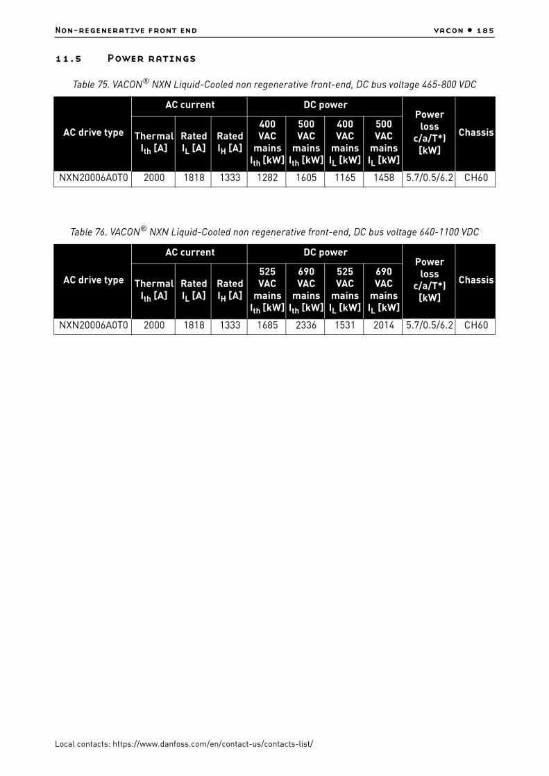
Non-regenerative front end vacon • 185
Local contacts: https://www.danfoss.com/en/contact-us/contacts-list/
11.5 Power ratings
Table 75. VACON® NXN Liquid-Cooled non regenerative front-end, DC bus voltage 465-800 VDC
AC drive type
AC current DC powerPower
loss c/a/T*)
[kW]
ChassisThermal Ith [A]
Rated IL [A]
Rated IH [A]
400 VAC
mains Ith [kW]
500 VAC
mains Ith [kW]
400 VAC
mains IL [kW]
500 VAC
mains IL [kW]
NXN20006A0T0 2000 1818 1333 1282 1605 1165 1458 5.7/0.5/6.2 CH60
Table 76. VACON® NXN Liquid-Cooled non regenerative front-end, DC bus voltage 640-1100 VDC
AC drive type
AC current DC powerPower
loss c/a/T*)
[kW]
ChassisThermal Ith [A]
Rated IL [A]
Rated IH [A]
525 VAC
mains Ith [kW]
690 VAC
mains Ith [kW]
525 VAC
mains IL [kW]
690 VAC
mains IL [kW]
NXN20006A0T0 2000 1818 1333 1685 2336 1531 2014 5.7/0.5/6.2 CH60

vacon • 186 Non-regenerative front end
Local contacts: https://www.danfoss.com/en/contact-us/contacts-list/
11.6 Non-regenerative Front End unit technical data
The technical data for the non-regenerative front end unit, see table below.
Table 77. Technical data
Mains connectionInput voltage Uin 2 x 3ph 400…690 VAC (–10%…+10%);
Input frequency 45…66 Hz
Output connection
Output voltage Uin x 1.35
Output frequency DC-voltage
DC bank capacitance 4800µF
Control characteristics
External NXP control
Run/StopControl and supervision for external DC precharging circuitControl and supervision for external ACB'sDC-voltage supervisionInput phase and undervoltage supervisionChoke temperature supervisionUnit temperarture supervisionFan operation supervisionOptional current monitor
Current capacity
Input current Ith 2 x 1000AAC
Output current Ith 2400ADC
Overload No overload
Power lossesPower loss into coolant: 5.7 kWPower loss into air: 0.5 kWPower losses of the chokes: see Table 81.
Ambient conditions
Ambient operating temperature
–10°C (no frost)…+50°C (at Ith)The NX Liquid-Cooled drives must be used in an heated indoor controlled environment.
Installation temperature
0°C...+70°C
Storage temperature –40°C…+70°C; No liquid in heatsink under 0ºC
Relative humidity 5% to 96% RH, non-condensing, no dripping water
Air quality:• chemical
vapours• mechanical
particles
No corrosive gasesIEC 60721-3-3, unit in operation, class 3C2IEC 60721-3-3, unit in operation, class 3S2 (no conductive dust allowed)
Altitude400...500 V: 3000m ASL; in case network is not corner grounded500...690 V: max. 2000m ASL
Vibration 5…150 Hz
ShockEN 50178, EN 60068-2-27
UPS Drop Test (for applicable UPS weights)Storage and shipping: max 15 G, 11 ms (in package)
Enclosure class IP00 (UL open type) / Open

Non-regenerative front end vacon • 187
Local contacts: https://www.danfoss.com/en/contact-us/contacts-list/
EMC
Immunity Fulfils IEC/EN 61800-3 EMC immunity requirements.
EmissionsEMC level N for TN/TT networksEMC level T for IT networks
SafetyIEC/EN 61800-5-1IEC/EN 60204-1 as relevant, (see unit nameplate for more details)
ApprovalsType tested CE, cULus
Type approval
Liquid cooling
Allowed cooling agents
Drinking water (see specification in chapter 5.2)Water-glycol mixtureSee derating specifications, Table 7
Temperature of cooling agent
0°C…43°C input (Ith);43°C...55ºC, contact your local distributor for further informationTemperature rise during circulation max. 5°CNo condensation allowed
Cooling agent flow rates
See Table 6.
System max. working pressure
6 bar
System max. peak pressure
30 bar
Pressure loss (at nom. flow)
See Table 8.
Protections
Undervoltage, overvoltage, mains supervision, unit undertemperature, overtemperature, cooling fan operation, ACB operation, DC precharging operation, choke temperature
Table 77. Technical data

vacon • 188 Non-regenerative front end
Local contacts: https://www.danfoss.com/en/contact-us/contacts-list/
11.7 Dimensions
Figure 105. VACON® Liquid-cooled Non-regenerative front end, CH60
Table 78. Non-regenerative front-end unit dimensions
ChassisWidth [mm]
Height [mm]
Depth [mm]
Weight [kg]
CH60 246 673 374 55
Table 79. Terminal connection
ChassisEarth terminal
(mm2)Eart terminal
Bolt sizeMain terminal
Bolt size per phaseDC terminal
Bolt size per polarity
CH60 25-185 M8 2 x M12 8 x M12
Table 80. Tightening torque of bolts
Bolt Torque (Nm) Max inward length (mm)
Grounding bolt 13.5 -
M12 70 22
11679_uk

Non-regenerative front end vacon • 189
Local contacts: https://www.danfoss.com/en/contact-us/contacts-list/
11.8 Chokes
* Losses for one choke. Two chokes are needed for each L/C NFE, so total losses are 2x1.17 kW.
NOTE! If you use other chokes than the recommended ones, contact your nearest distributor to ensure compatibility.
Figure 106. Example of CHK1030N6A0 choke
Table 81. Type and dimensions for chokes
Choke typeWidth [mm]
Height [mm]
Depth [mm]
Weight [kg]
Losses to air* [W]
Losses to coolant
[W]*Cooling
CHK1030N6A0 497 677 307 213 1840 0 Air
CHK-1030-6-DL 450 642 274 119 777 1073 Liquid
W
D
H
11749_00
1 1 1 1
3 3 3 3
2 2 2 2

vacon • 190 Non-regenerative front end
Local contacts: https://www.danfoss.com/en/contact-us/contacts-list/
Figure 107. Example of FLU-CHK-1030-6-DL choke
Coolant connector Festo CK-3/8-PK-9.
11.9 Non-regenerative front end - fuse selection
AC fuses are used to protect the input network in case the Non-regenerative Front End unit or the choke is faulty. DC fuses are used to protect the Non-regenerative Front End unit and the choke in case there is a short circuit in the DC buses. If DC fuses are not used, short-circuit in the DC buses will cause a loading of the Non-regenerative Front End unit. Vacon Ltd will not assume any responsibility for damages caused by insufficient protection. The warranty becomes void if the drive is not equipped with appropriate fuses.
Main circuit breakers are used to protect chokes and Non-regenerative Front End units from overloading and unbalanced loading. Therefore, both rectifier bridges must be equipped with individual circuit breakers, see Figure 100.
Fuse information
The values in tables are based on max ambient temperature of +50ºC.
Table 82.
Supply voltage AC drive connection (terminal no.)
400-480 Vac 2
500 Vac 3
525-690 Vac 3
D
H
1 1 1
1
3
2
222
33 3
11748_00
W

Non-regenerative front end vacon • 191
Local contacts: https://www.danfoss.com/en/contact-us/contacts-list/
The required AC fuse type for the non-regenerative front end unit can be found from Table 83. The required DC fuse type for the non-regenerative front end unit can be found from Table 84.
11.9.1 Fuse sizes, Non-regenerative Front End units
11.9.2 Circuit breaker settings, Non-regenerative Front End units
NOTE! If other circuit breakers are used, the overload and short circuit characteristics must be similar than those of the circuit breakers mentioned above. Overload IN = 1000AAC/3sec, instantaneous short-circuit l = 1500AAC. Note that IEC, UL and other related approvals may be required. For UL enclosures, use UL Listed Breakers with category code PAQX or DIVQ.
11.10 Settings
11.10.1 Phase monitor settings
The option boards and phase monitor relays have settings that you may need to adjust. For settings of software application parameters, see Chapter 11.13.
The phase monitor relays (PMR1.1 and PMR1.2) have functions to detect under voltage, phase sequence and phase failure. All of those have to be correct so that the power unit is powered
Table 83. AC Fuse sizes for VACON® NX NFE units
Chassis Code Fuse, Mersen UN [V] IN [A] Size Bolts Qty.
CH60 NXN 2000 6 PC233UD69V16CTF/ F300270A 690 1600 2x33 M12 6
Table 84. DC Fuse sizes for VACON® NX NFE units
Chassis Code Fuse, Mersen UN [V] IN [A] Size Bolts Qty.
CH60 NXN 2000 6 PC87UD11C38CP50 / K302988A 1050 3800 284 M12 2
Table 85. Circuit breaker settings for VACON® NX NFE units
Type Code Type, ABB Qty.L I N
I1 t1 I3 InN
NFE NXN 2000 6
X1N16FF3PR331LI 2 0.625 3s 1.5 50%
X1N12FF3PR331LI 2 0.825 3s 1.5 50%
X1N10FF3PR331LI 2 1.000 3s 1.5 50%

vacon • 192 Non-regenerative front end
Local contacts: https://www.danfoss.com/en/contact-us/contacts-list/
correctly and stays in run mode. If any of them is not correct, the phase monitor relay's output does not activate and the control unit gives an input phase fault.
11.10.2 Option board settings
The option boards have jumpers which you may need to set according to the external wiring and connections. See the VACON® NX I/O Board User manual for settings.
The option board slots A–D are fixed. The slot E can be configured.
1. "U" Green LED: Supply voltage• LED ON: Supply voltage present
2. "MIN" Red LED: Lower threshold value (under voltage)• LED flashes: Set threshold value exceeded, set delay
time is running• LED ON: Set threshold value exceeded, delay time
has elapsed3. "SEQ" Red LED: Phase failure/phase sequence
• LED flashing: phase has failed, set delay time is running
• LED on: phase has failed, delay time has elapsed4. "REL" yellow LED: Output relay
• LED ON: Output relay has picked up (OK)• LED OFF: Output relay has dropped out (Fail)
5. "Delay" potentiometer: response delay• 400-690Vac: 0.1s
6. "MIN" potentiometer: Lower threshold value• 400-500Vac: ≥360Vac• 500-690Vac: ≥450Vac
11684_00
1
5
6
2
3
4
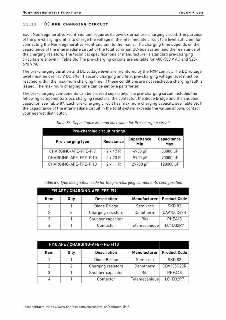
Non-regenerative front end vacon • 193
Local contacts: https://www.danfoss.com/en/contact-us/contacts-list/
11.11 DC pre-charging circuit
Each Non-regenerative Front End unit requires its own external pre-charging circuit. The purpose of the pre-charging unit is to charge the voltage in the intermediate circuit to a level sufficient for connecting the Non-regenerative Front End unit to the mains. The charging time depends on the capacitance of the intermediate circuit of the total common DC-bus system and the resistance of the charging resistors. The technical specifications of manufacturer's standard pre-charging circuits are shown in Table 86. The pre-charging circuits are suitable for 400-500 V AC and 525-690 V AC.
The pre-charging duration and DC voltage level are monitored by the NXP control. The DC voltage level must be over 40 V DC after 1 second charging and final pre-charging voltage level must be reached within the maximum charging time. If these conditions are not reached, a charging fault is issued. The maximum charging time can be set by a parameter.
The pre-charging components can be ordered separately. The pre-charging circuit includes the following components: 2 pcs charging resistors, the contactor, the diode bridge and the snubber capacitor, see Table 87. Each pre-charging circuit has maximum charging capacity, see Table 86. If the capacitance of the intermediate circuit in the total system exceeds the values shown, contact your nearest distributor.
Table 86. Capacitance Min and Max value for Pre-charging circuit
Pre-charging circuit ratings
Pre charging type ResistanceCapacitance
Min Capacitance
Max
CHARGING-AFE-FFE-FI9 2 x 47 R 4950 µF 30000 µF
CHARGING-AFE-FFE-FI10 2 x 20 R 9900 µF 70000 µF
CHARGING-AFE-FFE-FI13 2 x 11 R 29700 µF 128000 µF
Table 87. Type designation code for the pre-charging components configuration
FI9 AFE / CHARGING-AFE-FFE-FI9
Item Q‘ty Description Manufacturer Product Code
1 1 Diode Bridge Semikron SKD 82
2 2 Charging resistors Danotherm CAV150C47R
3 1 Snubber capacitor Rifa PHE448
4 1 Contactor Telemecanique LC1D32P7
FI10 AFE / CHARGING-AFE-FFE-FI10
Item Q‘ty Description Manufacturer Product Code
1 1 Diode Bridge Semikron SKD 82
2 2 Charging resistors Danotherm CBV335C20R
3 1 Snubber capacitor Rifa PHE448
4 1 Contactor Telemecanique LC1D32P7

vacon • 194 Non-regenerative front end
Local contacts: https://www.danfoss.com/en/contact-us/contacts-list/
The Non-regenerative Front End unit must not be connected to mains without pre-charging. In order to ensure the correct operation of the pre-charging circuit, the input circuit-breaker and the pre-charging circuit contactor must be controlled by the Non-regenerative Front End unit. The input circuit-breaker and the pre-charging circuit contactor must be connected as shown in Chapter 11.2.1.
NOTE! You need to double-insulate all wirings that do not have short circuit protections and are used for connecting the pre-charging circuit to the intermediate circuit.
NOTE! Enough space must be reserved around the resistors to ensure sufficient cooling. Do not place any heat sensitive components near the resistors.
11.12 Paralleling
The power of the input group can be increased by connecting several Non-Regenerative Front End units in parallel. Manufacturer's standard chokes must be used for parallel units. Use of other than these chokes in the Non-Regenerative Front End units connected in parallel may cause a too large current imbalance between the units.
Each Non-Regenerative Front End unit connected in parallel must have its own short-circuit protection on AC and DC sides and own circuit breakers in AC side. When paralleling, attention must be paid to the sufficient short-circuit capacity of the system.
The derating of Non-Regenerative Front End units connected in parallel is 10% of the DC power; this should be taken into account when dimensioning the system.
If a device is to be isolated from the AC and DC voltages, and other Non-Regenerative Front End units connected in parallel are also to be used, separate isolators are required in the AC input and DC output. The AC input can be isolated using a circuit-breaker or a fuse switch. Contactors are not suitable for isolating the AC input because they cannot be locked in a safe position. The DC output can be isolated using a proper load switch. The pre-charging circuit must also be isolated from the AC input by using fuse switch. The device can also be connected to mains even when the other devices connected in parallel are already connected and running. In such a case, the isolated device must first be pre-charged. When that is done, the AC input can be switched on. After this, the device can be connected to the intermediate DC circuit.
FI13 AFE / CHARGING-AFE-FFE-FI13
Item Q‘ty Description Manufacturer Product Code
1 1 Diode Bridge Semikron SKD 82
2 2 Charging resistors Danotherm CBV335C11R
3 1 Snubber capacitor Rifa PHE448
4 1 Contactor Telemecanique LC1D32P7
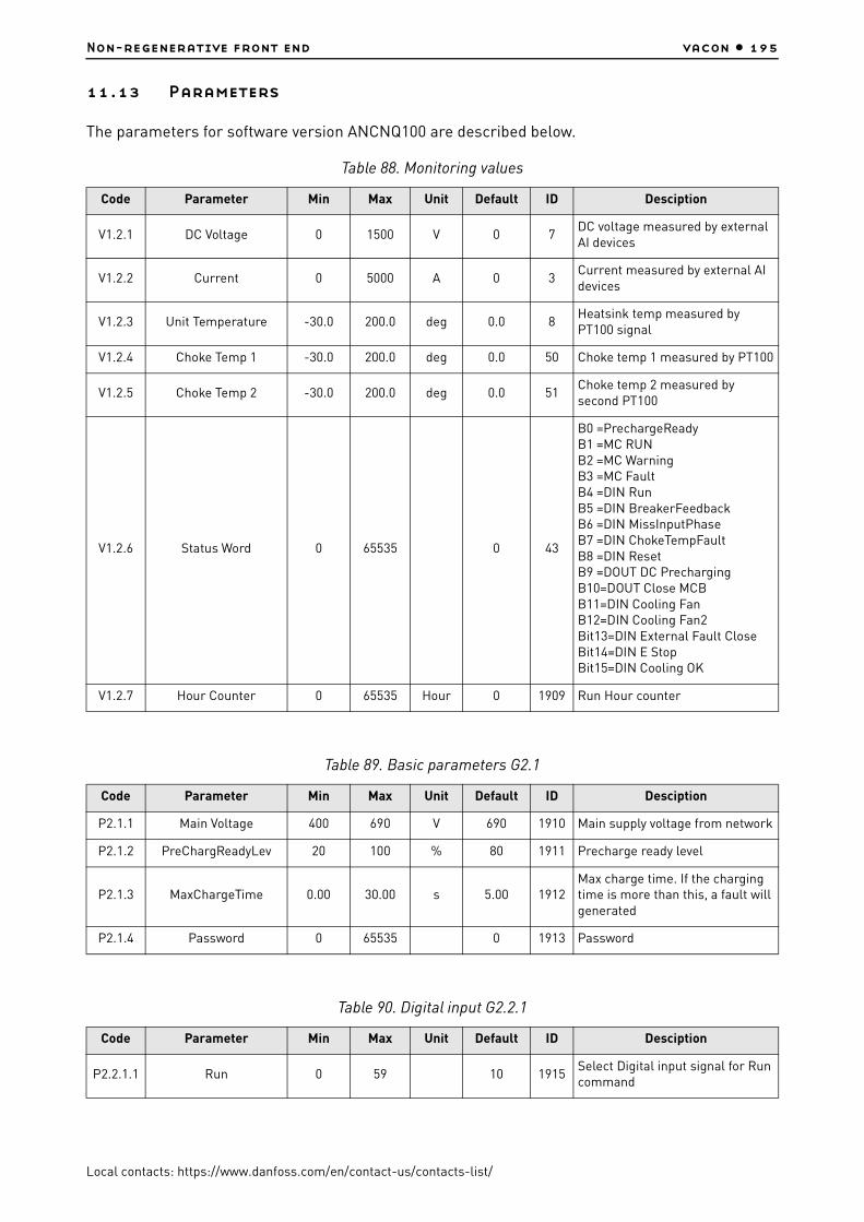
Non-regenerative front end vacon • 195
Local contacts: https://www.danfoss.com/en/contact-us/contacts-list/
11.13 Parameters
The parameters for software version ANCNQ100 are described below.
Table 88. Monitoring values
Code Parameter Min Max Unit Default ID Desciption
V1.2.1 DC Voltage 0 1500 V 0 7DC voltage measured by external AI devices
V1.2.2 Current 0 5000 A 0 3Current measured by external AI devices
V1.2.3 Unit Temperature -30.0 200.0 deg 0.0 8Heatsink temp measured by PT100 signal
V1.2.4 Choke Temp 1 -30.0 200.0 deg 0.0 50 Choke temp 1 measured by PT100
V1.2.5 Choke Temp 2 -30.0 200.0 deg 0.0 51Choke temp 2 measured by second PT100
V1.2.6 Status Word 0 65535 0 43
B0 =PrechargeReadyB1 =MC RUNB2 =MC WarningB3 =MC FaultB4 =DIN RunB5 =DIN BreakerFeedbackB6 =DIN MissInputPhaseB7 =DIN ChokeTempFaultB8 =DIN ResetB9 =DOUT DC PrechargingB10=DOUT Close MCBB11=DIN Cooling FanB12=DIN Cooling Fan2Bit13=DIN External Fault CloseBit14=DIN E StopBit15=DIN Cooling OK
V1.2.7 Hour Counter 0 65535 Hour 0 1909 Run Hour counter
Table 89. Basic parameters G2.1
Code Parameter Min Max Unit Default ID Desciption
P2.1.1 Main Voltage 400 690 V 690 1910 Main supply voltage from network
P2.1.2 PreChargReadyLev 20 100 % 80 1911 Precharge ready level
P2.1.3 MaxChargeTime 0.00 30.00 s 5.00 1912Max charge time. If the charging time is more than this, a fault will generated
P2.1.4 Password 0 65535 0 1913 Password
Table 90. Digital input G2.2.1
Code Parameter Min Max Unit Default ID Desciption
P2.2.1.1 Run 0 59 10 1915Select Digital input signal for Run command

vacon • 196 Non-regenerative front end
Local contacts: https://www.danfoss.com/en/contact-us/contacts-list/
P2.2.1.2 BreakerFeedback 0 59 11 1916Select digital input signal for Breaker Feedback
P2.2.1.3 Miss Input Phase 0 59 12 1917Select digital input for missing input phase or low input voltage
P2.2.1.4 External Fault 0 59 13 1918Select for digital input signal external fault ,normal open logic
P2.2.1.5 Choke Temp 0 59 14 1919Select for digital input Choke Temp
P2.2.1.6 Fault Reset 0 59 15 1920Select for digital input signal fault reset
P2.2.1.7 E Stop 0 59 42 1921Select for digital input signal E-stop feedback
P2.2.1.8 Cooling OK 0 59 43 1922Select for digital input signal liquid cooling feedback
P2.2.1.9 Fan Sensor 1 0 59 44 1923Select for digital input signal cooling fan monitor
P2.2.1.10
Fan Sensor 2 0 59 45 1924Selection of fan sensor2 from digital input signal, default is from OPT-B1 DIN.D5
Table 91. Analog input G2.2.2
Code Parameter Min Max Unit Default ID Desciption
P2.2.2.1 DC Voltage 0 59 10 1925Selection for analog input of dc voltage
P2.2.2.2 DC Min Point 0.00 40.00 % 20.00 1926Percent value corresponds to 0 dc voltage
P2.2.2.3 Max DC Voltage 500 2000 V 1500 1927Dc voltage measurement devices max range
P2.2.2.4 Current 0 59 11 1928Selection of analog input signal input current
P2.2.2.5 Current MinPoint 0.00 100.00 % 0.00 1929Analog input signal min point for current measurement
P2.2.2.6 Max Current 0 32000 A 1000 1930Max current corresponds to max analog input 100.00%
P2.2.2.7 Unit Temp 0 59 30 1931Selection of analog input for heatsink Temp
P2.2.2.8 Choke Temp 1 0 59 31 1932Select analog input signal for choke temp 1 from pt100 signal
P2.2.2.9 Choke Temp 2 0 59 32 1933Select analog input signal for choke temp 2 from PT100 signal
Table 90. Digital input G2.2.1
Code Parameter Min Max Unit Default ID Desciption

Non-regenerative front end vacon • 197
Local contacts: https://www.danfoss.com/en/contact-us/contacts-list/
Table 92. Digital Output G2.3.1
Code Parameter Min Max Unit Default ID Desciption
P2.3.1.1 Running 0 59 10 1935Select for digital output signal MC running
P2.3.1.2 Close MCB 0 59 20 1936Selection for digital output close Main circuit breaker
P2.3.1.3 DC Precharge 0 59 21 1937Selection digital output signal for DC Precharging signal
P2.3.1.4 Warning 0 59 40 1938Select for digital output signal mc warning
P2.3.1.5 Fault 0 59 41 1939Selection for digital output sigal mc fault
P2.3.1.6 No Warning 0 59 0 1940 Inverted warning signal
P2.3.1.6 No Fault 0 59 0 1941 Inverted fault signal
Table 93. Analog Output G2.3.2
Code Parameter Min Max Unit Default ID Desciption
P2.3.2.1 DC Voltage 0 59 10 1942Selection for analog output signal dc voltage
P2.3.2.2 Current 0 59 0 1943Selection for analog output signal for current
Table 94. Protection G2.4
Code Parameter Min Max Unit Default ID Desciption
P2.4.1 CoolFanFaultMode 1 2 1 1945Cooling Fan Fault Mode1=Warning + Fault(after delay)2=Fault
P2.4.2 Fan Fault Delay 0 15 min 5 1946
The delay time after which a cooling fan fault will generate. Until the delay time is finished, only a warning is on.
P2.4.3 MissPhaseFautMod 0 2 2 1947
Miss input phase fault response mode0=no action1=Warning2=Fault
P2.4.4 MissPhaseFDelay 0.00 60.00 s 1.00 1948 Missing phase signal wait time
P2.4.5 BreakerFaultMode 0 2 2 1949
MCB feedback signal is missing after settled time0=No action1=Warning2=Fault
P2.4.6 Breaker Ack Time 0.00 10.00 s 1.00 1950 Breaker feedback signal wait time

vacon • 198 Non-regenerative front end
Local contacts: https://www.danfoss.com/en/contact-us/contacts-list/
P2.4.7 ChokeTempFauMode 0 3 1 1951
Response to Choke Temp mode when Temp measurement is using digital input (DI)signals or PT100 signal0=No action (DI)1=Warn + Fault (after delay) (DI)2=Fault (DI)3=PT100
P2.4.8 ChokeOTFaultDela 0 30 min 5 1952When choke temp fault mode=1, after this time, warning will be changed to fault
P2.4.9 ChokeOTWarnLevel -30.0 200.0 deg 110.0 1953Choke temp using pt100. If temp is over this limit, a warning will generate
P2.4.10 ChokeOTFaultLeve -30.0 200.0 deg 130.0 1954Choke temp using pt100. If temp is over this limit, a fault will generate
P2.4.11 Ext Fault Mode 0 4 0 1955
External fault mode selection0=No action1=Warnng + Fault(after delay)2=Fault3=Inv Warning+ Fault(after delay)4=Inv Fault
P2.4.12 Ext Fault Delay 0 600 min 0 1956The Delay Time for triggering an external fault after an external warning is active.
P2.4.13 CoolingFaultMode 0 4 0 1957
Fault mode selection for liquid cooling fault from digital input signal0= No action1= Warning + Fault(after delayed)2= Fault3= Inv Warning + Fault (after delay)4= Inv Fault
P2.4.14 CoolingFaultDela 0 3600 s 1 1958A delay time for triggering a liquid fault after liquid warning is active
P2.4.15 E Stop Mode 0 4 0 1959
E stop mode selection0=No action1=Warning, ditial input goes to TRUE2=Fault, digital input goes to TRUE3=Inv Warning, digital input goes toFALSE4=Inv Fault, digital input goes to FALSE
Table 94. Protection G2.4
Code Parameter Min Max Unit Default ID Desciption

Non-regenerative front end vacon • 199
Local contacts: https://www.danfoss.com/en/contact-us/contacts-list/
Table 95. Fieldbus G2.5
Code Parameter Min Max Unit Default ID Desciption
P2.5.1 Process Data IN1 0 10000 0 876
P2.5.2 Process Data IN2 0 10000 0 877
P2.5.3 Process Data IN3 0 10000 0 878
P2.5.4 Process Data IN4 0 10000 0 879
P2.5.5 Process Data IN5 0 10000 0 880
P2.5.6 Process Data IN6 0 10000 0 881
P2.5.7 Process Data IN7 0 10000 0 882
P2.5.8 Process Data IN8 0 10000 0 883
P2.5.9 ProcessData Out1 0 10000 0 852
P2.5.10 ProcessData Out2 0 10000 0 853
P2.5.11 ProcessData Out3 0 10000 0 854
P2.5.12 ProcessData Out4 0 10000 0 855
P2.5.13 ProcessData Out5 0 10000 0 856
P2.5.14 ProcessData Out6 0 10000 0 857
P2.5.15 ProcessData Out7 0 10000 0 858
P2.5.16 ProcessData Out8 0 10000 0 859
Table 96. Advanced par G2.6
Code Parameter Min Max Unit Default ID Desciption
P2.6.1 OT Alarm Level -30.0 55.0 deg 55.0 1961If CH62 PT100 sensor is over this level, alarm will generated
P2.6.2 Fan Type 1 2 2 1962
Cooling fan type selection1=fan sensor is status sinal, if signal is low, fault will generate2=also status signal, fan sensor signal is inverted, if signal is high, fault will generate
P2.6.3 Run Start 0 1 0 1963
Start mode selection0=Rising Edge, run command need rising edge to restart the system1=Auto Start, run command active, system will auto restart

vacon • 200 Non-regenerative front end
Local contacts: https://www.danfoss.com/en/contact-us/contacts-list/
NFE’s internal temperature sensor is PT100. Set 7.3.1.1 = 1.
11.14 CH60 Liquid-cooled NFE protections
The protections for software version ANCNQ100 are described below.
(*1) Temperature level may be changed by a parameter
(*2) Chokes require PT100 sensors. Temperature levels may be changed by parameters
Table 97. OPT-BH parameters G7.3
Code Parameter Min Max Unit Default ID Desciption
7.3.1.1 Sensor 1 type 0 6 0
0=No Sensor1=PT1002=PT10003=Ni10004=KTY845=2 x PT1006=3 x PT100
7.3.1.2 Sensor 2 type 0 6 0 See above
7.3.1.3 Sensor 3 type 0 6 0 See above
Table 98. Voltage protections
Main voltage P2.1.1 400VAC ≤ P2.1.1 ≤ 500VAC 500VAC < P2.1.1 ≤ 690VAC
Under voltage trip 333VDC 573VDC
Under voltage alarm 371VDC 633VDC
Over voltage alarm 830VDC 1150VDC
Over voltage trip 911VDC 1250VDC
Table 99. Unit temperature protections
Unit temperature V1.2.3
Under temp. trip -10°C
Over temp. alarm (*1) 55°C
Over temp. trip 60°C
Table 100. Choke temperature protections
Choke temperature V1.2.4 & V1.2.5
Over temp. alarm (*2) 110°C
Over temp. trip (*2) 130°C

Non-regenerative front end vacon • 201
Local contacts: https://www.danfoss.com/en/contact-us/contacts-list/
11.15 Fault codes
When a fault is detected by the NFE control electronics, the drive is stopped and main circuit breakers and the charging switch is controlled into open state, which will then disconnect the NFE module from the mains supply. The fault can be reset with the Reset button on the control keypad or via the I/O terminal. Resetting the faults will clear the fault and initiate new start-up procedure of the NFE unit. The faults are stored in the Fault history menu (M5) which can be browsed. The different fault codes you will find in the table below.
The fault codes, their causes and correcting actions for software version ANCNQ100 are presented in the table below.
Table 101. Fault codes
Fault code
Fault Possible cause Correcting measures
2 Overvoltage
The DC-link voltage has exceeded the limits.
- too short a deceleration time- high overvoltage spikes in supply
Fault:- 911Vdc, Main Voltage P2.1.1 400-
500Vac- 1250Vdc, Main Voltage P2.1.1 500-
690VacWarning:
- 860vdc, Main Voltage P2.1.1 400-500Vac
- 1150Vdc, Main Voltage P2.1.1 500-690Vac
• Set deceleration time longer.
• Use brake chopper or brake resistor (available as options).
• Set over voltage control active with INU devices.
• Check input voltage.
4 Charging fault
The pre-set charging time (defined by MaxChargeTime parameter P.2.1.3, default 5 sec) has been exceeded.DC voltage must rise above40VDC in 1 second
• Check the external charging circuit & charging resistor dimensioning
• Check P.2.1.3 MaxChargeTime
9 UnderVoltage
The DC-link voltage has decreased under the limits defined.
- Too low supply voltage.- Component failure.- Defect input fuse.- External charge switch not closed.
Fault:- 333Vdc; Main Voltage P2.1.1 400-
500Vac - 573Vdc; Main Voltage P2.1.1 500-
690VacWarning:
- 371Vdc; Main Voltage P2.1.1 400-500Vac
- 633Vdc; Main Voltage P2.1.1 500-690Vac
• If there is a temporary supply voltage break, RESET the fault and RESTART the drive.
• Check the supply voltage. If the measured value is sufficient, internal failure has occurred.
• Check the electrical network, if any breaks occur.
• If the fault re-occurs, contact your local/nearest service center or distributor. Report carefully all the used software, application and all options.

vacon • 202 Non-regenerative front end
Local contacts: https://www.danfoss.com/en/contact-us/contacts-list/
10 Input phase
External electronic monitoring relay have detected undervoltage, phase sequence or phase failure issue.
• min. threshold value: 360Vac for 400-500Vac supply voltage
• min. threshold value: 470Vac for 525-690Vac supply voltage
• response delay is set to be 0.1 sec
Various causes:- Supply phase failure- Supply fuse failure- Incorrect Mains cabling- Grid interruption
Check EMD relay settings, Signal wiring, supply volt-age, fuses, supply cable, rectifying bridge.
13 UndertemperaturePower module heatsink temperature is under –10°C.
Power module is in a too cold place or coolant agent is too cold. Check the ambient & coolant temperature. Check the signal wiring.
14 Overtemperature
Fault:Power module heatsink temperature is over 60°C.
Warning:Power module heatsink temperature is over 55°C.
• Check Coolant flow and temperature
• Check the ambient temperature.
• Check the cooling fan condition
• Check the power module loading
• Check the signal wiring
32 Fan coolingJammed cooling fan
- Cooling Fan failure- Cooling Fan is not rotating
• Check the signal wiring
• Change the cooling fans
51 Ext FaultExternal fault digital input have triggered the fault
• Check the signal wiring
• Check External Fault input
56 Choke Temp
Over temperature switch feedback or
Fault:The temperature of the external input AC choke is over 130°C (measured from PT100 thermistor).
Warning:The temperature of the external input AC choke is over 110°C. (measured from PT100 thermistor)
• Check input AC choke cooling conditions
• Check the power module loading
• Check the signal wiring
Table 101. Fault codes
Fault code
Fault Possible cause Correcting measures

Non-regenerative front end vacon • 203
Local contacts: https://www.danfoss.com/en/contact-us/contacts-list/
60 CoolingCooling OK digital input for liquid cooling feedback have triggered the fault
• Check liquid cooling• Check the signal
wiring• Check Cooling OK
input
63 EmergencyStopE-stop digital input for emergency stop feedback have triggered the fault
• Check Main Circuit Breaker functionality
• Check signal wiring
64 Breaker TripMCBs Feedback signal missing after set-tled time defined with parameter Breaker Ack Time P2.4.6.
• Check Main Circuit Breaker functionality
• Check signal wiring
Table 101. Fault codes
Fault code
Fault Possible cause Correcting measures

vacon • 204 Brake chopper unit (NXB)
Local contacts: https://www.danfoss.com/en/contact-us/contacts-list/
12. BRAKE CHOPPER UNIT (NXB)
12.1 Introduction
The VACON® NXB (Brake chopper unit) is a unidirectional power converter for the supply of excessive energy from a common DC bus drive line-up to resistors where the energy is dissipated as heat. External resistors are needed. The NXB improves the DC-link voltage controllability as well as enhances the motor drives performance in dynamic applications.
Mechanically, the NXB module is based on inverter unit construction. The dynamic DC energy brake function is achieved through a specific NXB system software. Several NXB modules can be installed parallelly in order to increase the braking capacity, however, the modules require mutual synchronization.
12.2 Type designation code
In Vacon type designation code, the Brake Chopper Unit is characterized by number 8, for example:
12.3 Diagrams
12.3.1 NXB Brake Chopper Unit block diagram
Figure 108. BCU block diagram
NXB 0300 5 A 0 T 0 8WF A1A2000000
POWER MODULE
CONTROL MODULE
B+
B-
Powersupply
Fan
Measure-ments
Driver
ASIC
IGBTbridge
U/T1
V/T2W/T3
Control
I/Oslot A
I/Oslot B
I/Oslot C
I/Oslot D
I/Oslot E
RS-232
KEYPAD
11399_uk
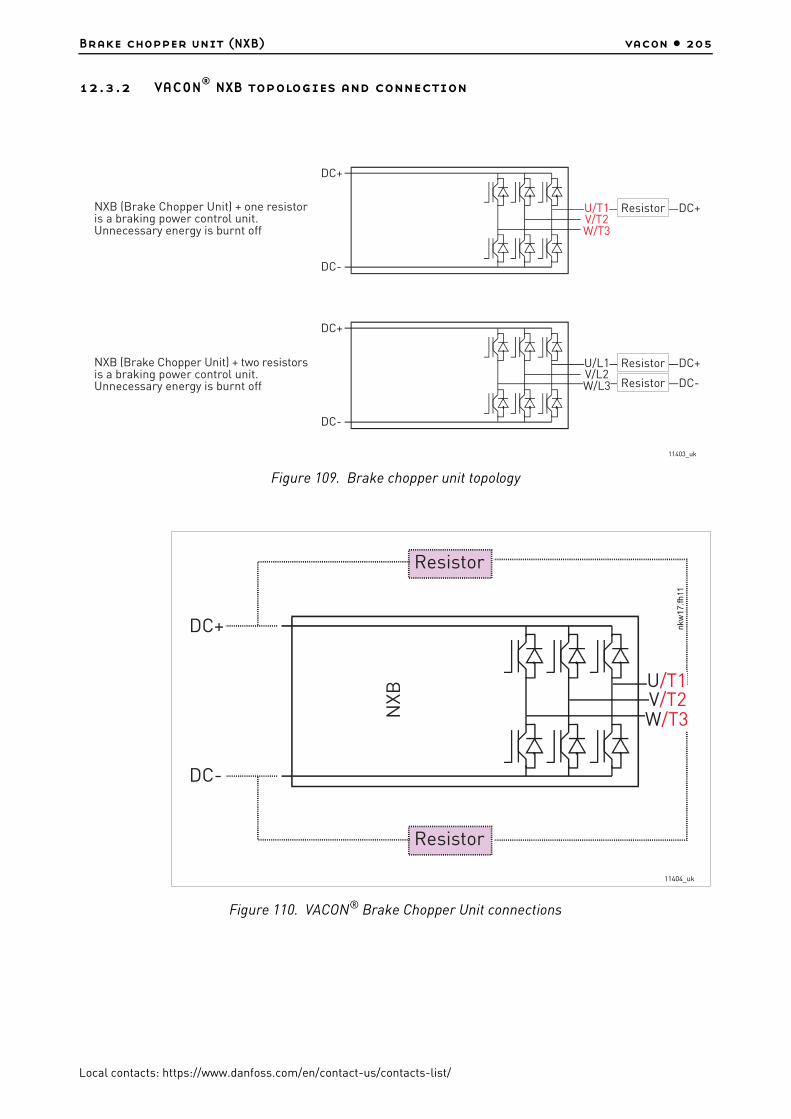
Brake chopper unit (NXB) vacon • 205
Local contacts: https://www.danfoss.com/en/contact-us/contacts-list/
12.3.2 VACON® NXB topologies and connection
Figure 109. Brake chopper unit topology
Figure 110. VACON® Brake Chopper Unit connections
DC+
DC-
U/T1V/T2W/T3
Resistor DC+
DC+
DC-
U/L1V/L2
Resistor DC+
Resistor DC-W/L3
NXB (Brake Chopper Unit) + one resistoris a braking power control unit.Unnecessary energy is burnt off
NXB (Brake Chopper Unit) + two resistorsis a braking power control unit.Unnecessary energy is burnt off
11403_uk
DC+
DC-
Resistor
Resistor
W/T3
U/T1V/T2
11404_uk

vacon • 206 Brake chopper unit (NXB)
Local contacts: https://www.danfoss.com/en/contact-us/contacts-list/
12.4 Brake chopper unit technical data
*) NX_8 AC drives only available as Ch6x AFE/BCU/INU units.
Table 102. Technical specification for VACON® NXB Liquid-Cooled brake chopper unit
Supply connection
Input voltage Uin
NX_5: 400…500 VAC (–10%…+10%); 465…800 VDC (–0%…+0%)NX_6: 525…690 VAC (–10%…+10%); 640…1100 VDC (–0%…+0%)NX_8: 525…690 VAC (–10%…+10%); 640…1136 VDC (–0%…+0%)*)
Input current DC Iin ~ Iout
DC bank capacitance
Voltage class 500 V: Ch3 (16-31A units): 600 µF Ch3 (38-61A units): 2400 µF CH4: 2400 µF CH5: 7200 µF CH61: 10800 µF CH62: 10800 µF
Voltage class 690 V: CH61: 4800 µF CH62: 4800 µF
Starting delay 2…5 s
Resistor connection
Output voltage Uin ~ Uout
Continuous output current
Ibr: Max ambient temperature +50°C
Connection orderR1 U – DC+R2 W – DC-
Control characteristics
Control method Voltage level control, default Un+18%
Parallel BCU Requires synchronization
Ambient conditions
Ambient operating temperature
–10°C (no frost)…+50°C (at Ith)
The VACON® NX Liquid-Cooled drives must be used in a heated indoor controlled environment
Installation temperature 0°C...+70°C
Storage temperature –40°C…+70°C; No liquid in heatsink under 0ºC
Relative humidity 5% to 96% RH, non-condensing, no dripping water
Air quality:- chemical vapours- mechanical
particles
IEC 721-3-3, unit in operation, class 3C2
IEC 721-3-3, unit in operation, class 3S2 • No conductive dust allowed• No corrosive gases
Altitude
NX_5 (380...500 V): max. 3000 m (in case network is not corner grounded)NX_6: max. 2000 m. For further requirements, contact factory 100-% load capacity (no derating) up to 1,000 m; above 1,000 m derating of maximum ambient operating temperature by 0.5°C per each 100 m is required.
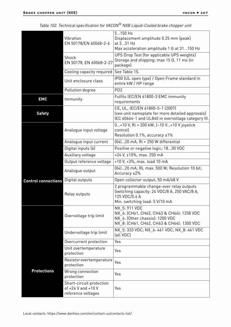
Brake chopper unit (NXB) vacon • 207
Local contacts: https://www.danfoss.com/en/contact-us/contacts-list/
VibrationEN 50178/EN 60068-2-6
5…150 HzDisplacement amplitude 0.25 mm (peak) at 3…31 HzMax acceleration amplitude 1 G at 31…150 Hz
ShockEN 50178, EN 60068-2-27
UPS Drop Test (for applicable UPS weights)Storage and shipping: max 15 G, 11 ms (in package)
Cooling capacity required See Table 15.
Unit enclosure classIP00 (UL open type) / Open Frame standard in entire kW / HP range
Pollution degree PD2
EMC ImmunityFulfils IEC/EN 61800-3 EMC immunity requirements
SafetyCE, UL, IEC/EN 61800-5-1 (2007) (see unit nameplate for more detailed approvals)IEC 60664-1 and UL840 in overvoltage category III.
Control connections
Analogue input voltage0…+10 V, Ri = 200 kW, (–10 V…+10 V joystick control)Resolution 0.1%, accuracy ±1%
Analogue input current 0(4)…20 mA, Ri = 250 W differential
Digital inputs (6) Positive or negative logic; 18…30 VDC
Auxiliary voltage +24 V, ±10%, max. 250 mA
Output reference voltage +10 V, +3%, max. load 10 mA
Analogue output0(4)…20 mA; RL max. 500 W; Resolution 10 bit; Accuracy ±2%
Digital outputs Open collector output, 50 mA/48 V
Relay outputs
2 programmable change-over relay outputsSwitching capacity: 24 VDC/8 A, 250 VAC/8 A, 125 VDC/0.4 AMin. switching load: 5 V/10 mA
Protections
Overvoltage trip limit
NX_5: 911 VDC NX_6: (CH61, CH62, CH63 & CH64): 1258 VDC NX_6: (Other chassis): 1200 VDCNX_8: (CH61, CH62, CH63 & CH64): 1300 VDC
Undervoltage trip limitNX_5: 333 VDC; NX_6: 461 VDC; NX_8: 461 VDC (all VDC)
Overcurrent protection Yes
Unit overtemperature protection
Yes
Resistor overtemperature protection
Yes
Wrong connection protection
Yes
Short-circuit protection of +24 V and +10 V reference voltages
Yes
Table 102. Technical specification for VACON® NXB Liquid-Cooled brake chopper unit

vacon • 208 Brake chopper unit (NXB)
Local contacts: https://www.danfoss.com/en/contact-us/contacts-list/
Liquid cooling
Allowed cooling agentsDrinking water (see specification on page 46)Water-glycol mixtureSee derating specifications, Chapter 5.3.
Volume See Table 19.
Temperature of cooling agent
0ºC…35°C input (Ibr); 35ºC…55ºC: derating required, see Chapter 5.3 .Max. temperature rise during circulation 5°CNo condensation allowed. See Chapter 5.2.1.
Cooling agent flow rates See Table 15.
System max. working pressure
6 bar
System max. peak pressure
30 bar
Pressure loss (at nominal flow)
Varies according to size. See Table 17 .
Table 102. Technical specification for VACON® NXB Liquid-Cooled brake chopper unit

Brake chopper unit (NXB) vacon • 209
Local contacts: https://www.danfoss.com/en/contact-us/contacts-list/
12.5 BCU power ratings
12.5.1 VACON® NXB; DC voltage 460–800 V
For dimensions of BCU units, see Table 14.
NOTE! The rated currents in given ambient (+50 °C) and coolant (+30°) temperatures are achieved only when the switching frequency is equal to or less than the factory default.
NOTE! Braking power: Pbrake = 2*Ubrake2 / Rbrake
NOTE! Max input DC current: Iin_max = Pbrake_max / Ubrake
Table 103. Power ratings of VACON® NXB, supply voltage 460–800 Vdc
Braking voltage 460-800 VDC
NXB type
Loadability Braking capacity
Chassis
BCU rated cont. braking current, Ibr
[A]
Rated min resistance at 800 VDC
[Ω]
Rated min resistance at 600 VDC
[Ω]
Rated max input
current[Adc]
Rated cont. braking power 2*R at
800 VDC
[kW]*
*. 800 VDC equals Ubrake at 500 VAC
Rated cont. braking power 2*R at
600 VDC
[kW]**
**. 600 VDC equals Ubrake at 380 VAC
NXB_0031 5 2*31 25.7 19.5 62 49 37 CH3
NXB_0061 5 2*61 13.1 9.9 122 97 73 CH3
NXB_0087 5 2*87 9.2 7.0 174 138 105 CH4
NXB_0105 5 2*105 7.6 5.8 210 167 127 CH4
NXB_0140 5 2*140 5.7 4.3 280 223 169 CH4
NXB_0168 5 2*168 4.7 3.6 336 267 203 CH5
NXB_0205 5 2*205 3.9 3.0 410 326 248 CH5
NXB_0261 5 2*261 3.1 2.3 522 415 316 CH5
NXB_0300 5 2*300 2.7 2.0 600 477 363 CH61
NXB_0385 5 2*385 2.1 1.6 770 613 466 CH61
NXB_0460 5 2*460 1.7 1.3 920 732 556 CH62
NXB_0520 5 2*520 1.5 1.2 1040 828 629 CH62
NXB_0590 5 2*590 1.4 1.1 1180 939 714 CH62
NXB_0650 5 2*650 1.2 1.0 1300 1035 786 CH62
NXB_0730 5 2*730 1.1 0.9 1460 1162 833 CH62

vacon • 210 Brake chopper unit (NXB)
Local contacts: https://www.danfoss.com/en/contact-us/contacts-list/
12.5.2 VACON® NXB; DC voltage 640–1100 V
For dimensions of BCU units, see Table 10.
NOTE! The rated currents in given ambient (+50 °C) and coolant (+30°) temperatures are achieved only when the switching frequency is equal to or less than the factory default.
NOTE! Braking power: Pbrake = 2*Ubrake2 / Rresistor when 2 resistors are used
NOTE! Max input DC current: Iin_max = Pbrake_max / Ubrake
Table 104. Power ratings of VACON® NXB, supply voltage 640–1100 Vdc
Braking voltage 640-1100 VDC ***)
NXB type
Loadability Braking capacity
Chassis
BCU rated cont.
braking current, Ibr
[A]
Rated min resistance
at 1100 VDC[Ω]
Rated min resist-ance at 840 VDC
[Ω]
Rated max input
current[Adc]
Rated cont. braking power 2*R at
1100 VDC
[kW]*
*. 1100 VDC equals Ubrake at 690 VAC
Rated cont. braking power 2*R at
840 VDC
[kW]**
**. 840 VDC equals Ubrake at 525 VAC
***) Mains voltage 640-1136 VDC for NX_8 inverter units.
NXB_0170 6 2*170 6.5 4.9 340 372 282 CH61
NXB_0208 6 2*208 5.3 4.0 416 456 346 CH61
NXB_0261 6 2*261 4.2 3.2 522 572 435 CH61
NXB_0325 6 2*325 3.4 2.6 650 713 542 CH62
NXB_0385 6 2*385 2.9 2.2 770 845 643 CH62
NXB_0416 6 2*416 2.6 2.0 832 913 693 CH62
NXB_0460 6 2*460 2.4 1.8 920 1010 767 CH62
NXB_0502 6 2*502 2.2 1.7 1004 1100 838 CH62

Brake chopper unit (NXB) vacon • 211
Local contacts: https://www.danfoss.com/en/contact-us/contacts-list/
12.6 VACON® brake resistors and brake chopper dimensioning
12.6.1 Braking energy and losses
Table 105. VACON® standard brake resistors and NXB energy, mains voltage 465–800 Vdc
Mains voltage 465-800 VDC
BCU type
BCU output BCUPower loss at full
brakingChassis
Resistor Brake energy
Resistor type & R[Ω] Light duty 5 sec (kJ)
High Duty 10 sec (kJ)
c/a/T*)
[kW]
NXB 0031 5 BRR0031 / 63 82 220 0.7/0.2/0.9 CH3
NXB 0061 5 BRR0061 / 14 254 660 1.3/0.3/1.5 CH3
NXB 0087 5 BRR0061 / 14 254 660 1.5/0.3/1.8 CH4
NXB 0105 5 BRR0105 / 6.5 546 1420 1.8/0.3/2.1 CH4
NXB 0140 5 BRR0105 / 6.5 546 1420 2.3/0.3/2.6 CH4
NXB 0168 5 BRR0105 / 6.5 546 1420 2.5/0.3/2.8 CH5
NXB 0205 5 BRR0105 / 6.5 546 1420 3.0/0.4/3.4 CH5
NXB 0261 5 BRR0105 / 6.5 546 1420 4.0/0.4/4.4 CH5
NXB 0300 5 BRR0300 / 3.3 1094 2842 4.5/0.4/4.9 CH61
NXB 0385 5 BRR0300 / 3.3 1094 2842 5.5/0.5/6.0 CH61
NXB 0460 5 BRR0300 / 3.3 1094 2842 5.5/0.5/6.0 CH62
NXB 0520 5 BRR0520 / 1.4 2520 6600 6.5/0.5/7.0 CH62
NXB 0590 5 BRR0520 / 1.4 2520 6600 7.5/0.6/8.1 CH62
NXB 0650 5 BRR0520 / 1.4 2520 6600 8.5/0.6/9.1 CH62
NXB 0730 5 BRR0730 / 0.9 3950 10264 10.0/0.7/10.7 CH62
Table 106. VACON® standard brake resistors and NXB energy, mains voltage 640–1100 Vdc
Mains voltage 640-1100 VDC
BCU type
BCU output BCUChassis
Resistor Brake energyPower loss at full braking
Resistor type & R[Ω]Light Duty 5 sec (kJ)
High Duty 10 sec (kJ)
c/a/T*
[kW]
NXB 0170_6 BRR0208 / 7 968 2516 3.6/0.2/3.8 Ch61
NXB 0208_6 BRR0208 / 7 968 2516 4.3/0.3/4.6 Ch61
NXB 0261_6 BRR0208 / 7 968 2516 5.4/0.3/5.7 Ch61
NXB 0325_6 BRR0208 / 7 968 2516 6.5/0.3/6.8 Ch62
NXB 0385_6 BRR0208 / 7 968 2516 7.5/0.4/7.9 Ch62
NXB 0416_6 BRR0416 / 2.5 2710 7046 8.0/0.4/8.4 Ch62
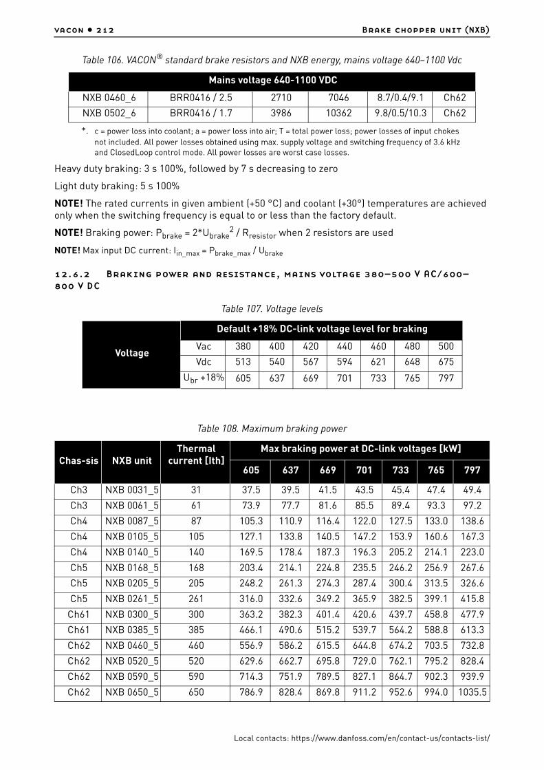
vacon • 212 Brake chopper unit (NXB)
Local contacts: https://www.danfoss.com/en/contact-us/contacts-list/
Heavy duty braking: 3 s 100%, followed by 7 s decreasing to zero
Light duty braking: 5 s 100%
NOTE! The rated currents in given ambient (+50 °C) and coolant (+30°) temperatures are achieved only when the switching frequency is equal to or less than the factory default.
NOTE! Braking power: Pbrake = 2*Ubrake2 / Rresistor when 2 resistors are used
NOTE! Max input DC current: Iin_max = Pbrake_max / Ubrake
12.6.2 Braking power and resistance, mains voltage 380–500 V AC/600–800 V DC
NXB 0460_6 BRR0416 / 2.5 2710 7046 8.7/0.4/9.1 Ch62
NXB 0502_6 BRR0416 / 1.7 3986 10362 9.8/0.5/10.3 Ch62
*. c = power loss into coolant; a = power loss into air; T = total power loss; power losses of input chokes not included. All power losses obtained using max. supply voltage and switching frequency of 3.6 kHz and ClosedLoop control mode. All power losses are worst case losses.
Table 107. Voltage levels
Voltage
Default +18% DC-link voltage level for braking
Vac 380 400 420 440 460 480 500
Vdc 513 540 567 594 621 648 675
Ubr +18% 605 637 669 701 733 765 797
Table 108. Maximum braking power
Chas-sis NXB unitThermal
current [Ith]Max braking power at DC-link voltages [kW]
605 637 669 701 733 765 797
Ch3 NXB 0031_5 31 37.5 39.5 41.5 43.5 45.4 47.4 49.4
Ch3 NXB 0061_5 61 73.9 77.7 81.6 85.5 89.4 93.3 97.2
Ch4 NXB 0087_5 87 105.3 110.9 116.4 122.0 127.5 133.0 138.6
Ch4 NXB 0105_5 105 127.1 133.8 140.5 147.2 153.9 160.6 167.3
Ch4 NXB 0140_5 140 169.5 178.4 187.3 196.3 205.2 214.1 223.0
Ch5 NXB 0168_5 168 203.4 214.1 224.8 235.5 246.2 256.9 267.6
Ch5 NXB 0205_5 205 248.2 261.3 274.3 287.4 300.4 313.5 326.6
Ch5 NXB 0261_5 261 316.0 332.6 349.2 365.9 382.5 399.1 415.8
Ch61 NXB 0300_5 300 363.2 382.3 401.4 420.6 439.7 458.8 477.9
Ch61 NXB 0385_5 385 466.1 490.6 515.2 539.7 564.2 588.8 613.3
Ch62 NXB 0460_5 460 556.9 586.2 615.5 644.8 674.2 703.5 732.8
Ch62 NXB 0520_5 520 629.6 662.7 695.8 729.0 762.1 795.2 828.4
Ch62 NXB 0590_5 590 714.3 751.9 789.5 827.1 864.7 902.3 939.9
Ch62 NXB 0650_5 650 786.9 828.4 869.8 911.2 952.6 994.0 1035.5
Table 106. VACON® standard brake resistors and NXB energy, mains voltage 640–1100 Vdc
Mains voltage 640-1100 VDC

Brake chopper unit (NXB) vacon • 213
Local contacts: https://www.danfoss.com/en/contact-us/contacts-list/
NOTE! The braking powers indicated in Table 108 can only be achieved with minimum resistance.
Ch62 NXB 0730_5 730 883.8 930.3 976.8 1023.3 1069.9 1116.4 1162.9
Table 109. Minimum resistance
Chassis NXB unitThermal
current [Ith]
Minimum resistance at DC-link voltages [ohm]
605 637 669 701 733 765 797
Ch3 NXB 0031_5 31 19.5 20.6 21.6 22.6 23.6 24.7 25.7
Ch3 NXB 0061_5 61 9.9 10.4 11.0 11.5 12.0 12.5 13.1
Ch4 NXB 0087_5 87 7.0 7.3 7.7 8.1 8.4 8.8 9.2
Ch4 NXB 0105_5 105 5.8 6.1 6.4 6.7 7.0 7.3 7.6
Ch4 NXB 0140_5 140 4.3 4.6 4.8 5.0 5.2 5.5 5.7
Ch5 NXB 0168_5 168 3.6 3.8 4.0 4.2 4.4 4.6 4.7
Ch5 NXB 0205_5 205 3.0 3.1 3.3 3.4 3.6 3.7 3.9
Ch5 NXB 0261_5 261 2.3 2.4 2.6 2.7 2.8 2.9 3.1
Ch61 NXB 0300_5 300 2.0 2.1 2.2 2.3 2.4 2.5 2.7
Ch61 NXB 0385_5 385 1.6 1.7 1.7 1.8 1.9 2.0 2.1
Ch62 NXB 0460_5 460 1.3 1.4 1.5 1.5 1.6 1.7 1.7
Ch62 NXB 0520_5 520 1.2 1.2 1.3 1.3 1.4 1.5 1.5
Ch62 NXB 0590_5 590 1.0 1.1 1.1 1.2 1.2 1.3 1.4
Ch62 NXB 0650_5 650 0.9 1.0 1.0 1.1 1.1 1.2 1.2
Ch62 NXB 0730_5 730 0.8 0.9 0.9 1.0 1.0 1.0 1.1
Table 110. Maximum resistance
Chassis NXBunit Thermal
current [Ith]
Maximum resistance at DC-link voltages [ohm]
605 637 669 701 733 765 797
Ch3 NXB 0031_5 31 97.6 102.8 107.9 113.1 118.2 123.3 128.5
Ch3 NXB 0061_5 61 49.6 52.2 54.8 57.5 60.1 62.7 65.3
Ch4 NXB 0087_5 87 34.8 36.6 38.5 40.3 42.1 43.9 45.8
Ch4 NXB 0105_5 105 28.8 30.3 31.9 33.4 34.9 36.4 37.9
Ch4 NXB 0140_5 140 21.6 22.8 23.9 25.0 26.2 27.3 28.4
Ch5 NXB 0168_5 168 18.0 19.0 19.9 20.9 21.8 22.8 23.7
Ch5 NXB 0205_5 205 14.8 15.5 16.3 17.1 17.9 18.6 19.4
Ch5 NXB 0261_5 261 11.6 12.2 12.8 13.4 14.0 14.6 15.3
Ch61 NXB 0300_5 300 10.1 10.6 11.2 11.7 12.2 12.7 13.3
Ch61 NXB 0385_5 385 7.9 8.3 8.7 9.1 9.5 9.9 10.3
Table 108. Maximum braking power
Chas-sis NXB unitThermal
current [Ith]Max braking power at DC-link voltages [kW]
605 637 669 701 733 765 797
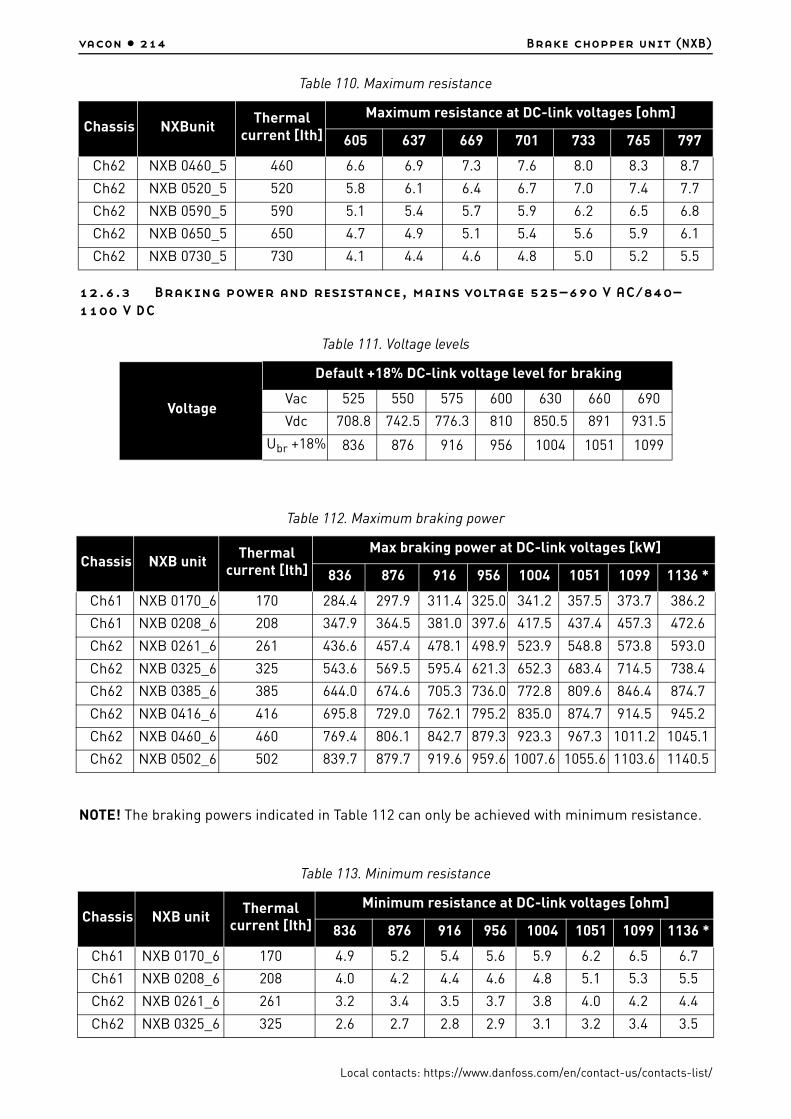
vacon • 214 Brake chopper unit (NXB)
Local contacts: https://www.danfoss.com/en/contact-us/contacts-list/
12.6.3 Braking power and resistance, mains voltage 525–690 V AC/840–1100 V DC
NOTE! The braking powers indicated in Table 112 can only be achieved with minimum resistance.
Ch62 NXB 0460_5 460 6.6 6.9 7.3 7.6 8.0 8.3 8.7
Ch62 NXB 0520_5 520 5.8 6.1 6.4 6.7 7.0 7.4 7.7
Ch62 NXB 0590_5 590 5.1 5.4 5.7 5.9 6.2 6.5 6.8
Ch62 NXB 0650_5 650 4.7 4.9 5.1 5.4 5.6 5.9 6.1
Ch62 NXB 0730_5 730 4.1 4.4 4.6 4.8 5.0 5.2 5.5
Table 111. Voltage levels
Voltage
Default +18% DC-link voltage level for braking
Vac 525 550 575 600 630 660 690
Vdc 708.8 742.5 776.3 810 850.5 891 931.5
Ubr +18% 836 876 916 956 1004 1051 1099
Table 112. Maximum braking power
Chassis NXB unitThermal
current [Ith]
Max braking power at DC-link voltages [kW]
836 876 916 956 1004 1051 1099 1136 *
Ch61 NXB 0170_6 170 284.4 297.9 311.4 325.0 341.2 357.5 373.7 386.2
Ch61 NXB 0208_6 208 347.9 364.5 381.0 397.6 417.5 437.4 457.3 472.6
Ch62 NXB 0261_6 261 436.6 457.4 478.1 498.9 523.9 548.8 573.8 593.0
Ch62 NXB 0325_6 325 543.6 569.5 595.4 621.3 652.3 683.4 714.5 738.4
Ch62 NXB 0385_6 385 644.0 674.6 705.3 736.0 772.8 809.6 846.4 874.7
Ch62 NXB 0416_6 416 695.8 729.0 762.1 795.2 835.0 874.7 914.5 945.2
Ch62 NXB 0460_6 460 769.4 806.1 842.7 879.3 923.3 967.3 1011.2 1045.1
Ch62 NXB 0502_6 502 839.7 879.7 919.6 959.6 1007.6 1055.6 1103.6 1140.5
Table 113. Minimum resistance
Chassis NXB unitThermal
current [Ith]
Minimum resistance at DC-link voltages [ohm]
836 876 916 956 1004 1051 1099 1136 *
Ch61 NXB 0170_6 170 4.9 5.2 5.4 5.6 5.9 6.2 6.5 6.7
Ch61 NXB 0208_6 208 4.0 4.2 4.4 4.6 4.8 5.1 5.3 5.5
Ch62 NXB 0261_6 261 3.2 3.4 3.5 3.7 3.8 4.0 4.2 4.4
Ch62 NXB 0325_6 325 2.6 2.7 2.8 2.9 3.1 3.2 3.4 3.5
Table 110. Maximum resistance
Chassis NXBunit Thermal
current [Ith]
Maximum resistance at DC-link voltages [ohm]
605 637 669 701 733 765 797
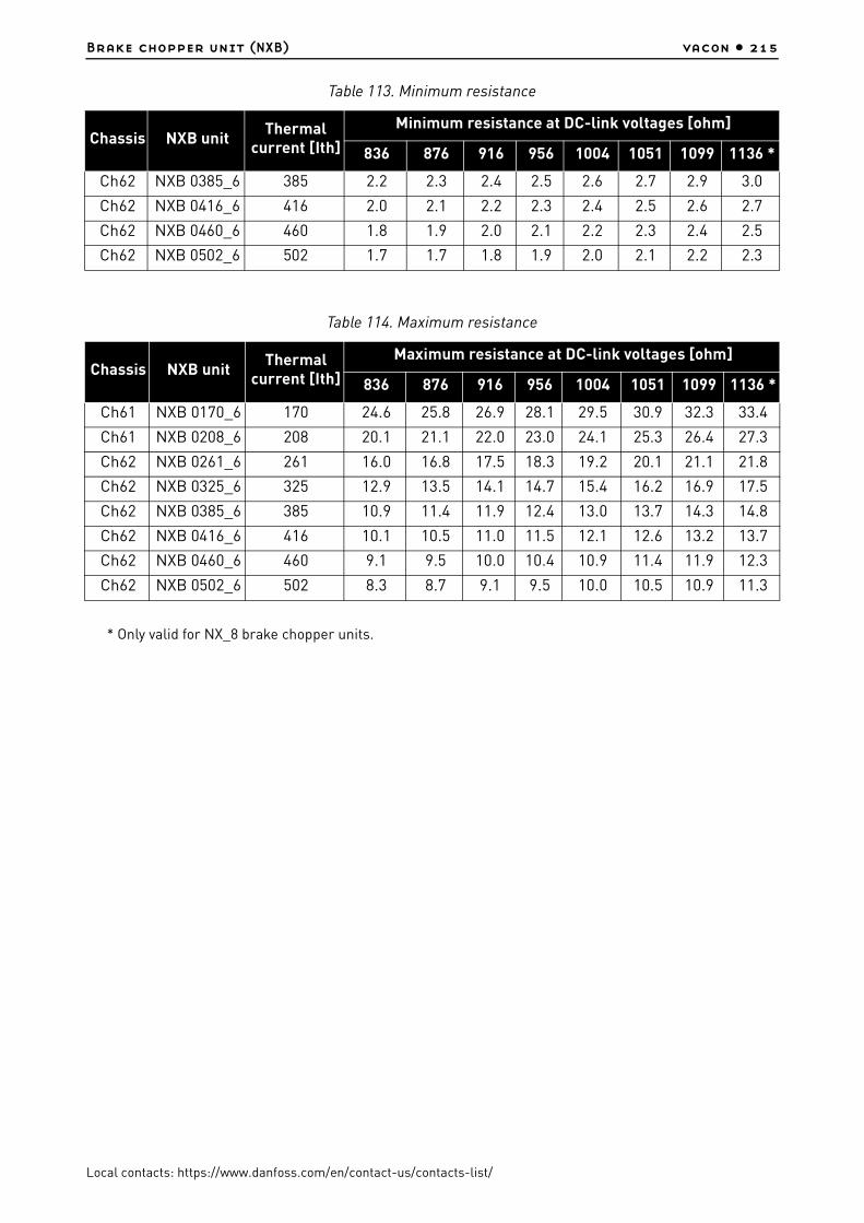
Brake chopper unit (NXB) vacon • 215
Local contacts: https://www.danfoss.com/en/contact-us/contacts-list/
* Only valid for NX_8 brake chopper units.
Ch62 NXB 0385_6 385 2.2 2.3 2.4 2.5 2.6 2.7 2.9 3.0
Ch62 NXB 0416_6 416 2.0 2.1 2.2 2.3 2.4 2.5 2.6 2.7
Ch62 NXB 0460_6 460 1.8 1.9 2.0 2.1 2.2 2.3 2.4 2.5
Ch62 NXB 0502_6 502 1.7 1.7 1.8 1.9 2.0 2.1 2.2 2.3
Table 114. Maximum resistance
Chassis NXB unitThermal
current [Ith]
Maximum resistance at DC-link voltages [ohm]
836 876 916 956 1004 1051 1099 1136 *
Ch61 NXB 0170_6 170 24.6 25.8 26.9 28.1 29.5 30.9 32.3 33.4
Ch61 NXB 0208_6 208 20.1 21.1 22.0 23.0 24.1 25.3 26.4 27.3
Ch62 NXB 0261_6 261 16.0 16.8 17.5 18.3 19.2 20.1 21.1 21.8
Ch62 NXB 0325_6 325 12.9 13.5 14.1 14.7 15.4 16.2 16.9 17.5
Ch62 NXB 0385_6 385 10.9 11.4 11.9 12.4 13.0 13.7 14.3 14.8
Ch62 NXB 0416_6 416 10.1 10.5 11.0 11.5 12.1 12.6 13.2 13.7
Ch62 NXB 0460_6 460 9.1 9.5 10.0 10.4 10.9 11.4 11.9 12.3
Ch62 NXB 0502_6 502 8.3 8.7 9.1 9.5 10.0 10.5 10.9 11.3
Table 113. Minimum resistance
Chassis NXB unitThermal
current [Ith]
Minimum resistance at DC-link voltages [ohm]
836 876 916 956 1004 1051 1099 1136 *
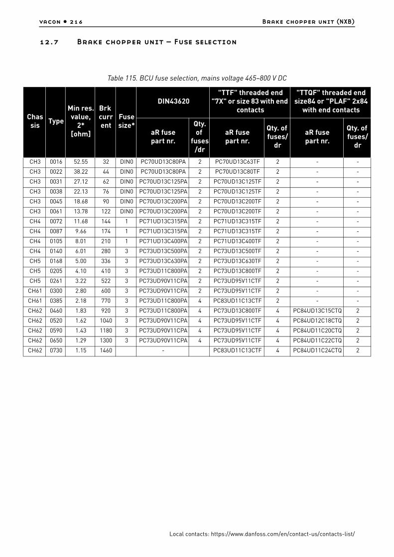
vacon • 216 Brake chopper unit (NXB)
Local contacts: https://www.danfoss.com/en/contact-us/contacts-list/
12.7 Brake chopper unit – Fuse selection
Table 115. BCU fuse selection, mains voltage 465–800 V DC
Chassis
Type
Min res.value,
2*[ohm]
Brk current
Fuse size*
DIN43620"TTF" threaded end
"7X" or size 83 with end contacts
"TTQF" threaded end size84 or "PLAF" 2x84
with end contacts
aR fuse part nr.
Qty. of
fuses/dr
aR fuse part nr.
Qty. of fuses/
dr
aR fuse part nr.
Qty. of fuses/
dr
CH3 0016 52.55 32 DIN0 PC70UD13C80PA 2 PC70UD13C63TF 2 - -
CH3 0022 38.22 44 DIN0 PC70UD13C80PA 2 PC70UD13C80TF 2 - -
CH3 0031 27.12 62 DIN0 PC70UD13C125PA 2 PC70UD13C125TF 2 - -
CH3 0038 22.13 76 DIN0 PC70UD13C125PA 2 PC70UD13C125TF 2 - -
CH3 0045 18.68 90 DIN0 PC70UD13C200PA 2 PC70UD13C200TF 2 - -
CH3 0061 13.78 122 DIN0 PC70UD13C200PA 2 PC70UD13C200TF 2 - -
CH4 0072 11.68 144 1 PC71UD13C315PA 2 PC71UD13C315TF 2 - -
CH4 0087 9.66 174 1 PC71UD13C315PA 2 PC71UD13C315TF 2 - -
CH4 0105 8.01 210 1 PC71UD13C400PA 2 PC71UD13C400TF 2 - -
CH4 0140 6.01 280 3 PC73UD13C500PA 2 PC73UD13C500TF 2 - -
CH5 0168 5.00 336 3 PC73UD13C630PA 2 PC73UD13C630TF 2 - -
CH5 0205 4.10 410 3 PC73UD11C800PA 2 PC73UD13C800TF 2 - -
CH5 0261 3.22 522 3 PC73UD90V11CPA 2 PC73UD95V11CTF 2 - -
CH61 0300 2.80 600 3 PC73UD90V11CPA 2 PC73UD95V11CTF 2 - -
CH61 0385 2.18 770 3 PC73UD11C800PA 4 PC83UD11C13CTF 2 - -
CH62 0460 1.83 920 3 PC73UD11C800PA 4 PC73UD13C800TF 4 PC84UD13C15CTQ 2
CH62 0520 1.62 1040 3 PC73UD90V11CPA 4 PC73UD95V11CTF 4 PC84UD12C18CTQ 2
CH62 0590 1.43 1180 3 PC73UD90V11CPA 4 PC73UD95V11CTF 4 PC84UD11C20CTQ 2
CH62 0650 1.29 1300 3 PC73UD90V11CPA 4 PC73UD95V11CTF 4 PC84UD11C22CTQ 2
CH62 0730 1.15 1460 - PC83UD11C13CTF 4 PC84UD11C24CTQ 2

Brake chopper unit (NXB) vacon • 217
Local contacts: https://www.danfoss.com/en/contact-us/contacts-list/
Table 116. BCU fuse selection, mains voltage 640–1100 V DC
Chassis
TypeMin res.value,
2*[ohm]
Brk current
Fuse size*
DIN43620"TTF" threaded end "7X" or size 83 with
end contacts
"TTQF" threaded end size84 or "PLAF" 2x84
with end contacts
aR fuse part nr.
Qty. of
fuses/dr
aR fuse part nr.
Qty. of fuses/
dr
aR fuse part nr.
Qty. of fuses/
dr
CH61 0170 6.51 340 DIN3 PC73UD13C630PA 2 PC73UD13C630TF 2 - -
CH61 0208 5.32 416 DIN3 PC73UD11C800PA 2 PC73UD13C800TF 2 - -
CH61 0261 4.24 522 DIN3 PC73UD11C800PA 2 PC73UD13C800TF 2 - -
CH62 0310 3.41 650 DIN3 PC73UD13C630PA 4 PC83UD12C11CTF 2 - -
CH62 0385 2.88 770 DIN3 PC73UD13C630PA 4 PC83UD11C13CTF 2 - -
CH62 0416 2.66 832 DIN3 PC73UD11C800PA 4 PC83UD11C14CTF 2 PC84UD13C15CTQ 2
CH62 0460 2.41 920 DIN3 PC73UD11C800PA 4 PC73UD13C800TF 4 PC84UD13C15CTQ 2
CH62 0502 2.21 1004 DIN3 PC73UD11C800PA 4 PC73UD13C800TF 4 PC84UD13C15CTQ 2

vacon • 218 Grid converter/Utility interactive
Local contacts: https://www.danfoss.com/en/contact-us/contacts-list/
13. GRID CONVERTER/UTILITY INTERACTIVE INVERTER
13.1 Safety
To be connected only to a dedicated branch circuit protection.
The output of the inverter can be connected with up to 4 parallel combination of modules.
Ground fault detector/interrupter shall be installed at the inverter or at the array, if the inverter is connected to direct photovoltaic inputs from a grounded photovoltaic array.
Surge protection device shall be installed.
Read the user manual, drawings and all other related documentation.
13.2 Used symbols and markings
WARNING
Risk of electric shock from energy stored in capacitor. Both AC and DC voltage sources are terminated inside this equipment. Each circuit must be individually disconnected and the service person must wait 5 minutes before servicing or accessing or removing the cover.
WARNING
Hazardous Voltage remains for 5 minutes after disconnecting the main power supply.
WARNING
When the photovoltaic array is exposed to light, it supplies a DC voltage to this equipment.
WARNING
For continued protection against risk of fire, use fuses as mentioned in the user manual.
WARNING
Hot surface - Risk of Burn. Resistors, heaters, chokes, dU/dt filters, LCL filters, sine-wave filter are examples of hot surfaces and not limited to these.
CAUTION
Wear protective gloves when you do installation, cabling or maintenance operations. There can be sharp edges in the AC drive/frequency converter that can cause cuts.
Table 117. Symbols and Markings
B+ The terminal for the DC+ connection
B- The terminal for the DC- connection
U/T1 The terminal for the L1 connection
V/T2 The terminal for the L2 connection
W/T3 The terminal for the L3 connection
The grounding terminal
9000.emf
9000.emf
9000.emf
9000.emf
9001.emf
13006.emf

Grid converter/Utility interactive inverter vacon • 219
Local contacts: https://www.danfoss.com/en/contact-us/contacts-list/
13.3 Conditions of acceptability
1. The power converter shall be installed in compliance with the enclosure, mounting, spacing, casualty, and segregation requirements of the ultimate application.
2. The equipment is intended to be installed within a suitable enclosure for the end product and operating environment.
3. The need for external equipment disconnect devices shall be evaluated in the end product. 4. The suitability of the module chassis in combination with the end product enclosure, including
accessibility of live parts through openings in the enclosure, impact tests for reduced enclosure thicknesses, reliable retention of guards or barrier for prevention of shock hazards, etc., shall be considered in the end product evaluation.
5. The power supply bulk capacitors store hazardous energy for 5 minutes after disconnecting all sources of power.
This inverter is intended for operation in an environment having a maximum ambient temperature of 50°C (122°F).
13.3.1 Conditions of acceptability and engineering considerations for UL1741
1. Inverter can be connected only to Delta winding of transformer.2. Communication cables shall be routed via grounded metallic conduits for field wiring.3. UL listed Surge protection shall be installed in enclosure. For UL1741 certification, Mersen
STXR600D05 was used.4. Additional relay shall be included in end installation for detection of Open phase.
5. VACON® pre-charging circuit shall be used.6. Only semiconductor fuses which are in UL1741 files shall be used for modules protection.
Please refer to Table 122 and Table 125.7. UL listed branch circuit protection current rating shall be as per ratings mentioned in Table 118. 8. UL1741 Utility Interactive inverters and Stand-alone inverters shall be loaded with System
software NXP2V200.9. UL1741 Utility Interactive inverters shall be loaded with Application software ARFIF106V103.
13.4 Required tools
No special tools apart from a torque wrench and screwdrivers are needed for the installation of the device. The bolt and screw sizes and tightening torques are stated in this manual.
13.5 Mounting
For mounting instructions, see Chapter 5.
13.5.1 Dimensions - Drive unit
Find the dimensions for the grid converter unit in Chapter 5.1.2.
13.5.2 Dimensions - RLC filter
Find the dimensions for the RLC filter in Chapter 10.6.3.
13.6 Cooling
Find the guidelines and specifications for the cooling of the grid converter in Chapter 5.2.

vacon • 220 Grid converter/Utility interactive
Local contacts: https://www.danfoss.com/en/contact-us/contacts-list/
13.7 Power cabling
The AC input and AC output circuits are isolated from the enclosure. The system grounding, if required by Section 250 of the National Electrical Code, ANSI/NFPA 70, is the responsibility of the installer.
Use the wiring methods described in National Electrical Code, ANSI/NFPA 70.
CAUTION!
To reduce the risk of fire, connect only to a circuit provided with branch-circuit overcurrent protection in accordance with the National Electrical Code, ANSI/NFPA 70. See the maximum branch circuit overcurrent protection values in Table 118.
13.7.1 Cable installation and the UL standards
To meet the UL (Underwriters Laboratories) regulations, a UL-approved copper cable with a minimum heat-resistance of +60/75°C must be used.
Use Class 1 wire only.
Use shielded cables.
13.7.2 Cable sizes - UL1741
Table 118. Cable sizes for 640–1100 V DC (525–690 V AC)
Enclosure size
TypeMaximum input DC overcurrent protection (A)
Max. branch circuit overcurrent
protection (A)DC supply cable AC cable
CH61
NX_0170 6 400 250 250 kcmil 4/0 AWG
NX_0208 6 400 250 350 kcmil 250 kcmil
NX_0261 6 500 400 500 kcmil 400 kcmil
CH62
NX_0325 6 700 400 2x250 kcmil 2x3/0 AWG
NX_0385 6 800 500 2x300 kcmil 2x250 kcmil
NX_0416 6 1000 500 2x350 kcmil 2x250 kcmil
NX_0460 6 1000 600 3x300 kcmil 2x300 kcmil
NX_0502 6 1000 600 2x500 kcmil 2x350 kcmil
CH63
NX_0590 6 1100 750 3x300 kcmil 3x250 kcmil
NX_0650 6 1500 800 3x400 kcmil 3x300 kcmil
NX_0750 6 1500 1000 3x500 kcmil 3x350 kcmil
CH64
NX_0820 6 1500 1000 4x350 kcmil 4x250 kcmil
NX_0920 6 1800 1250 4x400 kcmil 4x300 kcmil
NX_1030 6 2000 1250 4x500 kcmil 4x400 kcmil
NX_1180 6 2200 1600 6x350 kcmil 4x400 kcmil
NX_1300 6 2400 1600 6x400 kcmil 5x400 kcmil
NX_1500 6 3000 2000 6x500 kcmil 6x350 kcmil
NX_1700 6 3400 2000 6x500 kcmil 6x500 kcmil

Grid converter/Utility interactive inverter vacon • 221
Local contacts: https://www.danfoss.com/en/contact-us/contacts-list/
13.7.3 Terminal sizes
See the dimensional drawings in Chapter 5.1.2.
13.7.4 Bolt sizes and tightening torques
13.8 Grounding
Connect the cable shields of the mains cables to the grounding conductor of the switchgear enclosure.
For grounding of the drive itself, use the grounding terminal on the drive mounting plate. See Chapter 6.1.7.
13.8.1 Grounding terminal
Grounding conductor sizing shall follow NEC Article 250 and minimum conductor size requirements as per NEC Table 250.122.
Use copper, copper-clad aluminum, or aluminum conductors.
Wire type – rated 75/90°C (167/194°F).
Mounting: M8 bolt, tightening torque: 13.5 Nm (120 lb-in).
2xCH64
NX_1850 6 2x1800 2250 2x4x500 kcmil 2x4x400 kcmil
NX_2120 6 2x2000 2500 2x6x350 kcmil 2x4x500 kcmil
NX_2340 6 2x2200 3000 2x6x400 kcmil 2x5x400 kcmil
NX_2700 6 2x2400 3000 2x6x500 kcmil 2x6x350 kcmil
NX_3100 6 2x3000 3500 2x6x500 kcmil 2x6x500 kcmil
Table 119. Bolt sizes and tightening torques
Enclosure size
DC terminal AC terminal
Drive type BoltTorque (Nm)
Torque (lb-in)
BoltMax.
number of cables
Torque (Nm)
Torque (lb-in)
CH61NX_0300 5 - NX_0385 5NX_0170 6 - NX_0261 6
M12 70 620 M12 2 70 620
CH62NX_0460 5 - NX_0730 5NX_0325 6 - NX_0502 6
M12 70 620 M12 4 70 620
CH63NX_0820 5 - NX_1150 5NX_0590 6 - NX_0750 6
M12 70 620 M12 8 70 620
CH64NX_1370 5 - NX_2300 5NX_0820 6 - NX_1700 6
M12 70 620 M12 4 70 620
2×CH64NX_2470 5 - NX_4140 5NX_1850 6 - NX_3100 6
M12 70 620 6×M12 2×4 70 620
Table 118. Cable sizes for 640–1100 V DC (525–690 V AC)
Enclosure size
TypeMaximum input DC overcurrent protection (A)
Max. branch circuit overcurrent
protection (A)DC supply cable AC cable

vacon • 222 Grid converter/Utility interactive
Local contacts: https://www.danfoss.com/en/contact-us/contacts-list/
13.9 Protections
Integral solid state short circuit protection does not provide branch circuit protection. Branch circuit protection must be provided in accordance with the National Electrical Code and any additional local codes. See the maximum branch circuit overcurrent protection values in Table 118.
13.9.1 Overcurrent protection
The overcurrent protection fuses must be installed by the end user.
13.9.1.1 AC output circuit - European grid codes
Overcurrent protection for the AC output circuit must be provided in the field. See the fuse specifications in the tables below.
Table 120. AC fuse sizes for VACON® NX Liquid-cooled drives (380-500 V)
Enclosure size TypeInput
terminals (pcs)
Fuses needed
(pcs)
Minimum prospective grid short circuit current
(A) @ 10 ms
TTF threaded end fuse (type code)
CH5
NX_0168 5 3 3 2000 PC30UD69V315TF
NX_0205 5 3 3 2700 PC30UD69V400TF
NX_0261 5 3 3 3400 PC31UD69V500TF
CH61NX_0300 5 3 3 4200 PC32UD69V630TF
NX_0385 5 3 3 4200 PC32UD69V630TF
CH62
NX_0460 5 3 3 7600 PC33UD69V1000TF
NX_0520 5 3 3 7600 PC33UD69V1000TF
NX_0590 5 3 3 9000 PC33UD69V1100TF
NX_0650 5 3 3 11000 PC33UD69V1250TF
NX_0730 5 3 3 11000 PC33UD69V1250TF
CH63
NX_0820 5 36 2x6100 PC32UD69V800TF
3 10000 PC44UD75V16CTQ
NX_0920 5 36 2x7600 PC33UD69V1000TF
3 10000 PC44UD75V16CTQ
NX_1030 5 36 2x7600 PC33UD69V1000TF
3 12500 PC44UD75V18CTQ
NX_1150 5 36 2x9000 PC33UD69V1100TF
3 14000 PC44UD75V20CTQ
CH64
NX_1370 5 39 3x7600 PC33UD69V1000TF
3 18000 PC44UD75V24CTQ
NX_1640 5 39 3x7600 PC33UD69V1000TF
3 23000 PC44UD70V27CTQ
NX_2060 5 39 3x11000 PC33UD69V1250TF
3 42000 PC44UD69V34CTQB
NX_2300 5 39 3x11000 PC33UD69V1250TF
3 24000 PC47UD70V36CP50
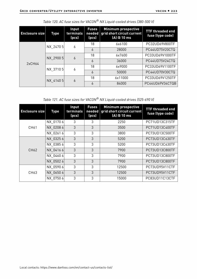
Grid converter/Utility interactive inverter vacon • 223
Local contacts: https://www.danfoss.com/en/contact-us/contacts-list/
2xCH64
NX_2470 5 618 6x6100 PC32UD69V800TF
6 28000 PC44UD75V20CTQ
NX_2900 5 618 6x7600 PC33UD69V1000TF
6 36000 PC44UD75V24CTQ
NX_3710 5 618 6x9000 PC33UD69V1100TF
6 50000 PC44UD70V30CTQ
NX_4140 5 618 6x11000 PC33UD69V1250TF
6 84000 PC44UD69V34CTQB
Table 121. AC fuse sizes for VACON® NX Liquid-cooled drives (525-690 V)
Enclosure size TypeInput
terminals (pcs)
Fuses needed
(pcs)
Minimum prospective grid short circuit current
(A) @ 10 ms
TTF threaded end fuse (type code)
CH61
NX_0170 6 3 3 2250 PC71UD13C315TF
NX_0208 6 3 3 3500 PC71UD13C400TF
NX_0261 6 3 3 3800 PC73UD13C500TF
CH62
NX_0325 6 3 3 5200 PC73UD13C630TF
NX_0385 6 3 3 5200 PC73UD13C630TF
NX_0416 6 3 3 7900 PC73UD13C800TF
NX_0460 6 3 3 7900 PC73UD13C800TF
NX_0502 6 3 3 7900 PC73UD13C800TF
CH63
NX_0590 6 3 3 12500 PC73UD95V11CTF
NX_0650 6 3 3 12500 PC73UD95V11CTF
NX_0750 6 3 3 15000 PC83UD11C13CTF
Table 120. AC fuse sizes for VACON® NX Liquid-cooled drives (380-500 V)
Enclosure size TypeInput
terminals (pcs)
Fuses needed
(pcs)
Minimum prospective grid short circuit current
(A) @ 10 ms
TTF threaded end fuse (type code)

vacon • 224 Grid converter/Utility interactive
Local contacts: https://www.danfoss.com/en/contact-us/contacts-list/
13.9.1.2 AC output circuit - UL1741
Overcurrent protection for the AC output circuit must be provided in the field. See the fuse specifications in the tables below.
CH64
NX_0820 6 36 2x7900 PC73UD13C800TF
3 17000 PC83UD11C14CTF
NX_0920 6 36 2x7900 PC73UD13C800TF
3 20000 PC83UD95V16CTF
NX_1030 6 36 2x12500 PC73UD95V11CTF
3 19000 PC84UD12C18CTQ
NX_1180 6 36 2x12500 PC73UD95V11CTF
3 23000 PC84UD11C20CTQ
NX_1300 6 39 3x7900 PC73UD13C800TF
3 27000 PC84UD11C22CTQ
NX_1500 6 39 3x12500 PC73UD95V11CTF
3 29000 PC84UD11C24CTQ
NX_1700 6 39 3x12500 PC73UD95V11CTF
3 42000 9 URD 84 TTQF 3000
2xCH64
NX_1850 6 612 3x7900 PC73UD13C800TF
6 40000 PC83UD95V16CTF
NX_2120 6 612 3x12500 PC73UD95V11CTF
6 50000 9 URD 83 TTF 1800
NX_2340 6 612 3x12500 PC73UD95V11CTF
6 46000 PC84UD11C20CTQ
NX_2700 6 618 3x7900 PC73UD13C800TF
6 54000 PC84UD11C22CTQ
NX_3100 6 618 3x12500 PC73UD95V11CTF
6 70000 PC84UD10C27CTQ
Table 122. AC fuse sizes for VACON® NX Liquid-cooled drives (525-690 V)
Enclosure size Type Fuses needed (pcs) Fuse (type code)
CH61
NX_0170 6 3 PC71UD13C315TF
NX_0208 6 3 PC71UD13C400TF
NX_0261 6 3 PC73UD13C500TF
Table 121. AC fuse sizes for VACON® NX Liquid-cooled drives (525-690 V)
Enclosure size TypeInput
terminals (pcs)
Fuses needed
(pcs)
Minimum prospective grid short circuit current
(A) @ 10 ms
TTF threaded end fuse (type code)

Grid converter/Utility interactive inverter vacon • 225
Local contacts: https://www.danfoss.com/en/contact-us/contacts-list/
CH62
NX_0325 6 3 PC73UD13C630TF
NX_0385 6 3 PC73UD13C630TF
NX_0416 6 3 PC73UD13C800TF
NX_0460 6 3 PC73UD13C800TF
NX_0502 6 3 PC73UD13C800TF
CH63
NX_0590 6 3 PC73UD95V11CTF
NX_0650 6 3 PC73UD95V11CTF
NX_0750 6 3 PC83UD11C13CTF
CH64
NX_0820 66 PC73UD13C800TF
3 PC83UD11C14CTF
NX_0920 66 PC73UD13C800TF
3 PC83UD95V16CTF
NX_1030 66 PC73UD95V11CTF
3 PC84UD12C18CTQ
NX_1180 66 PC73UD95V11CTF
3 PC84UD11C20CTQ
NX_1300 69 PC73UD13C800TF
3 PC84UD11C22CTQ
NX_1500 69 PC73UD95V11CTF
3 PC84UD11C24CTQ
NX_1700 69 PC73UD95V11CTF
3 9 URD 84 TTQF 3000
2xCH64
NX_1850 612 PC73UD13C800TF
6 PC83UD95V16CTF
NX_2120 612 PC73UD95V11CTF
6 9 URD 83 TTF 1800
NX_2340 612 PC73UD95V11CTF
6 PC84UD11C20CTQ
NX_2700 618 PC73UD13C800TF
6 PC84UD11C22CTQ
NX_3100 618 PC73UD95V11CTF
6 PC84UD10C27CTQ
Table 122. AC fuse sizes for VACON® NX Liquid-cooled drives (525-690 V)
Enclosure size Type Fuses needed (pcs) Fuse (type code)

vacon • 226 Grid converter/Utility interactive
Local contacts: https://www.danfoss.com/en/contact-us/contacts-list/
13.9.1.3 DC source circuit - European grid codes
Overcurrent protection for the DC source circuit must be provided in the field. See the fuse specifications in the tables below.
Table 123. DC fuse sizes for VACON® NX Liquid-cooled drives (380-500 V)
Enclosure size TypeInput terminals
(pcs)Fuses needed
(pcs)TTF/TTQF threaded end fuse
(type code)
CH5
NX_0168 5 2 2 PC71UD13C315TF
NX_0205 5 2 2 PC71UD13C400TF
NX_0261 5 2 2 PC73UD13C500TF
CH61NX_0300 5 2 2 PC73UD13C630TF
NX_0385 5 2 2 PC73UD13C800TF
CH62
NX_0460 5 2 2 PC73UD95V11CTF
NX_0520 5 2 2 PC73UD95V11CTF
NX_0590 5 2 2 PC73UD95V11CTF
NX_0650 5 2 2 PC83UD11C13CTF
NX_0730 5 2 2 PC83UD11C13CTF
CH63
NX_0820 5 24 PC73UD13C800TF
2 PC84UD13C15CTQ
NX_0920 5 24 PC73UD95V11CTF
2 PC84UD12C18CTQ
NX_1030 5 24 PC73UD13C800TF
2 PC84UD11C20CTQ
NX_1150 5 24 PC83UD11C13CTF
2 PC84UD11C22CTQ
CH64
NX_1370 5 2/44 PC83UD11C14CTF
2 PC84UD10C27CTQ
NX_1640 5 2/48 PC73UD13C800TF
2 PC87UD12C30CP50
NX_2060 5 2/48 PC73UD95V11CTF
2 PC87UD11C38CP50
NX_2300 5 2/48 PC73UD95V11CTF
2 10 URD 284 PLAF 4400
2xCH64
NX_2470 5 4/88 PC83UD11C13CTF
4 PC84UD11C24CTQ
NX_2900 5 4/816 PC73UD13C800TF
4 PC87UD12C30CP50
NX_3710 5 4/816 PC73UD95V11CTF
4 PC87UD11C38CP50
NX_4140 5 4/816 PC73UD95V11CTF
4 10 URD 284 PLAF 4400

Grid converter/Utility interactive inverter vacon • 227
Local contacts: https://www.danfoss.com/en/contact-us/contacts-list/
Table 124. DC fuse sizes for VACON® NX Liquid-cooled drives (525-690 V)
Enclosure size TypeInput terminals
(pcs)Fuses needed
(pcs)TTF/TTQF threaded end fuse
(type code)
CH61
NX_0170 6 2 2 PC71UD13C400TF
NX_0208 6 2 2 PC71UD13C400TF
NX_0261 6 2 2 PC73UD13C500TF
CH62
NX_0325 6 2 2 PC73UD13C630TF
NX_0385 6 2 2 PC73UD13C800TF
NX_0416 6 2 2 PC73UD13C800TF
NX_0460 6 2 2 PC73UD12C900TF
NX_0502 6 2 2 PC73UD12C900TF
CH63
NX_0590 6 2 2 PC83UD12C11CTF
NX_0650 6 2 2 PC83UD11C13CTF
NX_0750 6 2 2 PC83UD11C14CTF
CH64
NX_0820 6 2/44 PC73UD13C800TF
2 PC84UD13C15CTQ
NX_0920 6 2/44 PC73UD12C900TF
2 PC84UD12C18CTQ
NX_1030 6 2/44 PC83UD12C11CTF
2 PC84UD11C20CTQ
NX_1180 6 2/44 PC83UD12C11CTF
2 PC84UD11C22CTQ
NX_1300 6 2/44 PC83UD11C13CTF
2 PC84UD11C24CTQ
NX_1500 6 2/44 PC83UD11C14CTF
2 PC87UD12C30CP50
NX_1700 6 2/48 PC73UD12C900TF
2 PC87UD11C34CP50
2xCH64
NX_1850 6 4/88 PC73UD12C900TF
4 PC84UD12C18CTQ
NX_2120 6 4/88 PC83UD12C11CTF
4 PC84UD11C20CTQ
NX_2340 6 4/88 PC83UD11C13CTF
4 PC84UD11C22CTQ
NX_2700 6 4/88 PC83UD11C14CTF
4 PC84UD11C24CTQ
NX_3100 6 4/816 PC73UD13C800TF
4 PC87UD12C30CP50

vacon • 228 Grid converter/Utility interactive
Local contacts: https://www.danfoss.com/en/contact-us/contacts-list/
13.9.1.4 DC source circuit - UL1741
Overcurrent protection for the DC source circuit must be provided in the field. See the fuse specifications in the tables below.
Table 125. DC fuse sizes for VACON® NX Liquid-cooled drives (525-690 V)
Enclosure size Type Fuses needed (pcs) Fuse (type code)
CH61
NX_0170 6 2 PC71UD13C400TF
NX_0208 6 2 PC71UD13C400TF
NX_0261 6 2 PC73UD13C500TF
CH62
NX_0325 6 2 PC73UD13C630TF
NX_0385 6 2 PC73UD13C800TF
NX_0416 6 2 PC73UD13C800TF
NX_0460 6 2 PC73UD12C900TF
NX_0502 6 2 PC73UD12C900TF
CH63
NX_0590 6 2 PC83UD12C11CTF
NX_0650 6 2 PC83UD11C13CTF
NX_0750 6 2 PC83UD11C14CTF
CH64
NX_0820 64 PC73UD13C800TF
2 PC84UD13C15CTQ
NX_0920 64 PC73UD12C900TF
2 PC84UD12C18CTQ
NX_1030 64 PC83UD12C11CTF
2 PC84UD11C20CTQ
NX_1180 64 PC83UD12C11CTF
2 PC84UD11C22CTQ
NX_1300 64 PC83UD11C13CTF
2 PC84UD11C24CTQ
NX_1500 64 PC83UD11C14CTF
2 PC87UD12C30CP50
NX_1700 68 PC73UD12C900TF
2 PC87UD11C34CP50
2xCH64
NX_1850 68 PC73UD12C900TF
4 PC84UD12C18CTQ
NX_2120 68 PC83UD12C11CTF
4 PC84UD11C20CTQ
NX_2340 68 PC83UD11C13CTF
4 PC84UD11C22CTQ
NX_2700 68 PC83UD11C14CTF
4 PC84UD11C24CTQ
NX_3100 616 PC73UD13C800TF
4 PC87UD12C30CP50
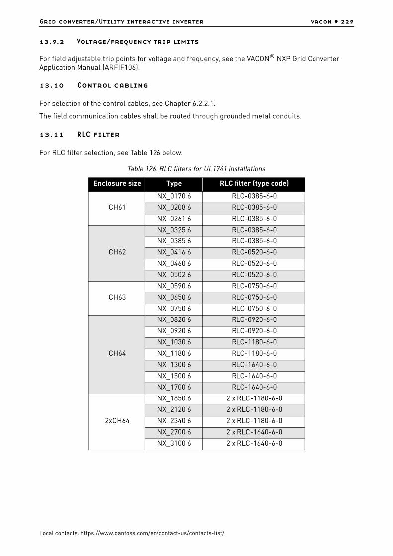
Grid converter/Utility interactive inverter vacon • 229
Local contacts: https://www.danfoss.com/en/contact-us/contacts-list/
13.9.2 Voltage/frequency trip limits
For field adjustable trip points for voltage and frequency, see the VACON® NXP Grid Converter Application Manual (ARFIF106).
13.10 Control cabling
For selection of the control cables, see Chapter 6.2.2.1.
The field communication cables shall be routed through grounded metal conduits.
13.11 RLC filter
For RLC filter selection, see Table 126 below.
Table 126. RLC filters for UL1741 installations
Enclosure size Type RLC filter (type code)
CH61
NX_0170 6 RLC-0385-6-0
NX_0208 6 RLC-0385-6-0
NX_0261 6 RLC-0385-6-0
CH62
NX_0325 6 RLC-0385-6-0
NX_0385 6 RLC-0385-6-0
NX_0416 6 RLC-0520-6-0
NX_0460 6 RLC-0520-6-0
NX_0502 6 RLC-0520-6-0
CH63
NX_0590 6 RLC-0750-6-0
NX_0650 6 RLC-0750-6-0
NX_0750 6 RLC-0750-6-0
CH64
NX_0820 6 RLC-0920-6-0
NX_0920 6 RLC-0920-6-0
NX_1030 6 RLC-1180-6-0
NX_1180 6 RLC-1180-6-0
NX_1300 6 RLC-1640-6-0
NX_1500 6 RLC-1640-6-0
NX_1700 6 RLC-1640-6-0
2xCH64
NX_1850 6 2 x RLC-1180-6-0
NX_2120 6 2 x RLC-1180-6-0
NX_2340 6 2 x RLC-1180-6-0
NX_2700 6 2 x RLC-1640-6-0
NX_3100 6 2 x RLC-1640-6-0
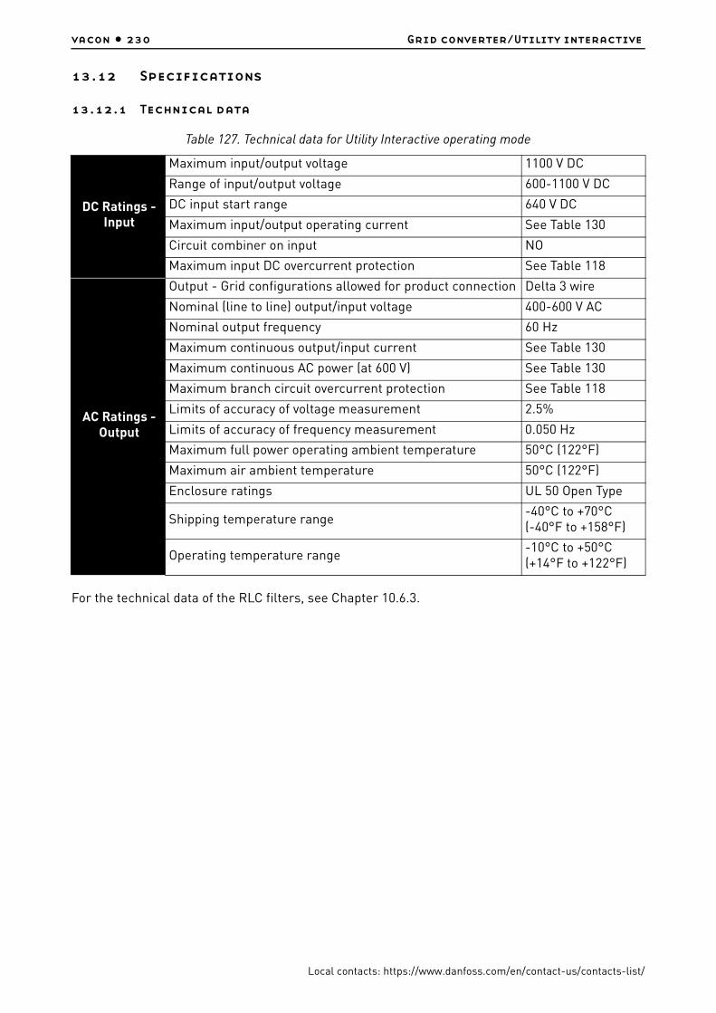
vacon • 230 Grid converter/Utility interactive
Local contacts: https://www.danfoss.com/en/contact-us/contacts-list/
13.12 Specifications
13.12.1 Technical data
For the technical data of the RLC filters, see Chapter 10.6.3.
Table 127. Technical data for Utility Interactive operating mode
DC Ratings - Input
Maximum input/output voltage 1100 V DC
Range of input/output voltage 600-1100 V DC
DC input start range 640 V DC
Maximum input/output operating current See Table 130
Circuit combiner on input NO
Maximum input DC overcurrent protection See Table 118
AC Ratings - Output
Output - Grid configurations allowed for product connection Delta 3 wire
Nominal (line to line) output/input voltage 400-600 V AC
Nominal output frequency 60 Hz
Maximum continuous output/input current See Table 130
Maximum continuous AC power (at 600 V) See Table 130
Maximum branch circuit overcurrent protection See Table 118
Limits of accuracy of voltage measurement 2.5%
Limits of accuracy of frequency measurement 0.050 Hz
Maximum full power operating ambient temperature 50°C (122°F)
Maximum air ambient temperature 50°C (122°F)
Enclosure ratings UL 50 Open Type
Shipping temperature range-40°C to +70°C(-40°F to +158°F)
Operating temperature range-10°C to +50°C(+14°F to +122°F)
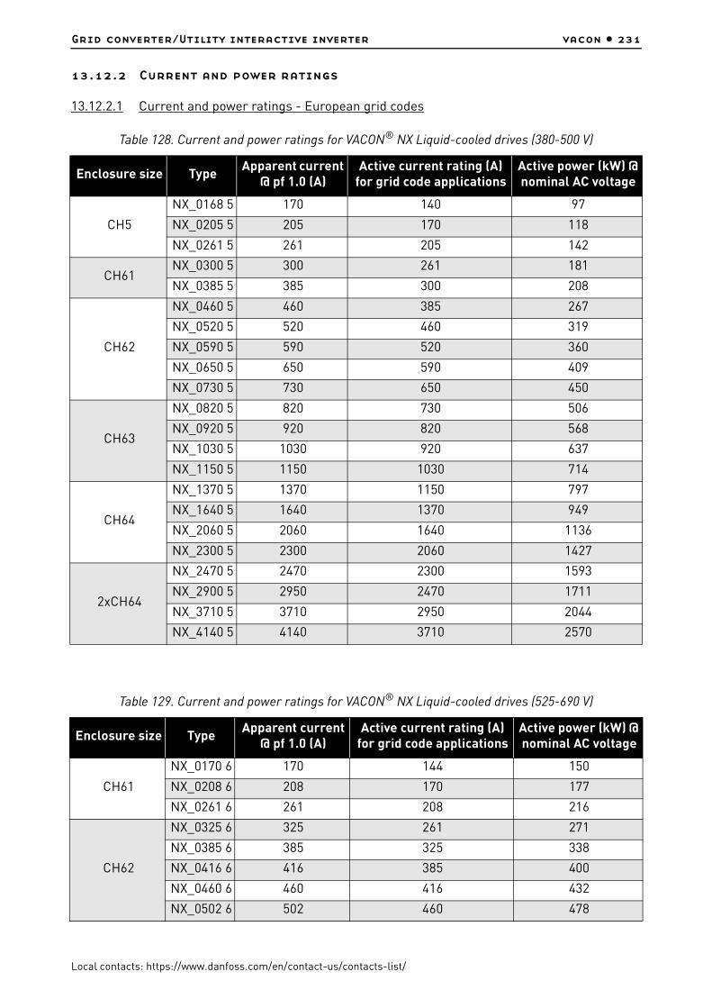
Grid converter/Utility interactive inverter vacon • 231
Local contacts: https://www.danfoss.com/en/contact-us/contacts-list/
13.12.2 Current and power ratings
13.12.2.1 Current and power ratings - European grid codes
Table 128. Current and power ratings for VACON® NX Liquid-cooled drives (380-500 V)
Enclosure size TypeApparent current
@ pf 1.0 (A)Active current rating (A)
for grid code applicationsActive power (kW) @ nominal AC voltage
CH5
NX_0168 5 170 140 97
NX_0205 5 205 170 118
NX_0261 5 261 205 142
CH61NX_0300 5 300 261 181
NX_0385 5 385 300 208
CH62
NX_0460 5 460 385 267
NX_0520 5 520 460 319
NX_0590 5 590 520 360
NX_0650 5 650 590 409
NX_0730 5 730 650 450
CH63
NX_0820 5 820 730 506
NX_0920 5 920 820 568
NX_1030 5 1030 920 637
NX_1150 5 1150 1030 714
CH64
NX_1370 5 1370 1150 797
NX_1640 5 1640 1370 949
NX_2060 5 2060 1640 1136
NX_2300 5 2300 2060 1427
2xCH64
NX_2470 5 2470 2300 1593
NX_2900 5 2950 2470 1711
NX_3710 5 3710 2950 2044
NX_4140 5 4140 3710 2570
Table 129. Current and power ratings for VACON® NX Liquid-cooled drives (525-690 V)
Enclosure size TypeApparent current
@ pf 1.0 (A)Active current rating (A)
for grid code applicationsActive power (kW) @ nominal AC voltage
CH61
NX_0170 6 170 144 150
NX_0208 6 208 170 177
NX_0261 6 261 208 216
CH62
NX_0325 6 325 261 271
NX_0385 6 385 325 338
NX_0416 6 416 385 400
NX_0460 6 460 416 432
NX_0502 6 502 460 478

vacon • 232 Grid converter/Utility interactive
Local contacts: https://www.danfoss.com/en/contact-us/contacts-list/
13.12.2.2 Current and power ratings - UL1741
CH63
NX_0590 6 590 502 522
NX_0650 6 650 590 613
NX_0750 6 750 650 675
CH64
NX_0820 6 820 750 779
NX_0920 6 920 820 852
NX_1030 6 1030 920 956
NX_1180 6 1180 1030 1070
NX_1300 6 1300 1180 1226
NX_1500 6 1500 1300 1351
NX_1700 6 1700 1500 1559
2xCH64
NX_1850 6 1850 1700 1767
NX_2120 6 2120 1850 1923
NX_2340 6 2340 2120 2203
NX_2700 6 2700 2340 2432
NX_3100 6 3100 2700 2806
Table 130. Current and power ratings for VACON® NX Liquid-cooled drives (525-690 V)
Enclosure size
Type
Max. input/output
operating current (A DC)
Max. continuous output/input
current (A AC) -Stand-alone
inverter
Max. continuous output/input
current (A AC) -Utility interactive
inverter
Max. continuous AC power (W)
@600 V AC - Utility interactive
inverter
CH61
NX_0170 6 199 170 144 149 649
NX_0208 6 244 208 170 176 669
NX_0261 6 309 261 208 216 160
CH62
NX_0325 6 385 325 261 271 239
NX_0385 6 456 385 325 337 750
NX_0416 6 493 416 385 400 104
NX_0460 6 545 460 416 432 320
NX_0502 6 595 502 460 478 046
CH63
NX_0590 6 699 590 502 521 694
NX_0650 6 770 650 590 613 146
NX_0750 6 889 750 650 675 500
Table 129. Current and power ratings for VACON® NX Liquid-cooled drives (525-690 V)
Enclosure size TypeApparent current
@ pf 1.0 (A)Active current rating (A)
for grid code applicationsActive power (kW) @ nominal AC voltage

Grid converter/Utility interactive inverter vacon • 233
Local contacts: https://www.danfoss.com/en/contact-us/contacts-list/
CH64
NX_0820 6 972 820 750 779 423
NX_0920 6 1090 920 820 852 169
NX_1030 6 1221 1030 920 956 092
NX_1180 6 1414 1180 1030 1 070 407
NX_1300 6 1558 1300 1180 1 226 292
NX_1500 6 1798 1500 1300 1 351 000
NX_1700 6 2040 1700 1500 1 558 846
2xCH64
NX_1850 6 2193 1850 1700 1 766 692
NX_2120 6 2513 2120 1850 1 922 576
NX_2340 6 2774 2340 2120 2 203 169
NX_2700 6 3236 2700 2340 2 431 799
NX_3100 6 3715 3100 2700 2 805 922
Table 130. Current and power ratings for VACON® NX Liquid-cooled drives (525-690 V)
Enclosure size
Type
Max. input/output
operating current (A DC)
Max. continuous output/input
current (A AC) -Stand-alone
inverter
Max. continuous output/input
current (A AC) -Utility interactive
inverter
Max. continuous AC power (W)
@600 V AC - Utility interactive
inverter

vacon • 234 Grid converter/Utility interactive
Local contacts: https://www.danfoss.com/en/contact-us/contacts-list/
13.12.3 Configuration circuit diagrams
Figure 111. Single line diagrams of grid converter configurations for European grid codes
2
2
DC-DC
CONVERTER
2
2
DC-DC
CONVERTER
M/G
3+PE
M/G
3+PE
3
LC OR LCL
FILTER
3
LC OR LCL
FILTER
3
LC OR LCL
FILTER
3
LC OR LCL
FILTER
GRID
CONVERTER
3
2
3
3
2
DC CHOKES
2
GRID
CONVERTER
3
2
3
3
2
GRID
CONVERTER
3
2
3
3
2
INVERTER
2
3
3
2
DC CHOKES
2
3
2 2
GRID
CONVERTER
3
2
3
INVERTER
2
3
3
I>>
I>
3
I>>
I>
3
I>>
I>
3
I>>
I>
3
+DCSOURCE/LOADS
+GRID
15620_UK
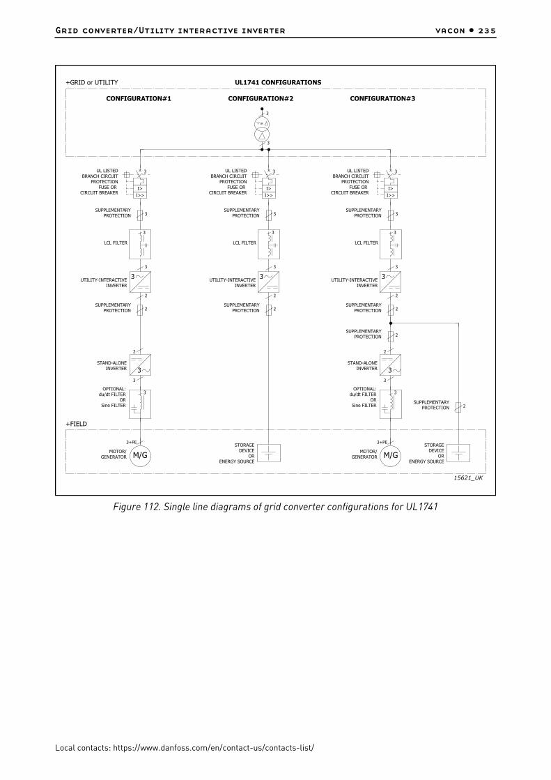
Grid converter/Utility interactive inverter vacon • 235
Local contacts: https://www.danfoss.com/en/contact-us/contacts-list/
Figure 112. Single line diagrams of grid converter configurations for UL1741
15621_UK
M/G
3+PE
3
LCL FILTER
3
MOTOR/
GENERATOR
3
LCL FILTER
CONFIGURATION#1 CONFIGURATION#2
3
3
or
UL1741 CONFIGURATIONS
M/G
3+PE
3
LCL FILTER
3
MOTOR/
GENERATOR
CONFIGURATION#3
UTILITY-INTERACTIVE
INVERTER
3
2
3
SUPPLEMENTARY
PROTECTION 3
STAND-ALONE
INVERTER
2
3
3
UL LISTED
BRANCH CIRCUIT
PROTECTION
FUSE OR
CIRCUIT BREAKERI>>
I>
3
+FIELD
+GRID or UTILITY
OPTIONAL:
du/dt FILTER
OR
Sine FILTER
UTILITY-INTERACTIVE
INVERTER
3
2
3
SUPPLEMENTARY
PROTECTION 3
UL LISTED
BRANCH CIRCUIT
PROTECTION
FUSE OR
CIRCUIT BREAKERI>>
I>
3
STORAGE
DEVICE
OR
ENERGY SOURCE
SUPPLEMENTARY
PROTECTION 2SUPPLEMENTARY
PROTECTION 2
UTILITY-INTERACTIVE
INVERTER
3
2
3
SUPPLEMENTARY
PROTECTION 3
STAND-ALONE
INVERTER
2
3
3
SUPPLEMENTARY
PROTECTION 2
STORAGE
DEVICE
OR
ENERGY SOURCE
SUPPLEMENTARY
PROTECTION 2
UL LISTED
BRANCH CIRCUIT
PROTECTION
FUSE OR
CIRCUIT BREAKERI>>
I>
3
OPTIONAL:
du/dt FILTER
OR
Sine FILTER
SUPPLEMENTARY
PROTECTION 2

vacon • 236 Appendices
Local contacts: https://www.danfoss.com/en/contact-us/contacts-list/
14. APPENDICES
14.1 Appendix 1 - Circuit diagrams
VACON® NX Liquid-Cooled AC drive and inverter main circuit and control diagrams
L1
L2
L3
PE
POWER BOARD
X3
X4
X5W / T3
V / T2
U / T1
X17
J2
J1
J3
X2
B-
B+ / R+
R-
X10
POW
DC -
DC +
MEASUREMENTSDC +DC -
DC-
DC+
R
U
V
W
Skiip81...83AC
Skiip81...83AHB
37
FIBER ADAPTERBOARD
X6
Fanconnector
OPTION BOARD
X1
OPTION BOARDOPTION BOARD OPTION BOARD
X3
(slot B)
X2
(slot A)
X7
CONTROL BOARD
9
X4
(slot C)
X5
(slot D)
ADAPTER BOARD
OPTION BOARD
X6
(slot E)
X1
7
X1
372
CONTROLPANEL
OPTIC FIBRES
External + 24 V
H1...H7
CH3, FC
11405_uk

Appendices vacon • 237
Local contacts: https://www.danfoss.com/en/contact-us/contacts-list/
L1
L2
L3
PE
POWER BOARD
X1
X2
X3
W / T3
V / T2
U / T1
X4
MEASUREMENTSDC +DC -
X5
X6
X11
X1
X6X13
K1 K2 K3X7 X8 X9
RECTIFIER BOARDJ1
X7
X12
U3
U2
U1
K1, K2, K3
6
3
SKiM 4
X6
(slot E)
OPTION BOARDOPTION BOARDOPTION BOARD OPTION BOARD OPTION BOARD
CONTROL BOARD
X3
(slot B)
X5
(slot D)
X4
(slot C)
ADAPTER BOARD
External + 24 V
OPTIC FIBRES
X1
37
X1
2
79
X1 X7
X2
(slot A)
CONTROLPANEL
FIBER ADAPTERBOARD
H1...H7
37
X8
CH4, FC
11406_uk
L1
L2
L3
PE
POWER BOARD
W / T3
V / T2
U / T1
MEASUREMENTSDC +DC -
X4
X1
X6X13
K1 K2 K3
X7 X8 X9
RECTIFIER BOARD
U3
U2
U1
K1, K2, K3
X1
X2
X3
X6
X5
X10 X11 X13
X12
4
3
SKiM 5
2
4
4
4
X1
CONTROLPANEL
OPTION BOARD DRAOB NOITPODRAOB NOITPODRAOB NOITPO
X2
(slot A)
CONTROL BOARD
X7
9
X3
(slot B)
X4
(slot C)
X5
(slot D)
ADAPTER BOARD
OPTION BOARD
OPTIC FIBRES
External + 24 V
X1
X1
X6
(slot E)
372
7
H1...H7
37
X3
+ 24 V
J2
FIBER ADAPTERBOARD
CH5, FC
11407_uk

vacon • 238 Appendices
Local contacts: https://www.danfoss.com/en/contact-us/contacts-list/
1L1
1L2
1L3
PE
X1
X2
X3
X9
X8
FILTER BOARD X13
X41
X6
X4
690 /70CVB00862
X50
X200
X201
PT100
2L1
2L2
2L3
PE
X1
X2
X3
X9
X8
FILTER BOARD X13
X41
X6
X4
690 /70CVB00862
X50
X10024 VDC FanX200
X201
B+
B-
3*2
24 VDC Fan 1 1Pt100 R+
Pt100 RM 2 23 34567 7
654
Pt100 R-FAN +24VDC
FAN GND
FAN1 FB
FAN2 FB
11750_uk
L/C NFE
L1
L2
L3
PE
RECTIFIER BOARD
MEASUREMENT BOARD 1
MAINS VOLTAGESUPERVISION
DRIVER BOARD
MODULE RIGHT SIDE
W / T3
U / T1V / T2
With SPU-024 option only
X1/+: connected to DC+ if SPU-024 not in use
CH61, FC
11408_uk

Appendices vacon • 239
Local contacts: https://www.danfoss.com/en/contact-us/contacts-list/
CONTROL BOARD
OPTION BOARDOPTION BOARDOPTION BOARDOPTION BOARDOPTION BOARD
CONTROLPANEL
OPTOADAPTERBOARD
CONTROL UNIT
ASICBOARD DC +
DC -
RECT / X13
DRIVER / X13
DRIVER / X14
DRIVER / X15
DRIVER / H4
DRIVER / H5
DRIVER / H6
DRIVER / H9
DRIVER / H7
DRIVER / H8
+ 24 V forinternal fans
CH61, FC, CONTROL
x) Cable can be removedif necessary
x)
11409_uk
B+
B-
PEMEASUREMENT BOARD 1
DRIVER BOARD
MODULE RIGHT SIDE
W / T3
U / T1V / T2
With SPU-024 option only
X1/+: connected to B+ if SPU-024 not in use
CH61, INVERTER
11410_uk
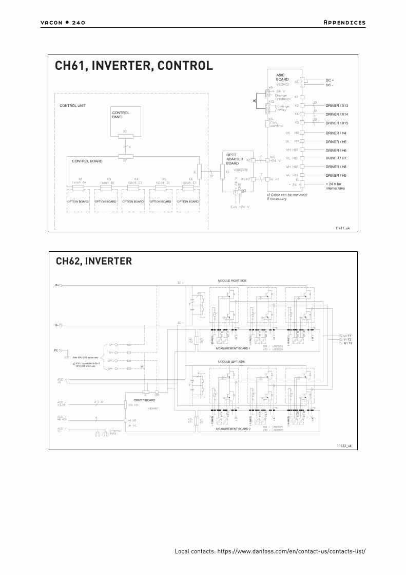
vacon • 240 Appendices
Local contacts: https://www.danfoss.com/en/contact-us/contacts-list/
CONTROL BOARD
OPTION BOARDOPTION BOARDOPTION BOARDOPTION BOARDOPTION BOARD
CONTROLPANEL
OPTOADAPTERBOARD
CONTROL UNIT
ASICBOARD DC +
DC -
DRIVER / X13
DRIVER / X14
DRIVER / X15
DRIVER / H4
DRIVER / H5
DRIVER / H6
DRIVER / H9
DRIVER / H7
DRIVER / H8
+ 24 V forinternal fans
CH61, INVERTER, CONTROL
x)
x) Cable can be removedif necessary
11411_uk
B+
B-
PEMEASUREMENT BOARD 1
MEASUREMENT BOARD 2
DRIVER BOARD
MODULE RIGHT SIDE
MODULE LEFT SIDE
W / T3
U / T1V / T2
With SPU-024 option only
X1/+: connected to B+ if SPU-024 not in use
CH62, INVERTER
11412_uk

Appendices vacon • 241
Local contacts: https://www.danfoss.com/en/contact-us/contacts-list/
CONTROL BOARD
OPTION BOARDOPTION BOARDOPTION BOARDOPTION BOARDOPTION BOARD
CONTROLPANEL
OPTOADAPTERBOARD
CONTROL UNIT
ASICBOARD DC +
DC -
DRIVER / X13
DRIVER / X14
DRIVER / X15
DRIVER / H4
DRIVER / H5
DRIVER / H6
DRIVER / H9
DRIVER / H7
DRIVER / H8
+ 24 V forinternal fans
CH62, INVERTER, CONTROL
x) Cable can be removedif necessary
x)
11413_uk
L1
L2
L3
PE
U / T1
RECTIFIER BOARD
DC+
DC-
MEASUREMENT BOARD 1
MAINS VOLTAGESUPERVISION
DRIVER BOARD U
CH63, FC, MODULE 1
11414_uk

vacon • 242 Appendices
Local contacts: https://www.danfoss.com/en/contact-us/contacts-list/
SPU-024
PE
MEASUREMENT BOARD 3
W / T3
DC+
DC-
V / T2
MEASUREMENT BOARD 2
DRIVER BOARD V DRIVER BOARD W
With
optiononly
X1/+ and X15/+: connected to DC+ if SPU-024 not in use
CH63, FC, MODULE 2
11415_uk
CONTROL BOARD
OPTION BOARDOPTION BOARDOPTION BOARDOPTION BOARDOPTION BOARD
CONTROLPANEL
OPTOADAPTERBOARD
CONTROL UNIT
ASICBOARD DC +
DC -
RECT / X13
DRIVER U / X6
DRIVER V / X2
DRIVER W / X6
DRIVER U / H15
DRIVER U / H16
DRIVER V / H2
DRIVER W / H16
DRIVER V / H4
DRIVER W / H15
Module 2internal fans
CH63, FC, CONTROL
x)
x) Cable can be removedif necessary
11416_uk

Appendices vacon • 243
Local contacts: https://www.danfoss.com/en/contact-us/contacts-list/
PE
U / T1
DC+
DC-
MEASUREMENT BOARD 1
DRIVER BOARD U
B+
B-
CH63, INVERTER, MODULE 1
11417_uk
X1/+ and X15/+:
SPU-024
PE
MEASUREMENT BOARD 3
W / T3
DC+
DC-
V / T2
MEASUREMENT BOARD 2
DRIVER BOARD V DRIVER BOARD W
With
optiononly
connected to DC+ if SPU-024 not in use
CH63, INVERTER, MODULE 2
11418_uk

vacon • 244 Appendices
Local contacts: https://www.danfoss.com/en/contact-us/contacts-list/
CONTROL BOARD
OPTION BOARDOPTION BOARDOPTION BOARDOPTION BOARDOPTION BOARD
CONTROLPANEL
OPTOADAPTERBOARD
CONTROL UNIT
ASICBOARD DC +
DC -
DRIVER U / X6
DRIVER V / X2
DRIVER W / X6
DRIVER U / H15
DRIVER U / H16
DRIVER V / H2
DRIVER W / H16
DRIVER V / H4
DRIVER W / H15
Module 2internal fans
CH63, INVERTER, CONTROL
x)
x) Cable can be removedif necessary
11419_uk
B+
B-
PEMEASUREMENT BOARD 1
MEASUREMENT BOARD 2
DRIVER BOARD
MODULE RIGHT SIDE
MODULE LEFT SIDE
( )U / T1
( )
With SPU-024 option only
X1/+: connected to B+ if SPU-024 not in use
CH64, INVERTER, PHASE U
11420_uk

Appendices vacon • 245
Local contacts: https://www.danfoss.com/en/contact-us/contacts-list/
CONTROL BOARD
OPTION BOARDOPTION BOARDOPTION BOARDOPTION BOARDOPTION BOARD
CONTROLPANEL
OPTOADAPTERBOARD
CONTROL UNIT
ASICBOARD DC +
DC -
DRIVER / X1
DRIVER / H2
DRIVER / H4
DRIVER / X1
DRIVER / H2
DRIVER / H4
DRIVER / H4
DRIVER / X1
DRIVER / H2
PHASEMODULEU
PHASEMODULEV
PHASEMODULEW
CH64, INVERTER, CONTROL
Charge fbx)
x) Cable can be removedif necessary
11421_uk
L1
L2
L3
PE
RECTIFIER BOARD
MEASUREMENT BOARD 1
MAINS VOLTAGESUPERVISION
MEASUREMENT BOARD 2
DRIVER BOARD
MODULE RIGHT SIDE
MODULE LEFT SIDE
W / T3
U / T1V / T2
With SPU-024 option only
X1/+: connected to DC+ if SPU-024 not in use
CH72, FC
11422_uk

vacon • 246 Appendices
Local contacts: https://www.danfoss.com/en/contact-us/contacts-list/
CONTROL BOARD
OPTION BOARDOPTION BOARDOPTION BOARDOPTION BOARDOPTION BOARD
CONTROLPANEL
OPTOADAPTERBOARD
CONTROL UNIT
ASICBOARD DC +
DC -
DRIVER / X13
DRIVER / X14
DRIVER / X15
DRIVER / H4
DRIVER / H5
DRIVER / H6
DRIVER / H9
DRIVER / H7
DRIVER / H8
+ 24 V forinternal fans
RECT / X13
CH72, FC, CONTROL
x)
x) Cable can be removedif necessary
11423_uk
)
L1
L2
L3
PE
RECTIFIER BOARD
MEASUREMENT BOARD 1
MAINS VOLTAGESUPERVISION
MEASUREMENT BOARD 2
DRIVER BOARD
MODULE RIGHT SIDE
MODULE LEFT SIDE
)
U V WX6 ------ X13 X6 ------ X13
X50 X50 X50open open close
) RECT BOARD CONNECTIONS:
( )U / T1
(
With SPU-024 option only
X1/+: connected to DC+ if SPU-024 not in use
CH74, FC, PHASE U
11424_uk

Appendices vacon • 247
Local contacts: https://www.danfoss.com/en/contact-us/contacts-list/
CONTROL BOARD
OPTION BOARDOPTION BOARDOPTION BOARDOPTION BOARDOPTION BOARD
CONTROLPANEL
OPTOADAPTERBOARD
CONTROL UNIT
ASICBOARD DC +
DC -
RECT / X13
DRIVER / X1
DRIVER / H2
DRIVER / H4
DRIVER / X1
DRIVER / H2
DRIVER / H4
DRIVER / H4
DRIVER / X1
DRIVER / H2
PHASEMODULEU
PHASEMODULEV
PHASEMODULEW
CH74, FC, CONTROLCharge fb
x)
x) Cable can be removedif necessary
11425_uk

vacon • 248 Appendices
Local contacts: https://www.danfoss.com/en/contact-us/contacts-list/
14.2 Appendix 2 - OETL, OFAX and charging circuit
OETL2500 + OFAX3 + Charging circuit for VACON® NX Liquid-Cooled inverters 1640_5 to 2300_5 (3 diagrams)
MAIN CIRCUIT
-F2.1-A
1
2
3
4
PE
-M1 M3~
U1
1
V1 W1
2
PE
TH2 /2-5FTH1 /2-5F
-U1
DC+ DC- DC+ DC- DC+ DC-
U W V
X
DC+ DC-
-W1 32 41
11
12
13
14
23
24
-Q1 1
2
3
4
/5-3C DC+
/5-3C DC-
-F1
1
2
3
4
5
6
500V
aux L1 aux L2
400 VAC
Sheet 1
A
B
C
D
E
F
A
B
C
D
E
F
87654321
11426_00

Appendices vacon • 249
Local contacts: https://www.danfoss.com/en/contact-us/contacts-list/
31-X2
-V1K
A
-F31
2
32
3
4
33
35-X2
34
-A1
7
-A16
1
E0.0
-A11
1
+10Vref
1-X2
2
AIA1+
2
3
AIA1-
3
-A12
NXOPTA32RO+PTC
4
AIA2+
4
5
AIA2-
5
6
+24V
6
7
GND
7
21
RO1 NC
21-X2
22
RO1 C
22
23
RO1 NO
23 24
CONTROL UNIT
8
DIN1
8
9
DIN2
9
10
DIN3
10
11
CMA
11
-W13 21
X1
AB
25
RO2 C
CD
26
RO2 NO
X2
ABCD
27
X3
28
TI1+
28
BA
TH1 /1-3FTH2 /1-3F
-W101x(2x0,5)+0,5
1b
-KENTTÄ-Q213
14
-Q1/1-1B
13
14
12
+24V
12
13
GND
13
14
DIN4
14
15
DIN5
15
X6
29
TI1
29
ABCD
-A13
NXOPTA5Encoder I/F
SLOT C
PE PE
-W114x(2+1)x0,5
1r 1b 2r 2b 3r 3b 4b 4r
-B1
2
1
0
1 23 45 67 8 EPEPEP PE
16
DIN6
16
17
CMB
17
18
AOA1+
18
19
AOA1-
19
1 2 3 4 5 6 7 8 9 10
X4
20
DOA1
20
2415
VACON-03-A1: PE
-A2 Vacon
+
-
9
NOT INCLUDED IN DELIVERY
/5-8B
24 VDC SUPPLY
Sheet 2
A
B
C
D
E
F
A
B
C
D
E
F
87654321
11427_00

vacon • 250 Appendices
Local contacts: https://www.danfoss.com/en/contact-us/contacts-list/
-R3
-R4 -K10.1
1L1 2T1-1C13 14 -7B21 22
A1
A2
-K11
121114 -2F
2242 12 -6D
3243 13 -5D
A1
A2
/1-5D CH1
/1-6D CH2
-Q1/1-1B
23
24
-U1.325
26
-K11-8E
12
11
14
-Q4
>I I > I >
1
2
3
4
5
6
-T4
-F44A
1
2
PE
/1-7C AUX (L1)
/1-7C AUX (L2)
25-X2
26-X2
3 101
START4 2
-S1 4
3
0
1
START
1
2-K10.1
-7E
13
14
-K11-8E
22
21
24
-Q1.1A1
A2
-H1DC ready
Head switch in used
1
2
-K11-8E
32
31
34
-K10.2
1L1 2T1-1D13 14 -7C21 22
A1
A2
-K10.2-8E
13
14
-K10.1-7E
1L1
2T1
-K10.2-8E
1L1
2T1
-Q1/1-1B
11
12
spare
Sheet 5
A
B
C
D
E
F
A
B
C
D
E
F
87654321

Appendices vacon • 251
Local contacts: https://www.danfoss.com/en/contact-us/contacts-list/
14.3 Appendix 3 - Fuse sizes
Fuse information: Fuse sizes, Bussman aR fuses
Max fuse ambient temperature +50ºC.
Fuse sizes can differ in the same chassis. Make sure that the Isc of the supply transformer is high enough to burn fuses fast enough.
Check the current rating of the fuse bases according to the input current of the drive.
The physical size of the fuse is chosen on the basis of the fuse current: Current < 400 A (size 2 fuse or smaller), current > 400 A (size 3 fuse).
Table 131. Fuse sizes (Bussman aR) for VACON® NX Liquid-Cooled (500 V) AC drives
Chassis Type Ith[A]
DIN43620DIN43653 (80mm)
DIN43653 (110mm) Fuse
Un[V]
FuseIn
[A]
Qty. of fuses per
phase3~/6~
aR fuse part nr.
Fuse size
aR fuse part nr.
Fuse size
aR fuse part nr.
Fuse size
CH3 0016 16 170M1565 DIN000 170M1415 000T/80 690 63 1
CH3 0022 22 170M1565 DIN000 170M1415 000T/80 690 63 1
CH3 0031 31 170M1565 DIN000 170M1415 000T/80 690 63 1
CH3 0038 38 170M1565 DIN000 170M1415 000T/80 690 63 1
CH3 0045 45 170M1567 DIN000 170M1417 000T/80 690 100 1
CH3 0061 61 170M1567 DIN000 170M1417 000T/80 690 100 1
CH4 0072 72 170M3815 DIN11 170M3065 1*TN/80 170M3215 1*TN/110 690 200 1
CH4 0087 87 170M3815 DIN11 170M3065 1*TN/80 170M3215 1*TN/110 690 200 1
CH4 0105 105 170M3815 DIN11 170M3065 1*TN/80 170M3215 1*TN/110 690 200 1
CH4 0140 140 170M3815 DIN11 170M3065 1*TN/80 170M3215 1*TN/110 690 200 1
CH5 0168 168 170M3819 DIN11 170M3069 1*TN/80 170M3219 1*TN/110 690 400 1
CH5 0205 205 170M3819 DIN11 170M3069 1*TN/80 170M3219 1*TN/110 690 400 1
CH5 0261 261 170M3819 DIN11 170M3069 1*TN/80 170M3219 1*TN/110 690 400 1
CH61 0300 300 170M5813 DIN2 170M5063 2TN/80 170M5213 2TN/110 690 700 1
CH61 0385 385 170M5813 DIN2 170M5063 2TN/80 170M5213 2TN/110 690 700 1
CH72 0460 460 170M6814 DIN3 170M6064 3TN/80 170M6214 3TN/110 690 1000 1
CH722 0460 460 170M6813 DIN2 170M5063 2TN/80 170M5213 2TN/110 690 700 1
CH72 0520 520 170M6814 DIN3 170M6064 3TN/80 170M6214 3TN/110 690 1000 1
CH722 0520 520 170M6813 DIN2 170M5063 2TN/80 170M5213 2TN/110 690 700 1
CH72 0590 590 170M6814 DIN3 170M6064 3TN/80 170M6214 3TN/110 690 1000 1
CH722 0590 590 170M6813 DIN2 170M5063 2TN/80 170M5213 32N/110 690 700 1
CH72 0650 650 170M8547 3SHT3 170M6066 3TN/80 170M6216 3TN/110 690 1250 1
CH722 0650 650 170M5813 DIN2 170M5063 2TN/80 170M5213 2TN/110 690 700 1
CH72 0730 730 170M8547 3SHT3 170M6066 3TN/80 170M6216 3TN/110 690 1250 1
CH722 0730 730 170M5813 DIN2 170M5063 2TN/80 170M5213 2TN/110 690 700 1
CH63 0820 820 170M6812 DIN3 170M6062 3TN/80 170M6212 3TN/110 690 800 2
CH63 0920 920 170M6812 DIN3 170M6062 3TN/80 170M6212 3TN/110 690 800 2
CH63 1030 1030 170M6814 DIN3 170M6064 3TN/80 170M6214 3TN/110 690 1000 2
CH63 1150 1150 170M6814 DIN3 170M6064 3TN/80 170M6214 3TN/110 690 1000 2

vacon • 252 Appendices
Local contacts: https://www.danfoss.com/en/contact-us/contacts-list/
____________________________1 Tj = 25°C
2 Data in Italic refer to drives with 12-pulse supply
3 SHT fuses can be assembled into DIN fuse base of the corresponding size
CH74 1370 1370 170M6814 DIN3 170M6064 3TN/80 170M6214 3TN/110 690 1000 3
CH742 1370 1370 170M6812 DIN3 170M6062 3TN/80 170M6212 3TN/110 690 800 2
CH74 1640 1640 170M6814 DIN3 170M6064 3TN/80 170M6214 3TN/110 690 1000 3
CH742 1640 1640 170M6812 DIN3 170M6062 3TN/80 170M6212 3TN/110 690 800 2
CH74 2060 2060 170M8547 3SHT3 170M6066 3TN/80 170M6216 3TN/110 690 1250 3
CH742 2060 2060 170M6814 DIN3 170M6064 3TN/80 170M6214 3TN/110 690 1000 2
CH74 2300 2300 170M8547 3SHT3 170M6066 3TN/80 170M6216 3TN/110 690 1250 3
CH742 2300 2300 170M6814 DIN3 170M6064 3TN/80 170M6214 3TN/110 690 1000 2
Table 132. Fuse sizes (Bussman aR) for VACON® NX Liquid-Cooled (690 V) AC drives
Chassis Type Ith[A]
DIN43620DIN43653 (80mm)
DIN43653 (110mm) Fuse
Un[V]
FuseIn
[A]
Qty. of fuses per
phase3~/6~
aR fuse part nr.
Fuse size
aR fuse part nr.
Fuse size
aR fuse part nr.
Fuse size
CH61 0170 170 170M3819 DIN11 170M3069 1*TN/80 170M3219 1*TN/110 690 400 1
CH61 0208 208 170M3819 DIN11 170M3069 1*TN/80 170M3219 1*TN/110 690 400 1
CH61 0261 261 170M3819 DIN11 170M3069 1*TN/80 170M3219 1*TN/110 690 400 1
CH72 0325 325 170M5813 DIN2 170M5063 2TN/80 170M5213 2TN/110 690 700 1
CH722 0325 325 170M3819 DIN11 170M3069 1*TN/80 170M3219 1*TN/110 690 400 1
CH72 0385 385 170M5813 DIN2 170M5063 2TN/80 170M5213 2TN/110 690 700 1
CH722 0385 385 170M3819 DIN11 170M3069 1*TN/80 170M3219 1*TN/110 690 400 1
CH72 0416 416 170M6812 DIN3 170M6062 3TN/80 170M6212 3TN/110 690 800 1
CH722 0416 416 170M3819 DIN11 170M3069 1*TN/80 170M3219 1*TN/110 690 400 1
CH72 0460 460 170M6812 DIN3 170M6062 3TN/80 170M6212 3TN/110 690 800 1
CH722 0460 460 170M3819 DIN11 170M3069 1*TN/80 170M3219 1*TN/110 690 400 1
CH72 0502 502 170M6812 DIN3 170M6062 3TN/80 170M6212 3TN/110 690 800 1
CH722 0502 502 170M3819 DIN11 170M3069 1*TN/80 170M3219 1*TN/110 690 400 1
CH63 0590 590 170M6814 DIN3 170M6064 3TN/80 170M6214 3TN/110 690 1100 1
CH63 0650 650 170M8547 3SHT3 170M6066 3TN/80 170M6216 3TN/110 690 1250 1
CH63 0750 750 170M8547 3SHT3 170M6066 3TN/80 170M6216 3TN/110 690 1250 1
CH74 0820 820 170M5813 DIN2 170M5063 2TN/80 170M5213 2TN/110 690 700 3
CH742 0820 820 170M6812 DIN3 170M6062 3TN/80 170M6212 3TN/110 690 800 1
CH74 0920 920 170M5813 DIN2 170M5063 2TN/80 170M5213 2TN/110 690 700 3
Table 131. Fuse sizes (Bussman aR) for VACON® NX Liquid-Cooled (500 V) AC drives
Chassis Type Ith[A]
DIN43620DIN43653 (80mm)
DIN43653 (110mm) Fuse
Un[V]
FuseIn
[A]
Qty. of fuses per
phase3~/6~
aR fuse part nr.
Fuse size
aR fuse part nr.
Fuse size
aR fuse part nr.
Fuse size

Appendices vacon • 253
Local contacts: https://www.danfoss.com/en/contact-us/contacts-list/
____________________________1 Tj = 25°C
2 Data in Italic refer to drives with 12-pulse supply
3 SHT fuses can be assembled into DIN fuse base of the corresponding size
CH742 0920 920 170M6812 DIN3 170M6062 3TN/80 170M6212 3TN/110 690 800 1
CH74 1030 1030 170M5813 DIN2 170M5063 2TN/80 170M5213 2TN/110 690 700 3
CH742 1030 1030 170M6814 DIN3 170M6064 3TN/80 170M6214 3TN/110 690 1000 1
CH74 1180 1180 170M5813 DIN2 170M5063 2TN/80 170M5213 2TN/110 690 700 3
CH742 1180 1180 170M6814 DIN3 170M6064 3TN/80 170M6214 3TN/110 690 1000 1
CH74 1300 1300 170M6814 DIN3 170M6064 3TN/80 170M6214 3TN/110 690 1000 3
CH742 1300 1300 170M8547 3SHT3 170M6066 3TN/80 170M6216 3TN/110 690 1250 1
CH74 1500 1500 170M6814 DIN3 170M6064 3TN/80 170M6214 3TN/110 690 1000 3
CH742 1500 1500 170M8547 3SHT3 170M6066 3TN/80 170M6216 3TN/110 690 1250 1
CH74 1700 1700 170M6814 DIN3 170M6064 3TN/80 170M6214 3TN/110 690 1000 3
CH742 1700 1700 170M6812 DIN3 170M6064 3TN/80 170M6212 3TN/110 690 800 1
Table 132. Fuse sizes (Bussman aR) for VACON® NX Liquid-Cooled (690 V) AC drives
Chassis Type Ith[A]
DIN43620DIN43653 (80mm)
DIN43653 (110mm) Fuse
Un[V]
FuseIn
[A]
Qty. of fuses per
phase3~/6~
aR fuse part nr.
Fuse size
aR fuse part nr.
Fuse size
aR fuse part nr.
Fuse size

vacon • 254 Appendices
Local contacts: https://www.danfoss.com/en/contact-us/contacts-list/
______________________________________
1 Tj = 25°C
2 SHT fuses can be assembled into DIN fuse base of the corresponding size
Table 133. Fuse sizes (Bussman aR) for VACON® NX Liquid-Cooled (450—800 V) inverters
Chassis TypeIth[A]
DIN43620DIN43653 (80mm)
DIN43653 (110mm) Fuse
Un[V]
FuseIn
[A]
Qty. of fuses/ poleaR fuse
part nr.Fuse size
aR fuse part nr
Fuse size
aR fuse part nr.
Fuse size
CH3 0016 16 170M3810 DIN11 170M3060 1*TN/80 170M3210 1*TN/110 690 63 1
CH3 0022 22 170M3810 DIN11 170M3060 1*TN/80 170M3210 1*TN/110 690 63 1
CH3 0031 31 170M3810 DIN11 170M3060 1*TN/80 170M3210 1*TN/110 690 63 1
CH3 0038 38 170M3813 DIN11 170M3063 1*TN/80 170M3213 1*TN/110 690 125 1
CH3 0045 45 170M3813 DIN11 170M3063 1*TN/80 170M3213 1*TN/110 690 125 1
CH3 0061 61 170M3813 DIN11 170M3063 1*TN/80 170M3213 1*TN/110 690 125 1
CH4 0072 72 170M3815 DIN11 170M3063 1*TN/80 170M3213 1*TN/110 690 200 1
CH4 0087 87 170M3815 DIN11 170M3065 1*TN/80 170M3215 1*TN/110 690 200 1
CH4 0105 105 170M3815 DIN11 170M3065 1*TN/80 170M3215 1*TN/110 690 200 1
CH4 0140 140 170M3819 DIN11 170M3069 1*TN/80 170M3219 1*TN/110 690 400 1
CH5 0168 168 170M3819 DIN11 170M3069 1*TN/80 170M3219 1*TN/110 690 400 1
CH5 0205 205 170M3819 DIN11 170M3069 1*TN/80 170M3219 1*TN/110 690 400 1
CH5 0261 261 170M6808 DIN3 170M6058 3TN/80 170M6208 3TN/110 690 500 1
CH61 0300 300 170M6812 DIN3 170M6062 3TN/80 170M6212 3TN/110 690 800 1
CH61 0385 385 170M6812 DIN3 170M6062 3TN/80 170M6212 3TN/110 690 800 1
CH62 0460 460 170M6814 DIN3 170M6064 3TN/80 170M6214 3TN/110 690 1000 1
CH62 0520 520 170M6814 DIN3 170M6064 3TN/80 170M6214 3TN/110 690 1000 1
CH62 0590 590 170M6812 DIN3 170M6062 3TN/80 170M6212 3TN/110 690 800 2
CH62 0650 650 170M6812 DIN3 170M6062 3TN/80 170M6212 3TN/110 690 800 2
CH62 0730 730 170M6812 DIN3 170M6062 3TN/80 170M6212 3TN/110 690 800 2
CH63 0820 820 170M6814 DIN3 170M6064 3TN/80 170M6214 3TN/110 690 1000 2
CH63 0920 920 170M6814 DIN3 170M6064 3TN/80 170M6214 3TN/110 690 1000 2
CH63 1030 1030 170M6812 DIN3 170M6062 3TN/80 170M6212 3TN/110 690 800 3
CH63 1150 1150 170M6812 DIN3 170M6062 3TN/80 170M6212 3TN/110 690 800 3
CH64 1370 1370 170M8547 3SHT2 170M6066 3TN/80 170M6216 3TN/110 690 1250 3
CH64 1640 1640 170M8547 3SHT2 170M6066 3TN/80 170M6216 3TN/110 690 1250 3
CH64 2060 2060 170M8550 3SHT2 170M6069 3TN/80 170M6219 3TN/110 690 1600 3
CH64 2300 2300 170M8550 3SHT2 170M6069 3TN/80 170M6219 3TN/110 690 1600 3

Appendices vacon • 255
Local contacts: https://www.danfoss.com/en/contact-us/contacts-list/
1 SHT fuses can be assembled into DIN fuse base of the corresponding size
Fuse sizes (Bussman aR) for VACON® NX Liquid-Cooled (640—1100 V) inverters
Chassis TypeIth[A]
DIN43620 DIN43653 (110mm)Fuse Un [V]
FuseIn [A]
Qty. of fuses/ poleaR fuse
part nr.Fuse size1
aR fuse part nr.
Fuse size
CH61 0170 170 170M4199 1SHT 170M4985 1TN/110 1250 400 1
CH61 0208 208 170M4199 1SHT 170M4985 1TN/110 1250 400 1
CH61 0261 261 170M6202 3SHT 170M8633 3TN/110 1250 500 1
CH62 0325 325 170M6305 3SHT 170M8636 3TN/110 1250 700 1
CH62 0385 385 170M6305 3SHT 170M8636 3TN/110 1250 700 1
CH62 0416 416 170M6277 3SHT 170M8639 3TN/110 1100 1000 1
CH62 0460 460 170M6277 3SHT 170M8639 3TN/110 1100 1000 1
CH62 0502 502 170M6277 3SHT 170M8639 3TN/110 1100 1000 1
CH63 0590 590 170M6305 3SHT 170M8636 3TN/110 1250 700 2
CH63 0650 650 170M6305 3SHT 170M8636 3TN/110 1250 700 2
CH63 0750 750 170M6305 3SHT 170M8636 3TN/110 1250 700 2
CH64 0820 820 170M6277 3SHT 170M8639 3TN/110 1100 1000 2
CH64 0920 920 170M6277 3SHT 170M8639 3TN/110 1100 1000 2
CH64 1030 1030 170M6277 3SHT 170M8639 3TN/110 1100 1000 3
CH64 1180 1180 170M6277 3SHT 170M8639 3TN/110 1100 1000 3
CH64 1300 1300 170M6277 3SHT 170M8639 3TN/110 1100 1000 3
CH64 1500 1500 170M6277 3SHT 170M8639 3TN/110 1100 1000 3
CH64 1700 1700 170M6277 3SHT 170M8639 3TN/110 1100 1000 3
Table 134. Fuse sizes (Bussman aR) for VACON® NX AFE units (380—500 V)
Chassis TypeIth[A]
DIN43620DIN43653 (80mm)
DIN43653 (110mm) Fuse
Un[V]
FuseIn
[A]
Qty. of fuses /
phase 3~aR fuse part nr.
Fuse size1
aR fuse part nr.
Fuse size1
aR fuse part nr.
Fuse size1
CH3 0016 16 170M2679 DIN00 170M4828 00TN/80 1000 63 1
CH3 0022 22 170M2679 DIN00 170M4828 00TN/80 1000 63 1
CH3 0031 31 170M2679 DIN00 170M4828 00TN/80 1000 63 1
CH3 0038 38 170M2679 DIN00 170M4828 00TN/80 1000 63 1
CH3 0045 45 170M2683 DIN00 170M4832 00TN/80 1000 160 1
CH3 0061 61 170M2683 DIN00 170M4832 00TN/80 1000 160 1
CH4 0072 72 170M2683 DIN00 170M4832 00TN/80 1000 160 1
CH4 0087 87 170M2683 DIN00 170M4832 00TN/80 1000 16 1
CH4 0105 105 170M2683 DIN00 170M4832 00TN/80 1000 160 1
CH4 0140 140 170M4199 1SHT 170M4985 1TN/110 1250 400 1
CH5 0168 168 170M4199 1SHT 170M4985 1TN/110 1250 400 1
CH5 0205 205 170M4199 1SHT 170M4985 1TN/110 1250 400 1
CH5 0261 261 170M4199 1SHT 170M4985 1TN/110 1250 400 1
CH61 0300 300 170M6202 3SHT 170M8633 3TN/110 1250 500 1
CH61 0385 385 170M6305 3SHT 170M8636 3TN/110 1250 700 1

vacon • 256 Appendices
Local contacts: https://www.danfoss.com/en/contact-us/contacts-list/
____________________________1 SHT fuses can be assembled into DIN fuse base of the corresponding size
1 SHT fuses can be assembled into DIN fuse base of the corresponding size
CH62 0460 460 170M6277 3SHT 170M8639 3TN/110 1100 1000 1
CH62 0520 520 170M6277 3SHT 170M8639 3TN/110 1100 1000 1
CH62 0590 590 170M6277 3SHT 170M8639 3TN/110 1100 1000 1
CH62 0650 650 170M6305 3SHT 170M8636 3TN/110 1250 700 2
CH62 0730 730 170M6305 3SHT 170M8636 3TN/110 1250 700 2
CH63 0820 820 170M6305 3SHT 170M8636 3TN/110 1250 700 2
CH63 0920 920 170M6277 3SHT 170M8639 3TN/110 1100 1000 2
CH63 1030 1030 170M6277 3SHT 170M8639 3TN/110 1100 1000 2
CH63 1150 1150 170M6277 3SHT 170M8639 3TN/110 1100 1000 2
CH64 1370 1370 170M6277 3SHT 170M8639 3TN/110 1100 1000 3
CH64 1640 1640 170M6277 3SHT 170M8639 3TN/110 1100 1000 3
CH64 2060 2060 170M6277 3SHT 170M8639 3TN/110 1100 1000 4
CH64 2300 2300 170M6277 3SHT 170M8639 3TN/110 1100 1000 4
Table 135. Fuse sizes (Bussman aR) for VACON® NX AFE units (525—690 V)
ChassisType Ith
[A]
DIN43620 DIN43653 (110mm)Fuse Un [V]
FuseIn [A]
Qty. of fuses /
phase 3~aR fuse part nr.
Fuse size1
aR fuse part nr.
Fuse size1
CH61 0170 170 170M4199 1SHT 170M4985 1TN/110 1250 400 1
CH61 0208 208 170M4199 1SHT 170M4985 1TN/110 1250 400 1
CH61 0261 261 170M4199 1SHT 170M4985 1TN/110 1250 400 1
CH62 0325 325 170M6305 3SHT 170M8636 3TN/110 1250 700 1
CH62 0385 385 170M6305 3SHT 170M8636 3TN/110 1250 700 1
CH62 0416 416 170M6305 3SHT 170M8636 3TN/110 1250 700 1
CH62 0460 460 170M6277 3SHT 170M8639 3TN/110 1100 1000 1
CH62 0502 502 170M6277 3SHT 170M8639 3TN/110 1100 1000 1
CH63 0590 590 170M6277 3SHT 170M8639 3TN/110 1100 1000 1
CH63 0650 650 170M6305 3SHT 170M8636 3TN/110 1250 700 2
CH63 0750 750 170M6305 3SHT 170M8636 3TN/110 1250 700 2
CH64 0820 820 170M6305 3SHT 170M8636 3TN/110 1250 700 2
CH64 0920 920 170M6277 3SHT 170M8639 3TN/110 1100 1000 2
CH64 1030 1030 170M6277 3SHT 170M8639 3TN/110 1100 1000 2
CH64 1180 1180 170M6277 3SHT 170M8639 3TN/110 1100 1000 2
CH64 1300 1300 170M6305 3SHT 170M8636 3TN/110 1250 700 3
CH64 1500 1500 170M6277 3SHT 170M8639 3TN/110 1100 1000 3
Table 134. Fuse sizes (Bussman aR) for VACON® NX AFE units (380—500 V)
Chassis TypeIth[A]
DIN43620DIN43653 (80mm)
DIN43653 (110mm) Fuse
Un[V]
FuseIn
[A]
Qty. of fuses /
phase 3~aR fuse part nr.
Fuse size1
aR fuse part nr.
Fuse size1
aR fuse part nr.
Fuse size1

Appendices vacon • 257
Local contacts: https://www.danfoss.com/en/contact-us/contacts-list/
_________________________1 SHT fuses can be assembled into DIN fuse base of the corresponding size
Table 136. Brake chopper unit fuse selection (Bussman aR), mains voltage 465–800 Vdc
Chassis TypeMin resistor
value, 2* [ohm]
Braking current
DIN43620Fuse Un [V]
FuseIn [A]
Qty. of fuses per
poleaR fuse part nr.
Fuse size1
CH3 0016 52.55 32 170M2679 DIN00 690 63 1
CH3 0022 38.22 44 170M2679 DIN00 690 63 1
CH3 0031 27.12 62 170M2679 DIN00 690 63 1
CH3 0038 22.13 76 170M2679 DIN00 690 63 1
CH3 0045 18.68 90 170M2683 DIN00 690 160 1
CH3 0061 13.78 122 170M2683 DIN00 690 160 1
CH4 0072 11.68 144 170M2683 DIN00 690 160 1
CH4 0087 9.66 174 170M2683 DIN00 690 160 1
CH4 0105 8.01 210 170M2683 DIN00 690 160 1
CH4 0140 6.01 280 170M4199 1SHT 690 400 1
CH5 0168 5.00 336 170M4199 1SHT 690 400 1
CH5 0205 4.10 410 170M4199 1SHT 690 400 1
CH5 0261 3.22 522 170M4199 1SHT 690 400 1
CH61 0300 2.80 600 170M6202 3SHT 690 500 1
CH61 0385 2.18 770 170M6305 3SHT 690 700 2
CH62 0460 1.83 920 170M6277 3SHT 690 1000 2
CH62 0520 1.62 1040 170M6277 3SHT 690 1000 2
CH62 0590 1.43 1180 170M6277 3SHT 690 1000 2
CH62 0650 1.29 1300 170M6305 3SHT 690 700 3
CH62 0730 1.15 1460 170M6305 3SHT 690 700 3
Table 137. Brake chopper unit fuse selection (Bussman aR), mains voltage 640–1100 Vdc
Chassis TypeMin resistor
value, 2* [ohm]Brakingcurrent
DIN43620 Fuse Un[V]
FuseIn
[A]
Qty. of fuses
per poleaR fuse part nr.
Fuse size1
CH61 0170 6.51 340 170M6305 3SHT 1250 700 1
CH61 0170* 80 27 170M2679 DIN00 1000 63 1
CH61 0208 5.32 416 170M6277 3SHT 1250 1000 1
CH61 0208* 30 73 170M2683 DIN00 1000 160 1
CH61 0261 4.24 522 170M6277 3SHT 1250 1000 1
CH61 0261* 12 183 170M4199 1SHT 1250 400 1
CH62 0310 3.41 650 170M6305 3SHT 1250 700 2
CH62 0385 2.88 770 170M6277 3SHT 1250 1000 2
CH62 0416 2.66 832 170M6277 3SHT 1250 1000 2
CH62 0460 2.41 920 170M6277 3SHT 1250 1000 2
CH62 0502 2.21 1004 170M6277 3SHT 1250 1000 2

vacon • 258 Appendices
Local contacts: https://www.danfoss.com/en/contact-us/contacts-list/
14.4 Appendix 4 - Power conversion equipment
14.4.1 Technical data
Table 138. Additional technical specifications for VACON® Active Front End units used in grid converter applications
DC connection
Operating voltageNXA_xxxx5: 465-800 V DCNXA_xxxx6: 640-1100 V DC
Maximum operating DC current See Chapter 14.4.2.
ISC
85 kA when fuses are used as per the fuse tables for grid converters with circuit breaker, busbar, busbar supports, enclo-sures, etc., which are sized for 85 kA based on relevant installation standards.
Maximum inverter backfeed cur-rent to the DC load
Depends on the DC fuse rating.See Chapter 14.3.
Minimum DC voltage for inverter to begin operation
The DC link must be charged up to 85% of nominal DC voltage (1.35 × grid nominal VAC)
AC connection
Nominal voltage See Chapter 14.4.2.
Current (maximum continuous) See Chapter 14.4.2.
Inrush current
Duration: < 10 msPeak value: Depends on the short circuit capacity of the grid (grid impedance), grid voltage, RLC filter/LC filter, etc.
Frequency See Chapter 14.4.2.
Power (maximum continuous) See Chapter 14.4.2.
Power factor range
-0.95...+0.95 with 100% active power.Other power factor values depend on the selected control mode.See the application manual for details.
Maximum output fault current
The value depends on grid impedance and the fuse I²t value. The maximum output current (from the inverter to the grid) is limited by the fast overcurrent protection, the software overcurrent protection, or the output current limit of the inverter. If the fault occurs upstream of the AC fuses, one of these limits the current from the inverter to the fault.
Maximum output overcurrent protection
Depends on the AC fuse rating.See Chapter 14.3.

Appendices vacon • 259
Local contacts: https://www.danfoss.com/en/contact-us/contacts-list/
* See the Grid converter application manuals (DPD01599 and DPD01978) and the reference design for more specific information.
14.4.2 Power ratings
External isolation transformer
(not in the scope of Danfoss supply)
Configuration type
Delta-connection on the converter side is recommended. For other configurations, please contact local Danfoss representa-tives for further assistance.
Electrical ratings *
• The transformer’s secondary nominal voltage must be selected according to load DC voltage variation and/or grid code requirements. Refer to the design guide (DPD02146) or a local Danfoss representative for further assistance.
• Rated Power of the transformer must be similar or higher than the maximum power of the inverter or group of inverters.
• Frequency: 50/60 Hz• Transformer must indicate losses and
SC current.• Transformer secondary winding
impedance must be ≥ 4%, if LC filter is used
Environmental ratings
Must be based on the installation location, end user requirements, compliance with applicable safety standards and direc-tives, etc.
Ambient conditionsEnclosure class IP00
Pollution degree 2
Protection
Over voltage category OVC III
Protection class(IEC 61140)
Class I
Table 139. AC output/AC input ratings for VACON® Active Front End units used in grid converter applications
CodeEnclosure
size
Voltage nominal*
[V AC]
Current [A AC]
Frequency nominal
[Hz]
Frequency range[Hz]
Power at pf 1.0[kW]
NXA_0168 5 CH5 400 140 50 50/60 97
NXA_0205 5 CH5 400 170 50 50/60 118
NXA_0261 5 CH5 400 205 50 50/60 142
NXA_0300 5 CH61 400 261 50 50/60 181
NXA_0385 5 CH61 400 300 50 50/60 208
NXA_0460 5 CH62 400 385 50 50/60 267
NXA_0520 5 CH62 400 460 50 50/60 319
NXA_0590 5 CH62 400 520 50 50/60 360
Table 138. Additional technical specifications for VACON® Active Front End units used in grid converter applications

vacon • 260 Appendices
Local contacts: https://www.danfoss.com/en/contact-us/contacts-list/
* Voltage range: see the Design guide (DPD02146) and the VACON® Select web tool.
NXA_0650 5 CH62 400 590 50 50/60 409
NXA_0730 5 CH62 400 650 50 50/60 450
NXA_0820 5 CH63 400 730 50 50/60 506
NXA_0920 5 CH63 400 820 50 50/60 568
NXA_1030 5 CH63 400 920 50 50/60 637
NXA_1150 5 CH63 400 1030 50 50/60 714
NXA_1370 5 CH64 400 1150 50 50/60 797
NXA_1640 5 CH64 400 1370 50 50/60 949
NXA_2060 5 CH64 400 1640 50 50/60 1136
NXA_2300 5 CH64 400 2060 50 50/60 1427
NXA_0170 6 CH61 600 144 50 50/60 150
NXA_0208 6 CH61 600 170 50 50/60 177
NXA_0261 6 CH61 600 208 50 50/60 216
NXA_0325 6 CH62 600 261 50 50/60 271
NXA_0385 6 CH62 600 325 50 50/60 338
NXA_0416 6 CH62 600 385 50 50/60 338
NXA_0460 6 CH62 600 416 50 50/60 400
NXA_0502 6 CH62 600 460 50 50/60 478
NXA_0590 6 CH63 600 502 50 50/60 522
NXA_0650 6 CH63 600 590 50 50/60 613
NXA_0750 6 CH63 600 650 50 50/60 675
NXA_0820 6 CH64 600 750 50 50/60 779
NXA_0920 6 CH64 600 820 50 50/60 852
NXA_1030 6 CH64 600 920 50 50/60 956
NXA_1180 6 CH64 600 1030 50 50/60 1070
NXA_1300 6 CH64 600 1180 50 50/60 1226
NXA_1500 6 CH64 600 1300 50 50/60 1351
NXA_1700 6 CH64 600 1500 50 50/60 1559
Table 140. DC input/DC output ratings for VACON® Active Front End units used in grid converter applications
CodeEnclosure
sizeVoltage nominal at
nominal AC [V DC] *Voltage range
[V DC]Current maximum continuous [A DC]
NXA_0168 5 CH5 630 465-800 154
NXA_0205 5 CH5 630 465-800 187
NXA_0261 5 CH5 630 465-800 225
Table 139. AC output/AC input ratings for VACON® Active Front End units used in grid converter applications
CodeEnclosure
size
Voltage nominal*
[V AC]
Current [A AC]
Frequency nominal
[Hz]
Frequency range[Hz]
Power at pf 1.0[kW]

Appendices vacon • 261
Local contacts: https://www.danfoss.com/en/contact-us/contacts-list/
* 1.575 x nominal AC voltage. The value 1.575 comes from the ratio 1.5 (√2 + control margin) between the DC link and INU side, plus 5% filter losses.
NXA_0300 5 CH61 630 465-800 287
NXA_0385 5 CH61 630 465-800 330
NXA_0460 5 CH62 630 465-800 423
NXA_0520 5 CH62 630 465-800 506
NXA_0590 5 CH62 630 465-800 572
NXA_0650 5 CH62 630 465-800 649
NXA_0730 5 CH62 630 465-800 715
NXA_0820 5 CH63 630 465-800 803
NXA_0920 5 CH63 630 465-800 902
NXA_1030 5 CH63 630 465-800 1012
NXA_1150 5 CH63 630 465-800 1133
NXA_1370 5 CH64 630 465-800 1265
NXA_1640 5 CH64 630 465-800 1507
NXA_2060 5 CH64 630 465-800 1804
NXA_2300 5 CH64 630 465-800 2265
NXA_0170 6 CH61 945 640-1100 158
NXA_0208 6 CH61 945 640-1100 187
NXA_0261 6 CH61 945 640-1100 229
NXA_0325 6 CH62 945 640-1100 287
NXA_0385 6 CH62 945 640-1100 357
NXA_0416 6 CH62 945 640-1100 357
NXA_0460 6 CH62 945 640-1100 423
NXA_0502 6 CH62 945 640-1100 506
NXA_0590 6 CH63 945 640-1100 552
NXA_0650 6 CH63 945 640-1100 649
NXA_0750 6 CH63 945 640-1100 715
NXA_0820 6 CH64 945 640-1100 825
NXA_0920 6 CH64 945 640-1100 902
NXA_1030 6 CH64 945 640-1100 1012
NXA_1180 6 CH64 945 640-1100 1133
NXA_1300 6 CH64 945 640-1100 1298
NXA_1500 6 CH64 945 640-1100 1430
NXA_1700 6 CH64 945 640-1100 1650
Table 140. DC input/DC output ratings for VACON® Active Front End units used in grid converter applications
CodeEnclosure
sizeVoltage nominal at
nominal AC [V DC] *Voltage range
[V DC]Current maximum continuous [A DC]

Document ID:
DPD00887IRev. I
Sales code: DOC-INSNXPLC-10+DLUK
Vacon LtdMember of the Danfoss GroupRunsorintie 765380 VaasaFinland
www.danfoss.com