nx nastran model checks | ata engineering
TRANSCRIPT

www.ata-plmsoftware.com844-756-7638 (844-PLM-SOFT)
WHITEPAPER
NX Nastran Model Checks
NX Nastran 9
ATA Engineering NX Nastran 9
NX Nastran Model Checks
Content subject to change without notice. © 2018 ATA Engineering, Inc. NX Nastran is a trademark of Siemens PLM Software, Inc.
Overview
Your finite element analysis results are only as good as the model on which they are based, and understanding the numerical conditioning of your model is critical to ensuring high-quality results. This paper explains key modeling checks to help you build confidence in your results and make better engineering decisions.
Software:NX Nastran 9
This whitepaper is part of a series of free Siemens PLM Software training resources provided by ATA. For more whitepapers, tutorials, videos, and macros, visit ATA’s PLM Software website: http://www.ata-plmsoftware.com/resources.
ATA Engineering NX Nastran 9
NX Nastran Model Checks
1 Content subject to change without notice. © 2018 ATA Engineering, Inc. NX Nastran is a trademark of Siemens PLM Software, Inc.
Six Essential NX Nastran Model Checks
Below are six essential quality checks you should perform when working with a finite element model. These checks are designed to assess the numerical conditioning of your model. This paper discusses each check.
1. Check for grounding2. Check for the presence of six rigid body modes3. Check the weight4. Check the element shape quality5. Check stiffness matrix singularity6. Check forward-backward substitution residual
Grounding Check
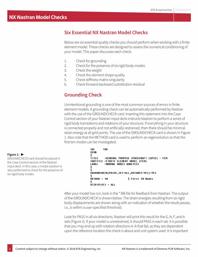
Unintentional grounding is one of the most common sources of errors in finite element models. A grounding check can be automatically performed by Nastran with the use of the GROUNDCHECK card. Inserting this statement into the Case Control section of your Nastran input deck instructs Nastran to perform a series of rigid body translations and rotations of your structure. If everything in your structure is connected properly and not artificially restrained, then there should be minimal strain energy at all grid points. The use of the GROUNDCHECK card is shown in Figure 1. Also note that the METHOD card is used to perform an eigensolution so that the first ten modes can be investigated.
After your model has run, look in the *.f06 file for feedback from Nastran. The output of the GROUNDCHECK is shown below. The strain energies resulting from six rigid body displacements are shown along with an indication of whether the result passes, i.e., is within a user-specified threshold.
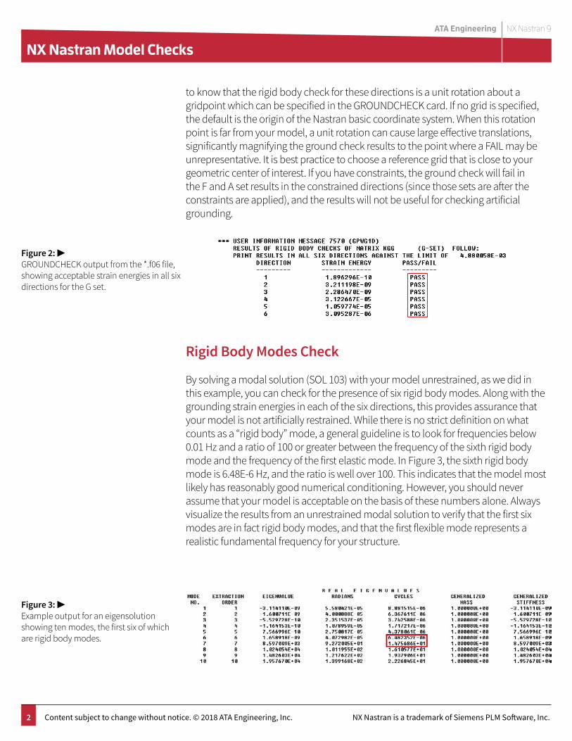
Look for PASS in all six directions. Nastran will print this result for the G, N, F, and A sets (Figure 2). If your model is unrestrained, it should PASS in each set. It is possible that you may end up with rotation directions 4–6 that fail, as they are dependent upon the reference location the check is about and unit system used. It is important
Figure 1: ▶ GROUNDCHECK card should be placed in the Case Control section of the Nastran input deck. In this case, a modal solution is also performed to check for the presence of six rigid body modes.
ATA Engineering NX Nastran 9
NX Nastran Model Checks
2 Content subject to change without notice. © 2018 ATA Engineering, Inc. NX Nastran is a trademark of Siemens PLM Software, Inc.
to know that the rigid body check for these directions is a unit rotation about a gridpoint which can be specified in the GROUNDCHECK card. If no grid is specified, the default is the origin of the Nastran basic coordinate system. When this rotation point is far from your model, a unit rotation can cause large effective translations, significantly magnifying the ground check results to the point where a FAIL may be unrepresentative. It is best practice to choose a reference grid that is close to your geometric center of interest. If you have constraints, the ground check will fail in the F and A set results in the constrained directions (since those sets are after the constraints are applied), and the results will not be useful for checking artificial grounding.
Rigid Body Modes Check
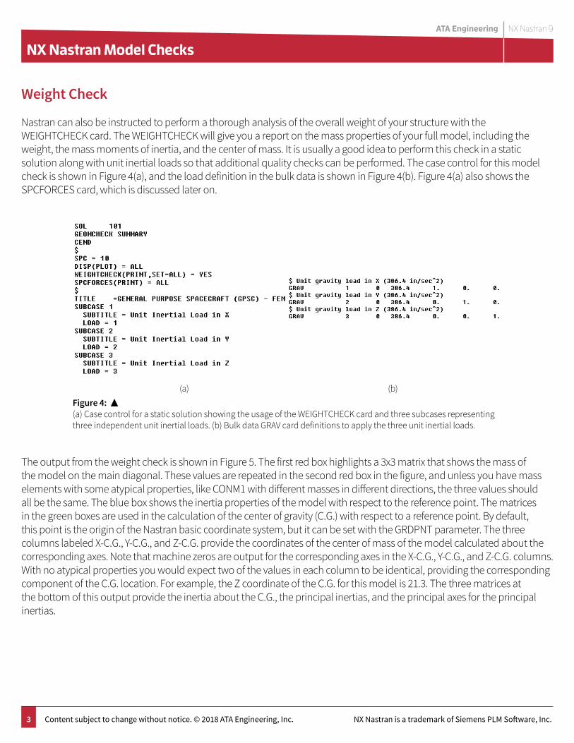
By solving a modal solution (SOL 103) with your model unrestrained, as we did in this example, you can check for the presence of six rigid body modes. Along with the grounding strain energies in each of the six directions, this provides assurance that your model is not artificially restrained. While there is no strict definition on what counts as a “rigid body” mode, a general guideline is to look for frequencies below 0.01 Hz and a ratio of 100 or greater between the frequency of the sixth rigid body mode and the frequency of the first elastic mode. In Figure 3, the sixth rigid body mode is 6.48E-6 Hz, and the ratio is well over 100. This indicates that the model most likely has reasonably good numerical conditioning. However, you should never assume that your model is acceptable on the basis of these numbers alone. Always visualize the results from an unrestrained modal solution to verify that the first six modes are in fact rigid body modes, and that the first flexible mode represents a realistic fundamental frequency for your structure.
Figure 2: ▶ GROUNDCHECK output from the *.f06 file, showing acceptable strain energies in all six directions for the G set.
Figure 3: ▶Example output for an eigensolution showing ten modes, the first six of which are rigid body modes.
ATA Engineering NX Nastran 9
NX Nastran Model Checks
3 Content subject to change without notice. © 2018 ATA Engineering, Inc. NX Nastran is a trademark of Siemens PLM Software, Inc.
Weight Check
Nastran can also be instructed to perform a thorough analysis of the overall weight of your structure with the WEIGHTCHECK card. The WEIGHTCHECK will give you a report on the mass properties of your full model, including the weight, the mass moments of inertia, and the center of mass. It is usually a good idea to perform this check in a static solution along with unit inertial loads so that additional quality checks can be performed. The case control for this model check is shown in Figure 4(a), and the load definition in the bulk data is shown in Figure 4(b). Figure 4(a) also shows the SPCFORCES card, which is discussed later on.
Figure 4: ▲(a) Case control for a static solution showing the usage of the WEIGHTCHECK card and three subcases representing three independent unit inertial loads. (b) Bulk data GRAV card definitions to apply the three unit inertial loads.
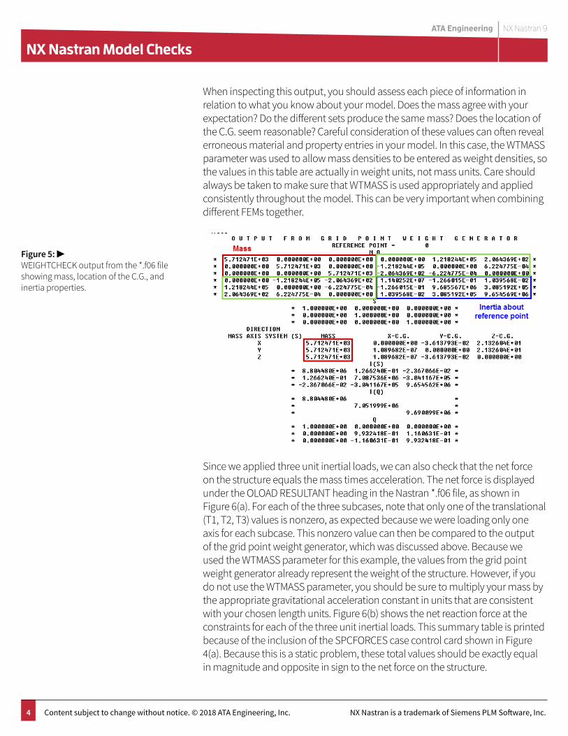
The output from the weight check is shown in Figure 5. The first red box highlights a 3x3 matrix that shows the mass of the model on the main diagonal. These values are repeated in the second red box in the figure, and unless you have mass elements with some atypical properties, like CONM1 with different masses in different directions, the three values should all be the same. The blue box shows the inertia properties of the model with respect to the reference point. The matrices in the green boxes are used in the calculation of the center of gravity (C.G.) with respect to a reference point. By default, this point is the origin of the Nastran basic coordinate system, but it can be set with the GRDPNT parameter. The three columns labeled X-C.G., Y-C.G., and Z-C.G. provide the coordinates of the center of mass of the model calculated about the corresponding axes. Note that machine zeros are output for the corresponding axes in the X-C.G., Y-C.G., and Z-C.G. columns. With no atypical properties you would expect two of the values in each column to be identical, providing the corresponding component of the C.G. location. For example, the Z coordinate of the C.G. for this model is 21.3. The three matrices at the bottom of this output provide the inertia about the C.G., the principal inertias, and the principal axes for the principal inertias.
(a) (b)
ATA Engineering NX Nastran 9
NX Nastran Model Checks
4 Content subject to change without notice. © 2018 ATA Engineering, Inc. NX Nastran is a trademark of Siemens PLM Software, Inc.
When inspecting this output, you should assess each piece of information in relation to what you know about your model. Does the mass agree with your expectation? Do the different sets produce the same mass? Does the location of the C.G. seem reasonable? Careful consideration of these values can often reveal erroneous material and property entries in your model. In this case, the WTMASS parameter was used to allow mass densities to be entered as weight densities, so the values in this table are actually in weight units, not mass units. Care should always be taken to make sure that WTMASS is used appropriately and applied consistently throughout the model. This can be very important when combining different FEMs together.
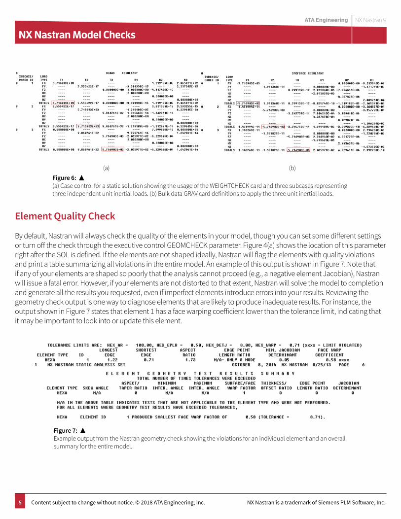
Since we applied three unit inertial loads, we can also check that the net force on the structure equals the mass times acceleration. The net force is displayed under the OLOAD RESULTANT heading in the Nastran *.f06 file, as shown in Figure 6(a). For each of the three subcases, note that only one of the translational (T1, T2, T3) values is nonzero, as expected because we were loading only one axis for each subcase. This nonzero value can then be compared to the output of the grid point weight generator, which was discussed above. Because we used the WTMASS parameter for this example, the values from the grid point weight generator already represent the weight of the structure. However, if you do not use the WTMASS parameter, you should be sure to multiply your mass by the appropriate gravitational acceleration constant in units that are consistent with your chosen length units. Figure 6(b) shows the net reaction force at the constraints for each of the three unit inertial loads. This summary table is printed because of the inclusion of the SPCFORCES case control card shown in Figure 4(a). Because this is a static problem, these total values should be exactly equal in magnitude and opposite in sign to the net force on the structure.
Figure 5: ▶WEIGHTCHECK output from the *.f06 file showing mass, location of the C.G., and inertia properties.
ATA Engineering NX Nastran 9
NX Nastran Model Checks
5 Content subject to change without notice. © 2018 ATA Engineering, Inc. NX Nastran is a trademark of Siemens PLM Software, Inc.
Element Quality Check
By default, Nastran will always check the quality of the elements in your model, though you can set some different settings or turn off the check through the executive control GEOMCHECK parameter. Figure 4(a) shows the location of this parameter right after the SOL is defined. If the elements are not shaped ideally, Nastran will flag the elements with quality violations and print a table summarizing all violations in the entire model. An example of this output is shown in Figure 7. Note that if any of your elements are shaped so poorly that the analysis cannot proceed (e.g., a negative element Jacobian), Nastran will issue a fatal error. However, if your elements are not distorted to that extent, Nastran will solve the model to completion and generate all the results you requested, even if imperfect elements introduce errors into your results. Reviewing the geometry check output is one way to diagnose elements that are likely to produce inadequate results. For instance, the output shown in Figure 7 states that element 1 has a face warping coefficient lower than the tolerance limit, indicating that it may be important to look into or update this element.
Figure 6: ▲(a) Case control for a static solution showing the usage of the WEIGHTCHECK card and three subcases representing three independent unit inertial loads. (b) Bulk data GRAV card definitions to apply the three unit inertial loads.
(a) (b)
Figure 7: ▲Example output from the Nastran geometry check showing the violations for an individual element and an overall summary for the entire model.
ATA Engineering NX Nastran 9
NX Nastran Model Checks
6 Content subject to change without notice. © 2018 ATA Engineering, Inc. NX Nastran is a trademark of Siemens PLM Software, Inc.
Stiffness Matrix Singularity Check
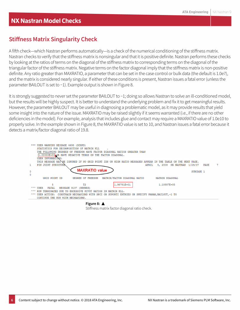
A fifth check—which Nastran performs automatically—is a check of the numerical conditioning of the stiffness matrix. Nastran checks to verify that the stiffness matrix is nonsingular and that it is positive definite. Nastran performs these checks by looking at the ratios of terms on the diagonal of the stiffness matrix to corresponding terms on the diagonal of the triangular factor of the stiffness matrix. Negative terms on the factor diagonal imply that the stiffness matrix is non-positive definite. Any ratio greater than MAXRATIO, a parameter that can be set in the case control or bulk data (the default is 1.0e7), and the matrix is considered nearly singular. If either of these conditions is present, Nastran issues a fatal error (unless the parameter BAILOUT is set to −1). Example output is shown in Figure 8.
It is strongly suggested to never set the parameter BAILOUT to −1; doing so allows Nastran to solve an ill-conditioned model, but the results will be highly suspect. It is better to understand the underlying problem and fix it to get meaningful results. However, the parameter BAILOUT may be useful in diagnosing a problematic model, as it may provide results that yield some insight into the nature of the issue. MAXRATIO may be raised slightly if it seems warranted (i.e., if there are no other deficiencies in the model). For example, analysis that includes glue and contact may require a MAXRATIO value of 1.0e10 to properly solve. In the example shown in Figure 8, the MAXRATIO value is set to 10, and Nastran issues a fatal error because it detects a matrix/factor diagonal ratio of 19.8.
Figure 8: ▲Stiffness matrix factor diagonal ratio check.
ATA Engineering NX Nastran 9
NX Nastran Model Checks
7 Content subject to change without notice. © 2018 ATA Engineering, Inc. NX Nastran is a trademark of Siemens PLM Software, Inc.
Substitution Residual
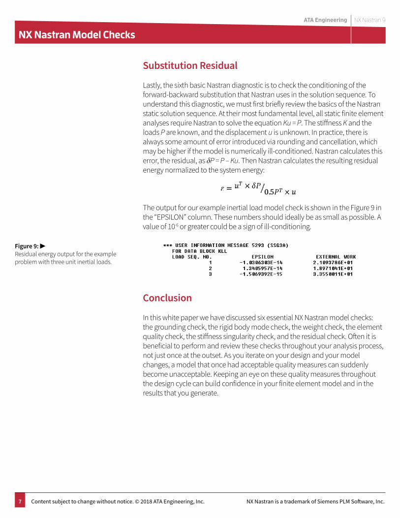
Lastly, the sixth basic Nastran diagnostic is to check the conditioning of the forward-backward substitution that Nastran uses in the solution sequence. To understand this diagnostic, we must first briefly review the basics of the Nastran static solution sequence. At their most fundamental level, all static finite element analyses require Nastran to solve the equation Ku = P. The stiffness K and the loads P are known, and the displacement u is unknown. In practice, there is always some amount of error introduced via rounding and cancellation, which may be higher if the model is numerically ill-conditioned. Nastran calculates this error, the residual, as δP = P – Ku. Then Nastran calculates the resulting residual energy normalized to the system energy:
The output for our example inertial load model check is shown in the Figure 9 in the “EPSILON” column. These numbers should ideally be as small as possible. A value of 10-6 or greater could be a sign of ill-conditioning.
Conclusion
In this white paper we have discussed six essential NX Nastran model checks: the grounding check, the rigid body mode check, the weight check, the element quality check, the stiffness singularity check, and the residual check. Often it is beneficial to perform and review these checks throughout your analysis process, not just once at the outset. As you iterate on your design and your model changes, a model that once had acceptable quality measures can suddenly become unacceptable. Keeping an eye on these quality measures throughout the design cycle can build confidence in your finite element model and in the results that you generate.
Figure 9: ▶Residual energy output for the example problem with three unit inertial loads.

www.ata-plmsoftware.com
ATA Engineering
Copyright © ATA Engineering, Inc. 2018 www.ata-plmsoftware.com
San DiegoCorporate Headquarters Denver Huntsville Los Angeles Washington, D.C.San FranciscoAlbuquerque
www.ata-e.com
ata-engineering
@ataengineering
858.480.2000