innovation construction
TRANSCRIPT

Creating Impacts Through Innovation
ISSN
231
2-82
91
SPECIAL ISSUE
in
RESEARCH JOURNAL 2018
INNOVATIONCONSTRUCTION

© All rights reserved. Copyright of material published is to be retained by the Construction Industry Council and the respective contributors.
No part of the Innovation in Construction, written or pictorial, may be reproduced, stored in retrieval system or transmitted, in any form or by any means, electronic, mechanical photocopying, recording or otherwise, without the permission in writing of the copyright holder.
The papers express the opinions of the authors and do not necessarily reflect the views of the CIC.

ABOUT THE CONSTRUCTION INDUSTRY COUNCIL
VISION
MISSION
The Construction Industry Council (CIC) was formed on 1 February 2007. CIC consists of a chairman and 24 members representing various sectors of the industry including employers, professionals, academics, contractors, workers, independent persons and Government officials.
The main functions of CIC are to forge consensus on long-term strategic issues, convey the industry’s needs and aspirations to Government, as well as to provide a communication channel for Government to solicit advice on all construction-related matters. In order to propagate improvements across the entire industry, CIC is empowered to formulate codes of conduct, administer registration and rating schemes, steer forward research and manpower development, facilitate adoption of construction standards, promote good practices and compile performance indicators.
CIC has set up Committees to pursue initiatives that will be conducive to the sustainable development of the construction industry.
To drive for unity and excellence of the construction industry in Hong Kong.
To strengthen the sustainability of the construction industry in Hong Kong by providing a communications platform, striving for continuous improvement in standards and practice, increasing awareness of health and safety, as well as improving skills development.

CONTENTS04 MESSAGE FROM THE CIC CHAIRMAN AND EXECUTIVE DIRECTOR
Mr. CHAN Ka-kui, SBS, JP; Ir Albert CHENG
05 MESSAGE FROM THE JUDGING PANEL CHAIR AND VICE CHAIRIr Kevin POOLE; Prof. Christopher LEUNG
06 JUDGING PANEL
07 CIC CONSTRUCTION INNOVATION AWARD 2017
AWARDED PROJECTS08 INTERNATIONAL GRAND PRIZE AWARD
Internet-of-Things-based Portable and Agile Monitoring System for Blind Hoisting in Metro and Underground ConstructionCheng ZHOU, Weili FANG, Ran WEI, Lieyun DING, Hanbin LUO and Xinggui LIN
18 INTERNATIONAL RUNNER-UP3D Printed Wave Dissipation System, Customized for Local Needs in Coastline Resilience, Habitat Enhancement and Community EngagementIan CHUNG, C.K. TSANG, Claudio TRUCCO, Heather LI and Yihe MA
24 INTERNATIONAL RUNNER-UPAutomated Construction by Contour CraftingBehrokh KHOSHNEVIS
32 LOCAL GRAND PRIZE AWARDUse if Innovative Rammed Earth Construction Technology in Rural Areas of Southwest China — with Post-earthquake Reconstruction Project in Guangming Village as a DemonstrationLi WAN, Xinan CHI, Edward NG and Wenfeng BAI

40 YOUNG INNOVATOR AWARDA Revolutionary Design for Ventilation in the Built Environment – Air Induction UnitTony LAM, Camby SE, Ricky LI and Alvin LO
50 FIRST PRIZE OF CONSTRUCTION PRODUCTIVITYHybrid Outrigger System with Structural Fuse for Tall BuildingsMichael KWOK, Goman HO, Penny CHEUNG and Li-gang ZHU
60 SECOND PRIZE OF CONSTRUCTION PRODUCTIVITYNew Machines to Enhance Productivity of Bridge ConstructionJames Edward LAWTON
68 FIRST PRIZE OF CONSTRUCTION SAFETYBio-Inspired Anti-Vibration Exoskeleton for Manipulating Demolition ToolsXingjian JING
76 SECOND PRIZE OF CONSTRUCTION SAFETYReducing Work at Height by Teleoperated Service Robot for Pipe Repair in Hong KongK.H. KOH, Kenny P.C. YEUNG, Musthafa FARHAN, Florence H.L. CHAN, David C.H. TANG, Michelle P.Y. LAU, B. L. LUK, P.K. CHEUNG and King W.C. LAI
84 FIRST PRIZE OF CONSTRUCTION SUSTAINABILITYSupercritical Vortex Intakes for Urban Stormwater ManagementJoseph Hun-wei LEE, Anthony K.L. TSANG, Andy KWOK and John ACKERS
94 SECOND PRIZE OF CONSTRUCTION SUSTAINABILITYInnovative Capsule Technology for Producing High-performance Lightweight Cellular ConcreteRuby ZHU, Kevin SHANG, Honggang ZHU, Jeffery LAM, Ivan SHAM, Richard TSE and Derek SO

RESEARCH JOURNAL 2018 INNOVATION IN CONSTRUCTION04
MESSAGE FROM THE CIC CHAIRMAN AND EXECUTIVE DIRECTOR
Chairman, CIC Executive Director, CICMr. CHAN Ka-kui, SBS, JP Ir Albert CHENG
We are pleased to announce the publication of this special issue of our Research Journal “Innovation in Construction” (iCON). With a focus on the CIC Construction Innovation Award 2017 (“Award”), this issue continues to act as a communication platform between industry stakeholders and researchers to exchange innovative knowledge and ideas, thereby enhancing the overall performance of the industry.
Embracing the CIC’s vision to drive for excellence of the industry, the Award is a significant opportunity for local and international industry practitioners and academia to showcase their innovative creations in construction productivity, safety and sustainability. It also highlights Hong Kong’s achievements in promoting research, innovation and technological development in the construction industry to our international audience.
CIC promotes innovation as the key to the efficient and sustainable development of the construction industry. In celebration of excellence and recognition of outstanding work, the Award motivates our stakeholders to innovate and provides a high-profile platform for innovators to realise their aspiration to become leaders in the field.
CIC will spare no effort in promulgating awa rd e e s ’ i d e a s a n d c re at i n g opportunities for the project teams. This issue of iCON records the awardees’ inventions which were selected from a significant number of exceptional contributions. We are delighted to see the active engagement a n d p a r t i c i p at i o n o f i n d u st r y stakeholders in this Award, reflecting our strong passion for innovations and our determination to strive for the best. Indeed, it is the support of all the participants in the Award lays a solid
foundation to produce high-quality work.
The Award would not have been a success without the tremendous effort of the prestigious Judging Panel who are all leading construction professionals with different expertise. They have exercised professional judgement during the rigorous assessment process in selecting the winners. We would like to extend our heartfelt gratitude to all the judges, particularly Ir Kevin POOLE and Prof. Christopher LEUNG, who are the Judging Panel Chair and Vice Chair respectively. May we also take this opportunity to thank all participants for their invaluable contributions, congratulate the awardees for their accomplishments, and wish all pioneers every success.

INNOVATION IN CONSTRUCTION RESEARCH JOURNAL 2018 05
MESSAGE FROM THE JUDGING PANEL CHAIR AND VICE CHAIR
Panel Chair, Judging Panel
Vice Chair, Judging Panel Ir Kevin POOLE Prof. Christopher LEUNG
It is our honour to chair the Judging Panel of the CIC Construction Innovation Award 2017. The submissions for the Award this year are excellent and truly innovative. This special issue of iCON captures the essence of this event, and demonstrates the industry’s efforts in promoting innovation and technology in Hong Kong. In the process of selection, the Judging Panel evaluated each submission meticulously against the three judging criteria: Benefits to the industry; Originality; and Applicability.
Not only are all the winning projects pioneering in their own areas, they have also demonstrated their functional significance at the project, industry, and city levels.
Our heartfelt congratulations go to all awardees for their commendable achievements. We also offer our sincere thanks and appreciation to members of the Judging Panel and the Organising Committee for their
contributions in making this event a success.
With a view to striving for continuous improvement of the industry, we will continue to support research and development, and to promote the adoption of innovative construction technologies. We look forward to witnessing the rippling effects of these innovations, in taking our industry to another level.

RESEARCH JOURNAL 2018 INNOVATION IN CONSTRUCTION06
PANEL CHAIR
Ir Kevin POOLE
PANEL MEMBERS
Ms. Ada FUNG, BBS, JP
Prof. Dongping FANG
Sr LAI Yuk-fai, Stephen
Prof. Roger FLANAGAN
Prof. Thomas BOCK
Prof. Miroslaw SKIBNIEWSKI
PANEL VICE-CHAIR
Prof. LEUNG Kin-ying, Christopher
JUDGING PANEL

INNOVATION IN CONSTRUCTION RESEARCH JOURNAL 2018 07
CIC CONSTRUCTION INNOVATION AWARD 2017
The CIC Construction Innovation Award aims to spearhead development of new concepts and initiatives to enable continuous improvement of the construction industry in Hong Kong. It also aims to recognise and promote new technologies and scientific breakthroughs by both local and international academia and industry practitioners.
The Award focuses on innovative ideas in one of the following areas:
CONSTRUCTION PRODUCTIVITY
Innovative materials, equipment, systems, technologies, construction pract ices, or any init iat ives applicable to different construction projects in enhancing productivity and quality.
CONSTRUCTION SAFETY
Innovative materials, equipment, techno log ies , const ruct ion practices, or any initiatives that could improve safety and health conditions at construction sites.
CONSTRUCTION SUSTAINABILITY
Innovative materials, equipment, systems, technologies, or any init iat ives appl icable in the construction industry that are beneficial to the built environment.

INTERNATIONAL GRAND PRIZE AWARD

INNOVATION IN CONSTRUCTION RESEARCH JOURNAL 2018 09
Internet-of-Things-based Portable and Agile Monitoring System for Blind Hoisting in Metro
and Underground Construction
Cheng ZHOU1,2, Weili FANG1,2, Ran WEI1,2, Lieyun DING1,2, Hanbin LUO1,2, Xinggui LIN1,2
1 Dept. of Construction Management, Huazhong University of Science and Technology (HUST), China2 Hubei Engineering Research Center for Virtual, Safe and Automated Construction (ViSAC), HUST, China
This study proposes an Internet-of-Things (IoT)-based portable and agile monitoring system (IPAMS) for blind hoisting in metro and underground construction. The Sanyang Road Tunnel of the Wuhan Yangtze Metro in China is used as a case study. The major challenge for crane hoisting is the limited visibility of crane operators. The IPAMS is proposed to overcome these challenges by simulating and monitoring the hoisting process. IoT technologies, such as sensor-based location and tracking, and WiFi self-organization technologies, are used to avoid an unsafe status of objects hoisted under complex and dynamic conditions. Implementation of the proposed system in the Yangtze River-Crossing Metro Tunnel construction site was successful and the target object was hoisted into the underground shafts without any collision or injury. The IPAMS can be applied in a broad range of construction projects, such as dams, high-rise buildings, and large-scale infrastructure projects, to increase the likelihood of project success in a complex environment.
Keywords: Crane safety; Blind hoisting; Safety management; Internet-of-Things (IoT)
ABSTRACT
1. INTRODUCTIONCrane-related accidents are a major problem in the construction industry (Ren and Wu 2014; Chen et al. 2016). Beavers et al. (2006) concluded that “struck by” is the main cause of crane-related accidents. In most cases, this scenario occurs mainly due to limitations in the visibility, skill, and experience of the crane operators. These shortcomings lead to spatial conflicts between crane parts and the surrounding obstructions.
A study of metro and underground construction incidents concluded that crane visibility was at least partially responsible for 42.7% of all accidents. Crane-related accidents are becoming increasingly serious in large-scale metro and underground construction projects with increasingly complex environments, sensitive urban infrastructure, and migrant workers with poor safety awareness in construction sites. Crane operators often encounter difficulties in safely controlling a crane boom, which requires the simultaneous control of several raising, lowering, and hoisting actions to lift or lower an object to areas with poor visibility using two levers without visual observation. The implementation of safety monitoring systems is recommended to address the challenges

RESEARCH JOURNAL 2018 INNOVATION IN CONSTRUCTION10
presented by such projects, reduce the likelihood of human errors in metro and underground construction projects, and improve safety during crane operations.
In recent years, numerous researchers have proposed a series of methods to prevent crane accidents (Cheng and Teizer 2012; Li et al. 2012; Ren and Wu 2014; Luo et al. 2015; Fang et al. 2016; Han et al. 2016). These methods have improved the perception of operators and potentially enabled real-time measurement and feedback from other crane operators. However, current digital crane monitoring systems are mainly solving inherent problems of machine safety by focusing on the monitoring of mechanical equipment reliability and data related to the fatigue and damage to key mechanical parts, such as hoisting slewing angle and bending moment. Blind hoisting in underground projects is mainly concerned with the safety problem of human-machine-environment coupling under complex conditions (Cheng and Teizer 2012). In addition, safety risk in blind hoisting changes dynamically during on-site hoisting operations. Consequently, real-time perception of the man-machine loop system must be realized.
To overcome these issues, an IPAMS has been developed for blind hoisting in metro and underground construction. This system provides additional safety measures in blind hoisting at such sites, including fast tracking of workers and objects, accurate positioning information, and high response speed, which allow early warning signals to be sent automatically. The IPAMS can change operators’ risky behaviours, reduce human errors during hoisting, and improve managers’ task organisation and safety planning through vivid and quantitative analysis of monitoring data at dynamic construction sites.
2. RELATED WORKConsiderable efforts have been made to address the safety problems of blind hoisting in metro and underground construct ion. These inc lude the
formulation of safety regulations, safety training programs, and industry safety practices. For example, when hoisting with cranes, a competent person and a qualified employee are required for the safety inspection and command of the hoisting operation. To increase the safety awareness of construction workers, a number of safety training programs is required to be taken under safety regulations. However, this conventional approach is strongly dependent on experienced engineers who command crane motions on the basis of intuition.
A solution that can directly address the problem of blind spots around cranes is monitoring by video camera. The conventional video camera system displays only the top view of a lifted object from a video camera attached to the crane trolley or hung at the tip of a luffing jib through a wireless data transmitter. This video system is ineffective for deep excavation because the vertical view of a lifted object does not give the crane operator a good sense of distance from surrounding objects.
Previous studies related to overcoming these i ssues us ing crane safety monitoring systems can be classified into sensor-based and vision-based methods. For sensor-based methods, radio frequency identification (RFID) (Domdouzis et al. 2007; Montaser and Moselhi 2014), ultra-wideband (Maalek and Sadeghpour 2013; Li et al. 2016), and global positioning system (GPS) (Razavi and Moselhi 2012; Pradhananga and Teizer 2013) have been applied to collect location information and establish a location system to avoid potential collisions. While such nonvisual sensors have been successfully applied, they generally track location and therefore do not measure the key operational parameters of crane lifting processes, such as the hoisting status of cutter wheels.
With the recent development of machine learning and computer vision in image processing, vison-based methods have become widely used in construction applications, such as the recognition of unsafe worker
behavior (Ding et al. 2018; Fang et al . 2018). Vision-based methods are effective in terms of providing alternative views to enhance operator visibility and situational awareness (Zhang et al. 2017). Considerable computational power is required to achieve real-time hazard warning by automatically extracting data from stream videos and then converting the data to useful information for safety warning. However, existing image processing techniques face challenges in practical applications to anti-collision scenarios, due to their large errors on distance computation under complex backgrounds conditions and delayed processing.
Metro and underground construction projects have complex construction processes, multisource hazard energy coupling, and numerous tasks requiring worker collaboration. These factors make monitoring on-site safety performance difficult (Shahrokhi and Bernard 2010). The use of IoT technologies to establish a digital underground construction site and the application of proactive safety barrier warnings provides a new approach to achieve real-time monitoring and early warnings during blind hoisting. These technologies are applied in many manufacturing and transportation solutions (Piyare and Lee 2013; Perumal et al. 2014; Skibniewski 2014). For instance, a reformed safety behavior modification approach that integrates a location-based technology with Behavior-Based Safety (BBS) was proposed and tested at a construction site in Hong Kong, followed by details of a corresponding online supporting system, real-time location system (RTLS), and virtual construction system (Heng et al. 2016). Similarly, a stochastic state sequence model that predicts discrete safety states was proposed through an RTLS for construction sites; and aimed to identify the hazardous level of a project or individual person over a period of time (Li et al. 2016).
To achieve successful blind hoisting in metro and underground construction, th i s study deve lops the IPAMS, which combines wireless location

INNOVATION IN CONSTRUCTION RESEARCH JOURNAL 2018 11
INTERNATIONAL GRAND PRIZE AWARD
and tracking sensors, portable high-definition digital cameras, laser distance measurement and gyroscope sensors, and environmental monitoring sensors, using IoT technology. The proposed system for blind hoisting is a proactive control system for isolating hoisting hazard energy and preventing accidents in metro and underground construction sites, and is completely different to manual and experience-based safety monitoring approaches. The IPAMS can be applied in many construction projects, such as dams, high-rise buildings, and large-scale infrastructure projects, to
increase the likelihood of project success in complex environments.
3. PROPOSED INNOVATIVE IPAMS
3.1 System architectureThe IPAMS architecture is shown in Figure 1. This system is developed for collecting, analyzing, and managing multisource information for automatic monitoring and providing early warning of unsafe status in blind hoisting. The proposed system is comprehensive,
proactive, and integrated with IoT technologies to effectively monitor unsafe conditions and behaviors of workers on site, thereby leading to a vision of smart and safe construction sites.
3.1.1 Data sensingThe main advantages of this system are portability and agility. Within the IPAMS, the status of the cutter wheel environment and appropriate warnings can be tracked and received in real time through multiple integrated sensors and devices (Figure 2), namely, a
Figure 1: System architecture: sensing, transmission, analytics and control
Figure 2: IoT sensors

RESEARCH JOURNAL 2018 INNOVATION IN CONSTRUCTION12
portable CCTV camera and ultrasonic positioning, laser ranging, 3D gyroscope, and environmental detection devices. These sensors are carefully selected by considering the information needed for analysis, data accuracy, requirements for sensor installation and sensitivity, and fulfilling 360° monitoring of blind hoisting. To ensure an easy installation of sensors and accuracy of collected data, various aspects of the system equipment, such as power dissipation, accuracy, volume, weight, installation, protection, deployment, debugging, operation, and maintenance, are balanced and optimized numerous times. The improvements are as follows:
(1) To guarantee easy installation and flawless operation of the sensors during lifting, the magnitude of the magnet behind each sensor is designed according to its weight. Furthermore, the sensors are designed to be waterproof and dustproof, and are provided with anti-electromagnetic radiation, due to the complex work environment during crane operation of shield cutter wheels.
(2) To guarantee installation without interfering the activities of crane workers, these devices are designed to be small and light weight. The device switches are all one-button mechanisms that does not require network setups. This system is simple to operate even for inexperienced operators who do not have relevant training in preset parameters or regulating network operation.
(3) To fulfill self-adaptation and low power consumption requirements, each device 1) collects self-adaptive frequency data and bimodulate standby plus work in order to achieve long-lasting continuation during application processes of the sensors and 2) adjusts the sensor frequencies, respectively.
The key parameters of the five above-mentioned sensors are as follows:
(1) Portable CCTV cameraThe portable CCTV camera enables site managers and crane operators to observe and monitor hoisting behavior and thus avoid unsafe incidents. The resolution of the portable CCTV camera is 1280×960 pixels, which clearly shows the situation in the monitored area.
(2) Ultrasonic positioning deviceThe ultrasonic positioning device improves the accuracy and efficiency of adjusting the position of the hoisted objects, especially for detecting the change in distance between moving objects and existing structures and obstacles. The ultrasonic positioning device achieves mutual transformation between electricity and ultrasound by the piezoelectric effect.
(3) Laser ranging deviceA laser ranging device is designed to measure the distance between the bottom of the hoisted object and the ground in real time. The high speed and measurement accuracy of this device allows it to be fully applied in the innovative system to provide the correct position of the hoisted object.
(4) 3D gyroscope device Of the many sensors that can be used for 3D gesture measurement, a gyroscope (ICM-20608-G) sensor is applied in the proposed system. This sensor consumes low power, and has high accuracy with a thinner packaging compared to other similar devices.
(5) Environmental detection deviceIn safety management, the interaction among workers, equipment, and environment cannot be ignored. Obtaining environmental information in real time through use of an environmental detection sensor allows workers to respond proactively to a potent ia l l y unfavorab le
environment. According to the data needs of this system, several kinds of environmental detection sensors are applied.
3.1.2 Data transmissionAfter collecting all the sensor data in real time, including location of cutter wheels and environmental data, the IPAMS uses a WiFi self-organized network to transmit the data and provide early safety warnings. The self-organized WiFi network comprises a large number of ubiquitous, tiny sensor nodes with communication and computing capabilities and a “smart” system that can complete assigned tasks independently according to the environment and the demand (Zhou and Ding 2017). If a sensor is broken or the sensor signal is occluded, the other sensors can still transmit the signal to the computer server. With the WiFi self-organization technology, the developed system can provide immediate instructions and warnings for construction workers.
3.1.3 Data analytics and controlThe head of the system is the remote control layer, which contains data analytics and control, for data storage and management, generates early safety warnings, and provision of a user interface for managers and crane operators. To set safety warning dynamically, the system accurately calculates the relative position and trajectory of the cutter head and determines if the cutter wheel and shafts are at an unsafe distance. The warnings are designed as three different levels of early warnings or alerts. The green level shows that the cutter wheel is safe and all monitored data are normal. The orange level shows that the distance between cutter wheel and the shaft reach the cautious level, while the red level shows that the cutter wheel is too close to the shaft to be potentially unsafe. The information stored in the system is visualized and received in real time, as shown in Figure 3. Finally, all the warning information and signals are sent

INNOVATION IN CONSTRUCTION RESEARCH JOURNAL 2018 13
INTERNATIONAL GRAND PRIZE AWARD
Figure 3: User interface of the monitoring system
to the warning control center. It helps managers and drivers manually operate when an object is approaching the shaft.
3.2 Function of IPAMSThe IPAMS is targeted at assisting construction workers, safety inspectors, and project managers with the safety management of blind hoisting with cranes. This innovative solution has the following advantages:
(1) 360° monitoring. In general, this system can provide full identification and monitoring of the most common hoisting failures by incorporating a clear user interface. Several types of sensors are adopted for data acquisition and transition in the proactive control of blind hoisting monitoring.
(2) Real-time remote interaction. With a plug-and-play IoT-based technology, the continuous wireless connections in the proposed system can help monitor the performance of blind hoisting as frequently as desired.
(3) User-defined early warning. Along with the suggested thresholds for different warning levels, which are predefined according to relative safety regulat ions and crane manufacturers’ suggestions for proactive management of crane operation by end users, the system can provide access to the system such that the threshold of potential hazards can be redefined.
(4) Portable and agile devices. Portable IoT-based monitoring or warning devices should be installed and connected easily and be non-intrusive to the work at a hoisting construction sites. All the IoT devices used for monitoring blind hoisting are assembled into a suitcase, and each is designed to be easy to use and install. By considering the educational and training background of some construction workers, a portable and agile system can be promoted and used quickly and correctly. Besides, the portable and agile features of the IoT devices assists safety inspectors and project
managers in safety management without the need for special or extensive training programs.
(5) Accuracy and reliability. The blind hoisting poses a considerable requirement for data accuracy and high resolution because of the potential failures caused by the dynamic hoisting operation process and construction environment.
4. CASE STUDY OF THE WUHAN METRO CONSTRUCTION
The Sanyang Road Tunnel is the first combined rail-and-road shield tunnel across the Yangtze River and has a total length of 2590 m. A slurry shield machine with a cutter diameter of 15.76 m was utilized to push the tunnel from Xujia Peng Station to Sanyang Road Station under the Yangtze River, which is the sixth largest river in the world and the third largest in China.
In this project, the blind areas were the major challenge for successfully hoisting

RESEARCH JOURNAL 2018 INNOVATION IN CONSTRUCTION14
the cutter wheel down to the shafts up to 44 m underground. Firstly, the five afore-mentioned sensors were installed, and the installation coordinates of these sensors were confirmed by safety experts from the construction company, as shown in Figure 4. Secondly, the relative position and trajectory of the cutter head and environmental data were calculated and stored in the
system database. Finally, early warning information (such as collisions with shafts) was sent to a control center, as shown in Figure 5. The managers should then adjusted the operation if necesary (such as slowing down or stopping) according to the warning data in order to avoid any unsafe contact between machinery and workers.
The IPAMS was implemented in February and May 2016 and both of the twin tunnels’ cutter wheels were successfully hoisted into the shafts 44m underground without any collision or injury. On-site installation of the IPAMS consumed merely several minutes, and vital safety assurance was provided for the blind hoisting activity.
Figure 4: Layout of sensors on cutter wheel
3D gyroscope sensorUltrasonic positioning sensorLaser ranging sensor
Figure 5: User interface of real-time early warning in IPAMS

INNOVATION IN CONSTRUCTION RESEARCH JOURNAL 2018 15
INTERNATIONAL GRAND PRIZE AWARD
5. CONCLUSIONTo achieve successful blind hoisting in complex and dynamic working environments, portable and agile IoT technologies were developed in a smart and self-organized network architecture. The benefits offered by the system to construction safety management were validated in the Sanyang Road-Yangtze River tunnel construction site of the Wuhan Metro Line 7. The key features and applicability of the IPAMS led to improved safety and efficiency and reduced cost to stakeholders and other participants in the projects. The results demonstrated the feasibility of the proposed IPAMS, which can be applied to monitor blind hoisting in similar projects by providing guidelines for safety management.
Although the system was developed specifically for underground construction conditions in China, further study is needed in the following aspects: (1) future large-scale trials with longer application periods than those used in this work will help to realistically verify the capacity of the system; (2) positioning algorithm optimization can be used to enhance on-site positioning accuracy to a decimeter level; and (3) compression and storage of the large amount of monitoring data can be improved to ensure system stability.
ACKNOWLEDGMENTS This research is supported in part by a major project of The National Social Science Key Fund of China (Grant No.13&ZD175), under the National Natural Science Foundation of China (Grant No.71671072 & No. 514082245 & No.71730001 & No.51678265). Many thanks are given to the Wuhan Metro Group Co., Ltd and the Shanghai Tunnel Engineering Co., Ltd. Also thanks are given to the Construction Industry Council to offer the opportunity to publish our research.
REFERENCESBeavers, J. E., Moore, J. R., Rinehart, R., and Schriver, W. R. (2006). "Crane-Related Fatalities in the Construction Industry." J. Constr. Eng. Manage., 132(9), 901-910.
Chen, Y. C., Chi, H. L., Kang, S. C., and Hsieh, S. H. (2016). "Attention-Based User Interface Design for a Tele-Operated Crane." J. Comput. Civ. Eng., 30(3), 04015030.
Cheng , T. , and Teizer, J . (2012) . "Modeling Tower Crane Operator Visibility to Minimize the Risk of Limited Situational Awareness." J. Comput. Civ. Eng., 28(3).
Ding, L., Fang, W., Luo, H., Love, P. E. D., Zhong, B., and Ouyang, X. (2018). "A deep hybrid learning model to detect unsafe behavior: Integrating convolution neural networks and long short-term memory." Autom. Constr., 86, 118-124.
Domdouzis, K., Kumar, B., and Anumba, C. (2007). Radio-Frequency Identification (RFID) applications: A brief introduction, Elsevier Science Publishers B. V.
Fang, Q., Li, H., Luo, X., Ding, L., Luo, H., Rose, T. M., and An, W. (2018). "Detecting non-hardhat-use by a deep learning method from far-field surveillance videos." Autom. Constr., 85, 1-9.
Fang, Y., Yong, K. C., and Chen, J. (2016). "A framework for real-time pro-active safety assistance for mobile crane lifting operations." Autom. Constr., 72, 367-379.
Han, S., Lei, Z., Bouferguene, A., Al-Hussein, M., and Hermann, U. (2016). "3D Visual izat ion-Based Motion Planning of Mobile Crane Operations in Heavy Industrial Projects." J. Comput. Civ. Eng., 30(1).
Heng, L., Shuang, D., Skitmore, M., He, Q. H., and Qin, Y. (2016). "Intrusion warning and assessment method for site safety enhancement." Safety Science, 84, 97-107.
Li, H., Chan, G., and Skitmore, M. (2012). "Multiuser Virtual Safety Training System for Tower Crane Dismantlement." J. Comput. Civ. Eng., 26(5), 638-647.
Li, H., Chan, G., Wong, J. K. W., and Skitmore, M. (2016). "Real-time locating systems applications in construction." Autom. Constr., 63, 37-47.
Li, H., Yang, X. C., Wang, F. L., Rose, T., Chan, G., and Dong, S. (2016). "Stochastic state sequence model to predict construction site safety states through Real-Time Location Systems." Safety Science, 84, 78-87.
Luo, X., Leite, F., Asce, M., and 'Brien, W. J. O. (2015). "Location-Aware Sensor Data Error Impact on Autonomous Crane Safety Monitoring." J. Comput. Civ. Eng., 29(4).
Maalek, R., and Sadeghpour, F. (2013). "Accuracy assessment of Ultra-Wide Band technology in tracking static resources in indoor construction scenarios." Autom. Constr., 30(30), 170-183.
Montaser, A., and Moselhi, O. (2014). "RFID indoor location identification for construction projects." Autom. Constr., 39(4), 167-179.
Perumal, T., Sulaiman, M. N., Mustapha, N., and Shahi, A. "Proactive architecture for Internet of Things (IoTs) management in smart homes." Proc., Consumer Electronics, 16-17.
Piyare, R., and Lee, S. R. (2013). "Towards Internet of Things (IOTS):Integration of Wireless Sensor Network to Cloud Services for Data Collection and Sharing." International Journal of Computer Networks & Communications, 5(5), 59-72.
Pradhananga, N., and Teizer, J. (2013). "Automatic spatio-temporal analysis of construction site equipment operations using GPS data." Autom. Constr., 29(1), 107-122.

RESEARCH JOURNAL 2018 INNOVATION IN CONSTRUCTION16
BIOGRAPHY
Cheng ZHOU
Dr ZHOU is Associate Professor of Construction Management, School of Civil Engineering and Mechanics, Huazhong University of Science and Technology. He is also the Deputy Director of Hubei Engineering Research Center for Virtual, Safe and Automated Construction (ViSAC) and member of Digital Construction Committee, Architectural Society of China.
Dr ZHOU has been working in the safety management in construction, automated construction and construction management. As a principal investigator, he has led two National Science Foundation of China (NSFC) projects in metro construction safety management. He won the National Science and Technology Progress Award, 2nd Prize in 2014, the Ministry of Education Science and Technology Progress Award, 1st Prize, and Provincial Science and Technology Progress Award, 1st Prize. Focusing on safety management in metro construction, Dr ZHOU has published several SCI journal papers and obtained several Chinese patents.
Weili FANG
Mr. Weili FANG is a Ph.D. candidate in the School of Civil Engineering and Mechanics of Huazhong University of Science & Technology. Sponsored by the Key Program of Natural Science Foundation of China, he has been doing research in the field of integrated device for safety perception and early warning in metro construction. He won the National Scholarship for Doctoral Students in 2016. His research interests focus on computer vision for construction management and digital construction applications.
Ran WEI
Mr. Ran WEI is a Ph.D. candidate in the School of Civil Engineering and Mechanics of the Huazhong University of Science & Technology. He is also the Chief Engineer of ViSAC. He worked in two Key Technology R&D Program (11th Five-Year Plan and 12th Five-Year Plan). As a managing investigator, he has also joined many projects of metro safety management. He won the Science and Technology Progress Award of Architectural Society of China, 2nd Prize in 2015. His research interests focus on informationization of construction management.
Razavi, S. N., and Moselhi, O. (2012). "GPS-less indoor construction location sensing." Autom. Constr., 28(28), 128-136.
Ren, W., and Wu, Z. (2014). "Real-Time Anticollision System for Mobile Cranes during Lift Operations." J. Comput. Civ. Eng., 29(6), 04014100.
Shahrokhi, M., and Bernard, A. (2010). "A development in energy flow/barrier analysis." Saf. Sci., 48(5), 598-606.
Skibniewski, M. J. (2014). "Information technology applications in construction safety assurance." Journal of Civil Engineering and Management, 20(6), 778-794.
Zhang, M., Cao, T., and Zhao, X. (2017). "Applying Sensor-Based Technology to Improve Construct ion Safety Management." Sensors, 17(8), 1841.
Zhou, C., and Ding, L. Y. (2017). "Safety barrier warning system for underground construction sites using Internet-of-Things technologies." Autom. Constr., 83.

INNOVATION IN CONSTRUCTION RESEARCH JOURNAL 2018 17
INTERNATIONAL GRAND PRIZE AWARD
Lieyun DING
Dr DING Lieyun is Professor of Construction Management, School of Civil Engineering and Mechanics, Huazhong University of Science and Technology (HUST); Academician of Chinese Academy of Engineering. He is also the President of HUST, the President of Construction Management Research Branch, Architectural Society of China, the Director of Department of Management, Science and Technology Commission of Ministry of Education and the Editor-in-Chief of Journal of Civil Engineering and Management (Chinese).
Focusing on the research of Virtual, Safe and Automated Construction, Prof. DING has made outstanding achievements in the fields of safety risk identification, early warning and controlling in metro construction, and made great contribution to the improvement of safety performance in construction engineering in China. His research findings have been successfully applied in many metro and infrastructure construction projects in China and he won the second-class award for national science and technology progress in 2006 and 2014.
Hanbin LUO
Dr Hanbin LUO is Professor of Construction Management, School of Civil Engineering and Mechanics, Huazhong University of Science and Technology. He is also the associate dean of School of Civil Engineering Mechanics, the Director of Construction Management Department, the Deputy Secretary General of Architectural Society of China–Construction Management Research Sector (CMRS-ASC), the Secretary General of Architectural Society of China–Digital Construction Academic Committee (DCAS-ASC) and the Director of ViSAC.
Dr LUO has been working on the research of Virtual, Safe and Automated Construction. He won the National Science and Technology Progress Award, 2nd Prize, the Science and Technology Progress Award of the Ministry of Education, 1st Prize, and the Science and Technology Progress Award of Hubei Province, 1st Prize. Dr LUO is the author or co-author of more than 100 scholarly publications. His research findings have been successfully applied in many metro and infrastructure construction projects in China.
Xinggui LIN
Mr. Xinggui LIN is a Master of School of Civil Engineering and Mechanics of the Huazhong University of Science & Technology. He has joined the project of research and development of integrated device for safety perception and early warning in metro construction. His research interests focus on Internet-of-Things-based construction safety management.

INTERNATIONAL RUNNER-UP

INNOVATION IN CONSTRUCTION RESEARCH JOURNAL 2018 19
3D Printed Wave Dissipation System, Customized for Local Needs in Coastline
Resilience, Habitat Enhancement and Community Engagement
Ian CHUNG1, C.K. TSANG1, Claudio TRUCCO2, Heather LI1, Yihe MA3
1 AECOM Asia Company Ltd. 2 AECOM Ltd. Beijing Office
3 Yingchuang Building Technique (Shanghai) Co. Ltd (WINSUN)
3D printing technology is widely and rapidly applied in the construction field and is expected to revolutionize construction (Frank T. 2014). The application of 3D printing in construction can be sub-divided into several broad categories, including customized buildings, components for landscaping, environment and transport. The technology can greatly reduce labour, time and material costs, and generate great social and economic benefits (Campbell T. 2011). The 3D printing technology developed by WINSUN has the potential to revolutionise the current construction industry, as it integrates the design and construction process, construction equipment and materials, leading to a combination of digitalized, mechanical and intelligent construction. AECOM has worked with WINSUN to apply the technology to environment-friendly design, using the eco-shoreline concept as a starting point. This customized design is intended to create a new breathing interface, a linkage among all systems, and an ecologically and socially resilient community.
ABSTRACT
1. OVERVIEW OF CURRENT APPLICATIONS IN CONSTRUCTION
The technology of 3D printing possesses practical functions while fulfilling regulatory standards through specially-developed printing equipment and “ink”. The “ink” for 3D-printed structures can be made from construction waste, specially modified cement as the base material, glass fiber for reinforcement and environment-friendly additives. The “ink” can be transformed from a liquid to a solid state at room temperature, and shaped automatically in a timely way. Its flexibility, light weightand plasticity, while causing zero pollution to the environment, are well in line with green and safe construction requirements (Sevenson B. 2015).
2. BENEFITS OF 3D PRINTING IN CONSTRUCTION APPLICATIONS
The technology of 3D printing has been improved significantly through more than ten years of industrial practice. Buildings constructed by the

RESEARCH JOURNAL 2018 INNOVATION IN CONSTRUCTION20
technology are more beautiful, durable, cost-effective, and environment-friendly as compared with those constructed by conventional methods. The significant advantage is that 3D printers can provide customized final products, for example printed components which are suitable for specific site conditions, and can be easily adjusted based on design ideas. The technology will help the construction industry reach a green, flexible, customized and internet-based era. The application of this technology has already achieved great success internationally (Campbell T. 2011).
3. CHALLENGES AND THREATS IN THE CURRENT ENVIRONMENT
As discussed, 3D printing technology has a vast potential, and we are exploring its true value in order to create a new infrastructure interface. Nowadays, the urban-centric way in which we live has become increasingly disconnected from the natural environment and the world’s various ecological systems. The degree of this disconnection is anticipated to increase over time. Indeed, it is forecast that two-thirds of the world’s population will live in urbanized areas by 2050, while the proportion will potentially reach 90% in some regions, such as Africa and Asia (UNDESA report 2014).
Climate change is bringing forth another new global challenge, impacting all cities
worldwide. Sea levels are rising and extreme climatic conditions and natural disasters, such as the devastating Hurricanes Maria (2018) and Sandy (2012), are becoming more and more frequent. Such challenges are reshaping the urban form in coastal areas worldwide and the negative impact on coastlines is becoming increasingly pronounced by the day, particularly given that around 40% of the world’s population lives near the coast (Cooper, J.A.G. & McKenna, J. 2008).
The coastline is representative of the physical link between human beings and the natural environment, the urban form and ecological systems (Tanaka, Y. 2002 & Lewis, J.R. 1964). Typically, man-made infrastructure separates these various communities by erecting barriers, thus creating further disconnection between them, instead of viewing the linkage as a benefit (Tanaka, Y. 2002).
As architects and engineers, we wish to go beyond merely serving up a short-term solution to this problem. We want to protect our communities and at the same time create a long-term connection, using the coastline as an opportunity to enhance the linkage between them. Our aim is to create a breathing infrastructure, which takes care of eco-systems and the local community, improves the natural habitat, and offers pleasant and educational personal experiences. We hope to make the transit ion from offering solely hard-engineered coastline protection to providing more
of a soft-engineered solution (Jackson, A.C. 2002), as shown in FIgure 1.
According to ‘ecological edge’ theory, the intertidal zone has the most developed and diverse ecological system. We aspire to construct a natural, dual, land-ocean ecosystem through creating a new intertidal zone based on the use of 3D printing technology.
4. 3D PRINTING APPLIED TO ENVIRONMENT-CUSTOMIZED DESIGN FACTORS
In contrast to the mass production of conventional wave dissipater blocks, 3D printing technology allows complex customization. It enables the inner part of the wave dissipation block to be specifically designed to maximize complexity and habitat for a diversity of species in order to enhance marine life biodiversity and to facilitate grow of a resilient ecosystem, as shown in Figure 2. All the relevant parameter data used to create the inner complexity of the block are collected locally, based on many factors including water temperature, tidal system, marine life biodiversity, animal species, and wave energy (Miller, J.K., 2016).
5. UNIQUE COASTLINE ENVIRONMENT
The on-site “fabrication” process is completed by first surveying the site with drones, and then designing the
Figure 1: Wave dissipation system in urban area

INNOVATION IN CONSTRUCTION RESEARCH JOURNAL 2018 21
INTERNATIONAL RUNNER-UP
wave dissipation system according to the specific littoral environment, so as to deliver the most suitable product in practice (Ban, N.C., 2014), as shown in Figure 3.
6. ON-SITE MATERIAL USAGE
While traditional shoreline design discourages people from interacting with the coastline, and often decreases the
quantum and diversity of marine life, 3D printing technology can customize the design to the targeted species, whilst at the same time creating opportunities for people to safely engage in nature (Chapman, M.G., 2009). 3D printing is more adaptable and flexible than conventional production methods in terms of materials and fabrication conditions, and allows easy use of on-site materials, such as local sand, with consequent reduction of waste associated with the construction process.
The 3D printed wave dissipation system protects the local community through minimizing risks, creating awareness of climate change and developing economies around coastlines. Ultimately it creates a connection between human beings and the natural environment (Figure 4). This type of new interface infrastructure helps to establish social and ecological resilience, and connects local communities and nature (Goff, M. 2010).
Figure 2: Designed around marine life cycle – customized for local needs
PARAMETER WHEEL
Today
Today
Tomorrow
Tomorrow
Figure 3: Set-up process

RESEARCH JOURNAL 2018 INNOVATION IN CONSTRUCTION22
7. OTHER RELATED INNOVATION TECHNOLOGY
The incorporation of other smart technologies with 3D printing gives rise to the potential for ‘smart’ 3D-printed wave dissipation system (3D-WDS) blocks. For example, real-time monitoring sensors could be attached to 3D-WDS blocks and directly connected to remote research centers, creating a world-wide database of relevant scientific information, and
micro hydro turbines embedded in the blocks could produce clean energy to help sustain the monitoring systems, thus creating an interconnected self-sustaining global system that can be used in any circumstances (Figure 5).
8. CONCLUSIONThis project has investigated the value of 3D printing technology related to global issues like climate change, sea level rise and natural disasters. Application of the
Figure 5: Concept shoreline design
technology to a wave dissipation system can help protect our communities while developing socially resilient ecosystems harmoniously connected with urban development (Dyson, K. & Yocom, K. 2015).
We aim to 3D print a resilient future.
ACKNOWLEDGMENTS The authors gratefully acknowledge the technical support provided by AECOM and Winsun. Any opinions, findings, conclusions, or recommendations expressed in this paper are those of the authors and do not necessarily reflect the views of the CIC.
REFERENCESBan, N.C., Maxwell, S.M., Dunn, D.C., Hobday, A.J., Bax, N.J., Ardron, J., Gjerde, K.M., Game, E.T., Devillers, R., Kaplan, D.M., (2014). Better integration of sectoral planning and management approaches for the interlinked ecology of the open oceans. Mar. Policy 49, 127e136.
Brittney, S., (2015), ‘Shanghai-based WinSun 3D Prints 6-Story Apartment Building and an Incredible Home’, in 3D Printing, viewed 18 January 2015, from https://3dprint.com/38144/3d-printed-apartment-building/.
Figure 4: Implementation process

INNOVATION IN CONSTRUCTION RESEARCH JOURNAL 2018 23
INTERNATIONAL RUNNER-UP
BIOGRAPHY
Ian CHUNG
lan CHUNG is the PRC Leader at AECOM, senior Vice President of AECOM Asia, and senior executive in AECOM’s Greater China Civil & Infrastructure business. He is a chartered civil engineer with over 25 years in providing management and technical expertise to multi-disciplinary, large scale transportation, civil and infrastructure projects. He is also the immediate past Chairman of The Association of Consulting Engineers of Hong Kong (ACEHK).
C.K. TSANG
Mr. TSANG is a Chartered Geotechnical engineer with about 18 years of experience in Civil and Geotechnical engineering for wide range of projects including highways, metro, ground engineering and slopes. He has wide experience in both the design and construction of various types of deep excavations, site formation and tunneling works. His tunneling experience includes Drill and Blast tunnels, TBM tunnels and Immersed Tube Tunnels.
Claudio TRUCCO
Claudio is currently a Project Architect in AECOM Beijing office. He obtained his Master’s Degree in Architectural Engineering at the University of Genova in Italy, with 2 years european scholarship at the Universidad Alcala de Henares-Madrid in Spain and 2 years international scholarship at the University of Technology Sydney in Australia. His research interests are in the area of innovation technology, sustainability and resiliency.
Heather LI
Heather LI is an environmental consultant in AECOM Hong Kong office. She has helped to promote and apply best practices to environmental and ecological planning projects across three key fields (environmental planning, ecosystem services and GIS analysis integration).
Yihe MA
The founder of Winsun Science and Technology Corporation and 3D-printing proprietor. He has been engaged in 3D printing building and new materials research, invention and production management. He has won the “Top Talent of Science and Technology” in Suzhou Industrial Park and “First Prize of Construction Group of the Fifth National BIM Contest” and “China Building Application Innovation Award”.
Campbell T., (2011), ‘Technologies, Potential, and Implications of Additive Manufacturing, viewed October 2011, in strategic foresight initiative from https://info.aiaa.org/SC/ETC/MS%20SubCommittee/Alice%20Chow_3D%20Printing%20Change%20the%20World_April%202012.pdf.
Chapman, M.G., Blockley, D.G., (2009). Engineering novel habitats on urban infrastructure to increase intertidal biodiversity. Oecologia 161, 625–635.
Cooper, J.A.G., McKenna, J., (2008). Working with natural processes: the challenge for coastal protection strategies. Geogr. J. 174, 315e331.
Dyson, K. & Yocom, K. (2015). Ecological design for urban waterfronts. Urban Ecosystem, 18, 189-208.
Frank T., (2014), ‘The trends, sector use cases and steps to accelerate your 3D printing journey’, in 3D Printing Report’, viewed November 2014, from http://www.ey.com/Publication/vwLUAssets/ey-3d-printing-report/$FILE/ey-3d-printing-report.pdf
Goff, M. (2010). Evaluating Habitat Enhancements of an Urban Intertidal Seawall: Ecological Responses and Management Implications. Master Thesis. School of Aquatic and Fishery Sciences, University of Washington.
J a c k s o n , A .C . , C h a p m a n , M .G . , Underwood, A.J., (2008). Ecological interactions in the provision of habitat by urban development: whelks and engineering by oysters on artificial seawalls. Aust. Ecol. 33, 307–
Lewis, J.R., (1964). The Ecology of Rocky Shores. English University Press, London. 323 pp.
Miller, J.K., Rella, A., Williams, K., Sproule, E., (2016). Living Shorelines Engineering Guidelines. Technical Report. Prepared for New Jersey Department of Environmental Protection.
Tanaka, Y., H. Suzuki, and H. Nakata. (2000). Habitat creation using seawalls: A seawall construction project in Tokyo Bay (Yokosuka Port). In Techno-Ocean 2000. Nippon Foundation.
U N D E S A r e p o r t ( 2 0 1 4 ) . Wo r l d Urbanization Prospects. Department of Economic and Social Affairs, United Nations, New Yorks.

INTERNATIONAL RUNNER-UP

INNOVATION IN CONSTRUCTION RESEARCH JOURNAL 2018 25
Contour Crafting (CC) is a construction-scale 3D printing technology that aims at additive fabrication of large-scale structures directly from computer models . CC s imultaneously uses computer controlled extrusion and trowelling to achieve smooth and accurate free-form surfaces. CC has been enabled by many unique technologies in robotics, material delivery, and control systems that have been created over the course of the last few years. A general review of the technology and future plan for its advancement are provided.
Keywords: Construction automation, 3D printing, concrete
ABSTRACT
1. TECHNOLOGY DESCRIPTIONIn Contour Crafting (CC), computer control is used to take advantage of extrusion and the superior surface forming capability of trowelling to create smooth and accurate, planar and free-form surfaces. CC is a hybrid method that combines an extrusion process to form the object surfaces and a filling process (by pouring, or extrusion) to build the object core. Under support from NSF, NASA, ONR and several industries, we have conducted extensive experiments over the last few years to configure the CC process to produce a variety of small and full scale objects. Small 2.5D and 3D parts with square, convex, and concave features have been fabricated from a variety of thermoplastic and ceramic materials. A limited axis but larger machine was later produced to demonstrate the possibility of fabricating full-scale concrete structures.
Figure 1-left shows a CC nozzle assembly that can build hollow concrete walls. Note that the middle nozzle in this assembly reciprocates as the transporting robot moves the entire nozzle assembly. Such an internal structure creates a truss system that delivers impressive strength to the walls created by CC. Figure 1-right demonstrates the high strength of a 14 cm wide, 10 cm high (four layers) wall structure that has been flipped 90 degrees. The beam (i.e., wall section) segment length between the two end supports is about 2.4 meters long. Note that
Automated Construction by Contour Crafting
Behrokh KHOSHNEVIS1
1 Contour Crafting Corporation, USA

RESEARCH JOURNAL 2018 INNOVATION IN CONSTRUCTION26
construction. Today many complex products are accurately produced by robotic systems in a fully automated manner. Buildings are relatively simpler with respect to geometry and required accuracy. The layer-wise fabrication paradigm used by CC should now allow the realization of automation of total building construction. Following are some of the aspects of building construction beyond basic structure that may be automated by CC.
Automated tiling of floors and walls: Tiling of floors and walls may be automated by robotically delivering and spreading grout and other material for adhesion of tiles to both surfaces, as shown in Figure 2-top. Another robotics arm can then pick the tiles from a stack and accurately place them over the area treated with the adhesive material. Often 60% of the time in manual tiling could be spent on alignment. With an accurate robotic infrastructure in place, alignment will not be an issue at all.
Automated plumbing: The CC process has the potential to build uti l ity conduits within walls. This makes plumbing automation possible. In this arrangement, after fabrication of a certain number of wall layers, a segment of copper (or other material) pipe may be attached onto the lower segment already installed inside the conduit. The robotics system, shown on the left side of Figure 2-middle, delivers the new pipe segment and has a heater element (shown in red) in the form of a ring. The inside (or outside) rim of each pipe segment may be pretreated with a layer of solder. The heater ring heats the connection area, melts the solder, and once the alignment is made, bonds the two pipe segments. Other universal passive (requiring no active opening or closing) robotic gripper and heater mechanism designs used for various plumbing components are also shown in the figure. Note that automated PVC plumbing using adhesives for pipe connections is also possible.
Automated electrical and communication line wiring: A modular approach similar to industrial bus-bars may be used for automating electrical and communication
Figure 2: Embedding external objects – top: automated tiling; middle: automated plumbing; bottom: automated electrical network installation
Figure 1: Left: CC nozzle assembly for solid and hollow concrete walls – Right: Demonstration of strength of thin hollow segment
the concrete used for building the structure has been reinforced with composite fibers which have been mixed with cement and aggregates. Use of composite and stainless steel fibers instead of conventional steel beams (rebar) is expected to become commonplace in the concrete industry, as almost all cement companies have aggressive research programs for use of fiber-based reinforcement.
Several wall specimens and other structures have been constructed using the current CC machine based on
hollow structure design. This design is expected to be a good initial candidate for sound barrier walls somewhat equivalent to the current Concrete Masonry Unit (CMU) based wall designs which are widely used in sound barrier construction.
Once the CC robotic infrastructure is in place, several robotic manipulators may be joined to eventually achieve total automation of building construction. Given what robotics has achieved in manufacturing, it should be possible to achieve the total automation of building

INNOVATION IN CONSTRUCTION RESEARCH JOURNAL 2018 27
INTERNATIONAL RUNNER-UP
l i n e w i r i n g i n t h e co u rs e o f C C construction. The modules, as shown in Figure 2-bottom, have conductive segments for power and communication lines, and inter-connect modularly. All modules may be robotically fed and connected. A simple gripper at the end of a robotic manipulator attached to the CC machine can perform the task of grabbing the component and connecting it to the component already placed within the conduit. The automated construction system properly positions these modules behind the corresponding openings on the walls. The only manual part of the process is inserting fixtures into the automatically constructed network.
Automated insulation, finish work and painting: Insulation as well as finish work such as plastering of walls may be achieved by using a hybrid CC nozzle that concurrently delivers multiple materials such as concrete, polyurethane, and plaster. After walls are constructed, a conventional spray-painting robotic manipulator driven by the same CC machine may paint each room according to desired specifications. The painting mechanism may be a simple spray nozzle, or a large inkjet printer head (such as those used for printing large billboards). The latter mechanism makes painting wallpaper or other desired patterns possible.
Automated imbedding of sensors and computational devices: In the course of CC construction, materials such as smart concrete may be used in certain segments of the building. Such materials demonstrate varying resistance under stress. Discrete sensors may be densely placed by a robotic arm at pre-specified locations inside any type of construction material (e.g., regular concrete). These sensors can be useful for in-process feedback for construction process control, and in completed structures as a means for inspection and for creation of smart structures that can sense numerous variables such as temperature, humidity, stress, vibration, presence of people and their attributes (such as in hospitals to monitor patient conditions as they move around), etc.
2. APPLICATION AREAS Applications of the CC technology may include construction of various types of buildings including residential, commercial and government buildings. Each building type (e.g., single story, multi-story, high rise, etc.) may be built by a special implementation of the CC technology, such as those in Figure 3 where standard, self-climbing, and multi-nozzle CC machines are shown. Another application domain is infrastructure construction which could include foundations, slabs, bridges, pylons, etc. And finally extraterrestrial construction, that is bui lding on the Moon and Mars for planetary exploration, exploitation, habitation and colonization, is another major field of use of CC technologies.
As for the extraterrestrial applications, a revolution is now underway as humanity transitions from being a single planet species to a solar system species. This has been set in motion by the explosion of technologies over the 40 years since the early Moon landings of the Apollo program. Some of the key technology areas include: rocketry, robotics, additive manufacturing, chemical processing, solar power, and artificial intelligence, to name just a few. Current extraterrestrial settlement buildup philosophy holds that, in order to minimize the materials needed to be flown in at great cost, strategies that maximize the use of locally-available resources must be adopted, but feasible construction approaches using in-situ materials have so far been hard to conceive.
Material processing tools and special CC construction equipment flown as cargo from Earth are proposed to build required infrastructure to support future missions and settlements on the Moon and Mars. Economically viable and reliable building systems and tool sets centered around CC robotic construction technology are being sought, examined and tested for extraterrestrial infrastructure buildup. A series of NASA-supported projects which focus on a unique approach, weaving the robotic building construction technology with designs for assisting rapid buildup of Lunar and Martian bases with initial operational capability, have proven
successful. The projects have aimed to study new methodologies to construct certain crucial infrastructure elements in order to evaluate the merits, limitations and feasibility of adapting and using such technologies for extraterrestrial application.
The complexity of the technologies and engineering systems required to transform the solar system will require the most advanced application of fabrication and systems engineering h u m a n s h av e e v e r k n o w n . T h e growing l ist of commercial space companies whose business plan is to do this profitably is a good indicator that the time is now! Construction of infrastructure elements such as landing pads, blast walls, roads, hangars, radiation shields, etc., which have been proven possible using variations of CC and novel methods of beneficiation and processing the constituents of the in-situ Lunar and Martian materials, will be the precursor to all other major planetary expeditions. Our proposed approaches supported by experiments have so far won two NASA international competition grand prizes.
3. ECONOMIC, ENVIRONMENTAL AND SOCIAL IMPACTS
With the level of automation afforded by the CC process, we expect significant time saving (hours or days vs. months) compared to conventional methods of construction. The automation and the time savings will in turn dramatically lower the amortized cost of construction.
Efficient, safe and waste-free construction techniques are needed to reduce the environmental footprint of construction. It is a fact that 40% of all materials in the world are used in construction-related activities and about 40% of all energy (70% of all electricity) consumed in the USA is used for buildings and infrastructures. The problem of reducing energy and waste in buildings is massive and multifaceted. In this respect, we have a tangible opportunity to reduce costs and save energy using efficient, high-technology building techniques.

RESEARCH JOURNAL 2018 INNOVATION IN CONSTRUCTION28
The question remains as to which construction technology is the most efficient and environmentally safe for use in the public and private construction sectors. We believe that CC will position the company to reduce its construction costs and environmental profile, using advanced robotic technology. Using this technology, construction materials are extruded in a layered fashion with perfect precision and near zero waste. CC offers construction without waste, noise, dust or harmful emissions – a more sustainable approach compared to other construction practices. And since CC is an automated robotics technology, worker exposure to hazards will be minimized. With this technology, worker compensation claims due to physical and repetitive tasks will be eliminated. The resulting reduction in labour injuries and the subsequent litigations will further decrease the cost of construction substantially.
We have performed a Life Cycle Analysis (LCA) to compare CMU- and CC-constructed structures with respect to CO2 emission and energy use. LCA considers the life-cycle stages by modelling the process flows for each technology in order to identify and quantify the major inputs and outputs of materials and energy, and estimate the potential impacts of the resultant emissions.
The LCA analysis indicated that CC reduces total CO2 emissions by 58% as compared to CMU. A more pronounced reduction is shown in the life-cycle embodied energy of the CC building. The total embodied energy of a CC building is reduced by more than 80% over the CMU construction method. Furthermore, CMU seems to produce more than FIVE times the solid waste as compared to CC during its material manufacturing and on-site construction phases. In summary, the total CO2 emissions and embedded energy for the two methods are shown in Figure 4. A significant portion of the emissions and energy saving of CC is due to the shorter construction time, resulting in significant reduction in labour transportation to and from construction sites for the duration of construction.
It is believed that the environmental benefits of CC technology will become
Figure 3: Top to bottom: Standard, self-climbing, and multi-nozzle CC machines suitable for construction of varieties of building types
more prominent as market penetration increases. This technology has the potential of reducing energy use and emissions in a significant way, thereby reducing dependence on fossil fuel sources. In addition, the large amount of waste generated by the conventional construction industry would be less of an issue if CC technology is implemented to its full automation potential. The environmental advantage of CC is a result of less total material use, less total energy required for
all construction activities, lower material and energy waste during construction, and less transportation of material, equipment, and labour.
Finally, the CC developers are also cognizant of the social impacts of the technology, in addition to organizational and political barriers to its implementation. In this respect, different actors view this technology differently as the technology penetrates into the fabric of our social

INNOVATION IN CONSTRUCTION RESEARCH JOURNAL 2018 29
INTERNATIONAL RUNNER-UP
structures. The technology is welcomed or rejected based on the degree of compatibility/incompatibility with the social structures in place. The degree of compatibility or incompatibility can be measured along two dimensions of structural depth and scope. Structural depth refers to the depth of penetration into the system structure. Scope is the impact across structures; this can be a real impact across a whole society, industry or community, or it can be a segmental impact affecting primarily sub-components of the society (e.g., construction workers and their families).
4. COMMERCIALIZATION STRATEGY
Founded by the author and started in May of 2017, Contour Crafting Corporation (CC Corp) is an early stage company with the mission to commercialize a collection of disruptive
technologies that are destined to revolutionize construction. CC is the flagship technology of CC Corp. Over 100 USA and international patents have been issued, and there are a significant number of additional in-process patent applications in the CC Corp’s IP portfolio. At this point CC Corp technologies are grouped under two international award winning technologies: Contour Crafting (CC) which is the large-scale extrusion-based 3D printing method described here, and Selective Separation Shaping (SSS), which is a large-scale powder-based 3D printing method. The lead investor of CC Corp is Doka Venture, the investment arm of Doka, which i s a mu l t in at ion a l con st ru ct ion technology company and the leader in advanced formwork manufacturing and implementation.
CC Corp’s business plan is to initially leverage its technologies to support
Figure 4: Top: Total CO2 emissions; Bottom: Embodied energy for CMU and CC construction methods
Embodied Energy
CO2 Emissionbuilding of low-cost and emergency h o u s i n g p ro j e c t s i n d eve l o p i n g c o u n t r i e s . T h i s p l a n w i l l s o o n be extended to construct larger residential and commercial buildings. The company ’s business strategy entails Technology Deployment and Distribution Agreements with a highly selective number of partners around the world, who are established building construction material companies and builders/developers in specific regions and/or countries.
5. CONCLUSIONS It currently takes six to nine months to construct an average-sized house in the United States – and costs too much. In industrialized countries, automation of manufacturing generally results in production costs that are roughly 25% of those from conventional manufacturing by manual methods. Efficient automation of construction should result in similar cost reductions. We expect cost reductions to be realized through a) rapid time-to-market, which drastically reduces construction financing costs, b) savings through near elimination of material waste, and c) major reduction in manual work-related expenses. While most manufactured p r o d u c t s c a n b e i m p o r t e d o r outsourced, construction must remain largely indigenous.
CC is a major innovation that has the potential to automate the construction of whole structures and radically reduce the time and cost of construction. If CC becomes widely deployed, the result would be a revolution in the construction industry that would lead to affordable construction of high quality low-income housing; the rapid construction of emergency shelters and on-demand housing in response to disasters; and the timely construction of arrays of similar new structures.
CC aims at ultimately automating the construction of substantial parts of buildings, including exterior walls, interior wall partitions, openings for doors and windows, building interfaces (e.g., anchor attachments), tiling,
LCA
LCA

RESEARCH JOURNAL 2018 INNOVATION IN CONSTRUCTION30
plumbing, electrical, etc. The metrics to evaluate CC include the performance of the resulting building, and the reduction in cost and time of the construction process as compared to manual methods.
The performance metric decomposes into three types: form, fit, and function. The form metrics determine if the building conforms to the size, shape and dimensions specif ied by the architectural CAD drawing. The fit metrics determine if the building parts constructed by CC are able to physically interface with non-CC constructed parts, such as foundation slabs and roofs. The function metrics determine if the constructed building is able to meet the intended functional requirements such as strength, insulation efficiency, and endurance. We expect CC to outperform the alternative construction methods in all of these areas, as well as to offer unusually attractive construction cost savings.
Massive construction of low-income housing in various parts of the world, rapid response to large scale disasters by prov id ing d ign i f ied shel ters , and significant positive impact on environment and energy shortagea are some of the long term performance criteria for which statistics will be available a few years after the public and commercial introduction of the technology. According to the UN, the world has a shortage of 800 million homes. CC will ultimately be able to effectively respond to this shortage and to emergency shelter needs worldwide. The ideal ultimate long-term outcome is to revolutionize the construction industry.
ACKNOWLEDGMENTS The author wishes to thank all the government, commercial and nonprofit
organizations that sponsored CC research projects in the last two decades. The enthusiasm and efforts of numerous students at the University of Southern California who worked at the Contour Crafting research laboratory are also recognized. The recognition of the CC technology by the Construction Industry Council is highly appreciated.
REFERENCESDav ta lab , O. , Kazemian , A . and Khoshnevis, B., (2018). Perspectives on a BIM-integrated software platform for robotic construction through Contour Crafting. Automation in Construction, 89, pp. 13–23.
Kazemian, A., Yuan, X., Cochran, E. and Khoshnevis, B., (2017). Cementitious materials for construction-scale 3D printing: Laboratory testing of fresh printing mixture. Construction and Building Materials, 145, pp.639-647.
Khoshnevis, B., (2004). Automated construction by contour crafting—related robotics and information t e c h n o l o g i e s . A u t o m a t i o n i n construction, 13(1), pp.5-19.
Khoshnevis, B. and Bekey, G., (2003). Automated Construction Using Contour Crafting—Applications on Earth and Beyond. NIST Special Publication Sp, pp.489-494.
Khoshnevis, B., Bodiford, M.P., Burks, K.H., Ethridge, E., Tucker, D., Kim, W., Toutanji, H. and Fiske, M.R., (2005), January. Lunar contour crafting—a novel technique for ISRU-based habitat development. In 43rd AIAA Aerospace Sciences Meeting and Exhibit—Meeting Papers (Vol. 538).
Khoshnevis, B., Bukkapatnam, S., Kwon, H. and Saito, J., (2001). Experimental investigation of contour crafting using ceramics materials. Rapid Prototyping Journal, 7(1), pp.32-42.
Khoshnevis, B., Hwang, D., Yao, K.T. and Yeh, Z., (2006). Mega-scale fabrication by contour crafting. International Journal of Industrial and Systems Engineering, 1(3), pp.301-320.
Khoshnevis, B., Yuan, X., Zahiri, B., Zhang, J. and Xia, B., (2015). Deformation Analysis of Sulfur Concrete Structures Made by Contour Crafting. AIAA Sp.
Khoshnevis, B., Yuan, X., Zahiri, B., Zhang, J., and Xia, B., (2016). Construction by contour crafting using sulfur concrete with planetary applications. Rapid Prototyping Journal, 22(5), pp.848-856.
Khoshnevis, B., Yuan, X., Zahiri, B., Zhang, J. and Xia, B. (2016). Contour Crafting construction using sulfur concrete with planetary applications, selected Best Paper, Rapid Prototyping Journal, Vol 22, Iss 5, pp 848-856.
Rahimi, M., A. Arhami and B. Khoshnevis, (2009). Crafting Technologies, Time Journal of Construction and Design, pp 30-32.
Yuan, X., Zhang, J., Zahiri, B. and Khoshnevis, B., (2016). Performance of Su l fur Concrete in P lanetary Applications of Contour Crafting. Solid Freeform Fabrication (Proceedings of the 26th Annual International Solid Freeform Fabrication Symposium – An Additive Manufacturing Conference).
Zareiyan, B. and Khoshnevis, B., (2017). Interlayer adhesion and strength of structures in Contour Crafting-Effects of aggregate size, extrusion rate, and layer thickness. Automation in Construction, 81, pp.112-121.
Zareiyan, B. and Khoshnevis, B., (2017). Effects of interlocking on interlayer adhesion and strength of structures in 3D printing of concrete. Automation in Construction, 83, pp.212-221.
INNOVATION IN CONSTRUCTION RESEARCH JOURNAL 2018 31
INTERNATIONAL RUNNER-UP
BIOGRAPHY
Behrokh KHOSHNEVIS Dr Behrokh KHOSHNEVIS is a Dean’s Professor of engineering at University of Southern California and is the President and CEO of Contour Crafting Corporation (www.ContourCrafting.com). He is a Fellow of the National Academy of Inventors and a member of the EU Academy of Sciences. Through his passion driven inventive research activities, he has made many useful inventions and innovations in different domains including robotics, haptics, biomedical, oil and gas, renewable energy, fabrication, construction and space systems. His automated construction inventions, Contour Crafting, is destined to cause a revolution in terrestrial construction and is regarded as the most promising approach for planetary construction of human outposts. A prestigious NASA organization awarded Contour Crafting the Grand Prize of the Create the Future Design Contest among 1000+ globally competing technologies. In 2016 another invention of KHOSHNEVIS, SSS, received the top NASA prize in an international competition on in-space fabrication technologies, and in 2017 he was recognized by the Connected World magazine as one of ten pioneers in the Internet of Things (IoT).
Dr KHOSHNEVIS has nearly 200 technical publications, and holds over 100 US and international patents. He has developed products that help people worldwide. He is a NASA Innovative Advanced Concept Fellow, a Fellow of the Society of Manufacturing Engineers, a Fellow of the Institute of Industrial & Systems Engineering, and a Fellow of the Society for Computer Simulation.

LOCAL GRAND PRIZE AWARD

INNOVATION IN CONSTRUCTION RESEARCH JOURNAL 2018 33
Use of Innovative Rammed Earth Construction Technology in Rural Areas of Southwest China — with Post-earthquake Reconstruction Project in
Guangming Village as a Demonstration
Li WAN1, Xinan CHI1, Edward NG1, Wenfeng BAI2
1 School of Architecture, The Chinese University of Hong Kong2 Faculty of Architecture and City Planning, Kunming University of Science and Technology
Rural construction and development are significant issues in China, which has more than 40% of its population living in rural areas. The improvement of poor rural areas in mountainous regions has been relatively s low and unsustainable. Most rural areas should create their own development model instead of following urban/modernization models. Meanwhile, the government also encourages autonomous, diverse, endogenous, and sustainable rural development. The crucial support that poor rural areas of China require is not only funding but also innovative ideas and systematic strategies. This study explores the research and implementation of a post-earthquake reconstruction project in Yunnan, China to demonstrate the use of “high-science and low-technology” strategies with the “local materials, local labor, and local technology” principle of rural construction, and to encourage sustainable and endogenous development in the poor rural areas of southwest China.
Keywords: high-science and low-technology, local materials, local labor, local technology, rural endogenous development
ABSTRACT
1. INTRODUCTIONRammed earth construction has a long history in China, particularly in rural Yunnan. Mud is the main material used in traditional architecture because it is inexpensive, accessible and exhibits remarkable thermal performance. However, local residents stopped implementing traditional rammed earth building technology because of several reasons. On the one hand, traditional rammed earth buildings have several limitations, such as poor seismic performance, limited daylighting and insufficient ventilation. Moreover, most rural residents viewed earthen buildings as symbols of poverty and backwardness. On the other hand, high-speed, top-down rural construction and transformation funded by external capital limited the time and space for innovation and expansion of local traditional technology. This study provides a new construction solution that integrates ‘local labour, local materials, and local technology’ (3L) through an innovative development of local traditional rammed earth construction. A demonstration project was implemented to persuade stakeholders of its viability and to promote the new construction solution in southwest China.

RESEARCH JOURNAL 2018 INNOVATION IN CONSTRUCTION34
2. CHALLENGES OF POST-EARTHQUAKE RECONSTRUCTION IN GUANGMING VILLAGE
Guangming Village is in Ludian County, Yunnan Province, China. A total of 90% of the local houses in this village are rammed earth structures. Guangming Village was hit by a shallow earthquake with a magnitude of 6.1 on 3 August 2014. After the earthquake, villagers lost their confidence in the local traditional rammed earth buildings, 90% of which were damaged during the earthquake (Figure 1). Therefore, most vi l lagers preferred to build brick–concrete houses during the reconstruction period. However, the prices of building materials rapidly increased and became unaffordable for most of the local villagers because of the increase in reconstruction needs and poor traffic conditions after the earthquake. Consequently, most of the local conventionally reconstructed buildings were built without any passive design, insulation and decoration.
The quality of these buildings and their indoor environments was poor (Figure 2). Furthermore, the villagers had to seek financial assistance to complete the reconstruction. The debt incurred after the disaster was an economic and psychological burden to the villagers. A considerable number of the residents attempted to find jobs in urban areas for increased income. Consequently, the elderly and children were left behind in the village.
In Ludian County, most of the traditional rammed earth residences in rural areas are considered a testament to poverty rather than historical heritage. Many rural earthen buildings were built by manual labour at least 50 years ago. These structures are dangerous because of their poor construction quality and disrepair. For villages that can obtain external capital for tourism development, the rural landscape is commonly disconnected from local materials, technology and labour. Therefore, rural residents and the local government are still looking for a good low-cost solution that can improve the safety and comfort of the vernacular architecture without destroying its historical and cultural values.
To provide a suitable and sustainable solution for local reconstruction, we innovated the local house-building technology using local materials and labour. However, several challenges remained regarding the local traditional rammed earth buildings:
• Ant i - se i smic per formance of traditional rammed earth buildings built by wood rammers and manual labour was poor and urgently needed to be improved.
• Most villagers considered traditional earthen buildings as a symbol of poverty and backwardness.
• Local traditional artisans and crafts were gone. New knowledge and technology needed to be studied to innovate the rammed earth buildings.
Figure 1: Local traditional rammed earth building destroyed by earthquake
The re-empowerment of the local r e s i d e n t s n e e d e d a l o n g - t e r m relationship and mutual trust to be established with the research team.
3. INNOVATIVE RECONSTRUCTION STRATEGIES IN GUANGMING VILLAGE
3.1 “High-science and low technology” strategy of reconstruction
To ensure systematic and sustainable r u ra l re co n st r u c t i o n wo r k w i t h innovative ideas, scientific research is essential to understand the context, identify the problem, and find a proper solution.
A prototype house was bui l t to demonstrate a comprehensive and systematic construction system and the resulting substantially high building quality. This house was built for an aged couple who lived in a tent after the earthquake. A passive design with recycled local materials gathered from the ruins ensured a comfortable indoor environment and low energy c o n s u m p t i o n . T h e d e s i g n w a s integrated with semi-outdoor spaces to provide a comfortable and artistic living environment for the couple (Figure 3). The semi-outdoor atrium with a skylight and cross ventilation was bright and had natural ventilation. Double-glazed windows and insulated roofs were used to improve the thermal performance of the building. A steel roof structure and aluminium alloy windows were used to increase building quality and airtightness.
After a survey and study of the weak points of the local traditional rammed earth buildings, several innovations were made to improve the seismic performance. Appropriately-sized concrete foundations formed with a correct cement mortar was selected to enhance the integrity of the foundation of the house. The soil at the site was

INNOVATION IN CONSTRUCTION RESEARCH JOURNAL 2018 35
LOCAL GRAND PRIZE AWARD
examined in the laboratory of the Kunming University of Science and Technology (KMUST) and mixed with sand, straw, and a small amount of cement (<3%) to prevent cracking and to make the walls solid. Concrete ring beams were added to the walls to improve structural integrity and to prevent vertical cracking. Aluminum a l l oy fo r mwo r k a n d a n e l e c t r i c rammer was used to make the walls substantially compact and smooth. A shaking table test on a single-layered rammed earth house pilot project was conducted at KMUST to verify the improved technology we used in the reconstruction project.
To empower the local residents and encourage endogenous development, the proposed innovative technology s h o u l d b e s i m p l e a n d e a s i l y disseminated within the community. The use of outside materials and labour should be limited to reduce construction cost and improve the local
market. Therefore, the 3L principle was considered suitable for the conditions of the poor rural areas in southwest China. Instead of promoting the benefits of imported brick and concrete, we determined whether the shortfalls of traditional rammed earth technology and the fragility of village life could be addressed in situ. The implementation of this strategy was a simple step in rebuilding the lives of the people. With this simple strategy and empowerment of the local residents, the performance of the rammed earth buildings was improved, thereby protecting the lifestyle of the village.
3.2. Implementation of demonstration project in Guangming village
Facing the aforementioned challenges of reconstruction, external financial capital could not improve local development efficiently and sustainably, because the potential to improve the self-
Figure 3: Floor plans of prototype house
Figure 2: Local conventional reconstruction
organising ability of the local residents was limited. Studies have shown that besides financial capital support, the empowerment of local residents and promotion of local endogenous development are other significant strategies for the development of poor rural areas (Wan & Ng 2016). A systematic and strategic bottom-up implementation method needed to be developed in these regions.
This bottom-up implementat ion meant applying the 3L principle. The residents were empowered through the demonstrat ion project with craftsman training and co-construction. Furthermore, the project was based on the principle of volunteerism. Villagers could join or opt out according to their view of the demonstration and the resources they could obtain. They were not required to join. We not only created the design as architects but also worked with the villagers throughout the process as partners. Through this long-term cooperation and learning-by-doing process, we established mutual trust with the villagers and convinced them that our innovative, anti-seismic rammed earth building was a good solution.
This project was organised by the One University One Village (1U1V) rural programme of The Chinese University of Hong Kong (CUHK), which was donated by the Chan Cheung Mun Chung Charitable Fund. The 1U1V team

RESEARCH JOURNAL 2018 INNOVATION IN CONSTRUCTION36
Figure 4: Entrance and courtyard of prototype house
conducted investigation, research, building design, on-site construction supervision, and coordination. The programme provided construction materials and tools to the villagers. Furthermore, the project was supported by KMUST and the University of Cambridge in terms of building structure, seismic performance improvement, and testing. The Construction Bureau of Zhaotong City supported the project through local coordination, and the local residents handled the construction with guidance from the 1U1V team.
4. PROJECT OUTCOME A contemporary design was used to address the physical and social needs of the villagers. The building shape and facade were simple and tidy (Figure 4). The indoor environment was spacious, bright, clean and well ventilated (Figures 5 & 6). Accordingly, the vil lagers could not connect this modern living environment to backwardness anymore and were willing to participate in the testing and training. The residents easily felt and understood the benefits of the innovative system after completion of the demonstration project.
4.1. Environmental friendliness
Natural resources and recycled materials from seismically-ruined buildings were the major construction materials used in the project. This choice reduced the environmental impact and solved the disposal problem of the seismic ruins. The use of industrial materials was carefully controlled so as to minimise the embodied energy of the prototype house. Proper passive design guaranteed low operating energy consumption.

INNOVATION IN CONSTRUCTION RESEARCH JOURNAL 2018 37
LOCAL GRAND PRIZE AWARD
4.2. Cost efficiencyUse of naturally-resourced and recycled materials from seismic ruinshelped to minimize construction costs. The cost of the prototype house is only 60%-70% of that of a local conventional brick-concrete building in the same region. The operation cost of the project was also small because of proper passive design. With the affordable reconstruction system and well-trained villagers who were equipped with knowledge of this new technology and framework, such houses can be easily improved and maintained in the future. The residents can also utilise this technology as their livelihood.
and warmth in winter. Double-glazed windows and insulated roofs were used to further improve the thermal performance of the prototype building. Figures 7 & 8 illustrate the enhanced thermal performance of the prototype house.
4.5. Protection of local traditional construction method and lifestyle
The project changed the attitude of the villagers towards rammed earth buildings. Our innovative technologies ensured the safety of new rammed earth houses by improv ing and enhancing the traditional technology with simple materials and tools. Villagers became interested in switching back from their brick-concrete houses because the project protected their local traditional construction method and lifestyle. The success of this project showed the villagers that the newly-energised local construction industry could not only provide potential employment opportunities but also allow the ?architecturally-influenced design of these buildings to include social spaces, passive ventilation, private gardens and an aesthetically pleasing finish.
4.6. Awards and media coverage
This project has been widely reported by media from Hong Kong and Mainland China, thereby attracting considerable
Figure 6: Multi functional space of prototype house
4.3. Seismic performance improvement
The shaking table test results showed that the seismic performance of the innovative rammed earth building significantly improved and could meet fortification intensity 8 of the national seismic code, which is higher than the local requirement (Engineering seismic institute in Yunnan Province 2015).
4.4. Thermal performance improvement
In comparison with local building materials for conventional reconstruction, earth materials have outstanding thermal performance that provides a cooling effect to houses in summer
Figure 5: Atrium of prototype house

RESEARCH JOURNAL 2018 INNOVATION IN CONSTRUCTION38
attention. The project also won several local and international awards in 2017, such as the Architectural Review House Award, World Architecture Festival Building of the Year, Silver Award of the Design for Asia, and the Local Grand Prize of the CIC Construction Innovation Award.
5. CONCLUSIONS This project innovated traditional rammed earth building technology and provided a safe, economical, simple and sustainable reconstruction strategy that the villagers could afford, own and disseminate. The design of the project attempted to integrate with the large context of the rural areas in southwest
China by providing an endogenous and sustainable solution. We believe that fixed long-term support can help in the substantial understanding of the situation and needs of a village, thereby allowing a strong relationship to be established with local residents and systematic and efficient long-term support to be provided.
Figure 7: Thermal performance in the Summer time
Figure 8: Thermal performance in the Winter time

INNOVATION IN CONSTRUCTION RESEARCH JOURNAL 2018 39
LOCAL GRAND PRIZE AWARD
Several similar new rural construction projects have been launched in the provinces of Yunnan and Sichuan. Books and guidelines will be published to systematically document the innovative rammed earth method and provide references for national reconstruction policies and seismic standards for buildings made of earth materials in the future. The team has also been invited to formulate the seismic standards for local earth buildings in Yunnan Province. Moreover, a terra centre is under construction at KMUST to support the research and testing of earth architecture in southwest China. In this centre, considerable craftsman training, research and international academic exchange will be conducted.
ACKNOWLEDGMENTS The authors are grateful to the Chan Cheung Mun Chung Charitable Fund for their financial support for the ‘One University One Village’ projects. The authors also express their gratitude to Dr Emily So from the University of Cambridge for her effort and assistance.
REFERENCESEngineering seismic institute in Yunnan Province (2015). Report of shaking table test: New rammed-earth building. Retrieved from Kunming University of Science and Technology.
Wan, L. & Ng, E., (2016). Assessing the sustainability of the built environment in mountainous rural v i l lages in southwest China. Mountain Research and Development 36(1), 4-14.
BIOGRAPHY
Li WAN Dr Li WAN is a postdoctoral fellow in the School of Architecture of The Chinese University of Hong Kong. She specializes in sustainable building design and assessment system in poor rural areas of China. She is also the co-founder and project convener of “One University One Village” initiative. Their rural projects have been honored by numerous international awards such as the UNESCO Asia Pacific Awards for Cultural Heritage Conservation, the Terra Award, the AR House Award, and World Architecture Festival Building of the Year Award.
Xinan CHI
Mr. Xinan CHI is a PhD student in the School of Architecture of The Chinese University of Hong Kong. His study is mainly focusing on anti-seismic rammed earth building technology and rural sustainable development in China. He is also the Project Coordinator of “One University One Village” initiative who work closely with rural residents and local craftsmen in rural China.
Edward NG
Prof. Edward NG is an architect and Yao Ling Sun Professor of Architecture in the School of Architecture of The Chinese University of Hong Kong. He specializes in Green Building, Environmental and Sustainable Design, and Urban Climatology for City Planning. In early 2014, noting the cultural and socio-economical needs of remote villagers in Southwest China, Professor NG established the “One University One Village” initiative to continue his humanitarian work with his students. He believes that knowledge creates the future, and it is the responsibility of academia to chart this future.
Wenfeng BAI
Prof. Wenfeng BAI is a professor of the Faculty of Architecture and City Planning, Kunming University of Science and Technology. He specializes in green building and structure design. He is the director of Institute of Green Vernacular in Kunming and engineer partner of “One University One Village” initiative.

YOUNG INNOVATOR AWARD

INNOVATION IN CONSTRUCTION RESEARCH JOURNAL 2018 41
A Revolutionary Design for Ventilation in the Built Environment –
Air Induction Unit
Tony LAM1, Camby SE1, Ricky LI1, Alvin LO1
1 Arup
Building, energy, comfort and the environment are key issues for mankind. In hot and humid regions like Hong Kong and Singapore, mechanical ventilation is a common strategy to remove heat and moisture from non-air-conditioned spaces. Given the intensive development of green building technology over the past two decades, people nowadays expect the design of comfortable built environment with energy-efficient measures. The Air Induction Unit (AIU), a ventilating device, has therefore been invented to enhance thermal comfort of a space by inducing a large volume of air moving gently. Additionally, the AIU enhances the quality of the built environment due to its streamlined design and quiet operation. The design of the AIU also simplifies maintenance requirements and its performance effectiveness reduces overall building energy use which consequent ly reduces the negative impact to the environment. This paper elaborates the development of the AIU, describes its working principles, identif ies potential applications and evaluates its performance against traditional wall-mounted fans.
Keywords: Air Induction Unit; Energy efficiency; Mechanical ventilation; Built environment
ABSTRACT
1. INTRODUCTIONThe Air Induction Unit (AIU) is an innovative ventilating device designed to enhance thermal comfort by inducing a large volume of gentle air movement in semi-outdoor spaces, as an alternative to other means of mechanical ventilation such as traditional wall-mounted fans. The AIU is designed to simulate a natural breeze so as to enhance thermal comfort. It is bladeless, with no moving parts, and its streamlined design can be seamlessly integrated into the building and architectural design. The superior energy efficiency and quiet operation of the AIU provides a technological breakthrough in sustainable building applications. This paper will discuss the design development of the AIU, its working principle and its benefits over existing technologies. As well, an application in a completed project and other potential applications will be highlighted to demonstrate the universality and potential that the AIU encompasses.

RESEARCH JOURNAL 2018 INNOVATION IN CONSTRUCTION42
Figure 1: Outlook appearance of AIU
Horizontal Diffuser
Vertical Connectors
Figure 2: Working principle of the AIU
2. DESIGN DEVELOPMENT OF THE AIU
2.1. Design originEx ist ing mechanica l vent i lat ion technology and products, such as wall-mounted oscillating fans, appear to be insufficient to fulfil various end-users’ needs and building design requirements i n s e m i - o u td o o r s p a c e s . T h e s e conventional solutions can only provide localized, high-speed, low-volume airflow with short flow distances and low energy efficiency, and they are usually difficult to clean and maintain. As a result, the AIU has been developed with the aim of addressing the above shortcomings of existing technologies.
2.2. Key components of the AIU
T h e A I U c o n s i s t s o f t w o m a j o r components: the horizontal diffuser and the vertical connectors. The horizontal diffuser comprises a specially-designed chamber with two discharge slots, which conditions the air flow discharging from the AIU. The vertical connectors function as the ceiling mounts and the air inlet ductwork connected to the upstream fan. The outlook appearance of the AIU is illustrated in Figure 1.
2.3. Aerodynamic principlesThe AIU is targeted to solve ventilation problems by providing a gentle wind
similar to natural breezes with higher efficiency than conventional products. Aerodynamic principles were utilized in the design of the AIU. The unique design of the AIU produces a high-speed air jet via the two slots fitted on the top and bottom of the unit. This high-speed primary flow accelerates the surrounding air to induce a much larger volume but slower secondary flow, resulting in a unidirectional laminar air flow with a gentle speed to serve the occupancy zone.
Such a ventilation model minimizes local recirculation and unnecessary turbulence, and is therefore more effective in removing heat, odour or pollutants in a large occupied area, in

INNOVATION IN CONSTRUCTION RESEARCH JOURNAL 2018 43
YOUNG INNOVATOR AWARD
comparison with a conventional mixed flow ventilation system like ceiling fans and wall-mounted fans. The shape of the AIU is optimized to control pressure differentials along the horizontal diffuser, ensuring uniform air flow is discharged across its entire length. Furthermore, the AIU is configured to adjust the angle of the serving airflow for optimum ventilation of the occupancy height.
The design has been focused on providing control of the air flow and distribution pattern to enhance comfort to occupants within the served area, and avoid discomfort such as gusts (i.e. excessively high wind speed) and dead spots (i.e. air stagnation). The working principle of the AIU is shown in Figure 2.
3. DESIGN OPTIMIZATION BY NUMERICAL MODELLING
Resources and in-house expertise from mechanical, building services, structural, facade, fluid dynamics and product design were gathered to come up with an energy-efficient solution for ventilating a large semi-outdoor area. Extensive engineering investigations and Computational Fluid Dynamic (CFD) analyses were conducted during the development process, based on parametric studies to optimize the resultant air flow and performance efficiency of the AIU.
With the help of computat ional analyses, the shape and internal arrangement of the AIU was fine-tuned to supply uniform air f low across its entire length. An example of streamline plots of the air flow pattern created by the AIU is shown in Figure 3. Moreover, research was also conducted to ensure the feasibility of fabrication and installation, enabling the AIU to be adapted to the local context of Hong Kong. Detailed installation and operation requirements were further investigated with respect to the site constraints.
Figure 3: Air flow created by AIU from CFD analysis
4. CASE STUDYThe performance of the AIU was further demonstrated with a case study. In this study, the air flow pattern, energy savings and lifecycle costs of the AIU and traditional wall-mounted fan were compared for a semi-open space with a serving area of 10m wide by 15m long. In this serving space, it was assumed that 2 units of AIU and 12 units of wall-mounted fans are required respectively. The configuration of the space under study is shown in Figure 4.
4.1. Mathematical modelling
4.1.1 SoftwareThe CFD package, Star CCM+ v6.04, was used to solve the steady incompressible fluid flow in this semi-outdoor space. The fluid flow is described by steady Favre-averaged transport equations for mass and momentum in a three-dimensional form using Cartesian coordinates and are given in Equations (1) and (2). Rhie and Chow SIMPLE is used to solve the momentum equations; while a hybrid model is used for all other equations. The eddy-viscosity concept is employed for the representation of the turbulent diffusivities in the governing equations due to turbulence. Realizable k- modelling method proposed by Shih et al. (1994) was applied and the equations are shown in Equations (3) through (6). This technique provides an accurate representation of the levels of turbulence that can be expected in an urban environment. Detailed information can be found in CD-adapco (2011). The thermal effect was not taken into account, so the problem is an iso-thermal one. As well, a convergence criterion of 1.0E-3 was set in the model.
Mass(1)
Momentum(2)
where xi, ui, p, ρ,τіј, sm and si are Cartesian coordinate, absolute fluid velocity component in direction xi, piezometric pressure, density, stress tensor components, mass source and momentum source components respectively

RESEARCH JOURNAL 2018 INNOVATION IN CONSTRUCTION44
Figure 4: Set up for the case study comparing AIU and traditional wall-mounted oscillating fan
Turbulent kinetic energy(3)
(4)
Dissipation rate
(5)
where Cε1, Cε2 and Cε4 are coefficients with the values of 1.44, 1.92 and -0.33 respectively
Turbulence viscosity
(6)
where A0 and AS is 4.04 and , respectively k is 0.419
4.1.2 Computational domain and grid sizeAs shown in Figure 4, the computational domain is formed by two 5m-wide by 15m-long (i.e. symmetrical by mid-plane) spaces. Therefore, only half of it was modelled by CFD techniques for simplification. As such, the domain size of the CFD model for both design schemes was 15m(L) × 5m(W) × 4m(H). ANSYS ICEM v14.0 was used to generate the mesh for such a domain with an unstructured tetrahedral mesh. The model contained more than 500,000 cells, with a much finer grid applied to the AIU, particularly at the two discharge slots.
4.1.3 Boundary conditionsAll lateral sides are set as pressure outlets with a gauge pressure difference of 0Pa (green patches as shown in Figure 5). The top and bottom sides, as well as the 6 columns, are set as walls with a no-slip condition.
4.2. Air flow patternThe air distribution for the AIU and the wall-mounted fans were demonstrated by the CFD analyses. Figure 6 shows the comparative contour plots of velocity at 1.5m above floor level. It shows that the AIU is able to create a continuous, large-volume air flow at a gentle and uniform air speed to the designated area; while the wall-mounted fans create various localized high speed zones which would likely cause discomfort to occupants.
The AIU gives a much more uniform airflow over large areas due to the characteristics of the air distribution pattern and the thermal comfort is enhanced by maintaining a uniform velocity of 1 to 1.5 m/sec. The difference is exemplified as the wall-mounted fans create various localized dead spots and high-speed spots simultaneously, where air velocity is either unperceivable or uncomfortably high at up to 2 m/sec or more.

INNOVATION IN CONSTRUCTION RESEARCH JOURNAL 2018 45
YOUNG INNOVATOR AWARD
4.3. Energy efficiencyIn addition to the even distribution of velocity, the AIU also outperforms the traditional wall-mounted fans in terms of energy efficiency. The energy saving achieved by the AIU can be estimated through simple mathematics. In the same case study as presented in this section, two AIU units were connected to a single supply fan, which is assumed to have a rated power of 750W, whereas the wall-mounted fan is assumed to have a rated power of 180W each. Although the rated power of a single wall-mounted fan is much lower than the upstream supply fan of the AIU, the number of fans required to serve the same area is higher, which leads to a significant difference in total energy consumption.
Table 1: Total power of industrial fans and AIU for a serving area of 10m wide by 15m long
Number of fan units Power per fan unit Total power
Industrial fans 12 180W 2,160WAIU 1 750W 750W
The comparative energy consumption of the traditional wall-mounted fans and the AIU in the case study is summarized in Table 1. Considering the energy consumption of each device and the corresponding required number of units, the AIU system consumed 65% less energy than the wall-mounted fan system. With the flexible design of the AIU system, one single fan can be connected to several AIU units, meaning that the energy saving concept is exponentially related to the served area. Hence, the larger the serving area, the higher the energy saving which can be achieved.
4.4. Lifecycle costThe relative costs and benefit of the AIU was analyzed for a 50-year lifecycle by comparing the AIU with traditional wall-mounted fans. Various costs were considered such as capital, installation, operating, maintenance and replacement costs throughout the 50-year period. The result of the lifecycle analysis demonstrates that the AIU has a lifecycle payback of less than 4 years as compared to the wall-mounted fans. The details of the lifecycle cost analysis are shown in Figure 7.
Figure 5: Computational Domain and Boundary Conditions (Figure not to scale)
5. KEY BENEFITS Based on the previous analysis, the AIU has served as a better alternative to conventional industrial fans in several aspects, including energy saving, safety and maintenance, noise attenuation, and enhanced human comfort. Each of these benefits will be re-capped or discussed in this section.
5.1. Energy efficiencyWith less provision of supply fans, the AIU can save more than 65% of energy consumption as compared to the wall-mounted fans. It is expected that the savings could be even greater when more AIUs are connected to the supply fan for serving a larger area than the one considered in the case study.
5.2. Safety and maintenance The AIU has no mechanical parts exposed to its service environment. As a result, hazards and safety risks are significantly reduced during operation. Moreover, the AIU is designed for easy maintenance due to its relatively longer lifecycle. Maintenance is mainly limited to regular replacement of the upstream fan and filtration media. As well, the high-speed primary flow would clean the dust accumulated inside the AIU during operation. Therefore, occasional

RESEARCH JOURNAL 2018 INNOVATION IN CONSTRUCTION46
short operation during non-operational seasons (such as winter) would be enough to keep the AIU internally dust-free.
5.3. Noise attenuationNoise is generated from movement of the mechanical parts in most wall-mounted fans. For the AIU system, the highly-efficient supply fan can be installed away from the service area, with airflow supplied to it through air ducts. Therefore, no mechanical noise will be generated at the location of the AIU, and the noise generated by the upstream supply fan can be attenuated by appropriate acoustic treatments.
5.4. Enhanced thermal comfort
Other than the technical aspects, thermal comfort was another key concern
during the invention and optimization process. Long exposure to localized high-speed wind always leads to discomfort. Therefore, the AIU aims at introducing gentle and natural breeze-like air flow to provide a comfortable semi-outdoor environment.
The gentle air movement induced by the AIU to indoor spaces is in alignment with the environmentally friendly campaign. In the research conducted by Cheng and Ng (2005) regarding the thermal comfort, an increase in air movement by 0.5 m/sec would increase user acceptance of indoor air temperature by around 1.5°C. With a higher air temperature tolerance in the served space, the temperature of chilled water supplied from the chiller could be increased. As a result, the electricity consumption of the entire cooling system could be reduced, which lowers carbon emissions.
Figure 6: CFD analyses of air distribution by AIU (top) and wall-mounted fans (bottom)
6. APPLICATION OF THE AIU
The design of the AIU was originally conceived as an engineering-driven so lut ion for vent i lat ing a semi-outdoor dining area at The Green Atrium, a sustainability centre in a residential development in Yuen Long, Hong Kong. The sustainability centre aims to educate the public about a holistic, sustainable living style through numerous features and installations. The AIU is an innovative design developed at The Green Atrium, aiming to fulfil the design requirements of the client and the project team, which include being energy efficient, aesthetically appealing by integrating the architectural design, reducing noise nuisance, minimizing maintenance needs, and enhancing thermal comfort of the semi-open restaurant sitting area. Hence, sustainability and occupants’ comfort were the key drivers of the design. The exterior view of The Green Atrium is shown in Figure 8.
The AIU in The Green Atrium was i n s ta l l e d a t t h e 1 / F s e m i - o p e n restaurant sitting area with dimensions of approximately 20m by 5m. There is a total of 5 units of AIU installed in the serving area, each with a length of around 3.5m. The AIUs are connected to supply fans mounted within the ceiling void by air ducts. Due to the high headroom and shallow floor depth, the serving angle of each AIU was adjusted to facilitate the air flow towards the occupancy zone. The Green Atrium was completed in 2016 and is currently in operation. The AIU installation at The Green Atrium is shown in Figure 9.
7. OTHER POTENTIAL APPLICATIONS
The AIU introduces a revolutionary mechanical ventilation device for semi-open and non-air-conditioned spaces. It is able to provide a uniform and linear air flow. The AIU is especially effective for applications that have a large serving

INNOVATION IN CONSTRUCTION RESEARCH JOURNAL 2018 47
YOUNG INNOVATOR AWARD
area, limited head room or where require effective heat and contaminant removal. The potential applications inc lude mass t rans i t p lat forms, pedestrian walkways, air curtains and covered carparks. These potential applications are illustrated in Figure 10.
8. CONCLUSIONS There is a strong need to promote s u sta i n a b i l i t y w i t h l e s s e n e rg y consumption, especially in the construction industry. Mechanical ventilation consumes much less energy than air-conditioning systems; however, the aesthetics of available conventional mechanical ventilation devices and the difficulty of integrating them into the architectural design are often the determining factors that rule out this means of air ventilation. The AIU is a brand-new concept for mechanical ventilation that aims to mimic natural breeze-like air ventilation.
Figure 8: The Green Atrium at Yuen Long (Source: New World Development Company Limited)
Figure 7: Lifecycle cost analysis of AIU and existing technologies.

RESEARCH JOURNAL 2018 INNOVATION IN CONSTRUCTION48
Through the installation of AIU and its associated ductwork and system, potential energy savings and enhanced thermal comfort can be achieved. The success of the AIU installation in the building project as described in this paper should encourage wider adoption of this technology in Hong Kong, eventually leading to a change in lifestyle with less reliance on air-conditioning systems for human comfort. Ultimately, cities will benefit from innovative products like the AIU for a greener and more sustainable environment.
ACKNOWLEDGMENTS The authors would like to acknowledge the Venture Team of Arup (UK) who provided legal advice and seed funds for development of the AIU, as well as the New World Development Company Limited for support in the development of the AIU and the opportunity to undertake the pilot application of the AIU at The Green Atrium.
REFERENCESCD-adapco (2011) User Guide, Star-CCM+ Version 6.04.014.
Cheng, V. and Ng, E. (2005) Comfort Temperatures for Naturally Ventilated Buildings in Hong Kong, Architectural Science Review, 492:179-182.
Shih, T.H., Liou, W.W., Shabbir, A., Yang, Z. and Zhu, J. (1994) “A New k-ε Eddy Viscosity Model for High Reynolds Number Turbulent Flows – Model Development and Validation”, NASA TM 106721.
Figure 9: AIU installation at The Green Atrium
Figure 10: Potential applications of AIU: mass transit platform (top left), pedestrian walkway (top right), air curtain of a shop (bottom left), carpark garage (bottom right).

INNOVATION IN CONSTRUCTION RESEARCH JOURNAL 2018 49
YOUNG INNOVATOR AWARD
BIOGRAPHY
Tony LAM
Dr Tony LAM is an Associate in Building Sustainability Group at Arup. He obtained his Ph.D. from City University of Hong Kong for his works in solar radiation and daylighting analysis. He has extensive experience in tackling environmental impacts on built environments. Tony is the WELL Faculty in Asia to suggest and implement the healthy & wellness building designs in East Asia region.
Camby SE
Dr Camby SE is a Building Physics Specialist in Building Sustainability Group at Arup. Camby has more than 13-year experience in research and development of CFD. She is actively involved in research study at local universities and company. She conducts modelling and analyses on various types of CFD problems, such as external and internal flow problems, heat transfer problems, multi-phase modelling, Lagrangian modelling etc.
Ricky LI
Mr. Ricky LI is a Building Physics Specialist in Building Sustainability Group at Arup. He is experienced in building physics and microclimate studies, possessing knowledge and skills in carrying out computational analysis for built environment. He is also the expert in low carbon & sustainable development for both community and building scaled projects in East Asia.
Alvin LO
Mr. Alvin LO is an Associate Director in Building Sustainability Group at Arup. He is experienced in the design of building services system and optimizing building operational energy performance for low / zero carbon building. He has extensive experience on practical building services system design as well as the application of advanced analytical methods for improving environmental and energy performance of buildings.

FIRST PRIZE OF CONSTRUCTION PRODUCTIVITY

INNOVATION IN CONSTRUCTION RESEARCH JOURNAL 2018 51
Hybrid Outrigger System with Structural Fuse for Tall Buildings
Michael KWOK1, Goman HO1, Penny CHEUNG1, Li-gang ZHU1
1 Arup
The research team set out to develop a new hybrid outrigger system suitable for use in high-rise buildings in moderately seismically active regions. The hybrid system uses concrete walls (adjacent to cores), steel diagonals and structural fuses (suitable for dissipating seismic energy during an earthquake). To develop the hybrid system, the team studied force patterns, deformation and failure sequences. Finite element analyses were carried out on the separate elements and on the outrigger system working as a whole. Three suites of experiments were designed by our engineers and conducted with the help of the China Academy of Building Research (CABR) to ensure the reliability of our study and to refine the design. The patented hybrid outrigger system was successfully applied in the design and construction of the two highest towers (each 350 meters high) in the Raffles City Chongqing development in China, where its use saved about 10% of steel consumption in the construction as compared with a traditional outrigger system, resulting in significant cost and time savings.
Keywords: Hybrid outrigger; structural fuse; Raffles City Chongqing
ABSTRACT
1. INTRODUCTIONWith rapid urbanisation and a continuous growth in the world’s population, buildings are becoming ever taller. This is particularly the case in Asia, where many cities are experiencing massive urban growth.
To ensure the structural safety of tall buildings, outriggers are commonly used in the structure – these are rigid horizontal structures designed to improve building overturning stiffness and strength by connecting the building core or spine to distant columns, similar to a skier using his arms and shoulders to hold onto the ski-poles. Outriggers are typically used to provide stability in an earthquake and during high winds. The Cheung Kong Centre (290m), 2IFC (420m)and the ICC (484m) in Hong Kong, as well as Taipei 101 (509m) and the Guangzhou CTF Tower (520m) are typical well- known examples of buildings using the outrigger system.
In general, traditional outrigger systems are designed using a steel truss to achieve huge stiffness. There are good reasons for using steel – it is strong and light, and allows access for services to pass through, as normally the outriggers are installed in the mechanical floors of tall buildings. However, the design and construction of a complete
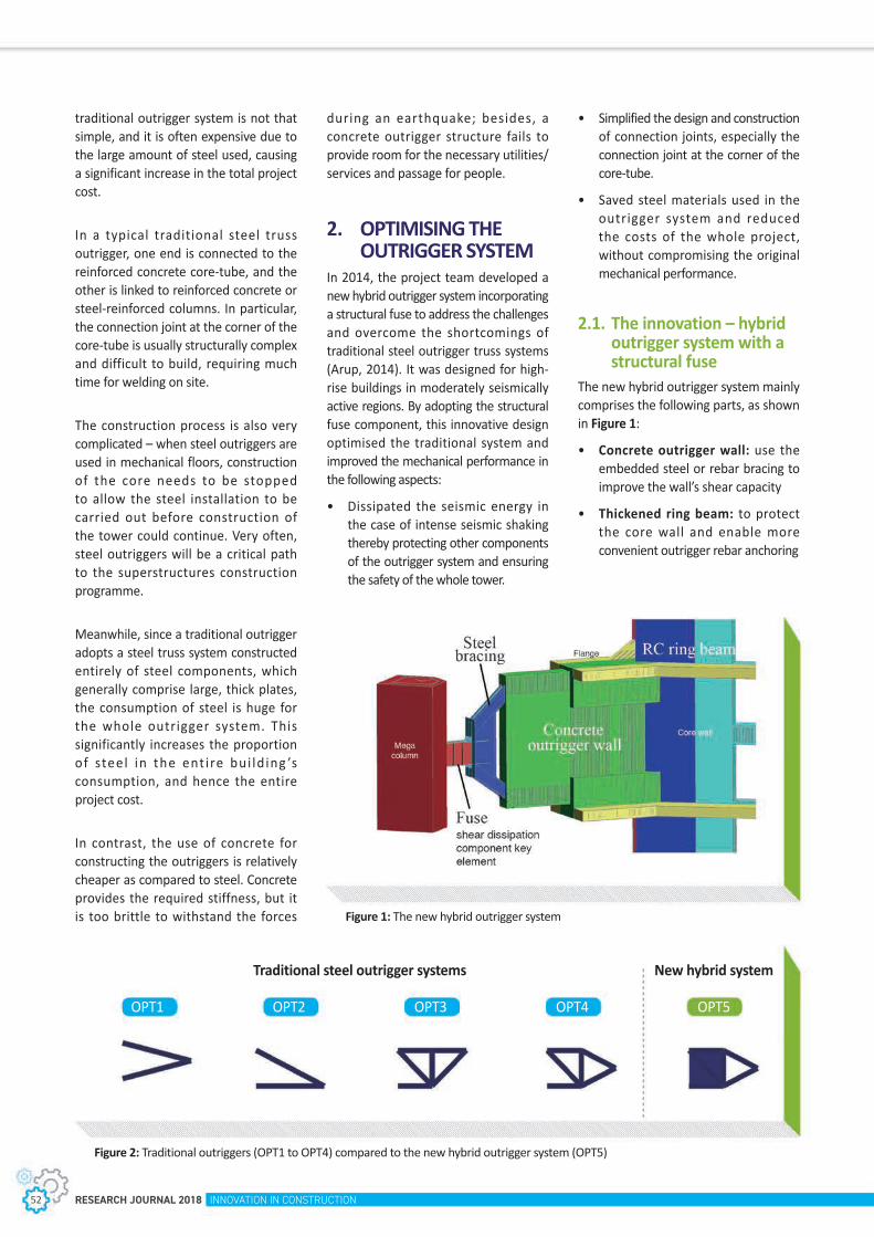
RESEARCH JOURNAL 2018 INNOVATION IN CONSTRUCTION52
during an earthquake; besides, a concrete outrigger structure fails to provide room for the necessary utilities/services and passage for people.
2. OPTIMISING THE OUTRIGGER SYSTEM
In 2014, the project team developed a new hybrid outrigger system incorporating a structural fuse to address the challenges and overcome the shortcomings of traditional steel outrigger truss systems (Arup, 2014). It was designed for high-rise buildings in moderately seismically active regions. By adopting the structural fuse component, this innovative design optimised the traditional system and improved the mechanical performance in the following aspects:
• Dissipated the seismic energy in the case of intense seismic shaking thereby protecting other components of the outrigger system and ensuring the safety of the whole tower.
• Simplified the design and construction of connection joints, especially the connection joint at the corner of the core-tube.
• Saved steel materials used in the outrigger system and reduced the costs of the whole project, without compromising the original mechanical performance.
2.1. The innovation – hybrid outrigger system with a structural fuse
The new hybrid outrigger system mainly comprises the following parts, as shown in Figure 1:
• Concrete outrigger wall: use the embedded steel or rebar bracing to improve the wall’s shear capacity
• Thickened ring beam: to protect the core wall and enable more convenient outrigger rebar anchoring
traditional outrigger system is not that simple, and it is often expensive due to the large amount of steel used, causing a significant increase in the total project cost.
In a typical traditional steel truss outrigger, one end is connected to the reinforced concrete core-tube, and the other is linked to reinforced concrete or steel-reinforced columns. In particular, the connection joint at the corner of the core-tube is usually structurally complex and difficult to build, requiring much time for welding on site.
The construction process is also very complicated – when steel outriggers are used in mechanical floors, construction of the core needs to be stopped to allow the steel installation to be carried out before construction of the tower could continue. Very often, steel outriggers will be a critical path to the superstructures construction programme.
Meanwhile, since a traditional outrigger adopts a steel truss system constructed entirely of steel components, which generally comprise large, thick plates, the consumption of steel is huge for the whole outrigger system. This significantly increases the proportion of steel in the ent i re bui ld ing ’s consumption, and hence the entire project cost.
In contrast, the use of concrete for constructing the outriggers is relatively cheaper as compared to steel. Concrete provides the required stiffness, but it is too brittle to withstand the forces Figure 1: The new hybrid outrigger system
Traditional steel outrigger systems New hybrid system
OPT1 OPT2 OPT3 OPT4 OPT5
Figure 2: Traditional outriggers (OPT1 to OPT4) compared to the new hybrid outrigger system (OPT5)

INNOVATION IN CONSTRUCTION RESEARCH JOURNAL 2018 53
FIRST PRIZE OF CONSTRUCTION PRODUCTIVITY
• Steel outrigger truss: to connect with embedded steel in the concrete outrigger wall
• Eccentrically-braced frame (EBF) link: during seismic events, the EBF link between the mega column and steel truss acts as a “structural fuse” by yielding at controlled demand levels and limiting damage to the outrigger wall (through its shear deformation and energy dissipation of the ground motion input)
Four traditional options of steel outrigger systems (OPT1-OPT4) and the new hybrid steel diagonal and concrete wall outrigger (OPT5) were compared, as shown in Figure 2. Four parameters were selected for sensitivity analysis and comparison of results between the five options. The four parameters were efficiency, steel consumption, size of individual component, and rebar consumption. Based on the results, we made the following preliminary conclusions:
• The new hybrid outrigger system could achieve the maximum system efficiency as compared to the traditional steel outrigger;
• The new hybrid outrigger system could achieve the minimum size of steel components and steel consumption as compared to the traditional steel outrigger;
• Compared to the traditional steel outrigger, the rebar consumption would be slightly increased for the proposed system.
Therefore, the new hybrid steel diagonal and concrete wall outrigger (OPT5) proved to be a reasonable form of outrigger system.
2.2. Application in Raffles City Chongqing
The new hybrid outrigger system was successfully applied in the design and construction of the two highest towers (each 350m) at the Raffles City Chongqing (RCCQ) development in China (Arup, 2014). The structural system of the north tower at RCCQ is shown in Figure 3.
Chongqing is located inland, with relatively low wind load and moderate seismicity. Situated at the confluence of
the Jialing and Yangtze rivers, the RCCQ mega-sculpture is an eight-tower, mixed-use development made up of curved, slender buildings which mimic the billowing sails of ancient ships.
Of the two tal lest towers in this development, one is used for luxury residences with a typical storey height of 3.8m. The 350m main structure comprises 72 stories above the podium. It spans a total length of 38m from the west to the east. The north face of the tower resembles the shape of a sail. In a north-south direction, the length of the structure varies from 32m to 45m at different elevations.
The other tower is designed for use as office space at the low tier (typical storey height of 4.3m) and as a hotel at the high tier (typical storey height of 3.6m). The 350m main structure consists of 70 stories above the podium. It spans a total length of 38m from the west to the east. The north face of the tower also resembles the shape of a sail, with length varying between 32m to 45m at different elevations.
Figure 3: Structural system of the north tower

RESEARCH JOURNAL 2018 INNOVATION IN CONSTRUCTION54
• The concrete wall outrigger has a higher performance objective than the fuse and the steel diagonal, and should be elastic under a Level 2 earthquake.
• The concrete core wall has the highest performance objective and is non-yielding under Level 1, Level 2 and Level 3 earthquakes.
Generally speaking, the whole outrigger system is an important structure in protecting the core wall as an effective entity (MOHURD, 2010).
3.1. Elastic analyses of concrete outrigger wall
3.1.1 Sensitivity analyses of outrigger wall thicknessContrast analyses of the thickness of the outrigger wall from 400 mm to 1,200 mm and the sensitivity of the structure’s period and maximum storey drift under wind loading are indicated in Table 1.
Table 1: Contrast analyses of different thickness of concrete wall
Wall thickness (mm) Period (s) Wind-DriftX Wind-DriftY
1,200 7.58 1/844 1/5411,000 7.59 1/840 1/539800 7.60 1/837 1/536400 7.66 1/822 1/525
From these results:
• For a range of outrigger wall thickness from 400 mm to 1,200 mm, the structure’s period is between 7.66s to 7.58s, a variation of <1%.
• The maximum storey drift under wind-Y loading variation is 3%.
• The maximum storey drift under wind-X loading variation is 2.7%
Thus, the thickness of outrigger wall is not sensitive to the overall structural performance.
3.1.2 Calculation of the outrigger wall’s shear studConsidering that the axial force of steel outrigger can be transferred to the embedded steel in the outrigger wall, this tension force needs to be transferred through all the sections’ shear studs to the concrete first, and then from the concrete to the reinforcement.
While this analysis adopts an approximate elastic design method, assessment of the anchoring performance of the embedded steel in the outrigger wall under intense seismic shaking requires both an elastic-plastic FEA analysis and to be consistent with experimental results.
3. STRUCTURAL ANALYSES OF THE NEW HYBRID OUTRIGGER SYSTEM
C h o n g q i n g h a s a l o w s e i s m i c precaut ionar y c r i ter ion , so the requirement for ductility and strength is less than in an area with high seismic precautionary intensity. This new hybrid outrigger system was considered most suitable for application in areas of low to moderate seisimicity (Zhu et al., 2015).
We adopted different structural analysis methods and software to check the structural performance of different components under Level 1, Level 2 and Level 3 seismic events, to ensure the system is able to maintain the basic operation. We also adopted the objectives and procedures of performance-based seismic design, and each component in the new hybrid system had different ductility requ i rements and per formance objectives (MOHURD, 2011). Figure 4 shows the performance objectives of each structural component. The structural performance varies from fuse to the reinforced concrete core wall as follows (Arup, 2014):
• The fuse is designed to be elastic under wind load and frequent earthquakes (Level 1), and able to dissipate energy at the yield stage under Level 2 and Level 3 earthquakes.
• The steel diagonal has a higher performance objective than the fuse and is non-yielding under a Level 2 earthquake.
Figure 4: Performance objectives of each structural component

INNOVATION IN CONSTRUCTION RESEARCH JOURNAL 2018 55
FIRST PRIZE OF CONSTRUCTION PRODUCTIVITY
An estimate of the shear stud diameter based on the severe seismic design condition is given by:
SGE: Gravity Loading Action; SEhk: Horizontal Earthquake Action; ϒRE: 0.85 Constant Parameter; Units: KN(Force)
From the results of our analysis, the diameter of the shear stud is 19mm. Based on the Chinese Code for design of steel structures (GB 50017-2003) (MOC & AQSIQ, 2003) 11.3.1, the design value of strength for one shear stud is:
As: Area of shear stud; Ec: Elastic Modulus of Concrete; fc: Compression strength of concrete; f: Tension strength of shear stud; ϒ: 0.85 Constant Parameter; Units: KN(Force)
From this formula, the design value of strength for one shear stud is 71KN, assuming that, to calculate the anchoring length of the embedded steel through the section adjacent to the core-wall, the shear stud can transfer the tension force to the surrounding concrete in 50% of the embedded steel.
Based on the above assumption, an anchoring length of approximately 3 meters can meet the requirement of the shear stud force transfer in the concrete.
3.1.3 Stress analysis of the outrigger wallSince wind load is the main control of the design loading condition, stress analysis of the outrigger wall is mainly based on the wind loading.
Based on the load design combination, we cannot directly obtain the maximum tension stress. The software only calculates normal stress and shear stress in two orthogonal directions, so we need to apply the Mohr equation to calculate the maximum tension stress:
S11:X in-plane Maximum Principle Stress; S22: Y in-plane Maximum Principle Stress; S12:in-plane Maximum Shear Stress; Units: MPa (Stress)
The analytical results show that the maximum principal tensile stress is largest in the two lower zones of the outrigger wall. The stress declines in the higher tier (Arup, 2014).
According to the Mohr equation, the maximum principal tensile stress in the lower tier is 4.7MPa.
As can be seen from the results of the stress analysis, there is local stress concentration in the outrigger wall near the core area. The average maximum principal tensile stress exceeds the C60 concrete tensile strength with standard value of 2.85MPa (Arup, 2014).
To solve this problem, we took the following measures:
• The outrigger wall is disconnected from the adjacent floor slab with movement joint, so the outrigger wall is decoupled from the floor slab which is subjected to high plane stress.
• A 650mm-deep ring-beam is set around the perimeter core wall to protect the core wall and to facilitate fixing of the outrigger’s heavily reinforeced rebar for better anchoring.
• On the premise of the analysis, the embedded steel in the outrigger wall is extended to the thickened ringbeam and thereby enhances the reinforcement ratio in the outrigger wall.
From the results of further analyses based on these measures, according to the Mohr equation, the maximum principal tensile stress in the lowtier is reduced to 2.0MPa.
3.1.4 Reinforcement estimation for the outrigger wall
T o a c h i e v e t h e r e a s o n a b l e reinforcement ratio of outrigger wall, structure engineer test several load combination to envelope the controlled load case.
Based on the analytical results, key aspects of the estimated reinforcement for the outrigger wall are as follows:
• The reinforcement ratio is between 1.6% to 2.5%.
• To a v o i d t h e r e i n fo r c e m e n t arrangement overcrossing in the outrigger wall and to facilitate the simple construction, therefore, thickening flange and thickening web to reduce the reinforcement ratio of 2% (MOC, 2011).
• The high t ier ’s outrigger wall reinforcement can be reduced by considering the construction-sequencing simulation analysis results.

RESEARCH JOURNAL 2018 INNOVATION IN CONSTRUCTION56
3.2. Elastic analyses of the structural fuse
The structural fuse between the mega column and steel truss is used in the severe intensity seismic condition, so as to achieve the aim of protecting the core and tower (Arup, 2014).
A c c o r d i n g t o s o m e o v e r s e a s experiments and research, the effect of link length on the failure mode and deformation capacity is summarised in the following notes:
• e < 1.6Mp/Vp; − short or shear link (developing only shear yielding)
• 1 . 6 M p/ V p < e < 2 . 6 M p/ V p ; −intermediate link (developing both shear and flexural yielding)
• e > 2.6Mp/Vp; − long link (developing only flexural yielding)Mp: Plastic Moment Capacity of Link; Vp: Plastic Shear Capacity of Link; e: Eccentric distant
• For the short or shear link, relatively uniform shear yielding occurs in the web along the entire link length, thus producing a large deformation capacity.
• For the long link, where flexural buckling occurs primarily in the form of local buckling of the flange, the deformation capacity is very limited, as the link web does not yield along its length or contribute any plastic deformation.
• For the intermediate link, both shear and flexural buckling occurs in the flanges and web shear buckling in the end panels.
3.3. Experiments with scaled models
To verify the hybrid outrigger system, it was necessary to use prototype physical experiments to test the reliability of the calculation and analysis. Therefore, three experiments were designed:
• Hybrid outrigger system (SRC mega column + fuse + steel diagonal + concrete wall outrigger + concrete core wall): a static loading and
Figure 6: The experiment model of outrigger wall system
low period repetitive experiment (Experiment 1);
• Steel diagonal + concrete wall outrigger: astatic loading and low period repetitive experiment (Experiment 2);
• Fuse: a low period repetit ive experiment (Experiment 3).
Experiment 1 was designed to test the whole system performance throughout the entire process, including capacity, deformation, concrete crack, yield sequence of elements, etc. At present, the rebar assembly and concrete pouring for th is exper iment are completed.
Experiment 2 was designed to assess the force path in the steel and concrete elements, and to test the anchor performance of the steel element inside the outrigger concrete wall.
Experiment 3 was designed to test shear capacity and lag properties of the fuse. Different fuse dimensions were fabricated and tested to achieve the best design objective. This experiment was completed, and the resulting capacity and stiffness of the fuse were quite close to the design values. Under a rare extreme earthquake condition, the hysteretic performance was also promising.
Figure 5: The sketch of reinforcement arrangement of outrigger wall

INNOVATION IN CONSTRUCTION RESEARCH JOURNAL 2018 57
FIRST PRIZE OF CONSTRUCTION PRODUCTIVITY
4. ACHIEVEMENT AND OUTCOME
4.1. Summary of materials, cost and time savings
At the RCCQ development in China, the hybrid outrigger design has saved about 10% of steel consumption as compared with traditional outrigger systems, resulting in significant cost and time savings. This innovative design has also simplified construction of the steel connection joints, which are often very complex and bulky in traditional systems.
4.2. Patent and awardsThe new hybrid outrigger system was patented in China in 2014. In 2016 it was awarded an Honorable Distinction in China Innovation Award at the inaugural CITAB-CTBUH China Tal l Bui lding Awards, for its integration of various structural solutions that yield exceptional performance under considerable seismic loads. It was also included in the technical guides titled Outrigger Design
for High-Rise Buildings published by the Council on Tall Buildings and Urban Habitat (Choi, H., Ho, G., Joseph, L. & Mathias, N., 2012).
4.3. Benefits and impact on the construction industry
4.3.1 Further implementation in tall building projects
The new hybrid outrigger system has been proved to be highly promising. It was rigorously tested at the China Academy of Building Research in Beijing, and eventually approved by the Expert Review Panel in China for application in the RCCQ project. By incorporating the new outrigger system in two of the RCCQ towers, substantial cost savings were made through efficiencies in steel tonnage and acceleration of the construction schedule. Due to its proven cost-saving and time-saving outcomes, it is anticipated that this hybrid outrigger system will continue to spark enthusiasm and be implemented in many other high-rise building projects in China and elsewhere.
Figure 7: Typical steel/rebar
T h e hy b r i d o u t r i g ge r syste m i s particularly suitable for:
• Towers with a great slenderness ratio which require a very strong horizontal outrigger system for lateral stability.
• Tall building projects located in a moderate seismic zones and where the wind loading is the controlling case for tower design. (Under Level 1 seismic and normal wind loads, the fuse will remain fully elastic; while under Level 2 and Level 3 seismic events, the fuse shear dissipation component will yield and deform and dissipate energy. This damping effect protects the outrigger wall and thus the whole building structure).
• All towers which need an outrigger system to provide the stiffness and where significant savings in steel consumption and project construction costs are desired.
4.3.2 Simplifying steel connection joints
The new hybrid outrigger system also simplifies the steel connection joints as compared to conventional outriggers, where the connection joint at the corner of the core-tube is usually structurally complex, bulky and difficult to build, and requires much time for welding on site, and moreover, the joint connecting the steel truss and the concrete core-tube is always an abrupt change of high stress transition zone area between the two component. In contrast, the new system uses a reinforced concrete wall to replace the steel outrigger at the core-tube corner. This simplifies the steel connection joint, especially at the corner, and also provide a transition zone of stress transfer via outrigger wall outside the core-tube, protecting the core-tube.
4.3.3 Release more refuge zone The new hybrid outrigger system has achieved a higher rigidity and structural performance as compared to the conventional steel outrigger based on the same outriggersize. In other words, to achieve the same structural performance

RESEARCH JOURNAL 2018 INNOVATION IN CONSTRUCTION58
of tower structures, structural engineers can use this innovation to reduce the outrigger size, and release more of the refuge zone for architectural design, thus achieving further cost savings.
4.3.4 Inspiring broader design exploration and sustainable solutions
The majority of conventional outrigger systems were designed with a steel truss or replaced by concrete walls. Arup were the first to combine the steel and concrete structures and introduce the concept of “structural fuse” into the outrigger system. This innovation creates the possibility of subsequent exploration and development of other new forms of outriggers in future.
5. CONCLUSIONS A new hybrid outrigger system has been developed for high-rise buildings in moderately seismically active regions. The hybrid system uses concrete walls (adjacent to cores), steel diagonals and structural fuses (suitable to dissipate seismic energy during an earthquake). Comprehensive studies and reviews
were conducted to ensure the reliability, and optimize the design. The new system was successfully applied in the design and construction of Raffles City Chongqing, China, and saved about 10% of steel consumption as compared with a traditional outrigger system, resulting in significant overall project cost and time savings.
ACKNOWLEDGMENTS The authors gratefully acknowledge the contribution and support from Andrew Luong, Jie Liu, Yue-Qi Hou, Shi-Chao Wu and Oliver Zhang, as well as Arup Tall Building Skills Network and Seismic Skills Network.
REFERENCESArup. (2014) Review of structural seismic design for Raffles City Chongqing. Beijing: Arup.
Choi, H., Ho, G., Joseph, L. and Mathias, N. (2012) Outrigger Design for High-Rise Buildings: An output of the CTBUH. Chicago: Council on Tall Buildings and Urban Habitat.
MOC (Ministry of Construction of the People’s Republic of China). (2011) Code for design of concrete structures GB 50010-2010. Beijing: China Architecture and Building Press.
MOC and AQSIQ (Ministry of Construction of the People’s Republic of China and the General Administration of Quality Supervision, Inspection and Quarantine of the People’s Republic of China). (2003) Code for design of steel structure GB 50017-2003. Beijing: China Planning Press.
MOHURD (Ministry of Housing and Urban-Rural Development of the People’s Republic of China). (2010) Code for seismic design of buildings GB 50011-2010. Beijing: China Architecture and Building Press.
MOHURD (Ministry of Housing and Urban-Rural Development) of the People’s Republic of China. (2011) Technical specification for concrete structures of tall building JGJ 3-2010. Beijing: China Architecture and Building Press.
Zhu, L., Liu, J., and Zhang, C. et al. (2015) Application of an innovative hybrid outrigger system in the north towers of Raffles City in Chongqing. Building Structure, 45 (24):16-21.

INNOVATION IN CONSTRUCTION RESEARCH JOURNAL 2018 59
FIRST PRIZE OF CONSTRUCTION PRODUCTIVITY
BIOGRAPHY
Michael KWOK
Ir Michael KWOK is the East Asia Chairman of Arup and a member of Arup Group Board. He has over 30 years of project experience, and he is a Registered Structural Engineer in Hong Kong and in the People’s Republic of China. He is conversant with Building Regulations and Codes of Practice in Hong Kong, China and Europe. He has been involved in the structural design of many large-scale projects such as Heng Fa Chuen, Hong Kong University of Science and Technology, Chek Lap Kok Airport Terminal Building and West Rail in Hong Kong. For projects in China, he is the director in-charge for a number of key projects associated with 2008 Beijing Olympics including Beijing Capital International Airport Terminal 3, CCTV Headquarters, Bird’s Nest, and the Denmark Pavilion and Korea Pavilion of Shanghai 2010 World Expo. Through these major projects he has worked closely with many world renowned architectural practices.
Goman HO
Dr Goman HO is an Arup Fellow. He has extensive experience in multidisciplinary and mega scale and tall building projects, especially in the East Asia Region. He is currently the global leader of the Tall Building Skills Network. He joined Arup in 1992 after completing his PhD at Hong Kong Polytechnic University. He has been involved in projects across the East Asia Region including Hong Kong, Japan, Korea, Mainland China, Myanmar, the Philippines, Taiwan and Vietnam. He is a registered Chartered Engineer in the UK, Registered Professional Engineer in Hong Kong and Qualified First Class Registered Structural Engineer in the People’s Republic of China.
Penny CHEUNG
Ir Penny CHEUNG graduated with the bachelor degree in civil engineering at the University of Hong Kong with master degrees in civil engineering and in real estate. He is Arup’s Chongqing office leader and Building Group Leader in Chongqing and Wuhan offices. He is the Project Manager of the Raffles City Chongqing development. A professional structural engineer, he has worked in Hong Kong, Shanghai and recently, leads the Chongqing and Wuhan team of over 50 staff. He has extensive experience in leading and managing multidisciplinary engineering teams for large comprehensive development in Mainland China and Hong Kong. He has been involved in the International Trade and Commerce Centre in Chongqing (468m development under construction), The Hub in Shanghai and the International Commerce Centre in Hong Kong.
Li-gang ZHU
Mr Li-gang ZHU graduated with a bachelor degree in industrial and civil engineering at the China University of Mining and Technology. He is First Class Registered Structural Engineer in the People’s Republic of China. With over 25 years of experience in structural design and construction, he is an Associate Director and a seismic expert in Arup. He has extensive experience in structural analysis and optimisation in super high-rises. He led the team to get the EPR final approval for many complicated projects including Raffles City Chongqing, the 468m Chongqing Shui On International Trade and Commerce Centre and Suzhou Opera House etc.

SECOND PRIZE OF CONSTRUCTION PRODUCTIVITY

INNOVATION IN CONSTRUCTION RESEARCH JOURNAL 2018 61
New Machines to Enhance Productivity of Bridge Construction
James Edward LAWTON (Ted LAWTON)1
1 Gammon Construction Limited
Gammon has developed a new range of machines to benefit the erection of segmental bridges, in terms of cost efficiency, productivity and sustainability. These machines feature the K-Frame with its signature ‘K’ shape and exoskeleton structure, enabling multifunction capability with a high lifting power to self-weight ratio of more than 2 to 1.
These machines were invented and implemented in Hong Kong and is assembled from a common- parts library of interchangeable modules, enabling the erection of virtually all types of segmental bridge, irrespective of curvature. This has been applied at the Tuen Mun-Chek Lap Kok Link project and is currently erecting spans up to 200m long with segments weighing up to 240 tonnes, relieving the need for traditional machines, notably launching gantries.
“Innovation is at the core of Gammon culture. We shall hold onto the spirit to further enhance productivity and safety in the industry, as well as to lower the construction cost”, said Thomas Ho, Chief Executive of Gammon.
Keywords: Segmental bridge construction, new machines, design for manufacturing and assembly, multi-function, K-Frame Family, common parts library, safety
ABSTRACT
1. BACKGROUND
1.1. The Tuen Mun – Chek Lap Kok Link ProjectThe construction of numerous bridges in marine and land conditions is required for the HK$8.66 billion Tuen Mun – Chek Lap Kok Link (TM- CLKL) project which, once completed, will connect Mainland China with Hong Kong through its newly constructed Boundary Crossing Facilities (BCF).
The project involves design and construction of a dual two-lane sea viaduct approximately 1.6km long, and construction of nine approach viaducts. The construction of these viaducts is expedited by the use of concrete segments which are precast off-site and the methods used to erect these segments on-site require specialised erection machines and expertise.
Facing challenges from marine and land conditions, the presence of sensitive infrastructure, acute curvatures and gradients, as well as gradient change, the project team found traditional bridge erection machinery was not always suitable.

RESEARCH JOURNAL 2018 INNOVATION IN CONSTRUCTION62
Gammon’s in-house engineering consultancy Lambeth was tasked to find a solution, which led to the development of the K-Frame, a multi-function deck erection machine.
1.2. Multifunction capability of the K-Frame for enhanced productivity
The K-Frame’s signature shape permits rotation of a concrete segment within its recess. This results in benefits of reduced lifting radius, and an efficient and compact structure capable of lifting the 200-tonne segments, with a self-weight of the K-Frame of only 100 tonnes.
Important ly, segments may a lso be passed through the K-Frame exoskeleton structure, which includes seven inter laced porta l f rames. Combined with the use of a single strand jack to enable segment rotation and hydraulic control of all actuators, a seamless multi-function capability is enabled, consisting of:
1. Lifting frame
2. Rear-fed lifting frame
3. Straddle carrier
4. Off-loading gantry
The above elements are illustrated in Figure 1.
All the four functions can be used readily on one bridge span when the requirements for a type of function change as the span progresses. Trials indicated that straddle carrying a segment with the K-Frame could reach speeds of up to 70 metres/hour when required.
Figure 1: K-Frame Multi-Function
K-FRAMEMULTI-FUNCTION
1. LIFTING FRAME
2. REAR FED LIFTING FRAME
3. STRADDLE CARRIER
4. OFF LOADING GANTRY
TRANSPORTER
GOLDHOFER
STRADDLE CARRIER STRADDLE CARRIER
MTRC BOUNDARY FENCE
MTRC BOUNDARY FENCE
DELIVERY BARGE
SEAWALL BCF
MTRC
MTRC
GOLDHOFER OR STRADDLE CARRY
NLH
NLH
GOLDHOFER
DELIVERY BARGE
CRANE
CRANE

INNOVATION IN CONSTRUCTION RESEARCH JOURNAL 2018 63
SECOND PRIZE OF CONSTRUCTION PRODUCTIVITY
Figure 2: The K-Frame Family
As the project progressed, this innovation was then further developed to create the ‘K-frame Family’ (Figure 2) of machines from a common parts library providing more functions, capable of delivering and erecting segments throughout the entire range of bridge spans on the TM-CLKL project (Figures 3, 4 and 5) . It is proposed that this new approach adopts more re-use of equipment in a more sustainable manner for subsequent projects.

RESEARCH JOURNAL 2018 INNOVATION IN CONSTRUCTION64
Figure 3: Overview of deck erection commencing at piers as balanced cantilevers
Figure 4: Deck segments delivered by barge under K-Frames commencing 200m spans
Figure 5: Balanced cantilever bridge deck construction, working outwards from a central pier

INNOVATION IN CONSTRUCTION RESEARCH JOURNAL 2018 65
SECOND PRIZE OF CONSTRUCTION PRODUCTIVITY
2. RESEARCH METHODOLOGY AND DATA
The primary requirement was to engineer the most cost-effective and productive method of constructing four 200m-long spans over a sensitive construction area on the TM-CLKL project.
Firstly, a need analysis was carried out and identified that:
1. T h e K - F r a m e w a s t h e b e s t ‘engineering solution’ for construction activities in this sensitive area;
2. If it could be multi-functional and applied to other spans on the project, it would become more financially feasible and lead to great productivity as the enabling of more work fronts ensures programme surety;
3. The capability to tender competitively for future works was needed. The K-Frame innovation helps provide a competitive advantage using in-house expertise, rather than depending on a few outside specialist subcontractors who also share their expertise with competitors.
Market research was then carried out which confirmed the feasibility and productivity benefits of the K-Frame, as illustrated in Table 1.
A concept design was then created, using 3D modelling to quickly present the design and gain approval, without waiting for 2D CAD drawings.
3. ADVANTAGES OVER ALTERNATE APPROACHES
• Multi-functional: The multi-function capability of the K-Frame challenges the need for traditional ‘monster’-style launching gantries.
• Cost-effective: Notably, four work fronts may be provided by K-Frames for the same cost as one work front provided by a launching gantry. It also costs no more than a normal lifting frame, less than a rear-fed
lifting frame, underslung travelling lifting frame and offloading gantry, and much less than a launching gantry.
• Programme Surety: Compared with a launching gantry, work fronts do not have to be sequential but may be numerous, and increased to suit programme acceleration.
• Su i ta b le fo r a l l ge o m etr i ca l constraints: Notably, the underslung travelling lifting frame cannot be used over an MTR line or expressway, as there is insufficient headroom under the deck. The length-to-span ratio makes the launching gantry difficult and slow to operate when spans become curved, and it is incapable of constructing 200m spans in a feasible manner.
• Bridge loading: The K-Frame imposes no greater vertical load on the bridge deck than an ordinary lifting frame, whereas a launching gantry typically requires the bridge and foundations be designed for its 1400 tonne weight, plus significant extra lateral wind loading as it presents a large ‘sail area’. Ref. Tables 1 and 2
• Reduced risk: A launching gantry has many more moving parts representing more risk to safety and production rates than other types of machine, in terms of breakdowns and accidents.
• Improved logistics: Delivery time for the K-Frame is approximately four months opposed to one year for a launching gantry.
Table 1: Illustrative comparison between types of machines for segmental, balanced cantilever, deck erection
Machine Type
Segment Delivery OptionsFrom…… Bridge Geometry Suitability Bridge Design
Requirements Risk Logistics Programme Cost
Haul road
under deck
On top of deck
from pier head
Marine barge
Back span
Along already erected bridge
deck from abutment
Tight curves
Steep gradient
Gradient changes
Long spans
High deck
Low deck
Acceptable self-weight of machine
on deck
No major strengthening of bridge and
foundations to support machine
Normal construction
risk and consequence
Speed of erection
Short mob
demob time
Short delivery
time
No sequential construction.
Multiple, flexible
work fronts to suit site constraints
Programme suretyDelays
mitigated by additional, work fronts
Cost per work front HKD
CRANE 200T Capacity ✓ ✓ ✓ ✓ ✓ ✓ Nil Nil ✓ 2 days ✓ ✓ ✓ Hire
LIFTING FRAME ✓ ✓ ✓ ✓ ✓ ✓ ✓ ✓ 110 ton ✓ ✓ 1 week ✓ ✓ ✓ 5M
REAR-FED LIFTING FRAME ✓ ✓ ✓ ✓ ✓ ✓ ✓ ✓ ✓ ✓
150 to 200 ton ✓ 1 week ✓ ✓ 14M
TRAVELLING LIFTING FRAME (Under-slung seg.)
✓ ✓ ✓ ✓ ✓ ✓ ✓No
Head Room
150 to 200 ton ✓ 1 week ✓ ✓ 14M
LAUNCHING GANTRY ✓ ✓ ✓ ✓ ✓ Not Suitable ✓ ✓ 1000 ton
Major strengthening
requiredHighest risk & consequence
Fastest for
straight decks
Longest 8 weeks Longest Sequential 1 work
front 24M
K-FRAME ✓ ✓ ✓ ✓ ✓ ✓ ✓ ✓ ✓ ✓ 100 ton ✓ ✓ 1 week ✓ ✓ ✓ 3M
OFF-LOADING GANTRY
Traditional 150 ton Major 8 weeks 7M
K-Frame 100 ton ✓ 1 week 3M

RESEARCH JOURNAL 2018 INNOVATION IN CONSTRUCTION66
Table 2: A Comparison of ratios of lifting capacity to self-weight
Erection machines in use on site
Lifting methodSelf-weight Lifting
capacity RatioStrand Jack Winch
Travelling Hanger Beam Lifting frame Yes N/A 80t 210t 2.6
K-FrameMulti-function Yes N/A 100t 210t 2.1
TraditionalLifting Frame N/A Yes 100t 120t 1.2
Traditional Launching Gantry N/A Yes 1450t 900t 0.6
Figure 7: Kinematic envelope: rotation of a segment within the K shape is shown in red
Figure 6: K-Frame BIM workflow
4. APPLICATION / FIELD TRIAL
The use of a central BIM model to manage the design and fabrication of the new machines as shown in Figures 6 and 7 resulted in virtually clash-free assembly and commissioning when they arrived on site from the fabricator. This was an achievement, not only due to the complexity of their articulation, but also because the hydraulic components were not available until the machines arrived on site.
Contrasting colours as shown in Figure 7 highlight components with relative movement during modelling. The approach was then adopted on the actual machine to enhance safety.
The days of producing a prototype construction equipment for extensive development and alterations before final commissioning should now be a thing of the past.

INNOVATION IN CONSTRUCTION RESEARCH JOURNAL 2018 67
SECOND PRIZE OF CONSTRUCTION PRODUCTIVITY
ACKNOWLEDGMENTS 1. Clients – HKH&T, AECOM
Approval and support for use of this innovation on their projects
2. Consultants – Arup and TGPDesign of bridge structure and erection analysis, including loads imposed by erection equipment
3. Independent Checking Engineers – Atkins
4. Top Gammon managementProvision of resources for innovation, design and implementation
5. Lambeth design office, HKInnovation, design for manufacturing and assembly, promotion, development and implementation
6. Dorman Long Technology LtdDesign and supply of hydraulic control system, all hydraulic equipment and provision of specialists for training and operation
7. Lambeth digital designProvision of BIM design engineers and software for production of digital models and animations.
8. Steelwork fabricators:- Gammon Construction Services Department (CSD) Pristine, Zhong JiProduction of shop drawings from digital model, fabrication, trial assembly and delivery
9. Gammon Health & Safety DepartmentThe incorporation of “Safety by Design”
10. Project - TMCLK Site managementSite training of engineers and operatives, development of operations manuals and check lists
11. For contributions to this paperFung Kwok Fai (Alex) BEng, Msc.Principal Design Engineer with Lambeth Associates Ltd., experienced in steel work design and construction for major infrastructure and building projects.
BIOGRAPHY
James Edward LAWTON (Ted LAWTON)
Senior Engineering Development Manager for Gammon Construction Ltd., with a balance of multi-discipline design and construction experience, gained from a range of major infrastructure and building projects.
These include long-span bridges such as the Second Severn Crossing in the UK and Kap Shui Mun, Shenzhen Bay, Stonecutters and currently, Tuen Mun – Chek Lap Kok Link.
Building projects include the Retail Bridges linking HK Central Station to IFC1 & 2, Cathay Pacific Air Cargo Handling Terminal, HKAA Passenger Terminal 3 “Midfield” and Express Rail Station XRL810A.
He specialised in the design and management of alternative designs and construction methods. Recent years, he involved in the development and application of new methods of mechanised construction for commercial buildings and bridges.

FIRST PRIZE OF CONSTRUCTION SAFETY

INNOVATION IN CONSTRUCTION RESEARCH JOURNAL 2018 69
Bio-Inspired Anti-Vibration Exoskeleton for Manipulating Demolition Tools
Prof. Xingjian JING1
1 Department of Mechanical Engineering, The Hong Kong Polytechnic University
Long-term exposure to high-level vibration can lead to considerable pain and time off work, and even result in permanent disability. Targeted at manipulating heavy duty jackhammers, this study has led to development of an innovative, anti-vibration exoskeleton technology which is passive, portable, cost-efficient and crucially suppresses significant vibration during the drilling and hitting process. The exoskeleton mimics the limb structure of animals and fully employs the nonlinear benefits of the bio-inspired X-shaped structure, which consequently significantly reduces vibration transmission without sacrificing loading capacity. Theoretical modeling, simulation and experimental results demonstrate the effectiveness and efficiency of this innovative technology.
Keywords: Nonlinear dynamics; Vibration control; Exoskeleton; Demolition tools; X-shaped structures
ABSTRACT
1. INTRODUCTIONVibration-related syndrome in human bodies includes damage to sensory nerves, muscles and joints in the hands and arms. Installation of vibration isolators is a common method for vibration control. With the development of vibration control theory in the past decade, results increasingly indicate that traditional linear isolators are very limited in meeting the increasing demands for high vibration control performance. Meanwhile nonlinear vibration control has been attracting ever greater attention in the analysis and design of various vibration control or isolation systems (Liu et al. 2015, Jing & Lang 2015, Jing 2014, Jing & Lang 2009), in extensive engineering practices ranging from vehicle suspension and high-precision machines, to space launches or on-orbit vibration control, etc.
As early as the 1970s, Ruzicka & Derby (1971) discussed the attenuation of forces in linear and nonlinear systems, Dange and Gore (1978) analyzed the nonlinear isolator by the computer simulation method, and Hundal & P S Parnes (1979) studied dynamic responses of the isolator in the same system under basal vibration conditions to prove that the vibration isolation effect of the nonlinear system was significant. Later, many research results have been developed for analysis and design of nonlinear vibration control systems (Nayfeh et al. 1997). In recent years,

RESEARCH JOURNAL 2018 INNOVATION IN CONSTRUCTION70
more attention was paid to employing nonlinear benefits in vibration control systems, including several recent review papers by Liu et al. (2015) and Jing & Lang (2015), which serving as good summaries of recent advances in this active area. Recent progress indicates that good passive vibration control is possible in cases where nonlinear dynamics can be ful ly employed through a feasible structural design. Sun et al. (2014), Sun & Jing (2016), Wu et al. (2015), and Wu & Jing (2016) present a bio-inspired X-shaped structural approach which naturally combines the benefits of nonlinear dynamics and feasible structural design in a purely passive manner, and achieves excellent vibration control performance.
Construction workers manipulating heavy-duty jackhammers or road breakers receive excessive vibration to their hands and arms, eventually leading to serious vibration-related syndrome. It is known that the most harmful vibration is in the frequency range between 6 Hz and 20 Hz (Su et al. 2011, ISO 5349-1986). However, traditional springs or dampers cannot solve the problem due to: (1) the worker needs to press and hold down the machine tightly in order for high demolition efficiency, and (2) adding more compression to traditional springs or materials leads to dramatically increased stiffness and consequently s e r i o u s r e d u c t i o n i n v i b ra t i o n suppression. Therefore, products with different active vibration control methods have been developed, but at much increased cost of manufacturing and maintenance, and limited reduction of practical vibration levels.
To solve this troublesome problem, an innovative passive anti-vibration exoskeleton has been developed in this study based on a bio-inspired X-shaped structure referred to as a bio-inspired anti-vibration exoskeleton (BIAVE) (Figures 1 and 2). The BIAVE is designed to be l ight-weight, foldable and adjustable in size and stiffness, and thus adaptable to different jackhammers. Vibration in jackhammers is significantly reduced due to the beneficial non-linear stiffness provided by the BIAVE.
Moreover, when an operator presses down on the BIAVE handles, a greater d o w nwa rd fo rc e s a d d e d to t h e jackhammer which increases demolition efficiency and decreases the dynamic stiffness between the jackhammer and the handles. These advantages solve the challenging issues mentioned above.
2. THE BIO-INSPIRED ANTI-VIBRATION EXOSKELETON (BIAVE)
Natural things always have some special structures such as animal leg/limb skeletons, trees and flower formation, etc. Inspired by a bird leg/limb skeleton (Figure 1), the bio-inspired X-shaped structure has been studied by several authors, e.g. Sun et al. (2014), Sun & Jing (2016), Wu et al. (2015), Wu & Jing (2016). Actually, many natural structures including trees, flowers, and
bones share very similar structures to the X-shape or near variants.
The X-shaped structure is readily foldable and f lexible, and easi ly manufactured and implemented in practice. Most importantly, the nonlinear dynamic behavior of the X-shaped structure and its different variants (different asymmetric cases) are shown to be very beneficial for vibration control in a purely passive manner (Wu et al. 2015). These facts have motivated the studies described in this paper.
To solve the long-lasting vibration control issue in demolition tools, the bio-inspired structure is designed to be a flexible assistive tool that can be easily installed in different demolition tools such as jackhammers, road breakers or chisels, etc., as shown in Figure 2.
Figure 1: The X-shaped structure in biological systems: example of a bird-limb skeleton
Figure 2: The novel BIAVE fitted a breaker for demolition

INNOVATION IN CONSTRUCTION RESEARCH JOURNAL 2018 71
FIRST PRIZE OF CONSTRUCTION
SAFETY
During manipulation of a breaker, the operator usually holds the handles tightly for controlled demolition, therby generating excessive vibrations in breakers weighing up to 50kg or even higher. Using a BIAVE, the operator can hold the new handles more freely and with much smaller harmful vibrations transmitted to the hands and arms, thus significantly reducing potential damage to operators and extending their daily working hours.
3. MODELLING OF THE BIAVE
The X-shaped structure used in the BIAVE is shown in Figure 3, where there are 4 layers, one of which has a rod-length twice as long as the others, such that springs are more easily installed within this layer as shown. In the modelling, the breaker is considered as a rigid body M2 and the two parallel X-shaped structures are simplified into one without losing generality. The vibration is modelled to be exerted vertically upwards at the bottom of M2. The upper mass M1 is assumed to act as the added vertical push-down force from the operators’ hands. The rod weight of the X-shaped structure can also be considered equivalent to the upper mass M1. The spring used is a traditional linear one with stiffness K. The simplified model in Figure 3a was also used in FEM analysis later, where L1 = length of the small rods, and L2 = length of the large ones, and θ = assembly angle with respect to the horizontal (see also Figure 3b). The air damping effect is denoted by D with the corresponding damping coefficient c.
Details of the mathematical modelling of the dynamic equation are given by Jing et al. (2017). The displacement transmissibility, Td, is defined as the ratio between the vibration amplitude of the top mass M1 over the vibration amplitude of the lower mass M2. This is then used for evaluat ing vibration isolation performance at different frequencies. Displacement transmissibility and natural frequency are commonly used to reflect the vibration isolation effect with different structural parameters.
Figure 4: Static stiffness of the BIAVE in compression
Figure 3: (a) The simplified model of the prototyped BIAVE, (b) Modeling of the 4-layer BIAVE
4. STATIC STIFFNESSThe structural parameters of the system can be designed for different vibration isolation performance. To have more understanding, the static stiffness of the BIAVE is developed with different stiffness K, as shown in Figure 4. It can be seen clearly from Figure 4 that the stiffness of the BIAVE decreases with an increase in suppression of the structure (i.e., the relative displacement between M1 and M2 is increased). This shows that when more downward force is applied to the BIAVE handles, the working position of the BIAVE is lower, leading to more compression in the X-shaped structure and thus a decreasing dynamic stiffness which is very beneficial for vibration control. It is also noted that more downward force results in higher demolition efficiency in practice. This again demonstrates the unique nonlinear advantages of the BIAVE as compared with all other traditional systems.
5. PARAMETRIC INFLUENCE
Understanding of the parametric influence on vibration suppression i s important . Severa l st ructura l parameters affect the vibration isolation significantly, including spring stiffness K, damping coefficient, assembly angle, rod length, rod length ratio, and so on. For example, the influence of different rod length ratios are shown in Figure 5, with the same L1 = 100mm and different ratio of L1 / L2. Considering that the first two resonant frequencies are critical to vibration suppression in the frequency range 6-20 Hz, a summary of parameter influence on the vibration suppression performance of the BIAVE is given in Table 1.
With these results, the BIAVE structure can be well designed with several properly-tuned structural parameters, to achieve good vibration suppression performance at low natural frequencies,
(a) (b)

RESEARCH JOURNAL 2018 INNOVATION IN CONSTRUCTION72
while maintaining a high loading capacity and large displacement motion without the stability problem. Overall, there are redundant structural parameters which can be employed to tune the vibration suppression performance of the BIAVE, thus achieving good flexibility in practical applications. Optimization of the structural parameters can be done for even better performance with a more compact structure.
6. EXPERIMENTSA prototype of the BIAVE was tested both in the laboratory and on-site environments for validation (see Figure 6). The prototype BIAVE has the refined parameters as discussed before, i.e. L1 = 100mm, L2 = 200mm, M1 = 15kg, M2 = 20kg, θ = π/6, K = 100N/mm, D = 0.1, and the rod material is aluminum alloy. Once the breaker is in operation, the BIAVE handle is pushed down to the desired position, which is equivalent to the mass M1, with an assembly angle θ = π/6. The mass M2 is exactly the mass of the breaker used in the experiments. The prototype BIAVE is about one meter tall and has two 4-layer X-shaped structures in parallel (Figure 2). Both of these structures have 1 large layer and 3 smaller layers, each constructed with corresponding rotating joints. The mass of the connecting rods is around 0.3kg per 100mm. The downward force used to make the X-shaped structure work at the desired assembly angle is 15kN, which follows the parameter settings used in the theoretical calculation and FEM analysis. The electric breaker is 20kg, and its impact frequency is 1800 times/min, i.e., 30Hz.
Once the breaker is working, hitting on a concrete or rubber surface generates a single-frequency vertical excitation to the BIAVE system, which has a main frequency of around 30Hz on rubber or 20Hz on concrete. Vibration acceleration signals on the breaker and on the BIAVE handle can be measured for further analysis, and are referred to as Z-down and Z-up respectively in the following discussion.
Table 1: A summary of parametric influence on vibration suppression
The 1st resonance The 2nd resonance Transmissibility in 6-20 Hzfrequency peak frequency peak
M1 ↑ ↓↓ -- = = ↓↓
Stiffness K ↑ ↑↑ ↑ = = ↑↑
Assembly angle θ ↑ ↑↑ ↑ ↑ -- ↑↑
Length ratio (L1 / L2) ↑ with fixed L1 = 100mm ↓↓ -- ↑↑ ↓ ↓↓
Layer number n ↑ ↓↓ ↓ ↓↓ ↓ ↓↓
Damping effect ↑ = ↓ = ↓ ↑
Materials from steel, to aluminum, to magnesium ↓ ↓ ↓ ↓ ↓
Figure 5: Acceleration transmissibility with different rod length ratio R = L1 / L2
Figure 6: Experimental BIAVE prototype: (a) Laboratory experiment; (b) On-site experiment.
(a) (b)

INNOVATION IN CONSTRUCTION RESEARCH JOURNAL 2018 73
FIRST PRIZE OF CONSTRUCTION
SAFETY
To evaluate the vibration level, the ISO5349 standard calculation for hands and arms vibration is adopted (see Figure 7, Su et al. 2011, ISO 5349-1986). Based on this calculation, the measured data f rom severa l exper imenta l laboratory tests using the breaker to hit rubber materials are summarized in Table 2.
The following points can be drawn from Table 2:
(i) Vibration on the breakers is about 14 m/s2, while on the handles it is only about 5 m/s2. The vibration reduction is very significant, up to 70%, and the suppressed vibration level means that operators can continuously work up to 5 or 8 hours with the BIAVE but only about 30 minutes without it (Su et al. 2011).
(ii) When a greater pushing force is applied, vibration of the breaker is much higher, indicating more powerful demolit ion, but the vibration level on the BIAVE handles remains at a reasonable healthy level, without obvious increase in the reduced vibration rate. This is a very beneficial feature of the BIAVE.
(iii) Adding more springs provides a greater downward pushing force at the same compression level, but the corresponding vibration levels on the handles are increased, although not uniformly due to the inconsistent hitting surface during the testing.
Figure 7 shows sometime and frequency responses in these tests. It can be seen that the main excitation comes from the vibration frequency of the breaker, with an obvious vibration peak around 30Hz. The vibration suppression between 6Hz and 20Hz is very good in each test. An overall complicated nonlinear dynamic response can be seen, as with the previous analysis, including super-harmonics, sub-harmonics and intermodulation. In some cases, the sub-harmonic response is quite strong (around 15Hz) and can be seen both on
Table 2: Frequency-weighted acceleration of the BIAVE in laboratory testing
Vibration on the breaker –DownVibration on
the BIAVE handle – Up
Ta=Vibration up/Vibration
down
Working Condition
Only Z-direction
14.014 4.665 0.332898 3 springs full loading
13.85208 5.13896 0.370988 4 springs no loading
15.46943 6.111534 0.395072 4 springs full loading
13.87586 4.306374 0.310350 5 springs no loading
16.61955 5.460997 0.328589 5 springs full loading
Figure 7: Time and frequency responses in typical laboratory testing (Z1 is the vibration on the breaker and Z2 is the vibration on the BIAVE handle)

RESEARCH JOURNAL 2018 INNOVATION IN CONSTRUCTION74
the breaker and the BIAVE handles due to the coupling dynamics, but obvious suppression is still maintained.
On-site testing was also conducted and compared with a similar breaker without BIAVE protection. The results are summarized in Figure 8. It can be seen that (1) vibration on the breaker is even stronger with the BIAVE than without it (improved up to 75% in terms of overall vibration energy, or 30% for the weighted vibration), which is very helpful for improvement of demolition efficiency; (2) with the BIAVE, the vibration can be suppressed significantly to a much healthier level according to the ISO hand-arm vibration standard. The conclusions are very consistent with those obtained before.
Figure 8 also shows one typical test result, where “traditional Z” refers to the vibration on the traditional breaker without the BIAVE, while “BIAVE down, up and hand” refer to the vibration on the breaker body, BIAVE handle and operator hand with the BIAVE structure, respectively. The vibration suppression performance of the BIAVE is very significant, both in terms of overall vibration energy and the vibration within the sensitive frequency range 6-20Hz.
7. CONCLUSIONBy employing nonlinear benefits, a novel bio-inspired vibration suppression system, referred to as the Bio-Inspired Anti-Vibration Exoskeleton (BIAVE), has been systematically developed with a purely passive structural design. With mathematical modelling, FEM analysis and experimental validation, it is shown that the BIAVE is very effective for vibration suppression, up to 70% or above, and can significantly reduce the vibration transmitted from heavy-duty breakers to operator handles. It also improves the demolition efficiency (up to 30% in terms of weighted vibration energy). This innovative technology successfully solves the long-standing issue of excessive vibration in operating portable construction tools.
Figure 8: Acceleration signals from the BIAVE and traditional breaker
ACKNOWLEDGMENTS The work is supported by the Innovation and Technology Fund project of Hong Kong ITC (ITS/248/16) and the General Research Fund of Hong Kong RGC (15206717). Many thanks are also given to Mr Vincent Young of Gammon Construction and Mr Derek Foo of Hilti Limited for assisting with on-site experiments and providing much other support to this project.
REFERENCESDange Y.K., Gore S.R. (1978). Analysis of a nonlinear vibration isolator with the help of an analog computer, Indian Journal of Technology, 16:282–285.
Hundal M.S., Parnes P.S. (1979). Response of a base excitation system with Coulomb and viscous friction, Journal of Sound and Vibration, 64(3): 371-378.
ISO 5349-1986, Mechanical vibration - Measurement and evaluation of human exposure to hand-transmitted vibration.

INNOVATION IN CONSTRUCTION RESEARCH JOURNAL 2018 75
FIRST PRIZE OF CONSTRUCTION
SAFETY
ISO 5349-1986. https://www.iso.org/standard/32355.html.
Jing X.J. (2014), Nonlinear characteristic o u t p u t s p e c t r u m fo r n o n l i n e a r analysis and design, IEEE/ASMETrans.Mechatron.19(1), 171–183.
Jing X.J., Lang Z.Q. (2009), Frequency domain analysis of a dimensionless cubic nonlinear damping system subject to harmonic input, Nonlinear Dyn. 58(3), 469–485.
Jing X.J. and Lang Z.Q. (2015), Frequency D o mai n An a l ys i s an d D es i gn o f Nonlinear Systems Based on Volterra Ser ies Expans ion: A Parametr i c Characteristic Approach, Switzerland: Springer International Publishing (doi:10.1007/978-3-319-12391-2).
Jing X.J., Zhang L.L., Feng X., Sun B., Li Q.K. (2017), Analysis and Design of a Bio-Inspired Anti-Vibration Exoskeleton
for Manipulating Demolition Tools, submitted to Journal of Sound and Vibration, Nov 2017.
Liu C.C., Jing X.J., Daley S., Li F. (2015), Recent advances in micro-vibration isolation, Mechanical Systems and Signal Processing, 56-57, pp55–80.
Nayfeh T.A., Emaci E., Vakakis A.F. (1997). Appl icat ion of nonl inear localization to the optimization of a vibration isolation system, American institute of aeronautics and astronautics journal, 35(8): 1378-1386.
Ruzicka J.E., Derby T.F. (1971). Influence of damping in vibration isolation, the shock and vibration information center, Washington, DC, 1971. http://www.dtic.mil/docs/citations/AD0737829.
Su T.A., Hoe V.C.W., Masilamani R., et al. (2011). Hand-arm vibration syndrome among a group of construction workers
in Malaysia. J Occup Environ Med. 68(1):58-63.
Sun X., Jing X.J. (2016). Analysis and design of a nonlinear stiffness and damping system with a scissor-like structure, Mechanical Systems and Signal Processing, 66–67, Pages 723–742.
Sun X., Jing X.J., Xu J., Cheng L. (2014). Vibration Isolation Via A Scissor-Like Structured Platform, Journal of Sound and Vibration, 333(9), 2404-2420.
Wu Z., Jing X.J., Bian J., Li F., Allen R. (2015). Vibration Isolation by Exploring Bio-Inspired Structural Nonlinearity, 10 (5), 056015-056015.
Wu Z., Jing X.J., Sun B., Li F. (2016). A 6DOF Passive Vibration Isolator Using X-Shape Supporting Structures, Journal of Sound and Vibration, 380, 90-111.
BIOGRAPHY
Xingjian JING
Xingjian JING received the Bachelor degree from Zhejiang University in 1998, M.S. degree and PhD in Robotics from Chinese Academy of Sciences in 2001 and 2005 respectively. He achieved the PhD in nonlinear systems from University of Sheffield, U.K., in 2008. He is now an Associate Professor with the Department of Mechanical Engineering, the Hong Kong Polytechnic University. His research interests include: nonlinear dynamics, vibration and control with applications to vibration control, robust control, sensor, energy harvesting, fault diagnosis and robotics.
Dr JING is the recipient of 2016 IEEE SMC Andrew P. Sage Best Transactions Paper Award, 2017 TechConnect Global Innovation Award in US and 2017 EASD Senior Research Prize in Europe. He has published more than 100 referred papers and obtained about 10 patents in China and US. He serves as Technical Editor of IEEE/ASME Trans. on Mechatronics, Associate Editor of Mechanical Systems and Signal Processing.
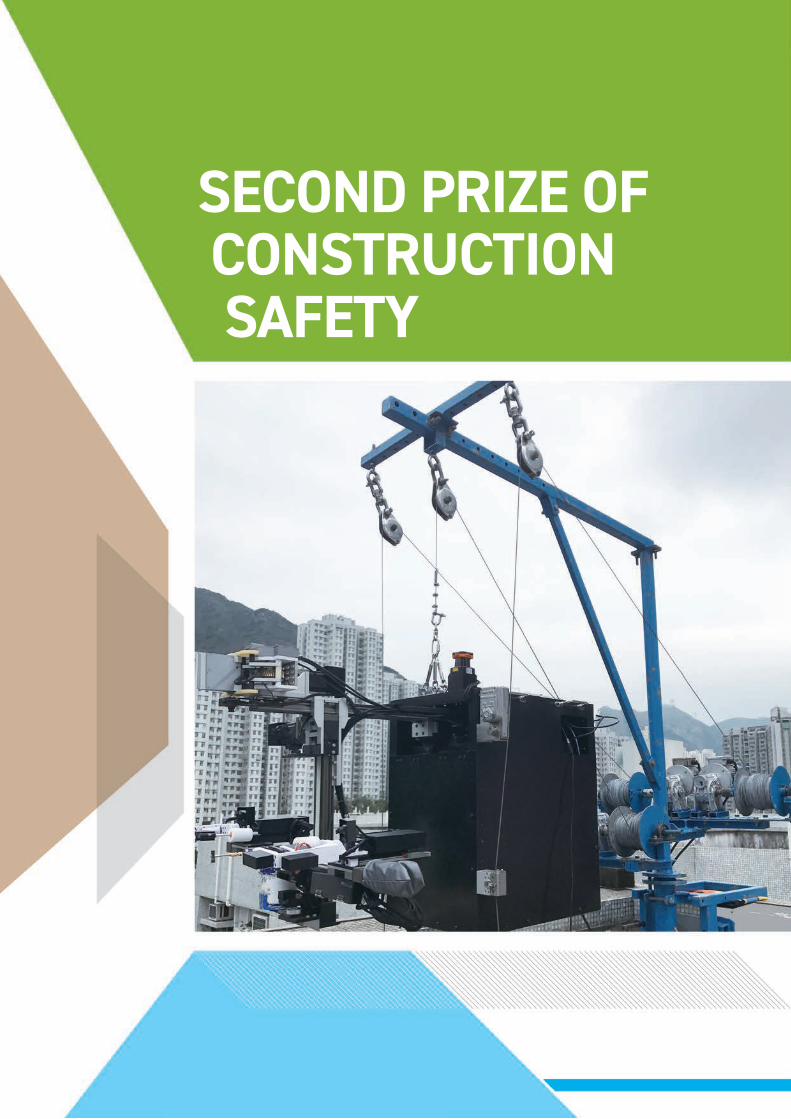
SECOND PRIZE OF CONSTRUCTION SAFETY

INNOVATION IN CONSTRUCTION RESEARCH JOURNAL 2018 77
Reducing Work at Height by Teleoperated Service Robot for Pipe Repair in Hong Kong
K.H. KOH1, Kenny P.C. YEUNG2, Musthafa FARHAN1, Florence H.L. CHAN1, David C.H. TANG2, Michelle P.Y. LAU2, B. L. LUK1, P.K. CHEUNG2, King W.C. LAI1
1 Department of Mechanical and Biomedical Engineering, City University of Hong Kong2 Customer Maintenance Services Department, The Hong Kong and China Gas Company Limited
Utility piping on the façades of buildings in Hong Kong are susceptible to environmental harshness. Specifically, galvanized iron pipes that carry gas supply may be corroded and ultimately lead to gas leakage. The conventional repair method is to replace these affected pipes manually, which may cause inconvenience to customers, material wastage, and workers’ safety concerns. The work described here proposes a different approach by developing a robotic solution in a preventive maintenance manner. The entire robotic system consists of a service robot working at height and a remote user ground station. This teleoperation setup enables the robot to perform specific tasks on the pipe section in mid-air while the user controls the robot action and monitors the robot status remotely. The robot is designed to remove rust from pipe surfaces and apply an anti-rust compound. These tasks are being semi-automated in the service robot system. This paper briefly presents the work process and the major robotic modules. Results from field deployment tests have validated the effectiveness of the concept.
Keywords: service robot; teleoperation; high-rise environment; exterior pipe
ABSTRACT
1. INTRODUCTIONIn Hong Kong, it is common construction practice that all public utilities such as water supply pipes, sewage pipes, drainage pipes and gas supply pipes are designed to be mounted on the façades of buildings. Specifically, the main gas supply pipes (also known as risers) are installed vertically along the exterior façades of housing estates and then branch out horizontally into individual homes. Over the years due to the harshness of outdoor environment, these galvanized iron (G.I.) pipes may be corroded. Since the public utilities are densely packed together, in the event of even minor seepage from the sewage pipes, any nearby G.I. pipes will be greatly affected.
Rusting degrades the useful properties of these G.I. pipes, including strength, appearance and permeability to gases. Prolonged corrosion will ultimately lead to gas leakage, which may cause damage to lives and properties. The conventional method of repairing these affected pipes is to replace them with new pipe sections. House occupants must receive a notice before the work is carried out as their gas supply will be affected, causing inconvenience. In practice, a 3-meter section of the gas pipe is usually replaced, even though, typically only a 30-cm portion is corroded, leading to a 90% wastage. There are also occupational risks to the frontline workers as they have to work at height using scaffolding.

RESEARCH JOURNAL 2018 INNOVATION IN CONSTRUCTION78
S e r v i c e ro b o t s h ave b e e n u s e d for inspection of utilities such as power plants (Caprari et al., 2012), power transmission lines (Pouliot & Montambault, 2012), marine vessels (Eich et al., 2014) and live natural gas mains (Schempf et al., 2010); and also for maintenance tasks, such as window cleaning for building façades (Moon et al., 2015), cleaning of large-diameter sewers (Walter et al., 2012), and repair of hydropower turbine blades (Hazel et al., 2012). For several decades much research into wall-climbing robots has been reported which focuses on the methods to adhere and locomote on building structures (Chu et al., 2010).
There are also technologies that aim at putting robots to work at both in-pipe and out-pipe locations (Rollinson & Choset, 2016). For practical reasons, however, service robots that work in a high-rise environment may need to use a wire rope for climbing, obstacle avoidance, and to increase their payload capacity for carrying work tools (Seo et al., 2013).
This paper presents the development of a prototype service robot to repair rusted pipes. The robot operates semi-autonomously in mid-air with different functions: the rusted pipe section is polished, and then coated with layers of anti-rust compound for long-term protection. Using the robot can shorten the time for repair work, minimize disturbance to housing occupants, and avoid frontline workers having to work at height. We also briefly presents the functional modules designed to perform the repair work on exterior pipes, and describe the head-tracking visual sub-system that helps the remote teleoperation process.
2. DESIGN OF ROBOTIC SYSTEM
The service robot system consists of the robot operating at a high-rise situation and a remote ground station. This tele-
operation setup enables the robot to perform service tasks on pipe sections in mid-air while the user controls the robot action and monitors the robot status remotely. The work environment of the robot is semi-structured. It includes variation of pipeline configuration, minimum clearance between pipeline and building exterior wall, typical distance between the remote ground station and the robot, and minimum operating time for a service session. These factors formed the basis of design input during the development phase of the service robot system.
2.1 Work process of a service session
In order to repair one pipe section, the service robot is equipped with two functional modules as shown in Figure 1. The wire-rope overhang cable is fastened to support the top of the robot body, which is then hoisted to the desired pipe repair section. First, the robot stabilizes its relative position and orientation against the pipe using the gripper arm. This action is semi-automated with the help of a scanning laser range finder, camera, inertial measurement unit, and gripper force
feedback control. Then, the robot performs the polishing and painting tasks in sequence using the work tool arm. It makes physical contact with the pipe surface and travels along the pipe circumference on a programmable trajectory path. This action is semi-automated with the help of the camera and feedback control. When the repair is completed, the robot releases the gripper and retracts both arms. Then the next cycle continues.
2.2 Teleoperation control system
The described work process is carried out in a teleoperated manner using wireless communication between the robot and the remote ground station. During operation, the robot body may slightly swing (pan and tilt) during hoisting and extension of the gripper arm, due to wind loading and shifting of its center of mass. Thus real-time visual information about the surroundings, especially around the targeted pipe section, is required. This enables the user to have flexibility to fine-tune positions of the gripper arm and work tool arm for good alignment against the pipe section and also to inspect the
Figure 1: Functional modules of the robot to perform repair work on one pipe section.

INNOVATION IN CONSTRUCTION RESEARCH JOURNAL 2018 79
SECOND PRIZE OF CONSTRUCTION
SAFETY
work outcome. This visual sub-system is integrated into the overall control system as shown in Figure 2.
In this setup, the robot control is coordinated using Robot Operating System (ROS) middleware that runs on personal computers (PC) installed at both the robot and the remote station. At the remote side, a graphical user interface (GUI) is linked with the ROS and provides the user with information on the robot status and issues action commands. The GUI also reads sensor data from the joystick and helmet (more details in Section 2.4). Together, these data are exchanged with the Robot PC using wi-fi communication. At the robot side, the main microcontroller is interfaced with the Robot PC to perform low-level control by exchanging electronic signals with the described functional modules and gimbal. These functional modules contain actuators and sensors, such as stepper motors, dc motors, limit switches, current and force sensors, etc., that perform the work process. They are briefly described in the next two sections.
2.3 Work tool arm function module
This robot arm is equipped with the primary function module to conduct polishing and painting processes, by removing rust and applying a protective coating on outer pipe surfaces. It consists of two mirrored symmetrical left and right tooling sides as shown in Figure 3. Each side has a polish and paint tool. Process design using a two-side arrangement improves the work time and efficiency. The work tool is able to make contact with the pipe circumference using X-Y linear positioning, plus a bi-direction slider to provide mirrored positioning.
The work tool is depicted in Figure 4. A variety of light-weight and miniature polish options were evaluated. It is required to have a polishing agent that
Figure 3: Work tool function module. Red circles denote the polishing tool, green circles denote the painting tool.
Figure 2: Diagram of control system for teleoperation. Dotted arrows denote wireless communication, colored box denotes the visual sub-system.
Service robot
Remote ground station
Function module 1
Function module
Control data
Sensor data
Joystick
Main micro-controllerRobot PC
Remote PC
2
Gimbal
Screen
Camera
Helmet

RESEARCH JOURNAL 2018 INNOVATION IN CONSTRUCTION80
does not generate sparks and limits the temperature rise. This is because the targeted surface is a live gas pipe. Polishing bristles made of polymer with a 1-inch diameter were selected and can be driven by a brushless DC motor at high speed. The mechanical power required to remove rust was experimentally optimized using the feedback control mechanism. For the painting agent, a variety of suitably-sized and disposable roller brush options were evaluated. It is required to achieve satisfactory absorption of the anti-rust compound, and to be capable of performing multiple rounds of painting operations. A sponge material roller brush was selected. It is fixed on an aluminum tube and able to rotate while squeezing paint onto the pipe surface. The outcome is evaluated using a wet-film thickness gauge to measure the coating thickness.
2.4 Head-tracking visual sub-system
The visual sub-system has a head-tracking feature consisting of two components: helmet and gimbal, as shown in Figure 5. The head-tracking gimbal contains two servo motors and is placed on the robot. The head-tracking helmet holds an inertial measurement unit ( IMU) and an auxiliary microcontroller. This IMU is an absolute orientation sensor that uses a sensor fusion algorithm to integrate measurements from the accelerometer, gyroscope and magnetometer and then return three-angle orientation data. The helmet orientation data is provided to the Remote PC. Using wi-fi communication at the high-level control, the Robot PC receives the data and sends it to the main microcontroller. From here, the orientation data is converted into a pulse width modulated (PWM) signal to command the rotation of the mentioned two servo motors on the gimbal. One servo determines the pan angle of the camera view based on the head movement from left to right, while the other servo determines the tilt angle of the camera view based on the head movement from up to down.
Figure 4: Photograph of evaluated work tool. (a) polish bristle. (b) paint roller and the tube fitting.
Figure 5: Control diagram of head-tracking visual sub-system.
(a)
(b)

INNOVATION IN CONSTRUCTION RESEARCH JOURNAL 2018 81
SECOND PRIZE OF CONSTRUCTION
SAFETY
3. FIELD DEPLOYMENT RESULTS
The robot prototype was deployed in a field test to perform actual repair tasks on sections of gas pipes. These tests were conducted in a housing estate in the Wong Tai Sin district, where the site location and the test environment are considered to be very close to the conditions where actual deployment of the robot will be feasible in the future.
3.1 Hoisting of the robotThe lifting equipment is set on the building rooftop to hoist the robot using wire-cables, as shown in Figure 6. It consists of one main wire-cable that winds up to electrical winches, and is supported by a steel crane structure clamped onto the building. Two auxiliary wire-cables go through the sides of the robot body frame and are weighted at ground level, to prevent self-turning of the robot in mid-air. In Figure 6, the robot is being brought to the pipe section by operating the electrical winch that pulls-in or lets-out the main wire-cable.
3.2 Removing rust and coating with an anti-rust compound
The bristles are aligned with the pipe tangent using camera visuals as shown in Figure 7 (a). This is done by adjusting the position of the work tool arm and also the bi-direction slider. During the automatic polishing process, both the left and right polishing motor current are independently feedback to adjust the bristle position. This feedback mechanism ensures optimum contact force by the bristles for effective rust removal. After satisfactory preparation to remove surface rust, the paint rollers are then refilled with an anti-rust compound and brought to align with the pipe tangent using camera visuals. Figure 7(b) shows the painting process. The tool makes contact with the pipe surface in a circular trajectory path and coats the pipe with a sufficient
Figure 6: Photograph of the lifting equipment.
thickness of paint. The path parameter is adjustable to ensure that the sponge material is squeezed to evenly disperse the paint onto the pipe surface. When the repair work of one pipe section is deemed complete after satisfactory painting, the robot is then hoisted to the next position for the subsequent repair cycle.
4. CONCLUSIONConventional work methods to replace corroded pipes has been replaced by a new approach using a semi-automated robotic process. This approach has eliminated the use of a scaffold platform; instead it uses hoisting equipment to position the robot at the target pipe section. The teleoperated robotic system is then able to carry out the designed work process for preventive maintenance of exterior pipes. The remote user is able

RESEARCH JOURNAL 2018 INNOVATION IN CONSTRUCTION82
to monitor the status of the robot and its environment, identify the problematic pipe section, and then issue commands to automatically secure relative positions of the robot and the pipe, remove rust by a polishing process, and apply an anti-rust compound by a painting process. This concept has been validated with a working robot prototype deployed in several field tests. The process saves the time for setup and reduces material wastage as compared to conventional methods. The developed robotic system and process has the potential to be used in the design of relevant high-rise utilities repair work. It is proposed that future work should include the optimization of the robot sub-systems for weight reduction, and fine-tuning of the control parameters for the best repair outcome.
ACKNOWLEDGMENTS The authors gratefully acknowledge the financial support provided by the Innovation and Technology Fund (UIM/277 and UIM/322), Innovation and Technology Commission, HKSAR.
REFERENCESCaprari, G., Breitenmoser, A., Fischer, W., Hürzeler, C., Tâche, F., Siegwart, R., et al., (2012). Highly compact robots for inspection of power plants. Journal of Field Robotics, 29(1), 47-68.
Chu, B., Jung, K., Han, C.-S., and Hong D. (2010). A survey of climbing robots: locomotion and adhesion, International Journal of Precision Engineering and Manufacturing, 11(4), 633-647.
Eich, M., Bonnin-Pascual, F., Garcia-Fidalgo, E., Ortiz, A., Bruzzone, G., Koveos, Y., and Kirchner, F. (2014). A robot application for marine vessel inspection. Journal of Field Robotics, 31(2), 319-341.
Hazel, B., Côté, J., Laroche, Y., and Mongenot, P. (2012). A portable, multiprocess, track-based robot for in situ work on hydropower equipment. Journal of Field Robotics, 29(1), 69-101.
Moon, S., Shin, C., Huh, J., Oh, K., and Hong, D. (2015). Window cleaning system with water circulation for building façade maintenance robot and its efficiency analysis. International Journal of Precision Engineering and Manufacturing-Green Technology, 2(1), 65-72.
Pouliot, N., and Montambault, S. (2012). Field-oriented developments for LineScout technology and its deployment on large water crossing transmission lines. Journal of Field Robotics, 29(1), 25-46.
Rollinson, D., and Choset, H. (2016). Pipe network locomotion with a snake robot. Journal of Field Robotics, 33(3), 322-336.
Schempf, H., Mutschler, E., Gavaert, A., Skoptsov, G., and Crowley, W. (2010). Visual and nondestructive evaluation inspection of live gas mains using the explorer™ family of pipe robots. Journal of Field Robotics, 27(3), 217-249.
Seo, K., Cho, S., Kim, T., Kim, H. S., and Kim, J. (2013). Design and stability analysis of a novel wall-climbing robotic platform (ROPE RIDE). Mechanism and Machine Theory, 70, 189-208.
Walter, C., Saenz, J., Elkmann, N., Althoff, H., Kutzner, S., and Stuerze, T. (2012). Design considerations of robotic system for cleaning and inspection of large-diameter sewers. Journal of Field Robotics, 29(1), 186-214.
Figure 7: (a) Image of the polishing work. (b) Image of the painting work. Inset: outcome at the back of pipe.
(a)
(b)

INNOVATION IN CONSTRUCTION RESEARCH JOURNAL 2018 83
SECOND PRIZE OF CONSTRUCTION
SAFETY
BIOGRAPHY
Keng Huat KOH
Dr Keng Huat KOH received the B.Eng degree in mechatronics from Monash University Gippsland Campus, Australia, and the Ph.D. degree from the School of Engineering, Monash University, Malaysia, in 2015.
He was a Process Engineer with the Motion Control Products Division, Agilent Technologies Inc, Malaysia. Since 2015, he has been a Postdoctoral Fellow with the Department of Mechanical and Biomedical Engineering, City University of Hong Kong. His research interests include wall-climbing robots, electrostatic adhesion, mechatronics, and service robotics.
Musthafa FARHAN
Musthafa FARHAN received his B.E. in Electronics and Communication Engineering from Anna University, Chennai, India, in 2013 and M.Sc. in Integrated Circuit Design Engineering (ICDE) from The Hong Kong University of Science and Technology (HKUST), in 2015.
Since 2015 he joined as Research Assistant with the Department of Mechanical and Biomedical Engineering, City University of Hong Kong. His current research interest includes embedded system, electronic circuit design and development of robotic system.
B.L. LUK
Dr LUK Bing Lam is the current chairman of Hong Kong Nuclear Society and also a member of Energy Advisory Committee of Hong Kong Environment Bureau. He was the Past Chairman of Nuclear Division of HKIE. Dr LUK has participated in large scale nuclear reactor inspection programmes in the UK before. He was also an investigator of a number of European and British robotic research projects for the nuclear industry. With his extensive knowledge, he was invited as a member of Expert Advisory Committee for Hong Kong Government during the Fukushima nuclear accident and also reviewed the latest Daya Bay Contingency plan.
Pak-kin CHEUNG
Ir Pak-kin CHEUNG joined Towngas as a gas craft apprentice in 1977. Throughout his 41 years of service in the company, he has worked in various sections in the customer service field and has accumulated solid technical knowledge and work experience in the installation, inspection and maintenance of the gas appliances and installations. He is currently the Senior Customer Maintenance Services Manager, leading a workforce of over 400 technicians to serve more than 1.85 million residential, commercial and industrial Towngas customers in Hong Kong.
Ir CHEUNG is a Chartered Engineer, a Corporate Member of the Hong Kong Institution of Engineers as well as the Institution of Gas Engineers and Manager. He is currently a committee member of the Institution of Gas Engineers and Managers – Far East District Section.
King Wai Chiu LAI
Dr King Wai Chiu LAI received the Ph.D. degree from the Department of Automation and Computer-Aided Engineering, The Chinese University of Hong Kong, Hong Kong, in 2005.
He was a Post-Doctoral Research Associate with the Department of Electrical and Computer Engineering, Michigan State University, East Lansing, MI, USA, in 2006. He is currently an Associate Professor with the Department of Mechanical and Biomedical Engineering, City University of Hong Kong, Hong Kong. His current research interests include development of micro/nano sensors using MEMS and nanotechnology, nanobiotechnology, automation, and micro/nano manipulation.

FIRST PRIZE OF CONSTRUCTION SUSTAINABILITY

INNOVATION IN CONSTRUCTION RESEARCH JOURNAL 2018 85
Supercritical Vortex Intakes for Urban Storm Water Management
Joseph Hun-wei LEE1, Anthony K.L. TSANG2, Andy KWOK3, John ACKERS4
1 The Hong Kong University of Science and Technology2 Drainage Services Department, HKSAR Government
3 Black and Veatch Hong Kong Ltd.4 Black and Veatch Ltd. (UK)
O v e r t h e p a s t d e c a d e s , r a p i d urbanization and global climate change have resulted in significant increase in flood risks in urban areas of Hong Kong. In the early 2000s, the Drainage Services Department proposed an innovative “upstream interception” scheme, namely The Hong Kong West Drainage Tunnel (HKWDT) to improve the flood protection standard for areas around Causeway Bay, Admiralty, Central and Sheung Wan.
The engineering challenge was how to effectively intercept and transfer the supercritical (high speed) flow from the steep natural watercourses located in the densely-populated Mid-Levels district to the drainage tunnel located some 100 m below ground. The breakthrough was the development of a compact bottom rack and vortex intake system to stably decelerate the supercritical flow, with efficient energy dissipation, for smooth conveyance of flow from higher elevations to the deep drainage tunnel and discharge to the sea.
Since commissioning of the HKWDT in 2012, the vortex intake system has been put to the test on many severe rainfall occasions, and has successfully protected the downhill urban areas of Hong Kong Island from flooding. This system has set a global standard for reference and has been adopted in many critical hydraulic infrastructure designs internationally.
Keywords: Urban storm water management; vortex intake; supercritical flow
ABSTRACT
1. INTRODUCTION
1.1 Background to the HKDWTHong Kong is frequented by tropical cyclones and experiences an average annual rainfall of 2,400 mm. In the past two decades, global climate change has resulted in extreme rainfall intensity – hourly rainfalls of over 140 mm were recorded. In times of heavy rainfall, the mid-levels and downstream areas of northern Hong Kong Island are prone to flooding. Torrents of mud-laden and highly-aerated storm flows can overshoot stream channels into roads and cause hazardous traffic conditions.
The protection of urban infrastructure from flooding is of foremost importance for the sustainable development of Hong Kong. Substantially upgrading the existing drainage systems in densely populated and commercial districts using traditional pipe installation methods is extremely difficult due to site constraints such as congested underground utilities. The traditional methods for drainage improvement cause traffic disruptions and inconvenience to the public and commercial activities.
In the early 2000s, akin to the “sponge city” concept, the Drainage Services Department (DSD) proposed an innovative “upstream

RESEARCH JOURNAL 2018 INNOVATION IN CONSTRUCTION86
interception” scheme that would greatly enhance flood protection of the urban areas. The Hong Kong Island West Drainage Tunnel (HKWDT) was proposed to intercept storm water runoff through intakes located on the main drainage paths for direct discharge to the sea, thus diverting the runoff away from the downhill urban areas and effectively alleviating flood risks (DSD 2003). The design consists of a 10.5 km long drainage tunnel (maximum diameter 7.25 m) that extends from Tai Hang on the east to Cyberport on the west, connected by a series of vertical drop shafts to the drainage path intakes. As a result of the HKWDT, about 30 percent of the storm water in northern Hong Kong Island is now collected via 34 storm water intakes located in the densely populated hillside in the midst of residential blocks including some premium properties. The project provides a safe conduit to convey storm water through the tunnel to an outfall structure at Cyberport.
1.2 Engineering challenges The 34 storm water intakes are located on steep hillslope watercourses (average
slope of 40 %) with supercritical flow regimes characterized by velocities in the order of 10 m/s and Froude numbers of F = 3 - 8. Each intake intercepts and transfers storm water runoff to the main tunnel through a vertical drop shaft. The system is intended to convey a 1 in 200-year return period rainstorm event, with an intake design flow of up to 18 m3/s. Central to the success of the HKWDT is an innovative vortex intake system for diversion of the high velocity supercritical flows stably and smoothly to the drop shaft in a helical flow, thus leaving a core of air in the middle of the drop shaft and preventing negative pressure build-up in the tunnel. The design of a compact intake structure adjacent to the densely populated residential areas was the most challenging aspect of the project.
Figure 1 shows the conceptual design of the intake structure - a primary feature of the urban flood control scheme. A bottom rack intake was proposed to screen off large sediment debris, rock and vegetation. The intercepted flow passes the bottom racks into a bottom rack chamber, which is connected to a vortex drop shaft through a link
channel. The change in flow direction is required because of site constraints. A vortex drop transfers the flow vertically from an open channel to a lower level in the form of a swirling annular jet. A stable swirling flow with an adequate central air core (for continuous release of entrained air within the drop shaft) results in good energy dissipation.
Bottom rack intakes are used for hy d ro p o w e r, w a t e r s u p p l y a n d irrigation, mainly in areas with steep terrain and gravel river beds. Previous studies were mainly concerned with a subcritical-approaching flow through the rack openings into the below-ground empty space (Brunnela et al. 2003). For the HKWDT project, further investigation was required to examine the hydraulics of the complex aerated bottom rack chamber for supercritical underflow through the rack openings, which is critical to the present design. In addition, studies on supercritical vortex inlets are rare and no general design guidelines are available for such hydraulic structures involving complex three-dimensional turbulent two-phase (air-water) flows. This was also the first time such intakes were used
Figure 1: Bottom rack intake for supercritical flow diversion into spiral vortex inlet

INNOVATION IN CONSTRUCTION RESEARCH JOURNAL 2018 87
FIRST PRIZE OF CONSTRUCTION
SUSTAINABILITY
for urban drainage. The design of the integrated bottom rack – vortex inlet structure is even more challenging – as the intake must ensure: (i) efficient flow interception by the bottom rack, with stable supercritical flow in the bottom rack chamber and into the link channel; and (ii) stable supercritical flow with minimum shockwave height in the vortex inlet, and a minimum air core area to drop shaft area ratio of 25 percent.
The HKWDT vortex intake design was developed through a combination of theory, heuristic reasoning and physical model experiments. Extensive experiments were performed in an undistorted Froude scale model at two model scales (1:24.5 and 1:9.5) for the: (i) bottom rack intake; (ii) spiral or tangential vortex inlet; and (iii) an integrated bottom rack – vortex intake. The flow in the bottom rack chamber and link channel, and shock wave height and air core ratio in the
Figure 2: Vortex intake designs for supercritical flow
vortex inlet were studied. The physical modelling study was supplemented by fundamental research into the hydraulics of vortex intakes. This paper presents the key elements of the design of the intake structure.
2. DESIGN OF BOTTOM RACK – VORTEX INTAKE SYSTEM
2.1 Flow interception by bottom rack
The bottom rack structure includes the approach channel, the longitudinal rack bars (aligned parallel to the flow), the underlying bottom rack chamber, and the adjoining orifice and link channel. The objective is to arrive at a design that ensures smooth and stable diversion of discharges ranging from the base flow to the maximum 200-year flood discharge. Figure 1 shows a schematic diagram of the bottom rack intake for supercritical flow diversion into the spiral vortex
inlet. The slope of the approach channel is standardised to be 1:2.5. The bottom rack is made of parallel bars oriented along the watercourse axis at a slope of 1:5, with a void ratio (ratio of opening area to total rack area) of around 0.4. The channel bottom beneath the rack follows a curved boundary (resembling a free jet trajectory) at the entrance to the bottom rack chamber; the flow is diverted by 90 degrees to the vortex intake structure via the link-channel (see also Figure 4).
The complex flow in the bottom rack chamber was studied for six designs (with different bottom rack slopes and lengths), for flows in the range of 1 to 18 m3/s. While circular bars (12.1 mm diameter bars with 22.6 mm centre-to-centre separation) were adopted for the baseline design, different cross-sectional shapes were also tested: including circular, diamond, I beam and trapezoidal bars. Detailed flow characteristics such as wetted rack
Figure 3: Unstable flows for improper designs. (a) Unstable flows for bottom rack with splashing and overflow downstream; and (b) Unstable standing wave and vortices

RESEARCH JOURNAL 2018 INNOVATION IN CONSTRUCTION88
length were obtained from digital image analysis of photographic and video observations. Point velocity measurements were made with electromagnetic current meters. Details of the experimental investigations on different designs can be found in Lee et al. (2005a and b).
With a well-designed bottom rack, the upstream flow penetrates between the bars to form an underflow that runs along the bed of the channel (Figure 1). The free surface profile crosses the axis
of the rack bar at a longitudinal distance of x = L1 from the beginning of the rack. Beyond x = L1, due to the forward momentum, the fluid still clings onto the rack bar, and a small part of the discharge runs along the rack bars. A partly aerated forward flow is carried in the region between the underflow and the rack. The wetted length Lw refers to the distance at which the top of the rack bars is no longer wetted. Beyond x = Lw, the fluid still clings to the lower side of the rack bar, and the flow is increasingly aerated. The wetted length L2 is the
distance where the flow attached to the rack bars eventually stops. The complex bottom rack flow behaviour depends on (i) the length and slope of the approach channel; (ii) the slope, length and arrangement of the bottom rack bars; and (iii) the length and slope of the channel bed, the volume and geometry of the rack chamber.
For many designs the flow in the bottom rack chamber is highly fluctuating and unsteady, characterised by a large unstable rolling plume (‘roller’) that
Figure 4: Integrated vortex intake designs for supercritical flow diversion (prototype dimensions shown in m)

INNOVATION IN CONSTRUCTION RESEARCH JOURNAL 2018 89
FIRST PRIZE OF CONSTRUCTION
SUSTAINABILITY
impinges on and rises higher than the downstream wall of the rack chamber; the flow that overtops the wall passes straight downstream without entering the intake (Figure 3a). Based on these observations, the channel bed inside the chamber was modified to a curved shape that resembles the nappe of a free jet, with enlargement of the chamber at the downstream end. In the final designs (Figures 4a, 4b and 5), the intercepted flow follows the bottom slope and curved surface stably into the chamber. The bottom part of this flow hits the far end of the chamber and is re-directed towards the inside of the chamber. The momentum of the top part of the bottom rack flow is partly offset by this opposing jet stream from the downstream end of the enlarged chamber; the combined flow is stably re-directed onto the link channel. Additional details on the experimental and 3D numerical modelling aspects of the supercritical bottom rack can be found in Chan et al. (2018a).
2.2 Spiral vortex intakeFigure 2 shows three types of vortex inlets: spiral with warped invert (Figure 2a), spiral with flat invert (Figure 2b), and tangential slot intake (Figure 2c). Under the action of the centrifugal force, most of the flow is concentrated towards the inner surface of the outer wall, and piles up against that surface as
a coherent stream, creating a standing wave (shock wave). The objective was to ensure stable supercritical flow with minimum shockwave height and a minimum air core area to drop shaft area ratio of 25 %, thereby avoiding flow back up or blockage at junctions.
The complex three-dimensional air-water flow in a large number of spiral vortex inlets – with varying bottom slope, flat or warped invert, inflow channel length, guide wall and spiral geometry – were studied for nominal inflows of 5-18 m3/s. The experiments were first carried out for individual model designs with a uniform approach channel flow. After the individual vortex inlet model testing, integrated bottom intake – vortex inlet models were tested (Lee et al. 2005a and b, 2006).
Experiments showed that for spiral flat inverts, the inlet flow could become subcritical due to the backwater effect induced by the vortex structure; a highly unstable flow with a fluctuating air core can result under certain inflow conditions (Figure 3b). In view of the unstable condition, the optimum spiral vortex inlet with a warped invert was developed (Figure 4a). The curvature of the sp ira l intake structure i s characterized by two semi-circles with the first half 180° of diameter 5.75 m and the second 180° of radius 3.45 m. The semi-circular inner guide wall plays
an important role in determining the flow characteristics.
2.3 Tangential slot intakeThe tangential vortex intake (Figure 4b or c) is a compact-size alternative to the spiral vortex intake. Unlike the spiral vortex inlet, the inflow is led into the drop shaft in a steep sloping and tapering (laterally converging) tangential inlet. The inflow impinges onto the inner surface of the drop shaft as a tangential jet with angular momentum, and a vortex flow is established without the need for a complex spiral arrangement. This intake is suited for small discharges. As a significant advance over previous studies (Jain 1984; Jain and Ettema 1987), a general design theory was developed (Yu and Lee 2009). For the first time, the theory provides a basis for the design of a “stable” tangential vortex intake without the need for unguided, trial-and-error physical model testing.
2.4 Final integrated designA physical model study was carried out to understand the hydraulics of supercritical vortex intakes and to develop the optimum storm water diversion intake design. Based on the individual intake design tests, warped- and flat-invert spiral vortex intakes and tangential vortex intakes with 90° and
Figure 5: Bottom rack intake for supercritical flow diversion (final design); observed flow at Q = 53.9 L/s.

RESEARCH JOURNAL 2018 INNOVATION IN CONSTRUCTION90
Figure 6: Spiral vortex intake with warped invert for supercritical flow diversion (final design)
Figure 7: Measured performance characteristics of various vortex intake designs (integrated model). Note the spiral inlet warped invert and tangential intake have the highest air core area with acceptable shock wave heights.

INNOVATION IN CONSTRUCTION RESEARCH JOURNAL 2018 91
FIRST PRIZE OF CONSTRUCTION
SUSTAINABILITY
Figure 8: a) Side view of stable tangential vortex intake (left); b) validation of theoretical design criterion (Qc = critical discharge; Qf = free drainage discharge) (right).
inline inlets were selected and studied in integrated models of the interception and vortex inlet structures.
The comprehensive experimental study showed that the spiral intake with a warped invert performed best in terms of the minimum shock wave height and maximum air core area ratio. The tangential vortex intake was found to be a compact-size alternative to the spiral intake, especially for low flows. As a result, these two types of vortex intakes with proven performance were adopted in the HKWDT. Figure 5 and Figure 6 show the observed flow in a 1:9.5 model of the final design for the warped-invert spiral intake. The significant air-
entrainment in the large-scale stable roller in the bottom rack chamber can be clearly seen (Figure 5), along with the standing wave and air core in the spiral vortex inlet with warped invert (Figure 6).
Figure 7 shows the key performance indicators for the different designs. The maximum shockwave height of each design increases almost linearly with the flow (Figure 7a). The shock wave height of the warped-invert spiral intake is lower than that of the flat invert spiral intake by approximately 0.4 m on average. The air core area of the spiral warped intake is the largest almost for the entire flow range (Figure 7b). The
air core area ratio of the tangential intake with inline inlet is comparable to that of the warped-invert spiral intake. The flat invert spiral intake yields the smallest air core area. The results of the 1:24.5 scale model agree very well with those of the larger 1:9.5 scale model – showing that the results are free from “scale effect”.
Figure 8a shows the observed flow for a stable tangential intake. The optimal design can be expressed in terms of a free draining discharge Qf and a critical discharge Qc that can be defined in terms of the intake geometry (Figure 8b; Yu and Lee 2009). Figure 9 shows the swirling flow with a stable
Figure 9: Air core of the tangential vortex intake.

RESEARCH JOURNAL 2018 INNOVATION IN CONSTRUCTION92
air core in such an intake. This Hong Kong-developed design method has since been used internationally by the industry; examples of where this guidance has been applied include the design of the Thames Tideway Tunnel in London, the Toronto – Don River and Central Water Front, and the Singapore Deep Tunnel Sewer System (Plant and Crawford 2016). Further details of the measured velocity field and computational fluid dynamics modelling can be found in Chan et al. (2018b).
3. CONCLUSIONAn innovative design of a supercritical vortex intake system for interception and diversion of fast-moving turbulent two-phase flows is presented. The design consists of: (i) a unique integrated bottom rack - spiral vortex intake design for supercritical flow diversion; and (ii) the spiral vortex intake with warped invert in storm water management. This design produces smaller shockwave heights than spiral vortex intakes with flat invert (the only previous reported design). A new theory for the design of tangential vortex intakes was also developed.
Since the commissioning of the HKWDT in 2012, the vortex intake system has been put to the test during many severe rainstorms, and has successfully protected the downhill urban areas of Hong Kong Island from flooding. This project was developed through the long-term collaboration among academia, industry and Government, with a common goal to benefit the community. This system has set a new global standard for reference and has been adopted in many critical hydraulic infrastructure designs internationally.
REFERENCESBrunella, S., Hager, W. and Minor, H.E. (2003) Hydraulics of bottom rack intake, Journal of Hydraulic Engineering, ASCE, 129(1), 1-10.
Chan, S.N., Wong, C.K.C., and Lee, J.H.W. (2018a) Hydraulics of air-water flow in a supercritical bottom rack intake, Journal of Hydro-environment Research (submitted).
Chan, S.N., Qiao, Q.S., and Lee, J.H.W. (2018b) On the three-dimensional flow of a tangential vortex intake, Journal of Hydro-environment Research (submitted).
Drainage Services Department (DSD) (2003). Stormwater Drainage Master Plan Study in Northern Hong Kong Island: Executive Summary. The Government of Hong Kong Special Administrative Region, China.
Hager, W.H. (1990) Vortex drop inlet for supercritical approaching flow, Journal of Hydraulic Engineering, ASCE, 116(8), 1048-1054.
Jain, S. C. (1984) Tangential vortex-inlet, Journal of Hydraulic Engineering, ASCE, 110(12), 1693–1699.
Jain, S.C. and Ettema, R. (1987) Vortex-flow intakes, In Knauss J, ed. Swirling Flow Problems at Intakes, Rotterdam, Netherlands: A.A. Balkema.
Lee, J.H.W., Chan, H.C., Yu, D.Y. and Choi, D.K.W. (2005a) Physical hydraulic model tests for Hong Kong West Drainage tunnel in Northern Hong Kong Island - Intake Structure, Final Report to Drainage Services Department, HKSAR Government, February 2005, 104 pp.
Lee, J.H.W., Yu, D.Y., Chan, H.C., Gore, L., and Ackers, J. (2005b) Bottom rack
intake for supercritical storm flow diversion on steep urban catchment, Proc. 31st IAHR Congress, Seoul, Korea, September 11-16, 2005 (CDROM).
Lee, J.H.W., Yu, D.Y., Chan, H.C., Ackers, J. and Gore. L. (2006) Experimental study on supercritical vortex intakes for urban drainage diversion, Proc. 11th Asian Congress of Fluid Mechanics, 22-25 May 2006, Kuala Lumpur, Malaysia, 122-127.
Plant, J. and Crawford, D. (2016) Pushing the limits of tangential vortex intakes: is higher capacity and flow measurement possible in a smaller footprint? Proceedings of WEFTEC 2016, New Orleans, Water Environment Federation.
Qiao, Q.S., Lee, J.H.W. and Lam, K.M. (2013) Steady vortex flow in tangential intake, Proceedings of 2013 IAHR World Congress, Chengdu, China.
Thames Water (2011) Hydraulic design criteria for Thames Tideway Tunnel Scheme.
Yu , D.Y. a n d L e e , J . H .W. ( 2 0 0 9 ) Hydraulics of tangential vortex intake for urban drainage, Journal of Hydraulic Engineering, ASCE, 135(3), 164-174.

INNOVATION IN CONSTRUCTION RESEARCH JOURNAL 2018 93
FIRST PRIZE OF CONSTRUCTION
SUSTAINABILITY
BIOGRAPHY
Joseph Hun-wei LEE
Professor Joseph Hun-wei LEE is Chair Professor of Civil and Environmental Engineering at HKUST. He is the Chief Editor of the Journal of Hydro-environment Research and past Vice-President of the International Association for Hydro-environment Engineering and Research (IAHR). He is the recipient of the ASCE Hunter Rouse Hydraulic Engineering Award (2009) and numerous other awards including the Croucher Senior Research Fellowship (1998) and the 2010 China State Scientific and Technological Progress Award. He is a Fellow of the Royal Academy of Engineering of the UK and the Hong Kong Academy of Engineering Sciences. He was bestowed Honorary Membership by IAHR in 2015. Prof. LEE has served on many international advisory bodies and as an independent expert on numerous hydro-environmental projects, including the Commission of Inquiry into Excess Lead Found in Drinking Water (2015) in Hong Kong. Prof. LEE has served as Pro-Vice-Chancellor and Vice-President (Staffing) at the University of Hong Kong (2004-2010) and Vice-President for Research and Graduate Studies at HKUST (2010-2016).
Anthony TSANG
Mr. Anthony TSANG is the Assistant Director/Projects & Development of the Drainage Services Department (DSD) of the Government of the Hong Kong Special Administrative Region. He has over 30 years of experience on implementation of infrastructure projects in Hong Kong. He worked in civil engineering consultants in his early career before he joined DSD in 1991 and has been working in DSD mainly on the planning, design and construction of sewerage and drainage projects since then. Mr. TSANG has worked on many major projects implemented by DSD including the Harbour Area Treatment Scheme for cleaning up the Victoria Harbour as well as the Happy Valley Underground Stormwater Storage Scheme, an iconic drainage improvement project of DSD.
Andy KWOK
Ir Andy KWOK is the Managing Director of Black & Veatch Hong Kong Limited. He is responsible for the management and sales of the company’s water business in Hong Kong and Mainland China. Andy has 25 years of experience in planning, feasibility study, design and contract administration of civil engineering projects for both Government and private sectors. He has rich experience in hydrology, hydraulic analysis and design of drainage works and has conducted several drainage projects in Hong Kong and Mainland China including Shenzhen, Guangzhou and Kunming etc. He is a Fellow of the Hong Kong Institution of Engineers.
John ACKERS
Mr. John ACKERS is a Technical Director specialising in hydraulics. He has 46 years of experience in various areas of civil engineering, including hydraulic structures, flood alleviation, dam safety and remedial works, physical model studies, sediment control and site supervision. His particular strength is in the identification of appropriate innovative solutions in hydraulic engineering, such as air-regulated siphons, passive flow control devices, labyrinth weirs and their most recent variant, the piano-key weir. He was appointed to the All Reservoir (AR) Panel under the Reservoirs Act 1975 in late 2001, since when he has undertaken over 120 Section 10 inspections.
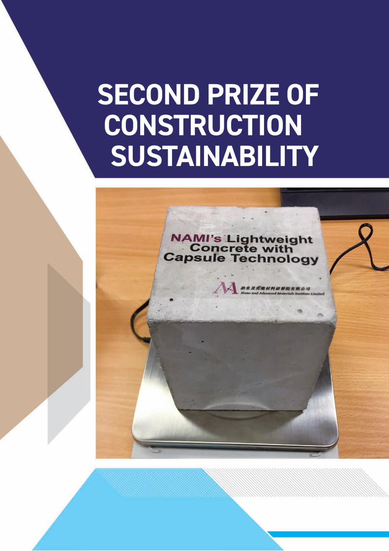
SECOND PRIZE OF CONSTRUCTION SUSTAINABILITY

INNOVATION IN CONSTRUCTION RESEARCH JOURNAL 2018 95
Innovative Capsule Technology for Producing High-performance Lightweight Cellular Concrete
Ruby ZHU1, Kevin SHANG1, Honggang ZHU1, Jeffery LAM1, Ivan SHAM1, Richard TSE2, Derek SO2
1 Nano and Advanced Materials Institute Limited (NAMI)2 Hip Hing Construction Company Limited
Lightweight cellular concrete possesses many attributes of new-generation materials, and are highly fire resistant with good thermal and acoust ic properties. However, the limitations of existing lightweight concrete have hindered its structural applications in the construction industry. Production of current lightweight concrete is difficult to scale up as the foam in cement slurry collapses during prolonged transportation, and does not mix with aggregates without settlement. In response, Hip Hing and NAMI have developed an innovative capsule technology that enables the production of high-performance lightweight cellular concrete on an industrial scale. Hip Hing - NAMI’s capsule is dissolvable in alkaline-in-nature concrete after a pre-determined period for cell-structure formation. The capsules can be mixed well with aggregates without settlement. Water is encapsulated inside the capsules to promote internal post-curing of concrete for enhanced cement hydration reaction, with fewer thermal cracks and increased durability. Separate tiny capsules enable closed cell microstructure and thus enhance the mechanical properties of cellular concrete. Hip Hing - NAMI’s novel cellular-structure forming approach using capsule technology realizes high-performance, lightweight cellular concrete for green buildings with superior environmentally-sustainable properties to address the increasing global demand for the next generation of concrete.
Keywords: Alkaline sensitive; Capsule technology, Cel lu lar concrete, High performance, Sustainability
ABSTRACT
1. INTRODUCTIONTo address the needs of a sustainable and eco-friendly society, it is commonly considered that the next generation of construction materials should be lightweight, highly fire resistant, and have good thermal and acoustic properties. Lightweight cellular concrete possesses many of the attributes to fit those requirements. However, conventional cellular concrete is produced either by mixing a pre-formed foam, by adding mix-foaming agents (such as surfactants) into the cement and water slurry, or by adding expansion agents (such as aluminium powder or hydrogen peroxide) to the mix during the mixing process. At the construction site, foam is generated from the surfactant by using a foam generator, and the foam is then added to the slurry in a ready-mix truck. Generated foam may merge together and pre-formed foam can easily collapse during prolonged mixing due to transportation. The production of foamed concrete is therefore limited to the construction site.
On the other hand, it is difficult to control the size and distribution of air voids generated by expansion agents during the mixing process. More importantly, it is not possible to add coarse aggregates into foamed concrete since the foam in the cement slurry is likely to rupture when mixed with aggregates. These limitations have hindered the structural applications of foamed concrete in the construction industry, and restricted its use in non-structural low-value applications, such as void filling.

RESEARCH JOURNAL 2018 INNOVATION IN CONSTRUCTION96
To overcome these hurdles, our capsule technology offers a revolutionary a p p ro a c h to t h e p ro d u c t i o n o f lightweight cellular concrete. The capsules are compatible with other concrete ingredients and can be mixed with cementitious materials, water and aggregates in a conventional rotary mixer to d istr ibute them uniformly and form a stable cellular structure. This process is targeted to be easily integrated into a concrete production plant. Moreover, the pore size and distribution of capsules can be customized to meet specific requirements. The adjustable shell thickness of the capsule provides f lexibi l ity with regard to various applications of capsule-enabled cellular concrete. Separate tiny capsules are strong enough to resist pressure when being mixed with aggregates and enable closed cells to form in the cementitious matrix for enhancing and optimizing the mechanical properties and durability of concrete. Furthermore, individual and stable air voids formed by capsules enable superior thermal and acoustic performance.
2. USE OF ALKALINE-SENSITIVE MATERIALS
Considering the hydration process of concrete which forms a highly alkaline environment (pH 12~13), alkalinity can be treated as a triggering mechanism for capsule rupture in concrete. The water inside the capsules can then be released to provide internal post-curing of the cellular concrete. The shell material of capsules is alkaline-sensitive. Once the morphological change of the polymer shell is large enough to induce rupture, the water inside the capsules is completely released within a controlled period of time. Polymers have been
identified as a capsule shell material and their dissolution process is shown in Figure 1. When a polymer is added into a given solvent, its chain segment starts to absorb solvent molecules, resulting in an increase of volume and a loosened structure over a relatively long period. If polymer-polymer interactions are relatively stronger than polymer-solvent interactions, the process stops at this first stage, producing a swollen gel as a result. On the contrary, if polymer-solvent interactions are relatively stronger, the process continues until all segments are solvated.
Polymers with acidic functional groups can be generally dissolved in an alkaline solution. Acidic groups accept protons at low pH and ionize at high pH, which changes the precipitation and dissolution behaviour of a polymer chain network. Among the common types are carboxylic acid (Felber et al., 2012; Dong et al., 2007), sulfonic acid (Gabaston et al., 1999), phosphoric acid (Bingol et al., 2008), and boronic acid.
It is noted that polymers derived from weak acids only have a low pKa value, which may lead to dissolution in a neutral or even mildly acidic environment. Capsules have been designed to be stable over several hours and then release water under alkaline-in-nature concrete, the shell material thus should also have a certain capability to resist alkalinity. Therefore, hydrophobic monomers, such as acrylate and styrene, are introduced to cross-link with acidic monomers during polymerization. Such polymerized products are also named as hydrophobically modified alkali-soluble emulsion (HASE) polymers (Evonik Industries, 2016; Zhu et al., 2017) as shown in Figure 2.
Besides the abovementioned polymers which can be totally dissolved, there are numerous polymers which only swell in water, such as acrylate-containing polymers (Zuo et al., 2014; Evonik Industries, 2016; Zhu et al., 2017). By using such alkaline swollen polymers, the release of water depends on swelling and fracturing of the polymer shell. The swelling property of these polymers in water and alkali solution has been studied and the degree of polymer swelling in the alkali solution is expected to be faster. The encapsulated water would then be completely released from the capsules after their rupture within a controlled time.
3. CHARACTERIZATION OF RESULTING CAPSULES
3.1. MethodologyIn view of different swelling/dissolution properties of the polymers, several capsule fabrication methods, such as single emulsion, double emulsion, spray drying and encapsulation, have been investigated and described in the feasibility report (Zhu et al., 2017). Through the parametric study, the most suitable method has been identified. One of these fabrication processes, single emulsion, is briefly introduced here (Mana et al., 2007; Manokruang and Manias, 2009). The HASE polymers were dissolved in a methanol-water solution and a 0.1 wt% methylene-blue dye was added to visualize the release rate of encapsulated water. Then, the mixture was slowly emulsified in mineral oil at a stirring rate of 600 rpm and at room temperature until all the methanol evaporated. Capsules were then retrieved, washed and dried in a fume hood. The key factors, such as
Figure 1: Dissolution process of polymer molecules in an alkaline solution
Polymer just after being added to an alkaline solution
A swollen gel in alkaline solution Solvated polymer dispersed in alkaline solution

INNOVATION IN CONSTRUCTION RESEARCH JOURNAL 2018 97
SECOND PRIZE OF CONSTRUCTION
SUSTAINABILITY
polymer dosage and stirring rate, were investigated. In the parametric study, one factor was varied at a time while all other factors were maintained at the designated baseline level. Three polymer dosages, namely 1, 3 and 5 wt% (to methanol-water mixture), and four agitation rates, namely 150, 300, 600 and 900 rpm, were tested.
The morphology of the resulting capsules was observed using an optical microscope and a scanning electron microscope (SEM). The capsule size was evaluated by measuring at least 150 individual capsules in the micrographs. The thermal stability and water content of the capsules were characterized with
a thermogravimetric analyzer. The water release behavior of the capsules in an alkaline environment was evaluated by dispersing 0.2 wt% capsules in NaOH solution (pH 12 and 13). A small amount of the outside solution was then taken out and the concentration of methylene-blue was measured by using a UV-Vis spectrometer. The amount of water released from capsules can be reflected by the concentration of methylene-blue in the outside solution.
3.2. Effect of polymer dosageCapsules were fabricated via an oil-in-oil encapsulation method. The effects of polymer dosage and agitation rate on
the properties of capsules were studied. It was found that polymer dosage has a significant effect on the size of the produced capsules. Figure 3 shows that the average size of capsules formed by 1%, 3% and 5% HASE polymers were 7.3 μm, 9.6 µm and 45 μm respectively. This indicates that lowering the polymer dosage from 5% to 3% in the inner oil phase resulted in a dramatic reduction in capsule size and size distribution. When the polymer dosage was further reduced from 3% to 1%, the difference in the capsule size was less apparent. This is likely to be due to the viscosity of the inner oil phase, which increases with an increasing polymer dosage. Lower viscosity at a lower polymer
Figure 2: HASE polymers
Poly (methacrylic acid-co-methyl methacrylate)
Poly (methacrylic acid-co-ethyl acrylate)
Poly (methacrylic acid-co-styrene)
Figure 3b: Alkaline resistance capabilities of capsules fabricated with different HASE dosages (of methanol-water mixture by weight): (a) 1%, (b) 3% and (c) 5% (agitation rate, 600 rpm)
Figure 3a: Optical micrographs of capsules fabricated with different HASE dosages (of methanol-water mixture by weight): (a) 1%, (b) 3% and (c) 5% (agitation rate, 600 rpm)

RESEARCH JOURNAL 2018 INNOVATION IN CONSTRUCTION98
dosage would facilitate the breakup of methanol/water droplets during emulsification and the capsules would be comparatively smaller. A compact membrane was formed at a lower polymer dosage since the methanol was evaporated more easily and no pores were left on the shell.
The alkaline resistance capability of the capsules was then evaluated. When the pH level of the solution is increased from 7 to 13, the capsules start to dissolve and the encapsulated water and dye is released. As a result, the dye intensity in the outside solution can reflect the alkaline resistance. The dye intensity is taken to be the ratio of released dye to capsule by weight. For 1% HASE, the released dye was approximately 15mg/g initially, increased to 45mg/g at 7 hours, and became steady at 7-20 hours. Dosages of 3% HASE and 5% HASE gave similar behaviour, except that the total amount of released dye was less than 30mg/g. This is because less water was encapsulated in capsules fabricated using a higher level of polymer. The pH level had less influence on the
concentration of released dye for 1% and 3% HASE, whilst the released dye at pH 12 was significantly less than that at pH 13 since 5% HASE had a thicker shell to resist the alkaline concrete environment.
3.3. Effect of agitation rateThe size of capsules could be controlled by adjusting the stirring rate during the emulsification process. Figure 4 shows the optical micrographs of capsules using different agitation rates of 150 rpm, 300 rpm, 600 rpm and 900 rpm. The average sizes of the resulting capsules were 169 μm, 119 μm, 68 μm and 71 μm, respectively. The diameter of capsules decreased with an increasing stirring rate, likely due to the strong shear force induced at a high stirring rate.
Figure 5 shows SEM images of a single capsule at a specific agitation rate. The capsules were of a similar size and very fine pores were found on the shell. More pores were induced when the agitation rate was set at 900rpm. Nevertheless, water released from the capsules was
not significantly affected. From this comparison, the suitable agitation rate is between 300 rpm and 600 rpm.
4. LIGHTWEIGHT CONCRETE WITH CAPSULES
Lightweight cellular concrete blocks were prepared using the resulting capsules, and compared with normal concrete blocks. The cellular concrete wa s co m p o s e d o f c e m e nt i t i o u s materials, water, aggregate, capsules a n d c h e m i c a l a d m i x t u r e s . I t s preparation process was similar to that of normal concrete, except that capsules were mixed with other dry materials before water was added. Blocks were produced, in which the volume fraction of the capsules in the cellular concrete was around 25%, and its wet density (right after demoulding) was measured to be around 1735kg/m3, in comparison with the normal concrete density of around 2300 kg/m3, as shown in Figure 6. Moreover, cellular concrete of various densities can be produced by
Figure 4: Optical micrographs of capsules fabricated using different agitation rates: (a) 150 rpm, (b) 300 rpm, (c) 600 rpm and (d) 900 rpm (HASE/methanol-water mixture, 7% in weight)

INNOVATION IN CONSTRUCTION RESEARCH JOURNAL 2018 99
SECOND PRIZE OF CONSTRUCTION
SUSTAINABILITY
Figure 5: SEM images of capsules fabricated with different agitation rates: (a) 150 rpm, (b) 300 rpm, (c) 600 rpm and (d) 900 rpm (HASE/methanol-water mixture, 7% in weight)
introducing varying amounts of capsules and fine-tuning the cementitious matrix.
Figure 7 shows the concrete blocks sliced to observe their structure. Compared to the normal concrete, the concrete with capsules had a number of evenly-distributed pores on the fractured surface. Such a phenomenon demonstrates that the capsules could survive during the mixing process and dissolve in an alkaline environment to form a cellular structure.
5. CONCLUSIONThe ce l lu lar-st ructured forming approach using capsules is a game-changing technology that can be used to enhance stability and resistance to rupture during prolonged transportation and mixing with aggregates. The capsule technology can also address the challenges of making cellular concrete that incorporates stable and discontinuous pores. This paper has described the selection of alkaline-sensitive polymers, fabrication of capsules, followed by characterization of capsules under high pH levels. The capsules have a diameter in the range of 10-200 μm, which are compatible to
Figure 6: Normal concrete and cellular concrete blocks
Figure 7: Micrographs of fractured surfaces of (a) normal concrete and (b) cellular concrete. Capsule fabrication: HASE/methanol-water mixture, 7 % in weight; agitation rate, 600 rpm

RESEARCH JOURNAL 2018 INNOVATION IN CONSTRUCTION100
mixing with concrete slurries. Research has revealed that the capsules could survive after mixing with aggregates during the concrete production phase. The encapsulated water was gradually released in alkaline solutions of pH 12~13 within one day, demonstrating the versatility of lightweight cellular concrete. The resulting concrete has a density that was around 25% less than concrete of normal weight.
The capsules are compatible with other concrete ingredients and can be stored in either dry powder or slurry form in a silo that is linked to conventional batching facilities. This process can be easily integrated into a concrete production plant.
The patented technology enables capsules which are strong enough to resist pressure during mixing with aggregates. They also form discontinuous cells in the cementitious matrix that can improve compressive strength and provide good thermal insu lat ion and water t ightness . Moreover, this technology paves the way to enable the use of lightweight cellular concrete in structural elements, such as floor slabs, staircases and façades, etc., and provides a distinctive building material with superior mechanical properties and better insulation which meet the demands for creating a sustainable smart city as advocated by the HKSAR Government. Moreover, the Government is now exploring
Modular Integrated Construction (MIC) to enhance constructability and productivity. We believe that our high-performance lightweight cellular concrete will be one of the appropriate materials for the MIC system in view of its performance and durability.
ACKNOWLEDGMENTS This project is supported in part by the Innovative Technology Fund provided by the Innovation Technology Commission of the Hong Kong SAR Government under the project code ITP/088/16NI. The authors are grateful for the assistance provided by Mr. Dennis Tai, Mr. Edmond Pau, Mr. K.C. Wong and Mr. K.M. Chan of Quon Hing Concrete Company Ltd. on this project.
REFERENCESBingol, B., Strandberg, C., Szabo, A., Wegner, G., (2008). Copolymers and hydrogels based on vinylphosphonic acid. Macromolecules 41(8), 2785–2790.
Dong, W., Zhou, Y., Yan, D., Li, H., Liu, Y., (2007). pH-responsive self-assembly of carboxyl-terminated hyperbranched polymers. Physical Chemistry Chemical Physics 9(10), 1255–1262.
Evonik Industries, (2016). http://healthcare.evonik.com/product/health-care/en/products/ pharmaceutical -excipients/EUDRAGIT/Pages/default.aspx.
Felber, A. E., Dufresne, M. H., Leroux, J. C., (2012). pH-sensitive vesicles, polymeric micelles, and nanospheres prepared with polycarboxylates. Advanced Drug Delivery Reviews 64(11), 979–992.
Gabaston, L. I., Furlong, S. A., Jackson, R. A., Armes, S. P., (1999). Direct synthesis of novel acidic and zwitterionic block copolymers via TEMPO-mediated living free-radical polymerization. Polymer 40 (16), 4505–4514.
Mana, Z., Pellequer, Y., Lamprecht, A., (2007). Oil-in-oil microencapsulation technique with an external perfluorohexane phase. International journal of pharmaceutics 338(1), 231–237.
Manokruang, K., Manias, E., (2009). Hollow microspheres and aqueous phase behavior of pH-responsive poly (methyl methacrylate-co-methacrylic ac id ) copolymers wi th a b locky comonomer distribution. Materials Letters 63(13), 1144–1147.
Zhu, R.X.H., Zhu, H.G., Lam, J.Y.K., Sham, M.L., (2017), Feasibility study on water capsule technology for producing cellular concrete, Technical Report (Internal), Nano and Advanced Materials Institute.
Zuo, M., Liu, T., Han, J., (2014). A novel method to prepare water-soluble core microcapsules with controlled burst release. Polymer Chemistry 5(20) 6060–6067.

INNOVATION IN CONSTRUCTION RESEARCH JOURNAL 2018 101
SECOND PRIZE OF CONSTRUCTION
SUSTAINABILITY
BIOGRAPHY
Ruby Xiaohu ZHU
Dr Ruby Xiaohu ZHU is a Research Engineer at Nano and Advanced Materials Institute. She received her bachelor degree in Environmental Science from Nanjing University, and PhD degree in Environmental Engineering from the Hong Kong University of Science and Technology. Her research interests are capsule technology and its application in cementitious materials.
Kevin SHANG
Dr Kevin SHANG is a Research Engineer at Nano and Advanced Materials Institute. He received his Bachelor degree in Civil Engineering from the Jilin Jianzhu University in 2009, and Doctor of Philosophy degree in Structure Engineering from the Xi’an University of Architecture and Technology in 2014. He is an aff. member of ASCE. His research interests include durable and sustainable cement-based materials and green building materials. Dr SHANG has over 20 publications in international peer reviewed journals/conferences.
Honggang ZHU
Dr Honggang ZHU is a Principal Engineer at Nano and Advanced Materials Institute. He received his Bachelor degree in Materials Science and Engineering from the Southwest University of Science and Technology in 2004, and Doctor of Philosophy degree in Civil Engineering from the Hong Kong University of Science and Technology in 2009. He is an accredited BEAM Professional, and also a member of HKCI and HKGBC. His research interests include green building materials, nanocomposites, advanced high performance building materials. Dr ZHU has over 20 publications in international peer reviewed journals/ conferences, and 8 granted patents in United States/ China.
Jeffery Y.K. LAM
Ir Dr Jeffery Y.K. LAM is a Technical Manager at Nano and Advanced Materials Institute. He obtained his Bachelor of Civil Engineering and Doctor of Philosophy degrees at the University of Hong Kong. He has participated in a number of large scale high-rise building projects in Hong Kong and China. He has been awarded the HKIE Outstanding Paper Award for Young Engineers/Researchers in 2009. He is a member of HKIE, IStructE and HKCI. His research interests include high performance cementitious materials, functional concrete, strengthening and retrofitting methods for concrete structures.
M.L. SHAM
Dr M.L. SHAM is the R&D Director at Nano and Advanced Materials Institute, overseeing the market segment of Construction and Building Materials. He received his PhD degree in Mechanical Engineering from the Hong Kong University of Science and Technology and MBA from the University of Strathclyde (UK), with major in innovation management. His research interests include advanced fiber reinforced and nanostructured composites materials, surface modifications and finite element analysis. Dr SHAM has over 45 publications in international peer reviewed journals/ conferences, and 9 granted patents in United States/ China.
Derek SO
Ir Derek SO joined Hip Hing Construction in 2015 as an Executive Director. He graduated from the Hong Kong Polytechnic University in 1986 with an Associateship in Civil and Structural Engineering and qualified as a Chartered Structural Engineer in 1990. Ir SO has over 32 years of experience in civil engineering and building construction in Hong Kong, India and the Middle East. Prior to joining Hip Hing, he worked at Gammon Construction and Ove Arup & Partners.

2019CIC Construction Innovation Award is
coming in


CONSTRU
CTION IN
DUSTRY COU
NCIL IN
NOVATION
IN CON
STRU
CTION
ICON
I SPECIAL ISSUE
CONSTRUCTION INDUSTRY COUNCIL建造業議會Address 地址 : 38/F, COS Centre, 56 Tsun Yip Street, Kwun Tong, Kowloon, Hong Kong 香港九龍觀塘駿業街 56號中海日升中心 38樓
Tel 電話 : (852) 2100 9000Fax 傳真 : (852) 2100 9090Email 電郵 : [email protected] 網址 : www.cic.hk
© 2018 Construction Industry Council 2018 建造業議會。
Construction Industry Council Hong Kong
cic_hkhkcic
Construction Industry Council
hkcic
CICHK