geotechnical risk assessment based approach for rock tbm selection in difficult ground conditions
TRANSCRIPT
Available online at www.sciencedirect.comTunnelling and
www.elsevier.com/locate/tust
Tunnelling and Underground Space Technology 23 (2008) 318–325
Underground SpaceTechnologyincorporating Trenchless
Technology Research
Geotechnical risk assessment based approach for rock TBM selectionin difficult ground conditions
Kourosh Shahriar, Mostafa Sharifzadeh *, Jafar Khademi Hamidi
Department of Mining, Metallurgy and Petroleum Engineering, Amirkabir University of Technology, Hafez 424, Tehran 15875-4413, Iran
Received 7 January 2007; received in revised form 8 May 2007; accepted 19 June 2007Available online 10 September 2007
Abstract
There are many potential sources of geotechnical risk in mechanized rock tunnelling. Problems such as encountering fault zones withrunning and water bearing gouge, tunnel walls instabilities in running or blocky grounds, hard and abrasive rock sections and convergenttunnel sections are principal causes in geotechnical risk occurrence. On the other hand, the performance of each TBM encountering suchconditions will be different. Therefore, using different TBMs will have variable risk levels. This paper is to discuss rock TBM selectionbased on geotechnical risk minimization. So, a new approach was proposed based on decision analysis using decision tree. Based on thenewly proposed approach, the most appropriate TBM is one that has the minimum risk level either before or after hazards mitigationmeasures. To be able to check the performance of this approach in practice, selection of machine for Nosoud water transfer tunnel hasbeen evaluated. A shielded TBM (either single or double shield one) was proposed for the tunnel based on the newly proposed method.However, a double shield TBM was selected because of its more flexibility in difficult ground conditions in comparison with single shieldTBM and limitation of project construction duration. The machine performance during tunnelling period verifies the success of excava-tion using selected TBM.� 2007 Elsevier Ltd. All rights reserved.
Keywords: Full face mechanized tunnelling; TBM selection; Geotechnical risk; Decision tree; Nosoud water transfer tunnel
1. Introduction
As demand for the development of new undergroundstructures, even in difficult ground conditions, hasincreased, probable hazards considerations in different tun-nelling methods have become even more important. On theother hand, the TBM performance in such conditions willbe much lower than predicted rate, if the selected machineis not the appropriate one. Generally when mechanizedtunnelling is selected as construction method, the mostimportant problem is often related to selection of the mostappropriate TBM and its performance estimation and pre-diction in each geotechnical conditions. Many investigatorshave studied risk and TBM selection issues separately.
0886-7798/$ - see front matter � 2007 Elsevier Ltd. All rights reserved.
doi:10.1016/j.tust.2007.06.012
* Corresponding author. Tel.: +98 21 6454 2952; fax: +98 21 6640 5846.E-mail address: [email protected] (M. Sharifzadeh).
Among them, the efforts of Nord and Stille (1988) intro-ducing effective parameters in tunnelling techniques selec-tion, Einstein et al. (1992) introducing the decision aidsin tunnelling, AITES-ITA Working Group No. 14 (2000)introducing standards for TBM selection, Bieniawskiet al. (2006) presenting a new rating system in determina-tion of rock mass excavability (RME) indicator whenselecting excavation technique should be noted. Only fewstudies on TBM selection focusing risk assessment havebeen reported. This is undoubtedly due to the complexityand frequency of effective decision variables. In this study,a decision analysis based approach for selection of a rockTBM has been proposed using a decision tree. The mostappropriate TBM in this approach is selected based onminimizing geotechnical risk during tunnelling operation.The basis for selecting a machine is considerations regard-ing geotechnical risk intensity, mitigation measures capa-bility in reducing geotechnical risk and acceptance or
K. Shahriar et al. / Tunnelling and Underground Space Technology 23 (2008) 318–325 319
rejection of this risk based on vulnerability index. Sincedecision maker while TBM selection should be aware ofnot only the geotechnical aspect, but also other aspectssuch as project cost, construction duration and machineavailability, selection of the most appropriate TBM basedon geotechnical risk assessment should be followed by con-sidering these aspects. To evaluate the effectiveness of theproposed approach in this study, the appropriate TBMfor Nosoud water transfer tunnel, lot 2, is selected.
2. Rock TBMs
As a general classification scheme, TBMs can be dividedinto two main groups consisting of hard rock and softground TBMs. Rock TBMs were divided into unshieldedTBM (i.e. Open TBM) and single and double shield TBMs.Each of rock TBMs has its own advantages and disadvan-tages which makes it appropriate under special conditionsand purposes. Comparison of three types of rock TBMsare illustrated in Table 1 based on their advantages anddisadvantages.
3. Developed method for appropriate TBM selection
Various methods for TBM selection have been proposedand discussed up to now. Several countries such as Japan,
Table 1Comparison of three rock TBMs (after Barla and Pelizza, 2000)
Open TBM Single shieldTBM
Double shield TBM
Advantages
Easy operation Wide range ofapplication
Wide range of application
Applicability in hardrock
Safety Safety
High excavation rate Precastsegmentallining
Support system flexibility
Support systemflexibility
installation Simultaneous installation of finalsupport system
Less construction cost Highperformance
Low investment cost Working infalling ground
Working in falling ground
Controlling water inflow withclosed shield
Disadvantages
Grippers inability inunstable rock mass
Two workphases
High investment cost
Support installation inweak rock masses
Drive in weakground
Complex operation
Need ofprecast lining
Need of cleaning the telescopicjoint
HighinvestmentcostComplexoperation
Possibility of TBM jamming inhighly convergent ground
Need ofsegment plant
Norway, Italy and France have proposed different guide-lines and recommendations for TBM selection based ongeological and geotechnical conditions. These guidelinespublished by AITES/ITA entitled ‘‘Recommendationsand Guidelines for Tunnel Boring Machines (TBMs)’’(AITES-ITA Working Group No. 14, 2000). However,these standards provide some general guidelines for selec-tion of tunnelling techniques and were rather optional.Almost none of these guidelines have been used as a univer-sal method for TBM selection. Decision making processwhich can provide a rational procedure for selection ofthe most appropriate TBM based on consistency with exist-ing conditions requires a decision analysis. A new approachdeveloped for TBM selection using a decision tree. The pro-posed approach for selecting the most appropriate TBMmainly include geotechnical hazards considerations andinvolves integrating the following essential elements:
1. Collecting available geological and geotechnical data ofthe tunnel alignment.
2. Determination of similar geological units along tunnelalignment.
3. Geotechnical and geomechanical characterization andquantitative description of uncertainties associated witheach unit using probabilistic procedures.
4. Definition and determination an acceptable risk vulner-ability index for geotechnical hazards.
5. Geotechnical hazards assessment which could be possi-bly encountered during tunnelling operation.
6. Establishing a framework for selecting the optimumexcavation method using the decision tree technique.
7. Determination of the most appropriate TBM on thebasis of a detailed decision analysis with the aim of min-imizing geotechnical risk.
This paper mainly deals with the last four aspects.
3.1. Vulnerability index
Vulnerability can be defined as the extent or the capacityof elements such as persons and equipments at risk in tun-nel to respond to a hazard or its consequences. When deal-ing with geotechnical hazards, (specific) risk can bequantified as the product of vulnerability, cost or amountof the elements at risk and the probability of occurrenceof the event with a given intensity. With TBM tunnellingprojects, geotechnical hazards such as rock hardness andabrasivity, tunnel walls and face instabilities, and waterinflow increase the vulnerability of tunnel sections, espe-cially when several events affect the same locations. Quan-tification of the vulnerability of the elements at risk, as astep in the assessment of risk is achieved by making anassessment of the degree of damage that may result fromthe occurrence of a hazard of a given type and volume.In this study, vulnerability index is used to accept or rejecta specific TBM based on risk acceptability under differentgeotechnical hazard conditions.
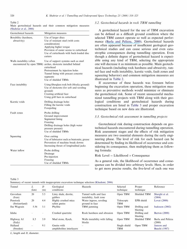
Table 2Main geotechnical hazards and their common mitigation measures(Shahriar et al., 2006)
Geotechnical hazards Mitigation measures
Borability (hardness,abrasivity)
Use of larger discsUse of resistant steel (with costsconsideration)Applying higher torqueProvision of easier access to cutterheadUse of cutterheads with back-loaded disccutters
Walls instability (oftenencountered by open TBM)
Use of support systems such as steelarches, shotcrete installed behindcutterheadPretreatment by injection holesTunnel lining with precast concretesegmentsUse of shielded TBMs
Face instability Using fiberglass rock bolt (blocky ground)Use of shotcrete (for soft and ravelingground)Creating artificial faceUsing grill bars in cutterhead
Karstic voids Drilling drainage holesFilling the karstic voidsForepoling
Fault zones Probe drillingGround improvementSegmental liningFreezingDrilling drainage holes (high waterpressure present)Use of shielded TBMs
Squeezing Over cuttingUse of lubricator such as bentonite, greasePrevention of machine break downsIncreasing thrust of longitudinal jacks
Water inflow Probe drillingDrainagePre-injectionFreezingUse of shielded TBMs
Table 3Summary of recent tunnels with inappropriate excavation technique selection
Tunnel L
(km)D
(m)Geologicalconditions
Hazards
Gavoshan(Iran)
20 5.5 Limy shale, diorite,gabbro
Tunnel walinstability,
Penstock(Switzerland)
20 4.4 Highly crushed micaschist gneiss
Water ingreground in f
Ilse Wagrain 5.56 3.1 Phyllite TBM jamm
Idaha – – Crushed quartzite Rock hardn
Highway A1(Italy)
8.5 3.9 Mud stone, flysch, Walls instabblocks
Halland(Sweden)
– 9.1 Gneiss withamphibolites interlayers
–
L, length and D, diameter.
320 K. Shahriar et al. / Tunnelling and Underground Space Technology 23 (2008) 318–325
3.2. Geotechnical hazards in rock TBM tunnelling
A geotechnical hazard for the use of TBM excavationcan be defined as a difficult ground condition where theselected TBM cannot operate so well as expected perfor-mance (Barla and Pelizza, 2000). Geotechnical hazardsare often appeared because of insufficient geological–geo-technical studies and can cause serious and even cata-strophic consequences during tunnelling operation. Eventhough a definite degree of geotechnical hazard is expect-able using any kind of TBM, selecting the appropriateone will decrease it as minimum as possible. Main geotech-nical hazards (including rock hardness and abrasivity, tun-nel face and walls instability, karstic voids, fault zones andsqueezing behavior) and common mitigation measures areillustrated in Table 2.
If occurrence of these hazards was foreseen beforebeginning the excavation operation, these mitigation mea-sures as preventive methods would minimize or eliminatethe geotechnical risk. Some of recent unsuccessful mecha-nized tunnelling projects with TBM along with their geo-logical conditions and geotechnical hazards duringconstruction are listed in Table 3 and proper excavationtechnique based on new data are illustrated.
3.3. Geotechnical risk assessment in tunnelling projects
Geotechnical risk during construction depends on geo-technical hazards encountered during tunnelling operation.Risk assessment stages and the effects of risk mitigationmeasures are two essential elements during the early engi-neering phase. The level of risk for each hazard can bedetermined by finding its likelihood of occurrence and con-sidering its consequence, then multiplying them as follow-ing formula:
Risk Level ¼ Likelihood� Consequence
As a general rule, the likelihood of occurrence and conse-quence can be divided into arbitrary levels. Here, in orderto get more precise results, the five-level of each one was
(Khademi, 2006)
Selectedtechnique
Propertechnique
Reference
ls and facefault zone
Open TBM Shielded TBM Sharghi et al.(2004)
ss, ravelingace
TelescopicTBM
EPB shield Lovat (2000)
ing Open TBM Drilling andblasting
Isaksson (2002)
ess and abrasion Open TBM Drilling andblasting
Barton (2000)
ility with falling Open TBM Shielded TBM Barla and Pelizza(2000)
Single shieldTBM
Open TBM Janzon andBuechi (1987)
K. Shahriar et al. / Tunnelling and Underground Space Technology 23 (2008) 318–325 321
used. The rating of likelihood and consequence is presentedin Tables 4 and 5. Combining the likelihood rating and theconsequence rating results in a risk index of between 1 and25 for any given risk are presented in Table 6.
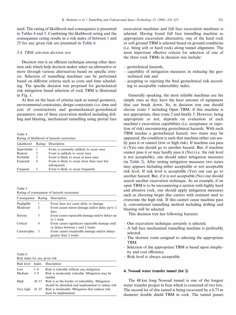
3.4. TBM selection decision tree
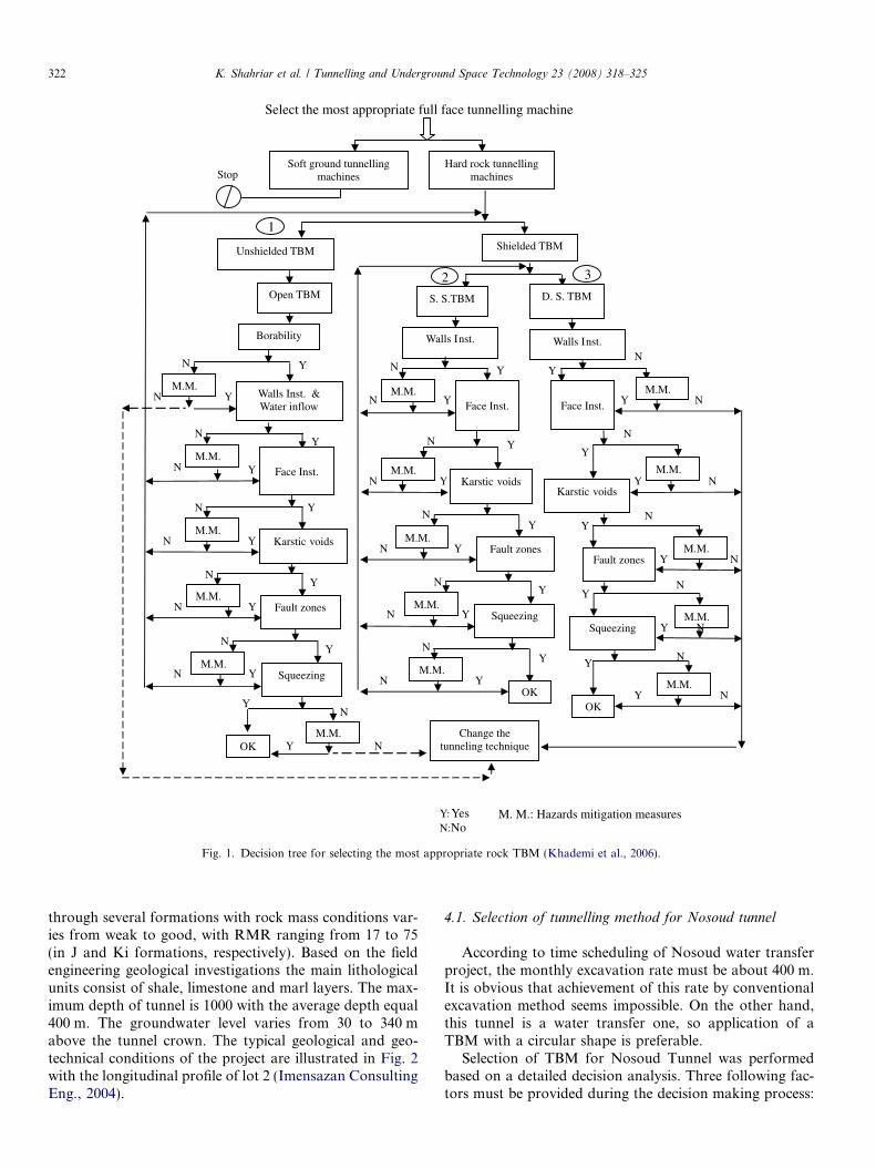
Decision tree is an efficient technique among other deci-sion aids which help decision maker select an alternative ormore through various alternatives based on specific crite-ria. Selection of tunnelling machines can be performedbased on different criteria such as costs and time schedul-ing. The specific decision tree proposed for geotechnicalrisk mitigation based selection of rock TBM is illustratedin Fig. 1.
At first on the basis of criteria such as tunnel geometry,environmental constraints, design constraints (i.e. time andcost of construction) and geomechanical–geotechnicalparameters one of three excavation method including dril-ling and blasting, mechanized tunnelling using partial face
Table 4Rating of likelihood of hazards occurrence
Likelihood Rating Description
Improbable 1 Event is extremely unlikely to occur onceRemote 2 Event is unlikely to occur onceProbable 3 Event is likely to occur at least onceExpected 4 Event is likely to occur more than once but
infrequentlyFrequent 5 Event is likely to occur frequently
Table 5Rating of consequence of hazards occurrence
Consequence Rating Description
Negligible 1 Event does not cause delay or damageModerate 2 Event causes minor damage and/or delay up to 2
daysSerious 3 Event causes repairable damage and/or delays up
to 1 weekCritical 4 Event causes significant repairable damage and/
or delays between 1 and 2 weeksCatastrophic 5 Event causes irreparable damage and/or delays
greater than 2 weeks
Table 6Risk index for any given risk
Risk level Index Description
Low 1–4 Risk is tolerable without any mitigationMedium 5–9 Risk is moderately tolerable. Mitigation may be
neededHigh 10–15 Risk is at the border of tolerability. Mitigation
should be identified and implemented to reduce riskVery high 16–25 Risk is intolerable. Mitigation that reduces risk
must be implemented
excavation machines and full face excavation machines isselected. Having found full face tunnelling machine asappropriate excavation alternative, one of the hard rockor soft ground TBM is selected based on ground conditions(i.e. being soft or hard rock) along tunnel alignment. Themost important effective criteria for selection of one ofthe three rock TBMs in decision tree include:
– geotechnical hazards,– capability of mitigation measures in reducing the geo-
technical risk and– accepting or rejecting the final geotechnical risk accord-
ing to acceptable vulnerability index.
Generally speaking, the most reliable machines are thesimple ones as they have the least amount of equipmentthat can break down. So, in decision tree one shouldchoose route 1 including Open TBM, if this machine isnot appropriate, then route 2 and finally 3. However, beingappropriate or not, depends on evaluation of eachmachine’s excavation capabilities (i.e. acceptance or rejec-tion of risk) encountering geotechnical hazards. With eachTBM reaches a geotechnical hazard, two states may beappeared, the condition is such that machine either can eas-ily pass it or cannot (low or high risk). If machine can passit (Yes) one should go to another hazard. But, if machinecannot pass it or may hardly pass it (No) (i.e. the risk levelis not acceptable), one should select mitigation measures(in Table 2). After testing mitigation measures two statesmay appears including either acceptable or not acceptablerisk level. If risk level is acceptable (Yes) one can go toanother hazard. But, if it is not acceptable (No) one shouldsearch another excavation technique. As an example, if anopen TBM is to be encountering a section with highly hardand abrasive rock, one should apply mitigation measuressuch as choosing larger disc cutters with resistant steel toovercome the high risk. If this cannot cause machine passit, conventional tunnelling method including drilling andblasting will be selected.
This decision tree has following features:
– One excavation technique certainly is selected.– A full face mechanized tunnelling machine is preferably
selected.– The shortest route assigned to selecting the appropriate
TBM.– Selection of the appropriate TBM is based upon simplic-
ity and cost efficiency.– Risk level is always acceptable.
4. Nosoud water transfer tunnel (lot 2)
The 48 km long Nosoud tunnel is one of the longestwater transfer project in Iran which is consisted of two lots.The second lot of this tunnel is being excavated by a 6.73 mdiameter double shield TBM in rock. The tunnel passes
Y: YesN:No
M. M.: Hazards mitigation measures
M.M. OK
Y N
YChange the
tunneling technique
Borability
Walls Inst. & Water inflow
Y N
M.M. Y N
Open TBM
Karstic voids
M.M.
Y
Y
N
N
N
OK
M.M.
Y
Y N
Fault zones M.M.
Y N
YN
Squeezing M.M.
Y N
YN
D. S. TBM
M.M.
Face Inst. Y
3
Walls Inst.
S. S.TBM
Walls Inst.
Karstic voidsM.M.
Y
Y
YN
N
N
N
Y
Y
N
M.M.Face Inst.
Y Fault zones M.M.
M.M.
OK
Y
YN
N
N
Squeezing M.M.
YN
YN
2
Fault zones M.M.
Y N
M.M. Y
N
Y N Squeezing
Y
Karstic voids
N
M.M. N Y
Y
M.M.
Y N
N
Y N
Face Inst.
Unshielded TBM Shielded TBM
1
Soft ground tunnelling machines
Hard rock tunnelling machines
Select the most appropriate full face tunnelling machine
Stop
1
Y N
N
N
Fig. 1. Decision tree for selecting the most appropriate rock TBM (Khademi et al., 2006).
322 K. Shahriar et al. / Tunnelling and Underground Space Technology 23 (2008) 318–325
through several formations with rock mass conditions var-ies from weak to good, with RMR ranging from 17 to 75(in J and Ki formations, respectively). Based on the fieldengineering geological investigations the main lithologicalunits consist of shale, limestone and marl layers. The max-imum depth of tunnel is 1000 with the average depth equal400 m. The groundwater level varies from 30 to 340 mabove the tunnel crown. The typical geological and geo-technical conditions of the project are illustrated in Fig. 2with the longitudinal profile of lot 2 (Imensazan ConsultingEng., 2004).
4.1. Selection of tunnelling method for Nosoud tunnel
According to time scheduling of Nosoud water transferproject, the monthly excavation rate must be about 400 m.It is obvious that achievement of this rate by conventionalexcavation method seems impossible. On the other hand,this tunnel is a water transfer one, so application of aTBM with a circular shape is preferable.
Selection of TBM for Nosoud Tunnel was performedbased on a detailed decision analysis. Three following fac-tors must be provided during the decision making process:
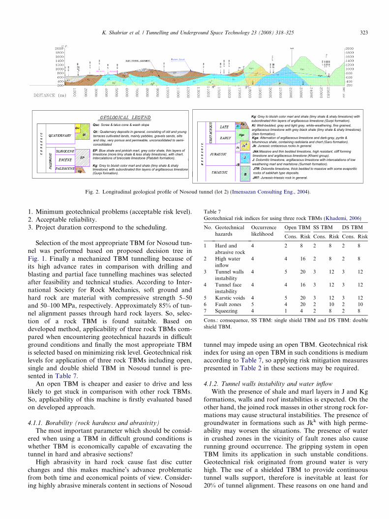
Qsc: Scree & talus cone & wash slope
Qt:: Quaternary deposits in general, consisting of old and young terraces cultivated lands, mainly pebbles, gravels sands, silts and clay, very porous and permeable, unconsolidated to semi-consolidated
Kg: Grey to bluish color marl and shale (limy shale & shaly limestone) with subordinated thin layers of argillaceous limestone (Gurpi formation).
EP: Blue shale and pinkish marl, grey color shale, thin layers of limestone (more limy shale & less shaly limestone), with chert. Intercalations of brecciate limestone (Pabdeh formation).
Kg: Grey to bluish color marl and shale (limy shale & shaly limestone) with subordinated thin layers of argillaceous limestone (Gurpi formation).
Ki: Well-bedded, gray and light gray, white-weathering, fine grained, argillaceous limestone with grey black shale (limy shale & shaly limestone), (Ilam formation).
Jkk:Massive and thin bedded limestone, high resistant, cliff forming limestone and argillaceous limestone (Khami group).
Kga: Alternation of argillaceous limestone and dark-gray, pyrite & bituminous shale, containing radiolaria and chert (Garu formation).Jk: Jurassic cretaceous rocks in general.
J: Dolomitic limestone, argillaceous limestone with intercalations of low weathering marl and marlstone (Surmeh formation).JTR: Dolomite limestone, thick bedded to massive with some evaporitic rocks of sabkhah type deposits.JRT: Jurassic-triassic rock in general.
Fig. 2. Longitudinal geological profile of Nosoud tunnel (lot 2) (Imensazan Consulting Eng., 2004).
Table 7Geotechnical risk indices for using three rock TBMs (Khademi, 2006)
No. Geotechnicalhazards
Occurrencelikelihood
Open TBM SS TBM DS TBM
Cons. Risk Cons. Risk Cons. Risk
1 Hard andabrasive rock
4 2 8 2 8 2 8
2 High waterinflow
4 4 16 2 8 2 8
3 Tunnel wallsinstability
4 5 20 3 12 3 12
4 Tunnel faceinstability
4 4 16 3 12 3 12
5 Karstic voids 4 5 20 3 12 3 126 Fault zones 5 4 20 2 10 2 107 Squeezing 4 1 4 2 8 2 8
Cons.: consequence, SS TBM: single shield TBM and DS TBM: doubleshield TBM.
K. Shahriar et al. / Tunnelling and Underground Space Technology 23 (2008) 318–325 323
1. Minimum geotechnical problems (acceptable risk level).2. Acceptable reliability.3. Project duration correspond to the scheduling.
Selection of the most appropriate TBM for Nosoud tun-nel was performed based on proposed decision tree inFig. 1. Finally a mechanized TBM tunnelling because ofits high advance rates in comparison with drilling andblasting and partial face tunnelling machines was selectedafter feasibility and technical studies. According to Inter-national Society for Rock Mechanics, soft ground andhard rock are material with compressive strength 5–50and 50–100 MPa, respectively. Approximately 85% of tun-nel alignment passes through hard rock layers. So, selec-tion of a rock TBM is found suitable. Based ondeveloped method, applicability of three rock TBMs com-pared when encountering geotechnical hazards in difficultground conditions and finally the most appropriate TBMis selected based on minimizing risk level. Geotechnical risklevels for application of three rock TBMs including open,single and double shield TBM in Nosoud tunnel is pre-sented in Table 7.
An open TBM is cheaper and easier to drive and lesslikely to get stuck in comparison with other rock TBMs.So, applicability of this machine is firstly evaluated basedon developed approach.
4.1.1. Borability (rock hardness and abrasivity)
The most important parameter which should be consid-ered when using a TBM in difficult ground conditions iswhether TBM is economically capable of excavating thetunnel in hard and abrasive sections?
High abrasivity in hard rock cause fast disc cutterchanges and this makes machine’s advance problematicfrom both time and economical points of view. Consider-ing highly abrasive minerals content in sections of Nosoud
tunnel may impede using an open TBM. Geotechnical riskindex for using an open TBM in such conditions is mediumaccording to Table 7, so applying risk mitigation measurespresented in Table 2 in these sections may be required.
4.1.2. Tunnel walls instability and water inflow
With the presence of shale and marl layers in J and Kgformations, walls and roof instabilities is expected. On theother hand, the joined rock masses in other strong rock for-mations may cause structural instabilities. The presence ofgroundwater in formations such as Jkk with high perme-ability may worsen the situations. The presence of waterin crushed zones in the vicinity of fault zones also causerunning ground occurrence. The gripping system in openTBM limits its application in such unstable conditions.Geotechnical risk originated from ground water is veryhigh. The use of a shielded TBM to provide continuoustunnel walls support, therefore is inevitable at least for20% of tunnel alignment. These reasons on one hand and
324 K. Shahriar et al. / Tunnelling and Underground Space Technology 23 (2008) 318–325
low acceptable risk from the project owner on the otherhand, make the decision makers consider a shieldedTBM. This raises the question as to whether a double orsingle shield should be used.
The shorter single shield is less likely to get stuck, but itis inherently slower than the double, as it relies for itsthrust and torque reactions on the lining. In this stagethe single shield TBM is selected based on the proposedapproach. Since a precast concrete or steel lining (or pre-lining) inside and under the protection of the shield canbe installed, walls instability is not a serious problem forshielded TBMs.
4.1.3. Face instabilityBased on tunnel face stability analysis, encountering this
phenomenon in shale and marl and also in blocky groundis expectable. If this instability appeared, using fiberglassrock bolts can be helpful. Using shotcrete in soft and ravel-ing ground is applicable. Pre-treatment inside the shieldbefore encountering unstable face is an effective way toovercome such difficult areas. To avoid problems in muck-ing system resulted from large falling blocks, using grillbars in cutterhead openings is required.
As presented in Table 7 geotechnical risk resulted fromface instabilities for application of shielded TBM is high(however at the border of acceptability). Application ofrisk mitigation measures for face instabilities, the shieldedTBM can pass through this hazard.
4.1.4. Karstic voidsApproximately 80% of the tunnel alignment is consisted
of limestone and its components. On the other hand,almost whole tunnel is below the underground water table.Encountering karstic terrane therefore, is expectable alongthe tunnel alignment. The risk resulted from this phenom-enon is high for shielded TBMs. So, application of mitiga-tion measures such as drainage holes, filling the karsticvoids and forepoling is required. This application makesshielded TBMs pass through the karsts without any consid-erable problem.
4.1.5. Fault zones
Based on early geological investigations, 13 main faultshave been distinguished throughout the tunnel. So, it is fre-quent the likelihood of encountering the fault. The esti-mated width of these faults is between 0.5 and 2 m. Therisk of encountering fault zones are high for shielded TBMsas presented in Table 7. Based on stability analyses in fall-ing crushed zones, TBM driving in these zones seems pos-sible if a shielded TBM is used.
4.1.6. Squeezing
Ground squeezing behavior should be well evaluatedwhen using a shielded TBM. A single shield TBM becauseof its shorter shield in comparison with a double one hasadvantages in this situation. On the other hand a doubleshield TBM because of its continuous operation in excava-
tion and segment installation has more advantages. So theexposed time is shorter in this machine (Sharifzadeh andHemmati Shaabani, 2006).
In some sections of tunnel because of highly thick over-burden and weak and water bearing layers such as clayeylimestone and marl, appearance of this phenomenon isexpectable. However the maximum convergence was esti-mated 2% along tunnel alignment which occurred in faultcrushed zones and sections with highly thick overburden.Although the risk index of encountering squeezing groundalong Nosoud tunnel alignment by shielded TBMs is med-ium, a double shield TBM because of its more excavationrate in comparison with a single shield one is preferablein such conditions. On the other hand it is expected thatusing the preventive measures as presented in Table 2 suchas over cutting, prevention of machine break downs anduse of lubricator such as bentonite cause machine passthrough this hazard without getting stuck.
4.2. The selected TBM
According to geological and geotechnical conditionsalong Nosoud tunnel alignment, the ideal TBM to beselected must have some main characteristics includingexcavation of a wide range of rock mass quality from weakto good, possibility of precast concrete segments installa-tion and achievement high advance rates and working indifficult ground conditions such as tunnel walls and faceinstabilities. The results of tunnel walls and face stabilityanalyses have indicated that application of an open TBMis limited. Based on the distribution of different geologicalunits along the tunnel alignment, it is clear that any lengthof different tunnel sections is not limited for the use of ashielded TBM (either single or double shield one). In otherwords, both the single and double shield TBMs have thesame preference based on geotechnical risk assessment.However, according to limits of construction duration, adouble shield TBM because of its continuous operationand more flexibility when encountering difficult groundconditions was proposed. The excavation of Nosoud tun-nel using a double shield TBM was started in January2006 and its average rate of monthly advance after 9months has reached 400 m which is an acceptable ratebased on Iranian norm of rock TBM tunnelling.
5. Conclusions
Appropriate TBM selection in tunnel excavation willplay an important role in project success from the safety,time and economical points of view. On the other hand,uncertainty in geological and geotechnical parameters isinevitable because of not being possible to know everyaspect of the geological profile during site investigations.Although a certain degree of geotechnical risk is expectablefor each TBM, selection of an appropriate one decreasesthe risk as minimum as possible. Based on the newly devel-oped approach the most appropriate TBM in difficult
K. Shahriar et al. / Tunnelling and Underground Space Technology 23 (2008) 318–325 325
ground conditions is one which has the minimum risk leveleither before or after hazards mitigation measuresexecution.
The most important limiting cause for using the openTBM in Nosoud tunnel is very high risk index in followingconditions:
– Weak rock masses with UCS equals 28 MPa in formationJ and inability to use grippers is the principal limitingfactor.
– Probability of tunnel walls instability in some sectionsespecially in J and Kg formations which may damageequipment and personnel inside the machine.
– Presence of ground water along whole tunnel alignmentespecially in Jkk with high permeability.
On the basis of the proposed approach, the most appro-priate TBM for Nosoud tunnel is a shielded one (either sin-gle or double shield), where according to the limitation ofconstruction duration, a double shield TBM was selected.The recorded advance rates by Nosoud tunnelling machineduring previous months validate the success of TBMselection.
References
AITES-ITA Working Group No. 14, 2000. Recommendations and
Guidelines for Tunnel Boring Machines (TBMs). www.ita-aites.org.
Barla, G., Pelizza, S. 2000. TBM tunneling in difficult ground conditions.
In: Geoeng, Melbourne, Australia.
Barton, N., 2000. TBM Tunneling in Jointed and Faulted Rock. Balkema,
Rotterdam.
Bieniawski, Z.T., Tamames, B.C., Fernandez, J.M.G., Hernandez, M.A.
2006. Rock mass excavability (RME) indicator: new way to selecting
the optimum tunnel construction method. In: ITA-AITES World
Tunnel Congress & 32nd ITA General Assembly, Seoul, Korea.
Einstein, H.H., Dudt J.P., Halabe V.B., Descoudres F. 1992. Decision aids
in tunneling – principle and practical application. Monograph. Swiss
Federation Office of Transportation.
Imensazan Consulting Eng. 2004. Nosoud tunnel construction method.
Report No. 142-00.
Isaksson, T. 2002. Model for estimation of time and cost based on risk
evaluation applied on tunnel projects. Ph.D. Thesis, Stockholm,
Sweden.
Janzon, H., Buechi, E. 1987. Record performance of TBM in the 13.5 km
Amlach tunnel, Austria. In: Proceedings of the Rapid Excavation and
Tunneling Conference, New Orleans, Louisiana, pp.1251–1267.
Khademi, J. 2006. A methodology for selection of TBM according to
geotechnical conditions. MSc Thesis, Amirkabir University of Tech-
nology (Tehran Polytechnic), Iran.
Khademi, J., Shahriar, K., Sharifzadeh, M. 2006. A methodology for rock
TBM selection based on geotechnical hazards mitigation. In: 8th
Regional Rock Mechanics Symposium, Turkey.
Lovat, R.P. 2000. Cleuson Dixence penstock tunnel. In: AITES-ITA
World Tunnel Congress, Durban, South African, vol. 24, pp. 611–614.
Nord, G., Stille, H., 1988. Bore and blast techniques in difficult types of
rock: Sweden’s experience. Int. J. Tunnel. Underground Space
Technol. 3 (1), 45–50.
Shahriar, K., Sharifzadeh, M., Khademi, J., Haddadi, M.R., 2006.
Selection of rock TBM based on geotechnical hazards mitigation. In:
7th Iranian Tunneling Conference, Tehran, Iran, pp.1059–1070.
Sharghi, A., Shakour, I., Habibagahi, M.A., Pelasi, M., 2004. Using open
TBM in caving zones and it’s controlling in Gavoshan tunnel. In: 6th
Iranian Tunneling Conference, Tehran, Iran.
Sharifzadeh, M., Hemmati Shaabani, A., 2006. TBM tunneling in adverse
rock mass with emphasis on TBM jamming accident in Ghomrud
water transfer tunnel. In: Van Cotthem, A., Charlier, R., Thimus, J.F.,
Tshibangu, J.P. (Eds.), Processing of Eurock2006, May 9–12, Liege,
Belgium. Taylor & Francis Publication, pp. 643–647.