generating 2.5d character animation by switching ... - j-stage
TRANSCRIPT

Generating 2.5D Character Animation by Switching theTextures of Rigid Deformation
Yuki Morimoto.Tokyo Denki University, Kyushu [email protected]
Atsuko Makita.Tokyo Denki University
Takuya Semba.Tokyo Denki University
Tokiichiro Takahashi.Tokyo Denki University, ASTRODESIGN Inc.
AbstractWe generated 2.5D animation from raster images, skeletal animation data, and other data formats. The input image of acharacter is divided into several parts with arbitrarily assigned joint positions. The joint positions in the motion data andadditional points are then applied as the control points of rigid deformation, generating a character animation. Geometricinterpolation is replaced by switching of the cell animation images. In experimental evaluations, our animation resultswere successfully generated without interpolation techniques, a large number of input images, and high editing costs forinterpolation. We also introduced a transformation content using the method, and confirmed the entertainment value of thecontents.
Keywords: 2.5D cartoon model, bone animation, cel animation
1 IntroductionIn the traditional cel animation process, characters are animatedby making slight changes to each manually drawn frame alongthe time series. However, the process requires more than eightcels per second and is very expensive. To reduce these costs,animators abstract the motions of their characters from a reducednumber of drawn frames in the process called limited animation.Alternatively, animators reuse parts of the cels such as the mouth,eyes, and background. Recently, animation has become a digitalprocess. However, the overall process in which multiple cels ofeach part are drawn and switched to generate the animation hasnot changed [1].
In non-photorealistic rendering (a field of computer graphics),many works have focused on a technique called toon rendering,which transforms 3D models to a 2D cartoon or anime-like im-ages. Although toon rendering has recently improved the produc-tion cost of animation creation and game development, it encoun-ters problems when the 2D expressions contradict the 3D world.To overcome such problems, some researchers have interpolatedbetween the user-specified 3D geometries viewed from some per-spectives. The interpolation sometimes induces unnatural appear-ances especially when the 3D model is bumpy or complicated. Toavoid this problem, additional editing is needed for interpolation.
Rivers et al. [2] proposed a 2.5D cartoon model that generatessmooth animations such as 3D animations from one input imageper part. In this method, the user specifies the appearances (ge-ometry and color) of each part from different viewpoints. Theresult animation is smooth like 3D animation by morphing but it
has 2D appearance. However the inputs of this method is lim-ited to simple geometry. Also the method inapplicable to generalbone animations.
2.5D animation of more complicated images can be conductedin Live2D Cubism software [3]. The main differences betweenthe method of Rivers et al. and Cubism are the texture mappingand the morphing parameters of each part. Users of Cubism cancorrespond the parameter values to the part geometries. The sys-tem then interpolates the geometries by keyframe animation withthe morphing parameters. The user sequentially edits the ver-tices of the part geometry at the keyframe. And also the usercan edit many vertices at once by deforming the curved surfacesthat the vertices are mapped onto. Such detailed editing usuallyincurs high costs. Live2D Inc. has released the animation soft-ware Euclid, which improves the viewpoint angle to 360 degreeby switching the textures of each part. For this purpose, Euclidextends the method already employed in Cubism. The switchingoperation is applied only to parts of face and head.
Here, we propose a method that generates character anima-tions from images, while avoiding unnatural interpolations. Ourmethod replaces interpolation with texture-switching and a rigiddeformation procedure. Moreover, we correspond part texturesviewed from different angles using joints instead of vertices suchas in the above 2.5D methods, our method is not reliant on thetexture geometry (which can be uneven and complex). The en-tertainment value of the method was assessed in a questionnairesurvey of the animation results. Although the resulting anima-tions are less smooth than other 2.5D methods, the smoothness
Received January 8th, 2019; Accepted May 27th, 2019
16

quality was deemed reasonable by the respondents of our ques-tionnaire survey.
2 Related works2.1 Rigid deformationProposed by Alexa et al. [4], the rigid deformation techniquereduces the distortion in the deformed geometry. Unlike simplelinear interpolation of the vertices, the rigid deformation is anaffine transformation excluding rotation and shear as far as possi-ble. Igarashi et al. [5] divided a target image into triangle meshesand specified multiple vertices as control points. Their methodenables a fast and smooth deformation with reduced distortionof each triangle. Using similar inputs, Schaefer et al. [6] de-formed an image by affine transforms weighted by the distancesbetween control points and mesh vertices. Further, Jacobson etal. proposed a method that accommodates the positions and rota-tions of control points, control lines, and control cages within thesame framework enabling flexible image deformation [7]. Otherrigid deformation techniques include the registration of hand-drawn animation [8], image processing methods such as content-aware image resizing [9]. Although rigid deformation has beenextended in various ways, we present the first documented exten-sion of 2.5D animation.Vertex blending is similar to rigid deformation method proposedby Schaefer et al [6]. Vertex blending is generally used for cal-culating the vertex positions of a 3D model in bone animation.Vertex blending operates by summing the weighted affine trans-formations of bone joints. Rigid deformation in the method pro-posed by Schaefer et al. is limited to translation, rotation, anduniform scaling of both the x and y axes. These results are lessdistorted in human perception.
2.2 Combination of 2D and 3D expressionsSome research papers have simultaneously captured the texturesof 2D expressions with the smoothness of 3D animations [10, 11,12]. These methods map 2D textures onto 3D models. Based onsimilar concepts, other researchers have arranged 2D layers into3D spaces [13, 14], but these methods have unique goals.
3 Our method3.1 OverviewThe overview of our system is described below, with reference toFig. 1. First, the character image is segmented into parts (Fig.1(a)), which are the input for our system. Here, the green trian-gles and green arrows indicate the joint positions and bones of thecharacter, respectively. Our system requires two or more differentimages of the angles of each part. The body parts are shown bythe rectangles in Fig. 1(a). The body-part images that are inputsfor our system are corresponded to their orientations. Hence, oursystem selects the image with the closest direction of each part(see Fig. 1(b)). The additional control points can be specified foraligning arbitrary positions of different parts (Fig. 1 (c)). In thisexample, the rigid deformation will align the blue and red posi-tions shown in Fig. 1(c). Then, bone animation is applied. Asshown in Fig. 1(d), the part images are switched and deformedto correspond to the direction or angle of the joints of the inputskeletal animation.
Figure 1 Overview.
4 Details4.1 Rigid deformation scheme of Schaefer et al.We apply rigid deformation proposed by Schaefer et al. usingmoving least-squares method [6]. This method deforms an imagebased on the specified positions before and after the deformation,while avoiding intuitive distortions. In this way, a wide range ofmotions are covered in one image. The method maps the inputimage onto flat triangle meshes, and calculates the positions ofthe vertices on the meshes.
f (v) = |v− p∗|f (v)
| f (v)|+q∗, f (v) = ∑
iqiAi
Ai = wi
(pi
−p⊥i
)(v− p∗
−(v− p∗)⊥
)T
, wi =1
|pi − v|4,
pi = pi − p∗, qi = qi −q∗,
p∗ =∑i wi pi
∑i wi, q∗ =
∑i wiqi
∑i wi
(1)
Here, v is the vertex of the lattice divided in the input image,p and q are the control points before and after deformation, re-spectively, and f (v) is the deformation function applied to v.The weight function w is related to the distance between eachvertex and control-point, and m is the number of vertices when(i = 0,1, ...,m). Please refer [6] for more details.
4.2 Two kinds of control points4.2.1 Joint-based control pointsOur method defines control points as the joint positions of eachpart. The joint positions are specified by a mouse click on the partimages. The required positions after deformation are obtained byscaling the motion data to the size of the character. Note that rigidjoint deformation of the long parts, such as arms and legs, wouldyield round shapes. To avoid this problem, the control pointsin our method are arranged along the bones. Here i is the jointnumber, j is the neighboring joint of i, and k = 1,2, ...,n, wheren is the number of control points between joints i and j. Theposition P joint
i, j,1 of joint i corresponds to P jointi . To additionally
constrain the rigid deformation, we add the sub-joints as controlpoints approximately every four pixels between the joints, fol-lowing a parent-child relation. These sub-control points after de-
Received January 8th, 2019; Accepted May 27th, 2019
17
formation Q jointi, j,k are arranged on the bones between joints i and j
at the interval of |Q jointi −Q joint
j |/n (shown as black triangles inFig. 1(d)).
4.2.2 Additionally specified control pointsIf rigid deformation uses the joint only as control points, voids aregenerated between neighbouring parts in some cases. Our systemallows the addition of other control points to cover such voids.Moreover, it also enables to add accessory parts to other than thejoint positions. This method also enables to add accesory imagesarbitrarily such as the star, heart, and light-colored belly area inthe example of the pink bear (Fig. 2).In our system, controllers and receivers are additionally specifiedcontrol points at arbitraril locations. The controllers are locatedby rigid deformation and their positions are passed as constraintsto the receivers. The correspondence between controllers and re-ceivers is not necessarily one-to-one, as each receiver can acceptinputs from more than one controller. In such cases, the receiversfind the nearest corresponding controller (in relative coordinates)using the two nearest joints of the controller.In Figure 1(c), the additional points are the red and blue points onthe shoulder and top of the arm, respectively. In this example, thered points are controllers Padd
a and the blue points are receiversQadd
a . Part images are deformed in sequential order. Specifi-cally, the part that has controllers is deformed first; the receiversare then deformed to correspond with the deformed controllers.Here, a is the index of the additional control-point set. Other ex-amples of setting for additional constraints are shown in Fig. 3.Note that the number and locations of the additional points arespecified arbitrarily to allow trial and error editing for generatingthe better result.
4.3 Mesh generationTexture mapping and rigid deformation are performed on meshesof grid points and controll points (see Fig. 1(d)). Rigid defor-mation is computed by using equation (1) with the settings ofp = P joint
i, j,k ∪Padda , q = Q joint
i, j,k ∪Qadda .
4.4 Scaling of joint positionsIn our method, the input data are the part images and their markedjoint positions. A human character has 20 joints: head, neck, cen-ter, left and right shoulders, waist, left and right elbows, left andright wrists, left and right hands, left and right hips, left and rightknees, left and right ankles, and left and right toes (the greentriangles in Fig. 1(a)). Based on the 3D motion data, joint po-sitions are calculated to fit the scaling rate of the bone lengthsin the input 2D character images. We define the scaling rate sc,which roughly scales the entire input image to the motion datain 3D space. The scaling rate sc avoids the inherent distortionsin certain animations such as stretching of a cloth, by using rigiddeformation. The scaling rate sc is calculated as
sc =|KHipCenter −KShoulderCenter||P joint
HipCenter −P jointShoulderCenter|
, (2)
where Ki is a position in the 3D coordinates, and i is an indexof joint. The 3D joint positions are then transformed into 2Dcoordinates as follows:
Q jointi = Q joint
j +HKi −K j
|Ki −K j|sc|P joint
i −P jointj | (3)
Here, the function H transforms the 3D positions to 2D positionson the x-y plane, and j is the parent joint of i. The waist joint isthe root, meaning that all joint positions from parents to childrenare calculated with Q joint
root being the projected position of Kroot
onto the x-y plane.
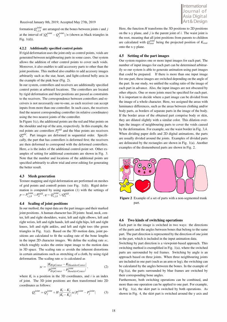
4.5 Setting of the part imagesOur system requires one or more input images for each part. Thenumber of input images for each part can be determined arbitrar-ily so our system is able to generate animation using part imagesthat could be prepared. If there is more than one input imagefor one part, these images are switched depending on the angle ofthe part. In our study, we unified the scaling ratio of the image ofeach part in advance. Also, the input images are not obscured byother objects. One or more joints must be specified for each part.It is important to decide where a part image can be divided fromthe image of a whole character. Here, we assigned the areas withluminance differences, such as the areas between clothing and/orbody parts, as borders of separate parts in the image of the body.If the border areas of the obtained part comprise body or skin,they are dilated slightly with a similar color. This dilation over-laps the images of neighbouring parts to cover the voids causedby the deformation. For example, see the waist border in Fig. 3,4.When dividing paper dolls and 2D digital animations, the partsare usually divided around the joints. Examples of divided partsare delineated by the rectangles are shown in Fig. 1(a). Anotherexamples of the dismembered parts are shown in Fig. 2.
Figure 2 Example of a set of parts with a non-segmented trunkpart.
4.6 Two kinds of switching operationsEach part in the image is switched in two ways: the directionsof the parts and the angles between bones that belong to the samepart. The part direction is represented by the direction of one jointin the part, which is included in the input animation data.Switching by part direction is a viewpoint-based approach. Thisswitching method is exemplified in Fig. 1(a), where the switchedparts are surrounded by red frames. Switching by angle is anapproach based on three joints. When three neighbouring jointsare included in one part (such as an arm or leg), the switching canbe calculated by the angles between the bones. In the example ofFig.1(a), the parts surrounded by blue frames are switched bytheir corresponding bone angles.Furthermore, both switching operations can be combined, andmore than one operation can be applied to one part. For example,in Fig. 1(a), the skirt part is switched by both operations. Asshown in Fig. 4, the skirt part is switched around the y axis and
Received January 8th, 2019; Accepted May 27th, 2019
18

Figure 3 Examples of correspondences between joints and im-ages. In the encircled area, the corresponding pointsare green to green and red to blue.
also by the angle between the right knee, waist, and left knee inthis case. In this example, the part images are switched in fivedirections around the y axis and through three angle ranges (lessthan -15, -15 to 15, more than 15 degrees).
Figure 4 Examples of image switching by direction of a partaround the y axis (top row) or by the angle betweenjoints (bottom row and right column).
4.7 Setting of joint depthIn rendering, the relative-depth order of each joint is decided fromthe captured joint depths. The user can optionally specify the rel-ative depth based on the input image and orientation of the bodypart. The depth of each vertex in the mesh (Fig. 1(d)) is thendefined as the nearest joint depth. To avoid the unnatural appear-ance caused by vertices of uneven depths, the vertices around theborder of the corresponding part are assigned the same depth.
5 Results, evaluation, and applicationThe results of our approach are shown in Figs. 5 and 6. Ouranimations are shown in a supplemental video. Our animationswere compared against a stylized 3D animation. In one of ourresults, we input the captured images of the stylized 3D model;other animation results using hand-drawn versions of the samecharacter, the pink bear, and the photo of person. Our systemwas developed and tested in the following environment: Intel(R)Core(TM) [email protected] GHz 2.39 GHz, 8 GB memory, Win-dows 8.1 Professional 64-bit, and motion-capture equipment (Mi-crosoft Kinect v1). Note that the center shoulder joint was calcu-lated as the center point of the distance between the right and left
shoulders detected by Kinect in our system. Moreover, we didnot use joints other than the 20 joints described in the section 4.4.As the motions were captured by Kinect, our system operated ata real-time rate (Table 1). Table 1 displays the numbers of ver-tices in representative parts of the images of each character, andthe computational time of each frame. The numbers change alittle by switching images in our actual experiments. The com-putational time includes the rendering time but not the motion-capture time. The part images which are used as inputs for thecomparison experiments are shown in Fig. 7.In our method, the depth variations in single image parts are han-dled by setting the depth on each mesh. For example, in the toprow of Fig. 6, the shoulder area of the arm part hides behindthe upper body part, and the elbow area appears in front of theupper body part. Setting multiple additional control points Qadd
agenerates relatively more natural results, as shown in the bottompanels of Fig. 6. Our method is also applicable to photographs,as shown in the bottom images of Fig. 9 in the final page of thispaper.
Figure 5 Comparison between an anime-styled rendered 3Dmodel (left) and our 2.5D animation results (second,third and fourth images from left).
Table 1 Number of vertices and processing time for every frame.
modelthe number ofvertices
computationtime (ms)
captured stylized 3D model 1846 3.5hand-drawn girl 1467 5.0hand-drawn bear 4081 33.5
Using our system, we generated a virtual-character transforma-tion application for users and also evaluated its performance in aquestionnaire survey. Transformation scenes are common in ani-mated television programs and SFX television programs for chil-dren. Such transformation scenes are popular traditional contentsthat reflect human desires. General transformation scenes in tele-vision programs include many visual effects. Thus, our contentsprepared by us displayed a 2.5D animation after a transformationscene. Throughout the content, we captured the motion of theuser in real-time for interaction and animation generation. When
Received January 8th, 2019; Accepted May 27th, 2019
19

In the arm part, the shoulder area hides behind the upper body (left).In the leg part, the upper area hides behind the skirt (right).
Result of applying multiple control points on one part.
Figure 6 Effects of our method.
Captured stylized 3D model(the hand and skirt parts are shown in Fig. 1 and 4), respectively.
Hand-drawn girl model
Hand-drawn bear model
Figure 7 Sets of input images for generating results. Same-partinputs are grouped in the frames. The images of thehand and leg parts were inverted for the other side. Theparts enclosed in red and blue rectangles were switchedby orientation and angle, respectively.
the user raised his or her right hand, glittery stars were seen tomove from head to toe. This visual effect was accompanied bysound effects (Fig. 8). Next, the user arranged his or her lefthand around the side of her face, eliciting heart marks as anothervisual effect. The content then transited to the 2.5D character an-imation, which appeared after the transformation. Here, the usercan freely pose using anything other than the left hand.This content was shown to 15 participants. We experimentally
evaluated whether or not the user became a cartoon character.Users were asked to rate their perceptions on a three-grade scale(3 = yes, 2 = unsure, and 1 = no). Ten out of 15 participantsrated their experiences as 3, suggesting that they perceived them-selves as a cartoon characters. The remaining participants wereunsure of their experience. The main content was the 2.5D ani-mation scene; the transformation scene that was included but wassignificantly shorter. Therefore, our animation results were natu-ral and familiar to the users. Incidentally, a vast majority of theparticipants (14) rated the experiment as ”fun.” One rated it as”normal”, and none rated it as ”not fun.” Our content was highlyappreciated as entertaining.
Figure 8 Interactive scene of transformation into a 2D character.
6 DiscussionOur static results had a natural appearance, as shown in Fig. 5.Our animation results were also perceived as natural animationcontents by the 15 participants of our questionnaire survey. Be-cause our animation results are switched by certain angles, theyare less smooth than in existing 2.5D animation, 3D stylized an-imation, and traditional cel animation. However, the study ful-filled its purpose of generating validated cartoon animations with-out interpolation methods. So we showed possibilities in ourmethod to be a method to more easily generate 2.5D animationsin future.It is necessary to input more images or apply interpolation to im-prove the smoothness of animation, however, this will also in-crease its cost. Furthermore, some existing animations, such asstop-motion animation and time lapse videos are not uniformlysmooth. Therefore, our method can potentially realize a new styleof animation with low editing costs.Although the present study ignored the user interface (UI), a com-fortable UI for generating the animations is one of our goals. Es-pecially, by automating some processes on the UI and replacingthe manual joint specification by image processing, we can ex-pect to reduce the editing costs and improve the quality of theanimation result. Another future task is shading the textures inthe animation that are not achieved by existing 2.5D methods.Here we describe the difference and comparison between Live2Dand our method. Live2D requires only one image per part. Oursrequires more than one images per part. Both methods need tocreate a mesh for each image. Key frame animation is applied inLive2D to create movements and also picture itself. In Live2D,editing key frame animation is the task to generate not only ani-mations but also pictures (geometries). On the other hands, ani-mations in our method are generated by switching multiple partimages and rigid deformation with bone data. Unlike drawing a
Received January 8th, 2019; Accepted May 27th, 2019
20

picture, Live2D is not a intuitive way; it must generate all ge-ometries (or appearances from all view point) from one mesh ofpart image. In our method, input images are just raster images.So there is no cost to edit mesh vertices. In animation genera-tion of Live2D, the shape may collapse for two reasons. One islarge deformation caused by covering with only one mesh. Theother is that there is no constraints on geometric deformation. Inour method, because vertex positions are calculated only by rigiddeformation, there is almost no unnatual collapses of shapes.Live2D enables to generate professional animation by detailedediting from very few input images. They are quite useful forproducing proffesional animation. Our method is not suitable forgenerating such professional animations. However our methodhas an advantage in that it is simple to create a 2D animationwith more than minimal quality. The above considerations areexplained in terms of the basic theory of both methods except forsome optional editing. In the future, simple content generation byindividuals would be required because currently virtual avatersare popular online. Thus simple animation generation with mini-mal quality would be valid as one choice.
7 ConclusionWe present a system that generates 2.5D animations from boneanimation, rigid deformation, and switching of part images. Wethen generated digital content in our system and evaluated its en-tertainment value in a questionnaire survey. Our system gener-ated animations without interpolation (which produce its smooth-ness but sometimes cause the severity of distortions), and withfewer input images than cel animation. In future work, we hopeto install our system in an intuitive UI and evaluate the quality ofthe generated animations.
References[1] Inc. Celsys. Retus studio.[2] Alec Rivers, Takeo Igarashi, and Fredo Durand. 2.5d cartoonmodels. ACM Trans. Graph., Vol. 29, No. 4, pp. 59:1–59:7, July2010.[3] Live2D Inc. Live2d. 2008.[4] Marc Alexa, Daniel Cohen-Or, and David Levin. As-rigid-as-possible shape interpolation. In Proceedings of the 27th An-nual Conference on Computer Graphics and Interactive Tech-niques, SIGGRAPH ’00, 2000.[5] Takeo Igarashi, Tomer Moscovich, and John F. Hughes.As-rigid-as-possible shape manipulation. ACM Trans. Graph.,Vol. 24, No. 3, July 2005.[6] Scott Schaefer, Travis McPhail, and Joe Warren. Imagedeformation using moving least squares. ACM Trans. Graph.,Vol. 25, No. 3, July 2006.[7] Alec Jacobson, Ilya Baran, Jovan Popovic, and Olga Sorkine.Bounded biharmonic weights for real-time deformation. ACMTrans. Graph., Vol. 30, No. 4, July 2011.[8] Daniel Sykora, John Dingliana, and Steven Collins. As-rigid-as-possible image registration for hand-drawn cartoon an-imations. In Proceedings of the 7th International Symposium onNon-Photorealistic Animation and Rendering, NPAR ’09, 2009.[9] Yu-Shuen Wang, Chiew-Lan Tai, Olga Sorkine, and Tong-Yee Lee. Optimized scale-and-stretch for image resizing. ACMTrans. Graph., Vol. 27, No. 5, December 2008.
Figure 9 Our animation results.
[10] Johannes Schmid, Martin Sebastian Senn, Markus Gross,and Robert W. Sumner. Overcoat: An implicit canvas for 3dpainting. ACM Trans. Graph., Vol. 30, No. 4, July 2011.[11] Eakta Jain, Yaser Sheikh, Moshe Mahler, and Jessica Hod-gins. Three-dimensional proxies for hand-drawn characters.ACM Trans. Graph., Vol. 31, No. 1, February 2012.[12] Katie Bassett, Ilya Baran, Johannes Schmid, Markus Gross,and Robert W. Sumner. Authoring and animating painterly char-acters. ACM Trans. Graph., Vol. 32, No. 5, October 2013.[13] Xueting Liu, Xiangyu Mao, Xuan Yang, Linling Zhang, andTien-Tsin Wong. Stereoscopizing cel animations. ACM Trans.Graph., Vol. 32, No. 6, November 2013.[14] Daniel Sykora, Ladislav Kavan, Martin Cadık, OndrejJamriska, Alec Jacobson, Brian Whited, Maryann Simmons,and Olga Sorkine-Hornung. Ink-and-ray: Bas-relief meshesfor adding global illumination effects to hand-drawn characters.ACM Trans. Graph., Vol. 33, No. 2, April 2014.
Received January 8th, 2019; Accepted May 27th, 2019
21