real-time animation for formal specification
TRANSCRIPT

Real-Time Animation for Formal Specification
Dominique Mery and Neeraj Kumar Singh
Abstract A formal specification is a mathematical description of a given system.Writing a formal specification for real-life, industrial problems is a difficult and er-ror prone task, even for experts in formal methods. It is crucial to get the approvaland feedback when domain experts have a lack of knowledge of any specificationlanguage, to avoid the cost of changing a specification at later stage of development.This paper introduces a new functional architecture, together with a direct and effi-cient method of using real-time data set, in a formal model without generating thelegacy source code in any target language. The implemented architecture consistsof six main units. These units are: Data acquisition and preprocessing unit; Featureextraction unit; Database; Graphical animations dedicated tool: Macromedia Flash;Formal model animation tool Brama plug-in to interface between Flash animationand Event-B model; and formal specification system Event-B. These units are in-voked independently and allow for simple algorithms to be executed concurrently.All the units of this proposed architecture help to animate the formal model withreal-time data set and offer an easy way for specifiers to build a domain specificvisualization that can be used by domain experts to check whether a formal specifi-cation corresponds to their expectations.
Dominique MeryLORIAUniversite Henri Poincare Nancy 1BP 23954506 Vandœuvre-les-Nancye-mail: [email protected]
Neeraj Kumar SinghLORIAUniversite Henri Poincare Nancy 1BP 23954506 Vandœuvre-les-Nancye-mail: [email protected]
1
inria
-005
4000
5, v
ersi
on 1
- 21
Feb
201
1Author manuscript, published in "Complex Systems Design & Management 2010 (2010) 49-60"
DOI : 10.1007/978-3-642-15654-0_3
2 Dominique Mery and Neeraj Kumar Singh
1 Introduction
Formal methods aim to improve software quality and produce zero-defect software,by controlling the whole software development process, from specifications to im-plementations. Formal methods are used by industries in a range of critical domains,involving higher safety integrity level certification and IEC 61508 [7] safety stan-dard. IEC 61508 is intended to be a basic functional safety standard applicable toall kinds of industry.
In formal model development, they use top-down approaches and start from high-level and abstract specifications, by describing the fundamental properties of thefinal system. A detailed information about a given system is introduced in an incre-mental way [2]. The correctness between two levels is ensured by refinement proofs.The final refinement leads to the expected behaviour of the system implementationmodel.
The role of verification and validation is very important in the developmentof safety critical systems. Verification starts from the requirements analysis stagewhere design reviews and checklists are used for validation where functional testingand environmental modelling is done. The results of the verification and validationprocess are an important component in the safety case, which is used to support thecertification process.
Event-B is a formal method for system-level modelling and analysis. There aretwo main proof activities in Event-B: consistency checking, which is used to showthat the events of a machine preserve the invariant, and refinement checking, whichis used to show that one machine is a valid simulation of another. There are sev-eral ways to validate a specification: prototyping, structured walkthrough, trans-formation into a graphical language, animation, and others. Each technique has acommon goal, to validate a system according to the operational requirements. Ani-mation focuses on the observable behaviour of the system [19, 21]. The principle isto simulate an executable version of the requirements model and to visualize exactbehaviours of the actual system. Animators use finite state machines to generate asimulation process which can be then observed with the help of UML diagrams, tex-tual interfaces, or graphical animations [12, 21]. Animation can be used in the earlystage of development during the elaboration of the specification: there is no need towait until it is finished and get the generated code. As a relatively low cost activity,animation can be frequently used during the process to validate important refine-ment steps. It then provides us with a validation tool consistent with the refinementstructure of the specification process [21].
The final code generation process consists of two stages: final level formal spec-ifications are translated into programs in a given programming language, and thenthese programs are compiled. Nevertheless all approaches which support formaldevelopment from specification to code must manage several constraining require-ments, particularly in the domain of embedded software where specific propertieson the code are expected [23]. Finally, it is not possible to use the real-time datain the early stage of formal development without compiling the source code in anytarget language. Based on our various research experience using formal tools in an
inria
-005
4000
5, v
ersi
on 1
- 21
Feb
201
1
Real-Time Animation for Formal Specification 3
industrial requirements (verification and validation) and our desire to disseminateformal methods, we have imagined a new approach to present an animated modelof specification using real-time data set, in the early stage of formal development.
It can help a specifier gain confidence that the model that is being specified,refined and implemented, does meet the domain requirements. This is achieved bythe animation component of Brama [16] with Macromedia Flash tool, that allowsto check the presence of desired functionality and to inspect the behaviour of aspecification.
In this paper, we describe an approach to extend an animator tool which will beuseful to use the real-time data set. Now, present time all the animation tools use atoy data set to test the model while we are proposing a key idea to use the real-timedata set with the model without generating the source code in any target language (C,C++, VHDL etc.). In this work, we present an architecture which allows to easily de-velop visualizations for a given specification. Our architecture supports state-basedanimations, using simple pictures to represent a specific state of a Event-B speci-fication, and transition-based animations consisting of picture sequences by usingreal-time data set. The animated model consists in Macromedia Flash componentsin picture sequences that is controled by the real-time data set and it presents anactual view of the system. Before moving on we should also mention that there arescientific and legal applications as well, where the formal model based animationcan be used to simulate (or emulate) certain scenarios to glean more information orbetter understanding of the system requirements.
This paper is organized as follows. Section 2 briefly introduces an animator tool,Brama. Section 3 presents the functional architecture which enables the animationof a proved specification with real-time data set. The functional architecture is thenillustrated in section 4 on a real case study, the cardiac pacemaker system. Section5 concludes the paper with some lessons learned from this experience and someperspectives along with future works.
2 Overview of Brama
Brama [16] is an animator for Event-B specifications which is designed by Clearsy.Brama is an Eclipse plug-in suit and Macromedia Flash extension that can be usedwith Windows, Linux and MacOS for RODIN platform [13]. Brama can be used tocreate animations at different stages of development of a simulated system. To doso, a modeler may need to create an animation using the Macromedia Flash plug-infor Brama. The use of this plug-in is established through a communication betweenthe animation and the simulation.
A modeler can represent the system manually within RODIN [13] or representthe system with the Macromedia Flash tool that allows for communication with theBrama animation engine through a communication server. Brama communicateswith Macromedia Flash through a network connection. Brama acts as a server towhich the animation will connect. In order to connect to a Brama server, a Flash
inria
-005
4000
5, v
ersi
on 1
- 21
Feb
201
1

4 Dominique Mery and Neeraj Kumar Singh
animation has to use the Brama component. This component handles the connec-tion and the communication with the Brama server. This server has been created tocommunicate with animations which would stimulate the simulation and display animage of the system. The communication server exchanges the information packetsbetween a model and a tool. Macromedia Flash controls the functional behaviourof all graphical components (button, check box, movie clip etc.). When the mod-eler and domain experts are satisfied with output, Brama can export the finishedanimation.
Brama contains the following main modules: B2Rodin: an animation engine(predicate solver), event and B variable visualization tools, an automatic event link-age management module, a variable management module, observed predicates andexpressions, and a Macromedia Flash communication module. The Brama modelanimation tool provides some feedbacks that can be used by the modeler throughoutthe modeling process. The animation functions allow it to “create” various modelevents, filters and properties during testing process [16].
3 Description of the Architecture
Figure 1 depicts the overall functional architecture that can use the real-time data setto animate the Event-B model without generating source code of the model in anytarget language (C, C++, VHDL etc.). This architecture has six components: Dataacquisition and preprocessing unit; Feature extraction unit; Database; Graphical an-imations dedicated tool: Macromedia Flash; Formal model animation tool Bramaplug-in to interface between Flash animation and Event-B model; and formal spec-ification system Event-B.
Data acquisition and preprocessing begin with the physical phenomenon or phys-ical property to be measured. Examples of this include temperature, light intensity,heart activities and blood pressure [14] and so on. Data acquisition is the process ofsampling of real world physical conditions and conversion of the resulting samplesinto digital numeric values. The data acquisition hardware can vary from environ-ment to environment (i.e camera, sensor etc.). The components of data acquisitionsystems include sensors that convert physical properties. A sensor, which is a typeof transducer, that measures a physical quantity and converts it into a signal whichcan be read by an observer or by an instrument.
Data preprocessing is a next step to perform on raw data to prepare it for anotherprocessing procedure. Data preprocessing transforms the data into a format that willbe more easily and effectively processed for the purpose of the user. There are anumber of different tools and methods used for preprocessing on different types ofraw data, including: sampling, which selects a representative subset from a largepopulation of data; transformation, which manipulates raw data to produce a singleinput; denoising, which removes noise from data; normalization, which organizesdata for more efficient access.
inria
-005
4000
5, v
ersi
on 1
- 21
Feb
201
1

Real-Time Animation for Formal Specification 5
Data acquistion &
Pre-processingUnit
FeaturesExtraction Unit Database
Flash Animation
Brama Plug-in
Event-B Model Unit
Fig. 1 A functional architecture to animate a formal specification using real time data set withoutgenerating source code
The features extraction unit is a set of algorithms that is used to extract the pa-rameters or features from the collected data set. Theses parameters or features arenumerical values that are used by animated model at the time of animation. The fea-ture extraction relies on a thorough understanding of the entire system mechanics,the failure mechanisms, and their manifestation in the signatures. The accuracy ofthe system is fully dependent on the feature or parameter values being used. Fea-ture extraction involves simplifying the amount of resources required to describe alarge set of data accurately. When performing analysis of complex data one of themajor problems stems from the number of variables involved. Analysis with a largenumber of variables generally requires a large amount of memory and computationpower or a classification algorithm which overfits the training sample and gener-alizes poorly to new samples. Feature extraction is a general term for methods ofconstructing combinations of the variables to get around these problems while stilldescribing the data with sufficient accuracy. Collecting measured data and process-ing these data to accurately determine model parameter values is an essential taskfor the complete characterization of a formal model.
The database unit is optional. It stores the feature or parameter values in thedatabase file in any specific format. This database file of parameters or features canbe used in future to execute the model. Sometimes, feature extraction algorithmstake more time to calculate the parameters or the features. In such a situation, mod-eler can store the parameters or the features in database file to test the model infuture. A modeler can also use the extracted parameters or features directly in themodel, without using the database.
The animated graphics are designed in the Macromedia Flash tool [15]. Macro-media Flash, a popular authoring software developed by Macromedia, is used tocreate vector graphics-based animation programs with high graphic illustrations andsimple interactivity. Here we use this tool to create the animated model of the phys-ical environment and use the Brama plug-in to connect the Flash animation and theEvent-B model. This tool also helps to connect the real-time data set to a formalmodel specification using some intermediate steps and finally makes the animatedmodel closer to the domain expert expectations.
inria
-005
4000
5, v
ersi
on 1
- 21
Feb
201
1
6 Dominique Mery and Neeraj Kumar Singh
Brama is a tool allowing to animate Event-B models on the RODIN platform.It allows animating and inspecting a model using Flash animations. Brama has twoobjectives: to allow the formal models designer to ensure that his model is executedin accordance with the system it is supposed to represent; to provide this modelwith a graphic representation and animate this representation in accordance withthe state of the formal model. The graphic representation must be in MacromediaFlash format and requires the use of a separate tool for its elaboration (Flash MX,for example). Once the Event-B model is satisfactory (it has been fully proven andits animation has demonstrated that the model behaves like its related system), youcan create a graphic representation of this system and animate it synchronously withthe underlying Event-B Rodin model. Brama does not create this animation. It is upto the modeler to create the representation of the model depending on the part ofthe model he wants to display. However, Brama provides the elements required toconnect your Flash animation and Event-B model (in more detail see sec. 2) [16].
Event-B is a proof-based formal method [5, 2] for system-level modeling andanalysis of large reactive and distributed systems. In order to model a system, Event-B represents in terms of contexts and machines. The set theory and first order logicare used to define contexts and machines of a given system. Contexts [5, 2] containthe static parts of a model. Each context may consist of carrier sets and constantsas well as axioms which are used to describe the properties of those sets and con-stants. Machines [5, 2] contain the dynamic parts of an Event-B model. This part isused to provide behavioral properties of the model. A machine is made of a state,which is defined by means of variables, invariants, events and theorems. The use ofrefinement represents systems at different levels of abstraction and the use of math-ematical proof verifies consistency between refinement levels. Event-B is providedwith tool support in the form of an open and extensible Eclipse-based IDE calledRODIN [13] which is a platform for Event-B specification and verification.
4 Applications and Case Studies
We have tested our proposed architecture on a case study performed on bradycardiaoperating modes of an artificial single electrode cardiac pacemaker [9]. A pace-maker is a high confidence medical device [1, 6, 20] that is implemented to provideproper heart rhythm when the body’s natural pacemaker does not function properly.In the single electrode pacemaker, the electrode is attached to the right atrium orthe right ventricle. It has several operational modes that regulate the heart function-ing. The specification document [4] describes all possible operating modes that arecontrolled by the different programmable parameters of the pacemaker. All the pro-grammable parameters are related to real-time and action-reaction constraints, thatare used to regulate the heart rate.
In order to understand the “language” of pacing, it is necessary to comprehendthe coding system that is produced by a combined working party of the North Amer-ican Society of Pacing and Electrophysiology (NASPE) and the British Pacing and
inria
-005
4000
5, v
ersi
on 1
- 21
Feb
201
1

Real-Time Animation for Formal Specification 7
Electrophysiology Group (BPEG) known as NASPE/BPEG generic (NBG) pace-maker code [8, 24, 18, 25]. This is a code of five letters of which the first threeare most often used. The code provides a description of the pacemaker pacing andsensing functions. The sequence is referred to as “bradycardia operating modes”(seeTable-1). In practice, only the first three or four-letter positions are commonly usedto describe bradycardia pacing functions. The first letter of the code indicates whichchambers are being paced, the second letter indicates which chambers are beingsensed, the third letter of the code indicates the response to sensing and the finalletter, which is optional, indicates the presence of rate modulation in response tothe physical activity measured by the accelerometer. Accelerometer is an additionalsensor in the pacemaker system that detects a physiological result of exercise oremotion and increases the pacemaker rate on the basis of a programmable algo-rithms. “X” is a wildcard used to denote any letter (i.e. “O”, “A”, “V” or “D”).Triggered (T ) refers to deliver a pacing stimulus and Inhibited (I) refers to aninhibition from further pacing after sensing of an intrinsic activity from the heartchamber.
Category Chambers Chambers Response to Rate ModulationPaced Sensed Sensing
Letters O-None O-None O-None R-Rate ModulationA-Atrium A-Atrium T-TriggeredV-Ventricle V-Ventricle I-InhibitedD-Dual(A+V) D-Dual(A+V) D-Dual(T+I)
Table-1 Bradycardia operating modes of a pacemaker system
An Event-B specification of the model has been written [4, 9] as an effort tomake it amenable to the formal techniques required by high confidence medical de-vice certification [1, 20, 6]. The formal specification of a cardiac pacemaker systemconsists of five machines; one abstract and four refinements.
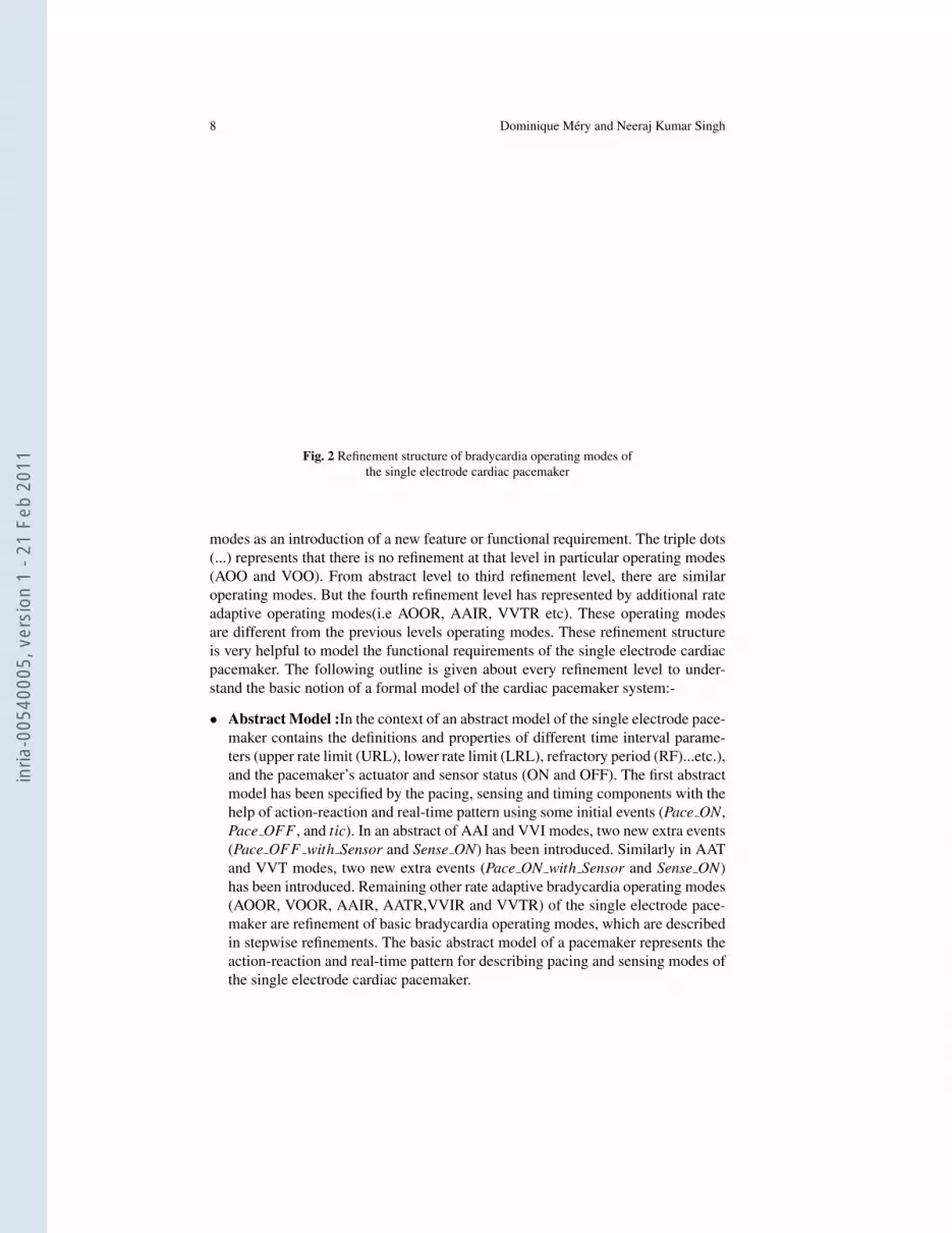
This study represents a formal specification and a systematic block diagram (seeFig. 2) of hierarchical tree structure of the bradycardia operating modes of the sin-gle electrode cardiac pacemaker. The hierarchical tree structure shows the stepwiserefinement from abstract to concrete model. Each level of refinement introduces thenew features of pacemaker as functional and parametric requirements. The root ofthis tree indicates the single electrode cardiac pacemaker. The next two branches oftree show the two chambers; atrium and ventricular. These atrium and ventricular arethe right atrium and ventricular. The atrium chamber uses the three operating modes;AOO, AAI and AAT (see Table-1). Similarly, the ventricular chamber uses the threeoperating modes; VOO, VVI and VVT (see Table-1). It is an abstract level of themodel. The abstract model presents all the operating modes abstractly with requiredproperties of the pacemaker. From the first refinement to the last refinement, thereis only one branch in every operating modes of the atrium and ventricular cham-bers. The subsequent refinement models introduce all detailed informations for theresulting system. Every refinement level shows an extension of previous operating
inria
-005
4000
5, v
ersi
on 1
- 21
Feb
201
1
8 Dominique Mery and Neeraj Kumar Singh
PACEMAKER
VentricularAtrial
AOO VVTVVIVOOAATAAI
. . . VVTVVI. . .AATAAI
. . . VVTVVI. . .AATAAI
. . . VVTVVI. . .AATAAI
AOOR VVTRVVIRVOORAATRAAIR
Chambers
Abstract Model
First Refinement
Second Refinement(Threshold)
Third Refinement(Hysteresis)
Fourth Refinement(Rate Modulation)
Fig. 2 Refinement structure of bradycardia operating modes ofthe single electrode cardiac pacemaker
modes as an introduction of a new feature or functional requirement. The triple dots(...) represents that there is no refinement at that level in particular operating modes(AOO and VOO). From abstract level to third refinement level, there are similaroperating modes. But the fourth refinement level has represented by additional rateadaptive operating modes(i.e AOOR, AAIR, VVTR etc). These operating modesare different from the previous levels operating modes. These refinement structureis very helpful to model the functional requirements of the single electrode cardiacpacemaker. The following outline is given about every refinement level to under-stand the basic notion of a formal model of the cardiac pacemaker system:-
• Abstract Model :In the context of an abstract model of the single electrode pace-maker contains the definitions and properties of different time interval parame-ters (upper rate limit (URL), lower rate limit (LRL), refractory period (RF)...etc.),and the pacemaker’s actuator and sensor status (ON and OFF). The first abstractmodel has been specified by the pacing, sensing and timing components with thehelp of action-reaction and real-time pattern using some initial events (Pace ON,Pace OFF , and tic). In an abstract of AAI and VVI modes, two new extra events(Pace OFF with Sensor and Sense ON) has been introduced. Similarly in AATand VVT modes, two new extra events (Pace ON with Sensor and Sense ON)has been introduced. Remaining other rate adaptive bradycardia operating modes(AOOR, VOOR, AAIR, AATR,VVIR and VVTR) of the single electrode pace-maker are refinement of basic bradycardia operating modes, which are describedin stepwise refinements. The basic abstract model of a pacemaker represents theaction-reaction and real-time pattern for describing pacing and sensing modes ofthe single electrode cardiac pacemaker.
inria
-005
4000
5, v
ersi
on 1
- 21
Feb
201
1
Real-Time Animation for Formal Specification 9
• Refinement 1 : In this refinement of the single electrode cardiac pacemakermodel, we have introduced more invariants to satisfy the pacing and sensingrequirements of the system under real time constraints.
• Refinement 2 : This refinement is relatively more complex then the last refine-ment. In this refinement, we have introduced the threshold parameter is used tofilter the exact sensing value within a sensing period to control the sensing andpacing events. A pacemaker has a stimulation threshold measuring unit whichmeasures a stimulation threshold voltage value of a heart and a pulse generatorfor delivering stimulation pulses to the heart. The pulse generator is controlled bya control unit to deliver the stimulation pulses with respective amplitudes relatedto the measured threshold value and a safety margin.
• Refinement 3 : In this refinement, we have introduced the application of hysteresisinterval to provide consistent pacing or to prevent constant pacing in the heartchambers (atrial or ventricle).
• Refinement 4 : In the last and final refinement, we have introduced the ac-celerometer sensor component and rate modulation function to obtain a newrate adaptive operating modes of the pacemaker. Rate adaptive term is used todescribe the capacity of a pacing system to respond to physiologic need by in-creasing and decreasing pacing rate. The rate adaptive mode of the pacemakercan progressively pace faster than the lower rate, but no more than the upper sen-sor rate limit, when it determines that heart rate needs to increase. This typicallyoccurs with exercise in patients that cannot increase their own heart rate. Theamount of rate increase is determined by the pacemaker on the basis of maxi-mum exertion is performed by the patient. This increased pacing rate is some-times referred to as the “sensor indicated rate”. When exertion has stopped thepacemaker will progressively decrease the paced rate down to the lower rate.The final refinement represents the rate modulation function with new operat-ing modes (AOOR, VOOR, AAIR, VVIR, AATR and VVTR) of the pacemakersystem.
To find the complete formal development of the single electrode cardiac pace-maker see the research report [9].
We have mainly used this case study to experiment on our proposed architec-ture which enables the animation of a proved specification with real-time data setwithout generating the legacy source code in any target language. According to theproposed architecture (see Figure 1) for this experiment, we have not used any dataacquisition device to collect the ECG (electrocardiogram) signal [26, 17, 18]. Wehave done this experiment in off-line mode, meant we have used our architectureto test the real-time data set of ECG signal that is already collected. ECG signalcollection and features extraction in on-line mode is too expensive due to complexdata acquisition process and limitation of feature extracting algorithms. So, we haveused the ECG signal and feature extraction algorithms for our experiment from theMIT-BIH Database Distribution [11].
We have downloaded the ECG signal from ECG data bank [11]. ECG signalsare freely available for academic experiments. We have applied some algorithms toextract the features (P, QRS, PR, etc.) from ECG signal and stored it into a database.
inria
-005
4000
5, v
ersi
on 1
- 21
Feb
201
1
10 Dominique Mery and Neeraj Kumar Singh
FeaturesExtraction Unit Database
Brama Plug-in
Event-B Model Unit
ECG SignalECG Features
Flash Animation
Event-B Model
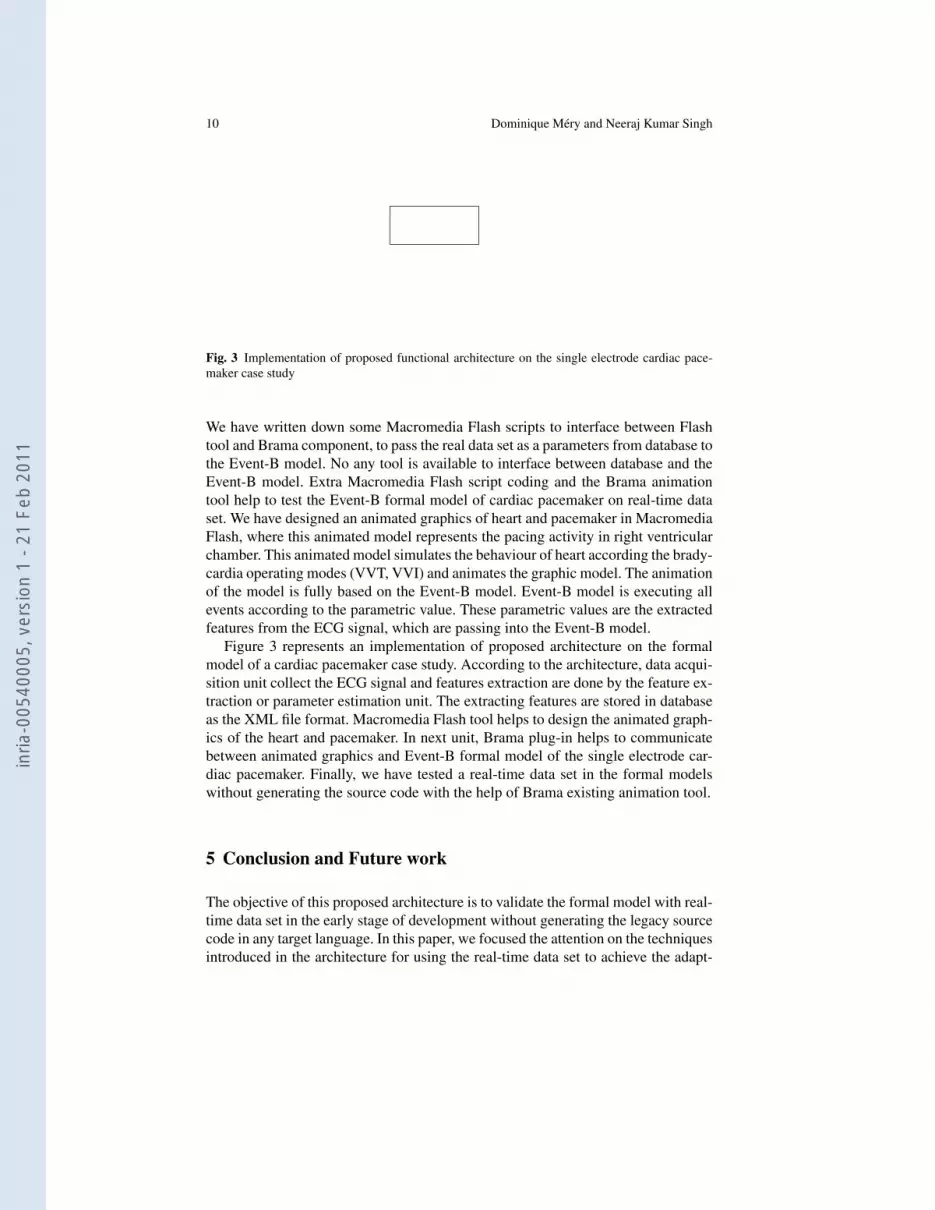
Fig. 3 Implementation of proposed functional architecture on the single electrode cardiac pace-maker case study
We have written down some Macromedia Flash scripts to interface between Flashtool and Brama component, to pass the real data set as a parameters from database tothe Event-B model. No any tool is available to interface between database and theEvent-B model. Extra Macromedia Flash script coding and the Brama animationtool help to test the Event-B formal model of cardiac pacemaker on real-time dataset. We have designed an animated graphics of heart and pacemaker in MacromediaFlash, where this animated model represents the pacing activity in right ventricularchamber. This animated model simulates the behaviour of heart according the brady-cardia operating modes (VVT, VVI) and animates the graphic model. The animationof the model is fully based on the Event-B model. Event-B model is executing allevents according to the parametric value. These parametric values are the extractedfeatures from the ECG signal, which are passing into the Event-B model.
Figure 3 represents an implementation of proposed architecture on the formalmodel of a cardiac pacemaker case study. According to the architecture, data acqui-sition unit collect the ECG signal and features extraction are done by the feature ex-traction or parameter estimation unit. The extracting features are stored in databaseas the XML file format. Macromedia Flash tool helps to design the animated graph-ics of the heart and pacemaker. In next unit, Brama plug-in helps to communicatebetween animated graphics and Event-B formal model of the single electrode car-diac pacemaker. Finally, we have tested a real-time data set in the formal modelswithout generating the source code with the help of Brama existing animation tool.
5 Conclusion and Future work
The objective of this proposed architecture is to validate the formal model with real-time data set in the early stage of development without generating the legacy sourcecode in any target language. In this paper, we focused the attention on the techniquesintroduced in the architecture for using the real-time data set to achieve the adapt-
inria
-005
4000
5, v
ersi
on 1
- 21
Feb
201
1
Real-Time Animation for Formal Specification 11
ability and confidence on formal model. Moreover, this architecture should guaran-tee that the formal model is correct with respect to the high level specifications andit is runtime error free. At last, this proposed architecture should be adaptable tovarious target platforms and formal models techniques (Event-B, Z, Alloy, TLA+
etc.).With respect to adaptability of new architecture, two techniques were considered
useful, implemented and tested on the case study. The proposed architecture resultsare satisfactory and demonstrate the ability to validate the formal model of a singleelectrode cardiac pacemaker system with real-time data set. The certification of asoftware item is concerned both by verification and validation activities. Ideally, theformer should be fully formal, relying on proofs and formal analysis. The latter dealswith an inherently informal element: the requirements [21]. The gains rely then onthe guarantees provided by the use of a formal method and on the certification levelwhich can be obtained by this way. The technique discussed here aims at improvingthe confidence in the software at earlier stages of development cycle. As far as weknow, no any animation tool support to validate the formal model on real-time dataset, which can be closed to the source code. The adaptation of this architecture needsmore complete experiments, specially for their impact on the data acquisition andfeatures extraction time for some specific domains.
A alternative approach is developed: rather than generating a source code of for-mal model in advance that the proposed architecture always produces a desired re-sult which is similar to the correctly implemented source code. A key feature of thisvalidation as it is full automation and animation of specification in the early stageof formal development. The case study has shown that requirement specificationscould be used directly in real-time environment without modifications for automatictest result evaluation using our approach. Moreover, there are scientific and legal ap-plications as well, where the formal model based animation can be used to simulate(or emulate) certain scenarios to glean more information or better understanding ofthe system and assist to improve the final given system.
While arguing about the relationship between refinement based modeling and itsstepwise validation, we discovered that not every refinement step is animatable. Thisis consistent with using animation as a kind of quality-assurance activity duringdevelopment. We believe that one animation per abstraction level is sufficient. Infact, the first refinement of a level may often have a non-determinism too wide toallow for meaningful animation (concept introduction), but subsequent refinementsget the definitions of the new concept precise enough to allow animation [22].
The proposed architecture is not complete yet due to certain limitations; acqui-sition devices, features extraction algorithms and so on. In future this is expectedto use same architecture in multi domain, the proposed architecture to use the realtime data set to validate the any formal model specification in the early stage ofdevelopment. Manual application of this architecture to apply real-time data set inthe formal model is tedious, cumbersome and may be error prone if not appliedcarefully. Therefore we are planning to write an application programming interface(API) which can interface automatically from any acquisition device or database toformal model using Flash animation and Brama component.
inria
-005
4000
5, v
ersi
on 1
- 21
Feb
201
1

12 Dominique Mery and Neeraj Kumar Singh
Acknowledgements Work of Dominique Mery and Neeraj Kumar Singh is supported by grantNo. ANR-06-SETI-015-03 awarded by the Agence Nationale de la Recherche. Neeraj KumarSingh is supported by grant awarded by the Ministry of University and Research.
We are deeply grateful to our colleague Dominique Cansell, Jean-Pierre Jacquot, Atif Mashkoor,Joris Rehm and Nazim Benaissa, who provided us expertise and information for shaping our ideas.
References
1. A Reseach and Development Needs Report by NITRD. High-ConfidenceMedical Devices : Cyber-Physical Systems for 21st Century Health Care.http://www.nitrd.gov/About/MedDevice-FINAL1-web.pdf.
2. J.-R. Abrial. Modeling in Event-B: System and Software Engineering. 2010. Forthcomingbook.
3. Dines Bjørner and Martin C. Henson, editors. EATCS Textbook in Computer Science.Springer, 2007.
4. Boston Scientific Boston Scientific: Pacemaker system specification, Technical report. 2007.5. Dominique Cansell and Dominique Mery. Logics of Specification Languages, pages 33–140.
Springer, 2007. See [3].6. C.A.R. Hoare, Jayadev Misra, Gary T. Leavens, and Natarajan Shankar. The verified software
initiative: A manifesto. ACM Comput. Surv., 41(4):1–8, 2009.7. IEC, IEC functional safety and IEC 61508: . Working draft on functional safety of electri-
cal/electronic/programmable electronic safety-related systems (2005).8. Writing Committee Members, Andrew E. Epstein, John P. DiMarco, Kenneth A. Ellen-
bogen, III Estes, N.A. Mark, Roger A. Freedman, Leonard S. Gettes, A. Marc Gillinov,Gabriel Gregoratos, Stephen C. Hammill, David L. Hayes, Mark A. Hlatky, L. Kristin Newby,Richard L. Page, Mark H. Schoenfeld, Michael J. Silka, Lynne Warner Stevenson, andMichael O. Sweeney. ACC/AHA/HRS 2008 Guidelines for Device-Based Therapy of CardiacRhythm Abnormalities: Executive Summary: A Report of the American College of Cardiol-ogy/American Heart Association Task Force on Practice Guidelines (Writing Committee toRevise the ACC/AHA/NASPE 2002 Guideline Update for Implantation of Cardiac Pacemak-ers and Antiarrhythmia Devices): Developed in Collaboration With the American Associationfor Thoracic Surgery and Society of Thoracic Surgeons. Circulation, 117(21):2820–2840,2008.
9. Dominique Mery and Neeraj Kumar Singh. Pacemaker’s Functional Behaviors in Event-B.Research Report (http://hal.inria.fr/inria-00419973/en/), 2009.
10. Dominique Mery and Neeraj Kumar Singh. Technical Report on Formal Develop-ment of Two-Electrode Cardiac Pacing System. Research Report (http://hal.inria.fr/inria-00465061/PDF/Report 2electrode.pdf),2010.
11. MIT-BIH Database Distribution and Software : . http://ecg.mit.edu/index.html.12. C. Ponsard, P. Massonet, A. Rifaut, J.F. Molderez, A. van Lamsweerde, and H. Tran Van.
Early verification and validation of mission critical systems. Electronic Notes in TheoreticalComputer Science, 133:237 – 254, 2005. Proceedings of the Ninth International Workshop onFormal Methods for Industrial Critical Systems (FMICS 2004).
13. Project RODIN. Rigorous open development environment for complex systems. http://rodin-b-sharp.sourceforge.net/, 2004. 2004–2007.
14. M. A. Quiones, F. Tornes, Y. Fayad, R. Zayas, J. Castro, A. Barbetta, and F. Di Gregorio. Rate-Responsive Pacing Controlled by the TVI Sensor in the Treatment of Sick Sinus Syndrome.Springer, 2006.
15. Robert Reinhardt and Snow Dowd. Adobe Flash CS3 professional bible, page 1232. Wiley,2007. ISBN-9780470119372.
16. Thierry Servat. BRAMA: A New Graphic Animation Tool for B Models, pages 274–276.LNCS. Springer, 2006.
inria
-005
4000
5, v
ersi
on 1
- 21
Feb
201
1

Real-Time Animation for Formal Specification 13
17. Kenneth A. Ellenbogen and Mark A. Wood. Cardiac Pacing and ICDs. 4th Edition, Blackwell,2005, ISBN-10 1-4051-0447-3.
18. Aaron Hesselson. Simplified Interpretations of Pacemaker ECGs. Blackwell Publishers, 2003,ISBN 978-1-4051-0372-5.
19. Hung Tran Van, Axel van Lamsweerde, Philippe Massonet, and Christophe Ponsard. Goal-oriented requirements animation. Requirements Engineering, IEEE International Conferenceon, 0:218–228, 2004.
20. Jim Woodcock and Richard Banach. The verification grand challenge. J. UCS, 13(5):661–668,2007.
21. Atif Mashkoor, Jean-Pierre Jacquot and Jeanine Souquires. Transformation Heuristics for For-mal Requirements Validation by Animation. 2nd International Workshop on the Certificationof Safety-Critical Software Controlled System, 2009.
22. Atif Mashkoor Formal Domain Modeling: From Specification to Validation. 16th Interna-tional Symposium on Formal Methods - FM 2009 (Doctoral Symposium), 2009.
23. Didier Bert and Sylvain Boulme and Marie-Laure Potet and Antoine Requet and LaurentVoisin Adaptable Translator of B Specifications to Embedded C Programs. FME 2003,Springer, 94–113, 2003.
24. S. Serge Barold and Roland X. Stroobandt and Alfons F. Sinnaeve. Cardiac Pacemakers Stepby Step. Futura Publishing, 2004, ISBN 1-4051-1647-1.
25. Charles J. Love. Cardiac Pacemakers and Defibrillators. Landes Bioscience Publishers, 2006,ISBN 1-57059-691-3.
26. Jaakko Malmivuo. Bioelectromagnetism. Oxford University Press, 1995, ISBN 0-19-505823-2.
inria
-005
4000
5, v
ersi
on 1
- 21
Feb
201
1