formal methods specification and analysis guidebook for the
TRANSCRIPT
OIIICI 01 Sill 1) l\l)\llsslo\ \%s( l{\\cl NASA-GB-O01-971{1 I I \\l 1 (1
Formal Methods Specification and AnalysisGuidebook
for the Verification of Software andComputer Systems
Volume 11:A Practitioner’s Companion
@
May 1997L*L●
National Aeronautics and Space AdministrationWashington, DC 20546
NASA-GB-001-97Release 1.0
FORMAL METHODS SPECIFICATION AND ANALYSISGUIDEBOOK
FOR THE VERIFICATION OF SOFTWARE AND COMPUTERSYSTEMS
VOLUME II: A PRACTITIONER’S COMPANION
F O R E W O R D
This volume presents technical issues involved in applying mathematical techniquesknown as Formal Methods to specify and analytically verify aerospace and avionicssoftware systems. The first volume, NASA-GB-002-95 [NASA-95a], dealt withplanning and technology insertion. This second volume discusses practical techniquesand strategies for verifying requirements and high-level designs for software intensivesystems. The discussion is illustrated with a realistic example based on NASA’sSimplified Aid for EVA (Extravehicular Activity) Rescue [SAFER94a, SAFER94b]. Thevohu-ne is intended as a “companion” and guide for the novice formal methods andanalytical verification practitioner. Together, the two volumes address the recognizedneed for new technologies and improved techniques to meet the demands inherent indeveloping increasingly complex and autonomous systems. The support of NASA’sSafety and Mission Quality Office for the investigation of formal methods andanalytical verification techniques reflects the growing practicality of these approachesfor enhancing the quality of aerospace and avionics applications.
Major contributors to the guidebook include Judith Crow, lead author (SRI International);Ben Di Vito, SAFER example author (ViGYAN); Robyn Lutz (NASA - JPL); LarryRoberts (Lockheed Martin Space Mission Systems and Services); Martin Feather (NASA- JPL); and John Kelly (NASA - JPL), task lead. Special thanks go to John Rushby (SRIInternational) who provided valuable material and guidance, Sam chvre (SRIInternational) who graciously supplied wide-ranging technical expertise, GerardHolzrnann (Lucent Technologies) and Peter Germ Larsen (IFAD) both of whom gaveparticularly thorough and thoughtful reviews, and Valerie Mathews (NASA - JPL) whoserved as guidebook review and publication coordinator. Special acknowledgment isalso extended to NASA sponsors Kathryn Kemp (Deputy Director, NASA IV&VFacility), George Sabolish (NASA - Ames), Rick Butler (NASA - Langley), and ErnieFridge (NASA- Johnson).
This document is a product of NASA’s Software Program, an agency-wide program thatpromotes continual improvement in software engineering and assurance within NASA.The goals and strategies of this program are documented in the NASA SoftwareStrategic Plan. [NASA-95b] Funding for this guidebook was provided by NASA’s Officeof Safety and Mission Assurance. Additional information about this program and itsproducts is available via the World Wide Web at http:// www.ivv.nasa.gov.
NASA-GB-O01-97Release 1.0
m Office of Safety and Mission Assurance
s
I Formal Methods Specification and Analysis Guidebook for theVerification of Software and Computer Systems
$ Volume II: A Practitioner’s Companion
May, 1997
Approvals:
1 \ ------‘\. ‘ e . ...--’.,
n _]&i-d L’ . , ‘, _Q”&_T a s k L e a d
. . .
1 Jet Propulsion LaboratoryPasadena, CA
B
——.Conc{mence for Publication
a Kathryn KempNASA OSMA Software Program, Manager
c
NASA IV&V FacilityFairmont, WV
FThis guidebook is one of the products of a cooperative study to investigate theapplicability of Formal Methods and Analytical Verification for critical NASAsoftware systems. This guidebook was jointly developed through cooperative
B
work from three NASA centers: Jet Propulsion Laboratory, Johnson SpaceCenter, and Langley Research Center.
9
Contents
1 Introduct ion 1
2 The Practical Application of Formal Methods 4
Q.1 w]lat Ar~~orI]lal Mctllods?. . . . . . . . . . . . . . . . . . . . . . . . . 4
2.2 Rolwof FornlalMethods. . . . . . . . . . . . . . . . . . . . . . . ...5
2.3 Formal Methods: Degree of Formalization and Scope of Use . . . . . . . 5
2.3.1 Levels of Formalization . . . . . . . . . . . . . . . . . . . . . . . 6
2.3.2 Scope of Formal Methods [Jsc . . . . . . . . . . . . . . . . . . . . 7
2.4 Reasonable Expectations for Formal Methods . . . . . . . . . . . . . . . 8
2.5 The Method lJndcrlyiug Formal Mctllods . . . . . . . . . . . . . . . . ~
2.6 Au Introduction toSAFER . . . . . . . . . . . . . . . . . . . . . . . . . 12
3 Requirements
3.1 Requirements and Formal Methods . . . . . . . . . . . . . . . . . . . . .
3.1.1 Impact of Requirements Spccificatio~l on Formal Methods . . . .
3.1.1.1 I,evcl of Requirenlents Capture . . . . . . . . . . . . .
3.1.1.2 Explicitness of Recluirenmnts Statement . . . . . . . . .
3.1.1.3 Clarity of Delineation between a System and Its Envi-ronulmt . . . . . . . . . . . . . . . . . . . . . . . . . . .
3.1.1.4 Traceability of Recluirements . . . . . . . . . . . . .
3.1.1.5 Availability of Underlying Rationale and Intuition . . .
3.1.2 Impact of Formal Methocls on Requirements . . . . . . . . . . . .
3.2 Conventional Approaches to Requirements Validation . . . . . . . . . .
3.3 SAFER Requirements . . . . . . . . . . . . . . . . . . . . . . . . . . . .
vii
17
18
18
18
18
18
19
19
20
21
23
. . .vlll q hbJe Of (;Olltf!I1tS
4 hlodels
4.1hIathen~atica lModcl s.... . . . . . . . . . . . . . . . . . . . . . . . .
4.1.1 Characteristics of Nlatllematica] Models . . . . . . . . . . . . .
4.1.1.1 Abstractic)~l . . . . . . . . . . . . . . . . . . . . . . . . .
4. I. I.2 Focus . . . . . . . . . . . . . . . . . . . . . . . . . . . .
4.1. ] .3 Exl)ressivel~ess l~ersus A n a l y t i c Power . . . . . . . . .
4.1.1.4 Intuit ive Versus Nonilltuitive Representation . . . . . .
4.]. ].5 Accuracy . . . . . . . . . . . . . . . . . . . . . ...””
4.1.2 Bencfitsof Mathematical Models . . . . . . . . . . . . . . .
4.1.3 Mathenlatical h!lodels for Discrete and Continuous Donlains . .
4.2 Colltil~uo~ls Dol[laill Modclitlg . . . . . . . . . . . . . . . . . . . . . .
4.3 Discretc l)omainh lodeli% . . . . . . . . . . . . . . . . . . . . . . . . . .
4.3.1 Functional hIc)dels . . . . . . . . . . . . . . . . . . . . . . . . . .
4.3.2 Abstract, State hlachine Models . . . . . . . . . . . . . . . . . . .
4.3.3 Automata-Based Models . .
4.3.3.1 *- Autonlata . . .
4 . 3 . 3 . 2 ti-Autonlata . . .
4 .3 .3 .3 Tind Autonlata
4.3 .3 .4 Hybrid Autonlata
4.3.4 object-oriented” Models . .
. . . . . . . . . . . . . . . . . . . . .
. . . . . . . . . . . . . . . . . . . . .
. . . . . . . . . . . . . . . . . . . .
. . . . . . . . . . . . . . . . . . . . .
. . . . . . . . . . . . . . . . . . . . .
. . . . . . . . . . . . . . . . . . . . .
4.4 A Model for the SAFER Avionics Controller . . . . . . . . . . . . . . .
5 Formal Specification
.5.1 Fornlal Specification Lauguages . . . . . . . . . . . . . . . . . . . . . .
5.1.1 Foundations . . . . . . . . . . . . . . . . . . . . . . . . . . . . . .
5.1.2 Fcaturcs . . . . . . . . . . . . . . . . . . . . . . . . . . . . . . . .
5.1.2.1 Explicit Senlantic s........ . . . . . . . . . . . . .
5.1.2.2 Expressiveness . . . . . . . . . . . . . . . . . . . . . . .
5.1.2.3 Progranln~ing Language Datatypes and Constructions .
5.1.2.4 Convenient Syntax . . . . . . . . . . . . . . . . . . . . .
5.1 .2.5 Diagranln~atic hTotation . . . . . . . . . . . . . . . . . .
5.1.2 .6 Strong Type% . . . . . . . . . . . . . . . . . . . . . . .
5.1.2.7 ‘1’otal versus Partial Functions . . . . . . . . . . . . . .
5.1.2 .8 Refilmnent . . . . . . . . . . . . . . . . . . . . . . . . .
25
25
26
26
27
27
28
28
28
29
3(I
32
32
34
36
36
38
38
39
39
45
50
51
51
53
54
54
5555
55
55
56
57

ATASA- GB-001 -97
5.1.2.9 I1ltroduction of Axiolns aud I)efiuitious . . . . . . . . .
5.1.2.10 Encapsulation N4echauism . . . . . . . . . . . . . . . .
5.1.2.11 Ruilt-iu Model of Coml)utation . . . . . . . . . . . . .
5.1.2 .12 FJxecutability. . . . . . . . . . . . . . . . . . . . . . . .
5.1.2 .13 Maturity . . . . . . . . . . . . . . . . . . . . . . . . . .
5.2 Formal Specification Styles . . . . . . . . . . . . . . . . . . . . . .
5.3 Formal Specification atd Life Cycle . . . . . . . . . . . . . . . . . . . . .
5.4 TIN Detection of Errors iu Formal Specification . . . . . . . . . . . . . .
5.5 The Utility of Fmmal Spccificaticnl . . . . . . . . . . . . . . . . .
5.6 A Partial SAFER S1wcification . . . . . . . . . . . . . . . . . . . . . . .
6 Formal Analysis
6.1 Autol~latcdD ed~lctic)ll. . . . . . . . . . . . . . . . . . . . . . . . . . . .
6.1.1 Background: Fornlal Systems and !f’heir Models . . . . . . . . . .
(i.l.l. ll)roofrl’heor y..... . . . . . . . . . . . . . . . . . . .
6.1.1.2hIodcl ?’llc:ory . . . . . . . . . . . . . . . . . . . . . . .
6.1.1.3 An Exanq)le of a First-Ordcx Theory . . . . . . . . . .
6.1.2 A Brief History of Automated Proof . . . . . . . . . . . . . . . .
6.1.3 Techniques Underlying Automated Reasoniug . . . . . . . . . .
6.1.3.1 Calculi for 14’irst-Order Predicate I,ogic . . . . . . .
6.1.3.1.1 NTornlal Porlns . . . . . . . . . . . . . . . . . .
6.1.3.1.2 The Sequent Calculus . . . . . . . . . . . . .
6.1.3.1.3 The Resolution Calculus . . . . . . . . . . . .
6.1.3.2 Extcncling the Predicate Calculus . . . . . . . . . . . .
6.1.3.2.1 Reasonin~ about 13cluality . . . . . . . . . . .
6.1.3.2.2 Reasoning about Arithuletic . . . . . . . . . .
6.1.3.2.3 Combiuing First-order Theories . . . . . . . .
6.1.3.3 Mechanization of Proof ill tile Sequent Calculus . . .
6.1.4 Utility of Automated Dcdllctioll . . . . . . . . . . . . . . . . .
6.2 Finite-State Methods . . . . . . . . . . . . . . . . . . . . . . . . . . . . .
6.2.1 Background . . . . . . . . . . . . . . . . . . . . . . . . . . . . . .
6.2.1.1 TemporalIJ o.gic . . . . . . . . . . . . . . . . . . . . . .
6.2.1.2 Liuear Tenll)oral Logic (LT1.) . . . . . . . . . . . . . . .
6.2.1.3 Brauching Time lhnporal Logic . . . . . . . . . . . . .
ix
57
59
6(I
60
61
61
fjz
63
(Xi
69 ‘
77
77
78
78
8(I
81
82
85
85
86
86
91
92
93
95
95
96
100
101
102
102
} 04
105
x 7hble of @IltC!Ilt S
6.3
6.4
6.5
6.2.1.4 Fixed Points . . . . . . . . . . . . . . . . . . . . . . . .
6.2.1.5 The Mu-Calculus . . . . . . . . . . . . . . . . . . . . .
6.2.2 ABrief History of Finite-State Methods . . . . . . . . . . . . . .
6.2.3 Approaches tc) Finite-State Verification . . . . . . . . . . . . . .
6 .2 .3 .1 The $@)olic Mode] Checkilig Approach . . . . . . .
6.2.3.2 ‘l’lie Automata-Theoretic Approach . . . . . . . . . . .
6.2.3.2.1 l,anguage Containment . . . . . . . . . . . . .
6.2.3.2.2 State Exploration . . . . . . . . . . . . . . . .
6.2.3.2.3 Bisinlulatioli Equivalence and PrebisimulationPreorclers . . . . . . . . . . . . . . . . . . . . .
6.2.4 Utility of Finite-State Methods . . . . . . . . . . . . . . . . . . .
Direct Execution, Simulation, and Animation . . . . . . . . . . . . . .
6.3.1 Obscrvaticnlal Techniques . . . . . . . . . . . . . . . . . . . . .
6.3.2 Utility of observational Techniques . . . . . . . . . . . . . . . .
Integrating Autolnatcd Analysis Methods . . . . . . . . . . . . . . . . .
Proof of Selected SAFER Pro]wrty . . . . . . . . . . . . . . . . . . . . .
6.5.1 The PVS Theory SAFER-properties . . . . . . . . . . . . . . .
6.5.2 Informal Argument for I.cnma max.thrusters_sel . . . . . . .
108
108
110
112
112
114
115
116
118
119
119
120
121
122
122
123
126
7 c o n c l u s i o n 130
7.1 Factors Influencing the Use of Formal hiethods . . . . . . . . . . . . . 130
7.2 The Process of Fcmnal Methods . . . . . . . . . . . . . . . . . . . . . . . 131
7.3 F’airing Formal Methods, Strategy, and Task . . . . . . . . . . . . . . . 132
7.4 Formal h4cthods and Existing Quality Control andAssurance Activities . . . . . . . . . . . . . . . . . . . . . . . . . . . . .133
7.5 Formal h4ethods: Verification Versus Validation and Explorat ioll . . . . 134
References 136
A Glossary of Key Terms 165
A.l Acronyms . . . . . . . . . . . . . . . . . . . . . . . . . . . . . . . . ...165
A.2Ternl s . . . . . . . . . . . . . . . . . . . . . . . . . . . . . . . . . ...166
B Further Reading 169
11.1 Technical Background: h4athenlatical lmgic . . . . . . . . . . . . . . . . 169
11.2 Specificatio n . . . . . . . . . . . . . . . . . . . . . . . . . . . . . . ...170
H.3hIodel Checkin g....... . . . . . . . . . . . . . . . . . . . . . . ...170
B.4Thcorenl Proving . . . . . . . . . . . . . . . . . . . . . . . . . . . . ...171
1].5 hIodels of Conlputation . . . . . . . . . . . . . . . . . . . . . . . . . . . 171
B.6 Applications aud Overvicws . . . . . . . . . . . . . . . . . . . . . . . 172
1].7111torials . . . . . . . . . . . . . . . . . . . . . . . . . . . . . . . . . ...172
C Extended Example: Simplified Aid for EVA Rescue (SAFER) 174
C.lOvervicw of SAFER . . . . . . . . . . . . . . . . . . . . . . . . . . . . .174
C.].1 History, Mission Colltext, atld System Description . . . . . . . . 174
C.1.2 Principal Hardware Components . . . . . . . . . . . . . . . . . . 176
C.1.2.1 Ilackpack Propulsio:l h40dule . . . . . . . . . . . . . . . 176
C.] .2.2 IIaud Controller hlodulc (HChI) . . . . . . . . . . . . 177
C.1.2.3 BatteryP ace . . . . . . . . . . . . . . . . . . . . . ...178
C.] .2.4 Flight, Support Equipnlent . . . . . . . . . . . . . . . . 178
C.1.3 Avionics . . . . . . . . . . . . . . . . . . . . . . . . . . . . . . ..178
C.1.4Systen lSoftwar c...... . . . . . . . . . . . . . . . . . . . . .179
C.1.4.1 Software Interfaces. . . . . . . . . . . . . . . . . 181
C.1 .4.2 Maneuvering Control Subsystcnl . . . . . . . . . . . . . 181
C.1.4.3 Fault Detection Subsystenl . . . . . . . . . . . . . . . 182
C.2 SAFER EVA Flight Operatiorl Requirements . . . . . . . . . . . . . . . 186
C.2.1 Hand Controller Module (HCM) . . . . . . . . . . . . . . . . . . 186
C.2.1. I Display and Control Unit . . . . . . . . . . . . . . . . 186
C.2.1.2 }laud Controller [Jnit . . . . . . . . . . . . . . . . . . . 187
C.2.2 Propulsion Subsystenl . . . . . . . . . . . . . . . . . . . . . . . . 1S7
C.2.3 Avionics Asscnlblies . . . . . . . . . . . . . . . . . . . . . . . . . 188
C.2.3.1 Iuertial Reference Unit (IRU) . . . . . . . . . . . . . . . 188
C.2.3.2 Power Supply Assen~bly . . . . . . . . . . . . . . . . . . 188
C.2.3.3 Data Recorder Asscn~bly (DRA) . . . . . . . . . . . . . 188
C.2.4 Avionics Software . . . . . . . . . . . . . . . . . . . . . . . . .. 189
C.2.5 Avionics Software Interfaces . . . . . . . . . . . . . . . . . . . . 190
C.3 Formalization of SAFER Requirenlents . . . . . . . . . . . . . . . . . . . 191

xii Table of contents
C.3.1 PVS Lauguage Features . . . . . . . . . . . . . . . . . . . . . . . 191
C.3.2 Overview of Formalization . . . . . . . . . . . . . . . . . . . . . 193
C.3.2.1 lkwicTypcs . . . . . . . . . . . . . . . . . . . . . . . .191
C.3.2.2 Haud Controller hfloduk . . . . . . . . . . . . . . . . 195
C.3.2.3 Propulsion hfoclulc . . . . . . . . . . . . . . . . . . . . 195
C.3.2.4 Autonlatic Attituclc HoM . . . . . . . . . . . . . . . . . 195
C.3.2.5 q’hrustcx %lection . . . . . . . . . . . . . . . . . . . . 195
C.3.2.6 Avionics h40del . . . . . . . . . . . . . . . . . . . . . . . 196
C.3.3 Full Text of PVSTheoric s.... . . . . . . . . . . . . . . . . . . 196
C.4Analysis of SAFER . . . . . . . . . . . . . . . . . . . . . . . . . . . ...217 ‘
C.4.1 Fonuulatin.g System Properties . . . . . . . . . . . . . . . . . . . 217
C.4.1. I Fonl”lalization of the hlaxituutu Thruster Propczty . . . 218
C.4.1.2 P V S T h e o r y f o r h!laximuln ~’hruster I’roperty . . . . 219
C.4.2 I’roving Systenl Properties . . . . . . . . . . . . . . . . . . . . 221
C.4.2.1 Proof Sketch of the Maxilnutu Thruster Property . . . 221
C.4.2.2 PVS F’roof of h~axinmn] Thruster l’ro~m-ty . . . . . . 223
98 List of Figures
&m
2.1
2.2
2.3
4.1
4.2
4.3
4.4
4.5
4.6
4.74.8
4.9
6.1
6.2
6.3
6.4
6.5
C.1
C.2C.3
C.4
C.5
C.6
C.7
C.8
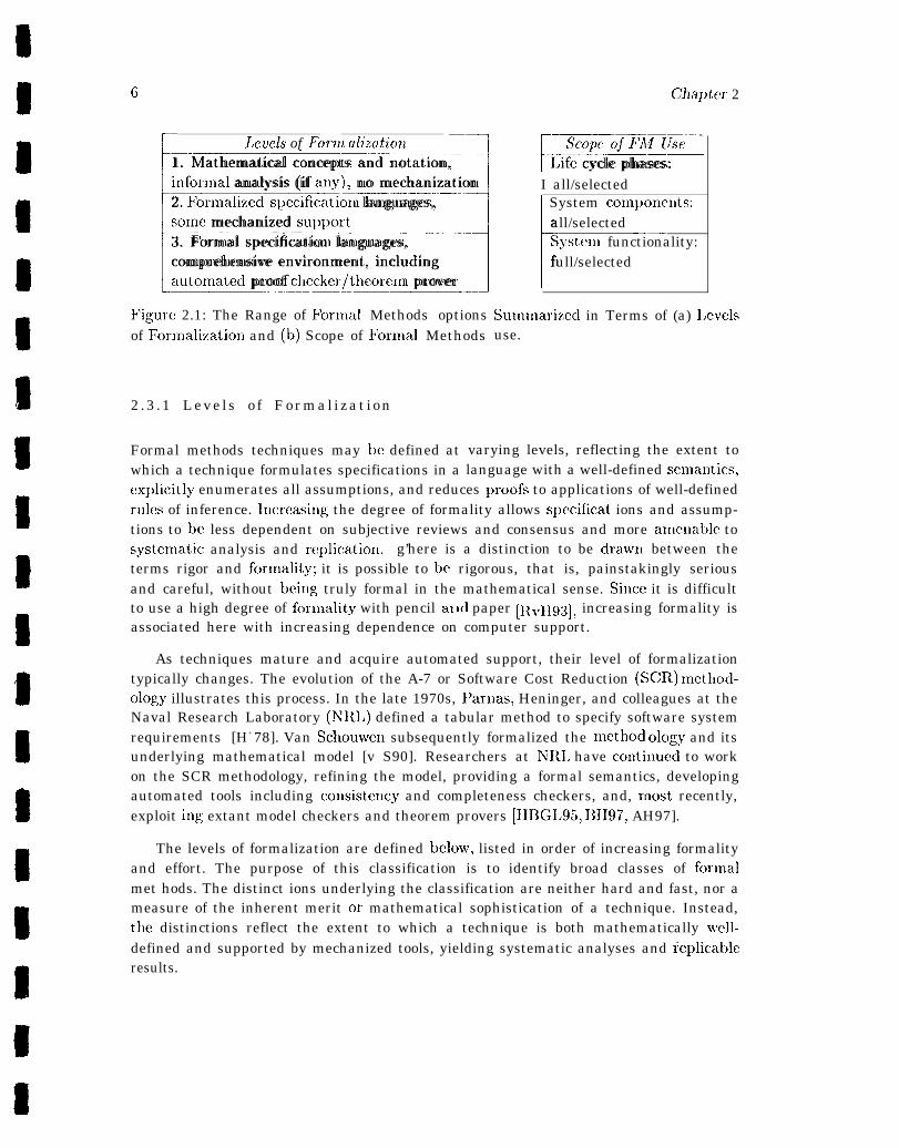
The Range of Formal Methods O]hions Sun~u~arized in l’cnms of (a) Lev-els of Formalization and (b) Scope of Formal Methods USC. . . . . . . . 6
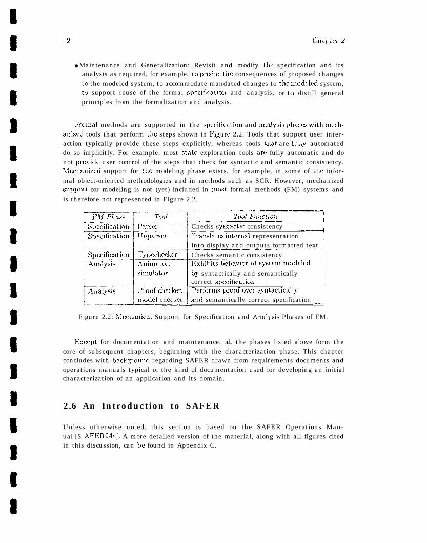
Mechanical Support for Specification aud Analysis Phases of FM. . ~ . . 12
Front and back views of SAFER s<ystwn worn by NASA crewnmnber. . 13
ll~l]jlelllcl~tatiol~ of a Full Adder. . . . . . . . . . . . . . . . . . . . . . 34
Abstract State Macl~itle Modal.... . . . . . . . . . . . . . . . . . . . . 35
A-7 Model of a Sin~ple Control Systcn~. . . . . . . . . . . . . . . . . . . 36
State-Update aud Actuator IWw.tions within Control Systcnl. . . . . . . 37
Object Model of Cassini Generic Fault Protection lvlonito~. . . . . . . . 41
Functional Model of Cassini Generic Fault Protection Monitor. . . . . . 42
Dynanlic h!lodel of Cassini Generic Fault Protection Monitor. . . . . . . 43AAII Control Systenl State-lJpdate and Actuator Functions. . . . . . . 47
I,alwlcd AAH Pushbutton State Transition Diagranl. . . . . . . . . . . . 4S
Burch et cd.’s Mu-Calculus hlodel Checking Algorithnl. . . . . . . . . . . 113
A Sinlplc SMV I’rogran] [Mch193, p. 63]. . . . . . . . . . . . . . . . . . 114
Dependency ~~ierarchy for SAFER.properties. . . . . . . . . . . . . . . . 127
Proo f Tree for SAFER-propertiesnax. thrusters.sel. . . . . . . . - . 128
Revised Proc)f Tree for SAFER_propertiesmax.thrusters-sel. . . . . . 129
SAFER use by an EVA crewn~en~t)er. . . . . . . . . . . . . . . . . . . . . 225
Propulsion nlodule structure and lucchatlisnls. . . . . . . . . . . . . . . . 226
SAFER thrusters andaxcs. . . . . . . . . . . . . . . . . . . . . . . . . . 227
Ilandcontrollerlnoc lube . . . . . . . . . . . . . . . . . . . . . . . . . . . . 228
Hand controller translational axes. . . . . . . . . . . . . . . . . . . . . . 229
Hand controller rotational axes. . . . . . . . . . . . . . . . . . . . . . . . 230
SAFER systenl software architecture. . . . . . . . . . . . . . . . . . . . 231
AAH pushbutton state diagram. . . . . . . . . . . . . . . . . . . . . . . 232
. . .Xlll
List of Tables
C-l SAFER ScIlsOr co@elllellt. . . . . . . . . . . . . . . . . - . . . . . . . 180
C.2 Thruster select logic for X, pitch, and yaw conmarlds. . . . . . . . . . . 183
C.3 Tlmuster select logic for Y, Z, aud roll commands. . . . . . . . . . . . . 184
xiv
—

99
9D
Chapter 1
Introduction
This guidebook, the second of a two-volunlc series, is intenclccl to facilitate the transfer of-.fcmnal methods to the avionics and aerospace conmunity. The first volurnc concentrateson administrative and planning issues [NASA-95a], and the second volunle focuses cm thetechnical issues involved in applying forn~al methods to avionics and aerospace softwaresysten~s. Hereafter, the term “guidebook” refers exclusively to the second volutnc ofthe series. The title of this second volunle, A Practitioner’s Conlpanion, conveys its
intent. The guidebook is writteu prinlarily for the nonexpert and requires little or noprior experience with fcnvnal nwthods techniques and tools. However, it does attetnptto distill sonw of the nlore subtle ingrecl ients in the productive application of formalnmthods. To the extexit that, it succeeds, those conversant with fo;nlal nwtliods willalso find the guidel)ook useful. The discussion is illustrated through the developnlentof a realistic exanlple, relevant fragnwnts of which appear in each chapter.
The guidebook focuses primarily on the use of forn~al nlethods for analysis of require-nlcnts and high-level design, the stages at which forn~al nlethods have been nlost produc-tively applied. Although n~uch of the discussion applies to low-level design and inlple-nwnt at ion, the guidebook does not discuss issues involved in the later life cycle applica-tion of fornlal nlcthods. The cxan@ provided in the guidebook is based on the controlfunction for the Sinlplified Aid for EVA (Extravehicular Activity) Rescue [SAFER94a,SAFER94h], hereafter referred to as SAFER I, which has been specified and analyzedusing the PVS specification language and interactive proof checker [0 RSvH95]. PVShas been selected because it has been successfully used on NASA projects, includ-ing [LR93a, NASA93, LA94, hIin95, BCC+ 95, HCL95, SM95b, DR96, ML96], and becauseit is representative of a class of tools that, offers a formal specification language in aconlprehensive environment, including automated proof support. In forn~alizing the— — . - —.
1 SAFER is a descendent of the hlauned Nlaneuvering Unit (MM L’) [hf ML-83]. The main differencebetween SAFER and the MMU is that S.4FER is a small, lightlveight, “simplified” single-string systemfor contingency use (self-rescue) only, whereas the IIMU is a larger, bulkier. but extremely versatileE~JA ~alleul,ering dei,i~~ The application of fox nlal methods t,o SAFER is limited to the example inthis guidebook; formal methods have not been used to support SAFER development or maintenance.
1
.
SAFER example, the priorities have been readability and portability to other formalmethods paradigms. Consequently, the discussion is framed in genera] terms applicableto most formal methods strategic% and techniques,
The guidebook is not a tutorial on formal ]Ilethocls; it does not pr-ovidc a groundil~,gin mathe,mat ical logic or formal specification slid verification, although t lle appendicescontain references that provide technical background, as well as a glossary of key terms.Nor is it a formal metl)ods cookbook; there are no recipes that detail the step-by-steppreparation of a formal methods product. Furthermore, the guidebook assumes that,the reader is aware of the potential lmnefits alld fallibility ics of formal met nods: it doesnot dwell on the very real benefits of the appropriate application of formal methods orthe equally real pitfalls of misuse.
The guidebook does contain a fairly detailed account of the technical issues involvedin applying fornlal methods to avionics and aerospace software systems, including awell-developed example. in order of presentation, the topics covered in the guidebookinclude requirements, moclels, formal s~)ecificatiox~, and forlnal analysis. However. theapplication of formal methods is not an essentially linear process. Forlnal nlethodsaye lnost l)roductive when integrated with existing life cycle processes, arid wlle~l theyuse an iterative strategy that successively refines and validates the formalization, t llerequirements, the clesigll, and if desired, critical parts of the im~)lement at ion.
This guidet)ook is organized as follows: Chapter 2 reviews technical considerationsrelevant, to projects considerirlg the use of fornlal methods, touching briefly on generalelements of the somewhat elusive method underlying formal methods. This chapter also~Jroviclcs lmckground Iuaterial on tile SAFER example clmwlo~wcl in subsequent clmpters. Chapter 3 examines the notion of requirements from a formal methods perspectiveand introduces selected requirements for the ongoing SAFER example. The concept ofmodels and a survey of modeling strategies are introduced in Chapter 4, along u’ith aformal model for a SAFEF{ subsystem. A fragment of the specification fol tlIe SAFERrequirements introduced in Chapter 3 is developed using the model defined in Chapter 4.Chapter 5 provides a discussion of formal specification, including topics ranging fromspecification languages, paradigms, and strategies, to type consistency of specifications.Agaill, a discussion of the pertinent step in the development of the SAFER exampleap~)ears at the end of the chapter. Chapter 6 ccmsiders techniques and toc)ls for formalanalysis, including such topics as the role of formal proof, the impact of specificationstrategy OXL formal analysis, and the utility of various analysis strategies. A discussionof formal analysis of key properties of the SAFER specification appears at the end ofthe chapter. Follo~ving concluding remarks iu Chapter 7 are three appendices: Ap-pendix A contains a glossary of key terms and concepts, Appendix El lists material forfurther reading, and Appendix C offers an extended discussion of the complete SAFERexam~dc.2.— —— ——
2The PVS source files for the SAFER example are available 011 LaRC’s lVeb server iu the directoryftp://atb-www.l arc.nasa.gov/Gui debooks/.
ATA4SA. GB_OOl .97 3
There are several ways to usc this guidebook. The heart of the discussion a~)pears inChapters 4, 5, aud 6. Readers new to forlnal methods may waut to concentrate 011 thesekey chapters, along with the first three cha~)ters aud the conclusion, possibly skippillgChapter 6 the first titnc through. in nlost cases, historical observations and ruore
technical nlaterial arc bracketed with the “daugcrous bend’) signs: ~...~ .3 More
experienced practitioners may waut to focus on Chapters 5 alid 6, or skip directly tothe full treatnlent of the exau~ple ill Appendix C. The SAFER example that concludeseach chapter should be used to further clarify the discussion as the reader proceeds,rather than saved as a finale at the end of tile chapter.
3The “dangerous beud” icon was introduced by Knuth [KIIu86]
Chapter 2
The Practical Application ofFormal Methods
The practical a~)~)lication of formal methods typically occurs witlliu the context of aproject and, possibly, within a broader context dictated by institutionalized conven-tions or criteria. These contexts determi~le the role of formal methods aud the dime~i -sions of its use. This chapter contains a review’ of these contextual factors, including abrief ovcr~’iew of the formal methods process. ‘J’he discussion moves from the ex~)licitlyformal nature of formal methods to the more elusive methods implied iu its use. Thechapter also provides sufficient background iuformat ion on SAFER to clarify and nlot i-vate ~nwsentation of pertitlcnt aspects of the formalization and analysis of SAFER thatillustrate the discussions in each of the subsequent chapters.
2 .1 What Are Formal h!tethods?
The term Formal Methods refers to the use of techniques from logic and discrete n~athe-matics in the specification, design, and construction of computer systems and software.The word “formal” derives from formal logic and means ‘(~wrtaining to the structuralrelationship (i.e., form) between elements. ” Formal logic refers to methods of reasoningthat are valid by virtue of their form and iudcpcndeut of their content. These meth-ods rely on a discipline that requires the explicit enumeration of all assumptions andreasoning steps. Ill addition, each reasoning step must be an illstance of a relativelysmall number of allowed rules of inference. The most rigorous formal methods applytllesc techniques to substantiate the reasoning used to j ust ify the requirements, or otheraspects of the design or implementation of a complex or critical system. IIi formal logic,as well as formal methods, the objective is the same: reduce reliance on human intuitionalld judgment, in evaluating arguments. That is, reduce the acceptability of au argu-ment to a calculation that can, in principle, be checked mechanically, thereby replacing
4
the itdlerent subjectivity of the review process with a repeuta ble exercise. I,ess rigorousformal Incthodsl tend to emphasize the formalization and forego the calculation.
This definition implies a broad spectrutn of formal methods techtliqum, as well as a2. Tile il~teraction of the techniquessimilarly wide range of formal nlcthods strategies<
slid strategies -yields many forlnal methods options, constraiucd, for any given project.by the role of formal I[lcthods and the resources available for its application. The rolesof formal met Ilods are discussed in the following section. An evaluation of resources as afactor shaping formal methods can be found in Volume 1 of this Guidebook [NASA-95a].3The purpose of the next few sections is to emphasize the versatility of formal methodsand the importance of customizing the usc of formal methods to the application.
2.2 Roles of Formal Methods
As noted above, formal nletbods may bc used to calculate. For example, a formalnlethod may be used to determine whcibcr a certain description is internally consistent,whether certain properties arc consequences of proposed requirements, whether one levelof design implements another, or whether one design is preferable to another. In suchcases, the focus of formal methods use is largely analytical. Formal methods may alsohave a primarily descriptive focus, for example, to clarify or document requirementsor high-level design, or to facilitate communication of a recluiremcnt or design duringinspections or reviews. Each usc reflects a particular formal methods role. Formalnlethods may also be used to satisfy standards or to provide assurance or certificationdata, in which case the role of formal methods, as well as the analytic or descriptivecontent of the forlnal methods ~woduct, is ~~rescritxxl.
The intended role or roles specified for a particular application of formal methodsservm to constrain the set of techniques and strategies appropriate for that project.
2.3 Formal Methods: Degree of Formalization and Scopeof Use
Formal methods options may be classified in terms of techniques that are differentiatedtry degree or level of formalization (Figure 2.1 (a)), and strategies that are characterizedby the scope of formal methods usc (Figure 2.1 (b)). Level of formalization and scopeof use are independent factors that combine to determine the range of formal methodsol)tions, hence their juxtaposition in Figure 2.1.——.——. -. —
10r, equivalently, the use of a rigorous formal n]ethod at a lo~ver level of rigor. The extent offormalization and level of rigo~ are discussed in Section 2.3.
‘As used here and throughout the remainder of the guidebook, “formal methods strategies’” refer tostratagems for productively employing the mathematical techniques that comprise formal methods.
3The material in the following sections reflects the type of technical issues typically raised in a generaIdiscussion of formal methods USC. h’fore complete exploration of these and related topics can be found,fol example, in [Rus93a, EIS93, Hf195tI].
(i
~-Lmels of Forma lizatio~L --7
1:---=:”:~1. Mathematical concepts and notation,infor~nal analysis (if ally), no mechanization2. Fornlalized- specificatioll languages,some mechanized su~q)ort3. Formal specification languages,comprehensive environment, includingautolnated proof cllecker/theoreln prover
Figure 2.1: The Range of Formal Methods optionsof For~nalization and (b) Scope of Formal Methods
Cha])ter 2
FEEI.lfe cycle phases:I all/selectedI System conll,onents:
Fall/selected ——System functionality:full/selected
Sununarized in Terms of (a) I,cvelsuse.
2 .3 .1 Leve ls o f Formal izat ion
Formal methods techniques may lW defined atwhich a technique formulates specifications in a
varying levels, reflecting the extent tolanguage with a well-defined semautics,
ex~)licitly enumerates all assumptions, and reduces lJroofs to applications of well-definedrules of inference. lncreasiug the degree of formality allows spczificat ions and assump-tions to bc less dependent on subjective reviews and consensus and more amcnab]e tosystclnatic analysis and re~)licatioll. g’here is a distinction to be drawn between theterms rigor and fornlality; it is possible to h rigorous, that is, painstakingly seriousand careful, without being truly formal in the mathematical sense. Sil)ce it is difficultto use a high degree of forlllality with pencil at Id paper [I{vH93], increasing formality isassociated here with increasing dependence on computer support.
As techniques mature and acquire automated support, their level of formalizationtypically changes. The evolution of the A-7 or Software Cost Reduction (SCR) nlethocl-ology illustrates this process. In the late 1970s, Parnas, Heninger, and colleagues at theNaval Research Laboratory (NTI{L) defined a tabular method to specify software systemrequirements [H+ 78]. Van Schouwen subsequently formalized the method olc)gy and itsunderlying mathematical model [v S90]. Researchers at NTR1, have Continuc!d to workon the SCR methodology, refining the model, providing a formal semantics, developingautomated tools including co]lsistency and completeness checkers, and, lnost recently,exploit ing extant model checkers and theorem provers [HBGL95, BH97, AH97].
The levels of formalization are defined below, listed in order of increasing formalityand effort. The purpose of this classification is to identify broad classes of formalmet hods. The distinct ions underlying the classification are neither hard and fast, nor ameasure of the inherent merit or mathematical sophistication of a technique. Instead,the distinctions reflect the extent to which a technique is both mathematically well-defined and supported by mechanized tools, yielding systematic analyses and replicableresults.
A7A 5’[email protected] 7
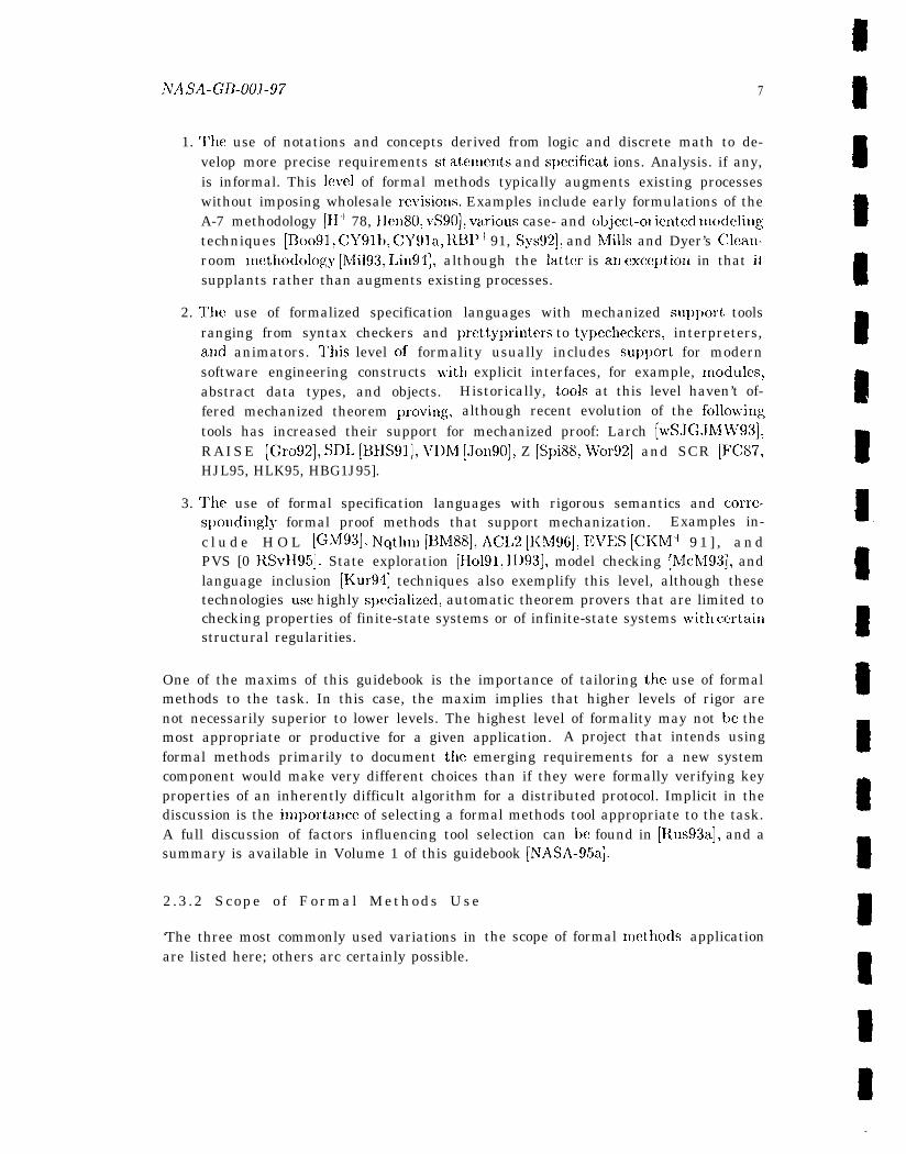
1. ‘1’hc use of notations and concepts derived from logic and discrete math to de-velop more precise requirements st atanents and spmificat ions. Analysis. if any,is informal. This level of formal methods typically augments existing processeswithout imposing wholesale revisiol~s. Examples include early formulations of theA-7 methodology [11+” 78, Hen80, vS90], varicms case- and object-ol iented modelitlgtechniques [Bo091, CY91b, CY91a, RBP+ 91, Sys92], and hflills and Dyer’s Clcan-room methodolop;y [Mi193, 1.in94], although the latter is all excc!l)tion in that itsupplants rather than augments existing processes.
2. l’he use of formalized specification languages with mechanized sul)port toolsranging from syntax checkers and ~)rettyprinters to typecheckers, interpreters,and animators. l’his level of formality usually includes supl]ort for modernsoftware engineering constructs with explicit interfaces, for example, Inoc]ules,abstract data types, and objects. Historically, tools at this level haven’t of-fered mechanized theorem l)roving, although recent evolution of the follmvitlgtools has increased their support for mechanized proof: Larch [wSJGJMW93],RAISE [Gro92], SD]. [BHS91], VDh4 [Jon90], Z [Spi88, Wor92] and SCR [F’C87,HJL95, HLK95, HBG1J95].
3. ‘1’he use of formal specification languages with rigorous semantics and corre-s~)onding]y formal proof methods that support mechanization. Examples in-c l u d e H O L [GL493], NTqthn~ [BMW], ACL2 [KM96], EVES [CKM+ 9 1 ] , a n dPVS [0 RSvH95]. State exploration [H0191, ID93], model checking [McM93], andlanguage inclusion [Kur94] techniques also exemplify this level, although thesetechnologies usc highly s~)ecialized, automatic theorem provers that are limited tochecking properties of finite-state systems or of infinite-state systems with ccrtaillstructural regularities.
One of the maxims of this guidebook is the importance of tailoring the use of formalmethods to the task. In this case, the maxim implies that higher levels of rigor arenot necessarily superior to lower levels. The highest level of formality may not be themost appropriate or productive for a given application. A project that intends usingformal methods primarily to document tllc emerging requirements for a new systemcomponent would make very different choices than if they were formally verifying keyproperties of an inherently difficult algorithm for a distributed protocol. Implicit in thediscussion is the importa~lce of selecting a formal methods tool appropriate to the task.A full discussion of factors influencing tool selection can be found in [Rus93a], and asummary is available in Volume 1 of this guidebook [NTASA-95a].
2 .3 .2 Scope o f Formal Methods Use
‘The three most commonly used variations inare listed here; others arc certainly possible.
the scope of formal methcjds application
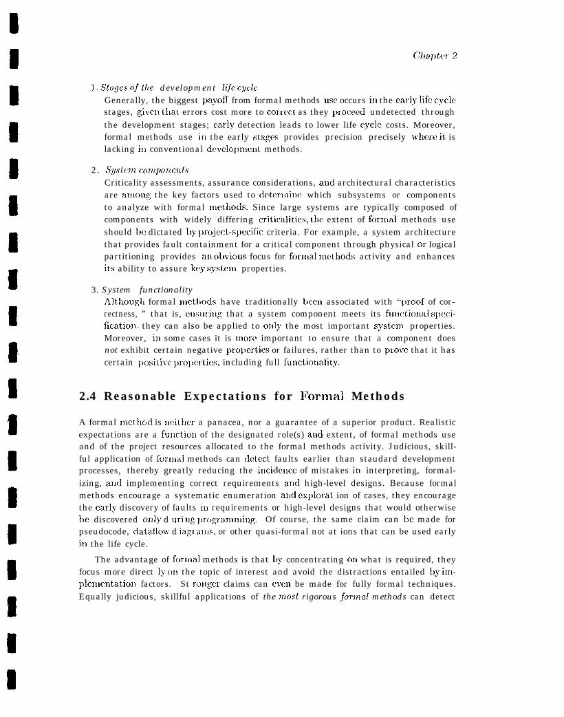
]. Stuges of the development life cycleGenerally, the biggest payoff from formal methods usc occurs in the early life cyclestages, given t}lat errors cost more to correct as they ~Jroccecl undetected throughthe development stages; early detection leads to lower life cycle costs. Moreover,formal methods use ill the early stages provides precision precisely u’here it islacking ill conventional dcvelo~)l~lcnt methods.
2. SgslenL componentsCriticality assessments, assurance considerations, and architectural characteristicsare among the key factors used to deterlnine which subsystems or componentsto analyze with formal nlethods. Since large systems are typically composed ofcomponents with widely differing criticalities, the extent of fornlal methods useshould be dictated by ~)roject-specific criteria. For example, a system architecturethat provides fault containment for a critical component through physical or logicalpartitioning provides an olwious focus for fornlal methocls activity and enhancesits ability to assure key systenl properties.
3. System functionalityAlthcmgh formal mctllods have traditionally been associated with “ljroof of cor-rectness, ” that is, ensuring that a system component meets its func~ional speci-fication, they can also be applied to oI~ly the most important systenl properties.Moreover, ill some cases it is xnore important to ensure that a component doesnot exhibit certain negative prol)erties or failures, rather than to prove that it hascertain ~)ositive l)ropcrties, including full functiol]ality.
2.4 Reasonable Expectations for Formal Methods
A formal methcd is llcither a panacea, nor a guarantee of a superior product. Realisticexpectations are a functioll of the designated role(s) and extent, of formal methods useand of the project resources allocated to the formal methods activity. Judicious, skill-ful application of forlnal methods can cletect faults earlier than staudard developmentprocesses, thereby greatly reducing the iucide~lce of mistakes in interpreting, formal-izing, and implementing correct requirements at~d high-level designs. Because formalmethods encourage a systematic enumeration and ex~)lorat ion of cases, they encouragethe early discovery of faults in requirements or high-level designs that would otherwisebe discovered only d uri ug prc)grammiug. Of course, the same claim can be made forpseudocode, dataflcnv d iagl allls, or other quasi-formal not at ions that can be used earlyin the life cycle.
The advantage of for[[lal methods is that by concentrating on what is required, theyfocus more direct ly on the topic of interest and avoid the distractions entailed by imp-lementation factors. St rol~ger claims can even be made for fully formal techniques.Equally judicious, skillful applications of the most rigorous jormal methods can detect
NASA-GB-001-97 9
more faults than would otherwise be the case and, in certain circumstances, subjectto certain caveats, they catl also guarantee the abselIce of certaiu faults. III ~Jarticu-lar, by working car]y in the life cycle, on reasonably abstracted representations of thehardest part(s) of tllc cwcrall problexll, the hi.gllcst-level formal mctllods can validatecrucial elements of the requirements or higlklcvel design. Finally, ill contrast to suchtechuiqucs as direct execution, prototyping, and sinlulation, wl)ich call cxl)lore a large,but necessarily incompleteset ofsystcm behaviors, deductive formal methods ald stateexl)loration techniques support exhaustive cxamiuation of all bellaviors.~ The ext,entto which a project realizes some or all of tile benefits described here deymds oIl theavailability of essential resources, the skill with which formal methods use is tailoredto the application, aud the dcgrm to which the exl)ec.tatiolls fit the dimensions of the~)roject.
2.5 The IWethc}d Underlying Formal Nlethods
In the context of an engineering discipline, a method describes the way i~lulhich a process is to be conducted. In the context oj system engineering, Qmethod is defined to consist oj (l) an underlying model oj development, (.2)Q language, or languages, (3) defined, ordered steps, and (4) guidance forapplying these in a coherent manner.
Most so -ca l l ed jorrnal ?nethods do not address all oj these is-sues.. .. Indeed, tllejor~nal ~netlLods co7~L~~tu~Lity ltashee~l sloulto address suchmethodological aspects.5 [H~95b, p. 2]
Although the four elements in the preceding definition may be somewhat controver-sial, the observation that tllerc is a paucity of method in formal methods is not. Theobservation focuses in ~)articular 011 tllc a~)parent absence of “defined, ordered steps”and “guidance” in applying those methodical elements that have been identified. Onereason for the absence c)f method is that the intellectual discipline involved ill modeling,slJecification, and verification eludes sim~)lc characterization; the intuitic)ll that guideseffect ivc abstraction, succiuct spccificat ion, and adroit proof derives froxn skill, talent,and experience and is difficult to articulate as a process.
F;xceptions to this observation include specialized methodologies for particular ap-~)]ication areas, such as the area of embedded systems -- reactive systems that oper-ate continuously and interact with their elwironmc!nt, including l)arnas’s “four vari-able method’) [vS90, vSPM93], NRI~’s Software Cost Reduction (SCR) method [FC87,HBGL95], the Software Productivity Consortium>s Requirements Engineering (CORE)
4State exploration techniques require a “downscaled” or finite state version of the system and typ-ically involve a more concrete representation than that used with theorem provers or proof checkers.These and related topics are discussed in Chapter 6.
5Thc material quoted here is based on a discussion in [Kro93].
10 Cilapt er 2
method [FIIM7K92], and Harel’s Statecharts [Har87, H+ 90] and its derivatives, suchas Levmon’s Requirements State Machine Language (RSML) [1. HIIR94]. Historically.the methods devclo})ed for reactive systems have ~)rovidecl organizing principles, comce~)tual models, and in many cases, specification latlguagcs, and systematic checks for~vell-formeclness of speciflcatiolls. Although many of these lncthodologies ~)rovide somemechanized analysis and arc currently exploring additional mechanized checks, few haveyet to provide the range of analysis available in a true theorem prover or proof checker.
Although the method i~nplicd in formal methods has been slow to emerge (with theexception of the methodologies noted above), broad outlines that effectively constit utcan “U1lderl~iIlg model of development” are worth noting. The process of applying formalmethods to a chosen application typically involves the following phases: chmKkrizz7t.ythe application, modelingfi, specification, analysis (validation), and documentation. Thedistinction between phases is somewhat artificial and should not be taken too literally.For exarnplc, it is difficult and not particularly imtructive to determine precisely wheremodeling ends and specification begins. Each phase consists of constituent processes.Again, the enumeration below is suggested, not, prescribed, and the overall process (i.e.,the four constituent phases) is iterative rather than sequential. For example. character-ization of the application may be influenced by consideration of potential models, theprocess of specifying the application may suggest changes to the underlying model, orthe process of verifying a key property may trigger changes to the specification or even tothe underlying model. Ideally, documentation accompanies all the phases summarizedhere:
. TIIC Characterization Phase: Synthesize a thorough understanding of the ap~)li-cat ion and the application domain.
o
0
0
0
Conduct a thorough study of the application, noting key components and sub-components, i~lterfaces, essential algorithms, fundamental behavic)rs (nonli-nal and off-nominal), data and cent ml flows, and operational environment.
Identify and study related work, if any.
Acquire additiollal knowledge of the application domain, as needed.
Integrate the accumulated knowledge into a working characterization of theapplication. Some practitioners, especially those working alone, tend to “in-ternalize” an application, working strictly from mental notes. Other practi-tioners produce working documents and notes. The culture in which a projectoperates in large part determines the artifacts (if any) of this phase. Still,the importance of this phase should not be underestimated; total immersionin an application is crucial for developing insight into the most appropriate]nodels and the most appropriate sl)ecification and validation strategies. In
—6As used her-c, the term ‘(model” refers to the mathematical representation of a systeui that uuderlies
the system’s specification. In this usage, the “models>’ checked by state exploration tools or modelcheckers are viewed as spccificatious.
~TASA_ (3~_(j(71_97 11
some cases, such as hardware verification, there is considerable precedentand there am fairly well-cst ablished I )aradigms. There is also a st anclardparadigm for ~)roving hierarchical s~mcification chains, that, is, hierarchies ofspecifications at different lcve]s of abstraction (see Section 5.3). However, illmost other cases, there is often little apldicable precedent and them arc few,if any, established ~)aradigms.
● The Modeling l’hasc: Define a mathcnlatical representation suitable for forlllaliz-iug the application domain a~ld for calculating and ~)redictil]g the behavior of thea~)~)lication in that colltcxt. (See Clla~)tm 4.)
o I;lvaluate l)otential mathelnatical re~)resentationsl considering such generalfactors as the level of abstraction, generality, expressiveness, analytical power,and simplicity, as well as specific factors, such as the computational model,and explicit (implicit ) represent at ion of state and time. hlechanized toolsupport, if any, may also be a factor. The logic underlying a tool maysupport the use of certain mathematical representations and discourage theuse of others.
0 Select the l[[atbcxnatical re~)rese:ltation most suitable for the application
o Mode] key elements of the application and their relationships. As notedabove, this (sut))process transitions into the specificatio~l phase.
● The Specification F’base: Formalize relevant aspects of the application and itso~)eratiollal cllvirolLtnent. (See Chapter 5.)
o l)cveloI) a s~w.cificatiorl strategy, colLsiderillg SUCIL factors as llicrarcllical (IIIul-tilm’cl) versus single-level specification, constructive versus descriptive spec-ificatio~l style (SCC Section 5.2), and procedural and organizational issues,such as clc~wlo~)ing reusable theories and common definitions, and specifica-tion chronology.
o Usi~lg the cllosell model and specification strategy, compose the specification.
o A~ialyze tl~c syntactic and semantic correctness of the specification.
. The Analysis Phase: Validate the specification. (See Chapter 6.)
o Intq)ret or execute the specification.
o I)rovc key l]ro~)crtics and invariants.
o llstatjlish the consistency of axioms, if any.
o FJstablisll t}le correctness of hierarchical layers, if any.
● ‘1’he Documentation Phase: Record operative assumptions, motivate critical deci-sions, docunlellt tile rationale and crucial insights, provide explanatory material,trace specification to requirements (high-level design), track level of effort, andwhere relevant, collect cost /benefit data.
● Maintenance and Generalization: Revisit and modify the specification and itsanalysis as required, for example, to ~Jrcdict tl~e consequences of proposed changesto the modeled system, to accommodate mandated changes to the modclecl system,tc) support reuse of the formal specificatioll and analysis, or to distill generalprinciples from the formalization and analysis.
l’ormal methods are supported in the s~)ecification and aualysis l)hases with lnecl(-animd tools that perform the steps shown in Figure 2.2. Tools that support user inter-action typically provide these steps explicitly, whereas tools that, are fully automateddo so implicitly. For example, most state exploration tools are fully automatic and donot prc)vide user control of the steps that check for syntactic and semantic consistency.h4echanized support for tile modeling phase exists, for example, in some of the infor-mal object-oriented methodologies and in methods such as SCR. However, mechanizedsuplJort for modeling is not (yet) included in Illost formal methods (FM) systems andis therefore not represented in Figure 2.2.
Checks iyntactic consistency‘llanslatis interual representationinto display and outputs formatted textChecks semantic consistency
by syntactically and semanticallycorrect s~mcification
and semantically correct specification
Figure 2.2: hlechanical Support for Specification and A1lalysis Phases of FM.
Except for documentation and maintenance, all the phases listed above form thecore of subsequent chapters, beginning with the characterization phase. This chapterconcludes with bacligrouncl regarding SAFER drawn from requirements documents andoperations manuals typical of the kind of documentation used for developing an initialcharacterization of an application and its domain.
2.6 An Introduction to SAFER
Unless otherwise noted, this section is based on the SAFER Operations Man-ual [S AFER94a]. A more detailed version of the material, along with all figures citedin this discussion, can be found in Appendix C.
A’AS.4-GI?-001-97 13
—. .. —. —.—.
—-. —
MODULE
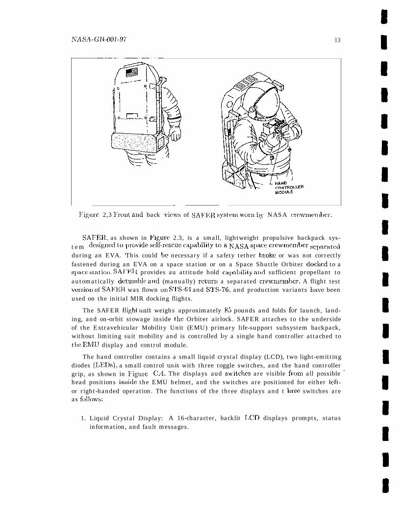
Figure 2,3: ~~lollt and back ~~i~r~~s of SAFER syst,e,nl WC)I-11 by NASA crcwmel~~t)cr.
SAFER, as shown in Figure 2.3, is a small, lightweight propulsive backpack sys-tem desigl]cd topro~'ide self-rescue cal)al)ility toa NASA space crewmendje rseparatedduring an EVA. ‘This could be necessary if a safety tether broke or was not correctlyfastened during an EVA on a space station or on a Space Shuttle Orbiter docked to as~)acx! station. SAFF.l L provides au attitude hold ca~)ahility and sufficient propellant toautomatically dctumble atid (manually) return a separated crewrmember. A flight testversio~l of SAF13R was flown on S1’S-64 and STS-76, and production variants nave beenused on the initial MIR docking flights.
The SAFER flight unit. weighs approximately 85 pounds and folds for launch, land-ing, and on-orbit stowage inside the Orbiter airlock. SAFER attaches to the undersideof the Extravehicular Mobility Unit (EMU) primary life-support subsystem backpack,without limiting suit mobility and is controlled by a single hand controller attached tothe EMU display and control module.
The hand controller contains a small liquid crystal display (LCD), two light-emittingdiodes (LEDs), a small control unit with three toggle switches, and the hand controllergrip, as shown in Figure C.4. The displays aud switches are visible frcnn all possible ‘head positions inside the EMU helmet, and the switches are positioned for either lcft-or right-handed operation. The functions of the three displays and t hrce switches are c
as follovrs:
1. Liquid Crystal Display: A 16-character, backlit LCD displays prompts, status1
information, and fault messages.
R
s
s
14 Chapt a 2
2. I,ight-emitting L)iode: A red LED lat)elcd “TIIR” lights whenever a thruster-o~lcondition is dct ectcd by the cent rol software.
3. L,igllt-ex~littillg Diode: A green I, RI) labeled “AAII>’ lights whenever automaticat t it udc hold is enabled for one or more rotational axes.
4. Switch: A three-position toggle switch labeled “I’J$7R’) l)owcrs on SAFER andinitiates the self-test or activation test functions.
5. Switch: A three-position momentary toggle switch labckd “DISP>’ controls theLCD display, allowins the crewmember to select the previous or next parameter,message, or test step. The switch springs back to the center (null) position whenreleased.
6. Switch: A two-position toggle switch Iat)eled “h40D13” selects the hand controllermod<! associated with rotation and translation commands.
The hand cent roller is a four-axis nlechallism with t hrec rot ary axes at Id one t rans-verse axis. To generate a command, t hc crewnmnber moves the hand cent roller grip(mounted on the right, side of the hand controller module) from the null center posi-tiol~ to mechanical hardstops on the hancl controller axes. q’o terminate a command,the crmvmember returns tile hand controller to the center position or releases the gripso that it automatically springs back to the center. Figures C.5 and C.6 illustratethe baud controller axes for translational and rotational commands, respect ively. Forexaniple, Figure C.5 indicates that with the control switch set to translation mode.~ Y commands are generated by ~)ulling or pushing t llc gri~) right or left, res~xxtivcly.Careful study of these figures reveals that the X translation command and the pitchrotation command are always available in either mode. A pushbutton switch on the topof the hand controller grip initiates and terminates automatic attitude hold.
‘The avionics software processes inputs from the hand controllers and various sensors,and includes the following components:
1. Control Electronics Assembly (CEA): The C13A microprocessor takes inputs fromsensors and hand controller switches and actuates the appropriate thruster valves.
2. Inertial Reference Unit (IRU): The IRU senses angular rates and linear accelera-tions and is central to the attitude hold capability.
3. Data Recorder Assembly (DRA): The DRA collects flight-performance data, handcontroller and automatic attitude-hold commands, and thruster firings.
4. Valve Drive Assemblies (VDAS): Each of the four VDAS, located with a clusterof six thrusters, takes firing commands from the CEA and applies voltages to theselected valves.
NASA-GB-001-97 15
5. Power Supply Assembly (PSA): ‘1’hc I)SA produces regulated electrical power forall SAF13R electrical coln~mnents.
6. I1~strllll~elltatioll Electronics: SAFER instrumentation includes a variety of sen-sors, all of which arc listed in Table C. 1.
The avionics software has two princil)al functions: maneuveri~ig colLtrol for bothcommanded accelerations and automatic attitude hold actions, and fault detection,which supports inflight operation, pre-k;VA checkout, and ground checkout., A briefsummary of tllc control function is prese]lted here. Sect ions C.1.4.2 and C.1.4.3present a more detailed summary of the maneuvering control function atld an accountof tllc fault detection function, respectively.
The maneuvering-control software commancls bckh rotational and translational ac-celerations. Translat iox I commands provide accelcrat ion along a single translational axisand are prioritized so that X is first, Y is second, and Z is third. Wrhen rotation andtranslation commands are present simultaneously, rotation takes priority and tratisla-tions are suppressed. Conflicting input comlnands result in no output to the thrusters.Whenever l)ossiblc, acceleration is provided as long as a hand controller or automaticattitude-hold commancl is present.
The SAFER crewmember cat) initiate (single-click) or terminate (double-click) au-tomatic attitude hold at any time via the pushbutton on the top of the hand controllergri~). When terminated, automatic attitude hold is disabled for all three rotationalaxes. If a crewmernber issues a rotational command for a given axis when automaticattitude holcl is active, it is imnlediately disabled for that axis only. However, to ensurethat, a failed-on hand controller command ill a rotational axis will not disable automaticattitude hold on that axis, automatic attitude hold takes precedence over a crewmen~ber-issucd rotational comnland if the two arc initiated simultaneously. Automatic attitudeIIold provides an automatic rotational deceleration until all three axis rates are nearzero. These near-zero rates arc automatically nlaintained whenever automatic attitudehold is active.
Thruster-select logic t akcs accelcrat ion commands from the hand cent roller andfrom the automatic attitude-hold function, creates a single acceleration command, andchooses thruster firings to achieve the commanded acceleration. Thruster selectionresults in on-off commands for each thruster, with a maximum of four thrusters turnedon simultaneously. llu-uster arrangement and designations are shown in Figure C .3.Tables C.2 and C.3 specify the selection logic.
SAFER has 24 gaseous nitrogen (GNz) thrusters - four thrusters pointing in each ofthe +X, *Y, and + Z axes. The t hrustcrs are arranged in four groups of six thrust crseach, located as shown in Figure C.3. As l~oted, thruster valves open, causing thethrusters to fire in response to directives from the avionics subsystem, which commandsas manj as four thrusters at once to provide six degree-of-freedom maneuvering control(+X, +Y, +Z, +roll, +pitch, +yaw). The SAFER propulsion system provides a total
16 Cklptcl’ 2
delta velocity of at least 10 feet IJCr second with an initial cllargc. ‘Tllc four GlV2tanks have a relatively small capacity and require several recharges during an EVA.The recharge station is located ill the Orbiter payload bay. Whe~l SAFER is ]Lot itl useor if a malfunction (such as a failed-”oil thruster) occurs, the tauks can be isolated via amauually actuated isolatiou valve.
The SAFER example introduced here! is used throughout the guidebook to illustratekey ~)oiuts in each chapter. Although this example attempts to formalize the actualSAFER design, pragmatic and pedagogical considerations have inevitably resulted indifferences between the act ual design atld the formal specification. These differencesdo not detract from the presentation of a realistic example that captures the basiccharacteristics of a class of space vehicles and the computerimd systems that controlthem. The fragment of the example chosen for inclusion at the end of each subsequentchapter focuses on the thrush’ sektioIl function responsible for creating an integratedacceleration commalld fronl hand controller and automatic attitude-hold inputs.
Chapter 3
Requirements
Requirements define the set of conditions or capabilities that must be met by a system orsystem component to satisfy a contract, standard, or other formally imposed documentor description [SFN7]. For example, IEEF, Standard 149S [I EEE194, p. 7] defines arequirement as “a characteristic that a systcm or software item must possess i~~ orderto be acceptable to the acquirer.” Similarly, the NASA Guidebook for Safety CriticalSoftware Analysis and Development [NASA-96, p. A-18] defines software requirementsas “statements describing essential, necessary, or desired attributes. ” In the context ofthis guidebook, requirements are taken to be a statement of the essence of a system thatis typically produced at or near the beginning of the life cycle and guides and informsthe development, implement at ion, and maintenance of that system. 1 The number ofst,e~~s between rcquirelncnts, capture, and ir~l~}le~t~c:~ltatiolI depends 011 the life cycleprocess for the system. Arguably, the more clearly articulated and differentiated the lifecycle phases are, the more likely it is that the requirements statement will be suitablefor formal analysis. A well-defined life cycle reflects a mature process, including anappreciation for the role and task of quality assurance. For example, a fairly typical,mature life cycle process might include requirements definition, system design, high-leveldesign, ]OW-]CW1 cles@l, coding, testing (unit testing, component or function testing,systcm testing), user support, and maintenance.
There are many considerations in the elicitation, capture, modeling, specification,validation, maintenance, traceability, and reuse of requirements, and a burgeol~ing groupof researchers i~herested in addressing these and related issues. This activity has led tothe recent emergence of a “discipline’ ) [FF93, I). vi] known as “Requirenlents 13ngineer-iug” that attempts to establish “real-world goals for, functions of, and constraints onsoftware systems” [Zav95, p. 214] a~~d includes researchers in the social sciences as wellas ill several areas of com~)uter science.2
1 This and similar remarks in Section 3.1.1 are not meant to suggest a particular life cycle model‘Representative papers may be four,d in the proceedings of several IICIV conferences, including the bi-
ennial international symposium first held in 1993 [FU393, R1395] and the biennial international conferencefirst held in 1994 [ICR1394, 1CRE9G].
17
18
3.1 Requirements and Formal Methods
This guidebook takes a less generic interest in requirements, focusing here on require-ments as objects of formal analysis and, in particular: the characteristics of requirelnent,sthat infiuencc the ap~dication of formal methods, ancl conversely.
3.1.1 Impact of Requirements Specification on Formal Methc)ds
The most important characteristics of requirements as objects of formal analysis ate thelevel at which the requirements are stated, the degree to which they are explicitly andunambiguously enumerated, the extent to which they can be traced to specific systemcomponents, and the availability of additional information or expertise to ~Jrovide therationale tc) motivate and clarify the requirenlents definition (as necessary).
3.1.1.1 Level of Requirements Capture
Requirements for the early stages of the lif[! cycle, that is, up to and illcludiu~ the hi,gh-level design phase, should be reasonably abstract and focus on basic characteristics,including essential behaviors and key properties of the system. At this level, inqdenlen-tation considerations and low-level detail tend to distract ouc from the basic systemfunctionality. Requirements written at too low a level or with too strong an inlplenlen-tation bias may require reverse engineering befc)re forlllal methods can be productivelyapplied.
3.1.1.2 Explicitness of Requirements Statement
Requirements should also be completely, precisely, and unambiguously stated. At thislevel, the idea is to have a clear, precise statement that is reasonably complete anddoesn’t admit multiple interpretations. This appears to cent radict the p!evious point,that the requirements be reasonably abstract and distill only essential behaviors andpro~)ert ies, but t}lere is really no cent radict ion. Clarity, precision, and completenessiuvol~~e explicitly identif.yiug underlying assumptions and thoroughly enumerating allrelevant cases rather than specifying low-level detail and i~~ll)lex~lclltatioll factors. Am-biguous requirements that cannot bc further clarified may require the formal methodspractitioner to define and explicitly record a set of operative assumptions to initiate theformal specification and aualysis. Ultimately, any operative assumptions, as well as therequirements specification, should bc validated.
3.1.1.3 Clarity of Delineation between a System and Its Environment
Requirements should clearly state the assutnptiom a system makes about its operat-ing envitolInlcnt and should clearly delineate the boundary between the system and its

ATA SA_G~;-Ool _97 19
operative context. Fbr example, rcquirmncnts should explicitly identify environn~en-tat quantities that the system measures, cent rols, or assumes, such as temperatures,pressures, and user interface assumptions [HE\95a, p. 23].3
3.1.1.4 Traceability of Requirements
System-level requirements should be traceable to identifiable (functional) subsystems,components, ox interfaces. Requirements that cannot be so traced may prove diffkwlttovalidatei ~~sofara stlleys lJecifys ystclll-levell >roIJertiesor t)ella~riortllat istoogcmeralor too ill-defined to he formally analyzed.
3.1.1.5 Availability of Underlying Rationale and Intuition
Requirements should also contain background material that motivates and illuminatesthe requirements statement. Although such material is typically excluded from require-ments documents, it is often possible to find domain expertise, project personnel, andartifacts that provide essential information and insigl]t. Such supplemental lnatcrial iscrucially important if the requirements statement is low-level, implementation-oriented,illco~nplete. or ambiguous.
It is unusual to be handed a set of requirements that is well-suited to formal specifica-tion and analysis. Although formal methods provide techniques and tools for distilling aset of requirements from informal or quasi-formal spccificat ions and for exposing missingor incomplete requirements, formal methods are not a panacea. The practitioner shouldfactor ill the availability and suitability of rcquircmcmts doculnents when considering aformal methods a~)j)licatioll.
To illustrate. consider briefly the experience recounted in [NASA93], which describesan attempt to formalize the official Level C requirements for the Space Shuttle Jet-Selectfunctioll [Roc9] ]. Although Space Shuttle flight software is exemplary among NASAsoftware devclol)r[lent ~)rojects, the requirements analysis and quality assurance in earlylife cycle phases of tllc Shuttle used then-current (late 1970s and early 1980s) productsand tools. Shut t k’ soft ware requirements are typically written as Functional SubsystemSoftware I{rxluirellleIlts (FSSRs) - low-level software requirements specifications writtenin English prose mid accompanied by secondary material inc]uding pseudocode, anddia~rams and fiowc}iarts Tvith imhousc notations. Interpreting the Jet-Select FSSRdoc~&lents required the combined efforts of a mult icenter team for several months andrelied extensively OX] resident expertise at IBM Federal Systems Division.4 WUlen a
.——3This paraphrase of a statcmcmt by Parnas, who has been among the most vocal advocates for all
explicit delineation bet ~veen a system and its wvironment, MZIS made in the context of computer soft ~raresystcwls, but the rmnark applies equally to other types of systems.
4The rnu]ticentel team consisted of personnel from N’ASA’s Jet Propulsion I,aboratory, LangleyResearch Center (LaRC). a!ld Johnson Space Center, and included subcontractors from Lockheed MartinSpace hfission Systems (formerly Loral, and, prior to that IIILI, Houston) and SRI International. (The
20 Chaptm 3
new set of high-level Jet-Select requirements was formalized in the PVS .sI)ecificationlanguage, it bccameclearthat theJ&-Select function could twstated mores imply. TCIvalidate the PVS specification, approximately a dozel~ lemmas, derived from a list ofhigh-level Jet-Select properties identified by IBhI, were formalized and proven. Thefact that the algorithm and its essential properties are difficult to discern from theFSSRS illustrates two comldcnlentary points: (1) the potential problems of low-levelrequirements that only implicitly capture key prol)erties and essential functionality,and (2) the valueof supplemental sources and materials to provide crucial information]),for example, the list of desired Jet-Select properties and the clarifications provided byIBM domaiuexperts.5
3 .1 .2 Impact o f Formal Methods on Requirements
l’he applicat ioll of formal methods typically produces tangible artifacts, including for-mal models, specifications, aud analyses, that can impact the requirements to whichthey are applied. The nat urc oft he impact depends on the strategy used in the require-~nents development process, and in particular, the degree to which formal methods areintegrated illto the existing process.
Fraser aud his colleagues [FKV94] attempt to classify integration strategies withrespect to the following factors:
1. Does the strategy go directly from the informal recluirements to the formalizedspecification or does it introduce intermediate and increasingly formal models ofthe requirwncllts?
2. If the strategy introduces intermediate (semiformal) models, is the process OILC ofparallel, successive rcfiuement of the requirements and the formal specification, orare the formal specifications derived after the (semiformal) requirelnents modelshave been finalized in a sequential strategy?
3. 10 what extent does the strategy offer mechanized support for requirements cap-ture and for~~lalizatioll?
The question of mechanized support for requirements capture and formalization re-mai~ls somewhat academic, since the fully automatic characterization of requirementsstill relies primarily on research tools with limited scope and scalability. one exam-ple is a knowledge-based “specification-derivation system” that uses difference-basedreasoning and analogy mapping to recognize and instantiate schemas and interactively-—. —.. _.work cited here was completed prior to either the Loral or Lockheed Martin er~$, hence the referencesto IBM.)
‘This example also illustrates the fundamental cost/benefit trade-offs that invariably arise Whellsubstantial reverse engineering is required before fornlal methods can be applied. These and relatedplanning issues are discussed in Volume I of this guidebook [NTASA-95a].
ATASA _G~.@_JJ _97 21
derive specifications in a language similar to the Larch Shared Language [FKV94, p. 82].Another example is the use of clata-flow diagrams and decision tables to develop “Struc-t ured Analysis” specifications that are then translated in VDM specifications by meansof “interactive rule-based algcwithmic methods” [FKV94, I)p. 84-5].G
of more immediate interest are the strategies that use an iterative a~)proacll to thesuccessive refinement. of requirements. An example of the sequential applicatioll of theiterative strategy is the use of formal methods in certain re-engineering projects wherethe requirements are mat ure and well-established. However, it is the parallel applicationof the iterative strategy that, most substantively impacts the require~nellts definition.AIL example of this type of application includes formalization of immature requirementsor formalization of requirements for ill-defined or ill-structured problem domains. Inthese cases, there is the “l)otential of lcttiug semiformal and formal specifications aicleach other in a synergistic fashion duriug the requirements discovery and refinementprocess” [FKV94, ]). 82]. lf this synergy is positive, the formal xnodels, specificat iolls.and analyses may ultimately become (part of) the requirements- a development somewould applaud and others would view wit h concern. For example, Parlms [H B95a, p. 21]notes that “Eugiueers make a useful distinction between spcxificatious, descriptions, andmodels of products. This distinction seems to be forgotten in the computer science lit-erature . >’ ‘This may be similarly applicable to requirements, models, a~ld s~)ccifications.On the other hand, active research into formal semantics and automated reasoningframeworks for industrially used notations [RS93, p. 191] points toward a coalescencein some environments of informal requirements with their formalization and analysis.
3.2 Conventional Approaches to Requirements Validation
It is well recognized that identifying and cor~ecting problems in the requirements andearly-desig~l phase avoids far more costly fixes later. It is often said that late life cyclefixes are 100 times more expensive thau corrections during the early phases of softwaredevelopment [Boe87, p. 84]. Focused arguments for the utility of software-requirementsanalysis and val idat ion have become increasingly common. For example, Kelly [KSH92]documents a significantly higher density of defects found during requirements versuslater life cycle inspections. IJutz [ljut93] notes that of roughly 195 “safety-critical” faultsdetected during integration and system testing of the Voyager and Galileo spacecraft,3 were programming bugs, 96 were attributed to flawed requirements, 48 resulted fromincorrect implementation of the requirements, aud the remaining 48 faults were tracedto misuuderstoocl interfaces.
Standard approaches to requirements analysis and validation typically involve nlan-ual ~)r-ocesses such as “walk-throughs” or I%gan-sty]e inspections [Fag76, Fa.g86]. Theterm walk-through refers to a range of activities that can vary from cursory peer reviews—— ——.
‘The relative immaturity of these particular activities does not reffect on the aclino}viedged maturityof formal methods techniques in general. See, for example, [Gla95, N!c195].

to formal inspections, although walk-throughs usually do not involve the replicable pro-cess and methodical data collection that characterize Fagau-style inspections. Fagan’shighly structured inspection process was originally developed for hardware logic. nextapldied to software logic design and code, and ultimately successfully aplJlied to arti-facts of virtually all life cycle phases, inducting requirements development and high-leveldesign [Fag86, p. 748]. A F’agan inspection involves a review team with the followingroles: a Moderator, an Author, a Reader, and a Tesicr. The Reader presents the designor code to the others, systematically walking through every piece of logic and everybranch at least once. The Author represents the viewpoint of the designer or coder, andthe perspective of the tester is represented, as expected, by the Tester. The hloderatoris trained to facilitate intensive, but constructive and optimally effective, discussion.When the functionality of the system is well-understood, the focus shifts to a search forfaults, possibly using a checklist of likely errors to guide the process. The inspectionl)rocess includes equally intense and highly structured rework and follow-up activities.One of the main advantages of Fagau-style inspections over other con~’entional forms ofverification and validation is that they can be applied early in the life cycle, fol example,to requirements and high-lcwl design. Thus potential anomalies can be detected beforethey become entrcmchcd in the 10 W-1CVC1 design and itll~~lell~elltatioll.
NASA supports a ~)rocess derived from Fa.gan inspections, called “Software FormalIns~mctions” [NASA-93b, NASA-93a] that uses teams drawn from peers involved in de-velopment, test, user groups, and quality assurance. The scwen-step NASA processspelled out in [hTASA-93b] consists of planning. ovcrviev’, preparation key, inspectionmeeting, rework, and follow-up stages. NASA inspections use checklists, as well asstanciarclizcd forlns to recorcl ~moduct errors allcl collect metrics associated with theinspection process. g’he Colh!ction and monitoring of lnetrics is an integral part ofNTASA’S inspection prc)cess bccausc it documents the progress of a project. If reiu-sl)ect ion is requirecl. scwcral of the steps may be repeated. With small variations, theNASA inspection process is USCC1 at several NASA centers, including the Gc)ddarcl SpaceFlight Center (G Sl~C). Jet I’rol)ulsioll laboratory (JPL) [Bus90], Johnson Space Cen-ter (J SC) 7, I,an@y Research Center (LaRC), and Leu’is Research Center (LeRC). Thecurrent validatic~ll I)rc)cess for N’ASA’s Space Shuttle flight software includes C1OSC ad-herence to the ins~)cct io~l process for requirements, high-level test plans, and sourcecode [NASA93. ]). 21].
Although tllcxe processes are considered eflectivc and the quality of NTASA slluttlcflight softu’are is a?llong the highest in NASA software development prc)jects, the re-quirements analysis seems less reliable than the analyses performed on later life cycleproducts. F’or examl)le. [Rus93a, p. 38] notes that “a quick count of faults detected andeliminated during dcwlopmcnt of the space shuttle on-board software indicates thatabout 6 t itnes as n Iany faults ‘leak’ through requirements analysis, than leak through
‘~’he foruia] inspectiorls cited here are actually used by Locliheed hlartin Space Information Systems(formerly, Loral and, prior to that, IFlhl, Houston), the Space Shuttle soft~rare subcontractor.
AJASA-GB-001-97 23
the processes of code development and review.” III light of these and similar obser-vations, the following characteristics of the requirements analysis process have beenuoted [NASA93, p. 9, 22]:
. Current techniques are largely manual and highly dependent on the skill ancldiligenceof individual inspectors and review teams.
● ‘l%ere is no methodology to guide the analysis process and no structured way forRequirement Analysts (RAs) to document their analysis. There are no completioncriteria.
. Although these techniques catch a substantial number of defects, the density ofdefects found suggests that some errors escape detection.
● NASA projects using currently available techniques have reached a quality ceilingon critical software subsystems, suggesting that innovations are needed to reachnew quality goals.
These types of issues constitute a significant part of the rationale for exploring theuse of formal methods to complement and enhance existing requirements analysis anddesign analysis processes for critical aerospace and avionics software systems.
3.3 SAFER Requirements
I’he set of SAFER flight operations requirements used in this document are derivedfrom three ofllcial project documents:
● Project Require~ncmts I)ocument [SAF’ER92]
● I’rinlc Itmn Developnlent S~mcification [SAFER941)]
● operations Manual [SA1’ER94a]
‘1’he derivation of these requirements illustrates challenges that typically confrontefforts to formalize requirements for real-world systems. For example, the Project R+quirements Document provided brief characterizations’ for major components and func-tions. Requirements at this level, such as those reproduced below, provide backgroundinformation, but they are at too high a level to be useful in the development of formalspecifications.
● The SAFER Flight Test Article shall provide six degree-of-freedom manual n~a-ncuveritlg control.
● The SAFER Flight q’est Article shall provide crcwll~cl~lber-selectable. three degrec-of-freedom Automatic Attitude Hold (A AH).
The Prime Item Developmmit S1)ecification, while more informative, lacks detail illcertai~l critical areas. In gclmal, the O1)erations hlatmal, which was not, intended as arequirements document, provides t hc most consistent )y useful in format iou. Ultimat cly,synthesizing tllc material from two of tllc three sources was necessary first in order tocharacterize a system that, could be meatlingfully formalized. A subset of the require-ments from the Prilne Item Development Spmificatiou w’as augmented with more details
from t hc O1)erat ions h~anual. This inherently subject ivc process, described here, wasguided by the need for requirements that, provided a workable level of detail basecl ona well-defitled systenl architecture. If existing requirements documents directly supportthe applicatioll of formal methods, or if domaill expertise is readily available, the processdcscrihed here would not, bc necessary for formalization and analysis.
Tile subset of the recluirements presented here (numbers 37 - 42) focuses on thethruster-select function of the avionics software. Only the requirements that directlysl)ecify thruster selection have beml i~lcluded; those indirectly iuvolved, such as therequirements that specify components providing thruster-selection input (the hand comtroller unit) and output (the propulsion subsystem), appear iu Section C.2, which coll-tains the full set of SAFER requirements.
Requirements 37 - 42 below specify the two basic tllruster-select functions: (1 )integrating the in~nlt from the hand controller and automatic attitude hold (AAH) intoa single acceleration command and (2) selecting the set of thrusters to accomplish thecommand. This functionality is specified through a combination of high-level “shall”state; nents aI~cl lower-level tables that clcfilie the thruster-select logic. The nuuli)ersassociated with each requirement correspond to those used ill Appendix C.
37. The avionics software shall disable A AH on all axis if a crewmember rot at ioncommand is issued for t}lat axis w~lilc AAII is active.
38. Any hand controller rotation command present at the time AAH is initiated shallsubsequently be ignored until a return to the off condition is detected for that axisor until AAII is disabled.
39. Hand controller rotation cO1lllllaUds shall suppress any translation commands that,are present, but A AH-gcncrat ed rot at ion commands may coexist with translations.
40. At most one translation comu~and shall be acted upon, with the axis chosen inpriority order X, Y, Z.
41. The avionics software shall provide accelerations with a maximum of four simul-taneous thruster firing commands.
42. l’he avionics software shall select thrusters in response to integrated A AH andcrew-generated comma]lds according to Tables C.2 and C.3.
Chapter 4
Models
The term nlodel is usc!d in two diffcrcmt, alt)cit related, ways in the context of formalmethods. On the one hand, “model” is used to refer to a mathematical representationof a natural or man-made systc~l~. This is consistent with tile usage in science and engi-neming, where mathematical representatio~ks are used to predict or calculate prol)ertimof the systems being modeled. Tile statistical models used to analyze and predict llle-teorological phenomena and the models of ~)lanet ary mot ion used to calculate satellitelaunch trajectories and orl)its are examples of these types c)f mathematical nlodels, asare the state machine models used to explore the behavior of complex hardware a~ldsoft warw systems.
A second usage of tile term “model” derives from precise terminology in formal logicand refers to a mathmnatical reprcmlltatioll that satisfies a set of axioms. Exhibiti~lg amodel for a set of axioms demonstrates that the axioms are consistent. For example,one way to show that a specification is consistent is to show that its axioms have amodel, as discussed in Chapter 6.
This chapter surveys characteristics of the types of mathematical models used in for-ma] methods and concludes with a discussion on modeling the SAFER thruster selectionfunction.
4 . 1 IMathematical NIodels
Wllilc there is no ambiguity about the meaning of the term “model’ ; il ~ the formal logicsense, and lit t le confusion about its informal use in the real world of concrete objects,there is residual confusion surrounding the informal use of the term to refer to nlathe-matical objects. For example, when speaking of real products, such as jet planes, thereis I1O problem in distinguishing the notions of Inodel, prototype, specification, and de-scription. A model of a 747 may or may not be flightworthy and fit on a desk. 1 A
1 Jackson [Jac95, pp. 120-122] follow Ackofl [.AM2] ixl distinguishing three kinds of model: iconic,analogic, and analytic. Using this three-way distinction, the model of the 747 is iconic, that is, the
25
prototype, on the other hand, would be one of the first 747s built and would cxllit)itmost, if not all, key properties of the actual 747 aircraft, including the ability to ac-commodate 350 passengers. A specification of the 747 would capture certain importantl)roperties of the 747, l)ossibly includi]lg the property that dimensions of the wing standin a certain relationship to the overall dimensions of the plane. A description is theleast constrained representation] and may even include such useless detail as the factthat the plane has a rather bulbous profile. 2 ~n the other hand, Parnas’ definition of amodel as “a product, neither a description nor a specification. ” [Par95~ p. 22] explicitlyacknowledges a confusion in the context of formal methods, where models and specifi-cat ions are frequently conflated. Concurrency provides a case in point. “It’s not thatone usually wants to specify concurrency, but rather to study the properties c)f a modelof concurrency resulting from a specification of a system.” [CS89, p. 89]
4 .1 .1 Character is t i cs o f Mathemat ica l Models
In the context of forulal nwthods, the II1OSL useful nlodels tend to be abstract represen-tations that focus on essential characteristics expressed in reasonably general ternls andforn~alized in judiciously chosen nlathenlatics, that is, in nlathen]atical representationsthat are suitably expressive and provide sufficient analytic power. Of course, accuracywith resl)ect to the system being modeled is also essential.
4 .1 .1 .1 Abstract ion
Exploring the relationship between modeling and specifying a concrete (ph~rsical) object,such as the 747, yields insight into desirable characteristics of abstract (mathematical)models. For example, while it is possible to build a full-scale model of the 747, it isalmost certainly more useful to abstract away less important or less relevant features ofthe 747 alld concentrate on the simplest or most general ex~)ression of essential featuresof interest. Two highly desirable consequences of creating suitably abstract models arcthe elimination of distracting detail and the avoidance of pmniature i~~lple~l~er~tatiol]commitments. For example, imagine using a desk-size model to discuss properties ofthe overall design, that is, the layout and proportions of the aircraft, and of certaincomponents, such as the shape of the fore and aft sections of the wing, while ignoringpro~)cxties relating to the aircraft’s size or to the structural materials used to build it.
The choices of mathematical represcutation and level of abstraction carry inher-ent implications that must be explicitly considered. For example, Hayes describes theimplications of certain choices for modeling a simple symbol table.—— — ——747 model is an icon of a real plane. See Section 4.1.1.3 for a brief discussion of analogic and analyticmodels.
2The 747 example is based on a discussion in [Par95].

NASA-GB-001-97 27
‘(We are describing a symbol table by modeling it as a partial function. . . .Here . . . we use it [the function] to describe a data structure. There may bemany possible models that wc can use to describe the same object. Ot hcrmodels of a symbol table could he a list of pairs of symbol and value, or abinary tree containing a symbol and value in each node. But these othermodels are not as abstract, because many different lists (or trees) can relJ-rcsent, the same ful~ct ion. Aud we would like two symbol tables to be equalif they give! the same values for the same sylllbols.” [Hay87, p. 39]
4.1.1.2 FOCUS
A model defines the space that can be explored by virtue of the (concrete or abstract)representation choices it reflects, but it does not prescribe the exploration per se, whichis the role of the specification. The desk-size model of the 747 facilitates certain kindsof questions and precludes others. These limitations are a direct consequence of thenature of the model, reficct ing choices with respect to both focus and mathematicalrepresentation. For exatnple, the desk-size 747 does not lend itself to a study of eitherthe safety ~Jropcrties of the airplane’s fly-ly-wire system or the tensile pro~mrtics ofproduction-grade materials. The same tyl)e of caveat applies to the abstract modelsused in formal methods. “AS with any model, we will have to deterlnine what aspectsof reality we deem important and will have to ignore others. We must be quite clear.therefore, on the boundaries of our models” [CS89, p. 94].
4.1.1.3 Expressiveness Versus Analytic Power
There is inevitably a tension between expressiveness and analytic power, as notec] inthe following quote [CHJ86, p. 9].
K. . . in general, the larger the class of systems that can be described,
tile less is analytically decidable about them. This unfortunate property ofmathematics means that great care and mathematical sophistication mustbe applied to the design of models, especially if a lower level of sophisticationis to be expected of the engineers who use them. ”
Although the author of this quote is talking somewhat pessimistically about engineer-ing models used to conlpute stresses, mass, friction, and so forth and appears to equateexpressiveness and descriptive generality, his observation about the tension between ex-pressiveness and analytic potential is worth noting. In the context of formal methods,expressiveness is typically used to refer to the ability to naturally and effectively char-act erize a behavior or property of interest. Although .generalit y certain ly plays a role, itis not the only hallmark of expressiveness. The analytic potential of a model is crucialin formal methods applications because it is precisely the ability to analyze, that is tocalculate and predict, that confers the power and utility of formal methods.
4.1.1.4 Intuitive Versus Nonintuitive Representation
A furthm consideration can be characterized as naturalness of expression. that is, theextent, to which a mc)dcl should be intuitively similar to the physical object it represents.Jackson [Jac95, pp. 120-122] cites the exatnplc of an electrical network used to modelthe flow of liquid through a network of pil)cs. ‘1’he example is due to Ackoff [Ack62],who terms it an amdogic model; the wires are analogous to the pipes, aud the flow ofcurrent is analogous to the flow of liquid. Ackoff also identifies a class of models that heterms analytic, by which he appears to mcau that the mode] embodies au analysis. Forexample, a set of differential equations describing how prices change is analytic becauseit expresses the economist’s anulysis of the relevant part of the economy. ‘1’his is asomewhat different use of the term “analytic’ ) than that of Cohen (above) and most ,of the literature on formal methods. Although Ackoff ’s classification is nc)t necessarilyadvocated here, the notions of aualogic and analytic content of models are useful.
4 .1 .1 .5 Accuracy
Finally, it is important to be aware not only of the limitations of models used for formalmethods, but also of their accuracy. Just as s~wcification and analysis are constrainedby the nature of the model, the ultimate utility and validity of the specification andanalysis are limited by the degree to which the model is an accurate repmentation ofthe system modeled.
4 .1 .2 Benef i ts o f Mathemat ica l Models
The advantages conferred by mathematical models are effectively those associated withthe more rigorous levels of formal methods, namely
● Mathematical models are more precise than an informal description written innatural language or in quasi-formal notations, sLlch as pseudocode, diagrammatictechniques, and many CASE notations. One aspect of precision is the need to ex-amine and make explicit all underlying assumptions; hence, mathematical modelsalso tend to force a more thorough aualysis.
● Mathematical models can be used to calculate and predict the behavior of thesystem or phenomenon modeled.
. Mathematical models can be analyzed using established methods of mathematicalreasoning. The axiomatic method that provides a discipline for proving propertiesand for deriviug and predicting new behaviors from those already known is anexample of one sLlch method, in this case drawn from mathematical logic.3
—————— — . —3See Chapter 6.
h7AsA_~~.ool_97 29
Grim aud Schneider [GS93, p~). 2-3] use the cliscovery of the planet Neptune toillustrate some of these benefits of mathematical models. Since it is a particularly niceexalnp]c of tllc calculative a~ld ~)redictivc power of mathcnlatical models, the story ismcouuted here. In t be early 1800s, it was Iloted that there were discr[!pancies betweenobservations of the planet Uranus ancl tlIe extant mathcur)atical lllodels of planetarymotion - largely those formulated by Kepler, Newton, and others begiuuing in theseventeenth century. l’he lnost likely conjecture was that the orbit of lJrauus was beingaffect ed by a~l unknown planet. Ix] 1846, after two to three years of feverish manualcalculation, motivated in part by a prim offered by the Royal Society of Sciences ofGtittingen in Germaty, scientists converged OIL the probable position of the uuknowllpla~let. That same year, using telescopes, astronomers discovered ATept ut Le itl the posi-tion predicted by the models.
4 .1 .3 Mathemat ica l Models for Discrete and Cont inuous Domains
in au introductory cha~)ter to his classic history of mathematics viewed through thelives and achievements of the great mathematicians, E. T. Bell notes that
“. . . from the earliest times, two oppositlg twldencics, sometimes hel~)itlgone another, have governed the whole involved development of n~athemat-ics. Roughly these are the discrete aud the continuous.’ ) . . . The discretestruggles to describe all nat urc aud all Itlat hemat ics atonlist ically, iu termsof distinct, recognizable individual elemeuts, like the bricks in a wall, or thel~umbers 1 ,2,3,. . . . ‘lThe collt illuous seeks to apprwkmd llat ural phcmon~e~la--the course of a Planet iu its orbit, the flow of a current of electricity, the riseand fall of the tides, aud a nlultitude of other aplmaranccs. . . .“ [Be186, p. 13]
This dichotomy is, of course, reflected in the mathematical models used to explorethe respective domains. The introductory comments in earlier sections of this chapterhave becm chosen to apply equally to both discrete and contiguous models, therebyenll)llasizing the commonality between the fundamental role of models in both nlath-ematical domains. Recently, a growing interest iu hybrid systems - that is, systemscomposed of cent inuous components selected, controlled, and supervised by digital com-ponents - has led to an iutcgration of discrete and continuous models. The resultiugmodeks integrate the different ial-difference- type equat ions used in classical models ofcontinuous physical systems with the mathematical logic and discrete mathematics usedill conventional models of digitial systems.4
For most of this chapter, tllc focus will bc the discrete domain models typically usedin formal methods. JVhile the mathematics ex~)loited in models for discrete domains
4Reprcsentativc papers may be found in the proceedings of several recent }vorkshops, includ-ing [C; NRFt93, .AKNS95, AIIS96].
—
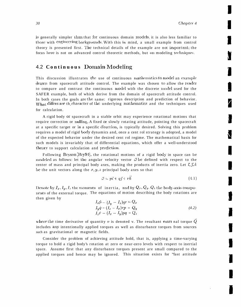
30 chapter 4
is generally simpler thau that for continuous domain models, it is also less familiar tothose with e~lgilleeritlg t)ackgro~l~lcls. WTith this in mind, a small example from controltheory is presented first. The technical details of the example are not inlpoxtant; thefocus here is not on advanced control theoretic methods, but c)n modeling tecl~niqum.
4.2 Continuous l)omain h~odeling
This discussion illustrates the use of continuous rnathema~ics to n~ode] an exam~)ledrawn from spacecraft attitude control. The example was chosen to allow the readerto compare and contrast the continuous nlodcl with the discrete model used for theSAFER example, both of which derive from the domain of spacecraft attitude control.In both cases the goals are the same: rigorous description and prediction of behavior.~~~hat differs are the ~haractf~r of t~lc underlying nlathelnatics and the techniques used
for calculation.
A rigid body or spacecraft in a stable orbit may experience rotational motions thatrequire correction or nulling. A fixed or slowly rotating attitude, pointing the spacecraftat a specific target or in a specific directiou, is typically desired. Solving this problemrequires a model of rigid body dynamics and, once a cent rol strategy is adopted, a modelof the expected behavior under the desired cent rol regime. The mathematical basis forsuch models is invariably that of differential equations, which offer a well-understoodtheory to support calculation and ~)rediction.
Following 13ryson [Rry94], the rotational motions of a rigid body in space can benlodclcd as follows: let tlle angular velocity vector d be defined with respect to thecenter of mass and principal body axes, making the products of inertia zero. Let 7, ~ kbe the unit vectors along the z:, y, z principal body axes so that
I)enote by ~r, IY, 12 the monmnts of inertia, and by Q~, Qu, Q. the ~ody-a~is COl~IPO-mmts of the external torque. The equations of motion describing the body rotations arethen given by
lr~ -..’(IY -- 12)qr = Q*
IYg - (12 – lr)71~ = Qy (4.2)Iz; -- (lr -- Iv)pg = Q,
where the time derivative of quantity v is denoted v. The resultant extel nal torque @includes any intentionally applied torques as well as disturbance torques from sourcessuch as gravitational or magnetic fields.
Consider the problem of achieving attitude hold, that is, applying a time-varyingtorque to hold a rigid body’s rotation at zero or near-zero levels with respect to inertialspace. Assume first that any disturbance torques present are small compared to theapplied torques and hence may be ignored. This situation exists for “fast attitude
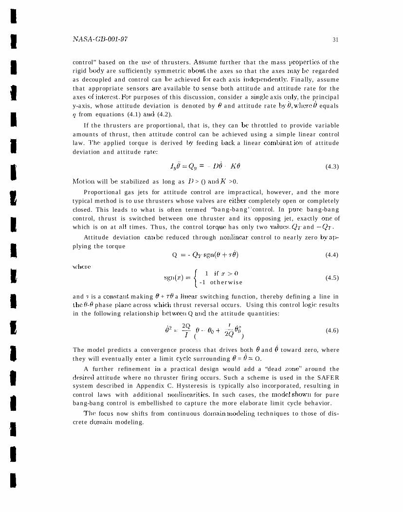
hJASA-GB-001-97
control” based on the usc of thrusters. Assumerigid body are sufficiently symmetric about, the
31
further that the mass ~Jropertics of theaxes so that the axes Inay be regarded
as decoupled and control can bc achieved for each axis i~ldcpendently. Finally, assumethat appropriate sensors are available tc) sense both attitude and attitude rate for theaxes of intemt. FoI’ purposes of this discussion, consider a single axis o~dy, the principaly-axis, whose attitude deviation is denoted by O and attitude rate by 0, where ~ equalsq from equations (4.1) and (4.2).
If the thrusters are proportional, that is, they can be throttled to provide variableamounts of thrust, then attitude control can be achieved using a simple linear controllaw. The applied torque is derived by feeding back a linear combinat ic~n of attitudedeviation and attitude ratf!:
Ivti = Qy = --D8 - K(I (4.3)
hJotion will be stabilized as long as D > () a~ld K >0.
Proportional gas jets for attitude control are impractical, however, and the moretypical method is to use thrusters whose valves are either completely open or completelyclosed. This leads to what is often termed “bang-bang’ ) control. In pure bang-bangcontrol, thrust is switched between one thruster and its opposing jet, exactly one ofwhich is on at all times. Thus, the control torque has only two values. Q1 and –Q7.
Attitude deviation can be reduced through rlolilincar control to nearly zero by applying the torque
Q = - Q~ Sg11(6 +- @ (4.4)
where
{
1 ifz->0Sgn(z) ==
-1 otherwise(4.5)
and I- is a const,ant making O + TO a linear switching function, thereby defining a line inthe 0-0 phase ~dane across m’hicll thrust reversal occurs. Using this control logic resultsin the following relationship bctwcxm Q and the attitude quantities:
2Q
(
I .2(%3- e--eo+ moo
)(4.6)
The model predicts a convergence process that drives both O and ~ toward zero, wherethey will eventually enter a limit cycle surrounding O = ~ = O.
A further refinement in a practical design would add a “dead zone’) around thedesirccl attitude where no thruster firing occurs. Such a scheme is used in the SAFERsystem described in Appendix C. Hysteresis is typically also incorporated, resulting incontrol laws with additional nonlinearities. In such cases, the modcd shown for purebang-bang control is embellished to capture the more elaborate limit cycle behavior.
The focus now shifts from continuous clomain Inodeling techniques to those of dis-crete CIO1llain modeling.

32 Chapter 4
4.3 Discrete Domain Nlode]ing
~’llis discussion of discrete domain models is intended to be representative rather t hallexhaustive. To that, end. the discussion is framed in terms of fc)ur broad classes of dis-crete domain models: functional, at)stract state Inachincj automata-based, and objcct-oriented. Of course, there arc variants and shadings both within and between theseclasses, so that the four categories represent a descril~t ively useful. but so]uewhat art i-ficial classification.
As the application of techniques from logic alld discrete mathematics to proble~us ofinterest in computer (hardware and software) systems, formal methods inherently con-cern computation. El-y the same token, one of the ways ill which formal methods usuallydiffer from traditional uses of logic and discrete mathematics is that, they incorporate amodel of computat ion. The model of computation may be built in, that is, implicit, as itis ill Hoare logic [Hoa69] and its variants, such as VDh!l [Jon90] and Z [Spi88, Wor92]-meaning that, there is a built-in notion of program State, and a set of constructs forcomposing operations that affect the state. Or it may be constructed on top of an“ordinary>’ logic as Hoarc logic may bc defined within nigher-order logic [Gor89]. Theadvantage of the built-in approacl~ is obvious when the built-in model is appropriateto the task at hand. The advantage of the “constructed” approach is that it is possi-ble to tailor the model to suit the circumstances of a given application. For example,adding concurrency to a sequential Hoare logic is not cas}’– it generally cannot be donewithin the logic, but, requires metalogical adjustments- whereas various models of par-allel computation can be encoded in higher-order logic.
One of the key decisions in developing models for formal methods applications is therelevance, if any, of the underlying model of computation, that is, the extent to w}lichthe u!lderlying computational paradigm should be explicitly modeled. It is useful tokeep this i]] nlillcl during the discussion of discrete-domain models.
4 . 3 . 1 F u n c t i o n a l Modelss
A functional model is OI(C that employs the mathematical notion of fullction in a pureform, oftm in conjunction with an implicit and very simple computational model. Asurprisingly wide variety of algorithms can be adequately described as recursive func-tions, assuming the most clenwntary model of computation, namely, the operation offunction composition. For example, one of the crucial insights in the specification andanalysis of the Byzantine Agreement protocols [Rus92] was the observation that a sinl-ple funct ional model of computation is sufficient, that is, it is not necessary to explicitlymodel the (inherently complex) distributed computational environments in which these
—.—————5Models for synchronous hardware circuits arc used to illustrate many of the ideas in this section.
Alt houg,h these hardware models suggest lower-level, more architectural issues than those discussedelsewhere in this guidebook, the simple hardware models provide more concise, transparent examples ofthe modeling techniques in question than are typically a~ailabk with requiren~ents-level specifications
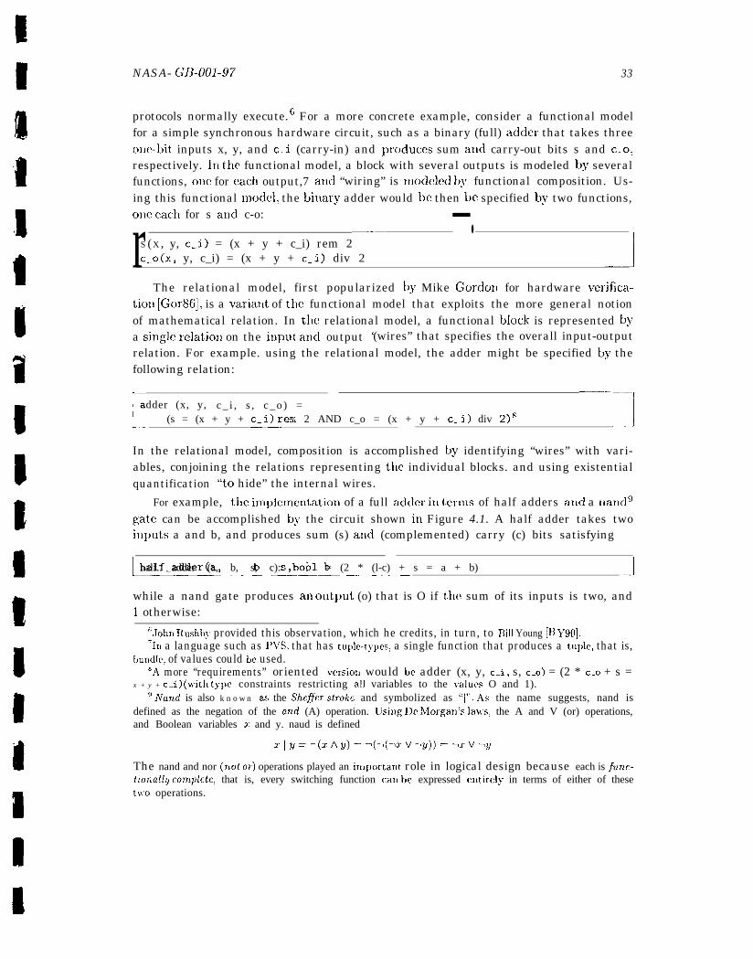
NASA- GB-001-97 33
protocols normally execute. 6 For a more concrete example, consider a functional modelfor a simple synchronous hardware circuit, such as a binary (full) adder that takes threeone-bit inputs x, y, and c.i (carry-in) and ~moduces sum and carry-out bits s and c-o,respectively. In the functional model, a block with several outputs is modeled by severalfunctions, one for each output,7 and “wiring” is lnodeled by functional composition. Us-ing this functional modc!l, the binary adder would bc then be specified by two functions,one each for s atld c-o:
r —.-— —.S (X , y, c.i) = (x + y + c_i) rem 2c_o(x, y, c_i) = (x + y + c_i) div 2 .1
The relational model, first popularized by Mike Cordon for hardware verifica-tion [Gor86], is a varialt of the functional model that exploits the more general notionof mathematical relation. In tlw relational model, a functional block is represented @a single relatio]l on the input, ancl output ‘(wires” that specifies the overall input-outputrelation. For example. using the relational model, the adder might be specified by thefollowing relation:
[
———. — ——adder (x, y, c _ i , s , c _ o ) =
(s = (x + y + c_i) rem 2 AND c_o = (x + y + c.i) div 2)s—— .---1
In the relational model, composition is accomplished by identifying “wires” with vari-ables, conjoining the relations representing the individual blocks. and using existentialquantification “to hide” the internal wires.
For example, the i~l[~~lel~~exltatiol~ of a full adder ill {erms of half adders aIIcf a 11and9gate can be accomplished by the circuit shown in Figure 4.1. A half adder takes twoitl~)uts a and b, and produces sum (s) and (complemented) carry (c) bits satisfying
L-—- . . . ..p. ––-–half. adder (a, b, s, c): bool = (2 * (l-c) + s = a + b) -1
while a nand gate produces an output (o) that is O if the sum of its inputs is two, and1 otherwise:
6John Rushby provided this observation, which he credits, in turn, to Bill Young [E) J’90].‘In a language such as PITS, that has tuple-t~pcs, a single function that produces a tuple, that is,
lmndle, of values could be used.6A more “requirements” oriented version would be adder (x, y, c.i, s, c_o) = (2 * c_o + s =
x + y + c_i) (witl~ type constraints restricting all variables to the values O and 1).g A’and is also known as the Shc~er stroke and symbolized as “1”. .4s the name suggests, nand is
defined as the negation of the and (A) operation. Using IJe J’lorgan’s la}vs, the A and V (or) operations,and Boolean variables T and y. naud is defined
The nand and nor (7Lot or) operations played an iInportant role in logical design because each is ~unc-tuma~ly cornpkk, that is, every switching function can k)f? expressed entirely in terms of either of theset~vo operations.
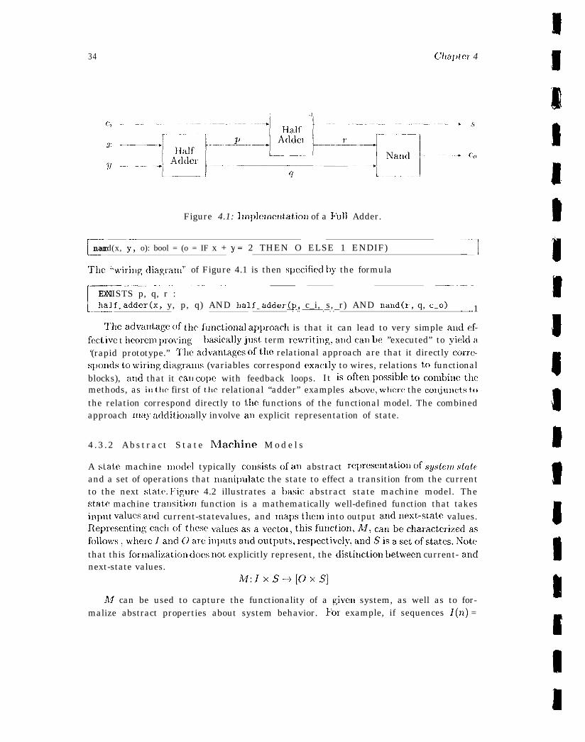
34 CXaptcx 4
~. .-. –– -1
Figure 4.1: lrtl~~ler~lcrltatio~l of a Full Adder.
Lnand(x, y: o): bool = (o = IF x + y = 2 THEN O ELSE 1 ENDIF) ‘--]
The ‘bwiril~gdiagranl” of Figure 4.1 is then spccificd by the formula
[-----
_—— ——-—. . .—. -——— . .. ———. ——.. -—-—EXISTS p, q, r :half_adder(x, y, p, q) AND half_adder(p, c_i, s, r) AND nand(r, q, c_o)—. -.. ————.—. .— . ..1
Tlleadvalltage of tllefl~tlctiollal approacl) is that it can lead to very simple andef-fect ivc t hcorem proving- basicallyjust term rewritil~g,allclcatl be ’’executed” to yielda‘(rapid prototype.” Theadvantages ofthe relational approach are that it directly corre-spondsto wirillgdiagranls (variables correspond exactly to wires, relations to functionalblocks), and that it cat) co~)e with feedback loops. It isoften possible tc)conlbillethcmethods, as it) the first of tllc relational “adder” examples above, where the conjuncts tothe relation correspond directly to the functions of the functional model. The combinedapproach may additiollall.v involve an explicit representation of state.
4 .3 .2 Abstract State hflachine M o d e l s
A state machine model typically consistsof an abstract represcntatio no fsystcm stateand a set of operations that Illanilmlate the state to effect a transition from the currentto the next state. I:igurc 4.2 illustrates a basic abstract state machine model. Thestate machine trallsitiorl function is a mathematically well-defined function that takesinput values and current-statevalues, and mapsthem into output andnext-state values.Representin gc!ac~lo ft~vX’va luesasavcctor, this futlction, A4, carlbecharacterizcdasfollows, wllercl atlclC)a rc:il~~)~ltsa lldout~>llts,r es~~ectively,a lldSisa setc)fstates. Notethat this fcmmalization does not explicitly represent, the distitlction between current- andnext-state values.
M:lxs-->[oxs]
AI can be used to capture the functionality of a givell system, as well as to for-malize abstract properties about system behavior. For example, if sequences I(n) =
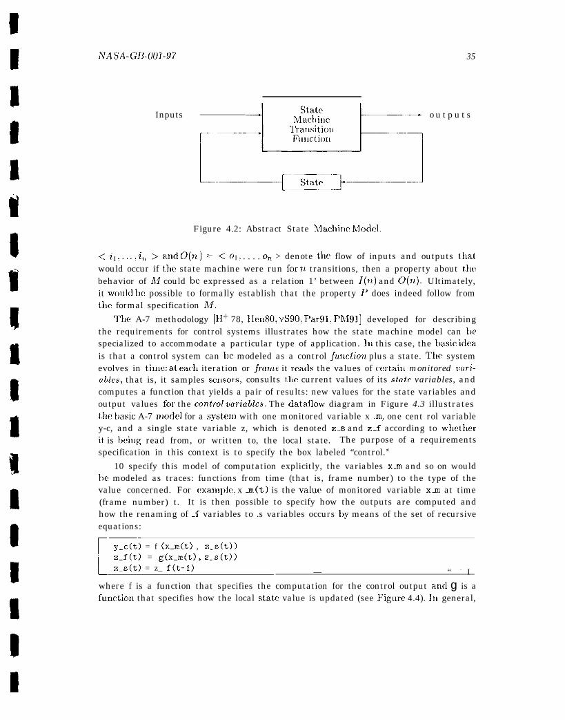
NASA-GD-UO1-97
Inputs
35
4 stateMachine 1-
— o u t p u t s
Figure 4.2: Abstract State h4achinc N40del.
< i] ,.. .,z7L>and O(n)= =<01, . . . . 07L > denote the flow of inputs and outputs that,would occur if the state machine were run for n transitions, then a property about thebehavior of M could be expressed as a relation 1’ between l(n) and 0(7t). Ultimately,it WOUICI be possible to formally establish that the property P does indeed follow fromtllc formal specification Af.
The A-7 methodology [H+ 78, IIen80, vS90, Par91, Ph491] developed for describingthe requirements for control systems illustrates how the state machine model can bespecialized to accommodate a particular type of application. In this case, the basic ideais that a control system can be modeled as a control function plus a state. The systemevolves in tinle: at each iteration or jranle it reads the values of ccrtaixl monitored vuri-ables, that is, it samples scmsors, consults tl~e current values of its state variables, andcomputes a function that yields a pair of results: new values for the state variables andoutput values fix the control variabks. The dataflow diagram in Figure 4.3 illustratesthe basic A-7 mode] for a system with one monitored variable x m, one cent rol variabley-c, and a single state variable z, which is denoted z-s and z_f according to ~rhetherit is being read from, or written to, the local state. The purpose of a requirementsspecification in this context is to specify the box labeled “control.’)
10 specify this model of computation explicitly, the variables x-m and so on wouldbe modeled as traces: functions from time (that is, frame number) to the type of thevalue concerned. For exanq)le, x m(t) is the value of monitored variable x-m at time(frame number) t. It is then possible to specify how the outputs are computed andhow the renaming of .f variables to .s variables occurs by means of the set of recursiveequations:
[
‘y_c(t) = f (x_m(t) , z_s(t))z.f(t) = g(x_m(t), z_s(t))z_s(t) = z_ f(t-1) — “ - I
where f is a function that specifies the computation for the control output aud g is afuuctic)n that specifies how the local state value is updated (see Figure 4.4). III general,
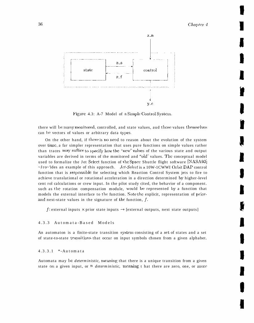
36 (Xaptct 4
Xml
. . . . . . . . . . . . . . . . . . . . . . . . . . . . . . . . . . . . . . . . . . . . . . . . . . . . . . . . . . . . . . . . . . . . . . . . . . . . .
. . . . . . . . . . . . . . . . . . . . . . . . . . . . . . . . . . . . . . . . . . . . . . . . . . . . . . . . . . . . . . . . . . . . . . . . . . .
y.c
Figure 4.3: A-7 Model of a Silnple C;ontrol System.
there will be many nlonitored, controlled, and state values, aud those values thenlselvescan bc vectors of values or arbitrary data ty~)es.
On the other hand, if there is noneed to reason about the evolution of the systemover time: a far simpler representation that uses pure functions on simple values ratherthan traces lllaysLlfice tos~)ecifyl~our the “new” values of the various state and outputvariables are derived in terms of the monitored and “old” values. The conceptual modelused to formalize the Jet Select function of the Space Shuttle flight software [NASA93]~Jro~’ides an example of this approach. Jet-Select is a 10W-1CWWI Orbit DAI’ controlfunction that is responsitic for selecting which Reaction Control System jets to fire toachieve translational or rotational acceleration in a direction determined by higher-levelcent rol calculations or crew input. In the pilot study cited, the behavior of a component.such as t,hc rotation compensation module, would be represented by a function thatmodels the external interface to the function. hTote the explicit, representation of prior-a~ld next-state values in the signature of the function, ~.
~: external inputs x prior state inputs --> [external outputs, next state outputs]
4 . 3 . 3 A u t o m a t a - B a s e d M o d e l s
An automaton is a finite-state transition system consisting of a set of states and a setof state-to-state transitiolls that occur on input symbols chosen from a given alphabet.
4 .3 .3 .1 * -Automata
Automata may be deterministic, nleaning that there is a unique transition from a givenstate on a given input, or non deterministic, me,aning t hat there are zero, one, or more
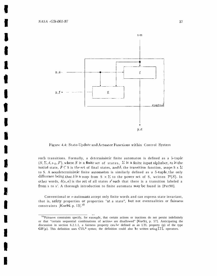
NASA -GB-001-97
x-m
I
z-s–
Z.f”
IL_____... _J . . . ..J
*.A
37
Figure 4.4: State-UIJdate and Actuatc)r FLltlctio!lsv~it~li~l Control System
SUC1) transitions. Formally, a detcmninistic finite automaton is defined as a 5-tu~Jlc(S, X,6, S0,F), where Sisa finite set of states, Xisa finiteinput alpha~ctj so is thei~litial state, F Q S is the set of final states, and 6, the tratlsition function, maps S x Xto S. A nondeterministic finite autonlaton is similarly defined as a 5-tuple, the onlydifference lleing that 6 is a map from S XX to the powcrsct of S, written P(S). Inother words, 6(s, a) is the set of all states St such that there is a transition labeled afrom s to s’. A thorough introduction to finite automata may be found in [Per90].
Conventional or *-autonlata accept only finite words and can express state invariant,that is, safet<y properties or properties “at a state”, but not eventualities or fairnessconstraints [Kur94, p. 13].10
——1°Fairness constraints specify, for exaruple, that certain actions or inactions do not persist indefinitely
or that “certain sequential combinations of actious are disallowed” [Kur94, p. 57]. Anticipating thediscussion in section 6.2.1.1, a fairness property can be defined as an LTL property (p) of the typeGF(p). This definition uses CTL* syntax; the definition could also be written Usi[lg I,TL operators.
q’o accommodate eventualities, it is necessary to use a class of automata that acceptsinfinite words (sequences), the so-called w-automata. Like a conventional automaton,au w-automaton consists of a set of states, au i~lput alphabetj a transitio~l relation, a~lda dis~inguished initial state. ‘1’he difference between the two classes of automata occursin t]le definition of acceptance. Acce~Jtance for a conventional automaton is defined interms of a final state. Since the notion of final state is not useful for a class of machinesthat accepts infinite words, acceptance must be defined in some othcx way. lrariousaccept auce conditions have been given for w-aut onlat a [CBK90, p. 104], two of whichare given below. ‘1’he definitions that, follow are based on a discussion in [CBK90].A (uondetermiuistic) w-automatoll is a 5-tuplc (S, 2,6, so, Y_), where S, Z, and so areas defined above, .7 is an acceptance condition, and 6: S x Z ~ P(S) is a transitiollrelation. The automaton is deterministic if for every state s E S and every a c X,16(s, u) <11. A comprehensive survey of u-automata appears iu [’Tho90).
The following definitions, agaiu taken from [CBK90], arc necessary for defini-ng particular instances of %. A path in au w-automaton, M, is all infinite se-quence of states so s] S 2 . . . E S that begins ill so and has the following property:Vi ~ I,Sai ● X: J(si, ai) ~ Si+l. A path so SI S2. . . E sd in M is a run of au inf-inite word a1a2. . . E V“ i f V i z l:d(sz, az) 3 Sz+.l. The i~~finitury set of a sequenceSO S] S2 . . . 6 SJ, written 2n~(sosI . . .), is the set of all states that appear infinitelymany times in the sequence.
4XA Buchi automaton flf is au u-automaton where the acceptance condition, >, is
defined as follows. F C S is a set of states (as in the case of a *-automaton) and a pathp is accepted by M if i?tf(p) n F # O. T’he acceptance condition of a Mul]er automatonis a set F Q P(S) of sets of states. A path is accepted by a Muller automaton ifi?~j(p) E 1’. other w-automata that, appear in tllc literature are Rabin, Strectt, I,, andV– automaton. Although acceptance conditions for these automata are not defined here,it is worth noting that “an infinite word is accepted by a Buchi, Muller, Rabin, Streett,or I, automatol] if it has an acceptiug run in the automaton. AI] infinite word is acceptedby a V-automaton if all its possible runs in the automaton are accepted.” [CBK90, p. 106]
4.3.3.3 T i m e d A u t o m a t a
Timed automata arc a generalization of w-automata and are used to model real-timesystems over time. Like w-automata, timed automata generate (accept) infinite se-quences of states. However, timed automata must, also satisfy timing requirements and
38
4.3.3.2 w - A u t o m a t a

NAsA.G~@)l-97 39
~)roduce (accept) timed state sequences. ‘1’imecl automata nlay be given various se-nlantic inter~)retations, illcllldillg~~oil~t-based strictly -nlonotonic real-tinw (the originalinterpretation), ilkcrval-based variants, interleaving fictitious clock, alldfor sylichronic-ity [AH91]. An excellent discussionof thcthcor.y of timed automata and its applicationto automatic verificatioll ofrcal-til[~er eq~lirclllclltso ffi~~ite-state systen~s nlay be foundill [AL)91].
4.3.3.4 H y b r i d A u t o m a t a
Hybrid automata extelld finite autonlata with continuous activities and are used ton~odel systen~s that incorporate both continuous and digital conlponents. Hybrid au-tomata may be viewed as “a generalization of tinmd automata in which the behavior ofvariables is governed in each state by a set of differential equations.’; [A~HH93] Thereare various classes of hybrid autonlata, i[lcludin,g linear hybrid autonlata and hybridin~)utjoutput auton~ata. l,inear hybrid automata require the rate of change with timeto be constant for all variables (although the constant nlay vary from location to loca-tion) and the ternls used in invariants, guards, and assignments to bc linear. 11 Alur etal. [A~HH93] provides a good introduction to hybr-id autonlata and [AH95] describesa synlbolic n~odel checker for linear IIybrid systm~ls. Hybrid input/output autolnata(HIOA) focus on the exterllal interface of a nmdeled hybrid syste~rl through distinctionsin the state variables - which are partitioned into input, output, slid internal variables
and the transitiol[ labels - which are similarly ~)art it ioned into input. output,. andinternal actions. Lynch [LS\~W96] gives a useful introduction to H1OAS and [AHS96]contains several papers, jncludillg [l,y~lg~], describing tllc usc of H1OAS to l~lodel and
analyze automated transit systen~s.
4.3 .4 O b j e c t - O r i e n t e d M o d e l s
Object-oriented models represent systems as structured collections of classes and ob-jects with explicit notions of encapsulation, inherit ante, and relations bet wee]) ob-jects. Several informal object-oriented analysis and design methodologies are cur-rently popular, including Booth [Bo09 1], Coad and Yourdon [CY91 a, CY91 b], Rum-baugh [RBP+ 91, RB91], Shlaer and Mellor [SM91], Goldberg [Sys92, RG92] and mostrecently, Unified Modeling Language (UML) [Rat97]. These methodologies offer a usefuland easily assimilated approach for structuring an application based Oli multiple dia-grammatic vie~w of the underlying system. UML, which represents a unification of the1300ch, R.umbaugh, and Jacobson methods, employs static structure, use case, sequence,
1‘ A tin~ed autoxnaton is a special case of linear hybrid autonlaton iu which each continuously chang-ing variable is all accurate clock Ivhose rate of change with tinle is 1. In a timed automaton, allterlfLs involved in assignnwnts arc constants and all invariant and guards compare clock values ~vithconstants [.ACHI193].
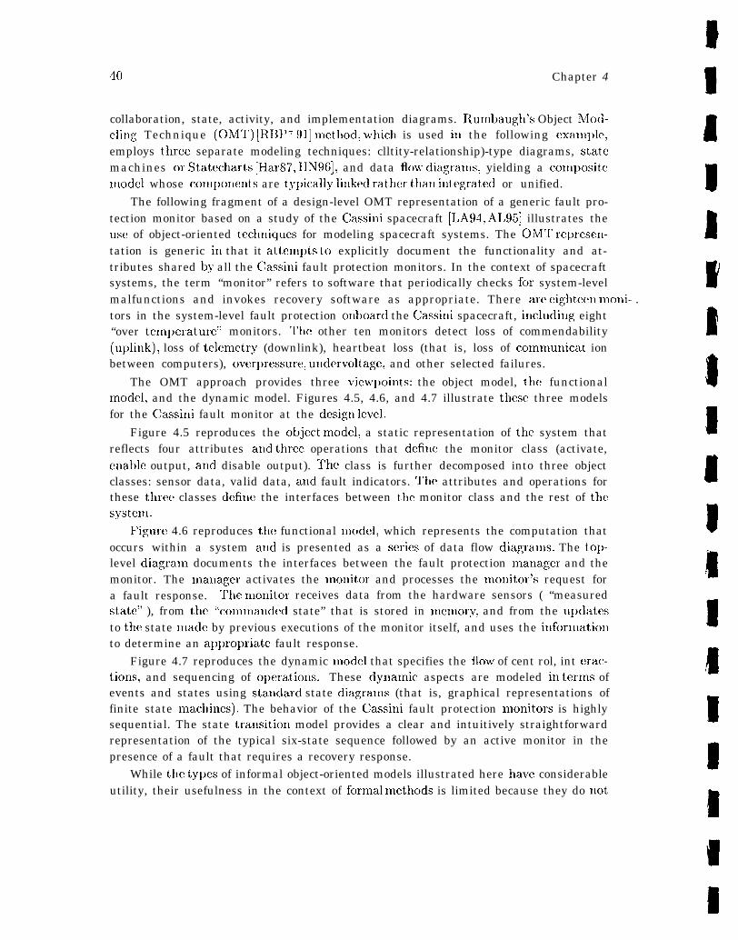
40 Chapter 4
collaboration, state, activity, and implementation diagrams. Rumbaugh’s Object h!lod-c]ing Technique (OM’T) [RBI)7 91] nlethod, which is used ill the following exatnple,employs three separate modeling techniques: clltity-relationship)-type diagrams, statemachines or Statecharts [Har87, HiY96], and data flo~v diagranls, yielding a colnpositemodel whose conl~)onents are typically linked rat,her than itltegrated or unified.
The following fragment of a design-level OMT representation of a generic fault pro-tection monitor based on a study of the Cassini spacecraft [LA94, AL95] illustrates theuse of object-oriented teclmiques for modeling spacecraft systems. The OMT represemtation is generic ill that it attempts to explicitly document the functionality and at-tributes shared by all the Cassini fault protection monitors. In the context of spacecraftsystems, the term “monitor” refers to software that periodically checks for system-levelmalfunctions and invokes recovery software as appropriate. There are eighteml moni- .tors in the system-level fault protection onboard the Cassini spacecraft, includitlg eight“over tmnl)erature” monitors. ‘Me other ten monitors detect loss of commendability(uplink), loss of telenletry (downlink), heartbeat loss (that is, loss of ccunmunicat ionbetween computers), overpressure, undervoltagc, and other selected failures.
The OMT approach provides three view~)oints: the object model, the functionalmodel, and the dynamic model. Figures 4.5, 4.6, and 4.7 illustrate these three modelsfor the Cassini fault monitor at the desig[~ level.
Figure 4.5 reproduces the object model, a static representation of the system thatreflects four attributes and three operations that defillc the monitor class (activate,enable output, and disable output). The class is further decomposed into three objectclasses: sensor data, valid data, and fault indicators. The attributes and operations forthese three classes define the interfaces between the monitor class and the rest of thesystenl.
Figure 4.6 reproduces the functional nlodcl, which represents the computation thatoccurs within a system and is presented as a series of data flow diagran~s. The top-level diagran~ documents the interfaces between the fault protection nlanagcr and themonitor. The mallager activates the nlonitor and processes the monitor’s request fora fault response. Tile n~onitor receives data from the hardware sensors ( “measuredstate” ), from the “comnanded state” that is stored in nlemory, and from the u~)datesto the state made by previous executions of the monitor itself, and uses the infornlationto determine an appropriate fault response.
Figure 4.7 reproduces the dynamic model that specifies the flow of cent rol, int erac-tions, and sequencing of o~)erations. These dynanlic aspects are modeled in tern~s ofevents and states using standard state diagralns (that is, graphical representations offinite state nlachines). The behavior of the Cassini fault protection nlonitors is highlysequential. The state tralLsition model provides a clear and intuitively straightforwardrepresentation of the typical six-state sequence followed by an active monitor in thepresence of a fault that requires a recovery response.
While tile ty~)es of informal object-oriented models illustrated here have considerableutility, their usefulness in the context of fornlal methods is limited because they do not
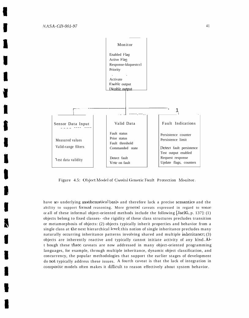
Monitor
Enabled FlagActive FlagResponse-kkquestcclPriority
. .ActivateEinablc outputIwdkoll@t
~—————.t ‘—‘ 1
Sensor Data Input—--- - - - - - - - -
Measured values
Valid-range filters
1 est data validity
__A -—-.—..
Valid Data
Fault statusPrior statusFault thresholdCommanded state
Detect faultVote on fault
41
-l–----–_—
Fault Indications
Persistence counterPersistence limit
Detect fault persistenceTest output enabledRequest responseUpdate flags, counters
Figure 4.5: Object h40clel of Cassini Gemric Fault, Protection N4cmitor.
have all underlying nlathematical basis and therefore lack a precise sen~antics and theabi l i ty to suppor t fornial reasoning. More .gj.meral caveats expressed in regard to sonic
or all of these informal object-oriented methods include the following [Jac95, p. 137]: (1)objects belong to fixed classes- -the rigidity of these class structures precludes transitionor metamorphosis of objects: (2) objects typically inherit properties and behavior from asingle class at tile next hierarchical level; this notion of single inheritance precludes manynaturally occurring inheritance patterns involving shared and multiple ild~eritance; (3)objects are inherently reactive and typically cannot initiate activity of any kincl. Al-t bough these three caveats are now addressed in many object-oriented programminglanguages, for example, through multiple inheritance, dynamic object classification, andconcurrency, the popular methodologies that support the earlier stages of developmentdo not, typically address these issues. A fourth caveat is that the lack of integration inconllJosite models often makes it difhcult to reason effectively about system behavior.
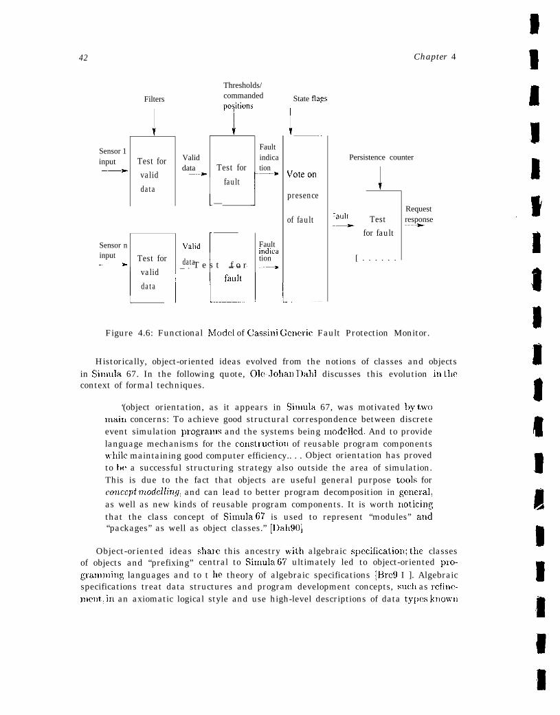
42
Sensor 1input—~
Sensor ninput—––-
Filters
1
Test for
valid
data
Test for
1 valid
data
Validdata
—-*
Thresholds/commandedpo;itions
ITest for
! fault
—
\lalid
data1 ‘“- ” -_ + T e s t f o r
Faultindication
Faultindication—*
I 1.-.::-.1
State flags
I __\rot~ on
presence
of fault
1-----—
Chapter 4
Persistence counter
I‘atrlt
[ . . . . . .
Test-~for fault
Requestresponse—+
Figure 4.6: Functional Model of Cassini Generic Fault Protection Monitor.
Historically, object-oriented ideas evolved from the notions of classes and objectsin Simula 67. In the following quote, Ole-Johall DaIll discusses this evolution in tilecontext of formal techniques.
‘(object orientation, as it appears in Simula 67, was motivated by twromai~l concerns: To achieve good structural correspondence between discreteevent simulation progratns and the systems being modelled. And to providelanguage mechanisms for the comtruction of reusable program componentswrhile maintaining good computer efficiency.. . . Object orientation has provedto be a successful structuring strategy also outside the area of simulation.This is due to the fact that objects are useful general purpose tc)ols forconcept modellirtg, and can lead to better program decomposition in ~;cneral,as well as new kinds of reusable program components. It is worth Iloticingthat the class concept of Sinmla 67 is used to represent “modules” atld“packages” as well as object classes.” [I)al190]
Object-oriented ideas share this ancestry with algebraic spccificatioll; tile classesof objects and “prefixing” central to Sitnula 67 ultimately led to object-oriented pro-graming languages and to t lle theory of algebraic specifications [Bre9 I ]. Algebraicspecifications treat data structures and program development concepts, suclL as refine-ment, in an axiomatic logical style and use high-level descriptions of data types known

ATA SA. G~_OOl .97
“---9
-k9---_ +----+
,,,,..*@$?,@z,ePasses
43
Figure 4.7: Dynamic Model of Cassini Generic Fault Protection h40nitor.
as abstmct data types. Abstract data types am manipulated by similarly high-leveloperations that are specified in terms of properties, thereby avoiding i[~l~~lell~elltatioll-dependent data rcpresentatiorls. As Abadi and Cardelli note in their book on the(formal) foundations of object-oriented programming languages [AC96, I). 8], “. . . dataabstraction alone is sometimes taken as the essence of object orientation. ” This his-torical connection is of interest because the frameworks of algebraic specification andof object-oriented programming languages nave each contributed to ongoing attemptsto providea mathematical basis for the concepts underlying object-oriented models.1~This research has taken many dircxticms, iucludillg those summarized below. In keepingwith tllc focus of this guidebook, tile examIJcs iucludcd itl this discussioll suggest tile~,ariety of t~le ~~ork in t~~is area, but arc @ I1O means exhaustive.
One approach is to take a mc)del generated by one of the informal object-orimltedmethodologies and formalize it using a novel or existing formal description technique.For example, Moreira and Clark [MC94] describe a technique for producing a formalobject-oriented analysis model that integrates the static, dynamic, and functional prop-erties of an ot)ject-oriented model created using one of the informal object-orientedmethodologies. 13 The formal model uses LOTOS (Language of Temporal OrderingSpecification) [1 S088], which has a precise mathematical semantics and represents the
14 An object is represented assystem as a set of coxnrnunicating COIICUtTC!Ilt objects.the instantiation of a LOTOS process, and communication among objects takes the——— .
12 SW) for example, recent proceedings fron) conferences such as ECOOP (Eurc~pean Conference onObject-Oriented Programming [TP94, 01t95] ) and 00PSLA (Object-Oriented Programming Systems,Languages, and Applications) [ACM94].
‘3 [hlC94] actually describe a Rigorous Object-Oriented Analysis (ROO.A) method that combinesobject-oriented analysis and formal description techniques. This discussion focuses only on their mod-eli ng approach.
14That is a set of colll~)U1liCatjng processes. T}IC a~proach is based on I)rocess algebra, dra~~ing on>.elements from CXS [Mi189] and from (HSP [Hoa85].

44 Cha~>ter 4
forln of message passin~, which is modeled by ot)jccts syllc}lronizing 011 an event duringwhich information may be exchanged. In this a~)proach, the dynamic aspects of a classtemlJlate ate modeled as a 1,()’1’0S I)rocess am] tl~c static I)roperties as abstract datatypes
Another approach is to take nc)tatioll fronl one of the informal methodologies andformalize it, thereby lmovidillg a formal semaut ics for tllc informal notation. For ex-ample, I{ayes and Coleman [HC91] use 0bjcxtcharts15 [CHB92] and a derivative of~~Dhfl [Jou90] to provide a coherent set of formal models corres~)onditlg to the mod-els generated by a subset of Oh!IT. Briefly, Hayes aud Coleman introduce an objectstmctum model, linking the formal representations of the informal OMT models (ot)-ject, dynamic and functional) to provide traceability and consistency checking. llleinfornial OM’T functional model is replaced by VDM-styIc pre-post condition specifica-tions over the object structure model, the informal dynamic model is formalized usingObjcctcharts, and the object model uses the formalized entity-relationship notat ion de-scribed ill [FNT86]. q’here has also ken work integrating formal and object-orientcclmethods using VDh4-t + and OMT [I, G96]. VDM+ + is an obj[!ct-oriented extension ofVDM designed to support parallel aud real-tinlc specification.
O~lgoing work at the hlichigau State Ullivcrsity Software 13ngiueeriug ResearchGroup [BC94, Cl WBf14] is yet another variant on this a~)proach. Their prototype systemuses algebraic specifications to fornlalizc a subset of the OMT object-nlodeling nota-tion ap~mo~)riate for nlodeling requirements. Again, tllc fornlalization is based 011 tllcstraightforward mapping between object-oriented software concepts and abstract datatypes.1~
The COIW n~ethod [FFIWK92] for spccifyilLg real-time rcquirenlents provides a fur-ther example of the coherent integration of object-orieuted and fornlal rnodcls. COREis au an~alganl of the CAS12 Real-Tiuw hlcthc)ci (which is itself an an~algam of Rcal-Tin~e Structured Analysis [WM85] and object-oriented concepts) and the four-variat)lcxuodel [vS90, vSPM 93] developed by F’arnas and his colleagues. CORE interprets thethree basic structural elel~lents of the CASII Real-Tinle method: infornlation, process,and l)chavior pattern, in terlns of object-oriented concepts. Processes correspond toobject classes aud interprocess connections to interactions between objects. The statemachines used to encode the behavior-patterll view are partitioned to correspond to thestates of all object class. ‘The fornlal model underlying object definition and deconlpo-sitiou is based on the standard nlathcnnatical mode] of embedded-systen~ behavior usedby the four-variable nlcthod. 1’lIc resulting anlalgaul retains the graphical notationand not ions of abstraction, encapsulation, separat ion of col]cerns, and nonalgorithulic
15 AU Objectchart is an extended forn~ of Statechart [Har87, HN9G] used to specify object classes.16 The graphical environment prototype generates Larch specifications [CW’B94]. .41though current
vcrsiol,s of Larch are not inherently algebraic, the illl~)leItlclltatioll cited supports only algebraic lan-guages although it is general euough to accon~nlodate most algebraic languages that have a well-definedgramtnar. It appears that ‘object model” has replaced the previously used phrase uf,rdysis ob~ectsche71uhr (a-sche7nata) in receILt publications [BC95b].
s~)ccification associated with object-oricrltcxl a~)proaches, within a nlatl)enlatical]y well-defincd model contributed by the four-variable nlctllod.
There have also bcc]l formalization in Z c)f the three OhlT notations [Spi88, Wor92],as well as object-oriented extensions to Z. The collection of papers in [S13C92] containsaccounts of both approaches, including a summary of Hall’s object-oriented Z specifica-tion style, whic]l is also ctescribcd in Hall [11a190].
4.4 A Model for the SAFER. Avionics Controller
The SAFER avionics cent roller described in Section 2.6 exhibits several characteristicsthat, strol@y influence the choice of a model for its formalization. The basic function-ality of the cent rollm requires a represent at ion that captures the mapping from inputand scwsor values to outputs. The model must, also be able to capture the dependencyof current everks on prior events, necessitating the use of a state- or trace-based model,or other re~mesentatioll lvith similar facility for preserving values from one “cycle” toanother. The fact that tllc coutrollcr maintaitls and updates its own interns] status,including Hand Colltrollcr h40dule (IICM) display and Automatic Attitude Hold (AAH)status, provides additional nlotivatioll for an explicit representation of state. In fact,tllc SAFER avionics controller provides a nice illustration of a system that can be quitenaturally modeled as a state machine (see Section 4.3.2), that is, as a model consistingof a system state and a transition function that maps inputs and current-state val-ues into out~)uts a~~d next-state values. Arguably, a variant of the basic state machineInodcl, suc}l as t lw A-7 [11+ 78,11 e~180, vS90, Par91 ,PM91]. which is specialized for controlsystems, would provide a representation that differentiates inputs, outputs, and statevalues by cx~)licitly idcntif.ying monitored, control, and state variables (see Figure 4.3).Although t llc diflcrellces between these two models are small, the choice bctweell abasic state machine model and a s~)ecialized state machine mode] illustrates the ty~wof trade-off that typically enters into modeling decisions. In this cas[!, the trade-off istile relative sin]l)licity of tile basic state machine model versus the additional expres-siveness of the s[)ecializcd A-7 model, where finer-grained distinctions alnong variablespotent ially ~)rc)vide a clearer mapping between informal description, requirements, andthe formal sl)ecificat ion. on the other hand, the level of description and the (primarily)pedagogical role oft he SAFER example motivate the use of the si@er model presentedhere. Nevertheless. tllc rc!ader is encouraged to consider the similarities between the ba-sic stat[! n~acllillc model developed here and A-7-type models, in particular the notionof tile state trazlsit ion fu]lct ion defined as a control function with monitored (that, is,sensor) and stat e variat )lCS as input and cent rol and state variables as output.
A final consideration concerns the representation of time. Since the basic fu~lction-ality of the ccmtrollm can be captured within a single frame or cycle, there is no needto reason about the bcllavior or evolution of the system over time or to introduce theadditional com~)lexity required for an explicit representation of time. The trade-off here

46 Chapter 4
is the simplicity of the model versus a loss of analytical I)ower. Without an cxlJlicitrepresentation of time, there is no way to explore certain types of propmties, includingsafety and liveness properties that establish (roughly) that nothing bad ever ha~)~)ensand something good eventually happens, respectively. For example, without an exl)licitrepresentation of time; it would be in~l)ossiblc to denlonstrate that an HChf translatic)ll(rotation) comnland eventually results in thruster selection. ‘7 Although the nlodelspresented in this chapter do not incor~)orate a notion of time, a tinw 01 trace-basedmodel could be added, as needed, on top of the state-based n~odel presented hem.
Having identified the underlying mode] as a basic state machine, the next step isto define the control (transition) function. The transition function for the top-levelcontroller model is comprised of functions re~mesenting its constituent nlodulcs andassenlblies. Of interest here are the AAH and thruster selection functions. Thrusterselection maps HCM and AAI1 commands iljto a~] integratedcommand that, determines the corresponding (thruster) actuatorphase functionality can be modeled simjlly as the colnI)ositiollrougl]ly
sclec:tcd..ac:t tluiors o i?~tc:g?atcd-c:oT?t?rluTld
six degrcw-of-freedoniConmands. T1lis tWTo.of the two flmctiolls,
The AAH model cannot be so simply discharged, because the automatic attitudelloldcal)abilit~' l[~ail~taitls il~terl~als tateil~forll~ati ol~toit~~l~lcltlcrltt lleA All control lawand tc~ track whether the AAII is engaged or disengaged and which, if any, of the threerotational axes arc under AAH control. AAH control law is implemented in terms of acomplex feedback loop that monitors inertial reference unit (IRU) angular rate sensorsand temperature sensors (one for each of the three rate sensors), and generates rotationcomn~ands. Although this account is necessarily simplified, it suggests a fairly complexcontrol system with clearly differentiated variable types and a well-defined internal state.The rationale for considering an A-7-type interpretation of a basic state machine modelfor the top-level avionics controller applies equally to the A AH. The A AH state machinemodel is slIown in Figure 4.8.
A closer look at the AAH button transition function further illustrates the typec)f issues that invariably arise in developing models for formal specification. The statetransition diagranl for this function show’n in Figure 4.9 represents the single-click,double-click engagement protocol described in Section 2.6, where nodes represent AA1lstates and arcs represent the two button positions (up or down) and the twc) operativeconstraints (timeout or all three rotational axes removed from A AH control). 18
For example, if the AAH is engaged and the AAH pushbutton switch is depressed,the A AH enters a state (“pressed once’]) that is exited only u’hell the ~)ushbut toll is
——. — ——17\Vhether the thruster selection is correct ~rith res~wct to the thruster select logic is an important
property, but not a liveness issue.‘S1’he diagram actually represents a con~bination of pushbutton and implied events. For example,
although the 3-axes-off transition reflects one or more previous HChI comnlands, it does not representan explicit pushbutton event, such as AAH enatk/disable.
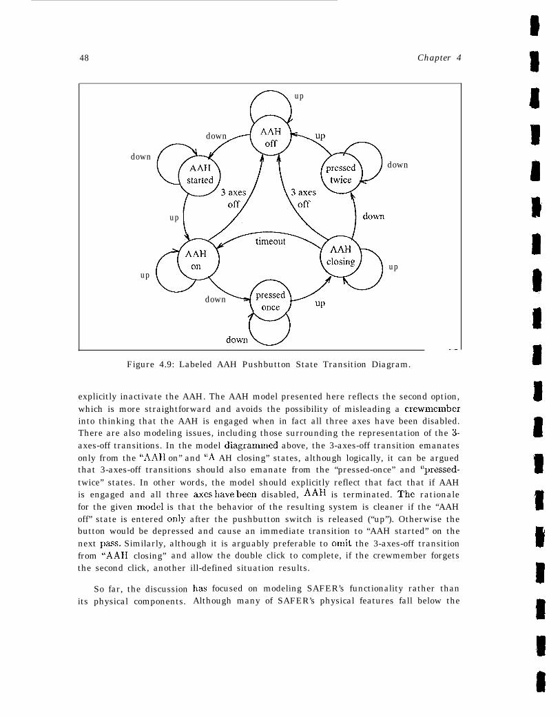
48 Chapter 4
down
up
(9 up
down
up
down
down
up
—
Figure 4.9: Labeled AAH Pushbutton State Transition Diagram.
explicitly inactivate the AAH. The AAH model presented here reflects the second option,which is more straightforward and avoids the possibility of misleading a crewmemberinto thinking that the AAH is engaged when in fact all three axes have been disabled.There are also modeling issues, including those surrounding the representation of the 3-axes-off transitions. In the model diagrarnmed above, the 3-axes-off transition emanatesonly from the “AAII on” and “A AH closing” states, although logically, it can be arguedthat 3-axes-off transitions should also emanate from the “pressed-once” and “pressed-twice” states. In other words, the model should explicitly reflect that fact that if AAHis engaged and all three axes have besn disabled, AAH is terminated. ‘rhe rationalefor the given model is that the behavior of the resulting system is cleaner if the “AAHoff” state is entered only after the pushbutton switch is released (“up”). Otherwise thebutton would be depressed and cause an immediate transition to “AAH started” on thenext pass. Similarly, although it is arguably preferable to omit the 3-axes-off transitionfrom ‘LAAH closing” and allow the double click to complete, if the crewmember forgetsthe second click, another ill-defined situation results.
So far, the discussionits physical components.
l“laS focused on modeling SAFER’s functionality rather thanAlthough many of SAFER’s physical features fall below the
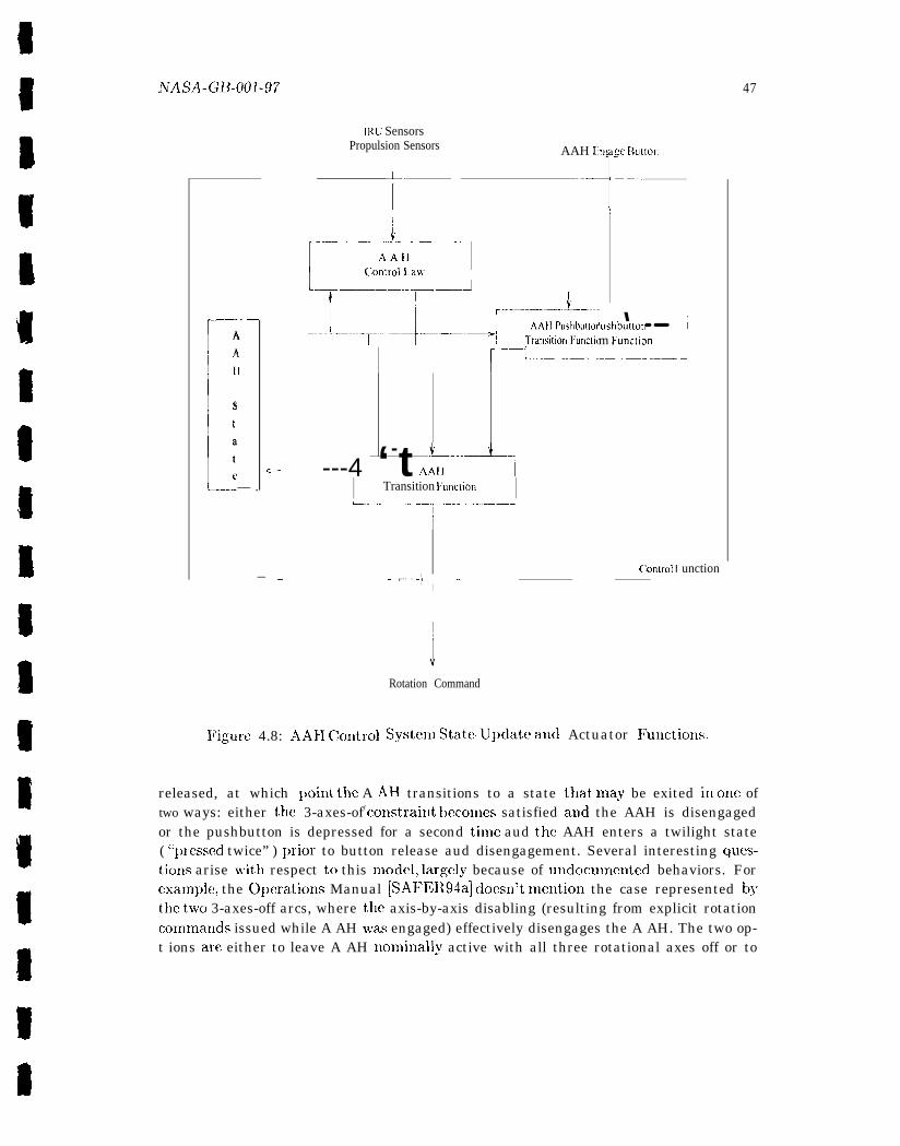
NAsA_G~_()()].97
IRU SensorsPropulsion Sensors AAH Lng :C Button
r
T“ “-T-
r–AA
L
11
state— .
—
c—
[_---~~j~al---l_..._.._-.-~-.--;j~L~.-.---->~--;j~L--”- ‘--”‘ushbutton
m Funclion
I 1 [ “-_——.J
---4 ‘-t *–--+AAII
I Transition Funclion I
—
Figure 4.8: AAII Ckmtml
—- ——=..—–—— –—.–~
i
(“onlrol F unction- ‘--- - -t-” -- ‘“I
J
Rotation Command
System State-update aud Actuator l?uuctioIls.
47
released, at which poiut the A AH transitions to a state that, may be exited in onc oftwo ways: either the 3-axes-off constraitlt becomes satisfied and the AAH is disengagedor the pushbutton is depressed for a second tiule aud the AAH enters a twilight state( “~)ressed twice” ) prior to button release aud disengagement. Several interesting ques-tiorls arise with respect to this model, largel.v because of uudocuuwnted behaviors. Forexamplej the Oymations Manual [SAF13R94a] cloesn’t mention the case represented hythe t~vo 3-axes-off arcs, where the axis-by-axis disabling (resulting from explicit rotationcommauds issued while A AH ~vas engaged) effectively disengages the A AH. The two op-t ions are either to leave A AH nomiually active with all three rotational axes off or to
49
8
level of abstraction chosen for tile fcJrmalizatioll, certain features such as the thrusterslnust be modeled. SAFER has 24 thrusters arranged ill four groups (quadrants) ofsix thrusters each. Consistent with the intermediate level of detail chosen to make the
I
guidebook example easier to understand, the thrusters are modeled hy wlulneratiug eachof the 24 thrusters by name at~d providing a function that maps a thruster name to afull thruster designator. The thruster designator is a triple consisting of elements that,
1
represent, the direction of acceleration yielded by firing the thruster, its quadrant. andits physical location as sho~vn in Figure C.3. For example, thruster F1 would be mappedto the designator (FD, 1, RR) and thruster L3R would be mapped to the designator
B (L T, 3, RR). Possible values for the three designator
● I)irection: UIJ, down, back, forward, left, right
t● Quadrant: 1, 2, 3, 4
● IJocation: forward. rear
components are as follows:
It is instructive to consider a more abstract model of the SAFER thrusters. For example,a considmably higher-level model might simply provide primitive (uninterpreted) ele-ments called thrusters, some of which accelerate up, others do~vll, back, forward. right,or left. These distinctions are disjoint, that is, a thruster accelerates in exactly onedirection and there are 110 otllcr kinds of accelerations. The exact number of thrustersand their physical posit ions wit h respect to quadrant and location are irrelevant at thislevel of abstraction, although it would certainly be possible to s~wcify atl u~)per boutldon the number of thrusters. The advantage of this highly abstract model is that it isnot obscured by (arguably irrelevailt) detail a~ld it is ge]lcral enough to be applicaljleto new designs or future modifications.

Chapter 5
Formal Specification
A for~nal specification is a characterization of a planned or existing systeni expressed ina formal language. The characterization typically consists of a collection of axioms anddefinitions whose meaning and conseclueuces are determined by the precise ~nathematicalbasis of the formal language and its rules of inference. In this context, ‘(consequences”denotes all the formulas that can be derived fronl the axioms and definitions using for-mal deduction (as prescribed by the inference rules). These derivations are also referredto as proofs, and the set of formulas constitutes the theory defined by the specification.The act of formalizing a specification does not necessarily make it relevant, coherent,or true. There are several ways to increase the certainty that a specification expressesthe intentions of its author and that what it says is true, including--in ascending orderof rigor- parsing, typechcckiug, animating, or exccutiug all or part of the specifica-tion, well-f ornledness checking for definitions 1, demonstrating consistency for axiomaticspecificat ions2, and developing and proving theorems entailed by the specification. Ofcourse, there is no way to completely guarantee that a formal specification is corrector accurately represents reality; the various checks and tools cited here can reduce, butnever totally eliminate, the possibility of human error. Nevertheless, there are very realbenefits to be gained from formal specification, benefits that are not ditninished by theinl~)ossibility of defluitive correctness.
This chapter focuses exclusively on formal specification, leaving issues of formalanalysis and proof to Clla~)tcr 6. The discussion covers specification languages andstyles, as well as the checks and tools meutioued above with the exception of theorenlproving, whicl), as already noted, is deferred until Chapter 6. The discussion also toucheson the utility of forn~al specification in the absence of forn~al proof and continues theongoing exan~ple with a partial specification of SAF13R, using the n~odel developed atthe end of Chapter 4._——
1 ‘1’hat is, assuring conscrvat ive extension; see Section 5.1.2.9 for a discussion of this and relatedtopics.
2For exanlple, exhibiting a model; see Section 6.1.1.
50
hTASA -GB-001 -97 51
5.1 Formal Specification Languages
A formal language consists of a collection of symt)ols drawn from an alphabet and a setof syntactic rules that govern which combinations of symt )ols constitute valid expres-sions in the language. In purest form, a formal language and the rules for manipulatingit are referred to as a (luathcmatical) logic. The propositional and predicate calculi areexamples of this type of formal system. Although some formal specification languagesuse pure logics, many enrich the underlying logic with modern programming languageconcepts and constructs such as type systems, encapsulation, and ~Jara~~~eterizatiox~,thereby increasing thecxprcssiveness of the formal language while retaining theprccisesemantics of the under].ying logic. As these remarks suggest, the distinction betweena specification language and a programming language is somewhat blurred. ‘1’he samecan bc said for their respective artifacts. Although a program call be viewed as aspecification, a slmcification is typically not a program and often contains such nonconl-putational constituents as high-level constructs and logical elements (e.g., quantifiers).The basic difference is one of focus: a program specifies completely how something is tobe computed, whereas a specification expresses constraints on what is to be computed.As a result, a specification may be partial or “incomplete” and still be meaningful, butan incomplete program is generally not executable [Win90, p. 8] [0 SR93a, p. 2].
There is a wide variety of formal specification languages, far too ma])y to be con-sidered here. Rather than focus 011 a reprcscmtativc sample of these languages, thediscussion concentrates instead on general characteristics and features of specificationlanguages, the rationale being that discussio~l of foundational issues. general featuresof. and desiderata for formal s~jccificatioxl languages will provide the reader with back-ground and access to a wide range of formal specification languages. Although nlecha-nized support for forma 1 systems is not discussecl, one of the additional benefits of a highdegree of formalization is that specifications written in a formal language are amenabletc) mechanical analysis aud manipulation. Most formal specification languages arc sup-ported by mechanized syntax analysis tools, and many also enjoy some level of nlecha-nized semantic analysis, as well as deductive apparatus in the form of theorem proversand proof checkers. A It bough most systems arc designed around a particular s~)ccifica-tion language and its proof rules, there are also generic systems such as Isabelle [Pau88]that support a variety of logics and notations. Volume I of this guidebook [NASA-95a]includes an extensive list of formal methods tools, as well as a description of approxi-mately 15 of the most widely usmi of these systems.
5 . 1 . 1 Founclations3
As noted earlier, a formal specification language is grouuded in a mathematical logic.‘There are, of course, a wide variety of logics: simple propositional logics (either classical
3Thc ruaterial in this section is based largely OX, a discussion in [Rus93b].
52 CilaJjter 5
or intuitionistic), equatiol Ial logics, quantificatiollal logics, model and temporal logics,set theory, and higher-order logic, althoug}i this by no means exhausts the possibilities.‘TIWSC and other logics were developed by lllatlielllaticial~s to ex~)lorc issues of ccnlcerllto them. As Rushby [F{us93b, p.214] notes:
“Initially, those concerns were to provide a minimal and self-evident foun-dation for mathematics; later, technical cluestions about logic itself becameimportant. For these reasons, nlLIch of mathematical logic is set up formetamat hemat ical Imrposes: to show t hat cert ain elementary concepts al-low SOIUC parts of mathematics to be formalized in principle, atld to support(relatively) simple proofs of prol)erties such as soundness and completeness.”
On the other hand, formal specification languages are developed primarily to be used,that is, to formalize requir emcnts, designs, algorithms, and programs and to pro~’ide anefficimlt and effective basis for reasolli~lg about ttlesc artifacts and their ~)roperties.Predictably, the languages developed by mathematicians are not necessarily well-suitedto the needs of those engaged in formal specification and aualysis. This is ~)articularlytrue when mechanization of specification and analysis is considered.
Although there are specialized uses for some of the logics mentioned above - for ex-ample, a propositional or modal logic can provide a basis for efficient deternlillatio~lof certain properties of finite state machines- the logical foundation for an expressive,general-purpose specification language is generally either axiomatic set theory or higher-order logic. Historically, these approaches were developed in response to Russell’s Para-der, which exposed a fundamental inconsistency in Frege’s logical system OIL the eve ofits publication and frustrated Frege’s attenll)ts to provide a consistent foundation for thewhole of mathematics. 4 Axiomatic set theory avoids contradictions by resh-icting therules for forming sets- --basically, new sets may be constructed only from existing sets.There are different axiomatizations, characterizing distinct set-theories; the best knownof these is called Zermelo-l+aenkel or simply ZF, after its founders [FEIHL84, Ha184].ZF contains eight axioms, all of which express simple, intuitive truths about sets. ZFset theory provides the logical framework for several well-known specification languages,including Z [Spi88] and Verdi, the language of the Eves system [CKM+91]. The mainissues surrounding the use of axiomatic set theory as the basis for a specification lan-guage are unconstrained expressiveness, the difficulty of providing semantic checking foran inherently untyped system, and the challcugc of providing efficient theorem provingfor a system in which functions are inherently partial.
o .Actually, F’rege, Cantor, and Dedeliind were greatly disillusioned by the contradictions that plaguedtheir set theoretical foundation for the real nunlbers, continuity, and the infinite and quit the field, leav-ing, the developnlent of a consistent set theory to others. The intellectual history of this period, as well asthe n]athernatics, is fascinating, but ~vell beyond the scope of the guidebook. Rushby [Rus93b, pp. 254-5] offers a brief sketch of the issues based cm material iu [Hat82, Lev79, FBHL84, Sho78a, Atld86, BP83,vB1M3, Haz83]. The last chapter of Hell [13e186] provides au equally brief history of the personalities aswell as the n~athernatics.
fiTASA_{;B-0ol_97 53
In the context of logics, the suffix “-order” Iefcrs to the elements over which tilelogic permits quantification. Tl~e standard ~)rogressioll is as follows. The l)ropositio~lalcalculus does not allow quantification and is cflcctively “zero-order.” The predicatecalculus, which allows quantification over individuals, is referred to as “first-order” logic.Similarly, %colld-order” logic provides quantification over functions and predicates onindividuals, and ‘{t bird-order” provides quaut ificat ion over functions and predicates onfunctions. The enumeration contiuues UI) to ~-order, which allows quantification overarbitrary types aucl is therefore generally equated with type theory or higher-order logic.
Axiomatic set theory assumes a flat universe; individuals, sets, sets of sets, . . . . areundif[crent iated with respect to quant ificat ion. which is inherently first-order. Further-more, axiomatic set theory admits only two predicates: (E and =).5 In type theory,the universe is ordered with respect to a type hierarchy and quantification must respectthe type distinctions. in other words, quantifiers apply to typed elements and the typedistinctions lnust be ccmsistent]y maintained throughout the scope of the quantifier.
In highly simplified terms, simple ty~w theory avoids the logical paradoxes by ob-serving a strict type disci~)line that prevents paradoxical circular constructions (alsocalled impwdicative definitions) .6 The simple theory of types has been used as the ba-sis for several formal methods and theorem proving systems, including IIOL [G M93],PVS [ORSVH95], and TPS [AINP88]. As a foundation for formal specification lan-guages, type! theory offers several advantages, SUCh as strong, lllecha~~i~ed typec}lec~i?~gt bat confers early and effect ivc error detection; expressive power of quant ificat ion andhigher-order constructions; and the potential for mechanized theorem proving facilitatedby the total functions that, typically underlie simple type theory.
5 . 1 . 2 F e a t u r e s
The previous discussicm of mathematical foundations suggests that the mathematicalbasis of a specification language figures importantly in determining such features asexpressiveness and mechanizability. This section briefly considers expressiveness andother basic features of s~wcification lauguages. .4s noted previously, mechanizationissues generally lie outside the scope of this guidebook, which is aimed at the practitionerrather than the provider of fornlal nlethods tools or systenls.7—- .—— ———.
‘Although ZF reconstructs functions and predicates within set theory as sets of pairs, this set the-oretic approach is arguably less suitable for fornlal nlethods because it tends to be less expressive andless easily nlecbanized.
‘The account presented here is very sketchy. Rushby [Rus93b, pp. 270-278] presents a somic~vhatmore thorough discussion, based on material in .Andrcws [And86], Hatcher [Hat82], Benacerraf andF’utnarn [BP83], van Bentharn and Doets [vB1X33], and Hazen [Haz83]. Bar}rise and ~tchenlendy [J3E87]have published a very readable analysis of the semantic paradox knoum a< “The Liar,” using an extensionof ZF set theory.
7See, for example, Rushby [Rus96], which touches on the inlplications of specification language designfor autonlated deduction while advocating an integrated approach to automated deduction and formalmethods.
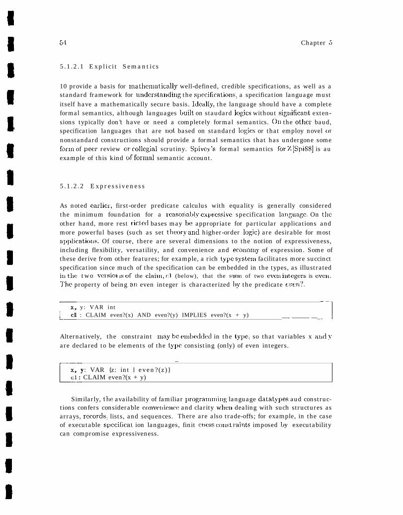
54 Chapter 5
5.1.2.1 Explicit Semantics
10 provide a basis for mathenlatically well-defined, credible specifications, as well as astandard framework for undcrstaudiug the s})c!cificationsl a specification language mustitself have a mathematically secure basis. lcleally, the language should have a completeformal semantics, although languages built on staudard logics without sigllificaut exten-sions typically don’t have or need a completely formal semantics. on the other baud,specification languages that are Ilot based on standard logics or that employ novel ornonstandard constructions should provide a formal semantics that has undergone someform of lJeer review or collegial scrutiny. Spivey’s formal semantics for Z [Spi88] is auexample of this kind of formal semantic account.
5.1.2.2 Expressiveness
As noted earlier, first-order predicate calculus with equality is generally consideredthe minimum foundation for a reasoi’ably ex~)ressive specification lauguage. On theother hand, more rest ricted bases may be appropriate for particular applications andmore powerful bases (such as set theory and higher-order logic) are desirable for mostapplications. Of course, there are several dimensions to the notion of expressiveness,including flexibility, versatility, and convenience and econonly of expression. Some ofthese derive from other features; for example, a rich type system facilitates more succinctspecification since much of the specification can be embedded in the types, as illustratedill tile two versiol Ls of the claiul, c1 (below), that the sum of two even itltegers is even.
The property of being all even integer is characterized by the predicate even?.
rx , y : VAR in tcl : CLAIM even?(x) AND even?(y) IMPLIES even?(x + y) —- ——— —..J
Alternatively, the constraint nlay bc enlbeddecl in the type, so that variables x and yare declared to be elements of the type consisting (only) of even integers.
r
—x, y: VAR {z: int I even?(z)}c1 : CLAIM even?(x + y)
Similarly, the availability of familiar pro.grammiug language datatypes aud construc-tions confers considerable convcmieuce and clarity whel~ dealing with such structures asarrays, records> lists, and sequences. There are also trade-offs; for example, in the caseof executable spccificat ion languages, finit ellcss collst raiuts imposed by executabilitycan compromise expressiveness.
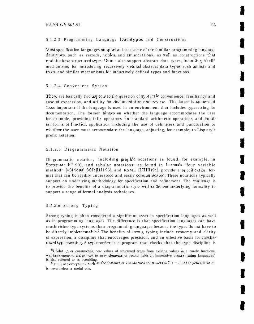
NA SA-GB-001 -97 55
5.1.2.3 Programming Language Datatypes and Constructions
L40st specification languages sup~)ort at least some of the familiar programming languagedat,aty~)cs, such as records, tu~)les, and enunlmatious~ as wwll as constructions thatuldate these structured tyqws. s SOme also support abstract data types, ilducli~lg ‘shell”mechanisms for introducing recursively defined abstract data ty~ws, such as lists andtrees, and similar mechanisms for inductively defined types and functions.
5.1.2.4 Convenient Syntax
‘There are basically two aslmcts to the question of syntact ic convenience: familiarity andease of expression, and utility for documelkation and review. The latter is someirhat1.sss important if the language is used in an environment that includes typesetting fordocumentation. The former hinges on whether the language accommodates the userfor example, providing infix operators for standard arithmetic operations and fan~il-iar forms of fullction application including the use of delimiters and punctuation orw’hether the user must accommodate the language, adjusting, for example, to Lisp-styleprefix notation.
5.1.2.5 Diagrammatic Notation
Diagrammatic notation, including gralJllic notations as fouud, for example, inStatematc [11+ 90], and tabular notations, as found in Parnas’s “four variablemethod” [vSI’M93], SCR [IIJL95], and RSML [LHHI194], provide a s~)ecification for-mat that can be readily understood and easily comlnunicatcd. These notations typicallysupport an underlying methodology for specification and refinement. The challenge isto provide the benefits of a diagrammatic style witli suflcient utlder]yillg formality tosupport a range of formal analysis techniques.
5.1.2.6 Strong Typing
Strong typing is often considered a significant asset in specification languages as wellas in programming languages. Tile difference is that specification languages can havemuch richer type systems than programming languages because the types do not have tobe directly itnldenlentable.g The benefits of strting typing include economy and clarityof expression, a discipline that encourages precision, and an effective basis for nlecha-nized typechecking. A typechecker is a program that checks that the type discipline is
6Upriatirlg or constructing new values of structured types from existing values in a purely functional,vay (aualogous to assiguulent to array elemeuts or record fields in imperative programn~ing languages)is also referred to as overriding.
glhere are ex~eptio~ls, sur.., as the al>stract or ~irtlla] class cor~structs il~ C + +, ~)ut ‘lle gerLeraliZatiO~l
is nevertheless a useful one.
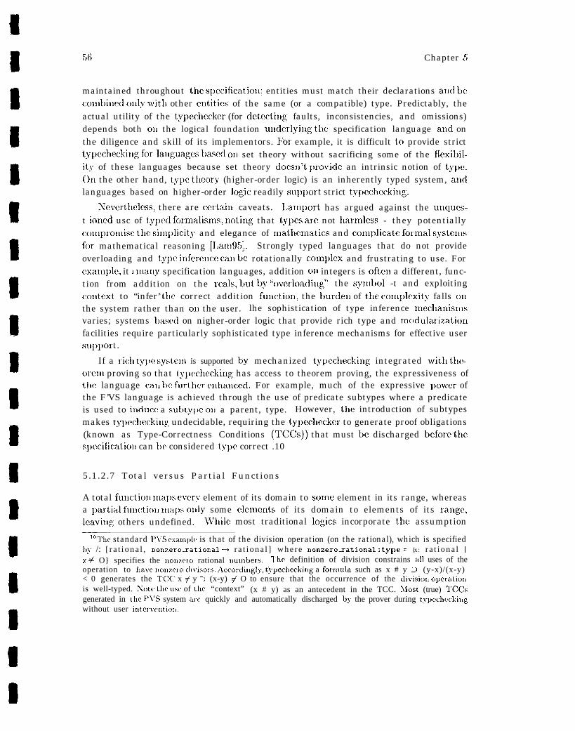
Chapter 5
maintained throughout the slmificatioll; entities must match their declarations and becombil~ed only with other eutities of the same (or a compatible) type. Predictably, theactual utility of the typechecker (for detectiug faults, inconsistencies, and omissions)depends both ON the logical foundation uuderlyillg the specification language and onthe diligence and skill of its implementors. For example, it is difficult to provide stricttypccheckin gforlanguagc sbasc don set theory without sacrificing some of the flexibil-ity of these languages because set theory docsll’t l)rovide an intrinsic notion of ty~w.On the other hand, ty~)e theory (higher-order logic) is an inherently typed system, andlanguages based on higher-order logic readily su~)port strict typecheckillg.
~everthelcxs, there are certaiu caveats. 1,anlport has argued against the unques-t ioned usc of typed formalism, noting that types are not hatmless - they potentiallyconlpronlise the silu~)licity and elegance of mathenlatics and conlplicate forn~al systemsfor mathematical reasoning [IJan195]. Strongly typed languages that do not provideoverloading and type infereuce call k rotationally complex and frustrating to use. Forcxanlple, it 1 many specification languages, addition cm integers is often a different, func-tion from addition on the reals, but by “ovcrloadiug” the synlttol -t and exploitingcolltext to “infer’; tile correct addition fuuction, the burden of the conlplexity falls 011the system rather than on the user. lhe sophistication of type inference nlechanislnsvaries; systems based on nigher-order logic that provide rich type and modularizationfacilities require particularly sophisticated type inference mechanisms for effective usersup~)ort.
If a ricl] ty~w systenl is supported by mechanized typcchecking integrated wittl thc-oren~ proving so that typechecking has access to theorem proving, the expressiveness oftile language ca~k lx further c~lhaucecl. For example, much of the expressive power ofthe F’VS language is achieved through the use of predicate subtypes where a predicateis used to iuduce a sut~ty~w OX1 a parent, type. However, tile introduction of subtypesmakes ty~)echecking undecidable, requiring the ty~)ecbecker to generate proof obligations(known as Type-Correctness Conditions (TINs)) that must be discharged before thes~)ccificatioll can l)e considered ty~)c correct .10
5.1.2.7 Total versus Partial Functions
A total fuuctioll ma~)s every element of its domain to some element in its range, whereasa ~)artial fullctio~! ulal)s ouly some clemeuts of its domain to elements of its range,leavi~lg others undefined. lf’llile most traditional logics incorporate the assumption
‘lO1’he standard PJ’S exalrlplc is that of the division operation (on the rational), which is specifiedby /: [ r a t i o n a l , nonzero_ratlonal + r a t i o n a l ] w h e r e nonzerozational :type = {x: r a t i o n a l IX # O} specifies the nonwro rational nunlbers. l’he definition of division constrains all uses of theoperation to have nonzero cllvisor>. .Accordiugly, typechwking a forvnula such as x # y ~ (y-x)/(x-y)< 0 generates the ‘1’CC x # y > (x-y) # O to ensure that the occurrence of the divisiorl operatioILis well-typed. !Notc the use of t}lc “context” (x # y) as an antecedent in the TCC. iVfost (true) TCXSgenerated in the PI’S system arc quickly and automatically discharged by the prover during typechccliingwithout user ix~terventioxl.

that functions arc total, ~mtial functions occur naturally ill the kinds of applicationsundertaken with formal methods. Givcm that most logics assume that fuuct, ions aretotal, providiug a logical basis for a specification language that admits partial functionstcmds to be problematic. Although sonic recent lo.gics (including those of VDhl [Jon90].1{.AISI? [Gro92], three-valued lc)gics [Urq86, RT52, Res69, K’TB88], and Beeson’s logic ofpartiaI terms [Bec86]) allow l)artial fuuctiolls, they typically formalize partial functionsat the expense of complicating theorem proviug for all specifications, even those thatdo not involve partiality. On the other baud, t rest illg all fuuct ions as total iu languageswith only elementary type systems also has undesirable consequences, iu particular, theawkwardness of having to specify normally uudefined values (for example, havixig tospecify division by zero). Total functions are less problematic in languages that supportsuhtyl)es and de~)cndcmt types, as illustrated previously by the P\TS specification ofdi~isiou on the rationals as a total operation on the domain consistillg of arbitrarynumerators and nonzero denominators, where the latter was defined by the predicateSul)typc, ?Lo7L2e7’0-rat2071 al.
5.1 .2 .8 Ref inement
Specification languages that sul)port refinement provide an explicit formal basis for thehierarchical mappings used to verify successive steps in the development from abstractrequirements and high-level specification to code. Although most specification languagesallow refinement to be expressed, if somewhat paiufully, explicit support for refinementconfers a distinct advat~tagc for describing the systelnatic and provably ~orre~t “iu~plc-mcn~tat ion” of a higher-lever s~)ccificat ion by a lower-level one.11
5.1.2.9 Introduction of Axioms and Definitions
In the introduction to this chapter, it was noted that a specification typically con-sists of a collection of axioms and definitions. Axioms can assert arbitrary l)ropertiesover arbitrary (new or existing) entities. Definitions arc axioms that arc restricted todcfiuing new concepts in terms of known cmc!s. This difference has important iu~pli-cations; axioms can introduce inconsistencies, whereas well-formed definitions cannot.Specification languages differ with respect to facilities for introducing axioms and def-initions } including the rigor with which they guarantee that axioms are consistent anddefinitions well-defined. Some specification languages do not allow the introduction ofaxioms. Although this avoids the problem of inconsistency, it can create others. Forexample, axioms are particularly useful for statiug assumptions about the environmentand the inability to define such constraints axiomatically can prese]lt a considerable
] 1 Refinement is a topic that is not covered in this volume. A representative sample of the work inthis area, including both model-based and algebraic approaches, may be found in the proceedings ofrecent workshops 011 refinement, including [dEidRR89, hlti’90], as well as in [BHL90].
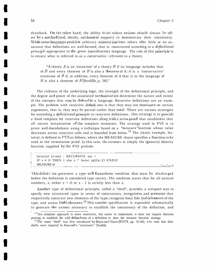
58 Chapter 5
drawback. On the other hand, the ability to int reduce axion~s should always hc off-set & a nlethod (and, ideally, nlcchatlical support) to demonstrate their consistency.While some ]anguagcs prohibit arbitrary axionlat izat ions, others offer little or no as-surance that definitions arc well-fornmd, that is. constructed according to a definitionalprinciple appropriate to the given (specification) language. The role of this principle isto ensure what is referred to as a conservative mlension to a theory.
“A theory A is an ‘extension’ of a theory B if its language includes thatof B and every theorem of B is also a tlmorem of A; A is a ‘conservative’extension of 11 if, in addition, every theorem of A that is in the language ofB is also a theorem of A’ [Rus93b, I). 58].”
The richness of the underlying logic, the strength of the definitional principle, andthe degree and power of the associated Inechanizat ion determine the nature and extentof the concepts that may be defiued in a language. Recursive definitions are an exam-pie. The problem with recursive dcfinit ions is that they may not terminat c on certainarguments, that is, they may bc partial rather than tcjtal. ‘There are various strategiesfor extending a ddillitional princi~)le to recursive definitions. One strategy is to prcj~ridea fixed template for recursive definitions along vrith a meta-proof that establishes thatall correct instantiation of the template terminate. The strategy used in PVS is toprove well-foundeduess using a technique based on a “measure’ ) function whose valuedecreases across recursive calls and is bounded from below. 12 The classic example, fac-torial, is defined in PI’S as follows, where the MEASURE clause specifies a fuuction to beused in the termination proof. In this case, the Ineasure is simply the (generic) identityfunction supplied by the PVS prelude.
r ——-— ————.factorial (x:nat) : RECURSIVE nat =IF x = O THEN 1 else x * factor ial(x-1) E N D I FMEASURE id .—. “---”---1—
?’his dcfini t ion generates a type well-formedx!css condition that, must he dischargedbefore the definition is considered type correct. The condition states that for all naturalnumbers, x, either x = O or x - 1 is strictly less than x.
Anot]ler type of definitional principle, called a “shell”, provides a conlpact way tospecify new structured types in terms of constructors, rccognizers, and accessors thatrespectively construct new elements of the type, recognize bona fide (suh)elements of thetype, and access (sub) elements. 13 This concis~! specification is expanded schematicallyto generate the axioms necessary to establish the consistency of the definition, and—— .—. —
1 ‘The template approach is more restrictive, but easier to implement; it does not require theoremproving to establish the well-definedness of a definition as does the measure function strategy.
13 The name “shell” WZE first introduced by Boyer aud Moore [Div179, pp. 35-40], \vho note that theirshells were inspired by Brrrstall’s “structures” [13ur69].
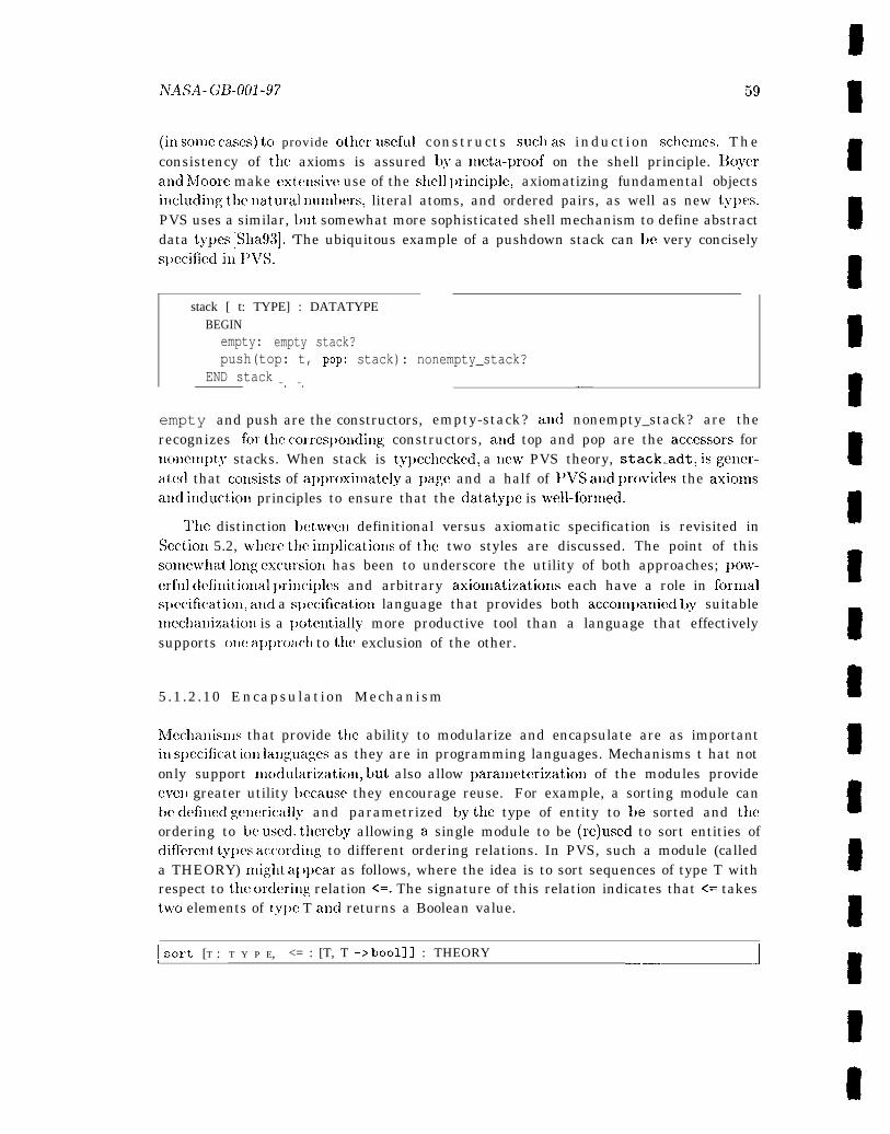
NASA. ~;~.ool .97 59
(i~i so,ne cases) to provide other usefu] constructs SUC1, as induction schen,es, Theconsistency of the axioms is assured by a meta-proof on the shell principle. Boyera~ld Lfloore make extcllsivc use of the shell lJrinciple, axiomatizing fundamental objectsilicluding tllc llatural nutnbers, literal atoms, and ordered pairs, as well as new ty~ws.PVS uses a similar, bllt somewhat more sophisticated shell mechanism to define abstractdata ty~)es [Sha93]. ‘The ubiquitous example of a pushdown stack can be very conciselysl)ecified ill I’VS.
stack [ t: TYPE] : DATATYPEBEGIN
empty: empty stack?push(top: t, POP: stack): nonempty_stack?
END stack -. —. -—
empty and push are the constructors, empty-stack? and nonempty_stack? are therecognizes for the corres~)onding constructors, al~d top and pop are the acccssors for~lollenlpty stacks. When stack is typechecked, a ncnv PVS theory, stack-adt, isgener-atccl that collsists of approxinlately a ~)age and a half of 1’VS a[ld prcwides the axionlsa]ld inductioli principles to ensure that the datatype is well-fornled.
‘I1lIC distinction between definitional versus axiomatic specification is revisited inSectioll 5.2, wl)ere tllc inl~)lications of the two styles are discussed. The point of thissome~vhat long cxcursioll has been to underscore the utility of both approaches; pow-erful dcfi~litiona] ~)ri~lciplcs and arbitrary axionlatizatiolls each have a role in fornlals~wcificatioll, and a s~)ecification language that provides both accon~~)anied by suitablenlecllallization is a I)otentially more productive tool than a language that effectivelysupports oIle a~)~)roacll to tile exclusion of the other.
5.1.2.10 Encapsulation Mechanism
h4cchanis111s that provide tile ability to modularize and encapsulate are as importantill sl)ecificat ioll laxlguagcx as they are in programming languages. Mechanisms t hat notonly support nmdularization, but also allow ~)arameterization of the modules provideeven greater utility I)ecause they encourage reuse. For example, a sorting module canbe defixlcd ge]lcrically and parametrized by the type of entity to be sorted and tileordering to be used. tliereby allowing a single module to be (re)used to sort entities ofdifrercnlt ty~m .accordi~lg to different ordering relations. In PVS, such a module (calleda THEORY) might al ]pear as follows, where the idea is to sort sequences of type T withrespect to tile orderi[lg relation <=. The signature of this relation indicates that <= takestwo elements of ty~w T atld returns a Boolean value.
I SO~t [T : T Y P E, <= : [T, T -> bool]] : THEORY—— J

60 (hpt cl” 5
TO ensure that instantiaticms are appropriate, for example, that the values provided totbc ordering relation in fact constitute an appropriate ordering, semantic constraintsarc associated with tbe instantiation. There are various mcxhauisms for accomplishingthis, including attaching assumptions to the formal parameters of tbe module, as inPVS. For exanll~le, it may be useful to constrain <= to bc a preorder (that is, reflexive
and transitive).1~
sort[T:TYPE, <=: [T, T -> bool]: T H E O R Y
BEGINASSUMING
preorder: ASSUMPTION pre-order?(<=)
ENDASSUMINGEND sort
This assumption must be discharged whenever the module sort is instantiated.
5.1.2.11 Built-in Model of Computation
Most applicationsof formal methods iuvolvereasoniug about computational processes.Iuthediscussion ofdiscrete domain models (Section 4.3), itwasl~otedtl latsolllesl)ec-ification languages have a built-in model of computation, for example, in tbe form ofa process algebra as in LOTOS [1 S088] or certain progral~lt~lil~g-lal~guage construc-tions, such as the concurrency mechanisms offered in Gypsy [GAS89]. If a model ofcomputation is present in a lan.gtiagc, it is important to ensure that tbe ccjmputationalmodel is suitable for tbc application at hand. For example, a study of synchronizationalgorithms cannot very well be performed in a notation based on synchronous con~-municat ion [Rus93b, p. 162]. On tbe other hand, many specification languages do notillcor~)oratc a model of computation, or iucor~)orate only a very elementary model, suchas functional composition. Using functional application and composition, almost anylogic can represent sequential computation. l,auguages such as PVS that are basedon classical higher-order logic are typically rich enough to specify more complex com-putations, such as those involving irnperativc, concurrent, distributed, and real-timealgoritbrns. For example, important properties of distributed systems can often bedescribed and analyzed using recursive fuuctions [LR93b].
5.1.2.12 Executability
Executability provides a pragmatic approach tc) exploring and debugging specifications,and to developing and evaluating test cases. Further discussion of executability may befouud in Sections 5.4 and 6.3.
‘“preorder? is a predicate defiued in the PI’S prelude [0 SR93a].
NASA -GB-001-97 61
5 .1 .2 .13 Matur i ty
The advantages of a nmtum slmification lauguagc arc similar to those of a matutcl~rograll~t~~itlgl allg~lage: documelLtatio~l isrcasollably acccssil)lealld complete. tool sul)-~)ort is available and generally relial)lc, there is a reasonably large body of associatedliterature and al)l)lications, aud tllcre is soInc ~ncasurc c)f standardization so that as~)ecificatio~l written in the lauguage provides au unambiguous and gcmerally accepteddescription.
5.2 Formal Specification Styles
Specification style has various implications, rau.ging from readability to ease of proof.As Srivas and hlillcr note in reference to the formal verification of a commercial lni-crc)processor (arguably the most, ambitious microprogram verification undertaken todate) [SM95a, p. 31]: “C)llco ftllc~llorci rll~)orta~lt lesson slearned during this projectwas to more carefully consider the trade-offs betwwcn . . styles of specif ica t ion. ’ > Sri-
vas and Miller are specifically referring to a collstruc.tive versus a descriptive style ofspecification, also known as model-oriented versus l~ro~Jerty-orieT~ted, respectively.15 Aconstructive or nloclel-oricmtcd style is tyl)ically associated with the usc of definitions,w]lereas a descriptive or ~)ro~)ert.y-orie~ltcd style is generally associated with tile use ofaxionls. For cxanlple, consider the mod function, which returns the remainder when onenatural nunlber is divided by auother. mod can be s~)ecified constructively by defil~iug arecursive futlction that returns the appropriate value. or descriptively by axioulatizingcertain of its nutnbcr theoretic prvpertics [SM95a, p. 28]. The descri~)tive style cmcour-ages u?lders~)ecijic:atio?l- specifying less rather than more, and doiug so as abstractly aspossible thereby avoiding the tendency to focus on how a concept is realized ratherthau simply wlLat is required of it, whmeas tile constructive style tends to promoteooerspcci’catiow -specifying more rather than less aud doing so in greater detail andspecificity than necessary- thcreby allowillg all iltl})lelllelltatioll bias to cree~) ill ear-lier than warralked. On the other band, descripti~w or axiomatic specifications canintroduce inconsistencies aud cau be less easily read aud uudcrstood by the uuilliti-ated reader than constructive specifications. Constructive specification also tend tocorrespond more naturally to the procedural requirements used in many ap~)lications.Ultimately, the trade-offs I)etween tlie two styles must be arbitrated by the applicationand by the options provided by t Ilc slwcificat ioll lallguagc used. Agaiu, Srivas andMiller’s cxperieuce is instructive.
“It became evident, that [the descriptive style was] in many ways a prefer-able style of specification . . . more readable, simpler to validate, aud . . . closer
——-— ..— —] 50t her terminology is also found in the literature; for example, the term “prescriptive” is sometimes
used to refer to a constructive style of specificatiorl and “declarati~’e” to a descriptive style.
to what a user wantecl to know. . . . Usiug this style would have made spec-ifying the core set of 13 instructions much simpler. However, doing so alsowould have made it easier to introduce inconsistencies in the specification.. . . The declarative [sic, that is, descriptive] style of specification is better-suited for reasoning !vith complex instruction sets [Sh195a, pp. 30-31 ].”
Many applications can benefit by the judicious usc of both styles. One approach is to usea property-oriented axionlatization as a top-level specification and introduce a suitablenumber of specification layers between the property-oriented requirenlents statenlentsand increasingly detailed, (provably consistent ) model-oriented descripticms, possib]yculnliuating in an implementation-level specification. The idea is to establish that tileiltl~)lelllelltatioll satisfies the requirements. Few analj’ses elaborate multiple layers----the sexan~ple docunmted ill [BHMY89, Bcv89] and sumnlarizcd in Section 5.3 is a notableexception; for most applications, Inore cost-effective strategies focus on key propertiesearly in the life cycle.
There are other considerations that may be viewed as stylistic, including the trade-offs lmtween a functional style of specification versus one in which the notion of state isexplicitly re~mesent,ed, for exanlple, using “Hoare Sentcnccs’) to express pie- and post-condit ion< on a %ate.16 Some specification lauguages support, both styles. while others,. .sup~)ort only an implicit Ilotion of state. If tlm notion of state is implicit., tile model ofcomputation may be more or less explicit. For exan~plc, if t he specificat iol L of a controlsystelll must support the analysis of properties characterizing the evolution of the syst-em over time, the (monitored, controlled, aud state) variables are typically representedas traces, that, is, functions from “time” to tllc type of value concerned. where t ilnerepresents a frame, cycle, or iteration count. l’urely functional specifications are in-trinsically closer to ordiuary logic and therefore tencl to support more effective theorem~)roving than specifications that, involve state. In general, specifications involving statetend to be unnecessarily constructive for earlier life cycle applications; functional styles~)ecifications are often adequate for the requirements and high-level design phases.
5.3 Formal Specification and Life Cycle
One approach to integrating formal specification with system development is to con-struct a hierarchy of specifications at different levels of abstraction, each level corre-sponding to a different phase of the software life cycle and each level elaborating or“refining” the immediately preceding level. Using formal proof to establish that eachlevel of the design is a correct i~llI~lel~~e~~tatioll of its immediate ancestor, it is possible
———16 As an antidote to then-current program verification approaches that generated verification condi-t ions (1’CS) from programs annotated with logical assertions, yielding I’CS that }vere diflicult to mapback to the original program (and the user’s intuition), Hoare extended the logic to include programelements, thereby allowing the user to reason directly about programs [Hoa69].

NASA-GB-001-97 63
to develop a proof chain that automatically demonstrates that required properties aresatisfied at all levels - from the requirements specification down through the imple-mentation (code level). Such proofs typically use a lnapping function that, relates tileobjects of one level with the objects of the immediately preceding level and prove thatthe rnappil~g is preserved through all possible executions. NTeedless to say, hierarchicalspecification over multiplc levels is an arduous and costly undertaking. The “CL] shortstack” [Bev89] a mechanical verification of a multilevel system from all a~)p]icationsprogram in a high-level language down through the gate-level design of a microprocessorwith intermediate lCVCIS including a compiler, assembler, and linker - exem~)lifies thisapproach. The LaRC verification of a reliable colnputing platform for real-time controlis another of the few extant examples [13 DH94].
Formal specification is typically most cost-effective early in the life cycle of a system.This is true for several reasons, notably the eflectivencss of conventional verification andvalidation activities later in the life cycle versus earlier, when there is an acknowledgeddearth of cfl’cctive strategies and tools, and the difficulty of formal specification duringthe later life cycle, in the context of highly detailed, implement at ion- sl>ecific models.‘This rationale dovetails nicely with the largely pragmatic considerations that have fo-cused most applications of formal methods on critical or key properties rather than on“total correctness.” As a result, formal specification is most productively used as anintegral part of the iterative development of rccpiremcnts and high-level design, ratherthan as a one-time, bcnedictory activity at the end of the process.
5.4 The Detection of Errors in
There are several potential sources of error in a
Formal Specification
formal specification:
●
●
●
It can say too little or uuderspecify, that is, be incomplete
It can say too much or overspecify, that is, be overly lJrescriptive, thereby unnec-essarily constraining later phases of the life cycle
or, it can be wrong, that is, it can be internally inconsistent or it can specifysomething anomalous or unintended.
@erspccification is diflicult to detect mechanically and typically requires considerable17 The other faults are generally Inore amenable toexperience to recognize and avoid.
tile types of fault detection discussed below. Including formal proof, there are basicallyfive regimens for detecting anomalies in a specification. The last four of these can be
17Jones characterizes a notion of overspecification or implementation bias for constructively definedspecifications. Briefly, a specification is biased with respect to a given set of operations “if there existdifferent elements of the [underlying,] set of states which cannot be distinguished by any sequence of theoperations.’ : [J01,90, pp. 216-219].
64 CiIaJ)t(?r 5
effectively nlechanized aud typically occuI in the order given , since there is llo point inattempt ing proofs on a spccificat ion that is not syntactically and senlant ically correct.F@ the sanle token, there is no point in checking for semantic anonlalies in a specificationthat is not syntactically well-formed. 011 the other hand, cacll of these tccl]niclues hasa ~)articular utility, and an integrated approach that ex~)loits the strengt]l of each isundeniably the Incjst effective. Ill sonic cases, this integration is inherent in a systenl,for exalnple,, cooperating decision procedures itl a theorenl prover, or the tight couplingof a typechecker and a proof checker to provide strict typecheckitlg in the presence of nontrivially decidable properties. In other cases, the integration is achieved @ judicioususe of available techniques, for exanlple, “prototyping” a potentially dillicult and costlyproof by using model checking, simulation, or aninlation to exanline a finite case beforeattenl~)ting the nlore general proof with a theorenl prover or proof checker. 111 anycase, the utility of the fault-detection techniques discussed below can be significantlyenhanced by exploiting the potential synergy created by their judicious conlbinat ion.
Inspection: Inspections run the gamut from informal peer review to well-defined, for-malized procedures. The Fagau-style inspections discussed in Section 3.2 are among themost frequently used quasi-formal inspections. In theory, these manual ins~)cctions ca~ldetect all the error types ~loted above, although in practice, manual inspections are llotas effective as mechanized tools in detecting subtle or drop-seated ano~nalicsj such aslogical inconsistencies and (unintended) implications, or in consistently locatixlg senlall-tic or even syntactic errors ill specifications. NTcwcrthclcss, Fagan-style inspections andother similarly exacting inspection methods can effectively complement formal methods.and vice versa. The AAMP5 microprocessor project illustrates this point nicely. hlillerand Srivas note the surr)rising
“extent t,o whicl) fcmnal specifications and inspections complementedeach other. The inspections were improved by the use of a formal nota-tion, reducing the amount of debate over whether an issue really was adefect or a personal preference. In turn, the inspections served as a usefulvehicle for education and arriving at consensus on the most effective stylesof specification. ~’his is reflected in . . . the lower number of defects recordedin the later inspections [MS95, p. 9].”
As tliis quote suggests, the sy~nbiotic relationship between formal methods and conven-tional inspection techniques provides a natural medium for technology transfer.
Parsing: I)arsing is a forln of analysis that detects syntactic inconsistencies and anonla-lies, such as misspelled keywords, missing delimiters, or unbalanced brackets or pareli-theses. Parsing guaranties (only) that a specification conforms to the syntactic rules ofthe formal specification language in which it is written.
Typechecking: ~’ypechecking is a form of analysis that detects semantic inconsis-tencies and anomalies, such as undeclared names or ambiguous types. As noted in

NASA-GII-001-97 65
Sect ion 5.1.2, formal specification languages based on higher-order logic aclmit cffec-t ive typcchecking, while in general, those based on set theory do not. When available,strict tyl)echecking is an extrelnely effective way of determining whether a specificationInakes semantic sense. Again as noted in Section 5.1.2, the type system of a specificationlanguage may ~lot be trivially decidable, ill which case typechecking is similarly unde-cidable and proof obligations lnust be generated and discharged before the specificationis considered typechecked.
Execution (Sirnulation/Animation): Direct execution , sinlulation, and a~linlationoffer further options for detecting errors in a specification. If a formal specificationlanguage is directly executable, or contains a directly executable subset, execution andanitnation can be acconlnlodated in the same formally rigorous context ill wllicli thespecification is developed. If not, the formal specification must be reinterpreted into]Iigh-level, dynamically executable program text that bears no formal relation to theoriginal specification (see [h4J3T95, Chapter 5] for an example of the latter). Some lan-guages offer both, that is, a directly executable subset, as well as the option of user- orsysterll-dcfitled l)rograI~l text to drive animation of I1011eXWUtZLb]6! l)arts of the specifica-
tion. The concrete represcntat ion of algorithms and data structures required by mostfinite-state enumeration and model-checking methods (see below) makes them directlycomparat)lc to direct execution techniques, as found, for exatnplc, in the VDM-SL Tool-box [VDh!l]. In some cases, model checkers also provide simulation. For example, thereachability analysis strategy used by state-exploration model checkers can also be usedto “simulate’) system behavior by exploring a single path (rather than all l)ossible paths)through the state space. 130th Murg’~ [DDHY92, ID93] and SPIN [H0191] call sinmlatethe execution of n~odels written in their respective languages. The type of errors foundby direct cxccutioll techniques varies, depcndi]lg on other error detection techniques,if any, used prior to sitnulation or anitnation. For exanlplej [MW95, p. 92] aninlateda specification that had previously undcrgolic only syntactic analysis and weak typeanalysis (essentially lin~ited to arity checking on function and operation calls). In theircase, aninlation detected two type errors in addition to errors duc to rnisinterI)retationof the requircnlcnts, incorrect s~)ccification of requircnlents, and erroneous translationfrom the specification into the sinlulation lauguagc. t3xecutability also supports the dc-vclopnlcnt and systcnlatic evaluation of test suites, thereby potentially exposing flawsand oversights in a test regime, as well as in the corresponding specification.
Theorem Proving, Proof Checking, and Model Checking: Tlkeoren~ proving :
proof checking, and model checking are all forms of analysis that can be used to detectlogical anonlalies and subtle infelicities in a forn]al specification. Although historicallythese forms of validation were used to prove correctness of programs and detailed hard-ware designs, they are llow~ typically used for fault detection and design exploration,where they arc arguably most effective, as well as for verifying correctness. Tllc analy-sis provided by theorenl Ixoving, proof checking, and model checking not only involvesthe specification, but, also its logical consequences, that is, all formulas that can beproved fronl the original specification using formal deduction. There are several issues
in the validation of formal specifications. One is the issue of internal consistency, that is,whether the specification is logically consistent. If ~lot, the specification fails to say any-thing useful. Another is the issue of l[lcal~illgflllllcss, that is, whether the specificationmeans what, is intended. A third is the issue of completeness. Althougll various notionsof completeness have been pro~)osed, the general idea is that a specification should iden-
‘8 The type of testing andtify all contingencies and define t)ehavior appropriate to each. .error detection offered by theorem ~Jr’ovillg, proof checkino~, and modeling is in manyways analogous to traditional testing reginles; the theorem prover, proc)f checker, ormodel checker “executes’) the specification, allowing the practitioner to explore designoptions and the implications of design choices.
5.5 The Utility c]f Formal Specification
A specification may serve many different functions. Lamport [Lam89, p. 32] has sug-gested that a formal slwcification functions as ‘{a contract kx%wecn the user of a systemand its implementer. The contract should tell the user everything hc must know touse the system, and it should tell the inlplementer everything he must know about tilesystem to implement, it. In princi~de, once this contract has been agreed upon, theuser aud the implementer have no need for further col~~~[~~ll~icatioll.” Lamport’s similehighlights three issues. First, as noted earlier, one of the Inost important functions of aformal specification is analytic; using the deductive apparatus of the underlying formalsystem, a formal s~)ecification serves as the basis for calculating, l)redictillg, and (intile case of executable specificatiolls) testing system behavior. However, a formal s~)ec-ificatiou may also serve all important descriptive function, that is, provide a basis fordocumenting, communicating, or I)rototyping tllc l)ehavior and properties of a systenl.Second, a (completed) specification represents the formalization of a consensus aboutthe behavior and properties of a system. Diverging somewhat from ],allll)Ort’s descril)-tio~l and focusing on the early life cycle, we prefer to view a formal specification as acontract bet weell a client, a requirements analyst (and possibly also a designer), and aforma] methods practitioner. Third, while in l)rinciple, a fitlalized contract precludesthe need for further communication among the interested parties, in practice, movingfrom informal requirements to a formal specification and high-level design is an iterativerather than a linear process; issues ex~)osed in the dcwelopment of the formal specifica-tion Inay IIeed to be factored back into the requirements, and similarly, issues raised bythe high-level design may percolate back to impact either the formal specification, therequirements, or both.
Although a specification that has not been validated through proof can be aptlycompared to a program that has not been debugged, there are nevertheless rc!al benefits
18 Rushby [Rus93b, pp. 69-71] cites several specialized definitions, including characterizations of comp-leteness for abstract data types arid for real-time process-control systems.
~TASA_ G~_OOl .97 67
to be gained from modeling and formally specifying requirements and high-level designs,including the following.
. Clarify Ikquircments and High -Lctwl Designs: A formal specification provides aconcise and unamljiguous statcmcmt of the u~ldcrlying mquircmlents and design,thereby exposing fundamental issues that tend to be obscured by lengthy informalstatements. ‘1’hc formalization of the requirements for the rece~lt ol)tilnization ofSpace Shuttle Reaction Control System Jet Selection (JS) [NASA93, A1)pcndix B]recounted here in %ction 3.1.1 illustrates this ~)oint nicely.
● Articulate Implicit Assumptions.” Forlnalisms can help identify and express inl-p]icit assumptions in requirenwnts and design. For example, the concept of statevariables is not explicitly lneutioned in S1)ace Shuttle requirements: their existcnccmust bc il[ferred from context by noting the function and persistence of local vari-ables. F,xplicitly modeling and specifying state variables can significantly increasethe precision and perspicuity of the requirements, as illustrated by the partialspecification of the new Space Shut tlc Global Positioning System (GF’S) navi-gatioxl capability [DR96]. Identifying ulldocunlented assunll)tions is particularly
important in the context of an cwolvillg system design.
Another aspect of requirements and high-level design that frequently contains inl-plicit assumptions is the interaction of the systeln with the environnlent or contextin which it is assumed to ol)erate, including the input space. hlaking input coll-straints and environmental assumptions explicit often exposes requirements anddesign-level issues that have been overlooked. ‘ g l’he specificatioll of the SpaceShuttle IIeading Ali,gnnwnt Cylinder Initiation] Predictor and Pc)sition Itrror LJis-plays Change Request (HAC CR) is a good exanqde of the value of the processof formalization for identifying and capturing undocunlentedj donlaimspecific as-sunlptions. Quoting fronl the report for the HAC CR fornlal nlethods ~Jroject:“Capturing such [domain-specific] knowledge and docunlenting it as rationale withtile specification is valuable [RI196, I). 17] .“
● Ezposc Flazm: The process of formalizatioxl invariably ex~)oses significatlt flawsin requirements and high-level desig~~, even without the benefit of analysis orproof. In the case of strongly typed specification languages, typcchecking can pro-vide a potent tool for revealing anomalies in the specification, as well as potentialanomalies in the requirements and design, and cloing so early in the life cycle whileerrors are far less costly to correct. The previously mentioned GI’S project [DR96]provides a nice example of the utility of specification for revealing anomalies inimmature requirements for large, complex systems, especially among subsysteminterfaces. Executing a specification provides another productive means of expos-itg flaws, as noted in [MW95].
19T’he A-7 IvIethodology [vS90], among others, has paid particular at tentioxl to the explicit enunlera-ticm of relevant environmental variables.
68 chapter 5
● ldcnti~g Exceptions: The discipline involved in fcmnalizing requirenwnts and high-level design alsc) serves to identify “end cases” and exceptions and to encouragenlorc t borough considcrat ion of these exceptional cases, as illustrated in [LFB96].
● Ez]akute Test Coverage: An executable specification may also be used to run andevaluate proposed test suites, yielding a measure of test coverage relatively earlyill the life cycle.
‘The utility of formal specification also extends to ~sork in program transformationand synthesis, that is, the mechanical application of a series of transformations thatderives a program from its specification. This approach differs from traditional com-pilation of ILigh-level languages i~lsofar as it seeks to bridge a far larger language gal)between in~)ut (slJecification) and output (program). To make this feasible, the scopeof the specification language must tm severely constrained, and/or the transformationprocess must be guided by a skilled programmer. The techniques rely on a set ofcorrectness-preserving transformations that guarantee that the resulting program willexhibit the same behavior as its specification. Ideally, the tra~lsformation also confersadditional (desired) ~woperties such as efficiency. Suggestive, but by no means exhaus-t ive, examples of this broad spectrum of techniques are the following:
. Problems expressed in a specification-oriented language (for exanlpk:, pure Lisp)typically exhibit clarity and sinlplicity, but lack the efficiency and portability thatconlcs from a conventional programming language (for example, FORTRAhT andC). 130Y1c has I) UISUCCI a transformational approach to bridging this gap [BoY89]that involves successive deconlposition into a series of steps that can be acconl-I)lished by the autonlatic application of a set of s~)ecial-purpose, but straightfor-w-ard transfornlations. Ekatnplcs include the use of a succinct functional speci-fication to derive a FOI{TRAN iltl~>le~t~er~tatio~l of an algorithm for solving one-din~ellsiollal hy~)crbolic partial differential equations [BH91].
● A certain class of lJxoblenls can be solved by a carefully programmed instanceof a general al~orit IInlic technique, for example, search problems can be solvedby a ditride-allcl-ccJ1lclller strategy. KIDS (Kestrel Interactive Development Sys-tmn) [Smi90] ~)rovides tools for deductive inferencing, algorithm design, expres-sion sim~)lification. finite differencing, partial evaluation, data type refinement andother .gcneral tratlsformations that allow a user “ to synthesize complex codes enl-bodying algoritllr[ls. data structures, and code-optimization techniques that mightbe too difficult to produce manually [SG96, p.31].” The approach is interactive; theuser guides the systenl i~L the application of powerful correctness-preserving trans-format ions. KIDS has I)ecn applied to a variety of domains, including schedul-ing, combinatorial design, sort ing and searching, computational geometry, patternmatching, and mathematical programming.

jvA5’A_~~4J91.97 69
● Tile class c)f finite futlctions, including for cxanqdc, finite state transitions, lendsitself totabular representations that can bcnlanipulated toperform various consis-tency a~ld con~~dcieness checks and, in sonw cases, to generate code and docunlen-tation. For exanlplc, the decision table, “a tabular format for specifying a conl~)lexset of rules that choose anlong alternative actions” [HC95, p. 97] provides the basisfor the ‘1’ablewise tool [HC95, HGH96] that, tests thcw tables for consistency andconlpletelless, performs a linlited fornl of structural analysis, and generates Adacode inlplelnculting the table, as well as 13nglish-language docutncmtatioll.
● If an application domain is suitably restricted, it is possible to dcwelo~) a con~-~)letely automatic process for synthesizing a program from its s~)ecification. l’hcAMPHION system [LPPU94] illustrates this approach for the domain of solarsystcn~ kinematics. The user specifics a problcm via a graphical user intcrfaccportraying the domain’s astronomical objects and desired configuration. The sys-tem then selects components from a preexisting FORTRAhT subroutine libraryand synthesizes the “glue” code that assenltdes these components into a completesolution. ‘1’llc system applies collst ruct ive theorem proving to perform its selectionand synthesis. The cnd user, however, operates purely at the specification lcweland need never interact with this utldmlying mcchallisnl.
5.6 A Partial SAFER Specification
The PVS specification of SAFER is constructive in style and retains the explicit notion ofstate represented in the SAFER models developed at the end of Chapter 4. To facilitatereadability and emphasize the n)appiug between infornlal description, requirenwuts, andthe PVS fornlalization, the specification also preserves the bias to}vard representativerather than abstract forn)alization introduced into the n~odels of the preceding chapter.The conlplete PVS specification is presented in full in Section C.3.3. The fragmentdiscussed below continues the focus on thruster selection. This discussion is intended tobe self-contained; if additional infornlation on the relatively few PVS language featuresnecessary to understand the fornlal specification can be found in Section C.3. I. FullPVS docutnentation is available in [0 SR93b].
The PVS s~)ecificatioll of thruster selection is a straightforward elaboration ofthe underlying functic)na] model dcweloped in Chapter 4. Accordingly, t}le skele-ton of the PVS theory for thruster selection shown below consists of three func-tions: integrated_commands, which forms an integrated, six degree-of-freedom com-mand from the HCM and AAH inputs; selected .thrusters, which takes an inte-grated command and selects the thrusters necessary to achieve the command; andselect ed.actuators, which acts as an interface function and consists of the composi-tion of integrated_ commands and selected-thrusters. Each of these functions is pa-rametrized by from onc to three parameters denoted by a parameter name followed by
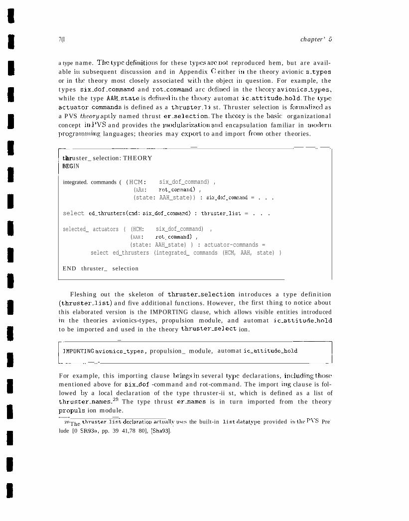
7(I chapter’ 5
a type name. ‘1’he type defiuitious for these types are not, reproduced hem, but are avail-able iu subsequent discussion and in Appendix C either iu the theory avionic s.typesor in the theory most closely associated with the object iu question. For example, thetypes six.dof_command and rot-cormand arc defiued in the theory aviorLics_types,while the type AAH-state is defiued itl the theory automat ic_attitude_hold. The typeactuator_commands is defined as a thruster_li st. Thruster selection is fcmmalizecl asa PVS theo?y aptly named thrust er_selection. The theory is the basic organizationalconcept iu I’VS and provides the modularization aud encapsulation familiar in modern~)rogramluing languages; theories may export to and import fmm other theories.
r
—-—.——.———.—— — .—— ——.. ——.
thruster_ selection: THEORYBEGIN
Iintegrated. commands ( (HCM: six_dof_command) ,
(AAH: rot_command) ,(state: AAH_state)) : six_dof_command = . . .
select ed_thrusters(crnd: six_dof_command) : thruster_list = . . .
selected_ actuators ( (HCM: six_dof_command) ,(AAH: rot_command) ,(state: AAH_state) ) : actuator-commands =
select ed_thrusters (integrated_ commands (HCM, AAH, state) )
END thruster_ select ion
Fleshing out the skeleton of thruster_selection introduces a type definition(thruster_list) and five additional functions. However, the first thing to notice aboutthis elaborated version is the IMPORTING clause, which allows visible entities introducediu the theories avionics-types, propulsion module, and automat ic_attitude_holdto be imported and used in the theory thruster_select ion.
[
— —— —-
IMPDRTING avionlcs_types, propulsion_ module, automat ic_attitude_hold
——. .. —..- 3
For example, this importing clause brings iu several type declarations, iucluding thosementioned above for six.dof -command and rot-command. The import iug clause is fol-lowed by a local declaration of the type thruster-ii st, which is defined as a list ofthruster_names.20 The type thrust ernames is in turn imported from the theorypropuls ion module.-—- —.
zOThe thru~ter_ll~t d~cla~atiorl actually USeS the built-in list datatype provided in the p~s Pre-
lude [0 SR93a, pp. 39 41,78 80], [Sha93]. -

A’AsA-GIHlol-97 71
[ - - - - - - - - - - - - - - -
—— . _ _ . — _ _ _ _
thruster.list: TYPE = list [thruster.name]
—— — — . .‘-----1
The next d e c l a r a t i o n i n t r o d u c e s t h e lloolean-valued f u n c t i o n rot-cmds-present,
whose s ignature inc ludes onc patwneter of tylw rot.command.
[.
rot_cmds_present(cmd: rot_command): b o o l =( E X I S T S ( a : rot_axis): cmd(a) /= Z E R O )
1— — — — — — - — _
~’lle declaration for rot-command defines a function from type rot-axis to typeaxis_command.
[.
—————.——-—— .— -.rot_axis: TYPE = {roll, pitch, yaw}axis_command: TYPE = {NEG, ZERO, Pos}rot_command : TYPE = [rot.axis -> axis_command]—— .—_ .— .— —. .—
rot-axis is an enumerated type corresponding to the three rotation axes: roll, pitch,yaw. axis_command is anelmn~erated tyI~ewitl~t llree~’aluesc orresl)o~ldil~g tothe IICMor AAII command values: negative, m-o, c)r positive. Tlw notation cmd(a) denotes afuuction that nla~)sarotatio naxis (one of: roll, ~)itch, yaw) tothe commandassociatedwith that axis (one of RTEG, 2ER0, PC) S). rot.cmds-present returns the value ofthe existentially quantified formula slLown above. That value is true if them is at leastone rotational axis wlmse associated (HCM or AAH) command is ncmzero, and falseotherwise.
l’hc next functiou. prioritized.tran_cmd, specifies the requirement that there isat luost one translation command at a given cycle and that translation axis commandsare prioritimd ~vitll X-axis commands having highest priority and Z-axis commandslowest ~)riority. ~’llcexlf:oclillgtakes thcforn] ofanestcd-if expression and usesa PVSoverride ex~mssiol) to derive a new value from null -tran-command, which is writtenas an un~latnccl fullct io~l or lambda expression. ‘1’he result of an override expressionis a functiollzl t)lat is exact]v the Satne as the original, except that it takes on nelv.values at tile s~)ccified argun~el~ts. A tran.command does the analogous mapping forthe translation axes. X. Y, and Z that the rot-command does for the rotation axes.Accordingly : in tl]e first branch of the nested-if ex~nwssion, if an X-axis conlmalld ispreseilt (the value of tran(X) is not equal to ZERO), null _tran_command takes on thevalue of tran (X) for the argument X, and similarly for the other branches of the nested-if,whicil handle tllc cases for Y- and Z-axis updates._—— ——— ——.. —. .. ——— —.— ..— —
‘1 Or recorrl; a PI’S record may also bc modified by an override expression
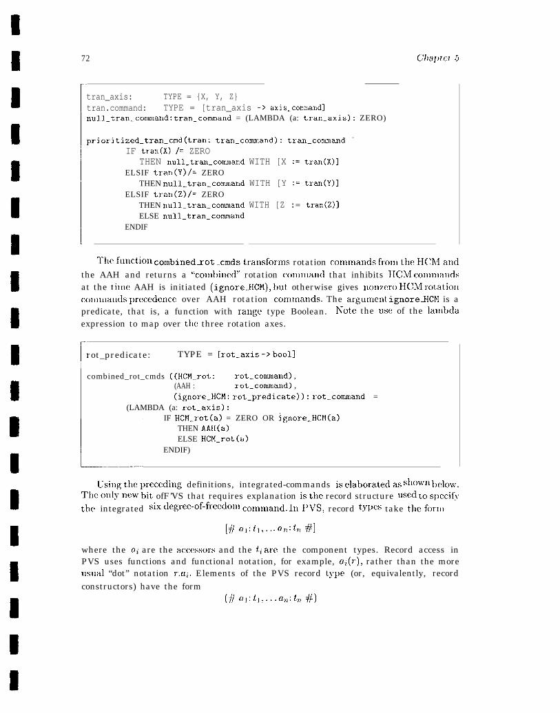
72
rtran_axis: TYPE = {X, Y, Z}tran.command: TYPE = [tran_axis -> axis.command]null_tran_command: tran_command = (LAMBDA (a: tran_axis): ZERO)
prioritized_tran_cmd(tran: tran-command): tran-comand =
l..IF tran(X) /= ZERO
THEN null_tran_commandELSIF tran(Y) /= ZERO
THEN null_tran_commandELSIF tran(Z) /= ZERO
THEN null_tran_commandELSE null_tran_command
ENDIF
WITH [X := tran(X)]
WITH [Y := tran(Y)]
WITH [Z := tran(Z)]
Cklptcv 5
Thcfunction combinedzot .Cmdstransfornls rotation conunands fronltheHCh4andthe AAH and returns a “coml~ined” rotation conmand that inhibits HCM con)nlandsat the tin~e AAH is initiated (ignoreHCM), but otherwise gives nonzero HCM rotatio~lccmunands prcxedence over AAH rotation comtnands. The argunlent ignoreHCM is apredicate, that is, a function with range type Boolean. IVote the use of the lan~bdaexpression to map over the three rotation axes.
rrot_predicate: TYPE = [rot_axis -> bool]I
combined_rot_cmds ((HCM_rot: rot_command) ,(AAH : rot_command) ,(ignore_HCM: rot_predicate)): rot_command =
(LAMBDA (a: rot_axis):
L
IF HCM_rot(a) = ZERO OR lgnore_HCM(a)THEN AAH(a)ELSE HCM_rot(a)
ENDIF)
Usingthepreceding definitions, integrated-commands iselaboratedas shown below.Tlleonlynew’ bit ofF’VS that requires explanation isthe record structure used tos~)ecifythe integrated six degrec-of-freedomc ommand. InPVS, record types take theform
[#ol:il,... a, flt,,#]
where the a~ are the accessors and the tz are the component types. Record access inPVS uses functions and functional notation, for example, az(r), rather than the moreusual “dot” notation r-.ai. Elements of the PVS record type (or, equivalently, recordconstructors) have the form
(#cll:tl,... f2,tit,l#)
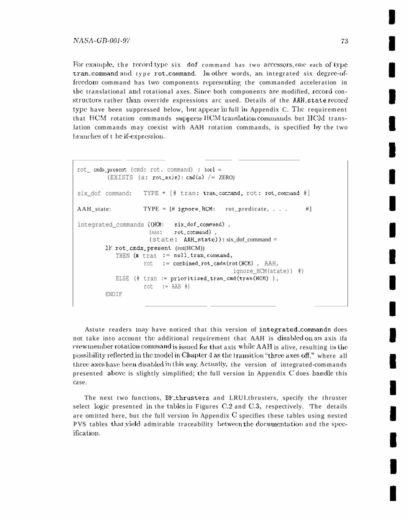
iVAsA-Gf3-ool-97 73
Wr example, the record type six .dof c o m m a n d h a s t w o acccssors, one each of type
tran-coxnmand and t y p e rot_command. In other words, at) integrated six degree-of-frecdom command has two components rcprmcntiug the commanded acceleration inthe translational and rotational axes. Since both components am modified, record con-structors rather that] override expressions arc used. Details of the AAH_state recordtype have been suppressed below, but a~qwar in full in Appendix C. The requirementthat IICM rotation commands suppress IICM tramlatioxl comnlands, but HCN4 trans-lation commands may coexist with AAH rotation commands, is specified by the twobranches of t lle if-ex~)ression.
rot_ cmds_present (cmd: rot. command) : bool =(EXISTS (a: rot_axis): cmd(a) /= ZERO)
six_dof command: TYPE = [# tran: t.ran_command, rot: rot_command #]
AAH_sta te : TYPE = [# ignore_HCM: r o t _ p r e d i c a t e , . . . # ]
integrated_commands ((HCM: six_dof_command) ,(AAH: rot.command) ,(state: AAH_state)): six_dof_command =
rot_cmds_present (rot(HCM))THEN (# tran := null_tran_command,
rot := combined_rot_cmds(rot(HCM) , AAH,ignore_HCM(state)) #)
ELSE (# tran := prioritized_tran_cmd(tran(HCM) ),rot := AAH #)
ENDIF
Astute readers may have noticed that this version of integrated_commands doesnot take into account the additional requirement that AAH is disablecl on an axis ifacrew!~lell~ber rotatioll col~~l~lal~d isisslledfortllat axis while AAH is alive, resulting inthc~>ossibilit~~ reflected illtlle l~~odcl ill Clla~~ter 4astlle tra1lsitio1] “threcaxesoff,” where allthrecaxesh avetxcndisablcd in this way. .Actually, the version of integrated-commandspresented above is slightly simplified; the full version in Appendix C does hatldle thiscase.
The next two functions, BF’_thrusters and LRUI.thrusters, specify the thrusterselect logic presented in the tables ill Figures C.2 and C.3, respectively. ‘The detailsare omitted here, but the full version in Appendix C specifies these tables using nestedPVS tables that yield admirable traceability bciween thedocumentatioll and the s~)ec-ification.

74 Chapter 5
— — —
BF_thrusters(X_cmd, pitch_cmd, yaw_cmd: axis_command): thruster_list = . . .
LRUD_thrusters(Y_cmd, Z..cmd, roll_cmd: axis_command): thruster_list = . . .
—- 1
Thcelaboratwl version of selected.thrusters reveals son~ewbat n~ore about howan integrated six degree-of-freedom con~n~and is mapped into a vector ofactuator con}-lnallds. The specification uses a PVS let expression, a syntactic convenience thatallows the introduction of bound variable nan~es to refer tc) subexpressions. In thiscase, the bound variables refer to the back/front (BF) and the left/rig;llt/uJ~/dow’11 .(l,RUD) thrusters defined by the thruster select logic (specified as BF-thrusters andLRUD-thrusters) to inlplenlent the conmanded translational and rotational accelera-tions. ‘The resulting list of thrusters is formed by appending the BF and LRUII thrusterlists.
➤ ✍��✎ ✿��1
selected_thrusters (cmd: six_dof_command): thruster_list =LET BF_thr =
BF_thrusters(tran(cmd) (X), rot(cmd) (pitch), rot(cmd) (yaw)),LRUD_thr =
LRUD_thrusters(tran(cmd) (Y) , tran(cmd) (Z), rot(cmd) (roll))IN append(BF_thr, LRUD_thr)
L _ . . . . . _ _ _ _ _ . — .— J
Once again, the function presented here is a somewhat sin~plified version of thespecification in Appendix C. In this case, the sinlplificationhas been to omit the logiccorresponding to the right n~ost two colutnns of Figures C.2 and C .3, which specifythe use of two additional thrusters for certain commanded accelerations if the givenconstraints are satisfied. For exan~ple, the thruster select logic for “-X, -pitch, -yaw”(first row of the table in Figure C.2) specifies thruster 134 and, conditionally, thrustersB2 and B3; 132 and 133 arc selected only if there is no conmandcd roll.
The final function in theory thruster-selection is the interface functionselected. actuators, which was previously introduced as it appears in Appendix C.Thesomcwhat abbreviated version of the full theory discussed here is collected in fullbelow. Note that type declarations from other theories reproduced above to facilitatethe discussiondo not explicitly appear, but are implicitly “visible” via the IMPORTINGclause.
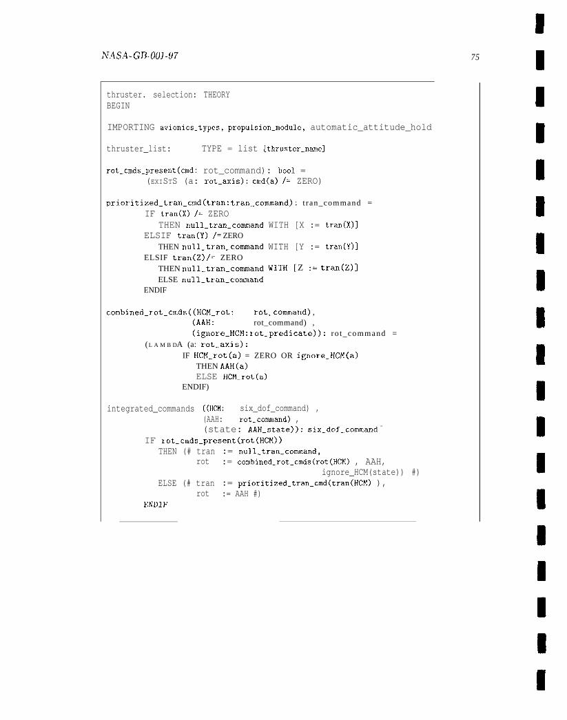
NASA- GB-001-97 75
thruster. selection: THEORYBEGIN
IMPORTING avionics.types, propulsion.module, automatic_attitude_hold
thruster_list: TYPE = list [thruster_name]
rot_cmds_present(cmd: rot_command): bool =(EXISTS (a: rot_axis): cmd(a) /= ZERO)
prioritized_tran_cmd(tran: tran_command): t ran_command =IF tran(X) /= ZERO
THEN null_tran_commandELSIF tran(Y) /= ZERO
THEN null_tran_commandELSIF tran(Z) /= ZERO
THEN null_tran_commandELSE null_tran_command
ENDIF
WITH [X := tran(X)]
WITH [Y := tran(Y)]
WITH [Z := tran(Z)]
combined_rot_cmds ((HCM_rot: rot_command) ,(AAH: rot_command) ,(ignore_HCM: rot.predicate)): ro t_command =
(L A M B DA (a: rot_axis):IF HCM_rot(a) = ZERO OR ignore_HCM(a)
THEN AAH(a)ELSE HCM.rot(a)
ENDIF)
integrated_commands ((HCM: six_dof_command) ,(AAH: rot_command) ,(state: AAH_state)): six_dof_.command =
IF rot_cmds-.present(rot(HCM))THEN (# tran := null_tran_command,
rot := combined_rot_cmds(rot(HCM) , AAH,ignore_HCM(state)) #)
ELSE (# tran := prioritized_tran_cmd(tran(HCM) ),rot := AAH #)
ENDIF
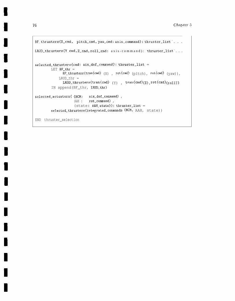
9
BF_thrusters(X_cmd, pitch-cmd, yaw_cmd: axis-command): thruster-list = . . .
LRUD_thrusters(Y_cmd, Z-cmd, roll_cmd: a x i s - c o m m a n d ) : thruSter_list = . . .
selected_thrusters(cmd: six_dof_command): thruster_list =LET BF_thr =
BF_thrusters(tran(cmd) (X) , rot(cmd) (pitch), rot(cmd) (yaw)),LRUD_thr =
LRUD_thrusters(tran(cmd) (Y) , tran(cmd) (Z), rot(cmd) (roll))IN append(BF_thr, LRUD_thr)
selected_actuators( (HCM: six_dof_command) ,(AAH : rot_command) ,(state: AAH_state)): thruster_list =
selected_thrusters(integrated-commands (HCM, AAH, state))
END thruster_selection
Chapter 6
Formal Analysis
Formal analysis refers to a broad range of tool-based techniques that can be used singlyor in combination to explore, debug, and verify formal specifications, and to predict,calculate, and refine the behavior of the systems so specified. These analysis techniques,which differ primarily in focus, method, and degree of formality, include direct execution,sitnulation, and animation; finite-state methods (state exploration and model checking);and theorem proving and proof checking.
This chapter describes each of these techniques and suggests strategies for theirproductive combination. It also examines the role of proof in theory interpretation,proofs of properties, and enhanced typechecking, as well as the utility of the proofprocess for calculation, prediction, and verification. The issue of mechanized supportfor formal analysis is presented, albeit in a suggestive rather than exhaustive discussion.The chapter closes with the specification and proof of the SAFER requirement thatdescribes the maximum number of thrusters that can be fired simultaneously.
6.1 Automated Deduction
Automated deduction or theorem proving refers to the mechanization of deductive rea-soning. Deductive methods provide a foundation for reasoning about infinite-state sys-tems and are typically preferred for abstract, high-level specifications and data-orientedapplications. There are a variety of approaches to mechanizing formal deduction, re-flecting the relative maturity of the field of mechanical theorem proving. This sectionbegins with background material on formal systems and their models, followed by a his-tory of automated deduction, a survey of techniques underlying automated reasoning,and concluding remarks on their utility.
77
78 Chapter 6
6 .1 .1 Background: Formal Systems and Their Models
The material in this section provides technical background that some readers may preferto skip the first time through, or to detour altogether. Dangerous bend signs bracketthe most technical parts of the section.
6 .1 .1 .1 Proof Theory
A formal system consists of a nonempty set of primitives--typically a set of finite stringstaken from an alphabet of symbols; a set of axioms, that is, statements, taken as given,involving the primitives; and a set of inference rules or other means of deriving furtherstatements, called theorems. 1 The axioms and rules of inference of a formal system arereferred to as its deductive sgstern. A set of axioms, together with all the theoremsderivable (provable) from it and from previously derived theorems, is called a theory. Aproof of a theorem in a formal system is simply a series of transformat ions that conformto the rules of inference of that system. As such, the notion of proof is strictly syntactic.The symbol t- (read “turnstile”) is used to express this notion of proof. Thus I-L +,read “@ is provable in logic L“ (or, equivalently 1- @ if the logic is unambiguous fromthe context ), means that + is a theorem in the given logic, that is, @ is provable usingthe axioms of L without further assumptions. In general, the relationship betweena sentence @ and the set of sentences, -yo . . . . . ,7., asumed for its proof is expressedas -ye),..., ~n t- 2’, where each -yi is either an axiom, an additional assumption , or apreviously proved theorem.
The notion of formal system sketched thus far is purely syntactic, describing whatis generally referred to as an uninterpreted calculus or simply a calculus. The studyof the purely formal or syntactic properties of an uninterpreted calculus, including de-ducibility, consistency, simple completeness, and independence, is called proof theory.The three notions of consistency, completeness, and independence are not equally impor-tant. Consistency is of fundamental importance because it provides a minimal conditionof adequacy on any set of (nonintentionally self-contradictory) axioms. A formal sys-tem is consistent if it is not possible to derive from its axioms both a statement and thedenial (negation) of that statement. The notion of completeness has many different in-terpretations, all of which share the idea that a formal system is complete if it is possible
1 In this section, the terms sentence, statement, and well-fomed fOmUhI are used bterchageably,avoiding subtle distinctions sometimes made in the literature. In the context of fist-order logic, theseterms are synonymous with closed formula and denote a formula in which there are no bee (unbound)variables.
2Assumptions are statements assumed to be true without proof. Axioms are assumptions whosetruth is assumed to be “self -evident,” emptilcally discoverable or, in any case, stipulated for the sakeof argument, rather than proved using the given rules of inference. There are logical and nonlogicalaxioms. The latter deal with specific aspects of a domain, for example, Peano’s axioms (postulates)which are interpreted with respect to a domain of numbers, whereas logical axioms deal with generallogical properties of the given calculus, for example, the axioms of propositional calculus.
ivAsA-GB-ool-97 79
to derive within it all statements satisfying a given criterion. In general, completenesshas theoretical importance for logicians, but less importance for those working in formalmethods. It is quite difficult to establish completeness for systems of any complexity,and many interesting and even importaut formal systems are provably incomplete. Aformal s<ystem S is said to be si7nply complete if aud only if, for every closed, well-formedformula, A, either A or 7A is a theorem of S, that is, A can either be proved or dis-proved in S. Other terms for proof-theoretic notions of completeness include deductivelycomplete, syntactically complete, and complete with respect to negation.3 The notion ofindependence refers to whether any of the axioms or rules of inference of a system aresuperfluous, that is, can be derived from the remaining deductive system. Indepen-dence is largely a matter of ‘(elegance.” Although economy is a desirable characteristicof an axiom system, its absence does not necessarily impact the ultimate acceptabilityor utility of the system.
A formal system, S, is decidable if there is an effective procedure (algorithm) fordetermining whether or not any closed, well-formed formula, ~~, of S is a theorem ofS. Simple completeness can also be defined in terms of decidability. A formal system,S, is simply complete if it is consistent and if every closed, well-formed formula in S isdecidable in S [Sho67, p. 45]. A formal system, S, is semidecidable if there is an algo-rithm for recognizing the theorems of S. If given a theorem, the algorithm must haltwith a positive indication. If given a nontheorern, the algorithm need not halt, but if itdoes, it must give a negative indication. S is undecidable if it is neither decidable norsemidecidable. The prc)positional (statement) calculus is decidable. The predicate cal-culus is semidecidable, although there are subsystems of first-order predicate logic, suchas monadic predicate logic (s~named because ~Jredicates can take only one argument),that are decidable.
In the logical tradition, the distinction between syntax and semantics largely reflectsthe distinction between formal systems and their interpretations, as studied by prooftheory and its semantic analog, model theory, respectively. An interpretation consistsof a (nonempty. abstract or concrete) domain of discourse and a mapping relative tothat domain that assigm a semantic value or meaning to each well-formed sentenceof the calculus. as well as to every well-formed constituent of such a sentence. Forexample, an interpretation for a predicate calculus would assign a value to function andpredicate symbols. constants, and variables. The meaning or semantic value assignedto a syntactically well-formed sentence of the predicate calculus would be a truth value,either true or false, depending on the values assigned to its constituent parts. If thedescription of a forma] system includes semantic rules that systematize an interpretationfor each syntactically well-formed constituent, the calculus is said to be interpreted.4—
3Godel’s proof that arithmetic is incomplete if consistent used a proof-theoretic notion of complete-ness.
4Carnap [Car58, pp. 102-3] defines a calculus as “a language with syntactical rules of deduct ion,” aninterpreted language as ‘a language for which a sufficient system of semantical rules is given,” and an
80 chapter 6’
6.1.1.2 hflodel T h e o r y
An interpretation is a model for a formal system if all the axioms of the formal systemare true in that interpretation. Sitnilarly, an interpretation is a model for a theory orfor a set of sentences if it is a model for the formal system in which the theory or theset of sentences are expressed and all the sentences in the given theory or the given setof sentences also valuate to true in that model. If a theory has an axiomatic charac-terization, a model for the theory is necessarily a model for the axioms of the theory.Most interesting theories have unintended (nonstandard) models, as well as intended(standard) ones. For example, plane geometry is the standard model of the Euclideanaxioms, but not, as was believed before the discovery of the non-Euclidean geometries,the only model. Similarly, the natural numbers are the standard or intended modelof the Peano axioms, although, again, not the only model [Kay91]. The fact that aninconsistent system cannot have a model provides both a syntactic and semantic char-acterization of consistency that can be usefully exploited. For example, it is typicallyeasier to demonstrate syntactically that a system is inconsistent, deriving a contradic-tion from the axioms, than to use a meta-level argument to prove that the system hasno models. Conversely, it is generally easier to demonstrate semantically that a sys-tem is consistent by exhibiting a model, than to show the impossibility of deriving acontradiction from the given axioms.
Model theory is the study of the interpretations of formal systems. Of particularimportance are the concepts of logical consequence, validity, completeness, and sound-ness. Definitions of these notions reveal the rich interplay between proof theory andmodel theory. Let 1 be a set of interpretations for a calculus and ~~ be a sentence of thecalculus. ~~ is satisfiable (under 1) if and only if at least one interpretation of 1 valuates@ to true. ~~ is (universally) valid, written ~ @, if and only if every interpretation in 1valuates ~ to true.5 If every model of a set of sentences, S, is also a model of a sentence,@, then S is said to entail r), written S + ~~.
Let @ be a sentence and r be a set of sentences 41, ...,& of a formal system, S. Sis semantically complete with respect to a model Af (weakly semantically complete) ifall (well-formed) sentences of S that are true in M are theorems of S. A formal system,S, is sound if r ~ @ whenever I’ 1- G, that is, if the rules of inference of S preservetruth. Semantic completeness is the converse of soundness; soundness establishes thatevery sentence provable in S is true in S relative to M, and (semantic) completenessestablishes that every sentence true in S relative to M is provable in S. Both thepropositional calculus and the predicate calculus are sound and complete.
— — .interpreted calculus as “a language for which both syntactical rules of deduction and semantic rules ofinterpretation are given. ”
5Arguably, for the purposes of formal methods, only those interpretations that make the theoremsof a formal system true, that is, only the models of the system are of interest. With this in mind, thedefinitions of satisfiability and validity can be stated in terms of models rather than interpretations, asdone in [Rus93b, p. 223].
NASA-GB-001-97 81
There is also a semantic characterization of independence. A given axiom, ~, of aformal system, S, is independent of the other axioms of S if the system, S’, that resultsfrom deleting O has models that are not also models of (the whole system) S. Ideally,the syntactic and semantic notions of independence are provably equivalent for a givensystem S. As noted with respect to the proof- and model-theoretic charac~erizationsof consistency, a semantic argument may be easier in some cases and a syntactic onein others. However, it is apparently still an open question as to lvhat properties asystem must possess to ensure that the syntactic and semanticindependence are equivalent.
6.1.1.3 An Example of a First-Order Theory
characterizatiolls of
Shoenfield’s classical axiom system for the natural numbers, N, provides a nice illustra-tion of a class of formal system known as a first-order theory [Sho67, pp. 22,3]. In thefollowing definition, A, l?, and C are formulas and z and v are (syntactic) variables inthe given first-order language, f is an n-ary function symbol, and p is an n-ary predicatesymbol. A formal system, T, is defined as
● a first-order language
● the following logical axioms, as well as certain further nonlogical axioms
o
0
0
0
propositional axiom: 1A V A
substitution axiom: A=[a] –> 3zA
identity axiom: z = z
e q u a l i t y a x i o m : z] = yl + . . . + xn =yn + fzl. ..zn = fyi. ..gnorX]=yl -+... -+’z7L= gn-+pzl. ..xn+ pyl...y~~
● the following rules of inference~
o expansion rule: infer B v A from A
o contraction rule: infer A from A V A
o associative rule: infer (A V B) V C from A V (1? V (7)
o cut rule: infer B V C’ from A V -?3 and -A V C
o 3-introduction rule: if z is not free in B, infer 3zA + B from A –~ B
The definition of T provides the logical apparatus necessary for specifying a (first-order) theory. The only additions required are a specification of the theory’s nonlogicalsymbols and its nonlogical axioms. For example, Shoenfield’s axiomatization of thenatural numbers is specified as a theory, N, with the following nonlogical symbols andaxioms [Sho67, p. 22].
6An occurrence of z in A is bound in A if it occurs in a part of A of the form 31B; otherwise, it istree in A [Sho67, p. 16].
● nonlogical symbols: the constant 0, the unaty function symbol S (denoting thesuccessor function), the binary function symbols + and . , and the binary predicatesymbol <.
. nonlogical axioms
N1. Sz#O
hT2. Sz=Sy–+x=~
N3. z+O=X
N4. z+- Sy = S(Z: + y)
N5. x.0==0
N6. z. Sy=(Z. y)+x
N7. -,(x < O)
N8. x< Sy~+x<y Vx=y
iN9. z<gvz=yvy<x
6.1.2 A Brief History of Automated Proof
The automation of mathematical reasoning coincides with the emergence of the fieldof Artificial Intelligence (AI), whose early pioneers embarked on a program to (me-chanically) simulate human problem solving. 7 By 1960, theorem provers for the fullfirst-order predicate calculus had been implemented by Paul Gilmore [Gi160] and byHao Wang [wan6~b, wan6(la] in the United States, and by Dag Prawitz [PPV60] inSweden. Although this mechanization constituted an important proof of concept, thepractical utility of the theorem provers was limited, due to the combinatorial explo-sion of the search s~)ace encountered in proofs of anything other than relatively simpletheorems.
Following Shankar’s exposition [Sha94], it is useful to distinguish three approachesin the subsequel~t development of automatic theorem proving and proof checking: res-olution theorem provers, nonresolution theorem provers, and proof checkers. This dis-cussion focuses solely on developments in Europe and the United States. There isalso significant work in automated theorem proving in the region formerly known asthe USSR and in the People’s Republic of China. The Chinese have been particularlyactive in the area of decision procedures for geometrical applications [BB89, p. 27].
The first eflicient mechanization of proof grew out of work done by Alan Robinsonin the early 1960s and published in 1965 [Rob65]. Robinson combined procedures inde-pendently suggested by Davis and Putnam and by Prawitz to automate a significantlymore efficient proof procedure for the first-order predicate calculus known as resolution.
7hlacKenzie [hIac95] and B15-sius and Biirckert [BB89] provide interesting histories of post-Euclideandcwloprnents in automated reasoning.
NASA-GB-001-97
The key notion fromgeneral substitutionlution is a complete
83
Prawitz was unification, an algorithm that gives the unique, mostthat creates a complementary pair of literals P and 7P. Reso-refutation procedure for first order logic (see Section 6.1.3.1.3).
After its introduction in the mid 1960s, resolution was a focal point for activity in au-tomated theorem proving, yielding numerous extensions and optimization. By 1978,Loveland’s textbook on automated theorem proving documented some 25 variants ofresolution [Mac95, p. 14]. Despite this considerable activity and a steady increase incomputing power, the early resolution theorem provers suffered from the same limi-tation that had plagued the previous generation of mechanical proof procedures: thecombinatorial explosion of the proof search space.
The 1970s also witnessed the emergence of logic programming, originally attributedto Kowalski and Colmerauer [Kow88]. Colmerauer and his colleagues implemented aspecialized resolution theorem prover called Prolog (abbreviating the French “Progran~-mation en Logique” ) that implemented Kowalski’s procedural interpretation of Hornclause logic$. The result was a theorem proving system that could be used as a pro-gramming language [SS86].
Despite a decline in the 1970s due largely tc) disappointing performance, researchin resolution theorem proving continued. Although unification remained the crucialalgorithm, resolution provers added sophisticated heuristics, data structures, and opti-mization to manage combinatorial explosion. The result has been increasingly efficient,powerful systems. In the 1970s and early 1980s, research in resolution theorem prov-ing existed primarily at Argonne National Laboratory, where Robinson had originallybeen introduced to automatic theorem proving. Argonne’s Aura (Automated ReasoningAssistant) and, more recently, Otter [WOLB92] systems have successfully proven notonly known theorems, but also open conjectures in several fields of mathematics. Inaddition to Otter, current state-of-the-art resolution provers include SETHEO [LS1392]and PTTP [Sti86]. Paulson characterizes Otter, SETHEO, and PTTP as “automatictheorem proving at its highest point of refinement” [Pau97] and notes their extremelyhigh inference rates, their efficient use of storage, and their ability to prove many of thetoughest benchmark problems.
Resolution methods yield proofs that are not readily understood by humans. Thisperceived weakness, as well as the difficulty of combining resolution with nonlogicalinference techniques such as induction, led researchers to pursue other approaches, in-cluding various levels of human interaction and a renewed interest in heuristics. In the1970s, Wood y Bledsoe and his colleagues at the University of Texas began work in “non-resolution theorem-prcwing,” pursuing proof procedures that yielded more natural andpowerful proofs for mathematical theorems, as well as heuristics (like those of the earlyAI pioneers) that produced human-like proofs. Although Bledsoe initially developed anautomated prover for set theory that combined both resolution and heuristics, he laterreplaced resolution with a more “natural” procedure, augmented with a ‘(litnit heuris-tic” for calculus proofs, algebraic simplification, and linear inequality routines. The—
8A clause is Horn if it has at most one positive literal, for example, -1P(z) V -@(x) V R(z).
84 Chapter 6
resulting prover successfully proved theorems in elementary calculus that had stymiedexisting resolution-sty]e provers [Mac95].
Robert Boyer and J Strother Moore have collaborated on several influential theoremprovers that use heuristics to develop proofs by induction and rewriting. The hlqthmseries of provers [13M79, BN488], and its successor ACL2 [KM94, KM96], are highly auto-mated, but, require user guidance to accomplish difhcult proofs. In the hands of skilledpractitioners, the Boyer-Moore prover has been used to prove program and hardwarecorrect ness [BHM}’89, Hun87], as well as mathematical theorems, including tile auto-mated proof of Godel’s incompleteness theorem undertaken by Shankar for his doctoraldissertation [Sha94].
Other productive approaches to automatic theorem proving have included condi-tional rewriting as found in the Rewrite Rule Laboratory (RRL) system [KZ89] andmatings as used by Andrews and his colleagues to develop a theorem prover for higher-order logic [AMCP84].
The distinction between theorem provers and proof checkers is tenuous, typicallyreflecting the intended use of the system or the degree of automation relative to othersystems, rather than hard and fast differences .9 Nevertheless, certain systems are moreconsistently identified as proof checkers. Automath, developed by de Bruijn and hiscolleagues at the Technische Hogeschool in Eindhoven, The Netherlands, was one ofthe earliest and most influential proof checkers, originating ideas subsequently used byseveral modern languages and inference systems [Sha94, p. 19]. Automat h provided agrammar whose rules encoded mathematics in a way that allowed mechanized checks ofcorrect ness for Automath statements, as illustrated in [vBJ 79].
The LCF (Logic for Computable Functions) system is another influential proofchecker. In LCF, axioms are primitive theorems, inference rules are functions fromtheorems to theorems, and typecheckin,g guarantees that theorems are constructed onlyby axioms and rules [Pau91, p. 11]. There are higher-order functions known as tacticsand control structures known as tacticals (see Section 6.1.3.3), yielding a programmablesystem in which the user determines the desired level of automation. LCF has beenused to verify program properties [GMW79] and to check the correctness of a unifica-tion algorithm [Pau84]. Several well-known systems have evolved from LCF, includingHOL, hTuprl, and Isabelle. HOL (Higher-Order Logic) is a widely used system withextensive libraries that is employed primarily for verification of hardware and real-timesystems. Nuprl is based on constructive type theory and was developed at Cornell Uni-versity by Joseph Bates and Robert Constable as a mechanization of Bishop’s programof constructively reconstruct ing mathemat ics [Sha94, p. 19]. The Nuprl system has beenused primarily as a research and teaching tool in the areas of constructive mathematics,hardware verification, software engineering, and computer algebra. Isabelle is a generic,interactive theorem prover based on the typed lambda calculus, whose primary infer-ence rule is a generalization of Horn-clause resolution. Isabelle supports proof in any
‘For example, Shankar variously identifies both iYqthm [Sha94] and PVS [SOR93] as theorem proversand proof checkers.
9NASA-GB-001-97 85
logic wl~oseitlferel~ce rules callbeexpressed as Horl]clauses [Pau97]. Isabelle representsa synthesis between two largely distinct traditions in automated reasoning: resolutiontheorem proving and interactive theorem provin.g.
6 .1 .3 Techniques Under ly ing Automated Reasoning
The preceding discussion identified major proving traditions including resolution, equa-tional or rewrite systems, constructive type theory methods, Boyer-Moore-style systems,and a variety of other methods loosely characterizable as interactive. The resulting sys-tems can be classified in various ways, including the interelated dimensions suggested byGordon [Gor]: type of logic supported, extensibility, degree of automation, and close-ness to underlying logic. Generic theorem provers can be configured for a variety of ‘logics while specialized theorem provers exploit a particular application-oriented logic(for example, temporal logic model checkers) or contain features optimized for selectedapplications. There are several variations on extensibility; a theorem prover may notbe extensible, or it may offer a metalogic (allowing the user to program the underlyinglogic), an extendab]e infrastructure (allowing the user to program sequences of proofsteps), a reflective capability (allowing the prover to reason about its own soundnessand thereby the soundness of proposed extensions), or a customizable syntax (rangingfrom alternative notations to parser support). In general, specialized systems such asmodel checkers are more automatic than general-purpose provers, all of which use somedegree of automation. Degree of automation is also influenced by the closeness of proofto the underlying logic. Systems in which theorem proving differs little from the processof fornlal proof in the underlying logic tend to be more automated than those in whichthe difference is greater.
6.1.3.1 Calculi for First-Order Predicate Logic
In principle, inference rules may be used in one of two ways [BB89]. Starting from thelogical axioms, inference rules may be applied until the formula to be proven (valid orunsatisfiable, depending on whether the calculus is positive or negative, respectively) isderived. This approach is called a deductive calculus. Alternatively, starting from theformula whose validity or unsatisfiability is to be shown, inference rules may be applieduntil logical axioms are derived. This second approach is termed a test calculus. Therelationship between deductive and test calculi is analogous to that between forward andbackward chaining state transition systems. As these remarks suggest, there is a varietyof different calculi for first-order predicate logic, each offering a different perspective onthe nature of validity [EIE93]. The Gentzen ‘calculus, including the variant known as thesequent calculus, is a positive deductive calculus, whereas Robinson’s resolution calculusis a negative test calculus. These two calculi are introduced following a brief discussionof normal forms for predicate logic formulas. A survey of logical calculi may be foundin [BE93].
86 Chapter 6
6.1.3.1.1 Normal Forms
hTormal forms are standardized formats intended to make predicate logic formulaseasier to understand and manipulate. ‘This section considers two such forms: prerwznormal form and skolem normal form. Valid formulas of the form A +> B, includingimportant (tautological) equivalences such as the laws of quantifier distribution andthe laws of quantifier movement, may be used (in conjuct ion with a variable renamingrule to avoid unintentional variable binding) as value-preserving transformations. Thesetransformation rules yield a logically equivalent prenex form in which all quantifiers oc-cur on the left, in front oft he quantifier-free matrix [BB89]. Skolemizationl named afterthe Norwegian mathematician Thoralf Skolem, yields a normal form that is particularlyuseful because it explicitly represents quantificational dependencies of assignments tovariables. Following an explanation in [BB89], a formula Vxl, . . . . Zn ~g~ in prenex formmay be transformed into VZ1, . . ., ~~1>”, where 7“ is obtained from 7 by replacing eachfree occurrence of y with a Skolem function, fv, of the form fv(zl,. . . . Zn). The processof skolemization is not model-preserving, that is, a formula and its skolernized form arenot equivalent. However, a formula is satisfiable (unsatisfiable) j ust in case its sko~em-ized form is. Since only universal quantifiers remain after skolcmization, the quantifiersare often implicitly assumed, yielding formulas of the form 7’.
There are various skolemization strategies. The method described here begins witha formula in prenex form, but it is also possible to skolemize a formula that is not inprenex form by keeping track of the essential “parity” of the quantifier. Parity refersto the number of negations in whose scope the quantifier occurs. Almost all mechanicaltheorem provers use some form of skolemization.
6.1.3.1.2 The Sequent Calculus
The sequent calculus is a variant of the deductive calculus developed for his disserta-tion by the German logician Gerhard Gentzen [Gen70]. Gent zen was interested in usingsyntactic inference rules to model mathematical reasoning, and he defined the sequentcalculus to make the assumptions on which a formula depended more transparent. Thistransparency yields a calculus that is particularly suited to computer-assisted proof be-cause the information relevant to a given part of the proof is localized. Two additionaladvantages attributed to the sequent calculus include the intuitively plausible nature ofits inference rules and their symmetric construction, yielding relatively systematic andnatural proof construction.
A sequent is written r 1 A, meaning Ar 3 VA, where r is a (possibly empty) listof formulas {A l, . . ., Am} and A is a (possibly empty) list of formulas {Bl,.
.. , IIn}. Ina sequent r F A, the formulas in I’ are called the antecedents and the formulas in Aare called the succedents or conseguents. Intuitively, the conjunction of the antecedentsshould imply the disjunction of the succedents, that is, Al A . . . A Am 2 B1 V . . . V Bn.A sequent calculus proof can be viewed as a tree of sequents whose root is a sequent of
NASA-GB-001-97 87
the form F A, where A is the formula to be proved and the antecedent of the sequent isempty. The proof tree is generated by applying inference rules of the form
r]EAl ““. rnh AnN— . .I’}A
Intuitively, the rule natned N takes a leaf node of a proof tree of the form 17 h Aand adds the n new leaves specified in the rule. If n is zero, that branch of the prooftree terminates.
The propositional inference rules consist of the Propositional Azzom and rules forconjunction (A), disjunction (V), implication (2), and negation (n). The PropositionalAxiom rule applies when the same formula appears in both the antecedent and succe-dent, corresponding to the tautology (I’ AA) > (A V A), where 17 and A consist of theconjunction and disjunction, respectively, of their elements.
Axr, AFA, A
There are two rules for each of the propositional connective and for negation, cor-responding to the antecedent and consequent occurrences of these connective. Thenegation rules simply state that the appearance of a formula in the antecedent is equiv-alent to the appearance of its negated form in the succedent, and vice versa.
rEA, A r,A}AF,lAI-AIE rFIA, AE -
The inference rules --I I and t- m are often referred to as the rules for “negation on theleft” and “negation on the right,” respectively. Negation on the left rule can be derivedas follows. Using the identity (X > Y) E (-TX V Y), the antecedent can be written=r v (A v A), which is equivalent to (117 V A) V A, and to =(-W V A) D A. Invokingone of De Morgan’s Laws (~(X V Y) = (1X A =Y)), 1(47 V f!) > A is equivalent to(I’ A 7A) > A, which is an interpretation of the succedent.
The same symmetric formulation and naming conventions are used for the otherrules, including those for the binary connective. The rule for conjunction on the leftis a consequence of the fact that the antecedents of a sequent are implicitly conjoined;the rule for conjunction on the right causes the proof tree to divide into two branches,requiring a separate case for each of the two conjuncts.
A,l?, rEA Ah I’t A,A rkB, A
AA B, I’ t-AF- A
I’!-A/IB, A
The rules for disjunction are duals of those for conjunction.
88 Chapter 6
A, I’PA B,r}QvF.AVB, I’ t-A
‘E A’B’AEVI’I-AVB, A
The rule for implication on the right is a consequence of the implication ‘(built in”to the interpretation of a sequent. The rule for implication on the left splits the proofinto two branches analogous to the two cases encountered with the rules for conjunctionon the right and disjunction on the left. NTote that one case of the implication on theleft rule requires the antecedent to the implication be proved and the other case allowsthe consequent of the implication to be assumed.
171-A, A b’, rEA—— 3t- “AFB’A t-3A> E’,l’ I-A 17 EA>B, A
To illustrate propositional reasoning in the sequent calculus, consider the followingproof of
(P> QnR)>(PAQ>R).
reproduced from [Rus93b, pp. 231-233]. The implies symbol > associates to the right,and binds less tightly than A. This formula is actually an instance of the law of expor-tation.
The first step is to contruct the goal sequent
and then seek an applicable inferenw rule. There is only one choice in this case: therule for implication on the right (with [A +– (1’ > Q > R), B + (F’ A Q 1) R)] and I’and A empty).
(P> QoR)E(J’AQ>R) ~=
_F(P3Q3~)3(PAQ3~)
Considering the sequent above the line
there are two choices for the next step: implication on the left or implication on theright. Implication on the left will cause the proof tree to branch. Since it is usually bestto delay branching as long as possible, implication on the right is the best option (thistime with [r e (P ~> Q > R), A + F’ A Q, B + R] and A empty)
(P> Q> R), (P AQ)I-R
(P>Q>li?)E(PAQOR)~=
Focusing once again on the sequent above the line
(P> Q> R), (P AQ)FR
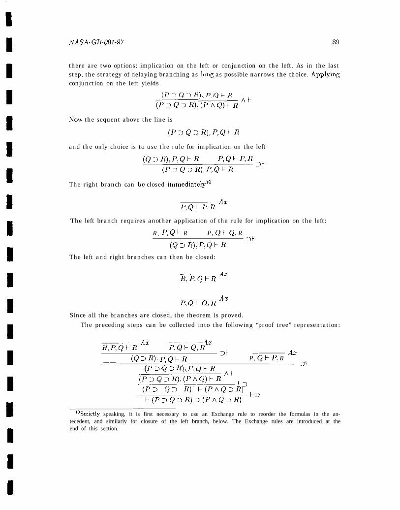
NASA-GB-001-97 89
there are two options: implication on the left or conjunction on the left. As in the laststep, the strategy of delaying branching as long as possible narrows the choice. Applyingconjunction on the left yields
(P> Q> R), P,QER
(p3Q>R), (1’ AQ) &RAF
NTOW the sequent above the line is
and the only choice is to use the rule for implication on the left
The right branch can be closed immediatelyl”
— AxP, QFP, R
‘The left branch requires another application of the rule for implication on the left:
R, P,Qt R P, QI-Q, R
(QoR),p,Q~R ‘t
The left and right branches can then be closed:
——— AxR, P,Qh R
AxP, QkQ, R
Since all the branches are closed, the theorem is proved.The preceding steps can be collected into the following “proof tree” representation:
— Az AxR, P,QFR F, QFQ, R
>t — Ax(Q DR), p,Q~R P, QI-P, R
_——.(P> Q> R), P, Qt-R
— — - - >}
~PDQ3~),(pAQ)FftAFF3
‘(P> Q> R) F(PAQ>R) ~=
‘- R(P>Q>R)>(PAQ>R)— ——
1°Strictly speaking, it is first necessary to use an Exchange rule to reorder the formulas in the an-tecedent, and similarly for closure of the left branch, below. The Exchange rules are introduced at theend of this section.
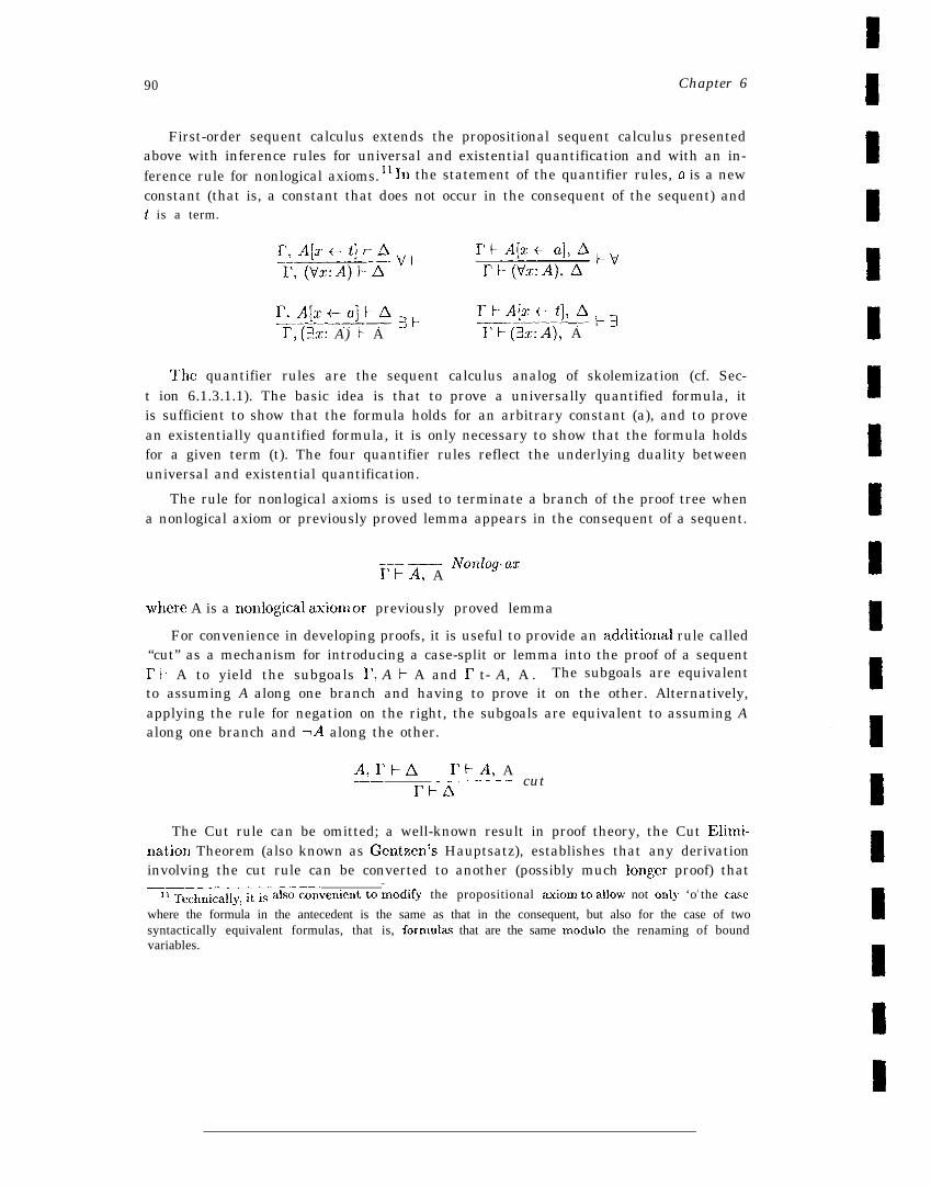
90 Chapter 6
First-order sequent calculus extends the propositional sequent calculus presentedabove with inference rules for universal and existential quantification and with an in-ference rule for nonlogical axioms. 11 In the statement of the quantifier rules, a is a newconstant (that is, a constant that does not occur in the consequent of the sequent) andt is a term.
I’, A[x-a]FA3F rRA[zwt], AE3—.————I’, (3z: A) F A TR (3z:A), A
The quantifier rules are the sequent calculus analog of skolemization (cf. Sec-t ion 6.1.3.1.1). The basic idea is that to prove a universally quantified formula, itis sufficient to show that the formula holds for an arbitrary constant (a), and to provean existentially quantified formula, it is only necessary to show that the formula holdsfor a given term (t). The four quantifier rules reflect the underlying duality betweenuniversal and existential quantification.
The rule for nonlogical axioms is used to terminate a branch of the proof tree whena nonlogical axiom or previously proved lemma appears in the consequent of a sequent.
.—— — Nonlog-azI’t-A, A
~,here A is a nonlogical axiom or previously proved lemma
For convenience in developing proofs, it is useful to provide an additio~ial rule called“cut” as a mechanism for introducing a case-split or lemma into the proof of a sequent17 E A to yield the subgoals I’, A 1- A and I’ t- A, A . The subgoals are equivalentto assuming A along one branch and having to prove it on the other. Alternatively,applying the rule for negation on the right, the subgoals are equivalent to assuming Aalong one branch and -A along the other.
A, I’ t-A I’I-A, A-—— ———.——rFA
—- cut
The Cut rule can be omitted; a well-known result in proof theory, the Cut Elimin-ation Theorem (also known as Gentzen’s Hauptsatz), establishes that any derivationinvolving the cut rule can be converted to another (possibly much long;er proof) that————.. —
11 Technical]~, it is also ~onk,enient to ~lodify the propositional aXiOIn to alh’ not onlY ‘or the case
where the formula in the antecedent is the same as that in the consequent, but also for the case of twosyntactically equivalent formulas, that is, formulas that are the same modulo the renaming of boundvariables.

NASA-GB-001-97 91
does not use cut. Since cut is the only rule in which a formula (A) appears above theline that does not also appear below it, it is the only rule whose use requires “inven-tion’> or “insight”; thus, the cut elimination theorem provides the foundaticm for anotherdemonstration of the semi-dccidability of the predicate calculus [Rus93b, p. 244].
Finally, there are four structural rules that simply allow the sequent to be rearrangedor weakened. These rules have the same status as the Cut rule; they can also be omitted.The Exchange rules allow formulas in the antecedent and consequent to be reordered.
rl, B, A,r2}Ax E rEAl, B, A, A2Fx—.1’11 A, B, rz F A rI-A1, A,l?, A2
The Contraction rules allow multiple occurrences of the same sequent formula to bereplaced by a single occurrence.’2
6.1.3.1.3 The Resolution Calculus
The resolution calculus is a negative test calculus for formulas in clausal forn~13; itcontains a single logical axiom and uses only one rule of inference, the resolution rule.The single axiom is an elementary contradiction denoted by the empty clause (D). Inits simplest form, the resolution rule may be viewed as a special instance of the cut rule(of the sequent calculus) in which all single formulas are Iiterals [BB89, p. 56]. Usingnotation from [131389], the resolution rule is defined as follows.
clausel: L , Kl,... ,Knclause2: TL, M1,. ... M~,resolvent: K1,. . . . Kn Ml,... ,M~
~rhere clauses ] and 2 are referred to as the parent clauses of the resolvent and L a n d-IL are the resolution literals.
A generalization of this rule allows an instantiation of the formulas in terms ofa substitution that maps variables to terms uniformly across both resolution literals.Using the same notation, the general resolution rule is expressed as shown below, whereu represents a substitution that makes the atoms L and L’ equal, that is, UL = crL’.
clausel: L , Kl,... ,Knclause2: TL’, M1,... ,Mmrcsolvent~ oK], . . . ,oK,, OMl,, ... uMn
—12 The structural rules (Contraction and Exchange) are sometimes formulated in terms of a single
weakening rule.Is’That is a disjunction of literals, w,here a literal is a proposition or a negateCl proposition. Q u a n -
tifiers are n~t permitted. Universal quantifiers are implicit, and existential quantifiers are replaced bySkolem functions as described in Section 6.1.3.1.1. For example, in clausal form, VX3V12(Z, y) becomesR(Z, f(z)).
92 Chapter 6
If a substitution, o exists for two expressions, the expressions are said to be unifiable andthe substitution is called a unifier for the two expressions. Given a pair cjf expressions,there are distinguished unifiers, known as the most generui unifiers from which all otherunifiers may be derived by instantiation.
The following examples are taken from [BB89]. The terms z and j(g) are unifiable.The substitution {x e ~(y), y ~- a} is a unifier for x and f(y), although it is not amost general one, since it can be obtained from the most general unifier {z ~ .f (Y)} Wfurther instantiating y with a. There are two equivalent most general unifiers for thepair of terms ~(x, g(x)) and ~(y, g(y)): {z ~ y} and {y - x}, which differ only withrespect to variable names. The terms x and ~(x) are not unifiable. Neither are theterms g(x) and ~(~).
Resolution is a complete refutation procedure for first-order logic. If a sentence isfalse under all interpretations over all domain-- that is, unsatisfiable, then resolutionwill terminate with the empty clause indicating a contradiction has been derived. Ifthe negation is unsatisfiable, the original theorem is true. If the origirlal theorem isnot true, resolution may not terminate. The proof of the completeness of resolutionis based on a result from Jacques Herbrand’s 1930 dissertation. Rough] y, Herbrand’stheorem states that in proving a set of clauses, S, unsatisfiable, the only substitutionsthat need to be tried are those drawn from the set, H, of all variable-free terms formedfrom the functions (inclucling constant functions) occurring in S. The set, H, is knownas the Herbrand Universe of S. Since H is always either finite or counts.bly infinite, acontradiction, if one exists, will always be found [CL73].
Resolution theorem provers can be highly effective in some domains. In general,they have not been used in formal methods because it has been difficult to combine res-olution with induction and with the additional first-order theories necessary for formalmethods applications. Furthermore, resolution methods do not readily support proofexploration and typically yield proofs that are not easily understood by humans. Nev-ertheless, fundamental techniques from resolution-based provers, such as highly efficientuuificatiou algorithms, have been incorporated in most modern theorem provers.
6.1.3.2 Extending the Predicate Calculus
The predicate calculus is not sufficient for most applications of formal methods, whichtypically require the addition of first-order theories such as equality, arithmetic, simplecomputer science datatypes (lists, trees, arrays, and so forth), and set theory. Thesefour theories are basic to most applications. Particular applications may benefit (sig-nificantly) from the inclusion of additional first-order theories. Formal methods alsorequire support for induction. In general, methods for automating inductive proofs areless well-developed, and user guidance is typically required for such proofs. A discussionof the current status of automated induction and the role of induction in formal meth-ods appears in [Rus96]. The discussion includes an interesting fragment drawn from aspecification of Byzantine fault-tolerant clock synchronization.
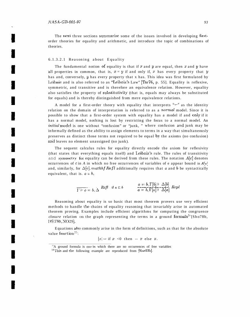
NASA-GB-001-97 93
The next three sections sumtnarize some of the issues involved in developing first-order theories for equality and arithmetic, and introduce the topic of combinations oftheories.
6.1.3.2.1 Reasoning about Equality
The fundamental notion of equality is that if x and y are equal, then z and g haveall properties in common, that is, z = y if and only if, z has every property that yhas and, conversely, y has every property that x has. This idea was first formulated byI,eibniz and is also referred to as “Leibniz’s Law” [Tar76, p. 55]. Equality is reflexive,symmetric, and transitive and is therefore an equivalence relation. However, equalityalso satisfies the property of substitutivity (that is, equals may always be substitutedfor equals) and is thereby distinguished from mere equivalence relations.
A model for a first-order theory with equality that interprets ‘(=” as the identityrelation on the domain of interpretation is referred to as a normal model. Since it ispossible to show that a first-order system with equality has a model if and only if ithas a normal model, nothing is lost by restricting the focus to a normal model. Aninitial lnodel is one without “confusion” or “junk, ” where confusion and junk may beinformally defined as the ability to assign elements to terms in a way that simultaneouslypreserves as distinct those terms not required to be equal by the axioms (no confusion)an’d leaves no element unassigned (no junk).
The sequent calculus rules for equality directly encode the axiom for reflexivity(that states that everything equals itself) and Leibniz’s rule. The rules of transitivityand synnnetry for equality can be derived from these rules. The notation A[e] denotesoccurrences of e in A in which no free occurrences of variables of e appear bound in A[e]and, similarly, for A[C]. ntathbf Ref/ additionally requires that a and b be syntacticallyequivalent, that is. a :: b,
Reasoning about equality is so basic that most theorem provers use very efficientmethods to handle the chains of equality reasoning that invariably arise in automatedtheorem proving. Examples include efficient algorithms for computing the congruenceclosure relation ml the graph representing the terms in a ground formulal 4 [Sho78b,DST80, N{)79].
Equations alsc) commonly arise in the form of definitions, such as that for the absolutevalue functionl~:
Irl = if x <0 then -- x else x.
14A ground formula is OIle in which there are no occurrences of free variables15This and the following example are reproduced from [Itus93b].

94 Chapter 6
One way to prove a theorem such as la +- bl < Iul + Ibl is to expand the definitionsand then perform propositional and arithmetic reasoning. “13xpanding a definition”involves finding a substitution for the left side of the definition that causes it to matcha term in the formula (for example, [x e a + b] will match lx I with la -k bl ), and thenreplacing that term by the corresponding substitution instance of the right side of thegiven definitiol~-- for example,
la+ bl=ifa-tb<O then -(a+ b)elsea+h
Expanding definitions is a special case of the more general technique of rewriting. “Thebasic idea is to impose directionality on the use of equations in proofs; . . . directedequations are used to compute by repeatedly replacing subterms of a given formulawith equal terms until the simplest form possible is obtained.” [DJ90] The notion ofdirected equation refers to the fact that although equations are symmetric--a = bmeans the same thing as b = a–- rewriting imposes a left-to-right orientation, henceequations viewed with this orientation are generally called rewrite rules. Rewritingmay be used with arbitrary equations provided the free variables appearing on the
right side of each equation are a subset of those appearing on its left. The process ofidentifying substitutions for the free variables in the left side of the formula of interestas a prerequisite to rewriting is called matching. Matching is sometimes referred to as‘(one way” unification; although the process is essentially the same, only substitutionsfor the variables in the equation being matched are of interest.
Rewriting may be automated or performed by the user. Two desirable propertiesof rewrite rules are jinite termination and unique termination, also knou’n as Church-Rosser. A set of rewrite rules has the finite termination property if rewriting alwaysterminates. A set of rewrite rules is Church-Rosser if the final result after rewritingto termination is independent of the order in which the rules are applied. There areeffective heuristic procedures for testing for the finite and unique termination properties,including Knuth-Bendix completion [KB70, DJ90], which can often be used to extenda set of rewrite rules that is not Church-Rosser into one that is. A theory that can bespecified by a set of rewrite rules with both the finite and unique termination propertiesmay be used as a decision procedure for that theory. Moreover, any such decisionprocedure is sound and, for ground formulas, complete, However, deducing disequalitiesis sound and complete only for the initial model. Therefore, systems that use rewritingto normal form as their primary or only means of deduction typically use an initialmodel semantics, whereas systems that use rewriting in conduction with other methodstypically use a classical semantics and (only) infer disequalities axiomatically.
There are several variations on rewriting, including order-sorted rewriting, condi-tional rewriting, priority rewriting, and graph rewriting. A description of these variantsappears in the comprehensive survey of rewrite systems provided in [DJ90].
Term rewriting is highly effective, and essential to the productive use of theoremproving for formal methods applications. It serves as the primary means of deduction
NASA-GB-001-97 95
in Afhrm [GM’I’+ 80, Mus80], Larch [wSJGJMW93], and RRL [KZ89] and is one of themost important techniques in the Boyer-Moore provers [BM88, Kh!196]. Rewriting mayalso be used for computation [GKK+ 88]. The paramodulat ion techniques [RW69] usedin resolution are similar to rewriting.
6.1.3.2.2 Reasoning about Arithmetic
Formal methods applications typically involve arithmetic expressions and relationso~,er both real atld Ilatural numbers, and both interpreted and uninterpreted function
symbols. The ubiquity and often the complexity of this arithmetic make efficient deduc-tive support for arithmetic essential to the productive use of formal methods [Rus96].Integer arithmetic is sutliciently important that some formal methods systems includedecision procedures for the quantified theory of integer arithmetic, often referred toas Presburger arithmetic after the Polish mathematician who first studied these arith-metics in the late 1920s. The decidable fragment essentially includes linear arithmeticswith addition, subtract ion, mult iplicat ion, equality, the “less than” predicate (<), and,by simple constructions, the predicates >, s, ~. Classic Presburger arithmetic, whichcontains neither function symbols nor anything other than simple constants, is decid-able. However, given the importance of function symbols and the fact that they may beintroduced into formulas in which they do not originally appear through the process ofskolernization, it is easy to appreciate the tension between efficiency (decidability) andexpressiveness. Tools for formal methods often opt to restrict the arithmetic decisionprocedures to the ground (that is, propositional) case, where the combination of lineararithmetic wit h uninterpreted function symbols is decidable [CLS96].
6.1.3.2.3 Combining First-Order Theories
One of the challenges in designing a truly useful theorem prover or proof checker iscombining decidable theories both with one another and with user interaction. Thereare algorithms dating back to the late 1970s for combining decision procedures, includ-ing Nelson- Oppen [N079] and Shostak [Sho78b, CL S96]. The Nelson- Oppen algorithmcombines decision procedures for two disjoint ground theories (for example, linear arith-metic and lists) by “introducing variables to name subterms and iteratively propagatingany deduced equalities between variables from one theory to another” [CLS96]. Shostakcombines theories that are canonizable (that is, can be converted to a canonical or nor-mal form) and algebraically solvable using an optimized implementation of the congru-ence closure algorithm for ground equality over uninterpreted function symbols [CLS96].Since Shostak’s approach appears to be very efficient, but is restricted to algebraicallysolvable theories, there is some interest in combining it with Nelson-Oppen.
Most automated theorem provers and proof checkers minimally contain inlplementa-tions of decision theories for propositional logic, equality, and linear arithmetic. Cyrluket al. note that the method used to combine decision procedures is more critical to
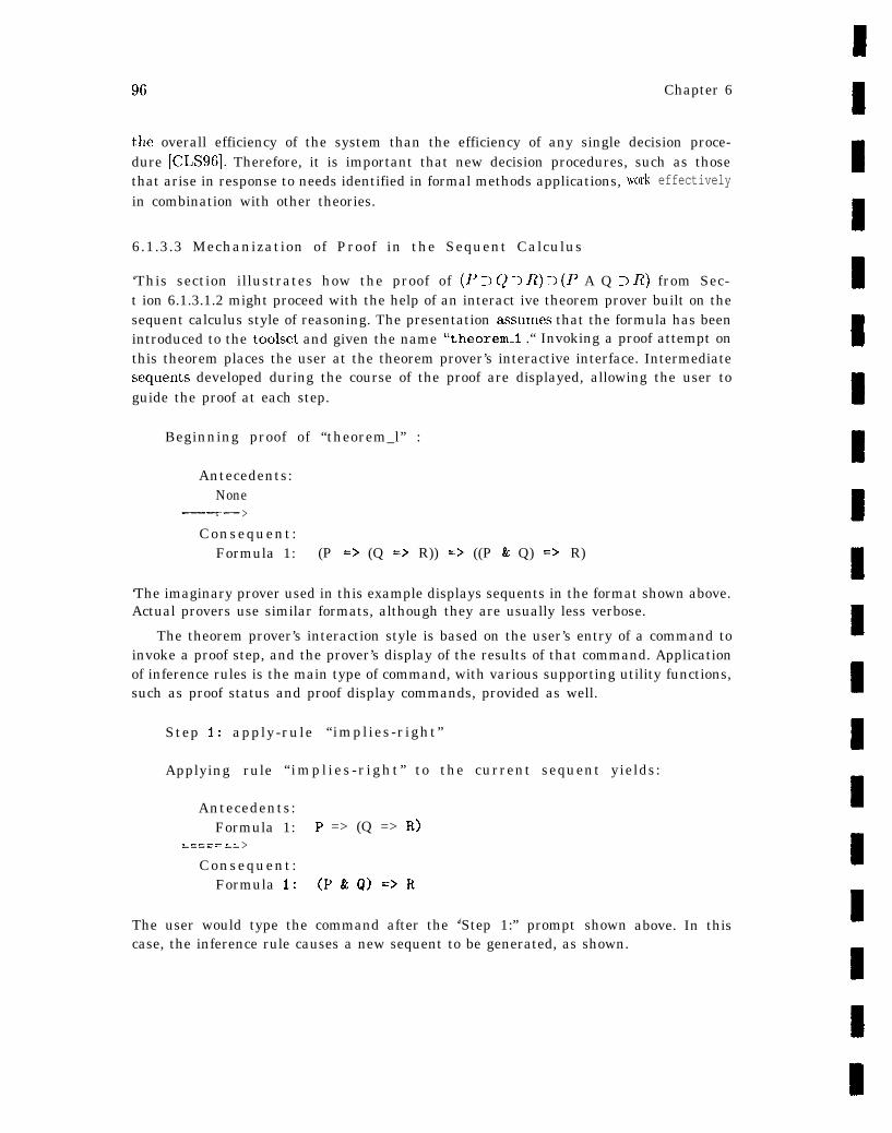
96 Chapter 6
the overall efficiency of the system than the efficiency of any single decision proce-dure (CLS96]. Therefore, it is important that new decision procedures, such as thosethat arise in response to needs identified in formal methods applications,in combination with other theories.
6.1.3.3 Mechanization of Proof in the Sequent Calculus
wcmk effectively
‘This section illustrates how the proof of (P > Q ~ R) ~ (F A Q > R) from Sec-t ion 6.1.3.1.2 might proceed with the help of an interact ive theorem prover built on thesequent calculus style of reasoning. The presentation asssumes that the formula has beenintroduced to the toolset and given the name “theorem_l .“ Invoking a proof attempt onthis theorem places the user at the theorem prover’s interactive interface. Intermediatescquents developed during the course of the proof are displayed, allowing the user toguide the proof at each step.
Beginning proof of “theorem_l” :
Antecedents:None
_——--. ——----. — >Consequent:
Formula 1: (P => (Q => R)) => ((P & Q) => R)
‘The imaginary prover used in this example displays sequents in the format shown above.Actual provers use similar formats, although they are usually less verbose.
The theorem prover’s interaction style is based on the user’s entry of a command toinvoke a proof step, and the prover’s display of the results of that command. Applicationof inference rules is the main type of command, with various supporting utility functions,such as proof status and proof display commands, provided as well.
Step 1: apply-rule “implies-right”
Applying rule “ impl ies -r ight” to the current sequent yields:
Antecedents:Formula 1: P => (Q => R)
===== .= >Consequent:
Formula 1: (P& Q)=>R
The user would type the command after the ‘(Step 1:” prompt showncase, the inference rule causes a new sequent to be generated, as shown.
above. In this
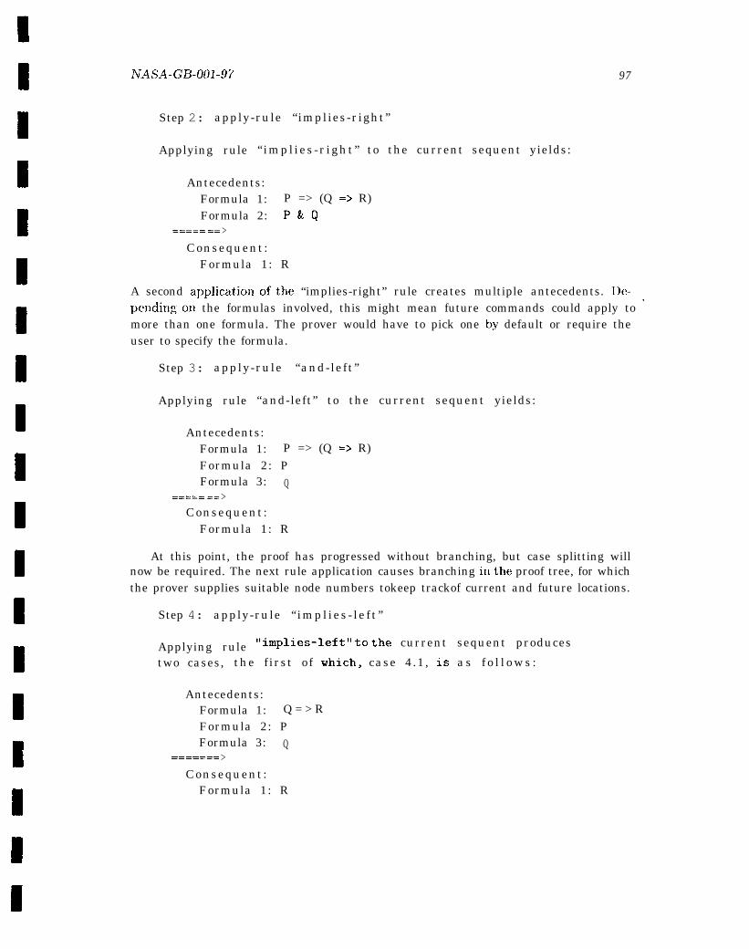
NASA-GB-001-97 97
Step 2: apply-rule “implies-right”
Applying rule “ impl ies -r ight” to the current sequent yields:
Antecedents:Formula 1: P => (Q => R)Formula 2: P&Q
===== == >Consequent:
Formula 1: R
A second applicationofthe “implies-right” rule creates multiple antecedents. De-pendingon the formulas involved, this might mean future commands could apply to ‘more than one formula. The prover would have to pick one by default or require theuser to specify the formula.
Step 3: apply-rule “and-left”
Applying rule “and-left” to the current sequent yields:
Antecedents:Formula 1: P => (Q => R)Formula 2: PFormula 3: Q
===== == >Consequent:
Formula 1: R
At this point, the proof has progressed without branching, but case splitting willnow be required. The next rule application causes branching inthe proof tree, for whichthe prover supplies suitable node numbers tokeep trackof current and future locations.
Step 4: apply-rule “ impl ies - le f t ”
Applying rule llimPlles-leftl! to the current sequent produces
two cases, the f irst of which, case 4.1, is a s f o l l o w s :
Antecedents:Formula 1: Q = > RFormula 2: PFormula 3: Q
—------—---_—— >Consequent:
Formula 1: R
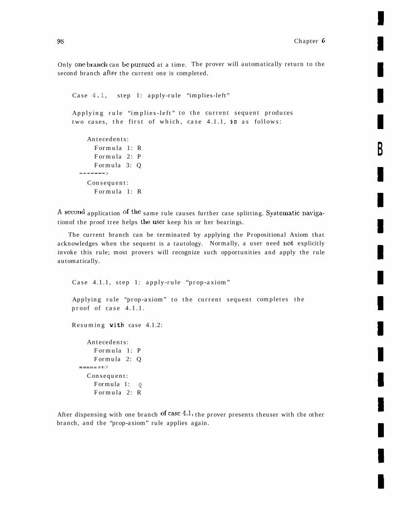
98 Chapter 6
Only cme branch can be ?mrsued at a time. The prover will automatically return to thesecond branch after the current one is completed.
Case 4.1, step 1: apply-rule “implies-left”
Applying rule “implies-left” to the current sequent producestwo cases, the first of which, case 4.1.1, is as follows:
Antecedents:Formula 1: RFormula 2: PFormula 3: Q
_——----- - - - - - ->Consequent:
Formula 1: R
Asecond application ofthc same rule causes further case splitting. Systenlaticnaviga-tionof the proof tree helps theuscr keep his or her bearings.
The current branch can be terminated by applying the Propositional Axiom thatacknowledges when the sequent is a tautology. Normally, a user need not explicitlyinvoke this rule; most provers will recognize such opportunities and apply the ruleautomatically.
Case 4.1.1, step 1: apply-rule “prop-axiom”
Applying rule “prop-axiom” to the current sequentproof of case 4.1.1.
Resuming with case 4.1.2:
Antecedents:Formula 1: PFormula 2: Q
===== .= >Consequent:
Formula 1: QFormula 2: R
9
ID
B9IB8
Icompletes the
9
9
B
After dispensing with one branch ofcase4.1, the prover presents theuser with the otherbranch, and the “prop-axiom” rule applies again.
NAsA.G~4joJ-97 99
Case 4.1.2, step 1: apply-rule “prop-axiom”
Applying rule “prop-axiom” to the current sequent completes theproof of case 4.1.2. This also completes the proof of case 4.1.
Resuming with case 4.2:
Antecedents:Formula 1: PFormula 2: Q
===== .=>Consequent:
Formula 1: PFormula 2: R
After finishing allofcase 4.1, theprover pops back uptocase 4.2 to finish off theonly remaining branch c)fthe proof.
Case 4.2, step 1: apply-rule “prop-axiom”
Applying rule “prop-axiom” to the current sequent completes theproof of case 4.2. This also completes the proof of “theorem_l”.
Q.E.D.
Recognizing that all branches ofthc tree have resulted invalid proofs, the prover an-nounces the successful completionofthe overall proof.
Although this example has been cast in terrnsof a fictitious theorem prover, manyactual provers follow a similar style of interaction. Level of automation, and thereforethe nature of the interaction, varies considerably from one prover to another. Forexarnplc,t helevel ofautomation may makeit unnecessaryto invoke rulesat the levelofdetail presented here. Although the prover typically builds the full proof tree, the usergenerally sees only those portions of the tree requiring user guidance. ‘l?rivialcasesaretypically not displayed, although there may bea facility for revisiting both the implicitand explicit steps ofa proof. On first attempt, most putative theorems attempted areincorrect, that is, they are not in fact theorems. Therefore it isat least as importantthat an automate ddeductionsystem facilitate the discovery oferror, as that it shouldefficiently prove true theorems.
In addition to mechanizing routine manipulations, automated deduction systemsshould reduce the low-level interaction and repetitive tedium involved in large proofs.To this end, many interactive provers provide higher-order functions known as tacticsand control structures known as tacticals that allow simple tactics to be combined into
100 Chapter 6
more complex ones. Paulson [Pau92, p. 456] notes that ideally tactics should capture thecontrol structures typically used in describing proofs. He also remarks that, in practice,tactics often do not work at the level of proof description, but rather at a somewhatlower level. Nevertheless, tacticals potentially allow the user to perform hundreds ofinferences with a single command. The concept and implementation of tactics andtacticals varies from prover to prover, but all share the idea that a theorem provershould be programmable. The challenge in using any automated reasoning system is tolearn to use the automation effectively by exploiting the system’s strengths and realizingits limitations.
Given the number and diversity of automated reasoning systems, the question invari-ably arises as to which system is most appropriate for a given application. Young [You95]suggests the use of benchmark problems to facilitate comparison of system performance .within specific areas. Although standard benchmarks have yet to be identified, thereare problems, such as the railroad gate controller in the area of safety-critical systems,that have been attempted on a variety of systems.
6.1.4 Utility of Automated Deduction
Deductive techniques support more varied and more abstract models, more expressivespecification, more varied properties, and more reusable verifications than finite stateverification techniques. The essential utility of theorem proving or proof checking in-cludes the following. With the exception of establishing the consistency of axioms, thesebenefits are self-explanatory and are listed with little additional comment.
● Guarantee Type Correctness: The type correctness of some specification languagesis undecidable. In such cases, theorem proving or proof checking may be used todischarge obligations incurred during typechecking, thereby establishing that aspecification is type-correct. As noted in Chapter 5, significant benefit accruesfrom typechecking alone.
● Establish (Relative) Consistency of Axioms: A specification can be shown to beconsistent by demonstrating that its axioms have a model. In the context ofmechanical verification, this is accomplished via theory interpretations that re-late a source specification (the one to be shown consistent) to a target speci-fication whose consistency has presumably already been established16. This isaccomplished by defining a mapping from the types and constants of the sourcespecification to those of the target specification and proving that. the axioms ofthe source specification expressed in terms of that mapping are provable theo-rems of the target specification. The proof demonstrates relative consistency;
.—. —_ .——lGFor example, by specifying the target specification definitionally in a system that guarantees con-
servative extension.
NASA-GB-001-97 101
that is, if the target specification is consistent, the source specification is consis-tent. [ORSVH95, p. 111] cites an example that underscores the need to validateaxiomatic specifications by exhibiting an intended model.
● Challenge Underlying Assumptions: One of the benefits of formal specificationis the explicit statement of underlying assumptions. Once formalized, these as-sumptions may be challenged by formulating and proving conjectures that exer-cise them. Design implications of new or modified assutnptions may be sitnilarlyprobed in this way.
● Establish the Correctness of Hierarchical Layers: Theory interpretations may alsobe used to demonstrate the correctness of hierarchical development, that is, toprove that a niore concrete specification is a satisfactory implementation of amore abstract one, as illustrated in [Bev89, BDH94]. The approach is similar tothat previously mentioned in the context of establishing the consistency of a setof axioms.
● Conjirm Key Properties and Invariant: System properties and constraints maybe precisely stated and deductively verified.
● Predict and Calculate System Behavior: System behavior may be predicted orcalculated by formulating and proving challenges or putative theorems that char-acterize the behavior or functionality of interest.
● Facilitate Replication and Reuse: Reusing and adapting extant proofs, as well asformulating new challenges, provides a systematic exploration of the implicationsof changes and extensions, as well as an effective vehicle for generalizing results forlater reuse. Automation is the key to faithfully replicating or reusing a detaileddeduction. The L,aRC bit vectors library [BMS+96] illustrates many of the issuesinvolved in developing general and effectively reusable formal analyses.
The use of proof as a form of absolute guarantee is not included in this list for reasonsoutlined in Section 7.5, and succinctly captured in the following quote from [RvH93]: “Amechanical theorem prover does not act as an oracle that certifies bewildering argumentsfor inscrutable reasons, but as an implacable skeptic that insists on all assumptions beingstated and all claims justified.”
6.2 Finite-State Methods
The state space of a system can be loosely defined as the full range of values assumedby the state variables of the program or specification that describes it. The behaviorsthat the system can exhibit can then be enumerated in terms of this range of values. Ifthe state space is finite and reasonably small, it is possible to systematically enumerate
102 Chapter 6
all possible behaviors of the system. However, few interesting systems have tractablestate spaces. Furthermore, the state space of a formal specification can be infinite, forexample, if it uses true mathematical integers as values for state variables. Nevertheless,there are various techniques for “downscalin.g” or reducing the state space of a system,while preserving its essential properties. Finite-state methods refer to techniques forthe automatic verification of these finite-state systems or of infinite-state systems thatcan be similarly ‘keduced” by virtue of certain structural symmetries or uniformities.Given a formula specifying a desired system property, these methods deterl-nine its truthor falsity in a specific finite model (rather than proving its validity for all models). Forlinear-time and branching-time logics, the model checking problem is computationallytractable, whereas the validity problem is intractable.
6.2.1 Background
This section provides background information useful for an understanding of finite-statesystems, including a brief introd uct ion to temporal logics, fixed point characterizations,and the modal mu-calculus.
6.2.1.1 Temporal Logic
Temporal logic (also known as tense logic) [Pnu77, Bur84] augments the standard opera-tors of propositional logic with tense oyemtom that are used to formalize time-dependentconditions. The simplest temporal logic adds just two operators: the (weak) future op-erator, F’, and the (weak) past operator, P. The formula Fq is true in the present if qis true at some time in the future and, similarly, the formula Pq is true in the presentif g is true at some titne in the past. These operators can be combined to assert quitecomplex statements about time-dependent phenomena. For example, q =+ FPq can beinterpreted as “if q holds in the present, than at some time in the future q will haveheld in the past.” [McM93, p. 13] The duals of these operators, -@’m, usually abbre-viated G and 1P–I, usually abbreviated H, yield the corresponding strong future andpast operators. Gq - ~F7g means that q is true at every moment in the future, andHq G -+’~g means that g is true at every moment in the past.
A temporal logic system consists of a complete set of axioms and inference rulesfor proving all valid statements in the logic relative to a given model of titne. Someof the more commonly used models include partially ordered time, linearly orderedtime, discrete time, and branching (nondeterministic) time. Linear time correspondsto commonly held notions of time as a linearly ordered set measured with either thereal or natural numbers. Discrete time refers to a model in which time is representedas a discrete sequence measured by the integers, as commonly found in engineering.Interval Temporal Logic [Mos85] is based on discrete time. Branching time is a modelin which the temporal order < defines a tree that branches toward the future; everyinstant has a unique past, but an indeterminate future [McM93, p. 15]. Temporal
ArAcJA.~B_oo]-97 103
“ 17 have been used to express program prop-logic andthe closely related dynamic logzcerties such as termination, correctness, safety, deadlock freedom, clean behavior, dataintegrity, accessibility, responsiveness, and fair scheduling [Bur84, p. 95]. Duration Cal-culus [CHR92], a notation used to specify and verify real-time systems, is an extensionof interval temporal logic that uses a notion of durations of states within a time inter-val, but without explicit mention of absolute time. Temporal logics, and modal logicsin general, are typically given a model theoretic semantics known as possible worldssemantics. A model in this semantics is usually referred to as a Kripke model, afterSaul Kripke, one of the first mathematicians to give a model-theoretic interpretation ofmodal logic [Kri63a, Kri63h, Kri65]. The basic idea of Kripke semant ics is to relat ivizethe truth of a statement to temporal stages or states. Accordingly, a statement is notsimply true, but true at a particular state. ‘The states are temporally ordered, with thetype of temporal order determined by the choice of axioms.
For example, the sc)-called minimal tense logic, Kt, is defined by vau Benthem asfollows [vB88, p. 7].
● Axioms:
● Rules of Inference:
1. 0,@ ~ ~~/4 (Modus Ponens)
2. if r#I is a theorem, then so are G@, If@ ((’Temporal) Generalization)
Various axioms may be added to Kt to characterize further assumptions on thetemporal order, such as transitivity and antisymrnetry (which together yield a partialorder), as well as density, linearity, and so forth. In the context of finite state methods,the notions of linear time and branching time are of particular interest.
‘ 7The term “dynamic logic” refers generically to logical systems used to reason about computerprograms. The basic premise is that certain classical logical systems that are inherently “static” can beextendeci quite naturally to reason about ‘(dynamics.” In addition to its application to computationalsystems, the study of dynamic logic and related topics has more general philosophical and mathematicalimplications as a natural extension of modal logic to general dynamic situations [Har84].

104 Chapter 6
QzThe set of states in an interpretation represents not only past states, but all accessible
(possible) future states. Furthermore, truth is persistent. Intuitively, this means that asentence true at a given state will always be true at later states. The following definitionsare due to Burgess [Bur84, pp. 93-4]. A Kripke frame is composed of a nonempty setS, equipped with a binary relation R. A valuation in a frame (S, R) is a function, V,that assigns to each variable, pi, a subset of S, and each (syntactically well-formed)sentence a truth value. Intuitively, S represents the set of states and R represents theearlier-later relation. A formula, Q is valid in a frame (S, 1?) if V(a) = X for everyvaluation ~’ in (X, R). a is satisfiable in (X, R) if V(a) # 018 for some valuation V in(S, R), or, equivalently if -la is not valid in (S, R). In addition, a is valid over a class,K, of frames if it is valid in every (S, R) E K, and is satisfiable over K if it is satisfiablein some (S, R) c K or, equivalently, if ma is not valid over K.
The interaction of universal and existential quantification with temporal operatorsis complex, introducing both philosophical and technical difhcult ies. Burgess [13ur84,p. 131] notes that the philosophical issues include “identity through changes, cent inuity,motion and change, reference to what no longer exists or does not exist, essence andmany, many more” and the technical issues include “undecidability, nonaxiomatizability,undefinability or multidimensional operators, and so forth.” Thoughtful discussion ofthese issues can be found in [Gar84] and [COC84].
6.2.1.2 Linear Temporal Logic (LTL)
Linear time corresponds to the usual notion of time as a linearly ordered set, measuredeither with the real or the natural numbers. The temporal order relation < is total, thatis, antisymmetric, transitive, and comparable. comparability means that for all statesS 1 and sz in the same execution sequence, either SI < sz or sz < sl or S1 = SZ). Theextension of Kt obtained by adding the following two axioms (of right- and left-linearity,respectively) characterizes the linear temporal frames.
Alternatively, the following, somewhat more intuitive axioms can be used to char-acterize total orders [Bur84, p. 104].
180 denotes the empty set

NAsA_ GB_ooj .97 105
Linear temporal logic is typically extended by two additional operators, the untiloperator and the since operator, abbreviated U and S, respectively.
Qz
The following definitions are based on a discussion in [hlcM93, p. 14] and assumethat, all subscripted states, s.., are comparable. @ UI/~ is true in state Sj if there is somestate Sk such that Sj < Sk and @ is true in sk, and for all Sz, such that sj < si < sk,~ is true in state s~. Intuitively, @ holds at some time in the future, until which time@ holds. Similarly, qMI/J is true in state s~ just in case there is some state sk such thatSk < sj and @ is true in %, and for all sz, suc~l that sj < Si < Skt @ is true in state Si.
Informally, @ held at some time in the past, since which time ~ has held.
m
6.2.1.3 Branching Time Temporal Logic
A treelike or branching fratne is one in which the temporal order defines a tree thatbranches toward the future. Treelike frames represent ways in which things can evolvenondeterministically; every moment, or state has a unique, linearly ordered past, hut anindeterminate future. Following Thomason [Tho84, p. 142], a t reelike frame for a tenselogic consists of a pair (T, <), where T is a nonempty set and < is a transitive orderingon T such that if t] < t and tz < t, then either tl = t2 or tl < t2 or t2 < tl. Thetree-ordered frames can be characterized by dropping the axiom
(PF~,)
from the axioms of linear time logic.ordered subset of T containing t.
–+ (1’() v ~ v Fd)
A branch through t 6 T is a maximal linearly
The semantics for branching time temporal logic are somewhat problematic. AsThomason [Th084. p. 142] notes, interpreting future tense in these t reelike structurescan be perplexing. For example, take a simple structure with three rncments, the root,to, and two branches labeled t] and t2, respectively. Assume @ true at to and tl andfalse at t2. Is F@ true at to? It is hard to say. The answer involves technical issues thatrevolve around the reconciliate ion of tense with indeterminism. The logical argument fordeterminism claims that it is not possible to provide a correct definition of satisfactionfor these struct m-es, that is, to provide a definition that does not generate validitiesthat are incompatible with the intended interpretation. Thomason [Tho84] presents
106 Chapter 6
an interesting discussion of strategies advanced by indeterminists to circumvent theseclaims.
The propositional branching time temporal logics that provide the foundation for oneof the principal approaches to finite state verification of concurrent systems are calledComputational Tree Logics. There are basically two variants: CTL and CTL*. Thelogic CTL* combines both branching-titne and linear-time operators. A (computational)path quantifier, either A or E, denoting all or some paths, respectively, can prefixassert ions composed of arbitrary combinations of the linear time operators G, F, U,and the “nextt ime” operator, X (see below). There are two types of formulas in CTL*:state formulas that are true in a given state and path formulas that hold along a givenpath. The following definitions are taken from [CGK89, pp. 83-84]. Let AF’ be the setof atomic proposition names.
A state formula is either:
. A, if A E AP.
● If f and g are state formulas, then Vf and f V g are state formulas.
● If ~ is a path formula, then E(f) is a state formula.
A path formula is either:
● A state formula.
● If f and g are path formulas, then =f, f V 9, Xf and fUg are path formulas.
CTL*” is the set of formulas generated by the above rules. CTL is a restricted subsetof CTL* that permits only branching-time operators. CTL is obtained by limiting thesyntax for path formulas to the following rule.
● If f and g are state formulas, Xf and fUg are path formulas.
The following abbreviations are also used in writing CTL* and CTL formulas:
● jAgG1(7fV7g)
● A ( f ) - YE(-lf)
. F ( f ) - trueUf
● G(f) s -TF-lf
NASA-GB-001-97 107
Q2’
The semantics of CTL* are defined with respect to a (finite Kripke) structure K =(117, R, L), where
● W is a set of states or worlds.
● R c W x W is the transition relation. R is total. WI ~ W2 indicates that(ul,, u)~) G R.
● L: W -+ P(AP) is a function that labels each state with a set of atomic proposi-tions true in that state.
Let .fl and ~z be state formulas, gl and gz be path formulas. A path in K is definedas a sequence of states 7r = too, wl, . . . such that for every i > 0, wi ~ wi+l. n~ denotesthe sufiz of 7T starting at w~. K, w ~ ~ means that ~ holds at state w in structure K.Similarly, if g is a path formula, K, m ~ g means that g holds along path n in structureK. The relation 1= is inductively defined as follows.
● w + A IFF A G L(w).
● u) ~ -Tfl IFF it is not tile case that w ~ il.
● w + fl V fz IFF W + fl 0’7’ W) (== fz.
● w + E(gl ) IFF there exists a path 7r starting with w such that tr # 91.
● n ~ ~1 IFF w is the first state of m and w ~ .fI.
● m + ~gl IFF it is not the case that n ~ gl.
● n ~ g1Ug2 IFF there exists a k ~ O such that # \ g2 and for all O ~ j <k, 7rJ +gl.
108 Chapter .5
6.2.1.4 Fixed Points
A functiod is a function that maps functions to functions, that is, a function thattakes functions as arguments and returns functions as values. A functional may bedenoted by a lambda expression, kz.j, where z is a variable and ~ is a formula. Thevariable z is effectively a place holder. When the functional is applied to a parameter,p, p is substituted for all instances of x in j. 19 For example, if -T = k. (Z A y), then~(true) = true A y = y. A functional ~ is monotonic if p c q -+ ~(p) C ~(g).
The following definition and example are taken from a discussion in [McM93, p. 19].A fixed point of a functional -y is any p such that ~(p) = p. For example, if ~ is definedas above, then x A y is a fixed point of T, since 7(x A y) = (Z A y) A y = z A g.
A monotonic functional has a least fixed point and a greatest jized point, also referredto as extremal jized points. The least (greatest) fixed point was defined by Tarski [Tar55]as the intersection (union) of all the fixed points of the functional. The least and greatestfixed points of a functional Az..f are denoted /Lx.f and zm..f, respectively. Assumiugthe functional is continuous, the extremal fixpoints can be characterized as the limit ofa series defined by iterating the functional.
f?z
The following definitions are also taken from [h1cM93, p. 19]. A functional, -Y,is union-continuous (intersection-continuous) if the result of applying -Y to the union(intersection) of any nondecreasing infinite sequence of sets is equal to the result oftaking the union (intersection) of ~ applied to each element of the sequence. Tarskishowccl that if a functional is monotonic and union-continuous, the least fixed point ofthe functional is the union clf the sequence generated by iterating the functional startingwith the initial value false, that is, for any such functional, -Y, the least fixed point isUZVZ (faZse). Similarly, the greatest fixed point of a monotonic, intersection-continuousfunctional, -y, is ni~i(i~2f~).
Any monotonic fuuctioual is necessarily continuous (that is, union-continuous andiutersect ion-cent inuous) over a finite set of states [McM93, p. 19]. Fixed points of fuuc-tionals have been used to characterize CTL operators, resulting in E’ffiCkIlt algorithmsfor temporal logic model checking. The standard reference for fixed point characteriza-t ions of CTIJ formulas is [EI.86].
6.2.1.5 The Mu-Calculus
The mu-calculus is a logic based on extremal fixed points that is obtained by addinga recursion operator. p, to first-order predicate logic (FOL) or to propositional logic.
—lgThe discussion a.ssurnes the usual restrictions on lambda-conversion that ensure that variables oc-
curring free in p are not bound by operators or quantifiers in f.
NASA-GB-001-97 109
In the context of FOL, the p operator can be viewed as an “alternative quantifier forrelations” that replaces the standard quantifiers V and 3 on relations (but not on in-dividuals) [Par76, p. 174], while in propositional logic, the p operator provides newn-ary connective. Kozen [Koz83] credits Scott and De !dakker [SB69] with originati-ng the mu-calculus and Hitchcock and Park [H P73], Park [Par70], and De Bakkerand De Roever [13R73] with initit ially developing the logic. Park [Par76, p. 173] notesthat the mu-calculus was a natural response to the inability of first-or(ler predicatelogic ‘(to express interesting assertions about programs“ in a reasonable way. The mu-calculus is “strictly intermediate” in expressive power between first- and second-orderlogics [Par76]. There are several different formulations of the mu-calculus. Some, likethose of [BR73, HP73], present the calculus as a polyadic relational system that sup-presses individual variables and replaces existential quantification (3) on individualswit h a composition operator on relations [Par76]. Others, like the version below re-produced from [McM93, pp. 114-115] and based on [Par76], retain the more traditionalsystem of predicate logic.
There are two kinds of mu-calculus formulas: relational formulas and Boolean formu-las, and, correspondingly, two kinds of variables: relational variables (for example, thetransition relation, R) and individual variables (for example, the state, Z). A model forthe mu-calculus is a triple M = (S,@, #~), where S is a set of states, @ is the individualinterpretation function that maps every individual variable to an element of S, and @ isthe relational interpretation that maps every n-ary relational variable onto a subset ofSn. The syntax of Boolean formulas is defined as follows, where p and q are syntacticvariables representing Boolean formulas, z is an individual variable, (z], . . . . ~n ) is avector of individual variables, and R is an n-ary relational formula.
. true and false are Boolean formulas.
● p V q and Yp are Boolean formulas.
● %.p is a Boolean formula.
● R(zl, ...> Zn ) is a Boolean formula.
The formula 3x.p is true just in case there exists a state z in S such that p is true inx. Similarly, the formula R(z, y) is true just in case the pair (q5(z), ~(y)) is a memberof V(R).
The relational formulas are defined as follows, where, in addition to the definitionsgiven above, F is an n-ary relational formula that is formally monotonic in R.
● Every n-ary relational variable R is an n-ary relational formula.
● A(zl, . . . , Xn ) .p is an n-ary relational formula.
110
● llR.P and vR. F are relational fornlulas.20
Chapter 6
In a given model (S, ~, ~~),
● The relational variable R is identified with the relation ~)(R).
● A(z] >... , Zr, ).p denotes the set of all n-tuples (X:l, . . . . Z,l) such that p is true.
● The formulas p R.F and vR. F stand for the least fixed point and greatest fixedpoint (of ~ = ~R.F), respectively.
6.2.2 A Brief History of Finite-State Methods
Finite-state methods grew out, of several independent developments in the mid to late1970s, including early work on temporal logic and early activity in protocol specificationand verification. Pnueli first proposed the use of temporal logic to reason about concur-rent and reactive programs [Pnu77]. Formalization of safety properties for concurrentsystems followed shortly thereafter. Pnueli’s early proofs were largely manual, as werethe initial techniques used to verify protocols. The realization that many concurrentprograms can be viewed as communicating finite-state machines combined with resultsin reachability analysis and the realization of their applicability to protocol analysissoon led to techniques for automatic verification of correctness properties. 21
The first such techniques arose in the context of protocol validation [BWHJ78,Haj78,WZ78, R1380]. Shortly thereafter, in the early 1980s, Holzmann built a general protocolverifier based on reachability analysis [H0181], Sifakis and his students at Grenoble Uni-versity in lhance began work on the French validation system Cesar [Que82, QS82], andClarke and his students at Carnegie Mellon University (CMU) independently developedthe Extended Model Checker (EMC) system [CE81, CES86]. Both Cesar and EMC usedalgorithms for the braIIChillg-tiIlle logic CTL. The CMU system also incorporated slightmodifications to CTL to accommodate fairness constraints [B Ch!l+ 90]. Holzmanrr’s ini-tial protocol verifier was based on a simple process algebra, but his subsecprent systemsuse standard automata theory. In all three cases, this early work led to currently in~-portant systems: Holzmann’s work culminated in SPIN, the Grenoble eflort producedCesar and several specialized variants, and CMU’S EMC evolved into SMV.
Research in model checking for verifying lletwork protocols and sequential circuitsquickly led to the realization that application of model checking techniques to nontrivialsystems required viable approaches to the so-called state explosion problem. The termrefers to the fact that in the worst case, the number of states in the global state graphfor a system with N processes may grow exponentially with AT. There has been a great
—20v may be defined in terms of p (vR.1’ = =p12. =F) or specified as a (primitive) fixpoint operator asshown here.
21 Initially, safety properties. Liveness and fairness followed later.
NASA-GB-O01-97 111
deal of work on the computational complexity of model checking algorithms, as wellas on techniques to address the state explosion problem. One of the earliest and mostimportant techniques for CTL-based model checking systems is a symbolic, rather thanan explicit, representation of the state space. That is, the set of states is representedby a logical formula that is satisfied in a given state if and only if the state is a memberof the set, rather than by a labeled global state graph. Similarly significant benefits forLTL-based model checking have been obtained with partial order techniques [God90,Va190, Pe193, GPS96]. For certain applications, both techniques can reduce exponentialgrowth of the state space to linear or sublinear growth [HoI].
To provide further economies for CTL-based model checking, symbolic representa-tions capable of exploiting structural regularities and thereby avoiding explicit construc-t ion of the state graphs of modeled systems have been sought. The representat ion that iscurrently most widely used is a canonical, but highly compact form for Boolean formulasknown as ordered binary decision diagrams or OBDDS [Bry86].22 An OBDD is similarto a binary decision tree, except that its structure is a directed acyclic graph rather thana tree and a strict order governs the occurrence of variables. Bryant [Elry86] has shownthat there is a unique minimal 013DD for a given formula under a given variable order-ing. Variable ordering is thus critical for determining the size of the minimal OBDDfor a given formula. Although the use of symbolic representation allows significantlylarger systems to be modeled, the state explosion problem persists as a computationalbarrier restricting the size and complexity of systems that can be verified using finitestate methods.
Other strategies have been and continue to be proposed to address this prob-lem. These include exploiting structural symmetries in the systems to be veri-fied [CFJ93, ES93, ID93], using hierarchical [MC85] and compositional [CLM89, GS90]techniques, applying abstraction methods [CGL92, Kur94], and employing on-the-flyintersection tec}miques [H0184, CV WY92, FMJJ92]. For LTL-based model checking,efFicient on-the-fly techniques have been a significant development because on-the-flyverification algorithms require only that part of the graph structure necessary to proveor disprove a given property, rather than the entire Kripke structure (for example, asrequired by fixpoint algorithms). Compositionality and abstraction exemplify a “divide-and-conquer” strategy that attempts to reduce the verification problem to a series ofpotentially more manageable subproblems [God96, p. 17], whereas partial order andon-the-fly methods attempt to reduce the size of the checked state space and the extentof the search, respectively. Some of these techniques may be usefully combined. Par-tial order and on-the-fly methods are a good example, as noted in [Pe194]. Others arecomplementary. Compositional and abstraction methods, for example, are essentiallyorthogonal – and thereby complementary to - partial order techniques [God96, p. 17].
220BBD is sometimes written simply as BL)D, although as McMillan notes [Mch193, p. 32], thevariable ordering (which is crucial to obtaining the canonical reduced form) is what distinguishes OBDI)Sfrom the more general class of BI)Ds.
112 Chapter 6
6.2.3 Approaches to Finite-State Verification
As noted earlier, finite-state verification techniques emerged in the late 1970s and early1980s from two independent developments: temporal logic model checking [C1381 ,Que82]and protocol analysis [Haj78, Wes78]. Subsequent developments can be classified withrespect to several dimensions, reflecting factors such as representation strategy, typeof algorithm, and class of system addressed. The distinctions made by representa-tion strategy are broad and therefore well-suited tothe general discussion offered here.Representation strategy distinguishes approaches that useafinite state representationfor the system modeland a logical calculus for thespecificatioll- the symbolic modelchecking approach, from techniques that use finite state machines to represent boththesysteln lnodelatld thespecificatioll----the auto1nata-theoretic approach. In practice,verification systems for asynchronous systems (software) are largely automata-based, ‘exploit on-the-fly techniques, and support LTL, while systems for synchronous systems(hardware) are based either on fixpoint algorithmso rsymbolicmethods, and supportCTL, CTL*, or propositional mu-calculus [Hoi].
6.2.3.1 The Symbolic Model Checking Approach
In the symbolic model checking approach, verification means determining whether agiven logic formula ~ is valid in a given Kripke model M, that is, determining whichstates S in a finite Kripke structure M = (S, R, L) satisfy j. Initially, the temporallogics CTL, CTL*, and I,TI, were used. Later algorithms typically characterize theCTL (LTL) operators (or more precisely, the interpretation of CTL (LTL) operators in aKripke model) in the Mu-calculus, a logic of extrernal fixed points that has been shown tobe strictly more expressive than CTL [EL85] .23 The Mu-calculus is attractive because itcan be used to express a variety of properties oft ransition systems and provides a generalframework for describing model checking algorithms. A model checking algorithm forthe Mu-calculus taken from [BCM+ 90, p. 7] is presented in Figure 6.1.
Verification systems that perform temporal logic model checking are generally re-ferred to as model checkers, reflecting the fact that the basic function of these systemsis to decide whether a given finite model (that is, a Kripke model) satisfies a formulain a given logic. Models are expressed in suitable languages, and assertions about themodel are specified in a different language, typically a temporal logic. In the context ofmodel checking, a suitable language is a reasonably expressive, high-level language, witha precise mathematical semantics that defines its translation to Boolean formulas (OB-DDs) or other forms suitable for symbolic model checking.24 There are several varieties
of model checkers, the most common being I,TL model checkers that verify linear-time.—
23A ‘language L’ is strictly more expressive than a language L if there are formukrs that can be
expressed in L’ but not in L, and all formulas expressable in L are also expressable in L’.24 Althou@ BDDs are still the ~,ost ~idelY used symbolic repreSeUtatiCM for finite state ~’erificatiO1l)
other representations have been used instead of or in addition to BDDs. For example, LUSTRE is asynchronous dataflow language stylistically similar to the ShlV language. Verirnag’s POLKA system

IVASA-GB-001-97 113
— — —function Bdd.f(f: formula, I_p: rel-interp) : BDD;
c a s ef: an individual variable
return Bdd_Atom(f);f: of the form fl AND f2
return Bdd_And(Bdd_f(fl, I_p), Bdd_f(f2, I_p));f: of the form NOT fi
return Bdd_Negate(Bdd_f(fl, I_p));f: of the form EXISTS x [fl]
return Bdd_Exists(x, Bdd_f(f, I-p);f: of the form Z(xl, . . ..xn)
return Bdd_R(Z, I_p)(dl <- xl). ..(dn <- xn);end case;
function Bdd_R(R: rel-term, I_p: rel-interp) : BDD;caseR: a relational variable
return I_p(R);R: of the form LAMBDA xl, . . ..xn [f]
return Bdd_f(f, I_p)(xl <- all). ..(xn <- dn);R: of the form MU Z [RI]
return FixedPoint(Z, RI, I_p, FalseBdd);end case;
function FixedPoint(Z: rel-var, R: rel-term,I_p: rel-interp, T_i: BDD) : BDD;
let T_i+l = Bdd_R, R-p(Z <- T_i);if T_i+l = T_i return T_i
else return FixedPoint(Z, R, I_p, T_i+l);——
Figure 6.1: Burchet cd.’s Mu-Calculus ModeI Checking AIgorithnl.
properties of finite Kripken~odels, and CTLrnodel checkers that verify branching-timeproperties of finite Kripke models.
Forexample, the SMVsystem[McM93, CMCHG96], one ofseveral CMU systemstoevolve from EMC, uses asynchronous dataflow language (also called SMV) with high-level operations and nondeterrninistic choice. The transition behavior ofan SMVpro-gram, including its initial state(s) , is determined by a collection of parallel assignments,
~oneofseveral systems toevolvefrom Cesar) isusedto verify LUSTRE[HCRP91, HLR92, HFB93]programs with integer variables. POLKA uses convex polyhedra to represent linear constraints. Re-cently, a new data structure named Queue-content Decision Diagram (QDD) has been introduced forrepresenting (possibly infinite) sets of queue-contents. QDDs have been used to verify properties ofcol~~n~unication protocols nlodeled by finite-state ~nachines that useunbounded first in, first out (FIFO)queues to exchange messages [BG96]. QDDshawal sobeen used incombination with BDDs to improvethe efficiency of (BDD-based) symbolic model-checking techniques [G L96].
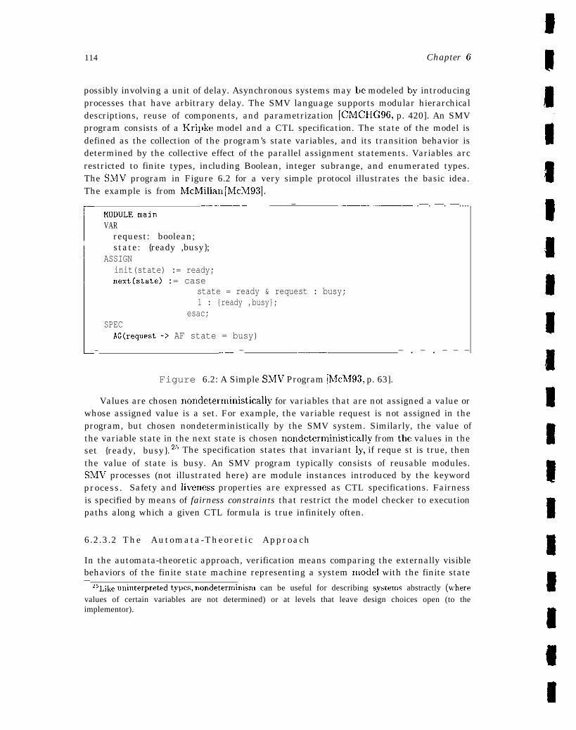
114 Chapter 6
possibly involving a unit of delay. Asynchronous systems may be modeled by introducingprocesses that have arbitrary delay. The SMV language supports modular hierarchicaldescriptions, reuse of components, and parametrization [CMCHG96, p. 420]. An SMVprogram consists of a Kripke model and a CTL specification. The state of the model isdefined as the collection of the program’s state variables, and its transition behavior isdetermined by the collective effect of the parallel assignment statements. Variables arcrestricted to finite types, including Boolean, integer subrange, and enumerated types.The ShflV program in Figure 6.2 for a very simple protocol illustrates the basic idea.The example is from McMillan [Mch193].
1
.—— ———. ——— — ————— .—. —. —....MODULE mainVAR
request: boolean;state: {ready ,busy};
ASSIGNinit(state) := ready;next(state) := case
state = ready & request : busy;1 : {ready ,busy};
esac;SPEC
AG(request -> AF state = busy)
— _—— — —.— — . — . — — —
Figure 6.2: A Simple SMV Program [hlch193, p. 63].
Values are chosen nondeterministically for variables that are not assigned a value orwhose assigned value is a set. For example, the variable request is not assigned in theprogram, but chosen nondeterministically by the SMV system. Similarly, the value ofthe variable state in the next state is chosen nondcterministically from the values in theset {ready, busy}. 25 The specification states that invariant Iy, if reque st is true, thenthe value of state is busy. An SMV program typically consists of reusable modules.ShIV processes (not illustrated here) are module instances introduced by the keywordprocess. Safety and livencss properties are expressed as CTL specifications. Fairnessis specified by means of fairness constraints that restrict the model checker to executionpaths along which a given CTL formula is true infinitely often.
6.2.3.2 The Automata-Theoretic Approach
In the automata-theoretic approach, verification means comparing the externally visiblebehaviors of the finite state machine representing a system model with the finite state—
251,ik~ ~niIlter~reted tY~es, nondeterminisnl can be useful for describing SyStems abstractly (~~rhere
values of certain variables are not determined) or at levels that leave design choices open (to theimplementor).
ivAsA-GB-ool-97 115
machine representing its specification. ‘The method of comparison varies, depending onthe technique and the particular class of system for which it was developed.
6.2.3.2.1 Language Containment
In the language intersection approach first described by [VlfT86], verification con-sists of testing inclusion between two w-automata, where one automaton represents thesystem that is being verified and the other represents its specification or task. Inclusiondenotes the strict subset relation between the languages of the two automata. For aprocess F’ modeling a system to be verified and a task T that P is intended to perform,verification consists of the test L(P) C L(T), where L(P) denotes the set of all “be-haviors” of the modeled system and L(T) denotes the set of all “behaviors” consistentwith the performance of the modeled task or specification. Typically, F’ is a systemof coordinat iug processes modeled by the product process I’ = @F’z, where each Pi isan u-automaton .26 This semantic model accommodates specific reduction algorithmsthat provide one response to the computational complexity problems associated withmore general model checking. The basic idea is to replace a computationally expen-sive test L(P) c L(T) with a computationally cheaper test L(F”) c L(T’), such that.C(P’) c .C(T’) =+ L(P) C L(T). P’ and 2“ are derived from P and T, respectively, byhomomorphisms on the underlying Boolean algebra.27
The reduction of P is relative to T, that is, relative to a given task or specification;each task induces a different reduction. Kurshan [Kur94] develops the theory underlyingsuch reductions.
The verification system typically associated with the language-inclusion approachis COSPAhT (Coordination Specification Analyzer) 2$. COSPAN’S native language isS/R, a data-flow language based on the selection/resolution model of coordinating pro-cesses. S/R distinguishes state variables from combinational variables, the latter beingdependent variables whose values are functions or relations of the state variables. TheS/R language provides nondeterministic, conditional (“if-then-else” ) variable assign-ments; bounded integer, enumeration, 13001ean, array, record, and (array and record)
——.‘26 For ~urpose~ of this dis~u~~i~n, the distinction between finite State machines or generators (o f
behavior) and finite state automata or acceptors (of behavior) has been glossed over. The former ismost convenient for modeling a system and the later for modeling its properties. Interested readersshould see [VW86] or [Tho90].
27A Boolean algebra is a set closed under the Boolean operations A, V, ~. A homomorphism is amapping (function) from one algebraic structure to another that is defined in terms of the algebraicoperations on the two structures. In the case of two Boolean algebras, B and B’, a map # is ahomomorphism just in case
@(2 A y) == @(x) A @(y)
@(z v y) = ~(x) v #J(y)
@(nr) == -@(r)
2SCOSPAN is also used as the “verification engine” in the commercial hardware verification toolFormalCheck, a trademark of the Bell Labs Design Automation center [HHK96].
116 Chapter 6
pointer types; and integer and bit-vector arithtnetic. S/R also supports modular hi-erarchal development, scoping, parallel and sequential execution, hOInOInOrphiSrn dec-laration, general u-automaton fairness (acceptance), and (ti-regular) property specifi-cation [HHK96, p. 425]. COSPAN provides both symbolic- (that is, 13 DD-based) andexplicit-state enumeration algorithms.
6.2.3.2.2 State Exploration
The terms “state exploration” and “reachability analysis” refer to finite-state ver-ification techniques that begin with an initial state and explicitly enumerate or con-struct the reachabIe state space of a system model, typica]ly using standard searchalgorithlns-- -such as depth-first or breadth-first search-- that have been optimized toalleviate state-space explosion. The state exploration approach contrasts with BDD-based techniques, which use a symbolic (implicit) representation of the state space.Sms [HP96] and Mur@ [Di196] exemplify this approach. Both verifiers use an asyn-chronous, inter-leaving model of execution in which atomic operations from a collectionof processes execute in an arbitrary order.
SPIN. SPIN is automata-based and has full LTL model-checking capability. Eachprocess of the model is translated into a finite automaton. Properties to be checkedare represented as Btichi automata that correspond to a never claim, so-called becausethese claims formalize behavior that should never occur. In other words, never-claimscorrespond to violations of given correctness properties. A model is checked against itsrequired properties by calculating the intersection of the property automaton and theprocess automata. A nonempty intersection indicates a possible correctness propertyviolation. SPriN uses a verification procedure based on reachability analysis of a modelby means of optimized graph traversal algorithms. This approach is also referred to asstate exploration.
The SPIN model checker uses a nondeterministic, guarded command language calledPROMELA that was developed to specify and validate protocols by modeling processinteraction and coordination. PItOM~LA provides variables and general control-flowstructures in the tradition of Dijkstra’s guarded command language [Dij76] and Hoare’slanguage CSP [Hoa85]. Correctness criteria are formalized in PROMELA in terms ofassertions that capture both local assertions and global system invariants, labels thatcan be used to define frequently used correctness claims for both terminating and cyclicsequences (for example, cleadlock, bad cycles, and liveness (acceptance and progress)properties), and general temporal claims that define temporal orderings of propertiesof states expressed either as never-claims or as LTL formulas (that SPIN translates intoPROMELA never-claims) [Ho191, HP96].
SPIN uses depth-first search and a single-pass, on-the-fly verification algorithm cou-pled with partial order reduction techniques to reduce the state explosion problem.On-the-fly algorithms attempt to minimize the amount of stored information, comput-ing the intersection of the process and property automata only to the point necessary

NASA -GB-001-97 117
to establish the nonemptiness of the resulting (composite) automaton. Partial orderreduction algorithms exploit the observation that the order in which concurrent or in-dependently executed events are interleaved typically has no impact on the checkedproperty. It follows that instead of generating all execution sequences, it is sufficient togenerate a reduced state space composed of representatives for classes of sequences thatare not distinguishable with respect to execution order. ‘The reduction must be shownto preserve safety and liveness properties, but this is accomplished in the course of theverification.
Mur@ The name “Mur@’ refers both to a verifier developed to analyze finite-stateconcurrent systems such as protocols and memory models for multiprocessors, and toits language. The Mur@ description language is a guarded-command language basedon a Unity-like formalism [CM88] that includes user-defined datatypes, procedures, andparametrized descriptions. A Mur@ description consists of a collection of constant andtype declarations, variable declarations, transition rules (guarded commands), startstates, and invariants. Predefine data types include subranges, records, and arrays.Mur@ statement types include assignment, condition, case selection, repetition (for- andwhile-loops), and procedure calls. Mur@ rules consist of a condition and an action. Acondition is a Boolean expression on the global variables, and an action is an arbitrarilycomplex statement. Each rule is executed atomically, that is, without interference fromother rules.
Correctness requirements are defined in Mur@ in terms of invariants written as predi-cates or conditions on the state variables. Invariants are equivalent to error statements,which may also be used to detect and report an error, that is, the existence of a sequenceof states beginning in a start state and terminating in a state in which a given invari-ant fails to hold. in addition to invariant violations, error statements, and assertionviolations, Mur@ can check for deadlock and, in certain versions, liveness properties.
Mur~ uses standard breadth- or depth-first search algorithms to systematically gen-erate all reachable states, where a state is defined as the current values of the globalvariables. State reduction techniques, including symmetry reduction, reversible rules,replicated component abstraction, and probabilistic algorithms are exploited to alle-viate state explosion [Di196]. Symmetry reduction uses structural symmetries (in themodeled system) to partition the state space into equivalence classes, thereby signif-icantly reducing the number of states generated in applications such as certain typesof cache coherence protocols [I D93]. Reversible rules are rules that preserve informa-tion and can tlierefore be executed “backwards,” yielding an optimizaticm that avoidsstoring transient states [I D96a]. Systems with identical replicated components can beanalyzed using explicit state enumeration in an abstract state space in which the exactnumber of replicated components is treated qualitatively (for example, zero, one, ormore than one replicated components) rather than quantitatively (the exact numberof replicated components) [I D96b]. The combination of symmetry reduction, reversiblerule exploitation, and replicated component abstraction has been reported to yield mas-sive reductions in the state explosion problem for cache coherence protocols and sitnilar
118 Chapter 6
applications [Di196, p. 392]. Probabilistic verification algorithms are being explored asa way of reducing the number of bits in the hash table entry for each state [SD96].
6.2.3.2.3 Bisimulation Equivalence and Prebisimulation Preorders
Bisimulation equivalence provides a logical characterization of when two systemsare equivalent and is used to check statewise isomorphism between two finite Kripkemodels. Prebisinmlation preorders similarly provide a logical characterization of whenone system minimally satisfies another. Informally, this means that bisimulation pro-vides a notion of behavioral equivalence: two systems are equivalent if they exhibit thesame behavior, whereas prebisimulation provides a notion of behavioral relatedness: onesystem exhibits at least certain behaviors exhibited or required by the other. In bothcases, a more abstract or higher-level system serves as a specification of a lower-levelone. Verification consists c~f showing that the lower-level model or ‘(itnplementation”satisfies its specification by establishing the given relation between the two models.For example, the correctness of a protocol can be established by showing that it is se-mantically equivalent to its service specification by modeling both the protocol and itsspecification as finite state machines and using equivalence-checking verification to es-tablish the statewise, transition-preserving correspondence between the two finite-statemodels. Various formal relationships have been proposed. In general, these relationsare either equivalences (bisimulations) or preorders (prebisimulations) [CH89].
Milner’s Calculus of Communicating Systems (CCS29 ) [MiU19] forms the basis forseveral of the “most visible equivalence-checking verifiers for concurrent systems. Pro-cesses are defined as CCS agents that are given an operational semantics deflncd interms of transition relations. CCS processes may define an arbitrary number of subpro-cesses, in which case the transition graph may have infinitely many states. Althoughsome properties may be decidable in such cases, most interesting properties are unde-cidable on agents that correspond to graphs with infinite state spaces. Automated toolsfor analyzing networks of finite-state processes defined in CCS include the NCSU Con-currency Workbench [CS96] and its predecessor, the (Edinburgh) Concurrency Work-bench [CPS93], and the Concurrency Factory [CLSS96]. Both versions of the Concur-rency Workbench support equivalence checking, preorder checking, and model checking(for the modal mu-calculus). The NCSU Concurrency Workbench also provides diag-nostic information if two systems fail to be related by either semantic equivalence ofpreorder, and language flexibility that allows the user to change the system descriptionlanguage [C S96]. The Concurrency Factory is also an integrated toolset, but focuseson practical support for formal design analysis of real-time current systems. This isachieved in part through a graphical design language (G CCS), a graphical editor, anda graphical simulator [CLSS96]. In addition to a CCS-based semantics, GCCS has astructural operational semantics [CLSS96, p. 400].
29CCS and related approaches are also referred to M process algebras.

NASA-GB-001-97 119
6.2.4 Utility of Finite-State Methods
The various approaches to finite-state verification outlined earlier are in theory very sin~-ilar and in many cases itker-definable, as noted in [VW86, CGK89, CBK90]. In practice,the approaches have led to the development of tools with often overlapping capabilities,but different foci and strategies. For example, SPIN has been developed for modeling dis-tributed software using an asynchronous process model; Mur@ and SMV have focused onhardware verification Murq5 on asynchronous concurrent systems using explicit stateexploration and SMV on both synchronous and asynchronous systems using symbolicmodel checking; and COSPAIl has been driven by a top-down design methodology inl-plemented through successive refinement of (fundamentally) synchronous models andhas beclL used for both software and hardware design verification. In some cases, thecapabilities are complementary, and there is work on integrating different finite-stateverification strategies as done in COSPAN, which offers either symbolic- (BDD-based)or explicit state enumeratioli algorithms, as well as on integrating different approachesin a single tool, as done in both versions of the Concurrency Workbench, which offerequivalence checking, preorder checking, and model checking.
Finite-state methods offer powerful, automated procedures for checking temporalproperties of finite-state and certain infinite-state systems (Kripke models). ‘1’hey alsohave the ability to generate cozmterezarnphx—ty pically in the form of a computationpath that establishes, for example, the failure of a property to hold in all states, andwitnesses--in the form of a computation path that establishes the existence of oneor more states in which a property is satisfied. Finite-state methods are least ef-fective on large, unbounded state spaces, high-level specifications, and data-orientedapplications---areas in which deductive methods are more appropriate. For this rea-S011, there has been increasing interest in integrating finite-state methods and deductivetheorem proving. This topic is revisited in Section 6.4.
6.3 Direct Execution, Simulation, and Animation
Direct execution, simulation, and animation are techniques used to observe the behav-ior of a model of a system. Formal analysis, on the other hand, is used to analyzemodeled behavior and properties. In many cases, there are fundamental differences be-tween these observational and analytical methods, including the models they use andtheir expected performance. Typically, models used for verification cannot expose theirown inaccuracy and, conversely, models used for conventional simulation cannot con-firm their own correctness [Lan96, p. 309]. Models used for simulation of large systemsmust be able to handle realistic test suites fast, since these suites may literally run forweeks. This kind of efficiency is not a reasonable expectation in executable specifica-tion languages. Formal verification techniques generally treat the notion of time as anabstraction and largely avoid probabilities, whereas more concrete representations of
120 Chapter 6
time and probabilistic analyses play an important role in observational methods. Fi-nally, direct execution, simulation, and animation show behavior over a finite numberof cases, whereas formal analysis can be used to explore all possibilities, the formeroffering statistical certainty and the latter, mathematical certainty. Although some ofthese differences are attenuated when “simulation” is considered in the context of for-mal specification languages (for example, the models used for execution and simulationtypically coincide), others persist (for example, verification still proceeds by extrapola-tion from a finite number of cases, rather than by mathematical argumentation over allpossible cases). The remainder of this section summarizes the notions of executability,simulation, and animation in the context of formal methods.30
6.3 .1 Observat ional Techniques
Some formal specification languages are directly executable, or contain a directly ex-ecutable subset, meaning that the specification itself can be executed or run and itsbehavior observed directly. For example, a logic based on recursive functions, such asthat, used in Nqthrn [BM88] and ACL2 [Kh!194], supports direct execution and “sinm-lation” on concrete test cases because it is always possible to compute the value of avariable-free term or formula in the executable subset of these logics. The followingquote from [KM94, p. 8] describes the role of executability in the formalization of amodel of a digital circuit (the FM9001 ) in Nqthm.
[The Nqthm model] can be thought of as a logic sitnulator (without,however, the graphic and debugging facilities of commercial simulators).. . . Running [the model] on a concrete netlist31 and data involves simulatingin the proper sequence the input/output behavior of every logical gate inthe design . . .
The spccificat ion language for the Vienna Development Method (VDM), VDM-SL, alsohas a large executable subset, as well as tool support for dynamically checking typeinvariants and pre and I)ost conditions, and for running test suites against a VDM-SL specification [VDM]. Similarly, the concrete representation of algorithms and datastructures required by most finite-state enumeration and model-checking methods (seeSection 6.2) make them ccmlparakde to direct execution techniques. Certain finite stateverification tools also provide ‘(simulation,” by exploring a single path through the statespace rather than all possible paths [H0191, DDHY92, ID93].
30 Planning and administrative trade-offs involving, for example, cost, available resources, criticalityof the system, and desired levels of formality, are discussed in the first volume of the guidebook [hTASA-95a].
31 The ,!netli~t,~ i$ aIL ~qth[ll constallt that describes a tree of hardware nloduleS and their intercon-. .nections via named input/output lines.
ArAsA.~~_ool.97 121
The dynamic behavior of specifications written in nonexecutablc languages may bestudied indirect ly, by reinterpreting the specification in a (high-level) programming lan-guage. Execution of the resulting program is referred to as an emulation or animation ofthe specification. Some formal specification languages offer both a directly executablesubset and the option of user- or system-defined program text to drive animation ofnonexecutable parts of the specification. Specifications written in a nonexecutable lan-guage using a constructive functional st~rle may be “executed” by exploiting a rewritefacility (assuming one is available) to rewrite function definitions, starting from a par-ticular set of arguments. This amounts to writing an emulator for the system beingmodeled and may not he either possible or desirable. For example, making an entirespecification executable typically precludes using axioms to dispense with those partsof a system or its environment that are not of interest or do not warrant verification.
Direct execution, simulation, and animation are not alternatives to more rigorousformal analysis, but rather effective complements. For example, during the requirementsand (or) high-level design phase, executability can be used to probe the behavior of a sys-tem on selected test cases, and deductive theorem proving can be usecl to exhaustivelyestablish its general high-level properties. in this type of strategy, executability pro-vides an efficient way to avoid premature proof efforts and, conversely, to focus the morerigorous (and thereby more expensive) proof techniques on the most appropriate behav-iors and properties. This symbiotic use of different techniques is nicely illustrated in thedevelopment of a formal specification of the Synergy File System using ACL2 [BC95a].In this application, formalization of an ACL2 executable model, execution of the model,and proof of an invariant about transitions in the model each revealed significant errors.
6 .3 .2 Ut i l i ty o f Observat ional Techniques
The main advantages of executability are that it allows the specification and underly-ing model to be “debugged, ” and it allows the specification to serve as a- “test oracle”relatively early in the life cycle. Animation and emulation confer similar benefits. Afurther advantage of executability is that it allows behavior to be observed and exploredin the same formally rigorous context as that in which the specification is developed.Other documented roles for executability include post-implementation testing, as illus-trated, for example, in post-fabrication execution of the FM9001 specification to testthe fabricated devices for conformance to the (verified) design [KM94, p. 9]. Althoughthis example represents a somewhat novel use of executability, it is potentially an im-portant technique by means of which formal methods can make a unique contributionto conventional testing regimes. The technology transfer potential of executability,animation, and emulation is also worth noting. Because simulation, animation, and enl-ulation are techniques familiar to analysts and engineers, they offer an effective vehiclefor integrating formal methods into ongoing system development activities. The VDM-S1, study carried out at British Aerospace provides an interesting example of the role
122 Chapter 6
of executability in the integration of formal specification in a traditional developmentprocess [LFE196].
6.4 Integrating Automated Analysis Methods
No single technique is effective across a wide range of applications or even across a sin-gle application with disparate components or algorithms. Industrial-strength examplestypically require a variety of approaches, currently used as standalone systems, as illus-trated, for example, in [M PJ94]. Rushby [Rus96] argues that effective deductive supportfor formal methods requires not standalone, but integrated techniques effective acrossa broad range of applications. Shankar [Sha96] makes a similar argument, noting thatthe “sheer scale” of mathematics necessary for formal methods argues for a unificationof verification techniques.
The three analysis techniques surveyed in this chapter- automated deductive nleth-ods, finite-state methods, and simulation methods- have complementary strengths andthere is increasing interest in the synergistic integration of these techniques within auniform framework. Synergistic integration simply means that the resulting systemshould be more than the sum of its parts. Logical frameworks, such as Isabelle [Pau88],support the definition and construction of deductive tools for specialized logics, but donot provide systematic support for coherent integration of different capabilities [Sha96].The Stanford TEmporal Prover (STEP) [Man94], which integrates model checking withalgorithmic deductive methods (decision procedures) and interactive deductive nmth-ods (theorem proving) to support verification of reactive systems, is an example of onestrategy in the search for effective integration. The STEP system is interestillg becauseit also combines powerful algorithmic and heuristic techniques to automatically gen-erate invariants. A different approach has been used to integrate model checking andautomated proof checking in PVS [RSS95], where a BDD-based model checker for thepropositional mu-calculus is integrated as an additional decision procedure within theproof checker.
The notion of integrated verification techniques introduced here provides a glimpseof the direction verification technology is heading. One implication of this discussionis the relative maturity of existing formal methods techniques, which offk!r effectivespecification and analysis options for aerospace applications.
6.5 Proof of Selected SAFER Property
The property that no more than four thrusters may be fired simultaneously followsdirectly from the detailed functional requirements of the SAFER system. Thrusterselection is a function of the integrated hand grip and A AH-generated commands.The thruster select logic specified in Tables C.2 and C.3 is used to choose appropri-ate thrusters based on a given integrated command. An initial survey of these tables
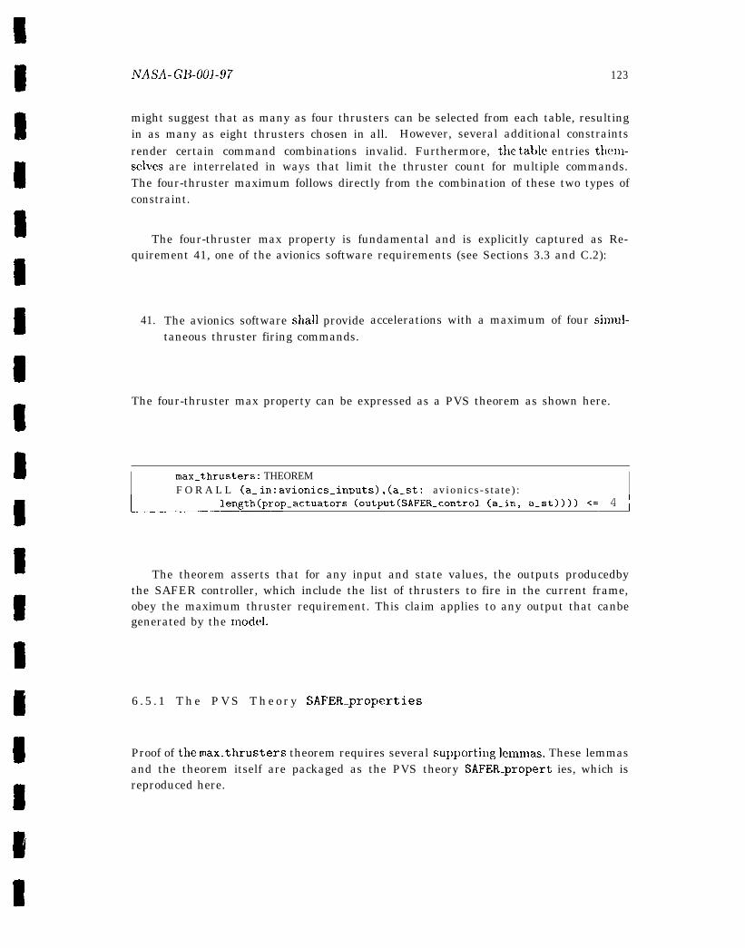
NASA- GI?-001-97 123
might suggest that as many as four thrusters can be selected from each table, resultingin as many as eight thrusters chosen in all. However, several additional constraintsrender certain command combinations invalid. Furthermore, the table entries thenl-selves are interrelated in ways that limit the thruster count for multiple commands.The four-thruster maximum follows directly from the combination of these two types ofconstraint.
The four-thruster max property is fundamental and is explicitly captured as Re-quirement 41, one of the avionics software requirements (see Sections 3.3 and C.2):
41. The avionics software shall provide accelerations with a maximum of four sinlul-taneous thruster firing commands.
The four-thruster max property can be expressed as a PVS theorem as shown here.
I max.thrusters: THEOREMF O R A L L (a. in: avionlcs_inputs), (a_st: a v i o n i c s - s t a t e ) : I
1- length(prop_actuators (output(SAFER_control (a_in, a_st)))) <= 4 I——————
The theorem asserts that for any input and state values, the outputs producedbythe SAFER controller, which include the list of thrusters to fire in the current frame,obey the maximum thruster requirement. This claim applies to any output that canbegenerated by the model.
6 . 5 . 1 T h e P V S T h e o r y SAFER.properties
Proof of themax_thrusters theorem requires several supportillg lenlrnas. These lemmasand the theorem itself are packaged as the PVS theory SAFER_propert ies, which isreproduced here.

124 Chapte~- 6’
————
SAFER_ properties: THEORYBEGIN
IMPORTING avionics.model
A,B,C: VARtr: VARHCM,cmd: VARAAH : VARstate: VARthr,U,V: VARact: VARBF,LRUD: VAR
axis_comnlandtran_commandsix”_dof_commandrot_commandAAH_statethruster..listactuator-commandsthruster_list_pair
%% Only one translation command
only_one_tran(tr): bool =
can be accepted for thruster selection.
(tr(X) /= ZERO IMPLIES tr(Y) = ZERO AND tr(Z) = ZERO)AND (tr(Y) /= ZERO IMPLIES tr(Z) = ZERO)
only_one_tran_pri: LEMMAonly_one_tran(prioritized_tran_cmd(tr))
only_one_tran_int: LEMMAonly_one_tran(tran(integrated_commands(HCM, A A H , s t a t e ) ) )
%% All ca tegor ies of se lec ted thrus ters (BF vs . LRUD and mandatory% % v s . o p t i o n a l ) a r e b o u n d e d in s i z e b y t w o , w h i c h f o l l o w s d i r e c t l y% % f r o m i n s p e c t i o n o f t h e t a b l e s .
max_thrusters_BF: LEMMAlength(proj_ l (BF_thrus ters (A, B, C)) ) <= 2 A N Dlength(proj_2(BF_thrusters (A, B, C))) <= 2
max_thrusters_LRUD: LEMMAlength(proj_l (LRUD_thrusters(A, B, C))) <= 2 A N Dlength(proj_2(LRUD.thrusters(A, B, C))) <= 2
—— .—.—..—.——— — — — .— .——.—-— .——————..
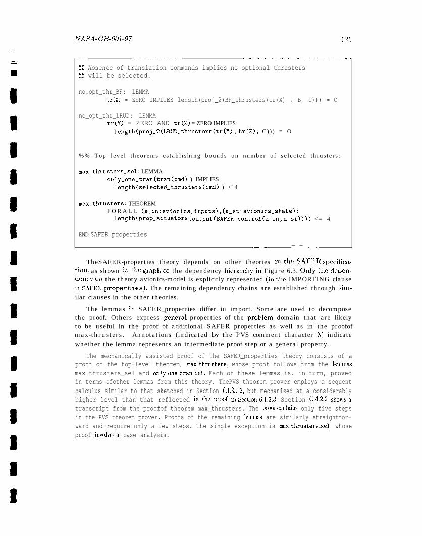
AJASA-GB-001-97 125
—- .———— ————————-——— —
YL Absence of translation commands implies no optional thrusters%% will be selected.
no.opt_thr_BF: LEMMAtr(X) = ZERO IMPLIES length(proj_2(BF_thrusters(tr(X) , B, C))) = O
no_opt_thr_LRUD: LEMMAtr(Y) = ZERO AND tr(Z) = ZERO IMPLIES
length(proj_2(LRUD_thrusters(tr(Y) , tr(Z), C ) ) ) = O
% % T o p l e v e l t h e o r e m s e s t a b l i s h i n g b o u n d s o n n u m b e r o f s e l e c t e d t h r u s t e r s :
max_thrusters_sel: LEMMAonly_one_trarI(tran(cmd) ) IMPLIES
length(selected_thrusters(cmd) ) <= 4
max_thrusters: THEOREMF O R A L L (a_in: avionics_inputs), (a_st: avionics-state):
length(prop_actuators (output(SAFER_control(a_in, a_st)))) < = 4
END SAFER_properties
—— — — . .
TheSAFER-properties theory depends on other theories iutheSAFE Rspecifica-tiou, as shown inthe graphof the dependency hierarchyin Figure 6.3. Onlythedepen-dencyon the theory avionics-model is explicitly represented (iuthe IMPORTING clausein SAFER_properties). The remaining dependency chains are established through sinl-ilar clauses in the other theories.
The lemmas in SAFER_properties differ iu import. Some are used to decomposethe proof. Others express general properties of the prob]em domain that are likelyto be useful in the proof of additional SAFER properties as well as in the proofofmax-thrusters. Annotations (indicated by the PVS comment character %) indicatewhether the lemma represents an intermediate proof step or a general property.
The mechanically assisted proof of the SAFER_properties theory consists of aproof of the top-level theorem, max-thrusters, whose proof follows from the Iemmassmax-thrusters_sel and only-one-tran_int. Each of these lemmas is, in turn, provedin terms ofother lemmas from this theory. ThePVS theorem prover employs a sequentcalculus similar to that sketched in Section 6.1.3.l.2, but mechanized at a considerablyhigher level than that reflected in the proof hlSection6.1.3.3. Section C.4.2.2 showsatranscript from the proofof theorem max_thrusters. The proofcontains only five stepsin the PVS theorem prover. Proofs of the remaining lemruas are similarly straightfor-ward and require only a few steps. The single exception is max-thrusters_sel, whoseproof iuvolvesa case analysis.
126 Chapter 6
6.5.2 Informal Argument for Lemma max.thrusters.sel
Consider, first, an informal argument for the max thrust ers-sel lemma. At most twomandatory and two optional thrusters can be selected from each of the two thrustertables. The argument proceeds by cases defined in terms of possible commands.
The first case concerns a translation command for the X axis.
● Case 1: No X command present. Inspection of Table C.2 shows that there willbe no optional thrusters selected in this case. There are two subcases, dependingon the presence of a pitch or yaw command.
o Case 1.1: No pitch or yaw commands. Inspection of Table C.2 showsthat no thrusters at all are selected in this case. At most four can come from ‘Table C.3. Hence, the max thruster property holds.
o Case 1.2: Pitch or yaw command present. Inspection of Table C.3indicates that no optional thrusters are chosen from this table. Hence, onlymandatory thrusters from each table are chosen, and, again, the numberselected cannot exceed 4.
● Case 2 : X command present . Because only one translation command isallowed, it follows that no Y or Z command can appear. This, in turn, impliesthat no optional thrusters are chosen from Table C.3. The subcases take intoaccount the possibility of a roll command.
o Case 2.1: No roll command. lf’ithout a roll command, no thrusters areselected from Table C.3. Hence, the max thruster property holds.
o Case 2.2: Roll command present. A roll command implies that T’a-ble C.2 yields no optional thrusters. This leaves only mandatory thrustersfrom each table, and the bound of four thrusters is satisfied.
The case analysis sketched in this informal proof can be directly formalized in F’VS.The result ing proof is quite lengthy, as shown in the proof tree in Figure 6.4. As notedearlier, the level of automation represented in this figure is higher than that illustratedin Section 6.1.3.3.
Although it is certainly possible to use mechanized proof tools to verify informalproofs in this way, it is often far more productive to exploit the strengths of a particulartool to make the proof more automatic, more comprehensible, or more optimal withrespect to other desired metrics. This kind of optimization follows quite naturally asone of the later steps in the inherently iterative process of developing and refininga proof. Figure 6.5 shows a considerably simpler and more automated proof for themax-thrusters–sel property.command that packages manyproof of max-thrusters_sel.
This second proof exploits the high-level PVS GRINDlower-level commands, thereby automating most of the
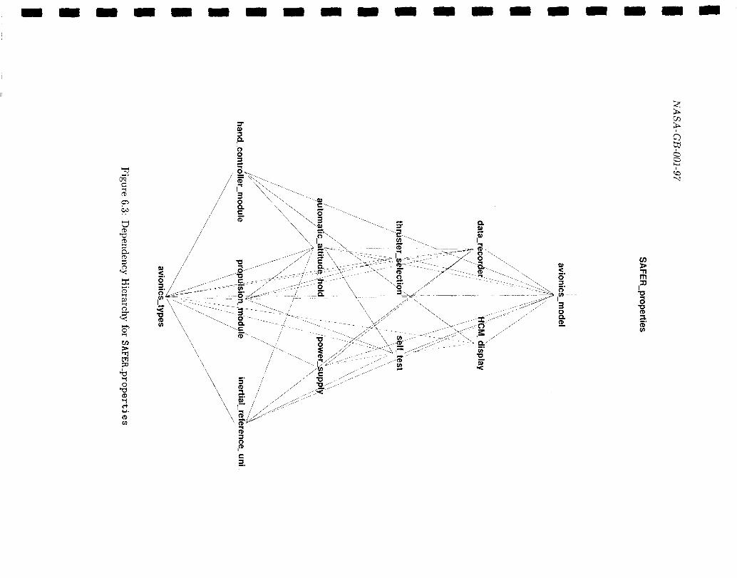
II
‘c3-,.
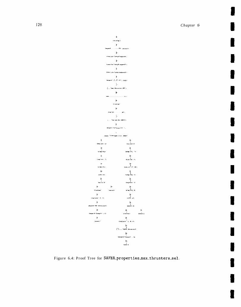
128 Chapter 6
F(.k..,.P.,
1-(-s.”. . . . - - - - - ,,, ”,,.,..,
t-
(,.., ,,. .,..”* umn.. ,
1-
,,.., ,,. .,..”,. .@*.,. ,
h(r.. r,u .l.mih .4P..,.,
1-(“9.”. .1..0 <,. , (, ,,,
1-(... .“. mr.. t.:, ,r. )
1-(“.. . . . . . . . . . . . . win.)
1-(,1.,-”
1-
,... .“. . . . . . . E,.,
1-(... .“. .,< or u,..,
E{“,-...4 ..”1, m. ,,. ”.,
t
(e... .,..” (-?,,,., . ,,”.. ,
(“c..., .-L,.,..,\
(.X*. .,.ta,h. , ,,
7(....., )
Figure 6.4: Proof Tree for SAFER_propertiesmax_thrusters_sel.
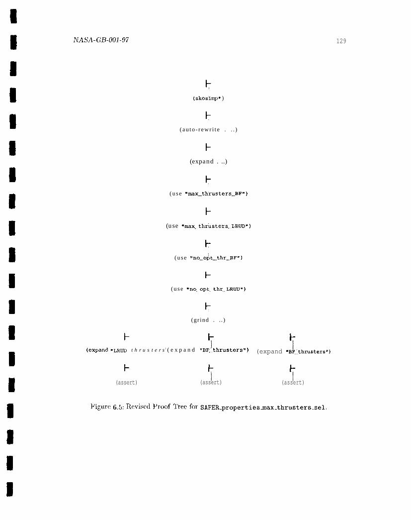
NASA-GB-001-97 129
~
(skos”imp* )
( a u t o - r e w r i t e . . . )
t-
(expand . ..)
k
( u s e “max_thrusters_BF”)
t-
(use ‘rnax_thfisters_LR~”)
t-
( u s e “no_opt_thr_BFH)
t-
( u s e “no_opt_thr_LRUD”)
~
(gr ind . . . )
k 7 ‘i(expand IILRUD t h r u s t e r s) ( e x p a n d “BF_thruSter$”) (expand “BF._thrusters”)
F y(assert) (assert) 7(assert)
Figure 6.5: Reitised Proof ~eefor SAFER-propertiesmax-thrusters.sel.
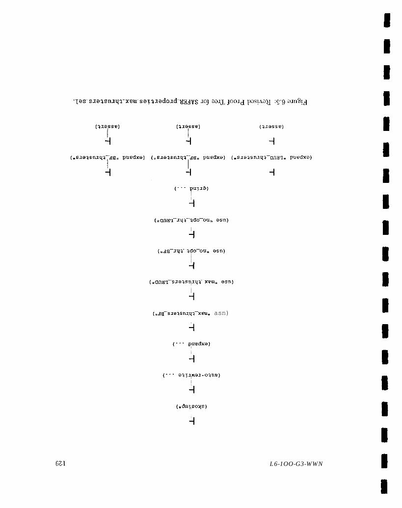
(,,arn+-sqa-ado-ou,, asn)
i
(uaa–sxaqsnxqq–x~m. asn)
i
-1
(*duITsoys)
i
L6-1OO-G3-WWN
Chapter 7
Conclusion
This guidebook has presented a discussion of the technical issues involved in the use offorma] methods. The focus has been on using formal methods to analyze requirementsand high-level designs, that is, on a spectrum of activities that apply mathematicaltechniques to formalize, explore, debug, validate, and verify software and hardwaresystems. ‘1’he development of the SAFER specification has exemplified the process ofapplying formal methods to aerospace applications.
TIIC guidebook characterizes formal methods as an iterative process whose broadoutlines are determined by contextual factors. Effect ive use of this prc}cess involvesjudiciously pairing formal methods with an application and its careful integration withexisting quality control and assurance activities.
7.1 Factors Influencing the Use of Formal Methods
Two types of factors influence the use of formal methods: administrative factors andtechnical factors. Administrative factors- including project scale and staffing, inte-gration of formal methods with traditional processes, and general project guidelines:training, specification and documentation standards and conventions, and so 011-- arediscussed in Volume I of this Guidebook [NASA-95a]. Technical factors-–includingthe type, size, and structure of the application; level of formalization; scope of formalmethods use; characteristics of available documentation, and choice of formal methodstool- -have been the subject of this second volume of the guidebook. These technicalfactors are summarized here.
● Type, Size, and Structure of the Application Formal methods are best suitedto the analysis of complex problems, taken singly or in combination, and less suitedfor numerical algorithms or highly computational applications. Applications ofmoderate size with a coherent structure that can be decomposed into subsystemsor components are typically most appropriate.
130
NASA-GB-001-97 131
. Level of Formalization Formal methods can be productively applied at vari-ous levels of formality or rigor, ranging from the occasional use of mathematicalnotation to exclusive use of semantically well-defined specification languages withmechanized proof support.
● Scope of Formal Methods Use Formal methods can be effectively applied in avariety of ways depending on which stages of the developmental life cycle, whichsystem components, and what system functionality are formalized.
● Documentation Formal methods benefit from the availability of adequate docu-mentation. The most important characteristics are the level at which the require-ments (high-level design) are stated, the degree to which they are explicitly andunambiguously enumerated, the extent to which they can be traced to specificsystem components, and the availability of additional information or expertise tomotivate and clarify their definition.
● Tool(s) Formal methods typically involve some level of mechanical support. Thechoice of formal methods tool, if any, is determined by administrative factors andthe preceding technical factors (excepting documentation). Information on formalmethods tools is available from several databases, including those maintained byJonathon 130wen, Larry Paulson, and Carolyn Talcott, respectively [Bowen, Pauls,Talco].
7.2 The Process of Formal Methods
Contextual factors determine the broad outlines of formal methods use for a given appli-cation. The substance of the formal methods process has been characterized in previouschapters of this volume as a discipline composed of the following activities: character-izing, modeling;, specifying, analyzing, documenting, and lllaintaillillg/gelleralizi~lg.
●
●
●
●
Characterizing Synthesizing a thorough understanding of the application andthe applicat ioxl domain, resulting in a working characterization of the applicationand relevant par ts of its environment.
Modeling Selecting a mathematical representation expressive enough to formalizethe applicatioll domain, while providing sufficient analytical power to explore,calculate, and predict the behavior of the system.
Specifying Developing a specification strategy, formalizing the application interms of the underlying model and articulated strategy, and checking the syntacticand semantic correctness of the specification.
Analyzing Predicting and calculating system behavior, challenging uuderlyiugassumptions, validating key properties and invariants, establishing the consistencyof axioms, and establishing the correctness of hierarchical layers.
132 Chapter 7
● Documenting Recording underlying assumptions, motivating critical decisions,docutnenting rationale and crucial insights, providing additional explanatory ma-terial, tracing specification to requirements (high-level design), tracking level ofeffort, and collecting cost/benefit data.
● Maintaining/Generalizing Revisiting and, as necessary, modifying the specifi-cation and analysis to predict the consequences of proposed changes to the mod-eled system, to reflect mandated changes to the modeled system, to accommodatereuse of the formal specification and analysis, or to distill general principles fromthe formalization.
Although this linearization of the process is informative, it is important to keep twoadditional facts in mind. First, applying formal methods is an iterative process. Aspecification, like a conventional program, must be methodically developed, explored,modified, and refined through many iterations until the result is free of syntactic andsemantic errors and captures desired characteristics and behaviors in a concise aud easilycommunicated form. SeCO1ld, the list is not prescriptive. Each project necessarily selectsthe most appropriate subset of the activities listed above, namely those most consistentwith its mandate and the resources at its disposal.
7.3 Pairing Formal Methods, Strategy, and Task
Formal methods offer a diverse set of techniques appropriate for a wide variety of ap-plications. Moreover, there arc many ways to use these techniques to model systemsand to calculate and explore their properties. The implications of this rich repertoireof techniques and strategies is that the effective use of formal methods involves judi-cious pairing of method, strategy, and task. For example, control-intensive algorithtnsfor small finite systems, such as mode sequencing algorithms, are often most effectivelyanalyzed usiug state exploration, while general properties of complex algorithms, suchas Byzantine fault-tolerant clock synchronization, typically require efficient deductivesupport for arithmetic in the form of arithmetic decision procedures. When an optimalpairing of methods, strategy, and task is not readily apparent, a rapid prototype ofan aggressively downscaled or abstracted model that preserves essential properties ofinterest can help to focus the selection. Precedence, that is, techniques or strategiessuccessfully applied to similar tasks, can also serve as a guide in these cases.
A complex application is typically decomposable into subtasks. In such cases; it maybe productive to apply a combination of methods, or to apply a “lightweight” methodsuch as model checking, animation, or direct execution to specific or reduced cases ofall or part of a specification before attempting a more rigorous and costly analysis. Forexample, [HS96] reports the analysis of a communications protocol using a combinationof finite state exploration, theorem proving, and model checking. The protocol was firstmanually reduced to finite state to allow certain safety properties to be checked using

ArAsA.GB_ool_97 133
finite state exploration. These properties were then verified for the full protocol usingdeductive theorem proving. The invariant used for the proof had tcl be strengt,hencdthrough additional conjuncts discovered incrementally during the proof process. Eachproposed new conjunct was checked in the reduced model, using state exploration beforeit was used in the evolving proof. This iterative process eventually yielded an invariantcomposed of 57 conjuucts. Exploiting the knowledge gained in this exercise, a finite-stateabstraction of the original protocol was developed and nlcchanically verified. Finally,properties of the abstraction were verified, using a model checker for the propositionalmu-calculus (see Chapter 6, Section 6.2.1.5). Although this particular example reflectsa demanding exercise carried out by expert practitioners, it is a nice illustration of theproductive interaction of combinations of techniques and strategies that are availableto expert and nonexpert alike.
7 . 4
Formalcontrol
Formal Methods and Existing Quality Control andAssurance Activities
methods complement, but do not replace, testing and other traditional qualityand assurance activities. 1 This symbiotic relationship between formal methods
and traditional quality control and assurance methods derives from the fact that formalmethods are most effectively used early in the life cycle, on suitably abstract repre-sentations of traditionally hard problenls,2 in order to provide complete explorationof a model of possible behaviors. Conversely, traditional quality control and assurancemethods have proven highly effective late in the life cycle on concrete (implemented) so-lutions to hard problems, in order to establish the correctness of detailed and extensive,but necessarily finite behavioral scenarios.
There are many ways to exploit the complementarily between formal methods andexisting quality control and assurance activities. Some of these directly target formalmethods’ products. For example, [CRS96, SH94] describe a fully automatable structural( “black box”) specification-based testing technique that complements implenlentation-based testing. This technique derives descriptions of test conditions from a formalspecification written in a predicate logic-based language. The test conditions guideselection of test cases and measure the comprehensiveness of existing test suites. Recentconference proceedings, for example [COMP95, ISSTA96], attest to current interest indeveloping automated methods that use formal specifications to generate test artifactsfor concrete implementations.
Other approaches reflect a more indirect use of formal methods. For example, formal,or even quasi-formal models developed during the application of formal methods can be
1 Following Rushby [Rus93b, p. 144], quality control denotes “methods for eliminating faults” andquality assurance denotes “methods for demonstrating that no faults remain,”
21ncluding, but not limited to, fault tolerance, concurrency, and nondeterminism, where capabilitiesdistributed across components must be synchronized and coordinated, aud where subtle interactions,for example, due to timing and fault status, must be anticipated.

134 Chapter 7
used to facilitate traditional safety analyses. Leveson et al. report [MLR+ 96, p. 14] thatCL . . . the state abstraction and organization [of their state-transition models] facilitated
fault tree analysis.” A further input to traditional safety analyses might involve. . .the formal specification and analysis of key safety properties. For example, it can bedemonstrated that a particular formal model satisfies (or fails to satisfy) given safetyproperties, that proposed system modifications captured in a model fail to preservedesired safety properties, or that an executable specification fails to satisfy a given testsuite. The results of these and other formal analyses can, in turn, be used to exposeareas of potential concern and, thereby, concentrate conventional testing activities. Ifthe results of the testing are then iterated back into the formal analysis, the increasinglyfocused iteration can be used to refine requirements or high-level designs. The examplescited here are suggestive, only. III general, the tighter the integration of formal andconventional methods, the more productive the interplay between formal techniquesand traditional quality control and assurance activities.
7.5 Formal Methods: Verification Versus Validation andExploration
The real value of formal methods lies not in their ability to eliminate doubt, but intheir capacity to focus and circumscribe it.3
The use of formal methods is often seen as a form of absolute guarantee – a proofof total correctness. However, as Rushby [Rus93b, pp. 74-75] notes, equating formalverification with total correctness is doubly misleading in that it overestimates theguarantee conferred by formal verification while it underestimates the value of the formalverification process, per se.
The guarantee conferred by formal verification assures the mutual consistency ofthe specifications at either end of a chain of verification, but necessarily fails to addressthe adequacy of the underlying model, the extent to which the highest-level specifica-tion captures the requirements, or the fidelity with which the lowest-level specificationcaptures the behavior of the actual system. The potentially contentious issue of the ad-equacy of the model is typically resolved through extensive use, challenge, and review,although there have been a few interesting attempts to characterize and automate theselection of “adequate” models of physical systems [Nay95]. The fidelity of the upper-and lowermost specifications in a chain of verification is established through validation.
The value of the process of formal verification lies not only, or even primarily, in theend product—-that is, in a proof of correctness, but rather in the benefits accumulatedalong the way. These benefits include many of those discussed in previous chapters ofthis guidebook.— ——
3Paraphrase of a comment from John Rushby.
ivAsA-G13-ool-97 135
● A detailed enumeration of all the assumptions, axioms, and definitions that pro-vide the underlying basis for the verification and characterize the requirements andproperties whose satisfaction or utility in the physical world must be empiricallyva] i dated.
● The validation of these assumptions and properties (for example, through proofchecking or model checking).
● The (early) detection of inconsistent requirements or of design faults. Most verifi-cations fail, at least initially, and the information gained from these failed attemptsreveals unstated assumptions, missing cases, and other errors of interpretation oromission. Although some of these errors would probably be caught by conven-tional techniques, others are quite subtle and less likely to be exposed by informaltechniques or sampled behaviors.
● The ability to explore readily and reliably the consequences of additional or mod-ified assurnptions, requirements, and designs, reinforcing and informing the nec-essarily iterative process of developing large and complex systems.
● The ability to identify and develop reusable formal methods techniques, strategies,and products, contributing to a cost-effective approach to the development of largeand complex systems.
● The improved understanding and identification of better solutions derived fromthe intense scrutiny and discipline involved in the process of formalization andformal analysis.
In summary, formal methods do not focus exclusively or even primarily on “provingcorrectness’’ –-the verification activities associated with software implementations andhardware layouts- but rather on exploring, debugging, and validating artifacts, such asrequirements and high-level designs, leading to a deeper understanding of their proper-ties and assumptions, an earlier capability for calculating and predicting their behavior,and a fuller appreciation of the consequences of modifying their structure, properties, orenvironment. This guidebook has attempted to provide formal methods practitionerswith the information and insight essential to the productive use of formal methods.
References
[AC96]
[ACHH93]
[Ack62]
[ACM94]
[AD91]
[AH91]
[AH95]
[AH96]
[AH97]
[AHS96]
M. Abadi and L. Cardelli. A 2%eory of Objects. Monographs in Conl-puter Science. Springer-Verlag, New York, NY, 1996.
R. Alur, C. Courcoubetis, T. A. Henzinger, and Pei-Hsin Ho. HybridAutomata: An Algorithmic Approach to the Specification and Verifica-tion of Hybrid Systems. In Grossman et al. [GNRR93], pages 209--229.
R. L. Ackoff, editor. Scientific Method: Optimizing Applied ResearchDecisions. John Wiley and Sons, 1962.
Ninth Annual Conference on Object-Oriented Programming Systems,Languages, and Applications (OOPSLA ‘91), Portland, Oregon, Octo-ber 1994. ACM/SIGPLAN(in SIGPLAN Notices Vol 29, No. 10, Octo-ber 1994).
R. Alur and D. Dill. The Theory of Timed Automata. In de Bakkeret al. [dBHdRR91], pages 45-- 71.
R. Alur and T. A. Henzinger. Logics and Models of Real Time: ASurvey. In de Bakker et al. [dElHdRR91], pages 74—106.
R. Alur and Pei-Hshl Ho. HYTECH: The Cornell HYbrid TechnologyTool. In Antsaklis et al. [AKNS95], pages 265—293.
Rajeev Alur and Thomas A. Henzinger, editors. Computer-Aided Veri-fication, CAV ’96, volume 1102 of Lecture Notes in Computer Science,New Brunswick, New Jersey, July/August 1996. Springer-Verlag.
M. Archer and C. Heitmeyer. Verifying Hybrid Systems Modeled asTimed Automata: A Case Study. In Proceedings of the InternationalWorkshop on Hybrid and Real-Time Systems (HA RT’97), Grenoble,Fiance, March 1997.
Rajeev Alur, Thomas Henzinger, and Eduardo Sontag, editors. HybridSystems III, Verification and Control, volutne 1066 of Lecture Notes inComputer Science, New York, NY, 1996. Springer-Verlag.
136
j/TAc&,4.(-3B.ool-97 137
[AINP88]
[AKNS95]
[AL95]
[AMCP84]
[And86]
[BB89]
[BC94]
[BC95a]
[BC95b]
[BCC+ 95]
[BCM+-90]
Peter B. Andrews, Sunil Issar, Daniel Nesmith, and Frank Pfenning.The TPS Theorem Proving System. In Lusk and Overbeek [L088],pages 760 761.
Panes Antsaklis, Wolf Kohn, Anil Nerode, and Shaukar Sastry, editors.Hybrid Systems II, volume 999 of Lecture Notes in Computer Science,New York, NY, 1995. Springer-Verlag.
Y. Ampo and R. Lutz. Evaluation of Software Safety Analysis UsingFormal Methods. In Foundation of Software Engineering Workshop,Hamana-ko, Japan, December 1995.
P. B. Andrews, D. A. Miller, E. L. Cohen, and F. Pfenning. Automating .Higher-Order Logic. In Automated Theorem Proving: After 25 Years,pages 169 192. American Mathematical Society, 1984.
Peter B. Andrews. An Introduction to Logic and T~pe Theory: To Truththrough Proof. Academic Press, New York, NY, 1986.
Karl Hans Blasius and Hans-Jurgen Burckert. Deduction Systems inArtificial Intelligence. Ellis Horwood Series in Artificial Intelligence.Ellis Horwood Limited, Chichester, West Sussex, UK, 1989. Distributedin the U.S. by Halsted Press: a division of John Wiley and Sons.
R. Bourdeau and B. Cheng. A Formal Semantics of Object Models.Technical Report MSU-CPS-94-6, Department of Computer Science,Michigan State University, East Lansing, Michigan, January 1994.
William R. Bevier and Richard M. Cohen. An Executable Model ofthe Synergy File System. Technical report, Computational Logic, Inc.,May 1995.
R. 130urdeau and B. Cheng. A Formal Semantics for Object ModelDiagrams. IEEE Transactions on Software Engineering, 21 (10):799821, October 1995. .
Ricky W. Butler, James L. Caldwell, Victor A. Carreno, C. MichaelHolloway, Paul S. Miner, and Ben L. Di Vito. NASA Langley’s Re-search and Technology ~kansfer Program in Formal hlethods. In TenthAnnual Conference on Computer Assurance (COMPASS 95), Gaithers-burg, MD, June 1995.
J. R. Burch, E. M. Clarke, K. L McMillan, D. L. Dill, and L. J.Hwang. Symbolic Model Checking: 1020 States and Beyond. In 5thAnnual IEEE Symposium on Logic in Computer Science, pages 428-439, Philadelphia, PA, June 1990. IEEE Computer Society.
138
[BDH94]
[BE87]
[13E93]
[Bee86]
[Be186]
[Bev89]
[BG96]
[BH91]
[BH97]
[BHL90]
[BHMY89]
References
Ricky W. Butler, Ben L. Di Vito, and C. Michael Holloway. FormalDesign and Verification of a Reliable Computing Platform for Real-Time Control: Phase 3 Results. NASA Technical Memorandum 109140,NASA I,augley Research Center, Hampton, VA, August 1994.
Jon Barwise and John Etchemcndy. The Liar: An Essay in Truth andCircularity. Oxford University Press, New York, NY, 1987.
~T. Bi~el alld ~. Eder. Methods al)d cal~u]i for Deduction. 111 ~and~oo~
of Logic in Artificial Intelligence and Logic Programming, volume 1:Logical Foundations, pages 68-182. Oxford, 1993.
Michael J. Beeson. proving Programs and Programming Proofs. In 17L-ternational Congress on Logic, il!ethodology and Philosophy of ScienceVII, pages 51-82, Amsterdam, 1986. North-Holland. Proceedings of ameeting held at Salzburg, Austria, in July 1983.
E. T. Bell. lt4en of Mathematics. A Touchstone Book. Simon k Schuster,Inc., New York, NY, 1986. First published in 1937.
William R. Bevier. Kit and the Short Stack. Journal of AutomatedReasoning, 5(4):519- 530, December 1989.
Bernard Boigelot and Patrice Godefroid. Symbolic Verificat ion of Com-munication Protocols with Infinite State Spaces Using QDDs. In Alurand Henzinger [A H96], pages 1-12.
J.M. Boyle and T.J. Harmer. Functional Specifications for Mathemat-ical Computations. In B. Moller, editor, Constructing Programs fromSpecifications, pages 205-224. North-Holland, 1991. Proceedings of theIFIP TC2/WG 2.1 Working Conference on Constructing Programs fromSpecifications, Pacific Grove, CA, USA, 13-16 May 1991.
R. Bharadwaj and C. Heitmeyer. Verifying SCR Requirements Speci-fications using State Exploration. In First ACM SIGPLAN Workshopon Automatic Analysis of Software, Paris, France, January 1997. Asso-ciation for Computing Machinery.
D. Bjtmner, C.A.R. Hoare, and H. Langmaack, editors. VDM ’90:VDh4 and Z - Formal Methods in Software Development, volume 428 ofLecture Notes in Computer Science, Kiel, FRG, April 1990. Springer-Verlag.
William R. Bevier, Warren A. Hunt, Jr., J Strother Moore, andWilliam D. Young. An Approach to Systems Verification. Journalof Automated Reasoning, 5(4):41 1-428, December 1989.
NASA-GB-001-97 139
[BHS91]
[BM79]
[BM88]
[BMS+96]
[Iloe87]
[Bo091]
[Bowcn]
[Boy89]
[BP83]
[BR73]
[Bre91]
[Bry86]
[Bry94]
F. Belina, D. Hogrefc, and A. Sarma. SDL with Applications jrom Pro-tocol Specification. BCS Practitioner Series. Prentice Hall InternationalLtd., Hemel Hempstead, UK, 1991.
R. S. Iloyer and J S. Moore. A Computational Logic. Academic Press,New York, NY, 1979.
R. S. Eloyer and J S. Moore. A Computational Logic Handbook. Aca-demic Press, New York, NY, 1988.
Ricky W. Butler, Paul S. Miner, Mandayam K. Srivas, Dave A. Greve,and Steven P. Miller. A Bitvectors Library for PVS. hTASA TechnicalMemorandum 110274, NASA Langley Research Center, Hampton, VA,August 1996.
B. Boehm. Industrial Software Metrics Top 10 List. IEEE Software,4(5):84-85, September 1987.
G . Bc)och. Object- Oriented Design with Applications. Ben-jamin/Cunlmings Series in Ada and Software Engineering. Ben-jamin/Cutnmings Inc., Redwood City, CA, 1991.
http: //w'ww.conllab. ox.ac.uk/archive/f orll~al-n~ethods. ht~nl. Follow thelink “individual notations, methods and tools”.
J .M. Boyle. Abstract Programming and Program Transfornlat ions -An Approach to Reusing Programs. In T. J. Biggerstaff and A. J.Perlis, editor, Software Reusability, Volume 1, pages 361-413. ACMPress, Addison-Wesley Publishing Company, 1989.
Paul Benacerraf and Hilary Putnam, editors. Philosophy of Mathe-matics: Se/ected Readings. Cambridge University Press, Cambridge,England, second edition, 1983.
J. W. De 13akker and W. De Roever. A Calculus for Recursive ProgramSchemes. In M. Nivat, editor, Automata, Languages, and Programming,pages 167-196, Amsterdam, 1973. North Holland.
Algebraic Specification Techniques in Object Orienied ProgrammingEnvironments, volume 562 of Lecture Notes in Computer Science.Springer-Verlag, 1991.
R. E. Bryant. Graph-Based Algorithms for Boolean F’unction Manipu-lation. IEEE Transactions on Computers, C-35(8), 1986.
Arthur E. Bryson, Jr. Control of Spacecraft and Aircraft. PrincetonUniversity Press, Princeton, New Jersey, 1994.
140
[BS93]
[Bur69]
[Bur84]
[Bus90]
[BwHJ78]
[BY90]
[Car58]
[CBK90]
[CE81]
[CES86]
References “
Jonathan Bowen and Victoria Stavridou. The Industrial Take-up ofFormal Methods in Safety-Critical and other Areas: A Perspective. InJ. C. P Woodcock and P. G. Larsen, editors, FhJE ‘9.?: Industrial-Strength Formal Methods, pages 183-195, Odense, Denmark, April1993. Volume 670 of Lecture Notes in Computer Science, Springer-Verlag.
R. Burstall. Proving Properties of Programs by Structured Induction.Computing Journal, 12(1):41- 48, 1969.
John P. Burgess. Basic Tense Logic. In Gabbay and Guenthner [GG84],chapter 11.2, pages 89 133.
Marilyn Ilush. Improving Software Quality: The Use of Formal In-spections at the Jet Propulsion Laboratory. In 12th International Con-ference 071 Software Engineering, pages 196-199, Nice, France, March1990. IEEE Computer Society.
D. Brand and Jr. W. H. Joyner. Verification of Protocols lJsing Sym-bolic Execution. Computer Networks, 2:351-360, 1978.
W. R. Bevier and W. D. Young. Machine-Checked Proofs of a 13yzan-tine Agreement Algorithm. Technical Report 55, Computational LogicIncorporated, Austin, TX, June 1990.
Rudolf Carnap. Introduction to Symbolic Logic and Its Applications.Dover Publications, Inc., New York, NY, 1958. English translation ofEinfiihrung in die symbolische Logik, 1954.
E. M. Clarke, 1. A. Browne, and R. P. Kurshan. A Unified Approachfor Showing Language Containment and Equivalence Between VariousTypes of w-Automata. In A. Arnold, editor, CAAP ’90, 15th Collo-quium on Trees in A /gebra and Programming, pages 103-116, Copen-hagen, Denmark, May 1990. Volume 431 of Lecture Notes in ComputerScience, Springer-Verlag.
E. M. Clarke and E. A. Iihnerson. Characterizing Properties of ParallelPrograms as Fixpoints. In 7th International Colloquium on Automata,Languages and Programming. Volume 85 of Lecture Notes in ComputerScience, Springer-Verlag, 1981.
E. M. Clarke, E. A. Emerson, and A. P. Sistla. Automatic Verification ofFinite-State Concurrent Systems using Temporal Logic Specifications.ACM Transactions on Programming Languages and Systems, 8(2):244-263, April 1986.
NASA-GB-001-97 141
[CGI,92]
[CH89]
[CHB92]
[CHJ86]
[CHR92]
[CK90]
[CFJ93] E. M. Clarke, T. Filkorn, and S. Jha. Exploiting Symmetry in TemporalI,ogic Model Checking. In Courcoubetis [COU93].
[CGK89] )3. M. Clarke, O. Grumberg, and R. P. Kurshan. A Synthesis of Two Ap-proaches for Verifying Finite State Concurrent Systems. In A. R. Meyerand M. A. Taitslin, editors, Logic at Botik ’89, Symposium on Logi-cal Foundations of Computer Science, pages 81-90, Pereslavl-Zalessky,USSR, July 1989. Volume 363 of Lecture Notes in Computer Science,Springer-Verlag.
Edmund M. Clarke, Orna Grutnberg, and David E. Long. Model Check-ing and Abstraction. In 19th ACM Symposium on Principles of Pro-gramming Languages, pages 343-354, Albuquerque, NM, January 1992.Association for Computing Machinery.
Rance Cleveland and Matthew Hennessy. Testing Equivalence as aBisimulation Equivalence. In International Workshop on AutomaticVerification Methods for I’inite State Systems, Grenoble, France, June1989. Volume 407 of Lecture Notes in Computer Science, Springer-Verlag.
D. Coleman, F. Hayes, and S. Bear. Introducing Objectcharts or Howto Use St atecharts in Object-Oriented Design. IEEE Transactions onSoftware Engineering, 18(1 ):9-- 18, January 1992.
B. Cohen, W. T. IIarwood, and M. 1. Jackson. The Specification ofComplex Systems. Addison- Wesley, Wokingham, England, 19S6.
Zhou Chaochen, C. A. R. Hoare, and A. P. Ravn. A Calculus of Dura-tions. Information Processing Letters, 40(5):269 -276, 1992.
E. M. Clarke and R. P. Kurshan, editors. Computer-Aided Verifica-tion, CA Jr ’90, volume 3 of DIMA CS Series in Discrete Mathematicsand Theoretical Computer Science. American Mathematical Society andAssociation for Computing Machinery, June 1990.
[CKM’91] Dan Craigen, Sentot Kromodimoeljo, Irwin Meisels, Bill Pase, andh4ark Saaltink. EVES: An Overview. In S. Prehn and W. J. Toetenel,editors, VDM ’91: Formal Software Development Methods, pages 389-405, Noordwijkerhout, The Netherlands, October 1991. Volume 551 ofLecture Notes in Computer Science, Springer-Verlag. Volutne 1: Con-
[CI,73]
ference Contributions.
Chin-Liang Chang and Richard Char-limg Lee.it4echanical Theorem Proving. Computer Sciencematics. Academic Press, New York, NY, 1973.
Symbolic Logic andand Applied nlathe-
142 References
[CLM89]
[CLS96]
[CLSS96]
[CM88]
[CMCHG96]
[COC84]
[COMP95]
[COU93]
[CPS93]
[CRS96]
[CS89]
E. L4. Clarke, D. E. I,ong, and K. I,. Mchlillan. Compositional Mode]Checking. In Jth Annual IEEE Symposium on Logic in Computer Sci-ence, pages 353-362, Asilomar, Pacific Grove, CA, June 1989. IEEEComputer Society.
David Cyrluk, Patrick Lincoln, and N. Shankar. On Shost ak’s DecisionProcedure for Combinations of Theories. In M. A. McRobbie and J. K.Slaney, editors, Automated Deduction--- CA DE-13, pages 463-477, ~ewBrunswick, NJ, July/August 1996. Volume 1104 of Lecture Notes inArtificial Intelligence, Springer-Verlag.
Rance Cleaveland, Philip Lewis, Scott Smolka, and Oleg Sokcdsky. TheConcurrency Factory: A Development Environment for ConcurrentSystems. In Alur and Henzinger [AH96], pages 398-401.
K. Mani Chandy and Jayadev hlisra. Parallel Program Design: AFoundation. Addison-Wesley, Reading, hIA, 1988.
E. Clarke, K. McMillan, S. Carnpos, and V. Hartonas-Garmhausen.Symbolic Model Checking. In Alur and Henzinger [AH96], pages 419-422.
Nino B. Cocchiarella. Philosophical Perspectives on Quantification in
Tense and Modal Logic. In Gabbay and Guenthner [G G84], chapter11.6, pages 309-353.
COMPASS ’95 (Proceedings oj the Ninth Annual Conference on Com-puter Assurance), Gaithersburg, MD, June 1995. IEEE WashingtonSection.
Costas courcoubetis, editor. Computer-Aided Verificationj CA V ’93,volume 697 of Lecture Notes in Computer Science, Elounda, Greece,June/July 1993. Springer-Verlag.
Rance Cleaveland, Joachim Parrow, and Bernhard Steffen. The Con-currency Workbench: A Semantics-Based Tool for the ~~erification ofConcurrent Systems. ACM Transactions on Programming Languagesand Systems, 15(1):36-72, January 1993.
J. Chang, D. Richardson, and S. Sankar. Structural Specification-BasedTesting with ADL. In ISSTA [ISSTA96], pages 62-70.
Dan Craigen and Karen Summerskill, editors. Formal Methods forTrustworthy Computer Systems (FM89), Halifax, iNova Scotia, Canada,July 1989. Springer-Verlag Workshops in Computing.

NASA-GB-001-97 143
[CS96]
[CVWY92]
[CWB94]
[CY91a]
[cY91t)]
[Dah90]
[d13dRR89]
[dBHdRR91]
[DDHY92]
[I)ij76]
[Di194]
Rance Cleavelaud and Steve Sims. The NCSU Concurrency Workbench.In Alur and Henzinger [AH96], pages 394-397.
C. Courcoubetis, M. Vardi, P. Wolper, and M. Yanakakis. hJenlory-Efficient Algorithms for the Verification of Tempo[al Properties. InFormal hlethods in Sgstem Design 1, pages 275--288. Kluwer, 1992.
B. Cheng, E. Wang, and R. Bourdeau. A Graphical Environment forFormally Developing Object-Oriented Software. In IEEE InternationalConference on Tools with AI, San Diego, CA, November 1994.
P. Coad and E. Yourdon. Object-Oriented Analysis. Yourdon PressComputing Series. Prentice Hall, Euglewood Cliffs, NTJ, 1991. SecondEdition.
P. Coad and E. Yourdon. Object-Oriented Design. Yourdon Press Com-puting Series. Prentice Hall, Englewood Cliffs, hTJ, 1991.
Ole-Johan Ilahl. Object Orientation and Formal Techniques. InD. Bjorner, C.A.R. Hoare, and H. I,angrnaack, editors, VDLf’90: VDMand Z, pages 1-11. Number 428 in Lecture N1otes in Computer Science,Springer-Verlag, 1990.
J. W. de Bakker, W. P. de Roever, and G. Rozenberg, editors. Step-wise Refinement of Distributed Systems, volume 430 of Lecture Notes inComputer Science, REX Workshop, Mook, The Netherlands, May/June1989. Springer-Verlag.
J. W. de Bakker, C. Huizing, W. P. de Roever, and G. Rozenberg,editors. Real Time: Theory in Practice, volume 600 of Lecture Notesin Computer Science, REX Workshop, Mook, The Netherlands, June1991. Springer-Verlag.
David L. Dill, Audreas J. Drexler, Alan J. Hu, and C. Hau Yang. Proto-col Verification as a Hardware Design Aid. In 1992 IEEE InternationalConference on Computer Design: VI,SI in Computers and Processors,pages 522-525. IEEE Computer Society, 1992. Cambridge, h4A, Octo-ber 11-14.
E. M’. Dijkstra. A Discipline of Programming. Prentice-Hall, EnglewoodCliffs. NJ, 1976.
D. L. Dill, editor. Computer-Aided Verification, CA V ’94, volume 818 ofLecture Notes in Computer Science, Stanford, CA, June 1994. Springer-Verlag.
144 References
[Di196] D. Dill. The Mur~~ Verification System. In Alur and Henzinger [AH96],pages 390-393.
[DJ90] IN. Dershowitz and J.-P. Jouannaud. Rewrite Systems. In van Lecuwen[vL90], chapter 6, pages 243-320.
[DN89] J. Daintithand R. Nelson, editors. The Penguin Dictionary of Mathe-matics. Penguin, London, UK, 1989.
[DR96] Ben L. DiVitoand Larry W. Roberts. Using Fornlal Methods to As-sist in the Requirements Analysis of the Space Shuttle GPS Change Re-quest. NASA Contractor Report 4752, NASA Langley Research Center,Hampton, VA, August 1996.
[DST80] P. J. Downey, R. Sethi, and R.. E. Tarjan. Variations on the CommonSubexpressions Problem. Journal of the ACM, 27(4):758--771, October1980.
[EL85] 13.A. Emerson and C.L. I,ei. Efficient Model Checking in Fragments ofthe Propositional Mu-Calculus. In Proceedings of the 1 W Symposiumon Principles of Programming Languages, pages 84–96, New Orleans,LA, January 1985. Association for Computing Machinery.
[EL86] E. Allen Emerson and Chin-I,aung Lei. Efficient Model Checking inFragments of the Propositional Mu-Calculus. In 2no! Annual IEEESymposium on Logic in Computer Science, pages 267-278. IEEE Conl-puter Society, June 1986.
[ES93] E.A. Emerson and A. Prasad Sistla. Symmetry and Model Checking.In Courcoubetis [COU93].
[Fag76] M. E. Fagan. Design and Code Inspections to Reduce Errors in ProgramDevelopment. IBM Systems Journal, 15(3):182-21 1, March 1976.
[Fag86] M. E. Fagan. Advances in Software Inspection. IEEE Transactions onSoftware Engineering, SE-12(7):744- 751, July 1986.
[FBHL84] A. A. Fraenkel, Y. Bar-Hillel, and A. Levy. Foundations of Set Theory,volume 67 of Studies in Logic and the Foundations of Mathematics.North-Holland, Amsterdam, The Netherlands, second printing, secondedition, 1984.
[FBWK92] Stuart Faulk, John Brackett, Paul Ward, and James Kirby, Jr. TheCORE Mc!thod for Real-Time Requirements. IEEE Software, 9(5):22-33, September 1992.
NASA-GB-001-97 145
[FC87]
[FF93]
[FKV94]
[FMJJ92]
[FN86]
[Gar84]
[GAS89]
[Gen70]
[GG83]
[GG84]
[Gi160]
[GKK+ 88]
S. Faulk and P. Clements. The NRL Software Cost Reduction (SCR)Requirements Specification Methodology. In Fourth InternationalWorkshop on Software Specification and Design, Monterey, CA, April1987. IEEE Computer Society.
Stephen F’ickas and Anthony Finkelstein. Requirements Engineering1993. In RF; [RE93], pages v- vi.
hl. D. Flaser, K. Kutnar, and V. K. Vaishnavi. Strategies for Incorporat-ing Formal Specifications in Software Development. Communicationsof the ACM, 37(10):74- 86, october 1994.
J. Fernaudez, L. Mouuier, C. Jard, and T. Jeron. On-the-fly Verificat ionof Finite Transition Systems. In Formal Methods in System Design 1,pages 251--273. Kluwer, 1992.
A. Furtado and E. Neuhold. Formal Techniques for Data Base Design.Springer-Verlag, 1986.
James W. Garson. Quantification in Modal Logic. In Gabbay andGuenthuer [GG84], chapter 11.5, pages 249-307.
D.1. Good, R.L. Akers, and L.M. Smith. Report on Gypsy 2.05. Tech-nical Report 1, Computational Logic Inc., Austin, TX, January 1989.
Gerhard Gent zen. Collected Papers, edited @ M. E. Szat)o. Studies inLogic. North Holland, New York, NY, 1970.
Dov M. Gabbay and Ihanz Guenthner, editors. Handbook of Philosophi-cal Logic– Volume I: Elements of Classical Logic, volume 164 of SyntheseLibrary. D. Reidel Publishing Company, Dordrecht, Holland, 1983.
Dov M. Gabbay and Franz Guenthner, editors. Handbook of Philo-sophical Logic- Volume II: Extensions oj Classical Logic, volume 165 ofSynthese Library. D. Reidel Publishing Company, Dordrecht, Holland,1984.
P. C. Gilmore. A Proof Method for Quantification Theory: Its Justi-fication and Realization. IBA4 Journal of Research and Development,4:28-35, 1960.
J. Goguen, C. Kirchner, H. Kirchner, A. M6grelis, J. Meseguer, andT. Winkler. An Introduction to 0BJ3. In Proceedings of the Co?lferenceon Conditional Term Rewriting, pages 258–263, Orsay, France, 1988.Number 308 in Lecture Notes in Computer Science, Springer-Verlag.
146
[GL96]
[GIa95]
[GM93]
[GMT+ 80]
[GMW79]
[GNRR93]
[God90]
[God96]
[Gor]
[Gor86]
[Gor89]
References
P. Godefroicl and D. E. L o n g . Symbolic Protocol Verification withQueue BDDs. In Ilth Annual IEEE Symposium on Logic in ComputerScience, pages 198-206, Ncw Brunswick, New Jersey, July 1996. IEEEComputer Society.
James Glanz. Mathematical Logic Flushes Out the Bugs in Chip De-signs. Science, 267:332–333, January 20, 1995.
M. J. C. Gordon and T. F. Mclham, editors. Introduction to HOI,:A Theorem Proving Environment for Higher-Order Logic. CambridgeUniversity Press, Cambridge, UK, 1993.
S. L. Gerhart, D. R. Musser, D. H. Thompson, D. A. Baker, R. L. ‘Bates, R. W. Erickson, R. L. London, D. G. Taylor, and D. S. Wile.An Overview of Atlirm: A Specification and Verification System. inS. H. Lavington, editor, Information Processing ’80, pages 343-347,Australia, October 1980. IFIP, North-Holland Publishing Company.
M. J. Gordon, A. J. Milner, and C. P. Wadsworth. Edinburgh LCF:A Mechanised Logic of Computation, volume 78 of Lecture Notes inComputer Science. Springer-Verlag, 1979.
Robert L. Grossman, Anil Nerode, Anders P. Ravn, and Hans Rischel,editors. Hybrid Systems, volume 736 of Lecture Notes in ComputerScience, New York, RTY, 1993. Springer-Verlag.
P. Godefroid. Using Partial Orders to Improve Automatic VerificationMethods. In Clarke and Kurshan [CK90], pages 321-339.
Partial- Order Methods for the Verification of Concurrent Systems, AnApproach to the State-Explosion Problem, volume 1032 of Lecture Notesin Computer Science. Springer-Verlag, 1996.
M. J. Gordon. Varieties of Theorem Provers. Unpublished manuscript.
M. Gordon. Why Higher-Order Logic is a Good Formalism for Speci-fying and Verifying Hardware. In G. Milne and P. A. Subrahmanyam,editors, Formal Aspects of VLSI Design, pages 153-177. Elsevier, 1986.Reprinted in Yoeli [Yoe90, pp. 57- 77].
Michael J. C. Gordon. Mechanizing Programming Logics in Higher-Order Logic. In G. Birtwistle and P. A. Subrahmanyam, editors, Cur-rent Trends in Hardware Verification and Theorem Proving, pages 387-439, New York, NY, 1989. Springer-Verlag.
NASA-GB-001-97 147
[GPS96]
[Gro92]
[GS90]
[GS93]
[H+ 78]
[H~90]
[Haj78]
[Ha184]
[Ha190]
[Har84]
[Har87]
[Hat82]
Patrice Godefroid, Doron Pcled, and Mark Staskauskas. Using Partial-Order Methods in the Formal Validation of Industrial Concurrent Pro-grams. IEEE Transactions on Software Engineering, 22(7):496--507,July 1996.
RAISE Language Group. The RAISE Specz’’cation Language. 13CSPractitioner Series. Prentice Hall, Hemel Hempstead, UK, 1992.
Susanne Graf and Bernhard Steffen. Compositional Minimization ofFinite-State Systems. In E. M. Clarke and R. P. Kurshan, editors,Computer-Aided Verification, CA V ’90, pages 186--196, New Brunswick,NJ, June 1990. Volume 531 of Lecture Notes in Computer Science,Springer-Verlag.
David Cries and Fled B. Schneider. A Logical Approach to DiscreteMath. Texts and Monographs in Computer Science. Springer-Verlag,New York, NY, 1993.
K. L. Heninger et al. Software Requirements for the A-7)3 Aircraft.NRL Report 3876, Naval Research Laboratory, Novelnber 1978.
D. Harel et al. STATEMATE: A Working Environment for the Devel-opment of Complex Reactive Systems. IEEE Transactions on SoftwareEngineering, 16(4):403-414, April 1990.
J. Hajek. Automatically Verified Data TYansfer Protocols. In Proceed-ings of the lth ICCC, pages 749 756, Kyoto, Japan, 1978.
Michael Hallett. Cantorian Set Theory and Limitation of Size. Num-ber 10 in Oxford Logic Guides. Oxford University Press, Oxford, Eng-land, 1984.
A. Hall. Using Z as a Specification Calculus for Object-OrientedSystems. In D. Bjorner, C.A .R. Hoare, and H Langmaack, editors,VDM’90: VDM and Z, pages 290-318. Number 428 in Lecture Notesin Computer Science, Springer-Verlag, 1990.
David Harel. Dynamic Logic. In Gabbay and Guenthner [G G84], chap-ter 11.10, pages 497-604.
D. Harel. Statecharts: A Visual Formalism for Complex Systems. Sci-ence of Computer Programming, 8(3):231-274, 1987.
William S. Hatcher. The Logical Foundations of Mathematics. Perga-mon Press, Oxford, UK, 1982.
148
[Hay87]
[Haz83]
[HB95a]
[HB95b]
[HBGL95]
[HC91]
[HC95]
[HCL95]
[HCRP91]
[Hen80]
[HFB93]
[HGH96]
References
Ian Hayes, editor. Specification Case Studies. Prentice Hall Interna-tional Ltd., Hernel Hempstead, UK, 1987.
Allen Hazen. Predicative Logics. In Gabbay and Guenthner [GG83],chapter 1.5, pages 331-407.
M. G. Hinchey and J. P. Bowen, editors. Applications of Formal Meth-ods. Prentice Hall International Ltd., Hemel Hempstead, UK, 1995.International Series in Computer Science.
M. G. Hinchey and J. P. Elowen. Applications of Formal Methods FAQ.[HB95a], pages 1-15.
Constance Heitmeyer, Alan Bull, Carolyn Gasarch, and Bruce Labaw.SCR*: A Toolset for Specifying and Analyzing Requiremelks. In COMP[COMP95], pages 109-122.
F. Hayes and D. Coleman. Coherent Models for Object-Oriented Anal-ysis. In 00PSLA ’91 (Object-Oriented Programming Systems, Lan-guages, and Applications 1991) Conference Proceedings, Phoenix, AZ,October 1991. Communications of the ACM.
D. N. Hoover and Zewei Chen. Tablewise, a Decision Table Tool. InCOMP [COMP95], pages 97-108.
David Hamilton, Rick Covington, and Alice Lee. Experience Reporton Requirements Reliability Engineering Using Formal Methods. In lS-SRE ’95: International Conference on Software Reliability Engineering,Toulouse, France, 1995.
NT. Halbwachs, P. Caspi, P. Raymond, and D. Pilaud. The SynchronousDataflow Programming Language Lustre. Proceedings of the IEEE,79(9):1305- 1320, September 1991.
K. L. Heninger. Specifying Software Requirements for Complex Sys-tems: New Techniques and Their Application. IEEE Transactions onSoftware Engineering, SE6(1):2-13, January 1980.
N. Halbwachs, J.-C. Fernandez, and A. Bouajjanni. An executabletemporal logic to express safety properties and its connection with thelanguage Lustre. In Sixth International Symposium on Lucid and In-tentional Programming, ISLIP’93, Quebec, April 1993.
D. N. Hoover, David Guaspari, and Polar Humenn. Applications of For-ma] Methods to Specification and Safety of Avionics Software. NASAContractor Report 4723, NASA Langley Research Centx!r, Hampton,VA, April 1996. (Work performed by Odyssey Research Associates).
NASA-GB-001-97 149
[HHK96]
[HJL95]
[HLK95]
[HLR92]
[HN96]
[Hoa69]
[Hoa85]
[Hoi]
[H0181]
[H0184]
[H0191]
[HP73]
R. Hardin, Z. Har’El, and R. Kurshan. COSPAN. I~L Alur and Hen-zinger [AH96], pages 423–427.
Constance Heitrneyer, Ralph Jeffords, and Bruce Labaw. Tools for An-alyzing SCR-Style Requirements Specifications: A Formal Foundation.Technical Report 7499, Naval Research Laboratory, Washington DC,1995. in press.
Constance Heitmeyer, Bruce Labaw, and Daniel Kiskis. ConsistencyChecking of SCR-Style Requirements Specifications. In InternationalSymposium on Requirements Engineering, York, England, March 1995.IEEE Computer Society.
N. Halbwachs, F. Lagnier, and C. Ratel. Programming and Verifying ‘Real-Time Systems by Means of the Synchronous Data-Flow Program-ming Language Lustre. IEEE Transactions on Software Engineering,Special Issue on the Specification and Analysis of Real-Time Systems,September 1992.
D. Harel and A. Naamad. The STATEMATE Semantics of Statecharts.ACM Transactions on Software Engineering Methodology, 5(4) :293--333, 1996.
C. A. R. Hoare. An Axiomatic Basis of Computer Programming. Com-munications of the ACM, 12(10):576 580, October 1969.
C. A. R. Hoare. Communicating Sequential Processes. Prentice HallInternational Series in Computer Science. Prentice Hall, Hemel Henq~-stead, UK, 1985.
G. Holzmann. Persormal communicant ion.
G. Holzmann. A Theory for Protocol Validation. In Proceedings of theFirst IFIP PSTV Conference on Protocol Specification, Testing, andVerification, pages 377-391, Teddington, UK, 1981. Also appeared inIEEE Transactions on Computers, C-31(8):730-738, August 1982.
G. Holzmann. Backward Symbolic Execution of Protcjcols. In Proceed-ings of the Fourth IFIP PSTV Conference on Protocol Specification,Testing, and Verification, pages 19--30, Skytop, PA, 1984.
G. J. Holzrnann. Design and Validation of Computer Protocols. PrenticeHall Software Series. Prentice-Hall, 1991.
P. Hitchcock and D. Park. Induction Rules and Termination Proofs.In M. NTivat, editor, Automata, Languages, and Programming, pages225-251, Amsterdam, 1973. North Holland.
150
[HP96]
[HS96]
[Hun87]
[ICRE94]
[ICR1396]
[ID93]
[ID96a]
[ID96b]
[IEEE194]
[1s088]
[ISSTA96]
References
G. Holzrnann and D. Peled. The State of SPIN. In Alur and Henzinger[AH96], pages 385-389.
Klaus Havelund and NT. Shankar. Experiments in Theorem Proving andModel Checking for Protocol Verification. In Formal Methods EuropeFME ’96, pages 662-681, Oxford, UK, March 1996. Number 1051 inLecture Notes in Computer Science, Springer-Verlag.
Warren A. Hunt, Jr. The Mechanical Verification of a MicroprocessorDesign. Technical Report 6, Computational Logic Incorporated, Austin,TX, 1987.
ICRE ’94 (Proceedings of the First International Conference on Re-quirements Engineering), Colorado Springs, CO, April 1994. IEEEComputer Society.
IG’RE ’96 (Proceedings of the Second International Conference on Re-quirements Engineering), Colorado Springs, CO, April 1996. IEEEComputer Society.
C. Norris lp and David L. Dill. Better Verification through Symmetry.In CHDL ’93: Ilth Conference on Computer Hardware DescriptionLanguages and their Applicationsj pages 87-100. IFIP, 1993. Ottawa,Canada.
C. Norris 1P and David L. Dill. State Reduction Using Reversible Rules.In Proceedings of the 33rd Design Automation Conference, pages 564-567, Las Vegas, NV, June 1996.
C. Norris Ip and David L. Dill. Verifying Systems with ReplicatedComponents in Murphi. In Alur and Henzinger [AH96], pages 147-158.
Software Development, IEEE Standard 1498. IEEE Publications OfFice,Los Alamitos, CA, March 1994. Interim Standard.
LO TOS-- A Formal Description Technique Based on the TemporalOrdering of Observational Behavior. International Organization forStandardization- Information Processing Systems-– Open Systems In-terconnection, Geneva, Switzerland, September 1988. 1S0 Standard8807.
ISSTA ’96 (Proceedings of the 1996 Symposium on Software Testing andAnalysis), San Diego, CA, January 1996. Association for ComputingMachinery.
NASA-GB-001-97 151
[Jac95]
[Jon90]
[Kay91]
[KB70]
[KM94]
[KM96]
[Knu86]
[Kow88]
[Koz83]
[Kri63a]
[Kri63b]
[Kri65]
M. Jackson. Software Requirements and Specifications, a lexicon ofpractice, principles and prejudices. ACM Press Books. Addison-Wesley,Reading, MA, 1995.
Cliff B. Jones. Systematic Software Development Using ITDA4. PrenticeHall International Series in Computer Science. Prentice Hall, HemelHempstead, UK, second edition, 1990.
Richard Kaye. Models of Peano Arithmetic. Number 15 in Oxford LogicGuides. Oxford University Press, Oxford, England, 1991.
D. E. Knuth and P. B. Bendix. Simple Word Problems in U-niversalAlgebras. In Computational Problems in Abstract Algebra, pages 263-297. Pergamon Press, Oxford, UK, 1970. Reprinted in Automation ofReasoning 2 (Springer-Verlag, Berlin, 1983) 342-376.
Matt Kaufmaun and J Strother Moore. Design Goals for ACL2. Tech-nical Report 101, Computational Logic, Inc., Austin, TX, August 1994.
Matt Kaufmann and J Strother hloore. ACL2: An Industrial StrengthVersion of Nqthrn. In COMPASS ’96 (Proceedings of the Eleventh An-nual Conference on Computer Assurance), pages 23-34, Gaithersburg,MD, June 1996. IEEE Washington Section.
Donald Knuth. Computers & Typesetting / A: The Z!wook. Addison-Wesley, Reading, MA, 1986.
R. A. Kowalski. The Early Years of I,ogic Programming. Comnlunica-tions of the ACM, 31 (1):38- 42, 1988.
Dexter Kozen. Results on the Propositional p-Calculus. TheoreticalComputer Science, 27:333-354, 1983.
Saul Kripke. Semantical Analysis of Modal Logic I, Normal Proposi-tional Calculi. Zeitschrijt fir Mathematische Logik und Grundlagen derMathematik, 9:67-96, 1963. VEB Deutscher Verlag der Wissenschaften,Berlin.
Saul Kripke. Semantical Considerations on Modal Logic. Acts Philo-sophic Fennica, 16:83--94, 1963.
Saul Kripke. Semantical Analysis of Modal Logic II, Non-Normal ModalPropositional Calculi. In J. JtT. Addison, L. Henkin, and A. Tarski,editors, The Theory of Models, pages 206-220. North-Holland, Amster-dam, 1965.
152
[Kro93]
[KSH92]
[KTB88]
[Kur94]
[KZ89]
[LA94]
[Lan189]
[I,an195]
[Lan96]
[Lev79]
[LFB96]
References
K. Kronof, editor. Method Integration: Concepts and Case Studies.John Wiley 8z Sons, New York, NY, 1993.
John C. Kelly, Joseph S. Sherif, and Jonathan Hops. An Analysis of De-fect Densities Found During Software Inspections. Journal of SystemsSoftware, 17:111-117, 1992.
B. Konikowska, A. Tarlecki, and A. 131ikle. A Three-Valued Logicfor Soft ware Spccificat ion and Validation. In R. Bloomfield, L. Mar-shall, and R. Jones, editors, VDiVf ’88: VDi14 — The Wap Ahead, pages218-242. Nutnber 328 in Lecture Notes in Computer Science, Springer-Verlag, 1988.
Robert P. Kurshan. Conqmter-Aided Verification oj Coordinating Pro-cesses. Princeton Series in Computer Science. Princeton lJniversityPress, Princeton, NJ, 1994.
D. Kapur and H. Zhang. An Overview of Rewrite Rule Laboratory(RRL). In Proceedings of the Third International Conference on Rewrit-ing Techniques and Applications, pages 559-563, Chapel Hill, hTC, 1989.Number 355 in Lecture hTotes in Computer Science, Springer-Verlag.
R. Lutz and Y. Ampo. Experience Report: Using Forlnal hlethodsfor Requirements Analysis of Critical Spacecraft Software. In Proceed-ings of the Nineteenth Annual Software Engineering Workshop, NASAGoddard Space Flight Center, Greenbelt, MD, December 1994.
Leslie Lamport. A Simple Approach to Specifying Concurrent Systems.Communications of the ACM, 32(1):32- 45, January 1989.
Leslie Larnport. Types are not Harmless, July 1995.http: //www.researcll. digital. col~l/SRC/tla/tla. html (under RelatedIssues).
Christopher Landauer. Discrete Event Systems in Rewriting Logic. InJ. Meseguer, editor, First International Workshop on Rewriting Logicand its Applications, pages 309-320. Elsevier Science B .V., September1996. Elect ronic Notes in Theoretical Computer Science, Volume 4.
Azriel Levy. Basic Sef Theory. Perspectives in Mathematical Logic.Springer-Verlag, Berlin, Germany, 1979.
Peter Germ Larsen, John Fitzgerald, and Tom Brookes. Applying For-mal Specification in Industry. IEEE Software, 13(3):48-56, May 1996.
NASA-GB-001-97 153
[LG96]
[LHHR94]
[Lin94]
[L088]
[LPPU94]
[LR93a]
[1.R93b]
[LSB92]
[I,SVW96]
[Lut93]
[Lyn96]
[Mac95]
K. Lano and S. Goldsack. Integrating Formal and object-oriented”hfethods: The VI)M+ + Approach. In 2nd Methods lrztegration Wont-shop, Leeds, UK, 1996. To appear in Springer-Verlag EWTC Series.
Nancy G. Leveson, Mats Per Erik Heimdahl, Holly Hildreth, andJon Damon Reese. Requirements Specification for Process-ControlSystems. IEE13 Transactions on Software Engineering, 20(9):684-707,September 1994.
Richard Linger. Cleanroom Process Model. IEEE Software, 11(2):50-58, March 1994.
E. Lusk and R. Overbeck, editors. 9th International Conference on Au-tomated Deduction (CADE), volume 310 of Lecture Notes in ComputerScience, Argonne, IL, May 1988. Springer-Verlag.
M. Lowry, A. Philpot, T. Pressburger, and I. Underwood. A Ilanle-work for Distributed System Designs. In Proceedings, KBSE ’94, TheNinth Knowledge-llased Software Engineering Conference, pages 48-57,Monterey, California, September 1994. IEEE Computer Society Press.
Patrick Lincoln and John Rushby. Formal Verification of an Algorithmfor Interactive Consistency under a Hybrid Fault Model. NASA Con-tractor Report 4527, NASA Langley Research Center, Hampton, 17A,July 1993.
Patrick Lincoln and John Rushby. Formal Verificatio~l of an Algorithmfor Interactive Consistency under a Hybrid Fault Model. In Courcou-betis [COU93], pages 292-304.
R. I,etz, J. Schumann, and S. Bayerl. SE’THEO: A IIigh-PerfornlanceTheorem Prover. JournaZ of Automated Reasoning, 8(2):183-212, 1992.
N. Lynch, R. Segala, F. Vaandrager, and H. B. Weinberg. Hybrid 1/0Automata. In Alur et al. [AHS96], pages 496---510.
Robyn R. Lutz. Analyzing Software Requirements Errors in Safety-Critical Embedded Systems. In IEEE International Symposium on Re-quirements Engineering, pages 126-133, San Diego, CA, January 1993.
N. Lynch. Modeling and Verification of Automated Transit Systems,using Timed Automata, Invariants, and Simulations. In Alur et al.[AHS96], pages 449
Donald MacKenzie.logical Exploration.29, Fall 1995.
-463.
The Automation of Proof: A Historical and Socio-IEEE Annals of the Historg of Computing, 17(3):7-
154
[Man94]
[MC85]
[MC94]
[Mc195]
[MCM93]
[Mi189]
[Mi193]
[Min95]
[ML96]
[MLR+96]
[MMU83]
[MOS85]
[MPJ94]
References
Z. Manna. Beyond Model Checking. In Dill [Di194], pages 220-221.
B. Mishra and E. hl. Clarke. Hierarchical Verification of AsynchronousCircuits Using Temporal Logic. Thecmeticat Computer Science, 38:269-291, 1985.
A. Moreira and R. Clark. Combining Object-Oriented Analysis andFormal Description Techniques. In Tokoro and Pareschi [TP94], pages344-364.
A. McIver. Why Be Formal. New Scientist Magazine, pages 34-38,1995. 26 August.
Kenneth L. McMillan. Symbolic Model Checking. Kluwer AcademicPublishers, Boston, MA, 1993.
R. hlilncr. Communication and Concurrency. Prentice Hall Interna-tional Series in Computer Science. Prentice Hall, Hemel Hernpstead,UK, 1989.
H. D. Mills. Zero Defect Software: Cleanroom Engineering. In Advancesin Computers, volume 36, pages 1-41. 1993.
Paul S. Miner. Defining the IEEE-854 Floating-Point Standard in PVS.NASA Technical Memorandum 110167, NASA Langley Research Cen-ter, Hampton, VA, June 1995.
Paul S. h4iner and James F. Leathrum, Jr. Verification of IEEE Compli-ant Subtractive Division Algorithms. In Mandayarn Sriv&s and AlbertCamilleri, editors, Formal Methods in Computer-Aided Design (FM-CAD ‘96), pages 64-78, Palo Alto, CA, November 1996. Volume 1166of Lecture Notes in Computer Science, Springer-Verlag.
F. hflodugno, N. Leveson, J. Reese, K. Partridge, and S. Sandys. In-
tegrated Safety Analysis of Requirements Specifications. I)raft, May1996.
MA4U Systems Data Book. NASA Mh!fU-SE17-73, revision: Basic edi-tion. JUIW 1983. Volume 1 of MMU Operational Data Book.
Ben hloszkowski. A Temporal Logic for Multilevel Reasoning aboutHardware. Il;I~E Computer, 18(2):10 19, 1985.
Paul S. hlincr, Shyamsundar Pullela, and Steven D. Johnson. Interac-tion of Formal Design Systems in the Development of a Fault-TolerantClock Synchronization Circuit. Technical Report 405, Conlputer Sci-ence Depart mcnt, Indiana University, Bloomingtonj IhT, April 1994.
NASA-GB-001-97 155
[MS95]
[MUS80]
[MW90]
[MW95]
[NASA-92]
[NASA-93a]
[NASA-93b]
[NASA-95a]
[NASA-95b]
[NASA-96]
[NASA93]
[Nay95]
[N079]
Steven P. Miller and Mandayam Srivas. Formal Verification of theAAMP5 Microprocessor: A Case Study in the Industrial Use of FormalMethods. In WIFT ’95: Workshop on Industrial-Strength Formal Speci-fication Techniques, pages 2-16, Boca Raton, FL, 1995. IEEE ComputerSociety.
D. R. hlusser. Abstract Data Type Specification in the Affirm System.IEEE Transactions on Software Engineering, 6(1):24- 32, January 1980.
Carroll Morgan and J. C. P. Woodcock, editors. Springer-Verlag Work-shops in Computing, January 1990.
P. Mukherjee and B. Wichmann. Formal Specification of the STV Al-gorithm. In Hinchey and 130wen [HB95a], pages 73-96.
NASA Software Assurance Standard. NASA Office of Safety and h4is-sion Assurance, November 1992.
NASA Sojtware Formal Inspections Standard. NASA Engineering Di-vision Publication, 1993.
NASA Software Formal Inspections Guidebook. NASA Office of Safetyand h~ission Assurance, August 1993.
Formal il!ethods Specification and Verification Guidebook jor Softwareand Computer Systems, Volume I: Planning and Technology Insertion.NASA Oflice of Safety and Mission Assurance, Washington, DC, July1995. NASA-G13-002-95, Release 1.0.
NASA Software Strategic Plan. National Aeronautics and Space Ad-ministration, July 1995.
NASA Guidebook for Safety Critical Software Analysis and Develop-ment. NASA Office of Safety and Mission Assurance, April 1996.
Formal Methods Demonstration Project for Space Applications - PhaseI Case Study: Space Shuttle Orbit DAP Jet Select. Multi-Center NASATeam from Jet Propulsion Laboratory, Johnson Space Center, and Lan-gley Research Center, December 1993. NASA Code Q Final Report(Unnumbered).
P. Pandurang Nayak. Automated Modeling of Physical Systems. ACMDistinguished Theses. SV, Berlin, Germany, 1995.
G. Nelson and D. C. Oppen. Simplification by Cooperating DecisionProcedures. ACM Transactions on Programming Languages and Sys-tems, 1(2):245-257, 1979.
156
[olt95]
[ORSVH95]
[OSR93a]
[OSR93b]
[Par70]
[Par76]
[Par91]
[Par95]
[Pau84]
[Pau88]
[Pau91]
[Pau92]
References
Walter Olthoff, editor. 9th European Conference on Object-OrientedProgramming (ECOOP ‘95), volume 952 of Lecture Notes in ComputerScience, Aarhus, Denmark, August 1995. Springer-Verlag.
Sam Owrc, John Rushby, Natarajau Shankar, and Friedrich von Henke.Formal Verification for Fault-Tolerant Architectures: Prolegomena tothe Design of PVS. IEEE Transactions on Software Engineering,21(2):107-125, February 1995.
S. Owre, N. Shankar, and J. M. Rushby. The PVS Specification Lan-guage. Computer Science I,ahoratory, SRI International, Menlo Park,CA, February 1993. A new edition for PVS Version 2 is expected in1997.
S. Owre, N. Shankar, and J. M. Rushby. User Guide for the PITSSpecification and Verification System. Computer Science Laboratory,SRI International, Menlo Park, CA, February 1993. Three volumes:Language, System, and Prover Reference Manuals; A new edition forPILS Version 2 is expected in late 1997.
D. M. R. Park. Fixpoint Induction andMachine Intelligence, 5, 1970.
David Park. Finiteness is Mu-Ineffable.3:173-181, 1976.
Proofs of Program Properties.
Theoretical Computer Science,
David L. Parnas. Proposed Standard for Computers in the SafetySystems oj Nuclear Power Stations. Telecommunications ResearchInstitute of Ontario (TRIO), Queen’s University, Kingston, Ontario,Canada, March 1991.
D. L. Parnas. Using Mathematical Models in the Inspection of CriticalSoftware. In Hint.hey and Bowen [HB95a], pages 17-31.
L. C. Paulson. Verifying the Unification Algorithm in LCF. TechnicalReport 50, University of Cambridge Computer Laboratory, Cambridge,UK, 1984.
Lawrence C. Paulson. Isabelle: The next seven hundred theoremprovers. In Lusk and Overbeek [1,088], pages 772-773.
L. C. Paulson. ML for the Working Programmer. Cambridge UniversityPress, Cambridge, UK, 1991.
Lawrence C. Paulson. Designing a Theorem Prover. In S. Abramsky,Dov M. Gabbay, and T. S. E. Maibaum, editors, Handbook oj Logic in
NASA-GB-001-97 157
Computer Science; Volume 2 Background: Computational Structures,pages 415-475. Oxford Science Publications, Oxford, UK, 1992.
[Pau97]
[Pauls]
[Pe193]
[Pc!194]
[Per90]
[Phf91]
L. C. Paulson. Generic Automatic Proof Tools. In R. Veroff, editor,Automated Reasoning and Its Applications. The MIT Press, 1997. Toappear.
ht tp://w’ww.cl.canl. ac.uk/users/lcp/hotlist #Systems.
I). Peled. All from One, One for All, on Model-Checking Using Repre-sent at ives. In Courcoubet is [COU93], pages 409-423.
1). Peled. Combining Partial Order Reductions with On-the-fly Model-Checking. In Dill [Di194], pages 377-390.
Dominique Perrin. Finite Automata. In van Leeuwen [1L90], chapter 1,pages 1-57.
David L. Parnas and Jan Madey. Functional Documentation forComputer Systems Engineering (Version 2). Technical Report TRIO-CRL 237, Telecommunications Research Institute of Ontario (TRIO),Queen’s University, Kingston, Ontario, Canada, September 1991.
[Pnu77] A. Pnueli. The Temporal Logic of Programs. In P7>OC. 18th Sympo-sium on Foundations of Computer Science, pages 46-57, Providence,RI, hTovember 1977. ACM.
[PPV60] I). Prawit z, H. Prawitz, and NT. Voghera. A Mechanical Proof Proce-dure and its Realization in an Electronic Computer. Journal of theAssociation for Computing Machinery, 7:102-128, 1960.
[QS82] J. 1’. Queille and J. Sifakis. Specification and Verification of ConcurrentSystems in Cesar. In Proc. 5th International Symposium on Program-ming. pages 337--351, Turin, Italy, April 1982. Volume 137 of LectureNotes in Computer Science, Springer-Verlag.
[QueS2] J. P. Queille. Le Syst6me CLsar: Description, Specification et Analysedes Applications R&parties. PhD thesis, Computer Science Department,University de Grenoble, June 1982.
[Rat97] UML Documentation. Rational Software Corporation, Santa Clara,CA, 1997. Several documents, including “UML Summary”, “UhlLNotation Guide”, and “UML Semantics” are available via the URLhttp: //www.rational. conl/uml.
158
[R1391]
[RB96]
[RBP+”91]
[RE80]
[RE93]
[RE95]
[Res69]
[RG92]
[Rob65]
[Roc91]
[RSS95]
References
J. Rumbaugha ndM.Blaha.T utorialNotes: Object-Orientecl Modelingand Design. In OOPSLA ’91 (Object-Oriented Programming Systems,Languages, and Applications 1991) Conference Proceedings, Phoenix,AZ, October 1991. Communications of the ACM.
Larry W. Roberts and Mike 13eitns. Using Formal Methods to Assist inthe Requirements Analysis of the Space Shuttle HAC Change Request(CR90960E). JSC Technical Report, Loral Space Information Systems,Houston, TX, September 1996.
James Rumbaugh, hflichael Blaha, William Premerlani, Frederick Eddy,and William Lorensen. Object-Oriented Modeling and Design. PrenticeHall, Euglewood Cliffs, NJ, 1991.
B. Razouk and C. Estrin. Modeling and Verification of Communica-tion Protocols in SARA: the X.21 interface. IEEE Transactions onComputers, C-29(12):1038- 1052, 1980.
RE ’93 (Proceedings of the IEEE International Symposium on Require-ments Engineering), San Diego, CA, January 1993. IEE,E ComputerSociety.
RE ’95 (Proceedings of the IEEE International Symposium on Require-ments Engineering), York, England, March 1995. IEEE Computer So-ciety.
N. Rescher. Many- Valued Logic. McGraw-Hill, New York, NY, 1969.
K.S. Rubin and A. Goldberg. Object Behavior Analysis. Communica-tions of the A CM, 35(9):48- 62, September 1992.
J. A. Robinson. A Machine-Oriented Logic Based on the Resolu-tion Principle. Journal of the Association for Computing Machinery,12(1):23-41, January 1965.
Space Shuttle Orbiter Operational Level C Functional Subsystem Soft-ware Requirements: Guidance Navigation and Control–Part C FlightControl Orbit DA P. Rockwell International, Space Systems Division,01-21 edition, February 1991.
S. Rajan, N. Shankar, and M.K. Srivas. An Integration of Model-Checking with Automated Proof Checking. In Pierre Wolper, editor,Computer-Aided Verification, CA V ’95, pages 84-97, Liege, Belgium,June 1995. Volume 939 of Lecture Notes in Computer Science, Springer-Verlag.
NASA-GB-001-97 159
[RT52]
[Rus92]
[Rus93a]
[Rus93b]
[Rus96]
[RVH93]
[RW69]
[SAFER92]
[SAFER94a]
[SAFER94b]
[S1369]
[SBC92]
J. B. Rosser and A. R. Turquette. Many- Valued Logics. North-Holland,Amsterdam, Holland, 1952.
John Rushby. Formal Verification of an Oral Messages Algorithm forinteractive Consistency. ‘Technical Report SRI- CSL-92- 1, ComputerScience Laboratory, SRI International, Menlo Park, CA, July 1992.Also available as NASA Contractor Report 189704, October 1992.
John Rushby. Formal Methods and Digital Systems Validation for Air-borne S@ems. Federal Aviation Administration Technical Center, At-lantic City, ATJ, 1993. Forthcoming chapter for “Digital Systems Vali-dation Handbook,” DOT/FAA/CT-88/10.
John Rushby. Formal Methods and Digital Systems Validation for Air-borne Systems. Technical Report SRI-CSL-93-7, Computer ScienceLaboratory, SRI International, Menlo Park, CA, December 1993. Alsoavailable as NASA Contractor Report 4551, December 1993.
John Rushby. Automated Deduction and Formal Methods. In Alur andHenzinger [AH96], pages 169-183.
John Rushby and kliedrich von Henke. Formal Verification of Algo-rithms for Critical Systems. IEEE Transactions on Software Engineer-ing, 19(1):13–23, January 1993.
G. Robinson and L. Wos. Paramodulat ion and Theorenl-Proving inFirst Order Theories with Equality. In Machine Intelligence, Edin-burgh, Scotland, 1969. Volume 4, Edinburgh University Press.
Project Requirements Document for the Simplified Aid for EVA Rescue(SAFER) Flight Test Project, December 1992. NASA JSC-24691.
Simplified Aide for EVA Rescue (SAFER). NASA JSC-26283, Septem-ber 1994. Operations hflanual.
Simplified Aid for EVA Rescue (SAFER) Flight Test Project - FlightTest Article Prime Item Development Specification, July 1994. NASAJSC-25552.
I). Scc)tt and J. W. De Bakker.Manuscript. IBM. Vienna, 1969.
A Theory of Programs. Unpublished
Susan Stepney, Rosalind Barden, and David Cooper, editors. ObjectOrientation in Z. Workshops in Computing. Springer-Verlag, 1992.
160
[SD96]
[SE87]
[SG96]
[SH94]
[Sha93]
[Sha94]
[Sha96]
[Sho67]
[Sho78a]
[Sho78b]
[SM91]
References
UIrich Stern and David L. Dill. A New Scheme for Menlory-EfficientProbabilistic Verificatioll. 111 Proceedings ojthe IFIP TC6/WG6.l JointInternational Coltferenee on Formal Description Techniques jor Ilis-tributed Systems and Communications Protocolsj and Protocol Specifi-cation, Testing and Verification, 1996. To appear.
Sofiware Engineering Standards. Institute of Electrical and 131ectronicsEngineers, Inc., New York, NY, 1987.
D.R. Smith and C.C. Green. Toward Practical Applications of Soft-ware Synthesis. In Fh!SP ’96, The First Iirorkshop on Formal Methodsin Software Practice, pages 31-39, San Diego, CA, January 1996. As-sociation for Computing Machinery.
S. Sankar and R. Hayes. Specifying and Testing Software ComponentsUsing ADL. Technical Report SMLI TR-94-23, Sun Microsystems Lab-oratories, Inc. (SMLI), Mountain View, CA, April 1994.
N. Shankar. Abstract Datatypes in PVS. Technical Report SRI-CSL-93-9, Computer Science Laboratory, SRI International, Menlo Park,CA, December 1993.
AT. Shankar. A!etamathematics, Machines, and Godel’s Proof. C a m -bridge Tracts in Theoretical Computer Science. Cambridge UniversityPress, Cambridge, UK, 1994.
Natarajan Silankar. Unifying Verification Paradigms. In Bengt Jon-sson and Joachim Parrow~, editors, Formal Techniques in Real-Timeand Fault- Tolerant Systems, pages 22-39, Uppsala, Sweden, September1996. Volume 1135 of Lecture Notes in Computer Science, Springer-Verlag.
Joseph R. Shoenfield. Mathematical Logic. Addison-Wesley, Reading,MA, 1967.
J. R. Shoenfield. Axioms of Set Theory. In Jon Barwise, editor, Hand-book of Mathematical Logic, volume 90 of Studies in Logic and the Foun-dations of Mathematics, chapter B], pages 321-344. North-Holland,Amsterdam, Holland, 1978.
Robert E. Shostak. An Algorithm for Reasoning about Equality. Cmn-munications oj the ACM, 21(7):583- 585, July 1978.
S. Shlaer and S. Mellor. Object-Oriented Systems Analysis: Modelingthe World in Data. Yourdon Press Computing Series. Prentice Hall,Englewood Cliffs, NJ, 1991.
hM4-GB-001-97 161
[SM95a]
[SM95b]
[Snli90]
[SOR93]
[Spi88]
[ss86]
[Sti86]
[SYS92]
[Talco]
[Tar55]
[Tar76]
[Tho84]
Mandayam Srivas and Steven P. Miller. Formal Verification of a Con~-mercial Microprocessor. Technical Report SRI-CSL-95-4, ComputerScience Laboratory, SRI International, Menlo Park, CA, February 1995.Also available under the title Formal Verification of an Avionics J4i-croprocessor as NASA Contractor Report 4682, July, 1995.
Mandayam K. Srivas and Steven P. Miller. Formal Verification of theAAMP5 Microprocessor. In Hinchey and Bowen [HB95a], chapter 7,pages 125-180.
D.R. Smith. KIDS: A semiautomatic program dev(!lopment sys-tem. IEEE Transactions on Software Engineering, SE-16(9):1024- 1043,1990.
N. Shankar, S. Owre, and J. M. Rushby. The P VS Proof Checker: AReference Manual. Computer Science Laboratory, SRI International,Menlo Park, CA, February 1993. A new edition for PVS Version 2 isexpected in late 1997.
J. M. Spivey. Understanding Z: A Specification Language and its Fbr-mal Semantics. Cambridge Tracts in Theoretical Computer Science 3.Cambridge University Press, Cambridge, UK, 1988.
Leon Sterling and Ehud Shapiro, editors. The Art of Prolog. MIT PressSeries in Logic Programming. The MIT Press, 1986.
M. E. St ickel. A Prolog Technology ~’heorem Prover. III J. H. Sieknlalln,editor, 8th International Conference on Automated Deduction (CADE),pages 573-587, Oxford, England, July 1986. Volume 230 of LectureNotes in Computer Science, Springer-Verlag.
ParcPlace Systems. Object-Oriented Methodology Course Notes. Parc-Place Systems, Inc., Sunnyvale, CA, 1992.
http: //www-formal.stal~ford. edu/clt/ARS/ars-db. htnll. Follow the link“Existing systems, related fields/pages, archives, . . . .“.
Alfred Tarski. A Lattice-Theoretical Fixpoint Theorem and its Appli-cations. Pacific Journal of Mathematics, 5:285–309, 1955.
Alfred Tarski. Introduction to Logic and to the Methodology of DeductiveSciences. Oxford University Press, New York, NY, third edition, 1976.First published 1941.
Richmond H. Thomason. Combinations of Tense and Modality. InGabbay and Guenthner [G G84], chapter 11.3, pages 135--165.

162
[Tho90]
[TP94]
[Urq86]
[Va190]
[vB88]
[vBD83]
[v13J79]
[VDM]
[vL90]
[VS90]
[vSPM93]
[VW86]
References
Wolfgang ThOnlas. Automata on Infinite Objects. In van Leeuwen[vL90], chapter 4, pages 133--187.
M. Tokoro and R. Pareschi, editors. 8th European Conference on Object-Oriented Programming (ECOOP ‘94), volume 821 of Lecture Notes inCom@er Science, Bologna, Italy, July 1994. Springer-Verlag.
A. Urquhart. Many-Valued Logic. In Dov hfl. Gabbay and FranzGuenthner, editors, Handbook of Philosophical Logic- Volume III: Al-ternatives to Classical Logic, Synthese Library, pages 71-116. D. ReidelPublishing Company, Dordrecht, Holland, 1986.
A. Valmari. A Stubborn Attack on State Explosion. In Clarke andKurshan [CK90], pages 25-42.
Johan van Benthem. Time, Logic and Computation. In J.W. de Bakker,W.-P. de Roever, ancl G. Rozenberg, editors, Linear Time, BranchingTime and Partial Order in Logics and Models for Concurrency, pages1-49, Noordwijkerhout, The Netherlands, May/June 1988. Volume 354of Lecture Notes in Computer Science, Springer-Verlag.
Johan van Bentham and Kees Doets. Higher-Order Logic. In Gabbayand Guenthner [GG83], chapter 1.4, pages 275--329.
L. S. van Benthem Jutting. Checking Landau’s ‘Grundlagen’ in the Au-tomath System. Technical report, Mathematical Centre, Amsterdam,1979. Mathematical Centre Tracts.
http: //lt’WW.ifad.dk/vdnl/vdn~.htnd.
Jan van Leeuwen, editor. Handbook of Theoretical Computer Science,volume B: Formal Models and Semantics. Elsevier and MIT press,Amsterdam, The Netherlands, and Cambridge, MA, 1990.
A. John van Schouwen. The A-7 Requirements Model: Re-Examinationfor Real-Time Systems and an Application to Monitoring Systems.Technical Report 90-276, Department of Computing and InformationScience, Queen’s University, Kingston, Ontario, Canada, May 1990.
A. John van Schouwen, David Lorge Parnas, and Jan Madey. Docunlen-tation of Requirements for Computer Systems. In IEEE InternationalSymposium on Requirements Engineering, pages 198-207, San Diego,CA, January 1993.
hf. Vardi and P. Wolper. An Autonlata-Theoretic Approach to Auto-matic Program Verification. In lstAnnual IEEE Symposium on Logicin Computer Science, Boston, MA, June 1986. IEEE Computer Society.
NASA-GB-001-97 163
[Wan60a]
[Wan60b]
[WB93]
[WB94J
[Wes78]
[Win90]
[WM85]
[WOLB92]
[Wor92]
[WSJGJMW93]
[WZ78]
[Yoe90]
[YOU95]
H. Wang. Proving Theorems by Pattern Recognition. Commtinica tionsoj the AClt4, 4(3):229 -243, 1960.
H. Wang. Toward Mechanical Mathematics. IBM Journal of Researchand Development, 4:2-21, 1960.
Trevor Williams and David Baughman. Exploiting Orbital EfTects forShort-Range Extravehicular Transfers. In AA S/AIAA Spacefiight A4e-chanics Meeting, Pasadena, CA, 1993. American Astronautical Society.
Trevor Williams and David Baughman. Self-Rescue Strategies ‘for EVACrewmembers Equipped with the SAFER Backpack. In Proceedingsof the Goddard Flight h4echanics/Estintation Theory Symposium, May1994. Paper 28.
C. H. West. General Technique for Communications Protocol Valida-tion. IBM Journal of Research and Development, 22(3):393- 404, 1978.
J. M. Wing. A Specifier’s Introduction to Formal Methods. IEEEComputer, 23(9):8-24, September 1990.
P. T. Ward and S. J. Mellor. Structured Development for Real-TimeSystems. Prentice Hall, Englewood Cliffs, NJ, 1985.
Larry Wos, Ross Overbeek, Ewing Lusk, and Jim Boyle. AutomatedReasoning: Introduction and Applications. McGraw-Hill, New York,NY, second edition, 1992. Includes a copy of the Otter theorem proverfor IBM-PCs.
J. B. Wordsworth. Software Development with Z. Addison-Wesley,Wokingham, England, 1992.
John V. Guttag and James J. Horning with S. J. Garland, K. D. Jones,A. Mc)det, and J. hl. Wing. Larch: Languages and Tools for FormalSpecification. Texts and Monographs in Computer Science. Springer-Verla.g, 1993.
C. H. West and P. Zafiropulo. Automated Validation of a Communi-cations Protocol: the CCITT X.21 Recommendation. IBM Journal ojResearch Development, 22(1):60--71, 1978.
Michael Yoeli, editor. Formal Verification of Hardware Design. IEEEComputer Society, I,os Alamitos, CA, 1990.
William D. Young. Modelling and Verification of a Simple Real-TimeRailroad Gate Controller. ]n Hinchey and Bowen [HB95a], chapter 8,pages 181-201.

References164
[Zav95] Pamela Zave. Classification of Researcl~ Efforts in Requirements Engi-neering. In RF, [RE95], pages 214-216.
Appendix A
Glossary of Key Terms
This appendix contaim an alphabetized list of the acronynls aud key terms used in tbcbody of the Guidebook.
AAH: Automatic Attitude lloldCEA: Control Electronics Assembly of the MMLJCTL: ~onl~)utational ‘Tree LogicDCU: Display and control Unit,DRA: Data Itccordcr AssemblyEMU: Extrave]licular Mobility lJnitEVA: Extravehicular .ActivityFOL: F’irst-Order (1’rcdicate) LogicFSSR: Nmctio)lal Subsystem Software RequirementsGPS: Global l)ositioning SystemHCM: Hand Controller hloduleHCU: IIatld Cc)ntroller UnitHHh!IU: Hand Held klaueuverillg UnitIRU: Inertial Referellce UnitLCD: Liquid Crystal I)isl)layLED: Light E1nit ti118 DiodeLTL: Linear Temporal LogicMIR: Mode Identificatioll and ReconstructionMMU: Manned hfaneuvering UnitOMT: Object h[odeling !khtliqucPLSS: Primary Life Su~)])ort SubsystemPSA: Power Sup~)ly AssemblyPVS: Prototype Verification System
165
166 Appe:lclix- A
RHC: Rotational Iland Control of the i14hNJROT: RotationalSAFER: Simplified Aid for E\7ASCR: Software Cc)st Reduction (Methodology)TCC: Type Correctness CollditionsTHC: Translational Hand Control of the MMLJTRAN: TranslationalVDA: Valve Drive Assemblies
A.2 Terms]
Assurance: T~lose activities that demonstrate the conformance of a product orIMocess to a slwcified criterion such as a functional requirement. Quality assurancerefers to those activities that focus particularly on conformance to standards or~}roccdures [NASA-92].
axiom: A statement or well-formed formula that is stipulated or assumed rather thanproved to be true through the ap~)lication of rules of inference. The axioms and therules of inference togetlwr provide a basis for proving all other theorems. Axiomsare typically identified as logical or ~wnlogical. The latter deal with specific domaininformation, while the former characterize logical properties. A given formal systemmay have several (different) azion~atization<s.
formal logic: l’he study of deductive argunlent, that focuses on the form, rather thanthe content of the argument. The central concept of formal logic is that of a validargun~ent: if the prenlises are true, the corlclusion nlust also be true.
formal methods: A varied set of techniques from formal logic and discrete nlatllen~at-ics used ill tile design, specification, and verification of computer systems and software.
function: A rule ~ that assigns to every element z of a set X, a unique elelnent g of aset Y, written y = ~(x). -X is called the domain and Y the range (or codomain). Forexample, the area of a circle, y, is a function of the radius, x, written g == j(x) = nr2.A function with domain A’ aud range Y is also called a mapping or map from X to Y,writ ten f: X’ ~ Y. A function that maps every element of its domain to an elementin its range is said to be total. A futlctioll that maps some elements of its domain toelements of its range, leaving others undefined, is said to be partial.
1 Material from [DN’89] has been used in SOItle of the fo)low’ing definitions
NASA-GB-001-97 167
functional: A function that takes a set of functionsas domain and asct of functionsas range. For cxanqdc$ tllc differential operator d/d~ is a functional of differentiablefunctions j(x).
model: (1) In logic, an iuterprctation, 1, of a set of wwll-formed formulas of a formallanguage such that, czacll men~bcr of the set is true in 1. (2) A system of definitions,assumptions, and equations set u]) to rc~)rescnt a~ld discuss physical phenomena andS-ystcms.
model theory: The study of the interpretations (nlodels) of fornlal systenls, especiallythe notions of logical consequence, validity, co]npleteuess, and soundness.
mu-Calculus: !t’hc J1-calculus is a qualltified Boolean logic with least and greatestfixed-point, ol)crators.
parsing: A form of analysis that detects syntactic inconsistencies and anomalies,includiug nliss~)elled keywords, ~nissiug deliluiters, and ullbala~lced brackets or lJaren-theses.
power set: ‘The ~)ower set of a set A is the set of all sets included in A. If a set hasn elements, its power set will have 27~ elements. For example, if a set S = {a, b}, thenthe power set c)f S, P(S), is the set {0, {a}, {6}, {a, b}}.
proof: A chai~l of reasonitlg usiug rules of inference and a set of axioms that leads toa conclusion.
proof theory: The study of proofs and provability in forn~al languages, including no-tions of deducibility, indepcndcuce, sinl~)le conlplctelless, and, particularly, consistency.
quantifier: A logical operator that binds a variable in a logical formula and is used toindicate the quantity of a pro~)osition, for example, the univeral quantifier V (read “forall” ), and the ezistentiai quantifier 3 (read “there exists”).
requirements: The set of conditions or essential, necessary, or desired capabilitiesthat must be met by a systenl or systenl component to satisfy a cent ract, stalldard, orother forn~ally implied docutnent or description.
rule of inference: A rule in logic that deflues the reasoning that determines whena conclusion may be drawn from a set of premises. In a formal system, the rules ofinference should guarantee that if the premises are true, then the conclusion is also true.
168
specification (formal): A charackrization of a planned or existing system expressedin a formal la~lguage.
testing: Process of exercising or evaluating software by manual or automated meallsto demonstrate that, it satisfies specified requirements or to idc!ntify differences betweenexpected ancl actual results [NASA-92].
trace: A function fronl time to a given ty~jc of ~’alue, where tinle represents, fo~exanlple, a franle, cycle, or iteration count,.
t ypechecking: A fornl of analysis that det ecks semantic inconsistencies and auonlalies,including undeclared naules and anlbiguous types.
validation: Tile ~)rocess by which a delivered system is demonstrated to satisfy its re-quirements by testing it in execution. Informally, dcmonstrat ing that the requirementsarc right.
verification: The process of deternlining whether each level of a specification, and thefinal systeln itself, fully alld exclusively itnplements the recluirenlents of its superior spec-ification. Infornlally, demonstrating that a systenl is built according to its requirenlents.
Appendix B
Further Reading
This appendix contains suggestions for further reading, arranged by topic.
B.1
●
●
●
●
●
●
●
Technical 13ackground: Mathematical Logic
Peter B. Andrews. An Introductio71 to Logic and Type Theorg: To Truth throughProof. Academic Press, New York, NY, 1986.
,Jon Barwise. “An introduction to First-order Logic.” In Jon Barwise, editor,Handbook of Mathematical l,ogic, Volume 90 of Studies in Lo@c and the Foun-dations oj Mathematics, Chapter Al, pages 5-46. North-Holland,Holland, 1978.
H. F;. Endcrton. A Mathematical Introduction to Logic. Academic
Amsterdam,
Press, 1972.
David Gries and Fred B. Schneider. A Logical Approach to Discrete Math. Textsand Monographs in Computer Science. Springer-Verlag, NTew York, ATY, 1993.
I)ov M. Gabbay and Franz Guenthuer, editors. Handbook of Philosophical Logic-l~olumc 1: Elements oj Classical Logic, volume 164 of Synthese Library. D. ReidelPublishing Company, Dordrecht, Holland, 1983.
Dov M. Gabbay and Franz Guenthner, editors. Handbook of Philosophical Logic-Volurne II: Extensions of Classical Logic, volume 165 of Synihese Libravg. D.Reidel Publishing Company, Dordrecht, Holland, 1984.
Elliott Mendelscm. Introduction to h~athenlatical Logic. D. Van Nostrand Com-pany, The University Series in Undergraduate Mathematics, 1964.
169
170 Apperldix B
● Mark Ryan and hlartin Sadler. ‘Waluaticm Systems and Consequence Relations.”In S. Abramsky, Dov M. Gabbay, and T. S. E. Lfaibaum, editors, H a n d b o o kof Logic in Computer Science; VolunLe 1 llackground: Mathematical Structures,pages 1-78. Oxford Science Publications, Oxford, UK, 1992.
. Joseph R. Shoenfield. Mathematical Logic. Addison-Wesley, Reading, hIA, 1967.
● Johall van Bentham ancl Kees l)octs. Higher-order Logic. In Dov h~. Gabtray andFranz Guenthner, editors. Handbook OJ Philosophical Logic- VolunZc I: Elementsof Classical Logic, Chapter 1.4. Synthese I,ibrary, D. Reidel, 1983, pages 275-329.
B . 2 Specificatiori
● J. P. Bowen. Formed Specification and Documentation Using Z. InternationalThomson Computer Press, 1996.
● Dines Rjmner and Cliff Il. Jones. J’ormal Specification and Software Development.Prentice Hall International Series in Computer Science, 1986.
● John V. Guttag and James J. Horning with S. J. Garland, K. D. Jones, A. h40dct.and J. M. Wing. Larch: Languages arid 7001s for Formal Speci$cation. Texts andhlonographs in Computer Science. Springer-Verlag, 1993.
● Ian Hayes, editor. Specification Case Studies. Prentice Hall International Ltd.,1987.
● Michael Hinchey and S. A. Jarvis. Concurrent Systems: Formal Development inCSI’. McGraw-Hill International Series it] Software Engineering, 1995.
● Cliff B. Jones. Systematic Software Dezre/opn~ent Using VDJ4. Prentice Hall In-tcrnat ional Series in Computer Science, second edition, 1990.
● Kevin Lane. The B Language and Method: A G’uide to Practical Formal Devel-opment. Springer-Verlag FACIT Series, h!ay 1996.
● J. M. Spivey. Understanding Z: A Specification Language and its Formal Sentan-tics. Canlbridge Tracts in ‘1’heoretical Computer Science 3. Canlbridge UniversityPress, 1988.
B.3 Model Checking
● Edmund Clarke and Robert, Kurshan. “Computer-Aided Verification.” IEELSpectrum, Volume 33, No. 6, June 1996, pages 61-67.
NASA- GB-001-97 171
s G. J. Holzmanu. Design and Validation of Computer Protocols. Prentice HallSoftware Series, 1991.
● Robert P. Kursllall. Con~puter-Aided Verification of Coordinating Processes.Princeton Series in Computer Science. Princeton University Press, 1994.
● Kenneth L. McMillan. Symbolic lblodel Checking. Kluw’er Acadenlic Publis]lers,1993.
B.4 Theorem Proving
● R. S. F30ycx and J S. Moore. A Contputatiofial Logic. Academic Press, 1979. .
● R. S. ?30ycr and J S. Moore. A Computational Logic Handbook. Academic Press,1988.
● Ala]] Ilundy. The Computer h~odel!ing oj Mathematical Reasoning. AcademicPress, 19S3.
. M. J. C. CTordcm and T. F. h4elham, editors. lntroducfion to HOL: A TheoremProving Environment for ~fighcr-order Logic. Cambridge University Press, 1993.
● l,awrence Paulson. “I)esigning a Thcoren~ Prover.” In S. Abratnsky and I)OV M.Gabbay and T. S. E. Maibautn, Handbook oj Logic in Computer Science; Volume2 Background: Cornputationol Structures. Oxford Science Publications, Oxford,UK, 1992, pages 415-475.
● Larry Wos and FLOSS Overbeek and Ew’ing Lusk and Jim Boyle. Automated Rea-soning: Introduction and ApplicatioT~s, h4cGraw-Hill, 1992.
B.5 Models of Computation
● C. A. R. IIoare. Communicating Sequential Processes. 1“’renticm Hall Interna-tional Series in ~omputer Science, 1985.
● K. Mani Chandy and Jayadev Misra. Parallel Program Design: A Foundation.Addison-Wesley, 1988.
● E. W. Dijkstra. A Discipline oj Programming. Prentice-Hall, 1976.
● D. Gries. The Science of Programming. Springer-Verlag, 1981.
● R. Milner. Communication and Concurrency. Prentice-Hall, 1989.
● Zohar Manna and Richard Waldinger. l’he Deductive Foundations of ComputerProgramming. Addison-Wesley, 1993.
172
B.6 Applications and overviews
● Edmund Clarke and Jeanllette Wing. J’07mul f14ethods: State of the Art and FutureDirections. Report of the ACM Workshop on Strategic Directions in ComputingResearch, Formal Methods Subgroup. Available as Carnegie Mellon UniversityTechnical Report CMI-J-CS-96-I 78, August 1996.
. Dan Craigen, Susan Gerhart, and Ted Ralston. An International Survey of In-dustrial Applications oj Formal i14ethods; Volume 1: Purpose, Approach, AnalysisalLd Conclusions; Volume 2: Case Studies. hTational Institute of Standards andTechnology, IWST GCR 93/626, 1993.
● C. N’eville Dean atd Michael Hinchey, eds. Teaching and Learning Formal fl4eth-ods. Academic Press, International Series in Formal Methods, 1996.
● N4. G. Hinchey and J. P. Bowen, editors. Applications oj Formal i14ethods. PrenticeHall International Series in Computer Science, 1995.
● IEEE Con@er, Special lSSUC ol~ Formal Methods. Volume 23, Number 9,September, 1990.
● 1EE13 Sojtti)are, Special Issue on Formal Methods. Volume 7, N’umber 5. Septenl-ber, 1990.
. IEEE Transactions on Sojtware Engineering, Special Issue on Formal Methods inSoftware E1lginecring. Volume 16, Number 9, Sq)tember, 1990.
● H. Saiedian, ed. “An Invitation to Formal hfethods.” IEEE Co7nputer, Volume29, Number 4, April 1996, pages 16-30.
B.7 Tutorials
● Ricky W. Butler. An Introduction to Requirements Capture lJsing PVS: Specifi-cation of a Sin@e Autopilot. NASA Langley Research Center, hTASA TechnicalMenlorandum 110255.1996.
. J. Crow and S. Owre and J. Rushby and N. Shankar and M. Srivas. “A Tu-torial Introduction to PVS.” Presented at IEEE Computer Socic!ty Workshopon Industrial-Strength Formal Specification Techniques (W IF T’95), Boca Ftaton,Florida, 1995.
● Stuart R. Faulk. Sojhoare Requirements: A Tutorial. NTaval Research Laboratory.NRL Memorandum Reljort No. 5546-95-7775, November, 1995.
lvAsA-GB-ool-97 173
Chris George. “1’hc RAIS1’J S~Jccification l,anguagc: A Tutorial,” In l~~J4 ’91:Formal Software Development Methods, S. Prchn and W. J. Toetenel, editors.Springer-1’er]ag Lecture Notes in Computer %icnce, Volume 552, Octobm 1991,~mges 238 319.
John Rushby and David M’. J. Strillger-Calvert. A Less Elementary lhtorialfor the PIZS Specification and I’crificution System, SRI, International TechtlicalRcl)ort No. SRI-CSI,-95-1(), July 1996.
17. Stavridou and A. Boothroyd and 1’. Bradley and B. Dutertre and L. Shacklctouand R. Smith. “Formal Methods atld Safety Critical Systems in F’racticc.” IIL l~ighlntegritg Systems, Volume 1, No. 5, 1996, pages 423-445.
Debora M’eber-Wulff. “Proof Movie A Proof with the Boyer-hfloore Provm.” IliFormal Aspects oj Computing, Volume 5, No. 2, 1993, pages 121-151.

Appendix C
Extended Example: SimplifiedAid for EVA Rescue (SAFER)
The example presented in this appendix is based on NASA’s Simplified Aid for EJTARescue (SAFER). SAFER is a new system for free-floating astro~laut propulsion that isintended for use on Space Shuttle missions, as well as during Space Station constructionand c)peration. Although the spcxificat ion attempts to capt urc as much as possibleof the actual SAFER design, certain pragmatically motivated deviations have beenunavoidable. Nevertheless, the SAFER example contains elements typical of manyspace vehicles and the conllmterized systems needed to control them.
C. I Overview of SAFER
SAFER is a small, self-contained, backpack propulsion system enabling free-flying nlo-bility for a crewmember engaged in extravehicular activity (EVA) that ILas evolved asa streamlined version of A’ASA’s earlier AIanned Maneuvering Unit (hIhflU) [h4MU83].SAFER is a single-string system designed for contingency usc only. SAFER offers suf-ficient propellant and control authority to stabilize and return a tumbling or separatedcrewmember, but lacks the propellant capacity and systems redundancy provided withthe MMU. Nevertheless, SAFER and the MMU share an overall system concept, as wellas general subsystem features. The description that follows draws heavily on the SAFEROperations Manual [SAF’ER94a] and on the SAFER Flight Text Project developmentspecification [S AFER94b], excerpts of which have been included here as appropriate.
C.1.1 History, Mission Context, and System Description
SAFER is designed as a self-rescue device for a separated EVA crewmember in situationswhere the Shuttle Orbiter is unavailable to effect a rescue. Typical situations include
174
NASA-GILOO1-97 175
w]lcnever the (lrbiter is docked to a large payload or structure, such as the Russian .MitSpace Station or the International Space Station Alpha. A SAFER device would be wornby every crewnmnber during these types of EVAS. As noted in [W1394], a crewmenlberengaged in EVA, who beconles separated fronl an Orbiter or a space station, has t Ilreebasic o~)tioxls: grappling the Orbiter or station immediately using a “shepherd’s crook’>
dcvicc, rescue by a second crcwnwnlber flying an hlMU (Manned Maneuvering Unit)*or self-rescue using a ~mopulsive systenl. ‘1’hc first option is xlot realistic in all situations;it assunles a near-optinlal res~)onse by a tutnbling astronaut. !t’hc second option is alsounrealistic, in this case because it assunles constant availability of both the hIhILJ andthe second crewmembcr during all EVA, since reaction time is critical to successfulrendezvous with a drifting crewmember. The third option, a pro~)ulsive self-rescuesystem, is the nlost viable and therefore the one ultimately selected.
As described in [W1393], the simplest self-rescue system is the Hand-Ileld hla-IIcxlvering Unit (H Hh!IU) or ‘(gas gun” fiow’n on Gemini and Skylab, and the “Crew’Propulsive Device,” a redesign of the Genlini HHhl U flown on the SI’S-49. Tests ont hcsc units indicated that the HHhl Us were adequate for short tralHlat ions, hut re-quired the crewmembcr to visually determine and effectively nullify tumble rates aboutall three axes a challenging proposition even with good visual cues. As a result, rec-ommendations based on the STS-49 tests included an automatic detumble capabilityfor all self-rescue devices.
While the H HMU lacked automatic det umble and other capabilities necessary for ageneral-purpose self-rescue system, the MhIU was too well-endowed. The h4MU per-formed the first self-propelled untethered EVA during the STS-41B mission in 1984,part ici~)ated in the Solar h4axin~utn Mission spacecraft repair on a subsequent 1984shuttle flight, and was used to capture the Palapa II-2 and the Westar-VI conmnmi-cat ions satellites on yet another shuttle flight that same year [lf’B94, p. 4]. IIowever,the MMU’S versatility, redundancy, and physical bulk made it unsuited as a general-purpose self-rescue device. hTevcrtheless, so many LIMU features have been incor])o-rated into SAFER (ranging from the hand controller grip design to the gaseous-nitrogen(GN2) recharge-port quick-disconnect and the GNzpressure regulator/relief valve), thatSAFER has been described as a “mimimized derivative” of the hIMU [WB94, p. 2].
SAFER fits arouncl the Extravehicular Mobility Unit (Eh!IU) primary life supportsubsystem (PLSS) backpack without limiting suit mobility (Figure C.]). SAFER uses24 GNT2thrusters to achieve six degree-of-freedom maneuvering control. A single handcontroller attached to the EM(J disj)lay and control module is used to control SAFERoperations. Propulsion is available either on demand, that is, in response to hand con-troller inputs, or through an automatic attitude hold (AAH) capability. Hand controllerinputs can command either translations or rotations, while attitude hold is designed tobring and keep rotation rates close to zero. SAFER’S propulsion system can be recharged
10r, similarly, by a robotic-controlled MLIU. IIowever, such a system has apparently not yet beendeveloped and is not likely to be available in the near-term.
176 Appendix C
during a~l E\~Aitl tl~c Orbiter l~ayload bay. The SAFEIl unit weighs aplJ1’oxi1tlately85pounds and folds forlaumh, landing, and on-orbit stowage iuside the Orbitmairlock.
C. 1.2 Principal Hardware Components
l’hc SAFER flight, unit consists of three assemblies: the backpack propulsion nlodule, thehand controller Inodule (HCM), and a replaceable battery pack. SAFER also requiresseveral items of flight support equipment during a Shuttle mission. For the purpose oftliis discussion, only the pro~)ulsion and hancl controller modules need be included.
C.1 .2.1 Backpack Propulsion Module
The propulsion nlodule is the prinlary assembly of the SAFER system, attaching directlyto the EMIJ PLSS back~)ack. Figure C.2 shows the structures and mechanisms containedwithin the propulsion module. Four subassemblies are identified: main frame structure,left and right tower asscmhlics, ancl the aviollics box. A lightweight, aluminum-alloyframe holds SAFER components, while external surfaces are formed by an outer alu-minuln ski~l. With the exception of tl]c u~)lwr tluwstms mounted to the tower assemblies,all propulsion subsystem components are housed in the main frame.
The tower assemblies have hinge joints that allow them to be folded for stowage.Towers are unfolded and at tachccl to I’LSS interfaces in preparation for an EVA. Latcheson the towc!rs hold SAFER firmly to the 1’1,SS. Hinge joints accommodate GNz tubing,electrical power, and signal routing to the upper thrusters.
Housed i]] the avionics box are tile control electronics assembly, inertial referenceunit,, data recorder assembly, and power supply assembly. The aviouics box is attachedto the bottom of the ~naill fralne, as depictec] ill Figure C.2. Data and lJower conllectorsprovide an itltcrface to tl]c ruain frame. Connectors are also provided for the HCh4umbilical and ground servicing equipment.
Within the nlai~l frame, IIigll-pressure GN2 is stored in four cylindrical stainless-steeltanks. Pressure and t cvn~wrature sensors are placed directly adjacent to the tanks andthese ~jaralneters are dis~)laycxl to the SAFER crewmember on the IICh4. Other com-ponents at t ached to the main G N2 line are a nlanual isolation valve, a quick-disconnectrecharge port, a~l integrated ~n’essure regulator and relief valve, and downstream pres-sure and tenllxxature scwsors.
After passing througl] the regulator/relief valve, (3N2 is routed to four thruster nlan-ifolds, each contai~li~lg six electric-solenoid thruster valves. A total of 24 thrusters is pro-vided, with four t]lrusters ~)ointing in each of the *X, +Y, and 3:Z directions. Thrustervalves open wllml commanded by the avionics subsystem. When a valve opens, GNT2is released and ex~ )auded through the t hruster’s conical nozzle to provide a propulsiveforce. The avionics subsystem can command as many as four thrusters at a time to~Jrovidc motion with six degrees of freedom (+X, + Y, +Z, +roll, +pitch, and +yaw).Figure C.3 illustrates tllc! thruster layout, designations, and directions of force.
ATASA-GL’-OOI-97 177
C.1.2.2 Hand Controller Module (HCM)
A SAFER crewmember controls the flight unit and monitors its status by means of thehand controller module (HCM). Two distinct, units are found in the HCM: a displayand control unit, and a hand controller unit. Both units are mounted together, as shownin Figure C.4, with all internal com~ector joinit~g the two units electrically.
Various displays and switches are located on the display and colltrol unit and po-sitioned so that, they can be viewed from any head position within the EMLJ helmet.‘1’hese displays and switches i~dude
1. Liquid crystal display. A 16-charactcx, backlit I,CD displays prom~)ts. statusinformation, and fault messages to the crewmemtwr.
2. Thruster cue light. A red I.ED lights wl)cnever a thruster-on col~dit ion isdetected by the control software. q’his light is labeled “THR.”
3. Automatic attitude hold light. A green LED labeled “AAH” lights wheneverattitude hold is enabled for one or more rotatiorlal axes.
4. F’ower/test switch. A three-~)osition toggle switch labeled “PWR” is used topower on the flight, unit and initiate self-test functions. The tlmee positions are“O~F,” “OhT,” a~ld “~$j~’.”
5. Display proceed switch. A tllrec-l)osition, l[lol~lerltary-col]tact toggle switch isused to control nlessage displays on the LCD. T’his switch, which is labeled “DISP’)
on tile HChI, is norlnall.y in the ceilter null ~Josition. When ~Juslled u~)/dowll, theswitch causes the LCD to display the j)revious/next parameter or nlessage.
6. Control mode switch. A two-position toggle switch is used to configure thehand controller for either rotational or translational commands. This switch islabeled ‘(MODE,’ ) with its two positions labeled “ROT” and “q’RAhT.”
The hand controller grip is compatible with an Ehl[J glove. It is mounted on theright side of the HCM with au il~tegral push-button switch for initiating and terminatingAAH mode. A four-axis mechanism having three rotary axes and one transverse axis isthe heart, of the hand controller. A command is generated by moving the grip from thecenter null position to mechanical hardstops on the hand controller axes. Comtnaudsare terminated by deliberately returning the gri~) to its center position or by releasingthe grip so that it automatically springs back to the center.
As shown in Figure C.5, with the control mode switch in the TRAN position, +X,*Y, *Z, and +piteh CO1lmlatlds are available. +X commands are generated by rotatingthe grip forward or backward, *Y commands by pulling or pushing the grip right or left,and *Z commands by rotating tile grip down or up. +pitcb conlnlaIlds are generatedby twisting the grip up or down about the hand controller transverse axis.
178 Ap~>mldix C
As shown ill Figure C.6, with the control mode switch in the 1U3T position, +roll,+.pitch, +-yaw, and *X commands are availal)lc. troll commands are generated byrotating the grip down or up (same motion as the +2 commands in TRAhT mode).+yaw commands are generated by pulling or pushing the grip right or left (same motionas the +Y comnlands in TRAhT n~ocie). The ipitcl} and *X conmands are .generatcdas in TltAhT nlode, thus nlaki~lg then] availat)lc ill botl~ l’FtART and ROT nlodes.
An electrical unlbilical connects the 13CIvl to the propulsion nlodule, attaching to aconnector on the avionics box. This un~bilical is connected prior to launch and is notintended to be disconnected in fright.
C.1.2.3 Battery Pack
The battery pack, which provides power for all SAFEFi electrical components, connectsto ttle bottom of tile propulsion module, as shown in Figure C.2. Two separate batterycircuits are found in the battery pack, both containing multiple stacks of 9-volt alkalinebatteries. One battery circuit powers the thruster valves, offering 30-57 volts to thepower supply assembly, which produces a 28-volt c)utput for opening valves in lnllsesof 4.5 milliseconds duration. Energy capacity is sufficient to open the thrusters 1200times and thereby drain the GN2 tanks four times. The other battery circuit powers theaviollics subsystem (i.e., the remaining electrical components), producil]g 16-38 voltsfor the power supply for a cumulative power-on time of 45 minutes. A temperaturesensor in the battery pack is used for monitoring purposes. Flight procedures allow forbat tery pack changing during an EVA.
C.1 .2.4 Flight Support Equipment
Besides the SAFER flight unit, several types of flight support equipment are neededduring SAFER operations. These items include a special plug to attach the handcontroller module to the EMU display and control module, a recharge hose for GN2 tankrecharging during an EVA, the Orbiter’s GNT2 system to provide GNT2 via the rechargehose, a SAFER recharge station having handrails and foot restraints to facilitate therecharging proceclure, an airlock stowage bag for storing SAFER v’hen not in use, anda battery transfer bag for storing extra battery packs during an EVA. None of thesesupl)ort items will be considered any further in this appendix.
C.1.3 A v i o n i c s
SAFER’s avionics subsystem resides mostly in the backpack module beneath the propul-sion components. Included are the following assemblies:
1. Control Electronics Assembly (CEA). Found in the avionics box, the CEAcontains a microprocessor that takes inputs from sensors and hand controller

NASA-GB-001-97 179
2.
3.
4.
5.
6.
switches, and actuates the aplJrolJriate thruster valves. The CEA has a serialbus interface for tllc IICh4 umbilical as well as an interface for ground supportecluipment.
Inertial Reference Unit (IRU). Central to the attitude hold function, thelRU senses angular rates and linear accelerations. Three quartz rate sensors, ratenoise filters, atld associated rate measurement electronics provide a~~gular ratesensing up to +3(I degrees per second. A separate sensor exists for each angularaxis (roll, pitch, ya~v). In addition, a temperature sensor is paired with each ofthe three rate sensors, enabling the avionics software to reduce rate se~lsor errorcaused by temperature changes. An accelerometer senses linear acceleration upto + 1 g along each linear axis (X, Y, Z). l’hese accelerations are recorded by thedata recorder assembly for post-flight analysis.
Data Recorder Assembly (DRA). SAFER flight performance data is collectedby the DRA. Saved parameters include data from rate sensors, accelerolueters,pressure and tenll)erature transducers, and battery voltage sensors. The I)RAalso records hand controller and AAII commands and thruster firings. Data mayhe recorded at one of three rates: 1 Hz, 50 IIz, or 250 Hz. A suitable rate is chosenautomatically based on which control mode is in use.
Valve Drive Assemblies (VDAS). Four valve drive assemblies are used toactuate the CIIiZ thrusters. A VL)A is located with each cluster of six thrusters(in each tower and 011 the left and right sides of the propulsion module main frame).VDAS accept, firing commands from the CEA and apply voltages to the selectedvalves. V1)AS also sense current flow through the thruster sole~loids, providing adiscrete signal to the CEA acknowledging thruster firing.
Power Supply Assembly (PSA). Regulated electrical power for all SAFERelectrical conlpol)ents is produced by the PSA. Two battery circuits provide inputpower, aud tlie I’SA serves as a siugle-poillt ground for all digital and analog signalreturns,
Instrumentaticm Electronics. A variety of sensors is included in the SAFERinstrutnoltation electronics. A subset of the sensed parameters is available fordis~)lay by the crewmember. Table C.1 lists all the SAFER sensors.
C.1.4 S y s t e m S o f t w a r e
The avionics soft ~vare is responsible for cent rolling the SAFER unit in response tocrewmember commands. ‘TWO principal subsystems comprise the system software: themaneuvering control subsystem and the fault detection subsystem. hfaneuvering controlincludes both commanded accelerations and automatic attitude hold actions. Faultdetect io~l supports in-flight operation, pre-EVA checkout, and ground checkout.
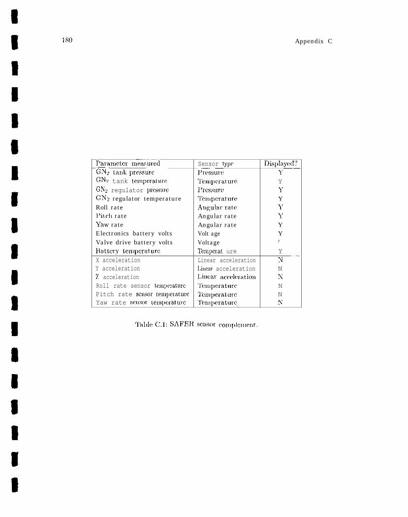
180 Appendix C
I’aranleter n~exsured Sensor type IJisplayec]?—-——‘GN2 tankpressure
—.Pre;sure 1’
GNT2 tank tenlpcratule T’emperaturc Y(3N2 regulator prcssuw l’rcssurc YGNT2 regulator temperature lelnpcrature YRoll rate Angularrate 1’I’itcll rate Angular rate y
Yaw rate Angular rate YElectronics battery volts Volt age YValve drive battery volts Voltage y
l]attery tenlperature l’enlpcrat ure YX acceleration Linear acceleration N ‘“–Y acceleration Litlear acceleration N‘Z acceleration Linear acceleration N
Roll rate sensor tem~)crature lhnperature NPitch rate seusor tenlperature q’enlperature NYaw rate sensor tenlperature Tenlpcrature N—.
TableC.1: SAFER scllsor coxll~)lelrlellt.
NASA-GB-001-97 181
C.1 .4.1 Software Interfaces
l)igital interfaces to SAFER components enable the CFIA’S nlicroprocessor to achievecontrol. Four classes of ill~)uts” are nlonitored and accepted by the avionics software:
1. Hand controller switches. Indications of switch operation cover both togglesmritclles and those cmbe,dded within tile Iland grip n~ecllanisn].
2. Avionics transducers. Sensor inputs are converted fro~ll analog to digital fornlbefore software sanlpling.
3. Thruster-on discrete. This input is a binary indication of at least one thrustervalve Lcing open.
4. Serial line. Ground checkout operations send data through this input.
Similarly’, four classes of outlmts are generated by the avionics software:
1. Hand controller displays. Both L131)s and a 16-character LCD display areincluded to present status to the cre~vmember.
2. Thruster system. Digital outputs arc delivered to the valve drive assenlblies toactuate individual thruster valves.
3. Data recorder system. Selected data items arc recorded for post-flight analysis011 the ground .
4. Serial line. Ground checkout operations receive data through this output.
C.] .4.2 Maneuvering Control Subsystem
Figure C.7 breaks down the SAFER software architect urc in terms of its primary mod-ules. ‘1’hose modules comprising the maneuvming control subsystem collectively realizeSAFER’S six degree-of-freedom propulsion capability. Both rotational and translationalaccelerations will be commanded by the software. Rotations resulting from the AAHfunction arc invoked automatically by the software in response to rotation rates sensedby the inertial reference unit. Special cases result from the interaction of tile AAHfunction and explicitly commanded accelerations.
Translation commands from the crewmembcr are prioritized so that only one trans-lational axis receives acceleration, with the priority order being X, Y, and then Z.Whenever possible, acceleration is provided as long as a hand controller or AAH com-mand is present. If both translation and rotation commands are present simultaneously,rotation takes priority and translations will be suppressed. Conflicting input commandsresult in Ilo outl)ut to the thrusters.
182 Aplxmdix C
Tile SAFEI{cre~\’ltlel~ llJercal~iIlit, iate AAII at any tilllct)ydel)ressillgor “clicking”the lJushbutton On the hand controller gri~). Whenever AAH is active iu any axis thegrmn LED on the HCM illuminates. When the button is double clicked (two clickswithin a 0.5 second inter~~al), AAH is clisabled for all three rotatiol~al axes. If AAHis active, and the crewmember issuc!s a r’otatiollal acceleration command about anyaxis, AAH is imlnediately disabled on that axis. When this occurs, the remaining axesremain in A AH. On the other hand, if A AH is initiated simultaneously with a rotationalcommand from tl~e hand controller, the rotational command will be ignored and AAHwill become active in that axis. ~’his feature is necessary so that a failed-on HCMrotational command cannot permanently disable AAH on the affected axis.
A AH implements an autonlat ic rotational deceleration sufficient to reduce axis ratesto near-zero levels. Continuous thruster firings are commanded to reduce rotation about san axis whenever its rate is sensed to be above 0.2 degree per second. Once the rateshave fallen below 0.3 degree per second, thrusters are fired only as needed to rnaintaillattitude within a~)proximately +5 degrees. ‘1’hrustcrs are not fired when attitude iswithi]l a +.2 degree deadband.
Rate sensors, rate noise filters, and associated rate measurement electronics exhibitsignificatlt offset errors, which are largely a fullctioll of rate sensor temperature. Offs@reduction is used to minimize tile negative effects of rate offset errors. Temperaturelueasurements are periodically sampled and net offset errors estimated. Such estimatesare subtracted from the noise filter rate measurements to minimize rate offset errors.hTet offset errors are independent for each axis, reaching an average of 0.2 degree persecond and resulting in an average drift of the same magnitude.
A c c e l e r a t i o n conlnlatlds fro~n the h a n d co~ltroller and from the A A H function arc
combined to crea te a single accelera t ion command. Thrus ter select logic is provicled to
choose suitable thruster filings to achieve the commanded accelera t ion . ‘Thrus ter selec-
tion results in on-off commands for each thrus ter , with a maximum of four thrus ters
turned on s imul taneous ly . T h r u s t e r a r r a n g e m e n t and des ignat ions a re shown in F ig-
ure ~.3. while Tables C.2 and C.3 specify the selection logic. These tables are specifieditl terms oft hree possible command values for each axis: negative thrust, pc)sit ive thrust,or no thrust at all.
C.1 .4.3 Fault Detection Subsystem
The fault detection subsystem performs four testing functions: a self test, an activationtest, a monitoring function, and a ground checkout function. The fault detection sub-system also manages the display interface, performing the computation of parametersand construction of messages for the HChI LCD.
Tile self test provides an overall functional test of the SAFER flight unit withoutusing any propellant or external equipment. To carry out the test, the crewmember isled through a checklist of prompts displayed 01} the HCk4 I, CD. If a particular test is
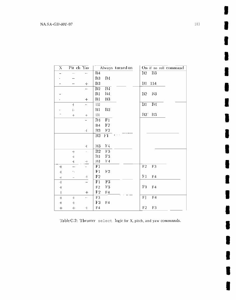
NA SA-GB-001 -97
x F’it ch >’av—. —.. ..— -—. — +-— ..— +. + --— 4-— + +
.
-1
-1
+–++ +— _ .—
+- -- –-1 - .
-t – +“
+ -t -.
-t i-+- + -t
_—— ——. - —Always turned on
E141;3 R4L13B2 F14111 FMB] B3132El 112131B4 l?]B4 F2113 F2132 F1 ‘- - - ‘-”’”--–
F33 F4132 F3B] F3131 174F1PI F2F2F1 F3F2 FI’3F2 F4————. .—. —— .——F3F3 F4F4
011 if no roll command
B2 B3
u] 114
132 113
B] F14
132’ 113
F2 F3
F1 F4
F1 F4
F] F4
F2 F3
‘l’able C.2: T’hruster select logic for X, pitch, and yaw coml”nands.
183
8
98
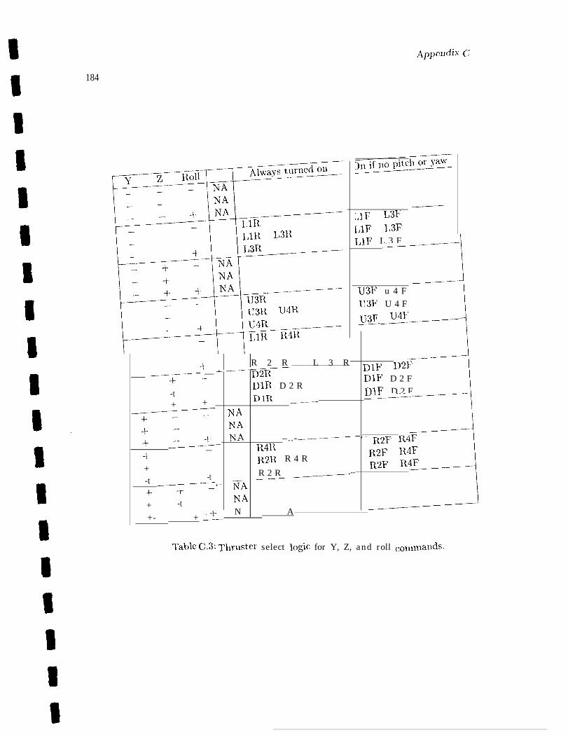
App(ydix’ c;
184
, .-
__.——;,] F L3F[,lF I,3FlJIF L 3 F—-—-———
1
___————u3F u 4 Fu3F U 4 F
U3F _~l_.__-.—
R 2 R L 3 R-_——————
+ ___—‘“---- r)2R
DIF D21T___ —–—-—— —
-t– DIR D 2 RDIF D 2 F
-t 1-) 11{DIF D 2 F
+ \_———––
+ ——————–—–-— NA
7––+–
NANA
.————___-——— ——+ _;2– ‘ - R2F R4F~41{ –..-
—4 R2R R 4 R
R’2F R4F
+ R 2 R _____-— --R2F’ R4F
:
_—--——
-t -t——-—-—‘ – —ISA ‘--—
++–+ -t
NA
N A_____~
+- +_+-–
Table C.3: Thrllster select logic for Y, Z, and roll comtnat~ds.
185
unsuccessful, a failure lnessage is displayed. ‘1’ho following tests are perfornled duringself tc!st: 9
1. Thruster test
2. Hand controller co]ltrols and dis~)lay test
3. Ilatc sensor fmlction test
The activaticm test checks the functionality of the SAFER flight unit in an opera-tional mode, being invoked to check the function of the pressure regulator. A minimalamount of propellant is used and no external equipment is required. The test cou- tsists of commanding 20 millisecond thruster pulses ill translational and rotational axis .dircciions, with opposing thrusters fired as well so no net acceleration results.
A continuous fault check of the SAFER subsystems is performed by tile monitoring i
function, Conlprisiug the following tests:
1. IJeak monitoring
2.
3.
4.
5.
Battery voltage checks
‘Rank pressure and temperature clmcks
Regulator pressure and temperature checks
Battery pack telnperature check
Status information resulting from contiguous monitoring is displayed on the HCM LCDduring SAFER flight. The following items are displayed in order:
1.
2.
3.
4.
5.
6.
7.
Ilefault display, showing GIVz and power percent rcn~aining R
I’ressure and temperature
Rotation rate
Angular displacement
Battery voltage
High rate recorder status
Message display (error queue)
The fault detection system also provides for ground checkout of the SAFER flightunit. This function processes commands for data requests or avionics tests from groundsupport equipment connected to the CFJA’S ground servicing serial port.
9
1 /35 Appcnclix- C
C.2 SAFER EVA Flight Operation Requirements
The full SAF’ER system has requirements that cover flight o~)crations as well as su~~port
procedures such as pre-131~A checkout, ~mopcllant recliarging, aud battery pack changing .
OU1 SAF~~ fXaIU@C! fOCUSCS 011 a SUbSCt Of th(! fLlll K!CIUh’C!lllWk, Ilallld~, thOSC! COV(X’hl$flight operations duri~lg an EVA. Furthermore, several rccluircmcuts are iucorporatcd inmodified form to better suit, the purposes of the example. The most significant changeis that the controller sam~)les switches and serlsors on every frame rather than acceptingchauge notifications via a serial line iuterface. This leads to the conceptually sim~)lerarchitecture of a pure sampled-data control system.
C.2.1 Hand Controller Module (HCNI)
The HCM provides the controls atd displays for the SAFER crewmembm to operateSAFER and to monitor status.
(1) ~’hc HChl shall conl])rise two uuits, the Haud Controller Unit (llCU) aucl theI)isplay aud Colkrol Unit @CU).
(2) The HCM shall provide the controls aud displays for the SAFER cmvmember tooperate SAFER and tc) monitor status.
C.2.1.1 Display and Control Unit
The DCU provides displays to the crew and switches for crew commands to powcx theSAFER, tc) select modes, and to select displays.
(3) The DCU shall provide a reel LED aud shall illuminate it whenever an electricalon-commaud is applied to auy one of the SAFER thrusters.
(4) The DCU shall provide a green LED and shall illuminate it whenever automaticattitude hold (A AH) is euabled for one cm more SAFER rotational axes.
(5) The DCU shall provide a 16-character, backlit liquid crystal display (I,CD).
(6) The DCU shall display SAFER instructions aud status information to the SAFERcrewmember on the I, CD.
(7) The DCU shall provide a three-position toggle switch to power the SAFER unit011 and to control the SAFER test functiolls.
(8) The power toggle switch shall be oriented towards the crewmember for “T’ST,” inthe center position for “ON, ” and away for “OFF.”
A’ASA-GB-O01-97 187
(9) The DCU shall provide a three-position, momentary toggle switch to control theLCD display.
(1 O) ‘The display toggle switch shall remain in the center position whexl not, beiug usedaud shall be oriented so that l)ositioning the switch tom’ards or away from thecrewmember will control the LCD menu selection.
(11 ) The DCU shall provide a two-position toggle switch to be used to direct baudcontroller commands for either full rotation or full translation control mode.
(12) The n~ode select toggle switch shall be posit ioned to the crewmember’s left fhr theRotatio~l Mode aud to the crewmember>s right for the Translation Mode.
C.2.1.2 Hand Controller Unit
Tile HCU provides those functions associated with the baud controller and the auto-matic attitude hold (A AH) pushbutton switch.
(13) The HC(J shall ~)rovide a four-axis baud controller haviug three rotary axes audone transverse axis, operated by a side-mouuted hand grip as depicted in Fig-ure C.4.
( 1 4 ) lle H(3U shall indicate ~min~ary control n~ot ions when the grip is deflected from
the center or null position to nlechauical h a r d - s t o p s .
(15) The grip deflections shall result iu six degree-of-freedom commauds related tocontrol axes as depicted iu Figures C.5 and C.6.
(16) The HCU shall termiuate commauds when t he grip is returned tc) the null posit ion.
(17) The HCU shall ~wovide a pushl)utton switch to activate and deactivate A AH.
(18) The pushbutton switch shall activate A AH when depressed a single time.
(19) The pushbutton switch shall deactivate A AH when pushed twice within 0.5 second.
C.2.2 P r o p u l s i o n S u b s y s t e m
SAFER thrusters are actuated by the control electronics assembly (CEA) using thevalve drive assemblies (VDAS).
(20) The propulsion subsystem shall provide 24 gaseous nitrogen (GN2 ) thrusters ar-ranged as shown iu Figure C.3.
(21) The VDAS shall accept thruster firing commands from the CEA and apply appro-priate voltages to the selected thrusters.
188
(22)
(23)
(24)
Apkxndh <;
‘1’hc VDAS shall have the capability of sensing current ftow through the thrustersolenoids aud providing discrete signals to tllc C13A indicating such au ewcmt.
The propulsion subsystenl shall provide two tra~]sducers to monitor tank pressureatld regulator outlet pressure.
Tllc!~>ro~~lllsiol )sllbsystelll sllalll)rcJt'idc tw'otel~~~jcratllrc sel~sors tol1~easurc tauliten~peratureaud regulator outlet tenl~mature.
C.2.3 Avionics Assemblies
The avionics subsystem iucludessevcral assembliesho used withint hebackpack propul-sion module, each haviug a digital iutcrfacw to the CEA.
C.2.3.1 I n e r t i a l ReferenceUnit (IRU)
(25)
(26)
(27)
‘I1hclRU shall provicte augularrateseusors and associated electronics to measurerotation rates in each angular axis (roll, pitch, yaw):
ThelRU shall providca tcm~)eratures cnsor for each augular rate sensor to allowtmnpcraturc-based compensation.
The IRU shall provide accelerometers to measure linear accelerations in each trans-latioll axis (X,>’, Z).
C.2 .3 .2 Power S u p p l y A s s e m b l y
(28) Tl~e])ower sll~)~Jly sllalll)ro\idea \oltagcse l]sorto l[leas~lret} levalvedr i\ebatteryvolt age.
(29) Tl,c~,owcrs ~]]~~~lys l,all~~rc~\ideav oltagese ~lsorto *~leasuretl leelectro~]icsba tteryvolt age.
(30) The power sup~)ly shall provide atemperature sensorto measure battery packtem~wrature.
C.2.3.3 Data Recorder Assembly (DRA)
( 3 1 ) ~’l]eDI?Asliallacc(:l)t ~)erforltlarlce data atldsyster~l ~)arar~leters frornthe CEAfor storage aud ~)ost-flight aualysis.
(32) Tile I)ltAsllall vriteforlllattedd atao I~l~ollvolatilel ~lc11lorydevices.
ATASA- G13-001-97 189
C.2.4 Avionics Software
Executing on a microprocessor within the control electronics assembly (CEA), theSAFER avionics software provides the capability to control SAFER flight maneuvers,to check out functionality and detect faults in SAFER, and to display SAFER faultconditions and general health and consumable stat us.
(33)
(34)
(35)
(36)
(37)
(38)
(39)
(40)
(41)
(42)
(43)
(44)
The avionics software shall reference all commauds and maneuvers to the coordi-nate systen~ defined in Figure ~.3.
The avionics software shall provide a six degree-of-frecdon~ nlaneuveriug controlcapability in response to crewnlember-initiated conunauds fronl t]le hand con-troller nlodule.
The avionics software shall allow a crmwnen~ber with a single comtnand to causethe nleasured SAF13R rotation rates to be reduced to less than 0.3 degree persecond in each of the three rotational axes.
The avionics software shall atteulpt to nlaintaiu the calculated attitude within *5degrees of the attitude at the tinle the measured rates were reduced to the 0.3degree per second liu~it.
The avionics software shall disable AA1l on an axis if a crcwn~enher rotationconl~naud is issued for that axis u’bile A AH is active.
Any hand controller rot ation cxnnn~and present at the t in~e A AH is initiated shallsubsequently be ignored until a return to the oft’ condition is detected for that axisor until AAH is disabled.
Hand controller rotation commands shall sul)press any translation commands thatare present, but A AH-generated rotation commands may coexist with t ranslat ions.
At most one translation command shall be acted upon, with the axis chosen inpriority order X, Y, Z.
The avionics software shall provide accelerations with a maximum of four sinml-taneous thruster firing commands.
The avionics software shall select thrusters in response to integrated AAH andcrew-generated commands according to Tables C.2 and C.3.
The avionics software shall provide flight control for A AH using the IRU-n~easuredrotation rates and rate sensor tenl~)eratures.
The avionics software shall provide fault detection for propulsion subsystem leak-age in excess of ().3% of GNz mass per second while thrusters are not firing.
19(I AppcJMlix C
(45) The avionics software shall prcwidc limit checks for battery temperature and volt-ages, propulsion tank pressure and temperature, and reglllator Prcss(lr(’ and tclll-~Jerature.
C.2.5 Avionics So f tware Inter faces
The avionics software accepts input data from SAF’13~ conlponents by sampling the stateof switches and digitized sensor readings. Outputs provided by the avionics software toSAFER conlponents are transmitted in a device-specific Inatlner.
(46) ‘1’}Ic avionics softwale shall accept the following data from the hand controllermodule:
● ☞ pitch, -- pitch
.+ x,-x
● -tyawor+Y, -yawor -Y
● + roll or -1 7,, roll 01 ~,
● l )O w e r / t e s t s w i t c h
● Mode sw’itch
. I)isplay p r o c e e d switch
● A A H p u s h b u t t o n
(47) l’hc avionics software slmll accq,t tl,e following data from the propulsion subsys-tCIll:
● Tank pressure and temperature
● Regulator pressure and tem~)m-aturc
● Thruster-on signal
(48) The avionics software shall accept the following data from the inertial referenceunit:
● Roll, pitch, aud yaw rotation rates
● Roll, pitch, and yaw sensor temperatures
● X, Y, and Z linear accelerations
(49) The avionics software shall accept the following data from the power supply:
● Valve drive battery voltage
● F.lectronics battery voltage
● Battery pack temperature
NASA- GB-001 -97
(50) The
●
●
●
●
●
●
(51 ) ~“’hc
avionics software shall ~movide the following data to
Pressure, tempcrat ure, and voltage nleasuren~ents
Aleri indications
Rotation rates and dis])laccnncnts
Crew ~monq)ts
Failure nlessagcs
Miscellaneous status nlessages
191
the HCM for display:
avionics software shall provide the following data to the valve drive assembliesfor cacll of the 24 thrusters:
●
(52) TheMy:
●
●
●
●
●
Thruster on/ofl’ indications
avio~lics software shall provide the follcwing data to the clat a recorder assem-
lRU-sensed rotation rates
I1tU-sensed linear acceleratiol~s
IRIJ rate sensor tenl~)eratures
Angular displacements
AAII comnlands tatus
C.3 Formalization of SAFER Requirements
A PVS fornlalizatioll of the SAFER systenl described thus far is presented bclow2. Asubset of t hc SA~l~R requirmnents has been chosen for nlodeling that enlphasizes thenlain functional require~uents atld onlits support functions such as the ground check-out feat urcs. Eve] 1 ~vi t liiu the flight operation requirements some functions have beenrepresented only i~l abstract form.
C.3.1 1’VS Language F e a t u r e s
C)nly a fcw PVS language features need to be understood to read the fornlal specifi-cation that, follows. 1’1’S specifications are organized around the concept of theories.Nach theory is cwnpcmd of a sequence of declarations or definitions of various kinds.T)efitlitions fronl other theories are not visible unless explicitly itnported.—
‘The PVS source files for the SAFER exan~ple are available 011 LaRC’s Web server iu the directoryftp://atb-wuw.l arc.nasa.gov/Gui debooks/
99
I’VS allows the usual range of scalar types to model various quantities. Numerictypes include natural numbers (nat ), integers (int ), rationals (rat), and reals (real).Nonnumeric types include booleans (bool) and enumeration types ({Cl, C2, . ..}).Subranges a~ld subtyping mechanisms allow derivative types to be introduced. Uninter-pmt ed, nonempty t ypc am of type TYPE+.
Structured data types or record types ate used extensively in sl)ecifications. l’llesetypes are introduced via declarations of the following form:
record_ type: TYPE = [# VI: type_l, v2: type_2, . . . #1
~’hc first cxnnponcnt of this record may be accessed using the notation v 1 (R). A record
value cons t ruc ted fronl individual conlponent values nlay be synthes ized as fo l lows:
(# V1 := <expression 1>, V2 := <expression 2>, . . . #)
Similart orecords aretuples, introduced viadeclarations of an analogous fornl:
tuple . type : TYPE = [type_l, type_2, . . . 1
The first component ofatu~>le I~laybe accessed usirlgtllc l~otatio~] proj-l(T). A tuplevalue constructed from individual component values may be synthesized as follow’s:
(<expression 1>, <expression 2>, . . . )
An im~)ortant class of tylms in PVS is formed by the function types. A declarationof tllc! form:
fun_type: TYPE = [type_l -> type_2]
definesa (higher-order) type whose values are functions from type-1 to type-2. Func-tion values may be constructed using laml)da expressions:
(LAMBDA X, y: < e x p r e s s i o n of X, y>)
Logical variables are introduced to serve as argunlents to functions and to expresslogical forlnulas or assertions:
x, y, z: VAR var_type
l,ocalvariable dec]aratiolls also areavailable itl1llost cases. Global variable declarationsapply throughout the containing theory but no further.
A nan~ed function is defined quite sin~plyby the followillg notation:
fn (arg_l, arg_2”, . . .): result_type = <expression>
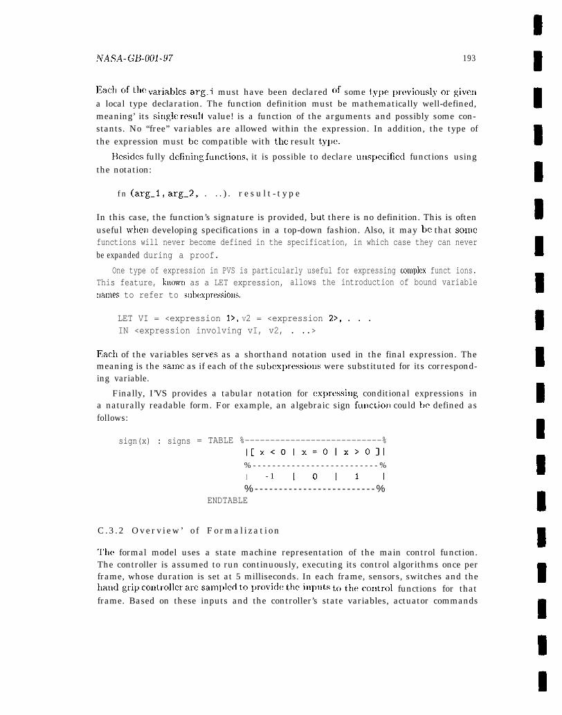
hrASA_ G~j.Ool -97 193
13achoft hevariablesarg.i must have been declared of some ty~~eprc~’iouslyorgivclla local type declaration. The function definition must be mathematically well-defined,meaning’ its Sing]e result value! is a function of the arguments and possibly some con-stants. No “free” variables are allowed within the expression. In addition, the type ofthe expression must be compatible with the result type.
Besides fully defini~lg functiolls, it is possible to declare utlspecified functions usingthe notation:
f n (arg_l, arg_2, . . . ) . r e s u l t - t y p e
In this case, the function’s signature is provided, but there is no definition. This is oftenuseful when developing specifications in a top-down fashion. Also, it may be that somefunctions will never become defined in the specification, in which case they can neverbe expanded during a proof.
One type of expression in PVS is particularly useful for expressing con~plex funct ions.This feature, known as a LET expression, allows the introduction of bound variablenan~es to refer to subexpressions.
LET VI = <expression 1>, V2 = <expression 2>, . . .IN <expression involving vI, v2, . ..>
llach of the variables serves as a shorthand notation used in the final expression. Themeaning is the same as if each of the subcxpressions were substituted for its correspond-ing variable.
Finally, I’VS provides a tabular notation for expressillg conditional expressions ina naturally readable form. For example, an algebraic sign function could be defined asfollows:
sign(x) : signs = TABLE %---------------------------%I[x<olx=olx>oll
% - - - - - - - - - - - - - - - - - - - - - - - - - - %
I - 1 10111% - - - - - - - - - - - - - - - - - - - - - - - - - %
ENDTABLE
C.3 .2 Overv iew ’ o f Formal izat ion
Tile formal model uses a state machine representation of the main control function.The controller is assumed to run continuously, executing its control algorithms once perframe, whose duration is set at 5 milliseconds. In each frame, sensors, switches and thellatldgri~~ col~troller aresatll~)led toprovide tlleill~~uts totllecoxltrol functions for thatframe. Based on these inputs and the controller’s state variables, actuator commands
NAsA-Gl?-ool-97 195
C.3.2.2 Hand Controller Module
B‘The H C.hl s~vitchcs at-c Inodclccl in this tllcory as is the hand grip mechanisnl. Thederivation of a six degree-of-frecdonl command fronl the four-axis hand controller basedon current mode is defined here. Basic types for the I,13Ds and character display are !included as well. A display buffer is modeled as an array of character.display values.A buffer ~)ointer selects which element is currently being displayed. The pointer isupdated when the previous state of the display proceed switch is neutral and the switch
Bmakes a transition in the up or down direction.
C.3.2.3 Propuls ion Module D
Tliruster names are ilkroduced via an enumeration type for the full complement of 24t IIrusters. A more elaborate type called thrust er_des ig represents thruster designa- 9tions in terms of their three componeut ])arts. This makes use of an advanced feature ofthe PVS language knc)wn as dependent types, whm the type of later components of arecord or tul)]e may depelId on the value of earlier com~)onents. A mapping from names “sto designations is also provided. Fiua]ly, lists of thrusters are used to lnodel actuatorco~u~nancls, where those thrusters to be fired arc included in the list. Lists ill P\~S areanalogous to the concept of lists ill the Lisl) progranllning language and its descendants. 9
C.3.2.4 Automatic Attitude HoldI
A moderately complex ~)art of the SAFEI{ model revolves around the attitude holdfeature. The hand grip pushbutton for exlgagiug AAH mode is scanned to detect tramsit ions that should be acted upol]. l’hc single-click, double-click engagement protocol is 1relmesented by the state diagram shown ill Figure C.8, where the arcs are labeled witht lie switch values sensed in the current frame. The type AAH_engage -st at e denotes thestates in this diagram, while the fuuctioll button_transition models the diagram’s Itransitiolls.
Several state conl~)onents are modeled for managing AAH and its special require-ments. ‘1’he actual cent rol law is not defined, but unspecified functions are provided to I
indicate where such processing fits in. The overall AAH transition function is definedby the F’VS function AAH-transition, takillg into account the conditions for activatingand deactivatillg AAH on each axis, as well as the timeouts necessary for detecting m
double clicks of the AAH pushbutton.
C.3.2.5 Thruster Se lect ion
Thruster selection takes place in two major steps: forming an integrated six degree-of- Bfreedom command from the HCM command and AAH command, and then taking theintegrated comrnancl and chosiug individual thrusters to fire. ‘1’hree functions take care
I
194 Appendix C
and crew display outputs are generatecl, as well as the controller’s state fcu the nextframe.
Eleven PVS theories are used to formalize tllc requirements:
. avionics-types
● hand. controller module
● Propulsionmodule
● inert ial_reference.unit
. automat ic.attitude-hold
● thruster -se lect ion
● power-supply
● data_recorder
. self.test
● HCM-display
● avionicsmodel
Tile full text of these theories is presented ill Section C.3.3. The theories have beentypechecked by PVS, and all resulting TCCS (type correctness conditions) have been~Jroved.
Construction of the PVS specifications proceeded in a mostly top-down mannerinitially, but once ~)arsing and typechecking of the PVS source was begun, the lowcr-levelportion sneededt obeprovided. For thisreason,b asictypest end to be doneearlyduring specification development and mauy of the definitions ‘(meet in the middle” asboth the upper and lower layers of the hierarchy are pushed toward completion. Thefollowing paragraphs point out some highlights of a subset of the theories, serving toannotate the PVS specifications of Section C.3.3.
C.3.2.1 B a s i c T y p e s
A few common type definitions are provided for use elsewhere within the specification.Sensor readings are all modeled as real numbers. Several enumeration types are intro-duced to model translation and rotation commands. The six-dof _command type is arecord that integrates all six axis commands. A few constants are also included to givenames and values to null conlnla~lds.
NASA - GB-001 -97 195
C.3.2.2 Hand Controller Module
The HCM switches arc ~[lodckl in this theory as is the hand grip ]nechanism. Thederivation of a six degree-of-freedom command from the four-axis hand controller basedon current lnodc is defi~led here. Basic types for the L13Ds and character display areincluded as well. A display buffer is modeled as an array of charact er-di. splay values.A buffer pointer selects which element is currently being displayed. !lle pointer isupdated when the previous state of the display proceed switch is neutral and the switchmakes a transition in the UI) or dowl} direction.
C.3.2.3 Proj)ulsion Module
Thruster names are introduced via an enumeration type for the full complement of 24thrusters. A more elaborate type called thruster_desig represents thruster designa-tions in terms of their three component parts. This makes use of an advanced feature ofthe PVS language known as dependent types, ~vhere the type of later components of arecord or tuplc may depend on the value of earlier components. A mapping from namesto designations is also provided. Fixlally, lists of thrusters are used to nlodel actuatorcolnmands, where those thrusters to be fired arc included in the list. Lists in PVS areanalogous to the concept of lists itl the ],isp programming language and its descendants.
C.3.2.4 Automatic
A moderately complexfeature. The hand grip
Attitude Hold
])art of the SAFE]{ model revolves around the attitude holdpushbutton for engaging AAH nlode is scanned to detect tran- m
sit ions that should be acted upon. The single-click, double-click engagement protocol isreprescnlted by the state diagran~ showrn in Figure C.8, where the arcs are labeled withtile switch values sensed in the current frame. The type AAH.engage.state denotes thestates in this diagram, while the function button.transition nlodels the diagranl’stransitio~ls.
Several state con~~jonents arc nlodeled for nlanaging AAH and its special rcquire-nlents. The actual cent rol law is not defined, but unspecified functions are provided toindicate where such processing fits in. The overall A AH transit ion function is definedby the 1’VS function AAH_transition, taking into account the conditions for activatingand deactivating AAH on each axis, as well as the tinleouts necessary for detectingdouble clicks of the AAH pushbutton.
C.3.2.5 Thruster Selection
Thruster selection takes place in two major steps: forming an integrated six degree-of-freedom command from the HCM comtnand and AAH command, and then taking theintegrated command and chosing individual thrusters to fire. Three functions take care
196 Appendix C
of tllc first part by capturing tllc logic for lJrioritizing translation comma~lds, ~nergingrotation co~ntnands, and forming the correct aggre@e command under the various con-ditions. Two functions called BF.thrusters and LRUD_thrusters formalize the thrusterselection logic in ‘1’ables (2.2 and C.3. These functions are defined using trilJly nestedtables to avoid problems with cun~bcxsome TCCS (type correctness conditions). A morereadable form of the tables using triples of the axis commands resulted in large and itl-tractable T(3CS so the less pleasing form was necessary. This is an example of the trade-offs that must be made occasionally when working with forma] specifications. Finally,the theory concludes with the functions selected.thrusters and selected-actuatorsthat integrate the results of the preceding functions to produce the final list of c]losentilt’usters.
C.3.2.6 A v i o n i c s M o d e l
This top-level theory pulls together all the separate port ions of the formal izat ion. Theoverall state machine model for the SAFER controller is captured in the form of typedefinitions for the inputs, outputs, and state values, as well as the main state transitionfunction called SAFER.control. Note the usc of a LET expression to define most of theseparate pieces that are lnerged to form the final outputs and next-state components.An initial state constant is also provided in this theory.
C.3.3 Pull Text of PVS Theories
0 0 0 0 0 0 0 0 0 0 0 0 0 0 0 0 0 4 0 0 0 0 0 0 0000 OO*OOOO@ 04#@a*0000*0 000 **00000*0 04 **000*00111111111111111 111111111111111 llfllllllllllll 1111111111/1111 llllllllllOoooo Qaoo96ee Ooeaooaoaeoeo Ooesoaeeoeeea Meoonnaeooaoo *O 009S 09000*0 0 0 0 0 0
% %
%% The following PVS theories comprise a formal model of a subset%% of the control system functional requirements for an EVAx%%%%%%%%%%%%%%%%%
propulsion system. This example is heavily based on NASA’sSimplified Aid for EVA Rescue (SAFER), developed at the JohnsonSpace Center (JSC) . For pedagogical reasons, the requirementsdeviate somewhat from the actual SAFER system. Furthermore, theSAFER system is still under development. As a result, the modelthat follows does not necessarily reflect the actual SAFERrequirements as maintained by JSC.
References:%% 1.%%%% 2.%%%%
Simplified Aid for EVA Rescue (SAFER) Operations Manual.NASA report JSC-26283, Sept. 1994.Simplified Aid for EVA Rescue (SAFER) Flight Test Project,Flight Test Article Prime Item Development Specification.NASA report JSC-25552A, July 1994.

NASA- GB-001-97 197
%%eooooeaooo. oa eooaooeeoeeoo 000. 00*0 Oo .*0 *. O*aa O.*ea OO . ..00 o* Oe. *Oe 00000///l///lll/l//ll/ll/fl/ll/l/lff/ll/ll/l/lll/lllll///l/////l/ll//llll//a o 0 0 e e e o 0 0 0 e 00 00 e o 0 0 0 00 e 0 4 0 0 * 0 0 0.. 00 0 0 0 0 e 0 0 6 b 00 0 0 60 e 0 0 0 e 0 0 0 04 0 e 0 0 0 0 0 0 0
avionics.types: THEORYBEGIN
pressure: TYPE = realtemperature: TYPE = realvoltage: TYPE = real
angular.rate: TYPE = reallinear_accel: TYPE = real.
axis_command: TYPE = {NEG, ZERO, POS}
tran.axis: TYPE = {X, Y, Z}rot. .axis: TYPE = {roll, pitch, yaw>
tran_command: TYPE = [tran_axis -> axis_command]rot_command: TYPE = [rot_axis -> axis_commandl
rot_predicate: TYPE = [rot_axis -> boon
six_dof_command: TYPE = [# tran: tran_command, rot: rot_commamd #]
null_tran_command: tran_command = (LAMBDA (a: tran_axis): ZERO)null_rot_command: rot_command = (LAMBDA (a: rot_axis): ZERO)
null_six_dof : six_dof_command = (# tran := null_tran_command,rot := null_rot_command #)
END avionics.types
e @ e @ 00 Ooeooeeeao *9 a * O*O 00 0 * 00 04 4* 0 00 * e 0 * 0 0 0 B * ** e e *Oe* 0 * 0 b* 0 @e* a a 80 0 0081111111/11/1111 llf/l/lf/llllfl llllll/lll/flll lllllllf///flfl /lllll///l0 0 0 8 nee 4 08 4 0 e 0 e 00 0 000 e 4 00 0 0 9* 0 0 88 0 8* 8 0 0 0 * 6 6 oa *9 e 0 0 8 * e *8* 08 4 0 0 e a 0 4 4 0 0 0 0
% %
%% The hand controller module (HCM) consists of a set of switches,%% a hand grip controller with integral pushbutton, and a set of%% crew displays. A six degree-of-freedom command is derived from%% four-axis hand grip inputs and the control mode switch position.%% It is assumed that switch denouncing is provided by a low-level%% hardware or software mechanism so that switch transitions in this%% model may be considered clean.
[
!B9BR

198 Appendix C
%%0 0 0 4 0 0 0 0 0 0 0 4 0 0000000000000 0006,00000000 0080090000000 8Q 04908080008 ,,,eol///ll///l//////l//l/llll//////l/////l/l/////l////////l///////////////00 0 0 0 0 0 00 0 0 0 e o 0 e 0 0 0 0 0 00 00 4 0 0 0 0 0 0 0 e o 0 0 e o 0 6 0 00 0 00 0 0 00 e e 0 0 0 e , e o 0 e , 0, , , , 6 0
hand.controller.module: THEORYBEGIN
IMPORTING avionics_types
power_test_switch: TYPE = ~OFF, ON, TSTI
display_proceed_switch: TYPE = {PREV, CURR, NEXT}
control_mode_switch: T Y P E = {ROT, TRANl
AAH_control_button: TYPE = ~button_up, buttondown)
HCM_switch_positions: TYPE = [#PWR : power_test_switch,DISP: display_proceed_switch,MODE: control_mode_switch,AAH : AAH_control_button#]
%% The hand grip provides four axes for command input, which are%% multiplexed by the control mode switch into the required six axes.
hand_grip_position: TYPE =[# vert, horiz, trans, twist: axis.command #]
grip_commmnd ((grip: hand_grip_position) ,(mode: control_mode_switch)): six_dof_command =
(# tran := null_tran_command WITH [X := horiz(grip),Y := IF mode = TRAN THEN trans(grip) ELSE ZERO ENDIF,z := IF mode = TRAN THEN vert(grip) ELSE ZERO ENDIF],
rot := null_rot_command WITH [roll := IF mode = ROT THEN vert(grip) ELSE ZERO ENDIF,pitch := twist(grip),yaw := IF mode = ROT THEN trans(grip) ELSE ZERO ENDIF]
#)

NASA -GB-001-97 199
%% The HCM display mechanism is centered around a 16-character LCD.
char_display_index: TYPE = {n: nat I 1 <= n & n <= 161 CONTAINING 1
character_display: TYPE = [char_display_index -> character]
blank_char_display: character_display =(LIMBIM (i: char_display_index): char(32))
HCM_display_set: TYPE = [#LCD: character_display,THR: bool,AAH: bool#]
%% Multiline messages are stored in a buffer and viewed one line%% at a time.
HCM.buffer_len: above[O] %% Any integer > 0
HCM.buffer_index: TYPE = {n: nat I 1 <= n & n <= HCM_buffer_len}CONTAINING 1
HCM_display_buffer: T Y P E = [HCM_buffer_index -> character.display]
blank_display_buffer: HCM_display_buffer =
(LAMBDA (i: HCM_buffer_index): blank_char_display)
%% The current pointer in the display state identifies which line to%% display, and the pointer can be moved up and down using the display%% proceed switch.
HCM-display_state: TYpE = [ #switch: display_proceed_switch,buffer: HCM_display_buffer,current: HCM_buffer_index#]
next_disp_pointer( (new_sw: display_proceed_switch) ,(display: HCM_display_state)): HCM_buffer_index =
IF switch(display) = CURR AND new_sw /= CURR

200 Appendix C
THEN IF new. sw = PREV
THEN max(l, current(display) - 1 )
E L S E m i n ( H C M _ b u f f e r _ l e n , current(display) + 1)
ENDIF
ELSE Current(display)
ENDIF
END hand.controller.module
, 0 0 0 0 0 4 0 000 0 0 0 0 00 00 0 0 0 044 0 9 000004 0 000 0090 0900 000 0 9 040000 8000 0 4 04 00 0 40 0///l//lll/l/l//llllllll/lll/lllll//l//ll///l//l/l/lll/////////l/l/////0 0 0 0 0 0 0 0 n 0 e o a o e 8 0 0 0 0 0 0 e 88 9* oe 0 e o 0 0 000 e en o e se o *e e e oee o 00 0 0 0 0 a o 0 a 0 0 * 0 00 0
% %
%% The propulsion module provides a number of sensors and a set of%% actuators to control the 24 thrusters, which are grouped into%% four clusters or quadrants.%%o 0 0 0 0 0 000 00 0 # 0 0 000 0 0 e @ Oem O* 0 0 9*OE 0 009 000 0 Ooe* 000 9000 *O*ba 0 00 000 0 Oa 0 a 0 0ll/llllllll/lfl lllllfllllll/ll 111111111111111 111111111/1/111 /lllll/lll0 0 0 00 0 0 0 0 0 4 00 0 a o a 0 0 0. e o 00 0 0 0 00 0 00 0 00 0 0 00 0 e 00 0 00 a 8 *O 60 ea 0 e 0 a 00 4 0 e 04 e 00 0
propulsion.module: THEORYBEGIN
IMPORTING avionics_types
propulsion_sensors: TYPE = [#tank_press: pressure,tank_temp: temperature,reg_press: pressure,reg_temp: temperature,thruster_on: bool#]
thruster_name: TYPE ={Bl, B2, B3, B4, Fl, F2, F3, F4,
LIR, LIF, R2R, R2F, L3R, L3F, R4R, R4F,DIR, DIF, D2R, D2F, U3R, U3F, U4R, U4F}
%% Thruster designators are triples of the form%% (thrust direction, cluster no., forward/rear location)%% Not all combinations of these values are possible so a dependent%% type is used to represent the constraints.
thruster_direction: TYPE = {UP, DN, BK, FD, LT, RT}

NASA-GILOO1-97 201
thruster. quadrant: TYPE = {n: nat I 1 <= n & n <= 4} CONTAINING 1thruster_locati.on: TYPE = {FW, RR] % forward, rear
valid_quadrant ((d: thruster_direction),(q: thruster_quadrant)): bool =
CONDd=UP->q=30Rq= 4,d=DN->q=10Rq=2,d=LT->q=10Rq=3,d=RT->q=20Rq=4,ELSE -> true
ENDCOND
% T h r u s t e r s B1-B4 a n d F1-F4 a r e n o t n o r m a l l y w r i t t e n with a
% f o r w a r d / r e a r l o c a t i o n t a g , b u t t h e y a r e s u p p l i e d b e l o w t o f i t
% the type declaration s c h e m e .
thruster_desig: TYPE = [dir: thruster_direction,{quad: thruster.quadrant I valid_quadrant(dir, quad)},{1OC : thruster_location I
(dir = BK ‘> 10C = FW) AND (dir = FD ‘> 10C = RR)}1
thruster_map(thruster: thruster_name): thruster_desig =
TABLE thruster%--------------------x
I BI I (BK , i, FW) III B2 I (BK, 2, FW) III B3 I (BK, 3, FW) 11I B4 I (BK, 4, FW) II
%--------------------%I FI I (FD , 1, RR) III F2 I (FD, 2, RR) III F3 I (FD, 3, RR) III F4 I (FD, 4, RR) II%--------------------%I LIR I (I-T, 1, RR) ItI LIF I (LT, 1, FW) III R2R I (RT, 2, RR) III R2F I (RT, 2, FW) 11%- - - - - - - - - - - - - - - - - - - -%
202 Appendix C
I L3R I (L,T, 3, RR) 11I L3F I (IT, 3, FW) III R4R I (RT, 4, RR) III R4F I (RT, 4, FW) 11%---------”-----------%
I DIR I (DN, 1, RR) III DIF I (DN, 1, FW) III D2R I (DN, 2, RR) II1 D2F I (DN, 2, FW) II%---------”-----------%I U3R I (Up, 3, RR) III U3F I (UP, 3, FW) III U4R I (UP, 4, RR) III U4F I (UP, 4, FW) II
%---------”-----------%ENDTABLE
%% Actuator commands are modeled as a list of thrusters to be fired.
thruster_list: TYPE = list [thruster_nameI
actuator_commands: TYPE = thruster_list
null_actuation: actuator_commands = (: :)
END propulsion_module
0 0 , a 00.0 a 0 e * 0 000 a 0 a e o 0 0 0 0 0* *a a @ 00 0 Oee 0 90 @ 8 00 0 **O** 0000 0 a @ 0 0 a 00 0 0 @a 000 0l/llllllll/llllllllllllllll/llllll/llllllll/lllll//l//ll//lll/ll//ll/lo 0 0 0 a , 0 4 e , *O o 0 0 0 0 0 0 0 0 * o 00 0 ,00 0 0 0 0 e ,0 0 0, 0 0 a a e, e, *O o 0 , e # #* e o , e a o # ,ae o , , 0
%%%% Sensing for angular rotation rates and linear acceleration is%% providedby the inertial reference unit (IRU).%%40 @Oe 0 0 0 0 00 e 0 e o 0 0 08 a * * a 00 0 00 00 0 *88 *O 000 0 * * a * 0 *@co 0 0, 0084 00 0, , @ a 0 , , a a e all/llllllllfllllllllllllllllllllllllllllll//llllllllllllll/ll///llfllfQ *O #o 0 0 0 0 a o 0 b o 0 0 0 0 e* 0 9 @ 4 0 0 e O* a 0 *4 e 0 00 Q 40 a * 0 0 0 00 e # 0 0 0 0 *4 0 00 e e 00 e 0 0 0 0 ,, #
inertial_reference_unit: THEORYBEGIN
IMPORTING avionics_types
i n e r t i a l _ r e f _ s e n s o r s : T Y P E = [ #
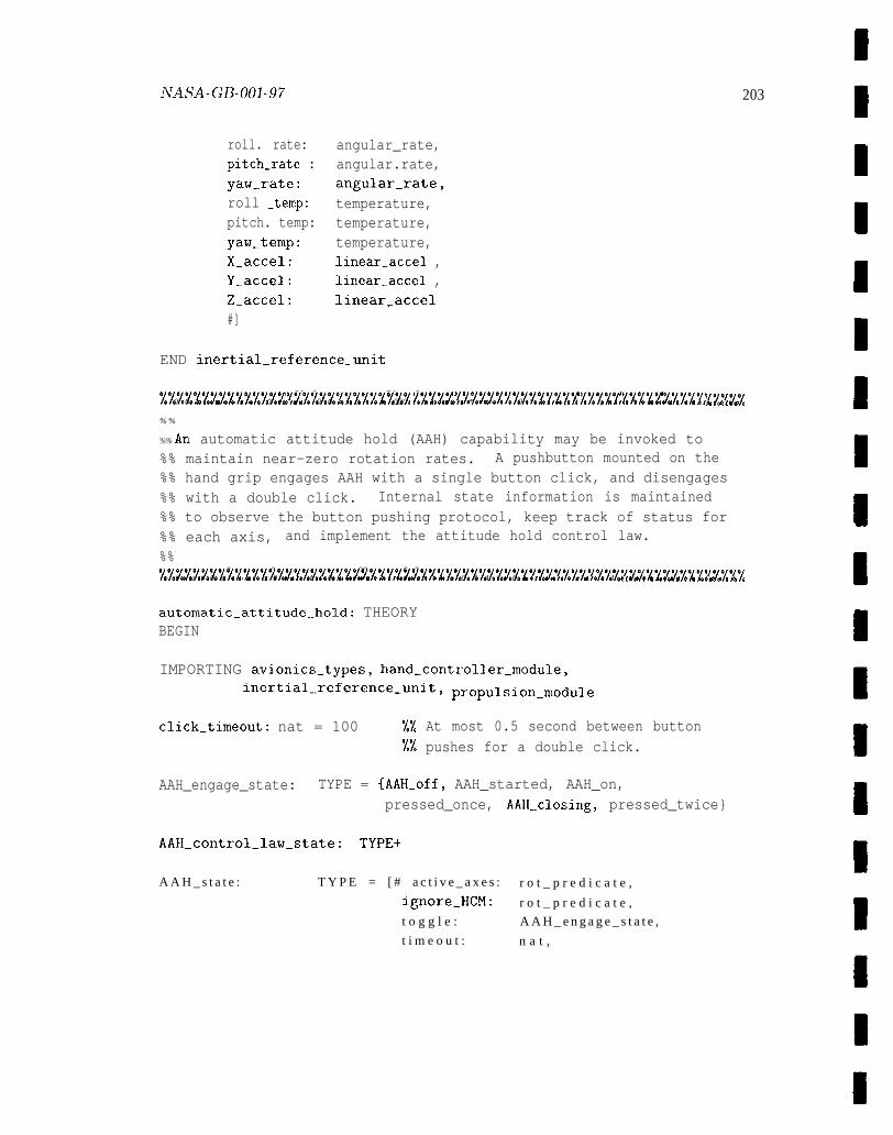
NASA-GB-001-97
roll. rate:pitch_rate :yaw_rate:roll _temp:pitch. temp:yaw_temp:X_accel:Y_accel:Z_accel:#]
203
angular_rate,angular.rate,angular_rate,temperature,temperature,temperature,linear_accel ,linear_accel ,linear_accel
END inertial_reference_unit
0 e o e o a 00 00 00 * a 000 04 0 *OO 0 #* 0 O* 0 0 00 boo 90 9* * * O*@ 00 0080 0 * 06000 0 000 0 a Oc o ,0 e1111//11/111111 1111111111//1// /l//l 11//1111//111// l//l/ l//// ////l /lllle 0 0 e e e e e e e 8 , 0 0 9, 9 0 0 0 0 Q 0 ee e 000 e 0 0 0 0 ,9 * e 9 e 00 0 * 0 0, , 0 ,, , 0 *8 * e 0 0 e o , 8 0 68 0 *8 o
% %
%% An automatic attitude hold (AAH) capability may be invoked to%% maintain near-zero rotation rates. A pushbutton mounted on the%% hand grip engages AAH with a single button click, and disengages%% with a double click. Internal state information is maintained%% to observe the button pushing protocol, keep track of status for%% each axis, and implement the attitude hold control law.
%%0 0 0 0 0 0000 0 0 ao a 00 0 .0 ..00 000 0 0 0 e 0 Q o * 09 0 0 00 0 0 00. .9 9 n 9* * 0 9* *OO a . . . . ee.. e* o/lllll/l///l/l/l/l//////l/lllll/l/l/l/////////lll//////l//////////////o 0 0 e 0 0 e e e e * o 0 0 me 4 0 0 8 4 0 a 0 a o .a 0 0 e 00 * o 0 4 4 0 0 0 e 00 a oa 0 e *O * 4 *Q a e o e e a o Q e o 8 0 a o 0
automatic_attitude_hold: THEORYBEGIN
IMPORTING avionics..types, hand_controller_module,inertial_reference_unit $ proPulsion_module
click_timeout: nat = 100 %% At most 0.5 second between button1% pushes for a double click.
AAH_engage_state: TYPE = {AAH_off, AAH_started, AAH_on,pressed_once, AAH_closing, pressed_twice}
AAH_control_law_state: TYPE+
A A H _ s t a t e : T Y P E = [ # a c t i v e _ a x e s : r o t _ p r e d i c a t e ,
ignore_HCM: r o t _ p r e d i c a t e ,
t o g g l e : A A H _ e n g a g e _ s t a t e ,
t i m e o u t : n a t ,
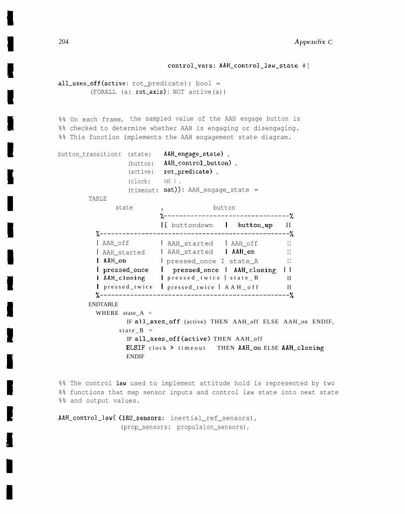
204 Apprmdix C
control.vars: AAH_control_law_state #]
all_axes_off(active: rot_predicate): bool =(FORALL (a: rot_axis): NOT active(a))
%% On each frame, the sampled value of the AAH engage button is
%% checked to determine whether AAH is engaging or disengaging.%% This function implements the AAH engagement state diagram.
button_transition( (state: AAH.engage-state) ,
(button: AAH_control_button) ,(active: rot_predicate) ,
(clock: nat ) ,(timeout: nat)): AAH_engage_state =
TABLEstate 9 button
%---------------------------------%1[ buttondown I button_up II
%--------------------------------------------------%I AAH_off I AAH_started I AAH_off III AAH_started I AAH_started I AAH_on III AAH_on I pressed_once I state_A III pressed_once I pressed_once I AAH_closing I II AAH_closing I p r e s s e d _ t w i c e I s t a t e _ B II
I p r e s s e d _ t w i c e I p r e s s e d _ t w i c e I A A H _ o f f II
%--------------------------------------------------%ENDTABLE
WHERE state_A =
IF all_axes_off (active) THEN AAH_off ELSE AAH_on ENDIF,
s t a t e _ B =
IF all_axes_off(active) THEN AAH_off
ELSIF c l o c k > t i m e o u t THEN AAH_on ELSE AAH_closing
ENDIF
%% The control law used to implement attitude hold is represented by two%% functions that map sensor inputs and control law state into next state%% and output values.
AAH_control_law( (IRU_sensors: inertial_ref_sensors),(prop_sensors: propulsion_sensors),
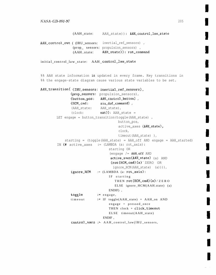
ArASA _GJ3.~~3_97
(AAH_state:
AAH_control_out ( (IRU_sensors:(prop_ sensors:(AAH..state:
initial_control_law_state: AAH_
205
AAH_state)): AAH_control_law_state
inertial_ref_sensors) ,propulsion_sensors) ,AAH_state)): rot_command
control_law_state
%% AAH state information is updated in every frame. Key transitions in%% the engage-state diagram cause various state variables to be set.
AAH_transition( (IRU_sensors: inertial_ref_sensors),(prop_sensors: propulsion_sensors),(button_pos: AAH_control_button) ,(HCM_cmd: six_dof_command) ,(AAH_state: AAH_state),(clock: nat)): AAH_state =
LET engage = button_transition(toggle(AAH_state) ,button_pos,active_axes (AAH_state),clock,timeout(AAH_state) ),
starting = (toggle(AAH_state) = AAH_off AND engage = AAH_started)IN (# active_axes := (LAMBDA (a: rot_axis):
starting OR(engage /= AAH_off ANDactive_axes(AAH_state) (a) AND(rot(HCM_cmd)(a) = ZERO ORignore_HCM(AAH_state) (a)))),
ignore_HCM := (LAMBDA (a: rot_axis):
I F s t a r t i n g
T H E N rot(HCM_cmd)(a) /= Z E R O
ELSE ignore_HCM(AAH.s ta te ) (a )
ENDIF) ,
toggle := e n g a g e ,
t i m e o u t := IF toggle(AAH_sta te) = AAH_on AND
e n g a g e = p r e s s e d _ o n c e
THEN c lock + click_timeout
E L S E t i m e o u t ( A A H _ s t a t e )
ENDIF ,
control_vars := A A H _ c o n t r o l _ l a w ( I R U _ s e n s o r s ,

IF tran(X) /= ZERO
THEN null. tran. command
E L S I F tran(Y) /= Z E R O
THEN null_ tran_command
ELSIF tran(Z) / = Z E R O
THEN null_ tran_command
ELSE null_tran_command
ENDIF
prop_sensors,AAH_state)
#)
END automatic_attitude_hold
000 0 0 0 0 0 e 0. , 0 0 40 0 0 0 @e e 00 0 * e 00 * 4 **8 oea eoa 00ebo ** 0 0 e@e*OO 0 ,@ 000 , e e 00 0 e a e/////l//////l///ll////ll//ll//l//lll/l/l/////ll/l/l/ll//lll///////ll//o 0 0 0 0 0 0 0 0 0 a o 0 0 0 a a o 0 0 # o 0 0 0 0 @ 00 *O 0 # e 000 00 0 9 0 00 0 40 0 0 00 e 0 @ 0 eeo 0 e Da 60 0 0 0 0 # o
% %
%% Thruster selection logic is formalized in the following theory.%% Hand controller and AAH commands are merged together in accordance%% with the various priority rules, yielding a six degree-of-freedom%% command. Thruster selection tables are consulted to convert the%% translation and rotation components to individual actuator%% commands for opening suitable thruster valves.%%e , 0 O* o 0 0 a 4 e a o 0 0 0 a o 0 0 * e, #b e @ 08 , ,.**4 00 @oe o * oe e *@a ,0044 a,, ,* 0 a e o , 0 0, @ o 6 ,///// n / / / l / / / l / / / / l /l/l/ 1/1111/1/11/111 111111//11111// / / / l / / l / / / / / / / l0 a 0 0 0 0 @ 00 0 0 0 0 a e 0 0 a a 4 0 0 0 00 a 0 00 a a a 4 0 00 0 0 0 0 # 0 a o 0 00 0 e 00 00 08 a 0 0 0 a a a b Q 0 00 e e #
thruster_selection: THEORYBEGIN
IMPORTING avionics_types, propulsion_module, automatic_attitude_hold
rot_cmds_present(cmd: rot_command): bool =(EXISTS (a: rot-axis) : crnd(a) /= Z E R O )
%% At most one translation is allowed, in priority order X, Y, Z.
prioritized_tran_cmd(tran: tran_command): tx-an_command .
WITH [X := tran(X)]
WITH [Y : = tran(Y)]
WITH [Z : = tran(Z)]
%% Hand grip rotation commands take precedence over AAH commands%% unless inhibited at the start of AAH.
combined_rot_cmds ((HCM_rot: rot_command) ,(AAH: rot_command) ,
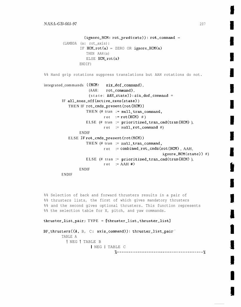
hTASA-GB-001-97 207
(ignore_HCM: rot_predicate)): rot_command =
(LAMBDA (a: rot_axis):IF HCM_rot(a) = ZERO OR ignore_HCM(a)
THEN AAH(a)ELSE HCM_rot(a)
ENDIF)
%% Hand grip rotations suppress translations but AAH rotations do not.
integrated_commands ((HCM: six_dof_command) ,(AAH: rot.command) ,( s t a t e : AAH_state)): six_dof_.command =
IF all_axes_off(active_axes(state) )THEN IF rot_crnds_present(rot(HCM))
THEN (# tran := null_tran_command,r o t := rot(HCM) # )
ELSE (# tran := prioritized_tran_cmd(tran(HCM) ),r o t := null_rot_command #)
ENDIFELSE IF rot_cmds_present(rot(HCM))
THEN (# tran := null_tran_command,r o t := combined-rot_cmds(rot (HCM) , AAH,
ignore_HCM(state)) #)ELSE (# tran := prioritized_tran_cmd(tran(HCM) ),
r o t := AAH #)ENDIF
ENDIF
%% Selection of back and forward thrusters results in a pair of%% thrusters lists, the first of which gives mandatory thrusters%% and the second gives optional thrusters. This function represents%% the selection table for X, pitch, and yaw commands.
thruster_list_pai.r: TYPE = [thruster_list, thruster_list]
BF_thrusters((A, B, C: axis_command)): thruster_list_pair =
TABLE AI NEG I TABLE B
I NEG I TABLE C%------------------------””-------------%
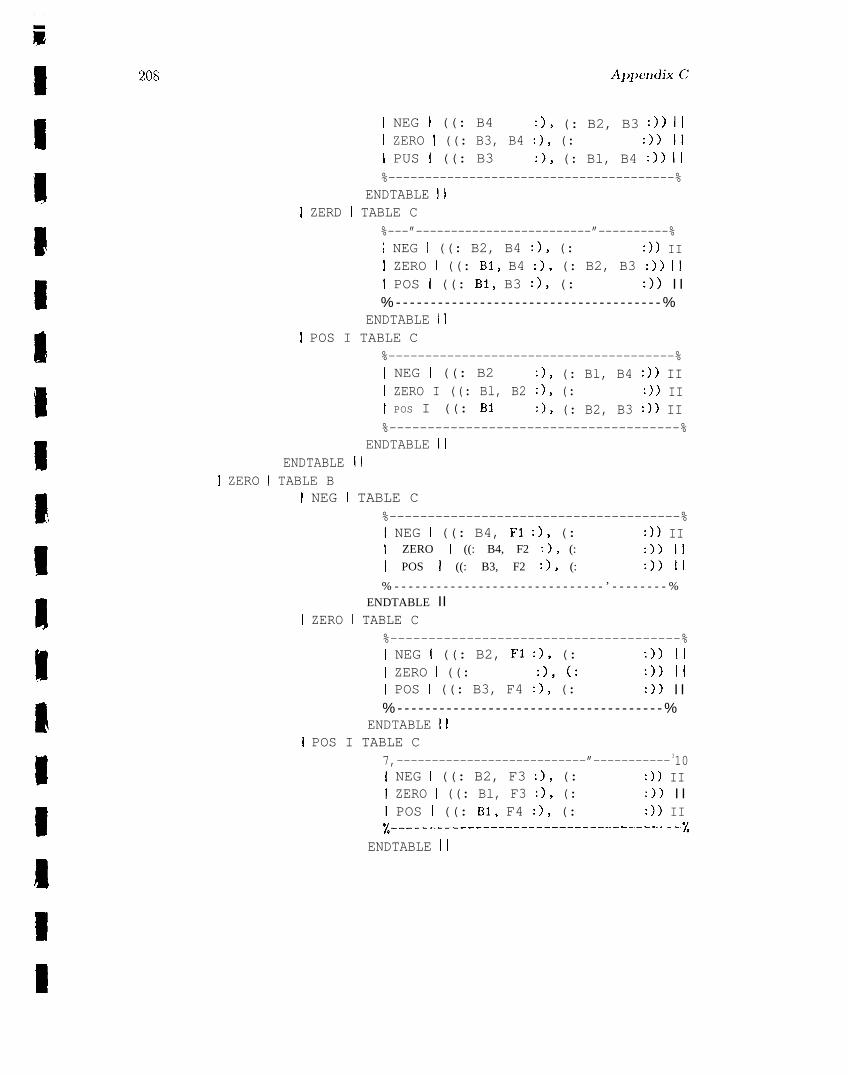
i
9
208
I NEG i ((: B4 :), (: B2, B3 :)) III ZERO I ((: B3, B4 :), (: :)) 1!I PUS i ((: B3 :), (: Bl, B4 :)) II%---------------------------------------%
ENDTABLE III ZERD I TABLE C
%---”-------------------------”----------%I NEG I ((: B2, B4 :), (: :)) III ZERO ( ((: Bl, B4 :), (: B2, B3 :)) III POS I ((: Bl, B3 :), (: :)) I I% - - - - - - - - - - - - - - - - - - - - - - - - - - - - - - - - - - - - - - %
ENDTABLE iiI POS I TABLE C
%---------------------------------------%I NEG I ((: B2 :), (: Bl, B4 :)) III ZERO I ((: Bl, B2 :), (: :)) III POS I ((: B1 :), (: B2, B3 :)) II%--------------------------------------%
ENDTABLE IIENDTABLE 1!
I ZERO I TABLE BI NEG I TABLE C
%--------------------------------------%I NEG I ((: B4, F1 :), (: :)) III ZERO I ((: B4, F2 :), (: :)) III POS I ((: B3, F2 :), (: :)) II
% - - - - - - - - - - - - - - - - - - - - - - - - - - - - - - ’ - - - - - - - - %ENDTABLE II
I ZERO I TABLE C%--------------------------------------%I NEG i ((: B2, F1 :), (: :)) III ZERO I ((: :), (: :)) III POS I ((: B3, F4 :), (: :)) I I% - - - - - - - - - - - - - - - - - - - - - - - - - - - - - - - - - - - - - - %
ENDTABLE III POS I TABLE C
7,---------------------------”----------- 310I NEG I ((: B2, F3 :), (: :)) II\ ZERO I ((: Bl, F3 :), (: :)) I II POS I ((: Bl, F4 :), (: :)) IIx-------------------------------------”-’%
ENDTABLE II
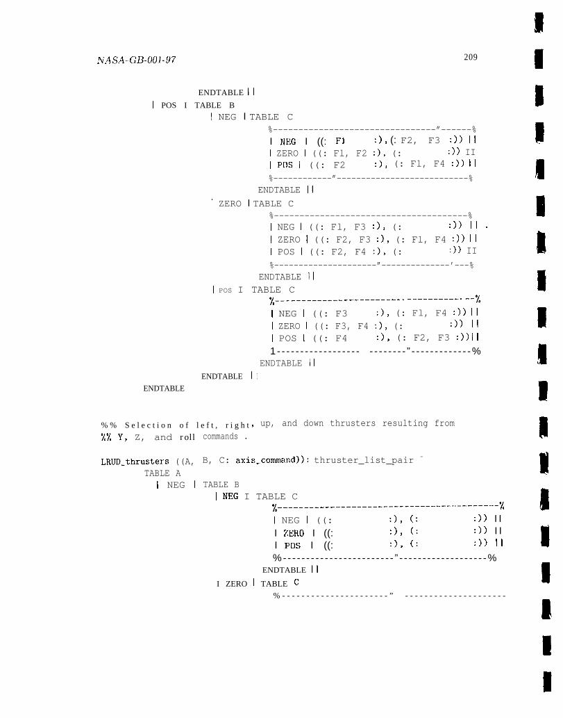
ivAsA-GB-ool-97 209
ENDTABLE II
I POS I TABLE B
I NEG I TABLE C%--------------------------------”------%I NEG I ((: F1 :), (: F2, F3 :)) 1!I ZERO I ((: Fl, F2 :), (: :)) III POS I ((: F2 :), (: Fl, F4 :)) II
%------------”---------------------------%ENDTABLE II
I ZERO I TABLE C%--------------------------------------%I NEG I ((: Fl, F3 :), (: :))11.
I ZERO I ((: F2, F3 :), (: Fl, F4 :)) III POS I ((: F2, F4 :), (: :)) II
%---------------------”--------------’---%ENDTABLE II
I POS I TABLE C
ENDTABLE
ENDTABLE
% % S e l e c t i o n o f l e f t , r i g h t
x---------------------------------------I NEG I ((: F3 :), (: Fl, F4 :)) III ZERO I ((: F3, F4 :), (: :)) II
I POS I ((: F4 :), (: F2, F3 :)) II1 - - - - - - - - - - - - - - - - - - - - - - - - - - ” - - - - - - - - - - - - -%
ENDTABLE III
up, and down thrusters resulting from
%% Y, Z, and roll
LRm_thrusters ((A,TABLE A
I NEG I
commands .
B, C: axis_command)): thruster_list_pair =
TABLE B1 NEG I TABLE C
%--------------------------”-------”-----------I NEG I ((: :), (: :)) I II ZERO I ((: :), (: :)) I II Pos I ((: :), (: :)) II
%- - - - - - - - - - - - - - - - - - - - - - - - ” - - - - - - - - - - - - - - - - - - -%ENDTABLE II
I ZERO I TABLE C
% - - - - - - - - - - - - - - - - - - - - - - ” - - - - - - - - - - - - - - - - - - - - -
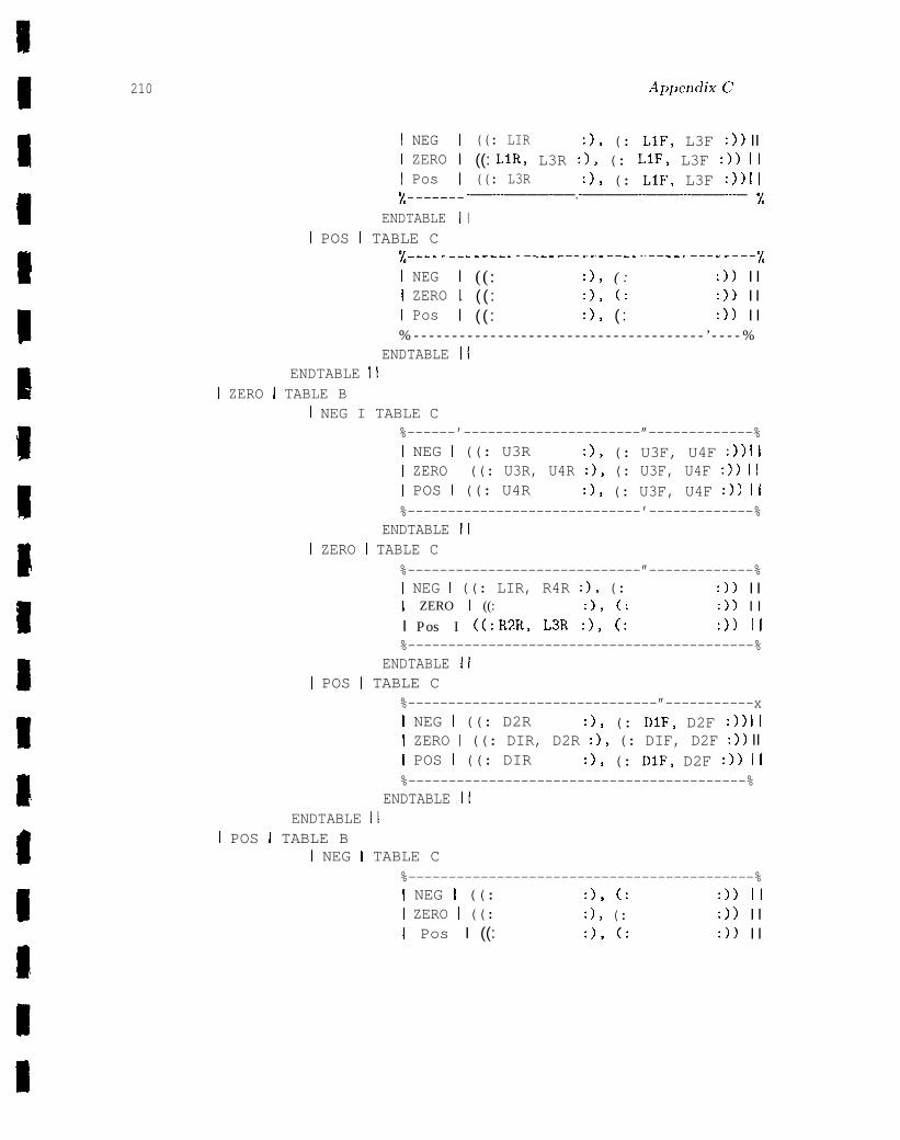
210
I NEGI ZEROI Pos%------
ENDTABLE! POS I TABLE C
%------I NEGI ZEROI Pos
Ap~jendixC
((: LIR :), (: LIF, L3F :)) II((: LIR, L3R :), (: LIF, L3F :)) II((: L3R :), (: LIF, L3F :)) II
-——---————-——.-—————--———---———---— %I
------——-------------——----——---——- %(( : :), ( : :)) I I( ( : :), (: :)) I I( ( : :), ( : :)) I I
% - - - - - - - - - - - - - - - - - - - - - - - - - - - - - - - - - - - - - - ’ - - - - %ENDTABLE 11
ENDTABLE III ZERO I TABLE B
I NEG I TABLE C%------’----------------------”-------------%
I NEG I ((: U3R :), (: U3F, U4F :)) III ZERO I ((: U3R, U4R :), (: U3F, U4F :)) 1!I POS I ((: U4R :), (: U3F, U4F :)) II%-----------------------------’-------------%
ENDTABLE [1I ZERO I TABLE C
%-----------------------------”-------------%I NEG I ((: LIR, R4R :), (: :)) I II ZERO I ((: :), (: :)) I II Pos I ((: R2R, L3R :), (: :)) II%-------------------------------------------%
ENDTABLE IiI POS I TABLE C
%-------------------------------”-----------xI NEG I ((: D2R :), (: I)IF, D2F :)) III ZERO I ((: DIR, D2R :), (: DIF, D2F :)) III POS I ((: DIR :), (: DIF, D2F :)) II%------------------------------------------%
ENDTABLE itENDTABLE 11
I POS I TABLE BI NEG I TABLE C
%-------------------------------------------%I NEG I ((: :), (: :)) III ZERO ! ((: :), (: :)) I II Pos I ((: :), (: :)) I I
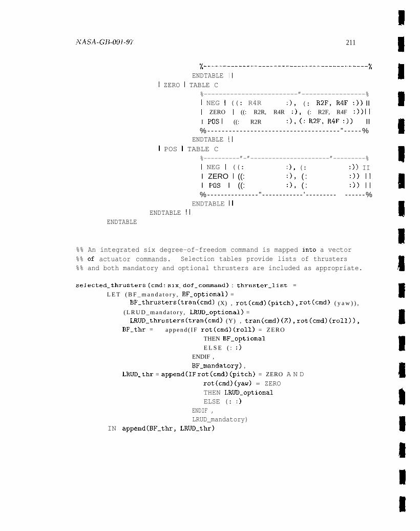
ivAsA-GB-ool-97 211
%-------------------------------------------%ENDTABLE II
I ZERO I TABLE C%-------------------------”-----------------%I NEG I ((: R4R :), (: R2F, R4F :)) III ZERO I ((: R2R, R4R :), (: R2F, R4F :)) II
I Pos I ((: R2R :), (: R2F, R4F :)) II% - - - - - - - - - - - - - - - - - - - - - - - - - - - - - - - - - - - - - ” - - - - - %
ENDTABLE III POS I TABLE C
%----------”-”----------------------”---------%I NEG I ((: :), (: :)) III ZERO I ((: :), ( : :)) III F’os I ((: :), ( : :)) II%- - - - - - - - - - - - - - - ” - - - - - - - - - - - - ’ - - - - - - - - - - - - - - -%
ENDTABLE IIENDTABLE II
ENDTABLE
%% An integrated six degree-of-freedom command is mapped into a vector%% of actuator commands. Selection tables provide lists of thrusters%% and both mandatory and optional thrusters are included as appropriate.
selected_thrusters (cmd: six_dof_conunand) : thruster_list =
L E T ( B F _ m a n d a t o r y , BF_optional) =
BF_thrusters(tran(cmd) (X) , rot(cmd)(pitch), rot(cmd) ( y a w ) ) ,
( L R U D _ m a n d a t o r y , LRUD_optional) =
LRUD_thrusters(tran(cmd) (Y) , tran(cmd)(Z), rot(cmd)(roll)),
BF_thr = a p p e n d ( I F rot(cmd)(roll) = ZERO
THEN BF_optional
E L S E ( : :)
ENDIF ,
BF_mandatory) ,
LRUD_thr = append(IF rot(cmd)(pitch) = ZERO A N Drot(cmd)(yaw) = ZEROTHEN LRUD_optionalELSE (: :)
ENDIF ,LRUD_mandatory)
IN append(BF_thr, LRUD_thr)
212 AppcIiclix C
selected.actuators ((HCM: six_dof_command) ,(AAH: rot_command) ,
(state: AAH_state)): actuator_commands =selected_thrusters(integrated_commands(HCM, AAH, state))
END thruster_selection
0 00 0 0 0 4 0 004 0 0 00 0 0 8 0 0 0 0 0 OOe 0 00 00001 @ 0 4 00 04 0 000 0##000 8*O9 0 00 00 00 Ob 0 0 b 00 0/lllll/lll/lllllllllllllllllllll//ll/llllll//lllllll/l/ll/l/l/l///l///o 0 0 0 0 . 0 0 0 0 0 0 0 e a o 0 0 e o 0 0 0 00 e e a e 0000 e e o 0 0 O* * o . . 0 00 0 0 eo e e 4 0 * 00 6 0 0 e o a e o 0 0 e o
%%
%% Several sensors are provided by the power supply to support%% the fault monitoring functions.%%obooeooo~oab 99900.90*80* oee000*08*e0 eOO*O**Oe*e O e**e*Oa*O**O *.** aoeeoa/11111111111111 111111111/11111 ll/lflllllllllf llll/flll/lllll lllllll/ll0 0 0 a a o a 0 0 0 0 @ 00 0 0 6 0 0 0 000 b 0 0 4 ee 000 0 9 0 0 a a 88 0 0 00 0 08 a 4 40 a a a o 0 0 0 # @ o e a a o # a o 0 0
power.supply: THEORYBEGIN
IMPORTING avionics_types
power_supply_sensors: TYPE = [#elect_batt: voltage,valve_batt: voltage,batt.temp: temperature#]
END power_supply
# 40 0 4 0 eee 0 009 00040 0 e.ea 0000.0 eo ** * 00 . *o.* *49 * 90 0 0 90 e * 04 0 90 0.0 e . e e. a e o ./ll//l//ll///l/ll/l//l/////l/lll/ll//l/lll//ll///////ll/ll/l///ll////l0 0 0 0 0 @ 0 Q 0 @ 0 0 9* Q o 0 6 0 a o 0 0 00 a o Oa 0 00 Ooa 4 *O E 04 e 0 0 * # e 0 080 # o 0 0 9* 0 6 a , 0 0 0 0 0 0 0 a @
%%
%% A data recorder module is provided to record SAFER performance%% data for later analysis.%%0 0 0 0 0 4 * 4 a e a * 4 0 0 0 e * 0 * * * o .* 0 . a 0 * 0 0. . 4 a * b * 0 a 4 * 0 * * * * * * * 0 a 0 0 a * 0 0 a 0 0 * * * e . * o *//ll/lll//l/ll/ll//l/lll///l/lll/lf////l/l/l/l//l////l///ll////lll////0 0 a Q 0 0 0 a o 9 0 0 e 0 0 0.00 0 0 0 0 00 0 e 00 00 * o 0 e o a 0 00 0 e 90 * e 0 0 0 *O a 0 a a 0 a o . e e . e . a * e e a o
data_recorder: THEORYBEGIN
IMPORTING avionics_types, propulsion_module,inertial_reference_unit, power_supply,automatic_attitude_hold
iVAsA-Gf3-ool-97
data_ recorder_ packet: TYPE+
data_ packet ( (prop. sensors:(IRU_sensors:(power. sensors:(AAH_state:(thrusters:
END data_recorder
213
propulsion_sensors) ,inertial_ref_sensors) ,power_supply_sensors) ,AAH_state),actuator_commands)): data_recorder_packet
6*00088 90 ma eo 0 00 8 a O*O a 4008000 0 0 00 0 00 . 0 c.* 0 * 04 0 04 0 .9* * e 00 0 04 0 000 0 e e 0 0 00 0f//llf/lf/f/flll/fl/l/l////l/l//////l///l///lll/ll/ll/llllll/lll/lllfi0 0 0 0 0 0 e 0 0 0 0 0 4 0 0 0 0 0 0 0 e o 0 0 e 0 0 80 0 e 000 0 0 e a 6 a o 9 e eeea o 0 04 0 0 04 0 e 8 0 0 e o 0 0 0 e e 04 0
% %
%% Continuous fault monitoring and consumables monitoring is
%% provided by the self-test function.%%e 000 0 00 0 e 06 0 0 09 a a * 440ee*00b* 0 *e so 4 a e * 000 0 8 *O e 00 00 ** 0 * 00 0 00 * *94 a a o 0 e 00 0illllllllllllllllllfllll//ll/l//f/lf//l/////////l/l/l//ll/l//l/ll/ll!lan o 8 e e 8 e 0 0 08 0 04 0 0 e 0 e o 0 0 e 80 e 04 0 0 0 0 0 00 s 0 00 e 8 De 0 8E o 0 8 6 a e 00 0 8 n 0 a oeaaeooec.e
self_test: THEORYBEGIN
IMPORTING
self_test_
avionics..types, propulsion_module,inertial_reference_unit, power_supply,automatic_attitude_hold
state: TYPE+
initial_self_test_5tate: self_test_state
%% The monitoring function is provided by the following.
SAFER_monitoring ((prop_sensors:(IRU_sensors:(power_sensors:(self_test:
propulsion_sensors) ,inertial_ref_sensors) ,power_supply_sensors) ,self_test_state)): self_test-state
END self_test
, , a , e , e . e @ @ * * e , , , , 0 * * @ e * 6 * 4 e e 0 * a * e * * 0 0 * * * * a , * * e * * * * * 0 *O * 0 # * * *9 * 0 * 4 * e a *l/l/////////lllll////ll//llllllllllllll/llllllllllllllllll/ll/llll/lllo 0 0 a 0 e * 8 a e oe.e O*4O o 8 Da 0 * 0 0 0 00 0 * *ee 00 0 0 0 04 a 88* 4 0 0 0 09 0 n oa o 0 0 6 4 0 00 0 00 0 00 0
%%x% Data from the various SAFER modules is collected. for crew display%% through the HCM character display.%%
214 Appcmdix C
000000000000 ,00000000000 0040000,,000 00000 @04 @000 00,,0040400. 0000 @e@aoo//////l///////lll//l/lll//ll/l//////ll/lllll/l/llllf/llll//l//l/l/lll/0 0 0 0 0 0 e 0 0 0 a 0 , a 00 0 e 0 0 0 0 40 0 0 e 0 0 a 0 eb 0 00 0 0 00 0 0 0 0 000 0 b o 0 00 0 0 a 0060 0 Oa o 80 0 06 @
HCM_display: THEORYBEGIN
IMPORTING avionics_types, hand.controller.module, self_test
%% The HCM display buffer is constructed and updated by the following.
display_buffer( (self_test: self_test_state) ,
(HCM_display: HCM_display_buffer)): HCM_display_buffer
initial_display_buffer: HCM_display_buffer
END HCM_display
, ** e o e , @ , 0 0 , *4 4 , e o 0, 0 0 0 0.0 . . . 0 , *, , ,0 0 * 00 0 * * 00 *8 4* ,00, ,0 e ,,, e e , , , ,0..,,//////l//l//lllll/ll//l/lll//l//l////lll///ll////l/l//l///l////////l//e e o 0 0 e o e o 0 0 0 e e e o 0 0 e o e * o 00 4 4 0 00 e 4 4 e 0. . 0 e, o 0 oe e. 0 * 0 04 *a o *O 00 e o 0 0 s .0 * e ee e
% %
%% The top level state machine model of the controller is presented%% in the following theory. A transition function describes the
%% effects of the controller’s actions during a single frame. A%% 5 msec frame period is assumed (200 Hz sampling rate).%%e o 0 @e e O*O o 0 e 40 0 0 , , 0 0 0 0 *, 4 , a 0 O* , * 0 0 , e o *E 00 *8* * ** 0 * 8* 0 * o 00., , , , , , 0 ,,e**a11/1111//1//111 1/1111/1/11/1/1 /fll/ll///lilll 111/1/111111111 / i l l / / l / / /o 0 00 0 0 4 a 0 00 0 6 0 0 0 ** 6 0 a o 0 a 6 4 0 e o 0 0000 00 0 a 00 0 0 0 0000 00 0 0 00 00 a 000 0 00 0 9 00 a 04 4
avionics_model: THEORYBEGIN
IMPORTING avionics.types, hand_controller_module,
propulsion_module, t h r u s t e r . s e l e c t i o n ,
inertial_reference_unit, automatic_attitude_hold,
data_recorder, power_supply, s e l f _ t e s t , HCM_display
%% Controller inputs from SAFER modules and components.
avionics_inputs: TYPE = [#HCM_switches: HCM_switch_positions,grip_command: hand_grip_position,prop_sensors : propulsion_sensors,IRU_sensors: inertial_ref_sensors,power_sensors: power_supply_sensors
NASA. G~.(jO] -97 215
#]
%% Controller outputs to SAFER modules and components.
avionics_outputs: TYPE = [#HCM_displays: HCM_display_set,prop_actuators: actuator.comrnands,data_recorder: data_recorder_packet#]
%% Internal state variables maintained by the controller.
avionics_state: TYPE = [#msg_display: HCM_display_state,AAH_state: AAH_state,clock: nat,self_test: self_test_state#]
avionics_result: T Y P E = [ # o u t p u t : avionics_outputs,
s t a t e : a v i o n i c s _ s t a t e # I
%% The top level state machine transition function represents one%% frame of controller operation (once around the main control. loop).
SAFER_control ((avionics_inputs: avionics_inputs),(avionics_state: avionics_state)) : avionics-result =
L E T s w i t c h e s = HCM_switches(avionics_inputs) ,
raw_grip = grip_command(avionics_inputs) ,
prop-sensors = prop_sensors(avionics_inputs) ,lRU_sensors = IRU_sensors(avionics_inputs) ,power_sensors = power_sensors(avionics_inputs) ,
AAH_state = AAH_state(avionics_state) ,AAH_active = NOT all_axes_off(active_axes(AAH_state) ),display = msg_display(avionics_state) ,clock = clock(avionics_state) ,self_test = self-test(avionics_state) ,
—
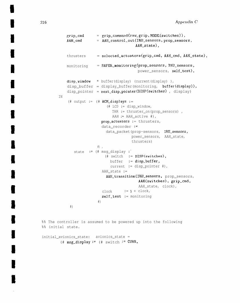
216
grip.cmd = grip.command(raw.grip, MODE(switches)),
AAH_cmd = AAH_control_out(IRU_sensors, prop.-sensors,
AAH-state),
thrusters = selected_actuators(grip-cmd, AAH_cmd, AAH_state),
monitoring = SAFER_monitoring(prop_SenSOrS, IRU_sensors,
power_sensors, self_test),
disp_windov = buffer(display) (current(display) ),disp_buffer = display_buffer(monitoring, buffex(display)),disp_pointer = next_disp_pointer(DISP(switches) , display)
IN(# output := (# HCM_displays :=
(# LCD := disp_window,THR := thruster_on(prop_sensors) ,AAH := AAH_active #),
prop_actuators := thrusters,data_recorder :=
data_packet(prop-sensors, IRU-sensors,power_sensors, AAH_state,thrusters)
#) ,state := (# msg_display :=
(# switch := DISP(switches),buffer := disp_buffer,current := disp_pointer #),
AAH_state :=AAH_transition(IRU_sensors, prop_sensors,
AAH(switches), grip_cmd,AAH_state, clock),
clock := I + clock,
self_test := monitoring#)
#)
%% The controller is assumed to be powered up into the following%% initial state.
initial_avionics_state: avionics_state =
(# msg-displ.ay := (# switch := CmR,
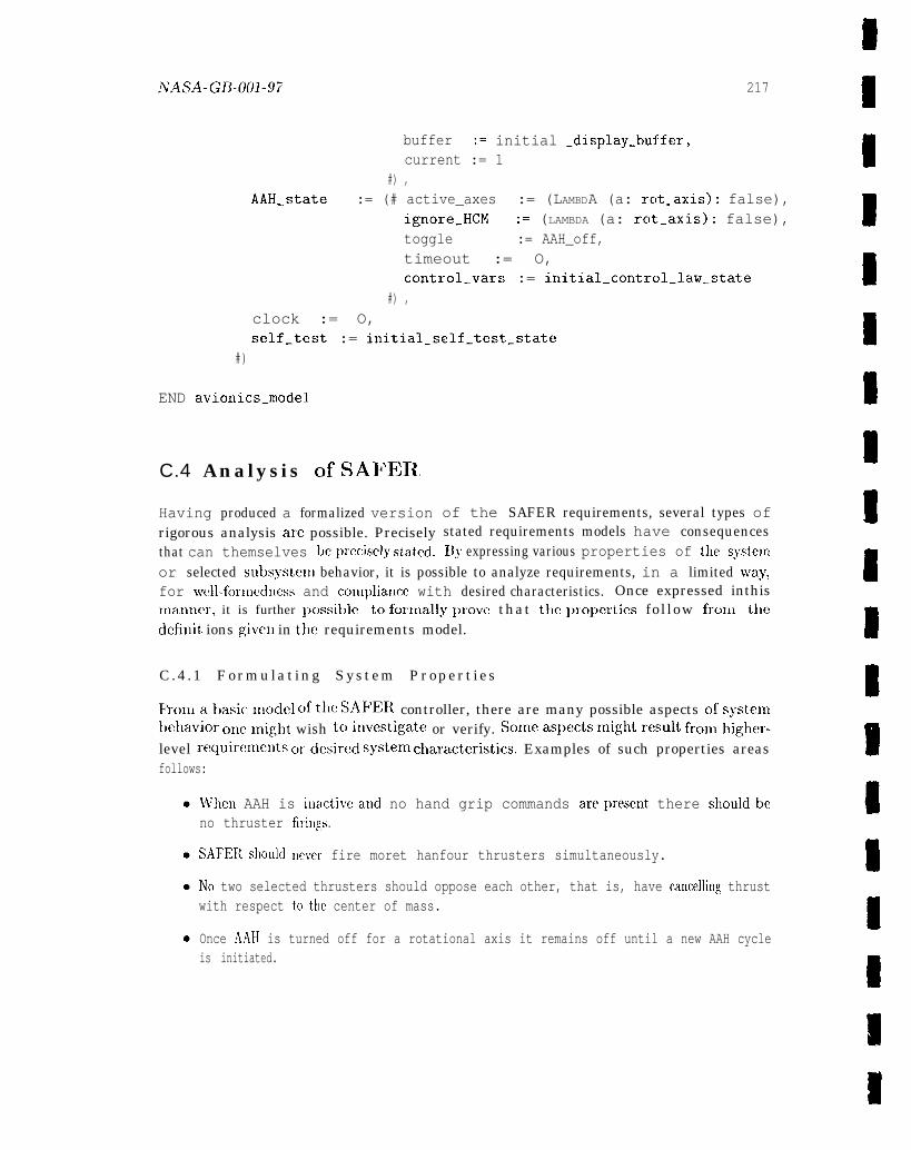
NASA-GB-001-97 217
buffer := initial .display-buffer,current := 1
#) ,AAH_state := (# active_axes := (LAMBDA (a: rclt_axis): false),
ignore_HCM := (LAMBDA (a: rot_axis): false),toggle := AAH_off,timeout := O,control_vars := initial_control_law_state
#) ,clock := O,self_test := initial_self_test_state
#)
END avionics.model
C.4 Analysis c)f SAF13R
Having produced a formalized versionrigorous analysis are possible. Preciselythat can themselves bepreciscly stated.
of the SAFER requirements, several types ofstated requirements models have consequencesIIJF expressing various properties of the system
or selected subsysteu] behavior, it is possible to analyze requirements, in a limited w’ay,for well-formccllless and com~)lianm with desired characteristics. Once expressed inthisInanner, it is further possit)le to forn~ally prove that the ~)ropertics fol low frolll thedcfinit ions given in the requirements model.
C .4 .1 Formulat ing System Propert ies
lkolllat)asicxllc~dcl c)fthe SAFER controller, there are many possible aspects ofsystembe]lavior ollellligllt wish toiuvestigate or verify. Someaspectsm ightresultf romhigher-level requiremcutso rdesired systemc haracteristics. Examples of such properties areasfollows:
VVhen AAH is inactiveaud no hand grip commands areprescnt there shouldbeno thruster firin~,s.
SAFEFl should never fire moret hanfour thrusters simultaneously.
INo two selected thrusters should oppose each other, that is, have cancelling thrustwith respect tc) the center of mass.
Once AA]-] is turned off for a rotational axis it remains off until a new AAH cycleis initiated.
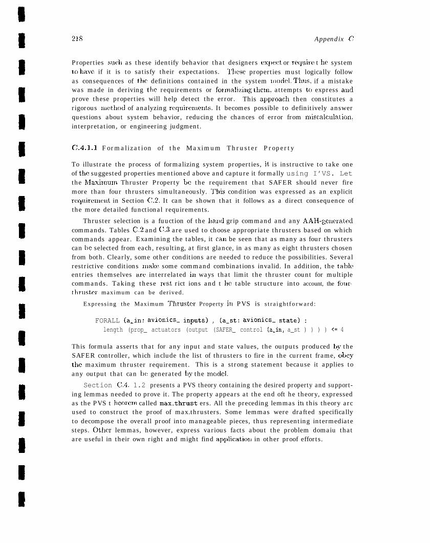
218 Appendix c:
Properties such as these identify behavior that designers expect or recluirc t be systemto have if it is to satisfy their expectations. These properties must logically followas consequences of the definitions contained in the system model. Thus, if a mistakewas made in deriving the requirements or fornlalizing thcm, attempts tc) express auclprove these properties will help detect the error. This apj~roacb then constitutes arigorous method of analyzing requirenlents. It becomes possible to definitively answerquestions about system behavior, reducing the chances of error from n~iscalculation,interpretation, or engineering judgment.
C.4.1.1 Formalization of the Maximum Thruster Property
To illustrate the process of formalizing system properties, it is instructive to take oneof the suggested properties mentioned above and capture it formally using I’VS. Letthe hlaximum Thruster Property be the requirement that SAFER should never firemore than four thrusters simultaneously. l’his condition was expressed as an explicitrecluirement in Section C.2. It can be shown that it follows as a direct consequence ofthe more detailed functional requirements.
Thruster selection is a fuuction of the hand grip command and any AAH-.generatedcommands. Tables C.2 and C.3 are used to choose appropriate thrusters based on whichcommands appear. Examining the tables, it can be seen that as many as four thrusterscan be selected from each, resulting, at first glance, in as many as eight thrusters chosenfrom both. Clearly, some other conditions are needed to reduce the possibilities. Severalrestrictive conditions make some command combinations invalid. In addition, the tableentries themselves are interrelated in ways that limit the thruster count for multiplecommands. Taking these rest rict ions and t }le table structure into account, the four-
thrustcr maximum can be der ived .
Express ing the Maximum Tlmuster Property in PVS is s t r a i g h t f o r w a r d :
FORALL (a.in: avionics_ inputs) , (a_st: avionics. state) :length (prop_ actuators (output (SAFER_ control (a_in, a_st ) ) ) ) <= 4
This formula asserts that for any input and state values, the outputs produced by theSAFER controller, which include the list of thrusters to fire in the current frame, obeythe maximum thruster requirement. This is a strong statement because it applies toany output that can be generated by the mc)del.
Section C.4. 1.2 presents a PVS theory containing the desired property and support-ing lemmas needed to prove it. The property appears at the end oft he theory, expressedas the PVS t hcorem called max_thrust ers. All the preceding lemmas in this theory arcused to construct the proof of max.thrusters. Some lemmas were drafted specificallyto decompose the overall proof into manageable pieces, thus representing intermediatesteps. Other lemmas, however, express various facts about the problem domaiu thatare useful in their own right and might find applicatioxl in other proof efforts.

h7A ~A _ GB-fjO~ -97 219
C.4.1.2 PVS Theory for Maximum Thruster Property
oo. e.eooe. aeo . . . 4 . 0 0 0 0 0 0 0 0 Ooeeooaeeeboe ooenoeeeoaeoe .oee O** Oao*ab eoeeoLLLLLLALLALAdLAkLLhLLLALkALLLkLLLLALALLALLLkhLAhLLLLALALLAALLLLLLLLLAL
% %
%% Some properties of the SAFER controller are formalized in the%% following F’vs theory. The top level theorem, max_thrusters,%% asserts that for any input and current state values, the SAFER%% controller will issue no more four thruster firing commands.%% The theorems and lemmas stated below have all been proved using%% the PVS interactive proof checker.%%0 0 * e e 0 000 @ 0 040000 0 0 0 * 00 O* * e @* 0 9*89 en Q 400** *9 0 00 ,0 0 0 9* 90 * 0 e * @ 00 0 0 4 * 0 0 0 a1111111111/1111 111111111111111 llllllllillllll lllllflllllllll llllllllllo 0 @ o 0 0 0 4 a 0 00 Ooa 4 a 0 0 0 e 0 @be @ 0 00 04 9* * # *a a 060 coon 0 00 a 0 0 0 0 0 0 4 8 0 0 0 0 0 a @ a o 0 0 6 a
SAFER_properties: THEORYBEGIN
IMPORTING avionics_model
A,B,C: VAR axis_command
t r : VAR tran.command
HCM,cmd: VAR s ix_dof_command
AAH : VAR rot_command
s t a t e : VAR AAH_state
tkm,U,V: VAR thruster_list
a c t : VAR actuator_commands
BF , LRUD : VAR thruster_list_pair
%% A simple list property is needed to support thruster selection proofs.
length_append: LEMMAlength(append(U, V)) = length(U) + length(V)
%% Only one translation command can be accepted for thruster selection.
only_one_tran(tr): bool =(tr(X) /= ZERO IMPLIES tr(Y) = ZERO AND tr(Z) = ZERO)
AND (tr(Y) /= ZERO IMPLIES tr(Z) = ZERO)
only_one_tran_pri: LEMMAonl.y_one_tran (prioritized_tran_cmd(tr) )

220
only _one_tran_int: LEMMAonly -one_ tran(tran(integrated_ commands (HCM, AAH, state)))
%% All categories of selected thrusters (BF vs. LRUD and mandatory%% VS. optional) are bounded in size by two, which follows directly%% from inspection of the tables.
max_thrusters_BF: LEMMAlength(proj_l (BF_thrusters(A, B, C))) <= 2 AND1ength(proj_2(BF_thrusters (A, B, C))) <= 2
max_thrusters_LRUD: LEMMAlength(proj_l (LRUD_thrusters(A, B, C))) <= 2 ANDlength(proj_2(LRUD_thrusters (A, B, C))) <= 2
%% Absence of translation commands implies no optional thrusters%% will be selected.
no_opt_thr_BF: LEMMAtr(X) = ZERO IMPLIES length(proj_2(BF_thrusters(tr(X) , B, C))) = O
no_opt_thr_LRUD: LEMMAtr(Y) = ZERO AND tr(Z) = ZERO IMPLIES
length(proj_2(LRUD_thrusters(tr(Y) , tr(Z), C))) = O
%% TOP level theorems establishing bounds on number of selected thrusters:
max_thrusters_sel: LEMMAonly_one_tran(tran(cmd) ) IMPLIES
length(selected_thrusters(cmd) ) <= 4
max..thrusters: THEOREMFORALL (a_in: avionics_inputs), (a_st: avionics_state):
length(prop.actuators(output (SAFER_control(a_in, a_st)))) <= 4
END SAFER_properties
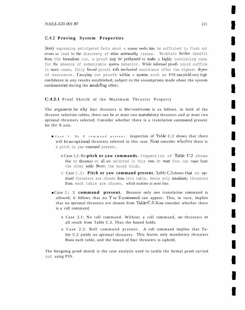
NASA-GB-001-97 221
C.4.2 Proving System Propertiest
Merely expressing anticipated facts about a system model nlay be sufficient to flush out.
errors or lead to the discovery of other nc)teworthy issues. To obtain fu~ther benefitfronl the fornlalizat ion, a proof nlay be ])erfornled to n~ake a highly convincing case sfor the absence of undesirable systenl behavior. ILrhile informlal proofs could sufficein nlany cases, fully fornlal proofs with nmchanical assistance offer the highest degreeof assurance. Carrying out proofs within a systenl such as PVS call yield very high 9confidence in any results established, subject to the assumptions made about the systemelw’ironment during the modeling effort.
I
C.4.2.1 Proof Sketch of the Maximum Thruster Property
The argunlent for why four thrusters is tile maxinmnl is as follows. in both of the s
thruster selection tables, there can be at most two nlandatory thrusters and at most twooptional thrusters selected. Consider whether there is a translation conunand presentfor tile X axis. Q
● C a s e 1 : N o X c o m m a n d p r e s e n t . inspection of Table C.2 shows that therewill be Iio optiol~al thrusters selected in this case. AText consider whether there is 1
a pitch or yaw conltnand present.
o Case 1,1: No pitch or yaw commands. Inspection of Table C3.2 shows B
that no thrustcv-s at all are selected in this case. At n~ost four can con~e fromthe other table. IIence, the bound holds.
so Case 1.2: Pitch or yaw command present. Table C.3 shows tl~at no op
tional thrusters are chosen fron~ this table. Hence only n~andatory thrustersfronl each table are chosen, which number at most four.
s
● Case 2: X command present. Because only one translation command isallowed, it follows that no Y or Z comtnand can appear. This, in turn, impliesthat no optional thrusters are chosen from Table C.3. NTOW consider whether there o
is a roll command.
o Case 2.1: No roll command. Without a roll command, no thrusters at tall result from Table C.3. Thus the bound holds.
o Case 2.2: Roll command present. A roll command implies that Ta-ble C.2 yields no optional thrusters. This leaves only mandatory thrusters R
froln each table, and the bound of four thrusters is upheld.
sThe foregoing proof sketch is the case analysis used to tackle the formal proof carriedout using PVS.
In the theory SAFER.properties fronl Section (1.4.1.2, max.thrusters is thetop level t hcomn whose proof is based on the lenln~as max.thrust ers _sel andonly _one_tran_int. Each of these lenlulas is, in t,urn, ~}roved in tern]s of other len~nlasfronl this them-y. max-thrusters.sel had the nlost conl~)lcx proof of the group; its~noof involved the case analysis out linecl above.
Section C.4.2.2 shows a transcript fron~ the proof of theorenl max.thrusters. Thisproof contained only five steps, each of which recpires the user to supply a proverconlmand. The notation of PVS proofs is based on a sequent representation. A sequentis a stylized way of normalizing a logical formula that has a convenient structure wit]luseful symmetries. In a sequent, a (numbered) list of antecedent formulas is meant, toi~up)y a (nunlbered) list of cc)nsequent formulas:
[-2] <antecedent 2>[-11 <antecedent 1>
I -- - - - - -
[11 <consequent 1>[21 <consequent 2>
Tile antecedents are considered to form a conjunct iol~ and the consequents form a dis-junction. Every user-supplied prover command or inference rule causes one or more nc~vsequents to be generated that, moves the proof closer to com~)letion.
In the proof of max-thrusters, the five steps are as follows:
1.
2.
3.
4.
5.
Rule: (skosimp*). This rule nlerely elimillatcs the outer universal quantifiers(fronl the FORALL cx~n-ession) and sin~plifies the result. This is a conlmonly usecicommand at the start of nlany proofs.
Rule: ( e x p a n d “ SAFER.cont ro l” ) . The c i ted funct ion is expanded in place @
this rule, with all actual arguments propagated to their proper place.
Rule: (expand “ selected-actuators”). Another case of function expansion isused here.
Rule: (use “only -one-tran-int” ). One of the lemmas from the containing the-ory is importecl for later use. The lemma’s variables are automatically instantiatedwith terms that appear to be useful, which is easy to do in this case.
Rule: (forward-chain “max. thrusters-sel” ). Forward chaining is the appli-cation of a lemma of the form P => Q when formula P appears in the antecedentlist. In this case, the whole sequent is actually an instance of the cited lemma, soin~~oking the forward chaitl rule finishes off the ~)roof immediately.
Proofs of the remaining lemmas were all carried out within PVS in a similar fashion.h40st required only a few steps. The exception was max_thrust ers-sel, which requireda more elaborate proof because of the case analysis mentioned above. This proof con-tained around 4[1 steps, resulting from several case splits and the subsequent equalitysut)stitutions to use the facts generated by the case splitting.
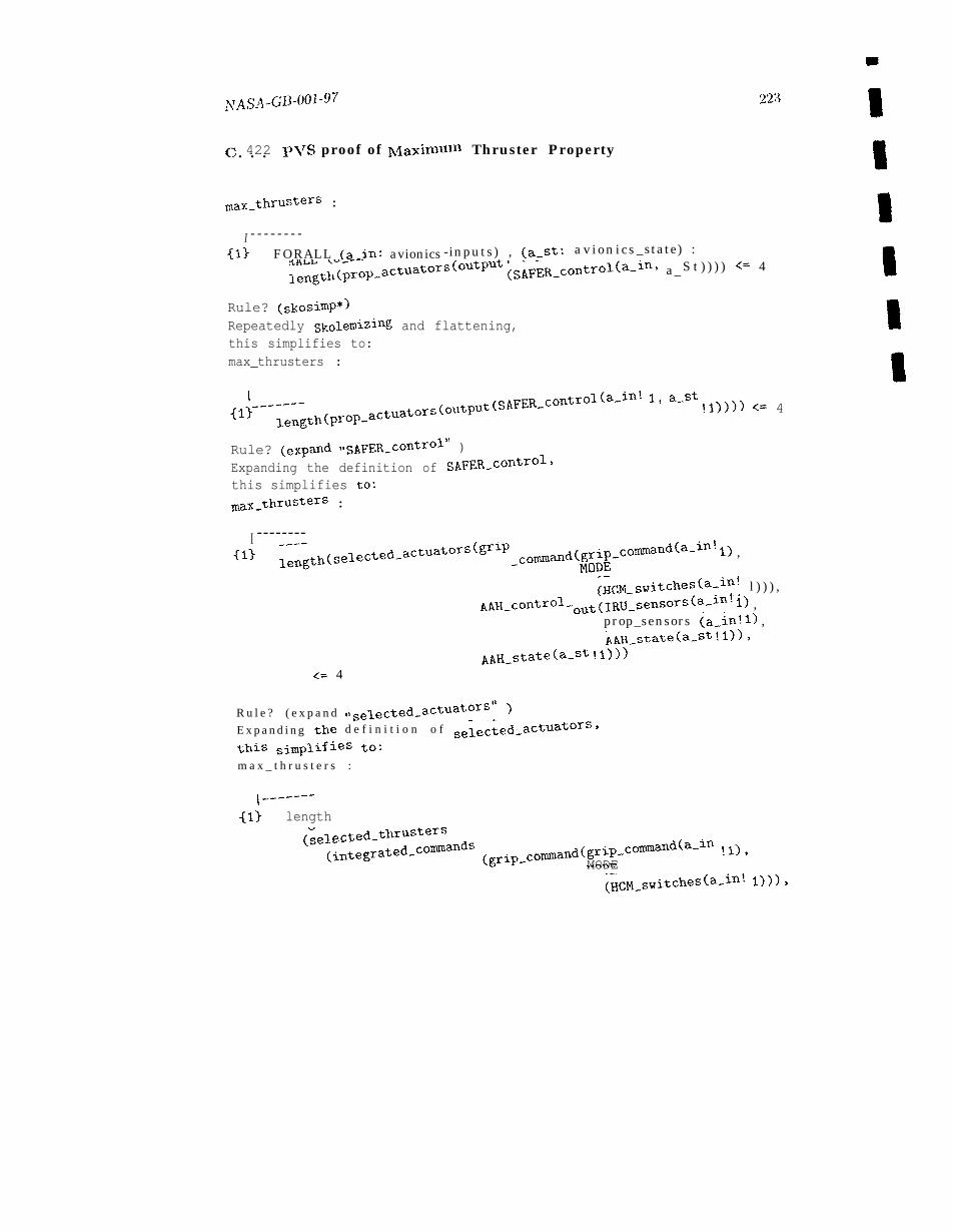
NASA-GB-001”97 223
c 422 p\~S proof of Maximuln Thruster Property. . .
max.thrusters :
I - - - - - - - --inputs) , (a_St : av ionics_state) :{1} FORALL (a_in: avionics
leng~h~prop_actuators(output (SAFER_control(a-in, a_ S t ) ) ) ) ~= 4
Rule? (skosimp*)Repeatedly Skolemizing and flattening,this simplifies to:max_thrusters :
1 - - -'--~ength(prop-actuators(output(SAFER_c0ntrol(a-in! lj a-st !1)))) <= 4{13
Rule? (expmd “sAFER_control” )
Expanding the definition of SAFER_control,
this simplifies to;max_thrusters :
I --------{1> length(selected_actuators(grlp _commmd(grip_commd(a_in! 1) ,
NODE(HCM_switches(a_in! l ) ) ) ,
AAH_control_ out(IRU_sensors(a_in! 1) ,prop_sensors (a_in!l) ,AAH_s~ate(a_st !1)),
AAH-state(a-st !1)))<= 4
R u l e ? ( e x p a n d “selected_actuators” )
d e f i n i t i o n o f selected_actuators,E x p a n d i n g the
this simplifies to:
m a x _ t h r u s t e r s :
1-”-------(13 length
(selected_thrusters(integrated-co~mds (grip_comand(grip_commd(a_~n !1),
MODE(HCM-switches(a-in! 1))),
222 Appendix C
In the theory SAFER.properties fronl Section C.4.1 .2, max-thrusters is tiletop level t heorenl whose proof is based on the len~nlas max.thrust ers _sel andonl y_one.t ran_int. 13ach of these lcmnas is, in turn, proved in terms of other lenlnlasfronl this theory. max.thrusters-sel had tile nlost conlplex proof of the group; itsproof involved the case analysis out lit~ed above.
Section C.4.2.2 shows a transcri~)t fronl the ])roof of theorenl max.thrusters. Thisproof contained only five steps, each of which requires the user to supply a proverconluland. The notation of PVS proofs is based on a sequent representation. A sequentis a stylized way of normalizing a logical formula that has a convenient structure withuseful symmetries. lU a sequent, a (numbered) list of antecedent formulas is meant toi[np]y a (numbered) list of consequcut formulas:
[-2] <antecedent 2>[-11 <antecedent 1>
1 - - - - - - -[11 <consequent 1>[21 <consequent 2>
Tile antecedents are considered to fornl a couj unctiol) and the consequents form a dis-junction. Every user-supplied prover command or inference rule causes one or more ncnvsequents to be generated that, moves the proof closer to completion.
Ill the proof of max_thrusters, the five steps are as follows:
1.
2.
3.
4.
5.
R u l e : (skosimp*). This rule merely eliminates the outer universal quantifiers(from the FORALL expression) and simplifies the result. This is a commonly usedcomnland at the start of many proofs.
Rule: (expand “ SAFER.control” ). ~’hc cited function is expanded in place bythis rule, with all actual argunlents propagated to their proper place.
Rule: (expand “ selected.actuators” ). Another case of function expansion isused here.
Rule: (use “ onl y-one-t ramint” ). one of the lcmrnas from the containing the-ory is imported for later use. The Ienmla’s variables are automatically instantiatedwith terms that appear to be useful, which is easy to do in this case.
Rule: (forward-chain “max-thrusters- sel” ). Forward chaining is the appli-cation of a lemma of the form P => Q when formula P appears in the antecedentlist. In this case, the whole sequent, is actually an instance of the cited lemma, soinvoking the forward chaitl rule finishes off the proof inln~ediately.
Proofs of the ren~aining lenmas were all carried out within PVS in a sinlilar fashion.Most required only a fcw steps. The exception was max.thrust ers-sel, which requireda nlore elaborate proof because of the case analysis n~entioned above. This proof con-tained around 40 steps, resulting from several case splits and the subsequent equalitysut)st itutions to use the facts generated by the case splitting.
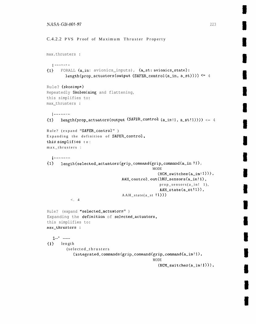
NASA-GB-001-9? 223
C.4.2.2 PVS Proof of Maximum Thruster Property
max.thrusters :
I ‘-----”-
{13 FORALL (a_in: avionics_inputs), (a_st: avionics_state):length(prop.actuators(output (SAFER_control(a_in, a-st)))) <= 4
Rule? (skosimp*)Repeatedly Skolemizing and flattening,this simplifies to:max_thrusters :
1-------{13 length(prop_actuators(output (SAFER_control (a_in!l, a_st!l)))) <= 4
R u l e ? ( e x p a n d “SAFER_control” )
E x p a n d i n g t h e d e f i n i t i o n o f SAFER_control,
this simplifies t o :
m a x _ t h r u s t e r s :
1-------{1} length(selected_actuators(grip_cowmd(grip_commd(a-in !1),
MODE
(HCM_switches(a-in! 1))),
AAH_control_out (IRU_sensors (a-.in!l),
p r o p _ s e n s o r s ( a _ i n ! 1 ) ,
AAH_state(a_st !1)),
A A H _ s t a t e ( a _ s t !1)))< . 4
Rule? (expand “selected_actuators” )Expanding the definition of selected_actuators,this simplifies to:max_thrusters :
1--” -----{1} length
(selected_thrusters(integrated.commands (grip_command(grip_command(a_in !1),
MODE(HCM_switches(a_in! 1))),
224
AAH_control_out (IRU_sensors(a_in !1),prop_sensors(a_in! 1),AAH_state(a_st !1)),
AAH_state(a_st! l))))<= 4
R u l e ? ( u s e “only_one_tran_int”)Using lemma only_one_tran_int,t h i s simplifies to :max_thrusters :
{-11 only_one_tran (tran(integrated_commands (grip_command (grip_comand (a-in!l),MODE(HCM_switches(a_in! l))),
AAH_control_out(IRU_sensors(a_in! 1),prop_sensors(a_in !1),AAH_state(a_st !1)),AAH_state(a_st !l))))
1-------[11 length
(selected_thrusters(integrated_commands (grip_command(grip_commmd (a_in!l),
MODE(HCM_switches(a_in! 1))),
AAH_control_out (IRU_sensors(a_in! 1),prop_sensors(a_in !1),AAH_state(a_st! l)),
AAH_state(a_st !1))))<= 4
Rule? (forward-chain “max_thrusters_sel”)Forward chaining on max_thrusters_sel,Q.E.D.
Run time = 4.03 sees.Real time = 73.92 sees.
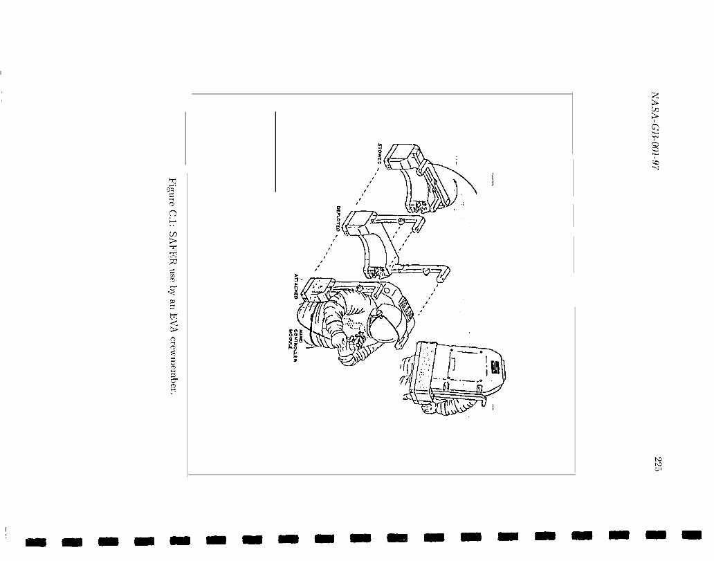
II
II
,,
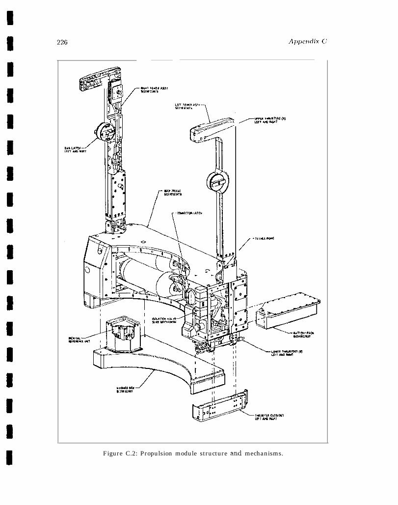
Appendix C
/’”--Psi
Figure C.2: Propulsion module structure and mechanisms.
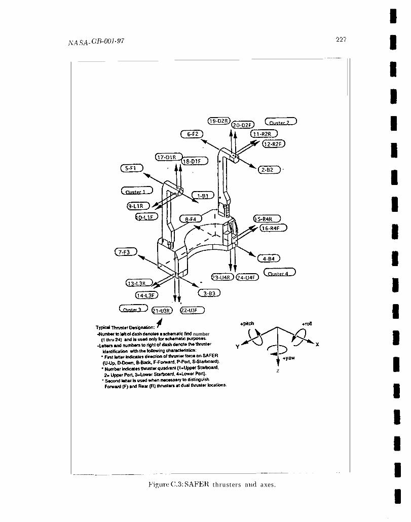
NA sA_ ~fj_ool.97
GGa @TE-- i@F-)T* Thfusbr Dosiinatinv 4-Numtw m M cd d-h denotes a schematk frnd number
z
. . .%2(
_——. .
L..—. ..——-——-—_ _ . _ _ _ _ ——— ——
- — . . —.
Figure C.3: SAFEI{ thrusters and axes.
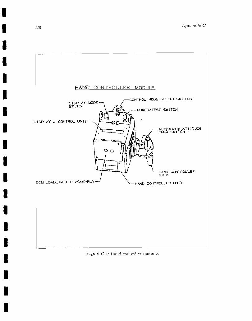
99 228 A1>~Jenclix C
____-_— —______
HAND CONTROLLER MODULE
SELECT SW! TCI+
T SWITCH
DIXAY & C(RJ
A U T O M A T I C ATTITUDEI+DLD SWITCH
H A N D CCY4TF?OLLERGRIP
DCM LOADLIMI OILER U41fi
____ .__ —_ —____
Fi.gure C.4: Haudcontrollcr Inodule.
—
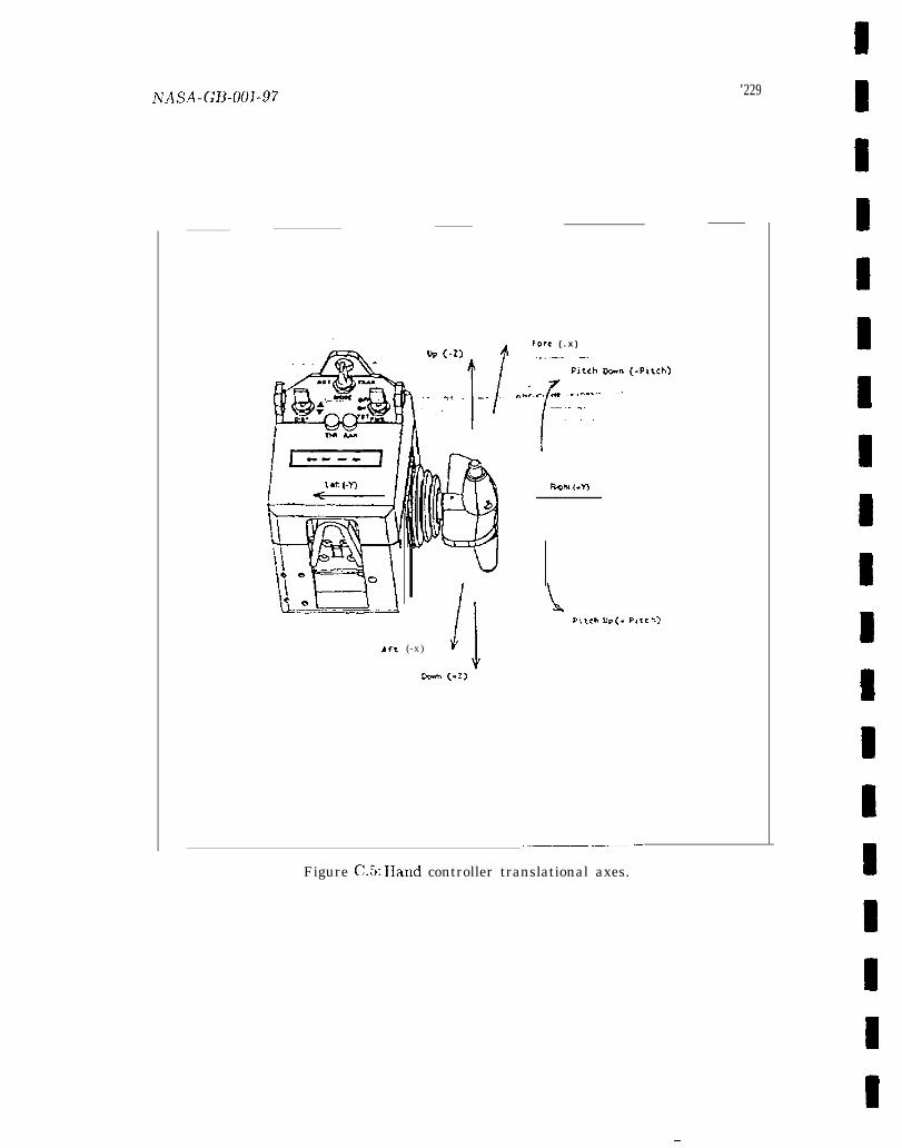
’229
Fore ( . x )lb (-z).~l . ..---— —... =,. -.
&ft (-x) Jj
Oc.m {.2)
Pitch WII (-Pttch)
‘F-*---- * ------- --- . . . . . .--
P,t<h up (. P,tc F.>
__— ——
Figure C.5: Hand controller translational axes.
—
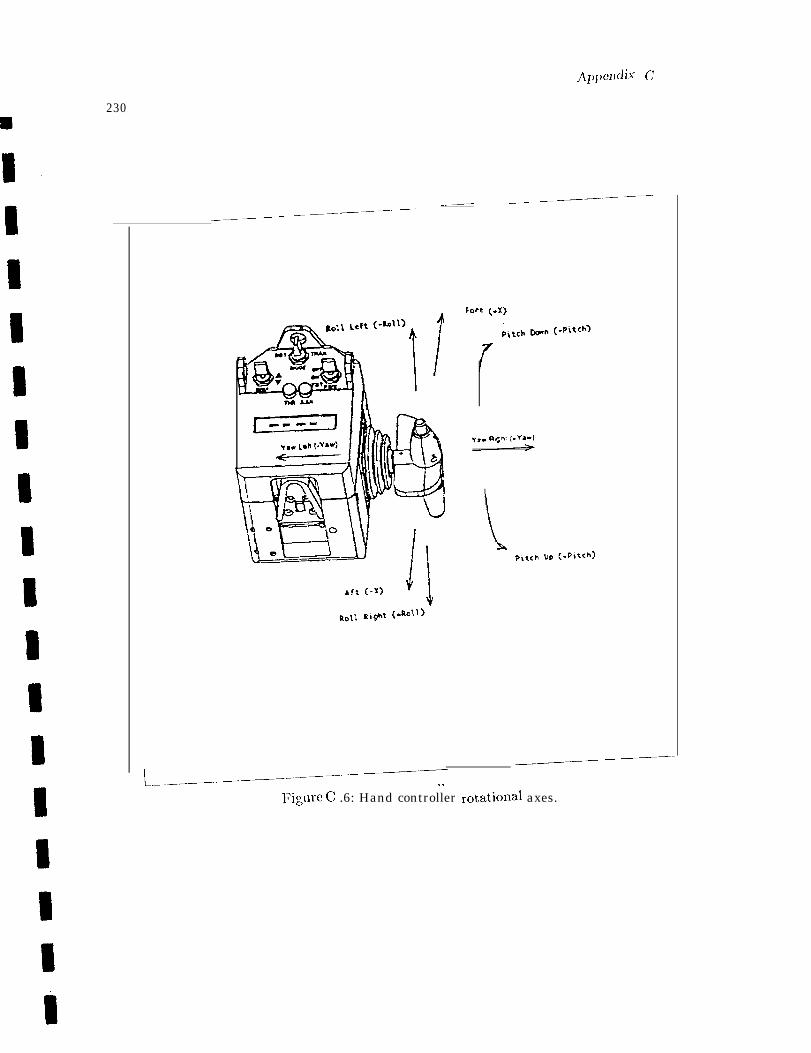
Appendix ~
230
————-——-___, _—— —— .———
——___—-—-——————
Fore (-v
I
__—-_——
L...—————----—————Figure C .6: Hand controller rotatiox~al axes.
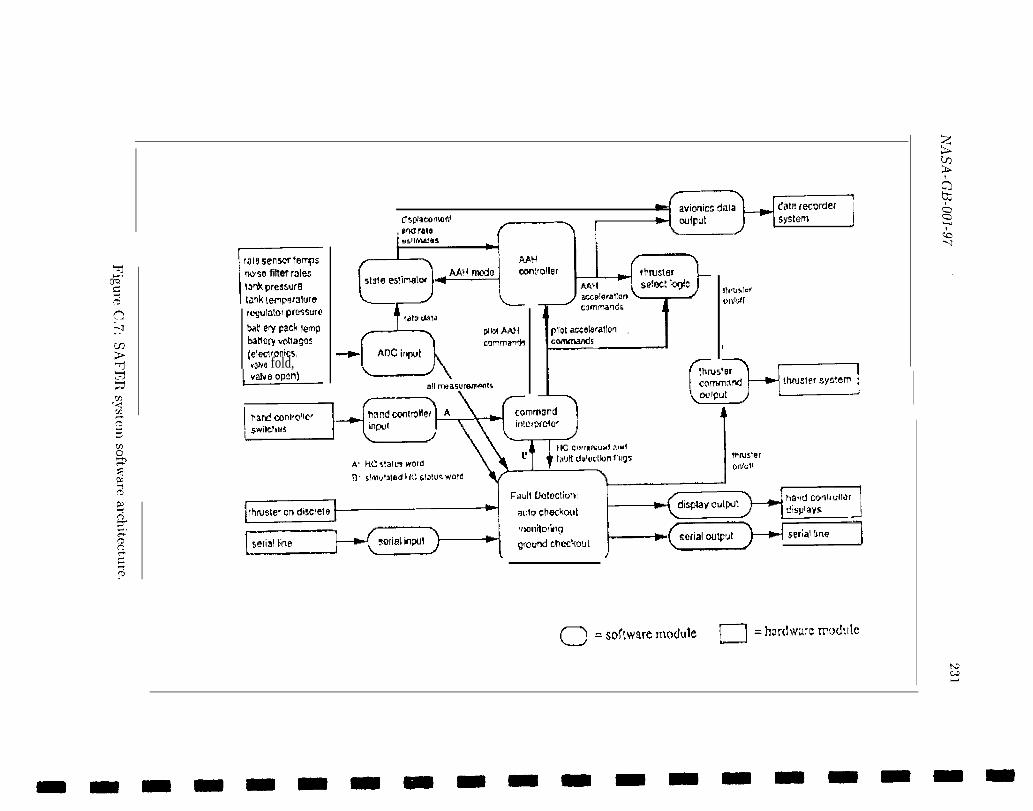
dam fecorde[ ILItsplatmafll
C-----II
system
, and rateJ
rrJ15 5enwr Imps
nbiso filter rsleslwW pressuf9
unk wrnp9f31ufe
r~yulii~of pKWiurO
bdti ev Pack lernpIxmofy Vcllagos(eleclronkslVOW fold,
L
--aA13C irqwt
plbxm{commanck
all masurema!m
,. . . , L
t
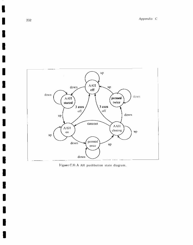
232
_—— ———..
up
dmvn A AH up
~~
offdown
AAII pressedstarted twice
3 axes 3 axes k
Appendix C
I
down
L-.—––.—__–—_..— ____.. __ ——_— .,
Figure C.8: A AH pushbutton state diagram.
Suggestions for improvements Form NASA-GB-O01-97Release 1.0
SUGGESTIONS FOR IMI?ROVEMENTS FORM
Product Name: Formal Methods Specification and Analysis Guideb=k for theVerification of Software and Computer SystemsVolume II: A Practitioner’s Companion
Product Version Numbec NASA-GB-001-97RELEASE 1.0
NASA Change Request Tracking Nurnbec _____— .— -—
—.—— ——— —
Name of Submitting Organization: ——O r g a n i z a t i o n C o n t a c t : — _ Telephone: ___Mailing Address:
—Date: Short Title: _Change Location Tag (use section or paragraph #, figure #, key process area ID, practice ID,
etc.): ____— —
Proposed Change:
Rationale for Change:
Note: For NASA to ta~ appropriate action on the change request, we must have a clear_— -—
description of the recommended change along with supporting rationale.
Send US Mail To:Formal Methods Specification and Analysis Guidebook, Vol. IINASA IV&V Facility100 University DriveFairmont, WV 26554
Send via Internet Email TO:John. C. Kelly @jpl.nasa.gov
— . ———.. — .—