position-based facial animation synthesis
TRANSCRIPT
Position Based Facial Animation Synthesis
Marco FratarcangeliSapienza University of Rome
http://www.dis.uniroma1.it/ frat/
AbstractWe propose an integrated facial dynamicsmodel addressing the animation of 3D hu-manoid faces in real time. The computationalmodel mimics facial motion by reproducing thelayered anatomical structure of a human headincluding the bony structure, overlapping facialmuscles and the skin. The model is flexibleenough to animate face meshes of variousshape, connectivity and scale. Differentlyfrom previously proposed approaches based onmass-spring networks, overshooting problemsare avoided by simulating the dynamics througha position-based scheme, which allows forreal-time performance, control and robustness.Experiments demonstrate that convincingexpressive facial animation can be interac-tively prototyped on consumer class platforms.
Keywords: facial animation, deformation, musclemodel, virtual humans
1 Introduction
Animation of virtual faces has been an active re-search field in computer graphics for almost fortyyears [1]. The applications of facial animation in-clude such diverse fields as character animation forfilms and advertising, computer games, video tele-conferencing, user-interface agents and avatars, aswell as facial surgery planning. In character ani-mation, it is of critical importance to accurately re-produce facial motion because it is one of the primesources of emotional information.
The complex and sophisticated structure of the hu-man head involves the motion, deformation and con-tact handling between bio-tissues that are viscoelas-tic, non-linear, anisotropic and structurally hetero-geneous. This makes it hard to formulate a math-ematical model able to represent the biomechanical
inner workings of the face. Nonetheless, high accu-racy and precision are required because, as humans,we are used to observing and decoding facial expres-sions from the moment we are born, and we are ex-pert at easily detecting the smallest artifacts in a vir-tual facial animation.
We propose a muscle based approach for facial an-imation based on the stable and robust position baseddynamics schema (PBD) introduced in [2]. This al-lows for avoiding the overshooting problem typicalof force-based systems solved explicitly, and it en-ables real-time performance and interactive applica-tion.
The main contribution resulting from our workconcerns an anatomical model, which is able to gen-erate facial expressions and can be applied to a widerange of input face meshes varying in shape, connec-tivity and dimensions.
Differently from other approaches [3, 4], ourmuscle-model is adaptive and it is not bound to a spe-cific template skin mesh and muscle map. The com-plete facial model allows for any number of muscleand passive tissue layers; muscles can actively con-tract and each layer influences the deformation of thelayers on top of it, but not those underlying it.
The contraction of each muscle is controlled by asingle, scalar parameter; this allows for finding easilya mapping between muscle contractions and the mo-tion of facial landmarks tracked from a human sub-ject. We use this mapping for transfering the mo-tion form real actors to virtual heads and evaluate thequality of the produced animations.
2 Related WorkFor a comprehensive overview of the methods pro-posed in literature to achieve facial animation, pleaserefer to one of the many surveys on the topic, e.g.,[5, 6]. Here, we focus on muscle model driven facialanimation pionered more than thirty years ago [7, 8].
Amongst the most advanced techniques currentlyused for muscle-based facial animation are the finiteelement algorithms and mass-spring models. Finiteelement models of facial muscles are used to build anaccurate biomechanical musculature model. Thesemethods enable to reproduce with accuracy highlyrealistic facial expressions (e.g., [9, 10, 11, 12]), butthey have a high comptational cost and set up time.
Other anatomically-based models use mass-springformalism and may lead to interactive applications[3, 4, 13, 14]. These methods allow for interactivity,but the behaviour of the network is sometimes diffi-cult to predict and it may depend from the topologyand scale of the skin mesh.
In particular, Kahler et al. [4] devised a compu-tational representation of the anatomical structure ofa real head, complete with the skull, a single muscu-lar layer and skin, in order to model a general tem-plate of a virtual face. The muscle map can be in-teractively designed by the artist through an editingtool which is hard-coded to the template mesh. Thedifferent anatomical parts are connected together, re-sulting in the final template face model. To repre-sent different humans, the template model adapts itsshape, and appearance, while conserving spatial di-mensions and connectivity.
3 Position Based DynamicsWhile our anatomical model is still based on thesimulation of a particle system, like in mass-springnetworks, the physical simulation is computed us-ing the position based dynamics (PBD) introducedby Muller [2]. PBD allows for imposing non lin-ear constraints of a geometric nature on a deformablesurface, as in the case of volume preservation of thewhole surface or of maintaining distance betweentwo nodes of the mesh during deformation. Thispermits the modeling of the virtual anatomical struc-tures without the use of internal or external forces,which simplifies the deformable model and producesunconditionally stable simulations, due to the elimi-nation of the overshooting problem.
A geometric constraint can be expressed asCj(p1, ...,pn) ≥ 0. During the simulation, giventhe current spatial configuration p of the set of par-ticles, we want to find a correction ∆p such thatC(p + ∆p) = 0. In order to be efficiently solved,the constraint equation is approximated by
C(p + ∆p) ≈ C(p) +∇pC(p) · k∆p = 0 (1)
where k ∈ {0, ..., 1} is the stiffness parameter. Thesolution of the set of the resulting non linear con-straints governing the dynamic system, is computedthrough an iterative Gauss-Siedel solver.
In this context, stiffness k can be considered asthe speed with which the particle positions converge
towards a legal spatial state, that is a state in whichall the constraints are satisfied. By tuning the valueof k, we control how much a constraint is stringentduring the evolution of the system. For example, adistance constraint between two particles with k =0.5 behaves similar to a spring, while with k = 1.0behaves nearly like a stiff rod.
For an exhaustive explanation of the PBD method,including how to specify and solve the various con-straint types, please refer to [2, 15].
4 Scattered Data InterpolationIn different parts of the following description ofmodel building process (i.e., Sec. 5.1, Sec. 7), weuse a scattered data interpolation function for mor-phing a mesh M such that the position of a subset ofits vertices P matches with another setQ not belong-ing to M . In mathematical terms, for given positionpairs (pi, qi), (i = 1...n, pi ∈ R3, qi ∈ R3), we findG : R3 −→ R3, G ∈ C1 so that
qi = G(pi) i = 1...n (2)
By applying G(p) to all the vertices of M , we obtainpi = qi, i = 1...n, and the remaining vertices of Mdeformed accordingly. We define G(p) as a sum ofradial basis functions based on Hardy multiquadrics,which proved to be effective in the context of sur-gical correction and growth simulation of humanoidheads. The reader can refer to [16, 17] for the defini-tion details.
5 Muscle ModelIn this section we describe the adaptive model whichcan simulate linear and circular muscles, by imitatingtheir macroscopic behaviour when they contract orelongate.
We first describe action lines, which allow forcontrolling muscle activation by using a single scalarparameter expressing the magnitude of the musclecontraction. Then, we describe the construction andcontrol of the volumetric muscles out of action lines.
5.1 Geometric ShapeThe initial shape of a muscle in its rest state is definedby a closed contour C lying over existing anatomicalstructures. Next, a template hexahedral mesh is mor-phed such that it matches C (Fig. 1). The deformedmesh is used to build the geometrical constraintswhich govern the muscle dynamics. In the follow-ing section, we first explain how to define C throughpiecewise linear curves (namely, action lines), andthen how to build the muscle mesh through the mor-phing of a template mesh.

Figure 1: The closed contour C is drawn upon underlying structures, in this case the skull. Then, a hexahedralmesh M is morphed to fit C. M is passively deformed as the skull moves.
Figure 2: When the bottom icosahedron rotates, thesurface points, and thus the action line,update accordingly.
5.1.1 Action Lines
An action line is a piecewise linear curve A ∈ R3
lying over a set of triangulated surface meshes. Thepurpose of the action lines is twofold: (1) they definethe bottom contour of the muscle geometry duringthe simulation, and (2) they provide a mechanism tocontrol the active contraction of the muscle itself, asexplained in Sec. 5.2.
A surface point is a point sp ∈ S, where S isa triangulated surface in R3. A surface point sp isuniquely described by the homogeneous barycentriccoordinates w.r.t. the vertexes of the triangular facetto which it belongs.
The relevant attributes of a surface point are theposition and the normal attributes; both of them areobtained as the linear combination of the barycen-tric coordinates combined with the corresponding at-tributes of the triangle vertexes. When these latterare displaced due to a deformation of the triangle,the new position and normal of sp are also updated,using the new attributes of the vertexes.
Each segment forming the action line is defined bytwo surface points; thus, an action line is describedby the ordered list of its surface points. When theunderlying triangles deform, the surface points onthem are displaces and the action line deforms ac-cordingly. A graphical example of this mechanism isshown in Fig. 2.
5.1.2 Specification of Muscle Geometry
Using action lines, composed by surface points, wedefine a muscle contour C, which is formed by four
h = 5w = 3
0v 1−wv
wv
w2v
w3v
wh )1( −v
wh )2( −v
12 −wv
13 −wv
14 −wv
1)1( −− whv
1−hwv
1v 2v
1)1( +− whv
2)1( +− whv
w
h
Figure 4: Hexahedral mesh in its initial state. Thisexample has h = 5 latitudinal sectionsand w = 3 longitudinal sections.
action lines Ai, i = 0, ...3, two latitudinal and twolongitudinal. The end points of the latitudinal linesare connected to the end points of the longitudinalones, as shown in Fig. 3. Note that the surface pointsare defined over the barycentric coordinates of exist-ing triangles. So, a contour C may be defined onlyover already existing meshes.C is sampled at regular intervals separately on
each action line; the sample step for each action lineis defined according to the Euclidean norm measuredon the segments:
step =
∑Ni=0 ‖spi − spi−1‖
N,N ∈ {w, h} (3)
where N assumes the value w or h, depending onthe type of the sampled action line, longitudinal orlatitudinal, respectively.
Each sample is characterized by its position s andnormal ns, similarly to surface points. The positionsi and the normal vector nsi of each sample on anaction line are found through a simple linear combi-nation of the corresponding surface point attributes.
Since the number of samples is w for each latitu-dinal action line and h for each longitudinal line, thecardinality of the set of samples of C is 2(w + h).We build a triangulated, oriented hexahedral meshM ∈ R3 with exactly h longitudinal section and wlatitudinal sections (Fig. 4). The contour of one ofthe sides of the mesh is arbitrarily chosen as the bot-tom contour.

(a) (b) (c) (d)
Figure 3: (a). A contour C composed by four action lines layed upon a curved, triangulated surface. Bluesegments represent the surface points’ normal. (b) The contour is sampled (h = 5, w = 3). (c) Thehexahedral muscle mesh is morphed to fit C and it is constrained to the position of the sample points.(d) Changing the sampling step, the sample points slide on the action lines and the muscle contracts.
We define a bijective mapping between the sam-ples on the actions lines of C and the contour of thehexahedral mesh. From this mapping, we computea scattered data interpolation G(p) (Sec. 4). Ap-plying G(p) to M , we obtain the mesh M ′ lying ontop of the surfaces where C is defined. The size andorientation of the initial mesh M are not important,and thus are not specified, because they do not influ-ence the final shape of M ′. This is because the RBFbased algorithm is invariant w.r.t. affine transforma-tions, like translation and rotation. The thickness ofthe mesh M ′ can thus be adjusted by displacing thevertices on the upper surface along their normals.
5.2 Muscle Dynamics and Control
The muscle mesh is the basis for defining the geo-metric constraints that govern the dynamics of themuscle itself. The expressive facial muscles are oftwo basic types: linear and sphincter. The action pro-duced by these muscles is always along the tangentof their fibers. We use a generic template musclemodel in which the fibers are represented by the lon-gitudinal action lines forming the contour C. Theconstraints on the template model, and its geome-try, are adapted according to the type of muscle thathas to be simulated. In Sec. 5.2.1 and Sec. 5.2.2,we describe how the muscle contraction is controlledthrough the modulation of the sampling step of thelongitudinal action lines.
First, a network of distance constraints is built asshown in Fig. 5. This network alone is not sufficientto describe the dynamics of the muscle. In order tomimic the bulging behavior of the muscle when con-tracting and to avoid face inversions, for each pairof triangulated faces fi, fj sharing the same edgeeij , a bending constraint is defined. A bending con-straint conserves superficial tension and reacts when-
particle
longitudinal
latitudinal
connection
shear
bottom side
upper side
bottom side
upper side
particle
longitudinal connection
shearlatitudinal
Figure 5: Distance constraints involved in musclemodel dynamics.
ever there is a compression, or an elongation, perpen-dicular to the edges of the triangulated muscle meshM ′. A further volume preserving constraint is de-fined over all the particles of the muscle geometry,making the muscle thicker due to compression andthinner due to elongations.
The softness of the muscular deformable body de-pends on the stiffness of each individual constraint,regardless of its kind, and from the number of Gauss-Siedel iterations performed within the numerical in-tegration [2]. Since this latter parameter is fixed andset to the lowest possible value ensuring interactivity(as specified in Sec. 3), each type of muscle definesits own set of stiffness constraints as described in thefollowing two sections.
5.2.1 The Linear Muscle
A linear muscle model represents a sheet muscle, aflat and thin muscle, whose fibers are arranged in par-allel threads. When it contracts, the fibers shortenby equal amounts and pull the skin surface from theinsertion site towards the origin site, which can beregarded as fixed.
Given the contour C, as defined in Sec. 5.1.2,and the action lines Ai, i ∈ {0, ...3}, we consider

the latitudinal action lines A3 and A1 as, the originsite and the insertion site of the muscle, respectively.The longitudinal action lines A0 and A2 representthe fibers of the muscle and define the direction ofcontraction.
Each particle pi of the muscle model which cor-responds to the sample sj on the longitudinal actionlines A1 and A3, is bound to its corresponding sam-ple through a position constraint (Sec. 3). If the sam-ple sj is displaced, the dynamics of the correspond-ing particle pi will change the position pi attemptingto match this displacement. The new position of thesamples is computed by using the Eq. 3 with thesampling step:
step′ = step(1− c) (4)
where step is defined in Eq. 3, and c ∈ [0, 1] isthe contraction factor. If c = 0, the muscle is inrest position. If c = 1, it is undergoing the greatestcontraction possible.
The constraints, with the corresponding stiff-ness, involved in the dynamics of the sheet mus-cle are: kuplatitudinal = 1.0, kuplongitudinal =0.1, kconnection = 1.0, kbend = 0.4, kvolume =1.0, kposition = 0.2. The stiffness of the remain-ing constraints is set to 0; these constraints are thusdisabled and not considered further in the simula-tion. Note the low stiffness value of the position con-straints: while the difference between the expectedposition and the actual position remains acceptable,such a low value allows the muscle to slide over theunderlying surfaces.
5.2.2 The Sphincter Muscle
The sphincter muscle model is used to simulate theorbicularis oris, which is the muscle surrounding theoral orifice.
In the sphincter muscle model, the two longitudi-nal action lines, A1 and A3, are both closed curves(for both, the first surface point corresponds to thelast), and define the inner and the outer contour ofthe muscle, respectively. The remaining latitudinalaction lines,A0 andA2, are coincident and both con-nect the first surface point of A1 to the first surfacepoint of A3.
In the sphincter muscle model there is no fixed siteof origin. In fact, while contracting around a virtualcenter o, the body of this kind of muscle slides on theunderlying anatomical structures.
Similarly to the way in which other authors haveapproached the problem in the context of interactivephysically based facial animation [3, 13], we modelthe contraction of the sphincter muscle through theuse of the parametric ellipsoidal function. The el-lipsoid constructed by choosing the best fit for the
action line samples in their current position in accor-dance with the least square method, while the posi-tion of the virtual center o is computed as their aver-age position.
An ellipsis is defined to compute the sample dis-placements and thus the motions of the muscle. Foreach pair
⟨s1i , s
3j
⟩of action line samples,
x = (s′3j − o) · diray = (s′3j − o) · dirb
so that
δ = (o− s1i )(1− c)cos(π2
(1−√y2b2 + x2a2
ab))
s1i = s1i + δ
s3j = s3i + δ
where dira and dirb are respectively the direc-tions of the semi major and semi minor axis of theellipses, (x, y) is the coordinate of s′3j in the coordi-nate frame of dira and dirb, and δ is the displace-ment of the samples and thus the muscle motion.The constraints, with the corresponding stiffness, in-volved in the dynamics of the sphincter muscle are:kuplatitudinal = 0.2, kconnection = 1.0, kupshear =0.3, klowshear = 0.3, kbend = 1.0, kvolume =1.0, kposition = 0.2. Like in the case of the sheetmuscle, the stiffness of the remaining constraints isset to 0 and thus they are disabled.
6 The Facial ModelThe facial model is organized into layers. The deep-est layer is the bony structure, which is the skull.Next are the successive layers of muscle, one lyingbelow the other. The last, most superficial layer isthe skin, represented by the face mesh that is to beanimated. The deepest layer influences the more su-perficial ones, propagating the deformation until theskin moves, producing animation. Multiple musclelayers allow the artist to design muscle maps reflect-ing the arrangements of the real head. This leadsto a wider degree of expressiveness compared withapproaches allowing only a single muscular layer.Before discussing the musculature and its influenceupon the shape of the skin surface, we briefly de-scribe the influence of the articulated, rigid skull.
6.1 The Skull
The skull is represented by a triangulated surfacemesh ∈ R3, where the other anatomical parts arelayed. Fig. 8a illustrates an example of the meshused in the experiments. The face model is not lim-ited to the use of this particular skull mesh.
The skull is divided into two components: the up-per skull and the mandible. The mandible constitutesthe complete lower jawbone. The motions of themandible are modeled through the use of rigid trans-formations applied to the jaw mesh vertices. Thelowering and elevation of the jaw is represented asrotation around the pitch axis, the small amount oflateral movement as rotation around the yaw axisand, finally, protrusion and retraction as a translationalong the protrusion axis; thus making the total num-ber of degrees of freedom equal to three.
A set of 31 landmarks is defined on the skull sur-face (Fig. 8a). The landmarks belong to a subsetof MPEG-4 Facial Definition Points [18]. Their pur-pose is twofold: (1) they are useful in defining thepitch and yaw rotation axes and the direction of pro-trusion of the mandible, and (2) they provide a spatialreference for computing the morphing function usedto fit the skull and the muscle map into the facial skinmesh (see Sec. 7).
6.2 The Muscle Map
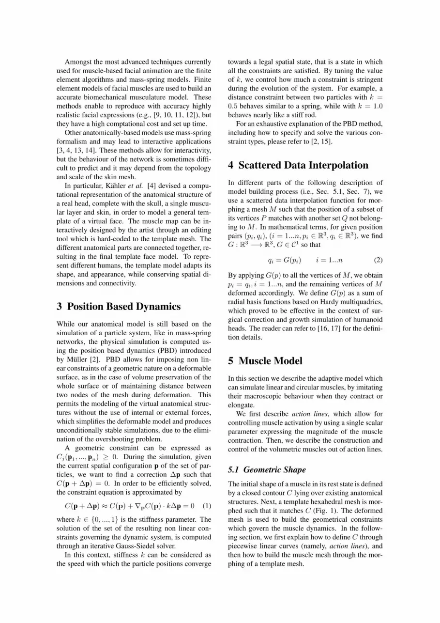
The muscle map is made up of overlapping musclesand it is positioned over the skull. The muscle modelpresented in Sec. 5 is used to build the facial musclesresponsible for expression, and the structural mus-cles which are used to support other muscles and theskin. Each layer influences the deformation of thelayers on top of it, but not those underlying it. Fig.6 presents the different layers forming the particularmuscle map used in the experiments.
The muscle map comprises 25 linear muscles andone circular muscle, the orbicularis oris.
Some of the linear muscles do not actively movebut are just passively deformed by the underlyingstructures. Their function is to provide structuralsupport to other muscles. In particular, the masseterwhich the risorius muscle originates; the fatty tissueunder the cheeks, on top of which there are the zy-gomaticus major muscle, the levator labii and partof the orbicularis oris. The last supporting muscle isthe platysma, under the chin bone: it is useful as asupport for the skin when the jaw rotates, otherwisethe skin vertices would enter in the lower part of theface producing an unrealistic, and unpleasant, effect.
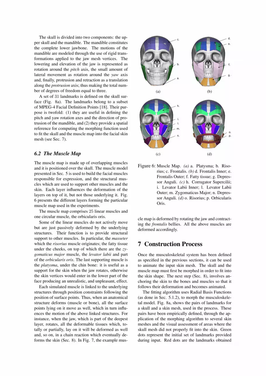
Each simulated muscle is linked to the underlyingstructures through position constraints following theposition of surface points. Thus, when an anatomicalstructure deforms (muscle or bone), all the surfacepoints lying on it move as well, which in turn influ-ences the motion of the above linked structures. Forinstance, when the jaw, which is part of the deepestlayer, rotates, all the deformable tissues which, to-tally or partially, lay on it will be deformed as welland, so on, in a chain reaction which eventually de-forms the skin (Sec. 8). In Fig. 7, the example mus-
(a) (b)
(c) (d)
Figure 6: Muscle Map. (a) a. Platysma; b. Riso-rius; c. Frontalis. (b) d. Frontalis Inner; e.Frontalis Outer; f. Fatty tissue; g. Depres-sor Anguli. (c) h. Corrugator Supercilii;i. Levator Labii Inner; l. Levator LabiiOuter; m. Zygomaticus Major; n. Depres-sor Anguli. (d) o. Risorius; p. OrbicularisOris.
cle map is deformed by rotating the jaw and contract-ing the frontalis bellies. All the above muscles aredeformed accordingly.
7 Construction ProcessOnce the musculoskeletal system has been definedas specified in the previous sections, it can be usedto animate the input skin mesh. The skull and themuscle map must first be morphed in order to fit intothe skin shape. The next step (Sec. 8), involves an-choring the skin to the bones and muscles so that itfollows their deformation and becomes animated.
The fitting algorithm uses Radial Basis Functions(as done in Sec. 5.1.2), to morph the musculoskele-tal model. Fig. 8a, shows the pairs of landmarks fora skull and a skin mesh, used in the process. Thesepairs have been empirically defined, through the ap-plication of the morphing algorithm to several skinmeshes and the visual assessment of areas where theskull mesh did not properly fit into the skin. Greendots represent the initial set of landmarks providedduring input. Red dots are the landmarks obtained
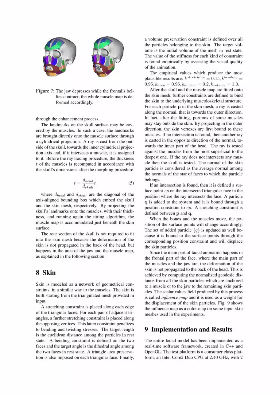
Figure 7: The jaw depresses while the frontalis bel-lies contract; the whole muscle map is de-formed accordingly.
through the enhancement process.The landmarks on the skull surface may be cov-
ered by the muscles. In such a case, the landmarksare brought directly onto the muscle surface througha cylindrical projection. A ray is cast from the out-side of the skull, towards the inner cylindrical projec-tion axis and, if it intersects a muscle, it is assignedto it. Before the ray tracing procedure, the thicknesst of the muscles is recomputed in accordance withthe skull’s dimensions after the morphing procedure
t =dheaddskull
t (5)
where dhead and dskull are the diagonal of theaxis-aligned bounding box which embed the skulland the skin mesh, respectively. By projecting theskull’s landmarks onto the muscles, with their thick-ness, and running again the fitting algorithm, themuscle map is accommodated just beneath the skinsurface.
The rear section of the skull is not required to fitinto the skin mesh because the deformation of theskin is not propagated in the back of the head, buthappens in the area of the jaw and the muscle map,as explained in the following section.
8 SkinSkin is modeled as a network of geometrical con-straints, in a similar way to the muscles. The skin isbuilt starting from the triangulated mesh provided ininput.
A stretching constraint is placed along each edgeof the triangular faces. For each pair of adjacent tri-angles, a further stretching constraint is placed alongthe opposing vertices. This latter constraint penalizesto bending and twisting stresses. The target lengthis the euclidean distance among the particles in reststate. A bending constraint is defined on the twofaces and the target angle is the dihedral angle amongthe two faces in rest state. A triangle area preserva-tion is also imposed on each triangular face. Finally,
a volume preservation constraint is defined over allthe particles belonging to the skin. The target vol-ume is the initial volume of the mesh in rest state.The value of the stiffness for each kind of constraintis found empirically by assessing the visual qualityof the animation.
The empirical values which produce the mostplausible results are: kstretching = 0.15, kbending =0.95, karea = 0.95, kanchor = 0.2, kvolume = 1.0.
After the skull and the muscle map are fitted ontothe skin mesh, further constraints are defined to bindthe skin to the underlying muscoloskeletal structure.For each particle p in the skin mesh, a ray is castedalong the normal, that is towards the outer direction.In fact, after the fitting, portions of some musclesmay stay outside the skin. By projecting in the outerdirection, the skin vertexes are first bound to thesemuscles. If no intersection is found, then another rayis casted in the opposite direction of the normal, to-wards the inner part of the head. The ray is testedagainst the muscles from the most superficial to thedeepest one. If the ray does not intersects any mus-cle then the skull is tested. The normal of the skinparticle is considered as the average normal amongthe normals of the star of faces to which the particlebelongs.
If an intersection is found, then it is defined a sur-face point sp on the intersected triangular face in theposition where the ray intersects the face. A particleq is added to the system and it is bound through aposition constraint to sp. A stretching constraint isdefined between p and q.
When the bones and the muscles move, the po-sition of the surface points will change accordingly.The set of added particle {q} is updated as well be-cause it is bound to the surface points through thecorresponding position constraint and will displacethe skin particles.
Since the main part of facial animation happens inthe frontal part of the face, where the main part ofthe muscles and the jaw are, the deformation of theskin is not propagated to the back of the head. This isachieved by computing the normalized geodesic dis-tance from all the skin particles which are anchoredto a muscle or to the jaw to the remaining skin parti-cles. The scalar values field produced by this processis called influence map and it is used as a weight forthe displacement of the skin particles. Fig. 9 showsthe influence map as a color map on some input skinmeshes used in the experiments.
9 Implementation and ResultsThe entire facial model has been implemented as areal-time software framework, created in C++ andOpenGL. The test platform is a consumer class plat-form, an Intel Core2 Duo CPU at 2.40 GHz, with 2

(a) (b)
Figure 8: (a). Set of reference points used to compute the morphing function for fitting the skull mesh into theskin. Green dots represent reference points provided in input, red ones are computed by ray tracing.(b). The result of the morphing process. The front part of the skull and the muscle map, that is themovable part of the musculoskeletal system, are fitted inside the skin mesh.
Figure 9: Influence of the musculoskeletal structureon the skin. Red are zones under directcontrol of the musculoskeletal structure,blue with no control at all.
Mesh V F C t(ms)Mesh A 1466 2822 16461 31Mesh B 2502 4908 28785 28Mesh C 4604 9160 53834 45Mesh D 4904 9541 55687 50
Skull + Muscles 4297 8352 4919 6
Table 1: Facial dynamics computation time. V:number of vertices, F: number of faces, C:number of constraints, t: physical simula-tion time for each animation frame.
GB of main memory using only one core. The sys-tem is tested through visual evaluations of the vari-ous facial expressions produced with different targetskin meshes, and particularly the basic expressionsdefined in [19]: anger, disgust, fear, joy, sadness andsurprise. Time performance is also measured and re-ported in Table 1.
In the preprocessing phase, the most demandingstep is the definition of the muscle map, which canbe designed in less than one working day and then beused for all the input skin meshes. Once the musclemap is ready, the time required for fitting the mus-culoskeletal structure inside the skin is less than 1second, while binding it to the skin from the inside,which involves ray tracing for each skin vertex, takes
less than 5 seconds per each input skin mesh.Fig. 11 shows several face models built from the
input skin mesh as they are performing basic facialexpressions. Further results are available in the ac-compaining videos, were we also show an interactiveeditor, which assists the artist in sketching the mus-cles and the passive tissues directly on the bones andalready existing muscles.
To further validate the expressiveness of the facialmodel, we mapped tracked motion from real facesto the virtual muscle contractions and visually eval-uated the resulting animation. We used videos ofactors performing basic expressions taken from theMMI-Facial Expression Database collected by Val-star and Pantic [20]. The actual tracking was doneusing a facial tracking software package [21] com-mercially available.
The output of the tracking software is a descrip-tion of the facial motion encoded using Facial An-imation Parameters (FAPs), defined in the MPEG-4Facial and Body Animation standard [18].
Each parameter describes a basic action that a facecan perform, like closing an eyelid or stretching acorner lip. Most of these actions have been definedconsidering the displacement caused by the contrac-tion of a single muscle. The magnitude of facial pa-rameters is expressed in normalized units of measure(Facial Animation Parameter Units, FAPU); thus themagnitude value is indipendent from the tracked facemorphology.
Since we used a muscle map similar to the one ina real face, and the value of the muscle contractionsis normalized between 0 and 1 by construction, webuilt a mapping between the normalized FAPs andmuscle contractions. For each normalized FAP, wedefine which muscles contract to synthesize the fa-cial action described by the FAP. We are able to pre-cisely map the muscle contraction to the magnitudeof a FAP because we control the muscle using the

contraction c (Sec. 5.2), which tunes the muscle fiberlenght. This would be much more difficult to do ifour muscle model would be based on forces ratherthan positions. Fig. 10 shows some of the obtainedresults. The corresponding animations are availablein the accompaining videos.
10 Limitations and Future WorkWe have presented an anatomically based musclemodel, which is not restricted to a specific input skullor skin mesh. Unlike past approaches [3, 4], it is notbound to a template mesh and allows for any num-ber of facial muscle and passive tissue layers. Theselayers interact and slide upon each other, formingan overlapping structure. The given muscle modelis deformed according to its own active contraction,which is controlled by a single scalar parameter, ordue to the motion of the underlying anatomical struc-tures. The skin is deformed by muscular and bonymotion.
We have modeled computationally inexpensiveyet expressive anatomical elements by using theposition-based dynamics approach for the facial ani-mation setting. This simulation approach has provento be effective at modeling complex dynamics in amanner guaranteeing stability, which is of major im-portance in interactive applications. Since the stiff-ness values of the constraints are normalized be-tween zero and one and are adimensional, the param-eters are suitable for the creation of virtual models ofheads characterized by various scale and shape.
The Gauss-Seidel iterative method used to workout the dynamics of the model, may lead to some in-stability when the number of constraints increases.However, this can be solved by increasing the num-ber of iterations in the numerical integration, whichhowever may lead to slower frame rate.
11 AcknowledgementsThis paper describes research done under the EUFP7ICT 247870 NIFTI project.
References[1] Frederick I. Parke. Computer generated an-
imation of faces. In ACM annual confer-ence (ACM72), pages 451–457, New York, NY,USA, 1972. ACM.
[2] M. Muller, B. Heidelberger, M. Hennix, andJ. Ratcliff. Position based dynamics. In VirtualReality Interactions and Physical Simulations(VRIPhys), Madrid, November 6-7 2006.
[3] Yuencheng Lee, Demetri Terzopoulos, andKeith Waters. Realistic modeling for facial an-imation. In Computer graphics and interactivetechniques (SIGGRAPH95), pages 55–62, NewYork, NY, USA, 1995. ACM.
[4] Kolja Kahler, Jorg Haber, Hitoshi Yamauchi,and Hans-Peter Seidel. Head shop: gener-ating animated head models with anatomicalstructure. In ACM SIGGRAPH/Eurographicssymposium on Computer animation (SCA02),pages 55–63, New York, NY, USA, 2002.ACM.
[5] Frederic I. Parke and Keith Waters. Computerfacial animation. A. K. Peters, Ltd., 2nd edi-tion, 2008.
[6] Jorg Haber, Demetri Terzopoulos, NadiaMagnenat-Thalmann, and Volker Blanz. FacialModeling and Animation - Eurographics 2003Tutorial Notes. Eurographics, Granada, Spain,September 2003.
[7] Stephen M. Platt and Norman I. Badler. An-imating facial expressions. SIGGRAPH Com-put. Graph., 15(3):245–252, 1981.
[8] D. Terzopoulos and K. Waters. Physically-based facial modeling, analysis, and animation.Journal of Visualization and Computer Anima-tion, 1(2):73–80, 1990.
[9] E. Gladilin, S. Zachow, P. Deuflhard, and H.C.Hege. Anatomy-and physics-based facial an-imation for craniofacial surgery simulations.Medical and Biological Engineering and Com-puting, 42(2):167–170, 2004.
[10] Eftychios Sifakis, Igor Neverov, and RonaldFedkiw. Automatic determination of facialmuscle activations from sparse motion capturemarker data. ACM Trans. Graph., 24(3):417–425, 2005.
[11] Joseph Teran, Eftychios Sifakis, Geoffrey Irv-ing, and Ronald Fedkiw. Robust quasistaticfinite elements and flesh simulation. In ACMSIGGRAPH/Eurographics symposium on com-puter Animation (SCA05), pages 181–190,New York, NY, USA, 2005. ACM.
[12] Eftychios Sifakis, Andrew Selle, AvramRobinson-Mosher, and Ronald Fedkiw. Simu-lating speech with a physics-based facial mus-cle model. In ACM SIGGRAPH/Eurographicssymposium on Computer animation (SCA06),pages 261–270, Switzerland, 2006. Eurograph-ics Association.
[13] Y. Zhang, E.C. Prakash, and E. Sung. ”EfficientModeling on An Anatomy-Based Face and Fast3D Facial Expression Synthesis”. In Computer

Figure 10: Facial tracking applied to muscle contractions.
(a) (b) (c) (d) (e) (f) (g)
Figure 11: Test input faces performing basic expressions. a. Neutral; b. Joy; c. Sadness; d. Surprise; e. Anger;f. Disgust; g. Fear.
Graphics Forum, volume 22, pages 159–169,June 2003.
[14] Kolja Kahler. 3D Facial Animation- RecreatingHuman Heads With Virtual Skin, Bones, andMuscles. Verlag, October 2007.
[15] Matthias Muller. Hierarchical position baseddynamics. In Virtual Reality Interactions andPhysical Simulations (VRIPhys2008), Greno-ble, November 2008.
[16] C.A. Micchelli. ”Interpolation of ScatteredData: Distance Matrices and ConditionallyPositive Definite Functions”. Constructive Ap-proximations, 2:11–22, 1986.
[17] S. Fang, R. Raghavan, and J. Richtsmeier.”Volume Morphing Methods for LandmarkBased 3D Image Deformation”. In SPIE In-ternational Symposium on Medical Imaging,
volume 2710, pages 404–415, Newport Beach,CA, February 1996.
[18] I.S. Pandzic and R. Forchheimer, editors.”MPEG-4 Facial Animation – The Standard,Implementation and Applications”. John Wiley& Sons, LTD, Linkoping, Sweden, 1st edition,2002.
[19] Paul Ekman, Wallace V. Friesen, and PhoebeEllsworth. Emotion in the Human Face. OxfordUniversity Press, 1972.
[20] M. F. Valstar and M. Pantic. Induced disgust,happiness and surprise: an addition to the mmifacial expression database. In Int’l Conf. Lan-guage Resources and Evaluation, Workshop onEMOTION, pages 65–70, Malta, May 2010.
[21] Visage Technologieshttp://www.visagetechnologies.com, January2012.