gas–particle two-phase turbulent flow in horizontal and inclined ducts
TRANSCRIPT

Gas±particle two-phase turbulent ¯ow in horizontal andinclined ducts
Jianfa Cao, Goodarz Ahmadi *
Department of Mechanical and Aeronautical Engineering, Clarkson University, Potsdam, NY 13699-5725, USA
Received 9 June 1999; accepted 3 December 1999
Abstract
Gas±particle two-phase turbulent ¯ows at various loadings in horizontal and inclined ducts are studied.The upgraded thermodynamically consistent two-phase ¯ow model which includes a low Reynolds number¯uid-phase turbulence closure is used in the analysis. The governing equations are discretized with the aidof a semi-implicit numerical algorithm. The case of low-concentration gas±particle turbulent ¯ow in ahorizontal channel is ®rst analyzed, and the predicted mean velocity and solid volume fraction pro®les arefavorably compared with the available experimental data. Additional ¯ow properties such as the phasic¯uctuation energy and ¯uctuation energy production and dissipation, as well as the phasic and total normaland shear stress pro®les are also presented and discussed. The case of gas±particle ¯ow in a duct with aninclination is then analyzed. Sample model predictions for both dilute and nondilute two-phase turbulent¯ows under various conditions are presented. The e�ect of particle diameter on variation of ¯ow propertiesis also studied. Ó 2000 Elsevier Science Ltd. All rights reserved.
1. Introduction
Turbulent two-phase ¯ows including the particle±turbulence interaction is of great signi®cancein many industrial applications and in particular in coal processing systems. Earlier, utilizing thecontinuum mixture theories, a number of models for two-phase ¯ows were provided by Truesdelland Toupin [34], Bowen [4], Eringen and Ingram [12], Nunziato and Walsh [27], Ahmadi [1,2],and Massoudi [26]. However, most of these earlier models were limited to the case of laminar¯ows where the e�ects of ¯uid-phase turbulence and inter-particle collision were negligible.Dispersed two-phase turbulence ¯ows were studied by Genchev and Karpuzov [13], Ishii and
www.elsevier.com/locate/ijengsci
International Journal of Engineering Science 38 (2000) 1961±1981
*Corresponding author. Tel.: +1-315-268-2322; fax: +1-315-268-6438.
E-mail address: [email protected] (G. Ahmadi).
0020-7225/00/$ - see front matter Ó 2000 Elsevier Science Ltd. All rights reserved.
PII: S0020-7225(00)00020-3
Mashima [17] Chen and Wood [8], Gidaspow et al. [15], Koch [21], Elghobashi and Abou-Arab[11], Crowe et al. [10], Govan et al. [16], among others. These works were generally limited to thecase of dilute suspension and the e�ects of ¯uctuation kinetic energy of particulate phase wereneglected. While Kashiwa [20] and Sommerfeld et al. [33] proposed more elaborated models thato�ered certain improvements, their models were also not concerned with dense mixtures and theparticle collisional e�ects. Recently, Tsuji et al. [36,37] and Louge et al. [23] and Gidaspow [14]included the e�ect of inter-particle collisions, while using an idealized model for the ¯uid phase.Additional improvement on particulate pressure in monodispersed ¯uidized beds was reported byBuyevich [5]. Earlier Ahmadi and Ma [3] used a phasic mass-weighted averaging technique toestablish a thermomechanical formulation for turbulent multi-phase ¯ows. The formulation in-cluded distinct transport equations for the ¯uctuation kinetic energies of the particulate and ¯uidphases. The model also accounts for the particulate collisional stresses and, therefore, is suitablefor analyzing turbulent ¯ows of relatively dense mixtures.
The air±solid two-phase ¯ow in a channel has long been investigated in connection withpneumatic conveying of solid particles [16,22,23,25,28,29,32,35±37]. Boundary conditions forparticulate ¯ow was studied by Jenkins [18], Cao et al. [7], Jenkins and Louge [19], among others.Recently, Cao and Ahmadi [6] upgraded the model of Ahmadi and Ma [3] by including a two-equation low Reynolds number turbulence closure model that can be integrated directly to thewall and used this modi®ed model to analyze the two-phase gas±particle turbulent ¯ows in avertical duct. A no-slip boundary condition for the gas-phase and slip-boundary condition for theparticle phase were used in the analysis. The resulting governing equations were solved by using asemi-implicit ®nite-di�erence method. The solutions, which were obtained for fully developeddown-¯ow and up-¯ow, exhibited a variety of two-phase turbulent patterns. It was found that, theparticle distribution was nonuniform across the channel, with a high concentration at the cen-terline. Furthermore, for a ®xed mass ¯ow ratio of solids to air, the mean air velocity distributionbecame more ¯at. Large particles also increased air turbulence intensity throughout the channelsection, while small particles reduced it.
In this study, the thermodynamically consistent model is used to analyze the steady, fully de-veloped two-phase gas±particle turbulent ¯ow in horizontal and inclined channels at variousloadings. The computational model is ®rst applied to simulate a low-concentration gas±particleturbulent ¯ows in a horizontal channel. The model predictions for the phasic mean velocity andsolid volume fraction are compared with the experimental data of Tsuji et al. [36,37]. It is shownthat the model predictions are in good agreement with the experimental data. The model is thenapplied to gas±particle turbulent ¯ows in an inclined channel. Both dilute and nondilute ¯ow casesare studied. While experiment data for inclined duct is not available for comparison, the modelpredictions appear to be reasonable. The e�ect of particle size on the properties of gas±particleturbulent ¯ows is also studied.
2. Governing equations
The modi®ed two-phase turbulence model of Ahmadi and Ma [3] as described by Cao andAhmadi [6] is used in the present study. For a fully developed, two-phase, turbulent ¯ow in achannel with a inclination angle a, the ¯ow variables are only functions of y and t. A schematic of
1962 J. Cao, G. Ahmadi / International Journal of Engineering Science 38 (2000) 1961±1981

the ¯ow region is shown in Fig. 1. It is assumed that the ¯uid and particulate constituents areincompressible and the ¯ow is isothermal. In this case, the continuity equations for particulateand ¯uid phase are identically satis®ed. The momentum and ¯uctuation kinetic energy equationsare then reduced to:
Momentum balanceParticulate phase
q0mouot� q0mg sin aÿ m
dpf
dx� o
oylÿ� � lT
� ouoy
�� D0 uf
ÿ ÿ u�; �1�
ÿmdpf
dyÿ q0mg cos aÿ o�cq0mk�
oy� 0: �2�
Fluid phase
qf0m
f ouf
ot� qf
0mfg sin aÿ mf dpf
dx� o
oylfÿ� � lfT
� ouf
oy
�� D0�uÿ uf�; �3�
ÿmf dpf
dyÿ qf
0mfg cos aÿ 2
3
o qf0m
fkfÿ �
oy� 0: �4�
Fluctuation kinetic energy balanceParticulate phase
q0mokot� lT ou
oy
� �2
� ooy
lT
rk
okoy
� �ÿ q0m�� 2D0 ckf
ÿ ÿ k� �5�
Fig. 1. Flow ®eld schematic.
J. Cao, G. Ahmadi / International Journal of Engineering Science 38 (2000) 1961±1981 1963

Fluid phase
qf0m
f okf
ot� lfT ouf
oy
� �2
� ooy
lf
��� lfT
rfk
�okf
oy
�ÿ qf
0mf�f � 2D0 k
ÿ ÿ kf�: �6�
Global continuity equation
mf � m � 1: �7�
In Eqs. (1)±(7), u is the mass-weighted average velocity, k the ¯uctuation kinetic energy per unitmass, � the dissipation rate per unit mass, pf the mean pressure in the ¯uid phase, m the solidvolume fraction, q0 the constituent density, l the coe�cient of viscosity, lT the coe�cient ofturbulence (eddy) viscosity, g the acceleration of gravity and rk is the turbulence Prandtl numberfor ¯uctuation kinetic energy. The superscript f refers to the ¯uid phase and a symbol without asuperscript represents a particulate-phase quantity.
Here the coe�cients of turbulence viscosity and the dissipation rate for particulate phase aregiven as
lT � C�lClqmdk1=2; � � ak3=2; �8�
where
Cl � 0:0853 �vm�ÿ1h
� 3:2� 12:1824mvi;
C�l � 1
1� �TL=s��1ÿ �m=mm��3;
a � 3:9mv 1ÿ r2� �d
; �9�
where v�m� is the radial distribution function. Throughout this paper, it is assumed that theparticles are spherical and nearly elastic with a diameter d and a coe�cient of restitution r. Theparameters TL and s are the Lagrangian time macro-scale and the particle relaxation time, and aregiven as
TL � 0:165kf
�f; s � q0m
D0
: �10�
The drag coe�cient D0 is given as
D0 � 18lf0m
d2
1� 0:1�Red�0:75h i�1ÿ �m=mm��2:5mm
; �11�
1964 J. Cao, G. Ahmadi / International Journal of Engineering Science 38 (2000) 1961±1981

in which the particle Reynolds number is de®ned as
Red � qf djuf ÿ ujlf
0
: �12�
The coe�cient C�l is introduced in Eq. (8) to account for the reduction of collisional e�ect asparticle relaxation time becomes small.
For spherical particles, Ma and Ahmadi [24] found that
v � 1� 2:5m� 4:59�m�2 � 4:515�m�3
1ÿ �m=mm�3h i0:678
�13�
with mm � 0:644. The increase in the particulate pressure is accounted for through the parameter cwhich is given as
c � 2
3�1� 4mv� � 1
31ÿ ÿ r2
�: �14�
In Eq. (5), the coe�cient c is related to the ratio of the particle relaxation time to the La-grangian time macro-scale of turbulence, i.e.,
c � 1
1� �s=TL� : �15�
For the phasic coe�cients of mean viscosity, the following expressions are used:
l � mlf0
�1ÿ �m=mm��2:5mm; lf � mflf
0
�1ÿ �m=mm��2:5mm: �16�
These coe�cients of mean viscosity are similar to those suggested by Ishii and Mishima [17] andSinclair and Jackson [32], and are consistent with Einstein's equation for e�ective viscosity ofdilute suspensions.
Note that the original expression for the phasic momentum interactions described by Ahmadiand Ma [3] included the lift force. However, in Eqs. (1) and (3), the e�ect of the lift force isneglected.
Eliminating dpf=dy between Eqs. (2) and (4), it follows that
F1
dmdy� F2; �17�
where F1, F2, C1 and C2 are given as:
F1 � C2mkf � �1ÿ m�mkdcdm� �1ÿ m�ck; �18�
J. Cao, G. Ahmadi / International Journal of Engineering Science 38 (2000) 1961±1981 1965

F2 � C1�1ÿ m�m� C2m�1ÿ m� dkf
dyÿ �1ÿ m�mc dk
dy; �19�
C1 � qf0
q0
�ÿ 1
�g cos a �20�
C2 � 2
3
qf0
q0
: �21�
Cao and Ahmadi [6] described a suitable transport equation for the ¯uid-phase energydissipation rate which is valid up to the solid walls. Accordingly, the turbulence viscosity is givenas
lfT � Clf
qf0m
ff lf
kfÿ �2
=~�f ; �22�
where the dissipation variable ~�f satis®es the following transport equation:
qf0m
f o~�f
ot� f1C�1 ~�f
kflfT ouf
oy
� �2
ÿ f2C�2 ~�f2
kf� E � o
oylfÿ" � lfT=r�f
� o~�f
oy
#: �23�
The ¯uid-phase energy dissipation �f is given as
�f � ~�f � �f0; �24�
where �f0 is the extra dissipation. In Eqs. (22) and (23), the damping functions f lf
, f1, f2, E and �f0
are given as:
f lf � 1ÿ eÿ0:0115y� ; �25�
f1 � 1; �26�
f2 � 1ÿ 0:22 eÿ�ReT=6�2 ; �27�
E � ÿ 2lf
qf0m
f
~�f
y2eÿy�=2; �28�
�0 � 2lf
qf0m
f
kf
y2; �29�
1966 J. Cao, G. Ahmadi / International Journal of Engineering Science 38 (2000) 1961±1981

where ReT and y� are de®ned as
ReT � qf0m
fkf2
~�flf; y� � qf
0mfu�ylf
; �30�
in which u� �����������������sw=qf
0mf
pis the shear velocity and sw is the gas shear stress at the wall.
The coe�cients Clf, C�1, C�2 and r�f are given by
Clf � 0:09C�lf
; C�1 � 1:35; C�2 � 1:80; r�f � 1:3: �31�
In Eq. (31), the coe�cient C�lf
is also introduced to account for the e�ect of higher particulatesolid volume fraction on damping the ¯uid turbulence, and is given as
C�lf � 1
1� �s=TL��m=mm�3: �32�
In the absence of particulate phase, i.e., m � 0, Clfapproaches to 0:09, and the model reduces to
that of Chien [9].
2.1. Boundary conditions
The global conservation of mass implies that
m �R H
0q0mu dyR H
0qf
0mfuf dy
� const:; �33�
where m is the ratio of particle-to-gas mass ¯ow rates (loading) and H is the width of theduct.
Due to presence of gravity, there is no symmetric boundary condition at the duct centerline,and the boundary conditions must be satis®ed at the both solid walls. At the both solid walls, no-slip boundary conditions for ¯uid phase are used. These are
uf � 0; kf � 0; ~�f � 0: �34�
For the particulate phase, the boundary conditions suggested by Jenkins [18] are adopted.These boundary conditions were obtained based on the balance of tangential momentum and¯uctuation kinetic energy of granular particles colliding with a solid wall. Accordingly,
S � ÿlwN �35�
J. Cao, G. Ahmadi / International Journal of Engineering Science 38 (2000) 1961±1981 1967
and
K � ÿ 3
8N
�����2kp 7
2�1
�� rw�l2
w ÿ �1ÿ rw��; �36�
where rw is the coe�cient of restitution for a particle±wall collision. Here, the particulate shearstress S, the normal stress N and the ¯uctuation kinetic energy ¯ux K are given as:
N � q0mk3
2�1� � 4mv� � 1ÿ ÿ r2
��; �37�
S � lÿ � lT
� ouoy; �38�
K � ÿj���kp ok
oy; �39�
where
j � 0:0711q0d�1� r2� vÿ1ÿ � 4:8m� 12:1184m2v
�: �40�
3. Numerical procedures
Di�erential equations (1), (3), (5), (6) and (23) together with algebraic equations (7), (8) and(17) form a set of eight equations for determining the eight unknowns, u, uf , k, kf , m, mf , � and ~�f .Since the governing equations are parabolic in nature, they can be solved numerically by the timemarching forward iteration. That is, results at the previous time step are used initially to start thecalculation and the iterative procedure is continued until converged.
The governing equations are discretized using the forward di�erencing in time and centraldi�erencing in space de®ned as:
oot� � �
�n�1�i ÿ � ��n�i
Dt; �41�
ooy� � �
�n�1�i�1 ÿ � ��n�1�
iÿ1
2Dy: �42�
Using Eqs. (41) and (42), the discretized forms of Eqs. (1), (3), (5), (6) and (23) are givenas:
1968 J. Cao, G. Ahmadi / International Journal of Engineering Science 38 (2000) 1961±1981

Particulate-phase momentum balance
DtD0
q0m
� ��n�i
uf�n�1�i � 1
q0m�n�i
Dt
�Dy�2 lÿ � lT
��n�iÿ1=2
u�n�1�iÿ1
ÿ 1
(� 1
q0m�n�i
Dt
�Dy�2 �lh� lT��n�iÿ1=2 � �l� lT��n�i�1=2
i� Dt
D0
q0m
� ��n�i
)u�n�1�
i
� 1
q0m�n�i
Dt
�Dy�2 lÿ � lT
��n�i�1=2
u�n�1�i�1 � ÿu�n�i ÿ
1
q0
dpf
dx
�ÿ g sin a
�Dt; �43�
¯uid-phase momentum balance
1
qf0m
f�n�i
Dt
�Dy�2 �lf � lfT��n�iÿ1=2 uf�n�1�
iÿ1 ÿ 1
(� 1
qf0m
f�n�i
Dt
�Dy�2 �lf
h� lfT��n�iÿ1=2 � �lf � lfT��n�i�1=2
i� Dt
D0
qf0m
f
� ��n�i
)uf�n�1�
i � 1
qf0m
f�n�i
Dt
�Dy�2 �lf � lfT��n�i�1=2uf�n�1�
i�1 � DtD0
qf0m
f
� ��n�i
u�n�1�i
� ÿuf�n�i ÿ 1
qf0
dpf
dx
�ÿ g sin a
�Dt; �44�
particulate-phase kinetic energy balance
c�n�i Dt2D0
q0m
� ��n�i
kf�n�1�i � 1
q0m�n�i
Dt
�Dy�2lT
rk
� ��n�iÿ1=2
k�n�1�iÿ1
ÿ 1
(� 1
q0m�n�i
Dt
�Dy�2lT
rk
� ��n�iÿ1=2
� lT
rk
� ��n�i�1=2
" #� Dt
2D0
q0m
� ��n�i
)k�n�1�
i
� 1
q0m�n�i
Dt
�Dy�2lT
rk
� ��n�i�1=2
k�n�1�i�1 � ÿk�n�i ÿ Dt
lT
q0mouoy
� �2(
ÿ �)�n�
i
; �45�
¯uid-phase kinetic energy balance
1
qf0m
f�n�i
Dt
�Dy�2 lf
��lfT
rfk
��n�iÿ1=2
kf�n�1�iÿ1
ÿ 1
(� 1
qf0m
f�n�i
Dt
�Dy�2 lf
�"�lfT
rfk
��n�iÿ1=2
� lf
��lfT
rfk
��n�i�1=2
#�Dt
2D0
qf0m
f
� ��n�i
)kf�n�1�
i
� 1
qf0m
f�n�i
Dt
�Dy�2 lf
��lfT
rfk
��n�i�1=2
kf�n�1�i�1 �Dt
2D0
qf0m
f
� ��n�i
k�n�1�i �ÿkf�n�
i ÿDtlfT
qf0m
f
ouf
oy
� �2(
ÿ �f
)�n�i
;
�46�
J. Cao, G. Ahmadi / International Journal of Engineering Science 38 (2000) 1961±1981 1969

dissipation variable transport equation
1
qf0m
f�n�i
Dt
�Dy�2 lf
�� lfT
r�f
��n�iÿ1=2
~�f�n�1�iÿ1 ÿ 1
(� 1
qf0m
f�n�i
Dt
�Dy�2 lf
�"� lfT
r�f
��n�iÿ1=2
� lf
�� lfT
r�f
��n�i�1=2
#)~�
f�n�1�i � 1
qf0m
f�n�i
Dt
�Dy�2 lf
�� lfT
r�f
��n�i�1=2
~�f�n�1�i�1
� ÿ~�f�n�i ÿ Dt f1C�1 ~�f
kflfT ouf
oy
� �2"
ÿ f2C�2 ~�2
kf� E
#�n�i
; �47�
where the superscript n is referred to the time step and the subscript i denotes the position on thegrid. Subscripts i� 1=2 and iÿ 1=2, respectively, stand for
� �i�1=2 � � �i� � � �i�1
�=2; �48�
� �iÿ1=2 � � �i� � � �iÿ1
�=2: �49�
In addition, Eq. (17) is solved directly by using the Runge±Kutta method.The following step-by-step procedure is used for obtaining the steady-state solution of
Eqs. (43)±(47):1. The initial values of u�n�, uf�n�1�, k�n�, kf�n�, m�n�, mf�n�, ��n�, �f�n�, l�n�, lf�n�, lT�n� (for n � 0) and time
step length Dt were speci®ed.2. Solutions of system of equations (43) and (44) for u�n�1� and uf�n�1�, system of equations (45) and
(46) for k�n�1� and kf�n�1�, and Eq. (47) for ~�f�n�1� were obtained.3. A fourth-order Runge±Kutta's method was used to solve Eq. (17) for m�n�1�.4. Eqs. (7), (8), (16), (22) and (24) were used to obtain mf�n�1�, lT�n�1�, ��n�1�, l�n�1�, lf�n�1�, lfT�n�1�
and �f�n�1�.5. Steps 2±4 were repeated until the ®nal steady solution is reached.
For the initial values in step 1, the laminar velocity pro®les for particulate and ¯uid phases uand uf given as
u � 4U0
yH
�ÿ y
H
� �2�; uf � 4U0
yH
�ÿ y
H
� �2�; �50�
are used. Here U0 is the mean velocity across the duct. The initial pro®les of k and kf are pre-scribed by using the method suggested by Schmidt and Patankar [30,31]:
k � k0
uU0
� �2
; kf � kf0
uf
U0
� �2
; �51�
1970 J. Cao, G. Ahmadi / International Journal of Engineering Science 38 (2000) 1961±1981

where k0 and kf0 are given as
k0 � 1:5 ITu0
ÿ �2; kf
0 � 1:5 ITuf0
ÿ �2; �52�
in which IT is the initial nondimensional turbulence intensity. (Here IT � 0:05 is used). The initialvalue of ~�f is assumed to be given as
~�f � 0:1kf ouf
oy
���� ����; �53�
and the initial values of mf , lT, �, l, lf and lfT are evaluated from Eqs. (7), (8), (16) and (22).For the iteration in step 3, the under-relaxation procedure for evaluating m�n�1� is used. That is,
m�n�1�new � m�n�1�
old � x m�n�1�h
ÿ m�n�1�old
i; �54�
where m�n�1� is the value directly obtained from Eq. (17), and x is the under-relaxation constant.Typically, x � 0:3 was used in the computations.
To accommodate for the rapid variations occurring near the walls, a special nonuniform meshdistribution in the y direction was used which still allowed the usage of the central di�erenceformulas for uniform mesh. This was accomplished by employing the procedure of using n1 in-tervals of mesh size Dy starting from the lower wall, continued with n2 intervals of mesh size 2Dy,and then continued with n3 intervals of mesh size 4Dy, and so on until the channel centerline isreached. In the region from the channel centerline to the upper wall, the symmetric mesh isdistributed. At the interface of di�erent mesh sizes, say at point m, the derivatives with respect to yare approximated by central ®nite-di�erence formulas using points mÿ 2, m and m� 1 and thecorresponding mesh size. Similarly, for the interface of di�erent mesh sizes in the region from thechannel centerline to the upper wall, the derivatives at point m should be approximated by central®nite-di�erence formulas using points mÿ 1, m and m� 2. In the present paper, nine such regionswith a total number of 125 grid points, a Dy of 7:81� 10ÿ5 m and a Dt of 5� 10ÿ5 s are used.
4. Results and discussions
For several loading ratios m (particle-to-air mass ¯ow ratio), average mean air velocity U andparticle mean diameter d, the gas±particle turbulent ¯ows in horizontal and inclined ducts arestudied. The mean velocity, solid volume fraction and ¯uctuation kinetic energy pro®les areevaluated and are compared with the available experimental data and the numerical simulationresults. The phasic normal and shear stress pro®les and the ¯uctuation kinetic energy productionand dissipation rates are also evaluated. The particles are polystyrene spheres with a density of1038 kg/m3. A channel height of H � 25 mm, a particle±particle restitution coe�cient of r � 0:93and a wall±particle friction coe�cient of l � 0:28 are used in the present simulation. These pa-rameters are identical to those reported in the numerical simulation and experimental measure-ments of Tsuji et al. [36,37]. In the computation, the pressure gradient in the gas and the particleconcentration at the wall are input and are adjusted until the average mean gas velocity and themass loading ratio are within 1% of the experimentally measured values.
J. Cao, G. Ahmadi / International Journal of Engineering Science 38 (2000) 1961±1981 1971

The present model predictions are ®rst compared with the experimental data for the gas±solid¯ow in a horizontal channel. The predicted phasic mean velocity, ¯uctuation kinetic energy andsolid volume fraction pro®les together with the measured data of Tsuji et al. [36,37] are presentedin Fig. 2. Here the particles were 1.1 mm polystyrene spheres, the mass loading ratio was m � 1,and the channel average mean air velocity was U � 7 m/s. Fig. 2(a) shows that the particulatemean velocity has a nearly uniform distribution and is much smaller than the air-phase velocity.The air velocity pro®le develops an asymmetric distribution with the peak velocity drifting toabove the centerline. This is because the particle drag retardation of the ¯uid phase is larger nearthe lower wall due to the higher concentration there. Fig. 2(a) shows that the predicted air-phasevelocity is in good agreement with the experimental data while the particulate-phase mean velocityis somewhat underestimated.
Fig. 2(b) presents the predicted phasic ¯uctuation kinetic energy pro®les. It is observed that the¯uctuation kinetic energy for the air phase has peaks near both walls. The peak near the upperwall is larger than that near the lower wall. This implies that the presence of high concentration ofparticles reduces the air turbulence intensity. The particulate ¯uctuation kinetic energy pro®le isquite ¯at and smaller than that of the air phase, particularly near the walls. The solid volumefraction pro®le shown in Fig. 2(c) clearly shows the strong migration of particles toward thebottom wall. Clearly, the gravity causes the heavier solid particles to migrate toward the lower
Fig. 2. Variations of mean velocity, ¯uctuation kinetic energy and solid volume fraction pro®les for air ± 1.1 mm
particle mixture in a horizontal channel. Comparison with the data of Tsuji et al. [35].
1972 J. Cao, G. Ahmadi / International Journal of Engineering Science 38 (2000) 1961±1981

wall of the horizontal channel. The experimental data for solid volume fraction, as reported byTsuji et al. [36,37], is reproduced in Fig. 2(c) for comparison. It is observed that the agreement ofthe model predictions with the experimental data is quite good.
The predicted phasic normal and shear stress pro®les are shown in Fig. 3. Note that the normalstresses shown here include the contributions of the ¯uctuation (turbulence) and collisional parts(for the particulate phase) but not the mean pressure. Because of high concentration of particlenear the bottom wall, the particulate-phase normal and shear stresses increase toward the lowersurface of the duct. The air normal stress follows the same trend as the ¯uctuation kinetic energyvariation with two peaks appearing near the upper and lower walls. Fig. 3(b) shows that air shearstress switches sign near the duct centerline, while that of the particle remains positive. Fig. 3(c)shows that the total shear stress pro®le has a linear variation. The results presented in Fig. 3shows that particulate-phase stresses are comparable (or larger) than the air stresses even at arelatively low loading of m � 1 corresponding to an averaged solid volume fraction ofma � 0:0019.
The phasic ¯uctuation kinetic energy production and dissipation are shown in Fig. 4. It isobserved that the particulate ¯uctuation kinetic energy production and dissipation are quite largeat the lower wall, decrease rapidly toward the upper wall, and are very small in the region near theupper surface. Fig. 4(b) shows that the air-phase ¯uctuation kinetic energy production and
Fig. 3. Variations of normal stress, shear and total stress pro®les for air ± 1.1 mm particle mixture in a horizontal
channel.
J. Cao, G. Ahmadi / International Journal of Engineering Science 38 (2000) 1961±1981 1973

dissipation have very large peaks near both upper and lower walls. Fig. 4 indicates that the¯uctuation energy productions of both phases are greater than those of their respective dissipationrates. The excess ¯uctuation energy production is dissipated by the interaction ¯uctuation energylosses.
Fig. 5 presents the model predictions for a gas±particle two-phase ¯ow in a horizontal channelwith a loading of m � 3, an average solid fraction ma � 0:0062 and a comparison with the cor-responding experimental data of Tsuji et al. [36,37]. The rest of the parameters used in thissimulation are kept the same as those used in Fig. 2. Fig. 5(a) shows the variation of phasic meanvelocity pro®les. It is observed that the particulate phasic mean velocity is almost constant acrossthe channel and is about one half of the air mean velocity. Air mean velocity has an asymmetricpro®le with a peak in the upper part of the duct. Comparing Fig. 5 with Fig. 2, it is observed thatas m increases from 1 to 3, the particulate mean velocity remains nearly unchanged. The mean airvelocity pro®le also has the same trend of variation, while the location of the peak mean velocity isdrifted closer to the upper wall. As expected, the retardation e�ect of particle drag on the ¯uidphase increases with the increase of mass loading. Fig. 5(a) also shows that the model predictionsfor the particulate mean velocity are in close agreement with the experimental data of Tsuji et al.[36,37]. Unfortunately, the experimental data for the air velocity were not reported for additionalcomparison.
The corresponding phasic ¯uctuation kinetic energy pro®le for m � 3 (ma � 0:08) is shown inFig. 5(b). It is observed that, while the particulate ¯uctuation kinetic energy is uniform and re-mained nearly unchanged, the air-phase ¯uctuation kinetic energy has now a highly asymmetricdistribution. Comparing Fig. 5(b) with Fig. 2(b), it is found that as the mass loading ratio in-creases, the air-phase ¯uctuation kinetic energy near the bottom wall decreases, while that nearthe upper wall of the channel is not a�ected signi®cantly. This is because the local concentration
Fig. 4. Variations of energy production and dissipation pro®les for air ± 1.1 mm particle mixture in a horizontal
channel.
1974 J. Cao, G. Ahmadi / International Journal of Engineering Science 38 (2000) 1961±1981
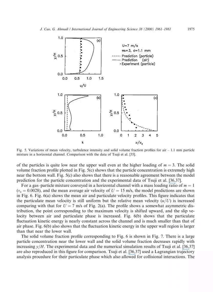
of the particles is quite low near the upper wall even at the higher loading of m � 3. The solidvolume fraction pro®le plotted in Fig. 5(c) shows that the particle concentration is extremely highnear the bottom wall. Fig. 5(c) also shows that there is a reasonable agreement between the modelprediction for the particle concentration and the experimental data of Tsuji et al. [36,37].
For a gas±particle mixture conveyed in a horizontal channel with a mass loading ratio of m � 1(ma � 0:0028), and the mean average air velocity of U � 15 m/s, the model predictions are shownin Fig. 6. Fig. 6(a) shows the mean air and particulate velocity pro®les. This ®gure indicates thatthe particulate mean velocity is still uniform but the relative mean velocity (u=U ) is increasedcomparing with that for U � 7 m/s of Fig. 2(a). The pro®le shows a somewhat asymmetric dis-tribution, the point corresponding to the maximum velocity is shifted upward, and the slip ve-locity between air and particulate phase is increased. Fig. 6(b) shows that the particulate¯uctuation kinetic energy is nearly constant across the channel and is much smaller than that ofair phase. Fig. 6(b) also shows that the ¯uctuation kinetic energy in the upper wall region is largerthan that near the lower wall.
The solid volume fraction pro®le corresponding to Fig. 6 is shown in Fig. 7. There is a largeparticle concentration near the lower wall and the solid volume fraction decreases rapidly withincreasing y=H . The experimental data and the numerical simulation results of Tsuji et al. [36,37]are also reproduced in this ®gure for comparison. Tsuji et al. [36,37] used a Lagrangian trajectoryanalysis procedure for their particulate phase which also allowed for collisional interactions. The
Fig. 5. Variations of mean velocity, turbulence intensity and solid volume fraction pro®les for air ± 1.1 mm particle
mixture in a horizontal channel. Comparison with the data of Tsuji et al. [35].
J. Cao, G. Ahmadi / International Journal of Engineering Science 38 (2000) 1961±1981 1975

present model prediction appears to be in good agreement with the simulation result of Tsuji et al.But both model predictions deviate somewhat from the experimental data. As pointed by Tsujiet al. [36,37], this is mainly because the particles used in their experiment were not perfectlyspherical. In fact, their experimental data showed that a small deviation of particle shapes fromperfect spheres has a signi®cant e�ect on the concentration pro®le.
Fig. 7. Variations of solid volume fraction pro®le for air ± 1.1 mm particle mixture in a horizontal channel. Com-
parison with the data of Tsuji et al. [35].
Fig. 6. Variations of mean velocity, ¯uctuation kinetic energy pro®les for air ± 1.1 mm particle mixture in a horizontal
channel.
1976 J. Cao, G. Ahmadi / International Journal of Engineering Science 38 (2000) 1961±1981

The predicted results for the mean phasic velocity, the ¯uctuation kinetic energy and the solidvolume fraction pro®les for a gas±particle turbulent ¯ow in a duct with an inclination of 10° areshown in Fig. 8. In this case, no external pressure gradient is applied, and thus the gas±particlemixture ¯ow is completely driven by the gravity. As shown in the ®gure, the average mean airvelocity is U � 3:7 m/s which is quite low, the mass loading ratio is m � 21:3 and the average solidvolume fraction is ma � 0:025. Fig. 8(a) shows that the air velocity pro®le is nearly symmetric andthe mean particle velocity is larger than that of the air phase. The particle slip velocities at bothwalls are also quite large. The pro®les of the phasic ¯uctuation kinetic energies shown in Fig. 8(b)also indicate that the particle ¯uctuation kinetic energy is larger than that of the air phase in mostpart of the duct. The solid volume fraction pro®le in Fig. 8(c) shows that the particle concen-tration tends to be very high near the bottom wall and decreases sharply toward the upper wall ofthe duct.
The phasic and total normal and shear stresses are presented in Fig. 9. The air-phase normaland shear stresses shown in Fig. 9(a) and (b) are generally much smaller than those of the par-ticulate phase. The exception is the low-concentration region near the upper wall, where thephasic normal and shear stresses of air and particulate constituents are nearly the same. Fig. 9(c)shows that the total normal and shear stresses decrease toward the upper wall. The observeddeviation of the total shear stress from a linear trend is due to the sharp increase of particle
Fig. 8. Variations of mean velocity, ¯uctuation kinetic energy and solid volume fraction pro®les for air ± 1.1 mm
particle mixture in a chute with 10° inclination.
J. Cao, G. Ahmadi / International Journal of Engineering Science 38 (2000) 1961±1981 1977

concentration toward the lower wall and the corresponding strong variation of the mean density.The corresponding energy production and dissipation rates are shown in Fig. 10. This ®gureindicates that the energy production and dissipation for particulate phase are quite large at thelower half of the channel and quite small in the upper part. For air phase, the energy productionand dissipation reach to peak values near both solid walls and are very small in the central part ofthe channel. It is also observed that the energy production and dissipation are nearly balanced forthe ¯uid phase, while the energy production is much larger than the dissipation rate for theparticulate phase.
5. Conclusions
A thermodynamically consistent turbulent two-phase ¯ow model is used to simulate ¯ows ofgas±solid mixtures in a horizontal and inclined channel at di�erent loadings. The model predic-tions for the phasic ¯ow properties of particulate and gas phases are compared with the availableexperimental data and good agreement is observed. Based on the presented results, the followingconclusions may be drawn:
Fig. 9. Variations of the phasic normal and shear stresses, the total normal and shear stress pro®les for air ± 1.1 mm
particle mixture in a chute with 10° inclination.
1978 J. Cao, G. Ahmadi / International Journal of Engineering Science 38 (2000) 1961±1981
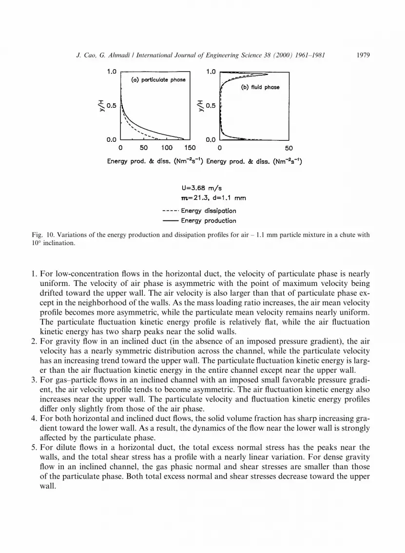
1. For low-concentration ¯ows in the horizontal duct, the velocity of particulate phase is nearlyuniform. The velocity of air phase is asymmetric with the point of maximum velocity beingdrifted toward the upper wall. The air velocity is also larger than that of particulate phase ex-cept in the neighborhood of the walls. As the mass loading ratio increases, the air mean velocitypro®le becomes more asymmetric, while the particulate mean velocity remains nearly uniform.The particulate ¯uctuation kinetic energy pro®le is relatively ¯at, while the air ¯uctuationkinetic energy has two sharp peaks near the solid walls.
2. For gravity ¯ow in an inclined duct (in the absence of an imposed pressure gradient), the airvelocity has a nearly symmetric distribution across the channel, while the particulate velocityhas an increasing trend toward the upper wall. The particulate ¯uctuation kinetic energy is larg-er than the air ¯uctuation kinetic energy in the entire channel except near the upper wall.
3. For gas±particle ¯ows in an inclined channel with an imposed small favorable pressure gradi-ent, the air velocity pro®le tends to become asymmetric. The air ¯uctuation kinetic energy alsoincreases near the upper wall. The particulate velocity and ¯uctuation kinetic energy pro®lesdi�er only slightly from those of the air phase.
4. For both horizontal and inclined duct ¯ows, the solid volume fraction has sharp increasing gra-dient toward the lower wall. As a result, the dynamics of the ¯ow near the lower wall is stronglya�ected by the particulate phase.
5. For dilute ¯ows in a horizontal duct, the total excess normal stress has the peaks near thewalls, and the total shear stress has a pro®le with a nearly linear variation. For dense gravity¯ow in an inclined channel, the gas phasic normal and shear stresses are smaller than thoseof the particulate phase. Both total excess normal and shear stresses decrease toward the upperwall.
Fig. 10. Variations of the energy production and dissipation pro®les for air ± 1.1 mm particle mixture in a chute with
10° inclination.
J. Cao, G. Ahmadi / International Journal of Engineering Science 38 (2000) 1961±1981 1979

6. For both dilute and nondilute ¯ows, the particulate ¯uctuation energy production is larger thanthe particulate energy dissipation. The air turbulence energy production is, however, nearly bal-anced by turbulence energy dissipation.
7. For both dilute and nondilute ¯ows, the slip velocity between the particles and the air phaseincreases when either the the average air velocity, the channel inclination angle or the particlesize increases.
Acknowledgements
The authors are very grateful to Professor Tsuji for making the details of his data available tothem. This work was supported by the US Department of Energy (University Coal ResearchProgram, FETC) under Grant DE-FG26-99FT40584, and the New York State Science andTechnology Foundation (through the Center for Materials Processing, CAMP, of ClarksonUnivesity).
References
[1] G. Ahmadi, A continuum theory for two-phase media, Acta Mech. 44 (1982) 299±317.
[2] G. Ahmadi, Thermodynamics of multitemperature ¯uids with applications to turbulence modeling, Appl. Math.
Modelling 9 (1985) 271±274.
[3] G. Ahmadi, D. Ma, A thermodynamic formulation for dispersed multiphase turbulent ¯ows. Part I. Basic theory,
Int. J. Multiphase Flow 16 (1990) 323±340.
[4] R.M. Bowen, Toward a thermodynamics and mechanics of mixtures, Arch. Rational Mech. Anal. 24 (1967) 370±
403.
[5] Y.A. Buyevich, Particulate pressure in monodisperse ¯uidized beds, Chemical Engrg. Sci. 52 (1997) 123±140.
[6] J. Cao, G. Ahmadi, Gas±particle two-phase turbulent ¯ow in a vertical duct, Int. J. Multiphase Flow 21 (1995)
1203±1228.
[7] J. Cao, G. Ahmadi, M. Massoudi, Gravity granular ¯ows of slightly frictional particle down an incline bumpy
chute, J. Fluid Mech. 316 (1996) 197±221.
[8] C.P. Chen, P.E. Wood, Turbulence closure model for dilute gas±particle ¯ows, Canad. J. Chem. Engrg. 63 (1985)
349±360.
[9] K.Y. Chien, Predictions of channel and boundary-layer ¯ows with a low Reynolds number turbulence model,
AIAA J. 20 (1982) 33±38.
[10] C. Crowe, M. Sommerfeld, Y. Tsuji, Multiphase Flows with Droplets and Particle, CRC Press, New York, 1998.
[11] S.E. Elghobashi, T.W. Abou-Arab, A two-equation turbulence model for two-phase ¯ows, Phys. Fluids 26 (1983)
931±938.
[12] A.C. Eringen, J.D. Ingram, A continuum theory of chemically reacting media. Part I, Int. J. Engrg. Sci. 3 (1965)
197±212.
[13] Z.D. Genchv, D.S. Karpuzov, E�ects of the motion of dust particles on turbulence transport equations, J. Fluid
Mech. 101 (1980) 823±842.
[14] D. Gidaspow, Multiphase Flow and Fluidization Continuum and Kinetic Theory Description, Academic Press,
New York, 1994.
[15] D. Gidaspow, Y.T. Shih, J. Bouillard, D. Wason, Hydrodynamics of a lamella electrosetter, AIchE J. 35 (1989)
714±724.
[16] A.H. Govan, G.F. Hewitt, C.F. Ngan, Particle motion in turbulent pipe ¯ow, Int. J. Multiphase Flow 15 (1989)
471±481.
1980 J. Cao, G. Ahmadi / International Journal of Engineering Science 38 (2000) 1961±1981

[17] M. Ishii, K. Mishima, Two-¯uid model and hydrodynamic constitutive relations, Nucl. Design 87 (1984) 107±126.
[18] J.T. Jenkins, Boundary conditions for rapid granular ¯ow: ¯at, frictional walls, J. Appl. Mech. 59 (1992) 120±127.
[19] J.T. Jenkins, M.Y. Louge, On ¯ux of ¯uctuation energy in a collisional grain ¯ow at a ¯at frictional wall, Phys.
Fluids 9 (1997) 2835±2840.
[20] B. Kashiwa, Statistical theory of turbulent incompressible ¯ows, Ph.D. thesis, Los Alamos National Laboratory,
Report No. LA-11088T, 1987.
[21] D. Koch, Kinetic theory for a monodisperse gas±solid suspension, Phys. Fluids A 2 (1990) 1711±1723.
[22] S. Lee, F. Durst, On the motion of particles in turbulent duct ¯ows, Int. J. Multiphase Flow 8 (1982) 125±146.
[23] M.Y. Louge, E. Mastorakos, J.T. Jenkins, The role of particle collisions in pneumatic transport, J. Fluid Mech. 231
(1991) 345±359.
[24] D. Ma, G. Ahmadi, An equation of state for dense rigid sphere gases, J. Chem. Phys. 84 (1986) 3449±3450.
[25] D. Ma, G. Ahmadi, A thermodynamic formulation for dispersed multiphase turbulent ¯ows. Part II. Simple shear
¯ows for dense mixtures, Int. J. Multiphase Flow 16 (1990) 341±351.
[26] M. Massoudi, Application of mixture theory to ¯uidized beds, Ph.D. thesis, University of Pittsburgh, Pittsburgh,
1986.
[27] J.W. Nunziato, E.K. Walsh, On ideal multiphase mixtures with chemical reaction and di�usion, Arch. Rational
Mech. Anal. 73 (1980) 285±311.
[28] R. Ocone, S. Sundaresan, R. Jackson, Gas±particle ¯ow in a duct of arbitrary inclination with particle±particle
interactions, AIChe J. 39 (1993) 1261±1271.
[29] D. Sanjay, R. Jackson, S. Sundaresan, Turbulent gas±particle ¯ow in vertical risers, AIChE J. 40 (1994) 215±228.
[30] R.C. Schmidt, S.V. Patankar, Simulating boundary layer transition with low Reynolds number k±� turbulence
models. Part 1. An evaluation of prediction characteristics, Trans. ASME J. Turbomachinery 113 (1991a) 10±17.
[31] R.C. Schmidt, S.V. Patankar, Simulating boundary layer transition with low Reynolds number k±� turbulence
models. Part 2. An approach to improving the predictions, Trans. ASME J. Turbomachinery 113 (1991b) 18±26.
[32] J.L. Sinclair, R. Jackson, Gas±particle ¯ow in a vertical pipe with particle±particle interactions, AIChE J. 35 (1989)
1473±1486.
[33] M. Sommerfeld, A. Ando, D. Wennerberg, Swirling particle-laden ¯ows through a pipe expansion, J. Fluid Engrg.,
Trans. ASME 114 (1992) 648±656.
[34] C. Truesdell, R.A. Toupin, The classical ®eld theories, in: S. Flugge (Ed.), Handbuck der Physik, vol. III/I,
Springer, Berlin, 1960.
[35] Y. Tsuji, Y. Morikawa, H. Shiomi, LDV measurements of an air±solid two-phase ¯ow in a vertical pipe, J. Fluid
Mech. 139 (1984) 417±437.
[36] Y. Tsuji, N. Shen, Y. Morikawa, Numerical simulation of gas±solid ¯ows. Part 1. Particle-to-wall collision,
Technology Reports of the Osaka University, vol. 39, Japan, 1989a, pp. 233±241.
[37] Y. Tsuji, N. Shen, Y. Morikawa, Numerical simulation of gas±solid ¯ows. Part 2. Calculation of a two-dimensional
horizontal channel ¯ow, Technology Reports of the Osaka University, vol. 39, Japan, 1989b, pp. 243±254.
J. Cao, G. Ahmadi / International Journal of Engineering Science 38 (2000) 1961±1981 1981