functional specification for the installation of ducts and
TRANSCRIPT
FUNCTIONAL SPECIFICATION FOR THE INSTALLATION OF DUCTS AND ANCILLARY STRUCTURES FOR 38KV UNDERGROUND POWER CABLES AND ASSOCIATED COMMUNICATION CABLES FOR CONTESTABLE PROJECTS
Network Assets, Underground Networks
SPEC-191213-AXT
Note: The following document is highly technical in nature and may be complex to understand. If you are having trouble understanding the content of this document, please reach out to ESB Networks and we will assist you to understand their meaning.
Specification Number 18150 Functional Specification for the Installation of Ducts and Ancillary Structures for 38kV Underground Power Cables
and Associated Communication Cables for Contestable Projects – Rev 1
Page 2 of 21
Specification Number: 18150
Title: Functional Specification for the Installation of Ducts and Ancillary Structures for 38kV Underground Power Cables and Associated Communications Cables for Contestable Projects
Revision Number: 1
Issue Date: March 2021
Latest Review Date: March 2026
(ESB Networks Specifications are subject to change, this specification version shall only be used for the purpose/project for which it was issued by ESB Networks to you)
Approved for Issue: Specifications Manager ESB Networks
Copyright – all rights reserved: No part of this Specification may be altered or incorporated into another document without permission in writing from ESB Networks Specifications Manager.
Specification Number 18150 Functional Specification for the Installation of Ducts and Ancillary Structures for 38kV Underground Power Cables
and Associated Communication Cables for Contestable Projects – Rev 1
Page 3 of 21
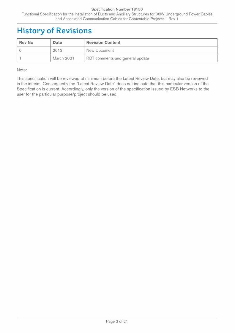
History of RevisionsRev No Date Revision Content
0 2013 New Document
1 March 2021 RDT comments and general update
Note:
This specification will be reviewed at minimum before the Latest Review Date, but may also be reviewed in the interim. Consequently the “Latest Review Date” does not indicate that this particular version of the Specification is current. Accordingly, only the version of the specification issued by ESB Networks to the user for the particular purpose/project should be used.
Specification Number 18150 Functional Specification for the Installation of Ducts and Ancillary Structures for 38kV Underground Power Cables
and Associated Communication Cables for Contestable Projects – Rev 1
Page 4 of 21
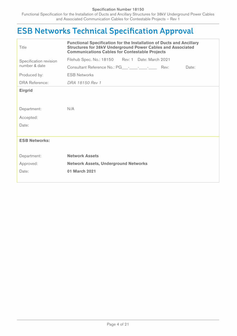
ESB Networks Technical Specification Approval
TitleFunctional Specification for the Installation of Ducts and Ancillary Structures for 38kV Underground Power Cables and Associated Communications Cables for Contestable Projects
Specification revision number & date
Filehub Spec. No.: 18150 Rev: 1 Date: March 2021
Consultant Reference No.: PG___-____-____-____ Rev: Date:
Produced by: ESB Networks
DRA Reference: DRA 18150 Rev 1
Eirgrid
Department: N/A
Accepted:
Date:
ESB Networks:
Department: Network Assets
Approved: Network Assets, Underground Networks
Date: 01 March 2021
Specification Number 18150 Functional Specification for the Installation of Ducts and Ancillary Structures for 38kV Underground Power Cables
and Associated Communication Cables for Contestable Projects – Rev 1
Page 5 of 21
Table of Contents1.0 SCOPE 6
2.0 CABLE ROUTE 6
2.1 DESIGN REVIEW 6
2.2 CABLE ROUTE DESIGN CONSIDERATIONS 6
2.3 CABLE ROUTE TERRAIN 7
2.4 BRIDGES/CULVERTS/NON STANDARD TERRAIN/OTHER SERVICES ETC. 7
2.5 PEAT 7
2.6 REINSTATEMENT FINISHES 9
3.0 DUCT INSTALLATION 9
3.1 SUPERVISION 9
3.2 WORKS INCLUDED 9
3.3 TRANSPORT, STORAGE AND HANDLING OF DUCTS 9
3.4 MATERIALS 10
3.4.1 38KV JOINT BAY REINSTATEMENT THERMAL SAND 11
3.4.2 UNDERGROUND CABLE PROTECTION MATERIAL FOR UNAVOIDABLY SHALLOW DEPTHS 11
3.5 TRENCH LAYOUT 12
3.6 JOINT BAYS 12
3.7 COMMUNICATIONS CHAMBER 13
3.8 LUBRICATION POINTS 13
3.9 CLEARANCES FROM OTHER SERVICES AND ESB NETWORKS LV, MV AND HV CABLES 13
3.10 JOINING OF DUCTS 14
3.11 CUTTING OF DUCTS 14
3.12 TREFOILING OF DUCTS 14
3.13 AVOIDANCE OF POWER DUCT CROSSOVERS 14
3.14 BENDS 14
3.15 AVOIDANCE OF CRINKLING/FLATTENING OF DUCTS WHILE LAYING DUCTS AT BEND POSITIONS 14
3.16 TRENCHLESS TECHNOLOGY 15
3.17 DIRT INGRESS INTO THE DUCTS 15
3.18 ESB NETWORKS APPROVED PROTECTION STRIP, WARNING TAPE AND MARKER POSTS 16
3.19 TRENCH BACKFILLING 16
3.20 CLEANING, PROVING, ROPING AND SEALING 16
3.21 RECORDING OF DUCT INSTALLATION 17
APPENDIX 1. DUCT DELIVERY CHECKLIST 18
APPENDIX 2. QUALITY REPORT TEMPLATE 19
APPENDIX 3. DUCT CLEANING/PROVING REPORT 20
Specification Number 18150 Functional Specification for the Installation of Ducts and Ancillary Structures for 38kV Underground Power Cables
and Associated Communication Cables for Contestable Projects – Rev 1
Page 6 of 21
1.0 ScopeThis document specifies the requirements for the supply and installation of Ducts and Ancillary Structures for 38kV Underground Power Cables and Associated Communications Cables on the ESB Networks Distribution System.
The materials used and construction methods employed shall comply with the requirements of
a) This Specification Number 18150 andb) Specification Number 18149 – General Specification for Contestably Built Underground
Networksc) The individual ESB Networks materials Specifications for ducting and cable materials and
components and ancillary structuresd) Specification Number 18151 – Specification for the Installation of 38kV Underground Power
Cables for Contestable Projects
In the event of any dispute arising from a difference of interpretation regarding the contents of these specifications, ESB Networks interpretation shall be taken as final.
2.0 Cable Route
2.1 Design Review
Cable route design and associated risk assessment and residual risk register shall be submitted to ESB Networks for review prior to any works commencing on site.
2.2 Cable Route Design Considerations
Where there are multi circuit situations e.g. near or in electricity switching stations, provision shall be made for separation from other circuits to avoid derating of the existing or proposed cables.
Cable de rating calculations shall be carried out on all cable circuits, including those that deviate from standard construction due to crossing/pinch point/depth effects. The full cable rating report shall include all parameters used for this de rating calculation and shall be submitted to ESB Networks for review.
Where more than one circuit/two cables per phase is being installed or where one cable is installed adjacent to an existing HV cable, the design shall take due account of cable derating due to mutual heating of the cables through HV cable analysis. The mutual coupling effect of other cables and pipelines shall also be taken into account. Where 38kV underground cables cross lower voltage cables, they shall be routed under the lower voltage cables for safety reasons. If it is necessary to bury the cable at greater depth at any point, then the IPP shall take account of this in the rating of the cable as per IEC 60287. The IPP shall take note of the presence of existing HV & MV underground circuits. The IPP design shall model the impact of neighbouring underground circuits in terms of the new cables rating and the impact on the existing cables ratings. Where it is proposed to cross (over or under) or run in parallel with an existing circuit, the cable system shall be designed to ensure that no de-rating of existing circuits occurs as a result of the proposed cable. Where this scenario arises, the IPP shall demonstrate via detailed cable rating calculations that mitigations have been taken to limit potential de-rating of existing underground circuits. This may include but is not limited to the use of bentonite, the use of a larger cable, the use of Horizontal Directional Drilling to increase thermal separation and thermal independence.
The design of measures proposed to deal with any such situations that deviate from the functional specifications shall be submitted to ESB Networks for review. Early engagement pre-construction with ESB Networks shall be required for any proposed deviations.
Specification Number 18150 Functional Specification for the Installation of Ducts and Ancillary Structures for 38kV Underground Power Cables
and Associated Communication Cables for Contestable Projects – Rev 1
Page 7 of 21
2.3 Cable Route Terrain
ESB Networks policy in relation to the routing of underground cables is that they shall be routed through public roads or public lands. The route of the cable duct shall follow solid stable ground on flat or gently graded slopes not subject to erosion. Trial excavations shall be conducted in advance to determine the suitability of the route.
Where the gradient of the route exceeds 1 in 3 metres, specialist measures shall be designed and implemented to achieve satisfactory long-term duct and cable performance. These specialist measures shall be submitted for review at design stage and reviewed design captured in the Residual Risk register along with construction method statement.
2.4 Bridges/Culverts/Non Standard Terrain/other Services etc.
The IPP shall also note that where the minimum standard clearance requirements cannot be achieved e.g. bridge crossings/culverts, then alternate design shall be investigated.
Provision shall be made for additional protection of the cable duct where burial depth to specification cannot be achieved. These additional measures shall be submitted to ESB Networks for review. ESB Networks will provide guidance on each case.
Higher voltage underground cables shall be routed under lower voltage cables for safety reasons.
Prior written agreement shall be required from the road authorities for proposal of shallow crossings, road level changes etc. in conjunction with Purple Book “ Guidelines for Managing Openings in Public Roads “.
The IPP shall refer to drawing pack for standard design requirement.
2.5 Peat
Cable Trenches crossing through peatland shall be avoided if at all possible. Any routes identified through peatland shall be reviewed and accepted by ESB Networks on a case by case basis. Should a potential requirement for such an installation be proposed, ESB Networks shall be consulted at the earliest available opportunity. If all other cable route options have been exhausted (to the satisfaction of ESB Networks) then a design may be considered by ESB Networks through peatland. Such design shall be reviewed and accepted by ESB Networks before the IPP can submit the planning permission. The IPP shall submit a detailed feasibility study of the options and their proposal for installation of a short section of the cable route in peatland. The feasibility study shall advise why the other route options are not being progressed and also provide case studies of where a similar peat land cable design has been installed successfully. For all underground cables constructed in peat, regardless of location (e.g. within or beneath a road or otherwise), the IPP shall include the following in the feasibility:
• A desktop study of the route including a review of all existing geotechnical information, outlining all constraints and geotechnical risks
• An outline of all site investigation carried out along the route• A peat stability risk assessment/peat landslide hazard risk assessment shall be completed that
shall consider the risk of peat slides in blanket bog and bog bursts in raised bog.• In association with the peat stability risk assessment/peat landslide hazard risk assessment a
Materials Management Plan shall also be submitted for review by ESB Networks• A preliminary peat stability mitigation plan shall also be submitted with the peat stability risk
assessment/peat landslide hazard risk assessment outlining how all design, construction and operations risk are to be controlled and/or mitigated
• A feasibility design for the cable route trench the IPP shall include the following in the design submission:
• An outline of any site investigations carried out and the associated findings
Specification Number 18150 Functional Specification for the Installation of Ducts and Ancillary Structures for 38kV Underground Power Cables
and Associated Communication Cables for Contestable Projects – Rev 1
Page 8 of 21
• A detailed peat stability mitigation plan shall also be submitted with the peat stability risk assessment/peat landslide hazard risk assessment outlining how all design, construction and operations risk are to be controlled and/or mitigated
• A demonstration that settlement or differential settlement of the cable shall not occur to the extent to which the cable’s function or durability could be compromised over the design life.
• Demonstrations that lateral movement due to downhill creep of peat shall not occur.• Clear outline of any planned site investigation or ground condition verification during the works• An outline of the construction supervision during the works• Flooding risk shall be assessed.
Cable mast locations shall be assessed in a similar manner. However, this shall include access and egress routes to the locations. If roads in peatland are proposed to be constructed as “floating roads”, the IPP should consider in the design that these are prone to gradual differential settlement leading in time to an undulating surface. Where the cable route is proposed to be constructed in a “floating road”, the IPP shall assess whether it will be necessary to replace the “floating road” with a road founded on mineral soil in order to avoid future settlements or peat instability. The peat stability risk assessment/peat landslide hazard risk assessment shall be carried out by an experienced geotechnical engineer (min. 10 years’ experience, Chartered Geotechnical Engineer). The assessment shall be carried out in accordance with all current legislative requirements and guidelines, and at a minimum the Scottish Government Peat Landslide Hazard and Risk Assessments.
Best Practice Guide for Proposed Electricity Generation Developments Specific requirements on the design of any cable route through peatland are listed below:
• A minimum 3 m paved and gated service road designed for heavy traffic will be installed to provide safe access for inspection, maintenance and fault repair along the entire cable route through peatland.
• All materials used shall comply with the Transport Infrastructure Ireland (TII) Specification for Road Works and all relevant Irish and European Standards. British Standards may also be used where appropriate and where no equivalent Irish or European Standard is applicable. A maintenance plan listing responsible parties for maintaining the cable, trench, road and gates shall be submitted.
• A drainage design for the route shall be included with the submission. The drainage design shall ensure the continued integrity of the road surface, but it shall be demonstrated that the peatland will not be adversely affected by pollution, by siltation or by changes to the hydrological conditions.
• The service road which accompanies the cable route shall be suitably designed (i.e. if the road is to be used by heavy vehicles or machinery this shall be reflected in the structural design for the road).
• Peat shall be completely excavated to either competent mineral soil or bedrock at the joint bay locations.
• Joint bays and communication chambers are to be located adjacent the service road.
It should be noted that as with any non-standard design, ESB Networks shall receive early notification pre-construction that a non-standard design is being proposed and a formal derogation submitted. It should also be noted that the process for seeking acceptance of a non–standard design is more onerous and timelier as more stakeholders are involved in the review. Also, the design may require additional warranties to mitigate risk if deemed necessary. These reviewed designs shall be captured in the Residual Risk Register along with construction methodology.
Specification Number 18150 Functional Specification for the Installation of Ducts and Ancillary Structures for 38kV Underground Power Cables
and Associated Communication Cables for Contestable Projects – Rev 1
Page 9 of 21
2.6 Reinstatement Finishes
The reinstatement and surface finish for trenches, manholes and joint bays shall be agreed in advance by the IPP with the local authority, relevant public body or private landowners.
All reinstatement works shall be in accordance with the TII/Dept of Environment Specification for Road Works and any conditions specified in the Road Opening Licence and/or route consents. If any part of the route impinges on private property, the reinstatement specification shall be as agreed with the Landowner.
Upon completion of the works, a statement of satisfaction with the completed works shall be obtained from the relevant landowners, public body or local authority.
This shall be submitted to ESB Networks before the ownership of the circuit is transferred.
3.0 Duct Installation
3.1 Supervision
All Works shall be continuously supervised by competent personnel. Each civil crew shall have a designated single competent person responsible for Quality control at the installation phase and along the full length of the route.
Quality reports in an agreed template as per General Specification 18149 shall be produced to Lead Project Manager on a weekly basis. Before any duct installation works commence the IPP’s contractor shall attend the ESB Networks approved duct installation workshop. The IPP’s contractors directly involved with duct installation shall be required to attend.
3.2 Works Included
Duct installation shall also include cleaning, proving, draw rope installation, and sealing of the ducts. It shall also include excavation of joint bays, backfilling around direct buried cable joints (with the cable jointer in attendance) and reinstatement of joint bays and other structures to facilitate cable installation and jointing.
Duct surround sand shall be approved by ESB Networks for use. It shall fulfil the Thermal and grading requirements detailed in section 3.4.1 of this specification.
3.3 Transport, Storage and Handling of Ducts
Great care shall be taken during handling of ducts to avoid damage. Ducts shall be delivered with end caps in place which shall remain in place until installation of the duct to prevent the entry of dirt.
The ducts shall not be stored in a place where they are likely to be in contact with surface water or other foreign matter which could make its way into the ducts. The method of stacking shall be such as to avoid distortion and the integrity of the ducts shall be maintained throughout their site storage and transport. The bales of ducts shall not be stacked over two tiers.
The Quality Assurance management system shall include detailed inspection of delivered ducts and accessories. Each delivery of ducts shall be inspected to ensure compliance with specification and to verify the following:
– Correct labelling– Duct Marking– Correct dimensions
Duct Length
Specification Number 18150 Functional Specification for the Installation of Ducts and Ancillary Structures for 38kV Underground Power Cables
and Associated Communication Cables for Contestable Projects – Rev 1
Page 10 of 21
Duct Wall thickness– Duct ovality– Duct caps are installed– Correct packaging on delivery and storage
Ducts which have become discoloured due to external storage and/or UV exposure or damaged from transport or storage shall not be installed.
Refer to duct delivery quality checklist in Appendix 1
3.4 Materials
• All ducts and associated installation materials detailed in this specification shall be supplied by an ESB Networks approved manufacturer. Details are available on ESB Networks website: (http://www.esb.ie/esbnetworks/en/download_documents/builders_developers/approved_material.jsp)
• Ducts (Power and Communications) for use at 38kV shall be 110mm HDPE – the materials shall comply with ESB Networks Specification 16113 technical requirements.
• Ducting Templates shall be constructed and used (3 Mtr intervals) to guaranteed minimum required interduct separation and centralisation of ducts in trench. These templates shall be approved by ESB Networks for use,
• Concrete for structural work shall be in accordance with the TII “Specification for Road Works”, except where amended below.
• Material for duct bed and surround and trench backfill for standard formation shall be CBGM Category B (Cement Bound Granular Material Category B), 15N/mm2.To obtain this value a minimum of 7 days curing is required in accordance with Series 1000 of the TII “Specification of Road Works”. The material shall conform to the thermal resistivity requirement of this specification. Proof of conformance to the thermal resistivity requirement of this Specification following ASTM D5334-08, namely 1.0 K.m/Watt) at 0% moisture content, is required during duct installation. Test sheets confirming the thermal properties shall be available for on-site inspection and shall be submitted with the ‘as-built’ documentation.
• Concrete for road reinstatement shall be grade C40/N20 with a minimum cement content of 350 kg/m3 in accordance with Series 1000 of the TII “Specification for Road Works”.
• Concrete for joint bay and communication chambers shall be grade C35/N30 with a minimum cement content of 325 kg/m3.
• Formed finishes to Joint Bays shall be to class F2 and unformed finishes shall be to class U1 in accordance with Clause 1708 of Series 1000 of the TII “Specification for Road Works”.
• Pre-Cast Joint Bays and Chambers shall be obtained from approved ESB Networks suppliers only.
• Pea gravel and foam concrete shall not be used for duct surround materials.
The materials supplied and used shall comply with the latest edition of the following ESB Networks Materials Specifications
Spec Number Material
16001 Plastic Warning and Protection Tapes, Tiles and Marker Posts
16002 Plastic Cable Ties
16110 Galvanised Steel Cable Protection Covers Plates and Cast Steel Warning Plate
16112 Lubricant for Pulling Power Cables into Cable Ducts
16113 Plastic Ducts and Fittings for Power and Telecommunications Cables
Specification Number 18150 Functional Specification for the Installation of Ducts and Ancillary Structures for 38kV Underground Power Cables
and Associated Communication Cables for Contestable Projects – Rev 1
Page 11 of 21
3.4.1 38kV Joint Bay Reinstatement Thermal SandThermal Sand shall be used to backfill around 38kV cables and joints, usually in the following locations; 38kV cable joint bays, 38kV cables on approach to a cable mast and pull pits near substation basements. ESB Networks keeps a live list of pre-approved suppliers around Ireland. New suppliers are added regularly upon completion and passing of the tests set out below.
The thermal sand shall meet the requirements set out in this Specification and ENA Technical Specification 97-1 (latest Revision) section 6.1 (with this Specification taking precedence).
There are 3 main criteria for the thermal sand;
1. It shall have no sharp stones or flints (may damage the cable sheath during compaction).2. At least 95% shall pass a 4 mm sieve and 100% shall pass an 8 mm sieve.3. The fully dried sample @ 0% moisture shall have a maximum thermal resistivity of 2.7 K.m/W.
This test shall be completed by an ESB Networks approved laboratory to the thermal needle probe method as outlined in ASTM D5334. The thermal resistivity @ 2% moisture shall also be recorded.
The IPP shall, before commencement of the project, select samples of sands which fall within the above grading, and subject them to testing for thermal resistivity, particle distribution and dry relative density all at his own cost and submit the following information to ESB Networks for approval prior to commencement of the Works:
• The source or sources of the material• Certificates of Compliance with the specified grading limits• Thermal resistivity test results demonstrating the ability of the material to meet the above criteria
3.4.2 Underground Cable Protection Material for Unavoidably Shallow DepthsWherever the trench layout and burial depth standards set out in this specification cannot be achieved, because of the terrain or the presence of other services, the design, for all such deviations from the standards shall be submitted by the IPP for review by ESB Networks.
The following additional materials shall be used in these situations:
Refer to drawing pack for standard design requirement.
3.4.2.1 Heavy Duty Underground Cable Protection PlateDescription:
750mm long x 200mm wide x 6mm thick galvanised steel plate, with red marker strip fixed to top surface. These shall be laid over the power and communication ducts as specified in the design drawings.
3.4.2.2 Surface Cable MarkersDescription:
Metallic plate; 300mm x150mm; 4 screw-holes and bolts. These shall be placed on footpaths/fences, bridges, walkways etc., where cable depth is unavoidably shallow. They shall be fitted to solid durable surfaces and shall be fitted flush with their surround when placed on footpaths or walkways with full embedment of hold down bolts.
3.4.2.3 Marker PostsDescription:
They shall be installed in adequately sized concrete foundations and shall be placed at both sides of river crossings, wherever directional drilling has been used and where burial depth is not to standard. They shall also be used in non-roadway routes and in forestry routes to delineate the duct route.
Specification Number 18150 Functional Specification for the Installation of Ducts and Ancillary Structures for 38kV Underground Power Cables
and Associated Communication Cables for Contestable Projects – Rev 1
Page 12 of 21
3.4.2.4 Other items for unavoidably shallow burial depthsFor additional mechanical protection of the duct route, 6mm thick galvanised steel plate and A393 reinforcement mesh may be required as specified by ESB Networks.
3.5 Trench Layout
The trench layout shall be as per the relevant ESB Networks drawing(s) in the drawings in work pack. The specification of the TII /Dept of Environment, Local Authorities shall be complied with for the excavation and reinstatement of the ducted cable trenches.
Where a change in the gradient of the trench is required to accommodate other services, the gradient change shall be as minimal as possible. Ducts shall be laid in straight lines to even gradients.
Ducts may be laid to slow and even curves on plan to avoid an obstruction. If a change in direction is required, bends formed by evenly bending the ducts themselves only shall be used and the couplers shall be braced so that there is no bending or stress on the coupler. No heat shall be applied to the ducts when bending ducts. The spacing of the ducts shall be in accordance with the drawings in the Appendices to this specification.
Natural bends in the ducts shall be as wide and gradual as possible. Clearances from other services shall be strictly observed and shall be maintained at all times.
The duct route shall be designed and constructed to ensure that the cable manufacturer’s maximum tensile and sidewall pressure pulling forces shall not be exceeded on the relevant 38kV Cable. Design calculations to confirm this requirement shall be included in the design review submission.
3.6 Joint Bays
Joint bays shall be provided to meet the requirements of standard cable drum lengths and/or as required to limit cable pulling forces. Joint bays shall be no further than 1200 m centre to centre apart.
Joint Bay locations shall be chosen with suitable terrain and access to facilitate
• the operation of cable pulling equipment,• cable jointing• future operation of the installation and with future traffic management plan in mind. A traffic
management plan for each joint bay location shall be submitted to ESB Networks for review. This shall be included in the Residual Risk Register.
The area around Joint bays shall be designed and constructed for joint bay installation, cable pulling and future cable works.
The construction of the joint bays shall be as specified by ESB Networks and pre-cast joint bays shall be sourced from an approved ESB Networks Supplier.
Pre-cabling temporary backfill and reinstatement shall comply with ESB Networks standard design requirement.
Refer to drawing pack for standard design requirement.
Joint bays shall be labelled as follows:
From export station facing cable route to ESB Networks station RST left to right and Circuit name.
Specification Number 18150 Functional Specification for the Installation of Ducts and Ancillary Structures for 38kV Underground Power Cables
and Associated Communication Cables for Contestable Projects – Rev 1
Page 13 of 21
3.7 Communications Chamber
Communications chambers shall be provided to meet the requirements of standard telecommunications cable drum lengths or as required to limit cable pulling forces.
Communications Chamber locations shall be chosen with suitable terrain and access to facilitate
• the operation of cable pulling equipment,• cable jointing• future operation of the installation
and with future traffic management plan in mind. A traffic management plan for each communication chamber location shall be submitted to ESB Networks for review. This shall be added to the Residual Risk Register.
The construction of the Communication Chamber shall be as specified by ESB Networks drawing and shall be sourced from an approved ESB Networks Supplier. The chamber shall be installed as detailed in work pack drawing folder.
The D600 cover shall not be removed from the precast chamber to alter finish ground levels.
3.8 Lubrication Points
Lubrication points shall be provided to ensure cable installation can be carried out without exceeding the manufacturer’s maximum permissible cable pulling forces of the proposed cable. Lubrication points shall be installed in cable runs in close proximity to areas of high bend concentration. Optimised positions shall be chosen, e.g. on the crest of steep incline for maximum lubricant dispersion on the route. Lubrication points shall be properly sealed to prevent the ingress of dirt.
Lubrication Point locations shall be chosen with suitable terrain and access to facilitate
• the operation of cable pulling equipment,• future operation of the installation
The construction of the Lubrication Points shall be as specified by ESB Networks and shall be sourced from an approved ESB Networks Supplier.
3.9 Clearances from Other Services and ESB Networks LV, MV and HV Cables
A minimum clearance of 300mm from outer most duct edge to other 3rd party service shall be strictly observed. A clearance of 600mm from outer most duct edge to transmission high pressure infrastructure services shall be observed.
Deviations from ESB Networks minimum clearances may be unavoidable at “Pinch Points”. Where reduced clearances only can be achieved, the design shall be submitted to ESB Networks for review.
Written clarification in respect of reduced clearances shall be obtained from the relevant utility owner and, in the case of LV, MV and HV cables, clarification shall be obtained from ESB Networks and shall be included in the ‘as built’ documentation.
Cable de rating calculations shall be carried out on all cable circuits affected due to crossing effects, and reasons for this de rating documented and be submitted to ESB Networks.
Specification Number 18150 Functional Specification for the Installation of Ducts and Ancillary Structures for 38kV Underground Power Cables
and Associated Communication Cables for Contestable Projects – Rev 1
Page 14 of 21
3.10 Joining of Ducts
When joining ducts and couplers, approved ESB Networks lubricant shall be applied to the coupler for ease of fitting. Ducts shall be tapped home until the white or black mark on the duct is reached. Ducts shall only be tapped with a smooth timber or a plastic plank to avoid damage. Ducts shall be staggered by a coupler length as appropriate to minimise extent of trefoil deviations.
3.11 Cutting of Ducts
Where duct cutting is required, they shall be suitably held, supported and protected during the process. All ends shall be cut square to the longitudinal axis of the pipe and suitably finished (chamfered) with no rough edges.
3.12 Trefoiling of Ducts
38kV ducts shall be installed in trefoil formation and shall be bound together (without flattening the ducts) by plastic duct ties at 3m intervals. Ducts shall be staggered by a coupler length as appropriate to minimise extent of trefoil deviations. The ducts shall be installed as per drawings detailed in the drawing pack for standard design requirement.
3.13 Avoidance of Power Duct Crossovers
Duct position in the trefoil group shall remain fixed throughout the entire route. The top duct of a trefoil formation shall become the centre duct where duct formation flattens at a pinch point.
Duct crossovers shall be prevented and shall be deemed an unacceptable defect. Cables shall not be installed in ducting that contain a crossover of the ducts.
3.14 Bends
Bends in the ducts shall be as large and as gradual as possible. Bends formed shall only use 9m or 12m duct lengths to minimise thrust force on couplers. Preformed bends shall not be used.
Ducts, when bent shall have a bend radius of greater than 4m.
Where a lesser bending radius is required, design calculations for the pulling forces shall be produced to confirm that manufacturers side wall forces are not exceeded.
The term “Bends” also includes trench offsets/sidesteps both in the horizontal and vertical plane, which may be necessary to avoid obstructions e.g. manholes or to maintain clearances with other underground services running parallel to the trench.
At all trench route deviations/bends, the radius of the bend shall be maximised and made uniform over the entire bend. The centre of rotation of the arc shall be chosen so that the bend radius is as large as possible and the radius of curvature throughout the bend is maintained constant.
3.15 Avoidance of Crinkling/Flattening of Ducts While Laying Ducts at Bend Positions
The ducts shall be uniformly/regularly supported as they are being formed around the bend to avoid imposing concentrated (point) sidewall forces which result in crinkling or excessive flattening of the ducts at the bend position.
Specification Number 18150 Functional Specification for the Installation of Ducts and Ancillary Structures for 38kV Underground Power Cables
and Associated Communication Cables for Contestable Projects – Rev 1
Page 15 of 21
3.16 Trenchless Technology
Should it be necessary to cross obstacles such as bridges, railways, water courses. with the cable duct(s), and all possible routes and installation possibilities have been thoroughly examined and are deemed not possible, namely
i. Crossing in the structurea. To ESB Networks min standard depthb. To ESB Networks standard as per section 2.3
ii. Open crossingiii. Independent structure
then the method of installing the cable duct(s) by trenchless technology may be accepted by ESB Networks. Details of such locations and the proposed design and mechanical protection measures shall be submitted to ESB Networks for review and comment.
The route length undertaken using trenchless technology shall be an absolute minimum and shall only be that length required to clear the crossing that cannot be undertaken by conventional trenching methods.
The design and cable rating calculation report for the proposed crossing by trenchless technology shall be submitted to ESB Networks for review.
The following duct type shall be used for directional drilling for 38kV ducting and it shall be chamfered to allow correct transition to the standard ducting ID.
Type and Size of Duct
110mm HDPE for Directional Drilling
SDR 11
3.17 Dirt Ingress into the Ducts
Dirt ingress into the ducts shall be prevented as any dirt or pebbles trapped in the ducts may lead to cable failure. During cable pulling, dirt or other sharp objects will be pressed between the duct and cable resulting in deep scores and gashes on the cable sheath which may result in cable failure. Allowing dirt to enter ducts and attempting to remove it later by cleaning the ducts with brushes shall be not acceptable.
The ingress of dirt into the ducts shall be prevented by the following measures:
• On delivery from the supplier, the ducts shall be fitted with end caps. These shall remain in place to prevent dirt entering on the duct bales.
• When the ducts are installed, rubber bungs shall be immediately fitted to exposed installed duct ends and retained in place at all times. These bungs shall be fitted with an internal D-ring to facilitate the tying of draw rope.
• Trenches, joint bays pull pits at pole sets, masts and basements shall be kept free of water so as to prevent any risk of the cables and other materials to be laid in the trenches etc being detrimentally affected.
Specification Number 18150 Functional Specification for the Installation of Ducts and Ancillary Structures for 38kV Underground Power Cables
and Associated Communication Cables for Contestable Projects – Rev 1
Page 16 of 21
3.18 ESB Networks Approved Protection Strip, Warning Tape and Marker Posts
ESB Networks Protection Strip (Red) and ESB Networks Warning Tape (Yellow), shall be used at all times as specified in the relevant ESB Networks drawings.
Where ducts are laid, the red protection strip shall be placed on top of the CGBM B layer. In all situations yellow warning tape shall be placed higher up in the trench, at a distance of not more than 300mm below the finished surface.
Sufficient parallel layers of red marker strip and yellow marking tape shall be used to fully cover and slightly extend beyond the full plan widths of the ducts below it. The layer of backfill immediately underneath the yellow marker tape or red marker strip shall be properly levelled and compacted prior to laying the strip or tape evenly along the trench.
ESB Networks cable marking materials shall not be used over any other ducting which is not intended for use by ESB Networks.
3.19 Trench backfilling
Provision shall be made to prevent duct movement during the placing of the duct surround. All duct bedding, duct surround and backfill materials shall be compacted in layers using manually operated vibrating plate which shall not crush the ducts beneath.
3.20 Cleaning, Proving, Roping and Sealing
When the ducts have been installed and backfilled the duct run shall be thoroughly cleaned by pulling the appropriate size of ESB Networks approved duct brush and sponge through the duct and shall be proven by pulling the appropriate size of ESB Networks approved mandrel through the duct in the planned direction of the cable pull.
Each duct shall be cleaned and proven at completion/handover AND immediately prior to pulling in the cable winch rope and the cable in the case where the IPP is also responsible for cable installation.
A full set of risk assessment and method statement (RAMS) shall be submitted for review for the duct proving, prior to any activities taking place.
Duct Cleaning – BrushesBrushes with the specified dimensions only shall be used to ensure that any dirt or debris within ducts is transported out of the ducts rather than being merely loosened up and left within. The brush shall have the following dimensions:
Duct Outside Diameter Minimum Length of Brush Brush Code
110mm HDPE SDR 17.6 250mm 8783250 Diameter 110 mm
Brushes shall be cleaned regularly using a power hose. Approved Brushes shall have two sets of brushes per core.
Specification Number 18150 Functional Specification for the Installation of Ducts and Ancillary Structures for 38kV Underground Power Cables
and Associated Communication Cables for Contestable Projects – Rev 1
Page 17 of 21
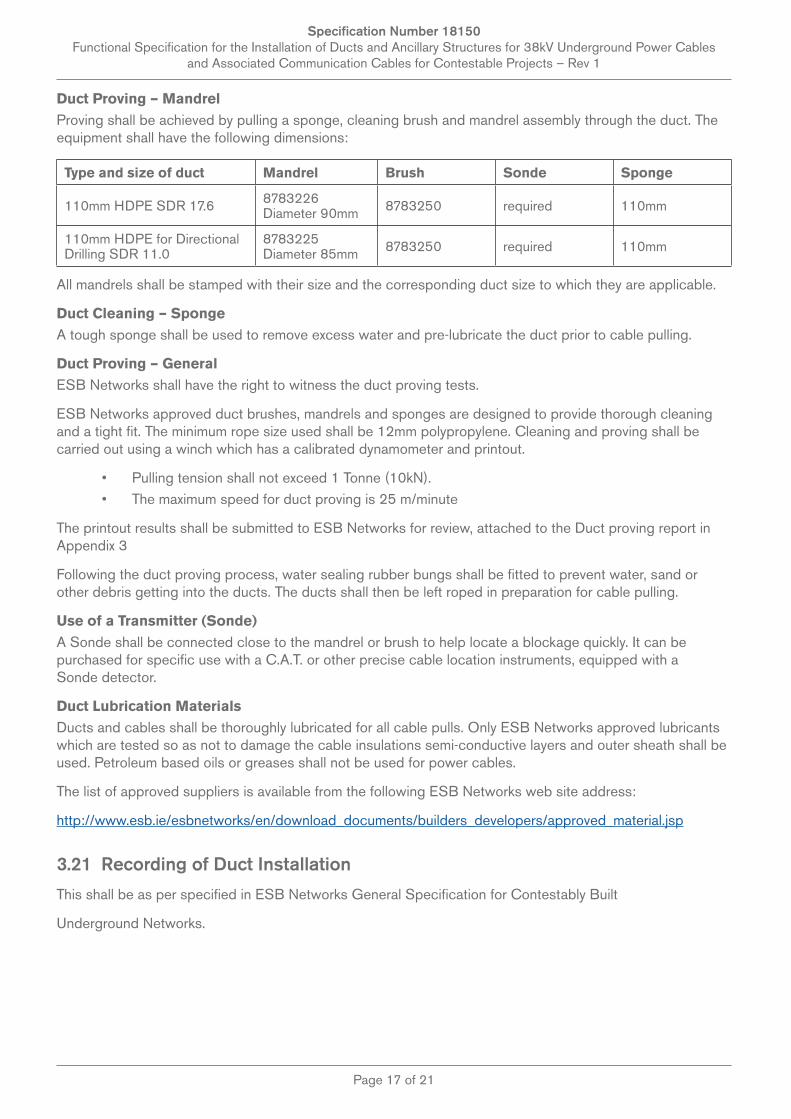
Duct Proving – MandrelProving shall be achieved by pulling a sponge, cleaning brush and mandrel assembly through the duct. The equipment shall have the following dimensions:
Type and size of duct Mandrel Brush Sonde Sponge
110mm HDPE SDR 17.6 8783226 Diameter 90mm 8783250 required 110mm
110mm HDPE for Directional Drilling SDR 11.0
8783225 Diameter 85mm 8783250 required 110mm
All mandrels shall be stamped with their size and the corresponding duct size to which they are applicable.
Duct Cleaning – SpongeA tough sponge shall be used to remove excess water and pre-lubricate the duct prior to cable pulling.
Duct Proving – GeneralESB Networks shall have the right to witness the duct proving tests.
ESB Networks approved duct brushes, mandrels and sponges are designed to provide thorough cleaning and a tight fit. The minimum rope size used shall be 12mm polypropylene. Cleaning and proving shall be carried out using a winch which has a calibrated dynamometer and printout.
• Pulling tension shall not exceed 1 Tonne (10kN).• The maximum speed for duct proving is 25 m/minute
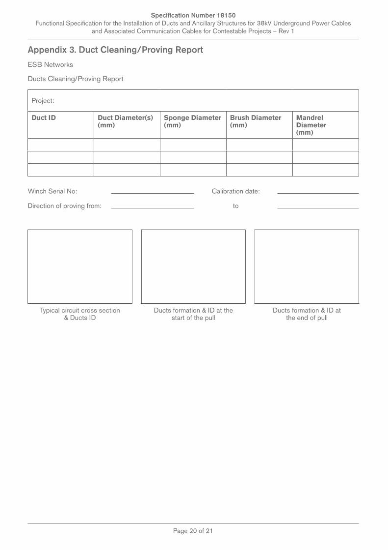
The printout results shall be submitted to ESB Networks for review, attached to the Duct proving report in Appendix 3
Following the duct proving process, water sealing rubber bungs shall be fitted to prevent water, sand or other debris getting into the ducts. The ducts shall then be left roped in preparation for cable pulling.
Use of a Transmitter (Sonde)A Sonde shall be connected close to the mandrel or brush to help locate a blockage quickly. It can be purchased for specific use with a C.A.T. or other precise cable location instruments, equipped with a Sonde detector.
Duct Lubrication MaterialsDucts and cables shall be thoroughly lubricated for all cable pulls. Only ESB Networks approved lubricants which are tested so as not to damage the cable insulations semi-conductive layers and outer sheath shall be used. Petroleum based oils or greases shall not be used for power cables.
The list of approved suppliers is available from the following ESB Networks web site address:
http://www.esb.ie/esbnetworks/en/download_documents/builders_developers/approved_material.jsp
3.21 Recording of Duct Installation
This shall be as per specified in ESB Networks General Specification for Contestably Built
Underground Networks.
Specification Number 18150 Functional Specification for the Installation of Ducts and Ancillary Structures for 38kV Underground Power Cables
and Associated Communication Cables for Contestable Projects – Rev 1
Page 18 of 21
Appendix 1. Duct Delivery Checklist
Duct Inspection Report Comment
1. Project Name and Worksite
2. Date of Delivery to site
3. Date and Location of Inspection
4. Name of Duct/Coupler Supplier
5. Duct Size (110, 125, 160, 200, 250mm)
6. Duct Type (uPVC/HDPE)
7. Wall thickness
8. Duct Length
9. Quantity of Ducts
10. Quantity of Couplers
11. Are Ducts & Couplers Packaged and Secured? (Timber struts 3 & Nylon or Plastic Straps)
12. Are ducts marked with ESBN Approved Specification No. 16113 marking?
13. Are Ducts discoloured?
14. Are all ducts fitted with Transportation Caps?
15. Are there any visible signs of Damage along lengths of Ducts?
16. Are there any visible signs of Damage to ends of Ducts?
17. Are duct end chamfered inside and outside?
18. Are there any visible signs of damage to couplers?
19. Are rubber seals correctly fitted to all Couplers?
20. Any others items of Note?
Signed & Dated

Specification Number 18150 Functional Specification for the Installation of Ducts and Ancillary Structures for 38kV Underground Power Cables
and Associated Communication Cables for Contestable Projects – Rev 1
Page 19 of 21
Appendix 2. Quality Report Template
Weekly Quality Report
Project Name:
PSCS:
ESB Networks Rep on Site:
Monday Tuesday Wednesday Thursday Friday
Location XY coordinates:
Monday Tuesday Wednesday Thursday Friday
Pictures of works to include: templates, compaction, duct installation, measurements from other services, material used, crews, duct storage, sample copy of delivery dockets, trench build up covering each step etc.
Example of Picture dimension, also clarity required so user can zoom in to assess trench construction and quality.
Drawing Number Used:
Specification Number 18150 Functional Specification for the Installation of Ducts and Ancillary Structures for 38kV Underground Power Cables
and Associated Communication Cables for Contestable Projects – Rev 1
Page 20 of 21
Appendix 3. Duct Cleaning/Proving Report
ESB Networks
Ducts Cleaning/Proving Report
Project:
Duct ID Duct Diameter(s) (mm)
Sponge Diameter (mm)
Brush Diameter (mm)
Mandrel Diameter (mm)
Winch Serial No: Calibration date:
Direction of proving from: to
Typical circuit cross section & Ducts ID
Ducts formation & ID at the start of the pull
Ducts formation & ID at the end of pull

Specification Number 18150 Functional Specification for the Installation of Ducts and Ancillary Structures for 38kV Underground Power Cables
and Associated Communication Cables for Contestable Projects – Rev 1
Page 21 of 21
Pre-Taking Over
Duct ID Duct Designation Max Pulling Tension (tonnes) Comments
1
2
3
4
5
6
7
8
9
Have the ducts maintained the correct formation? Yes No
Rubber bungs fitted after ducts proving? Yes No
Have the ducts been cleaned and proved successfully? Yes No
Name of Contractor:
Signed for Contractor: Date:
ESB N Supervisor who witnessed the tests:
Signed for Contractor: Date:
Note:
• The proving of the ducts will be deemed as failed if:• The pulling tension exceeds 1 tonne (10 kN)• If max speed of 25M/minute is exceeded.• Mandrel is stuck• Mandrel is moving with sudden bursts even if the pulling tension is less than maximum specified• Rope shoots suddenly up the duct• Ducts do not maintain the same formation as at the start of the pull