fluid dynamics - iare
TRANSCRIPT

Fluid Dynamics
IV B. Tech III semester (Autonomous IARE R-18)
BY
Mr. Shiva Prasad U
Assistant Professor
Dr. Govardhan D
Professor & HoD
DEPARTMENT OF AERONAUTICAL ENGINEERING
INSTITUTE OF AERONAUTICAL ENGINEERING(Autonomous)
DUNDIGAL, HYDERABAD - 500 043
FLUID DYNAMICS
Mr. Shiva
Assistant Professor
Department of Aeronautical Engineering
2
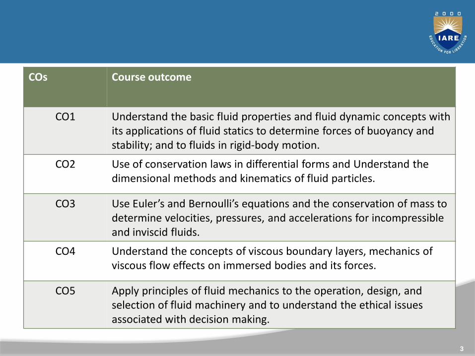
COs Course outcome
CO1 Understand the basic fluid properties and fluid dynamic concepts with its applications of fluid statics to determine forces of buoyancy and stability; and to fluids in rigid-body motion.
CO2 Use of conservation laws in differential forms and Understand the dimensional methods and kinematics of fluid particles.
CO3 Use Euler’s and Bernoulli’s equations and the conservation of mass to determine velocities, pressures, and accelerations for incompressible and inviscid fluids.
CO4 Understand the concepts of viscous boundary layers, mechanics of viscous flow effects on immersed bodies and its forces.
CO5 Apply principles of fluid mechanics to the operation, design, and selection of fluid machinery and to understand the ethical issues associated with decision making.
3
4
5
Unit I
Fluid Properties and Fluid Statics
6
7
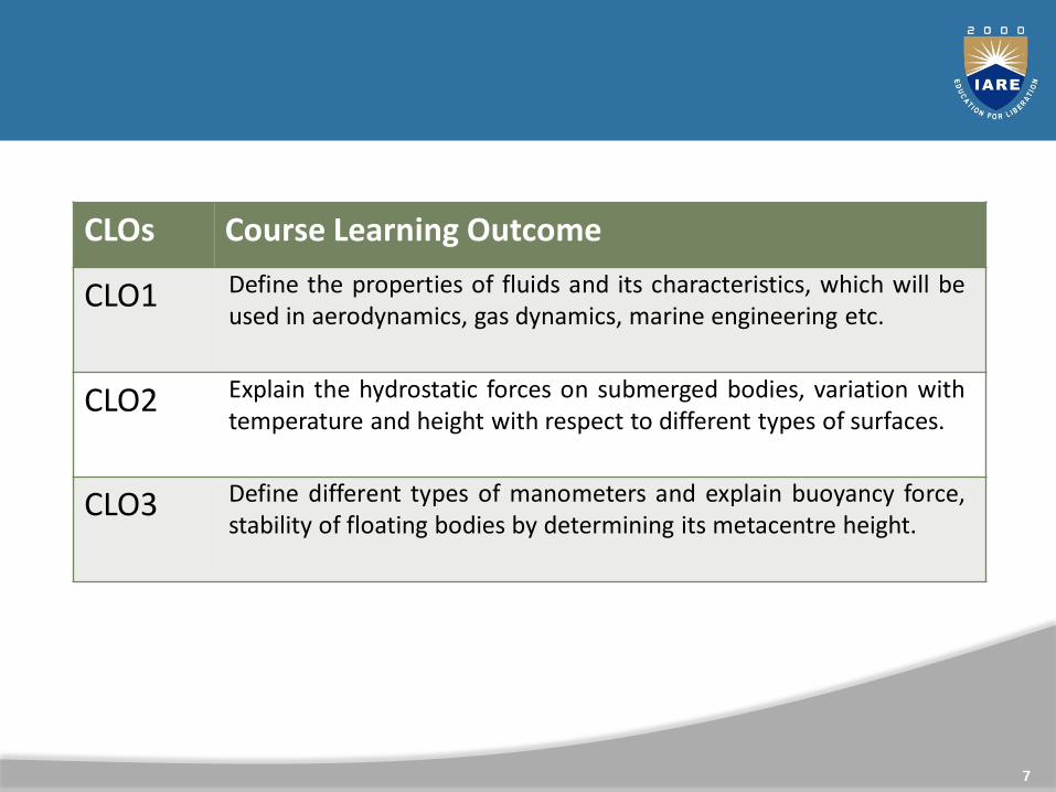
CLOs Course Learning Outcome
CLO1 Define the properties of fluids and its characteristics, which will beused in aerodynamics, gas dynamics, marine engineering etc.
CLO2 Explain the hydrostatic forces on submerged bodies, variation withtemperature and height with respect to different types of surfaces.
CLO3 Define different types of manometers and explain buoyancy force,stability of floating bodies by determining its metacentre height.
Syllabus
Density, specific weight, specific gravity, surface tension andcapillarity, Newton‘s law of viscosity, incompressible andcompressible fluid, numerical problems; Hydrostatic forces onsubmerged bodies - Pressure at a point, Pascal's law, pressurevariation with temperature and height, center of pressure plane,vertical and inclined surfaces; Manometers - simple anddifferential Manometers, inverted manometers, micromanometers, pressure gauges and numerical problems.Buoyancy - Archimedes principle, meta-center, Meta centricheight calculations; Stability.
8
Introduction
Fluid mechanics is a study of the behavior of fluids, either atrest (fluid statics) or in motion (fluid dynamics).
The analysis is based on the fundamental laws of mechanics,which relate continuity of mass and energy with force andmomentum.
An understanding of the properties and behavior of fluids atrest and in motion is of great importance in engineering.
9

10
Fluid Mechanics
Fluid: Fluids are substance which are capable of flowing andconforming the shapes of container.
Fluids can be in gas or liquid states.
Mechanics: Mechanics is the branch of science that dealswith the state of rest or motion of body under the action offorces.
Fluid Mechanics: Branch of mechanics that deals with theresponse or behavior of fluid either at rest or in motion.
Branches of Fluid Mechanics
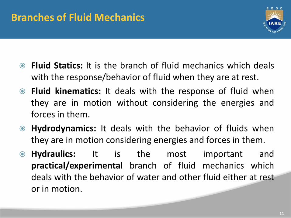
Fluid Statics: It is the branch of fluid mechanics which dealswith the response/behavior of fluid when they are at rest.
Fluid kinematics: It deals with the response of fluid whenthey are in motion without considering the energies andforces in them.
Hydrodynamics: It deals with the behavior of fluids whenthey are in motion considering energies and forces in them.
Hydraulics: It is the most important andpractical/experimental branch of fluid mechanics whichdeals with the behavior of water and other fluid either at restor in motion.
11
Significance of Fluid Mechanics
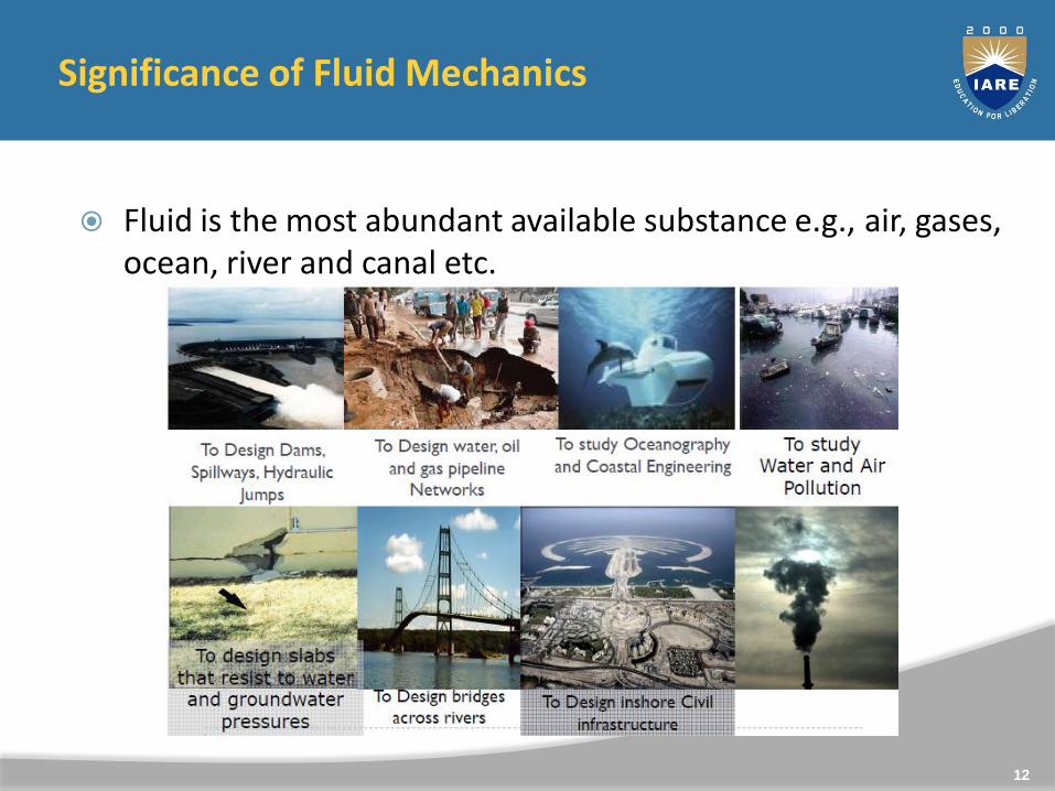
Fluid is the most abundant available substance e.g., air, gases, ocean, river and canal etc.
12
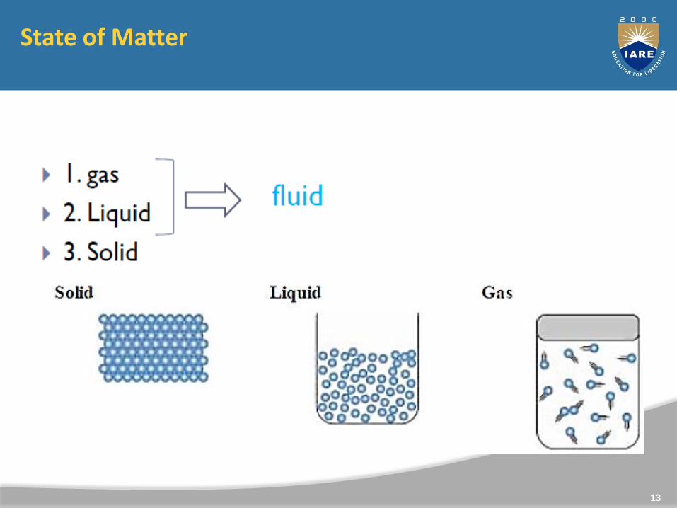
State of Matter
13

Comparison Between Liquids and Gases
Liquids have definite volumeat any particular temperature
Liquids have free levelsurface
Molecules of liquid are closeto each other
Liquids have relatively moremolecular attraction
Liquids are slightlycompressible
Rate of diffusion of liquid isless
Gases do not have anydefinite volume
Gases do not have free levelsurface
Molecules of gases are farapart
Gases have less molecularattraction
Gases are highlycompressible
Gases have higher rate ofdiffusion
14
Comparison Between Liquids and Solids
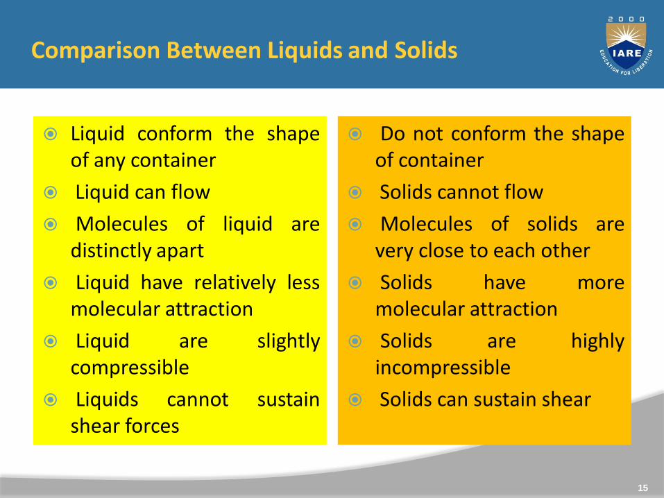
Liquid conform the shapeof any container
Liquid can flow
Molecules of liquid aredistinctly apart
Liquid have relatively lessmolecular attraction
Liquid are slightlycompressible
Liquids cannot sustainshear forces
Do not conform the shapeof container
Solids cannot flow
Molecules of solids arevery close to each other
Solids have moremolecular attraction
Solids are highlyincompressible
Solids can sustain shear
15
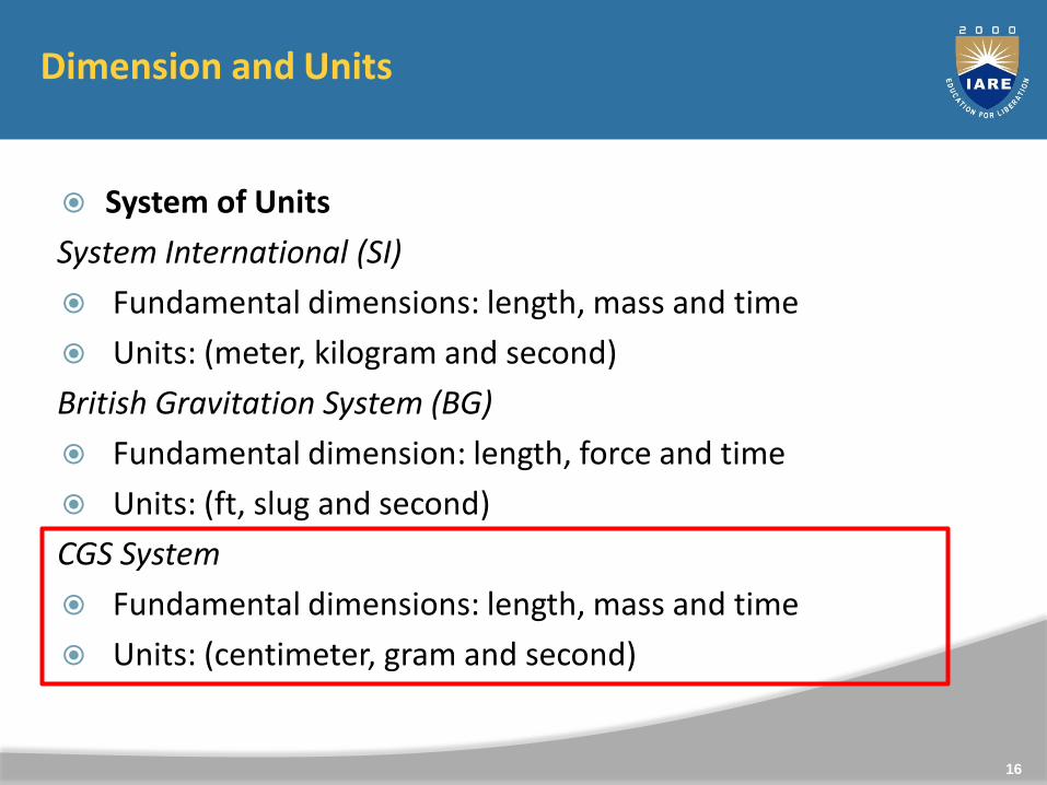
Dimension and Units
System of Units
System International (SI)
Fundamental dimensions: length, mass and time
Units: (meter, kilogram and second)
British Gravitation System (BG)
Fundamental dimension: length, force and time
Units: (ft, slug and second)
CGS System
Fundamental dimensions: length, mass and time
Units: (centimeter, gram and second)
16

Dimension and Units
Dimension
Fundamental/Primary Dimension
length(L), mass (M) and time (T)
Derived/Secondary Dimensions
e.g., force, velocity, acceleration etc
Fundamental/Primary Dimension
17
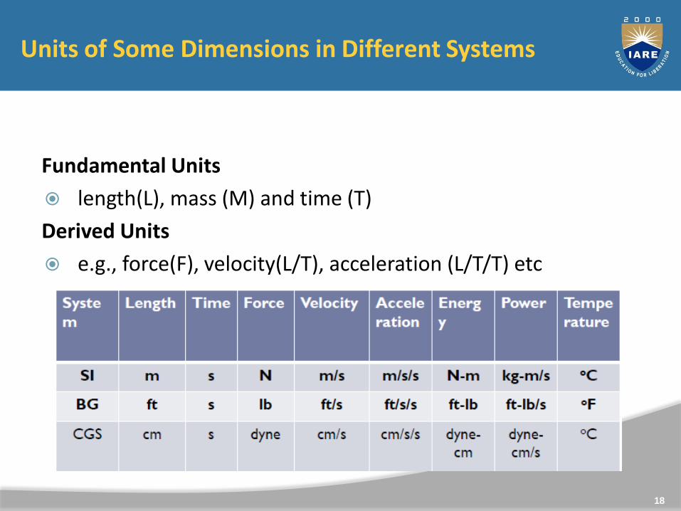
Units of Some Dimensions in Different Systems
Fundamental Units
length(L), mass (M) and time (T)
Derived Units
e.g., force(F), velocity(L/T), acceleration (L/T/T) etc
18
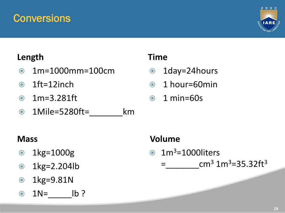
Conversions
Length
1m=1000mm=100cm
1ft=12inch
1m=3.281ft
1Mile=5280ft=_______km
Mass
1kg=1000g
1kg=2.204lb
1kg=9.81N
1N=_____lb ?
Time
1day=24hours
1 hour=60min
1 min=60s
Volume
1m3=1000liters =_______cm3 1m3=35.32ft3
19
20
Properties of Fluids- Mass Density, Specific Weight, Relative Density, Specific volume

Properties of Fluids
The properties outlines the general properties of fluids whichare of interest in engineering.
The symbol usually used to represent the property is specifiedtogether with some typical values in SI units for common fluids.
21
Density
The density of a substance is the quantity of matter contained in aunit volume of the substance. It can be expressed in three differentways.
Mass Density
Specific Weight
Relative Density
22
Mass Density
Mass Density: Mass Density, ρ , is defined as the mass ofsubstance per unit volume.
Units: Kilograms per cubic metre, (or )
Dimensions: ML-3
Typical values:
Water = 1000 kgm-3, Mercury = 13546 kgm-3, Air = 1.23 kgm-3,Paraffin Oil = 800 kgm-3.
(at pressure =1.013x 10 -5 Nm-2 and Temperature = 288.15 K.)
23
Specific Weight: Specific Weight ω, (sometimes , and sometimesknown as specific gravity) is defined as the weight per unitvolume.
or
The force exerted by gravity, g, upon a unit volume of thesubstance.
The Relationship between g and ω can be determined byNewton's 2ndLaw, since
weight per unit volume = mass per unit volume g
ω = ρg
24
Specific Weight
Units: Newton's per cubic metre, N/m3 (or ) Nm-3
Dimensions: ML-2T-2
Typical values:
Water =9814 Nm-3
Mercury = 132943Nm-3
Air =12.07 Nm-3
Paraffin Oil =7851 Nm-3
25
Relative Density : Relative Density,σ, is defined as the ratio ofmass density of a substance to some standard mass density.
For solids and liquids this standard mass density is the maximummass density for water (which occurs at 4oC) at atmosphericpressure.
Units: None, since a ratio is a pure number.
Dimensions: 1.
Typical values: Water = 1, Mercury = 13.5, Paraffin Oil =0.8.
26
Relative Density
Specific volume: Specific volume is a property of materials,defined as the number of cubic meters occupied by onekilogram of a particular substance.
The standard unit is the meter cubed per kilogram (m 3 /kg orm 3 · kg -1 ).
Specific volume is inversely proportional to density. If thedensity of a substance doubles, its specific volume, as expressedin the same base units, is cut in half. If the density drops to 1/10its former value, the specific volume, as expressed in the samebase units, increases by a factor of 10.
27
Specific Volume

28
Dynamic viscosity, Kinematic viscosity, Newtonian and Non-Newtonian Fluids
Viscosity
Viscosity, µ, is the property of a fluid, due to cohesion andinteraction between molecules, which offers resistance toshear deformation. Different fluids deform at different ratesunder the same shear stress. Fluid with a high viscosity suchas syrup, deforms more slowly than fluid with a low viscositysuch as water.
All fluids are viscous, "Newtonian Fluids" obey the linearrelationship given by Newton's law of viscosity.
29

where τ is the shear stress,
Units Nm-2; Kgm-1s-2
Dimensions ML-1T-2.
du/dy is the velocity gradient or rate of shear strain,
μ is the "coefficient of dynamic viscosity"
30
Coefficient of Dynamic Viscosity
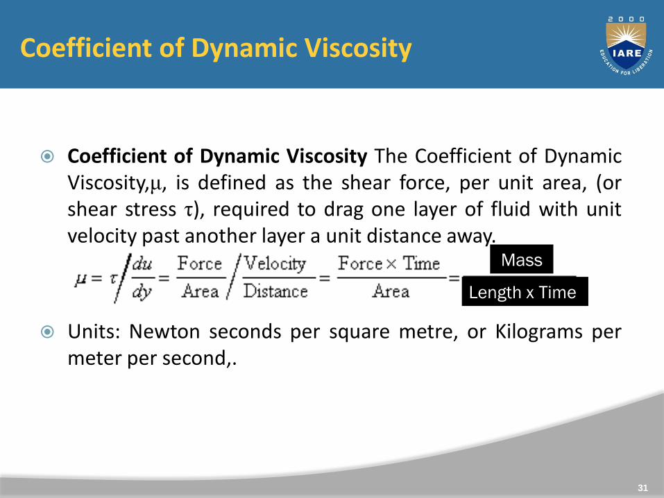
Coefficient of Dynamic Viscosity The Coefficient of DynamicViscosity,μ, is defined as the shear force, per unit area, (orshear stress τ), required to drag one layer of fluid with unitvelocity past another layer a unit distance away.
Units: Newton seconds per square metre, or Kilograms permeter per second,.
31
Length x Time
Mass
(Although note that is often expressed in Poise, P, where 10 P =1kgm-1s-1.)
Typical values:
Water =1.14x10⁻³ kgm-1s-1,
Air =1.78x 10⁻⁵kgm-1s-1,
Mercury=1.552kgm-1s-1 ,Paraffin Oil =1.9kgm-1s-1 .
32
Kinematic Viscosity
Kinematic Viscosity :Kinematic Viscosity, ʋ , is defined as theratio of dynamic viscosity to mass density.
Units: square metres per second, m2s-1
(Although note that ʋ is often expressed in Stokes, St,where 104 St = 1m2s-1.)
Dimensions: L2T-1.
33
Typical values:
Water =1.14 10-6 m2s-1
Air =1.46 10-5 m2s-1
Mercury =1.145 10-4 m2s-1
Paraffin Oil =2.375 10-3 m2s-1
34
35
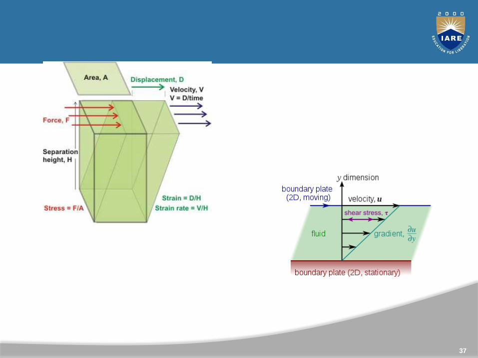
A fluid is a substance, which deforms continuously, or flows,when subjected to shearing force
In fact if a shear stress is acting on a fluid it will flow and if afluid is at rest there is no shear stress acting on it.
Fluid Flow Shear stress – Yes
Fluid Rest Shear stress – No
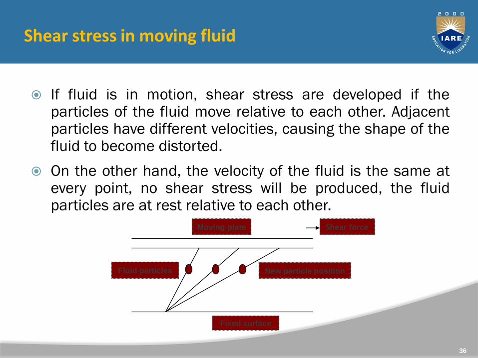
Shear stress in moving fluid
If fluid is in motion, shear stress are developed if theparticles of the fluid move relative to each other. Adjacentparticles have different velocities, causing the shape of thefluid to become distorted.
On the other hand, the velocity of the fluid is the same atevery point, no shear stress will be produced, the fluidparticles are at rest relative to each other.
36
Moving plate Shear force
Fluid particles New particle position
Fixed surface
37
38
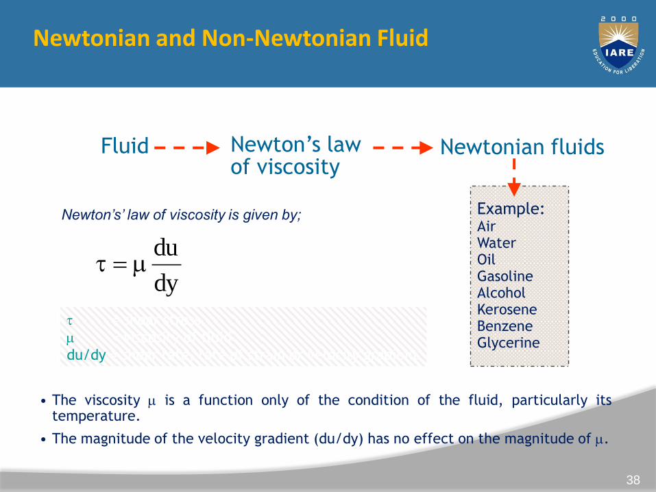
Example:AirWaterOilGasolineAlcoholKeroseneBenzeneGlycerine
Fluid Newton’s lawof viscosity
Newtonian fluids obey refer
Newton’s’ law of viscosity is given by;
dy
du (1.1)
• The viscosity is a function only of the condition of the fluid, particularly itstemperature.
• The magnitude of the velocity gradient (du/dy) has no effect on the magnitude of .
= shear stress
= viscosity of fluid
du/dy = shear rate, rate of strain or velocity gradient
Newtonian and Non-Newtonian Fluid
39
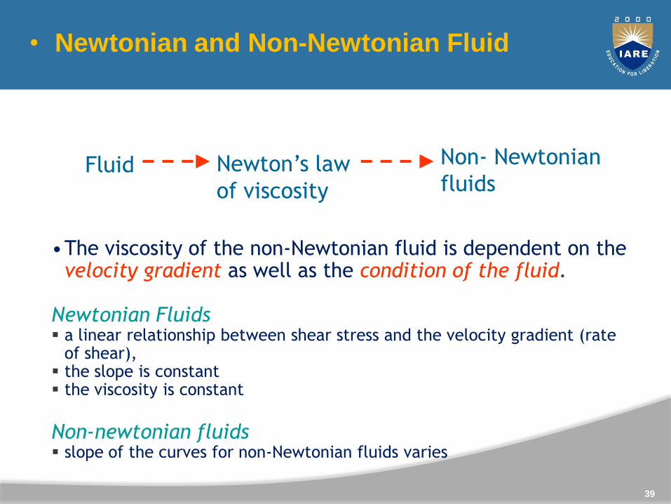
Fluid Newton’s law
of viscosity
Non- Newtonian
fluids
Do not obey
•The viscosity of the non-Newtonian fluid is dependent on the velocity gradient as well as the condition of the fluid.
Newtonian Fluids a linear relationship between shear stress and the velocity gradient (rate
of shear), the slope is constant the viscosity is constant
Non-newtonian fluids slope of the curves for non-Newtonian fluids varies
• Newtonian and Non-Newtonian Fluid
40
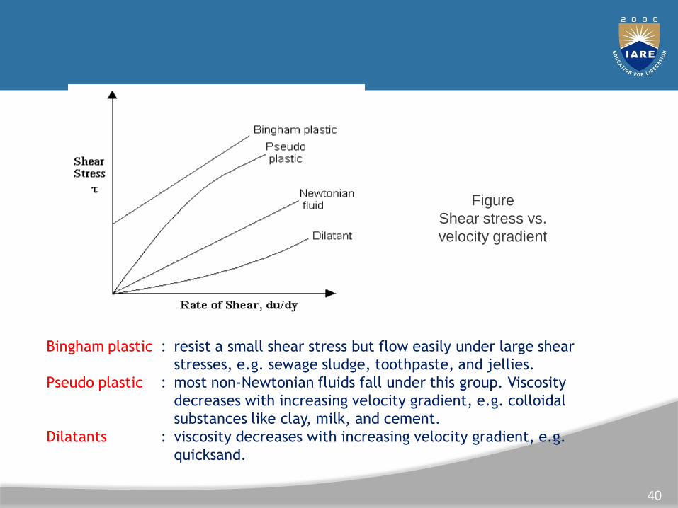
Figure
Shear stress vs.
velocity gradient
Bingham plastic : resist a small shear stress but flow easily under large shear
stresses, e.g. sewage sludge, toothpaste, and jellies.
Pseudo plastic : most non-Newtonian fluids fall under this group. Viscosity
decreases with increasing velocity gradient, e.g. colloidal
substances like clay, milk, and cement.
Dilatants : viscosity decreases with increasing velocity gradient, e.g.
quicksand.
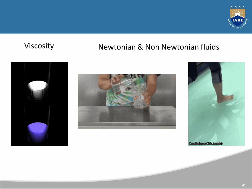
Viscosity Newtonian & Non Newtonian fluids
41
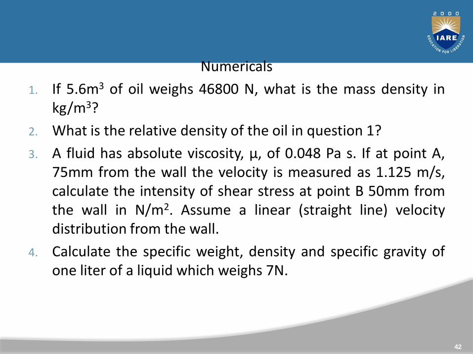
Numericals
1. If 5.6m3 of oil weighs 46800 N, what is the mass density inkg/m3?
2. What is the relative density of the oil in question 1?
3. A fluid has absolute viscosity, μ, of 0.048 Pa s. If at point A,75mm from the wall the velocity is measured as 1.125 m/s,calculate the intensity of shear stress at point B 50mm fromthe wall in N/m2. Assume a linear (straight line) velocitydistribution from the wall.
4. Calculate the specific weight, density and specific gravity ofone liter of a liquid which weighs 7N.
42
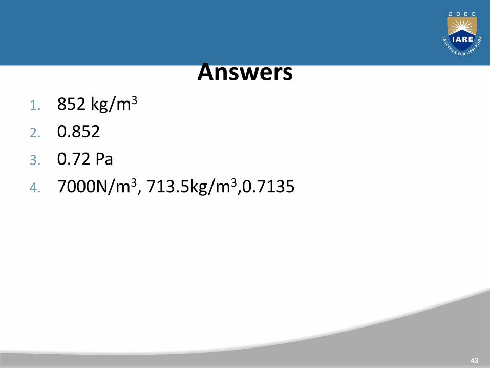
Answers1. 852 kg/m3
2. 0.852
3. 0.72 Pa
4. 7000N/m3, 713.5kg/m3,0.7135
43
Surface Tension, Capillarity, Bulk Modulus (Compressibility)
44
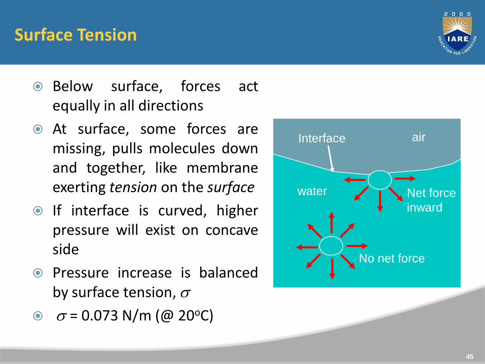
Surface Tension
Below surface, forces actequally in all directions
At surface, some forces aremissing, pulls molecules downand together, like membraneexerting tension on the surface
If interface is curved, higherpressure will exist on concaveside
Pressure increase is balancedby surface tension, s
s = 0.073 N/m (@ 20oC)
water
air
No net force
Net force
inward
Interface
45
Surface Tension
● Molecular attraction forces in liquids:
– Cohesion: enables liquid to resist tensile stress
– Adhesion: enables liquid to adhere to another body
● Liquid-fluid interfaces:
– Liquid-gas interface: free surface
– Liquid-liquid (immiscible) interface
● At these interfaces, out-of-balance attraction forces forms imaginary surface film that exerts a tension force in the surface » surface tension
● Computed as a force per unit length
46
● Surface tension of various liquids
– Cover a wide range
– Decrease slightly with increasing temperature
● Values of surface tension for water between freezing and boiling points
– 0.00518 to 0.00404 lb/ft or 0.0756 to 0.0589 N/m
47
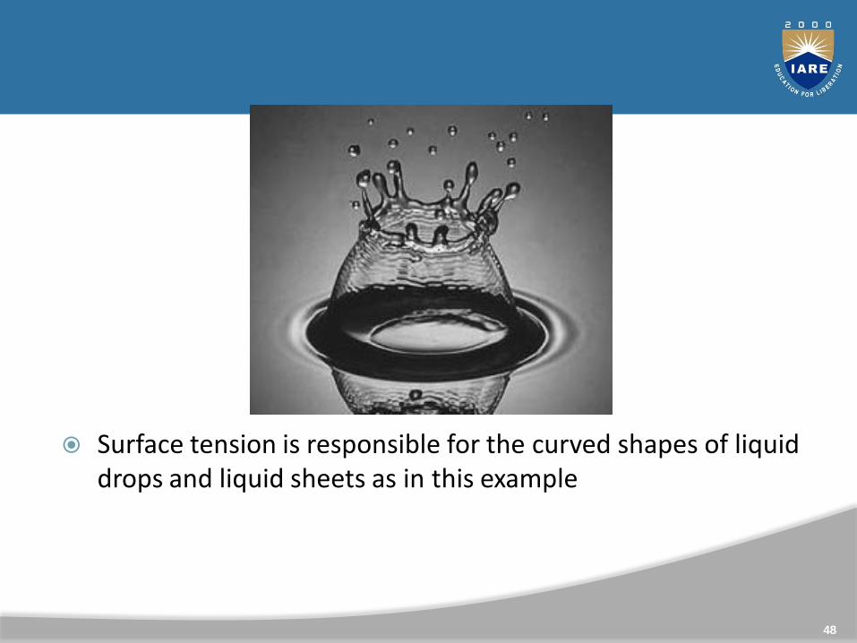
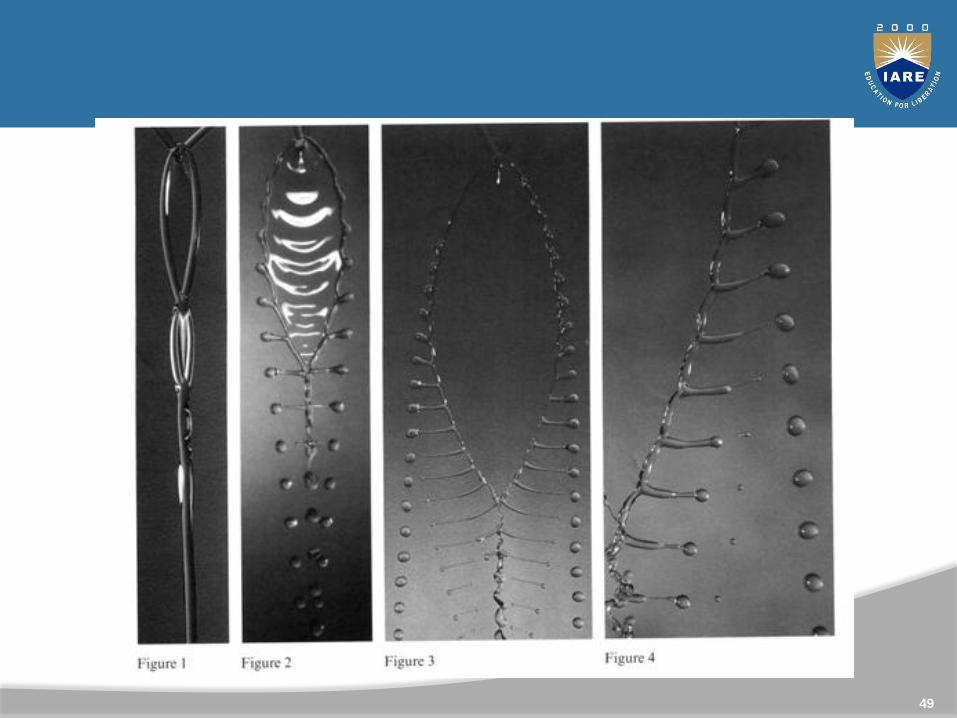
Surface tension is responsible for the curved shapes of liquid drops and liquid sheets as in this example
48
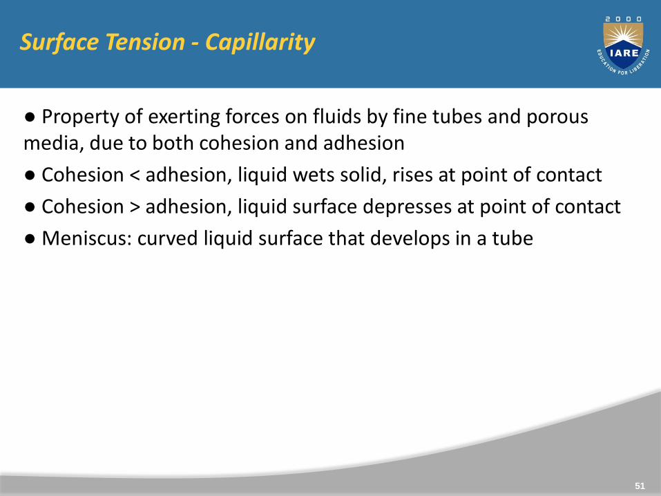
Surface Tension - Capillarity
● Property of exerting forces on fluids by fine tubes and porous media, due to both cohesion and adhesion
● Cohesion < adhesion, liquid wets solid, rises at point of contact
● Cohesion > adhesion, liquid surface depresses at point of contact
● Meniscus: curved liquid surface that develops in a tube
51
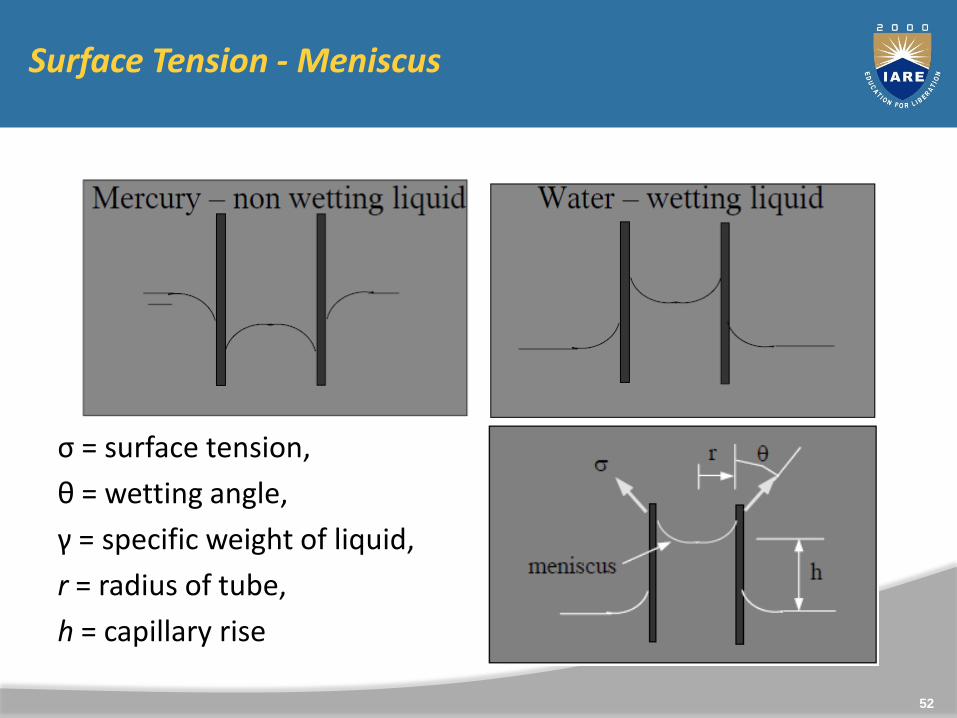
Surface Tension - Meniscus
ς = surface tension,
θ = wetting angle,
γ = specific weight of liquid,
r = radius of tube,
h = capillary rise
52
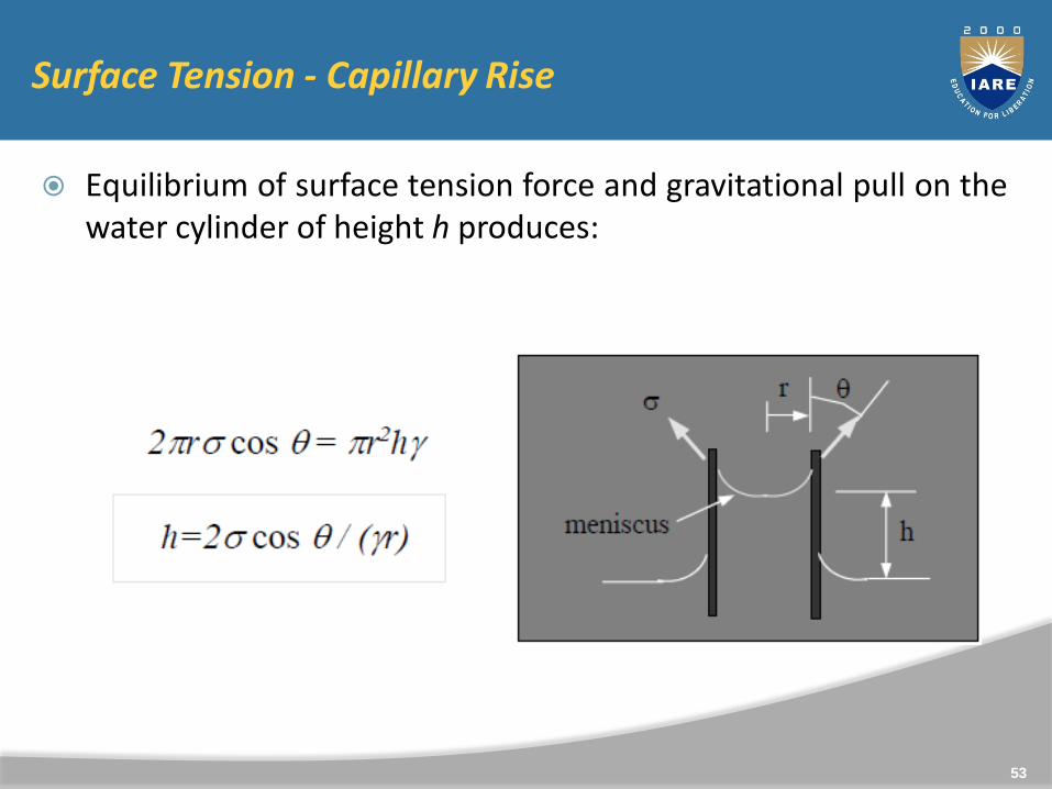
Surface Tension - Capillary Rise
Equilibrium of surface tension force and gravitational pull on thewater cylinder of height h produces:
53

Surface Tension
● Expression in previous slide calculates the approximate capillaryrise in a small tube
● The meniscus lifts a small amount of liquid near the tube walls, asr increases this amount may become significant
● Thus, the equation developed overestimates the amount ofcapillary rise or depression, particularly for large r.
● For a clean tube, θ = 0o for water, θ = 140o for mercury
● For r > ¼ in (6 mm), capillarity is negligible
54
Surface Tension - Applications
● Its effects are negligible in most engineering situations.
● Important in problems involving capillary rise, e.g., soil water zone, water supply to plants
● When small tubes are used for measuring properties, e.g., pressure, account must be made for capillarity
● Surface tension important in:
– Small models in hydraulic model studies
– Break up of liquid jets
– Formation of drops and bubbles
55
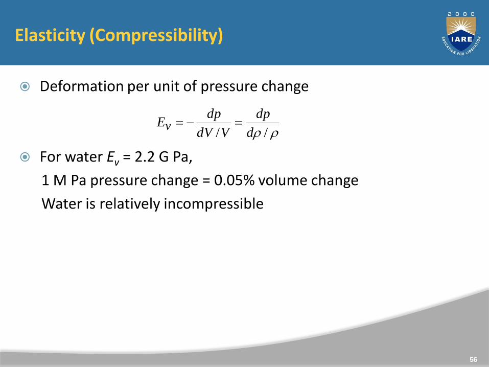
Elasticity (Compressibility)
Deformation per unit of pressure change
For water Ev = 2.2 G Pa,
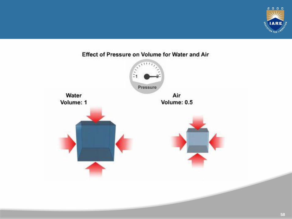
1 M Pa pressure change = 0.05% volume change
Water is relatively incompressible
// d
dp
VdV
dpEv
56
Compressibility
Compressibility is the fractional change in volume per unitincrease in pressure. For each atmosphere increase in pressure,the volume of water would decrease 46.4 parts per million. Thecompressibility k is the reciprocal of the Bulk modulus, B.
57
58
Numerical
Determine the viscosity of a liquid having kinematic viscosity6 stokes and specific gravity 1.9.
The velocity distribution for flow over a flat plate is given by u= 3/4y – y2 in which u is the velocity in metre per second at adistance y metre above the plate. Determine the shear stressat y = 0.15 m. Take Dynamic viscosity of fluid as 8.6 poise.
If the velocity profile of a fluid over a plate is a parabolic withthe vertex 20cm from the plate, where the velocity is120cm/sec. Calculate the velocity gradients and shearstresses at a distance of 0, 10 and 20 cm from the plate, if theviscosity of the fluid is 8.5 poise.
59
Answers
11.40 poise
0.3825 N/m2
10.2 N/m2 ; 5.1 N/m2, 0 N/m2
60
Numerical
Determine the bulk modulus of elasticity of a liquid, ifpressure of the liquid is increased from 70 N/cm2 to 130N/cm2. The volume of the liquid decreases by 0.15 percent.
The surface tension of water in contact with air at 20oC is0.0725 N/m. The pressure inside a droplet of water is to be0.02 N/cm2 greater than the outside pressure. Calculate thediameter of the droplet of water.
Find the surface tension in a soap bubble of 40mm diameterwhen the inside pressure is 2.5 N/m2 above atmosphericpressure.
61
4x 10⁴ N/cm2
1.45 mm
0.0125 N/m
62
Numerical
Calculate the capillary rise in a glass tube of 2.5 mm diameterwhen immersed vertically in a (a) water and (b) mercury. Takesurface tension σ = 0.0725 N/m for water and ς = 0.52 N/m formercury in contact with air. The specific gravity for mercury is13.6 and angle of contact = 130o.
Find out the minimum size of glass tube that can be used tomeasure water level if the capillarity rise in the tube is to berestricted to 2mm. Consider surface tension of water in contactwith air as 0.073575 N/m.
63
Answers
1.18cm ; -0.4cm
1.5cm
64
1. Determine the absolute pressure in Pa at a depth of 6mbelow the free surface of a tank of water when a barometerreads 760mm mercury (relative density 13.57)
2. Determine the pressure in bar at a depth of 10m in oil ofrelative density 0.750.
3. What depth of oil (in m), relative density 0.75, will give agauge pressure of 275000 Pa.
Answers
1. 160 032 N/m2
2. 0.736bar
3. 37.38m
65

Viscosity
Viscosity is defined as the property ofa fluid which offers resistance to themovement of one layer of fluid overanother adjacent layer of the fluid.
Viscosity is also defined as the shearstress required to produce unit rateof shear strain.
Units of viscosity are(SI) Ns/m2.
66
Density and Buoyant Force
The buoyant force is the upward force exerted by a liquid on anobject immersed in or floating on the liquid.
Buoyant forces can keep objects afloat.
67
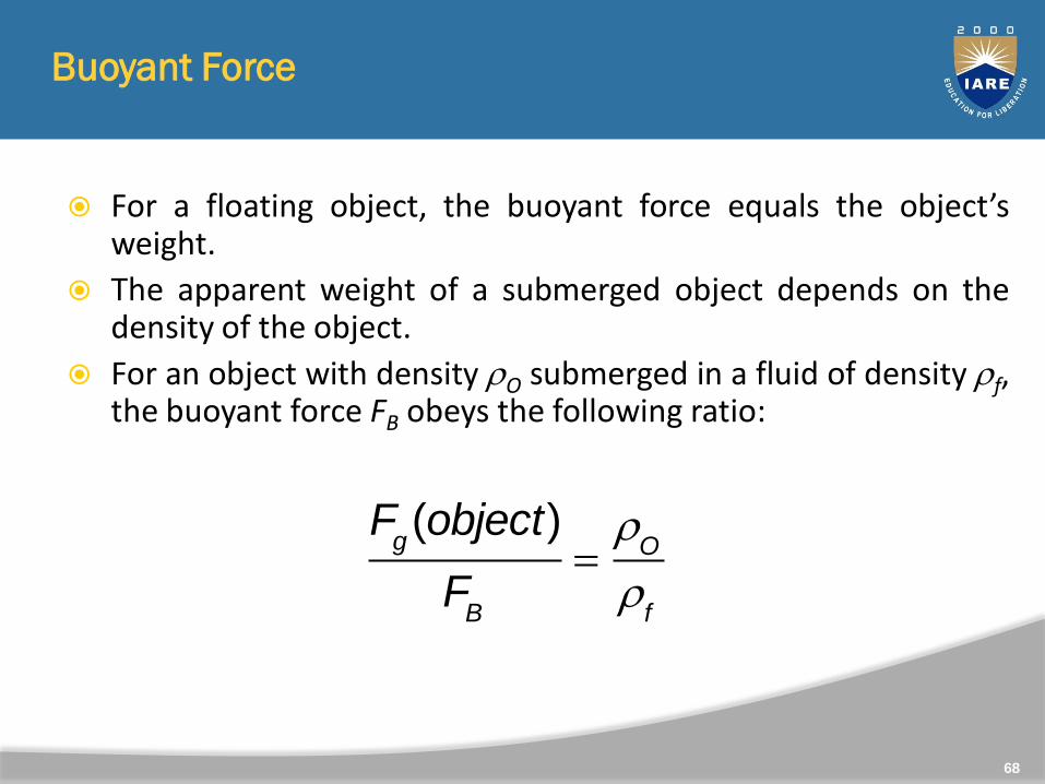
Buoyant Force
For a floating object, the buoyant force equals the object’sweight.
The apparent weight of a submerged object depends on thedensity of the object.
For an object with density O submerged in a fluid of density f,the buoyant force FB obeys the following ratio:
Fg(object)
FB
O
f
68
69
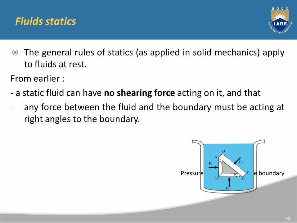
Fluids statics
The general rules of statics (as applied in solid mechanics) applyto fluids at rest.
From earlier :
- a static fluid can have no shearing force acting on it, and that
- any force between the fluid and the boundary must be acting atright angles to the boundary.
Pressure force normal to the boundary
70
Pressure
Deep sea divers wear atmospheric diving suits to resist theforces exerted by the water in the depths of the ocean.
You experience this pressure when you dive to the bottom of apool, drive up a mountain, or fly in a plane.
71
Pressure
Pressure is the magnitude of the force on a surface per unit area.
Pascal’s principle states that pressure applied to a fluid in a closed container is transmitted equally to every point of the fluid and to the walls of the container.
P F
A
pressure = force
area
72
The SI unit for pressure is the pascal, Pa.
It is equal to 1 N/m2.
The pressure at sea level is about 1.01 x 10⁵ Pa.
This gives us another unit for pressure, the atmosphere, where 1 atm = 1.01 x 10⁵ Pa
73

Pascal’s Principle
When you pump a bike tire, you apply force on the pump that inturn exerts a force on the air inside the tire.
The air responds by pushing not only on the pump but alsoagainst the walls of the tire.
As a result, the pressure increases by an equal amountthroughout the tire.
74
Pascal’s Principle
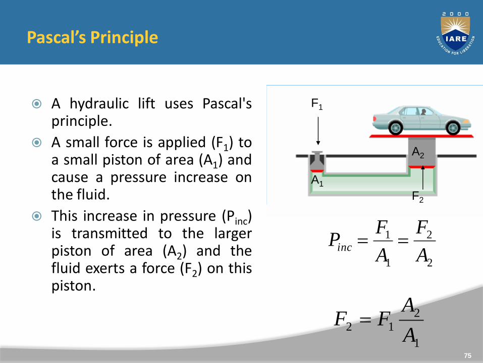
A hydraulic lift uses Pascal'sprinciple.
A small force is applied (F1) toa small piston of area (A1) andcause a pressure increase onthe fluid.
This increase in pressure (Pinc)is transmitted to the largerpiston of area (A2) and thefluid exerts a force (F2) on thispiston.
F1
F2
A1
A2
2
2
1
1
A
F
A
FPinc
1
212
A
AFF
75
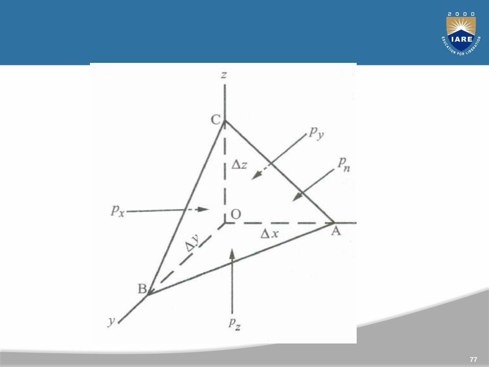
Pascal’s Law: Pascal’s law states the pressure intensity at a point, in a static fluid, is equal in all directions. It can be proved in the following way.
Consider a tetrahedron of sides Δx, Δy and Δz inside a shown in fig. Let ‘O’ a point inside the fluid be the origin.
Let area ABC = ΔA and pressure on ΔA equal to pn. The weightof a fluid element in the tetrahedron = (γ. Δx. Δy. Δz)/6.
The weight is proportional to the third order of magnitude ofvery small quantities like Δx, Δy, Δz, whereas the pressure forcesare proportional to the second order of magnitude.
Hence the weight can be neglected in comparison to thepressures when Δx, Δy, Δz, tend to zero. Since the element is instatic condition, the net forces in the x, y and z directions arezero.
76
77
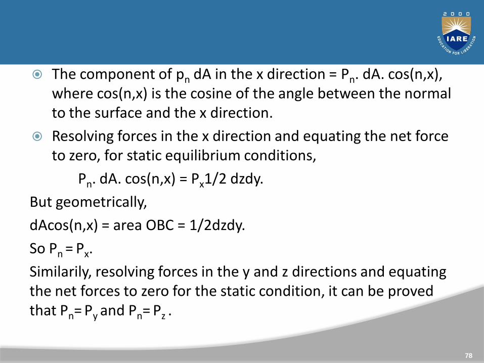
The component of pn dA in the x direction = Pn. dA. cos(n,x), where cos(n,x) is the cosine of the angle between the normal to the surface and the x direction.
Resolving forces in the x direction and equating the net force to zero, for static equilibrium conditions,
Pn. dA. cos(n,x) = Px1/2 dzdy.
But geometrically,
dAcos(n,x) = area OBC = 1/2dzdy.
So Pn = Px.
Similarily, resolving forces in the y and z directions and equating the net forces to zero for the static condition, it can be proved that Pn= Py and Pn= Pz .
78
79
Hydro static Law
A Hydrostatics Law state that rate of increase of pressure in a vertically downward direction in fluid/liquid is equal to weight density of the liquid.
80
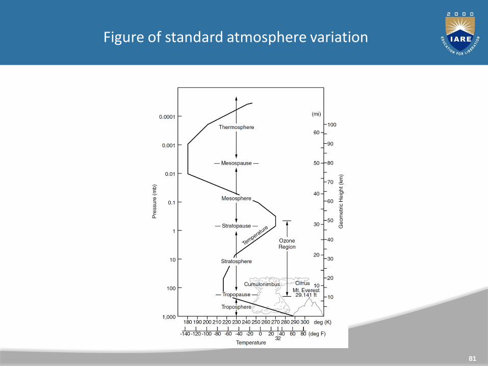
Figure of standard atmosphere variation
81
Mathematical Model– The standard atmosphere defines the temperature variation
with altitude as shown
– Now need to find pressure and density as functions of either T or h
– Begin with the hydrostatic equation, divided by the equation of state for a perfect gas
dp / p=godh/RT
– Can integrate this equation for pressure when we know the P relationship between T and h
82
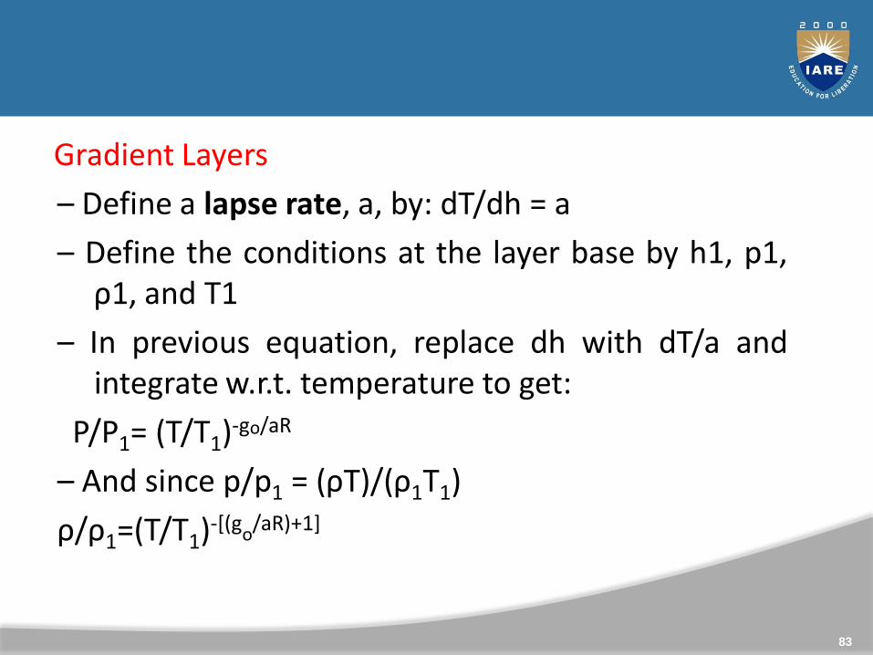
Gradient Layers, T varies linearly with h
– Define a lapse rate, a, by: dT/dh = a
– Define the conditions at the layer base by h1, p1,ρ1, and T1
– In previous equation, replace dh with dT/a andintegrate w.r.t. temperature to get:
P/P1= (T/T1)-go/aR
– And since p/p1 = (ρT)/(ρ1T1)
ρ/ρ1=(T/T1)-[(go/aR)+1]
83
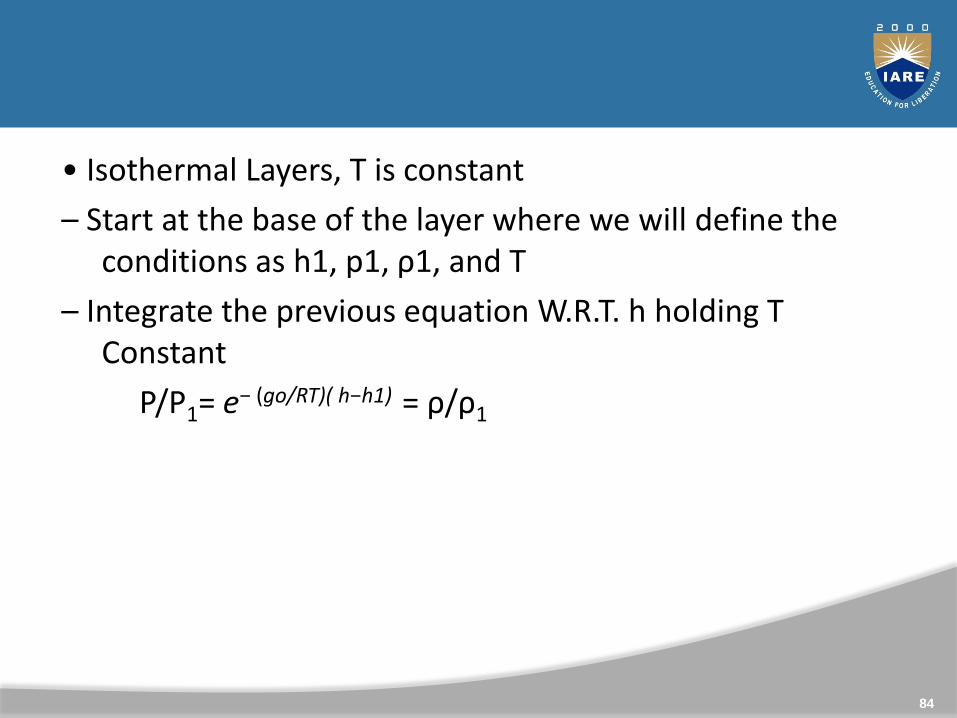
• Isothermal Layers, T is constant
– Start at the base of the layer where we will define the conditions as h1, p1, ρ1, and T
– Integrate the previous equation W.R.T. h holding T Constant
P/P1= e− (go/RT)( h−h1) = ρ/ρ1
84
Variation of Pressure Vertically In A Fluid Under Gravity
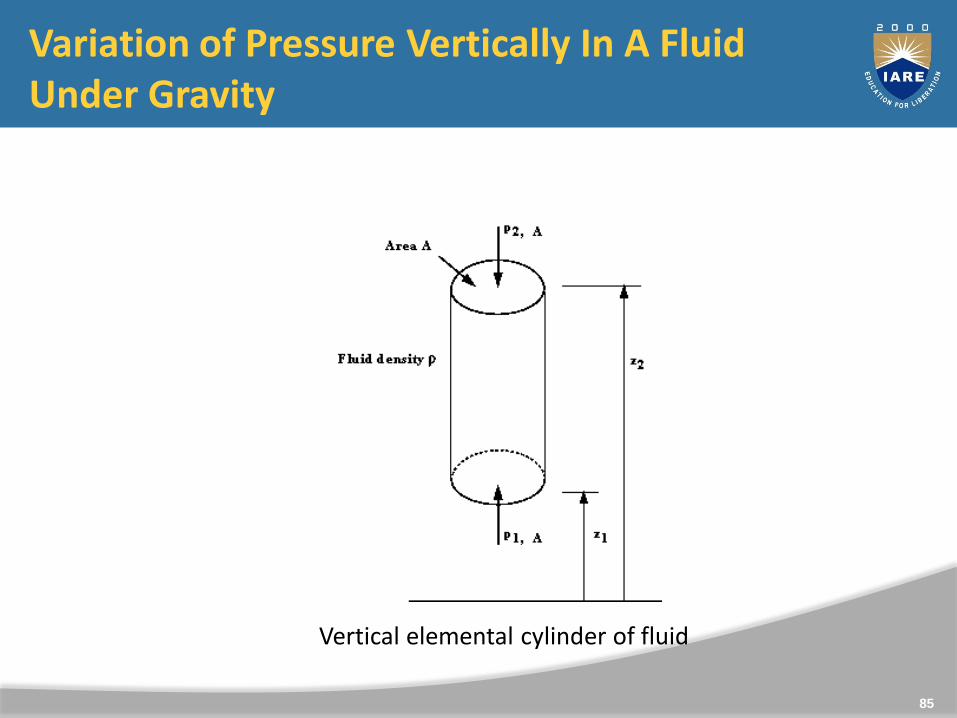
Vertical elemental cylinder of fluid
85
In the previous slide figure we can see an element of fluidwhich is a vertical column of constant cross sectional area, A,surrounded by the same fluid of mass density ρ.
The pressure at the bottom of the cylinder is p1 at level z1 ,and at the top is p2 at level z2.
The fluid is at rest and in equilibrium so all the forces in thevertical direction sum to zero. i.e. we have
Force due to p1 on A (upward) = p1 A
Force due to p2 on A (downward) = p2 A
Force due to weight of element (downward) mg
ρgA(z2-z1) mass density volume
86
Taking upward as positive, in equilibrium we have
p1 A - p2 A = ρgA(z2 - z1)
p2 - p1 = - ρgA(z2 - z1)
Thus in a fluid under gravity, pressure decreases with increase in height
z= (z2 - z1)
87
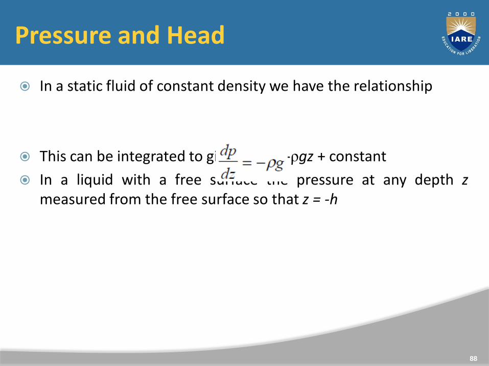
Pressure and Head
In a static fluid of constant density we have the relationship
This can be integrated to give p = -ρgz + constant
In a liquid with a free surface the pressure at any depth zmeasured from the free surface so that z = -h
88
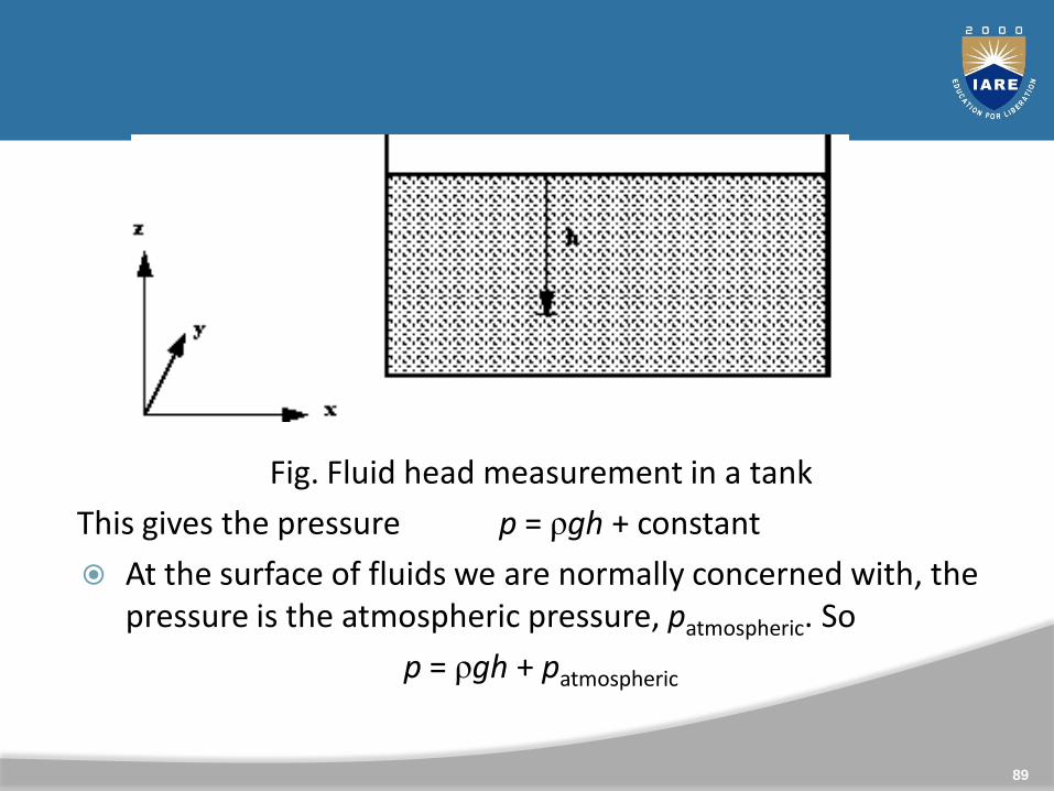
Fig. Fluid head measurement in a tank
This gives the pressure p = ρgh + constant
At the surface of fluids we are normally concerned with, the pressure is the atmospheric pressure, patmospheric. So
p = ρgh + patmospheric
89
As we live constantly under the pressure of the atmosphere,and everything else exists under this pressure, it isconvenient (and often done) to take atmospheric pressure asthe datum. So we quote pressure as above or belowatmospheric.
Pressure quoted in this way is known as gauge pressure i.e.
Gauge pressure is p = ρgh
The lower limit of any pressure is zero - that is the pressure ina perfect vacuum. Pressure measured above this datum isknown as absolute pressure i.e.
Absolute pressure is p= ρgh + p absolute atmospheric
Absolute pressure = Gauge pressure + Atmospheric pressure
90
As g is (approximately) constant, the gauge pressure can begiven by stating the vertical height of any fluid of density ρ
which is equal to this pressure.
p = ρgh
This vertical height is known as head of fluid.
Note: If pressure is quoted in head, the density of the fluid must also be given.
91

Problem:
92
Simple and Differential Manometers
Manometer: manometers are defined as the devices used formeasuring the pressure at a point in the fluid by balancing thecolumn of fluid by the same or another column of the fluid.
They are classified as
1.Simple manometer 2.Differential manometer
Simple manometer: simple manometer consist of a glass tubehaving one of its ends connected to a point where pressure is tobe measured and other end remains open to atmosphere.
Differential manometer: these are the devices used for measuringthe difference of pressures between two points in a pipe or intwo different pipes.
93
Pressure Measurement By Manometer
The relationship between pressure and head is used to measurepressure with a manometer (also know as a liquid gauge).
1. Piezometer
2. U-tube Manometer
3. Single Column Manometer
94
The Piezometer Tube Manometer
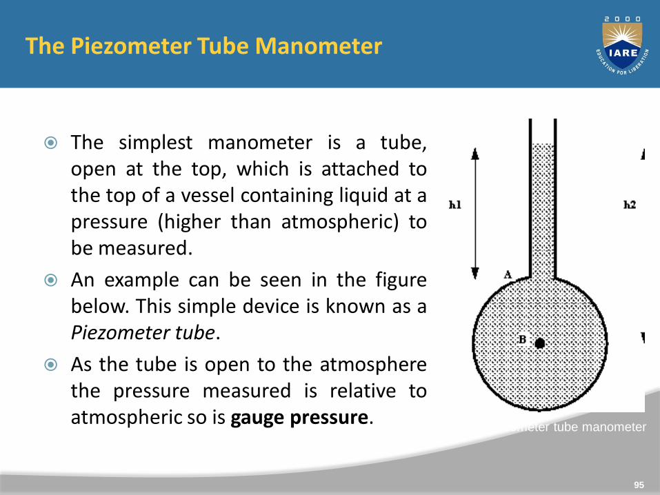
The simplest manometer is a tube,open at the top, which is attached tothe top of a vessel containing liquid at apressure (higher than atmospheric) tobe measured.
An example can be seen in the figurebelow. This simple device is known as aPiezometer tube.
As the tube is open to the atmospherethe pressure measured is relative toatmospheric so is gauge pressure.
95
A simple piezometer tube manometer

Pressure at A = pressure due to column of liquid above A
pA= ρgh1
Pressure at B = pressure due to column of liquid above B
pB= ρgh2
This method can only be used for liquids (i.e. not for gases) and only when the liquid height is convenient to measure.
96
The “U”-Tube Manometer
Using a “U”-Tube enables the pressure of both liquids and gasesto be measured with the same instrument.
The “U” is connected as in the figure and filled with a fluid calledthe manometric fluid.
The fluid whose pressure is being measured should have a massdensity less than that of the manometric fluid and the two fluidsshould not be able to mix readily - that is, they must beimmiscible.
97
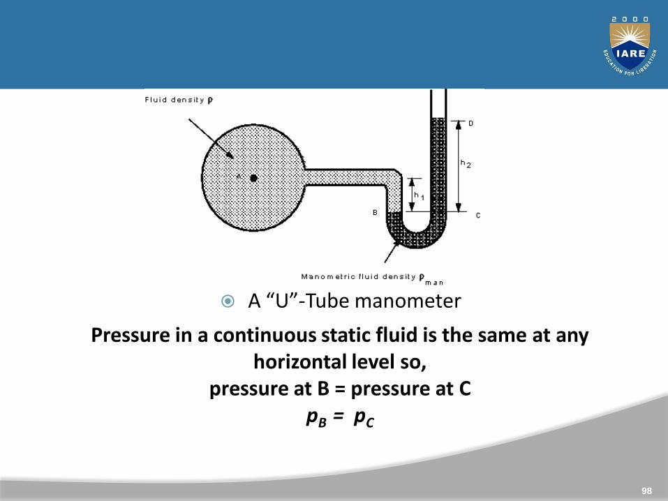
Pressure in a continuous static fluid is the same at any horizontal level so,
pressure at B = pressure at CpB = pC
A “U”-Tube manometer
98
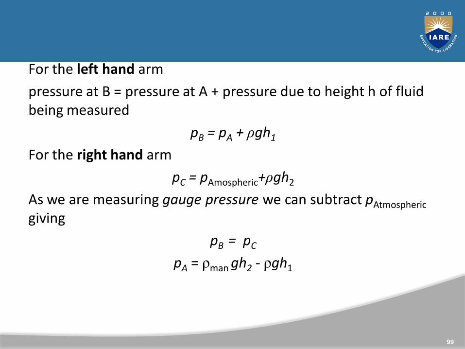
For the left hand arm
pressure at B = pressure at A + pressure due to height h of fluid being measured
pB = pA + ρgh1
For the right hand arm
pC = pAmospheric+ρgh2
As we are measuring gauge pressure we can subtract pAtmospheric
giving
pB = pC
pA = ρman gh2 - ρgh1
99
If the fluid being measured is a gas, the density will probably bevery low in comparison to the density of the manometric fluidi.e. ρman >> ρ.
In this case the term ρgh1 can be neglected, and the gaugepressure given by
pA = ρman gh2
100
Single Column Manometer
Modified form of a U Tube manometer in which a reservoir,having a large cross-sectional area (about 100 times) ascompared to tube. Due to large cross-sectional area of thereservoir, the change in the liquid level in this reservoir isnegligible and the reading in the limb is taken as thepressure. The limb may be vertical or inclined
When the fluid starts flowing in the pipe, the mercury level inthe reservoir goes down by a very small amount whichcauses a large rise in the right limb.
101
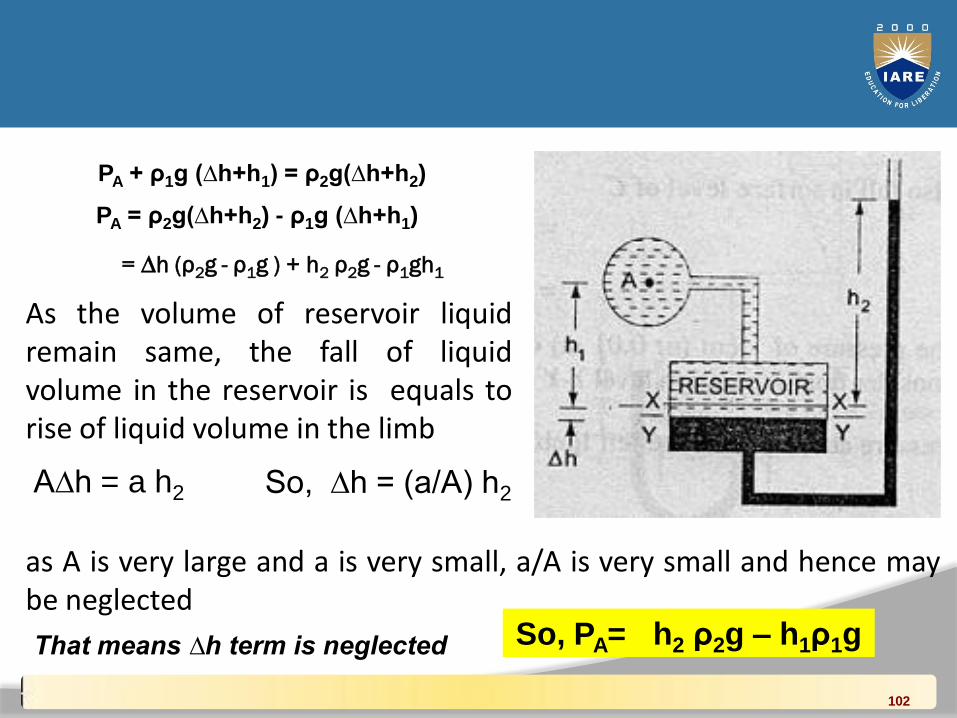
= ∆h (ρ2g - ρ1g ) + h2 ρ2g - ρ1gh1
PA + ρ1g (∆h+h1) = ρ2g(∆h+h2)
PA = ρ2g(∆h+h2) - ρ1g (∆h+h1)
As the volume of reservoir liquidremain same, the fall of liquidvolume in the reservoir is equals torise of liquid volume in the limb
A∆h = a h2 So, ∆h = (a/A) h2
as A is very large and a is very small, a/A is very small and hence maybe neglected
That means ∆h term is neglected So, PA= h2 ρ2g – h1ρ1g
102
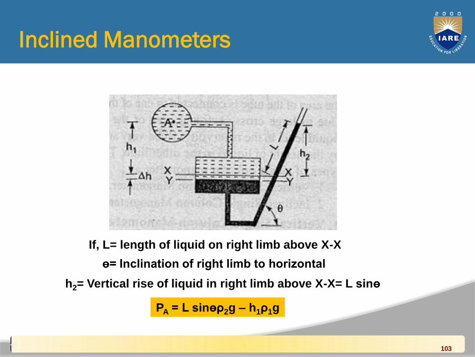
PA= h2 ρ2g – h1ρ1g becomePA = L sinөρ2g – h1ρ1g
If, L= length of liquid on right limb above X-X
ө= Inclination of right limb to horizontal
h2= Vertical rise of liquid in right limb above X-X= L sinө
Inclined Manometers
103
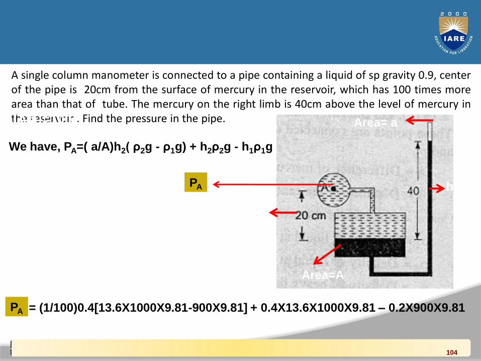
A single column manometer is connected to a pipe containing a liquid of sp gravity 0.9, centerof the pipe is 20cm from the surface of mercury in the reservoir, which has 100 times morearea than that of tube. The mercury on the right limb is 40cm above the level of mercury inthe reservoir . Find the pressure in the pipe.(A/a)=100
We have, PA=( a/A)h2( ρ2g - ρ1g) + h2ρ2g - h1ρ1g
= (1/100)0.4[13.6X1000X9.81-900X9.81] + 0.4X13.6X1000X9.81 – 0.2X900X9.81
= 5.21N/cm2
Area=A
Area= a
h2
h1PA
PA
104
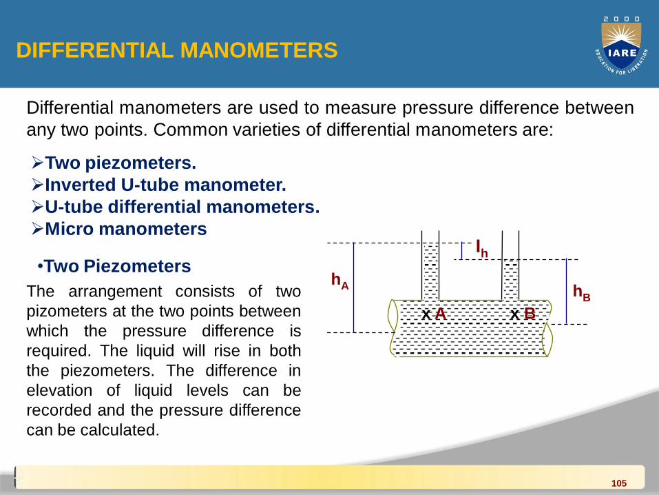
DIFFERENTIAL MANOMETERS
Differential manometers are used to measure pressure difference between
any two points. Common varieties of differential manometers are:
Two piezometers.
Inverted U-tube manometer.
U-tube differential manometers.
Micro manometers
•Two Piezometers
hB
Ih
hA
x A x B
The arrangement consists of two
pizometers at the two points between
which the pressure difference is
required. The liquid will rise in both
the piezometers. The difference in
elevation of liquid levels can be
recorded and the pressure difference
can be calculated.
105
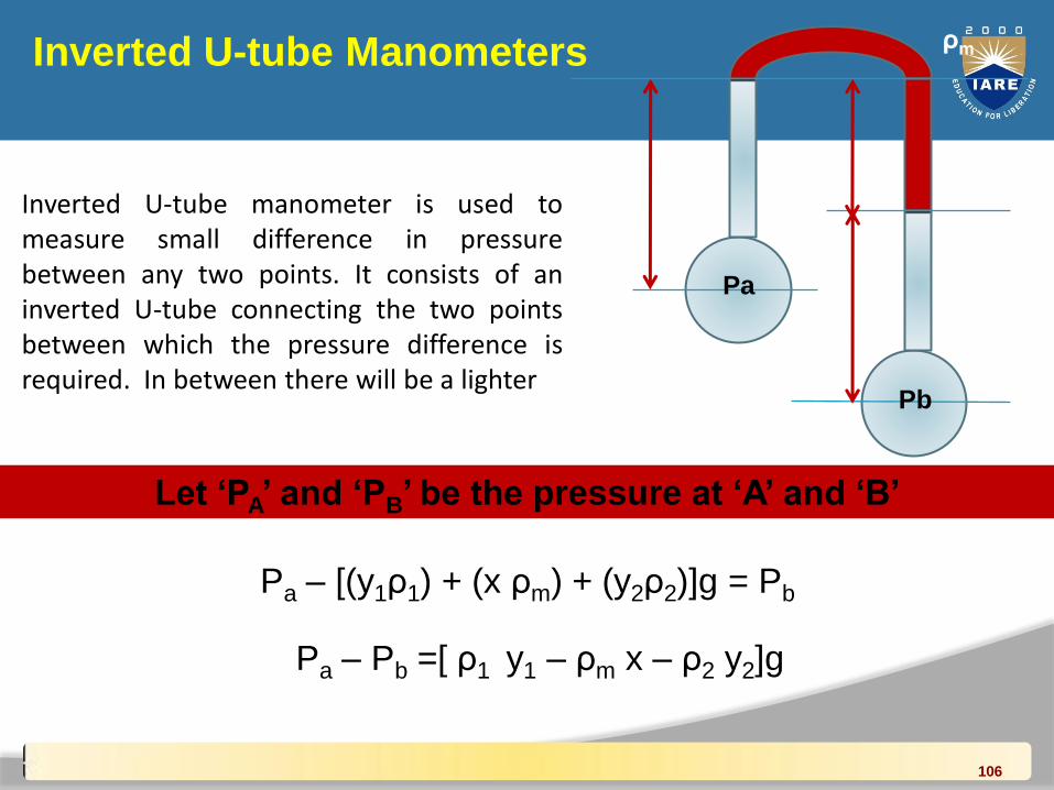
Inverted U-tube Manometers
Inverted U-tube manometer is used tomeasure small difference in pressurebetween any two points. It consists of aninverted U-tube connecting the two pointsbetween which the pressure difference isrequired. In between there will be a lighter
Let ‘PA’ and ‘PB’ be the pressure at ‘A’ and ‘B’
Pa – [(y1ρ1) + (x ρm) + (y2ρ2)]g = Pb
Pa – Pb =[ ρ1 y1 – ρm x – ρ2 y2]g
y1
y2
xρ1
ρ2
ρm
Pa
Pb
106
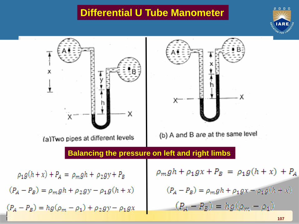
Differential U Tube Manometer
Balancing the pressure on left and right limbs
107
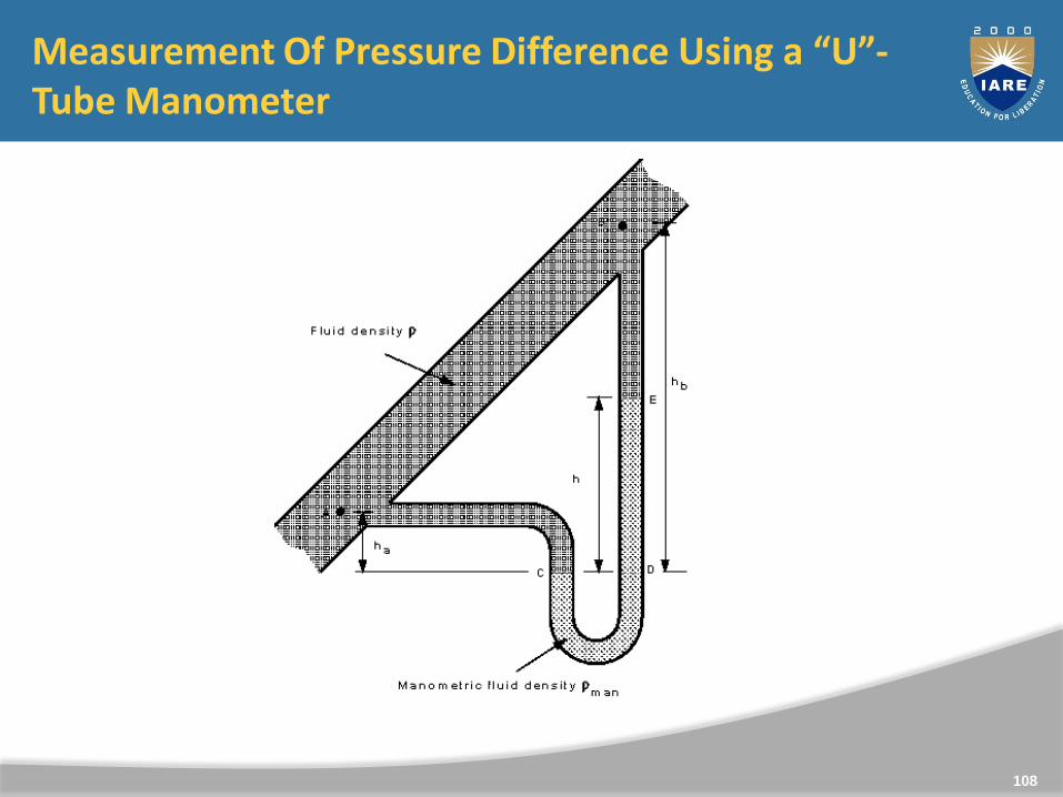
Measurement Of Pressure Difference Using a “U”-Tube Manometer
108
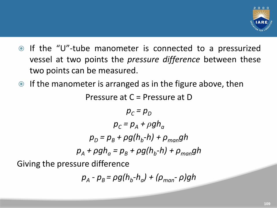
If the “U”-tube manometer is connected to a pressurizedvessel at two points the pressure difference between thesetwo points can be measured.
If the manometer is arranged as in the figure above, then
Pressure at C = Pressure at D
pC = pD
pC = pA + ρgha
pD = pB + ρg(hb-h) + ρmangh
pA + ρgha = pB + ρg(hb-h) + ρmangh
Giving the pressure difference
pA - pB = ρg(hb-ha) + (ρman- ρ)gh
109
Again, if the fluid whose pressure difference is being measuredis a gas and ρman >> ρ , then the terms involving ρ can beneglected, so
pA - pB = ρmangh
110
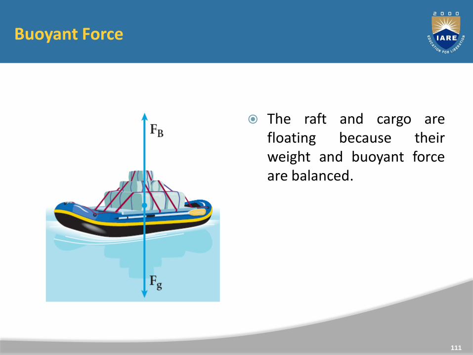
Buoyant Force
The raft and cargo arefloating because theirweight and buoyant forceare balanced.
111
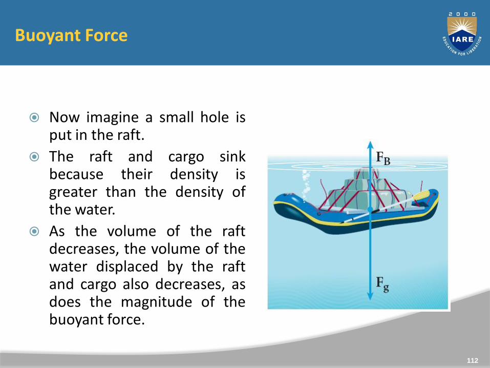
Buoyant Force
Now imagine a small hole isput in the raft.
The raft and cargo sinkbecause their density isgreater than the density ofthe water.
As the volume of the raftdecreases, the volume of thewater displaced by the raftand cargo also decreases, asdoes the magnitude of thebuoyant force.
112
Buoyant Force and Archimedes’ Principle
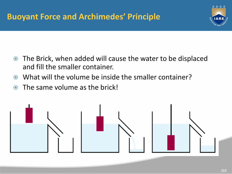
The Brick, when added will cause the water to be displaced and fill the smaller container.
What will the volume be inside the smaller container?
The same volume as the brick!
113
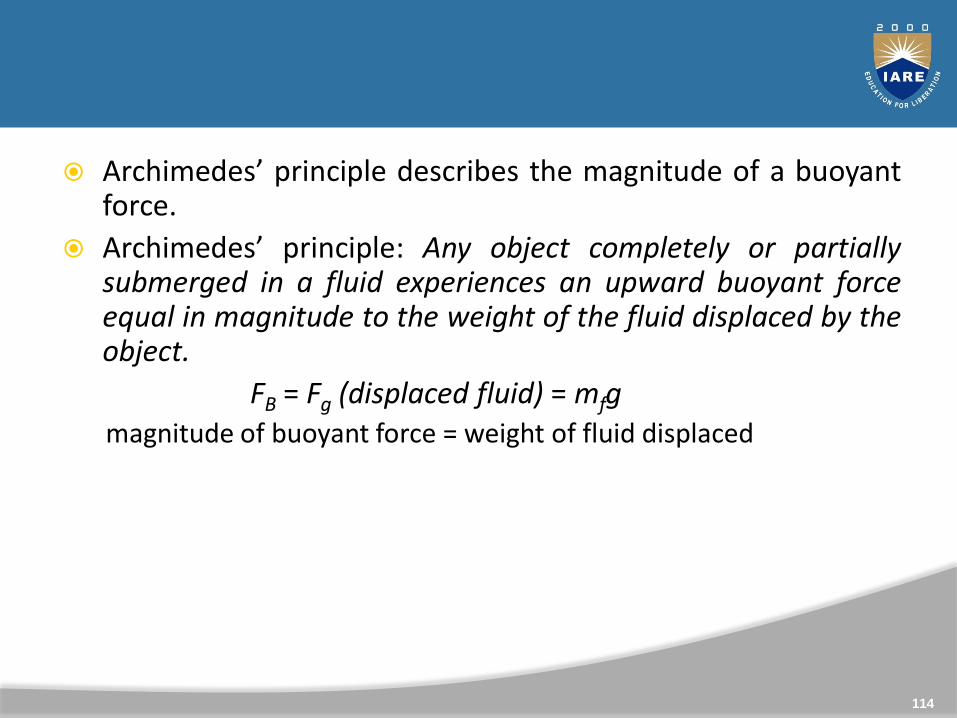
Archimedes’ principle describes the magnitude of a buoyantforce.
Archimedes’ principle: Any object completely or partiallysubmerged in a fluid experiences an upward buoyant forceequal in magnitude to the weight of the fluid displaced by theobject.
FB = Fg (displaced fluid) = mfgmagnitude of buoyant force = weight of fluid displaced
114
Buoyancy
Immersed Body in Static Fluid
115
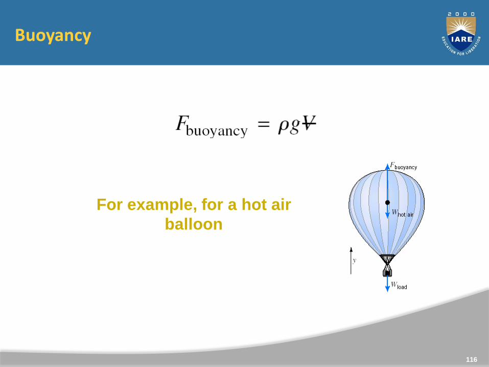
Buoyancy
For example, for a hot air
balloon
116

Archimedes’ Principle and Buoyancy
Why do some things float and other things sink ?
117
Buoyancy and Stability
Buoyancy is due to the fluid displaced by a body. FB=fgV.
Archimedes principle : The buoyant force = Weight of the fluiddisplaced by the body, and it acts through the centroid of thedisplaced volume.
118
Meta-center
Metacentre, also spelled metacenter, in fluid mechanics, thetheoretical point at which an imaginary vertical line passingthrough the centre of buoyancy and centre of gravity intersectsthe imaginary vertical line through a new centre of buoyancycreated when the body is displaced, or tipped, in the water,however little.
119
Meta centric height calculations
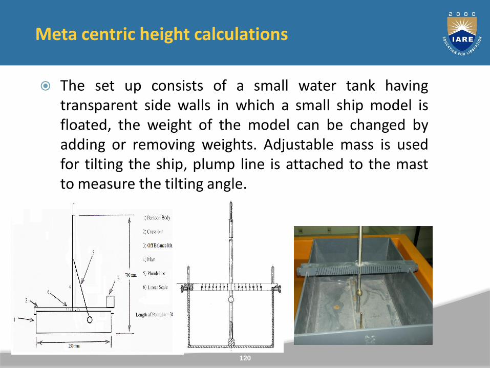
The set up consists of a small water tank havingtransparent side walls in which a small ship model isfloated, the weight of the model can be changed byadding or removing weights. Adjustable mass is usedfor tilting the ship, plump line is attached to the mastto measure the tilting angle.
120
Buoyancy and Stability
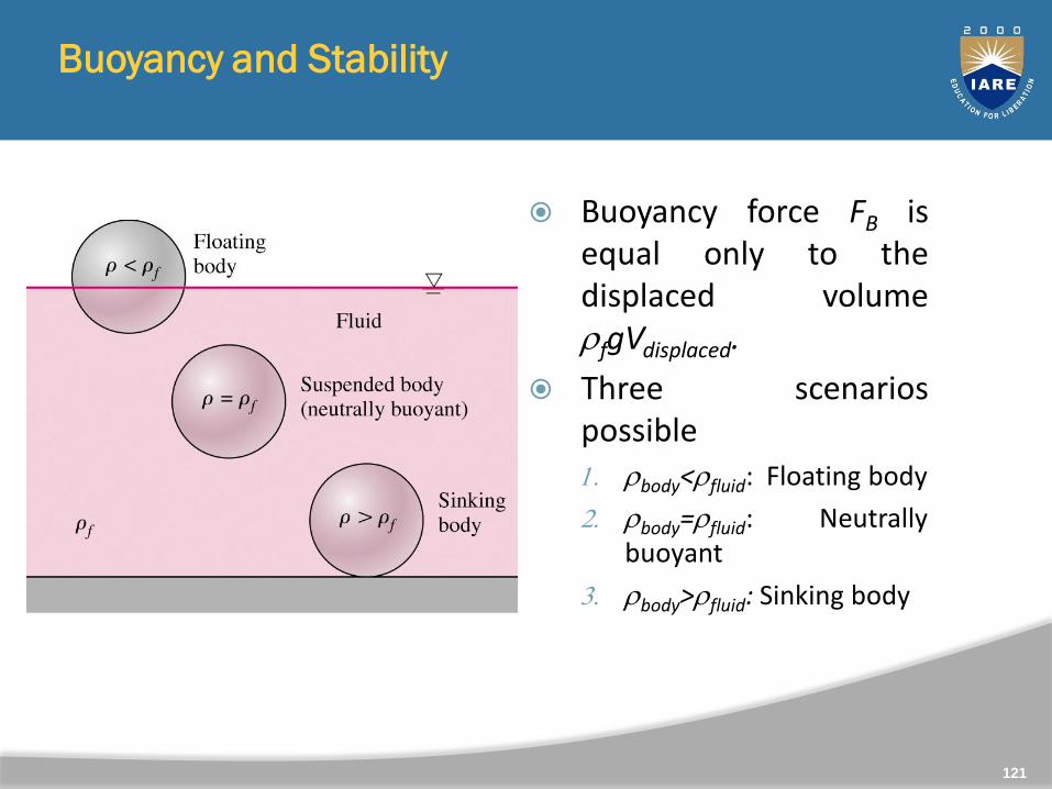
Buoyancy force FB isequal only to thedisplaced volumefgVdisplaced.
Three scenariospossible
1. body<fluid: Floating body
2. body=fluid: Neutrallybuoyant
3. body>fluid: Sinking body
121
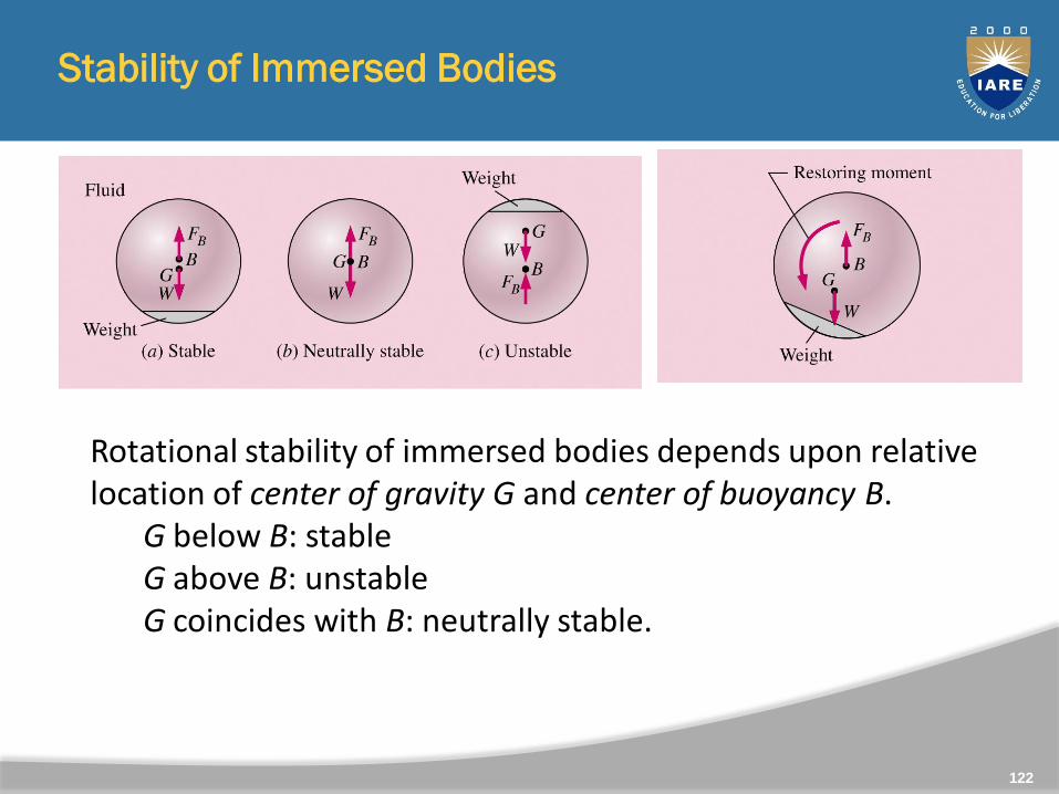
Stability of Immersed Bodies
122
Rotational stability of immersed bodies depends upon relative location of center of gravity G and center of buoyancy B.
G below B: stableG above B: unstable G coincides with B: neutrally stable.
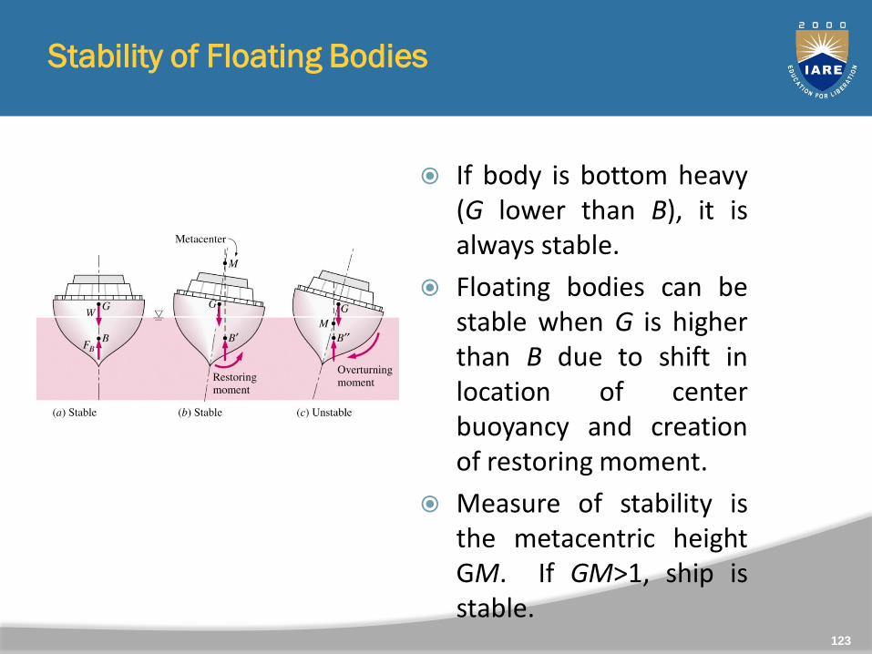
Stability of Floating Bodies
If body is bottom heavy(G lower than B), it isalways stable.
Floating bodies can bestable when G is higherthan B due to shift inlocation of centerbuoyancy and creationof restoring moment.
Measure of stability isthe metacentric heightGM. If GM>1, ship isstable.
123
Stability of Floating Bodies in Fluid
When the body undergoes an angular displacement about ahorizontal axis, the shape of the immersed volume changes andso the centre of buoyancy moves relative to the body.
As a result of above observation stable equilibrium can beachieved, under certain condition, even when G is above B.Figure illustrates a floating body -a boat, for example, in itsequilibrium position.
Let the new line of action of the buoyant force (which is alwaysvertical) through B' intersects the axis BG (the old vertical linecontaining the centre of gravity G and the old centre ofbuoyancy B) at M. For small values of q the point M is practicallyconstant in position and is known as metacentre
124
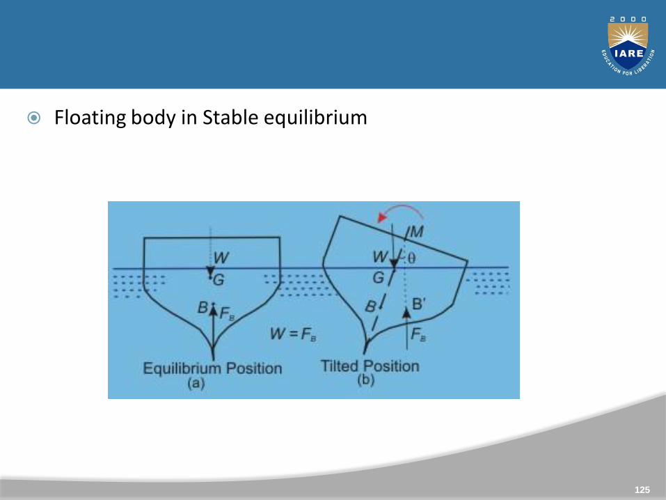
Floating body in Stable equilibrium
125

Important points
The force of buoyancy FB is equal to the weight of the body W
Centre of gravity G is above the centre of buoyancy in thesame vertical line.Figure b shows the situation after the body has undergone asmall angular displacement q with respect to the vertical axis.
The centre of gravity G remains unchanged relative to thebody (This is not always true for ships where some of thecargo may shift during an angular displacement).
During the movement, the volume immersed on the righthand side increases while that on the left hand sidedecreases. Therefore the centre of buoyancy moves towardsthe right to its new position B'.
126
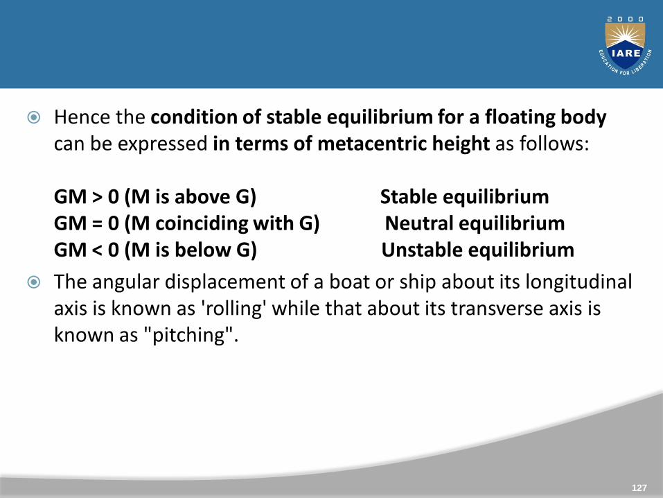
Hence the condition of stable equilibrium for a floating body can be expressed in terms of metacentric height as follows:
GM > 0 (M is above G) Stable equilibrium GM = 0 (M coinciding with G) Neutral equilibrium GM < 0 (M is below G) Unstable equilibrium
The angular displacement of a boat or ship about its longitudinal axis is known as 'rolling' while that about its transverse axis is known as "pitching".
127
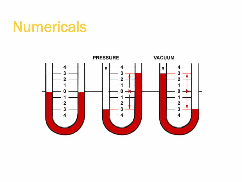
Numericals
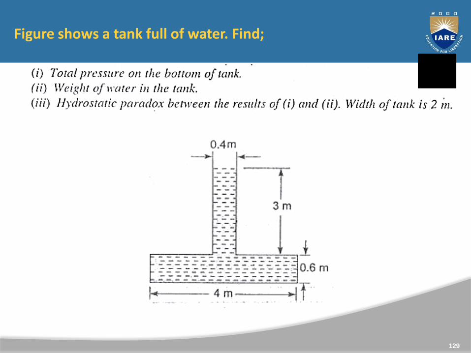
Figure shows a tank full of water. Find;
129
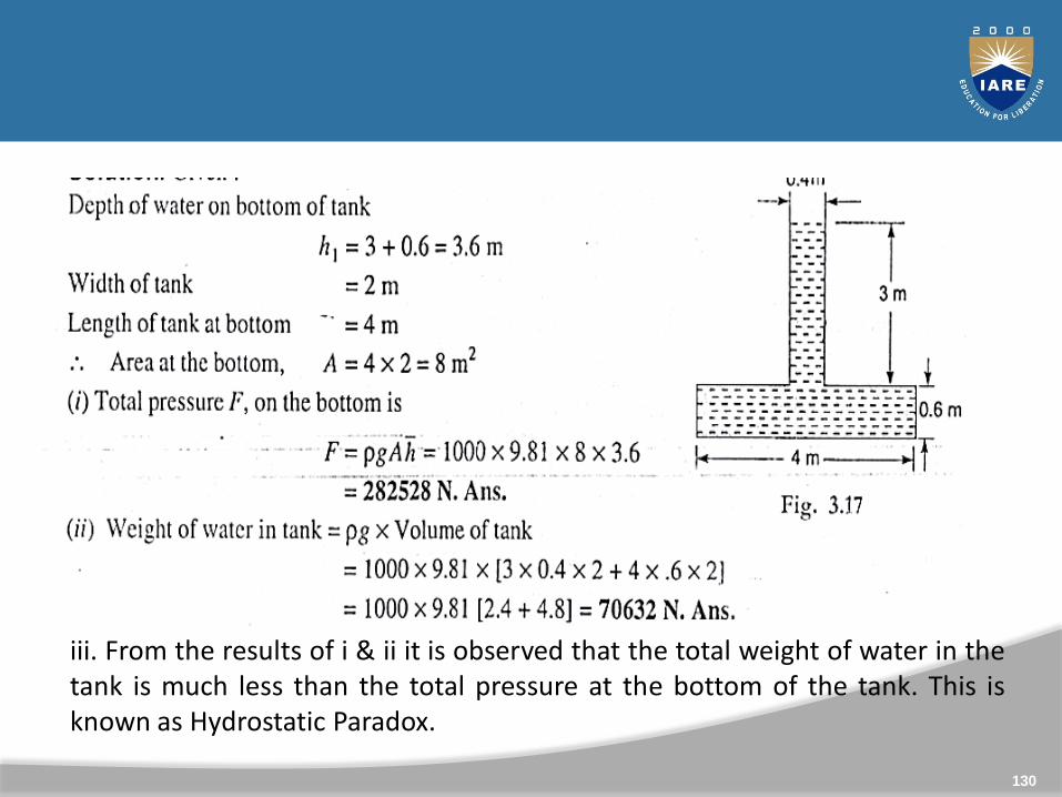
iii. From the results of i & ii it is observed that the total weight of water in thetank is much less than the total pressure at the bottom of the tank. This isknown as Hydrostatic Paradox.
130
Unit 2
FLUID KINEMATICS AND BASIC EQUATIONS OF FLUID FLOW ANALYSIS
131

Syllabus
Statement of Buckingham’s π- theorem, similarityparameters - Reynolds number, Froude number, concepts ofgeometric, kinematic and dynamic similarity, Types of fluidflows, differential equations of mass and momentum forincompressible flows, inviscid eulers equation and viscousflows- navier stokes equations, concept of fluid rotation,vorticity and stream function, exact solutions of navier stokesequations for coquette flow and poiseuille flow, numericals.
132
133
CLO Course Learning Outcome
CLO4 Dimensional similarity and prediction of flow behaviour usingdimensionless numbers.
CLO5 Classification of fluid flows and governing equations ofinviscid fluid flows.
CLO6 Conceptual analysis of fluid flow and exact solutions of navierstokes equations for coquette flow and poiseuille flow.

Fluid Kinematics
What is fluid kinematics?
Fluid kinematics is the study on fluid motion in space andtime without considering the force which causes the fluidmotion.
According to the continuum hypothesis the local velocityof fluid is the velocity of an infinitesimally small fluidparticle/element at a given instant ‘t’. It is generally acontinuous function in space and time.
134
135
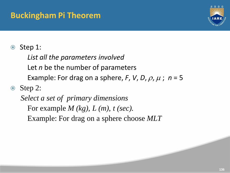
Buckingham Pi Theorem
Step 1:
List all the parameters involved
Let n be the number of parameters
Example: For drag on a sphere, F, V, D, , ; n = 5
Step 2:
Select a set of primary dimensions
For example M (kg), L (m), t (sec).
Example: For drag on a sphere choose MLT
136
Buckingham Pi Theorem
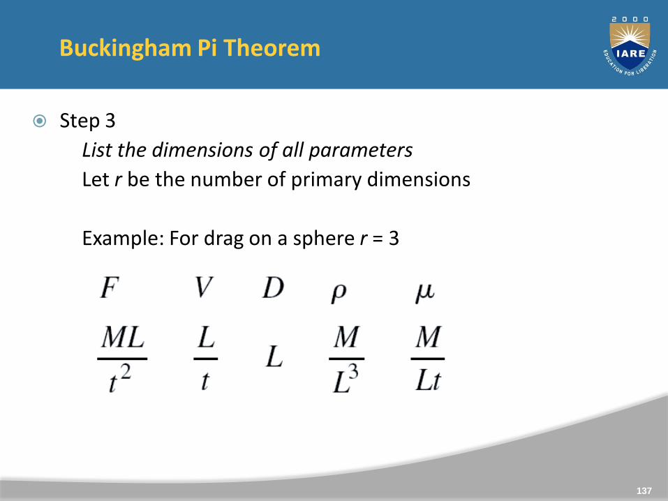
Step 3
List the dimensions of all parameters
Let r be the number of primary dimensions
Example: For drag on a sphere r = 3
137
Buckingham Pi Theorem
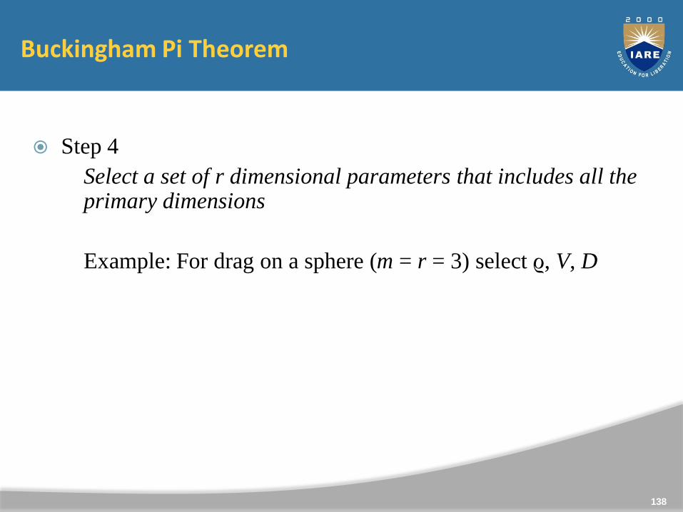
Step 4
Select a set of r dimensional parameters that includes all the primary dimensions
Example: For drag on a sphere (m = r = 3) select ϱ, V, D
138
Buckingham Pi Theorem
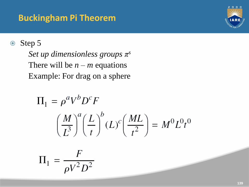
Step 5
Set up dimensionless groups πs
There will be n – m equations
Example: For drag on a sphere
139
Buckingham Pi Theorem
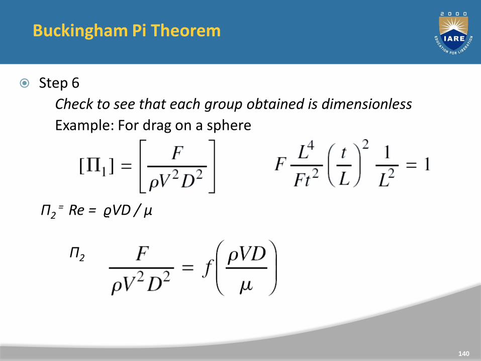
Step 6
Check to see that each group obtained is dimensionless
Example: For drag on a sphere
Π2 = Re = ϱVD / μ
Π2
140
Similitude and Model Studies
For a study on a model to relate to that on a prototype it isrequired that there be
Geometrical SimilarityKinematic SimilarityDynamic Similarity
141
Geometrical Similarity
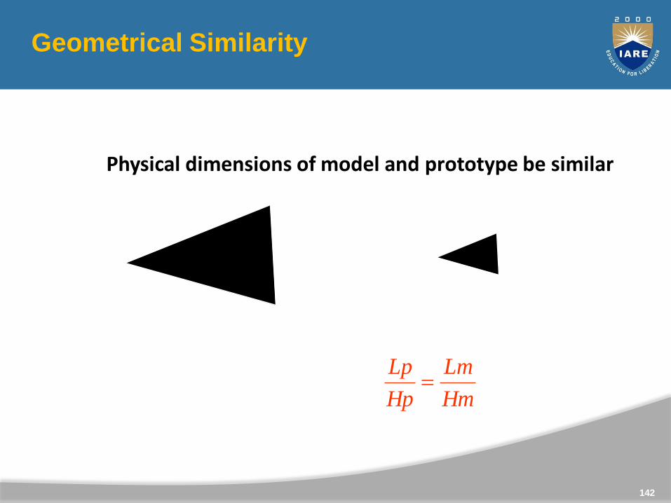
Physical dimensions of model and prototype be similar
Lp
Hp Hm
Lm
Hm
Lm
Hp
Lp
142
Kinematic Similarity
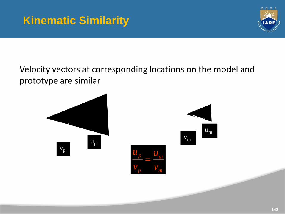
Velocity vectors at corresponding locations on the model and prototype are similar
vp
up
vm
um
m
m
p
p
v
u
v
u
143
Dynamic Similarity
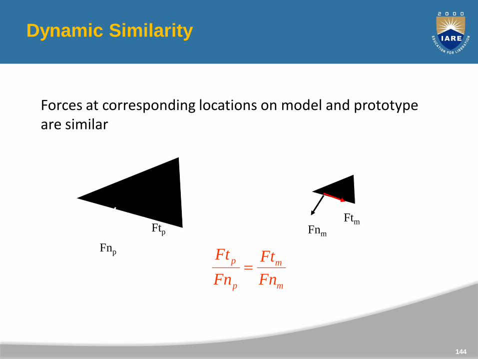
Forces at corresponding locations on model and prototype are similar
Fnp
Ftp Fnm
Ftm
m
m
p
p
Fn
Ft
Fn
Ft
144
145
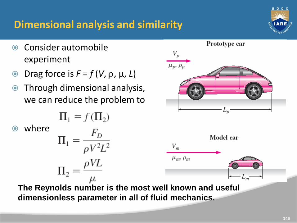
Dimensional analysis and similarity
Consider automobile experiment
Drag force is F = f (V, , µ, L)
Through dimensional analysis, we can reduce the problem to
where
= CD
=Reand
The Reynolds number is the most well known and useful
dimensionless parameter in all of fluid mechanics.
146
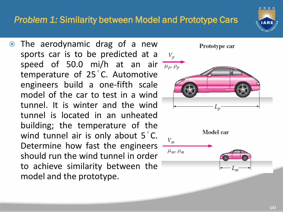
The aerodynamic drag of a newsports car is to be predicted at aspeed of 50.0 mi/h at an airtemperature of 25°C. Automotiveengineers build a one-fifth scalemodel of the car to test in a windtunnel. It is winter and the windtunnel is located in an unheatedbuilding; the temperature of thewind tunnel air is only about 5°C.Determine how fast the engineersshould run the wind tunnel in orderto achieve similarity between themodel and the prototype.
Problem 1: Similarity between Model and Prototype Cars
147
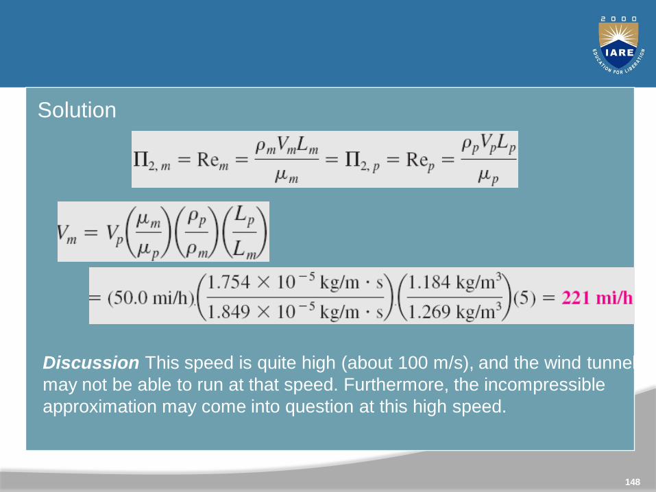
Solution
Discussion This speed is quite high (about 100 m/s), and the wind tunnel
may not be able to run at that speed. Furthermore, the incompressible
approximation may come into question at this high speed.
148
Methods of Describing the Fluid Flow
The fluid motion is described by two methods.
1. Lagrangian Method
2. Eulerian Method
149
Eularian and Lagrangian approaches
Eularian and Lagrangian approaches are of the two methods tostudy fluid motion. The Eularian approach concentrates on fluidproperties at a point P (x,y,z,t). Thus it is a field approach.
In the Lagrangian approach one identifies a particle or a group ofparticles and follows them with time. This is bound to be acumbersome method. But there may be situations where it isunavoidable. One such is the two phase flow involving particles.
150
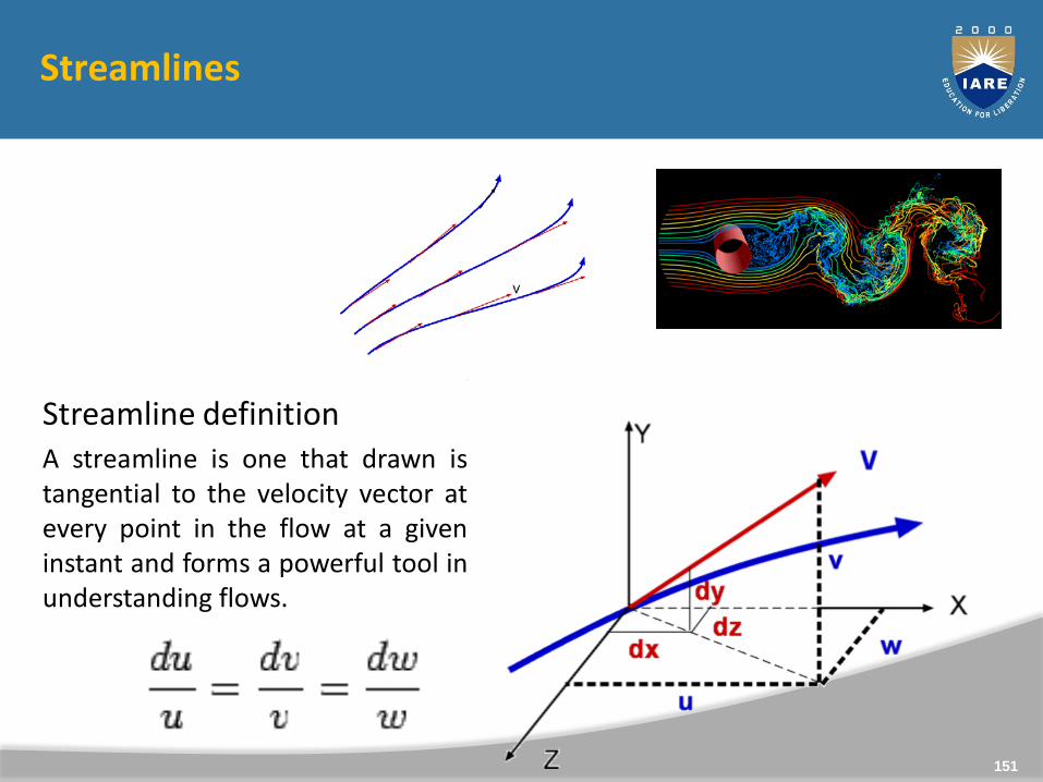
Streamlines
Streamline definitionA streamline is one that drawn istangential to the velocity vector atevery point in the flow at a giveninstant and forms a powerful tool inunderstanding flows.
151
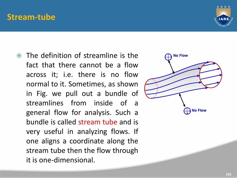
The definition of streamline is thefact that there cannot be a flowacross it; i.e. there is no flownormal to it. Sometimes, as shownin Fig. we pull out a bundle ofstreamlines from inside of ageneral flow for analysis. Such abundle is called stream tube and isvery useful in analyzing flows. Ifone aligns a coordinate along thestream tube then the flow throughit is one-dimensional.
152
Stream-tube
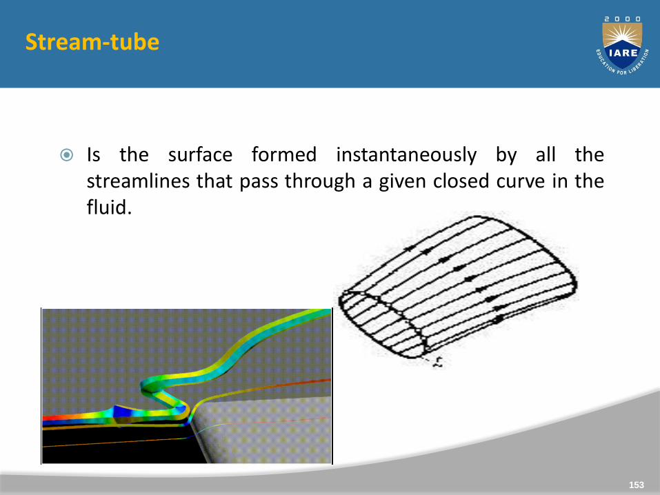
Stream-tube
Is the surface formed instantaneously by all thestreamlines that pass through a given closed curve in thefluid.
153
Pathlines
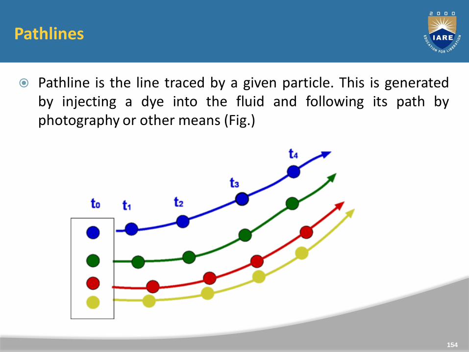
Pathline is the line traced by a given particle. This is generatedby injecting a dye into the fluid and following its path byphotography or other means (Fig.)
154
Streakline
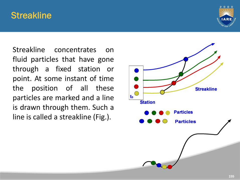
Streakline concentrates onfluid particles that have gonethrough a fixed station orpoint. At some instant of timethe position of all theseparticles are marked and a lineis drawn through them. Such aline is called a streakline (Fig.).
155
Timeline
Timeline is generated by drawing a line through adjacentparticles in flow at any instant of time.
In a steady flow the streamline, pathline and streakline allcoincide. In an unsteady flow they can be different.Streamlines are easily generated mathematically whilepathline and streaklines are obtained throughexperiments.
156
157
Flow classifications
Incompressible vs. compressible flow.
Incompressible flow: volume of a given fluid particle does not change.○ Implies that density is constant everywhere.
○ Essentially valid for all liquid flows.
Compressible flow: volume of a given fluid particle can change with position.○ Implies that density will vary throughout the flow field.
○ Compressible flows are further classified according to the value of the Mach number (M), where.
○ M < 1 - Subsonic.
○ M > 1 - Supersonic.
Types of flows
Steady
Unsteady
Uniform
Non-uniform
Laminar
Turbulent
Rotational
Irrotational
One dimensional flows
Two dimensional flows
Three dimensional flows
158
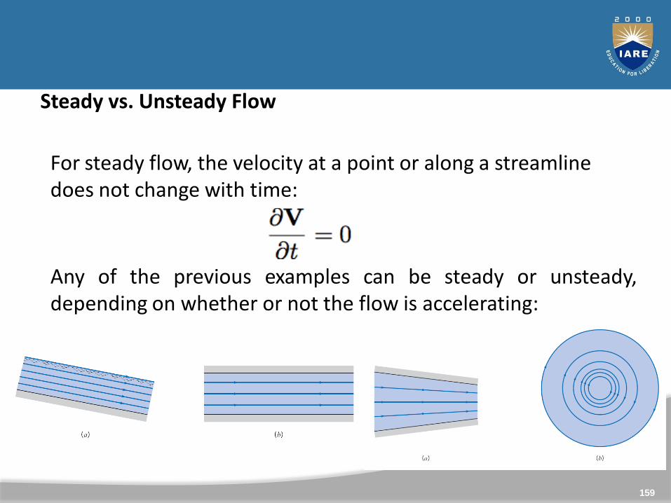
Steady vs. Unsteady Flow
For steady flow, the velocity at a point or along a streamline does not change with time:
Any of the previous examples can be steady or unsteady,depending on whether or not the flow is accelerating:
159
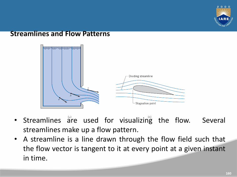
Streamlines and Flow Patterns
• Streamlines are used for visualizing the flow. Severalstreamlines make up a flow pattern.
• A streamline is a line drawn through the flow field such thatthe flow vector is tangent to it at every point at a given instantin time.
160
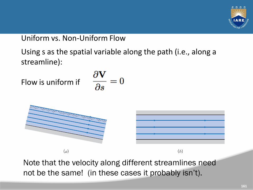
Uniform vs. Non-Uniform Flow
Using s as the spatial variable along the path (i.e., along a streamline):
Flow is uniform if
Examples of uniform flow:
Note that the velocity along different streamlines need
not be the same! (in these cases it probably isn’t).
161
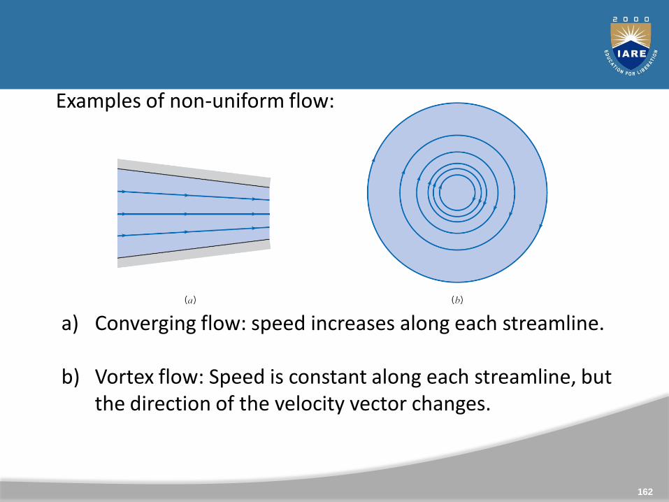
Examples of non-uniform flow:
a) Converging flow: speed increases along each streamline.
b) Vortex flow: Speed is constant along each streamline, but the direction of the velocity vector changes.
162
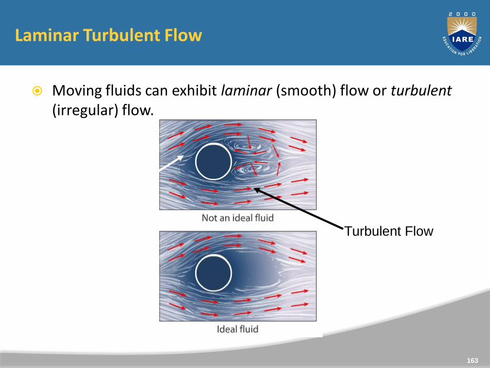
Laminar Turbulent Flow
Moving fluids can exhibit laminar (smooth) flow or turbulent(irregular) flow.
Laminar
Flow Turbulent Flow
163
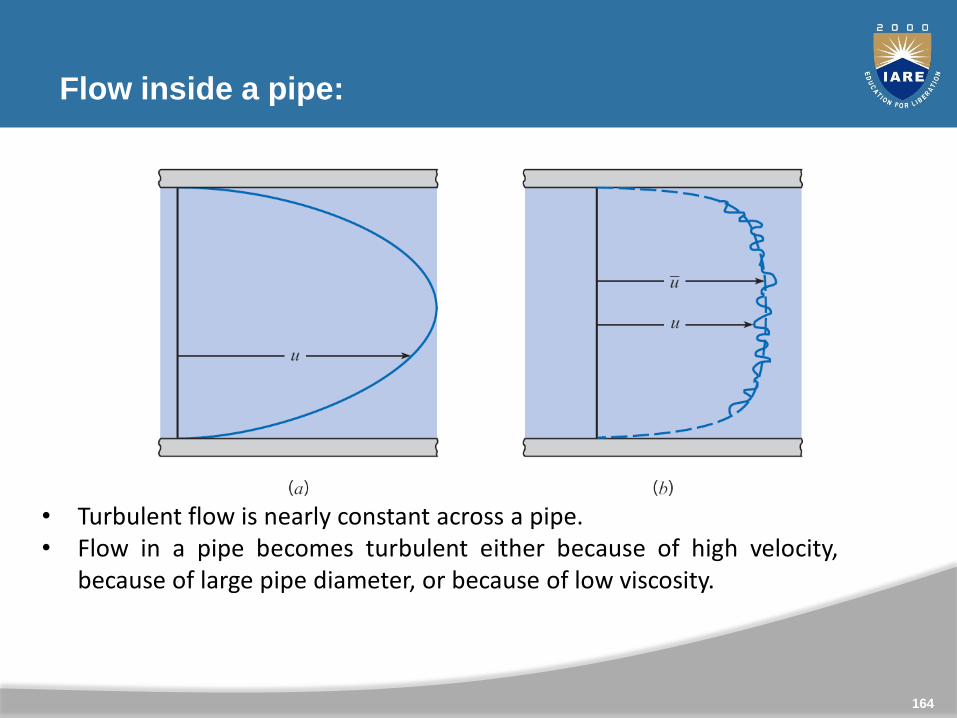
Flow inside a pipe:
Laminar Turbulent
• Turbulent flow is nearly constant across a pipe.• Flow in a pipe becomes turbulent either because of high velocity,
because of large pipe diameter, or because of low viscosity.
164

Flow around an airfoil
Partly laminar, i.e., flowing past the object in “layers” (laminar).
Turbulence forms mostly downstream from the airfoil.
(Flow becomes more turbulent with increased angle of attack.)
165
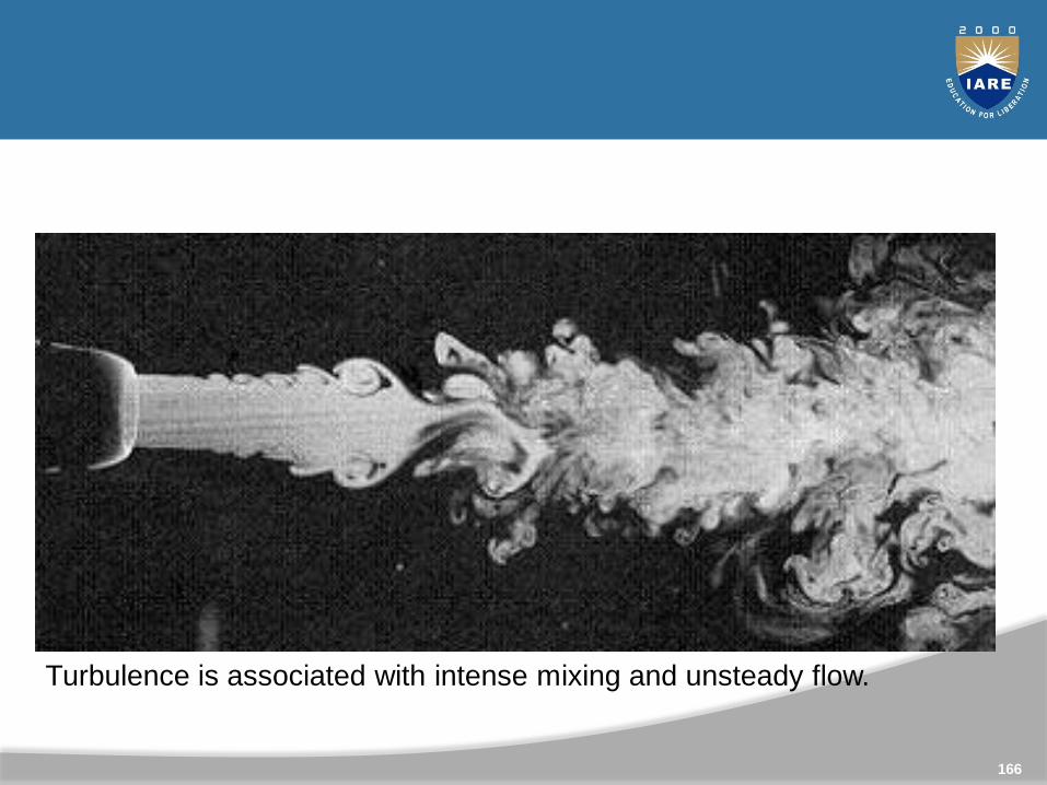
Turbulent flow in a jet
Turbulence is associated with intense mixing and unsteady flow.
166
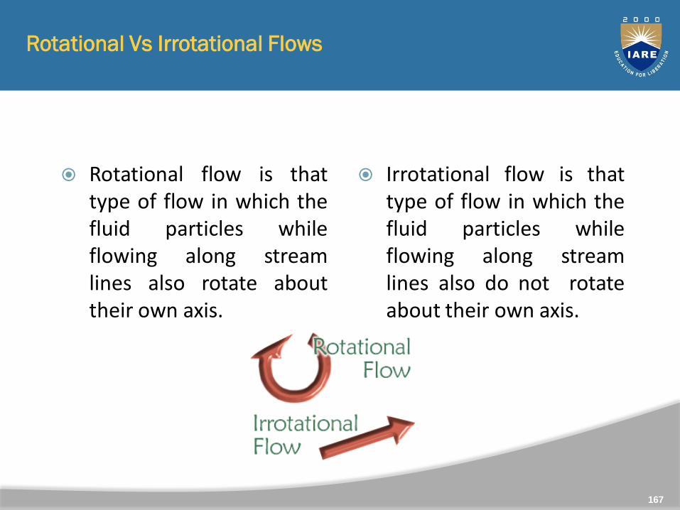
Rotational Vs Irrotational Flows
Rotational flow is thattype of flow in which thefluid particles whileflowing along streamlines also rotate abouttheir own axis.
Irrotational flow is thattype of flow in which thefluid particles whileflowing along streamlines also do not rotateabout their own axis.
167
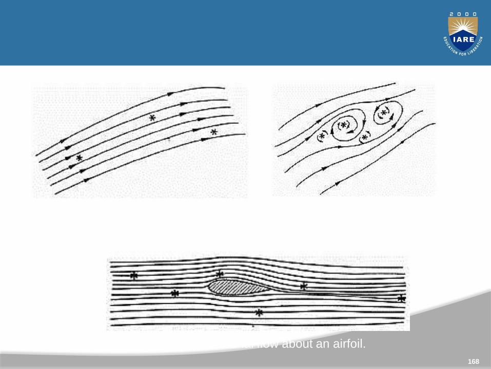
168
(a) Irrotational flow. (b) Rotational flow.
(c) Inviscid, irrotational flow about an airfoil.
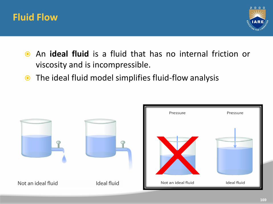
Fluid Flow
An ideal fluid is a fluid that has no internal friction orviscosity and is incompressible.
The ideal fluid model simplifies fluid-flow analysis
169
1D,2D,3D flows
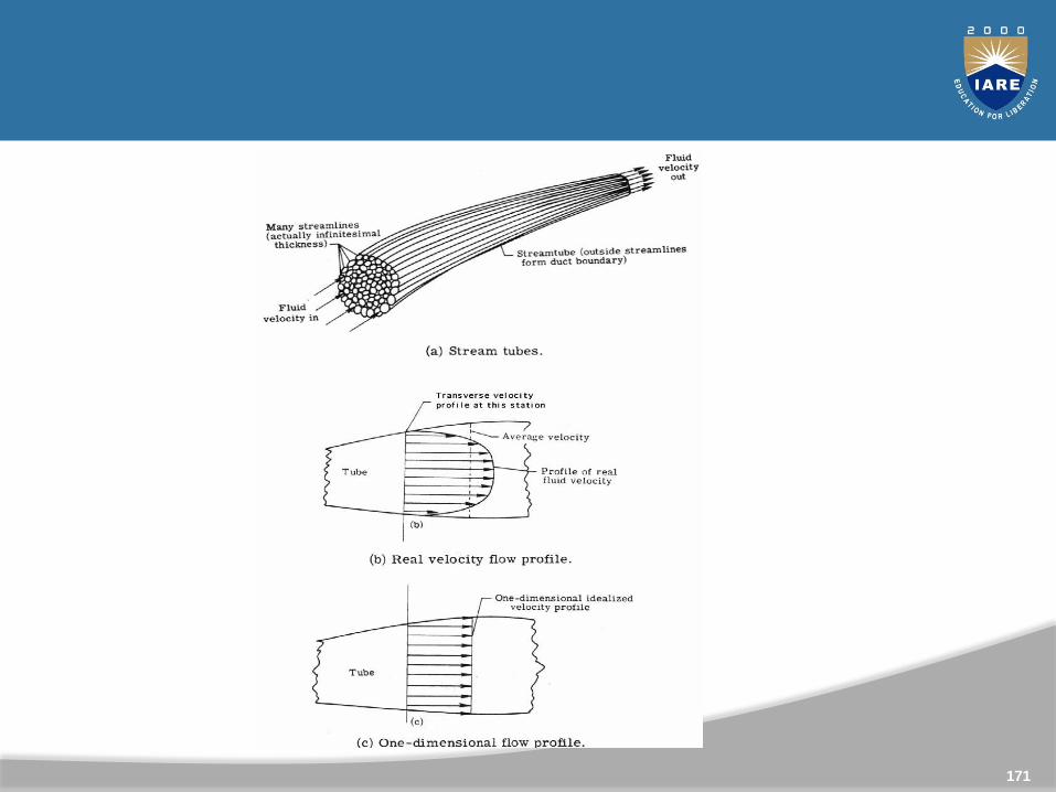
One dimensional flow: Is that type of flow in which the flow parameter such as velocity is a function of time and one space co-ordinate only.
Two Dimensional Flow: Is that type flow in which the velocity is a function of time and two rectangular space co-ordinates.
Three Dimensional flow: Is that type of flow in which the velocity is a function of time and three mutually perpendicular directions.
170
171
Principles of Fluid Flow
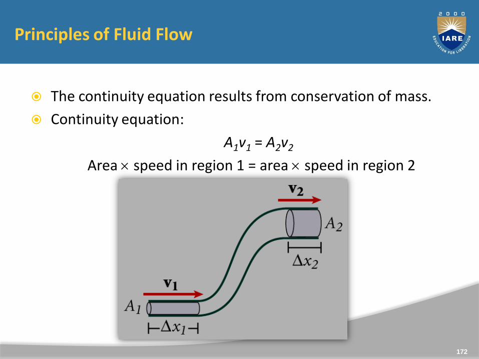
The continuity equation results from conservation of mass.
Continuity equation:
A1v1 = A2v2
Area speed in region 1 = area speed in region 2
172
Principles of Fluid Flow
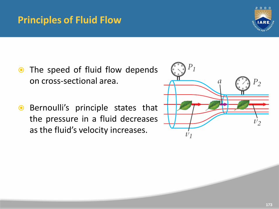
The speed of fluid flow dependson cross-sectional area.
Bernoulli’s principle states thatthe pressure in a fluid decreasesas the fluid’s velocity increases.
173
Continuity Equation
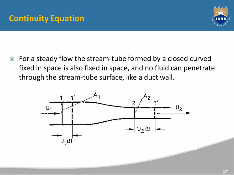
For a steady flow the stream-tube formed by a closed curved fixed in space is also fixed in space, and no fluid can penetrate through the stream-tube surface, like a duct wall.
174
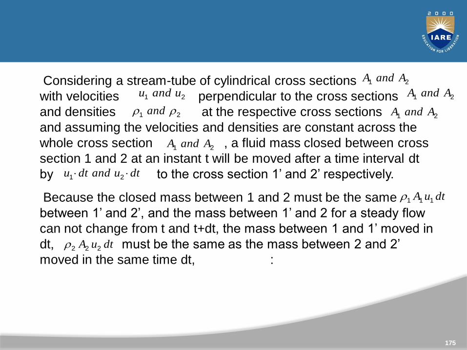
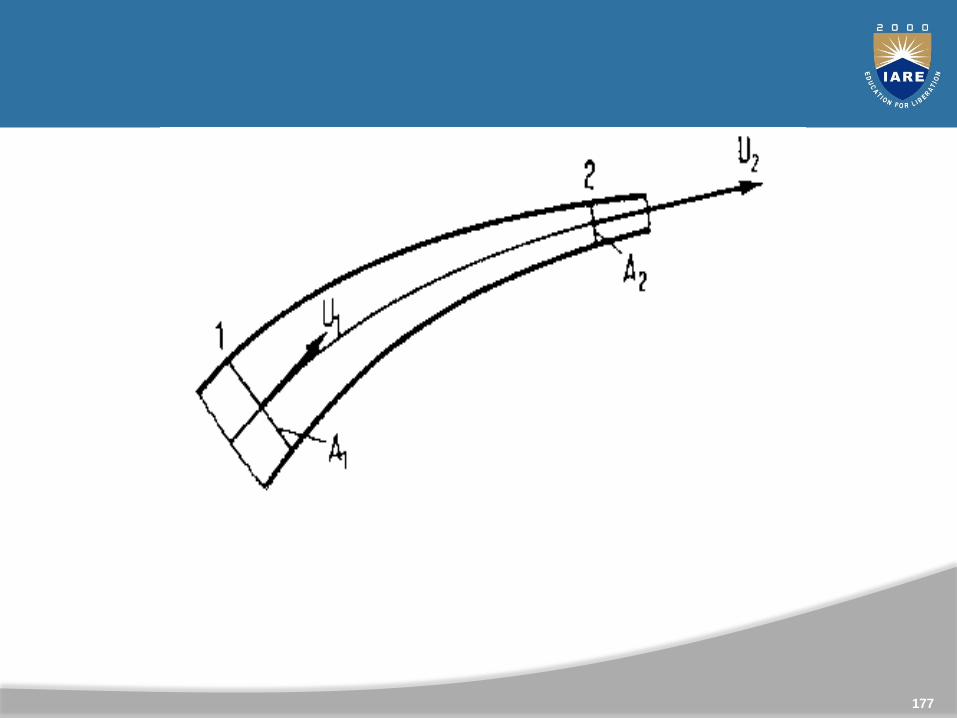
Considering a stream-tube of cylindrical cross sections
with velocities perpendicular to the cross sections
and densities at the respective cross sections
and assuming the velocities and densities are constant across the
whole cross section , a fluid mass closed between cross
section 1 and 2 at an instant t will be moved after a time interval dt
by to the cross section 1’ and 2’ respectively.
Because the closed mass between 1 and 2 must be the same
between 1’ and 2’, and the mass between 1’ and 2 for a steady flow
can not change from t and t+dt, the mass between 1 and 1’ moved in
dt, must be the same as the mass between 2 and 2’
moved in the same time dt, :
21 uandu21 AandA
21 AandA21 and
21 AandA
dtuanddtu 21
dtuA 111
dtuA 222
21 AandA
175
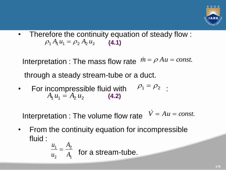
• Therefore the continuity equation of steady flow :
Interpretation : The mass flow rate
through a steady stream-tube or a duct.
• For incompressible fluid with :
Interpretation : The volume flow rate
• From the continuity equation for incompressible
fluid :
for a stream-tube.
222111 uAuA
.constuAm
21
2211 uAuA
.constuAV
1
2
2
1
A
A
u
u
(4.1)
(4.2)
176
177
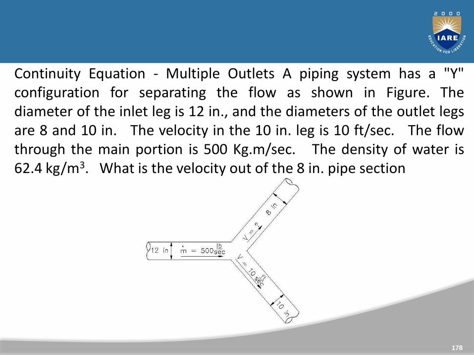
Continuity Equation - Multiple Outlets A piping system has a "Y"configuration for separating the flow as shown in Figure. Thediameter of the inlet leg is 12 in., and the diameters of the outlet legsare 8 and 10 in. The velocity in the 10 in. leg is 10 ft/sec. The flowthrough the main portion is 500 Kg.m/sec. The density of water is62.4 kg/m3. What is the velocity out of the 8 in. pipe section
178
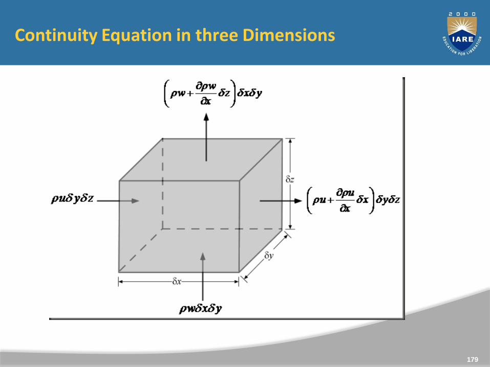
Continuity Equation in three Dimensions
179
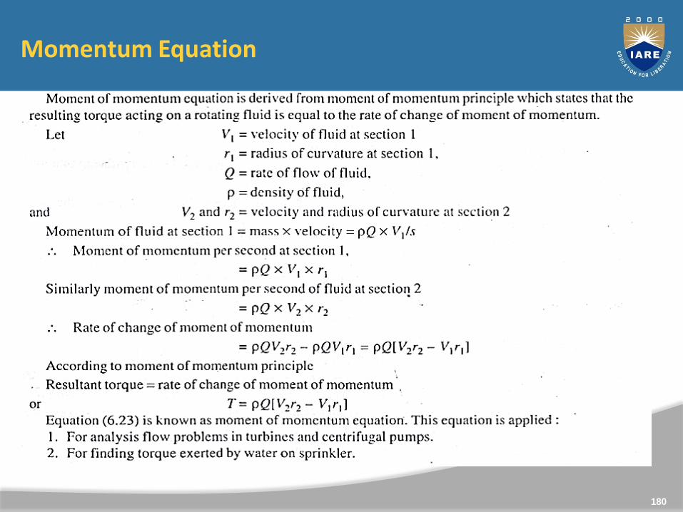
Momentum Equation
180
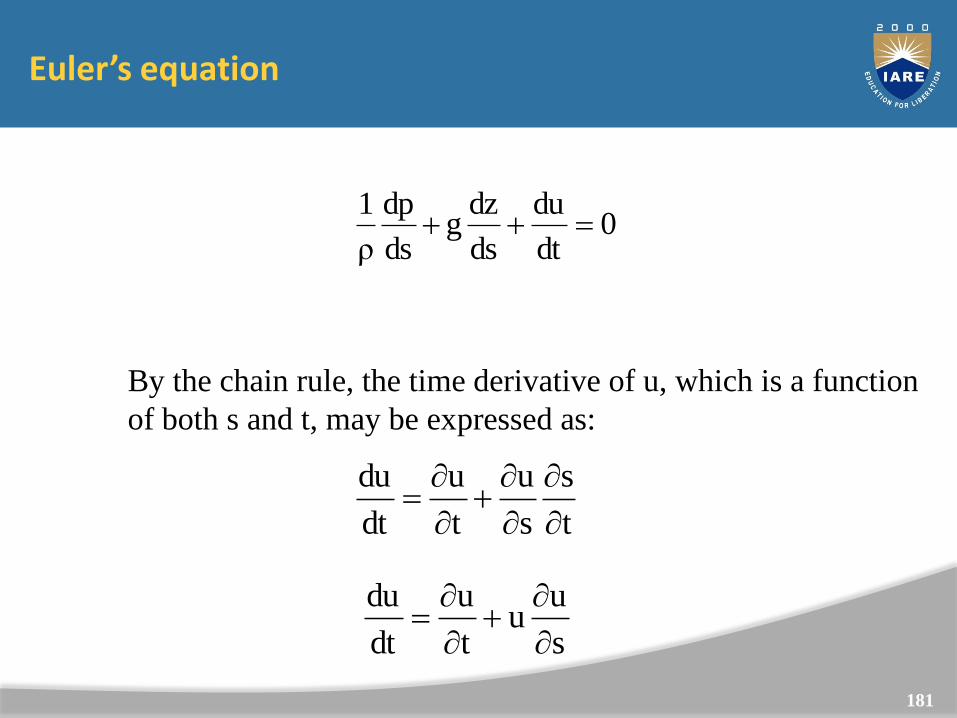
Euler’s equation
0dt
du
ds
dzg
ds
dp
ρ
1
By the chain rule, the time derivative of u, which is a function
of both s and t, may be expressed as:
t
s
s
u
t
u
dt
du
s
uu
t
u
dt
du
(We will come
back to this
equation later)
181
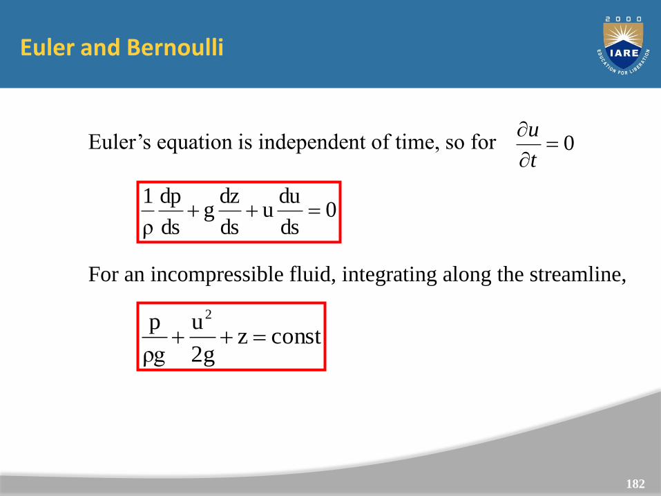
Euler and Bernoulli
Euler’s equation is independent of time, so for 0
t
u
0ds
duu
ds
dzg
ds
dp
ρ
1
For an incompressible fluid, integrating along the streamline,
constz2g
u
ρg
p 2
Euler’s equation
Bernoulli’s equation
182
Navier-Stokes equations
So far we have separately considered flow
in one dimension affected by pressure and gravity
in one dimension affected by pressure and viscosity
Need three dimensions and all forces in order to providea full solution for any general flow problem
The following is not rigorous- see Bachelor for a rigorousderivation
183
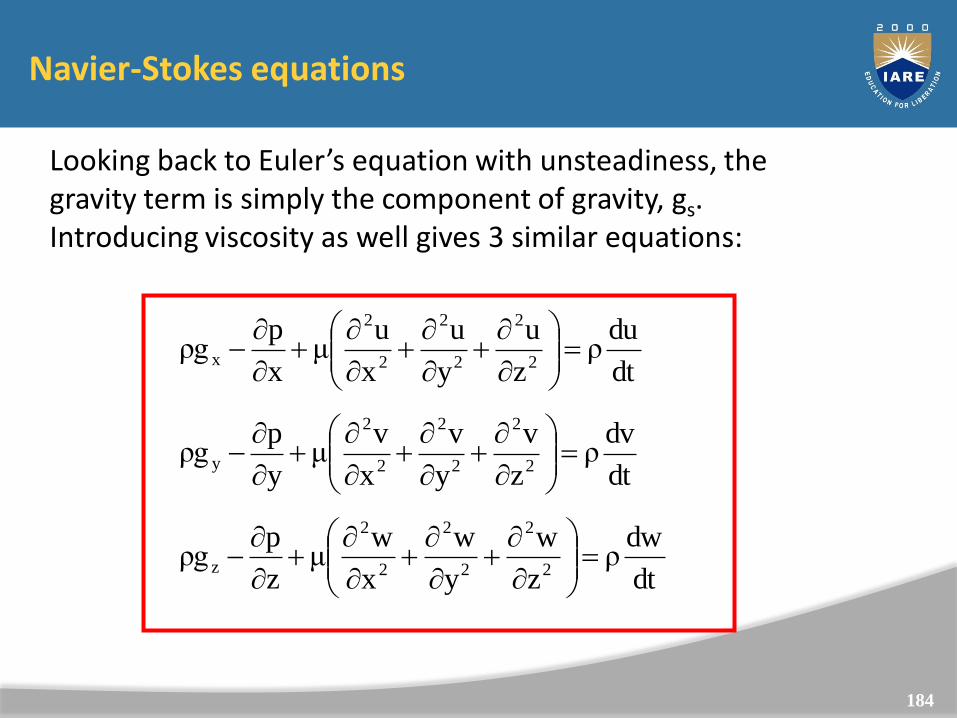
Navier-Stokes equations
Looking back to Euler’s equation with unsteadiness, the gravity term is simply the component of gravity, gs.Introducing viscosity as well gives 3 similar equations:
dt
duρ
z
u
y
u
x
uμ
x
pρg
2
2
2
2
2
2
x
dt
dvρ
z
v
y
v
x
vμ
y
pρg
2
2
2
2
2
2
y
dt
dwρ
z
w
y
w
x
wμ
z
pρg
2
2
2
2
2
2
z
184
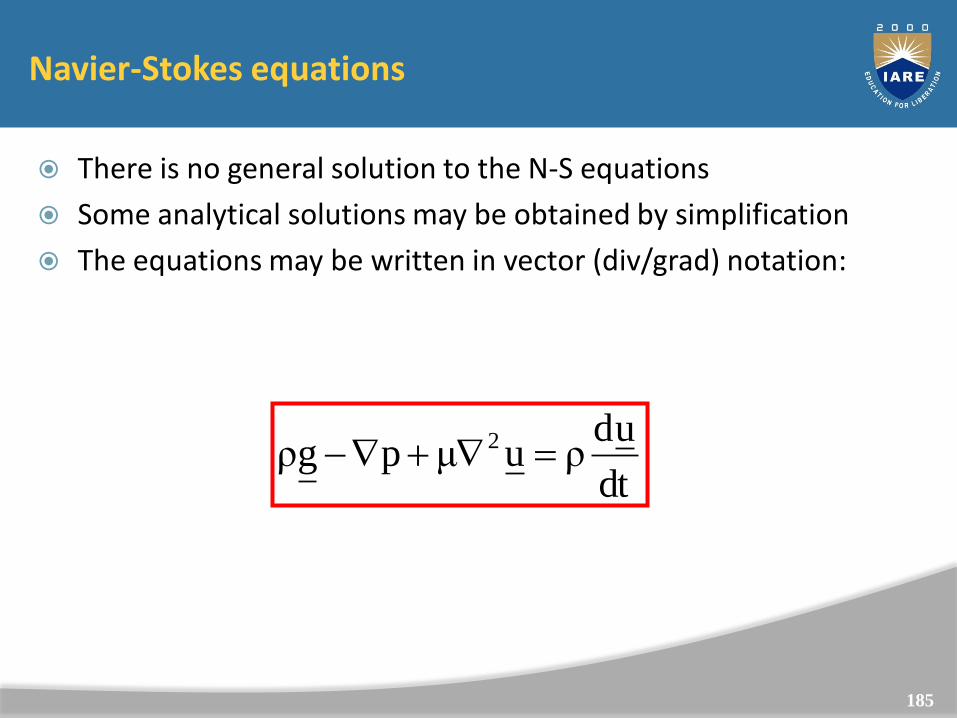
Navier-Stokes equations
There is no general solution to the N-S equations
Some analytical solutions may be obtained by simplification
The equations may be written in vector (div/grad) notation:
dt
udρuμpgρ 2
185
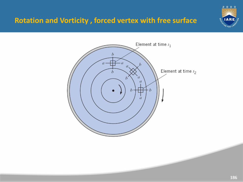
Rotation and Vorticity , forced vertex with free surface
Rotation of a fluid element in a rotating tank of fluid
(solid body rotation).
186
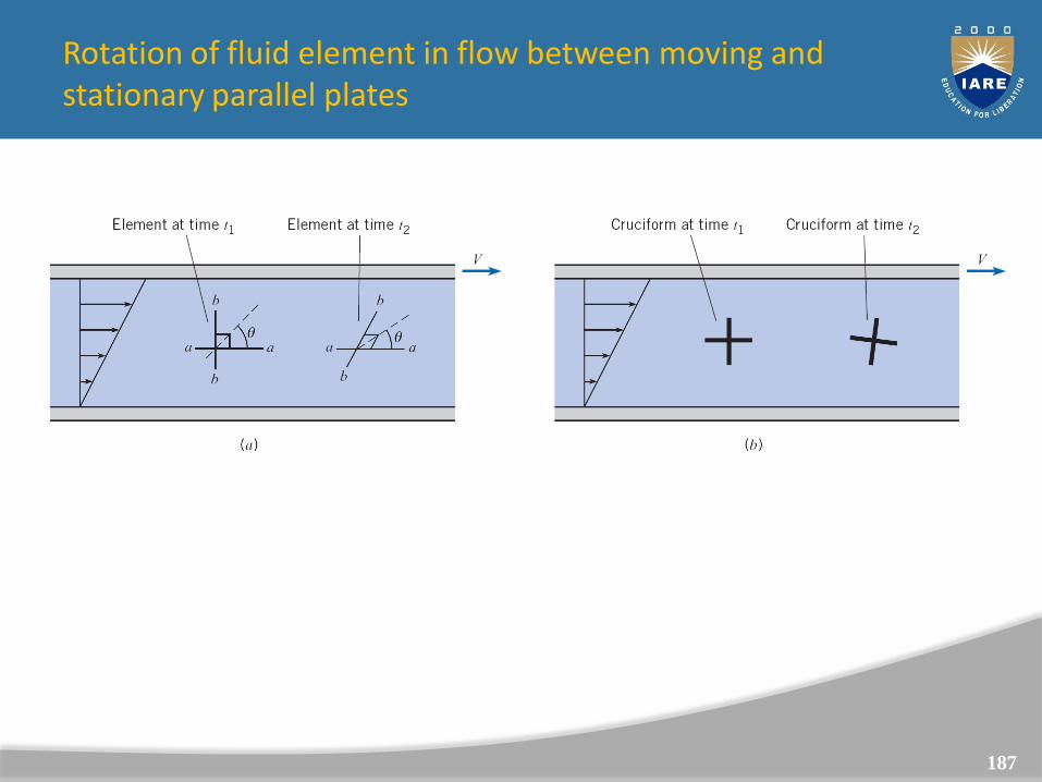
Rotation of fluid element in flow between moving andstationary parallel plates
You can think of the “cruciforms” as small paddle wheels that
are free to rotate about their center.
If the paddle wheel rotates, the flow is rotational at that point.
187
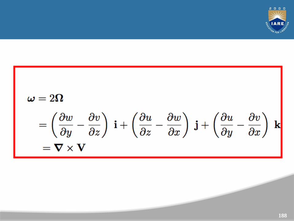
The property more frequently used is the vorticity
188
Stream Function
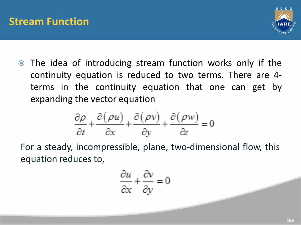
The idea of introducing stream function works only if thecontinuity equation is reduced to two terms. There are 4-terms in the continuity equation that one can get byexpanding the vector equation
189
For a steady, incompressible, plane, two-dimensional flow, thisequation reduces to,
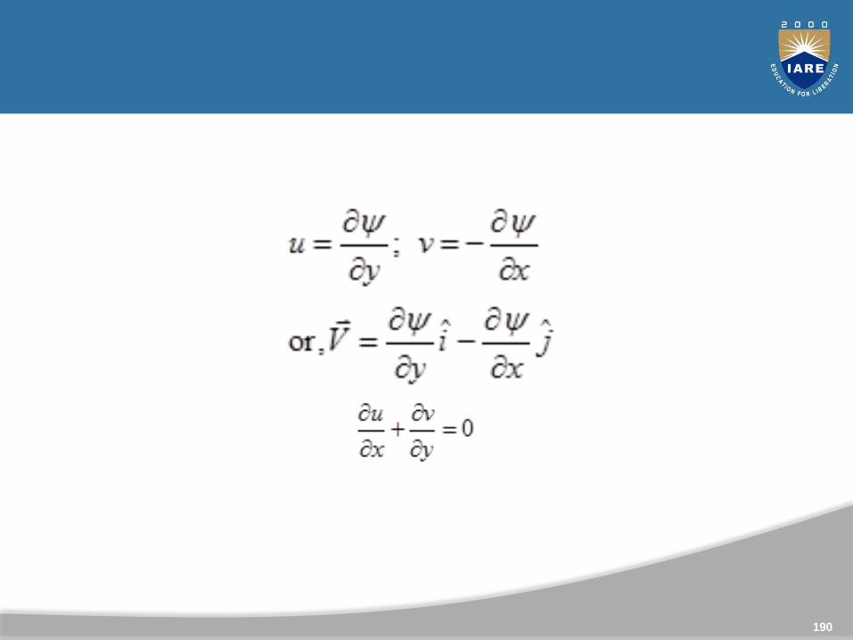
190
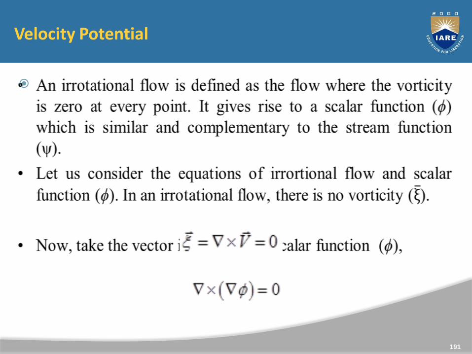
Velocity Potential
191
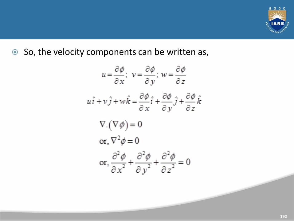
So, the velocity components can be written as,
192
193
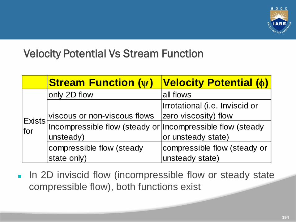
Velocity Potential Vs Stream Function
Stream Function (y) Velocity Potential (f)only 2D flow all flows
viscous or non-viscous flows
Irrotational (i.e. Inviscid or
zero viscosity) flow
Incompressible flow (steady or
unsteady)
Incompressible flow (steady
or unsteady state)
compressible flow (steady
state only)
compressible flow (steady or
unsteady state)
Exists
for
In 2D inviscid flow (incompressible flow or steady state
compressible flow), both functions exist
194
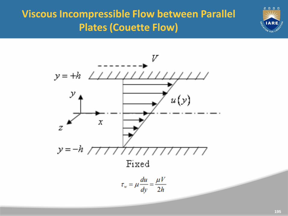
Viscous Incompressible Flow between Parallel Plates (Couette Flow)
195
Fig. Incompressible viscous flow between parallel plates with no pressure
gradient.
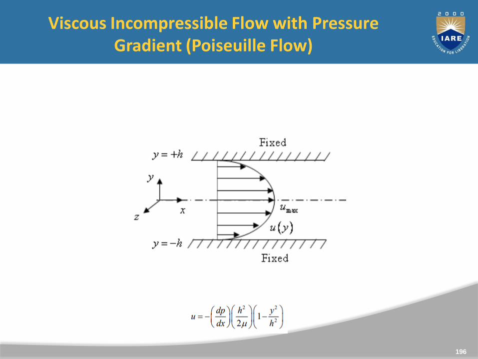
Viscous Incompressible Flow with Pressure Gradient (Poiseuille Flow)
196
Fig. Incompressible viscous flow between parallel plates with pressure
gradient.

Unit 3
Fluid Dynamics
197
198
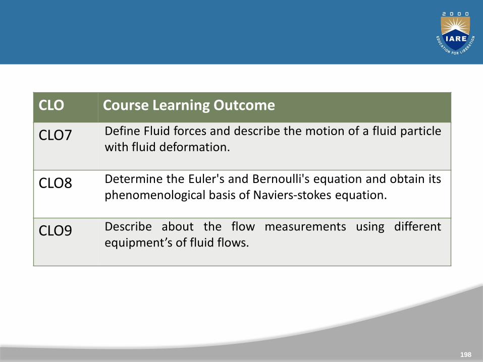
CLO Course Learning Outcome
CLO7 Define Fluid forces and describe the motion of a fluid particlewith fluid deformation.
CLO8 Determine the Euler's and Bernoulli's equation and obtain itsphenomenological basis of Naviers-stokes equation.
CLO9 Describe about the flow measurements using differentequipment’s of fluid flows.
Fluid forces and Motion of a fluid particle; Fluid deformation; Euler's andBernoulli's equation, phenomenological basis of Naviers- stokes equation,flow measurements : pressure, velocity and mass flow rate, viscosity, pitot-static tube, venturi meter, orifice meter and V-Notch, numericals.
199
Syllabus
Fluid Dynamics
In some cases, fluid forces have little effect on an object’smotion (e.g., shotput)
In other cases, fluid forces are significant – badminton, baseball,swimming, cycling, etc.
Three major fluid forces of interest: – Buoyancy – Drag – Lift
200
201
Motion of a fluid particle and Fluid deformation
In fluid mechanics we are interested in general motion, deformation, and rate of deformation of particles
Fluid element can undergo 4 types of motion or deformation:
1. Translation
2. Rotation
3. Shear strain
4. Extensional strain or dilatation
We will show that all kinematic properties of fluid flow
Acceleration
Translation
Angular velocity
Rate of dilatation
Shear strain
are directly related to fluid velocity vector V = (u, v, w)
202
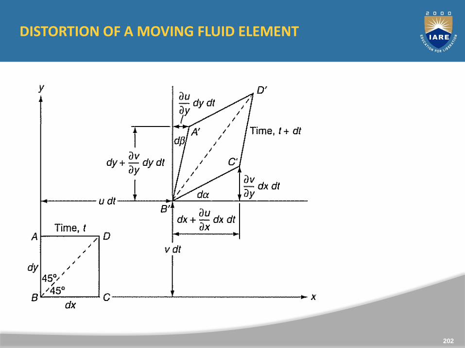
DISTORTION OF A MOVING FLUID ELEMENT
203
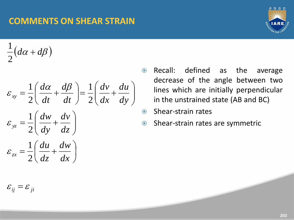
COMMENTS ON SHEAR STRAIN
Recall: defined as the averagedecrease of the angle between twolines which are initially perpendicularin the unstrained state (AB and BC)
Shear-strain rates
Shear-strain rates are symmetric
jiij
zx
yz
xy
dx
dw
dz
du
dz
dv
dy
dw
dy
du
dx
dv
dt
d
dt
d
dd
2
1
2
1
2
1
2
1
2
1
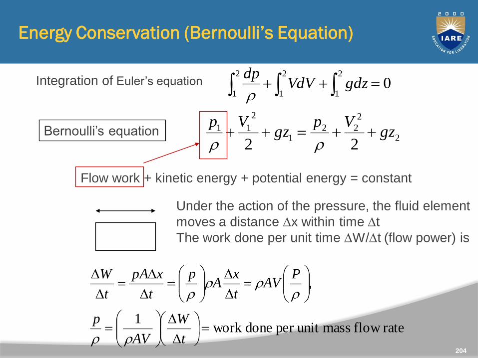
Energy Conservation (Bernoulli’s Equation)
02
1
2
1
2
1 gdzVdV
dp
Integration of Euler’s equation
Bernoulli’s equation2
2
221
2
11
22gz
Vpgz
Vp
Flow work + kinetic energy + potential energy = constant
p
A
Dx Under the action of the pressure, the fluid element
moves a distance Dx within time Dt
The work done per unit time DW/Dt (flow power) is
rate flow massunit per donework 1
,
D
D
D
D
D
D
D
D
t
W
AV
p
PAV
t
xA
p
t
xpA
t
W
204
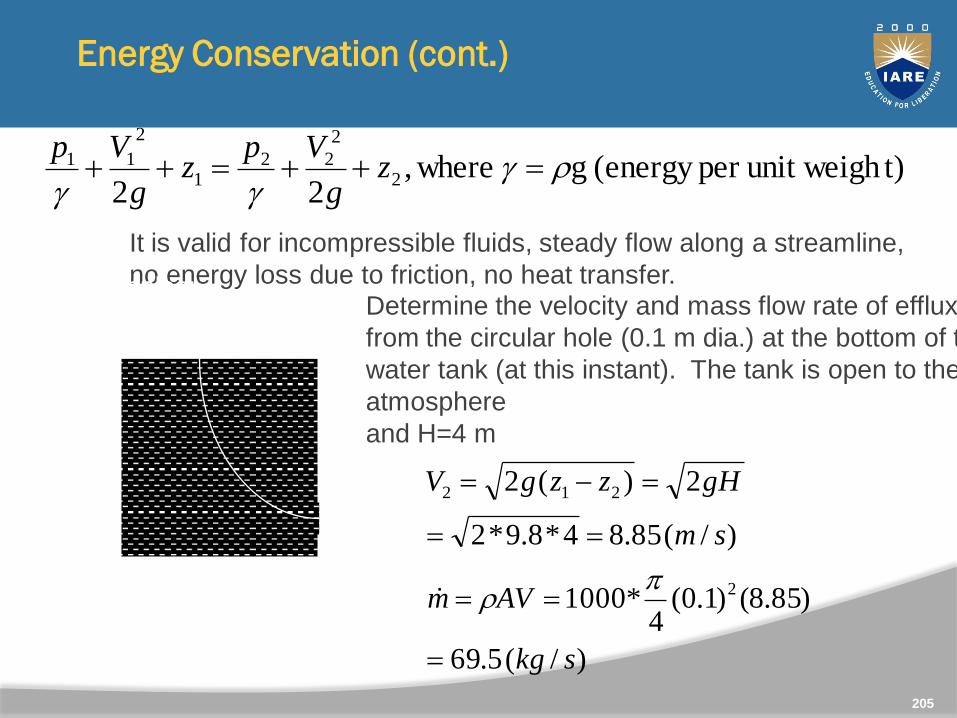
Energy Conservation (cont.)
t)unit weighper (energy g where,22
2
2
221
2
11
zg
Vpz
g
Vp
It is valid for incompressible fluids, steady flow along a streamline,
no energy loss due to friction, no heat transfer.Examples:Determine the velocity and mass flow rate of efflux
from the circular hole (0.1 m dia.) at the bottom of the
water tank (at this instant). The tank is open to the
atmosphere
and H=4 mH
1
2
p1 = p2, V1=0
)/(5.69
)85.8()1.0(4
*1000
)/(85.84*8.9*2
2)(2
2
212
skg
AVm
sm
gHzzgV
205
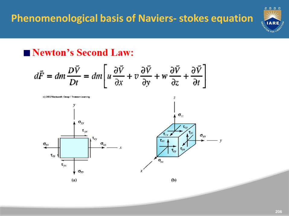
Phenomenological basis of Naviers- stokes equation
206
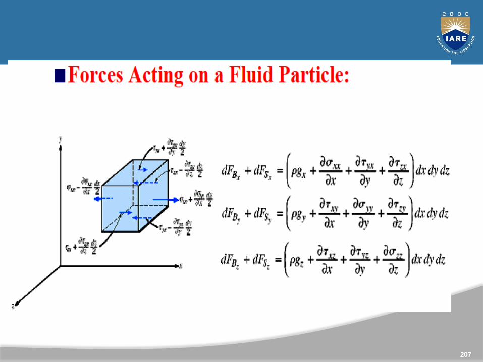
207
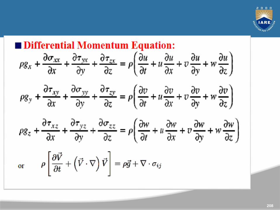
208
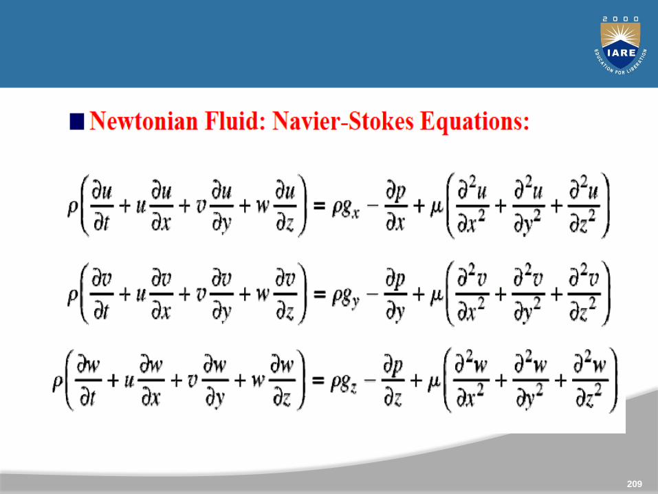
209
Flow measurements
Accurate measurement of flow rate of liquids and gases is anessential requirement for maintaining the quality of industrialprocesses. In fact, most of the industrial control loops controlthe flow rates of incoming liquids or gases in order to achievethe control objective. As a result, accurate measurement of flowrate is very important.
Needless to say that there could be diverse requirements of flowmeasurement, depending upon the situation. It could bevolumetric or mass flow rate, the medium could be gas or liquid,the measurement could be intrusive or nonintrusive, and so on.As a result there are different types of flow measuringtechniques that are used in industries.
210
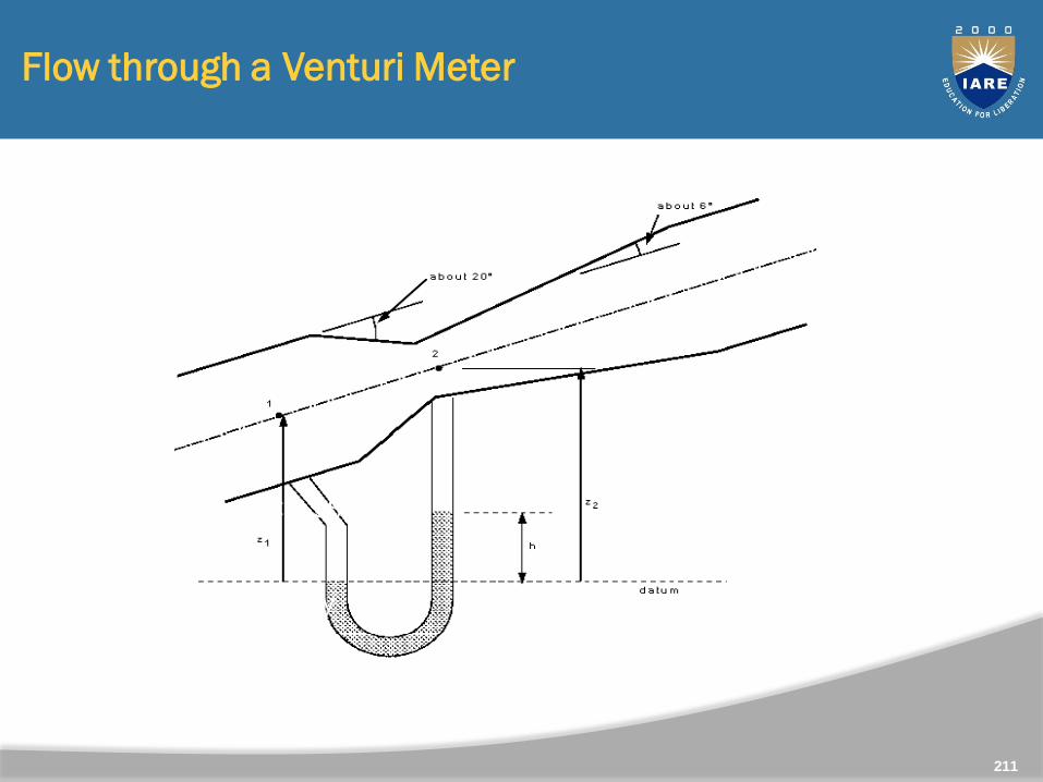
Flow through a Venturi Meter
In a venturi, 0.95 < C < 0.98
Advantage:
Pressure recovery
Uses little power
211
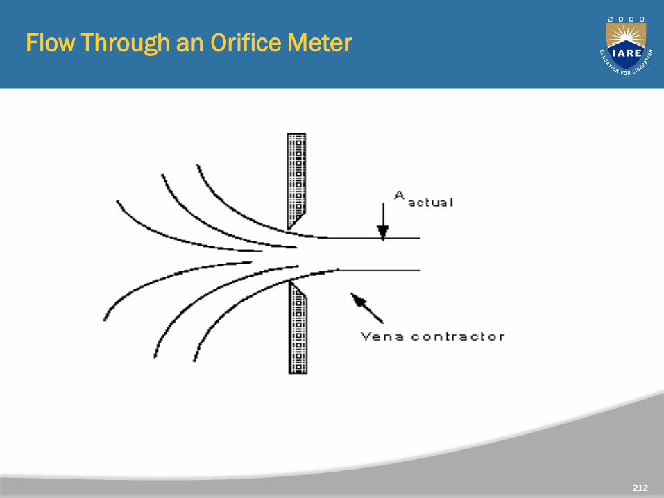
Flow Through an Orifice Meter
212
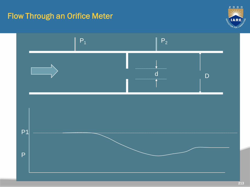
Flow Through an Orifice Meter
P1 P2
P
P1
d D
213

Flow Through an Orifice Meter
-Cheapest and Simplest
-But biggest pressure drop and power lost (C~0.6 - 0.7)
-Side Note:
Pressure drop caused by friction and turbulence of shear layer
downstream of vena contracta
CM
A
A
C
2
1
21
1
0.6
0.85
=d/D0.1 0.8
Re
100k
5000
10k
214
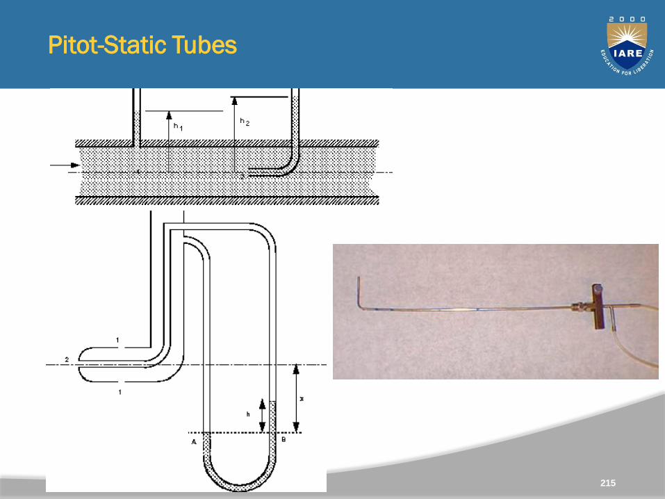
Pitot-Static Tubes
215
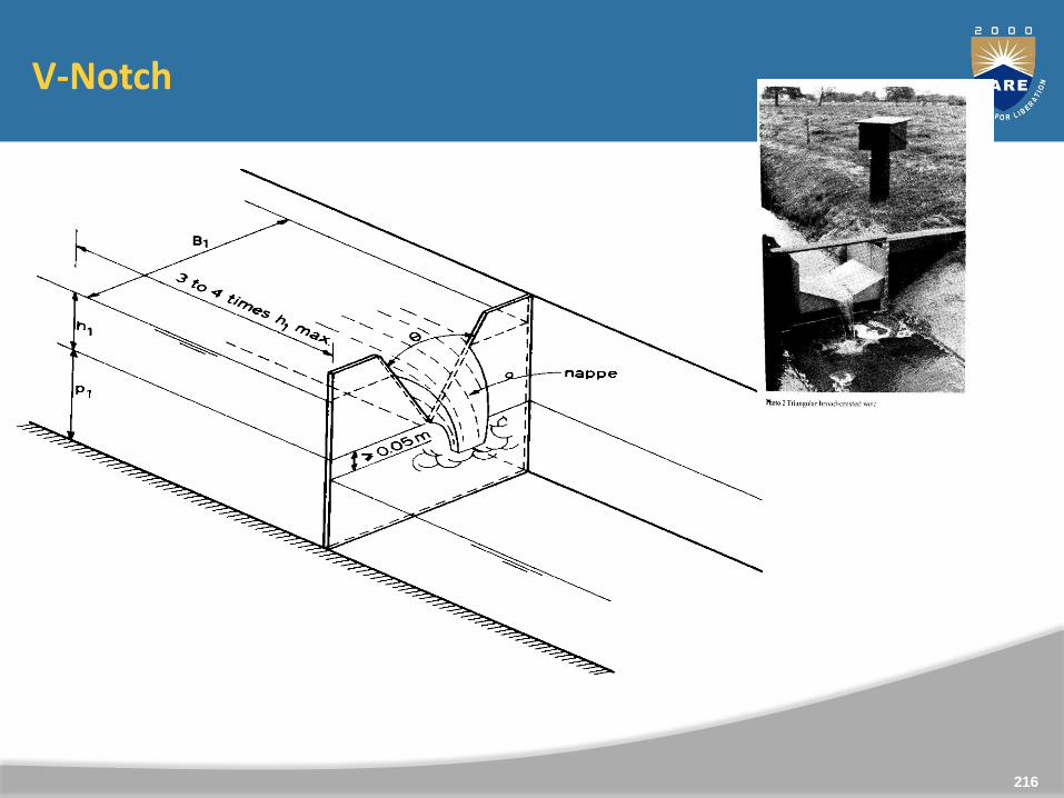
V-Notch
216
217
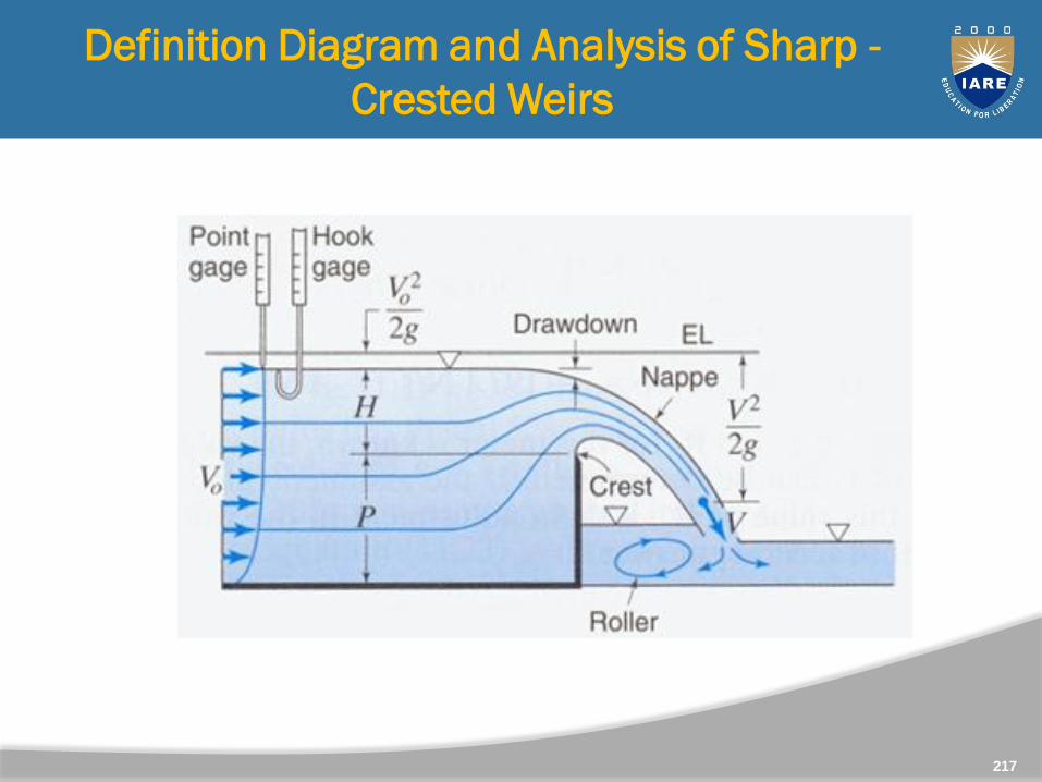
Definition Diagram and Analysis of Sharp -
Crested Weirs
Drawdown at crest is typically ~0.15
H
218
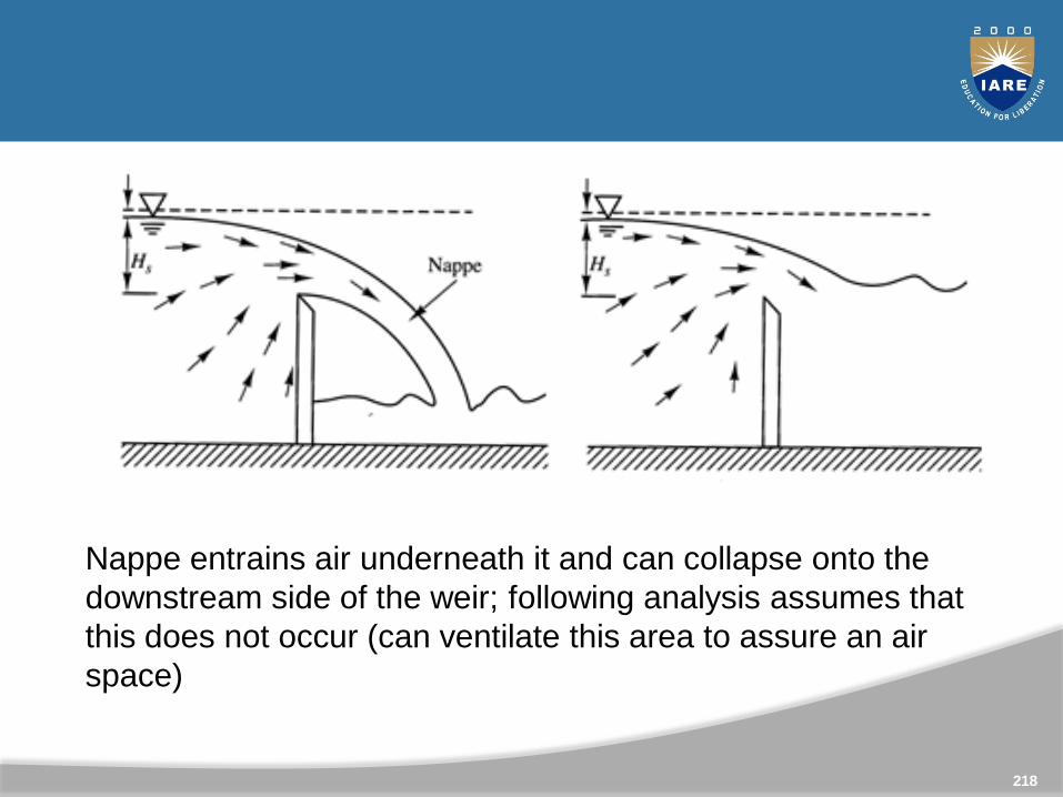
Nappe entrains air underneath it and can collapse onto the
downstream side of the weir; following analysis assumes that
this does not occur (can ventilate this area to assure an air
space)
219
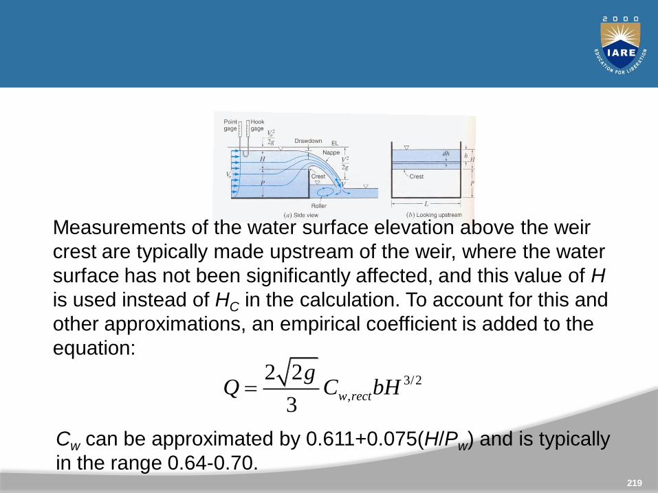
Measurements of the water surface elevation above the weir
crest are typically made upstream of the weir, where the water
surface has not been significantly affected, and this value of H
is used instead of HC in the calculation. To account for this and
other approximations, an empirical coefficient is added to the
equation:
3/2
,
2 2
3w rect
gQ C bH
Cw can be approximated by 0.611+0.075(H/Pw) and is typically
in the range 0.64-0.70.
Unit 4
BOUNDARY LAYER THEORY
220

221
CLO Course Learning Outcome
CLO10 Understand the Concept of boundary layer flowsand control of flow separation.
CLO11 Determine the flows over streamlined and bluffbodies to predict the drag and lift forces.
CLO12 Understand the thickness factor with respect toDisplacement, momentum and energy thickness.
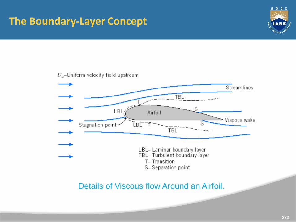
The Boundary-Layer Concept
Details of Viscous flow Around an Airfoil.
222
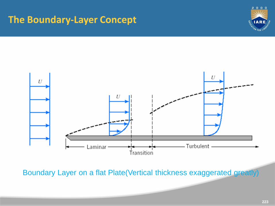
The Boundary-Layer Concept
Boundary Layer on a flat Plate(Vertical thickness exaggerated greatly)
223
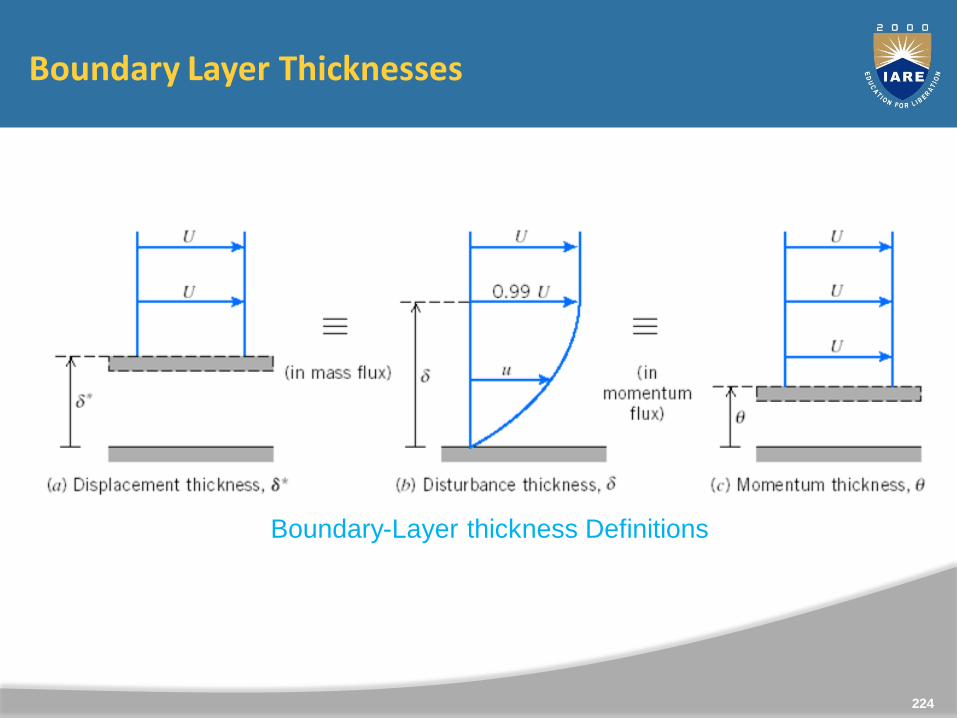
Boundary Layer Thicknesses
Boundary-Layer thickness Definitions
224
Boundary Layer Characteristics
0
y
vz
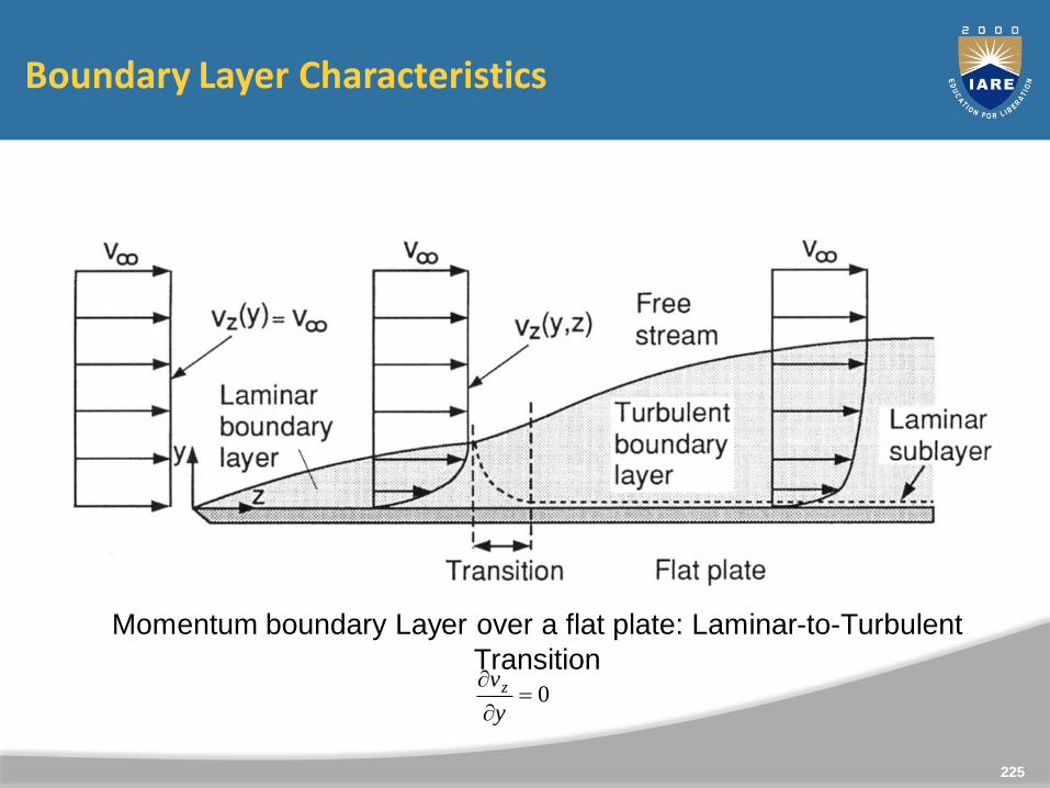
Momentum boundary Layer over a flat plate: Laminar-to-Turbulent
Transition
225
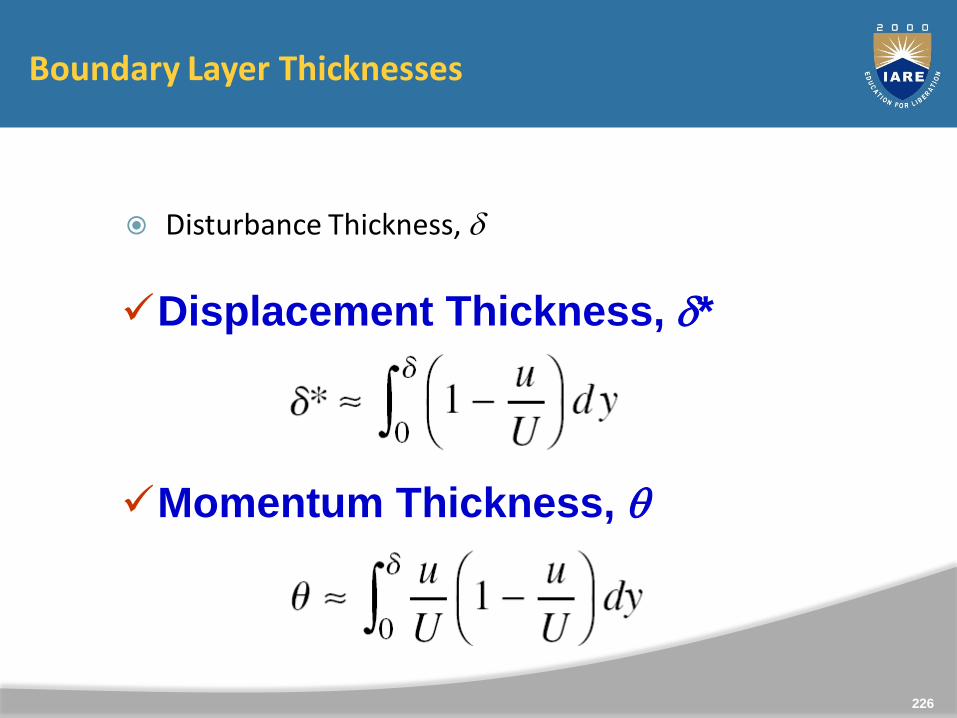
Boundary Layer Thicknesses
Disturbance Thickness, d
Displacement Thickness, d*
Momentum Thickness, q
226
Energy thickness
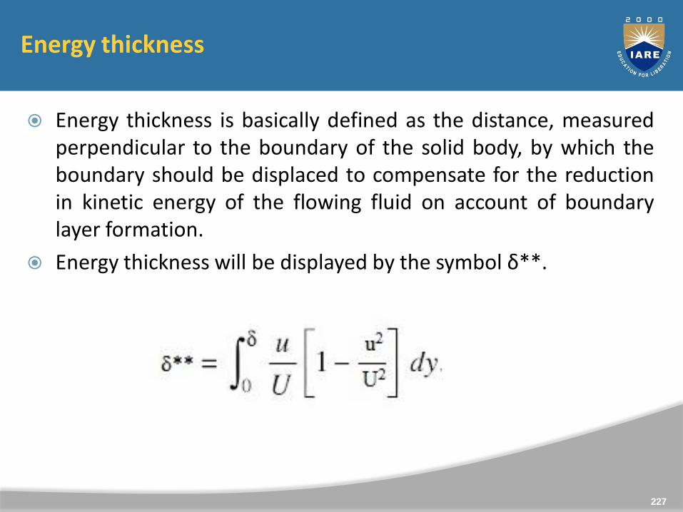
Energy thickness is basically defined as the distance, measuredperpendicular to the boundary of the solid body, by which theboundary should be displaced to compensate for the reductionin kinetic energy of the flowing fluid on account of boundarylayer formation.
Energy thickness will be displayed by the symbol δ**.
227
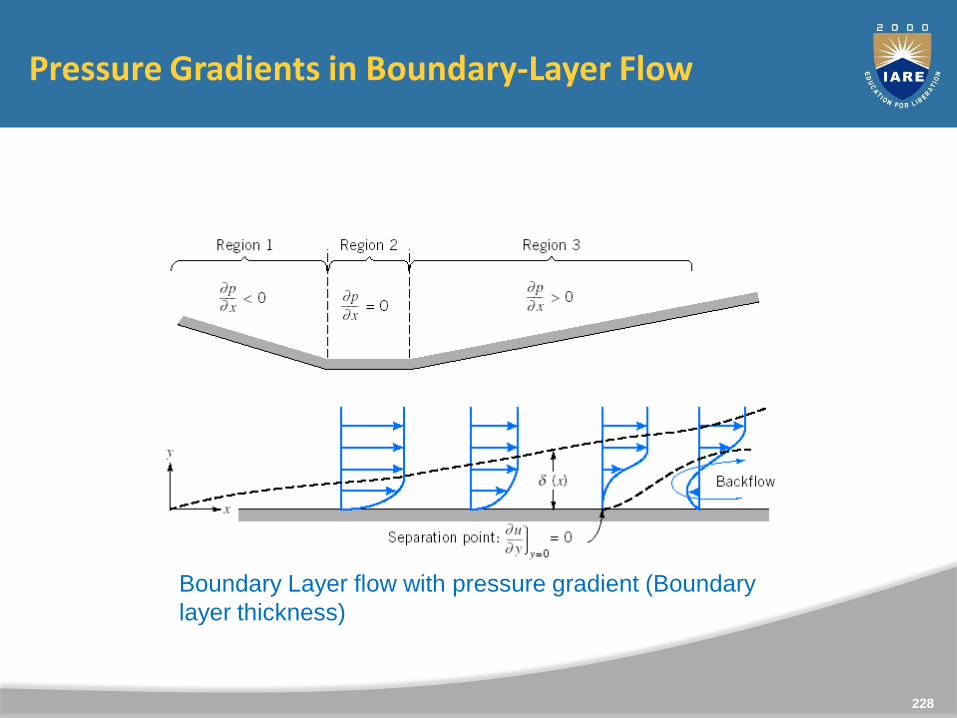
Pressure Gradients in Boundary-Layer Flow
Boundary Layer flow with pressure gradient (Boundary
layer thickness)
228
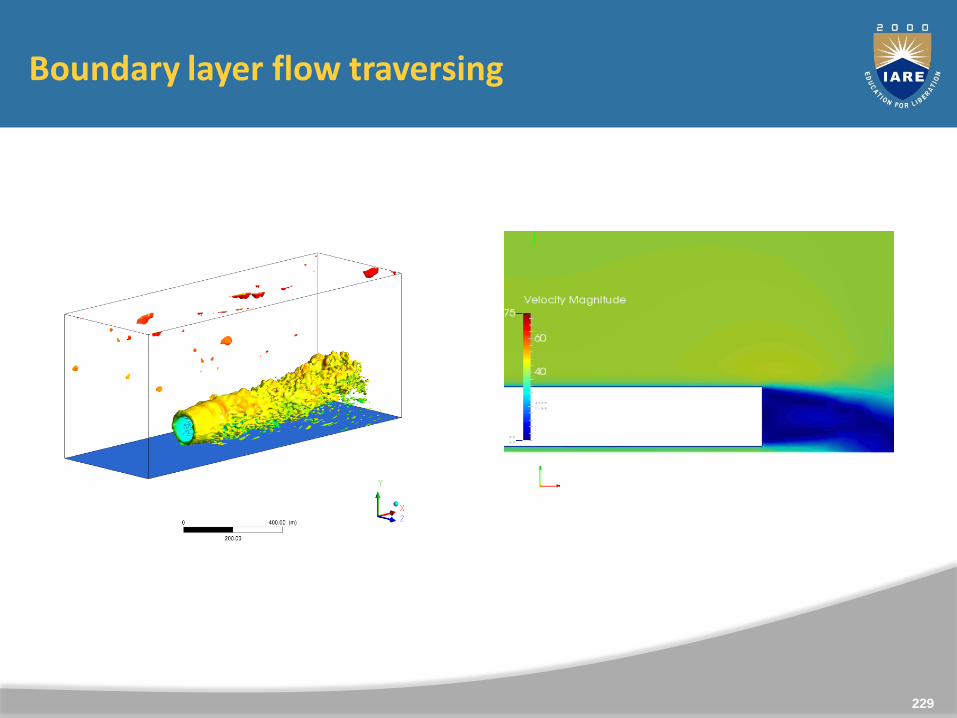
Boundary layer flow traversing
229
230
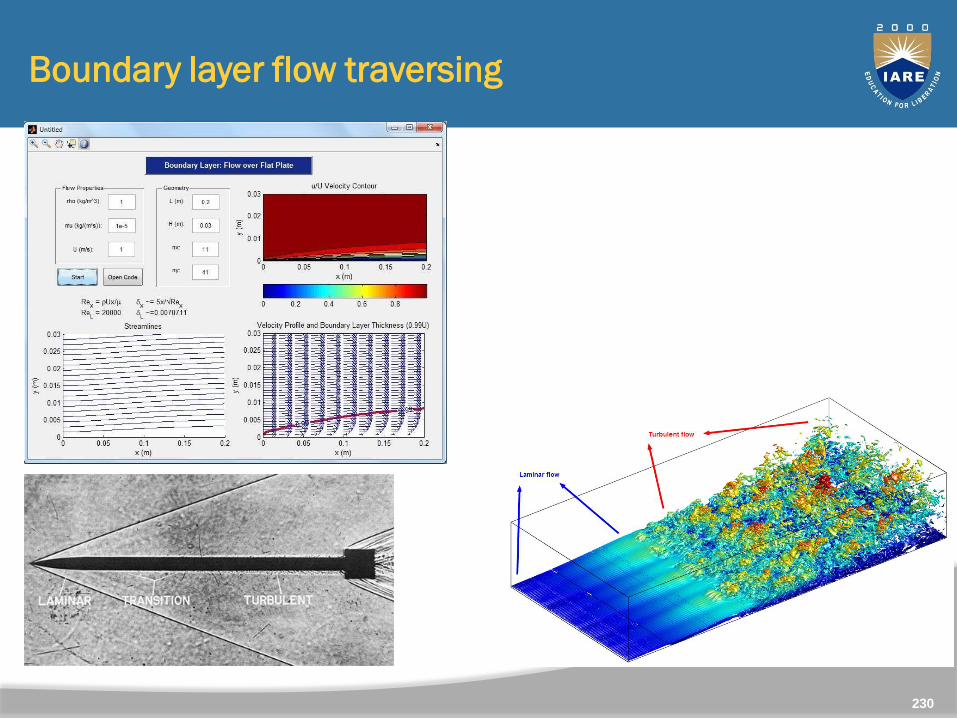
Boundary layer flow traversing
Methods of Preventing the Separation of Boundary Layer
Suction of the slow moving fluid by a suction slot
Supplying additional energy from the blower
Providing a bypass in the slotted wing
Rotating boundary in the direction of flow
Providing small divergence in a diffuser
Providing guide-blades in a bend
Providing a trip-wire ring in the laminar region for the flow asphere.
231
Lift force
FL = ½ CLρAPv2
FL is lift force,CL is the coefficient of lift,ρ is fluid density,AP is the projected area of the body or surface area orientatedperpendicular to the fluid flow, andv is relative velocity of the body with respect to the fluid.
Note: The size, shape and orientation of the body (angle of attack)in the fluid are essential for generating lift force. The lift forceincreases with the square of the flow of velocity similar to dragforce, but lift force increases are an advantage in sportingactivities.
232
233
The lift/drag ratio
The aim in sport is to maximize lift force while reducing dragforce. The angle of attack of projected objects (a swimmer’shand) is constantly changing throughout the flight path, andtherefore, the lift/drag ratio changes as well.
234
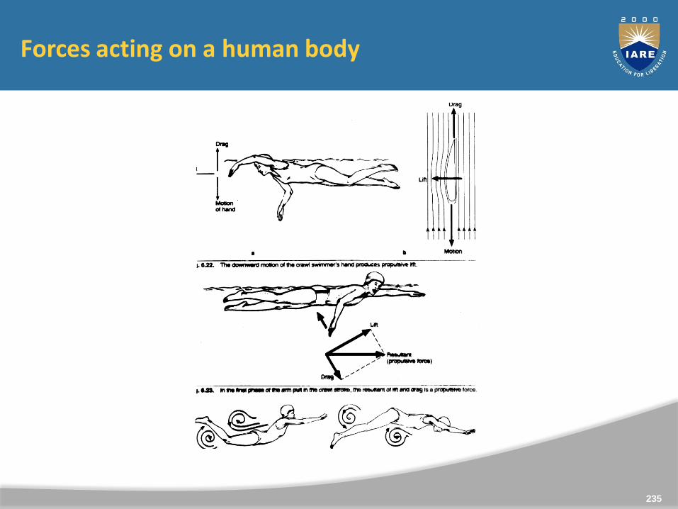
Forces acting on a human body
235

Drag
Drag Coefficient
with
or
236
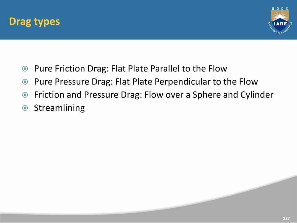
Drag types
Pure Friction Drag: Flat Plate Parallel to the Flow
Pure Pressure Drag: Flat Plate Perpendicular to the Flow
Friction and Pressure Drag: Flow over a Sphere and Cylinder
Streamlining
237
Drag
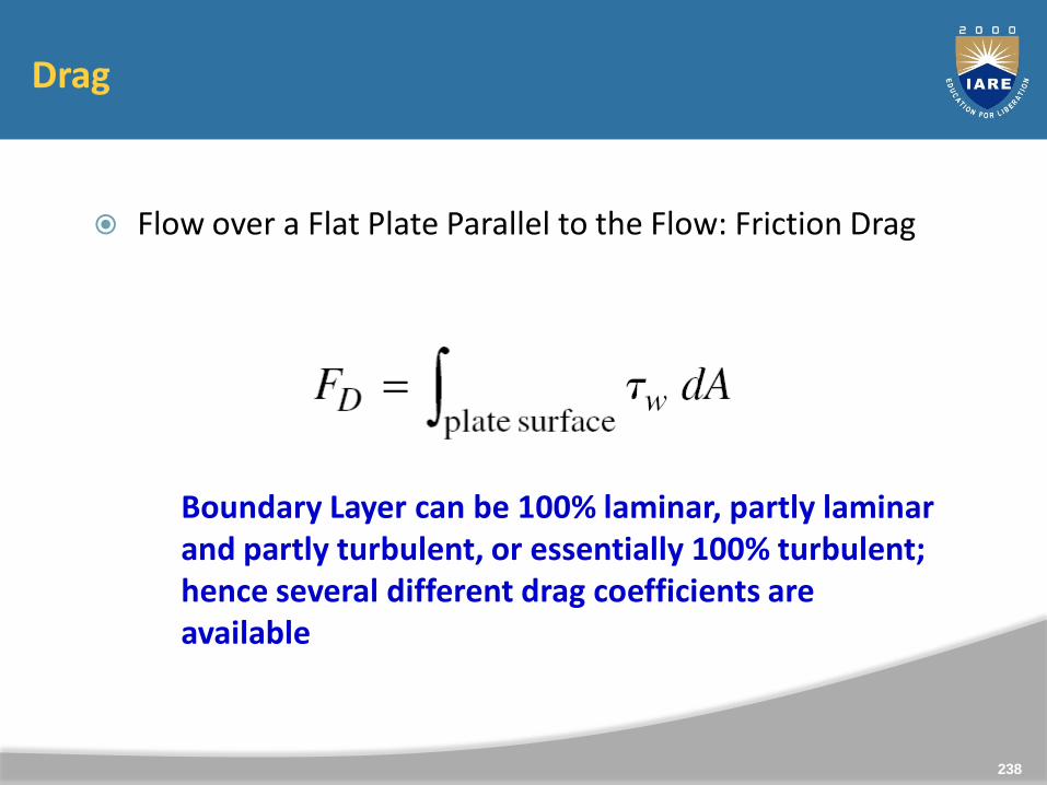
Flow over a Flat Plate Parallel to the Flow: Friction Drag
Boundary Layer can be 100% laminar, partly laminar and partly turbulent, or essentially 100% turbulent; hence several different drag coefficients are available
238
Drag
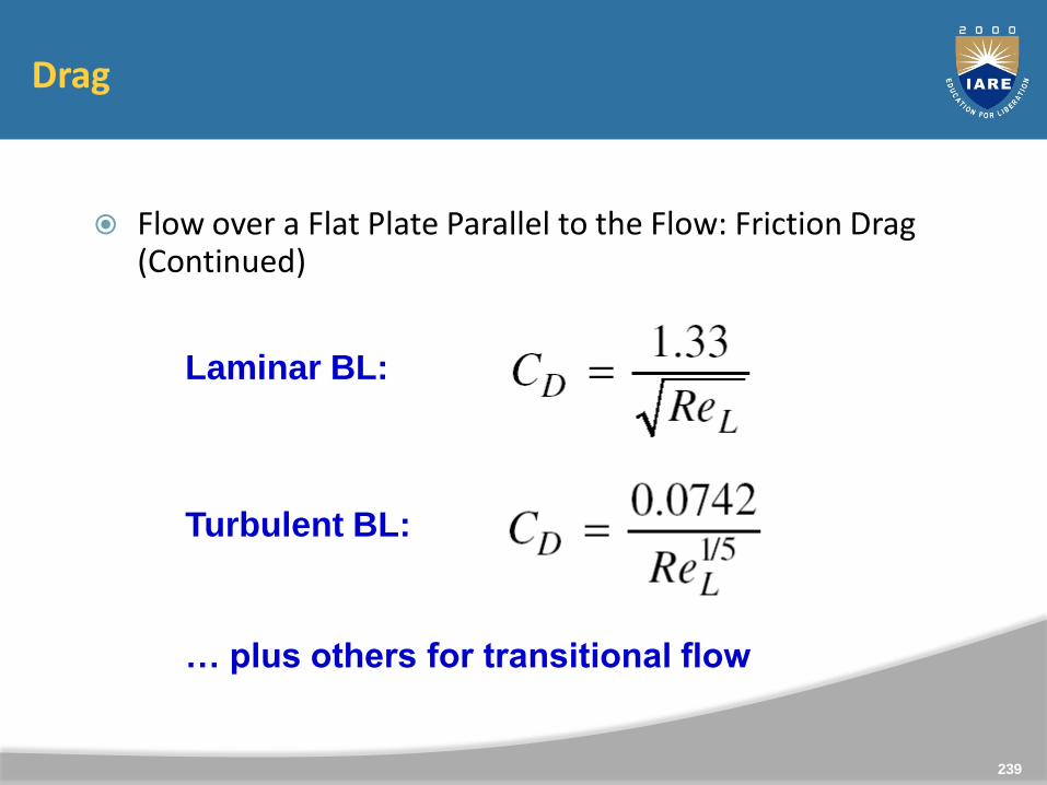
Flow over a Flat Plate Parallel to the Flow: Friction Drag (Continued)
Laminar BL:
Turbulent BL:
… plus others for transitional flow
239
Drag
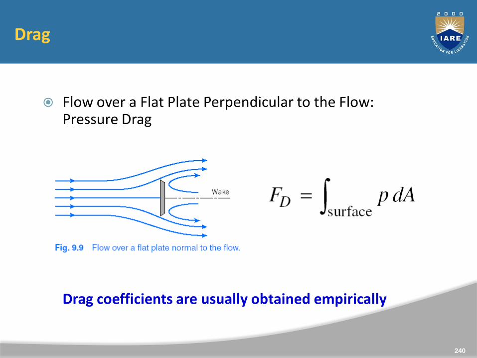
Flow over a Flat Plate Perpendicular to the Flow: Pressure Drag
Drag coefficients are usually obtained empirically
240
Drag
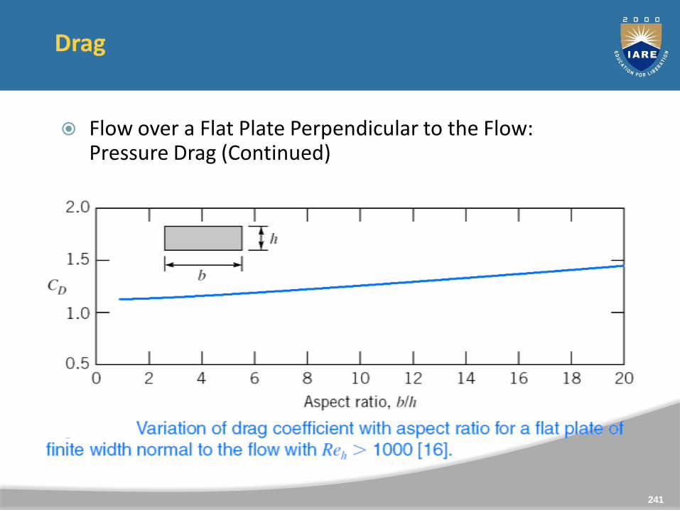
Flow over a Flat Plate Perpendicular to the Flow: Pressure Drag (Continued)
241

Drag
Flow over a Sphere and Cylinder: Friction and Pressure Drag
242
Drag
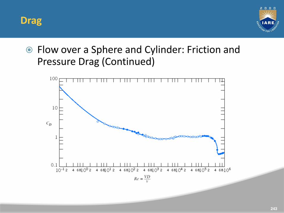
Flow over a Sphere and Cylinder: Friction and Pressure Drag (Continued)
243
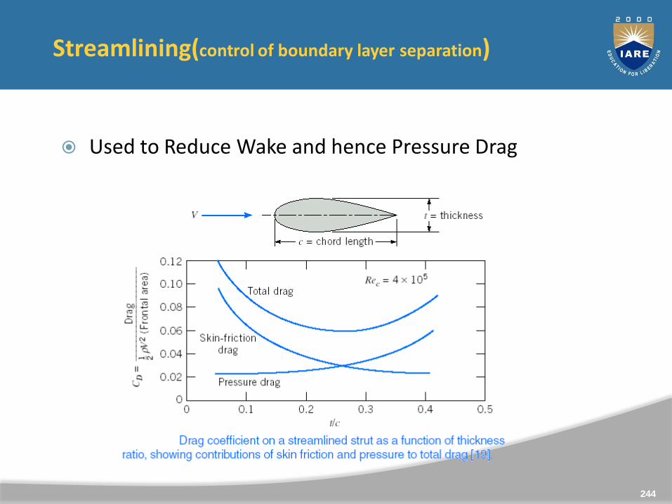
Streamlining(control of boundary layer separation)
Used to Reduce Wake and hence Pressure Drag
244
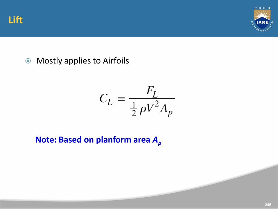
Lift
Mostly applies to Airfoils
Note: Based on planform area Ap
245
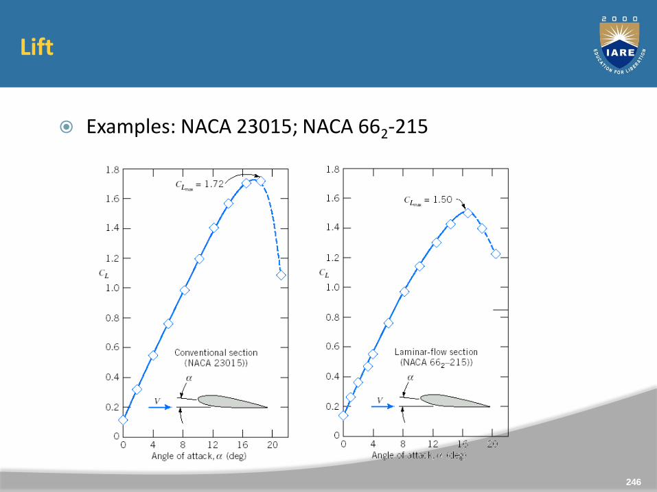
Lift
Examples: NACA 23015; NACA 662-215
246
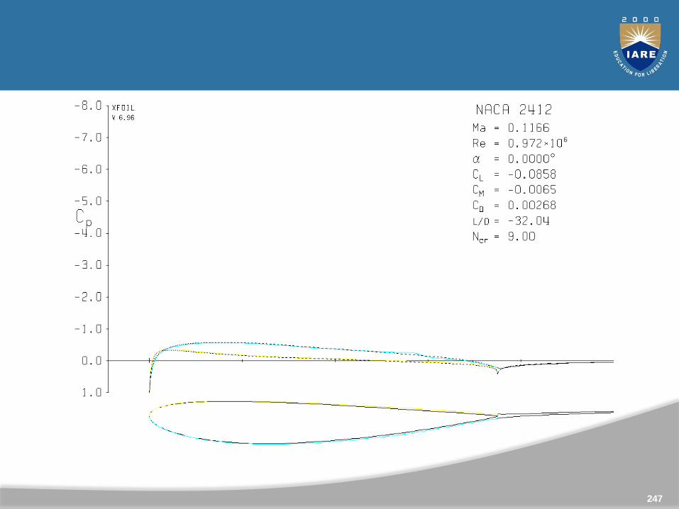
247
Lift
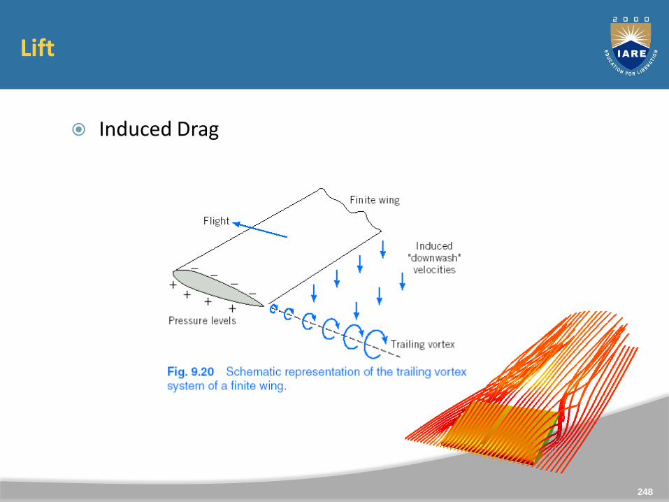
Induced Drag
248
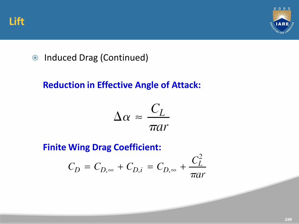
Lift
Induced Drag (Continued)
Reduction in Effective Angle of Attack:
Finite Wing Drag Coefficient:
249
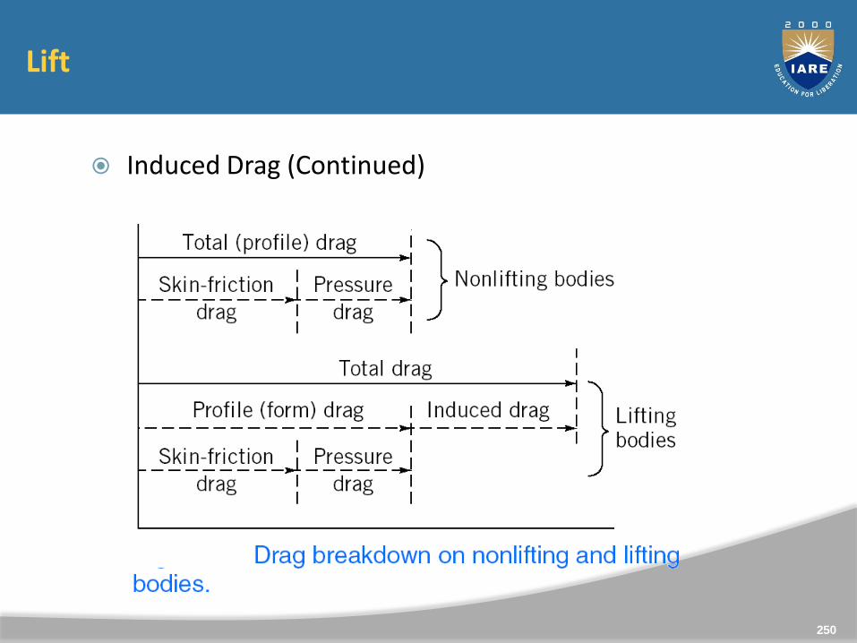
Lift
Induced Drag (Continued)
250
1. A flat plate 1.5m x 1.5m moves at 50 km/hr in stationary air ofdensity 1.15kg/m3. If the coefficients of drag and lift are 0.15and 0.75 respectively, determine
i. Lift force
ii. Drag force
iii. The resultant force and
iv. The power required to keep the plate in motion.
251
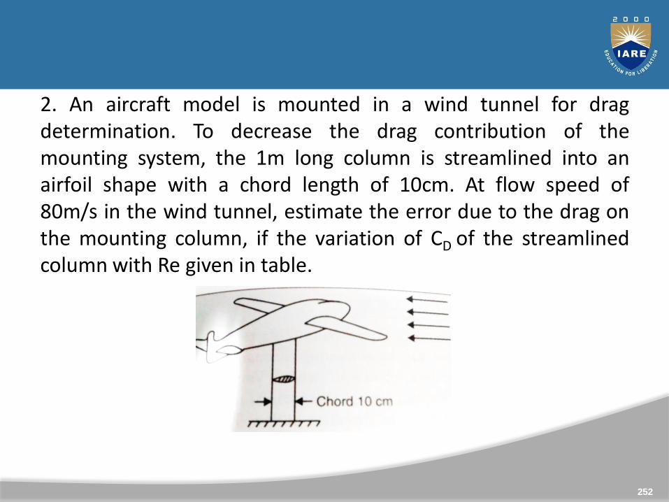
2. An aircraft model is mounted in a wind tunnel for dragdetermination. To decrease the drag contribution of themounting system, the 1m long column is streamlined into anairfoil shape with a chord length of 10cm. At flow speed of80m/s in the wind tunnel, estimate the error due to the drag onthe mounting column, if the variation of CD of the streamlinedcolumn with Re given in table.
252
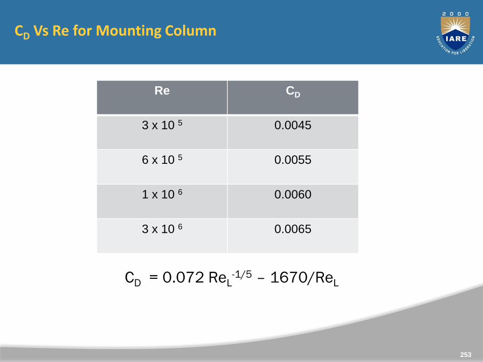
CD Vs Re for Mounting Column
253
CD = 0.072 ReL-1/5 – 1670/ReL
Re CD
3 x 10 5 0.0045
6 x 10 5 0.0055
1 x 10 6 0.0060
3 x 10 6 0.0065
Unit 5
Turbo Machinery
254
255
CLO Course Learning Outcome
CLO13 Explain about the turbo machinery systems and working.
CLO14 Describe the concepts of turbo machinery in the field ofaerospace engineering and concepts of internal flowsthrough engines.
CLO15 Demonstrate the knowledge gained from the working ofcompressors, fans and pumps.
Syllabus
Introduction and classification of fluid machines: Turbomachinery analysis; The angular momentum principle;Euler turbo machine equation; Application to fluidsystems, working principle overview of turbines, fans,pumps and compressors.
256
Introduction
A fluid machine is a device which converts the energystored by a fluid into mechanical energy or vice versa.
The energy stored by a fluid mass appears in the formof potential, kinetic and intermolecular energy.
The mechanical energy, on the other hand, is usuallytransmitted by a rotating shaft.
Machines using liquid (mainly water, for almost allpractical purposes) are termed as hydraulic machines.
257
CLASSIFICATIONS OF FLUID MACHINES
The fluid machines may be classified under differentcategories as follows:
Classification Based on Direction of EnergyConversion.
Classification Based on Principle of Operation
Classification Based on Fluid Used
258
Classification Based on Direction of Energy Conversion
The device in which the kinetic, potential orintermolecular energy held by the fluid is converted inthe form of mechanical energy of a rotating member isknown as a turbine .
The machines, on the other hand, where themechanical energy from moving parts is transferred toa fluid to increase its stored energy by increasing eitherits pressure or velocity are known as pumps,compressors, fans or blowers .
259
Classification Based on Principle of Operation
The machines whose functioning depend essentially onthe change of volume of a certain amount of fluidwithin the machine are known as positive displacementmachines.
The word positive displacement comes from the factthat there is a physical displacement of the boundaryof a certain fluid mass as a closed system.
The machines, functioning of which depend basicallyon the principle of fluid dynamics, are knownas rotodynamic machines.
260
For turbines, the work is done by the fluid on the rotor,while, in case of pump, compressor, fan or blower, thework is done by the rotor on the fluid element.Depending upon the main direction of fluid path in therotor, the machine is termed as radial flow or axial flowmachine .
261
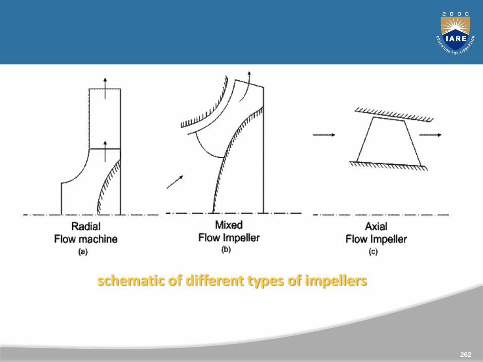
schematic of different types of impellers
262
Classification Based on Fluid Used
The fluid machines use either liquid or gas as theworking fluid depending upon the purpose.
The machine transferring mechanical energy of rotor tothe energy of fluid is termed as a pump when it usesliquid, and is termed as a compressor or a fan or ablower, when it uses gas.
The compressor is a machine where the main objectiveis to increase the static pressure of a gas.
263
ROTODYNAMIC MACHINES
The important element of a rotodynamic machine, ingeneral, is a rotor consisting of a number of vanes orblades. There always exists a relative motion betweenthe rotor vanes and the fluid. The fluid has acomponent of velocity and hence of momentum in adirection tangential to the rotor. While flowing throughthe rotor, tangential velocity and hence the momentumchanges.
264
The rate at which this tangential momentum changescorresponds to a tangential force on the rotor. In aturbine, the tangential momentum of the fluid isreduced and therefore work is done by the fluid to themoving rotor.
But in case of pumps and compressors there is anincrease in the tangential momentum of the fluid andtherefore work is absorbed by the fluid from themoving rotor.
265
Turbo machinery analysis
The word turbo implies a spinning action is involved. Inturbomachinery a blade or row of blades rotates and imparts orextracts energy to or from the fluid. Work is generated orextracted by means of enthalpy changes in the working fluid.
In general, two kinds of turbomachines are encountered inpractice.
These are open and closed turbomachines. Open machines suchas propellers, windmills, and unshrouded fans act on an infiniteextent of fluid, whereas, closed machines operate on a finitequantity of fluid as it passes through a housing or casing.
We will examine only turbomachines of the closed type.
266
Basic Equation of Energy Transfer in RotodynamicMachines
The basic equation of fluid dynamics relating to energytransfer is same for all roto-dynamic machines and is asimple form of "Newton 's Laws of Motion" applied to afluid element traversing a rotor.
Here we shall make use of the momentum theorem asapplicable to a fluid element while flowing throughfixed and moving vanes.
267

Figure represents diagrammatically a rotor of a generalisedfluid machine, with 0-0 the axis of rotation and ω theangular velocity.
Fluid enters the rotor at 1, passes through the rotor by anypath and is discharged at 2. The points 1 and 2 are at radiir1 and r2 from the centre of the rotor, and the directions offluid velocities at 1 and 2 may be at any arbitrary angles.
268
For the analysis of energy transfer due to fluid flow in thissituation, we assume the following:
(a) The flow is steady, that is, the mass flow rate is constantacross any section (no storage or depletion of fluid mass in therotor).
(b) The heat and work interactions between the rotor and itssurroundings take place at a constant rate.
(c) Velocity is uniform over any area normal to the flow. Thismeans that the velocity vector at any point is representative ofthe total flow over a finite area. This condition also implies thatthere is no leakage loss and the entire fluid is undergoing thesame process.
269

Components of flow velocity in a generalised fluid machine
270

The velocity at any point may be resolved into threemutually perpendicular components as shown in Fig.
The axial component of velocity Va is directed parallel to theaxis of rotation, the radial component Vf is directed radiallythrough the axis to rotation, while the tangential componentVw is directed at right angles to the radial direction and alongthe tangent to the rotor at that part.
271
The change in magnitude of the axial velocity componentsthrough the rotor causes a change in the axial momentum.
This change gives rise to an axial force, which must be taken bya thrust bearing to the stationary rotor casing.
The change in magnitude of radial velocity causes a change inmomentum in radial direction.
However, for an axisymmetric flow, this does not result in anynet radial force on the rotor. In case of a non uniform flowdistribution over the periphery of the rotor in practice, a changein momentum in radial direction may result in a net radial forcewhich is carried as a journal load.
272
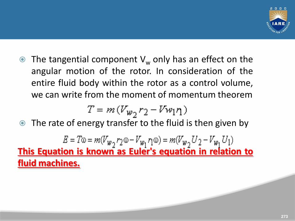
The tangential component Vw only has an effect on theangular motion of the rotor. In consideration of theentire fluid body within the rotor as a control volume,we can write from the moment of momentum theorem
The rate of energy transfer to the fluid is then given by
This Equation is known as Euler's equation in relation tofluid machines.
273
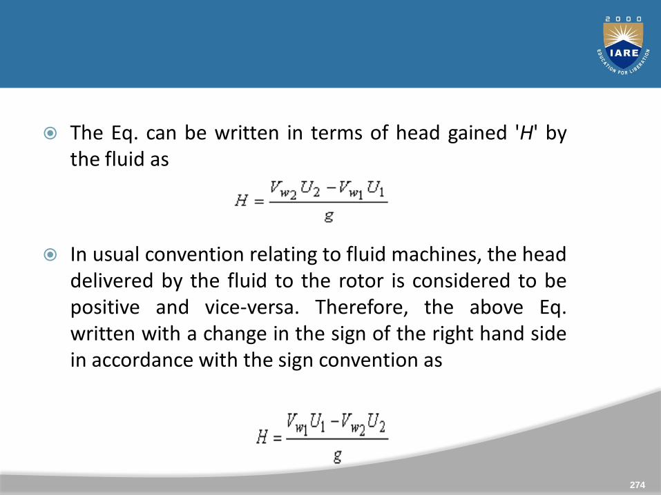
The Eq. can be written in terms of head gained 'H' bythe fluid as
In usual convention relating to fluid machines, the headdelivered by the fluid to the rotor is considered to bepositive and vice-versa. Therefore, the above Eq.written with a change in the sign of the right hand sidein accordance with the sign convention as
274
Components of Energy Transfer It is worth mentioningin this context that either of the Eqs. (1.2) and (1.4) isapplicable regardless of changes in density orcomponents of velocity in other directions.
Moreover, the shape of the path taken by the fluid inmoving from inlet to outlet is of no consequence.
The expression involves only the inlet and outletconditions. A rotor, the moving part of a fluid machine,usually consists of a number of vanes or bladesmounted on a circular disc.
275
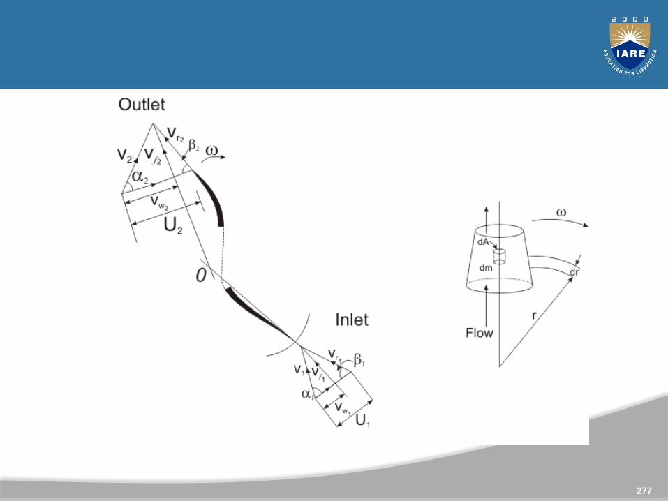
Figure 2a shows the velocity triangles at the inlet andoutlet of a rotor. The inlet and outlet portions of a rotorvane are only shown as a representative of the wholerotor.
276
277

Application to fluid systems and working principle overview of turbines
278
Velocity Triangles
In turbomachinery, a velocity triangle ora velocity diagram is a triangle representing thevarious components of velocities of the working fluid ina turbomachine.
Velocity triangles may be drawn for both the inlet andoutlet sections of any turbomachine.
279
280
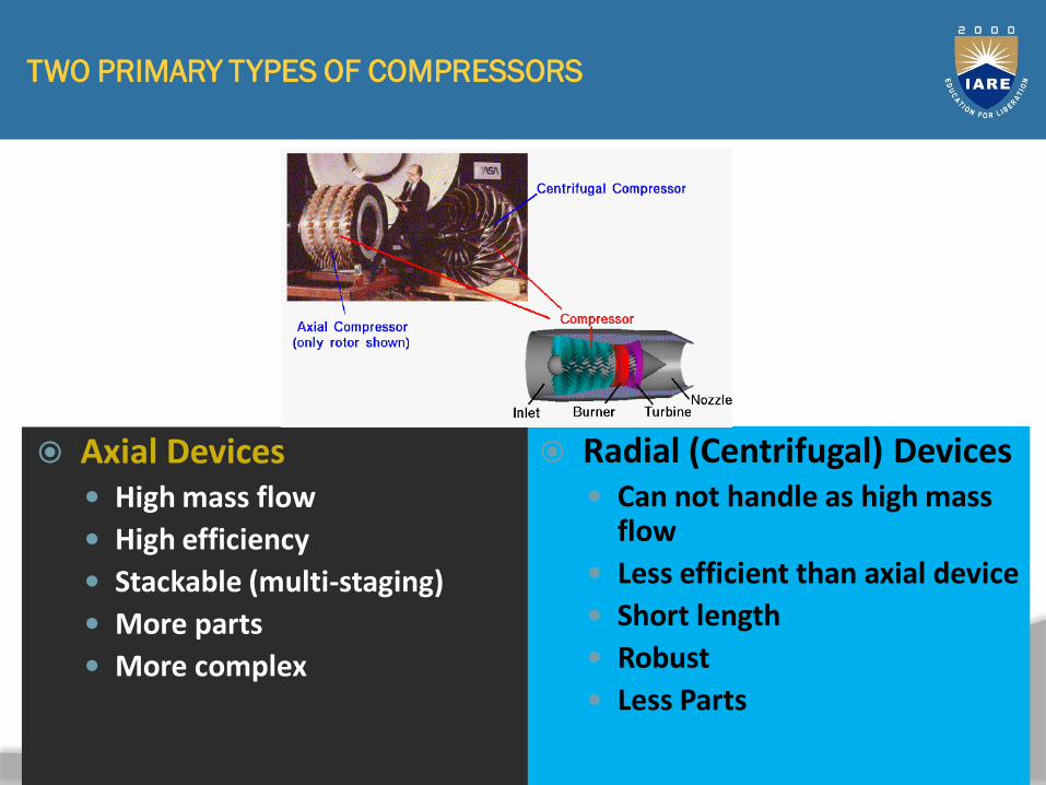
TWO PRIMARY TYPES OF COMPRESSORS
Radial (Centrifugal) Devices Can not handle as high mass
flow
Less efficient than axial device
Short length
Robust
Less Parts
Axial Devices High mass flow
High efficiency
Stackable (multi-staging)
More parts
More complex
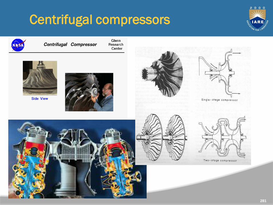
Centrifugal compressors
281
28
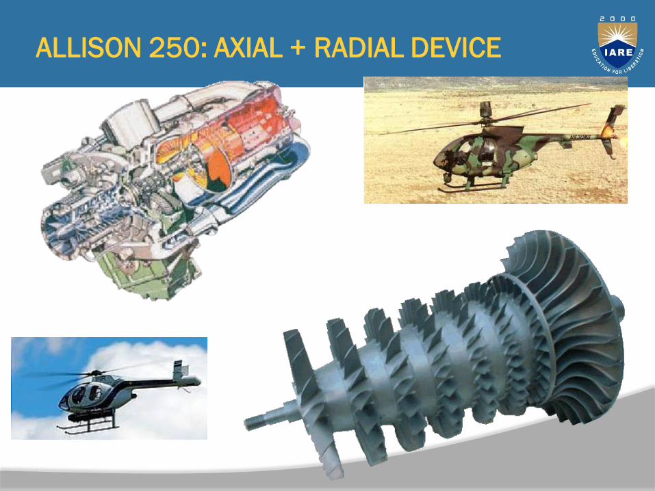
2ALLISON 250: AXIAL + RADIAL DEVICE
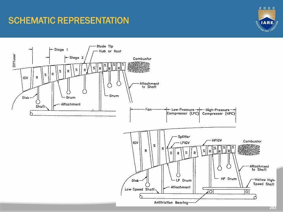
SCHEMATIC REPRESENTATION
Single Shaft Compressor
Twin-Spool Turbofan
283
28
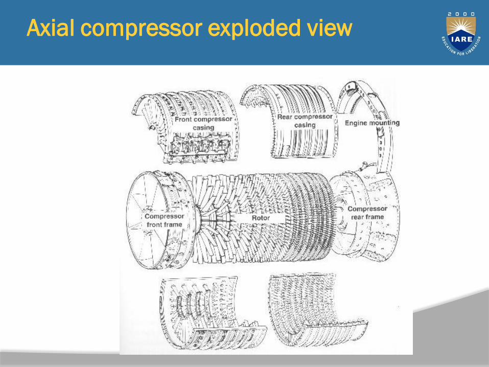
4Axial compressor exploded view
28
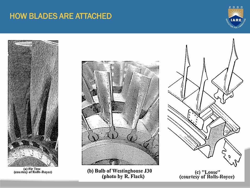
5HOW BLADES ARE ATTACHED
28
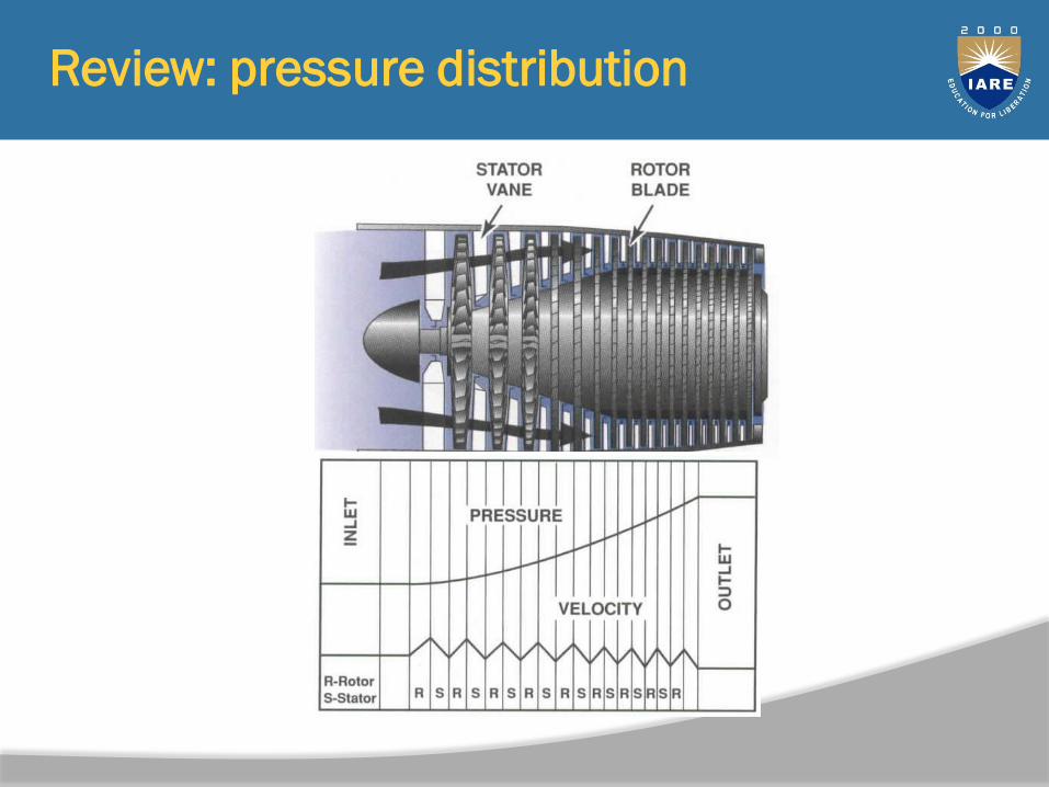
6Review: pressure distribution
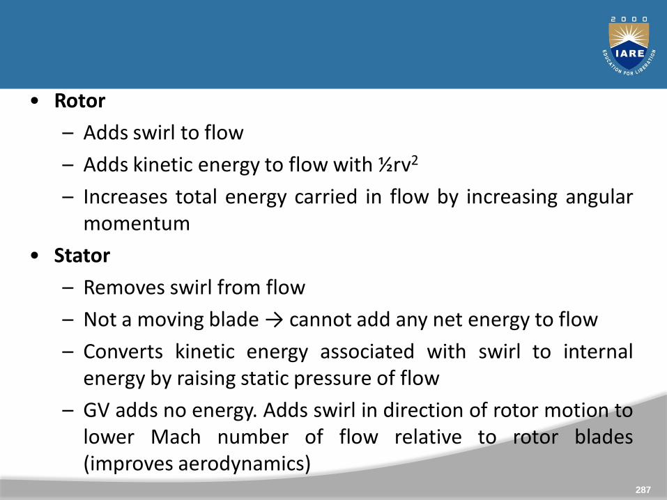
• Rotor
– Adds swirl to flow
– Adds kinetic energy to flow with ½rv2
– Increases total energy carried in flow by increasing angularmomentum
• Stator
– Removes swirl from flow
– Not a moving blade → cannot add any net energy to flow
– Converts kinetic energy associated with swirl to internalenergy by raising static pressure of flow
– GV adds no energy. Adds swirl in direction of rotor motion tolower Mach number of flow relative to rotor blades(improves aerodynamics)
287
28
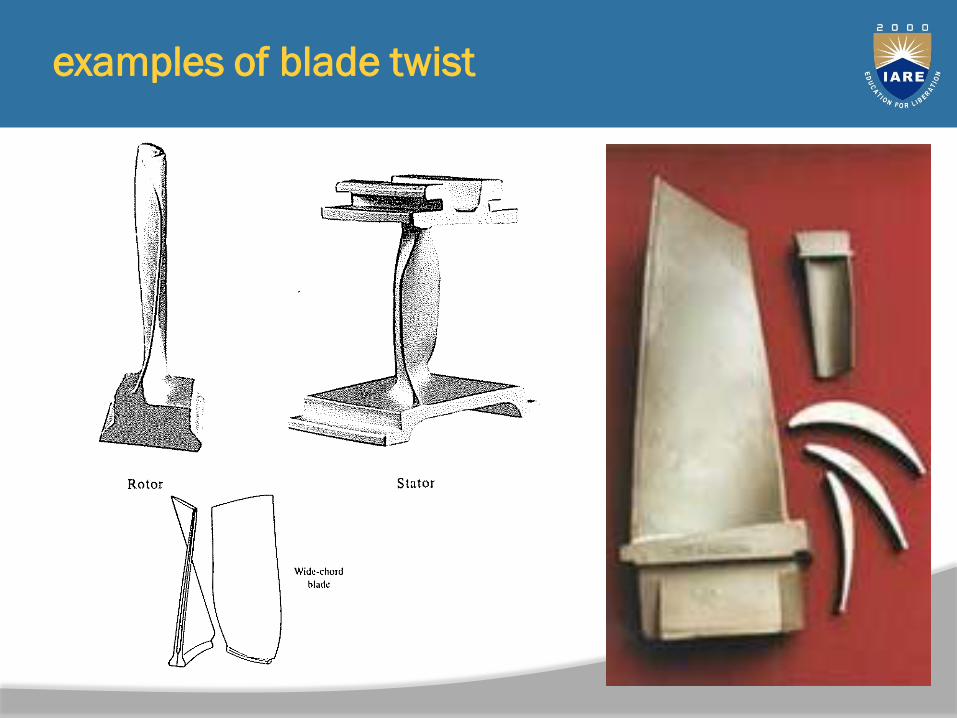
8examples of blade twist
28
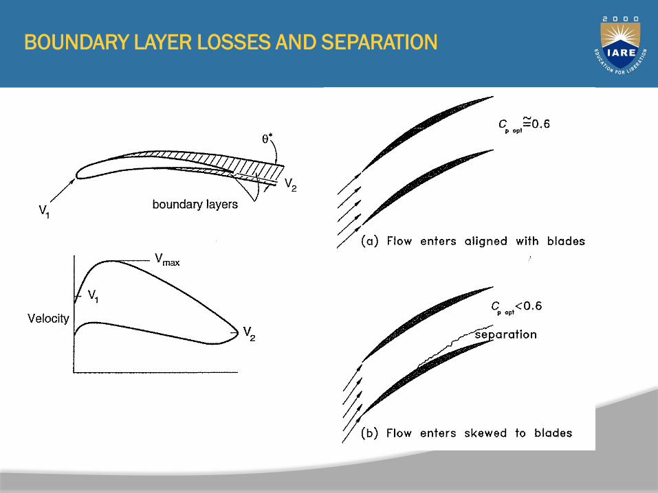
9BOUNDARY LAYER LOSSES AND SEPARATION
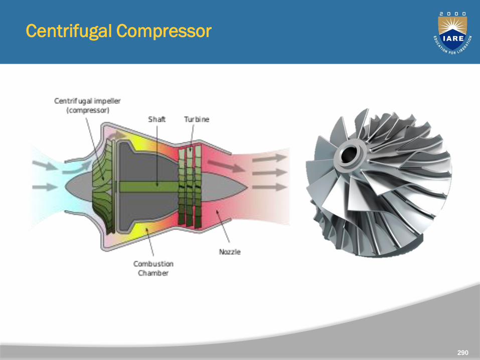
Centrifugal Compressor
290
Turbomachines employing centrifugal effects for increasingfluid pressure have been in use for more than a century.
The earliest machines using this method were hydraulicpumps followed later by ventilating fans and blowers.
A centrifugal compressor was incorporated in the Whittleturbojet engine.
Axial flow compressors are more suitable for larger enginesin terms of smaller frontal area (and drag) and 3-4% higherefficiency for the same duty than centrifugal compressors.
291
But for very small compressors with low flow rates, theefficiency of axial compressors drops sharply, blading is smalland difficult to make accurately, and the centrifugalcompressor is again preferable .
Many applications are found in small gas turbines for roadvehicles and commercial helicopters as well as biggerapplications, e.g., diesel engine turbochargers, chemical plantprocesses, factory workshop air supplies, large-scale air-conditioning plant, etc.
292
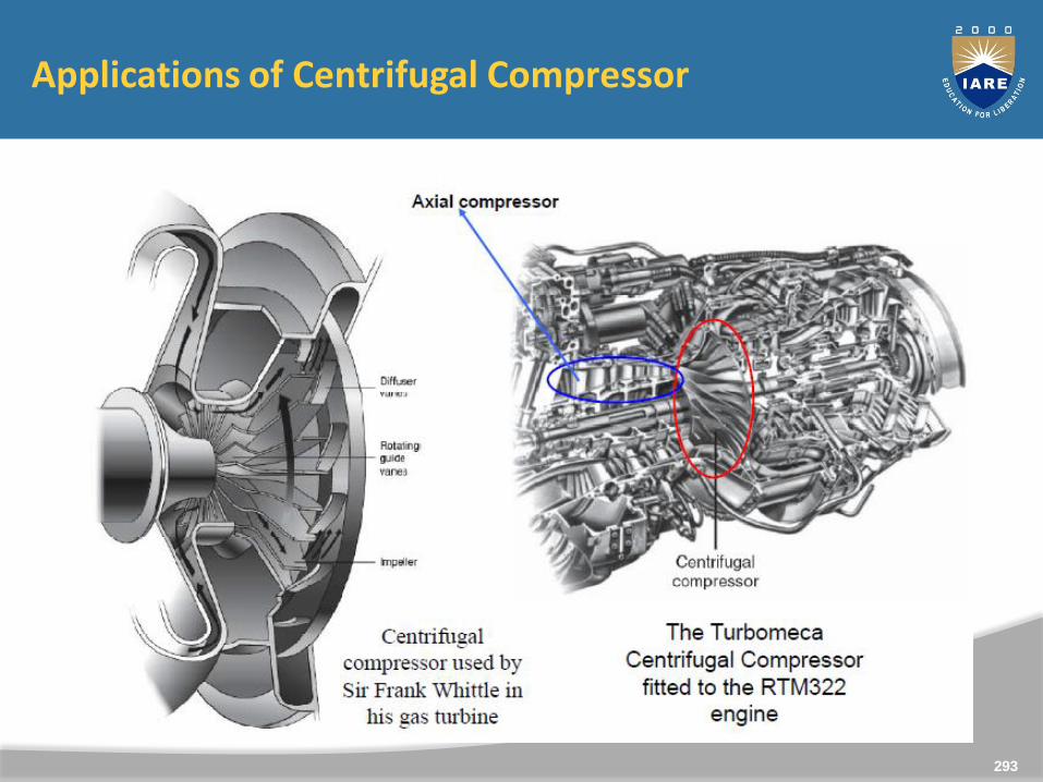
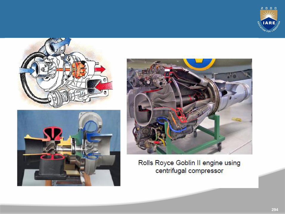
Applications of Centrifugal Compressor
293
294
A centrifugal compressor essentially consists of three components.
A stationary casing
A rotating impeller as shown in fig (a) which imparts ahigh velocity to the air. The impeller may be single ordouble sided as show in Fig. (b) and (c), but thefundamental theory is same for both.
A diffuser consisting of a number of fixed divergingpassages in which the air is decelerated with aconsequent rise in static pressure.
295
Principle of operation: Air is sucked into the impellereye and whirled outwards at high speed by theimpeller disk. At any point in the flow of air through theimpeller the centripetal acceleration is obtained by apressure head so that the static pressure of the airincreases from the eye to the tip of the impeller. Theremainder of the static pressure rise is obtained in thediffuser, where the very high velocity of air leaving theimpeller tip is reduced to almost the velocity withwhich the air enters the impeller eye.
296
Usually, about half of the total pressure rise occurs in theimpeller and the other half in the diffuser. Owing to theaction of the vanes in carrying the air around with theimpeller, there is a slightly higher static pressure on theforward side of the vane than on the trailing face. The air willthus tend to flow around the edge of the vanes in theclearing space between the impeller and the casing. Thisresults in a loss of efficiency and the clearance must be keptas small as possible. Sometimes, a shroud attached to theblades as shown in Figure.(d) may eliminate such a loss, but itis avoided because of increased disc friction loss and ofmanufacturing difficulties.
297
The straight and radial blades are usually employed to avoidany undesirable bending stress to be set up in the blades. Thechoice of radial blades also determines that the totalpressure rise is divided equally between impeller anddiffuser.
298
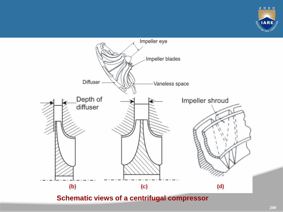
Schematic views of a centrifugal compressor
299
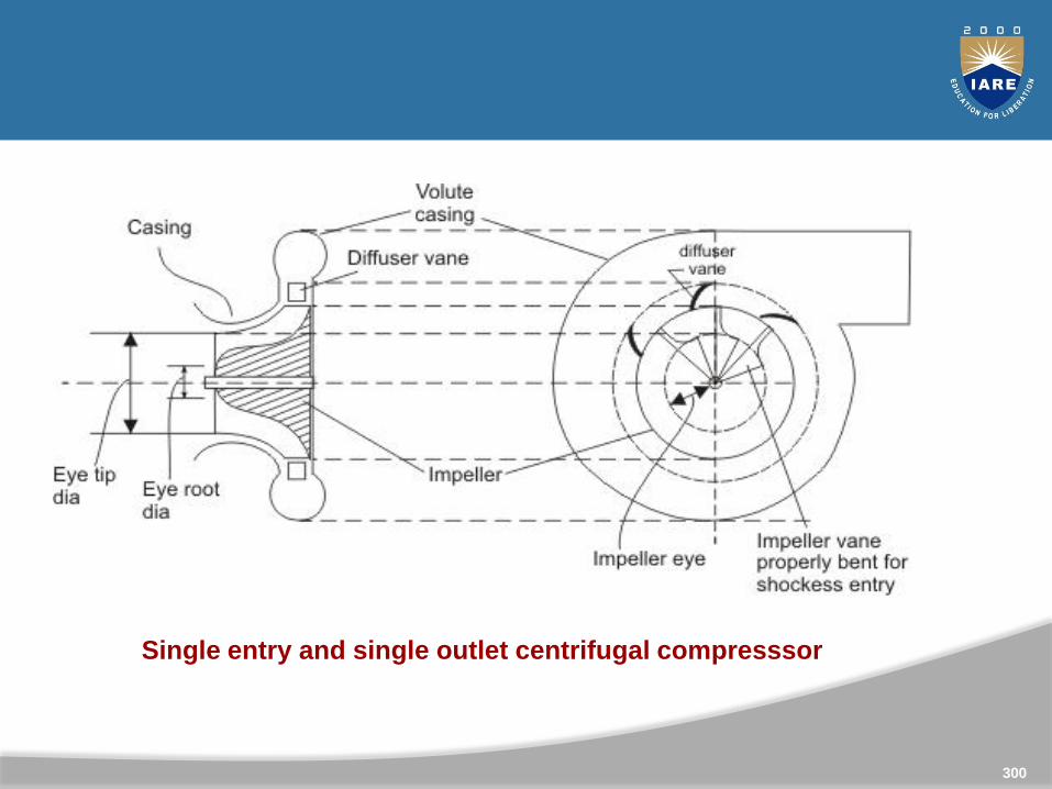
Single entry and single outlet centrifugal compresssor
300
Before further discussions following points are worthmentioning for a centrifugal compresssor.
(i) The pressure rise per stage is high and the volumeflow rate tends to be low. The pressure rise per stage isgenerally limited to 4:1 for smooth operations.
(ii) Blade geometry is relatively simple and smallforeign material does not affect much on operationalcharacteristics.
(iii) Centrifugal impellers have lower efficiencycompared to axial impellers and when used in aircraftengine it increases frontal area and thus drag.Multistaging is also difficult to achieve in case ofcentrifugal machines.
301
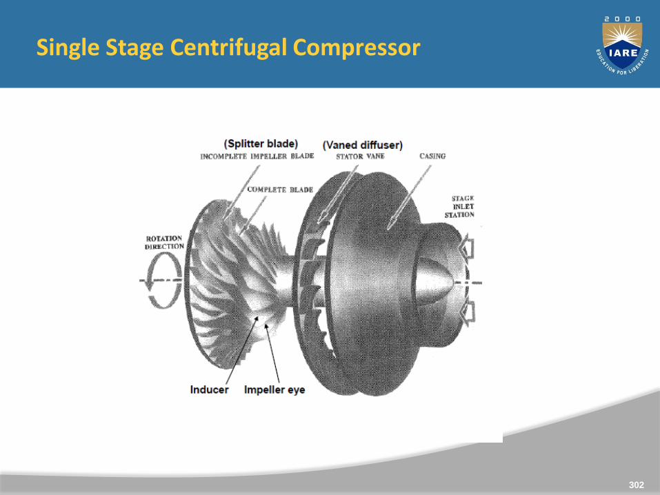
Single Stage Centrifugal Compressor
302
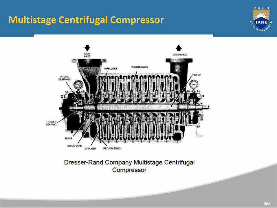
Multistage Centrifugal Compressor
303
Pumps
Rotodynamic Pumps
A rotodynamic pump is a device where mechanicalenergy is transferred from the rotor to the fluid by theprinciple of fluid motion through it. The energy of thefluid can be sensed from the pressure and velocity ofthe fluid at the delivery end of the pump. Therefore, itis essentially a turbine in reverse. Like turbines, pumpsare classified according to the main direction of fluidpath through them like (i) radial flow or centrifugal, (ii)axial flow and (iii) mixed flow types.
304
Centrifugal Pumps
The pumps employing centrifugal effects for increasingfluid pressure have been in use for more than acentury. The centrifugal pump, by its principle, isconverse of the Francis turbine. The flow is radiallyoutward, and the hence the fluid gains in centrifugalhead while flowing through it. Because of certaininherent advantages, such as compactness, smoothand uniform flow, low initial cost and high efficiencyeven at low heads, centrifugal pumps are used inalmost all pumping systems.
305
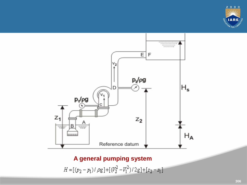
A general pumping system
306
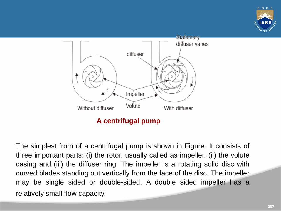
A centrifugal pump
The simplest from of a centrifugal pump is shown in Figure. It consists of
three important parts: (i) the rotor, usually called as impeller, (ii) the volute
casing and (iii) the diffuser ring. The impeller is a rotating solid disc with
curved blades standing out vertically from the face of the disc. The impeller
may be single sided or double-sided. A double sided impeller has a
relatively small flow capacity.
307
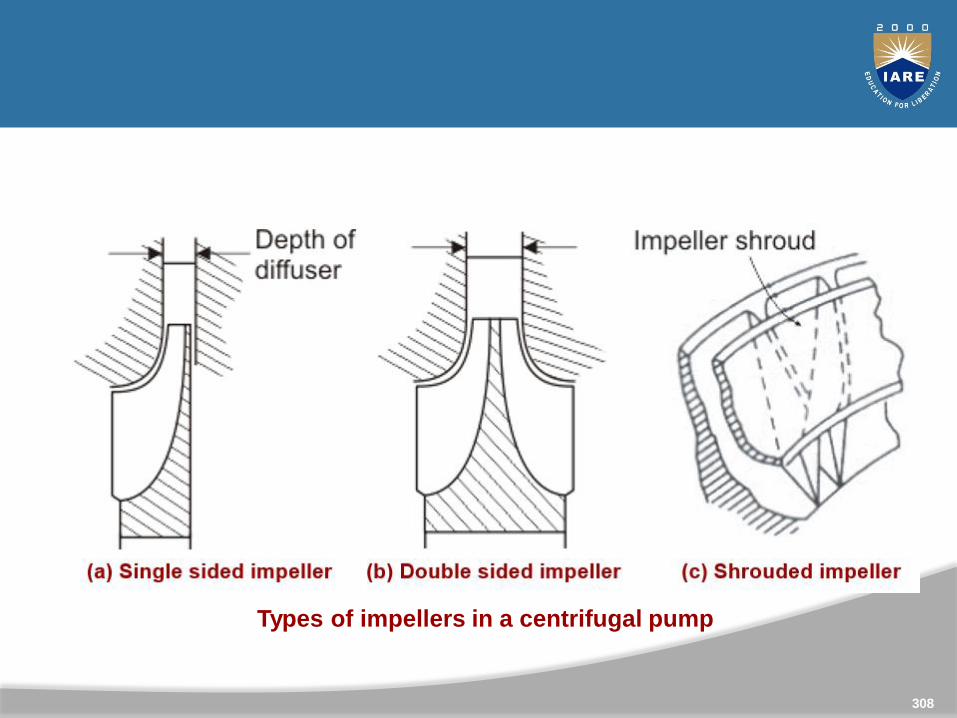
Types of impellers in a centrifugal pump
308
Axial Flow or Propeller Pump
The axial flow or propeller pump is the converse of axialflow turbine and is very similar to it an appearance.
The impeller consists of a central boss with a number ofblades mounted on it.
The impeller rotates within a cylindrical casing with fineclearance between the blade tips and the casing walls.
Fluid particles, in course of their flow through the pump, donot change their radial locations.
309
The inlet guide vanes are provided to properly directthe fluid to the rotor. The outlet guide vanes areprovided to eliminate the whirling component ofvelocity at discharge.
The usual number of impeller blades lies between 2and 8, with a hub diameter to impeller diameter ratioof 0.3 to 0.6.
310
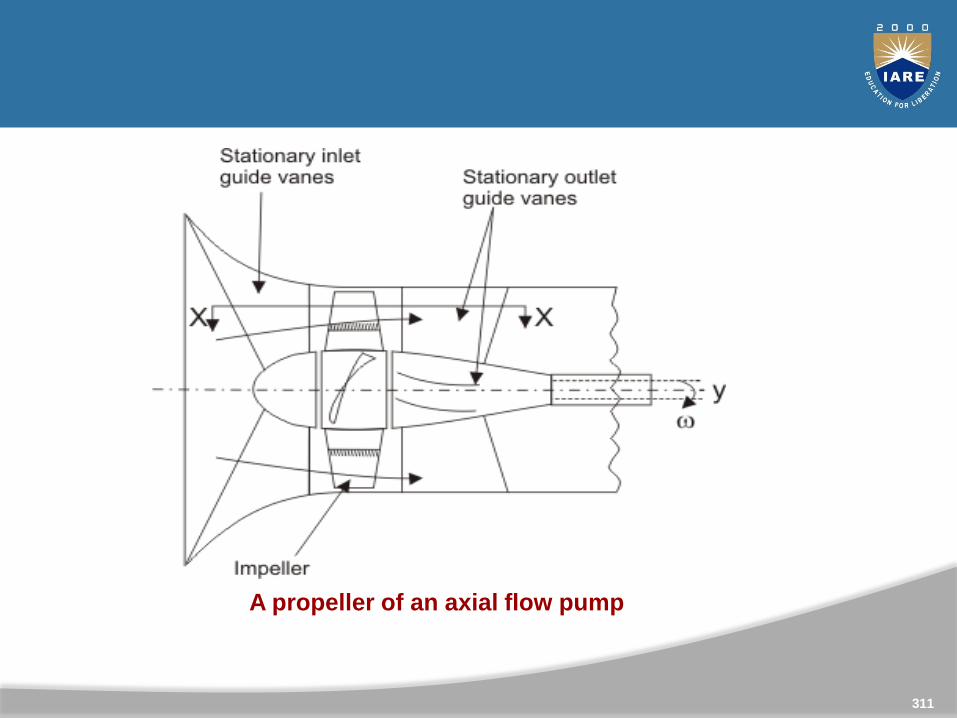
A propeller of an axial flow pump
311
Fans
Fans and blowers are turbo-machines which deliver airat a desired high velocity (and accordingly at a highmass flow rate) but at a relatively low static pressure.
The pressure rise across a fan is extremely low and is ofthe order of a few millimeters of water gauge.
The upper limit of pressure rise is of the order of250mm of water gauge. The rise in static pressureacross a blower is relatively higher and is more than1000 mm of water gauge that is required to overcomethe pressure losses of the gas during its flow throughvarious passages.
312
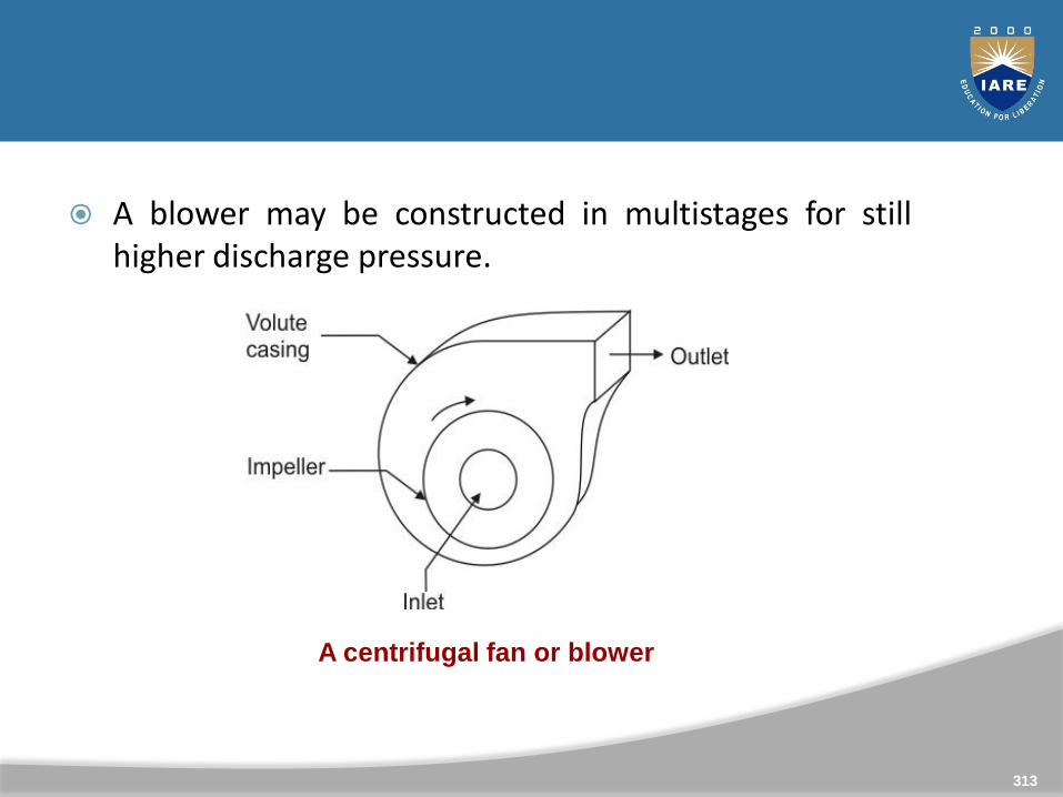
A blower may be constructed in multistages for stillhigher discharge pressure.
A centrifugal fan or blower
313
A large number of fans and blowers for relatively highpressure applications are of centrifugal type. The maincomponents of a centrifugal blower are shown in Fig. 2.
A blower consists of an impeller which has blades fixedbetween the inner and outer diameters. The impeller canbe mounted either directly on the shaft extension of theprime mover or separately on a shaft supported betweentwo additional bearings.
Air or gas enters the impeller axially through the inletnozzle which provides slight acceleration to the air beforeits entry to the impeller.
314
The action of the impeller swings the gas from asmaller to a larger radius and delivers the gas at a highpressure and velocity to the casing. The flow from theimpeller blades is collected by a spiral-shaped casingknown as volute casing or spiral casing .
The casing can further increase the static pressure ofthe air and it finally delivers the air to the exit of theblower.
315
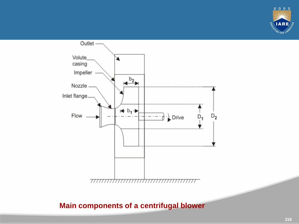
Main components of a centrifugal blower
316

Thank You