computational fluid dynamics analysis of penstock branching
TRANSCRIPT
37Jacem
Journal of Advanced College of Engineering and Management, Vol. 5, 2019
jacem, Vol.5, 2019 �Computational fluid dynamics analysis of penstock branching in hydropower project��
�COMPUTATIONAL FLUID DYNAMICS ANALYSIS OF PENSTOCK BRANCHING IN HYDROPOWER PROJECT�
Bipin Kandel1, Mahesh Chandra Luitel2
1MSc., Energy System Planning and Management, Pulchowk Campus, T.U. 2Associate Professor, Department of Mechanical Engineering, Pulchowk Campus, T.U.
__________________________________________________________________________________
Abstract
The penstock branching manifold is regarded as most critical part of the hydropower project. A computational research has been carried out to conclude the most efficient branching manifold with has more than or equal to three units of turbine. Starting from the base data from a project �Solukhola-Dudhkoshi Hydropower Project, 86 MW� for three units of turbines. More than 20 models were prepared to visualize flow pattern, to minimize the head loss and mas flow variation among 3 different units. The research has been finally concluded to go towards a single trifurcation instead of successive two bifurcation or individual branching form main branches.
Keywords: Trifurcation, CFD, hydropower __________________________________________________________________________________
1. Background
In the hydropower project, a single generating unit is seldom chosen. The Turbines and generators needs periodic repair and maintenance. The shut down time required for the maintenance purpose is the time the generation will be lost. In case of single unit, the plant generation loss for the maintenance will be huge. Hence, most of the plant will have at least two generating units. For more than 3 units of turbine the design of branching manifold will lead to greater study requirement, which is basically taken in consideration in the research. The base data has been taken from Solukhola-Dudhkoshi Hydropower Project, 86 MW as,
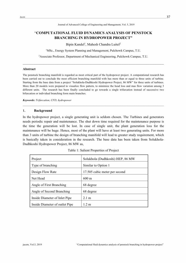
Table 1: Salient Properties of Project
Project Solukhola (Dudhkoshi) HEP, 86 MW
Type of branching Similar to Option 1
Design Flow Rate 17.505 cubic meter per second
Net Head 600 m
Angle of First Branching 68 degree
Angle of Second Branching 68 degree
Inside Diameter of Inlet Pipe 2.1 m
Inside Diameter of outlet Pipe 1.2 m
38 Jacem
jacem, Vol.5, 2019 �Computational fluid dynamics analysis of penstock branching in hydropower project��
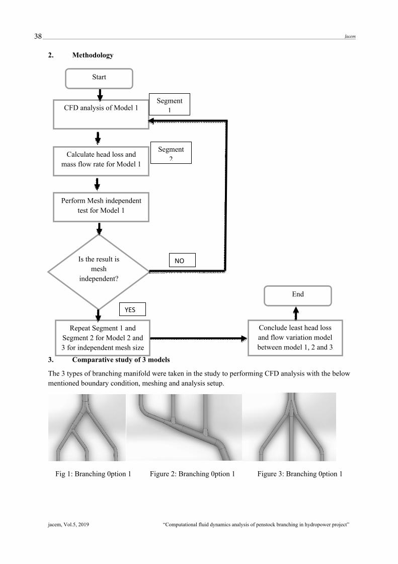
2. Methodology
3. Comparative study of 3 models
The 3 types of branching manifold were taken in the study to performing CFD analysis with the below mentioned boundary condition, meshing and analysis setup.
Fig 1: Branching 0ption 1 Figure 2: Branching 0ption 1 Figure 3: Branching 0ption 1
CFD analysis of Model 1
Calculate head loss and mass flow rate for Model 1
Perform Mesh independent test for Model 1
Start
Is the result is mesh
independent?
Repeat Segment 1 and Segment 2 for Model 2 and 3 for independent mesh size
Segment 1
Segment 2
Conclude least head loss and flow variation model between model 1, 2 and 3
End
���
��

39Jacem
jacem, Vol.5, 2019 �Computational fluid dynamics analysis of penstock branching in hydropower project��
Table 2: Simulation and mesh setup for the analysis
Boundary Conditions Simulation Setup Inlet Residual error : 10^-4 Mass Flow rate (kg/s) 17505 Maximum iteration : 200 Outlet Analysis type : Steady state Pressure Head (m) 600 Mass momentum : No slip wall
Pressure (Pa) 5868930.6 Wall roughness : Smooth
Wall No slip wall Turbulence model : Shear Stress Transport (SST)
Mesh Generation Meshing type Tetrahedron Body sizing 50 mm Smoothing High
Inflation
Outer layer including boundary layer
Mesh Independent test:
The mesh independent test for the model 3 shows that all analysis can be performed with the mesh size of 50 mm.
Fig 4: Mesh Independent test
4. CFD Analysis of Option 1
After performing simulation setup for the Option 1, it was put to target to achieve mentioned residual error target. The results are interpreted as below.
Pressure Distribution in Option 1:
���������� �����������������������
� � � �
����
����
����
���������������
Mesh Size versus Head loss
�������������� ����!"#$��
40 Jacem
jacem, Vol.5, 2019 �Computational fluid dynamics analysis of penstock branching in hydropower project��
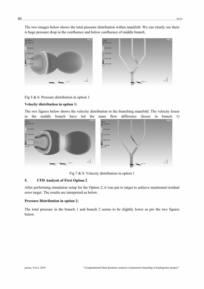
The two images below shows the total pressure distribution within manifold. We can clearly see there is huge pressure drop in the confluence and below confluence of middle branch.
Fig 5 & 6: Pressure distribution in option 1
Velocity distribution in option 1:
The two figures below shows the velocity distribution in the branching manifold. The velocity lesser in the middle branch have led the mass flow difference (lesser in branch 1)
Fig 7 & 8: Velocity distribution in option 1
5. CFD Analysis of First Option 2
After performing simulation setup for the Option 2, it was put to target to achieve mentioned residual error target. The results are interpreted as below.
Pressure Distribution in option 2:
The total pressure in the branch 1 and branch 2 seems to be slightly lower as per the two figures below.
41Jacem
jacem, Vol.5, 2019 �Computational fluid dynamics analysis of penstock branching in hydropower project��
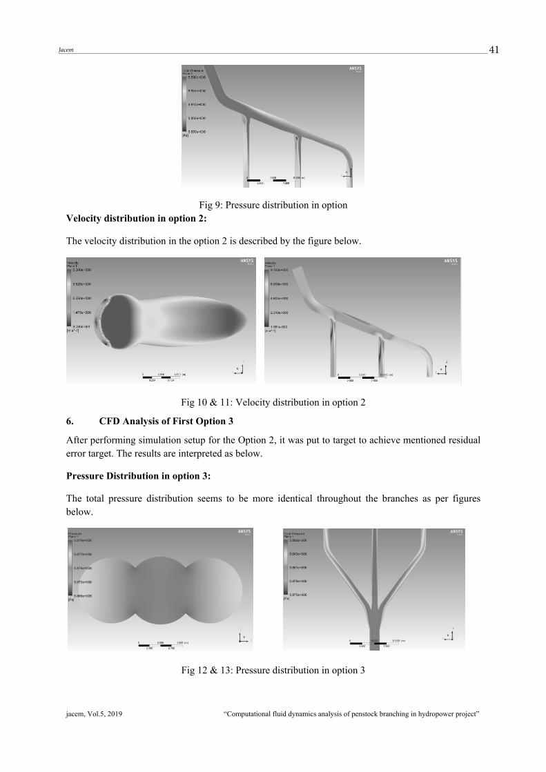
Fig 9: Pressure distribution in option Velocity distribution in option 2:
The velocity distribution in the option 2 is described by the figure below.
Fig 10 & 11: Velocity distribution in option 2
6. CFD Analysis of First Option 3
After performing simulation setup for the Option 2, it was put to target to achieve mentioned residual error target. The results are interpreted as below.
Pressure Distribution in option 3:
The total pressure distribution seems to be more identical throughout the branches as per figures below.
Fig 12 & 13: Pressure distribution in option 3

42 Jacem
jacem, Vol.5, 2019 �Computational fluid dynamics analysis of penstock branching in hydropower project��
Velocity distribution in option 3
The velocity is lower in trifurcation junction, and the other distribution can be well described as per the figure below.
Fig 14 & 15: Velocity distribution in option 3
7. Comparative Analysis for 3 Types of Branching
Two parameters head loss and mass flow variation within the units have been calculated to analyze the performance of 3 types of branching. Similar analysis setup, meshing setup, boundary condition were applied to conclude the following result.
Table 3: The comparison of CFD simulation between all branches type
S.N Types of Branching
Total Pressure comparison Velocity Comparison
Velocity Streamline comparison
1 Type 1
Total Pressure drop in the confluence and below confluence of middle branch
The velocity lesser in the middle branch have led the mass flow difference (lesser in branch 1).
Low velocity zone in the middle branch
2 Type 2
The total pressure in the branch 1 and branch 2 seems to be slightly lower
The velocity in the branch 1 and branch 2 seems to be slightly lower, after branching junction
Similar result, as velocity comparison
3 Type 3
The total pressure distribution seems to be more identical throughout the branches
The velocity is lower in trifurcation junction, and the other distribution are almost identical
Similar result, as velocity comparison
8. Analysis Result and Selection of the Branching:
CFD analysis were conducted for all 3 models with efficient profiles and the results are as per the table below. Which concludes the option 3 to be most efficient is chosen for detailed analysis.
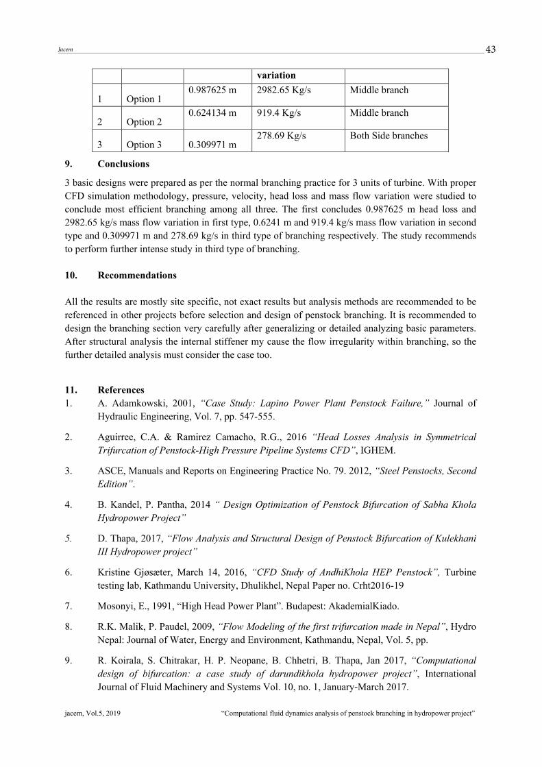
Table 4: The comparison of 3 options in terms of head loss and mass flow variation. S.N. Types Head loss Mass flow Variation occurred in
43Jacem
jacem, Vol.5, 2019 �Computational fluid dynamics analysis of penstock branching in hydropower project��
variation
1 Option 1 0.987625 m 2982.65 Kg/s Middle branch
2 Option 2 0.624134 m 919.4 Kg/s Middle branch
3 Option 3 0.309971 m 278.69 Kg/s Both Side branches
9. Conclusions
3 basic designs were prepared as per the normal branching practice for 3 units of turbine. With proper CFD simulation methodology, pressure, velocity, head loss and mass flow variation were studied to conclude most efficient branching among all three. The first concludes 0.987625 m head loss and 2982.65 kg/s mass flow variation in first type, 0.6241 m and 919.4 kg/s mass flow variation in second type and 0.309971 m and 278.69 kg/s in third type of branching respectively. The study recommends to perform further intense study in third type of branching.
10. Recommendations
All the results are mostly site specific, not exact results but analysis methods are recommended to be referenced in other projects before selection and design of penstock branching. It is recommended to design the branching section very carefully after generalizing or detailed analyzing basic parameters. After structural analysis the internal stiffener my cause the flow irregularity within branching, so the further detailed analysis must consider the case too.
11. References 1. A. Adamkowski, 2001, �Case Study: Lapino Power Plant Penstock Failure,� Journal of
Hydraulic Engineering, Vol. 7, pp. 547-555.
2. Aguirree, C.A. & Ramirez Camacho, R.G., 2016 �Head Losses Analysis in Symmetrical Trifurcation of Penstock-High Pressure Pipeline Systems CFD�, IGHEM.
3. ASCE, Manuals and Reports on Engineering Practice No. 79. 2012, �Steel Penstocks, Second Edition�.
4. B. Kandel, P. Pantha, 2014 � Design Optimization of Penstock Bifurcation of Sabha Khola Hydropower Project�
5. D. Thapa, 2017, �Flow Analysis and Structural Design of Penstock Bifurcation of Kulekhani III Hydropower project�
6. Kristine Gjøsæter, March 14, 2016, �CFD Study of AndhiKhola HEP Penstock�, Turbine testing lab, Kathmandu University, Dhulikhel, Nepal Paper no. Crht2016-19
7. Mosonyi, E., 1991, �High Head Power Plant�. Budapest: AkademialKiado.
8. R.K. Malik, P. Paudel, 2009, �Flow Modeling of the first trifurcation made in Nepal�, Hydro Nepal: Journal of Water, Energy and Environment, Kathmandu, Nepal, Vol. 5, pp.
9. R. Koirala, S. Chitrakar, H. P. Neopane, B. Chhetri, B. Thapa, Jan 2017, �Computational design of bifurcation: a case study of darundikhola hydropower project�, International Journal of Fluid Machinery and Systems Vol. 10, no. 1, January-March 2017.