application of computational fluid dynamics (cfd ... - mdpi
TRANSCRIPT
processes
Review
Application of Computational Fluid Dynamics (CFD)Simulation for the Effective Design of Food 3D Printing(A Review)
Timilehin Martins Oyinloye 1 and Won Byong Yoon 1,2,*
�����������������
Citation: Oyinloye, T.M.; Yoon, W.B.
Application of Computational Fluid
Dynamics (CFD) Simulation for the
Effective Design of Food 3D Printing
(A Review). Processes 2021, 9, 1867.
https://doi.org/10.3390/pr9111867
Academic Editor: Li Xi
Received: 28 September 2021
Accepted: 14 October 2021
Published: 20 October 2021
Publisher’s Note: MDPI stays neutral
with regard to jurisdictional claims in
published maps and institutional affil-
iations.
Copyright: © 2021 by the authors.
Licensee MDPI, Basel, Switzerland.
This article is an open access article
distributed under the terms and
conditions of the Creative Commons
Attribution (CC BY) license (https://
creativecommons.org/licenses/by/
4.0/).
1 Department of Food Science and Biotechnology, College of Agriculture and Life Sciences,Kangwon National University, 1 Kangwondaehak-gil, Chuncheon 24341, Korea; [email protected]
2 Elder-Friendly Research Institute, Kangwon National University, 1 Kangwondaehak-gil,Chuncheon 24341, Korea
* Correspondence: [email protected]
Abstract: The progress of food 3D printing (3DP) applications demands a full understanding ofthe printing behavior of food materials. Computational fluid dynamics (CFD) simulation can helpdetermine the optimum processing conditions for food 3DP such as layer height, deposit thickness,volume flow rate, and nozzle shape and diameter under varied material properties. This papermainly discusses the application of CFD simulation for three core processes associated with 3DP:(1) flow fields in the nozzle during the extrusion process; (2) die swelling of materials at the die(the exit part of the nozzle); and (3) the residual stress of printed products. The major achievementsof CFD simulation in food 3DP with varied food materials are discussed in detail. In addition,the problems and potential solutions that modelers encountered when utilizing CFD in food 3DPwere explored.
Keywords: food 3D printing; computational fluid dynamics (CFD); extrusion process; viscoelasticflow simulation; additive layer manufacturing (ALM) model; die swell; residual stress
1. Introduction
Three-dimensional printing (3DP) is a rapid prototyping technology that combinesmaterial science with computing and control technologies [1]. The application of 3DP tofood began primarily with digitally controlled extrusion operations that could accuratelybuild up the material deposition layer by layer from a pre-designed file such as stere-olithography (STL) or computer-aided design (CAD) [2,3]. Several studies have emergedwith strong efforts in applying 3DP technology to various designs of food products. Inthe early stage, the material used in food 3DP was limited to chocolate products [4–6],but recently, various materials have been applied successfully and their characteristicsin the 3DP have been reported (i.e., potato starch with pea protein, wheat, corn starch,lemon juice gel, alginate with pea protein, cereal food, oat protein, meat product, andsurimi [7–11]). 3DP applications were accompanied by a large number of trial-and-errorattempts and conservative designs, which resulted in a waste of resources and time duringthe experiments. This is in part due to a lack of accurate instruments for predicting theresults of the process [9]. Recently, patents associated with food 3DP technology havepresented computational methods, mainly computational fluid dynamic (CFD) simulation,to predict and quantify the performance of 3DP [12–14].
CFD is one of the computer simulation methods used to characterize fluid flowbehavior under certain geometries with boundary conditions [12,14]. The criterion for itsperformance is how well numerical simulation outcomes align with experimental resultsconducted under specific conditions, and how well simulations can predict extremelycomplicated processes that cannot be analyzed in the real world [9]. CFD has gainedrecognition as an emerging science around the world, particularly since the late 2000s when
Processes 2021, 9, 1867. https://doi.org/10.3390/pr9111867 https://www.mdpi.com/journal/processes
Processes 2021, 9, 1867 2 of 23
there was a significant increase in the development and application of CFD to all areasrelated to fluid behaviors associated with momentum, heat, and mass transfer [15]. Asa result of its ability to anticipate the success of modern designs or systems before theyare manufactured or applied, CFD has played an important role in many industries inthe engineering design and research environments [16]. CFD is being used increasinglyin the food and bioprocess industries by researchers, system manufacturers, and processengineers to study the flow behavior and efficiency of process equipment such as bakingovens, refrigerators, spray dryers, and 3D printers [9,17,18]. In the 3DP process, CFDtechnology has been used to identify the critical parameters that dictate the shape of theprinted product as well as to find the best material deposition strategy. Thus, CFD hascontributed to the reduction in production costs, improvements in the product quality, andincrease in productivity (i.e., printing speed) [12,19,20].
In the design of 3DP food products and 3DP processes, the CFD simulations arenow considered to be standard numerical tools to predict not only the fluid behaviorduring extrusion, but also the complicated flow characteristics associated with heat andmass transfer, phase transfer (i.e., solidification), chemical reactions (i.e., bindings andwall stickiness), mechanical movements (i.e., impeller turning, or pistons movement), andstress or deformation of related solid structures (i.e., total collapse) [9,21]. The CFD modelinvolved in 3DP has been continuously developed and extensively studied. Woodfieldet al. [22] defined the flow behavior of biomaterials through the nozzle using the Hagen–Poiseuille rule. Based on the rheological properties of the material and layer thickness,Oyinloye and Yoon [9] evaluated the influence of residual-stress components and totaldeformation across the printed alginate and pea protein sample. Li et al. [23] developed anumerical model for the relationship between volumetric velocity in gels, scaffold porediameter, and porosity. The fluid flow properties of lemon juice gel in the syringe werealso studied using CFD [1].
Many review articles have examined the general applications of CFD for various unitoperations involved in food processing for final product such as freezing systems in meat aswell as for food ingredients such as spray drying of tomato pulp [15,17,24–27]. To the bestof our knowledge, previous reviews have focused mainly on the material properties, foodformulations, and machine design for 3D printing; however, one research paper focused onthe use of CFD in terms of tissue engineering with potential in 3DP fabrication [11]. Unlikeprevious studies, this paper provides an overview of recent developments in CFD use in3D food printing as well as a discussion of various problems faced during the 3D printingprocess and their solutions. This work can be seen as a quick guide for the use of CFD inthe design of different forms of food 3DP processes.
2. Overview of Studies on the CFD Analysis of 3DP
Over the last 20 years, a total of 44 research articles on CFD research and its applica-tions in 3D food printing and extrusion analysis have been reported when searched usingspecific keywords (CFD, food, numerical simulation, 3D printing, and extrusion process) onGoogle Scholar. The annual distribution of findings reflects the growing importance of thetopic, with more than half of the publications occurring in the last four years (Figure 1). Themajority of them focused on the development of novel food items. Several researchers haverecently begun exploring issues related to 3D food printing processes such as the die swelleffect at the 3D printer nozzle, residual stress component in the extruded products, and theshape of printed products during and after the 3DP process. However, such informationis disseminated in several publications with differing technical foci. The related articlespublished during the last 10 years were analyzed (Table 1).

Processes 2021, 9, 1867 3 of 23
Figure 1. The number of publications with the keywords: CFD, food, numerical simulation, 3DP, andextrusion process. Data was found in ‘Google Scholar’ and searched over the last 20 years.
Table 1. CFD simulation on food 3DP in the last 10 years.
Application Software Code Aim Time-DependentState Author
3D printing of alginateand pea protein gel ANSYS Discovery AIM
To predict the residual stress, totaldeformation, and printing precision
requirement.Transient [9]
3D printing of cerealgrains. ANSYS POLYFLOW To investigate the use of cereal grains as
alternative printing material. Transient [28]
3D printing of lemonjuice gel ANSYS POLYFLOW
Evaluation of the fluid characteristics oflemon juice gel in the 3D printer flow
channel.Steady [1]
Comparative study of asyringe and screw-based
3D food printerCOMSOL Multiphysics
Developing CFD models to investigateand compare the flow field
characteristic of two 3D extrusion-basedprinting units (syringe and Screw based
printing).
Transient [21]
Soy white flakes baseddough in a single screw
extruderANSYS POLYFLOW
To characterize the rheologicalproperties of soy white flakes-based
dough in a single screw extruder andanalyze the flow behavior in the high
shear rate zone extruder.
Transient [29]
Extrusion process of soywhite flakes Design Expert
To analyze the extrusion process ofJatropha seeds by a single screw
extruder.Steady [30]
3D deposition of porousscaffolds for cartilage
tissue engineering
To establish the flow of biomaterialsthrough the nozzle. [22]
Mixing in food extrusionANSYS POLYFLOW
andANSYS Fluent
To characterize the dispersive mixing ofoil in the plasticized starch matrix
within a twin-screw extruder.Transient [14]
Processes 2021, 9, 1867 4 of 23
3. Fundamentals of the CFD Extrusion Process
The extrusion process is the core process for the food 3DP [3]. The extrusion inthe food 3DP is a thermomechanical technology that was specifically designed for massproduction [1,9–11]. A correct combination of variables involving product formulation,process, and equipment settings are required to obtain the final product. There is a sizeablenumber of process variables involved in the extrusion process. Thus, it causes difficultyin controlling and analyzing the extrusion process theoretically. In extrusion processesinvolving either screws or pistons, materials are compressed and sheared with extremelyhigh pressure, which causes thermal and mechanical stresses on the material [9,21]. Thethermomechanical effects in the screw or piston section have a considerable influence onthe printing process and, as a result, play an important role in the structural and mechanicalcharacteristics of the extruded material. Strong interactions between mass, energy, andmomentum transfer, coupled with complex physicochemical transformations governingthermochemical properties are present, making control of the extrusion process difficult.Therefore, understanding the mechanisms involved in the process is an essential step toapply the CFD simulation in the design of 3DP products or 3D printers for food.
3.1. Governing Equations
The mathematical equations of fluid motion have been developed for approximatelytwo centuries. First, the Euler equations, which describe the motion of fluid based onthe conservation of energy, mass, and momentum, were formulated in 1756–1757 [31].The Navier–Stokes equations describe fluid motions based on the stress tensor with theEuler equations [32,33]. The Navier–Stokes equations are mathematical formulations ofthe conservation laws of fluid dynamics (CFD), which are referred to as the governingequations of fluid flow and heat transfer. When applied to a fluid continuum, theseconservation laws attribute the rate of change of a desired fluid property to external forcesand may be thought of as follows [27,34–36]:
i. The law of conservation of mass (continuity), which states that the mass flows enteringand exiting a fluid product must be equal (Equation (1));
∂ρ
∂t+
∂
∂xi
(ρuj)= 0 (1)
where ρ and t are density (kg/m3) and time (s); x is the Cartesian coordinates (m); uis the velocity component (m/s); and i is the Cartesian coordinate index.
ii. The law of conservation of momentum (Newton’s second law of motion), which statesthat the number of external forces acting on a fluid particle equals the rate of changein linear momentum (Equation (2));
∂
∂t(ρui) +
∂
∂xj
(ρuiuj
)=
∂
∂xj
[−pδij + µ
(∂ui∂xj
+∂uj
∂xi
)]+ ρgi (2)
where j is the Cartesian coordinate index; δ is the Kronecker delta; µ is the dynamicviscosity (kg/ms); and g is the acceleration due to gravity (m/s2).
iii. The law of conservation of energy (the first law of thermodynamics), which statesthat the rate of change of energy of a fluid particle is equal to the heat addition andthe work done on the particle (Equation (3));
∂
∂t(ρCaT) +
∂
∂xj
(ρujCaT
)− ∂
∂xj
(λ
∂T∂xj
)= sT (3)
where Ca is specific heat capacity (W/kgK); T is the temperature (K); λ is the thermalconductivity (W/mK); and sT is the thermal source
(W/m3) [36].
Processes 2021, 9, 1867 5 of 23
By applying these conservation laws over discrete spatial volumes in a fluid domain, itis possible to achieve a systematic account of the changes in mass, momentum, and energyas the flow crosses volume boundaries. Although direct solving of Navier–Stokes equationsis possible for laminar flow, computationally solving fluid motion in the Kolmogorovmicroscales in turbulent flow is not yet possible; hence, turbulence models need to besolved in addition to the Navier–Stokes equations in the case of turbulent flow regime,which is generally encountered in the modeling of a low viscosity food process because ofthe high flow rates and complex geometry involved [37]. As a result, choosing a suitableturbulence model is crucial and has a direct impact on the CFD results of the 3DP process.Several review studies are available on selecting the suitable turbulence models for variousfood processing, comparable to the 3D printing process, based on accuracy, computingtime, and cost, thus this review will not go into detail [25,37].
Specifically in the extrusion process in 3DP, when developing a thermomechanicalfinite-element (FE) model for the stress and deformation analysis involved in the 3DP, itshould be noted that the calculation of 3DP material deformations and residual stressesis dependent on the temperature field variation and the phase transfer according to thematerial’s mechanical properties such as plastic strain and plasticity [38]. Thus, the initialmechanical properties and boundary conditions are required to develop the structural-mechanical problems. To simulate the heat effect during the 3DP process, the total heatflow introduced into the component must be estimated. This can be computed using the3DP material deposition parameters, taking into account the thermal efficiency and radialdispersion of the material’s heat flux density. As a result, as indicated in Equation (4),the temperature-field distribution may be characterized by the transient and nonlinearheat-balance equations of the Fourier–Kirchhoff heat conduction with the thermophysicalcharacteristics, namely thermal conductivity (λ), specific heat capacity (c), and density (ρ)being dependent on the temperature and 3DP material sample [9,38].
cρvw∂T∂t
= ∇(λ∇T)−∇(
cρ→v T)+ QT (4)
If the convection is ignored for a moving heat source with a constant printing speed(vw) and a torch power (QT), Equation (5) is expressed in a moving coordinate system:
cρvw∂T∂t
= ∇(λ∇T) + QT (5)
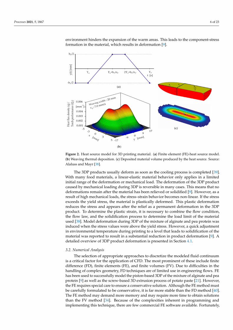
For boundary conditions used in simulations, the various temperature loading con-ditions such as uniform, time-dependent, or spatially varying temperature throughoutthe selected geometry are used as boundary conditions to calculate the heat losses due toconduction and convection heat transfer associated with the 3DP process. The heat sourcefor 3DP on a localized distribution spot is usually assumed to be an ellipsoid-moving heatsource with a normally distributed heat flux density in the form of a Gaussian function(Figure 2). The localized heat distribution strongly affects the 3DP process as well as the3DP products. Thus, temperature-dependent heat losses around the geometry must beanalyzed. Radiation and convection heat transfer are the major modes for the localizedheat distribution for all boundaries in the geometry. In this case, the heat transfer can bemodeled by Equation (6),
− λ∂T∂n
= αk(T− T0) + εC0
(T4 − T4
0
)(6)
where αk is the heat transfer coefficient due to free convection; ε is the emission coefficient;C0 is the radiation coefficient; T is the component temperature; and T0 is the ambienttemperature. Radiation and convection are significant only on the upper part of thegeometry, but relatively less on the lower part. Thus, ε can be assumed to be 0. Thelocal heating of the component causes an uneven thermal expansion, whereby the colder
Processes 2021, 9, 1867 6 of 23
environment hinders the expansion of the warm areas. This leads to the component-stressformation in the material, which results in deformation [9].
Figure 2. Heat source model for 3D printing material. (a) Finite element (FE)-heat source model.(b) Weaving thermal deposition. (c) Deposited material volume produced by the heat source. Source:Alaluss and Mayr [38].
The 3DP products usually deform as soon as the cooling process is completed [39].With many food materials, a linear-elastic material behavior only applies in a limitedinitial range of the deformation or mechanical load. The deformation of the 3DP productcaused by mechanical loading during 3DP is reversible in many cases. This means that nodeformations remain after the material has been relieved or solidified [9]. However, as aresult of high mechanical loads, the stress–strain behavior becomes non-linear. If the stressexceeds the yield stress, the material is plastically deformed. This plastic deformationreduces the stress and appears after the relief as a permanent deformation in the 3DPproduct. To determine the plastic strain, it is necessary to combine the flow condition,the flow law, and the solidification process to determine the load limit of the materialused [38]. Model deformation during 3DP of the mixture of alginate and pea protein wasinduced when the stress values were above the yield stress. However, a quick adjustmentin environmental temperature during printing to a level that leads to solidification of thematerial was reported to result in a substantial reduction in product deformation [9]. Adetailed overview of 3DP product deformation is presented in Section 4.1.
3.2. Numerical Analysis
The selection of appropriate approaches to discretize the modeled fluid continuumis a critical factor for the application of CFD. The most prominent of these include finitedifference (FD), finite elements (FE), and finite volumes (FV). Due to difficulties in thehandling of complex geometry, FD techniques are of limited use in engineering flows. FEhas been used to successfully model the piston-based 3DP of the mixture of alginate and peaprotein [9] as well as the screw-based 3D extrusion process of potato paste [21]. However,the FE requires special care to ensure a conservative solution. Although the FE method mustbe carefully formulated to be conservative, it is far more stable than the FD method [40].The FE method may demand more memory and may require more time to obtain solutionsthan the FV method [34]. Because of the complexities inherent in programming andimplementing this technique, there are few commercial FE software available. Fortunately,
Processes 2021, 9, 1867 7 of 23
such challenges may be avoided by employing FV approaches [41] that provide ease inunderstanding, programming, memory usage, solution speed, and versatility of finitevolumes, particularly for large problems, high Reynolds number turbulent flows, andsource term dominated flows. It is now the most commonly used numerical techniquein CFD code development, and as a result, it is considered the most commonly usedmethod to form design solutions for the 3DP process. In the FV method, the governingpartial differential equations such as the Navier–Stokes equations, the mass and energyconservation equations, and the turbulence equations are developed in a conservative form,and then solved over discrete control volumes.
3.3. Generation of the Computational Grid (Meshing Process)
In CFD simulations for 3DP, the product geometry, often called a model, must be builtbefore simulations. The small cells or elements are developed to fill the volume of the model.They constitute mesh, with each cell representing a discrete space that defines the localflow. The flow physics is then represented mathematically by equations that are appliedto each cell of the mesh. As a result, each cell may store time-dependent flow propertiessuch as pressure, velocity, shear rate, or temperature [42]. Generating a high-quality meshis critical for obtaining reliable solutions and ensuring numerical stability.
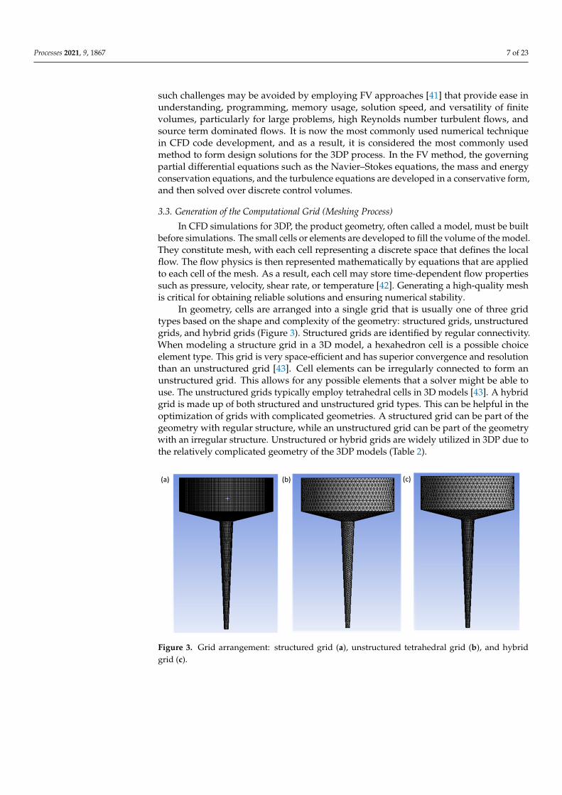
In geometry, cells are arranged into a single grid that is usually one of three gridtypes based on the shape and complexity of the geometry: structured grids, unstructuredgrids, and hybrid grids (Figure 3). Structured grids are identified by regular connectivity.When modeling a structure grid in a 3D model, a hexahedron cell is a possible choiceelement type. This grid is very space-efficient and has superior convergence and resolutionthan an unstructured grid [43]. Cell elements can be irregularly connected to form anunstructured grid. This allows for any possible elements that a solver might be able touse. The unstructured grids typically employ tetrahedral cells in 3D models [43]. A hybridgrid is made up of both structured and unstructured grid types. This can be helpful in theoptimization of grids with complicated geometries. A structured grid can be part of thegeometry with regular structure, while an unstructured grid can be part of the geometrywith an irregular structure. Unstructured or hybrid grids are widely utilized in 3DP due tothe relatively complicated geometry of the 3DP models (Table 2).
Figure 3. Grid arrangement: structured grid (a), unstructured tetrahedral grid (b), and hybridgrid (c).
Processes 2021, 9, 1867 8 of 23
Table 2. CFD simulation techniques used for 3D printed model.
Sample Model Geometry NumericalTechnique Meshing Software References
Cereal paste Fluid domain in a 3D printersyringe and nozzle FEM Hexahedral cell,
structured grid ANSYS Polyflow [28]
Lemon juiceI. Fluid domain in a 3D
printer syringe and nozzleII. Extrudate
FEM Hexahedral cell,structured grid ANSYS Polyflow [1]
Potato flakes
I. Fluid domain of screw-based extrusion
II. Fluid domain syringebased extrusion
FEM COMSOLMultiphysics [21]
Wheat flour Fluid in syringe and nozzle FEM Hexahedral cell,structured grid ANSYS Polyflow [44]
Yeast Fluid domain in hydrocyclone FEM Polyhedral cell,unstructured grid ANSYS Fluent [45]
Alginate and peaprotein Extruded paste domain FEM Hexahedral cell,
structured gridANSYS Discovery
AIM [9]
Polymer Extrudate flow FEM Tetrahedral cell,unstructured grid
COMSOLMultiphysics [46]
FEM—Finite element method.
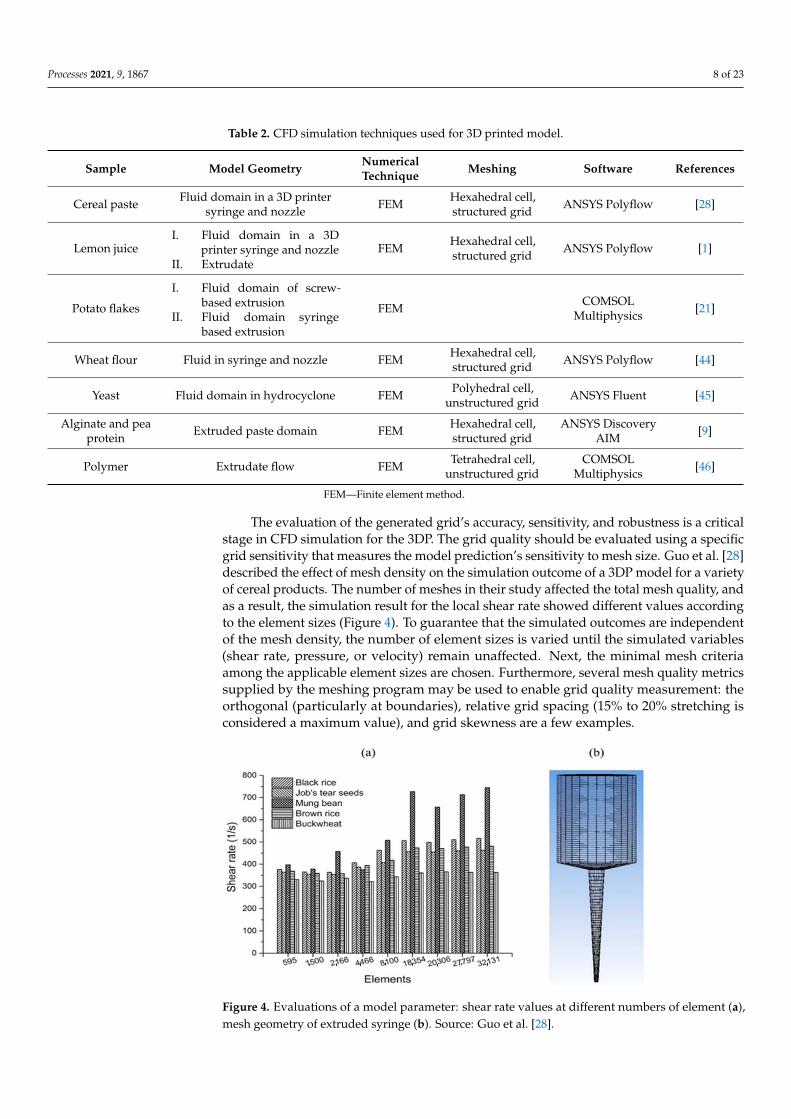
The evaluation of the generated grid’s accuracy, sensitivity, and robustness is a criticalstage in CFD simulation for the 3DP. The grid quality should be evaluated using a specificgrid sensitivity that measures the model prediction’s sensitivity to mesh size. Guo et al. [28]described the effect of mesh density on the simulation outcome of a 3DP model for a varietyof cereal products. The number of meshes in their study affected the total mesh quality, andas a result, the simulation result for the local shear rate showed different values accordingto the element sizes (Figure 4). To guarantee that the simulated outcomes are independentof the mesh density, the number of element sizes is varied until the simulated variables(shear rate, pressure, or velocity) remain unaffected. Next, the minimal mesh criteriaamong the applicable element sizes are chosen. Furthermore, several mesh quality metricssupplied by the meshing program may be used to enable grid quality measurement: theorthogonal (particularly at boundaries), relative grid spacing (15% to 20% stretching isconsidered a maximum value), and grid skewness are a few examples.
Figure 4. Evaluations of a model parameter: shear rate values at different numbers of element (a),mesh geometry of extruded syringe (b). Source: Guo et al. [28].
Processes 2021, 9, 1867 9 of 23
3.4. Boundary Conditions
All CFD problems are defined by initial and boundary conditions, which must bespecified correctly. The initial values of heat and mass flow variables must be specified atall solution points in the computational domain. When modeling heat and mass transfer inthe 3DP model, the distribution of all flow variables at the inlet boundary must be specified.In the case of 3DP with molten chocolate, the flow variables include inlet volume flowrate, pressure, turbulent intensity, and temperature [47]. The 3D printer’s piston speedalong with the dimensional parameters of the 3D printer chamber is used to define theinlet volume flow rate. Temperature and flow property distributions at the inlet are usuallyspecified based on the experimental data [9]. Outlet boundary conditions can be stated andused in conjunction with the inlet boundary conditions. This type of boundary condition isspecified mostly where outlet velocity is known. At the outlet of the flow domain, the forceconditions are set (Equation (7));
Fn = Vs = 0 (N) (7)
where subscript n and s represent the normal and tangential components of the force andvelocity, respectively. When the 3D printer’s outlet position is far away from the chamber,the flow reaches a fully developed state with no change in the flow direction. As long as afully developed state is maintained, the gradient of all variables could be equated to zeroin the flow direction, except pressure [41]. In the chamber of the 3D printer, the continuityand the momentum conservation equations (Equations (8) and (9)) are usually used:
∇·v = 0 (8)
ρ
(∂ν
∂t+−ν·∇ν
)= −∇p +∇·=τ (9)
where−ν is the velocity vector; ρ is the material density; p is the hydrostatic pressure; and
=τ
is the extra stress tensor. Mostly, the effect of gravity is neglected [10,21,28]. This seemsto be a reasonable assumption in materials with high viscosity. At the wall boundarycondition, models are usually established as no-slip between the material and the wallof the channel during the extrusion process wherein the normal component of velocityis fixed at zero, and the tangential component is set equal to the velocity of the wall(Equation (10)) [1]:
Vs = Vn = 0 (mm/s) (10)
where Vs and Vn represent tangential and normal components, respectively. Althoughit may seem counterintuitive, the no-slip condition has been firmly established in bothexperiment and theory [48]. The wall is the most common boundary condition consideredwhen solving heat and mass flow problems, specifically during the structural analysisof 3D printed food components. The bottom face of the printing bedplate on whichmolten materials are printed is supplied with a steady pre-heat temperature. Conductionheat transfer between the molten material and the bedplate occurs, and the temperaturedifference is important to control the cooling rate of the bottom layer. For the boundaryconditions involving heat transfer, it is necessary to specify the rate of heat transfer throughthe walls. In general, the heat flux
.q is defined by (Equation (11)):
.q = K
(Tbed − Tsample
)rs → or
.q = constant (11)
where Tbed and Tsample are the bedplate temperature and molten sample temperature,respectively. The overall heat transfer coefficient K depends on the thermal conductivityand thickness of the conductive solid material as well as the fluid material properties(density, heat capacity, etc.) and flow characteristics (geometry specification, turbulence,etc.). The radiant heat coefficient rs is determined by factors specific to the printingenvironment or the ambient temperature.
Processes 2021, 9, 1867 10 of 23
The symmetric boundary condition assumes that identical physical processes existon both sides of the boundary. In the symmetric boundary conditions, all the variableshave the same value and gradients at the same distance from the axis or plane of symmetry.It acts as a mirror that reflects all the flow distribution to the other side [49]. The condi-tions at the symmetric boundary allow no flow and no scalar flux across the boundary(Equations (12) and (13));
vn = o (mm/s) (12)
ft = 0 (N) (13)
where subscript t and n represent the tangential and normal components of the velocityand force, respectively. Here, n indicates the normal direction to the free surface. This isa great tool to reduce the computational effort and resource if the flow can be envisagedto be symmetrical about a plane or pair of planes. However, it must be noted that thegeometrical symmetry does not guarantee the symmetry of the flow. Similarly, in caseswhere micro-structure of flow eddies are being captured such as “Large Eddy Simulation”or “DES–Detached Eddy Simulation”, symmetry cannot be used due to the inherent natureof the eddies. As a result, this approach has not been used in many research publicationson CFD analysis for 3DP processes.
4. CFD Applications in Food 3DP
CFD offers research tools for improving the process design and understanding ofthe fundamental physical basis of fluid dynamics. It provides benefits to food 3DP inmany areas including evaluating the flow characteristics in the nozzle, die-swell analysis,residual stress analysis in the printed sample, material deformation after printing, andsolidification of the printed sample, among others [9,21,28]. Vast improvements have beenmade in these fields in recent years. For food 3DP, the flow field analysis usually requiresno mass transfer calculation, unlike CFD simulations for other unit operations used in thefood industries such as spray drying of tomato pulp [17,25,44]. However, 3-dimensionalflow field modeling is necessary to provide essential information regarding the 3D printingsystem design and the final product design. In addition, CFD can model several situationsinfluenced under different circumstances faced during 3DP including the characteristicsof the fluid at the inlets, inside the 3D printer chamber, nozzle domain, and outlets at thenozzle exit. Characterizing the flow field can also be utilized to validate a solution’s degreeof confidence before moving on to additional transport models or large-scale printingprocedures. The following subsections are some of the properties that have been examinedusing CFD in 3D printing applications [9,21,28,44].
4.1. Thermal Mechanical Behavior in 3D Printed Food Material
The thermo-mechanical characteristics of food materials are studied in the food 3DPprocess to predict material behavior during or after printing in a wide range of factorsdescribing their internal states (i.e., temperature, residual stress, and deformations) andstructures (i.e., model shape or permeability). Changes in state parameters and structuralcharacteristics of printed food material are induced by the energy exchange and mechanicalinteraction of a material with the environment. When a material is deformed, the strengthdescribes the critical stresses. The residual stress is usually taken into account throughoutthe 3D printing process [9].
Residual stresses are the stresses maintained by a printed solid model after external orinternal force loads have been removed and an equilibrium condition has been reached.These stresses are caused by misalignments in the form of components from differentregions and phases. In addition, the residual stress is influenced by local variations ofmaterial properties such as elasticity and thermal properties. Residual stress can haveseveral negative effects on the characteristics of a model part such as bending of the surfaceof the printed model or, in extreme cases, the entire deformation of the printed model [9,50].The primary source of residual stresses in printed foods could be directly related to the

Processes 2021, 9, 1867 11 of 23
material properties (viscosity, storage modulus, and loss modulus, etc.) and the parametersof the printing process such as nozzle size, printing speed, and layer height. Furthermore,the residual stress can be influenced by printing processes that incorporate temperaturechanges, which vary the material properties as well as cause phase transitions. Oyinloyeand Yoon [9] investigated the mechanical behavior of printed alginate and pea proteinpaste at 45 ◦C on a 22 ◦C printing bed using numerical simulations. The finite elementmethod (FEM) based numerical simulation was conducted to predict the residual stressand distortion of the printed material as the nozzle size was varied (Figure 5). The stress ofthe samples was typically concentrated at the layers in the center of the sample toward theedges, and the stress value increased with increasing nozzle size. As the diameter of thenozzle increases, the extrusion flow rate increases and the printing time decreases. Thislimits the solidification and stability of each printed layer before printing another layer ontop. Furthermore, it was observed that the increasing stress value became constant as soonas the build-up phase ended and the cooling phase began (Figure 5). This was due to adecrease in the thermal gradient in the printed sample.
Figure 5. Simulation result of stress distribution during the buildup and cooling phase (A) andaccording to deposit thickness, 0.20 mm (B), 0.68 mm (C), and 1.00 mm (D). Source: Oyinloye andYoon [9].
In general, the major cause of stress is the presence of a high-temperature gradientduring the build-up phase. The stress acts as an impediment to the expansion of moltenmaterial at the top layers due to the quick cooling process of the lower layers via thermalconduction with the printing bedplate. As a result, compressive stress is formed in theselayers. In extreme temperatures, the yield stress of the material decreases, which causesstress formation that consequently produces plastic deformations. Additionally, shrinkageoccurs during the material’s cooling phase, affecting the material previously deposited
Processes 2021, 9, 1867 12 of 23
under the layer. This results in a tensile residual stress in the top layer and compressiveresidual stress in the bottom layer [10].
In a temperature gradient environment, the generated stresses can be represented byEquation (14):
σ(T) = E(T)× ∝CTE (T)× (Tm − T) (14)
In the simplified Equation (14), the residual stress σ (functions of temperature) at anarbitrary temperature T during cooling is given. It is a variant of Hooke’s law σ = E∈,in which the strain replaces the linear shrinkage strain. The temperature interval overwhich residual stresses can build up is limited by the sample melting temperature [50].Therefore, materials with a lower melting temperature reduce the residual stress [50]. Therate at which strain accumulates during cooling is then defined by thermal expansion(∝CTE). Finally, stiffness governs the conversion of these strains to stress (E). ∝CTE, andespecially E, are both dependent on temperature, with ∝CTE typically increasing withincreasing temperature, and E reducing to 0 at the melting temperature. E(T) and ∝(T)are temperature-dependent, and these parameters, along with Tm, are material-specificproperties. Hence, the only controllable parameter in the above equation is T, which maybe either the bedplate preheat temperature or the temperature of the printing environment.In the CFD process, it may not be adequate to completely define the stress state sinceadditional parameters affect the residual stress. These are entirely dependent on user inputsuch as nozzle speed, mesh quality, and layer thickness [21,28]. However, it should benoted that the residual stress is also bounded by the material’s melting temperature, whichis a material property that cannot be user-defined.
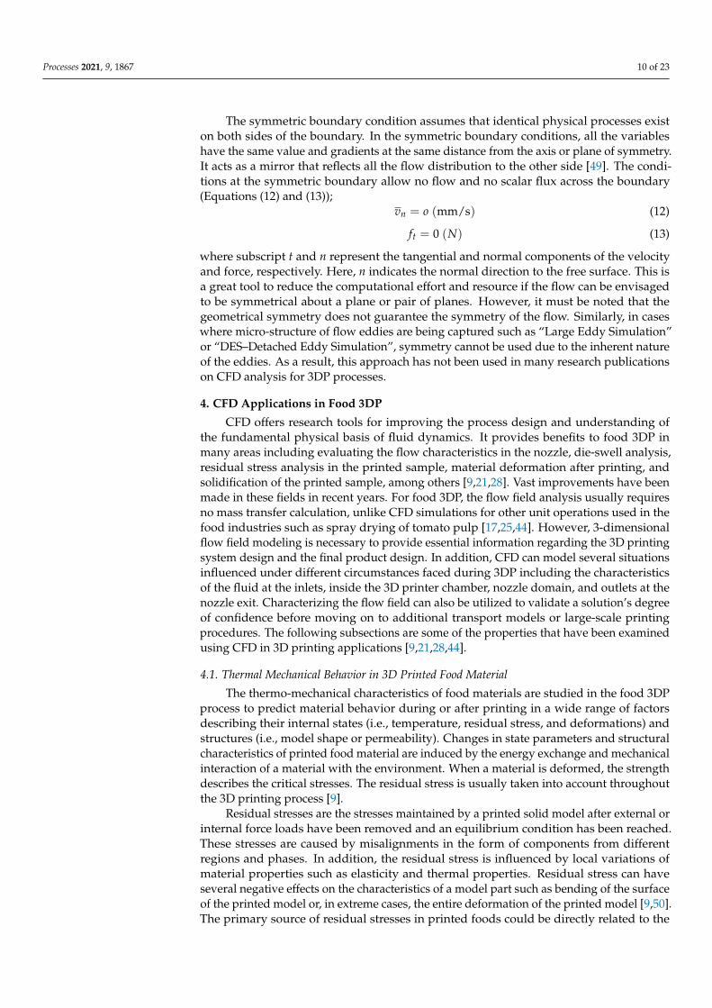
A less severe but still detrimental consequence of the residual stress is the deformationof the printed parts. The bending moment caused by the stresses leads to componentscurling upward, regardless of the shape of the part itself. This is explained in Oyinloyeand Yoon’s [9] study for the mixture of alginate and pea protein paste, where the edgesof the horizontally built cylindrical model show a substantial positive deformation in theZ direction (Figure 6). The residual stress, which increases with increasing nozzle sizes,accounted for a greater total deformation in the sample printed with a 1.0 mm nozzlesize than in the sample printed with a 0.20 mm nozzle size (Figure 6). The high-stressvalue (7.1× 10⁻³ Pa) obtained from the 1.0 mm nozzle size caused the deformation ofthe printed material. Furthermore, the high flow rate associated with the bigger nozzlesize limited the required time for each printed layer to solidify before another layer isprinted on top of it. Therefore, the deformation of the product is usually associated with3DP, regardless of whether the magnitude of deformation is big or small. It is possible toconclude that extending the downtime between the printing of successive layers allowsthe entire structure to reach thermal equilibrium. Keeping downtime to a minimumenables some heat to accumulate inside the printed product, which lowers the temperaturegradients and consequently causes residual stress. This method can also be used in aprinting process that does not involve temperature change.
4.2. Die Swell Effect in the 3D Food Printing Process
The paste in the 3D printer nozzle is under stress, with some of the deformation energybeing stored elastically [51]. As the food paste leaves the printing nozzle, the free boundaryof the die allows the paste to assume a plug-flow velocity profile (i.e., constant velocity inthe radial direction [52]). Because the paste is no longer constrained by the walls of the 3Dprinter nozzle, the stresses acting on the paste in the nozzle are relaxed, and the elasticallystored energy is released, resulting in radial expansion of the paste known as die swell [51].The swelling of the extrudate emerging from a die is typical of viscoelastic liquids thatcontribute to the quality achieved during extrusion-based food 3DP [1].
Processes 2021, 9, 1867 13 of 23
Figure 6. Total perpendicular deformation in the 3D printed alginate and pea protein paste duringprinting and cooling phase (A), and based on deposit thickness after complete component buildup1.00 mm (B), 0.68 mm, (C), and 0.20 mm (D). Source: Oyinloye and Yoon [9]. The Korean in thepicture means afternoon.
Liang [53] analyzed the relationship between extrudate swell ratio and the entry storedelastic strain energy during die flow by regression analysis (Equation (15));
X = β1 + β2log.γ (15)
whereβ1 andβ2 are constants characterizing the material elastic properties. The parametersβ1 and β2 are calculated using Gaussian quadrature. β1 represents the swell value at ashear strain rate of
.γ = 1 s−1. The dependence of the die swell on the shear rate, which is
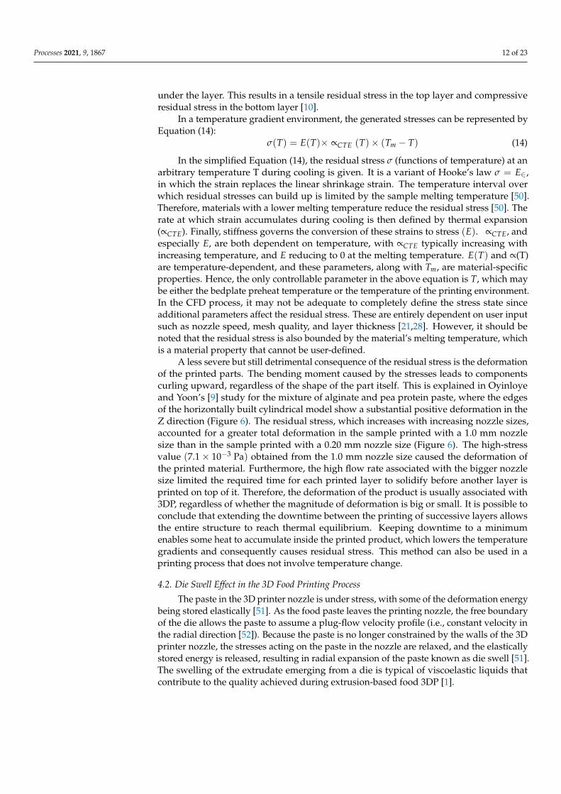
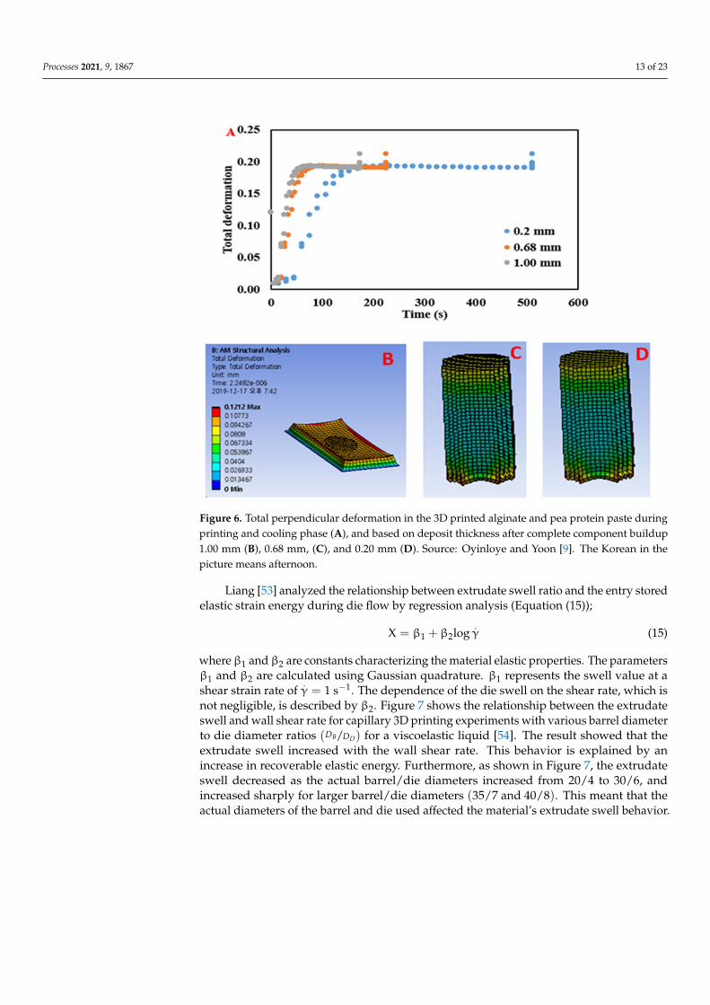
not negligible, is described by β2. Figure 7 shows the relationship between the extrudateswell and wall shear rate for capillary 3D printing experiments with various barrel diameterto die diameter ratios (DB/DD) for a viscoelastic liquid [54]. The result showed that theextrudate swell increased with the wall shear rate. This behavior is explained by anincrease in recoverable elastic energy. Furthermore, as shown in Figure 7, the extrudateswell decreased as the actual barrel/die diameters increased from 20/4 to 30/6, andincreased sharply for larger barrel/die diameters (35/7 and 40/8). This meant that theactual diameters of the barrel and die used affected the material’s extrudate swell behavior.
Processes 2021, 9, 1867 14 of 23
Figure 7. Percentage of the extrudate swell as a function of the shear rate for different barrel and diediameters (DB/DD = 5). Source: Sombatsompop and Dangtangee [54].
The dependence of the swell value on the 3D printer barrel diameter to die diameterratio is intriguing. This indicates that the amount of elastic energy stored in the pastedepends on the diameter of the 3D printer barrel up to a certain value, after which theconical zone of the converging flow streamlines into the die and is unaffected by the barrelwall. This fact demonstrates that the swelling of the extrudate is caused by the recoverableelastic energy stored in the paste, which is in turn caused by the large pressure drops at thecapillary die’s entrance.
According to Müllner et al. [55], the die swell ratio for a viscoelastic liquid is alsoaffected by the temperature of the material and the length of the printing chamber up tothe nozzle tip (residence time). However, this has not been evaluated in the food 3DPprocess, which could be an interesting area for further research. In general, understandingdie swell during 3D printing aids in producing a high-quality printed sample. However,experimentally quantifying the die swell ratio during the food 3DP process is difficult dueto several challenges including the small and closed 3DP environment and the small sizeof the swelling effect, which is sometimes not visible to the naked eye.
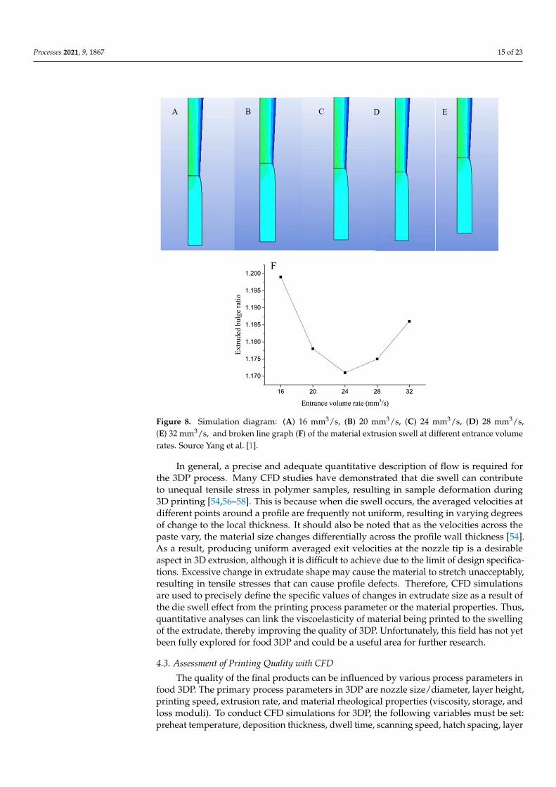
Yang et al. [1] demonstrated that CFD could provide information on the elastic natureof food paste. CFD was used to investigate the effect of inlet volume rate on the die swellratio for lemon juice gel during 3DP. As shown in Figure 8, the extrusion at the exit of thedie exhibited a certain level of swelling, with varying degrees of swell at different inletvolume rates. As the flow rate of the entrance volume increased, the extrusion swell ratiodecreased first and then increased. This is most likely because the extrudate swell ratio isaffected by the volume flow rate, shear rate, and pressure, all at the same time. Accordingto the report, increasing the entrance volume flow rate increased the pressure in the flowchannel, resulting in the fluid storing more elastic potential energy.
Processes 2021, 9, 1867 15 of 23
Figure 8. Simulation diagram: (A) 16 mm3/s, (B) 20 mm3/s, (C) 24 mm3/s, (D) 28 mm3/s,(E) 32 mm3/s, and broken line graph (F) of the material extrusion swell at different entrance volumerates. Source Yang et al. [1].
In general, a precise and adequate quantitative description of flow is required forthe 3DP process. Many CFD studies have demonstrated that die swell can contributeto unequal tensile stress in polymer samples, resulting in sample deformation during3D printing [54,56–58]. This is because when die swell occurs, the averaged velocities atdifferent points around a profile are frequently not uniform, resulting in varying degreesof change to the local thickness. It should also be noted that as the velocities across thepaste vary, the material size changes differentially across the profile wall thickness [54].As a result, producing uniform averaged exit velocities at the nozzle tip is a desirableaspect in 3D extrusion, although it is difficult to achieve due to the limit of design specifica-tions. Excessive change in extrudate shape may cause the material to stretch unacceptably,resulting in tensile stresses that can cause profile defects. Therefore, CFD simulationsare used to precisely define the specific values of changes in extrudate size as a result ofthe die swell effect from the printing process parameter or the material properties. Thus,quantitative analyses can link the viscoelasticity of material being printed to the swellingof the extrudate, thereby improving the quality of 3DP. Unfortunately, this field has not yetbeen fully explored for food 3DP and could be a useful area for further research.
4.3. Assessment of Printing Quality with CFD
The quality of the final products can be influenced by various process parameters infood 3DP. The primary process parameters in 3DP are nozzle size/diameter, layer height,printing speed, extrusion rate, and material rheological properties (viscosity, storage, andloss moduli). To conduct CFD simulations for 3DP, the following variables must be set:preheat temperature, deposition thickness, dwell time, scanning speed, hatch spacing, layer

Processes 2021, 9, 1867 16 of 23
thickness, density, number of heat sources, cool down condition, and working atmosphere.Previous research for extrusion-based food printing has focused on two critical factors indetermining product quality: the printability of the materials during extrusion and thestability of the products after printing [9].
Food material printability is determined by their rheological (dynamic viscosity),thermal (i.e., melting point and glass transition temperature), and gel properties, which areimportant criteria for CFD processes [9,59,60]. Most commercial CFD software packagesprovide visible 3D/2D fluid characteristics values such as pressure, velocity, shear rate,and displacement with the input of fluid parameters (density and dynamic viscosity),assisting in a better understanding of the extruding processes. The Carreau model ispopularly used to estimate the viscosity distribution of the material in the extruder fromthe experimental values. The model also describes the effect of shear rate on materialviscosity (Equation (16)).
η = η∞ + (η0 − η∞)[1 + (λγ)2
] n−12 (16)
where η is the viscosity; η0 is the zero shear viscosity; η∞ is the infinite shear viscosity; λ isthe relaxation time; γ is the shear rate; and n is the rheological index. Many publications onCFD analysis for extrusion processes have successfully used this model for the simulationand analysis of the flow properties in the 3DP extrusion process [28].
Liu et al. [44] used CFD to examine the effects of rheological properties on the print-ability of high and low gluten wheat flour, and found that pressure had an impact onthe quality of 3D printed products. When the pressure applied to the material was toolow during the extrusion process, the material could not be extruded out of the nozzle,and when the pressure was too high, a poorly textured model was printed. This was alsojustified by a reduction in viscosity as the printing pressure increased (Figure 9). As aresult, the material extruded has limited time to expel the sample’s inherent shear stress.
Figure 9. (a) Viscosity distribution on the central axis along the direction of extrusion with a differentflow behavior index (n) and (b) pressure distribution on the central axis along the direction ofextrusion with a different flow behavior index (n). Source: Liu et al. [44].
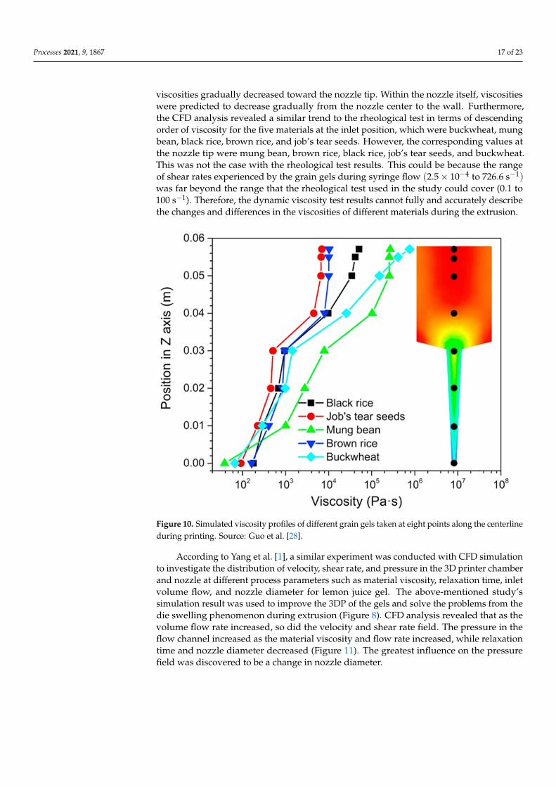
Guo et al. [28] used the Bird–Carreau model to simulate and investigate the 3Dprintability performance of five cereal grains: buckwheat, brown rice, mung bean, job’s tearseeds, and black rice. The result of the CFD simulation was validated with real printingexperiments and rheological tests over a narrow range of shear rates. The viscosity ofthe material at eight different points in the 3D printer chamber is described in Figure 10.Because the model geometry causes the fluid flow to converge toward the centerline, theshear rate along the wall is expected to increase downward toward the nozzle tip. Figure 10also shows that the viscosities of the materials were higher in the syringe, particularlyat the corners and top center, where the shear rate value was expected to be lower. The
Processes 2021, 9, 1867 17 of 23
viscosities gradually decreased toward the nozzle tip. Within the nozzle itself, viscositieswere predicted to decrease gradually from the nozzle center to the wall. Furthermore,the CFD analysis revealed a similar trend to the rheological test in terms of descendingorder of viscosity for the five materials at the inlet position, which were buckwheat, mungbean, black rice, brown rice, and job’s tear seeds. However, the corresponding values atthe nozzle tip were mung bean, brown rice, black rice, job’s tear seeds, and buckwheat.This was not the case with the rheological test results. This could be because the rangeof shear rates experienced by the grain gels during syringe flow (2.5× 10⁻⁴ to 726.6 s−1)was far beyond the range that the rheological test used in the study could cover (0.1 to100 s−1). Therefore, the dynamic viscosity test results cannot fully and accurately describethe changes and differences in the viscosities of different materials during the extrusion.
Figure 10. Simulated viscosity profiles of different grain gels taken at eight points along the centerlineduring printing. Source: Guo et al. [28].
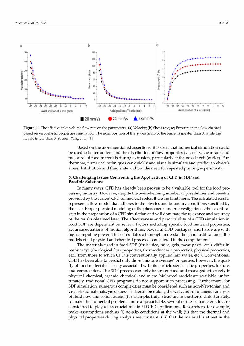
According to Yang et al. [1], a similar experiment was conducted with CFD simulationto investigate the distribution of velocity, shear rate, and pressure in the 3D printer chamberand nozzle at different process parameters such as material viscosity, relaxation time, inletvolume flow, and nozzle diameter for lemon juice gel. The above-mentioned study’ssimulation result was used to improve the 3DP of the gels and solve the problems from thedie swelling phenomenon during extrusion (Figure 8). CFD analysis revealed that as thevolume flow rate increased, so did the velocity and shear rate field. The pressure in theflow channel increased as the material viscosity and flow rate increased, while relaxationtime and nozzle diameter decreased (Figure 11). The greatest influence on the pressurefield was discovered to be a change in nozzle diameter.
Processes 2021, 9, 1867 18 of 23
Figure 11. The effect of inlet volume flow rate on the parameters. (a) Velocity; (b) Shear rate; (c) Pressure in the flow channelbased on viscoelastic properties simulation. The axial position of the Y-axis (mm) of the barrel is greater than 0, while thenozzle is less than 0. Source. Yang et al. [1].
Based on the aforementioned assertions, it is clear that numerical simulation couldbe used to better understand the distribution of flow properties (viscosity, shear rate, andpressure) of food materials during extrusion, particularly at the nozzle exit (outlet). Fur-thermore, numerical techniques can quickly and visually simulate and predict an object’sstress distribution and fluid state without the need for repeated printing experiments.
5. Challenging Issues Confronting the Application of CFD in 3DP andPossible Solutions
In many ways, CFD has already been proven to be a valuable tool for the food pro-cessing industry. However, despite the overwhelming number of possibilities and benefitsprovided by the current CFD commercial codes, there are limitations. The calculated resultsrepresent a flow model that adheres to the physics and boundary conditions specified bythe user. Proper physical modeling of the phenomena under investigation is thus a criticalstep in the preparation of a CFD simulation and will dominate the relevance and accuracyof the results obtained later. The effectiveness and practicability of a CFD simulation infood 3DP are dependent on several factors including specific food material properties,accurate equations of motion algorithms, powerful CFD packages, and hardware withhigh computing power. This necessitates a thorough understanding and justification of themodels of all physical and chemical processes considered in the computations.
The materials used in food 3DP (fruit juice, milk, gels, meat paste, etc.) differ inmany ways (rheological flow properties, thermodynamic properties, physical properties,etc.) from those to which CFD is conventionally applied (air, water, etc.). ConventionalCFD has been able to predict only those ‘mixture average’ properties; however, the qual-ity of food material is closely associated with its particle size, elastic properties, texture,and composition. The 3DP process can only be understood and managed effectively ifphysical–chemical, organic–chemical, and micro–biological models are available; unfor-tunately, traditional CFD programs do not support such processing. Furthermore, for3DP simulation, numerous complexities must be considered such as non-Newtonian andviscoelastic materials, yield stress, frictional force along the wall, and simultaneous analysisof fluid flow and solid stresses (for example, fluid–structure interaction). Unfortunately,to make the numerical problems more approachable, several of these characteristics areconsidered to play a less crucial role in 3D CFD applications. Researchers, for example,make assumptions such as (i) no-slip conditions at the wall; (ii) that the thermal andphysical properties during analysis are constant; (iii) that the material is at rest in the
Processes 2021, 9, 1867 19 of 23
initial condition; and (iv) that the material observes a steady and laminar flow in the flowchannel, among others [1,9,21,28]. However, these assumptions are often improper. Atypical example is a 3DP research in which laminar flow is completely assumed for thematerial flow channel [1]. However, turbulent and laminar flow could still exist in thesame problem. This has been reported in a simulation study of annular Couette flow inwhich turbulent and laminar flow regimes coexist [61]. Recent modeling advances haveaddressed this issue by developing a predictive laminar to turbulent flow transition model,which is now included in the ANSYS CFX® 10.0 program upward [62]. However, nostudy using this model for the 3DP has been reported as of yet. Both the transient processand the steady-state process are used to analyze several flow regimes in 3DP [1,9,21,28].The transient process arises as a result of the moving inlet boundary (i.e., the piston inthe 3D printer chamber). In these cases, a steady-state flow regime does not exist andnumerical difficulties are often encountered when attempting to solve the problem usingsteady governing equations [63]. Nonetheless, a steady solution can be ‘forced’, whichmeans that some limiting constraints can be imposed to inhibit the flow regime’s unsteadycharacteristics. These typically include one or more of the following: first-order convectionschemes, dissipative turbulence models (standard ε-k model), and two-dimensional orsymmetrical boundary conditions. However, because this driving action does not exist innature, the credibility of solutions derived from such calculations has been doubted [63].Before starting CFD modeling, it should be noted that the limitations of the availableturbulence models and their associated wall functions must be considered. Models suitablefor the study should be chosen based on previous experiences with similar applications inthe literature.
Other challenges faced might be connected to the complexity of the geometry and themesh quality, both of which have a significant role in deciding the correctness of the finalresult. The computational mesh offers spatial discretization of the governing equationsand is a major vehicle for ensuring correct predictions of the fluid continuum, particularlyin steady-state simulation. To obtain a high degree of precision, the mesh must be properlyrefined in areas of interest and where gradients exist in the flow field. This has been exten-sively discussed in Section 3.3. However, there are also situations when low mesh qualityis reported after mesh refinement [64]. These issues can be unavoidable in some situations,but in many others, identifying and repairing problematic mesh areas can eliminate suchdifficulties. This means that cells with high aspect ratios or highly skewed cells mustbe eliminated from the simulation to obtain an accurate and efficient representation ofconvective fluxes. Some CFD programs provide methods for locating these cells. However,in many situations, the CFD modeler will rely on their prior knowledge with a CFD soft-ware program to validate the mesh quality. The use of CFD in food 3DP has not becomewidespread because, to date, several obstacles have stood in the way of its development inthis area: a lack of basic knowledge of local kinetic processes at small scales (paste dropletor flow), the complexity of biological processes with the scarcity of models for those thatare compatible with CFD and the nature of the food-processing industry and its relation toCFD, the difficulties linked to the cost of purchasing or leasing the software, the cost ofhigh-powered computer hardware, and the scarcity, cost, and managerial difficulties ofensuring adequately trained and experienced personnel.
More efforts are needed to promote the use of mathematical models for 3DP in thefood sector. Model prediction accuracy might be enhanced by using correct heat and masstransport coefficients. To obtain a more precise outcome, the CFD simulation in 3DP mightbe coupled with other techniques such as optimal shape design (OSD) and discrete elementmethod (DEM). Sarghini [65] described the use of OSD in conjunction with CFD to analyzethe extrusion process of paste dough. In OSD, the essential element concerning numericalsimulations in fixed geometrical configurations is the introduction of a certain number ofgeometrical degrees of freedom as one of the unknowns, meaning that the geometry is notcompletely defined, but part of it is allowed to move dynamically to minimize or maximizethe objective function. The applications of optimal shape design (OSD) are found in many
Processes 2021, 9, 1867 20 of 23
places: structure mechanics, electromagnetism, and fluid mechanics, or a combination ofthese [65,66]. Furthermore, the DEM model technique enhances the modeling of flowsinvolving an equal amount of fluid and powders that cannot be analyzed solely by thecontinuum flow based models used in CFD simulation [67]. DEM has recently been usedto model a wide range of granular mixing applications with high qualitative accuracy [67].This method can account for powder cohesion and has been combined with CFD to simulatethe transport of powder materials through pneumatic pipes [68]. This will be useful forsimulating mixture materials, particularly samples containing both fluid and solid phasessuch as meat products and starch paste. However, the computational cost of DEM is veryexpensive, and simulations often take many days to complete. This has made it unrealisticto extend this model to other modes of dense gas–solid flow exhibited by fine powders(particle size less than 100 mm). As a result, this technique may not be utilized in food 3DPprocessing immediately [69].
Additionally, validation of simulation with the experimental result is paramountfor the future success of CFD modeling in the 3DP. As of now, most publications havevalidated the 3DP simulation model by comparing the images of the printed samplewith the simulation results or the material properties measured [1,28]. However, a moreaccurate method such as the image process such as that used in the validation of a printedmodel of alginate and pea protein [9] may be introduced. This method could providetime-dependent changes occurring during the printing process such as the die swell effectdiscussed in Section 4.2 and the post-printing process such as time-dependent deformationin the printed sample.
6. Conclusions
This paper reviewed the application of CFD in food 3DP. The examined studiesdemonstrate the need to maintain a high degree of accuracy through careful decisionsmade during model development such as selecting an acceptable numerical model, refiningthe mesh, and selecting appropriate boundary conditions. The numerical simulation couldpredict the distributions of average velocity, local shear rate, and pressure of the materialsduring the extrusion process. The link between the rheological properties of the materialsand their printing qualities was established, and it is clear that material properties play asignificant role in achieving printability and application. To simulate the flow characteristicsof food material using CFD, it is necessary to understand how the essential constituentof food material behaves during the printing process. The present state of CFD has beendemonstrated to be of significant value in its use in 3DP, which extends from the studyof residual stress to total deformation in the printed product and die swell effect at thenozzle tip, all of which contribute to a successful printing process. Additionally, futurestudy areas in 3D CFD analysis such as the effect of die swell on material deformationis also emphasized. This field has the potential to improve the printing process withfood materials.
Author Contributions: Conceptualization, T.M.O. and W.B.Y.; Methodology, T.M.O. and W.B.Y.;Investigation, T.M.O.; Writing-original draft preparation, T.M.O.; Writing-review and editing, T.M.O.and W.B.Y.; Supervision, W.B.Y.; Project administration, W.B.Y. All authors have read and agreed tothe published version of the manuscript.
Funding: This study was supported by 2018 Research Grant (PoINT) from Kangwon NationalUniversity. This research was supported by Basic Science Research Program through the NationalResearch Foundation of Korea (NRF) funded by the Ministry of Education (2018R1D1A3B06042501).
Institutional Review Board Statement: Not applicable.
Informed Consent Statement: Not applicable.
Data Availability Statement: No data was reported.
Conflicts of Interest: The authors declare no conflict of interest.
Processes 2021, 9, 1867 21 of 23
References1. Yang, F.; Guo, C.; Zhang, M.; Bhandari, B.; Liu, Y. Improving 3D printing process of lemon juice gel based on fluid flow numerical
simulation. LWT-Food Sci. Technol. 2019, 102, 89–99. [CrossRef]2. Malone, E.; Lipson, H. Fab@Home: The Personal Desktop Fabricator Kit. Rapid Prototyp. J. 2007, 13, 245–255. [CrossRef]3. Periard, D.; Malone, E.; Lipson, H. Printing Embedded Circuits. Proceedings of the 2007 International Solid Freeform Fabrication
Symposium. 2007. Available online: http://utw10945.utweb.utexas.edu/Manuscripts/2007/2007-43-Periard.pdf (accessed on 23September 2021). [CrossRef]
4. Lacerda, R.A.; Burgatti, J.C. Automatic Moulding Chocolate Depositing Line, Chocolate Depositing Machine. Rev. Da Esc. DeEnferm. Da USP 2009, 43, 237–244. [CrossRef]
5. Li, P.; Mellor, S.; Griffin, J.; Waelde, C.; Hao, L.; Everson, R. Intellectual property and 3D printing: A case study on 3D chocolateprinting. J. Intellect. Prop. Law Pract. 2014, 9, 322–332. [CrossRef]
6. Løland, G. Wiibooxsweetin High Accuracy Touch Panel China Impresora 3D for DIY Chocolate Printing. Ph.D. Thesis, NorwegianUniversity of Science and Technology (NTNU), Trondheim, Norway, 1991.
7. Dick, A.; Bhandari, B.; Prakash, S. 3D printing of meat. Meat Sci. 2019, 153, 35–44. [CrossRef] [PubMed]8. Lille, M.; Nurmela, A.; Nordlund, E.; Metsä-Kortelainen, S.; Sozer, N. Applicability of protein and fiber-rich food materials in
extrusion-based 3D printing. J. Food Eng. 2018, 220, 20–27. [CrossRef]9. Oyinloye, T.M.; Yoon, W.B. Stability of 3D printing using a mixture of pea protein and alginate: Precision and application of
additive layer manufacturing simulation approach for stress distribution. J. Food Eng. 2021, 288, 110127. [CrossRef]10. Yang, F.; Zhang, M.; Bhandari, B.; Liu, Y. Investigation on lemon juice gel as food material for 3D printing and optimization of
printing parameters. LWT-Food Sci. Technol. 2018, 87, 67–76. [CrossRef]11. Zhang, S.; Vijayavenkataraman, S.; Lu, W.F.; Fuh, J.Y. A review on the use of computational methods to characterize, design, and
optimize tissue engineering scaffolds, with a potential in 3D printing fabrication. J. Biomed. Mater. Res. Part B Appl. Biomater. 2019,107, 1329–1351. [CrossRef]
12. Duggleby, A.; Ball, K.; Sewall, E. Computational Fluid Dynamics (CFD) Coprocessor-Enhanced System and Method. U.S. Patent20070219766 A1, 20 September 2007.
13. Emin, M.A.; Schuchmann, H.P. Analysis of the dispersive mixing efficiency in a twin-screw extrusion processing of starch basedmatrix. J. Food Eng. 2013, 115, 132–143. [CrossRef]
14. Emin, M.A.; Köhler, K.; Schlender, M.; Schuchmann, H.P. Characterization of Mixing in Food Extrusion and EmulsificationProcesses by Using CFD. In High Performance Computing in Science and Engineering ’10; Springer: Berlin/Heidelberg, Germany,2011; pp. 443–462. [CrossRef]
15. Xia, B.; Sun, D.W. Applications of computational fluid dynamics (CFD) in the food industry: A review. Comput. Electron. Agric.2002, 34, 5–24. [CrossRef]
16. Schaldach, G.; Berger, L.; Razilov, I.; Berndt, H. Computer Simulation for Fundamental Studies and Optimisation of ICP Spray Chambers;Current Research Reports; Institute of Spectrochemistry and Applied Spectroscopy: Berlin, Germany, 2000.
17. Kuriakose, R.; Anandharamakrishnan, C. Computational fluid dynamics (CFD) applications in spray drying of food products.Trends Food Sci. Technol. 2010, 21, 383–398. [CrossRef]
18. Smale, N.J.; Moureh, J.; Cortella, G. A review of numerical models of airflow in refrigerated food applications. Int. J. Refrig. 2006,29, 911–930. [CrossRef]
19. Holbrook, T.R.; Osborn, L.S. Digital patent infringement in an era of 3D printing. Univ. Campbell Davis Law Rev. 2014, 48, 1319.[CrossRef]
20. Tabrizi, A.S.; Asadi, M.; Xie, G.; Lorenzini, G.; Biserni, C. Computational fluid-dynamics-based analysis of a ball valve performancein the presence of cavitation. J. Eng. Thermophys. 2014, 23, 27–38. [CrossRef]
21. Guo, C.F.; Zhang, M.; Bhandari, B. A comparative study between syringe-based and screw-based 3D food printers by computa-tional simulation. Comput. Electron. Agric. 2019, 162, 397–404. [CrossRef]
22. Woodfield, T.B.; Malda, J.; De Wijn, J.; Peters, F.; Riesle, J.; van Blitterswijk, C.A. Design of porous scaffolds for cartilage tissueengineering using a three-dimensional fiber-deposition technique. Biomaterials 2004, 25, 4149–4161. [CrossRef]
23. Li, M.G.; Tian, X.Y.; Chen, X.B. Modeling of flow rate, pore size, and porosity for the dispensing-based tissue scaffolds fabrication.J. Manuf. Sci. Eng. 2009, 131, 034501. [CrossRef]
24. Goula, A.M.; Adamopoulos, K.G. Effect of maltodextrin addition during spray drying of tomato pulp in dehumidified air: I.Drying kinetics and product recovery. Dry. Technol. 2008, 26, 714–725. [CrossRef]
25. Malekjani, N.; Jafari, S.M. Simulation of food drying processes by Computational Fluid Dynamics (CFD); recent advances andapproaches. Trends Food Sci. Technol. 2018, 78, 206–223. [CrossRef]
26. Moraga, N.O.; Rivera, D.R. Advantages in predicting conjugate freezing of meat in a domestic freezer by CFD with turbulencek-E3D model and a local exergy destruction analysis. Int. J. Refrig. 2021, 126, 76–87. [CrossRef]
27. Norton, T.; Sun, D.W. Computational fluid dynamics (CFD)—An effective and efficient design and analysis tool for the foodindustry: A review. Trends Food Sci. Technol. 2006, 17, 600–620. [CrossRef]
28. Guo, C.; Zhang, M.; Devahastin, S. 3D extrusion-based printability evaluation of selected cereal grains by computational fluiddynamic simulation. J. Food Eng. 2020, 286, 110113. [CrossRef]
Processes 2021, 9, 1867 22 of 23
29. Singh, S.K.; Muthukumarappan, K. Rheological characterization and CFD simulation of soy white flakes based dough in a singlescrew extruder. J. Food Process Eng. 2017, 40, e12368. [CrossRef]
30. Singh, S.K.; Muthukumarappan, K. Effect of feed moisture, extrusion temperature and screw speed on properties of soy whiteflakes based aquafeed: A response surface analysis. J. Sci. Food Agric. 2016, 96, 2220–2229. [CrossRef]
31. Euler, L.J. Principia Motus Fluidorum. In Novi Commentarii Academiae Scientiarum Petropolitanae; University of the Pacific, WilliamKnox Holt Memorial Library: Stockton, CA, USA, 1761; pp. 271–311.
32. Navier, C.L.M.H. Mémoire sur les lois du mouvement des fluides. Mém. Acad. R. Sci. Inst. Fr. 1823, 6, 389–440.33. Stokes, G.G. On the Effect of the Internal Friction of Fluids on the Motion of Pendulums. 1851. Available online: https:
//theindex.nawcc.org/Articles/Stokes-InternalFriction.pdf (accessed on 23 September 2021).34. Ferziger, J.H.; Peric, M.; Street, R.L. Computational Methods for Fluid Dynamics; Springer: Berlin/Heidelberg, Germany, 2002;
Volume 3. [CrossRef]35. Ghani, A.A.; Farid, M.M.; Chen, X.D.; Richards, P. Numerical simulation of natural convection heating of canned food by
computational fluid dynamics. J. Food Eng. 1999, 41, 55–64. [CrossRef]36. Norton, T.; Sun, D.W.; Grant, J.; Fallon, R.; Dodd, V. Applications of computational fluid dynamics (CFD) in the modelling and
design of ventilation systems in the agricultural industry: A review. Bioresour. Technol. 2007, 98, 2386–2414. [CrossRef] [PubMed]37. Defraeye, T.J. Advanced computational modelling for drying processes–A review. Appl. Energy 2014, 131, 323–344. [CrossRef]38. Alaluss, K.; Mayr, P. Additive Manufacturing of complex components through 3D plasma metal deposition—A simulative
approach. Metals 2019, 9, 574. [CrossRef]39. Gheorghe, G.I. Proceedings of the International Conference of Mechatronics and Cyber-MixMechatronics; Springer: Berlin/Heidelberg,
Germany, 2019; Volume 85.40. Peiró, J.; Sherwin, S. Finite Difference, Finite Element and Finite Volume Methods for Partial Differential Equations. In Handbook
of Materials Modeling; Springer: Berlin/Heidelberg, Germany, 2005; pp. 2415–2446. [CrossRef]41. Versteeg, H.K.; Malalasekera, W. An Introduction to Computational Fluid Dynamics: The Finite Volume Method; Pearson Education:
London, UK, 2007.42. Katz, A.; Sankaran, V. Mesh quality effects on the accuracy of CFD solutions on unstructured meshes. J. Comput. Phys. 2011, 230,
7670–7686. [CrossRef]43. Opara, U.L.; Ambaw, A.; Berry, T. CFD Investigation of Fresh Produce Cooling Processes and Effects of Package Stacking. In
Computational Fluid Dynamics in Food Processing; CRC Press: Boca Raton, FL, USA, 2018; pp. 121–148.44. Liu, Q.; Zhang, N.; Wei, W.; Hu, X.; Tan, Y.; Yu, Y.; Deng, Y.; Bi, C.; Zhang, L.; Zhang, H. Assessing the dynamic extrusion-based
3D printing process for power-law fluid using numerical simulation. J. Food Eng. 2020, 275, 109861. [CrossRef]45. Cilliers, J. Optimising small hydrocyclone design using 3D printing and CFD simulations. Chem. Eng. J. 2018, 350, 653–659.
[CrossRef]46. Shahriar, B.B.; Arthur, C.; France, C.; Valérie, N. Influence of Parameters Controlling the Extrusion Step in Fused Filament
Fabrication (FFF) Process Applied to Polymers Using Numerical Simulation. In AIP Conference Proceedings; AIP Publishing LLC:Melville, NY, USA, 2018. [CrossRef]
47. Lanaro, M.; Forrestal, D.P.; Scheurer, S.; Slinger, D.J.; Liao, S.; Powell, S.K.; Woodruff, M.A. 3D printing complex chocolate objects:Platform design, optimization and evaluation. J. Food Eng. 2017, 215, 13–22. [CrossRef]
48. Prabhakara, S.; Deshpande, M.D. The no-slip boundary condition in fluid mechanics. Resonance 2004, 9, 61–71. Available online:https://link.springer.com/content/pdf/10.1007/BF02834016.pdf (accessed on 23 September 2021). [CrossRef]
49. Augusto, P.E.D.; Cristianini, M. Evaluation of geometric symmetry condition in numerical simulations of thermal process ofpacked liquid food by computational fluid dynamics (CFD). Int. J. Food Eng. 2010, 6, 5. [CrossRef]
50. Vrancken, B. Study of Residual Stresses in Selective Laser Melting, 2016. KU Leuven—Faculty of Engineering Science Web Site.Available online: https://lirias.kuleuven.be/1942277?limo=0 (accessed on 23 September 2021).
51. Hopmann, C.; Michaeli, W. Extrusion Dies for Plastics and Rubber: Design and Engineering Computations; Carl Hanser Verlag:Munich, Germany, 2016.
52. Bellini, A. Fused Deposition of Ceramics: A Comprehensive Experimental, Analytical and Computational Study of Material Behavior,Fabrication Process and Equipment Design; Drexel University: Philadelphia, PA, USA, 2002.
53. Liang, J.Z. A relationship between extrudate swell ratio and entry stored elastic strain energy during die flow of tyre compounds.Polym. Test. 2004, 23, 441–446. [CrossRef]
54. Sombatsompop, N.; Dangtangee, R. Effects of the actual diameters and diameter ratios of barrels and dies on the elastic swell andentrance pressure drop of natural rubber in capillary die flow. J. Appl. Polym. Sci. 2002, 86, 1762–1772. [CrossRef]
55. Müllner, H.W.; Eberhardsteiner, J.; Fidi, W. Rheological characterization of the die swell phenomenon of rubber compounds.Polym. Test. 2007, 26, 1041–1048. [CrossRef]
56. Aloku, G.O.; Yuan, X.F. Numerical simulation of polymer foaming process in extrusion flow. Chem. Eng. Sci. 2010, 65, 3749–3761.[CrossRef]
57. Mezi, D.; Ausias, G.; Grohens, Y.; Férec, J. Numerical simulation and modeling of the die swell for fiber suspension flows. J.Non-Newton. Fluid Mech. 2019, 274, 104205. [CrossRef]
Processes 2021, 9, 1867 23 of 23
58. Wang, Z.; Smith, D. The Effect of Polymer Melt Rheology on Predicted Die Swell and Fiber Orientation in Fused FilamentFabrication Nozzle Flow. In Proceedings of the 28th Annual International Solid Freeform Fabrication Symposium—An AdditiveManufacturing Conference, Austin, TX, USA, 7–9 August 2017.
59. Godoi, F.C.; Prakash, S.; Bhandari, B.R. 3d printing technologies applied for food design: Status and prospects. J. Food Eng. 2016,179, 44–54. [CrossRef]
60. Liu, Z.; Bhandari, B.; Prakash, S.; Zhang, M. Creation of internal structure of mashed potato construct by 3D printing and itstextural properties. Food Res. Int. 2018, 111, 534–543. [CrossRef]
61. Kunii, K.; Ishida, T.; Duguet, Y.; Tsukahara, T. Laminar-turbulent coexistence in annular Couette flow. J. Fluid Mech. 2019, 879,579–603. [CrossRef]
62. Fluent, A. Technical Specifications Public Notice; ANSYS, Inc.: Canonsburg, PA, USA, 2009.63. D’Agaro, P.; Cortella, G.; Croce, G. Two-and three-dimensional CFD applied to vertical display cabinets simulation. Int. J. Refrig.
2006, 29, 178–190. [CrossRef]64. Mirade, P.S.; Rougier, T.; Daudin, J.D.; Picque, D.; Corrieu, G. Effect of design of blowing duct on ventilation homogeneity around
cheeses in a ripening chamber. J. Food Eng. 2006, 75, 59–70. [CrossRef]65. Sarghini, F. Analysis and Simulation of Pasta Dough Extrusion Process by CFD. In Computational Fluid Dynamics in Food Processing;
CRC Press: Boca Raton, FL, USA, 2018; pp. 463–486.66. Mohammadi, B.; Pironneau, O. Shape optimization in fluid mechanics. Annu. Rev. Fluid Mech. 2004, 36, 255–279. [CrossRef]67. Bertrand, F.; Leclaire, L.A.; Levecque, G. DEM-based models for the mixing of granular materials. Chem. Eng. Sci. 2005, 60,
2517–2531. [CrossRef]68. Li, M.; White, G.; Wilkinson, D.; Roberts, K.J. Scale up study of retreat curve impeller stirred tanks using LDA measurements and
CFD simulation. Chem. Eng. J. 2005, 108, 81–90. [CrossRef]69. Fitzpatrick, J.J.; Ahrné, L. Food powder handling and processing: Industry problems, knowledge barriers and research opportu-
nities. Chem. Eng. Process. Process. Intensif. 2005, 44, 209–214. [CrossRef]