on computational fluid dynamics tools in architectural design
TRANSCRIPT

ISSN 1901-726X DCE Technical Report No. 56
On Computational Fluid Dynamics Tools in Architectural Design
P.H. KirkegaardM. Hougaard
J.W.Stærdahl
Department of Civil Engineering

DCE Technical Report No. 55
On Computational Fluid Dynamics Tools in Architectural Design
by
P.H. Kirkegaard, M.Hougaard & J.W. Stærdahl
December 2008
© Aalborg University
Aalborg University Department of Civil Engineering
Group Name

Scientific Publications at the Department of Civil Engineering Technical Reports are published for timely dissemination of research results and scientific work carried out at theDepartment of Civil Engineering (DCE) at Aalborg University. This medium allows publication of more detailedexplanations and results than typically allowed in scientific journals. Technical Memoranda are produced to enable the preliminary dissemination of scientific work by the personnel of theDCE where such release is deemed to be appropriate. Documents of this kind may be incomplete or temporary versionsof papers—or part of continuing work. This should be kept in mind when references are given to publications of thiskind. Contract Reports are produced to report scientific work carried out under contract. Publications of this kind containconfidential matter and are reserved for the sponsors and the DCE. Therefore, Contract Reports are generally notavailable for public circulation. Lecture Notes contain material produced by the lecturers at the DCE for educational purposes. This may be scientificnotes, lecture books, example problems or manuals for laboratory work, or computer programs developed at the DCE. Theses are monograms or collections of papers published to report the scientific work carried out at the DCE to obtain adegree as either PhD or Doctor of Technology. The thesis is publicly available after the defence of the degree. Latest News is published to enable rapid communication of information about scientific work carried out at the DCE.This includes the status of research projects, developments in the laboratories, information about collaborative work andrecent research results.
Published 2008 by Aalborg University Department of Civil Engineering Sohngaardsholmsvej 57, DK-9000 Aalborg, Denmark Printed in Aalborg at Aalborg University ISSN 1901-726X DCE Technical Report No. 56

Recent publications in the DCE Technical Report Series
On Computational Fluid Dynamics Tools in Architectural Design
Poul Henning Kirkegaard Aalborg University Department of Civil Engineering Sohngaardsholmsvej 57, DK 9000 [email protected]
Mads Hougaard Aalborg University Department of Architecture and Design Sohngaardsholmsvej 57, DK 9000 [email protected]
Jesper Winther Stærdahl Aalborg University Department of Civil Engineering Sohngaardsholmsvej 57, DK 9000 [email protected]
Abstract
In spite of being apparently easy to use, computational fluid dynamics (CFD) based tools require specialist
knowledge for modeling as well as for the interpretation of results. This point of view implies also that users of
CFD based tools have to be carefully choosing and using them. Especially when many existing types of CFD
based tools are developed for different purposes but for a user with lack of skills they can seem to be equal and
faciliate inappropriate applications. This issue has initiated the present paper where two different types of
CFD tools have been explored. A traditional engineering computational fluid dynamics (CFD) simulation
program ANSYS CFX and a CFD based representative program RealFlow are investigated. These two
programs represent two types of CFD based tools available for use during phases of an architectural design
process. However, as outlined in two case studies the durability of the two program types for simulation of
flow is strongly depended of the purpose. One case presents results obtained with the programs with respect
to the accuracy and physical behaviour of the flow. Another case deals with wind flow around a complex
building design, the roof of the new Utzon Centre in Aalborg, Denmark. The obtained results show that
detailed and accurate flow predictions can be obtained using a simulation tool like ANSYS CFX. On the
other hand RealFlow provides satisfactory flow results for evaluation of a proposed building shape in an
early phase of a design process or as a tool for flow based form inspiration in the conceptual phase.
1. INTRODUCTION
During the last decades the computer development has affected the practice of architecture in many ways.
From the automated production of drawings and virtual simulation to the more recent computer based
design techniques. The fascination with the power of the digital technology has inspired architects to the
exploration of alternative conceptual and material strategies in a wide range of areas and application. Today
architects are not merely passive recipients of prescribed computing tools and techniques. Instead, they are
increasingly able to express their intuitive design ideas through the rational medium of computing, see e.g.,
to calculate and simulate different technical matters during an integrated digital design proces. One
approach for form generating seen in many emerged architectural designs is simulation or representation of
flow. For instance, Greg Lynn used computing to generate a particle pattern representing a flow of
pedestrian and vehicular traffic as a design approach for the Port Authority Gateway Competition [3].
Particles were dispersed along routes of traffic responding to gravity and each another to create a “phase
portrait” from which an architectural form is emerged directly from the vectors describing the flow of the
particles. An architectural design project like Greg Lynn’s Port Authority Gateway Competition, can
emerge due to a fascination of the creative possibilities inherent in the digital medium where representation
of flow form the basis for the design. Such representations can be created using the popular computer
animation programs like Maya [4] and RealFlow [5] where generated physical forces and flow represent
those one would observe in engineering programs using Computation Fluid Dynamics (CFD). The flow
generation is designed by the end user and not given directly by physical modelling used when flow
simulations are obatined from CFD tools which emphasize the accurate solving for a rational analysis;
computer animation programs focuse on the visual appearance. In the architectural design process CFD
tools have most of all been used as verification of form rather than a tool in the early phase of design.
Typical applications are designing e.g. a thermally conformable, healthy and energy-efficient building or
prediction of wind loads on the surface of structures. CFD has also been used for site planning cases, i.e.
making building sites by predicting the distributions of air velocity, temperature, moisture,
turbulence intensity and contaminant concentration around buildings, see e.g. [6-9]. CFD calculations
are very time consuming and therefore in the architectural practice, simulations are not integrated into the
usual workflow. After an initial design, engineers work on the simulations, interpret the results and return
recommendations to the architects.Then changes are made and sometimes a second or even third iteration
of the simulation is run. This time-consuming process is very limiting to find the best possible solution [9].
However, due to the development of computer performance the future will see architectural design projects
with CFD tools incoporated in iterative design processes as seen in e.g. the parametric design approach
involving a CFD form finding process for the Swiss Re project by Sir Norman Forster [1]. This kind of
architectural design is driven by the fascination of engineering, parametric design and performative
architecture where CFD tools are used for physically simulations of e.g. wind flow. However, during the
different phases of a design process the level of information required to make decisions related to e.g. wind
flow will change, i.e. different types of numerical tools can be used. The aim of the present paper is to
outline how the different tools for simulation and representation of flow can be used in phases of
architectural design. The inducement for this work is recently seen inappropriate applications of numerical
animation tools for architectural design purposes where an engineering CFD programs should have been
used. In general both types of programs can deliver a flow field round a shape, however, the physical
realism can be quite different due to reduced physical modelling possibilities in e.g. the flow representation
tool as outlined in section 2. In section 3 an introduction to the modelling facilities in the two tools and the
accuracy of the results will be discussed. Further an example dealing with simulation of flow for a complex
building design, the roof of the new Utzon Centre in Aalborg, Denmark will be given. Finally, in section 4
conclusions and some guidelines for application are given.
2. FLOW SIMULATION AND REPRESENTATION TOOLS The following sections outline the two program types considered in the present paper for exploring
simulation and representation of flow. The two different types of programs will be exemplified by the
commercial programs ANSYS CFX [10] and RealFlow [5], respectively.
2.1. Simulation of flow using ANSYS CFX The physical properties of a compressible fluid are fully described by the so-called Navier-Stokes (NS)
equations which include mass conservation and three momentum equilibrium equations [11]. In three
dimensions defined by the coordinate axis the NS-equations are given as

Where are the density, pressure, and velocity components in the three coordinate
directions, respectively. are the viscosity and second viscosity, and finally .
Sx, Sy, and Sz, are constants due to constant external forces usually taken to be gravity. The partial
differential equations (1), (2), (3) and (4) are nonlinear and coupled, which makes solving them analytical
for relevant cases virtually impossible. Instead a numerical approach, computational fluid dynamics (CFD)
is taken where the flow is discretized into finite volumes (mesh) and the equations are approximated by a
system of algebraic equations where the unknowns are the velocity components u, v, w and pressure p at
each finite volume. Often the number of unknowns is relatively large making direct solution of the
algebraic equations impossible and an iterative procedure is adopted. A mesh discretizing the flow around a
cube using 140.000 volumes are illustrated in Figure 1a and a flow visualization of the solution is
illustrated in Figure 1b, respectively.
a) b)
Figure 1: a) Discretization of fluid domain around cube. b) Streamlines for flow around cube.

The Reynolds number (Re) defined as Re = uD/υ, where D is a characteristic length scale of the problem,
e.g. the chord length of a profil, u is the free stream flow velocity and υ is the kinematic viscosity of the
fluid, defines the ratio between inertia and viscous forces. When this ratio becomes large the flow becomes
turbulent with large flow variations over small distances. To resolve these changes a very fine mesh is
needed, which increases the computational time. Resolving all length scales in the flow is called direct
solution of the NS equation (DNS). For most engineering problems this approach is too expensive, instead
so-called turbulence models are used to simulate the effects of the small eddies. This introduces an
additional approximation in the simulation and often a source of errors to the flow solution. A great amount
of such turbulence models exists, see e.g. [11]. To solve the system of equations on a limited domain,
boundary conditions are needed. This could be inflow velocity, smooth or rough wall for the hard surfaces,
openings or outlet where the flow is streaming out of the domain. Specifying these boundaries makes it
possible to solve for the flow variables. However, the solution is very sensitive to the correct specification
of boundary values, introducing yet another approximation to the solution and an additional source for
possible errors. When the solution of the problem is obtained all physical properties of the flow are
available, e.g. pressure distribution on a hard surface, flow velocity components in any spatial point, etc.
Due to the sources of error and estimations in the numerical solution not all properties are well determined,
e.g. the surface pressure is often relatively far from corresponding wind tunnel results which are well
established and reliable [12]. A fluid is commonly said to be one of the hardest phenomena to simulate
realistically. Therefore numerical solution of the NS-equations requires specific specialist knowledge as
well for generation of the computer model as well for interpretation of the results. In spite of CFD results
can be quantitative uncertain a physical based flow solution is often obtained, which can be used as design
criteria in an initial architectural design phase due to the qualitative content. In section 3 the qualitative
content of a simulation will be investigated closer.
2.2. Representation of flow using RealFlow RealFlow [5] developed by Next Limit Technologies for the simulation of fluids, water surfaces, rigid
bodies, soft bodies, fibers, and meshes is groundbreaking in that it is particle based. The elements of the
simulation use physical properties to control their behavior and can interact with each other and recact
according to impulses, forces and accelerations. The program is frequently used in movies and commercials

to produce visual effect, for instance splash, rough sea, melting ice, etc, see Figure 2. Those problems are
meant to be solved for visual effects, not engineering since RealFlow represents fluid flows that are
designed by an end-user.
Figure 2: Visualization of fluids using RealFlow [5].
The RealFlow program is also based on the NS equation, however, a Lagrangian meshless solution method
is used while the engineering CFD tools use an Eulerian mesh based method as described in sec 2.1. The
meshless solution method, the Smoothed Particle Hydrodynamics (SPH) method, works by dividing the
fluid into a set of discrete "fluid elements". These particles have a spatial distance (known as the
"smoothing length", typically represented by h), over which their properties are "smoothed" by a kernel
function. This means that any physical quantity of any particle can be obtained by summing the relevant
properties of all the particles which lie within two smoothing lengths. For example, the velocity of particle i
depends on the temperatures of all the particles within a radial distance 2h of particle i [13-14]. The SPH
solution method handes open, free boundaries problems much better than a mesh based method and
therefore prefared for animation of fluids where it often is renderings of a free surface which are of
interest. The most basic components of a typical RealFlow solution (scene) are emitters and daemons.
Emitters generate fluid particles in scenes, and their settings dictate the basic behaviour of the fluid. The
settings can e.g. be density, pressure and viscosity. There is no hard rule on selecting these values, it
depends on the look the usere want as well as scene scale and the forces being applied. How the user knows
what value to set depends to a large extent on experimental trials, experience, and also knowledge of the
physics. Daemons allow the user to selectively add effects, like forces, that control and sculpt the
behaviour of the fluid particles. E.g. a gravity daemon will be used to apply downward pull, producing
vertical stretching as it counters the force applied by the attractor, and for bits of fluid that escape the
influence of the attractor the gravity will also cause accelerating downward descent. In general the final
scene is obtained by a trial-and-error procedure where the user run several similar experiments to determine
good values for the surface tension strength and attractor strength, with e.g. gravity enabled. As a user gain
more experience, he or she will get better at controlling the values designing a given scene. This approach
for giving input data for RealFlow is different from what a user is doing within ANSYS CFX where the
input values are specific physical data. This means that RealFlow have a direct connectivity to the physical
properties but not to physical values, and therefore a scientific use of the program is not obvious. For
animation artists using e.g. RealFlow the end goal is often to create a picture which satisfies a visual
expectation related to the totality of a scene. Inaccurate or unphysical behaviour of the flow is not a
problem if it fulfils the expression. Related to architectural conceptual design such solutions have a
potential since accuracy is not always necessary because of an artistic and aesthetic approach.
Argumentation for form does not necessarily have to be scientific or supported by common sense. One can
say that the form findings in RealFlow are a kind of digital fingers poking a digital piece of clay. In this
perspective RealFlow is able to support an early conceptual phase of design. However for a wind flow
simulation e.g. flow around a building one needs a accurate and realistic physical modelling and solution. A
closer look into the durability of solutions with RealFlow is presented in the following chapter.
3. EVALUATION OF CFD TOOLS To explore the two CFD based program types; ANSYS CFX and RealFlow, two case studies have been
performed. Before dealing with complex problems it is advantageous to know about more simple cases.
Therefore the first case is meant to verify some methods to simulate flows. By considering a known
example with flow around an aerofoil, the verification is more easily performed. This first case is an
introduction to the modelling facilities in the two tools and the accuracy of the results. Especially results
from RealFlow will be considered due to several modelling possibilities. The second case considers
simulation of flow for a complex building design, the roof of the new Utzon Centre in Aalborg, Denmark.
The reason why this case is considered is due to recently seen examples where RealFlow has been used for
such a problem where users want to estimate results for evaluating the physical content of a flow. Therefore
aim of the example is to discuss the appropriateness of RealFlow for such an application.
3.1. Simulation of Flow Around an Aerofoil This case is testing the ANSYS CFX and RealFlow for their results with respect to simulation of flow
around an aerofoil with a sectional length of 3.5 meters. ANSYS CFX is expected to give reliable results
while results obtained by RealFlow are expected to differ in some way.
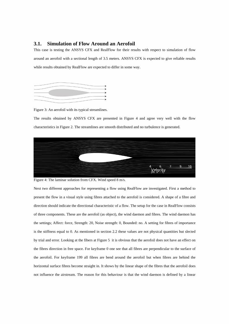
Figure 3: An aerofoil with its typical streamlines.
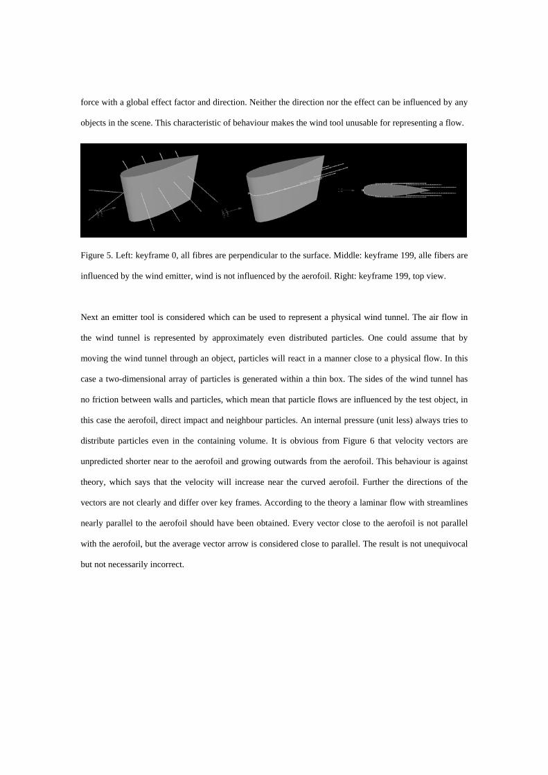
The results obtained by ANSYS CFX are presented in Figure 4 and agree very well with the flow
characteristics in Figure 2. The streamlines are smooth distributed and no turbulence is generated.
Figure 4: The laminar solution from CFX. Wind speed 8 m/s.
Next two different approaches for representing a flow using RealFlow are investigated. First a method to
present the flow in a visual style using fibres attached to the aerofoil is considered. A shape of a fibre and
direction should indicate the directional characteristic of a flow. The setup for the case in RealFlow consists
of three components. These are the aerofoil (as object), the wind daemon and fibres. The wind daemon has
the settings; Affect: force, Strength: 20, Noise strength: 0, Bounded: no. A setting for fibres of importance
is the stiffness equal to 0. As mentioned in section 2.2 these values are not physical quantities but slected
by trial and error. Looking at the fibers at Figure 5 it is obvious that the aerofoil does not have an effect on
the fibres direction in free space. For keyframe 0 one see that all fibres are perpendicular to the surface of
the aerofoil. For keyframe 199 all fibres are bend around the aerofoil but when fibres are behind the
horizontal surface fibres become straight in. It shows by the linear shape of the fibres that the aerofoil does
not influence the airstream. The reason for this behaviour is that the wind daemon is defined by a linear
force with a global effect factor and direction. Neither the direction nor the effect can be influenced by any
objects in the scene. This characteristic of behaviour makes the wind tool unusable for representing a flow.
Figure 5. Left: keyframe 0, all fibres are perpendicular to the surface. Middle: keyframe 199, alle fibers are
influenced by the wind emitter, wind is not influenced by the aerofoil. Right: keyframe 199, top view.
Next an emitter tool is considered which can be used to represent a physical wind tunnel. The air flow in
the wind tunnel is represented by approximately even distributed particles. One could assume that by
moving the wind tunnel through an object, particles will react in a manner close to a physical flow. In this
case a two-dimensional array of particles is generated within a thin box. The sides of the wind tunnel has
no friction between walls and particles, which mean that particle flows are influenced by the test object, in
this case the aerofoil, direct impact and neighbour particles. An internal pressure (unit less) always tries to
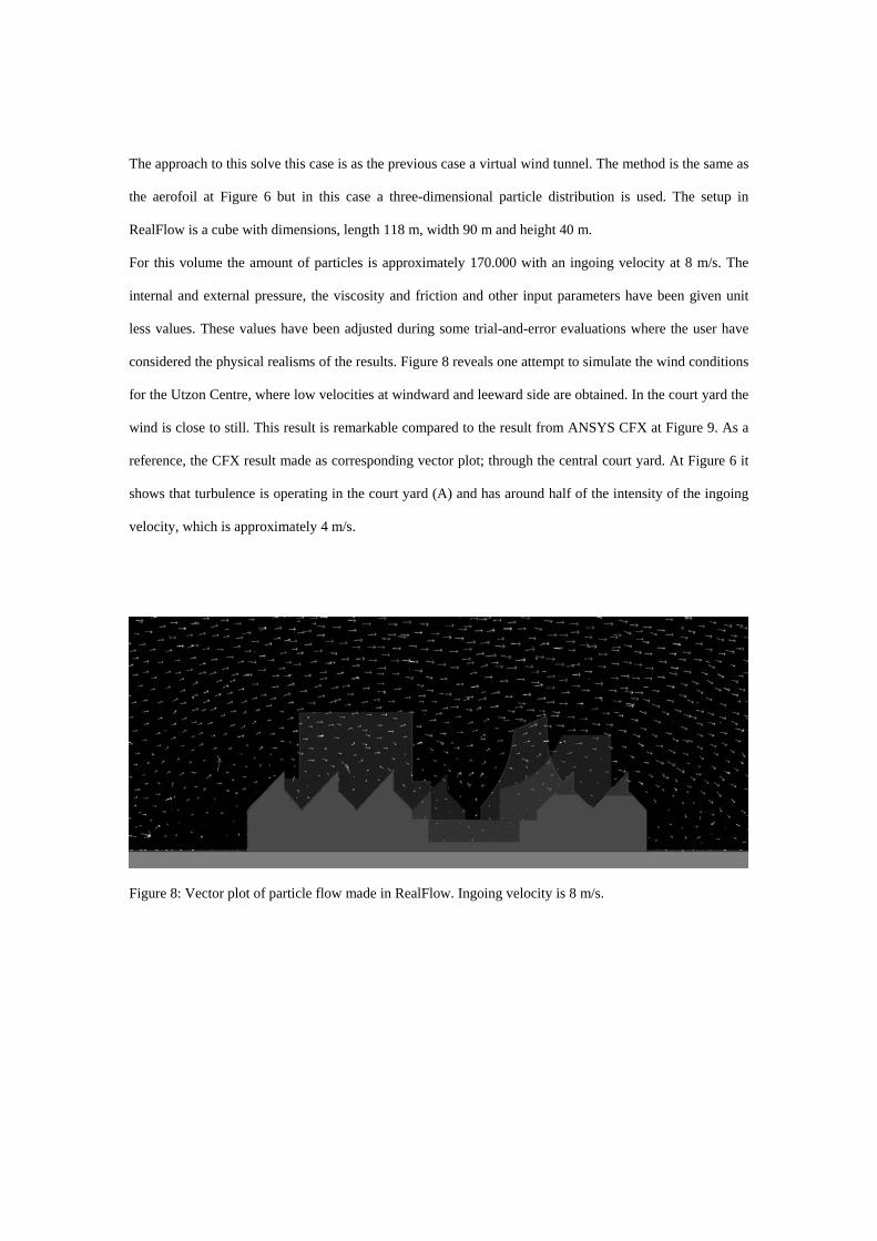
distribute particles even in the containing volume. It is obvious from Figure 6 that velocity vectors are
unpredicted shorter near to the aerofoil and growing outwards from the aerofoil. This behaviour is against
theory, which says that the velocity will increase near the curved aerofoil. Further the directions of the
vectors are not clearly and differ over key frames. According to the theory a laminar flow with streamlines
nearly parallel to the aerofoil should have been obtained. Every vector close to the aerofoil is not parallel
with the aerofoil, but the average vector arrow is considered close to parallel. The result is not unequivocal
but not necessarily incorrect.
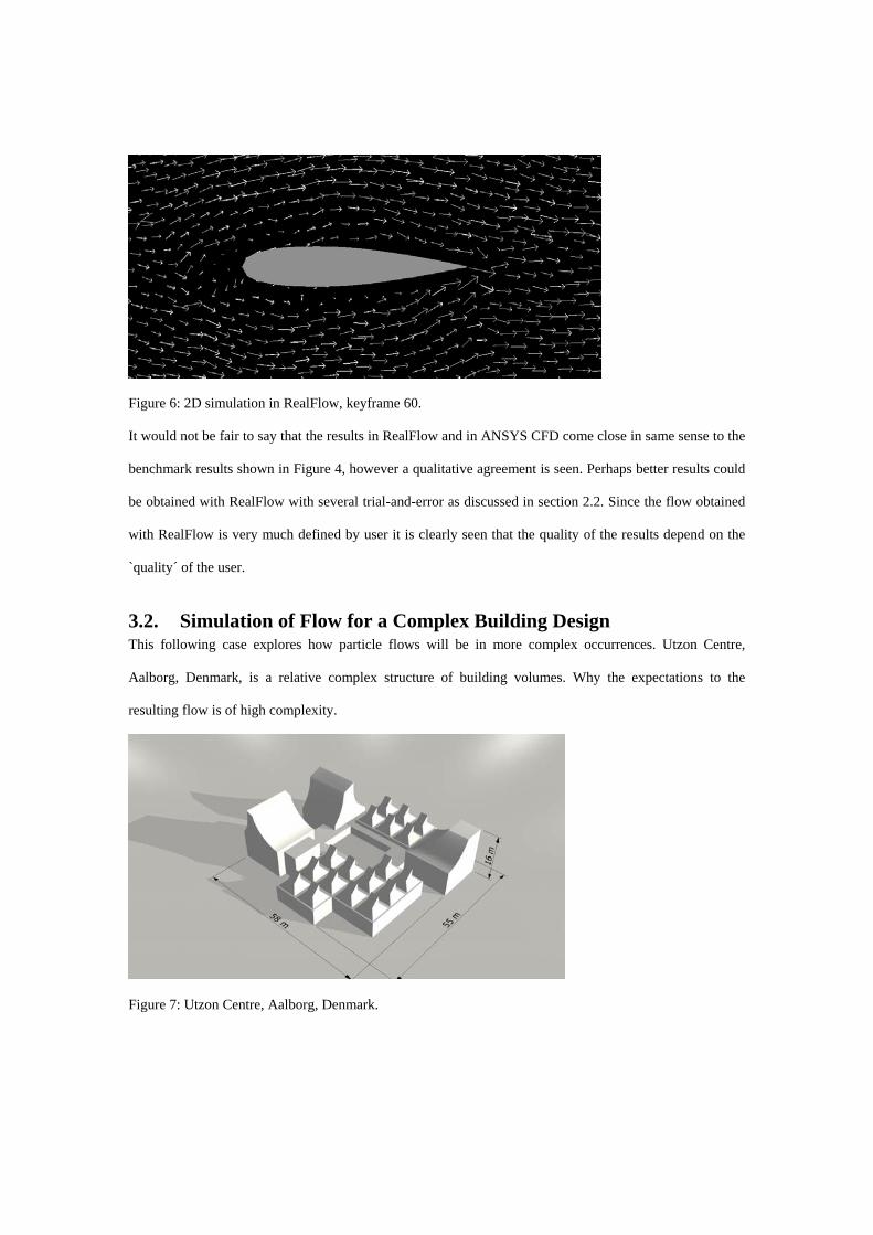
Figure 6: 2D simulation in RealFlow, keyframe 60.
It would not be fair to say that the results in RealFlow and in ANSYS CFD come close in same sense to the
benchmark results shown in Figure 4, however a qualitative agreement is seen. Perhaps better results could
be obtained with RealFlow with several trial-and-error as discussed in section 2.2. Since the flow obtained
with RealFlow is very much defined by user it is clearly seen that the quality of the results depend on the
`quality´ of the user.
3.2. Simulation of Flow for a Complex Building Design This following case explores how particle flows will be in more complex occurrences. Utzon Centre,
Aalborg, Denmark, is a relative complex structure of building volumes. Why the expectations to the
resulting flow is of high complexity.
Figure 7: Utzon Centre, Aalborg, Denmark.
The approach to this solve this case is as the previous case a virtual wind tunnel. The method is the same as
the aerofoil at Figure 6 but in this case a three-dimensional particle distribution is used. The setup in
RealFlow is a cube with dimensions, length 118 m, width 90 m and height 40 m.
For this volume the amount of particles is approximately 170.000 with an ingoing velocity at 8 m/s. The
internal and external pressure, the viscosity and friction and other input parameters have been given unit
less values. These values have been adjusted during some trial-and-error evaluations where the user have
considered the physical realisms of the results. Figure 8 reveals one attempt to simulate the wind conditions
for the Utzon Centre, where low velocities at windward and leeward side are obtained. In the court yard the
wind is close to still. This result is remarkable compared to the result from ANSYS CFX at Figure 9. As a
reference, the CFX result made as corresponding vector plot; through the central court yard. At Figure 6 it
shows that turbulence is operating in the court yard (A) and has around half of the intensity of the ingoing
velocity, which is approximately 4 m/s.
Figure 8: Vector plot of particle flow made in RealFlow. Ingoing velocity is 8 m/s.

Figure 9: Sectional vector plot of result from CFX. Ingoing velocity is 8 m/s.
4. CONCLUSIONS With this research, it was the aim to find new and easier methods for solving fluid dynamics. Of cause
RealFlow is not the only tool to that was possible to explore. But working with particles it is of many
considered to be the strongest tool. When dealing with RealFlow as a tool to simulate a physical event it is
obvious that the software is not developed for it. The main reason for this is that all parameters do not have
units known from physics. When dealing with simple parameters e.g. distance density and temperature
RealFlow use SI units. In more advanced parameters such as viscosity, pressure and surface tension there
are no connection to physicals standards. In these instances it is not possible to be objective and adjust
parameters from common sense. It is not possible to know how parameters should be adjusted to fulfil the
specific case.
References
1. Kolarevic, B. (ed.), Architecture in the Digital Age: Design and Manufacturing, London, UK:
Spon Press, 2003.
2. Szalapaj, P., Contemporary Architecture and the Digital Design Process, Elsevier, 2005.
3. Lynn, G., Animate Form, Princeton Architectural Press, 1998.
4. Maya

5. Realflow - Next Limit Technologies. http://www.realflow.com (14-5-2008).
6. Tsou, J.-Y., Chow, B. and Lam, S., Performance-based simulation for the planning and design of
hyper-dense urban habitation. Automation in Construction, 12(5), 2003, 521-526.
7. Axley, J. and Nielsen, P. V., Ventilation Systems: Design and Performance, London and New
York : Taylor & Francis, 2008, 155-263.
8. Zhiqiang, Z., Application of Computational Fluid Dynamics in Building Design: Aspects and
Trends. Indoor Built Environment, 4(4), 2006, 305–313.
9. Kieferle, J., Wössner, U. and Becker, M. Interactive Simulation in Virtual Environments - A
Design Tool for Planners and Architects. International Journal of Architectural Computing, 5(1),
2007, 116-126.
10. ANSYS CFX
11. Wilcox, D.C., Basic Fluid Mechanics, DCW Industries, Inc., 3rd edn., 2007.
12. Westbury, P. and Miles, S., It’s a breeze. The Architect’s Journal, 40, 2002, 40-41.
13. Liu, Y.Q., Liu, X.H., Zhu, H.B., Wu, E.H., Physically based fluid simulation in computer
graphics, J. Comput. Aided Des. Comput. Graph. 17(12), 2005, 2581–2589.
14. Liu, M.B, Xie, W.P. and Liu, G.R., Modeling incompressible flows using a finite particle method,
Applied Mathematical Modelling, 29(12), 2005, 1252-1270.