farm buildings - oldu.fr
TRANSCRIPT

iixii;: .;;'
':''•'
;,
•
:
'
:
ItBh
. :;'

HA
CORNELLUNIVERSITY
COLLEGE OFARCHITECTURE
LIBRARY .

Cornell University Library
NA8201.B74
Farm buildings; a compilation of plans fo
3 1924 015 223 765
DATE DUE
«***&*,
ia ft-- .
^ J>fVV)
MIMrCOlNU-S.A

Cornell University
Library
The original of this book is in
the Cornell University Library.
There are no known copyright restrictions in
the United States on the use of the text.
http://www.archive.org/details/cu31924015223765


I"
<asWB
o
wOS
HK
OS O
W m
W
K
W
JJ<J
wPS
oQZ<PQ
4

FARMBUILDINGS
, * < , , , A COMPILATION OF ,,,,,,PLANS FOR GENERAL FARM BARNS,CATTLE BARNS, HORSE BARNS, SHEEPFOLDS, SWINE PENS, POULTRYHOUSES, SILOS, FEEDING RACKS, ETC.ALL REPRESENTING CONSTRUCTION IN ACTUAL USE.
CHICAGO:SANDERS PUBLISHING CO.
1905.

tjto^leej
COPYRIGHT, 1904.
SANDERS PUBIJSHING COMPANY,ALL RIGHTS RESERVED.

PUBLISHER'S NOTE.
1 'HIS is not a book of proposed plans for farm buildings, but for the most part is
* a presentation of actual construction by practical men. It is in the main a com-
pilation of the best plans contributed to The Breeder's Gazette by the farmers and
stockmen of the United States in recent years. Many different types are illustrated.
Different farms, different latitudes and different methods of management demand an
infinite variation in the style, dimensions and detail of American farm buildings.
In barn building as in the planning of the farm home, nearly every individual
has his own peculiar ideas and tastes. It is rarely that one is entirely satisfied with
what a neighbor has done in such matters. At the same time it is clear that many
general propositions and many matters of detail possessing real value to a prospective
builder may be gleaned from a study of what successful farmers in different parts of
the country have already carried out.
In the belief that many helpful hints will be found in these pages and to fill a
persistent demand for information upon the subject treated the publishers present this
compilation with full confidence that it will meet with general appreciation.


TABLE OF CONTENTS.
PAGELocation and General Arrangement . .
.
11-14
The Modern Barn 15-19
Wing's Joist Frame 17
General Farm Barns 19-38
Bank Barn, A.. 33
Barn for Small Farm 38
Barn of Round Poles 38
Basement Barn and Carriage House ... 33
Circular Barn, New Type of 23
Farm Barn, Good Type of 37
Hay Barn, A Joist Frame 36
Horses and Range Cattle, Barn for. ... 38
Indiana Farm Barn 29
Iowa Experiment Station Barn 25
Kentucky Farm Barn 30
Kentucky Stock Barn 35
Lovejoy's Farm Barn 21
Minnesota Farm Barn 19
Ohio Farm Barn 33
Small Barn. Plan for 37
Stock and Hay Barn 25
Stock Barn, A Small 36
Umbrella Barn, The Glide 39
Whitehall Cattle and Horse Barn 29
Wisconsin Farm Barn 29
Cattle Barns 39-56
Breeding Cattle, Barn for 50
Corn-Belt Barn 48
Feeding Barn, A Cattle 53
Feeding Cattle Loose, A Barn for 54
Hawkeye Cattle Barn 42
Hoosier Cattle Barn 47
Illinois Cattle Barn 50
Indiana Cattle Barn 43
Iowa Cattle Barn 41
Kansas Cattle Barn 40, 43
Missouri Barn Plan 53
Modern Type of Cattle Barn 49
Morgan Cow Barn 41
Octagonal Cattle Barn 47
Steer Barn, An Iowa 54
Open-Centre Cattle Barn 51
Sale Barns 55, 56
Horse Barns and Stables 57-76
Bank Stable TO
Barn for Forty Horses 70
Colt Stables, Convenient 74
Horse Barn Without Cross Ties
Illinois Stallion Barn
Iowa Stallion BarnKentucky Barn for Speed Horses
Kentucky Coach and Stallion Barn
Light Horses, Barn for
McMillan's Horse BarnMontana Horse Barn
Mule BarnNebraska Horse BarnOaklawn, Stabling at
Plan for Horse BarnPlymouth Hackney Stud Stables
Stallion Barn, A ModernThree-Story Farm and Horse Barn
Dairy BarnsCow BarnHygienic Dairy BarnIllinois Dairy BarnNebraska Dairy BarnPennsylvania Dairy BarnRound BarnWisconsin Dairy Barn
Swine Barns and HousesFarrowing Pens, Lovejoy
Farrowing Pen for Early Litters
Feeding Floor and Pig Houses
Hog House for Sows and Pigs
Illinois Hog HouseMaryland Hog HouseMorgan Hog BarnMovable Hog HouseNebraska Hog HousePortable Pig PenTwenty Sows, House for
Sheep Barns and ShedsBaby Mutton Factory
Barn with Glass-Covered Lamb Shed.
Experiment Station Sheep BarnFeeding Barn for SheepFeeding Shed for SheepInterior Arrangement of Sheep Barn
.
Lambing Barn for the SouthLambing ShedMorgan Sheep BarnNebraska Sheep BarnSmall Sheep BarnUtah Sheep Shed
page63
73
68
71
61
60
71
62
76
65
58
64
70
63
67
77-85
81
82
77
83
84
77
85
86-97
94
92
95
90
87
95
87
94
90
97-110
102
105
99
107
107
105
108
109
98
106
102

10 TABLE OF CONTENTS.
Poultry Houses 111-120
Convenient Poultry House 114
Design for Poultry House 116Farm Hen House 115Farm Poultry House 119
General Remarks Ill
Hen House, A Convenient Small 120Hen House, Good Type of 117
House for One Hundred and Fifty Hens
.
117House for Two Hundred and Fifty Hens. 118Illinois Poultry House 116Simple and Practical Ben House 118Summer Hen House 115
Miscellaneous 120-177Anchoring a Barn 158Breeding Box for Swine 158Bull Stocks 160Cement and Concrete Work 129-133
Cistern Making, A Hint on 173Covering Stacks, Device for 162Cribs, Granaries and Workshops 127-129
Dehorning and Hog-Ringing Device. . . 159Dipping Tanks 166-172
Drainage System, A Farm 173
Drinking Fountain 161
Feed Racks and Troughs 133-138
Fences 138-146
Fence-Breaking Bulls, Device for 162
Gates 146-156
Hay Barracks, Joist Frame 129
Holding Hogs, Device for 160
Hog Loader, A Portable 163
Hog Pen Front 157
Ice Houses. . , 163-165
Roofs and Roofing 174
Self-Sucking Cows, Devices for 158
Shipping Crate for Hogs 162
Silos 120-127
Stalls for Cattle 175-177
Ventilation of Stables 165
"Wagon Rack and Stanchion 156
Water Closets 174
Water in the Cow Stable 174
Whitewash Formula 174
Water Supply, The Farm 172
Water Tank of Earth 173
Appendix 177-185

FARM BUILDINGS.
LOCATION AND GENERAL ARRANGEMENT.The planning and construction of farm build-
ings should be done with regard to the surround-ing outside features as much, as to the interior
arrangement and convenience of the rooms. It
is a common error to see little forethought takenin the placing of the buildings, in their relation
to each other or to the surrounding conditions;the total disregard of a fine outlook that mayhave been had from the windows that are mostfrequented; many errors in the proper way to
approach the house from the highway, and manytimes the utter absence of any attempt at orna-mentation in the way of tree planting—nothingsave bare sides and sharp angles of buildingsopen to all winds, storms and sun heat, or theopposite extreme, burying the house in a denseshade of loneliness.
Now this should not be so. When the advan-tages and increased value of the property as a
whole are considered it is at once apparent. Anyone can distinguish between a nice farm, a place
where it would be a pleasure to live, and on the
other hand one that is bare and uninviting. Thecost is a matter of forethought on the part of
the individual at the beginning in the planningof the work, and the actual material to be used
y in beautifying the grounds almost always canbe had for the gathering. One may easily find
the time to do the work when once he hastasted of the pleasures there are in surroundingsthat are made attractive with trees and plants
arranged to make a landscape that is ever
improving and changing in scene.
When a beginning is made toward embellish-
ment of the home surroundings then there is
a new birth given, the feeling of attachmentthat reflects back into pleasant and longing
recollections of the happy lives passed there,
and the far-reaching influence of cheerful homesurroundings on the character and future life
y of the growing generation toward the good andhigh of ideal life is above any estimation, besides
being a source of interest and everlasting joy
and pleasure alike to the owner and to all whoenter here.
Farming is not all corn. There are many fine
farms that are -only such from the fact that_
there is a quiet natural park-like effect resting
over the home place and if favored with a fertile
soil and a kind climate how much more blest wecould be if we would bring about us more of the
natural beauties so abundant everywhere. Thisneed not detract an instant from the economicaloperation of the farm but if practically plannedshould add many fold thereto.
We can assume that the residence and other
buildings are already placed, or that building is
to be done at some future time. With respect
to the all-important question of choosing the
house site, the custom in the city seems to be the
law without recourse in the country, in that the
house must stand facing square, with the best
rooms toward the public road. If a better expo-sure or a fine scene lies in another direction,
reverse the order regardless of the highway.Again, houses are dropped in a hollow, carried
to the top of a bare hill, or placed too near dustyroads or stables, making things more disagree-,
able than convenience would compensate. Thehouse should not be put on a poor or waste piece
of ground just to gain a little extra tillable land>"
Personal preferences should of course be takeninto consideration, but as a rule many desirable
locations are ignored. Among the specific direc-
tions to apply in selecting the home site are goodsanitary conditions. These demand air andquick drainage of water. All this is secured ona dryish soil, slightly elevated if possible andfairly open to admit a free circulation of air.
Any protection against prevailing north and westwinds in the winter season, such as hills, trees
or any other natural objects in the track of regu-
lar storms, should be made use of, but cool andrefreshing winds should not be hindered in their
direction during the heated season.
The distance from the highway is hardly a
matter of importance. If the best place is 400'
from the road it ought to be chosen over anotherless desirable, though 200' nearer. Besides this
an entrance approach of reasonable length, if
properly laid out among a > grove of trees, will
add much to the dignity and bearing of the
place. The relation of the house and barn shouldbe such that they do not appear as a part of
each other and in driving to the house one is notled first through yards and past gaping barn

12 FARM BUILDINGS.
doors. The barn should occupy a position so
that the prevailing winds will carry the stable
odors in a direction away from the house and
not toward it, as is often the case. The exact
position and arrangement of the out-buildings
and enclosures will be according to their use,
and to be convenient should be few and com-
• pact and not scattered over a whole area. Pens,
sheds and stacks should not be conspicuous in a
general front view.
In country houses broad simple design is much^to be preferred. All about a house of this order
there is a quiet dignity and homelike restfulness
that, is in pleasing harmony with every rural
landscape. The rooms should be few and large.
The veranda is right if one step up from the
ground and at least 10' wide, and a porte-
cochere or carriage porch should be a part of
every country house, as it surely is a comfort
when rainy or windy to drive up to the door^ under a roof. Especially is the excessive use
of all "ginger-bread" mill work in gable orna-
ments, railings, brackets and the like to be dis-
couraged, as such detail soon falls into decay andis a constant item of repairing and the greater
part of it is vulgar and meaningless. Likewise
the use of many discordant colors in outside
paintin? is not in keeping with surroundings; a
modest neutral shade that blends with the fields
and trees is the correct- one. Eed is a good andcheap color for barns and possibly for houses
also, but it should be shaded down and the glare
and flash taken off.
' Features of the natural landscape should
receive great consideration, as it is these that
give character to the farmstead. A grove of
noble trees on a slight eminence would at once
suggest the future home site. In the choice of
views here is a suggestion as to the points ,of
interest: first would come the immediate sur-
roundings made beautiful with lawn, trees andshrubs, and farther out the adjacent fields of
growing crops or pasturing animals are con-
stantly in mind. The neighboring farm houses,
the travel on the highway, or a speeding rail-
road train are all of every-day attraction. Thelandscape that is characteristic of the particular
country, a broad far prairie scene that holds
hands with the horizon beyond; hills or wood-lands bounding the view with their picturesque
sky line, a river or winding stream with woodedshores and spanning bridge or a lake of broadexpanse and quiet surface—all these are everlast-
ing scenes of delight and inspiration.
Now as a practical demonstration of how a
farm can be developed in a complete and intelli-
gent manner, reference to the example shown bythe plan will serve to clinch the essential points
mentioned. The plan represents a general
scheme for the layout of a 160-acre prairie farm.
There are no trees on the tract of any import-
ance ; the surface is slightly rolling with no
prominent elevations anywhere—in all a typical
grain and stock farm; corn, oats, some wheat,
hay and pasturage, almost all sold off in the
finished products of beef and pork. It is believed
that this scheme comes very near an economical
use of all of the land combined with a beautifi-
cation of the home surroundings, a park-like
entrance and approach drive, a commanding
position for the house and the farm buildings
centrally located and accessible from all parts
of the premises.
The house is placed in a ten-acre piece, which
,/may be properly called the home plot. Here are
collected all the buildings (except the barn and
feeding lot), orchard, vegetable and fruit garden,
shaded lawn, flowers and all that goes into daily
life. This plan leaves no waste ground; every-
thing is compactly arranged and yet in such a
manner as to allow the extension of any particu-
lar part without interfering with another.
The residence is about 700' from the high-
way and stands in the southwest corner of the
home plot, the ground sloping off gently to the
south. All the main rooms have a south and east
exposure. It is approached from the public high-
way on a curve which is in the direction of the
most traffic (the city in this case). This is a
much better way than entering at right angles
and adds greatly to the appearance of the
entrance and does not allow a direct view up the
drive from the road. The drive slants over
until within about 20' of the fence; it then
parallels the fence in a straight line to the barn.
A short distance from the house a branch road
leads over on a gradual curve to the carriage
porch, passing underneath it; the curve then
continues and joins the main road to the barn.
By placing the house about 70' or so from the
main drive all clatter and noise of teaming is
to a large degree shut away from contact with
the rooms and a nice lawn space comes up to
the house on that side. This entrance road is
ten feet wide, the branch nine feet, graded with
gravel from a near-by pit and smoothly surfaced
off with a crown just sufficient to turn the water.
The barn is 250' from the house and is set
40' into the ten-acre pasture to the west,
with a silo on the north side convenient alike to
the barn and feeding lot. Another building is
put up 80' directly east for general storage
purposes of machinery, wagons, supplies andrepair shop. The space between the barn andstorage house should be drained and bedded withgravel to serve as a general movement yard andentrance for both buildings; a place to set upthe shredding outfit, grinding, unloading and

LOCATION AND GENERAL ABHANQEMENT. 13
the like. Water is piped into this yard and to
the house from the tank and well just back of the
storage house. A poultry shed is at the north of
this building.
A good big orchard contains about 125 trees,
including apples, pears, plums and cherries,
manent than the raspberries and blackberries,
which can be moved bade and forth into the
nursery ground when they get old and worn out
'in one place; currants and gooseberries are also
planted. The strip for nursery purposes does
good service in growing trees and bushes to set
m^sm^^^JTO. 1—PLAN FOB LAYING OUT A 160-ACRE FARM AND I\ARM HOME.
which will give plenty of fruit for home use and
much to sell. A fence is run along the lower side
of the orchard ; then the pigs can be turned in any
time to consume the fallen fruit, although the
trees will be cared for the same as a crop of corn.
One acre is given to small fruits. The grapes are
put next the orchard because they are more per-
out in the future. A row of hot-beds and framesis useful in many ways; it is protected alongthe north with evergreen trees. The vegetable
garden of one and one-quarter acres will giveabundance of good things and all that is left overthe pigs will take as dessert. The strawberrypatch is moved about the garden every year or

14 FARM BUILDINGS.
two. Asparagus and rhubarb are along the fence.
A lawn space bounds the house on all sides,
varying in width from 150' to 200'. It is not
necessary, however, to keep it closely mown. In
the rear the grass covers the clothes-drying
space; further back are the beehives and a place
for the wood pile. The grounds about the house
are planted with trees for shade and beauty; a
place for children to play and climb and a source
of recreation and ease for the older members of
the family. As to the kinds used for this p'Ur-
pose : in making the ground work or foundation
of the scene use such native trees as are found''growing in the immediate locality ; elms, maples,
lindens and. ash are in greater abundance. All
these trees are reasonably quick in growth, bear
transplanting well and will therefore prove a
success from the start. Hawthorns, wild cher-
ries, plums and crab apples, juneberry, dogwoodand redbud are planted in the places to thicken
up and mass with the other trees; occasionally
they appear in detached groups or specimens by
themselves. They will lend variety and charmto the surroundings in the springtime with their
white, pink and red flowers, and in the autumnmany of them close the growing season with a
contrast of scarlet fruits and golden-hued foliage.
Along the entrance road the work is done in
a like manner. Evergreen trees—pines andspruce—are planted in clumps; at the left handside of the entrance gate is one group,- farther
up on the other side another. On the west andnorthwest sides of the house are thick groups
'to lessen the prominence of the barn, to check
cold winds and vary the effect with the deciduous
trees. Trees are placed along those sides of the
barn ; seen from the highway they will soften the
blank barn side and give a proper setting to the
building as a whole. The gable and tower
appearing among the tree tops will mark a dis-
tinctly rural scene. To protect the buildings andfeeding lots somewhat against the direct force of
cold northwest winds groups of Norway spruce
are planted in alternate groups with deciduous
trees, as shown in the plan, north of the barn
and act as a wind check.
The entrance gate should be set in at least
thirty feet from the fence line, leaving an open
space of 60' to 70' on each side of the drive, as
shown in the plan. This space is planted with
trees, and if an elm is planted on each side of the
gate a beautiful arching effect will be had over
the formal entrance to the place.
A tree to appear in all its natural beauty
should spread its branches out and down to the
ground on all sides. Never trim all the branches
off and expose a bare stem, nor hack off the ends
of branches and make a stubby, broom-shaped
thing. If a good set of roots is dug with the
tree no pruning is required. Pruning of orna-
mental trees is properly a thinning out in the
center of minor twigs and branches. Let the
tree develop into its own natural form. Cutting
can never accomplish this.
Shrubs should be massed in a border along the
entrance drive next to the fence, to add variety
with their foliage and flowers at different times.
An irregular massing of shrubbery forms a boun-
dary belt along the east and south sides of the
house. The lawn extends out on those sides to
this border; along the edges next the grass is the
place for hardy flowers, native perennials and
any other favorites that are desired; here they
will be in charming contrast with the lawn and
bushes. The kinds of shrubs used are wild native
species found growing in the neighborhood, such
as dogwoods (the red^branched and others),
sumach, elderberry, wild rose, Indian currant,
snowballs, spiraea, lilacs, mock-orane andhoneysuckles. Japan quince and forsythia are
nice in places where they are seen from the win-
dows, because of their early blossoms. So are
those early flowering trees, such as juneberry,
wild goose plum, Judas tree and dogwood. Suchearly spring flower scenes of color are delightful
to children or invalids who are confined to the
house until the weather becomes, milder. Vinesramble all over the porch columns and upthe fireplace chimney on the west side of the
living room.
The views from the house are indicated by the
converging lines-. (Fig- 1-) Three different
scenes are open from the living room: We havethe veranda along the south and east sides of
this room. To the west the sight is across openfields to the lowering sunset. Different openingsthrough the trees give glimpses of the life on the
highway. Out of the dining room the pic-
ture is one of sunlight and shadow, over the openlawn, under the trees to the color of flowers.
The kitchen and rear porch are shaded in the
summer; a walk connects them with the drive;
storage room is ample; the office is handy to thedrive and an outlook to the west; the carriage
porch and entrance hall face west.
In conclusion we may say that the farm homestands as the central feature, with the barns in
a subordinate position. They are then broughtinto harmonious relation with each other
through the artistic planting of native trees.
Orchard and gardens are grouped as nearbyaccessories and the grounds about the house are
further enriched with shrubs and flowers. Thedrive and walks allow convenient and easy access
to all places and lead in a natural manner to the
highway. Along the highway and in groupsabout the boundaries and cross fences trees are
planted as per introduction and outline.

THE MODERN BARN.
Do you want a barn? Have you any definite
idea of what it is that you want? Have youcarefully considered first your means, then yourneeds, then the needs of years to come? Is it
your idea to build a small, cheap barn that will
hold a few tons of hay, the grain, a few cows,
the working horses, a colt or two, the farmmachinery, the chickens and ducks? If that is
your idea think whether it is economy to shelter
farming tools on the barn-floor, which meansthat they are endlessly, in the way and that
they have a shed costing ten times what onewould cost designed especially for such a pur-
pose. No farmer can afford to build a barn with
such a small storage capacity for forage that hewill be compelled to fill it in summer and then
re-fill it again and again during the winter andspring, drawing hay from the stacks, damagedin quality and at double the expense of putting
it directly where it is to be used.
Is it not cheaper to make shingles shelter a
depth of 20' or 25' of hay than a depth of 5'
to 15' ? Consider whether it is real economy to
combine into one barn all the shelter and stor-
age room needed on the farm. There is fire to
be considered and convenience in handling stock.
Do you wish the colts or cows to run in the yard
with the pregnant ewes? Do you wish to mixbreeding sows and small lambs?The barn must fit the farm and the needs of
the farmer. It is folly to insist that any one
type of building is of universal suitability. There^ is this thought to consider when building a barn
:
Building is one of the great events that come
far apart. After a new barn is built it is not
likely that one can afford to add to it or build
another for many years. Build, then, of suffi-
cient size and capacity to allow for a reasonable
growth and expansion of not merely the farm
crops but the farm animals. Especially pro-
vide ample room for the storage of forage. Sheds
may be cheaply constructed to surround the barn
and these sheds will shelter the stock, and maybe added at any time,, but the storage room of
the mow is a fixed quantity when the rafters are
put on.
Notwithstanding the fact that barns must
always vary in shape, size and arrangement, it is
true that they will have certain things in com-
mon if they are modern and up-to-date.
Beginning at the foundation the modern barn
has no sills under it. The basement posts rest
directly upon stones, which are bedded well in
v:
the ground and should reach below the frost
line. Sills near the ground are not merely un-
necessary but a nuisance from every standpoint.
They decay, harbor rats and obstruct. Themodern barn has an earthen floor, preferably
hard clay, or cement where necessary. The lat-
ter is cheaper than the wooden floor and has
very many points of advantage. It conserves
warmth, no cold drafts come under it, does
not shelter rats, manures do not leach through
it and it does not decay. Yet where sheep are to
be sheltered or calves or cattle run loose no 1 other
floor is needed than the natural earth well bed-
ded. Even horses prefer to stand on the groundand many of the most successful horsemen in-
sist that their horses shall have earthen floors
in their stalls.
The modern barn has a basement or lower
story beneath its entire area used for sheltering'
farm animals. The reason for this is that it is
in the line of economy; moreover, it is a great
convenience to be able to drive through to clean
out manure or for other purposes. There is also
a free circulation of air through the basementwhen the windows are opened on opposite sides,
there being no wall or mow of hay to oppose the
air currents. Modern hay-lifting machinerymakes it as easy to lift the hay above the base-
ment as to drop it on the ground level.
In calling this lower story a basement it is
not meant that it should be under ground.
Where the ground is inclined and level positions
are not easy to be had, the old-fashioned bankbarn may be considered, yet in adopting this
type it should be constantly borne in mind that
stone walls are apt to be productive of disease
germs, especially of tuberculosis, which thrive
in a dark and poorly ventilated barn basement.However, the advantages of a bank barn may be
had without sacrificing light or ventilation. Letthe earth be heaped against the wall not
more than 4' or 5' and above this provide
numerous windows, all arranged to open wide.
The ventilation of the basement must be care-
fully thought out according to climatic condi-
tions and the kind of stock to be sheltered. Thisis a point against sheltering all sorts of animalstogether. Ventilation that is desirable for the
sheep barn is very undesirable for the dairy cows.
The lighting of the basement is an importantmatter. Sunlight is the great purifier and de-
stroyer of microbes and germs. It adds to the
comfort of calves, lambs, and pigs as it conies

16 FABM BUILDINGS
through the generous south windows during cold
winter days. Glass is fortunately almost as
cheap as siding. It will pay for itself manytimes over if used to let the sun in the barn
basement. This also is true of the poultry-house.
It is a commentary on the ignorance of a manthat so often the farm animals will go almost
anywhere rather than into the quarters he has
provided for them. If the barn is built right
and managed right the animals will need to be
shut away from it rather than driven into it.
An important consideration is that the barn
shall store an abundance of provender that maybe easily and cheaply put in it. To this end the
building must have depth of hay mow without
cross-ties through the middle to obstruct the free
working of the hay-carrier and fork or the use
of slings. For the ordinary barn of about 40'
length the height from the level of the mowfloor to eaves should be 20' and the best width
is between 30' and 50'. The chief consideration
is carrying the hay back from the center to the
sides when filling the mow. The track on which
the carrier runs should be directly in the center
of the roof and the hay dropping below it will not
easily be carried back more than 25' and on the
whole a width of 40' or 45' is preferable.
The roof should be what is termed "a half-
pitch; that is, the rafters inclined at an 'angle
of 45 degrees, or the curb roof of two angles.
The roofing material should be slate, good shin-
gles or galvanized iron. Painted iron roofing is
not very satisfactory.
Almost all manufacturers make carriers that
hold the load and run it in at any desired height
just to clear the floor or the level of the hay in
the mow or up to the peak of the roof, according
to the needs of the occasion. The use of such a
carrier effects economy in time and power, andresults in making better hay, for there is less
mow-burning when hay is not dropped from a
height.
It should be borne in mind that most barns
are too small, too low, too inconvenient in
arrangement, too uncomfortable to the animals,
while some are too large (this is rare), and too
ornate and expensive.
The day of ihe barn sill has gone. Instead
the posts set directly on stone or piers of con-
crete made of cement. Between the post andthe pier it is well to lay a block 2" thick
which will effectually prevent the absorption of
moisture by the bottom of the post. Should this
block decay it is readily"replaced.
Posts should not come clear down to the floor
level; the stones or piers should rise 12" to 16"
to throw the post above moisture or manure,which may accumulate in cattle or sheep barns.
Box-3talls in horse stables may also be permitted
to accumulate manure, being kept well littered,
and the result is better dryness, and no heating
of the well-tramped manure, beside the total
saving of all liquids.
Concrete blocks to set posts on are cheap and
satisfactory. They are made right in place.
Excavate to solid ground, usually 18" will
suffice, a hole 24" square. Make wooden moulds
shaped like truncated pyramids 8" square at the
top, 18" at bottom or larger, depending on the size
and weight of the building. These moulds mayhinge together and. fasten with bolts that may be
loosened so that they may be easily removed from
the blocks. It should be leveled so that the top
comes to the right place, then filled with con-
crete in which may well be imbedded a good
many cobble stones. A %" pin projected upwardfrom center of block and post set down on it 4" is
useful, if the building is not very heavy, to keep
wagons from butting the posts off the stones.
After a few hours of setting the mould may be
taken carefully away and another block made.
The moulds should be filled full enough to makethem of the same level. A surveyor's level at
hand.when setting the blocks is most convenient
and saves much time and trouble.
Hard earth is a very satisfactory floor for
sheep barns and cattle barns where animals run
loose. Earth is desirable for box stalls where
they are kept littered, as they should be. Cementshould be used for cow stalls and horse stalls.
Vertical siding is best. Matched siding is sel-
dom dry enough so that the tongues stay in the
grooves. It is better to use plain unmatchedbarn boards 12" wide, battened with 3" strips
after seasoning. In any event put siding on ver-
tically; it is stronger, more durable and cheaper
to erect in this way. If you wish to whitewashthe building either inside or out use unplanedlumber and the whitewash will adhere better.
Only' the best shingles should be used. Cedaris said to be durable but the cedar shingles com-monly sold are very thin. Steep roofs last doublethe time of flat roofs if of wood. Soakingwooden shingles for a moment in boiling linseed
oil adds to their durability. A trifle of red color
added to the oil adds to the beauty of the roof.
The color should not be of sufficient quantityto more than stain. Dip the shingles in large
handfuls to the tips, lay them on a piece of sheet
iron and let them drain into the kettle. Thisis said to make inferior shingles last 40 years.
They will not crack badly nor curl when so
treated. Painting shingles is not recommended.Shingle nails as now made of steel wire will rust
off in 10 years or less. They may be had gal-
vanized and should be so for either shingles or
slate.
There is no roofing more durable or more

THE MODEBN BABN. 17
satisfactory than slate. It is heavier thanshingles and requires strong rafters. For barnssingle-lap slate is coming much into favor; it is
lighter and much cheaper than double-lap and,save that storms sometimes blow in a very little,
it is as good.
Perhaps no form of roofing has caused moredisappointment and vexation than metal, whichrusts rapidly and requires frequent paintings.Galvanized steel seems durable and when wellgalvanized it has .endured for many years un-injured. Metal roofs are hot in summer.
_
Kubber, papeT, felt . and asphalt and otherkinds of roofing will serve if given proper atten-tion. Barn roofs are usually neglected.
For eave troughs modern tin rusts throughin three seasons. Paint will not prevent rust ina tin eave trough. Galvanized iron is to be pre-ferred. It is well to make eave troughs andspoutings of generous size.
"Let all hinges be larger than seems neces-sary" is the suggestion of an experienced barnbuilder. Hinges are cheap; get them strong.
Make sliding doors to run on flexible hangerswhich permit the doors to be raised up at thebottom without twisting the hinges or track.
Stalls for dairy cows should be 3y2 ' wide;for beef cattle 4' wide. Three single horsestalls will go in a 16' bent. Four horsesmay easily occupy the same space in two doublestalls and teams accustomed to standing togetherwill do so without injury. Box-stalls should beof .fairly generous size. For cows 7' x 8' is
permissible as a minimum; for horses 8' x 10'.
Do not make many box-stalls so small. Agood horse stall is. 10' x 12'. Horses will eat
their hay from the ground in a box-stall with-out waste if not given too much, and manyhorsemen think it is the best way. Put windowsin a stable as high as you can and put in plenty
of them. Make doors 4' wide where youcan. Make as many of them to slide as you can.
A height of 7' in a cow stable is permis-
sible if a good system of ventilation is provided.
Make the horse stable 8' or higher. Makethe sheep barn as well ventilated as possible. Awidth of 13' between centers of posts workswell in the sheep barn. Do not try to putunder one roof all classes of stock, tools, hens,
and hired men. Do not plan immensely wide
hams. They seem economical but greater com-fort and better results come from narrower barns
built partly to surround a paved court, sheltered
thus from wind and storm.
• WING'S JOIST FEAMEJoseph E. Wing thus describes the joist frame
:
I have for many years studied the question of
barn frames and designed a good many types.
A barn frame should have great strength to up-
hold weight, resist wind pressure and withstand
the pressure of rafters when weighted with snow.
My progress has been a steady evolution towards
the simple frame of two stories or more, with
curb roof and purlin posts, in which every stick
has a purpose and is so placed that it exerts its
utmost power in the line of its greatest strength.
The frame is an arrangement, an adaptation,
and I have not hesitated to adopt other men's
ideas. The roof was invented many years ago
and used in New York and New England. It
has stood the test of 40 years or more in the
heavy snows of that region, and I have never
seen nor heard of one crushing. Built in the
form of an arch it supports itself. The side walls
need not be extremely high; from 18' to 20'
with this roof gives great storage capacity.
They are prevented from spreading by the long
.</***.
W W "M
FIG. 2—WING'S JOIST FRAME.
brace which will withstand ten times the pull
that the thrust of rafters may ever put over it.
For very wide barns purlin posts should be used,
but up to 50' this roof is safe when rightly
framed, with the supplemental truss beneath theangle, and when so framed there is yet a savingin material and convenience over the. old style
roof supported by purlin posts. (See Figs. 2,
3 and 4.)
There is no solid timber at all in the frameand few sticks need be of unusual length. Thereshould be full-length posts ; aside from these ties,
joist-bearers, plates, nail girts and all may bespliced wherever convenience indicates and byalways placing^; piece 2' long behind the splice,
and, spiking- well, the whole is made as thoughof one piece. But one difficulty may confront thebuilder: the building of hay chutes. It is notdesirable to have permanent hay chutes, for with

18 FARM BUILDINGS.
the mow unobstructed by cross-ties hay is takenin by sling carriers that grip the rope and holdthe draft at any height, thus swinging it in
as soon as it clears the level of the hay in themow or the mow floor, and hay chutes are veryoften needed in the middle of the barn. To makethis come right have the hay chutes made in sec-
tions of about 6' high, building them 3%' or4' square, and in this manner build two panelsof solid boarding, like doors, say 3%' x 6', andbinge together at the edges so that they collapse
and lie flat. Provide hooks on one edge andstaples on the other. Take two of these pairs
and opening them hook together and set over the
opening in the floor and you have a section of6' of your hay chute. Fill the mow that high or
a little higher and set up another section; thustill the mow is filled. When taking out hay these
sections are folded up and hung on pegs in the
side of the mow until needed again next season.
This hay chute costs no more and is as easy to
build as any. A light ladder may be fastenedto one side of each section for entrance to themow.A great many of these frames have been
erected, some in very windy and some in snowylocations, since the plan was first presented in
The Breeder's Gazette and not one has given
.trouble to erect or in use, so far as I have learned.
Siding on this barn is better put on vertically.
If matched siding is desired it works as well
vertically as horizontally. The building may,however, be studded and siding put on hori-
zontally.
In building the joist frame barn the following
directions may be of value:
Get one carpenter to superintend the job; three
or four men can find employment and the moremen the shorter the job. Pile up joists six or
eight high and square, mark and cut off with a
small crosscut saw; pile each sort out by itself
so you can get hold of it quickly and surely.
Never make splices without breaking joints anduse a block 2' long at the splice. Spike to-
gether well at splices and everywhere. Usespikes 6" long and drive in a plenty; they are
cheap. Put bents together on the ground,
though you may finish spiking together after
raising, as spikes should be driven from each side.
Eaise the bents and brace up temporarily until
you have two standing, then put on box plate,
plumb very carefully, then put in long side
braces and one or two pieces of nail girts. Thatwill make the frame very rigid. You can nowcontinue to raise the bents one at a time andcontinue putting on plates and braces as fast as
they are raised. •
It will take four men two days to frame a
barn 40' x 60' and if convenient they should have
four others to help raise, which will take another
day. After the frame is up as far as the square,
complete that part and put on the siding before
erecting the rafters. A scaffold at the level of
the plates is convenient, though some have
erected the rafters without it. If you wish to
change the proportions of timber used, do so, but
ii //v i a r^

THE MODERN BABN. 19
and spike the bases to the plates. Begin raising
rafters in the morning so you can get them all
safe before night. Select good 2" x 6" longstuff, run diagonal braces under the rafters fromthe corners of the building clear to the center of
the roof, two spikes in each intersecting rafter.
This will make the roof very rigid. Get these
braces up as soon as three sets of rafters are
raised. If hay is to be taken in at the end, throwout two sets of diverging rafters to hold the endof the trade and shelter the hay door. Theirfeet may be spiked against the outer long rafters
and their points thrown out, each pair 2'.
Brace the gable well. Hay doors should be
8' to 12' wide. They may be double and their
upper ends fold down to admit of swinging
under the roof. Turn these doors away from
direction of wind. Vertical siding is strongest
and best for this frame. Hoof projection should
be 2' at gables and generous at eaves. It is best
added at eaves by spiking on sides of rafters
short pieces of 2" x4", giving the same slope as
the top part of the roof. Shingle this clear up.
Do not attempt to bend the shingles. Use gal-
vanized shingle nails. Do not leave out any
braces. Put 2" blocks on stones under end of
posts. When they decay they can be replaced
and no injury to posts result.
GENERAL FARM BARNS.
The farm barn built by W. H. Dunwoody on
his farm in Minnesota is 120' long, 90' wide, 48'
high and cost complete $20,000. The basement
floor is cemented throughout and on it there is
a poultry house 10' x 25' with a glass front to
south, nesting boxes, with inclines, roosts andrunway to outside yard. There also is a storage
room 12' x 20' in the west end of the basement,
together with an old pump room and wash room] 0' x 25' ; west stairway to main floor ; three box-
stalls 12' x 17' for dairy cattle ; six stalls for dairy
cows; five horse stalls and two box-stalls 8' x 12'
for horses ; two rows of box-stalls 9' x 12' (six
stalls to the row) with alleys between; 12
FIG 5—A MINNESOTA FARM BARN (ELEVATION)

20 FARM BUILDINGS.
double tie-up stalls 5' 8" long, mangers 26",
width of stall 8' 9", each stall being equipped
with iron enamel water bowl, with drop cover,
piped to water supply; drain trenches behind or
connected with all stalls, 18" wide by Sy2" deep;
large ventilating flues from basement to attic of
barn ; the height of the basement on north side of
barn is 4' above outside grade, giving large base-
ment windows for admission of fresh air; handextinguishers throughout barn and fire hose onreels, connected to attic tanks; root boiler room10' x 15', containing large root cooker; masonryon all sides; steel roof; window for fuel; root
r
&<, X
>MJ.£ V'£ v" J-rj*it\j
QouS*. £ Y/f fy*$**n <&
Bo t J"r/t£o&t*/ *m *
rtrr*,*j/*G iv**.*.
FIG. 6—MINNESOTA FARM BARN (GROUND FLOOR).
cellar 12' x 24', adjoining boiler room ; two silos
about 11' x 14' x 30', cement plastered; engine
room containing 15-horse power gasoline engine;
about 50' line shaft, with pulleys to grinder, con-
veyor, elevator, sheller and cutter on floor above,
and also connecting pump in pump room, and to
circular saw outside; east stairway to main floor;
artesian well pump room off engine room.The passageways or alleys between rows of stalls
all lead to doors on south side of barn openinginto lower cattle yard, which is divided into east
and west halves' with sheds on farther side; yardsslope to south. (See Pig. 5.)
The main or first floor is described thus:
Machinery shed 18' x 60', containing farm
machinery, also separate tool room and work
shop. Driveway from east to west through barn
120' long; flooring 3" matched plank; 3' on cen-
ter floor timbers or joists under driveway, size
6" x 12";joists elsewhere same size but 6' on cen-
ters ; hay and straw bays on south side of drive-
way (hay carriers above the hay distributing
floor, above part of the driveway—this floor is
provided with trap doors and when bays are full
this floor can be filled its full length);grain and
feed bins on north side of driveway, connected to
§
t
*+
«c*m
fieeoMut.
T
ofirrJ /* ret
UPPfH Wo
Roar OfPump /footer
FIG. 7—MINNESOTA FARM BARN (SECOND FLOOR).
conveyor and elevator for handling the grain andfeed; feed grinder, cutter, sheller, grain cleanerand elevator arranged next to bins on east end offloor and over engine room; office or men's roomadjoining with heater, bed and wash-sink; stair-
way to second floor in east end. (See Pig. 6.)The second floor is explained as follows:
Men's room with heater and, -furnishings; largestorage platform adjoining; stairs to top of silos,
elevator head and water tank's. In the attic thereare two water tanks holding about 350 gallons ofwater. The scale and scale platform are outside

GENEBAL FABM BABNS. 21
FIG. 8—LOVEJOY'S FARM BARN (ELEVATION)
of the barn on the driveway leading to the east
end of the barn. (See Fig. 7.)
LOVEJOY'S FARM BARN.
The general-purpose barn shown in Figs. 8, 10
and 11 was designed by Mt. A. J. Lovejoy andbuilt on his Riverside Farm in Winnebago Co.,
111., in 1903. It is for horses and cattle, together
with machinery, wagons, manure spreader, car-
riages, buggies and sleighs. It also has bins for
5,000 bushels of small grain, mow room for hay,
shredded fodder, a large amount of straw andlarge tank of water which supplies the barn andadjoining yards. It is 96' x 64' and is built in a
first-class manner, having a joist frame made of
the best grade of hemlock lumber, with Wisconsin
white pine siding and 2" x 6" studding, on whichrosin paper is used and the whole sheathed with
best kiln-dried dressed yellow pine, making an
interior finish equal to many houses. The foun-
dation is made of concrete, from screened gravel
and Portland cement. Every post in the build-
ing rests on solid concrete piers set in the ground3', on a 4' base. The entire floor is of concrete,
8" thick on a gravel fill of 15", and was madewith a good finish by an expert builder of con-
crete sidewalks. The approaches to each door
are also concrete and a concrete sidewalk extends
along the south side of the building to the door
of the engine room. The inside is divided into
suitable rooms, as shown in the plan. The engine
room is closed so as to exclude dust or dirt from
the mill room. A 12-horse power gasoline engine
furnishes power enough to run the grinder, feed
cutter, sheller, elevator and pump all at the same
time. There is a 28' elevator with a swinging ex-
tension that stands at the side of the driveway and
swings behind a wagon while standing on scales.
This elevator will elevate all kinds of grain to
the large bins above. These bins have hopper
bottoms with pipes leading to the mill room
below, direct to the grinder, fanning mill and for
loading wagons. The barn is lighted by acetylene
gas furnished from a plant which also lights the
residence and farm office.
The barn was made for convenience in han-
dling feed and preparing it for best results. Nohogs are kept in the barn, but all feed is prepared
in it except the steaming, which is done at the
feed house. All wagons are driven in the barn
and all hitching and unhitching done in it.
The total cost without any of the machinery,
engine and the "L" was about $5,000, which
includes painting. The 26' x 100' "L" was
.00.1 ELEVATION
FIG. 9—LOVEJOY'S FARM BARN (FRONT ELEVATION).
joined to the barn for a cattle shed and hasarched openings that can be closed by roller doors.
Where the diagram is marked "platform grain
dump" a set of scales was put in and an elevator
installed to carry grain to the granary upstairs.
The six large hopper-bottom grain bins are onthe second floor. (Fig. 11.) The bay for hay,indicated in the illustration, was changed andfloored with cement, the same as all the rest of
the barn. The elevator does not require a dump,as the hopper swings round behind the wagonand grain is let out into it from the rear end ofthe wagon. Plank floor is laid in the horse stalls

22 FABM BUILDINGS.
FIG. 10—LOVEJOY'S FABM BARN (GROUND PLAN).
Jxl—tn?:L rTi
FIG. 1 1—LOVHJOY'S FARM BARN (SECOND FLOOR)
.

GENEBAL FABM BARNS. 23
on the cement, as it was thought that horseswould be less liable to slip. A drilled well is inthe stable with a 100-barrel tank above in thesecond story. A system of water works from theelevated tank in the barn furnishes a good supplyof water in the barn and out in the yards.A better system of ventilation is used than the
one shown. All posts in the first story are boxed,giving a finished appearance. The barn is almostfrost-proof and is very convenient and a comfortto stock housed in it. The front elevation is
shown in Fig. 9. A photographic view of thebarn is presented in Fig. 8.
NEW TYPE OF CIRCULAR BARN.The illustrations (Figs. 12 and 13) show a
circular barn designed by Archiiect Benton Steeleof Indiana and erected on a farm in that State.

24 FABM BUILDINGS.
IB~J?ErWALif\
Alley
7 tow SVaAls \
'/Scales
BKICK FLOORm?M8 COVJ STA L,L3 1
&\SSAGE\Closet \X
HayChuti
\6RAW/> BOXES
7 FEEDRoom
Alcev
T lORHarnis:
moMWaterTrouoi>
MAV6B&
1_M t^ (-
/3?
TeedBo* C
&£
V <
^
H*
J
ALLEY
jiilEV
5
>v
/'RETW/ILL J1
w.c. !j6SHOWERBATH- *X
ffAXNSSS
ROOM
Box- Stalls EORhfOR. ES
S\SlioikoDoor's
~&
-\
OfficeFOR
HERDSMEN
ye*'
*«•""
ff-»- -*-£
^-V
-32 -O-
-/oo-o-Covered
fig. 14—an experiment station barn (ground plan)
ARCHOR& Second TIoor Plan
iVriveWay
iBrickPavement
Carriage «^ Implementroom
D
8
T=^
/=
Seedroom
I ffi55/R*a»l ny Office ^BEDffoon i
T=T ^ M ^->E
FIG. 15—AN EXPERIMENT STATION BARN (SECOND FLOOR).

GENERAL FARM BABNS. 25
tions with the exception of the crib and mills,
as before mentioned. The roof is entirely self-
supporting, no trusses being employed, nothingheavier than 2" x 6" rafters. The mow floor has
an estimated hay capacity of 350 to 400 tons.
The haying outfit consists of a circular track sus-
pended about midway up> the span of the roof
and operates an ordinary swivel car or carrier,
in other ways much the same as in ordinary rec-
tangular barns with straight-away track.
AN EXPERIMENT STATION BARN.
The Iowa Experiment Station barn at Amesis a very modern affair, roomy and well arranged.
It is a brick veneer, three stories high, 50' x 100'.
The first or ground floor is for stock, the second
for grain, implements, carriages and the like,
while the third is the hay mow. The silo is of
brick, has a 4" dead air space in the wall and is
18' in diameter by 28' deep, giving a capacity of
70 tons. The root cellar, which is under the
driveway, also has a hollow wall. In the horse
stalls a 3" false floor, with wide cracks to allow
urine to drain away quickly, is laid over the
cement, which is the flooring of the cattle stalls,
all passages being brick-paved. Over those parts
marked A, which are ceiled up 3', there is a wire
network 24" high. That in front of the horse
stalls is hinged so that all the feeding may be
done from the alley. The box-stalls for horses
are sided up 5' with 2" stuff and iron rods run
the rest of the way to the ceiling. (See Figs.
14 and 15.)
In the feed-room the hay and straw are brought
from the third floor in chutes with doors at the
bottom. The grain is also brought down in small
chutes with cut-offs, so that all the mixing of
feeds may be done on the first floor. A hot water
stove in the herdsman's office heats the bathroom
and the teamsters' rooms above on the second
floor and also the seed-corn room. The 18"
retaining walls on the southwest corner and north
side show the difference in the elevation, the
ground on the west being higher than that on the
east of these walls. On the second floor are the
bedrooms and office of attendants. In the corn-
room there are racks all around so the seed corn
can be ricked or corded, up in them, giving better
ventilation and economizing space.
The driveway is covered and is roughly paved
to give horses a foothold in drawing loads over
it. A continuous chute from top of silo permits
silage to be thrown from either of the three doors
to the feeding floor. The motor-room just off
the blanket-room is for a 15-horse power electric
motor. A line shaft from here into the feed
grinding room allows for belting to feed cutters
and other machinery. All the feed-bins have
sloping bottoms to facilitate the passage of grain
through the chutes to the mixing-room.' Venti-
lator courses from the ground floor to the outlets
on top give ample ventilation. A stand pipe andfire hose on reels afford partial protection fromfire within, while larger hydrants outside have
been placed near the building.
A STOCK AND HAY BARN.
The illustrations (Figs. 16, 17 and 18) are of
one of the most commodious and best arrangedstock and hay barns in the West. The building
in the main stands 132' east and west by 112'
north and south and the wings are 32' wide. Thedetails of the basement are very fully shown (Fig.
18) and the conveniences of such an arrange-
ment are obvious. In the basement and imme-diately under the wagon floor there are located
three bins for grain or ground feed and roots.
They are filled through trap-doors from above,
the sheller, or grinder, or root-cutter, or corn-
crusher being placed over the traps and the power
FIO 16—A STOCK AND HAY BABN (FRONT ELEVATION).

2fi FARM BUILDINGS.
BTG. 17—A STOCK AND HAY BARN (REAR ELEVATION).
i r 1 r
TJZC i JZE L
CeltBox.
I0ra/h
1 r
^Ji—rX,
oRoot Cellar.
ffCC
^./
-WaterTan/c
jxann TT
J5ca/fJ26 ineA - / feat, ftia/tf* meaau/vm*&3.
Softer
r^ i r 1 r
Deer 2)rive Whyit
J)nve Way

GENERAL FARM BARNS. 27
except as otherwise indicated on the diagram.The water tank is in the center of the barn andlarge gates expedite the handling of the cattleback and forth from the tank to the stalls, orto the yards if they1 are turned out. There aregood-sized box-stalls for the service bulls, with
direction and the manure loaded onto a wagonor spreader and carted to the fields. This base-
ment is surrounded by a stone wall and is very
warm, though amply lighted and ventilated bynumerous windows and doors. The water is
piped underground to the trough from well and
r 1

28 FARM BUILDINGS.
CAt I/O IKON HOOO
FIG. 20b—CATTLE AND HORSE BARN AT WHITEHALL (CONSTRUCTION).
„CATTL,
I ¥_J 1
FEED RACK BELOW H HAYRACK QFCCP RACKBELQW g1
HAYRACK
HAY |3HUT(: ALLEYL J
>VjTACK TlffEDgACK BELOW 1~1 HAYRACK FtEPRACJT
X 1 JorATTi^t '5'^'II 15^
FEEPRACK BELOW 1"
"CATTLE"
DftAtrO
DRAIN

GENERAL FARM BARNS. 29
reserved for feed-cutter and for hay-rake andhay-loader and yet additional room in the threemows for 200 tons of hay. The capacity forgrain, including both floors, is from 7,000 to8,000 bushels. The barn will accommodate 125head of cattle, including from 25 to 30 calves.The building is very substantially constructedand with due regard to general symmetry andeffect. As it stands it is a very attractive build-ing, well painted and trimmed and cost about$4,000.
AN INDIANA FARM BAEN.Fig. 19 shows the ground plan of a barn in
which cattle and calves may be fed, 20 cows kept(in Van Norman stalls) and "baby beef" pro-duced. It is also provided with stalls for horses.The diagram shows how the ground floor is
basement are of sound native whiteoak. The8" x 12" beams in the drives on the outside are
also of whiteoak. All bill stuff and timbers above
the basement are first quality longleaf Southernpine; 6" x 10" middle tie beams are set back 4"
from face of posts to allow studding, which is
2"x4", to pass without cutting. The floor of
two outside drives is made of 2" x 12" oak alter-
nating with 2" x 3" oak pieces set on edge, all
laid on 8" x 12" whiteoak stringers. The entire
first floor is floored with iy2 " dressed andmatched yellow pine flooring and the drivewayson the first floor have an upper floor of 1"
dressed and matched oak. The entire basementis ceiled all around the stalls, passages and alley-
ways 4' high with 1" dressed and matched yel-
low pine. The stable doors are built in twopieces, upper half 3' and the lower half 4' hi h.
TIG. 80d—CATTLE AND HORSE BARN AT WHITEHALL (END ELEVATION).
divided. Fig. 20 shows the arrangement of the
second floor. This barn has a cement floor
throughout and is conveniently arranged for the
uses to which it is put. Two silos are shown in
one corner, and the corn silage stored in themis very successfully used in the making of "baby
beef."
CATTLE AND HORSE BAEN AT WHITE-HALL.
Figs. 20a, 20b, 20c, 20d and 20e show the
elevation, floor and other plans of the beef cattle
and horse barn which E. S. Kelly recently built
on his Whitehall farm in Ohio. Fig. 20c shows
the ground floor on which there .are stalls for
cattle and horses. All the stone work is of good
native limestone, laid up in good lime and sand
mortar. The retaining walls around the drives
have half cement and half lime in the mortar.
All the bill stuff and dimension lumber in the
The roof of the Whitehall barn and ventilators
are covered with the best quality 16" cedar or
cypress shingles. The entire barn is framed to
secure the greatest strength and permanency of
shape with the least weakening of timbers. Thewindows in the basement are arranged to slide
sideways, as directed. The entire outside of thebarn is covered with 4" 'drop siding. The cattle
floors are made of cement. The barn cost about$7,000.
A WISCONSIN FAEM BAEN.
J. W. Martin's Wisconsin barn shown in Figs.
21, 22 and 23 has a stone wall foundation 20"high; the first story 8' is double-boarded withpaper between and shiplap floor above. Fig. 22shows the arrangement of the interior and Fig.23 the plan of construction. The approaches tothe main driveway and end doors are paved withcement. Box-stalls occupy the entire first floor

30 FARM BUILDINGS.
of the barn, and one stall is cemented for a rest-
less bull.
The cow barn (Fig. 21) is 30' x 80' with Bid-well stalls and a driveway between the rows of
cow stalls on through the middle. This barnwould be more convenient if it were 34' wide.
A KENTUCKY FARM BARN.The general description and plan (Figs. 24,
25 and 26) herewith given are of a Kentucky
barn built a decade ago. It is a, bank barn an-
stands on high ground where natural drainage it
good. The size is 62' x 74', and from basement
floor to the 1 wind-engine tower the height is 56',
divided into four stories. The basement wall is
of limestone, 22" wide and 8' high, and the posts
in the basement supporting the frame work are
twentv in number and are of oak, 12" x 12". Theparts of the frame are 10" x 10", 16' high. Theentire framework is of oak, the shingles of poplar
FIRST FLOOR PIAN
TIG. We—CATTLE AND HORSE BABN AT WHITEHALL.

GENEBAL FABM BABNS. 31
and the siding of Northern pine. There wereused in the structure 100,000 feet of lumber and50,000 shingles, and the total cost was about
with a cross aisle and forty box-stalls for grown animals, and the cross
or calf aisle will accommodate fifty calves.
The feed descends through a chute fromthe third story and two cars await to carry it
FIG. 22—A WISCONSIN FARM BARN (GROUND PLAN)
$3,900. The diagrams of basement and main
floor (Figs. 25 and 26) are quite complete and
need but little explanation. There are two feed
FIG. 24—A KENTUCKY FARM BARN (ELEVATION).
The floor of this story is double, with pitched
felt between, which protects the animals belowfrom the ones above. This floor is inclined eachway from the center sufficiently to cause properdrainage. The entrance to this story is throughdouble doors, 14' high (Fig. 24), via an elevated

32 FABM BUILDINGS.
macadamized drive extending outward from each, out at the opposite door. A gigantic hay-lift
. Scales are placed at one door, so that the grain reaches down from above, takes up a load of hay
is weighed by the wagon load as it is taken from and puts it in any desired part of the third and
the barn. The wagon passes along the aisle and

GENERAL FARM BARNS. 33
fourth stories or hay loft, which loft has a
capacity of 500 bales. The second story has
fourteen calving stalls, as shown in diagram,which are so arranged that they can readily be
converted in case of necessity into four stalls
each, making room for 56 cows. In the center or
main aisle, 12' wide, there is room for 50 calves.'
This gives the barn a capacity of 196 animals,
all sizes. There also is an office on the second
E*R.m bank.
• •.-••-.-: rr ••:•. ~ ;•• . * a'sffSfZ'/fxi'
i
j^cissyoMsJj;
<k tirle.

34 IBM BUILDINGS.
WIG. 30—A BASEMENT BARN AND CARRIAGE HOUSE (ELEVATION)
Cor/i
2^'
Mi/SJF'eed
Oate
% Cowsa'x/4-'
Sta/rch/o/iS
/3'x r'
/0 'X/4
'
//owe t>f&6/e
*
FIG. 31—A EASEMENT BARN AND CARRIAGE HOUSE (BASE-MENT PLAN).
V
\
r
24-'
24-'X/2'6'
/V /Y /V
Carr/agTes
24 'X V2'
v,^
FIG. 32—A BASEMENT BARN AND CARRIAGE HOUSE (MAINELOOR PLAN)

GENERAL FARM BARNS. 35
is complete by opening^Indows on three sides,in warm weather and the transom over theentrance at head of stairway. In the winterwarm air passes up a ventilating shaft to theventilator on top of the roof. The granary is set
up from the floor one foot and out from wallsa foot, so it is dry and rat-proof. It and thebedding-room occupy the back part of the base-
ment, leaving the front part nearest the light andSunshine for the horse and cow stalls. The horsestalls are 4' 6" x 12'. The partitions of 1" oakare set into the posts, so there are no nails or
bolts to injure horses.
The hay raxsks are perpendicular, with rounds3' long set 4 apart. The back of the racks is
boarded tight, sloping, leaving a space of 6" for
hay at the bottom and 18" at the top, beingfilled from the trap-doors in the hallway on first
floor. The stall on the east side is 1' wider thanthe other two to make more room for passing
from the feed way into the stable. The bed-
ding-room opens into the stable behind the
horses and is filled from trap-door at the right of
carriage entrance on first floor. The granary is
divided for corn, oats and mill feed and a dropdoor at the bottom of each, so feed is removedand the doors always closed to keep out rats.
The cow stable is fitted with stanchions and a
drop 6" deep and 4' 6" back. The litter fromhorse stalls is pressed into the drop to absorb
the moisture from cows and in front of the cowstable stands a low-down manure truck, which is
removed to the meadows or fields when filled.
At the head of the feed-room is a water faucet
connecting with a cistern on the bank to which
the water from the roof is piped. There is also
a trough of spring water in the barn lot.
The front elevation is shown in Fig. 30. Thedouble doors to the right open into the carriage-
room. The double doors on the left open into
the shop, which is fitted up with bench, vise, tool-
cases, and so on, and lighted by two windows
opposite the doors. The central door enters the
hall to the hay-mow and the stairway into the
basement. Into it hay falls from the mow at the
far end and is put into the racks through trap-
doors that fall back against the partition. In
warm weather these trap-doors are kept open.
In cold weather they are closed down.
The plan of first floor, as well as that of the
basement, is drawn to a scale of one-eighth inch
to the foot. (See Figs. 31 and 33.)
A—Double door 8' x 8' 9" to carriage-room ; B—Single door 6' x 3' 3" and transom 3' 3" by14" • c—Double door T x 8' to shop ;D—(Hallway5' 6" by 24' ; E—Trap-door for bedding below; F—Trap-door for feed to granary below; 6
—
Stairway to basement ; I—Ladder to hay-mow ; J—Entrance to cow stable ; K—Entrance to horse
stable; L—Water faucet; N—Trap-doors to hay-
racks below.
The building is covered with best pine shin-
gles, weather-boarded with dressed lumber, bat-
tened and painted. The corner posts are 14'
6" x 6". The floors to shop and carriage-room
are 1*4" sycamore and the floor to hay-mow is
tongued and grooved pine flooring with no knot-
holes.
A KENTUCKY STOCK BARN.
The drawings (Figs. 33 and 34) are of a Ken-tucky stock barn 20' wide surrounding a feed-
FIQ. 33—A KENTUCKY STOCK BARN (MOW PLAN).
JTG. 34—A KENTUCKY STOCK BARN (CROUP PLAN).
lot 100' in diameter. The feed-shed with troughand rack next to wall has the south side open to

36 FABM BUILDINGS.
the feed-lot. The barn has a sheep department,
hay-rack next to the outside wall and small stalls
for ewes and young lambs. It also is provided
with stalls for milch cows and calves, boxes for
bran and crushed corn and box-stalls for horses;
there is an 8' unboxed passage outside and a loft
over all except the scales and gateway, which are
open for hoisting hay with fork on an endless
track. In this loft there is room to store shredded
corn and different kinds of hay. A crib . should
be made separate and rat-proof.
A SMALL STOCK BARN.
The barn shown in Figs. 35 and 36 is designed
to hold 50 tons of hay, to have six horse stalls,
6' wide, three cow stalls, two box-stalls and a

GENERAL FABM BABNS. 37
the side. A A are ends of the tie shown in Fig.37. At the lower piece of plate is shown cutaway to show the block, 2" x 8", 3' long, thatrests on top of the post and on which the platesplices, as at 8 S. B B are blocks put in to fill
the post where the braces come against it. Nail-
SHEO I6XS3
MANPER fl/ff FEEDING CATTLEIN SHED— a „
HOXSESTALL
9FT WIDE
OOUBLE
HORSESTALL
feed alley & ft wide
6ATE
COIV •s taOls
OOCaLEHORSE
3FT.STALLS
WIDE
DRIVE WAY
Tcom
DOOR
ILLS
FEED ALLEY
PIG. 40—PLAN FOR A SMALL BARN.
girts are 2" x 8" spiked on 4' apart, not shownin the cut. The tie T splices at S. This tie is
double, breaking the joints. Posts are of twopieces 2" x 10".
The frame is put together with y2 " carriage
bolts and 40-penny spikes. The track for the
carrier runs under the peak and the draughtsare run in as soon as they clear the level of the
hay in the mow. Slings also carry in boundgrain.
PLAN FOE A SMALL BAEN.
Fig. 40 shows a barn with four double horse
stalls, one box-stall and room for 30 cows and20 other cattle. It is seldom satisfactory to
combine a horse and cow bam, as the latter canbe more economically built by making it only 30'
wide, but this does not suit so well for the horse
stalls. If 1 one could dispense with the drivewayit would be better to cut off as much as neededfor the horse stable and place the stalls across
the building with entry from the outside to each
double stall. The oats bin should be placed over-
head, so that oats can be drawn down through a
spout near the horse stalls. This barn with highcurb roof will hold about 60 tons of hay.
GOOD TYPE OF FABM BAEN.
The plan illustrated in Fig. 39 shows a cattle
barn which is 96' x 48'. It is a pole barn withposts 20' high and a corncrib 80' x 12' runsthrough the center of the barn ; the lower boards
TIG. 39—GOOD TYPE OP FARM BARN (BLBVATION).
of the crib are hinged and feed boxes built onlevel with the crib bottom so as to make prac-tically a selfrfeeder, especially when feedingshelled corn. Hay-racks on the sides are 80'
long. Hay is put in at the ends of the barn.Sliding doors, controlled by weights, are used at
K

38 FARM BUILDINGS.
the ends of the mow. They are closed when the
hay is in the mow. There are doors alongside
of the hay mow. When filling the mow a space
of 4' between the hay and the sides df the barn
may be left so that hay may be thrown into the
racks when feeding. The south end is open ; the
north end has doors which are closed in bad
weather. This barn will easily accommodate 100
cattle.
BARN FOE SMALL FARM.
A transverse driveway in a barn is rather a
waste of space, as. it usually shelters only the
farm wagon, yet it is often desired and in this
plan (Fig. 41) it is made to do duty as a feed
alley. There are stalls for four horses and five
cows and a large mow reaching to the
ground and granaries over the drive on each
side, where they are readily filled by hoisting the
grain with a hay-carrier rope. Where roofs are
40' wide or more there should be the truss methodof framing rafters, using 2" x 4" brace beneath
the angle, fastened by short pieces of 1" x 4".
This truss must be on both sides of the roof; it
is shown on one side only in the diagram.
BARN FOR HORSES AND RANGECATTLE.
This barn (Figs. 46 and 47) was erected in
Wyoming to shelter pure-bred and range cattle
f ]i ii 1 1 1 1
1
1 1 1 i i iHs?Mls>Si 1 1 1 1
1
m'fi 1 1 I'll fi f ' 1
1
I It H EQO 1 1 1 1
1
KajEtSSssl'** w 1 1 1 li IXQJ rtTii
PIG. 46—BABN FOR HORSES AND RANGE CATTLE (SIDEELEVATION).
and horses. The long shed is open on one side
next the yard and forms a good windbreak. Theend of this shed is shown to right of cut of the
~IL_

QENEBAL FABM BABNS. 39
is a hay track and where hay comes directly tothe earth. Well braced this building will keepits shape for many years.
THE GLIDE UMBKELLA BAEN.In the Sacramento Valley of California there
is little cold weather but some rain in winter. AMr. Glide has there built an immense barn witha roof projecting about 12' on every side, beneathwhich cattle shelter and eat hay stored within.
The idea is worth considering in any warm wet
country. (See Figs. 43, 44 and 45.)
FIG. 45—THE GLIDE UMBRELLA BARN (SIDE VIEW).
CATTLE BARNS.
The ideal location for the barn should be as
nearly as possible in the center of the farm. Thedwelling of course must be near. The advanr
tage of having as many pastures and fields
directly connecting with the barns is obvious.
Time, distance, labor, all are saved, and over-
sight, at all seasons, of the stock made moreconvenient. The character of the site, however,
is of still greater importance, and perhaps there
is nothing worse than a low, flat, undrained barn-
yard and adjacent lots. Strange to say, how-ever, nothing is more common.
If such a location is unavoidable then it will
pay to use all the resources of drainage, tile andstone, till even the longest wet spell loses its
terrors and planks and rails no longer are needed
as bridges to cross th'e depths and reach the barn
door. Wet, and not cold, is the greatest enemy to
thrift and flesh, and the floors of all sheds andpens should be high, dry and well drained. Theimportance of a sufficient number of well fenced,
conveniently arranged lots of sizes from a hun-
dred or so square feet up to an acre or two should
not be overlooked. There are never too many.
There is an infinite variety of wants met by an
infinite variety of circumstances, mental pecu-
liarities and financial conditions, resulting in a-
corresponding variety of farm buildings.
Good air, good light and dryness are foremost
in importance; they go together. One of these
qualities lacking, the others are almost sure to
be absent. The dark, cavernous recesses of very
large barns are seldom ventilated or dry. Theheavy foundations imply a basement dark, dampand malodorous. The great roof and floors meanheavy timbers, much skilled labor and expense,
and last but not least is the chance that some
winter night, in red and yellow flame skyward
soaring, the huge structure vanishes with all the
horrors of agonizing death to helpless animals
and to the owner loss immeasurable. More desir-
able are two or more smaller buildings, all above
ground, on light foundations, light timbers with
but little framing and far enough apart for somedegree of safety from fire and a chance to save
life. There should be doors on every side andample windows. Nothing is so cheap as sunlight
and yet nothing is so scarce in the average barnor stable. Another great advantage of somewhatscattered and smaller buildings is the possibility
of dividing up the stock and obtaining direct
access from different lots and pastures for differ-
ent classes of stock. It is not uncommon to see in
the middle of the night, in a large barn, a hun-dred cattle aroused and disturbed by one uneasyheifer or lost calf. Avoid all plank flooring as
one of the worst temptations of the artful archi-
tect. Broken stone (8") with here and there a3" tile running to the outside, with 6" of porous,
yellow clay on top, wetted and tamped, harden-ing like a brick, will always be dry, never slip-
pery, needs only here and there after the winteris over a little fresh clay and affords no harborfor rats. Many breeders prefer cement floors,
which are in common use. Have no narrow, con-
tracted passageways in which the larger cattle
will crowd and jam together. A favorite arrange-
ment seems to be a narrow feeding alley, tworows of cattle, heads in, and two narrow passage-
ways behind the cattle. This is a. misuse of space,
more expensive and no more convenient. Earbetter have one wide space, not less than 10',
which is less than the 3' in the center, in whichthe cattle have ample room to walk quietly to
their stalls, Where they stand heads to the wall.
A hand-cart may be used to distribute the feed
(before the cattle come in at night) and every
animal always has the same stall. A noted cattle
breeder is quoted as saying that time and again
he has seen 70 head of cows walk into such a

40 FARM BUILDINGS.
stable from three entrances and -be tied up bytwo men and munching their feed in 20 minutes,
with neither noise, hurry nor confusion.
Every barn should have a mow sufficient at
least to supply its inmates with the winter's hay,
bins for bran and prepared feed, but it is the
opinion of many farmers that the corncribs
should be separate and distinct structures.
In latitudes where the mercury only now andthen falls below zero animals suffer more fromthe barn being too warm and close than fromcold. In fact but for the difficulty of properly
apportioning feed, so far as health is concerned,
a good, deep shed, say 20' from front to rear,
with a hay-rack and plenty of bedding, is better
than a barn; the air is pure; there are nodraughts and no over-heating and no chilling.
Health and vitality are in direct proportion to
pure air and well bedded is half fed.
No matter how perfect the barn may be noth-
ing can take the place of abundant bedding, andconvenience in getting it in and getting it out
(in the shape of manure) easily and rapidly is
a thing indispensable. The manure should godirect from the stalls to the pastures and corn-
fields. As long as wheat will pay the cost of
production the straw is a .sufficient profit to
justify the stock raiser in growing it. Sawdustand even dry leaves are useful if straw is lack-
ing. Water in the barn is not generally a suc-
cess. A large central tank supplying drinkingtroughs in every lot, fitted with covers to beclosed at night in the winter, seems to serve everypurpose, and it is a rare day when all kinds of
stock should not be turned out for a few hours at
least. Thirsty cattle coming suddenly out of anoverheated barn may be hurt by drinking ice
water but the cold air has the same effect andthe 'condition of the cattle is the fault.
Hinges of course are obsolete. Nothing butthe best of rollers should be used, the track of
iron, put up as true and solid' as it is possible to
have it, and then watch and keep clean the groovein which it runs at the bottom. Box-stalls shouldbe built wherever a roof can be extended alongthe sides without cutting off the light and air
from the main building. A long shed closed in
front and divided into box-stalls, on the northside of a lot, is of great utility.- One or twoextra warm ones should always be provided a lit-
tle to one side for winter-night calving, sick ani-
mals and the like.
Many patent fastenings have been suggested
and advertised, but after all nothing in practice
has been found more convenient, more speedy or
more safe than the old-fashioned German chaincattle tie with about a foot play on a vertical
y2 " iron r°d under the edge of the manger.The cattle have perfect freedom up and down
and can reach to the center of the manger of an8' or 9' double stall. When taken off the cattle
the end ring should be hooked over a nail in the
side of the stall just above the animal's neck,
where it is just in place for use at night.
A KANSAS CATTLE BABN.
, The diagram (Figs. 48 and 49), as will be
seen,- <fully carries out the idea that an expensive,
elaborate barn is not a necessary adjunct to suc-
cessful cattle breeding in the Western States, but
that reasonable shelter for the herd from the
rigors of winter and some little outlay for the
protection of the hay is in keeping with the best
principles of economy. This barn was built by
Col. W. A. Harris on his Linwood Farm in
F amen \^, guttes *^> * &' ourrca V/ gutter
FIG. 48—A KANSAS CATTLE BARN (GROUND PLAN).
Kansas. The unpretentious yet admirablyarranged building (briefly described herewith)
was built many years ago and has given the
best of satisfaction. The materials used in its
construction were as follows: 32 telegraph poles,
20' long; 32 telegraph poles, 25' long; 6,000' of
boards, 16' long; 30,000 shingles; 400 battens,3" x y2 ", 16' long; 34 sashes, 4 lights, 10" x 12"
;
4,500' of flooring; 200 joists, 2" x 8", 16' long;2,500' of rough boards; 250 pieces, 2"x4", 16'
long; 1,400' of masonry in underpinning.
TRONT ELEVATION
FIG. 49—A KANSAS CATTLE BARN.
Points in favor of this cattle barn are cheap-ness, light, ventilation and ample room. Thewide alleyway permits the ready and uncrowdedpassage of cattle, and the same is true of thestalls. Wagons go through and take up themanure, which goes direct to the fields. Beddingis distributed in the same way, and hay from theoutside is distributed in' this way, holding inreserve that in the mow. The dirt floor is cheapand never slippery. The holes which wear arereadily filled by a load or two of dry earth whichis at once an absorbent and deodorizer. All the

CATTLE BARNS. 41
FIG. 50—THE MORGAN COW BARN (FRONT ELEVATION).
windows open on one side or the other (to the
leeward) and have no "wheezing" or "coughing."
It was built by two carpenters and four laborers
in thirty days and cost about $1,100. The mow
holds nearly 140 tons of hay by filling up after
the first has settled.
THE MORGAN COW BARN.
The barn shown in Figs. 50 and 51 is T-shaped,
413' across the front and extending back 280'.
It was recently built by F. W. Morgan on his
Wisconsin farm. The entire barn covers about
three-quarters of an acre. There are two silos in
connection with the barn, the forward one being
25' inside diameter with 18" walls and 40' high
with 8' in ground. The other silo is 30' inside
diameter and 40' high. Both are constructed of
grout, a mixture of four parts ordinary gravel,
two parts sand and one part Portland cement.
These silos have given good satisfaction. The
entire floor of the barn is also made of grout Apatent roofing is used in covering both the sides
and roof. This is composed of layers of felt,
burlap and felt, the three coats being cemented
BOX STALESi
HlwiovABi-E sijoesj
SAMf 1
FIG. 51—THE MORGAN COW BARN (GROUND PLAN).
together with asphalt. The sides are battened.
The frame is composed of 2" x 10", 6" x 6" and2" x 6" planks and is of ordinary construction.
In the center of the barn is an open space in
which is a weighing scale and from which silage
can be loaded and carried to feed troughs undercover. The maternity stable has double rows of
posts equi-distant apart with grooved sides into
which portable gates can be placed, thereby form-
ing separate stalls 28' square for each cow andcalf. There are eight bull stalls 16' x 25', each
one with separate door into yard.
AN IOWA CATTLE BARN.
The barn shown in Figs. 52 and 53 is 48' x 68'.
It was built in 1893 as a hay, stock and feed
barn, with the hay part in the center 24' x 48',
with a 14' stock driveway on each side and corn-

42 FABM BUILDINGS.
cribs 8' x 48' on each side of stock-way, withtroughs in the stock-way next to crib and oat-bin
over each stock-way, with chutes leading to
troughs below. As thus arranged the barn holds3,000 bushels of corn, 1,500 bushels of oats and
the barn figures as follows: Hay, 240 tons;
grain, 9,000 bushels; cattle, 100 head; horses, 10
head. The frame is balloon construction and all
of native hard-wood, the lumber being sawed on
Mr. Barclay's farm. With the exception of the
CROUWO PLAN OF CATTLE BARN 41X68
FIGS. 58 AND 53—AN IOWA CATTLE BARN.
65 tons of hay, with feeding room for 40 head of
cattle.
In order to increase the stock room and reducethe hay compartment the center part waschanged into a cattle-barn, providing room for
30 cattle in stalls, with the same stock roomoutside of this as before. A feed-bin 8' x 6' x 48'
was built, with a chute to stalls below. There is
room for 60 cattle (20 stalled), 3,000 bushels of
ear-corn, 1,500 bushels of oats, 1,000 bushels of
shelled corn or ground feed and about 40 tons
of hay. The frame is whiteoak poles set in
ground every 8' except at cribs, where they are4' apart, with additional foundations set on stone
under each crib.
A HAWKEYB CATTLE BARN.The cattle barn shown in Figs. 54 and 55 was
built for C. S. Barclay of Iowa. The capacity of
4" x 12" sill there is nothing thicker than 2" in
the frame, the girders, posts and some other mem-bers being built up.
This makes a much stronger job and saves
time in the framing., The back 45' of the first
floor is used as the main mow. The bents whichform the frame in this part of the barn are so
constructed that no cross-tie beams are required.
This arrangement requires less labor and mate-rial and makes a stronger construction, besides
doing away with the objectionable tie-beams. Theframe is all securely bolted together.
A dump elevator and grinding machinery are
so installed as to save much labor. (See Fig. 57.)
The power required to run the machinery is fur-
nished by a 12-horse power portable gasolineengine. Chutes are so arranged that all kinds offeed are accessible in the feed room without han-dling. A water supply is also installed. (SeeFig. 56.)
The floor in the driveway of the basement andalso in part of the stalls is of paving brick laid
FRONT ELEVATION
FIG. 54—A HAWKEYH CATTLE BARN.LIFT 9101 CLCVATIOH.
ITIG. 55—HAWKEYE CATTLE BABN.

CATTLE BABNS. 43
on a bed of sand, the cracks between the bricksbeing washed full of thin cement. The remainderof the floor in the basement is of concrete. Thefloor for the house stable, which is on the firstfloor, is of concrete.
Behind the stalk the concrete is covered with2" flooring. The stalls are provided with hard-wood gratings, which can be removed for clean-ing. The cattle mangers and feed-racks are anew departure. The barn cost about $6,000.
ANOTHER KANSAS CATTLE BARN".
This barn is built of joist construction, nopiece being more than 2" thick. It has amplestorage for all the cattle that can get beneath theroof and is so constructed that winds have little
effect upon it, the low roof deflecting them harm-lessly upward.The dimensions are 60' x 112'. It is so
designed, however, that the length may at any
BASEMENT PLAN
BG. 56—HAWKIYE CATTLE BARN.
time be increased by adding more bents. Theprinciple of construction is clearly shown in Pig.
58, an end elevation showing a doorway framedto take in hay from the outside. This feature is
not in the barn as built.
This barn has the open-center which admits of
hay being unloaded by slings and carriers that do
not raise the hay higher. than high enough to
clear the level of the top of the mow before
they swing back.
The interior arrangement as adapted to the
feeding of young beef cattle also is shown in
Fig. 58. The exterior is nicely presented in the
This barn has been extensively copied. It is
unique in that it dispenses with siding except at
the ends, and for strength, cheapness and general
1

44 FABM BUILDINGS.
i^
i
i
i i
i j
ii
i J i
L__h
n
K 1
ii
1 I

CATTLE BABN8. 45
FIG. 59—AN INDIANA CATTLE BARN (BEAR ELEVATION).
sized and well-drained paddocks, and the fall is
equally good on the west. Fig. 59 shows the rear
(west) elevation, and also the engine-house andwater tank. A large gasoline engine pumps waterand runs corn-sheller, grinder, fodder-shredder
and' hay-cutter on the upper floor. While pos-
sibly a little power may be lost in transmission,
yet the engine is adequate, and this small loss
The posts are all set on stone foundations. Pig.
61 gives an idea of the framing of the barn, show-
ing an end and an inside bent. The ends are
strongly framed and a very large inside space
is clear. The ground plan is indicated in Fig.
62, which shows the arrangement of the stalls. Arow of large boxes runs through the. center andthe middle partitions through the entire row are
V N/ W W W \K N^
X7^7^S
/ w w w \y w \y
6 >,&, 6 A
FIG. 60—AN INDIANA CATTLE BARN (FRAMEWORK).
is more than compensated for=by the protection
from fire in this detached engine-house. Thewell is equipped with a 6" pipe and the supply
is fairly inexhaustible.* Hot ,and"cold water is. on
tap in the barn, The entrance to the huge upper
.movable, so that two boxes may be thrown into
one. On either side the cows with calves" maybe tied, two to a stall, although each stall will
comfortably accommodate three cows. The con-
venience of the calf pens needs no explanation.
floor for hay and corit-fodder is at the corner „ThIs barn is very substantially built but without
nearest the engine-house. ,.
;
, ,1r -extravagance. 1 It was. designed throughout byThe side of the framework is shown in Fig. 60. "f'Mr. Nave as "the most convenient plan that he
FIG. 61—AN INDIANA CATTLE BARN (FRAMEWORK AND FOUNDATION).

46 FABM BUILDINGS.
I J)iiin.(«p
fflmn
/l
JwC u-r; ZS" c u~ \
'
.. .;.vc:
3 (tit ton .iH«i«;
an . 4^ <
3^C=3
^tal* rt»u.
*' *4I » M* i IT
Oowit —
PIG. 62—AN INDIANA CATTLE EARN (GROUND PLOOR PLAN).
PIG. 68—A HOOSIER CATTLE BARN (SIDE ELEVATION).
could figure out for the economical care of a large The second story will hold all the provenderherd. It will easily accommodate 150 head of and forage needed for a large herd, thus doingcattle, and 200 head may be comfortably housed away with the necessity of hay barns and fodderwithout crowding. stacks. In the west end the mill rooms are lo-

CATTLE BABNS. 47
cated, and the prepared feed drops below to themixing floor.
A HOOSIEB CATTLE BAEN.Figs. 63 and 64 show the ground plan, interior
arrangement and elevation of one of the largecattle barns on the farm of J. H. Miller of In-diana. The arrangement of this barn is very con-venient, and while it is large and roomy it hasnot cost an extravagant amount of money. Theadvantage of the arrangement of the different
stalls and paddocks will be readily perceived, and
4" x 4" ; rafters, 2" x 4". and the barn cost about
$2,500.
AN OCTAGONAL CATTLE BARN.
An octagonal barn that will accommodateabout 50 head of cattle is shown in Pigs. 65 and66.
The octagonal form has always seemed open to
the objection of being hard to fill with hay andmore difficult to arrange in the interior. How-ever, it may be that the great amount of space
secured at the cost of a much less amount in the
FEED TROUGH on

48 FABM BUILDINGS.
ment 8' to 10', the roof will rise 20' and the little
turret in the peak will be about 48' above the
foundation. The roof is self-supporting, the
plates being bolted together at the corners andheld by a band of iron 4' long bent to fit andsolidly bolted so that the corners can never spread.
The plates are of 2" x 12", two parts. All parts
are of joist construction.
The basement plan shows stalls for over 60
cattle; the larger cattle would be in the outer
circle, the smaller ones in the inner row. One
JTG. 68—AN OCTAGONAL CATTLE BARN (ELEVATION).
TIG. 68—AN OCTAGONAL CATTLE MRS (GROUND PLAN).
feeding alley serves for the two rows and a circu-
lar track brings in grain or silage1 and another
circular track and conveyor takes away the
manure. Above the passage and just within the
outer door there will be chutes from above, downwhich will come hay, bran and other feed, the
granaries being located there, and filled from the
same door that takes in hay. There would be
other hay chutes leading down to the feed alley.
Abundant light and air are let in to the base-
ment by a practically continuous window 3' high
and 3' above the ground. The sashes of this
window hinge at the bottom edge and incline in-
ward, each one being opened all at one motion or
closed by a motion, the mechanism being the
familiar contrivance employed in greenhouse con-
struction. The outer walk is 4' wide at its nar-
rowest point. Perhaps 3' would be better, as it
would give more room between the cattle, andwith the manure conveyors there is not the need
of wide passages that there once was. Cementfloor throughout and Van Norman stalls com-plete the basement construction.
A CO'BJST-BEI/T BAKN".
The Illinois barn illustrated in Figs. 67, ,68
and 69 has an immense storage capacity afforded
for hay and straw, and in view of the vast quan-
uiiF*Mij, ii 'I lit jmpumiUBaaewW^-PIG. 67—A CORN-BELT BARN (END SECTION).
tity of forage of that description wasted annuallyfrom lack of protection from the inclementweather the question arises as to whether or not
more attention should be given to that subject
in the construction of barns.
eoxsml
coir$*T£
MINIMIton $m
My 8/ir f/?o/H <?/)ou*/o ro/roof 2o'srso'
&rf
Cow
/fii£y J'
cnwpens
^vgj/? £»«
I I I I LUtUWXJJJtiv/iiLS B£>sii/o carne
ctifP£t/<S
fire
PIG. 69—A CORN-BELT BARN (GROUND PLAN).
The plan indicates a barn 50' x 70', with cattlestalls and a 3' alley on each side, central spaceand entire area above the stalls being devoted tothe mowing of hay and straw. The "end section"(Fig. 67) is intended to show this arrangement.There are doors at the rear end of the barn the
same as in front and over the main doors in the

CATTLE BABNS. 49
rear are two smaller doors wide enough to admitthe straw-carrier of a threshing machine, so thatwhen threshing the machine dumps the straw intothe loft of the barn over the stack on either or
There is alsoboth sides by moving the machine,
a large door 10' x 9' for taking hay from the load
by the horse hay forks on a trade running the
entire length of the comb of the barn, hauled upby horse at the other end of the barn.
Material of the following description is used:
TIG. 70—MODERN TYPE OT CATTLE BARN (ELEVATION).
Cbv*r
J*"/
PIG. 71—MODERN TYPE OF CATTLE BARN (GROUND PLAN).
Sills, 6" x 8";joists, 2" x 8" ; corner posts, 6" x 6"
;
other posts, 4" x 6" ; braces, 4" x 4";girts, 2" x4"
;
plates, 4" x 6"; rafters, 2" x 4" ; sheeting, secondfencing; shingles, 18", best; siding, 12" stock
boards; flooring,?" x 8".
MODEEN TYPE OF CATTLE BAKN".
A sanitary, comfortable and commodious barnrecently built is that designed by Joseph E. Wingfor H.H. Trimble of Iowa. It has 84 single
stalls and 10 box-stalls or breeding pens. Thereare bins for grain and storage for 350 tons of
forage above. Silos may be conveniently added,one at the end of each wing, where the feed-car-
rier will convey the silage down the central alley
between the rows of cattle.
The barn is 30' wide and forms three sides ofan open court (Pig. 70), 66' x 78', which is
designed to be paved with vitrified brick or con-creted, having a water tank in center, thus form-

50 FABM BUILDINGS.
ing a convenient sheltered yard where cattle mayexercise any day in severe weather. Fig. 71 showsthe ground floor. The specifications provide this
barn with manure-carriers behind the cattle, feedcarriers with track in front of them and numer-ous windows to admit light and air. The win-dows are hinged at the lower edge and openinward with ,greenhouse construction, so that a
about 300 tons of hay and there is a place directly
over the meal bin for two carloads of bran or
feed. One floor of the barn is cement, having
a slope of 5" from where the cows are chained
in the box-stalls. The stalls also slope 2" from
MBBT3m$t K|"il"a gljifm |@jS IH ffl;M p bli_ia|—p|—lap—m—fa|_laM.: '..J Musi i i ; { ; I L i
.'...: [....
JBTG. 74—AN ILLINOIS CATTLE BABN (SIDE ELEVATION).
turn of a wheel opens a row of them. Sectional
hay chutes extend down into the feed alleys. Thebarn has cement floors and Van**Norman stalls.
This barn has proved very satisfactory to the
proprietor, who says that "we believe we have
FIG. 72—A BABN FOB BBEEDING CATTLE (END ELEVATION).
outside the barn to the drain behind the cows.
The drain slopes gradually from both ends to-
ward the center, where there is a till to receive
the liquid. There are six large ventilators run-
ning from the bottom of the barn up to the
124
Pi
"ool
FEED BIN
12X12'

CA1TLE BABNS.' 51
erage in the barns and yards and there are watertroughs in every yard that drain directly into thesewer, so that when hot in use they can be
iSECTION SHOWING FRAMINGor INTERIOR BAYS
iSrCTJOH SHOWING FRAMINGOrijABLf fNDi
FIG. 75—ILLINOIS CATTLE BARN (SECTION).
fl|£
i na
i; n
na
i4'iu' 156 i2ir
at14'
as14'
7fT"~
i FIRST FLOOR PLAN i FOUNDATION PLAN
PIG. 76—ILLINOIS CATTLE BARN (PLAN).
drained, thereby obviating the danger of freezing
and insuring water of even temperature at all
times.
The dimensions of this barn are 71' 8" x 121'-
10". The diagrams shown in Pigs. 74, 75 and 76
present a clear idea of its arrangement.
Peed is conveyed by trolley cars on either side
of the main floor and in front of the cattle stalls.
The capacity of the hay loft is 260 tons. Thehay is taken up in the center of the barn and con-
veyed by reversible carriers to either end of the
barn and is thrown down in center of main floor
to feed cattle in the stalls. The racks in the
box-stalls are filled directly from the loft through
trap doors in the floor which may be closed whennot in use. Alleys behind the stalls are wideenough so that a manure spreader for receiving
the manure may be driven through and taken
directly to the fields.
AN OPEN CENTEK CATTLE BAEN.
The cattle barn shown herewith is 50' x 105'
with a basement 10' high and second floor posts •

52 FARM BUILDINGS
,
are in their stalls. The stalls may be put further
apart than they are if it is not thought best to
turn the cattle into the yard while the stable
is being cleaned. The stalls are 3y2 ' apart, thus
getting 14 animals in a row. The whole barnmay be divided in this way or part of it may be
made into pens in which polled or dehorned cattle
may run loose.
-—w— 1
W/Uk

CATTLE BABNS. 53
accuracy before the building, is erected, so thatnothing will be in the way when all is done. Ifbuilt in joist frame this ba"rn can be completedin good shape and fitted with stalk for from$1,000 to $1,200.
A MISSOURI BARN PLAN.The cattle barn shown in Pig. 80 was built by
James A. Barrett of Missouri. The length is 52'
;
width, 36'; 9' and 16' posts are used. The tim-bers are 8" x 8" and 8" x 10". An 8' x 26' self-
feeder is placed in the basement. The chutes Aand the octagon ends of the cribs empty into theself-feeder. The barn has a capacity of 25 tons
of hay, 1,500 bushels of corn and 500 bushels of
oats. Nine "single and two box-stalls afford amplestabling quarters. Forty head of cattle find com-fortable quarters in the basement. Diagram Grepresents oat bins ; C corn cribs ; B the box-stalls
(which are 10%' x 12') ; S single stalls 5'; D a10' driveway; H harness-room; K and F stair-
ways to the hay mow and basement respectively.
At either end of the row of single stalls shownat the top of Fig. 80 chutes are placed for throw-ing hay into the basement, This barn was built
at a cost of $1,750. r
A CATTLE FEEDING BARN.
A convenient and comparatively cheap barn in
which to grow "baby beef" in the Corn-belt may
FIG. 81—A CATTLE FEEDING BARN (ELEVATION).
be constructed from the .general description andplans following:
To get best results among average cattle andin a climate like that of the Corn-belt the animals
should run loo^e in a rather small yard, with
shelter from wind and storm. It is with a view
of meeting this requirement that the enclosed
yard shown in Fig. 81 is provided with a shed
on three sides, 8' in the clear and with hay
loft above. There is a manger running along
the outside of the shed in which may be fed hay
or silage. Hay is thrown in this directly from the
mow through a slit in the floor and it may be
boarded up to make a continuous chute open at
the bottom through which the cattle draw their
hay. The mow is 7' to the eaves and over 18'
to the peak, allowing the use of horse forks for
filling with hay. While it does not hold a very
great amount of hay, it will hold an entire rick
and the design is to draw during good weather
a rick at a time and stow it away in the dry.
The sheds and yard are large enough for about
125 head of yearling steers.
SAt«t 10VJ
FIG. 82—A CATTLE FEEDING BARN (FLOOR PLAN).
Two silos are provided having a capacity of
more than 200 tons each. The doors for empty-ing are inside the sheds and there may be an over-
head track carrying a large box along the line of
FIG. 83—A CATTLE FEEDING BARN (CROSS SECTION)
the manger, thus making feeding easy and rapid.In the yard (Fig. 82) may be provided openboxes for feeding ear corn or shock corn whendesired. As this yard is not very large it mightbe expedient in .many, cases to, cement the entire

54 FARM BUILDINGS.
bottom and save mud and waste of manure. Suf-
ficient corn should be fed on the stalk to bed theyard thoroughly and keep it dry and clean.
A cement tank affords water for the cattle. Eavetroughs carry away the drip from the eaves.
Modern tin generally lasts about five years andgood galvanized iron makes a better trough.
Forty acres of corn in a favorable season will
a little more than fill the silos. There is silage
enough in the two silos to feed 175 calves (year-
lings) for six months, provided they are fed at
the rate of 25 pounds per head per day. If there
is a little silage left over until summer it can be
used to advantage in supplementing pastures,
which often are short during a part of that
season.
The cross section of the frame (Fig. 83) showsa building 30' wide, which is preferable to one
, of less width. With the hay self-feeder in placeI with a width of 30', a height of posts of 18', with
I
long rafters 16' and short rafters 10' enclosing a
court 80' in diameter the barn will hold nearly
300 ton® of hay. The self-feeder is shown in
cross section (Fig. 83); the continuous chute is
30" wide, the manger 24" out from that, the
chute reaching to within 6" of the top level of the
manger. Doors in the chute admit of hay beingthrown in from any level. Strong feed-racks3%' x 8' that can be set where convenience dic-
tates and readily removed on occasion are pre-
ferred to permanent mangers. The side opposite
the hay-feeder and next to the enclosed yard is
open except that gates may be hung so that
cattle, when putting in silage for instance, can
he shut into the yard.
A BARN FOE FEEDING CATTLE LOOSE.
There is a demand for cheap barns in which to
store forage and feed to cattle below running
loose. The design submitted (Figs. 84 and 85)
has several good features. Hay stored above is
thrown through chutes into the central feeding
alley, and thence placed in two long mangers, in
which grain may also be fed. The openings maybe at the ends or sides and wagons will be driven
through to remove the manure.
Shed 1111,0
Minftr into
FIG. 85—A BARN FOB FEEDING CATTLE LOOSE (GROUND PLAN).
This building may be of any convenient length,
or may enclose three sides of a square open to
the south in which cattle will be sheltered. It is
all of joist frame construction, without sills or
wooden floor. The floor is hard clay, which is as
good as anything where cattle run loose. Thebarn has a hay track in the peak and, hay is takenin at one end of barn.
AN IOWA STEEK BARN.H. J. Hess' Iowa barn shown in Figs. 86 and
87 is 60' x 80' with 14' outside posts. It was built
for feeding steers and will accommodate morethan 100 head besides 160 tons of hay. The first
FIG. 84—A BABN FOR FEEDING CATTLE LOOSE (ELEVATION).
FIG. 86—AN IOWA STEER BARN (CONSTRUCTION).
floor or basement is one large enclosure with adriveway running through lengthways. Thisdriveway is wide enough to admit a team andmanure spreader to pass through the barn.The mow floor is supported by posts which
stand upon cut stone caps 12" x 14", and thesecaps rest upon concrete bases 18" x 18" and 24"

CATTLE BABNS. 55
deep. In making the concrete bases (see Fig.
87) holes were dug a little more than 2' deep andinto each was placed an empty cement barrel
having about 12" of it sawed off and the headtaken out; the concrete was then tamped thor-
}-,»--£ >--•*---£
*
—* -iff-*' -Kf- * HO1 J»—
EJ D *
CONCRETE "PIERS Igxlgx^'IlEEP WITH STONF CAP 12x14
"D D El DO*
*D &
—w- - . -f-— itf_ _ _
.
? _ ;_
•»9s
Sf4'- - tf*- c- Mff" > «- »*- -
« .«-* »
EIG. 87—AN IOWA STEER BARN (BASEMENT PLAN).
oughly in these barrels and when it became hard
the hoops on the barrels were cut and the staves
removed, leaving a round concrete pier on which
to lay the stone caps.
The outside wall of the barn was made of
stones (boulders) laid in cement. It is 3J^' high,
ELEVATION
OCTAGONAL SALE BARN
TIG. 88—CATTLE SALE BARN.
3' wide at the base and 2' wide on top. About
38" of it is in the ground. From the ground
floor to the mow floor is 10' ; this gives the cattle
plenty of room. The second floor or hay mowwill hold about 160 tons of hay, which is fed
through six chutes, three on each side of the barn,
placed 10' on each side of the center of the mowthus making the two rows of chutes 20' apart.
These chutes are cone-shaped, larger at the top
than at the bottom, and feed into a mangerbelow. They extend to the roof and hay may be
pitched into them at any point.
The barn is built of 2" pine stuff; there is not
a solid timber in it. All the posts are continuous
from the cap stones to the roof, being spliced with
heavy spikes. The siding is 8" dressed andmatched. The large hay room or mow was madepossible by constructing the hip roof. Hay is
taken in by slings. The barn cost $2,000.
A CATTLE SALE BARN".
Designed for use as a barn in which to hold
auction sales of pedigreed beef cattle, this
FIG. 89—CATTLE SALE BARN.
building (see Fig. 88) seats 600 people (Fig.
90) and has stalls for 30 cattle (Fig. 89). Asit is not meant regularly to accomodate cattle noprovision is made for the storage of hay or grain,
which will be received at the barn in smallamounts, the hay in bales, and stored temporarilyin the passage. The seats are over the cattle
stalls and are arranged in a regular incline, giv-
ing every visitor a good view of the sale-ring,
which is 24' in diameter. The building is 25'
long on each side, of octagon shape, and 16' highat the eaves. Light to the sale-ring is affordedby sky lights in the roof. The stalls are welllighted by two windows in each side. The build-ing is very economical of material and space and

56 FABM BUILDINGS.
30' in diameter and around the side of the build-
ing are 20 large stalls, as shown in Pig. 92.
Fig. 92 shows the arrangement of the ground
TIG. 90—CATTLE SALE BARN.
may be built at very moderate expense or if
desired made quite elaborate.
A CATTLE SALE PAVILION.
The cattle sale pavilion shown in Fig. 91 cost
about $1,000. It was built by Stow & Ginrich,
proprietors of the Clover Wave Hereford Farm in
Iowa. This barn is 60' in diameter and 50' high.
The sills are made of boards 1" x 6" green native
lumber six boards thick, placed on edge on the
foundation, making a sill 6" x 6". The studdingis of pine 2" x 6" and 16' long. The girders are1" x 4" native lumber bent around the outside of
the studding. The boards are double and put on
so as to break the joints. This makes a 2" x 4"
girder. The plates are made of 1" x 6" in the
same manner; the rafters are of pine 2" x 6" and18' long to purlin plate, which is made of 1" x-6" native lumber. The upper rafters are samelength, reaching up to the top plate which formsthe base of the cupola. The cupola has 2" x 4"
studding 6' long and at the top is another plate
made of native lumber 1" x 4". The siding is pine8" boards; the sheathing is l"x3" native lumberexcept on cupola, which is 1" x 2", so as to bendmore easily. About 35,000 shingles were re-
quired to cover it. The doors are hung on rollers
and are curved the same as the side of the barn.
The roof is cone-shaped and is self-supporting.
The hay capacity of the mow is 150 tons and the
ground floor will accommodate 32 head of large
cattle. In the center of the barn is a sale-ring
PIG. 81—CATTLE SALE PAVILION (ELEVATION).
FRANCE TOR STOCK
^Om- CNTRANct
FIG. 98—CATTLE SALE PAVILION (PLAN).
floor. The entrance for stock is 6' wide and thefront entrance 4' wide. The aisle is 4' wide.Gates opening into the stalls are 4' wide and aremade to fasten across the aisle when open for
convenience in handling stock. There are 12feed boxes around the circle in the center for thatnumber of large cattle or quite a number of calvescould be put in loose.

HORSE BARNS AND STABLES.
On the farm a general style and principle maybe employed in building housing for horses andcattle. Preceding pages in this work may be
taken as providing horse shelter for many farms,
but when it comes to building stables exclusively
designed for horses special plans must be fol-
lowed. The ceaseless activity of the horse, youngand old, must be reckoned with from first to last
and this necessitates a solidity of structure in
detail which need not be observed in the erection
of ordinary farm buildings.
A fairly large barn is desirable on account of
the economy of construction involved. Box-stalls
must be provided for stallions and for mares andfoals. The walls of every box should be madeso that they slope inward for the first four feet
of their height, being at the ground point one
foot inside the perpendicular of the wall. This
prevents a horse from being cast or rubbing his
tail or bruising his hocks. ' Doors from each box
should open to the outside. This insures a ready
egress for the animals in case of fire and an easy
way to clean out the boxes day by day. Once the
manure is thrown on the outside it may be drawnaway and spread on the grasslands or fields at
once and its utmost benefit secured to the farm.
A gravel or stone road should be laid entirely
around a stable with these outside doors. Theinside space of a large barn must necessarily con-
tain boxes which cannot open to the outside.
These should communicate with large doors by
broad alleyways.
Convenient space should always be reserved on
the ground floor for a feed-mixing room and hay
may be delivered to the manger in each box di-
rectly by chutes or to convenient spots in the
alleyways. If each box is equipped with a chute
a great waste of hay is almost certain, as the ten-
dency will be to save time and work by filling
the chute full and allowing the horse to stand to
hay all the time. This is one of the most costly
and most unnecessary wastes on the American
farm.
Loft-room should be very ample. To this end
the open form of construction in the roof has
been found to be the most satisfactory. Large
bins for keeping grain and bran should also be
provided as nearly rat-proof as possible and con-
nected with the feed-room below by spouts. In
the comb of the roof in large barns there should
be a complete system of tracks for hay forks or
slings, admitting of the filling of the loft fromeach end.
Partitions between box-stalls for the first five
or six feet from the ground upward must be very
strong and substantial. Above this, iron rods %"thick or heavy wire netting should be used.
Horses love company and if closely confined but
unable to see each other they are likely to get
restless and contract the bad habit of pawing.These iron rods should be set top and bottom in
oak or other hardwood timber 2" x 4" in size andthe edges should always be rounded off with the
plane. It seems likely that partitions of concrete
will come into great favor. For the mangers iron
is preferred by some and wood by others, butwhen wood is used it will be found that the short
and crabbed grain of the dry beech tree is thebest. The perpetual gnawing to which mostwooden mangers are subjected, chiefly by colts,
makes little impression on beech wood. Someprefer to leave nothing in the box at all on whichthe horse may fix his teeth. A portable feed-box,
placed inside the door and removed whenthe feed is finished, and hay fed on the floor
are preferred by many of the best breeders andhorsemen of the day, but the feeding of longhay on the floor is wasteful. It is better to pro-vide a manger bound with tin or sheet iron to
prevent gnawing. The best flooring for the boxesis a hard clay.
Light and air are essential in all horse barns.
Windows should be easily opened and each oneshould be fitted with a wire screen so that in
summer the flies may be kept out. Doors to the
'
outside should be in two parts, the lower half
about 5' high and the upper smaller, its place to
be taken in hot weather by strong wire screenednetting. This must be protected by a frame workof hard wood bars. With windows and doors thusopened and screened, the horses will be cool andcomfortable as possible in hot weather. Electric-
ally driven fans of course may be installed, butthey are not common.
If the design is to build a barn which maybe used partially for breeding horses and also
for driving horses, a series of standing stalls
should be arranged. These may be floored withpine or other planks for two-thirds of their
length, allowing the fore feet to rest on a clay
floor. A well-built harness-room fitted with cases,
in .which the leather goods may be shut up air-

58 FARM BUILDINGS.
tight is desired. The ammonia arising from the
stables where horses are kept is very destructive
both to leather and the varnish on carriages. Forthis reason the carriage-house should be shut off
from the section in which the horses are kept.
Glass doors should be used in the harness cases
in order that the condition of the leather maybe readily noted.
Ventilation is one of the essentials in a stable.
There must be air shafts from the lower story
leading to slatted cupolas on the comb of the
roof. If a reasonable amount of attention
is paid to the location of the windows and doors
there need not be any trouble as to the supply
of necessary fresh air, but ample shafts to carry
off the heated foul' air must be provided.
Generally it is well to devote barns to one dis-
tinct use or another but very satisfactory com-posite structures may be built. If there are
several stallions, usually the most valuable ani-
mals on the farm to be cared for, it is best to
give them a stable to themselves, and in such a
case^ more than in any other, doors should opento the outside. Fire is an ever-present possibility
and the horse is the most stupid of all the domes-tic animals when fire is to be fought. The utmostcelerity of action is necessary, and any plan of
construction which does not coincide with that
is faulty.
The method of watering is rather unimportantso long as the water is pure. Perhaps as good a
way as any to water horses is the old-fashioned
one of carrying it to them in buckets. A hydrantin the barn or a convenient pump are preferred
by many owners to a system of water troughsin the stalls which must be cleansed daily or
become foul from the dropping of food in them.A watering trough of cement, galvanized iron or
wood, conveniently placed in the stable yard or
inside the stable, is perhaps as economical of
time and labor as the individual troughs in each
stall, when the trouble of keeping the latter clean
is considered. Fresh cool water in the summerand tempered water in the winter add much to
the comfort and thrift of the horse. Water fresh
from a well or hydrant meets both conditions.
When horses are watered from an outside troughin winter a tank heater is necessary to keep it free
from ice. In all cases the water should be close
at hand.
THE STABLING AT AKLAWN FARM.When horses were first kept at Oaklawn 35
years ago the big basement barn was the mainstructure on the premises made so famous by the
late Mark W. Dunham, DuPage Co., 111. It is
still a central figure. Observe this barn in the
diagram showing the stabling o.n this farm. Seealso the engraving constituting the frontispiece
of this volume. There are three stories in it
—
the stone basement filled with box-stalls only,
the floor or "show barn" on the ground level
also filled with box-stalls, and the loft above for
the storage of hay and grain. This barn stretches
its length east and west. The barn where the
driving horses are kept adjoins it on the west,
but that in its width extends some 12' or moreto the southward, which can not be seen in the
picture. Room is provided in single stalls on the
upper ground level for 12 driving horses. Still
to the west of this driving barn is the coach housewith room for 20 vehicles of all sizes from the
barouche to the run-about or single speedingbuggy. Above the driving horse barn and the
coach house are the lofts where the seedcorn andother similar supplies are stored in winter—
a
fire being kept in the coach house in cold weather.Below these two divisions are the root-cellars,
solid stone walled pits where hundreds of tonsof carrots, sugar beets and mangels are stored
each fall for the winter consumption of the 600or more horses, young and old, on the farm.
Observe now the convenience with which themanure is handled from these two barns. Theground-level floor contains the 12 drivers andmore stallions in boxes in the show barn. Themanure is thrust from properly covered apper-tures in the walls to the ground below on thelevel of the floor of the basement and is therejoined by the manure from the boxes therein.It is all thrown in piles on a stone causeway andremoved daily by a teamster whose sole duty it
is in and out of season to keep this litter spreadout on the grasslands.
Adjoining the root-cellars on the lower leveland stretching at right angles to the basementcome the sheds, one story structures, runningfirst from the root-cellar south, then east andthen north to meet the "running shed," a vaultedstructure 300' long by 120' wide used for showingstallions to customers in cold or stormy weather.This running shed stretches its length east andwest and is advantageously used in summer forthe storage of grain and hay, loads of sheaf grainor hay over night, or corn fodder in the fall, theonly requisite being that it shall be free forshowing and exercising in the winter sellingseason.
On the opposite side of this big shed and run-ning northward is a row of box-stalls, terminat-ing in a double-stalled bam near the hedge asmarked in plat, Fig. 92a. About half-way 'be-tween the running shed and the terminal barnas here described a row of stallion boxes runs east-ward to the west line of Barn No. 5. There aredouble boxes in this row, the doors facing northand south. The manure from these is thrownm piles at the doors each day and removed almost

HOUSE BABNS AND 8TABLJHS. 59
as soon as thrown out. Above all these boxes are
lofts for the storage of hay and grain.'
Barn No. 5 is used altogether for the housingof colts. It stretches again east and west andalong its north side there is an alleyway fromwhich feed may be placed in the mangers. Theboxes in this very large stable are spacious andhold from three to ten foals or yearlings and 100head may safely be housed in it. Spouts bringoats from large bins in the loft to a feed-roomin the extreme west end of the building andhay is run down convenient chutes at intervals
throughout its length. No. 6 and the runningshed terminate about on a line at their eastmostextremities. A court is formed within the two,
the west end being encompassed by the row of
boxes and the exercising of horses may be done in
this court at anv time.
grown and fed at Oaklawn, and the excellence
of the grain crops on this farm prove the efficacy
of this method of utilizing the vkst quantities of
horse manure which must be handled each season.
In addition, after the fertilizing elements have
had due opportunity to be dissolved and sink into
the earth, the unrotted straw is carefully raked
up again when dry, and carted back to the barns,
where it is stacked and made to do duty as bed-
ding once more.
In the second story of No. 6 is a vast amount of
hay and grain storage, that portion of the barnhaving been built with an open center with a
view of affording the utmost room for this pur-
pose. Large storage of oats and bran is also pro-
vided, the necessary bags of these products being
swung to their place by means of an ingenious
system of ropes and pulleys which enables the
BLAtKSthlTH
BAlRN
.No I 6I6°
-Q-5HEDS
RUNNING-a h h-
SHED
^B^N^^"^ W
JL.
SHOWHOUSE
[]
BARN
ENGINE
Q
BOXES
BABA
NKRN
-H-qBARNq
^CARRIAGE
HOUSE
OFFICE
ROAD
>2
GRA53
PLOT
CRASS
ROAD
FIG. 92a^-GENERAL ARRANGEMENT OTT BARNS AT OAKLAWK.
The big barn farthest east is No. 6. It is the
largest and best barn in Kane county that is
devoted exclusively to the keeping of commercial
horses. It is 112' long, 62' wide and 54' high'
from sill to peak of roof, the posts being 28' high.
Storage capacity for over 400 tons loose hay is
afforded. Main timbers are 10" x 12" and 32'
long. In it on the ground floor there are box-
stalls only with accommodations for something
like 28 stallions. All but a very few of the stalls
open to the outside and the few in the center have
access to the outside by broad alleyways. Themanure here is thrown to the outside where hard
gravel roads have "been made and, as in all other
barns, is removed each day or twice a day as the
case may be, to be at once spread on the land
most requiring it. The enormous crops of hay
work to be easily .and quickly done by horse power.
Similarly the. hay floor is filled from the wagonsby means of slings, harpoons and grip forks, the
tracks being laid in the apex of the roof with the
object of filling the loft from either or both ends,
as the case may be, and at the same time fromboth if desired. It may be said that this barnwas built from plans approved beforehand by the
insurance companies with which the risk wasplaced.
Directly south of about the middle of the run-ning shed and well down the hill is the black-
smith shop, safely removed from both that shedand the single story sheds which run north andsouth to meet it at its westmost end. In themiddle of the quadrangle formed by the root-
cellars, the single story sheds and the basement

60 FABM BUILDINGS.
barn stands the engine which pumps the water
for the entire farm, boils feed, grinds grain,
shreds fodder, saws wood and the like.
In each barn there are several hydrants. Thewell which is driven in the center of the quad-
rangle described grants an abundance of the
purest water, which is pumped by the engine to
a reservoir back of Oaklawn House on the highest
part of the farm. From there the water is dis-
tributed to every barn and field by means of
pipes sunk 6' to 8' in the ground. The supply
is never-failing, but is reinforced by a multi-
plicity of windmills and wells in the pastures
somewhat remote from the main engine. An-• other well, fitted with a powerful windmill, is
placed at the southeast corner of the show barn,
as shown in the picture, Pig. 92a, to aid in
maintaining a full supply in times of drouth.
In addition to supplying the stables and fields
with water the engine and main well are also
made to supply Oaklawn House and other smaller
dwellings on the farm.
Such is the Oaklawn plant. Its convenience
for the purpose for which it is used is beyondcriticism. The small barn, where the show and
are all painted a dark rich red, the trimmings
being white. The mares and foals are kept onother parts of the farm which cannot be seen
in the engraving to which this refers.
BARN FOR LIGHT HORSES.
A very complete and convenient horse barn was
built several years ago in Pennsylvania for the
stabling of light horses. The diagrams (Figs.
93 and 94) afford a capital idea of the front
elevation and the ground plan of the structure,
which is very handsome in its architecture,
economical in its construction and admirable in
its arrangement.The dimensions and capacity appear in figures
on the diagrams. The grooms have very com-fortable steam-heated quarters in the second
story, over the harness and wash-rooms, andthere is ample reserve room over the left wingof the front of the barn. A feature not shownin the diagram is the half-story over the entire
circle of boxes, which affords storage for- a large
quantity of hay that can be mowed away andpitched out at various convenient points: Mostof the Eastern light horse-breeding establish-
JISM^m Rffl!
FIG. 93—BABN FOB LIGHT HORSES (FRONT ELEVATION).
breeding horses are kept for the most part, is
situated by itself and about half way from the
double-stalled barn to No. 5. It extends north andsouth nearly to the main road and is in itself a
model for its uses. It has limited hay storage
above the boxes and plenty of room for grain,
while the appliances for mixing feed on the mainflooT are thoroughly modern.The same may be said of all the other barns.
The object has been in arranging the entire plant
to make the steps taken by the- grooms the fewest
possible under the circumstances. The hay may be
dropped just where wanted and the grain spouted
to its place for mixing. The walls of the box-
stalls are all fitted with small sliding doors open-
ing into the mangers so that the grooms need not
enter the boxes when feeding the horses and mostof the boxes are also fitted with water troughs
into which a supply of water may be turned at
will or in which one may be retained permanentlyby means of ball and float valves. The buildings
ments are equipped either with stables in whichboxes are arranged around a big covered area orelse with large riding or training schools, in bothof which large and costly roofs are needed. Pro-vision has been made in this case for such a train-
ing school without the expense of the roof byallowing the roof of the boxes to project over the
' inner circular court twelve feet, thus affordinga covered track under shelter the entire distancearound without a single post. The drain-pipesfrom the eaves are hinged, so that they may behooked up to the inner side of the roof out ofthe way, thus giving an arena 119' in diameter,with 12' under cover all around the outer circle.
The inner circle on the diagram is an imaginaryline, designed to show the distance that the roofprojects over the court. The entire court, is laidin rolled cinders and has a slight fall toward thecenter for drainage. All doors opening onto it
may be tightly closed, thus affording as fine atraining and exercising arena as could be

HORSE BABJSS AND 8TABLES. 61
desired in clear weather, while it must be a verywild day that will interfere with work on the 12'
track under shelter. Twenty-eight box-stalls,
each 10' x 12', give luxurious quarters to the
horses.
A KENTUCKY 0OAOH AND STALLIONBAEN.
J. B. Haggin's combination coach and stallion
barn at the famous Elmendorf farm is in keepingwith the substantial buildings "at that great
breeding establishment. It is constructed of
stone and brick, the upper part of the building
being of the latter material, while over all is a
tile roof, making the. structure ; as nearly fire-
proof as it is possible to make such a building
(See Fig. 94a.)
Mr. Haggin had in mind the great value of his
stallions when he ordered the barn built. As a
stallion barn it is a fairly large structure, the
main barn having two wings, one on each side.
In both the main structure and the wings are
box-stalls for the coach horses and the valuable
stallions which form the nucleus of his Thor-
oughbred stud. The, partitions between the box-
stalls and the main barn are of brick (Pig. 94b)
so that no ordinary fire would be able to do any
great amount of damage to the animals contained
therein. On one, side of the main barn are open
stalls for the coach horses. In addition to the
doors to the box-stalls from the interior are small
windows and on the exteriori
of the stalls are
windows placed well up. They afford plenty of
light while ndt allowing the stallions a view of
what is going on outside. vIn the center of the stallion barn are large
ventilators, while the wings are ventilated with
circular ventilators made of galvanized iron. In
PIG. 94—BARN FOB LIGHT HORSES (GROUND PLAN).

62 FABM BUILDINGS
JTG. 94a—KENTUCKY COACH AND STALLION BARN (ELEVATION).
the upper barn is room for the feed, hay andgrain.
As a model of fireproof construction the Hag-gin coach and stallion bam is considered the best
around Lexington, Ky.
A MONTANA HOESE BARN.The dimensions of this barn, shown in Pig. 95,
are 36' x 84'; posts are 12' apart; two horses are
put in a stall; the stalls are 12' wide, facing thesides of the barn. There are several advantagesin this arrangement : horses are easily put in and
taken out, easily groomed, harness may be hungon hooks suspended by pulleys right behind themand drawn up out of the way. Besides with such
wide stalls it is easy to put feed in their mangerseven when the horses are in place. The trans-
verse driveway is to be used only when hay is putin ; at other times it is closed with swinging par-
titions and made into two box-stalls, which are
very useful in any stable. This stable may be
equipped with an overhead track and carrier for
taking out the manure. In the mow floor there
should be bins for oats or corn, to be spouted
FIG. 94t>-KENTUCKY COACH AND STALLION BABN (INTERIOR).

HOUSE BABNS AND STABLES. 63
down beside the posts, and filled by a horse-hoist
from the central driveway. The frame is all
joist, ,with a self-supporting curb roof.
A MODERN STALLION BARN.Plans for an admirable barn (Fig. 96) for
stallions recently built in Northern Illinois areherewith given.
The main barn has 18' studding. The lowerstory is 9' high, covered outside with drop-siding,
galvanized iron, molded gutters, red cedar shin-wmjOw

64 FABM BUILDINGS.
even purlin plates. The roof is self-supporting,
each rafter being so spliced to the one above as to
make it virtually one piece and the half of an
arch. This arrangement gives ample strength
to the roof.
END ELEVATION or FRAME
FIG. 97—HORSE BARN WITHOUT CBOSS-TIES
firmly in place. At the peak there is the collar-
beam 1" x 6", which adds materially to the rigid-
ity of the frame. The hay track is put on this
collar-beam. No floor is used nor sills, the posts
resting directly on stone.
The floor is of hard earth. The stalls are
double, two horses being put in each. Grain (in
bins in the second story) is spouted down to each
alleyway and hay chutes reach into the feeding-
alleys. These chutes should reach up through
the mow nearly to the roof, should be 3%'square and open on one side. These chutes form
very, efficient ventilators. There is an alleyway
(Fig. 98) that gives access to the central passage
where horses are harnessed or hitched to the
vehicles. There should be a window to the har-
ness-room, omitted in the drawing, opposite the
one in the alley.
Ladders through the hay chutes give access
to the mow. Hay is taken in at either end
through doors arranged so as to allow the use of
slings and the taking in of draughts at any
desired height, these doors reaching from the
peak down to the floor of the mow. This barn
MAIN LJspcutD»
FEED
ALLEY
HARNESSROOM [
^
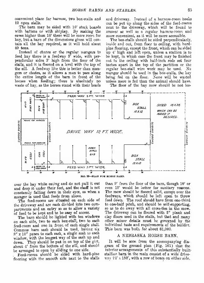
HOUSE EABNS AND STABLES. 65
convenient place for harness, two box-stalls and12 open stalls.
The barn may be sided with 16' stock boardswith battens or with shiplap. By making the
eaves higher than 16' there will be more room for
hay, but a barn of the dimensions given will con-
tain all the hay required, as it will hold about
40 tons.
Instead of chutes or the regular mangers to
feed hay there is a feedway 3' wide, with per-
pendicular sides 3' high from the floor of the
stalls, and it is floored on a level with the top of
the sill. A feedway like this is better than man-gers or chutes, as it allows a man to pass along
the entire length of the barn in front of the
horses when feeding; there is absolutely nowaste of hay, as the horses stand with their heads
and driveway. Instead of a harness-room hooks
can be put up along the sides of the feed-rooms
next to the driveway, which will be found to
answer as well as a regular harness-room andmore convenient, as it will be more accessible.
The box-stalls should be sided perpendicularly,
inside and out, from floor to ceiling, with hard-
pine flooring, except the front, which can be sided
up 4' high and left open, unless a stallion is to
be kept, in which case the front may be finished
out to the ceiling with half-inch rods set four
inches apart in the top of the partition or the
regular box-stall wire work may be used. Nomanger should be used in the box-stalls, the haybeing fed on the floor. None will be wastedunless more is fed than the animal should have.
The floor of the hav mow should be not les>

66 FABM BUILDINGS.
Hi » - fm |n| i fife p >! ;T|^|jM
-NEBRASKA HORSE BARN (SIDE ELEVATION).
This driveway affords a place in which to exercise
the horses every day in the year, being of such,
dimensions that they may be taken on a gallopif desired from one end to the other—and all
horsemen understand the value of such a placewhen the inclemency of the weather preventsoutdoor exercise.
Another special feature is the construction of
the boxes. The partitions between the boxes andabutting on the hall consist of a solid 4" wall of
pine, made of 2" x 4" pieces laid like brick, oneon top another, with a cap-piece of oak 5' up.
Above this for 3%' more there is a grating ofgas-pipe %" in size, outside measure, and 4"
apart. To provide means of speedy egress in case
of fire there is an outside door to every stall.
The foundation consists of a solid 18" wall 18"
deep; piers and interior posts are 18" x 18" and3' deep. The frame is a mortise and tenon;8" x 8" stuff for posts, sills and cross-beams;
posts 22' high. The first floor is of earth and the
second floor over boxes is matched flooring, andover hall common boards. The joists are 2"xl0" ;
16" apart over stalls, 12" apart over hall. Sides
5y2 " patent siding; rafters 2" x 8", 2' apart, with2"x8" ridge-pole; shingle roof, with eaves pro-
jecting 24". Stall windows have nine lights andslide to one side. The hall and office windowshave twelve lights 10" x 18", and second floor
windows have twelve lights 10" x 14". The inside
doors are of three thicknesses of %" matchedflooring. There is a cellar 9' deep under feed-
OTG. 101—NEBRASKA HORSB BARN (GROUND PLAN).

HOBSE BABNS AND STABLU8. 67
room for carrots. The sides and ceiling of office-
room are matched ceiling of pine and in thesecond-floor room laths and plaster. The largeventilator is 10' x 10' and handsomely propor-tioned.
Several years ago the cost of this barn wasprobably between $8,000 and $9,000. Pig. 100shows the elevation.
THREE-STORY FARM AND HORSE BARN.The three-story farm and horse barn shown in
Figs. 102, 103 and 104 is 34' wide and 80' long,
with six double stalls, two single and four large
box stalls. Though the basement (Fig. 103) is a
cross driveway. Grain is spouted down into
small bins at one side of the passage and closets
on the other side will be found convenient for
harness and stable furniture.
As this three-storied barn is narrow it wasneedful to restrain the height as much as is safe
to avoid wrong proportion, so each story wasbuilt 8' in the clear. With the self-supporting
roof ample room for hay storage is secured. Hay
9
I.

68 FARM BUILDINGS.
is taken in from outside, though empty wagonsmay be driven through the second story. Tomake the drive high enough to take in loads of
,,i<^N.
hay would be a useless extravagance. Hay doors
may be put in each end. To take out braces andyet make the center span of joist-bearers strong
enough can be done by the wooden truss shownwhich makes the span unbreakable.
AN IOWA STALLION BARN.
The brick stallion barn shown in Fig. 105 wasbuilt by Champlin Bros, in Iowa at a cost of
$16,100. This barn is built of solid brick andis 140' x 75'. The front elevation shows two
stories high, the rear is three stories. (See Fig.
FIG. 103—THREE STOKY FARM AND HORSE BARN.
REM ELEVATION
FIG. 107—IOWA STALLION BARN.
FIG. 105—IOWA STALLION BARN (FRONT ELEVATION).

HORSE BABNS AND STABLES. 69
PIG. 108—BARN FOB FORTY HORSES (SIDE ELEVATION).
Ctmtq
t
Uxk.
3
Cross 5ect/on of Stalls. Cinttnt FlaA-opan win or iron mor'k or jftiajs
W. W. . Jl JWk SAJi/ij Z).j
vBiqs.d&ovox
Dn/e Way /or

70 FARM BUILDINGS.
107.) The first and second floors are for horses
and the third floor is for hay-mow and grain bins.
It has a capacity for 100 horses, there being 40box-stalls and 60 single stalls. The blacksmith
shop, heated harness-room, wash-room, robe-room,
offices and large space for showing horses are onthe first floor (Fig. 106), and a large carriage
room is on the second floor. The barn is equippedwith an electric motor, which cost $1,000, to runelevator, grind feed, pump water and unload hayand oats.
BARN FOE 40 HORSES.
This barn for about 40 horses (see Figs. 108
and 109) was erected on a large Kansas farm andhas many excellent features. There are stalls for
architecture has been preserved throughout, pre-
senting a very pleasing impression. PlymouthStud comprises a breeding department, where
stallions, mares, foals and young horses receive
attention, and a training department, where
harness and saddle horses are schooled for the
market and for the shows. Good taste rather than
lavish outlay has characterized the building of
this establishment, and the idea ever foremost has
been the utility and sanitation of the stables and
the comfort of the men as well as the horses.
Details are not submitted, but the accompany-
ing illustration No. 109a will afford an idea of
the equipment of the place in general. Stallion
boxes, brood mare boxes, boxes with yards for
foals and yearlings, with liberal allowance of room
FIG. 109a—PLYMOUTH HACKNEY STUD STABLE.
42 horses and three box-stalls, abundant hay
room, harness room and room for stableman.
The latter room may be made into a box-stall if
preferred. The diagrams show the interior
arrangement and exterior appearance of the barn.
PLYMOUTH HACKNEY STUD STABLES.
An excellent illustration of the combination of
utility and taste which m'ay be obtained in the
construction of the stabling on a horse breedingfarm is found in the equipment of PlymouthStud, property of Eben D. Jordan, Chiltonville,
Mass., near Plymouth Rock. These buildings rep-
resent the accretions of several years, as demandsfor space multiplied, but the same general style of
in each instance, constitute the stabling, and com-fortable sleeping and resting quarters for thegrooms are also provided. In connection with thestables a commodious riding school has beenerected, one of the largest and best lighted to befound at any private establishment in this coun-try. This structure has been very valuable inconditioning horses for the show arena and themarket, All the buildings are frame withshingled sides and roofs and are stained lichen-gray.
BANK STABLE FOR HORSES.This building is 36' wide and 52' long, there
being two bents of 16' each and for convenience

HORSE BABNS AND STABLER. 71
in placing posts two bents of 10' width at the
box-stalls. It has a feed alley 6' wide and a wider
passage between- the box-stalls. Bins may be
above this wider passage with spouts down.Abundant light and air may be provided, as the
wall sets back to allow a row of windows on each
side. Ventilation also through the hay chutes
make the structure stronger. The barn has a
capacity for 175 to 200 tons of hay.
A KENTUCKY BARN FOR SPEEDHORSES.
AVhat is considered one of the best barns in
Kentucky from a sanitary and practical stand-
Titd Am, aJi
£>....«•«-

72 FABM BUILDINGS.
d„,
Dmrtw/Jrs
FIG. 113—M'MILLAN'S HORSE BARN (GROUND PLAN).
stormy weather it is possible to exercise the horses
indoors. (Pig. 113b.) This really has all the
merits of a covered track—all that is needed
indeed for a barn in that section of the country.
Exactly in the center of the stable is a section
for road carts and sulkies and here also are doors
opening from the stable capable of allowing a
man in a vehicle to drive out. In this section
are cement floors for the washing of the vehicles.
On either side of the driveway, which extends
the whole length of the barn, are the box-stalls.
These are commodious with doors facing on the
interior driveway and also doors facing on the
exterior, while above are small windows. Theseexterior doors are constructed so that in case of
fire the attendants will be able to liberate all of
FIG. 113a—A KENTUCKY BARN FOR SPEED HORSES (EXTERIOR VIEW).
FIG. 113b—A KENTUCKY BARN FOR SPEED HORSES (INTERIOR VIEW).

HORSE BARNS AND STABLES. 73
the horses without going into the building. Onceout the horses can roam as they please and becaptured at will.
'Above the large box-stalls is limited space for
the daily feed of the horses. Evidently Mr.Barkness' idea in constructing the building wasto afford plenty of space for air, and in this
respect the barn is an admirable pattern. Thatthe idea is all that was intended is best evidencedfrom the fact that few horses have ever had anysickness in the stables.
The entire barn is of frame construction and
while not elaborate in regard to finish is certainly
practical and has every convenience for everyday
use.
AN ILLINOIS STALLION BAEN.
This stallion barn built a few years ago in
Illinois is regarded by many as a model of con-
venience, although there is nothing very preten-
tious in its architecture, neither is it an expen-
sive building.

74 FARM BUILDIpTOS.
Fig. 114 represents the south elevation of barn
and shed connected with it. Basement with box-
stalls and the plan of the yards and distribution
of water also are shown in the drawing. (Fig-
114.) The barn (40' x 70') is located on the
south and near the top of a gentle ridge running
east and west. It is constructed partly on the
side-hill or basement plan, the north wall being
only full height of basement and this wall is all
above ground except 3', which gives room for
large windows. All other foundation walls are
on a level and extend but a few inches above the
ground floors, which are of earth in the boxes
as well as in the driveway of basement. Founda-tion walls and frame-work of basement corre-
spond with the main framework of the building.
attached to the top of this post, which is swu^ground by the workman as his work proceeds and
enables him to form a perfect arch.
Inch-and-a-quarter gas pipe is laid from cis-
tern to hydrant in barn basement and also to
yards and pastures as desired.
The diagram representing stock-waterer (in-
cluded in diagram) shows two barrels set side
by side, connected by a short piece of gas-pipe, D.
The water enters the barrel, A, from the bottom,
E, to a height controlled by a float connected by
a copper wire to a hinged valve. This allows the
water to stand in the barrel to just such a height
as desired. As the barrels, A and B, are filled
to the same height any water taken from the
drinking-tub, C, is quickly replaced. For a
FIG. 116—CONVENIENT COLT STABLE (EXTERIOR VIEW).
The framework, consisting of five 14' bents, gives
the space of 28' x 40' on each side of the drive-
way on the second floor. This driveway is
reached from the north side of the building. Astone wall 20' long and parallel with the building,
14' distant, gives foundation for a driveway.
Against this earth is graded, forming an easy
approach to the second floor.
The reservoir or cistern is located on the high-
est ground obtainable, and this not being as high
as desired a portion of the arch is built above the
natural level and heavily banked with earth. It
is bricked up from the bottom with an 8" brick
wall laid in cement and the mortar well flushed
against the earth bank and finished with a heavy
coating of cement on the inside of brickwork.
The pipes should be laid at the same time the
cistern is built. The diagram shows the mannerof constructing the arch. A post is firmly set
in the center of the cistern to a height at which
the arch is designed to begin. A hinged rod is
drinking-tub one-half of a beer barrel set in the
end of a kerosene barrel may be used.
CONVENIENT COLT STABLES.The colt stable illustrated and described here-
with is one of a series built by the late M. W.
FIG. 115—CONVENIENT COLT STABLE (ARRANGEMENT).
Dunham at Oaklawn, the noted Illinois horse-
breeding establishment. He regarded these

HORSE BARNS AND STABLES. 75
FIG. 117—CONVENIENT COLT STABLE WITH PARTITION IN PLACE.
stables as of especial value with reference to the
development of young horses.
The buildings are situated in line east andwest, about 40 rods from building to building.
The strip of land used is 60 rods wide. This
gives a pasture 20 x 30 rods for each field andeach affording abundant pasture for two animals
the year round. (See Pig. 116.) Of course in
the winter a certain amount of hay is necessary.
Each stable contains stall room for eight animals,
with the partitions in (Figs. 115 and 117), so
that four animals are in the fields and four in
the stable alternately. In the summer time the
doors are left open and are provided with a can-
vas fastened at the top, fitting the doorwayclosely. This excludes the light and protects the
animals when in the stable from the flies. In
the angle of each stall, which combine to formthe center of the stable, is a hydrant to which is
attached a float valve (see Fig. 118) which con-
trols the supply of water, except in the intense
cold weather in the winter when the float valve is
removed and the tub filled with water from the
hydrant as required.
The grain is also fed from the center, directly
over the water tub. The feed bin is about 6'
WIO. 1 18—CONVENIENT COLT STABLE WITH PARTITION REMOVED.

76 FARM BUILJHNOS.
square and of sufficient height to hold about 200
bushels of oats. The bottom of the bin tapers
to the center at an angle of about 60° and is
closed by a circle of sheet-iron with eight holes
of sufficient diameter to hold two quarts of oats,
and projects to within 2" of the bottom of the
feed trough. Another sheet-iron plate, fastened
FIG. 119—MULE BARH (END ELEVATION).
in the center, with holes corresponding to the
pipes, is placed flat upon its top surface, to whichis riveted a lever. The slot in which this lever
works is long enough to allow the opening andclosing of the holes in the lower plate by the
movement of the lever. By this device the move-
ment of the lever permits the filling of the pipes
slow feeding, consequently better mastication.
The fences enclosing the pastures are T high, the
upper 2' being made of woven wire.
The necessity for natural development of
young horses in the open air and on green feed
in order to secure the highest usefulness whengrown led Mr. Dunham for many years to pas-
ture his young stallions in the summer; and the
losses incurred by accident where 'numbers were
kept together prompted the devising of the plan
just described.
Mr. Dunham found the use of these buildings
and pastures of great advantage. Where the ani-
mals are put in in a healthy condition there is
almost entire immunity from disease. By this
means health and natural growth are secured and
accidents and unsoundness are rare.
A MULE, BAKKAs a type of special-purpose building the mule
barn shown in the accompanying illustration,
Fig. 119, is admirable in its way. It is designed
for about 165 mules and the arrangement is com-mendable. The mules are fed, watered, harnessed
and taken out without interfering with each
other. The sanitation is excellent; the light is
ample ; the provision for aeration is sufficient andthere is ample warmth in cold weather.
FLOOR PLAN OF BARN B4X 100
TIG. 120—MULE BARN.
with oats and the reversal shuts off the supply,
giving each animal two quarts, or any quantity
the pipes are made to hold—the grain filling the
pipes—and is eaten from the bottom. Thismethod of feeding has the advantage of rapidity,
uniform quantity, prevents waste and secures
As the barn is quite wide three carriages andthree tracks are used in filling it with hay. Thissaves a great deal of hand labor in moving awaythe hay. The floor plan (Fig. 120) explains
itself. Painted neatly this barn presents a very
attractive appearance.

DAIRY BARNS.
The dairy barn shown in Figs. 121 and 122was built in Southern Illinois by the late H. L.
Borden. It is a frame structure on stone piers
from 1' to 2' off the ground. It is used as a cowstable and has a loft overhead for hay, which is
elevated by hay slings in the center of the barn.
The cow stable consists of two rows of stalls (see
Fig. 123) with some box-stalls. Each single cowstall is 5' wide. The passageway behind the cows
eighty cows and ten horses and which would per-
mit of driving behind the cattle in cleaning andin front of them in feeding green fodder. A silo,
a granary and storage place for dry fodder suffi-
cient for all the animals were desired, and the
whole was to be covered by the same roof, to be
conveniently accessible in all its parts, but not
very expensive.
The plan in several fundamental features
FIG. 121—ILLINOIS DAIRY BARN (ELEVATION).
is wide enough to allow the passage of a two-
horse manure spreader, which saves the handling
of the manure very often. The barn cost about
$2,400.
A BOUND DAIRY BARN.
The accompanying plan of barn for a dairy
farm was designed some years ago by Prof. F.
H. King for a Wisconsin dairyman. The design
was the result of a request for a plan of a barn
for a dairy farm which would accommodate
embodies ideas which are believed to be worthyof general imitation:
1. Whatever other advantages or disadvan-
tages a shelter for live stock possesses, it shouldin no way interfere with the best performance of
the animals housed.
2. The shelter should so be built that the heatnecessarily given off by the bodies of animalshoused shall be sufficient to maintain the best
stable temperature during cold weather and at
the same time admit of ample ventilation, while

78 FABM BUILDINGS.
during warm weather the surplus heat mayreadily escape.
3. The construction should be such as to admit
the needed amount of light to all the animals
housed.
4. The construction of the shelter should be
such as to reduce the labor of caring for the ani-
mals,to the smallest amount which will admit of
the largest yearly net profit.
capacity of 14,126 cubic feet, occupies the cen-
ter. Around this silo in the first story 98
adult cows are accommodated in two circular
rows facing a common feeding alley 9' wide, and
behind each row of cattle is a wagon drive 6' wide
for cleaning the barn, which leaves and returns
to the common single broad entrance.
Extending entirely around the silo in the
second story is a barn floor 18' wide, from the
TIG. 1aS—ILLINOIS DAIRY BARN (CONSTRUCTION).
5. The form and arrangement of the buildings
should be such as to necessitate the least first cost
and the smallest maintenance expense compatible
with the necessary accommodations.
Pigs. 124 and 125 are birdseye views of the
interiors of the first and second stories designed
to show the construction of the barn and the
outer edge of which, through chutes leading to
the feeding alley in front of the cattle, green
fodder can be delivered to them from the wagonor dry fodder from the storage space above. This
floor also permits of driving around the silo andout at the entrance after unloading, even whenthe silage cutter is being run to fill the silo.
i— u u - u *— s a u u
I

JDAIBY BABNS 79
occupied by the horses. In the rear of the silo
i& a space 16' deep for farm tools, having 32'
frontage on the barn floor and possessing a floor
. space equal to 16 x 40 square feet. Betweenthe tool-room and the horse barn on one side andthe granary on the other.- are two hay bays which,together with the space above the barn floor, tool-
room, granary and horse barn, furnish amplestorage space for dry fodder.
The siiage is delivered to the cattle barn fromthe silo through a triangular chute shown in Fig.
124, extending up the inside of the silo ; in oneside of this chute there are doors and attachedto the other is a fixed ladder by which any desired
level in the silo may be reached.
The foundation of this barn consists of four
FIG. 124—A ROUND DAIRY BARN (FIRST FLOOR).
concentric stone walls, the inner one carrying the
walls of the silo and through them the central
portion of the floors and roof; the two middleones carrying the stationary uprights of the
stanchions, and through them the floor, mainposts, purlin plates and roof, while the outer
one supports the walls of the structure. Thelaying of the walls to a circle and leveling themwas a simple matter and accomplished with the
aid of a straight-edge, one end of which was fixed
to a post in the center, with the lower edge at the
level desired for the top of the walls. The mov-able end of the straight-edge rested on a ring of
boards tacked to stakes driven in the groundoutside the wall being built. The inner wall wasfirst built and the straight-edge lengthened as
necessary. The frame of the barn consists almost
wholly of 2" stock and the only long timbers are
the eleven posts carrying the purlin plates. Nomortise and tenon work was used in its construc-
tion, all work being done with the hammer andsaw. The first story sills of the barn are single
2" x 10" plank sawed in 4' sections and bedded
in mortar on the walls, the sections having heen
sawed on a bevel determined by the direction of
the radii of the barn. On the sills 2" x 10" studs
are set 2' apart and constitute the outer frame
of the basement; 2" x 12" studs set flatwise on
the two middle walls, at the right distance apart
to serve as the uprights of the stanchions, and2" x 12" studs in the walk of the silo, as shown
in Fig. 124, constitute the vertical supports for
the second story. The sills of the second story
consist of short pieces of 2" x 10" plank spiked
down upon the ends of the three outer circles of
studding, as shown in Fig. 124, and of three
thicknesses of 6" boards bent around the upper
ends of the silo studding and resting on the
shoulders sawed for them. Two thicknesses of
plank rest on the stanchion supports, but the
outer sill is single ; upon these 2" x 10" joists are
distributed, as shown at 5, Fig. 124, and these
carry the floor of the second story.
Each of the posts carrying the purlin plates
rests on four 2" x 10" joists spiked together andresting on the sills carried by the two rows of
stanchions, the particular stanchion uprightswhere these posts come being strengthened by2" x 6" studding spiked to them at the edge not
occupied by the cows. On the tops of these posts
short pieces of 2" x 10" plank are spiked, as
shown at 1, 1, 1, Fig. 125, and upon them the
purlin plates rest, spikes being driven upwardinto them to hold them in place.
The rafters and studding for the second story
are 2" x 6" stuff, the latter being set 3' apart,
and the lower ends of the rafters are carried by
FIG. 125—A ROUND DAIRT BARN (SECOND FLOOR).
two layers of 2" x 6" pieces spiked to the tops ofthe studding, the upper layer breaking joints
with the lower. Fig. 125 shows the manner ofplacing the rafters.
The rafters were cut so that their ends whenin place were vertical and the fascia was formedby springing a board to them. The lower one ortwo rows of roof board were sawed in short sec-
tions, reaching from rafter to rafter, and thenfencing was used, full length, and sprung to therafters over the remainder of the roof. It wasnot necessary to cut shingles in laying, excepton the cupola, and in laying them each man wasprovided with a "horse," made by driving spikes

80 FARM BUILDINGS.
through one edge of a short piece of 2" plank,
which served as legs and prevented sliding. Amark was filed in the edge of the shingling
hatchet at a distance from the nailing face equal
to that which the shingles were laid to the
weather, and this served as the only guide in
placing them, which was done rapidly and
readily, the men following one another round and
round.
This barn is covered outside with drop siding
sprung and nailed to the studding so as to break
joints, and on the inside of the cattle barn, horse
barn and granary with shiplap.
In the construction of the silo, 2" x 6" stud-
ding were used above the basement, these being
spiked side by side to form the eleven long ones,
which extend to and help support the roof. Thelining of the silo consists of three layers of half-
inch lumber, formed by ripping common fencing
in two, and between these are two layers of tarred
paper. The same kind of lumber forms the outer
covering of the silo and the spaces between the
studding act as ventilating flues for the cattle
barn.
The large doors slide open and are made of
matched fencing nailed to cleats having the samecurvature as the sides of the barn. These cleate
are made by springing the boards into the desired
curvature and then fastening them securely
together while in that attitude. When this is
done they remain bent as if they had grown in
that form.
The feeding mangers in the cattle barns are
made by forming the earth in the shape of shal-
low, round-bottomed troughs in front of each
row of cattle, raising the earth between theminto a broad rounded ridge. This earth after
being thoroughly firmed was plastered with a coat
of water lime.
When it is known that air once breathed, unless
diluted with that which is fresh, cannot support
higher animal life; that one-fifth of the weight
of materials taken into our bodies daily is oxygen
from the air, and that we must breathe 346 cubic
feet of air to get it; that on the average our live
stock consumes more air per capita than we do,
and that horses have died from suffocation while
being shipped in box cars, it should be evident
that, coupled with our efforts to secure warmbarns there should also be those to provide ampleventilation. The plan here described possesses
a very simple, cheap and effective method. It
will be seen from Figs. 124 and 125 that the
32 spaces between the studs in the walls of the
silo, being open at the floor of the cattle barnfind also at the top, constitute so many ventilat-
ing flues, each 34' in length. The heat given
to these flues by the silage in the silo, the warm-ing of the air in the basement by the cattle, and
the suction produced by the wind blowingthrough and around the cupola, all combine to
maintain a strong current of air out of the barnthrough the cupola and in through thegangs of auger holes in the outer walls
FIG. 126—A BARN FOR DAIRY COWS.
shown at 2, 2 in Pig. 124. It will be seenfrom the arrows in the cut that provision is'madefor fresh air to enter the barn from all sides,
which, rising between the studding and flowingalong the space between the joists, falls betweenthe two rows of cattle, but is first mingled withthe warmest air of the barn, while the coldest andmost impure air is constantly drawn out fromalong the floor. A very important feature in thismethod of ventilation is that pure air comes
END ELEVATION
FIG. 127—A BARN FOR DAIRY COWS.
direct to all animals alike, while the impure airis drawn out in a uniform sheet all around thesilo. It will be seen that this ventilation is securedwithout sensibly affecting the cost of the build-ing, while at the same time the walls of the siloare kept dry and thereby protected from decay.The temperature of a barn whose plan of ven-
tilation is the one here described is under as good

DAISY BABNS. 81
control as is possible where artificial heat is not
employed, because the cold air is introduced at
the warmest part of the barn, while it is the
coldest and most vitiated air in the barn which
INTCfUOR 8CNT OF wINCS JOIST fRAMC
FIG. 128—A BARN FOE DAIRY COW5.
is being removed. Then when the barn is too
warm the doors to the feed chutes may be opened,
thus providing a direct escape of the over-heated
air from the ceiling.
This barn was built for a little less than $2,400.
By combining everything under the single roof,
by adopting the cylindrical form, which requires
FIG. 129—A BARN FOR DAIRY COWS.
the smallest amount of siding, roofing and paint,
and which admits of the cheapest and least lum-
ber for the frame, and by distributing the lumber
so as to make it perform two or more func-
tions a great deal of economy was secured in this
barn.
Another advantage which the consolidated
barn possesses over several small, scattered struc-
tures, and especially where the feeding is done
from a central point, as it is in the plan in ques-
tion, is the large saving of time which it makes
possible in feeding and caring for the animals.
The great economy of the circular plan for
farm buildings over other types of structure
diminishes as the size of the building decreases,
but it is nevertheless well adapted to some of the
smaller structures, such as horse barns and sheep
barns. In any case where an octagonal barn is
desired the circular type will always be found
cheaper and more stable.
Where a silo is to stand separate from other
buildings there is no other type of structure which
can be built so cheaply as the circular one, even
if its diameter is not greater than 12' x 16'.
A BARN FOR DAIRY COWS.
This barn is designed for 20 dairy cows- It
has ample breathing space for them and provision
is made for as much light and sun as possible,
unless the plan of detached shed with sky-lights
is adopted; the manure is removed at the mini-
mum of labor and the entire building is planned
to be labor-saving. The little room termed an
TEED AlLCr *!
MIOCSL BAflN 3t.it
FIG. 130—A BARN FOR DAIRY COWS.
office, containing lavatory, towels, soap, records
and the like, is possibly larger than is needed
and in that case it may be narrowed to a smaller
limit and another stall or two made of the room.
The feed-room is a convenience that no dairymancan afford to do without. Peed is stored in three
or more bins above and spouted down to one large
mixing bin, where it is measured or weighed,
mixed, scooped up and fed.
Reference to the side elevation, Fig. 126, showsthe window-openings on the south side (turning
the building east and west). The over-hang is to
protect the door-way where hay is taken in at
the end, as there is no space wasted in drive-
ways to unload hay. Fig. 127 shows the endelevation, and in the gable is noted a combinationof window and ventilated shutter that looks well
and acts well. Providing these at each end there
is no need of ventilators in the roof, as ventila-
tion will be upward through the hay-chutes.
These may if desired be extended through the
roof, though if metallic shingles are not used(which condense vapors) there is no ill effect in

82 FARM BUILDINGS.
letting the ventilation proceed through the
gables. ,The doors to take in hay open down to
the line of the floor so that hay may be takenin without raising it to the level of the track.
This is an open-center building, with joist-frame
construction, as shown in Fig. 128. The frameis all of 2" stuff, is very much cheaper, fully as
strong and in every way more desirable than the
old-fashioned frame. It is put together with
spikes and bolts in a very short time. The base-
ment is made 10' high, not for the sake of head-
room so much as for better air and light.
Pig. 129 illustrates the mow plan; hay is
thrown down into the feed-alleys ; ladders should
take the manure away. In the, space between the
feed-room and office the milk-wagon may stand
if necessary. The VanNorman stall is used.
' This barn is adapted to either beef cattle or
dairy cows, though there is no provision for
calves, as it was designed- primarily for milking
cows.
A HYGIENIC DAIEY BAEN\
After studying for many years to learn the
best way to fasten cattle in a barn a great manydairymen have, come to believe that the best wayis not to fasten the animals at all. A good plan
is to have a large open shed to which light and
FLEVA-inNFIG. 131—A HYGIENIC DAIRY BARN.
be built in the chutes. The stairway is apt to be
covered over at times with hay. The bran bin is
large enough to allow storage of a great deal of
bran.
Fig. 130 shows the arrangement of stalls. It
will be noted that there is everywhere plenty of
room. The cart can go between the cows and
air have free access and in which are feed-racks
and troughs. This shed should be kept well
bedded and aired. The cows, loose and dehorned,
stand in it day and night. Adjoining this shedas planned is a small stable fitted with stalls andstanchions where some grain is fed and the milk-ing done. The cows are in their stalls only while
CATTLE SHED 40X100
WTOC ~\
GROUNO PLANor
HYOENIC DAIRY BARN
ENCLOSURE 42X100
FIG. 133—A HYGIENIC DAIRY BARN.

DAIRY BABNS. 83
they eat and are being milked. The barn shouldbe white-washed two or three times a year bymeans of a sprayer that reaches every nook andcrack and the floor kept clean. Pigs. 131, 132
FRAME Or CATTLE SHED
FIG. 133—A HYGIENIC DAIBT BARN.
and 133 show the plan quite clearly. The barnis well ventilated and convenient in arrangement.Three silos are shown in Fig. 132. No provisionis made for storing hay.
A NEBRASKA DAIEY BARN.
The Nebraska dairy barn illustrated in Fig.
134 was erected in 1896 to house a herd of Jer-
seys. The floor plan and dimensions are shownin Fig. 135. The cows stand in the south L,
which is protected by the north L from the winter
winds. The two Ls are the same size—each30' x 48', 8' posts. The barn is floored upstairs
as well as down (except the space occupied by
silos), and cows stand high and dry 3' to 6' above
the ground, and there is a window for every twocows. The latter stand in two rows facing in ona feeding alley and are tied with halters. Thefloor of the manger is level with the feeding alley
and for convenience in cleaning the manger is
open in front.
There are two thicknesses of boards on all
sides, keeping the temperature even and above
FIG. 134—A NEBRASKA DAIBT BABN (FRONT VIEW).
the freezing point. The silos extend 10' belowthe floor and up into the loft, making them about20' deep. The silos and the separator-room havea thickness of building paper between the boards.With a separator at the barn only the cream is
taken to the dairy-house and the skimmilk is fedwarm to the calves and pigs. The barn has a root

84 FARM BUILDINGS.
cellar under the south end and cost $1,300. It
will accommodate a dairy herd of about 30 cows.
A PENNSYLVANIA DAIEY BAKN.
A very complete, elaborate and convenient barn(Figs. 136 and 137) for dairy cattle is thus
described by the proprietors:
TIG. 136—A PENNSYLVANIA DAIRY BARN (SECTION A B).
"Our barn is a polygon of 16 sides. It is
believed that nothing has been neglected whichwould add to the comfort or healthfulness of the
herd. The barn is heated by steam and in win-
ter a uniform temperature of from 40 to 45° F.
is maintained night and day, never colder than
PIG. 137—A PENNSYLVANIA DAIRY BARN (ELEVATION).
40°, never warmer than 45°. Self-registering
thermometers in locked cases show at all times
any variation from this temperature. The aimis to maintain a temperature just above the
freezing point.
"More attention to proper ventilation has been
paid than to all else. The barn is surmountedby a cupola 20' in diameter. This is open every
day and night in the year. The lower sash of
each window is raised 8" and a board placed
under the sash. A hole 6" in diameter is cut
through this board in which is placed a zinc pipe
opening outwardly and turned up on the inside
some 3' in height. This allows for the admission
of air between the two window sashes and also of
a full current of air through the 6" pipe, thus
PIG. 138—A PENNSYLVANIA DAIRY BARN (BASEMENT PLAN).
preventing any possibility of a current of air
striking directly upon the animals. By this
arrangement, no matter what the weather maybe, a full supply of pure fresh air is given to
every animal by the current from the lower floor
passing up the stairway in the center of the barn,
PIG. 139—A PENNSYLVANIA DADJY BARN (SECOND FLOOR PLAN).
and also through two chutes extending from thelower floor well up toward the roof.
"The basement (Fig. 138) of the stable is
devoted mainly to the milking cows. It is laid
with concrete. Gutters covered with iron grat-ings extend back of the cows and terminate in asewer which leads 100 rods away from the stable.
This floor can be scalded out with hot water, the

DA1BY BABNS. 85
gutters and sewers flushed and the cattle put backin the barn on a dry floor in an hour's time.
"The first floor (Fig. 140) is of two thicknesses
of matched yellow pine with tarred paper between
FIG. 140—A PENNSYLVANIA DAIRY BARN (FIRST FLOOR PLAN).
the layers. Sawdust is used for bedding on this
floor, which is devoted mainly to box-stalls, both
open and tight, for the service bulls and for cows
soon to calve.
"The second-floor space (Fig. 139) is devoted
to storage for fodder, grain and bedding and also
for power cutter, which cuts one ton of dry corn-
fodder into one-third inch lengths in 25 minutes.
"The barn is lighted by 60 incandescent elec-
tric lamps. A night watchman is employed who,
at intervals of every half-hour, makes a complete
tour of the stable, seeing that all is well, a touch
of the button enabling him at any time to notify
the superintendent of anything wrong. Toinsure the watchman's wakefulness and attention
to duty an electric time detector is in use which
keeps perfect record of his movements throughthe barn."
A WISCONSIN DAIRY BARN.
The barn shown in Fig. 141 was built by A.
Dutton & Son in 1896;
It is 60' in diameter
and built on a southern slope with a basementfor stock. Stone was used on the hill side; the
rest is built the same as the upper part.. Thestuds are 2' apart; it is sided with drop ^sidingand sealed on the inside. The basement floor is
made of cement. There are 20 patent sta£ls androom for 15 head of young cattle, six horses anda box-stall. There is a silo in the center 16' in
FIG. 141—A WISCONSIN DAIRY BARN.
"In a room on this floor is placed the cream
separator and engine. On this floor is also a
cleaning machine, which by a system of revolv-
ing brushes cleans a cow perfectly in from three
to five minutes' time. During the winter months
each cow receives a daily cleaning, three menbeing able by this method to thoroughly clean
160 head per day.
diameter and 34' deep. It will hold 150 tons of
silage. The studs above the basement are 20'
high; this, makes the barn 28' high to eaves.
There is room for 70 tons of hay. A hay-carrier
is used on a circle track. On each side of thedriveway there is granary room for 2,000 bushelsof oats and a carload of, bran. The silo is filled
from the upper floor..

SWINE BARNS AND HOUSES.
What would be the business future of the
swine breeder whose hogs were compelled to be
exposed to the cold blasts of winter or the glaring
sun of summer ? What would their condition be
if they were obliged to eat and sleep in filth?
What would the pig crop be if the sows were
allowed to farrow in the fence corner some cold
stormy night with only the canopy of heaven
to shelter them ? Answers to these questions will
urge the proper equipment of the farm for the
breeding of pure-bred swine. How extensive the
equipment should be will depend of course on
the number of animals to be carried on the farmand the amount of money to be invested.
First a swine breeder should have necessary
buildings for housing the herd, the feed, the
apparatus for mixing and preparing the feed andthe procuring of the necessary water. There are
many kinds of buildings for this purpose, manyof which are satisfactory. Breeders have dif-
ferent ideas regarding this matter, many pre-
ferring the large gloomy hoghouse or building
where the whole herd may be kept under one roof,
and where the bedding, feed, water and every-
thing pertaining to the comfort of the animals
may be kept convenient and used with the least
labor, and where all the work in oaring for the
herd may be done under cover. This plan has
many advantages and where adopted the build-
ings should be so arranged that as much sunlight
as possible may be admitted to the pens and feed-
ing floors. There are other breeders who prefer
the outdoor individual house large enough for
only one sow and her litter, with a grass lot of
at least one-half acre where the sow and pigs mayalways be by themselves. This latter plan will
of course occupy considerable land, at least wherethe herd is large, and will necessitate consider-
able fencing into lots along either side of a lane
and the hauling of all the feed to the different
lots at each feeding time. But this plan insures
both abundant pasture for the sow and litter as
well as plenty of room for the necessary exercise
and has the advantage of always affording clean
quarters for the hogs.
There are many different plans for both the
large houses and small individual houses, fromwhich may be selected whatever best pleases the
breeder. As much or little expense may be put
into the building of hoghouses as the breeder
desires.
All buildings used for breeding and feeding
swine should be strongly built and made of goodmaterial, and all should have floors both for feed-
ing and sleeping apartments. Floors made of
wood are preferable in the sleeping quarters,
being warmer and more easily kept dry. Wherethe large hoghouse is used many prefer the feed-
ing floor to be constructed of concrete or cementand the sleeping floor of wood. Where the build-
ing is used for the feeding of a large number of
swine together some prefer the feeding floor to be
constructed along the outside of the building, andin such instances the floor should be constructed
of concrete or cement, raised slightly above the
surrounding surface. A cement feeding floor of
this kind properly made would be practically
indestructible and would be easily kept cleaneither by sweeping or flushing with water.
Where the individual system of houses is usedthere is no necessity for a feeding floor except a
small one about 8' x 8' in one corner of the lot
most convenient to feed, and this only for theuse of the litter where the pigs may be fed securefrom the intrusion of the mother. She may befed near them from a single trough.
Where the individual houses are used it will
be necessary to have a feedhouse or building so
arranged that all feed may be kept there inseparate bins ; where water may be easily obtainedeither from an elevated tank or from a pump in
the building and where the mixing of the feedmay be done. With this system the easiest wayto distribute the feed to the various lots is to usea wagon not to exceed 12" in height from theground, and large enough to hold three or fourbarrels of feed set upon it. Such a wagon witha pair of shafts and a gentle horse kept for thepurpose of hauling all feed and water to thedifferent lots make it very easy for the feeder tocare for 100 or 200 hogs in a short time withvery little labor.
Where the feeding is all done in one buildingor house a feed carrier suspended from a steeltrack above the alley is the most convenient wayto handle the feed, as it requires but very little
effort to carry a large amount of feed in thismanner along the alley.

SWINH^BABNS AND HOUSES. 87
• There are many kinds of troughs on the mar-ket. Some of them are good, others better andsome absolutely worthless. Old-fashioned woodentroughs are about past. They are expensive
because so soon destroyed, and are always dampand convenient for animals to put their feet in
while eating. There are several types of gal-
vanized iron troughs as well as two or three cast
iron troughs. One of the latter is made for
animals of any size and is absolutely unbreak-able. This trough weighs 120 pounds, is roundand accommodates eight animals, and whethersmall or large animals they are never crowded,
as the trough forms a circle. A hog or pig can-
not get his "feet into it, for the reason that he
eats out of a cup just large enough to stick his
nose in. These cups are filled from the center
in a receptacle where the feed falls on a cone,
thus being evenly 'distributed to the eight indi-
vidual cups which are separated by a heavy iron
rod, and the pigs can eat only from the cup
before them. These troughs are always clean,
having no place for the feed to lodge and become
down into it and have to swim through the dip
will pay on any pure-bred swine farm. It is of
great value in preventing disease.
Another valuable appurtenance is a first-class
feed steamer. It is generally admitted that while
cooked or steamed feed is of no advantage so far
as economy or nutriment is concerned it is of
great value in the feeding of young pigs during
the cold months, as young pigs fed on warm feed
either cooked or scalded with hot water thrive
almost as well during cold months as through
the warm weather. It also is of value in feeding
brood sows during the winter season, as a mixture
of clover hay, or where possible alfalfa, run
through a feed cutter and mixed with meal, bran
or middlings and steamed or mixed with hot
water is an ideal feed for brood sows.
THE MOKGAN HOG BABN.
F. W. Morgan's hog barn on his Wisconsin
farm is a T-shaped' balloon-frame building,
ceiled on the inside and outside, and has a shingle
roof. (See Pig. 143.) It is 280' wide and
fflG. 142—MORGAN HOG BARN (FRONT ELEVATION).
foul. This style of trough possibly is not suited
to pens along a feeding alley in a building, but
for outdoor use it is admirable for feeding
slop. The matter of feed troughs is of great
importance, as all feed fed in the condition of a
slop or mush should be fed in good troughs
easily kept clean. No feed should ever be fed
on the ground, unless it may be ear corn where
the ground is frozen or is hard and smooth.
A breeding crate should always be used. This
is an important matter. By this method of breed-
ing the number on the ear tag or the ear mark
may be taken and entered in a book, at the time
of breeding, giving day and date. There are
several kinds of breedings crates and the breeder
can easily learn which is best for his purpose.
Another necessary fixture on the swine breed-
ing farm is a good dipping tank. This is of
great value not only for the purpose of disin-
fecting swine, destroying vermin and mange but
in keeping the skin and hair in a healthy condi-
tion. Such a tank sunk into the ground with a
chute from an incline .where the animals slide
extends back 130'. There are in all 52 pens, each
with a small rustling box for winter use and anoutdoor addition extending back 24'. There is a9' shed roof extending from the barn proper over
this.. Each outdoor pen has a cement wallowingtrough/ so that each hog gets two rooms and a
bath.. 'At each end of the barn are rooms 24'
square and 20' high, which are kept at an eventemperature during the winter, and are very use-
fur in the case of young pigs. The entire floor
is of cement. The large room in the center is
30' square and 24' high. It is supported by truss
work inside so as to be entirely open. It is usedas an engine and mixing room. Fig. 143 showsthe details of interior arrangement.
A NEBBASKA HOG-HOUSE.
The hog-house erected by McKelvie & Son of
Nebraska faces south and is 24' x 3^5'. , It stands
on level ground and is built on a brick wall2' 6" high and the space underneath the building
is utilized for shade in the summer and makes a
warm sleeping room for cold weather. There are

88 FABM BUILDINGS.
two doors in the south wall, also two directly
opposite in the north wall. The north doors are
closed in the winter and the late summer andfall pigs that are weaned run in there to sleep,
Tiaving the space divided so that the fall pigs take
on this was put huilding paper and then the best
6" drop siding. This makes a wall that wind
does not blow through. Tar paper also was used
under the shingles. This makes a warm roof and
keeps the wind and fine snow from driving
5MAi_L. RUSTLING BCWESFOR WINTER USE
CEMEHTWALLOWING BOXESONE TO EACH PEN
DD 7
SHED ROOF1 OOMES TO HERB
STOREROOM.
--24.'---— - - IOO- -20'-
FIG. 143—MORGAN HOG BARN (GROUND PLAN).
IOO' - -* ZO! i
one-half and the summer ones the other half.
By; opening all the doors in the summer the pigs
are enabled to get in out of the extreme heat andthe flooring of the house gets thoroughly dried.
through. Besides it gives a warm building whichis ventilated by raising one or more of the upperwindows shown in Fig. 144. The north roof is
17' long and the south roof is 12' long. The
tu-
wrv
Sy //<</// y / y ////// y S yy y y yy~71^
// y yy/yy/y / / zzz Z / i^Zz£££zz2t
WWvrr
D- Door
FIG. 144—A NEBRASKA HOG HOUSE.
2r¥ rr--^=r' *w\»Kun(^£"C C"'
.Scale^iach=|fr
The flooring of the building is made of 1",
lumber and doubled and the stuff used should
be clear of knots so there will be no leaks to let
water through. The sides of the building are
also double. The first is common sheeting and
offset in the roof where the windows are set in
to give light for the north pens is 3' 8". Thisis the space between the roofs. A larger windowcan be used here if so desired.
The interior is divided as follows: A 4' aisle

8WINE BARNS AND HOUSES. 89
runs through the long way east and west, leav-
ing 10' on each side to divide up into pens. Thisdivides it into five pens on each side, two of eachfive being 6' x 10' and three 8' x 10' with a doorto each pen. One pen is used for stove and bunk.By the construction of the front and roof as
shown sunshine is admitted in the pens duringthe greater part of the day, particularly duringthe middle of the day, when it is most beneficial.
The pens are made of movable partitions, so that
if desired one or all of them can be raised andthe entire floor used for feeding. It makes a
very good place to fatten hogs during the winterin case it happens that it is not wanted as abreeding-house, as less feed is needed to keep upthe animal heat. The chimney or flue is at oneend and 2' north of the aisle. The stove is at the
other end and the pipe runs the length of the
building and heats it with very little fuel. Wherethe cost of fuel is not much of an object heatingcould be done with steam. Where a steam cookeris used the building can be heated conveniently
and very evenly. The hogs get into the house byapproaches (not shown in the illustration) madeto lead to each door and are 8' long, one end rest-
ing on the ground and the other end just below
the door. This makes a gradual slope and the
hogs walk up easily on the slats which prevent
their slipping.
This is an all-purpose hoghouse and a farrow-
ing place in particular, where no matter whatthe weather the litters can be saved. After the
which are provided with small houses 7' x 7' madeof shiplap 5' on south and 2' 4" on north, with
a drop door in the south side to let in the sun-
shine. Here they are kept for a time, one sowand litter to a lot. Here they have the ground to
run on, which, like daylight and sunshine, is
essential. These small houses and yards are all
that are required for pigs during mild weather,but for early or late fall pigs it would no doubtpay to build such a house as described. The cost
of this building was about $250.
AN ILLINOIS HOG HOUSE.
The peculiar feature of the windows at the
apex of the roof serves to admit, in the early
PIG. 145—AN ILLINOIS HOG HOUSE (PBAME).
spring, the warm rays of the sun on the northrow of pens, the south' row being lighted by the
3 ccvU I I I I I I I I I I I i o T'c.
PIG. 146—AN ILLINOIS HOG HOUSE (GROUND PLAN).
pigs are farrowed and a few days old and the lower tier of windows, thus affording a sun-bath
weather will admit they are hustled out on the to all the occupants, the value of which in swine-
ground into lots of about one-eightb of an acre, culture is well known. (See Fig. 147.)

90 FABM BUILDINGS.
The foundation is made of "blocks of stone
which are laid about 4' apart. Sill beams are
of 6" x 6" lumber. The frame consists of 2" x 6"
scantlings placed 2' apart and which are 1' high.
There are two rows of 4" x 4" posts—one on each
side the alley, 6' apart, extending to and sup-
porting the roof—as shown in Fig. 146. Girts of
2" x 6" go1
across every 6'. Plate beams consist of
a 2" x 6" and 2" x 4" spiked together. Rafters
are 2" x 4" and 2' 6" apart. The roof is one-third
pitch (see Fig. 145) and is made1
of sheeting
and shingles.,
Sides are of drop-matched 6" sid-
ing. Eaves and gables project 13". Floor joists
side; this leaves 10' in the center for a feeding
floor to feed young pigs on and two bins on each
side at the north end for feed 8' x 10' and a
mixing room 8' x 10' for cooker. Water is to
be piped to mixing room, concrete is to extend
from A to B. The object of the concrete not
extending all over the whole floor is to have 5'
of dirt at the back end of each stall for pigs andsows to lie on.
HOUSE FOE TWENTY SOWS.
The house (shown in Figs. 150 and 151) for
20 brood sows is practically rat-proof. The plan
Wm
r~T ^5L^ i i
t—
n
it i
I _i_
:l.. i i
?F^i.i i
r-: i—i—
i
i i r
il_L.1
TT '
CTiir
.../ \ t —
r
' > ' t
1' '
I I I 'I t
'I >
_s_
a Tt'
FIG. 147—AN ILLINOIS HOG HOUSE (SIDE ELEVATION).
are 2" x 8" and 2' apart. Floor of 2" plank.
Windows are 2' by 2' 3". Those above are madeto slide sideways and the lower ones up and down.
All the partitions are movable drop partitions
except those adjoining south side of alley and
shows a row of feeding pens around the building,
which means a concrete floor all around the
building. This floor is on the level of the boardfloor in the breeding or sleeping stall and the
concrete in the alleyway through the center of
8 FT
68FT.FIG. 148—HOG HOUSE FOB SOWS AND PIGS (SIDE ELEVATION).
the middle cross partition. The total cost of this
building was about $200.
HOG HOUSE FOE SOWS AND PIGS.
The hog-house shown in Figs. 148 and 149 is
intended for sows to farrow in. Pigs when weaned
may also be fed in it. This house is 68' x 30'
;
stalls are 6' wide and 10' deep, a row on each
the house. The concrete feeding floor and alley-
ways are to be built first and with a fall of 3
"
in t'h6 length of the building to give drainageso that the alleyway may be flushed out often. Inextremely cold or stormy weather it may be desir-
able to feed and slop the sows in the sleepingpens. Some may object to the plan of board floor
for the sleeping stalls, but experience shows that

SWINE BABNS AND HOUSES. 91
w w68 FT.www w w
5 FT.
'*—1-rBll 2"O' !
DOOR
\9
A
DIHT•4—4—3 6-
CONCRE—7-
^CONCRETE
-Mt-> -12- 13—
w
CONC RETE-14—— 15-
DIRT-16- -17—
w w
-8 g--4—lo—
-18— -19-
ww w•'* 68 FT.
FIG. 149 HOG HOUSE FOB SOWS AND PIGS (GROUND PLAN).
-20—
FEED
BIN
MIXING oBOOM
]J
v ooot\.
FEED
BINc
sows and pigs are warmer and require less bed- lay the nail ties for the floor, so that the cindersding on the board floor than on concrete. or sand will fill the space completely up to the
_In building fill the spaces under the floor with floor. This makes the floor solid, warm, dry and
cinders or coarse sand or fine gravel and in this effectually shuts out rats, as they can not burrow
ns A
DD DD --
^^_( ,„ 1^=17.
FIG. 1E0—HOUSE FOB TWENTY SOWS (ELEVATION).
TIG. 151—HOUSE FOB TWENTY SOWS (FLOOB PLAN).

92 FABM BUILDINGS.
in cinders. The cinders should be at least 6"
deep; deeper is better. The durability of the
concrete floors depends on the construction. Apoorly-built concrete floor is short-lived; a well-
built one is practically as lasting as granite. Theconcrete and board floors can all be made before
the building is erected, but one will have a firmer
building and fences to erect the frame of the
building and set posts for the outside fence before
laying concrete.
The plan of construction gives sizes andlengths of material, so that any handy farmer can
do the carpenter work. The siding is what is
called patent siding, tongued and grooved. It
should be well dried before it is put on. It is
covered with redwood shingles. The sash have
himself. A cistern or drive-well will add to the
convenience and place water at hand.
The cost of the building not painted will be
about $200. This plan places the health of the
herd above the convenience of the herdsman.
Sanitary conditions are the first requisite of
health and these mean plenty of sunlight, pure
air and clean dry sleeping places. The cementfloor outside favors a clean house inside, reduces
inroads of filth and rats and adds to the comfort
of the sows and pigs.
FARROWING PEF FOR EARLY LITTERS.
For warmth, sunlight and convenience the far-
rowing pen shown in Fig. 152 is unexcelled. Its
~t
FIG. 152—FARROWING PEN FOR EARLY LITTERS (FRONT VIEW).
six lights, each 8" x 10" ; they can be boughtready glazed. The plan shows them in pairs.
To get a better distribution of sunlight they
should be distributed so as to divide the deadspace equally between windows. The»deck sides
are not perpendicular but have an 8" slope in the
2%' of height, thus admitting more direct rays
of the sun. By this arrangement of sash one can
have sunlight in every corner of the house andby hinging half of the sash and elevating or
lowering it as in a green-house one can have
almost complete ventilation.
By doors opening into the alley one can changeor sort the sows or pigs readily and from the endor side doors sows can pass to as many different
grass lots or fields as are available. If one wantsfire in the house for heating it or making slop
he can arrange that in the alley and have a flue
put in the deck when building. More space "for
stove or boiler may be had in the center of"the''*
house by setting the partition of a stall on each
side back one foot, thus making two small stalls
G' x 7' and stove space 8' x 8'. In building every'
other partition of stalls may be made movable,
but this is a matter for each man to settle for
foundation is on stone pillars. The joists are2" x 6" by 20' long ; the floor is tight. The south
\ A/sls S'x.S4-' o Sroye I
Pens
7%X.8'
FIG. 158—FARROWING PBN FOR EARLY LITTERS (PLAN).
side is 6y2 ' to the eave; north side 4' 8" to eave;highest point of house, 12' ; 4" x 4" corner postsand also to roof in center. The sides are all

SWINE BABNS AND HOUSES. 93
boxed tightly, papered and weather-boarded. The
roof is sheeted down solid, papered aifd shingled
with best shingles. Sash are 2%' x 6i/2
' each.
The partitions and doors are made of matched
torn 8" from floor and with inside 8" from par-
tition. The great advantage of using matched
flooring for partitions is it prevents one sow from
knowing what her next neighbor is doing and
one disturbs the other but little. A pen 8' x 16'
FIG. 154—1,0VBJOY FARROWING PENS (FRONT VIEW).
flooring and are 33" high and movable. The
dotted lines around each farrowing pen (Fig.
153) are a 2" x4" hardwood scantling with bot-
FIG. 155—LOVEJOT FARROWING PEN (CONSTRUCTION).
for each farrowing pen is on the outside of the
house, and is made so one pig cannot get in his
neighbor's pen, thus allowing the sow to be fed
outside of the house and exercise for sow and pigs
FIG. 156—A PORTABLE PIG PEN (COMPLETE).

94 FABM BUILDINGS.
when the weather will admit. The cost of this
house complete was about $125.
LOVEJOY FARROWING PENS.
These pens or portable houses (Fig. 154),designed by A. J. Lovejoy of Illinois, are eachsituated in the middle of an acre lot and oneither side of a driveway, the divisions beingmade by the use of wire fencing. The houses
are 8' square. Pour 16' boards make the floor,
arid the roof and sides are made of matched floor-
ing, lined with building paper, and that covered
on the inside with common lumber. The housesare set to front south. There is a door in both
north and south ends and a window in the southend, the latter being hinged at the top with ropeand pulley attached so that it can be swung upout of the way when it is open. In cold weather
about $10. They are set up on blocks in the sum-
mer to keep* the floors dry and in the winter time
they are dropped to the ground and banked to
keep the wind out from under the floor.
A PORTABLE PIG PEN.
The primary object of this pig house "(Figs.
156 and 157) is to secure shelter, warmth, sun-
shine and pure air at reasonable cost, and the
secondary object is to have it as handy for feeding
and handling the sows and pigs as possible. L.
N. Bonham of Ohio perfected 'this plan.
This house is 5' x 6'. Four scantlings 2" x 2"
x 12' and two scantlings 2" x 4" x 12' will makethe frame and roof supports. The bottom rail
is 2" x 4", the others 2" x 2". The three pieces
for the roof are cut 6' 6" to give a 3" projection
of roof beyond the sides.
FIG. 157—A PORTABLE PIG PEN (TOP AND FRONT OFF).
and early spring the north door is closed, and if
necessary the south openings also are closed,
fresh air being secured through the ventilator in
the roof that is made by carrying the ridge a
trifle higher than the sides that comprise the roof.
This is shown clearly in Fig. 155.
In hot weather the houses are converted' into
summer resorts by leaving both doors and windowopen. Each house is nicely painted with twocoats and trimmed in white, and costs complete
Fig. 156 shows, the house;' set up and the dropwindow partly down. Fig. 157 shows the top off!
The construction is readily seen. After the hous^is ready to set together have the floor made just
large enough to let the sides of the house set
outside the floor. The cost of this house is about$5. It pays to paint the roof every three yearsbut the sides will last without paint as long as
the roof will painted. -Taken down each fall andspring and whitewashed and set up against a

SWINE BABNS AND HOUSES. 95
fence or in a shed until needed it will give longservice.
PIG HOUSES AND FEEDING FLOOR.
The floor shown in Fig. 158 is made of 6"
flooring as free from sap and loose knots as it is
possible to secure it, and nailed every two feet
to the 2" x 3" nail ties. On the ends and sides
of the floor joists '£*jx 8" are set onedge, over
which the floor lapi^fl^^MBts ke^p ..the cin-
ders in and the edges*oJi fhe'«jf>r solid. "'On such
cleaned off before the snow is packed. The clean
dry feeding floor invites the pigs out many an
hour when pigs in the average pen will not ven-
ture out. If one has three or four sows to farrow
the same week he can put them in these pens and
make them more comfortable than in the large
house. If but one or two sows farrow in the sameweek they are assigned to the single houses lo-
cated at convenient places for good sanitary sur-
roundings.
With this floor 16' x 48' there is room for four
TIG. 158—PIG HOUSES AND FEEDING FLOOR.
a floor one can drive a team without injury to
the floor. With a fall of 2" in 16' there is gooddrainage and it is easy to clean.
The feeding and slopping are done on the floor
outside the houses, as this is the only way to
keep the pen dry and free from droppings. Thesize of the pens, 6' x 1', also favors this. If the
pens are much larger the pigs will use a corner
for droppings and keep the floor wet and air foul.
The space on the floor in front of the pens is
divided by gates, so the sows and litters are keptseparate the first week or two until they begin to
want to go out onto blue-grass. After that the
gates are swung back against the fence and the
sows and pigs are encouraged to go out every
bright day.
It is surprising how soon these floors are dryand warm after snow storms if the floors are
of these houses and floor room left sufficient for
feeding 50 shotes.
PLAN FOR MOVABLE HOG HOUSE.The hog houses used at the Iowa Experiment
Station are made as indicated in Fig. 159. Thedimensions are 8' square, with 2' 8" corner posts
and 5' rafters. The pen is supported by five2" x 4"s running from end to end and sawedslanting at the front end, the two outside pieceshaving holes for attaching a rope, thus enablingthe house to be drawn by a team and placed indifferent locations when desired. The floor is
made from four rough boards 1" x 12" x 16' cutin the center, and the roof is made of groovedroof boards 1" x 10" x 12', cut in the center. Thesides and ends are made of 8" drop siding andthe pen when complete is given two coats of

96 FABM BUILDINGS.
paint. All dimension pieces are of 2" x 4". Theroof window is 2' x 5' and covered by a hingedsection of the roof the same width, which maybe open or closed to admit or exclude sunshine.
The door is 2' 6" by 2' 8", and the opposite endcontains a gable window 2' by 21" for light andventilation. Tbe pen complete, including win-
dows and painted two coats will cost about $12.
After the pigs are old enough for the sows to be
turned together as many as three sows and eigh-
teen pigs may be accommodated without difficulty
in one of these pens.
They may also be used for fattening hogs andfor this purpose they possess some important ad-
FIG. 159—MOVABLE HOG HOUSE.
vantages over larger apartments or shed room,
chief among which is that they can be readily
moved and placed where desired and also that
pens of this size prevent the hogs from piling upand injury by overcrowding. Another point is
that this system permits the hogs to be movedreadily to clean fresh quarters as often as maybe desired. This is the most effective way of
disinfecting after a scourge of hog cholera. This
system of handling hogs may be modified as ex-
perience or varying conditions dictate.
A MAEYLAND HOG HOUSE.
Neither corn nor pork can' be successfully pro-
duced without plenty of sunshine. In the North
this sunshine in winter will have to be brought
into the pens through glass. In more Southern
latitudes under normal conditions it is only neces-,*
sary to face the pen to the south ; allow the sun's
rays to reach to the back of the pen on the beds
and give good shelter and protect from the north
and west winds.
The end elevation and floor plans, designed by
the Maryland Experiment Station, give almost a
complete idea of the pen at that station which
has met with very general favor. A few of the
special points in construction are thus given
:
1. It is faced to the south (Fig. 160) so as to
permit the rays of the sun to shine on the beds
, jJBSShb

SWINE BABNS AND HOUSES. 97
manure can be removed. 5. The swinging gates
close the pigs into their beds while the manureis being loaded; 6. The swinging fronts to the
pens permit the food to be easily placed in the
trough and evenly distributed so that the pigs
have an equal chance at feeding time. 7. Themanure pit is concreted, which enables the sav-
ing of all liquid excrements, which with the pig
amounts to 51 per cent of the total manure value.
8. Ease of changing pigs from pen to pen.
9. Feed bins are placed in front of each pen
which facilitates feeding and enables keeping dif-
ferent feeds for each pen if desired. (See Pig.
162.) 10. The gene^l plan can be used andthe dimensions and materials modified so as to
meet the demand of circumstances.
SHEEP BARNS AND SHEDS.
In the old world there is little housing of sheep.
In England many flocks are in the open the year
round ; in France they are housed and artificially
fed winter and summer in some parts, mainly
no doubt because of the great value of the land
and the cheap labor. In America cold winters,
drenching storms and intense summer heat are
encountered so that there is in the region north
of Tennessee and east of Colorado need for pro-
vision for shelter.
Inexperienced flockmasters err in making too
careful provision for shelter. Sheep need to be
dry and out of the wind—that is all. Manyexpensive sheep barns fail because of lack of
fresh air. Sheep have been fed in these expensive
barns at a loss and in later years they have been
fed in the open yard alongside the barn, the feed
being stored within, at a profit.
The sheep is not a hardy animal. A native of
mountainous regions it is used to having its
lungs full of pure fresh air. Deprived of this
no amount of feed or coaxing will make it thrive.
Some one has said that "the worst enemy of a
sheep in the barn is another sheep." The sheep
barn then needs primarily two things : a water-
tight roof and provision for the entrance of an
abundance of fresh air. Add to these things
provision for storing a large amount of forage
and a supply of pure water and the sheep barn
should prove satisfactory, whether it is built
cheaply or expensively.
Perhaps the best manner of ventilation is by
haying all of two sides provided with continuous
doors, divided horizontally, the lower half swing-
ing outward like a gate, the upper half lifting
up horizontally, as a box lid lifts, and held upby props hinged to the door. These doors maythen be opened slightly to admit some air during
a blizzard, wider on a cold day, entirely up when-
ever the weather is warm and the air sluggish,
and one side may be left wide open at all times. It
is better to leave off the upper doors altogether,
leaving mere open spaces there, than providedoors and then forget to open them.
Sheep bear crowding together in the fattening
flock and six square feet of floor space to a
fattening lamb eight months old is ample. Twicethat will suffice for a pregnant ewe. To crowdthem without providing fresh air is of course to
be avoided.
Movable racks are best. Make them of suchlength that they may be set to form partitions
in the barn. The most economical hay-racks are
those in which the sheep thrusts its head in be-
tween the slats, then eats without pulling the hayout and trampling it beneath the feet. Try to
prevent this waste by making very narrow slats
and the waste is doubled, as all hay is first drawnthrough the narrow spaces before being consumedand very much of it is wasted. Provide plentyof racks, so that every lamb can eat at the sametime. It matters little how many sheep are keptin a pen if the air and water are pure andeach lamb has a chance to eat at will. Certainlyin the breeding flock there must be separate pensfor the ewes advanced in pregnancy and manysmall pens for ewes that have lambed. Thesepens may be built of simple tight panels about4' high and 5' long, two panels hinged togetherand when opened at right angles and hooked into
a corner of the room they form the other twosides of a very convenient small pen.
A small yard paved or concreted attached to
the sheep barn is indispensable. Do not make it
large, as it will cause loss of droppings and bemore difficult to keep dry.
The fattening flock should be confined to thebarn at all times save when feed is being putin ; then it is convenient to run them in the yard.In this way the saving of manure is material andthe lambs or sheep fatten faster to have little
exercise. There should be provided inside a flood
of pure air for them.Water should be in abundant supply and so

98 FABM BUILDINGS.
convenient of access that the sheep have no diffi-
culty at any time in satisfying their thirst. It
should be kept pure enough for man's use. Sheep
are dainty in their appetites and readily detect
foulness in the water.
When the sheds are keg^ well littered with dry
straw there is no harm in permitting the manureto accumulate to considerable depth. The tread
of the sheeps' feet prevents its heating and all Is
saved. It should be hauled out, however, as fast
as the condition of the fields will allow and all
cleaned out on the approach of warm weather.
Sheep manure being rich in nitrogen it is good
economy to sprinkle the bam frequently with
finely ground phosphate rock or phosphate flour
or with acidulated- rock or aoid phosphate. Ap^
plying the manure to the land with a manurespreader it may be put on more thinly when so .
treated. The manure from sheep barns forms
a considerable source of profit 'and has madesome farms famous.
A dipping tank is part of the indispensable
sheep barn furniture. It may be of galvanized
iron or cement. It may be 16" wide at the top,
8" at the bottom, 4' long at the bottom and 10'
at the top>, giving an incline on which sheep maywalk out. All sheep that have traveled on cars
are probably infected with scab germs. Dip themthoroughly before they go into the sheds. Turnthem in wet and allow them to rub their wet
a small turnip house. On all sides of the barn
are hay self-feeders. The wings are 32' wide.
FIG. 164—THE MOBGAN SHEEP BARN (GROUND PIAN).
The plan shown in Fig. 164 gives a clear idea as
to arrangement.
A NEBRASKA SHEEP BARN".
On a Nebraska farm where from 5,000 to 7,000
lambs annually are raised two large barns have
been constructed according to the affixed plans.
The barn in which the greater number of the
lambs are dropped is shown in the ground plan,
FIG. 163—THE MOBGAN SHEEP EARN (BEAB ELEVATION).
sides against the posts and racks. All homesheep are apt to be ticky. Dip them once a year
and the tides may be eradicated. There is no
stock on the farm more miserable than poorly
cared-for sheep.
THE MORGAN SHEEP BARN.
This barn built by F. W. Morgan in Wisconsin
is of ordinary balloon frame construction ceiled
on inside and outside with shingle roof. (Fig.
163.) It is 182' wide by 155' long in the shape
of a cross. The entire floor is of grout construc-
tion. In the front is a shearing and engine roomand in one corner of the center of the barn is
Fig. 165. There is a loft above in which hay is
stored and chutes down which it is thrown to
be fed in the permanent hay-rack shown. Thishay-rack partitions off the space so that the cen-tral part is used for one class of ewes, generallythe ones least advanced in pregnancy, while thoseshowing nearness to lambing are placed in theouter space.
The small pens on three sides of the barnare for the reception of ewes after lambing orin some cases before lambing. They are 4' x 6'
in size furnished with convenient gates, with also
a wooden trough communicating through the par-tition to furnish two pens with water, which is

SHEEP BABNS AND SHEDS. 99
carried in buckets. There is also a small feed
trough to each pen.
The hay feeding arrangement is unique. Atthe outside of the building there is a bin4ike
addition with hinged lids that open upward, as
shown in Fig. 165. This is the hay feeder. Par-titions across the front keep the lambs out while
allowing the hay to be pulled through readily.
The hay is placed in the feeders from wagonsalong the outside. Where hay is generally
stacked outdoors, this arrangement has muchto commend it.
it. Allowing 12 sq. ft. to the ewe and lamb this
barn will carry 2,000 ewes. It will not hold a
liberal amount of hay for that number and the
chief and only important defect of the building
is its lack in height.
.
It is a question that must largely be settled
by environment and individual preference
whether this is a cheaper type of barn than the
barn in which the hay is stored in lofts and the
entire floor-space devoted to the sheep. In each
of these barns hay is rapidly placed by machineryand horse-lifting. While no elevation of these
^T
1 1 1 1 1 1 1 1 1 1 1 1 1 ! 1 1 1 1 1 1 1 1 1 1 1 1 1 1 1 1 J
mound rLAH ar itHtr mk I
FIG. 165—A NEBRASKA SHEEP BARN.
Grain is fed the ewes before lambing in a
small yard outside the barn. The dimensions of
the building are 88' x 112', the basement story 10'
high, the mow should have a* height of at least
10' at the plates, making a 20' post.
Fig. 165 shows a very large Western barn, the
dimensions of which are 120' x 288'. It is com-
paratively low, has no loft but instead is more
in the nature of a covered yard. The hay is
stacked in this building in long ricks or mows16' x 56'. There are eight of these ricks. Theroof of the building rises in steps, there being
plenty of windows and change of air through
them, so that the light and ventilation are good.
Self-feeders are provided in this barn so that win-
ter lambs may be produced and old ewes fattened
with their lambs.
A fence divides, the barn lengthwise in the
center and a system of gates is so conveniently
arranged that sheep are very easily managed in
buildings is shown the intending builder canreadily adapt another* elevation to 'fit, choosingfrom among the forms of pole or joist frames.
EXPERIMENT STATION SHEEP BARN.The sheep barn built, several years since at the
Wisconsin Experiment Station is believed to em-brace many features worthy of general adoptionby practical sheep-breeders and several pointsthat are vitally essential to successful sheep hus-bandry are brought out.
The building (see Fig. 169) consists of a mainpart 24' x 30' two stories high, under the wholeof which is a root cellar, and two wings reachingout at right angles from it. The east wing is
125' long, 18' wide and one story high. Only,a part of this is shown in the cut.
The south wing is 100' long, 18' wide and twostories high. An alley or passageway 4' wide is
partitioned off along the entire west side of the

100 FARM BUILDINGS.
building by means of a low fence-like partition
(see Fig. 166). This leaves a space 14' wide anda little over 83' in length, exclusive of a lambing-room that may be occupied by the flock as onelarge room, or it may be divided into any desired
number of pens up to ten by means of a light
but strongly-fastened panel that rests in grooves
made for it at each end (see Fig. 167). Thesepanels are easily managed and when placed in
position are entirely secure without fastenings of
any kind.
Since it has been explained how all the space
in the shed may be used as one room, we will fromnow on consider the building as it is when divided
into ten parts. Each pen is 8' 4" wide and is
entered from the passageway through a sliding
gate (see Fig. 167) that is suspended from a2" x 4" scantling which is fastened in a hori-
zontal position to the upright pieces of the pas-
sageway partition.
Each pen is provided with a low flat-bottomed
trough for the feeding of grain and also a large
! I
YY^YYYYYY"'! l»M ITTTT1
FIG. 166—EXPERIMENT STATION SHEEP BARN (PLAN).
hay or fodder rack, as see Fig. 168. This hay-
rack is made with a tight front which prevents
chaff and dust from falling into the eyes andfleece of the sheep while feeding and is also ad-
justable so that not only the angle of the front
but the width of the opening at the bottom where
the sheep throw the feed out may be changed
to meet the necessities of the feed that is being
used. The feeder or trough that is below the
opening where the feed is drawn out serves an
admirable purpose in catching all the finer parts
of the hay or fodder that would otherwise be
trampled under foot and wasted. This hay rack,
as illustrated in Fig. 168, can easily be changedso as to meet the requirements of ordinary feeding
by making it so that sheep can feed from both
sides and long enough to reach across the shed.
It may serve the double purpose of feed-rack andpartition.
Experience has taught that adequate ventila-
tion must be provided in all sheep buildings if
trouble in their management would be avoided,
and it appears that the building that is best
adapted to the successful care of a flock is the
one that may be the most readily and completely
changed from an open to a closed shed according
as the weather makes one or the other of the
conditions essential. In recognition of these ne-
cessities each pen has double doors that whenopened out into the yard make an opening that
only lacks 38" of being as wide as the pen. Themanner in which these doors are operated and
fastened may be seen in Fig. 167. One door is
bolted securely at the top and bottom by bolts
operated by a lever, as shown in the figure, and
the other one fastened to it by means of an ordin-
ary thumb-latch so that one or both doors maybe opened at will. A slight upward movementof the lever allows both doors to swing open andwhen pushed shut a similar downward movementlocks them safely.
Over these double doors are windows that are
the sameCwidth as the doors and 2' high. These
windows are hinged at the top and are openedand closed from the passageway by means of a
FIG. 167—EXPERIMENT STATION SHEEP BARN (SLIDING GATE).
rope that runs over two small pulleys. The win-dows are provided with a fastening device (Fig.
168) that works automatically. A pull on therope from the passageway unlocks the windowand raises it at the same time. When the ropeis released the window closes and locks itself.
Since the windows are operated from the hall-
way time is saved* and annoyance and confusionto the sheep are prevented.
From what has been said it is easy to see howreadily the barn may be converted into an openshed. If the weather is stormy but not cold theflock can be kept in the barn with the doors closedand the large windows left wide open, which willinsure the admission of an abundance of freshair without the bad results following the exposureto a draught directly upon their bodies. Shouldit become necessary to close the barn tight therestill is ventilation by means of shafts that areconstantly carrying off air from near the floor
of each pen. These shafts (see Fig 167) aresimple wooden boxes that start a foot from the,
floor and extend up through the roof as high asthe peak. They are made by nailing two 8" and

SHEEP BABNS AND SHEDS. 101
two 10" boards together. Near the bottom onone side of the shaft is an opening for the admis-sion of air, the flow of which can be regulatedby a door that is hinged at the bottom and pushedinto the shaft.
A lambing-room occupies tne space of two pensin the partition adjoining the main barn. It is
There are no permanent partitions of any kind
upstairs. The space is divided by means of light
fence panels. The sheep in going to and from
the second story pass up and down through a
chute at the end of the barn (Figs. 166 and 169)
.
The east or one-story wing has a 4' passageway
along the north side which leaves a room 14'
fFIG. 168—EXPERIMENT STATION SHEEP BARN (HAYRACK).
14' x 16%'. This, room is inclosed by tight walls
on all four sides, with an outside door and a
door leading to the shepherd's room. The wall
next to the alleyway and that next the first pen
are provided with wide hanging doors hinged
above, extending horizontally, which reach from
wide by 125' in length. This may be occupied
as one room or divided into any number of pensup to fifteen, which is the maximum. The gates
and panels are similar to those described in the
south wing.
A reference to Fig. 166 will show that the main
FIG. 169—EXPERIMENT STATION SHEEP BABN (GENERAL VIEW).
about 2' below the ceiling to a point 4' above the
floor. In cold weather they are fastened down
;
at other times they are swung to the ceiling,
leaving the pen light and airy. By means of
movable partitions this will accommodate six or
eight ewes at lambing time.
The second story is also arranged for sheep.
The floor is constructed of 1" matched material
with a coating of gas tar mopped on while hot.
barn is arranged to be convenient for both wings.
The scales are located in the corner where the
passageways from the wings meet. By this planthe sheep may be let out from any pen in .either
wing and driven along the passageway to the
scales. The shepherd's room is in the southwestcorner and by means of small windows in the
partition a view of the whole interior of bothwings may be had. A door from this room opens

102 FABM BUILDINGS.
directly into the lambing-room and if necessary
the lambing-room can be warmed from the shep-
herd's room.
The dotted lines beside the shearing and in-
spection floor in Pig. 166 represent a railing 3'
high that forms the passageway partition, and
the space between this railing and the shepherd's
room is used as a shearing floor. Feeding bins
and stairways leading to the second story of the
south wing and to the root cellar below occupy
the rest of the space on this floor as shown in
Fig. 166.
A BABY MUTTON FACTOSY.
A moment's study of Figs. 170, 171 and 172
will show that the dominant ideas about the con-
struction of this building were ventilation, light
FIG. 170—A BABY MUTTON FACTORY (ELEVATION).
and sunshine—three things absolutely essential
to success in growing baby mutton.
The building faces the southeast and is 26'
x 52' with 16' posts. The lower story is 7', the
upper 9' and as the rafters have a rise of 10'
there is ample space for hay and fodder. Thewindows in front are 3' x 6' and the sash are
raised and lowered at will. Those in the end are
hinged to open inside. Around the back and
northeast end above the nail tie are six doors
each 24" x 30". A 10' flap door admits the sheep
without crowding.
During the winter there are often spells of
warm, muggy weather which make ventilation a
serious problem. At such times the small doors
should be opened and the lower sash raised. This
admits fresh air next the ground and any un-
pleasant odors are quickly dispelled. Every foot
of floor space is utilized, and the hay racks are
high enough from the ground to furnish resting
places for the lambs. The water is brought by
piping from a nearby wind-pump. The trough
is an 8' galvanized iron one hung on pivots at
each end and can quickly be tipped over for
cleaning.
A bran bin reaching from the nail tie of the
lower story to the nail tie of the upper story
holds two tons and does not rob the sheep of any
of the floor space. A paddock 40' x 50' at the
west end, placed there after the photo was taken,
gives ample room for exercise when the weather
is good. The building is largely tenon and mor-
tise, but the three inside bents are somewhat dif-
ferent. The long braces are about 25' long, are
spiked to the rafters above (see Fig. 171) and-
the posts below and rest on the foundation. Theyare also spiked to the girders and to the short
braces, which are 2" x 6". This makes a strong
brace and leaves unobstructed room for the hay
fork.
The frame and joists are of oak; the rafters
of sugar tree ; the mow floor and nail ties of elm
;
PIG. 171—A BABY MUTTON FACTORY (CONSTRUCTION).
the siding of pine ship-lap; the sheathing roughpine; the roofing, felt. The foundation is madeby placing stone pillars under the posts and filling
the space between with bowlders, gravel andcement. Therefore there are no cold draughtsnear the ground in rough weather. Two haychutes drop the feed directly into the long rack.
These and the stairway assist in making the ven-tilation perfect.
A UTAH SHEEP SHED.
Willard Hansen's Utah sheep barns or sheds(Fig. 173) are large enough to,accommodate 500ewes and lambs and 600 to 700 yearlings. Inthe breeding shed there are 10 large pens 32'
square, planned for the accommodation of 500ewes. The division between the sections is a longfeed rack. Each section may be divided into
four smaller pens. A movable hurdle from thewater trough to the door divides into two andby swinging the lamb-creep into place yet twoother divisions are made. In the center of the
pen facing south is a door 16' wide and 4' high;

SHEEP BARNS AND SHEDS. 103

104 FARM BUILDINGS.
FIG. 174—SHEEP BARN WITH GLASS COVERED LAMB SHED (END ELEVATION).
JfyloU* Core>\e*( Sko-d^
i 1
FIG. 175—SHEEP BARN WITH GLASS COVERED LAMB SHED (ELOOR PLAN).

SHEEP BABNS AND SHEDS. 105
storage room for about 100 tons of hay. Therest of the hay is stacked about 100' west of theshed. In the winter the hay is loaded from thestack onto a wagon and with slings and a derrickfrom 1,000 to 1,500 pounds of hay is transferred
at one lift to the car and from there through the
hay chutes to the mangers below.
South of the sheds are the yards or runs. Bythe arrangement of the door and a gate, as shown,there is either a driveway lb' wide along thewhole front of the shed or an open passage for
the sheep from the pen to the yard. The shedon the north is for feeding the lambs during their
first winter. The arrangement is similar to the
breeding shed, but this is open in front of eachpen, no doors being provided. The hay is thrownin from the wagon oh the north through doorsat the end of each manger. The sheep can bedivided as their feeding demands, 50 to 60 in apen. The shepherd can pass from pen to penthrough the boxes shown on the end of the longmangers.
SHEEP BARN WITH GLASS-COVERED. LAMB SHED.
This sheep barn for 100 ewes is distinctly a
sheep barn ; there is no room in the basement for
any other stock, while the floor above is all de-
voted to the storage of hay. Grain may be stored
in moderate amounts in bins built above the racks
at the side.
The plan (Pigs. 174 and 175) shows a building36' square, with posts set 12' apart. The shed
at the side is also 12' wide and 36' long. It is
built with a brick, stone or wooden wall 4' high,
all above being glass, set as green-house glass.1 The barn should face east and west, so that the
glass shed may be on the south side. At the endthere are doors at each bent so thai! wagons mayreadily pass through to remove the manure.These doors are all in two parts, the upper part
hinging at its upper edge and raising up as an
awning rises, the lower half swinging as a gate
swings. It will be noted in the floor plan that
there are two posts, set opposite the door posts
and 2' away, against which the doors may be fas-
tened if desired; this gives the sheep opportunity
to pass around the end of the hay-racks, or whenthe doors are closed the barn is divided by the
hay-racks into three long pens.
In explanation of the floor plan (Pig. 175) Hshows hay-racks, which are also so constructed
that grain is fed in them at will; PP are posts
supporting the barn ; C shows the chutes 4' square
down which hay is thrown; DD are doors; WWare water troughs ; GG the troughs or self-feeders
for lambs. The lambs gain access to this shed bymeans of a creep and have it to their sole use
unless it is desirable to put a few old sheep there
so that they will have a better chance.
The elevation (Fig. 174) shows a type of joist
frame with open center and taking hay up from
the outside. It is 16' to the square, with half-
pitch roof and holds ample forage for the 100
ewes and their lambs. For cheapness, conven-
ience, good ventilation, comfort to the sheep and
general all-around practicability this barn is ad-
mirable. With the upper doors raised and the
wind circulating through, it is cool in summer;with the doors lowered it is a warm winter barn
and with the ventilation that comes from the
hay chutes there is never any danger of too muchcloseness in it.
INTERIOR ARRANGEMENT OF SHEEPBARN.
The sheep barn in which the arrangement of
hay-racks is shown (Fig. 176) is 34' x 50'. In
Fig. 176 H stands between the posts dividing the
barn into four compartments. Each rack is sep-
arate from the building and may be removed or
turned around across the alleys if desired. Ateach end of alley is a door of full width to admit
of a team passing through for convenience of
cleaning out manure and also to allow of perfect
ventilation. These doors should be in halves,
divided horizontally, the lower half swinging,
the upper half raising on hinges affixed to its
upper edge. This confines the sheep while allow-
ing free circulation of air.
The doors' are hung by common strap hinges,
12" or 16" size, and are held open by two %"ropes fastened up about 10' and with rings in
them that catch in spikes driven in lower edge of
doors. A good way is to use small wire rope, as
the weather will not affect it. There may easily
be devised other convenient devices for raising
the doors.
C is the hay chute, and through it by means of
a ladder the mow is reached. W is either a hay-
rack or watering-trough, as thought best. If a
trough it is not so wide. It may be supplied
either by a hydrant or float-valve. It is better
to have water in the yard on the south side of
the barn, there being comparatively few days
when it is so cold that the sheep would not prefer
to drink there.
To give access to the various alleyways the
arrangement shown at P and R is very satis-
factory. It consists of an extra post in the groundabout 2' from the barn. To this post the doors
latch when desired, allowing man or sheep to
pass from one alley to the other. This is used
during mild weather when the sheep are not de-
sired separated into flocks. One such arrange-
ment is to be put on the opposite side of the barn.
There may also be gates through the hay-racks
but that is a waste of rack space. Hay is takenfrom either side of the chute, so that all racks
are filled without traveling across the line of the

106 FARM BUILDINGS.
m
w
w
1TIG. 176—INTERIOR ARRANGEMENT OP SHEEP BARN.
hay-racks. The arrangement of doors at P allows
of the sheep being assorted while passing through,
the operator standing at the door and by openingor closing it turning the sheep into yard or into
adjacent alley.
Fig. 177 shows a cross section of one alley with
-INTERIOR ARRANGEMENT Off SHEEP BARN(CROSS SECTIONS).
section of the hay-racks adjusted to receive the
hay. These racks are used for either hay or grain
and when grain is to be put in the hinged sides
are turned over, maiding a square box open at the
top into which the ewes cannot see. The grain
is then put in and all filled, the sides are turnedback as shown and at once the ewes begin eating
at nearly the same time. It may also be desirable
to provide a few self-feeders for the ewes suckling
their lambs. A, Fig. 177, represents a meal bin
which may extend along a good part of each side.
It is filled at D from outside (or inside if
preferred) and the meal is drawn out at B. Themeals should be mixed before being put into this
bin.
SMALL SHEEP BAEN.The plan and elevation (Figs. 178 and 179)
are of Joseph E. Wing's designing and of the
barn he says : "For the average farm it is nearly
an ideal sheep house. It may be built of anylength and may inclose two or three sides of ayard. Being narrow it is readily ventilated and

SHEEP BABN8 AND SHEDS. 107
XIG. 178—SHALL SHEEP BARN (END AND SIDE CONSTRUCTION)
.

108 FABM BUILDINGS.
rear is 6' high, the front 24', and the width 40'.
A portion of the higher part is floored to holdhay. All of two bents may be floored if desired.The frame should be of the simplest, either 6"
FIG. 182—A SHEEP FEEDING SHED (SIDE ELEVATION).
x 6" posts with joist-construction plates and tier
or all of joist construction. The plates should be
2"xl0"; the roof should , be of shingles, whichshould be nailed with either galvanized wire nails
or cut nails. Common wire nails do not last well.
Fig. 181 shows the front elevation of the shed.
The doors turn to the south and each bent has
its large half-door. It is not necessary to provide
doors to the space above the half-doors. In feed-
ing lambs these spaces would not need to be closed
on the south side often enough . in a season to
make it worth providing them. If they are pro-
vided with doors they should be hinged at the
upper edge so as to open upward.The length of this building is 60'. The bents
are spaced 12' from center to center. Hay is
put in through the upper windows. A track
could be attached to the rafters and hay taken in
by carrier at the end.
The floor-plan is shown in Fig. 183. The racks
are not stationary. Doors are provided at the
middle of each end, so that a team may pass
through when cleaning out manure. The racks
may be set aside from the middle bents duringthis process. Water will flow through all the
troughs or be kept at a level by means of float-
valves.
A LAMBING BARN FOR THE SOUTH.
The lambing barn illustrated in Figs. 184, 185and 186 has a joist frame but has no interior
posts, the width being but 20' and the joist-
183—A SHEEP FEEDING SHED (FLOOB PLAN).
FIG. 184—A LAMBING BARN FOB THE SOUTH (FBONT ELEVATION).
bearers running crossways of the frame and madeof three pieces of 2" x 16" stuff and further sup-ported by braces above and below. The upperbrace passes between two of these joist-bearers
and also between the two pieces of 2" x 8" (see
Fig. 185) that compose the posts which sustaina good deal of weight, leaving the joist-bearers
only 10' of unsupported span. The floor joists
should be let in between these joist-bearers; thatis, cut just long enough to slip down and spikefast at the ends, so there will be no waste of spaceas would be by putting them on top. There is
no great weight to sustain.
The nail girts are simple 2" x 4" or 2" x 6"
spiked on. A track runs the length of the barnunder the peak. The building is three parts ofa hollow square, enclosing a court open to the

SHEEP BABNS AND "SHEDS. 109
sky 60' x 80' (Fig 186). In this will be a tank,
preferably of cement, into which the roof water
is led and maybe a spring made to pour through
FIG. 185—A LAMBING BARN FOB THE SOUTH (CONSTRUCTION)
a pipe. Of course the open side is to the south.
On two sides are many small 4'x4' pens, in
which ewes may be confined at lambing time;
FIG. 186—A LAMBING BARN FOR THB SOUTH (GROUND PLAN).
these may be stationary or movable. Simple panels
4' long, two hinged together and provided with
hooks so as to be put together as nailed, is an
admirable arrangement, as it gives all the space
to the flock except when pens are needed. It
will be noted that there are many pens divided
off by the feed-racks, each opening by a wide
door to the yard, so that one can separate the
ewes according to his needs, or, turning the feed-
racks about, throw two or all of them together.
On one side is the creep for the winter lambs.
The doors are all on the court side and are double,
one opening as common doors and gates do, the
other swinging up as an awning swings, to let
in a little air or a great deal of the sun, as de-
sired. The court should be cemented or paved
so there will never be mud, and the gate to the
court should swing either way so sheep can never
crowd it shut and injure themselves. Thereshould be spouting along the court side of the
building to carry away the drip. This building
is nearly ideal for a Southern situation where the
ewes get a considerable part of their feed in the
fields yet require some forage, grain and shelter.
It does not hold enough forage for a far Northernlocation but could be built wider and taller.
A LAMBING SHED.
While there is no doubt that lambs born in
winter are generally worth more than those born
later there is more or less risk in having themappear in the ordinary ewe sheds. Good manage-ment, therefore, dictates that there should be
provided a small building apart from the regu-
lar sheep barn where the most forward ewes maybe drafted and where they may go through the
ordeal of delivery with more attention andgreater quiet than can be had in the usual quar-
ters. There are times too when artificial heat is
essential.
The lambing-shed illustrated in Fig. 187 is
light, warm, easily ventilated, the feed is above
where enough hay is easily stored to carry the
stock below through the season, the access is con-
venient and the manure easily removed. Fur-thermore, it is cheaply built. Reference to the
floor plan shows the arrangement of the pens.
The water is in half-barrels, all on the same level,
connected by means of iron pipe that is buriedin the ground and enters the tubs at the bottom.
This -arrangement insures against freezing andeach tub will have in it the same amount of
water. A float-valve in the supply pipe will
regulate the water in each.
The gates to the pens are so arranged thatwhen they open they hook across the passage,
thus closing it and making it easy to direct sheep
to any desired pen. The feed-racks are so ar-
ranged that lambs can not creep into or throughthem. At one end there is a room finished off
nicely for the shepherd. The pen next to the
shepherd's room is completely separated from the
other pens by a tight partition reaching to the
ceiling, the other pens being merely separated bvthe feed-racks. Between the closed pen and the

110 FABM BUILDINGS.
shepherd's room there is a sliding door next the
stove. One side of the door is covered with zinc.
There also is a sliding lath gate, so that by open-
ing the door and closing the gate the heat fromthe stove will enter the pen. Entrance to this
it not being practicable to use machinery in so
small a building.
As this building should be free from draughts
it is well to build of good matched siding with
paper under it or of rough siding and plaster out-

POULTRY HOUSES.
Too often, says Prof. G-. C. Watson in Bulletin
No. 41, United States Department of Agricul-
ture, the location of the poultry house is thought
to be of minor importance and consequently is
given less consideration than any other farmbuilding. Frequently the other buildings are
located first and the poultry house then placed
on the most convenient space, when it should
have received consideration before the larger
buildings were all located.
In caring for the various classes of live stock
the question of labor is always an important item,
and the class that requires the closest attention
to petty details as a rule requires the greatest
amount of labor. As poultry-keeping is wholly
a business of details the economy of labor in
performing the necessary work is of great im-
portance. Buildings not conveniently located
and arranged become expensive on account of
unnecessary labor.
As it is necessary to visit poultry houses several
times each day in the year convenience is of moreimportance than in case of almost any other farmbuilding. The operations must be performed fre-
quently, so that any little inconvenience in the
arrangements of the buildings will cause not only
extra expense in the care but in many cases a
greater or less neglect of operations that ought
to be performed carefully each day.
Poultry houses are likely to be more or less
infested with rats and mice unless some meansare provided to exclude them, and this should be
taken into account in selecting a location. It is
generally best to locate the poultry house at somedistance from other farm buildings, especially if
grain is kept in the latter. Convenience of access
and freedom from vermin are two desirable points
to be secured, and they depend largely on the
location. Everything considered it is safest to
have the house quite isolated.
A dry, porous soil is always to be preferred as
a site for buildings and yards. Cleanliness andfreedom from moisture must be secured if the
greatest success is to be attained. Without doubt
filth and moisture are the causes, either directly
or indirectly, of the majority of poultry diseases,
and form the stumbling block which brings dis-
couragement and failure to many amateurs. It
must not be inferred that poultry cannot be suc-
cessfully reared and profitably kept on heavy
soils, for abundant proof to the contrary is readily
furnished by successful poultrymen who have to
contend with this kind of land. The necessity
for cleanliness, however, is not disputed by those
who have had extended experience in caring for
fowls, particularly the less hardy breeds. Thatan open, porous soil can be kept comparatively
clean with much less labor than a clay soil will
be evident to those who are at all acquainted withthe habits of domesticated fowls. When the fowls
are confined in buildings and yards that part of
the yard nearest the buildings will become moreor less filthy from the droppings and continualtramping to which it is subjected. A heavy or
clayey soil not only retains all of the manure onthe surface, but by retarding percolation at timesof frequent showers aids materially in giving to
the whole surface a complete coating of filth. If
a knoll or ridge can be selected where naturaldrainage is perfect the ideal condition will benearly approached. Where natural favorable con-ditions as to drainage do not exist thorough underdrainage will go a long way toward making thenecessary amends to insure success.
The material to be used in the construction andthe manner of building will necessarily be gov-erned largely by the climatic conditions. Ingeneral it may be said that the house should pro-vide warm, dry, well lighted and well ventilatedquarters for the fowls. In order to meet theserequirements it will be necessary to provide agood roof with side walls more or less imperviousto moisture and cold, suitable arrangements forlighting and ventilating and some means for ex-cluding the moisture from beneath. Wherepermanent buildings are to be erected some pro-vision should be made to exclude rats and mice,and for this reason if for no other the structureshould be placed on cement walls with foundationbelow the frost line. Cheap, efficient walls maybe made of small field stone in the followingmanner: Dig trenches for the walls below thefrost line; drive two rows of stakes in thetrenches, one row at each side of the trench and

112 FABM BUILDINGS.
board inside of the stakes. The boards simply
hold the stones and cement \& place until the
cement hardens. Eough and uneven boards will
answer every purpose except for the top ones,
which should have the upper edge straight andbe placed level to determine the top of the wall.
Place two or three layers of stone in the bottom
of the trench, put on cement mixed rather thin
and pound down; repeat this operation until the
desired height is obtained. The top of the wall
can be smoothed off with a trowel or ditching
spade and left until the cement becomes hard,
when it will be ready for the building. Theboards at the sides may be removed if desirable
at any time after the cement becomes hard.
For the colder latitudes a house with hollow or
double side walls is to be preferred on many ac-
counts, although a solid wall may prove quite
satisfactory, particularly if the building is in the
TIG. 188—SHOWING METHOD Or CONSTRUCTION.
hands of a skilled poultryman. Imperfect build-
ings and appliances when under the managementof skilled and experienced men are not the hin-
drances that they would be to the amateur.
Buildings with hollow side walls are warmer in
winter and cooler in summer, with less frost in
severe weather and less resulting moisture whenthe temperature moderates sufficiently to melt
the frost from the walls and roof of the house.
'
A cheap efficient house may be made of two
thicknesses of rough inch lumber for the side andend walls. This siding should be put on ver-
tically, with good quality of tarred building paper
between. In constructing a building of this kind
it is usually best to nail on the inner layer of
boards first, then put on the outside of this layer
the building paper in such a manner that the
whole surface is covered. Where the edges of the
paper meet a liberal lap should be given, the
object being to prevent as far as possible draughtsof air in severe weather. Nail the second thick-
ness of boa'rds on the building paper so as to
break joints in the two boardings. In select-
ing lumber for siding it is best to choose boards
of a uniform width to facilitate the breaking of
joints.
In constructing a roof for a house in the colder
latitudes one of two courses must be pursued:either to ceil the inside with some material to
exclude draughts or to place the roof boards close
together and cover thoroughly with tarred paperbefore shingling. The ordinary shingle roof is
too open for windy weather when the mercuryis at or below the zero mark. The fowls will
endure severe weather without suffering from
Tar Paper'
ri'HW^y^S-
FIG. 189—SHOWING HOLLOW WALLS AND FOUNDATION.
frosted combs or wattles if there are no draughtsof air. Hens will lay well during the wintermonths if the houses are warm enough so thatthe single-comb varieties do not suffer from frostbite. Whenever the combs or wattles are frozenthe loss in decreased egg production cannot beother than serious.
Figs. 188 and 189 represent a cheap and effi-
cient method of building a poultry-house with ahollow side wall. The sill may be a 2" x 6" or2" x 8" scantling, laid flat on the wall or founda-tion ; a 2" x 2" strip is nailed at the outer edgeto give the size of the space between the boardswhich constitute the side walls. A 2" x 3"
scantling set edgewise forms the plate and to thisthe boards may be of rough lumber if economv

POULTBY HOUSES. 113'
in building is desired. If so the inner boardingshould be nailed on first and covered with tarred
building paper on the side that will come withinthe hollow wall when the building is completed.
This building paper is to be held in place withlaths or strips of thin boards. If only small nails
or tacks are used the paper will tear around' the nail heads when damp and will not stay in
place.
The cracks between the boards of the outside
boarding may be covered with inexpensive bat-
tens if they are nailed at frequent intervals withsmall nails. Ordinary building laths will answerthis purpose admirably and will last many years,
although they are not so durable as heavier andmore expensive strips. The tarred paper on the
inside boarding and. the battens on the outside
make two walls, each impervious to wind, withan air-space between them.In preparing plans for a building one of the
first questions to be decided is the size and formof the house. If the buildings are made with the
corners right angles there is no form so econom-ical as a square building. This form will inclose
more square feet of floor space for a given amountof lumber than any other, but for some reasons
a square building is not so well adapted for fowls
as one that is much longer than wide. Tt is
essential to have the.different pens or divisions in
the house so arranged that each one will receive
as much sunlight as possible, and to secure this
some sacrifice in economy of building must bemade.Many poultrymen prefer a building one story
high and not less than 10 nor more than 14' wideand as long as circumstances require. In mostcases a building 30' to 60' long meets all require-
ments. If this does not give room enough it is
better to construct other buildings than extend
one building more than 60'. It must' be remem-bered that each pen in the building should have
a separate yard or run and that a pen should not
be made to accommodate more than 50 fowls, or
better 30 to 40.
The building should extend nearly east andwest in order that as much sunshine as possible
may be admitted through windows on the south
side. The windows should not be large nor morethan one to every 8' or 10' in length for a house12' wide, and about 17" from the floor, or at
such height that as much sunshine as possible
will be thrown on the floor. The size and formof the windows will determine quite largely their
location., In all poultry houses in cold latitudes
the windows should be placed in such position
that they will give the most sunlight on the floor
during the severe winter months. One of the
common mistakes is in putting in too many win-
dows. While a building that admits plenty of
sunlight in winter time is desirable a cold one is
equally undesirable and windows are a source of
radiation at night unless shutters or curtains are
provided. Sliding windows are preferred on
many accounts. They can be partially opened for
ventilation on warm days. The base or rail on
which the window slides should be made of sev-
eral pieces fastened an inch or so apart, through
which openings the dirt that is sure to accumulate
in poultry houses may drop and insure free move-
ment of the window.Some means of ventilating the building should
be provided. A ventilator that can be opened and
closed at the will of the attendant will give good
results if given proper attention, and without
attention no ventilator will give best results. All
ventilators that are in continuous operation either
give too much ventilation at night or too little
during the warm parts of the day. Ventilators
are not needed in severe cold weather, but during
the first warm days of early spring and whenever
the temperature rises above the freezing point
during the winter months some ventilation should
be ' provided. Houses with single walls will
become quite frosty on the inside during severe
weather, which will cause considerable dampness
whenever the temperature rises sufficiently to
thaw out all the frost of the side walls and roof.
At this time a ventilator is most needed.
A ventilator in the highest part of the roof
that can be closed tightly by means of cords or
chains answers the purpose admirably and maybe constructed with little expense. The ease andconvenience of operation are important points
and should not be neglected when the building
is being constructed. It is a simple matter for
the attendant to open or close a ventilator as hepasses through the house if the appliances for
operating it are within easy reach. Fig. 188 rep-
resents an efficient and easily operated venti-
lator.
Perches should not be more than 2%' from thefloor and should be all of the same height. Manyfowls prefer to perch as far above the ground as
possible in order without doubt to be more securefrom their natural enemies; but when fowls are
protected artificially from skunks, minks andfoxes, a low perch is just as safe and a great dealbetter for the heavy-bodied fowls. It must beborne in mind that the distance given at whichperches should be placed from the floor applies
to all breeds of fowls. It is true that some ofthe Mediterranean fowls would not in any waybe injured in flying to and from the perches, butsome of the heavy breeds would find it almostimpossible to reach high perches and would sus-
tain positive injuries in alighting on the floor
from any considerable elevation. Convenientwalks or ladders can be constructed which will
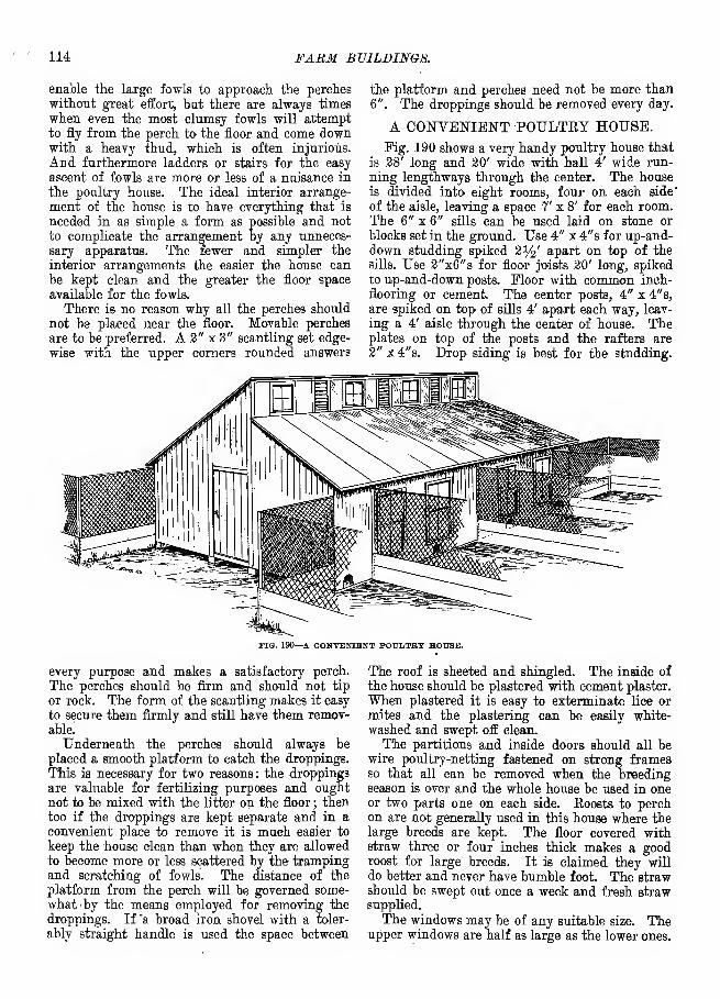
114 FABM BV1LDINGIS.
enable the large fowls to approach the perches
without great effort, but there are always times
when even the most clumsy fowls will attempt
to fly from the perch to the floor and come downwith a heavy thud, which is often injurious.
And furthermore ladders or stairs for the easy
ascent of fowls are more or less of a nuisance in
the poultry house. The ideal interior arrange-
ment of the house is to have everything that is
needed in as simple a form as possible and not
to complicate the arrangement by any unneces-
sary apparatus. The fewer and simpler the
interior arrangements the easier the house can
be kept clean and the greater the floor space
available for the fowls.
There is no reason why all the perches should
not be placed near the floor. Movable perches
are to be preferred. A 2" x 3" scantling set edge-
wise with the upper corners rounded answers
the platform and perches need not be more than6". The droppings should be removed every day.
A CONVENIENT POULTRY HOUSE.
Fig. 190 shows a very handy poultry house that
is 28' long and 20' wide with hall 4' wide run-
ning lengthways through the center. The house
is divided, into eight rooms, four on each side'
of the aisle, leaving a space 7' x 8' for each room.The 6" x 6" sills can be used laid on stone or
blocks set in the ground. Use 4" x 4"s for up-and-down studding spiked 2%' apart on top of the
sills. Use 2"x6"s for floor joists 20' long, spiked
to up-and-down posts. Floor with common inch-
flooring or cement. The center posts, 4" x 4"s,
are spiked on top of sills 4' apart each way, leav-
ing a 4' aisle through the center of house. Theplates on top of the posts and the rafters are2" x4"s. Drop siding is best for the studding.
FIG. 190—A CONVENIENT POULTRY HOUSE.
every purpose and makes a satisfactory perch.
The perches should be firm and should not tip
or rock. The form of the scantling makes it easy
to secure them firmly and still have them remov-able.
Underneath the perches should always be
placed a smooth platform to catch the droppings.
This is necessary for two reasons : the droppings
are valuable for fertilizing purposes and oughtnot to be mixed with the litter on the floor ; thentoo if the droppings are kept separate and in a
convenient place to remove it is much easier to
keep the house clean than when they are allowed
to become more or less scattered by the trampingand scratching of fowls. The distance of the
platform from the perch will be governed some-what 'by the means employed for removing the
droppings. If "a broad iron shovel with a toler-
ably straight handle is used the space between
The roof is sheeted and shingled. The inside of
the house should be plastered with cement plaster.
When plastered it is easy to exterminate lice or
mites and the plastering can be easily white-
washed and swept off clean.
The partitions and inside doors should all bewire poultry-netting fastened on strong framesso that all can be removed when the breedingseason is over and the whole house be used in oneor two parts one on each side. Roosts to perchon are not generally used in this house where thelarge breeds are kept. The floor covered withstraw three or four inches thick makes a goodroost for large breeds. It is claimed they will
do better and never have bumble foot. The strawshould be swept out once a week and fresh strawsupplied.
The windows may be of any suitable size. Theupper windows are half as large as the lower ones.

PUUL1&Y HOUSES. 115
No more windows should be used than the dia-
gram shows, as too much glass light is said to be
injurious to poultry.
The yards outside should be 10' wide and at
least 100' long. To get four yards 10' on each
side of the housethe corner pens must be brought
out G' on each corner of house. This leaves 4'
of the house for each of the outside pens. These
pens should also be bedded with straw or litter
of some kind from three to five inches deep andall grain fed should be strewn, in this to makethe hens work most of their time.
A SUMMER HEN HOUSE.
A practice in some communities is to close upthe winter quarters of fowls and compel them to
constructed adjacent to the regular house or
apart from it and will serve the purpose of a
protection to the fowls during the night almost
as effectually as though they were shut in winter
quarters under lock and key, provided always
that the lock is also applied to the latter.
Its general plan of construction is shown quite
plainly in the halftone. It has a shed roof andstands with an end to the other poultry house.
The back and the other end are sided with roughlumber. The front is left almost entirely open
save for the covering of poultry netting, which
serves the purpose of a front and yet is perfectly
open to the air. There is also a door by whichthe structure may be entered independently of
the regular house. The summer house should
FIG. 191—A SUMMER HEN HOUSE.
seek shelter elsewhere during the hot summerweather, the object being to rid the house of
vermin, avoid further care of the fowls and give
the poultry a cooler roosting place. Those whothus close the hen houses up and turn the poultry
out make the mistake of not providing other
quarters. The poultry will to some extent take
to the trees and this will teach the young fowls
to roost there, which not only exposes them to
danger during the night but renders it difficult
to accustom them to going into a house whenfall approaches.
A poultry house is illustrated in Fig. 191 that
has the advantage of being quickly and easily
include an exit other than the regular door for
the poultry. After such a house has served its
purpose for a summer shelter it still has a further
usefulness during the winter as a combinationscratching shed and sunning place for the poul-
try. If this is in view the shed should be closely
attached to the regular poultry house. Whetherthe house is to be used for summer or for bothsummer and winter it should have a water-tight
roof.
A FARM HEN HOUSE.A cheap and convenient poultry house that can
be built by any farmer is illustrated in Fig.

116 FABM BUILDINGS.
192. The building is 10' x 24' and should standfacing the south. The sides and ends can be
made of rough boards and the cracks battened
with laths or strips inside and out, or matchedboards can be used and lined inside with building
paper. It can be made any height desired andthe roof can be made ofi shingles or matched andgrooved boards well painted. Fig. 192 gives anend view of the inside. A partition should
extend the full length 4' from the north side.
This will make an entry (A) 6' x-24' and a room(B) 4' x 24', which can be made in two pens6' x 12' if desired. C is a movable floor with tworoosting poles attached. D is nest boxes, extend-ing into the entry, with lids so eggs can be gath-
ered without going inside the pen. E is a eleated
board leading to the nests. The space F is madeof slats so fowls can reach through to the drink-
«fffiltfrJJu il Alia
i , „ ,
n |f]
J I JlMilttS^^
l^j^nlMG. 192—A FABM HEN HOUSE.
ing trough G. H is a sliding door for the ingress
and egress of fowls which can be opened andclosed from entry by means of a cord. I J is a
door leading from the entry to the pen.
AN ILLINOIS POULTRY HOUSE.
The poultry house shown in Fig. 193 is 7' x 16'
and T high at the front side and 4' at the back,
with a shed roof. It may be built of 2" x 4"s for
frame, covered with common rough or dressed
boards and battened on the outside with planed
or rough battens. Shingles are better for roof
than tarred paper, which does not make a durable
roof. To make it warm the house should be lined
inside with tarred paper and should have at least
two 9" x 13" six-light windows in the south side
near the center of the building. A half-dozen flat
stones may be used for a foundation just set even
with the surface so as to allow the sills to clear
the ground. Gravel or cinders to the depth of
6" may be used for floor. All surface water in
winter and early spring should be kept out. Thegravel or cinders may be covered with sand so as
to make a smooth surface.
The roosts should be built 6n the north side
of inch boards cut into 4" strips and should have
the edges made rounding and set flat side downin notches cut in brackets extending from the
back side of the coop. The perches are 2%' above
the floor and under them is suspended a platform
to receive the droppings, which can be easily
removed every morning or twice a week. Thefloor can be kept clean by using a common gardenrake and raking up all the droppings that maybe scattered during the day. The material for
the house shown in Fig. 193 costs exclusive of
floor and paint about $12.
To build the yards connected with the house
FIG 193—AN ILLINOIS POULTRY HOUSE.
set posts 12' apart and board up 2' from theground with common rough 12" boards; thenabove that use 2" mesh poultry netting 36" wide.This makes a fence 5' high and no fowl exceptsome of the small breeds will ever fly over it.
The boards at the bottom are to keep cocks fromfighting through the fence. If desired this housecan be used for breeding fowls to accommodatetwo yards of 12 fowls each by running a partitionthrough the center and having eaph yard connectwith one end of, the house. The yards should bethree rods wide and six rods long, north andsouth, with the north end connecting with thehouse. If a large number of fowls is to be kepta number of these houses can be built in a row,all facing the south, far enough apart to admitof the runs or yards being built three rods wide.In this case a tight fence can be built betweenthe houses on the north side to keep the coldwind from the fowls.
DESIGN FOR A POULTRY HOUSE.The poultry house shown in Fig. 194 has some
good points about it not generally used. Itaccommodates 100 hens and is 20' long, 12' wide

POULTRY HOUSES. 117
and 12' high at the back side. It has a dirt-
proof roosting floor running from the top of the
back side to near the bottom of the front. This
floor is made of cheap flooring boards and lacks2' of being the full length of the building. Thisspace allows one to pass from the house proper
to the perches, which are placed along on the
upper side of this slanting floor far enough apart
to be perfectly clear of each other, the droppings
rolling down in front of and outside the build-
ing. Underneath the bottom of this floor is madea run extending half-way across the width of the
building. The top of the run is intended for nests.
At the bottom of the back are two rows of secret
nests. Make a number of windows in the south
and at least two in the back. The perches should
not come nearer than 6" of the slanting floor
and should be easily removed for cleansing andwhitewashing as often as desired. All nests
should be movable, one at a time if wanted. Anearthen or cement floor may be used. At the
FIG. 194—DHSIGfl FOB A POULTRY HOUSE.
bottom of the perches lay a flat board on which
to walk.
The secret nests open on the inside but are
built on the outside. Chickens enter at the door
and a small open window which is made above
the slanting floor at the back end. The opening
at the bottom of the slanting floor is about 6"
in the clear. The building faces south and has
the door or entry way in the east. The double
row of secret nests is to the right. * Another row
of nests is made to the left. These nests are
built upon the run, which is open only under
the south side of the building. The upper half
of the south side is made chiefly of glass.
A G-OOD TYPE OF HEN HOUSE.
One of the essential characteristics of a modelpoultry house is that it shall not be too expen-
sive to be within the reach of the average farmer.
Another essential is that it be warm and another
FIG. 195—A GOOD TYPE OF HEN HOUSE.
that it be well lighted. The illustration (Fig.
195) very nearly explains itself. The front of
the house should face the south. It is 10' highin front and 6' in the rear. With a width of 12'
the house may be built of 16' boards withoutwaste. No frame is needed except the horizontal
girts. Braces should be cut and nailed diagonally
to stiffen the building. Put several windows in
the front to let in sunlight in winter. All roosts
should be on the same level or there will be end-less rivalry for high perches. Along the front
put the nests. A is a hinged board that maybe lifted to gather the eggs. B is the alleywaythrough which the hens pass to their nests.
The house may be built 12' x 20' for 100 hens.
Put in a cement floor.
HOUSE FOE 150 HENS.
The house shown in Fig. 196 for 150 hens maybe divided into five departments. A good widthis 15'. Make a scratching room where the exer-
cise will be had and the food given in deep, drylitter 15' square. Next this is a roosting depart-
ment 5' x 15'. Then make another roosting-roomfor the second pen, then another scratching roomand so on the length of the house, which in this
plan is 15' x 100'. Let the roof slope from front
to rear, the house 5' high at the rear and 8' infront with glass at the scratching rooms to coverat least a fourth of the space. Let- the sun in.
Have the glass in front of the scratching sheds

118 FABM BUILDINGS.
100 PEET --4
Scratching
room
Scratching
ROOM
Scratching
ROOMScratching
ROOM
Scratching
ROOM
FIG. 196—HOUSE ITOB 150 HENS.
so that the windows may open on hinges and the
fowls be restrained by wire.
Take the fonl air out by means of galvanized
iron pipes (with dampers) 6" in diameter run-
ning up through the roof and opening near the
ground to admit the colder and fouler air fromnear the floer. Let the roosts be easily removable
and all on the same level. Turn the glass side
toward the sun. Make the house tight and warmby double boarding and tarred paper. Put in a
cement floor. The partitions may be made of
wire. The doors should swing on double-acting
spring hinges so that one may go rapidly throughthem in either direction.
POULTKY HOUSE FOR 250 HENS.
A roosting house to accommodate 250 hens at
night and with some 50 nests may be built 12'
wide and 40' long with six roosts through it,
FIG. 197—POULTRY HOUSE FOB 250 HENS (END ELEVATION).
which will give 240' of roosting space. (See
Pigs. 197, 198 and 199.) The roosts will be
PIG. 193—POULTRY HOU5E »ns 250 HBN3 (FRONT ELEVATION).
square 2" x 2" sticks, not fastened down, laid ontrestles 2' high. The whole thing is easily taken
out to be cleaned and disinfected. There ought
to be some galvanized pipe ventilators going outthrough the roof, taking their air from near the
floor. Make the sides tight and warm with tarredbuilding paper. Turn the front to the south.
Make the back wall 5' high, the front wall 8' or
*

POULTBY HOUSES. 119
entire length of each, room is a laying-box,
divided into compartments and covered with a
hinged lid, allowing the eggs to be gathered bysimply raising the lid and passing along on the
outside. Two rooms, built in this way, are muchbetter than one, because very often one class of
fowls should be separate from the rest. The floor
should be tight and be cleaned weekly. Theinner side of walls should be whitewashed fre-
quently, as the lime will cause vermin to seek
other quarters.
FARM POULTRY HOUSE.
This building (Fig. 201) will accommodatefrom 50 to 75 fowls. Face it to the south to
«'
12'
li'

120 FARM BUILDINGS.
shied affords opportunity for occasional confine-
ment.
CONVENIENT SMALL HEN HOUSE.
Fig. 202 represents the south side and west
end of a hen house 10' wide and 20' long, divided
into two rooms by a partition of wire netting.
This building serves two yards, as the middlefence between the two yards joins up to the cen-
ter of the building at the front and back.
Fig. 203 represents the platform and perches
removed from the house to the outside, in order
to get a good view of it. It stands on the outside
in the same position as if in use on the inside.
Fig. 204 represents the perches as raised upagainst the wall in cleaning, to a perpendicular
position.
Fig. 205 represents the percbes and platform
raised to a perpendicular position for the pur-
pose of cleaning out the trough.
MISCELLANEOUS.
SILOS.
LOCATION OF A SILO.
When possible the silo should be located in the
feeding barn, since it not only brings the cost of
building within the reach of every one who is
really in need of a silo, but greatly facilitates
the handling of the silage when feeding it out.
Depth in a silo is always preferable to breadth,
so that in the case of basement barns it is advis-
able to let the silo reach from the top of barn
posts to the ground floor of the basement; a door
or opening can then be made from the silo
directly into the basement where the silage is to
be fed. The next best location is adjoining the
feeding stable. In most dairy stables the cowsare stanchioned in two long rows facing each
other and whenever it is possible it should be
arranged so that the silo can be entered from the
end of this feeding alley. A wooden track canbe laid along the center of the feed-way andinto the silo, upon which a low-wheeled car canbe operated to distribute the feed. If the silo
building is located entirely separate it should beplanned to load the silage into a cart,, which canbe driven into the feeding barn, thus delivering
the silage with little labor directly to the stock.
The idea of convenience should not be lost sight
of, for by exercising a little thought and judg-ment the labor. of waiting on the stock throughthe long feeding season can be greatly reduced.
FILLING SILOS.
The cost of putting corn into the silo dependslargely on the advantage taken of all the little
devices that are calculated to lighten and reducethe labor of harvesting and drawing to the silo.
By the use of the corn binder for cutting in the
field and conveniently equipped wagons for haul-
ing there will be no more hard work connected
with securing the fodder for filling the silo thanthere would be in harvesting a clover or grass
crop. Many farms are supplied with low-wheeledwagons or trucks. A very simple and practical
way of equiping the ordinary high-wheeled farmwagon is shown in Fig. 206. This rack is madeof 2" x 8" plank, 16' long, one end of each being
placed on top of the forward bolster; the other
ends pass under the rear axle and are chained or
bolted up tight to it; these two pieces make thefoundation of the -rack. The wagon is coupledout as far as these planks will allow. On top ofthe plank are placed four cross-pieces, equallydistant from each other, as shown in the figure.
These cross-pieces are 2" x 4" and should beabout 7' long; upon these are laid inch boardsparallel with the wagon. The load is of courseplaced wholly in front of the rear wheels, but therack is sufficiently large and low enough to enablea man to put on a ton of green corn from theground without having to climb up on the loador hand it to a second person to deposit.
While it is true that silage cut fine may packsomewhat closer than that cut long, it is doubtfulwhether there is any material gain in the opera-
FIG. 20e—RACK FOB DRAWING FODDER CORN.
tion; by cutting fine more of the inner parts ofthe stalks are exposed to the air, and perhapsmore fermentation induced than with 'longercuts. There is nothing gained by cutting fodder

MltiVELLANEOUS. 121
fine instead of coarse, provided stock eats it
equally well in both cases; the gain in cutting,
which is often very great, comes mainly fromgetting consumed that which would otherwise be
wasted. In the case of silage, there being nonecessity for cutting the fodder in order to haveit eaten, the length of the cut appears to turnupon somewhat closer packing on the one side
and extra expense of fine cutting on the other.
With ample power and a modern feed-cutter a
silo can be filled in about half the time takenby the old methods.When corn has reached the proper stage of
maturity it is not necessary that it be wilted
before putting into the silo in order to make the
so-called sweet silage; only the immature fodderneeds wilting; such should be wilted fromtwenty-four to forty-eight hours, if possible,
before cutting into the silo. Varieties that
mature, if left until the ears begin to glaze, canbe put into the silo immediately after being cut
with satisfactory results, provided there is nooutside moisture on the corn as it goes into the
silo; nor is it necessary to -suspend operations
every other day in order to let the silage in the
silo reach a certain temperature before filling
can be continued. If the corn is sufficiently
mature, and is put into the silo without rain or
dew, there need be no fears about the quality
of the silage, whether put in slowly or rapidly.
There is a limit to putting dry or excessively
wilted corn into the silo beyond which we darenot go. When the corn has lost enough waterto cause the leaves to rustle and break in han-dling it does not pack closely enough in the silo
to exclude the air, and on opening the pit it will
be found that the silage is fire-fanged and per-
meated all through with a white mould. Thereis another reason why the corn should not beallowed to become so dry even if there were notrouble about its keeping in the silo: when drycorn is put into the silo we have lost the succu-
lent quality of the silage that makes it especially
desirable. Having once commenced to fill thesilo the work can be crowded right along byobserving the conditions mentioned. In case of
an accident or break-down it will do no harm to
suspend work for a day or two, but if left longerthan this the silage to a depth of two or three
inches usually begins to mould. When filling is
completed a fobt and one-half of chaffed straw,
marsh hay or cornstalks will make a sufficient
covering. The use of weights is now obsolete.
The silo should be examined daily for a coupleof weeks and the covering pressed down until
the settling has ceased.
The question is often asked if one crop can be
placed on top of another in the silo, provided that
the first has only partially filled it. Most cer-
tainly; if one crop, as clover, for example, only
partly fills the silo, when the corn crop has
matured the covering of the clover can be
removed or left on, as desired, and the other
crop placed on top of it. By filling at different
times much more can be got into the silo than if
a single crop is placed therein by rapid filling.
Even with the slow filling silage settles consider-
ably after the silo is closed up; with very rapid
filling it may settle as much as two-fifths or evenone-half. Under any system it is well to allow
two or three days' settling at the last and filling
up again so as to get in all the feed possible.
CONSTRUCTION AND TYPE OF ILLINOISSILO.
The well-known Illinois dairyman, H. B. G-ur-
ler, thus describes several types of silos and their
construction : My first silo was built over twentyyears ago. It was rectangular in form, 20' deepand sheeted inside the studding with a singlesheeting of first-class matched %" pine. A fewyears later I built another silo with three com-partments and double^sheeted the inside walls,,using paper between the two courses of lumber.In about seven years these double walls beganto show decay and at the end of ten years I wascompelled to tear them out and put round silos
in their place. A double wooden wall is thelast kind of a silo I would build if I were tobuild another, as the moisture gets between thetwo layers of wood and does not dry, causingdecay, and the walls are decayed beyond useful-ness in a few years. If one will persist in usingwood let it be of but one thickness and of aquality that will be sound and make as near anair-tight wall as possible.
Five years ago I built my first round cementedsilos, building three that season. The followingyear I built one 38' in diameter, which I con-sider too large, as I am compelled to feed about200 head of cattle when it is opened to keepahead of decay. If I am feeding less than thatnumber there is danger of the silage beingexposed so long that decay will begin and thentrouble begins, especially if it is being fed tocows that are milking. Twenty feet in diameteris a convenient size and I would not build withmy present knowledge any larger in diameter,but build as deep as I could conveniently in ourprairie country. ( See Pig. 207. ) Three of mineare 38' deep and three are 24' deep. I prefer thedeeper ones. With five years' experience I amconfident that the round cemented silo is themost economical kind to build that I know any-thing about. The cement preserves the silageand also preserves the wood, as it prevents mois-ture from reaching the wood from the silage. Incase the cement cracks (I have had very little

122 FABM BUILDINGS.
E

MISCELLANEOUS. 123
we have them filled nearly to this point put the
wash on to another section and so on to the top.
The silo that I built in 1898 on which I put
no roof cost me 12^ cents per square foot of
surface wall. To illustrate : A silo 20' in diam-
eter is 63' in circumference and if 38' deep or
high it has 2,400 surface feet, which at 12x/£
cents per foot would cost $300, and it would hold
250 tons. Some would figure it to hold 300 tons.
This does not include the cost of a roof, which
after three years' experience I am confident is
more a matter of convenience than of necessity.
I do not believe it adds a dollar to the value of
the contents of the silo. I do know that the roof
is very much in the way when we reach the top
in 'filling, as a man six feet tall is constantly
bumping his head against the roof.
,My silos all have clay floors and the silage
keeps as well on clay as on cement. If you need
to keep the rats out cement the bottom. Thefoundation may be of stone, brick or cement(grout) to a proper distance above ground. I
used 2" x 4" studding, 12 in centers, but I amcertain that they might have been put 15 to 16
in centers just as well, as all the object of the
studding is to hold the lumber together, as there
no lateral pressure can reach the studding unless
the lumber sheeting is first pulled in two by the
pressure, and the pressure required to break this
circular sheeting is something surprising. Theinside sheeting was secured by taking 6" fencing
and having it resawed, making the material a
little less tiian J4" thick. On this were put laths
made from the same material, the laths being
made with beveled edges so that when nailed
onto the sheeting horizontally the same as the
sheeting is put on we have a dovetailed joint
between the laths to receive the cement, prevent-
ing its loosening until it is broken. The patent
grooved laths might be used, but they cannot be
sprung to a 20' circle.
The first three circular silos that I built wereput in a row and inclosed with a frame building
like a barn. This obviated the need of sheeting
outside the studding. Not being certain that I
had sufficient resistance to the lateral pressure
in the inside sheeting, laths and cement, I putwooden hoops outside the studding, using the
same material that I did for the inside sheeting,
putting it on double and breaking joints. I
learned that I could secure more resistance for
the money in wood than I could in any form of
iron hoops and where protected from the weather
they were all right. For outside sheeting I used
in one case the same material that was used for
sheeting inside. This acts as weather-boarding
and also helps to resist the lateral pressure. Forthe cement work use none but the best (I used
the Portland) and mixed it one part cement and
two parts clean sand. Be careful not to have any
clay or loam in it.
A SILO OF WOOD, CEMENT, PLASTER ANDSHINGLES.
According to Joseph E. Wing this is the cheap-
est and perhaps the most economical silo yet
devised. He thus explains the method of con-
struction :
Begin by digging a trench as narrow as you can
with your post hole diggers and 3' deep, widen-
ing it at the bottom. This trench will be cir-
cular, of the diameter you wish your silo, 12', 14''
or 16'. I would not build wider than 16' with
this form of construction. Fill the trench with
good cement concrete, ramming it hard, andextend it up above ground 2'. It should be made8" thick above ground. To build this make a
form of thin boards bent in a circle like a cheese
box. Make the top of the concrete exactly level.
Procure common rough barn siding or fencing;
for a silo of small diameter 6" fencing will be
good j for a wide silo the stuff may be wider.
Make two hoops of boards %" x 6", 5" larger
than the inside circle .of the concrete foundation.
Treble the i£" boards, breaking joints. Laythese hoops on the wall and take a piece of sid-
ing, set it up inside the circle and nail fast, see-
ing that it is vertical. Set up four of these
boards about the wall, then plumb them carefully
and brace them, raising up the other circle andnail it at the top. If you wish to go higher let
the upper hoop extend above the top of the boards.3". It will then serve to catch the lower endsof the second set of boards. Now nail on all the
boards, siding as though siding a barn. Nail bar-
rel staves lightly at the middle to hold in place.
Leave an open strip 3' wide where the doors will
come. You now have a big barrel made of 1"
boards and nothing whatever yet to give strengthor tightness.
The bottom of the lower door should be 7' upfrom the ground ; side up to that point. At theside of the doors, on the inside, nail 2" x 6"
studding, flat-ways, directly to the boards tostrengthen them there and make a finish. Pro-vide stuff y2 " or %" thick 3" wide and begin to
put it on horizontally around the outside of silo,
spacing 3" apart. Nail it well and break joints.
On this shingle the wall. Let the stuff go acrossthe doors and be especially careful to select goodmaterial there and to place it judiciously. Doorsneed not be closer than 4' to each other. It is
easy to lift silage 2' and then to dig down 2' toa lower door. It will add to strength to makethem 6' between.
If one length of the boards can not be obtainedset up another set on top of the first. It is justas well to do this in any case. A silo should be

124 FABM BUILDINGS.
at least 30' deep. You may use 16' stuff for
bottom set and 14' for the top. That with the wall
gives a 32' silo. Run a few strips of strap iron
up the siding to hold the two sections together
in a cyclone. When all is stripped with the
y2 " x3" stuff you have a wall that can not be
rent asunder. The tensile strength of wood is
enormous. Cheap elm or green oak will bend
easily and make good material for this stripping.
Lath the inside with common plastering laths
but space them 1" apart. Nail a row of themright around, then another row right on top of
the first, breaking joints and allowing the second
lath to project above the under one }4". thus giv-
ing a secure hold for the plaster. These plaster-
ing laths alone would hold the silo from spread-
ing. Plaster with best Portland cement into
which sufficient fibrous gypsum has been mixedto make it adhesive. Now and then whitewash
it with pure cement after being used or coat it
with pitch to preserve it from the acid of the
silage in that when it settles will leave> the silo
ful of the silage will be good. Bevel the 2" x 6"s
that form the door jambs to receive the doors.
This silo has had tests in Michigan and else-
where and has enthusiastic adherents. It should
endure for many years and has the advantage
of the stave silo in that it will never blow downnor collapse. In roofing it at the top bend aroundand nail five thicknesses of the %" stuff to makea plate. Get 2" x 12" plank long enough for
rafters and rip them diagonally from corner to
corner. This should be done in a mill, where it
is done very rapidly. Set them up with points,
together and toe-nail together, then shingle. This
makes a sightly conical roof. Make it steep ; it
looks better and enables you to blow a mound of
silage. Leave the earthen floor and every spoon-
nearly full.
THE WING CEMENT SILO.
This silo built by Joseph E. Wing has a wall6" thick at the base thinning to 4" at top. It is
16' in diameter and 30' high. (See Fig. 208.)
Mr. Wing thus tells how it is built: Webought a quantity of 2" x 7" hemlock staves to
form the inner core of the form. In erecting
this core we nail a %" strip 6" wide horizontally
about the staves on the inside as we set them up;this keeps them in place, and is easily torn off
when taking down the wood. The staves webeveled slightly as silo staves are beveled. I think
now that to have grooved them and put in the
grooves short metal tongues at three or four points
along. the length so that they would have been
unable to move against each other would have
been wise; they could have been set up morerapidly. We set them up much as you would set
up any wooden silo, a 16' length first, using a
wooden hoop 2" x 6" built of i/2" stufE as a form
to build against, this hoop being on the inside of
the silo. Each stave was spiked to this hoop;
when the lower section was finished the spikes
were withdrawn and the hoop raised up for the
second form.
The outer wall of the form was of Vfe" °&stuff, 8" wide, the boards running about the silo
horizontally and held in place by 2" x 4" stud-
ding set about 2" apart. To hold these studding
at the right distance from the inner core they
were wired in three -places with No. 12 wire,
TIG. 208—THE WING CEMENT SILO.
boring through the staves of the inner form for
this and passing the wires through these holes
and fastening by letting the loop pass about a big
nail. The wires we learned should be twisted to
get the slack all out of them. They pass throughthe wall and are left in.
In beginning we dug a circular trench 2' deep,
widening it at the bottom to give a good bearingand filling it first. The concrete was raised bymeans of a pole derrick, which should be about6' higher than the silo is designed. This derrickis easily revolved and is guyed in four or six
directions with long and heavy guy wires. Scaf-folding is carried up as you go. Concrete mortaris lifted up by horse power, swung in placerapidly and deposited in the forms with shovels.
After one knows how, silos may be very rapidlybuilt in this manner. Our men were all our

MI8CELLANJH0 US. 125
regular farm laborers. We think this silo will
be a permanent thing.
The thinness of the walls forbids putting muchif any dependence in their strength to resist
bursting. The bursting pressure of silage at 30'
depth is 330 pounds per square foot, according
to King. If your silo is 16' in diameter it musttherefore have strength to resist 2,640 poundspressure for each foot in height. As you go upthe pressure decreases, of course. Concrete
should have a tensile strength of about 200 to 500pounds per square inch. We imbed wires or rods
directly in the mortar to hold the strain. Iro.
hoops designed to hold wooden silos may be putin. Wire is rather cheaper and more easily han-dled. Get No. 00 wire. It is hard to handle,
so reel it out across the field and rig a lever of a6" sapling about 20' long and put a team on it
across a stump and stretch it till it lies straight.
Then cut it into lengths long enough to reach
around the silo and 6' longer. At each board lay
in a wire or two before you put in cement, wrapthe ends about each other and turn them back;the cement will not let them slip when it is hard.
These encircling wires should be in the middleof the thickness of the wall, so insert uprightwires in the wall about 3' apart; they will also
prevent cracks and will hold the horizontal wires
in place. No. 00 wire has a tensile strength of
about 7,000 pounds. If the silo is to be 30' deepbegin by putting one at the ground level, thenup 8" put in another and at each 8" board. Thisis a little stronger than is absolutely needed, butI do like a thing to be safe and wire is notvery costly. It will not rust in the cement. Atthe doors, which need not be closer to each other
than 6' and should not be nearer the groundthan 7', place upright rods 1" in diameter oneach side and loop the wires about them. Acrossthe bottom and top of the doors pass similar iron5' long with ends turned up 2" and curving as
the curve of the wall.
We mixed our concrete .at a strength of onebarrel of cement to a yard of gravel. It seemsto be very hard. We washed the wall with abrush with a wash of nearly pure cement, waterand a little sand. We put a roof on, as the silo
may hold silage until summer time some years
and roofs are not very costly. The floor is of
clay, which it seems is better than anything else.
It is not excavated at all. The pole may be sawedin sections and thrown out of the window or left
in the silo until it is fed out and sawed off then.
If you are building of a different dimensionremember the rule for calculating the pressureon your walls is to assume the normal pressure
at a depth of 30' to be 330 pounds per square
foot and to multiply this by one-half the diameterof your silo wall. Be sure you put in enough and
put no dependence in the cement for resisting
bursting strain. The thin wall is very muchcheaper than the thick one and just as good, if
the steel is there.
The oak stuff that makes the outside of the
form warps and cannot readily be used again for
silo building, though it is useful in a hundred
other ways; the inner shell is practically unin-
jured by the use made of it.
All concrete work should be' moderately wet
down, never made sloppy, and rammed hard in
the mould until moisture rises on top. If it is
made very wet it is nearly ruined. It should not
be wet until just as it is ready to use.
I think a 4" wall is right and just as good as
one 18" thick, barring possible freezing. I insist
that abundant steel must be used and advise
coating the inside with hot pitch to make it acid
and air-proof.
It is not necessary to use a complete form for
the entire silo. We set up first a 16' length of
inner staves, afterward another 16' length on
these, thus needing as much timber for this inner
form as is needed to build a complete wooden silo.
We now think this a mistake. These staves can
as well be in 8' lengths and after two sets are
up the lower set is as well taken away and movedup, next the second set moved up, thus proceed-
ing until the silo is tall enough. These staves
should be all accurately fitted together before
work is begun. There should be three dowels or
pins in each stave and holes exactly correspond-
ing on the other side. These dowels should be
made of Y^" steel. They should fit tightly onthe one side and the holes to engage them shouldbe large enough to allow them to enter andremove easily. Thus equipped the staves are veryrapidly set up, as each one supports the one nextto it, and the dowels prevent them crowding in
when the concrete is tamped behind them. Aset of these staves will last for many years. Thefirst year's use of this silo disclosed less than 10pounds of spoiled silage.
A SILO OF CONCRETE BLOCKS.
A silo built of concrete blocks has beendesigned by Joseph E. Wing. He says the blocks
are easy to make and will lay without mortarunder them or at the ends and make an air-tight
and water-tight job. There will be no need for askilled mason in laying them. They are madejust right in length and curve to make the wall,
and where windows come they can be sawed in
two or shorter ones made to fit the openings.
Joints are broken just as in any stone work andthe effect is pleasing.
The block is made in a wooden mould and after
being set the mould is taken off and the blockhardened before being used, as any artificial stone

126 FABM BUILDINGS.
blocks are made. It consists of two pieces, each2" thick, 8" high and of convenient length, say3'. These pieces are curved to fit the desired
diameter of the silo and are spaced 2" from eachother. They are held together by square loopsof steel wire, large size, such as No. 4. This wireis bent in a form into the desired shape and twopieces are put in each block. Being very large
stiff wire the blocks keep their position exactly
when made even, though they do not at any parttouch each other. This forms a stone block 6"
wide (it may be made 8" if desired) and with ahollow clear through its length of 2". Theseblocks may also be easily made in two parts; in
one part is moulded two bolts 6" from each end;they are bolts y^" x 7". In the inner block, the
mate, two holes corresponding with these bolts
would be moulded with a %" depression in theinner surface of the block. After they were hardthe two parts would be fitted together, nuts put
FIG. 209—A SILO OF CONCRETE BLOCKS (CROSS SECTION).
on, the depression making the nut flush with theinside of the wall, then the double block laid in
the wall and the channel filled as described.
Afterward the projecting bolt ends would besmoothly clipped off. The bolts would not showon the outside at all. This block would presentno difficulties in manufacture whatever and whenonce completed the two original blocks andthe core would be inseparably united. The foun-
dation is made below ground in a narrow trenchin which ordinary concrete is rammed. Level it
and lay the first course of hollow blocks. Fill
the channel with rather thin concrete, lay in aNo. 4 wire to hold the wall from spreading andlay the next course, breaking the joints carefully.
Again fill the channel with cement, lay down
another wire and another layer of blocks and so
on up to the windows. At the windows (and the
lower one should be up T and the next one up6' higher) one can fit in a good wooden frame
against which to build and there should be iron
rods run up vertically through the channel to
make it extra solid there, while the wires will
loop about these rods and their tops and bottoms
be fastened together, so that there will be nodanger of the silo bursting at this point. Thereshould be abundant steel put into this wall, so
that all bursting strains would be resisted by the
concrete. Eeference to the diagram (Pig. 209)will make plain the idea. The section of silo
shows a course of blocks laid with the continu-
ous channel open and ready to be filled withcement. It is actually a form of concrete and is
left there when filled instead of being taken awayas a wooden form would be. The block construc-
tion is clearly shown and the bit of heavy wire
bent into shape to be inserted in the form andbuilt into the block to hold the parallel sides in
place. This idea, by the way, is applicable to
straight walls for houses or any kind of build-
ings.
The wood mould is made with a curve to fit thesilo and of any convenient length, as 3', and as
wide as the wall is thick, say 6". A depth of 8"
will lay very well. Clamps hold the bottom of
the mould to the ends and sides. A curvedwooden block 2" thick fills the central portion of
the mould to make the hollow in the stone andthis block must be made a trifle tapering to bereadily taken out and in three parts divided ver-
tically, so that the cross wires will not hold it.
These cross wires are held in place by the centralblock and cement, poured in and gently rammedabout them.
In making these cement stones gravel is notused but coarse sand instead. In erecting a silo
after this manner only scaffolding timber wouldbe needed and the scaffold would be inside thesilo, though hoisting ^would be by pole and der-rick, as in any silo, the arm simply swingingmaterial over the wall to the scaffold.
Silage has a bursting-pressure at a depth of30' of 330 pounds per square foot. At 20' depththe pressure is 220 pounds. To calculate thebursting-pressure per vertical foot in a round silo
multiply the pressure per square foot by half thediameter of the silo. Thus in a 16' silo 30' deepthe bursting-stress at the bottom is 8x330=2,640 pounds for the vertical foot, decreasingas you get higher.
A STONE SILO.
The silo shown in Pig. 210 has a capacity ofabout 650 tons. Its walls are 2' thick and arelined with cement. It is of a somewhat different

MliSCELLANEOVS. 127
type from most silos, being wider and not so high.
This silo is built cylmdrically and largely of
stone. Where they are lined with cement one
-STONE SILO.
seldom if ever has moldy silage around the edges.
Silos built like this one are expensive of course
to build, but are economical in the long run.
CRIBS, GRANARIES AND WORK SHOPS.
Perhaps the cheapest building for a crib or
granary is square, of capacity enough for the
grain produce on the farm. But as corn is
stored when not entirely dry it can be cured bet-
ter in narrow cribs. On this theory are designed
two cribs set parallel under one roof and 12'
apart. (Pig. 212.) This gives a driveway of
sufficient size to store reaper, mower and all
implements of the farm if necessary to store themhere. If this driveway should be used for imple-
ment room care should be taken not to let anyof the tools or implements come near enough to
the sides of the crib to give rats a chance to gnawtheir way in.
The cribs are each 6' x 36' at the bottom and8' x 36' at the top. The object of this is to give
the sides of the cribs an outward slope, whichsenses two or three valuable purposes. First, it
prevents rats climbing up the sides; second, it
prevents rain driving into corn and third, makesit easier scooping corn from wagon. Rats will
climb up the perpendicular sides of a crib to anopen window or even to the top of the crib. Toprevent their going over top of crib place a boardextending 6" over the edge of the ties and plate
to which the slats are nailed. The windows mustnot be left open after the corn is put in.
The bottom of each crib is 6" x 36' and rests
on stone foundation 3' in ground. (Pig. 211.)
The sills are 8' x 10" by 36', and the joists are
PIG. 211—CORN CRIB (FOUNDATION P.LAN).
2" x 10" by 6'. The sills rest on the stone piers
18" thick iy2 ' above ground. This gives thor-
ough ventilation.
There are three windows on each side of drive-
way for receiving corn when the cribs are filled.
These windows are 4' x 4' and are fastened by a
strong wooden button. After the crib is filled
to middle of these windows the corn is thrownovei the top. With top of crib 8' x 36' there can
be stored after the crib proper is full to the
square one-third more corn.
The framework consists of three bents 12' each.
The space over the driveway out 12' at each endis floored over and gives room for several hun-
dred bushels of corn or 1,000 bushels of wheat.
This crib and granary are absolutely rat-proof if
the doors and windows are not left open longer
than when used to put in or take out corn, andif one is careful not to set boards or tools against
the cribs for resting places for rats to gnaw their
way in.
The slats on the outside and inside of the cribs
are oak, 3" x l 1̂ " and y2 " apart. Care should
be taken not to use any slats with sappy or wavyedges.
It will be noticed that the size of the ties mayseem heavy, but the fact is they are not too heavy,
^=

128 FABM BUILDINGS.
posts are 12' long, 6" x 8". Ties are 12' long,4" x 8", three to a post. There are four ties
G" x 6" 26' long which are tenoned into the out-
side posts and receive in a mortise the inside
posts. This makes the inside of each crib onefoot lower than the plate on which the rafters rest
and makes it easier to fill the crib. If the crop is
heavy set a board on edge, making the inside of
crib as high as the outside. The driveway is
closed by sliding doors, which locked makes a
safe store for the corn crop. The narrow slatted
cribs have also perpendicular ventilators placedin front of each receiving window where cornis likely to pack and mold if at any place in thecrib. These ventilators extend from floor to roof.
While the narrow crib is needed in moist East-ern climates farther West this crib may very wellbe widened to 8' or even 10' at the bottom. It
is worthy of note that when pine lumber mustbe used and rat-proofing 'is desired it may besecured by lining the inside of the crib withwire netting of about i/
2" mesh. This is not
expensive.
TOOL HOUSE AND WORK SHOP.
A model tool house should be of generous size,
so that machines may be put away without muchlabor; it ought to be as easy to unhitch in the
Ktihint 5w- Cfta > Sj^niflR.
c?FIG. 213—TOOL HOUSE AND WOBKSHOP (CONSTRUCTION).
wELEVATION 'TOOL SHED 30'QO ft.
mux not cum smh.WUTI LUNBCRMOH»WW BOMUM
wWO. 214—TOOL HOUSE AND WORKSHOP.
shed as out of doors, else men will be apt to leave
machines out. The shed illustrated in Pigs. 213
and 214 is merely a great umbrella with posts
one wav 30' apart, the other way- 12' or 16', no
side to "it at all, so that there is nothing in the
way of driving into it at any point. Putting the
main machinery in the inner parts leaves the
over-hanging roof 10' wide for wagons and as it
is 10' high there is no difficulty in driving under
to unhitch. Buggies may be sheltered on the
shady side and if it is feared that snow would
drift into them one or two sides may be boarded
up. This is not designed for a house for fine
carriages, which should of course have a tight
dust-proof building.
The work-room above will hold a lot of smaller
tools, be a good place in which to mend harness,
make gates,' repair machinery or store seed grain.
By putting the truss above it with an inch truss-
rod coming down to the cross-beam there is given
a clear span of 30' in the shed below. The whole
thing is built in joint construction, posts 2" x 8",
in two pieces, built up solid below the cross-beam,
this made of three pieces of 2" x 12", spaced 2"
apart, box plates of 2" x 10", bridge truss of
6" x 6", rafters of 2" x 4" or 2" x 6", according
to whether they are ever to hold much weight.
The work-room should have a bridge stairway
wide enough and sloping enough to take up a
vehicle if necessary for repairs or painting. This
may be in any bent that is most convenient. Thefloor may be of hard earth or cement; the posts
rest on stone pillars. Put on a shingle roof* that
will not be too hot in summer. If there is too
much room in this upper story finish off a roomfor an extra hand to use now and then.
A CONVENIENT TOOL SHED.
It is difficult to, keep things in their places
unless one has provided places for them. On anyordinary farm there is a great collection of
TOOL SHCDMXAI
FIG. 215—A CONVENIENT TOOL SHED.
machinery, wagons, plows, harrows, drills, rakes,
mowers, binders and what not which are gener-
ally supposed to be stored on the barn floor or in
odd corners of other buildings. Too often theyare left out under the sky. Yet it is not difficult
to keep them sheltered and in a place where theywill be convenient of access, not in the way andeasily put in their places. Pig. 215 shows such

MISCELLANEOUS. 129
a building. It has no sides but is simply a roof
of pyramid shape, projecting on each side 10'
beyond the posts, being 56' square over all.
Under these projecting eaves the farm wagonsmay stand and in the middle spaces the
machinery may be stored. Any machine may be
driven to any part, as there is nothing to inter-
fere with driving through in any direction.
There is much satisfaction in storing machinesin a building by themselves ; they are not in the
way, nor are they in danger of injury from con-
tact of animals ot wagons. There is no dangerof fire in such a building as this. Protectionfrom sun and rain alone is needed. The posts
are 6" x 6", set on stone; the roof is of shingles.
A TWO-STOKT nOTJBLE COBN-CKIB.
The double crib with two stories and two drive-
ways shown in Fig. 216 is about 30' wide, eachcrib being about 10' wide and 20' deep and 60'
long. Built of these dimensions it will hold
PIG. 216—A TW0-STORY DOUBLE CORN CRIB.
about 7,000 bushels of corn on each side of thedriveway, but on most Western farms it will bebuilt 12' wide rather than 10', which will con-siderably increase the capacity, without addingmaterially to the expense.
JOIST FRAME HAY BARRACKS.Where hay is to be stored under roof and no
stock to be provided for this simple frame (Fig.
217), which is easily made all of 2" stuff or of
part round poles if desired, commends itself asbeing simple, strong and cheap. There should bebraces running the long way of the building at
the same angle shown in the eut to protectagainst winds. The artist fails to show all thedetails of the curb roof, which must be tied
together by collar-beams at the peak and effect-
ually tied at the angles of the rafters. Referenceto roofs of barns shown in more detail will
explain the roof and how the plates are put on.
CEMENT AND CONCRETE, WORK.
There is no material for floors in stables, cel-
lars and out-houses comparable- with cement. Itis cheaper and cleaner than wood and properly
made will last forever. Failures in the use of
cement have come from the employment of
inferior materials or from ignorance of the
process of making it. To make a cement floor in
the stable remove enough top soil to get down to
where it is firm. A layer of coarse gravel or
broken stone should be applied and rammeddown. This serves for drainage and keeps frost
from affecting the cement. The concrete maynow be prepared. Concrete is made of finely-
broken stone, sand, gravel and cement. If youdo not have the broken stone, gravel will answer.
Take five bucketfuls of gravel and one bucketful
of cement and build up the contents in a conical
pile on the floor. Shovel it over carefully three
or four times to mix it thoroughly • while dry.
Continue mixing it in this way and sprinkle it
slowly with water. Mix it until it is moist butnot sloppy. It is now ready to use. Spread it
down and with a heavy rammer pack it thoif-
oughly. The better it is packed the better thefloor will be.
The thickness of the concrete will depend onthe use to which the floor is to be put. Fromthree to six inches will usually be satisfactory.
Where the floor comes against the side of thetrench or manure ditch there should be a plankplaced at the side and braced solidly to hold thematerial in place. A loose two-inch plank may
TIG. 217—JOIST FRAME HAT BARRACKS.
be used between the restraining plank and theconcrete, which, after ramming the latter, maybe taken out, leaving the surface finish to formthe face of the offset. The material used inmaking this surface finish consists of two partsof clean sharp sand and one part of cement mixed'thoroughly while dry and then wet carefully,

130 FABM BV1LDTNGS.
rammed again until it is solid and then smoothedwith the trowel. If of the proper consistency it
will appear rather dry when laid down but will
be moist after it is rammed and troweled downsmoothly. After it has been troweled it maybe sprinkled with coarse sand to make the sur-
face rough. If it is desired to make it roughershallow grooves may be made by pressing downwith a short piece of fork or hoe handle. Thethickness of the finishing layer should be fromone to two inches.
Foundations and pillars for buildings may bemade of cement; walls for sheltering barnyards,floors of porches, walks and even entire barn-yards are somtimes covered with it in order to
avoid the mud that frequently is found in suchplaces. Cement should be used quickly after it
had with coarser mesh. This woven wire comes
in rolls. It is put over the wall of the building,
spaced y2 " away, or if a very warm wall is
desired, %", and stretched tight. The best wayto put it on is to unroll and hang it as wall paper
is hung, fastening the top first, then one edge,
then by using 6 or 8-penny nails, starting themslanting in the edge of the netting, it may be
stretched sideways. This stuff can not be
stretched lengthways but may easily be stretched
taut sideways. It. is kept away from the wall bythe use of laths running vertically, 2' apart. lightstaples 1" long hold it in place and if it should
pucker anywhere it is held down by a staple.
Screws 1" long are used to hold it away fromthe building; the mesh-wires are placed in the
slot of the screws ; the staple holds- them there
FIG. 218—A PLASTERED HOUSE.
is wet and not be disturbed while drying. It
should always be of best quality. To prevent it
from becoming too dry while "setting," especially
if exposed to sun, sprinkle it several tianes.
THE USE OF OUTSIDE PLASTERING.
To put plaster on outside walls with commonlaths one must have first a solid backing of somerough lumber; any dry stuff will serve but pineis to be preferred, as it is not apt to warp. Spacethe laths out from the side of the building about%". Nail them on iy2 " apart.The best way to plaster the outside of build-
ings is to use common poultry netting, that of aninch mesh being best, although good results are
and a tap of the hammer drives it down right.The netting is put on rapidly and is cheap. Beinggalvanized it is very durable, especially whenincased in plaster.
The plaster should be made of good fresh limeand sharp sand. It should be made up in largeamount before the plastering is begun so that allcolors will be alike. It should not be rich inlime but should be made as though for mason'smortar. It is put on as over laths. It is bestto apply two coats, the first barely hiding thewire and a thin coat over that before it is thor-oughly dry. This will fill and hide all smallcracks. When it is completed the wire isimbedded in the middle of the thickness of the

M1SGELLANE0 US. 131
plaster. It can not crack ; it can not peel off, for
the wire being firmly stapled to the wall holds it
solidly in place. As time goes on and the wall
gets wet and dry again the mortar becomes harder
and harder until it is like stone. It is warm in
winter and cool in summer.There is yet another use for outside plaster.
That is for covering out-buildings; poultry
houses plastered outside and in are warm, sightly,
easily kept free from vermin and cheap. Thereneed be but one thickness of boards and the wire
stretched over it on each side or common laths
may be used for the inside. The cost of this sort
of plastering is about double the cost of painting
once. A better plaster is made of Portlandcement ,one 'part, clean sand two parts. Thishardens into a cement impervious to moisture.
Fig. 218 shows a farm cottage plastered accord-
ing to the foregoing directions.
CEMENT FLOOH IN HOG HOUSE.
Fig. 219 shows the cross section of a hog house24' x 60' with a cement floor. The floor is madein two levels, 1' lower in the middle than at the
sides. By tbis means a dry clean feeding floor
in front and a dry clean sleeping floor back are
insured with a space in the middle to collect all
droppings and moisture. Bedding should be usedand absorbents. The trough should extend alongthe front and be of cement 10" deep and the front
CROSS SECTION HOG HOUSE24' WIDE
CEMENT FLOOR AND TROUGH
FIG. 219—CEMENT FLOOR AND HOG HOUSE.
by the trough should be hinged so as to open in-
wardly enough to lock at the front side of the
trough, thus shutting the swine away from the
trough while it is being cleaned and food put in.
The trough should be divided at intervals of about16' so that liquid feed cannot run away. Thecement should extend upward 1' to form the
foundation wall and the superstructure of woodanchored to it by %" bolts imbedded in the
cement.
CONCRETE FLOOR FOR HOG HOUSE.
The bottom to receive concrete should be solid,
so that it will not settle in holes nor out of the
original level. It must be so that no water canstand under it, as it will freeze in winter and
heave up the floor, of course cracking the concrete.
It is best to remove a few inches of top soil and
tamp well the surface that is to receive the ce-
ment. The general way is to excavate eight to
twelve inches and fill with gravel. But if the
floor is protected from water getting under it the
gravel is not necessary.
The best concrete is made from broken stone,
gravel and coarse sand. Mix dry 13 parts gravel,
6 parts sand, 6 parts Portland cement, then whenthoroughly mixed, add water to make a stiff
paste. Then take 27 parts broken stone, thor-
oughly drenched with water, so that all fine dust
may be washed out and mix the crushed stone
with the other until all is incorporated with the
cement.
In laying cement it is best to divide the floor
into squares of 4' or 5' with 2" x 4" pieces firmly
staked down. Fill every alternate square withthe mortar well tamped down until the fine ce-
ment begins to come to the top. After it has
stood a short time but before it is dry apply a
finishing coat of half or three-quarters of an inch
made of two parts sifted sand to one part of ce-
ment, smoothing down with a trowel. After set-
ting it so as to be fairly firm remove the 2" x 4"sand fill the other squares in the same way. If
made in too large squares shrinkage cracks will
occur.
To make concrete without the broken stone
coarse gravel may be used but it will need morecement, say six or seven parts of sand and gravelto one of cement. There seems to be no hard andfast rule as to this. Only as much should bemixed at one time as can be immediately used.
After completion the floor should be sprinkleddaily with water, which is necessary to completehardening of the concrete. It is best to leavethe studding around the outside for a long while.As to the comparative cost of wood and concretemuch depends on the cost of the materials. Inmost places the concrete will cost from a quarterto a half more than wood but the concrete is forall time and is certainly more sanitary and easierto clean and keep clean.
CEMENT FEEDING FLOOR FOR HOGS.
A cement feeding floor for hogs may be built12' wide, as long as desired, with a slope of 1"
FIG. 820—CEMENT FEEDING FLOOR FOR HOGS.
in 12" and preferably with a drop at the lowerside and a cement trough at the upper side. A

132 FABM BUILDINGS.
cross-section of the ideal feeding floor is shown in
Pig. 220. Let the floor be in plain uninterruptedsunlight, as sun is a sure destroyer of disease
germs.
In the cut T is the trough and over it is a
section of swinging fence that will close it fromthe hogs while the slop or feed is put in; L is line
of level ; F fence of woven wire to prevent hogsfrom crowding each other over the bank ; S slope
over which cobs and manure descend.
CEMENT EOOES.
Joseph E. Wing, who has used cement roofs for
several years with success, says of their construc-
tion:
First the roof needs to be strong and the roof
boards should be well nailed down. The weightis a little more than that of slate, as the cementis put on about %" thick. It must be put on a
month before freezing weather. The manner of
doing it is first to spread down a thin layer of
cement mortar in a strip about 3" or 4" wideup and down the roof. Before this strip is muchset unroll upon it a strip of galvanized wovenwire poultry fencing, l1/^" mesh, spread it out
and staple it down only as much as is needed to
make it lie flat. Now spread another layer of
cement over this, hiding the wire, and trowel it
down smooth. Continue until the roof is covered.
It should not be of steep pitch, though cementmay be applied over old shingles on ordinary
roofs. When it begins to dry sprinkle it fre-
quently. A layer of straw or chaff 2" thick will
serve to keep it moist and it is better if it dries
out very slowly; if sprinkled well every day for
a week all the better. After it is set there will
appear some small cracks; these may be filled
by sprinkling the surface with equal parts of
cement and fine sand, about %" thick all over,
brushing it with a broom to get it in the cracks,
then sprinkling with water and spreading with
a whitewash brush. Use the best Portland ce-
ment for this work—one part of cement and twoparts of very clean sand. It makes a cheap roof
for cattle sheds, poultry houses and the like andis a cheap way of repairing old shingled roofs.
Should it crack a little the second year it may be
washed over with a trifle of pure cement whichwill stop that. Further test is needed before it
is to be recommended for dwellings or main barnroofs.
CEMENT WATERING TROUGH.
Cement or concrete watering troughs are fast
supplanting the fast-decaying and ever-ready-
to-leak troughs. Of the former two types are
shown in the accompanying illustrations. Fences,
walls, floors, troughs and well coverings all decay.
Therefore the coming of good cement at a low
price is doubly welcome to the farmer. It seems
now that he may do things so well that they
will stay done through several generations and at
slightly greater expense than the temporary
makeshifts to which he has been accustomed.
Use the best cement. Cheap cements are not
worth the using. Get clean, sharp sand and
gravel. If there is earth or loam in it it will not
make good cement. Broken stone is excellent but
it needs a proportion of sharp sand or finely-
crushed stone to fill the interstices of the broken
stone. The stone and cement or gravel and ce-
ment must be mixed in right proportions. There
should be just ©nought cemexit to fill all inter-
stices in the sand and gravel; a very little more
to allow for poor mixing is safe. The amountneeded may be ascertained by the water test.
Taking a measure of dry material, such as

MISCELLANEOUS. 133
harder the ramming the better the work will be.
Use the material as soon as wet. If any stands
till it becomes somewhat set throw it away or
use it for some -unimportant job. Wetting again
will not restore the life of set cement.
To build a watering trough, remove the top
soil down to where it is firm, say 8". Build a
box the size of the outside of the trough, say 4'
x 13' and 3' high. Make it strong to resist pres-
sure when cement is rammed against it, setting
stakes at the sides and tieing across the top.
Put in the bottom a layer of concrete about 4"
thick and through it insert a drain pipe, and aninlet pipe. Make the drain pipe lyi' with coup-
FIG. 283—CEMEHT WATERING TROUGH.
ling, coming just flush' with the floor of cement.
Into this coupling screw a short standpipe, so that
into this the overflow will discharge and whenit is unscrewed the whole tank will be emptied.
Make this short standpipe to screw in easily andkeep the threads greased. (See Figs. 221 and222.)
Do not try to fill up the tank with concrete
high enough to allow stock to drink out all the
water. Water is the cheapest material with whichto fill the bottom of a trough. Make an inner
form with sloping sides so that the wall will be6" thick at the top and 16" thick at the bottom;put in place and fill with concrete and poundit down as hard as possible. Do this before the
bottom has become thoroughly hard. When it
has set a day or two take off the wood carefully
and wash trough well with a mixture of equalparts pure cement and pure sand, using a fairly
fine clean sand, or cement alone. Put it on witha whitewash brush. Sprinkle the work twice a
day and when a little hard carefully fill it withwater.
FEED PACKS AND TROUGHS.A PRACTICAL FEED RACK FOE SHEEP.
Cheapness, simplicity and effectiveness are the
three strong points of this rack. Fig. 223 showsthe construction. The end pieces are of 2" x 6"
pine, the bottom boards are of 1" x 12" and the
top boards are set at an angle and leave a wide
opening through which the hay descends and
plenty of room for the sheep to thrust their
heads in to eat. This form of rack gives the
animals easy access to every bit of the feed and
prevents any waste of consequence, for when
2X6" PLANK
2X6" PLANK
FIG. 883—A PRACTICAL FEED RACK FOR SHEEP.
sheep can thrust their heads in they let themremain there and eat without drawing the hayout and trampling it under foot. In general this
rack is built without a bottom, though if it is
desired to feed grain in it there may be provideda tight bottom, putting it about midway of thebottom board. It is better to provide separate
troughs for feeding grain.
GOOD IDEA IN FEED RACKS.
The cuts Figs. 224 and .225 are self-explana-
tory. By hitching a team on one end of thisunique rack it can be moved very easily. The18' ark holds 1,000 pounds of hay or one ton ofsorghum. The frame-work is made mostly outof 2" x 4" except the runners, which are 2" x 6".
The rack ib 18' long, as shown in Fig. 225.
A SELF-FEEDING MANGER AND STALL.
This stall-manger plan can be used in nearly anyform of building. The stalls being only 3' to 3'

134 FARM BUILDINGS.
'-*-''"''"-^SiswalS" -**?
HO. 384—GOOD IDEA IN PEED RACK (CONSTRUCTION).
PIG. 325—GOOD IDEA IN PEED RACK.
4", as may be preferred, in width and coming
out 2' from the manger, the front edge of stall
being perpendicular as shown in Pig. 226, there
is no danger of animals getting hemmed in or
injured in any way.
On the outside of the building above the top of
the manger there is an opening in the siding for
feeding silage, ground grain, bran, cottonseed-
meal and the like. This is closed by a shutter
turning up or down as desired. The stalls should
be braced from near the end of the 2" x 4" sup-
port of manger to near the middle of mangerand closed between the brace and side of the stall
so that stock can not get their feet fastened. Fig.
226 is thus described : A, A, hay chute 2' wide,
continuous with building. B, outer door to feed

MISCELLANEOUS. 135
silage or grain of any sort without disturbing be moved more easily. The troughs should be &'
cattle; track hung out from siding may carry wide and have a space of 1%" at the bottom of
feeder for the corn to run out into the tro-ughs.
H-hVl. Still FttA. AWgtr"
FIG. 326—A SELF-FEEDING MANGER AND STALL.A SELF-FEEDER FOB CATTLE.
oar to distribute silage. C, wooden partition be- _, „,, ... . ,. ., . , , , „, ,
tween stalls; partitions 36" to 42" between cen-The,2
'x 4' pieces on the side should be 8 apart
ten, 44" from hay chute to outside of partition;at tbe ^P and 4 at the bottom
's0 the Sldes Wl11
r be slanting.
A GOOD SELF-FEEDER.
The self-feeder for cattle shown in Fig. 229
is for an open feed-lot or pasture. When cattle
are made to put their heads through spaces like
FEEDING TROUGH FOB CATTLE.
outer piece of partition should be 2" x 6" firmly
fastened to stub-post set in ground. D, two
boards 1" x 6" to brace the upper part of parti-
tions.
SELF-FEEDER FOE CATTLE.
Herewith is a diagram (Fig. 228) of a self-
feeder for cattle that can be built on posts or
built on runners of 4" x 8" pieces, so that it can
FIG. 329—A GOOD SELF-FEEDER.
this to eat their food much outside wastage is
saved. The dimensions of this feeder are aboutright for cattle weighing, say, 1,000 pounds. Inmaking it use bolts freely.
A SHEEP BACK.
The sheep rack shown in Fig. 230 has beenused with satisfaction at the Iowa ExperimentStation. The rack is 8' long, 18" wide and 38"
A
i ii innnnnnnnnnt
//
/1
1
1
1/^"-

1^6 FABM BUILDINGS.
. high. This size is found convenient for small
\pens, but any size may be used to suit the require-
ments. Economy of time and material may be
:' gained by making the rack a little wider and
[feeding from both sides. Fig. 230 on left gives ,i
'side view of the rack as used for feeding hay, on
A WISCONSIN HAY SELF-FEEDER FOR SHEEP.
right an end view, showing . operation of grain
trough and explaining method of construction.
The bottom of the rack (0) is 14" from the
ground floor. The front is boarded tight from Ato B, a distance of 14" and slopes inward, mak-ing B 4" inside of the perpendicular line A, C.
A 3" strip extends across the front joining onto
the bottom to prevent the chaff and seeds frombeing worked out. The space from C to B (8")
gives the sheep access to the hay, and is separated
into 3" spaces by narrow cleats, as shown on left.
The grain is fed in a trough consisting of
two boards joined together, as shown in end view.
one being 6" and the other 12" in width and both
of the same length as the rack. The trough is
attached by hinges to the front of the rack at a
point midway between A and C and can be low-
POBTABLE FEED BACK.
ered for grain-feeding and fastened up out of
the way when the grain is eaten, as shown in
Fig. 230. All lumber used should be planed on
one side at least and the grain trough should be
planed on both sides. The hay-rack of itself is
a good one and gives good satisfaction used alone.
The grain-feeding attachment is easily and
cheaply made, occupies no room when not in use
and makes the rack complete.
SHEEP-FEEDING RACK.
Into the rack shown in Fig. 231 hay falls to
the sheep as they eat it and they do not nose
SHED FOB HAT FEEDING.

MISCELLANEOUS. 137
it all over, and lambs may run there withoutbeing on top of the hay all the time. This rackis to a certain extent a self-feeder, and thoughit is not recommended to feed sheep in any other
way than what they will eat at one time it is
an advantage to have a little hay left for the
FLG. 231—SHEEP-FEEDING BACK.
weaker ones. They waste very little hay withthis rack and as it has no> bottom it can be raised
and then moved by one man. The frame is madeof 2" x 6"s edgewise; for the block at the bottomsaw 2" x 6"s diagonally; nail 12" hoard along the
SELF-FEEDER FOB SHELLED CORN, MIXED GRAINS ORGROUND FEED.
bottom lengthwise, then take three 10" boards
and nail up the front; set the bottom 10" level
with the 12" or about 1" higher; make the
rack with a frame about every 4', omitting cross
piece except at the center, and this is not neces-
sary unless the rack is to be moved about. Forrack to feed only one side make 18" betweenstuds. The sides may be made separate and set
against light posts. Do not nail, but wire so
they can be raised.
A HAT SELF-FEEDEE.
This is a combined feeder and windbreak. Thehay ought in any event to be covered and a little
additional roof covers the cattle as well. A cross
section of the feeder is shown in Fig. 232. Cornor bran or any ground feed may also be fed
in the bottom on the tight floor. The posts are
set in the ground. Galvanized steel corrugated
roofing is used. Such a feeder and windbreak
along the cold side of the yard would be useful
on many a farm to hold bright straw, shredded
fodder or hay.
CATTLE YABD AND SELF-FEEDER FOE HAT.
The feeding of cattle in open yards is com-
monly practiced, yet shelter pays well. Small
FIG 232—A HAT SELF-FEEDEH.
yards too are recommended and they may be
paved to advantage. (See Fig. 233.)
The hay feeder shown in Fig. 234 holds twoloads of hay which is all eaten without waste.
J

138 FARM BUILDINGS.
yard need not be more than large enough to com-plete the square, then all manure is saved and
less litter needed to keep it dry.
COMBINED HAT AND GRAIN BACK.
The cross section of this rack, shown in Fig.
235, explains its construction. It is a corn box,
times corralled in enclosures made of tenting.
Afterwards came the stone fence, the picket fence
and the zigzag rail fence that are now relics of
the past.
The three kinds of fences that are m general
use today are the board fence, the barbed-wire
^fence and the woven wire fence. Barbed-wire
has been used quite extensively but it is no doubt
Hearing its end of service, since at the present
time the woven wire fence either alone or in
combination with the barbed-wire is coming more
CROSS SECT/ONFEEDINQSHED
FIG. 834—CATTLE YARD AND SELF-FEEDER TOR HAT (SECTION)
very strongly made to resist the pushing of big
cattle, with added hay slats spaced 4" apart to
hold hay. What is pulled through mostly drops
and more into use. The woven wire is proving
to be a very substantial fence and one best suited
for ordinary farm fields.
FENCE POSTS.
Corresponding to the foundation of a building
are the posts which are necessary in the construc-
tion of all fences. The cost as compared with
the durability of the post is the thing to be con-
sidered when making the selection of posts.
/ Of the wood posts red cedar gives the best
service. Good cedar posts cost from 15 to 20
.While oak posts are cheaper theycents apiece
38. IN.

MISCELLANEOUS. 139
by frost or breaking by blows, as in the ease of
building stones. The posts are also claimed to
be fire, rot, frost and rust-proof, much stronger
than wood and to improve instead of degenerate
with age. There are several different patterns of
these poets on the market. The weight of the
posts prohibits long shipments, but a farmer canmake his own posts with the least possible out-
lay. One or two moulds and a level piece of
ground covered with sand two or three inches
thick comprise the necessary machinery.The moulds made of cypress will cost about
$3 each aud those made 'of pine will cost about
half as much. One style of these posts is 4%"square at the ground line and tapers on three
sides to 3" square at the top and 3y2 " square at
the bottom, and also makes a small truss of the
four wires which run lengthwise through the
post. The post can be made any length desired,
a 6' post weighing about 50 pounds when cured.
The approximate cost is about as follows: l^/fc
pounds No. 8 wire at $1.80 per cwt.,2.7 cents,
and 8 pounds cement at 60 cents per cwt., 4.8
cents, (gravel and labor not included in the cost)
would be per 6' post 7.5 cents. A 6J^' post at
this rate would cost 8.25 cents.
Small holes are moulded through the post par-
allel to the fence and in the direction which the
i ii i—
i—i—i—*—i
—
i—t-
t i t * f
FIG. 840.
fence runs. Through these holes a short wire is
run and wrapped around the wire of the fence
at each side of the post ; in the same way boards -
can be attached. The posts are claimed to bevery strong. No. 8 wire is capable of holding a
weight of 1,800 pounds. With four of themin the post it makes it almost indestructible.
Also the holes through the post are behind the
front wires so that should the cement be knockedoff in front the wire would still hold.
The posts are composed of three parts sand andone part cement mixed thoroughly dry first andthen wet enough to pound into the mould with-
out becoming sloppy. Enough of the wet mixtureis placed in the mould to make about l 1/^" in
26 IN.
FIG. 339.

140 FAEM BUILDINGS.
depth. Then it is pounded down. Two of thelong wires with hooks on each end are placed in
lengthwise with the cross wires to make theholes through which the tie wires pass. Next fill
the mould to within 1" of the top, place in twomore longitudinal wires and tamp. Pill upthe mould a little more than level and tampagain; smooth off and turn the post out on thewet sand floor to cure. They are moulded face
downward and a groove runs through the cen-
ter of the face in which can be placed a wire for
lightning arrester. Keep posts moist for fourdays by sprinkling.
SETTING FENCE POSTS.
Next to the material is the manner of setting
the posts. In building a fence it must be remem-bered that the end posts are the mainstay of thewhole fence. These should be about 3" greater
in diameter and about 2' longer than the inter-
mediate posts. The hole for the end posts shouldbe at least 4' deep, if 5' is to be above the ground,
will pull some of the staples. The wire should
always be fastened on the side of the posts
towards the field where the stock is kept.
Figs. 247 and 248 show the two very popular
methods of bracing end or corner posts.
Figs. 236, 237 and 238 show cuts of woven wire
fences constructed from galvanized wire. These
fences are very "serviceable and are sufficiently
strong, and woven in a manner as to enclose cat-
tle, horses, shegp or hogs. Some farmers prefer
a combination fence as shown in Figs. 239 and
241. This is a good kind of fence for a hog pas-
ture and will turn any kind of stock. In Fig. 239
is shown a combination woven and barbed-wire
fence. This makes a cheaper fence than an all
woven one of the same height, since the 26"
space covered by the three barbed-wires does not
cost as much as woven wire 26" high. Evenwith an all ' woven wire fence it is often ad-
visable to have a barbed-wire on top, so horses
will not reach over and bend down the wire on
top of the woven wire.
i ^
I 4 !
L
-t h- I I -* 1-
i i i i ii ' iii ii i
—
t i f—t t i—t—
n
t—y-
m iI wi
—
FIG. 341.
Il»»"ll7
and should be 3' square. In the side of the wood-en post toward the end of the fence and about 7"
from the bottom end of the post a piece 2"x6" and30" long should bef spiked and fastened into a
notch in the post cut for it. If for a corner an-
other piece should be fastened above it and at
right angles to the first. About 10' from the endpost in line with the fence another post aboutthe same size should be set at the same depth.
About a foot from the top of the end post and to
a few inches above the ground on the other shouldbe extended diagonally a wooden brace 4"x4",being fitted into notches cut in the posts.
Another brace of twisted wire should extend fromnear the top of the brace post to the bottom of
the end post. The intermediate posts should beabout 7' long and 4" to 6" in diameter andshould be placed 2y2 ' or 3' in the ground andabout a rod apart. All posts must be in perfect
line from top to bottom, otherwise the tension
The old-fashioned board fence is rapidly goingout of use and is now only seen around yardsand short stretches near buildings where it is
often better than wire. One hundred rods of
the old board fence would cost $85 for the boards
alone. It takes twice as many posts and is muchmore tedious to build, since the posts have to be
set in in such a manner as to let the boardsmeet. This kind of fence completed would cost
about $1.20 per rod. This puts it out of compe-tition with the woven wire fence, since the best54" woven wire fence can be purchased for 65
cents or less per rod and is more sightly and ser-
viceable.
Figs. 243, 244 and 245 show a strong hurdlefence composed entirely of ordinary fence boards.
The triangular frames which serve as posts are
each of two pieces of 1" boards crossed andbraced as shown in Fig. 244. The panels, Fig.
243, are 16' long, each composed of four boards;

MISCELLANEOUS. 141
in setting up the fence each, triangular framesupports the ends of the panels. The upper and.
lower boards of each panel interlock with the
nt:fc
*tt
no. 247.
frame, as shown in Pig. 245, making a verystrong fence. This is a very handy fence for
fencing temporary pastures and is often usedto divide a pasture from tilled land.
Fig. 249 is a windbreak and is used to enclose
the barnyard or feed-lot. The fence is generally8' high but some prefer 6'. The boards should
be on the side next to the feed-lot so that the
stock by rubbing cannot knock the boards off.
Although primarily this fence is a windbreak it
is very valuable in that it hides the manure piles
and general disorder of the feed-lot.
Pig. 246 represents another style, a very neat
farm fence, rather preferable to the old straight
fence. It saves one board to each length and by
nailing on the two upper boards as shown in the
illustration great additional strength is given.
These boards not only act as braces but as ties
FIG. 249.
also, and a fence built on well-set posts and thor-oughly nailed will never sag or get out of line
until the posts rot off.
STONE ANCHOR-WALLS FOR FENCE.
Mrs. Virginia C. Meredith of Indiana submitsthe accompanying photographs that illustrate
stone-anchor walls used with wire fence. Thesewalls are built of boulders laid in cement; theyare 8' long, 2' wide, 4' 6" above ground, and3' under ground. In building them it was theintention to get something that would endure,that would stand plumb and at the same time benot unsightly. The expense is greater than thatof putting in the best red cedar posts and braces,but on the other hand there is every reason tothink that these walls will not only stand plumbbut that they will last indefinitely. On a homefarm it is worth while to make permanentimprovements. To make the holes through whichthe wires pass (see Pig. 251) the stonemason inbuilding laid gas pipe on a level at the requireddistances apart and before the cement hardenedwithdrew the pipe.
The fence shown in the pictures is of fourbarbed-wires, the top one being 50" from theground, the bottom one 16" from the ground.The fence is an outside one and' intended to

142 FABM BUILDINGS.
FIG. 250—STONE ANCHOR-WALLS FOR FENCE.
enclose cattle and horses upon a permanent pas-
ture. To fence an entire farm for hogs seems a
needless expense. The wire is fastened only at
the two ends at the anchor-walls. It is fastened,
after passing through the holes, to a stretcher or
raehet by means of which it may be stretched as
tight as desired. Between the end stone anchor-
walls small red cedar posts are set 50' apart or
less, according to the surface of the ground.
Upon the cedar posts are iron insulators through
FIG. 251—STONE ANCHOR-WALLS FOR FENCE.

MISCELLANEOUS. 143
which, the wires pass but are not fastened.
Between the cedar posts the wires axe held in
place by steel stays at distances of about 10'.
In a short line of fence, 100 rods or less, the wire
is attached to the rachet or stretcher at one endonly while at the other end it is wrapped around
a vertical piece, of gas pipe, asi may be plainly
seen in the anchor-walls at the gateway (Fig.
250).
Three things are necessary to a good fence
—
strength, elasticity and light weight. By using
barbed-wire one gets the very great advantageof the cable in stretching as well as extra
strength, while by using but four wires one cer-
tainly secures a fence of light weight. The barb
itself on a tight wire is a harmless but effective
warning to cattle and horses to let the fence
alone. Barbed-wire, used after this plan of not
stapling it to the post, is elastic enough to with-
stand any ordinary shock, such as a falling tree,
because the force of the impact is distributed
along the entire line of fence between the endanchor-walls.
A gate is always a source of weakness to a
fence and a cause of care to the farm owner. Thestone posts to which the gate is hung (Fig. 250)are 2' 6" square. The hinges as well as the latch
piece were set in the cement as the posts werebeing built.
Mrs. Meredith says : "We are greatly indebted
to the pure breeds for animals with little of the
scrub propensity for jumping fences, conse-
quently a fence 4' 2" high is ample safeguard
for the stock usually kept on a farm. I haveused a fence of the style here described for morethan twenty years and with entire satisfaction.
We seem not yet to have learned how to build
farm' fences. A ride through any section of the
country reveals a succession of poor fences con-
structed after the vagaries of each particular
owner. Hardly ever does one find a fence that
stands plumb. With plank fences the great
weight inevitably forces them to- lean; withwoven wire fences, in many cases, the wire usedis so light and so poorly galvanized that in a
short time it yields to the rubbing of stock andshows holes or else is borne to the ground. Theusual barbed-wire fence seems to inspire in its
owner a disinclination to replace a staple or menda broken wire. The very best fence ever con-
structed was the - old time split rail Virginia
worm fence; it would stand plumb and wouldturn hogs as well as horses, but it is a luxury of
the past, too expensive for modern farm econ-
omy."
A CONVENIENT POETABLE FENCE.
It is often desirable to have a fence that maybe quickly erected and as quickly removed. The
fence shown in Fig. 252 is very cheap, strong andconvenient. It is built of pine, 1" x 6" for the
bottom rail and 1" x 4" for the top rails. Thebraces that hold it upright are of 2" x 4" and the
base or cross piece is 2" x 6". The base is notched2" and the bottom boards notched as much, whichmakes a secure lock. This fence is easily madeand is erected when needed as fast as the panels
and braces can be taken from the wagon. Asthe base piece of the brace is apt to decay first
it might well be made of oak and if set on twobricks or small fiat stones it would be less
affected by moisture of the soil. These panels
PIG. 252—A CONVENIENT PORTABLE PENCE.
must not be too long or they will warp out of
shape, 12' being long enough. Pine is better
than oak because of the warping tendency of hardwoods.
PORTABLE HOG AND SHEEP FENCING.
The cut (Fig. 253) shows a good type of aportable hog and' sheep fence. It should be built
of good material that will not warp nor rot read-ily. Put together with long wire nails, clinched,
painted or treated with a wood preservative it
will endure for years and form a ready means ofenclosing a patch of rape or clover pasture.
PORTABLE HOG AND SHEEP PENCE.
The panels in the portable hog fence shownin Fig. 254 are made of 4" fencing, 14' long, with6" spaces between the boards—thus making afence 3' high by allowing the cleats to project 2".
If the fence is to be used for pigs the lower space

144 FABM BUILDINGS.
1.

MISCELLANEOUS. 145
straight wood, pine is best; these bars are 1" x 3"
and 10' long. There must be a bar to make holes
in the ground for inserting the posts, which then
get a tap or two with the sledge to make themsolid. A metal band slips over and holds the
tops together. Heavy wire will serve or light
wire for that matter.
BRACING A WIEE FENCE.
The general principle of bracing a wire fence
is shown in Fig. 258. This brace is a rod of %"iron, nutted and threaded at each end, passing
through a 3' length of 6" x 6" stuff. If the iron
rod is not at hand a cable of six twisted wires
JW_
FIG. 258-*RACING A WIRE FENCE.
may be used. This brace is cheap>—will hold the
post down instead of pulling or pushing it up.
It also is immovable and frost or wet does not
affect it. It is not generally desirable, however,
to have a brace extending out beyond the end of
the fence. When it is not desirable to have such
a brace the difficulty in obviated by the brace
shown in Fig. 260. Take half of this illustration,
PIG. 259—BRACING A WIRE FENCE.
which shows a gateway in the line of fence, makethe end of the wire cable, C, or rod, as the case
may be, and make it fast to the "dead-man," D
;
this gives an end that will allow any strain with-
out getting out of plumb or moving the post in
the least. If a wire oable is used at C it is well
to make it large and tightly twisted and short
enough to make the posts B incline towards each
other at the top a very little before the wire is
strained, so that when all tine slack is out they
will be perpendicular. With an iron rod nutted
at the up'per end this is not necessary, for anyobliquity can be remedied by a few turns with the
wrench. When a gateway in the line of fence is
required the plan shown in Fig. 260 has been
found very satisfactory. The cable or rod passes
under the block D, which should be a good dura-
ble stick of oak, 6" x 6" and about 4' long. The
fence will not lift it.
Fig. 259 illustrates the bracing of a post when
it is desired that no brace should appear to view,
as in the case of a lawn or yard fence. C is a rod
of %" iron passing through the lower end of the
l~

146 FABM BV1LDINQS.
removed. I am now replacing division fences. I
hope the wire fence will last as long as did mythird-grade pine and locust fence. The posts I
have used in the wire fence are made from old
locust trees which the borers had damaged, so
the posts are not first-class and would not do for
a board fence, even if I could get as good fencing
as I purchased 25 years ago.
The new fence has a post every rod set 36" in
the ground. There are 10 strands of No. 10
galvanized wire, each double and twisted into a
cable as the fence is made. For stays between
the posts I have a crimped No. 9 wire that is put
in every 15" as the weaving progresses, and these
stays- are gripped by the cable so firmly that
neither cables nor stays can be displaced without
force enough to break one or both. The fence is
hog-tight and bull strong. In the line of 110
rods I have three anchor posts 9' long (butt cuts
of whiteoak) squared to 12" above ground. Theyare set 4' in the ground and braced and anchored
FIG. 261—A GOOD CHEAP FENCE.
as shown in Fig. 261. A is an oak timber buried
horizontally 3' under ground and at right angles
with the fence. Around the middle of this "dead
man" are four strands of No. 9 galvanized wire
E that pass around the anchor post B and are
twisted into a cable. Another cable of the samesize and material passes around anchor post Bnear the ground and post C near the top. After
the brace is put in place this cable is twisted tight
enough to hold the second post firmly against it.
Each end of the line of fence has the samearrangement of anchor posts, braces and cables,
and in the middle of the line (55 rods from each
end) is another anchor post similarly braced,
except the cable is attached to an extra strong
fence post instead of a "dead man."The anchor posts are painted with oil and
mineral paint and the tops covered with tin
painted on both sides. The wires pass through
the center of the anchor posts to ratchets. I
think the twisted strands of wire will be less
affected by changes of temperature than plain
wire. I had the fence built in hot weather in
preference to freezing or cold weather, as my
experience is that wire and slat or paling fences
keep in place better when put together in dry,
hot weather than when built early in the spring
or late in the fall.
I see many failures in wire fences from lack
of well-constructed anchor posts and stays and
from placing the posts too far apart and not deep
enough. The most common form of bracing is
to set one end of the brace near the top of the
anchor post and at the foot of the next post in
the line, and it is no uncommon sight to see the
anchor post rise enough during the first winter
to ruin the fence. I can no longer afford board
fences. Wire fences have many objections, but
their cheapness, neatness as well as ease of con-
struction and keeping clean commend them.
Before setting this fence I plowed a head land
10' wide, harrowed it well and sowed grass and
clover seed. Such a fencerow is free from weeds,
furnishes good pasture and gives increased height
and better drainage to the fence.
FARM GATES.
Every fence must have its gate. Where gates
are opened and shut several times every day it
is very important that the gate move easily and
quickiy. There are two gates that are in com-
mon use. The first is the common board gate
which slides part way open on two wooden pegs
before it swings. The second is the hinge gate.
The first has the advantage of being easier on
the posts. There is also an iron gate manufac-
tured on the same principles, but instead of
sliding it is provided with rollers. The hinge
gate is quickly and easily swung. The greatest
trouble is in keeping the gate posts in position
so that the end of the gate will not drag. If the
ground is not firm the post hole should be
tamped full of small rocks against the back side
of the post at the bottom of the hole and another
at the top on the front side.
A still better way is to set a permanent gate
post in cement. Gates are sometimes hung so
that the top hinge is set back about 2" so as
to raise the gate as it swings open. If the swing-
ing end of the gate is set on a block when the
gate is open or shut, the strain on the gate post
will be greatly relieved. The board gate of course
is the cheapest.
Of the iron gates the prices on 14' gates are
from $8 to $9, according to height. There are
several forms of patent opening gates on the
market costing more. Some of them are quite
satisfactory, though none of them meets all the
requirements.
Thorp is nothing on the farm that adds moreto the appearance of the place than a good fence.
There may be some choice as to the kind of
fence one would want to use but there is no choice

MISCELLANEOUS. 147
as to the way it should be. built. Every fence
should be carefully built; it will last longer andincrease actual value of the farm. The late Jere-
miah M. Eusk said: "Show me the farmer's
fences and I will tell you the kind of farmer heis."
This gate (Fig. 262) is horse-high, bull-strong
and pig-tight, besides being light and easily
opened and closed. It swings both ways, hangson common iron hinges and an iron cable fastened
from the outermost end to the swinging post.
This cable may be tightened as the gate sags bymeans of a turn buckle. When the gate is closed
FLATTENS1 SURFACE OF LD^DlJBtn^ UNOERNEAWMTE I
IMG. 268—FARM GATE.
it stands 2" above a sill; the sill is made by im-bedding a log, flattened on the upper-side, di-
rectly underneath the gate. The imbedded log
is not level with the surrounding ground but is
raised several inches and the ground leveled off
to a gentle slope so as to make the approach to
the sill gradual. This makes the gate swing morethan half a foot above the ground when openingor closing and it can clearly be seen that this
would help considerably to make easy the use of
the gate during heavy snows. The latch is simply
Pig. 263 shows a farm gate that is hung to
swing clear in and out and is constructed of the
best yellow pine or hard wood. The advantage
claimed for it is that it swings clear either in or
out, is easily opened by one on horseback fromeither side, is self-fastening and does not sag.
The materials necessary in construction include
one post 8"x8" and 15' long; one post 6" x 6"
and 8' long; one piece 4" x 4" and 10' long, mainstandard; seven pieces 1" x 4" and 14' long, hori-
B'lG. 264.
zontal strips; two pieces 1" x 3" and 17' long,
braces; two pieces 1" x 4" and 6' long, end stand-
ards; one piece l"x3" and 4' long, latch; onepiece 1" x 2" and 3%' long, handle bar; one piece
of y2 " galvanized rod 3' long; three pounds 10-
penny wire nails and 20' of wire for another
brace.
FIG. 265.
a. sliding 4" stick with notches cut in it so as to
keep the latch in place when open or closed.
The latch is hung with No. 24 copper wire,swings clear and has no friction. The lower endof the handle bar passes through a staple 4" widedriven through the latch. The catch is made of2" x 3" hard wood 8" long and is gained in flush

148 FARM BUILDINGS.
on post. The gate rests on a 6" x 6" block set 2'
in the ground. Pit the thimble skein over thetop of the main standard, bend y%' rod as shownand staple to the post. In the bottom of thestandard insert an iron pin 4" long to fit in ahole in the bottom block.
A gate that gives general satisfaction is con-structed as follows: Set two posts 20' apart,
take a piece of strong timber 20' long, mortiseand tenon down on top of the posts and bore a2" hole in the center of the cross-piece. Thegate posts should be high enough to allow a loadof hay to pass under this cross-piece without thelatter dragging off the driver; take two piecesof iron 2' or 3' long, an old wagon tire will do,
drill three holes in each piece large enough to
receive a %" bolt, hammer one end of onepiece round to go through the 2" hole in thecross-piece overhead and hammer one end of theother piece of iron to an abrupt bevel to fit intoan iron socket near the ground, which is the axisor pivot upon which the gate is to turn. Taketwo 2" x 4" scantlings, bore three holes in eachend of each one to match the holes in the irons,
put the irons between the scantlings and boltsecurely; leave enough of the iron projecting togo through the hole in the cross-piece, as shownin Pig. 265, and enough projecting at the otherend to go into the socket near the ground. Wenow have up the two gate posts, the cross-girderand upright pivotal piece upon which the gate is
to turn. (Pig. 264.) The gate may be built tosuit one's personal taste. When completed thereare two gates or two driveways 10' wide whenthe gate is open, ' so that two teams may passthrough the gate at the same time.
Pig. 265 shows the gate closed. In the framework 2" x4"s are used and the upright or picketpieces are 1" x 4" ; the latch is 3' long made of anold buggy tire fastened to the gate at the distalend with a loose bolt, having a hole in it 6" fromthe end next to the gate post; one end of a smallrope is passed through the hole in the latch andthe other end of the rope through a hole in thelower end of the lever and a latch receiver oneach post beveled on both sides makes it a self-
latcher when the gate is opened from either sideor turned round and round either way; it will
latch every time the latch comes to either post.
One can ride up to the gate, pull down the lever,
push the gate open, ride through, swing his horsehalf round and close the gate behind or push it
forward until the latch catches in the receiver
at the opposite post.
The post for a farm gate is an all-importantthing. A good, strong, immovable post helpsto keep the gate in shape. Where practicable,
permanent posts of cement are recommended,
with 3' below the surface. As to the gate shownin Pig. 266, an iron runs through the post 6"
from the ground and another 4' above this.
These rods project far enough from the posts
with bolt holes through the ends to form butts
for hinges on one side and on the other to screw
on a piece of timber, to which the fence is at-
tached. This gives a permanent and immovable
post, both for gate and fence. The posts have
square sockets in the upper end, in which can
be inserted wooden poets to construct an arch
over the gate if so desired. The posts are not
less than 15' apart on the inside and are con-
nected by a beam overhead 8' from the ground.
The gate is not less than 15' wide, and, instead
of being hung on hinges in the ordinary way, it
revolves on a center post. This gives two spaces
7\' wide when the gate is open, amply wide for
all ordinary farm purposes. The gate being
light can easily be lifted out of its holdings
for heavy machinery and wagons of hay to pass.
The upper beam can also be removed for the
higher loads. The gate itself is thus con-
structed: Pour slats 16' long, 1" thick and 4"
wide; two pieces of scantling 4' long, 4" wide
and 2" thick. Por a 15' gate saw one foot off
two of the slats and bolt them on the ends of the
scantling with 4" bolts running down into the
fflG. 266.
stile. The other two slats are used as bent braces
in such a way as to form two arohes bolted
together in the middle. Weave the wire of No. 9
and No. 15 and while it is still tight nail it fast
to the frame work. This makes a light, strong
gate through which no pig can squeeze and whichwill defy larger stock.
The frame work is made fast to the revolving
post with three bolts with hooked ends. These
are put under the top and bottom slats and the
center of the brace boards, going entirely throughthe revolving post. This post has an iron spur
at each end and a good ring fitted over the endto keep it from splitting out. The bottom spur
is 1\" long and the top one 3". The bottom
revolves on a cedar or locust post in the groundflush with the surface, and the top one in a hole
in the cross beam. The top one is long enoughto allow the bottom to be lifted out of socket
when necessary. The weight of the gate will keepit in place.
To keep the gate from sagging put woodenbraces from each end up to the center post or
twist in a doubled No. 9 wire, which perhaps is

MISCELLANEO VS. 149
better. In this way are secured two short, stronggates in one that can not possibly sag. Thereare no hinges to be getting out of order. Uselag bolts freely of various sizes. When used forspurs to the revolving post, screw them up asclose as required and then cut off the heads. Thisgives a good tight pin.
The gate can be constructed at a cost formaterials of about $1. It can be built by any-one who is handy with tools for less than thatamount. When the gate is put in place it looksneat and gives good satisfaction.
The gate illustrated in Pig. 267 is 5' high and11' wide. It requires eight 16' boards. Hardpine, dressed on two sides and 5" wide has givensatisfaction. A child can open and close it. Prop-erly put up and with posts braced there is no sagor twisting out of shape. One of these gates madefrom rough pine fencing has been swingingeighteen years and is still good, and has beenopened and closed as often as 20 times daily.
DIG 267.
The latch is placed in the gate between thebrace boards, which are double, one on each side
of gate, as also are the end and center 'pieces.
Use two bolts in each board as shown in the cut.
It holds the gate in place better than when one
bolt is used. Porty-eight 3£"x§" bolts are re-
quired. The cost is about $6 for painting, build-
ing and lumber.
The type of gate shown in Pig. 268 for
pastures and fields may be 12' to 14' by 4£' high.
Make a frame of five pieces, two 2"x4" and one2" x 6", as shown in illustration. Cut as manypieces of No. 9 wire as are desired about 2'
longer than twice the length of the gate; fasten
the ends of the wire to 2"x6" after passing
around the out end. Creases should be cut in
the 2"x4" and 2"x6" pieces just deep enough
to imbed the wire. The wires being in place, nail
two l"xl2" pieces 5£' long, one on each side of
the 2"x6" end piece, forming a strong gate head
to which to attach hinges; the 18" extending
above the top of the gate, receiving one end ofthe brace or supporting wire, as seen in Pig. 268,makes the support more effectual. Over the 2"x4s" at the opposite end I nail a l"x6". Nexttwist the wires evenly until all are drawn tight,but not too tight, else they will warp the frame.To prevent stock from rubbing against the
gate some farmers use barbed wire in place ofNo. 9 smooth just above the center and some-times put on cross wires, doubling them and
ffIG. 268.
twisting between the horizontal wires, thus hold-
ing the latter in place and preventing pigs fromsqueezing through. The number of horizontal
wires used will depend on the kind of stock
fenced against. The brace or supporting wire is
last put on and should be twisted till it holds the
outer end of gate at its proper position. If the
gate sags at any time one or two twists will bring
it up. This is a strong, neat gate that any one
can make, and if the parts of the wood that will
not be accessible after the gate is finished are
well painted or coated with hot tar before putting
together and all exposed parts kept well painted
afterward it will be a gate for a lifetime.
The drawing (Pig. 269) shows a farm gate10£' longxand 5' high. The material used maybe l"x4" hard pine or oak, dressed on both sides.
Paint the pieces before putting the gate together.
Use five upright pieces, two 'at each end andone in the middle. On the side with the middlepiece use two short braces and on the other side
a long brace. If this is done the gate will neversag. Use as many boards in this gate as desired.
The fewer boards the lighter the gate will beand the less the wind will catch it. Use No. 9
wire. Wrap each end around the head of thegate, running it back to the heel,' where it is cutoff and fastened to a f" bolt, which has had thehead part bent into the shape of a hook B in the

150 FABM BUILDINGS.
illustration. Eun the bolt through, the twoupright pieces at the heel of the gate. Tighteningup the nuts on the bolts will stretch the wires.Staple each wire to each piece of wood that it
crosses. Do not drive the staples in tight.
FIG. 269.
The most important thing is the hanging of
the gate. Many farmers contend that all gatesshould be made to open both ways. This will
save many runaways besides being much moreconvenient. Use strap and screw hinges. Whenboring holes in the gate post for the screwsbegin on the corner of the post and bore towardthe opposite corner. Fasten the hinges on thebide of the gate that will permit of it beingopened both ways.
The plan of a gate that can be instantly ad-
justed to any height to swing over snowdrifts or
set high enough to allow sheep or pigs to pas?
beneath it and restrain cattle or horses is indi-
cated in the drawing.
This gate may be made of light, stiff material,
good pine being commonly employed. Theplanks may be l£"x4", and any length up to 12'.
It is all put together with f" carriage bolts.
Pig. 270 shows the Fate with holes bored and
FIG. 270.
half the upright pieces in place. It will be
noted that the braces A B are bolted through
the rail next the bottom at C, and the other bolts
merely pass through the braces either above or
below the rails, as shown in the drawing. Theconnecting pieces D must be just f" above the
top rail when the braces are vertical, as in
Fig. 270.
Fig. 271 shows the gate completed and the
braces pushed back to hold it square. These
braces must be put on loosely enough so that
PIG 271.
they will work easily back and forward, andwashers should be put between the braces andrail at C.
Fig. 272 shows how the gate is raised up andthe braces pushed back to hold it to allow pigsto run under it. It may be raised much higherthan this if desired. By pulling the brace for-
TIG. 272.
ward the end of the gate drops to the groundand this serves to keep it open when desired. Thehinges are common strap and screw hinges, thestrap bent around as shown in Fig. 272 andbolted to the vertical pieces:
To make the gate represented by Fig. 273 re-quires eight 6" pine fencing boards 16' long.
FIG. 278.
Plane them smooth on both sides. From six ofthe boards cut 5$', leaving them 10$' in lengthfor the bars of the gate. Take two of the 5fpieces and use for battens for the back. Eip 2"

MISCELLANEOUS. 151
off two .others and place them 3^' from the
front of the gate, one on each side of the bars.
Take another of these boards, rip it into two 3"
strips and use for battens for the front part.
Take the two remaining boards, cut them the
proper length to reach from the bottom of the
battens at the back to the top of the battens
which are placed 3|' from the front. Kip enoughoff one side of these boards to make them 4" wideat the top, leaving them 6" wide at the bottom.
To make this gate use f" bolts, placing a washerunder each nut. In hanging it the 12" hookand strap hinges are the most satisfactory. Place
the latch just above the third bar from the top.
This makes it easy to be opened on horseback.
This is a neat, strong and substantial gate, andcan be built with but little waste of lumber. IE
kept well painted it will last many years. InJurying lumber make it a practice to select
enough good straight boards to keep material on
hand to make the necessary gates for the farm.
Fig. 274 shows a gate that has been used con-
stantly for the last 30 years. Probably the best
material out of which to make it is seasoned
white oak or black walnut. Use fencing boards.1" thick, 6" wide and 12' long, and for an ordi-
nary gate five planks high is enough: Bolt the
gate together with \" bolts and washers ; leave the
upright boards where the hinges are fastened 6"
wide and the other uprights and braces 3" wide,
which is strong enough and much lighter. Letthe braces into the uprights top and bottom \"
The posts should be 10' long for a five-plank gate.
Cut the tops slanting like a roof and nail on a
short board for top. The bottom of the posts
should go into the ground 4' deep in a hole madelarge enough to contain a yard of small broken
stone or bats well rammed in from bottom to
top mixed with the dirt or clay. Set the posts
12'4" apart, 2" at each end of the gate space.
Set the gate 4" off the ground, level on top, andleave 2" at the top so as to make it open upward
and hang shut when not fastened. Make the
hinges of heavy wagon-tire iron, four f" bolts to
each.
Fig. 274A shows a gate that is made of commonfence boards generally 16' long fastened together
with wire nails clinched, then hung on a cleat
between two posts set close together. One of
the posts should reach up about 2' above the gate
with pivot for the lever to turn on. No matter

152 FABM BUILDINGS.
the post, a gate with its nose in the ground is
good enough for him.
Pig. 276 shows a gate braced, hung 'and latched
as a Virginia farmer has been successfully using
it for 25 years. A gate hung and latched like
this is easily opened on horseback and one neednot look back to see if it is going to latch. At Nare notches 2£" or 3" apart-in the top slat for a
bolt in the top of the braces to rest in; this
allows the gate to be adjusted as desired. At I
is a safe-pin to prevent hogs from raising the
gate. At L two strong pins are put in the post
with a \\" or 2" auger, with a I"x8"xl5" board
nailed on as shown, with the side next to the
gate dressed. The inner edge of the board is
about 1" from the gate and just far enough fromthe post for the latch to pass behind it freely;
the outer edge of the board should be at such
an angle from the gate as will cause the latch to
strike it near the outer edge; this causes the
latch to swing back and glide in easily.
Fig. 277 explains how the gate is hung to in-
sure self-shutting. The posts are leaned from the
gate about 3" ; this causes the gate to rise as it
is opened and to descend as it is shut. The gate
comes down to the proper place when shut. Tomake this plan of hanging plain, if the gate
FIG. 277.
stands east and west when shut and points south
when open the posts should lean north ; the more
they lean the higher the gate will rise when
open and the more heft it will have on going shut.
Posts should stand plumb east and west. Toobtain the same result in hanging gates to trees
or posts already set which are plumb the bottom
hook in the post should extend about 3" further
from the post than the top one. Hooks must be
put in side of the post as in Fig. 276. .At S, in
Fig. 277 is the stake behind to prevent the gate
from opening around further than is necessary.
The second and top slats should not be less than
l"x6", the braces l"x4". On several gates illus-
trated in this book the bottom hinge is shown to
be on the bottom slat. This will cause it to rot
loose quicker than if it were higher. In several
instances the braces are shown to extend to the
bottom, which will cause them to give way earlier
from decay.
Fig. 278 shows how by placing a stick of timber
a little below the surface of the ground solidly
from one post to the other the gate is prevented
from sagging down with the weight of the outer
end and the post must keep its upright position.
MMG. 278.
It is not necessary that the sleeper should reach
clear to the second post, although it is better. Theearth will hold it if it is 6' long. At right
angles to this sleeper put another in the direc-
tion that the gate is to open and the post will
never sag in that direction either.
Fig. 279 shows a good strong gate that maybe very quickly nailed together and it is rigid
and retains its shape well with age and hardusage. The two short braces make a better and
C 7X~ '"A|~~-—
,
stiffer gate than one long one would. Good pine,
l"x4", will answer for this gate, and about 12-
penny nails to put it together so that they mayclinch well will serve as well as bolts.
Fig. 280 shows a gate with a wire brace. Whenthere is much snow to obstruct gates it is some-
times desirable to raise them high enough to
allow them to swing over the drifts. The wire
looping around the gate and not fastened except

MISCELLANEOUS. 153
at the upper corner may be slipped down as thegate is raised to hold the outer end at any angle.
The wire brace ought not to come so low whenthe gate is square as drawn; when slipped down
PIG. 881.
to position shown the gate should be in the sameshape as Pig. 281. This gate must be bolted to-
gether, one bolt at each intersection.
Fig. 282 shows a very strong and durable gate,
neat-looking and adapted to use along roadsides
where a neat gate is desirable. It is not expen-sive to construct. The frame is of good pine,
2"x4", except the heel post, which is 4"x4". On
FIG. 282.
this frame, which is mortised together, is
stretched and stapled some sort of woven wire
fencing that will not be injured' by hard usage.
There are a number of varieties of wire fencing
that may be made right on the frame as wanted.Large, strong hinges with screw bolts to go into
the post a good distance are advised for any kindof gate.
Pig. 283 illustrates a form of gate that is in
extensive use in many localities. It is a 12' gate.
From upright A to upright B is 8' and fromupright B to C is 4'. The cut also shows a formof home-made spring latch which will be foundvery useful, especially when one wants to open
FIG. 283.
the gate from on horseback. 1, of course, is the
latch handle working on a bolt at K; 2 is the
latch proper; 3 is the latch spring fastened at Hand G with the upper end bolted to the end of
the latch.
The gate illustrated in Pig. 284 is made of3" strips li" at one end and f" at the other. Ais made of 12" plank 1" thick. The strips are
nailed onto A. The ordinary hinge is used. Thetop hinge is on one side and the bottom hingeon the other side. The gate is hung plumb. The
FIG. 284.
bottom hinge must be put on the side where thegate is to open. Make the gate, put on thehinges and then plumb it. Mark where to boreholes in the post while the gate is standingpropped up against the post. Any one can makeand hang such a gate.
A type of gate used a great deal in the South
FIG. 285.

154 FARM BUILDINGS.
and shown in Fig. 285 usually is made of oaktimber and lasts remarkably well. It is light
and strong. The post A is set 3' in the ground.F shows a .section of the post where the latch
strikes it. The latch slips into the mortise after
it is pushed back by sliding on the bevel. Thepost B is set 4' in ground. The latch is sus-
pended by two pieces of No. 10 wire and the
whole gate is made of l"x3" oak strips. Eos. 8
and 10 wire nails clinched across the grain maybe used. They hold as well as bolts.
or else on the side of a barn or shed by bolts or
nails. The top length of the gate is 20' ; bottomlength 16' 6" ; height from ground 48". It is an
easy gate to open.
A Tennessee farm gate is presented in Fig.
286. It is light, cheap and durable. It can bemade as tall or as low as may be desired by using
FIG. 286.
many or few horizontal bars. The drawing showssix bars which cut l"x4" and properly spacedmake the gate just 5' high.
The Minnesota farm gate shown in Fig. 287will stand a good deal of rough usage. It is
made of four 2"x6" planks (hard pine pre-
ferred);, 6" apart, making it 42" in width, and
An Ohio farmer gives his views as follows onfarm gates : We have just finished overhauling
our gates which have had for ten years the roughhandling of tenants. We find the gates hungwith hinges made by our blacksmith with straps2' long and hooks long enough to go through the
posts and with screw taps on the end all swingclear, although made and hung many years ago.
On the other hand all gates hung with straps andbooks that screw into the posts 5" to 6" are loose
and gates sagged and several of the hooks are outand lost. The latter straps and screw-hooks withbolts are furnished at hardware stores. They dowell for a few years, but are not as cheap in thelong run nor as satisfactory as the heavier black-
smith-made hinges. The latter are seldom usednow by farmers. The ready-made hinges are
neat and handy, but fail to give satisfactory
service as a rule.
We have three styles of gates. The cheapestis placed where not often used and not alongthe highway or near the houses and barns. Ourcommon slide gate is made 12' long and 4' high.
We use pine fencing boards 6" wide and 12' long,
of good quality, free from coarse knots. Sixboards are required for a gate five boards high.The spaces between boards, beginning at the top,
are 9", 7" 5" and 3" respectively. The sixth
board, cut into three pieces 4' long, makes the
wig. 287
four l"x6" cross pieces. All are nailed together,
and also bolted by 5"xf" bolts except the rear-
end groove wheel, which is fastened on by a
6"x£" bolt.. A 6" pulley can be used for the
groove wheel. The front bottom wheel is a 6"
band wheel taken from any old machine. It is
bolted to the gate with strap-iron by 6"x£" bolts.
The cross pieces are on both sides of the planks.
At the bottom of two rear posts is a roller for the
gate to slide or roll in between. The upper rear
groove wheel B rolls on a beaded 2"x6" plank
which can be fastened' on the wire or board fence,
battens. One end batten is set back 6" from theend of the gate; the other is set flush with theend, and the third batten is in the middle of thegate. The gate is put together with eight-pennywire nails, clinched. We set two posts with sides
1-J" apart to receive the end of the gate up to
the batten. We next set a post 15" in from theother end of the gate and another on the side to
.
which the gate is to open and nearer to the end ofthe gate, so as to allow the gate to come aroundat right angles to the line of the fence. The gateis to be supported on two cross strips nailed to

MISCELLANEO US. 155
the two posts. The upper strips should be 6"
wide, coming under the top board, and the lower
strip 3" wide, coming under the second boardfrom the bottom, so that the gate is 3" from the
ground. Two strips of the same kind should beput on the other posts, so as to carry the gate in
line with the fence. If these bottom strips are3" wide, scant, they will fill the bottom space
at each end of the gate and prevent hogs fromlifting it. If now a 1" hole is boned in the third
board of the gate so a pin can pass through it
and between the two heel posts the gate cannotbe moved out of place until the pin is removed.
This land of a slip gate is very convenient for
division fences where there is not frequent pass-
ing through. The posts used with this gate
need not be heavy. We find round posts, too
light for board fence, do admirably if straight
enough. The gate will last longer if the posts
are set as directed and there is only space enoughbetween the posts to allow the gate to pass freely
and not have much play when closed. It is a
cheap device, easily made, handier tihan bars or
slip gaps and will last 10 to 15 years with reason-
able care. We have never seen a sliding gate that
was equal to a hinged gate properly made andwell hung. It is miserable economy to go to the
expense for material for a gate and then neglect
to put it together in a substantial manner, or to
hang it with too light hinges to posts poorly set
or too light to carry the gate.
We have several swinging gates that were madefifteen years ago and are good for several years to
come. Occasionally we find one of these gates with
a broken board or stem. It is but a small task to
loosen the screw bolts and put in a new piece andthe life of the gate is prolonged and it does its
work satisfactorily. It is very poor economy to
neglect the gates when they drag or are not in
condition to turn stock. Neglect to keep gates in
repair is even more expensive and dangerous than
to neglect fences. Either entails loss to stock andinduces bad habits that are troublesome and
costly in the end. The swinging gates are 12'
long by 52" high. This is 4" higher than a com-
mon board or paling fence. It is better to have
the gate higher than the fence, as stock will
naturally try to get out at the gate* before they
will try the fence. The gate yields to the pressure
more than the fence, and if a little higher than
the fence the animals are less apt to reach over
and press against it. To strengthen the top
board we have a strip 3"xl" nailed on the top.
This stiffens the top board and covers the ends
of the battens so the weather does not check the
ends nor rot wood around the bolts.
The swing gates are made of 6" fencing of
good quality put together with bolts 3|"xf", with
washers under the tops. Ours are five boards
high and the spaces between the boards beginning
at the top are 8-J", 6", 4£" and 3", respectively.
The design is the same as shown in Fig. 288, hav-
ing the one long brace from the lower corner of
the end to which the hinges are attached to the
upper end of an upright 4' from the swinging
end. It pays to make the joints of the brace
neat and true and even to paint the ends of the
brace and battens to prevent decay. The lumbershould be fairly well seasoned and bolts well
drawn up. There is little danger of getting the
hinges too heavy, but much danger of getting
them too light. We find that where the bolt
nearest the hook is f" or less it breaks before
any other part of the gate. The most of the
hinges found in the stores take too small bolts.
If the heel bolts hold and the hooks that screw
into the post do not fail such a gate will last
longer than the average fence. The gate is
lighter if made with the brace and front battens
o"xX", and we find they do not give out. Theslide-latch is 3"xl", sides planed to move freely.
It enters a slot or mortise in the post. Themortise should be 5" long and. 2" deep and a
full inch wide to admit the latch freely, yet
without much play. A handy man can make andhang this gate in less than half a day.
We have another style of gate for along the
highway and near the barn, the grove, the car-
riage-house and other places where appearancescount something. The illustration (Fig. 288)
shows this gate. Gates of this style have beeupainted every four years and those on the high-way and grove and' near the carriage-house aresound and swing as clear as they did 25 yearsago, and have .not cost a cent for repairs exceptpaint. The posts the gates are hung to are white-oak, 9' long, butt cuts, squared to 10" at thesaw-mill half the length and left under covera year to dry out and not crack. The postswere set 4' in the ground and are all good formany years yet. The tops of the posts arepainted and covered with tin painted onboth sides. Such gates and posts are a solidcomfort, and considering the service and satis-

156 FABM BUILDINGS.
faction given they are not more expensive thansome of the cheaper sorts that have given their
owners no satisfaction and been an endless
annoyance. In the building of farm gates andfenoes that are to protect our crops and live
stock and make life endurable and less of aburden it pays to build thoroughly well.
A GOOD LATCH FOE FARM GATES.
The latch shown in Figs. 289 and 290 is madeof a piece of 1" or %" round iron with a threadcut on one end so that it may be screwed into the
PoSi
n3/t/ Iron.
4a*e S*uf.
GOOD LATCH FOB FARM GATE.
Posf
ommiiwiiimmi
5/iu't'nJ
0—A GOOD LATCH FOB FABM GATE.
post and a %" hole drilled through the other
end in which is passed a piece of %" iron, or a
little larger, which is welded into a ring and then
bent into the shape shown in Fig. 289. This is
screwed into the post and the wooden latch or
one of the gate boards extends out to engage it
on the under side. A little loop of wire about
the raising part of the latch keeps it from flying
cleaT over when struck hard by the gate, or a pin
may be thrust through the stem of the latch. A
blacksmith can make one of these latches in a
quarter of an hour.
A FARM GATE HINGE.
The cut, Fig. 291, is of a hinge which, if
applied, will keep a gate shut without a latch
and permit it to swing either way. The gate
must be short enough so as to swing past the
post. When the gate is opened it will be farther
from the ground at the swing end than at the
post. When there is snow on the ground it will
rise over it instead of pushing it back. No. 1
is the hinge part for the post; No. 2, hinge part
for gate. The distance between the lugs (AA) is
R
J
HooV ""> ^j" YW^j*
FIG. 291—A FABM GATE HINGE.
5". The greater this distance the higher the
end of the gate will rise as it opens. The shanks
(DD) of hinge parts Nos. 1 and 2 are driven into
the post and gate, respectively. When the gate
is hung the sockets (BB) bear against the lugs
(AA), one or the other of the lugs acting as
the pivot, according to the direction in whichthe gate is fopened. Fig. 291 gives the position
of Nos. 1 and 2 when viewed from the post end,
I) being the shank which is driven into the post.
A hook-and-eye hinge is used at the top of the
gate. The nut on the shank of this hinge is
used in adjusting the gate so as to hang level.
WAGON EAOK AND STANCHION.
The plan illustrated in Figs. 292 and 293 is
of a cattle and hog rack. As a cattle rack it will
hold the most unruly and strongest cow or bull
in such a position that it cannot do any damageto itself, "the driver or the wagon. The dimen-sions are as follows: Use 1" lumber for rack 3'
high and 12' long; the top board is 9' 8" long,
lower board 12' long; there is a 6" space betweenboards. The upright side pieces or slats are all
made of hardwood. Slats A, B and D are 3"
wide; slat C 1" wide; all double. Slat E is sin-
gle, placed outside, 3" wide, 2y2 ' long. Slat F is
also single, placed inside, 2" wide and 16" long;this slat is to rest on top edge of wagon-box to
hold front endgate when used as a hog rack.

MISCELLANEOUS. 157
Slats are spaced apart as given in Fig. 293.
The cut-out board G, for placing on the wagonseat, is slid in between double-slat D and bolted
to slats E and F. Nailed near the top on the
inside of rack and in front of slat C is a hard-wood block (H) y2 " x 18" ; it is used to preventthe stanchion from being pulled down backward.
FIG. 293—WAGON BACK AND STANCHION (SHOWING STANCHION).
Ordinary endgates and end rods are used for the
rack in either end.
The movable stanchion (Fig. 292) is made 5'
high and 3' wide or inside width of wagon box.
Cross-pieces at the top and bottom are double;
bottom ones are of 10" planks and top ones are
of 6" planks. The uprights are 2" x 4". The
two middle uprights are movable sideways at
the top to open the stanchion and are locked by
sticking in ordinary iron pins between them.
For hauling cattle after the rack is on the wagon
place the stanchion crossways between the racks
in the wagon-box in front of block H. Bolt it
down with hook bolts (I), running the bolts
through the bottom of the wagon-box and wagon-,
box crosspiece underneath. Next bolt it side-
ways onto the rack with hook bolts at J. Hookbolts are i/
2" 'thick, 12" long with 3" hooks,
threaded plentifully. To prevent the stanchion
from being pushed down forward use two stout
braces running upwards diagonally from the bot-
tom of front end of wagon-box to front of
stanchion against brace block at about point K(Fig. 292). For ugly and dangerous animals
tie their heads downward, running the ropes
through the bottom of the wagon-box.
A VIRGINIA HOGPEN FRONT.
The drawing (Fig. 294) is of a pig pen front.
Posts are shown at each end, and constitute a
part of the fence. A is 1" x 6" top-board of gate,
and extends across posts. B B B are 1" x 6"
[FIG. 294—A VIRGINIA HOGPEN FRONT.
uprights and should be on the inside. C C C Care 1" x 6". D is a small prop to hold the gate
back while feed is put in. E is a 1" x 2" cleat
nailed on front of post to keep A in place, cutwith slope on back side as shown at E, so that Amay have free play when the gate is pushed back.F at left top is a strip of steel roofing naileddown to posts and across A to keep pigs from
Stack JM%
PIG. 293—WAGON RACK AND STANCHION (SHOWING RACK).

158 FARM BUILDINGS.
hoisting the gate. H is a spike driven in the post
behind A to keep the gate in place. I shows a
section of a board which should extend the full
length of the trough and stand 2" above the
trough. This board is used only in front to keep
the gate from going forward. The half-length
board J at left bottom is omitted in building the
gate. It is only added in the cut to show howthe gate appears when dropped ready for pigs
to eat The gate should be hung about 1" for-
ward at top. This will insure it to drop in place
when the prop is removed.
PREVENTING COWS FROM. SUCKING.
The device shown in Fig. 295 nine times out of
ten will cure cows from sucking themselves or
others. Put it in the cow's nose and with a pair
of large blacksmith pinchers close it enough to
PIG. 295—NOSE PIECE POR SUCKING COW.
prevent it coming out. To remove it run the han-
dles of the pinchers through the ring and spread
it. Smaller ones can be made for calves and
heifers. A blacksmith can make one of these
devices in a short time at small cost.
DEVICE FOR SELF-SUCKING COWS.
Cows addicted to the habit of sucking them-
selves should be taken in hand as soon as they
PIG. 296—DEVICE POB SELP-SUCKING COWS.
are known to be self-suckers. The longer the
habit remains unchecked the more difficult it
will be to effect a cure. The only cure is some
sort of a device to be worn by the cow. SeePig. 296. C shows the form to make can-
vas bag. A piece of iron is riveted on front
belt to fit over back to keep harness fromslipping to one side. B shows snap at rear
end of canvas bag. A shows ring which is
fastened on front belt to hold bag forwardwhile milking in summer. Harness is madeof 1-inch leather straps.
ANCHORING A BARN TO GROUND.
To anchor a barn to the ground by means of
concrete blocks is quickly and cheaply done by
means of the wooden form, a frustum of a
pyramid, or a pyramid with the top cut off. It
may be IS" square on top, 24" square at the
bottom and 36" high, imbedded in the ground
according to the lay of the land about 24" ; holes
being dug at exactly the right places and to the
right depth the form is accurately placed (this
=1TS

MISCELLANEOUS. 159
1 ' a.
FIS. 298—BREEDING BOX FOR SWINE.
floor to ; b b extra boards to which the joists are
nailed to stiffen the sides of the box; c c are
boar supports which hold the boar's weight dur-
ing service. The one on the left is stationary,
while the one on the right is adjustable to the
size of the sow and should fit up tight against her
side; d is a piece used to adjust the right-hand
support; e is a pin which holds the support in
place; f is a strip to hold d in the groove or
mortise; the g's (of which there are six) are
pieces that hold the supports solid and are 13"
in length; h is a wooden screw to hold the front
end of the adjustable support in place; i is a 7/s"
rod which is placed behind the sow to keep her
from backing out of the box; j is a movable end
board which is used to adjust the box to different
length sows. When long sows are to be bred the
board is placed in the end of the box, as shownin the diagram, and when short sows are bred the
board is removed and placed in the slotted board
k. LL are cleats which hold the bottom endof the board j in place ; m is a platform used to
raise a small boar high enough to serve a large
sow.
A RACK FOR DEHORNING CATTLE ANDFOR RINGING HOGS.
The illustrations (Figs. 300 and 301) are of a
rack for dehorning cattle and ringing hogs. Forsills use three pieces 4' long and 4" x 4" mor-
tised for bottom of posts 8" each side of center
to allow the side and bottom boards to drop into
place. Four posts 4" x 4" and 5' 4" long andtwo posts 4" x 4" and 5' 8" long are tenoned
to sills. Three cap pieces 2" x 4" and 4' 2"
long are mortised at ends to receive tops of posts.
The caps are of oak. One oak piece in front of
TIG. 300—A RACK FOR DEHORNING CATTLE AND TOR RINGINGHOGS (END VIEW).
the cap which holds the stanchion is 2" x 2" and4' 2" long. The lower oak piece in front of stan-chion is 2" x 4", 2' long. The lumber is 2" thickand 7' long for sides. One board, 2" x 17", 7' longis for the bottom. For stanchions in front oneboard 2" x 10", 5' 6" ; one board 2" x 10", 5' 2".

160 FABM BUILDINGS.
For back gate, two pieces 2" x 12", 4' 4" long,
cut sloping to fit frame. It is put on with hingesas shown in the diagram. The gate is held upby a piece of iron 1' long stapled to the upperboard at the side of frame to allow the cattle to
enter, and gate fastens when down with a forkedpiece of iron as shown in Fig. 300. Stanchionsin front are bolted at the bottom between 2" x 4"
oak piece and sill, leaving a space up and downin front 5" wide. Two and one-half feet fromthe bottom of the stanchion slope out a place for
animal's neck. The 2" x 2" oak piece is bolted
to side of cap with blocks to allow the top of
stanchions to open and close and work with alever as shown in Fig. 301. The lever of wagon
FIG. 301—A BACK TOR DEHORNING CATTLE AND TOR RINGINGHOGS (SIDE AND FRONT VIEW).
tire is 5' 6" long. A %" hole is punched in top
of lever. The second hole is 13y2" from top hole
and the third hole 11" from second hole. This
lever is rounded at the lower part for a handle
and bent, being bolted between oak piece and cap
on corner of frame through middle hole of lever.
The upper hole is fastened to the left-hand
stanchion by two iron straps, one on each side
of stanchion. These straps.are 3' long, ^4" thick
and 114"' wide. The lower hole is fastened to
the right-hand stanchion with two pieces of strap
iron 14" long. When the stanchions are closed
bore one or two y2 " holes in post back of lever,
in which use iron pin to open and close the
dehorner. Bore a hole outside of each post 1'
from the top to put rope around to hold the head.
Also spike two wedge-shaped pieces outside of
stanchions, as shown in diagram, to keep cattle
from getting their knees fastened.
The experience of most operators is that the
saw is the best implement to use in dehorning.
Unless the horns are taken off very close they
will bleed badly, and unless they are slanted with
the natural slope of the head there will be an
ugly square head, very unsightly to see. There
must be some skin removed from the upper side
of the horn.
A DEVICE FOR HOLDING HOGS.
The device shown in Fig. 299 for holding hogs
by the head while ringing is simple and cheap in
its construction and easy in its operation—so
simple, in fact, that the mere illustration fur-
nishes all the specifications necessary. Theuprights should be firmly set in the ground and
the upper piece of the stocks pinioned to the
upright on a pivot at A. By nailing boards to
PIG. 299—A DEVICE TOR HOLDING HOGS.
the uprights on both sides in the rear a small
chute may be formed by means of which the hogs
may easily be driven into the "trap."
BULL STOCKS.
The diagram (Fig.. 302) and description of
stocks for securing a bull so that his feet maybe trimmed or any other operation performedare herewith presented. Probably most of the
stocks now in use at cattle breeding establish-
ments in the Central West were patterned after
the one built at Shadeland by the late AdamsEarl. Such stocks are a very great convenience
if not a necessity at all breeding establishments
where the bull is accorded proper care.
The timber is pine or hemlock, and the floor
the same, 3" or 4" thick. This gives a solid
foundation to stand on, and in some cases
the operator can trim the feet to advantage whilethe animal is standing on the floor. The side

MISCELLANEOUS. 161
timber D should be of oak; it extends beyondthe frame and there are three boles boredthrough it. This is to bring the foot back as
follows : buckle a strap around the foot just abovethe hoof (after the animal is drawn up), and
hoofs with a chisel. The tools commonly used
are a heavy mallet, an inch and a quarter chisel
and two crooked knives (right and left), such
as blacksmiths use. The bottom of the feet often
require attention and this can be done best by
FIG. 302—BULL STOCKS
bring the rope through one of these holes. Thiswill bring the foot on top of D, and it can be
tied there and the bottom of the foot pared off
as much as necessary.
In the octagon roller are hooks to which the
chains are fastened and two holes are bored in
the roller to hold iron rods used in turning the
roller and drawing the animal up. The chains
are ordinary trace chains, five on each side. Thebelt is made with an iron rod on each end 1"
FIG. 305—POULTBY DRINKING FOUNTAIN.
in diameter, and the belt fastened around this
with chains, attached to rods. Use heavy leather.
The drawing shows the front of stocks. The round
sticks ZZ are removable from the top; usually
take out one until the animal is led in and placed
and then put the other one in, thus making the
head secure. There is only one timber across
the rear end of the stock, as shown by C.
It is a good idea to let the animal stand awhile
in the stocks before drawing him up> and the time
can be utilized in trimming off the ends of the
swinging the animal up and drawing the feet
back and using the crooked knives. The dimen-sions of timbers are as follows: A—6" x 6" by7' 6" ; B—6" x 6" by 9' iy2 " ; C—6" x 6" by 4'
10i/2"; D—4"x4" by 9' 1"; E—6" x 6" by 6'
81/." ; F—4" x 4" by 2'; X—Octagon roller, 6' 6"
long, 8" diameter; size of belt, 2' 11" by 5' 3";
length of chains, 3' 5" (five chains) ; Z—Boundoak sticks, 1%" in diameter by 3' 8" in length(15" apart). Distance between D and B (base)
is 7".
POULTEY DRINKING FOUNTAIN.
A simple drinking fountain for poultry (see
Fig. 305) may be made as follows: Place anordinary milk-pan on a block or shallow box, thetop of which shall be 4" or 5" from the floor.
The water or milk to be drunk by the fowls is tobe placed in this pan. Over the pan is to beplaced a board cover supported on laths about8" long, nailed to the cover so that they are about2" apart, the lower ends resting upon the boxwhich forms the support of the pan. In orderto drink from the pan it will be necessary for thefowls to insert their heads, between ihese laths.
The cover over the pan and the laths at the sidesprevent the birds from fouling the water in anymanner except in the act of drinking. .Wheredrinking-pans of this kind are used it is veryeasy to cleanse and scald them with hot water asoccasion demands. This arrangement can be car-ried a little further by placing a pan or whatwould be still better a long narrow dish, some-thing like a tin bread-tray, on a, low shelf a fewinches from the floor, and hinge the cover to oneside of the poultry-house so that it can be tippedup in front for the removal of the dish or forfilling it with water. Whatever device is used

162 FARM BUILDINGS.
it must be easily cleaned and of free access to the
fowls at all times.
PENCE-BREAKING BULLS.Herewith is produced an illustration of an
Australian device that is recommended by sev-
eral breeders in the "island continent."
A block of wood is screwed on to each horn
(see Pig. 303), and a wire stretched from block
tion is better than feeding by expressmen. Aneatly-built crate, a shipping tag bearing the
FIG. 303—FOB FEKCE-BBEAKING BOLLS.
to block and also to the nose ring, as shown. So
long as there is no pressure on the wires between
the ring and the horns the nose ring is simply
held upwards without any discomfort to the ani-
mal. Should the bull rush any other animal or
attempt to get through any fence, the pressure
pulls the nose ring upwards, causing considerable
pain. It requires very few experiences to teach
the animal that any misbehavior on his part is
attended by suffering to himself. In place of the
blocks on the horns the latter are sometimes bored
through near the point and the wires secured.
The blocks may also be put on in different ways,
the object being to bring the wires from the horns
to the nose away from the head and face.
A SHIPPING CRATE.
The illustration (Fig. 304) shows a strong
shipping crate for hogs. It should be well built
of pine or other light wood. Por sheep a similar
construction is good but %" lumber is heavy
enough. About 16" wide, 3%' to 4' long and30" to 36" high are the right dimensions for a
sheep crate. If it is to go a long journey wire
in a small tin pail in one corner, so that the sheep
can be watered. One can put a lot of green
clover or grass in the crate at the beginning of
the journey. Do not try to feed much 'grain nor
to send a bag of it along unless a very dilute
chop, mostly of bran, for a short period of starva-
FIG. 304—A SHIPPING CBATB.
shipper's name and that of his farm will often
aid in selling stock.
DEVICE FOR COVERING STACKS.
A simple and inexpensive device for the pres-
ervation of hay put up in ricks or stacks (Fig-
FIG. 306—DEVICE FOB COVEBING STACKS.
306) is constructed as follows: Use commonboards 12' to 16' long, a foot or more wide,- put-
ting one on top of the rick first, then slipping
one on each side under the top one about twoinches and fastening by driving a common fence
staple over a No. 9 smooth wire just at the edgeof the upper board so as to make a sharp bendin the wire over the edge of the upper board,
and so on down as far as wanted ; six to eight
boards on each side are generally enough; thenfasten a good-sized stone in the end of the wireand the thing is finished. Use two wires to eachlength of board about 2' from the ends and as
many sections as may be needed for the length

M1SCELLANEOVS. 163
of rick, putting the middle section on last withthe ends lapping over the next ones. In usingthe hay a single section is taken off by drawingout the staples and the rick cut down so as to
leave the cover over the remainder. Boards, andwire can be used over and over again.
A PORTABLE HOG-LOADEB.A device for loading hogs and sheep that is
very handy, light and strong is shown in Fig.
307. It can be moved readily or it can be backedup to the wagon and by a rope or chain attached
to the wagon bed and hauled to the distant penor lot where hogs are to be loaded. It saves
moving the hogs from their feed-lot to somestrange place or corner, which always excites or
worries some of them. By the use of a hurdle
or two as many can be cut out from the drove
as will load the wagon, or the chute and wagoncan be backed up to the door of house or pen
and the hogs enter the wagon without anyworry.
PIG. 307—A PORTABLE HOG-LOADER.
The cut (Fig. 307) represents one side of the
chute set ready to load into the wagon. It is
easily made. The bottom is two 12" boards, 1"
thick and 10' long. Each side has one board of
the same dimensions and two boards 6" wide
and 1" thick, with spaces of 4". This makesthe side 2' 8" high. The two uprights are 2"x4"with a mortise 4"xl" at top and bottom to
receive ties that are tightened by a draw pin.
The lower ties support the floor and are 16"
from the end of the floor boards, which also
rest on the axle of the old buggy wheels used
for moving the chute. A third or middle upright
has a slot cut in the lower end large enough to
drop down over the axle. By cutting the slot 4"
deep the ends extend below the axle 3" and a 40-
penny spike or wooden pin put through the up-
right just under the axle will keep it in place. Thechute is 2' in the clear and the bottom board of
the side is nailed to the floor, which helps to
stiffen floor and sides.
It will be more convenient to make the chute
without the middle uprights, and before locat-
ing them place one end of the chute in the
wagon bed and the other end on ground. Nowput the axle and wheels under the chute and
locate so the axle will be a support to the bot-
tom, and then drop the middle upright downover the axle 'and nail to the side of the chute,
using care to have the axle at right angles to
the bottom, and put in the spike or pin to hold
the axle in the slot of the upright. Cleats
should be nailed in the bottom to keep stock
from slipping. Before loading put straw in
the wagon and down the chute, which makes the
hogs take more kindly to the chute.
In some oases a cast-off pair of buggy wheels
and axle have been used for the chute. Ofcourse the axle must be cut so the hubs fit neatly
against the middle uprights.
A FARM ICEHOUSE.
In building an icehouse one of the mainobjects is to secure isolation of the ice and to
surround it with an adequate barrier of non-con-
^-^IC^fV-y VfNTLLATION,
PIG. 308—A FARM ICEHOUSE (CROSS SECTION).
ducting materials. To do this a triple wall ofplanks or boards must be made from 12" to 18"apart and the spaces between each compactly

164 FARM BUILDINGS.
filled with sawdust or straw. The bottom mustbe equally well secured and a drain provided for
the escape of water, yet not for the admission of
air. The drain as shown; in Fig. 308 is one of
the cheapest and best that can be made. Thisdrain is made by digging a hole 3' deep and 4'
square; over this are laid logs say 5y2 ' long, 1'
wide and 6" thick. This permits the water to
run off the ice, but this will not be the case if theice has~been securely and properly packed. Inaddition to this drain is a box 17' long made of6" boards in which can be applied whenevernecessary a pump to draw out water. Over this
box should be kept a lid so as to prevent the
entrance of warm air. The dotted lines in Fig.
309 show that between the plank wall and ice is
left a space 6" or 8" on all sides of the ice, which
12 FEET
9—A FARM ICEHOUSE FLOOB.
is packed in with straw or sawdust, all spaces or
cracks between the cakes of ice being also filled
in with sawdust.
When filling the house 5" or 6" of straw andsawdust are put on the floor. The ice is packedsolidly on this. Experience proves that this sur-
rounding of sawdust on all sides will keep the ice
satisfactorily the entire summer. The wall on
which the frame work is built is l'in height and is
built of brick or stone. This icehouse is 12' x 12'
and 17' in height, not including roof. The house
is filled in front by a door 3' wide and 4' high.
About half of the middle (as drawn in Fig. 308)
of the ridge is a cut-out, leaving an opening 4"
or 5" wide, and over this is a cap, supported by
a saddle piece at each end of it, leaving an open-
ing on each side under it for ventilation. Thecap extends far enough over to keep out rain.
An icehouse of this kind will cost from $25 to
$50. The entire house except the foundation is
made of pine lumber.
A COMMERCIAL ICEHOUSE.
The icehouse shown in Figs. 310 and 311 wasrecently buiit in Iowa by W. M. Lambing to
supply a superior quality of ice to a limited num-ber of consumers in a near-by city. It is 36' x 60'
and 22' to the plates, 6' of this height being below
ground and the remaining 16' above. The build-
ing holds about 1,400 tons of ice and cost about
$1,500. A stone wall 2' thick encloses the base-
FIG. 310—A COMMERCIAL ICEHOUSE (SHOWING MACHINERY).

MISCELLANEOUS. 165
pounds of ice per minute with the elevator showrjstanding in a lake.
THE VENTILATION OF STABLES.
Climates differ so widely that it is not possible
to lay down a rule of building that will be per-
fectly adapted to all situations. So also do breedsdiffer in their requirements. The dairy cow shouldbe kept fairly warm, yet she needs abundance of
pure air ; the beef steer, heavily fed, cares little
for temperatures, so he is dry and out of thewind. Horses need especially to have plenty of
fresh air.
Sheep can hardly have too much air. Being of
an essentially delicate organization they suffer
FIG. 312—VENTILATION OE STABLES.
severely from the poison of each other's breath.
A good way to ventilate the sheep barn is to have
on two sides or more a continuous series of doors
;
that is, make all the siding into doors and hangon hinges. This costs little more than to side upas it is usually done and is profitable from manystandpoints. Let the doors be cut in two hori-
zontally, the lower part about 3%' high swinging
as a gate swings, the upper part hinged at its
upper edge and lifting upwards like a box lid so
that it is supported by ropes with rings, or bylittle braces hung on hinges. It is advisable to
put three strong hinges on the upper doors to
keep them in shape, and as they will be exposed
more or less they should be of good material.
When the weather is suitable all these upperdoors may be open, permitting a free circulation
of air through the barn, making it practically' a
covered yard; and when storms blow one side or
the other may be closed and only the lee-side left
open.
An architect and builder of stables says that
"if possible there should be a continuous but
narrow opening high up so arranged that the
stablemen cannot conveniently close it." This
should not be on the north or west side, but on
sheltered sides. Draughts on the horses are sources
of trouble, yet in some way provision should be
made for the ingress of a great abundance of air.
Windows, 2' x 3', put as high as the story will
allow, each one hinged at the middle of the sash
and controlled by a greenhouse adjuster, which
can manage several windows, provide the mostready means of letting in fresh air. The haychutes may carry off more or less impure air andshould be boxed tight, with doors to open for
throwing in hay. There must be provision for
the escape of the air at the roof.
Milking cows seem to be of a nervous and sus-
ceptible temperament, making it necessary for
EIQ. 313—VENTILATION OF STABLES.
them to be kept much warmer than other farm an-
imals, so the supplying of fresh air and the re-
moval of that which is impure is a most important
matter. What is known as the King system works
very effectively. It is the building of the stable to
be as warm and as nearly air-tight as possible,
using two or more layers of wood with building
paper between. (See Pigs. 312 and 313.) Acovering of plaster on the outside would be of
advantage in this connection and save the woodfrom weather as well. Unless the stable is nearly
air-tight the ventilators will not work well.
Ingress of fresh air is provided above the cows.
Prof. King says there should be an opening of
2' x 2' for 20 cows. It would perhaps be better
to provide more than one opening and of some-
what greater capacity than that. Cow stables
in cold climates should not be above 8' in height,
as the warm air raises out of reach of the animal,
and her body is to warm the stable. The ingress
of air is through a box that starts 2' or 3' belowthe ceiling, rises and enters at the ceiling level.
This rise is to prevent the thing working the
wrong way and to permit the warm air to escape
at that point. The doors and windows shouldfit well and there should be no leakage of cold
air from beneath the doors. The air escapes from

166 FABM BUILDINGS.
the stable through flues starting close to the floor
level. These flues are better if they run straight
up through the roof to the level of the peak. Theymay, however, be curved to follow the underside
of the roof and escape at the peak through a
cupola. These boxes in a cold climate should be
of wood, else they may fill with frost in very
severe weather from the condensation of the
cows' breath. The size of the flues should be in
excess of the size of the intakes; that is, for 20
cows there should be flues of a capacity of over24" x 24" inside diameter ; for 40 cows twice that
amount. Warm air is lighter than cold air ; the
column of air in the flues is much warmer thanthe column outside, therefore it rises, cool air
enters over the cows, flows over them, diffuses,
sinks to the ground, enters the flues at that level
and goes out from the building. Carbon dioxide,
the poisonous product of breathing, is heavier
than air and tends to settle to the floor, even
though it is warm; it is thus drawn up and out.
Also the coldest air in the stable is that whichis drawn out. There should be, however, pro-
vision made for letting the air at the ceiling
escape directly into the ventilators when that it>
desired. Both openings should be provided with
valves that may be opened or closed at will.
DIPPING TANK CONSTRUCTION.It behooves every stock owner to see that his
animals are free from skin parasites. Youngstock especially should receive attention in this
matter. The cold rains, sleet and snow of win-
ter are new experiences to many of them andeven if they are in perfect condition and free
from parasites the winter months tax their vital-
ity severely. Matters will be much worse if lice,
fleas, mites and ticks are robbing the young ani-
mals of the nourishment they need. Lousy ani-
mals may pull through the winter but the set-
back which they receive from the combinedeffects of parasites and cold stormy weather
seriously impairs their usefulness.
As a means of correcting this condition, dip-
ping is a question that stockmen can well afford
to think about. It was not many years ago that
sheep were the only animals supposed to require
dipping, and the very suggestion of dipping hogs
or cattle would have been ridiculed. Why such
a sentiment should exist concerning the dipping
of hogs and cattle is not clear. The latter ani-
mals suffer just as much from parasites as sheep
do. Fortunately this prejudice is disappearing.
Dipping is now recognized as the easiest and
most satisfactory treatment of mange and other
skin diseases of cattle and the best swine breeders
of the country regard dipping as essential to
their success. No domestic animal can thrive
while it is being tormented by lice and the food
it eats is being stolen by myriads of parasites.
No manner of combating skin parasites and
diseases is equal to that of submerging the ani-
mal affected in a fluid capable of destroying the
pests, that is, dipping.
Of course it is essential that the fluid used
should not be injurious to .the animal itself.
Spraying or scrubbing or dusting with insect
powders or greasing with lard and sulphur will
furnish some relief to animals infested with
parasites, but there is nothing equal to a swim in
a good penetrating dip. The selection of an effi-
cient dip is essential, that is,one that will destroy
unfailingly the parasites and at the same time
have no bad effect upon the skin and hair or
fleece. Coal-tar carbolic dips are being recog-
nized as the most satisfactory preparations,
since they come nearest meeting these require-
ments. They are death to lice and mites andother vermin, and at the same time their effect
upon the skin and hair is, stimulating and invig-
orating rather than otherwise.
The tank problem is one which puzzles manyfarmers. The galvanized iron tank fills a long-
felt want for a light durable tank, without leaks
and easily transported from place to place.
Tanks of this description are manufactured in
the large cities and are becoming popular
throughout the country. Many regard a galvan-
ized iron tank rather too expensive, especially
where high freight charges must be added to
original cost. Many farmers would prefer to
construct a tank from materials that may be
obtained close at home, working at the job at
odd times and thus utilizing time which wouldotherwise be of little value. For this reason manywill be glad to get plans and specifications for
home-made tanks. Here is a plan for a tank madeof lumber. The material should not cost morethan $4 or $5. The directions are given for.
a
tank of the following dimensions with the ideathat they may be varied to suit the convenienceof each particular case:
Length 8'; depth 4'; width (at bottom) 16";width (at top) 20" ; capacity about 360 gallons.
These dimensions may easily be varied to suit thebuilder. A bottom width of 12" or 14" is wideenough for ordinary purposes ; 6' is long enoughfor the smaller animals, but we prefer an 8'
length, and 10' is desirable for the larger ani-mals.
The side pieces are of 2"x4" material, 4', 4"
in length. Make ten of these and mortise theminto the sills (which are also of 2"x4" material,24" long) in the manner shown in Fig. 314 whichis a view from below. Fig. 314 will give a goodidea of one of the U-shaped frames. Set thesefive fram.es upon a smooth level surface, 2' apartand secure by temporary support. Be sure that

MISCELLANEOUS. 167
all axe upright aJid true, then begin laying the
sides. The sides and ends are of %" tonguedflooring. The sides are laid first. Plane the
tongue from one piece of flooring and place this
upon edge on the sills, planed edge down. Thereshould be a small projection beyond each end-
post. When the sides are finished these ends
are sawed off leaving a smooth planed surface
for the end boards to cover. Paint the tongueand groove ofeach board as it is laid.
After laying a few boards on one side build
the other side to an equal height. The bottomcan now be laid much more conveniently thanif this is postponed until the sides are entirely
enclosed. For the bottom use two 8' planks.
Bevel one side of each to the angle of the sides,
put the planks in place and draw down with
bolts through the sills. The bolts used in the
middle sill should be about 2," longer than the
others for the purpose of attaching the ladder
which is described later. The crack between the
two bottom planks should be covered with a thin
strip of batting or other light material. Fig. 315
illustrates the appearance of the tank at this
stage, except that one side is entirely boarded
up. The sides are now finished and the pro-
jecting ends sawed off. Much depends on this
job. If done properly the end boards whennailed securely will make a water-tight joint.'
Give the entire box a good coat of paint inside
and outside.
A cement tank is easily and cheaply con-
structed and is very durable. It has the disad-
-ao „
J.-*1 m
JTG. 314—DIPPING TASK CONSTRUCTION.
FIG. 315—DIPPING TANK CONSTRUCTION.

168 FARM BUILDINGS.
vantage of not being portable but otherwise is avery satisfactory tank. Select a rather high,
well-drained spot where the earth is firm. If
the selection can be such that a drain pipe canbe laid from the bottom of the tank to the sur-
face of the ground some distance away so muchthe better. Dig a pit of the following dimen-
ITG. 316—DIPPING TANK CONSTRUCTION.
sions: Length (at top) 10'; length (at bot-
tom) 5'; width (at bottom) 23"; width (at top)
28" ; depth 4'. See Fig. 316. Smooth the sides
of this pit and at the bottom place a 2" layer of
cinders, gravel or other material and tamp until
firm.
Make a frame of rough lumber 4" shorter and8" narrower than the pit. This frame will then
have the following dimensions: Length (at
top) 9', 8"; length (at bottom) 4', 8"; width (at
bottom) 15"; width (at top) 20"; depth 4'.
This frame has no floor at the bottom or on the
PIG. 317—DIPPING TANK CONSTRUCTION.
slant end. Place the frame in the pit as indi-
cated in Fig. 317. This frame is of use only in
constructing the side walls and the vertical end
wall. The bottom and slant end are laid after
the frame is removed.
Mix good Portland cement with coarse sand
and gravel at the rate of one part cement to
six parts sand. Such a tank will require from 350
to 400 pounds of cement and something like a
ton of gravel and sand mixed. Fill in the sides
and straight end with cement, tamping well as
the rilling is done. Allow plenty of time for the
cement to set. Two weeks is not too long; if
the ground is damp a longer time should be
given. The pit should be covered by means of a
tent or water-tight roof of some kind during this
period, in order that chance showers may not
interfere with the setting of the cement.
After the sides and one end are hard, remove
the frame and lay the bottom and slant end with
a trowel. In the angle "where the bottom of the
tank joins the slant end, two bolts should be em-
bedded in the cement. The ends should project
about two inches above the surface of the cement.
These are for the attachment of a ladder to
assist the animals in getting out of the tank.
Pound the joints where the sides join the bottom.
If this is done properly and carefully there will
be no danger of leakage. When the bottom is
set the tank is ready for use.
A CATTLE DIPPING VAT.
The plan of the cattle-dipping plant illus-
trated in Fig. 318, is one that has been used in
Nebraska by Eiehards & Comstoek since they
built their first dipping tank, about seven years
ago, since which time they have made some slight
alterations, but practically are using today the
same vats they did before.
The dipping plant is thus described by the
builders: At the entrance of the vat is a trap,
as shown in the illustration, swinging on a pivot,
and when a steer goes onto this trap it would tip
up and precipitate the animal into the vat. Wefound that this was not satisfactory, so changedthis trap to a slight incline, covering the incline
with a piece of sheet steel 8' in length. Thisincline would have a drop of 8" or 10" in 6' andby wetting it before the cattle go onto it it
becomes very slippery and acts as a tobogganslide, so that when they go out on this incline
they slide off into the vat, completely submergingthemselves, as the solution in the vat is aboutsix feet deep.
This vat is made from 2" yellow pine, the vat
itself being set in the ground about 6' or 8'. Theribs to hold the sides, as well as the bottom,are 4"x4s" placed about 4' apart and bolted bothat the topi and bottom so as to form a completeband around the tank.
We have one vat in which about 200,000 headof cattle have been dipped and the only partrequiring any repairs is the incline where thecattle come out of the vat and the dripping penfloor.
The planks are beveled on the edges and thecracks packed with oakum, which makes atighter joint than if they were tongued andgrooved. The cost of one of these plants withoutboiler will average from $175 to $250, accordingto the material, labor and point at which it is
constructed.
We have a man stand on the top of the vatwith a pole arranged with an iron fork to goover the neck so as to crowd the steer under asecond time, so that in swimming the length ofthe vat the animal is completely submergedtwice.
Originally we used entirely cold preparations,but from careful observation as well as thoroughtests we find that it should be used hot, so we
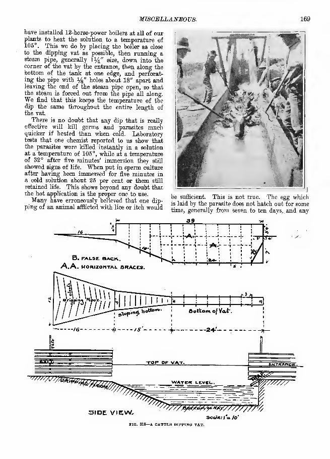
MISCELLANEOVS. 169
have installed 12-horse-power boilers at all of ourplants to heat the solution to a temperature of105°. This we do by placing the boiler as close
to the dipping vat as possible, then running asteam pipe, generally 114" size, down into thecorner of the vat by the entrance, then along thebottom of the tank at one edge, and perforat-ing the pipe with ys " holes about 18" apart andleaving the end of the steam pipe open, so thatthe steam is forced out from the pipe all along.We find that this keeps the temperature of thedip the same throughout the entire length ofthe vat.
There is no doubt that any dip that is really
effective will kill germs and parasites muchquicker if heated than when cold. Laboratorytests that one chemist reported to us show thatthe parasites were killed instantly in a solutionat a temperature of 105°, while at a temperatureof 32° after five minutes' immersion they still
showed signs' of life. When put in sperm cultureafter having been immersed for five minutes ina cold solution about 25 per cent or them still
retained life. This shows beyond any doubt thatthe hot application is the proper one to use.
Many have erroneously believed that one dip-
ping of an animal afflicted with lice or itch would
be sufficient. This is not true. The egg whichis laid by the parasite does not hatch out for sometime, generally from seven to ten days, . and any
39
B. FALSE. BACK.
A.A. HORIZONTAL BRACES. m->—1—
n
H !—
!
FMH 1—i H LJ^
-*. . /6 _
J—^p^bo*"^- Bottom of Vat.
-# /S' 4 24-'-
SIDE VIEW.Scale: < = Jo'
1TG. 318—A CATTLE DIPPING VAT.

170 FARM BUILDINGS.
preparation that is strong enough to kill these
eggs would be very disastrous to the animal,
so they require a second dipping from eight to
eleven days after the first. This is effective withany good preparation provided the animalsdipped have been kept in a pen, yard or pasture
where there has been no infection, as the dippingof cattle is not a preventive, but simply a cure,
and after dipping if they go; to a post, shed or
windmill tower or any similar thing or even lie
down where the post or ground is infected theyare very liable to become infected again.
. Those who have been most successful in exter-
minating this trouble from their herds haveadopted a system of dipping every week or ten
days each animal that shows any indication of it
until it is completely eradicated from the herd.
After dipping seven years we are pleased to say
that we consider it an unqualified success, whichevery herdsman will have to adopt.
We dip all our cattle once a year to insure their
being free from trouble. No new purchases are
allowed to go onto our ranch until after they
have been dipped.
A DIPPING VAT FOR SHEEP.
The strongest argument for the dipping of
sheep lies in the fact that it is the best way of
freeing them from external parasites. Sheep are
very frequently troubled with red lice, whichcan hardly be seen, and yet they cause the sheep
unlimited annoyance. Dipping will completely
destroy them. Ticks cause the farm flocks of
this country untold annoyance and for these dip-
ping is thoroughly effective. Ticks and red lice
do more damage than sheepmen are aware of,
because the evidences of the annoyance whichthey give the sheep are not so marked as in
some other troubles, but they are none the less
a severe cheek to their well-doing. Dipping fol-
lowed faithfully each year will completely re-
move the baneful results from the presence of
these parasites. For the eradication of scab dip-
ping stands first among remedial measures.
While the destruction of these pests is usually
the mainly-accepted argument for dipping, yet
there are others that, grouped together, make a
more favorable endorsement for the operation.
Among these may be briefly mentioned cleansing
the skin, cleaning the wool and particularly en-
couraging the growth of the latter. To get the
fullest returns in these directions the dipping
should be done twice each year—in the spring
shortly after shearing and again in the fall, just
before the advent of winter.
Shortly after shearing it is an advantage to
dip the flock thoroughly so as to cleanse the
skin. This not only adds to the thrift of the
sheep and the lambs, but in both instances it
favors the secretion of yolk and this means the
growth of a sound, live, uncotted fleece. Notonly is the growth of wool better from it, but it
adds directly to the function of the fleece as a
protection to the sheep. The fleece of a sheep
that has been dipped is more likely to remainintact throughout the season, as there is nocause for the sheep rubbing or otherwise break-
ing the compactness of it. Another advantage
that seems to follow dipping at this time is that
it seems to lessen the tendency of the sheep to
lose its wool in spots too early in the season.
When the fleece is clean and healthy it seems to
continue growing longer and the wool does not
peel in patches. Dipping in the fall is more for
the purpose of removing from the fleece such for-
eign matter as may have been gathered during
the summer and also freeing it from any of the
parasites that prove such an annoyance during
the winter season. Even under the best condi-
tions the fleece is likely to become filled moreor less with sand and other foreign matter which,
during the winter, would produce such irrita-
tion as to cause the sheep to rub against sharp
surfaces and destroy the compactness of the
fleece.
By dipping sheep late in the fall, when the
ground is frozen and then keeping them awayfrom the straw stacks and feeding them in racks
that prevent the chaff from falling into the wool,
it is possible to put a clip on the spring marketjust as clean as if the sheep had been washedjust previous to being shorn.
It is hard to measure the damage that is done
to the fleece alone, to say nothing of the thrift of
the sheep, by overlooking dipping in the fall.
It is quite common to see sheep in the ordinary
flocks of the country with fleeces badly broken byrubbing under wagons or some such means,through their endeavors to get rid of the irrita-
tion of the dirt that was left in the fleece. Suchfleeces are likely to become cotted, especially if
the sheep have not been dipped in the spring.
Neglect of spring dipping is apt to result in a
decreased secretion of yolk, a condition whichfavors cotting. A fiber of wool is covered withscales that overlap each other similarly to the
shingles on a roof. To' keep these scales downand to prevent them from warping just as shin-
gles would do there must be a liberal supply of
yolk in the fleece. If this yolk is not secreted,
owing to the unthrifty condition of the skin,
the scales rise and the fibers become so mattedthat they finally reach what is known as a cotted
condition. Fleeces of this kind sell for 3 or -1
cents per pound less than they otherwise wouldon the general market.
The fleece of a sheep that has not been dipped,
also one that is dirty or discolored, sells for

MISCELLANEOUS. 171
". or 4 cents per pound less in title Chicago mar-ket tihan the fleece of a sheep that has beencleaned by dipping. These are facts that maybe verified every spring. It is said that the ben-efits of dipping applied to a single fleece wouldpay for the dipping of more than a dozen sheep.
While the foregoing applies especially to breed-ing flocks, there are just as forcible reasons for
dipping feeders. In feeding sheep it is of primeimportance to reach as rapidly as possible that
sappy and thrifty condition which is conduciveto good gains. Dipping will hasten this andalso remove the risk of unlimited losses throughan outbreak of scab. It is good policy to takeit for granted that the feeders are in need of
dipping rather than wait for the evidence of it
which usually comes when the sheep should goto market.
Dipping being so necessary it follows that it
will pay to arrange for a dipping vat especially
for this purpose. The cost of this is sometimesused as an argument against it, but this maybe easily overcome by a number of farmers in acommunity combining and building a dippingvat for the use of all. It would be easy to drive
the sheep to this plant and the ease with whichthey may be dipped would result in a consid-erable saving of labor.
The dipping vat (Fig. 319), which is here-with described, cost about $50 and could be

172 FABM BUILDINGS.
that case the yards and draining-pens shouldbe enlarged so that the 'sheep could be runthrough in larger groups. It would seem thatfor dipping sheep on an extensive scale it wouldbe an advantage to have the vat double, so thatthe sheep turns when it gets to the end andswims back and goes out near the point whereit started. This long swim cleanses the fleece
thoroughly.
For a farm flock a small dipping plant of
this kind is admirably adapted, but it would be
a more economical arrangement for several to
combine and make a plant for this purpose.
THE WATEE SUPPLY ON THE FARM.
Proximity of a source of pure water to the
barn or stable is of more importance than mightat first thought appear. To have a spring or
running stream located a quarter, of a mile fromthe barns often means a great deal of extra labor
on the part of the work stock in traveling that
distance every day for their water. Put the
water even one-eighth of a mile from the barnand say the horses are watered there. Three trips
a day with work horses mean three-quarters of
a mile of travel, and generally not over the
smoothest road. This amounts to some 270 miles
each year and a farmer may live sixty years onhis farm. Put it low and say that he travels but
15,000 miles in watering his horses during his
lifetime. Is this not an important item in farmeconomies ?
Small streams for watering live stock are
usually of more detriment than value in that they
are the distributors of many diseases. Swine-
breeders know to their sorrow the cost of water-
ing at running streams where contagion is so
easily carried with the current.
A spring high enough above the farm so that
water from it may be carried in iron pipes to the
yards and buildings is of incalculable value ona stock farm. Next to this comes the well andwind-pump. Dug wells are sink-holes of iniquity,
summer resorts for mice, toads, worms andinsects, breeding places for disease germs. Thedrainage of the yards, distant privy vaults andsink-drains is often to these wells. The driven
well, put down where there are tight veins of
clay to keep out surface water, is generally safe.
Nothing can get in it from above. Seepage of
surface impurities is almost impossible. Thedriven well can be put any place where it is
desired, within the stable, at the kitchen door,
in the barn-yard or wherever it is most con-
venient.
Where the subsoil is of sand or gravel or is not
water-tight the driven well will of course afford
no security against water pollution. It will, how-ever, in any case be free from danger of invasion
by rats, mice or insects. A good driven well at
the house will repay its cost many times over.
Best of all is the well which is sunk clear into
the hard rook. Then if the steel tubing is sunk
properly there can be no fear of contamina-
tion.
WATEE SUPPLY FOE FARM BUILDINGS.
A farm water supply system is thus described
by one who is using it: An ordinary windmill
v/forces the water into an underground tank, fromwhich it is conducted by pipes where wanted.
The water being forced through a check-valve
from the pump into the tank fills the bottom of
the tank and thus compresses the air in the top
of the tank. The pressure thus obtained is suffi-
cient to force the water into any part of the barn
or house. A water-pressure gauge is attached to
the pipes just over the kitchen sink and shows at
a glance and at all times the exact amount of
pressure,, obviating any liability to excessive
pressure and danger of breaking pipes. Thepump is usually shut off at forty pounds, when a
hose can be attached and the water thrown over
the house or barn. The tank may be located in
the cellar. It may be an iron tank 3%' in diam-
eter and 12' long, and located underground near
the well. Its capacity is 30 barrels, but it is
never full, as the air occupies some of the space
in the tank. A 50-barrel tank for a stock or
dairy farm would be advisable.
The system is very simple, easily constructed
and anybody can manage it successfully. It puts
the enterprising farmer on a par with the dwellers
of cities as regards a water supply and it is not
expensive. Including a well 100' deep, a wind-\l mill and force pump, tank, 1,000' of supply pipe,
400' of sewer pipe, hydrants, sinks and bath-room
fixtures this water system cost $600. It can gen-
erally be installed at much less cost than the esti-
mate given. Very often a second-hand boiler
good enough to hold water can be obtained at low
cost. Any iron tank strong enough to sustain a
pressure of about 40 pounds will serve. There is
no danger of the water freezing, no luke-warmwater in summer and there is a lively pressure at
any point where it is led in pipes.
There is a simple system operating on the sameplan applicable to houses. It consists of two or
three of the cylindrical galvanized boilers, of
about 40 gallons capacity, one of which is
heated from the range. A force pump in the
kitchen sink forces water into the bottom of the
other two tanks and the air is compressed in the
upper ends. This keeps the hot' water reservoir
always filled and gives pressure to force either
cold or hot water to any part of the house. Asmall steam gauge registers the amount of pres-
sure, which is usually about 20 pounds.

MISCELLANEOUS. 173
This system is so simple and cheap that anyfarmer can afford it and the satisfaction it gives
is beyond calculation. Any plumber can put it
in and it should not cost, piping and all, morethan $40.
EARTH WATER TANK.The plan illustrated in Fig. 320 shows a sec-
tion of a dirt tank. The dimensions are given,
but the size can be suited to requirements. A100,000-gallon dirt tank costs very little more
himself with but little help. The plan explains
itself fully, the principle being that the bacteria
which are generated by putrefaction multiply
very quickly in the first septic tank, devouring
bhe solid matter until almost eliminated. Whatpasses into the second septic tank undergoes the
same process, but to a less amount, owing to its
being purer. The liquid now flows into the
primary filter, being a trench 15' long and 3'
to 4' deep. At its bottom is a layer of broken
stone, surmounted by a layer of gravel, which is
DIRT WALLS ABOUT 9FEET HEIGH ABOUT 30 FEET WIDE AT BOTTOM
.TAKEN OUT. -WiffMjgi -.\WITH PLOW/FOUNDATION LOOSENED WITH
NDSCRAPCR/ APLOW TO BUILD SOILONX PIPE LAID IN BEFORE
BUILDING
FIG. 320—EARTH WATER TANK.
than a 10,000-gallon cypress cistern. Hundredsof these dirt tanks have been made, and are
being made in Western and Southwestern Texas.
A HINT ON CISTERN MAKING.
Many cisterns are faulty in construction in twoimportant details: they are too shallow; the
water gets warm quickly and soon fails. Theyare too flat on the bottom. The bottom of the
cistern should be like the bottom of a funnel,
V-shaped, and in the lowest apex should be the
pipe connecting to the pump. Whatever sedi-
ment, leaves or trash gets into the cistern will
at once be pumped out before it will have time
to taint the water.
PAEM DRAINAGE SYSTEM.
The drainage system shown in Pig. 321 is cheap
and effective and can be put in by the farmer
underdrained by an Akron pipe, leading the
filtered water into a siphon set a foot below the
bed and made of the same piping. The secon-
dary filter, reached through the siphon, consists
of an air chamber of cobblestones, above whichrests three feet of double-screened gravel andsand. An 8' pipe runs from the surface of the
ground into' this air chamber and by means of a
force pump the purified water is raised.
The septic tanks must be water-tight andsealed practically air-tight on top by an iron
manhole. The bacteria thrive without oxygen,
and sewer gas will not generate unless a certain
amount of air space is provided. One cubic
yard of filtering space is sufficient for one per-
son. In this plan 50' of filter space has beenprovided with 15 cubic yards of filtering material
in this instance, because 15 is the average num-ber of persons supposed to occupy the farm and
|"*.htt«.Ta»k £W&>t£jTinfc
^ej><rm *~S Sure. yVcCTet- .
>IG. 321—FARM DRAINAGE SYSTEM.

174 FABM BUILDINGS.
using it. This system is becoming popular both
for private and public places.
WATER CLOSETS.
There is no reason why sanitary conditions on
the farm should be so objectionable as they are
often found. Disease on farms is often traceable
to contamination of water by filthy cess-pools.
In these days of windmills and force pumps there
seems to be no reason why country people should
be without the advantages of water in any part
of the house desired.
Perhaps no one thing adds more to the charm
and healthfulness of a dwelling than a bath-tub.
There is nothing that can be added to the homethat will give more pleasure to all the family
than the bath-tub and a plentiful supply of water
always at hand, hot or cold. A bath-room may be
fitted up with porcelain-lined tub, water closet
and all for about $100.
The water closet if properly constructed and
the drainage from it carried off a sufficient dis-
tance is the most sanitary of all systems. Oneshould avoid the use of an underground cess-
pool near the house to receive drainage from the
bath-room. It should be carried to a distance,
the farther the better.
The well that supplies the drinking water
should be a driven well and should, if possible,
penetrate the earth deep enough to put several
feet of impervious clay between the water supply' and surface drainage. Such a well may cost a
trifle more at the start but it is by many con-
sidered cheaper in the long run.
Privies with vaults or cess-pools below are
universally condemned. Beneath the privy put
an impervious lining of cement, so that under nocircumstances can any drainage from it pollute
the soil below. Make a dust-bin in the privy,
lining it with sheet-iron, so that if necessary in
winter dry ashes may be used instead of dust.
Beneath the seats there may be placed large gal-
vanized iron buckets, or if preferred square
buckets of the same material. These buckets are
easily emptied and it should be attended to as
regularly as any other farm-work.
WATER IN THE COW STABLE.Where it is desired to water cows in their stalls
there is perhaps nothing so satisfactory as the
AI—
I
C/osed. OpenBTG. 322—WATER IN THE COW STABLE.
simple trough that is covered by a hinged cover,
which when closed helps make the front of themanger. This trough should be made of con-
crete, if the floor and manger are of concrete.
The trough may be 8" wide, 6" deep and with a
slight incline at the bottom, level at top and a
plug at the lower end that will drain it each timeit is used. One user of this system has a 1^4"pipe in the bottom of his trough with a *4" hole
opposite each cow, so that the water does not flow
appreciably from one cow to another. ( See Pig.
322.)
FORMULA FOR WHITEWASH.Take a half bushel of unslacked lime, slack it
with boiling water, cover during the process to
keep in steam, strain the liquid through a fine
sieve or strainer, and add to it a peck of salt,
previously dissolved in warm water; three poundsof ground rice boiled to a thin paste and stirred
in while hot; half a pound Spanish whiting andone pound of glue, previously dissolved by soak-ing in cold water, and then hanging over thefire in ,a small pot hung in a larger one filled
with water, add five gallons of hot water to themixture, stir well and let it stand a few dayscovered from dirt, It should be applied hot, forwhich purpose it can be kept in a portable fur-nace. Whitewash makes things look neat andclean and is especially adapted to the inside ofstables and sheds. For outside work a little tint
added to it makes it better. Pretty tints of yel-
low are made by the use of yellow ochre. It is
necessary to use considerable of the ochre. Itis much lighter after it is dry than it appearswhen first put on. Where outside plastering is
done this limewash with ochre in it is admirable.The addition of ochre to the wash seems to add toits permanence and to make it less liable to ruboff. The essential thing in making limewashseems to be to have good fresh lime, slake it inboiling water, add some corn starch or flour pasteor paste made from boiled rice, which is supposedto make it stick, and some glue.
EOOFS AND ROOFING.For roofs of farm buildings slate and good
shingles are popular. Steel roofing unless keptwell painted is of very short usefulness. Paint-ing makes it costly. It is hot in summer, drips incool weather and is sometimes noisy. It is, tobe sure, proof against sparks. Slate in the longrun is perhaps the cheapest of all roofs if welllaid. Shingles come next. Make the roofs withan angle of 45 degrees. Lay them with eithergalvanized nails or the old-fashioned cut nails.Do not be deceived with the small wire nailswhich rust off in a few years. A shingle roofwill last a long time if the shingles are boiled inlinseed oil. Put in a little color if you like. Awarm red makes a roof look well. Do not paintthe butts of shingles under the impression that

MIBCELLANEOUS. 175
it will make them more durable. This will really
hasten decay.
WING'S COW STALL.
Joseph E. Wing describes this stall thus : Thereare three essentials to a perfect stall : that it be
'comfortable for the cow, that it keep her clean,
and that it be convenient for the man who cares
for the cow. The stall I describe (see Pig. 323)
PIG. 333—WING'S COW STALL.
is nearly perfect in all these particulars. I
am indebted to Geo. E. Scott of Ohio for my first
knowledge of this stall, but I have since changedit slightly from his model.The cement floor is admirable. Let it extend
forward far enough to form the bottom of the
feed box at A (Fig. 324). Imbedded in it step
the foot of the post C, and place the 2"x4" onwhich rest the ends of the front posts at A. Letthe manure trench be 16" wide and 8" or 10"
deep. This depth permits the, use of plenty of
absorbents and also prevents the cows from step-
ping into the ditch either when standing in
PIG. 384—WING'S COW STALL SHOWING CEMENT TLOOB.
their stalls or when passing out and in. Thedistance back of the ditch may be 3' or more, ac-
cording to space at hand. From B to trench let
there be a slope of not more than 4". From the
edge of the trench to the front of the stall at
A the distance should be from 6' to 6' 8", accord-
ing to the size of the cows to be stabled. Thepartitions between the cows are 5' high and 3' 6"
long and in the drawing are shown cut away to
give sight of the %" iron rod R, on which slides
the chain that confines the cow. This rod is
best placed midway between the partitions, as
then the cow can lick herself on either side.
The ends of the 1 " x 3 " laths that formthe front
of the manger are shown. They should be spaced
about 4" apart. The cow draws her hay through
these spaces. The board B is about 1' high and
hollowed slightly in the center where the cow's
neck comes when she lies down. The one-quarter
round keeps it solid and makes it easier for her
to clean the meal out of her box. The partitions
go clear across the manger and feed-boxes. Thesloping side of the manger D is tight, so that
meal may be poured thereon and allowed to run
down into the feed-box below. Hay is put in at
E. The space E is not partitioned off but is con-
tinuous along the entire front of the cows. A box
for bran may easily be made below the sloping
board D.The advantage of this stall is that as the cow
cannot push ahead, being restrained by the slats
in front of her, she is compelled to drop her
manure in the gutter. She will not step in this,
as it would be uncomfortable for her to do so andthe real and practical working of the thing is
perfection. We have fitted a small stable with
these stalls and the cows have never soiled them-selves in it since it was made.
Place the partitions from 3' 6" apart to 4', ac-
cording to the size of the cows to be stabled. Thepartitions being high and tight prevent cows an-
noying each other, and being short give room to
the milker and groom and also cause the cows to
present a handsome appearance when viewed fromthe side or rear. The rod R is bolted at eachend, but if a safe fire-escape is wanted it shouldbe arranged as shown in Fig. 323. Here the rodslips through the eyes of the eye bolts A and Band is held suspended by the small chain C. Thisis riveted to the iy2 " gas pipe D, which has ashort piece turned down to make a crank at oneend, as E. This pipe extends along the entire rowof cattle and turns easily in its supports. Whenthere is danger or the cows are to be loosened afew turns of the crank winds all the chains andraises the rods out of their places, when thecow chains slip off and the cows are free. Itmay pay to fit a stable with this simple devicewith a view of freeing cows at any time whenthey are to be watered or turned out. Of coursethe chains would be unwound before the cows areput back in their stalls. This device is, so faras I know, original with me.
THE VAN NORMAN COW STALL.The ideal cow stall should have among other
requisites the following : a fastener that will hold

176 FARM BUILDINGS.
the animal securely, be easy to fasten when secur-
ing the animal and to unfasten when turning it
out. The fastener should be so arranged that
there is no danger of the animal getting the feet
caught in it, and should give the maximum of lib-
erty commensurate with cleanliness. The stall
should be so constructed as to keep the animalclean and absolutely to prevent one animal frominjuring another by stepping on the udder or byhooking and from frightening another by being
able almost to reach it. The manger should hold
the necessary feed and roughage, keeping it with-
in reach of the animal, preventing it being gotten
moval. The stall may be constructed of 2" lum-
ber, dressed on two sides, or if to be whitewashed
iy2 " stuff, rough, will hold the whitewash better
than if smooth. These are standard sizes of lum-
ber, but iy2" dressed and 1%" rough are strong
enough. For dairy cows of average size stalls
3' 6" from center to center and 5' from gutter to
manger will be about right. The animal should
have just room to stand comfortably with hind
feet an inch from the gutter and front feet just
back of A in Fig. 3. A desirable arrangement
is to place the timber A 5' from the gutter at one
end of the barn and enough closer at the other
MMseMciir crTmnsursvsaasnKimEAaimiCR
r/G2
Murimsau vw/e/i
Fife. 6.
K.
Vig.1
under foot and should be easily cleaned of all
refuse matter. Often the owner of a herd' of
cattle desires a stall that will expose to the visi-
tor's view as much of each animal as possible
without lessening the security to his animals. Astall should be inexpensive and strong. These
conditions are met fully in the cow stall designed
by Prof. H. E. Van Norman of the Indiana Ex-
periment Station.
Fig. 2 represents the arrangement for two rows
of stalls facing each other with the feeding alley
raised to the top of the manger, allowing feed and
hay to be swept into the manger and refuse to be
swept out of the manger into the alley for re-
W-
Fig i.
end to fit the smallest animal, thus giving the
stalls varied lengths.
To build the stall place the 2" x 6" A (Fig. 3)' in position 5' or less from the gutter, then the
raised feeding floor should be built with the joist
S 2~y2' in the clear from A ; then cut the plank B
and fasten in place, and successively planks C,
D and E, holding them temporarily with a cleat
until F and G are secured. To cut F and G,lay two pieces of plank on the floor, and on the
one G (Fig. 6) lay off the distance 1 to 2 alongthe edge equal to the distance from the top of
partition 2 (Fig. 4) to middle of manger on topof A at 1, Fig. 4; then mark off 2-3 and 3-1,

MISCELLANEOUS. 177
making the corner at 3 exactly square. It will
make little difference if planks 6 and P, Pig. 4,
do not touch at 1. When properly fitted toe nail
G to A at 1, and nail B, C, D and E to F and G;then toe nail H and I in place. The partition
between the stalls is now held securely in place
and the operation may be repeated for as manystalls as wanted.
It is well to leave the planks B, C, D, E a little
long, or even square and. when in position drawlines from 4 to 5 and' 4 to 6, Fig. 3, and saw off
along these lines. The ends of the planks B, C,
D and B should be covered with a partition cap
0, Pig. 3, which holds them in place and gives
a finished appearance to the stalls. In the ab-
sence of the capping 0, strips as shown at P, Fig.
3, may be used. The bar J, Fig. 4, should be 1"
shorter than the distance between partitions andmade of 1" x 3" light strong wood, round corners
and slides behind iron staples. K, Figs. 4 and 7,
are made of %" round iron, with nuts on the
end or with a hole and key. These staples Kshould be placed 9" from the partition and lower
end near the floor. In the middle of J place a
clevis of 1" x y8 " strap iron, in which to fasten a
common chain tie. Bore a hole for clevis bolt
just above the middle of bar. This bar should
hang far enough from the neck to allow the cowto stand comfortably with the head in a natural
position. Where conditions make the feeding
alley impracticable the front of the manger maybe arranged on the plan of the dotted lines in
Fig. 3. If desired a 2" x 2" piece may be run
along on top of the stalls at 2, Fig. 4, though it
is not recommended. It has been suggested that
J\ ixi" i^.\Kjof Ircva
Fig. 5
instead of the gutter a drop be arranged, as
shown in Fig. 5. T and U are made of a 2" x 6",
split diagonally.
Commenting on the Van Norman stall Joseph
E. Wing says : "It is the simplest, cheapest and
in some ways the most hygienic stall of them all.
It gives an uninterrupted view of the cattle. It
does not waste the feed. The objection to it is
that cows that are wild are not so readily secured
as with some other stalls and there is some noise
when cattle are feeding, owing to their being
fastened to a sliding bar in front. It keeps themclean and they are comfortable."
APPENDIX.Since the foregoing pages were put to press
some additional views of barns and other farmbuildings have come to hand. While we are
without details as to dimensions and construc-
tion in these cases we nevertheless have deemed
them of sufficient general interest to be incor-
porated in a supplementary way in this volume.
Possibly some hints of value may be gleaned^from these illustrations, most of which are fromrecent photographs.
THB YARD AND MAIN BUILDINGS ON THE tfABM OIP W. B. COFMAN, JVAIBFIELD CO., OHIO.

178 FARM BUILDINGS,
-.^ u
A PICTURESQUE WELL SHELTERED FARM IN WESTERN MAINE.
A UTAH SHEEP SHED. SEE DESCRIPTION. PAGE 102.
A MODEL KENTUCKY MULE

APPENDIX. 179
NEW BARN AT THE COLORADO AGRICULTURAL COLLEGE, FORT COLLINS.

180 FARM BUILDINGS.
AN IOWA DAIRY BARN SHOWING SILO—W. B. BABNEY & CO., FRANKLIN 00.
Co
DOOR 8 r-T WIDE
\a. 55o
< CMO X
JL4|t\L§__ ml U _l__LL__
§ rafflv aisle
GRINDER 8 FEED ROOM OVER THIS PAW20x32x|8
MANGER
DOOR SLIDING DOOR B'-'

APPENDIX. 181
STABLES FOR STOCK ON PENNSYLVANIA FARM OF SENATOR P. C. KNOX.
PRIVATE STABLES AT THE COUNTRY PLACE OP SENATOR P. C. KNOX OF PENNSYLVANIA.

182 FARM BUILDINGS.
ARRANGEMENT OF BARNS AND SILO IN THE YARDS OF SMITH & M'GREGOR, WASHINGTON CO., MINN.
A MINNESOTA SELF-FEEDER TOR HOGS.
42
FEED ALLEY 6X42'
FEED ROOM.lVXI3'
MANURE tRE N Ch nr
STA .LS 3 6
RASSAGE 5
FLOOR PLAN OF DAIRY DARN FOR 20 COWS.
TWO LARGE BARNS ON FARM OF J. B. BTJRRIS, PUTNAM CO., IND.

APPENDIX. 183
GROUP OP FARM BUILDINGS ON THE GROUNDS OF THE TENNESSEE EXPERIMENT STATION AT KNOXVTLLE.
C- CHUTE WITH DODGE GATE
D— DIPPING TANKP- SMALL PEN FOR STARTING
CATTLE THROUGH CHUTE
ARRANGEMENT OF CORRALS FOR A RANCH.
* ;iW* -A .""" —~A -A.
—""™=—-« . —
4* » *• 6***• un*»
I—lllll'lll'lflllii^l
A SOUTHERN EXPERIMENT STATION BARN.

184 FABM BUILDINGST
j'SRu^i.
To Tow/*
O
'^fjfDOft^ CSC*
fclm^i iiiiiiiiii-iiii
SUGGESTED ARRANGEMENT OF FARM HOUSTC, BUILDINGS AND GROUNDS FOR A NORTH FRONT. SCALE 1 IN. TO 90 FEET.
(SEE PAGE 11.)
m
BARN AND YARD AT THE MINNESOTA EXPERIMENT STATION, ST. ANTHONY PARK.

APPENDIX. 185
DAIRY BARN AT TENNESSEE EXPERIMENT STATION.
-<?)-^<?^-f?3—e<^-SUGGESTED ARRANGEMENT OF FARM HOUSE, BUILDINGS AND GROUNDS FOR A SOUTH FRONT. SCALE 1 IN. TO 90 FT.
(SEE PAGE 11.)


PRINTED BY R. R. DONNELLEYAND SONS COMPANY AT THELAKESIDE PRESS, CHICAGO, ILL


